
WHEAT Post-harvest Operations -Post-harvest Compendium WHEAT: Post-harvest Operations
Upload
independentCategory
view
0download
0
Contents
LIST OF FIGURESLIST OF TABLESGLOSSARY OF TERMS AND ABBREVIATIONSBIBLIOGRAPHY
INTRODUCTION
Page
IXXI
XII
XV
XVII
PRINCIPLES OF MOORING 1
1.1 General 1
1.2 Forces Acting on the Ship 2
1.2.1 Wind and Current Forces 2
1.3 Mooring Pattern 4
1.4 Elasticity of Lines 7
1.5 General Mooring Guidelines 9
1.6 Operational Considerations 101.7 Terminal Mooring System Management 11
1.7.1. Operating Limits 11
1.7.2 Operating Guidelines/Mooring Limits 111.7.3 Joint Terminal/Ship Meeting and Inspection 15
1.7.4 Instrumented Mooring Hooks or Visual Inspection of MooringLines 16
1.8 Ship Mooring Management 16
1.8.1 Line Tending 16
1.9 Precautions Applicable in High Mooring Load Conditions 17
1.10 Limitations on Use of Tugs and Boats 18
1.11 Unberthing the Ship in an Emergency 18
1.12 General Recommendations 18
1.12.1 Recommendations for Berth Designers 18
1.12.2 Recommendations for Terminal Operators 19
1.12.3 Recommendations for Ship Designers 19
1.12.4 Recommendations for Ship Operators 20
MOORING RESTRAINT AND ENVIRONMENTAL CRITERIA
2.1 General Considerations
2.2 Standard Environmental Criteria
2.3 Computation of Environmental Loads for any Wind andCurrent Combination
21
21
22
23

Section Page
2.4 Maximum Longitudinal and Transverse Forces Under the StandardEnvironmental Criteria 32
2.4.1 Maximum Longitudinal and Transverse Forces on Oil Tankers 32
2.4.2 Maximum Longitudinal and Transverse Forces on 75,000 m3
Gas Carrier with Membrane or Prismatic Tanks 33
2.4.3 Maximum Longitudinal and Transverse Forces on 125,000 m3
Gas Carrier with Spherical Tanks 33
2.5 Mooring Restraint Requirements 34
2.5.1 Basic Principles of Mooring Calculations 34
2.5.1.1 The Principle of Static Equilibrium . 34
2.5.1.2 The Load/Deflection Characteristics of each MooringLine and Breasting Dolphin 34
2.5.1.3 The Geometrical Relationship Between the Parts of theSystem 35
2.5.2 Computer Calculations 35
2.5.3 Hand Calculation Procedures 36
2.5.4 Standard Restraint Requirements 37
2.6 Approximate Methods for Determining Mooring Restraint Requirementsfor Tankers and Gas Carriers Under Standard Environmental Criteria 38
2.6.1 Mooring Restraint Requirements for Oil Tankers above16 kDWT 39
2.6.1.1 Wire Systems 39
2.6.1.2 Synthetic Line Systems 40
2.6.2 Rough Spring Line Restraint Determination for Oil Tankers above16 kDWT when the Ship's Transverse Wind Area is Unknown 40
2.6.3 Rough Breast Line Restraint Determination for Oil Tankers above16 kDWT when the Ship's Lateral Wind Area is Unknown 40
2.6.4 Mooring Restraint Requirements for Gas Carriers 40
2.6.5 Example Calculations 41
3.0 MOORING ARRANGEMENTS AND LAYOUTS
3.1 Principal Objectives
3.2 Requirements at Piers and Sea Islands
3.2.1 Number and Size of Lines
3.2.2 Arrangements for Breast Lines
3.2.3 Arrangements for Spring Lines
3.2.4 Special Arrangements for Gas Carriers
3.3 Requirements at SPMs
3.4 Requirements for Emergency Towing
3.5 Requirements for Multi-Buoy Moorings
IV
45454546474754585858

3.6 Requirements for Tug Handling
3.7 Requirements for Barge Mooring
3.8 Requirements for Canal Transit
3.9 Requirements for Ship-to-Ship (STS) Transfer
3.9.1 Requirements for Off taker
3.9.2 Requirements for Discharge Ship
3.10 Mooring Augmentation in Exceptional Conditions
3.10.1 Excessive Environmental Forces
3.10.2 Use of Shore Based Pulley
3.10.3 Advantage of Pulley System
3.10.4 Disadvantage of Pulley System
3.11 Fire Wires
3.12 Combination of Various Requirements
3.13 Safety and Operational Considerations
3.14 Equipment and Fitting Line-up
DESIGN LOADS, SAFETY FACTORS AND STRENGTH
4.1 General
4.2 Basic Strength Philosophy
4.3 Existing Standards
4.4 Recommended Standards
4.5 Strength Testing of Mooring Fittings
4.6 Marking of Mooring Fittings
4.7 Recommendations for Designers
4.8 Recommendations for Operators
STRUCTURAL REINFORCEMENTS
5.1 Basic Considerations
5.2 Mooring Winches
5.3 Chocks and Fairleads
5.4 Pedestal Fairleads
5.5 Bollards
5.6 SPM and Emergency Towing Fittings
5.7 Special Considerations
5.7.1 Rounded Gunnel Connection
5.7.2 Doublers Versus Inserts
5.7.3 High Strength Steel Fittings
V

MOORING LINES
6.1 Design Stage Decisions
6.2 Wire Mooring Lines
6.2.1 Material
6.2.2 Construction
6.2.3 Corrosion Protection
6.2.4 Bend Radius
6.2.5 Maintenance, Handling and Inspection
6.2.6 Standard Specifications
6.2.7 Use of Synthetic Tails
6.3 Fibre Mooring Lines
6.3.1 Material
6.3.1.1 Polyester
6.3.1.2 Nylon
6.3.1.3 Polypropylene
6.3.1.4 Polyethylene
6.3.1.5 Aramid and Other Materials
6.3.1.6 Combinations of Materials
6.3.2 Construction
6.3.3 Bend Radius
6.3.4 Identification
6.3.5 Handling, Maintenance and Inspection
6.3.6 Standard Specifications
Page
91919191919393939494959595969797999999101101103108
WINCH PERFORMANCE, BRAKE HOLDING CAPACITY AND STRENGTHREQUIREMENTS 113
7.1 Function and Type of Mooring Winches 113
7.2 Automatic Tension Winches Versus Manual Winches 113
7.3 Winch Drums 113
7.3.1 Split Drums 114
7.3.2 Undivided Drums 116
7.3.3 Handling of SPM Pick-up Ropes 116
7.4 Winch Drives 117
7.4.1 Steam 117
7.4.2 Hydraulic Drives 117
7.4.3 Electric Drives 117
7.5 Winch Brakes 118
7.5.1 Layers of Mooring Line on Drum 118
VI

7.5.2 Band Brakes
7.5.2.1 Torque Applied
7.5.2.2 Condition of the Winch
7.5.2.3 Winch in Gear
7.5.2.4 Friction Coefficient
7.5.2.5 Load Dependency of Holding Capacity
7.5.2.6 Sensitivity in Reeling Direction
7.5.3 Disc Brakes
7.5.4 Input Brakes
7.5.5 Winch Brake Testing
7.5.5.1 Test Program
7.5.5.2 Method of Testing
7.5.6 Brake Holding Capacity
7.6 Winch Performance
7.6.1 Rated Pull
7.6.2 Rated Speed
7.6.3 Slack Line Speed
7.6.4 Stall Heaving Capacity
7.6.5 Drum Capacity
7.7 Strength Requirements
7.8 Winch Testing
7.8.1 Rules Concerning Testing at Manufacturer's Works for theAcceptance of the Manufacturer and Purchaser
7.8.2 On Board Acceptance Tests and Inspections
7.9 Summary of Recommendations
7.9.1 Recommendations for Ship Designers
7.9.2 Recommendations for Ship Operators
DECK MOORING FITTINGS
8.1 Introduction
8.2 Vertical Bollards
8.3 Cruciform Bollards
8.4 Closed Fairleads and Panama-Type Fairleads
8.5 Roller Fairleads and Pedestal Fairleads
8.6 Universal Roller Fairleads
8.7 Eyeplates
8.8 Stoppers
8.9 Selection of Fitting Type
VII

Section
9.0 DECK FITTINGS IN THE MANIFOLD AREA
9.1 Introduction
9.2 Fitting Arrangement
9.3 Fitting Details
9.3.1 Cruciform Bollards
9.3.2 Mooring Bollards
9.3.3 Panama-Type Fairleads
9.3.4 Oval Eyeplates
9.4 Lightening Arrangements (Over 160,000 Tonnes DWT)
9.5 Manifold Fittings for Gas Carriers
APPENDICES
A. Design Standard for Tanker Mounted SPM Fittings
B. Guidelines for Handling, Inspection and Removal from Service of WireMooring Lines
C. Care, Handling, Inspection and Replacement of Fibre Ropes
D. Example of Force Predictions for Use with Hand Calculation Procedures
E. Calculation of Mooring Restraint and LoadsDetails of Hand Calculation MethodExample: Comparison with Computer Method Results
F. Strength of Chain Tensioned over a Curved Surface
VIII

List of FiguresFigure Page
Typical Mooring Pattern 1Wind Forces on a Ship 3Effect of Underkeel Clearance on Current Force 3Mooring Pattern Analysis 5Effect of Hawser Orientation on Restraint Capacity 6Effect of Mooring Elasticity on Restraint Capacity 8Effect of Line Length on Tending Requirements 10Operating Wind Limits for 250,000 Dwt Tankers with all Nylon Mooring Ropes 12Operating Wind Limits for 250,000 Dwt Tankers with all Wire Mooring Lines 13Operating Wind Limits for 250,000 Dwt Tankers with Mixed Moorings 14Effect of Pretensioning 17
1.11.21.31.41.51.61.71.81.91.101.11
2.12.22.32.42.5
2.62.7
2.82.92.10
3.1
3.23.33.43.53.63.73.83.93.103.113.123.133.143.14(a)3.153.16
5.15.25.35.45.55.6
Sign Convention and Co-ordinate System 24Variation in Bow Configuration 26Lateral Wind Force Coefficient at the Forward and Aft Perpendiculars 26Longitudinal Wind Force Coefficient 27Lateral Current Force Coefficient at the Forward and Aft Perpendiculars — LoadedTanker 28Longitudinal Current Force Coefficient — Loaded Tanker 29Lateral Current Force Coefficient at the Forward and Aft Perpendiculars in BallastCondition 30Longitudinal Current Force Coefficient—Ballasted Tanker 31Mooring Layout Used for Computational Purposes 36Idealised Mooring Line Layout 38
Mooring Fitting Arrangement of 200 kDWT Tanker with 12 Mooring Wires(42mm Dia.) 48200 kDWT Tanker—Mooring Arrangement on the Forecastle Deck 49200 kDWT Tanker — Mooring Arrangement on the Aft Deck 50Typical Mooring Fitting Arrangement of 35 kDWT Tanker with 10 Mooring Wires 5135 kDWT Tanker — Mooring Arrangement on the Forecastle Deck 5235 kDWT Tanker—Mooring Arrangement on the Aft Deck 53Special Arrangement for Aft Backsprings 54Typical Mooring Pattern — LNG Carrier 55125,000 m3 LNG Carrier—Mooring Arrangement on the Aft Deck 56125,000 m3 LNG Carrier—Mooring Arrangement on the Forward Deck 57Multi-Buoy Mooring (MBM) 59Mooring Pattern During Ship-to-Ship Transfer 61Relative Freeboard Changes During STS Transfers 62Shore Based Pulley System 64Turning up on Ship of Synthetic Rope Tail 65Emergency Towing Wire Requirements 66Alignment and Maximum Fleet Angle for Mooring Winches 68
Typical Cantilevered Foundation in Way of Rounded Gunnel 8384858687889293
Example of a Cantilevered Fairlead FoundationUniversal Fairlead with Individual End FramesDeck Reactions with Two Types of Universal FairleadsTypical Foundation for Pedestal FairleadDeck Reinforcement for Pedestal Fairlead
6.1 Wire Line Constructions6.2 Effects of Bending on Wire Rope Strength
IX

Figure Page
6.3 Stainless Steel Shackle for Lines with Tails 956.4 Load — Extension Characteristics — Wire and Fibre Ropes, New and
Broken-In6.5 Synthetic Rope Structures6.6 Examples of Snap-Back Danger Zones6.7 Example of Hockle in 3 Strand Rope
7.1 The Split Drum Winch7.2 Split Drum Mooring Winches: Turns Required on Tension Part of Drum and Force
in Line at Transfer PointEffect of Applied Torque on Brake Holding PowerSpring-Applied Brake with Hydraulic ReleaseTypical Winch Brake Test EquipmentSimplified Brake Test Kit
Methods of Belaying a BollardTypes of Universal Roller FairleadsAdditional Chafe Plates for Type A FairleadsUniversal Fairleads with Additional Inboard RollersStoppers
Standard Manifold Arrangements — Category 'A' and 'B'Standard Manifold Arrangements—Category 'C' and 'D'
Tongue Type Chain StopperHinged Bar Type Chain StopperSchematic LayoutPositioning of Forward Fairleads, Bow Chain Stoppers and Pedestal Roller LeadsTypical Chock Design
Winding Left and Right Lay Ropes on the Winch Drum
VLCC Berth Mooring Layout Nomenclature for Hand and Calculation MethodMooring Layout Used for Computational Purposes
Three Cases of a Chain Bent over a Curved SurfaceGeometry of a Chain Bent over a Curved SurfaceApproximate Relation between Angle a and Angle f tAngle o as Function of D/d for Various Angles PFree Body Analysis of Half Chain LinkNon-dimensional Stress Factor as a Function of D/d for Various Angles /?Comparison of Grooved and Ungrooved Surface CasesTest Set-up. Test 15, a = 135°, D/d = 4, 8 LinksResults of Tests of Chain Tensioned over Curved Surface
X

List of TablesTable
4.1 Mooring Equipment Design Criteria from Existing Standards4.2 Standards for Mooring Equipment4.3 Recommended SWL, Load Position, Safety Factor and Test Load
6.1 Synthetic Rope Characteristics6.2 Typical Strengths of Synthetic 3 Strand and 8 Strand Ropes6.3 Synthetic Line Service Requirements and Recommendations6.4 Burn Test Characteristics of Synthetic Fibres6.5 "Standard" Strengths of Polyester 8 Strand Ropes6.6 "Standard" Strengths of Nylon 8 Strand Ropes6.7 "Standard" Strengths of Polypropylene 8 Strand Ropes
7.1 Performance Specification for Mooring Winches
8.1 Maximum Permissible Rope Loading of Bollards8.2 Rollers for Fairleads
F.I Chain Tensioned over Curved Surface, Properties of Chain SamplesF.2 Summary of Test Results, Chain Tensioned over Curved Surface
XI

Glossary of Terms and AbbreviationsBIGHT
BITTS
BOLLARD
BREAST LINES
BS
BSI
CHAIN STOPPER
CHOCK
DEAD WEIGHT-D WT
ELASTICITY
ELONGATION
FLAKE DOWN
FAIRLEAD
FLEET ANGLE
FIRE WIRE
FIRST-ASHORE LINE
HA WSER
HEAD LINES
HEA VING LINE
HOCKLE
HTS
A loop formed by doubling back a rope upon itself.
Vertical steel posts or bollards mounted in pairs around which a linecan be secured.
A vertical post to which the eye of a mooring line can be attached.
Mooring lines leading ashore as nearly perpendicular as possible tothe ship's fore and aft line.
British Standard.
British Standard Institution.
A fitting for securing a chain, consisting of two parallel vertical platesmounted on a base, with a pivoting bar or pawl which drops downto bear on a chain link.
A guide for a mooring line which enables the line to be passedthrough a ship's bulwark or other barrier (See also FAIRLEAD).
The carrying capacity of a ship, including cargo, bunkers and stores,in metric tonnes. Strictly speaking, it can be given for any draft, buthere it is used to indicate summer deadweight at summer draft.
The elastic (non permanent) elongation of a unit length of an elementcaused by a unit load. May refer to a material or a compositestructure such as a mooring line.
Refers here to the total elongation (elastic and plastic) of a line.
Laying a rope in long bights on the deck with each bight clear ofthe adjacent one, so that it can be paid out quickly and free fromturns.
A guide for a mooring line which enables the line to be passedthrough a ship's bulwark or other barrier, or to change directionthrough a congested area without snagging or fouling.
The angle between the mooring line and a plane perpendicular tothe axis of the winch drum.
A wire rigged to the waterline over the off-berth side of a ship tofacilitate towing off in an emergency.
A line (usually fibre) put ashore first to help in hauling the ship intoberth.
Synthetic or natural fibre rope or wire rope used for mooring,warping and towing.
Mooring lines leading ashore from the fore end or forecastle of aship, often at an angle of about 45 degrees to the fore and aft line.
A very light line that is thrown between the ship and the berth, andis used to draw the messenger line ashore.
A knot-like twisting of individual strands of a twisted rope.
High Tensile Steel.
XII

IMO International Maritime Organization.
INDEPENDENT WIREROPE CORE (IWRC)ISOJISkDWT
LEAD
LENGTH BETWEENPERPENDICULARS (LBP)
A type of construction of wire rope.
International Organization for Standardization.
Japanese Industrial Standard.
Deadweight in thousands of tonnes.
The direction a mooring line takes up whilst being handled or whenmade fast.The length of a ship, generally between the stem at the design loadlineand the centre of the rudder stock.
LENGTH OVERALL (LOA) The extreme length of a ship.
LIGHTENING ORLIGHTERING
LOADING ARMS
MANDEL SHACKLE
MESSENGER LINES
MINIMUM BREAKINGLOAD (MBL)
MOORING RESTRAINT
MULTI-BUOY MOORINGS(MBM)
NPANAMA TYPE FAIRLEAD
PEDESTAL ROLLERFAIRLEAD
PRE-TENSION
SAFE WORKING LOAD(SWL)
SEA ISLAND
SEICHE
The process of transferring cargo from a tanker to another ship.
Oil transfer units between ship and shore for discharge and loading;may be articulated all-metal arms (hard arms) or a combination ofmetal arms and hoses.
A special shackle used to connect a wire mooring line to a synthetictail.A light line attached to the end of a main mooring line and used toassist in heaving the mooring to the shore or to another ship.
The minimum breaking load of a mooring line as declared by themanufacturer for a new line. It does not include allowance forsplicing or for wear and tear.
The capability of a mooring system to resist external forces on theship.A facility whereby a tanker is usually moored by a combination ofthe ship's anchors forward and mooring buoys aft and held on afixed heading. Also called conventional buoy moorings (CBM).
Newton (unit of force); IkN = 1000 N.
A non-roller type fairlead mounted at the ship's side and enclosed sothat mooring lines may be led to shore with equal facility eitherabove or below the horizontal. Strictly pertains only to fairleadscomplying with Panama Canal Regulations, but often applied to anyclosed fairlead or chock.
A roller fairlead usually operating in a horizontal plane. Its purposeis to change the direction of lead of a mooring or other line on aship's deck.
Additional load applied to a mooring line by a powered winch overand above that required to remove sag from the main run of theline.
A load less than the yield or breaking load by a safety factor definedby a code, standard or good engineering practice.
A pier structure with no direct connection to the shore, at whichtankers can berth. Berthing can take place either on one or both sidesof the structure.Very long waves of small height generated by resonant oscillationwithin a partly closed harbour or other body of water. Stronghorizontal currents can also be set up which may cause ship surgingin adverse circumstances.
XIII

SHIP-TO-SHIP TRANSFEROPERA TIONS (STS)
SINGLE POINT MOORING(SPM)
SMIT BRACKET
SPRING LINES
STERN LINES
STOPPER
STS
SUMMER DEADWEIGHT
SUMMER MARKS
TAIL
VERY LARGE CRUDECARRIER (VLCC)
ULTRA LARGE CRUDECARRIER (ULCC)UNIVERSAL FAIRLEAD
Transfer of crude oil or petroleum product between two ocean-goingships made fast alongside at anchor or underway. The transfer ofpetroleum to barges and estuarial craft is specifically excluded.A facility whereby the tanker is secured by the bow to a singlebuoy or structure and is free to swing with the prevailing wind andcurrent.A fitting for securing the end link of a chafing chain, consisting oftwo parallel vertical plates mounted on a base with a sliding boltpassing through the plates.Mooring lines leading in a nearly fore and aft direction, the purposeof which are to prevent longitudinal movement (surge) of the shipwhile in berth. Headsprings prevent forward motion and backspringsaft motion.Mooring lines leading ashore from the after end or poop of a ship,often at an angle of about 45 degrees to the fore and aft line.A device for securing a mooring line temporarily at the ship whilstthe free end is made fast to a ship's bitt. A Carpenter's stopper is adevice with opening jaws to receive wire and shaped wedges to holdline when tension is applied.
See SHIP-TO-SHIP TRANSFER OPERATIONS (STS) above.The deadweight of a ship when loaded to summer marks.The summer loadline mark and centre of Plimsoll disc on the ship'sside.Metric ton(s) or tonne(s); unit of mass, but often also used forforces (sometimes expressed as 'tf'); Itf = 9.81kN.A short length of synthetic rope attached to the end of a wiremooring line to provide increased elasticity and also ease of handling.For purposes of these guidelines, used to describe ships with dead-weight between 140,000 tonnes and 400,000 tonnes.In these guidelines, used for ships with a deadweight greater than400,000 tonnes.A fairlead with three or more cylindrical rollers.
XIV

BibliographyReference 1 OCIMF publication "Recommendations for Equipment Employed in the Mooring of
Ships at Single Point Moorings".
Reference 2 OCIMF publication "Recommendations for Oil Tanker Manifolds and AssociatedEquipment".
Reference 3 OCIMF publication "Prediction of Wind and Current Loads on VLCCs".
Reference 4 OCIMF/ICS publication "Ship to Ship Transfer Guide (Petroleum)".
Reference 5 OCIMF/SIGTTO publication "Prediction of Wind Loads on Large Liquefied GasCarriers".
Reference 6 OCIMF/ICS/IAPH publication "International Safety Guide for Oil Tankers andTerminals".
Reference 7 Marsh, F.W. and Thurston, R.C.A., "Investigation of Stress Distribution in StudLink Anchor Cable", Report IR61-46, Department of Mines and Technical Surveys,Ottawa, Canada.
Reference 8 Buckle, A. K., "Anchoring and Mooring Equipment on Ships", 1974, Royal Instituteof Naval Architects.
Reference 9 OPTIMOOR Mooring Analysis Computer Program Users Guide (1997)
XV

Section 1.0Principles of Mooring
1.1 GENERALThe term "mooring" refers to the system for securing a ship to a terminal. The most commonterminals for tankers are piers and sea islands, however, other shipboard operations such as mooringat Single Point Moorings (SPM's), Multi-Buoy Moorings (MBM's), emergency towing, tug handling,barge mooring, canal transit, lightening and anchoring may fall into the broad category of mooringand thus require specialised fittings or equipment. Anchoring equipment is covered by ClassificationSociety rules and is therefore not included in these guidelines.
Figure 1.1 shows a typical mooring pattern at a tanker terminal.
FIGURE 1.1: TYPICAL MOORING PATTERN
The use of an efficient mooring system is essential for the safety of the ship, her crew, the terminaland the environment. The problem of how to optimise the moorings to resist the various forces willbe dealt with by answering the following questions:
• What are the forces applied on the ship?
• What general principles determine how the applied forces are distributed to the mooring lines?
• How can the above principles be applied in establishing a good mooring arrangement?
Since no mooring outfit has unlimited capability, in order to address these questions it will be necessaryto understand precisely what the moorings of a ship are expected to achieve.

1.2 FORCES ACTING ON THE SHIP The moorings of a ship must resist the forces due to some, or possibly all, of the following factors:
• Wind
• Current
• Tides
• Surges from passing ships
• Waves/Swell/Seiche
• Ice
• Draft changes
This Section deals mainly with the development of a mooring system to resist wind, current and tidal forces on a ship at a conventional berth. Normally, if the mooring arrangement is designed to accommodate maximum wind and current forces, reserve strength will be sufficient to resist other moderate forces which may arise. However, if appreciable surge, waves or ice conditions exist at a terminal, considerable loads can be developed in the ship's moorings. These forces are difficult to analyse except through model testing, field measurements or dynamic computer programs. Ships calling at terminals where such extraordinary conditions exist should be made aware that the standard environmental condition may be exceeded and appropriate measures will need to be implemented.
Forces in the moorings due to changes in ship elevation from either tidal fluctuations or loading or discharging operations must be compensated by proper line tending.
1.2.1 Wind and Current Forces The procedures for calculating these forces are covered in Section 2 of these guidelines and in Reference 3 (OCIMF publication "Prediction of Wind and Current Loads on VLCCs", 1994). Although the calculations were intended for large ships, additional testing conducted for smaller ships has shown that the wind coefficients are not significantly different for most cases. Consequently, the large ship coefficients published in Reference 3 may be used for bridge-aft tankers with similar geometry down to 16,000 DWT in size.
Figure 1.2 demonstrates how the resultant wind force on a ship varies with wind velocity and direction. For simplicity, wind forces on a ship can be broken down into two components: a longitudinal force acting parallel to the longitudinal axis of the ship, and a transverse force acting perpendicular to the longitudinal axis.
Wind force on the ship also varies with the exposed area of the ship. Since a head wind only strikes a small portion of the total exposed area of the tanker, the longitudinal force is relatively small. A beam wind, on the other hand, exerts a very large transverse force on the exposed side area of the ship. For a given wind velocity the maximum transverse wind force on a VLCC is about five times as great as the maximum longitudinal wind force. For a 50-knot wind on a light 250,000 DWT tanker, the maximum transverse and longitudinal forces are about 320 tonnes (3138 kN) and 60 tonnes (588 kN), respectively.
If the wind hits the ship from any quartering direction between the beam and ahead (or astern), it will exert both a transverse and longitudinal force, since it is striking both the bow (or stern) and the side of the ship. For any given wind velocity, both the transverse and longitudinal force components of a quartering wind will be smaller than the corresponding forces caused by the same wind blowing abeam or head on. With the exception of wind which is dead ahead or astern or dead abeam, the resultant wind force does not have the same angular direction as the wind. For example, a wind 45° off the bow yields a resultant wind force of about 80° off the bow for a 250,000 DWT tanker. In this case the point of application of the force is forward of the transverse centre line, producing a yawing moment on the ship.

Current forces on the ship must be added to the wind forces when evaluating a mooring arrangement. In general, the variability of current forces on a ship due to current velocity and direction follows a pattern similar to that for wind forces. Current forces are further complicated by the significant effect of clearance beneath the keel. Figure 1.3 shows the increase in force due to reduced under-keel clearance. The majority of terminals are oriented more or less parallel to the current, thereby minimizing current forces. Nevertheless, even a current with a small angle (such as 5°) off the ship's longitudinal axis can create a large transverse force and must be taken into consideration. Model tests indicate that the current force created by a one-knot head current on a loaded 250,000 DWT tanker with a two metre underkeel clearance is about 5 tonnes (49 kN), whereas the load developed by a one-knot beam current for the same underkeel clearance is about 230 tonnes (2268 kN).
1.3 MOORING PATTERN
The term 'mooring pattern' refers to the geometric arrangement of mooring lines between the ship and the berth.
The most efficient line 'lead' for resisting any given environmental load is a line oriented in the same direction as the load. This would imply that, theoretically, mooring lines should all be oriented in the direction of the environmental forces and be attached at such a longitudinal location on the ship that the resultant load and restraint act through one and the same location. Such a system would be impractical since it has no flexibility to accommodate the different environmental load directions and mooring point locations encountered at various terminals. For general applications the mooring pattern must be able to cope with environmental forces from any direction. This can best be approached by splitting these forces into a longitudinal and a transverse component, and then calculating how to most effectively resist them. It follows that some lines should be in a longitudinal direction (spring lines) and some lines in a transverse direction (breast lines). This is the guiding principle for an effective mooring pattern for general application, although locations of the actual fittings at the terminal will not always allow it to be put into practice. The decrease in efficiency by deviating from the optimum line lead is shown in Figs. 1.4. and 1.5 (Compare Cases 1 and 3 in Fig 1.4 where the maximum line load increases from 57 (559 kN) to 88 tonnes (863 kN)).
There is a basic difference in the function of spring and breast lines which must be understood by designers and operators alike. Spring lines restrain the ship in two directions (forward and aft); breast lines restrain in only one direction (off the berth), restraint in the on-berth direction being provided by the fenders and breasting dolphins. Whereas all breast lines will be stressed under an off-berth environmental force, only the aft or the forward spring lines will generally be stressed. For this reason the method of line-tending differs between spring and breast lines (as explained later). If spring lines are pretensioned, only the difference between the forces in the opposing spring lines will be available for the longitudinal restraint of the ship. This fact also relates to the problems with constant tension winches mentioned in Section 7.
Some mooring patterns incorporate head and stern lines which are oriented between a longitudinal and transverse direction. The longitudinal component of such a line acts like a spring line and the transverse component like a breast line. Under tension, the longitudinal components of head and stern lines oppose and tend to cancel each other, and are therefore ineffective in the longitudinal restraint of the ship. Head and stern lines are only partially effective in providing the transverse restraint as shown in Fig. 1.5. Their effectiveness will be further reduced due to elasticity effects if they are arranged in combination with breast lines.
The effectiveness of a mooring line is influenced by two angles: the vertical angle the line forms with the pier deck and the horizontal angle the line forms with the parallel side of the ship. The steeper the orientation of a line, the less effective it is in resisting horizontal loads. For instance, a line oriented at a vertical angle of 45" is only 75% as effective in restraining the ship as a line oriented at a 20° vertical angle. Similarly, the larger the horizontal angle between the parallel side of the ship and the line, the less effective the line is in resisting a longitudinal force.
4

CASE 1Idealised All WireAll lines 42mmMBL 115 tonnes
®
T\\@ IL^•R'~^
^-t0
(Til
^ n^L-^'^—"^ w©i^<- 'liBk/- .All loads are in tonnes
Line number
60 knot head wind
60 knot wind 45° off bow
60 knot beam wind
1
8.6
56.7
56.7
2
11.3
57.1
56.7
3
0
34.5
39.5
4
0
34.9
39.9
5
0
39.0
44.9
6
0
5.9
13.2
7
0
5.9
13.2
8
39.0
10.9
6.3
9
39.5
11.3
6.3
10
0
25.9
43.5
11
0
25.4
42.6
12
0
34.0
57.1
13
0
24.9
51.2
14
0
23.6
47.6
CASE 2IdealisedMixed Moorings
Mooring arrangements as aboveexcept that lines 2, 4, 11 and 13 are polypropylene
Line number
60 knot head wind
60 knot wind 45° off bow
60 knot beam wind
•t
15.9
91.6
91.2
2
5.0
6.8
6.8
3
0
54.4
61.2
4
4.1
5.9
5.9
5
0
62.6
69.8
6
0
7.7
17.2
7
0
7.3
16.8
8
39.4
14.5
9.5
9
39.4
15.0
9.5
10
0
37.6
67.1
11
3.65.4
5.9
12
050.3
88.0
13
2.7
5.4
6.3
14
0
33.6
73.0
CASE 3Non-IdealisedAll Wire Moorings
Line number
60 knot head wind
60 knot wind 45° off bow
60 knot beam wind
1
10.4
52.6
56.2
2
n.e49.9
54.0
3
5.4
48.5
53.1
4
8.2
43.5
48.1
5
0
83.9
88.4
6
0
19.5
17.7
7
0
19.0
17.2
8
28.6
5.0
11.8
9
28.6
5.0
12.2
10
0.9
36.7
70.3
11
0
30.4
49.9
12
040.8
70.3
13
024.9
46.3
14
0
24.0
45.8
Note: Computer Programme assumes line does not yield or break. Examples are based on ballasted 250.000 dwt ship. Loads are for conditions shown. Should wind shift, lineswithout loads, as shown above, would assume some loadings, hence all lines should be tended at all times.
FIGURE 1.4: MOORING PATTERN ANALYSIS

Assume "Flat"
X0-J3
Assume 0° Spring LinesHead/Stern Lines
Transverse Restraint Capacity = 2 x A = 2A*Longitudinal Restraint Capacity = 1 x B = 1B*
"A = Allowable Working Load in Head/Stern Lines"B = Allowable Working Load in Spring Lines
30°
L—o °-\»Assume 0°
Spring Lines
Head/Stern Lines
Transverse Restraint Capacity = 2 x A x SIN 30° = 0.87A" Longitudinal Restraint Capacity = 1 x B x COS 30° + 1 x A x COS 30° x COS 30°
= 0.87B + 0.75A
' Longitudinal Restraint Capacity under a longitudinal force only; if a transverse force is present the longitudinal restraint will be further reduceddue to opposition of forces in head and stern lines. Also, elasticity effects have been neglected in this example which may further reduce thelongitudinal restraint capacity.
FIGURE 1.5: EFFECT OF HAWSER ORIENTATION ON RESTRAINT CAPACITY

1.4 ELASTICITY OF LINES
The elasticity of a mooring line is a measure of its ability to stretch under load. Under a given load, an elastic line will stretch more than a stiff line. Elasticity plays an important role in the mooring system for several reasons:
• High elasticity can absorb higher dynamic loads. For this reason, high elasticity is desirable for ship-to-ship transfer operations, or at terminals subject to waves or swell.
• On the other hand, high elasticity means that the ship will move further in her berth and this could cause problems with loading arms or hoses. Such movement also creates additional kinetic energy in the mooring system.
• A third and most important aspect is the effect of elasticity on the distribution of forces among several mooring lines. The simple four-line mooring pattern shown in the upper portion of Fig. 1.5 is insensitive to the elasticity of the lines but is suitable only for boats or very small ships. Due to size limitations on individual lines, many more lines must be used for larger ships. The optimum restraint is generally accomplished if all lines, except spring lines, are stressed to the same percentage of their breaking strength. Good load-sharing can be accomplished if the following principles are understood:
The general principle is that if two lines of different elasticity are connected to a ship at the same point, the stiffer one will always assume a greater portion of the load (assuming the winch brake is set), even if the orientation is exactly similar. The reason for this is that both lines must stretch an equal amount, and in so doing, the stiffer line assumes a greater portion of the load. The relative difference between the loads will depend upon the difference between the elasticities, and can be very large.
The elasticity of a mooring line depends upon the following factors:
• Material
• Construction
• Length
• Diameter
Figure 1.6 demonstrates the significance of each of the above factors on load distribution. The most important points to note are the appreciable difference in elasticity between wire lines and fibre ropes and the effect of line length on elasticity. Cases A) and B) in Fig. 1.6 are examples of mooring arrangements that should be avoided, while Case C) shows an acceptable mooring where each rope is stressed to approximately the same percentage of its breaking strength.
Wire mooring lines are very stiff. The elongation for a 6 x 37 construction wire line at the loading at which the material begins to be permanently deformed is about one percent of wire length. (For a more complete discussion, see Section 6). Under an equivalent load a polypropylene rope may stretch ten times as much as a wire. Thus if a wire is run out parallel to a fibre line, the wire will carry almost the entire load, while the fibre line carries practically none. Elasticity also varies between different types of fibre lines and, although the difference is generally not as significant as that between fibre line and wire, the difference will affect load distribution. Aramid fibre lines for example have much less elasticity than other synthetic fibre lines and would carry the majority of the load if run out parallel to conventional synthetic lines.
The effect of material on load distribution is critical and the use of mixed moorings for similar service, e.g. forward springs, is to be avoided. In some cases the fibre lines may carry almost no load, while at the same time some of the wires are heavily loaded, possibly beyond their breaking strength. The same could be true of mixed fibre lines of varying elasticity, although the differences would generally not be as great.
7

<?lOOT'OBI kN)
cn
Steel = 477' (461 kN}
Polypropylene =-2^ (20 kN)Nylon » iT'OOkN)
NOT ACCEPTABLE
A) Effect Of Mooring Line Material
Same Size &Type MooringUna
150"T(1471 kN)
a
^25T (245 kN)
> 501" (490 kN)
NOT ACCEPTABLE
B) Effect Of Mooring Line Length
150T(1471 kN)• 300mm Nylon = 50T (461 kN)
• 200mm Nylon = 25T (245 kN)
i
C=]ACCEPTABLE
C) Effect Of Mooring Line Size
Note: All Loads Are Approximations
FIGURE 1.6: EFFECT OF MOORING ELASTICITY ON RESTRAINT CAPACITY
fhe effects of mixing wire and synthetic fibre lines are shown in Fig. 1.4, by comparison of Cases 1md 2. (Note the low loads in fibre lines 2, 4, 11 and 13 and the increase in wire loads from anaximum of 57 tonnes (559 kN) to a maximum of 88 tonnes (863 kN)).
Fhe effect of line length on load distribution must also be considered. Line elasticity varies directlyvith line length and has a significant effect on line load. A wire line 60 m long will assume onlyibout half the load of a 30 m parallel and adjacent line of the same size, construction and material.
8

The effect of line length on load distribution must also be considered. Line elasticity varies directly /ith line length and has a significant effect on line load. A wire line 60 m long will assume only bout half the load of a 30 m parallel and adjacent line of the same size, construction and material. Elasticity of a given type of line also varies with its diameter and construction. Usually this factor is not an important consideration since the load relative to a line's strength is the governing factor rather than the absolute load.
1.5 GENERAL MOORING GUIDELINES
Consideration of the principles of load distribution in 1.4 lead to the following mooring guidelines. These assume that the moored ship may be exposed to strong winds or current from any direction.
• Mooring lines should be arranged as symmetrically as possible about the midship point of the ship. (A symmetrical arrangement is more likely to ensure a good load distribution than an asymmetrical arrangement.)
• Breast lines should be oriented as perpendicular as possible to the longitudinal centre line of the ship and as far aft and forward as possible.
• Spring lines should be oriented as parallel as possible to the longitudinal centre line of the ship.
Head and stern lines are normally not efficient in restraining a ship in its berth. Mooring facilities with good breast and spring lines allow a ship to be moored most efficiently, virtually 'within its own length'. The use of head and stern lines requires two additional mooring dolphins and decreases the overall restraining efficiency of a mooring pattern when the number of available lines is limited. This is due to their long length and consequently higher elasticity and poor orientation. They should only be used where required for manoeuvring purposes or where necessitated by local pier geometry, surge forces or weather conditions. Obviously, small ships berthed in facilities designed properly for larger ships may have head and stern lines because of the berth geometry.
• The vertical angle of the mooring lines should be kept to a minimum.
The 'flatter' the mooring angle, the more efficient the line will be in resisting horizontally-applied loads on the ship.
A comparison of Cases 1 and 3 in Fig. 1.4 demonstrates that a ship can usually be moored more efficiently within its own length. Although the same number of lines are used in each situation. Case 1 results in a better load distribution, minimising the load in any single line.
• Generally, mooring lines of the same size and type (material) should be used for all leads. If this is not possible due to the available equipment, all lines in the same service, i.e. breast lines, spring lines, head lines, etc. should be the same size and type. For example, all spring lines could be wire and all breast lines synthetic.
First lines ashore can be synthetic lines, even though the main mooring lines are wire. This is acceptable as long as it is realized that the fibre lines will not add to the final restraining capacity of the system unless all lines in that group are of the same material.
• If tails are used on the wires, the same size and type of tail should be used on all lines run out in the same service.
Synthetic tails are often used on the ends of wire lines to permit easier handling and to increase line elasticity. The addition of an 11 m nylon tail would increase line elasticity of a 45m long wire line by five to sixfold (see also Section 6.2.7).
• Mooring lines should be arranged so that all lines in the same service are about the same length between the ship's winch and the shore bollard. Line elasticity varies directly with line length and shorter lines will assume more load.
9

1.6 OPERATIONAL CONSIDERATIONSThe above mooring guidelines were developed to optimize load distribution to the moorings. Inpractice, final selection of the mooring pattern for a given berth must also take into account localoperational and weather conditions, pier geometry and ship design. Some pilots, for example, desirehead and stern lines to assist ships moving into, along, or out of a berth, while others may use springlines for this purpose. Head and stern lines would be advantageous at berths where the mooringpoints are too close to the ship and good breast lines cannot be provided, or where the bollardsare located so that the spring lines will have an excessive vertical angle in the light condition. Theseexcessive angles would result in considerably reduced restraint capability.
High winds and currents from certain directions might make it desirable to have an asymmetricalmooring arrangement. This could mean placing more mooring lines or breast lines at one end of theship.
The other factor to consider is the optimum length of mooring lines. It would be desirable tokeep all lines at a vertical angle of less than 25°. For example, if the ship's chock location is 25mabove the shore mooring point, the mooring point should be at least 50m horizontally from thechock.
Long lines are advantageous both from standpoint of load efficiency and line-tending. But wherefibre ropes are used, the increased extension can be a disadvantage by permitting the ship to moveexcessively, thereby endangering loading arms. Figure 1.7 illustrates the effects of line lengths online-tending requirements.
15.2m|————————| v.4--—----—-a-r-Winch
Tend Lines At These Points (2) -i
-^^ Tend Line AtThese Points (8)
-a.
•\ Light Ship
Loaded ShipMinimum No. Tendings
Due To 15.2m Ship Rise842
Distance FromBollard To Ship Side
30.5m45.7m61m
Rise •15,2m
Notes: • Assume Wire Lines. Yield Strain « 1'K) Length = 0.46m for 45.7m Hawser• Assume No Slack in Wires• Assume Lines Tended when they reach Maximum Allowable Load
FIGURE 1.7: EFFECT OF LINE LENGTH ON TENDING REQUIREMENTS
10

1.7 TERMINAL MOORING SYSTEM MANAGEMENT
Good mooring management requires the application of sound principles, well maintained equipment, trained personnel and, most importantly, proper co-ordination and interaction between ship and shore. /
While the safety of the vessel and hence its proper mooring is the prime responsibility of the Master, the terminal, because of its knowledge of the operating environment at its site and its equipment, should be in the best position to advise the Master regarding mooring line layout and operating limitations.
The responsibilities and arrangements for mutual checking of moorings, cargo transfer and other aspects of the ship shore interface are covered under the ship/shore check list.
Mooring equipment of existing tankers varies widely, ranging from synthetic mooring ropes, mixed moorings (synthetic ropes and wire lines), all wire moorings (with and without synthetic tails) to modern synthetic "high modulus" systems. Rated brake capacities, winch and fairlead locations can vary significantly from ship to ship. Ship crews will have varying degrees of expertise in mooring matters and varying philosophies concerning maintenance and/or replacement of critical items of mooring equipment.
The terminal can utilize a number of concepts in modern mooring management to reduce the possibility of ship break-out. These are:
• To develop guidelines for the safe mooring of vessels for the operating environment existing at the terminal.
• To obtain information from the ship prior to arrival concerning the ship's mooring equipment
• To examine the ship's mooring equipment after berthing to determine what modification, if any, must be made to standard guidelines in view of the state of maintenance, training of crew, etc.
• To inspect line tending periodically either visually or by the instrumentation of mooring hooks.
• To take whatever action is deemed appropriate to ensure stoppage of cargo transfer, disconnection of loading arms and removal from berth of the ship should the ship fail to take appropriate measures to ensure safety of mooring.
1.7.1 Operating Limits
Another important aspect in restraining the ship at its berth is the movement of the ship. No simple formula can be offered for the ship movement, although this is generally included in the output of computer calculations. Movement of the ship due to environmental loads can exceed loading arm operating limits before the strength limits in the mooring lines are reached. Similarly limits and requirements may apply to gangways, particularly shore-based equipment incorporating a tower or a long span from the jetty to the ship. This is especially true for synthetic line systems. Under worsening environmental conditions the loading arms and gangways may therefore have to be disconnected at lesser wind and current conditions than those used as a design basis for the mooring system.
1.7.2 Operating Guidelines/Mooring Limits
In the past, operating guidelines have generally been developed empirically. With the advent of computers and more accurate wind and current coefficients, guidelines can be developed systematically which can provide the limits for various classes of ships with varying mooring capabilities. At facilities which are located in climes where the operating environment is other than mild, it is desirable to have this done.
11

Applies To Wind Sector
19
24
29
p „.uj 34wte.0 39
§ 44UJ111EC 401A»
54
59
64
ANEMOMETER WIND SPEED (KNOTS) :
PEAK GUST ,|
43° 283°
^ A ^ ID'^' ^' ^10t^l 3- ^-^ ^F1
( ^ B \ —7 •11-1-1.:.,^1.1111-,.11: ^ i^/' ^», 1-4 HeadLnes ^
^^>»'' 'SN.. 9-12 Stern Lines :]^> • 5-8 Springs - ^
•!03<' 223°
WIND SECTORS MOORING CONFIGURATION <!
Lssend :
——————— Rated Winch Brake Capacity >55 tonnes (539 kN) :Mooring Line Breaking Strength >85 tonnes (834 kN) ::•
^ • — —, ~ — Rated Winch Brake Capacity "-40 tonnes (392 kN) :Mooring Line Breaking Strength £72 tonnes (706 kN)
Notes• Loading Arm Wind Limits Are Governed By Vessel Motions.• Limits Shown Are Based On Pretens on Of 2-3 Tonnes (20-29 kN)
And Use of Nylon Lines.• Limits Applicable To A Flood Current Condition From Stern.• Lines 1 ,2 ,3 .4 , 11, 12 Are Led Around Shore Based Pulleys :;
Back To Ship's Bitts. !
(.
65
» 60
55
c,fl
&ff 45
— < 40
1C.
- 30
- 25
- 20
C
MhJiM-1
3 20 40 60 80 100 120
Ml——— I LJ 1————LJ
'^r?' i-^^Luv i-j i
w-w ^——
1—1-
^M/ / /++-'-/ /rr
•-JMMU
——1-
1
-f-y/
-h1
^=-.
A-"7/7/,^—///
/ ?/
A
T,i
' f
^
Bf—'/
/
Br-~-^
-^
x MaximumDraft
=: SeeLegenc! :
Maximum/ Freeboard
1 1 1 1 1 ; ;
^GURE 1.8: OPERATING WIND LIMITS FOR 250,000 DWT TANKERS WITH ALL NYLONMOORING ROPES
12

« Applies To Win
19
24
29
& 34UJU.0 39§§ 4 4UJ1:. : ::1 s
.';; u- 49
54
: 59
64
ANEMOMETER WIND SPEED (KNOTS) ;PEAKQUST , -|
43'' 283° '
:' ^ ^ t^
\ A ,^ M-ff 1111111^ ^ A^
B ( ^> B \ . . ^
^""^ ^\ 1-4 Head Lines " :',-- ' ^ ^ 9-12 Stern Lines ;'
^f • 5-8 Springs :
103° 223° :WIND SECTORS . MOOFfINQ CONFIGURATION
Legend
Mooring Line Breaking Strength >85 tonnes (834 kN)
— — — Rated Winch Brake Capacity £40 tonnes (392 kN)Mooring Line Breaking Strength >60 tonnes (588 kN)
Notes• Limits Applicable To A Flood Current Condition From Stern.• Loading Arm Wind Limit Set By Either Loading Arm Or Ship
Manifold Allowable Stresses.• L nes 1, 2, 3, 4, 11. 12 Are Led Around Shore Based Pulleys
Back To Ship's Bitts.
— 65
- 60
— 55
- 50£UJ AC,fc w
- 35
30
- 25
20
0 20 40 60 80 100 120
- Rated Winch Brake Capacity >55 tonnes (539 kN)
Ei
— -DC
5
<0)
—.£
—I
/
-^/ \Li j j
i J/
/-/-/r~i
A•"7/
/j
B
//'/
t<—
^
^d Sector
B
^
•-¥•
MaximumDraft
See Legend
^ Maximum/ Freeboard :
FIGURE 1.9: OPERATING WIND LIMITS FOR 250,000 DWT TANKERS WITH ALL WIREMOORING LINES
13

Applies To Wind Sector
19
24
29
J "u•3«t
0 395S 44UJUJ
£ 49
54
59
64
ANEMOMETER WIND SPEED (KNOTS)PEAK GUST ,,
43° 283°
^ A ^
( ^ B X 7 6 7-•^ ^\ 1-4 Head Lines
.»•- '^ 9-12 Stem Lines^' ^-, 5-8 Springs
03' 223''WIND SECTORS MOORING CONFIGURATION
Legend
——————— Rated Winch Brake Capacity ?55 tonnes (539 kN)Mooring Line Breaking Strength >85 tonnes (834 kN)
— — — — Rated Winch Brake Capacity >40 tonnes (392 kN)Mooring Line Breaking Strength £60 tonnes (588 kN)
Notes• 2 Nylon Lines In Each Set Of Head-Stern Lines.• Limits Shown Are Based On Pretension Of 2-3 Tonnes (20-29 t(N) And Use of :
Nylon Lines. ;• Limits Applicable To Flood Current Condition From Stern.• Loading Arm Wind Lim t Set By Either Loading Arm Or Ship Manifold Allowable
Stresses.• Lines 1, 2, 3, 4, 11,12 Are Led Around Shore Based Pulleys
Back To Ship's Bitts.
65
60
55
50e 45
S 40a:Cl
— 35
*~ 30
25
20
0 20 40 60 80 100 120
£-jcS
- E<CT
~~ C•D
§— --J
11
1
7-771/ / /1 ] 1 l1 ^1nr
y/-+-
1-/—/
4
X/r1
f
-1fr-/—/<-,
B
~ArfB
/ ^
^
•s MaximumDraft
—— See Legend
Maximum/ Freeboard : :
FIGURE 1.10: OPERATING WIND LIMITS FOR 250,000 DWT TANKERS WITHMIXED MOORINGS
14

A number of terminals have developed information to be used by their operators as guidelines. Examples of the type of information that would be valuable to the jetty operator for mooring 250 kdwt tankers are shown in Figures 1.8, 1.9 and 1.10. These examples are for mooring configurations as shown and for wind variations, wind only and for flood tide. They have been developed for the following mooring systems: nylon rope, all wire lines and mixed wire and nylon moorings.
Inclusion of the mixed mooring case as an example should not be construed to be an endorsement of this system. Other sites will probably have other criteria on which to base operating limits.
With 18 nylon lines Figure 1.8 shows that at maximum freeboard (or minimum draft) the loading arms should be disconnected at wind speeds of approximately 30 knots peak gust. As the draft increases, the permissible wind speed increases to 50 knots peak gust. Loading arm limits are governed by vessel motion. For the winch brake capacities shown and for the wind directions indicated, mooring line loads become excessive in at least one line at the drafts and wind speeds indicated by the curved lines.
For an 18 wire with tails case, Figure 1.9, the loading arm wind limit is constant at 50 knots peak gust. This limit is no longer a function of vessel movement but of the allowable stress levels in the arm or ships manifold. Allowable wind speeds for mooring are as shown.
Figure 1.10 demonstrates a mixed mooring situation wherein 14 wire and tail mooring lines and 4 nylon mooring ropes are used as indicated. In this case as with the all wire case the loading arm wind limits are established by the stresses in the arms or ship's manifold. However, a comparison of the two figures shows there is a marked reduction in the wind speeds that can be tolerated by the mixed mooring wire and rope system.
The foregoing limitations can be created for varying combinations of wind and current, vessel draft, mooring line combinations and configurations and various ship winch design brake capacities. The information thus generated can be used for a number of purposes:
• To decide whether a given ship can be moored at a given berth under the expected weather conditions.
• To determine when to discontinue cargo transfer and to disconnect loading arms.
• To advise the ship when it would be desirable to take on ballast to reduce its freeboard.
• To advise the ship when it would be desirable to have tugs available to assist in maintaining the ship's position at the jetty.
1.7.3 Joint Terminal/Ship Meeting and Inspection
As soon as practicable after berthing, it is recommended that terminals have their representative board the vessel to establish contact with the Master or his designated representative. At this meeting the Terminal Representative should provide information relating to shore facilities and procedures. In addition he should in concert with the Ship Representative:
• Complete the Ship/Shore Safety Check List in line with guidance given in ISGOTT and, where appropriate, physically check items before ticking off.
• Obtain details of moorings and winches, including state of maintenance.
• Review forecasted weather and arrange for the Master to be advised of any expected changes.
• Assess freeboard limitations.
• Assess type and condition of ship mooring equipment and its ballasting ability.
• Determine the conditions at which cargo transfer will be discontinued and loading arms and hoses be disconnected and precautions to be taken under high mooring load situations.
15

1.7.4 Instrumented Mooring Hooks or Visual Inspection of Mooring Lines The terminal should monitor the ship's line tending activity by visual inspection of the mooring lines, particularly during cargo transfer and periods of changing environmental conditions.
In addition to the above, and dependent on the physical environment at the berth, it may be desirable to install mooring line load measurement apparatus where an appropriate need has been identified. This equipment is now available and has been installed at a number of large tanker berths and at many LNG berths. It measures the line loads and has a central read-out in the terminal operation's control room. Should the line loads become high or the lines become slack, the terminal operator can advise the ship accordingly.
In many terminals mooring tension information is transmitted to a shipboard fixed or portable display for direct access by ships staff. In any case the terminal should inspect lines periodically. If poor line tending by ships staff is observed, the terminal should notify the ship.
1.8 SHIP MOORING MANAGEMENT
Good ship mooring management requires a knowledge of good mooring principles, information about the mooring equipment installed on the ship, proper maintenance of this equipment, and good, seamanlike line tending.
Officers in charge of line tending and personnel assigned to tend lines should be aware of the capabilities of the equipment installed on their ship. Specifications should be available on the winch drum to show the design holding capacity and the torque required on the hand wheel or lever to achieve this. Specifications of the mooring lines should also be available.
Recommendations concerning the proper direction of reeling of the wire on the drum should be followed and the drum should be marked accordingly to prevent any possibility of error.
1.8.1 Line Tending
The objective of good line tending is to ensure that all lines share the load to the maximum extent possible and to limit the ship's movement off the berth or alongside the berth. Pretensioning of lines (that is loading a line with a winch prior to the application of environmental forces) reduces ship movement and improves the load distribution when lines of different lengths and elasticities are being used. Figure 1.11 demonstrates how pretensioning affects the load distribution and the movement of the ship.
It is very important to tend spring lines differently from breast lines. Tending head or stern lines presents a special problem (which is one more reason why they are not recommended). They must be tended like either spring or breast lines depending on whether longitudinal or transverse restraint is more critical. For example, if a high longitudinal current on the bow is expected, the bow line should be pretensioned while the stern line is tensioned only to take up any slack. The following general rules apply to line-tending.
• Slack lines should be hauled in first. Slack lines may permit excessive movement of the ship when there is a sudden change in the environment.
• Only one line should be tended at a time. Any time a line is tended, it temporarily changes the load in other lines and may increase it. The simultaneous tending of two lines may therefore
give erratic results or even an overload.
• Whenever a spring line is tended, the opposite spring must also be tended. Otherwise, rendering or heaving-in on one spring line may cause excessive movement of the moored ship along the pier face.
16

Note: Ali hawsers are steel 40mm dia. 6 x 37 1WRC
FIGURE 1.11: EFFECT OF PRETENSIONING
Generally only the forward or aft spring lines will be tensioned by environmental loads. The tensioned lines should be tended first, but only if necessary to correct longitudinal positioning of the ship. The opposing spring lines should then be adjusted to remove slack only.
• Fender compression should be observed during discharge or during a rising tide. Fender compression may be caused by over-tight breast lines. If there is high fender compression which is not caused by on-shore winds or currents, the breast lines must be slackened.
1.9 PRECAUTIONS APPLICABLE IN HIGH MOORING LOAD CONDITIONS
Overloading of mooring lines is evidenced in a number of ways; for example, by direct measurements of mooring line loads, by direct observation of the moorings by experienced personnel, or by predictions made by those having a knowledge of the effects of wind and current on the ship mooring system or by winch slippage.
The following precautions are likely to apply:
• Harden-up on the winch brakes Do not release brakes and attempt to heave in
• Discontinue cargo operations
• Reduce freeboard by taking-on ballast if loads are due to high wind conditions.
• Disconnect loading arms and gangways.
17

Call out crew, linemen, mooring boats, tugs and put ship's engines on readiness.
Run extra moorings as available together with any shore mooring available to augment ship's equipment.
In emergencies place winches in gear.
1.10 LIMITATIONS ON USE OF TUGS AND BOATS
Tugs can perform a very useful function in holding the ship against the berth in order to reduce the strain on moorings. However, care should be exercised when high horsepower tugs are engaged to keep the tanker alongside a jetty. The application of excessive power could result in over compression of the fenders and damage to the ship's side. Also, it must be recognized that tugs have certain operating limits and that, particularly in berths subject to waves, these limits are likely to be exceeded. For instance experience has shown that tugs that are in general use lose significant efficiency in controlling VLCCs and other vessels in wave heights of 1.5 m or more, primarily because of tug motions.
In the case of Multi-Buoy Moorings, boats may be required to release mooring lines from buoys. At jetties, boats may be required to put line handlers on detached mooring dolphins. As with tugs, the boats will have operating limits which will be exceeded under extreme conditions.
1.11 UNBERTHING THE SHIP IN AN EMERGENCY
It is apparent that the ship may be required to leave the berth to prevent damage to itself or to the pier and that the point at which it leaves may be dictated by the limits on the use of tugs and work boats and not by mooring line loads or ship movement. It must be emphasized, however, that the ship Master who is responsible for the safety of the ship must decide whether it is safe to do so or whether by making a hurried unberthing manoeuvre he will in fact place his ship in greater jeopardy. There are also certain berths where tidal conditions or manoeuvring areas may be such as to prevent the unberthing of the ship at certain times.
1.12 GENERAL RECOMMENDATIONS
1.12.1 Recommendations for Berth Designers
• The mooring facilities provided at the berth should be such as to permit the largest vessel which is to be accommodated to remain safely moored alongside.
• The wind and current forces on the ship should be calculated for the wind and current conditions under which the ship may remain moored at the berth, using the procedures covered in Section 2 of these guidelines and in Reference 3.
• Allowable loads in any one mooring line should not exceed 55% of its Minimum Breaking Load (MBL).
• The following principles should be applied when designing the layout of mooring facilities on the berth:
Mooring points shall be disposed as nearly as possible symmetrically about the centre point. Breast moorings shall be provided such that they will emanate from points near the fore and aft ends of the ship and as nearly as possible perpendicular to the fore and aft line of the ship.
The length of mooring lines should be within the range 35 to 50 m and, where intended for the same service and practicable, be equal.
18

Sufficient mooring points should be installed to provide a satisfactory spread of moorings for the range of ship sizes which the berth is to accept. VLCCs are preferably moored by breast lines and spring lines only, although on berths designed to accept a range of ship sizes, the mooring points will inevitably be such that smaller ships may need to use head lines and stern lines in addition to breast lines.
The heights of mooring points should be such that vertical angles will be as small as practical and, if possible, should not exceed 30° from the horizontal.
• Breasting dolphins should preferably be positioned at a distance apart of one third of the overall length of the ship. At berths accommodating a range of ship sizes the spacing of breasting dolphins should preferably be located so that they provide a breasting face between 25% and 40% of the ships overall length.
• Quick release hooks should be provided with a SWL not less than the MBL of the largest rope anticipated and be supplemented by capstans or winches and fairleads to enable the handling of large ship's moorings.
• Shore based mooring equipment should be provided to augment shipboard equipment when the operating conditions at the berth exceed the Design Environmental Conditions.
1.12.2 Recommendations for Terminal Operators
• Terminal Operators should have a good understanding of mooring principles, of the design of the mooring system for the berth, of the loads likely to be experienced in the mooring system under varying conditions of wind and current and to have a clear appreciation of the operating limits applying to the various types of ships and mooring systems which may be used in the berth.
• They should recognize the problems likely to arise from the use of mixed moorings and be aware of the need for effective application of winch brakes and good mooring management while the ship is in the berth.
• Ship-to-shore liaison should be established by the Terminal Operator prior to arrival. A joint agreement is required with the ship on the way in which the ship will actually be moored, and on continuing liaison on mooring matters during the time the ship is in the berth; particular attention being paid to the procedures to be followed in the event of emergencies.
1.12.3 Recommendations for Ship Designers
• The mooring facilities provided in the ship should be such as to permit the vessel to remain safely moored under the Standard Environmental Criteria alongside a berth which is provided with a standard arrangement of mooring points.
• Wind and current forces on the ship should be calculated applying the Standard Environmental Criteria and the coefficients determined by OCIMF (reference 3) and by using the methods described in this book. This calculation will determine the number, size and disposition of moorings required on board.
• Loads in any one mooring line should not exceed 55% of the MBL.
• Mixed moorings, comprising full length synthetic ropes used in conjunction with wires, are not recommended.
• Wire ropes should be the standard mooring equipment for all large tankers and it is recognised that wire ropes greater than 44 mm diameter may require special handling arrangements in terminals.

• Synthetic ropes may be used as the first line ashore for positioning the ship at either end, preferably by means of handling and storage winches. These ropes should not be considered as contributing to the restraint of a vessel moored principally with wires.
•When nylon tails are fitted to wire ropes they should have an MBL at least 25% in excess of the wire, have a length of about 11 m, and be subject to rigorous examination and renewal procedures, as recommended in Section 6.
• Winches for handling the wire ropes may be either of the split drum or undivided drum type; the relative merits of the two types are described in Section 7.3.
• Automatic winches are not recommended, but if fitted must have a capability to disengage the automatic operational features.
• Winch brakes should provide a minimum holding capacity of 60% of the MBL of the wire on the first layer of wire of a split drum winch and on the normal working layer of an undivided drum winch. They should be maintained during service in order to retain their efficiency.
• The layout of moorings should be such as to provide:
— symmetry about the mid length and to provide the design numbers of moorings on each side of the ship,
— breast lines sited as near as possible to the end of the ship,
— moorings used in the same service to be as nearly as possible of the same length inboard of the ship,
— suitable chocks and fairleads to be provided in order to ensure correct alignment of moorings,
— bitts to be positioned for supplementary moorings.
• Minimum safety factors listed in Table 4.3 are based upon the appropriate design criteria and loading assumptions, and should be incorporated in all new equipment and mooring fittings. • All equipment and fittings should be clearly marked with their SWL.
1.12.4 Recommendations for Ship Operators
• The principles of good mooring, including the dangers associated with mixed moorings, should
be understood by ship operators. Particular attention should be given in ship's instructions to the proper application of winch brakes, the maintenance of moorings and winch brakes, good line tending procedures and the practices to be observed in the case of mooring emergencies.
• Each ship should be provided with information on the design of the mooring system, with examples to show the loads likely to be experienced under particular conditions and to illustrate those situations under which the limit of the system is likely to be reached.
20

Section 2.0 Mooring Restraint and Environmental Criteria
2.1 GENERAL CONSIDERATIONS
In order to design a ship's mooring system, the environment loads likely to act upon the ship must first be determined. These can be highly variable from terminal to terminal. To ensure a minimum standard is met for mooring equipment on ships engaged in worldwide trades, the Standard Environmental Criteria given below should be assumed. The Standard Environmental Criteria apply to the design of the ship mooring system and are not criteria for pier design nor a required operating capacity for a pier/ship mooring plan. These parameters are not intended to cover the worst possible conditions, since this would be neither practical nor reasonable. In situations where the Standard Environmental Criteria are exceeded, such as during hurricanes or at a river berth with extremely strong currents, additional measures must be taken such as doubling mooring lines, requesting tug assistance or leaving the berth.
Environmental loads acting upon a ship due to wind and current should be derived from specific model test data for that ship design or from the general non-dimensional force coefficients for oil tankers and gas carriers contained in Reference 3 and Reference 5.
The wind and current coefficients contained in Reference 3 were defined originally for VLCC size ships above 150,000 tonnes deadweight. More recent model test data on the modern tanker forms which have all accommodation superstructures aft confirms that these same coefficients are, in most cases, sufficiently accurate when applied to smaller ships, and that they may therefore be used for a range of ships down to approximately 16,000 tonnes deadweight.
For gas carriers the wind coefficients quoted in Reference 5 are recommended. These apply to membrane and spherical tank designs in the range 75,000 m3 to 125,000 m3. For smaller gas carriers, generally acceptable wind coefficient data is not available and, unless model tests are to be carried out in each case, a conservative extrapolation from large gas carrier data must be adopted.
The current coefficients quoted in Reference 3 for VLCCs may be used for all sizes of tankers with similar geometry down to 16,000 tonnes deadweight and for gas carriers of an equivalent length and draft.
It must be recognised that the coefficients contained in Reference 3 and Reference 5 will yield accurate results only if the vessel geometry and drafts are similar to those of the models used in establishing the coefficients. Reference 3 contains some general guidelines for adjustments if the actual vessel geometry is outside the model range. For instance, oil tanker models used correspond to typical pre-MARPOL vessels with a ratio of overall length to freeboard of 50-60, and a ratio of ballast freeboard to full load freeboard of 3.1:1 Reference 3 suggests that wind coefficients for post-MARPOL (SBT and double hull) vessels (which generally have higher freeboard than pre-MARPOL vessels) be obtained by interpolation or extrapolation on the basis of midships freeboard. The transverse coefficients will generally be higher for newer vessels in full load condition and may be higher in ballast conditions depending on actual ballast draft and trim. Likewise, current coefficients contained in Reference 3 are based on vessels with a length to beam ratio of 6.3-6.5:1. Some vessels have a lower ratio, and Reference 3 indicates that the longitudinal current coefficient may be 25% to 30% higher with a length to beam ratio of 5.0.
21

The appropriate formulae for mooring restraint requirements per Section 2.6 are less sensitive to freeboard changes (since the breast line requirements are based on the transverse coefficient at the aft perpendicular, where the differences between full load and ballast coefficients are much smaller than for the total lateral coefficients). Therefore, these formulae may be used also for newer vessels with higher freeboard.
2.2 STANDARD ENVIRONMENTAL CRITERIA
For all tankers above 16,000 tonnes deadweight intended for general worldwide trading, the mooring restraint available onboard the ship as permanent equipment should be sufficient to satisfy the following conditions:
60 knots wind from any direction simultaneously with either:
3 knots current at 0° or 180°; or 2 knots current at 10° or 170°;
or 0.75 knots current from the direction of maximum beam current loading.
Water depth to draft ratios for these conditions are to be taken as 1.1:1 when loaded and 3.0:1 when in ballast.
While a number of terminals have a minimum depth to draught ratio alongside the berth of 1.05:1 this ratio will inevitably prevail around low slack water when average current velocities would be less than when the water level is at a depth to draught ratio of 1.1:1. It is therefore suggested that the average velocities previously recommended be used with the 1.1:1 ratio.
Obviously when a terminal designer is reviewing the need for shore augmentation, he will find it necessary to be more precise and should use actual site data for his calculations.
The ballast condition is to correspond to the mean IMO ballast draft given approximately by 0.02LBp + 2.0m.
Wind velocity is the velocity measured at the standard datum height of 10 m above ground/water surface and is representative of a 30 second average mean velocity. The selection of the 30 second wind is based on the time it takes the forces in a mooring system to respond to wind velocity changes. Thirty seconds is a typical value for a ballasted VLCC. Smaller vessels will respond more quickly; and a fully laden VLCC may require 60 seconds to respond. However, for consistency, a 30 second average period is suggested for all vessel sizes and loading conditions.
The current velocity is to be taken as the average velocity over the draft of the ship.
For gas carriers above 150 metres in length the same standard environmental criteria should be applied. However, the water depth to draft ratio should be taken as 1.1:1 for all conditions, since the draft of a gas carrier changes little during normal cargo transfer operations.
The above criteria are intended to cover conditions that could readily be encountered on worldwide trade, but they cannot possibly cater for the most extreme combination of environmental conditions at every terminal worldwide. Particularly exposed terminals, or those where for some reason the criteria are likely to be exceeded, are expected to supplement ships' mooring restraint with appropriate shore-based equipment.
Where a ship is operating exclusively on a dedicated route using terminals whose specific environmental data is available the recommended criteria may be revised to suit the local conditions.
22

Although dynamic effects are not explicitly included in the above criteria, the design margins areconsidered conservative and may allow for some dynamics. At terminals where dynamic effects frompassing ships, wave action, etc. are significant, shore-based mooring equipment may have to bedeployed to supplement the ship's equipment.
2.3 COMPUTATION OF ENVIRONMENTAL LOADS
FOR ANY WIND AND CURRENT COMBINATIONEnvironmental loads induced by wind and current can be computed with the procedures describedin Reference 3 which are also listed in this section for ease of reference. The forces and momentsgenerated are suitable for a computer analysis of the required mooring restraint. The followingnon-dimensional coefficients are used in the calculation of design loads:
Cx — longitudinal force coefficientCy — lateral force coefficientCxy — yaw moment coefficient
Additional subscripts w and c are used to distinguish between wind and current.
The sign convention and coordinate system adopted are illustrated in Fig. 2.1. Force and momentcoefficients are a function of wind and current angle of attack. The wind and current coefficientsare based upon data obtained from model tests.
Instead of a lateral force coefficient and a yaw moment coefficient, some sources quote a lateralforce coefficient at the forward perpendicular (Cyp) and a lateral force coefficient at the aft per-pendicular (Cy/y). This is generally more convenient for hand calculations, but either convention canbe converted to the other with the following equations:
(a) From total force/yaw moment system to forces at perpendicular system:
Cyp = ^Cy + C,y
"yA — T"y — -"xy
(b) From forces at perpendicular system to total force/yaw moment system:
Cy = Cyp + CyA
__ Cyp - CyA
V-/W ——
2
The wind forces/moment acting on a moored ship are calculated using the following equations:
Longitudinal F,, = C^f-^—) V;A^ (1)wind force \7600/
F^ = C^(^—]^A^ (2)/ p, \ ,
Lateral wind Fy», = Cy»l ——— I V;Aforce \7600/
Wind yaw moment M,,,,.,= C.vwl—w— } V^AiLnp (3)\7600/
The current forces/moment acting on a moored ship are calculated using the equations:
Longitudinal F,, = C,(———) V^TLgp (4)current force \7600/
23

270°
FIGURE 2.1: SIGN CONVENTION AND CO-ORDINATE SYSTEM

Lateral current Fye = Cy^f-^) V^TLgp (5)force \7600/
Current yaw M,yc= C,^-13—) V^TLip (6)moment. \7600/
Where:
C,», = non-dimensional longitudinal wind force coefficient
Cyw = non-dimensional transverse wind force coefficient
C,yw = non-dimensional wind yaw moment coefficient
p«, = density of air = 1.223 Kg/m3 at 20° C
V, = velocity of wind at 10m elevation in knots
AT = transverse (head-on) above water area in metre2 (for condition investigated)
AL = longitudinal (broadside) above water area in metre2 (for condition investigated)
LBP = length between perpendiculars in metres
F,», = longitudinal wind force in kN
Fy,, = lateral wind force in kN
M»y» = wind yaw moment in kN metres
C,c = non-dimensional longitudinal current force coefficient
Cyc = non-dimensional transverse current force coefficient
C,yc = non-dimensional current yaw moment coefficient
pe = density of sea water = 1025 Kg/m3 at 20°C
Vc = average current velocity acting over the draft of ship in knots
T = ship draft in metres (for condition investigated)
F,e = longitudinal current force in kN
Fyc = lateral current force in kN
M^yc = current yaw moment in kN metres
For the convention using lateral forces and coefficients at the perpendiculars, the formulae (2) and(5) above apply with the substitution of Fy with either Fyp or FyA and Cy with either Cyp or CyA.
The shape of the bow may have some influence on the wind and current coefficients. Reference 3shows two separate values where the coefficients are different. A "conventional" bow represents abulbous bow, and "cylindrical" bow represents a bow without a bulb and rounded waterlines in thestem area. The different bow shapes are shown in Figure 2.2.
Figures 2.3 through 2.8 are provided for use with hand calculations. Figures 2.6 through 2.8, andFigure 2.2 are taken directly from Reference 3.
Figure 2.3 provides the lateral wind coefficients at the forward and aft perpendicular (Cya» andC y f y ) for loaded and ballasted oil tankers. Figure 2.4 provides the longitudinal wind force coefficient forloaded and ballasted oil tankers. Figures 2.3 and 2.4 provide these coefficients for various windattack angles. Figure 2.5 provides the lateral current force coefficients (CYAC and Cypc) and Figure 2.6the longitudinal current force coefficients (Cxc) for water depth to draught ratios of 1.1 in full loadcondition and various current attack angles. Figure 2.7 provides the lateral current force coefficients(CyAc and CyFc) in the ballast condition with a water depth to draught ratio of 1.5. Coefficients forthe standard ratio of 3.0 are not available.
25

Vessel With "Conventional" Bow (bulb)
FIGURE 2.2: VARIATION IN BOW CONFIGURATION
°YAw STW
YAw .-YFw °-3
10) 180 140 120 100 80 60 40 20 0
WIND ANGLE OF ATTACK, 6^
FIGURE 2.3: LATERAL WIND FORCE COEFFICIENT AT THE FORWARD ANDAFT PERPENDICULARS
26

WIND ANGLE OF ATTACK, 8^
FIGURE 2.4: LONGITUDINAL WIND FORCE COEFFICIENT
27

WATER DEPTH TO DRAFT RATIO =1.1:1
^c' S^c' SFC'
CURRENT ANGLE OF ATTACK, 0-c
FIGURE 2.5: LATERAL CURRENT FORCE COEFFICIENT AT THE FORWARDAND AFT PERPENDICULARS—LOADED TANKER
28

WATER DEPTH TO DRAFT RATIO = 1.1:1
FIGURE 2.6: LONGITUDINAL CURRENT FORCE COEFFICIENT—LOADED TANKER
29
140 120 100 80 60 40CURRENT ANGLE OF ATTACK, Qc

WATER DEPTH TO DRAFT RATIO = 1.5:1
0.4-
n
SAC
SFC0.2-
0.1 -
1(B(
WATER DEPTH TO DRAFT RATIO = 1.5:1
J
o ieow
/
^Cr
SF\^
"
7^///
30 14
\/
/ .
/
/
/
/
^ ^
^
r'—"1"""""""""""""""") """"""" """" i 1
10 120 100 80 6
CURRENT ANGLE OF ATTACK, ©„. . ,: . : : .. : w
/
^y//7'—
0
•
/
7//
0 — — — — . -
STERN ^A/ BO
/ Legend^\ 90°//* "—""""~ "Conv</ -—— "Cylinc
7^- 7-<//
——^ A • -^~t e/1 ^
'^
^f ' ^
^^
^-—-
\
\\\
'S
"" '»fc^
\s.\\
• 180°
)W
entional'jrical" B
\
'<
"\
s.\
BOWOW
0 4
SA
-•\
\s
\
c
\
\\
\\
0 2
^^
<
.\>
^-\
< ^
^
0STER^
^)^
FIGURE 2.7: LATERAL CURRENT FORCE COEFFICIENTAT THE FORWARD AND AFT PERPENDICULARS IN BALLAST CONDITION
NOTE: Coefficients are not available for the standard water depth to draft ratio of 3.0:1.

0.10
0.05
^c
0
: : ' ' :' -0.05
• ; : -0.10
18
WATER DEPTH TO DRAFT RATIO < 4.4:1
fti
0 160 140 120 100 80 60 40 20
CURRENT ANGLE OF ATTACK, 0-0
s •s^ <te
- ^e
^
an
/
\/
IV/lea
/
n Vt
/
^r
^
T= (1 1-1.5)
/
/
0
S-»err
^
^——yi
2
9
70
0°
0
I
Be
18C
3W
r
0
FIGURE 2.8: LONGITUDINAL CURRENT FORCE COEFFICIENT—BALLASTED TANKER
Figure 2.8 provides the longitudinal current coefficient (C^) in the ballast condition. Accordingto Reference 3 these coefficients are not sensitive to the water depth to draft ratio, and may be usedfor all ratios, other than deep water cases. NB. note that the attack angle is anti-clockwise from thestern. Also, the positive X and Y directions are forward and up, respectively.
An example for predicting wind and current forces to be used in determining numbers of mooringlines with hand calculations is provided in Appendix D.
Section 2.4 provides information on the maximum combined forces on a vessel when subjected tothe Standard Environmental Criteria, both for oil tankers and two types of gas carriers.
31

1;: 10-14 Aft Breast Lines
: 6-9 Springs
"N-I—f j ^10
A13 r'i
Not To Scale
Inboanj I
Line No.
1234567
1-5 Forward Bre
lie L2
^y ,——L^^T 5/^3 ^
Lengths Of Lines
LengthIn Metres Line No. In Metres
66
42.544353535
?50,000 DWT ji KOA = 349.7m »» \/ .>B=51.8m 41 If ,
ast Lines
H14 H
Length
8 359 3510 3211 3212 7.513 614 6
FIGURE 2.9: MOORING LAYOUT USED FOR COMPUTATIONAL PURPOSES
Pre-tensioning of the mooring lines may be taken into account in determining the mooring lineforces. When this is done, the force calculated in Step 4 is added to the pre-tension force. Themooring line force calculated in Step 4 may be negative reducing the pre-tension provided that thenet load is never negative. The pre-tension forces in the lines and the forces in the breasting dolphinsshould be in equilibrium before applying forces due to wind, current and other environmental factors.
2.5.3 Hand Calculation Procedures
The hand calculation method for assessing the restraint capabilities of mooring layouts is intendedfor use when circumstances preclude the application of more sophisticated computer methods. Inaddition, it can be used to improve the quantitative understanding of good mooring principles.
The method is described in detail in Appendix D.
It uses the basic principles outlined earlier in this chapter but includes a number of assumptions andapproximations to yield a workable procedure. As a result it is reasonably accurate provided certainlimitations are observed. The mooring layout should comply with the Principles of Mooring given inSection 1, notably the separation of lateral and longitudinal restraint functions, symmetry of layout,avoidance of poorly angled head and stern lines, similarity of line type and size. If such criteria areobserved the answers produced are within 10% of those from computer methods. Bearing in mindthe accuracy of other input data, it is considered that the method has quite adequate validity ifapplied with discretion.
Appendix D includes a worked example and the results are compared with a computer methodsolution. The particular mooring layout used is well-conditioned and thus the results agree quiteclosely with those of the computer method.
Another way to determine a vessel's general mooring line requirement without the knowledge of aspecific terminal geometry is to base the requirement on the maximum components of the envi-ronmental forces, and an efficiency factor for each line group. Such method is the basis for the
36

Mooring Dolphin
Symmetrical
|Loading Platform Breasting Dolphin
(assume 0.3 LOA for standard layout)horizontal angles not to exceed values shown.
Mooring Dolphin
Water Line
BREAST LINES Loading Platform SPRING LINES
Vertical angles of lines (in true elevation) not to exceedvalues shown with vessel in least favourable load state.
For Calculation by vessel designer of |lne requirements for Design Conditionsuse standard layout generally with max values of angles shown.Lightest load state then determines distances from vessel to dolphins/hoods.Vertical angles may be recalculated for laden state.
NOT TO SCALE
FIGURE 2.10: IDEALISED MOORING LINE LAYOUT
2.6 APPROXIMATE METHODS FOR DETERMINING
MOORING RESTRAINT REQUIREMENTS FOR
TANKERS AND GAS CARRIERS UNDERSTANDARD ENVIRONMENTAL CRITERIA
In practice it is often necessary to evaluate a ship's mooring equipment without the detailed knowledgeof all ship and berth parameters. For this purpose the formulae quoted in this Section may be used,providing the underlying assumptions on which they are based are applicable.
The formulae are developed on the philosophy that spring line restraint should be proportional tothe maximum longitudinal force on the ship due to the standard environmental loads, and the breastline restraint should be proportional to the maximum transverse forces at the ship perpendiculars.Although this approach does not consider the variations in actual mooring patterns, it provides arational "scale" for mooring restraint systems of different size ships, and as such is more realistic
38

ITEM DESCRIPTION1, 2 Combined Anchor Windlass/Mooring Winch3, 4, 5 & 6 Single Drum Mooring Winch with Warping Head
7 Universal Roller Fairlead8 Pedestal Fairlead9 Panama-type Fairlead, 600 x 300mm opening, deck mounted
10 Closed Fairlead, 450 x 300mm opening, deck mounted11 Panama-type Fairlead, 600 x 300mm opening, bulwark mounted12 Panama-lype Fairlead, 600 x 450mm opening, bulwark mounted13 Overhead Roller Fairlead : :14 Vertical Bollard, 600mm diameter15 Vertical Bollard, 350mm diameter16 Cruciform Bo'lard, 300mm diameter17 Chain Stopper for Anchors18 SPM Chain Stopper19 Tugger Winch20 Towing Filling
FIGURE 3.1: MOORING FITTING ARRANGEMENT OF 200 kDWT TANKER WITH 12 MOORING WIRES (42 MM DIA)

CLOSED CHOCK
FIGURE 3.2: 200 kDWT TANKERMOORING ARRANGEMENT ON THE FORECASTLE DECK
49
CLOSED CHOCK
CLOSED CHOCK

CLOSED CHOCKROLLER FA1RLEAO
ROLLER FA1RLEAD
CLOSED CHOCKROLLER FA1RLEAD.
CLOSED CHOCK
FIGURE 3.3: 200 kDWT TANKERMOORING ARRANGEMENT ON THE AFT DECK
50
PRIMARY LINES
*• AUX. LINES

FIGURE 3.4: TYPICAL MOORING FITTING ARRANGEMENT OF 35 kDWT TANKER WITH 10 MOORING WIRES

FIGURE 3.7: SPECIAL ARRANGEMENT FOR AFT BACKSPRINGS
overhead rollers on the starboard side to the shipside fairlead. Figure 3.4 shows the winches arrangedon both port and starboard sides. This placement is less common since it would take two operatorsto control a pair of winches (unless shipside remote controls are provided port and starboard), aswell as requiring more hydraulic or steam piping. Ships with elevated deck piping should lead thewire under the pipes to simplify bringing out of lines. In this case, low horizontal rollers would beused to prevent line chafing on the deck.
Attention must be paid to the method of bringing the mooring line from the drum to the shipsidefairlead prior to docking. For lines running over the deck pipes, a cross-over walkway should bearranged directly next to the winches. In addition, some owners provide powered capstans for largeships. These allow the line to be drawn out with a heaving line led from the eye of the mooring lineto the associated shipside fairlead, and from there back through an adjacent fairlead onto a capstan.Such an arrangement is shown in Fig. 3.1 (Item 19).
3.2.4 Special Arrangements for Gas Carriers
For flush deck LNG and LPG carriers (membrane type, etc.) the arrangement for spring lines andassociated winches may be similar to those adopted for oil tankers. For spherical tank LNG carriersand lobe/cylindrical tank LPG carriers it is usually not practicable to incorporate main deck winches
54

FIGURE 3.8: TYPICAL MOORING PATTERN—LNG CARRIER

FIGURE 3.9: 125,000 M3 LNG CARRIERMOORING ARRANGEMENT ON THE AFT DECK
56

FIGURE 3.10: 125,000 M3 LNG CARRIERMOORING ARRANGEMENT ON THE FORWARD DECK
and the lead of springs must be from aft of the accommodation deckhouse and from the forwardmain deck or the forecastle. A typical arrangement is shown in Figs. 3.8, 3.9 and 3.10.
The lack of main deck winches on this type of ship can mean that capstans are required close totug positions for handling tug lines. These should be rated at 1.0 to 1.5 tonnes (10 to 15 kN)depending upon the size and length of the tug line to be brought onboard. It is also common practiceon such high freeboard ships to utilize towing chocks recessed into the side shell at appropriate heightsfor easy handling of the line from the tug.
57

FIGURE 3.11: MULTI-BUOY MOORING (MBM)(5-BUOY MOORING SHOWN)
Multi-buoy moorings are usually located in areas where weather and sea conditions are mild tomoderate. This is because the mooring restraint is limited due to the requirement to pay out themooring lines on both port and starboard sides, in contrast to mooring at piers and sea islandswhere the lines are paid out on one side only.
59

40 tonnes (392 kN) MBL would require 315mm diameter bollards and one with mooring lines of92 tonnes (902 kN) or more MBL would require 500mm diameter bollards.
3.7 REQUIREMENTS FOR BARGE MOORING
In many cases barges can be moored with fittings provided for other mooring requirements. None-theless, some VLCCs and ULCCs lack suitable fittings for mooring a fuel oil barge alongside themidships manifold or the aft fuel oil manifold. In this case it is recommended that a set of closedchocks and bollards be provided, port and starboard, about 35 metres forward and aft of the mani-fold and, where appropriate, the aft bunkering station.
3.8 REQUIREMENTS FOR CANAL TRANSIT
Special fittings may be required for transit through canals. The best known requirements are thosefor the Panama Canal where ships are pulled in and out of locks by shoreside locomotives havingtheir own mooring lines mounted on winches. Ships suitable for transit through the Panama Canalshould comply wi th the detailed regulations contained in the U.S. Central Federal Register (CFR).Title 35, Chapter 1, Part 4. Some reference to fittings required by Panama Canal Regulations canalso be found in Section 8.
3.9 REQUIREMENTS FOR SHIP-TO-SHIP
(STS) TRANSFER
Ship-to-ship transfer requires the mooring alongside offshore of two different size ships for thepurpose of cargo transfer. The mooring arrangements adopted will depend upon the sizes of theships carrying out the operations and the difference between their sizes. As a general guideline,Fig. 3.12, taken from Reference 4, illustrates a recommended and proven mooring arrangement fora transfer operation in offshore waters. A prime consideration in mooring during STS operationsis to provide fairleads for all lines without the possibility of chafing against each other, the shipsor the fenders. This is critical in view of the large relative freeboard changes between the ships,illustrated in Fig. 3.13.
FIGURE 3.12: MOORING PATTERN DURING SHIP-TO-SHIP TRANSFER
61

Loaded
After First Lightering
iSjLZ ILoaded Ballast
FIGURE 3.13: RELATIVE FREEBOARD CHANGES DURING STS TRANSFERS
62

This allows heaving aboard of the shore line, or the ship's own line from a shore pulley, via heavinglines led to warping heads of mooring winches. The strength of fairleads and bollards should bebased on the MBL of the ship's standard mooring lines.
3.10.2 Use of Shore Based Pulley
In its simplest form the shore fitting could consist of a bollard of a sufficient diameter for the sizeof wire to be employed. A minimum ratio of bollard/wire diameter of 12:1 should be employed.
The provision of a revolving bollard or pulley wheel is recommended to reduce friction on thewire and to ensure that when moorings are adjusted the tension in each part is readily equalized.To provide a release facility under normal operational conditions, the pulley should be incorporatedon a quick release mounting so that on the activation of the release mechanism the pulley capsizesand the bight of the wire is released and thrown clear of the jetty. This equipment is availablefrom manufacturers of conventional quick release hooks. The pulley must be designed properly toprevent it from releasing the line inadvertently due to the pulley's weight. Figures 3.14 and 3.14(a)show an instrumental shore based pulley and the method of securing the tail at the shipboard end ofthe ship's mooring wire.
In considering the design specifications for this equipment it should be remembered that loads sus-tained will be approximately twice that experienced by a mooring hook or bollard to which a singlewire is attached.
A suitable heavy duty winch or capstan should be provided to assist in heaving the bight of thewire on to the fixed mooring structure and securing it over the pulley or bollard.
FIGURE 3.14: SHORE BASED PULLEY SYSTEM
64

FIGURE 3.14(a): TURNING UP ON SHIP OF SYNTHETIC ROPE TAIL
3.10.3 Advantage of Pulley System
The principal advantage of this equipment is that all moorings can be properly tensioned by thevessel's mooring winches in the normal way and manual handling of heavy wires on board isreduced. Also the problem arising from divided control which can occur with the use of shore wireson winches is avoided.
While the use of such a system will reduce the load in a vessel's moorings in proportion to thenumber of pulleys provided, its complete effectiveness depends on a vessel's mooring equipment beingin good condition initially, as with all mooring systems. The terminal should evaluate the effect thatship's tails would have on the loads induced in the mooring lines. Since now there is only one tailfor two lines, the elasticity of each is decreased.
3.10.4 Disadvantage of Pulley System
The principal disadvantage of this system is the difficulty of handling the length of wire involvedby using the bight particularly at marginal jetties where moorings may have long drifts. In additioncare must be exercised to prevent abrasion of the tails when they come back aboard ship. Since thetail will usually be in the fairlead, the tail can abrade, especially if the fairlead is not smooth orfree of burrs.
To avoid abrasions, some terminals take the tail end to a more distant ship's bitt and others shortenthe tail by belaying around the bitt (as in Figure 3.14(a)).
Both of these affect the elasticity of the system and must be considered when calculating restraintcapacity.
Larger mooring boats may also be necessary to adequately handle heavy bights associated with thissystem.
3.11 FIRE WIRES
Terminals require the provision of so-called 'fire-wires' or 'towing-off wires'. These are mooringwires hung over the off-berth side of the ship. They enable tugs to pull the ship away from the pier
65

hout the assistance of any crew member in case of a serious fire or explosion. Refer also toference 6 ("International Safety Guide for Oil Tankers and Terminals", 4th edition, 1996),apter 3.7.2.
common method is to provide two wires, one near the bow and one near the stern. They areured to bollards with a minimum of five turns and are led directly to a shipside chock with no:k on deck. The outboard end of the line is provided with an eye to which a heaving line isiched and led back to the deck;. During loading or discharge, the heaving line is periodicallyusted to maintain the eye of the fire wire one to two metres above the water as shown in Figure5. Some terminals require different methods and operators should be aware of local regulations.
FIGURE 3.15: EMERGENCY TOWING WIRE REQUIREMENTS
ien not in use, the wires are preferably spooled onto reels which may be located on or below;k.
e wires should be of 6 x 36 IWRC construction and be made of the same type of steel asommended for standard mooring wires in Section 6. The use of synthetic or natural fibre ropeslot permitted as these would burn in the event of a fire.

PEDESTAL FAIRLEAD
FIGURE 3.16: ALIGNMENT AND MAXIMUM FLEET ANGLE FOR MOORING WINCHES
68^

Section 4.0Design Loads, Safety Factors
and Strength4.1 GENERAL
These guidelines are intended to assist ship operators, designers and equipment suppliers in outfittingships with mooring equipment designed to safely accommodate the expected loads.
Mooring equipment means those pieces of equipment mounted onboard a ship to handle the loadsneeded to temporarily attach the ship to a pier, the ocean bottom or another ship. Mooring equip-ment includes bollards, mooring winches, anchor windlasses, chain stoppers, fairleads and capstans.Anchoring equipment is not included in these guidelines, since it is adequately covered in ClassificationSociety rules.
In order to define the strength of a fitting or piece of equipment, the following factors must beknown or assumed:
• the magnitude, position and direction of application of the most severe service load; this isthe safe working load (SWL) of the fitting.
• the safety factor associated with the above load.
• the 'design basis' for the fitting.
The safe working load is the maximum load that should normally be applied in service conditions.The 'design basis' of a fitting provides an additional margin of safety against the rupture of anyportion of the fittings or attachments. The stress levels on which the 'design basis' is calculatedare in excess of the SWL and represent the load level at which any part or component reaches theminimum yield point of the material. The safety factor may therefore be defined as the ratio ofyield load to safe working load, where yield load is the load at which the fitting or equipment willstart to deform permanently. Alternatively, the safety factor may be defined as the ratio of breakingload to SWL. The latter definition would be applicable to items such as fibre or wire ropes wherethe yield load is difficult to establish.
Safety factors account for uncertainties such as additional dynamic loads, normal wear or corrosionof fittings or equipment, small material or welding defects, locked-in weld stress, etc. The choice ofthe safety factor is also influenced by the consequence of a failure. For example, safety factors mustbe very high for ropes used to hoist personnel.
The load location and direction, in combination with the line load, determines the total load andstress on a fitting. A line led 180° around a bollard or pedestal fairlead subjects the fitting to twicethe rope load; and a line attached to a bollard near the top of the barrel produces a higher stressthan one attached close to the base.
4.2 BASIC STRENGTH PHILOSOPHYSince the wire rope, synthetic rope or chain with a specific breaking strength is used as the linkbetween the ship and the berth, it is convenient to relate the strength of equipment and fittings tothe strength of the associated lines or chains.
69

Industry practice has not been consistent in this respect. Some designers base the strength of fittingsand equipment on the maximum line tension anticipated for certain weather criteria; others base thebreaking strength of fittings and equipment on the minimum breaking load of mooring line. Neitherof these strength criteria is appropriate if damage to the fitting and equipment is to be avoided.Under heavy loads it would be possible for the fitting to become damaged while the mooring lineis still intact. A deformed fitting may be unusable, where the overstressing of a line may not beobvious until it breaks.
In terms of repair expense, damage to fittings and equipment is usually more serious than damagingor breaking a line.
The recommended strength standard for mooring fittings and equipment is therefore that the fittingor piece of equipment and its components should be able to withstand, without permanent de-formation, loads equivalent to the specified breaking strength of the mooring line.
4.3 EXISTING STANDARDS
Numerous national standards for mooring fittings exist, but they often do not provide sufficientinformation to establish the actual strength. In some cases a 'SWL' is stated, but no safety factor;in others an 'applicable line' is listed, but no information as to how the line stress relates to fittingstress is given; in yet other cases the line position, direction or quantity may be missing. In com-paring two fittings designed to different standards, it is possible that the obviously weaker designlists a higher rated 'load'. Listed 'load' differences between two fittings of equal size may be as muchas a ratio of 1 to 10, most of which can be due to different definitions of 'load', safety factors andload application.
Mooring fittings are often specified in nominal sizes such as 300mm or 400mm diameter bollards.Fittings with the same nominal size manufactured to different standards may have widely varyingactual strength capabilities and safety factors.
Table 4.1 gives a summary of current mooring equipment safety factors and design criteria as faras these can be determined from some existing standards. As can be seen from the table, theseparameters cannot easily be established for all mooring equipment. In the absence of recognizeddesign criteria, manufacturers rely on internal criteria developed during the design, testing andmanufacture of mooring equipment. They may also manufacture mooring equipment to recognizedstandards that specify dimensions, materials of construction, tolerances, quality assurance and testingprocedures, as well as the maximum loads or maximum rope or chain sizes that can be accepted.A list of widely used standards (ISO, British and Japanese) for mooring equipment is containedin Table 4.2. These standards can become defacto industry standards as owners experience satis-factory service from a particular manufacturer's equipment. The ISO standards are the recognizedinternational industrial standards on which many national standards are based. However, withoutuniversally recognized strength standards, evaluation of new offerings and definition of strengthlimits by designers and operators is difficult.
When the applicable mooring line size is determined from the existing standards, it is recommendedto check the allowable minimum breaking load (MBL) of the rope, if specified, along with thespecified applicable rope size because the rope breaking strengths may be different among standardsand depending on the grade.
It is to be noted that Regulation 15-1 of SOLAS Chapter V (Ch 11-1/3-4 from 1/7/98) requires allemergency towing components to have the specified working strength for all relevant towline angles, i.e.,up to 90 degrees from the ship's centreline to port and starboard, and 30 degrees vertical downwards.
Since no conventional closed chocks designed to the current standards will meet the above loadingrequirements, particular attention should be paid when closed chocks are ordered for compliancewith the above regulation, or if closed chocks for SPM will also be used for the emergency towing.
70

ITEM
Bollards
Closed Chocks
Roller Fairleads
SPM Chafe Chain
SPM Chain Stopper
Emergency TowingComponents
STANDARD
ISO 3913
BS MA 12
JIS F2001F2018
BS MA 19
JIS F2005F2007F2017
BS MA 22DIN 81906JIS F2014
OCIMF
OCIMF
SOLAS
DESIGN CRITERIA
Design load:
MBL of 2 ropes for figure-of-eightfashion, close to base.
2 times MBL of 1 rope on singlebitt.
Ditto except the loading point onsingle bitt specified at height of1.2 x bitt diameter.
Size/strength of applicable rope.
Size/strength of applicable rope.
Applicable rope size.Applicable rope size.
MBL of applicable rope.180° wrap & SWL specified.Applicable rope size.
SWL 200/250 tonnes.
SWL 200/250 tonnes.
SWL 1000/2000 RN.
SAFETYFACTOR
2.0
2.0
—
—
\ — ,
Y ^ —
2.2 - 2.4
1.5
, —
REMARKS
Safety factor: Design load/Max. Single rope load
The bending stress is limited to 85% of the yieldstress of the material, and the shear stress to60% of the yield stress.
Safety factor: Design load/Max. Single rope load
The same limits of bending stress and shearstress as by ISO 3913.
The specified MBL of "applicable" rope cor-responds to ISO 3913 values.
Safety factor based on chain B.S.
Safety factor based on yield stress.
Tow line angle; up to 90° from ship's centre lineand 30° vertical downwards.
TABLE 4.1: MOORING EQUIPMENT DESIGN CRITERIA FROM EXISTING STANDARDS

g|S;l..—. ————:1^-,;1 1 ,
TITLE
Bollards
Cast Iron Bar Type Chain Cable Stoppers
Cast Iron Deck End Rollers
Steel Plate Deck End Rollers
Closed Chocks
Open Chocks
Mooring Pipes (Closed Chock in Bulwark)
Fairleads (Roller)
i Cast Steel Bar Type Anchor Cable Stoppers
Cast Steel Pawl Type Anchor Chain CableStoppers for Grade 2 Anchor Chain Cable
Panama Chocks
Bollards (Simple Type)
Small Size Cast Iron Deck End Rollers
Small Size Steel Plate Deck End Rollers
Small Size Fairleads
Ship's Horizontal Rollers
Ship's Small Size Cast Steel Bar Type AnchcChain Cable Stopper
Ship's Small Size Stand Rollers
Cable Clenches
Fairleads with Horizontal Rollers
Rollered Pawl Type Anchor Chain CableStoppers for Grade 2 Anchor Chain Cable
Rollered Bar Type Anchor Chain CableStoppers for Grade 2 Anchor Chain Cable
Ship's Towing and Mooring Brackets^••"'
Single Point Mooring Pipes (Closed Chock in
Cast Steel Pawl Type Anchor Chain CableStoppers for Grade 3 Chain Cable
Rollered Pawl Type Anchor Chain CableStoppers for Grade 3 Chain Cable
Rollered Bar Type Anchor Chain CableStoppers for Grade 3 Chain Cable
Double Type Cross Bitts for Tugboat
Ship's Cross Bitts
BS MA No.
12(Pt. 1)
or
Bulwark)
12(Pt. 2)
56
21
2007-76
22
56
56
18
,12 :
21 :
21
22
56
22
23
56
56
56
56
56
JIS F No.
2001-90
2002-76
2003-90
2004-90
2005-75
2006-76
2014-87
2015-87
2016-87
2017-82
2018-76
2019-79
2020-79
2021-76
2022-90
2023-76
2024-75
2025-76
2026-80
2027-87
2028-87
2029-78
2030-78
2031-87
2032-87
2033-87
2051-76
2804-76
ISO
3913
6325
ll
6325
6325
6325
TABLE 4.2: STANDARDS FOR MOORING EQUIPMENT
72

TITLE
Anchors
Cast Steel Anchor Chain Cables
Flash Butt-Welded Anchor Chain Cables
Anchor Stoppers
Anchor Stoppers (Small Size)
Chain Stoppers
Ship's Wire Reels
Application of Wire Ropes in Ship
Steel Wire Ropes
Manila Ropes
Synthetic Ropes
Mooring Winches
Windlasses
Warping End Profile•"ffifff-'-'Mi————————————————————————————————————————
BS MA No.
32
35
JIS F No.
3301-90
3302-90
3303-90
3307-78
3310-90
3406-90
3430-80
3433-83
JIS Q 3525
JIS L 2701
3434-83JIS L 2703-2707
6709-85
6714-83
ISO
1704
1704
2408
1141/1346
3730/7825
4568
6482
TABLE 4.2: (Cont)
4.4 RECOMMENDED STANDARDSUntil accepted standards are developed for all mooring equipment, safety factors and SWL, should beset as given in Table 4.3. These recommendations are based on the basic strength criteria mentionedabove and allow for wear and tear or corrosion in service, residual stresses or construction defectsduring manufacture, and a degree of dynamic loading of the fitting. For all fittings and equipment,the basic requirement is that the fitting or equipment should not suffer any permanent deformationwhen the associated line or lines are tensioned to their MBL. The criteria for chain stoppers andSmit brackets used at SPMs and for emergency towing are modified to take account of existingstandards, which recognize that the actual strength of the associated chafing chain, when bent arounda closed bow chock, is less than the nominal chain strength.
When selecting mooring equipment for new ships or conversions, it is recommended that the strengthcriteria listed in Table 4.3 be specified in addition to the usual information on size and materials.Reference to a specific standard should only be made if all strength details are published and are ingeneral agreement with Table 4.3. Standard fittings of unknown strength may be specified with theproviso that the standards are to be used as a guide to overall dimensions, materials and designconcept, but that actual scantlings must be modified, if necessary, to meet the strength requirementsin Table 4.3. In this case, compliance with the criteria must be substantiated with detailed calculationsand a load test for each type and size of fitting.
4.5 STRENGTH TESTING OF MOORING FITTINGSUnless a fitting is constructed in strict compliance with a recognised standard that specifies designload, safety factor and load application, a load test may be required. The load test should beperformed on one fitting of each type and size. A manufacturer's test certificate is acceptable if thetest was witnessed by an independent authority (such as a Classification Society) and the witnesscertificate lists all details such as test load, load application, dimensions of scantlings and materials.
73

FITTING
Double Bollards0 o
rh +^, ——t-Cruciform BoHards
" ^ ^f^1 1
Closed Chocks
-< r-. V-30° \ , / ^-^^y
1 (''"'' ' 30°-J ^
-»—————-^ /'1 1 \
SWL(See Footnotes ® and ®)
Per ISO 3913"Single RopeMaximum Loading"
Single type:2 x above load
Double type:same as above
MBL of one line-i -1R ~ 4IWRC wire rope withmin. strand strengthof 1770 N/mm2
(See Note)
LOAD POSITION(LINE POSITION)
1.2 x barrel dia. (D)above base, max.
1.2 x dia. (D) abovebase, max.
Outboard:horizontal: ± 90°
vertical: up 30°down 90°
Inboard:horizontal: ± 90°
vertical: ± 30°
SAFETYFACTOR
ON YIELD(See
Footnote 0)
2.36
2.36
2.36
TESTLOAD
2 x SWL(See alsoISO 3913,Part 8.2, for testload position)
2 x SWL(See alsoISO 3913,Addendum 1)
2 x SWL
NOTES
1. Scantlings must be as perISO 3913
2. Barrel loading when figure-of-eight belayed assumedto be twice eye load
3. SWL applies to figure-of-eight belaying
1. Scantlings must be as perISO 3913
2. See note 2 above fordouble bollard.
d = rope diameterR = chock surface radiusIf used for primary mooringline, MBL may be that ofactual associated mooringline max. horizontal load =2 x rope toad.
TABLE 4.3: (SHEET 1)RECOMMENDED SWL, LOAD POSITION, SAFETY FACTOR AND TEST LOAD

FITTING
Closed Chocks for SPMsand Emergency TowingElevationto Strongpoint
t?^1'/' V>/ / • • -^\ To Strongpoint''-('/ ~7,j, / / J ...... -
j /qf/y^^30 '
i l l
r^--4^90»
|4--—---l-i-^0-1-f '"^^
7i •(ships over 20,000 DWT)
Strongpoint forEmergency Towing
SWL(See Footnotes I' and @)
20,000 to 50,000DWT:
1000 RN(stern only)2000 RN(bow only)
50,000 to 350,000DWT:
2000 kN(bow and stern)
Over 350,000 DWT:2500 RN(bow only)2000 kN(stem only)
Up to 50,000 DWT:1000 kN
Over 50,000 DW(¥-2000 kN
LOAD POSITION(LINE POSITION)
Outboard:horizontal: ± 90°
vertical: up 0°down 30°
towards closed chock
SAFETYFACTOR
ON YIELD(See
Footnote ®)
1.5(or 2.0 on
ultimatestrength)
2.0 onultimatestrength
TESTLOAD
SWL
SWLalso prototypetest required
'^i
NOTES I
Two chocks at bow requiredfor all ships over 150,000DWT (SPM)
Size of stern chock may bereduced for vessels less than50,000 DWT to suit reducedgear.
May be chain stopper, 1Smit bracket or similar fitting.At bow, SPM chain stoppermay be used as Strongpoint iif chafing chain is not f ,attached ^
TABLE 4.3: (SHEET 2)

FITTING
Pedestal Fairleadsand Rollers of r————-,Button-Roller ^ \ \ fChocks ~/ j \ .
H@j-A^/
Universal Fairlead4-roller type
30°/^ELEV. ——'—
V90°-^
i
, -*——b:; \-c.PLAN U^ Ur\jw ^A——fl^
IVIEW |--/——^\
/O |j/30° 30
] ,
^Us^
1-^n^"?4^
t"^ Jd
>\30°
\90°
-y^b\
SWL(See Footnotes •'''• and @)
0.55 MBL of one line:d 1
R 4IWRC wire rope withmin. strand strengthof 1770 N/mm2
(See Note)
0.55 MBL of one line:d 1R .,4IWRC wire rope withmin. strand strengthof 1770 N/mm2
(See Note)
LOAD POSITION(LINE POSITION)
180° wrap; at upperend of cylindrical orconical part of throat(at center of roller ifradiused throat)
Outboard:horizontal: ± 90°
vertical: up 30°down 90°
Inboard:horizontal: ± 30°
vertical: ± 15°
SAFETYFACTOR
ON YIELD(See
Footnote ®)
2.oe
2.02
TESTLOAD
1.82 x SWL(- MBL)
1.82 x SWL(= MBL)
- -- - : . - ^-ag
NOTES
If used for primary mooringline, MBL may be that ofactual associated mooringline. Total load on fitting isequal to twice the line load.
MBL may be MBL of actualmooring line.Inboard line leads may cor-respond to actual leads towinch drum.Position of line in apertureto be assumed such as toproduce max. stress in partinvestigated.Assume highest position tocalculate stress in frame androller bearings; at mid-lengthof roller to calculate bendingin rotter.
TABLE 4.3: (SHEET 3)

FITTING
5-roller type
| |I ' J^ f f ' V 1 "
' : \^7 iv4^i • \ i—^--— ~'~j~\"r—/^~\ \—^
- V ;' ' 3<' ^ i I-y •^—^^^X^ \ ! 30° ^
90° \J
Chain Stoppers for use at SPMs
Mooring Winch Drum, Shafts, Bearings.
Mooring Winch Brakes, Frames and; Foundations
Mooring Winch Drive Components
SWL(See Footnotes ® and ©)
As for 4 roller typeabove
Up to 350,000 DWT:2000 RN
Over 350,000 DWT:2500 kN
MBL of mooring line
MBL of mooring line
Stall load
LOAD POSITION(LINE POSITION)
Outboard:horizontal: ± 90°
vertical: up 30°down 90°
Inboard:horizontal: ± 30°
vertical: ± 15°
In-line with fitting
Split drums:on first layer
Single drums:first or top layer,whichever produceshighest stress
As above
Not applicable
SAFETYFACTOR
ON YIELD(See
Footnote <9)
2.02
1.5(or 2.0 onultimatestrength)
1.11(or 2.5
based onrated loadwhicheveris higher
1.5
See Note
TESTLOAD
1 fi*? X ^W!1 •0€- •' OVV L-
(= MBL)
SWL
SWL
SWL
SeeISO 3730 and
Section 7
NOTES
See comments for 4-rollertype.
SWL to be marked on fitting.Two fittings required for allships over 150,000 DWT.Bow stopper may be used asstrongpoint for emergencytowing.
See Section 7, Table 1 forstandard winch sizes andrope B.S.
Per BS MA 93, Part 4.3.2.
Safety factor =1.11 based onstall load; or 2.5 based onrated load; whichever ishigher (per ISO 3730, Parts4.2.2 and 4.2.1 respectively).
TABLE 4.3: (SHEET 4)

! FITTING
Mooring Lines
Tails for Mooring Lines
Chafing Chain for Emergency Towing
(if provided as chafing gear)
Grade U3 stud link chain
(vessels over 20,000 DWT)
Towing Pennant
6 x 41 W.S. + I.W.R.C.
galvanized wire rope
(vessels over 20,000 DWT)
Pick-up Gear(vessels over 20,000 DWT)
SWL
Highest loadcalculated for adoptedstandard environ-mental criteria
As above
Up to 50,000 DWT:1000 RN
Over 50,000 DWT:2000 kN
when bent 90°through chock
Up to 50,000 DWT:1000 kN
Over 50,000 DWT:2000 kN
225 kN
LOAD POSITION(LINE POSITION)
Not applicable
Not applicable
Not applicable
Not applicable
Not applicable
SAFETYFACTOR
ONDRY MBL
STEEL: 1.82NYLON: 2.2OTHERSYNTH: 2.0
POLYESTER:2.3
NYLON: 2.5
2.0 onultimatestrength
2.0 onultimatestrength
2.0 onultimatestrength
TESTLOAD
Test sample todestruction toconfirm MBL
As above
Up to 50,000 DWT:1589 kN
Over 50,000 DWT:3011 kN
Test sample todestruction
As above
NOTES
The safety factors for ropesquoted should only be appliedto primary mooring lines incombination with the SWLdefined. For generalapplication, safety factors ofropes must be higher.
Up to 50,000 DWT: ;54 mm dia; B.L. = 2265 kN iOver 50,000 DWT: '76 mm dia; B.L. =4295 kNLength outboard: 3.0 m.Required forward; Aft require-ment depends on design.
Up to 50,000 DWT:58 mm diameterOver 50,000 DWT:76 mm diameter !
Length = 2 x freeboard atchock + 50 m. Pennantrequired aft; optional forward.
Size 7 polypropylene line56 mm dia.Length = 120 m.Required aft; optional forward. |
TABLE 4.3: (SHEET 5)Footnotes® SWL to be marked on or near the fittings in units of metric tons (letter "t")® The SWL of foundations and supporting deck structure must be specially considered when siting and rating the capabilities of the fitting. In principle the
strength of the supporting structure and connection of the fitting to it should be greater than the fitting itself so that any failure does not result in damage tothe ship's structure. Since foundations and connections to the deck are often made in non-ideal conditions onboard the ship rather than factory conditions,and to allow for possible weld imperfections, it is recommended that they be at least 10% stronger than the fitting.
Nominal material yield stress<3) Safety Factor ———:—————•——————-—————:————— if only tension compression or bending stress (S) applied
combined tension, compression or bending stressNominal material yield stress
if only shear stress (T) applied•\/3 x shear stress
Nominal material yield stressif both 9 and T applied
•v'a2 + a 2 -a,a,+ 3^2

BS MA 12 requires that bollards be marked in the centre of one of the caps with the number and nominal size of the British Standard.
BS MA 19 requires that Panama-type fairleads be marked with the number, type and size of the British Standard.
Each fitting must be clearly marked by weld bead outline with its SWL as listed in Table 4.3, in addition to any markings required by other applicable standards. The SWL is expressed in metric tonnes (letter 't') and corresponds to the loading of the associated line or lines, or chain (not the resultant load which may be higher). Note that the unit 't' is recommended rather than the technically correct kN, since some operators may not be fully familiar with the metric system and a fitting may be overloaded if 'kN' is confused with 't'. For double bollards the SWL should correspond to the loading by a wire rope belayed in a figure-of-eight fashion near the base of the bollard.
Since the SWL does not provide information on safety factor, test load or line application, and marking of all data would be impractical, the ship should be provided with all additional relevant information such as actual test load applied, geometry of load application, bollard strength when belayed by eye and higher up on the barrel, maximum size and MBL of applicable line or chain, test certificates, standard drawings, etc. Ideally, such information should be incorporated in a mooring layout plan available or displayed on the ship.
4.7 RECOMMENDATIONS FOR DESIGNERS
Minimum safety factors listed in Table 4.3 are based upon the appropriate design criteria and loading assumptions, and should be incorporated in all new equipment and mooring fittings.
All equipment and fittings should be clearly marked with their SWL and design standard.
4.8 RECOMMENDATIONS FOR OPERATORS
All damaged or deformed equipment or fittings should be treated with suspicion regarding residual strength capabilities and only utilized for low loads, or ideally not used at all until repaired or replaced.
If any doubt exists regarding strength capabilities or rated SWL of a fitting or piece of equipment, it should be proof-tested.
79
Section 5.0 Structural Reinforcements 5.1 BASIC CONSIDERATIONS
Mooring fittings and equipment must be connected to the ship structure in such a way that no failure will occur under anticipated static and dynamic loadings. Section 4 gives the recommended minimum strength criteria for the fittings or equipment. For heavy equipment such as winches, the weight of the equipment and dynamic loads in a seaway must also be taken into account. It is not usually necessary to add the static and dynamic loads caused by the ship's seaway motion to the loads generated by mooring lines or chains, since the ship will rarely be subjected to excessive motion while moored. Nevertheless, once the static requirements are met, the foundations of heavy equipment should be checked for dynamic forces in the same manner as other main and auxiliary machinery.
In selecting fittings from various standards or vendors, the method of hull attachment must be carefully considered. Less expensive fittings may require elaborate hull reinforcements. For example, some universal fairleads do not provide strength members between the end posts, which results in very high localized reaction loads on the deck.
Fittings or equipment generally apply tension, compression and shear stresses to the deck structure. These stresses must be added to the hull stresses that may exist while the ship is moored. The longitudinal deck stress may be assumed to correspond to the stress generated by the maximum allowable still water bending moment. For fittings in the bow and stern area, this stress may be ignored.
Another consideration for equipment and fittings in the mid-body area is the stress-raising effect that any local reinforcements may have on longitudinal strength members. This applies especially to deck plating and deck longitudinals of high tensile steel (HTS) where the ends of reinforcing members may generate fatigue cracking in the primary structure. For this reason, transverse reinforcing members are strongly preferred over longitudinal reinforcements. Where longitudinal reinforcements cannot be avoided,

the ends of the reinforcing members should be very gradually tapered.
Tensile loadings (pull on deck plate) are the most difficult ones to accommodate. If the deck plating is thin in relation to the member on top and the reinforcement below, the heavy welding required could cause tearing of the deck plate. Furthermore, any misalignment between members above and below the deck would result in high deck bending stresses. For this reason, deck insert plates should be provided where the deck plate is thinner than the member welded to it. Another method, especially suitable for bow and stern area equipment such as anchor points for brake bands on mooring winches, is to lead a tension member through a slot in the deck and connect it directly to reinforcing members below the deck. The deck slot generated by this method can be sealed with collar plates.
Special attention must be paid to connections of fittings made from steel of higher strength than the hull steel. If local stresses are high, and adequate compensation cannot be made using the original hull steel quality, then local installation of higher strength steel may be necessary.
5.2 MOORING WINCHES Mooring winches are bolted to foundations that are welded to the ship's deck. Further details on the safety aspects of deck machinery installation may be found in BS MA-93. The foundation should be designed so that all parts are accessible and hold-down bolts can be fitted from below. Vertical members should be positioned close to bolt holes and generally span the under-deck longitudinals or beams.
81
GUTTER BAR 400 x 16.5
A' - A'SEC
A" - A" SIMI FIGURE 5.2: EXAMPLE OF A CANTILEVERED FAIRLEAD FOUNDATION
Section 5.0 Structural Reinforcements 5.1 BASIC CONSIDERATIONS
Mooring fittings and equipment must be connected to the ship structure in such a way that no failure will occur under anticipated

static and dynamic loadings. Section 4 gives the recommended minimum strength criteria for the fittings or equipment. For heavy equipment such as winches, the weight of the equipment and dynamic loads in a seaway must also be taken into account. It is not usually necessary to add the static and dynamic loads caused by the ship's seaway motion to the loads generated by mooring lines or chains, since the ship will rarely be subjected to excessive motion while moored. Nevertheless, once the static requirements are met, the foundations of heavy equipment should be checked for dynamic forces in the same manner as other main and auxiliary machinery.
In selecting fittings from various standards or vendors, the method of hull attachment must be carefully considered. Less expensive fittings may require elaborate hull reinforcements. For example, some universal fairleads do not provide strength members between the end posts, which results in very high localized reaction loads on the deck.
Fittings or equipment generally apply tension, compression and shear stresses to the deck structure. These stresses must be added to the hull stresses that may exist while the ship is moored. The longitudinal deck stress may be assumed to correspond to the stress generated by the maximum allowable still water bending moment. For fittings in the bow and stern area, this stress may be ignored.
Another consideration for equipment and fittings in the mid-body area is the stress-raising effect that any local reinforcements may have on longitudinal strength members. This applies especially to deck plating and deck longitudinals of high tensile steel (HTS) where the ends of reinforcing members may generate fatigue cracking in the primary structure. For this reason, transverse reinforcing members are strongly preferred over longitudinal reinforcements. Where longitudinal reinforcements cannot be avoided, the ends of the reinforcing members should be very gradually tapered.
Tensile loadings (pull on deck plate) are the most difficult ones to accommodate. If the deck plating is thin in relation to the member on top and the reinforcement below, the heavy welding required could cause tearing of the deck plate. Furthermore, any misalignment between members above and below the deck would result in high deck bending stresses. For this reason, deck insert plates should be provided where the deck plate is thinner than the member welded to it. Another method, especially suitable for bow and stern area equipment such as anchor points for brake bands on mooring winches, is to lead a tension member through a slot in the deck and connect it directly to reinforcing members below the deck. The deck slot generated by this method can be sealed with collar plates.
Special attention must be paid to connections of fittings made from steel of higher strength than the hull steel. If local stresses are high, and adequate compensation cannot be made using the original hull steel quality, then local installation of higher strength steel may be necessary.
5.2 MOORING WINCHES Mooring winches are bolted to foundations that are welded to the ship's deck. Further details on the safety aspects of deck machinery installation may be found in BS MA-93. The foundation should be designed so that all parts are accessible and hold-down bolts can be fitted from below. Vertical members should be positioned close to bolt holes and generally span the under-deck longitudinals or beams.
81

UNIVERSAL CHOCK
^? ^^ GUTTER BAR
CANTILEVEREO FOUNDATION
UPPER DECK
STIPF6N6R(ALIGNED WITHFAIRLEAO SIDES)
FIGURE 5.1: TYPICAL CANTILEVERED FOUNDATION IN WAY OF ROUNDED GUNNEL
5.4 PEDESTAL FAIRLEADSThe critical connections are the roller pin to pedestal and pedestal to deck attachment. Pedestalfairleads have failed more often in these areas than any other mooring fitting. An example of a goodpin-to-pedestal connection and pedestal-to-deck connection is shown in Figs. 5.5 and 5.6.
Most existing pedestals are of cylindrical or conical shape, which makes a proper line-up with re-inforcements below the deck difficult. For this reason, a rectangular section with rounded edges (seeFigs. 5.5 and 5.6) may be more appropriate in some cases.
5.5 BOLLARDSBollards require deck strengthening members in line with all four sides of the bollard base. Themembers below deck should be of the same thickness as the base, and their welding to the deckshould be equal to the weld size between bollard base and deck. Where bollards line up with existingstructure, such as deck beams, girders, or transverse webs, the welding of these members to thedeck may have to be increased.
5.6 SPM AND EMERGENCY TOWING FITTINGSDue to the high loading on these fittings, the method of connection to the hull structure should bewell thought out. Each chain stopper or Smit bracket should be welded directly to the deck of thevessel or welded or bolted to a plate or pedestal structure which is in turn welded to the deck ofthe vessel. The stopper or bracket should not be bolted directly to the deck of the vessel. A heavydeck insert plate may be required. In place of one centreline girder, two parallel girders with spacingequal to the distance between the cheek plates of the chain stopper or SPM bracket are recommended.Additional transverse members and pillars may be required to absorb the load. The SPM or towingfitting should be located as close to the deck as possible. However, a small foundation will normallybe required to achieve proper alignment between the fitting, the bow chock and the pedestal fairlead.The foundation must be provided with a thrust block capable of absorbing the chain load specifiedin Section 4.
83

GUTTER BAR 400 x 16.5
i
A <r,,. ^"T
;
A " ^
>30
^
\
jUVb-
.n?U
!/
CABLING ..————(200 x 19) '
^A
00<•
^ 19 c
L
^~~Tco^ +
t00CO+
---TF- -r|l
——-J,---
^Lii6 11i!— ^4-^—.
B !! '; !! ^ii -' n' !1i hI) 4i- - - • • -"^"r"-j ' i 1
TT
- J L .r n ~ ~it 25
-•<»-»-! !
I!11111144-
81 ^-t "
*u-ntM|
-»1
-."t -"r"
-^-^«4
-"i---.t t
~T'25<- ^
<
^
lit'•
cu"
It
30n
A' - A' SECA" - A" SIMI
FIGURE 5.2: EXAMPLE OF A CANTILEVERED FAIRLEAD FOUNDATION
84

ITEM DESCRIPTION QTYFABRICATED FRAMEVERTICAL FRAMEVERTICAL ROLLERTHRUST BEARINGHORIZONTAL ROLLERHORIZONTAL ROLLERHORIZONTAL PINHORIZ. ROLLER BUSHVERTICAL PINTAP BOLTWASHERGREASE NIPPLE
List of material quantities for one fairlead
FIGURE 5.3: UNIVERSAL FAIRLEAD WITH INDIVIDUAL END FRAMES
5.7 SPECIAL CONSIDERATIONS
The following is a discussion of some specific shipboard installation problems:
5.7.1 Rounded Gunnel Connection
Most newer ships have a rounded connection between upper deck and side shell in the mid-bodyarea. The rounded plate is of a special steel grade to prevent propagation of major cracks in thehull envelope. Some Classification Societies place restrictions on welding to this plate. Whateverregulatory bodies may have to say on this subject, welding to the plate is discouraged, especially ifthe deck is of higher tensile steel. Since mooring chocks or fairleads in the mid-body area should beflush with the side shell to avoid line chafing on the rounded gunnel, a cantilevered foundation forall shipside mooring fittings will be required. Figures 5.1 and 5.2 show such an installation.
5.7.2 Doubters Versus Inserts
Deck plating in way of mooring fittings may be reinforced by doublers or insert plates. Doublets areusually less expensive but cannot transmit large tensile loads. This is because all loads to the deck aretransmitted only through the fillet welds or plug welds of the doubler and these are seldom in line
85

"n- i . j ._1--L-.-»-i-
OPEN
CASE AINDIVIDUAL END FRAMES
P x h2a
FS = F4
•DECK
CASE BCONNECTED END FRAMES
R, = Rg P x hL
DECK
NOTE THAT DECK REACTIONS ARE MUCH SMALLERIN CASE B AND ALSO ONLY TWO LOCATIONS
NEED TO BE REINFORCED BELOW DECK,
FIGURE 5.4: DECK REACTIONS WITH TWO TYPES OF UNIVERSAL FAIRLEADS
/ith stiffening below the deck. Doublers are more suitable for small fittings, such as eyes, since amall insert plate in a highly stressed upper deck may lead to crack initiation due to the additionalacked-in stress created by the welding. For mooring outfits on the bow and stern where the deck'singitudinal stress is insignificant and the thickness is much less than midships, insert plates shoulde used.
86

FIGURE 5.5: TYPICAL FOUNDATION FOR PEDESTAL FAIRLEAD
87

385 385
r}>>
i
0
i
^4B
—^
^
\
" |
INSERT PLATE 1000 x 1000TLTl 0-4. -^
- - - + — — — — — — — — — — —
I
I
^ I y
I
^
^ 1
":
r-(>^ —— LONGITUDINAL
GIRDER
LONGITUDINALGIRDER
SECTION A-A SECTION B-B
FIGURE 5.6: DECK REINFORCEMENT FOR PEDESTAL FAIRLEAD
88

Where doublers (or pads) are used, the width should be small to prevent bending under tensionloads. Following are typical pad widths and thicknesses which may be used as a guide:
Leg thickness offittings (mm)
Less than 12
12-13
14-16
17-19
20 and above
Pad width (mm)(max)
50
50
60
70
75
Pad thickness (mm)
14
16
19
22
25
Note: (a) Pad comers should be provided with a minimum of 20 mm radius. The shape of pads should be designed to suitthat of legs of fittings.
(b) A greater pad width causes failures (separation of the pad from the deck plate) at lower loads.
5.7.3 High Strength Steel Fittings
Some mooring fittings may be built of high tensile steel (HTS) to reduce weight or to improvestrength. Connections of such fittings, especially when the deck structure is of a lesser strength steel,should be carefully calculated. Where the maximum stress occurs at the base of the fitting (such as theframe of a universal chock) and the deck is not of HTS or of a sufficient thickness, a deck insertplate of HTS may be required along with HTS strengthening members below the deck. Likewise,existing structures such as deck beams directly in line with HTS members above the deck may haveto be locally replaced with HTS members. If the deck connection and reinforcing method is carefullythought out before designing or selecting fittings for a ship, installation will be simplified and overallcosts reduced.
89

FIGURE 5.3: UNIVERSAL FAIRLEAD WITH INDIVIDUAL END FRAMES
5.7 SPECIAL CONSIDERATIONS The following is a discussion of some specific shipboard installation problems:
5.7.1 Rounded Gunnel Connection
Most newer ships have a rounded connection between upper deck and side shell in the mid-body area. The rounded plate is of a special steel grade to prevent propagation of major cracks in the hull envelope. Some Classification Societies place restrictions on welding to this plate. Whatever regulatory bodies may have to say on this subject, welding to the plate is discouraged, especially if the deck is of higher tensile steel. Since mooring chocks or fairleads in the mid-body area should be flush with the side shell to avoid line chafing on the rounded gunnel, a cantilevered foundation for all shipside mooring fittings will be required. Figures 5.1 and 5.2 show such an installation.
5.7.2 Doubters Versus Inserts
Deck plating in way of mooring fittings may be reinforced by doublers or insert plates. Doublers are usually less expensive but cannot transmit large tensile loads. This is because all loads to the deck are transmitted only through the fillet welds or plug welds of the doubler and these are seldom in line

Section 6.0 Mooring Lines
6.1 DESIGN STAGE DECISIONS
A major decision must be made at the ship design stage as to whether wire or synthetic fibre mooring lines are to be used. The type of line used will influence such items as winch drum size, types of fairleads, bend radius of fairleads and required deck space.
The principal considerations in selecting a line type are discussed in Section 1. Wire is advantageous where limited movement is required, such as at berths with hard arm equipment and where low dynamic loads are expected. For these reasons wires are recommended on large ships.
Synthetic lines are often favoured for small ships where ease of handling, flexibility of moorings and lower line tension are important criteria. Other factors which may influence the choice of material include cost and the type of outfitting customarily used within a particular trade.
A system utilising wire spring lines and synthetic breast lines, as found on some ships, has certain theoretical advantages. It reduces the fore and aft excursion of the ship while moored which in turn reduces shifting of loads from one breast line to another and limits the motion of loading arms or hoses. Nonetheless, for simplicity and operational flexibility, it is recommended that all lines be of the same material.
Some newer 'high modulus polyethylene' (HMPE) and synthetic aramid fibre ropes with high strength and low stretch characteristics, may be suitable alternatives to steel lines. But they are expensive and have some disadvantages such as low abrasion resistance and being difficult to splice. Retrofitting can also prove problematical as wire line induced mechanical wear on fairleads can result in excessive abrasion of fibre lines.
6.2 WIRE MOORING LINES
6.2.1 Material
To meet the requirements of increased strength for wire mooring lines, manufacturers have developed preformed, drawn galvanized wire with high tensile strengths. The drawn galvanized wire provides strengths of the same magnitude as bright wire and an improvement in wire line quality. To save weight, preformed drawn galvanised wire strands of a minimum tensile strength of 180kg/mm2 are recommended.
6.2.2 Construction
A line should be selected which combines the proper attributes for mooring when reasonable flexibility and high MBL are top priority requirements. The recommended construction is 6 x 36 or 6 x 41 (6 x 37 class) with the wires in each strand of equal lay and the strands of regular (ordinary) right hand lay.
Figure 6.1 illustrates these constructions. Equal lay for lines in each strand is recommended when available because of its higher MBL than cross lay. While Lang lines have a slightly greater MBL than regular lay lines, they have a greater tendency to kink and unlay (or open up the lays of the strands) which is undesirable where grit, dust and moisture are present.
91
Steel wire lines with an independent wire rope core (IWRC) are strongly recommended over fibre core steel wire lines for several reasons. An IWRC steel wire line has a much greater resistance to crushing, higher MBL for a given diameter and greater strength retention when bent.
For mooring VLCCs, it is recommended that as a minimum a 42 mm (It") diameter 6 x 37 class IWRC preformed,

(a) Crosslay (6) Equal lay
DEFINITIONSLay—the twisting of strands to form a rope or wires to form a strand during its manufactureCrosslay or Equal Lay—terms describing the lay of the wires used to make up the strands. (See (a) + (b) above)Righthand or Lefthand Lay—the angle or direction of the strands relative to the centre of the ropeOrdinary Lay or Lang's Lay—terms applying to the lay of the strands when making up the rope. (See (r) + (d) below)
(c) Lefthand RighthandOrdinary Lay
(</) Lefthand RighthandLang's Lay
(e) 6 x 36 WS (/) 6 x 36 WS(1 + 7 + (7 + 7) + 14) (1 + 7 + (7 + 7) + 14)
+ Fibre core + Steel coreThis applies to the number of wires in each strand
1 = centre7 = next layer
7 + 7 = layer with mixed wire diameters14 = outer layer
(g) 6 x 41 WS(1 + 8 + (8 + 8) + 16)+ Steel core
FIGURE 6.1: WIRE LINE CONSTRUCTIONS
92

Steel wire lines with an independent wire rope core (IWRC) are strongly recommended over fibrecore steel wire lines for several reasons. An IWRC steel wire line has a much greater resistance tocrushing, higher MBL for a given diameter and greater strength retention when bent.
For mooring VLCCs, it is recommended that as a minimum a 42 mm (li") diameter 6 x 3 7 classIWRC preformed, heavily drawn galvanized wire line (minimum tensile strength of 180 kg/mm2)with a typical MBL of 115 mt (1128 kN) be specified.
6.2.3 Corrosion Protection
Corrosion protection can be provided by galvanising of individual wires. So-called 'commercial gal-vanising' is inadequate for marine application. 'Heavy' galvanising should be carried out in ac-cordance with JIS 3525 or DIN E 1548. These standards specify the zinc weight per wire surface asa function of wire diameter. The zinc weight ranges from about 100 g/m for a 1.0 mm2 diameterwire to 220g/m2 for a 2.5mm diameter or greater wire. The DIN E 1548 values are slightly higherfor normalised wires.
6.2.4 Bend Radius
Wire ropes will lose strength when bent over a radius. This is a major factor in the design ofshipboard equipment for wire rope, since items such as winch drums and fairleads must have anadequate diameter or surface radius. The recommended minimum values listed in sections 7 and 8are based on lines with the recommended independent wire rope core. A fibre core rope will losemore strength at a given bend ratio than an IWRC rope. This is clearly shown in Fig. 6.2.
As a general rule, a minimum bend ratio of 12 is recommended. Where this would create problemswith the size of the fitting, a ratio of 10 is an acceptable compromise for items such as universalroller fairleads.
1-Sir1e|§OJSocB m in
o£&S§
occLU0.
,LU(E03
12 14 16 18 20
BENDING RATIO 0/d
Where D = Diameter of Bitt, Bollard, Fairlead, Etc.d = Diameter of Wire Rope
FIGURE 6.2: EFFECTS OF BENDING ON WIRE ROPE STRENGTH
6.2.5 Maintenance, Handling and Inspection
These subjects are dealt with in Appendix B.
93

6.3.1.1 Polyester Polyester is the most durable of the common materials. It has high strength, both wet and dry. It has good resistance against external abrasion and does not lose strength rapidly due to cyclic loading. Recent Tests under OCIMF sponsorship indicated that polyester lasts 190 times longer than nylon and 570 times longer than polypropylene when subjected to cyclic loads. Although polyester ropes are the most expensive (about three times that of polypropylene and about 1.2 times that of nylon on an equal strength basis), the initial outlay is more than compensated by their much longer service life.
Broken-in polyester rope will stretch about 9% when loaded to half its new breaking strength. In comparison, wire rope stretches about 1% at half its breaking strength.
Polyester's low coefficient of friction allows it to slide easily around bitts. Its relatively high melting point (230°C/450°F as against 165°C/330°F for polypropylene) reduces the chances of fusion. Polyester is therefore preferred for large and small rope material where strength and durability are important and where high elasticity is not required.
95
s i^.
Nylon
Rope Cire DIa imeter (Polyamid e) Size No. Illflflu (See Note 2) Polypropylene (See Note 3) Polyester(See Note 2) (See Note 2) mm. in. tonnes tonnes tonnes
1 24 8 0.33 0.9 1.2 0.9 I
1.25 30 10 0.4 1.3 1.9 1.4 ?1.5 36 12 0.5 1.8 2.7 2.0 ^1.75 42 14 0.6 2.5 3.7 2.9 ^
2 48 16 0.67 3.1 4.8 3.7 2.25 54 18 0.7 4.0 6.1 4.6 2.5 60 20 0.8 4.8 7.4 5.7 2.75 66 22 0.9 5.8 9.0 6.9 3 72 24 1.0 8.7 11 8.2 3.5 84 28 1.1 9.1 14 11 4 96 32 1.3 11 18 14 4.5 108 36 1.5 .15 22 17 5 120 40 1.7 17 27 22 5.5 132 44 1.8 21 32 26 6 144 48 1.9 25 38 30 6.5 156 52 2.0 28 44 35 7 168 56 2.2 32 50 40 7.5 180 60 2.5 37 57 45 \ 8 192 64 2.7 42 65 52 1
9 216 72 3.0 53 81 65 10 240 80 3.3 65 99 80 11 264 88 3.7 78 118 95 12 288 96 4.0 92 139 113 Notes: 1) Spliced strength is approximately 90% of unspliced strength. Based on Britis h Standard breakin
gstrengths.
2) Rope size number is the nominal circumference of the rope in inches. All cir cumferences and diar neters are
approximate, as del ermined by common rope industry practices. 3) Wet nylon strength is about 80% of dry strength. Accordingly, the strengths of nylon provided i
nthis table
should be reduced for direct comparison with polypropylene and polyester.

FIGURE 6.3: STAINLESS STEEL SHACKLE FOR LINES WITH TAILS
6.3 FIBRE MOORING LINES6.3.1 Material
Today practically all fibre mooring lines are made from synthetics, the most common materials beingpolyester, nylon, polypropylene and polyethylene. Some ropes are made of combinations of thesematerials. Table 6.1 details materials used in making synthetic ropes, giving the construction inwhich these materials are normally used and the general characteristics of each. Table 6.2 statestypical strengths for ropes of different materials. Table 6.3 summarises the recommended applicationfor various ropes. Figure 6.4 shows typical elongation values for various rope materials.
6.3.1.1 Polyester
Polyester is the most durable of the common materials. It has high strength, both wet and dry.It has good resistance against external abrasion and does not lose strength rapidly due to cyclicloading. Recent Tests under OCIMF sponsorship indicated that polyester lasts 190 times longerthan nylon and 570 times longer than polypropylene when subjected to cyclic loads. Althoughpolyester ropes are the most expensive (about three times that of polypropylene and about 1.2 timesthat of nylon on an equal strength basis), the initial outlay is more than compensated by their muchlonger service life.
Broken-in polyester rope will stretch about 9% when loaded to half its new breaking strength. Incomparison, wire rope stretches about 1% at half its breaking strength.
Polyester's low coefficient of friction allows it to slide easily around bitts. Its relatively high meltingpoint (230°C/450°F as against 165°C/330°F for polypropylene) reduces the chances of fusion.Polyester is therefore preferred for large and small rope material where strength and durability areimportant and where high elasticity is not required.
95

(. Material
Polyester("Dacron")("Terylene")
1 Nyten^ (Polyarnide)
Polypropylene
: Polyethelene
Aramid„ ("Kevfar")
("Twarlon")
HMPE("Dyneema'')
Nylon/Polyester/Polypropylene("Jetkore")
Nylon Mono- &Multi-FilamentFibre Mixture
; ("Atlas Perlen")Polyester/PolypropyleneFibre Mixture("Deltaflex")Polyester/PolypropyleneMelt Mixture
("Karat")
Construction
3 strand8 strandDouble braid
3 strand8 strandDouble braid3 strand8 strand
3 strand8 strand
Varied
Varied
6 strand
6 strand8 strand
6 strand8 strand
3 strand8 strand
Features
High dry & wetstrengthModerate costModerate StretchHigh dry strengthModerate costHigh stretchLight weightLow costModerate stretch
Light weightLow costModerate stretch
Very Low StretchHigh strength toweight ratio
Highstrength/weightratio
High dry strengthGood fatigue lifeGood abrasionresistanceModerate costHigh stretchHigh dry strengthGood abrasionresistanceModerate stretchModerate to high& wet strengthModerate costModerate stretchModerate to high& wet strengthModerate costModerate stretch
Low wet strength Wet strength isLow fatigue life about 80% of dry
strength.
High Cost D/d bend ratioLow abrasion similar to that ofresistance wire. Tight bend
radii do not allowmigration of loadand can causedamage to thefibres.
Low wet strengthHockles
dry
dry
Deficiencies Comments
Low strength Special mediumLow Melt Point strength poly-Creep propylene ropes
are available.Low Strength Special mediumLow Melt Point strength poly-Creep ethylene ropes are
available.
Better flexibilitycharacteristics thanKevlar, sometimesused as a replace-ment for wire rope.
Low wet strengthLow fatigue life
TABLE 6.1: SYNTHETIC ROPE CHARACTERISTICS
6.3.1.2 Nylon
Dry nylon rope is slightly stronger than polyester rope. However, moisture reduces the strength ofnylon fibre, and wet nylon rope has about the same strength as wet polyester. Wet nylon rope losesstrength much faster under cyclic loading than polyester. Thus a heavily used nylon rope will becomeweaker than a heavily used polyester rope of the same size. For this reason, if nylon is used fortails, it should have at least 37% more strength than the associated wire rope. This rule is derivedfrom the general 25% recommendation for tails plus an additional 10% allowance for reduction inwet strength.
Nylon is more elastic than any other material. When broken in it will stretch 12% or more at50% MBL. This characteristic makes it especially suitable for use as tails with wire hawsers whereelasticity is required, such as for STS operations and at berths subject to wave motion or surge. It isless suited to operations where rigid moorings are required, such as a large ship in a loading armenvelope at a poor weather berth.
96

RopeSize No.
(See Note 2) (See Note 2)
11.251.5
1.75
22.252.5
2.75
33.6
4'^.B1
S5.5
66.5
77.5
11"1':'1:8-9
to11 :r:1 1 1 1 1 1 "'is1:1'111'
Notes:1) Spliced strength is
2) Rope size numberapproximate, as determined by common rope industry
3) Wet nylon strengthshould be reduced
': .,;,:' , '.. • .
Circmm.
24303642
48546066
728496
108
120132144156168180
192216240264288
approximately
is the nominal
is about 80%for direct comparison with polypropylene and polyester.
Dia(Seemm.
8101214
16182022
24283236
404448525660
6472808896
90% of
circumference of
of dry strength. Accordingly, the strengths
meterNote 2)
in.
0.330.40.50.6
0.670.70.80.9
1.01A1.31.5
1.71.81.92.02.2
!; 2.5
'.-••'i.'T3.03.33.74.0
unspliced
Polypropylenetonnes
0.91.31.82.5
3.14.04.85.8
6.79.11115
172125283237
4253657892
strength. Based on British Standard
the rope in inches. All circumferencespractices.
Nylon(Polyamid(See Note
tonnes
1.21.92.73.7
4.86.17.49.0
11141822
273238445057
658199
118139
of nylon provided
e)3)
breaking
and diameters are
Polyester
in
tonnes
0.91.42.02.8
3.74.65.76.9
8.2111417
222630354045
52658095
113
strengths.
this table
TABLE 6.2: TYPICAL STRENGTHS OF SYNTHETIC 3 STRAND AND 8 STRAND ROPES(New, Dry Rope With Splices)
6.3.1.3 Polypropylene
Polypropylene rope has approximately the same elasticity as polyester rope, but is significantlyweaker than either polyester or nylon. Polypropylene has a low melting point and tends to fuseunder high friction. It also has poor cyclic loading characteristics. Lastly, prolonged exposure to thesun's ultraviolet rays can cause polypropylene fibres to disintegrate due to actinic degradation.
Polypropylene is lighter than water and can be used for floating messenger lines. Otherwise, the useof polypropylene for moorings is not recommended.
6.3.1.4 Polyethylene
Polyethylene is similar to polypropylene in appearance, but is generally weaker and is less resistantto abrasion. It has about the same elasticity as polypropylene. Polyethylene rope is acceptable forfloating messenger lines provided they are constructed from top quality fibres.
97

AL
Service 1
Winch-MountedMooring Lines
AuxiliaryMooring Lines
Tails (onwire rope)
Heaving Lines
Messenger Lines
Pick-Up Lines
Stoppers andSnubbers
Lifting Lines
Note:1) Loads are approximate working or applied
purchasing ropes.
approximate.oad Rangein tonnes
See Note 1)
20-70
20-50
20-70
0.05
2
2
5
5
Other Requirements
Moderate stretchAbrasion resistant
Moderate stretchAbrasion resistant
High stretch
Light weightVery easy to handle
Light weightEasy to handle(Float on water)
Light weightLow stretchAbrasion resistant
Easy to handleAbrasion resistant
Low stretch
loads and appropriate safety factors must be applied to these when
Recommen
PolyesterCombination
Polyester
NylonCombination
PolyesterAramid
Polyester
Polypropylene
Polyester
PolyesterStaple-fibre
Polyester
ded Rope
8 Strand6 Strand
8 Strand
Double Braid6 Strand |
8 StrandVarious
8 Strand
8 Strand
8 Strand
8 Strand
8 Strand
TABLE 6.3: SYNTHETIC LINE SERVICE REQUIREMENTS AND RECOMMENDATIONS
a?
15 20
Extension, % Length
FIGURE 6.4: LOAD-EXTENSION CHARACTERISTICSWire and Fibre Ropes, New and Broken-lnCourtesy of Tension Technology International
(Reference 9)
98

characteristics as conventional nylon rope. The unique combination of polyester and polypropylene on the strand surface provides very good resistance to abrasion. Jetkore rope does not suffer significant strength reduction from cyclic loading. It is therefore a suitable alternative for tails on wires where high elasticity is required. It is also used successfully for winch-mounted lines on some ships where motions can be tolerated.
Atlas Perlon rope is a six-strand construction made of both mono filament and multifilament nylon yarns. The mono filaments are almost as large in diameter as a pencil and alternate with multifilament yarns as the outer yarns on the strands. Abrasion resistance is good, but cyclic load performance may be poor. It is used for winch-mounted lines on some smaller ships.
Polyester/Polypropylene Several manufacturers make rope comprised of mixtures of polyester and polypropylene fibres. These ropes are less expensive than pure polyester ropes. Their strength lies somewhere between corresponding ropes made of only polyester and only polypropylene. Depending on how the fibres are arranged in the yarns, abrasion resistance and cyclic load performance can be almost as good as for pure polyester. The better quality polyester/polypropylene mixed fibre ropes are a possible lower cost alternative to polyester ropes where slightly lower strength for a given size rope is acceptable.
Karat rope is made of fibres which are a melt mixture of polyester and polypropylene. It will float on salt water. Karat rope is significantly stronger than polypropylene rope, though some of this extra strength is achieved because the strands are not as tightly twisted. For this reason. Karat rope may not be as resistant to some forms of abrasion and other handling abuses.
6.3.2 Construction
Figure 6.5 shows the common structures used in synthetic ropes; three-strand, six-strand, eight-strand and double braid.
99 The three-strand rope is the most common form of twisted rope. It is adequate for some tasks, but is prone to hockling (see figure 6.7). This significantly reduces strength, making it a bad choice for use as a mooring rope.
The six-strand with core structure, used in Jetkore and Atlas ropes, is a twisted rope similar to conventional wire rope. It is not as prone to hockling as three-strand rope and is sometimes used for mooring lines.
The eight-strand rope, sometimes called square braid or plaited, is constructed of braided pairs of strands. It has essentially the same strength as a three-strand rope of the same size. It does not hockle and is more durable than twisted rope. It is a good rope structure for mooring lines and for most other purposes on ships.
Double braid rope, sometimes called braid-on-braid, is constructed of a core braided of many small strands and surrounded by a cover which is also braided of many small strands. It is generally stronger than other ropes of the same diameter because the structure is denser. It is commonly used for mooring hawsers at single point moorings (SPMs) and for tails on wire ropes.
6.3.3 Bend Radius The strength loss due to bending is apparently not as critical for conventional fibre lines as for wire given their ability to allow migration of load. Newer types of synthetic fibres such as the aramid types are more bend radius sensitive. As for all fibres the strength loss and durability factors may depend upon the specific material and construction. The rope manufacturers guidelines should be consulted for each specific application.
6.3.4 Identification

3 STRAND ROPE
6 STRAND ROPE
8 STRAND ROPE
CoreCover
Core Core Strands
DOUBLE BRAID ROPECover Strands
FIGURE 6.5: SYNTHETIC ROPE STRUCTURES
100

Nylon 6 and 6.6 Polyester Polypropylene Polyethelene
^r
Melts and burnsIn Flame Blue flame with yellow
ttp
White smoke
Yellow flame withblue edges
Blackish smoke
Shrinks and melts Shrinks, curls, meltsand drips
^yBlue flame with yellow tip
Yellowish melted dropsfailing down
•VMelted drops falling down
After RemovedFrom Flame Stops burning Continues to burn
rapidlyContinues to burnslowly
Small bead on end Small Stack beadon end
^r
Residue
Hot melting bead may be stretched into fine thread
Hard roundYellow bead
Hard roundBlackish bead
Hot melted substancemay be stretched intofine threadHard round brownto blackish
Hot melted substancecannot be stretched
No melting beadLike paraffin
Smell ofSmoke*
Celery-likefish odour, burntwool, or hair
^^Not crushable
Oily sooty odourFaintly sweetSimilar to sealing waxor burning rubber
Similar to dieselfumes, burning asphalt,wax or paraffin
Similar to burningparaffin
* The sense o< smell is subjective and should be used only with reservation. The smell may be altered by agents in or on the fibre.
Adopted from Table 3, Netting Materials for Ftshing Owes by Oarhard Klust, published by Fishing News Books; Surrey, England, 1973, for United NationsPood and Agriculture Organization (FAO).
TABLE 6.4: BURN TEST CHARACTERISTICS OF SYNTHETIC FIBRES

Point ofBreak
^..^.rrr/TTy/^^^/^^
Point ofBreak
FIGURE 6.6: EXAMPLES OF SNAP-BACK DANGER ZONES
the pier. If you must work near a line under tension, do so quickly and leave the danger zoneas soon as possible. Plan your activity before you approach the line. Never have more peoplethan necessary near the line. If the activity involves line handling, make certain that there areenough personnel to perform it in an expedient and safe manner. Instruct observers to standwell clear.
HandlingCrews handling synthetic lines which must be stopped off and made fast to bitts need goodtraining in accident prevention. Surging of lines on winch drum heads, which used to becommon practice with natural fibre rope, is not recommended for synthetic lines, poly-propylene in particular. The nature of the fibres, combined with the high loads, make itnecessary to walk back the winches rather than surge in order to provide slack when stoppingoff and making fast. Stoppers made of polyester are recommended. They should be used inthe double line configurations, where a half hitch is placed over the bitts and the two ends ofthe stopper are crossed over and under the line being stopped off. Training should includeaction to be taken during a break-out incident, namely, clearing the area to prevent injuries.
When holding and tensioning the line on the warping drum end, capstan or bitt, the linehandler must not stand too close. When the line surges, he could be drawn into the drum orbitt before he can safely take another hold or let go. He should stand back and grasp the lineabout 1 m (3 ft) from the drum or bitt.
104

If the composition of a mooring rope is not known, certain characteristics of appearance, bum properties and density may help to identify the material.
Fibre appearance Polypropylene fibres are usually coarse and thicker than a human hair and are normally flat instead of round. Polypropylene is often dyed black to provide resistance to sunlight. Sometimes other dye colours, such as yellow or orange, are used.
Thus a coloured or black rope with coarse flat fibres is probably polypropylene. The only exceptions to this are polyethylene and Karat, which can have a similar appearance.
Since polyethylene ropes may not be quite as strong as polypropylene, a burn test may be necessary to distinguish between the two for critical applications where there is a possibility that polyethylene ropes have been furnished.
Karat rope fibres are similar in appearance to polypropylene. They are straw coloured, as opposed to the distinctive yellow colour of some dyed polypropylene fibres.
Nylon and polyester fibres are almost always very thin and fine, distinguishing them from polypropylene. However, it is virtually impossible to distinguish between nylon and polyester by appearance. New nylon fibres have a bluish tinge, but even experts cannot always tell them apart, especially if the rope has been used. The only reliable way is by a burn test.
Aramid ropes are normally covered by a braid strand or extruded plastic jacket. The aramid fibres are very fine and straw coloured.
Density Polypropylene and polyethylene are lighter than water and can readily be distinguished from polyester and nylon by their density. Place several fibres or yarns in a glass or dish of water and stir, if necessary, to remove any air bubbles adhering to the sample.
If the sample floats, it is polypropylene or polyethylene. If it sinks, it is polyester or nylon.
101 Burn test
Because this test requires the use of an open flame, it should only be carried out in designated safe areas.
Take a specimen of fibre from the rope. A short length of small yarn is sufficient. On a used rope, the sample should be taken from a portion which is not soiled or oily. Take care not to damage the rope.
Table 6.4 summarises the burning characteristics to be observed.
In a designated safe area, hold the fibre sample over a clean flame, such as that from a gas cigarette lighter. Take care not to allow hot residue from the burning or burned fibres to fall on your skin, clothing or other vulnerable objects.
The sample should then be removed from the flame. Observe the reaction of the specimen and the nature of the smoke given off. While the smell of the smoke may be an indicator, this property alone should not be used for identification because the sense of smell varies between individuals. Taking care not to inhale more

fumes than necessary, extinguish any flame on the sample by blowing. After allowing to cool, the residue can be examined.
6.3.5 Handling, Maintenance and Inspection
A summary of recommendations is provided in Appendix C. Since synthetic ropes are common on smaller ships, a more detailed discussion concerning them follows below:
Safety hazards Synthetic lines can pose a great danger to personnel if not properly used. Handling of mooring lines has a higher potential accident risk than most other shipboard activities.
The most serious danger is snap-back, the sudden release of the static energy stored in the stretched synthetic line when it breaks.
When a line is loaded, it stretches. Energy is stored in the line in proportion to the load and the stretch. When the line breaks, this energy is suddenly released. The ends of the line snap back, striking anything in their path with tremendous force.
Snap-back is common to all lines. Even long wire lines under tension can stretch enough to snap back with considerable energy. Synthetic lines are much more elastic, increasing the danger of snap-back.
Synthetic lines normally break suddenly and without warning. Unlike wires, they do not give audible signals of pending failure; nor do they exhibit a few visible broken elements before completely parting.
Line handlers must stand well clear of the potential path of snap-back, which extends to the sides of and far beyond the ends of the tensioned line. Figure 6.6 illustrates potential snap-back danger zones.
As a general rule, any point within about a 10 degree cone around the line from any point at which the line may break is in danger. A broken line will snap back beyond the point at which it is secured, possibly to a distance almost as far as its own length. If the line passes around a fairlead, then its snap-back path may not follow the original path of the line. When it breaks behind the fairlead, the end of the line will fly around and beyond the fairlead.
If an activity in a danger zone cannot be avoided, the exposure time can at least be reduced by observing some simple rules. When it is necessary to pass near a line under tension, do so as quickly as possible. If it is a mooring line and the ship is moving about, time your passage for the period during which the line is under little or no tension. If possible, do not stand or pass near the line while the line is being tensioned or while the ship is being moved along
103 Synthetic lines are not very resistant to cuts and abrasion, and should not be exposed to conditions which might damage them. If they are used in fairleads previously used with wires, make certain the fairleads have not become grooved or roughened by the wires. It may be necessary to grind the fairleads smooth.
Care should be taken when dragging synthetic lines along a deck. Avoid sharp edges and rough surfaces. Small lines should be carried instead of dragged when possible.
When dirt, grit or rust particles are allowed to cling to and penetrate into synthetic ropes, internal abrasion will result. The rope should be brushed or cleaned before storing.
Twisted ropes can be harmed by kinking, which may form into hockles if not properly removed. When a kink forms, the load must be removed and the kink gently worked out.

Twisted rope must be coiled in the proper direction. Most lines are right-hand lay and should be coiled clockwise. When removing new rope from a coil, suspend the coil on a shaft and rotate it.
Winch-mounted synthetic lines should be end-for-ended after about two years to distribute wear, unless inspection dictates a shorter schedule.
Storage Synthetic lines should be stored in clean, cool, dry surroundings. Excessive heat can damage synthetic fibres, especially polypropylene and polyethylene. Do not store synthetic ropes near steam pipes or against bulkheads which may reach high temperatures.
Ultraviolet rays from sunshine can damage fibres. Polypropylene and polyethylene are especially vulnerable. The potential degree of damage increases as rope size decreases. Never store small polypropylene or polyethylene ropes in direct sunlight.
Synthetic fibres are also subject to chemical damage. Their susceptibility depends on the chemical and the fibre. Nylon is attacked by acids and bleaching agents. Polyester is attacked by some alkalis. Industrial solvents, including paint thinners, will damage most synthetic lines if they are stored in paint lockers or near paints and paint fumes.
Oil and petroleum products will not normally damage synthetic fibres. Nonetheless, care should be taken to avoid contact with them. If a rope becomes oily, it is more difficult to handle. Dirt and grit will adhere to the oil and cause internal abrasion of the rope. If the line becomes oily or greasy, it should be scrubbed with fresh water and a paste-like mixture of granulated soap. For heavy accumulations of oil and grease scrub the line with a solvent such as mineral spirits; then rinse it with a solution of soap and freshwater.
Inspection and replacement Synthetic lines should be examined frequently while in service. They should be checked for obvious signs of deterioration before each use and undergo a thorough inspection at least once each year.
Some signs of damage such as hockling, cuts, surface abrasion and fusion are readily visible. Others are not as evident. While it is not possible to prescribe definitive retirement criteria, the following sections discuss the types of damage and wear experienced by ropes and provide general guidelines.
Cuts The degree of damage caused by a cut depends on the depth and extent of the cut and on the rope construction. Each strand of a three-strand, six-strand or eight-strand rope carries a substantial portion of the load. If any one strand is significantly weakened by a cut, then the strength of the entire rope is significantly decreased. In general, any cut which penetrates through 25% of the area of one or more strands critically weakens the rope. The rope should be cut and spliced or retired.
105

FIGURE 6.7: EXAMPLE OF HOCKLE IN 3 STRAND ROPE
damage depends on the size of the rope. Small ropes, less than about size 3 (24 mm diameter),should be retired when there is evidence of significant ultraviolet damage. Larger ropes are nor-mally not as seriously damaged because only the yarns on the surface of the rope are affected.
Aramid fibres are also vulnerable to ultraviolet rays. They are normally covered by jacketsof another material for protection. If the jacket is damaged and the aramid fibres exposed tosunlight, deterioration may follow. If the jacketing of an aramid rope is damaged, it shouldbe repaired in accordance with the manufacturer's instructions.
Chemical damageSome synthetic rope materials can be damaged by chemical attack. Nylon is affected by acids.The products of rust can be acidic and weaken nylon. If a nylon rope has been significantlydiscoloured by rust beyond the surface yarns, the affected portion should be cut out or theentire rope should be discarded.
Paints, paint thinners and even the fumes of paints and thinners can damage some syntheticfibres. Ropes should not be stored in the same room as paints and thinners. If a rope hasbecome soaked in paint or thinners, it should be discarded.
SplicesThe proper techniques for splicing common types of synthetic rope are described in seamanshipmanuals and manufacturers' literature and are not covered here. Ropes should be spliced byexperienced personnel with reference to the applicable splicing instructions.
107

107 Rope Size No. (See Note 1)
CIrc. (See Note 1) mm
Die (See mm
uneter Note 1) in.
U.S. Cordage Ins. (1985) tonnes
British Standard BS 4928 (See Note 2) tonnes
German Standard DIN 83 331 (See Note 2) tonnes
Japanese Standard JIS 2704 (See Note 2) tonnes
1 24 8 0.33 1.0 1.0 1.0 1.0
1.25 30 10 0.4 2.0 1.6 1.7 1.6 1.5 36 12 0.5 2.6 2.3 2.4 2.2 1 1-75 42 14 0.6 3.3 3.2 3.4 3.0 I1 2 48 16 0.67 4.1 4.1 4.4 3.8 ^ 2.25 54 18 0.7 5.1 5.1 5.6 4.8 ?' 2.5 60 20 0.8 6.4 6,3 6.9 5.8 1 2-75 66 22 0.9 7.3 7.6 8.3 6.9 F 3 72 24 1.0 9.0 9.5 10.1 8.1 ^ 3.5 84 28 1.1 12.1 12.2 13.5 10.8 &. 4 96 32 1.3 13.5 15.7 15.1 13.9 i|; 4.5 108 36 1.5 15.3 19.4 21.7 17.3 & 1' 8 120 40 1.7 23.4 24.0 26.3 20.9 fc. 5.5 132 44 1.8 27.7 28.6 31.31- 6 144 48 1.9 32.7 33.6 36.7 1^ 6.5 156 52 2.0 37.6 39.0 43.1 1^ 7 168 56 2.2 43.8 44.9 49.4fc 7-5 180 60 2.5 49.9 49.9 54.8 44.5 1' 8 192 64 2.7 55.8 58.1 64.0 ^ 9 216 72 3.0 71.2 72.1 79,41 10 240 80 3.3 85.7 88.5 97.1 76.2 1^ 11 264 88 3.7 103.4 106.1 116.6I- 12 288 96 4.0 122.5 125.2 137.9 l»Notes:
'1) Rope size numt aer is the n ominal circumference of the rope in inches. All circumferences and diameters are approximate, as determined by common rope i ndustry practices. ; 2) British, German and Japanese Standards are for rope tested w ithout splices. Spliced strength i approximately
90% of Bsssissiaia:,.,
unspliced strength. New ISO Standard strengths are not yet determined.
TABLE 6.5: "STANDARD" STRENGTHS OF POLYESTER 8 STRAND ROPES

? Rope? Size No.
(See Note 1)
11.25
1.51.78
22.252.5
2.75
33.5
44.5
S5.5
6e.5
77.5
8::;- 9
101112
Notes:
1) Rope size number is the nominal; approximate,
2) British, German and Japanese Standards are90% of unspliced strength. New ISO Standard
Circ.(See Note 1)
mm
as
24303642
48546066
728496
108
120132144156168180
192216240264288
determined
Dia(Seemm
8101214
16182022
24283236
404448525660
1:11 64 •72808896
by common rope i
imeterNote 1)
in.
0.330.40.50.6
0.670.70.80.9
1.01.11.31.5
1.71.81.92.02.22.5
2.73.03.33.74.0
circumference of the rope in inches. All circumferences and diameters are
U.S.Cordage Ins.
(1985)tonnes
1.02.02.63.3
4.15.16.47.3
9.012.113.515.3
23.427.732.737.643.849.9
55.871.285.7
103.4122.5
ndustry practices.
for rope tested without splices.strengths are not
BritishStandardBS 4928
(See Note 2)tonnes
1.01.62.33.2
4.15.16.37.6
9.512.215.719.4
24.028.633.639.044.949.9
58.172.188.5
106.1125.2
yet determined.
GermanStandard
DIN 83 331(See Note 2)
tonnes
1.01.72.43.4
4.45.66.98.3
10.113.515.121.7
26.331.336.743.149.454.9
64.079.497.1
116.6137.9
Spliced strength
JapaneseStandardJIS 2704
(See Note 2)tonnes
is
1.01.62.23.0
3.84.85.86.9
8.110.813.917.3
20.9
44.5
76.2
approximately
TABLE 6.5: "STANDARD" STRENGTHS OF POLYESTER 8 STRAND ROPES
109
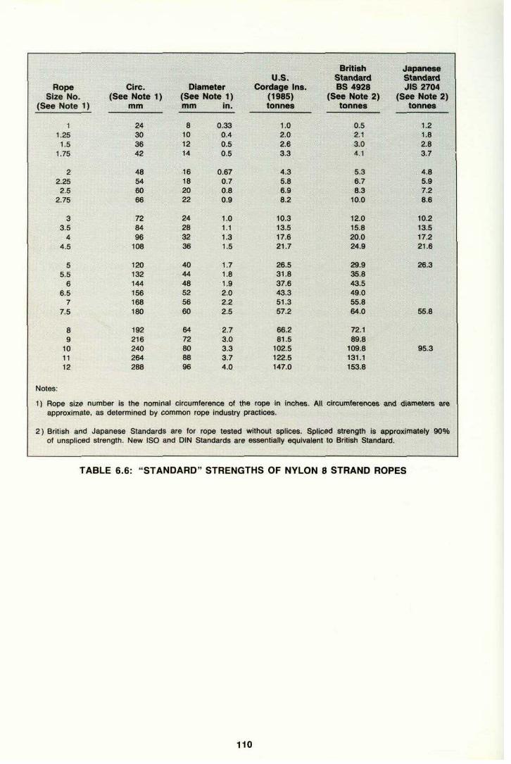
1 Rope1 Size No. (See
(See Note 1)
I'1.1 . 1;rl 1.25I 1.5| . 1-75
!• 2;- 2.25;L: 2.5
2.75
'^ 1 33.5
!? 44.5
'• ! ! : 1 S5.5
66.5
U; 7il ^ ^S
^11: :;•:::, g9
101112
?::;:;•':" • •' • . . .
Notes:
1) Rope size number isapproximate, as determined by common
2) British and Japanese,,„:„ Of unspliced strength.
::::";."
Circ.Note 1)
mm
24303642
48546066
728496
108
120132144156168180
192216240264288
the nominal
Standards are for rope testedNew ISO and
D(Semm in.
8101214
16182022
24283236
404448525660
6472808896
circumference of the rope in inches. Atl circumferences
DIN
iametere Note 1)
0.330.40.50.5
0.670.70.80.9
1.01.11.31.5
1.71.81.92.02.22.5
2.73.03.33.74.0
rope industry
Standards are essentially equivalent to
U.S.Cordage Ins.
(1985) (Stonnes
1.02.02.63.3
4.35.86.98.2
10.313.517.621.7
28.531.837.643.351.357.2
66.281.5
102.5122.5147.0
practices.
without splices. Spliced
BritishStandardBS 4928ee Note 2)tonnes
0.52.13.04.1
5.36.78.3
10.0
12.015.820.024.9
29.935.843.549.055.864.0
'Tai-89.8
109.8131.1153.8
strength isBritish Standard.
JapaneseStandardJIS 2704
(See Note 2)tonnes
1.21.82.83.7
4.85.97.28.8
10.213.517.221.6
26.3
55.8
95.3
and diameters are
approximately 90%
, , . sas
TABLE 6.6: "STANDARD" STRENGTHS OF NYLON 8 STRAND ROPES
110

RopeSize No. (Sec
(See Note 1)
11.25
1.51.75
22.252.5
2.75
33.5
44.5
55.5
66.5
77.5
! "''S9
10-:1:1 11
12
Notes:
1) Rope size number isapproximate, as deter
2) British and Japaneseunspliced strength. New ISO and
CIrc.s Note 1}mm
24303642
48546066
728496
108
120132144156168180
192216240264288
the nominalmined by common rope
Standards are for rope
Diame(See Ncmm
8101214
16182022
24283236
404448525660
6472808896
circumference of the rope in inches. All
DIN Standards are
iterite 1)
In.
0.330.40.50.6
0.670.70.80.9
1.01.11.31.5
1.71.81.92.02.22.5
2.73.03.33.74.0
industry
tested without splices. Spliced
U.S.Cordage Ins.
(1985)tonnes
0.81.41.72.1
2.53.44.04.7
5.77.59.6
12.2
14.717.621.224.928.132.7
36.746.755.866.277.6
practices.
essentially equivalent to British Standard.
BritishStandardBS 4928
(See Note 2) (tonnes
1.81.42.02.8
3.54.55.36.5
7.610.112.816.1
19.523.127.231.335.841.3
46.758.572.186.2
102.1
circumferences and
strength is approximately 90% of
JapaneseStandardJIS 2704
See Note 2)tonnes
0.81.11.72.2
2.83.54.25.1
6.08.0
10.312.8
15.6
33.1
56.7
diameters are
TABLE 6.7: "STANDARD" STRENGTHS OF POLYPROPYLENE 8 STRAND ROPES
111

109 Rope
CIre.
DiamE
ater
U.S. Cordage Ins.
British Standard BS 4928
Japanese i Standard JIS 2704
Size No. (See ' Note 1) (See Nc >te 1) (1985) (See Note 2) (! See Note 2)(See Note 1) mm mm in. tonnes tonnes tonnes 1 24 8 0.33 0.8 1.0 0.8
1.28 30 10 0.4 1.4 '?|J® fty 1.4 1-1 1.5 36 12 0.5 1.7 "'1:;1 2.0 1.7 1.75 42 14 0.6 2.1 2.8 2.2 '| 2 48 16 0.67 2.5 ^S il|$», 3.5 2.8 i 2.25 54 18 0.7 3.4 4.5 3.5 2.5 60 20 0.8 4.0 5.3 4.2 j 2.75 66 22 0.9 4.7 6.5 5.1 | 3 72 24 1.0 5.7 7.6 6.0 'i 3.5 84 28 1.1 7.5 10.1 8.0 I 4 96 32 1.3 9.6 12.8 10.3 ; •;:y-1-: 4.5 108 36 1.5 12.2 16.1 12.8 ] ::::..--y- g 120 40 1.7 14.7 18.5 15.6 '1
5.5 132 44 1.8 17.6 23.1e 144 48 1.9 21.2 27.2 e.5 156 52 2.0 24.9 31.3 7 168 56 2.2 28.1 35.87.5 180 60 2.5 32.7 41.3 33.1 | 8 192 64 2.7 36.7 46.7 9 216 72 3.0 46.7 58.5 10 240 80 3.3 55.8 ,:aa •iifik- 72.1 56.7 1 11 264 88 3.7 66.2 ^!^ Siw 86.2 12 288 96 4.0 77.6 102.1 Notes: ^N>'"ii =;;"'; 'MsSQ'ssS^'^S
1) Rope size number is the nominal circumference of the rope in inches. All circumferences and diameters are •approximate, as deter mined by common rope industry practices, a
2) British and Japanese Standards are for rope tested without splices. Spliced strength is approximately 90% of |
unspliced strength. New ISO and DIN Standards are essentially equivalent to British Standard. :l
TABLE 6.7: "STANDARD" STRENGTHS OF POLYPROPYLENE 8 STRAND ROPES

111 (a) Crosslay (b) Equal lay
DEFINITIONS Lay—the twisting of strands to form a rope or wires to form a strand during its manufacture
Crosslay or Equal Lay—terms describing the lay of the wires used to make up the strands. (See (a) + (b) above)
Righthand or Lefthand Lay—the angle or direction of the strands relative to the centre of the rope
Ordinary Lay or Lang's Lay—terms applying to the lay of the strands when making up the rope. (See (r) + (d} below)
(c) Lefthand Righthand Ordinary Lay (
d) Lefthand Righthand Lang's Lay
(e) 6 x 36 WS (/) 6 x 36 WS
(S) 6 x 41 WS (1 + 8 + (8 + 8) + 16) + Steel core
(1 + 7 + (7 + 7) + 14) (1 + 7 + (7 + 7) + 14) 4- Fibre core + Steel core This applies
to the number of wires in each strand 1 == centre 7 = next layer
7 + 7 = layer with mixed wire diameters 14 == outer layer

FIGURE 6.1: WIRE LINE CONSTRUCTIONS
92 6.2.6 Standard Specifications
Wire ropes are covered by many national standards. The following standard specifications concern wire ropes that comply with the material and construction recommended in paragraphs 6.2.1 and 6.2.2
• American Federal Specification (FS) RR-W-410-A: 6 x 37 with IWRC special improved plow steel.
• DIN 3066-SE-1770; equal lay, right hand, with heavy galvanising per DIN E 1548 .
• BS 3021 987.
• ISO 4344.
6.2.7 Use of Synthetic Tails
In order to provide additional elasticity, the wire mooring lines of some large tankers are fitted at the shore end with a length of synthetic rope, or tail. This additional elasticity reduces the dynamic loads induced in the wire mooring lines by allowing the ship to respond more closely to various combinations of wind, wave and current, as well as to ships passing nearby at low speeds. Tails also tend to distribute the loadings more evenly among mooring lines in the same service. Finally, the elongation of the mooring line system furnished by the tail serves to reduce the risk potential asso-ciated with poor line tending by lessening the frequency and precision of line tending requirements, particularly in berths with large tidal variations and/or high cargo handling rates.
The main disadvantage of tails is that they may introduce a weak link into the moorings which is not readily apparent to the ship operator. Tests conducted on failures have revealed that tails can undergo a substantial reduction in breaking strength in a relatively short period of time. Additionally, if the tail is too elastic the ship movement may be in excess of that which can be tolerated by the terminal's cargo transfer system.
If used, tails should be made of a material with high breaking strength such as braided or plaited nylon. The size of rope selected should be capable of easy handling, while at the same time being of sufficient quality to ensure that the tail has a dry breaking strength at least 25% greater than that of the wire line to which it is attached. Increasing the MBL of the synthetic tail above that of the wire will ensure that the loadings, as a percentage of the breaking strength of the tail, will be lower than that in the wire mooring line. For example, if the load is 55% of the MBL of the wire, it will correspond to approximately 45% of the MBL of a synthetic tail having a 25% higher MBL. Reducing the maximum per cent loading will increase the useful life of the tail, as experience indicates that the cyclic loadings degrade synthetic lines more quickly than wire under similar load conditions.
Another factor to consider when specifying a nylon material for the tails is the melting point of the grade. The higher the melting point, the less possibility of damage there will be from internal heat generated at high cyclic loadings.

Nylon tails have often been observed to be connected to the wire mooring lines with a cow hitch or other type of knot. This practise results in severe abrasion to the synthetic line, and should be actively discouraged. To guard against chafing, a wire line synthetic tail shackle such as the Mandel or Tonsberg shackle should be used and the eyes of the tail served with leather or plastic sheathing. (Fig. 6.3)
In summary, tails, if used, should preferably be made of nylon line (not three strand construction), be about 11 metres long overall and have a dry breaking strength at least 25% greater than the MBL of the wire to which they are attached. Tails should be replaced at least every 18 months unless experience and/or inspection indicates a longer or shorter period is warranted.
94 p;,:.- ;•— Material Construction Features Deficiencies .^~:,,.^ ,."......,. ,,,,,,.^,,,,^^^
CommentsPolyester ("Dacron") ("Terylene")
3 strand 8 strand Double braid
High dry & wet strength Moderate cost Moderate Stretch
Nylon (Polyamide)
3 strand 8 strand Double braid
High dry strength Moderate cost High stretch
Low wet strength Low fatigue life
Wet strength is about 80% of dry strength.
Polypropylene
3 strand 8 strand
Light weight Low cost Moderate stretch
Low strength Low Mett Point Creep
Special medium strength poly-propylene ropes are available.
Polyethelene
3 stand 8 strand
Light weight Low cost Moderate stretch
Low Strength Low Melt Point Creep
Special medium ;| strength poly- ; ethylene ropes are ; available. ^|
Aramid ("Kevlar") ("Twarlon")
Varied
Very Low Stretch High strength to weight ratio
High Cost Low abrasion resistance
D/d bend ratio similar to that of wire. Tight bend ; radii do not allow ; migration of load and can cause j damage to the fibres.
HMPE ("Dyneema")
Varied
High strength/weight ratio
Better flexibility characteristics than Kevlar, sometimes used as a replace-ment for wire rope. j
Nylon/Polyester/ Polypropylene ("Jetkore")
6 strand
High dry strength Good fatigue life Good abrasion resistance Moderate cost High stretch
Low wet strength Hockles
Nylon Mono- & Multi-Filament Fibre Mixture ("Atlas Perlen")
6 strand 8 strand
High dry strength Good abrasion resistance Moderate stretch
Low wet strength ?! Low fatigue life
Polyester/ Polypropylene Fibre Mixture ("Deltaflex")
6 strand 8 strand
Moderate to high dry & wet strength Moderate cost Moderate stretch
Polyester/ Polypropylene Melt Mixture ("Karat")
3 Strand 8 strand
Moderate to high dry & wet strength Moderate cost Moderate stretch
TABLE 6.1: SYNTHETIC ROPE CHARACTERISTICS

6.3.1.2 Nylon Dry nylon rope is slightly stronger than polyester rope. However, moisture reduces the strength of nylon fibre, and wet nylon rope has about the same strength as wet polyester. Wet nylon rope loses strength much faster under cyclic loading than polyester. Thus a heavily used nylon rope will become weaker than a heavily used polyester rope of the same size. For this reason, if nylon is used for tails, it should have at least 37% more strength than the associated wire rope. This rule is derived from the general 25% recommendation for tails plus an additional 10% allowance for reduction in wet strength.
Nylon is more elastic than any other material. When broken in it will stretch 12% or more at 50% MBL. This characteristic makes it especially suitable for use as tails with wire hawsers where elasticity is required, such as for STS operations and at berths subject to wave motion or surge. It is less suited to operations where rigid moorings are required, such as a large ship in a loading arm envelope at a poor weather berth.
96 ^^--
App
iroximat ad Rang< t
e &
•3
Service (Se e Note 1 ) Other Requirements > Recommen ded Rope I Winch-Mounted 20-70 Moderate stretch Polyester 8 Strand ; Mooring Lines Abrasion resistant Combination 6 Strand | Auxiliary 20-50 Moderate stretch Polyester 8 Strand ;
Mooring Lines Abrasion resistant Tails (on 20-70 High stretch Nylon Double Braidwire rope) Combination 6 Strand Heaving Lines 0.05 Light weight Polyester 8 Strand ,gs;:i;j:;|
Very easy to handle Aramid Various '^"S^Messenger Lines 2 Light weight Polyester 8 Strand |
Easy to handle (Float on water) Polypropylene 8 Strand ;
Pick-Up Lines 2 Light weight Polyester 8 Strand Low stretch :^^™1;IB|
Abrasion resistant Stoppers and 5 Easy to handle Polyester Snubbers Abrasion resistant Staple-fibre 8 Strand | Lifting Lines 5 Low stretch Polyester 8 Strand
Note: 1) Loads are approximate working or applied loads and appropriate safety factors must be applied to these whenpurchasing ropes. ;j
TABLE 6.3: SYNTHETIC LINE SERVICE REQUIREMENTS AND RECOMMENDATIONS

15 20 Extension, % Length
FIGURE 6.4: LOAD-EXTENSION CHARACTERISTICS Wire and Fibre Ropes, New and Broken-ln
Courtesy of Tension Technology
International (Reference 9)
3 STRAND ROPE

6 STRAND ROPE
8 STRAND ROPE
Cover
ore
Core Core Strands DOUBLE BRAID ROPE
Cover Strands
FIGURE 6.5: SYNTHETIC ROPE STRUCTURES

100
Point of Break
FIGURE 6.6: EXAMPLES OF SNAP-BACK DANGER ZONES
the pier. If you must work near a line under tension, do so quickly and leave the danger zone as soon as possible. Plan your activity before you approach the line. Never have more people than necessary near the line. If the activity involves line handling, make certain that there are enough personnel to perform it in an expedient and safe manner. Instruct observers to stand well clear.
Handling
Crews handling synthetic lines which must be stopped off and made fast to bitts need good training in accident prevention. Surging of lines on winch drum heads, which used to be common practice with natural fibre rope, is not recommended for synthetic lines, polypropylene in particular. The nature of the fibres, combined with the high loads, make it necessary to walk back the winches rather than surge in order to provide slack when stopping off and making fast. Stoppers made of polyester are recommended. They should be used in the double line configurations, where a half hitch is placed over the bitts and the two ends of the stopper are crossed over and under the line being stopped off. Training should include action to be taken during a break-out incident, namely, clearing the area to prevent injuries.
When holding and tensioning the line on the warping drum end, capstan or bitt, the line handler must not stand too

close. When the line surges, he could be drawn into the drum or bitt before he can safely take another hold or let go. He should stand back and grasp the line about 1 m (3 ft) from the drum or bitt.
104 Double braid ropes have many more strands. In conventional synthetic fibre double braid ropes the cover and the core each carry about 50% of the load. Thus, one or several cut strands in the cover normally do not significantly reduce the strength. If more than about 10% of the entire cover strands are cut, then the double braid rope should be retired.
In the case of the newer types of synthetic line such as the aramid fibres, almost the entire load is carried by the inner core. Therefore, should the external sheath be damaged the internal load bearing fibres may rapidly degrade through exposure to ultraviolet rays or through mechanical wear. It is consequently advisable to inspect these lines on a regular basis with a view to pre-emptive repair as necessary.
External abrasion and fusion A moderate amount of external abrasion is normal and can be tolerated in most synthetic ropes. The abrasion is evident as a general fuzzy appearance. If abrasion reduces the solid diameter by more than about 5%, then the rope should be retired. If the abrasion is localised and the remainder of the rope is in good condition, then the rope may be respliced.
Severe localised abrasion may be of concern. Severe abrasion of even one strand in three-strand, six-strand or eight-strand rope can significantly reduce the strength of the strand and upset the rope structure. The abrasion affects a number of yarns as it extends along the strand, so the degree of damage is not necessarily proportional to the depth of abrasion. If the abrasion on any one strand penetrates more than about 15% of the strand area, the rope should be cut and spliced.
Internal abrasion Internal abrasion is caused by the strands and yarns rubbing against each other as the rope undergoes cyclic loading. It is a form of fatigue entirely different from the type of fatigue experienced in metals.
The rope should be examined for signs of inter-strand abrasion. Carefully open the structure of three-strand, six-strand or eight-strand rope to examine the surfaces of the strands at points where they contact each other. A general fuzzy appearance at the points where strands rub against each other is an indication of moderate internal abrasion. If the abrasion has progressed to the extent that some yarns are worn through, the rope should be retired.
Internal abrasion in double braid rope is harder to detect because it may appear to be normal external abrasion. Closely examine the broken yarns which appear on the strands at the surface. If they have broken in the valleys between the strands, then it is internal abrasion. This internal abrasion probably extends throughout the entire rope structure. If it is severe, it has significantly decreased the rope strength and the rope should be retired.
Hockling Heckling normally occurs only in twisted ropes. A hockle resembles a knot in the rope, as shown in Fig. 6.7. Hockles greatly reduce the strength of the rope. When a hockle appears in a rope which is otherwise in good condition, it should be cut out and the rope spliced.
Hockles occasionally occur in the individual strands of three-strand, six-strand and eight-strand ropes. Such hockles upset the balance of load carried by the strands. The rope should be cut and spliced.
Broken Core The core of a double braid rope may break under high load without resulting in immediate rope failure. Under load, the rope will have a smaller diameter at the point of core break. Under no load, the rope may bend more freely at this point. If the core is broken, the double braid rope should be retired.

Ultraviolet Damage Ultraviolet rays from the sun destroy the strength of polypropylene and polyethylene fibres. The weakened fibres can easily be rubbed off the surface of the rope. The significance of the
106 Splices in used ropes should be examined for signs of wear. Look for strands which have slipped in the splice and tucks which have become undone, as these upset the load balance. The transition between the splice and the rest of the rope should be examined for signs of internal abrasion which may concentrate at this point. In double braid rope splices, look for any indications that the splice is pulling apart.
Eyes Abrasion and fusion at the inside back of the eye are common problems. Wear occurs at this point as the rope angle is changed under load around a bollard or hook. On eyes which are protected by thimbles, one should examine the rope in the mouth of the thimble for abrasion. If significant abrasion or fusion is found, the eye should be respliced.
In double braid rope, one should examine the crotch of the eye for broken strands. Make certain the splice is not pulling out. It may be possible to resplice small double braid rope. Large used double braid rope is very difficult to resplice and the rope may have to be replaced.
6.3.6 Standard Specifications The available standards generally specify only the manner in which the rope is made, the manner in which it is to be tested and its minimum new dry strength. There are significant differences in the test methods and the specified minimum breaking strengths among the standards.
The most widely recognized rope standards are those published in Great Britain (British Standards), the United States (U.S. Cordage Institute), and Japan (Japanese Industrial Standards). The U.S. and Japanese standards are generally only applied in the countries of publication.
Tables 6.5, 6.6 and 6.7 compare the minimum required breaking strengths specified by these standards for eight-strand polyester, nylon and polypropylene ropes. Table 6.5 also lists the German DIN Standard 83 331 which requires about 10% higher strengths for polyester ropes.
As indicated in the footnotes of each table, the strength values are not directly comparable due to differences in testing methods. This must be considered when comparing ropes produced to different standards.
Synthetic rope manufacturing is subject to continuous development and improvement. Some manufacturers are reluctant to produce higher strength ropes because they are more expensive: they find it difficult to market stronger ropes at increased prices when there are no standards which recognize the higher specification. Nevertheless, some companies do now produce and market ropes, especially those made from polyester, that are significantly stronger than the 'standard' product. These ropes should be considered for mooring applications since they will be lighter than a standard rope at generally the same cost and strength.

108 Rope
Circ.
D
iameter
U.S. Cordage Ins.
British Standard BS 4928
Japanese Standard J1S 2704
Size No. (See Note 1) (Se •e Note 1) (1985) (S ee Note 2) (See Note 2) (See Note 1) mm mm In. tonnes tonnes tonnes 1 24 8 0.33 1.0 0.5 1.2
1.25 30 10 0.4 2.0 2.1 1.8 1.5 36 12 0.5 2.6 3.0 2.8 1.75 42 14 0.5 3.3 4.1 3.7 2 48 16 0.67 4.3 5.3 4.8 2.26 64 18 0.7 5.8 6.7 5.9 2.5 60 20 0.8 6.9 8.3 7.2 2.75 66 22 0.9 8.2 10.0 8.6 3 72 24 1.0 10.3 12.0 10.2 3.5 84 28 1.1 13.5 15.8 13.5 4 96 32 1.3 17.6 20.0 17.2 4.5 108 36 1.5 21.7 24.9 21.6 ; 5 120 40 1.7 26.5 29.9 26.3 5.5 132 44 1.8 31.8 35.8e 144 48 1.9 37.6 43.5 ..i.,:;;|| 6.5 156 52 2.0 43.3 49.0 ''NS 7 168 56 2.2 51.3 55.87.5 180 60 2.5 57.2 64.0 55.8 8 192 64 2.7 66.2 72.1 9 216 72 3.0 81.5 89.810 240 80 3.3 102.5 109.8 95.3 11 264 88 3.7 122.5 131.1 12 288 96 4.0 147.0 153.8 Notes:
1) Rope size number is the nominal circumference of the rope in Inches. All circumferences and diameters areapproximate, as determined by common rope industry practices. 2) British and Japanese Standards are for rope tested without splices. Spliced strength is approximately 90%
of unspliced strength. New ISO and DIN Standards are essentially equivalent to British Standard. ,
TABLE 6.6: "STANDARD" STRENGTHS OF NYLON 8 STRAND ROPES
110
Section 7.0 Winch Performance, Brake Holding Capacity and Strength Requirements
7.1 FUNCTION AND TYPE OF MOORING WINCHES
Mooring winches perform a multitude of functions. They secure the shipboard end of mooring lines, provide for adjustment of the mooring line length to suit the mooring pattern in each port and compensate for changes in draft and tide. They serve to store the mooring line when not in use and to haul the ship into position against environmental or inertia forces. They also act as a safety device that releases the line load in a controlled manner once the force in the line increases to the point of near-breakage. General requirements for shipboard mooring

winches are dealt with in ISO Standards 3730 and 7825.
Winches can be categorised by their control type (automatic or manual tensioning), drive type (steam, hydraulic or electric), by the number of drums associated with each drive (single drum, double drum, triple drum), by the type of drums (split, undivided) and by their brake type and brake application (band, disc, mechanical screw, spring applied). Each of these features influences the mooring winch function and will be briefly discussed below.
7.2 AUTOMATIC TENSION WINCHES VERSUS MANUAL
WINCHES
Automatic tension winches are designed to automatically heave-in whenever the line tension falls below a certain pre-set value. Likewise, they will pay out if the line tension exceeds a pre-set value. Manual winches always require a person to handle the controls for heaving or rendering.
In practice, the use of the self-tension winch is not recommended except for moorings deployed at 90° to the ship's axis. Automatic tension winches should not be used for spring lines, for example, since it has been known for the winches to cause the ship to 'walk' along the pier. This is because spring line forces oppose each other, leaving only the difference between the heaving and rendering values of the winches available to resist longitudinal environmental forces.
In theory, automatic tension winches would be ideal for breast lines forming a 90° angle to the ship axis. If the breast lines cannot be arranged at the optimum 90° angle due to the location of mooring fittings at the pier and on the ship, the mooring restraint capability may be reduced because the lines' fore-and-aft components oppose each other. For this reason, most terminals do not allow the use of the automatic feature and require that the winch be placed on the manual brake while the ship is moored. See also Reference 6, Section 3.5.4.
7.3 WINCH DRUMS
Winch drums may be either split or undivided. The split drum is composed of a tension section and a line storage section. It has the advantage that it can maintain a constant brake holding capacity and heaving force, due to the fact that the mooring line is always run off the first layer of the tension drum. For this reason, split drum winches are preferred by some operators, especially for
113
large ships. The disadvantage of the split drum is the more difficult operation, a factor which can be overcome with proper instructions and operator experience. Another reason for their use is that ISO Standard 3730, Annex A, recommends that synthetic ropes under tension should not be wound on a drum in more than one layer or short life will result, and this can normally only be avoided by using split drums.
For either type of drum, the minimum drum diameter should be 16 times the wire rope diameter. Split drums should allow 10 turns of rope on the tension section.
While many VLCC owners and operators prefer the split drum type, the undivided drum has its proponents also. The following discusses the pros and cons for each type and also discusses the effects that the number of layers of wire on the tension or working drum has on each.
7.3.1 Split Drums
As shown in Figure 7.1 the split drum winch is a common drum divided by a notched flange into a wire storage section and a tension section. It is operated with only one layer of wire on the tension section and theoretically can maintain a constant, high brake holding power.
The split drum winch was designed as a solution to the spooling problem encountered with undivided drum winches. When wires are handled directly off drums, the final turns of the outer layer when under tension tended to bite into the lower layers. This could result in possible wire damage and difficulties when releasing the line.

Also the mechanical spooling devices which were used on undivided drums were found to be susceptible to damage.
Tension Drum
Storage Drum
Manual Band Brake
Courtesy of Pusnes
FIGURE 7.1: THE SPLIT DRUM WINCH
114
ar
4^1 Typical Drum Details
OC = Horizontal Distance Between Ship And Shore Connection
Ah = Height Difference Between Ship And Shore Connection (Ship Connection May Be Above Or Below Shore Connection)

10 15 20 25 30 35 40 45 50 55 LENGTH OF WI ON
TENSION DRUM IN FEET WITH 2'-0" DIA. DRUM RE
J_____I_____1_____I_____I_____1_____1_ 0 34567 NUMBER OF TURNS ON TENSION
DRUM
FIGURE 7.2: SPLIT DRUM MOORING WINCHES:
TURNS REQUIRED ON TENSION PART OF DRUM AND FORCE IN LINE AT TRANSFER POINT
3peration, the wire from the split drum winch is sent ashore first from the working half and then •ctly from the storage half. As the wire is recovered, it is wound directly on the stowage half until t time when only sufficient slack wire is available to provide a sufficient number of turns on the >ion drum to: (1) hold the tension of the wire on the tension drums only and (2) provide extra is to allow for adjustments of the line throughout cargo transfer. At that time the wire rope is through the slot from the storage portion to the tension portion.
115 The transfer of the wire from the storage section to the tension section is difficult to judge particularly when long drifts of wire are used such as at multi-buoy moorings. Care must also be exercised to prevent tension coming on

the wire during the transfer at the time when it passes through the slot. If this is not done such tension could cause damage to the wire or to personnel involved in the transfer. There is also concern that the mooring operations could take longer especially when excessive layers develop on the tension section. The delay occurs because steps must be taken prior to mooring completion to correct the number of turns on the tension half.
Figure 7.2 is a graph which one operator has distributed to its ships to provide a better understanding of the forces in the line and to show the effect of relative height changes between vessel and pier due to tidal changes and changes in vessel draft. The graph shows (for a 2 ft diameter drum), the number of turns that are required on the tension section at the time of mooring to allow line tending adjustments to be made from the tension drum only. The use of this guide will also ensure that there will always be sufficient turns of wire left on the drum to minimise the force at the transfer point between tension and storage sections. For instance, when seven turns are on the tension section, the load at the transfer point is only 1 % of the line pull. A calculation made for an extreme tidal range location indicates a maximum adjustment of approximately two turns. It should be noted that the curve for the required turns on the drum (shown on the right side) was developed for the particular drum size as shown. The curve for the force at the transfer point (shown on the left side) is a function of the coefficient of friction and number of turns and is, therefore, applicable to any size drum.
7.3.2 Undivided Drums
The undivided drum winch is commonly found on smaller ships and is preferred by some operators for VLCCs. These operators prefer the undivided drum to avoid the need to transfer the wire from section to section as is required for a split-drum winch when a poor estimate has been made of the spooling requirements. The undivided drum eliminates the potential for wire damage and personnel injury that exists at the time of transfer on a split drum.
However, if this type of drum is selected, the operator should be aware that it is often difficult to spool and stow the wire on the drum satisfactorily. If the wire is not spooled properly, the wire can be damaged when tension is applied to the system. To reduce this problem, care should be exercised in the location of the winch. It should be placed a sufficient distance from the fairlead to ensure that the wire can be properly spooled.
7.3.3 Handling of SPM Pick-up Ropes
Most, if not all, storage drums, regardless of whether split or undivided, are designed to meet the required capacity for storage of steel wire ropes to suit normal moorings at piers, and it is a fact that the designs of conventional windlasses or mooring winches have no consideration for handling bulky pick-up ropes at SPM terminals.
Section 6.3 of Reference 1 recommends a direct lead between bow fairleads and bow stoppers. The publication also states that if a winch storage drum is used to stow the pick-up rope, it should be of sufficient size to accommodate 150 metres of 80mm diameter rope.
Whilst it is recognised that either a warping end or a wire drum may be used to heave in the SPM pick-up rope prior to connection of the chafing chain to the stopper, opinions as to which should be used are equally divided.
Following reports of accidents and "near misses" during unmooring at SPMs when the pick-up rope has been released and allowed to fall un-controlled from the ship, it is recommended that each windlass be provided with a special drum of sufficient capacity to accommodate 150 metres of 80mm diameter rope. If fitted at the inboard end of windlasses they will minimise rope turns and angles. These drums may also be used for normal wire moorings.
116 If main mooring lines comprise of synthetic ropes, then traction winches specially designed for synthetic ropes are recommended. These winches are normally equipped with twin traction drums with grooves and a storage reel mounted on, or below, deck.
For warping ends, which are ordinarily used for natural or synthetic fibre ropes but not for steel wire ropes because of handling difficulties due to stiffness, ISO 6482 provides design criteria for the recommended diameter and length, nominal dimensions and the profile types.

7.4 WINCH DRIVES Winch drums are driven through reduction gears by a motor which may be powered by steam, electricity or hydraulic pressure. Hydraulic motors may be powered by a central power pack (which may also be used to power other motors such as those of cranes or cargo winches), or may be part of a self-contained winch incorporating an electrically driven hydraulic pump in each winch. Another version of a unitised hydraulic winch drive employs a torque converter for power transmission between an electric motor and the winch gearing.
The winch drive should ideally allow for continuous variation in line speed, permitting heaving and rendering at high speed when the load is small, and developing high pull when the speed is low. The pull at stalled heave should not exceed 50% of the mooring line's MBL to prevent routine over-stressing of the mooring line.
The considerations guiding the selection of drive systems at a ship's design stage will not be discussed in detail, since many are beyond the scope of this guide: these include initial cost, maintenance cost, energy cost, reliability, company experience, climatic conditions, availability of steam and interconnection with other systems. There are also many variations within each category (especially within hydraulic and electric systems) that may significantly alter the performance, reliability and cost. Any of these are acceptable aboard tankers if they are properly designed and executed.
The following short discussion on each basic type places emphasis on the speed/pull characteristics:
7.4.1 Steam
Steam winches have been most popular on large tankers. They are simple, safe, robust and have an ideal speed/pull characteristic. A minor drawback of the typical twin cylinder double acting steam engine is the non-uniform torque (varying by up to 50% for each 45% of crankshaft rotation). This is most noticeable at very low speeds.
Because of the change from steam main propulsion systems to diesel systems, even on the largest ships, hydraulic systems have gained in popularity.
7.4.2 Hydraulic Drives
The speed/pull characteristic varies with the type of motor:
• The speed of a low pressure vane motor can be infinitely varied up to the rated speed by a special throttle valve. High slack rope speeds can be obtained only by suitable drive modifications to provide a high speed range at reduced torque.
• A high pressure variable displacement hydraulic motor has an ideal speed/pull characteristic within certain limits. To achieve a high slack line speed, a speed change provision is required.
• A torque converter drive has a similar characteristic as a variable displacement high pressure motor and it also requires a second gear step to provide for a high slack line speed.
7.4.3 Electric Drives
Electric drives are the least popular types on tankers due to certain inherent disadvantages. All electric equipment in the cargo tank region must be of the certified safe type. Electric controls are
117 sensitive to moisture and corrosion. The relatively simple AC pole changing motor is inferior to other drives in pull/speed characteristic (speed variable in steps only, high starting torque, on/off control only). The AC/DC drive has excellent drive characteristics, but is expensive and more sensitive to moisture, corrosion and overheating than any other drive type.
7.5 WINCH BRAKES The brake is the heart of the mooring system, since the brake secures the drum and thus the mooring line at the shipboard end. A further important function of the brake is to act as a safety device in case the line load becomes excessive, by rendering and allowing the line to shed its load before it breaks.

Ideally, a brake should hold and render within a very small range, and once it renders, should shed only enough load to bring the line tension back to a safe level. Unfortunately, the widely used band brake with screw application is only marginally satisfactory in fulfilling these requirements and its operation requires special care.
7.5.1 Layers of Mooring Line on Drum
Split-drum Winch
The rated brake holding capacity is only achieved with one layer of wire on the tension drum.
Operation with additional layers will decrease the brake holding capacity.
As an example, the theoretical reduction in holding load for more than one layer on a 24" diameter drum is as follows and assumes a rated brake holding capacity of 55 tonnes:
Theoretical % Rated
Layer of wires holding capacity holding capacity (tonnes) (kN)
1 55 539 100
2 49 481 89
3 45 441 82
4 41 402 75
5 38 373 69
Undivided Drum Winch
Brake holding capacity of the undivided drum winch, as with the split-drum winch, is affected by the number of layers on the drum. It is therefore, essential that the operator of an undivided drum winch knows the number of layers of wires on the drum that the manufacturer states will develop the design brake capacity. More layers on the drum will increase the moment applied to the drum because of the increased moment arm. This means that a smaller mooring line load will provide the moment which will cause the brake to slip. Conversely with less layers on the drum, mooring line loads must be larger to cause the brake to slip. It is very possible that mooring line loads could become excessive thereby increasing the possibility of mooring line breakage. Thus, the operators, as in the case of split-drums, should be advised and trained in the use of the undivided drum winch to ensure integrity of mooring and safety of vessel.
When applying the requirement for winch brakes to hold to a minimum holding load of 60% of MBL to undivided winch drums, due consideration should be given to the number of layers of wire which will be found on a drum during normal operations. For this purpose, it should be assumed that 30-50 m of wire minimum will be outboard of the fairlead.
7.5.2 Band Brakes
Band brakes follow the same principle as wrapping a rope around a bitt or warping head to hold a line's force. Relatively little force is required to hold a high load. This principle provides for easy
118

brake application, but has disadvantages such as sensitivity to changes in friction, dependency ofsetting force on rope force and sensitivity to reeling direction.
The main factors which affect the actual holding capacity of the band brake are discussed below:
7.5.2.1 Torque applied
Figure 7.3 shows the results of a series of brake holding load tests on a VLCC when the torqueapplied is varied. It can be seen that the holding load will drop appreciably when the torque appliedis lower than the recommended value. It is, therefore, essential that the operator apply the brakeproperly.
Sg-4ri<0'^QO5 y^:
DesiredHoldingPower
BRAKE HOLDING POWER - METRIC TONS (kN)
This Diagram Illustrates The Reduction In Brake Holding PowerWhich Occurs When The Applied Torque Is Insufficient.
FIGURE 7.3: EFFECT OF APPLIED TORQUE ON BRAKE HOLDING POWER
Shipboard inspections have shown that winch brakes are very often not torqued to their design level;and, in some tests two men were required to apply the required torque. Hence, several VLCCoperators are now installing hydraulically actuated brakes on new VLCCs and are retrofitting themon older VLCCs to ensure proper brake holding load. Obviously, it is essential that the winch brakesbe operated properly to achieve desired holding loads.
Also, it has been found that some winch actuators and controls are poorly positioned. As a result,the operator is unable to see what is happening on deck. Proper design is essential to ensure properoperation.
7.5.2.2 Condition of the Winch
The physical condition of the winch gearing and brake shoe linings have a significant effect on brakeholding load capacity. Oil, moisture or heavy rust on the brake linings or brake drum can reducebrake holding load capacity by up to 75%. Many operators run the winch with the brake set slightlyto burn off or wear off the oil or moisture. (Care, however, must be taken to ensure that excesswear is not caused by this practice when using composite brake linings.) Excessive winch speed canalso reduce brake holding capacity by the build-up of heat in the composite brake lining.
7.5.2.3 Winch in Gear
The holding load capacity of a brake can be increased by leaving the winch in gear with the steamon. However, resort to this practice should be regarded as only an emergency measure with limited
119

application since it can only be wholly effective on winches with a single drum, which are notcommon on VLCCs. On double or triple drum winches, it is not normally possible to engage alldrum shafts and at the same time maintain equal tension on the mooring lines. If only one drum isengaged, this would result in the lines with lower brake holding capacity slipping and transferringloads to the drum whose brake is augmented by steam. This could result in the parting of the line.Thus, the particular circumstances should be fully assessed before using this emergency procedure.
7.5.2.4 Friction Coefficient
A small change in the friction coefficient will cause a large change in the holding capacity. As arule of thumb for typical mooring winch brakes, the change in holding capacity is twice the changein the friction coefficient. For example, a 10% change in friction will cause a 20% change in holdingcapacity. The friction change can be due to wear of the rim or brake lining, or to changes in weatherconditions, among others. This drawback can be partially offset by stainless steel lining of brakerims and by frequent testing and recalibration.
7.5.2.5 Load Dependency of Holding Capacity
Once a line load is applied to the drum, the brake band will stretch, reducing the load on the brakecontrols. For this reason, a conventional screw brake can be easily re-tightened when the mooringline is under high load, even if it was set hard originally. This means that there is no way todetermine the proper handwheel torque required once the winch is subjected to a high line load. Thedanger exists that under worsening environmental conditions the brakes can be re-tightened to thepoint where the line may part before the brake slips. The problem can be solved by using springapplied brakes. The spring automatically compensates for the elongation of the brake band, thusassuring a constant holding capacity of the brake. It also prevents the brake from being over-tightened.
HANDWHEEL(For Adjustment of Springand Emergency Release)
FIGURE 7.4: SPRING-APPLIED BRAKE WITH HYDRAULIC RELEASE
A schematic of a spring-applied band brake is shown in Fig. 7.4. In the case shown, the brake isreleased by a hydraulic hand pump. To apply the brake, a valve is opened to release the hydraulicpressure. Winches with hydraulic drives can utilise the main hydraulic pressure to release the brake.The handwheel is not used for routine operation: it serves to adjust the spring compression duringcalibration, and to release the brake in case of a hydraulic malfunction. The handwheel should besecured with a seal after each calibration to prevent tampering. Another advantage of the springapplied brake is its fail-safe feature.
120

brake application, but has disadvantages such as sensitivity to changes in friction, dependency of setting force on rope force and sensitivity to reeling direction.
The main factors which affect the actual holding capacity of the band brake are discussed below:
7.5.2.1 Torque applied
Figure 7.3 shows the results of a series of brake holding load tests on a VLCC when the torque applied is varied. It can be seen that the holding load will drop appreciably when the torque applied is lower than the recommended value. It is, therefore, essential that the operator apply the brake properly.
Desired Holding Power
BRAKE HOLDING POWER - METRIC TONS (RN)
This Diagram Illustrates The Reduction In Brake Holding Power Which Occurs When The Applied Torque Is Insufficient.
FIGURE 7.3: EFFECT OF APPLIED TORQUE ON BRAKE HOLDING POWER
Shipboard inspections have shown that winch brakes are very often not torqued to their design level; and, in some tests two men were required to apply the required torque. Hence, several VLCC operators are now installing hydraulically actuated brakes on new VLCCs and are retrofitting them on older VLCCs to ensure proper brake holding load. Obviously, it is essential that the winch brakes be operated properly to achieve desired holding loads.
Also, it has been found that some winch actuators and controls are poorly positioned. As a result, the operator is unable to see what is happening on deck. Proper design is essential to ensure proper operation.
7.5.2.2 Condition of the Winch
The physical condition of the winch gearing and brake shoe linings have a significant effect on brake holding load

capacity. Oil, moisture or heavy rust on the brake linings or brake drum can reduce brake holding load capacity by up to 75%. Many operators run the winch with the brake set slightly to burn off or wear off the oil or moisture. (Care, however, must be taken to ensure that excess wear is not caused by this practice when using composite brake linings.) Excessive winch speed can also reduce brake holding capacity by the build-up of heat in the composite brake lining.
7.5.2.3 Winch in Gear
The holding load capacity of a brake can be increased by leaving the winch in gear with the steam on. However, resort to this practice should be regarded as only an emergency measure with limited
119 application since it can only be wholly effective on winches with a single drum, which are not common on VLCCs. On double or triple drum winches, it is not normally possible to engage all drum shafts and at the same time maintain equal tension on the mooring lines. If only one drum is engaged, this would result in the lines with lower brake holding capacity slipping and transferring loads to the drum whose brake is augmented by steam. This could result in the parting of the line. Thus, the particular circumstances should be fully assessed before using this emergency procedure.
7.5.2.4 Friction Coefficient
A small change in the friction coefficient will cause a large change in the holding capacity. As a rule of thumb for typical mooring winch brakes, the change in holding capacity is twice the change in the friction coefficient. For example, a 10% change in friction will cause a 20% change in holding capacity. The friction change can be due to wear of the rim or brake lining, or to changes in weather conditions, among others. This drawback can be partially offset by stainless steel lining of brake rims and by frequent testing and recalibration.
7.5.2.5 Load Dependency of Holding Capacity
Once a line load is applied to the drum, the brake band will stretch, reducing the load on the brake controls. For this reason, a conventional screw brake can be easily re-tightened when the mooring line is under high load, even if it was set hard originally. This means that there is no way to determine the proper handwheel torque required once the winch is subjected to a high line load. The danger exists that under worsening environmental conditions the brakes can be re-tightened to the point where the line may part before the brake slips. The problem can be solved by using spring applied brakes. The spring automatically compensates for the elongation of the brake band, thus assuring a constant holding capacity of the brake. It also prevents the brake from being over-tightened.
HANDWHEEL (For Adjustment of Spring and Emergency Release)
FIGURE 7.4:

SPRING-APPLIED BRAKE WITH HYDRAULIC RELEASE
A schematic of a spring-applied band brake is shown in Fig. 7.4. In the case shown, the brake is released by a hydraulic hand pump. To apply the brake, a valve is opened to release the hydraulic pressure. Winches with hydraulic drives can utilise the main hydraulic pressure to release the brake. The handwheel is not used for routine operation: it serves to adjust the spring compression during calibration, and to release the brake in case of a hydraulic malfunction. The handwheel should be secured with a seal after each calibration to prevent tampering. Another advantage of the spring applied brake is its fail-safe feature.
120 7.5.2.6 Sensitivity in Reeling
Direction A band brake is designed to work in one direction only. Therefore the line must always be reeled correctly onto the drum. The line is properly reeled if it is pulling against the fixed end of the brake strap.
Disc brakes work equally well in either direction.
Some winches are equipped with so-called hydraulic-assist brakes. With this type, a hydraulic cylinder sets the brake. A pressure gauge connected to the cylinder allows the brake to be applied with the proper force, predetermined during brake testing. Once the brake is applied with the hydraulic assist, the load is transferred to the mechanical linkage by tightening the handwheel until the pressure in the assist cylinder starts to drop. Although this feature eliminates the need for a torque wrench, the brake has the same drawbacks as the mechanical screw brake mentioned above. This type of brake is therefore not recommended for new ships.
Since hydraulic-assist brakes and some spring-applied brakes with hand hydraulic release look similar, it is very important that operators study the instruction book for their particular ship's installation.
7.5.3 Disc Brakes Disc brakes are less sensitive to friction changes than band brakes and are therefore better suited for winch brakes. Disc brakes are in wide use for input brakes (see Section 7.5.4), but few winch manufacturers offer them for drum brakes. If available, they should be seriously considered for new construction.
Disc brakes do not have the other drawbacks mentioned earlier, but this is of secondary importance, since band brakes can be improved by spring application and proper operation. Spring application is also recommended for disc brakes because of the foolproof simple operation that it permits.
7.5.4 Input Brakes Most hydraulic and electric winches are provided with spring-applied brakes at the drive motor. They are automatically applied by springs when the control lever is in neutral and automatically released when the control lever is in the heave or rendering position (when the motor is powered). ISO Standard 3730 requires automatic brakes with a holding capacity of 1.5 times the rated load for all electric winches.
For single drum winches (one drum per drive), input brakes could serve as the primary brake and would eliminate the need for separate drum brakes. However, if the winch is also provided with a warping head, a drum brake and dog clutch would still be required to allow use of the warping head while the drum is held stationary.

Multiple-drum winches always require a brake for each drum.
Most input brakes are not rated to serve as a primary brake due to strength limitations of the gears. If this is the case, once the ship is moored the drum must be set on the drum brake and disengaged from the drive by means of the dog clutch. If the drum is left engaged and the drum brake is set, both brakes will work in unison (rated holding capacity is directly additive). The combined holding capacity will exceed 100% of the line's MBL, an undesirable result for reasons explained earlier.
7.5.5 Winch Brake Testing Regardless of the brake type, periodic testing is essential to assure a safe mooring. The following provides a guide for testing of mooring winch brakes:
121 7.5.5.1 Test Program
7.5.5.1.1 Frequency Each winch brake is to be tested individually and tests are to be carried out prior to the vessel's delivery and every year thereafter in line with recommendations in the International Safety Guide for Oil Tankers and Terminals (ISGOTT) Chapter 3. In addition, individual winches are to be tested after completion of any modification or repair involving the winch brakes, or upon any evidence of premature brake slippage or related malfunctions.
7.5.5.1.2 Test specification
For each vessel a winch test specification is prepared incorporating specific instructions for setting up the test gear, preparation of the winch for testing, setting of the winch brakes, application of the test load, revision of torque wrench or hydraulic pressure readings if required, and recording of test results. The coefficient of friction of the brake lining is considerably affected by moisture. To assure constant results the winch is to be operated for a short period with the brake set slightly on to dry the brake surface.
7.5.5.1.3 Supervision of testing
All winch testing is to be carried out under the supervision or in the presence of a senior officer designated by the Master or Chief Engineer or repair superintendent familiar with the test procedure and the operation of the winches.
Bolt B 40

7.5.5.1 Test Program
7.5.5.1.1 Frequency
Each winch brake is to be tested individually and tests are to be carried out prior to the vessel'sdelivery and every year thereafter in line with recommendations in the International Safety Guidefor Oil Tankers and Terminals (ISGOTT) Chapter 3. In addition, individual winches are to be testedafter completion of any modification or repair involving the winch brakes, or upon any evidence ofpremature brake slippage or related malfunctions.
7.5.5.1.2 Test specification
For each vessel a winch test specification is prepared incorporating specific instructions for setting upthe test gear, preparation of the winch for testing, setting of the winch brakes, application of thetest load, revision of torque wrench or hydraulic pressure readings if required, and recording of testresults. The coefficient of friction of the brake lining is considerably affected by moisture. To assureconstant results the winch is to be operated for a short period with the brake set slightly on to drythe brake surface.
7.5.5.1.3 Supervision of testing
All winch testing is to be carried out under the supervision or in the presence of a senior officerdesignated by the Master or Chief Engineer or repair superintendent familiar with the test procedureand the operation of the winches.
Bolt 040
1
Tr 1
T 2600
All dimensions in mm
FIGURE 7.5: TYPICAL WINCH BRAKE TEST EQUIPMENT
122

1
T ^
r i T
2600
All dimensmns in mm
FIGURE 7.5: TYPICAL WINCH BRAKE TEST EQUIPMENT
122 7.5.5.1.4 Testing equipment Typical equipment for testing the brakes is shown in Figure 7.5, and includes the following items:
• Lever consisting usually of two pieces of bar as shown on the sketch. The lever is secured to the drum of the winch by means of bolts furnished with the test kit and fitted through holes provided in the drum flange;
• Hydraulic jack with pressure gauge; and
• Foundation to be placed under the hydraulic jack for the purpose of distributing the load into the deck structure.
It is recommended that complete test equipment be placed on board each vessel, properly stowed in an appropriate location. Alternatively, the Owner may elect to procure one or two sets of testing equipment for each type and size of winch and retain this equipment in a convenient central location for shipment to repair facilities as required.
7.5.5.2 Method of testing
The testing arms are bolted to the flange of the winch drum with the hydraulic jack pressed under the end of the arms at the designated location and resting on supports. The flange brake is set as recommended in the test specification. If the winches are set normally, a torque wrench should be used. If they are set hydraulically, the pressure gauge should first be calibrated.
Before testing, the detailed instructions for testing included in the test specification should be reviewed and the equipment

prepared accordingly. The instructions will include:
• The values for torque wrench or pressure gauge fitted for setting up the brakes;
• A curve or table relating hydraulic jack test pressure to line pull; and
• Hydraulic jack pressure at which the brake is designed to render.
With the winch prepared for testing, the testing gear securely in place and winch brakes set in accordance with the recommendations, pressure is applied to the hydraulic jack. The winch drum is to be carefully observed. At the first sign of movement, the hydraulic pressure applied to the jack is recorded and the following action taken:
• If slippage occurs at a pressure less than designed, the brake should be tightened or repaired and jack pressure reapplied;
• If the recorded pressure corresponds to the design pressure the jack should be released and the test gear removed; or
• If slippage does not occur at the design pressure, the brake setting should be adjusted so the brake can render at the design load.
The lever should be lightweight for easy handling. Testing can be further simplified by reducing the lever to slightly more than the drum flange radius and placing the jack directly on the winch foundation. A schematic of such a test arrangement is shown in Fig. 7.6. In place of the heavy lever, a simple fitting attached to the drum flange suffices. The higher jack loads may pose a problem for existing equipment, but provision for this method can easily be incorporated into new equipment.
Once the brakes are tested and calibrated, the proper setting should be recorded. In case of conventional screw brakes, a tag should be attached stating the proper torque. For spring-applied brakes, the spring compression distance should be recorded and the spring adjustment mechanism secured with a seal.
123 ^^4^:^ -^ Payout K / Ditection •\
P ss Line Pull
D" F
run anc
i ?e
/ f
/ /^} ^ ~ v / ^ \ \ / r—.;—i v { i t / \ i i i
1-1
| t / V -A / /\^/^
ffi
t^ ^
^
r -
y \ / \/ / /^ l
^ \ ^ \ ^ \
-^"' \
4
1 Bolted 1; Bracke & Jack with ii- Gauge -~~. I Q
Required Jack Force ^ 4
—— Winch 1 Foundation ^.•:.^::,..1.1^1:;-^:• .1^.:::,.•1:1,-\,•. -i«as
FIGURE 7.6: SIMPLIFIED BRAKE TEST KIT
7.5.6 Brake Holding Capacity
The primary brake should be set to hold 60% of the mooring line's MBL. Since brakes may deteriorate in service, it is recommended that new equipment be designed to hold 80% of the line's MBL, but have the capability to be adjusted down to 60%

D:*, F
BoltedBracke
Jack withGauge ^
Q
runan<
t^
^
nge
t\
; 4 :V Payout Y
^ Dilection x- ,,/ ,j———————— ^ — — — — —
'/ r "--. \/ r-^r-r^ ^i i / ^ i \ i '
"\ '/\ \ /^^/ v^.i7--' •— ^^
4———————1«>
y \ l ;y \ ! 1\/ /
.^\ /' v \^ \— "^ \
F = Line Pull
Required Jack Force= F h4
WinchFoundation
L,
FIGURE 7.6: SIMPLIFIED BRAKE TEST KIT
7.5.6 Brake Holding Capacity
The primary brake should be set to hold 60% of the mooring line's MBL. Since brakes may deterioratein service, it is recommended that new equipment be designed to hold 80 °7o of the line's MBL, buthave the capability to be adjusted down to 60% of the line's MBL. A drum brake holding capacityof 80% MBL is also required by Lloyds, DNV and ISO Standard 3730 with the rope on the firstlayer. If a brake of an undivided drum is set to hold 80% MBL on the first layer, it will holdapproximately 65% MBL on the third layer.
7.6 WINCH PERFORMANCE
The principle performance particulars for different size mooring winches should correspond to valueslisted in Table 7.1. These are in general agreement with ISO Standard 3730, except for minimumlight line speed and in-service setting of brake.
7.6.1 Rated pull (also called drum load or hauling load)
This is the pull that the mooring line can develop at the rated speed on the first layer. The listedvalues correspond to approximately 30% of the line's minimum breaking strength. This value assuresadequate force to heave in against environmental forces. On the other hand, it is low enough toprevent line overstressing in the stalled condition, considering that the stall pull is generally higherthan the rated pull for most drive types.
124

RATED RATED fSIZE PULL* {
1
.::1,1' ,, t
,,;1t:::. 12
:'"tfi>;;:1 16
^SST" 20
• ,2$ , 25
32 32
40 40
* With rope on first layer.
*'*• This is a desirespeed depends
* * * For split-drums,
* * * * Appttes to split
Note: Performance data also
RATEDSPEEDUIN."
m/min
23
23
18
18
15
15
able ligon the
this applies to the
drums
) LIGHT-LINESPEEDHIN."
m/min
45
45
45
45
45
45
ht line speecwinch drive
only.
applies to winches designed
DESIGN MROPE BDIA. S1(WIRE 0ROPE)
mm
26
32
36
40
44
48
j in the first layeas mentioned in
storage part of the drum. |
INIMUMREAKINTRENGTF ROPE
t
43
66
83
103
124
148
r and is7.4 and
for fibre
STALG PULLrn MAX.
t
21
33
41
61
62
74
in excess7.6.3, and
ropes, but
L BRAK
DESKVALUNEW
t
35
53
67
83
100
119
of the 0.5should be
drum dimensions must be
(E HOLDINGFORCE*
GN IN-E SERVICE
SETTING
t
26
40
50
62
75
89
m/s requirementclarified with the
MINIMIDIA. 0DRUM
mm
416
512
576
640
704
768
of ISO Standard 3730. However,winch manufacturer.
increased to suit the larger
DM DRUM CAP/F
Normalm
200
250
250
250
250
280
\CITY
Highm
400
500
500
500
500
500
diameter of the fibre lines.
* * * WIDTH OF 1TENSION 1SECTION** **|
HUB
260
320
360
400
440 1
480
achievable light lineal
ix
TABLE 7.1: PERFORMANCE SPECIFICATION FOR MOORING WINCHES

The rated speed is the speed that can be maintained with the rated load applied to the mooring line. The rated speed in combination with the rated pull determines the power requirement for the winch drive. The recommended rated speed is higher for the smaller size winches because the smaller sizes are intended for smaller ships and these warp and moor more quickly than large ships.
7.6.3 Slack line speed (also called no-load speed or light-line speed)
This is the speed that can be achieved by the winch with negligible load on the line. High speed is essential to pass a line quickly to a shore mooring point or to bring the line quickly back on board. The listed value recognises that during this phase the line is normally not on the first layer, even on split-drum winches, and the actual line speed could be up to 50% higher. The slack line speeds achievable are different for different types of drives and this must also be considered when specifying performance and drive type for new equipment. For example, a low pressure two-speed vane motor can achieve only twice the rated speed.
7.6.4 Stall heaving capacity (also called stalling load)
This is the line pull the winch will exert when the control is in heave and the line is held stationary. A high stall heave capacity is desirable to winch a ship unto the pier against high environmental loads. On the other hand, the stall pull should not be so high that there is any danger of line breakage, and should never exceed 50% of the mooring lines MBL. Achievable stall pull depends on the drive type and control. As a rule of thumb the following ratios of stall pull to rated pull may be assumed:
Steam-driven 1.50 Hydraulic 1.05 Electric 1.25
7.6.5 Drum capacity
The drum should be capable of stowing the total line length. Table 7.1 lists the drum capacities as specified in ISO Standard 3730. Two capacities, 'normal' and high' are indicated. Winches with undivided drums could be more suitable for the 'normal' capacity since this would reduce the number of layers required. Nevertheless, many operators prefer longer hawsers and 365 metres would be a representative length. ISO Standard 3730 also specifics that for undivided drums the total number of layers shall not exceed five for normal capacity drums and eight for high-capacity drums when the total hawser length is stowed on the drum. For split drums, the number of layers on the storage section may be higher. The ISO standard notes the possibility of line damage if large loads are applied while more than four layers of rope are reeled on the drum. Presumably this applies to wire rope, since the standard also warns of a short rope life if synthetic rope under tension is wound in more than one layer.
On split-drum winches, it should be possible to store the total length of the mooring line on the stowage part of the drum. This would facilitate the rapid pay out of a line during mooring without the need to transfer the line through the dividing flange slot. An allowance for 1.5 extra turns should be made when determining the flange diameter of 'normal' capacity drums. For 'high' capacity drums, no allowance need be made if wound with the layers superimposed directly upon each other (i.e. without a half-rope diameter offset between adjacent layers). On split drums, the tension section should be wide enough for 10 turns of line.
7.7 STRENGTH REQUIREMENTS The strength of the mooring winch structure should be based on the breaking strength of the line and the criteria given in Section 4. The winch should therefore be clearly marked with the range of rope strengths for which it is designed.
126

Although brakes should slip before the line breaks, under extreme conditions such as overtightening of the brake or overriding rope turns, the winch may be subjected to the full MBL of the line. For this reason, it is recommended that all structural components of the winch including brakes, foundations and supporting deck structure should be designed in accordance with Table 4.3, Sheet 4.
Where a drive input brake is intended to be the primary brake, all components, including the reduction gears, must be based on the full MBL of the mooring line. For winches with undivided drums, the line must be assumed to be at the layer that produces the highest stress in each individual component. For split-drum winches the line shall be assumed to be on the first layer.
Ship designers should pay special attention to the support structure in way of the fixed end of band brakes, as this is the major load transfer point. (See Section 5 for further details.)
7.8 WINCH TESTING In addition to brake testing per 7.5.4, the following acceptance tests are recommended. The tests are in general agreement with ISO Standard 3730.
7.8.1 Rules concerning testing at manufacturer's works for the acceptance of the manufacturer and purchaser:
• Type testing One winch of each batch must be tested. This test may be replaced by a prototype test certificate
if agreed by the manufacturer and purchaser.
The test shall be carried out as follows:
(1) operation under load: alternately hauling and rendering at the rated load of the winch for 30 minutes continuously.
(2) holding test: to be tested by applying the holding load to a rope led off the drum, with no rotation of the drum; this may be carried out on board ship if agreed between purchaser and manufacturer.
(3) automatic brake system test: this test may be carried out on board ship if agreed between
purchaser and manufacturer.
(4) throughout testing, the following should be checked:
(a) tightness against oil leakages (b) temperature of bearings (c) presence of abnormal noise (d) power consumption (e) speed of rotation of the drum.
Where tests are required in excess of the type test, they should be agreed between the purchaser and manufacturer at the time of the contract.
• Individual tests
The following tests should be carried out:
(1) operation under no load: running for 30 minutes, 15 minutes continuously in each direction,
at light line speed.
(2) correct operation of brake system.
127 (3) throughout testing, the following should be checked:
(a) tightness against oil leakages

(b) temperature of bearings (c) presence of abnormal noise (d) power consumption (e) speed of rotation of the drum.
7.8.2 On-board acceptance tests and inspections
It is recommended that the following inspections and tests be carried out on board the ship using ship's power.
• Running tests The winch is to be run for ten minutes at light-line speed, five minutes continuously in each
direction. Bearing temperature rises must be checked.
7.9 SUMMARY OF RECOMMENDATIONS
The following is a summary of the recommendations contained in Section 7. 7.9.1 Recommendations for
ship designers
• All winches should be controlled in the manual mode, including self-tensioning winches as presently designed.
• In selecting drive systems, the speed-pull relationship for various types must be considered.
• Minimum rated winch pull should be about 30% of the line's MBL.
• Minimum rated speed should be selected on the basis of ship size, from 0.13m/sec for large ships to 0.20m/sec for small ones.
• Minimum light line speed should be 0.75m/sec., if practicable for the chosen drive system.
• Maximum stall pull should be 50% of the mooring line's MBL.
• New winch brakes should be capable of holding 80% of the line's MBL, with provision for adjustment to 60% of the line's MBL.
• Winch drums should have a minimum diameter of 16 times the rope diameter.
• The tension section of a split drum should be wide enough for ten turns of line.
• Winch brakes should be of the fail-safe spring applied type.
• Disc brakes are a good alternative for winch drums.
• For optimum ease, security of operation and manpower reduction, single drum winches with full capacity 'fail-safe' input brakes should be considered.
• Winch brake testing provisions should be incorporated into the winch design.
• The strength of all structural winch components, including drum brakes and deck support, should be based on the line MBL. Special attention should be given to the connection of the brake band anchor point to the ship's structure. • Winches should be clearly marked with the rope MBL for which they are designed. 128
7.9.3 Recommendations for ship operators
• The instructions for the particular mooring winches should be followed carefully. Items of equipment which appear similar may require very different operation.
• Automatic tension mooring winches should only be used in the manual mode.

• Winch brakes should be tested annually and adjusted to hold 60% of the MBL of the mooring lines. After adjustment, a tag with proper setting values should be attached to the winch. On spring-applied brakes, the spring adjustment mechanism should be secured with a seal to prevent inadvertent tampering.
• Mooring lines must be spooled onto the drum in the correct direction, since band brakes are designed to work in one direction only.
• Winches that are provided with both a drum brake and an input brake should be operated with one brake only while the ship is moored. On multiple drum winches, this will always be the drum brake. On single drum winches, the instruction book should be consulted to determine which brake is the primary brake designed to hold 60% of the line's MBL. Where the drum brake is the primary brake, the clutch between drum and shaft should be disengaged while the ship is moored. This applies also to winches without input brakes.
129

Section 8.0 Deck Mooring Fittings
8.1 INTRODUCTION
Many national, shipyard and vendor standards for mooring fittings exist. In almost all cases these standards lack complete information on the true strength of the fittings. Even where back-up calculations are provided, questions still arise. For complete evaluation of existing standards, extensive stress analysis would be required for each fitting and component. This has not been undertaken here. Instead, existing standards have been reviewed and recommendations made based upon successful or unsuccessful experience with them. In some cases even superficial analysis is sufficient to expose deficiencies. Any fitting of undocumented or incomplete strength characteristics should be verified for compliance with the recommended strength criteria by detailed calculations and prototype testing.
Generally, reference is made to the widely-used International Standards (ISO), British Standards (BS) and Japanese Industrial Standards (JIS). A complete listing of ISO, BS and JIS standards for mooring fittings and equipment may be found in Section 4.
One difficulty in establishing the general acceptability of a particular fitting is the inconsistency in load and design parameters between various standards. This can be partially compensated for by the continuing adoption of ISO Standards as the basis of national or vendor standards (e.g. the BS and Japanese standards for bollards now incorporate the appropriate ISO Standard requirements). Unfortunately, the ISO Standards do not yet cover all mooring fittings, nor do they always provide the detail included in some national standards. Moreover, some ISO and national standards have not been updated to keep pace with industry progress, adding further to the difficulty in knowing which strength criteria are relevant to a fitting.
Reproduction of the relevant ISO and national standards, which would have assisted in understanding the complexities of load and design criteria for mooring fittings and improved the effectiveness of this report, has been precluded owing to copyright constraints. The individual standards institutions should be contacted for detailed applications.
The following notes itemise some of the critical elements in selecting and installing acceptable deck mooring fittings.
8.2 VERTICAL BOLLARDS ISO 3913 and BS MA 12, Parts 1 and 2, show standards for bollards with diameters from 100mm to 800mm. Although the ISO Standard is recommended for the design of bollards, where detail is insufficient, e.g. in construction and weld details, reference should be made to the British Standard dealing with these points. The bitts should penetrate the baseplate rather than just be welded to the top of the baseplate, and strengthening rib plates should be fitted in the base. The JIS and other national standards, which closely follow the ISO Standard, are acceptable provided construction details follow the above principle. The range of sizes covered by other standards may vary, such as the JIS which also includes 355, 450 and 560mm sizes.
The tabulated 'single rope maximum loading' quoted in the ISO Standard is the SWL when the rope is belayed in a figure-of-eight fashion (the ISO safety factor is the same as that recommended in Section 4, Table 4.3). According to the ISO Standard (and some national standards), two ropes of this value may be applied in figure-of-eight fashion near the base, or alternatively a single rope of twice the load may be applied, as a loop, at heights up to 1.2 times the bollard nominal diameter.
131

Nominal Sizeof Bollard (D)
in mm
100125160200250315400500630710800
: , f f y ^ 1 1 1 1 1 1 - 1 - 1 - 1 - 1 - . 1 t-1- ;" - • • - 1"111111'111'"1:"^ 1 1 1 1 1 ' 1 1 1 1 1 1 1 1 1 1 1 1 '
1) Bollard Scantlings per ISO 39132) The "figure-of-eight" values correspond to the "single rope maximum toading"
in ISO 3913 and are the values recommended to be marked on the fitting asthe SWL.
Total Maximum Rope Loading in Tonnesif Load is Applied at 1.2 D above Base, ;or Lower
Figure-of-EightBelayed
3458
122032467082
100
Attached withEye
68
101624406492
140164200
TABLE 8.1: MAXIMUM PERMISSIBLE ROPE LOADING OF BOLLARDS
The British Standard refers to the methods of belaying the rope as 'mooring' for figure-of-eightbelaying, and 'towing' for loop belaying. The 'towing' SWL is twice the 'mooring' SWL. Table 8.1shows the permissible rope loadings. The reason that the SWL depends on the method of ropebelaying is that certain belaying methods tend to pull the two posts together and thus induce ahigher stress in each barrel than that produced by an eye laid around a single post. With figure-of-eight belaying, the loading in each post corresponds to the sum of all forces in the successive ropelayers, which can be higher than the maximum rope load. Experienced mariners are aware of thisphenomenon and have devised methods that effectively distribute the external load over the two posts(for instance, by taking one or two turns around the first post before starting to belay in figure-of-eight fashion). Nevertheless, ISO takes a conservative approach by assuming that some marinersmay lack this knowledge. Fig. 8.1 illustrates the two methods of belaying a bollard. Care must betaken in interpreting tabulated maximum rope loadings for other standards, since design criteria interms of belaying methods, and number and height of ropes applied, are not consistent with ISOdefinitions. See also Table 8.1.
8.3 CRUCIFORM BOLLARDS
ISO 3913, Addendum 1, covers bollards with a barrel diameter from 70mm to 400mm. JIS F2804covers bollards (called cross bitts by JIS) from 150mm to 350mm.
Similarly to vertical bollards, the tabulated 'single rope maximum loading' value quoted in ISO fordouble cruciform bollards is the SWL when the rope is applied in figure-of-eight fashion. Since asingle cruciform bollard cannot be overstressed if certain belaying methods are used, their SWL istwice that of a double bollard. No information on height of rope application is given in the standard;since the scantlings are the same, it is assumed to be the same as for vertical bollards. The designcriteria recommended in Section 4, Table 4.3 should therefore be used.
The BS Standard, MA 12, Part 2 (which is similar to ISO 3913) includes OCIMF recommendedsizes for single cruciform bollards for use at tanker manifolds.
132

FIGURE 8.1: METHODS OF BELAYING A BOLLARD
133

FIGURE 8.1: METHODS OF BELAYING A BOLLARD
133

8.4 CLOSED FAIRLEADS AND
PANAMA-TYPE FAIRLEADS Although the terms 'closed fairlead' and 'Panama fairlead' are often used interchangeably, not all closed chocks are 'Panama chocks'. Panama chocks must comply with Panama Canal regulations, which stipulate, among others, a minimum surface radius (178mm), a minimum throat opening (300 x 250mm for single, 350 ?< 250mm for double type) and a safe working load (32t for single, 64t for double type (314 kN or 628 kN)).
Closed chocks or Panama-type chocks are either deck mounted or bulwark mounted. BS MA 19 shows suitable standards for both types. The three sizes shown conform with Panama Canal regulations, although the footnotes indicate that only the two larger sizes are suitable.
Smaller size closed chocks which do not comply with Panama Canal regulations, can be found in JIS F2005. The Japanese Industrial Standard also covers true Panama-type fairleads (JIS F2017 gives six different sizes from 310 x 260mm to 500 x 260mm, for both deck mounting and bulwark mounting).
Information on allowable loads is scant. Neither BS nor JIS lists the direction or number of applied ropes. The BS lists the wire rope breaking load and JIS F2005 the diameter of 'applicable' wire and soft ropes. Strength of these fittings does not appear to be a problem due to their substantial design. Nevertheless, the method of attachment to the deck or bulwark is important, and it is recommended that the criteria listed in Table 4.3 of Section 4 be applied.
Some standards quote 'enlarged' type closed chocks. These are usually large throat opening size and large radius fittings. They are especially useful with large diameter wires where the effects of bend radius are significant. Where soft rope tails are used, the size of the throat opening may have to be of the enlarged type to allow for connector shackles.
8.5 ROLLER FAIRLEADS AND PEDESTAL FAIRLEADS The rollers resemble sheaves and may be mounted near the edge of the deck to serve as mooring fairleads; or they may be mounted upon a pedestal elsewhere on the deck to provide a fair lead to a winch drum or warping head. Deckside fairleads may be of the open or closed type. In the case of the open type the roller pin is a cantilever attached at the base only. Almost all pedestal fairleads are of the cantilever pin type. Experience has shown that the cantilever pin and its attachment are very critical: pin failure has been the cause of serious accidents. Pedestal fairleads have also failed at the pedestal-to-deck connection due to improper design or workmanship.
Roller fairleads and pedestal fairleads should be designed to meet the strength requirements of Table 4.3 of Section 4. Strength data available for existing standard fittings is inadequate to determine the actual strength. Table 8.2 compares the BS and JIS standards.
As no clear design criteria are given in the standards, it is recommended that a prototype of an actual fitting be strength tested to confirm compliance with the proposed criteria in Table 4.3 of Section 4. Since the pin connection is the critical part, the prototype testing must be carried out using the method of connection actually intended for the ship.
Figure 5.5 in Section 5 shows an example of a pedestal fairlead designed for a wire breaking strength of 85t (834 kN) with wire wrapped 180° (170t total load (1667 kN)) and a safety factor as listed in Table 4.3 of Section 4.
134

:
D[mm]130150160200250
300320350
400450
* "Load" Definition: BS MA 22 : Safety factor and wrap unknownJIS F 2014: Breaking strength of listed rope. Wrap unknown
BS MA 22
H[mm]
85—
106132160
180—
—
—
L(mm)
QLU
&5j5z
h-°^
J.
d[mm]
70—90
110140
165—
—
—
"Load—[t]
8—
12
2030
48—
66—
—
c^
C, +L
^
JIS F 2014
H[mm]
—
150
185220
240
260—
280292
H
J
L[mm]
—40
49
5861
65—6790
d[mm]
—60
8090
110
125—140155
"Load""[t]
—
15
232945
6S—
81104
1
TABLE 8.2: ROLLERS FOR FAIRLEADS
8.6 UNIVERSAL ROLLER FAIRLEADS
Universal roller fairleads consist of several cylindrical rollers, or a combination of rollers and curvedsurfaces. Possible arrangements are shown in Figs. 8.2, 8.3 and 8.4. Further details may be found inBS MA 23.
The basic four-roller type may have to be modified to suit extreme inboard or outboard line angles.Sometimes the inboard lead to the winch or bollard requires an additional vertical roller, or in rarecases, two additional vertical rollers as shown in Fig. 8.4. Extreme outboard angles can be accom-modated with chafe plates as shown in Fig. 8.3.
Some line angles are impractical and seldom occur. For example, the inboard lead seldom runs in anupward direction and the outboard angle is upward only at terminals with a large difference in tideor when moored in canal locks. In this case the Type C shown in Fig. 8.2 would be adequate andresult in a lower overall height of the fairlead.
135

TYPE ABasic 4-Rolfer Type
TYPE B3-Roller Type with Inboard
Upper Curved Plate
£T
n,,,,,~^ ^^ LT
- ^
TYPEC3-Roller Type with Inboard
and Outboard Upper Curved Plate
FIGURE 8.2: TYPES OF UNIVERSAL ROLLER FAIRLEADS
136

LOWER PLATE UPPER PLATELOWER AND
UPPER PLATE
Chafe Plate^
TYPEA-2 TYPE A-3
FIGURE 8.3: ADDITIONAL CHAFE PLATES FOR TYPE A FAIRLEADS
Care must be taken when installing fairleads on sloping bulwarks, such as those in the bow area, toavoid line chafing at the upper outboard edge of the frame. Type A-2 or A-3 of Fig. 8.3 would besuitable for this case.
Apart from line leads, the following considerations apply when selecting universal fairleads:
• Roller diameter. A small diameter will reduce the strength of the line (refer to Section 6.2.4).For use with wire rope with independent wire rope core, the roller diameter should be about12 times the rope diameter.
• Opening size (dimensions Wl and W2 in Fig. 8.2). The minimum size is determined by thespace required to pass the eye of the line or end fittings (such as those required for tails)through the fairlead. The following minimum dimensions are recommended, provided thatthe roller diameter is 12 times the diameter of the wire rope and four times the diameter ofa synthetic rope:
Width = 1.00 x roller diameterDepth = 0.65 x roller diameter
• Strength. Strength should be the main criterion. The recommended strength criteria is shownin Table 4.3 of Section 4. Many existing designs do not comply with these criteria. Often theframe is not strong enough to resist longitudinal forces such as those applied to spring lines.Proper frame strength can be provided by fitting flat bar reinforcements to the outer edgesof the frame, as indicated by the letter 'K' in Fig. 8.2.
5-ROU.ER TYPE — LEFT
5-ROLLER TYPE — RIGHT
P-A._ — _ - 6-ROLLER TYPE
FIGURE 8.4: UNIVERSAL FAIRLEADS WITH ADDITIONAL INBOARD ROLLERS
137

LOAD
GROOVE FOR SET SCREW
Chain stopper (Wire Rope)
LOAD
Synthetic fibre rope stopper
SSBESSaSK—- LOW
Natural cordage stopper
FIGURE 8.5: STOPPERS
139
APPLY SEIZINS OR HOLO BY HAND
LOAD

LOAD
GROOVE FOR SET SCREW
Chain stopper (Wire Rope)
LOAD
Synthetic fibre rope stopper
SSBESSaSK—- LOW
Natural cordage stopper
FIGURE 8.5: STOPPERS
139
APPLY SEIZINS OR HOLO BY HAND
LOAD

CATEGORY "A"
Distance from manifold supportto flanges to be al least 200mm Height to which lifting
equipment should operate
Outboard lineto which liftingequipment shouldplumb
STANDARD MANIFOLD ARRANGEMENTFOR 16,000 TO 25,000 DWT. TANKERS
CATEGORY "B"
Distance from manifold support .Height to which liftingto flanges to be at least 200mm equipment should
Sp
Open mesh gratingworkingof being removed for access ^ Outboard lineto spill tank below v
Bunker —,Line
2000mm
CargoLine
2000mm
CargoLine
:
B" • ;
STANDARD MANIFOLD ARRANGEMENT
l v——I—I guu
11 tank —
! r-surface capable •s
r-^t€
•-EM:L-.-r—flLt-
FOR 25,001 TO
-SS-VS Jl , ^ 6 0 0 . ««° '»»»^S&QSIQQQWSo^ f
~\
JN
IN
1800
^-^
^
[ ' o f f
^V^ to which liltingV-' "'""I equipment should
3et, ?;'Li -a
60,000 DWT TANKERS 1
1
1200apptox
t—^ cs .
U—"
.a , .„ -
D'Q7 T-
211»M»
--4-.JU\
plumb
'-— Patrteatt
Manifold ^ !
operate
BB '•
FIGURE 9.1: STANDARD MANIFOLD ARRANGEMENTS—CATEGORY "A" AND "B"(for manifold incorporating vapour recovery system; see Annex to Reference 2)

CATEGORY "G"Distato (la
\\ Mo i1 \ | , i
Spill tank —- .
Open mesh gratingworking surface capable ' \Of being removed for access Outboard line to
•:' to spill tank below \
Bunker -c-r-iIkA-Line
ZQOOnw
CargoLine
2SOO»rnn
CargoUrn
STANDARD MANIFOLD ARRANGEMENTFOR 60,001 TO 160,000 DWT TANKERS
nee from manifold support „. >,.. ,,. . ..,.nges to be at least 200mm He ght to whlch hftlnc' ,-- , equipment should operate
! [~
a—vri&-
—ji—dMhI j t ' N B——tIT Ur^
\\ V i i————— ————— »
1
i^--—r-——| r , m "«« •»"yiwiivjv^Lm,, t
r
A-SflR
fcfJ|LT Q *
Ti-^r-
—
IDOO
Ihr.1"IfF*
fB'6.*T-
IHni6-»
'}
A^> which lif t ing equipment\f)f should plumb
... ...^.. „ „„. .„-.„ „..„„
1200aopion
^^ £^.
1 ^D <i»
"Tc^
„.-.
•7 \.^f 2100 ™x
ii
3j
-4i-ljLu\
^
Fairleads
/Manifold ifc
n
Distance from rnanifolcto flanges to be at lea
— . t—imira"Sp
Openworkinof beito spil
Bunker -.Line
i^ ^ : •ao
Cargo ..Une '
300
Cargotwo
11 tank ^^^
f | ^ , « -mesh gratingg surface capable
ng removed for accesstank below i ^c>
c——IMll- "a—itnir--)fl)H)
.—j-dflxfr3Ti—ilnl-:linlli
—r-djyh^"—Ir'fi-;
STANDARD MANFOR TANKERS
CATEGORY "D"j supportst 200mm
.^- -.--—————..„.-L^JM »»• ano
^m
i "ffi^-
-—»i
la-f
i?00appfiw
^~^^ ^r^
^=&.TlB^
^a»
IFOLD ARRANG3 OVER 160,000
ft -•
tfn
•iIs
if..t
ED
Height to v>equipment
i
7 1 -?l00mai<
-4-iii i \Outboard 1which l i f t inshould plur
\,.
Manifold
MENTWT
hich liftingshould operate
'
too
ne tog equipmentTib
irieads
t ;,
.
FIGURE 9.2: STANDARD MANIFOLD ARRANGEMENTS—CATEGORY "C" AND "D"(for manifold incorporating vapour recovery system; see Annex to Reference 2)

FIGURE A1: TONGUE TYPE CHAIN STOPPER

(», \——.-(-!. }\£—I————:—\J
CHAFE CHAIN CUT-AWAY VIEW SHOWING CHAIN IN PLACE
SIDE VIEWTOP VIEW DIMENSIONS SHOWN ARESUITABLE FOR 76mm CHAIN
FIGURE A2: HINGED BAR TYPE CHAIN STOPPER
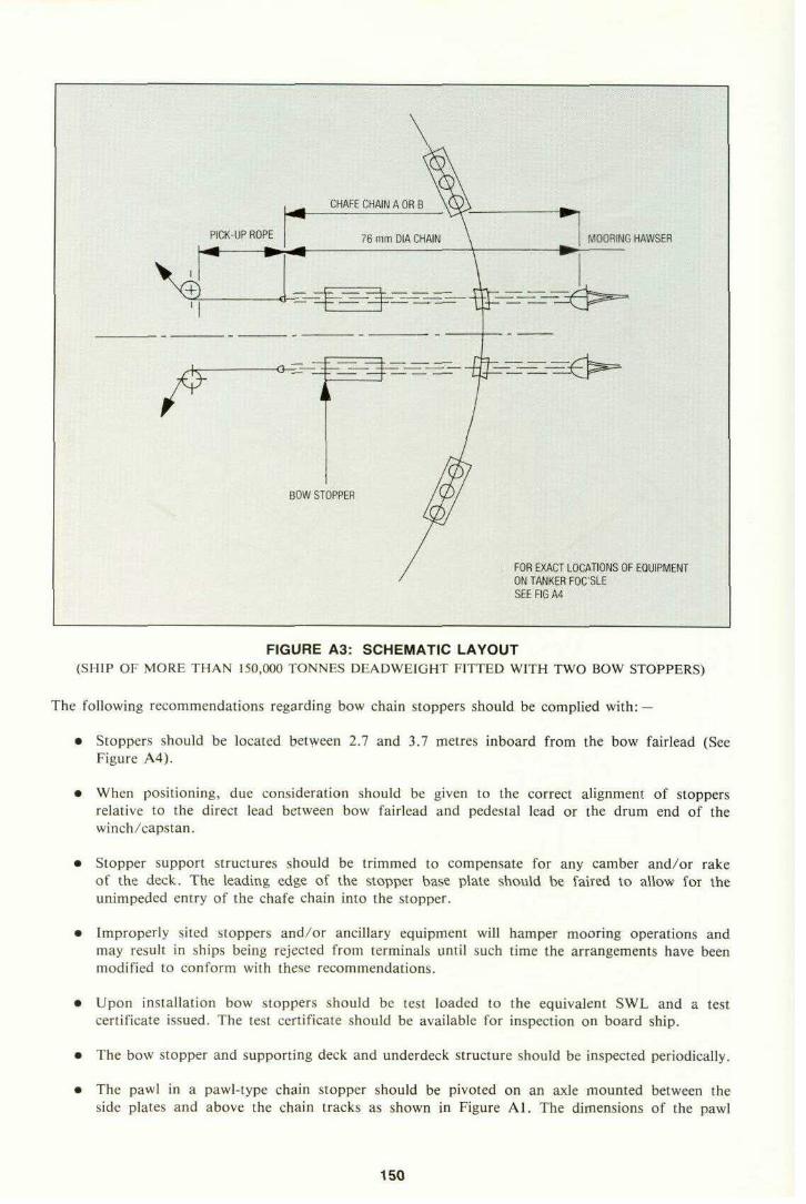
MOORING HAWSER
FOR EXACT LOCATIONS OF EQUIPMENTON TANKER FOC'SLESEE FIG A4 : :
FIGURE A3: SCHEMATIC LAYOUT(SHIP OF MORE THAN 150,000 TONNES DEADWEIGHT FITTED WITH TWO BOW STOPPERS)
The following recommendations regarding bow chain stoppers should be complied with: —
• Stoppers should be located between 2.7 and 3.7 metres inboard from the bow fairlead (SeeFigure A4).
• When positioning, due consideration should be given to the correct alignment of stoppersrelative to the direct lead between bow fairlead and pedestal lead or the drum end of thewinch/capstan.
• Stopper support structures should be trimmed to compensate for any camber and/or rakeof the deck. The leading edge of the stopper base plate should be faired to allow for theunimpeded entry of the chafe chain into the stopper.
• Improperly sited stoppers and/or ancillary equipment will hamper mooring operations andmay result in ships being rejected from terminals until such time the arrangements have beenmodified to conform with these recommendations.
• Upon installation bow stoppers should be test loaded to the equivalent SWL and a testcertificate issued. The test certificate should be available for inspection on board ship.
• The bow stopper and supporting deck and underdeck structure should be inspected periodically.
• The pawl in a pawl-type chain stopper should be pivoted on an axle mounted between theside plates and above the chain tracks as shown in Figure Al. The dimensions of the pawl
150

DISTANCE FROM CHAIN CLTO BASEPLATE BOTTOM 216mm
TO PEOESTAt- FAIRLEAD
FORWARD END OF STOPPERSEATING TO BE SUITABLY ROUNDEDAND FAIRED TO PERMITUNIMPAIRED ENTRY CHAIN
HALF BREADTH OF CHAIN 137mm
FAIRLEAD HEIGHT DETERMINED BYEXTENSION OF LEAD LINETHROUGH BOW STOPPER
600 x 450mm FAIRLEAD P & SSET LOW IN BULWARKON EXTENSION OF LEAD LINETHROUGH BOWSTOPPER
FIGURE A4: POSITIONING OF FORWARD FAIRLEADS, BOW CHAIN STOPPERS ANDPEDESTAL ROLLER LEADS
(SHIP OF MORE THAN 150,000 TONNES DEADWEIGHT FITTED WITH TWO BOW STOPPERS)
A.3 BOW FAIRLEADS
In practice, it has been found that the use of a single central fairlead often creates problems whenattempting to heave the second chafe chain inboard, as the first chain tends to obstruct the directline of pull. A certain amount of interaction between mooring hawsers, thimbles and hawser floatsalso occurs when mooring is effected by a single central lead, which frequently results in chafingand damage to flotation material. As a result, two bow fairleads are recommended for ships ofover 150,000 tonnes deadweight at maximum summer draft (equivalent to approx. 175,000 tonnesdisplacement).
The following recommendations refer to the size, location and type of bow fairleads (See alsoFigures A4 and A5):
• The chock opening must be large enough to pass the mooring/towing components but notso large that it allows the components excessive lateral or vertical movement.
All bow fairleads should measure at least 600 x 450 mm. The 600opening of Figure A5 will allow passage of two 76 mm (3 in.) diameterside, provided the chain is diagonally oriented. Chain normally comeswith the links diagonal to the chock surface.
152
x 450 mm chockchain links side bythrough the chock

Notes: 1) Steel Plating Should Be Welded To This ChockAfter Installation To Flare The Comer To PreventThe Chain From Hanging-Up During Passage.
FIGURE A5: TYPICAL CHOCK DESIGN

Appendix DExample of Force Predictions for Use
with Hand Calculation ProceduresProblem:
Determine wind and current force predictions for use with the hand calculation procedure for a250,000 dwt tanker for the conditions listed below.
Wind load calculations
Step 1: Determine the vessel's characteristics.Vessel particulars for a 250 kdwt tanker in a fully loaded condition are
A^ (Longitudinal or Broadside Wind Area) = 3225 m2
A T (Transverse or Head-on Wind Area) = 818 m2
Step 2: Obtain wind coefficient at 0, = 150°
Cx« = -0.73 Figure 2.4CYAW = +0.19 Figure 2.3CYF» = +0.13 Figure 2.3
Step 3: Compute wind forces from equations
FX» = Cx»(-p^—}yl,ATV7600 7
(-^-\V^\ s w'\7600/* YAw — ~V/4»vl i r wAfIMW IM»\ -,„„ I » I.
""• • '•[-^r-^where:
p^ = 1.223 ks- ail at 20°Cm3
V» =60 knots/1.223\
F^ =(-0.73) ———— (60)2(818) = -346 kN\ /6UU /
/1.223\FYA» = (+0.19)1———](60)2(3225) = +346 kN
\ /OvU y
/1.223\FYF^ = ( + 0 . 1 3 ) — — — ( 6 0 ) ^ 3 2 2 5 ) = +243 kN
\7600/
159

Current load calculations
Step 1: Determine vessel characteristics.Vessel particulars for a 250 kdwt tanker in a fully loaded condition are
Lgp = 329.3 mT = 19.2 m
Step 2: Obtain current coefficient at 0c =170°
WDJT= 1.1:1
and that the tanker has a "conventional" bow
Cjcc = 0 Figure 2.6CYAC = -0.175 Figure 2.5Gyre = +0.13 Figure 2.5
Step 3: Compute the current forces
Fxc =CXC^600V2CTLBP
FYAC =CYAC'^OOV2CTLBP
FYFC =C^6WV2CTLBP
where:ke
p, = 1025 —— salt water at 20 °Cm3
Vc = 2 knots
Fxc =0
/1025\FYAC = (+0.175)1 _.l(2)2(19.2)(329.3) = 597 kN
/1025 \T^y, = (+0.45) ——— (2)2(19.2)(329.3) = 1534 kN
\7600 /
Ballasted 250 kdwt tanker
For a ballasted 250 kdwt tanker, the following tanker characteristics are used:
AT (Transverse or Head-On Wind Area) = 1380 m2
AL (Longitudinal or Broadside Wind Area) = 7622 m2
Zap (Length between perpendiculars) = 329.3 m2
T(Average Draft)* = 6.1 mTrim (Down by the stern) = 1°
The same equations used for the loaded case apply to the ballasted case also. Only the pertinentcharacteristics and the wind and current coefficients vary.
""This draft is less than the IMO draft (abt. 8.6 m) assumed for formulae listed in Section 2.4 since the vessel investigatedis a pre-MARPOL type.
160

Summary of wind and current loads for Standard Environmental Criteria
Loaded 250 kdwt tanker
Table showing the wind loads on a fully loaded 250 kdwt tanker for a wind speed of 60 knots at a10 m elevation.
Force (kN) Angle of wind on the stern0° 30° 60° 65° 90° 100° 120° 150° 180°
Fx» +353 +304 +137 - +20 - -157 -346 -451FYAW - +677 +922 +930 +863 - + 7 0 6 + 3 5 5 -FYFV - + 1 4 7 + 3 2 4 - + 481 +500 + 451 +243 -
Table showing current loads on a fully loaded 250 kdwt tanker for the current speeds shown and adraft of 19.2 m.
Force (kN) Angle and speed of current on the stern average velocity0°/3 knots 10°/2 knots 80°/3/4 knots 100°/3/4 knots 170°/2 knots 180°/3 knots
Fxc +276 0 18 -22 0 -268FYAC - +1569 +758 +652 +597FYFC - +358 +600 +681 + 1467 -
Maximum combination of forces — loaded case
Fx = - 451 - 268 = - 719 kN from aheadFYA = + 930 + 1569 = 2499 kNFYF = + 500 + 1467 = 1967 kN
Ballasted 250 kdwt tanker (Wind speed = 60 knots at 10 m height)
Force (kN) Angle of wind on the stern0° 30° 60° 70° 90° 115° 120° 150° 180°
Fxw +490 +441 +216 - - - -108 -363 -697FYAW - +1550 +2384 +2420 +2295 - +1678 +775 -FYF» - +334 +1128 - +1903 +2190 +2168 +1285 -
Table showing current loads on a ballasted 250 kdwt tanker for the current speeds shown and a draftof 6.1 m.
Force (kN) Angle and speed of current on the stern average velocity *0°/3 knots 10°/2 knots 75°/3/4 knots 110°/3/4 knots 170°/2 knots 180°/3 knots
Fxc +132 +63 + 2 0 -47 -93FYAC - +54 +64 +49 +60 -Pyre - +22 +50 +63 +49
* based on coefficient for water depth to draft ratio of 1.5:1 since data is not available for the standard ratio of 3.0:1
Maximum combination of forces — ballast case
Fx = -697 -93 = - 790 i,. from aheadFYA = + 2420 + 64 = + 2484 kNFYF = + 2190 + 63 = + 2253 kN
161

As can be seen the maximum longitudinal force and maximum transverse force at the forwardperpendicular are developed in the ballast condition. The maximum transverse force at the aftperpendicular is practically equal in ballast and full load condition. These values compare with thoseof formulae (10), (9) and (11) in Section 2.4.1 as follows:
Formula (10) Fx max = 0.498 x 1380 + 0.04613 x 6.1 x 329.3 = 780 kN
Formula ( 9) Fy^ max = 0.2839 x 3225 + 0.2482 x 19.2 x 329.3 = 2485 kN
Formula (11) Fyp max = 0.284 x 7622 + 0.02595 x 6.1 x 329.3 = 2217 kN
As can be seen, the values derived by formulae (10), (9) and (11) are in good agreement with themaximum forces obtained in this example.
The maximum forces can be compared with the restraint capacities developed for a 250 kdwt tankerin Appendix E. This comparison will provide a rough check as to whether the ship, when mooredat an idealized mooring arrangement, can stay moored under the recommended design mooringconditions.
162
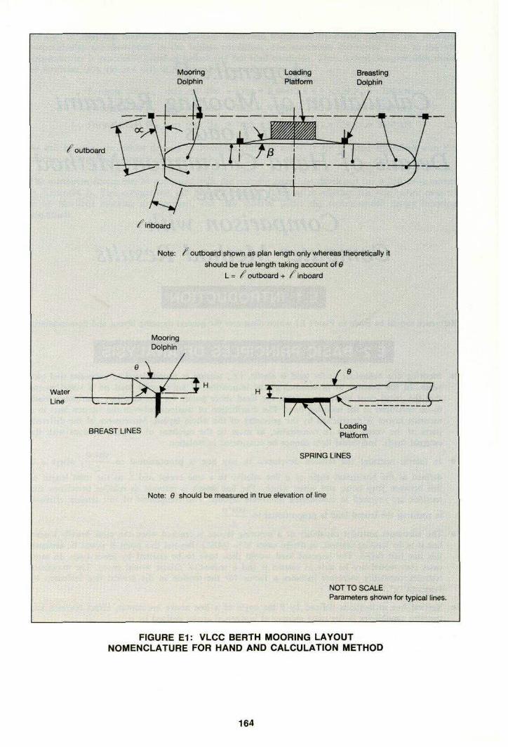
€ outboard
C inboard
Note: ^outboard shown as plan length only whereas theoretically itshould be true length taking account of 0
l.» ^outboard + /inboard
BREAST LINES LoadingPlatform
SPRING LINES
Note: 6 should be measured in true elevation of line
NOT TO SCALEParameters shown for typical lines.
FIGURE E1: VLCC BERTH MOORING LAYOUTNOMENCLATURE FOR HAND AND CALCULATION METHOD
164

E.3 ASSUMPTIONS
1. The problems may be fairly analysed in two separate parts by resolution of the loadings intolateral and longitudinal components.— Generally moorings are arranged in accordance with this concept as discussed in Sections 1.3
and 1.5. Longitudinal restraint should be provided by springs and lateral restraint by breastlines. While angled head and stern lines are not recommended, they can be taken into accountin the lateral restraint case, if they are tended like breast lines.
— Angled head and stern lines by virtue of their orientation and length take up lesser tensionsthan well placed springs and breasts. Provided they are arranged more as lateral restraintlines, i.e., a less than 45°, their effects on the case of longitudinal loading are not generallysignificant.
— Provided that the mooring line layout is reasonably symmetrical about the jetty centre-line,in the lateral loading case the longitudinal components of head and stern line tensions cancelout.
2. Mooring line tension is proportional to extension.— In fact, load/extension characteristics are not linear at very small or very large loads, but
with a small pre-tension applied they do not deviate significantly from linearity in the zoneof interest up to 55% (MBL).
— A small pre-tension, generally less than 10% (MBL), effectively removes the sag from a lineand allows this complication to be ignored.
3. When the imposed loads are zero, the tensions in the mooring lines are assumed to be zero,although the lines are just taut. For the purposes of the calculation, no further tending of linestakes place as external loads are imposed.
— While some pre-tension is required to remove sag and it is good practice to apply a significantpretension to reduce vessel movement under moderate load fluctuations, uneven applicationor poor line tending do nullify the benefits as far as ultimate restraint capacity is concerned.
— In practice, values of pre-tension are seldom more than 20% (MBL), and measurementsindicate that they are usually substantially lower.
— The assumption is slightly conservative in its results but is probably reasonably representativeof the majority of situations.
4. The problem of lateral restraint calculation may be further split into two parts by consideringthe bow and stern of the vessel separately.
— Lateral restraint lines are usually grouped near the bow and stern of the vessel.
— Generally, imposed loadings at bow and stern are not too dissimilar, so angular displacementsare not very significant.
5. In "mixed" mooring layouts synthetic lines are ignored.— By comparison with wires they take up insignificant tensions due to their much greater
elasticity.— Any benefit from pre-tensioning is excluded by assumption 3.
E.4 LIMITATIONS OF METHOD
In general, the method is applicable with reasonable accuracy to effective mooring layouts, inparticular:— Lateral and longitudinal restraint functions separated.
165

— Reasonably symmetrical layouts.— Vertical line angles (0) less than 25°.— Head and stern line deviations from breast (o-) less than 45°.— All lines of similar material, construction, make-up and size.— Lateral lines effectively grouped at head and stern.
It must be understood that this method only covers static strength requirements for a mooringsystem. It does not make allowance for dynamic effects, neither does it evaluate vessel movementsunder imposed loading. These must be considered separately.
E.5 CALCULATION PROCEDURE
(Note: for spring lines substitute f t for a)
1. Divide the mooring lines into groups for the different functions, i.e., lateral restraint at bow andat stern and longitudinal restraint forward and aft.
2. Assess the relevant parameters a, 6, L, = 1 (outboard) + 1 (inboard) for each line. Dependingon the accuracy required and personal preference, scale drawings or calculations may be used.Secondary parameters such as H, the height difference between jetty hook and vessel fairlead,may be introduced. The results are best tabulated as shown in the examples. As regards accuracy,the procedure already includes a number of approximations which for most layouts have littleeffect. Further approximations may be made at this stage, e.g.,
— Take average values for grouped lines.— Take only plan lengths of lines, ignoring correction for slope.
3. Evaluate and tabulate cos a, cos 6 for each line.cos2 a
4. Evaluate and tabulate ——— for each line and total (symbol E) for each group. In the examplesS-t
a constant of 100 is introduced for convenience. It is eliminated in the last line of the calculation.
5. Assess for each group the critical line, i.e., the one that will break or slip first. This is the linecos a
with the highest value of ———. It is the most efficiently placed line, with low values of a andLi
L. Subscript c is used to identify the relevant parameters.
6. Final step for each group:
lateral restraintcos2 a L.
RY = 0.55 (MBL) • E——— • ——— • cos 0,L COS Q-c
which has to resist the imposed load.
The nominal restraint capability of the lines is:
nom R Y = 0.55 (MBL) • N where N = no. of linesnomRyefficiency of layout = ————
RYlongitudinal restraint may be calculated by a similar formula, but often the lines have very similarvalues of L, f t , 0 and an approximation may be used:
R^ = 0.55 (MBL) • cos /?, • cos 6>,
166

The number of lines required to hold a vessel in a given situation would have to be assessed bytrial and error. Very approximate solutions may be obtained by use of the formulae listed inSection 2.6. These may then be verified by a full calculation.
Sample calculations have been worked out for a 250 kdwt tanker for both the loaded and ballastedconditions. These are shown on pages 167 and 169.
E.6 POSSIBLE REFINEMENTS OF CALCULATION
1. When all the lines are wires fitted with synthetic tails, their elastic properties and consequentlythe load distribution are altered. Each tail may be considered as an equivalent wire whose lengthis greater than that of the tail in proportion to the ratio of percentage elongations of the tail andthe wire at the same load (this allows for tail MBL greater than wire MBL). In the calculationonly L has to be modified. For example, if each line is fitted with an 11 m tail and the ratioof percentage elongations is 10, then l l x ( 1 0 - l ) = 9 9 m i s added to the length of each linealready assessed.
2. Where a shore pulley is provided to take a bight of a vessel's line, both legs are effective andassume the same tensions. In the calculation for each leg the average values of cos a, cos 6 andL for the two legs should be used.
Caution is required if tails are included as the tail on the one line is effectively shared by thetwo legs.
3. In ill-conditioned layouts with several lateral restraint lines taking up vertical inclinations of 25°or more, the accuracy may be improved by use of a more complicated formula:
cos a • cos 6critical line has highest value of ———————
L
RY= 0.55 (MBL) • £cos2 a • cos2 6
~LL.
COS dc • COS Be
EXAMPLE - LOADED VESSEL250 000 dwt tanker on 19.2 m draft
14 no. 42 mm wires of MBL 1110 kNLayout as shown in Figure E.2.
iiw
1! ! -2
- 'S4
. '5£ = 7.10
67
89
1011121314
; , , „„,„,„,,„,,,„ , . , „, , £"7.29 ^
1 1 1 ^a0
15.017.317.214.212.4
9.08.8
10.210.4
11.012.816.010.210.8
•outplan
474641.537.535.5
6869.5
60.559
4041.54458.565
H
3.43.43.43.43.4
3.43.4
3.43.4
3.43.43.43.43.4
19°
4.14.24.75.25.5
2.92.8
3.23.3
4.94.74.43.33.0
/OU
47 +46+41.537.535.5
68 +69.5
60.559+
40+41.544+58.565 +
« + / i ntrue
6 = <6 = f+ 42.5 = 84+ 44+ 35
35 =+ 35
+ 3535 =
32 =+ 327.5 =+ 6 =6 =71
-£
53S2
= 81.5= 70.5
103= 104.5
= 95.594
72= 73.5
-- 51.5= 64.5
cos 9
0.9970.9970.9970.9960.995
0.9990.999
0.9980.998
0.9960.9970.9970.9980.999
COS» 100
0.9660.9550.9550.9690.977
0.9880.988
0.9840.984
0.982 1.360.975 1.330.961 1.87*0.984 1.530.982 1.38
cos a. i. , ,
.82
.84*
.14
.19
.39
cos2
100———— i>
1.761.751.091.151.35
1.341.29 ,1.79 31.50 -1.36 .
* Indicates critical line of group.
167

1-5 Head Lines10-14 Stern Lines6-9 Springs
250,000 DWTLOA = 349.7mB =51.8m
- s^ &^s r I
<£
3.4 inV&rtas19.2m bow13.3m stern
LOADED CASE LIGHT BALLAST CASE
NOTE: This is not necessarily an ideal berth layout,although it approximates to the standard layouttor vessel design.
NOT TO SCALE
FIGURE E2: MOORING LAYOUT USED FOR COMPUTATIONAL PURPOSES
cos2 »V L,RY= 0.55 (MBL) E
\ L / \cos o,cos 0.
RYF = 0.55 (1110)(7.10)( —— ) (0.997) = 2350 kN
2?K4=0.55(1110)(7.29)1.87
(0.997) = 2373 kN
RX = N (0.55)(MBL) cos (3 cos 0
As variation in L, cos f t and cos 0 is less than 2% the simpler approximate formula may beused giving:
Rxp = 2 (0.55)(1110)(0.988)(0.999) = 1205 kN
^4 = 2 (0.55)(1110)(0.984)(0.998) = 1200 kN
168

EXAMPLE-LIGHT BALLASTED VESSEL250 000 dwt tanker, lightest operational draft 6.1 m, trim 1%
14 no. 42 mm wires of MBL 1110 kNLayout as shown in Figure E.2.
Note: As values of 0 go over 25° and are larger and more variable than those of a, the methoduses refinement 3 described in the text.
il:^,;?"^ •'Line
1: ! 2
34
; '5
67
89
1011121314
E =6.54
a°
15.017.317.214.212.4
9.08.8
10.210.4
11.012.816.010.210.8
•OBt
plan474641.537.535.5
6869.5
60.559
4041.54458.565
H
19.219.218.818.818.8
18.018.0
14.714.7
13.713.713.713.313.3
0°
22.222.624.426.627.9
14.814.5
13.714.0
18.918.317.312.811.6
/«u
51 +50 +45.542 +40+
70.572 +
62 +61 +
42.543.546 +60 +66.5
.+4tn<
6 =6 =+4244 =35 =
+ 3535 =
35 =35 =
+ 32+ 327.56 =+ 6
„"£M
57565 = 888675
= 106107
9796
= 74.5= 75.5
= 53.566=72.5
cos 0
0.9260.9230.9110.8940.884
0.9670.968
0.9720.970
0.9460.9500.9550.9750.980
COS a COS 0cos a 100 ———————
L
0.966 1.57*0.955 1.57*0.955 0.990.969 1.010.977 1.15
0.9880.988
0.9840.984
0.9820.9750.9610.9849.82
.25
.23
.72*
.45
.33
cos2 a cos2 0100———————
L
1.401.390.860.870.99
: E = 5.52
1.161.141.571.391.28
* Indicates critical line of group.
L.cos2 a cos2 0'L
Ry = 0.55 (MBL)(Ecos dc cos Or
RYP = 0.55 (1110)(5.52)—— 1 = 2147 kN1.57
RYA= 0.55 (1110)(6.54) —— = 2321 kN1.72 /
Rx = N (0.55)(MBL) cos /? cos Q
RXF = 2 (0.55)(1HO)(0.988)(0.967) = 1167 kN
RXA = 2 (0.55)(1110)(0.984)(0.970) = 1165 kN
Comparison of predicted forces and hand calculated restraint capacityAppendix D predicts the following maximum forces for the assumed conditions:
Max F]( = - 790 kN (in ballast conditions)
FYF = + 2253 kN (in ballast conditions)
FYA = + 2499 kN (in full load conditions)*
•Practically the same as ballast conditions.
169

The minimum restraint capabilities calculated in this section are for the ballasted case and are asfollows:
RU = 1165 kN
RXF = 1167 kN
RYF = 2147 kNRy^ = 2321 kN
The longitudinal restraint capabilities fore and aft are clearly adequate. The lateral restraint capabilitiesfore and aft are about 5 % and 7 % deficient respectively.
Comparison of mooring line requirements with approximate formulae in Section 2.6
Formula (22): S x MBL = 3271 kN
Formula (23): BR x MBL = 12923 kN
Formula (24): S x MBL = 3555 kN
Formula (25): BR x MBL = 12620 kN
This compares with the available S x MBL of 4 x 1110 = 4440 kN, and BR x MBL of 10 x 1110 =11100 kN.
In all cases the provided spring lines are more than adequate. The breast lines are 14% deficientper formula (23) and 12% deficient per formula (25).
E.7 SAMPLE OF COMPUTER CALCULATIONSFor the 250 kdwt tanker carrying 14 wire lines, computer runs were made for the 60 knot wind from0° to 180° and for the currents as given in the design mooring condition section. Both the ballastedand loaded cases, with a water depth to draft ratio of 1.1:1 for the loaded case, and 3.0:1 for theballast case were analysed, and the maximum loadings in the 42 mm IWRC wire lines are as providedin the table below: Details as to wind area, draft etc. are found in Appendix D in which the forcesacting on the vessel are calculated. Figure E2 illustrates the mooring line layout used for computationalpurposes. Vertical and horizontal angles are as illustrated in Figure 2.10.
Wire Number1234567
Load in Tonnnes63.9*63.5*47.643.148.554.954.4
Wire Number89
1011121314
Load in Tonnes48.148.545.444.459.460.856.2
•Slightly above 55% MBL: but well within order of accuracy of calculations.
• The loads given in the table are the highest loads generated in each line by the varying com-binations of wind, current and vessel draught.
• Normal allowable load = 0.55 x mo kN = 610 kN .
• 1110 kN is minimum breaking load of the 42 mm IWRC wire line which is recommended as theminimum sized wire line tor VLCCs.
Thus, based on our design mooring conditions and assumed ballast condition, 14 wire mooring linesas specified are required to safely moor the vessel.
170

Comparison of hand with computer method results from exampleIt can be seen that the results from the hand method are slightly worse than those given by the
computer method. This measure of agreement should be expected for a good mooring layout.For ill-conditioned layouts the hand method will be less accurate.
The results obtained by the approximate formulae in Section 2.6.1 are slightly conservative sincemost mooring layout are not as efficient as the layout assumed in this example.
171

Appendix FStrength of Chain Tensioned
over a Curved SurfaceThe chafing chain at the end of a tow line or SPM hawser normally is guided through a chockat the edge of the tanker deck. This chock restrains the chain from excessive lateral movementand provides a curved surface for the chain to bear against. The diameter of this curved surfacemust be large enough to prevent overstressing of the chain when it is subjected to high towing ormooring loads. The problem of defining a criteria for the minimum diameter of chock surfaces wasaddressed by both analysis and experiment in this study.
F.1 THREE CASES OF CHAIN ON A CURVED SURFACEAnalysis of the stresses in a chain tensioned over a curved surface is more complex than firstappears. Three cases of chains tensioned over curved surfaces are illustrated in Figure Fl. Case 1is that of an ungrooved surface, such as a chock. The chain links lie at angles to the surface,alternatively lying to one side and then the other, with all links bearing against the surface. This isthe case of primary interest in this study.
The second and third cases apply to grooved surfaces, such as anchor chain windlasses and chainsheaves. On grooved surfaces, every second chain link projects into a groove in the surface andhas its transverse axis perpendicular or upright to the surface. Intervening links lie with theirtransverse axis parallel or flat on the surface. In case the groove is so shallow that the upright linkrests on the bottom of the groove and the flat link is lifted tree of the surface. In this case bendingstresses are exerted on the upright links only. In case 3 the groove is so deep that the upright linksdo not touch bottom, and the flat links bear against the curved surface. Only the flat links aresubjected to bending stresses in this case.
Grooved surfaces are discussed to distinguish them from the ungrooved case and to allow discussionof other analyses and recommendations. An intermediate case can exist in which both the flat andupright links touch the surface. In the case of chain lying over a very small ungrooved surface withonly one or several links in contact, alternating links may lie flat and upright to the surface as inthe second and third cases.
F.2 DEFINITION OF ANGLES AND OTHER TERMSDimension and angles of chain links lying on a curved surface are shown in Figure Fl. The chaindiameter, d, is the nominal diameter of the bar from which the common stud link is formed.For common stud links the overall link length L is 6 times d and the link with B is 3.6 times d.
The diameter of the curved surface over which the chain is bent will be defined as D. This mustnot be confused with the diameter of the opening in the bow chock. For case 2, the shallow-groovedsurface with contact at the bottom of the groove. D is analyzed as the diameter to the bottom ofthe groove.
The ratio of bending surface diameter to chain diameter D/d will be used as a criteria for surfacediameter. This diameter ratio should not be confused with the ratio of the surface radius to chaindiameter which is sometimes referred to in recommendations made by others.
173
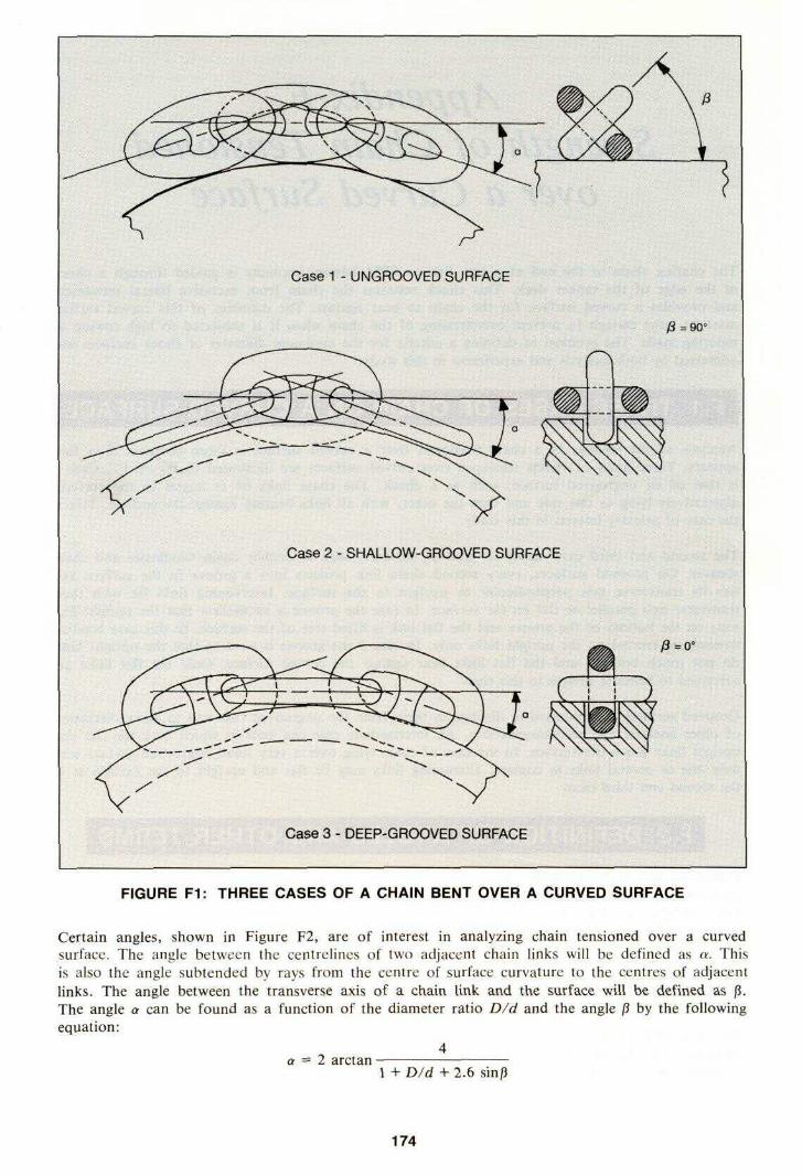
Case 1 - UNGROOVED SURFACE
j3 =90°
Case 2 - SHALLOW-GROOVED SURFACE
^=0"
Case 3 - DEEP-GROOVED SURFACE
FIGURE F1: THREE CASES OF A CHAIN BENT OVER A CURVED SURFACE
certain angles, shown in Figure F2, are of interest in analyzing chain tensioned over a curvedsurface. The angle between the centrelines of two adjacent chain links will be defined as a. Thiss also the angle subtended by rays from the centre of surface curvature to the centres of adjacentinks. The angle between the transverse axis of a chain link and the surface will be defined as f t .rhe angle a can be found as a function of the diameter ratio D/d and the angle f t by the following•quation:
4a = 2 arctan———————————
1 + D/d + 2.6 sin/5
174

FIGURE F2: GEOMETRY OF A CHAIN BENT OVER A CURVED SURFACE
Jnfortunately, the angle f t cannot be determined by a closed-form analytical solution. The problems a very complex solid geometry problem involving the interlocking of two toroids intersecting atin angle which depends on angles a and p. As a increases then the angle /? decreases. Figure F3hows the approximate relationship between the angle p and the angle a. These values were measuredvith small chain having proportions similar to large stud link chain. The angle f t decreases slowlyrom approximately 40° to approximately 30° as a increases to about 70°, and then it drops rapidlyis a increases to 90°.
175

50
40
WLULU0:0UJ003; 30LU
0
<UJ
§^ 203W2<0
10
0{
--' Limiting Case, Chair^/ Lifted Prom Surface
"'"'--•^
——\
I !
0 30 60 90 |
I NTER-UNK ANGLE a, DEGREES
i
Range Of
Observed Values
1 1
——- \\
\
\\
———————\Limiting Case,Chain Flat OnSurface 'X
1 t ^
FIGURE F3: APPROXIMATE RELATION BETWEEN ANGLE a AND ANGLE ff
The angle a as a function of the diameter ratio D/d and various angles /? is shown in Figure F4.The angle a cannot, therefore, be uniquely determined without first having determined p, and /?unfortunately depends on a. Thus a closed form solution is not possible.
F.3 FORCES ON THE CHAIN LINK
A free-body diagram of half a chain link, showing the forces and moments applied when bent overa curved surface, is given in Figure F5. The effect of the stud is ignored in this analysis.
The force P is the tension in the chain. For the purpose of analysis, it is assumed the tensionforce P is applied at the centreline of the chain. In the case of chain on an ungrooved surface,the tension force P between chain links acts at an angle a/I to the chain centreline, because everychain link bears on the surface. This is an important distinction from the case of chain on a groovedsurface, in which every other chain link is not in contact with the surface and thus is under tensiononly. The angle at which the tensile force P acts on the bent chain link in the grooved surface caseis a. Only the solution of the ungrooved surface case will be addressed here.
The reaction force of the surface against the chain link is R. For the half chain link free bodyshown, only half this reaction force applies. Because the chain lies at an angle to the surface, the
176

FIGURE F4: ANGLE a AS FUNCTION OF D/d FOR VARIOUS ANGLES ft
FIGURE F5: FREE BODY ANALYSIS OF HALF CHAIN LINK
177

reaction applies a moment about the centreline, which must be resisted by the interlocking chainlink. The manner in which this resisting moment is applied is complicated. For the purpose ofanalysis, a resisting moment N between chain links will be assumed to act about the chain linkcentreline.
The vertical component of the interlink tension is P sin a / I . This force applies a bending momentM at the centre of the chain link. From the dimensions of the link, this moment is
M - 2dP sin a/I
Considering the chain link as a beam consisting of two cylinders, each with its centreline a distanceu from the centroid, the moment of inertia is
vd4 Trd\l.3dsmlS)2
I = —— + ——-——————-32 2
The maximum tensile stress in the chain is at the top centre of the link. The distance to the outerfibre at that point is
C = x = 1.3d sin fi + 0.5d
By superposition of the tensile force which is exerted by the horizontal component of P acting onthe area of the link and the maximum tensile force which is produced by the vertical component ofP applying a moment M, the total stress at this point is
IP cos a/I IPdC sin a/2a = ————-—— + ————————
TTd2 I
To facilitate plotting and comparison of the stress level, a non-dimensional stress parameter isdefined by multiplying the above equation by d ^ / P
acP 2 2Cd3
—— = — cos a/2 + ——— sin a/2P v I
This factor has been plotted in Figure F6 as a function of the diameter ratio for various angles P.For convenience the surface diameter corresponding to 76 mm (3 in.) chain is also indicated onthe abscissa of the figure.
F.4 INCREASE IN MAXIMUM STRESS
Marsh and Thurston analyzed the stress distribution in a stud link chain under straight tensionusing stress equations which are more sophisticated than those used here. They measured thesestresses by strain gauging chain links. The results of their analysis (Figure 3 of Marsh and Thurstonreference) show the maximum tension stress in straight tension occurs at the outside of the linkat a position about 70° from the end of the link. The non-dimensional value of this stress,ad2
—— is 2.P
This non-dimensional stress value is plotted as a horizontal dashed line in Figure F6. It indicatesthat the maximum stress due to straight tension is higher than that due to being tensioned overthe surface for surface to chain diameter ratios greater than about 7 when f t =25°. The actualdiameter ratio at which stress due to tensioning over the surface becomes greater than that dueto tensioning over the surface becomes greater than that due to straight tension depends on theangle (S, which is undetermined.
178

FIGURE F6: NON-DIMENSIONAL STRESS FACTOR AS A FUNCTION OF D/d FOR VARIOUSANGLES ft
F.5 COMPARISON OF GROOVED
AND NON-GROOVED CASESThe two cases of chain tensioned over a curved surface with a groove can be analyzed by the stressequations given in the preceding section by replacing a / I by a. Also, recall that for the case ofthe upright link supported at the bottom of the groove, the surface diameter D must be definedas the radius to the bottom of the groove. Figure F7 shows the non-dimensional stress parameterad1
—— plotted for these two cases, together with the non-grooved surface case for p = 25 .P
As reported by Buckle, the two grooved surface cases were analyzed by Lloyds Register of Shipping.The analysis was done for stud-link chain with a finite-element technique. The inter-link angle a
179

10
03C/3UJ0:&)
^
0c/5zUJ20
0
5 10 15
SURFACE TO CHAIN DIAMETER RATIO D/cf
20
FIGURE F7: COMPARISON OF GROOVED AND UNGROOVED SURFACE CASES
was approximately 30°. The non-dimensional stress factors, as defined above, were approximately2 and 4.6 for the upright link (p = 90°) and flat link ( f t = 0°) cases respectively (Figure 12 ofBuckle reference).
Comparing the Buckle results with those of the present analysis gives some indication of theadequacy of the present calculations. For the 0° case (flat link). Buckle gives a stress only slightlylower than the present analysis. For the 90° case (upright link) Buckle gives a stress approximately70% higher. This higher value may be due to the action of the stud putting a concentrated load onthe middle section of the link.
The comparison indicates the simplified analysis done here may not be as accurate as the finite-element analysis performed by Buckle. Correlation is good for the 0° case, but poor for the 90°case. The intermediate cases of interest, i.e. f t = 25°, may be less inaccurate.
In the present study, a more accurate analysis of the case of a chain tensioned over an ungroovedcurved surface could have been obtained using finite-element methods. However, a more exactanalysis of the forces between two interlocking links would be necessary. A precise definition ofthe inter-link forces is a major problem. Further analysis does not appear to be warranted.
180

F.6 TESTS OF CHAIN TENSIONED
OVER CURVED SURFACEAn experimental program was conducted to determine the load at which stud link chain breakswhen tensioned over a curved surface. Specimens from two samples of flash-welded grade-2 steelstud-link chain from different manufacturers were tensioned around pins having surface diametersranging from 2.3 to 14 times the chain diameter. They were loaded until they failed. Propertiesof the chain specimens are given in Table F.I.
Sample A Sample B
Type of chainDiameterCertified proof loadCertified breaking loadActual breaking loadMetallurgical coupon test results:
Yield strength at 2% offsetUltimate strengthElongation, 2 in. gauge lengthReduction in areaHardness
Grade 2 stud-link35 mm if in.
490 kN 111,000lb690 kN 155,000 Ib830 kN 186,000 Ib
415,000 kPa568,000 kPa
34%73%
Rockwell B 81
60,200 psi82,400 psi
Grade 2 stud-link32 mm 11 in.
410 kN 92,200 Ib570 kN 129,000 Ib700 kN 156,500 Ib
373,000 kPa 54,100 psi555,000 kPa 80,500 psi
29%70%
Rockwell B 84
TABLE F.1: CHAIN TENSIONED OVER CURVED SURFACE, PROPERTIES OF CHAIN SAMPLES
A typical test set up is shown in Figure F8. Load was applied by a large hydraulic cylindermounted horizontally. One end of the chain specimen was attached to the cylinder head by adetachable link.
The other end was run over the test pin, mounted with its axis horizontal between two platesextending from a stationary frame and connected through a detachable link to a chain swivel boltedto a strong rail in the test floor.
A total of 24 tests were conducted. The set-up and results of each test is summarized in Table F.2.The first 17 tests were conducted with chain A. The results of these tests indicated the chainspecimens might be untypically ductile. Therefore chain B was obtained and specimens from itwere tested.
F.7 RESULTS OF CHAIN TESTS
When loaded in straight tension, both chain samples broke at loads significantly higher than theirrated break test loads. These straight break strengths were used as the basis for defining percent ofstrength for those chains loaded on the curved surfaces. There was very good agreement betweenidentical tests with chain A. Thus tests were not repeated with chain B.
There was wide scatter of results depending on the geometry of the chain in relation to the surface.When interlocking chain links were arranged to contact the surface at angles near 45°, the chainsbroke at the interlocking point at loads somewhat lower than the straight break test load. Whenthe interlocking chain links were alternating upright and flat to the surface, as happens with smallersurface diameters, chain strength was not significantly reduced. Sometimes the straight chain linksfree of the surface broke before the bent chain links did.
Figure F9 shows the tests results. The lowest breaking load obtained for each diameter ratio dividedby the straight breaking strength is plotted as a function of the surface diameter to chain diameterratio. In the case of identical tests, the average of the two loads is plotted.
181

FIGURE F8: TEST SET-UP. TEST 15. a = 135°, D/d = 4, 8 LINKS
Although chain A was at first thought to break at untypically high loads, because of greater thannormal ductility, chain B performed even better and appeared to be even more ductile.
It was thought that links which were deformed around the curved surface would have lowerstrength when loaded in straight tension. This did not occur. In the tests in which deformed linkswere loaded in straight tension, the chains broke at points other than the deformed links.
The results of the chain tests should be generally applicable over a wide range of chain sizes, eventhough only 32 and 35 mm (ly and l|-in.) chains were tested. The diameter ratio results have beentreated as non-dimensional quantities. Percent reduction in strength as a function of the ratio ofsurface diameter to chain diameter chain link proportions is independent of the experiment scale.Also, material properties and manufacturing processes are the same for the chains tested as forlarger chains. The findings of the chain tests generally agree with those of the analytical study.Therefore, the results of these studies should be applicable to larger chains.
The curve in Figure F9 is believed to be a reasonable indication of the manner in which surfacediameter to chain diameter ratio affects chain strength. The results indicate that strength reductiondue to tensioning chain over a curved surface is not significant for surface diameter to chaindiameter ratios greater than about 6.
182

testNo.
f: 1& 2^ 3
4^ 5
?' ei. 7^1 8t1 9'K-t.;:v
fc|t0s,' • '
i:' '
I'll112
13fr-N
1616
^^ •
1819
20
21
22
Chainsample
AAA
AA
AA
AA
A
AA
AA
AA
A
8B
B
B
B
Bendangle
0°0°
90°
90°90°
90°90°
90°90°
90°
90°90°
90°135°
135°135°
135°
0°90°
90°0°
90°
90°
0°
D/dratio
——14
149
96
64
4
42.9
2.94
42.9
2.9
^2.3
2.3
4
4
—
No.of
links
88
10 '
10.10)
j10 J8}
>8J8
8
6c \
eJ10
87
7
78
8
8
8
-
Linksin
contact
——2
3 and 452342342
34
.2
34
— As test 9 —23
3453434
—2 and 3
2 and 3—
2.3and 42,3
and 4
Attitudeangle
——
-40°
-38°-40°
-20°-70°
Almosthorizontal
-60°AlmosthorizontalAlmostverticalHorizontalAlmostvertical
-45-10°
-30°-25°-10°- 5°-80°-90°Ftet
—Diagonal
Diagonal—
Diagonal
Diagonal
~-
Pre-stressload(Ib)
———
——
——
-—
~
——
,——
• —! —
—
—-
92,000—
—
92,000
—
Breakingload(Ib)
185,800186,400185,300
184,800180,500
179.500174,400
177,400153,500
184,800
158,800174,900
169,600177,900
185,800149,000
186,400
156,500141,600
—155,400
161,100
—
165,400
Percentstraightstrength
100%100%
99.5%
99.2%96.9%
96.4%93.8%
95.3%82.4%
99.2%
85.3%93.9%
91.1%95.6%
100%80.0%
100%
100%90.5%
—99.3%
98.5%
—
99.3%
Brokenlink
5*5*6*
5*4
42
22
6*
22
33
54
5*
33
—5*
2
—
7*
Betweenlinks
4-55-66-7
5-63-4
3-42-3
2-32-3
6-7
2-31-2
2-33-4
4-53-4
—
2-32-3
—5-6
2-3
—
7-8
Remarks
Straight break testStraight break testLinks 2, 3, 4 bent
Links 2, 3, 4 bentLinks 2, 3 bent
Links 2, 3 bentLinks 2, 3 bent
Links 2, 3 bent
Broke in free link;links 2 and 3severely bent
Link 2 severely bent
Link 2 severely bent
Links 3, 4 severely
Link S was free ofsurface under highload; links 3, 4severely bentStraight break testLinks 2 and 3severely deformedChain first pre-stressed to ratedproof load over pin.Links 2 and 3 de-formed. Test chainthen straight breaktestedLink 2 severelydeformedChain first pre-stressed to ratedproof load over pin.Link 2 slightly de-formed. Test chainthen straight breaktested <
TABLE F.2: SUMMARY OF TEST RESULTS, CHAIN TENSIONED OVER CURVED SURFACE
183

TestNo.
23
24
Chainsample
B
A
Bendangle
90°
0°
0°
D/dratio
2.3
No.of
links
8
—
e
Linksin
contact
23—
—
Attitudeangle
-90"Flat
—
—
Pre-stressload(Ib)
130,000
—
—
Breakingload(Ib)
—
154,300
173,600
Percentstraightstrength
—
98.6%
>93%
Brokenlink
—
8*
Shackle
Betweenlinks
—
7-8
—
Remarks
Chain first pre-stressed to 130,000Ib to cause signifi-cant chain deforma-tion. Test chain thenstraight break testedStraight break testof unbroken sectionof chain from test10 including |severely deformedlinks. Broke in Ishackle beforechain broke |
' Indicates break occurred in straight chain link which was not m contact with curved surface.
TABLE F.2: (continued)
1.0
1LU
tO 0.8CT
SiSECCD
® O-6
i 0.40
£C<a ^
•sz2
0•c
SURFACE TO CHAIN DIAMETER RATIO D/d
0
0 /—r-
1 5 10 1
A First Chain
0 Second Chain
I I I I I I I )
S s
FIGURE F9: RESULTS OF TESTS OF CHAIN TENSIONED OVER CURVED SURFACE
184

F.8 RECOMMENDATIONS FOR CHOCK
SURFACE DIAMETERPracticality must be considered in specifying a chock diameter for SPM and towing chains. Retro-fitting or modification might be necessary on many tankers. If an impractical or too large diameteris required, many operators and owners may choose to resist or defer making modifications.
Many recommendations have been made in the past regarding the safe diameter for surfaces onwhich chains bear. Review of these past recommendations indicates that only some of them applyto chain tensioned over an ungrooved surface, the case of interest in SPM and towing chain chocks.The Lloyds investigation reported by Buckle, the only other known analysis, applies only for agrooved surface. No other experimental work of chain tensioned over ungrooved surfaces is known.Thus most past recommendations are apparently only conservative assumptions based on experiencein various dissimilar services.
In the present investigation, both analytical and experimental findings indicate that stud link chainwill not be significantly weakened provided the diameter of the surface over which it is tensionedis not less than 7 times the diameter of the chain.
Chocks with a 600 by 450 mm (24 by 18 in.) opening and a surface diameter of 560 mm (22 in.)are available. Such chocks are known as Mississippi fairleads, and are manufactured and marketedby several companies. When used with the 76 mm (3 in.) chain, recommended for SPM and towingchafing chain, the 560 mm surface curvature of such chocks provides a surface diameter ratio of7.4. Thus, the recommended surface diameter to chain diameter ratio of 7 is practical.
Many tankers are already fitted with bow chocks which comply with this recommendation. Sometankers probably have chocks with smaller surface diameters. The most common commerciallyavailable 600 by 450 mm (24 by 18 in.) opening chock has a surface diameter of 360 mm (14.1 in.)as specified by Japanese Industrial Standards (JIS). Such chocks provide a surface diameter tochain diameter ratio of only 4.7 with 76 mm chain. However, such chocks can be readily replacedwith larger surface diameter chocks.
185
Copyright © 2022 FDOKUMEN