No. 10 - Chain Anchoring, Mooring and Towing Equipment
24
No.10 Page 1 of 24 IACS Rec. 1982/Rev.4 2020 No. 10 (1982) (Rev.1 Aug 1999) (Corr. Dec 2004) Rev.2 Jun 2005) (Rev.3 Oct 2016) (Corr.1 Dec 2016) (Rev.4 Sep 2020) Chain Anchoring, Mooring and Towing Equipment 1. Anchoring equipment 1.1 Anchoring equipment for ships having Equipment Number EN below 205 to 50. (a) The anchoring equipment given here under applies to ships which are not covered under UR A1, i.e. for ships having 50 ≤ EN < 205. (b) The design basis of the anchoring equipment, i.e. the Equipment Number EN, is that given in UR A1. (c) These recommendations are applicable to ships operating in unrestricted service. Reductions of equipment may be considered for ships operating in restricted service. Note: References to UR A1 are preceded by ‘A1’ throughout this document. 1.1.1 Equipment number EN The equipment of anchors and chain cables should be as given in Table 1 based on an Equipment Number EN calculated in compliance with A1.2.
-
Upload
khangminh22 -
Category
Documents
-
view
2 -
download
0
Transcript of No. 10 - Chain Anchoring, Mooring and Towing Equipment

No.10
Page 1 of 24 IACS Rec. 1982/Rev.4 2020
No.10 (cont)
No. 10 (1982) (Rev.1 Aug 1999) (Corr. Dec 2004) Rev.2 Jun 2005) (Rev.3 Oct 2016) (Corr.1 Dec 2016) (Rev.4 Sep 2020)
Chain Anchoring, Mooring and Towing Equipment 1. Anchoring equipment 1.1 Anchoring equipment for ships having Equipment Number EN below 205 to 50. (a) The anchoring equipment given here under applies to ships which are not covered
under UR A1, i.e. for ships having 50 ≤ EN < 205. (b) The design basis of the anchoring equipment, i.e. the Equipment Number EN, is that
given in UR A1. (c) These recommendations are applicable to ships operating in unrestricted service.
Reductions of equipment may be considered for ships operating in restricted service. Note: References to UR A1 are preceded by ‘A1’ throughout this document. 1.1.1 Equipment number EN The equipment of anchors and chain cables should be as given in Table 1 based on an Equipment Number EN calculated in compliance with A1.2.
No.10
Page 2 of 24 IACS Rec. 1982/Rev.4 2020
No.10 (cont)
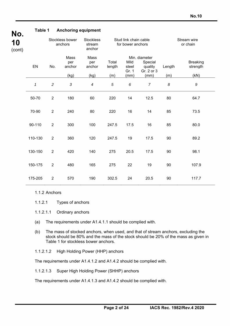
Table 1 Anchoring equipment Stockless bower
anchors Stockless
stream anchor
Stud link chain cable for bower anchors
Stream wire or chain
Mass
Mass
Min. diameter
per per Total Mild Special Breaking EN No. anchor anchor length steel quality Length strength
Gr. 1 Gr. 2 or 3 (kg) (kg) (m) (mm) (mm) (m) (kN)
1 2
3
4
5
6
7
8
9
50-70 2 180 60 220 14 12.5 80
64.7
70-90 2 240 80 220 16 14 85
73.5
90-110 2 300 100 247.5 17.5 16 85
80.0
110-130 2 360 120 247.5 19 17.5 90
89.2
130-150 2 420 140 275 20.5 17.5 90
98.1
150-175 2 480 165 275 22 19 90
107.9
175-205 2 570 190 302.5 24 20.5 90
117.7
1.1.2 Anchors 1.1.2.1 Types of anchors 1.1.2.1.1 Ordinary anchors (a) The requirements under A1.4.1.1 should be complied with. (b) The mass of stocked anchors, when used, and that of stream anchors, excluding the
stock should be 80% and the mass of the stock should be 20% of the mass as given in Table 1 for stockless bower anchors.
1.1.2.1.2 High Holding Power (HHP) anchors The requirements under A1.4.1.2 and A1.4.2 should be complied with. 1.1.2.1.3 Super High Holding Power (SHHP) anchors The requirements under A1.4.1.3 and A1.4.2 should be complied with.

No.10
Page 3 of 24 IACS Rec. 1982/Rev.4 2020
No.10 (cont)
1.1.2.2 Installation of the anchors on board The bower anchors should be connected to their chain cables and ready for use. The stream anchor should be ready to be connected with its cable. 1.1.2.3 Proof testing of anchors The requirements under A1.4.4 should be complied with. 1.1.3 Chain cables and wire ropes for anchors 1.1.3.1 Chain cables (a) The anchors should be associated with stud link chain cables of one of the grades
under A1.5.2, Table 3. For equipment numbers EN up to 90, as an alternative to stud link chain cables, short link chain cables may be used.
(b) Wire ropes for anchors may be adopted in compliance with 1.1.3.3 1.1.3.2 Proof and breaking loads of stud link chain cables (a) The breaking loads (BL) and proof loads (PL) should be in compliance with the
requirements under A1.5.3. (b) The test load values, rounded off from the loads defined in (a) above, which should be
used for testing and acceptance of chain cables with diameter between 11 and 19 mm are given in Table 2.
Table 2 Test load values for stud link chain cables
Chain cable Grade 1 Grade 2 Grade 3 diameter Proof load Breaking
load Proof load Breaking
load Proof load Breaking
load (mm) (kN) (kN) (kN) (kN) (kN) (kN)
1
2
3
4
5
6
7
11 35.8 51 51 71.7 71.7 102 12.5 46 65.7 65.7 92 92 132 14 57.9 82 82 116 116 165 16 75.5 107 107 150 150 216
17.5 89 127 127 179 179 256 19 105 150 150 211 211 301
1.1.3.3 Wire ropes for anchors In alternative to the stud link or short link chain cables under 1.1.3.1, wire ropes may be used for: (a) bower anchors of ships below 40 m in length (b) stream anchor as stipulated in Table 1.
No.10
Page 4 of 24 IACS Rec. 1982/Rev.4 2020
No.10 (cont)
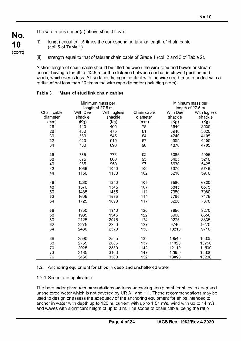
The wire ropes under (a) above should have: (i) length equal to 1.5 times the corresponding tabular length of chain cable (col. 5 of Table 1) (ii) strength equal to that of tabular chain cable of Grade 1 (col. 2 and 3 of Table 2). A short length of chain cable should be fitted between the wire rope and bower or stream anchor having a length of 12.5 m or the distance between anchor in stowed position and winch, whichever is less. All surfaces being in contact with the wire need to be rounded with a radius of not less than 10 times the wire rope diameter (including stem). Table 3 Mass of stud link chain cables
Minimum mass per length of 27.5 m
Minimum mass per length of 27.5 m
Chain cable diameter
With Dee shackle
With lugless shackle
Chain cable diameter
With Dee shackle
With lugless shackle
(mm) (Kg) (Kg) (mm) (Kg) (Kg) 26 410 405 78 3640 3535 28 480 475 81 3940 3820 30 550 545 84 4240 4105 32 620 615 87 4555 4405 34 700 690 90 4870 4705
36 785 775 92 5085 4905 38 875 860 95 5405 5210 40 965 950 97 5630 5425 42 1055 1040 100 5970 5745 44 1150 1130 102 6210 5970
46 1260 1240 105 6580 6320 48 1370 1345 107 6845 6575 50 1485 1455 111 7380 7080 52 1605 1575 114 7795 7475 54 1725 1690 117 8220 7870
56 1850 1810 120 8650 8270 58 1985 1945 122 8960 8550 60 2125 2075 124 9275 8835 62 2275 2220 127 9740 9270 64 2430 2370 130 10210 9710
66 2590 2525 132 10540 10005 68 2755 2685 137 11320 10750 70 2925 2850 142 12110 11500 73 3185 3100 147 12950 12300 76 3460 3360 152 13890 13200
1.2 Anchoring equipment for ships in deep and unsheltered water 1.2.1 Scope and application The hereunder given recommendations address anchoring equipment for ships in deep and unsheltered water which is not covered by UR A1 and 1.1. These recommendations may be used to design or assess the adequacy of the anchoring equipment for ships intended to anchor in water with depth up to 120 m, current with up to 1.54 m/s, wind with up to 14 m/s and waves with significant height of up to 3 m. The scope of chain cable, being the ratio
No.10
Page 5 of 24 IACS Rec. 1982/Rev.4 2020
No.10 (cont)
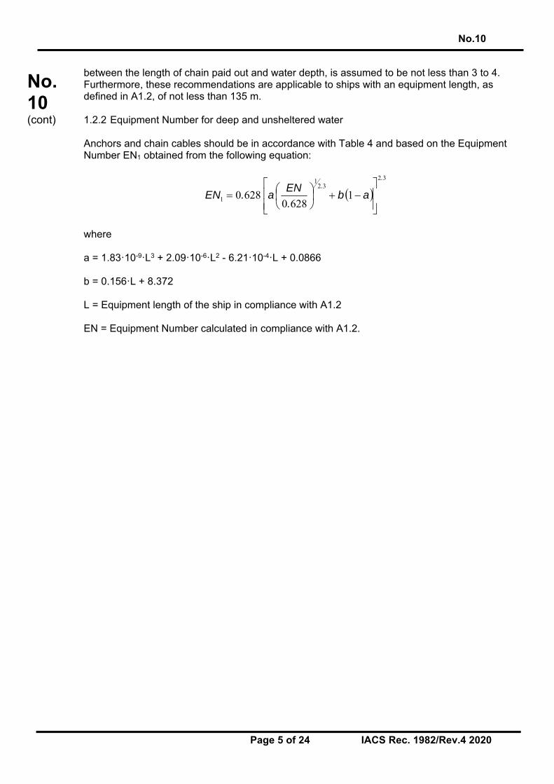
between the length of chain paid out and water depth, is assumed to be not less than 3 to 4. Furthermore, these recommendations are applicable to ships with an equipment length, as defined in A1.2, of not less than 135 m. 1.2.2 Equipment Number for deep and unsheltered water Anchors and chain cables should be in accordance with Table 4 and based on the Equipment Number EN1 obtained from the following equation:
32
321
1 16280
6280
..
ab.
ENa.EN
where a = 1.83ꞏ10-9ꞏL3 + 2.09ꞏ10-6ꞏL2 - 6.21ꞏ10-4ꞏL + 0.0866 b = 0.156ꞏL + 8.372 L = Equipment length of the ship in compliance with A1.2 EN = Equipment Number calculated in compliance with A1.2.

No.10
Page 6 of 24 IACS Rec. 1982/Rev.4 2020
No.10 (cont)
Table 4 Anchoring equipment for ships in unsheltered water with depth up to 120 m
Equipment Number EN1
High holding power stockless bower anchors
Stud link chain cable for bower anchors
Equal to or greater
than Less than Number
Mass per anchor (mA)
Length
Min. diameter (d) Special quality
(Grade 2)
Extra special quality
(Grade 3) (kg) (m) (mm) (mm)
1790 2 14150 1017.5 105 84 1790 1930 2 14400 990 105 84 1930 2080 2 14800 990 105 84 2080 2230 2 15200 990 105 84 2230 2380 2 15600 990 105 84 2380 2530 2 16000 990 105 84 2530 2700 2 16300 990 105 84 2700 2870 2 16700 990 105 84 2870 3040 2 17000 990 105 84 3040 3210 2 17600 990 105 84 3210 3400 2 18000 990 105 84 3400 3600 2 18300 990 106 84 3600 3800 2 19000 990 107 85 3800 4000 2 19700 962.5 108 87 4000 4200 2 20300 962.5 111 90 4200 4400 2 21100 962.5 114 92 4400 4600 2 22000 962.5 117 95 4600 4800 2 22900 962.5 119 97 4800 5000 2 23500 962.5 122 99 5000 5200 2 24000 935 125 102 5200 5500 2 24500 907.5 130 105 5500 5800 2 25000 907.5 133 107 5800 6100 2 25500 880 137 111 6100 6500 2 25700 880 140 113 6500 6900 2 26000 852.5 143 115 6900 7400 2 26500 852.5 147 118 7400 7900 2 27000 825 152 121 7900 8400 2 27500 825 154 123 8400 8900 2 28000 797.5 158 127 8900 9400 2 28900 770 162 132 9400 10000 2 29400 770 - 135 10000 10700 2 29900 770 - 139 10700 11500 2 30600 770 - 143 11500 12400 2 31500 770 - 147 12400 13400 2 33200 770 - 152 13400 14600 2 35000 770 - 157 14600 2 38000 770 - 162
1.2.3 Anchors The bower anchors should be connected to their chain cables and positioned on board ready for use. Anchors should be of the stockless High Holding Power (HHP) type. The mass of the head of a stockless anchor, including pins and fittings, should not be less than 60% of the total mass of the anchor. For the conditions of HHP anchors reference is made to A1.4.1.2 (a) and for the approval and/or acceptance of HHP anchors reference is made to A1.4.1.2 (c).

No.10
Page 7 of 24 IACS Rec. 1982/Rev.4 2020
No.10 (cont)
The mass, per anchor, of bower anchors given in Table 4 is for anchors of equal mass. The mass of individual anchors may vary to 7% of the tabular mass, but the total mass of anchors should not be less than that recommended for anchors of equal mass. Suitable arrangements should be provided for securing the anchors when stowed, see 1.3.3. For manufacture of anchors reference is made to UR W29. For proof testing of the anchors reference is made to A1.4.4.2. 1.2.4 Chain cables for bower anchors Bower anchors should be associated with stud link chain cables of special (Grade 2) or extra special (Grade 3) quality. The total length of chain cable, as given in Table 4 should be reasonably divided between the two bower anchors. For the proof and breaking loads of stud link chain cables reference is made to A1.5.3, Table 4. For manufacture of anchor chain cables reference is made to UR W18. For the installation of the chain cables on board, 1.3 should be observed. 1.2.5 Anchor windlass and chain stopper The application of UR A3 is recommended for the anchor windlass design and testing and the chain stopper design. Notwithstanding the requirements according to UR A3, the windlass unit prime mover should be able to supply for at least 30 minutes a continuous duty pull Zcont, in N, given by: Zcont = 35 d2 + 13.4 mA where d = chain diameter, in mm, as per Table 4 mA = HHP anchor mass, in kg, as per Table 4 In addition to the requirements of UR A3, as far as practicable, for testing purpose the speed of the chain cable during hoisting of the anchor and cable should be measured over 37.5 m of chain cable and initially with at least 120 m of chain and the anchor submerged and hanging free. The mean speed of the chain cable during hoisting of the anchor from the depth of 120 m to the depth of 82.5 m should be at least 4.5 m/min. For the hull supporting structure of anchor windlass and chain stopper reference is made to A1.7. 1.3 Installation of chain cables and anchors on board 1.3.1 Capacity and arrangement of anchor chain locker (a) The chain locker should be of capacity and depth adequate to provide an easy direct
lead of the cables through the chain pipes and a self-stowing of the cables. The chain locker should be provided with an internal division so that the port and starboard chain cables may be fully and separately stowed.

No.10
Page 8 of 24 IACS Rec. 1982/Rev.4 2020
No.10 (cont)
(b) The chain locker boundaries and their access openings should be watertight as necessary to prevent accidental flooding of the chain locker and damaging essential auxiliaries or equipment or affecting the proper operation of the ship.
(c) Adequate drainage facilities of the chain locker should be adopted. 1.3.2 Securing of the inboard ends of chain cables (a) The inboard ends of the chain cables should be secured to the structures by a fastening
able to withstand a force not less than 15% BL nor more than 30% BL (BL = breaking load of the chain cable).
(b) The fastening should be provided with a mean suitable to permit, in case of emergency,
an easy slipping of the chain cables to sea, operable from an accessible position outside the chain locker.
1.3.3 Securing of stowed anchors (a) To hold the anchor tight in against the hull or the anchor pocket, respectively, it is
recommended to fit anchor lashings, e.g., a ‘devil’s claw’. (b) Anchor lashings should be designed to resist a load at least corresponding to twice the
anchor mass plus 10 m of cable without exceeding 40% of the yield strength of the material.
No.10
Page 9 of 24 IACS Rec. 1982/Rev.4 2020
No.10 (cont)
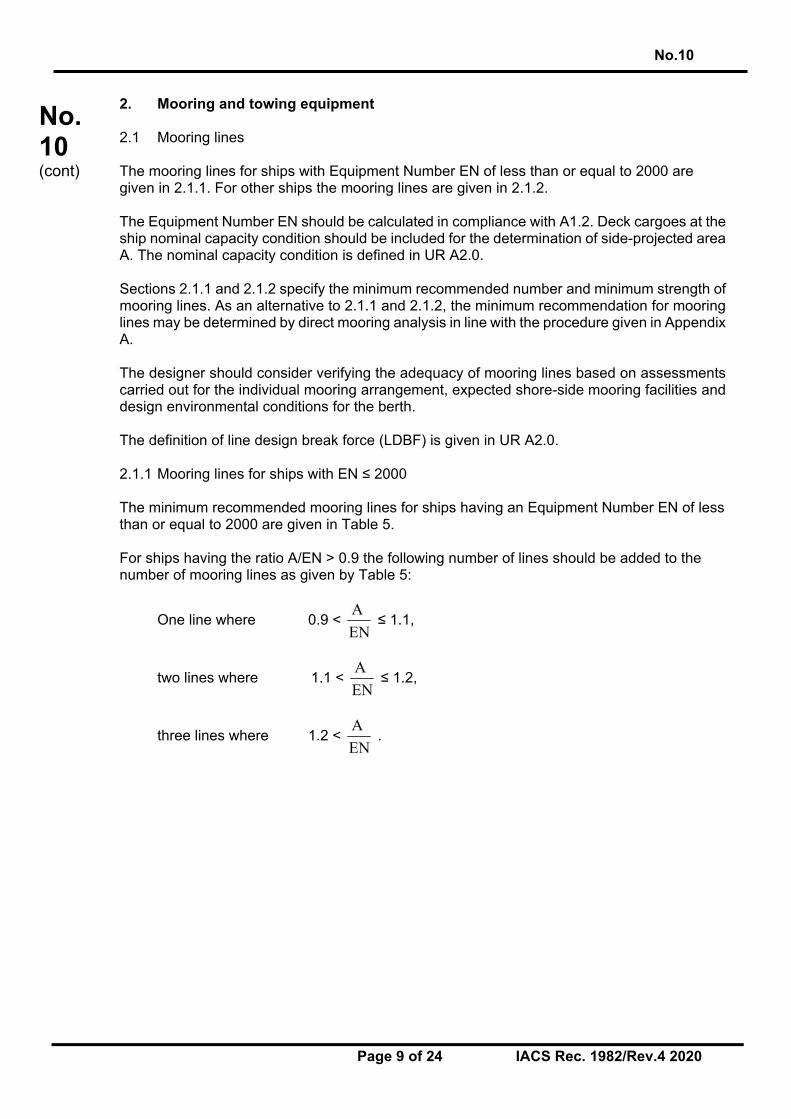
2. Mooring and towing equipment 2.1 Mooring lines The mooring lines for ships with Equipment Number EN of less than or equal to 2000 are given in 2.1.1. For other ships the mooring lines are given in 2.1.2. The Equipment Number EN should be calculated in compliance with A1.2. Deck cargoes at the ship nominal capacity condition should be included for the determination of side-projected area A. The nominal capacity condition is defined in UR A2.0. Sections 2.1.1 and 2.1.2 specify the minimum recommended number and minimum strength of mooring lines. As an alternative to 2.1.1 and 2.1.2, the minimum recommendation for mooring lines may be determined by direct mooring analysis in line with the procedure given in Appendix A. The designer should consider verifying the adequacy of mooring lines based on assessments carried out for the individual mooring arrangement, expected shore-side mooring facilities and design environmental conditions for the berth. The definition of line design break force (LDBF) is given in UR A2.0. 2.1.1 Mooring lines for ships with EN ≤ 2000 The minimum recommended mooring lines for ships having an Equipment Number EN of less than or equal to 2000 are given in Table 5. For ships having the ratio A/EN > 0.9 the following number of lines should be added to the number of mooring lines as given by Table 5:
One line where 0.9 < EN
A ≤ 1.1,
two lines where 1.1 < EN
A ≤ 1.2,
three lines where 1.2 < EN
A .

No.10
Page 10 of 24 IACS Rec. 1982/Rev.4 2020
No.10 (cont)
Table 5 Mooring lines for ships with EN ≤ 2000
EQUIPMENT NUMBER MOORING LINES Exceeding Not exceeding No. of
mooring lines Minimum length
of each line * (m)
Ship design minimum breaking
load (kN)
1
2
3
4
5
50 70 3 80 37 70 90 3 100 40 90 110 3 110 42
110 130 3 110 48 130 150 3 120 53 150 175 3 120 59 175 205 3 120 64 205 240 4 120 69 240 280 4 120 75 280 320 4 140 80 320 360 4 140 85 360 400 4 140 96 400 450 4 140 107 450 500 4 140 117 500 550 4 160 134 550 600 4 160 143 600 660 4 160 160 660 720 4 160 171 720 780 4 170 187 780 840 4 170 202 840 910 4 170 218 910 980 4 170 235 980 1060 4 180 250
1060 1140 4 180 272 1140 1220 4 180 293 1220 1300 4 180 309 1300 1390 4 180 336 1390 1480 4 180 352 1480 1570 5 190 352 1570 1670 5 190 362 1670 1790 5 190 384 1790 1930 5 190 411 1930 2000 5 190 437
* 2.1.3 should be observed
2.1.2 Mooring lines for ships with EN > 2000 The minimum recommended strength and number of mooring lines for ships with an Equipment Number EN > 2000 are given in 2.1.2.1 and 2.1.2.2, respectively. The length of mooring lines is given by 2.1.3. The strength of mooring lines and the number of head, stern, and breast lines (see Note) for ships with an Equipment Number EN > 2000 are based on the side-projected area A1. Side projected area A1 should be calculated similar to the side-projected area A according to A1.2 but considering the following conditions: • The ballast draft should be considered for the calculation of the side-projected area A1.
For ship types having small variation in the draft, like e.g. passenger and RO/RO vessels, the side projected area A1 may be calculated using the summer load waterline.
No.10
Page 11 of 24 IACS Rec. 1982/Rev.4 2020
No.10 (cont)
• Wind shielding of the pier can be considered for the calculation of the side-projected area A1 unless the ship is intended to be regularly moored to jetty type piers. A height of the pier surface of 3 m over waterline may be assumed, i.e. the lower part of the side-projected area with a height of 3 m above the waterline for the considered loading condition may be disregarded for the calculation of the side-projected area A1.
• Deck cargoes at the ship nominal capacity condition should be included for the
determination of side-projected area A1. For the condition with cargo on deck, the summer load waterline may be considered. Deck cargoes may not need to be considered if ballast draft condition generates a larger side-projected area A1 than the full load condition with cargoes on deck. The larger of both side-projected areas should be chosen as side-projected area A1. The nominal capacity condition is defined in UR A2.0.
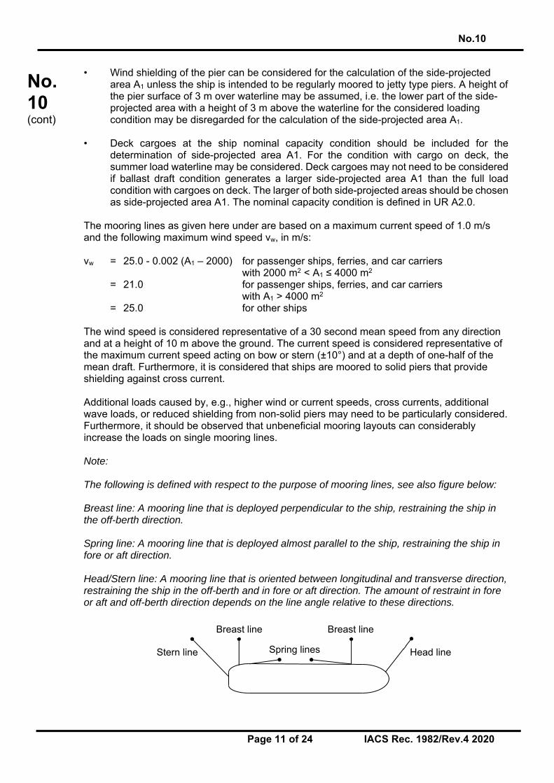
The mooring lines as given here under are based on a maximum current speed of 1.0 m/s and the following maximum wind speed vw, in m/s: vw = 25.0 - 0.002 (A1 – 2000) for passenger ships, ferries, and car carriers with 2000 m2 < A1 ≤ 4000 m2 = 21.0 for passenger ships, ferries, and car carriers with A1 > 4000 m2 = 25.0 for other ships The wind speed is considered representative of a 30 second mean speed from any direction and at a height of 10 m above the ground. The current speed is considered representative of the maximum current speed acting on bow or stern (±10°) and at a depth of one-half of the mean draft. Furthermore, it is considered that ships are moored to solid piers that provide shielding against cross current. Additional loads caused by, e.g., higher wind or current speeds, cross currents, additional wave loads, or reduced shielding from non-solid piers may need to be particularly considered. Furthermore, it should be observed that unbeneficial mooring layouts can considerably increase the loads on single mooring lines. Note: The following is defined with respect to the purpose of mooring lines, see also figure below: Breast line: A mooring line that is deployed perpendicular to the ship, restraining the ship in the off-berth direction. Spring line: A mooring line that is deployed almost parallel to the ship, restraining the ship in fore or aft direction. Head/Stern line: A mooring line that is oriented between longitudinal and transverse direction, restraining the ship in the off-berth and in fore or aft direction. The amount of restraint in fore or aft and off-berth direction depends on the line angle relative to these directions.
Breast line
Stern line Spring lines Head line
Breast line

No.10
Page 12 of 24 IACS Rec. 1982/Rev.4 2020
No.10 (cont)
2.1.2.1 Ship design minimum breaking load The ship design minimum breaking load, in kN, of the mooring lines should be taken as:
MBLSD = 0.1 ꞏ A1 + 350
The ship design minimum breaking load may be limited to 1275 kN (130 t). However, in this case the moorings are to be considered as not sufficient for environmental conditions given by 2.1.2. For these ships, the acceptable wind speed vw*, in m/s, can be estimated as follows:
𝑣∗ 𝑣 ∙𝑀𝐵𝐿∗
𝑀𝐵𝐿
where vw is the wind speed as per 2.1.2, MBLSD* the ship design minimum breaking load of the mooring lines intended to be supplied and MBLSD the ship design minimum breaking load as recommended according to the above formula. However, the ship design minimum breaking load should not be taken less than corresponding to an acceptable wind speed of 21 m/s:
𝑀𝐵𝐿∗21𝑣
⋅ 𝑀𝐵𝐿
If lines are intended to be supplied for an acceptable wind speed vw* higher than vw as per 2.1.2, the ship design minimum breaking load should be taken as:
𝑀𝐵𝐿∗𝑣∗
𝑣⋅ 𝑀𝐵𝐿
2.1.2.2 Number of mooring lines The total number of head, stern and breast lines (see Note in 2.1.2) should be taken as:
n = 8.3ꞏ10-4 ꞏ A1 + 6 For oil tankers, chemical tankers, bulk carriers, and ore carriers the total number of head, stern and breast lines should be taken as:
n = 8.3ꞏ10-4 ꞏ A1 + 4 The total number of head, stern and breast lines should be rounded to the nearest whole number. The number of head, stern and breast lines may be increased or decreased in conjunction with an adjustment to the ship design minimum breaking load of the lines. The adjusted ship design minimum breaking load, MBLSD**, should be taken as: MBLSD** = 1.2 ꞏ MBLSD ꞏ n/n** ≤ MBLSD for increased number of lines, MBLSD** = MBLSD ꞏ n/n** for reduced number of lines. where MBLSD is MBLSD or MBLSD* specified in 2.1.2.1, as appropriate, n** is the increased or decreased total number of head, stern and breast lines and n the number of lines for the considered ship type as calculated by the above formulas without rounding.

No.10
Page 13 of 24 IACS Rec. 1982/Rev.4 2020
No.10 (cont)
Vice versa, the ship design minimum breaking load of head, stern and breast lines may be increased or decreased in conjunction with an adjustment to the number of lines. The total number of spring lines (see Note in 2.1.2) should be taken not less than: Two lines where EN < 5000, Four lines where EN ≥ 5000. The ship design minimum breaking load of spring lines should be the same as that of the head, stern and breast lines. If the number of head, stern and breast lines is increased in conjunction with an adjustment to the ship design minimum breaking load of the lines, the number of spring lines should be taken as follows, but rounded up to the nearest even number.
nS* = MBLSD/MBLSD** ꞏ nS
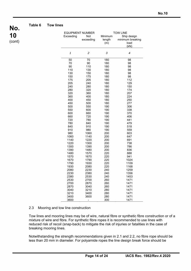
where MBLSD is MBLSD or MBLSD* specified in 2.1.2.1, as appropriate, nS is the number of spring lines as given above and nS* the increased number of spring lines. 2.1.3 Length of mooring lines The length of mooring lines for ships with EN of less than or equal to 2000 may be taken from Table 5. For ships with EN > 2000 the length of mooring lines may be taken as 200 m. The lengths of individual mooring lines may be reduced by up to 7% of the above given lengths, but the total length of mooring lines should not be less than would have resulted had all lines been of equal length. 2.2 Tow line The tow lines are given in Table 6 and are intended as own tow line of a ship to be towed by a tug or other ship. For the selection of the tow line from Table 6, the Equipment Number EN should be taken according to 2.1. The designer should consider verifying the adequacy of towing lines based on assessments carried out for the individual towing arrangement.
No.10
Page 14 of 24 IACS Rec. 1982/Rev.4 2020
No.10 (cont)
Table 6 Tow lines
EQUIPMENT NUMBER TOW LINE Exceeding Not
exceeding Minimum
length (m)
Ship design minimum breaking
load (kN)
1
2
3
4
50 70 180 98 70 90 180 98 90 110 180 98
110 130 180 98 130 150 180 98 150 175 180 98 175 205 180 112 205 240 180 129 240 280 180 150 280 320 180 174 320 360 180 207 360 400 180 224 400 450 180 250 450 500 180 277 500 550 190 306 550 600 190 338 600 660 190 370 660 720 190 406 720 780 190 441 780 840 190 479 840 910 190 518 910 980 190 559 980 1060 200 603
1060 1140 200 647 1140 1220 200 691 1220 1300 200 738 1300 1390 200 786 1390 1480 200 836 1480 1570 220 888 1570 1670 220 941 1670 1790 220 1024 1790 1930 220 1109 1930 2080 220 1168 2080 2230 240 1259 2230 2380 240 1356 2380 2530 240 1453 2530 2700 260 1471 2700 2870 260 1471 2870 3040 260 1471 3040 3210 280 1471 3210 3400 280 1471 3400 3600 280 1471 3600 - 300 1471
2.3 Mooring and tow line construction Tow lines and mooring lines may be of wire, natural fibre or synthetic fibre construction or of a mixture of wire and fibre. For synthetic fibre ropes it is recommended to use lines with reduced risk of recoil (snap-back) to mitigate the risk of injuries or fatalities in the case of breaking mooring lines. Notwithstanding the strength recommendations given in 2.1 and 2.2, no fibre rope should be less than 20 mm in diameter. For polyamide ropes the line design break force should be
No.10
Page 15 of 24 IACS Rec. 1982/Rev.4 2020
No.10 (cont)
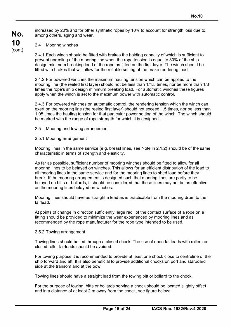
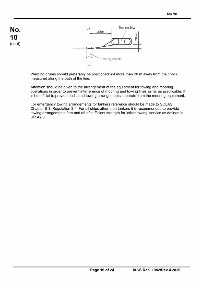
increased by 20% and for other synthetic ropes by 10% to account for strength loss due to, among others, aging and wear. 2.4 Mooring winches 2.4.1 Each winch should be fitted with brakes the holding capacity of which is sufficient to prevent unreeling of the mooring line when the rope tension is equal to 80% of the ship design minimum breaking load of the rope as fitted on the first layer. The winch should be fitted with brakes that will allow for the reliable setting of the brake rendering load. 2.4.2 For powered winches the maximum hauling tension which can be applied to the mooring line (the reeled first layer) should not be less than 1/4.5 times, nor be more than 1/3 times the rope's ship design minimum breaking load. For automatic winches these figures apply when the winch is set to the maximum power with automatic control. 2.4.3 For powered winches on automatic control, the rendering tension which the winch can exert on the mooring line (the reeled first layer) should not exceed 1.5 times, nor be less than 1.05 times the hauling tension for that particular power setting of the winch. The winch should be marked with the range of rope strength for which it is designed. 2.5 Mooring and towing arrangement 2.5.1 Mooring arrangement Mooring lines in the same service (e.g. breast lines, see Note in 2.1.2) should be of the same characteristic in terms of strength and elasticity. As far as possible, sufficient number of mooring winches should be fitted to allow for all mooring lines to be belayed on winches. This allows for an efficient distribution of the load to all mooring lines in the same service and for the mooring lines to shed load before they break. If the mooring arrangement is designed such that mooring lines are partly to be belayed on bitts or bollards, it should be considered that these lines may not be as effective as the mooring lines belayed on winches. Mooring lines should have as straight a lead as is practicable from the mooring drum to the fairlead. At points of change in direction sufficiently large radii of the contact surface of a rope on a fitting should be provided to minimize the wear experienced by mooring lines and as recommended by the rope manufacturer for the rope type intended to be used. 2.5.2 Towing arrangement Towing lines should be led through a closed chock. The use of open fairleads with rollers or closed roller fairleads should be avoided. For towing purpose it is recommended to provide at least one chock close to centreline of the ship forward and aft. It is also beneficial to provide additional chocks on port and starboard side at the transom and at the bow. Towing lines should have a straight lead from the towing bitt or bollard to the chock. For the purpose of towing, bitts or bollards serving a chock should be located slightly offset and in a distance of at least 2 m away from the chock, see figure below:
No.10
Page 16 of 24 IACS Rec. 1982/Rev.4 2020
No.10 (cont)
Warping drums should preferably be positioned not more than 20 m away from the chock, measured along the path of the line. Attention should be given to the arrangement of the equipment for towing and mooring operations in order to prevent interference of mooring and towing lines as far as practicable. It is beneficial to provide dedicated towing arrangements separate from the mooring equipment. For emergency towing arrangements for tankers reference should be made to SOLAS Chapter II-1, Regulation 3-4. For all ships other than tankers it is recommended to provide towing arrangements fore and aft of sufficient strength for ‘other towing’ service as defined in UR A2.0.
Offse
t≥2m
Towing chock
Towing bitt
No.10
Page 17 of 24 IACS Rec. 1982/Rev.4 2020
No.10 (cont)
3. Anchoring and mooring equipment for fishing vessels 3.1 Anchoring equipment 3.1.1 Application The following provisions apply to fishing vessels operating in unrestricted service. Reduction of equipment may be considered for fishing vessels operating in restricted services. 3.1.2 General recommendations (a) Each ship should be provided with anchoring equipment designed for quick and safe
operation in all foreseeable service conditions. Anchor equipment should consist of anchors, anchor chain cables and a windlass or other arrangements for dropping and weighing the anchors and for holding the ship at anchor.
(b) The equipment of anchors and chain cables given in Table 7 is based on the Equipment
Number EN which should be calculated as follows:
EN = Δ2/3 + 2Bh + 0.1A where Δ = moulded displacement, in t, to the maximum design waterline, B = greatest moulded breadth, in m, h = effective height, in m, from the maximum design waterline to the top of the
uppermost house. = a + Σhi
a = distance, in m, from the maximum design waterline to the upper edge of the
uppermost complete deck at the side amidships, hi = height, in m, on the centreline of each tier of houses having breadth greater than
B/4. For the lowest tier h is measured at centreline from the upper deck or from a notional deck line where there is local discontinuity in the upper deck. When calculating h, sheer and trim can be ignored. A = side-projected area, in m2, of the hull, within the length of the ship between
perpendiculars, and of superstructures and houses above the maximum design waterline having a width greater than B/4.
Screens and bulwarks more than 1.5 m in height should be regarded as parts of houses when determining h and A. 3.1.3 Particular recommendations (a) For ships below 40 m in length the anchor chain may be replaced with wire ropes of
equal strength of the tabular anchor cables of Grade 1. Wire ropes of trawl winches complying with this recommendation may be used as anchor chain cables.
No.10
Page 18 of 24 IACS Rec. 1982/Rev.4 2020
No.10 (cont)
(b) When wire ropes are substituted for anchor chain cables then: (i) the length of the ropes should be equal to 1.5 times the corresponding tabular
length of chain cable (col. 5 of Table 7), (ii) a short length of chain cable should be fitted between the wire rope and anchor
having a length of 12.5 m or the distance between anchor in stowed position and winch, whichever is less,
(iii) all surfaces being in contact with the wire should be rounded with a radius of not
less than 10 times the wire rope diameter (including stem).
(c) High holding power anchors of approved design may be used as bower anchors. The mass of each such anchor may be 75% of the tabular mass for ordinary stockless bower anchors.
(d) The tabular anchor equipment may be increased for ships fishing in very rough waters.
No.10
Page 19 of 24 IACS Rec. 1982/Rev.4 2020
No.10 (cont)
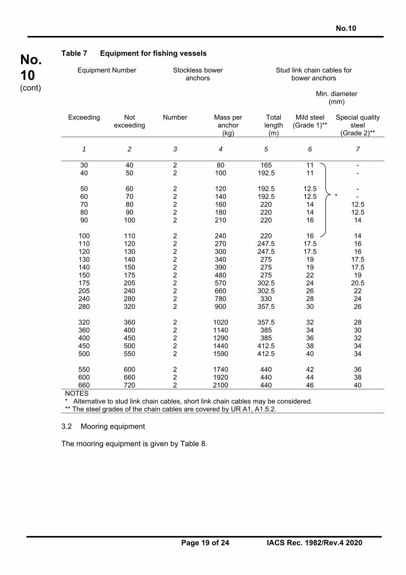
Table 7 Equipment for fishing vessels
Equipment Number Stockless bower anchors
Stud link chain cables for bower anchors
Min. diameter (mm)
Exceeding Not
exceeding Number Mass per
anchor (kg)
Total length
(m)
Mild steel (Grade 1)**
Special quality steel
(Grade 2)** 1
2
3
4
5
6
7
30 40 2 80 165 11 - 40 50 2 100 192.5 11 -
50 60 2 120 192.5 12.5 - 60 70 2 140 192.5 12.5 * - 70 80 2 160 220 14 12.5 80 90 2 180 220 14 12.5 90 100 2 210 220 16 14
100 110 2 240 220 16 14 110 120 2 270 247.5 17.5 16 120 130 2 300 247.5 17.5 16 130 140 2 340 275 19 17.5 140 150 2 390 275 19 17.5 150 175 2 480 275 22 19 175 205 2 570 302.5 24 20.5 205 240 2 660 302.5 26 22 240 280 2 780 330 28 24 280 320 2 900 357.5 30 26
320 360 2 1020 357.5 32 28 360 400 2 1140 385 34 30 400 450 2 1290 385 36 32 450 500 2 1440 412.5 38 34 500 550 2 1590 412.5 40 34
550 600 2 1740 440 42 36 600 660 2 1920 440 44 38 660 720 2 2100 440 46 40
NOTES * Alternative to stud link chain cables, short link chain cables may be considered. ** The steel grades of the chain cables are covered by UR A1, A1.5.2.
3.2 Mooring equipment The mooring equipment is given by Table 8.

No.10
Page 20 of 24 IACS Rec. 1982/Rev.4 2020
No.10 (cont)
Table 8 Mooring lines for fishing vessels Equipment Number Mooring lines
Exceeding Not exceeding Number Minimum length of
each line (m) Ship design minimum
breaking load (kN) 1
2
3
4
5
30 40 2 50 29 40 50 2 60 29 50 60 2 60 29 60 70 2 80 29 70 80 2 100 34
80 90 2 100 36.8 90 100 2 110 36.8
100 110 2 110 39 110 120 2 110 39 120 130 2 110 44
130 140 2 120 44 140 150 2 120 49 150 175 2 120 54 175 205 2 120 59 205 240 2 120 64
240 280 3 120 71 280 320 3 140 78 320 360 3 140 85.8 360 400 3 140 93 400 450 3 140 101
450 500 3 140 108 500 550 4 160 113 550 600 4 160 118 600 660 4 160 123 660 720 4 160 127

No.10
Page 21 of 24 IACS Rec. 1982/Rev.4 2020
No.10 (cont)
Appendix A Direct mooring analyses
1. General
As an alternative to the prescriptive approach, direct mooring analysis may be performed to determine the necessary mooring restraint, i.e. number and strength of mooring lines. Direct analyses allow to optimize mooring equipment and arrangement for the individual ship and the port mooring facilities typical for the considered ship type and size.
2. Documentation The calculations should be documented in a report. The report should include all assumptions made in calculations for the finally chosen mooring equipment, including lines, and its arrangement, reflected in the mooring arrangement plan as required by UR A2.
3. Analysis methodology Three dimensional quasi-static calculations should be performed to determine the acting mooring line forces. As a minimum, loads from wind and current should be accounted for in the analysis. Geometrical and material nonlinearities of mooring lines and fenders or breasting dolphins should be considered. An iterative calculation procedure should be applied to arrive at a converged solution with forces acting on mooring lines and on fenders or breasting dolphins being in equilibrium with forces and moments applied to the ship.
4. Environmental conditions
Mooring line forces should be calculated for environmental conditions given in 2.1.2 [of IACS Rec. 10]. Additional loads, e.g. wave loads or cross currents, or increased wind and current loads may be considered for certain ship types or for specific ports intended to be regularly called.
5. Steps to be taken in a direct mooring analysis
Direct assessment of mooring forces and determination of the necessary number and strength of mooring lines comprise the following steps:
a) Determine port mooring facilities representative for the considered ship type and size
b) Determine shipboard mooring equipment and arrangement c) Determine mooring line type(s) to be used d) Determine mooring layout(s) to be assessed e) Determine ship loading condition(s) to be assessed f) Select or determine wind and current drag coefficients g) Determine wind and current forces and moments h) Compute forces acting on all mooring line i) Determine necessary strength of mooring lines j) If strength of mooring lines should be altered, modify steps b), c) and/or d) with or
without changing the number of mooring lines and repeat steps h) and i)

No.10
Page 22 of 24 IACS Rec. 1982/Rev.4 2020
No.10 (cont)
5.1. Port mooring facilities Characteristics of port mooring facilities have strong influence on the resulting mooring line forces. Mooring analysis should be performed for port mooring facilities representative for the considered ship type and size, i.e. type of berth, type and arrangement of hooks/bollards, type and arrangement of fenders or breasting dolphins and height of pier above waterline. Fenders or breasting dolphins in many cases may not affect the critical mooring line loads. Hence, initially, generic fender or dolphin arrangements and infinitely stiff load-deformation characteristics may be considered. If no fender or dolphin loads occur for load cases yielding the critical mooring line loads, more specific fender or dolphin arrangements and characteristics may be omitted. If there are substantially different port mooring facilities typically encountered by the considered ship type, additional calculations should be performed to consider these variations.
5.2. Shipboard mooring equipment and arrangement The mooring equipment and arrangement need to be chosen for the mooring analysis, i.e. location of mooring decks and location of mooring winches and fairleads. As a starting point, mooring equipment for the number of lines as determined by the prescriptive approach may be chosen, see 2.1.2.2 [of IACS Rec. 10].
5.3. Mooring lines The mooring analysis should apply the mooring line type(s) intended to be supplied with the vessel. The geometrical and material nonlinearities of the mooring lines should be considered by the mooring analysis. Load-deflection characteristics of mooring lines can be taken from data sheets of rope manufacturers. If given, characteristics of the broken-in ropes should be applied. To achieve a good distribution of mooring line forces, mooring line type and characteristics should be at least same for lines in the same service, e.g. for head and stern lines, breast lines and spring lines. For very stiff mooring lines, e.g. made of steel or high modulus synthetic fibers, the use of elastic tails should be considered to enhance the elasticity in the mooring system and taken into account for the mooring analysis.
5.4. Mooring layout
For the assessment of forces acting on mooring lines, a realistic mooring layout needs to be assumed, i.e. for each mooring line it needs to be determined from which bollard or winch, along which path, through which fairlead it is led and to which shoreside hook or bollard it is connected. Inboard parts of the mooring lines (between fairlead and shipboard fixation point) contribute to the elongation behavior of the line and should be included in the analysis. The maximum number of lines connected to one shore mooring point needs to be limited to not load the shore side mooring points unrealistically high. For multi-purpose piers the number of lines per shore bollard should be limited to three. For other types of berths, the number mooring lines per shore mooring point is also
No.10
Page 23 of 24 IACS Rec. 1982/Rev.4 2020
No.10 (cont)
limited, e.g., by the available number of hooks. Reasonable assumptions should be made based on typical berth types encountered by the considered ship type. Alternative mooring layouts should also be assessed, considering possible and reasonable options to moor the ship to the assumed port mooring facilities. Also, a different position of the ship relative to the shoreside mooring bollards/hooks should be assessed to find the critical mooring line loads for the normal operation of the ship. Exemptions may be given to e.g. tankers, LNG carriers or ferries if typically moored in the same position relative to the shoreside mooring facilities.
5.5. Loading conditions
Mooring line forces should be calculated for loading conditions given in 2.1.2 [of IACS Rec. 10].
5.6. Wind and current drag coefficients
To calculate the wind and current forces and moments acting on the ship, wind and current drag coefficients are needed for the considered ship type, size and loading condition. Drag coefficients should be as specific as possible for the considered ship and loading conditions. There are different sources for drag coefficients. Some Industry Guidelines provide drag coefficients for tankers and LNG carriers which can be applied. Due to the similarity of hull forms and superstructures, these coefficients may also be used for bulk carriers and ore carriers. For other ship types drag coefficients may be taken from the literature, if available, or can be determined by CFD calculations or model tests. CFD calculations are to be justified with suitable validation and sensitivity studies. There are some effects that can influence the drag coefficients, i.e. blockage (limited under keel clearance, solid quay walls), ship draft and wind shielding by solid quays and buildings or cargo stored on quays (e.g. container stacks). Effects from blockage and ship draft can only be accounted for by appropriate coefficients. Drag coefficient should be chosen or determined for realistic water depth to draft ratios and for the considered ship draft(s). Some Industry Guidelines provide current drag coefficients for ballast and loaded draft conditions and for different water depth to draft ratios. Wind shielding effects are typically not considered by the wind drag coefficients. The effect of wind shielding of solid quays may be considered by an equivalent reduction of the lateral wind area of the ship. Shielding by buildings or cargo stored on quays should not be considered as their presence is imponderable.
5.7. Calculation of wind and current forces and moments Wind and current forces and moments can be calculated for the given environmental conditions with the geometrical particulars of the considered ship and the selected drag coefficients. Usually, the forces in longitudinal and transversal directions as well as the moment about the vertical ship axis (yaw) are calculated. Wind forces and moments should be calculated for all directions in intervals of preferably 15°, but not more than 30°. Current forces and moments should be calculated for selected directions as per 2.1.2 [of IACS Rec. 10]. For ships regularly moored to non-solid piers or jetties, cross current may need to be considered in addition.
No.10
Page 24 of 24 IACS Rec. 1982/Rev.4 2020
No.10 (cont)
5.8. Calculation of mooring line forces For all considered scenarios and all combinations of applied environmental conditions, the maximum mooring line force should be determined for groups of lines in the same service. In case of all lines are intended to be attached to winches, brake rendering can be considered to better distribute line loads among all lines in a group of lines in the same service. Then, the average mooring line force of a group of lines may be determined and taken as mooring line force used to determine the necessary strength of the mooring lines according to section 5.9.
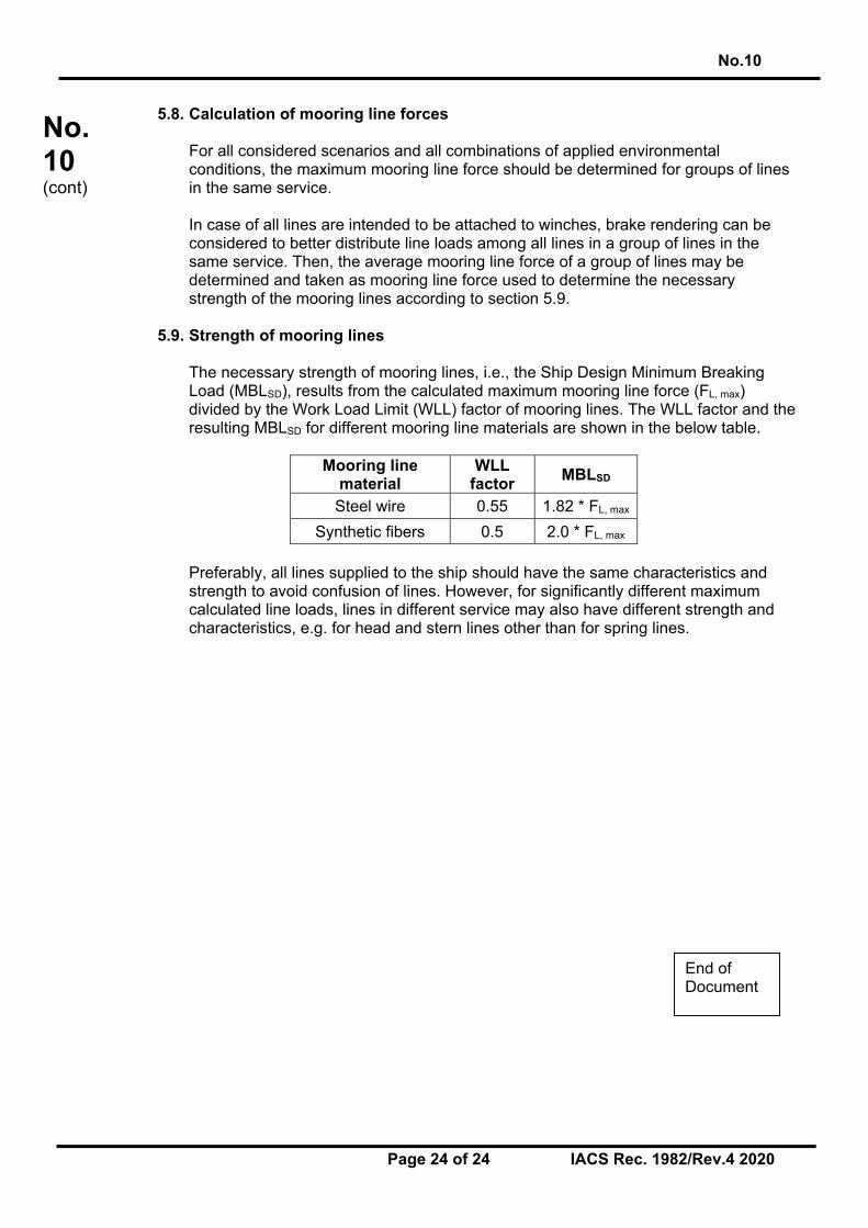
5.9. Strength of mooring lines The necessary strength of mooring lines, i.e., the Ship Design Minimum Breaking Load (MBLSD), results from the calculated maximum mooring line force (FL, max) divided by the Work Load Limit (WLL) factor of mooring lines. The WLL factor and the resulting MBLSD for different mooring line materials are shown in the below table.
Mooring line material
WLL factor
MBLSD
Steel wire 0.55 1.82 * FL, max
Synthetic fibers 0.5 2.0 * FL, max Preferably, all lines supplied to the ship should have the same characteristics and strength to avoid confusion of lines. However, for significantly different maximum calculated line loads, lines in different service may also have different strength and characteristics, e.g. for head and stern lines other than for spring lines.
End of Document