
Mooring Buoy Planning Guide - Wharram Builders and Friends
92
Mooring Buoy Planning Guide Poly Rope Buoy Weight Eye Bolt
-
Upload
khangminh22 -
Category
Documents
-
view
1 -
download
0
Transcript of Mooring Buoy Planning Guide - Wharram Builders and Friends

Mooring BuoyPlanning Guide
Poly Rope
Buoy
Weight
Eye Bolt

AcknowledgmentsThe Project AWARE Foundation and PADI International Resort Association (PIRA) have worked to develop this
booklet on mooring buoys to address some of the issues relating to the planning, installation and maintenance
of a mooring buoy program.
The following pages are excerpts and/or complete documents from many sources and contributors. We wish
to express gratittude to the leaders and experts in their fields, for their time and contributions to future mooring
buoy programs around the world, and to all who contributed in one way or another.
A special “thanks” goes out to Athline Clark, John and Judy Halas, Center for Marine Conservation, David
Merrill and Jeff Fisher for their contributions to this document. An additonal “thanks” goes out to Joy Zuehls,
Jeanne Bryant, Dail Schroeder, Joe De La Torre, Greg Beatty and Kelsey of PADI Americas for their hard work on
the production, designs, illustrations and typography of this document.
Mooring Buoy Planning GuidePublished by International PADI, Inc.30151 Tomas StreetRancho Santa Margarita, CA 92688-2125
PRODUCT NO. 19300 (Rev. 3/05) Version 1.2 © International PADI, Inc. 1996-2005All right reserved.

IntroductionIt is estimated that 40 percent of the world’s coral reefs are likely to seriously degrade, perhaps even beyond
recovery, by the year 2015. Population increase in coastal areas adjacent to reefs, waste disposal, pollution,
sedimentation, overfishing, coral mining, tourism and curio collection all damage coral reefs. These are serious
problems with complex solutions. Other problems, serious but smaller in scale, also face the reefs. Anchors, for
example, pose a threat that can easily be seen by recreational divers: they simply rip coral reefs apart. Deter-
mined individuals and organized local groups can help solve this and similar problems.
Since the early 1970s, pioneering members of the dive community, whose livelihoods depend on the quality
of the reefs in their area, have championed the installation and use of mooring buoys to lessen the harmaful
effects of anchors on coral reefs. Over the years the movement has gathered momentum and is now widely
accepted as an effective solution to one aspect of coral reef degradation.
The mooring buoy concept is simple: install a mooring buoy close to or over a site where boats traditionally
anchor. Instead of anchoring, boat users tie off to the mooring and this lessens damage. Mooring buoys can also
be used as an ongoing aid to coral reef conservation. They may be used to zone an area for a particular activity
and help avoid conflicts between, for example, fishermen and divers. If an area is being overused, moorings can
easily be removed, placed elsewhere, and replaced at the original site when it has had adequate recovery time.
Installing mooring buoys requires professional expertise at all phases of project planning and implementa-
tion. Several factos must be considered and in many situations, the scope of the project will demand cooperative
effort between relevant government agencies and interested parties. The anticipated use of the project site
determines the number, location and type of moorings deployed. Funding for installation and ongoing mainte-
nance, a crucial element of any mooring buoy system, must be organized. Educational programs must be
undertaken to ensure that private users understand what the buoys are for and adequate arrangements for
enforcement of the project or site regulations need to be in place.
Despite the effort involved in a mooring buoy planning and installation project, the benefits far outweigh
the work involved. Mooring buoy projects are firmly fixed as a healthy element in the future of the world’s coral
reefs. This booklet can be used as a valuable tool when developing a mooring buoy program. It outlines the
components that need to be considered when taking on such a project.We hope that you will use this booklet as
a guideline in initiating the process of mooring installations.

Table of Contents
Section I: The Importance of Coral Reefs
Section II: Types of Mooring Buoy Systems
Section III: The Benefits of Mooring Buoys
Section IV: Management and Liability Considerations
Section V: Case Studies of Mooring Buoy Programs
Section VI: Getting Started on a Mooring Buoy Project of Your Own

1-1
Section I
The Importance of Coral Reefs
OverviewIn this section you will find an introduction to the threats facing the
aquatic ecosystem, specifically the coral reefs. A brief summary of the
importance of the coral reefs and the interactions between people
and corals will also be covered in this section.
ContributionsReefs at Risk, coral reefs, human use and climate change, a
programme of action, Oct. 1993.
Contents1. A worldwide threat of ecological collapse
2. The living reef
3. People and corals
4. The threats and the causes

1-2
Reef at RiskCoral reefs, human use andclimate change1. A worldwide threat of ecological collapseFor once, the popular mythology contains some truth.
Coral reefs can be likened to tropical forests in certain
important ways. Both reefs and jungles are biologi-
cally diverse in comparison with other ecosystems.
Reefs are an essential supplier of protein to subsis-
tence communities; a valuable currency earner for
low-income countries through exploitation of their
resources and through tourism; a protector of land;
and a naturalist’s paradise.
Unfortunately, the analogy is equally apt with
respect to the dark side of the picture; though we have
barely tapped coral reefs for the knowledge to be
gained or the natural products of interest to society,
reefs are coming under increasing threat, almost
exclusively because of human activities.
Around the world coral reefs have suffered a
dramatic decline in recent years. About IO% may
already have been degraded beyond recovery. An-
other 30% are likely to decline seriously within the
next 20 years. It has been predicted that more than
two-thirds of the world’s coral reefs may collapse
ecologically within the lifetime of our grandchildren,
unless we implement effective management of these
resources as an urgent priority.
The reefs identified as being at greatest risk are in
South and Southeast Asia, East Africa, and the
Caribbean. An IUCN survey during 1984-1989 found
that people had significantly damaged or destroyed
reefs in 93 countries.
Coral reefs and biodiversityCoral forms range from compact brain corals found in
areas of high wave energy, through heavy branching
and plate corals in deeper water, off the reef edge, to
smaller finely branched corals found behind the reef
crest and in the lagoon.
Coral reefs are generally divided into four main
types: atolls, barrier reefs, platform reefs and fringing
reefs. Atolls, where reefs form a ring around a lagoon,
are mainly found in the Indian and Pacific Oceans.
In the Pacific they are grouped into long island chains
such as those of Micronesia and Central Polynesia.
Barrier reefs are separated from the mainland by a
deep channel or lagoon, in which are found platform
reefs. Fringing reefs are directly attached to land or
separated only by a shallow lagoon.
On an individual reef, the total count of fish
species and smaller marine organisms may exceed
several thousand, but the number of individual coral
species is much lower.
The Indo-Pacific has some 700 reef building coral
species, many times more than the tropical Atlantic
(with some 35). In general, reefs in the Indo-Pacific
differ from those of the Atlantic by having many more
coral species, and by supporting much richer animal
communities on their intertidal reef flats. The centre
of coral diversity is the Southeast.
�Asia region of the Indo-Pacific, and over 400
species of hard coral are believed to occur in Philip-
pine waters.
Moving away from this region, coral diversity
declines. Nevertheless, over 200 coral species are
recorded from the northern and central Red Sea,
about 200 from Madagascar and Chagos. The east
coast of the Malaysian peninsula has 174 identified
species, southeast India about 117, the Gulf of Thai-
land some 60, and the Persian Gulf 57.
2. The living reefCorals are colonial animals that produce a calcium
carbonate (aragonite) skeleton beneath their film of
living tissue. Reef-building or hermatypic corals
contain within their tissues symbiotic algae, so that
the colony actually functions as a plant-animal
combination. A coral reef is the physical structure
created by the growth of the reef community.
When a coral colony dies through storm damage,
SEA REEF FRONT REEF CREST REEF FLAT BEACH
COMPACT CORALS
SMALL CORALS
SEAGRASS
HEAVY BRANCHING CORALS
BRANCHING AND PLATE CORALS
De
pth
in
me
tre
s
5
10
15
Figure 1

1-3
Limits to abundanceThe living matter produced by the plants and algae in
a coral reef system, its gross primary productivity, is
between 30 and 250 times as great as that of the open
ocean. While the productivity of tropical oceans is
very low (18-50 grammes of carbon per sq. metre in a
year), coral reefs produce 1500-5000g. The reason for
the higher productivity of reefs is that corals and coral
communities recycle nutrients such as nitrate and
phosphate which are in limited supply in open-ocean
surface waters.
But it would be a mistake to assume that the high
productivity of a coral reef provides an automatic
surplus of potential food. The primary production -
the amount of energy produced by photosynthesis - is
very nearly balanced by the reefs whole consumption.
Net productivity is often only 2-3% of the gross, and
only slightly higher than the net productivity per unit
area in the surrounding ocean water. The highly
productive coral communities also occupy only a
fraction of the surface of a coral reef system.
So the amount of organic matter that can be taken
out of the reef whether by harvesting or other means
without causing damage to the community remains
severely limited. One calculation puts the amount
that could be extracted on a sustainable basis each
year at less than 50 grammes of carbon per square
metre (less that 50 tonnes per km2), an extremely
small figure by agricultural standards. Modern rice-
growing techniques can produce yields of over 400
tonnes per km2).
Reef growth and the environmentReef corals do best in shallow, warm, clear oceanic
water. Therefore reefs are most abundant away from
large land masses, which produce too much freshwa-
ter runoff and sediments. Coral reefs are found in
warm subtropical or tropical oceans where the annual
temperature range is 20-30C. Nevertheless, reefs in
the Florida Keys (USA) grow at 18C, and temperatures
above 33C are tolerated by healthy coral communities
in the northern Great Barrier Reef and the Persian
Gulf. But when air and water temperatures in the
Gulf fell to 10C in 1968, almost all the inshore coral
colonies died. Even small temperature increases above
the normal local maximum temperature may result in
coral bleaching, which occurs when the symbiotic
algae are expelled by the polyps in response to stress.
(See Figure 2.)
Though corals can be found to a depth of 100m,
is broken by the action of living organisms, or is eaten
by a parrotfish, the skeleton becomes the basic mate-
rial forming the reef structure. Dead coral branches
form the substrate on which new corals grow, while the
fragments are cemented together by the action of
coralline algae. The fragmented skeletons form the
sand which contributes to reef growth by filling in the
space between the larger fragments of dead coral
skeletons. Continual deposition allows a reef to keep
pace with rising sea-level by upward growth.
Coral species, coral communities and the reef
structure differ widely in the growth rates. Among the
species, branching and staghorn corals can add more
than 10 cm a year to their branches. Massive corals
grow at about a tenth of that rate, or roughly 10 mm a
year. As for vertical reef growth, in Mauritius it
reaches as much as 10 mm a year, but no more than a
few millimetres for some reefs in the Red Sea.
Coral reefs depend very much on the prevailing
environmental conditions. Some reefs did not survive
the rapid sea-level changes experienced during the ice
ages. We find many dead reefs drowned in earlier
periods, or stranded above present sea-level. But under
the right conditions coral colonies can survive for
centuries.
Although we think of reefs primarily in terms of
corals, they are home to a myriad of other organisms,
all of them important to the overall functioning of the
community, and all of them sensitive to climate and
environmental conditions. Coating the exposed sand
grains of coral lagoon are microscopic algae and
bacteria grazed by mollusks, crustaceans, sea cucum-
bers, sea urchins and sediment-eating fish. “Turf’ algae
cover all bare surfaces and are grazed by large popula-
tions of fish when the tide is rising. Many of these
animals provide food for fishers and gleaners of reefs.
Other organisms play an important role in building
the reef by breaking down the calcium carbonate
skeletons of larger organisms to produce sediments.
Some organisms, like sponges, worms and mollusks,
bore into the coral skeletons so that they become
fragile and fracture in strong waves. Grazing fish and
sea urchins at the surface produce large quantities of
sediment.
A major role in the functioning and survival of
coral reefs is played by the tiny plants and animals
known as plankton (from the Greek for “floating”),
which provide food for sedentary reef corals and other
animals. The life cycle of many corals and other
species, including fish, involves a larval planktonic
stage, enabling them to disperse over long distances
and between different reef areas.

1-4
reef-building corals do not grow well below 20-3Om
because their symbiotic algae depend on sunlight for
photosynthesis. Too much fresh water can kill
corals; heavy runoff has wiped out shallow reefs off
the north coast of Jamaica. So have hurricanes. But
the reefs’ ultimate chances of survival are determined
by the fact that they often coexist with large human
populations in the tropics. This could doom many to
extinction.
Because coral reefs grow close to sea surface in
warm waters, and often adjacent to land, changes in
environmental conditions in the atmosphere, on land,
or in the sea are all likely to have a marked influence
on the reef ecosystem.
3. People and coralsIt’s hard to say precisely how large an area of the seas
is covered by coral reefs. One commonly quoted
estimate is 600,000 km2 for reefs from the surface
down to 30m. More important than their total area,
however, is their role in global and local environmen-
tal processes and their contribution to human welfare.
Millions of people in developing countries depend on
reefs, at least in part, for their livelihood. Reefs
provide an important source of food for the inhabit-
ants of countries as populous as Indonesia, Jamaica,
Kenya and the Philippines.
Corals reefs are not just passive parts of the
environment. They form natural breakwaters,
creating sheltered lagoons and protected coastlines.
They protect mangroves - the nursery for many
commercially important marine species - against
wave damage, while the coastal mangrove systems
act in turn as a barrier against sediments and nutrient
loading that could create problems for the reefs.
The economy of Atoll nations such as the Maldives
is based on marine resources, mainly those of coral
reefs. Atoll islands account for most of Kiribati, the
Marshall Islands, Tokelau, Tuvalu, and French
Polynesia. The Pacific is home to some 2.5 million
people living on islands that are either exclusively
built by coral or surrounded by significant coral reefs.
Another 300,000 people live on coral islands in the
Indian Ocean, and many more in the Caribbean.
Coral reefs provide 10- 12% of the harvest of fin
fish and shell fish in tropical countries. Apart from
snapper and grouper, jacks, grunts, parrotfish,
goatfish and siganids are favorite catches. It has been
estimated that coral reefs may account for 20-25% of
the fish catch of developing countries. Up to 90% of
the animal protein consumed on many Pacific islands
comes from marine sources. In the South Pacific, reef
and lagoon fish can make up 29% of the commercial-
ized local fishery as well as supplying subsistence
food.
Tourism and recreational use of reefs on a large-
scale are recent developments, but the use of coral for
building has been a central part of some island
cultures for nearly 2500 years.
4. The threats and the causesThe dangers facing coral reefs today have more than
one cause, but they all result from global change.
One of the major factors is demographic: rapid
population growth found in the tropical developing
countries and migration to coastal areas where coral
reefs are located, result in increasing pressure on
coastal resources.
Another major factor in recent coral reef decline
has been technological development. Pre-industrial
peoples took material and resources from reefs with
minimal impact on the environment. Mechanical
dredges or hydraulic suction devices, dynamiting and
Figure 2

1-5
large scale poisoning of reefs to collect fish, produce
“the 4 Ds” of coral reef impact: damage, degradation,
depletion, and destruction.
Population growth and technology: operating
together these two factors account for the major causes
of coral reef decline - excessive domestic and agricul-
tural waste pouring into ocean waters, poor land-use
practices that increase sedimentation of rivers and
then of reefs, and over-exploitation of reef resources,
often in combination with practices such as harvesting
with dynamite and poison; all degrade reefs.
Domestic, agricultural and industrial wastes are
discharged into coastal waters in many countries.
Apart from the pollution and risks to human health
created by such wastes, nutrient-rich waters diminish
rather than increase the health of coral reefs. Defores-
tation, overgrazing, and poor land-use practices, often
far inland, are leading to massive soil erosion and
siltation of rivers - and washing large loads of sedi-
ment into coral reefs. (See Figure 3.)
Because reefs have such high species diversity,
overfishing may not be noticed until depletion of
resources is relatively advanced. Fish stocks have
certainly declined markedly in many reef areas,
particularly close to centres of human population in
developing countries. Landings of any fish species are
continuing to decrease and it takes much more energy
and effort to catch the fish in many areas. Average
and maximum sizes have diminished, and the mix of
species in the catch has changed. As-early as 1959 in
Jamaica, for example, fish catches in coral reefs waters
contained only juvenile fish.
In some areas fishermen say they have been forced
by the decline in catches to use destructive techniques
to get enough fish to feed their families and make a
living. These practices, which have now lasted several
decades, are today considered part of the “traditional”
culture. Dynamite fishing is illegal in the Philippines
but is still commonly practiced in some areas.
The overfishing of some species has other effects
which accelerate the degradation on coral reefs.
Removing fish and other grazers of reef algae such as
mollusks from the system allows the algae to compete
with the corals for substrate. Jamaica provides an
example of the devastating effect that can result. A
hurricane hit this Caribbean island in 1980 causing
severe destruction of corals. The normal recovery
process was impeded by a second event. The major
algal grazer on these reefs, a long-spined sea urchin,
was wiped out by disease. Coral cover dropped from
50-70% to under 5%, and 10 years afterwards, there is
still no sign of recovery.
Particularly in Southeast Asia, export of reef fish to
Japan, Taiwan, Hong Kong and Singapore is contrib-
uting to overfishing. Taiwanese harvesting of the
giant clams Tridancna spp. has led to population
crashes and local extinctions on isolated reefs,
Tobacco and soap may also be killing giant clams. In
the Philippines many tridancnid clam species have
become locally extinct. The main cause is the trade in
shells, frequently sold to tourists as ashtrays and soap
dishes. This country probably remains the major
exporter of coral reef curios, though largely prohibited
within the country and by the states where tourists��������������������������������������������������������������� ���Critical, loss in 10-20 years
Threatened, loss in 20-40 years
Stable����� Critical and threatened coral reefs of the world
Figure 3

1-6
import them. Giant clams have recently been added
to the list of species covered by the Convention on
International Trade in Endangered Species (CITES) as
a means of reducing the trade.
Collecting aquarium fish and live corals for
European and North American markets has developed
into another lucrative but damaging industry. The
techniques used in harvesting fish for this trade are
often destructive, killing organisms not intended for
collection. Cyanide is widely used to force fish out
from the coral and stun them so that they can be
easily captured. Probably more that 50% of the fish
collected in this way die before reaching the retail
market.
Tourism can be an environmentally friendly way
of generating income from coral reefs, but only when
resort development and operation are carefully
controlled. Unlimited collecting, sport fishing and
accidental damage by waders, swimmers and boat
anchors can all degrade the reefs that earn the tourist
dollars. Allowing sewage and other wastes from
tourist facilities to pollute reef areas, or siting resorts
so that beach erosion increase, can be even more
degrading to the health of the reef than the direct
damage caused by visitors.
As a result of human activities, many coral reefs
suffer chronic stress. Waste disposal, pollution,
sedimentation, overfishing, coral mining, tourism and
curio collection: all combine to degrade and threaten
the ecological collapse of an estimated 30% of the
world’s reefs within two decades.

2-1
Section II
Types of Mooring Buoy Systems
OverviewIn this section you will find a brief description of the various types
of mooring buoy systems available, the effectiveness and limitations
of these various systems, materials needed for installation along
with sources and price lists for these materials.
Contributionsvan Breda, Anita and Gjerde, Kristina. “The Use of Mooring Buoys
as a Management Tool, Types of Mooring Buoy Systems,” Center for
Marine Conservation
Halas, John and Judy. Environmental Moorings International
Helix Mooring Systems, Inc., Hurricane-tested Marine Embedment
Anchors
Foundation Findings, “Looking Below the Bottom Line,” Boat/U.S.
Reports
Foresight Productions, “Possible Alternatives and Potential Benefits”
Contents1. The Halas Mooring System
2. The Manta-Ray Anchoring System
3. Traditional Mooring Buoy Systems
4. The Helix Mooring System
5. Foundation Findings

2-2
The Use of Mooring BuoysAs a Management Tool
Types of Mooring Buoy Systems
by Anita van Breda and Kristina Gjerde
IntroductionThree mooring buoy systems are described in this
chapter - the Halas, the Manta-Ray, and the tradi-
tional system. All mooring buoys systems consist of
three elements: a permanent fixture on the sea
bottom, a floating buoy on the water surface, and
something in between to attach the two. Sea bottom
characteristics usually dictate what type of system is
most suitable. The Halas system is most successful in
areas with flat, solid bedrock. The Manta-Ray is
recommended for areas of sand, coral rubble, or a
combination of bottom types. Traditional systems,
limited in effectiveness, should only be used in sand or
mud, if at all.
Each mooring buoy system should be designed to
meet the needs of the area within the manager’s
technical and financial capabilities. The manager is
encouraged to examine all three systems. Creativity
and improvisation on all three systems can be used to
design a system to meet the needs of local conditions.
Whatever the technique used, the goal of a mooring
buoy array is to prevent anchor damage on sensitive
marine areas such as reef tracts and seagrass beds.
This goal should be kept foremost in mind when
planning and installing a mooring buoy system.
The Halas Mooring System(Most of the following information is synthesized from
“Mooring Buoy Installation Technique for Coral Reef
Environments” by John Halas (unpublished).)
Introduction and General DescriptionThe Halas mooring system, first developed and tested
in the early 1980s by John Halas, Key Largo National
Marine Sanctuary biologist, consists of a stainless steel
eyebolt cemented into a hole drilled into the sea floor.
A floating line shackled to the eyebolt extends to the
surface and through a plastic buoy to a pickup line
which attaches to the boat. (See Figure 1.) The Halas
system eliminates the need for the heavy block and
chain of conventional mooring systems which can
often damage the surrounding sea bottom.
Materials used in the Halas system were selected to
produce a strong, inexpensive, and environmentally
sound unit. Although developed for the Florida Keys
reef, approximately 1,000 Halas mooring buoys are
now in use around the globe.
Planning for the purchase of equipment and
installation of the Halas system should involve
consultation with someone experienced with installa-
tion of the system. The manager should also plan to
include local commercial user groups if appropriate.
Professional dive operators and local community
groups are often a good source for assistance in
evaluating use and abuse patterns of local areas.
Many marine protected area mangers rely on the
professional dive community, community groups, and
environmental groups for assistance in installing and
maintaining mooring buoys.
Purchasing the proper equipment requires tools,
mechanics, and knowledge of engineering basics for
working under water. Equipment recommended for
use changes over time as new materials are discovered
to be beneficial and older materials are no longer
available. The manager may find that components
Poly Rope
Buoy
Weight
Eye Bolt
Figure 1

2-3
that work together are not always available in his or
her location, and will have to improvise. Each site
will have unique problems and constraints related to
the bottom type, topography, sea conditions, and
patterns of use that will require some adaptations to
the equipment needed or the procedure for installa-
tion. For example, on Saba, a volcanic island in the
Netherland Antilles, the depth of the hole drilled was
decreased by six inches to reduce drilling time in deep
water. A shallow hole drilled into Saba’s hard volca-
nic basalt rock substrate provided the same holding
power as a deeper hole in a softer substrate. However,
modifications to the drill were required to work with
the extremely hard substrate.
In the United States, the typical cost of installation
and maintenance of one mooring buoy is approxi-
mately $500 for one year. Installation requires at
least three people-two divers and one boat operator-
but a working crew of four or five people is preferable.
The time required for installation is difficult to predict
but depends on how much preparation time is needed
for pre-installation arrangements including: surveying
mooring buoy sites; splicing lines; and preparing crew,
boat and equipment.
Adaptations have been made to the Halas system
to accommodate larger boats (90 feet to 100 feet) that
require more holding power. In the Cayman Islands
three eyebolts were installed close together in a
triangle configuration connected by a large single
line. The strain on the system is distributed to three
anchors which serve as backups in case one pin fails
(Halas, in press). In Bonaire, two pins are used in
place of three to reduce the cost of the system
(Hughes, peers comm. 1991).
EquipmentA) BuoysThe Halas system uses a commercial 18-inch diameter
buoy constructed from polyethylene plastic filled with
polyurethane foam and treated with UV inhibitors.
Halas has found this material remains flexible and
able to endure strain even after continual exposure to
sunlight. Embedded in the buoy is a PVC pipe through
which a 3/4-inch buoy through-line can pass. (See
Figure 2.)
B) Ground TackleThe Halas system is unique in that it uses a three-part
rope system instead of one continuous rope. One line
leads from the anchor pin at the bottom to the buoy
at the surface. A second line runs though the buoy
and is attached with a loop to the anchor line at one
end, and at the other end is attached with a loop to
the third pickup line.
A three-part rope system eliminates need for
shackles and thus decreases maintenance time and
cost of the system. Maintenance is made easier
because sections of the system can be replaced or
repaired as needed without detaching the entire down
line. However, the manager must plan initially for
more time spent splicing line. The amount of time
splicing line varies with the line splicing skill of the
worker. Tools needed for line splicing include a
soldering gun with a cutting blade to cut the line and
prevent unraveling. A marlin spike helps to make a
right permanent splice.
UV-treated polypropylene rope is recommended for
the three-part rope system: 3/4-inch rope for the down
line and pickup line, and 7/8-inch rope for the buoy
through line. The line is durable, lightweight, and
strong when protected from chafing.
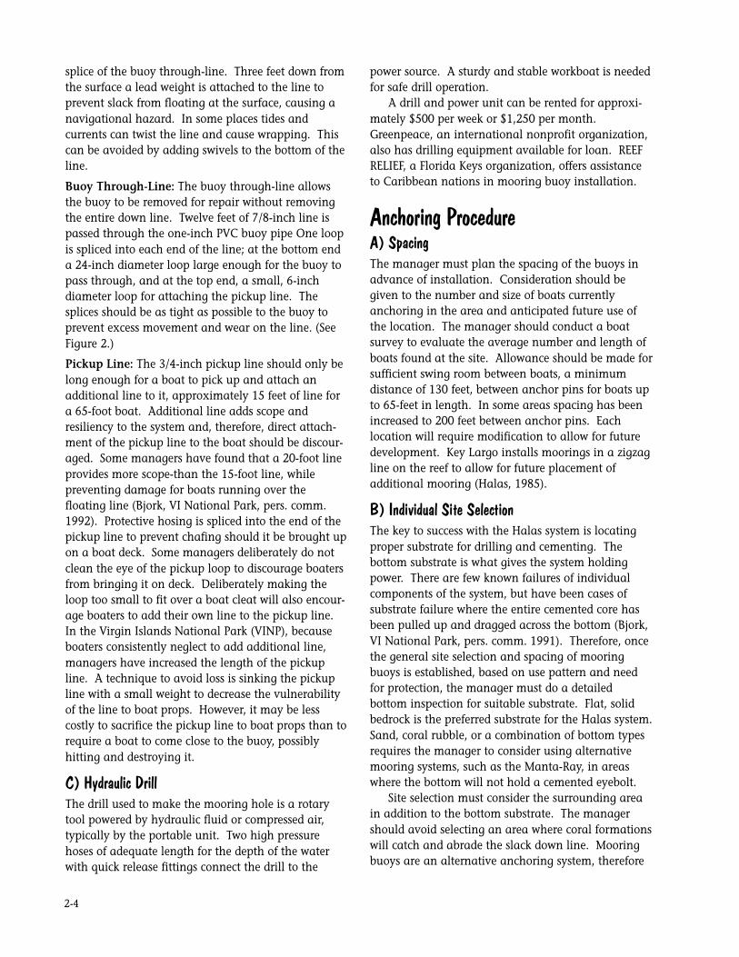
Down Line: 3/4-inch polypropylene line, approxi-
mately 1 0 feet longer than the depth of the water at
high tide serves as the down line. The length of the
down line should be adjusted for water depth and
local tide conditions. At the bottom of the line a
nylon reinforced hose is spliced into the loop to
prevent abrasion and chafing from the bottom. The
loop attaches with a shackle to the anchor pin. The
pin of the shackle is softer than the eye bolt so that
the shackle wears out before the anchor eye bolt. An
eye splice at the upper end interlocks with the eye
Figure 2
2-4
splice of the buoy through-line. Three feet down from
the surface a lead weight is attached to the line to
prevent slack from floating at the surface, causing a
navigational hazard. In some places tides and
currents can twist the line and cause wrapping. This
can be avoided by adding swivels to the bottom of the
line.
Buoy Through-Line: The buoy through-line allows
the buoy to be removed for repair without removing
the entire down line. Twelve feet of 7/8-inch line is
passed through the one-inch PVC buoy pipe One loop
is spliced into each end of the line; at the bottom end
a 24-inch diameter loop large enough for the buoy to
pass through, and at the top end, a small, 6-inch
diameter loop for attaching the pickup line. The
splices should be as tight as possible to the buoy to
prevent excess movement and wear on the line. (See
Figure 2.)
Pickup Line: The 3/4-inch pickup line should only be
long enough for a boat to pick up and attach an
additional line to it, approximately 15 feet of line for
a 65-foot boat. Additional line adds scope and
resiliency to the system and, therefore, direct attach-
ment of the pickup line to the boat should be discour-
aged. Some managers have found that a 20-foot line
provides more scope-than the 15-foot line, while
preventing damage for boats running over the
floating line (Bjork, VI National Park, pers. comm.
1992). Protective hosing is spliced into the end of the
pickup line to prevent chafing should it be brought up
on a boat deck. Some managers deliberately do not
clean the eye of the pickup loop to discourage boaters
from bringing it on deck. Deliberately making the
loop too small to fit over a boat cleat will also encour-
age boaters to add their own line to the pickup line.
In the Virgin Islands National Park (VINP), because
boaters consistently neglect to add additional line,
managers have increased the length of the pickup
line. A technique to avoid loss is sinking the pickup
line with a small weight to decrease the vulnerability
of the line to boat props. However, it may be less
costly to sacrifice the pickup line to boat props than to
require a boat to come close to the buoy, possibly
hitting and destroying it.
C) Hydraulic DrillThe drill used to make the mooring hole is a rotary
tool powered by hydraulic fluid or compressed air,
typically by the portable unit. Two high pressure
hoses of adequate length for the depth of the water
with quick release fittings connect the drill to the
power source. A sturdy and stable workboat is needed
for safe drill operation.
A drill and power unit can be rented for approxi-
mately $500 per week or $1,250 per month.
Greenpeace, an international nonprofit organization,
also has drilling equipment available for loan. REEF
RELIEF, a Florida Keys organization, offers assistance
to Caribbean nations in mooring buoy installation.
Anchoring ProcedureA) SpacingThe manager must plan the spacing of the buoys in
advance of installation. Consideration should be
given to the number and size of boats currently
anchoring in the area and anticipated future use of
the location. The manager should conduct a boat
survey to evaluate the average number and length of
boats found at the site. Allowance should be made for
sufficient swing room between boats, a minimum
distance of 130 feet, between anchor pins for boats up
to 65-feet in length. In some areas spacing has been
increased to 200 feet between anchor pins. Each
location will require modification to allow for future
development. Key Largo installs moorings in a zigzag
line on the reef to allow for future placement of
additional mooring (Halas, 1985).
B) Individual Site SelectionThe key to success with the Halas system is locating
proper substrate for drilling and cementing. The
bottom substrate is what gives the system holding
power. There are few known failures of individual
components of the system, but have been cases of
substrate failure where the entire cemented core has
been pulled up and dragged across the bottom (Bjork,
VI National Park, pers. comm. 1991). Therefore, once
the general site selection and spacing of mooring
buoys is established, based on use pattern and need
for protection, the manager must do a detailed
bottom inspection for suitable substrate. Flat, solid
bedrock is the preferred substrate for the Halas system.
Sand, coral rubble, or a combination of bottom types
requires the manager to consider using alternative
mooring systems, such as the Manta-Ray, in areas
where the bottom will not hold a cemented eyebolt.
Site selection must consider the surrounding area
in addition to the bottom substrate. The manager
should avoid selecting an area where coral formations
will catch and abrade the slack down line. Mooring
buoys are an alternative anchoring system, therefore

2-5
a buoy should not be placed in an area considered
unsuitable for anchoring.
C) Drilling and Cementing the Anchor PinOne person experienced in diving and installing
moorings should be responsible for supervising the
operation. Ideally, the work crew for drilling and
cementing the moorings in place will consist of two
teams of at least two people each. One team takes
responsibility for diving and drilling underwater while
a second team remains on the workboat deck. The
boat team should be responsible for assisting the
divers with equipment relay, operating the power unit
for the drill, and mixing the cement.
Once the proper site is selected a hole is drilled
into the solid substrate. An 18-inch stainless steel eye
pin with a wielded crosspiece (to prevent it from
pulling out of the hole) is cemented into the hole. If
the outside diameter of the eye is slightly larger than
the diameter or the hole, the pin will not drop down
into the hole, Initial site selection and placement of
the anchor pin is critical because once cemented it
cannot be moved.
Drilling time depends on the working conditions, a
function of water depth, hardness of the substrate,
experience level of the crew, mechanical difficulties
experienced, and weather conditions. Weights added
to the top of the drill help stabilize the drill and
decrease operator fatigue. At times it may be neces-
sary for the operator to remove the drill bit underwa-
ter to free excess or stuck sediment, so proper tools
(pipe wrenches of medium to large size) should be on
hand (Bjork, VI National Park, pers. comm. 1992).
D) Cementing the Eye PinTo prevent flexing of any exposed portion of the eye
pin, the drill operator should be sure the hole is deep
enough for the rim of the eye pin to rest against the
rim of the hold. Once it is determined that the hole is
deep enough, the drill operator signals the crew on
the boat deck to begin mixing the cement. While the
boat crew mixes the cement, the drill team sends the
drill back up to the boat and prepares the hole for
cementing by removing any loose debris by hand.
Portland Type 11 cement, manufactured to be used
in salt water, sets up quickly when mixed with a
catalyst. The routine mixture of cement to catalyst is
10 to 1. However, the catalyst is not absolutely
necessary and Type I cement can be used if type 11 is
not available (Halas, unpublished). Commercial
premixed cement is also available but is costly, and
does not allow the mixing crew flexibility in adjusting
setup time. When working in deeper water, slower
setting time is needed to get the mixture to the bottom
before hardening. In shallow water surges can wash
the cement out of the hole if setting time is too long.
Molding plaster used as a catalyst is varied to control
setup time of the cement. More critical than setting
time is ensuring that the cement reaches the bottom
of the hole.
The mixed cement, placed in a plastic bowl and
covered with a lid, is taken down to the hole by a drill
team diver. The wet cement is scooped into the hole
up to the rim. The anchor pin is pushed into the hole
until the eye rests on the rim. Additional cement is
then packed around the eye and into the hole to make
sure all void spaces are filled. A temporary string and
float is attached to an adjacent structure for locating
the site. Attaching the float to the anchor pin may
compromise the setting and hardening process (Bjork,
VI National Park, pers. comm. 1992). The cemented
anchor pin should be allowed to set for at least five
days prior to attaching the buoy. Detailed records,
including site description, compass bearings and
underwater photos and video if possible, should be
made of the exact location of the anchor pin. Locat-
ing the eye can be difficult if the location marking is
lost.
MaintenanceThe key to success of any mooring system is regular
maintenance. A proper maintenance program
requires planning. The manager should assign
supervision of maintenance to one individual.
Consistent records of repair and maintenance should
be kept on a schedule form. Each area will develop
unique needs and problems dependent on environ-
mental conditions and the type and use of the moor-
ings. Therefore, any maintenance plan should be
flexible to adapt to local conditions and patterns of
use.
Almost every manager of a protected marine area
using the Halas mooring system develops a different
maintenance routine and schedule; however, one
universal standard is regular and timely inspection of
the mooring buoy system. The common and major
loss to the system is damage from boats. In the
Florida Keys an average of 6 to 15% loss is due to
reparable boats. Inexperienced boat handlers rou-
tinely run over the moorings, severely damaging if not
completely destroying the buoy and lines. Detailed
records of the exact location of each anchor pin are
necessary for locating a site if the entire system of

2-6
lines and buoy is lost. Regular maintenance requires
anticipating replacement and repair of line, hosing,
and buoys. Therefore, a maintenance budget must
include sufficient funds for stocking supplies and
equipment for future use.
Inspection, repair, and routine maintenance of
mooring buoys quickly becomes a tedious and time
consuming process. Average time estimate for hands
on maintenance ranges from 45 minutes to two hours
per buoy per month depending on specific working
conditions and total mooring area covered. Most
managers have discovered that although it is often
easy to find volunteers with enthusiasm to assist with
installation of moorings, it is best not to rely on
volunteer help for routine maintenance. In Looe Key
and Key Largo Marine Sanctuaries many buoys are
maintained by the volunteer dive groups and commu-
nity groups that installed them. Key Largo also
contracts a private dive boat operator to maintain
mooring buoys.
The following is a suggested maintenance schedule
adapted from Halas and maintenance programs from
several organizations in the Florida Keys.
A) Monthly:1) Inspect all buoys and pickup lines for condition.
2) Clean pickup line of growth or replace if necessary.
3) Clean buoy and check for cracks; replace as
required.
4) Inspect and clean exposed portions of the buoy
through-line and replace as needed.
If the buoy and lines are not cleaned on a regular
basis, user may question the maintenance and
integrity of the system and choose to anchor instead.
The Virgin Islands National Park inspects monthly for
anchor movement as well.
B Three Months:1) Inspect down line and protective hosing for wear
and damage. Replace if necessary.
2) Inspect shackle for wear or damage. Replace if
needed.
3) Inspect anchor. Examine contact area between
anchor and shackle for signs of wear.
4) Inspect anchor mount site and surrounding area.
Look for signs of movement between anchor and
cement core or between the cement core and the
surrounding substrate.
C) Six Months:1) Replace buoy through-line and pickup line after six
months of use if the system is used on a regular basis.
D) Twelve Months:1) Replace pin in down line shackle.
E) Twenty -four Months:1) Replace down line if needed.
Modifications Unique adaptations incorporated into
the mooring system include:
1) Removing and replacing on a rotating basis the
entire system for cleaning and repair rather than on-
site maintenance. Rough water conditions often
preclude sufficient time for cleaning on-site. This
practice requires building an inventory of entire
mooring systems and may therefore in some cases
become cost-prohibitive.
2) Using polyplus line rather than polypropylene.
Many managers have found that polyplus is more
durable and resistant than polypropylene.
3) Replacing shackle pins every six months to insure
the pin will not break.
The Manta-Ray BuoyAnchoring System
General DescriptionThe Manta-Ray anchor is a utility pole anchoring
system adapted for underwater use. The first Manta-
Ray underwater systems were installed in 1990 in
Florida’s Key Largo National Marine Sanctuary.
Sea bottom characteristics dictate the type of
anchor system used for mooring buoys. Whereas the
Halas system require a hard bottom to drill a core and
cement an anchor pin, the Manta-Ray anchoring
system can be used in mixed bottoms of clay, sand,
gravel, broken bedrock, and coral rubble (Foresight,
unpublished). In Key Largo National Marine Sanctu-
ary, Manta-Ray anchors are used on the leeward side
of reefs in mixtures of sand and coral rubble. They
also work well in soft substrate. Because of sea
bottom characteristics, Virgin Islands National Park
plans to use Manta-Ray anchors for approximately
75% of their mooring buoys (Bjork, VI National Park,
pers. comm. 1991).
The Manta-Ray system consists of a utility anchor

2-7
attached to an anchor rod that is driven under the sea
bottom. A thimble eye nut is screwed into the end of
the anchor rod for attachment of the buoy line. (See
Figure 3.) Manta-Ray anchors are now available in
one-piece construction, which eliminates the problem
of one piece unscrewing from another. If the anchors
are purchased in sections, the sections should be arc-
welded together. Installation of the Manta-Ray
system does little environmental damage to the
surrounding sea bed. Installation time varies with sea
bottom characteristics but in most cases the Manta-
Ray can be installed in less than 30 minutes, reducing
time and labor costs.
Manta Ray
Buoy
Weight
Poly Rope
Figure 3

2-8
ProcedureAnchor style and size installed depends on the
sediment characteristics of the site. Probing the
bottom prior to installation will give the operator an
idea of the bottom conditions. However, short of
taking cored sediment samples, it is difficult to know
exactly where and how deep bedrock may be. Larger
and heavier Manta-Ray anchors are used in loose or
wet sediments that do not have the holding power of
normal sediment.
Lighter, smaller anchors are used in average
sediment. A hydraulic underwater jack hammer and
gad, attached to the anchor drives the Manta-Ray
anchor into the sea bottom. The anchor should be
driven deep enough that the anchor rod is not ex-
posed above the bottom.
Anchor rods are made in
either 3 1/2 or 7-foot
lengths. If the operator
believes a 3 1/2-foot
anchor rod can be driven
further down into the
bottom, (increasing the
holding capacity of the
anchor) couplers and
extensions can be added
in order to add length to
the anchor rod. Occasion-
ally an anchor will run
into a layer of bedrock
and cannot be advanced
any further. The anchor
should then be pulled up
and moved to another
location.
Once the anchor and
rod is in place the anchor
is set and locked into a
permanent position. To
lock the anchor into place,
an upward force must pull
the anchor so that the
anchor wing rotates and
pivots into a locked
position. An anchor
setting device, known as a
load locker applies a force
(measured in psi, (pound
per square inch)) to put
the anchor into locked
position. Without a load
locker, the anchor can be set by tieing a line from the
anchor to the workboat, driving either forward or in
reverse, to pull the anchor upward, locking it in place.
However, the holding capacity of the system cannot be
assured when the anchor is set without a load locker.
(See Figure 4.)
An advantage of using a load locker to set the
anchor is that the holding capacity of the anchor is
immediately determined. Documenting holding
capacity may be a crucial feature of a system if the
manger is concerned about legal liability (see legal
liability section). The psi force of the load locker can
be converted to pounds of holding capacity. Holding
capacity varies with the size of anchor use and
substrate characteristics, but can range from 8,000 to
14,000 pounds in medium-stiff clay or loose sand, to
Figure 4
2-9
2,000-40,000 pounds for dense sand, compact gravel,
or sandstone. Holding capacity requirements vary
with the size of the boat attached to the Manta Ray
system. On average, a 65-foot sailboat requires
approximately 30,000 psi of holding capacity. A
down line and mooring buoy can be immediately
attached to the Manta-Ray anchor. Typically, the
down line and mooring buoy used in the Halas system
is also used with the Manta-Ray system.
Videotapes demonstrating installation of the
Manta-Ray system are available free of charge from
Foresight Products, Inc.
Maintenance and BudgetOnce the Manta anchor is installed maintenance for
the mooring system is the same as for the Halas
system.
Required fixed cost equipment for installing
Manta-Ray anchors, as with the Halas mooring
system, includes: an underwater jack hammer, power
source, hoses, drive gad, and load locker. Much of this
equipment can be rented on a daily or weekly rate.
However, shipment overseas may require a down
payment of the full equipment purchase price.
Supplies for one average-sized Manta-Ray system cost
approximately $110 including anchor, rod, and eye
nut.
Modification of equipment as well as development
of new technology continues to improve the successful
Manta-Ray anchoring system. As with the Halas
system, the manager considering the use on Manta-
Ray anchors should consult with current users of the
system for advice in system design, equipment
purchase, and installation techniques (see Appendices
A and B). Unless the manager is experienced in
underwater work an the engineering involved in the
installation, anchoring system, hiring a consultant for
assistance could be critical for success.
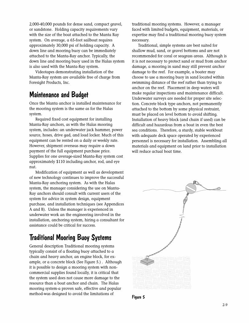
Traditional Mooring Buoy SystemsGeneral description Traditional mooring systems
typically consist of a floating buoy attached to a
chain and heavy anchor, an engine block, for ex-
ample, or a concrete block (See Figure 5.) . Although
it is possible to design a mooring system with non-
commercial supplies found locally, it is critical that
the system used does not cause more damage to the
resource than a boat anchor and chain. The Halas
mooring system-a proven safe, effective and popular
method-was designed to avoid the limitations of
traditional mooring systems. However, a manager
faced with limited budgets, equipment, materials, or
expertise may find a traditional mooring buoy system
necessary.
Traditional, simple systems are best suited for
shallow mud, sand, or gravel bottoms and are not
recommended for coral or seagrass areas. Although is
it is not necessary to protect sand or mud from anchor
damage, a mooring in sand may still prevent anchor
damage to the reef. For example, a boater may
choose to use a mooring buoy in sand located within
swimming distance of the reef rather than trying to
anchor on the reef. Placement in deep waters will
make regular inspections and maintenance difficult.
Underwater surveys are needed for proper site selec-
tion. Concrete block type anchors, not permanently
attached to the bottom by some physical restraint,
must be placed on level bottom to avoid shifting.
Installation of heavy block (and chain if used) can be
difficult and hazardous from a boat in even the best
sea conditions. Therefore, a sturdy, stable workboat
with adequate deck space operated by experienced
personnel is necessary for installation. Assembling all
materials and equipment on land prior to installation
will reduce actual boat time.
Figure 5

2-10
MaterialsHigh quality materials, equipment, and supplies
should be used whenever possible. Inexpensive local
materials such as bamboo or plastic bottle for the
buoy, and chain for the down line, can be used if
commercial materials are not available. If the man-
ager is concerned about theft or vandalism, these parts
can be easily replaced (Salm and Robinson, 1982).
Anchor/BlockA mooring block can be used as an alternative to a
cemented eyebolt. The block can be any heavy object
sufficient to hold a boat. Railroad wheels (Halas,
1985) or discarded car or truck engine blocks (properly
stripped and cleaned) are occasionally used as blocks.
However, most traditional mooring blocks are
made from cast concrete shaped into a square pyra-
mid, box, or drum. Metal rings are set into the
concrete for attaching the anchor line. The shape of
the block depends on the holding conditions of the
bottom. The holding power of any block not physi-
cally attached to the sea bottom is limited however,
and dragging does occur.
Screw anchors, eyebolts with a long shaft screwed
into the sea bottom, have been used in soft sand or
seagrass beds (Halas, 1985). These screw anchors tend
to back out if not monitored, and have limited holding
power. They are only recommended as marker buoys
(Kelley, pers. comm. 1991).
BuoyThe buoy can be obtained commercially or constructed
from plastic, tin, or a metal drum. Although not as
attractive or durable as a commercial model, readily
available local materials can also be used to construct
a buoy. For example, a simple, inexpensive buoy can
be constructed from bamboo, or any other buoyant
material, lashed together with cables and clamps
(Salm and Robinson, 1982).
Although somewhat unsophisticated, systems built
from local materials may suffice when other options
do not exist. The manager must understand that these
basic systems will require added maintenance.
Anchor Line:Chain, rope, or polypropylene line can be used as an
anchor line. Chain does not usually break and is
difficult to cut. However, chain is heavy, difficult to
transport, and can cause considerable structural
damage to the bottom and sedimentation as it swings
with the current. Rope is not as destructive as chain
but can rot and break easily. The preferred anchor
line, therefore, is made from polypropylene, material
that is light, durable, and easily replaced if cut or lost.
To protect the line from chafing, splice a thimble
(small metal strip) into each end of the line, or
modifications can be adapted from the Halas system
by splicing protective hose into the line. Attach one
end of the line with a shackle to the mooring on the
bottom. Attach the other end of the line to the
bottom of the buoy at the water’s surface.
If rope or line is used as a down line, two rings
should be set in the mooring block so that a replace-
ment line can be attached before the other wears and
breaks. Usually, a nylon line with greater flex than a
polypropylene line is used as a down line (Bjork, VI
National Park, pers. comm. 1992). The length of rope
or chain should be twice the depth of the water, with
consideration given to local tide and sea conditions.
Insufficient scope in the down line will cause a boat to
sit directly above the mooring, snapping the line or
lifting the block in rough seas or high tides. If the
Halas three part rope system is used the same instruc-
tions for ground tackle should be followed.
Pickup Line:The pickup line runs from the buoy to the boat. UV-
protected polypropylene line floats and is durable but
braided nylon can be used if polypropylene is un-
available or too costly. A thimble is spliced into a loop
at one end for attaching to the buoy and a loop is
spliced into the other end for attaching to the boat. A
plastic hose is spliced into the loop to protect the line
from chafing on the boat cleat or gunwale. Users
should be instructed to attach extra line to the pickup
line for additional scope and resiliency.
Maintenance and BudgetEvery buoy system, no matter how sophisticated or
simple, requires diligent maintenance. The manger
should plan a financial budget to maintain supplies
and a staff to oversee the system. All components of
the system must be visually inspected and worn parts
replaced as soon as possible. Therefore, the manger
should not install more buoys than can be properly
maintained. Inspections should be done routinely.
The system will require more frequent inspections if
nondurable materials are used. Replacements parts,
including line or chain, should be on hand and ready
for installation. If replacement parts are not avail-
able, the buoy should be removed until repairs can be
made.

2-11
The Helix Mooring System
Hurricane-tested MarineEmbedment AnchorsThe helix anchor has been used to secure:
• Single-point boat moorings
• Mediterranean-style boat moorings
• Floating docks
• Fixed walkways
• Floating breakwaters
• Bulkheads - Pipelines
• Storm moorings
• Navigation and boundary buoys
• Floating ice barriers
• Shellfish long lines
• Finfish cages
Helix Mooring Systems, Inc.1-800-866-4775
Simple installation proceduresSquare Shaft anchors are installed with a torque
motor taken below and operated by a diver. These
installations may be in depths exceeding 10 feet. In
shallower waters, the motor can be mounted on a
small barge. With the use of drive tools, the entire
installation can be managed from the surface.
Round Shaft anchors can be installed by hand
with the mechanical advantage of a pipe or other
turning bar. Although our low-load option, these
anchors can deliver significant holding capacity in
competent soils as demonstrated in the example at
Marshall, California. These anchors are available
with a single 6-,8- or 10-inch diameter helix on a 5 1/
2-foot-long shaft.
The helix-anchor concept andcompetitive test resultsThe first helical screw anchor was patented in the
early 1800s and used to support lighthouses in the
Chesapeake Bay. (See Figure 6.) Whether intended to
resist a downward force (supporting a fixed walkway)
or an upward force (securing a boat or a dock), helical
embedment anchors derive their significant holding
power from the soil into which they are installed.
HelixManta RayEye Bolt
Embedment Anchors
Figure 6

2-12
The soil above each helix on an anchor resists the
upward tension which is exerted by a moored boat or
dock. The firmer the soil and the deeper the anchor
has been turned into that soil, the more resistance to
the upward tension is generated. Anchors relying on
this exact same concept have been used in applica-
tions which required holding capacities up to 200,000
lb. loads far greater than those we are generally
considering.
The table above compares the holding power of
different traditional marine mooring anchors with
that of a helix anchor. The Vineyard Haven, Mass.,
harbormaster selected typical traditional anchors
within his harbor for a comparative test. A 65-foot
tug pulled laterally on each anchor until it failed and
the load at failure was recorded.
The helix anchor never failed. Rather, the 1 1/2"
pulling hauser parted at 20,800 lb. of load.
Figure 7 Figure 8
Vineyard Haven, Pull Test ResultsMooring Type Bottom Condition Breakout Force
350-lb. Mushroom 5 ft. deep in mud 2,000 lb.
500-lb. Mushroom in sand bottom 1,700 lb.
3,000-lb concrete block set in mud 2,100 lb.
6,000-lb. cement blodk on sand bottom 3,200 lb.
8/10 Helix soft clay mud 20,800+ bl.

2-13
How are Helix anchors manufactured?These anchors are manufactured in the USA by A.B.
Chance Co. which has been building embedment
anchors for more that 75 years. The steel, welding,
couplings, and hot-dipped galvanizing meet ASTM
specifications. The complete unit, including grade 7
coupling bolts, are load tested to minimum ultimate
tension strengths of 70,000 lb. (l 1/2" square shaft
anchors) and 100,000 lb. (1 3/4" square shaft an-
chors). Complete specifications available.
What does a Helix anchor cost installed?$700 to $1,000 is a fair rule of thumb for the high
load 1 3/4" Square Shaft anchors, but there are many
variables. The right size of a Helix anchor varies with
the harbor bottom and load requirement. The cost to
install varies with local conditions and the number of
anchors being installed at one time.
Chain and buoy prices are not included, but your
dealer can also help with those. A Helix mooring
anchor is more cost effective than traditional anchors
based on cost per holding capacity.
How are Helix anchors Installed?These anchors are installed using a hydraulic torque
motor to screw the anchor into the harbor bottom.
They can be installed from a surface barge using drive
tools to reach to the harbor bottom or by a diver using
an underwater torque motor and supported by a
surface vessel. If your dealer is not a trained Helix
installer, he/she will coordinate the installation with a
trained installer for you.
Can a Helix be removed or repositioned?Yes! Helix anchors can be removed by reversing the
installation process, or they can be water-jetted out by
blowing the subsoil off the helices.
How is holding power measured?Holding power is based on collected engineering data.
The torque (measured in PSI) required for installation
is related to the harbor bottom material and the size
of the torque motor used to install the anchor. Hold-
ing power can then be approximated using a chart.
Where is the dealer closest to me?Please give us a call to find the dealer closest to you.
If no dealer currently exists, we would appreciate your
suggestions of local marine contractors and commer-
cial divers who might be interested in becoming a
dealer. Alternatively, we may be able to meet your
needs with a mobile installation team.
Benefits of the Helix AnchorVersatile, high-load capacity to serve any permanent
anchoring need. Holding power which cannot be
equaled by traditional mushroom anchors or dead-
weight blocks. Maintains its holding power even with
the shorter scooping necessary in congested harbors.
Stays where it is put and is friendlier to harbor bottom
environments.
Single Point Boat MooringsThe anchor pictured in Figure 7 is our most popular
anchor. Its overall length is about 7', and there are
two helices welded to the central shaft. The top helix
is 10" in diameter; the lower one is 8". Although this
anchor weights just over 100 lb., it can deliver a
holding force in excess of 20,000 lb. in good compe-
tent soils. When there is a layer of soft materials over
the competent soils, an extension is added between
the anchor shaft and the mooring termination by the
installer. This ensures the helices are sufficiently
buried into good holding soils to deliver satisfactory
holding. When mud and silt are the primary subsoil,
the installer will use additional extensions or our
large anchor. The added installation depth and/or
number and size of the helices will compensate for the
weaker soils.
Standard1 3/4" Square Shaft Anchors
• Single 10"
• Double 8/10"
• Triple 14"
Extensions are available for both the 1 3/4" Square
Shaft and 1 1/2" Square Shaft Anchors. Extensions are
the same as the central shaft and come in lengths
from 3' to 10' long. If necessary these can be added
on continuously to make an anchor as long as
necessary.
Standard1 1/2" Square Shaft Anchors
• Single 8"
• Double 8/10"
• Double 14"
• Triple 10/12/14
“Helical Piles or sea screws (two names for Helix
anchors) are not common, but are exceptionally
effective . . . Recent tests have shown that holding
power is vastly greater than any traditional mooring
system of mushroom or deadweight anchors.” –

2-14
MOORINGS: A Discussion of Problems and Solutions
by Michael Taylor, CMS Marine Surveyor CIGNA
(Property & Casualty ) Loss Control Services January,
1994
“. . . Hurricane Erin’s 80 MPH sustained winds and
100 MPH gusts proved no threat to the (Florida)
vessels (moored on Helix anchors) . . . all five vessels
equipped with the new (Helix) moorings in the
immediate vicinity of Melbourne (Florida) rode out
the storm without an incident, even a large, 52 foot
yacht moored in open, exposed water.” Cape Cod
Times, August 14, 1995
After the hurricane season of 1985, the owner of a
109' LOA privately owned motor had two Helix
anchors installed in Palm Beach, Florida as the key
components of an in-line storm mooring which the
owner hopes will never be needed. anchor yanks loose, the pennant breaks or a cleat
pulls out.
The Hazelett Elastic Mooring Rode offers a better
solution. Because of its engineered ELASTICITY, it
stretches out smoothly under the load of wind and
sea, thereby eliminating the peak forces of a rigid
chain rode. The Hazelett rode provides a new dimen-
sion in mooring systems – the dimension of elasticity.
During storm conditions, this new dimension also
protects against the effects of the sudden increases in
water depth caused by storm surges or the impact of a
break-away boat. The Hazelett rode maintains its
elasticity to absorb these forces and to preserve the
integrity of the mooring system under the severest of
storm conditions. The smooth extension of the
Hazelett rode system also acts to keep the boat
pointed into the wind instead of yawing.
Hazelett Elastic Mooring RodeA conventional mooring system uses a chain rode or a
combination of chain and line to connect an anchor
on the sea floor to a float on the surface. In moderate
weather, this rode has a catenary curve between the
bottom and the top. A boat pulls harder against this
rode in reaction to the increasing force of wind and
waves. In gale conditions, the chain extends until it is
almost straight. When this happens, the elasticity
provided by the curve is lost. The chain becomes a
rigid steel rod between the bottom anchor and the
boat. Any additional increases in the force of the
wind or waves must be absorbed by a component in
the anchor system. Something is bound to fail. The

2-15
Foundation Findings
Report #20 Mooring Anchors
Looking Below the Bottom LineIn the aftermath of recent devastating hurricanes, the
wreckage left in numerous harbors has pointed to a
“weak link” in preventing storm damage - moorings.
Pictures of boats – moorings still attached - flung up
on beaches , docks and atop other boats remain
vividly etched in our memories. The thousands of
boat owners whose vessels were damaged or destroyed
by those disasters live in fear of another destructive
storm.
In an attempt to reduce the extent of storm-related
damage in the future, the BOAT/U.S. Foundation for
Boating Safety along with Massachusetts Institute of
Technology (MIT) Sea Grant College Program, and
Cruising World magazine, conducted tests earlier this
year to examine relative merits of old and new
anchoring technologies.
We tested five types of mooring anchors in Rhode
Island’s Newport and nearby Jamestown harbors by
pulling on them with a 65-foot tugboat powered by
two 450 horsepower engines capable of generating up
to 14,000 pounds of pull.
Our team measured force exerted upon two
traditional anchor types, concrete blocks and mush-
rooms; the pyramid-shaped Dor-Mor, and two “em-
bedment” anchors, a helical screw and the Manta
Ray. (See Figure 9.)
We will present the test outcomes and then
examine some mooring anchor attributes that
contributed to those results.
THE DOR-MORWe first tested a 650-pound version of the cast iron
Dor-Mor, which is available in 10 sizes from 35
pounds to 2,000 pounds. This anchor is shaped like
an inverted, squat pyramid with a short, large-eyed
shank extending from the center. The Dor-Mor we
tested had been in place for one year and our BOAT/
U.S. Foundation diver found it was completely buried
in mud.
Water depth was about 18 feet, creating a scope of
slightly less than 3: 1. Two strain gauges were tied into
the rode package - one an analog mechanical type,
and one digital, which fed data to the lap-top
computer. The tugboat began to pull and according to
both measuring devices, the Dor-Mor broke out at
approximately 4,500 pounds of pressure. Computer
data indicates the anchor may have tried to reseat
itself several times as it was pulled along the bottom
between breakout and shut down of the engines.
HELICAL SCREW ANCHORNext we tested a helical unit that had been placed in
about 20 feet of water, using a special hydraulic
torque motor. The anchor consisted of a 15-foot long,
Figure 9

2-16
galvanized, steel shaft, screwed into the harbor floor
with three 14-inch round helical plates in an area of
very deep mud.
It was connected through the two strain gauges
and attached to the tug at approximately a 4:1 scope.
The tug began its pull, increasing power until the
mechanical strain gauge showed 12,000 pounds of
pressure. Suddenly, the gauges hurled through the air
and slammed into the transom several yards away.
Some element of the system had given way, causing it
to break apart.
The aftermath of the incident revealed a damaged
and frayed steel cable, a warped and broken connect-
ing shackle, and a shattered analog strain gauge,
lying in pieces where it had landed on the fantail.
The digital unit was beyond repair.
Fortunately, we were able to continue our tests
using a backup digital gauge, brought along in
anticipation on just such a failure.
THE MANTA RAYNext, we attached the tug - digital strain gauge in line
- to the galvanized cast iron Manta -Ray. It had been
driven into an area of solid shale in about 19 feet of
water, creating a scope of about 4: 1.
The Manta Ray’s spade-shaped head is attached
by a swivel joint to a shaft that varies in length
according to how deeply it must be driven to hold in
different soil types. It is set by a hydraulic “load
locker,” which toggles the manta-like projection into a
position perpendicular to the shaft and locks it into
place below the harbor bottom. The load locker can
set an anchor with holding power up to 45,000
pounds, depending on the bottom composition.
We had the skipper increase engine revolutions per
minute until the computer tallied 7,500 pounds, then
backed off the throttle and removed the gauge to
insure its availability for the remainder of the tests.
We again increased engine power to the 1,700 rpm it
had taken to break down our initial setup. As with
the helical system, the Manta Ray didn’t budge when
the tug’s twin screws reached that power level.
Conventional Mooring AnchorsThe next anchor to be tested, a mushroom type lying
in about 15 feet of water, was not very well dug into
the mud. Optimally, the mushroom “cap” and the
shank to which it is attached are fully buried. But, as
so often happens, this one was only about half
covered, with the shank lying in line with the area’s
prevailing winds.
It took a “quick tap” of the tug’s throttle, generat-
ing about 1,200 pounds of pull, to break out the 500-
pound mushroom, despite the normally acceptable 3-
1/2:1 scope.
In our last two tests, it took only about 800 pounds
of pull in 14 feet of water to pull out a 2,000 pound
concrete block, and about 4,000 pounds of pull to
dislodge a pair, of 4,000 pound cement blocks con-
nected by chain in 35 feet of water. Both moorings
had 3:1 -scopes.
Now we can examine how the various anchors
differ and why they interact as they do with different
marine environments.
Weight-Dependent AnchorsThe first deadweight mooring used by a man was
probably a submerged rock with a length of vine tied
around it to keep a dugout canoe or raft from drifting
away. Today, many types of mooring systems are
available, meeting boat owners’ needs as dictated by
bottom conditions, weather patterns, and wallets.
Concrete blocks, chunks of granite, railroad wheels
or engine blocks make up the simplest category of
anchor, and all have one thing in common - their
holding power comes mostly from dead weight, with
some help from suction, especially in soft mud and silt.
Dead weights weigh less when underwater than on
land. Cement blocks lose 45%, while granite loses
36%, iron loses 14%, and steel 13% when submerged.
Mushroom anchors also, are best suited for use in
muddy or silty environments, but not in coarse sand,
hard mud or clay, or rocky conditions. The
mushroom’s upended “cap” works into the underwater
subsoil and the “stem” - to which ground tackle is
attached protrudes from the bottom. When all but the
tip of the shaft is buried, mushrooms are said to have
holding power 10 times their weight. But partially
buried mushrooms may hold only at a rate double to
their weight. When hurricane-force winds blow a
mushroom anchored mooring from a direction oppo-
site that of the prevailing winds, the force of the storm
can uproot the shaft by flipping it over, neutralizing
most of the anchor’s holding power.
To ensure that mushrooms are properly seated,
compressed air is sometimes “jetted” downward into
the bottom, creating a hole that later fills in around
and above the anchor. But generally a boat is used to
circle the newly placed mushroom, keeping the rode
taut so that it works the anchor partially into the
bottom.
The Dor-Mor because it offers less leverage when

2-17
the-prevailing wind reverses its direction, is probably
less likely to be uprooted-than the mushroom. And, as
our test seemed to indicate, it may have better gripping
power after being dislodged because of its sharp edges
and pointed construction. It is best suited to muddy or
silty bottom environments like the mushroom. Also,
the Dor-Mor’s thicker eyelet may not rust out as quickly
as those on the mushroom or block.
Embedment AnchorsHelical Screw Anchors were introduced as screw pilings
for lighthouses in 1838. The technology has been used
continuously since, most recently in the construction
industry for retaining walls, offshore pipelines, and
pole guy wires.
Holding power for helical anchors, just as with the
Manta Ray, is dependent oh the composition of the
harbor bottom where they are placed. They don’t do
well in rock bottoms, and the number of helixes
employed differs with soil type - from loose silt to
highly cohesive clay -just as wood screws with different
threads are used to achieve optimum results in differ-
ent woods like pine or oak. One underwater helical
anchor installer claims the mooring will withstand
“more that 25,000 pounds of straight upward pull”
when properly set into the bottom.
Manta Ray, like the helix, has been used in tradi-
tional construction applications and to anchor em-
bankments, sea walls, and artificial reefs. Its holding
capacity varies from 8,000 pound to 25,000-plus
pounds in soil ranging from loose sand and silt to very
dense sand and hardpan, according to the manufac-
turer. Manta Ray can be used in harbor bottoms
ranging from solid bedrock, which has to be predrilled,
to very loose sand, saturated silt, and swamp, where
two or three anchors are tied together.
Unlike weight-dependent anchors, embedment
types’ holding power appears not to be affected by the
angle from which they are pulled. Therefore, the
strength of other mooring system components, like the
hardware, rode, and pennant, dictate the amount of
scope required.
But we should not overlook the beneficial effects of
scope, with its uniform curve, or catenary, to absorb
storm surge or other sudden stress.
CostsThe manufacturers of both helical and Manta Ray
mooring anchors say their products offer greater
holding power than is offered by conventional moor-
ings. And some insurance companies offer lower rates
for approved mooring systems.
A helical mooring anchor with double helixes and
mooring adapter is about $550. Installation runs
about $250, with a $60 per hour surcharge for any
installation taking more than an hour. Total cost,
installed, would probably run $800 to $860 for a
single unit, with prices for multiple installations being
negotiable.
Manta Ray anchor and seven-foot-long rod
combination, adequate for recreational boats in most
soil types, costs $130. Typically, a professional diver
with the proper gear would charge a minimum of
about $1,000 per day, during which time he could put
eight to 12 Manta Ray units into place. A single
anchor, including placement, should run about
$1,150 to $1,200, with a sharp decrease in per unit
price for the multiple installations.
Equipment, installation, and maintenance costs
would be virtually the same for any recreational boat,
ranging from a 19-foot sloop to a 50-foot power
cruiser with a tuna tower.
The cost of inspections to check for deterioration of
underwater anchor sections protruding from the
bottom should also be figured into overall expense of
a system. Visual inspections, much like those made
on conventional mooring systems, may be necessary.
And, since both types require professional installation,
they might also require specialized personnel with
torque motors or load lockers to “proof load” and
perhaps reset them if they should loosen.
A 300-pound mushroom anchor retails for about
$500; a 500 pounder costs about $800. Transport and
placement of a mushroom within a harbor would
probably run about $150 to $200, according to one
New England harbor master. And installation at a
location remote from a commercial harbor or boat
yard, for instance near a private waterfront property,
could become quite expensive, based on time and
transportation costs, he said.
A 500-pound Dor-Mor sells for $600 and would be
subject to the same transportation charges as a large
mushroom.
Concrete blocks, though cheaper, could be subject
to higher transportation and installation costs be-
cause of their weight.
Some ConclusionsOur tests seem to indicate both the helical and Manta
Ray mooring anchors may offer at least a partial
solution to one of the most basic mooring problems -

2-18
preventing storm damage to recreational boats.
When viewing the test results, bear in mind that a
mooring system is made of four interdependent and
equally important parts: lines (See BOAT/U.S. Reports,
March, 1994, p.6), chains and shackles, deck hard-
ware (See BOAT/U.S. Reports, July, 1993, p. 6), and the
anchor. Our test covered just one of those elements.
Pulling on the mooring anchors in a steadily
increasing manner permitted us a sound evaluation
of the comparative merits of various anchor types, but
that is quite unlike the yanking about that occurs
when storm winds blow through an anchorage and
sharp gusts pick up the waves.
Sometimes it is difficult to figure what is best in
terms of safety, costs and benefits. And in areas where
the chance of hurricanes or violent storms is slim the
old technology still may suffice.
But investigators from BOAT/U.S. Marine Insur-
ance and others in the wake of hurricanes Bob (1991)
and Gloria (1985) identified traditional moorings with
inadequate scope as a major cause of boat damage. in
the final analysis, perhaps the only true measure of a
mooring’s value is how secure we eel when a big blow
is headed for our boat and whether - after the storm -
it still sits at its mooring.

2-19
ENVIRONMENTAL MOORINGSINTERNATIONAL172 Lorelane Place
Key Largo, Florida 33037-4235 U.S.A.
Fax/Phone: (305) 451-5984
1996 Price List(all prices in U.S. Dollars; does not include inland shipping orfreight charges)
MOORING ARRAYS:8-inch polyethelene MOORING BUOY (Standard) $58/eaFoam filled, true white, one-inch pipe, blue reflective stripe,bushings attached. (Colors available add $2).
30-inch polyethelene MOORING BUOY $145/eaFoam-filled, true white, 1 1/2 inch pipe (adjustable), bluereflective stripe, bushings attached. (Colors available, add $3).
22-inch polyethelene MOORING BUOY $90/eaFoam-filled, true white, 1-1/2 inch pipe (adjustable), bluereflective stripe, bushings attached. ( Colors available, add $2).
13-inch polyethelene MOORING BUOY $35/eaFoarn-filled, true white, one-inch pipe, blue reflectivestripe, bushings attached. (Colors available, add $1).
DEMARCATION BUOY. 9-inch diam., 62-in. ht.,lettering, stainless eye. $105/ea
7/8 inch POLY P LUS BUOY LINE $365/roll600 ft. roll, treated, heavy duty.
7/8-inch POLYPROPYLENE BUOY LINE $215/roll600 ft. roll, UV treated, heavy duty.
3/4-inch POLYPROPYLENE BUOY LINE $156/roll600 ft. roll, UV treated.
SHACKLE, stainless steel, 1/2-inch, with cable tie locks. $12.50/ea
Galvanized SHACKLE, 5/8-inch. $ 8/ea
CHAFING HOSE, I -inch ID, nylon reinforced,(100 ft. minimum). $1.10/ft
CHAFING HOSE (FIRE HOSE)I- 1/2 inch, single jacket, 250 psi $1.60/ft
2-inch, single jacket, 250 psi $2.10/ft
2-1/2 inch, single jacket, 250 psi $2.60/ft
Soft LEAD SHEET, 4" x 3" x 1/8", 1/4 lb. $1.35/ea
Heavy duty CABLE TIE $.70/ea
MOORING ANCHORING SYSTEMS (FOR SOLID SUBSTRATE)Mooring Anchor Eye, Standard, 5/8-inch ‘ )16 stainless steel, $38/ea18-inch depth.(Use with cement in limestone.)
Mooring Anchor Eye, 5/8-inch 316 stainless steel $48/ea24-inch depth, knurled or threaded. (Use with epoxy in hard rock),
“U” ANCHOR HEAVY DUTY MOORING, 3/4-inch $90/eastainless steel, 24-inch depth, 12-inch interior width.
Portland Type II CEMENT, 90-lb bag $15/bag
UNDERWATER ADHESIVE, 2-part epoxy, dual tube, I I oz.,with/Nozzle (extra nozzles @ $3/each) $26/appl.
UNDERWATER ADHESIVE dual tube applicator,I I oz. size $72/ea
MOORING ANCHORING SYSTEMS (FOR SOFT SUBSTRATE -SAND/RUBBLE): MANTA RAY MARINE MOORING ANCHORSHeavy duty, includes custom one piece 7-foot x 1 -inch anchor rodwith forged eye-nut.
MR-SRM (Wt. 42.5. lbs.) $135/ea + $15.00 ship FOB MIA $150/ea
MR-1M (Wt. 33.5 lbs.) $109./ea + $14.00 ship FOB MIA $123/ea
MR-2M (Wt. 31.5 lbs.) $101/ea + $14.00 ship FOB MIA $115/ea
MR-3M (Wt. 12.5 lbs.) $ 98/ea + $ 1 0.00 ship FOB MIA $108/ea
“FISH PLATE” for double anchor mooring (14.3lb. steel plate)$25/ea
MANTA RAY INSTALLTION EQUIPMENT
SGC- 1 8 “Stinger” dive gad set, 1-1/8 shank, 3 couplers, $ 899/ea2 extensions, I radiused drive tip, gad extractor bar.
LL-IM Load locker ram assembly (used to “toggle or “load” testMANTA RAY Anchors) $1,886/ea
HYDRAULIC INSTALLATION EQUIPMENTAVAILABLE, PRICED INDIVIDUALLY PER UNIT.
HYDRAULIC POWER UNIT, Marinized with aluminum frame,16 hp $3,800/unitBriggs & Stratton engine, gasoline, portable, runs installationequipment.
HYDRAULIC HOSES, dual 125 ft. power and return with stainlesssteel fittings. $950/set
HYDRAULIC COUPLERS, Stainless steel, 1/2-inch male/female.$ 78/set
DL-09 STANLEY HYDRAULIC DRILLw/hose whips, fittings $1,795/ea
BR-67 STANLEY HYDRAULIC HAMMER(for Manta Ray inst.) $2,200/ea
2-CB 2-inch Carbide tipped coring barrel- 24" length $ 275/ea
3/4 DB 3/4-inch Carbide drill bit (5/8-11) - 27" length $ 115/ea
ADAPTO@gr fit 5/8"x 1 6 male thread on drillto drill bit or core barrel. $64/ea
INSTALLATION TOOL KIT: Two 100 lb Lift bags,uw tool bag, pipe wrenches, hammer, rod, lines w/snaps, $200mixing bowls w/lids, marking tape, etc. $ 350/kit(price depends on content/needs of project)
All specified components of the Coral Reef Environmental MooringSystem make up a unique combination of materials that arenecessary for the mooring buoys to function safely with aminimum amount of maintenance in the coral reef environment.With ten years experience and modifications to bring the system tothe present state of the art, the materials have been selected withsafety, strength, and economy in mind. Environmental MooringsInternational is the only vendor that can easily consolidate all ofthe correct components, including the anchor eye and mooringbuoy specialty items, into one complete order. EnvironmentalMoorings International constitutes a sole source for this mooringbuoy system.

2-20
MANTA RAYMarine Mooring Anchors &Marine Installation EquipmentDomestic User Price List Manta Ray Marine Mooring Anchors(includes custom one piece anchor rod with forged eye-nut.)
MR-SRM Holding Capacity up to 20,000 lbs (88kn)Used with 7f (2. 1 M) x 1 “ (25mm) anchor rods42.5 lbs 19.3 kg $135
MR-IM Holding Capacity = up to 2O,OOOlbs.(88kn) Used with 71 (2. 1 m) x I” (25mm) anchor rods33.5 lbs. 15.2 kg $109
MR-2M Holding Capacity = 15,000-20,000 lbs.(66-88kn) Used with 71 (2.1 m) x 1" (25mm) anchor rods31.5lbs. 14.3kg $101
MR-3M Holding Capacity = up to .10,000 lbs.(44kn) Used with 6' (1. 8 m) x 5/8 “ (I 6mm) anchor rods11.8 lbs. 5.3 kg $88
“Fish Plate” for double anchor mooring (steel plate)14.3 lbs. 6.5 kg $20.*Holding capacities are dependent on soil and moisture content
MANTA RAY Installation EquipmentSCG-18 “Stinger” drive gad set, 1 1/8"(29mm) x (152mm) shank,3 couplers, 2 extensions, 1 radiused drive tip, I gad extractor bar.64lbs. 29.1 kg $899
LL-IM Hydraulic load locker ram assembly (used to”toggle” or“load” [test] the MANTA RAY anchors). 180 lbs. 81.lkg $1,886
LL-2M Manual load locker for MR-3M, MR-4M andMR-88M series anchors. 72 lbs. 3 2.7kg $749
Hydraulic Installation EquipmentStanley BR-87 Underwater Jackhammer $2,050(shipping weight 87 lbs./39.2kg)
GPU 18-8 - Hydraulic Power Unit (portable) -18 horsepower, 5-8 GPM (20-35 Ipm), 2,009,PSI (13, 790 kPa) $4,300Recommended to power all MANTA RAWe quipmentand processes (Shipping weight 220 lbs./99kg)
Hydraulic Hose 4.95/ftPrice per ft./ ft.=.305m
Stainless Steel Hydraulic Couplers $125/setMinimum order of 5 sets
Light Duty Marine AnchorsMR-4M Includes custom one piece 7' (2.14m) x 5/8 (16mm) $76/eaanchor rod with forged eye nut. Holding capacity 5,0000 lbs.(22kn) 10.7 lbs 4.9 kg
MR-88M Includes custom one piece $26/ea1/2" (13mm) x 30" (67mm)anchor rod with forged eye-nut.Holding capacity 4,000 lbs. (I 8kn) 3.5 lbs. 1.6 kg
8 8-DB1-SS Anchor Cabled with 3 -1/2" (I. 07m) of 1/4"(64mm)Stainless Steel Wire Rope, Copper Sleeves*holding Capacity 3,000 lbs. (13kn) 1.2 lbs. .5 kg $16.99
68-DB1-SS Anchor Cabled with 2-1/2' (0.76 m) of 1/8”(32 mm) stainless steel wire rope, copper sleeves. *Holding capacity1100 lbs. (4.9kn) .5 lbs. .23 kg $9.99
LL-2 Manual load locker can be used to load lock the DUCKBILLCanchors and MR—3M, MR-4M, MR-68M. Maximum Capacity =8,000 lbs. (35kn)
*Holding capacities are dependent on soil and moisture content
Drive Steel for Light Duty marine AnchorsNote: MR-4M uses standard “stinger” drive gad set for largeranchors.
For 68-DB AnchorDS68HD (hand drive gad) - 4 ft. (1.2m)long large striking head $24.99PDS68* (power drive gad) - 4 ft.(I.2m) long.Specify hammer chuck size w/order $130
For 88-DB AnchorDS88 (hand drive gad) - 4ft. (1.2m) $24.99long with large striking headPDS88 (power drive gad) - 4’6" (1.4m) long.Specify hammer chuck
*Standard Chuck Sizes — 7/8 (2.2cm) x 3 1/4 (8.3 cm) - 7/8 (2.2) x4 1/4 (10.8cm) - 1 (2.5cm) x 4 1/4 (10.8cm) - 1 1/8 (2.9cm) x 6(1.83cm) - 1 1/4 (3.2cm) x 6 (1.83m)
TERMS: $200 minimum order - Orders are F.O.B. Colorado 20%restocking fee for all returned goods LOC may be requested - Net 30days
Prices Effective 11/0 1/95Prices are subject to change without notice.
FORESIGHT PRODUCTS INC.6430 49th DriveCommerce City, CO 80022 (U.S.A.) U.S.Patent number 4,044,513, 4,096,673, 4,802,317, 5,031,370 andother international patents. Additional patents pending.

2-21
HELIX MOORING SYSTEMS INC.1 (800) 866-4775
Embediment AnchorsRetail Prices
Square Shaft Anchors
Standard 1 3/4" Shaft Standard 1 1/2" Shaft
Single 10" $460 Single 8"$330
Double 8/1 0" $495 Double 8/10"$355
Triple 14" $615 Double 14"
$435 Triple 10/12/14$470.
3' Extension $130 3.5' Extension$ 80
5' Extension $175 5' Extension$105.
7' Extension $200. 7' Extension$135
Max Installation Torque:10.,000 ft. lbsMax Installation Torque: 5,000 ft. lbs
Round Shaft Anchors
Single 6" 5.5' x 3/4" Dia. $ 55Single 8" 5.5' x I” Dia. $ 75Single 10" 5.5' x I 1/4Dia. $105Single 14" 8' x I 1/4Dia. $160Extension 6' x I 1/4Dia. $100
Max. installation Torque, 3/4" dia. - 400 ft. lbs, I” dia. - 1,000 ft.lbs., 1 1/4" dia.-2,300 ft. lbs
Rock Coral AnchorsRock Anchor 27" x 1 1/4 Dia. $ 55.
Epoxy Installation Gun, Mixing Nozzles are available upon requestEQUIPMENT All the necessary HELIX ANCHOR installationequipment is available to lease or purchase.
SEACURE RESOLUTIONSDavid Merrill
Manufacturer’s Representative
P.O. Box 119 Milford, NH 03055
Phone (603) 672-7260 Fax (60')) 672-1855
Nominal Boat Size Rode DiameterUp to 27' 1.38"Up to 35' 1.75"Two in Parallel
Component Prices1.375 inch diameter elastic rodeLength (ft) Item # Price14 287285 $3009 287287 $2904 287289 $250
1.750 Iinch diameter elastic rodeLength (ft) Item # Price14 287284 $3509 287286 $3004 287288 $275
Length is nominal and denotes the distance between the center ofthe eye at each end.
Price includes a circular thimble in the eye at each end. Thethimble is available in two styles. Pin style is intended to accept ashackle pin. ROPE style functions as a rope thimble.
Additional Elastic Rode Components
Item Item # PriceAnchor Shackle 283585 $29Rode Float8 in. dia. 7 lbs. floatation 283484 $1211 in. dia. 22 lbs. floatation 283485 $36
GUARANTEE Manufacturer provides a one-year guarantee againstmanufacturing defects. Seller’s liability for breach of suchguarantee shall be limited to product replacement. Sellerdisclaims all other express and any implied warranties except thewarranty of mechantability provided under Section 2-314 of theUniform Commercial code. Seller’s liability for breach of suchimplied warranty shall be limited to product replacement.
Purchaser acknowledges that the product is in development andthat it is being distributed to a limited number of distributors inorder for Manufacturer to obtain field experience. Purchaser agreesto communicate this to its customers and to clearly limitManufacturer’s liability for breach to product replacement.

3-1
Section III
The Benefits of Mooring Buoys
OverviewIn this section you will find articles and studies that describe the
effectiveness of mooring buoys in reducing coral damage. This
section will also cover many additonal benefits to using moorings
such as the ease of operation, the safety, the practicality and the
affordability.
ContributionsHocevar, John D. “A Survey of the Stoney Coral Community Compo-
sition of Pompano Ledge, Broward County, Florida with a
Presliminary Evaluation of the Effectiveness of Mooring Buoys in
Reducing Coral Damage.” NOVA University, 1003.
Segre, Liz. “Oh, What a Beautiful Mooring.” Power and Motoryacht,
January 1993
Murphy, Tim, “Staying Power.” Cruising World, September 1994.
Contents:1. Buoy Effectiveness
2. Management Considerations
3. Caution: Fragile Reefs
4. In Search of Funding
5. Traditional Mooring Approaches
6. New Thinking in the Mooring Field
7. The Pull Test
8. Don’t Overlook the Rode

3-2
by John D. HocevarNova University 1993
AbstractStony coral of Pompano Ledge, First Reef, Broward
County, Florida were sampled in situ using a new reef
assessment method. The circular-radial method was
used to assess the effectiveness of mooring buoys in
reducing damage to reefs. Data will be part of a long-
term monitoring study of buoy impacts. The parameter
of recent injury was used to provide preliminary infor-
mation on buoy effectiveness.
Results were as follows: approximately 6% of the
study area was covered by stony corals, with an average
of 3 colonies per square meter. Diversity based on
abundance (H’n) was 1.7, and diversity based on
relative coverage (H’c) was 1.1. Evenness based on
abundance (J’n) was nearly .8, and evenness based on
relative coverage (J’c) was .5. Approximately 6% of all
colonies surveyed were observed under the shelter of
ledges or overhangs. An average of 2% of colonies were
observed to be recently injured in the Winter, compared
with 6% in the Summer. Twenty-nine species of
scleractinian corals were observed, 26 of which were
present in sample areas. Montastrea cavernosa domi-
nated stony coral coverage, and Siderastrea spp. and M.
cavernosa were the most abundant.
Mooring buoys appear to be an effective manage-
ment tool for minimizing damage to corals on Pompano
Ledge. The percentage of corals that had been recently
injured was lower in the buoyed site (p = .082) even
though the buoyed site was more heavily visited by both
boats and divers. Future studies will be able to further
assess buoy impacts by noting any changes in coral
population parameters. The buoys have only been in
place two years, so it will be interesting to see if the
coral communities of the two sites begin to diverge in
the future.
A Survey of the Stoney Coral Community Compositionof Pompano Ledge, Broward Co. , Floridawith a Preliminary Evaluation of the Effectiveness ofMorring Buoys in Reducing Coral Damage
Buoy EffectivenessBoats that tie up to mooring buoys are not anchoring,
and anchoring in coral causes damage. Therefore, use
of mooring buoys will reduce that type of damage to
reefs. This is the basic premise behind mooring buoy
use. As long as damage prevented by anchors is greater
than possible diver damage caused by a resulting
increased usage of the site, buoys are extremely useful
management tools. Anchor damage can be minimized
or even prevented from occurring by use of mooring
buoys. The total amount of overall diver damage,
however, is not likely to be reduced or increased by
buoy usage; divers not using the buoyed site would
probably be diving somewhere else. A potential sce-
nario where mooring buoy usage would be detrimental
includes the following. 1. Diver damage was more
significant than anchor damage. 2. Diver damage was
concentrated in the area of the buoys as a result of the
buoys being there. 3. The concentrated diver damage
was elevated to a level beyond that of the reef to repair
itself by recruitment and regrowth.
There is no evidence to indicate that buoys are
causing concentrated diver induced reef damage on
Pompano Ledge. In fact, the mooring buoys on Pom-
pano Ledge seem to be a useful tool to reduce human
impacts to fragile reef organisms. The buoyed site was
visited 22% more than the control site during the
winter sampling period, and 116% more in the sum-
mer. Dive charters full of inexperienced student divers
frequently use the buoyed site. In spite of these factors,
% recent injury was lower in the buoyed site than in the
control site (p = .082). The value of the mooring buoys
is demonstrated even if injury is equal in both sites,
because visitation is much higher at the buoyed site.
Pompano Ledge is an example of an area where
buoys were installed on a popular reef with a preexist-
ing condition of heavy diver pressure. Before installa-

3-3
tion of mooring buoys, it is likely that dive pressure
was uniformly distributed along Pompano Ledge.
Buoyed and control sites are very similar in coverage
and composition of the stony coral community as well
as in overall appeal to divers. A notable exception is
the wreck of the Copenhagen at the southern end of
the buoyed site. The spectacular pillar coral
Dendrogyra cylindrus is also unique to the buoyed
site, but this is not likely to greatly influence dive
pressure to the site. Buoy installation appears to have
concentrated dive pressure to some degree. However,
there is no evidence to indicate that diver-caused
damage is greater in magnitude than anchor damage.
Concentration of diver effects is minimized by use of a
large number of buoys spread out over a large area.
Drift diving is popular in the area, particularly among
dive charters, and this would further contribute to
minimizing concentration of divers.
Management ConsiderationsMooring buoys are an excellent tool to reduce anchor
damage to heavily used reefs, and can be an impor-
tant part of a comprehensive reef management plan
(see van Breda and Gjerde 1992). Introducing buoys to
popular reefs will reduce anchor damage with maxi-
mum efficiency. Greater care needs to be taken in
locations where dive pressure is relatively low. In these
situations, mooring buoys may serve to attract divers
to the sites. This may be useful to mangers attempting
to more evenly distribute dive pressure. In general,
however, it is probably more desirable to retain some
areas in relatively pristine conditions where possible.
These areas can serve as sources of larval recruitment
and provide “natural” comparisons that will be useful
for assessing impacted reefs.
Education is a vital component of a successful
mooring buoy plan. Installation of mooring buoys is a
waste of time and money if the public is unaware of
what to do with them. Education is an ongoing
process, as new divers are constantly moving to or
visiting the area. Ocean Watch Foundation educates
the dive community through pamphlets available at
area dive shops, booths at topical expositions and
fairs, a quarterly newsletter, and numerous activities
such as parties, meetings, and beach cleanups. Dive
charter operators can and do play an important
leadership role in educating divers on their boats.
During the course of this study, several dive boat
captains were witnessed using loudspeakers or radios
to lecture private boat operators that had anchored
near mooring buoys.
A good maintenance program is another essential
part of a mooring buoy plan. A good mooring buoy
system, such as the Halas-type system, must be
designed for simple and inexpensive maintenance.
Buoys, lines, shackles, eyebolts, and pins must be
regularly inspected, cleaned and/or replaced as
necessary. Reef Relief (1992) outlines a thorough
maintenance and inspection plan patterned after the
National Marine Sanctuaries Program. Reef Relief and
Ocean Watch Foundation both utilize area dive
captains to assist in this task. However, it is important
to have one individual or committee to oversee
maintenance and inspection to make sure parts are
available and that missing buoys are promptly
replaced. Numerous buoys are frequently missing
from Pompano Ledge for long periods of time, during
which bouyless downlines are allowed to lie on the
bottom. This can result in injury to gorgonians,
sponges, and other high relief organisms, which can
be uprooted by the line when it is swept around by the
current.
Summary and ConclusionsThe stony coral community structure of Pompano
Ledge, part of the first reef of Broward County, Florida,
was described using a new reef assessment method
developed for this study. Organisms within a circular
sample area were identified and measured in situ.
This was well-suited for monitoring buoy effectiveness
because stations could be centered around buoy
eyebolts. Use of a weighted line allowed the method to
be adapted to use in the non-buoyed control site as
well. This method may be useful for future monitoring
studies because it allows for precise reoccupation of
sites while requiring only one permanent marker. An
additional advantage is that a circular sample area
had the smallest boundary distance for a given area.
Coral abundance, % cover, and diversity were
higher than reports for the First Reef in other parts of
Broward County. A total of 29 species of scleractinian
corals were observed, 26 of which were present in
sample areas. Siderastrea was the most abundant
genus, while Montastrea cavernosa dominated
coverage. The dominance of these species and relative
paucity of acroporids and Montastrea annularis that
are common to shallow Caribbean reefs suggests that
Pompano Ledge coral species composition may be
affected by low temperatures and high turbidity.
Mooring buoys were demonstrated to be an
effective management tool for minimizing injury to
corals of Pompano Ledge. In general, the percentage

3-4
of recently injured colonies was greater in the control
site, even though the buoyed site was more heavily
visited. Future studies will be able to further assess buoy
impacts by comparing any changes in coral population
parameters. The buoys have only been in place for two
years, so it will be interesting to see if the coral commu-
nities of the two sites begin to diverge in the future.
Power and Motoryacht
Oh, What a Beautiful Mooring
by Liz SegreJohn Halas is giving coral reefs a chance with perma-
nent moorings. You’re hovering peacefully in a silent
blue wilderness, slowly viewing, slowly gesturing as you
turn from right to left in a place where right and left
dissolve into the shapeless three-dimensional, and
points of reference give way to points of filtered light.
You’re surrounded by an octopus’s garden of white
elkhorn and bright brain corals. Yellowtail snapper
socialize, parrotfish sing their piscine songs, and a self-
effacing leopard ray hides its spots in a patch of
mottled sponge. Nature smiles and you smile back (or
as well as you’re able to with an airhose in your
mouth).
But what’s this? Your partner signals and points to a
bed of branch coral a few feet away. The twigs are
broken, grotesquely amputated. Further on, wide scars
mark the brain and star corals, monstrous wounds in
the ocean floor. Little piles of coral rubble dot sterile
expanses of exposed sand. You look around, and the
dead scrapes seem to go on forever. You search your
memory— were these marks here the last time you
dived this reef? And didn’t there used to be a lot more
fish and plant life here just a few short years ago?
Caution: Fragile ReefsWhat you’ve experienced has happened to lots of
divers in the past 20 years, including Dr. John Halas.
When he discussed the growing phenomenon of coral
reef damage with fellow sport divers, he began to
realize that the biggest cause of it was boat anchors.
And after he began work as Sanctuary Biologist at the
Key Largo National Maine Sanctuary in 1980, Halas
found a way to lessen anchor damage: permanent
moorings.
These devices consist of a mooring buoy spliced to
sturdy line that is in turn attached to the eye of an 18-
inch long stainless steel rod embedded in the ocean
floor. Dive or fishing boats simply tie up to the buoy
instead of anchoring on the fragile bottom.
“The problem was how to make this idea workable
and not too expensive,” says Dr. Halas. “The U.S.
Geological Survey Field Station that used to be on
Fisher Island had a drill they used to get core samples
from the bottom. We tried it out to drill holes in which
we could install our steel rods and it worked very well.
The first six moorings were placed in 1981 off French
Reef in Key Largo. Of those original six, only one had
to be reinstalled later, because it had been put too
close to a ledge. Now there are 400-odd buoys overall
in the Florida Keys.”
“So far, maintenance has not been a problem.
Lines have been cut by boats running over them, but
amazingly enough, Hurricane Andrew had almost no
effect on the moorings in the Keys,” adds Halas.
Dr. Halas also experimented with different materi-
als, settling on corrosion-resistant stainless steel for
the eyes, UV-resistant polypropylene for the lines, and
foam-filled polyethylene buoys (colored white with a
blue stripe in South Florida, though the colors differ
from country to country). “We tried using cable and
chain for the lines, but often they would rotate around
the eye and cause reef damage themselves. Plus, if a
boat ran over a buoy, the cable or chain could
damage the boat and props, while the polypropylene
lines are less likely to do so. There is no hardware on
the upper end of the moorings—the lines are spliced—
which further reduces the chance of damaging a boat.
And the lines float, making installation and usage
easier.”
In Search of FundingThe idea of permanent moorings over dive sites has
traveled like a hurricane throughout the Keys, all over
the Caribbean, and even to the South Pacific. In most
of these places, divers and snorkelers noticed the reef
damage and brought it to the attention of dive shops
and governments. When reefs became more barren
each year, divers abandoned traditional sites in search
of virgin territory elsewhere, and dive operators felt
the pinch. In some areas, moorings were purchased by
the government. In others, such as the Bahamas, the
dive operators and shops paid for them, since the
government couldn’t afford to.
Some programs are funded by environmental
groups, such as Reef Relief in Florida, and the Nature

3-5
Conservancy in Palau. Hawaii has been moving
towards a mooring project, but while the dive shops
are all for it, the citizens and the government have
dragged their feet. Not so in the British Virgin Islands,
where officials recognized early on the need to protect
their natural resources for touristic if not altruistic
reasons. At least 120 moorages are installed now in
the BVI, with a total of 250 planned. Dive site visitors
must use the moorings or risk fines, confiscation, and/
or imprisonment. They also must pay mooring fees,
but these are reasonable.
Dr. Halas has given a lot of his time and
brainpower to helping these projects get off the
ground. “Someone will call up and say, I need 50
units,’ and that’s all they have to say,” says Halas. “I
can call a freight forwarder and have them shipped
the next day.”
The cost of the moorages varies, depending on
how many will be installed, where the materials are
obtained, and the difficulty of installation in a
particular area. Reef Relief asks for a donation of
$500, which it estimates is sufficient to cover materi-
als, boat and equipment time, installation, and
maintenance for about two years. Some Florida
contractors can do the job for less; and of course, in
most Caribbean nations lower labor costs can bring
the price down considerably.
To Dr. Halas, the money and effort to install
permanent moorings and keep them going are well
spent. And while boat anchors are not the only threat
to coral, these moorings will help heal the wounds in
the reefs and restore the beauty of your favorite dive
spot in the blue wilderness.
CRUISING WORLD,
Staying Power
by Tim Murphy Old-school mooring dogma is facing strong chal-
lenges from recent entries into the permanent-anchor
marketplace. Pitting the claims of these new anchors
against those of the old standbys, CRUISING WORLD
teamed up with the BOAT/U.S. Foundation to stage a
pull test. Here’s what we discovered.
In the wake of the last decade’s headline-grabbing
storms, mariners all along the coastline have been
reevaluating traditional mooring systems. And with
good reason: Grotesque images of beaches littered
with broken hulls have flashed across our screens all
too often. In New England, the name Padanarum sill
evokes visions of GRP carnage three years after
Hurricane Bob left 100 boats mangled and stranded
along the shores of the Acushnet River in Massachu-
setts; throughout the region a total of 3,000 boats
were said to have broken free from moorings in that
storm.
And even if you didn’t lose a boat to Bob or
Andrew or Iniki, with each payment of your rising
insurance premiums you are affected by a mooring
that failed.
In response to these lessons, some innovative
mooring alternatives have appeared in the last few
years. To better understand today’s field of permanent
moorings, our editors joined forces with the BOAT/U.S.
Foundation to stage a pull test that compared some
newer mooring systems with more traditional mush-
rooms and blocks. We hired an 800-horsepower tug to
pull on a variety of moorings in Newport, Rhode
Island — some of which had been set long before we
arrived, and others that were installed just prior to our
test. With a strain gauge we measured the force it took
to dislodge each mooring. But before we consider test
results, let’s examine the different kinds of available
moorings and the conditions to which they’re best
suited.
Traditional Mooring ApproachesAny discussion of mooring systems begins with mud.
A permanent mooring needs to be paired carefully
with a single seabed (unlike a ship’s anchor, which is
typically chosen to hold in a wide range of bottom
conditions). Ledge, boulder, gravel, coarse sand, fine
sand, clay, silt, ooze: The gradation of bottom condi-
tions is infinite, and each sediment poses its own
anchoring problems. To simplify matters, engineers
speak in terms of the particle size and the “cohesive-
ness” of a sediment — the degree to which it clings
together. Clay is extremely cohesive, sand and silt are
not. In the context of buried anchors, greater cohesion
means better holding. Because several different
bottom conditions exist within the confines of one
cove, it’s worth collecting a sediment sample at your
particular site before selecting a mooring.
Permanent moorings fall into two categories:
deadweight moorings and anchor moorings. Dead-
weight granite or concrete blocks (as well as old

3-6
engines, railroad wheels and concrete-filled bathtubs),
dominate in locales where ledge prevails and nothing
short of underwater drilling will penetrate the bottom;
here, it’s simply a matter of pitting the mass and
surface friction of the dead weight against the dynamic
forces of wind and chop on the boat’s profile. In
choosing a mooring block, the material’s density is
critical because porous materials lose much of their
weight under water. Concrete is popular because it is
inexpensive, but it becomes 45 percent lighter under
water, so an extremely large block is required to do the
job. A general guideline for sizing concrete blocks is to
allow between 100 and 200 pounds of block for every
foot of boat length, depending on how high and beamy
the boat is. Along the Maine coast, where ledge bot-
toms and cut granite are ubiquitous, denser granite
blocks can be found at the ends of most mooring rodes.
These lose 36 percent of their weight under water, but
probably have the longest life span of any mooring.
Steel and iron is denser still, losing 13 and 14 percent
respectively. Some harbormasters use industrial-size
counterweights as moorings. Any dead weight set in a
soft bottom will create suction, adding to its holding
capacity. If it’s truly buried, so much the better.
In the second category, anchor moorings are meant
to penetrate a bottom and hold through resistance.
Traditionally, the most popular of these is the mush-
room anchor. Typically comprised of a long steel shank
joined to a broad iron bowl, mushrooms function best
in soils that are soft enough to allow penetration, yet
cohesive enough to prevent slippage. They do not work
well in rock, gravel or coarse sand. When fully buried
in a cohesive soil, a mushroom’s holding capacity is
estimated at 10 times its weight. Where conditions are
ideal, mushrooms can be set simply by dropping them
over the side and pulling on them in different direc-
tions with lots of power until they no longer move.
Theoretically once they’re in, mushrooms will continue
to bury themselves. A more positive approach is to jet
them in by blowing a hole in the bottom with forced
water, but jetting is an expensive, time-consuming
project. Also, jetting is not environmentally friendly,
because it stirs up contaminants that have settled in
the upper layers of sediment.
If a mushroom is not properly set, its estimated
holding capacity drops to about twice its weight.
Without inspecting the anchor visually there is no good
way to know how well it is set. A further shortcoming of
the mushroom is revealed when its long shank orients
itself in line with prevailing winds. When storm winds
change direction, as occurs when the eye of a hurricane
passes overhead, the long lever arm of the shank tends
to pull the mushroom out of the bottom. Also, the
corrosive underwater environment eats away at a
mushroom’s narrow shank. Once it deteriorates the
shank bends and the anchor becomes useless, as the
bowl simply skips across the bottom without digging in.
A 300-pound mushroom anchor retails for about $500;
a 500-pounder, for about $800.
New Thinking In The Mooring FieldTwo things have induced harbormasters and boat
owners to rethink mooring systems in recent years. The
first we’ve already alluded to: repeated instances of
boats dragged up a beach by storms. The second is a
growing awareness of the biological damage that
anchors and chain inflict on delicate sea grasses, coral
and other organisms in popular cruising destinations.
A host of permanent, low-profile solutions have
stepped up to greet these challenges.
At the more flexible end of the mooring spectrum is
the Dor-Mor, a pyramid-shaped mooring of solid cast
iron. A distant cousin of the mushroom in design, the
Dor-Mor does not require professional installation or
hydraulic tools to put it in place. The advantages of the
pyramid are in its construction: For one thing, there are
no dissimilar metals such as the mushroom’s steel
shank and iron bowl to cause galvanic corrosion.
Furthermore, the large-diameter eye is built to with-
stand years of corrosion from immersion in salt water
and acidic sediment. In terms of design, the advantages
are debatable. Some experts feel that pound for pound
the point loading of mushroom bowl’s rim as the
anchor lies on its side may offer a better grip than the
Dor-Mor’s linear edge, others feel the pyramid’s down-
ward-facing apex and linear edge offer an improve-
ment over the mushroom. Like a mushroom, the Dor-
Mor’s optimum holding capacity is rated at 10 times its
own weight; some towns such as Portsmouth, New
Hampshire, and Newport, Rhode Island, that require
mushroom anchors in local mooring fields make
special allowances for the Dor-Mor. It is available in 10
sizes from 35 pounds to 2,000 pounds; a 500-pound
Dor-Mor retails for $600, and the per-pound price
decreases as the size increases.
The rest of the newer moorings we reviewed are
called embedment anchors. In terms of initial holding
power, each of these moorings outclasses the aforemen-
tioned systems by far. Furthermore, they each exert a
very low-profile impact on the bottom environment.
Two limitations of these systems, though, are that they
have virtually no reset capability if they ever do break
out of the bottom and they are very difficult to inspect

3-7
one they’ve been installed. All of them require
professional installation.
One of these is a helical mooring. Used success-
fully for decades in the construction industry to
anchor retaining walls, telephone-pole guy wires and
underwater pipelines, the helix only recently made its
appearance on the boat-mooring scene. It is com-
prised of one or more steel helices of varying sizes
welded to a shaft, then hot-dip galvanized. The size
and number of helices for any given application is a
function of bottom conditions rather than of the size
of the boat that will hang on it after installation. The
mooring is installed from a workboat using a torque
motor with a capacity of at least 3,500 foot-pounds to
screw the helix into the bottom. A gauge on the
torque motor shows the installer how much power is
required to drive in the helix into the earth. The
manufacturers claim that holding capacity is directly
proportional to the torque reading, but the degree to
which the sediment is disturbed during installation
would lower those projected numbers accordingly —
at least until the soil settles again. One drawback of
the helix system, as with those that follow, is that they
require an almost absolute faith in the installer. If this
kind of anchor works itself free due to poor installa-
tion, the design grants no holding power to fall back
on. Also, over time it is necessary to check any
mooring system for corrosion, whether from salt water
near the mudline or from acids deeper down. On the
helix it would be desirable, yet difficult, to inspect the
weld between the disc and the shaft every couple of
years.
One of the biggest advantages of this kind of
system is that holding power is not a function of
scope; the helix holds against extraordinary loads,
even when those loads are exerted in a direct line with
the anchor. Manufacturers rate the direct upward
lifting capacity at “up to 25,000 pounds.” It is still
necessary to maintain ample scope to account for
storm surges and to keep the loads on deck hardware
and rodes at a reasonable level.
These moorings have been installed on a large
scale in recent years in Rockland, Maine; Marion and
Mattapoisett, Massachusetts; Atlantic Highlands near
New York Harbor; and the Florida Keys. The
harbormaster in Falmouth, Massachusetts, has
gridded the entire harbor and installed 150 helix
moorings. Helix moorings can be removed if neces-
sary, but it is a difficult job and requires a diver.
The retail price for a double helix plus a mooring
adapter is about $550. To get an idea of installation
prices, the Mattapoisett Boatyard charges $250, plus
$60 per hour for any installation exceeding one hour.
Another boat-mooring system that recently crossed
over from the construction industry is the Manta Ray.
(See Figure 1.) Originally based on a design to anchor
Figure 1

3-8
tower guy wires for the U.S. military, Foresight Prod-
ucts Inc. developed the Manta Ray to excel in difficult
substrates such as sand and coral rubble. They are
made of cast galvanized iron. Installation requires a
diver with a 70- to 90-pound underwater jackhammer,
plus a purpose-built device called a Load Locker. Once
the diver has hammered the Manta Ray deep enough
into the bottom, the hydraulic Load Locker exerts a
high upward force on the mooring, which causes the
anchor to pivot until it lies perpendicular to the rod.
The force measured on the Load Locker is the actual
upward force the anchor is holding, not a computed
projection as with the helix. Like the helix, the Manta
comes in different sizes to accommodate different
bottom conditions. According to manufacturers’ specs,
the holding capacity of the largest Manta Ray anchor
(called MR-SR) is “up to 30,000 pounds”; the MR-1 is
rated at 20,000 pounds, but the manufacturers
classify bottom conditions into eight distinct catego-
ries from solid bedrock to silt, and they rate holding
power separately for each category. Those figures are
available upon request from Foresight.
In order to protect reefs against the constant
onslaught of anchors from transient boats, the Virgin
Islands National Park in St. John has installed Manta
Ray anchors where the bottom is coarse sand. To
prevent single Mantas from lifting out of St. John’s
non-cohesive sand, the park installed mooring
“triads,” with each mooring comprised of three
Mantas set 120 degrees apart. According to park
officials, this has provided a “heavy-duty” result.
Critics cite the difficulty of removing the Manta
Ray as a disadvantage of the system. One would want
to inspect the joint where the shaft joins the anchor
plate periodically for corrosion, but that’s nearly
impossible. The manufacturers suggest proof loading
it periodically with the Load Locker to ensure that no
components have rusted out.
The Manta Ray MR-SM anchor with a seven-foot
anchor rod costs $130; the smaller MR-1 costs just over
$100. Installation costs depend on the substrate. One
diving firm in Michigan charges between $1,000 and
$1,100 a day, and according to Foresight’s Jeff Fisher
they typically install between eight and 12 Mantas per
day where conditions are satisfactory.
Another mooring system inspired by a wish to cut
down on anchor damage to reefs was developed by a
biologist named John Halas in association with the
Florida Keys National Maine Sanctuary in Florida. The
Halas system, as it has come to be known, is designed
for solid ledge bottoms and is essentially comprised of
an eyebolt cemented into the rock. Halas’s plan calls
for a diver to drill a hole into the bottom, four inches
in diameter by 18 inches deep, with the aid of a
hydraulic rotary wrench. In coral, which is relatively
soft, this part of the job takes about a half hour; in
granite, roughly three hours. The diver then places an
18-inch eyebolt with backing plate into the hole and
cements it into place with underwater concrete. Recent
modifications of the plan include using a smaller-
diameter hole and U-bolts in lieu of eyebolts. To avoid
the additional scourge of heavy chain on the bottom,
polypropylene line runs directly from the eyebolt to
the mooring buoy at the surface. The rode needs to be
inspected often to make certain that it has not been
damaged from ultraviolet light and errant propellers.
Since the system was pioneered in the mid 1980s,
Halas moorings have been installed widely in the
Mushroom Anchor Sizes for Single-point Moorings Mushroom anchor weight – lbs.Racing sailboat Crusing
LOA – feet and multihulls sailboats
up to 15 100 10020 100 15025 150 20035 200 25045 300 40055 400 600Source: Sea SpikeSome harbor masters recommend larger mushrooms, using theformula boat length x beam x 1.5 = mushroom weight. By thisstandard a 30-foot boat with a 10-foot beam should have a 450-pound mushroom.
Permanent Mooring Design LoadsWindspeed: Windspeed:
LOA Beam 64 knots 100 knots(feet) (feet) load in lbs. load in lbs.
10 4 720 1,50015 5 1,130 2,50020 7 1,630 3,60025 8 2,220 5,00030 9 3,170 7,00035 10 4,080 9,00040 11 5,440 12,00050 13 7,250 16,00060 15 9,060 20,00070 17 10,000 24,000To estimate the load that wind places on your boat, choose either thelength or beam that corresponds to your boat, whichever renders theligher load value.

3-9
Florida Keys, Tortola, Jamaica and Hawaii. According
to Phil Elliot, who has overseen the installation of 200
Halas moorings for the National Parks Trust in Tortola
since 1989, only about a dozen moorings there have
needed replacing. Most problems occurred where
sailors did not use sufficient scope, allowing wave
action to work the eyes out of their beds.
Because of bottom conditions and local regula-
tions in Newport Harbor, we were not able to include
the Halas mooring in our tests. Halas’s own tests in
Key Largo limestone have shown the system to
withstand more than 20,000 pounds of strain without
pulling out. Those loads did, however, begin to distort
the eyebolts.
The Pull TestIn order to rate the manufacturers’ claims, we felt that
it was important to observe these newer designs in the
real world and under strain. On hand for the test were
representatives from Helix Mooring Systems, Foresight
Products, Dor-Mor and the Hazelett Corporation
(whose elastic mooring rode is described below), as
well as two scientists from MIT and a marine surveyor
for CIGNA Insurance. We leased a mechanical strain
gauge that had up to 20,000 pounds so that we could
measure the loads placed on each of the moorings by
an 800-horsepower tug. In addition to our mechanical
strain gauge, MIT’s Norm Doelling recorded loads via
an electronic gauge wired to a laptop computer. A
diver observed each mooring before each test to
ensure that it was suitably buried.
Theoretical test procedures called for all the
moorings to be installed according to manufacturers’
recommendations or local custom, to be set in similar
soil and depth, using rodes of similar length and
material. In reality, our conformance to these guide-
lines was less than perfect, due to the wide range of
bottom conditions within Newport Harbor and gear
breakage throughout the day. Still, the results were
telling.
The first anchor we tested was a 650-pound Dor-
Mor buried completely in soft ooze under 18 feet of
water using 50 feet of steel cable (just under 3:1
scope). Dor-Mor literature claims a holding power of
10 times its weight with a scope of 3.5:1. The Dor-Mor
initially pulled out under a load of 4,500 pounds.
Norm Doelling’s computer graphic shows that after
the initial pullout, the Dor-Mor caught two more
times, breaking out at 2,800 pounds, sliding for 20
seconds under 2,000 pounds of load then catching
again at 2,200 pound. The tug’s jerking motion on the
inflexible cable probably caused the Dor-Mor to
dislodge earlier than it would have with more scope
and greater elasticity.
Next, we pulled on a helix that was installed four
days before our test. Because the bottom in that part
of the harbor was so soft, a 12-foot shaft with three
disks, each 14 inches in diameter, was installed. The
lower disks penetrated a denser layer of crushed shale.
The installers hoped to achieve a torque of 1,000 foot-
pounds for optimum holding, but the bottom was so
soft that they reached only about 650 foot-pound. In
the end, that was a moot point. The greatest drama of
the day occurred as we watched the load on the
mechanical strain gauge climb to 12,000 pounds.
Suddenly, the entire gauge disappeared from view. A
heavy shackle on one end of the gauge had let go; the
equipment lay in countless bits and pieces at the tug’s
transom. The tug’s engines were turning at 1,700 rpm
when the gauge let go. We did not dislodge the helix.
We still had the Manta Ray, mushroom and
concrete blocks to test, and without heavy-duty
equipment, we were unable to measure extremely
high loads. For the Manta Ray, we used Doelling’s
electronic equipment to measure loads up to about
7,500 pound. After that we disconnected the measur-
ing equipment and ran the tug up to a sustained load
at 1,700 rpm, the same that had been applied to the
helix. The Manta was installed about five feet below
the mudline in a bottom comprised of a foot of ooze
over solid shale ledge. Installation required drilling
into the shale. We did not dislodge it.
As for the mushroom, we pulled on a 500-pounder
under 15 feet of water. Our diver reported that all the
mushrooms in the vicinity of our test were half buried
with the shank lying on the bottom in line with the
prevailing southwesterlies. Clearly, this is not the ideal
disposition of a mushroom, but it is in accordance
with customary usage. According to the electronic
gauge, the mushroom began sliding at about 1,200
pounds of strain and never caught again once it
started moving.
Finally, we pulled on two different concrete blocks
near Jamestown, Rhode Island, where the bottom is
solid ledge. The first block weighted 2,000 pounds dry,
or about 1,100 pound under water. With a 3:1 scope
in 18 feet of water, the block moved at about 800
pound of strain. The other deadweight mooring was
comprised of two 4,000-pound concrete blocks wired
together. These moved when the strain reached 3,500
pounds.
Clearly, the embedment anchors are in a class of
their own when it comes to holding power. One item

3-10
our testing could not provide, though, was informa-
tion about the life-span of the newer embedment
anchors. The helix and the Manta Ray were intro-
duced decades ago in shoreside construction applica-
tions, but only four or five years ago in a saltwater
environment. Despite installers’ claims of 25-year life-
span, we simply will not know how these stand up to
the marine environment without the passage of time.
Don’t Overlook The RodeEven with a mooring that will hold many times the
strain a severe storm could put on your boat, it is
critical to consider all the other parts of the system:
chain, pennant, swivel, shackles, and deck hardware.
The preponderance of moorings that failed in recent
storms were due to parted rodes and broken deck
hardware — with the final result just as disastrous as
a dislodged anchor.
The question of rode begins with how much scope
to put out. Of course, five to seven times the water’s
depth is ideal from the standpoint of holding capacity,
but in popular harbors where hundreds of boats are
crowded into a limited space, 7:1 just isn’t practical. A
traditional mooring arrangement, as recommended in
Chapman’s, calls for a scope of about 4:1, beginning
with a length of heavy chain 1.5 times the maximum
depth of water shackled to the anchor. A swivel at the
other end connects the heavy chain to a light chain
whose length equals the maximum depth of the
water. At the surface, a buoy holds the light chain off
the bottom. From the buoy to the boat’s foredeck cleat
runs a nylon line whose length is 2.5 times greater
than the height from the water’s surface to the boat’s
sheer line. If we take a 35-foot cruising sailboat for
our example, the heavy chain should be one inch in
diameter; the light chain, 3/8 inch; the nylon line, 1
1/2-inches. These are minimum recommendations; as
such, they do not take into account the inevitable loss
of mass after a few seasons in a corrosive environ-
ment.
The crucial design element in this system is the
length of heavy chain, whose catenary provides the
first defensive line of shock absorption in a blow.
This “traditional” arrangement has been chal-
lenged recently on a number of grounds. Take the
nylon rode, for example. Experts agree on the desire
for added elasticity in the mooring system to absorb
the shock of a surging boat in stormy weather. Often
this shock dislodges an otherwise adequately set
anchor. But after a surprisingly high rate of parted
nylon lines were found following Hurricane Gloria,
the Sea Grant College Program at MIT embarked
upon a study of different fiber-based ropes under
strain. While the final paper was not yet published
when this article went to press (it is due this month),
the study found that many of the parted nylon lines
failed not because of chafe against an external object,
but because of internal abrasion among the indi-
vidual fibers as the line stretched. For this reason, the
study calls nylon “the worst material for mooring
pennants.”
Another problem with traditional mooring systems
is the inevitable mixing of dissimilar metals. Anchors,
chain, swivels, cotter pins — all these are likely to
Suggested Sizes of Permanent Mooring Rode ComponentsPennant size – inches
Mushroom anchor Light chain Heavy chain Rope Stainlessweight – lbs size – inches size – inches diameter cable diameter
200 1/4 1/2 5/8 7/32300 5/16 5/8 3/4 1/4400 3/8 3/4 7/8 5/16600 7/16 7/8 1 1/16 3/8800 1/2 1 1 1/4 7/16
1000 5/8 1 3/4 1 1/2 1/21200 5/8 1 1/4 1 5/8 9/16
From Complete Book of Anchoring and Mooring, second edition, by Earl R. Hinz. Copyright 1986, 1994 by Cornell Maritime Press, Inc.Used by permission.Using adequate-sized components is only the first step; it is also imperative that chocks be oriented for mooring angles and that chafe gear beused and checked often.

3-11
differ galvanically, and linking them together is a
saltwater bath means that corrosion will be hard at
work while your boat bobs peacefully on the surface.
At the very least, this situation calls for a diligent eye
and frequent inspections. Avoid using shackles whose
pins do not thread securely into place; relying solely
on a cotter pin that spends its whole life under water
is a recipe for disaster.
One response to these drawbacks is truly
postmodern: a bungee-cord rode. But don’t laugh.
Called the Hazelett elastic rode, it has been tested
extensively on Lake Champlain, and many of the
mooring experts who have witnessed it endorse the
rode strongly. Mike Taylor, a surveyor for CIGNA
Insurance who joined us for the pull test, said its
biggest advantage is that it holds boats head to wind
better than nylon, thereby alleviating some of the
massive loads of a yawing boat as it swings beam to
the wind in gusty storm conditions.
The elastic rode is made of a cast polyurethane
blend, and comes in lengths from 15 feet up, in 10-
foot increments. Bill Hazelett’s eventual goal is to
introduce a rode that eliminates all the metal links
from the system — along with the attendant worries
about galvanic corrosion. While the Hazelett elastic
rode is not yet on the market, you can expect to see
more of it in the coming seasons.
Mushroom and Block Moorings HaveBeen Used for Generations withRelative Success, So Why RethinkMoorings Now?One answer is population growth. In storms a
crowded harbor presents a much different scenario
than does a secluded cove with a gently sloping
shoreline. In a lonely cove, a mooring that becomes
dislodged in high winds may dig in again as the boat
drifts toward shore and scope increases; in a harbor
full of boats, though, a little slippage means a lot of
damage. Also, population growth has a high environ-
mental impact.
Biologists and other careful observers have
witnessed the beating that delicate bottom-dwelling
organisms have already taken from the growing
barrage of anchors and chain that are dropped on
and dragged across them day after day.
Perhaps permanent, low-profile embedment
anchors that remain right where you put them will
have the best staying power in the end. But the real-
world testing phase for them is not yet over. Lest we
prematurely discard the old standbys on the basis of
faults we know so intimately in favor of promising
newcomers whose underwater life-span have not yet
been measured. Keep a wary eye on new mooring
possibilities.

4-1
Section IV
Management and Liability Considerations
OverviewIn this section you will find detailed information regarding the man-
agement of mooring buoy systems in addition to information on legal
responsibilities and liabilities of mooring buoys.
Contributionsvan Breda, Anita and Gjerde, Kristina. “The Use of Mooring Buoys as
a Management Tool, Management of Mooring Buoy Systems.” Center
for Marine Conservation.
Gjerde, Kristina M. “Mooring Buoys Legal Liability.” Center for Ma-
rine Conservation, December 1991.
Contents1. Resource Evaluation
2. Resource Protection Options
3. Number and Concentration of Mooring Buoys
4. Education and Communication
5. Funding and User Fees
6. Monitoring Mooring Buoy Systems
7. Legal Liability under U.S. Law
8. Legal Liability under English Law
9. Exercising Reasonable Care: A Three-part Duty

4-2
The Use of Mooring Buoys AsA Management Tool
Management of Mooring Buoy Systemsby Anita van Breda and Kristina Gjerde
IntroductionMooring buoys immediately benefit marine resource
protection by reducing damage to the sea bottom
caused by anchors and associated chain sweep. How-
ever, the effective use of mooring buoys as a resource
protection tool involves more than installing as many
moorings as possible in high use areas. The manager
must develop and implement a comprehensive plan
for long term mooring buoy management in order to
meet the objective of resource protection. In developing
a mooring buoy management plan, the manager
should:
a) evaluate the current state of the resources, including
use patterns and potential resource damage,
b) consider alternative resource protection options,
c) determine acceptable numbers and concentration of
mooring buoys,
d) develop an education and outreach program,
e) establish enforcement, and
f) manage fund raising.
Resource EvaluationThe manager needs to consider all ecosystem compo-
nents in planning for resource protection. Seagrass
beds are an important component of reef ecology, and
in many areas are an important food source for
endangered sea turtles. Many seagrass beds surround-
ing coral areas are used as anchoring areas for visits to
the reef or for protected overnight anchorage. Our
anchor can damage an extensive area of seagrass beds
by ripping large divots out of the bottom and scouring
the bottom with chain as the boat swings. These
sensitive sites should not be ignored when planning
mooring buoy and anchoring guidelines.
The manager can use large-scale and small-scale
surveying to determine boat traffic and potential
resource damage. For example, aerial flights over a
reef and associated seagrass beds can efficiently survey
large areas to determine where boats typically concen-
trate. Aerial photos can be taken so that actual
number and location of boats can be determined,
which can isolate areas of concern. Aerial photographs
taken on a periodic basis can serve as a permanent
record of resource use.
Once a localized area of concern is identified,
small-scale, individual boat surveys can determine the
average number and size of boats anchored within the
area. In order to plan the proper mooring system, the
manager can design a simple boat survey to determine
the average size and number of anchored boats
typically found in a given location. Information from
consistent and long term boat surveys can help the
manager evaluate changes in visitation patterns and
are therefore critical in the planning process.
Evaluating and measuring physical damage to
coral reefs and seagrass beds is a difficult and inexact
science. However, the manager can survey specific
areas for an estimation of structural damage. In 1987,
biologists at the Virgin Islands National Park surveyed
park waters for anchor damage to coral reefs and
seagrass beds; they determined that 46% of the 186
boats surveyed were damaging seagrass or coral
(Rogers, 1988). Their report gives specific recommenda-
tions for monitoring and management of marine
recreation areas.
Mapping the reef area can be of great assistance to
the manager in planning resource protection. All
information obtained from aerial or visual surveys
should be recorded, and, if possible, maps of the
marine communities should be generated. The
manager can use a map as a guideline when planning
mooring buoy installation. Maps can also be used for
future comparison when evaluating resource protection
needs.
Local commercial dive operators, tour group
leaders, fishermen, and local conservation organiza-
tions can be helpful in assisting the manager with
identifying areas in need of protection. These groups
often have considerable experience on and in the water
and can be a valuable source of local knowledge and
expertise. In addition, local users are more likely to
comply with mooring buoy regulations if they are
included in the planning from the start.
Resource Protection OptionsOnce the patterns of actual and potential anchor
damage are determined, the manager has a range of
resource protection options to consider in deciding the
proper level of protection and the proper number of

4-3
buoys to be placed in order to reduce anchor damage.
Management actions are not always implemented
individually but often are sequential, building up the
level of protection offered. These include:
1) Continue to document use patterns and associated
damage to justify and support resource protection
actions in the future if prevented from taking any
manipulative action by limited funds, expertise, or
ability to install a mooring buoy system.
2) Penalize boats causing anchor damage to coral or
seagrass. In U.S. marine sanctuaries federal regulations
penalize even minor damage to coral and seagrass.
Adequate funding is required for enforcement.
3) Prohibit anchoring in coral and seagrass, permit
anchoring to sand and mud areas only.
4) Develop a zoning plan. Zoning places minimal
restrictions on visitors, but provides the manager
options for protecting resources.
5) Rotate available mooring buoys. Although mooring
buoys may eliminate anchor damage from boats, they
do not eliminate damage caused by careless or inexpe-
rienced snorkelers and divers who routinely stand on,
bump into, touch or break off coral.
Although cemented eyebolts are permanent fixtures,
mooring lines and buoys can be removed and mooring
buoy sites can be rotated. Therefore, if an area is
suffering from overuse, a manager may decide to limit
visitation for a period of recovery by removing the
available mooring buoys, but only if enforcement is
sufficient to prevent continued anchoring at the site. In
U.S. marine protected areas, most boaters follow
navigational aids and seem to prefer to use a mooring
buoy rather than drop an anchor (boaters have been
seen racing each other to get to a mooring) (Halas,
1985). In other countries however, mooring buoys are
an unfamiliar concept and boaters avoid using them.
6) Enforce “no anchoring” regulations in mooring buoy
areas.
7) Install marker buoys around reefs to warn boaters of
navigation hazard.
Number and Concentration ofMooring BuoysVisual ImpactA manger of shoreline bays will be faced with the visual
impact of plastic floating buoys lining the horizon.
Many tourists visit marine protected areas not for
boating but for the scenic bays and beaches. Concentra-
tion of buoys in shoreline areas therefore can become
an aesthetic problem the manager may need to
consider.
Environmental EffectsIn addition to aesthetics, the manager must consider
the environmental effects of boat concentration in
shallow shoreline areas that do not have good water
circulation. Concentration of chemicals and pollutants
in areas of poor flushing can affect local water quality
and in turn damage shellfish and other marine life.
Mooring buoys may also increase the use of an area,
with associated impacts. The manager may want to
describe the optimum ecological system and establish
limits of acceptable change (Bjork, VI National Park,
pers. Come. 1992). If those limits are exceeded, use
must be decreased. Demand for moorings buoys is
likely to increase with supply. Therefore, the manager
will need to limit the number of mooring buoys
installed in areas with a limited capacity for accommo-
dating boats. If the manager needs to offer an area of
safe anchorage to boaters but is limited in space, the
use of bow and stern anchors can extend the capacity
for the number of boats in a confined area
(Gaythwaite, 1989).
Mooring Buoy Conflict of UseOnce mooring buoys are made available to the public,
potential for conflicting uses develops. In small isolated
areas with one or two commercial dive or tour opera-
tors and only an occasional boater or fisherman,
conflicts will be minimal. However, in high-use, high-
traffic areas conflicts may arise that the manager
should anticipate. For example, in the Florida Keys
mooring buoy users include: commercial dive opera-
tors, charter boats, private boats, commercial and
recreational fishing boats, and glass bottom tour boats.
Down lines often develop growth of marine life and
build a small ecosystem which attracts fish. Many
fisherman like to use these mooring buoys to catch bait
fish. Commercial operators resent the removal of the
very fish their customers pay to see. A serious problem
arises when shark fisherman use moorings in close
proximity to divers and snorkelers. To alleviate poten-
tial conflict, proposals have been made to install
mooring buoys in deeper water specifically for fishing
boasts, an example of how mooring buoys can be used
to accommodate various needs.
Education and CommunicationObjectivesMooring buoy education programs should communi-

4-4
cate two basic concepts: a) boaters should use moor-
ing buoys to reduce anchor damage to sensitive and
fragile marine resources b) moorings are used prop-
erly by following established guidelines.
a) Many boaters, unaware that coral is a living
animal or that seagrass beds are an important
component of reef ecology that deserve protection,
will not know why they should use mooring buoys.
Mooring buoy education programs, therefore, should
include basic marine ecology. The education program
should explain that anchor damage is an additional
stress to a fragile marine ecosystem. Many coral reefs
and seagrass beds are already threatened from
natural causes such as hurricanes and other insults,
including increased sedimentation from land-based
development and pollution. The boater should
understand that direct participation in protecting the
reef is as simple as using a mooring buoy instead of
anchoring.
b) Anchoring is a skill learned with experience, but
even the experienced boater can save time and
aggravation by the proper use of a mooring buoy.
Although buoys are simple to use, boaters need to be
informed of basic information, including:
1) Attach additional line to the pickup line, increasing
scope and resiliency of the system.
2) Inspect the integrity of the system; do not use if the
mooring does not appear secure.
3) Report any damaged buoys to authorities,
4) Contact local harbor masters or marine patrols (via
radio if possible) if difficulties in using buoys arise.
Local Community EducationThe education program should be directed not only at
visitors to the park, but also at the local community.
For example, many members of island communities
do not swim, snorkel, or scuba dive, and as a result
are not familiar with the underwater environment.
Therefore, the manager should not be surprised that
local politicians or decision makers are not aware of
the vulnerability of the marine environment and the
need for resource protection. Education programs
should begin with informing the local community of
the need for marine resource protection and the
objectives of a mooring system. The education pro-
gram should also provide for local community
participation in planning the mooring buoy system.
Mooring buoys can be an excellent way to involve
communities and users in resource protection.
To insure communication of comprehensive and
accurate information, the manger should consult a
professional environmental educator when possible.
However, simple guidelines can be followed when
developing an education program for the mooring
buoy system.
1) Present complete, concise, and simple information.
2) Include illustrations in any written communication.
3) Emphasize positive actions that can be taken rather
than produce a long list of “do nots.”
Communication TechniquesWritten
A universal problem with education in marine
protected areas is the visitor out on the water. Recre-
ational trips that originate close to park facilities can
be targets for educational programs. Local charter
boat companies can be supplied with a one-page
brochure for mooring buoy instruction to be distrib-
uted to their customers. Most charter companies are
enthusiastic about encouraging their customers to use
moorings as it offers better protection to their rental
boats than relying on the anchoring skills of the
captain.
Written material can range from a simple one page
instruction handout to a full size color, water resistant,
mooring and anchoring guide. Information should
include:
1) how anchors cause damage and why use mooring
buoys,
2) labeled diagram of the buoy system
3) instructions for proper use of mooring buoys,
4) instructions for safe and proper anchoring,
5) a map of buoy location and a description of the
underwater features and available boater facilities if
applicable,
6) rules and regulations for the conservation of
marine communities, and
7) a list of user rights and responsibilities.
Boat Patrols
Written materials will not be effective if the informa-
tion cannot be distributed to boaters. However, even if
distribution is not a problem, it cannot be assumed
that everyone will read the brochures. Therefore, a
boat ranger patrolling the protected area for compli-
ance with park resource protection regulations may be
the best tool for educating visitors. For example, in the
Florida Keys, marine sanctuary ranger duties include
patrolling popular reefs for damage to coral and

4-5
seagrass from anchoring. Every boat on a mooring
saves the ranger time in checking for anchor damage.
As a result, more of the rangers time is available for
positive education rather than the negative enforce-
ment associated with regulation violations (Causey,
Florida Keys National Marine Sanctuary, pers. comm.
1991).’’
Permanent Buoy Marking
A successful method of permanently attaching
information and instructions directly to buoys has yet
to be perfected. Although mooring buoys can be
identified with spray paint or adhesive lettering, most
marking will come off with wear or cleaning. There-
fore, regular inspection and replacement of the
marking system should be part of the scheduled
maintenance program.
The Media
The manager should inform the media of mooring
buoy development and planning. Many local newspa-
pers, radio, and television stations will publish and air
public service announcements free of charge. In
addition, cruising and yachting guides are updated
periodically. The manager should be sure to inform
guide publishers of any changes to park features and
regulations, including the addition of mooring buoys.
Videos shown on dive boats, charter planes, and at
visitor centers and marinas are used to illustrate
proper reef etiquette. Videos can also be used to
illustrate proper use of mooring buoys.
The manger should review any videos, public
service announcements, or press releases prior to
distribution to insure the proper message is conveyed
with accurate information.
EnforcementEducation and enforcement programs should develop
together. The critical link for successful compliance
with mooring buoy regulations is adequate funding,
for regular boat patrols. Regulations should be clear
and consistent and the enforcement officer should be
prepared to serve as an extension of the education
program. An effective education program will aid
enforcement by encouraging proper use of mooring
buoys and compliance with resource protection
regulations.
Funding and User FeesSeveral private, nonprofit, volunteer organizations
have in consultation with a marine biologist, installed
and maintained mooring buoys in marine protected
areas. Mooring buoys can serve as a focus for fund-
raising. Oceanwatch, a conservation group in south
Florida, has an “adopt-a-mooring buoy” program to
which individuals of businesses can donate funds for
the purchase and installation of a mooring buoy. A
piece of the drilled core sample is given to the sponsor,
or the donor is acknowledged with a special marking
on the buoy itself (Rubin, pers. comm. 1991).
The manager limited by funding and/or staff can
collaborate with local and international nonprofit
organizations to purchase and install mooring buoys
for marine resource protection. For example, the
Canadian government recently donated mooring
buoy material and equipment to Hol Chan Marine
Reserve in Belize. The moorings will be installed by
reserve staff with assistance from volunteer divers
(Azueta, 1990).
Fee/Donation CollectionCollecting fees and/or donations for the use of moor-
ing buoys can be included in the management plan.
Collection usually becomes a responsibility of the boat
ranger or collection can be contracted to a concession-
aire. The amount of the fee will depend on the type of
use of the mooring. In some areas an overnight
mooring requires a $10 fee. In areas where daily
mooring buoy use is more common, boats are asked
to donate $1 per person for each dive or snorkel.
Collection of fees can be another opportunity for
education and additional donation collection. Often,
when visitors realize the nominal fee is applied to the
maintenance of the buoys they will donate additional
amounts to the program. Some dive operators may
also be willing to solicit donations from their custom-
ers for installation and maintenance of mooring
buoys.
Monitoring Mooring Buoy SystemsEvery management action should be monitored for
effectiveness. In addition for regular checks for buoy
integrity the manager should also be concerned with
the effect of the mooring buoy system to the protected
area. A monitoring program can be designed to
measure limits of acceptable change. Although it can
be assumed that mooring buoys reduce anchor
damage to an area, coral breakage may be increase
by a change in the number of divers and snorkelers to
the area. Efficient means of large area monitoring
comparable to aerial photography in terrestrial
ecosystems have not been developed yet
(Kenchington, 1980). Nevertheless, the manger has

4-6
several options for judging the effect over time of
mooring buoys on the protected resource.
Although long term coral reef monitoring now
occurs at several sites including the Dry Tortugas,
United States Virgin Islands, and the British Virgin
Islands, the concept of habitat monitoring is associa-
tion with a mooring buoy system is in its infancy.
Therefore, there is no preexisting formula or set of
guidelines for biological monitoring areas. However,
there are several monitoring methods that vary in
comprehensiveness and cost that could be adapted for
mooring areas. The manager can modify these methods
to create a monitoring program which fulfills manage-
ment needs within a limited budget.
Long-term monitoring of coral reef ecosystems
requires expertise in marine biology. A monitoring
system for mooring buoys, however, should be a
relatively simple recording of the physical changes that
occur in areas where mooring buoys are located. A
mooring buoy system installed without a strategy for
long-term monitoring, while better than nothing, has a
limited role in an overall resource protection plan. A
monitoring program requires a long-term commitment
of personnel time and some financial expense. There-
fore, managers should choose monitoring techniques
that are appropriate and feasible within the resource
protection plan. The manager should seek the assis-
tance of a marine biologist or resource protection
consultant for advice in establishing an initial monitor-
ing program.
Management ApproachCrucial monitoring factors are comparison and replica-
tion. The manager should be able to compare changes
in a system that has mooring buoys to a similar area
that does not have mooring buoys. Change can be both
positive (e.g., showing reef recovery post-mooring buoy)
or negative (e.g., showing continuing or worsening
decline). Therefore, the monitoring program should be
initiated at both an equally used site and a site slated
for use in the future but presently experiences little or
no use. Unfortunately, many marine areas experience
moderate or high levels of recreational or commercial
use prior to designation of protected status and active
management. Therefore, the possibility of beginning a
monitoring program in a pristine area is not a reality
for most managers. The manager may want to consider
the use of a zoning scheme in order to maintain a
relatively pristine section of the protected area as a
control site.
Monitoring should begin as soon as possible. A
period of baseline data collection is necessary to
characterize each site prior to mooring buoy installa-
tion.
Site SelectionSince the monitoring is relative to mooring buoy use,
site selection will be influenced by patterns of use. For
example, dive operators often send their clients down
the mooring line and gather them at the mooring
anchor before beginning the tour. It follows that the
mooring anchor becomes the area of most intense use,
and that impact will decrease as the distance from the
anchor increases. Saba Marine Park has taken that
idea one step further. Specific high use reefs have been
mapped out including the paths that dive tours
generally follow; attention is then focused on the
habitat along the path.
The manager may also choose to measure the
recovery rate of an area that has received anchor
damage in the past, but is now closed to visitation. A
representative sample of the damaged area can be
marked with permanent markers so that changes over
time are measured consistently. Alternatively, an area
now buoyed can be compared to an anchor zone.
Permanent MarkersEstablishing permanent markers for the monitoring site
is a common practice. The mooring buoy anchor pin
can be used as one fixed point. Installation of addi-
tional permanent sites requires the drilling and/or
hammering of either a reinforcement bar (´-inch) or
survey stakes into the reef pavement. If drilling is
required, two options exist. An individual may either
use a hydraulic drill or a pneumatic drill attached to a
scuba tank. Hydraulic drills provide far more power,
and more options for bit or core size, but are not as
portable. Pneumatic drills provide less power, are
limited in bit size (´-inch chuck drill accommodates no
larger than 5/8-inch bit), but are more portable and
less costly then a hydraulic drill. However, if a hydrau-
lic unit has been purchased to install moorings it can
be easily adapted to install permanent pins. After the
pins have been pounded into the reef it is may be
necessary to epoxy or cement the pins in place. The
pins should be numbered and a bearing/distance map
constructed so that they are referenced to each other
and the mooring anchors.
Specific techniquesPhotographic
Video Photographs: Managers may discover that
reproducible qualitative data may be suitable for
mooring buoy monitoring programs. Qualitative

4-7
information is primarily derived from videotape or
photographs. Video transects are an attractive moni-
toring option because they can cover a sizable area at
one time. Therefore, video can work well in creating a
visual inventory of the state of mooring buoy habitats.
For comparison purposes, the area should be video-
taped prior to installing the mooring buoys; the same
area should be periodically videotaped afterward.
Effective visual analysis requires that comparisons
be made from replicate images of the same area.
Reproducing the exact path, speed, and distance from
the sea bottom of a video transect is difficult. Exact
replication is not critical so long as the operator is
consistent and covers the same relative area for each
survey.
Still photographs: Still photographs can provide a
much less expensive and more reproducible alternative
to video monitoring and analysis. Still photos provide
a basis for qualitative monitoring, and as with the
video technique, still photography can be used to asses
the relative changes to mooring buoy area. Photo-
graphs should be taken of the same area on a consis-
tent basis. Individual coral heads can be tagged as a
reference point for monitoring changes to the area.
Nonphotographic
Circular-radial Method: The Circular-radial method is
adapted from a technique used to observe the presence
of coral pathogens. It is a visual survey of a circular
area searching for the presence or absence of a particu-
lar feature. For assessing the habitat surrounding a
mooring area, instances of coral death, physical
breakage, and damage would be of interest. The
survey is conducted within a circle of fixed radius and
center. A mooring could act as the fixed center for
replication purposes. A diver ties on end of a line to
the center and swims in any direction until the line is
tight. The diver then moves the line clockwise, survey-
ing the bottom which the line passes over for coral
breaks, scars, or death. The survey is conducted one
“pie wedge” at a time for a fixed interval. The number
and types of damage encountered are tabulated and
the manager can determine acceptable levels of
impact. A damage magnitude scale can also be
created by assigning a number representing degrees of
impact (weighting), for example 1 through 5, for each
observed disturbance. These figures can then be
entered into a computer program suitable for resource
evaluation. Although this method is more subjective, it
may benefit management in the long term. A large
area can be monitored effectively depending on the
length of the radius (5-7 meters is reasonable). The cost
of the method is minimal; equipment costs are limited
to materials and personnel time.
ConclusionMost marine park managers do not have unlimited
budgets. Therefore, with assistance from a marine
biologist, the manager should plan a system that is
feasible given financial and time constraints. If a
manager determines that a habitat which a mooring
buoy serves is suffering unacceptable damage, then
he or she should have the option of removing those
moorings and deeming the area closed for a period of
recovery. Again, this should be considered only if
enforcement is sufficient to prevent anchor damage to
the area.
Who does the monitoring should also be carefully
considered. It may be useful to coordinate routine
mooring buoy maintenance with an evaluation of the
site, although many managers contract commercial
dive operators to perform routine maintenance.
The Use of Mooring BuoysAs A Management Tool
Legal Liabilities of Mooring Buoysby Anita van Breda and Kristina Gjerde
IntroductionThe goal of this section is to educate private organiza-
tions and government agencies about how to mini-
mize their potential exposure to legal liability (respon-
sibility) for claims for damages arising from use of
mooring buoys.
There is no magic solution that can immunize an
organization or a person from liability for irrespon-
sible or unsafe actions. However, an organization can
virtually eliminate its chances of unfairly being held
responsible for injuries or property damage by using
reasonable care and good judgment. Proper installa-
tion of mooring buoys and a well designed, imple-
mented, and documented program of inspection and
maintenance will go a long way toward establishing
the use of “reasonable care” in mooring buoy projects.
In short, if “reasonable care,” good judgment, and
several other steps are followed, all of which are

4-8
described in fuller detail below, then it is quite likely
that an organization will be able to avoid being held
responsible for damages arising from use of such
buoys.
Warning: This section is for your guidance only,
and should not be relied on in any way to determine
your course of action. Requirements vary with loca-
tion and over time. You should always check with
local counsel prior to any mooring buoy project.
DefinitionsFor the convenience of the nonlegal reader, some
basic definitions of common legal terms are provided
below. Other terms will be defined as the discussion
proceeds.
Tort: from the Latin for “twisted”, a tort is a private or
civil wrong or injury, as opposed to a criminal wrong.
All torts involve four elements: existence of a legal
duty, breach of the duty, causation, and injury.
Legal liability refers to the responsibilities and duties
between persons. When one becomes liable to another
in tort, one becomes obligated to compensate that
person for the loss or injury suffered.
Legal Duty: a legal duty can arise through a variety
of means, indirectly as well as through an express
agreement. When a person undertakes an activity, the
person assumes the duty of assuring that such activity
does not expose others to an unreasonable risk of
harm.
Negligence occurs when a person’s thoughtless or
inattentive conduct injures another by creating
unreasonable risks of harm. Negligent conduct may
arise from active misconduct or passive inaction. A
determination of negligent conduct is made by
comparing the actor’s actions against the conduct of a
hypothetical ordinary, reasonable, and prudent
person under like or similar circumstances.
Gross negligence borders on intentional conduct: it
occurs when a person fails to use even slight care or
omits to use ordinary care to avoid a discovered or
apparent danger.
Reasonable care is generally defined as the conduct
of an ordinary prudent person of like skill and
experience under similar circumstances.
Proximate cause: to be held liable, it must be found
that one’s act or failure to act produced the injury,
and that but for such action or inaction, the result
would not have occurred.
Maritime law: Maritime or admiralty law is a body of
law which particularly relates to ocean-going com-
merce and navigation, but also applies to other
activities or events on navigable waters. Because
mooring buoys are deployed in navigable waters,
certain principles of maritime law may apply.
Legal Liability Under U.S. Law
Possible liability of providersA legal duty of care (i.e., an obligation) to users of
mooring buoys arises when providers of mooring
buoys invite boaters to use them. To meet this legal
duty, the party responsible for installing and main-
taining mooring buoys (the “provider”) must gener-
ally use that degree of care which a reasonable person
would exercise under the circumstances to prevent
unreasonable risks.
Although no cases in the United States have yet
ruled on the standard of care required by providers of
mooring buoys, a number of cases have discussed the
standard of care applicable to those who install and
maintain docks. The functional similarity between
docks and mooring buoys (i.e., providing a vessel with
a safe berth) suggests that the reasonable care stan-
dard for dock owners would probably apply to other
mooring systems.
One who either installs or maintains a dock has to
exercise reasonable care to ensure a safe berth to
vessels. Dock owners have been held liable for failing
to ensure that their facilities are properly constructed
and maintained. Failure to provide evidence that the
dock and its fittings were properly installed and its
structural integrity regularly inspected led one court to
declare that the dock owner had not established that
it had exercised reasonable care. Similarly, failure to
use accepted and proven designs in dock fittings has
been held to indicate a failure to exercise reasonable
care. Consequently, a private organization involved in
a mooring buoy project would probably be liable for
damage caused by a failure to exercise reasonable
care to ensure that the system was properly con-
structed and maintained. As with private organiza-
tions, state and federal agencies involved in efforts to
establish mooring systems are also required to exer-
cise reasonable care and are exposed to the same risk
of liability for engaging in these activities. This
exposure results because under applicable federal
laws, the federal government waives sovereign
immunity if an agency’s actions would give rise to
liability in a private context. Many states have similar
laws. Accordingly, if a private organization could be
held liable for failing to exercise reasonable care in

4-9
connection with installing or maintaining a mooring
buoy, a federal agency involved in the identical
activity would also be exposed to liability.
Possible means to avoid liabilitySeveral possibilities exist to reduce the risk of liability
for private organizations and government agencies
involved in mooring system projects. It should be
noted that none of the methods mentioned below,
other than prevention through the exercise of reason-
able care, are probably sufficient by themselves to
eliminate all risks of liability. Instead, the methods are
most effective when used in combination with one
another.
A) PreventionPrevention remains the best protection: conformity
with widely-practiced (professional) standards of
conduct and accepted standards of maintenance will
help establish the conduct as that of a reasonable and
prudent person.
To help establish that one’s conduct is that of a
reasonable and prudent person and thus reduce
exposure to liability, a management program for the
installation and maintenance of mooring buoys
should make provision for the fulfillment of the
following activities:
1) keeping the buoys, chains, ropes, and bottom
fixtures in safe repair;
2) inspecting the buoys, chains, ropes, and bottom
fixtures to discover hidden hazards;
3) removing hazards or warning of their presence;
4) anticipating foreseeable uses and activities by users
and taking reasonable precautions to protect the user
from foreseeable dangers; and
5) conducting operations on the water with reason-
able care for the safety of all users and persons one
can reasonably expect to be within the vicinity of a
mooring buoy (e.g., other boaters, divers, snorkelers,
and swimmers).
B) WarningsWarnings may be necessary to ensure use of mooring
buoys. Warnings may also be useful in establishing
the standard of care expected of mooring buoy users.
If adequate warnings are given, it can then be argued
that the user failed to act as a reasonable prudent
person if he or she failed to check the integrity of the
buoy, its ropes, and bottom fittings soon after the
vessel tied up.
The more knowledge the potential user of the buoy
has, the more capable he or she is of taking the
appropriate precautions. A user should be informed
that moorings may work themselves loose from the
bottom or ropes may break loose or become frayed for
a number of reasons over which the provider has no
control. For example, an extremely large or heavy
vessel may decide to tie up to a buoy, causing exces-
sive strain to be put on the buoy or its bottom fittings.
Or vessels may decide to use the mooring buoys to
wait out a severe storm, and the wind and waves
similarly put excessive strain on the buoy fittings. A
user should also be instructed as to the type and
magnitude of harm that may befall both person and
property from failure to inspect the buoy.
Historically, failure of the injured party to take
reasonable care to prevent the accident was enough, if
proven, to completely bar the injured party’s claim for
relief. However, most states, and all admiralty (mari-
time) proceedings, now favor an approach that
weighs the negligence of both sides, and reduces the
injured party’s recovery proportionately to his or her
fault. As a result, if a person is 50% at fault and has
suffered $500,000 in damages, his or her recovery
would be reduced by 50%, to $250,000.
Adequacy of warnings is generally an issue when
warnings are relied upon to ensure safe use. They
should be clearly visible, and convey sufficient
information to ensure safe use of the buoy.
C) Disclaimers of liabilityDisclaimers of responsibility for damage to vessels or
persons caused by negligence of the installer or
maintainer of the buoys may possibly reduce the risk
of liability. Any disclaimer must provide notice to
vessels using the mooring systems. For instance, a
“use at your own risk; provider assumes no responsi-
bility (even for negligence) for injuries or property
damage resulting from use of the buoys” statement
directly on a mooring buoy could be satisfactory.
Statements to the same effect in pamphlets or on
charts may also be helpful.
Courts, however, are generally hostile to disclaim-
ers in contracts, especially where the activity or
subject of disclaimer impacts on a public interest or
policy. For example, courts have held invalid clauses
disclaiming liability for injuries caused by negligence
in leases for residential property and in contracts for
the sale of used cars. On the other hand, courts have
not found a public interest in protecting those who go
to go-cart races or private swimming pools, and thus
have enforced disclaimers of liability. A court’s

4-10
decision often hinges on whether the party seeking to
disclaim liability provides an indispensable service that
is not readily available elsewhere.
Whether the use of mooring buoys is an activity
which impacts on a public interest or policy is unclear
and has not yet been addressed by any courts. Where
use of mooring buoys is mandatory, and not discretion-
ary, a court will more likely find that the activity is in
the public interest and hence declare disclaimers to be
invalid (see Section D). But given that disclaimers
might be effective, they should definitely be utilized
though not relied on exclusively for eliminating the
risk of liability.
It should also be noted that disclaimers will not
relieve the responsible party for injuries caused by
grossly negligent behavior.
D) Non-mandatoryUse Another method of reducing the risk of liability is
to give vessel owners discretion over whether to use
mooring systems. If a vessel owner “assumes the risk”
of using a mooring buoy, then he or she may be barred
from claiming that the supplier of the mooring buoy is
responsible for his or her injuries.
Assumption of risk occurs when a party is aware of
a danger and voluntary acquiesces to it. To constitute
to a legally sufficient defense to a lawsuit, the defen-
dant must establish that a party knew that the risk was
present, understood the risk, and was given a choice to
incur the risk or not. Posted notices or warnings my
help establish the user’s knowledge and understanding
of the risk involved.
Assumption of risk may be complete defense to
claim for damages, but is very difficult to prove. The
defendant must establish that the plaintiff consented to
the specific risk that caused the injury. Moreover, if the
injured party acted unreasonably in assuming the risk,
the defense fails and the injured party’s behavior is
viewed as negligent. Her or his damages may be
reduced in proportion to their fault, but recovery will
not be denied. Furthermore, if the injury is due to a
grossly negligent act by the installer or maintainer,
then the defense is invalid.
Where mooring buoy use is mandatory, as regula-
tions within the Looe Key and Key Largo National
Marine Sanctuaries currently require, it cannot be
argued that a vessel owner “assumed the risk” of using
a mooring buoy. A disclaimer of liability would simi-
larly be declared invalid. A person cannot be said to
have assumed the risk of injury when he or she had no
alternative but to use the mooring system.
Because assumption of risk is a question of fact
that the jury will decide based on the particular facts
of each case, it cannot be relied upon as a sure
defense. Nonetheless, so long as the use of the buoy is
voluntary and not mandatory, it can at least be
argued that the uninjured party “assumed the risk,”
and the liability of the installer or maintainer may
possibly be reduced if not eliminated.
E) StatutoryProtection In some states, recreational land-use
immunity statutes provide immunity from liability for
injuries to the public when landowners open their
property for public use (gross negligence or reckless
are not, however, excused). The policy behind these
statutes is to encourage private landowners to provide
recreational areas to the public that the state would
otherwise have to purchase and maintain.
It is unclear whether these statutes would apply to
mooring system projects. It could be argued that the
policy prompting immunity on land should apply in
the case of a mooring buoy at sea. Mooring buoy
projects also encourage safe public use of scarce
recreational areas to at the same time as preventing
damage to coral. Where a private group is involved in
installing and maintaining buoys it is also saving
scarce public revenues while promoting a public good,
which also coincides with the policy of the state
recreational land-use immunity statutes. Such a
strategy, however, should not be relied upon to
prevent liability as the question of the statute’s
applicability can only be decided after a lengthy court
battle.
In states where mooring buoys are commonly
used, private organizations may be advised to seek to
have state legislatures enact a similar law directly
applicable to mooring buoy systems. Even this
measure, however, may not suffice, for maritime law
in the United States is based on federal common law,
and state law is only applicable to the extent it fills
gaps left in federal maritime law. It may also be
necessary to enact a similar law at the federal level.
Safety considerations, and the protection of coral reefs
from groundings that might occur if boats break loose
from poorly installed or maintained buoys, may
dictate against the adoption of a lower standard of
care as a federal policy.
Legal Liability under English Law
Possible liability of providersA person who undertakes to perform a task, even

4-11
gratuitously, assumes a duty to act carefully in
carrying it out. Consequently, when a party under-
takes to supply buoys to the public they are placed
under a duty to act carefully. If they do not act as
reasonably competent providers and maintainers of
mooring buoys they will be in breach of this duty.
The applicable standard of care is based according
to the conduct of a reasonably competent person
exercising and professing to have a particular skill.
Again using the analogy of dock owners, but this time
under English law, providers of mooring buoys must
use reasonable care to ensure that the buoys are
properly installed and maintained and safe for their
intended use. Providers should be experts with knowl-
edge as to both the nature of the buoy system (their
necessary strength and durability and resistance to
strong winds, storms and large waves) and to the
maintenance required (the required amount of
attention and frequency of inspection).
If a private organization fails to act as reasonably
competent professionals and this causes boat owners
and users to suffer injury or loss due to their use of
mooring buoys, then the injured part will most likely
be entitled to compensation through an award for
damages.
Where a government body decides to make buoys
available to the public, its officers and servants are
placed under similar rules regarding liability. Thus
servants and officers of a government body are placed
under a duty to act carefully in carrying out its task.
Where a public body employs an independent con-
tractor to carry out the task of providing and main-
taining the buoys, the public body must provide
adequate oversight and funding to make sure the job
is being carried out in a satisfactory manner. For
example, the government body will still be under a
duty to select a competent independent contractor, to
provide adequate resources for installation and for
continued inspection and maintenance, and to
periodically inspect work records and evaluate
performance.
Possible means to avoid liability
A) PreventionAs previously noted, that best way to avoid liability is
for a person to take reasonable care to avoid acts or
omissions which she or he can reasonably foresee
would be likely to injure another.
When considering whether to take precautions, in
the form of, for example, more thorough checks of
buoys or providing components made out of stronger,
more durable material, consideration should be taken
of the magnitude of the risk of damage through not
taking these precautions. This involves consideration
and balancing of three factors: 1) the likelihood of the
risk materializing; 2) the potential severity of the
damage should it occur; and 3) the practicality of
precautions. Practicality will inevitably be a powerful
factor in determining which risks should be protected
against and which should not.
If providers of mooring buoys fail to balance these
considerations to the same extent as a reasonably
competent professional in their position would do,
they may be guilty of negligence. For example,
providers of mooring buoys might be excused for not
taking precautions which would involve enormous
expense against an unlikely tidal wave even though
the potential consequences of the damage caused by
such a wave would be extremely serious. On the other
hand, where the cost of eliminating a risk would be
small and the likelihood of damage would be great,
for example, where a frequent checking of the chains
attaching the buoys to the seabed would prevent them
from becoming loose and drifting away in everyday
storms and winds, mooring buoy providers would be
liable if they did not take such precautions.
Whether the mooring buoy provider acted reason-
ably in taking or not taking certain precautions in a
given situation will be decided by the court based on
the facts of each case. This balancing act is just
another way to determine whether the defendant
acted reasonably under the circumstances and did not
subject the plaintiff to an unreasonable risk of harm.
B) WarningsIt may be necessary to give all potential mooring
buoy users warnings of the steps necessary to ensure
safe use of the buoys. Where unseen hazards exist
that prevent safe use and notice of such hazard would
enable a person to protect herself or himself against it,
a duty to warn arises. Thus, if tieing up to mooring
buoys is dangerous under any or all circumstances,
and the user is theoretically able to take actions to
avoid the danger, the provider of mooring buoys may
have a legal duty to provide a adequate warning to
all mooring buoy users.
The question most often debated in courts is
whether the warning was sufficient to enable the
injured party to be reasonably safe and thereby avoid
the danger. The warning must at a minimum give an
indication of the nature and location of the danger. It
should further indicate a practical measure whereby a

4-12
person can make himself or herself safe. For example,
a notice warning that motor racing is dangerous but
does not tell an observer that he or she can reduce his
or her chances of injury by standing behind a barri-
cade is insufficient. It fails to inform the observer to
take measures to make himself or herself reasonably
safe. Nevertheless, if an observer were injured while
standing behind the barricade, the warning would
have no effect at all.
A warning notice posted on a buoy might state, at
a minimum, “Danger make sure that your boats are
securely attached to buoys and inspect buoys for
damage before use.” If the boat owner or user or a
reasonable person in their situation would possess the
skill to undertake such an inspection, and to detect
and amend any defect caused by storm damage to the
buoy, then the notice provided would be sufficient to
exclude liability, at least for the specific matter to
which the notice relates. A court will take into account
the practicalities of making such an inspection and
might hold that due to the difficulty of making a
thorough check while at sea a warning of this kind
would not be enough to enable the boat owners to be
reasonably safe.
C) Disclaimers of LiabilityNotices on mooring buoys excluding liability for all
accidents howsoever caused may be effective under
certain circumstances. Except in instances of personal
injury or death, English law allows a person to exclude
or restrict liability for negligence, provided the term or
notice satisfies the requirement of reasonableness.
Liability for personal injury or death caused by
negligence is expressly preserved by the Unfair Con-
tract Terms Act of 1977, and thus may not be avoided.
Courts will closely scrutinize the disclaimer to
determine whether it is fair and reasonable to allow
reliance on it under the circumstances. Various factors
are weighed in determining reasonableness:
1) the relative strength of the bargaining positions of
the parties;
2) whether the customer received an “inducement” to
agree to the terms or had an opportunity to enter into
similar contracts with other people without accepting
the term; and
3) whether the customer knew or ought to have known
of the existence and extent of the term.
In the context of mooring buoys, a disclaimer of
liability has more chance of being considered fair and
reasonable under the following circumstances:
1) the boat owners or users have a choice as to whether
or not to use the buoy; and
2) the mooring buoy provider takes reasonable steps to
bring the disclaimer to the attention of buoy users
through a warning written on the buoy, itself, by a
written license or permit distributed to all buoy users,
and by public announcement on the radio or in a
newspaper.
If use of the buoys is compulsory, a court may be
less willing to conclude that a disclaimer is reasonable
since the injured party had no choice as to whether or
not to use the buoy.
If these conditions are satisfied, mooring buoy
providers may be able to exclude liability for physical
damage to property and possibly pure economic loss by
virtue of a disclaimer. Once again, such matters are
decided based on the particular facts of each case, so it
is not advisable to rely exclusively on disclaimers. They
may, however, be useful in preventing minor incidents
involving only property damage from turning into
lawsuits. Such a notice might state that “all liability for
negligence howsoever caused is excluded.”
D) Non-mandatoryUse As under American law, if a vessel owner has
discretion over whether to use mooring buoys, it may
be possible to assert later that the injured party
“assumed the risk” of using the buoy, and therefore
should be denied compensation for resultant injuries.
Under English law, assumption of risk is referred to
as “volenti non fit injuria”, which means “that to
which a person assents is not regarded in law as an
injury.” To establish that the injured party assumed the
risk, two facts must be established:
1) the injured party willingly accepted the risks, and
2) the injured party had full knowledge of the nature
and extent of those risks.
Where the injured party did not know of the risks,
the defense is not available. Thus, prominently posted
warnings and notices are key in establishing the
injured party’s level of knowledge. Boat owners and
users should be made fully aware of the nature and
extent of any risk they might incur when they attach
their vessels to the buoys. A mere notice that “buoys
are used at own risk” is probably not sufficient to
impart this knowledge.
However, boat owners and user might well possess
knowledge as to the dangers associated with buoys, the
possibility of buoy deterioration arising from corrosion
and damage from other boats and storms, and the
consequent damage which could be incurred by boats
that are attached to them. It is therefore possible that

4-13
the boat owner may be held to have voluntarily
assumed the risk that some damage might be caused
to their vessel while attached to the buoys through
some defect in the latter.
Where the injured party ought reasonably to have
known of the risk, but did not, the defendant may
nevertheless argue that the injured party was con-
tributorily negligent, and therefore claim for damages
should be reduced proportionately to the injured
party’s own fault.
An important exception is made under English law
that is not made under U.S. law. Under English law,
the assumption of risk defense is not available if the
defendant has been negligent. Courts reason that one
may take on the risks inherent in a dangerous activity
but one does not willingly assume the risk of another
person’s negligence. For example, in a case dealing
with car racing, the court stated that “ if the organiz-
ers do everything that is reasonable, they are not
liable if a racing car leaps the barriers and crashes
into the crowd. But if the organizers fail to take
reasonable precautions, they cannot exclude them-
selves from liability by invoking the doctrine of
volenti non fit injuria for the simple reason that the
person injured or killed does not willingly accept the
risks arising from their want of reasonable care.”
Therefore, it is important for the mooring buoy
provider to use reasonable care in the selection and
maintenance of mooring buoys. It must be empha-
sized that the defense of volenti rarely succeeds.
Courts are reluctant to deny the plaintiff any redress
and may find contributory negligence a fairer way of
resolving the situation.
Exercising Reasonable Care:A Three-part DutyBased on the discussion of United States and English
law regarding the responsibility of mooring buoy
providers, a general principle becomes clear that is
broadly applicable: the best method of reducing the
risk of liability is for a private organization or govern-
ment body involved in a mooring project to take
precautions by exercising reasonable care and good
judgment in their activities.
Parties involved in mooring systems will have
exercised reasonable care when mooring buoys are
properly installed and maintained, and the users
adequately informed. Consequently, parties engaged
in a mooring system project should exercise a three-
part duty in order to provide the greatest protection
against the risk of liability.
First, parties must be able to prove that their
mooring buoys have been properly installed. Conse-
quently, the installation of mooring buoys must be
well documented. This should probably include,
among other items, the type of buoy, the manufac-
turer, the serial number, who installed a given moor-
ing buoy, and when and how it was emplaced. In
addition, proven mooring designs should be used for
these projects.
Second, parties must be able to show that their
moorings are properly inspected and maintained.
Therefore, parties involved in mooring buoy projects
should design and implement programs to regularly
inspect and maintain moorings which they have
installed. These programs should also be well docu-
mented with information about who inspected the
mooring buoys; when the inspection took place;
notations on the condition of the mooring; recording
of repairs; and taking the preventative steps of
regularly changing the mooring chain, mooring line,
and other hardware subject to corrosion.
Third, reasonable care should include the provi-
sion of warnings that are clear and detailed enough to
allow boat owners and their users to use buoys in
reasonable safety or at minimum, be made aware of
the extent and nature of the risk involved. They
should refer to the need for the user to inspect the
integrity of buoy, its attachments, and bottom fittings
whenever possible.
Although these efforts may place a burden on
private organizations and government agencies
involved in mooring projects, actions as outlined
above would go far in proving that reasonable care
had been exercised. Using due care is also the best
way to avoid accidents and prevent injury. Creating
confidence in the security of mooring buoys is an
important element in encouraging boaters to use
them, and this confidence is an essential element to
achieve the ultimate goal of mooring buoy systems
preventing damage to coral reefs and seagrass beds.

5-1
Section V
Case Studies of Mooring Buoy Programs
OverviewIn this section you will find actual case studies of mooring programs.
These studies will demonstrate the different techniques that are being
used to install and manage moorings in various locations.
ContributionsClark, Athline. “A Statewide Partnership for Reef Protection: Hawai’i’s
Day-Use Mooring Program.”
Halas, John. “Advances in Environmental Mooring Technology.”
Ebanks, G.C. and Bush, P.G. “The Cayman Islands: A Case Study for the
Establishment of Marine Conservation Legislation in Small Island
Countries.” Center for Marine Conservation.
Showker, Kay. “Save Our Sea, The Cayman Islands Lead the Caribbean
into an Era of Region-wide Marine Preservation.” Caribbean Travel and
Life, November-December 1993.
Bryant, Marci. “Reefs at Risk: A Programme of Action.”
Danyliw, Norie Quintos. “Take Back the Reef.” Caribbean Travel and Life.
De Meyer, �Kalli. “Channeling Revenues to Resource Protection”
Contents1. Hawai’i’s Day-Use Mooring Program
2. Advances in Environmental Mooring Technology
3. Case Study in Cayman Islands
4. The Cayman Islands lead the Caribbean in to an era of Region-side
Marine Preservation
5. Reefs at Risk
6. Tiny Bonaire plays the Caribbean’s Leading Role in Reef Protection
and Marine Preservation
7. Channeling Revenues to Resource Protection

5-2
A Statewide Partnership forReef Protection: Hawai’i’sDay-Use Mooring ProgramAthline M. ClarkCoordinator of Volunteer Programs Hawai’i
Department of Land and Natural Resources
IntroductionThe following is a case study in a long-term commit-
ment and critical partnership for ocean resource
protection, which was initiated in Hawai’i by the dive
operators. Using a technology developed elsewhere and
modifying it to meet Hawai’i’s unique environment
conditions, a type of mooring was designed to elimi-
nate anchor damage on Hawai’i’s reefs. A partnership
between researchers, federal and state regulatory
agencies, and dive operators resulted in the establish-
ment of a statewide day-use mooring program.
The mooring consists of a 5/8 inch stainless steel
eye bolt about 18 inches long that is cemented into the
reef substrate in a approximately one inch drilled hole.
A mooring buoy and the associated tackle is attached
to this eye bolt or pin once the cement has hardened
and the buoy is placed about 10 feet below the surface.
(See Figure 1.) The moorings are called day-use
moorings because a 2.5 hour time limit is placed on
their use and they are not designed for an overnight
stay.
BackgroundBeginning in 1985, dive operators along the Kona
coast on the island of Hawai’i, began to recognize that
anchors being dropped continuously at favorite dive
sites was beginning to have a detrimental effect on the
coral. They went to the University of Hawai’i seeking
answers on types of low impact mooring options that
might exist to stop the anchor damage on the reefs. Dr.
George Wilkinson from the Hawai’i Institute of Geo-
physics had just recently learned of a new type of eye
bolt or pin technology that they had begun using on
the reefs in the Florida Keys. This technology was
designed by John Halas, Harold Hutson and Eugene
Sinn and had been used successfully in the Keys since
the early 1970s.
In Hawai’i, the process was initiated by the Univer-
sity of Hawai’i (UH) Sea Grant Extension Service,
Hawai’i Institute of Geophysics and dive operators, to
obtain the necessary permits to test the pin technology
in volcanic substrate to determine holding power and
feasibility of employing the system on the reefs. Initial
testing was done on land and holding power was
measured through several devices. The pin technology
proved to be quite successful. In early 1987, the pins
were placed experimentally in the reef substrate off
Kailua-Kona pier to mark a swim lane, separating
swimmers and boat traffic. Members of a newly formed
ocean recreation organization, The Ocean Recreation
Council of Hawai’i (TORCH) began lobbying the
regulatory agencies to have these moorings installed
statewide. The technology had proven to be successful
both in Hawai’i and elsewhere and continued anchor
damage was occurring on many of the reefs in heavily
used dive locations.
Resource Degradation ExampleBetween 1981 and 1986 the tourism industry in
Hawai’i grew at an astonishing rate. The commercial
ocean recreation industry followed suit and grew at
over 13% annually in gross revenues from $128
million in 1981 to about $270 million in 1986
(MacDonald and Markrich, 1992). In the early 1980s,
Molokini Marine Life Conservation District (MLCD) at
Molokini Shoal, located three miles off the coast of
Maui, had no more than one or two boats visiting the
reef daily. By 1987, over 35 boats, some with capacities
for over 100 passengers, were visiting the Molokini
MLCD daily. Anchor damage on the reef was clearly
visible from the constant dropping of large anchors
and the associated damage caused by chains dragging
across the bottom.
Boats would drop anchor in a deep sand patch and
back down close into the shallow reef area against the
wall of the volcanic crater that formed the shoal. In
addition to the concerns expressed by the commercial
operators over degradation to the resource, boat
captains were concerned about the possibility of
crushing a tourist between boat hulls. The industry
began a lobbying campaign to have both bow moor-
ings placed in the sand patches to stop anchor damage
and pins placed in the crater walls to tie the sterns of
the vessels off and eliminate the potential of crushing a
snorkeler.
Due in a large part to the safety concerns expressed
by the commercial operators working in concert with
the regulatory agencies, a permit to install both
cement blocks as bow moorings and eye bolts as pin

5-3
Figure 1
8' to Surface
Tie Off Point
Tie Off Point
Safety Check
Safety Check

5-4
stern moorings was rapidly approved and the moor-
ings installed in less than a year. During this time, a
Day-use Mooring Advisory Committee made up of
both federal and state regulatory agencies, TORCH, UH
Sea Grant and others was also established to review
and advise on the installation and management of the
moorings (Table 1).
Regulatory/Industry StalemateAlthough the ocean recreation industry had been
lobbying to install the pin technology in several
locations, Molokini was the only site they were able to
obtain a permit to use the eye bolts. As indicated
previously, safety concerns assisted in expediting this
permit. In all other locations where the moorings were
desired, it seemed nearly impossible to get the regula-
tory agencies to begin the permit process. The main
problem was that the state agency tasked with grant-
ing the permit for the buoy was not the same agency
tasked with granting approval for anchoring the pin.
Neither agency seemed to be willing to begin the
process without the permission of the other. In addi-
tion to state permits, an environmental assessment
had to be approved and a general permit needed to be
obtained from the US Army Corps of Engineers.
Industry took matters into their own hands in late
1988 and began installing the pins along the Kona
coast without the permits. They had obtained a
$10,000 grant from the rock and roll band the Grateful
Dead to finance the initial installations and with
many operators and much secrecy, began putting in
the eye bolts. Forty six sets of pins were installed,
although no tackle or buoys were attached.
A new foundation, the Malama Kai Foundation
was formed during this installation period to assist in
additional fund raising efforts. TORCH had discovered
that because they lobbied, they could not offer non
profit tax breaks to individuals or organizations that
donated to the moorings. To rectify this situation,
members of TORCH worked with community members
to form a partnership for fund raising.
For almost two years, the industry used the pins
without any buoys successfully, diving down and
attaching their vessels directly to the pins, in some
locations. Unfortunately, a newspaper reporter who
was also an avid diver finally published an article on
the pins in Kona in late 1989. As the pins had not been
permitted, the diver operators had in fact broken the
law and prosecution proceedings were initiated. As the
installation process had been a community endeavor,
with no one person in charge, the community all
became involved and no one person could be identified
as the main perpetrator. It became a political night-
mare for all sides, even Jerry Garcia from the Grateful
Dead came to Hawai’i to testify. The Hawai’i State
Legislature finally took matters into their own hands
and passed a Bill mandating that the issue be resolved
and that the dive operators be allowed to use the
moorings.
During that same legislative session, the agency
with responsibility for the buoys was transferred into
the agency that had responsibility over the substrate so
that permits for activities such as moorings could be
better managed. The Department of Transportation’s
Boating Branch was transferred to the Department of
Land and Natural Resources (DLNR) and became the
Division of Boating and Ocean Recreation (DOBOR).
They willingly stepped up to the plate and assumed
regulatory responsibility for the moorings. More
importantly, they also assumed the liability, but
requested that the commercial operators using the
moorings keep records of their use.
Statewide Day-Use Mooring ProgramBetween 1986 and 1992, the ocean recreation industry
continued growing at a phenomenal rate. Annual gross
revenues grew by an average of 17% during this time
frame. The value of the industry grew from about $270
million in 1986 to $560 million in 1992. The number of
businesses also increased substantially. This growth
increased the risk of ocean and coastal resources being
overused, degraded and ultimately made unattractive
to the very users that made up the market (MacDonald
and Markrich, 1992). One of the top priorities continu-
ally expressed by the industry was the need to imple-
ment a day-use mooring program statewide.
In December 1992, a statewide conference was held
which was sponsored by the UH Sea Grant Extension
Service, TORCH and the Department of Business,
Economic Development and Tourism (DBEDT), Ocean
Resources Branch (ORB). Experts in the installation, use
and management of day-use moorings for the Florida
Keys, and the Caribbean were invited to participate
and share their experiences on day-use mooring
systems elsewhere. All regulatory agencies (both federal
and state) which would need to review the permits were
also invited to attend. Community and commercial
ocean recreation participants were asked to bring their
list of desired sites statewide.
The all day conference was held on Oahu and
shortened versions were also held in Maui and Kona,
Hawai’i. The end results of the conference were: 1)

5-5
general agreement among all participants including
the regulatory agencies that the moorings were needed
and permits for installation should proceed, 2) DLNR’s
Division of Boating and Ocean Recreation reiterated
their commitment to assuming liability and regulatory
authority for the moorings, 3) 270 sites were identified
and agreed upon statewide for inclusion in the day-use
mooring program, and 4) a new type of technology was
introduced by John Halas of the Florida Keys for use in
soft substrate.
DBEDT’s Ocean Resources Branch and the UH Sea
Grant Extension Service worked with DLNR’s DOBOR to
write the environmental assessment for the moorings.
TORCH provided latitude/longitude positions for each
site, summarized substrate types in each location and
worked with the community to rank use at each of the
sites (Table 2 and 3). All this information was also
reviewed by the Day-use Mooring Advisory Committee
before final submittal for the permits.
Unfortunately, due to significant turn over in staff,
it took a year and a half to obtain the general permit
from the Army Corp of Engineers. During this time,
TORCH members took turns calling the regulatory
agencies and requesting information on the status of
the permit. Because of the familiarity that all the
regulatory agencies had with the benefits provided by
the moorings, there was not significant changes
requested, nor requests for additional information
required, so actual processing of the permit was expe-
dited, once the processing began. Additionally, most of
the agencies which had to review the permits either had
been to the workshop or sat on the advisory committee
for the moorings.
At the same time the permits were going through
the review stages, TORCH, the UH Sea Grant Extension
Service and DBEDT’s ORB, brought John Halas back to
Hawaii to run an installation training at Molokini.
Because Molokini already had permits, the new tech-
nology which Halas had introduced at the workshop for
soft substrate was able to be installed on an experimen-
tal basis and additional eye bolts were installed along
the crater wall. Dive operators from each island,
through TORCH, sent divers to participate in the
training. Five Manta Ray anchors (See Figure 2.) and 20
additional pins were installed during the three day
training session. The new Manta Ray anchors will
eventually be used to replace the cement blocks that
were installed in 1988 as bow moorings.
Current StatusIn September of 1995, final permits and approvals for
the moorings were granted. The US Army Corps
general permit also provided for a shortened process
to add additional mooring sites that may be needed.
The US Army Corps permit also required that a
monitoring program be developed for the day-use
moorings. Again, the Day-Use Mooring Advisory
Committee with assistance from the University of
Hawaii’s Marine Option Program developed monitor-
ing protocols and submitted them for approval. Since
use monitoring of the initial Kona mooring sites had
been requested by DLNR, a data base already existed
for installation and use monitoring. Date sheets were
designed to record installation and use of the moor-
ings (table 4 and 5). An additional data sheet and
data base were established to track maintenance of
the moorings. (Table 6).
Underwater survey protocols were also developed
for pin and control locations to be surveyed. Two
representative sites on Oahu, Maui, along the Kona
coast and one on Lanai were chosen for the monitor-
ing surveys. ORB provided the funds for the first year
of monitoring. Subsequent funds for monitoring will
need to be obtained creatively. As moorings were
installed at the chosen study sites, underwater
baseline transects were completed at 10.25 meter
Manta Ray
Buoy
Weight
Poly Rope
Figure 2

5-6
quadrant sites along a 100 meter transect line. Sites
will be surveyed quarterly to assess change.
In addition to obtaining permits, a fund raising
strategy had to be developed to raise funds for the
moorings, since all funds to purchase the equipment
and install the moorings would have to be raised
through private donations. An Adopt-A-Buoy pro-
gram was developed as a partnership between the
Malama Kai Foundation and DLNR. Adoption
certificates were designed (See Figure 3) and a per-
petual recognition board was developed which will be
hung in the DLNR visitor center to recognize all
contributors who donate $500 or more.
Rules regulating the use of the day-use moorings
were also drafted and adopted. Informational meet-
ings had to be scheduled with the dive operators using
each of the geographically distinct mooring locations
to inform them of: 1) fund raising needs, boat,
equipment and diver needs to assist in the installa-
tions, 2) to obtain general agreement among all
operators on the locations for each of the eye bolts, 3)
to inform them of the rules regulating the use of the
mooring, in order to ensure they understood that the
moorings were installed for all to use on a first come
first served basis, 4) to ask for their assistance in filling
out the use monitoring data once the pins were
installed, and 5) to explain the process by which the
mooring sites were chosen and how to add additional
sites to the permitted list.
Since the permits were approved in September,
1995 much has happened to begin the installations of
the day-use moorings. The first five of the 270 moor-
ings were installed in December, 1995 off Waikiki
through a generous donation from Atlantis Adven-
tures, Inc. Weather and wave conditions, plus the
need to raise additional funds stalled any additional
installations until the Spring of 1996. Since that time,
15 moorings have been installed in Waianae off
Oahu, 10 have been installed along the Kona coast,
and Maui/Lanai are about to begin the installations
of 40 moorings. By the end of the summer almost all
Oahu moorings will have been installed, and the
urgent sites along the coasts of Hawai’i, Maui and
Lanai will have moorings.
Special ConsiderationsOne of the key tools needed to install the moorings is
a hydraulic drill and the associated power unit. When
the permits were granted, only one such drill was
available statewide to use for installations. This was
anticipated to make the logistics for installing moor-
ings much more cumbersome. On Oahu, a researcher
at the UH Hawai’i Institute of Geophysics stepped up
to assist. Malama Kai Foundation funded the pur-
chase of an additional core bit and he provided the
core drill and power unit to drill the holes with the
understanding that he was able to keep all the core
samples for his research. He will obtain over 30
additional core samples for his research in exchange
for drilling all the holes for the eye bolts.
In Maui County over 120 moorings need to be
installed in Molokini MLCD, and the waters of Maui
and Lanai. There was no drill available to initiate this
process and one of the larger ocean recreation compa-
nies, offered to purchase the drill and power unit for
the Maui installations. Installations are scheduled to
begin later this summer. Molokini MLCD is one of the
high priority sites for Maui.
Written the past six months, a new management
strategy has been implemented for this resource and a
cap has been placed on the number of boats allowed
to operate at Molokini. Forty one permits have been
granted and now that a stable number of boats is
operating out of this resource, a new mooring plan,
which replaces the cement bow moorings and adds
additional moorings, is being designed and will soon
be implemented.
Although most of the mooring sites chosen were
located in favorite dive sites, some are also sites where
other types of activities such as surfing during periods
of high swells occur. In locations where conflicts may
occur, it has been necessary to meet with members of
all affected ocean recreation constituent groups to
work out arrangements that are acceptable to all
parties concerned. Without these agreements, the
moorings would constantly be cut and of no use to
anyone. In one site, agreements had to be worked out
on the times of year the pins would have buoys and
when the buoys needed to be removed so surfers
would not get caught in the buoys with their surf
board skegs. At other locations, the moorings were
modified so no buoy was used but the dive operators
could still use the site. In one location close to shore,
complaints of too much use by a large catamaran on
weekends dropping over 50 snorkelers in the water
next to a heavily used family beach resulted in a
negotiated settlement where the operator does not use
that location on weekends.
SummaryOverall, it is because of the recognition all parties
have about the ability for the moorings to decrease

5-7
anchor damage and the associated benefits this
affords the reef ecosystems that has resulted in the
kinds of support and compromises being reached that
have occurred thus far in the program. Because the
regulatory agencies and the ocean users formed an
advisory committee early in the process and worked
together to develop the permit application, monitor-
ing procedures, etc. there were no major road blocks
to obtaining the permits and approvals needed. Since
it was not a priority project for many of the regulatory
agencies, it may have taken longer than anticipated
but the ocean recreation industry never gave up and
continued to call and lobby for the approvals
throughout the process. Internal regulatory accep-
tance combined with outside pressure to expedite the
permits played a critical role in establishing the
statewide day-use mooring program.
Although not legally acceptable, taking matters
into their own hands and installing moorings created
the political focus to finally achieve what several
years of lobbying was unable to do, obtain permission
and initiate the process to establish moorings state-
wide. The fact that the process is driven by volunteers,
all installations and, thus far, all maintenance has
been done by volunteers, and funding is through
mainly private donations, the state has had to invest
very little to establish a system for resource protection
statewide. By the state accepting the liability and
regulatory responsibility for the day-use moorings, the
ocean recreation industry can develop a system that
benefits them while also eliminating the resource
degradation.
Most ocean recreation businesses realize the
importance of protecting ocean resources to sustain
their businesses. When government and user groups
create partnerships for resource protection and work
together to develop technologies that support resource
sustainability, it is everyone’s gain.
ReferencesMacDonald, Craig D. and Mike Markrich. 1992.
Hawaii’s Ocean Recreation Industry; Economic
Growth (1981-1995) and Management Consider-
ations. In MTS ’92 Proceedings Vol. I. pp. 3371-377.
Maine Technology Society, Washington , D.C.
Hawaii’s Day-use MooringAdvisory Committee
Department of Land andNatural Resources• Division of Boating and Ocean Recreation
• Division of Aquatic Resources
• Volunteer Programs Coordinator
Department of Business,Economic Development andTourism• Ocean Resources Branch
University of Hawai’i• Sea Grant Extension Service
• Marine Option Program
• National Maine Fisheries Service
• The Ocean Recreation Council of Hawai’i
(TORCH)
Table 1

5-8
Table 2
D
raft
En
vir
on
men
tal
Ass
essm
ent:
Da
y-U
se M
oo
rin
gs
Ap
pen
dix
A –
Des
crip
tio
ns
of
Pro
po
sed
Sit
es
PR
OP
OSE
D M
AU
I C
OU
NT
Y D
AY-
USE
MO
OR
ING
PIN
LO
CA
TIO
NS
No
.SI
TE
NA
ME
LA
TIT
UD
ELO
NG
ITU
DE
DEP
TH
BO
TT
ON
CO
ND
ITIO
NN
OT
ES
1Tu
rtle
Ha
ven
12
0-4
9.9
0 N
15
6-4
8.5
0 W
30
’5
0/5
0%
La
va
Ro
ck w
/Sa
nd
La
na
i
Ch
an
nel
s
2Tu
rtle
Ha
ven
22
0-4
9.9
0 N
15
6-4
8.5
0 W
30
’5
0/5
0%
La
va
Ro
ck w
/Sa
nd
La
na
i
Ch
an
nel
s
3Sa
rgen
t M
ino
r2
0-4
5.2
63
N1
56
-50
.77
2 W
50
’6
0/4
0%
La
va
Ro
ck w
/Sa
nd
La
na
i
Ch
an
nel
s
4Sa
rgen
t M
ajo
r 1
20
-45
.28
2 N
15
6-5
0.7
15
W5
0’
60
/40
% L
ava
Ro
ck w
/Sa
nd
La
na
i
Ch
an
nel
s
5Sa
rgen
t M
ajo
r 2
20
-45
.28
2 N
15
6-5
0.7
15
W5
0’
60
/40
% L
ava
Ro
ck w
/Sa
nd
La
na
i
Ch
an
nel
s
6A
rmch
air
12
0-4
5.0
43
N1
56
-50
.88
7 W
30
’-4
0’
75
/25
% L
ava
Ro
ck w
/Sa
nd
La
na
i
Ch
an
nel
s
7A
rmch
air
22
0-4
5.0
43
N1
56
-50
.88
7 W
30
’-4
0’
60
/40
% L
ava
Ro
ck w
/Sa
nd
La
na
i
Ch
an
nel
s
8A
rmch
air
32
0-4
5.0
43
N1
56
-50
.88
7 W
30
’-4
0’
60
/40
% L
ava
Ro
ck w
/Sa
nd
La
na
i
Ch
an
nel
s
9Fi
sh R
ock
12
0-4
4.4
09
N1
56
-52
.72
9 W
50
’8
0/2
0%
La
va
Ro
ck w
/Sa
nd
La
na
i
Ch
an
nel
s
10
Fish
Ro
ck 2
20
-44
.40
9 N
15
6-5
2.7
29
W5
0’
80
/20
% L
ava
Ro
ck w
/Sa
nd
La
na
i
Ch
an
nel
s
11
Ou
tsid
e M
an
ele
20
-44
.47
6 N
15
6-5
3.1
40
W3
0’
60
/40
% L
ava
Ro
ck w
/Sa
nd
La
na
i
Ch
an
nel
s

5-9
Table 3
D
ay-U
se M
oo
rin
g S
ite
Ass
essm
ent
by T
OR
CH
Wo
rksh
eet
Dra
ft:
Oct
ob
er 2
9.1
99
4
PR
OP
OSE
D M
AU
I C
OU
NT
Y D
AY-
USE
MO
OR
ING
PIN
LO
CA
TIO
NS
FREQ
UEN
CY
OF
USE
INST
ALLA
TIO
N U
RG
ENC
Y
on
ce a
2-3
on
ce a
2-3
4-6
on
ce a
2 o
rU
rgen
tH
igh
Med
ium
Lo
w
No
.SI
TE
NA
ME
mo
nth
tim
es a
wee
kti
mes
ati
mes
ad
ay
mo
rem
on
thw
eek
wee
kti
mes
a d
ay
1Tu
rtle
Ha
ven
2Sa
rgen
t M
ino
r
3Sa
rgen
t M
ajo
r 1
4Sa
rgen
t M
ajo
r 2
5A
rmch
air
1
6A
rmch
air
2
7A
rmch
air
3
8Fi
sh R
ock
1
9Fi
sh R
ock
2
10
Ou
tsid
e M
an
ele
11
Ca
ttle
Ch
ute
12
Firs
t C
ath
edra
l 1

5-10
Table 4
HAWAII DAY-USE MOORINGS MONITORING PROGRAM
SITE DATA AND BUOY INSTALLATION FORM
BUOY LOCATION
• ISLAND (check one)
□ Kauai □ Oahu □ Maui □ Lanai □ Big Island
• Zone (pending DOBOR designation)
• Tax Map District (office use only)
• Site Name (example: Black Point)
• Buoy Number at Site (example: 4)
BUOY PARTS (check one each)
• Buoy Type □ Surface □ Subsurface
• Riser Line □ Nylon □ Polypro □ Other
Line Diameter (inches)
Remarks
• Bridle □ N/A □ Chain □ Cable □ Other
Remarks
• Mooring type □ Single Pin □ Double Pin
□ Manta □ U-bolt □ Block
• Stern Pin(s) (check one) □ 1-pin □ 2-pin
ADDITIONAL SITE INFORMATION
• How to get to the site (describe)
• Site Attractions (describe)
• Other Comments
Send completed form to the proper state, county or city department.
INSTALLATION DATA
• Date Installed
• Team Leader
• Pin Depth (feet)
• Description of bottom 50 feet around pin
(Bottom type and percent of cover, e.g. live coral 15%)
• Threatened/endangered species (check any seen)
□ Green Sea Turtle
□ Loggerhead Turtle
□ Leatherback Turtle
□ Monk Seal
□ Humpback Whale
□ Others
SITE COORDINATES
• Latitude (eg. N 020° 06’ 81”)
• Longitude (eg. W 155° 53’ 20”)
1 Shore Reference 1 (eg. 170° on Pt.)
1 Distance 1 (eg. 350 yards)
2 Shore Reference 2
2 Distance 2
3 Shore Reference 3
3 Distance 3
□
□
□
□
□
□

5-11
Table 5
HAWAII DAY-USE MOORINGS MONITORING PROGRAM
DAILY USE LOG
Page _______ of _______
Island □ Kauai □ Oahu □ Maui □ Lanai □ Molokai □ Big Island
Boat Name __________________________________ Company Name _____________________________
For Month/Year ______________________________
DATE SITE NAME BUOY HOOKUP NO. OF NO. OF REMARKS (Repair needed, threatenedNO. TIME SCUBA SNORKELERS or endangered species, unusual
(military) DIVERS conditions, etc.)
2/22 Opti Cove 1 0930 14 2 Line frayed – replacement
__________________________________________________________________________________________________________
__________________________________________________________________________________________________________
__________________________________________________________________________________________________________
__________________________________________________________________________________________________________
__________________________________________________________________________________________________________
__________________________________________________________________________________________________________
__________________________________________________________________________________________________________
__________________________________________________________________________________________________________
__________________________________________________________________________________________________________
__________________________________________________________________________________________________________
__________________________________________________________________________________________________________
__________________________________________________________________________________________________________
__________________________________________________________________________________________________________
__________________________________________________________________________________________________________
__________________________________________________________________________________________________________
__________________________________________________________________________________________________________
__________________________________________________________________________________________________________
__________________________________________________________________________________________________________
NOTE: Under Remarks describe unusual water or weather conditions, need for repair or maintenance andany sightings of threatened or endangered marine species.
Send completed form to the proper state, county or city department.

5-12
Table 6
HAWAII DAY-USE MOORINGS MONITORING PROGRAM
MAINTENANCE FORM
Date of Maintenance Action:
Island: Site Name: Buoy Number:
Items Replaced: (describe all parts which were replaced)
New Parts: (describe new parts)
EXPENSES PAID ITEMS DONATED ITEMS
Boat Time
(______hours@ $_____/hour
Labor
(______hours@ $_____/hour
New Parts (itemize) Cost
1.
2.
3.
4.
Other Items Cost
TOTALS
COMMENTS (note anything remarkable about maintenance action, new technique or procedure and recommendations for
future design or maintenance)
Form Completed by ________________________________________ Date _________________________
Daytime Phone ____________________________________________
Send completed form to the proper state, county or city department.

5-13Figure 3

5-14
Advances in EnvironmentalMooring TechnologyJ.C. HalasFlorida Keys National Marine Sanctuary
P.O. Box 1083
Key Largo, Florida 33037, U.S.A.
AbstractThe use of environmentally sensitive moorings as a
means to reduce or eliminate anchor damage has
become a widely accepted tool for managing the coral
reef environment. Mooring buoy technology has
advanced to adapt to the variety of coral reef habitats
found around the world. The original limestone
embedment mooring eye technique has been modified
to accommodate harder volcanic and granite sub-
strates by using high strength epoxy and smaller drill
hole sizes. In soft sand, and rubble and grass environ-
ments, a deep hydraulically driven anchor rod with a
perpendicular resistant plate or helical screw is used to
attain sufficient holding power. Large or multiple
embedment anchors have been developed with
stronger systems to accommodate larger vessels with
greater holding power requirements. Extreme tidal
ranges, steep slopes, and shallow-sand-covered hard
bedrock are challenges for mooring buoy establish-
ment.
IntroductionSince the early 1970s, when dive shop owner Captain
Don Stewart first set concrete-filled steel drums on the
reefs of Bonaire, Netherlands Antilles in order to secure
mooring buoys, anchor damage has been recognized
as a negative impact to coral reefs (Stewart pers. com.).
The Bonaire system sacrificed a confined area around
the mooring point but avoided widespread indiscrimi-
nate anchor damage around the dive site. The system
was effective for the lightweight boats used in Bonaire
at the time, but as larger boats were introduced,
heavier systems increased the sacrificed area.
In 1981, six experimental mooring buoys were
installed at French Reef off Key Largo, Florida, using
an embedment anchor pin that was drilled and
cemented into the hard bedrock substrate (Halas
1984). The key that provided a solution for an environ-
mentally sensitive reef mooring was in the work being
conducted by Harold Hudson for the United States
Geological Survey, studying growth rates in large coral
colonies (Hudson 1981). Hudson drilled into coral
heads, extracted the core, and filled the void with a
hydraulic cement plug. From this came the idea of
coring into the solid limestone bedrock and embedding
a stainless steel eye pin into the bottom with cement.
The original six systems installed in 1981 at French
Reef in the Key largo National Marine Sanctuary tested
a variety of attachment materials. The embedment pin
and use of floating line without cable or chain became
the key elements of the system. With slight modifica-
tions over the next several years, the experimental six
buoy system was greatly expanded in the Key Largo
National Marine Sanctuary and introduced into the
Looe Key National Marine Sanctuary (Halas 1985).
Over the past fifteen years, embedment anchor
technology has evolved to meet the challenges of
mooring large vessels in a variety of substrates over a
wide geographical range. Through advanced technol-
ogy, mooring buoy deployment has become a signifi-
cant tool for reducing anchor damage in environmen-
tally sensitive marine habitats and an asset in the
management of marine protected areas. The develop-
ment of several practical embedment anchoring
Poly Rope
Buoy
Weight
Eye Bolt
Figure 4

5-15
systems has led to advancement in this field. The use
of additional hydraulic tools and supporting equip-
ment has also been a factor in the advancement of
mooring technology.
Since 1981, the demand for embedment anchors
and mooring systems that could be used in a variety of
environmentally sensitive substrates has steadily
increased. Several adaptations have been developed to
meet these needs. When solid limestone substrate is
available, coring a hole and cementing a stainless
steel pin into the bottom continues to be a strong,
long-term, cost-effective method of securing a mooring
system in a coral reef environment. The single ce-
mented pin has been complemented by a heavy-duty
inverted “U” anchor for larger vessels and heavier sea
conditions. Small diameter drill bits and stainless steel
threaded pins secured with underwater adhesive epoxy
can be effectively used in volcanic areas with ex-
tremely hard substrates. The quickly installed small
diameter epoxy system is also effective for deep water
applications where bottom time is limited.
In unconsolidated substrate such as sand, grass,
and loose rubble environments, a Manta Ray anchor,
driven in with jackhammer and load-locker is a strong,
cost-effective method of securing mooring systems. For
heavier duty applications, multiple Manta Ray
anchors and deep penetrating helical anchors can
provide additional holding power. Most embedment
anchoring systems can be installed with portable diver-
operated hydraulic tools from a small boat. Hard
substrate penetrating helical anchors require greater
hydraulic power and a spudded vessel. Embedment
anchor systems complement one another, providing
security in both hard and soft substrates. They offer a
point of attachment for buoy systems that utilize
minimal hardware and eliminate the need for heavy
chain or cable. These systems can be used with floating
line and minimal scope in close proximity to delicate
bottom features without sacrificing holding power or
causing damage to the surrounding habitat. The use of
embedment anchoring systems has also become the
preferred mooring technique for demarcation buoys,
channel markers, and for securing scientific instru-
ments underwater.
Materials and MethodsHard bottom: Single pinmooring anchorsMost of the modifications made to the original system
have resulted in increased strength and durability of
the system, a wider range of substrate use, and a
savings in installation time or cost. In the Florida Keys,
the original 10.16 cm (4 in.) diameter eye pin hole was
reduced to 5.08 cm (2 in.) and the moulding plaster
catalyst initially used for making “quick setting
cement” was found to be unnecessary when contained
within the drilled core hole. Cement setting times are
slower than when catalyst is used, but the cement is
easier to work with particularly in deep water applica-
tions. The smaller core hole reduces drilling time and
requires less cement than the 10.16 cm (4 in.) hole
without sacrificing any holding power. A 5.08 (2 in.)
core barrel is also less expensive and easier to handle
than the larger core barrel. The eye pin is made from
316 stainless steel, 45.72 cm (18 in.) long by 1.59 cm
(5/8 in.) diameter with a reduced 4/76 cm (1-7/8 in.)
welded crosspiece at the bottom, embedded in Portland
Type II cement.
Portland Type II cement is recommended by the
manufacturer for high sulfate environments and
applications in sea water such as boat ramps and sea
walls. The more commonly found Portland Type I
cement has been used at locations where Type II is
unavailable. St. Croix, U.S. Virgin Islands and Belize
have both used Type I cement in their installations and
have seen no difference. Long term observations of
Type I cement (more than 10 yrs.) are not available. In
the Hawaiian Islands, a 2.22 cm (7/8 in.) drill bit has
been used successfully with Quickcrete cement and 304
stainless steel 45.72 cm (18 in.) by 1.91 cm (3/4 in.)
pins (Wilkins and Tabata 1989). These pins were
manufactured from smooth stock steel and initially
scored to give holding power and later “beaded” with
welding rod to give increased surface area without
losing rod diameter (Leicher pers. com.). In the Baha-
mas, good holding power for a heavy 16.76 m (55 ft.)
long displacement hull live-aboard boat has been
obtained by increasing the standard Key Largo 316
stainless steel pin to 55.88 cm (22 in.) by 1.91 cm (3/4
in.) placed in a 5.08 cm (2 in.) hole with Type II
cement (Doyle pers. com.).
In the summer and fall of 1994 in response to
encountering a variety of hardbottom substrates and
differing conditions for setting mooring pins including
a need to quickly set strong single pins in a small
diameter hole, a two part underwater adhesive epoxy
was tested. Tests In Key Largo were conducted on wet
cap rock and included both epoxy-set and cement-set
pins. Epoxy-set pins were also rested underwater in a
nearshore limestone substrate. Although cemented
pins had been used successfully in Key Largo for 13
years, no official pullout tests had been carried out. In
Hawaii some minimal pull tests were conducted when

5-16
pins were initially installed experimentally (Wilkens
and Tabata 1989).
The epoxy adhesive has an extremely high shear
strength and works best when the drilled hole is 0.32 cm
(1/8 in.) over the pin diameter (Koltenbeck per. Com.).
The pin is knurled or threaded to provide a rough
surface for epoxy adherence which eliminates the need
for the cross T used at the bottom of the conventional
pin. Using a 1.91 cm (3/4 in.) solid bit to drill the hole
for the 1.59 cm (5/8 in.) pin greatly reduces drilling
times and eliminates the need for pipe wrenches and
core rod. The surface job of mixing cement and deliver-
ing it to the bottom is no longer necessary. The epoxy
tube and gun can be carried down with the drill and
activated underwater as soon as the hole is completed.
Delivery of the epoxy adhesive through the mixing
nozzle is a clean process producing no turbidity cloud
that may result from cement delivery. The epoxy is
completely cured in 24 hours and a strain can be placed
on the pin at that time in contrast with a cemented pin
that requires several days of curing time. The system is
particularly well suited for extremely hard volcanic or
granite substrates where drilling times are not practical
with 5.08 cm (2 in.) core barrels or in deep water (>20
m) applications.
For the pull-tests, several welders constructed 1.59
cm (5/8 in.) and 1.91 cm (3/4 in.) 316 stainless steel
pins. The standard Key Largo 45.72 cm (18 in.) by 1.59
cm ( 5/8 in.) pin was used with a 4.76 cm (1-7/8 in.)
cross T in a 5.08 cm (2 in.) diameter hole cemented with
Portland Type II cement and cured for five days. The
same welder’s pin was used without the cross T, knurled
and set with epoxy with a one day cure. A different
welder constructed a threaded 45.72 cm (18 in.) by 1.59
cm (5/8 in.) eye pin welded in the same fashion as the
Key Largo pin. Several 45.72 cm (18 in.) by 1.59 cm (5/8
in.) threaded eye pins were constructed with a longer
overlapped weld site and 45.72 cm (18 in.) by 1.91 cm
(3/4 in.) threaded pins were also used in the test. A final
test was conducted using an inverted U anchor set with
cement (Table 1).
Hard Bottom: Multiple Pin/”U”AnchorsAs use of the original embedment anchor system spread
geographically, a variety of conditions were encoun-
tered requiring adaptations to the basic system and
installation techniques. Although the original single
pin system successfully mitigated anchor damage of
small to mid-sized vessels (up to 20 m long) in reason-
able weather, the growing popularity of live-aboard
dive vessels up to 32 m long posed a problem. With
their large size and ability to stay on buoys longer in
rough weather, a stronger system was needed to
alleviate the damage that their large anchors were
causing.
In mid-1987, Steve Smith in the Cayman Islands,
needing to obtain greater holding power from the pin
system for large live-aboard boats, installed triads
consisting of three pins placed in a triangle pattern
approximately 0.6 m apart joined together by chain
terminating just off the bottom with a pear-link and
subsurface buoy. The pear-link provided the attach-
ment point for a strong downline and large buoy. The
three pins helped distribute the load over a greater
bottom area thereby increasing the overall holding
power of the system (Smith pers. com.). Often, however,
only one of the pins took the strain of the vessel;
consequently, the other two pins served as backups in
case of a failure of one of the pins. The triad was
eventually modified into a two pin system.
A similar system uses a heavy duty swagged cable,
or multiple cables secured by cable clamps, connecting
the two pins. The downline is attached by a sliding
shackle to the cable so that both pins take the strain
thereby increasing the holding power adequately for
use by large live-aboard dive boats (Hassen per. com.).
Wayne Hassen also successfully modified a traditional
welded 1.91 cm (3/4 in.) eye pin by bending 1.91 cm
(3/4 in.) rod stock at each end so that it fit into a 10.16
cm (4 in.) cement-filled hole with no welding involved
to accommodate his growing fleet of large live-aboard
dive boats.
In other areas, systems using two anchoring points
have proved to be successful. In Hawaii, pins were
doubled up with two short chains attaching the pins to
the downline and a subsurface buoy in order to provide
a backup anchor point (Leicher pers. com.). In Cay Sal,
Bahamas, Capt. Tom Guarino reported that his 27
meter converted crew boat withstood winds in excess of
50 kts in semi-protected waters while moored to a
double pin system by a sliding shackle on a chain
connecting two single 45.72 cm (18 in.) by 1.59 cm (5/8
in.) pins cemented into the bottom approximately 2
meters apart (Guarino pers. com.). Peter Hughes has
successfully deployed a double galvanized 2.54 cm (1
in.) pin system with holes drilled about a meter apart
at an angle to one another so that the combined pull
on the pins opposes the direction of pull out (Hughes
pers. com.). Cable and chain connecting double pins
tend to become wear points and should be checked
periodically for replacement needs.
Another rigid triad was deployed in Saba, Nether-
lands Antilles in March, 1989 at the request of the

5-17
Saba Marine Park manager to accommodate three
large live-aboard dive boats that had begun operations
there. Seven units were installed consisting of three
approximately 0.6 meter lengths of heavy channel
iron welded together on the same plane symmetrically
with a pad eye in the center for the downline and 3.81
cm (1-1/2 in.) holes accommodating 0.76 m (2-1/2 ft.)
long by 3.18 cm (1-1/4 in.) galvanized all-thread rods
at the end of the channel iron arms. Three 5.08 cm (2
in.) by 60.96 cm (24 in.) holes were drilled into the
bottom and the 3.18 cm (1-1/4 in.) all-thread rod was
cemented into the holes and secured to the channel
iron with double nuts. Some difficulties were experi-
enced with positioning the rigid triad on level solid
substrate for all the drill holes. Occasional loosening of
the nuts occurred after a period of use.
At the same time the rigid triad was deployed, the
two-pin concept was modified to eliminate chain or
cable and associated hardware by utilizing an inverted
U-shaped anchor to provide additional holding power
and eliminate the possibility of a welded eye failure.
Two inverted U anchor were installed experimentally
to accommodate large boats, one in Saba and one in
the British Virgin Islands in March, 1989. The Saba
inverted U was fabricated from a one piece, approxi-
mately 1.68 m (5-1/2 ft.) long by 1.91 cm (3/4 in.), 316
stainless steel all-thread rod by lathing the center 45.7
cm (18 in.) and bending it into a U with 60.96 cm (24
in.) long legs positioned 30.48 cm (12 in.) apart. Petit
two-part epoxy paste was applied to the legs while out
of the water and the unit taken into the water and
inserted into 3.18 cm (1-1/4 in.) holes predrilled into
volcanic basalt rock. Tapped into place with a ham-
mer, the inverted U anchor formed a low profile ring
without any welds. This provided a non-moveable
attachment point for a single shackle and downline
(simplifying the downline attachment) while distribut-
ing the load over a greater substrate area. The BVI
inverted U was manufactured from 1.91 cm (3/4 in.)
316 stainless steel smooth stock bent into a U with
60.96 cm (24 in.) legs 30.48 cm (12 in.) apart but with
5.08 cm (2 in.) cross pieces welded to the end of the
legs. This unit was secured with Type II cement in
60.96 cm (24 in.) deep by 6.35 cm (2-1/2 in.) diameter
holes providing the same profile and distribution of
load as the Saba inverted U.
During this same general time period, inverted U
anchors were also developed by Craig Quirolo of Reef
Relief Foundation for “Big Boat Moorings” off Key
West, Florida in response to the increase in large boat
visitation in the lower Florida Keys. These were similar
to the BVI inverted U except the legs were positioned
45.72 cm (18 in.) apart (Quirolo pers. com.). In May,
1990, twelve heavy duty inverted U anchors were
installed on the Flower Gardens Bank in the Gulf of
Mexico, 161 km off the coast of Texas by the Gulf Reef
Environmental Action Team (GREAT). These were
manufactured with heavy 2.54 cm (1 in.) 316 stainless
steel stock with 60.96 cm (24 in.) long legs 30.48 cm
(12 in.) apart with cross bars on the end of the legs and
set with Portland Type II cement in 7.62 cm (3 in.)
diameter holes. The 3.81 cm (1-1/2 in.) downline was
connected to a large 76.2 cm (30 in.) buoy. This strong
system was tested by a 30.48 m (100 ft.) crew boat
(converted for diving) during thirty minutes of sus-
tained 35 kt winds with gusts to 50 kt 161 km off shore.
The system held without any sign of failure (Rinn pers.
com.). The twelve-buoy system has now been incorpo-
rated into the Flower Garden Bank national Maine
Sanctuary program.
A four-point mooring system was deployed to get
strong holding power in limestone substrate for
anchoring the 30.48 m (100 ft.) by 15.24 m (50 ft.)
Mobile Support Base (MSB) barge for the NOAA
Aquarius underwater habitat off Key Largo, Florida.
The bow moorings were placed 183 m out and the
stern moorings placed 85.34 m out from the barge.
Each mooring point consisted of a heavy-duty pad eye
with approximately a one square meter footprint
secured by four 3.175 cm (1-1/4 in.) by 1.22 m (4 ft.)
all-thread stainless steel rods, drilled and cemented
into the substrate and double-bolted to the pad eye. A
high strength non-shrink 5 star marine grade grout
was used to cement the pins. Sampson braid nylon line
5.08 cm (2 in.) in diameter was used as a downline
from a large 132 cm (52 in.) diameter steel buoy.
Another length of Sampson Braid line connected the
buoy to the barge. The system withstood 45 kt. sus-
tained winds with gusts to 60 kts from tropical storm
Gordon with seas building to 5.5 meters while satura-
tion divers were brought out of saturation. This is a
good example of how the original pin concept was
expanded to greatly increase holding power in the
same limestone substrate.
Soft Bottom: Manta Ray mooringanchorsThe original pin system was designed to protect coral
reef environments, but as mooring projects moved into
areas without hard limestone substrate, there was a
need to secure mooring anchors in soft bottom areas
consisting of sand, grass, or rubble. These were the
locations traditionally served by weighted moorings
with their concurrent problems (VanBreda 1992).

5-18
Initial solutions were not entirely satisfactory (Halas
1985). A 318 kg railroad wheel anchor moved with a
14.63 m (48 ft.) boat attached in 20 kt. winds, and a
1.68 m (5-1/2 ft.) Chance screw anchor augured into
the sand eventually worked out.
In the spring of 1990, a Manta Ray anchor, used to
secure utility pole guy wires, was tested for underwater
use in the Key Largo National Marine Sanctuary in the
grass and sand areas of Grecian Rocks and Key Largo
Dry Rocks. The original Manta Ray anchor tested
consisted of the MR-1 flat anchor plate with a 2.13 cm
(7 ft.) by 2.54 cm (1 in.) galvanized rod threaded at
each end with an accompanying “triple-eye” nut at
the top. Later, to adapt the land model Manta Ray
anchor to the marine environment, a few modifica-
tions were introduced. Now, a large eye nut replaces
the restrictive “triple-eye” nut used for utility poles and
easily accommodates several shackle sizes. Land
models have three components threaded and screwed
together, but marine Manta Ray anchors are welded
into one piece units to prevent unscrewing of the
system with the shifting orientation of the attached
boat. Hot-dipped galvanizing after welding protects
against corrosion. Minor modifications were made to
the installation equipment (load-locker, baseplate, and
adaptor setting bar) to facilitate underwater installa-
tion.
The anchor inventory was increased by adding
marine models with larger anchor plates for increased
holding power. A variety of anchor sizes are now
available for different bottom types. Probably the best
for most mooring buoy applications, the MR-SRM
weighting 19.3 kg (42.5 lbs.) provides a broad surface
of 916.12 sq. cm. (142 sq. in.) for greater holding
power in soft substrates. For extremely soft bottom
material such as mud, silt, or very loose sand, the
“Muskeg” (36.3 kg, 2,593.5 sq. cm. or 80 lbs., 402 sq.
in.) has been designed to provide even greater surface
area and weight to maintain holding power. The MR-
1M (15.2 kg, 458 sq. cm. or 33.5 lbs., 71 sq. in.) is
versatile and can provide a suitable, less expensive
anchor for smaller vessels in protected waters. Smaller
and narrower, the MR-2M anchors (14.3 kg, 271 sq.
cm. or 31.5 lbs., 42 sq. in.) may penetrate more easily
into rocky rubble areas and develop strong holding
power for small boats. These and the MR-3M anchors
provide good mooring anchors for demarcation buoys.
All the marine Manta Ray anchors have a structural
rating of 9,074 kg (20,000 lbs.). For the greatest
holding power, it is best to use the largest anchor that
can reasonably penetrate at least 2.13 m (7 ft.) into the
substrate.
To install the marine Manta Ray anchor systems
underwater, a diver drives the Manta Ray anchor into
the substrate using a BR-67 Stanley underwater
jackhammer and drive steel gad set. After attaching
an adaptor setting bar to the eye nut, the 2.13 m (7
ft.) rod is driven below the substrate and a two-piece
base plate positioned over the protruding bar. Han-
dlers on the surface exchange the BR-67 jackhammer
for the load-locker hydraulic tool which, when in
place on the base plates on the bottom, grips the
adaptor setting bar in order to pull up and “toggle” or
set the anchor plate. A pressure gauge on the load-
locker measures the force exerted in pulling up and
setting the anchor and provides a rating of the
holding power of the system. When the eye of the rod
protrudes above the substrate, the load-locker is
disengaged and a 45.4 kg (100-lb.) lift bag is used to
return it to the surface. Other heavy installation
pieces are also retrieved with lift bags.
Although its optimum use is in hard-packed sand,
the Manta Ray system provides secure holding power
for moorings in loose sand, rubble, and grassy sea
beds where the railroad wheel and 1.68 m (5-1/2 ft.)
screw anchor had proved inadequate. The Manta Ray
will also drive past or through rocks, shells and small
buried coral heads successfully and loads often reach
more than 7,713 kg (17,000 lbs.) of force. Immediately
after installation a mooring buoy array can be
attached and used.
Soft bottom: Multiple MantaRay anchorsFor stronger moorings in soft substrate, boats over 17
m long, sea conditions over 1.5 m waves, and for long
term attachment to the mooring system, multiple
Manta Ray anchors have been successfully used. To
satisfy these conditions and provide redundancy, the
National Park Service in St. John, U.S. Virgin Islands
successfully installed triple Manta Ray anchors for a
single mooring similar to the tripod pin system (Kelley
pers. com.). Double Mantas, either using a chain-
connected triangular metal “fish plate” or a sliding
shackle over a connecting chain, have also been used
successfully to provide increased holding power. The
sliding shackle or “fish plate” in tension serves to
distribute the load between the Manta Ray anchors.
The system causes little disturbance when used with a
subsurface buoy which holds the chain off the bottom.
Soft bottom: Helical anchorsHelical plate or “screw” anchors were invented in the
early 1900s Helical anchors used in the marine

5-19
environment are generally for heavy-duty long term
anchoring or “hurricane” applications in substrate
containing deep soft sediments. They can be installed
with a hydraulic system mounted on a platform or by
a diver using a slow turning high-torque hydraulic
power head. The current designs use either hollow or
solid square stock iron shafts that can be lengthened
by adding extensions to reach a desired torque
reading in deep loose substrate. Very strong holding
values can be obtained when these systems are
deployed with extensions deep into the substrate. The
systems perform well in resisting side loads and have
the capability of being removed if necessary. “Teeth”
added to the leading edge of the helical plate provides
some cutting capability in hard substrates when bored
in with downward pressure from a spudded support-
ing vessel. A floating line or a line with a subsurface
buoy can prevent terminal tackle contact with the
bottom.
Mooring Installation equipmentThe basic hydraulic system means of deployment for
embedment anchor systems (Halas 1984) accounts for
the majority of mooring installations. Hydraulic
power from a hydraulic power source through hoses to
a hydraulic power driven tool is an efficient means of
deploying embedment anchors in a variety of condi-
tions. Hydraulic systems provide continuous power to
drive underwater tools and are reliable for long term
use.
The power source can be either from a power
takeoff (PTO) unit attached to the main propulsion
engine of the support boat or from a portable power
unit. Advancements in portable power units incorpo-
rate lightweight twin cylinder gas engines mounted
on light, rust-free aluminum frames using “power on
demand” throttle linkage. The result is a savings in
weight and an increase in efficiency and reliability.
Plastic hydraulic hose using nonconductive
reinforcement is advantageous for underwater use.
The neutral to slightly negative hose, compared to a
heavy wire reinforced hose, minimizes contact with
the bottom. Stainless steel ends and quick disconnect
fittings provide good long lasting corrosion-free
connections. A small, but powerful, Stanley DL09
hand-held drill modified with a trigger guard and
added cross handle serves as a strong reliable light
weight drill. Using two different adaptors, core barrels
with 3.18 cm (1-1/4 in.) by 7 threads can be used as
well as smaller diameter drill bits with a 1.59 cm (5/8
in.) by 11 hub. Core barrels using surface set or
impregnated diamonds are used by geologists taking
core samples and in mooring pin installations. Thick-
walled core barrels using carbide teeth provide a
faster, more aggressive cut in limestone. In hard
basalt volcanic rock, hammer drills or sinker drills
using fluted drill bits or drill steel are needed to
effectively and efficiently penetrate the substrate with
1.91 cm (3/4 in.) to 2.2 cm ( 7/8 in.) holes. The Stanley
HD-45 is an effective tool for this, requiring no
additional flushing with water or air. In these smaller
holes, good holding power can be obtained with
epoxy.
For Manta Ray application, the BR-67 jackham-
mer is effective in most situations encountered. In the
Exumas Cays, Bahamas, Ray Darville has effectively
used a portable water pump to work MR-SRM Manta
Ray anchors into 2.4 m of consistent sand, free of
major obstructions, and set or turn the Manta plate
while still under the influence of the water jet
(Darville, pers. com.). Large Muskeg anchors on chain
have also been deployed in the harbor at Highbourne
Key, Exumas by water jet in soft consistent sand
bottom (Doyle pers. com.).
For helical anchor installations originally per-
formed from a spudded platform in shallow water, a
slow turning high-torque hydraulic motor has been
developed to enable diver-operated installations in
deeper water. A long resistant leverage arm or anchor
is required to resist the back force created during
installation. The use of air powered drills is generally
considered less effective than hydraulically driven
drills. If a large compressor and air bank is available,
however, an air drill can be considered for small
installation projects. A heavy duty model air drill can
effectively drill a 55.88 cm (22 in.) by 5.08 cm (2 in.)
diameter hole in limestone using approximately four
2.25 cubic meter (80 cubic ft.) SCUBA tanks of air
(Doyle pers. com.).
ResultsPull tests conducted on topside wet Key Largo cap rock
using both epoxy adhesive and Portland Type II
cement produced very high pull out rates in most
cases. The extreme force distorted anchor eyes and
compromised welds before failure. These values were
greater that the load limits of commonly used lines
and shackles and therefore would not have been
reached in an actual mooring situation. Eye distortion
began to occur at approximately 7,720 kg (16,000
lbs.) and continued until weld failure occurred at
approximately 9,087 kg (20,000 lbs.). Higher rates
were achieved when the weld site was lengthened

5-20
along the eye pin shank. In some cases, voids in the
substrate contributed to ground failure before eye pin
distortion occurred.
The first attempt at testing the pull out strength of
the inverted U anchor embedded in cement resulted in
the pulling apparatus breaking at 17,193 kg ( 37,840
lbs.). During a second attempt with a new stronger
device, an extremely high value (29,534 kg. or 65,000
lbs.) was attained before the cross piece weld on one
leg failed at the bottom of the hole. The force sud-
denly dropped to 15,903 kg. (35,000 lbs.) but the
inverted U anchor continued to hold and did not pull
out although the stainless steel stretched from a U-
shape to a V.
Tests were conducted underwater with single
stainless steel anchor pins and underwater adhesive
epoxy on near shore limestone hard bottom. The
bottom tested appeared to be somewhat more porous
than the topside Key Largo cap rock. Values attained
were slightly lower than surface tests but still reached
strengths from 4,089 kg (9,000 lbs.) to almost 8,178 kg
( 18,000 lbs.) before the anchor pins began moving up
through the substrate (Table 1).
DiscussionThe need to develop strong mooring systems in a wide
variety of bottom types has led to the advancement of
mooring technology by combining the original
embedment anchor concept with additional modifica-
tions, tools, and methods. To meet the problems posed
by varying substrates, embedded anchors effective for
those situations have been developed or adapted. A
suite of tools enabling efficient installation has been a
key element responsible for implementing moorings
in the diverse conditions encountered in the world’s
reef systems. Embedment anchors and mooring
systems are now used globally to protect tropical coral
reefs and the list of locations where they are found
continues to expand (Table 2).
Advancements in mooring technology have
broadened the scope of embedment anchors, but
mooring buoy site selection remains an important
element in establishing a strong permanent mooring
attachment point. Where there is a solid limestone
base, the site selection process can be uncomplicated
but becomes more complex with other bottom sub-
strates. Increased boat size and the need to tolerate
stronger sea conditions in narrowly defined sites can
add to that difficulty. Although increasing the area for
site selection will improve the chances of establishing
a stronger mooring attachment point, a mooring
installation should not be forced into an unsuitable
substrate that may not have sufficient holding power.
Some challenges remain. Steep slopes composed of
widespread living coral colonies growing over loose
deep rubble, like that found on Bonaire’s reefs, pose
problems for secure non-damaging mooring anchors.
Walls or steep drop-off areas, especially those situated
in shallow waters such as found in Palau, make
embedded anchor placement difficult. Great tidal
ranges require adaptive systems. Strong currents
impede installation techniques. A bottom consisting
of sand at a depth of one to two meters over hard
substrate is particularly difficult for establishing a
secure mooring. A means of overcoming human
frailty by providing a theftproof system without heavy
duty hardware remains a challenge in some localities.
AcknowledgmentsI would like to express my gratitude to all the people I
have worked with in the United States and overseas
during mooring buoy installation projects that have
added to the body of knowledge on mooring anchor
system technology. Harold Hudson, who provided the
original inspiration for the embedment pin system,
has continued to be supportive as new techniques
have been introduced. Jeff Fisher and the team at
Foresight Products, Inc. have assisted me greatly since
the introduction of the Manta Ray anchors by work-
ing to adapt the anchors and equipment for use
underwater. I appreciate the time and energy ex-
pended by Norm Schmotzer of B & A Manufacturing
Co., and Wayne Ray, representing Stanley Tools and
Hydraulic Supply Company, to help quantify the
strength of the cement and epoxy embedment pin
systems resulting in an additional pin installation
technique. I owe special thanks to my wife, Judith F.
Halas, for all her help.

5-21
ReferencesAnon (1995) Mooring buoy program planning. Post
DEMA seminar, PADI International Resort Assoc. and
DBEDT State of Hawaii, Los Angeles Honolulu.
Darville R (1994) Park Warden. Exuma Cays Land &
Sea Park. P.O. Box N. 3189, Nassau, Bahamas,
Personal communication.
Doyle D (1995) Out Island Oceanics, R/V SEA
DRAGON, 717 S.W. Coconut Drive,
Ft. Lauderdale, FL 33315.
Personal communication.
Guarino T (1990) Sea Fever, P.O. Box 398276, Miaimi
Beach, FL 33239.
Personal communication.
Halas J.C. (1984) An experimental mooring buoy
pilot study at French Reef, Key Largo National Marine
Sanctuary, Florida. Advanes in Reef Sciences, Miami:
48-49.
Hassan W (1990) Aggressor Fleet, Ltd. P.O. Box 1882,
Grand Cayman, Cayman Islands, B.W.I.
Personal communication.
Hughes P (1995) Peter Hughes Diving. 6851 Yumuri
Street, Suite 10, CoralGables, FL 33148.
Personal Communication
Hudson JH (1981) Growth rates in Montastraea
annularis – a record of environmental change in Key
Largo Coarl
Reef marine Sanctuary. Florida: Bulletin of Marine
Science 31/2: 444-459.
Kelley T (1991) U.S. Virigin Islands Nat. Park,
P.O. Box 710, Cruz Bay, USVI 00830.
Personal communication.
Koltenback, S (1994) Gunnebo Fastening. 1 Gunnebo
Drive, Lonoke, AR 72086.
Personal communication.
Leicher J (1992) Jack’s Diving Locker.
75-5819 Alii Drive, Kailua-Kona, HI 96740.
Personal communication.
Quirolo C (1990) Reef Relief.
201 William Street,
Key West, FL 33040
Personal communication.
Quirolo C (1992) Reef nooring buoy installation, use
and maintenance. In: Protecting Jamaica’s coral reefs:
final report of the Negril reef mooring buoy workshop
& installation project, Reef Relief, Negril, Jamaica, pp
4-21.
Rinn G (1990) Rinn Boats/Fling.
313 Juniper, Lake Hackson, TX 77566.
Personal communication.
Smith S (1987) Environmental Technologies Intl.
P.O. Box 3379, Honolulu, HI 96842.
Personal communication.
Stewart D (1988) Capt Don’s Habitat,
P.O. Box 88, Kralendijk, Bonaire, N.A.
Personal communication.
Van Breda A, Gjerde K (1992) The use of mooring
buoys as a managment tool.
Center for Marine Conservation, Washington, D.C.
Wilkens G (1988) Hawaii Institute of Geophysics.
2525 Correa Road, Univ. Of Hawaii,
Honolulu, HI 96822.
Personal communication.
Wilkens G and Tabata R (1989) Alternatives to
anchoring in scenic seabeds.
Quarterly Univ. Of Hawaii Sea Grant
College Program 11/1: 1-8.

5-22
Results of tension tests on mooring anchors embedded in cement and underwater adhesive epoxy and mooring
system materials pulled to failure. Starred sample numbers indicate underwater tests and ++UC indicated
probable upward compression of the substrate.
TENSION PULLOUT (TESTING TO FAILURE) SEPTEMBER, 1994SAMPLE APPLIED FAILURENO. LOAD MATERIALS MODE/NOTES
(kg)/(lbs.)
CEMENT MATRIXMooring anchor pins (45.72 cm long) in limestone substrate#1 9,226 kg 1.59 cm 316 StSt Eye weld failed,
20,300 lbs. Pin with foot. Pulling vehicle5.08 cm hole. Broke
#2 8,272 kg 1.59 cm 316 StSt Substrate failed,8,200 lbs. Threaded pin, Steel eye began to
1.91 cm hole. Distort at 4082 kg.
#3 9,210 kg 1.59 cm 316 StSt Eye weld gave,20,300 lbs. part. thread1.91 cm hole. Pin continued to hold.
#4 17,193 kg “U” anchor, Stretched to “V”, no37,840 lbs. 316 StSt 1.91 cm pullout, cracked
Pin w/foot, ground, broke testTwo 5.08 cm holes. Device
UNDERWATER ADHESIVE EPOXY MATRIXMooring anchor pins (45.72 cm long) in limestone substrate#5 5,965 kg 1.59 cm 316 StSt Bottom failed with
13,129 lbs. threaded pin 12.7 cm cone. UC**
#6 5,809 kg 1.59 cm 316 StSt Bottom failed with12,784 lbs. Threaded pin 27.94 cm cone, UC**
#7 7,221 kg 1.91 cm 316 StSt Bottom failed, 7.6 cm15,893 lbs. Threaded pin cone, bent anchor
#8* 4,396 kg 1.91 cm 316 StSt Bottom failed, 7.6 cm9,674 lbs. threaded pin cone, UC**
#9* 8,163 kg 1.91 cm 316 StSt Bond failed,17,966 lbs. Threaded pins UC**
#10* 4,083 kg & 1.59 cm 316 StSt Bond failed, two-way5,965 kg threaded pin bend.8,987 lbs.&13,129 lbs.
#11 11,616 kg 1.91 cm 316 StSt Bottom failed, UC**25,567 lbs. Threaded pin.
#12 28,885 kg “U” anchor, 2 Weld failed on one leg,63,572 lbs. legs, 1.91x61 cm 5-resets req. to extend test, no
316 StSt pull-out. Held at 28,885 kg
#13 7,221 kg 5/8-in. 316 StSt Bottom failed15,893 lbs. Knurled.
#14 11,930 kg 5/8-in. 316 StSt Steel failure.26,258 lbs. No threads.
SYSTEM MATERIALS TEST:
#15 4,710 kg 1.03 cm Wichard Cross pin failed at thread. 10,365 lbs. 316 StSt shackle
#16 6,437 kg 1.19 cm Wichard Cross pin failed at thread.14,166 lbs. 316 StSt shackle
#17 9,419 kg 1.27 cm Tawain Cross pin failed at thread.20,730 lbs. 316 StSt shackle
#18 2,512 kg 1.91 cm Polypropylene 1 of 3 braids failed.5,528 lbs. line.
Table 1

5-23
Locations in mid-1996 where environmental reef moorings or embedded mooring anchors have been installed.
Approximate numbers of current moorings are indicated. One star in the last column represents a site visited by
John Halas to train personnel and/or install mooring systems. Double stars indicate an additional site visit and
additional mooring installations.
REGIONS UTILIZING ENVIRONMENTAL REEF MOORINGSREGION INITIAL INSTALLATION DATE APPROX. NUMBER BY 1996U.S.A., South Florida June, 1981 500 *Cayman Islands, B.W.I. Sept., 1986 205 *Netherland Antilles, Saba April, 1987 20 *U.S.A. Hawaiian Islands July, 1987 45 *Malaysia, Peninsular July, 1987 150 *Turks and Caicos, B.W.I. Dec., 1988 35 *Netherlands Antilles, Saba March, 1989 7 **British Virgin Islands, B.W.I. March, 1990 170 *Belize, C.A. May, 1990 52 *Thailand, Phuket 1989 10U.S.A. Texas Flower Gardens May, 1990 12 *Samoa, American June, 1990 6U.S.V.I. Nat. Park, St. John Nov., 1990 40 *U.S.V.I. St. Croix Feb., 1991 20 *St. V. & Grenadines, Mustique March, 1991 25 *Jamaica, Negril Nov., 1991 35Jamaica, Montego Bay Dec., 1991 13 *Honduras, Bay Islands 1991 10Bahamas, Bimini Chain Jan., 1992 76 *Bahamas, Lucay G.B.I. March, 1992 75 *Puerto Rico May, 1992 64 *Anguilla, B.W.I. June, 1992 50 *Micronesai, Palau Sept., 1992 25 *Bahamas, San Salvador Dec., 1992 36 *Bahamas, Exumas/Land & Sea Park Feb., 1993 105 *St. V. & Grenadines, Tobago Cays March 1993 50 *Bahamas, Nassau June 1993 25Egypt, Hurghada (Red Sea) July, 1993 48 *Australia, Whitsunday Is. August, 1993 5 *Belize, Cay Caulker Sept., 1993 39 *Bahamas, Exumas/Land & Sea Park March, 1994 10 *Saipan May, 1994 10 *U.S.A., Hawaii/Molokini, Maui May, 1994 6 **Bahamas, Gingerbread/Bimini June, 1994 12 **Bahamas, Harbour Is./Eleuthera June, 1994 18 *Indonesia, Bali Barat Nat. Park Sept., 1994 8 *Indonesia, Konodo Nat. Park Sept., 1994 8 *St. Lucia, Soufriere/SMMA Dec., 1994 42 *Dominican Republic Jan., 1995 30 *Bahamas, Abaco/Hog Cay Feb., 1995 3 *Bahamas, Abaco/Green Turtle Cay May, 1995 6 *U.S.V.I. St. Thomas/Reef Ecol. Fr. May, 1995 50 *Indonesia, Komodo Nat. Park Sept., 1994 8 **St. Lucia, Soufriere/SMMA Dec., 1995 11 **Jordan, Aqaba Jan., 1996 10Paupa New Guinea, Walinde Bay March, 1996 14 *Micronesia, Yap March, 1996 16 *St. V. & Grenadines, Tobago Cays May, 1996 46 **U.S.A., Great Lakes (No. IL Scuba) May, 1996 3Aruba/Watersports Assn. June, 1996 22 *Bahamas, Abaco/March Harbour 1996 15Micronesia, Kosrae 1996 3Egypt, Hurghada/HEPCA-Winrock Proj 1996 225 **
APPROXIMATE TOTAL MOORINGS BY 1996: 2,530
Table 2

5-24
The Cayman Islands
A Case Study for the Establishment ofMarine Conservation Legislation inSamll Island Countries
by G.C. Ebanks and P.G. Bush
AbstractThe Cayman Islands have experienced a tremendous
rate of growth in the last twenty-five years and tour-
ism, particularly diving tourism, has emerged as one
of the two main pillars of the country’s economy. Ever-
increasing numbers of visitors and the parallel eco-
nomic growth and development of the Islands con-
tinue to place significant stress on the marine environ-
ment.
In response to early warnings of inevitable environ-
mental degradation, Government introduced the
Marine Conservation law in 1978. Since 1978 addi-
tional measures have been taken, culminating in the
establishment of the Marine Parks system in 1986.
Although much has been done towards management
of these protected areas, the legislation which regulates
activities within the Parks today does not adequately
address the main conservation issues facing the
Cayman Islands. These are a. overuse of the reefs and
b. degradation of the marine environment resulting
from coastal development. Solutions to these problems
are being sought and steps are being made toward the
creation of new legislation to ensure that future
development is more sensitive to the environment.
Key Words: marine conservation law, growth and
development, marine parks.
The Marine Conservation LawThe Marine Conservation Law (1978) created the entire
framework for Cayman’s marine conservation laws
and regulations and is arguably the most important
piece of conservation legislation passed in the Cayman
Islands to date.
It outlawed the taking of any marine life while on
SCUBA and prohibited the use of noxious substances
for the taking of marine life. The Law set a size and
catch limit and a closed season for the spiny lobster
(Panulirus argus), while the taking of any other species
of lobster was prohibited. In addition, a catch limit for
conch (Strombus gigas) was established and the use of
spearguns and nets regulated. The collection of coral
and sponges was outlawed and the displacement or
breaking of any coral or underwater plant formation
during construction or dredging was prohibited, unless
licensed by Government. A restriction was placed on
the taking and export of certain marine species and
the discharge of harmful effluent and raw sewage into
the sea was made illegal. The Marine Conservation
Board which is responsible for the general administra-
tion of the Law was established.
The Law also empowered Executive Council (the
main governing body of the C.I.G.) to make Regula-
tions prescribing marine parks, restricted marine areas,
minimum catch sizes for certain species, closed sea-
sons, and Regulations to control many other activities
such as anchoring and fishing. Regulations protecting
female sea turtles and their eggs during the months of
May through September were passed with the Law in
1978. The social and political climate at that time did
not allow the Law to encompass all of the recommen-
dations made by the Natural Resources Study but
provisions written into the Law have enabled the
subsequent introduction of more detailed legislation.
A Strategy for the Establishmentof Marine ParksAfter some years of working with this Law it became
evident that, with ever increasing numbers of visitors
to the islands and an expanding population, marine
resources were being placed under greater and greater
stress and needed more protection than the Marine
Conservation Law, as it then stood, could offer. Dive
operators, who for years had been lobbying for the
establishment of marine parks and some local fisher-
men complained of the noticeable degradation of the
reefs and the declining numbers of fish, conch and
lobster. At that time, September 1984, the Government
employed a Scientific Officer and Assistant Scientific
Officer for the Natural Resources Laboratory. The
function of the Laboratory was to monitor the coral
reef, lagoon and mangrove ecosystems of the islands.
This was the first time that the building originally
constructed to accommodate the investigators affiliated
with the 1975 Natural Resources study would have a
full-time staff as had been recommended. Information
provided by the Laboratory, the pressure of public
opinion and a change of Government at the 1984
General Elections all acted to provide the impetus for a
first try at the establishment of Marine Parks in the
Cayman Island. This first attempt met with failure,

5-25
both on the political and social fronts. However, in late
1985, certain factors once again converged to provide
the political mandate necessary to allow for a second
try.
A two person team - one biologist and one lawyer -
was assembled within the Government Portfolio
responsible for conservation and charged with the
responsibility of developing the Marine Parks Plan and
map. A large broad-based committee comprised of
watersports operators, fishermen, commercial boat trip
operators, Government biologists and local environ-
mentalists was set up. This committee held an inten-
sive series of meetings to establish the zone types, zone
boundaries and associated rules for Grand Cayman.
This was followed by the development of a public
information campaign which included a slide show on
the benefits and uses of marine protected areas as
applicable to the Cayman Island, and island-wide
Ocean Awareness week in the schools, special radio
broadcasts, and presentation of the slide show to all
service clubs, youth groups, churches and schools.
Meetings were also held in the Town Hall of each
district on the island where local biologists and other
members of the Committee explained the proposed
Grand Cayman Marine Parks system to the public. In
general the plan was extremely well received, but
strong objections to parts of the plan as well as
suggested alternatives were carefully noted and taken
back to the Committee. These points were discussed
and a revised version of the plan was drawn up which
reflected the input of the community without compro-
mising the purpose of the protected areas. In March
1986 Government accepted the plan and the Marine
Parks Regulations for Grand Cayman came into effect.
A similar method was used in Cayman Brac and Little
Cayman and one month later both of these islands
also had marine parks.
After several years of analysis of the techniques
used to gain support for the establishment of the parks
a few key reasons for success have become evident.
First, a significant volume of information on the
marine resources (both scientific and local) was readily
available for use. Due to the narrow shelf around the
Islands, there was a tremendous amount of local
knowledge of key areas, especially among dive opera-
tors and fishermen. The use of local biologists in the
preparation of the plan and its presentation to the
public greatly reduced the potential for cultural
conflicts. For example, it is easier to convey the need
for conservation measures to local fishermen of one is
able to use familiar expressions and terms for habitats
and fishes. Also, the public testimony of key figures in
the community on the current status of fisheries stocks
etc. had a great impact on the skeptics. While their
small size may be disadvantageous in some respects,
small islands present a “captive audience” easily
targeted by all available media and public meeting.
Lastly, the fact that the input received from the public
was taken into account lent much credibility to the
public review process.
The Marine Parks andEnforcement MethodsSalm (1984:213) provides a detailed set of guidelines,
based on sound ecological theory, for the determina-
tion of the sizes and boundaries of marine protected
areas and highlights the value of the zoning technique.
While lack of time, resources and personnel pre-
vented the strict application of Salm’s guidelines to the
establishment of marine parks in the Cayman Islands,
the principle of zoning was heavily utilized in order to
cater as much as possible to traditional activities and
to reduce user conflicts. The Cayman Islands Marine
Parks system utilizes three types of zones: the Marine
Park Zone, the Replenishment Zone and the Environ-
mental Zone).
The Marine Park Zones were created primarily to
protect the coral reefs and associated organisms incur
most heavily used diving areas. In these zones taking
of marine life, alive or dead, is prohibited except that
line fishing from shore and beyond the drop off is
permitted. Seine nets, spearguns, pole spears and fish
traps are totally prohibited. Anchoring is also prohib-
ited except that boats 60' or less may anchor in sand as
long as a grappling hook is not used and neither the
chain nor rope lies on the coral. Anchoring is also
permitted within the designated Port Anchorage areas.
The Replenishment Zones were created to ensure
protected breeding and nursery areas for marine life,
especially conch (Strombus gigas) and lobster
(Panulirus argus). Spearfishing and fishtraps are
strictly prohibited in these Zones but anchoring and
line fishing are allowed.
To ensure the preservation of a portion of the
undisturbed, mangrove-fringed North Sound lagoon
environment, a single Environmental Zone was
created. All fishing and anchoring are prohibited and
no in-water activities are allowed. A speed limit of five
knots or less applies in the Zone.
Regulations making spearfishing a licensed activity
were passed simultaneously with the Marine Parks
legislation. Applicants must fulfill certain age and
residency requirements and must produce a clean

5-26
Police Record.
With the introduction of Marine Parks legislation
the penalties for violating the Law and regulations
were made more severe: a judge may now impose a
fine of up to CI$5,000 and a term of imprisonment of
up to twelve months, and may order the confiscation
of all equipment and vessels used to commit to offence.
Initially enforcement of the Law and Regulations was
carried out by volunteer Fisheries Officers but now the
Parks are patrolled by Marine Enforcement Officers
seconded from the Police force. There are two Enforce-
ment Officers for Grand Cayman and one for Cayman
Brac and Little Cayman. It is hoped that these num-
bers will be increased in the future.
Additional Measures Taken to Protectthe Marine EnvironmentLang and Land (1976:2) noted the significant damage
being caused to the reefs on Grand Cayman by the
anchors of both large and small vessels. In 1984 when
the Government’s Natural Resources Unit began to
monitor the health of the Cayman’s coral reefs it
became evident that anchor damage was still the main
threat to the continued health of the reefs. The dam-
age being caused by cruise ship anchors was particu-
larly severe. Smith (1988:231) recorded 3150 square
metres of previously intact reef being destroyed by one
cruise ship anchoring on one day.
After the introduction of the Marine Parks legisla-
tion the C.I.G. provided the funds necessary to pur-
chase the equipment to implement a mooring system
for dive boats and recreational vessels. This mooring
system is based on that used in the Key Largo National
Marine Sanctuary, Florida (Halas 1985:239-240).
Today 205 dive sites in the Cayman Islands have
permanent moorings. Of this total 119 are located of
Grand Cayman; 60% of the sites on Grand Cayman
are located within the Marine Park on the western
coast. The question of providing permanent moorings
for cruise ships has still not been resolved.
New Regulations passed in 1988 make it an offence
for a vessel of any size to anchor in such a manner as
to cause damage to coral anywhere in Cayman’s
territorial waters. In 1988 Regulations giving the
Marine Conservation Board the authority to control
access to Bloody Bay Wall were passed. This area is
located in the Marine Park on the north coast of Little
Cayman and one of Cayman’s most famous and
popular dive sites. The Board is currently in the process
of gazetting the Directives which will be used to licence
boats using the area.
Current Problems and ProposedSolutionsOveruse of the reefs, particularly on Grand Cayman, is
perhaps the most pressing marine conservation
problem in the Cayman Islands today.
Long before the introduction of marine parks, dive
operators has discovered and named particular dive
sites e.g. Orange Canyon, Bonnie’s Arch and Big
Tunnels. Repeat visitors make special requests to return
to these favored sites. These sites are all located along
the west coast of the island where the reefs are easily
accessible, the weather conditions are most often
favorable and where the majority of hotels and
condominiums are located.
It is estimated that 85% of the diving taking place
on Grand Cayman occurs on the reefs in this area. The
West Bay peninsula continues to attract the vast
majority of tourist oriented development. Two large
hotels have recently opened and another is due to open
late in 1990. All of these hotels have large diving
franchises connected with them. However, the first
draft of the proposed Marine Control Law, which
advocates controlling the growth of the watersports
industry, has been produced as a result of dialogue
between the watersports industry and Government.
Certain symptoms of rapid growth are also beginning
to cause concern in other areas of life and the Govern-
ment has recently placed a five year moratorium on
hotel development. In the meantime, a 10 year
Tourism Development Plan has been commissioned by
the Government and environmental concerns have
featured heavily in all discussions to date.
Large scale speculative development of the man-
grove swamps on the western coast of the North sound
continues. Typically this development involves the
digging of canals, lakes and yachting basins; inevita-
bly a certain amount of dredging in the open Sound is
required to provide enough material to fill the land.
Much of the mangrove swamp of the West Bay penin-
sula has disappeared; the Central Mangrove Swamp is
the only remaining major body of undisturbed man-
grove on Grand Cayman. Small areas of mangrove
swamp have been designated as Wetlands of Interna-
tional Importance under the Ramsar Convention and
two of these have been declared Animal Sanctuaries
under the Animals Law.
In response to the overwhelming number of
dredging proposals, the Government has recently
formed a Coastal Works Advisory Committee. This
Committee embodies, for the first time, both biological

5-27
and technical expertise to advise Government. Its
terms of reference are to review and make recommen-
dations on all proposed coastal development. The
Government has also recently secured funding for a
consultancy which will look at the environmental
costs of providing fill material for developing by
dredging and discuss alternatives.
Ironically, the existing Marine Parks Regulation do
not cover dredging as the political situation in 1986
made passage of such legislation difficult. At the
moment there is an unwritten policy that dredging
should not be permitted in the Replenishment Zone
area of the North Sound, or in the marine protected
areas in general. It is hoped that, with the proposed
creation of a Department of the environment, these
sentiments will be translated into legislation.
The Natural Resources Unit, now with a staff
compliment of eight, continue to monitor the marine
resources of the island. Conchs and finfish popula-
tions studies are conducted annually and an in-depth
study on the status of the Nassau grouper
(Epinephelus striatus) fishery is nearing completion.
Unit staff have also been deeply involved in assisting
the National Trust for the Cayman Islands in provid-
ing environmental education materials to the school,
and to the adult membership on the Trust. Education
of the Caymanian public has done much to promote
the idea of controlled growth and development based
on the sustainable utilization of resources. It is now
generally well accepted that the creation of marine
conservation legislation and marine protected areas
has been a first and major step in protecting our
marine resources. Ensuring their continued survival
will require constant vigilance and cooperation on all
fronts.
Caribbean Travel and Life
Save Our SeaThe Cayman Island lead theCaribbean into the era ofregion-wide marine preservation
by Kay ShowkerThe Cayman Islands now have stiffer fines for dump-
ing and the destruction of marine life than any
country in the Caribbean. This recently approved
measure increases 100 times the fine that can be
levied on any ship—cargo, tanker, cruise, or plea-
sure—from CI$5,000 to CI$500,000 (about US$5,200
to US$518,000).
When the Honorable Thomas Jefferson, Executive
Council Member for Tourism, Environmental and
Planning of the Cayman Islands Government,
announced this new policy at the meeting of the Third
Caribbean Conference on Ecotourism in Grand
Cayman last May, environmentalists seized upon the
Cayman’s initiative to push for region-wide action.
They called for a task force to draft regional laws to
protect the Caribbean’s marine environment. The
group, working under the Caribbean Tourism Organi-
zation, will review existing international legislation
affecting the Caribbean region and will propose new
guidelines. The resulting code will be called the
Cayman Convention on Caribbean Marine Environ-
mental Protection.
Holding this year’s Ecotourism Conference in the
Cayman Islands could not have been more appropri-
ate. Dedicated to marine conservation with the theme
“Protecting the Caribbean Sea: Out Heritage, Our
Future,” the Conference (cosponsored by the Carib-
bean Tourism Organization and the Cayman Islands)
focused on how the Caribbean as a region can
safeguard its delicate marine environment. Few
Caribbean nations have set a better example than the
Caymans, which began hosting scuba divers soon
after the sport was first introduced 36 years ago; the
Caymans themselves have served as a model for
marine conservation efforts on many other islands.
The Caymans were the first Caribbean destination
to promote-diving vacations in a big way. Today, some
85,000 divers visit this three island country every year.
In addition, Grand Cayman, as an important cruise-
ship port in the Western Caribbean, receives an
average of 16,000 visitors a week aboard liners—a 14
percent increase over last year. Therefore, it is not
surprising to find the Cayman Government getting
tough in an effort to reverse the destruction that the
rapid growth in tourism has had on the islands’
marine life. What may be surprising is the road
traveled to achieve the kind of commitment that the
government now manifests.
Although the Cayman’s first conservation laws
were passed in 1978, the laws by the government’s
own admission-were not sufficiently enforced until the
first Marine Park Regulations were passed in 1986, 29
years after the first dive shop opened on Grand
Cayman and almost a decade after Bonaire had
established its Marine Park. But a Cayman park

5-28
might never have happened had it not been for the
Cayman Island Watersport Operators Association
(CIWOA).
Born initially out of safety concerns, the group took
on the conservation cause when it began to witness the
detrimental impact that increasing numbers of divers,
snorkelers, boaters, fishermen, and cruise ships had on
the reefs. CIWOA rallied public support and lobbied the
government for tougher environmental action. Particu-
larly, the group sought to establish a marine park
system, which it deemed essential to the government’s
ability to enforce conservation laws. CIWOA eventually
helped design the parks.
For the first time, the Cayman Islands Marine Park
Regulations clearly defined the areas for protection in
three levels: Replenishment Zones to prohibit the
taking of conch and lobster year-round, a single
Environmental Zone to preserve portions of the man-
grove-fringed North South Lagoon, and Marine Park
Zones where anchoring and fishing are strictly regu-
lated to protect delicate coral reefs. The kinds of
activities permitted in each zone—from diving to
boating to fishing—are clearly spelled out. The system
prohibits dumping, damaging, or taking of coral and
sponges. Newer regulations make it illegal to damage
coral anywhere in Cayman territorial waters. A
licensing system was established to limit access to
Bloody Bay Maine Park, home to the famous Bloody
Bay Wall. A pamphlet that outlines these laws, Guide-
lines for the Preservation of Diver Damage, is distrib-
uted to visitors. It details how divers must maintain
buoyancy control, avoid dangling gauges and alternate
air sources, keep their fins from scraping reefs and
resist touching and disturbing any and all sea crea-
tures.
But even before CIWOA had received government
sanction, its members began setting up moorings for
boats, having learned that anchors are one of the
major causes of reef destruction. There are now 206
mooring sites surrounding Grand Caymans, Little
Cayman, and Cayman Brac, and more are being
installed all the time. CIWOA also advises boat cap-
tains on anchor locations and even suggests the best
anchors to use. By developing a good working relation-
ship between its members and the government, CIWOA
continues to have influence on environmental matters.
Many CIWOA members sit on government committees,
such as Planning, Tourism, Development, and Conser-
vation.
Strengthening the conservation laws is only one
step the Cayman Government has taken to demon-
strate its commitment to environmental protection.
Following the election of a new government in 1992,
the Tourism portfolio was restructured to include the
newly created Department of the Environment and the
Department of Planning. A Ten-year Tourism Develop-
ment Plan, reviewing the impact of cruise tourism on
the Cayman environment, has recommended limiting
the number of ships calling at George Town Harbour to
three ships a day, or 5,500 passengers.
The Cayman Islands have set a fine example for
their Caribbean neighbors. So far, however, little has
been done to safeguard the Caribbean’s marine world
on a regional level (see side bar, “Reefs at Risk”).
Hopefully, this will change when proposals made at
May’s Ecotourism Conference become reality. Plans call
for the formation of a Caribbean Ecotourism Society to
keep a data and resource bank. In addition, a Regional
Advisory Council, Made up of representatives from
private and public sector groups concerned with
environmental matters, will form a link between
national and regional ecotourism activities; and an
Ecotourism Unit at CTO headquarters will service the
activities of the Society and Council, organize future
Ecotourism Conferences, and help to implement actions
the groups propose.
As Jefferson concluded at the Conference, “Our way
of life and our economies depend upon the mainte-
nance and preservation of our marine resources. This
can be achieved only with a strictly enforced marine
environmental code. It is our hope that other countries
will follow suit. All of us with tourism interests in the
region, including the cruise lines, can benefit, indeed
profit, from a protected and preserved Caribbean.”
Reefs at RiskBy Marci BryantIslands are surrounded by water—that’s their nature.
But until just three years ago, no one had ever com-
pleted a region-wide study of the Caribbean’s shallow-
water corals, which affect the sea and all other life
forms within and around it. Then in 1990, The Nature
Conservancy, cooperation with the University of
Miami, the Smithsonian Institution, and the
MacArthur Foundation, undertook the task of ranking
and classifying 147 corals found in eight biogeographic
regions from southern Florida to Central America. And
the results were shocking. More than half of the corals
studied in southern Florida, the northwest Caribbean,

5-29
and the continental Caribbean were either endangered
or rare; and more that one-third of those studied in the
other five regions (the Gulf of Mexico, the Bahamian
Archipelago, Puerto Rico, the Lesser Antilles, and
Bermuda) were in the same predicament.
The coral populations were ranked in three catego-
ries—fragility, abundance, and distribution. “The
objective with the ranking is to provide a tool to
conservation agencies so they can direct their pro-
grams,” said Brad Northrup, director of the
Conservancy’s Caribbean programs. “It struck me that
there are specific areas that clearly need some immedi-
ate conservation efforts.” The study, which was com-
pleted earlier this year and will be updated annually,
found that “several coral reef systems off the Florida
Keys, the Virgin Islands, Puerto Rico, and the Lesser
Antilles of the Eastern Caribbean were seriously
deteriorating. “A damaged reef might never be healthy
again...” said Kathleen Sullivan, an investigator in the
study. “Once it is damaged, it will erode away faster
than it can recover.”
When reefs break down, coastlines are threatened
by every tropical storm. Erosion of the beaches affects
tourism, which in turn affect the local quality of life.
Fish, which divers and snorkelers on vacation expect to
see in abundance, will also move farther out to sea as
their habitats and food sources become scarce. These
same fish sustain the livelihoods of local fishermen.
“The traditional focus has been protecting terres-
trial ecosystems. This study shows that reefs are as rich
in diversity as the rain forests ad deserve equal conser-
vation efforts,” said Nature Conservancy zoologist for
the Latin American Caribbean Program, Roberto Roca.
The Dominican Republic has 14 parks of which only
six are marine; Trinidad and Tobago have 10 parks,
one is marine; and Puerto Rico has more than 15
parks, non of which is marine.
Meanwhile, coral reefs continue to be “stressed.”
Ocean dumping, untreated sewage, coastal develop-
ment (deforestation and mining), and careless boaters,
fishers, and divers are among the culprits causing the
destruction. “Basically, anyplace where there are a lot
of people and a small shelf areas, the reefs are dam-
aged,” said Sullivan.
But the waves of destruction may soon be calmed
by “Rescue the Reef”, a Nature Conservancy program
that works with the local populace to create the basic
infrastructure needed for marine park management
and other long-term projects. The program, started in
January 1993 with a grant from Scubapro, a scuba
equipment manufacturers, is already active in the
Dominican Republic’s Parque del Este. Rangers are
being hired, trained, and provided with equipment. In
Florida, volunteer divers are identifying and tracking
endangered marine species via satellite.
Now that the Conservancy’s study has set up the
guidelines for how to determine marine rareness,
“Rescue the Reef” can work to prevent it.
To become a member of “Rescue the Reef”, send a
check for $30 (members will receive three newsletters
and a waterproof logo sticker) to Rescue the Reef, c/o
The Nature conservancy, 1815 North Lynn Street,
Arlington, Virginia 22209; or call (800) 628-6860.
Some major credit cards are also accepted.
Caribbean Travel and Life
Take Back the ReefTiny Bonaire plays theCaribbean’s leading role in reefprotection and marinepreservation.
by Norie Quintos DanyliwSince the beginning of this year, Bonaire has been
charging an admission fee to divers—the first major
diving destination in the Caribbean to do so. After
quite a furor last year over the impact of such a fee on
dive tourism, including dire predictions of a massive
diver boycott of Bonaire, the fee seems to have been
accepted by most involved as necessary to keep the
Bonaire Marine Park healthy. This is the way it works:
Anyone planning to dive in the Bonaire Marine Park
(which includes all the waters from the high water
mark to the 200-foot depth contour surrounding
Bonaire and Klein Bonaire) must pay a $10 fee, good
for one year of unlimited diving. Residents of Bonaire
are not excluded from paying the fee. Visitors may
pay at the Bonaire Marine Park headquarters in town
or at any island dive operator. A tag and admission
ticket are issued; the tag must be attached to dive gear
and be visible at all times. Dive operators have the
legal obligation to inspect tags before filling tanks
with air. Bonaire Marine Park rangers will also check
divers for tags. All monies collected (expected to be
about $150,000 in 1992) will go directly to the Marine
Park for upkeep and maintenance, law enforcement,
information and education, and research and moni-
toring.

5-30
This is pretty activist stuff, especially for an island
on the edge of the Caribbean that few people have
even heard of. But Bonaire’s no stranger to activism,
nor has it ever been afraid to be the first on the block
to take action, particularly when the reef is concerned.
I 1971, while dive magazines were publishing page
after page of spearfishing equipment ads, and spear
guns were widely considered standard scuba equip-
ment, the island of Bonaire was banning spearfishing
from its waters. Soon after came a project to place
permanent moorings at popular dive sites to prevent
anchor damage of reefs. Four years later, the govern-
ment banned the taking of coral—alive or dead—from
its waters. And in 1979, Bonaire took its biggest step,
becoming the first island in the Caribbean and
perhaps the world to declare all its surrounding waters
a protected marine park. Last year, Bonaire was the
first to offer free advanced buoyancy classes to every
single diver in 1991 in order to improve diver comfort
and reduce diver damage to the reef. That year also
saw the birth of the Dutch-Bonairean Turtle Club, a
group raising funds to save the endangered sea
turtles.
A mere mote on most maps, Dutch Bonaire, about
50 miles off the Venezuelan coast, is hardly the logical
choice for pacesetter in the fight to protect the reefs.
Other Caribbean nations have paid lip service to
marine conservation and there are even some marine
parks that predate Bonaire’s, but most of those were
and continue to be “paper” parks with little or no
active management.
Bonaire is on the cutting edge of dive ecology—
years ahead of places that are many times its size—
including the United States. Indeed, perhaps Bonaire’s
minute size has been an advantage in this matter.
Bonaire is basically a one-industry town. “Let’s face it,
we {Bonaire} don’t have Aruba’s beaches nor
Curacao’s commerce. What we have is great diving,”
says Sand Dollar dive operator Andre Nahr. And that
industry is growing. Last year, Bonaire had 15,000
divers making an average of 10 dives each. That’s a
lot of reef contact, especially on the more popular dive
sites. Twelve years ago, Bonaire got only 4,700 diving
visitors; in 1970, only several hundred. With this rapid
growth, Bonaireans have come to realize that it makes
good economic sense to preserve the reef-if not for the
nobler sake of future generations—then for the sake of
their own livelihoods. Also, with only 12 dive opera-
tors on the island—all pretty much in the same boat—
achieving consensus and cooperation is feasible.
According to Bonaire Marine Park manager Kalli De
Meyer, another advantage of size is that “people
notice. They notice if the groupers disappear—which
has happened here—or if a particular reef gets
damaged—which has also happened here. People see
the impact on their environment more readily and
greater pressure can be put on the government.”
But perhaps most significantly, Bonaire’s activ-
ism—which has not been limited to the sea but
extends to land as well—has been launched , driven,
and buoyed by a combination of factors: a receptive
government, concerned conservation groups, and
some very committed residents.
Undoubtedly the single most important person in
this story is “Captain” Don Stewart, who arrived on
Bonaire in 1962. A crusty Californian, Stewart came
to collect ornaments for the aquarium trade and
became involved with the expansion of the island’s
first hotel—the Flamingo Beach Club. Like many
intrepid divers during the early years of scuba, Stewart
was an avid spear fisherman. He worried little about
the marine environment—not because he didn’t care,
but because it seemed inconceivable that the sea
might one day fail to replenish what was taken; there
seemed to be an endless supply of fish, coral, shell—
all of it available for the taking.
But one day it him. He has been quoted as saying,
“I originally discovered conservationism after I put on
one of the biggest spearfishing tournaments in the
islands. I saw hundreds of fish piled up there for no
reason . . . and I stopped that very moment.” Stewart
hung up his spear gun and began actively campaign-
ing for a prohibition.
The spearfishing ban was passed by the Bonaire
government in 1971. But Stewart’s activism didn’t stop
there. He saw the damage wrought by anchors
dropped at dive sites and developed the concept of
permanent moorings for scuba diving vessels. First
used on Bonaire, mooring systems are now being
introduced all over the world (though many major
diving destinations still prefer to throw in an anchor).
Today, more that 75 permanent moorings, now
maintained by the Marine Park, ring the islands of
Bonaire and Klein Bonaire. Stewart considers this his
greatest achievement.
By the late 70s, various concerned groups were
pushing for stronger legislation and the creation of a
marine park. The Park was established de facto in
1979 (though the supporting legislation was not
passed until 1984), as the first in the Netherlands
Antilles. Funding for management of the Marine Park
came for the Dutch government and a grant from the
World Wildlife Fund-Netherlands.
Unfortunately, despite the good intentions, money

5-31
ran out a few years later, and with it went active
management of the Park. “In essence, it became a
paper’ park—a park in name only—with what little
management there was being done by CURO (Council
of Underwater Resort Operators), says De Meyer.
The diver operators—working voluntarily and as a
unit— took over such functions as the maintenance of
moorings and closures of overused dive sites. Most
importantly, they kept the idea of the park alive,
educating thousands of visitors about Park regula-
tions, even though these rules went unenforced for
years.
But however admirable CURO’s efforts were,
Bonaire’s reefs were beginning to show signs of wear.
Not all of the damage could—nor should—be attrib-
uted to divers. Non-ecological construction, thought-
less waste management, and certainly other users
often marine environment such as boaters, fishermen,
and swimmers had also taken their toll.
Finally in 1990, after increasingly vocal calls for
action by various groups, including Prince Bernhard
of the Netherlands, the Bonaire government commis-
sioned an evaluation with a view towards resuscitat-
ing the Marine Park.
The resulting recommendations formed the basis
for the revised Marine Ordinance, which the Island
Council of Bonaire passed in June 1991. Once again,
the Dutch government came up with funding and
technical assistance for a period of three years on the
condition that a visitor fee be introduced, which
would make the park self-sufficient beyond 1993.
The reception of the admission fee for divers has
been generally positive, if guarded. Leonora Reich, 68,
who first came to Bonaire more than 20 years ago,
recently brought her grandson, 13, to Bonaire to learn
how to dive. She took him down to Leonora’s Reef, the
dive site named after her by old pal Captain Don
Stewart, and pronounced it “in surprisingly good
shape.” And what of the new diver fee? “We pay $10
to commercial enterprises all the time that don’t do
one thing to help the environment, and we don’t even
blink. If it [a divers’ fee] does what it is meant to do,
and that is to preserve the island’s reefs for my
grandson’s grandson, then it is money well spent.”
Dee Scarr, a dive guide and a part-time Bonaire
resident, agrees, “People seem very glad, as I am, to
participate in the maintenance of the Park. It’s just
one more piece of evidence of this island’s desire to
keep its reefs healthy, which is one reason I’m here in
the first place.” Still, there are those who contend that
divers have been unfairly targeted, when swimmers,
snorkelers, and boaters use the Park too. De Meyer
defends the fee. “Yes, divers are bearing the load of
financing the Marine park. But they are 90 percent of
the users of the Park and they are the ones who will
most directly benefit as well. In fact, divers can see the
fruits of their investment immediately—in moorings
that are well maintained, in shore markers that
designate a dive site . . . in many cases we’ve even
marked the easiest point of entry and exit . . . that’s
all for the benefit of divers.”
Though the diver fee is certainly the most impor-
tant regulation to come out of the revised ordinance,
other significant changes were also implemented.
Among them: the ban against the taking of sea
turtles, the strengthening of the spear gun prohibition,
and the reduction of the unrestricted anchorage zone.
Everyone agrees that more can and needs to be
done. Tom van’t Hof, independent consultant to the
Netherlands Antilles National Parks Foundation,
notes, “Indeed there is a great need to do more coastal
zone planning. We’ve noticed increased runoff and
resulting damage to the reefs due to non-ecological
construction practices. We need to come up with
strategic and sensitive planing in future development
projects. The revitalized Marine Park is in a good
position to play a major role in this.”
More also could be done in the education and
enforcement level. Says Michael Gaynor, a dive
instructor and a Bonaire resident, “You see people of
through the airport all the time carrying bags of
shells, coral, sea fans—out in the open— and nobody
says anything.”
Still, Bonaire’s achievements far out pace many
other diving destinations and are an example to the
region of what a community, however small, can
accomplish. Says Andre Nahr, current president of
CURO, “We don’t want Bonaire for just 10 years. We
want it for 50, 100, 500 year from now.” So do we.
You Too, Can Save a ReefWhether sailing, scuba diving, snorkeling, swimming,
or just beaching, you can do your part to preserve the
reef and protect marine life wherever you happen to
be in the Caribbean. Here are some dos and don’ts
from Bonaire’s dive masters.
• If you dive or snorkel, avoid silting up the bottom
with your fins and touching living corals. Divers
should practice good bounce control to avoid acciden-
tally bumping into coral; most dive shops offer free
workshops in advanced buoyancy control.
• Though the point is debatable, many experts
recommend that you refrain from feeding a fish food

5-32
inappropriate to its diet (like Cheez Whiz) as it can
make a fish ill, change its behavior, or otherwise upset
the natural balance of the environment.
• To prevent distress to marine life, avoid handling
marine creatures, e.g., tormenting a puffer fish to
make it puff up, riding a sea turtle.
• Even dead coral and empty sea shells have their
roles. They often provide shelter for tiny reef animals;
eventually, they get crunched up and provide the white
sand we travel so far to see. Avoid taking them home
with you. (In Bonaire it is illegal to remove anything—
living or dead—from the Marine Park.)
• Boaters should keep in mind that anchoring causes
permanent damage to coral reefs. If at all possible,
find a mooring. If there is not one available, keep
frequency of anchoring to a bare minimum. (In
Bonaire, anchoring is strictly forbidden except in a
small harbor area in town or for fishing boats of less
than 12 feet.)
* Avoid buying items made out of coral, shell, or turtle
shell. On some islands it is illegal. U.S. Customs also
prohibits the importation of items made out of endan-
gered animals. Unless you are certain your purchase is
neither illegal nor ecologically harmful, it’s best to
avoid the issue altogether.
Channeling Revenues toResource ProtectionKalli De MeyerBonaire Marine Park Manager.I believe that most people here would agree that
resource management and protection is of paramount
importance for the development of sound economic
growth in the field of tourism especially where there is
“ecotourism”. More blandly stated a healthy environ-
ment is the goose which lays the golden egg for
tourism and the protection of that goose is really in
everyone’s best interests...
It should come as some surprise, therefore, to learn
that, according to a recent report by OAS (OAS/NPS,
1988), of the established marine protected areas in the
Caribbean only 29% may be considered “fully pro-
tected” - if the USA is excluded this figure drops to a
mere 16%. Furthermore that only 24% have effective
day to day management and that a stunning 50% are
without personnel. Considering their economic impor-
tance this is staggering . . . Why is this the case?
Brief Case History of theBonaire Marine Park(Let me briefly share with you our experiences on
Bonaire) Bonaire has always been very proactive
when it comes to conservation:
• Turtle nests and eggs have been legally protected
since 1961
• Spearfishing was banned way back in 1971 an act
equivalent in many ways to what would be the
banning of underwater cameras today.
• Capt. Don Stewart, the first person to set up a dive
business on Bonaire and quite a figure in his own
right, can be justly proud of setting up the first system
of moorings to avoid having his dive boats anchoring
on the reef.
• On Bonaire the corals, which are of course the
building blocks of any reef, have been legally pro-
tected since 1975.
These regulations show an increasing concern for
marine environmental protection which culminated
in 1979 in the establishment of the Bonaire Marine
Park.
With Tom van’t Hof as the Park’s first manager
and Eric Newton his local counterpart the Park go off
to a flying start. Perhaps most importantly, compre-
hensive legislation was drafted which established the
Marine Park as a protected area from the high water
mark to the 200' depth contour both around Bonaire
and the smaller adjacent island of Klein Bonarie.
Research and monitoring programs were set up, a
system of more than 40 moorings was established for
use by dive boats, shore access points were marked
and extensive information on the Park, including a
book, were produced and distributed.
And the goal of the Marine Park - simply to ensure
a sustainable marine environment.
With so much going for it, why was it then that
after 5 brief years, active management of the Marine
Park ceased? (I should emphasis that this is not to say
that marine protection and the concept of the Marine
Park were things of the past-the dive operators took it
upon themselves to maintain and expand the moor-
ing system through Capt. Don’s pioneering “Sea
Tether” program. They also continued to brief divers
about the existence of the Marine Park and did their
best to ensure that Park regulations were adhered to.
But the Marine Park had ceased to be actively man-

5-33
aged and many of its important functions such as the
provision of information and education, research and
monitoring and patrolling were simply not being
fulfilled)
The fatal flaw was lack of a firm financial basis for
the Marine Park. The original project was funded by
World Wildlife Fund, Holland with additional subsidies
from both the Dutch and Antillean governments. This
covered the initial start up costs. However once grant
funding ran out . . . so inevitably did active manage-
ment.
So, What’s the Answer?(I’d like to share with you what our solution has been)
In 1979 when the Marine Park was first established
there were just 4 dive operations on Bonaire catering to
less that 5,000 diver annually. By 1989 there were
already 8 dive operations catering to approximately
15,000 diver annually (i.e. over a 10 year period the
number of dive operations had doubled and the
numbers of divers had tripled!). Roughly 75% of the
tourism to Bonaire is dive related.
This tremendous growth in the tourism sector led to
renewed concern for the resource base-Bonaire’s
spectacular coral reefs-and sufficient impetus was
generated both on and off island that in April 1991 the
Marine Park was revitalized.
Again grant funding, was very generously supplied
by the Dutch government, was used to cover the initial
start up costs but this time the Dutch government very
wisely stipulated as a condition of providing the grant
monies that the Marine Park must become self sup-
porting within the term of the grant i.e. within 3 years.
A decision was therefore taken that, since tourism
relies directly on the natural resources of the island, it
should be the one to pay for the upkeep of the Marine
Park and at this point any number of funding options
were considered including raising existing tourist
taxes, introducing a new tax, franchising the hotels/
dive operations or passing the costs on to the end
users-those who in fact benefit most directly from a
well managed and well maintained Marine Park-the
divers.
Eventually, after extensive discussions with all
concerned, but particularly with members of the dive
community and hoteliers, it was decided (I can’t really
say “agreed”) to implement a $10.00 per annum
admission fee which would be paid by everyone scuba
diving in the Marine Park. This was promptly written
into the legislation together with regulations concern-
ing what use could be made of these fee monies and
the first tickets and tags were sold on the 1st January
1992.
Despite some initial unease about the admission
fee on the part of local dive operators and an influen-
tial dive magazine, the admission fee system has
found a whole hearted support amongst divers and
has been a tremendous success. Dive operators ensure
the success the program by selling admission tickets
on behalf of the Marine Park and they have been able
to fit the sale of admission tickets neatly into their
regular “check-in” procedure. When a diver pays the
admission fee they receive a ticket and plastic tag-the
tag is then attached to an item of dive gear the diver
will have with them in the water. For those of you
coming to Bonaire for the field seminar you will have
the opportunity to witness this process first hand.
And the Secret to (continued) Successin Managing Protected Areas?One of the keys to success has to be .. . GET THE
FINANCING RIGHT!
Here are some points to bear in mind:
1. It is important to distinguish between “one off” and
“continuing” expenses. One off expenses like start up
monies or special projects can most easily be covered
by applying for grant funding either from a govern-
ment or NGO or through corporate or private sponsor-
ship depending on the amount involved.
2. It is very difficult to get continuing expenses, such
as operational expenditure, met in this way-this is
where concession, user fees and the like come into
their own.
3. Finally, it is important to utilize as many different
funding options as possible in order to channel as
much money as possible into resource management.
• Our start up funds came from the Dutch govern-
ment and were used primarily for the purchase of
capital equipment (boats, cars, telecommunications,
office equipment) etc.
• Diver admission fees are used to cover basic opera-
tional and personnel costs. The money from admis-
sion fees comes directly to the Marine Park so none is
frittered away or lost in transit. By the end of 1992 we
were indeed able to meet our own day to day running
costs.
• We offer souvenirs for sale-at the moment this is
limited a to few T-shirts and caps-but it should be
realized that the sale of souvenir items may prove to

5-34
be a very lucrative source of additional funding. We
are currently trying to involve the local tourism
industry in selling souvenirs on our behalf.
• For special projects we apply for NGO funding. For
example we just received grant funding from World
Wildlife Fund Holland to bring a scientist from Europe
to spend 3 months working with the Park Manger in
order to set up a long term monitoring program for
the Marine Park.
• We have plans to set up a “Friends of the Bonarie
Marine Park” to accept private donations. We do
accept, and in fact have received private donation,
both of money and, just as importantly, donations of
equipment e.g. dive equipment, computer hard+
software .
• We solicit as much volunteer support as we can both
from the local community and from visiting tourists
(for data collection, administration, mooring mainte-
nance as well as a host of other things). We have one
scientific project right now which is being run entirely
by volunteers.
In conclusion, it is clear that tourism, especially
“ecotourism”, is an industry which is growing and
expanding at a phenomenal rate. The health of this
industry relies directly on the health of the tourism
“product” it seeks to sell in other words the natural
and cultural resources of the tourist destinations. As
resource protection agencies it is our task to work with
the industry, with government, with funding agencies,
and with the consumer to channel as much funding
as possible into resource protection by whatever
means at our disposal.
And any message to the tourism industry, I guess,
is don’t be too stingy on the food if you want that
goose to continue laying!
ReferenceOAS/NPS. 1988 Inventory of Caribbean Marine and
Coastal Protected Areas.
SummaryLimited only by your imagination!
• government funding (often difficult to obtain and
difficult to work with but may be a good source for
start up funds)
• NGO grants e.g. WWF, Nature Conservancy (excel-
lent for special groups)
• user fees (most appropriate for tourist destinations)
• concessions (most appropriate for tourist destina-
tions)
• private donations (“friends” of . . .)
• corporate sponsorship (may be money, equipment,
office space)
• sales (souvenir articles)
• trust endowments
• inkind services and support (volunteers local and
international – Earthwatch, Cedam)

6-1
Section VI
Getting Started on a Mooring BuoyProject of Your Own
OverviewIn this section you will find sources of additional information, sources
for possible funding and a guide to assist you in planning a mooring
buoy project of your own.
Contents1. List of Sources to Contact for Additional Information on Mooring
Buoy Projects
2. List of Sources to Contact for Possible Funding Opportunity
3. Mooring Buoy Program Planner

6-2
Center for Marine Conservation1725 DeSales St. NW
Washington, DC 20036
Pamphlet: The Use Of Moorings As A Management Tool
Dor-Mor Inc.RFD #2
Box 476
Claremont, NH 03743
603-542-7696
Environmental Moorings International172 Lorelane Pl.
Key Largo, FL 33037
305-451-5984
Components for Halas System
Foresight Products Inc.116 Cass St.
Traverse City, MI 49684
616-941-4212 or 800-748-0471
Manta Ray
Florida Keys Marine SanctuaryMile 100
U.S. Highway 1
Key Largo, FL 33037
305-451-6476
Information on Halas eyebolt system
Hazelett Corp.217 Lakeshore Dr.
P.O. Box 600 Colchester, VT 05446
802-863-6376
Elastic rodes
Helix Mooring Systems, Inc.170 Spring St.
Southington, CT 06489
603-672-1930 or 800-866-4775
Distributes helical moorings from A.B. Chance Products
Sea Spike Marine Supply Co., Inc.994 Fullerton St.
Farmingdale, NY 11735
516-249-2241
Mushroom Anchors
EnvironmentalFunding SourcesGreenpeace1436 U Street, NW, Washington, DC 20009
202-462-4507
The Nature Conservancy785 Market Street , San Francisco, CA 94103
415-777-0487 415-777-0244 fax
Ocean Futures FoundationAtten: Jon Englander
2050 S. Santa Cruz St., Ste. 1000
Anaheim, CA 92807
714-939-6399 714-939-6398 fax
Project AWARE FoundationAtten: Jenny Miller Garmendia
30151 Tomas Street
Rancho Santa Margarita, CA 92688-2125
866-80-AWARE
949-858-7657 949-858-7521 fax
PADI FoundationAtten: Charles Rettig
9150 Wilshire Blvd., Ste. 300 , Beverly Hills, CA 90210
310-281-3243 310-859-1430 fax
Patagonia Environmental Grants ProgramPatagonia, Inc.
PO Box 150, Ventura, CA 9300
Reef ReliefPO Box 430, Key West, FL 33041
305-294-3100
Surfrider Foundation122 S. El Camino Real #67
San Clemente, CA 92672
714-492-8170
The World Conservation Union (ICUN)Marine and Coastal Activities
Rue Mauverney 28
CH-1196 Gland, Switzerland
Listing of Sources to Contactfor Additional Information on Mooring Buoy Project

6-3
Mooring BuoyProgram Planner I. INITIAL PLANNING PHASE:• Identify all user groups, local organizations and
government agencies and their roles
• Educate community and government agencies on
need for moorings
• Identify how to reach pertinent government agen-
cies to grant permits, etc.
• Discuss liability issues
– Identify need for legislation to enforce mooring
use (if any)
– Identify methods of enforcement (including
volunteer)
– Identify needs (for or against) establishing marine
parks, sanctuaries, etc. To further protect coral
reefs
• Research
General water quality of areaNeeds assessment of sites for mooring buoys Types of
Substrates, etc.
Types of suitable mooring systems available
• Identify parties to perform administration
– Over-all Project Planning
– Fund-raising
– Mooring Buoy Installation
– Mooring Program Enforcement
– Mooring Buoy Monitoring (physical condition/
deterioration) Regular Maintenance Program for
Mooring Buoys
• Needs assessment of training program for installa-
tion and maintenance
• Identify local user groups, government agencies
and/or NGO’s to support project
– With publicity
– With cash
– With volunteers
– With equipment
• Develop Time Line
II. ECONOMIC AND ADMINISTRATION• Gather data required for permit proposals
• Write proposals for permits
• Plan and implement fund-raising events
• Obtain various sources of funding
• Obtain financial support for phone and fax support
III. INSTALLATION• Map and mark mooring buoy sites
• Develop complete equipment and materials lists
• Recruit volunteers:
PeopleBoats and captains
• Determine best mooring system type to use based
on research:
– Halas System (pin)
– Helix
– Hughes
– BEWR
– Manta Ray
• Find suppliers of mooring systems and other
equipment and materials
• Customs assistance & duty-waivers from govern-
ment agencies for imported equipment
• Needs assessment for technical assistance
• Logistics Shipping times/places/dates of materials
Shipping times/place/dates of equipment Manage-
ment of personnel
IV. MOORING BUOY PROJECT PROGRAMMAINTENANCE:
• Develop system of monitoring and logging condi-
tion of mooring buoy
• Develop system of monitoring and logging condi-
tion of mooring site
• Develop system of responsibility for each mooring
buoy’s replacement (& parts)
• Develop on-going financial support system
• Develop system of logging maintenance of each
mooring buoy