STANLEY® WI-Q™ TECHNOLOGY - Architectural Builders ...
344
STANLEY ® WI-Q ™ TECHNOLOGY STANLEY ® WI-Q ™ TECHNOLOGY
-
Upload
khangminh22 -
Category
Documents
-
view
1 -
download
0
Transcript of STANLEY® WI-Q™ TECHNOLOGY - Architectural Builders ...

STANLEY® WI-Q™ TECHNOLOGY
STANLEY
®WI-Q
™TECHNOLOGY

2 W I R E L E S S A C C
TA
BLE O
F C
ON
TEN
TS TABLE OF CONTENTS
PageIntroduction ................................................................2Software ......................................................................2Wireless intelligent option diagram ..............................3Locking hardware features ..........................................3Wireless portal gateway – standard door ....................4Wireless access controller & features..........................4Outdoor Bi Directional/parking gate ............................5Mortise lock & features ................................................6
PageCylindrical lock & features ..............................................7Accessories ....................................................................7Exit trim & feature ............................................................8Exit compatibiliy chart......................................................8Reader types ....................................................................9Components ..................................................................10How to order ..................................................................11Product selection chart ..................................................12
The Stanley® Wi-Q™ Wireless Technology is a smart, fast, efficient wireless access control solution that will change the way youlook at wireless access control. The system's 128 bit AES security encryption and ultra-smart power consumption provide unsur-passed online benefits without the online installation costs. Combine those benefits with multiple redundancy of the access controldata at the reader, gateway and host computer means the system makes the access control decision at the door when the card ispresented. Stanley also built this advanced technology into its existing line of access control solutions so one application can nowcontrol the BEST® offline, wireless and online access control doors, CCTV and ID Badging.
The Stanley® Wi-Q™ Wireless Technology utilizes the proven heavy duty BEST® electro-mechanical locksets which include our9KQ, 45HQ and EXQ products. We didn't want to stop there, so we included online features such as a door position switch, re-quest-to-exit control, a latch switch sensor and even a key override sensor as standard in our mortise lineup. In addition to theseon the door applications, we are also introducing our Wireless Access Controller (WAC) module that provides wireless control forparking gates, turnstiles, electromagnetic locks, electric strikes and many other electronic devices.
The Stanley® Wi-Q™ Technology Wireless Access Solution brings intelligent power to your access control needs. Its overall designgives you upgrade ability and scalability to go from very small secure solutions to extremely large solutions. If you have been wait-ing for uncompromising wireless intelligence to show up at your door, Stanley® Wi-Q™ Wireless Technology has arrived.
INTRODUCTION
DESCRIPTION Part #
WI-Q™ Software B.A.S.I.S.® 32ES Server* (base support for 32 readers, can be upgraded to 64) WQS-SWS-32ES B.A.S.I.S.® 32ES Client WQS-SWC-32ES B.A.S.I.S.® 32ES Server with Integrated Badging WQS-SWS-32ESI B.A.S.I.S.® ADV* (base support for 64 readers, can be upgraded to 256 readers) WQS-SWS-ADV B.A.S.I.S.® ADV & PRO Client WQS-SWC-ADV B.A.S.I.S.® ADV with Integrated Badging WQS-SWS-ADVI B.A.S.I.S. PRO* (base support for 128 readers, can be upgraded to unlimited) WQS-SWS-PRO Stanley® Wi-Q™ Access Management Software (2 readers enabled) WQS-SWAT * Requires Stanley® Wi-Q™ Access Control Software (WQS-SWAT) ** Includes Stanley® Wi-Q™ Access Control Software (WQS-SWAT)
B.A.S.I.S.® 32 Reader Upgrade for 32ES System WQS-32ES-W-32RUP-WQ B.A.S.I.S.® ADV and PRO reader upgrade (blocks of 64 readers) WQS-PRO-W-64RUP-WQ Note: Normal B.A.S.I.S.® software upgrade licenses apply. (Base software and 64 reader blocks)
Stanley® Wi-Q™ Software Reader Upgrades (These do not apply if B.A.S.I.S.® is also purchased) Software reader upgrade per 64 readers (base software defaults to a 2 reader license…does not apply if B.A.S.I.S.® is sold.) – Per facility upgrade WQS-12845-64 Reader memory upgrade from 2,000 to 10,000 users (Each reader defaults to 2,000 users) – Per reader upgrade WQS-12852-001 Reader memory upgrade from 2,000 to 30,000 users (Each reader defaults to 2,000 users) – Per reader upgrade WQS-12852-002 Reader memory upgrade from 2,000 to 65,000 users (Each reader defaults to 2,000 users) – Per reader upgrade WQS-12852-003 Portal Gateway upgrade per 64 readers (base software defaults to 16 readers. This expands from 16- 64, then each additional order adds 64 more reader capacity to the portal gateway.) – per Portal Gateway WQS-12846-64
WI-Q
™ –
SO
FTW
ARE WI-Q™– SOFTWARE
Products covered by one or more of the following patents:5,590,555 5,794,4725,083,122 6,720,861 Other products patent pending.

1 2 3
4 5 6
7 8 9
* 0 #
CardReader
Strike /Lock Power
RQE
LocalAC Power
Local DoorInterface board
DS
3E S S S O L U T I O N S
WIR
ELESS IN
TELLIG
EN
T O
PTIO
NH
ARD
WA
RE F
EATU
RES
STANLEY ® WI-Q™ TECHNOLOGY WIRELESS ACCESSMANAGEMENT SYSTEM – THE INTELLIGENT OPTION
• Dynamic memory up to 65K users per reader • Each reader has its own unique MAC address • Battery-powered by ‘AA’ battery pack • All intelligence is at the door, NOT at a controller • Standard Integrated Door Switch (DS), Latch Switch (LS), Request-to-Exit (RQE) and Key Override Sensor
(KOS) on BEST® mortise chassis • Standard Integrated DS, and RQE on BEST® cylindrical
Standard Integrated DS, LS, RQE or EX chassis with the Precision™ exit device line. • 85K-event audit trail stored dynamically at reader • 144 Multiple time zone intervals/holiday periods per reader • ADA compliant locksets • Available in cylindrical, mortise, exit device, and wireless access controller configurations • Magnetic stripe/PIN Dual-validation, HID and Indala proximity reader technology• Two processors for efficient and reliable transfers of data and firmware updates • Remote reader diagnostics right from PC (Battery Level and signal strength of each lock)
LOCKING HARDWARE – FEATURES
• Install electrified locking device• Install external card reader• Install external door position switch• Install request to exit device(s)• Install door control module• Terminate all door connections• Run wire from door control module to
head-end controller
Installation approximately 6-8 hours
• Includes electrified locking device• Includes card reader• Includes door position switch• Includes request to exit device• Includes door control module• No wiring or terminations needed• Connects wirelessly to remote Portal
Gateway
Installation approximately 1-2 hours
BEST® WirelessStandard Hardwired System

4 W I R E L E S S A C C
WIR
ELESS P
OR
TA
L G
ATEW
AY
Host
1 2 3
4 5 6
7 8 9
* 0 # Stanley® Wi-Q™ Wireless Technology
Lock
Ethernet 10/100 BaseT
Secure SocketWireless Network Ready
2.4GHzSpread
Spectrum
AES 128 Bit Encryption
12VoltsAC/DC
Static IPAddress
WQX-PGPortal Gateway
WIRELESS PORTAL GATEWAY – STANDARD DOOR
• Communicates at 2.4GHz spread spectrum to wireless readers or wireless access controllers• Uses 802.15.4 protocol with clear channels above 802.11 to allow Wi-Fi interoperability• 10/100 Base-T bit Ethernet• Provides redundant communication (locks attached to the strongest signal)• Non-dedicated portal can communicate with 1 to 128 readers
(Does not imply that 128 readers/locks will be within distance of RF range to connect. Total number of portal gateways required is based on individual system survey and requirements.)
• Ceiling mounted Omnidirectional antenna included as standard• Does not require typical controller hardwiring, simply plug the Portal Gateway into an existing TCP/IP network
and provide local power.
WIRELESS PORTAL GATEWAY – FEATURES

5E S S S O L U T I O N S
WIR
ELESS A
CC
ESS C
ON
TR
OLLER
DirectionalAntenna
IN OUTNEMA Enclosure
– Local Power
Turnstile connected via WAC andan outdoor directional antenna
Outdoor Parking GateApplication
Loop DetectorINSIDE
Loop DetectorOUTSIDE
GateOperator
DirectionalAntenna
NEMA Enclosure– Local Power
Wireless Access Controller (WAC) for turnstiles, parking gate arms, store front entrydoors and existing hard-wired card access doors in retrofit applications.
WIRELESS ACCESS CONTROLLER – FEATURES
WIRELESS ACCESS CONTROLLER
WQX-WACWireless Access Controller
• Provides wireless control of electric locks on glass/aluminum doors• Provides relay control for various locking devices• Recommended for exterior door applications• Existing wired system can be converted to wireless technology• 2 output relays (Form-C) control external devices (alarms, electrified
hardware, etc.)• Monitors door latch, door status and request-to-exit• Facilitates ADA compliance to control auto open type doors• Provide control for local door alarm/sounders for door held open events

Case: 0.095" cold rolled steel, 5 7/8" (149mm) H x 7/8" (22mm) D x 4 1/16" (149mm) W.Steel is zinc dichromate plated for corrosion protection.
Faceplate: Brass or bronze material, 8" (203mm) H x 1 1/4" (31mm) W x 1/16" (1mm) T. Lock face automatically adjusts to proper bevel during installation.
Strike: Brass, bronze, or stainless steel base material, 4 7/8" (124mm) H x 11/4" (31mm) W x 3/32" (2mm) T. Fits standard door frame cut out as specified in ANSI A115.1. Universal (non-handed) strike supplied standard with lock.
Backset: 2 3/4" (69mm)
Door thickness: Standard lock configuration designed for doors 1 3/4" (44mm) thick.
Latchbolt: Solid stainless steel, 3/4" (19mm) throw. Latch is oil-impregnated for anti-friction operation. Reversible without opening case.
Deadbolt: Stainless steel, 1" (25mm) throw.Auxiliary bolt: Stainless steel, non-handed.Lever handle: Brass, bronze, or stainless steel base material. Lever
styles 3, 14, and 15 return to a minimum of 1/2" (12mm) of door surface. Levers 12, 16, and 17 do not return.
Escutcheons: 10 3/8" (263mm) H x 3 1/4" (82mm) W x 1" (25mm) D (1" (25mm) at thetop, sloping down to 3/4" (19mm) at the bottom)
Finishes:605 – bright brass, clear coated 606 – satin brass, clear coated 611 – bright bronze, clear coated612 – satin bronze, clear coated 613* – oxidized satin bronze, oil rubbed 618 – polished nickel plated619 – satin nickel plated 625 – bright chromium plated 626 – satin chromium plated 629 – bright stainless steel 630 – satin stainless steel 690** – dark bronze powder coated* 613 finish is designed to wear over time, providing an “antique” appearance.
** 690 finish will continue as a dark brown appearance over time.
MORTISE LOCK – FUNCTIONS
TVDeadbolt with key override
Latchbolt operated by: • Outside key • Outside lever - unless locked by internal motor drive mechanism • Inside leverLatchbolt deadlocked by: • Auxiliary latchDeadbolt operated by: • Outside key • Inside turn knob • Outside lever when lever is unlocked by internal motor drive mechanism (retracts only) • Inside lever (retracts only)Outside lever locked and unlocked by: • Internal motor drive mechanism operated by time-activated elect- ronic signal or by valid card/PIN Inside lever is always unlocked
DVLatchbolt withkey override
Latchbolt operated by: • Outside key • Outside lever - unless locked by internal motor drive mechanism • Inside leverLatchbolt deadlocked by: • Auxiliary latchOutside lever locked by: • Internal motor drive mechanism operated by time-activated elect- ronic signal or by valid card/PINOutside lever unlocked by: • Internal motor drive mechanism operated by time-activated elect- ronic signal or by valid card/PINInside lever is always unlocked
6 W I R E L E S S A C C
MO
RTIS
E L
OC
K MORTISE LOCK
45HQProximity Reader

7E S S S O L U T I O N S
CYLIN
DRIC
AL L
OC
KCYLINDRICAL LOCK
DVLatchbolt withkey override
Latchbolt operated by: • Outside key • Outside lever-unless locked by internal motor drive mechanism • Inside leverOutside lever locked by: • Internal motor drive mechanism operated by time-activated electronic signal or by valid card/PINLatchbolt is deadlocked
Outside lever unlocked by: • Internal motor drive mechanism operated by time-activated electronic signal or by valid card/PINInside lever is always unlocked
Materials: Internal parts are brass, zinc, or corrosion-treated steel.Chassis: 2 1/16" (52mm) diameter to fit 2 1/8" (53mm) diameter hole in door.Strike: Brass, bronze, or stainless steel base material, 4 7/8" (123mm) H x 1 1/4" (31mm) W x 3/32" (2mm) T.
Fits standard door frame cut out as specified in ANSI A115.1. Correct strike automatically supplied with unit. Strike box supplied as standard.
Backset: 2 3/4" (69mm) standard, 3 3/4" (95mm) and 5" (127mm) available.Door thickness: Standard lock configuration designed for doors
1 3/4" (44mm) – 2 1/4" (57mm) thick.Core housing: 7-pin core.Latchbolt: 9/16" (24mm)
Lever handle: Manufactured from high quality zinc alloy, coated to match specified finish. Body is approximately 1 5/8" (41mm) in diameter; handle is approximately 4 3/4" (120mm) in length (from center of chassis). Lever styles 14 and 15 return to a minimum of 1/2" (12mm) of door surface. Lever 16 does not return.
Escutcheons: 10 3/8" (263mm) H x 3 1/4" (82mm) W x 1" (25mm) D (1" (25mm) at the top, sloping down to 3/4" (19mm) at the bottom).
Finishes: 605 – bright brass, clear coated; 606 – satin brass, clear coated; 611 – bright bronze, clear coated; 612 – satin bronze, clear coated; 613* – oxidized satin bronze, oil rubbed; 625 – bright chromium plated (brass base material); 626 – satin chromium plated (brass base material); 690** – dark bronze coated (brass base material)* 613 finish is designed to wear over time, providing an “antique” appearance. ** 690 finish will continue as a dark brown appearance over time.
9KQDual Validation Reader
NTD36012OWBDual Validation
Reader
HD-5365EGP00HID Proximity
Reader
NTD36012OWBKMagnetic CardAccess Reader
WQD12873001Modem Gateway WQD12929001
POE Injector
WQD12928001POE Splitter with Ferrite
ACCESSORIES
CYLINDRICAL LOCK – FUNCTION

8 W I R E L E S S A C C
EX
IT T
RIM
EXIT TRIM – COMPATIBILITY CHART
Materials: Internal parts are brass, zinc, or corrosion-treated steel.Escutcheons: 10 3/8" (263mm) H x 3 1/4" (82mm) W x 1" (25mm) D
(1" (25mm) at the top, sloping down to 3/4 (19mm) at the bottom)Door thickness: Standard lock configuration designed for doors 1 3/4" (44mm) - 2 1/4" (57mm) thick.Lever handle: Brass, bronze, or stainless steel base material. Lever styles 14 and 15 return to a minimum of
1/2" (12mm) of door surface.Finishes:
606 – satin brass, clear coated613* – oxidized satin bronze, oil rubbed626 – satin chromium plated (brass base material)690** – dark bronze coated (brass base material)* 613 finish is designed to wear over time, providing an “antique” appearance.
** 690 finish will continue as a dark brown appearance over time.
Exterior trim assembly compatible to exit hardware from Precision, Von Duprin, or Sargent 8000 rim device.• Provides online lock capabilities for applications where building code requires exit hardware• Exit trim comes standard with Door Position Switch (DS). It also comes with lead wires to connect to an
optional Request-to-Exit (RQE) switch and an optional latch position switch available with the Precision line of exit devices.• Request-to-Exit (RQE) & Latch Position Switch (LS) not available on Precision mortise• Latch Position Switch (LS) not available• The actual Request-to-Exit (RQE) & Latch Position Switch (LS) are never included with the EXQ trim.
Those switches must be pruchased separately.• All EXQ trim must be installed by a Stanley® Certified Technician or warranty will be voided• Exit hardware sold separately
EXIT TRIM
Latchbolt operated by: • Outside key • Outside lever-unless locked by internal motor drive mechanism • TouchbarOutside lever locked by: • Internal motor drive mechanism operated by time-activated electronic signal Outside lever unlocked by: • Internal motor drive mechanism operated by time-activated electronic signal or by valid card/PIN
Inside hardware is always unlocked
EVWith keyoverride
EXIT TRIM – FUNCTIONS

9E S S S O L U T I O N S
Magnetic Stripe Reader:Read rate: 5 inches per second to 50 inches per second.Card thickness: ISO standard .030" ± .003 thick. Operating temperature: -40°F to 167°F (-40°C to 75°C.) Relative Humidity: 100%.
Specifications for all readers:Primary power: Battery pack.Memory backup: Maintains all programming and
history data for up to 3 months after loss of power.User feedback indicators: Visual and audible.
Sealing: Weatherproof lens and gasket provides protection for outdoor use (usable in most environmental/exterior applications).
FCC Compliance: Compliant with US, Canadian, and European EMC requirements, and for FCC Class A digital apparatus interference.
HA
RD
WA
RE
DOOR HARDWARE INTEGRATED – OFFLINE
9KQ, 45HQ, EXQ Magnetic Stripe Reader
9KQ, 45HQ, EXQHID Proximity Reader orIndala Proximity Reader
9KQ, 45HQ, EXQDual Validation
HID Proximity Reader:Bezel size: 2 5/8" (66mm) x 3 1/4" (82mm)
Bezel Material: High impact ABS.ESD protection: 15 kilovolts.Operating temperature: -31°F to 149°F (-30°C to 65°C.) Relative Humidity: 0-95%.
Indala Proximity Reader:Bezel size: 2 5/8" (66mm) x 3 1/4" (82mm)
Bezel Material: High impact ABS.ESD protection: 15 kilovolts.Operating temperature: -31°F to 149°F (-30°C to 65°C.)
Note: Can be used in direct sunlight.
Dual Validation Reader:Bezel size: 2 5/8" (66mm) x 3 1/4" (82mm)
Bezel Material: High impact ABS.Keypad Material: Encapsulated elastomer.ESD Protection: 15 kilovolts.Keypad button operating life: 1 million cycles.Operating temperature: -31°F to +151°F (-35°C to +66°C).
MA
GN
ETIC
STRIP
EPRO
XIM
ITY
DU
AL V
ALID
ATIO
N
LOCKING HARDWARE TYPES AND TECHNOLOGIES
The Stanley Wi-Q™ Access Control Solutions supports:• BEST® Mortise locks• Precision™ Exit devices• BEST® Cylindrical locks• Stanley® Wireless Access Controller platforms
Lock reader types supports:• Magnetic stripe• Indala® proximity• HID® proximity• Dual validation (magnetic stripe plus keypad)
MAGNETIC STRIPE – READER
PROXIMITY – READER
DUAL VALIDATION – READER

10 W I R E L E S S A C C
STANLEY ® WI-Q™ COMPONENTS
* Antenna Kit includes: antenna, standard mount and 20’ cable to connect to PG or WAC ** Antenna Kit includes: antenna, wall and post mounts and 20’ cable to connect to WAC or PG *** Grounding Kit includes: coax grounding kit and lightning arrestor
Portal Gateways (PG): Part #
Portal Gateway for up to 128 Readers/Locks* with half wave dipole omnidirectional antenna (should only be used where PG is mounted in an open area (not in a ceiling or WQX-PG restricted signal area)
Portal Gateway for up to 128 Readers/Locks* with ceiling mount omnidirectional antenna WQX-PGC
Portal Gateway with enclosure, power supply and ceiling mount omnidirectional antenna WQX-PG-C-B
Integrated Portal Gateway with enclosure, power supply, I/O functionality and ceiling mount omnidirectional antenna WQX-PG-C-B-I
Portal Gateway for up to 128 Readers/Locks* with wall mount directional antenna WQX-PG-W
Portal Gateway with enclosure, power supply and wall mount directional antenna WQX-PG-W-B Integrated Portal Gateway with enclosure, power supply, I/O functionality and wall mount directional antenna WQX-PG-W-B-I Integrated Portal Gateway with enclosure, power supply, I/O functionality and outdoor mast mount directional antenna WQX-PG-D-B-I Integrated Portal Gateway with enclosure, power supply, I/O functionality and outdoor mast mount omnidirectional antenna WQX-PG-O-B-I
* Does not imply that 128 readers/locks will be within distance/RF range to connect. Total number of portal gates is based on individual system survey and requirements. Wireless Access Controllers (WAC): Part #
Wireless Access Controller (WAC) with half wave dipole omnidirectional antenna (should only be used where WAC is mounted in an open area (not in a ceiling or WQX-WAC restricted signal area)
Wireless Access Controller with ceiling mount omnidirectional antenna WQX-WACC Wireless Access Controller in enclosure with power supply and ceiling mount Omni-directional antenna WQX-WAC-C-B
Wireless Access Controller with wall mount directional antenna WQX-WACM Wireless Access Controller in enclosure with power supply and wall mount directional antenna WQX-WAC-W-B Wireless Access Controller in Nema enclosure with power supply and exterior directional antenna WQX-WAC-D-BW Wireless Access Controller in Nema enclosure with power supply and exterior amnia directional antenna WQX-WAC-O-BW
Power and adapters: Part #
Plug in Transformer (wall-mount) with 6' of cable WQD-12827
Power over Ethernet Power Supply/Inserter WQD-12927-001
Power over Ethernet Active Splitter with Isolation WQD-12928-001
Dial-up to Ethernet Modem WQD-12873-001
WI-Q™ Antenna's: Part # 2.4 GHz Interior Ceiling Mount Omnidirectional Antenna Kit* WQD-ACMO
2.4 GHz Interior Wall mount directional antenna Kit* WQD-AWMD
2.4GHZ Exterior directional antenna*** WQD-AEMD
2.4GHZ Exterior omnidirectional mast mount WQD-AEMO
Exterior Antenna Grounding Kit*** WQD-AGT
Surge Protection Kit WQD-SURG
STA
NLEY
®W
I-Q
™ C
OM
PO
NEN
TS

EXIT TRIM
WIRELESS CONVERSION KITS
11E S S S O L U T I O N S
HO
W T
O O
RD
ER
CYLINDRICAL LOCKS
MORTISE LOCKS

Hardware Features
BatteryOperated
Programw/PDA
Keypad EZ
IDH Max®
OP2000
B.A.S.I.S.® G
B.A.S.I.S.® V
NT500 OfflineBattery
Operated
NT500 OfflineAC512
NT500 Online
B.A.S.I.S.® Online
Stanley® Wireless
Programw/laptop@ door
Program w/computer@ centrallocation
# ofUsers
per lock
# ofTime
Zones
KeyOverrideCapability
KeyPad
Reader
Lengthof Pin
#’s
MagStripe
Reader
Prox.Reader
Mag/Pin Prox/Pin Exit Trim
Available
Control for offlineelectrified
locks
Control for onlineelectrified
locks
Decisionsmade at
Controller
Decisionsmade atReader
AuditTrail
Function
Power HardwareProgramming
User Information Keypad/Reader Type Miscellaneous DecisionLocation
Software
Controlled
Software
Controlled
Software
Controlled
Software
Controlled
50
5K
5K
5K
40K
40K
Unlimited
65K
4
32
100
100
100
32K
144
4
4
4-9
4-9
4-9
4-9
4-6
0 3-6
Software Features
DatabaseIntegrationCapable
Real TimeMonitoring ofDoor Status
SystemWide
Lockdown
IDBadgingModule
CCTVModule
CCTVIntegration
OfflineManagement
OnlineManagement
WirelessManagement
GuestHousingAbility
Keypad EZ
IDH Max®
OP2000
B.A.S.I.S.® G
B.A.S.I.S.® V
NT500 OfflineBattery
NT500 OfflineAC512
NT500 Online
B.A.S.I.S.®Online
B.A.S.I.S.®Wireless
Stanley® Wi-Q™Control Software
OfflineReader
Capacity
OnlineReader
Capacity
# ofClients
Software
Controlled
Unlimited
Unlimited
Unlimited
Unlimited
Unlimited
Unlimited
Unlimited
Unlimited
Unlimited
Unlimited
Unlimited
Unlimited
Unlimited
1-51000
1000 100
1-5
1-6
SoftwareControlled
ComingSoon
STANLEY
®WI-Q
™TECHNOLOGY
Stanley Security Solutions, Inc.6161 E. 75th Street Indianapolis, Indiana 46250
www.stanleysecuritysolutions.com© 2008 Stanley Security Solutions, Inc. and Stanley Logistics
10M 808PPBAS037

INTEGRATED SOLUTIONS GUEST HOUSING
INTEG
RA
TED
SO
LU
TIO
NS G
UEST H
OU
SIN
G

2 I N T E G R A T E D
INTRODUCTION
Lever Styles ............................................................................5KG Specifications ..................................................................6KG Function ..........................................................................6EX Specifications ..................................................................7Battery Life Chart ....................................................................7How To Order ........................................................................8
TABLE OF CONTENTS
Introduction ..................................................................2Software and Hardware Features ................................2Standard Cards ..............................................................2System Components ....................................................3HG Specifications ........................................................4HG Functions................................................................5
PagePage
Card Specifications:• Standard credit card size • .030" ±.003 thickness
(PVC or Polyester)• High coercivity ABA 3 tracks
STD
. C
AR
DS
STANDARD CARDS
BEST serialized cards VPA-PVC
Custom graphics cardsVPA-POLY
Photo I.D. CardsVPA-CUST
Introducing B.A.S.I.S.®G – a highly efficient stand-alone lock system that utilizes card reader technology and is driven by software specifically designed for residence halls. B.A.S.I.S.® G, ID cards are encoded with all the information necessary to control door access. The system integrates with virtually any existing database, and allows unsurpassed capabilities in storingand retrieving access activity data. B.A.S.I.S.® G involves no costly wiring, is easy to manage, and offers a broad range of integrated features. In fact, everything about B.A.S.I.S.® G was designed to think . . .so you don’t have to. The world of access control has become increasingly complex. This is especially true at campus residence halls. As higher demands are beingmade for student safety, there is also a greater need for convenience and efficiency for facility managers. The real genius of B.A.S.I.S.® G is in its ability to address both challenges.
B.A.S.I.S.® G utilizes pre-programmed ID cards, the likelihood of unauthorized door access is greatly reduced. And because the lock itself is off-line, individual door access changes can be made quickly and conveniently. Add to this the ease with which B.A.S.I.S.® G integrates into existing systems, and the incredible amount of data that can be tracked and stored. B.A.S.I.S.® G is doing the thinking so you don’t have to.
SO
FTW
AR
E &
H
AR
DW
AR
E FEA
TU
RES SOFTWARE FEATURES
• Designed specifically for the residence hall application, addressing the real life needs of daily operations such as lost cards and/or room changes.
• Term-based software allows for batch updating of data, saving significant and valuable time.• Dynamically integrates with most existing university databases with real-time information updates, eliminating the tedious
process of re-entering student data.• Multiple locations can be networked to conveniently access a single database.• Expiration date on cards prevents students from returning to their rooms after the semester has expired.• Complete history of access activity can easily be obtained.• Automatic backup reduces the risk of losing data.• B.A.S.I.S.® G (an off-line system) is integrated into BEST’s on-line software, eliminating the inefficiencies of having two
separate systems.
HARDWARE FEATURES
• Track Three technology greatly reduces the need to visit individual rooms for access changes. Locks do not have to be re-programmed to handle lost cards or room changes.
• Swipe reader is vandal resistant and can read various size I.D. cards.• Minimum 65,000 cycles / 2 to 5 year battery life for cylindrical chassis; Minimum 130,000 cycles / 2 to 5 year battery life for
mortise chassis.• Costs are controlled by availability of replacement parts versus having to replace entire unit.• Local factory-trained technical services are available 24 hours a day to meet any emergency need.• B.A.S.I.S.® G can allow or record 5,000 users / history, giving unmatched capacity for each residence hall room.• Available with a smart card reader, allowing for future technological advancements.• Heavy-duty mechanical platform designed and manufactured for the toughest residence hall applications.• Key override detection records and documents when a key is used.• Deadbolt sensing prevents access to unauthorized cards when deadbolt is thrown.• Interchangeable core mechanical override allows for emergency access.• B.A.S.I.S.® G hardware is available in trims and most finishes that match BEST’s 9K cylindrical series and 30H mortise
series, providing aesthetic continuity. • Weather-resistant for versatile applications, including doors exposed to inclement conditions.
INTR
OD
UC
TIO
N

SYSTEM COMPONENTS DESCRIPTION
B.A.S.I.S.® Software– Software that lets you define programming settings and the user database for groups of locks, as well as individual locks. The software lets you view and print information about locks at any time. (To order, contact your local Best Access Systems office.)
Programming Cable – Programming cable allows you to connect to individual locks. (To order, contact your local Best Access Systems office.)
Magnetic Stripe Cards– A credit-card-size card with a magnetic stripe containing information. These cards can be encoded and sent to the user or encoded by the user at their facility. (To order, see page 7.)
Magnetic Stripe Card Encoder– The device that “reads”, “writes” and “erases” information on the magnetic-stripe card. This also includes the software that controls the card encoder. Requires a PC & B.A.S.I.S.® software. (To order, see page 8.)
Magnetic Stripe Reader– A battery-powered, self-contained reader electronic lock that uses standard magstripe cards. Controls access to door and can be programmed with B.A.S.I.S.® software. (To order, see page 7.)
Dual Validation Reader– A battery-powered, self-contained dual validation reader electronic lock that combines standard mag stripe and keypad validation. Controls access to door and can be programmed with B.A.S.I.S.® software.
PDA (palm top)– A PDA (Personal Digital Assistant) is a palm top device that connects to a PC to transport programming data from a B.A.S.I.S.® system to the lockset or retrieve history data. The PDA is also a means toprovide diagnostic data from the lockset. Software for the palm device is included in the B.A.S.I.S.® software. (Contact your local Best Access Systems office or visit our web site for a recommended device.)
3 S O L U T I O N S
SYSTEM COMPONENTSThe B.A.S.I.S.® G System is an electronic access control system that can be programmed to meet your facility’s access control needs. The system is designed to secure your facility by granting specific access rights to authorized people, based on a defined time schedule, for each lock in the system. By tracking events at the locks, the system provides information to help you maintain the security of your facility.
Mag Stripe EncoderB.A.S.I.S. Software
Magnetic Stripe
Mag Stripe Cards
CO
MP
ON
EN
TS D
ESC
RIP
TIO
N
1 Programming Cable2
6 7Dual Validation5 PDA palm top
43
1
2
3
4
5
6
7
SY
STEM
C
OM
PO
NEN
TS
HOW TO ORDER-STANDARD CARDS
Part Description Catalog NumberPVC cards – (Box of 500) VPA– PVCPolyester cards – (Box of 500) VPA– POLYPhoto Identification/Custom cards* VPA– CUST
*Special quote contact your local BEST office.
HOW TO ORDER-ENCODERPart Description Catalog Number
Mag Stripe Encoder BASD–MSEProgramming Cable BASD–CAB

HG Magnetic Stripe Reader HG Dual Validation Reader
4 I N T E G R A T E D
ELECTRONICPrimary power: Alkaline standard 4 cells or extended life 8 cell battery pack Memory backup: Maintains all programming and history data for up to 3 months after loss of power.User feedback indicators: Visual and audible.Serial communications port: Used for programming lock from laptop or PDA.Operating temperature: -35˚C to +66˚C (-31˚F to +151˚F).Relative humidity: 10% to 90% non-condensing.Sealing: Weatherproof lens and gasket provides protection for outdoor use (Usable in most environmental/exterior
applications)
Magnetic Stripe Reader Specifications:Bezel material: High impact ABS.Read rate: 5 inches per second to 50 inches per second.Card thickness: ISO standard .030” ± .003 thick. Compliance: Compliant with US, Canadian, and European EMC requirements, and for FCC Class A digital apparatus
interference.
Dual Validation Reader Specifications (Magnetic Stripe & Keypad):Bezel size: 2 5/8" x 3 1/4".Bezel material: High impact ABS.Keypad material: Encapsulated elastomer.ESD Protection: 15 kilovolts.Keypad button operating life: 1 million cycles.Compliance: Compliant with US, Canadian, and European EMC requirements, and for FCC Class A.
HG SPECIFICATIONS
HG
SP
EC
IFIC
ATIO
NS
MECHANICALCase: 0.095" cold rolled steel, 5 7/8" H x 7/8" D x 4 1/16" W. Steel is zinc dichromate plated for corrosion protection.Faceplate: Brass or bronze material, 8" H x 1 1/4" W x 1/16" T. Lock face automatically adjusts to proper bevel during
installation.Strike: Brass, bronze, or stainless steel base material, 4 7/8" H x 1 1/4" W x 3/32" T. Fits standard door frame cut out as
specified in ANSI A115.1. Universal (non-handed) strike supplied standard with lock.Backset: 2 3/4"Door Thickness: Standard lock configuration designed for doors 1 3/4" thick. Thick door configuration available for doors
up to 3” thick (specify thickness when ordering).Latchbolt: Solid stainless steel, 3/4" throw. Latch is oil-impregnated for anti-friction operation. Reversible without opening case.Deadbolt: Stainless steel, 1" throw.Auxiliary bolt: Stainless steel, non-handed.Lever handle: Brass, bronze, or stainless steel base material. Lever styles 3, 14, and 15 return to a minimum of 1/2" of
door surface. Lever 12, 16 and 17 do not return. Escutcheons: 10 3/8" H x 3 1/4" W x 1" D (1" at the top, sloping down to 3/4" at the bottom)Finishes: 605- bright brass, clear coated; 606- satin brass, clear coated; 612 - satin bronze, clear coated;
625- bright chromium plated (brass base material); 626- satin chromium plated (brass base material); 690*- dark bronze coated (brass base material)
*690 finish will continue as a dark brown appearance over time.
Latch w/o key override
Deadbolt w/o key override
Deadbolt w/ key override
Latch w/keyoverride
Internal motor drive mechanism operatedby electronic signal, when presentingvalid token. Green light indicates validaccess. Red light and sounder indicateinvalid access attempt. Lock records cardnumber, time, date and type of event.
Diagram Function Mechanical ElectronicCode
5 S O L U T I O N S
HG FUNCTIONS
HG
FU
NC
TIO
NS
LEVER STYLES
LEV
ER
STY
LES
Latchbolt operated by lever either side, exceptwhen outside lever is locked by internal motor drivemechanism; latchbolt is retracted by key outside.Deadbolt operated by key outside and turn leverinside. When deadbolt is extended, turning insidelever or electronically unlocked outside leverretracts both deadbolt and latchbolt simultaneously.Auxiliary latch deadlocks latchbolt.
Internal motor drive mechanismoperated by electronic signal whenpresenting valid card. Green lightindicates valid access. Red light andsounder indicate invalid accessattempt. Lock records card number,time, date and type of event. Electronicsensor recognizes whether deadbolt isretracted or thrown. Lock grantsaccess only to deadbolt-authorizedpersonnel when deadbolt is thrown.Latchbolt operated by lever either side, except
when outside lever is locked by internal motor drivemechanism. Deadbolt operated by turn leverinside. When deadbolt is extended, turning insidelever or electronically unlocked outside leverretracts both deadbolt and latchbolt simultaneously.Auxiliary latch deadlocks latchbolt.
TV
LV
Latchbolt operated by lever either side, except whenoutside lever is locked by internal motor drivemechanism. Auxiliary latch deadlocks the latchbolt.
NV
DV Latchbolt operated by lever either side,except whenoutside lever is locked by internal motor drivemechanism; latchbolt is retracted by key outside.Auxiliary latch deadlocks the latchbolt.
“HG” lever style #14
“HG” lever style #16 “HG” lever style #17
“HG” lever style #3 “HG” lever style #12“HG” lever style #4
“KG” lever style #14
“HG” lever style #15
“KG” lever style #15 “KG” lever style #16
DV
6 I N T E G R A T E D
KG
FU
NC
TIO
N
KG FUNCTION
Diagram Function Mechanical ElectronicCode
Internal motor drive mechanism operated by time-activated electronic signal or presenting valid card/PIN. Green light indicates valid access. Red lightand sounder indicate invalid access attempt. Lockrecords card number, time, date and type of event.
Dead locking latchbolt operated by levereither side, except when outside lever islocked by internal motor drive mechanism;latchbolt is deadlocked
Cylindrical latch key override
MECHANICALMaterials: Internal parts are brass, zinc or corrosion-treated steel.Chassis: 2 1⁄16" diameter to fit 2 1⁄8" diameter hole in door.Strike: Brass or bronze, 4 7⁄8" x 1 1⁄4" x 3⁄32". Fits standard door frame cut out as specified in ANSI A115.1. Correct strike
automatically supplied with unit.Backset: 2 3⁄4" standard, 3 3⁄4" and 5" available.Door thickness: For doors 1 3⁄4" – 2 1⁄4" thick. Installation: Lock dimensions requires modified door prep ANSI A156.2, Series 4000, Grade 1 to mount housing. Core housing: 7 pin core.Latchbolt: 9⁄16" throw.Trim housing: 10 3⁄8" H x 3 1⁄4" W x 1" D sloping down to 3⁄4".Lever handle: Made from high-quality zinc alloy. Body is approximately 1 5⁄8" in diameter: Handle is approximately 4 3⁄4" in
length (from center-line of chassis). (Lever #3, #14 and #15 conform to California Titles 19 and 24.)Finish: 605-bright brass, clear coated; 606-satin brass, clear coated; 612-satin bronze,clear coated; 625-bright chromium
plated; 626-satin chromium plated; 690*- dark bronze coated (brass base material)*690 finish will continue as a dark brown appearance over time.
ELECTRONICMagnetic Stripe Card Reader:
Primary power: 4 AA Alkaline batteries.User feedback indicators: Audible and Visible.Operating temperature (Exterior side of door): -35°C to +66°C (-31°F to +150°F).Read rate: 2 to 60 inches per second.Card thickness: Accepts standard 0.030 inch card thickness. Compliance: Compliant with FCC, Canadian, and European EMC requirements and for FCC Class A digital interference.
Dual Validation – Combination Keypad & Magstripe Reader:Bezel size: 2 5⁄8" x 3 1⁄4" .Material: Bezel– High impact ABS. Keypad– Encapsulated elastomer.ESD Protection: 15KV.Button operating life: 1 million cycles.Operating temperature: -35°C to +66°C (-31°F to +151°F).Compliance: Compliant with FCC, Canadian, and European EMC requirements and for FCC Class A digital interference.
KG
SP
EC
IFIC
ATIO
NS KG SPECIFICATIONS
9KG Dual Validation Reader9KG Magnetic Stripe Reader

7 S O L U T I O N S
B.A.S.I.S. EX SERIES
B.A
.S.I.S
. EX
SER
IES
BA
TTER
Y LIF
E C
HA
RT
Magstripe
Dual Val
65,000 / 2–5 yrs.
65,000 / 2–5 yrs.
130,000 / 3–5 yrs.
130,000 / 3–5 yrs.
130,000 / 3–5 yrs.
130,000 / 3–5 yrs.
250,000 / 4–5 yrs.
145,000 / 3–5 yrs.
Reader Cylinder Mortise Cylinder MortiseCycles, Years Cycles, Years Cycles, Years Cycles, Years
BATTERY LIFE CHART
Standard Battery Pack Extended Battery Pack(Not available on EX Series)
MECHANICALMaterials: Internal parts are brass, zinc or corrosion-treated steel. Brass or bronze, 4 7⁄8" x 1 1⁄4" x 3⁄32".
Fits standard door frame cut out as specified in ANSI A115.1. Correct strike automatically supplied with unit.Lever handle: Brass or bronze. (Lever #14 and #15 conform to California Titles 19 and 24.)Finish: 606-Satin brass, clear coated; 613-oxidized satin bronze, oil rubbed; 626-satin chromium plated; 690*- dark bronze
coated (brass base material).*613 finish is designed to wear over time, providing an “antique” appearance.
ELECTRONICPrimary power: Alkaline battery pack. Memory backup: Maintains programming to 100 years.User feedback indicators: Visual and Audible.Operating & Storage temperature: -30°C to +60°C (-22°F to +140°F).Relative humidity: 10% to 90% non-condensing. Shock: 2000 Gs RMS (maximum door-slam shock)
Compliance to FCC , Canadian, EMC requirements; for interference FCC Class A digital apparatus.
KEYPADBezel size: 2 5⁄8" x 3 1⁄4"Material: Bezel–high impact ABS, Keypad–silicone rubber.ESD Protection: 15KV.Button operating life: 3-5 million cycles.Button operating force: 3.88 ounces.Operating temperature: -35°C to +55°C (-31ºF to +101ºF).Storage temperature: -40°C to +55°C (-40ºF to +101ºF).Sealing: Weatherproof gasket provides protection for outdoor use.
(Usable in all environmental/exterior applications.)
Magnetic Strip/KeypadCombination Card Reader
Magnetic StripeCard Reader

Stanley Security Solutions, Inc.6161 E. 75th Street Indianapolis, Indiana 46250
www.stanleysecuritysolutions.com
© 2006 Stanley Security Solutions, Inc. and Stanley Logistics
10M 1106FPBAS025 Litho USA
45HG– 0**– DV– latch Levers: DV– dual validation 626 690 RH EXBB*– extendedB.A.S.I.S. G keyless with key 3**– solid tube/ (magstripe and keypad) RHRB life battery pack
7– 7 pin TV– deadbolt w/return MS– magnetic stripe Satin* LH (Battery door housing; with key 12*– solid tube/ DVA– other cylinder 606 612 LHRB available in 622 accepts LV– deadbolt no return MSA– other cylinder finish only)all BEST without key 14– curved Bright* KOS*– key cores NV– latch return 605 625 override sensor
without key 15– contour SH*– security angle return head screws
16– curved Thick door*–no return specify thickness
17*– gull wing TAC*– tactile lever7/8" LTC*– flat
lip strike
HO
W TO
O
RD
ER
HOW TO ORDER-B.A.S.I.S. KG
93KG 7 DV 14 MS STK 626Backset Core Function Lever Rose Strike Finish Options
Housing Code Style Style Package
HOW TO ORDER-B.A.S.I.S. HG
45HG 7 TV 14 MS 626 RHSeries Core Function Lever Trim Finish Door Options
Housing Code Style Style Hand
93KG– 2 3/4" 0– keyless DV– with 14– curved DV– dual val STK– 626 690 EXBB*– extended life battery pack94KG– 3 3/4" 6– 6 pin key return (magstripe standard LM– lost motion95KG– 5" non-IC cyl. 15– contour and keypad) S3– ANSI Satin* SH*– security head screws
7– 7 pin angle return MS– magnetic 606 612 TAC*– tactile leverhousing; 16– curved stripe 3/4*– 3/4" throw latchaccepts all no return Bright* 7/8" LTC* – flat lip strikeBEST 605 625 OB**– non-IC zero-bottedcores KA**– non-IC keyed alike
KD**– non-IC keyed differentCOR***– non-IC Corbin-RusswinMED***– non-IC MedecoSAR***– non-IC SargentSCH***– non-IC SchlageYAL***– non-IC YaleSCHRC***– Schlage RC
EXG– 0** – EV– with 14– curved MS– magnetic 626 690 RHRB VD9– VonDuprin RM– rim*** SH*– B.A.S.I.S. G keyless key** return stripe satin* LHRB 98/99 series MO–mortise security
7– 7 pin NV– w/out 15– contour DV– dual val 606 613 PH1– Precision RD– surface headhousing; key angle return (magstripe hardware 1000 & concealed screwsaccepts and keypad) PH2– Precision vertical rods Thickall BEST hardware 2000 Door*–cores SA8– Sargent specify
8000 series *** thickness
HOW TO ORDER-B.A.S.I.S. EXG
EXG 7 EV 14 MS 626 RHR PH1 RMSeries Core Function Lever Trim Finish Door Manufacturer Locking Options
Housing Code Style Style Hand Type
* Extra cost option. Must specify keymark and number of keys** EV function (key override) is not availabe on PH1000 (all models) Von Duprin mortise type, or Sargent Rim type device.***SA8 Only available with Rim Type device.
* Extra cost option. ** Cost deduction. Must specify keymark and number of keys.
Knobs:4– round
* Extra cost option. Must specify keymark and number of keys.** Six-pin cylinder in Schlage “C” keyway included with 0B, KA, KD options. Must specify “6” for core housing. *** Cylinder not included with COR, MED, SAR, SCH, YAL, or SCHRC options. Must specify “0” for core housing.

sta
nd
-a
lo
ne elec
tr
on
ic
lo
cK
s
stand-alone electronic locKs

2 stand-alone elec
KBV lever styles ......................................................................7Standard cards........................................................................7EX specifications ....................................................................8Options ..................................................................................9Battery life chart ....................................................................9Patented keying system..........................................................9Order procedure..............................................................10, 11
taBle of contents
Introduction ..................................................................2 Software and hardware features ..................................2 System components ....................................................3 HBV specifications........................................................4 HBV functions ..............................................................5 HBV lever styles ............................................................5 KBV specifications ........................................................6 KBV functions ..............................................................7
PagePage
ta
Ble o
f c
on
ten
ts
fea
tu
res
InTRODUcTIOn
Introducing B.A.S.I.S.® V – a highly efficient stand-alone lock system that utilizes card reader technology and is integrated into B.A.S.I S.® software. With B.A.S.I.S.® V, ID cards are encoded with all the necessary information to control door access.The system integrates with virtually any existing database, and allows unsurpassed capabilities in storing and retrieving access activity data. B.A.S.I.S.® V involves no costly wiring, is easy to manage, and offers a broad range of integrated features. In fact, everything about B.A.S.I.S.® V was designed to think . . . so you don’t have to.
SOFTWARE FEATURES
• B.A.S.I.S.® V (an off-line system) is integrated into Stanley Security Solutions on-line software, eliminating the inefficiencies of having two separate systems – one for off-line and one for on-line.
• Can dynamically integrate with most existing databases with real-time information updates, eliminating the tedious process of re-entering user data.
• Multiple locations can be networked to conveniently access a single database.• Open architecture allows ease of upgrading and adding equipment to your system.• Complete history of access activity can easily be obtained.• Automatic backup reduces the risk of losing data.• Operates on a desktop PC, or laptop PC.• Provides easy-to-use menus and dialog boxes.• Is password protected.• Stores as many lockset configurations as you have disk space for.• Lets you create new lockset configurations by copy ing and editing existing configurations.
• Downloading of history events and the generation of reports.
HARDWARE FEATURES
• Mag stripe available as track 1 or track 2.• Swipe reader that reads ISO standard size I.D. cards.• Battery life varies depending on the token reader and chassis type chosen. (See page 12 for battery pack chart.)• Costs are controlled by availability of replacement parts versus having to replace entire unit.• Local factory-trained technical services are available 24 hours a day to meet any emergency need.• B.A.S.I.S.® V can allow or record 5,000 users / history per lockset.• Heavy-duty mechanical platform designed and manufactured for the toughest applications.• Key override detection records and documents when a key is used. (Key override feature available only on mortise B.A.S.I.S.® V.)
• Deadbolt sensing prevents access to unauthorized cards when deadbolt is thrown.• Interchangeable core mechanical override allows for emergency access.• B.A.S.I.S.® V hardware is available in trims and most finishes that match BEST’s 9K cylindrical series and 40H mortise series, providing aesthetic continuity.
• Weather-resistant for versatile applications, including doors exposed to inclement conditions.• Available in Indala and HID proximity readers, smart card, mag stripe card, and combination mag stripe and keypad for dual validation.

3 ctronic Products
SYSTEM cOMPOnEnTS DEScRIPTIOn
B.A.S.I.S.® Software– Software that lets you define programming settings and the user da ta base for groups of locks, as well as individual locks. The software lets you view and print information about locks at any time. (To order, contact your local Stanley Security Solutions office.)
Programming Cable – Programming cable allows you to connect to individual locks. (To order, contact your local Stanley Security Solutions office.)
Mag Stripe Cards – A credit-card-size card with a magnetic stripe containing information. These cards can be encoded and sent to the user or encoded by the user at their facility. (To order, see page 10.)
Proximity Cards – A credit-card-size card with a proximity chip containing information. (To order, see page 10.)
Mag Stripe Card Encoder – The device that “reads”, “writes” and “erases” information on the magnetic-stripe card. This also includes the software that controls the card encoder. Requires a PC & B.A.S.I.S.® software. (To order, see page 11.)
Mag Stripe Reader – A bat tery-powered, self-contained swipe reader electronic lock that uses standard mag stripe cards. Controls ac cess to door and can be pro grammed with B.A.S.I.S.® software. (To order, see page 10.)
Dual Validation Reader – A bat tery-powered, self-contained dual validation reader electronic lock that combines standard mag stripe and keypad validation. Controls ac cess to door and can be pro grammed with B.A.S.I.S.® software. (To order, see page 10.)
Proximity Reader – A bat tery-powered, self-contained proximity card reader electronic lock that uses standard proximity cards. Controls ac cess to door and can be pro grammed with B.A.S.I.S.® software. (To order, see page 10.)
PDA– A PDA Personal Digital Assistant that connects to a PC to transport programming data from a B.A.S.I.S.® system to the lockset or retrieve history data. The PDA can also provide diagnostic data from the lockset. Transports software for the PDA is included in the B.A.S.I.S.® software.
(Contact your local Stanley Security Solutions office or visit our web site for a recommended BEST – supported device.)
sY
steM
c
oM
Po
nen
tsSYSTEM cOMPOnEnTS
Mag Stripe EncoderB.A.S.I.S.® Software
Mag Stripe Reader
sY
steM
c
oM
Po
nen
ts d
esc
riP
tio
n
1
Programming Cable
2
6 7Dual Validation Reader
ProximityReader
85 PDA
43
1
2
3
4
5
6
7
8
The B.A.S.I.S.® V System is an electronic access control system that can be programmed to meet your facilities access control needs. The system is designed to secure your facility by granting specific access rights to authorized peo ple, based on a defined time schedule for each lock in the system. By tracking events at the locks, the system provides information to help you maintain the security of your facility.
Mag Stripe Cards/Proximity Cards

MEcHAnIcAl
Case: 0.095" cold rolled steel, 5 7/8" H x 7/8" D x 4 1/16" W. Steel is zinc dichromate plated for corrosion protection Faceplate: Brass or bronze material, 8" H x 1 1/4" W x 1/16" T. Lock face automatically adjusts to proper bevel during installation Strike: Brass, bronze, or stainless steel base material, 4 7/8" H x 1 1/4" W x 3/32" T. Fits standard door frame cut out as specified in ANSI A115.1. Universal (non-handed) strike supplied standard with lock Backset: 2 3/4" Door Thickness: Standard lock configuration designed for doors 1 3/4" thick. Thick door configuration available for doors up to 3" thick (specify thickness when ordering) Latchbolt: Solid stainless steel, 3/4" throw. Latch is oil-impregnated for anti-friction operation. Reversible without opening case. Deadbolt: Stainless steel, 1" throw Auxiliary bolt: Stainless steel, non-handed Lever handle: Brass, bronze, or stainless steel base material. Lever styles 3, 14, and 15 return to a minimum of 1/2” of door surface. Lever 12, 16 and 17 do not return. Escutcheons: 10 3/8" H x 3 1/4" W x 1" D (1" at the top, sloping down to 3/4" at the bottom) Finishes: 605- bright brass, clear coated; 606- satin brass, clear coated; 611- bright bronze, clear coated; 612- satin bronze, clear coated; 613*- oxidized satin bronze, oil rubbed; 625- bright chromium plated (brass base material); 626- satin chromium plated (brass base material); 629- bright stainless steel; 630- satin stainless steel; 690*- dark bronze coated (brass base material) * 613 finish is designed to wear over time, providing an “antique” appearance. 690 finish will continue as a dark brown appearance over time.
ElEcTROnIc
Specifications for all HBV Readers: Primary power: Alkaline battery pack Memory backup: Maintains programming and history data for up to 3 months after loss of power User feedback indicators: Visual and audible Serial communications port: Used for programming lock from laptop or PDA Operating temperature: -35˚C to +66˚C (-31˚F to +151˚F) Relative humidity: 10% to 90% non-condensing Sealing:Weatherproof lens and gasket provides protection for outdoor use (Usable in most environmental/exterior applications)
Magnetic Stripe Reader Specifications: Bezel material: High impact ABS Read rate: 5 inches per second to 50 inches per second Card thickness: ISO standard .030" ± .003 thick Compliance: Compliant with US, Canadian, and European EMC requirements, and for FCC Class A
Proximity Reader Specifications (HID and Indala formats): Bezel size: 2 5⁄8" x 3 1⁄4" Bezel material: High impact ABS ESD Protection: 15 Kilovolts Reader range: 0" – 3" from face of reader Compliance: Compliance with US, Canadian, and European EMC requirements, and for FCC Class A
Dual Validation Reader Specifications (Magnetic Stripe & Keypad): Bezel size: 2 5⁄8" x 3 1⁄4" Material: Bezel– High impact ABS Keypad– Encapsulated elastomer ESD Protection: 15 Kilovolts Keypad button operating life: 1 million cycles Compliance: Compliance with US, Canadian, and European EMC requirements, and for FCC Class A
Magnetic StripeReader
ProximityReader
Dual ValidationReader
4 stand-alone elec
HB
V sP
ec
ific
atio
ns HBV SPEcIFIcATIOnS

5 ctronic Products
Latch w/o key override
Deadbolt w/o key override
Deadbolt w/ key override
Latch w/keyoverride
Internal motor drive mechanism operatedby electronic signal when pre sent ing validtoken. Green light in di cates valid access.Red light and sound er in di cate invalidaccess attempt. Lock records card num-ber, time, date and type of event.
Diagram Function Mechanical Electronic Code
HBV FUncTIOnS
HB
V fu
nc
tio
ns
HBV lEVERS
HB
V leV
er
s
Latchbolt operated by lever either side, exceptwhen outside lever is locked by internal motor drivemechanism; latchbolt is re tract ed by key outside.Deadbolt operated by key outside and turn leverinside. When deadbolt is extended, turning insidele ver or electronically unlocked out side leverre tracts both deadbolt and latchbolt simultaneously.Auxiliary latch dead locks latchbolt.
Internal motor drive mechanismop er at ed by electronic signal whenpresenting valid token. Green lightindicates valid ac cess. Red light andsounder in di cate invalid accessattempt. Lock records card number,time, date and type of event. Elec tron icsensor recognizes whether dead bolt isretracted or thrown. Lock grants accessonly to deadbolt-authorized per son nelwhen deadbolt is thrown.Latchbolt operated by lever either side, except
when outside lever is locked by internal motor drivemech a nism. Deadbolt operated by turn lever inside.When deadbolt is extended, turning inside lever orelec tron i cal ly unlocked outside lever retracts bothdeadbolt and latchbolt simultaneously. Auxiliarylatch dead locks latchbolt.
TV
LV
Latchbolt operated by lever ei ther side, except whenoutside lever is locked by internal motor drive mech -a nism. Auxiliary latch deadlocks the latch bolt.
NV
DV Latchbolt operated by lever ei ther side, except whenoutside lever is locked by internal motor drive mech a nism; latchbolt is retracted by key outside.Auxiliary latch deadlocks the latch bolt.
#14 lever
#16 lever #17 lever
#3 lever #12 lever#4 knob
#15 lever

6 stand-alone elec
MEcHAnIcAl
Materials: Internal parts are brass, zinc or corrosion-treated steel Chassis: 2 1⁄16" diameter to fit 2 1⁄8" diameter hole in door. Strike: Brass or bronze, 4 7⁄8" x 1 1⁄4" x 3⁄32". Fits standard door frame cut out as spec i fied in ANSI A115.1. Correct strike automatically supplied with unit Backset: 2 3⁄4" standard. 3 3⁄4" and 5" available Door thickness: For doors 1 3⁄4" - 2 1⁄4" thick Installation: Lock dimensions requires modified door prep, ANSI A156.2 Series 4000, Grade 1 to mount housing Latchbolt: 9⁄16" throw Trim housing: Dimensions: 10 3⁄8" H x 3 1⁄4"W x 1" D sloping down to 3⁄4" Lever handle: Made from high-quality zinc alloy. Body is approximately 1 5⁄8" in diameter. Handle is approximately 4 3⁄4" in length (from center-line of chassis). (Lever #3, #14 and #15 conform to Cal i for nia Titles 19 and 24.) Finish: 605-bright brass, clear coated; 606-satin brass, clear coated; 612-satin bronze, clear coated; 625-bright chromium plated; 626-satin chromium plated; 690*- dark bronze coated (brass base material) * 690 finish will continue as a dark brown appearance over time.
ElEcTROnIc
SPECIFICATIONS FOR ALL READERS: Primary power: Alkaline battery pack Memory backup: Maintains programming and history data for up to 3 months after loss of power User feedback indicators: Visual and audible Serial communications port: Can be used to program locks individually Operating temperature: -35°C to +66°C (-31°F to +151°F) Relative humidity: 10% to 90% non-condensing Sealing: Weatherproof lens and gasket provides protection for outdoor use. (Usable in all environmental/exterior applications.) Battery Life: See page 9 for battery life chart
Magnetic Stripe Card Reader: Read Rate: 5 inches per second to 50 inches per second Card thickness: ISO standard .030" ± .003 thick Compliance: Compliance to FCC, Canadian, and European EMC requirements; for interference FCC Class A digital ap pa ra tus
Proximity Reader (HID and Indala formats): Bezel size: 2 5⁄8" x 3 1⁄4" Material: Bezel– High impact ABS ESD Protection: 15KV Reader range: Card reader range 0" – 3" Compliance: Compliance to FCC, Canadian, and European EMC requirements; for interference FCC Class A digital apparatus
Dual Validation – Combination Keypad & MagstripeReader: Bezel size: 2 5⁄8" x 3 1⁄4" Material: Bezel– High impact ABS Keypad– Encapsulated elastomer ESD Protection: 15KV Button operating life: 1 million cycles Compliance: Compliant to FCC and Canadian EMC requirements, and for FCC Class A
Magnetic StripeReader
KB
V sP
ec
ific
atio
ns KBV SPEcIFIcATIOnS
Dual ValidationReader
ProximityReader

7 ctronic Products
Diagram Function Mechanical Electronic Code
KB
V fu
nc
tio
nsKBV FUncTIOnS
KB
V leV
er
stY
lesKBV lEVER STYlES
Cylindrical Latchw/key override
DV Dead locking latchbolt operated by lever Internal motor drive mechanism operated by either side, except when outside le ver is time-activated electronic signal, or presenting locked by internal motor drive mech a nism; valid card/PIN. Green light in di cates validlatchbolt is deadlocked. access. Red light and sound er in di cate invalid
access attempt. Lock records card/PIN number,time, date and type of event.
Custom Graphics Card Serialized CardsMagnetic Stripe / Proximity
Card Specifications:• Standard credit card size • ISO standard .030" ±.003 thick ness (PVC or Polyester)• High coercivity ABA 3 tracks
sta
nd
ar
d c
ar
ds
STAnDARD cARDS
Photo I.D. Card
#14 lever #15 lever #16 lever

8 stand-alone elec
EX SPEcIFIcATIOnS
Adapts to: Precision’s 1000 & 2000 series.Von Duprin 98/99 series.Sargent 8000 series rim type device.
Devices supported: – Rim device – Surface vertical rod – Concealed vertical rod – Mortise
MEcHAnIcAl
Materials: Internal parts are brass, zinc or corrosion-treated steel Chassis: 2 1⁄16" diameter to fit 2 1⁄8" diameter hole in door Strike: Brass or bronze, 4 7⁄8" x 1 1⁄4" x 3⁄32". Fits standard door frame cut out as spec i fied in ANSI A115.1. Correct strike automatically supplied with unit. Backset: 2 3⁄4" standard, 3 3⁄4" and 5" available Door thickness: For doors 1 3⁄4" - 2 1⁄4" thick Installation: Lock dimensions requires modified door prep ANSI A156.2 Series 4000, Grade 1 to mount housing Latchbolt: 9⁄16" throw Die cast trim housing: Dimensions: 10 3⁄8" H x 3 1⁄4"W x 1" D sloping down to 3⁄4" Lever handle: Brass or bronze. (Lever #14 and #15 conform to California Titles 19 and 24.) Finish: 606-Satin brass, clear coated; 613*- oxidized satin bronze, oil rubbed; 626-satin chromium plated; 690*- dark bronze coated (brass base material) * 613 finish is designed to wear over time, providing an “antique” appearance.
ElEcTROnIc
Primary power: Alkaline battery pack Memory backup: Maintains programming to 3 months after loss of power User feedback indicators: Visual and Audible Operating & Storage temperature: -30°C to +60°C (-22°F to +140°F). Relative humidity: 10% to 90% non-condensing Shock: 2000 Gs RMS (maximum door-slam shock) Compliance: Compliance to FCC , Canadian, and European EMC requirements; for in ter fer ence FCC Class A digital apparatus
KEYPAD
Bezel size: 2 5⁄8" x 3 1⁄4" Material: Bezel– High impact ABS Keypad– Encapsulated elastomer ESD Protection: 15KV Button operating life: 3-5 million cycles Button operating force: 3.88 ounces Operating temperature: -35°C to +55°C (-31ºF to +101ºF) Storage temperature: -40°C to +55°C (-40ºF to +101ºF) Sealing: Weatherproof gasket provides protection for outdoor use. (Usable in all environmental/exterior applications
ex
sP
ec
ific
atio
ns
Proximity CardReader
Magnetic StripeReader
Dual Validation Reader

BEST® CORMAX™ is the premier patented keying system offered by Stanley Security Solutions. CORMAX will meet your needs for security, key control, and convenience. A simple solution with no compromising allowed.
CORMAX is the upgrade path for existing BEST Standard, Premium, and MX8 customers; and it is an essential element of non-residential access control as security administrators strive to eliminate the unauthorized duplication of keys.
CORMAX offers the following features and benefits:
• A long-term US utility patent that guarantees the extended useful life of the system through 2027.• A second, independent locking mechanism that utilizes a patented set of built-in side pins to provide higher security. • Several levels of geographical exclusivity, including national exclusivity, are available via the patented side pin feature.• CORMAX cores and keys are available exclusively through Stanley sales offices. Key blanks are only sold to individuals authorized by the customer to ensure key blanks do not end up in the possession of unauthorized personnel either inside or outside the customer’s facility.
• CORMAX cores are certified to meet the security, safety, and reliability requirements of BHMA A156.5 Grade 1.• Picking and drilling resistance options are available if higher levels of security are desired.• Complete factory masterkeying service offered, and at no charge with purchase of BEST locksets and PHI exit devices.• Keyways are organized in families of four keyways each, with double-milled and quad-milled key levels to facilitate the design of masterkey systems in multi-building campuses.
• BEST CORMAX cores are compatible with all existing BEST interchangeable core housings, eliminating the need for newor modified locksets.
9 ctronic Products
Ba
tter
Y life c
Ha
rt
Magnetic Stripe
Proximity
Dual Validation
65,000
50,000
65,000
130,000
75,000
130,000
130,000
95,000
130,000
250,000
145,000
250,000
Reader Cylindrical Mortise/Exit Trim Cylindrical MortiseCycles Cycles Cycles Cycles
BATTERY lIFE cHART
Standard Battery Pack Extended Battery Pack(Not available on EX Series)
OPTIOnS
AL– Abrasive levers are available with a special abrasive feature. Abrasive strip on the lever im me di ate ly identifies warnings on doors to hazardous areas for the blind.
EXBB– Extended battery packs for longer reader life.
LM– The Lost Motion feature allows the lever handle to move 45 degrees from parallel to the horizontal plane without engaging the latchbolt assembly. When the lockset is in the locked mode, this feature makes over-torque or over-leverage abuse more difficult to achieve.
SH– Security head screws provided for all exposed screws.
TL– Tactile levers may be used in areas where improved grip is required or as a warning in hazardous or Safety First areas.Grooves are machined into the back of the hand grasp portion of the lever to improve grip and/or provide a sensory warning. This option can be used for blind, safety, or accessibility applications.
oP
tio
ns
cORMAX™ PATEnTED KEYInG SYSTEM
co
rM
ax
™P
aten
ted
K
eY
in
G sY
steM
CORMAX™
Patented Keying System

Part Description Catalog Number
Standard Driver Bit VPD – T15
Cleaning Cards (Box of 50) VPD – CLN
Replacement Battery Pack VPD – BB
Extended Battery Pack VPD – EXBB
BV SERIES cARDS AnD cARD OPTIOnS
BV SERIES SYSTEM
BV SERIES AccESSORIES (not shown)
or
der
P
ro
ced
ur
e ORDER PROcEDURE
Part Description Catalog Number
Programming Cable BASD – CAB Mag Stripe Encoder MSR – 20633BA B.A.S.I.S. Software BAS – SWS – V
10
Part Description Catalog NumberMagnetic Stripe cards non-encoded (Stanley branded):
PVC - (Box of 500) VPA – PVC
Polyester - (Box of 500) VPA – POLY
PVC (single card) VPA – PVC – SC
Polyester (single card) VPA – POLY – SC
Magnetic Stripe cards encoded (Stanley branded):
PVC (single card) VPA – PVC – SCEN
Polyester (single card) VPA – POLY – SCEN
Proximity cards non-encoded (HID & Indala branded):
HID® Clam shell (box of 100) HID® branded 1326 – LSS – MV
Indala® Clam shell (box of 100) Indala® branded FPCRD – SSSMW – 0000
stand-alone elec

EXBV– 0** – EV– with 14– curved MS– magnetic 626 690 RHRB VD9– VonDuprin RM– rim*** SH*– exit device keyless key** return stripe satin* LHRB 98/99 series MO–mortise securityB.A.S.I.S. V 7– 7 pin NV– w/out 15– contour DV– dual val 606 613 PH1– Precision RD– surface head
housing; key angle return (magstripe hardware 1000 & concealed screwsaccepts and keypad) PH2– Precision vertical rods Thickall BEST PH– proximity hardware 2000 Door*–cores HID SA8– Sargent specify
PM– proximity 8000 series *** thicknessindala
11
or
der
P
ro
ced
ur
e
45HBV– 0**– DV– latch Levers: DV– dual validation 626 630 RH ABA or Weigard– mortise keyless with key 3**– solid tube/ (magstripe and keypad) 690 RHRB prox reader only
7– 7 pin TV– deadbolt w/return MS– magnetic stripe Satin* LH EXBB*– extended housing; with key 12*– solid tube/ PH– proximity HID 606 612 LHRB life battery pack accepts LV– deadbolt no return PM– proximity indala 613 (Battery doorall BEST without key 14– curved DVA– other cylinder Bright* available in 622cores NV– latch return MSA– other cylinder 605 611 finish only)
without key 15– contour PHA– other cylinder 625 629 KOS*– key angle return PMA– other cylinder override sensor16– curved SH*– security no return head screws17*– gull wing Thick door*–
specify thicknessTAC*– tactile lever 7/8" LTC*– flat
lip strike
93KBV 7 DV 14 MS STK 626Backset Core Function Lever Rose Strike Finish Options
Housing Code Style Style Package
ORDER PROcEDURE
HBV Series
KBV Series
EX Series
45HBV 7 TV 14 MS 626 RHSeries Core Function Lever Trim Finish Door Options
Housing Code Style Style Hand
93KBV– 2 3/4" 0–keyless DV– with 14–curved DV– dual val STK– 626 690 EXBB*– extended life battery packcylindrical 6–6 pin key return (magstripe standard (Battery door available in 62294KBV– 3 3/4" non-IC cyl. 15–contour and keypad) S3–ANSI Satin* finish only)cylindrical 7–7 pin angle return MS– magnetic 606 612 LM– lost motion95KBV– 5" housing; 16–curved stripe SH*– security head screwscylindrical accepts all no return PH– proximity Bright* TAC*– tactile lever
BEST HID 605 625 3/4*– 3/4" throw latchcores PM– proximity 7/8" LTC* – flat lip strike
indala OB**– non-IC zero-bittedKA**– non-IC keyed alikeKD**– non-IC keyed differentCOR***– non-IC Corbin-RusswinMED***– non-IC MedecoSAR***– non-IC SargentSCH***– non-IC SchlageYAL***– non-IC YaleSCHRC***– Schlage RC
EXBV 7 EV 14 MS 626 RHR PH1 RMSeries Core Function Lever Trim Finish Door Manufacturer Locking Options
Housing Code Style Style Hand Type
* Extra cost option. Must specify keymark and number of keys** EV function (key override) is not available on PH1000 (all models) Von Duprin mortise type, or Sargent Rim type device.***SA8 only available with rim type device.
* Extra cost option. ** Cost deduction. Must specify keymark and number of keys.
Knobs:4– round
* Extra cost option. Must specify keymark and number of keys.** Six-pin cylinder in Schlage “C” keyway included with 0B, KA, KD options. Must specify “6” for core housing. *** Cylinder not included with COR, MED, SAR, SCH, YAL, or SCHRC options. Must specify “0” for core housing.
ctronic Products

sta
nd
-a
lo
ne elec
tr
on
ic
lo
cK
s
For more information on Stanley Security Solutions’ products, services, and office locations visit our web site at www.stanleysecuritysolutions.com
Stanley Security Solutions, Inc.6161 E. 75th Street Indianapolis, Indiana 46250
© 2010 Stanley Security Solutions, Inc. • www.stanleysecuritysolutions.com
Product information contained in this catalog has been com piled and presented with as much care and com plete ness as is reasonably possible. Errorsor mistakes may be present, and in many cases, reliance has been placed on information supplied by other manufacturers which may be in error orwhich may be subject to changes or mod i fi ca tions by the man u fac tur er with out no tice and without obligation. Therefore, no guar an tee can be made orshould be assumed or implied with regards to product in for ma tion con tained in this catalog.
10M R1110BAS026

STANLEY PATIENT SAFETY LEVER (SPSL)
STANLEY SECLUSION ROOM LOCK (SSRL)
STANLEY EMERGENCY DOOR ALARM (SEDA)
BEHAVIORAL HEALTHCARE SOLUTIONS
BEH
AV
IO
RA
L H
EA
LTH
CA
RE SO
LU
TIO
NS

2 B E H A V I O R A L H E A L T
TABLE OF CONTENTS
Introduction ..............................................................................2Vertical market application example ....................................2SPSL Mortise features ............................................................3SPSL Mortise functions ......................................................4–6SPSL Mortise How to order....................................................6SPSL Tubular features ............................................................7
SPSL Tubular functions ..........................................................7SPSL Tubular How to orde......................................................7SSRL introduction & features ................................................8SEDA introduction....................................................................9SEDA typical installations ......................................................9SEDA elements ................................................................10–11
introDUction
Page Page
IN
TR
OD
UC
TIO
N
Stanley Security Solutions is pleased to offer the Best Access Systems® behavioral healthcare solutions product portfolio. Facilities arechallenged with maintaining a delicate balance of patient safety and security. The behavioral healthcare solutions portfolio provides acomprehensive breadth of products designed to meet these unique application challenges.
While no product can ever replicate the effectiveness of constant patient monitoring; we strive to present the most effective door locks,alarms and related hardware to assist facility staff in ensuring patient safety. Through close collaboration with behavioral healthcare pro-fessionals, Stanley Security Solutions has become the single source for the most up-to-date behavioral healthcare door safety solutions.
Specifications are subject to change. To ensure proper code compliance please consult the local AHJ - Authority Having Jurisdiction.
VER
TIC
AL M
AR
KET A
PP
LIC
ATIO
N
vertical market application example:
behavioral healthcare facility
SEDADesk Console
SSRLMulti-point
Deadlocking
SEDAController
SEDAPower Supply
SPSLTubular Lockset
SPSLMortise Passage
Lockset
SEDAStrobe Light
SEDAReset
Keyswitch
SEDADoor Sensor
Assembly
SEDAElectrified
Power TransferHi
SPSLMortise Security
Lockset
SPSLMortise Deadbolt
Lockset

Stanley Patient Safety Lever (SPSL) meets the needs of resisting ligature engagement on the lock trim while providing patients and staff with easy-to-operate hardware. The patent-pending design meets the intent of ADA (Americans with Disabilities Act) by eliminating the operational requirement "pinch & grasp" motion. The reliable performance and security found within the traditional Best Access Systems products is now available in an anti-ligature design.
The tight tolerances, smooth meshing of the lever and the non-moving conical lock escutcheon set the industry standard. As an added suicide resistant measure, the lever is always free-moving bi-directionally, regardless of the lock function. The solid stainless steel design represents the highest level of quality construction found in the industry.
A wide variety of locking needs are met by the different mortise lock functions.
Innovative Ligature–Resistant Features Designed in collaboration with the nation's largest behavioral healthcare service providers and industry consultants • Independent, tapered, bidirectional lever (patent pending design) • Thru-bolted fixed conical escutcheon • Low profile off the door
Durable Design Proven performance on thousands of applications • Independent lever springs in escutcheon • Lever movement stops within escutcheon • Stainless steel escutcheon and lever • Fewer moving parts • Accomodates 1 3/4" door thickness
Customer-Driven Functions SPSL locksets meet the unique needs of the various spaces within a secured behavioral ward • Patient Room - Allows locking patient "out-of-room" and then converting to passage for other times. Free egress at all times. • Key Only Entry - Key required at all time (storeroom), with anti-ligature levers. Free egress at all times. • Privacy - Unique patent pending turnpiece design with traditional privacy anti-lockout function (including coin- turn cylinder for emergency entry) • More industry - driven functions than any other lockset; See pages 4, 5, and 6.
Passage
Deadbolt
Security
3B E H A V I O R A L H E A L T H C A R E S O L U T I O N S
SP
SL –
STA
NLEY
P
ATIEN
T SA
FETY
LEV
ER
: M
OR
TISESPSL – STANLEY PATIENT SAFETY LEVER: MORTISE

4 B E H A V I O R A L H E A L T H C A R E S O L U T I O N S
SP
SL –
MO
RTISE LO
CK
FU
NC
TIO
NS SpSl – mortiSe lock fUnctionS
Keyed entry D-StoreroomF07
1
Deadbolt T-Dormitorydeadbolt
F13
1 • Key projects deadbolt
• Exterior lever retracts latch
• *Interior lever retracts latch and deadbolt
Cannotbe locked*
Operableexcept when
deadbolted
Office/privacy A-OfficeInstitutional privacy
F26
1 • Exterior cylinder OR interior cylinder
• Pressing the inside lever down allows free exiting from the room and reactivates the outside lever.
• Free egress at all times
Cannotbe locked
TurnpieceLockable
Lockabledouble cylinder
INL-IntruderF32
2 • Cylinder on exterior OR interior activates/deactiviates exterior lever.
• Free egress at all times
Cannotbe locked
CylinderLockable
Bathroom /Privacy LT-Bathroom Privacy
Special
LockablePatient Room
R-ClassroomF05
1
Behavorial HealthcareFunction
(Popular usage)
• Key always required for entry
• Free egress at all times
• Exterior lever push/pull only
• Emergency entry via coin-turn cylinder
• Free egress at all times
• *Anti-lockout feature
• Rotating inside lever
• Rotating outside lever only when unlocked by key
NomenclatureElement & operating information
SPSL-ML-D-16F
SPSL-ML-A-16F
SPSL-ML-R-16F
SPSL-ML-INL-16F
SPSL-ML-T-16F
SPSL-ML-LT-16F
Nearest ANSI equivalent &
Stanley #
Cannotbe locked
Dummy
Cannotbe locked
TurnpieceLockable*
Cannotbe locked
Lockable
Insidelever
Latch operated by Interiorlocking
Outsidelever
Cylinders
Keyed - most popular
Keyed - single & double cylinder
NOTES: Locked lever is always free-moving, but does not retract latch when "locked". Latchbolt deadlocked by auxiliary latch. Passage, privacy, and deadbolt models do not contain auxiliary deadlatch. Turnpiece, when used, is anti-ligature design. Coin-turn cylinder is openable without use of a key.
Passage ON-PassageF01
0 • Rotating inside OR outside lever at any time
Cannotbe locked
Cannotbe locked
Keyless
SPSL-ML-ON-16F

5B E H A V I O R A L H E A L T H C A R E S O L U T I O N S
SP
SL –
MO
RTISE LO
CK
FU
NC
TIO
NSSpSl – mortiSe lock fUnctionS
Keyed onlydeadbolt & latch
IND2-Storeroomdeadbolt
2 • Exterior OR interior key projects deadbolt
• Exterior OR interior key retracts latch and deadbolt
DummyDummy Cylinder
Behavorial HealthcareFunction
(Popular usage)Nomenclature
Element & operating informationNearest ANSI equivalent &
Stanley #Insidelever
Latch operated by Interiorlocking
Outsidelever
Cylinders
AsylumDouble cylinder
W2-AsylumF30
2
AsylumWith deadbolt
W3-AsylumDeadbolt
1 • Exterior lever retracts latch
• Deadbolt operated by key
DummyCannotbe locked
AsylumDouble cylinderNo interior lever
W20-AsylumF30
2 • Exterior OR interior key retracts latch
NoneCylinderDummy
AsylumNo interior lever
W10-Asylum 1
Asylum W1-Asylum 1
• Exterior OR interior key retracts latch
• Exterior key retracts latch
• Only exterior key retracts latch
SPSL-ML-W10-16F
SPSL-ML-W1-16F
DummyDummy
NoneDummy
DummyDummy
Asylum - no free egress
SPSL-ML-W3-16F
SPSL-ML-W20-16F
SPSL-ML-W2-16F
Cylinder
SPSL-ML-IND2-16F
Keyed - single & double cylinder (continued)
Deadboltdouble cylinder
IND-Intruderdeadbolt
F33
2 • Exterior OR interior key projects deadbolt
• Exterior lever retracts latch
• *Interior lever retracts latch and deadbolt
Cannotbe locked*
CylinderOperableexcept when
deadbolted
SPSL-ML-IND-16F
NOTES: Locked lever is always free-moving, but does not retract latch when "locked". Latchbolt deadlocked by auxiliary latch. Passage, privacy, and deadbolt models do not contain auxiliary deadlatch. Turnpiece, when used, is anti-ligature design. Coin-turn cylinder is openable without use of a key.

6 B E H A V I O R A L H E A L T H C A R E S O L U T I O N S
SP
SL –
MO
RTISE LO
CK
FU
NC
TIO
NS SpSl – mortiSe lock fUnctionS
AsylumWith deadbolt
Double cylinder
W40-AsylumDeadbolt
2 NoneCylinderOperableexcept when
deadbolted
SPSL-ML-W40-16F
• Exterior OR interior key operation
• Exterior OR interior key operates deadbolt
AsylumWith deadbolt
Double cylinder
W4-AsylumDeadbolt
2 Operableexcept when
deadbolted
CylinderOperableexcept when
deadbolted
AsylumWith deadbolt
No interior lever
W30-AsylumDeadbolt
1 • Exterior lever retracts latch
• Deadbolt operated by key
NoneOperableexcept when
deadbolted
Behavorial HealthcareFunction
(Popular usage)Nomenclature
Element & operating informationNearest ANSI equivalent &
Stanley #Insidelever
Latch operated by Interiorlocking
Outsidelever
Cylinders
Asylum - no free egress (continued)
SPSL-ML-W4-16F
SPSL-ML-W30-16F
• Exterior OR interior key operation
• Levers retract latch, not deadbolt
• Exterior OR interior key operates deadbolt
NOTES: Locked lever is always free-moving, but does not retract latch when "locked". Latchbolt deadlocked by auxiliary latch. Passage, privacy, and deadbolt models do not contain auxiliary deadlatch. Turnpiece, when used, is anti-ligature design. Coin-turn cylinder is openable without use of a key.
Ho
w TO
O
RD
ER
hoW to orDer
Series Chassis Function Lever Finish Hand OptionsSPSL ML R
A – Office privacyD – StoreroomIND – Intruder deadboltIND2 – Intruder storeroom deadboltINL – Intruder latchLT – Bathroom privacyR – ClassroomT – Dormitory deadboltW1 – Asylum lever/leverW2 – Asylum double cyl lever/lever
W3 – Asylum deadbolt lever/leverW4 – Asylum deadbolt double cyl lever/leverW10 – Asylum lever/blankW20 – Asylum double cyl lever/blankW30 – Asylum deadbolt lever/blankW40 – Asylum lever/blank
16F 630 RH* SH
SPSL – StanleyPatient Safety Lever
ML – Mortise 16F – Anti-ligature lever
630 – Satin stain-less steel
RHLHRHRBLHRB
SH – Includes security head screws
To ensure proper code compliance, please consult the local AHJ - Authority Having Jurisdiction.*Handed, not field reversible.

7 T H C A R E S O L U T I O N S
Passage
SP
SL –
PA
TIE
NT SA
FETY
LEV
ER
: C
YLIN
DR
ICA
LSPSL – STANLEY PATIENT SAFETY LEVER: CYLINDRICAL
FU
NC
TIO
NSSPSL – CYLINDRICAL LOCK FUNCTIONS
Ho
w TO
O
RD
ER
HOW TO ORDER
Passage ON-PassageF01
Behavorial HealthcareFunction
(Popular usage)
• Rotating inside OR outside lever
NomenclatureElement & operating information
Nearest ANSI equivalent& Stanley #
Cannotbe locked
Cannotbe locked
Insidelever
Latch operated by Interiorlocking
Outsidelever
Keyless
SPSL-CL-ON-16F
Series Chassis Function Lever Finish Hand OptionsSPSL CL ON
ON – Tubular passage
16F 630 RH* SH
SPSL – StanleyPatient Safety Lever
CL – Tubular2 ¾" backset (69mm)CL5 – Tubular 5" backset (127mm)
16F – Anti-ligature lever
630 – Satin stain-less steel
RHLH
RHRBLHRB
SH – Includes security head screws
To ensure proper code compliance, please consult the local AHJ - Authority Having Jurisdiction.*Handed, not field reversible.
Stanley Patient Safety Lever (SPSL) meets the needs of resisting ligature engagement on the lock trim while providing patients and staff with easy-to-operate hardware. The patent-pending design meets the intent of ADA (Americans with Disabilities Act) by eliminating the operational requirement "pinch & grasp" motion. The reliable performance and security found within the traditional Best Access Systems products is now available in an anti-ligature design.
The tight tolerances, smooth meshing of the lever and the non-moving conical lock escutcheon set the industry standard. As an added suicide resistant measure, the lever is always free-moving bidirectionally, regardless of the lock function. The solid stainless steel design represents the highest level of quality construction found in the industry.
Innovative Ligature–Resistant Features Designed in collaboration with the nation's largest behavioral healthcare service providers and industry consultants • Independent, tapered, bidirectional lever (patent pending design) • Thru-bolted fixed conical escutcheon • Low profile off the door
Durable Design Proven performance on thousands of applications • Independent lever springs in escutcheon • Lever movement stops within escutcheon • Stainless steel escutcheon and lever • Fewer moving parts • Handed • Accomodates 1 3/4" door thickness

8 B E H A V I O R A L H E A L T H C A R E S O L U T I O N S
Supervised surface mounted
SSR
L –
STA
NLEY
SEC
LU
SIO
N R
OO
M LO
CK SSrl – Stanley SeclUSion room lock
Stanley Seclusion Room Locks (SSRL) provide effective locking for behavioral health applications requiring temporary patient containment.
Single or multi-point bolts protrude into the frame or strike to provide added protection against unauthorized egress attempts. Pending the respective local code requirements, the SSRL can be ordered with features requiring continual or no supervision.
Continuous Supervision: (SSRLS-3, SSRLS-1) Bolts remain extended by facility staff engaging the lever.No Supervision: (SSRLU-3, SSRLU-1) Bolts remain extended or locked via the lever operation
Multiple-point locking on the same horizontal plane provides optimal protection from functional wear and/or violent egress attempts. Single-point locking is effective in less severe locations. Unsupervised models require keyed release of the lever lock preventing unauthorized locking of the door.
Retrofit applications, both in-swing and out-swing, are available. Out-swing applications require use of a surface-applied strike plate and mounting plate.
SSRL FEATURE SUMMARY• Multi-point deadlocking• Optional independent or supervised locking• Stainless steel deadbolts 1" throw• Surface mounted • No exposed interior hardware
Unsupervised Model3-point w/ lever & cyl.
Application: Behavioral Healthcare, Drug-Substance Abuse or Detention facilites
Operation: Lever projects/retract deadbolts; Cylinder locks lever
Please confirm code-compliance prior to ordering or installing
THREE POINT MODELS
Constant Supervision Model3-point w/ lever
Application: Behavioral Healthcare, Drug-Substance Abuse or Detention facilites
Operation: Lever projects deadbolts; Deadbolts automatically retract when lever is released
Please confirm code-compliance prior to ordering or installing
SSRLS-3
SSRLU-3
SSRLS-1
SSRLU-1
LocksetsSSRLS-3Constant supervision
SSRLU-3Unsupervised
StrikeSSRL-SK3Aluminum angled strike kit for 3-point out-swing doors(not packed with lock; must order separately)
Options-CDigital Counter (add after model number)
HANDING IS REQUIREDHanding is determined by looking at the door from the OUTSIDE of the room and identifying the HINGE side.
Strike kits are required for out-swing doors.
Unsupervised ModelSingle point w/ lever & cyl.
Application: Behavioral Healthcare, Drug-Substance Abuse or Detention facilites
Operation: Lever projects/retract deadbolts; Cylinder locks lever
Please confirm code-compliance prior to ordering or installing
SINGLE POINT MODELS
Constant Supervision ModelSingle point w/ lever
Application: Behavioral Healthcare, Drug-Substance Abuse or Detention facilites
Operation: Lever projects deadbolts; Deadbolts automatically retract when lever is released
Please confirm code-compliance prior to ordering or installing
SSRLS-1Constant supervision
SSRLS-1-SK1Constant supervision; includes aluminum angled strike for out-swing doors
SSRLU-1Unsupervised
SSRLU-1-SK1Unsupervised; includes aluminum angled strike for out-swing doors
SSRL-SK1Strike kit for single point out-swing doors(may be ordered separately with SSRLS-1 or SSRLU-1)
HANDING IS REQUIREDHanding is determined by looking at the door from the OUTSIDE of the room and identifying the HINGE side.
Strike kits are required for out-swing doors.
Concealed models are available, consult factory.

9 T H C A R E S O L U T I O N S
Stanley Emergency Door Alarm’s (SEDA) patent-pending full-width door sensor bars are activated by attempts to drape an item over the door. The sensor bar incorporates a curved design providing maximum sensitivity to pressure. The pressure activates internal switches, which are protected by the steel construction. The sensor bars are field adjustable to provide full door coverage and are easily installed.
Retrofit applications are ideal for SEDA. Electrified full-surface continuous hinges have been designed in an anti-ligature fashion and transfer the SEDA signal from the door to the frame. In doing so, coverage over the critical hinge side of the door is maintained. SEDA models may be applied to traditional swinging doors (mounted on pull side of door) or double-acting doors (mounted on patient side of door).
Additional notification and signal monitoring options are available to meet facility requirements. Field adjustments include a nuisance alarm and the piezo volume on the nurse’s station console.
SED
A –
STA
NLEY
EM
ER
GEN
CY
D
OO
R A
LA
RM
SEDA – STANLEY EMERGENCY DOOR ALARM
DOORSENSOR
ASSEMBLY
STROBE LIGHT
ELECTRIFIEDPOWER
TRANSFER HINGE
SPSLLOCKSET
110v AC
RESETKEYSWITCH
STROBE LIGHTSTROBE LIGHT
Room 8Room 7 Room 10Room 9 Room 12Room 11
Room 2Room 1 Room 4Room 3 Room 6Room 5
MULTIPLE DOOR MONITORING
NURSESTATION
POWER SUPPLY CONTROLLER NURSE’SSTATIONCONSOLE

Power Supply Controller
SEDA-SL2SEDA-SL1
10 B E H A V I O R A L H E A L T
SED
A –
STA
NLEY
ELEM
EN
TS SEDA – STANLEY ELEMENTS
Door Sensor AssemblyThe Door Sensor Assembly is available with telescoping adjustment to accommodate various door sizes. To avoid inadvertent activation, the DSA is equipped with a field adjustable nuisance delay. (factory default 3 seconds) Adjustment setting can be performed at the Controller.
Neutral beige finish. For additional finishes please consult factory.
Door Sensor Assemblies:SEDA-DSA-P1• For doors 36" - 42" wide• Specify PULL SIDE of door width when ordering
SEDA-DSA-P2• For doors 42" - 48" wide• Specify PULL SIDE of door width when ordering
SEDA-DSA-P3• Pair for closet doors up to 36" wide• Specify PULL SIDE of door width when ordering
Strobe LightSEDA-SL1• Strobe light for ceiling mounting (use with ceiling tiles)
SEDA-SL2• Same as above with steel mounting plate
Controller & Power SupplyAvailable for applications with up to 12, 24 or 36 doors, the Controller & Power Supply are the central point for electrical power and switch termination for the following SEDA elements.
Controller & Power Supply Elements:• Door Sensor (DSA) inputs• Strobe output• Reset Keyswitch inputs• Console output• Remote signal output (dry contract) • Remote signal output (12v) • Adjustable nuisance delay (factory preset 3 seconds)
• Power Requirements - 110v input• Neutral beige finish • Factory installed cylinder
Controller & Power Supply Dimensions:

Reset Keyswitch
Electrified Power Transfer Hinge
11 T H C A R E S O L U T I O N S
Console The desk mounted Console provides remote real-time visual and audible status to the Door Sensor assemblies. Pending the respective opening quantities, the console is available for order to monitor up to 12, 24, or 36 Door Sensor Assemblies.
Console elements: • LED (1 red/green per room) • Adjustable piezo alarm • Remote siren output • Console output • Strobe output • Reset keyswitch inputs • Power requirements – 110v AC input • Finishes: Desk Console - Blue case with a beige top. Wall mounted Console - Auminum cover plate
Console Dimensions:
Reset Keyswitch KS101 • Wall mounted keyswitch (single gang box not included) • 1 1/4" mortise cylinder/straight cam required (cylinder not included)
SED
A –
STA
NLEY
ELEM
EN
TSSEDA – STANLEY ELEMENTS
DESK CONSOLE
* These dimensions are the install dimensions. The cover plate will cover 1" on the wall around the box.
WALL MOUNTED CONSOLE
Desk Console Wall Mounted Console
Electrified Power Transfer HingeECHFS-MH-AL-4 • Full-surface angled aluminum construction and finish hinge (security screws provided with hinge) • Modified for use with existing or new full-surface hinge
AccessoriesSEDA-SPLB-1 • Splice box for use within room containing up to 5 doors.

10M 411B-357
Stanley Security Solutions offers the world’s most comprehensive line of services,
industry-leading products and cutting-edge technologies. With a powerful portfolio of top security
brands and services specialized to meet customer needs, we deliver complete, customized solutions
to any size facility. Our integrated team of 13,000 global employees, over 225 sales and service offices and
more than 1,000 mobile technicians, provide an unparalleled level of system support and customer service.
Our experts stand ready to respond to your needs 24 hours a day, 7 days a week.
© 2011 Stanley Security Solutions, Inc. • www.stanleysecuritysolutions.com
BEH
AVIO
RA
L H
EA
LTH
CA
RE S
OLU
TIO
NS

CABINET LOCKS
CA
BIN
ET
LO
CK
S

2 C A B I N E T2
SpecificationsMaterial– Bolt is stainless steel, springs are phosphor bronze, all other parts are brass.Backset– 7/8"Bolt– 1 1/8" x 3/16" – 3/4" throwCase– Height 1 21/32", width 2 1/8", thickness 21/32", hole spacing 1 39/64" x 1 1/4"Cylinder diameter– 1 1/8"Cylinder length– 7-pin tumbler, 1 13/64"Finish– Base finish 606 unless otherwise specified.Keeper plate– None supplied.
TABLE OF CONTENTS
L Series Page3L Features/specifications . . . . . . . . . . . . . . . . . . .23L How to Order . . . . . . . . . . . . . . . . . . . . . . . . . .25L Latchbolt specifications/mounting positions . . .35L Deadbolt mounting positions/strikes . . . . . . . . .45L How to Order . . . . . . . . . . . . . . . . . . . . . . . . . .48L Features/specifications . . . . . . . . . . . . . . . . . . .5
E Series1E Features/spec’s/ How to Order . . . . . . . . . . . . .55E Features/spec’s/ How to Order . . . . . . . . . . . . .6
TA
BLE
OF
CO
NTEN
TS
3L
SER
IES
Products protected by one or more of the following patents:U.S.: Canada:
4531390 4531389 4633690 12292344663839 4075878 46163944055973 4768360 D2900854722204 4843852 55905555794472
HOW TO ORDER – 3L
3LSeries
3L– coinbox lock
7Core
7– 7 pin housingaccepts allBest cores
RMountingHousingR– rim
DLatchType
D– deadbolt
606StandardFinish
606 612626
(cylinder only)
Std.CylinderLength
Standard1 1/2"2"
2HandType
2– vertical
3L SERIES DEADBOLT
3L7RD2(Vertical Only)
Operation–Deadbolt locked and unlocked by key. Must be locked by key after door is closed. Key may be withdrawn in lockedposition and unlocked position.
P Series Page2P Features/specifications . . . . . . . . . . . . . . . . . .7
S Series2S Functions/spec’s/ How to Order . . . . . . . . . . .83S Features/spec’s/ How to Order . . . . . . . . . . . .9
Service Equipment . . . . . . . . . . . . . . . . . . . . . . .10MX8 Patented Keying . . . . . . . . . . . . . . . . . . . .11

5L SERIES LATCHBOLT
SpecificationsLatchbolt function– Retracted by key to unlock. Key may be with drawn only in locked positionDeadbolt function– Locked and unlocked by key. Must be locked by key after door is closed. Key may be withdrawn inlocked position and unlocked position
Backset– 7⁄8"Body thickness– 1⁄2"Case– Length 2 1⁄8", width 2 19⁄32", thickness 21⁄32", hole spacing 2 3⁄16"Cylinder diameter– 1 1⁄8"Cylinder length– 1 1⁄16"Deadbolt– 3⁄4" x 25⁄64" – 1⁄2" throwDoor thickness– 5⁄8" minimum for rim type, 21⁄32" minimum for mortise type.Face– 1 7⁄8" x 21⁄32"Latchbolt– 3⁄4" x 25⁄64" – 9⁄32" throwMaterial– Nickel plated zinc case and bolts, stainless steel cover, phosphor bronze spring.Strike plate– 3⁄64" x 11⁄16" x 1 7⁄8", hole spacing 1 7⁄16", 1 1⁄4" wide lip.T-Option– Key is removeable only in locked position. (Deadbolt Only)
3L O C K S 3
Mortise(Vertical Mounting)
5L
SER
IES
Rim(Vertical Mounting)
5L SERIES LATCHBOLTMounting Positions
Left-hand(Vertical Mounting)
Inverted Right-hand(Vertical Mounting)
5L continued next page

4 C A B I N E T4
5L
DEA
DB
OLT 5L SERIES – DEADBOLT
Mounting Positions
Rim(Vertical Mounting)
Mortise(Vertical Mounting)
Left-hand(Vertical Mounting)
Inverted Right-hand(Vertical Mounting)
5LSeries
5L
DLatchType
D– deadboltL– latchbolt
606StandardFinish
606 612626
(cylinder only)
2Hand
2– vertical5– inverted
Options
T– deadlock(deadbolt only)
TR– specialtrim ring
5L STRIKES
HOW TO ORDER – 5L
A-450A00450
A-451A00451
A-453A00453
A-452A00452
RMountingType
M– mortiseR– rim
7Core
Housing
7– 7 pinhousingaccepts allBest cores
5L
SSTR
IKES
Strike plate specification: 3⁄64" x 11⁄16" x 1 7⁄8"; hole spacing 1 7⁄16"

1E7D4Direct motion cam prevents key frombeing withdrawn in unlocked position.Reversible cam may be assembledfor required hand at installation.
1E7E4270° lost motion cam permits key to bewithdrawn when locked or unlocked.
5T L O C K S 5
1E 7 E4 RP3 626Cylinder Core Function Rings FinishesDiameter Housing Code1E– 1 5⁄32" 7– 7 pin housing D4– direct motion RP– 3⁄16" and 3⁄8" 605 606
accepts all Best E4– lost motion RP1– 1⁄8" and 3⁄16" 612 613cores RP2– 1⁄8" and 1⁄4" 625 626
RP3– 1⁄8", 1⁄4" and 3⁄8"
The special cylinders are threaded to the head, mounted with a hex nut, and slabbed on both sides to prevent turning in themounting hole.
HOW TO ORDER – 1E
8L7SPR (Inside)
SpecificationsHousing– Steel, zinc plated.Cylinder– Machined from solid aluminum.Cylinder head diameter– 1 1/8".Latchbolt– 9/32" square with bevel.Handing– Right-hand standard – 8LSPR.Finish– 627 standard.
8L
SER
IES
1E
SER
IES1E SERIES – SLABBED CABINET MORTISE CYLINDERS
The 8L7SPR mail box lock features the convenience of the interchangeable core, allowingquick combination change, and is adaptable to a number of different mail box manufacturers.The 8L7SPR can be masterkeyed into any existing BEST® system. Variations are availablefor adaptation purposes.To order: Specify mail box manufacturer and style number, and/or send sample of mail box door.
SpecificationsLength– 1E7D4: 1 15/32" from head to cam.1E7E4: 1 1/4" from head to cam.Cylinder diameter– 1 5/32", 7/8" across flats.Thread– 1.150 - 32 (NS - 2A).Finish– 626 standard.
8L SERIES – MAIL BOX LOCKS
1E-R5 – 3⁄8"1E-R3– 3⁄16"
RP Standard Ring PackageThe RP standard ring packageincludes a 1E-R3 ( 3⁄16" ) and1E-R5 ( 3⁄8" ) ring.
1E-R2 – 1⁄8" 1E-R3 – 3⁄16"
RP1 Ring PackageThe RP1 ring package for the1E-76 cylinder includes a1E-R2(1⁄8" ) and 1E-R3 ( 3⁄16" ) ring.
1E-R2 – 1⁄8" 1E-R4 – 1⁄4"
RP2 Ring PackageThe RP2 ring package for the1E-64 cylinder includes a 1E-R2(1⁄8" ) and 1E-R4 (1⁄4" ) ring.
1E-R2 – 1⁄8"
RP3 Ring PackageThe RP3 ring package for the1E-62, 1E-72 and 1E-74cylinders includes a 1E-R2(1⁄8" ) and a 1E-R5 ( 3⁄8" )
1E-R5 – 3⁄8"Note: RP5 includes – 1ER2, 1ER4 & 1ER5

6 C A B I N E T6
5E Specifications:
5E6 – Series“A” (Body length)– 31/32",Body diameter– 3/4",Body– 6 pin,Head diameter– 7/8", Finish – 626,“B” (Max. mounting thickness)– 11/16"
5E7 - Series“A” (Body length)– 1 1/8",Body diameter– 3/4",Body– 7 pin,Head diameter– 7/8", Finish– 626,“B” (Max. mounting thickness)– 27/32"
Standard 5E Assembly unit includes:Keyed 3⁄4" with cam (specify cam length - if length is not specified, the 5EC1 x 7⁄8" will besupplied as standard), hex nut, spacer collar (not supplied unless length is specified), andlock washer.
Application:Fits standard 3⁄4" cylinder installations for e.g. desks, file cabinets, coin-operated vending machines, utility cabinets, storagecabinets, elevators,and security alarm control panels.
Material finish:Solid extruded brass cylinder body, 626 finish standard.
Cam motion operation:TYPE “A” - Standard 5E cylinder key rotates 360° right or left.TYPE “B” - Limited motion cam operation 90° or 180° as required.TYPE “C” - Lost motion cam operation 90°: Key removal with cam in locked or unlocked position.TYPE “D” - Throw member-type drive. Two throw pins engage key plug from rear of cylinder. (Direct 360° action-R or L.)
Throw member types available upon request.
HOW TO ORDER – 5E
5E
SER
IES 5E SERIES 3/4" UTILITY CYLINDER
Cam & Spacer Collar:Cam variations are detailed in the cylindercatalog section and may be modified foruse on the 5E cylinder. Standard camsare factory attached to key plug with screws.Spacer collars may be required to positionthe cam for proper lock operation. Thespacer collar is installed between the 5Ecylinder head and the mounting surface.Both straight collars and special taperedcollars available by request.To order: For more information see E series catalog section.
5E 7 A 1 C R708 4B 21 12 R 90 626Series Lock Keyway Combinating Cam Ring Cam Cam Mounting Cam Degree of Finish
Body Code Motion Length Length Position Direction Rotation5E– 3⁄4" 6– 6 pin designate 1– uncomb- A– direct R701– 1⁄16" 1–fixed straight 10– 5⁄8" 3– 3 R– right 90– 90º 626–
7– 7 pin specific inated B– limitedR702– 1⁄8" 2A– fixed 12– 3⁄4" o'clock L– left 180– 180º standardcores keyway 2– C– lost R703– 3⁄16" offset in 14– 7⁄8" 6– 6 360– 360º
(A, E, etc.) combinated D– throw R704– 1⁄4" 2B–fixed 16– 1" o'clockmember R705– 5⁄16" offset out and so 9– 9
R706– 3⁄8" 3–lost motion forth in o'clockR707– 7⁄16" 4A–lost motion 1⁄16 of 12– 12R708– 1⁄2" offset in inch o'clock
4B–lost motionoffset outD–direct throw
5E– Straight Cam

7T L O C K S 7
Specifications
Material– All parts are solid brass; phosphorbronze springs.Dimensions– See illustrations and table below.Finish– 2P Series 626 (satin chrome) standard finish.
5P series finish to match satin chrome. (7 pin only).
2P
SER
IES2P SERIES PUSH LOCKS FOR FILE CABINETS
Two types of file cabinet push locks are available from StanleySecurity Solutions. The 2P series incorporates the BEST®
interchangeable core and requires special cabinet preparation.The 5P series replaces standard industry size file cabinet lockswithout modification of lock opening, but does not have theinterchangeable core features. Both may be keyed individually,keyed alike, masterkeyed or grand-masterkeyed with otherBEST® lock of any type.To order: Specify proper lock, finish and keying instructions.
2P73 Vertical mounting slot
2P74 Horizontal mounting slot
2P Series Specifications
Dimensions in inchesVertical Mounting Slot
A B C D E F G H I J K L2P73
(7Barrel) 2 9⁄32" 1⁄4" 19⁄32" 1 1⁄8" 3⁄4" 5⁄16" 1⁄8" 5⁄32" #6-32 5⁄32"
Horizontal Mounting Slot
2P74(7Barrel) 2 9⁄32" 1⁄4" 19⁄32" 1 1⁄8" 3⁄4" 5⁄16" 1⁄8" 5⁄32" #6-32 5⁄32"

8 C A B I N E T8
SpecificationsCase– extruded brass.Width– 1 1/2"Thickness– 23/32"Inside face plate– 2 3/4" x 7/8", hole spacing 2 3/16".Detachable face plate– 1/16" x 1 1/8" x 2 3/4", hole spacing 2 3/16".Strike– 2 3/4" x 1 1/8", 2 3/16" hole spacing.Finish– 626 supplied unless otherwise specified.
2S74 x TBMThrough-Bolt Mounted
(BHMA E07161)
2S73 Surface Mounted(BHMA E07161)
FUNCTION CODE CHART
2S
SER
IES
73 19/32" dia. 19/32" dia.to 1 5/8" 1/ 2" throw
73 x TBM 7/ 8" 19/ 32" dia.to 1 5/ 8" 1/ 2" throw
74 x TBM 7/ 8" 19/ 32" dia.to 1 5/ 8" 3/ 4" throw
75 x TBM 3/4" 1/ 2" dia.to 1 5/ 8" x 7/ 16" bolt
engagement.1/ 8" locking
pin
When unlocked, case oflock moves out throughdoor stile and may beused as handle formoving door. To lock2S73 and 2S74, pushcase in through door.Spring locking action. Tolock 2S75, operate keyand push case “IN”through door to engagebolt retaining pin behindstrike plate in oppositedoor.
Function Door Bolt OperationCode Thickness
HOW TO ORDER 2S
2S 7 5 626 **Series Core Function Standard
Housing Code Finish2S– push lock 7– 7 pin see above 626for sliding door housingaccepts allBEST cores
Must specify key mark and number of keys or designate L/C for less core.
2S SERIES PUSH LOCKS FOR SLIDING DOORS
2S75 Surface Mounted withretaining pin(BHMA E07181)

SpecificationsStrike strap– stainless steel, 1/2" wide.Locking housing– aluminum.Finish– 627 aluminum only.Operation– A stainless steel strap mounts permanently onthe inner sliding panel. When panels are closed, the tongueofthe strike strap extends beyond the edge of the outer panel.To lock panels, slide lock housing onto overlapping tongueand up against edge of outer panel. Lock by turn of key. Keyis removable in locked position only.
9T L O C K S 9
3S SERIES SLIDING PANEL LOCKS
3S
SER
IES
3S75
3S77
3SS1
3SS2
3SS5
SPECIFICATIONS
3S 7 5 S2 627Series Core Function Strike Finish
Housing Code Strap
3S– sliding 7– 7 pin 5– straight lock S1– 4 1/4" x 1/4" 627– standardpanel lock housing housing S2– standard unless
accepts all 7– captured panel lock otherwise specifiedBEST cores 8– housing with 1" S3– 6 1/4" x 5/16"
extension S4– 6 1/4" x 13/32"S5– 6 1/4" x 3/4"
Strike strap Length Thickness3SS1 4 1/4" 1/4"3SS2 6 1/4" 7/32"3SS3 6 1/4" 5/16"3SS4 6 1/4" 13/32"3SS5 6 1/4" 3/4"
HOW TO ORDER – 3S

5ED261 Capping BlockThe capping process for single shearline 5E cylinders requiresthe following:
5E slide caps: 5ECP6– 6 pin5ECP7– 7 pin
5E Cylinder: 5ED261 Capping Block5ED262 Cap Depressor
Service Equipment for 5E Cylinders (single shearline)Best single shearline locks may be combinated to Grand Master,Master and/or any operating combinations in your BEST system.Utilizes the AD433 Key Combinator.See (D Series) Service Equipment Catalog for details.
5E254Metal Punch and DieThis tool provides a quick method for cutting accurate 3⁄4" slabbedholes in metal cabinets in order to mount the 5E cylinder. Slabbedside prevents cylinder from turning or being forced with head wrench.
To order specify: 5ED254 punch and die.
5ED253 Thread TapMatches standard 24 thread on 5E series cylinder locks.
To order specify: 5ED253 thread tap
10 C A B I N E T10
5ED261– 5ECapping Block
5ED250 Combinating Kit (single shearline)Similar to standard CD431 kit for figure 8 cores, the singleshearline kit provides a special 5ED261 capping block, springs(5ES1) and caps (5ECP)
To order specify:5ED250 - 2 (for A2 system)5ED250 - 3 (for A3 system)5ED250 - 4 (for A4 system)
Pin Segments (included in kit)Close tolerance segments assist in accurate combinating.To order: Contact your local Best Representative.
Core Springs (included in kit)This properly sized spring facilitates consistent action in allBEST figure 8 cores.To order specify: 22S springs.
Core Caps (included in kit)Barrels are securely sealed by applied core caps.To order specify: 21C caps.
SER
VIC
EEQ
UIP
MEN
T SERVICE EQUIPMENT
5ED253– Thread Tap
5ED254– Metal Punch and Die
5ED250– Combinating Kit(single shearline)

11T L O C K S 11
MX
8–
PA
TEN
TED
KEY
ING
SY
STEM
MX8 – PATENTED KEYING SYSTEM
One of the greatest threats to key control within your facility is the unauthorizedduplication of keys; one simple solution is the use of the MX8 Patented KeyingSystem by Stanley-Best Access Systems a patent-protected keying system.
Very seldom can a single product meet all of your exact needs, and often yourlevel of convenience must be sacrificed to fit the capabilities of the product. TheMX8 Patented Keying System provides you with an significant amount of flexibility,enabling a solution that fits your unique balance between security and convenience.
The MX8 Patented Keying System is available in two series of keyways, theM Series and the X Series. Each series offers a different blend of features to helpyou maximize convenience while optimizing your security.
The MX8 Patented Keying System has the ability to provide geographic exclusivityto the customer.
MX8 Key & Core
M Series Keyway Features• Patented keys operate both MX8 and Standard BEST® cores (backward compatibility) with existing BEST® keyways(JKLM only). Standard keys do not operate MX8 cores.
• Available in large bow, long blade, and long nose key blanks to work with special applications.• Available in core designs for use in special application locks, such as high security mortise, hotel cylinders, and glassdisplay-case locks.
• Utilizes the same combinating kits and key cutting equipment as the Standard BEST® keyways.• M Series keys operate MX8 cores and Standard (non-patented) BEST® cores. Standard key blanks do not operate MX8cores.
X Series Keyway Features• Distinctive key design includes thicker key blanks with larger bow for added strength and easier handling.• Keyways are unique to MX8 Patented Keying System offering even higher key duplication protection.• Requires only minor modifications to key cutting equipment to accommodate new keyways. X Series keyways utilize thestandard combinating kit, minimizing the expense of system changeover.
• X Series keys only operate MX8 cores.

CA
BIN
ET
LO
CK
S
For more information on Stanley Security Solutions’ products, services, and office locations visit our web site at www.stanleysecuritysolutions.com
SSttaannlleeyy SSeeccuurriittyy SSoolluuttiioonnss,, IInncc..6161 E. 75th Street Indianapolis, Indiana 46250
www.stanleysecuritysolutions.com©2009 Stanley Security Solutions, Inc. and Stanley Logistics
Product information contained in this catalog has been com piled and presented with as much care and com plete ness as is reasonably possible.Errors or mistakes may be present, and in many cases, reliance has been placed on information supplied by other manufacturers which may be inerror or which may be subject to changes or mod i fi ca tions by the man u fac tur er with out no tice and without obligation. Therefore, no guar an tee canbe made or should be assumed or implied with regards to product in for ma tion con tained in this catalog.
10M R709BAS029

LIGHT/MEDIUM DUTY COMMERCIAL
CY
LIN
DR
ICA
L L
OC
KS

LIGHT/MEDIUM DU
Features & Benefits• Universal latch easily adjusts to fit both a 2 3/4" and
2 3/8" backset.• 3" diameter rose with no exposed mounting screws.• Meets or exceeds ANSI/BHMA A156.2 Series 4000,
Grade 2 strength and operational requirements.• Meets ADA Title III requirements and Illinois
Accessibility Standard.• Quick rekeying with BEST® interchangeable cores.• Listed by Underwriters Laboratories for use on 3 hour,
A label single swinging doors (4' x 8' ).• Lockset reversible for either hand of door without
removing keyed lever.
5K Lockset
2
FEA
TU
RES FEATURES
Backset: Universal latch fits either 2 3/8" (60 mm) or 2 3/4" (70mm) Lock Chassis: Tubular construction. Steel with stainless steel or brass cover Finishes: 605 – bright brass, 612 – satin bronze, 613 – oxidized satin bronze, oil rubbed, 626 – satin
chromium platedCore Housing: Interchangeable core or key-in-knob Latch Bolt: Universal 1/2" throw deadlocking latch fits both backsets. Faceplate: 2 1/4" x 1" x 5/32" with adapter
for 11/8" wide faceplate applications Material: Levers are zinc base, roses are brass or stainless steel, plated to match finish symbols. Latch face
plates and strikes are stainless steel or steel. Lock chassis is steel with stainless steel or brass coverLevers: 15 Lever – 5 1/8" long handle (129mm). Projection on door 2 5/8" (66mm).
14 Lever – 4 3/4" long handle (119.2mm). Projection on door 2 5/8" (66mm).Mounting: 2 1/8" diameter bore for lock housing. 1" diameter for latch tubeRose: C – 3" diameter mounting screws concealedStrike: STK (standard) – 2 3/4" x 11/8" with curved lip (ANSI 115.2 for 1 3/8" doors). S3 – 4 7/8" x 11/4"
with curved lip (ANSI A115.2 for 13/4" doors). FL – 2 1/4" x 11/4" with curved lip and box and rounded corners.Door Thickness: 1 3/8" to 13/4" (35mm to 44mm standard)
SP
EC
IFIC
ATIO
NS SPEC I FI CA TIONS
HOW TO OR DER
5K 7
5K– 2 3/8"or 2 3/4"adjustablebackset
Backset
0– keyless6– 6-pin non-
IC cylinder7– 7-pin IC
housing accepts all Best cores
A
A– entranceD– storeroomL– privacyN– passageR– classroom1DT– dummy
trim***
14– curvedreturn
15– contourangle return
CoreHousing
FunctionCode
15 CLever Trim
Style
STKStrike
PackageStandardFinishes
C– 3" STK– standardS3– ANSIFL– full lip radius
strike
605 612613 626
626Options
0B*– non-IC zero-bittedKA*– non-IC keyed alikeKD*– non-IC keyed
differentOEM**– non-IC OEM
cylinder
HO
W T
O O
RD
ER
* Six-pin cylinder in Schlage “C” included with 0B, KA, and KD options. Must specify “6” for core housing** Cylinder not included with OEM option. Must specify “0” for core housing.*** Through-bolt makes it difficult to install two dummy trims on the same door with perfect alignment. Double dummy trimming may result in imperfect alignment.

TY LOCKS - LEVERS 3
A-Entrance
Function & Diag. Description Outside Lever Inside Lever(ANSI No.) Latch operated by Locked by Unlocked by Locked by Unlocked by
F81- Grade 2
Single Keyed
FU
NC
TIO
NSFUNCTIONS
• Rotating inside lever,• Rotating outside lever–only
when inside turn button is in unlocked position,
• Turning the key in the outside lever.
NOTE: Turn button must bemanually rotated to unlockthe outside lever.
• Turning the insidebutton
• Turning the key in the outside lever.
• Turning the insidebutton
• Turning the key in the outside lever.
Cannot be locked Always unlocked
D-Storeroom
F86- Grade 2
• Turning key in the outside lever,
• Rotating the inside lever.
Always locked Turning key in theoutside lever
Cannot be locked Always unlocked
L-Privacy
F76- Grade 2
• Rotating inside lever,• Rotating outside lever–only
when inside turn button is in unlocked position.
Turn inside button • Rotating outsideslotted button,
• Rotating the inside lever.
Cannot be locked Always unlocked
N-Passage
F75- Grade 2
• Rotating inside lever,• Rotating outside lever.
Cannot be locked Always unlocked Cannot be locked Always unlocked
R-Classroom
F84- Grade 2
• Rotating inside lever,• Turning the key in the
outside lever when outside lever is locked,
• Rotating outside lever when not locked by key.
Turning key in theoutside lever
Turning key in theoutside lever
Cannot be locked Always unlocked
1DT-SingleDummy Trim
Grade 2
This is a single, surface-mounted lever for an inactive door or a non-latching door.
NOTE: Through-bolt makes it difficult to install two dummy trims on the same door with perfect alignment. Double dummytrimming may result in imperfect alignment.

STRIKES & DOOR PREPARATION
STR
IKES &
DO
OR
PR
EP
AR
ATIO
N
STK Strike(Supplied Standard)
S3 Strike(ANSI Strike)
FL Strike(Full Lip Radius Strike)
Dimension: Conforms to ANSI 115.2 for 1 3/8" doors (2 3/8"x 11/8" with curved lip and box)
To order with lockset:Designate “STK”
Dimension: Conforms to ANSI 115.2 for 1 3/4" doors (4 7/8" x 11/8" with curved lip)
To order with lockset:Designate “S3”
Dimension: 2 1/4" x 11/4" with full curved lip and rounded corners
To order with lockset:Designate “FL”
Stanley Security Solutions, Inc.6161 E. 75th Street Indianapolis, Indiana 46250
www.stanleysecuritysolutions.com© 2008 Stanley Security Solutions, Inc. and Stanley Logistics
10M 708PPBAS012
MX8 – PATENTED KEYING SYSTEM
MX
8 –
PA
TEN
TED
KEY
ING
SY
STEM
One of the greatest threats to key control within your facility is the unauthorized duplicationof keys; one simple solution is the use of the MX8 Patented Keying System by Stanley-Best Access Systems a patent-protected keying system.
Very seldom can a single product meet all of your exact needs, and often your level ofconvenience must be sacrificed to fit the capabilities of the product.The MX8 PatentedKeying System provides you with an significant amount of flexibility, enabling a solutionthat fits your unique balance between security and convenience.
The MX8 Patented Keying System is available in two series of keyways, the M Series and the X Series. Each series offers a different blend of features to help you maximize convenience while optimizing your security.
The MX8 Patented Keying System has the ability to provide geographic exclusivity to thecustomer.
MX8 Key & Core
M Series Keyway Features• Patented keys operate both MX8 and Standard BEST cores (backward compatibility) with existing BEST keyways (JKLM only).
Standard keys do not operate MX8 cores.• Available in large bow, long blade, and long nose key blanks to work with special applications. • Available in core designs for use in special application locks, such as high security mortise, hotel cylinders, and glass display-case locks.• Utilizes the same combinating kits and key cutting equipment as the Standard BEST keyways. • M Series keys operate MX8 cores and Standard (non-patented) BEST cores. Standard key blanks do not operate MX8 cores.
X Series Keyway Features• Distinctive key design includes thicker key blanks with larger bow for added strength and easier handling. • Keyways are unique to MX8 Patented Keying System offering even higher key duplication protection. • Requires only minor modifications to key cutting equipment to accommodate new keyways. X Series keyways utilize the standard
combinating kit, minimizing the expense of system changeover. • X Series keys only operate MX8 cores.

MEDIUM DUTY LOCKS - KNOBS
CY
LIN
DR
IC
AL LO
CK
S

6K – #6 Tulip Knob
• Quick rekey ing by BEST interchangeable core. • Snap-on inside rose (no exposed mounting screws). • Threaded outside rose adjustable for door thick ness. • Keyed knob is removable only after removal of core. • Internal steel mechanisms are corrosion treated for normal atmospheric conditions. • Lockset reversible for either hand of door without removing keyed knob. • Listed by Underwriters Laboratories for use on 3 hour, A label single swinging doors (4' x 8'). GYJT Builders Hardware-Single point Locks or Latches. • ANSI/BHMA LISTED - This product is listed in BHMA Directory of Certified Locks and Latches as conforming to ANSI A156.2, Series 4000, Grade 2. (formerly FF-H-106C Series 160)
Products protected by one or more of the following patents:U.S.A. CANADA
4,428,570 4,843,852 4,435,967 1,194,0575,232,255 5,590,555 5,794,472 1,196,359D,290,085 Other patents pending
When a heavy duty knob lockset is required, our 8K heavy duty series is rec om mend ed.
2 MEDIUM DUTY 2
6K – #4 Round Knob
Backset: 2 3/8" for 62K Series; 2 3/4" for 63K Series; 3 3/4" for 64K Series; 5" for 65K Series.Case: 2 1/16" Dia. cylindrical, for 2 1/8" hole.Finish: Standard finishes are 605, 606, 611, 612, 613, 625, 626. Split finish is available.Interchangeable core: Solid brass, pin-tumbler type in knob with 7-pin core.Knobs: 2" or 2 1/8" Dia. brass or bronze in round or tulip style.Latch: 1/2" throw deadlocking latch. Front: 2 1/4" x 1" x 5/32" Standard for 62K. (Optional for 63K), 2 1/4" x 1 1/8" x 5/32" Standard for 63K (Optional for 62K).Lock and latchsets: Sets consist of latch complete with trim. Type and operation according to set number. Set also includes interchangeable core and two nickel silver keys, keyed to your sys tem.Material: Component parts include brass or bronze. Internal parts are brass or zinc dichromate steel.Mounting: 2 1/8" Dia. bore for lock housing, 1" Dia. or 7/8" Dia. for latch tube.Options: KNL– Knurl keyed knob, L8– drive in-latch.Roses: C– 2 9/16" Dia. D– 3 3/8" Dia. Mounting screws concealed.Strike: STK (standard)– 2 3/4" x 1 1/8" with curved lip & box (ANSI A115.2 for 1 3/8" doors). S3– 4 7/8" x 1 1/4" with curved lip and box (ANSI A115.2 for 1 3/4" doors).Thickness of doors: 1 3/8" to 1 7/8" Standard. If thickness is greater, use our heavy duty locksets for specified door thickness.
FEA
TU
RES
SP
EC
IFIC
ATIO
NS
FEATURES
SPEC I FI CA TIONS
HOW TO OR DER
63K 7
62K– 2 3/8"63K– 2 3/4"64K– 3 3/4"65K– 5"
Backset
0– keyless7– 7-pin housing accepts all Best cores
AB
AB– entranceD– storeroomL– privacyN– passageR– classroom etc.
4– round6– tulip
CoreHousing
FunctionCode
4 CKnobStyle
TrimStyle
STKStrikePackage
StandardFinishes
C– 2 9/16"D– 3 3/8"
STK– standardS3– ANSI
605 606611 612613 625626
626Options
KNL– knurled knobs (available on #4 & #6 keyed knobs only)L8– drive in-latch (available on 62K & 63K only)

Function & Diag. Description Outside Knob Inside Knob (ANSI No.) Latch operated by Locked by Unlocked by Locked by Unlocked by
3 LOCKS - KNOBS 3
Single Keyed
FU
NC
TIO
NSFUNCTIONS
• Rotating inside knob, • Pushing the inside button • Having button in Cannot be Always • Rotating outside knob • Pushing and turning vertical position and locked unlocked only when outside inside button keeps outside turning key, knob unlocked knob locked until the • Turning inside knob • Turning key in outside knob button is turned back • Closing door
• Turning key in outside knob, Always locked Cannot be Cannot be Always • Rotating inside knob unlocked locked unlocked
• Rotating inside knob, • Pushing inside button, • Having slot in vertical Cannot be Always • Rotating outside knob- • Pushing and turning position and turning key locked unlocked only when inside slotted inside slotted button in outside knob, push button is out, Note: Pushing and turning • Rotating inside knob, • Turning key in outside inside slotted button keeps • Closing the door, onlyknob outside knob locked until when button is not turned button is released• Rotating inside knob, Pushing inside button • Turning inside knob, Cannot be Always • Rotating outside knob • Turning emergency outside locked unlocked only when outside knob slot, is unlocked • Closing door
• Rotating inside knob, Pushing in button on • Rotating inside knob, Cannot be Always• Rotating outside knob inside knob • Closing door, locked unlocked when unlocked • Turning turn button in outside knob
• Rotating inside knob, Pushing in button on • Turning inside knob, Cannot be Always • Rotating outside knob inside knob • Closing door locked unlocked when unlocked
Rotating the inside knob No outside knob- No outside knob - Cannot be Always Blank rose Blank rose locked unlocked
This is a single, surface-mounted knob for an inactive or a non-latching door.
This is a through-bolt mounted pair of matching knobs for an inactive or a non-latching door.
• Rotating inside knob, Turning key in outside Turning key in outside Cannot be Always • Turning key in outside knob knob locked unlocked knob, when outside knob is locked, • Rotating outside knob when not locked by key
• Rotating inside knob, Cannot be locked Always unlocked Cannot be Always • Rotating outside knob locked unlocked
D-Storeroom
E-Service Station
L-Privacy
LL-Hospital Privacy
N-Pas sage
P-Patio
R-Class room
Y-Exit
1DT-SingleDum my Trim
2DT-DoubleDum my Trim
AB-Entry
F109 (F81xF82)
F86
F92
F76
F75
F77
F84

Stanley Security Solutions, Inc.6161 E. 75th Street Indianapolis, Indiana 46250
© 2010 Stanley Security Solutions, Inc. • www.stanleysecuritysolutions.com10M R310BAS011
CORMAX™ PATENTED kEYING SYSTEM
CO
RM
AX
™P
ATEN
TED
K
EY
IN
G SY
STEM
One of the greatest threats to key control within your facility is the unauthorized duplication of keys; one simple solution is the use of the CORMAX™ Patented Keying System.
Very seldom can a single product meet all of your exact needs, and often your level of convenience must be sacrificed to fit the capabilities of the product. The CORMAX Patented Keying System provides you with an significant amount of flexibility, enabling a solution that fits your unique balance between security and convenience.
The CORMAX Patented Keying System is available in two series of keyways, the M Series and the X Series. Each series offers a different blend of features. For example the CORMAX Patented Keying System can provide geographic exclusivity to the customer to help you maximize convenience while optimizing your security.
M Series Keyway Features• Patented keys operate both CORMAX and Standard BEST cores (backward compatibility) with existing BEST keyway (J,K,L,M only). Standard keys do not operate CORMAX cores.
• Available in large bow, long blade, and long nose key blanks to work with special applications. • Available in core designs for use in special application locks, such as high security mortise, hotel cylinders, and glass display-case locks.
• Utilizes the same combinating kits and key cutting equipment as the Standard BEST keyways. • M Series keys operate CORMAX cores and Standard (non-patented) BEST cores. Standard key blanks do not operate CORMAX cores.
X Series Keyway Features• Distinctive key design includes thicker key blanks with larger bow for added strength and easier handling. • Keyways are unique to CORMAX Patented Keying System offering even higher key duplication protection. • CORMAX keyways utilize the standard combinating kit, minimizing the expense of system changeover. • X Series keys operate CORMAX cores only.
CORMAX™
Patented Keying System
STRIkES & DOOR PREPARATION
STR
IK
ES &
D
OO
R P
REP
AR
ATIO
N
STK Strike(Supplied Standard)
S3 Strike(ANSI Strike)
Dimension: Conforms to ANSI 115.2 for 1 3/8" doors (2 3/4" x 11/8" with curved lip and box)
To order with lockset:Designate “STK”
Dimension: Conforms to ANSI115.2 for 1 3/4" doors (4 7/8" x 11/8" with curved lip)
To order with lockset:Designate “S3”

CY
LIN
DR
ICA
L L
OC
KS
MEDIUM DUTY LOCKS - LEVERS

2 MEDIUM DUTY
TABLE OF CONTENTS
Features ......................................................................2Specifications ..............................................................2Functions ......................................................................3Sample Specifications ................................................4Patented Keying ..........................................................4Deadlocking Latches & Strikes ....................................5
Strikes & Door Preparation..............................................5Service Equipment ..........................................................6How To Order ..................................................................7Lever Styles & Trim ........................................................7Shipping Weights ............................................................7
Page Page
TA
BLE O
F C
ON
TEN
TS
7KC Lockset
Backset– 2 3/8" for 72KC Series; 2 3/4" for 73KC Series; 3 3/4" for 74KC Series; 5" for 75KC Series.
Finishes– 605– bright brass, 606– satin brass, 612– satin bronze, 613– oxidized satin bronze, oil rubbed, 625– bright
chromium plated, 626– satin chromium plated
Interchangeable core– Solid brass, pin-tumbler type in lever with 7-pin core. Best Patented Keying System optional.
Latch– 1/2" throw deadlocking latch. Front: 2 1/4" x 1 1/8" x 5/32" standard for 2 3/4" backset; 2 1/4" x 1" x 5/32" for 2 3/8" backset.
Lever– 5 1/4" long handle with return. Projection on door 2 1/2". Zinc base, plated to match finish.
Material– Component parts include brass, bronze or zinc. Internal parts are zinc dichromated steel.
Mounting– 2 1/8" diameter bore for lock housing, 1" diameter for latch tube.
Rose– D– 3 1/2" diameter mounting screws concealed.
Strike– STK (standard)– 2 3/4" x 11/8" with curved lip & box. (ANSI A115.2 for 1 3/8" doors). S3– 4 7/8" x 1 1/4" with curved
lip & box. (ANSI A115.2 for 1 3/4" doors).
Door thickness– 1 3/8" to 2" .
Products protected by one or more of the following patents:4,843,852 D,290,085 4,930,822
SP
EC
IFIC
ATIO
NS
FEATURES
SPECIFICATIONS
NOTE: When a heavy duty cylindrical lockset is required, our heavy duty 9K series is recommended.
• Versatile trims & finishes available. • Cylindrical chassis to fit common door preparation.• Standard and Drive-in latches available.• Through-bolt mounting studs increase torque resistance.• Quick rekeying with BEST interchangeable core.• No exposed keeper hole on keyed units for increased
security.• Hub torque spring provides extra resistance to lever sag.• Snap-on inside rose (no exposed mounting screws). • Keyed lever is removable only after removal of core.• Internal steel mechanisms are corrosion treated for
normal atmospheric conditions.
• ADA compliance title III.• Lockset reversible for either hand of door without removing
keyed lever.• Listed by Underwriters Laboratories for use on 3 hour, A
label single swinging doors (4' x 8' ). • Certification– This product is listed in BHMA Directory of
Certified Locks and Latches as conforming to ANSI A156.3, Grade 2. California Administrative Code Title 19 and 24. Illinois Accessibility Standard.
FEA
TU
RES

LOCKS - LEVERS 3
FU
NC
TIO
NSFUNCTIONS
Function & Diag. Description Outside Lever Inside Lever
ANSI No. Grade Latch operated by Locked by Unlocked by Locked by Unlocked by
Single KeyedAB-Entry • Rotating inside lever, • Pushing inside button, • Turning the key in the Cannot be locked Always unlocked
OR OR outside lever, (only when • Rotating outside lever– • Pushing and turning the button is not turned)
only when inside push the inside button. ORbutton is out, Turning the button • Rotating the inside lever OR keeps the outside lever (only when the button is not
• Turning key in outside locked until the button turned) lever. is turned back. OR
F109-Grade 2 • Closing the door (only whenthe button is not turned).
D-Storeroom • Turning key in the Always locked Cannot be unlocked Cannot be locked Always unlocked outside lever, OR
• Rotating inside lever
F86-Grade 2
L-Privacy • Rotating inside lever, Pushing inside button • Rotating the outside slotted Cannot be locked Always unlocked OR button,
• Rotating outside lever– ORonly when inside push • Rotating the inside lever,button is out. OR
• Closing the door.
F76-Grade 2
N-Passage • Rotating inside lever, Cannot be locked Always unlocked Cannot be locked Always unlocked OR
• Rotating outside lever.
F75-Grade 2
R-Classroom • Rotating inside lever, Turning key in outside Turning key in outside Cannot be locked Always unlocked OR lever lever
• Turning key in outside lever when outside lever is locked, OR
• Rotating outside leverwhen not locked by key.
F84-Grade 2
Y-Exit Rotating the inside lever No outside lever-Blank No outside lever- Cannot be locked Always unlockedrose Blank rose
Grade 2
1DT-Single This is a single, surface-mounted lever for an inactive door or a non-latching door Dummy Trim
Grade 2

4 MEDIUM DUTY
ACCEPTABLE MANUFACTURERS
A. Locksets and LatchsetsBest Access Systems - No Substitution.
1. Locksets must be medium-duty cylindrical type with 2 3/8 inch backset, or greater as specified, with a 1/2 inch throw latchbolt.
2. Provide locksets with Best 7-pin interchangeable core.3. Locksets and latchsets must conform to ANSI A156.2, Series 4000, Grade 2, and be UL listed.4. Locksets and cores to be of the same manufacturer to maintain complete lockset warranty.5. Locks to have solid shank with no opening for access to keyed lever keeper.6. Keyed lever to be removable only after core is removed, by authorized control key, to allow access to lever "keeper".7. Permanent core face must be the same finish as the lockset finish.8. Levers must be zinc material with a minimum wall thickness of .060.
B. Keys and Keying
A. Provide construction cores and keys during the construction period. Construction, control and operating keys and cores shall not be part of the Owner's permanent keying system or furnished on the same keyway as the Owner's permanent keying system. Permanent cores and keys prepared according to the accepted keying schedule will be furnished to the Owner by the local Best Access Systems office prior to occupancy. The Owner or Owner’s agent will install permanent cores and return the construction cores to the Best Access Systems office.
B. All cylinders shall be Best 7–pin, interchangeable core and keyed into a [new] [existing] factory registered Grand Master Key System with a restricted keyway.
C. Permanent keys and cores shall be stamped with the applicable key mark for identification. These visual key control marks or codes will not include the actual key cuts. Permanent keys will also be stamped ["Do Not Duplicate".] ["U.S. Gov.-Do Not Duplicate".] [ .]
D. Grand Masterkeys, Masterkeys and other Security Keys shall be transmitted to the Owner by U.P.S., delivery confirmation requested.
E. Furnish keys in the following quantities:1 each Grand Masterkey2 each Masterkeys per set1 each Change key per each keyed core2 each Construction masterkeys2 each Control keys
F. Computer key and core control software Best Access System Keystone® 600 will be provided and registered to the owner by the local Best Access Systems office. The owner will furnish compatible hardware to operate the key and core control program. The Best Access Systems office will provide initial training on computer key and core control as well as on-going support including software updates.
SA
MP
LE S
PEC
IFIC
ATIO
NS
PATENTED KEYING
BEST Peaks®
Patented Keying
PA
TEN
TED
KEY
ING
BEST Peaks®– For advanced solutions in key control and security, BEST offers Peaks®, the most adaptable and cost effective patented keying system on the market. The patented mechanism ensures that cylinders and cores will only operate with the Peaks® keys, which are only available through authorized BEST distributors.
For BEST products, Peaks® offers the security and convenience of a patented solution for interchangeable core. Peaks® is also available to adapt to a wide variety of locks from other manufacturers. All cylinders can be keyed into the same system,providing you the ability to operate all the locks at your facility using a single key, regardless of the lock manufacturer.

LOCKS - LEVERS 5
6KS3 Strike (ANSI Strike)Dimension: Conforms to ANSI A115.2 for
1 3/4" doors (4 7/8" x 1 1/8" with curved lip)To order: (with unit) designate
“S3” (page 7)To order: (without unit) designate
6KS3 and finish
6KS3
STK strike(standard)
S3 strike
65KL5 Deadlocking LatchBolt throw– 1/2"Backset– 5"Front– 2 1/4" x 1 1/8" beveledTube– To fit 1" diameter hole in
door edgeTo order: (with unit) designate
“65K” (Page 7)To order: (without unit) designate
“65KL5”.
2 3/4" door preparation with through-bolt mountings
DEA
DLO
CK
ING
LA
TC
HES &
STR
IKES
72KCL2 Deadlocking LatchBolt throw– 1/2"Backset– 2 3/8"Front– 2 1/4" x 1" beveled.Tube– To fit 1" diameter hole in
door edgeTo order: (with unit) designate
“72KC” (Page 7)To order: (without unit) designate
“72KCL2”
DEADLOCKING LATCHES & STRIKES
6KS2 Strike (Supplied Standard)Dimension: Conforms to ANSI A115.2 for1 3/8" doors (2 3/4" x 1 1/8" with curved lip
and box).To order: (with unit) designate
“STK” (page 7).To order: (without unit) designate
6KS2 and finish.
6KS2
64KL4 Deadlocking LatchBolt throw– 1/2"Backset– 3 3/4"Front– 2 1/4" x 1 1/8" beveled.Tube– To fit 1" diameter hole in
door edgeTo order: (with unit) designate
“64K” (Page 7)To order: (without unit) designate
“64KL4”
73KCL3 Deadlocking LatchBolt throw– 1/2"Backset– 2 3/4"Front– 2 1/4" x 1 1/8" beveledTube– To fit 1" diameter hole in
door edgeTo order: (with unit) designate
“73KC” (Page 7)To order: (without unit)
designate “73KCL3”
STRIKES & DOOR PREPARATION
STR
IKES &
DO
OR
PR
EP
.

6 MEDIUM DUTY
KD312 & KD315 FACE PLATE MARKING CHISELKD325 PLATE LOCATING PIN
The KD312 faceplate marking chisel locates the mortising for theface plate of Federal Spec 160 (1" x 2 1/4" ) Cylindrical lockset. TheKD315 faceplate marking chisel locates the mortising for the faceplate of ANSI A156.2 (1 1/8" x 2 1/4" ) cylindrical lockset. A strikeplate locating pin KD325 is available for use in conjunction withANSI A156.2 cylindrical locksets. To order: designate KD312 faceplate marking chisel (1" ), KD315faceplate marking chisel (1 1/8" ), KD325 strike plate locating pin.
SER
VIC
E E
QU
IPM
EN
T CYLINDRICAL LOCKS SERVICE EQUIPMENT
KD303 THROUGH-BOLT DRILL JIG
KD303
Special accessory jig aids in aligning 5/16" holes for through-bolt mounting. Install latch first, then insert jig in 2 1/8" bored hole, align withdoor edge and drill with 5/16" drill bit. A KD303 drill jig is included in every9 locksets ordered. Additional jigs are available upon request.To order: designate KD303.
KD304A BORING JIG KITS
KD315 KD325
KD304A(Complete kit)
The KD304A jig kit is made for boring cut outs in wooden doors forANSI A156.2 series cylindrical/tubular locksets, doors 1 3/8" to 2 1/4"thick. The KD304A kit includes the boring jig (to drill wood doorsfor 2 3/8" , 2 3/4" , 3 3/4" and 5" backsets), adapter for 3/8" drill chuck,KD309: 2 1/8" bit, KD318: 1" dia. x 9" bit, KD312: face plate marking chisel 1", KD315: face plate marking chisel 1 1/8", and theKD325: strike plate locating pin.To order: complete kits specify KD304A Kit. All of the individualkit parts listed above may be ordered separately except for theadapter chuck and jig.

LOCKS - LEVERS 7
HOW TO ORDER
The chart is the approximate shipping weight for the standard 7KC functions locksets. This weight includes the weight of thelockset with the “#15” style lever, “D” style rose, latch, strike package, and box. Listed separately are the approximate weightsfor “with core” and “less core” shipments.
Y 9 31 lbs.N 9 40 lbs.L, 9 40 lbs.
AB,D,,R, 9 42lbs. 40 lbs.
SHIPPING WEIGHTSSH
IPP
ING
WEIG
HTS
LEVER STYLES & TRIM
LEV
ER
STY
LES &
TR
IM
LOCK CASE SHIPPING SHIPPINGFUNCTION QUANTITY WEIGHT- WEIGHT-
NOMENCLATURE WITH CORE LESS CORE
HO
W T
O O
RD
ER
#14D #15D
#16D #15D Non I/C
73KC 7 AB 15 D STK 626
Backset Core Function Lever Trim Strike Standard OptionsHousing Code Style Package Finishes
72KC– 2 3/8" 0– keyless AB– entrance 14– curved D– 3 1/2" STK–standard 605 606 L8*– drive-in latch73KC– 2 3/4" 7– 7 pin D– storeroom return S3–ANSI 612 613 SCH**– non-IC schlage74KC– 3 3/4" housing L– privacy 15– contour 625 626 75KC– 5" accepts N– passage angle return
all Best R– classroom 16– curvedcores Y– exit no return
1DT– dummy trim
* Available on 2 3/8" and 2 3/4" backsets only.** Available in #15 lever only. Cylinder not included.

CY
LIN
DR
ICA
L L
OC
KS
Best Access SystemsA Division of Stanley Security Solutions, Inc.
6161 E. 75th Street Indianapolis, Indiana 46250www.bestaccess.com
10M 106FPBAS010 Litho USA
© 2006 Stanley Security Solutions, Inc. and Stanley Logistics
For more information on BEST’s full line of security solutions visit our web site at www.stanleysecuritysolutions.com or call 1-317-849-2250 for the name of the Stanley Security Solutions office nearest you.
Stanley Security Solutions, Inc.6161 E. 75th Street Indianapolis, Indiana 46250
www.stanleysecuritysolutions.com
Product information contained in this catalog has been compiled and presented with as much care and completeness as is reasonably possible. Errors or mistakes may be present, and in many cases, reliance has been placed on information supplied by other manufacturers which may be in error or which maybe subject to changes or modifications by the manufacturer without notice and without obligation. Therefore, no guarantee can be made or should be assumedor implied with regards to product information contained in this catalog.
Product Warranty – Best Access Systems warrants that all of its products sold under its trade name "BEST" are free of defects in materials, workmanshipand operation, normal wear and tear excepted, for a period of three years from the date of sale to the original purchaser.
Concerning Proper Installation: Installation instructions for any Best Access Systems product should be carefully followed for proper operation of theinstalled product. If improperly installed, malfunction of the product may result.

HEA
VY
DU
TY
CY
LIN
DR
ICA
L L
OC
KS –
KN
OB
S
HEAVY DUTY LOCKS-KNOBS

2 HEAVY DUTY
• Quick, economical rekeying with the BEST original interchangeable core.• Knobs machined from brass or bronze bar stock.*• Rotating knob face provides for easy hand of door change without removing the knob. • No keeper hole on keyed knobs for added security.• Keyed knob removable only after the core is removed.• The tactile or knurled knob feature designed for blind, safety and accessibility ap pli ca tions.• The optional breakaway feature prevents the lockset from being overpowered by a wrench.• 9⁄16" throw, deadlocking latch.• Spin free knob feature permits the lock to be operated only by use of a key.• Friction insert inside rose resists loosening.• Steel retractor with low friction bearings for smooth, wear resistant operation.• Long bearing length in chassis for smooth, wear resistant operation.
* All knob styles feature solid extruded knob material.
Products covered by one or more of the following patents:
U.S. CANADA4,843,852 4,424,691 D289,369 1,179,855 4,262,507 4,428,212 D290,085 1,184,7734,312,201 4,428,570 1,184,7744,318,558 4,779,908 1,194,0574,342,478 4,444,034 1,196,3594,435,967 4,496,178 1,229,358 4,394,821 4,550,581 1,241,9804,655,059 1,327,279
FEATURES
CERTIFICATION
FEA
TU
RES
Certification....................................................................2Features ........................................................................2Specifications ................................................................3How To Order ................................................................3Functions....................................................................4-5Special Functions ......................................................6-7Special Features............................................................8
Trim Variations ................................................................9Shipping Weights ............................................................9Sample Specifications....................................................10Patented Keying ............................................................10Deadlocking Latches......................................................11Strikes/Door Preparation................................................11Service Equipment ........................................................12
PagePageTABLE OF CONTENTS
The 8K Cylindrical Lock meets or exceeds the following standards:CertificationANSI A156.2 Series 4000, Grade 1 as certified in Builder Hardware Manufacturers Association directory as complying with this standard. (Formerly FF-H-00106C Series 161.)
Underwriters LaboratoriesListed by Underwriters Laboratories for use on 3 hour, A label single swinging doors. GYJT Builders Hardware-Single point Locks or Latches.
TA
BLE O
F C
ON
TEN
TS
8K Cylindrical

LOCKS - KNOBS 3
see pages. 4–7 see page 9 see page 10 see page 3
HO
WTO
OR
DER
SP
EC
IFIC
ATIO
NSSPECIFICATIONS
** Must specify key mark and number of keys or designate L/C for less core.
see page 8
Materials: Internal parts are brass or corrosion treated steel.
Chassis: 2 1⁄16" diameter to fit 2 1⁄8" hole in door.
Backset: 2 3⁄4" standard, 3 3⁄4" and 5" available.
Latch: 9⁄16" throw. Front 2 1⁄4 x 11⁄8" beveled. Latch housing fits 1" hole in edge of door.
Knobs: Diameter– 2 1⁄8" ; Projection from door– 2 7⁄8" #4, #6 Knob Material - Machined from solid brass or bronze.
Roses: All roses are brass or bronze reinforced with steel liner. Roses are threaded to chassis. “A”– round, 3 3⁄8" diameter;
“C”– round, 2 9⁄16" diameter; “D”– convex round, 3 3⁄8" diameter “E”– special trim for 2 1⁄8" to 3" thick doors
Door Thickness: Adjustable from 1 3⁄8" to 2" standard. Special “E” trim for 2 1⁄8" to 3" doors available. The “B” style square
trim is for doors 1 3⁄4" to 2" only.
Strike: (STK)– 2 3⁄4" x 1 1⁄8" with curved lip and box standard (ANSI A115.3) (S3)– 4 7⁄8" x 1 1⁄4" with curved lip and box
available (ANSI A115.2) (S3-7/8)– Conforms to ANSI A115.2 for 1 3/4" doors.(4 7⁄8" x 1 7⁄8" flat)
Latch & Strike Screws: (STK) Strike Package– (1) 2 3⁄4" Strike plate, (4) #8-32 / #8-16 x 3⁄4" Phillips flat head screws.
8KS3 Strike Package–(1) 4 7⁄8" Strike plate, (2) #8-32 / #8-16 x 3⁄4" Phillips flat head screws, (2) #12-24 / #12-12 x 3⁄4"
Phillips flat head screws. Security head machine screws and driver can be ordered for added security.
Finish: 605– bright brass, clear coated; 606– satin brass, clear coated; 611– bright bronze, clear coated; 612– satin bronze,clear coated; 613– oxidized satin bronze, oil rubbed; 625– bright chromium plated; 626– satin chromium plated; 690– darkbronze coated
83K 7 AB 4 A STK 626Series Core Function Knob Rose Strike Finishes Options
Housing Code Style Style Package
83K– 2 3⁄4" 0– keyless AB– entrance 4– round A– 3 3/8" STK–standard 605 606 BRK– breakaway (#4, #6)84K– 3 3⁄4" 7– 7-pin D– storeroom 6– tulip C– 2 9/16" S3–ANSI 611 612 KNL– knurled (#6 knob)85K– 5" housing L– privacy D– convex S3-7/8– 7/8" flat 613 625 LL– lead lined
accepts N– passage E– thick strike 626 690 SH– security head screwsall Best R– classroom (not shown) SPN– spin free (D&W function)cores etc. split finish (#4, #6 knobs)
is available TAC– tactile knob (#4, #6)Note: specify inside ( l ),
outside (O), or both (B)for KNL, TAC options
3/4– 3/4" throw latch
**
HOW TO ORDER

4 HEAVY DUTY
TF90
ABF109(F81x F82)
FU
NC
TIO
NS
DF86
EF92
HF93
HJ
CF88
GF91
FUNCTIONS
RF84
NOTE: Turning the key in either the inside OR the outside, locks or unlocks both sides
Function & Diag. Description Outside Knob Inside KnobANSI No. Latch operated by Locked by Unlocked by Locked by Unlocked by
Single KeyedEntrance • Rotating the inside knob, • Pushing the inside button, • Turning the key in the Cannot be locked Always unlocked
• Rotating the outside knob • Pushing and turning the outside knob,only when the inside inside button (Turning the • Rotating the inside knob,push button is out button keeps the outside • Closing the door—(only
• Turning the outside key knob locked until button is when the button is notturned back and released) turned, this applies
for each operation)
Storeroom • Turning the key in the Always locked Cannot be unlocked Cannot be locked Always unlockedoutside knob,
• Rotating the inside knob
Service Station • Rotating the inside knob, • Pushing the inside button, • Turning the key in the Cannot be locked Always unlocked• Rotating the outside knob • Pushing and turning the outside knob,
only when the inside inside slotted button • Rotating the insideslotted push button is out (Turning the button keeps knob,
• Turning the key in the outside the outside knob locked • Closing the door-(onlyknob until button is turned back when the button is not
and released) turned, this appliesfor each operation)
Hotel Guest Rm. • Rotating the inside knob, Always locked • Key block feature is Cannot be locked Always unlocked• Turning the key in the outside released by:
knob- only when the inside • Rotating the inside• Push button is out, knob,• Removing the core with a • Closing the door
control key and using a • Removing the core with aspecial emergency key control key and using a
special emergency key
NOTE: Pushing the inside button projects an “occupied” indicator in the outside knob and blocks all operating keys.
Hotel Guest Rm. • Rotating the inside knob, Always locked • Key block feature is Cannot be locked Always unlocked• Turning the key in the outside released by:
knob-only when the inside • Rotating the insidepush button is out, knob,
• Removing the core with a • Closing the doorcontrol key and using aspecial emergency key
NOTE: Pushing the inside button blocks all operating keys, but no “occupied” indicator is projected.
Classroom • Rotating the inside knob, • Turning the key in the • Turning the key in the Cannot be locked Always unlocked• Turning the key in the outside outside knob outside knob
knob,• Rotating the outside knob
when not locked by key
Dormitory • Rotating the inside knob, • Turning the key in the • Turning the key in the Cannot be locked Always unlocked• Rotating the outside knob outside knob, outside knob,
when not locked by key • Pushing the button on the • Rotating the inside knobor push button inside knob (only when locked by
push button),• Closing the door (only when
locked by push button)Double Keyed*Apartment* • Rotating the inside knob, Turning the key in the inside Turning the key in the Cannot be locked Always unlocked
• Rotating the outside knob knob inside knobwhen not locked by insidekey,
• Turning the key in theoutside knob
Store lock* • Rotating the outside knob • Turning the key in the • Turning the key in the • Turning the key • Turning the keywhen not locked by key inside knob, inside knob, in the inside in the inside
• Rotating the inside knob • Turning the key in the • Turning the key in the knob, knob,when not locked by key outside knob outside knob • Turning the key • Turning the key
in the outside in the outsideknob knob
*ATTENTION: Locksets that secure both sides of the door are controlled by building codes and the Life Safety Code. In an emergency exit situation, failureto quickly unlock the inside knob could be hazardous or even fatal.

LOCKS - KNOBS 5
SF80
WF87
LF76
NF75
NXF89
PF77
Y
1DT
2DT
FU
NC
TIO
NSFUNCTIONS
Function & Diag. Description Outside Knob Inside Knob
ANSI No. Latch operated by Locked by Unlocked by Locked by Unlocked by
Communicating * • Turning the key in the Turning the key in the Turning the key in the Turning the key in Turning the keyinside knob, outside knob outside knob the inside knob in the inside knob
• Turning the key in the outsideknob,
• Rotating the inside or outsideknob (if unlocked)
NOTE: Turning the key in either knob, locks or unlocks its own knob independently.
Institutional * • Turning the key in the inside Always locked Cannot be unlocked Always locked Cannot be unlockedknob,
• Turning the key in the outsideknob
KeylessPrivacy • Rotating the inside knob, Pushing the inside button • Rotating the outside Cannot be locked Always unlocked
• Rotating the outside knob slotted button,only when the inside push • Rotating the inside knob,button is out • Closing the door
Passage • Rotating the inside knob, Cannot be locked Always unlocked Cannot be locked Always unlocked• Rotating the outside knob
Exit • Turning the inside knob Always locked Cannot be unlocked Cannot be locked Always unlocked
Patio • Rotating the inside knob, • Pushing the inside button • Rotating the inside knob Cannot be locked Always unlocked• Rotating the outside knob- • Closing the door
only when the inside pushbutton is out
Exit • Rotating the inside knob Cannot be locked Always unlocked
Single This is a single, surface-mounted knob for an inactive door or a non-latching doorDummy Trim
Double This is a through-bolt mounted pair of matching knobs for an inactive door or a non-latching doorDummy Trim
*ATTENTION: Locksets that secure both sides of the door are controlled by building codes and the Life Safety Code. In an emergency exit situation, failureto quickly unlock the inside knob could be hazardous or even fatal.

6 HEAVY DUTY
SP
EC
IAL
FU
NC
TIO
NS
DEL
DEU
AF81
BF82
DZ
EA
RZ
XD
SPECIAL FUNCTIONS
Function & Diag. Description Outside Knob Inside Knob
ANSI No. Latch operated by Locked by Unlocked by Locked by Unlocked by
ElectrifiedElectrically • Rotating the inside knob, Applying 24 Volts DC; the Switching off 24 Volts DC Cannot be locked Always unlockedLocked • Rotating the outside knob outside knob remains locked
only when power is off, only while power is on• Turning the key in the outside
knob
NOTE: Locks are powered by 24 Volts DC and 0.18 Amps, continuous duty.
Electrically • Rotating the inside knob, Switching off 24 Volts DC Applying 24 Volts DC; the Cannot be locked Always unlockedUnlocked • Rotating the outside knob outside knob remains
only when power is on, unlocked only while• Turning the key in the outside power is on
knob
NOTE: Locks are powered by 24 Volts DC and 0.18 Amps, continuous duty.
Special functionsDormitory or • Rotating the inside knob, Turning the inside button Turning the inside button Cannot be locked Always unlocked
Storeroom • Rotating the outside knobonly when inside turn buttonis in unlocked position,
• Turning the key in the outsideknob
NOTE: Turn button must be manually rotated to unlock the outside knob.
Office • Rotating the inside knob, • Pushing the inside button Turning the key in the Cannot be locked Always unlocked• Rotating the outside knob outside knob,
only when inside push button • Rotating the inside knobis out,
• Turning the key in the outsideknob
NOTE: Push button is released by turning the key in the outside knob, OR rotating the inside knob. Closing the door does not releasethe push button.
Closet or • Turning the key in the outside Always locked Cannot be unlocked Closet turn knob Closet turn knobStoreroom knob, cannot be locked always unlocked
• Turning the inside closet turnknob
Entrance or • Rotating the inside knob, • Pushing inside button, • Turning the key in the Cannot be locked Always unlockedOffice • Rotating the outside knob • Pushing and turning the outside knob*,
only when inside push button inside button (Turning • Rotating the insideis out, slotted button keeps the knob*,
• Turning the key in the outside outside knob locked until the • Closing the door*knob button is turned back)
*Only when slotted button depressed and not turned.
Closet or • Turning the key in the outside Turning the key in the outside Turning the key in the Closet turn knob Closet turn knobStoreroom knob, knob outside knob cannot be locked always unlocked
• Turning the inside closet turnknob,
• Turning the outside knobwhen unlocked by key
Special* • Turning the key in the inside Always locked Cannot be unlocked Always locked Cannot beknob unlocked
*ATTENTION: Locksets that secure both sides of the door are controlled by building codes and the Life Safety Code. In an emergency exit situation, failureto quickly unlock the inside knob could be hazardous or even fatal.

LOCKS - KNOBS 7
SP
EC
IAL
FU
NC
TIO
NSSPECIAL FUNCTIONS
YD
YR
DR
RD
LL
MF78
QF83
Z
XR
Function & Diag. Description Outside Knob Inside KnobANSI No. Latch operated by Locked by Unlocked by Locked by Unlocked by
Special functionsSpecial* • Turning the key in the inside Always locked Cannot be unlocked Turning the key in Turning the keyin
knob, the inside knob the inside knob• Rotating the inside knob
when not locked by key
Exit* • Turning the key in the inside N/A N/A Always Cannot beknob unlocked unlocked
Special* • Turning the key in the inside N/A N/A Turning the key Turning the keyknob, in the inside knob in the inside knob
• Rotating the inside knobwhen not locked by key
Special * • Rotating the inside knob when Always locked Cannot be unlocked Turning the key in Turning the key inunlocked by inside key, the inside knob the inside knob
• Turning the key in the outsideknob,
• Turning the key in the insideknob
Special * • Rotating the outside knob Turning the key in the Turning the key in the Always locked Cannot bewhen unlocked by outside outside knob outside knob unlockedkey,
• Turning the key in the outsideknob,
• Turning the key in the insideknob
Hospital Privacy • Rotating the inside knob, Pushing the inside • Turning the turn button Cannot be locked Always unlocked• Rotating the outside knob push button in the outside knob,
only when the inside push • Rotating the insidebutton is out knob,
• Closing the door
Communicating* • Rotating the inside knob Turning the inside Turning the inside turn Turning the Turning theonly when the outside turn turn button button outside turn button outside turn buttonbutton is in the unlockedposition,
• Rotating the outside knobonly when inside turn buttonis in the unlocked position
NOTE: Do not use this function for rooms that have no other entrance.
Exit • Rotating the inside knob, Turning the inside Turning the inside turn Cannot be locked Always unlocked• Rotating the outside knob turn button button
only when the inside turnbutton is in the unlockedposition
Closet • Rotating the outside knob, Cannot be locked Always unlocked Closet turn knob Closet turn knob• Turning the inside closet cannot be locked is always unlocked
turn knob
*ATTENTION: Locksets that secure both sides of the door are controlled by building codes and the Life Safety Code. In an emergency exit situation, failureto quickly unlock the inside knob could be hazardous or even fatal.

8 HEAVY DUTY
Spin Free FeatureThis unique feature is for #4, #6 knobs and is standardon H and HJ functions and optional on D and W. Thespin free feature allows the outside knob to spin freelyat all times while the core and knob face remainstationary, thus permitting the lock to be operated onlyby use of a key.
Toorder:Designate “SPN” on options of “How to Order” (page 3).
Tactile FeatureGrooves are machined into #4 and #6 solid brass orbronze knobs, to improve grip, or can be used as awarning in hazardous areas. This option can be usedfor blind, safety or accessibility applications.
Toorder:Designate “TAC” on options of “How to Order” (page 3).
Lead Lined FeatureLead lined can be used to protect against X-rays. Sincethe majority of lead lined doors contain the lead in thesurface of the door, the 8K lockset provides lead lining forthe holes cut in the door when preparing the door for thetrim. A 3⁄16" lead slug is installed in the knob face.Toorder:Designate “LL” on options of “How to Order” (page 3).
Breakaway FeatureWhen excessive force (approx. 300 inch lbs.) is applied to #4,#6 keyed knobs, they “breakaway” and spin freely, thus allowingentrance only by key. Simple part replacement returns lock tofunctional usage.To order: Designate “BRK” on options of “How to Order” (page 3).
Reversible Knob Face1. Core is upside down (wrong side)2. Partially remove core with Control Key.3. Rotate knob face 180 degrees.4. Reinsert core with "BEST" in up position. The locket is
easily reversible for either hand of the door without removingthe keyed knob.
Knurled FeatureThis feature is available only on #6 knob only. The knurling ismachined into the outer edge of the knob. The knurled featurecan be used for blind, safety or accessibility applications.To order: Designate “KNL” on options of “How to Order” (page 3).
SP
EC
IAL
FEA
TU
RES SPECIAL FEATURES

LOCKS - KNOBS 9
TR
IMV
AR
IATIO
NSTRIM VARIATIONS
Knob-4 Rose-C Knob-4 Rose-DKnob-4 Rose-A
Knob-6 Rose-C Knob-6 Rose-DKnob-6 Rose-A
SH
IPP
ING
WEIG
HTSSHIPPING WEIGHTS
The chart below gives the approximate shipping weight for standard functions of 8K lockset. This weight includes the weight ofthe lockset with the #4 style knob, “A” style rose, latch, strike package, and box. Listed separately are the approximate weightsfor “with core” and “less core” shipments.
Lock Case Shipping ShippingFunction Quantity Weight Weight
Nomenclature With core Less Core
Y 12 36 lbs 36 lbs.N 12 44 lbs. 44 lbs.
L,P 12 47 lbs. 47 lbs.AB,D,E,H,HJ,R,T 12 49 lbs. 47 lbs.
C,G,S,W 12 55 lbs. 51 lbs.

10 HEAVY DUTY
SAMPLE SPECIFICATIONS – ACCEPTABLE MANUFACTURERS
A. Locksets and LatchsetsStanley/Best - No Substitution.
1. Locksets must be extra heavy-duty cylindrical type with 2 3/4 inch backset, or greater as specified, with a9/16 inch throw latchbolt.
2. Provide locksets with Best 7-pin interchangeable core.3. Locksets and latchsets must conform to ANSI A156.2, Series 4000, Grade 1, and be UL listed.4. Locksets and cores to be of the same manufacturer to maintain complete lockset warranty.5. Locksets must be available with tactile or abrasive lever for identification of hazardous areas.6. Locks to have solid shank with no opening for access to keyed lever keeper.7. Keyed lever to be removable only after core is removed, by authorized control key, to allow access to lever "keeper".8. Permanent core face must be the same finish as the lockset finish.9. Levers must have a minimum wall thickness of .060.
B. Keys and KeyingA. Provide construction cores and keys during the construction period. Construction, control and operating keys and
cores shall not be part of the Owner's permanent keying system or furnished on the same keyway as the Owner'spermanent keying system. Permanent cores and keys prepared according to the accepted keying schedule will befurnished to the Owner by the local Stanley/Best office prior to occupancy. The Owner or Owner's agent will installpermanent cores and return the construction cores to the Stanley/Best office.
B. All cylinders shall be Best 7-pin, interchangeable core and keyed into a [new] [existing] factory registeredGrand Master Key System with a restricted keyway.
C. Permanent keys and cores shall be stamped with the applicable key mark for identification. These visual keycontrol marks or codes will not include the actual key cuts. Permanent keys will also be stamped ["Do NotDuplicate".] ["U.S. Gov.-Do Not Duplicate".] [ .]
D. Grand Masterkeys, Masterkeys and other Security Keys shall be transmitted to the Owner by U.P.S., deliveryconfirmation requested.
E. Furnish keys in the following quantities:1 each Grand Masterkey 2 each Construction masterkeys2 each Masterkeys per set 2 each Control keys1 each Change key per each keyed core
F. Computer key and core control software Stanley/Best Keystone® 600N5 will be provided and registered to the ownerby the local Stanley Security Solutions office. The owner will furnish compatible hardware to operate the key andcore control program. The Stanley/Best office will provide initial training on computer key and core control as well ason-going support including software updates.
SA
MP
LE
SP
EC
IFIC
ATIO
NS
MX8 – PATENTED KEYING SYSTEM
MX
8–
PA
TEN
TED
KEY
ING
SY
STEM One of the greatest threats to key control within your facility is the unauthorized duplication
of keys; one simple solution is the use of the MX8 Patented Keying System by Stanley–Best Access Systems a patent-protected keying system.
Very seldom can a single product meet all of your exact needs, and often your level ofconvenience must be sacrificed to fit the capabilities of the product.The MX8 PatentedKeying System provides you with an significant amount of flexibility, enabling a solutionthat fits your unique balance between security and convenience.
The MX8 Patented Keying System is available in two series of keyways, the M Series andthe X Series. Each series offers a different blend of features to help you maximizeconvenience while optimizing your security.
The MX8 Patented Keying System has the ability to provide geographic exclusivity to thecustomer.
MX8 Key & Core
M Series Keyway Features• Patented keys operate both MX8 and Standard BEST cores
(backward compatibility) with existing BEST keyways (JKLMonly). Standard keys do not operate MX8 cores.
• Available in large bow, long blade, and long nose key blanksto work with special applications.
• Available in core designs for use in special application locks,such as high security mortise, hotel cylinders, and glassdisplay-case locks.
• Utilizes the same combinating kits and key cutting equip-ment as the Standard BEST keyways.
• M Series keys operate MX8 cores and Standard (non-patented) BEST cores. Standard key blanks do not operateMX8 cores.
X Series Keyway Features• Distinctive key design includes thicker key blanks with
larger bow for added strength and easier handling.• Keyways are unique to MX8 Patented Keying System
offering even higher key duplication protection.• Requires only minor modifications to key cutting
equipment to accommodate new keyways. X Serieskeyways utilize the standard combinating kit,minimizing the expense of system changeover.
• X Series keys only operate MX8 cores.

LOCKS - KNOBS 11
8KL5 Deadlocking LatchBolt throw – 9/16"Backset – 5"Front – 2 1/4" x 1 1/8" beveled.Tube – To fit 1" diameter hole in door edge.To order: (with unit) designate “85K” on
how to order (page 3).To order: (without unit) designate “8KL5-SL”
(Spring Latch) or DL (Deadlocking Latch)and finish.
8KS2 Strike (Supplied Standard)Dimension: Conforms to ANSI A115.2
for 1 3/8" doors (2 3/4" x 1 1/8" withcurved lip and box).
To order: (with unit) designate “STK”on how to order (page 3).
To order: (without unit) designate8KS2 and finish.
8KL4 Deadlocking LatchBolt throw – 9/16"Backset – 3 3/4"Front – 2 1/4" x 1 1/8" beveled.Tube – To fit 1" diameter hole in door edge.To order: (with unit) designate “84K” on
how to order (page 3).To order: (without unit) designate “8KL4-SL”
(Spring Latch) or DL (Deadlocking Latch)and finish.
DEA
DLO
CK
ING
LA
TC
HES
8KL3 Deadlocking LatchBolt throw – 9/16"Backset – 2 3/4"Front – 2 1/4" x 1 1/8" beveled.Tube – To fit 1" diameter hole in door edge.To order: (with unit) designate “83K” on
how to order (page 3).To order: (without unit) designate “8KL3-SL”
(Spring Latch) or DL (Deadlocking Latch)and finish.
8KS3 StrikeDimension: Conforms to ANSI A115.2
for 1 3/4" doors (4 7/8" x 1 1/8" withcurved lip).
To order: (with unit) designate “S3”on how to order (page 3).
To order: (without unit) designate8KS3 and finish.
8KS28KS3
STR
IKES
DEADLOCKING LATCHES
STRIKES
8KS3-7/8 Flat StrikeDimension: Conforms to ANSI A115.2
for 1 3/4" doors (4 7/8" x 1 7/8" flat)To order: (with unit) designate “S3-7/8”
on how to order (page 3).To order: (without unit) designate
8KS3-7/8 and finish.
8KS3-7/8
CL
8KS2 Strike (Standard)83K Door Preparation 8KS3 Strike (ANSI)

KD315 Face Plate Marking Chisel and KD325 Strike Plate Locating Pin
The face plate marking chisel locates the mortising for the face plate of ANSIA156.2 Series 4000 cylindrical lockset. A strike plate locating pin KD325 isavailable for use in conjunction with ANSI A156.2 Series 4000 cylindrical locksets.
To order specify: KD315 face plate marking chisel and/or KD325 strike platelocating pin.
SER
VIC
EEQ
UIP
MEN
T SERVICE EQUIPMENT
83KA2B
KD304A kit
KD 316 Spanner WrenchAll 8K locksets require the use of theKD316 spanner wrench for doormounting. This tool is included withevery 10 locksets ordered. If more areneeded designate quantity and KD316on your order.
KD316
83KA2B One-Piece Universal Mortise/Cylindrical-to-CylindricalAdaptor KitDoor previously mounted with another manufacturer's lockset may be quickly adapted toa Best cylindrical lock through use of the following kit.
SpecificationsMaterials: Stainless steelFinish: 630 only.Face Plate Recess: 2 1/4" x 1 1/8"Backset: 2 3/4"Door Thickness: 1 3/4"To order specify: 83KA2B
83KA2A Mortise-to-Cylindrical Lock Adaptor Kit
Mortise lock mounting may be converted to Best cylindrical lock through use of this kit.
SpecificationsMaterials: Stainless steelFinish: 630 only.Escutcheon: 3 1/2" x 8 1/2" x .050" thicknessStrike: 1 1/2" x 8" with 6 3/4" lip, 1 1/4" to center.Face Plate: 83KF1–8" x 1 1/8" wide.Backset: 2 3/4" Door thickness is increased 7/64" for mounting 83K series locksets.
To order specify: adaptor kit 83KA2A kit.
KD315 KD325(1 1⁄ 8" x 2 1⁄4" )
83KA2A
SSttaannlleeyy SSeeccuurriittyy SSoolluuttiioonnss,, IInncc..6161 E. 75th Street Indianapolis, Indiana 46250
www.stanleysecuritysolutions.com©2009 Stanley Security Solutions, Inc. and Stanley Logistics
710M R609BAS009
KD304A Boring Jig KitThe KD304A jig kit is made for boring cut outs in wooden doors for ANSI A156.2 Series 4000 cylindrical locksets, doors 1 3⁄8" to 2 1⁄4" thick. The KD304A kit includes the boring jig (to drill wood doors for 2 3⁄ 8", 2 3⁄4", 3 3⁄4" and 5" back-sets), adaptor for 3⁄ 8" drill chuck, KD318 - 1"dia. bit, KD309 - 2 1⁄ 8" dia. bit. KD312 face plate mark ing chisel 1" x 2 1⁄4", KD315 face plate marking chisel 1 1⁄ 8" x 2 1⁄4", and KD325 strike locating pin.
To order specify: complete kit KD304A kit. All components can be ordered separately except for the boring jig and 3⁄ 8" drill chuck adaptor.

HEA
VY
DU
TY
CY
LIN
DR
ICA
LLO
CK
S–
LEV
ER
S
HEAVY DUTY LOCKS - LEVERS

2 H E AV Y D U T Y L
TABLE OF CONTENTS
Features ..............................................................2Specifications ..............................................................3How to Order ..................................................................3Trim Variations ..............................................................4Options/Features ................................................5Service Equipment ......................................................5
Function Descriptions . . . . . . . . . . . . . . . . . . . . . . . . .6-9Shipping Weights . . . . . . . . . . . . . . . . . . . . . . . . . . . . .99K Sample Specifications . . . . . . . . . . . . . . . . . . . . . .10Patented Keying . . . . . . . . . . . . . . . . . . . . . . . . . . . . .10Deadlocking Latches . . . . . . . . . . . . . . . . . . . . . . . . . .11Strikes & Door Preparation . . . . . . . . . . . . . . . . . . . . .11
FEATURES
Page Page
TA
BLE
OF
CO
NTEN
TS
&FEA
TU
RES
9K – EXPLODED
1. For versatile applications, lever by knob trim variations are available.
2. Rose locking pin and rose assembly design offers great torque resistance. It prevents the locking pin from twisting,bending, or breaking under attack.
3. The innovative design of the slotted key release cam and locking lug assembly create maximum attack resistance.Even though damaged, the lock still allows key access. In addition, the lever is fully functional from the inside.
The hub-mounted torsion spring and strong retractor springs help prevent lever sag and offer a smooth and snappyoperation.
4. Strong through-bolt mounting studs increase torque resistance.
Heavy rose liner material is highly attack resistant.
5. Strong retractor springs provide resistance to lever sag.
6. New zinc hubs with a shrouded locking lug, guaranteeing higher quality and increased torque resistance.
7. The outside lever sleeve is a seamless one piece construction made of a hardened steel alloy that provides additionalreinforcement in the locking lug slot.
8. Lost Motion feature available allowing lever movement between 45º – 60º without engaging retractor assembly.
9. Interchangeable core allows for quick re-keying and customized masterkeying.
1
2 3 4
5 6 7 8 9

14– curvedreturn
15– contourangle return
16– curvedno return
O C K - L E V E R S 3
SP
EC
IFIC
ATIO
NS
* Handles are made from a zinc alloy, and have been plated to be equivalent in appearance to the finishes listed.For information on 9K non IC products please refer to Best’s non-IC keying products brochure.
pages 4-5 page 11pages 6-9
AL– abrasive leverLL– lead linedLM– lost motionRQE– request to exitSH– security head screwsTL– tactile lever3/4– 3/4" throw latch7/8" LTC– flat lip strikeNOTE: specify inside (I),
outside (O), or both (B) forAL,TL options
Options
605 606611 612613 618619 622625 626690
93K 7 AB 15 D S3 626Backset Core
HousingFunctionCode
LeverStyle
RoseStyle
C– 3" convexD– 3 1/2"
convexK– 3" convex
- no ringL– 3 1/2"
convex -no ring
StrikePackage
STK– 2 3/4"ANSI
S3– 4 7/8"ANSI
S3– 7/8- 7/8"flat strike
AvailableFinishes*
HOW TO ORDER
SPECIFICATIONS
HO
WTO
OR
DER
pages 4-5 page 5
93K– 2 3/4"94K– 3 3/4"95K– 5"
0– keyless7– 7 pinhousingacceptsall Bestcores
AB– entranceD– storeroomL– privacyN– passageR– classroomEtc.
Latch – Solid brass 9/16" throw. Front 2 1/4" x 1 1/8" beveled.
Lever handles – Lever handles are a high-quality zinc alloy.Trim components are brass or bronze. Body is approximately1 5/8" in diameter; Handle is approximately 4 3/4" long (fromcenter-line of chassis). #14 and #15 levers conform toCalifornia Administrative Code Title 19 and Title 24. All threestyles of levers conform to the Illinois Accessibility Standard.
Mounting – In addition to standard door preparation (ANSIA115.2 for 1 3/4" doors), two additional holes are needed forthrough-bolts. Through-bolts require two 5/16" diameter holeslocated at 12 o'clock and 6 o'clock positions. A drill jig isprovided to insure accuracy of the holes. (see KD303 page 5).
Projection on door – Approximately 2 3/4" when mounted on1 3/4" door.
Roses – C - 3" ConvexD - 3 1/2" ConvexK - 3" Convex - no ringL - 3 1/2" Convex - no ring
Strike– STK: Conforms to ANSI A115.2 (2 3/4" x 1 1/8" withcurved lip & box). S3: Conforms to ANSI A115.2 for 1 3/4"doors (4 7/8" x 1 1/4" with curved lip). S3-7/8: Conforms to ANSIA115.2 for 1 3/4" doors (4 7/8" x 1 7/8" flat)
Products protected by one or more of the following patents:
U.S.: Canada:D290,085 4,428,212 4,428,570 1,184,7734,843,852 4,318,558 4,779,908 1,194,0574,262,507 4,496,178 5,794,472 1,229,3585,116,170 5,590,555
Other products patent pending.
Certifications – UL Listed:Listed by Underwriter's Laboratories for useon 3 Hr, A label single swinging doors(4'x10'). GYJT Builders Hardware-singlepoint locks or latches.
American National Standard:ANSI A156.2, Series 4000 Grade 1California Fire Code NOA ANSI A250.13Listed.
Finish – (BHMA) US DESCRIPTION605 3 bright brass606 4 satin brass611 9 bright bronze612 10 satin bronze613 10B oxidized satin bronze,
oil rubbed618 14 bright nickel plated619 15 satin nickel plated622 19 flat black625 26 bright chromium plated626 26D satin chromium plated690 20 dark bronze
Backset – 2 3/4" standard, 3 3/4" and 5" available.
Chassis – Critical latch and chassis components arebrass or corrosion-treated steel. 2 1/16" diameter to fit2 1/8" hole in door (Conforms to ANSI A115.2). LostMotion feature available as an option. (see page 5for options/features)
Door thickness – Available for 1 3/4" to 2 1/4" doors.Spacers available for 1 3/8" doors.

16C
16D
16K
16L
15C
15D
15K
15L
14D
14K
14L
4 H E AV Y D U T Y L
TR
IMV
AR
IATIO
NS
DIM
EN
SIO
NS
TRIM VARIATIONS
LEVER & TRIM DIMENSIONS
14C

O C K - L E V E R S 5
OP
TIO
NS/FEA
TU
RESOPTIONS/FEATURES
Abrasive Lever OptionBesides complying with a wide variety of accessibility codes and ordinances, Best Access Systems lever handles areavailable with a special abrasive feature. Abrasive strip on the lever immediately identifies warnings on doors tohazardous areas for the blind. To order: Designate "AL" on How to Order (page 3). Note: abrasive strip isavailable on all levers, except #14, #15, #16 levers in 613 finish.
Lost Motion FeatureThe Lost Motion feature allows the lever handle to move 45 degrees from parallel to the horizontal plane withoutengaging the latchbolt assembly. When the lockset is in the locked mode, this feature makes over-torque or over-lever-age abuse more difficult to achieve. To order: designate "LM" on How to Order (page 3).
Non IC Lever OptionThe 9K heavy duty cylindrical lock may be adapted to existing keying systems by using a special retrofit lever and throwmember that will accept 6 pin single shear-line cylinders from non BEST manufacturers. No internal modifications arerequired to adapt the 9K to cylinders from the following manufacturers: Corbin-Russwin, Medeco, Sargent, Schlage,Yale. Refer to non-IC Best keying products brochure for more details.
RQE FeatureThe 9K lever handle cylindrical can be supplied with a request-to-exit (RQE) switch. A normally open switch providesmomentary switch closure when the inside lever is rotated. To order: designate "RQE" on How to Order (page 3).
Tactile Lever OptionTactile levers may be used in areas where improved grip is required or as a warning in hazardous areas. Grooves aremachined into the back of the hand grasp portion of the lever to improve grip and/or to provide a sensory warning inhazardous areas. This option can be used for Blind, Safety or Accessibility applications. To order: Designate "TL" onHow to Order (page 3).
KD315 FACE PLATE MARKING CHISELKD325 PLATE LOCATING PIN
The KD315 faceplate marking chisel locates the mortising for the faceplate ofANSI A156.2 (1 1/8" x 2 1/4" ) cylindrical lockset. A strike plate locating pin KD325is available for use in conjunction with ANSI A156.2 cylindrical locksets.
To order: designate KD312 faceplate marking chisel (1"), KD315 faceplate markingchisel (1 1/8" ), KD325 strike plate locating pin.
KD317 SPANNER WRENCHKD340 SPRING TOOL
All 9K locksets require the use of KD317 spanner wrench for door mounting.This tool is included 1 per every 9 locksets with your order. If more are needed,designate KD317 on your order. The KD340 lever return spring tool with itsunique design feature is used when replacing the 9K lever return spring.
To order: designate KD340.
SER
VIC
EEQ
UIP
MEN
TSERVICE EQUIPMENT
KD304A BORING JIG KITSThe KD304A jig kit is made for boring cut outs in wooden doors for ANSI A156.2 seriescylindrical/tubular locksets, doors 1 3/8" to 2 1/4" thick. The KD304A kit includes theboring jig (to drill wood doors for 2 3/8" , 2 3/4" , 3 3/4" and 5" backsets), adaptor for 3/8"drill chuck, KD309: 2 1/8" bit, KD318: 1" dia. x 9" bit, KD312: face plate marking chisel1", KD315: face plate marking chisel 1 1/8", and the KD325: strike plate locating pin.
To order: complete kits specify KD304A Kit. All of the individual kit parts listed abovemay be ordered separately except for the adaptor chuck and jig.
KD303 THROUGH-BOLT DRILL JIGSpecial accessory jig aids in aligning 5/16" holes for through-bolt mounting. Install thelatch first, then insert jig in 2 1/8" bored hole, align with door edge and drill with 5/16" drillbit. A drill jig is included 1 per every 9 locksets with your order. Additional jigs are availableupon request.
To order: designate KD303.KD303-9K
KD315 KD325
KD340Spring Tool
KD317Spanner Wrench
KD304A(Complete kit)

6 H E AV Y D U T Y L
FU
NC
TIO
NS FUNCTIONS
• Rotating the inside lever,• Turning the key in the
outside lever-only when theinside push button is out,
• Removing the core with acontrol key and using aspecial emergency key
Pushing the inside button projects an “occupied” indicator in the outside lever and blocks all operating keys.
• Rotating the inside lever,• Rotating the outside
lever—only when the insidepush button is out,
• Turning the key in theoutside lever
Corridor
*ATTENTION: Locksets that secure both sides of the door are controlled by building codes and the Life Safety Code. In an emergency exit situation,failure to quickly unlock the inside lever could be hazardous or even fatal.
G
F91
Always unlocked• Pushing the inside button,• Pushing and turning the
inside button. Turning thebutton keeps the outsidelever locked until the buttonis turned back
• Turning the key in the outsidelever, (only when the button isnot turned)
• Rotating the inside lever, (onlywhen the button is not turned).
• Closing the door (only whenthe button is not turned)
Cannot be locked
Pushing the inside button blocks all operating keys, but no “occupied” indicator is projected.
Turning the key in either the inside or the outside, locks or unlocks both sides.
Double Keyed*
• Turning the key in theoutside lever,
• Rotating the inside lever
• Rotating the inside lever,• Rotating the outside
lever-only when the insidepush button is out.
• Turning the key in theoutside lever
• Rotating the inside lever,• Turning the key in the
outside lever-only when theinside push button is out,
• Removing the core with acontrol key and using aspecial emergency key
• Rotating the inside lever,• Turning the key in the
outside lever,• Rotating the outside lever
when not locked by key
• Rotating the inside lever,• Rotating the outside lever
when not locked by key orpush button
• Rotating the inside lever,• Rotating the outside lever
when not locked by key,• Turning the key in the
outside lever
• Rotating the outside leverwhen not locked by key,
• Rotating the inside leverwhen not locked by key
Always fixed
• Pushing the inside button,• Pushing and turning the
inside button. Turning thebutton keeps the outsidelever locked until the button isturned back
Turning the key in the outsidelever
• Turning the key in the outsidelever,
• Pushing the button on theinside lever
Turning the key in the insidelever
• Turning the key in the insidelever,
• Turning the key in theoutside lever
Cannot be unlocked
• Turning the key in the outsidelever,
• Rotating the inside lever,• Closing the door-only when
the button is not turned,• Turning back the slotted
button
Key block feature isreleased by:
• Rotating the inside lever,• Closing the door
• Turning the key in the outsidelever,
• Rotating the inside lever (onlywhen locked by push button),
• Closing the door (only whenlocked by push button)
EntranceAB
F109
StoreroomD
F86
Service Station
E
F92
Hotel Guest Rm.
H
F93
Hotel Guest Rm.
HJ
ClassroomR
F84
T
F90
Dormitory
C
F88
Storeroom *
Always unlockedCannot be locked
Always unlockedCannot be locked
Always fixed Always unlockedCannot be locked
• Turning the keyin the inside lever,
• Turning the keyin the outsidelever
Always fixed Key block feature isreleased by:
• Rotating the inside lever,• Closing the door
Always unlockedCannot be locked
Turning the key in the outsidelever
Always unlockedCannot be locked
Always unlockedCannot be locked
Always unlockedCannot be lockedTurning the key in the insidelever
• Turning the key in the insidelever,
• Turning the key in the outsidelever
• Turning the keyin the inside lever,
• Turning the keyin the outsidelever
DescriptionFunction & Diag.(ANSI No.) Locked by Unlocked by Locked by Unlocked by
Inside LeverOutside LeverLatch operated by
Single Keyed
IndicatorIncluded
No Indicator

O C K - L E V E R S 7
*ATTENTION: Locksets that secure both sides of the door are controlled by building codes and the Life Safety Code. In an emergency exit situation,failure to quickly unlock the inside lever could be hazardous or even fatal.
SingleDummy Trim
2DT
DescriptionFunction & Diag.(ANSI No.) Locked by Unlocked by Locked by Unlocked by
Inside LeverOutside LeverLatch operated by
Communicating*S
F80
Institutional*W
F87
L
F76
N
F75
ExitNX
F89
PatioP
F77
Exit
Y
DoubleDummy Trim
1DT
• Turning the key in theinside lever,
• Turning the key in theoutside lever,
• Rotating the inside oroutside lever (if unlocked)
Turning the key in either lever, locks or unlocks its own lever independently.
• Turning the key in theinside lever,
• Turning the key in theoutside lever
• Rotating the inside lever• Rotating the outside
lever only when theinside push button is out
• Rotating the inside lever,• Rotating the outside
lever
Rotating the inside lever
• Rotating the insidelever,
• Rotating the outsidelever only when theinside push button is out
Rotating the inside lever
This is a single, surface-mounted lever for an inactive door or a non-latching door
This is a through bolt mounted pair of matching levers for an inactive door or a non-latching door
Turning the key in the outsidelever
Always fixed
Pushing the inside button
Cannot be locked
Turning the key in the outsidelever
Cannot be unlocked
Always fixed
• Rotating the outside slottedbutton,
• Rotating the inside lever,• Closing the door.
Always unlocked
Always fixed
Pushing the inside button
Cannot be locked
Turning the key inthe inside lever
Turning the key inthe inside lever
Always fixed Cannot be unlocked
Cannot be locked Always unlocked
Always unlocked
Cannot be locked Always unlocked
• Rotating the inside lever,• Closing the door
Cannot be locked Always unlocked
Cannot be locked Always unlocked
FU
NC
TIO
NSFUNCTIONS
IN
• Rotating inside lever,• Rotating outside lever
only when not locked byinside or outside key
Intruder • Turning key in the insidelever,
• Turning the key in theoutside lever
• Turning key in the insidelever,
• Turning the key in the outsidelever
Cannot be locked Always unlocked
Double Keyed (Continued)
Privacy
Passage
Keyless

H E AV Y D U T Y L
Always fixed
8
FU
NC
TIO
NS
ElectricallyLocked
DEL
*ATTENTION: Locksets that secure both sides of the door are controlled by building codes and the Life Safety Code. In an emergency exit situation, failureto quickly unlock the inside lever could be hazardous or even fatal.
DescriptionFunction & Diag.(ANSI No.) Locked by Unlocked by Locked by Unlocked by
Inside LeverOutside LeverLatch operated by
Electromechanical
Special
Special*
DEU
XR
ElectricallyUnlocked
• Rotating the inside lever,• Rotating the outside lever
only when power is off,• Turning the key in the
outside lever
• Applying 24 Volts DC.• Outside lever remains locked
only while power is on
Switching off 24 Volts DC Cannot be locked Always unlocked
• Rotating the inside lever,• Rotating the outside lever
only when power is on,• Turning the key in the
outside lever
Switching off 24 Volts DC • Applying 24 Volts DC• Outside lever remains
unlocked only while power is on
Cannot be locked Always unlocked
Cannot be locked Always unlocked
A
F81
Dormitory orStoreroom
• Rotating the inside lever,• Rotating the outside lever
only when inside turn buttonis in unlocked position,
• Turning the key in theoutside lever
Turning the inside button Turning the inside button
NOTE: Turn button must be manually rotated to unlock the outside lever.
OfficeB
F82
• Rotating the inside lever,• Rotating the outside lever
only when inside pushbutton is out,
• Turning the key in theoutside lever
Pushing the inside button • Turning the key in the outsidelever,
• Rotating the inside lever
Cannot be locked Always unlocked
NOTE: Push button is released by turning the key in the outside lever, OR rotating the inside lever. Closing the door does not release the push button.
DZ
Closet orStoreroom
• Turning the key in theoutside lever,
• Turning the inside closetturn knob
Always fixed Cannot be unlocked Closet turn knobcannot be locked
Closet turn knobalways free
EA
Entrance orOffice
• Rotating the inside lever,• Rotating the outside lever
only when inside pushbutton is out,
• Turning the key in theoutside lever
• Pushing the inside button,• Pushing and turning the
inside button. Turning theslotted button keeps theoutside lever locked until thebutton is turned back
• Turning the key in the outsidelever,
• Rotating the inside lever,• Turning the slotted button back
Cannot be locked Always unlocked
Closet turn knobcannot be locked
Closet turn knobalways free
RZ
Closet orStoreroom
• Turning the key in theoutside lever,
• Turning the inside closetturn knob,
• Rotating the outside leverwhen not locked by key
Turning the key in theoutside lever
Turning the key in theoutside lever
XD
Special*
Turning the key in the insidelever
Cannot be unlocked Always fixed Cannot beunlocked
• Turning the key in the insidelever,
• Rotating the inside leverwhen not locked by key
Always fixed Cannot be unlocked Turning the keyin the inside lever
Turning the keyin the inside lever
FUNCTIONS

Y 9 31 lbs.N 9 40 lbs.
L,NX,P 9 40 lbs.AB,D,E,H,HJ,R,T 9 42lbs. 40 lbs.C,G,IN,S,W 9 44 lbs. 40 lbs.
9O C K - L E V E R S
FU
NC
TIO
NS
*ATTENTION: Locksets that secure both sides of the door are controlled by building codes and the Life Safety Code. In an emergency exit situation,failure to quickly unlock the inside lever could be hazardous or even fatal.
FUNCTIONS
Closet • Rotating the outside lever,• Turning the inside closet turn
knobZ
DescriptionFunction & Diag.(ANSI No.) Locked by Unlocked by Locked by Unlocked by
Inside LeverOutside LeverLatch operated by
Special (Continued)Exit *
YD
Turning the key in the insidelever
Cannot beunlocked
Always fixed
Cannot beunlocked
Always fixed
YRSpecial * • Turning the key in the inside
lever,• Rotating the inside lever when
not locked by key
Turning the key inthe inside lever
Turning the keyin the inside lever
Turning the key inthe inside lever
Turning the keyin the inside lever
Cannot be unlockedAlways fixedSpecial *DR
• Rotating the inside lever onlywhen not locked by key,
• Turning the key in the outsidelever,
• Turning the key in the insidelever
HospitalPrivacy
Special *RD
• Rotating the outside lever onlywhen not locked by key,
• Turning the key in the outsidelever,
• Turning the key in the insidelever
Turning the key in theoutside lever
Turning the key in theoutside lever
LL
• Rotating the inside lever,• Rotating the outside lever only
when the inside push button isout
Pushing the inside pushbutton
• Turning the turn button inthe outside lever,
• Rotating the inside lever,• Closing the door
Cannot be locked Always unlocked
Communicating* • Rotating the inside lever-onlywhen the outside turn button isin the unlocked position,
• Rotating the outside lever-onlywhen the inside turn button is inthe unlocked position
Turning the inside turnbutton
Turning the inside turnbutton
Turning the outsideturn button
Turning the outsideturn button
NOTE: Do not use this function for rooms that have no other entrance.
Exit • Rotating the inside lever,• Rotating the outside lever-only
when the inside turn button is inthe unlocked position
Turning the inside turn button
Cannot be locked Always unlockedTurning the inside turn button
Cannot be locked Always unlocked Closet turn knobcannot be locked
Closet turn knobis always free
M
F78
Q
F83
The chart is the approximate shipping weight for the standard 9K functions locksets. This weight includes the weight of thelockset with the “#15” style lever, “K” style rose, latch, strike package, and box. Listed separately are the approximate weightsfor “with core” and “less core” shipments.
SHIPPING WEIGHTS
SH
IPW
EIG
HTS
LOCK CASE SHIPPING SHIPPINGFUNCTION QUANTITY WEIGHT- WEIGHT-
NOMENCLATURE WITH CORE LESS CORE

10 H E AV Y D U T Y L
ACCEPTABLE MANUFACTURERS
A. Locksets and LatchsetsStanley/Best - No Substitution.
1. Locksets and latchsets: ANSI A156.2, Series 4000, Grade 1 UL listed, extra heavy-duty cylindrical type.2. Backset 2 3/4 inches (70mm)3. Interchangeable core 7-pin: [Restricted keyway] [Patented] [Standard] [ ].4. Locksets to have anti-rotational studs that are through-bolted.5. Keyed lever with no exposed keeper hole.6. Each lever to have independent spring mechanism designed to control lever only.7. Outside lever sleeve seamless, 1-piece construction, hardened steel alloy.8. Keyed Lever: Removable only after core is removed, by authorized control key, to allow access to knob keeper.9. Hub, side plate, anti-rotational studs 1-piece casting with shrouded locking lug.
B. Keys and Keying
A. Cylinders: 7-pin, interchangeable core and keyed into a [New] [Existing] factory registered Grand Masterkey Systemwith a [Standard] [Restricted] [Patented] keyway.1. Acceptable Material: Cylinders as manufactured by Best Access Systems.
B. Provide construction cores and keys during construction period. Construction control and operating keys and cores arenot part of permanent keying system or furnished on same keyway (or key section) as permanent keying system.
C. Permanent Keys and Cores: Prepare permanent cores and keys in accordance with keying schedule. [Stamp withapplicable key mark for identification.] [Do not stamp.] [ ].
D. Provide Grand Masterkeys, Masterkeys and other Security Keys.
E. Furnish keys in the following quantities:1. [4] [ ] each Grand Masterkeys.2. [4] [ ] each Masterkeys per set.3. [2] [ ] each Change keys each keyed core.4. [6] [ ] each Construction masterkeys.5. [2] [ ] each Control keys.6. Install permanent cores in locksets.
F. Return construction cores to [{Best} factory representative] [Hardware manufacurer’s representative].
MX8 – PATENTED KEYING SYSTEM
SA
MP
LE
SP
EC
IFIC
ATIO
NS
MX
8–
PA
TEN
TED
KEY
ING
SY
STEM One of the greatest threats to key control within your facility is the unauthorized duplication
of keys; one simple solution is the use of the MX8 Patented Keying System by Stanley-BestAccess Systems a patent-protected keying system.
Very seldom can a single product meet all of your exact needs, and often your level ofconvenience must be sacrificed to fit the capabilities of the product. The MX8 PatentedKeying System provides you with an significant amount of flexibility, enabling a solutionthat fits your unique balance between security and convenience.
The MX8 Patented Keying System is available in two series of keyways, the M Seriesand the X Series. Each series offers a different blend of features to help you maximizeconvenience while optimizing your security.
The MX8 Patented Keying System has the ability to provide geographic exclusivity to the customer.
M Series Keyway Features• Patented keys operate both MX8 and Standard BEST cores (backward compatibility) with existing BEST keyways (JKLM only).
Standard keys do not operate MX8 cores.• Available in large bow, long blade, and long nose key blanks to work with special applications.• Available in core designs for use in special application locks, such as high security mortise, hotel cylinders, and glass display-case locks.• Utilizes the same combinating kits and key cutting equipment as the Standard BEST keyways.• M Series keys operate MX8 cores and Standard (non-patented) BEST cores. Standard key blanks do not operate MX8 cores.
X Series Keyway Features• Distinctive key design includes thicker key blanks with larger bow for added strength and easier handling.• Keyways are unique to MX8 Patented Keying System offering even higher key duplication protection.• Requires only minor modifications to key cutting equipment to accommodate new keyways. X Series keyways utilize the standard
combinating kit, minimizing the expense of system changeover.• X Series keys only operate MX8 cores.
MX8 Key & Core

O C K - L E V E R S 11
STK strike (standard) S3 strike
8KL5 Deadlocking LatchBolt throw– 9/16"Backset– 5"Front– 2 1/4" x 1 1/8" beveled.Tube– To fit 1" diameter hole in door edge.To order: (with unit) designate “95K” on
How to Order (page 3).To order: (without unit) designate “8KL5-SL”
(Spring Latch) or DL (Deadlocking Latch)and finish.
8KS2 Strike (Supplied Standard)Dimension: Conforms to ANSI A115.2
for 1 3/8" doors (2 3/4" x 1 1/8" withcurved lip and box).
To order: (with unit) designate “STK”on How to Order (page 3).
To order: (without unit) designate8KS2 and finish.
9K door preparation withthrough-bolt mountings
8KL4 Deadlocking LatchBolt throw– 9/16"Backset– 3 3/4"Front– 2 1/4" x 11/8" beveled.Tube– To fit 1" diameter hole in door edge.To order: (with unit) designate “94K” on
How to Order (page 3).To order: (without unit) designate “8KL4-SL"
(Spring Latch) or DL (Deadlocking Latch)and finish. D
EA
DLO
CK
ING
LA
TC
HES
8KL3 Deadlocking LatchBolt throw– 9/16"Backset– 2 3/4"Front– 2 1/4" x 1 1/8" beveled.Tube– To fit 1" diameter hole in door edge.To order: (wit h unit) designate “93K” on
How to Order (page 3).To order: (without unit) designate “8KL3-SL”
(Spring Latch) or DL (Deadlocking Latch)and finish.
8KS3 StrikeDimension: Conforms to ANSI A115.2
for 1 3/4" doors (4 7/8" x 1 1/8" withcurved lip).
To order: (with unit) designate “S3”on How to Order (page 3).
To order: (without unit) designate8KS3 and finish.
8KS28KS3
STR
IKES
DEADLOCKING LATCHES
STRIKES
STRIKES & DOOR PREPARATION
STR
IKES
&D
OO
RP
REP
.
8KS3–7/8 Flat StrikeDimension: Conforms to ANSI A115.2
for 1 3/4" doors (4 7/8" x 1 7/8" flat)To order: (with unit) designate “S3-7/8”
on How to Order (page 3).To order: (without unit) designate
8KS3-7/8 and finish.
8KS3-7/8

HEA
VY
DU
TY
CY
LIN
DR
ICA
LLO
CK
S–
LEV
ER
S
For more information on Stanley Security Solutions’ products, services, and office locations visit our web site at www.stanleysecuritysolutions.com
SSttaannlleeyy SSeeccuurriittyy SSoolluuttiioonnss,, IInncc..6161 E. 75th Street Indianapolis, Indiana 46250
www.stanleysecuritysolutions.com©2009 Stanley Security Solutions, Inc. and Stanley Logistics
Product information contained in this catalog has been com piled and presented with as much care and com plete ness as is reasonably possible. Errorsor mistakes may be present, and in many cases, reliance has been placed on information supplied by other manufacturers which may be in error orwhich may be subject to changes or mod i fi ca tions by the man u fac tur er with out no tice and without obligation. Therefore, no guar an tee can be made orshould be assumed or implied with regards to product in for ma tion con tained in this catalog.
7.5M R709FPBAS008

CY
LIN
DR
ICA
LA
DA
PTA
TIO
NLO
CK
S
CYLINDRICAL ADAPTATION LOCKS

FEATURES/BENEFITS
9K• Once installed, no complex disassembly is required to remove the lever.Lever cannot be removed without a key.
• Accepts OEM Key-in-Knob (KIK) cylinders from the following manufacturers:Corbin-Russwin, Medeco, Sargent, Schlage, Yale. Special tailpiece required(supplied by BEST).
• Accepts OEM Removable Core cylinders from Schlage. Special tailpiecerequired (supplied by BEST).
• Available in all 9K finishes (When ordered with KIK cylinder from BEST, 626finish cylinder provided for 626 and 625 finishes; 606 finish cylinder providedfor all other finishes).
• Available in all keyed functions except H, HJ, and C• Available in standard BEST door preparation and alternative through-bolt doorpreparation (2 3/4" through-bolt hole spacing).
• Meets all BHMA Grade 1 requirements
7KC• Once installed, no complex disassembly is required to remove the lever.Lever cannot be removed without a key.
• Accepts OEM Key-in-Knob (KIK) cylinders from the following manufacturers:Corbin-Russwin, Medeco, Sargent, Schlage, Yale (use OEM suppliedtailpiece).
• Available in all 7KC finishes (When ordered with KIK cylinder from BEST, 626finish cylinder provided for 626 and 625 finishes; 606 finish cylinder providedfor all other finishes).
• Available in standard BEST door preparation and alternative through-bolt doorpreparation (2 3/4" through-bolt hole spacing).
• Meets all BHMA Grade 2 requirements.
CYLINDRICAL AD2
Introduction....................................................................29K/7KC Features ..........................................................29K/7KC Specifications ..................................................39K/7KC Functions ........................................................49K/7KC Lever & Trims ..................................................5
How to Order ................................................................6Alternate Through-Bolt Options ....................................6Components & Kits........................................................7KIK Cylinders ................................................................7SCHRC Kit ....................................................................7
PagePageTABLE OF CONTENTS
TA
BLE
OF
CO
NTEN
TS
9K–SCHRC
9K–KIK
7KC–KIK
INTRODUCTION
Many customers appreciate the quality and durability of Stanley/BEST cylindrical locks, but do not have the need forthe BEST interchangeable core keying systems. For these applications, BEST offers 9K grade 1 and 7KC grade 2cylindrical locks compatible with conventional Key-in-Knob (KIK) cylinders in a variety of trim styles. In addition, the9K lock is capable of accepting removable cores in the proprietary Schlage large format figure-8 design.
Stanley/BEST cylindrical locks can be ordered configured for use with OEM cylinders from another manufacturer(KIK or Schlage RC formats). Locks can also be ordered complete with a keyed KIK cylinder. In either case, wewill provide all the necessary components to assure the cylinder and lockset operate together properly.
Many customers may prefer to use Stanley/BEST locks, but have doors already prepared for a different through-boltconfiguration. We offer an alternative through-bolt option, enabling the 7KC and 9K to retrofit another common doorpreparation (2 3/4" through-bolt spacing).
FEA
TU
RES/B
EN
EFIT
S

Backset– 2 3/8" for 72KC Series; 2 3/4" for 73KC Series; 3 3/4" for74KC Series; 5" for 75KC Series.
Certifications– This product is listed in BHMA Directory of CertifiedLocks and Latches as conforming to ANSI A156.3, Grade 2. CaliforniaAdministrative Code Title 19 and 24. Illinois Accessibility Standard.
American National Standard– Listed by Underwriters Laboratories for use on 3 hour,A label single swinging doors (4' x 8' ).
Door thickness– 1 3/8" to 2".Finishes– 605– bright brass, 606– satin brass, 612– satin bronze,613– oxidized satin bronze, oil rubbed, 625– bright chromiumplated, 626– satin chromium plated
Latch– 1/2" throw deadlocking latch. Front: 2 1/4" x 1 1/8" x 5/32" standard for 2 3/4" backset; 2 1/4" x 1" x 5/32" for 2 3/8"backset.
Lever– 5 1/4" long handle with return. Projection on door 2 1/2". Zinc base, plated to match finish.Material– Component parts include brass, bronze or zinc. Internal parts are zinc dichromated steel.Mounting– In addition to standard door preparation (ANSI A115.2 for 1 3/4" doors), two additional holes are needed forthrough-bolts. Through bolts require two 5/16" diameter holes located at 12 o'clock and 6 o'clock positions. A drill jig isprovided to insure accuracy of the holes. Drill jig not available for ATB mounting option.
Rose– D– 3 1/2" diameter mounting screws concealed.Strike– STK (standard)– 2 3/4" x 1 1/8" with curved lip & box. (ANSI A115.2 for 1 3/8" doors). S3– 4 7/8" x 1 1/4" with curvedlip & box. (ANSI A115.2 for 1 3/4" doors).
Products protected by one or more of the following patents: 4,843,852 D,290,085 4,930,822
APTATION LOCKS 3
7KC SPECIFICATIONS
9K SPECIFICATIONS
American National Standard– ANSI A156.2, Series 4000 Grade 1 (formerly FF-H-106C Series 161.)Backset– 2 3/4" standard, 3 3/4" and 5" available.Certifications– UL Listed:Listed by Underwriter's Laboratories for use on 3 Hr, A label single swingingdoors (4'x10'). GYJT Builders Hardware-single point locks or latches.
Chassis– Critical latch and chassis components are brass or corrosion-treated steel.
Door thickness– Available for 1 3/4" to 2 1/4" doors. Spacers available for 1 3/8"doors.
Finishes– 605– bright brass, 606– satin brass, 611– bright bronze, 612– satin bronze, 613– oxidized satin bronze, oilrubbed, 618– bright nickel plated, 619– satin nickel plated, 622– flat black, 625– bright chromium plated, 626– satinchromium plated, 690– dark bronze
Latch– Solid brass 9/16" throw. Front 2 1/4" x 1 1/8" beveled.Lever handles– Lever handles are a high-quality zinc alloy. Trim components are brass or bronze. Body is approxi-
mately 1 5/8" in diameter; Handle is approximately 4 3/4" long (from center-line of chassis). #14 and #15 leversconform to California Administrative Code Title 19 and Title 24. All three styles of levers conform to the IllinoisAccessibility Standard.
Mounting– In addition to standard door preparation (ANSI A115.2 for 1 3/4" doors), two additional holes are needed forthrough-bolts. Through bolts require two 5/16" diameter holes located at 12 o'clock and 6 o'clock positions. A drill jig isprovided to insure accuracy of the holes. Drill jig not available for ATB mounting option.
Projection on door– Approximately 2 3/4" when mounted on 1 3/4" door.Roses– C - 3" Convex; D - 3 1/2" Convex; K - 3" Convex - no ring; L - 3 1/2" Convex - no ring.Strike– STK: Conforms to ANSI A115.2 (2 3/4" x 1 1/8" with curved lip & box). S3: Conforms to ANSI A115.2 for1 3/4" doors (4 7/8" x 1 1/4" with curved lip).S3-7/8: Conforms to ANSI A115.2 for 1 3/4" doors (4 7/8" x 1 7/8" flat)
Products protected by one or more of the following patents:U.S.: Canada:
D290,085 4,437,695 4,428,212 1,184,7734,843,852 4,318,558 4,428,570 1,194,0574,262,507 4,496,178 4,779,908 1,229,3585,116,170 Other products patent pending.
9K
SP
EC
IFIC
ATIO
NS
7K
CSP
EC
IFIC
ATIO
NS

CYLINDRICAL AD4
9K/7KC FUNCTIONS
• Rotating the inside lever,• Rotating the outsidelever—only when the insidepush button is out,
• Turning the key in theoutside lever
Always unlocked• Pushing the inside button,• Pushing and turning theinside button. Turning thebutton keeps the outsidelever locked until the buttonis turned back
• Turning the key in the outsidelever, (only when the button isnot turned)
• Rotating the inside lever, (onlywhen the button is not turned).
• Closing the door (only whenthe button is not turned)
Cannot be locked
• Turning the key in theoutside lever,
• Rotating the inside lever
• Rotating the inside lever,• Turning the key in theoutside lever,
• Rotating the outside leverwhen not locked by key
Always fixed
Turning the key in the outsidelever
Cannot be unlocked
Entrance
AB F109Storeroom
D F86Classroom
R F84
Always unlockedCannot be locked
Turning the key in the outsidelever
Always unlockedCannot be locked
DescriptionFunction & Diag.(ANSI No.) Locked by Unlocked by Locked by Unlocked by
Inside LeverOutside Lever
Latch operated by9K & 7KC Functions
Always unlockedCannot be locked
• Rotating the inside lever,• Turning the key in theoutside lever,
• Rotating the outside leverwhen not locked by key
Turning the key in the outsidelever
IND
DEL
ElectricallyUnlocked
DEU
Always unlockedCannot be locked
Turning the key in the outsidelever
Always unlockedCannot be locked
9K Only Functions• Rotating inside lever,• Rotating outside leveronly when not locked byinside or outside key
Intruder • Turning key in the insidelever,
• Turning the key in theoutside lever
• Turning key in the insidelever,
• Turning the key in the outsidelever
ElectricallyLocked
• Rotating the inside lever,• Rotating the outside leveronly when power is off,
• Turning the key in theoutside lever
• Applying 24 Volts DC.• Outside lever remainslocked only while power ison
Switching off 24 Volts DC
9K
/7
KC
FU
NC
TIO
NS
Note: Other functions available, refer to 9K series catalog.DV
Internal motor drive mechanism operated by time-acti-vated electronic signal or presenting valid card/ PIN.Green light indicates valid access. Red light andsounder indicate invalid access attempt. Lock recordscard number, time, date and type of event.
Dead locking latchbolt operated by lever eitherside, except when outside lever is locked byinternal motor drive mechanism; latchbolt isdeadlocked
Cylindrical latchkey override
Mechanical Electronic

#14 SCHRC Removable Core #15 SCHRC Removable Core
APTATION LOCKS 5
#14 non-IC #15 non-IC #16 non-IC
#14 non-IC #15 non-IC #16 non-IC
9K LEVER & TRIMS
7KC LEVER & TRIMS
9K
LEV
ER
&
TR
IMS
7K
C LEV
ER
/TR
IMS

CYLINDRICAL AD6
HOW TO ORDER
9K
&7
KC
–H
OW
TO
OR
DER
ALTER
NA
TE
TH
RO
UG
H-B
OLT
73KC 6 AB 15 D STK 626 KD
Backset Core Function Lever Trim Strike Standard OptionsHousing Code Style Package Finishes
72KC– 2 3/8" 0– keyless AB– entrance 14– curved D– 3 1/2" STK–standard 605 0B*– non-IC zero-bitted73KC– 2 3/4" 6– 6 pin D– storeroom return S3–ANSI 606 KA*– non-IC keyed alike74KC– 3 3/4" non-IC R– classroom 15– contour 612 KD*– non-IC keyed different75KC– 5" cylinder etc. angle return 613 OEM**– non-IC OEM
16– curved 625 cylinderno return 626 ATB – alternate through-bolt
* Six-pin cylinder in Schlage “C” included with 0B, KA, and KD options. Must specify “6” for core housing.** Cylinder not included with OEM option. “0” must be specified for core housing.
How To Order: 9K
ALTERNATE THROUGH-BOLT (ATB) OPTION
The alternate through-bolt (ATB) option for the 9K and 7KC Cylindrical Lock is designed to ease the installation whenretrofitting a competitor product. Many commercial grade cylindrical locksets utilize a through-bolt hole spacing of 2 3/4",whereas standard BEST cylindrical locks utilize a 2 35/64" spacing. On the 9K and 7KC, ATB option is only available forlocks that use the D rose.
Standard BEST door preparation ATB door preparation option
* Six-pin cylinder in Schlage “C” included with 0B, KA, and KD options. Must specify “6” for core housing.** Cylinder not included with OEM options. “0” must be specified for core housing.*** Only available on D rose, not available for 9K stand-alone electronic products or IDH Max.
93K 6 AB 15 D STK 626 KD
Backset Core Function Lever Trim Strike Standard OptionsHousing Code Style Package Finishes
93K– 2 3/4" 0– keyless AB– entrance 14– curved C– 3" STK–standard 605 0B*– non-IC zero-bitted94K– 3 3/4" 6– 6 pin D– storeroom return D– 3 1/2" S3–ANSI 606 KA*– non-IC keyed alike95K– 5" non-IC R– classroom 15– contour 612 KD*– non-IC keyed different
cylinder etc. angle return 613 COR**– non-IC Corbin–Russwin625 MED**– non-IC Medeco
16– curved 626 SAR**– non-IC Sargentno return 690 SCH**– non-IC Schlage
YAL**– non-IC YaleSCHRC**– Schlage removable
core (14 and 15 lever only)ATB***– alternate through-bolt
How To Order: 7KC

APTATION LOCKS 7
NOTE: When using the cylinders shown (right) with a 9K lock, aB55708 tailpiece is required (not included with cylinder).
COMPONENTS & KITS
Key In Knob CylindersBEST cylindrical locks can be ordered complete with a keyed KIK cylinder provided by BEST. All the necessarycomponents to assure the cylinder and lockset operate together properly will be provided.
Keyed Cylinders OptionsWhen a non-IC lockset is provided with a cylinder, the following three options are available. All three optionsutilize a “Schlage C” keyway.
• KD – Bag set includes a combinated cylinder, two cut keys, and a selection of tailpieces. Cylinders have aunique combination, which is noted on the keys. Available in either brass (606) or chrome (626).
• KA – Bag set includes a combinated cylinder, two cut keys, and a selection of tail pieces. Cylinders are sold insets of 4 having the same combination. Combination is noted on the keys. Available in either brass (606) orchrome (626). When ordered with a lock, locks will be packaged 4 to a box to prevent mixing of cylinder codes.
• 0B – Bag set includes a combinated cylinder, two uncut keys, and a selection of tailpieces. All barrelscombinated to a zero cut. Keys are uncut and blank. Available in either brass (606) or chrome (626). This optionis intended for pinning by the distributor or customer, so the uncut keys can be cut to the proper codes aftercombinating.
Keyed cylinders may also be purchased from BEST independently from a lockset by specifying the part numbers asshown.
Part No. Description1888955 Keyed Different non-IC cylinder – 6261888913 Keyed Different non-IC cylinder – 6061891329 Keyed Alike non-IC cylinder – 626 (set of 4)1891287 Keyed Alike non-IC cylinder – 606 (set of 4)1888798 Zero-Bitted non-IC cylinder – 6261888756 Zero-Bitted non-IC cylinder – 606
Key-In-Knob Cylinder
B55708 Tailpiece
SCHRC KIT
The SCHRC adaptation kit allows a 9K cylindrical lock to accept cores in the proprietary large format figure-8 designfrom Schlage®. This option enables customers to enjoy the benefits of a BEST 9K lockset without having to replacetheir existing Schlage Removable Core keying system.
The SCHRC adaptation kit contains all the necessary parts to convert a standard 9K interchangeable core chassis toaccept cores in the proprietary large format figure-8 design from Schlage® including: lever, tailpiece, washer andspacer.Please note that double keyed functions require two adaptation kits.Note: Core not included.
How To Order: 9KA9KA SCHRCKT 15 626
Family Kit Type Lever Style Finish
9KA– SCHRCKT– Schlage RC 14– curved 605 606Adaptation Adaptation Kit return 612 613Kit 15– contour 625 626
angle return 690
CO
MP
ON
EN
TS
&K
ITS
SC
HR
CK
IT
Replacement Kit

CY
LIN
DR
ICA
LA
DA
PTA
TIO
NLO
CK
S
For more information on Stanley Security Solutions’ products, services, and office locations visit our web site at www.stanleysecuritysolutions.com
SSttaannlleeyy SSeeccuurriittyy SSoolluuttiioonnss,, IInncc..6161 E. 75th Street Indianapolis, Indiana 46250
www.stanleysecuritysolutions.com© 2009 Stanley Security Solutions, Inc. and Stanley Logistics
Product information contained in this catalog has been com piled and presented with as much care and com plete ness as is reasonably possible. Errorsor mistakes may be present, and in many cases, reliance has been placed on information supplied by other manufacturers which may be in error orwhich may be subject to changes or mod i fi ca tions by the man u fac tur er with out no tice and without obligation. Therefore, no guar an tee can be made orshould be assumed or implied with regards to product in for ma tion con tained in this catalog.
10M R709FPBAS013

CY
LIN
DER
S
MORTISE AND RIM CYLINDERS

2 MORTISE AND
“A”
TABLE OF CONTENTS Page Page1E Series features..................................................................2 Eurocylinders ..........................................................71E Series specs/how to order ................................................2 Cylinders and cams ................................................81E Series rings/spindles/mortise/service equipment..............3 1E Cylinder special rings ........................................91E Series special cylinders ................................................4, 5 5E Series specs/accessories ................................101E7J4/1E7K4 high security cylinders ....................................6 5E Series how to order ..........................................11Patented keying system ........................................................6
“A”
1E SERIES – FEATURES
STEP A B C D E F G
1E 7 4 C4 RP3 626 **Cylinder Core Function Standard Cam or Rings StandardDiameter Housing Code Mortise Spindle Finishes
Length Code
1E– 1 5⁄32" 0– dummy 2– rim Blank– standard C4– standard cam RP1– tapered cyl. 605 6063E– 1 1⁄2" 6– 6 pin 4– mortise* 22– 1 3⁄8" C181– Adams Rite RP2– 6 pin mortise 612 6135E– see 7– 7 pin 6– tapered 24– 1 1⁄2" up to MS cam RP3– std. package 622 625pages 10,11 housing mortise 96– 6" S2– standard RP4– 3E mortise 626 6908E– see accepts spindlepage 7 all Best
cores
* For additional special mortise cylinders, see pages 4 and 5.** Must specify keymark and number of keys or designate L/C for less core.
Specifications
Cylinder Dimension DoorNomenclature “A” Thickness
1E-62 1 3⁄16" 1" to 2 3⁄4"1E-72 1 11⁄32" 1 1⁄4" to 3"
Cylinder diameter– 1 5⁄32"To order: example: 1E72-S2-RP3-626
HOW TO ORDER
1E
SER
IES
HO
WTO
OR
DER
1E Rim CylinderStandard rim cylinder applications require the use of BEST’s1E rim cylinder series. BEST rim cylinders are interchangeablewith other manufacturers’ rim cylinders. BEST rim cylindersare machined from solid bar stock and are available in avariety of finishes. The standard package for the BEST rimcylinder includes cylinder, RP3 ring package, 1E-S2 spindle,clamp plate and clamp plate screws. BEST rim cylindersfeature the BEST interchangeable core and may be master-keyed into any existing Best system.
see pages 4-5for specialcylinders (see page 4-5)
(For special camssee page 8)
(For special ringssee page 9)
Specify handif required
Specifications
Cylinder Dimension DoorNomenclature “A” Thickness1E-64 1 1⁄8" 1 5⁄8" to 2 1⁄4"1E-74 1 1⁄4" 1 7⁄8" to 2 1⁄2"
Cylinder diameter– 1 5⁄32"To order: example: 1E74-C4-RP3-626Products covered by on or more of the following patents:5,590,555 5,794,472
1E Mortise CylinderStandard mortise applicationsrequire use of BEST’s 1E seriescylinders with standard 1E-C4cam. BEST cylinders may bealtered to function with othermanufacturers' locks by use ofdifferent cams (see page 8) and different cylinder rings(see page 9). Special cylinder variations are availablefor most applications (see pages 4 & 5). BEST cylindersare machined from brass or bronze bar stock and areavailable in a variety of finishes. Additional security isprovided by a set screw that mounts diagonally in thecylinder wall and when tightened, holds the cylindersecurely in the housing. BEST mortise cylinders featurethe BEST interchangeable core and may be master-keyed into any existing BEST system. Contact your localStanley Security Solutions sales office for information onspecial cylinder applications not listed in this catalog.

RIM CYLINDERS 3
STANDARD CAMStandard Cam for 1E-64, and
1E-74 Mortise Cylinders
Unless otherwise specified, the 1E-C4 camis supplied on all 1E mortise cylinders.
Commonly used cams are listed on page 8.
If a cam other than the variety listed is needed, a sample camshould be forwarded to your local BEST office along with thelock manufacturer’s name and lock series or identificationnumber.
RP Standard Ring PackageThe RP standard ring package includes a 1E-R3 ( 3⁄16" ) and1E-R5 ( 3⁄8" ) ring.
RP1 Ring PackageThe RP1 ring package for the 1E-76 cylinder includes a1E-R2 (1⁄8" ) and 1E-R3 ( 3⁄16" ) ring.
RP2 Ring PackageThe RP2 ring package for the 1E-64 cylinder includes a1E-R2 (1⁄8" ) and 1E-R4 (1⁄4" ) ring.
RP3 Ring PackageThe RP3 ring package for the 1E-62, 1E-72 and 1E-74cylinders includes a 1E-R2 (1⁄8" ) and a 1E-R5 ( 3⁄8" )
STANDARD RINGS
1E-R53⁄8"
1E-R21⁄8"
1E-R21⁄8"
1E-R41⁄4"
1E-R33⁄16"
1E-R33⁄16"
STA
ND
AR
DC
AM
SP
IND
LES
1E-R53⁄8"
1E-R21⁄8"
SPINDLES
Standard1E-C4 Cam
1E-S2 Spindle (Steel) - A-40100-SH1E-S3 Spindle (Bronze) - A-40100-Z5" Spindle - A-54950; 5⁄32" Spindle - A-40101
The 1E-S2 flat spindle is supplied standard on all 1E rimcylinders. If marine application is necessary, request “marineconstruction” (1E-S3 bronze spindle and non-ferrous materi-als supplied). A five (5) inch spindle is available for thick doorapplications.
MORTISE SERVICE EQUIPMENT
ED211 Mortise Cylinder WrenchThe BEST mortise cylinder wrench and test handle is anessential dual-purpose tool. The double end is used primarily toinstall or remove BEST mortise cylinders without marring thecylinder surface finish. The single end may be used to test thelock operation, as well as align the throw pins.To order specify: ED211 mortise cylinder wrench.
ED212 Mortise Cylinder Cam Assembly ToolMortise cylinder cams are quickly changed with the use of thistool. Approximate length 1 3⁄4".To order specify: ED212 assembly tool.
ED221 Mortise Cylinder Thread Repair DieTool for re-threading 1 5⁄32" diameter cylinders.To order specify: ED221 thread repair die.
ED222 Cylinder Cam Testing ToolSpecial cylinder /wrench assembly. Screws provide rapidmeans to install cams for testing.To order specify: ED222 cam testing tool.
ED225 Hole Tap For 1 5⁄32" Mortise CylinderTap tool used to re-thread housing threads for 1E mortisecylinders.
A40095 Standard Throw Pins
ED211
ED212
SER
VIC
EEQ
UIP
MEN
T

4 MORTISE AND
SPECIAL CYLINDERSSpecial Length Mortise Cylinders SpecificationsDiameter: 1 5⁄32"Uses: Special thickness doorsLength: See chartMaterial: Solid brass or bronzeCam: Standard 1E-C4 cam (see page 2)supplied unless otherwise specified.
Rings: The RP2 (for 6 pin) and RP3(for 7 pin) package are supplied standard(page 2) unless otherwise specified.
To order: Designate desired length from chartunder length code step “D” as shown (page 2).
Example: 1E-74-32
Taper Head Mortise Cylinder SpecificationsDiameter: 1 5⁄32"Length: 6 pin – 23/32" ; 7 pin – 3⁄4"Door thickness: 6 pin- 1 3⁄8" to1 3⁄4" (including trim)7 pin– 1 3⁄8" (including trim)7 pin– 1 3⁄4" (without trim)
Material: Solid brass or bronzeCam: Standard 1E-C4 camsupplied unless otherwise specified.
Rings: The RP1 ring package (page 2) is suppliedstandard with all 1E taper cylinders (page 2).
To order: See page 2. Example: 1E-76-C181-626
Turn Knob Cylinders SpecificationsDiameter: 1 5⁄32"Length: Mortise- 6 pin–1 1⁄8" ; 1E6A4Mortise- 7 pin–1 1⁄4" - 1E7A4Rim- 6 pin–1 3⁄16" - 1E6A2Rim- 7 pin–1 11⁄16" - 1E7A2
Material: Solid brass or bronzeCam: Standard 1E-C140 camsupplied unless otherwise specified (see page 2).
Rings: Ring packages are supplied standard as follows(unless otherwise specified): Mortise 6 pin: RP2 ringpackage (see page 2)
Mortise 7 pin: RP3 ring package (see page 2) Rim 6and 7 pin: RP3 ring package (see page 2)
To order: Designate “A4” on step “C” of order procedure(page 2). Example: 1E-7A4-C140-RP3-626 R-functionturn knob cylinders, RH-1ESPL-7-B35401, LH-1ESPL-7-B35405 Special length cylinders 1.5"-1ESPL-7-A20336 1.75"-1ESPL-7- A20337, 2"- 1ESPL-7-B23409
Note: These should not be used in conjunction with deadboltfunction BEST mortise locks. To order the old style “UP” thumbturn contact your local BEST dealer.
1 1⁄2" Diameter Mortise Cylinder SpecificationsDiameter: 1 1⁄2"Length: 6 pin–11⁄8" ; 7 pin–1 1⁄4"Door thickness:6 pin–1 5⁄8" to 2 1⁄4" (includes trim)7 pin–1 7⁄8" to 2 1⁄2"
Material: Solid brass or bronzeCam: Standard 3E-C3 cam suppliedunless otherwise specified.
Rings: The RP4 ring package issupplied with 3E cylinders. Thispackage includes a 3E-R2 ( 1⁄8" ) and a3E-R4 ( 1⁄4" ) ring.
To order: Designate “3E” on step “A” of orderprocedure (page 2) Example: 3E-74-C3-RP4-626
Options: 3E-04-Dummy, 3E-7A4-Turn knob,3E-7B4-Dust Cover. Adaptor ring to allow 1E74cylinders to fit a 3E tapped hole - A26139.
Dummy Mortise and Rim Cylinders SpecificationsDiameter: 1 5⁄32"Length: Mortise –11⁄8" ; Rim –1 1⁄8"Material: Solid brass or bronzeRings: Ring packages are supplied standard asfollows: Mortise: RP2 ring package(see page 2)Rim: RP3 ring package (see page 3)
To order: Designate “0” on step “B” of order proce-dure (page 2) Example: 1E-02,1E04-slot in back-1ESPL-6-B4619 1E04-slot in back-1ESPL-7-B4620, 1E02-slot in face-1ESPL-6-A5035,Special 1E04 with slot on back- 1ESPL-7-B4620.Special length 1E04 cylinders: 1 1⁄2"–1ESPL-7-A9619 1 3⁄4" –1ESPL-7-A20331
* Reference to Length "A" on Mortise Cylinder Length Chart.
“A”*
1E76
1E74
“A”*
1E
SER
IES
“A”*3E74
1E04 1E02
Length Designate this number"A" on step “D”of order
procedure (page 2)
1 3⁄8" 221 1⁄2" 241 5⁄8" 261 3⁄4" 281 7⁄8" 302" 322 1⁄8" 342 1⁄4" 362 1⁄2" 402 3⁄4" 443" 483 1⁄2" 564" 644 1⁄2" 725" 805 1⁄4" 886" 96
Mortise Cylinder Length Chart
Rivetedcams
Screw-oncams
1E7A4

RIM CYLINDERS 5
Mortise and Rim Cylinders with Dust Covers SpecificationsDiameter: 1 5⁄32"Length: Mortise- 6 pin– 1 1⁄8" ; 7 pin– 1 9⁄32"Rim- 6 pin– 1 3⁄16" ; 7 pin– 1 11⁄32"
Material: Solid brass or bronzeCam: Standard 1E-C4 cam(see page 4) 1E series suppliedunless otherwise specified.
Rings: Ring packages are suppliedstandard as follows (unlessotherwise specified):Mortise 6 pin:RP2 ring package (see page 2),Mortise 7 pin: RP3 ring package (see page 2)Rim 6 and 7 pin: RP3 ring package (see page 2)
To order: Designate “B4” on step “C” of orderprocedure (page 2). Example: 1E-7B4-C4-RP3-626
Mortise Cylinder Direct Motion Cam SpecificationsDiameter: 1 5⁄32", slabbed, threaded to the headLength: 6 pin–1 5⁄16" ; 7 pin–1 15⁄32" From head to camMaterial: Solid brass or bronzeCam: C228 - cabinet cylindercam standard. Cam preventskey from being withdrawn inunlocked position.
Rings: The RP2 ring package issupplied standard for 6-pin and7-pin unless otherwise specified (page 2)
To order: Designate “D4” on step “C” of order procedure(page 2). Example: 1E-7D4-C228-RP3-626To order with a utility cam lengths from 5⁄8" - 3 1⁄2"1 3⁄4"- cylinder length (RH) 1ESPL-7-A10623 x C228(LH) 1ESPL-7-A10624 x C228
2 3⁄4"- cylinder length (RH) 1ESPL-7-A8774 x C228
Standard Mortise Cylinder Lost Motion Cam SpecificationsDiameter: 1 5⁄32"Length: 6 pin–1 1⁄8"; 7 pin–1 1⁄4"Material: Solid brass or bronzeCam: 1E-C230 - cam suppliedstandard 1E-C230 is cam 1E-C4(page 2) set up for lost motion.Specify cylinder handing as forhand and side of door.
Examples: RHO (Right Hand Outside); RHI (Right HandInside); LHO (Left Hand Outside); LHI (Left Hand Inside).
Rings: The RP2 ring package is supplied standard for6-pin and 7-pin unless otherwise specified (page 2)
To order: Designate “F4” on step “C” of order procedure(page 2). Example:1E-7F4-C230-RP3-626-RHO
1E7D4
1E7B4
1E
SER
IESSPECIAL CYLINDERS
1E7C4
Square Head Mortise Cylinder-Wrench Resistant Foruse in Narrow Stile Doors SpecificatonsDiameter: 1 5⁄32"Length: 6 pin–1 1⁄4" ; 7 pin–1 13⁄32"Material: Solid brass or bronzeCam: As specified on order(see page 8 for cams available)
Rings: Package includes special5⁄8" slip ring
To order: Designate “C4” on step“C” of order procedure (page 2)
Example: 1E-7C4-C181-R1010 (5⁄8" length)- 626Other length rings are available.
Slabbed Cabinet Mortise Cylinder Lost Motion CamSpecificationsDiameter: 1 5⁄32"Length: 6 pin–1 1⁄8" (effective length)7 pin–1 1⁄4" (effective length)
Material: Solid brass orbronze
Cam: C229- camsupplied unlessotherwise specified(1E-C229, whenordered separate fromunit). Specify hand: RH or LH
Rings: The RP2 ring package is supplied standardfor 6 and 7-pin unless otherwise specified (page 2)
To order: Designate “E4” on step “C” of orderprocedure (page 2).
Example: 1E-7E4-C228-RP3-626-RHSpecial Length:2" cylinder length (11⁄4" effective length)RH-1ESPL-7A-9580; LH-1ESPL-7-A9577
2 1⁄4" cylinder length (2" effective length)RH-1ESPL-7-A8813; LH-1ESPL-7-A8812
Hotel/Motel Mortise Cylinder Shifting CamSpecificationsDiameter: 1 5⁄32"Length: Mortise 6 pin–1 5⁄16" ; 7 pin–115⁄32"Material: Solid brass or bronzeCam: C258 or cam supplied asspecified (see page 8)
Rings: The RP2 ring package issupplied standard for 6-pin and7-pin unless otherwise specified(page 2)
To order: Designate “G4” on step “C” of orderprocedure (page 2).
Example: 1E-7G4-C258-RP3-626
1E7F4
1E7E4
1E7G4

6 MORTISE AND
1E7K4 High Security Cylinder
1E7J4 – 1E7K4 Cylinder FeaturesDesigned for high security applications, BEST offers the 1E7J4 high security cylinderand special 5C interchangeable core. This special cylinder is listed by UnderwritersLaboratories as meeting UL437 standard for key locks. The patented cylinder providesadditional strength through a hardened stainless steel alloy ring, face and keywaydisc. It can be masterkeyed into any BEST masterkey system. Cylinder also conformsto ANSI A156.5 mortise cylinder, Grade 1A. The 1E7J4 cylinder must be combinatedat the factory. The 1E7K4 cylinder is available where UL listing is not a requirement,and can be ordered uncombinated.
Note 1: The 1E7J4 cylinder meets UL437 standards only when used with a 36H/37Hmortise case.
Note 2: Both 1E7J4 and 1E7K4 require long blade key for operation. 1E7J4 High Security Cylinder
1E7J4 – 1E7K4 Cylinder SpecificationsDiameter: 1 5⁄32". 1.150-32 (NS-2A) threaded mortise cylinder.Mounting length: 7 pin– 1 1⁄16".Material: Brass (cylinder) and stainless steel ring.Finish: 630 (nickel plated satin stainless steel material).Cylinder rings: High security wrench resistant, machined from stainless steel,hardened, and nickel plated. Special door preparation required. Diameter of hole 1 3⁄4".
Cylinder face, Keyway disc.: Stainless steel, hardenedCam: Supplied with C258 cam. See page 8 for special cams.
To order: Designate "J4" or "K4" on Step "C"order procedure. (see page 2.)
HIG
HSEC
UR
ITY
SER
IES 1E HIGH SECURITY CYLINDERS
MX8 – PATENTED KEYING SYSTEM
MX
8–
PA
TEN
TED
KEY
ING
SY
STEM
One of the greatest threats to key control within your facility is the unauthorizedduplication of keys; one simple solution is the use of the MX8 Patented KeyingSystem by Stanley-Best Access Systems a patent-protected keying system.
Very seldom can a single product meet all of your exact needs, and often your levelof convenience must be sacrificed to fit the capabilities of the product.The MX8Patented Keying System provides you with an significant amount of flexibility,enabling a solution that fits your unique balance between security and convenience.
The MX8 Patented Keying System is available in two series of keyways, theM Series and the X Series. Each series offers a different blend of features to helpyou maximize convenience while optimizing your security.
The MX8 Patented Keying System has the ability to provide geographic exclusivityto the customer.
MX8 Key & Core
M Series Keyway Features• Patented keys operate both MX8 and Standard BEST cores(backward compatibility) with existing BEST keyways(JKLM only). Standard keys do not operate MX8 cores.
• Available in large bow, long blade, and long nose key blanksto work with special applications.
• Available in core designs for use in special application locks,such as high security mortise, hotel cylinders, and glassdisplay-case locks.
• Utilizes the same combinating kits and key cutting equipmentas the Standard BEST keyways.
• M Series keys operate MX8 cores and Standard (non-patented)BEST cores. Standard key blanks do not operate MX8 cores.
X Series Keyway Features• Distinctive key design includes thicker key blanks with largerbow for added strength and easier handling.
• Keyways are unique to MX8 Patented Keying Systemoffering even higher key duplication protection.
• Requires only minor modifications to key cutting equipmentto accommodate new keyways. X Series keyways utilize thestandard combinating kit, minimizing the expense of systemchangeover.
• X Series keys only operate MX8 cores.

RIM CYLINDERS 7
FlushMount
RabbetedMount
CylinderRetainingScrew
Rabbeted MountFront View
HOW TO ORDER: EUROPROFILE
3C– European Core
SPECIAL EUROPROFILES
Mortise locksets from a number of different internationalmanufacturers can be incorporated into your BEST masterkeyedsystem by replacing the cylinder with a Best Eurocylinder and3C European interchangeable core. When ordering, pleasespecify the lock manufacturer’s name and their model number.Some Euro profile cylinders will accept Best standard core ratherthan the 3C core. Please specify the “E” option when orderingstandard cores for use in Eurocylinders.
The most popular of the European adaptations is for the European cylinder. Best Access Systems order nomenclature andseveral required critical dimensions are listed below.Please specify, as requested when ordering.
Critical Dimensions - Europrofile“A”– Dimension to center of lockset case. Determined by
measuring from set screw location to outside of door face.“B”– Door thickness.“C”– Dimension from center of key rotation to center of handle
rotation, if other than 72mm. Maximum allowed– 114mm.Minimum allowed– 37mm
8E7E5– Europrofile*(* Requires use of 3C core)
8E7H6– for locks manufacturedin Germany
EU
RO
CY
LIN
DER
SEUROCYLINDERS
8E7E5 25mm 45mm 65mm Keyed Alike 619
Eurocylinder “A” Dimension “B” Dimension “C” Dimension Keying Finish: 619 - SatinInstructions Nickle Plated
626 - SatinChrome Plated

8 MORTISE AND
CYLINDERS AND CAMSSpecial cams are available which will operate most mortise locksets, regardless of make or function. With these cams,yourmasterkeyed system can be extended through the use of replacement cylinders with cams similar to those being used. A few of thecams are illustrated. Other designs are available upon request. All cams available are designed for use on BEST mortise cylinders.
WARNING– Best Access Systems desires to provide up-to-date and reliable product adaptation uses. However, BEST cannotguarantee the quality of other manufacturers' locksets. In addition, other lock manufacturers' may make changes to their product thataffect the operation and compatibility of our core and cylinder adaptation. When this occurs, those manufacturers' have no obligation tonotify BEST. If you are using a BEST cylinder in another manufacturers' lockset and find that it does not operate properly for anyreason, please contact your local BEST sales office immediately.
NOTE: Cams not drawn to scale
NOTE: While certain functions may require a different cam, in general the followingcams will work for these common applications.
C4........Standard camC127....Arrow mortise (latch)C161....Corbin-Russwin mortise
Arrow mortise (deadbolt)C181....Adams Rite
C161(when ordered with cylinder,step E, page 2) 1E - C161
(for cam only)
C191(when ordered with cylinder,step E, page 2) 1E - C191
(for cam only)
C208(when ordered with cylinder,step E, page 2) 1E - C208
(for cam only)
C118(when ordered with cylinder,step E, page 2) 1E - C118
(for cam only)
C4(when ordered with cylinder,step E, page 2) 1E - C4
(for cam only)
C127(when ordered with cylinder,step E, page 2) 1E - C127
(for cam only)
C128(when ordered with cylinder,step E, page 2) 1E - C128
(for cam only)
C136(when ordered with cylinder,step E, page 2) 1E - C136
(for cam only)
C129(when ordered with cylinder,step E, page 2) 1E - C129
(for cam only)
C265(when ordered with cylinder,step E, page 2) 1E - C265
(for cam only)
C258(when ordered with cylinder,step E, page 2) 1E - C258
(for cam only)
C210(when ordered with cylinder,step E, page 2) 1E - C210
(for cam only)
C181(when ordered with cylinder,step E, page 2) 1E - C181
(for cam only)
CY
LIN
DER
SA
ND
CA
MS
C191....Best mortise (latch)C208....SargentC258....Best mortise (deadbolt)C265....Schlage L mortise

RIM CYLINDERS 9
1E-R8 RING CHART
Overall Nomenclature NomenclatureLength if Ordered if OrderedAvailable With Cylinder Without
(see step “F” page 2) Cylinder1⁄8" R802 1E-R8023⁄16" R803 1E-R8031⁄4" R804 1E-R8045⁄16" R805 1E-R8053⁄8" R806 1E-R8067⁄16" R807 1E-R8071⁄2" R808 1E-R8089⁄16" R809 1E-R8095⁄8" R810 1E-R81011⁄16" R811 1E-R8113⁄4" R812 1E-R81213⁄16" R813 1E-R8137⁄8" R814 1E-R814
15⁄16" R815 1E-R8151" R816 1E-R816
SPECIAL RINGS
Specifications - 1E-R7To be used with BEST 1E series (1 5⁄32" ) Cylinders.
Dimensions– inside diameter- 1 5⁄32", outside diameter1 5⁄16" length-see chart at left.
Material– solid brass or bronzeFinish– available in 605, 606, 612, 613, 625 and 626
1E-R7 Straight Ring
1E
SER
IES
Specifications - 1E-R8To be used with BEST 1E series (1 5⁄32" ) Cylinders.
Dimensions– inside diameter - 1 5⁄32", inside rimcounter-bored to protect cylinder head. Outsidediameter - tapered 1 1⁄2" to 1 29⁄64" length-see chartat left.
Material– solid brass or bronzeFinish– available in 605, 606, 612, 613, 625 and 626
1E-R8 Tapered Slip Ring-Wrench Resistant
1E-R7 RING CHART
Overall Nomenclature NomenclatureLength if Ordered if OrderedAvailable With Cylinder Without
(see step “F” page 2) Cylinder1⁄8" R702 1E-R7023⁄16" R703 1E-R7031⁄4" R704 1E-R7045⁄16" R705 1E-R7053⁄8" R706 1E-R7067⁄16" R707 1E-R7071⁄2" R708 1E-R7089⁄16" R709 1E-R7095⁄8" R710 1E-R71011⁄16" R711 1E-R7113⁄4" R712 1E-R712

10 MORTISE AND
A spacer collar may be required to position the cam for properlock operation. The spacer collar is installed between the 5Ecylinder head and the mounting surface. To determine theproper length of the spacer collar, add together: the desireddistance from the cam to the inside of the mounting surface(“A” above) to the measured thickness of the mounting sur-face (“B” above). Then, subtract this total from: 31⁄32" wheninstalling a 5E6, or 1 1⁄8" when installing a 5E7. The remainderis the collar length, which is illustrated.
To properly order spacer collars, designate the following no-menclature for the length desired:
*NOTE: The 5E lock is not available for Premium andPeaks keying systems.
UTILITY CYLINDER LOCK
Refer To The Following Procedure When OrderingSee Order Example At Bottom Of Next Page.
Cam Motion and Degree of Rotation
When ordering 5E cylinders, specify the cam motion typeand degree of rotation. Available cam motion types arelisted below. Different type motions are limited to differentdegrees of key rotations.
Type A– Direct motion - Key and cam rotation is direct.Key may be removed in locked position only. Motion is360 degrees right or left.
Type B– Limited motion - Key and cam rotation is direct.Key may be removed in locked position only. Motion islimited to 90 degrees or 180 degrees right or left.
Type C– Lost motion. Cam rotates 90 degrees right or left.Key rotates 360 degrees. Key removal with cam in lockedor unlocked position.
Type D– Throw member drive - Key and drive motion isdirect. Key may be removed in locked position only.Motion is 360 degrees right or left.
5E– 3/4" Cylinder
A
B
5E
SER
IES
Determine Ring Length
7⁄8"3⁄4"
Length Nomenclature To order separately1⁄16" R701 5E-R7011⁄8" R702 5E-R7023⁄16" R703 5E-R7031⁄4" R704 5E-R7045⁄16" R705 5E-R7053⁄8" R706 5E-R7067⁄16" R707 5E-R7071⁄2" R708 5E-R708
SpecificationsThe 5E utility cylinder lock fits standard 3⁄4" diametercylinder installations such as wood or metal desks,filecabinets, vending machines, utility and storage cabi-nets, elevators and security alarm control panels. Thecomplete 5E assembly includes a combinated 3⁄4"cylinder with cam, hex nut, lock washer and spacercollar.
Maximum mounting surface thickness– 5E utilitycylinder locks may be mounted on surfaces with thefollowing maximum thickness: 5E6– 11⁄16", 5E7– 27⁄32"
Keying– May be keyed individually, keyed alike ormasterkeyed into a new or existing Best standardmasterkeyed security system.
Service– 5E cylinders may be recombinated andserviced onsite. Special service equipment isavailable (see Service Equipment Section of Bestcatalog).
Finish– 626 satin chrome only
5E Combinating and Service AccessoriesNomenclature ItemA-8049 5E 3/4" Hex NutA-21068 Washer for cylinder body headA-4845 Cam ScrewsA-4045 Lock washer for cam screws5ED261 5E capping block5ED253 5E thread tap - 3/4" x #245ED254 5E 3/4" metal punch and die set (slab)5ED262 5E cap depressor5ECP6 Slide cap - 6 pin5ECP7 Slide cap - 7 pin5ES1 5E springs
5E Spacer Collar Length Chart
A B

RIM CYLINDERS 11
Cam Mounting Position and Cam Direction
5E SERIES
3 o’clock = 36 o’clock = 69 o’clock = 912 o’clock = 12
Determine Cam LengthCam length is determined by measuring from center ofthe cam rotation to the tip of the cam.
Straight Cam
Cam Types Defined (Listed relative to motion/rotation)C1– Straight cam mounted for fixed motion operation (used in conjunctionwith type “A” and type “B” motions). To order cam separately, designate5E-C1 and length from code chart at option D.
C3– Straight cam mounted for lost motion operation (used in conjunctionwith type “C” cam motions). To order cam separately, designate 5E-C3and length from code chart at option D.
2A–Offset cam (inward mount) for lost motion operation (used inconjunction with type “A” and type “B” motions). To order camseparately, designate 5E-C2A and length from code chart at option D.
2B–Offset cam (outward mount) for fixed motion operation (used inconjunction with type “A” and type “B” motions). To order camseparately, designate 5E-C2B and length from code chart at option D.
4A–Offset cam (inward mount) for fixed motion operation (used inconjunction with type “C” cam motions). To order cam separately,designate 5E-C4A and length from code chart at option D.
4B–Offset cam (outward mount) for lost motion operation (used inconjunction with type “C” cam motions). To order cam separately,designate 5E-C4B and length from code chart at option D.
D– Direct throw member drive and tailpiece. Throw pins engage cylinderto flat spindle tailpiece. The standard flat spindle tailpiece is 1 1⁄16" andmay be cut to length desired. To order spindle separately, designate 5E-D.
C1 C3 4A&4B 2A&2BStraight Cam Straight Cam Offset Cam Offset CamFixed Motion Lost Motion Lost Motion Fixed Motion
2A & 4A 2B & 4BMounted Inward Mounted Outward
D Type
Direct Throw Member Drive and TailpieceCams may be mounted in one of four "clock” positions aspictured below. Designate cam mounting and rotationdirection (right-“R” left-“L”). Key is only removable inthe locked position, unless ordering type C.(Available in locked and unlocked positions.)
DC
A B E E A
Select Proper Cam Type
CamCams for 5E cylinders are available with a number ofvariations to suit the particular application as required. Twomajor variations that must be designated on the order are:A.) The cam type, and B.) The cam length.
Cam TypesThe following cam types are available for the Best 5E cylinder.Other designs are available upon request. (See page 8)
HOW TO ORDER C D5
ESER
IES
Offset CamLength Code #
1 1⁄16" 171 5⁄16" 211 13⁄16" 292 5⁄16" 372 13⁄16" 45
Length Code #5⁄8" 103⁄4" 127⁄8" 141" 1611⁄4" 2011⁄2" 242" 322 1⁄2" 403" 483 1⁄2" 56
E
Length
1 11⁄ 32"
see notepage 10.
5E 7 A 1 C R708 4B 20 12 R 90 626Series Lock Keyway Combinating Cam Ring Cam Cam Mouting Cam Degree of Finish
Body Code Motion Length Type Length Position Direction Rotation
5E–3/4" 6-6 pin designate 1– uncomb. A-direct R701- 1/16" C1-fixed straight 10- 5/ 8" 3– 3 o’clock R– right 90– 90° 6267-7 pin specific 2-A2 system B-limited R702- 1/ 8" 2A-fixed offset in 12- 3/ 4" 6– 6 o’clock L– left 180–180° stan-
keyway 3-A3 system C-lost R703- 3/16" 2B-fixed offset out 14- 7/ 8" 9– 9 o’clock (see E 360– 360° dard(A,E etc.) 4-A4 system D-throw R704- 1/ 4" C3-lost motion 16- 1" 12–12 o’clock above) (see A
member R705- 5/16" 4A-lost motion etc., in (see E above) page 10)drive R706- 3/ 8" offset in 1/16" of(see A etc. 4B-lost motion an inchpage 10) (see B offset out (see D
page 10) D-direct above)(see C above)

CY
LIN
DER
S
For more information on Stanley Security Solutions’ products, services, and office locations visit our web site at www.stanleysecuritysolutions.com
SSttaannlleeyy SSeeccuurriittyy SSoolluuttiioonnss,, IInncc..6161 E. 75th Street Indianapolis, Indiana 46250
www.stanleysecuritysolutions.com©2009 Stanley Security Solutions, Inc. and Stanley Logistics
Product information contained in this catalog has been com piled and presented with as much care and com plete ness as is reasonably possible. Errorsor mistakes may be present, and in many cases, reliance has been placed on information supplied by other manufacturers which may be in error orwhich may be subject to changes or mod i fi ca tions by the man u fac tur er with out no tice and without obligation. Therefore, no guar an tee can be made orshould be assumed or implied with regards to product in for ma tion con tained in this catalog.
10M 709 FPBAS030

KEYPAD EZ LOCKS
KEY
PA
D EZ LO
CK
S

2 E L E C t r O n i C
HArdwArE fEATurEs
• Heavy-duty mechanical platform designed and manufactured for the toughest applications.• When the deadbolt is projected, deadbolt sensing prevents access by unauthorized PIN’s. (Key override feature standard on Keypad EZ.)
• Mechanical override allows for emergency access.• Available in common finishes and trims to match Stanley/BEST’s 9K cylindrical series and 40H mortise series, providing aesthetic continuity.
• Available in cylindrical, mortise, and exit device trim platforms to meet most common applications. • 12 position keypad design with audible and visual feedback. • Standard battery pack yields a minimum of 65,000 cycles / 2–5 year battery life for cylindrical chassis, 130,000 cycles /3–5 year battery life for mortise or exit trim platform.
• Optional extended battery pack yields twice the battery life as the standard battery pack.• Local factory-trained technical services are available 24 hours a day to meet any emergency need.• Replacement parts available.• Features Stanley/BEST’s standard 3 Year warranty.• Weather-resistant for versatile applications, including doors exposed to inclement weather. • Remote unlock standard.
sofTwArE fEATurEs
• Variable PIN length from 3 – 6 digits. • Maximum of 50 users. • All programming occurs through the keypad. • Passage Mode privilege – authorized users can unlock device for extended periods of time. • Deadbolt Override privilege – authorized users can gain access even when a mortise deadbolt is thrown. • Provides for 1 Administrator PIN and 5 Supervisor PIN’s to allow easy management of groups of users.
tA
bLE O
f C
On
tEn
tS &
fEA
tu
rES
KZ cylindrical specifications . . . . . . . . . . . . . . . . . . . . . .5KZ cylindrical functions . . . . . . . . . . . . . . . . . . . . . . . . .6KZ cylindrical levers . . . . . . . . . . . . . . . . . . . . . . . . . . . .6EXZ exit hardware specifications & trim chart . . . . . . . .6Order procedure . . . . . . . . . . . . . . . . . . . . . . . . . . . . . . .7Patented keying system . . . . . . . . . . . . . . . . . . . . . . . . .8
TAblE of coNTENTs
Hardware / Software Features . . . . . . . . . . . . . . . . . . . .2Options . . . . . . . . . . . . . . . . . . . . . . . . . . . . . . . . . . . . . .2Accessories . . . . . . . . . . . . . . . . . . . . . . . . . . . . . . . . . .2HZ mortise specifications . . . . . . . . . . . . . . . . . . . . . . .3HZ mortise functions . . . . . . . . . . . . . . . . . . . . . . . . . . .4HZ mortise levers/knob . . . . . . . . . . . . . . . . . . . . . . . . .4
PagePage
EZ – oPTioNs
AL– Besides complying with a wide variety of accessibility codes and ordinances, Stanley/BEST lever handles are available with a special abrasive feature. Abrasive strip on the lever im me di ate ly identifies warnings on doors to hazardous areas for the blind. EXBB– Extended life battery pack for double the operating life. (93KZ & 45HZ ONLY) LM– Lost motion feature allows the lever handle to move 45 degrees from parallel to the horizontal plane without engaging the latchbolt assembly. When the lockset is in the locked mode, this feature makes over-torque or over-leverage abuse more difficult to achieve. Note: Available in 9K cylindrical only. Non-IC– The 9KZ may be adapted to existing keying systems by using a special retrofit lever and throw member that will accept 6-pin single shear-line cylinders from the following manufacturers: Corbin-Russwin, Medeco, Sargent, Schlage, Yale. Note: Available in #15 lever style only. (Cylinder not supplied). SH– Security head provided for all exposed screws. Thick door–Specify thickness if other than 1 3⁄4". TL– Tactile levers may be used in areas where improved grip is required or as a warning in hazardous or Safety First areas. Grooves are machined into the back of the hand grasp portion of the lever to improve grip and/or provide a sensory warning. This option can be used for blind, safety, or accessibility applications.
EZ –
OP
tiO
nS
EZ – AccEssoriEs (not shown)
McGard™ Battery Door Screw (Specify Finish) VPD - HS - SCRW McGard™ Driver Bit VPD - HS - DRVR Standard Driver Bit VPD - T15 Replacement Battery Pack VPD-BB Extended Battery Pack VPD-EXBB
Part Description Catalog Number
EZ–A
CC
ESSO
riES

3C P r O D u C t S
HZ SP
EC
ifiC
AtiO
nSHZ – MorTisE sPEcificATioNs
MEcHANicAl
Case: 0.095" cold rolled steel, 5 7/8" H x 7/8" D x 4 1/16"W. Steel is zinc dichromate plated for corrosion protection.
Faceplate: Brass or bronze material, 8" H x 1 1/4"W x 1/16" T. Lock face automatically adjusts to proper bevel during installation.
Strike: Brass, bronze, or stainless steel base material, 4 7/8" H x 1 1/4"W x 3/32" T. Fits standard door frame cut out as specified in ANSI A115.1. Universal (non-handed) strike supplied standard with lock.
Backset: 2 3/4"Certification: UL listed for GYQS electrically controlled single point locks or latches for use on 3 hour A label doors. The listing applies for both U.S. and Canadian applications.
Door Thickness: Standard lock configuration designed for doors 1 3/4" thick. Thick door configuration available for doors up to 3" thick (specify thickness when ordering).
Latchbolt: Solid stainless steel, 3/4" throw. Latch is oil-impregnated for anti-friction operation. Reversible without opening case.
Deadbolt: Stainless steel, 1" throw.Auxiliary bolt: Stainless steel, non-handed.Lever handle: Brass, bronze, or stainless steel base material. Lever styles 3, 14, and 15 return to a minimum of 1/2" of door surface. Lever 12, 16 and 17 do not return.
Escutcheon: 10 3/8" H x 3 1/4"W x 1" D (1" at the top, sloping down to 3/4" at the bottom)Finishes: 605 - bright brass, clear coated; 606-satin brass, clear coated; 611-bright bronze, clear coated; 612-satin bronze, clear coated; 613*-oxidized satin bronze, oil rubbed; 619-satin nickel plated; 625-bright chromium plated (brass base material); 626-satin chromium plated (brass base material); 690*-dark bronze coated (brass base material)
* 613 finish is designed to wear over time, providing an “antique” appearance. 690 finish will continue as a dark brown appearance over time.
ElEcTroNic
Primary power: Alkaline battery pack.Memory backup: Maintains programming 100 years.User feedback indicators: Visual and audible.Operating & Storage temperature: -30°C to +60°C (-22°F to +140°F).Relative humidity: 10% to 90% non-condensing. Shock: 2000 Gs RMS (maximum door-slam shock). Compliance to FCC, Canadian, EMC requirements; for interference FCC Class A digital ap pa ra tus.
KEYPAd
Bezel size: 2 5⁄8" x 3 1⁄4" .Material: Bezel–High impact ABS, Keypad–Encapsulated elastomer.
ESD Protection: 15KVButton operating life: 3-5 million cycles.Button operating force: 3.88 ounces.Operating & Storage temperature: -35°C to +65°C (-31°F to +149°F).
Sealing: Weatherproof lens and gasket provides protection for out door use. (Usable in all environmental/exterior applications.)
40HZ
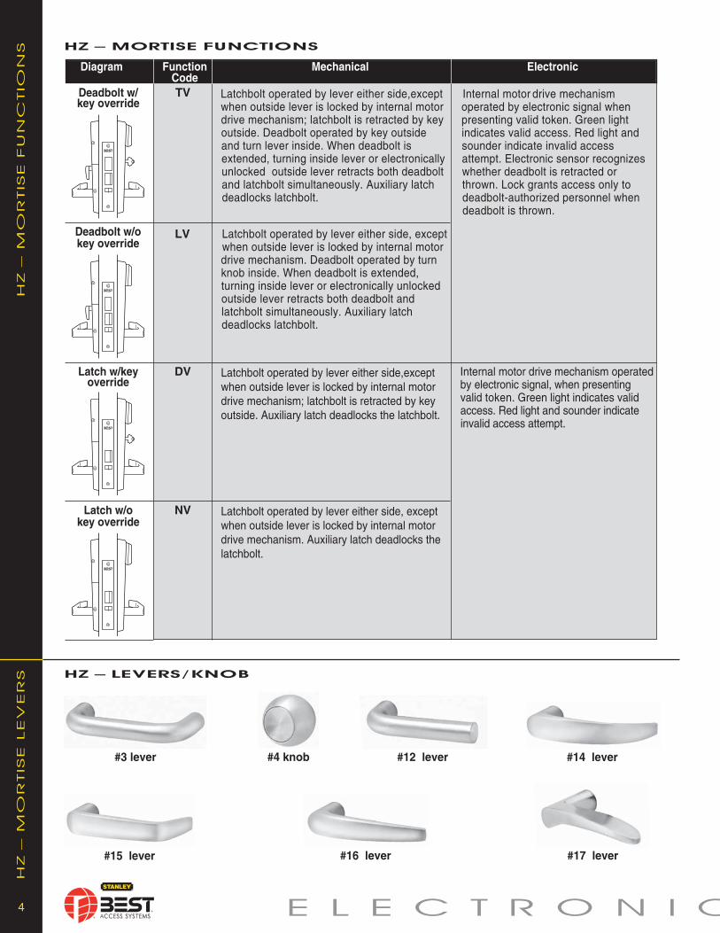
4 E L E C t r O n i C
HZ –
mO
rtiSE fu
nC
tiO
nS
Latch w/o key override
Deadbolt w/o key override
Deadbolt w/ key override
Latch w/keyoverride
Internal motor drive mechanism operatedby electronic signal, when pre sent ingvalid token. Green light in di cates validaccess. Red light and sound er in di cateinvalid access attempt.
HZ – MorTisE fuNcTioNs
Latchbolt operated by lever either side,exceptwhen outside lever is locked by internal motordrive mechanism; latchbolt is re tract ed by keyoutside. Deadbolt operated by key outsideand turn lever inside. When deadbolt isextended, turning inside le ver or electronicallyunlocked out side lever re tracts both deadboltand latchbolt simultaneously. Auxiliary latch dead locks latchbolt.
Internal motor drive mechanism op er at ed by electronic signal when presenting valid token. Green light indicates valid ac cess. Red light andsounder in di cate invalid accessattempt. Elec tron ic sensor recognizeswhether dead bolt is retracted orthrown. Lock grants access only todeadbolt-authorized per son nel whendeadbolt is thrown.
Latchbolt operated by lever either side, exceptwhen outside lever is locked by internal motordrive mech a nism. Deadbolt operated by turnknob inside. When deadbolt is extended, turning inside lever or elec tron i cal ly unlockedoutside lever retracts both deadbolt and latchbolt simultaneously. Auxiliary latch dead locks latchbolt.
TV
LV
Latchbolt operated by lever ei ther side, exceptwhen outside lever is locked by internal motordrive mech a nism. Auxiliary latch deadlocks thelatch bolt.
NV
DV Latchbolt operated by lever ei ther side,exceptwhen outside lever is locked by internal motordrive mech a nism; latchbolt is retracted by keyoutside. Auxiliary latch deadlocks the latch bolt.
Diagram Function Mechanical Electronic Code
HZ – lEVErs/KNob
HZ –
mO
rtiSE LEV
Er
S
#14 lever
#16 lever #17 lever
#3 lever #12 lever#4 knob
#15 lever

5C P r O D u C t S
MEcHANicAl
Materials: Internal parts are brass, zinc or corrosion-treated steel. Chassis: 2 1⁄16" diameter to fit 2 1⁄8" diameter hole in door. Strike: Brass or bronze, 4 7⁄8" x 1 1⁄4" x 3⁄32". Fits standard door frame cut out as spec i fied in ANSI A115.1. Correct strike automatically supplied with unit. Backset: 2 3⁄4" standard, 3 3⁄4" and 5" available. Door thickness: For doors 1 3⁄4" - 2 1⁄4" thick. Installation: Lock dimensions requires modified door prep ANSI A156.2 Series 4000, Grade 1 to mount housing. Latchbolt: 9⁄16" throw. Forged trim housing: Dimensions: 10 3⁄8" H x 3 1⁄4"W x 1" D sloping down to 3⁄4". Lever:Made from high-quality zinc alloy. Body is approximately 1 5⁄8" in diameter: Handle is approximately 4 3⁄4" in length (from center-line of chassis). (#14 and #15 conform to Cal i for nia Titles 19 and 24.) Certification: UL listed For GYQS Electrically controlled single point locks or latches for use on 3 hour A label doors. The listing applies for both U.S. and Canadian applications. Finish: 605 - bright brass, clear coated; 606-satin brass, clear coated; 611-bright bronze, clear coated; 612-satin bronze, clear coated; 613*-oxidized satin bronze, oil rubbed; 619-satin nickel plated; 625-bright chromium plated (brass base material); 626-satin chromium plated (brass base material); 690*-dark bronze coated (brass base material). * 613 finish is designed to wear over time, providing an “antique” appearance. 690 finish will continue as a dark brown appearance over time.
ElEcTroNic
Primary power: Alkaline battery pack. Memory backup: Maintains programming 100 years. User feedback indicators: Visual and Audible. Operating & Storage temperature: -30°C to +60°C (-22°F to +140°F). Relative humidity: 10% to 90% non-condensing. Shock: 2000 Gs RMS (maximum door-slam shock) Compliance to FCC , Canadian, EMC requirements; for in ter fer ence FCC Class A digital apparatus.
KEYPAd
Bezel size: 2 5⁄8" x 3 1⁄4" Material: Bezel–high impact ABS, Keypad–silicone rubber. ESD Protection: 15KV. Button operating life: 3-5 million cycles. Button operating force: 3.88 ounces. Operating temperature: -35°C to +55°C (-31°F to +131°F). Storage temperature: -40°C to +55°C (-40°F to +131°F). Sealing: Weatherproof gasket provides protection for outdoor use. (Usable in all environmental/exterior applications.)
KZ SP
EC
ifiC
AtiO
nSKZ – cYliNdricAl sPEcificATioNs
KZ fu
nC
tiO
nS
KZ tr
im
SKZ – cYliNdricAl lEVErs
KZ – cYliNdricAl fuNcTioNs
Diagram Function Mechanical Electronic Code
DV Dead locking latchbolt operated by lever either Internal motor drive mechanism operated by Cylindrical lever either side, except when outside le ver is electronic signal when presenting valid token. Latch w/key locked by internal motor drive mech a nism; Green light in di cates valid access. Red light override latchbolt is deadlocked. and sound er in di cate invalid access attempt.
#14 lever #15 lever #16 lever
9KZ

E L E C t r O n i C 6
Ex
Z SP
EC
ifiC
AtiO
nS EXZ – EXiT HArdwArE sPEcificATioNs
Ex
tr
im
C
HA
rt EX TriM cHArT
MEcHANicAl
Materials: Internal parts are brass, zinc or corrosion-treated steel. Brass or bronze, 4 7⁄8" x 1 1⁄4" x 3⁄32". Fits standard door frame cut out as spec i fied in ANSI A115.1. Correct strike automatically supplied with unit. Strike box sup plied stan dard. Forged trim housing
Lever handle: Brass or bronze. (Lever #14 and #15 conform to California Titles 19 and 24.)Certification: UL listed For GYQS Electrically controlled single point locks or latches for use on 3 hour A label doors. The listing applies for both U.S. and Canadian applications.
Finish: 606-Satin brass, clear coated; 613*-oxidized satin bronze, oil rubbed; 626-satin chromium plated; 690*-dark bronze coated (brass base material).
* 613 finish is designed to wear over time, providing an “antique” appearance. 690 finish will continue as a dark brown appearance over time.
ElEcTroNic
Primary power: Alkaline battery pack. Memory backup: Maintains programming to 100 years.User feedback indicators: Visual and Audible.Operating & Storage temperature: -30°C to +60°C (-22°F to +140°F). Relative humidity: 10% to 90% non-condensing. Shock: 2000 Gs RMS (maximum door-slam shock)Compliance to FCC , Canadian, EMC requirements; for in ter fer ence FCC Class A digital apparatus.
KEYPAd
Bezel size: 2 5⁄8" x 3 1⁄4"Material: Bezel–high impact ABS, Keypad–silicone rubber.ESD Protection: 15KV.Button operating life: 3-5 million cycles.Button operating force: 3.88 ounces.Operating temperature: -35°C to +55°C (-31°F to +131°F).Storage temperature: -40°C to +55°C (-40°F to +131°F).Sealing: Weatherproof gasket provides protection for outdoor use. (Usable in all environmental/exterior applications.)
EXIT HARDWARE SUPPORTED• Adapts to Precision’s 1000 & 2000 series and Von Duprin 98/99 seriesDevices supported:– Rim device– Surface vertical rod– Concealed vertical rod– Mortise
EXZ Keypad

45HZ 7 TV 14 MS 626 RHSeries Core Function Lever Trim Finish Door Options
Housing Code Style Style Hand
* Extra cost option. Must specify keymark and number of keys.** Cost deduction.
C P r O D u C t S 7
Or
DEr
P
rO
CED
ur
EHZ – MorTisE
KZ – cYliNdricAl
93KZ 7 DV 14 MS STK 626Backset Core Function Lever Rose Strike Finish Options
Housing Code Style Style Package
* Extra cost option. Must specify keymark and number of keys.** Six-pin cylinder in Schlage “C” keyway included with 0B, KA, KD options. Must specify “6” for core housing. *** Cylinder not included with COR, MED, SAR, SCH, YAL, or SCHRC options. Must specify “0” for core housing.
ordEr ProcEdurE
EXZ – EXiT HArdwArE
EXZ 7 EV 14 MS 626 RHR PH1 RMSeries Core Function Lever Trim Finish Door Manufacturer Locking Options
Housing Code Style Style Hand Type
* Extra cost option. Must specify keymark and number of keys** EV function (key override) is not available on PH1000 (all models) Von Duprin (mortise type), or Sargent (rim type) device.*** SA8– available (only) with rim type device.
Levers:3**– solid tube/ w/return
12*– solid tube/no return
14– curved return
15– contourangle return
16– curvedno return
17*– gull wing
Knobs:4– round
EXZ–Keypad EZ
0** –keyless7– 7 pinhousing;acceptsall BESTcores
EV– withkey**NV– w/outkey
14– curvedreturn15– contourangle return
KP– keypad 626 690
satin*606 613
RHRBLHRB
VD9– VonDuprin98/99 seriesPH1– Precisionhardware 1000PH2– Precisionhardware 2000SA8– Sargent8000 series ***
RM– rim***MO–mortiseRD– surface& concealedvertical rods
SH*–securityheadscrewsThickDoor*–specifythickness
EXBB*– extendedlife battery pack(Battery dooravailable in 622finish only)SH*– securityhead screwsThick Door*–specify thicknessTAC*– tactile lever7/8" LTC*– flat lipstrike
0**– keyless7– 7 pinhousing;acceptsall BESTcores
45HZ– lever DV– latchwith keyTV– deadboltwith keyLV– deadboltwithout keyNV– latchwithout key
KP– keypadKPA– other cylinder
626 690
Satin*606 612613 619
Bright*605 611625
RHRHRBLHLHRB
14– curved return
15– contourangle return
16– curvedno return
EXBB*– extended life battery pack(Battery door available in 622finish only)LM– lost motionSH*– security head screwsTAC*– tactile lever3/4*– 3/4" throw latch7/8" LTC*– flat lip strike0B**– non-IC zero-bittedKA**– non-IC keyed alikeKD**– non-IC keyed differentCOR***– non-IC Corbin-RusswinMED***– non-IC MedecoSAR***– non-IC SargentSCH***– non-IC SchlageYAL***– non-IC YaleSCHRC***– Schlage
0– keyless6– 6 pinnon-IC cyl.7– 7 pinhousing;acceptsall BESTcores
93KZ– 2 3/4"94KZ*– 3 3/4"95KZ*– 5"
DV– latchwith key
KP– keypad 626 690
Satin*606 612613 619
Bright*605 611625
STK–standardS3– ANSI

For more information on Stanley Security Solutions’ products, services, and office locations visit our web site at www.stanleysecuritysolutions.com
Stanley Security Solutions, Inc.6161 E. 75th Street Indianapolis, Indiana 46250
© 2011 Stanley Security Solutions, Inc. • www.stanleysecuritysolutions.com
Product information contained in this catalog has been com piled and presented with as much care and com plete ness as is reasonably possible. Errors or mistakes may be present, and in many cases, reliance has been placed on information supplied by other manufacturers which may be in error or which maybe subject to changes or mod i fi ca tions by the man u fac tur er with out no tice and without obligation. Therefore, no guar an tee can be made or should beassumed or implied with regards to product in for ma tion con tained in this catalog.
10M R311BAS023
CORMAX™ PAtented KeYInG SYSteM
CO
RM
AX
™P
ATEN
TED
K
EY
IN
G SY
STEM
BEST® CORMAX™ is the premier patented keying system offered by Stanley Security Solutions. CORMAX will meet your needs for security, key control, and convenience. A simple solution with no compromising allowed.
CORMAX is the upgrade path for existing BEST Standard, Premium, and MX8 customers; and it is an essential element of non-residential access control as security administrators strive to eliminate the unauthorized duplication of keys.
CORMAX offers the following features and benefits:
• A long-term US utility patent that guarantees the extended useful life of the system through 2027.• A second, independent locking mechanism that utilizes a patented set of built-in side pins to provide higher security. • Several levels of geographical exclusivity, including national exclusivity, are available via the patented side pin feature.• CORMAX cores and keys are available exclusively through Stanley sales offices. Key blanks are only sold to individuals authorized by the customer to ensure key blanks do not end up in the possession of unauthorized personnel either inside or outside the customer’s facility.
• CORMAX cores are certified to meet the security, safety, and reliability requirements of BHMA A156.5 Grade 1.• Picking and drilling resistance options are available if higher levels of security are desired.• Complete factory masterkeying service offered, and at no charge with purchase of BEST locksets and PHI exit devices.• Keyways are organized in families of four keyways each, with double-milled and quad-milled key levels to facilitate the design of masterkey systems in multi-building campuses.
• BEST CORMAX cores are compatible with all existing BEST interchangeable core housings, eliminating the need for newor modified locksets.
CORMAX™
Patented Keying System

ID
H M
ax
®&
ELEC
TR
OM
EC
Ha
NIC
aL LO
Ck
s
IDH Max®&
ELECTROMECHaNICaL LOCks

2 IDH Max® & ELECTRO
ID
H M
ax
®– IN
TR
OD
UC
TIO
NID
H M
ax
®– fEa
TU
REs
IDH MAX® – InTRoDUcTIon
40HW electrified functions ..............................................8-98KW/9KW electrified specification ....................................108KW/9KW elec tri fied how-to-order ..................................108KW/9KW electrified functions ........................................10Trim variations ..................................................................11Electrified accessories ................................................12,13Terminology ......................................................................131W electric switch lock introduction ..................................14Optional boxes ..................................................................141W electric switch lock how-to-order ................................141W electric switch locks................................................15-19
TabLE Of CONTENTs
IDH MAX® introduction ........................................................2IDH MAX® features ..............................................................2IDH Max® and IDH Max® 1300 comparison chart ................3HM, KM, HW & KW options..................................................340HM IDH MAX® specifications, how-to-order ....................440HM IDH MAX® functions ..................................................593KM IDH MAX® specifications, how-to-order ....................693KM IDH MAX® functions ..................................................740HW/8KW/9KW electrified lock introduction ......................740HW electrified specification ..............................................740HW electrified how-to-order..............................................8
PagePage
The IIDH MAX® from Stanley Security Solutions offers convenience and efficiency for your electrified lock applications. Instead of installing reader devices, installing electrified strikes, installing door contacts and installing request-to-exit devices, you can now install the IDH MAX® in cylindrical or mortise lock applications. With IDH MAX® all of the formerly separate equipment needed to control access are self-contained in a single installation. The complexity of multiple wire runs is drastically reduced.
You can let Stanley Security Solutions show you how to MAXimize your access control system with the IDH MAX®! For the name and location of your local office, visit our web site at www.stanleysecuritysolutions.com. IDH MAX® and W series locks (with the exception of the IDH Max® 1300) are compatible with Stanley’s NT500 and B.A.S.I.S. Acess Control Systems.
Magnetic Stripe Electronic Lock Features • Durable material has teflon-like characteristics for increased life and wear resistance • Variable read rate allows for easy usage
Proximity Card Reader Features • HID and Motorola/Indala proximity cards supported • UL listed for GYQS Electrically controlled single point locks or latches. • Usable in all environmental/exterior applications.
1300 Option Features • Eliminates need for small panel interface module • Eliminates reader interface board • Incorporates 3 modules into a single electronics board inside IDH Max escutcheon trim • Connects directly to ACP via 2 wire RS485 connection
IDH MAX® – FEATURES
IDH Max® Features • Includes latch and door position indicator, RQE switch. • The 1300 option eliminates the need for a RIM (reader interface module) which is embedded behind the escutcheon • Requires only one 4 conductor wire run • Reduces number of components installed and visible at the door (PIR, RQE push buttons and door contacts) • Installation time is reduced • The RQE switch senses the inside lever/knob rotation. • All of the door components are housed in one manufacturer's hardware • With the elimination of components, only the lockset is visible at the door • The reader is integrated into the lockset escutcheon • Available in magnetic stripe and proximity readers • Available in all popular lever/knob styles and finishes • Operates with BEST interchangeable core as a mechanical override • Integrates with many manufacturer's on-line EAC equipment
Mortise Features • Lock case meets the requirements as listed in the ANSI/ BHMA A156.13 standard for Series 1000, Grade 1 Operational and Grade 2 Security locks • UL listed for GYQS Electrically controlled single point locks or latches for use on 3 hr, A label doors (4' x 10' ). The listing applies for both U.S. and Canadian applications • Door contact, request-to-exit, and latch status sensors positioned inside lock case • The 1300 option eliminates the need for a RIM (reader interface module) which is embedded behind the escutcheon • The door contact magnet is installed behind the strike and out of site (except when deadbolt option is ordered) • All sensors are standard in IDH Max mortise locks • The heavy duty design of the mortise lock makes easy field maintenance and reduces risk of part failure
Mortise Features (continued) • Twist off lever spindle design protect internal lock parts from damage and failure. • Oil impregnated stainless steel 3/4" anti-friction latchbolt reduces door closing force and wear.
Cylindrical Features • Non-handed levers allow for ease of installation • Lock chassis meets the requirements as listed in the ANSI/ BHMA A156.2, standard for Series 4000 Grade 1 locks • UL listed for GYQS Electrically controlled single point licks or latches for use on 3 hr, A label single doors (4' x 10') GYJB. The listing applies for both U.S. and Canadian applications • Request-to-exit sensor positioned inside lock trim • The ISC (Intelligent System Controller) is embedded behind the escutcheon secured and out of site • Request-to-exit and door contact sensors are standard in IDH MAX cylindrical locks

MECHaNICaL LOCks 3
ID
H M
ax
®C
OM
Pa
RIsO
N C
Ha
RTIDH MAX® & IDH MAX® 1300 coMPARISon cHART
1. Prep door for IDH MAX®
2. Run single 4 conductor wire for IDH MAX®
3. Install IDH MAX®
4. Install electrified hinge5. Mount control panel
* Operates with any control panel hardware, including B.A.S.I.S. control panels.
1. Prep door for IDH MAX®
2. Run single 4 conductor wire for IDH MAX® 13003. Install IDH MAX® 1300 which includes Intelligent System4. Install electrified hinge
** Operates with B.A.S.I.S. control panels only.
***
IDH MAX® IDH MAX® 1300
HM
, k
M, H
W k
W – O
PTIO
NsHM, KM, HW & KW – oPTIonS
AL– Besides complying with a wide variety of accessibility codes and ordinances, lever handles are available with a special abrasive feature. Abrasive strip on the lever im me di ate ly identifies warnings on doors to hazardous areas for the blind.
BRK– When excessive force (approx. 300 inch lbs.) is applied to #4, #6 keyed knobs, they “breakaway” and spin freely, thus allowing entrance only by key. Simple part replacement returns lock to func tion al usage.
IDH– The integrated Door Hardware groups three components into one hardware package. 1. Door monitoring switch (normally closed) 2. Request-to-Exit switch (normally open) 3. Electrically controlled locking mechanism.
KNL– Knurl feature is available only on #6 knobs. The knurling is machined into the outer edge of the knob. The knurled feature can be used for blind, safe ty, or ac ces si bil i ty applications.
LL– Lead lined feature can be used to protect against X-rays. Since the majority of lead lined doors contain the lead in the surface of the door, the knob lockset provide lead lining for the holes cut in the door when preparing the door for the trim.
LM– The Lost Motion feature allows the lever handle to move 45 degrees from parallel to the horizontal plane without engaging the latchbolt assembly. When the lockset is in the locked mode, this feature makes over-torque or over-lever-age abuse more difficult to achieve.
SH– Security head provided for all exposed screws.
RQE– Cylindrical or Mortise locksets can be supplied with a request-to-exit switch. A normally open switch provides momentary switch closure when the inside lever/knob is rotated.
TAC– Grooves are machined into knobs to improve grip or to be used as a warning in hazardous areas. This option can be used for blind, safety or ac ces si bil i ty applications.
Thick door– Specify thickness if other than 1 3⁄4" .
TL– Tactile levers may be used in areas where improved grip is required or as a warning in hazardous or Safety First areas. Grooves are machined into the back of the hand grasp portion of the lever to improve grip and/or provide a sensory warning. This option can be used for blind, safety, or accessibility applications.
1300– Integrated BAS1300/LNL1300 reader electronics board or (ISC) Intelligent System Controller is embedded behind the escutcheon secured and out of site. Functions with B.A.S.I.S./Mercury on-line equipment only.

4 IDH Max® & ELECTRO
40H
M ID
H M
ax
®sP
EC
IfIC
aTIO
Ns 40HM IDH MAX® – SPEcIFIcATIonS
HO
W TO
O
RD
ER
40HM IDH MAX® – HoW To oRDER
MS– magnetic stripePM– proximityMotorolaPH– proximityHIDMSA– othercylinder
PHA– othercylinder
PMA– othercylinder
45HM– IDH Max™
0– Keyless or less cylinder, 7– 7 pin housing ONLY
605 606611 612613 618619 625626 690
RHRHRBLH
LHRB
**Must specify key mark and number of keys or designate L/C for less core. †See H Series catalog for details.
KNL
(page 11)
Series45HM 7
CoreHousing
DEU 14Function Lever/Knob
Style
MS 626TrimStyle
Finishes†
RHHanding Options†
(page 11)(page 5)
SH – se cu ri ty head screwsTAC – tactile leverThick Door – specify thick ness if other than 1 3/4"7/8" LTC– flat lip strike1300 – B.A.S.I.S. direct connect
(page 3)
MEcHAnIcAl
Case— Heavy wrought steel, 5 7⁄8" H x 4 1⁄4" D x 1" W steel parts are zinc dichromate plated for cor ro sion pro tec tion.
Faceplate— Brass or bronze, 1 1⁄4" x 8" x 7⁄32" . Armored. Adjustable from flat to beveled 1⁄8" - 2" .
Strike— Brass, bronze or Stainless Steel, 4 7⁄8" x 1 1⁄4" x 3⁄32". Fits standard door frame cut out as spec i fied in ANSI A115.1.Correct strike automatically supplied with unit. Strike box supplied standard.
Door thickness— For doors 1 3⁄4" – 4" thick. Installation— Lock requires modified door prep to mount the trim. Faceplate di men sions fit stan dard door prep a ra tion as specified in ANSI A115.1,. Lockset is re vers ible for hand of door.
Latchbolt— Stainless steel, 3⁄4" throw with anti-friction latch. Deadbolt— Solid stainless steel, 1" throw.Auxiliary bolt— Stainless steel.Die cast trim housing—Dimensions: 10 3⁄8" H x 3 1⁄4" W x 1" D sloping down to 3⁄4".Knobs— Diameter: 2 1⁄8" Projection on door: 2 7⁄8"#4, #6 knobs: Material machined from brass or bronze.
Lever handle— Brass, bronze or stainless steel. (Lever #3, #14 and #15 conform to California Titles 19 and 24.)
Mounting— Knob and lever attached with hardened set screw on inside knob or inside lever.
Finish— 605-bright brass, clear coated; 606-satin brass, clear coated; 611-bright bronze, clear coated; 612-satin bronze, clear coated; 613-oxidized satin bronze, oil rubbed; 625-bright chromium plated; 626-satin chromium plated; 629-bright stainless steel; 630-satin stainless steel; 690-dark bronze.
ElEcTRonIc Maximum current draw: 1.1 Amp for 50 milliseconds Typical current draw (hold condition): 650 milliAmps Voltage: 10.2 to 13.2 V (DC only) Operating Temperature: Minimum/Maximum range Inside: 70˚± 4˚F (21˚± 2˚C) Outside: -31˚F (-35˚C) to +151˚F (+66˚C)
Magnetic Stripe Card Reader: Read Rate: 5 inches per second to 50 inches per second. Card thickness: ISO standard .030" ± .003 thick. Compliance to FCC, Canadian, and European EMC requirements; for interference FCC Class A digital ap pa ra tus. Magnetic Stripe adaptation: Trim option that can accept other manufacturers cylinder.
Proximity Reader: ANSI/BHMA A156.25 compliant. Compatible with Motorola / Indala and HID proximity cards. ABA and Wiegand output. Weatherproof bezel and gasket provide protection for outdoor use. (Usable in all environmental/exterior applications) Card Read Range: 0 – 3 inches. Compliance to US FCC, Canadian FCC, and European EMC requirements ESD Protection:15 Kilo Volt
45HM IDH MAX® Mortise
Levers3– solid tube return12– solid tube14– curved return15– curved angle return16– curved no return17– gullwing no return
Knobs4– round
DEL– electrically lockedDEU– electrically unlockedNXEL– electrically lockedNXEU– electrically unlockedTDEL– electrically lockedTDEU– electrically unlockedLEL– electrically lockedLEU– electrically unlocked

MECHaNICaL LOCks 5
40H
M ID
H M
ax
®– fU
NC
TIO
Ns
NXEL–LockedFail Safe
• Outside knob/lever when power is removed from the solenoid• Outside key• Inside knob/lever.
Latchbolt is deadlocked by an auxiliary latch
Applying power to thesolenoid; remains lockedwhile power is on.
Removing power from the solenoid Cannot be locked Always unlocked
Removing power from thesolenoid
Applying power to the solenoid;remains unlocked while power ison.
Applying power to solenoid;remains locked while poweris on.
Removing power from the solenoid
Removing power from thesolenoid
Applying power to the solenoid;remains unlocked while power ison.
Cannot be locked Always unlocked
LatchFunctionLocked by Unlocked by Locked by Unlocked by
Inside Knob/LeverOutside Knob/LeverOperated by
DEL–LockedFail Safe
DEU–UnlockedFail Secure
NXEU– UnlockedFail Secure
Cannot be locked Always unlocked
Cannot be locked Always unlocked
Powered by 12V DC. temperature control module is not needed.
Powered by 12V DC. temperature control module is not needed.
Powered by 12V DC. temperature control module is not needed.
40HM IDH MAX® – FUncTIonS
• Outside knob/lever when power is applied to the solenoid• Outside key• Inside knob/lever.
Latchbolt is deadlocked by an auxiliary latch
LEL–LockedFail Safe
Cannot be locked Always unlocked
• Outside knob/lever when power is removedfrom the solenoid• Inside knob/lever.
Latchbolt is deadlocked by an auxiliary latch
Applying power to the solenoid; remains lockedwhile power is on.
Removing power from the solenoid
TDEL–LockedFail Safe
TDEU–UnlockedFail Secure
LEU– UnlockedFail Secure
Cannot be locked Always unlocked
Cannot be locked Always unlocked
Powered by 12V DC. temperature control module is not needed.
Powered by 12V DC. temperature control module is not needed.
Powered by 12V DC. temperature control module is not needed.
Powered by 12V DC. temperature control module is not needed.
• Outside key• Outside knob/lever when power is applied to the solenoid• Inside knob/lever.
Latchbolt is deadlocked by an auxiliary latch
Powered by 12V DC. temperature control module is not needed.
Deadbolt extended by:Inside thumb turn
Deadbolt retracted by:• Inside thumb turn• Inside knob/lever retracts the deadbolt and latchbolt simultaneously• Outside lever when power isremoved
• Outside key• Outside knob/lever when power is removed from the solenoid.• Inside knob/lever.
Latchbolt is deadlocked by an auxiliary latch
Applying power to the solenoid; remains lockedwhile power is on.
Removing power from thesolenoid
Deadbolt operated by:• Outside key• Inside thumb turn
Deadbolt and Latchbolt retracted simultaneously by:
• Inside knob/lever• Outside knob/lever when power is removed
Applying power to the solenoid;remains locked while power is on.
Removing power from thesolenoid
Deadbolt operated by:• Outside key• Inside thumb turn
Deadbolt and Latchbolt retracted simultaneously by:
• Inside knob/lever• Outside knob/lever when power is applied
• Outside knob/leverwhen power is removedfrom the solenoid• Inside knob/lever.
Latchbolt is deadlocked by an auxiliary latch
• Outside knob/lever when power is applied to the solenoid• Inside knob/lever.
Latchbolt is deadlocked by an auxiliary latch
• Outside knob/lever when power is applied to the solenoid• Inside knob/lever.
Latchbolt is deadlocked by an auxiliary latch
Cannot be locked Always unlockedApplying power to the solenoid;remains locked while power is on.
Removing power fromthe solenoid
Deadbolt extended by:Inside thumb turn
Deadbolt retracted by:• Inside thumb turn• Inside knob/lever retracts thedeadbolt and latchbolt simultaneously• Outside knob/lever when power is applied

6 IDH Max® & ELECTRO
9k
M ID
H M
ax
®– sP
EC
IfIC
aTIO
Ns 9KM IDH MAX® – SPEcIFIcATIonS
9KM/8KM IDH MAX® – HoW To oRDER
* Handles and trim are made from a zinc alloy, and have been plated to be equivalent in appearance to the finishes listed.
TL
Lever93KM– 2 3/4"94KM– 3 3/4"95KM– 5"
Knob83KM– 2 3/4"84KM– 3 3/4"85KM– 5"
0– keyless7– 7 pin housing accepts all BESTcores
DDEU– elec-trically-unlocked
DDEL– elec-trically-locked
STK– 2 3/4"ANSI
S3– 4 7/8"ANSI
605 606611 612613 618619 625626 690
Lever14– curved
return15– contour
anglereturn
16– curved noreturn
Knob4– round6– tulip
8KM:BRK – breakaway knobKNL – knurled knobTAC – tactile knob
9KM:AL – abrasive leverLM – lost motionTL – tactile lever Note: specify inside (I), outside (O), or both (B) for AL, TL,TAC, KNL options
Both 8KM & 9KM:SH – security head screws3/4 – 3/4" throw latch1300 – Integrated BAS1300/LNL1300 reader electronicboard
93KMSeries
7Core
Housing
DDEUFunc tion
14Lever*/Knob
Style
STK 626Strike
PackageFinishes* Options
(page 11)(page 7)
MS– magneticstripe
PM– proximityMotorola
PH– proximityHID
MSTrim*Style
(page 11) (page 3)
9k
M/8k
M – H
OW
TO
O
RD
ER
MEcHAnIcAl
Materials— Internal parts are brass, zinc or corrosion-treated steel.Chassis— 2 1⁄16" diameter to fit 2 1⁄8" diameter hole in door.Strike— Brass or bronze, 4 7⁄8" x 1 1⁄4" x 3⁄32". Fits standard door frame cut out as spec i fied in ANSI A115.1. Correct strike automatically supplied with unit. Strike box sup plied stan dard.
Backset— 2 3⁄4" standard, 3 3⁄4" and 5" available.Door thickness— For doors 1 3⁄4" – 2 1⁄4"Installation— Lock dimensions requires modified door prep ANSI A156.2 Series 4000, Grade 1 to mount housing.
Latchbolt— 9⁄16" throw.Die cast trim housing— Dimensions: 10 3⁄8" H x 3 1⁄4" W x 1" D sloping down to 3⁄4".Knobs— Diameter: 2 1⁄8" Projection on door: 2 7⁄8"#4, #6 knobs: Material machined from brass or bronze.
Lever handle— Made from high-quality zinc alloy. Body is approximately 1 5⁄8"in diameter: Handle is approximately 4 3⁄4" in length (from center-line of chassis). (Lever #14,15 conform to Cal i for nia Titles 19 and 24.)
Finish— 605-bright brass, clear coated; 606-satin brass, clear coated; 611-bright bronze, clear coated; 612-satin bronze, clear coated; 613-oxidized satin bronze, oil rubbed 625-bright chromium plated; 626-satin chromium plated; 690-dark bronze.
ElEcTRonIc
Maximum current draw: 850 MilliAmps, for 50 milliseconds Typical current draw (hold condition): 550 milliAmps Voltage: 10.2 to 13.2 V Operating Temperature: Minimum/Maximum range Inside: 70˚± 4˚F (21˚± 2˚C) Outside: -31˚F (-35˚C) to +151˚F (+66˚C)
Magnetic Stripe Card Reader: Read Rate: 5 inches per second to 50 inches per second. Card thickness: ISO standard .030" ± .003 thick. Compliance to FCC, Canadian, and European EMC requirements; for interference FCC Class A digital ap pa ra tus. Magnetic Stripe adaptation: Trim option that can accept other manufacturers cylinder.
Proximity Reader: ANSI/BHMA A156.25 compliant, Compatible with Motorola / Indala and HID proximity cards, ABA and Wiegand output Weatherproof bezel and gasket provide protection for outdoor use. (Usable in all environmental/exterior applications). Card Read Range: 0 – 3 inches. Compliance to US FCC, Canadian FCC, and European EMC requirements ESD Protection: 15 Kilo Volt
93KM IDH MAX® cylindrical

MECHANICAL LOCKS 7
9K
M ID
H M
AX
®-FU
NC
TIO
NS
Inside Knob or Lever
DDEL–Locked • Rotating the inside knob/lever,• Rotating the outside knob/lever— only when power is off,• Turning the key in the outside knob/lever.
Applying 12 volts DC.The outside knob/leverremains locked onlywhile power is on.
Cannot be locked Always unlocked
DDEU–Un locked • Rotating the inside knob/lever,• Rotating the outside knob/lever—only when power is on,• Turning the key in the out side knob/lever.
Switching off 12 volts DC
Switching off 12 volts DC
Applying 12 volts DC.The outsideknob/lever remainsunlocked only whilepower is off.
Cannot be locked Always unlocked
Function LatchOperated by
Outside Knob or LeverLocked by Unlocked by Locked by Unlocked by
Shading indicates a ridged lever/knob in a non-energized state.
9KM IDHMAX®– FUNCTIONS
Powered by 12V DC. Temperature control module (TCM) is not needed.
40H
W ELEC
TR
IFIED
- SP
EC
IFIC
ATIO
NS
ELEC
TR
IFIED
-IN
TR
O
40HW Mortise Electrically-Operated Lockset
Types: • 12 volts AC or DC — 0.60 amps • 24 volts AC or DC — 0.45 amps • All EU functions: Electrically Unlocked (Fail Secure) • All EL functions: Electrically Locked (Fail Safe)
Approval Listings: • UL listed for GYQS Electrically-controlled singlepoint locks or latches. • This product has been approved by the California State Fire Marshal (CSFM) pursuant to section 13144.1 of the California Health and Safety Code. • Approved by the city of New York Board of Stan dards and Appeals under calendar number 49-88-SA. See CSFM listing No. 4136-1175:101 for al low able values and/or conditions fo use concerning material pre sent ed in this doc u ment. It is subject to re-examination,revisions and possible cancellation.
NOTE: All W-series locks require the use of a (TCM) Temperature Control Module. A TCM and TCM connector are supplied standard with every order.
The 40HW, 8KW, and 9KW electromechanical locks provide fail-safe (electrically locked) and fail-secure(electrically unlocked) operation. They also provide a way to lock and unlock the door from a remote location for safety, security, or convenience through an individual switch, switch lock, relay, access controlsystem, or other automatic control system. More importantly, these locks exhibit the same features andmeet the same standards and specifications as our mechanical 40H mortise and 8K/9K heavy duty cylindrical locksets.
Powered by 12V DC. Temperature control module (TCM) is not needed.
40HW ELECTRIFIED – SPECIFICATIONS
40HW/8KW/9KW ELECTRIFIED LOCK INTRODUCTION

8 IDH Max® & ELECTRO
40H
W ELEC
TR
IfIED
– H
OW
TO
O
RD
ER
RQE
45HW– lever47HW– leverhigh security
45HW/47HW:DEL– single key
latch, fail safeDEU– single key
latch, fail secureWEL– double key
latch, fail safeWEU– double key
latch, fail secureTDEL– single key
deadbolt, fail safeTDEU– single key
deadbolt, fail secure
TWEL–double key deadbolt, fail safe
TWEU–double key deadbolt, fail secure45HW only:
NXEL– keyless, latch, fail safe
NXEU– keyless, latch,fail secure
LEL– keyless, deadbolt,fail safe
LEU– keyless, deadbolt,fail secure
45HW:605 606611 612613 618619 625626 690
47HW:626 630
AL – abrasive leverIDH – integrated door hardware w/RQE & DS LL – lead linedLS – latch statusDS – door statusRQE – request to exitSH – security head screwsTL – tactile leverThick Door – specify thickness if other than 1 3/4" (1 3/4" min. x 4" max)
Must specify: 24V or 12V
45HW:H– 2 3/4" flatJ– wroughtM– forgedN– forged con cealedcylinder
S– 3 1/2" flatR– 2 3/4" concave
47HW:M– forged
RHRHRBLH
LHRB
45HW:0– keylessor lesscylinder,
7– 7 pin 47HW:
7– 7 pin(accepts5C coresonly)
* “N” trim not available on double keyed functions. **Must specify key mark and number of keys or designate L/C for less core.†See H Series catalog for details.
45HWSeries
7Core
HousingFunc tionNXEU 12 J
LeverStyle
TrimStyle
(page 11) (page 3)(pages 8–9)
612Finishes
†
LHHand ing Options†
40H
W ELEC
TR
IfIED
– fU
NC
TIO
Ns
40HW ElEcTRIFIED – HoW To oRDER
(page 11)
Levers:3– solid tube/
return12– solid tube/
no return14– curved
return15– contour/
angle return 16– curved/no
return17– gullwing no
return
Knobs:4– round
LatchFunctionLocked by Unlocked by Locked by Unlocked by
Inside Knob or LeverOutside Knob or LeverOperated by
40HW ElEcTRIFIED – FUncTIonS
• Inside and Outside knob/lever when power is removed from the solenoid• Inside/Outside key
Latchbolt is deadlocked by an auxiliary latch
Applying power to solenoid; remains lockedwhile power is on
Removing power from solenoid
Applying power to thesolenoid; remainslocked while power ison
Removing powerfrom the solenoid
Powered by 12 or 24 volts AC/DC & 0.60 or 0.45 amps, continuous duty. Temperature control module (TCM) included.
Temperature control module (TCM) included.
• Inside and Outside knob/lever when power is applied to the solenoid• Inside/Outside key
Latchbolt is deadlocked by an auxiliary latch
Removing power from solenoid
Applying power to solenoid;remains unlocked whilepower is on
Removing power from solenoid
Applying power tosolenoid; remainsunlocked whilepower is on
DEL–LockedFail Safe
DEU–UnlockedFail Secure
Powered by 12 or 24 volts AC/DC & 0.60 or 0.45 amps, continuous duty. Temperature control module (TCM) included.
WEL–LockedFail Safe
WEU–Un lockedFail Secure
Powered by 12 or 24 volts AC/DC & 0.60 or 0.45 amps, continuous duty. Applying voltage locks inside & outside knobs/levers simultaneously.
Powered by 12 or 24 volts AC/DC & 0.60 or 0.45 amps, continuous duty. Removing voltage locks inside & outside knobs/levers simultaneously. Temperature control module (TCM) included.
• Outside knob/lever when power is removed from the solenoid• Outside key• Inside knob/lever.
Latchbolt is deadlocked by an auxiliary latch
Applying power to solenoid; remains lockedwhile power is on
Removing power from solenoid
Cannot be locked Always unlocked
Removing power fromsolenoid
Applying power to solenoid;remains unlocked whilepower is on
Cannot be locked Always unlocked• Outside knob/lever when power is applied to the solenoid• Outside key• Inside knob/lever.
Latchbolt is deadlocked by an auxiliary latch
Lock Voltage

MECHaNICaL LOCks 9
NXEL–LockedFail Safe
ATTENTION: Locksets that secure both sides of the door are controlled by building codes and the Life Safety Code®. In an emergency exit situation, failure to quickly unlock the inside lever could be hazardous or even fatal.
LatchFunctionLocked by Unlocked by Locked by Unlocked by
Inside Knob or LeverOutside Knob or LeverOperated by
NXEU–UnlockedFail Secure
Powered by 12 or 24 volts AC/DC & 0.60 or 0.45 amps, continuous duty. Temperature control module (TCM) included.
Powered by 12 or 24 volts AC/DC & 0.60 or 0.45 amps, continuous duty. Temperature control module (TCM) included.
40HW ElEcTRIFIED – FUncTIonS (conTInUED)
40H
W ELEC
TR
IfIED
– fU
NC
TIO
Ns
• Outside knob/lever when power is applied to the solenoid• Inside knob/lever.
Latchbolt is deadlocked by an auxiliary latch
Applying power to solenoid; remains lockedwhile power is on
Removing power fromsolenoid
Removing power fromsolenoid
Applying power to solenoid;remains unlocked while power ison
Cannot be locked Always unlocked
Cannot be locked Always unlocked
LEL–LockedFail Safe
LEU– UnlockedFail Secure
Powered by 12 or 24 volts AC/DC & 0.60 or 0.45 amps, continuous duty. Temperature control module (TCM) included.
Powered by 12 or 24 volts AC/DC & 0.60 or 0.45 amps, continuous duty. Temperature control module (TCM) included.
• Outside knob/lever when power is applied to the solenoid• Inside knob/lever.
Latchbolt is deadlocked by an auxiliary latch
• Outside knob/lever when power is removed from the solenoid• Inside knob/lever.
Latchbolt is deadlocked by an auxiliary latch
Applying power to the solenoid; remains lockedwhile power is on
Removing power from the solenoid Cannot be locked Always unlocked
Deadbolt extended by:Inside thumb turn
Deadbolt retracted by:• Inside thumb turn• Inside knob/lever retracts the deadbolt and latchbolt simultaneously
• Outside knob/lever when power isremoved
• Outside knob/lever when power is applied to the solenoid• Inside knob/lever.
Latchbolt is deadlocked by an auxiliary latch
Cannot be locked Always unlockedApplying power to the solenoid;remains unlocked while power is on
Removing power from thesolenoid
Deadbolt extended by:Inside thumb turn
Deadbolt retracted by:• Inside thumb turn• Inside knob/lever retracts the deadbolt and latchbolt simultaneously• Outside knob/lever when power is applied
• Outside & inside key• Outside & Inside knob/lever when power is removed from the solenoid.
Latchbolt is deadlocked by an auxiliary latch
Applying power to solenoid;remains locked while poweris on
Removing power from solenoid Applying power tosolenoid; remainslocked while power is on
Removing powerfrom solenoid
Powered by 12 or 24 volts AC/DC & 0.60 or 0.45 amps, continuous duty. Temperature control module (TCM) included.
• Outside & inside key• Outside & Inside knob/lever when power is applied to the solenoid.
Latchbolt is deadlocked by an auxiliary latch
Removing powerfrom solenoid
Applying power tosolenoid; remainsunlocked while poweris on
TDEL–LockedFail Safe
TDEU–UnlockedFail Secure
Powered by 12 or 24 volts AC/DC & 0.60 or 0.45 amps, continuous duty. Temperature control module (TCM) included.
TWEL–LockedFail Safe
TWEU–Un lockedFail Secure
Powered by 12 or 24 volts AC/DC & 0.60 or 0.45 amps, continuous duty. Applying voltage locks inside & outside knobs/levers simultaneously.
Powered by 12 or 24 volts AC/DC & 0.60 or 0.45 amps, continuous duty. Removing voltage locks inside & outside knobs/levers simultaneously.
• Outside key• Outside knob/lever when power is removed from the solenoid.
Latchbolt is deadlocked by an auxiliary latch
Applying power to solenoid;remains locked whilepower is on
Removing power from solenoid Cannot be locked Always unlocked
Removing power from solenoid
Applying power to solenoid;remains unlocked while power is on
Cannot be locked Always unlocked• Outside key• Outside knob/lever when power is applied to the solenoid.
Latchbolt is deadlocked by an auxiliary latch
Deadbolt operated by:• Outside or inside key• Outside & Inside knob/ lever when power is removed from the solenoid
Applying power to solenoid;remains unlocked while power is on
Removing power from solenoid
Deadbolt operated by:• Outside or inside key• Outside & Inside knob/ lever when power is applied to the solenoid
Deadbolt operated by:• Outside key• Inside thumb turn
Deadbolt operated by:• Outside key• Inside thumb turn
Deadbolt and latchbolt retracted simultaneously by:
• Inside knob/lever• Outside knob/lever when power isremoved.
Deadbolt and latchbolt retracted simultaneously by:
• Inside knob/lever• Outside knob/lever when power isapplied.
Temperature control module (TCM) included.
Temperature control module (TCM) included.

Lock Voltage
NOTE: 8KW/9KW Electromechanical locksets are intended for use on minimum 1 3/4"thick doors. Consult your local Stanley office when in stall ing 8KW/9KW electromechanical locksets on doors less than 1 3/4" thick.
NOTE: All W-series locks require the use of a (TCM) Temperature Control Module.A TCM and TCM connector are supplied standard with every order.
10 IDH Max® & ELECTRO
93KW cylindrical Electrically-operated lockset
8KW & 9KW ElEcTRIFIED locKS – SPEcIFIcATIonS
8KW & 9KW ElEcTRIFIED locKS – FUncTIonS
Inside Knob or Lever
DEL-Locked Applying power to thesolenoid; remainslocked while power ison.
Removing power from thesolenoid
Cannot be locked. Always unlocked.
DEU-Un locked • Rotating the inside knob/lever, • Rotating the outside knob/lever—only when power is on, • Turning the key in the outside knob/lever.
Removing power from thesolenoid
Applying power to thesolenoid; remains lockedwhile power is on.
Cannot be locked. Always unlocked.
Locks are powered by 12 or 24 volts AC/DC at 500mA max. or 0.18 amps. Temperature control module (TCM) included
Locks are powered by 12 or 24 volts AC/DC at .50amps max. or 0.18 amps. Temperature control module (TCM) included
Function LatchOperated by
Outside Knob or LeverLocked by Unlocked by Locked by Unlocked by
8k
W/9k
W – fU
NC
TIO
Ns
8k
W/9k
W – sP
EC
IfIC
aTIO
Ns
Shading indicates a ridged lever/ knob in a non-energized state.
8KW:4– round6– tulip
9KW:14– curvedreturn
15– contour angle return
16– curved no return
* Handles are made from a zinc alloy, and have been plated to be equivalent in appearance to the finishes listed.
TL
8KW:83KW– 2 3/4"84KW– 3 3/4"85KW– 5"
9KW:93KW– 2 3/4"94KW– 3 3/4"95KW– 5"
0– keyless7– 7 pinhousingacceptsall BESTcores
DEU–electrically-unlocked
DEL–electrically-locked
C– 3" convexD– 3 1/2" convexK– 3" convex—no ring
L– 3 1/2" convex —no ring
STK–2 3/4" ANSIS3–4 7/8" ANSI
605 606611 612613 618619 625626 690
8KW & 9KW ElEcTRIFIED locKS – HoW To oRDER
93KWSeries
7Core
Housing
DEUFunc tion
14Knob/Lever
Style
KTrimStyle
STK 626Strike
PackageFinishes* Options
8k
W/9k
W – H
OW
TO
O
RD
ER
(page 11) ( page 11) ( page 3)(See Below)
• Rotating the inside knob/lever • Rotating the outside knob/lever—only when power is off• Turning the key in the outside knob/lever.
Types: • 12 volts AC/DC when used with supplied TCM — 0.50 amps • 24 volts AC/DC when used with supplied TCM — 0.18 amps • All EU functions: Electrically Unlocked (Fail Secure) • All EL functions: Electrically Locked (Fail Safe)
Approval Listings: • UL listed for GYQS Elec tri cal ly-controlled singlepoint locks or latches. • This product has been approved by the California State Fire Marshal (CSFM) pur su ant to section 13144.1 of the California Health and Safety Code. • Approved by the city of New York Board of Standards and Appeals under calendar number 730-89-SA. See CSFM listing No. 4136-1175:103. It is subject to re-examination, revision and possible cancellation.
8KW only:BRK– breakaway knobKNL– knurled knobTAC– tactile knob
9KW only:AL– abrasive leverLM– lost motionRQE– request-to-exitTL– tactile lever Note: specify inside (I), outside(O), or both (B) for AL, TL, TAC,KNL options
8KW & 9KW:LL– lead linedSH– security head screws3/4 – 3/4" throw latch
Must specify: 24V or 12V

MECHaNICaL LOCks 11
#3 lever #12 lever #14 lever LEV
ER
sTy
LEs
kN
Ob
s
lEVER STYlES
RO
sEs TR
IM
s
MoRTISE RoSE TRIMS
EsC
UTC
HEO
N TR
IM
EScUTcHEon TRIM VARIATIonS
#15 lever #16 lever #17 lever
#4 knob #6 knob
KnoB STYlES
cYlInDRIcAl RoSE TRIMS
C rose D rose K rose L roseR rose S rose
J escutcheon M escutcheon N escutcheon MS escutcheon Prox escutcheon
H rose

Transformer
Function/Application: Transforms 120 volts AC to 24 volts AC. (To get 24 volts DC, use with 8WCON, AC to DC converter.) Typ i cal ly used as a power supply for electrically-op er at ed locks.
Function/Application: Converts AC (alternating current) to DC (direct current) for locking circuit applications. (Typ i cal ly used with 8W599 transformer.)
8WBU-1-AStandard plate
8WBU-1-nNarrow plate
Function/Application: Normally open push-button switch provides mo men tary switch closure when pressed. Typically used to momentarily en er gize electrified locks or strikes or used as a re quest-to- exit switch on access control systems.
12 IDH Max® & ELECTRO
Features: • 400 Ampere surge capability • Electrically isolated base • UL recognized • Single-phase, full wave bridge
Specifications: Average forward current: 25 amps Case: Plastic case with an electrically isolated aluminum base Polarity: Terminal designation embossed on case: +DC output, -DC output, AC not marked Mounting position: Bolt down. Gain the highest heat transfer ef fi cien cy through the surface op po site the terminals. Use silicone heat sink compound on mounting surface for max i mum heat transfer. Terminals: Suitable for “fast-on” connections. Readily solderable and corrosion resistant. Soldering is recommended for applications greater than15 amperes. Mounting torque: 20 inch-pounds maximum Case size: 1.030 x 1.030 inches Temperature range: -85° to 347°F (-65 ° to + 175°C)To order specify: 8WCON
Features: • Offers exceptionally high power for its compact size • UL listed • Thermally fused • Convenient 4 point mounting provision allows rapid installation in a standard 1/2" knockout • Foot-mounts for surface installation • Pre-stripped pigtails provided for quick primary connection • Secondary connection by screw terminals • Sturdy nylon bobbin construction • Cadmium plated finish
Specifications: Primary voltage: 120 VAC (Wire Leads) Secondary voltage: 24 VAC (Screw Terminals) Secondary VA: 40 volts-amperes Dimensions: 2 1/4" x 2 1/8" x 2 15/16"To order specify: 8W599
8W
599
8W599
8Wcon
ElEcTRIFIED AccESSoRIES
8W
CO
N
8WBU-1-A / 8WBU-1-n
8W
bU
-1-a
&
N
Features:• Positive “snap” feedback • Industrial-grade switch designed for rugged control applications • Factory assembled with trimplate • Standard or narrow plate available • 1 3/16" dia. mushroom head—red in color
Specifications: Electrical rating: 28VDC or 115 VAC, 10A resistive, 5A in duc tive, 3A lamp load (see ter mi nol o gy on the back cover) Switch type: SPST-NO-DB, FORM-X contacts, 25,000 cycles at full load, 50,000 cycles me chan i cal life Mounting hole: 5/8" (.625) dia. Switch dim.: 1.187 dia.x 1.528 overall length Std. wall plate: 2 3/4" x 4 1/2" Narrow wall plate: 1 1/2" x 4 1/2" Material/finish: Satin stainless steel Wire leads: Two 6" long 20 AWG insulated wire leadsTo order specify: 8WBU-1-A stan dard plate 8WBU-1-N narrow plate
Ac to Dc converterFull wave bridge rectifier

MECHaNICaL LOCks 13
ElEcTRIFIED AccESSoRIES
TERMInoloGY
Closed– A state in which a connection exists between the common terminal and another terminal on the switch. See Open also.
Common terminal– A terminal on a switch whose contact can be connected to one or more terminals on the switch.
Door status– A switch that monitors whether the door is open or closed. This switch is used to detect a forced entry, or a door
that is propped open.
Inductive load– An electrical device such as a motor, relay, or solenoid. Note: this type of load can cause arcing across switch
con tacts and may burn the contacts. See Resistive load and Lamp load also.
Latchbolt status– A switch that monitors whether the latch is engaged or retracted. This switch is used to detect a forced entry,
or a latch that has been taped open.
Lamp load – An electrical device that produces light using a tungsten filament, such as an incandescent light bulb. Note: this type
of load can cause surges of current upon contact closure. This may cause the contacts to weld together. See Inductive load and
Resistive load also.
Maintained– Remaining in a given state until the switch lever or button is actuated. Actuating the switch lever or button causes
the switch to change to another maintained state.
Momentary– Remaining in a given state only as long as an external force is applied to the switch lever or button.
NC– (Normally Closed) Switch contacts that are closed as long as no external force is applied to the switch lever or button.
NO– (Normally Open) Switch contacts that are open as long as no external force is applied to the switch lever or button.
Open– A state in which no connection exists between the common terminal or any other terminal on the switch.
Pole– The number of independent circuits in a switch. For example, a double-pole, single-throw switch can control two separately
powered motors. See Throw also.
Resistive load– An electrical device, such as a heater, having none of the char ac ter is tics of an inductive or lamp load. This type
of load is the least severe on the switch because only a small amount of arcing occurs when the switch contacts open and close.
See Inductive load and Lamp load also.
RQE– Request-to-exit. A switch that allows the user to exit without setting off an alarm. Turning the inside knob or lever actuates
the switch and, when wired to an alarm system, sends a signal to disable or sound an alarm, start a timer, etc.
Throw– The number of circuits, or contacts controlled by each pole. For example, a single-pole, double-throw switch can control
a motor with two contacts—a forward contact, and a reverse contact. See Pole also.
1300– Integrated BAS1300/LNL1300 reader electronics board or (ISC) Intelligent System Controller is embedded behind the
escutcheon secured and out of site. Functions with B.A.S.I.S./Mercury on-line equipment only.
Features • All circuitry completely sealed
Specifications Wire leads: Input– 24 AWG – Stranded wire with PVC insulation (approx. 60" in length) Output– 24 AWG – Stranded wire with Teflon insulation (approx. 2.6" in length) Input: 12 or 24 volts AC or DC @ at 0.50 or 0.18 amp Output: Voltage out @ 1 amp maximum for 0.5 seconds then 30% of voltage out for 5 seconds Output protection: Short circuit current limiting set at one (1) amp. Operating temp: -4 to 158°F (-20 to 70°C) Size: 1/2" x 2" x 1/2"To order specify: 8WTCM
TER
MIN
OLO
Gy
Function/Application A temperature control module (TCM) reduces the amount of current flow to a lockset one second after energizing, thereby lowering the tem per a ture of the lockset trim. A (TCM) also converts AC power to DC power and should be used on all electrified mortise and cylindrical locksets.Note: The TCM is not used with any IDH-Max function.
8W
TC
M
Temperature control module
8WTcM

14 IDH Max® & ELECTRO
ELEC
TR
IC
sW
ITC
H LO
Ck
–IN
TR
OD
UC
TIO
N Stanley Security Solutions offers a line of electric switch locks available in various “on-off” and “mo men tary” keyed switch func tions. Circuitry vari a tions are available in single, double and triple pole with varied voltage and amperage ratings. Units may be keyed into any BEST system. The BEST in ter change able core offers ver sa til i ty and adapt abil i ty for new and existing electrical controls, panels, machines, etc.Features • Double D lock cylinder prevents slipping and turning • Screw terminals on all switch locks (except the 1W7A1) provides ease of installation • All switches are UL recognized or listedNote on functionality: Switch lock keys can only be removed in the 12 o’clock position.
How to select a switch lock 1. Determine the electrical requirements for the device being controlled: A. Voltage (for example: 115 VAC or 24 VDC) B. Current or horsepower (for example: 6 amps or 1/2 horsepower) C. Type of load • Resistive (for example, heat er elements) • Inductive (for example, mo tors, large transformers) • Lamp (for example, in can des cent lights) 2. Determine the switch configuration (poles and throws) and key re mov al condition: A. Poles To determine the number of poles, find how many wires from the power source need to be switched on and off by the switch lock. B. Throws To determine the number of throws, find how many wires to the device the switch needs to control. For example, if a switch needs two different “on” conditions (low and high speed), two throws are needed. Or if the device is simply an “on-off” type (only one wire), you need one throw. Note: A switch throw may be left unwired and used as an “off” condition. C. Key removal To determine the key removal condition, ask the question, “When the key is removed, should the switch be “off”, or could the switch be either “on” or “off” ?” Although the key can only be removed in the 12 o’clock position, the switch itself may be left in two or three positions. Check each switch lock for key removal switch positions. 3. Use the information collected and find the switch lock that best meets the requirements. Refer to the following catalog pages for a de scrip tion of each switch lock. If en vi ron men tal conditions make it necessary that the switch lock be housed in an electrical box, see the Optional boxes (above) for the box that best suits the switch lock and your application.
ElEcTRIc SWITcH locK – InTRoDUcTIon
SWRStandard weather resistant box
4 5/8" x 2 7/8" x 2 1/4"
InTInterior box
4" x 2 1/8" x 1 7/8"
DWRDeep weather resistant box
4 5/8" x 2 7/8" x 3"
oc2 Deep octagon offset mount
3 1/2" x 3 1/2" x 3 1/4"
oc1Standard octagon center mount
3 1/2" x 3 1/2" x 1 5/8"
oPTIonAl BoXES
OP
TIO
Na
L b
Ox
Es
1W 7– 7 pin housingaccepts all
BEST cores
see pages15–19
605 606611 612613 619622 625626 690
see above
1W 7 B1 626Series Core
HousingFunc tion Finishes
SWR
HO
W TO
OR
DER
HoW To oRDER – 1W ElEcTRIc SWITcH locK
Box

1W ElEcTRIc SWITcH locKS
MECHaNICaL LOCks 15
Key & switch positions Remove key Optional box es
DWR INT OC1 OC2
1W
ELEC
TR
IC
sW
ITC
H LO
Ck
s
1W7A1
1W7B1 & 1W7J1
1W7B1—One switch
1W7J1—Twoswitches
1W7A1
5 /16
15 /16
2 1 /16
3 /4 1 /8
Key & switch positions Remove key Optional boxes
OC1 DWR OC2 INT SWR
Contact rating ........................................................................30 VDC, 15 amps, resistive 125 VDC, 0.6 amps, resistive 250 VDC, 0.3 amps, resistive 125 VAC, 15 amps, resistive 25 VAC, 5 amps, lamp 250 VAC, 15 amps, resistive Horsepower rating ..........................................................................125–250 VAC, 1/2 HP Operating temperature ....................................................................up to +176°F (+80°C)Switch type ....................................................................SPDT (Single pole-double throw)Switch lock action ..............................................................................Maintained (on-on)Number of switches per assembly ........................................1W7B1: One 1W7J1: Two
Contacts ..............................................................................................Silver or gold flashContact rating ..........................................................................28 VDC, 10 amps resistive
28 VDC, 3 amps inductive, lamp125 VAC, 10.1 amps resistive 250 VAC, 10.1 amps resistive
Horsepower rating ..................................................................................125 VAC, 1/4 HP Operating temperature ................................................-85°F to +257°F (-65° to +125°C)Switch type ....................................................................SPDT (Single pole-double throw)Switch lock action ..............................................................................Maintained (on-on)Number of switches per assembly ............................................................................One
(1W7B1 only)
Side view
The shaded area shows the additional 1W7J1 switch and cam length.
Back view
Key pos. 1 onlySwt. pos. 1
Key pos. 1only Swt.
Side viewBack view
Hole cutout
Hole cutout
31/32"
1 5/32"
31/32"
1 5/32"
Key pos.1– Swt. pos.1 Key pos.2– Swt. pos.2
Key pos.1– Swt. pos.1 Key pos.2– Swt. pos.2

16 IDH Max® & ELECTRO
1W
ELEC
TR
IC
sW
ITC
H LO
Ck
s
Key & switch positions Remove key Optional boxes
OC1 DWR OC2 INT SWR (1W7B3 only)
1W7B3—One switch
1W7J3—Two switches
Contact rating .................................................................. 30 VDC, 15 amps, resistive 125 VDC, 0.6 amps, resistive 250 VDC, 0.3 amps, resistive 125 VAC, 15 amps, resistive 125 VAC, 5 amps, lamp 250 VAC, 15 amps, resistive Horsepower rating ....................................................................125–250 VAC, 1/2 HP Operating temperature ..............................................................up to +176°F (+80°C)Switch type ..............................................................SPDT (Single pole-double throw)Switch lock action ........................................................................Momentary (on-on)Number of switches per assembly ..................................1W7B3: One 1W7J3: Two
The shaded area shows the additional 1W7J3 switch and cam length.
Hole cutout
1 5/32"
31/32"
Side viewBack view
Key pos.1– Swt. pos.1 Key pos.1– Swt. pos.1 Key pos.2– Swt. pos.2
Key & switch positions Remove key Optional box es
OC1 DWR OC2 INT SWR (1W7B2 only)
1W7B2—One switch
1W7J2—Two switches
Contact rating .................................................................. 30 VDC, 15 amps, resistive 125 VDC, 0.6 amps, resistive 250 VDC, 0.3 amps, resistive 125 VAC, 15 amps, resistive 125 VAC, 5 amps, lamp 250 VAC, 15 amps, resistive Horsepower rating ......................................................................125–250 VAC, 1/2 HP Operating temperature ..............................................................up to +176°F (+80°C)Switch type ..............................................................SPDT (Single pole-double throw)Switch lock action ..........................................................................Maintained (on-on)Number of switches per assembly ..................................1W7B2: One 1W7J2: Two
The shaded area shows the additional 1W7J2 switch and cam length.Back view
Hole cutout
1 5/32"
31/32"
Side view
Key pos. 2 (360°CCW)
Key pos. 1 and 2Swt. pos. 1 and 2
Swt. pos. 2 Key pos.1– Swt. pos.1
1W7B2 & 1W7J2
1W7B3 & 1W7J3
1W ElEcTRIc SWITcH locKS

1W ElEcTRIc SWITcH locKS
MECHaNICaL LOCks 17
Key & switch positions Remove key Optional boxes
OC2 DWR INT SWR
Key & switch positions Remove key Optional boxes
OC1 OC2
1W
ELEC
TR
IC
sW
ITC
H LO
Ck
s
Contact rating ..............................................................110 VAC or VDC, 10 amps, lamp 220 VAC or VDC, 5 amps, resistiveOperating temperature ..................................................-40°F to +150°F (-40° to +65°C)Switch type ......................................................................SPST (Single pole-single throw)Switch lock action ..............................................................................Maintained (off-on) Number of switches per assembly ............................................................................One
Hole cutout
Side view
†Installing the limiting plate limits key removal to switch position 1 or 2. The key is always removed in the vertical position (key position 1).
Limiting plate†Front view
Key pos. 1 only Swt. pos. 1 and 2†
Front (inside) view Side (inside) view
Key pos. 3 onlySwt. pos. 1 and 2
1 5/32"
7/8"
Contact rating . . . . . . . . . . . . . . . . . . . . . . . . . .110 VAC or VDC, 16 amps, resistive220 VAC or VDC, 8 amps, resistive
Horsepower rating . . . . . . . . . . . . . . . . . . . . . . . . . . .1 HP @ 125–250 VAC or VDCOperating temperature . . . . . . . . . . . . . . . . . . . . . . .0°F to +150°F (-18°C to +66°C)Switch type . . . . . . . . . . . . . . . . . . . . . . . . . . . . . . .DPST (Double pole-single throw)Switch lock action . . . . . . . . . . . . . . . . . . . . . . . . . . . . . . . . . . . .Maintained (off-on)Number of switches per as sem bly . . . . . . . . . . . . . . . . . . . . . . . . . . . . . . . . . . .One
1W7c2
1W7C2
1W7D2
Key pos.1– Swt. pos.1 Key pos.2– Swt. pos.2
Key pos.1– Swt. pos.1 Key pos.2– Swt. pos.2
1W7D2

1W ElEcTRIc SWITcH locKS
18 IDH Max® & ELECTRO
1W
ELEC
TR
IC
sW
ITC
H LO
Ck
s
Key & switch positions Remove key Opt. box es OC2
7/8"
1 5/32"
Hole cutout
1W7K4
1W7K4
Back viewSide view
Key pos.3 Swt. pos.3 Key pos.1 Swt. pos.1 Key pos 2 Swt. pos.2 Key pos. 1 only Swt. pos. 1 only
Contact rating ......................................................................110 VAC, 15 amps, resistive 220 VAC, 10 amps, resistiveHorsepower rating .................................................................................. 250 VAC, 1/2 HPOperating temperature ..................................................................up to +221°F (+105°C)Switch type ..................................................................DPDT (Double pole-double throw)Switch lock action ..............................................................Momentary (on-center off-on)Number of switches per assembly ............................................................................One
Key & switch positions Remove key Opt. box
OC2
Contact rating 110 VAC, 15 amps, resistive 220 VAC, 10 amps, resistiveHorsepower rating 125–250 VAC or VDC, 3/4 HP; 1, 2, or 3 phaseOperating temperature ........................................................0 to +150°F (-18°C to 66°C)Switch type ....................................................................TPDT (Triple pole-double throw)Switch lock action ............................................Maintained Momentary (on-center off-on)Number of switches per assembly ............................................................................One
Key pos.1 Swt. pos.1
Key pos.2 Swt. pos.2
Key pos.3 Swt. pos.3
Key pos. 1 onlySwt. pos. 1, 2, and 3*†
Limiting plate*
Hole cutout
1 5/32"
7/8"
1W7E2
*Installing the limiting plate limits key removal to switch position 2,or 3. The key is always removed in the vertical position (key position 1). The limiting plate isavailable for 1W7E2 only.
Front viewSide view
1W7E2

MECHaNICaL LOCks 19
1W
ELEC
TR
IC
sW
ITC
H LO
Ck
s
2 5 /16"
1 /8"
1 1 /2"
2 7 /8"
1 29 /32"
Contact rating ..........................................................110 VAC or VDC, 12 amps, resistive 220 VAC or VDC, 6 amps, resistiveOperating temperature ..................................................................up to +221°F (+105°C)Switch type ....................................................................SPDT (Single pole-double throw)Switch lock action ..............................................................................Maintained (on-on)Number of switches per assembly ............................................................................One
Contact rating ..........................................................................30 VDC, 15 amps, resistive125 VDC, 0.6 amps, resistive 250 VDC, 0.3 amps, resistive 125 VAC, 15 amps, resistive
125 VAC, 5 amps, lamp 250 VAC, 15 amps, resistive
Horsepower rating ............................................................................125–250 VAC, 1/2 HP Operating temperature ....................................................................up to +176°F (+80°C)Switch type ....................................................................SPDT (Single pole-double throw)Switch lock action ..............................................................................Momentary (on-on)Number of switches per assembly ........................................1W7P4: Two 1W7R4: Four
Side view Front viewLimiting plate†
Hole cutout
7/8"
1 5/32"
Key & switch positions Remove key Optional boxes DWR OC2
Key pos. 1 Swt. pos. 1
Key pos. 2 Swt. pos. 2
†Installing the limiting plate limits key removal to switch position 1 or 2. The key is always removed in the vertical position (key position 3).
Key pos. 3 onlySwt. pos. 1 and 2†
The shaded area shows the additional 1W7R4 switches and cam length.
Back view Side view
Hole cutout
1 5/32"
31/32"
Key & switch positions Remove key Boxes SWR† INT† DWR
†1W7P4 only
Key pos. 1 onlySwt. pos. 1 only
Key pos.1 Swt. pos.1 Key pos.3 Swt. pos.3 Key pos.2 Swt. pos. 2
1W7l2
1W7P4 & 1W7R4
1W7L2
1W7P4—two switches
1W7R4—four switches
1W ElEcTRIc SWITcH locKS

For more information on Stanley Security Solutions’ products, services, and office locations visit our web site at www.stanleysecuritysolutions.com
Stanley Security Solutions, Inc.6161 E. 75th Street Indianapolis, Indiana 46250
© 2011 Stanley Security Solutions, Inc. • www.stanleysecuritysolutions.com
Product information contained in this catalog has been com piled and presented with as much care and com plete ness as is reasonably possible. Errorsor mistakes may be present, and in many cases, reliance has been placed on information supplied by other manufacturers which may be in error orwhich may be subject to changes or mod i fi ca tions by the man u fac tur er with out no tice and without obligation. Therefore, no guar an tee can be made orshould be assumed or implied with regards to product in for ma tion con tained in this catalog.
10M 111BAS019
ID
H M
ax
®&
ELEC
TR
OM
EC
Ha
NIC
aL LO
Ck
s

KEYSTONE®600N5
KEY
& C
OR
E C
ON
TR
OL

2
KEYSTONE®600N5 SOFTWARE
The Best Access System Keystone® 600N5 key and core control software offers all of the same security, convenience, and functionality found in the original Keystone®
600 program, but with the added ability to operate in a network configuration. Keystone® 600N5 will assist you with thetedious task of managing your key and core
records in today’s environment, in which multiple people in different locations may need to access the data simultaneously. Designed to operate over modern network environments, such as Windows® NT, XP or Windows® 2000. Keystone® 600N5 includes special help screens that can be accessed whenever you need assistance.
Complex commands and detailed menutrees are eliminated by the function key index at the bottom of each screen. Select the information tab desired and the appropriate screen is called up.Instructions and help screens are immediately available.Demo Facility
K E Y S T O N
SO
FTW
AR
E
Security• Password restricted logins enable administration to restrict individuals
access for designated cards
Buildings• Designed to support multiple facilities• Display people, keys and departments with access to a building• Lists departmental access, designating the people, keys and keyrings
that have access to that department• Displays buildings with doors, cores and locks in the building
Keys• List all keys and items currently due back (or due back by any day
designated)• Lists keys that have been issued and keyholders• On-screen display of BEST masterkey code records entered• Records issuance of keys, keyrings, cores and locks to people• Maintains historical records on all keys, keyrings, cores and locks• Shows all “keyrings”, keyring holders, and what buildings, cores and
doors the keyring accesses• Maintains “key cabinet” records displaying the keys, keyrings and
locks located on a “hook”• Tracks “out-of-service” keys, keyrings and other items that are lost,
stolen or destroyed• Displays cores, departments, doors, buildings keys can access
Cores• Lists all cores and their location, buildings and doors• Cross-references employees, keys and departments
People• Displays people, keys, keyrings, cores, locks on one record• Maintains list of deleted employees (and doors) with the ability to
display and reactivate them• Searches for and identifies people by name, ID, department, title
and type• Cross-references people to cores, doors, buildings they access
Locks• Displays locks, lock location and the people, keys and departments
with access to that lock• Lists manufacturer product records with items connected specifically
to that manufacturer’s product
Doors• Shows the doors with cores, locks and other items that are installed
on the door• Displays doors and people, keys and departments that can access
those doors
Software – general• Comprehensive list of reports available as an on-screen menu• Built-in easy-to-use backup program• Program always displays date of last backup• Lists users who made backups with dates• Dynamic searching capability for all records• Large note field available on all card records• On-screen indicator shows when historical info. is present for a record• On-screen indicator appears when notes are present on a record• Able to operate in an NTFS network environment with TCPIP protocol• Multiple users can access program at same time• Stanley service that Import/Append data (Some formats)• Mass deletion
FEA
TU
RES KEYSTONE
®600N5 FEATURES

3
This card allows you to display BEST masterkey code sheets for your system. It also includes a manual pin
segment calculator (requires that allkey cut numbers have to be typed infor each key).This card main-
tains records on the keys, cores, key-rings and locks that a per-son is issued. It cross-references
the cores, doors, and buildings that aperson can access with their keys andkeyrings.
This card allows for the tracking of a product by: • the manufactur-
er's name catalog number
• type of product(key, core, lock or other). It also givesthe past history of locks that havebeen used in that product.
N E®
6 0 0 N 5
SC
REEN
TA
B D
EFIN
ITIO
NSS C R E E N TA B D E F I N I T I O N S
This card allows you to track the door,cores and locks in each building. Italso cross-references the employees,keys and departments that access thedesignated building.
This card tracks and maintains historicinformation for items (i.e. cores, keys,keyrings, and locks) that are reportedlost, destroyed or stolen.
With this card, locks can be identified by:• manufacturer • nomenclature• serialization
It also displays the core used in thedesignated lock (includes historical information for installed cores). It alsopermits the cross-referencing of thatlock to employees, keys, and depart-ments. This card can also report thelock's "disposition" (defined as the lo-cation of that lock, i.e. cabinet, door,employee, hook, destroyed, lost,stolen or unassigned.
This card allows you to maintainrecords of the cores and locks in adesignated door and provides a cross-reference to the employees, keys anddepartments that can access thatdoor.
This card lists the employees, cores,keys, and key rings that are associatedwith a department. It cross-referencesthe cores, buildings and doors that adepartment can access.
These cards allow you to record and reference the cores, keys locks, andkeyrings that are located in your cabinet.
This card maintains records for thesetting of security passwords allowingvarious levels of access to theKeystone® 600N program by securitypersonnel and program users.
This card displays records on keys,cores, keyrings, and locks when a keycabinet is not used for organizing keystorage.
These cards display the key marks,key serial numbers and any history ofa key. They permit the cross-referenc-ing of the employees with keys issuedand the associated cores, doors, anddepartments that can be accessed bythat key.
This card allows for a vast array ofstandardized reports to be generatedby:
• employee name or identification• door location• core• key• department or building• others
When multiple keys are issued to an individual, many times a “keyring” isused to organize the issuance andcontrol. This card tracks the keyring asa single file. This card shows currentand historic information of the keysattached to the assigned keyring. Italso cross-references the keyring keysto associated employees, cores, doorsand buildings involved.
When special"selective" keying is designed and used in a facility system, thesecards will track the keys that can
operate a selective core. These cardsmaintain historic information of coresand cross-references the employees,keys and departments that operate thecore. They also maintain the buildingand door location of a core. An auto-mated pin segment calculator is avail-able with these cards.
This card identif-ies the list of facili-ties that are beingtracked, as well as the list of userswith program access.
This card tracks all keys, keyrings and locks issued and reports their status when due for return. This function allows
you to view items due for return todayand for previous days. This card dis-plays a summary count of buildings,departments, doors, employees,cores, keys, keyrings, and locks in thefacility database. It also tracks thedates. Backups are made and identi-fies who did the backup.

SP
EC
IFIC
ATIO
NS SPECIFICATIONS
Automated Pin Segment Calculator• BEST pin segments generated automatically from
information entered into the Keystone® 600N5 program
PIN SEGMENTS
PIN
SEG
MEN
TS
Manual Pin Segment Calculator• Simple entry of key cut numbers determines proper pin segments• Determine single/double shear line combinations• Security “work slip” feature allows printing of segments for
combinating Best products without revealing key cuts• Accommodates combinating of complex selective Best masterkeying• Instantly displays Best pin segments for combinating Best cores
HOW TO ORDER
HO
W T
O O
RD
ER
Hardware RequirementsThe Best Access Systems Keystone® 600N5 Key and CoreControl software requires the following minimum hardwareconfiguration for operation:
• Workstation (client) with12MB fixed disk space with Windows® 98, NT, XP or 2000.
• Pentium Processor• 64MB Memory• 12MB Hard drive space• CD ROM drive• Keyboard and mouse• VGA Color monitor• Windows® NT, 2000 or XP with TCPIP protocol
KS 600NSeries
1
1 – 5 logins (default)
2 – 10 logins3 – 15 logins
1 – one facility database (default)2 – two facility databases3 – three facility databases
etc.
Product Number ofLogins
1Facility Database
Number
*Upgrades from G600 or a KS600 versions below 3.53 requires a full installation of KS600N
KS 600NLU
KS – key control software
Series
600NLU – increase the number of logins for anexisting KS600N installation
1
1 – add 5 logins2 – add 10 logins3 – add 15 logins
etc.
Product Number ofLogins
KS 600NDB
KS – key control software
Series
600NDB – add more facility databases to an existing KS600N installation
1
1 – add 1 facility database2 – add 2 facility database3 – add 3 facility data-
base, etc.
Product Number of Logins
KS – key control software
© 2006 Stanley Security Solutions, Inc. and Stanley Logistics
Stanley Security Solutions, Inc.6161 E. 75th Street Indianapolis, Indiana 46250
www.stanleysecuritysolutions.com
600N – full install forKS600N software*
600NUP – upgrade from KS600 V3.53 or higher
600N5 – upgrade from KS600N
10M 906FPBAS006 Litho USA

HEAVY DUTY MORTISE LOCKS
MO
RTISE LO
CK
SETS

40H
ExPLODED6
11
13
10
2 H E AV Y D U T Y M
FEATURES
FEA
TU
RES
1
Page
40H
CUTAWAY
TA
BLE O
F
CO
nTEn
TS
2
4
1. Solid one-piece stainless steel anti-friction latch provides 50% more surface contact with strike for superior strength and security. Reversible latch rotates 180 degrees for easy handing change without opening case. Precision-engineered curve provides enhanced cycle life with reduced wear to the strike.2. Non-handed cylinder retainer and stainless steel auxiliary bolt for ease of changing hand.3. Armored front completely surrounds latch and deadbolt providing increased lateral strength. Staked assembly design allows the armored front to self-align with the door bevel during installation. 4. Enhanced case integrity achieved through four case cover screws (one at each corner), plus interlocking armored front and cover design at the latch.5. Roller bearing hub mechanism provides smooth, wear resistant operation.6. Locking toggle includes clear indication of “locked” and “unlocked” states.7. 40H case, cover, and armored front manufactured from 0.095” cold rolled steel for strength and durability.8. Fusible link.9. Four position hub toggle design determines whether each hub is always locked, always unlocked, or locked by key for easy handing change without opening case.10. Lever return spring mechanism located in trim for enhanced protection against lever droop, providing a firm, positive return of the lever to the horizontal position.11. Self-aligning trim mechanism for fast, easy, and accurate installation.12. Curved lip strike and strike box assembly provides an aesthetic, non-handed solution to complement field reversible case.13. Solid machined cylinder rings with tension spring provide resistance to wrenching of cylinder. Cylinder security screw prevents removal of cylinder without first removing interchangeable core.14. Visual indicator shows a padlock icon open for unlocked and padlock icon closed for locked.
STRIKE BOx
& STRIKE
5 9 6
2
8
12
7 3
Features ..........................................................................2 Specification ....................................................................3 Universal Lock Concept ..............................................4-5 How To Order.............................................................. 6-7 Special Features..............................................................8 Service Equipment ..........................................................8 Hand of Door ..................................................................8
TABLE OF COnTEnTS PageMortise Sample Specification ............................................9Lever, Knob & Trim Variations....................................10-11Decorative Levers ......................................................12-13 Functions ....................................................................14-1748H & 49H High Security Specification............................1848H & 49H Function & How To Order..............................18Standard & High Security Cylinders ................................19
VISUAL
InDICATORS
UnLOCKED LOCKED
14

3 O R T I S E L O C K S
ADA-Americans With Disabilities Act:45H Series - The design and operation of the BEST® mortise lock meets the intent of the standard for ANSI A117.1 section 404.2.6.
Builders Hardware Manufacturers Association:45H Series - ANSI A156.13, Series 1000, Grade 1 Operation and Strength, Grade 2 Security. To meet Grade 1 Security, a drill resistant core (1CD, 1CDP, 1CDF, or 1CDX) must be used with escutcheon trims, and 1E7K4 high security cylinder must be used with sectional trims.
47H Series - ANSI A156.13, Series 1000, Grade 1 Operational, Strength, and Security.
Underwriters Laboratories®
The 40H series is listed by Underwriters Laboratories for use on a 3 hour A label doors. These locks also carry the C-UL mark which is officially accepted in all of Canada, indicating compliance with appropriate Canadian standards and codes. The 47H series locks conform to UL437 standard for key locks, referencing door locks. The 1E7J4 cylinder used in the 47H series also conforms to UL437 standard for key locks, referencing high security cyl in ders, and is listed for Canada as well as the United States.
Florida Building Code (FBC) Listed and Miami-DadeCounty Code Compliance Office For “AB” function 40H series lock is certified for use in applications requiring a design pressure rating as specified.
Description Single Door Double DoorPSF w/o DeadBolt +-60 +-35PSF w/ DeadBolt +-100 +-50
The 40H series lock has received a notice of acceptance from Miami-Dade County and is considered Miami-Dade County product control approved.
Auxiliary bolt: Stainless steel, non-handed.
Backset: 2 3/4"
Case: 0.095" cold rolled steel, 5 7/8" H x 7/8" D x 4 1/16" W. Steel is zinc dichromate plated for corrosion protection.
Deadbolt: Stainless steel, 1" throw.
Door Thickness: Standard lock configuration designed for doors 1 3/4" thick. Thick door configuration available for doors up to 5" thick (specify thickness when ordering).
Escutcheons: J – Wrought brass, bronze, or stainless steel base material, 7 1/2" H x 2 9/32" W x 17/32" T. M & N – Forged brass or bronze, 8" H x 2 1/8" W x 37/64" T, through bolt mounted (no exposed screws outside). M – Standard cylinder; N – Concealed cylinder.
Faceplate: Brass or bronze material, 8" H x 1 1/4" W x 1/16" T. Lock face automatically adjusts to proper bevel during installation.
Products protected by one or more of the following patents: 4,873,853 5,590,555 5,794,472
Finishes:• 605 – bright brass, clear coated• 606 – satin brass, clear coated• 611 – bright bronze, clear coated• 612 – satin bronze, clear coated• 613* – oxidized satin bronze, oil rubbed• 618 – bright nickel plated, clear coated (brass base material)• 619 – satin nickel plated, clear coated (brass base material)• 622 – flat black coated (brass base material)• 625 – bright chromium plated (brass base material)• 626 – satin chromium plated (brass base material)• 629 – bright stainless steel• 630 – satin stainless steel• 690* – dark bronze coated (brass base material)
* 613 finish is designed to wear over time, providing an “antique” appearance. 690 finish will continue as a dark brown appearance over time.
Antimicrobial Finish• 626AM – satin chrome plated with
UltraShield™ antimicrobial protected coating• 630AM – satin stainless steel with UltraShield™ antimicrobialprotected coating
The Stanley Security Solutions UltraShield™ finish inhibits the growthof bacteria and other microbes on the surface of the hardware.
Note: Stanley’s UltraShield™ option is recommended for use on any hardware application where product cleanliness is a high priority. i.e;. Hospital/Healthcare, Elderly Care, Education, Transportation, Food-Service, Hospitality.
#4 Knob: Diameter – 2 1/8" ; Projection on door – 2 7/8" Material machined from solid brass or bronze.
Decorative and Special Order Lever Handles: Stainless steel base material with applied finish.
Latchbolt: Solid stainless steel, 3/4" throw. Latch is oil-impregnated for anti-friction operation. Reversible without opening case.
Roses:Wrought brass, bronze, or stainless steel base material. H – Flat w/ round edge, 2 3/4" diameter. R – Contoured w/ round edge, 2 3/4" diameter. S – Flat w/ beveled edge, 3 1/2" diameter.
Standard Lever Handles: Brass, bronze, or stainless steel base material for standard lever designs. Lever styles #3, #14, and #15 return to a minimum of 1/2" of door surface. Lever styles #3 and #14 conform to California Titles 19 and 24. Lever styles 12, 16 and 17 do not return. Levers project 2 15/16" from door surface with H, J, R and S trim. Levers project 3 1/64" with M and N trim.
Strike: For complete strike package spec’s see page 5.
Vandal Trim: VT–Vandal trim is available in standard finish for H, J, M, N, R, and S trims in either #14 or #15 levers. Note: Not available in single or dummy trim functions.If compliance to California Building Code Title 19 & 24 is required, the #14 lever design must be specified.
Visual Indicators: VIN–Visual indication uses an unlocked padlock or locked padlock image with red background to indicate lock state.
SP
EC
IFIC
ATIO
NSSPECIFICATIONS
UltraShield™

44 H E AV Y D U T Y M
Un
IV
ER
SA
L LO
CK
FLEx
IB
ILITY
In
O
RD
ER
In
G
UNIvERSAL LOCK DESIgN CONCEPT
Strength, Durability…and now Flexibility.
Sure, a mortise lock is one of the strongest and longest lasting locks available. But who says it has to be the most complex to order and install? When designing the 40H mortise lock, BEST®
decided to focus on things that would make the lock easier to use, while at the same time maintaining the strength, durability, and dependability you would expect in a BEST®
mortise lock.
In addition to the ability to quickly change the lock handing, the universal case design of the 40H provides the ability to reconfigure a lock into many different functions easily and quickly, often by rearranging existing parts without disassembling the lock case. The efficiency of the design enables over 12 of the most commonly used lock functions to be included in just 3case configurations.
The 40H provides the ability to postpone decisions on how the lock will be configured all the way up to the point of installa-tion, making it one of the most flexible and user-friendly mortise locks available. This translates into value for anyone involved in the process, whether they’re an architect, specification writer, distributor, or end-user.
FLExIbILITy IN ORDERINg
Stanley/BEST offers three ways in which to order the 40H mortise lock. YOU get to choose which method meets your needs.
Function Specific LockIf you know exactly what you need in a mortise lock, and are confident that your needs won’t change, then order your 40H locks in the traditional way by specifying the exact function, trim, finish, and handing. BEST® will build the locks to work exactly as specified, so they may or may not have the ability to be converted to another function in the future.
Universal LockIf you want to keep your options open, this method of ordering the 40H is for you. BEST®
has developed three “universal” functions that can be configured to a variety of commonfunctions, all without opening the lock case.When any of the universal functions are ordered as a complete lock, all the necessaryparts (including trim) are provided to configureany of the functions in that group.
InsideKit
OutsideKit
CaseOnly
StrikePackage
For the maximum flexibility in ordering a mortise lock,BEST® provides a way to order your 40H lock in four parts:Inside Trim, Case Only, Outside Trim and Strike Packages.The kits that make up these four parts have been carefullydesigned so that when all three are combined you haveeverything found in a complete 40H lock. This order methodis ideal for customers wanting to stock a variety of trimdesigns with a minimal number of lock cases.
FOUR-PART LOCK

Strike PackagesS1 – Standard strike:47/8" x 1 1/4" x 3/32", handed, curved lip, 1 1/4" lip to center strike. Fits standard door frame ANSI A115.1, and comes with plastic strike box.
S5 – Latchbolt-only strike:47/8" x 1 1/4" x 3/32", non-handed, curved lip, 1 1/4" lip to center strike. Fits standard door frame ANSI A115.1, and comes with wrought steel strike box.
S6 – Latchbolt/Deadbolt strike:47/8" x 1 1/4" x 3/32", non-handed, curved lip, 1 1/4" lip to center strike. Fits standard door frame ANSI A115.1, and comes with wrought steel strike box.
55 O R T I S E L O C K S
PARTS ORDERINg MADE EASy
No more searching through service manuals or calling technical support for the right part numbers. BEST® has developed a variety of kits you can order when you only need part of a 40H mortise, rather than the whole lock.
Case OnlyA Case Only lock includes all parts normally included witha complete lock that are not specifically associated with either the inside or outside trim, including: lock case, faceplate, strike and strike box, fasteners (for case and strike),and installation instructions.
Case Only mortise locks will be shipped in the standard mortise packaging, allowing trim kits to be included at a future date to make a complete lock.
Trim KitA 40H Trim Kit is simply one half of a complete trim package. An Outside Trim Kit must always be matched up withan Inside Trim Kit to operate with a lock. Each kit includesall the necessary parts (including fasteners) required for installation that are associated with just the one side of the door.
Lever SetA lever set kit provides the inside lever assembly (with setscrew) and outside lever assembly (with spindle attached). Thick Door and Tactile Lever options are available for this kit.
Faceplate KitFace Plate kit includes a finished faceplate and the appropriate screws. Security Head screws are an option for this kit.
Replacement SpindleAs a security feature, the outside spindle on the 40H is designed to twist off during abuse before any internal damage to the lock occurs. The Replacement Spindle kit is a quick, easy, and inexpensive way to replace any spindles damaged by attack or abuse. This kit includes the inside and outside spindles, plus the pin to attach the outside lever.
Screw KitNothing’s more frustrating than spending time searching for the part number of a single screw. With the 40H Screw Kits, you don’t have to worry about that anymore. These kits have been designed to provide all the necessary fasteners for one lock in a single bag. All you need to know is the trim style and finish, and you’re set. Security head screws are an option for this kit.
Un
IV
ER
SA
L LO
CK
C
On
CEP
TFUNCTION LETTER ChART
STRIKE PACKAgES
S1 – Standard strike
S5 – Latchbolt-only strike
S5 – Latchbolt-only strike

Standard Levers:3– solid tube/return
12– solid return no return14– curved return15– contour/angle
return16– curve/no return17– gull wing
Knobs:4– round
66 H E AV Y D U T Y M
HO
W T
O O
RD
ER HOW TO ORDER: 45H
45HSeries
7Core
Housing
RFunction
Code
14Lever/Knob
Style
HTrimStyle
626Finishes
45H– standard mortise lock
0– non keyed ordummy trim
7– 7 pin housingacceptsall BESTcores
RHDoorHand Options
A– officeD– storeroomL– privacy N– passage R– classroomT– dormitory
etc.
H– 2 3/4" dia.R– 2 3/4" dia.S– 3 1/2" dia.J– wrought M– forgedN– forged
(concealed cyl.)
618 626630 690
Satin606 612613 619
Bright605 611622 625
629
Antimicrobial626AM630AM
RHRHRB
LHLHRB
LL– lead linedSH– security head screwsThick Door– (specify
thickness if other than1 3/4" )
TAC– tactile lever/knob7/8 LTC– 7/8" lip-to-center
strikeRQE– request-to-exitVIN*– visual indicatorS1– standard strikeS5– latchbolt-only strikeS6– latchbolt/deadbolt strikeVT– vandal trim
HOW TO ORDER: 47H
47HSeries
7Core
Housing
RFunction
Code
14Lever/Knob
Style
MTrimStyle
626Finishes
47H– lever /knob high security mortise lock
7– 7 pin housing,must use 5C cores and long blade keys
RHDoorHand Options
A– officeD– storeroomR– classroomT– dormitory
etc.
H– 2 3/4" dia.R– 2 3/4" dia.S– 3 1/2" dia.M– forged
RHRHRB
LHLHRB
K– non UL cylinderLL– lead linedThick Door– (specify thickness if
other than 1 3/4" )TAC– tactile lever/knob7/8 LTC– 7/8" lip-to-center strikeRQE– request-to-exitVIN*– visual indicatorS1– standard strikeS5– latchbolt-only strikeS6– latchbolt/deadbolt strikeVT– vandal trim
pages 14-17
HOW TO ORDER: 40H TRIM KITS
40HTKSeries
OS2Function
Code
14Lever/Knob
Style
626Finishes
40HTK– trim kit
Options
IS1– inside lever onlyIS2– inside lever x thumb turnIS3– inside lever x cylinderIS4*– inside cylinder onlyIS5– inside thumb turn onlyIS6– inside lever x cylinder x VIN
OS1– outside lever onlyOS2– outside lever x cylinderOS3– outside lever x emergency plateOS4*– outside cylinder onlyOS5– outside lever x VINOS6– inside lever x cylinder x VIN
Note: VIN– visual indicator
D– double cylinderThick Door– (specify
thickness if other than1 3/4" )
SH– security head screwsTAC– tactile lever/knob
page 3 page 8page 10-13pages 14-17
HOW TO ORDER: 45H CASE ONLY
45HCASeries
RFunction
Code
626Finishes
45HCA– case only mortise lock
Options
A– officeD– storeroomR– classroomT– dormitory
etc.
SH– security head screws7/8 LTC– 7/8" lip-to-center
strike
page 3 page 8pages 14-17
605 606 611612 613 618619 622 625626 629 630690
HTrimStyle
H– 2 3/4" dia.R– 2 3/4" dia.S– 3 1/2" dia.J– wrought M– forgedN– forged
(concealed cylinder)
605 606611 612613 618619 622625 626629 630690
RHDoorHand
RHRHRB
LHLHRB
* These options may not be immediately available.
* Only works with H, R, S, M and N trim.
pages10-11 page 8page 3pages 10-13pages 14-17
Standard Levers:3– solid tube/return
12– solid tube/no return14– curved return15– contour/angle return16– curved/no return17– gull wing
Knobs:4– round
Decorative & special order levers: pgs 11-13
pages10-11 page 8page 3pages 10-13
Standard Levers:3– solid tube/return
12– solid tube no return14– curved return15– contour/angle
return16– curve/no return17RH– gull wing right hand
17LH– gull wing left hand
Knobs:4– round
626630
Antimicrobial626AM630AM

Levers:3– solid tube/return
12– solid tube/no return14– curved return15– contour/angle return16– curve/no return17RH– gull wing-right hand17LH– gull wing-left hand
Knobs:4– round
Decorative & special order levers: pages 11-13
77O R T I S E L O C K S
HO
W T
O O
RD
ERHOW TO ORDER: 40H STRIKE PACKAGES
40HSTSeries
1Kit Number
626Finishes
40HST– strike package
Options
S1– standard strikeS5– latchbolt-only strikeS6– latchbolt/deadbolt strike4– strike box only
Thick Door– (specify thickness if other than 1 3/4" )
7/8LTC– 7/8" lip-to-center strikeSH– security head screws
605 606 611612 613 618 619 622 625626 629 630690
HOW TO ORDER: 40H LEVER SETS
40HLSSeries
14Lever/Knob
Style40HLS–
lever set
Options
Thick Door– (specify thicknessif other than 1 3/4" )
SH– security head screwsVT– vandal trim
page 3page 3
HOW TO ORDER: 40H FACEPLATE KITS
40HFPSeries
40HFP– faceplate kit
Options
SH– security head screws
page 3page 4-5
3Kit
Number
626Finishes
0– AB1– BW, TD, H, HJ2– A3– AT, D, C, INL,
NX, R, W4– N, LT5– AD, RD, YD, WD
605 606611 612 613 618 619 622625 626629 630 690
HOW TO ORDER: 40H REPLACEMENT SPINDLES
40HRSSeries
40HRS– replacement spindle kits
Options
page 3
2Function
Code2– 40H split spindle (standard)4– 40H hook spindle *
HOW TO ORDER: 40H SCREW KITS
40HSKSeries
40HSK– screw kits
Options
page 3page 4-5
1Kit
Number
626Finishes
1– H, R. S, J trim screw kit 2– M, N trim screw kit3– special purpose fasteners screw kit 4– surface mounted trim screw kit5– VIN trim screw kit
606612613622626
626Finishes
605 606611 612613 618619 622625 626629 630690
Thick Door– (specify thickness if other than 1 3/4" )
Thick Door– (specify thicknessif other than 1 3/4" )
SH– security head
*Hook spindle is available for 1 3/4" thick door only.
page 3page 4-5
6– blank7– BA, S, TA8– B, G, IND, L, LB, T9– CHB, RHB
10– blank (without logo)
HOW TO ORDER: 40H VANDAL TRIM RETROFIT KIT
40HVTKSeries
40HVTK– vandal trim kit
Options
page 3
2LeverStyle
14*– curved return15– contour/angle return
Thick Door– (specify thickness ifother than 1 3/4" )
*Complies with California Building Code Title 10 and Title 24, part 12
626LeverStyle
605, 606, 611, 612, 613618 619, 622, 625, 626629, 630, 690

88 H E AV Y D U T Y M
SPECIAL FEATURES
SP
EC
IA
L FEA
TU
RES
Lead Lined Feature – The 40H mortise lock can be lead lined to protect against x-rays. Since the majority of lead lined doors contain the lead in the surface of the door, the 40H provides lead lining for the holes cut in the door when preparing the door for the trim. The two holes that are lead lined are the lever hole and the cylinder hole. (except in double cylinder or non-keyed functions). To order: des ig nate “LL” on order pro ce dure (page 6-7)
Security Head Screws – Security head screws. To order: des ig nate “SH” on 45H/47H in order procedure (page 6-7).
Tactile Feature Knob/Lever – This option is for use in applications where special notice is needed to warn the blind about safety or accessibility environments. Depending on the style ordered, the knob or lever will receive either grooves or knurling as the tactile feature. To order: des ig nate “TL” on 45H/47H knobs/levers in order pro ce dure (page 6-7).
Visual Indicator Feature – This option adds a visual indicator for certain functions that visually reflects whether the lockset is in the locked or unlocked. This option is available for the following functions: TD– Dormitory, IND– Intruder, INL– Intruder, L– Privacy, LT– Privacy, S– Storeroom. Visual indicator feature is standard on the H– Hotel function (page 2).
Vandal Trim – VT–Vandal trim is available in standard finish for H, J, M, N, R, and S trims in either #14 or #15 levers. Note: Not available in single or dummy trim functions. If compliance to California Building Code Title 19 & 24 is required, the #14 lever design must be specified.
OUTSIDELeft hand Right hand
reverse bevel re verse bevel(LHRB) (RHRB)
hAND OF DOOR
HA
nD
O
F D
OO
R
OUTSIDELeft hand (LH) Right hand (RH)
SERvICE EQUIPMENT
SER
VIC
E EQ
UIP
MEn
T
ED211 Mortise Cylinder Wrench – The BEST mortise cylinder wrench and test handle is an essential dual-purpose tool.It is used primarily to install or remove Stanley/BEST mortise cylinders without marring the cylinder surface finish. The single end may be used to test the lock operation, as well as aligning the throw pins.To order specify: ED211 mortise cylinder wrench.
ED212 Mortise Cylinder Cam Assembly Tool –Mortise cylinder cams are quickly changed with the use of this tool. Ap prox . length 1 3/4". To order specify:ED212 assembly tool.
ED221 Mortise Cylinder Thread Repair Die –Tool for rethreading 1 5/32" diameter cylinders.To order specify: ED221 thread repair die.
ED225 Hole Tap for 1 5/32" Mortise Cylinder –Tap tool used to rethread housing threads for 1E Mortise Cylinders. To order specify: ED225 hole tap.
KD316 Spanner Wrench (C54466) –All “H” locksets require the use of the KD316 spanner wrench for door mounting. This tool is include with every (10) locksets ordered. If more are needed designate quantity and KD316 on your order.
ED212
ED211
KD316

99 O R T I S E L O C K S
A. Locksets and Latch sets: [Best Access Systems.] - [ .] [ .] 1. Base Specification: Best Access Systems components as listed in Hardware Schedule per Article 3.05. 2. Locksets and latchsets of other acceptable manufacturers must conform to the requirements of Subparagraphs 3 and 4. 3. Mortise Type: a. Locksets shall be tested and approved by BHMA for ANSI A156.13, Series 1000, Operational Grade 1, Extra-Heavy Duty, Security Grade 2 and be UL10C b. Locksets shall be mortise type with solid 3/4 inch throw one-piece radiused latchbolt made of self-lubricating stainless steel. Deadbolt functions shall be one inch projection stainless steel construction. Both deadbolt and latchbolt to extend into lock case with reinforcing a minimum of 3/8 inch when fully extended. c. Knobs to be [ ] design. Levers to be [ ] design. d. Furnish locksets and latchsets with sufficient strike lip to protect door trim. e. Provide locksets with 7 pin [BEST] interchangeable core cylinders. [All mortise cylinders shall have a concealed internal set screw for securing the cylinder to the lockset. The internal set screw will be accessible only by removing the core from the cylinder body with a control key] f. All mortise locksets and latchsets must conform to ANSI A156.13, Series 1000, Operational Grade 1 [Security Grade 2 for locksets in security areas] and be listed by UL. [High Security Option: All mortise locksets must conform to ANSI A156.13, Series 1000, Operational Grade 1, Security Grade 1 and listed by UL, and must include inter changeable core cylinders which conform to High Security Cylinder requirements of UL 437.] g. Locksets must fit ANSI A115.1 door preparation. h. Locksets and latchsets to have self-aligning through-bolted trim. i. Locksets and latchsets must have the ability to change handing without opening case. j. Auxiliary latch to be made of one-piece self-lubricating stainless steel. k. Locksets must be available with tactile or knurled knobs or levers for identification of hazardous areas. l. Lever handles must be of forged or cast brass, bronze or stainless steel construction and conform to ANSI A117.1. Levers which contain a hollow cavity are not acceptable. Subparagraphs m through r describe quality features of Best mortise locksets which may or may not be available from other lock manufacturers. Edit accordingly.
m.[Spindle to be such that if forced it will twist first, then break, thus preventing forced entry.] n. [Knobs and levers to be operated with a roller bearing spindle hub mechanism.] o. [Permanent core face must be the same finish as the lockset finish.] p. [Cylinder retaining screw, auxiliary latch, and strike must be non-handed.] q. [Locking toggle on face of door must clearly indicate whether mortise lock is in the “locked” or “unlocked” state.] r. [Cover and armored front must interlock at the latch, preventing the cover from spreading or bowing while under duress.]
Subparagraphs s through x describe quality features of Best mortise locksets which may or may not be available from other lock manufacturers. Subparagraphs s, t, and u should remain as a group, and subparagraphs v, w, and x should remain as a group. Choose either s-u or v-x, but not both groups.
s. [Mortise lock to offer a complete lock (including trim) with the ability to be configured in the field to any of the following ANSI functions: F01, F04, F05, F07, F31.] t. [Mortise lock to offer a complete lock (including trim) with the ability to be configured in the field to any of the following ANSI functions: F19, F13] u. [Mortise lock to offer a complete lock (including trim) with the ability to be configured in the field to any of the following ANSI functions: F12, F20] v. [Mortise lock to offer a multi-function case with the ability to be configured in the field to any of the following ANSI functions: F01, F04, F05, F07, F09, F30, F31, F32.] w.[Mortise lock to offer a multi-function case with the ability to be configured in the field to any of the following ANSI functions: F13, F19, F33.] x. [Mortise lock to offer a multi-function case with the ability to be configured in the field to any of the following ANSI functions: F12, F15, F20]
MORTISE SAMPLE SPECIFICATIONS
MO
RTISE SA
MP
LE SP
EC
IFIC
ATIO
nS

10 H E AV Y D U T Y M
40h SERIES - STANDARD LEvERS, KNOb & TRIMS
40H
SER
IES – STA
nD
AR
D LEV
ER
S, K
nO
B &
TR
IM
S
Knob- 4 Knob- 4 Knob- 4 Knob- 4 Knob- 4Rose - H Rose - R Rose - S Escutcheon - J Escutcheon - N
Lever- 3 Lever- 12 Lever- 14Rose - H Rose - H Rose - H
Lever- 3 Lever- 12 Lever- 14Rose - R Rose - R Rose - R
Lever- 15 Lever- 16 Lever- 17Rose - H Rose - H Rose - H
Lever- 15 Lever- 16 Lever- 17Rose - R Rose - R Rose - R

11 O R T I S E L O C K S
40h SERIES - STANDARD LEvERS,KNOb & TRIMS
40H
– STA
nD
AR
D LEV
ER
S, K
n0B
&
TR
IM
S
Lever- 3 Lever- 12 Lever- 14Rose - S Rose - S Rose - S
Lever- 15 Lever- 16 Lever- 17Rose - S Rose - S Rose - S
Lever- 3 Lever- 12 Lever- 14 Lever- 15Escutcheon - J Escutcheon - J Escutcheon - J Escutcheon - J
Lever- 16 Lever- 17 Lever- 3 Lever- 12Escutcheon - J Escutcheon - J Escutcheon - M Escutcheon - M
Lever- 16 Lever- 17Escutcheon - N Escutcheon - N
Lever- 14 Lever- 15Escutcheon - M Escutcheon - M

12 H E AV Y D U T Y M
40h SERIES - DECORATIvE LEvERS
40H
SER
IES – D
EC
OR
ATIV
E LEV
ER
S
# 50 # 51 # 52
# 53 # 54 # 55
# 60 # 61 # 62
# 63 # 64 # 65
# 67 # 68# 66
# 69 # 70 # 71
# 72 # 73 # 74

13 O R T I S E L O C K S
# 75 #76 # 77
# 78 # 79 # 80
# 81 # 82 # 83
# 84 #85 # 86
# 87 # 88 # 89
40h SERIES - DECORATIvE LEvERS
40H
SER
IES – D
EC
OR
ATIV
E LEV
ER
S
# 91# 90

HJ-Hotel
F15
Cannot be locked
Alwaysunlocked
• Turning inside turn lever,• Turning emergency key in O/S cylinder. (Rotating inside lever retracts deadbolt and latch simultaneously.)
Always locked Cannot be unlocked• Rotating inside lever, • Turning key in outside cylinder.
The latchbolt is deadlocked with an auxiliary deadlatch. Throwing deadbolt blocks out all keys except “ER” key.
Alwaysunlocked
Cannot be locked
Always locked Cannot be unlocked• Rotating inside lever, •Turning key in outside cylinder.
1414 H E AV Y D U T Y M
Function & Diag.ANSI No.
AB-Office
Single KeyedUnlocked by
F04
F07
F05
F06
F20
Description Inside Lever or KnobOutside Lever or KnobLatch operated by Unlocked byDeadbolt operated by Locked by
FUNCTIONS
Locked by
AT-Office
R-Classroom
The latchbolt is deadlocked with an auxiliary deadlatchRHB-Classroom
Holdback
F04
A-Office
FU
nC
TIO
nS
Alwaysunlocked
Cannot be locked
N/A Placing locking toggle in unlockedposition
• Rotating inside lever, • Rotating outside lever– only when locking toggle is in unlocked position, • Turning key in outside cylinder.
Placing lockingtoggle in lockedposition
Alwaysunlocked
Cannot be locked
N/A • Turning inside turn lever,• Turning key in outside cylinder.
• Rotating inside lever, • Rotating outside lever only when unlocked by key or turn lever,• Turning key in outside cylinder.
• Turning inside turn lever, • Turn key in outside cylinder.
Alwaysunlocked
Cannot be locked
• Turning key in outside cylinder,• Inside turn lever,• Inside lever retracts deadbolt and latchsimultaneously.
Turning key in outside cylinder and placing lockingtoggle in unlockedposition
• Rotating inside lever,• Rotating outside lever–only when locking toggle is in unlocked position,• Turning key in outside cylinder.
• Placing locking toggle in locked position,• Projecting dead-bolt by key or turn lever.
Cannot be locked
Alwaysunlocked
N/A Always locked Cannot be unlocked• Rotating inside lever, • Turning key in outside cylinder.
Cannot be locked
Alwaysunlocked
N/A Turning key in outside cylinder
Turning key in outside cylinder
• Rotating inside lever,• Turning key in outside cylinder,• O/S lever except when locked by outside key,• Latchbolt held retracted by turning O/S key while holding up I/S lever.
Alwaysunlocked
Cannot be locked
N/A Turning key inoutside cylinder
Turning key in outside cylinder
• Rotating inside lever, • Rotating outside lever only when unlocked by key,•Turning key in outside cylinder.
The latchbolt is deadlocked with an auxiliary deadlatch
The latchbolt is deadlocked with an auxiliary deadlatch
The latchbolt is deadlocked with an auxiliary deadlatch
D-Storeroom
The latchbolt is deadlocked with an auxiliary deadlatch
The latchbolt is deadlocked with an auxiliary deadlatchH-Hotel • Turning inside turn
knob• Turning key in O/S cylinder.(Rotating inside leverretracts deadbolt andlatch simultaneously).
F15 The latchbolt is deadlocked with an auxiliary deadlatch. Throwing deadbolt blocks out all keys except “ER” key.

Cannot be locked
Alwaysunlocked
• Turning inside turn lever,• Rotating inside lever retracts deadbolt and latch simultaneously.),• Turning key in out-side cylinder.
Cannot be unlocked• Rotating inside lever, • Turning key in outside cylinder.
TD-Dormitory
TA- Dormitory
F12
Always locked
Cannot be locked
Alwaysunlocked
• Turning key in outside cylinder, • Turning inside turn lever. (Rotating inside lever retracts deadbolt and latch simultaneously.)
• Placing locking toggle in locked position, • Projecting deadbolt by keyor turn lever.
Turning key in outside cylinderand placing lockingtoggle in unlockedposition
• Rotating inside lever, • Rotating O/S lever only when locking toggle is in unlocked position and deadbolt is retracted,• Turning key in outside cylinder.
The latchbolt is deadlocked with an auxiliary deadlatch
1515 O R T I S E L O C K S
Function & Diag.ANSI No.
Single Keyed (continued)Unlocked by
FU
nC
TIO
nS
Description Inside Lever or KnobOutside Lever or KnobLatch operated by Unlocked byDeadbolt operated by Locked by
FUNCTIONS
Locked by
Non-Keyed
F19
L-Privacy
N-Passage
F01
LT-Privacy
NX-Exit
F31
• Turning the emergency key, • Turning inside turn lever. (Rotating inside knob/lever retracts deadbolt and latch simultaneously.)
• Rotating inside lever, • Rotating outside lever only when deadbolt is retracted.
Alwaysunlocked
Cannot belocked
• Turning inside turn lever,• Rotating inside lever retracts latch and dead-bolt si mul ta- neous ly,• Turning the emergency key.
• Turning inside turn lever, • Turning the emergency key.
Cannot belocked
Alwaysunlocked
Rotating inside or outside lever
Always unlockedN/A Cannot be locked
Cannot belocked
Alwaysunlocked
Rotating inside lever Cannot be unlockedAlways lockedN/A
N/A• Rotating inside lever,• Rotating outside lever only when turn knob isunlocked.
Alwaysunlocked
Cannot belocked
• Turning inside turn lever,• Rotating inside lever, • Turning the emergency key.
• Turning inside turn lever, • Turning the emergency key.
The latchbolt is deadlocked with an auxiliary deadlatch
F13
Cannot be locked
Alwaysunlocked
• Turning key in out-side cylinder, • Inside turn lever, • Inside lever retracts deadbolt and latchsimultaneously.
• Turning key in outside cylinder, • Turning inside turn lever.
• Turning key in outside cylinder, • Turning inside turnlever, • Rotating inside lever.
• Rotating inside lever, • Rotating outside lever—only when deadbolt is retracted• Turning key in outside cylinder.
T-Dormitory

The latchbolt is deadlocked with an auxiliary deadlatch. When required, inside cylinder may be combinated to operateby master key only.
1616 H E AV Y D U T Y M
FU
nC
TIO
nS FUNCTIONS
Double Keyed*
F09
G-Communicating
F14
F33
F32
F35
*S-Storeroom
Outside Lever or Knob Inside Lever or KnobLocked by
Function & Diag.ANSI No. Latch operated by Deadbolt operated by
DescriptionLocked by Unlocked by Unlocked by
IND-Intruder
INL-Intruder
CHB-Holdback
Turning key ininside or outsidecylinder
Turning key ininside or outsidecylinder
Rotating inside or outsidelever— only when deadboltis retracted
Turning key in insideor outside cylinder
Turning keyin inside oroutsidecylinder
Turning keyin inside oroutsidecylinder
• Turning key in outside or inside cylinder, • Rotating inside lever (Retracts the deadbolt and latchsimultaneously).
Extending the deadbolt by turning key in inside or outsidecylinder
• Turning key in inside or outside cylinder,• Rotating outside lever when deadbolt is retracted,• Rotating inside lever.
• Retracting the deadbolt by turning key in inside or outside cylinder,• Rotating inside lever (Retracts the deadbolt and latch simultaneously).
Alwaysunlocked
Cannot belocked
N/A• Rotating inside lever, • Rotating outside lever only when unlocked by inside or outside key, • Turning key in inside or outside cylinder.
Alwaysunlocked
Turning key in insideor outside cylinder
Cannot belocked
Turning key ininside or outsidecylinder
Turning key ininside or outsidecylinder
Placing lockingtoggle in lockedposition
• Rotating inside lever, • Rotating outside lever only when locking toggle is in unlocked positionand deadbolt is retracted, • Turning key in inside or outside cylinder.
Turning key in outside cylinder or inside cylinder and placing locking toggle in unlocked position
Retractingthe deadbolt
Extendingthe deadbolt
*C-PublicEntrance
N/A• Rotating inside lever,• Rotating outside leveronly when unlocked bykey in inside cylinder, • Turning key in outside cylinder only.
Alwaysunlocked
Turning key in inside cylinder
Cannot belocked
Turning key ininside cylinder
N/A Alwaysunlocked
Turning key in inside cylinder
Cannot belocked
Turning key ininside cylinder
• Turning outside key,• Rotating outside leveronly when unlocked bykey in inside cylinder,• Inside lever,• Latchbolt held retracted by turning inside key while holding up on inside lever.
The latchbolt is deadlocked with an auxiliary deadlatch. When required, inside cylinder may be combinated to operateby master key only.
The latchbolt is deadlocked with an auxiliary deadlatch.
*ATTENTION: Locksets that secure both sides of the door are controlled by building codes and the Life Safety Code®. In an emergency exit situation, failure toquickly unlock the inside lever could be hazardous or even fatal.
F34
INA-Intruder • Turning key in outside or inside cylinder, • Rotating inside lever (Retracts the deadbolt and latchsimultaneously).
Extending the deadbolt by turning key in inside or outsidecylinder
• Turning key in inside or outside cylinder,• Rotating outside lever when deadbolt is retracted,• Rotating inside lever.
• Retracting the deadbolt by turning key in inside or outside cylinder,• Rotating inside lever (Retracts the deadbolt and latch simultaneously).
Alwaysunlocked
Cannot belocked
The latchbolt is deadlocked with an auxiliary deadlatch. When required, inside cylinder may be combinated to operateby master key only.

1717 O R T I S E L O C K S
AD-Deadlock
F17
F29
F18
F16
FU
nC
TIO
nS
RD-ClassroomDeadlock
Inside Lever or KnobLocked by
Function & Diag.ANSI No. Latch operated by Deadbolt operated by
DescriptionLocked by Unlocked by Unlocked by
Outside Lever or KnobFUNCTIONS
YD-Deadlock
WD-Deadlock
N/A • Turning key in outside cylinder • Turning inside turn lever.
N/A N/AN/A N/A
N/A• Turning key inoutside cylinder• Turning inside turn lever.*
N/A N/AN/A
*Function RD–the inside turn knob retracts deadbolt but will not project it. (Specify hand of door.) N/AN/A Turning key in outside
cylinder onlyN/A N/AN/A
Turning key in outsideor inside cylinder
N/A N/AN/A N/AN/A
The latchbolt is deadlocked with an auxiliary deadlatch*ZD-Storeroom
Cannot be locked
Alwaysunlocked
N/A N/A N/A• Rotating inside lever, • Turning key in outsidecylinder.
N/A N/AN/A Alwayslocked
Cannot beunlocked
Turning key in outside cylinder
Alwaysunlocked
Cannot be locked
N/A N/A N/A• Rotating inside lever, •Turning key in outside cylinder.• Latchbolt held retracted by turning O/S key while holding up I/S lever
The latchbolt is deadlocked with an auxiliary deadlatch
N/A
*ATTENTION: Locksets that secure both sides of the door are controlled by building codes and the Life Safety Code®. In an emergency exit situation, failure toquickly unlock the inside lever could be hazardous or even fatal.
XRHB-ClassroomHoldback
XR-Classroom
Double Keyed* (continued)
Deadlocks
Special
F30
*W-Storeroom
The latchbolt is deadlocked with an auxiliary deadlatch. When required, inside cylinder may be combinated to operate by master key only.
Turning key in inside oroutside cylinder
N/A Always locked
Alwayslocked
Cannot beunlocked
Cannot be unlocked

1818 H E AV Y D U T Y M
*ATTENTION: Locksets that secure both sides of the door are controlled by building codes and the Life Safety Code®. In an emer gen cy exit situation, failure to quickly retract the deadbolt could be hazardous or even fatal.
NOTES: Specify the hand of door when ordering. The R function deadlock can only be used on 1 3/4" thick doors.
*L-Cylinder Deadlock
48H/49H FUNCTION CHART
EO6071 EO6061
Function & Diag.BHMA#
*K-Cylinder Deadlock • Rotating the inside thumb turn rosette,
• Turning the outside key.
Turning the outside key
Deadbolt operated by: Function & Diag.BHMA#
*M-Cylinder Deadlock Turning the outside or inside key
• Turning the outside key,
• Rotating the inside thumb turn cylinder assembly retracts the deadbolt, but will not project it.
Deadbolt operated by:
*R-Cylinder Deadlock
EO6081 EO6091
HOW TO ORDER - 48H/49H SERIES
48H/49H SERIES-MORTISE DEAD LOCKS
48H
/49H
SP
EC
IFIC
ATIO
NS
48H
/4
9H
& F
UN
CTIO
NS
HO
W T
O O
RD
ER
48H 7 K S1 626Series Core Function Standard Options
Housing Code Finishes
48H– standard 0–less cylinder K– cylinder x turn S1– flat 48H– 605 606 48H: (48H only) L– cylinder only strike 611 612 SH– security head 7–7-pin housing M– double cylinder (default) 613 618 49H– high 48H accepts R– classroom S2– ANSI 619 625 49H: security all Best cores; cylinder x turn strike 626 690 K– non UL cylinder
49H only 5C 49H– 626 ONLY cores
**Must specify key mark and number of keys or designate L/C for less core.
Specifications Case: 0.095" cold rolled steel, 3 3/8" x 4 3/16" x 1". Steel is zinc dichromate plated for corrosion protection. Faceplate: Brass or bronze material, 5 3/8" x 1 3/16" x 7/32" . Strike: Brass, bronze, or stainless steel base material. 48HS1: Flat strike supplied standard, 3 1/2" x 1 1/8" x 3/32" Fits standard door frame cut-out as specified in ANSI A115.5. 48HS2: Lipped strike supplied as option, 4 7/8" x 1 1/4" x 3/32". Fits standard door frame cut-out as specified in ANSI A115.1. Backset: 2 3/4" Door Thickness: Standard lock configuration designed for doors 1 3/4" thick. Thick door configuration available for doors up to 3" thick (specify thickness when ordering). Note: “R” function not available for thick door. Deadbolt: Stainless steel, 1" throw Trim: 48H: Cylinder and trim ring only. 49H: M escutcheon supplied; refer to 47H specification for dimensions. Finishes: 48H: Available in all finishes offered for 45H. 49H: Available in 626 only.
48HSeries 49H
Series

1919 O R T I S E L O C K S
1E74 Cylinder Specifications
Diameter: 1 5/32". 1.150-32 (NS-2A) threaded mortise cylinder. Length: 1 1/4" Material: Brass or bronze. Finish: Supplied to match mortise lockset trim (see spec i fi ca tions, page 3). Cylinder Ring:Wrench resistant ring with tension spring, machined from all brass or bronze. Proper length automatically provided with lockset. For more ring information see cylinder catalog. Cam: Proper cam provided for cylinder as required by designated function on order. Spe cial cams available; see cylinder catalog section.
hIgh SECURITy CyLINDER
1E7J4 High Security CylinderDesigned for high security applications, BEST® offers the 47H/49H mortise locksets, utilizing the 1E7J4 high security cylinder and special 5C in ter change able core. This special cylinder is listed by Underwriters Lab o ra to ries as conforming to Standard UL437 for high se cu ri ty cyl in ders. The patented cylinder provides ad di tion al strength through a hardened stainless steel alloy ring, face and keyway disc. It can be mas ter keyed into any Stanley/Best masterkey system. It is available in most keyed functions (All functions are certified to ANSI A156.13 Security Grade 1.) and is supplied only with "M" trim. Cylinder also con forms to ANSI A156.5 Mortise Cyl in der, Grade 1A.
Note: 1E7J4 must be combinated at factory to comply to UL437. 1E7K4 is combinated in the field and may be or dered less core.
Standard 1E74 Mortise Cylinder
Designed for standard security applications, BEST® offers the 45H/48H mortise locksets, utilizing the 1E74 mortise cyl in der and special interchangeable core. Special cylinder vari a tions are avail able for most ap pli ca tions. Stanley/Best cyl in ders are machined from solid brass or bronze bar stock. Ad di tion al se cu ri ty is pro vid ed by a set screw that mounts di ag o nal ly into the cylinder wall. This set screw prevents un au thorized re mov al of the cylinder with out use of the control key.
STANDARD MORTISE CyL IN DER
STD
. M
OR
TISE C
YLIn
DER
HIG
H SEC
UR
ITY
C
YLIn
DER
47H Mortise Lockwith #14 lever
47H Mortise Lock with #4 knob
1E7J4 High Security Cylinder
1E74 Standard Mortise Cylinder
1E7J4 Cylinder Specifications
Diameter: 1 5/32". 1.150-32 (NS-2A) threaded mortise cylinder. Length: 1 1/16" Materials: Brass and stainless steel. Finish: Stainless steel base plated to match 626 finish. Cylinder Ring: High security wrench resistant, ma chined from stainless steel, hardened. Proper length automatically provided with lockset. Special door preparation re quired. Diameter of hole 1 3/4". Cylinder Face, Keyway Disc: Stainless steel, hard ened. Cam: Proper cam provided for cylinder as required by designated function order.
(Note: 1E7J4 requires long blade key for operation.)

For more information on Stanley Security Solutions’ products, services, and office locations visit our web site at www.stanleysecuritysolutions.com
Stanley Security Solutions, Inc.6161 E. 75th Street Indianapolis, Indiana 46250
© 2011 Stanley Security Solutions, Inc. • www.stanleysecuritysolutions.com
Product information contained in this catalog has been com piled and presented with as much care and com plete ness as is reasonably possible. Errorsor mistakes may be present, and in many cases, reliance has been placed on information supplied by other manufacturers which may be in error orwhich may be subject to changes or mod i fi ca tions by the man u fac tur er with out no tice and without obligation. Therefore, no guar an tee can be made orshould be assumed or implied with regards to product in for ma tion con tained in this catalog.
10M R311BAS018
MO
RTISE LO
CK
SETS

MIS
CELLA
NEO
US

2 M I S C E L L
TABLE OF CONTENTS
C Series – Cores ..............................................................2Patented Keying ................................................................22J Series – Semi-Trailer King Pin ....................................32P Series – Push Lock ......................................................4
2S Series – Sliding Door Lock ..........................................43S Series – Sliding Panel Lock..........................................54S Series – Sliding Door Cylinder ....................................5KRD Series – Key Retaining Devices ..........................6, 7
Page Page
1C 7 A 1 606
BEST Peaks®– For advanced solutions in key control and security, BEST offersPeaks®, the most adaptable and cost effective patented keying system on the market. The patented mechanism ensures that cylinders and cores will only operatewith the Peaks® keys, which are only available through authorized BEST distributors.
For BEST products, Peaks® offers the security and convenience of a patented solution for interchangeable core. Peaks® is also available to adapt to a wide varietyof locks from other manufacturers. All cylinders can be keyed into the same system,providing you the ability to operate all the locks at your facility using a single key, regardless of the lock manufacturer.
PATENTED KEYING
PA
TEN
TED
KEY
ING
BEST Peaks®
Patented Keying
C SERIES – CORES
SPECIAL APPLICATION CORES
C S
ER
IES
1C core(standard)
1CP core(premium)
1CK core(patented)
3C core(8E European lock)
5C core(High security mortise lock)
6C core(4S display case lock)
HOW TO ORDER: C SERIES
Core Type Core Keyway Combination Options FinishSize Code Code
1C– standard1CK– patented1CP– premium3C– for 8E cylinder5C**– high security6C– for 4S cylinder
5– 5 pin (1C only)6– 6 pin (1C, 1CKonly)7– 7 pin
Designate specific keyway(A, E, etc.)
1– uncombinated2– uncombinated
B*– pick & drill resistant(1C only)
K*– key trapT*– deadlocking (6C only)
605 606612 613625 626
*Extra cost option. **Long blade key required. If combinated, you must specify keymark and number of keys.

A N E O U S 3
2J7L21 Double latch armored kingpin lock requires two
separate authorized keys to open.
J SERIESSEMI-TRAILER KINGPIN LOCK
2J7L11Single latch armored kingpin lock operated by single key.
OperationThe semi-trailer lock, locks onto the kingpin on a dropped semi-trailer to prevent hookup. The lock is automatically secured when pushed onto the kingpin and the key(s) can be withdrawn only in the locked position. Bright red finish signals driver not to back into lock. The deadlocking bolt functions listed below (D11, D21) feature a deadlocking bolt controlled by key to prevent bolt(s) from being shimmed or jimmied. A key is necessary both to secure and remove deadlocking bolt models.
SpecificationsCase– Structural steel, machined solid steel head(s) heliarc welded to center body. Single head 8" x 8 3⁄4" x 4", weight
approx. 15 lbs. Double head 11 1⁄2" x 3 3⁄4" x 4". Weight approx. 19 lbs. Latch projection– 15⁄32" Cylinder(s)– Brass with interchangeable coreFinish– Case, bright red crinkle finish; cylinders and cores 606Armored front protection– Standard. Cylinder and core protected with hardened steel plate. Requires long blade key.
Optional extended block (without armor package) to protect cylinder.
Semi-Trailer Kingpin Storage RackMounts on wall. Holds 3 or 5 kingpin locks. Requires key to remove locks. Black finish standard. Plated corrosion-resistant finish available.Three-postmount 2JOR3 (2JOR3C-plated). Five-post mount 2JOR5 (2JOR5C-plated). Specify finish withorder.
J S
ER
IES
Semi-TrailerKingpin Storage Rack
2JOF1
Warning Flag AssemblyIncludes eyebolt, snap, chains and danger flag. Holein housing predrilled for attachment. Specify 2JOF1
HOW TO ORDER: J SERIES
2J 7 L11Series Core Function Options
Housing Code2J– standard body 7– 7-pin housing L11– single latch type TA– extended
accepts all Best L21– double latch type block without cores D11– single deadlatch type armor
D21– double deadlatch type
Must specify key mark and number of keys or designate L/C for less core.

4 M I S C E L L
Function Door Bolt OperationCode Thickness
19⁄32" dia.2S73 to 1 5⁄8" 1⁄2" throw
2S73 x TBM 7⁄8" 19⁄32" dia.to 1 5⁄8" 1⁄2" throw
2S74 x TBM 7⁄8" 19⁄32" dia.to 1 5⁄8" 3⁄4" throw
2S75 3⁄4" 1⁄2" dia.to 1 5⁄8" x 7⁄16"
Bolt engagement1⁄8" locking pin
2S73 Surface mounted
2S74 x TBM through bolt
mounted
2S75 Surface mounted with retaining pin
SpecificationsCase– Extruded brass Width– 1 1⁄2"Thickness– 23⁄32"Inside Face Plate– 2 3⁄4" x 7⁄8" ; hole spacing 1 7⁄8"Detachable Face Plate– 1⁄16" x 1 1⁄8"x 2 3⁄4" ; hole spacing 2 3⁄16"Finish– Base finish, 626, supplied unless otherwise specified
When unlocked, case of lock movesout through door stile and may beused as handle for moving door. Tolock 2S73 and 2S74 push case inthrough door. Spring locking action.To lock 2S75 operate key and pushcase “IN” through door to engage boltretaining pin behind strike plate inopposite door.
Function Code Chart
*Screws may be cut up to 5/8" shorter for doors to 7/8" door thickness.
HOW TO ORDER: 2S SERIES
2S 7 5 626 **Series Core Function Standard Options
Housing Code Finish
2S– sliding door 7– 7-pin see above 626– standard SP– support plate*push lock housing 605 606
accepts all 622 625Best cores
*Cannot be used with through bolt mounted (TBM) option. Available in 626 only.**Must specify key mark and number of keys or designate L/C for less core.
2P SERIESPUSH LOCKS FOR FILING CABINETS
2S SERIESPUSH LOCK FOR SLIDING DOORS
2P74 Horizontal Mounting Slot
2P73 Vertical Mounting Slot
SpecificationsMaterial– Parts are solid brass; phosphor bronze springs. Dimensions– See illustration and table.Finish– 2P series 626 (satin chrome) standard finish. The 2P series incorporates the BEST interchangeable core and requires special
cabinet preparation. It may be keyed individually, keyed alike, masterkeyed or grand–masterkeyed with other BEST removable core products.
2P
SER
IES
Dimensions in inchesVertical Mounting Slot
A B C D E F G H I J K L2P73
(7Barrel) 2 9⁄32" 1⁄4" 19⁄32" 1 1⁄8" 3⁄4" 5⁄16" 1⁄8 " 5⁄32" #6-32 5⁄32"Horizontal Mounting Slot
2P74(7Barrel) 2 9⁄32" 1⁄4" 19⁄32" 1 1⁄8" 3⁄4" 5⁄16" 1⁄8" 5⁄32" #6-32 5⁄32"
HOW TO ORDER: 2P SERIES2P 7 E 1 A 626
Series Lock Keyway Combination Bolt Type FinishHousing Code
2P– file 7– 7-pin Designate 1– uncombinated A– rectangular 626cabinet body may specific 2– combinated B– rectangular
be keyed keyway with bevel6-pin C– round
D– round for firecabinet
Must specify key mark and number of keys or designate L/C for less core.
2P
SER
IES

A N E O U S 5
3S77
SpecificationsCylinder– Head diameter– 1 3⁄8", cylinder projection– 3⁄8". Fits 1 3⁄16" diameter hole in
door. Machined from solid brass. Clamp Plate– Stainless steel.Mounting– Cylinder attached with 2 stainless steel screws. Supplied with 2 clear vinyl
washers for mounting on glass doors.Door thickness– 1⁄4"Finish– 625 bright chrome supplied standard. Available in 605, 606, 626.Core– Special 7 pin core prevents complete removal of core from cylinder. Machined
from solid brass. 6C or 6CT core is required. Operation– Core body blocks door from sliding open when in the locked position.
To unlock, insert key to retract locking lug and pull core forward to the unlocked position. 6C core must be ordered if key is to be removable in the locked or unlocked position. 6CT core must be ordered if key is to be removable only in the locked position.
OperationThe 4S73 locking cylinder for sliding doors offers quality security and Masterkey versatility by integrating a modified Best interchangeable core into the actual lockingmechanism. This machined solid brass cylinder is designed for use on display cabinets, window displays, or other storage areas that are closed by sliding panels
of glass, plastic, wood, etc. Available in a variety of finishes (bright chrome standard), the 4S73 can be keyed into any new or existing Best Access Masterkey System.
4S73 Mounted on glass cabinet-locked position
4S73 Mounted on glass cabinet-unlocked position
OperationA stainless steel strap mounts permanentlyon the inner sliding panel. When panels are closed, the tongue of the strike strap extends beyond the edge of the outer panel. To lock panels, slide lock housing as close to overlapping panel edge as pos-sible and lock by turn of key. Key is remov-able in locked position only.
3S S
ER
IES
3S75
SpecificationsStrike Strap– Stainless steel, 1⁄2" wide Lock housing– Aluminum ANSI 156.11,
Grade 1Finish– 627 aluminum only
3SS5
3S SERIESSLIDING PANEL LOCK
3S-Strike Strap ChartType Length Panel3SS1 4 1⁄4" 1⁄4"3SS2 6 1⁄4" 1⁄4"3SS3 6 1⁄4" 5⁄16"3SS4 6 1⁄4" 13⁄32"3SS5 6 1⁄4" 3⁄4"
HOW TO ORDER: 3S SERIES
3S 7 5 3SS2 627Series Core Function Strike Standard
Housing Code Strap Finish
3S– sliding 7– 7-pin 5– straight 3SS2– standard 627panel lock housing lock housing unless
accepts all 7– captured otherwise Best cores panel lock specifiedhousing
8– 1" extendedhousing
Must specify key mark and number of keys or designate L/C for less core.
3SS1
3SS2
4S SERIESSLIDING DOOR CYLINDER
4S S
ER
IES
HOW TO ORDER: 4S SERIES
4S 7 3 625Series Core Function Standard
Housing Code Finish4S– sliding door 7– 7 pin housing 3– standard 625– standard
cylinder accepts (6C or 4– for wood 605 6066CT only) doors 626
Must specify key mark and number of keys or designate L/C for less core.

6 M I S C E L L
KR
D S
ER
IES KRD SERIES
KEY RETAINING DEVICES
Key Retainer Device Operation and BenefitsThe key retaining device is an effective tool for improving key control. With a key retaining device, a release key is inserted into the retaining device and rotated. The rotation of this key both releases the retained key and traps the release key. The release key remains trapped until the retained key is returned and rotated. When this happens, the release key can be extracted, but the retained key is trapped. These retaining devices establish accountability for important keys (ex: master keys, emergency bypass keys, etc.) and dramatically reduce both human mistakes and risk exposure for higher level keys. These effective put-and-take systems act as mechanical sign-out sheets. When the cores are installed, the standard #10 front mounting screws are concealed. Additional 1/4-20 threaded mounting holes are provided in the back of each KRD case.
KRD-2 BEST Core Model (Cores and Keys not included) Two core retaining device with one retained core and key and one release core and key. Accepts 5, 6 and 7 pin BEST cores.
Case: Precision machined from solid aircraft aluminum bar stock
Size: 2 1/4" High x 4 1/2" Long x 2 1/4" Deep.
Weight: 2 pounds
Finish: Clear anodized – 628 *
Options: – S: Internal low-voltage SPDT switch– SS: Security Seal
* Other colors are available
KRD-2H Hybrid (Cores and Keys not included) The Hybrid KRD is used to combine, in one device, a BEST core with another manufacturer's core. Two models are currentlyavailable: Sargent RC and Schlage FSIC (contact your local BEST office for information on other models).
These two KRD-2H Hybrids have the BEST core as the retained position, but the user can decide which core position is to be the release and which is to be the retained.
Specifications for KRD-2H Hybrids are the same as the KRD-2 shown above.
How It Functions...A simple put-and-take method of operation
GM or any highlevel key retainedin KRD waiting for
any authorizeduser to remove it
when needed
An authorizeduser inserting
their personallyidentified
release key
User rotatesrelease key and
the high levelretained key isnow ready for
removal
Authorized userremoving the pre-viously secured
high level key andcan use it as
needed
Authorized user keyis retained (heldcaptive/trapped)
until the high levelkey is returned to its
secure location
KRD-2H – SAR/BEST KRD-2H – BEST/SCH
KRD-2

KRD Options-S Switch
Internal low-voltage SPDT switch rated at 5A, 125VAC supplied witha 3-wire, 36” jacketed cable. This switch can be used to connect any KRD to an annunciator, control circuitry, a camera, an access controlsystem with alarm monitoring capability, a linked output, etc.
-SS Security Seal(s) (Seals not included) Allows you to use a breakable seal on a retained key to provide asimple and effective visual indicator that this key has NOT been used.
-SS Option (Shown on KRD-2)
KRD-2 Non-BEST Full Size Core Models (Cores and Keys not included)Identical in operation to the KRD-2 for BEST cores, but these devices will accept other manufacturers' IC's and RC's. Some manufacturers of both 6 and 7-pin cores require a different version for each. A complete listing appears in HOW TO ORDERbelow. Specifications for these models are the same as the KRD-2 shown on the previous page.
KRD-3 BEST Core Dual Function Model (Cores and Keys not included)This three core model accepts BEST 5, 6 and 7-pin cores and provides the user with a choice of two different functions:
Function “A” – Dual Custody - 2 release keys presented to release 1 retained key: Two release keys must be simultaneously inserted into the retaining device and rotated 90 degrees. The rotation of these two keys traps them and releases the retained key. The release keys remain trapped until the retained key is returned and rotated. When this happens, the release keys can be extracted, but the retained key is trapped.
Function “B” – 1 release key presented to release 2 retained keys: A release key is inserted into the retaining device and rotated 90 degrees. The rotation of this key releases the retained keys, which should both be simultaneously removed,and traps the release key. The release key remains trapped until both of the retained keys are returned and rotated. When this happens, the release key can be extracted, but the retained keys are trapped.
Case: Precision machined from solid aircraft aluminum bar stock
Size: 2 1/4" High x 6 3/4" Long x 2 1/4" Deep.
Weight: 3 pounds
Finish: Clear anodized – 628 *
Options: – S: Internal low-voltage SPDT switch– SS: Security Seal(s)
Specify quantity and post location(s)* Other colors are available
HOW TO ORDER: KEY RETAINING DEVICES
Key Retaining Devices Part NumberKRD-2 BEST Core Model UL-KRD-2KRD-2H Hybrid (Sargent/BEST Model) UL-KRD-2H SAR/BESTKRD-2H Hybrid (BEST/Schlage FSIC Model) UL-KRD-2H BEST/SCHKRD-3 BEST Core Dual Function Model UL-KRD-3
Non-BEST Full Size Core ModelsKRD-2 Corbin Russwin 6-pin IC UL-CR6-KRD-2KRD-2 Corbin Russwin 7-pin IC UL-CR7-KRD-2KRD-2 Medeco IC UL-MED-KRD-2KRD-2 Sargent RC UL-SAR-KRD-2KRD-2 Schlage FSIC UL-SCH-KRD-2KRD-2 Yale 6-pin IC UL-YA6-KRD-2KRD-2 Yale 7-pin IC UL-YA7-KRD-2
Switch and Security Seal Options Add -S and/or -SS suffixAlso available: Special KRD-4, Custom Hybrids and Functions, Multi-Key Switches, etc.
A N E O U S 7
KRD SERIESKEY RETAINING DEVICES
KR
D S
ER
IES
KRD-3 (Function “A” Shown)
HO
W T
O O
RD
ER

MIS
CELLA
NEO
US
© 2007 Stanley Security Solutions, Inc. and Stanley Logistics
For more information on BEST’s full line of security solutions visit our web site at www.stanleysecuritysolutions.com or call 1-317-849-2250 for the name of the Stanley Security Solutions office nearest you.
Stanley Security Solutions, Inc.6161 E. 75th Street Indianapolis, Indiana 46250
www.stanleysecuritysolutions.com
Product information contained in this catalog has been compiled and presented with as much care and completeness as is reasonably possible. Errors or mistakes may be present, and in many cases, reliance has been placed on information supplied by other manufacturers which may be in error or which maybe subject to changes or modifications by the manufacturer without notice and without obligation. Therefore, no guarantee can be made or should beassumed or implied with regards to product information contained in this catalog.
Product Warranty – Best Access Systems warrants that all of its products sold under its trade name "BEST" are free of defects in materials, workmanshipand operation, normal wear and tear excepted, for a period of three years from the date of sale to the original purchaser.
Concerning Proper Installation: Installation instructions for any Best Access Systems product should be carefully followed for proper operation of theinstalled product. If improperly installed, malfunction of the product may result.
10M R407BAS031 Litho USA

PADLOCKS
PA
DLO
CK
S

2 P A D L O C K S
GEN
ER
AL IN
FO
RM
ATIO
N TABLE OF CONTENTS Page PageGeneral Information..........................................................2 21BSH Shroud Option..................................................6Shackle Chart / Patented Keying ....................................2 21JB Series Cable........................................................711B/12B Series ..............................................................3 Lockout/Tagout ............................................................821B/22B Series ................................................................4 Accessories / Options / Tools ................................9, 1041B/42B Series ................................................................5 Repair and Parts Exploded Views..............................11
Products protected by one or more of the following patents:
3,603,123 4,075,878 3,882,6993,850,014 3,652,114 3,728,8793,605,458 4,244,093 4,386,5104,424,693 4,444,034 4,655,063D290,085 Other patents pending.
BEST Peaks®– For advanced solutions in key control and security, BEST offers Peaks®,the most adaptable and cost effective patented keying system on the market. The patented mechanism ensures that cylinders and cores will only operate with the Peaks® keys, which are only available through authorized BEST distributors.
For BEST products, Peaks® offers the security and convenience of a patented solution for interchangeable core. Peaks® is also available to adapt to a wide variety of locks from other manufacturers. All cylinders can be keyed into the same system, providing you the ability to operate all the locks at your facility using a single key, regardless of the lock manufacturer.
PATENTED KEYING
GENERAL INFORMATION
PATENTS
PA
TEN
TED
KEY
ING
BEST Peaks®
Patented Keying
The heart of every Best Access Systems padlock is a standard key removable core which is interchangeablethroughout most of the entire line of BESTproducts. This standardization permits BEST locks of any type, size orstyle to be masterkeyed into one system which can expand to include future locking needs.
B SERIES SHACKLE CHART

(page 9) (pages 9-10)(page 9)
3O C K S
11B
/12B
SER
IES11B/12B SERIES
SpecificationsCase– Machined from solid extruded brass or aluminum.
Standard finish is 626 satin chromium plated.Width– 1 5⁄8"Length– 2 1⁄16"Thickness– 25⁄32"
Shackle– The shackle locks at both heel and toe. The length of shackle opening is measured from top of case to inside of shackle when padlock is locked.Material– Brass or stainless steelDiameter– 1⁄4"Width of opening– 7⁄8"
ASTM F883– Meets Grade 3 with stainless steel shackle.ASTM F883– Meets Grade 6 for option E. (Corrosion resistance).
11B782 Actual Size
11B/12B – HOW TO ORDER
11B 7 2 TShackle Core Shackle Function Chain Special OptionsDiameter Housing Height Code Option Stamp No.
11B772 Actual Size 11B72 Actual Size 11B722 Actual Size
11B Padlock
11B– 7– 7 pin T–key M– case Blank– Best logo F3– frangible shacklebrass 1⁄4" housing retained drilled for PS1010– safety first (11B720 only)diameter accepts L–non-key clevis only (11B only) 606– satin brass
12B– all Best retained M1– bronze (Specify padlock (11B only)aluminum cores chain stamp number or ZZ– double lockout1⁄4" dia. (11B only) describe stamp. (11B only)
M5– galvanize (11B only) Red– anodized finishsteel chain Price for special (12B only)with gray stamps available Black– anodizedpolycoating upon request. finish (12B only)
Steel shackle2 – 3⁄4"22 – 1 1⁄2"72 – 2"82 – 4"
Brass shackle0 – 3⁄4"20 – 1 1⁄2"70 – 2"80 – 4"

21B782 Actual Size21B72 Actual Size 21B722 Actual Size 21B772 Actual Size
21B 7 2 T Shackle Core Shackle Function Chain Special OptionsDiameter Housing Code Option Stamp No.21B– 7– 7 pin T– key M– case drilled for Blank–Best logo 606– satin brass (21B only)brass housing retained clevis only PS1010–safety SH– shrouded with cut5/16" dia. accepts L– non-key M1–bronze chain first (21B only) resistant shackle (21B only)22B– all Best retained (21B only) WC– weather cover aluminum cores M5– galvanize XSPL–cut resistant shackle 5/16" dia. steel chain with Red– anodized finish
grey polycoating (22B only)Black– anodized finish
(22B only)
(Specify padlockstamp number ordescribe stamp.(21B only) Price forspecial stampson request.)
21B/22B – HOW TO ORDER
4 P A D L
21B
/22B
SER
IES 21B/22B SERIES
(page 9) (pages 9-10)(page 9)
21B Padlock
SpecificationsCase– Machined from solid extruded brass or aluminum.
Standard finish is 626 satin chromium plated.Width– 1 25⁄32"Length– 2 1⁄16"Thickness– 13⁄16"
Shackle– The shackle locks at both heel and toe. The length of shackle opening is measured from top of caseto inside of shackle when padlock is locked.Material– Bronze or stainless steelDiameter– 5⁄16"Width of opening– 7⁄8"
ASTM F883– Meets Grade 4 with stainless steel shackle.ASTM F883– Meets Grade 6 for shackle cutting force with XSPL shackle option.ASTM F883– Meets Grade 6 for option E. (Corrosion resistance).
Steel shackle2 – 3⁄4"21 – 1" w/shroud22 – 1 1⁄2"72 – 2"82 – 4"Brass shackle0 – 3⁄4"20 – 1 1⁄2"70 – 2"80 – 4"

41B772 Actual Size41B72 Actual Size 41B722 Actual Size 41B782 Actual Size
41B Padlock
O C K S
41B/42B SERIES
41B/42B – HOW TO ORDER
41B 7 2 T Shackle Core Shackle Function Chain Special OptionsDiameter Housing Height Option Stamp No.
41B– 7– 7 pin T– key M– case drilled Blank– Best logo 606– satin brass (41B only)brass housing retained for chain S– car seal slot (41B only)
3⁄8" diameter all Best L– non-key M1– bronze WC– weather cover42B– cores retained chain (41B only) XSPL– cut resistant shackle
aluminum M5– galvanize Red– anodized finish3⁄8" diameter steel chain (42B only)
with gray Black– anodized finishpolycoating (42B only)
(page 9) (pages 9-10)(page 9)
(Specify padlockstamp number ordescribe stamp.(41B only.)
Price for special stamps on request.)
Steel shackle2 – 3⁄4"22 – 1 1⁄2"72 – 2"82 – 4"
Brass shackle0 – 3⁄4"20 – 1 1⁄2"70 – 2"80 – 4"
SpecificationsCase– Machined from solid extruded brass or aluminum.
Standard finish is 626 satin chromium plated.Width– 1 15⁄16"Length– 2 1⁄16"Thickness– 7⁄8"
Shackle– The shackle locks at both heel and toe.The length of shackle opening is measured fromtop of case to inside of shackle when padlock is locked.Material– Bronze or stainless steelDiameter– 3⁄8"Width of opening– 7⁄8"
ASTM F883– Meets Grade 3 with stainless steel shackle, grade 4 with XSPL shackle.
ASTM F883– Meets Grade 6 for option E. (Corrosion resistance).ASTM F883– Meets Grade 6 for shackle cutting force
with XSPL shackle option
5
41B
/42B
SER
IES

6 P A D L O C K S
21B
SH
SH
RO
UD
OP
TIO
N
21BSH SHROUD OPTION
Features & Benefits• Cast stainless steel shroud with black powder-coated finish• Through hardened shackle for cut resistance• Utilized same internal components and body as standard 21B padlock• Accepts all Best cores, with Standard, Premium, Peaks™ keying system • Meets ASTM F883 Grade 4; meets Grade 6 for cut resistance• Available in either key retained or non-key retained
21B Padlock with Stainless Steel Shroud on hinge hasp (not supplied)
21B with Stainless Steel Shroud
Shackle Core Shackle Function Chain Special OptionsDiameter Housing Code Option Stamp No.
7– 7-pinhousing accepts all BEST cores
T– key
retained
L– non-key retained
21– 1"shackle opening
N/A for shroudoption
N/A for shroudoption
21B 7 21 L SH
21B SHROUD – HOW TO ORDER
SH– shroud with cut resistantshackle (21B only)
21B– 5/16" dia.

7O C K S
21JB
SER
IES21JB SERIES
SpecificationsCase– Machined from extruded brass. Standard finish 626 satin
chromium plated.
Width– 1 25⁄32"
Length– 2 1⁄16"
Thickness– 27⁄32"
Shackle Cable: Diameter 1⁄8" stainless steel. Length variable.
18" standard unless specified other length.
Cable jacket: A tough plastic coating protects vulnerable surfaces.
Measure cable length from top of case to top of case.
21JB7 - 18
21JB – HOW TO ORDER
Series Core Cable OptionsHousing Length
21JB– cable 7– 7 pin 18– 18" 606– clear padlock housing 24– 24" coated satin
accepts all 36– 36" brassBest cores 42– 42"
48– 48"54– 54"

8 P A D L O C K S
LOCKOUT / TAGOUT
Lockout/Tagout Padlocks
The OSHA vinyl coated padlocks will not chip or corrode.They also resist acids, oils or abrasions. Available is anOSHA accepted 6-padlock red polyresin coated aluminumlockout (BD655), and easy-to-read energy source identification tags. In addition to names of the workers, ourtags can provide pertinent information, i.e. where the workercan be located. Details of OSHA Lockout/Tagout standardcan be found in the code of Federal Regulations for labor atTitle 29 part 1910.147, the control of hazardous energyLockout/Tagout.
OSHA requires that a Lockout/Tagout system be placedupon energy control devices to ensure that machines andequipment are isolated from all energy sources beforeemployees perform service or maintenance activities. This is particularly necessary where the unexpected energization, start-up, or release of stored energy couldcause injury or equipment damage. Stanley SecuritySolutions’ Lockout/Tagout system includes six durable PVCvinyl coated BEST padlocks with Lockout/Tagout devices (11B/12B, 21B/22B, 41B/42B).
LockoutsBD655
FrontIdentification Tag
BD657 (includes one tie per tag)Tagout Tag
BD658 (includes one tie per tag)
BackIdentification Tag
LO
CK
OU
T/
TA
GO
UT
LOCKOUT/TAGOUT PADLOCKS – HOW TO ORDER
11B 7 2 T O/ORAPadlock Core Shackle Function Chain Special OptionsSeries Housing Code Option Stamp No.
11B/12B– 1⁄4" 7– 7 pin Vinyl Cases21B/22B– 5⁄16" housing For specific order procedures O/RED– Red41B/42B– 3⁄8" accepts and complete specifications, see O/YEL– Yellow
all Best pages 3 through 7 O/BLU– Bluecores O/BLA– Black
O/ORA– OrangeO/GRE– Green
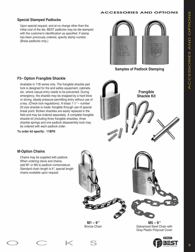
9O C K S
ACCESSORIES AND OPTIONS
AC
CESSO
RIE
S A
ND
OP
TIO
NS
F3– Option Frangible Shackle
Available in 11B series only. The frangible shackle padlock is designed for fire and safety equipment, cabinets, etc. where casual entry needs to be prevented. During emergency, the shackle may be snapped by a hard blow or strong, steady pressure permitting entry without use of a key. (Check lock regulations). A brass 1 1/2" – number 20 size shackle is made frangible through use of special break point. Broken shackles are easily replaced in the field and may be ordered separately. A complete frangibleshackle kit (including three frangible shackles, three shackle springs and one padlock disassembly tool) may be ordered with each padlock order.
To order kit specify: 11BFK
Frangible Shackle Kit
Special Stamped Padlocks
Upon special request, and at no charge other than the initial cost of the die, BEST padlocks may be die-stamped with the customer's identification as specified. If stamp has been previously ordered, specify stamp number.(Brass padlocks only.)
M1 – 9"Bronze Chain
M5 – 9"Galvanized Steel Chain with Gray Plastic Polycoat Cover
M-Option Chains
Chains may be supplied with padlock. When ordering clevis and chains, add M1 or M5 to padlock nomenclature. Standard chain length is 9", special length chains available upon request.
Samples of Padlock Stamping

10 P A D L
WC– Option Weather CoversAvailable in 21B/22B and 41B42B padlocks. The padlock weather covers are molded durable PVC that won’t chip or corrode and resists acids, oils and abrasion. When ordering add “WC” to option column of the padlock nomenclature.
SH– Option Shrouded PadlockAvailable in 21B padlocks. Cast stainless steel shroud with black powder-coated finish. Features hardened shackle for cut resistance. When ordering add “SH” to option column of the pad lock nomenclature.
ACCESSORIES AND OPTIONS
AC
CESSO
RIE
S A
ND
OP
TIO
NS
ZZ– Option Double Lockout/Safety FirstAvailable in 11B only, the double lockout safety padlock provides additionalsafety for maintenance crews making repairs in widely separated areas. The shackles of 11B padlocks are passed through holes in the extended skirt at the base of this lock. As long as either 11B padlock remains in place, the lock-out safety padlock cannot be unlocked. Elliptical solid brass case is 1 1/2" wide and is stamped with words “Safety First ” on one side. Holes at base of case will accommodate 11B shackles only. Minimum shackle opening should be 1 1/4". A long blade key is required for 7-pin systems. Dust cover cannot be used with double lockout.
S– Option Car Seal FeatureAvailable in all 41B padlocks. Case is slotted below the core to accommodatemost popular car seal bands. When in place, car seal band insures tampered with. Seals are available direct from car seal manufacturers. A special long blade key is required for 7-pin systems. When ordering simply add “S” to the option column of the 41B nomenclature.
41B car seal feature
21B shroud option
21B & 41B weather option
11B double lockout option

PADLOCK REPAIR AND PARTS
BD641Tweezers
11B/12B – 21B/22B – 41B/42B Series
Shackle
Steel Pin
Shackle Spring
41B Case
Shroud
(Tumbler) Steel Balls
Locking Cam
Throw Member
21B Case
Interchangeable Core
(Tumbler) Steel Balls
Locking Cam
Throw Member
Interchangeable Core
BD654Disassembly Tool
With the simplest of tools, proper replacement parts and minimal training, all BEST padlocks can be used for the duration ofany installation. Listed below are the parts and tools required for the various series of padlocks. Contact your local StanleySecurity Solutions office for special instruction and information about factory seminars for padlock repair. BEST padlocks canbe repaired and worn parts replaced, virtually eliminating padlock replacement costs.
11O C K S
PA
DLO
CK
REP
AIR
AN
D P
AR
TS
21B Shrouded PadlockExploded View
Standard Brass PadlockExploded View

For more information on Stanley Security Solutions’ products, services, and office locations visit our web site at www.stanleysecuritysolutions.com
Stanley Security Solutions, Inc.6161 E. 75th Street Indianapolis, Indiana 46250
www.stanleysecuritysolutions.com© 2007 Stanley Security Solutions, Inc. and Stanley Logistics
Product information contained in this catalog has been compiled and presented with as much care and completeness as is reasonably possible. Errorsor mistakes may be present, and in many cases, reliance has been placed on information supplied by other manufacturers which may be in error orwhich may be subject to changes or modifications by the manufacturer without notice and without obligation. Therefore, no guarantee can be made orshould be assumed or implied with regards to product information contained in this catalog.
10M 707BAS028
PA
DLO
CK
S

TU
BU
LA
RD
EA
DB
OLTS
TUBULAR DEADBOLTS

2 TUBULAR DEADBOLTS
1. No exposed mounting screws standard on 82T/83T doublecylinder M function only (available as an option on 82T/83TK, L, and S function)
2. Full 1" stainless steel throw deadbolt3. Free-turning, wrench-resistant, tapered cylinder ring4. 82T/83T-solid extruded brass or bronze cylinder
72T/73T-solid cast zinc with brass or bronze shell5. Stainless steel for strength and corrosion resistance6. Simple installation; self-aligning and reversible strike7. May be keyed into existing BEST® masterkeyed system8. The original interchangeable core permits instant,economical re-lock
9. ADA turn lever10. Deadbolt UL listed for use as auxiliary lock type on 3 hr. fire
doors (GWXT). These locks also carry the C-UL mark which isnow officially accepted in all of Canada, indicating compliancewith appropriate Canadian standards and codes
Products protected by one or more of the following patents:4,301,667 D290,085 4,843,852 5,590,555 5,794,472Other Patents Pending
FEA
TU
RES
5.
6.8.
1.
7.10.
2.
9.
4.3.
83T Deadbolt
Deadbolt: 72T/73T– 1" throw, 5⁄8" x 7⁄8" bolt. Brass nickel plated,with concealed hardened steel free-turning pin. Housing fits 1"bore. 82T/83T- 1" throw, 5⁄8" x 7⁄8" solid stainless steel bolt.Housing fits 1" bore.
Faceplate: brass or bronze base material.72T/82T– 1" x 2 1⁄4", 73T/83T– 1 1⁄8" x 2 1⁄4"
Backset: 72T/82T– 2 3⁄8", 73T/83T– 2 3⁄4"Trim: wrought brass or bronze cylinder rose or turn lever rose,2 3⁄4" dia. to cover 2 1⁄8" bore. Machined brass or bronzecylinder ring.
Cylinders: 82T/83T– machined from extruded brass or bronzebar stock. 72T/73T– zinc casting with stamped brass orbronze shell.
Strikes:8TSTK– rectangular 1 1⁄8" x 2 3⁄4" (Std.)8TS1– curved lip 1 1⁄4" x 4 7⁄8" (ANSI A115.2)8TS4– curved lip 1 1⁄8" x 2 3⁄4" (ANSI A115.3)8TS5– high security rectangular 1 1⁄4" x 4 7⁄8" (ANSI A115.1)
Door thickness: Fits 1 3⁄4" doors (standard)72T/73T: fits doors - from 1 3⁄8" to 2 1/8"82T/83T: fits doors - from 1 3⁄8" to 3"
Finishes:72T/73T: 612–satin bronze, 626–satin chromium,82T/83T: 605–bright brass, 606-satin brass, 611–brightbronze, 612–satin bronze, 613–dark oxidized satin,625–bright chromium, 626–satin chromium
DEADBOLT FEATURES
SP
EC
IFIC
ATIO
NS SPECIFICATIONS
STR
IKES
8TSTK Standard StrikeDimensions– 1 1⁄8" x 2 3⁄4"(Supplied with box and screws)
To order with unit– STKTo order without unit–8TSTK and finish
STRIKES
8TS4 StrikeDimensions– 1 1⁄8" x 2 3⁄4"with curved lip. (Suppliedwith box and screws).
To order with unit– S4To order without unit–8TS4 and finish.
8TS1 StrikeDimensions– 1 1⁄4" x 4 7⁄8"(ANSI 115.1) (Suppliedwith box and screws).
To order with unit– S1To order without unit–8TS1 and finish.
8TS5 High Security StrikeDimensions– 1 1⁄4" x 4 7⁄8"(Supplied with box and longscrews).
To order with unit– S5To order without unit– 8TS5and 630 finish ONLY.

82TDB Deadbolt Tube AssemblyBolt throw – 1"Backset – 2 3⁄8"Faceplate – brass or bronze1" x 2 1⁄4". self-adjusting andreversible for either door hand.
Tube – steel. fits 1" diameterbore.
To order without trim – 82TDBand finish
Function & Diag. Deadbolt operated by...ANSI (Fed. No.)K-Turnknob • Turning the key in the outside
cylinder• Turning the inside turn lever.
E2151, E2152 (181K)
L-One-Way Turning the key in the outsideDeadbolt cylinder; the inside cylinder is
blank
E2161, E2162 (181L)
*ATTENTION: Locksets that secure both sides of the door arecontrolled by building codes and the Life Safety Code. In an emer-gency exit situation, failure to quickly unlock the deadbolt could behazardous or even fatal.
3TUBULAR DEADBOLTS
82TD5 Drive-in Bolt Tube AssemblyBolt throw – 1"Backset – 2 3⁄8"Faceplate – brass or bronze, circularTube – steel. fits 1" diameter bore.
To order without trim – 82TD5 and finish
83TD5 Drive-in Bolt Tube AssemblyBolt throw – 1"Backset – 2 3⁄4"Faceplate – brass or bronze, circular.Tube – steel. fits 1" diameter bore.
To order without trim – 83TD5 and 626 finish
83TDB Deadbolt Tube AssemblyBolt throw – 1"Backset – 2 3⁄4"Faceplate – brass or bronze1 1⁄8" x 2 1⁄4". self-adjusting andreversible foreither door hand.
Tube – steel. fits 1" diameterbore.
To order without trim – 83TDBand finish
FU
NC
TIO
NS
HOW TO ORDER
Function & Diag. Deadbolt operated by...ANSI (Fed. No.)
*M-Double-Cylinder • Turning the key in the insideor outside cylinder. Theinside mounting screws areconcealed.
E2141, E2142 (181M)
S-Classroom • Turning the key in the outsidecylinder
• Turning the inside turn leveronly retracts the deadbolt(available ONLY in 82T/83T)
Note:Can’t throw the deadbolt.E2171 (181S)
KL-Closet Turning the turn lever only.(available ONLY in 82T/83T)
FUNCTIONS
82
T/8
3/T
TU
BE
ASSEM
BLIE
SH
OW
TO
OR
DER
82T/83T TUBE ASSEMBLIES
82TDB 83TDB
82TD5 83TD5
83T 7 K STK 606 **
Backset Core Function Strike Standard OptionsHousing Code Finishes
72T– 2 3⁄8" 7– 7 pin see STK– standard 72T/73T: CS– concealed screws (82T/83T only)73T– 2 3⁄4" housing above deadbolt 612 626 D5– drive-in bolt (82T/83T only)82T– 2 3⁄8" accepts 82T/83T only LL– lead lined (83T only)83T– 2 3⁄4" all Best S1– high security 82T/83T: NF– narrow face 1" (std. 82T)
cores S4– curved lip 605 606 SH– security head screws (82T/83T only)S5– high security 611 612 WF– wide face 1 1⁄8" (std. 83T)deadbolt (630 finish 613 625 Door thickness– specify if other than 1 3/4"only) 626 690 (82T/83T only)
**Must specify key mark and number of keys or designate L/C for less core.

KD312, KD315-FACE PLATEMARKING CHISELS
KD325-STRIKE PLATE LOCATINGPINThe KD312 face plate marking chisellocates the mortising for the face plate ofFederal Spec 160 (1" x 2 1⁄4" ) cylindricaland tubular lockset. The KD315 faceplatemarking chisel locates the mortising ofthe faceplate. Federal Spec 161(1 1⁄8" x 2 1⁄4" ) cylindrical and tubularlocksets. A strike plate locating pinKD325 is available for use in conjunctionwith Fed. Spec. 161 cylindrical andtubular locksets.
To order designate:KD312 face plate marking chisel (1" ).KD315 face plate marking chisel (1 1⁄8" ).KD325 strike plate locating pin.
KD304A–BORING JIG KIT
The KD304A jig kit is madefor boring cut-outs in woodendoors for Fed. Spec. 160 and161 series cylindrical/ tubularlocksets, doors 1 3⁄8" to 2 1⁄4"thick. The KD304A kitincludes the boring jig (to drillwood doors for 2 3⁄8", 2 3⁄4",3 3⁄4", and 5" backsets),adaptor for 3⁄8" drill chuck,KD309 2 1⁄8" bit, KD318 1" dia.x 9" bit, KD312 face plate marking chisel 1", KD315 faceplate marking chisel 1 1⁄8", and the KD325 strike platelocating pin.
To order complete kit specify: KD304A Kit.All of the individual kit parts listed above may be orderedseparately except for the adaptor chuck and jig.
SER
VIC
EEQ
UIP
MEN
T SERVICE EQUIPMENT
For more information on Stanley Security Solutions’ products, services, and office locations visit our web site at www.stanleysecuritysolutions.com
SSttaannlleeyy SSeeccuurriittyy SSoolluuttiioonnss,, IInncc..6161 E. 75th Street Indianapolis, Indiana 46250
www.stanleysecuritysolutions.com©2009 Stanley Security Solutions, Inc. and Stanley Logistics
Product information contained in this catalog has been com piled and presented with as much care and com plete ness as is reasonably possible. Errorsor mistakes may be present, and in many cases, reliance has been placed on information supplied by other manufacturers which may be in error orwhich may be subject to changes or mod i fi ca tions by the man u fac tur er with out no tice and without obligation. Therefore, no guar an tee can be made orshould be assumed or implied with regards to product in for ma tion con tained in this catalog.
10M 109FPBAS014
MX8 – PATENTED KEYING SYSTEM
MX
8 –
PA
TEN
TED
KEY
ING
SY
STEM
MX8 Key & Core
M Series Keyway Features• Patented keys operate both MX8 and Standard BEST® cores (backward compatibility) with existing BEST® keyways (JKLM only). Standard keys do not operate MX8 cores.
• Available in large bow, long blade, and long nose key blanks to work with special applications. • Available in core designs for use in special application locks, such as high security mortise, hotel cylinders, and glass display-case locks.
• Utilizes the same combinating kits and key cutting equipment as the Standard BEST® keyways. • M Series keys operate MX8 cores and Standard (non-patented) BEST® cores. Standard key blanks do not operate MX8 cores.
X Series Keyway Features• Distinctive key design includes thicker key blanks with larger bow for added strength and easier handling. • Keyways are unique to the MX8 Patented Keying System offering even higher key duplication protection. • X Series keyways utilize the standard combinating kit, minimizing the expense of system changeover. • X Series keys only operates the MX8 cores.
KD315
KD325
KD304A(Complete kit)
One of the greatest threats to key control within your facility is the unauthorized duplication of keys; one simple solution is the use of the MX8 Patented KeyingSystem by Stanley/Best Access Systems a patent-protected keying system.
Very seldom can a single product meet all of your exact needs, and often your levelof convenience must be sacrificed to fit the capabilities of the product.The MX8Patented Keying System provides you with an significant amount of flexibility,enabling a solution that fits your unique balance between security and convenience.
The MX8 Patented Keying System is available in two series of keyways, theM Series and the X Series. Each series offers a different blend of features to help you maximize convenience while optimizing your security.
The MX8 Patented Keying System has the ability to provide geographic exclusivityto the customer and is BHMA A156.5 Grade 1 Certified.

SER
VIC
EEQ
UIP
MEN
T
SERVICE EQUIPMENT

CD431
AD433Spanner Wrench
CD431/5ED250 Combinating KitThis small desk-drawer size kit contains everything necessary to combinate aBEST® core. It includes a complete selection of pin segments, springs, caps,a capping block, two capping pins, an ejector pin, tweezers, two standard keysand a key gauge. When securely closed, the kit may be carried in any positionwithout mixing contents. Kits can be ordered separately or combined (1C core)& (5E cylinder).
To order 1C kit only: To order 1C & 5E combined kit:CD431-2 (A2 system) CD431-25E (A2 system)CD431-3 (A3 system) CD431-35E (A3 system)CD431-4 (A4 system) CD431-45E (A4 system)
Pin segments (included in kit) Close tolerance segments assist in accuratecombinating. For order information, contact your local Stanley office.
Core springs (included in kit) This properly sized spring facilitates consistentaction in all Best figure 8 cores. To order specify: 22S springs.
Core caps (included in kit) Barrels are securely sealed by applied core caps.To order specify: 21C caps.
(Available only to registered Best Master Keyed System owners.)
2 S E R V I C E E
AD433 Key CombinatorThe key combinator is used to cut new or additional keys when required. BEST®
combinations are cut in accordance with the original masterkeyed code with noreliance on a pattern key. As a result, inaccurate tolerances are not introduced intoand compounded within the system as second, third and fourth generation keys are cut.Note: Key combinator is available for standard, premium, or Peaks systems.
To order specify:AD433-2 (A2 system); AD433-3 (A3 system); AD433-4 (A4 system);AD433P (Premium); AD436 (Peaks 6-pin); AD437 (Peaks 6-pin).
AD434 Key CarriagesAdditional key carriages for the AD433 key combinator allow you the flexibility to change from one keyway style to another.Changing carriages is simplified by the modular design of the combinator and chassis. Note: The AD502(D) Calibration Gaugemust be used when changing carriages to verify the accuracy of key cuts. (Please refer to the key combinator service manualfor detailed instructions).
To order specify: AD434 Carriage; AD434P Carriage for premium keyways
CYLINDRICAL/TUBULAR Page83KA2A Mortise-to Cylindrical Adaptor Kits . . . . . . . . . . .883KA2B Mortise/Cyl.-to Cylindrical Adaptor Kits . . . . . . .8KD315 Face Plate Marking Chisel . . . . . . . . . . . . . . . . . .8KD325 Strike Plate Locating Pin . . . . . . . . . . . . . . . . . . . .8KD303 Through-Bolt Drill Jig . . . . . . . . . . . . . . . . . . . . . . .9KD304A Boring Jig Kits . . . . . . . . . . . . . . . . . . . . . . . . . . .9KD352 Adaptation Cut-off fixture . . . . . . . . . . . . . . . . . . .9
5E CYLINDER SERVICE EQUIPMENT5ED250 Combinating Kit only . . . . . . . . . . . . . . . . . . . . .105ED261 Capping Block . . . . . . . . . . . . . . . . . . . . . . . . . .105ED253 Thread Tap . . . . . . . . . . . . . . . . . . . . . . . . . . . .10
MORTISE AND RIM CYLINDERED211 Mortise Cylinder Wrench . . . . . . . . . . . . . . . . . . .10ED212 Mortise Cylinder Cam Assembly Tool . . . . . . . . .10
PADLOCK SERVICE EQUIPMENTBD654 Padlock Disassembly Tool . . . . . . . . . . . . . . . . .11BD642 Padlock Shackle Plug Assembly Kit . . . . . . . . . .11
TABLE OF CONTENTS
COMBINATING SERVICE EQUIPMENT PageCD431/5ED250 Combinating Kit . . . . . . . . . . . . . . . . . . . .2AD433 Key Combinator . . . . . . . . . . . . . . . . . . . . . . . . . . .2AD502(D) Digital Calibration Gauge . . . . . . . . . . . . . . . . .2AD434 Standard Key Carriages . . . . . . . . . . . . . . . . . . . .2AD501 Key Cut Indicator . . . . . . . . . . . . . . . . . . . . . . . . . .2CD517 Core Capping/Decapping Press . . . . . . . . . . . . . .3CD549 Combinating Tweezer . . . . . . . . . . . . . . . . . . . . . .3CD540 Best Core Capping Block . . . . . . . . . . . . . . . . . . .3CD548 Ejector Pin . . . . . . . . . . . . . . . . . . . . . . . . . . . . . . .3CD547 Hand Capping Pin . . . . . . . . . . . . . . . . . . . . . . . . .3DD513 Core and Key Marking Block . . . . . . . . . . . . . . . .4CD535 Graphite Gun . . . . . . . . . . . . . . . . . . . . . . . . . . . . .4CD433 Combinating Parts Bin . . . . . . . . . . . . . . . . . . . . .4AD504A Key Marking Plate . . . . . . . . . . . . . . . . . . . . . . . .5DD502/DD503 Letter and Number Dies . . . . . . . . . . . . . .5QU-I.C-System Combinating Tool Packages . . . . . . . . . .6QU-I.C-System Combinating Tool Descriptions . . . . . . . .7
CO
MB
INA
TIN
GSER
VIC
EEQ
UIP
MEN
T COMBINATING SERVICE EQUIPMENT
TA
BLE
OF
CO
NTEN
TS

CD547 Hand Capping Pin (included in kit)
With the core held securely in the capping block, the hand capping pin may be used toseat the cap and thus seal the segments into each barrel of the Best core.
To order specify: CD547 hand capping pin.
CD548 Ejector Pin (included in kit)
The ejector pin of this handy tool may be inserted into the ejector pin hole, located at thebottom of each barrel opposite the cap of every BEST core, to eject the pins, spring andcap from the barrel preparatory to recombinating.
To order specify: CD548 ejector pin.
CD549 Combinating Tweezer (included in kit)
Combinating tweezers are available to assist in handling the small caps, springs and pinsused in combinating Best cores.
To order specify: CD549 combinating tweezers.
CD540 Best Core Capping Block (included in kit)
The barrels of the core are in alignment with corresponding barrels in the capping block,and meter the "set" of the cap when the hand capping pin is employed.Size 1 1⁄4" x 1 1⁄4" x 2".
To order specify: CD540 core capping block.
3Q U I P M E N T
Keyway Blockout Kit
A blockout blade may be inserted into any BEST system to prevent insertion of anoperating or control key. Provides quick, efficient lockout. Available for Standard,Premium and Kaba® Peaks® cores.(Contact your local Stanley office for information).
CO
MB
INA
TIN
GSER
VIC
EEQ
UIP
MEN
TCOMBINATING SERVICE EQUIPMENT
CD547
AD502(D) Digital Calibration GaugeThe new combinator calibration gauge (Manual or (D) Digital) is designed to be used withthe AD433 and AD433P keycombinators. It can be used for normal combinator inspectionand adjustments, or for calibrating the combinator after changing carriages. Each gaugecomes complete with detailed instructions for use.
To order specify: AD502 Manual; AD502(D) DigitalAD502(D) Digital Calibration Gauge
CD517 Core Capping/ Decapping Press (Heavy Duty)
In one smooth operation, this press seals all barrels of either a 6 or 7 pin combinatedcore. The cap seating depth is adjustable. This very rugged tool bolts to the bench andlasts indefinitely.
To order specify: CD517 core capping press.
CD517
CD548
CD549
CD540
AD501
AD501 Key Cut Indicator (included in kit)
The key cut indicator makes it possible to immediately determine the proper cut of Bestkeys. (For accurate test, use AD502(D) Digital Calibration gauge; see below.) Key cutindicator is heavy steel, 2 13⁄16" x 1 1⁄4".
To order specify:AD501-2 (for A2 system)AD501-3 (for A3 system)AD501-4 (for A4 system)
(Available only to registered Best Master Keyed System owners.)

DD513 Core and Key Marking BlockThis steel tool securely holds any Best core and/or key for accuratestamping with letter and number dies. Size is 1" x 1 1⁄4" x 2 1⁄4".Note: Marking the face of Peaks® cores can damage the face, resultingin faulty operation.
To order specify:DD513 marking block.
DD514 Core and Key Marking PlateThis plate can hold 5 cores for end-marking, 5 cores for side-markingand 10 keys for bow-marking at one time. It speeds the markingprocess and helps avoid error in sequential numbering and lettering.A heavy casting 8" x 6" x 7⁄4".Note: Marking the face of Peaks® cores can damage the face, resultingin faulty operation.
To order specify:DD514 marking plateCD504B stamping plate face only (87 cores)CD504C stamping plate side only (50 cores)DD514A magnetic strip
CD535 Graphite GunFlaked graphite provides penetrating lubrication to all working lockparts and remains dry throughout lock life. Degrease and cleanpreviously lubricated locksets before applying graphite
To order specify:CD535 GraphiteCD535A One-pound (refill) graphite
CD433 Combinating Parts BinThese convenient bin racks are available for all size Best systems.All bin racks are free standing and made for use on any desk or tabletop. Bins are designed for quick, easy access to pin segments andparts; yet, lessen the possibility of accidental intermixing of pinsegments when segment is dropped. Extra bins may be used forstorage of pins and caps.
To order specify:CD433
4 S E R V I C E E(Available only to registered Best Master Keyed System owners.)
CO
MB
INA
TIN
GSER
VIC
EEQ
UIP
MEN
T COMBINATING SERVICE EQUIPMENT
DD514
CD433
DD513
CD535

AD504A Key Marking Plate
This popular key marking plate makes bow marking large amounts of keyseven easier by allowing 55 keys to be placed at one time. Both standardand patented keys can be used with this plate. This size is 13" x 12" x 1⁄2".
To order specify:AD504A
DD502 Letter and DD503 Number Dies
Durable high carbon steel number and letter dies for markingBest cores and keys are available in 1⁄16" or 3⁄32" letter heights.
To order specify:DD502 letter dies or DD503 number dies and add theheight of letter required.Example: DD502 letter dies x 3⁄32".
DD537 Best/LPS Spray Lubricant
Factory tested and approved greaseless lubricant leaves a thin continuous lubrication film.Can be used with locks, even where other lubricants have been applied.Conforms to ANSI 156.6 cycle tested standards.
To order specify:DD537 Best/LPS lubricant
5Q U I P M E N T(Available only to registered Best Master Keyed System owners.)
CO
MB
INA
TIN
GSER
VIC
EEQ
UIP
MEN
TCOMBINATING SERVICE EQUIPMENT
DD537
AD504A
DD502 DD503

CKT-60 Core & Key Tray
6 S E R V I C E E(Available only to registered Best Master Keyed System owners.)
QU
-I.C
-SY
STEM
DED
ICA
TED
PA
CK
AG
ES
QU
-I.C
-SY
STEM
UN
IVER
SA
LP
AC
KA
GES
QU-I.C-SYSTEM COMBINATING TOOL PACKAGES
BQDP – Basic QU-I.C-KEY Dedicated Package Includes the 7 main system tools
PQDP – Professional QU-I.C-KEY Dedicated Package
Dedicated Packages – These QU-I.C-KEYS are permanently factory built specifically for just one key system. GM and Controlcodes required. Intended for long-term use by Institutional Locksmiths who continuously work with the same key system(s).
To order specify: UL–BQDP, PQDP or EQDP / A2, A3 or A4 / 6 or 7-pin / GM and CONTROL Codes
QU-I.C-CHEX Tool QU-I.C-Tweez-jector QU-I.C-PreamerQU-I.C-TEST ToolQU-I.C-LOAD ToolDedicated QU-I.C-KEYand Viewing Base
Includes the 7 main system toolsBQDP Package (shown above)
EQDP – Expert QU-I.C-KEY Dedicated Package
Includes the 10 tools in thePQDP Package (shown above)
QU-I.C-TEST Adapter QU-I.C-Power Preamer CKT-12 Core & Key Tray
QU-I.C-BLOCK Tool
BQUP – Basic QU-I.C-KEY Universal Package Includes the 8 main system tools
PQUP – Professional QU-I.C-KEY Universal Package
Universal Packages – You get to custom build a QU-I.C-KEY for any A2 key system that you are working with. These kits arebetter suited for temporary use and re-use – not for long-term / continuous key system use. (A4 System Kits are available).
To order specify: UL–BQUP, PQUP or EQUP / A2 or A4 / 6 or 7-pin
QU-I.C-CHEX Tool QU-I.C-Tweez-jector QU-I.C-PreamerQU-I.C-TEST ToolQU-I.C-LOAD Tool
Includes the 8 main system toolsBQUP Package (shown above)
EQUP – Expert QU-I.C-KEY Universal Package
Includes the 11 tools in thePQUP Package (shown above)
QU-I.C-TEST Adapter QU-I.C-Power Preamer CKT-12 Core & Key Tray
CKT-60 Core & Key Tray
QU-I.C-BLOCK Tool
Universal QU-I.C-KEYKit and Viewing Base

Dedicated QU-I.C-KEY and Viewing Base (QKD / A2, A3 or A4 / 6 or 7-pin / GM and CTL)This unique tool is permanently built to provide every pin segment calculation for your specificmaster key system (GM and Control). Every calculation is clearly displayed and incorporates aninnovative color-coded system. No math skills are required; no pen and paper are necessary;no slide charts; no computer programs; and no power needed (except for a twist of your wrist).Available in A2, A3 or A4, 6 or 7-pin.
Universal QU-I.C-KEY Kit and Viewing Base (QKU / A2 or A4)This kit allows you to custom build a QU-I.C-KEY for any A2 system that you are working on(kits also available for A4 systems). It will provide every pin segment calculation for the systemyou select. Every calculation is clearly displayed and incorporates an innovative color-codedsystem. No math skills are required; no pen and paper are necessary; no slide charts; nocomputer programs; and no power needed (except for a twist of your wrist). The special systemstrips in this kit are intended to be stored after use and re-used repeatedly.
QU-I.C-LOAD Tool * (QLT / 6 or 7-pin)This tool holds the core during combinating and provides color-coded, visual chamber identifiersthat match the QU-I.C-KEY pin segment calculator. This provides constant orientation, greatlyreduces errors and speeds production.
QU-I.C-TEST Tool * (QTT)This revolutionary tool is used with the QU-I.C-LOAD Tool and allows you to test combinatedcores before you cap them. It applies temporary spring pressure to all chambers so you can testevery key. If a mistake has been made, you can correct the error while it is easy to do, withouthaving to punch out and waste any pins, caps or springs. If all the keys work properly, you canthen permanently cap the core with complete confidence.NOTE: This tool must be used with the QU-I.C-LOAD Tool or QU-I.C-TEST Adapter!
QU-I.C-CHEX Tool * (QCT)This tool allows you to eject the pins into the clear viewing tube to visually inspect the pinsegments of any chamber for accuracy without worrying about “balancing” the pin stack. It iseasy to safely return the pin stack to the core. Also useful for transporting pin stacks.
QU-I.C-Tweez-jector (QTJ)2-in-1 tool that combines a full size, custom tip tweezer with an ejector pin that can tamp downor eject pin segments. A real time saver - no need for a separate ejector pin.
QU-I.C-Preamer (QPT)This tool allows you to pre-ream the top of core chambers. This removes any burrs and createsa slight funnel-like effect so that #4 top pin segments can drop more easily into the core. Aprotective cap is supplied and the other end of the tool contains an ejector pin.
QU-I.C-Power Preamer (QPP)This tool attaches to any hand held power screwdriver and allows you to pre-ream the top of thecore chambers faster. This is beneficial when doing large combinating projects.
QU-I.C-TEST Adapter (QTA)This is an accessory for the QU-I.C-TEST Tool and can be attached and removed as required.It enables testing of cores without having to load them into the QU-I.C-LOAD Tool.
QU-I.C-BLOCK Tool * (QBT)You can eject the pins from a 6 or 7-pin core in a controlled manner allowing you to decodecores from existing systems when no documentation is available. Punch-out tool is included.
Core & Key Tray (CKT-12)Provides 12 positions for cores or keys. It safely holds and transports combinated cores untilthey can be capped. Works with 6 and 7-pin BEST style or PEAKS® interchangeable cores.
Core & Key Tray (CKT-60)Provides 60 positions for cores or keys for large combinating projects. It safely holds andtransports combinated cores until they can be capped. Works with 6 and 7-pin BEST styleinterchangeable cores. Also accommodates PEAKS® I-Cores with extended front.
* NOT compatible with special .140 spacing cores
To order specify: UL–part number (shown above) / other system information if requred
7Q U I P M E N T(Available only to registered Best Master Keyed System owners.)
QU
-I.C
-SY
STEM
CO
MB
INA
TIN
GTO
OL
DESC
RIP
TIO
NSQU-I.C-SYSTEM COMBINATING TOOL DESCRIPTIONS
Dedicated QU-I.C-KEYand Viewing Base
Universal QU-I.C-KEYKit and Viewing Base
QU-I.C-LOAD Tool
QU-I.C-CHEX Tool
QU-I.C-Tweez-jector
QU-I.C-Preamer
QU-I.C-TEST Tool
QU-I.C-TEST Adapter
QU-I.C-Power Preamer
CKT-60 Core & Key Tray
QU-I.C-BLOCK Tool
CKT-12 Core & Key Tray

8 S E R V I C E E(Available only to registered Best Master Keyed System owners.)
CO
MB
INA
TIN
GSER
VIC
EEQ
UIP
MEN
T CYLINDRICAL/TUBULAR
83KA2AMortise-to-Cylindrical Lock Adaptor Kits
Mortise lock mounting may be converted to BEST® 6K and 8K cylindrical lock throughuse of this kit.
SpecificationsMaterials– Stainless steelFinish– 630 Only.Escutcheon– 3 1⁄2" x 8 1⁄2" x .050 thicknessStrike– 1 1⁄4" x 8" with 6 3⁄4" lip, 1 1⁄4" to centerFace plate: 83KF1- 8" x 1 1⁄8" wideBackset– 2 3⁄4" (Fed spec. 161)Door thickness is increased 7⁄64" for mounting either 6K or 8K series locksets.
To order an adaptor kit specify:83KA2A adaptor kit
One-Piece UniversalMortise/Cylindrical-to-Cylindrical Adaptor Kits
Doors previously mounted with another manufacturer's lockset may be quicklyadapted to a Best cylindrical 6K and 8K lock through use of one of the following kits.
SpecificationsMaterials– Stainless steelFinish– 630 onlyFace plate recess– 2 1⁄4" x 1 1⁄8"Backset– 2 3⁄4" x 1 1⁄8" (Fed. Spec. 161)Door thickness– 1 3⁄4"
To order specify:Kit number and door thickness.Example: 83KA2B x 1 3⁄4"
KD312 and KD315 Face Plate Marking ChiselKD325 Strike Plate Location Pin
The KD315 face plate marking chisel (which locates the mortisingfor the face plate) and the KD325 strike locating pin (which centersthe strike for proper installation) is used for Fed. Spec. 161 cylindricallockset, (1 1⁄8" x 2 1⁄4" ), and BEST® series 82T & 83T tubular locks.The KD312 face plate marking chisel is available for Fed. Spec. 160(1" x 2 1⁄4" ) preparation.
To order specify:KD312 face plate marking chisel (160)KD315 face plate marking chisel (161)KD325 strike plate locating pin
83KA2A
83KA2B
KD315(Fed. Spec. 161)
KD325

KD303 Through Bolt Drill Jig
Special accessory jig aids in aligning 5⁄16" holes for through bolt mountingof 9K cylindrical locks. Simply install latch first, then insert jig in 2 1⁄8"bored hole, align with door edge and drill with 5⁄16" bit.
To order specify: KD303
KD304A Boring Jig Kits
The KD304A jig kit is made for boring cut outs in wooden doors forFed. Spec. 160 and 161 series cylindrical/tubular locksets, doors1 3⁄8" to 2 1⁄4" thick.The KD304A kit includes the boring jig (to drillwood doors for 2 3⁄8", 2 3⁄4", 3 3⁄4". and 5" backsets), adaptor for 3/8"drill chuck,KD309 2 1⁄8" bit, KD318 1" dia. x 9" bit,KD312 face plate marking chisel 1",KD315 face plate marking chisel 1 1⁄8", and theKD325 strike plate locating pin.
To order complete kits specify: KD304A KitAll of the individual kit parts listed above may be orderedseparately except for the adaptor chuck and jig.
Adaptation Cutoff Fixture
To assist in adapting cylindrical locksets made by other manufacturer’s toBEST’s knobs and master keyed cores, adaptation cutoff fixtures are available.
For more information visit us at www.stanleysecuritysolutions.com.
9Q U I P M E N T(Available only to registered Best Master Keyed System owners.)
CY
LIN
DR
ICA
L/TU
BU
LA
RCYLINDRICAL/TUBULAR
KD304A
KD352 Cut-Off Fixture
KD303

Service Equipment for 5E Cylinders (Single Shearline)Best single shearline locks may be combinated to GrandMaster, Master and/or any operating combinations in your Best system.Utilizes the AD433 KEY COMBINATOR. (See page 2 for ordering details.)
5ED250 Combinating Kit (Single Shearline)Similar to standard CD431 kit for figure 8 cores (see page 2), the single shearline kit provides a special 5ED261 capping block,springs (5ES1) and caps (5ECP).
To order specify:5ED250 – 2 (for A2 system)5ED250 – 3 (for A3 system)5ED250 – 4 (for A4 system)
5ED261 Slide Capping BlockThe capping process for single shearline 5E cylinders requires the following:
Slide Caps (5E): For 5E Cylinder:5ECP6– 6Pin 5ED261 Capping Block5ECP7– 7 Pin 5ED262 Cap Depressor
5ED253 Thread Tap
Matches standard 24 thread on 5E series cylinder locks.To order specify: 5ED253 thread tap
10 S E R V I C E E(Available only to registered Best Master Keyed System owners.)
5E
CY
LIN
DER
SER
VIC
EEQ
UIP
MEN
T
5ED261
MO
RTIS
EA
ND
RIM
CY
LIN
DER
5E CYLINDER SERVICE EQUIPMENT
MORTISE AND RIM CYLINDER
ED211
ED212
ED211 Mortise Cylinder WrenchThe Best mortise cylinder wrench and test handle is an essential double-purpose tool.It is used primarily to install or remove Best mortise cylinders without marring thecylinder surface finish. It is also used to align throw pins, and as a testing tool wheninstalling mortise or tubular units. The single end may be used to test the lock operation.To order specify:ED211 mortise cylinder wrench.
ED212 Mortise Cylinder Cam Assembly ToolFast attachment of cams to Best mortise cylinders is effected with this important device.It works equally well with adaptation cams, permitting relocking of any masterkeyed mortiselockset through use of BEST® replacement cylinders. Approximate length 1 3⁄4".To order specify:ED212 mortise tool.
ED221 Mortise Cylinder Thread Repair DieTool for re-threading 1 5⁄32" diameter cylinder.To order specify: ED221 thread repair die 1E cylinder.
ED222 Cylinder Cam Testing ToolEngages throw pins and activates cam for testing.To order specify: ED222 cylinder cam testing tool.
3ED224 Hole Tap for 11⁄2" Mortise CylinderTap tool is used to re-thread housing threads for 3E mortise cylinders.To order specify: 3ED224 hole tap for 11⁄2" mortise cylinder.
ED225 Hole Tap for 1 5⁄32" Mortise CylinderTap tool used to re-thread housing threads for 1E mortise cylinder.To order specify: ED225 hole tap for 1 5⁄32" mortise cylinder.
5ED253

11Q U I P M E N T(Available only to registered Best Master Keyed System owners.)
BD642Shackle Plug Tool
F3 – Frangible Shackle Replacement Available for 11B720
The frangible shackle padlock is designed for fire and safetyequipment cabinets, etc., where casual entry is to be prevented.For more information on the 11B fangible shackle please refer tothe B Series Padlock catalog section.
Broken shackles are easily replaced on-site and may be orderedseparately. A complete extra frangible shackle kit (including threeextra frangible shackles, three extra shackle springs and adisassembly tool) may be ordered by adding suffix “K” to thecatalog number.Frangible shackles are available in bronze material only.
To order specify:Example: 11B20FK (kit only)
To order shackle only: add suffix FF and omit pin size.Example: 11B20FF (frangible shackle only)
BD640 Padlock Shackle Plug Assembly Kit
Items included in this kit are essential to the repair of 11B, 21B, 41Bpadlocks in the field.To order complete kit specify:BD640 assembly kit.
Individual items may be specified as follows:BD641 – Padlock parts tweezer 6"BD642 – Shackle plug installation tool and hammerBD643 – Padlock holding plate
Concerning Proper InstallationInstallation instructions for any BEST® product should be carefullyfollowed for proper operation of the installed unit. If improperly installed,malfunction of the unit may result.
PA
DLO
CK
SER
VIC
EEQ
UIP
MEN
TPADLOCK SERVICE EQUIPMENT
11B20FF
BD641Tweezers
BD654
BD643Holding Plate

SER
VIC
EEQ
UIP
MEN
T
For more information on Stanley Security Solutions’ products, services, and office locations visit our web site at www.stanleysecuritysolutions.com
SSttaannlleeyy SSeeccuurriittyy SSoolluuttiioonnss,, IInncc..6161 E. 75th Street Indianapolis, Indiana 46250
www.stanleysecuritysolutions.com©2009 Stanley Security Solutions, Inc. and Stanley Logistics
Product information contained in this catalog has been com piled and presented with as much care and com plete ness as is reasonably possible. Errors ormistakes may be present, and in many cases, reliance has been placed on information supplied by other manufacturers which may be in error or whichmay be subject to changes or mod i fi ca tions by the man u fac tur er with out no tice and without obligation. Therefore, no guar an tee can be made or shouldbe assumed or implied with regards to product in for ma tion con tained in this catalog.
10M R809BAS033


CREDITS/COPYRIGHT
Copyright © 2010 Stanley Security Solutions, Inc. All rights reserved.
Information in this document is subject to change without notice and does not represent a commitment on the part of Stanley Security Solutions, Inc. The software described in this document are furnished under a license agreement or nondisclosure agreement.
This publication is intended to be an accurate description and set of instructions pertaining to its subject matter. However, as with any publication of this complexity, errors or omissions are possible. Please call your BEST® distributor or Stanley Security Solutions, Inc. at (317) 849-2250 if you see any errors or have any questions. No part of this manual and/or databases may be reproduced or transmitted in any form or by any means, electronic or mechanical, including photocopying, recording, or information storage and retrieval systems, for any purpose, without the express written permission of Stanley Security Solutions, Inc.
This document is distributed as is, without warranty of any kind, either express or implied, respecting the contents of this book, including but not limited to implied warranties for the publication’s quality, performance, merchantability, or fitness for any particular purpose. Neither Stanley Security Solutions, Inc., nor its dealers or distributors shall be liable to the user or any other person or entity with respect to any liability, loss, or damage caused or alleged to be caused directly or indirectly by this publication.
HID and iCLASS are registered trademarks of HID Corporation.
Sargent is a registered trademark of Sargent Manufacturing Co.
TORX is a registered trademark of the Camcar Division of Textron.
Von Duprin is a registered trademark of Von Duprin, Inc.
Wi-Q is a trademark of Stanley Security Solutions, Inc.
Written and designed by Stanley Security Solutions, Inc. and Avalon Group, Inc., Indianapolis, Indiana.
T83338 Rev A ER7991-6 July 2010
Stanley Wi-Q™ Technology Illustrated Parts Catalog i
CONTENTS
GETTING STARTED 1–1Introduction 1–1
Product overview 1–2
Mortise lock overview 1–2Cylindrical lock overview 1–3Exit hardware trim overview 1–4
Documentation package 1–5
Technical support 1–6
Support services 1–6Telephone technical support 1–6
STANDARD ESCUTCHEON COMPONENTS 2–1Inside escutcheon 2–2
Magnetic stripe reader outside escutcheon 2–4
Proximity reader outside escutcheon 2–6
Dual validation reader outside escutcheon 2–8
MORTISE COMPONENTS 3–1Inside trim components 3–2
Outside trim components 3–3
Mortise cases by function and option 3–4
Mortise case faceplates 3–5
Strike boxes and strike plates 3–6
Cylinder components 3–7
Other components 3–7

Contents
ii Stanley Wi-Q™ Technology Illustrated Parts Catalog
CYLINDRICAL COMPONENTS 4–1Lever components 4–2
Levers 4–2Standard lever components 4–3Lever components for use with non-interchangeable cores 4–4
Trim components 4–5
Cylindrical chassis 4–6
Latches 4–7
Strike boxes and strike plates 4–8
Other components 4–9
EXIT DEVICE TRIM COMPONENTS 5–1Exit hardware trim compatibility 5–2
Inside trim components 5–3
Magnetic stripe reader outside escutcheon 5–4
Proximity reader outside escutcheon 5–6
Dual validation reader outside escutcheon 5–8
Cylinders and related components 5–10
Mortise cylinder and related components 5–10Rim cylinder and related components 5–11
Levers 5–12
Lift fingers 5–13
Other components 5–14
Changing the handing 5–15
FIELD SERVICE KITS 6–1Field replacement kits 6–2
Reader kits 6–2Control electronics kits 6–3Wire harness kits for standard Wi-Q Locks 6–3Internal part kits for EXQ Series Exit Hardware Trim 6–4Other part kits for EXQ Series Exit Hardware Trim 6–4Screw and spring kits for EXQ Series Exit Hardware Trim 6–5
B.A.S.I.S. to wireless conversion kits 6–6
Inside escutcheon conversion kits 6–6
Outside escutcheon assemblies 6–7

Contents
Stanley Wi-Q™ Technology Illustrated Parts Catalog iii
OTHER COMPONENTS 7–1Card readers and encoders 7–2
Wireless components 7–3
Wireless access controller 7–3Portal gateway 7–4Power and adapter devices 7–5Modem 7–6Antenna kits 7–7Site survey kit and beacons 7–8
Battery packs 7–9
Tools 7–10
TROUBLESHOOTING 8–1Visual and audible response quick reference 8–2
Responding to problems 8–4
Lock transaction types 8–6
GLOSSARY A–1
INSTALLATION INSTRUCTIONS B–1
INDEX C–1

Contents
iv Stanley Wi-Q™ Technology Illustrated Parts Catalog

Stanley Wi-Q™ Technology Illustrated Parts Catalog v
FIGURES
GETTING STARTED
Mortise lock overview diagram 1–2
Cylindrical lock overview diagram 1–3
Exit hardware trim overview diagram (Precision Hardware–rim type shown) 1–4
STANDARD ESCUTCHEON COMPONENTS
Inside escutcheon components (mortise TV function shown) 2–2
Magnetic stripe reader escutcheon components (mortise TV function shown) 2–4
Proximity reader escutcheon components (mortise TV function shown) 2–6
Dual validation reader escutcheon components (mortise TV function shown) 2–8
MORTISE COMPONENTS
Inside mortise trim 3–2
Outside mortise trim 3–3
Mortise case assembly (DV shown) 3–4
Mortise case faceplates 3–5
Mortise strike boxes and strike plates 3–6
Mortise cylinder 3–7
Door position switch and magnet assembly 3–7

Figures
vi Stanley Wi-Q™ Technology Illustrated Parts Catalog
CYLINDRICAL COMPONENTS
Cylindrical levers 4–2
Standard lever components 4–3
Lever components for use with non-interchangeable cores 4–4
Cylindrical trim 4–5
Cylindrical chassis 4–6
Cylindrical latches 4–7
Cylindrical strike boxes and strike plates 4–8
Door position switch and magnet assembly 4–9
EXIT DEVICE TRIM COMPONENTS
Inside trim components 5–3
Magnetic stripe reader escutcheon assembly (Precision Hardware–rim type shown) 5–4
Proximity reader escutcheon assembly (Precision Hardware–rim type shown) 5–6
Dual validation reader escutcheon assembly (Precision Hardware–rim type shown) 5–8
Mortise cylinder and cylinder ring 5–10
Rim cylinder and related components 5–11
Levers diagram 5–12
Lift fingers (shown actual size) 5–13
Door position switch and magnet assembly 5–14
Changing the handing 5–16
OTHER COMPONENTS
Card encoders 7–2
Wireless access controller 7–3
Portal gateway 7–4
Power and adapter devices 7–5
Modem and power adapter 7–6
Antenna kits 7–7
Site survey kit and beacons components 7–8
Battery pack 7–9
Tools 7–10

Stanley Wi-Q™ Technology Illustrated Parts Catalog 1–1
1 GETTING STARTEDINTRODUCTION
The Stanley Wi-Q™ Technology Illustrated Parts Catalog contains essential information to help you maintain your standard Wi-Q Locks as well as your EXQ Series Exit Hardware Trim. Throughout this manual, the term standard Wi-Q Locks is used to refer to 45HQ Series Mortise Locks and 93KQ–95KQ Series Cylindrical Locks. EXQ Series Exit Hardware Trim is available for use with the following types of exit devices manufactured by Precision Hardware (1000 Series and 2000 Series), Von Duprin (98/99 Series), and Sargent (8800 Series):
■ rim
■ mortise
■ surface vertical rod
■ concealed vertical rod.
Standard Wi-Q Locks and EXQ Series Exit Hardware Trim are available with the following types of readers:
■ magnetic stripe card readers
■ dual validation (magnetic stripe card/keypad) readers
■ proximity card readers (HID, HID iCLASS, and Indala).
This manual provides illustrations and part numbers for the following Wi-Q items:
■ inside escutcheons
■ outside escutcheons
■ mortise cases and cylindrical chassis
■ mortise, cylindrical, and EXQ trim components
■ field service kits
■ system components, such as card readers and encoders, portal gateways, and antennas.

Getting Started
1–2 Stanley Wi-Q™ Technology Illustrated Parts Catalog
PRODUCT OVERVIEW
Mortise lockoverview
The diagram below shows an exploded view of the components of a Wi-Q Mortise Lock, indicating their orientation to the door.
Figure 1.1 Mortise lock overview diagram
Inside
Outside

Getting Started
Stanley Wi-Q™ Technology Illustrated Parts Catalog 1–3
Cylindrical lockoverview
The diagram below shows an exploded view of the components of a Wi-Q Cylindrical Lock, indicating their orientation to the door.
Figure 1.2 Cylindrical lock overview diagram
Inside
Outside

Getting Started
1–4 Stanley Wi-Q™ Technology Illustrated Parts Catalog
Exit hardwaretrim overview
The diagram below shows an exploded view of the components of a Wi-Q Exit Hardware Trim application.
Figure 1.3 Exit hardware trim overview diagram (Precision Hardware–rim type shown)
Inside
Outside

Getting Started
Stanley Wi-Q™ Technology Illustrated Parts Catalog 1–5
DOCUMENTATION PACKAGE The following documentation is available to help you with the installation, start-up, and maintenance of your Electronic Stand-Alone Locks.
The installation instructions also can be ordered separately:
The templates and specifications required for lock and exit hardware trim installations also can be ordered separately:
Document Title Doc. No.Stanley Site Survey Quick Reference Guide T82611
Installation Instructions for 93KQ Wi-Q™ Cylindrical Locks†
†. These installation instructions are included in this manual. See Installation Instructions on page B–1.
T82619
Installation Instructions for 40HQ Wi-Q™ Mortise Locksa T82623
Installation Instructions for EXQ Wi-Q™ Exit Hardware Trima T82621
Backside Antenna Kit Installation Instructions T83302
Installation Instructions for Portal Gateway Series T12833
Stanley Wi-Q™ AMS Getting Started Guide T83305
Document Title Doc. No.Q01 Template; Installation Specifications for 93KQ Wi-Q™ Cylindrical Locks with Small Strike
T82601
Q02 Template; Installation Specifications for 93KQ Wi-Q™ Cylindrical Locks with Large Strike
T82602
Q05 Template; Installation Template for 93KQ Wi-Q™ Cylindrical Locks
T82605
Q03 Template; Installation Specifications for 45HQ Wi-Q™ Mortise Locks
T82603
Q06 Template; Installation Template for 40HQ Wi-Q™ Mortise Locks T82606
Q09 Template; Installation Specifications for Wi-Q™ Technology EXQ Exit Hardware Trim for Use with Von Duprin 98/99 Series Exit Devices
T82609
Q10 Template; Installation Specifications for Wi-Q™ Technology EXQ Exit Hardware Trim for Use with Precision Hardware 2000 Series Exit Devices
T82610
Q07 Template; Installation Template for Wi-Q Technology™ EXQ Exit Hardware Trim for Use with Von Duprin 98/99 Series Exit Devices
T82607
Q08 Template; Installation Template for Wi-Q Technology™ EXQ Exit Hardware Trim for Use with Precision Hardware 2000 Series Exit Devices
T82608

Getting Started
1–6 Stanley Wi-Q™ Technology Illustrated Parts Catalog
TECHNICAL SUPPORT
Supportservices
When you need a part number for a component in a Wi-Q Lock or EXQ Series Exit Hardware Trim application, your first resource for help is the Stanley Wi-Q Illustrated Parts Catalog. If you cannot find the part number you need, contact your local Stanley Security Solutions Representative.
Telephonetechnical
support
A factory-trained Certified Product Specialist (CPS) is available in your area whenever you need help. Before you call, however, please make sure that the product is in your immediate vicinity, and that you are prepared to give the following information:
■ what happened and what you were doing when the problem arose
■ what you have done so far to correct the problem.
Stanley Security Solutions Representatives provide telephone technical support for all Wi-Q products. You may contact a Representative by calling 1-800-392-5209 Monday through Friday, between 8:00 a.m. and 5:00 p.m. eastern standard time; or visit the web page www.stanleysecuritysolutions.com.

Stanley Wi-Q™ Technology Illustrated Parts Catalog 2–1
2 STANDARD ESCUTCHEON COMPONENTS
This chapter provides exploded diagrams of the escutcheon assemblies and related components for standard Wi-Q Mortise and Cylindrical Locks. This chapter also includes part numbers for all field-serviceable parts. For part numbers for complete escutcheon assemblies, see Outside escutcheon assemblies on page 6–7.

Standard Escutcheon Components
2–2 Stanley Wi-Q™ Technology Illustrated Parts Catalog
INSIDE ESCUTCHEON
Inside escutcheonexploded view
Figure 2.1 Inside escutcheon components (mortise TV function shown)
1
2
3
4
6
5

Standard Escutcheon Components
Stanley Wi-Q™ Technology Illustrated Parts Catalog 2–3
Inside escutcheonparts list
Refer to Figure 2.1 and the table below to find the part you need.
Item Qty. Part No. Description1 4 A83525a T15 TORX inside escutcheon cover mounting screw or
not shown 4 00945-91a
a. Specify finish.
Phillips head inside escutcheon cover mounting screw
2 1 B83541a Mortise inside escutcheon stamped bottom cover with thumbturn (TV function) or
not shown 1 C83503a Mortise inside escutcheon stamped bottom cover (DV function) or
not shown 1 C83501a Cylindrical inside escutcheon stamped bottom cover
3 2 A83513 Escutcheon mounting screw for standard doors(1 3/4″ to 2 1/4″ thick) or
not shown 2 A83514 Escutcheon mounting screw for thick doors(2 1/2″ to 3″ thick)
4 1 B83540a Cover assembly with wireless antenna
not shown 1 A83516 Top cover gasket
5 1 C83511 4-cell battery holder with 4 AA batteries(see also Battery packs on page 7–9)
6 1 C83508 Fire plate

Standard Escutcheon Components
2–4 Stanley Wi-Q™ Technology Illustrated Parts Catalog
MAGNETIC STRIPE READER OUTSIDE ESCUTCHEON
Magnetic stripe reader escutcheon exploded view
Figure 2.2 Magnetic stripe reader escutcheon components (mortise TV function shown)
1
2
3
4
5 7 8
9
10
11
12
6
1314

Standard Escutcheon Components
Stanley Wi-Q™ Technology Illustrated Parts Catalog 2–5
Magnetic stripereader escutcheon
parts list
Refer to Figure 2.2 and the table below to find the part you need.
Item Qty. Part No. Description1 1 B63269 Magnetic stripe reader (see also Reader kits on page 6–2)
2 1 B60321 Reader gasket
3 1 D62566a
a. Specify finish.
Mortise outside escutcheon or
not shown 1 D62571a Mortise outside escutcheon for use with non-IC cores or
not shown 1 D62567a Cylindrical outside escutcheon
4 2 A60317 Lens cover
not shown 2 A60318 Lens retaining ring
5 4 A60348 Reader assembly mounting screw
6 1 B82077 Universal wireless door controller (see also Control electronics kits on page 6–3)
7 2 A82250 Electronics mounting screw spacer
8 2 A82251 Electronics board mounting screw
9 1 A60800 Outside escutcheon gasket
10 1 B61439 Trim hole insert
11 1 1818846 Bushing
12 1 B82375 Antenna jumper cable (see also Wire harness kits for standard Wi-Q Locks on page 6–3)
13 1 B82098 Sensor harness (see also Wire harness kits for standard Wi-Q Locks on page 6–3)
14 1 C82092 Mortise primary harness (see also Wire harness kits for standard Wi-Q Locks on page 6–3) or
not shown 1 C82168 Cylindrical primary harness (see also Wire harness kits for standard Wi-Q Locks on page 6–3)

Standard Escutcheon Components
2–6 Stanley Wi-Q™ Technology Illustrated Parts Catalog
PROXIMITY READER OUTSIDE ESCUTCHEON
Proximity reader escutcheon exploded view
Figure 2.3 Proximity reader escutcheon components (mortise TV function shown)
1
2
3
4
5 7 8
9
10
11
12
6
1314

Standard Escutcheon Components
Stanley Wi-Q™ Technology Illustrated Parts Catalog 2–7
Proximity readerescutcheon
parts list
Refer to Figure 2.3 and the table below to find the part you need.
Item Qty. Part No. Description1 1 B82399 HID proximity reader (see also Reader kits on page 6–2)
or
not shown 1 B82999 HID iCLASS proximity reader (see also Reader kits on page 6–2) or
not shown 1 B64403 Indala proximity reader (see also Reader kits on page 6–2)
2 1 B60321 Reader gasket
3 1 D62566a
a. Specify finish.
Mortise outside escutcheon or
not shown 1 D62571a Mortise outside escutcheon for use with non-IC cores or
not shown 1 D62567a Cylindrical outside escutcheon
4 2 A60317 Lens cover
not shown 2 A60318 Lens retaining ring
5 4 A60348 Reader assembly mounting screw
6 1 B82077 Universal wireless door controller (see also Control electronics kits on page 6–3)
7 2 A82250 Electronics mounting screw spacer
8 2 A82251 Electronics board mounting screw
9 1 A60800 Outside escutcheon gasket
10 1 B61439 Trim hole insert
11 1 1818846 Bushing
12 1 B82375 Antenna jumper cable (see also Wire harness kits for standard Wi-Q Locks on page 6–3)
13 1 B82098 Sensor harness (see also Wire harness kits for standard Wi-Q Locks on page 6–3)
14 1 C82092 Mortise primary harness (see also Wire harness kits for standard Wi-Q Locks on page 6–3) or
not shown 1 C82168 Cylindrical primary harness (see also Wire harness kits for standard Wi-Q Locks on page 6–3)

Standard Escutcheon Components
2–8 Stanley Wi-Q™ Technology Illustrated Parts Catalog
DUAL VALIDATION READER OUTSIDE ESCUTCHEON
Dual validation reader escutcheon exploded view
Figure 2.4 Dual validation reader escutcheon components (mortise TV function shown)
1
2
3
4
5 7 8
9
10
11
12
6
1314
Standard Escutcheon Components
Stanley Wi-Q™ Technology Illustrated Parts Catalog 2–9
Dual validationreader escutcheon
parts list
Refer to Figure 2.4 and the table below to find the part you need.
Item Qty. Part No. Description1 1 B63281 Dual validation reader (see also Reader kits on page 6–2)
2 1 B63259 Reader gasket
3 1 D62566a
a. Specify finish.
Mortise outside escutcheon or
not shown 1 D62571a Mortise outside escutcheon for use with non-IC cores or
not shown 1 D62567a Cylindrical outside escutcheon
4 2 A60317 Lens cover
not shown 2 A60318 Lens retaining ring
5 4 A60348 Reader assembly mounting screw
6 1 B82077 Universal wireless door controller (see also Control electronics kits on page 6–3)
7 2 A82250 Electronics mounting screw spacer
8 2 A82251 Electronics board mounting screw
9 1 A60800 Outside escutcheon gasket
10 1 B61439 Trim hole insert
11 1 1818846 Bushing
12 1 B82375 Antenna jumper cable (see also Wire harness kits for standard Wi-Q Locks on page 6–3)
13 1 B82098 Sensor harness (see also Wire harness kits for standard Wi-Q Locks on page 6–3)
14 1 C82092 Mortise primary harness (see also Wire harness kits for standard Wi-Q Locks on page 6–3) or
not shown 1 C82168 Cylindrical primary harness (see also Wire harness kits for standard Wi-Q Locks on page 6–3)

Standard Escutcheon Components
2–10 Stanley Wi-Q™ Technology Illustrated Parts Catalog

Stanley Wi-Q™ Technology Illustrated Parts Catalog 3–1
3 MORTISE COMPONENTS
This chapter provides diagrams and part numbers for the inside trim, outside trim, and lock cases for standard Wi-Q Mortise Locks. It also describes the case faceplates, strike boxes, strike plates, and cylinders for Wi-Q Mortise Locks.

Mortise Components
3–2 Stanley Wi-Q™ Technology Illustrated Parts Catalog
INSIDE TRIM COMPONENTS
Inside trim parts list Refer to Figure 3.1 and the table below to find the part you need.
Figure 3.1 Inside mortise trim
Insidetrim cassette
#3 inside leverassembly
#4 inside knobassembly
#12 inside lever assembly
#14 inside lever assembly
#15 inside lever assembly
#16 inside lever assembly
#17 inside lever assembly
Item Part No.#3 inside lever assembly (solid tube / return) B45110a
a. Specify finish.
#4 inside knob assembly (round knob) B45170a
#12 inside lever assembly (solid tube / no return) C45408a
#14 inside lever assembly (curved return) B45130a
#15 inside lever assembly (contour angle return) B45150a
#16 inside lever assembly (contour angle / no return) B45172a
#17 right hand inside lever assembly (gull wing / no return) C45406a
#17 left hand inside lever assembly (gull wing / no return) C45405a
Inside trim cassette B45071
Trim cassette screw A44215

Mortise Components
Stanley Wi-Q™ Technology Illustrated Parts Catalog 3–3
OUTSIDE TRIM COMPONENTS
Outside trimparts list
Refer to Figure 3.2 and the table below to find the part you need. To order replacement spindles or thick door parts, see the 40H Series Service Manual.
Figure 3.2 Outside mortise trim
Outsidetrim cassette
#3 outside leverassembly
#4 outside knobassembly
#12 outside lever assembly
#14 outside lever assembly
#15 outside lever assembly
#16 outside lever assembly
#17 outside lever assembly
Item Part No.#3 outside lever and spindle assembly (solid tube / return) B45120a
a. Specify finish.
#4 outside knob and spindle assembly (round knob) B45180a
#12 outside lever and spindle assembly (solid tube / no return) C45423a
#14 outside lever and spindle assembly (curved return) B45140a
#15 outside lever and spindle assembly (contour angle return) B45160a
#16 outside lever and spindle assembly (contour angle / no return) B45182a
#17 right hand outside lever and spindle assembly (gull wing / no return) C45421a
#17 left hand outside lever and spindle assembly (gull wing / no return) C45420a
Outside trim cassette B45081

Mortise Components
3–4 Stanley Wi-Q™ Technology Illustrated Parts Catalog
MORTISE CASES BY FUNCTION AND OPTION
Mortise caseassemblies
Refer to the tables below to find the case assembly you need.
Figure 3.3 Mortise case assembly (DV shown)
Part Number
Sensor OptionDV
Functiona
a. All mortise case assemblies include two A18724 case mounting screws (#12–12 × 3/4″ Phillips flat head).
TV Functiona
Key override switch, request-to-exit switch, door position switch, & deadbolt monitor switch
— C45751b
b. Uses an external door position switch and magnet assembly. See Other components list on page 3–7.
Key override switch, request-to-exit switch, door position switch, & latch bolt monitor switch
C45749 —
Request-to-exit switch, door position switch, & deadbolt monitor switch
— C45744b
Request-to-exit switch, door position switch, & latch bolt monitor switch
C45022 —
Key override switch only C45742 C45668

Mortise Components
Stanley Wi-Q™ Technology Illustrated Parts Catalog 3–5
MORTISE CASE FACEPLATES
Mortise casefaceplates parts list
Refer to Figure 3.4 and the table below to find the part you need.
Figure 3.4 Mortise case faceplates
DV function mortise faceplate
TV function mortise faceplate
Item Part No.40H faceplate assembly (DV function)a
a. The assembly includes one faceplate and two faceplate screws.
D44033b
b. Specify finish.
40H faceplate assembly (TV function)a D44031b
Faceplate screw (#8–32 × 1/4″ Phillips flat head) A18722b

Mortise Components
3–6 Stanley Wi-Q™ Technology Illustrated Parts Catalog
STRIKE BOXES AND STRIKE PLATES
Strike boxes andstrike plates
parts list
Refer to Figure 3.5 and the table below to find the part you need.
Figure 3.5 Mortise strike boxes and strike plates
2
3
1
4
Item Qty. Part No. Description1 2 A18724a
a. Specify finish.
Strike screw (#12–12 × 3/4″ Phillips flat head)
2 1 C44004a 40H universal strike plateb
b. The 40H S1 strike package includes one strike plate, one plastic strike box, and two strike screws.
3 1 B34380 Plastic strike box
4 1 B61224 Magnetic strike box for DV function door status monitor

Mortise Components
Stanley Wi-Q™ Technology Illustrated Parts Catalog 3–7
CYLINDER COMPONENTS
Cylinder parts list Refer to Figure 3.6 and the table below to find the part you need.
OTHER COMPONENTS
Other componentslist
Refer to Figure 3.5 and the table below to find the part you need.
Figure 3.6 Mortise cylinder
Concealed cylinder for 1 3/4″– 2″ thick doors
Item Part No.Concealed cylinder for 1 3/4″– 2″ thick doorsa
a. The assembly includes one throw plug spacer, two throw pins, one throw plug, one IC cylinder, and one cloverleaf cam.
B61231
Concealed cylinder for 2 1/4″– 2 1/2″ thick doorsa B61232
Concealed cylinder for 2 3/4″– 3″ thick doorsa B61233
Figure 3.7 Door position switch and magnet assembly
Item Part No.Door position switch and magnet assembly (for TV function)
A60413

Mortise Components
3–8 Stanley Wi-Q™ Technology Illustrated Parts Catalog

Stanley Wi-Q™ Technology Illustrated Parts Catalog 4–1
4 CYLINDRICAL COMPONENTS
This chapter provides diagrams and part numbers for levers, trim components, and lock chassis for standard Wi-Q Cylindrical Locks. It also describes the latches, strike boxes, strike plates, and door position switch for Wi-Q Cylindrical Locks.

Cylindrical Components
4–2 Stanley Wi-Q™ Technology Illustrated Parts Catalog
LEVER COMPONENTS
Levers
Levers parts list
Refer to Figure 4.1 and the table below to find the part you need.
Figure 4.1 Cylindrical levers
#14 plain lever #15 plain lever #16 plain lever
#14 keyed lever #15 keyed lever #16 keyed lever
Item Part No.#14 plain lever D55022a
a. Specify finish.
#15 plain lever D55169a
#16 plain lever D55025a
#14 keyed lever D55020a
#15 keyed lever D55168a
#16 keyed lever D55023a
#14 non IC Schlage / Corbin / Medeco D80989a
#15 non IC Schlage / Corbin / Medeco D55723a
#16 non IC Schlage / Corbin / Medeco D80992a
#14 non IC Sargent / Yale D80987a
#15 non IC Sargent / Yale D55721a
#16 non IC Sargent / Yale D80990a
#14 Schlage large format D81211a
#15 Schlage large format D81212a

Cylindrical Components
Stanley Wi-Q™ Technology Illustrated Parts Catalog 4–3
Standard levercomponents
Standard lever components parts list
Refer to Figure 4.2 and the table below to find the part you need.
Figure 4.2 Standard lever components
Item Qty. Part No. Description1 1 A55697 “H” throw member
2 1 A55696 “HJ” throw member
3 1 B54200 Seven pin throw member
4 50 1882120 Six pin spacer
5 1 B54182 Lever keeper spring
1
2
4
3
5

Cylindrical Components
4–4 Stanley Wi-Q™ Technology Illustrated Parts Catalog
Lever componentsfor use with non-interchangeable
cores
Lever components for use with non-interchangeable cores parts list
Refer to Figure 4.3 and the table below to find the part you need.
Figure 4.3 Lever components for use with non-interchangeable cores
Item Qty. Part No. Description1 1 B55709a
a. To order the kit that contains the throw member, insert, and support ring for use with Sargent cores, use number 1770600. For Yale cores, use number 1770642; this kit contains two throw members, two inserts, and two support rings.
Throw member for use with Sargent and Yale cores
2 1 A55708b
b. To order the kit that contains the throw member, insert, and support ring for use with Schlage, Corbin, KA, KD, and OB cores, use number 1770527.
Throw member for use with Schlage, Corbin, KA, KD, and OB cores
3 1 A55712c
c. To order the kit that contains the throw member, insert, and support ring for use with Medeco cores, use number 1778196.
Throw member for use with Medeco core
4 1 C55714 Lever handle insert for use with non-interchangeable cores
5 1 A55713 Throw member support ring for use with non-interchangeable cores
1
2
3
4
5

Cylindrical Components
Stanley Wi-Q™ Technology Illustrated Parts Catalog 4–5
TRIM COMPONENTS
Trim parts list Refer to Figure 4.4 and the table below to find the part you need.
Figure 4.4 Cylindrical trim
2
3
1
45
Item Qty. Part No. Description1 2 A55557 Through-bolt screw
2 1 B60215 Inside rose liner
3 1 B55603 Outside rose liner
4 1 B61049 Inside rose liner with request to exit
5 2 A80775 Hub washer

Cylindrical Components
4–6 Stanley Wi-Q™ Technology Illustrated Parts Catalog
CYLINDRICAL CHASSIS
Cylindricalchassis list
Refer to the table below to find the chassis you need.
Figure 4.5 Cylindrical chassis
Part NumberChassis Type Standard Lost Motion9KQ chassis with request to exit D82150 D82154
9KQ chassis without request to exit D82157 D82153
9KQ non-IC chassis with request to exit D82151 D82156
9KQ non-IC chassis without request to exit D82152 D82155

Cylindrical Components
Stanley Wi-Q™ Technology Illustrated Parts Catalog 4–7
LATCHES
Latches list Refer to Figure 4.6 and the table below to find the part you need.
Figure 4.6 Cylindrical latches
2 3/4″ Latch 2 3/4″ Latch with 3/4″ throw
3 3/4″ Latch 5″ Latch
Item Part No.Latch for 2 3/4″ backset C54680a
a. Specify finish.
Latch for 2 3/4″ backset with 3/4″ throw A54661a
Latch for 3 3/4″ backset C51682a
Latch for 5″ backset C54684a
Latch screw A25359a

Cylindrical Components
4–8 Stanley Wi-Q™ Technology Illustrated Parts Catalog
STRIKE BOXES AND STRIKE PLATES
Strike boxes andstrike plates
parts list
Refer to Figure 4.7 and the table below to find the part you need.
Figure 4.7 Cylindrical strike boxes and strike plates
32
1
65
4
Item Qty. Part No. Description1 2 A18724a
a. Specify finish.
Screw for ANSI strike
2 1 B25641a ANSI strike
3 1 B34380 ANSI plastic strike box
4 2 A25359a Screw for standard strike
5 1 B25639a Standard strike
6 1 B25640 Standard steel strike box

Cylindrical Components
Stanley Wi-Q™ Technology Illustrated Parts Catalog 4–9
OTHER COMPONENTS
Other componentslist
Refer to Figure 4.7 and the table below to find the part you need.
Figure 4.8 Door position switch and magnet assembly
Item Part No.Door position switch and magnet assembly A60413

Cylindrical Components
4–10 Stanley Wi-Q™ Technology Illustrated Parts Catalog

Stanley Wi-Q™ Technology Illustrated Parts Catalog 5–1
5 EXIT DEVICE TRIM COMPONENTS
This chapter provides exploded diagrams of the escutcheon assemblies for Wi-Q Exit Device Trim. It also describes exit device cylinders, levers, and lift fingers. Part numbers are provided for all field-serviceable parts.

Exit Device Trim Components
5–2 Stanley Wi-Q™ Technology Illustrated Parts Catalog
EXIT HARDWARE TRIM COMPATIBILITYThe following table summarizes the applications for Wi-Q Exit Device Trim. For each product series, the compatible function numbers are shown for each type of exit hardware.
Exit hardware type
Exit hardware manufacturer, product series, and compatible functions
Von Duprin 98/99 Series
Precision Hardware 2000 Seriesa Sargent 8800 Series
Rim – w/o key override 98TP, 99TP,98L, 99L
2103 8828, 8863, 8866
Mortise – w/o key override 9875TP, 9975TP, 9875L, 9975L
N/A N/A
Surface vertical rod – w/o key override
9827TP, 9927TP, 9827L, 9927L
2203 N/A
Concealed vertical rod – w/o key override
9847TP, 9947TP, 9847L, 9947L
2703 N/A
Rim – with key override 98TP, 99TP,98L, 99L
2103 N/A
Mortise – with key override N/A 2303 N/A
Surface vertical rod – with key override
9827TP, 9927TP, 9827L, 9927L
2203 N/A
Concealed vertical rod – with key override
9847TP, 9947TP, 9847L, 9947L
2703 N/A
a. To use all of the Wi-Q options, order the Q option.

Exit Device Trim Components
Stanley Wi-Q™ Technology Illustrated Parts Catalog 5–3
INSIDE TRIM COMPONENTS
Inside trim components exploded view
Inside escutcheonparts list
Refer to Figure 5.1 and the table below to find the part you need.
Figure 5.1 Inside trim components
12 3
4
5
Item Qty. Part No. Description1 2 A83013 TORX battery cover screw or
not shown 2 A82264 Battery cover screw
2 1 C82374 Battery cover assembly with wireless antenna
3 2 A64602 Battery bracket screw for doors less than 2″ thick (see also Screw and spring kits for EXQ Series Exit Hardware Trim on page 6–5) or
not shown 2 A64603 Battery bracket screw for doors 2″ thick or greater (see also Screw and spring kits for EXQ Series Exit Hardware Trim on page 6–5)
4 1 B60726 Battery pack (see also Battery packs on page 7–9)
5 1 C64560 Battery bracket

Exit Device Trim Com
ponents
5–4Stanley W
i-Q™ Technology Illustrated Parts Catalog
MAGNETIC STRIPE READER OUTSIDE ESCUTCHEON
Magnetic stripe reader escutcheon assembly exploded view
Figure 5.2 Magnetic stripe reader escutcheon assembly (Precision Hardware–rim type shown)
1
2
34
5
9
67
13
14
15
10
12
11
8
16 17
18
19
20
21
26
25
27
22 23
24

Exit Device Trim Components
Stanley Wi-Q™ Technology Illustrated Parts Catalog 5–5
Magnetic stripereader escutcheonassembly parts list
Refer to Figure 5.2 and the table below to find the part you need.
Item Qty. Part No. Description1 1 B64572a
a. Specify finish.
Lever assembly (#15 lever shown) (see also Levers on page 5–12)
2 1 B64556 Shear pin
3 1 B63269 Magnetic stripe reader (see also Reader kits on page 6–2)
4 1 B60321 Reader gasket
5 1 C64565a Escutcheon with key (EV function) ornot shown 1 C64567a Escutcheon without key for Sargent rim installations (NV
function)
6 2 A60317 Lens covernot shown 2 A60318 Lens retaining ring
7 4 A60348 Reader assembly mounting screw
8 1 B64557 Beam
9 1 A64609 C-clip
10 1 A64571 Beam roller
11 2 A64610 Lever return spring (see also Screw and spring kits for EXQ Series Exit Hardware Trim on page 6–5)
12 1 C64552 Yoke
13 4 A64604 Shoulder screw (for yoke) (see also Screw and spring kits for EXQ Series Exit Hardware Trim on page 6–5)
14 1 B64562 Locking plate
15 1 B64573 Motor assembly
16 1 B82378 Control electronics board (see also Control electronics kits on page 6–3)
17 2 A64605 Electronics board mounting screw (see also Screw and spring kits for EXQ Series Exit Hardware Trim on page 6–5)
18 1 C82364 Primary harness (see also Internal part kits for EXQ Series Exit Hardware Trim on page 6–4)
19 1 B82375 Antenna jumper cable (see also Internal part kits for EXQ Series Exit Hardware Trim on page 6–4)
20 1 B82316 Sensor harness (see also Internal part kits for EXQ Series Exit Hardware Trim on page 6–4)
not shown 1 1879118 Cable tie
21 1 C64558 Lift finger (Precision Hardware rim and rod shown) (for additional lift finters, see Lift fingers on page 5–13)
22 1 A64607 Washer
23 1 A64600 Lift finger screw (see also Screw and spring kits for EXQ Series Exit Hardware Trim on page 6–5)
24 1 D64551 Mounting plate for Precision Hardware and Sargent installations or
not shown 1 D64634 Mounting plate for Von Duprin installations
25 4 A64601 Mounting plate screw (see also Screw and spring kits for EXQ Series Exit Hardware Trim on page 6–5)
26 6 A64611 Mounting standoff (see also Screw and spring kits for EXQ Series Exit Hardware Trim on page 6–5)
27 1 C64564 Escutcheon gasket

Exit Device Trim Com
ponents
5–6Stanley W
i-Q™ Technology Illustrated Parts Catalog
PROXIMITY READER OUTSIDE ESCUTCHEON
Proximity reader escutcheon assembly exploded view
Figure 5.3 Proximity reader escutcheon assembly (Precision Hardware–rim type shown)
1
2
34
5
9
67
13
14
15
10
12
11
8
16 17
18
19
20
21
26
25
27
22 23
24

Exit Device Trim Components
Stanley Wi-Q™ Technology Illustrated Parts Catalog 5–7
Proximity readerescutcheon
assembly parts list
Refer to Figure 5.3 and the table below to find the part you need.
Item Qty. Part No. Description1 1 B64572a
a. Specify finish.
Lever assembly (#15 lever shown) (see also Levers on page 5–12)
2 1 B64556 Shear pin
3 1 B82339 HID proximity reader (see also Reader kits on page 6–2) ornot shown 1 B64403 Indala proximity reader (see also Reader kits on page 6–2) ornot shown 1 B63255 HID iCLASS proximity reader (see also Reader kits on page 6–
2)
4 1 B60321 Reader gasket
5 1 C64565a Escutcheon with key (EV function) ornot shown 1 C64567a Escutcheon without key for Sargent rim installations (NV
function)
6 2 A60317 Lens covernot shown 2 A60318 Lens retaining ring
7 4 A60348 Reader assembly mounting screw
8 1 B64557 Beam
9 1 A64609 C-clip
10 1 A64571 Beam roller
11 2 A64610 Lever return spring (see also Screw and spring kits for EXQ Series Exit Hardware Trim on page 6–5)
12 1 C64552 Yoke
13 4 A64604 Shoulder screw (for yoke) (see also Screw and spring kits for EXQ Series Exit Hardware Trim on page 6–5)
14 1 B64562 Locking plate
15 1 B64573 Motor assembly
16 1 B82378 Control electronics board (see also Control electronics kits on page 6–3)
17 2 A64605 Electronics board mounting screw (see also Screw and spring kits for EXQ Series Exit Hardware Trim on page 6–5)
18 1 C82364 Primary harness (see also Internal part kits for EXQ Series Exit Hardware Trim on page 6–4)
19 1 B82375 Antenna jumper cable (see also Internal part kits for EXQ Series Exit Hardware Trim on page 6–4)
20 1 B82316 Sensor harness (see also Internal part kits for EXQ Series Exit Hardware Trim on page 6–4)
not shown 1 1879118 Cable tie
21 1 C64558 Lift finger (Precision Hardware rim and rod shown) (for additional lift finters, see Lift fingers on page 5–13)
22 1 A64607 Washer
23 1 A64600 Lift finger screw (see also Screw and spring kits for EXQ Series Exit Hardware Trim on page 6–5)
24 1 D64551 Mounting plate for Precision Hardware and Sargent installations or
not shown 1 D64634 Mounting plate for Von Duprin installations
25 4 A64601 Mounting plate screw (see also Screw and spring kits for EXQ Series Exit Hardware Trim on page 6–5)
26 6 A64611 Mounting standoff (see also Screw and spring kits for EXQ Series Exit Hardware Trim on page 6–5)
27 1 C64564 Escutcheon gasket

Exit Device Trim Com
ponents
5–8Stanley W
i-Q™ Technology Illustrated Parts Catalog
DUAL VALIDATION READER OUTSIDE ESCUTCHEON
Dual validation reader escutcheon assembly exploded view
Figure 5.4 Dual validation reader escutcheon assembly (Precision Hardware–rim type shown)
1
2
3
4
5
9
67
13
14
15
10
12
11
8
16 17
18
19
20
21
26
25
28
22 23
24

Exit Device Trim Components
Stanley Wi-Q™ Technology Illustrated Parts Catalog 5–9
Dual validationreader escutcheonassembly parts list
Refer to Figure 5.4 and the table below to find the part you need.
Item Qty. Part No. Description1 1 B64572a
a. Specify finish.
Lever assembly (#15 lever shown) (see also Levers on page 5–12)
2 1 B64556 Shear pin
3 1 B63281 Dual validation reader (see also Reader kits on page 6–2)
4 1 B63259 Reader gasket
5 1 C64565a Escutcheon with key (EV function)not shown 1 C64567a Escutcheon without key for Sargent rim installations (NV
function)
6 2 A60317 Lens covernot shown 2 A60318 Lens retaining ring
7 4 A60348 Reader assembly mounting screw
8 1 B64557 Beam
9 1 A64609 C-clip
10 1 A64571 Beam roller
11 2 A64610 Lever return spring (see also Screw and spring kits for EXQ Series Exit Hardware Trim on page 6–5)
12 1 C64552 Yoke
13 4 A64604 Shoulder screw (for yoke) (see also Screw and spring kits for EXQ Series Exit Hardware Trim on page 6–5)
14 1 B64562 Locking plate
15 1 B64573 Motor assembly
16 1 B82378 Control electronics board (see also Control electronics kits on page 6–3)
17 2 A64605 Electronics board mounting screw (see also Screw and spring kits for EXQ Series Exit Hardware Trim on page 6–5)
18 1 C82364 Primary harness (see also Internal part kits for EXQ Series Exit Hardware Trim on page 6–4)
19 1 B82375 Antenna jumper cable (see also Internal part kits for EXQ Series Exit Hardware Trim on page 6–4)
20 1 B82316 Sensor harness (see also Internal part kits for EXQ Series Exit Hardware Trim on page 6–4)
not shown 1 1879118 Cable tie
21 1 C64558 Lift finger (Precision Hardware rim and rod shown) (for additional lift finters, see Lift fingers on page 5–13)
22 1 A64607 Washer
23 1 A64600 Lift finger screw (see also Screw and spring kits for EXQ Series Exit Hardware Trim on page 6–5)
24 1 D64551 Mounting plate for Precision Hardware and Sargent installations or
not shown 1 D64634 Mounting plate for Von Duprin installations
25 4 A64601 Mounting plate screw (see also Screw and spring kits for EXQ Series Exit Hardware Trim on page 6–5)
26 6 A64611 Mounting standoff (see also Screw and spring kits for EXQ Series Exit Hardware Trim on page 6–5)
27 1 C64564 Escutcheon gasket

Exit Device Trim Components
5–10 Stanley Wi-Q™ Technology Illustrated Parts Catalog
CYLINDERS AND RELATED COMPONENTS
Mortise cylinderand related
components
Mortise cylinder and related components parts list
Refer to Figure 5.5 and the table below to find the part you need.
Figure 5.5 Mortise cylinder and cylinder ring
Item Part No. Description1 B35173a
a. Specify finish.
7-pin cylinder assembly
2 A06280a Cylinder ring
1
2

Exit Device Trim Components
Stanley Wi-Q™ Technology Illustrated Parts Catalog 5–11
Rim cylinder andrelated components
Rim cylinder and related components parts list
Refer to Figure 5.6 and the table below to find the part you need.
Figure 5.6 Rim cylinder and related components
Item Qty. Part No. Description1 1 B00689a
a. Specify finish.
7-pin cylinder assembly
2 1 C13910 Clamp plate
3 2 A14533 Mounting screws
not shown 1 A64635 Mounting sleeveb
b. For Von Duprin rim and rod applications and Sargent rim applications.
1
2
3

Exit Device Trim Components
5–12 Stanley Wi-Q™ Technology Illustrated Parts Catalog
LEVERS
Levers list Refer to Figure 5.7 and the table below to find the part you need.
Figure 5.7 Levers diagram
#14 lever #15 lever
Item Part No.#14 lever (curved return) B64577a
a. Specify finish.
#15 lever (contour angle return) B64572a

Exit Device Trim Components
Stanley Wi-Q™ Technology Illustrated Parts Catalog 5–13
LIFT FINGERS
Lift fingers parts list Refer to Figure 5.8 and the table below to find the part you need.
Figure 5.8 Lift fingers (shown actual size)
1
3
2
4
5
6
Item Part No. Description
1 C64576 Lift finger (left hand) for Precision Hardware mortise installations
2 C64568 Lift finger (right hand) for Precision Hardware mortise installations
3 C64558 Lift finger for Precision Hardware rim and rod installations
4 C81071 Lift finger for Sargent installations
5 C64566 Lift finger for Von Duprin mortise installations
6 C64633 Lift finger for Von Duprin rim and rod installations

Exit Device Trim Components
5–14 Stanley Wi-Q™ Technology Illustrated Parts Catalog
OTHER COMPONENTS
Other componentslist
Refer to Figure 5.9 and the table below to find the part you need.
Figure 5.9 Door position switch and magnet assembly
Item Part No.Door position switch and magnet assembly A60413

Exit Device Trim Components
Stanley Wi-Q™ Technology Illustrated Parts Catalog 5–15
CHANGING THE HANDINGEach time you change the handing you need to replace the following parts with new parts:
■ escutcheon gasket (C64564)
■ cable tie (1879118)
■ lift finger screw (A64600)
Note: For part numbers for screw kits, see Screw and spring kits for EXQ Series Exit Hardware Trim on page 6–5.
■ 4 mounting plate screws (A64601)
■ 4 shoulder screws (A64604).
Note: When changing the handing for Precision Hardware mortise applications, you must replace the lift finger with the correct lift finger for the desired handing. To order the left-hand lift finger, use part number C64576. To order the right-hand lift finger, use part number C64568.
1. Remove the following parts:
■ escutcheon from the door
■ mounting standoffs
■ escutcheon gasket
■ lift finger
■ mounting plate
■ lever return springs
■ yoke
■ beam and beam roller
■ lever assembly.

Exit Device Trim Components
5–16 Stanley Wi-Q™ Technology Illustrated Parts Catalog
2. Make sure that the shear pin is positioned in the lever so that the head faces the opposite direction of the lever handle. Then insert the lever through the escutcheon, positioning the lever so its handle will point toward the door hinges. See Figure 5.10.
3. Reinstall the following parts:
■ beam and beam roller
■ yoke
■ lever return springs
■ mounting plate
■ lift finger
■ escutcheon gasket
■ mounting standoffs
■ escutcheon on the door.
Figure 5.10 Changing the handing
Shear pin head
Lever

Stanley Wi-Q™ Technology Illustrated Parts Catalog 6–1
6 FIELD SERVICE KITS
This chapter describes field service kits for standard Wi-Q Locks and EXQ Series Exit Hardware Trim. It includes parts lists for field replacement kits, wireless conversion kits, outside escutcheon assemblies, and inside escutcheon retrofit kits. For part numbers for individual components, see Chapter 2 Standard Escutcheon Assemblies beginning on page 2–1 and Chapter 5 Exit Device Trim Components beginning on page 5–1.

Field Service Kits
6–2 Stanley Wi-Q™ Technology Illustrated Parts Catalog
FIELD REPLACEMENT KITSUnless otherwise noted, each kit contains a quantity of one for each component indicated.
Reader kits The reader kits described in the table below are used for both standard Wi-Q Locks and EXQ Series Exit Hardware Trim.
Components
Kit Name Part No. Mag
netic
stri
pere
ader
ass
embl
y (tr
ack
1)M
agne
tic s
tripe
read
er a
ssem
bly
(trac
k 2)
Mag
netic
stri
pere
ader
ass
embl
y (tr
ack
3)Du
al v
alid
atio
nre
ader
ass
embl
y (tr
ack
1)Du
al v
alid
atio
nre
ader
ass
embl
y (tr
ack
2)Du
al v
alid
atio
nre
ader
ass
embl
y (tr
ack
3)HI
D pr
oxim
ityre
ader
ass
embl
yHI
D iC
LASS
pro
xim
ityre
ader
ass
embl
yIn
dala
pro
xim
ityre
ader
ass
embl
y
Escu
tche
on g
aske
ts
Mou
ntin
g pl
ate
scre
w
Lift
finge
r scr
ew
Magnetic Stripe Reader (Track 1) Kit
1837869 ■ a 5 ■
Magnetic Stripe Reader (Track 2) Kit
1833445 ■ a 5■
Magnetic Stripe Reader (Track 3) Kit
1837900 ■ a 5■
Dual Validation Reader (Track 1) Kit
1837984 ■ a 5■
Dual Validation Reader (Track 2) Kit
1838024 ■ a 5■
Dual Validation Reader (Track 3) Kit
1838066 ■ a 5■
HID Proximity Reader Kit 1838307 ■ a 5■
HID iCLASS Proximity Reader Kit
3128832 ■ a 5■
Indala Proximity Reader Kit 1838464 ■ a 5■
a. Kit includes one escutcheon gasket for standard Wi-Q Locks and one escutcheon gasket for EXQ Series Exit Hardware Trim.

Field Service Kits
Stanley Wi-Q™ Technology Illustrated Parts Catalog 6–3
Control electronicskits
The table below describes control electronics kits for standard Wi-Q Locks and EXQ Series Exit Hardware Trim.
Wire harness kitsfor standardWi-Q Locks
The wire harness kits described in the table below are used only for standard Wi-Q Locks. For the Harness Kit for EXQ Series Exit Hardware Trim, see page 6–4.
Components
Kit Name Part Number Univ
ersa
l wire
less
doo
r con
trolle
r
Exit
Hard
war
e Tr
imco
ntro
l ele
ctro
nics
boa
rd
Mag
strip
e te
mp.
ope
rato
r car
d
HID
prox
. tem
p. o
pera
tor c
ard
Mot
orol
a pr
ox. t
emp.
ope
rato
r car
d
HID
iCLA
SS te
mp.
ope
rato
r car
d
Mou
ntin
g pl
ate
scre
w
Lift
finge
r scr
ew
Escu
tche
on g
aske
ts
Standard Wi-Q Universal Wireless Door Controller Kit
3130637■ ■ ■ ■ ■ ■
EXQ Series Exit Hardware Trim Control Electronics Kit
3130679■ ■ ■ ■ ■ 5 ■ ■
Components
Kit Name Part Number Prim
ary
harn
ess
Sens
or h
arne
ss
Ante
nna
jum
per c
able
Escu
tche
on g
aske
tMortise Wire Harness Kit 3130794 ■ ■ ■ ■
Cylindrical Wire Harness Kit 3130710 ■ ■ ■ ■

Field Service Kits
6–4 Stanley Wi-Q™ Technology Illustrated Parts Catalog
Internal part kitsfor EXQ Series
Exit Hardware Trim
The internal part kits described in the table below are for EXQ Series Exit Hardware Trim only.
Other part kits forEXQ Series ExitHardware Trim
The kit described in the table below is for EXQ Series Exit Hardware Trim only.
Components
Kit Name Part No. Prim
ary
harn
ess
Sens
or h
arne
ss
Ante
nna
jum
per c
able
Mot
or a
ssem
bly
Sock
et h
ead
scre
w
Spac
er
Shea
r pin
Shou
lder
scr
ew
Mou
ntin
g pl
ate
scre
w
Lift
finge
r scr
ew
Escu
tche
on g
aske
t
Wire Harness Kit 3131075 ■ ■ ■ 4 ■ ■
Motor Assembly Kit 1878973 ■ ■ ■ 4 ■ ■
Shear Pin Kit 1879013 ■ 4 4 ■ ■
Components
Kit Name Part Number Door
pos
ition
sw
itch
Door
pos
ition
mag
net a
ssem
bly
Tape
stri
p
AWG
butt
splic
e
Cabl
e tie
EXQ Sensor Installation Pack 3106489 ■ ■ 2 6 2

Field Service Kits
Stanley Wi-Q™ Technology Illustrated Parts Catalog 6–5
Screw and springkits for EXQ Series
Exit Hardware Trim
The kits described in the table below are for EXQ Series Exit Hardware Trim.
Kit Name Screw Qty. Part No.Battery Bracket Screw Kit for DoorsLess than 2″ Thick Kita
a. Contains 10 1–1/4″ battery bracket screws.
10 1879055
Battery Bracket Screw for Doors2″ Thick or Greater Kitb
b. Contains 10 1–3/4″ battery bracket screws.
10 1879097
Mounting Standoff Kit 10 1877587
Mounting Plate Screw Kit 25 1879170
Lever Return Spring Kit 10 1877545
Shoulder Screw (for Yoke) Kit 10 1879338
Lift Finger Screw Kit 10 1879411
Motor Mounting Screw Kit 10c
c. Contains 10 motor mounting screws and 10 motor stop spacers.
1879370
Electronics Board Mounting Screw Kit 25 1839300

Field Service Kits
6–6 Stanley Wi-Q™ Technology Illustrated Parts Catalog
B.A.S.I.S. TO WIRELESS CONVERSION KITSThe table below describes kits for converting a standard B.A.S.I.S. Lock to a Wi-Q Lock for use in a wireless application.
INSIDE ESCUTCHEON CONVERSION KITSThe table below describes kits for converting older standard Wi-Q Locks to the stamped inside escutcheon.
Components
Kit NameNomen-claturea 9K
Q Ch
assi
sb
45H
DV F
unct
ion
Mor
tise
Case
c
45H
TV F
unct
ion
Mor
tise
Case
d
Door
sta
tus
switc
h an
dm
agne
t ass
embl
yUn
iver
sal c
ontro
lel
ectro
nics
boa
rdEl
ectro
nics
mou
ntin
gsc
rew
and
spa
cer
Prim
ary
harn
ess
Sens
or h
arne
ss
4-ce
ll ba
ttery
hol
der
Cabl
e tie
and
reta
iner
Cylin
dric
al I/
S Es
cCo
nver
sion
Kite
Mor
tise
DV I/
S Es
cCo
nver
sion
Kite
Mor
tise
TV I/
S Es
cCo
nver
sion
Kite
Cylindrical Wireless Upgrade Kit
WQCNKT-1■ ■ ■ 2 ■ ■ ■ ■
Mortise DV Function Wireless Upgrade Kit
WQCNKT-2■ ■ 2 ■ ■ ■ ■ ■
Mortise TV Function Wireless Upgrade Kit
WQCNKT-3■ ■ 2 ■ ■ ■ ■ ■
Cylindrical (w/o Chassis) Wireless Upgrade Kitf
WQCNKT-4■ 2 ■ ■ ■
a. Specify finish.b. This chassis provides the new motor and includes an RQE hub.c. Includes RQE, door position switch, latch position switch, and key override sensor to provide full alarm functionality.d. Includes RQE, door position switch, deadbolt position switch, and key override sensor to provide full alarm functionality.e. For a description of the kit contents, see Inside escutcheon conversion kits below.f. This kit can only be used with a chassis dated January 2009 or later on the inside sleeve. It does not provide RQE functionality.
Components
Kit Name Nomenclaturea Fire
pla
te
Top
cove
r gas
ket
Cove
r ass
embl
y w
ithw
irele
ss a
nten
naSt
ampe
d es
cutc
heon
slee
ving
kitb
Cylin
dric
al in
side
escu
tche
on b
otto
m c
over
Mor
tise
insi
de e
scut
cheo
nbo
ttom
cov
erM
ortis
e in
side
esc
utch
eon
botto
m c
over
with
thum
btur
nIn
side
esc
utch
eon
cove
rm
ount
ing
scre
w
Escu
tche
on m
ount
ing
scre
w
Cylindrical Inside Escutcheon Conversion Kit
9KEKT-Q-DV■ ■ ■ ■ ■ 4 2
Mortise DV Function Inside Escutcheon Conversion Kit
40HEKT-Q-DV■ ■ ■ ■ ■ 4 2
Mortise TV Function Inside Escutcheon Conversion Kit
40HEKT-Q-TV■ ■ ■ ■ ■ 4 2
a. Specify finish.b. Includes two sleeving strips and instructions.

Field Service Kits
Stanley Wi-Q™ Technology Illustrated Parts Catalog 6–7
OUTSIDE ESCUTCHEON ASSEMBLIESThe table below provides part numbers for ordering complete outside escutcheon assemblies for Wi-Q Locks.
Part Numbera
a. Specify finish.
Reader Type Cylindrical
Mortise (Standard Cylinder)
Mortise (Other
Cylinder)
Mortise (Without Cylinder)
Magnetic Stripe C82137 C82387 C82394 C82391
Dual Validation C82135 C82385 C82328 C82327
HID Proximity C82136 C82386 C82395 C82392
HID iCLASS Prox C83446 C83447 C83448 C83449
Indala Proximity C82138 C82388 C82396 C82393

Field Service Kits
6–8 Stanley Wi-Q™ Technology Illustrated Parts Catalog

Stanley Wi-Q™ Technology Illustrated Parts Catalog 7–1
7 OTHER COMPONENTS
This chapter provides diagrams and part numbers for the following Wi-Q items:
■ card readers and encoders
■ wireless components including wireless access controllers, portal gateways, power-over-ethernet devices, transformers, modems, and antenna kits
■ replacement battery packs
■ service tools.

Other Components
7–2 Stanley Wi-Q™ Technology Illustrated Parts Catalog
CARD READERS AND ENCODERS
Card readers and encoders parts list
Refer to Figure 7.1 and the table below to find the part you need.
Figure 7.1 Card encoders
Nomenclature DescriptionOMD–11274 Track 2 magnetic card reader
BE-NTDMSR20633BA Track 1-2-3 magnetic stripe card encoder / decoder
OMD–11507–002 Proximity card enrollment reader
Track 2 magnetic card reader
Proximity cardenrollment reader
Track 1-2-3 magnetic stripe card encoder / decoder

Other Components
Stanley Wi-Q™ Technology Illustrated Parts Catalog 7–3
WIRELESS COMPONENTS
Wireless accesscontroller
Wireless access controllers parts list
Refer to Figure 7.2 and the table below to find the part you need. For information about antenna kits sold separately, see Antenna kits on page 7-7.
Figure 7.2 Wireless access controller
Nomenclature DescriptionWQX–WAC Wireless access controller with half wave dipole
omnidirectional antenna
WQX–WAC–C Wireless access controller with ceiling mount omnidirectional antenna
WQX–WAC–C–B Wireless access controller in enclosure with power supply and ceiling mount omnidirectional antenna
WQX–WAC–W Wireless access controller with wall mount directional antenna
WQX–WAC–D–BW Wireless access controller in Nema enclosure with power supply and exterior directional antenna
WQX–WAC–O–BW Wireless access controller in Nema enclosure with power supply and exterior omnidirectional antenna
WQD–WACPAD Single door controller sign-on keypad
Wireless access controllersign-on keypad
Wireless access controller

Other Components
7–4 Stanley Wi-Q™ Technology Illustrated Parts Catalog
Portal gateway
Portal gateways parts list
Refer to Figure 7.3 and the table below to find the part you need. For information about antenna kits sold separately, see Antenna kits on page 7-7.
Figure 7.3 Portal gateway
Nomenclature DescriptionWQX–PG Portal gateway with half wave dipole
omnidirectional antenna
WQX–PG–C Portal gateway with ceiling mount omnidirectional antenna
WQX–PG–C–B Portal gateway with enclosure, power supply, and ceiling mount omnidirectional antenna
WQX–PG–BP Portal gateway in a mounting enclosure with power supply
WQX–PG–BP–C Portal gateway in mounting enclosure without power supply
WQX–PG–W Portal gateway with wall mount directional antenna
WQX–PG–W–B Portal gateway with enclosure, power supply, and wall mount directional antenna

Other Components
Stanley Wi-Q™ Technology Illustrated Parts Catalog 7–5
Power and adapterdevices
Power and adapter parts list
Refer to Figure 7.4 and the table below to find the part you need.
Figure 7.4 Power and adapter devices
Nomenclature DescriptionWQD–12928–001 Power-over-ethernet active splitter with isolation
WQD–12927–001 Power-over-ethernet power supply / inserter
WQD–12827 Plug-in transformer
Power-over-ethernetpower supply / inserter
Power-over-ethernetactive splitter with isolation
Plug-in transformer

Other Components
7–6 Stanley Wi-Q™ Technology Illustrated Parts Catalog
Modem
Modem parts list
Refer to Figure 7.5 and the table below to find the part you need.
Figure 7.5 Modem and power adapter
Nomenclature DescriptionWQD–12873–001 Dial-up to ethernet modem with power adapter

Other Components
Stanley Wi-Q™ Technology Illustrated Parts Catalog 7–7
Antenna kits
Antenna kits list
Refer to Figure 7.6 and the table below to find the part you need.
Figure 7.6 Antenna kits
Nomenclature DescriptionWQD–AEMO Exterior omni-directional mast mount antenna kita
a. Includes antenna, wall and post mounts, and a 20′ cable to connect the antenna to a single door controller or portal gateway.
WQD–AEMD Exterior directional mast mount antenna kitb
b. Includes antenna, wall and post mounts, and a 20′ cable to connect the antenna to a single door controller or portal gateway.
WQD–ACMO Interior omni-directional ceiling mount antenna kitc
c. Includes antenna, standard mount, and a 20′ cable to connect the antenna to a portal gateway.
WQD–AWMD Interior directional wall mount antenna kitd
d. Includes antenna, standard mount, and a 20′ cable to connect the antenna to a portal gateway.
WQD–AGT Exterior antenna grounding kit (not shown)e
e. Includes coax grounding kit and lightning arrestor.
WQD–SURG Surge protection kit (not shown)
Exterior omni-directionalmast mount antenna kit
Exterior directionalmast mount antenna kit
Interior directionalwall mount antenna kit
Interior omni-directional ceiling mount antenna kit

Other Components
7–8 Stanley Wi-Q™ Technology Illustrated Parts Catalog
Site survey kitand beacons
Site survey kit and beacons parts list
Refer to Figure 7.7 and the table below to find the part you need.
Figure 7.7 Site survey kit and beacons components
Nomenclature orPart No. Description
WQD–SURVEY Site survey kit with 3 beacons
C82310 Site survey kit without beacons
3112597 Set of three wireless beacons
C83010 Single wireless beacon

Other Components
Stanley Wi-Q™ Technology Illustrated Parts Catalog 7–9
BATTERY PACKS
Battery packs parts list
Refer to Figure 7.8 and the table below to find the part you need.
Figure 7.8 Battery pack
Nomenclature DescriptionVDP–BB Sealed 4-cell battery pack
C83511 4-cell battery holder with batteries
C83522 8-cell battery holder with batteries
Sealed battery pack 4-cell battery holder
8-cell battery holder

Other Components
7–10 Stanley Wi-Q™ Technology Illustrated Parts Catalog
TOOLS
Tools parts list
Refer to Figure 7.9 and the table below to find the part you need.
Figure 7.9 Tools
Part No. DescriptionA82790 T15 TORX wrench
T15 TORX wrench

Stanley Wi-Q™ Technology Illustrated Parts Catalog 8–1
8 TROUBLESHOOTING
This chapter describes the visual and audible responses of Wi-Q Locks. It also contains instructions for troubleshooting problems. A reference table for understanding lock transaction types is also provided.

Troubleshooting
8–2 Stanley Wi-Q™ Technology Illustrated Parts Catalog
VISUAL AND AUDIBLE RESPONSE QUICK REFERENCEThe tables below summarize the visual and audible responses for Wi-Q Locks.
Visual Response Audible Response Meaning
Access EventsGreen — Access granted.
Green – Green — Token entered and accepted; PIN required.Or, manager code entered and accepted.
Green – Red – Red — Access granted and battery is low (warning).
Red Chirp – Chirp – Chirp(descending)
Access denied.
Red Chirp Keyboard timed out.
Red Beep – Beep(descending at start and
ascending at end)
Anti-tamper state in progress.
Red – Red – Red — Access denied and battery is low (warning).
— Chirp Lock failed to read the magnetic stripe card.
Sensor EventsGreen — Request to exit was made.
Or, key was detected.
Red — Strike relay was released.
Power EventsGreen – Green – Green –
Green – Green— External power is active (after initial power
up)
Red – Green (repeat 8 times) Chirp – Chirp – Chirp(ascending)
Lock powered up.
Red – Red – Red – Red – Red — External power was removed.
Reset EventsGreen Chirp Lock was reset by pressing reset button.
Green – Green – Green Chirp – Chirp – Chirp(ascending)
Lock completed a deep reset.
5 flashes (one for each test)Green = Pass
Red = Fail
5 chirps (one for each test)High chirp = PassLow chirp = Fail
Lock completed tests after being reset using the reset button.
Red – Red – Red Beep – Beep – Beep(descending)
Lock initiated a deep reset.

Troubleshooting
Stanley Wi-Q™ Technology Illustrated Parts Catalog 8–3
Programming and Communication EventsGreen — Programmer code entered and accepted.
Green steady on — Comm processor programming in progress.
Green – Green – Green Beep – Beep – Beep(ascending)
Portal connected.
Green & Red(flashing until portal connected
or search fails)
— Sign-on code entered and accepted for portal search.
Green – Red – Green — Channel lock acquired.
Red steady on — Main processor programming in progress.
Red – Red – Red Beep – Beep – Beep(descending)
Portal connection failed.
Visual Response Audible Response Meaning

Troubleshooting
8–4 Stanley Wi-Q™ Technology Illustrated Parts Catalog
RESPONDING TO PROBLEMSThe following table provides suggestions for responding to problems with your Wi-Q System.
You notice… Possible causes include… You should…Transactions, readers, or statistics are not updating or the portal gateway is not communicating.
a. A portal gateway error condition exists.
a. To check for error conditions:
1. Using Web Administration, log into the portal gateway.
2. Click Status to view the Status page.
3. Respond to any portal gateway errors that appear. (See the portal gateway errors listed in this table.)
b. Microsoft.NET / IIS registration is not configured properly.
b. To perform a quick registration repair by re-registering ASP.NET with IIS:
1. Navigate to a command line prompt on the PC. (Run CMD from the Start button.)
2. At the command line prompt, type the following command and then press Enter: C:\Windows\Microcoft.NET\Framework\v2.0.50727\aspnet_regiis -i
To perform a full repair of Microsoft.NET and IIS:
1. Navigate to the PC’s Control Panel and launch Add/Remove Programs.
2. Select Microsoft.NET 2.0 Framework, select Change/Remove, and click Repair.
Readers do not remain connected
a. The portal gateway and / or readers are not optimally placed.
a. Check the signal strength to ensure the readers and portal gateways are optimally positioned in relation to each other.
b. There are insufficient portal gateways to cover the areas with readers.
b. Check whether there are sufficient portal gateways to cover all of the readers in the building. If not, install additional portal gateways.
c. Portal gateways and / or readers may not have the latest firmware.
c. Confirm that all readers and portal gateways have the latest firmware version. If not, update the readers and portal gateways as necessary.
Portal gateway error:Error 110 or 113
a. The Wi-Q Server IP address is incorrect.
a. On the Wi-Q Portal Gateway Setup page, make sure that the IP address for the Wi-Q Server has been entered correctly.
b. The Windows Firewall is not configured properly.
b. Check Windows Firewall and make sure that the following ports, which are required for proper communication between the Wi-Q System, SQL, and IIS, are included in the firewall exception list: Ports 80, 443, 1433, and 1434.
Portal gateway error:Access Denied
The Windows account is not configured properly.
Make sure that the Username and Password for WAMS Server Access match the Windows account Username and Password. Also, make sure that the Windows account has the appropriate rights and privileges.

Troubleshooting
Stanley Wi-Q™ Technology Illustrated Parts Catalog 8–5
Portal gateway error:Method Not Allowed orInternal Server Error (500)
There may be a problem with IIS.
Check IIS functionality by going to the following web site: http://localhost/OSI/OSIPortalServices/OSIPortalsService.asmx
Portal gateway error:HTTP Errors 403(403.1 – Check IIS)
Web server extensions may not be configured properly.
Check the Web Server Extensions and ensure ASP.NET is allowed and not prohibited.
Portal gateway error:HTTP Errors 403(403.9 – Too many users)
The Wi-Q System has more than 4 portal gateways and IIS 5.x on Windows XP is configured for a maximum of 10 concurrent HTTP connections by default.
Increase the IIS 5.x connection limit to 40.Note: You can check the IIS log file at the following location: %WINDIR%\SYSTEM32\LogFiles.
Or, upgrade the server to the Microsoft Windows Server 2003 operating system, which has IIS 6.1.
Portal gateway error:Status description = can not set column readername the value violates the maxlength limit for this column
The number of characters in the name of the reader and portal gateway, including the MAC address, exceeds 50 characters.
1. Delete the reader from the facility.
2. Perform a deep reset on the reader and sign back onto the system.
3. Rename the reader, making sure that the combination of reader name, portal gateway name, and MAC address do not exceed 50 characters.
You notice… Possible causes include… You should…

Troubleshooting
8–6 Stanley Wi-Q™ Technology Illustrated Parts Catalog
LOCK TRANSACTION TYPESThe following table describes in numerical order each transaction that can be recorded at a Wi-Q Lock.
Transaction Type ID Description
AC FAIL 51 AC power to the lock was removed.
AC ONLINE 52 AC power to the lock was restored.
ALARM CLEARED 0 An alarm condition ended.
ANTI-TAMPER 6 The lock locked out users for 60 seconds after access was denied multiple times for the indicated card or PIN.
ATTEMPT 3 The lock denied entry for the indicated card or PIN.
CONFIGURATION UPDATED 18 Access information was updated for the system.
CONNECTED 36 The reader reconnected to the portal gateway.
CONNECTION ATTEMPT 37 The reader attempted to connect to the portal gateway.
DLP SUPERVISION FAULT 23 The latch status switch lost communication.
DOOR LATCH OPEN 13 The door latch was held open.
DOOR OPEN TOO LONG 12 The door was left open too long during a period when it should have been locked.
DPS SUPERVISION FAULT 24 The door position switch lost communication.
ENTRY 2 The lock allowed entry for the indicated card or PIN.
FORCED ENTRY 14 The door was opened without an Access Granted event.
INPUT POINT – ALARM 22 The I/O configured as alarm was activated.
INPUT POINT – NORMAL 20 The I/O configured as normal was activated.
INPUT POINT – WARNING 21 The I/O configured as warning was activated.
INVALID TRANSACTION TYPE –1 Credential information is corrupt.
KEY BYPASS 8 The lock was unlocked using the key override.
KEY SUPERVISION FAULT 25 The key override switch lost communication.
LOGON 1 The controller connected to the portal gateway.

Troubleshooting
Stanley Wi-Q™ Technology Illustrated Parts Catalog 8–7
LOST DATA 10 Packets of information were not received by the lock.
LOW BATTERY 15 The lock’s batteries are low and should be replaced immediately.
LOW BATTERY SHUTDOWN 16 The lock can no longer function because its battery power is too low.
MOTOR FAULT 17 The lock’s motor was not detected or was not operable.
PORTAL ANTI-TAMPER 50 The anti-tamper switch for the portal gateway has been tripped.
PORTAL BATTERY SHUTDOWN 53 The portal gateway shut down due to low battery power.
PORTAL FIRMWARE UPDATE 33 The firmware for the portal gateway was updated successfully.
PORTAL LOGIN ATTEMPT 35 An attempt to log into the portal gateway failed.
PORTAL LOGIN SUCCESSFUL 34 An attempt to log into the portal gateway was successful.
PORTAL OFFLINE 31 The portal gateway lost its connection to the server.
READER FIRMWARE UPDATE 32 The firmware for the reader was updated successfully.
READER OFFLINE 30 The reader lost its connection to the portal gateway.
REMOTE ENTRY 7 The remote release switch was activated.
REQUEST TO EXIT 11 The lock responded to a request to exit.
REX SUPERVISION FAULT 26 The request-to-exit switch lost communication.
SET ACCESS LEVEL 4 The access level was assigned to the user or the timezone interval was established to the reader.
SET CLOCK 9 The portal gateway or reader synchronized its time with the server.
SET USER GROUP LEVEL 5 The user group information for the user was set.
Transaction Type ID Description

Troubleshooting
8–8 Stanley Wi-Q™ Technology Illustrated Parts Catalog

Stanley Wi-Q™ Technology Illustrated Parts Catalog A–1
A GLOSSARY
Armored front The mortise lock front and faceplate designed to prevent tampering with the cylinder clamp screw and case mounting screws.
Backset The distance from the faceplate to the center of the cylinder or lever.
Cam See Cylinder cam.
Card reader A device that reads the information encoded on magnetic stripe cards or proximity cards.
Core See Interchangeable core.
Cylinder See Mortise cylinder.
Cylinder cam A rotating part of a keyed cylinder that drives the deadbolt or latchbolt.
Cylinder ring A metal ring that fits around the cylinder and protects it from tampering. The cylinder ring also spaces the cylinder out to the right position.
Door bevel The angle on the edge of a door.
Door statussensor
A sensor that monitors whether the door is open or closed. This sensor is used to detect a forced entry, or a door that is propped open.
Escutcheon A surface-mounted plate that covers holes that were made in the door for levers and cylinders.
Faceplate A finished part of a mortise lock that covers the armored front. See Armored front.
Figure-8 The basic shape of the interchangeable core and its housing (door lever, cylinder, padlock, and so forth.). See also Interchangeable core.

Glossary
A–2 Stanley Wi-Q™ Technology Illustrated Parts Catalog
Fob A small device that can be carried on a key ring, has an integrated circuit to which data is encoded, and is used to activate a lock.
Hand of door The swing direction of the door as viewed from the outside of the door. A right-handed (RH) door is hinged on the right and swings inward. A left-handed (LH) door is hinged on the left and swings inward. If either of these doors swings outward, it becomes a right-hand reverse bevel (RHRB) door, or a left-hand reverse bevel (LHRB) door respectively.
Interchangeablecore
A figure-8 shaped device that contains all mechanical parts for a masterkeyed system. The interchangeable core can be removed by a special control key and can be recombinated without disassembling the lock. See also Figure-8.
Key override An optional feature that enables an authorized user (in an emergency) to bypass all electronic locking features, and open the lock with a mechanical key.
Latch statussensor
A sensor that monitors whether the latchbolt is extended or retracted. This sensor can be used in combination with the door status sensor to determine whether the door is fully secure.
Lock function The way a lock operates.
Magnetic stripecard
A credit-card shaped device that has a magnetic strip to which data is encoded and is used to access a lock.
Mortise cylinder A threaded lock cylinder that screws directly into the lock case. A key-driven rotating cam, attached to the back, drives the locking mechanism.
Mortise A rectangular cavity cut into the edge of a door. Also can mean the act of making such a cavity.
Mortise lock A lock that fits into a mortise. Other locks fit into bored holes or mount to a surface. See also Mortise.
Proximity card A credit-card shaped device that has an integrated circuit to which data is encoded and is used to activate a lock.
Removable core See Interchangeable core.
Request-to-exitswitch
A switch that allows the user to exit without setting off an alarm. Wi-Q Locks can be supplied with an internal request-to-exit switch. Turning the inside lever actuates the switch and, when wired to an alarm system, sends a signal to disable or sound an alarm, start a timer, and so forth.
Template A precise, detailed hole pattern that serves as a guide for the mortising and drilling of doors and frames.
Wire harness A group of wires bundled together with connectors at either end.

Stanley Wi-Q™ Technology Illustrated Parts Catalog B–1
B INSTALLATION INSTRUCTIONS
The following pages contain:
■ Installation Instructions for 40HQ Wi-Q™ Mortise Locks
■ Installation Instructions for 93KQ Wi-Q™ Cylindrical Locks
■ Installation Instructions for EXQ Wi-Q™ Exit Hardware Trim

BEST ACCESS SYSTEMSa Product Group of Stanley Security Solutions, Inc
1
ContentsThese installation instructions describe how to install your 45HQ Mortise Lock. Topics covered include:Preparing the door ........................................................ 1Configuring and installing the mortise case.............. 3Installing the trim .......................................................... 4Completing the installation.......................................... 9Patents
Products covered by one or more of the following patents:
6,720,861
1 Identify holes to drill
1 Determine the lock function to be installed.Caution: Determine the inside and outside, hand, and bevel of the door.
2 See the Holes by Function table and Figure 1 to determine the holes to be drilled for the lock function.
FunctionsHoles by Function DV TV
Holes to drill I/S O/S I/S O/SA Forged trim
(2 holes)†
† Determine trim holes based on trim type.
Through door
Through door
B Harness† Through door
Through door
C Standard cylinder ■ ■
D Sensor & motor wire (2 holes)
■ ■
F Thumb turn ■
G Trim mounting (2 holes)‡
‡ Because these holes pass through the mortise pocket, it is recommended that each hole be drilled separately rather than straight through.
Through door
Through door
H Lever†† Through door
Through door
J Door sensing channel (2 holes)
DO NOT DRILL
See Figure 1
B
J
B A
A
C
F
H
DD
G
G
JJ
Figure 1 Identifying holes to drill
For hole sizes, see the Q06 Template (T82606).
Installation Instructions for Wi-Q™ Technology 45HQ Mortise Locks

Installation Instructions for Wi-Q™ Technology 45HQ Mortise Locks
BEST ACCESS SYSTEMSa Product Group of Stanley Security Solutions, Inc
Preparing the door
2
2 Align templates
Note: If the door is a fabricated hollow metal door, determine whether it is properly reinforced to support the lock. If door reinforcement is not adequate, consult the door manufacturer for information on proper reinforcement. For dimensions for preparing metal doors, see the Q03 Template—Installation Specifications for 45HQ Mortise Locks (T82603).
1 Separate the four templates provided on the Q06 Template—Installation Template for 45HQ Mortise Locks (T82606).
2 Position one of the door edge templates on the door, making sure that the lock case mortise shown on the template aligns with the mortise pocket prepared in the door.
3 Using the centerlines on the door edge template as a guide, position the appropriate door template on each side of the door. You need to take the bevel into account. Tape the templates to the door.
3 Center punch and drill holes
1 Center punch the necessary drill points. See the instructions on the template.
2 Drill the holes.
Note 1: To locate the center of a hole on the opposite side of the door, drill a pilot hole completely through the door.
Note 2: For holes through the door, it is best to drill halfway from each side of the door to prevent the door from splintering.
4 Install door status switch(optional for deadbolt TV function locks only)
1 Position the shield on the door status switch with the notch facing downwards (towards the mortise pocket).Caution: Make sure the wires are not routed across any sharp edges or over any surface that could damage its sleeving.
Figure 2 Aligning the templates
Installationtemplate
Door edgetemplate
CenterlineCenterline
Figure 3 Installing the door status switch
Door statusswitch
Shield

Installation Instructions for Wi-Q™ Technology 45HQ Mortise Locks
BEST ACCESS SYSTEMSa Product Group of Stanley Security Solutions, Inc
3
Installation Instructions for Wi-Q™ Technology 45HQ Mortise Locks
Configuring & installing the mortise case
2 Feed the wires for the door status switch into the door status switch hole and through the channel into the mortise cavity and out through one of the sensor and motor wire holes.
3 Press fit the door status switch assembly into the door status switch hole.
5 Rotate latchbolt (if necessary)
Note: If a function specific mortise case was ordered, some steps for configuring the case have already been performed at the factory.
1 Determine whether you need to rotate the latchbolt to match the handing of the door.
Note: The angled surface of the latchbolt must contact the strike when the door closes.
2 If you need to rotate the latchbolt, insert a flat blade screwdriver into the latch access point approximately 1/2″ into the case and press to extend the latch out of the case. See Figure 4.
3 Rotate the latchbolt 190 degrees (slightly past 180 degrees) and allow it to retract into the case.
6 Position hub toggles (if necessary)
1 Check whether the hub toggles are in the proper position for the lock. See the table below and Figure 5.
Note: For LH & LHRB doors, the inside is the back side of the case and the outside is the cover side of the case. For RH & RHRB doors, the inside is the cover side of the case and the outside is the back side of the case. The cover is mounted to the case with four screws.
2 To change the position of a hub toggle, remove the toggle screw, move the toggle into the desired position, and re-tighten the screw.
Hub toggle positions
Function Hub toggle positions
DV, TV Inside down (always unlocked) &outside up (lockable)
Figure 4 Rotating the latchbolt
Latch access point
Figure 5 Positioning hub toggles
Hub toggleHub toggle

Installation Instructions for Wi-Q™ Technology 45HQ Mortise Locks
BEST ACCESS SYSTEMSa Product Group of Stanley Security Solutions, Inc
Installing the trim
4
7 Install mortise case
1 Drill the holes for the case mounting screws.2 Insert the mortise case into the mortise cavity, while
feeding the sensor and motor wires into the mortise cavity and out the two sensor & motor wire holes to the inside of the door as shown in Figure 6.
Note: The armored front of the mortise case self-adjusts to the door bevel.
3 Secure the mortise case with the case mounting screws.
8 Install trim mounting plates
1 Insert the outside trim mounting plate through the door and mortise case.
2 Position the inside trim mounting plate opposite the outside trim mounting plate and screw them securely in place.Caution: Do not overtighten the trim mounting plate screws. Overtightening may damage the locking mechanism.
3 By temporarily installing a lever, test the lock to make sure that it doesn’t bind.
Figure 6 Installing the mortise case (inside of door)
Sensor & motor wire holes
Mortise case
Mortise cavity
Casemounting screws
Sensor wires and motor wires
Figure 7 Installing the trim mounting plates
Outsidemountingplate
Insidemounting plate

Installation Instructions for Wi-Q™ Technology 45HQ Mortise Locks
BEST ACCESS SYSTEMSa Product Group of Stanley Security Solutions, Inc
5
Installation Instructions for Wi-Q™ Technology 45HQ Mortise Locks
Installing the trim
9 Install concealed cylinder & core
1 Use a cylinder wrench to thread the cylinder into the mortise case so that the groove around the cylinder is even with the door surface as shown in Figure 8.Caution: A malfunction can occur if the cylinder is threaded in too far.
2 Secure the cylinder in the mortise case with the cylinder retainer screw.
3 Insert the control key into the core and rotate the key 15 degrees to the right.
4 With the control key in the core, insert the core into the cylinder.
5 Rotate the control key 15 degrees to the left and withdraw the key.Caution: The control key can be used to remove cores and to access doors. Provide adequate security for the control key.
10 Install trim hole insert and bushing
1 Insert the trim hole insert into the upper trim hole on the outside of the door, as shown in Figure 9.
2 Insert the bushing into the harness hole on the outside of the door, as shown in Figure 9.
Figure 8 Installing the concealed cylinder
Cylinderretainerscrew
Figure 9 Installing the trim hole insert and bushing
Trim hole insert
Bushing
Outside of door

Installation Instructions for Wi-Q™ Technology 45HQ Mortise Locks
BEST ACCESS SYSTEMSa Product Group of Stanley Security Solutions, Inc
Installing the trim
6
11 Route wire harnesses and position outside escutcheon
1 From the outside of the door, feed the motor connector, battery connector, and sensor connectors through the harness hole.Caution: When routing the connectors, make sure the harnesses are not routed across any sharp edges or over any surface that could damage their sleeving or wire insulation.
2 Perform these steps:a Firmly press the outside escutcheon in position on
the door. The core should be flush with the outer surface of the escutcheon.
b If necessary, adjust the cylinder depth plus or minus one turn so that the core is flush with the outer surface of the escutcheon.
c Secure the cylinder in the mortise case with the cylinder clamp screw.
3 Rest the outside escutcheon on the door by inserting the trim studs into the trim holes.
12 Install fire plate
1 From the inside of the door, feed the wiring through the fire plate harness hole.
2 Position the fire plate on the door so that the inside mounting plate fits through the square opening in the fire plate.
3 Insert the two counter sunk mounting screws into the holes at the top and bottom of the fire plate.
4 Tighten the mounting screws until the fire plate is securely mounted to the door.
Figure 10 Feeding the wire harness connectors through the harness hole
Motorconnector
Outside escutcheon Outside of door
SensorconnectorsBatteryconnector
Harnesshole
Antenna
Figure 11 Installing the fire plate
Inside of door
Mounting screws
Antenna wire

Installation Instructions for Wi-Q™ Technology 45HQ Mortise Locks
BEST ACCESS SYSTEMSa Product Group of Stanley Security Solutions, Inc
7
Installation Instructions for Wi-Q™ Technology 45HQ Mortise Locks
Installing the trim
13 Connect wire harnesses
1 From the inside of the door, make the following connections:
2 Insert the plastic wire tie through the mounting clip and secure the wires as shown in Figure 12.
Note: It is physically possible to connect the key override sensor connector from the mortise case to the battery connector from the wire harness. To avoid this mistake, connect only the connectors with matching wire colors.
Caution: When making the motor connection and sensor connections, make sure:◆ there are no loose wire connections where the
wires are inserted into the connectors◆ the connectors are firmly mated
Wire connection ColorsNo. ofwires
No. ofpins
Motor Yellow-gray 2 2
Key override sensor Gray 2 3
Deadbolt sensor Blue 2 3
RQE Orange-brown 2 3
Door sensing White 2 2
Latchbolt sensing Purple 2 2
Figure 12 Routing the wires
Route wire harness on the left side of the fire plate.
Mounting clip and wire tie
Dress wires so that wire connectors are mated here. Use electric tape to affix them as needed.
Antenna wire

Installation Instructions for Wi-Q™ Technology 45HQ Mortise Locks
BEST ACCESS SYSTEMSa Product Group of Stanley Security Solutions, Inc
Installing the trim
8
14 Install bottom cover(inside escutcheon)
1 Position the battery wires above the side tabs and against the side of the fire plate, as shown inFigure 13.
2 Optional for Thumb Turn option only: Make sure that the Thumb Turn is in the upright position, as shown in Figure 13.
3 Making sure that the cover does not pinch the wires, guide the bottom cover over the chassis onto the fire plate.
Note: Phillips Type 2 and T20 Torx options are available for the cover mounting screws.
Figure 13 Installing the bottom cover
Inside of door
Bottomcover
Coverscrews
Battery wires
Thumb turn(optional)
Antenna wire

Installation Instructions for Wi-Q™ Technology 45HQ Mortise Locks
BEST ACCESS SYSTEMSa Product Group of Stanley Security Solutions, Inc
9
Installation Instructions for Wi-Q™ Technology 45HQ Mortise Locks
Completing the installation
15 Install battery holder
1 Position the battery wires against the fire plate side wall, as shown in Figure 14.
2 Slide the battery holder behind the fire plate side tabs until it rests on the bent battery holding tabs.Caution: When routing the battery wires, make sure the wires are not routed across any sharp edges or over any surface that could damage their sleeving or wire insulation.
3 Connect the battery pack to the battery connector on the wire harness.Caution: When connecting the battery pack, make sure:◆ there are no loose wire connections where the
wires are inserted into the connectors.◆ the connectors are firmly mated.
16 Install inside and outside levers
1 Unscrew the inside spindle one full turn to allow the spindles to turn freely.
2 With the handle pointing toward the door hinges, insert the outside lever and spindles assembly into the lock from the outside of the door.
3 Slide the inside lever onto the inside spindle and secure it with the set screw.
4 Making sure that the core is positioned properly in the outside escutcheon (DV and TV function Locks only) and the escutcheons are aligned properly on the door, tighten the escutcheon mounting screws.
Note: If a core is not available, you can use the cylinder wrench to help you align the core opening in the escutcheon.
5 Turn the levers to check that they operate smoothly.
Figure 14 Installing the battery holder
Inside of door
Battery holder
Battery wires
Battery wires
Battery holding tabs
Antenna wire
Figure 15 Installing the levers
Spindles
Locationof setscrew
Outside of door Inside of doorSpindlesOutside of door

Installation Instructions for Wi-Q™ Technology 45HQ Mortise Locks
BEST ACCESS SYSTEMSa Product Group of Stanley Security Solutions, Inc
Completing the installation
10
17 Install top cover(inside escutcheon)
1 Connect the antenna to its mating connector.2 Place the top cover against the door and above the fire
plate. Slide the top cover down toward the bottom cover as shown in Figure 17.Caution: As you slide the top cover onto the fire plate, feed the antenna wire down into the bottom cover. Be sure not to pinch the antenna wire on the bottom cover as you slide the top cover into place.
3 Use two cover screws to secure the cover to the side of the fire plate, as shown in Figure 17.
Note: Phillips Type 2 and T20 Torx options are available for the cover mounting screws.
18 Install mortise case faceplate
1 Secure the mortise case faceplate to the mortise case with the faceplate mounting screws.
2 Check the lock for proper operation.
Figure 16 Inside view of top cover
Top cover
Antenna wire
Figure 17 Installing the top cover
Inside of door
Wireless cover
Cover screws
Antenna wire
Figure 18 Installing the mortise case faceplate
Outside of door
Mortisecasefaceplate
Faceplatemounting screws

Installation Instructions for Wi-Q™ Technology 45HQ Mortise Locks
BEST ACCESS SYSTEMSa Product Group of Stanley Security Solutions, Inc
11
Installation Instructions for Wi-Q™ Technology 45HQ Mortise Locks
Completing the installation
19 Install strike box and strike plate
1 Insert the strike box into the mortise in the door jamb. Place the strike plate over the strike box and secure the strike with the screws provided.
2 Check the position of the auxiliary bolt against the strike plate.Caution: The auxiliary bolt must make contact with the strike plate. The auxiliary bolt deadlocks the latchbolt and prevents someone from forcing the latch open when the door is closed. If the incorrect strike is installed, a lock-in can occur.
Note: The recommended gap between the door and jamb is 1/8″ .
Figure 19a Installing the strike box and strike plate
Strike box with magnet
Strike plate
Door jamb
Make sure to position the magnet at the top.
Figure 19b Positioning the strike
Auxiliary bolt
Strike plate

Installation Instructions for Wi-Q™ Technology 45HQ Mortise Locks
BEST ACCESS SYSTEMSa Product Group of Stanley Security Solutions, Inc
12
Testing the lock
20 Test lock
For 45HQ Locks with keypad
To test the lock for proper operation before the lock is programmed, follow these instructions:
1 Press 1234.2 Press #.
The green light flashes and the locking mechanism unlocks.
3 Turn the lever and open the door.
For all other locks:
To test the lock for proper operation before the lock is programmed, use the temporary operator card that came with the lock. This card is for temporary use only. After permanent cards have been programmed for the lock, the temporary card should be deleted.
1 Use the temporary operator card to activate the lock.
Note: If the lock has a proximity card reader, it may have already been activated by the presence of an object near the card reader.
2 Use the temporary operator card to access the lock.
The green light flashes and the locking mechanism unlocks.
3 Turn the lever and open the door.
If the mechanism doesn’t unlock, refer to the following table. For additional troubleshooting instructions, see the Service Manual.
For all locks
1 Insert and turn the key to unlatch the door.
For all TV function locks2 From the inside of the door, turn the turn knob and
make sure that the deadbolt operates properly.
LEDs Sounder You should
Single red flash
— Use the card at a moderate speed.
Red flashes
3 short tones
Use the temporary operator card provided with the lock.
Green flashes
— Check the motor connection.
— — Check the battery connection.
©2008–2009 Stanley Security Solutions, IncT82623/Rev C 3108931 ER-7991-12 Oct 2009

1
Planning the installation
BEST ACCESS SYSTEMSa Product Group of Stanley Security Solutions, Inc.
ContentsThese installation instructions describe how to install your 93KQ Cylindrical Lock. Topics covered include:
Planning the installation............................................... 1Preparing the door and door jamb.............................. 2Installing the lock........................................................... 7Completing the installation........................................13Patents
Products covered by one or more of the following patents:
5,590,555 5,794,472 5,083,122 6,720,861
Site surveyUse the following survey to record information about the installation site. You need this information to determine how to prepare the door for the lock.
Door information
Door handing and bevel:❑ Left hand (LH)❑ Left hand, reverse bevel (LHRB)❑ Right hand (RH)❑ Right hand, reverse bevel (RHRB)
Door thickness: inches (1 3/4″ to 2 1/4″ )Environment information
Ambient temperature:❑ Is within specifications. See the tables below.
This product meets the following Locked Door Outdoor test requirements for ANSI/BHMA 156.25:
This product meets the following Full Indoor test require-ments for ANSI/BHMA 156.25:
Side of door Range
Outside –31°F to +151°F (–35°C to +66°C)
Side of door Range
Inside and out-side
+32°F to +120°F (0°C to +49°C)
Components checklistUse the following checklist to make sure that you have the items necessary to install your Electronic Wireless Cylin-drical Lock.
Components provided in the box:❑ Chassis with outside lever and outside rose liner
assembly❑ Top and bottom inside covers❑ Fire plate❑ Battery holder with batteries❑ Inside rose liner❑ Outside escutcheon assembly❑ Inside lever❑ Throw member package❑ Latch❑ Hub washers❑ Trim hole insert package❑ Plastic bushing package❑ Escutcheon screw package❑ Door status switch assembly ❑ Strike package❑ Bar code ID sticker (for your records)❑ Installation template and instructions
Other components:❑ Core and control key❑ Temporary operator card
Special tools checklistUse the following checklist to make sure that you have the special tools necessary to install your Electronic Wireless Cylindrical Lock.❑ KD303 Drill jig❑ T20 TORX® bit driver❑ KD325 Strike plate locating pin❑ KD315 Faceplate marking chisel
Installation Instructions for Wi-Q™ Technology 9KQ Cylindrical Locks

Installation Instructions for Wi-Q™ Technology 9KQ Cylindrical Locks
2
Preparing the door and door jamb
BEST ACCESS SYSTEMSa Product Group of Stanley Security Solutions, Inc.
1 Position template and mark drill points
Note: If the door is a fabricated hollow metal door, determine whether it is properly reinforced to support the lock. If door reinforcement is not adequate, consult the door manufacturer for information on proper rein-forcement. For dimensions for preparing metal doors, see the Q01 and G02 Templates—Installation Specifi-cations for 93KQ Cylindrical Locks.
Note: If the door is a LH or RH door, mark the inside of the door. If the door is a LHRB or RHRB door, mark the outside of the door.
For uncut doors and frames
1 Measure and mark the horizontal centerline of the lever (the centerline for the chassis hole) on the door and door jamb. Mark the vertical centerline of the door edge.
Note: The recommended height from the floor to the centerline of the crossbore or chassis hole is 38”.
2 Fold the Q05 Template—Installation Template for 93KQ Cylindrical Locks on the dashed line and carefully place it in position on the high side of the door bevel.
Note: For steel frame applications, align the template’s horizontal centerline for the latch with the horizontal centerline of the frame’s strike preparation.
3 Tape the template to the door.
4 Center punch the necessary drill points. Refer to the instructions on the template.
For doors with standard cylindrical preparation
1 Fold the Q05 Template—Installation Template for 93KQ Cylindrical Locks on the dashed line. Looking through the hole from the opposite side of the door, align the template so that you see the template outline of the 2 1/8″ diameter chassis hole.
2 Tape the template to the door.
3 Center punch the necessary drill points. Refer to the instructions on the template.
Figure 1 Positioning the template
Installation template
Centerline of lock

Installation Instructions for Wi-Q™ Technology 9KQ Cylindrical Locks
3
Installation Instructions for Wi-Q™ Technology 9KQ Cylindrical Locks
Preparing the door and door jamb
BEST ACCESS SYSTEMSa Product Group of Stanley Security Solutions, Inc.
2 Drill holes and mortise for latch face
1 Drill the holes listed below:
■ upper and lower trim holes◆ 5/8″ diameter◆ through door
■ harness hole◆ 3/4″ diameter◆ through door
■ motor wire hole◆ 7/16″ diameter◆ through door◆ before drilling chassis hole
■ chassis hole ◆ 2 1/8″ diameter◆ through door◆ after drilling motor wire hole
■ latch hole◆ 1″ diameter◆ meets chassis hole
■ door status switch hole◆ 1″ diameter◆ meets harness hole
■ anti-rotational hole, see “Use drill jig to drill through-bolt holes” on page 5.◆ 5/16” diameter◆ through door
Note 1: To locate the center of a hole on the opposite side of the door, drill a pilot hole completely through the door.
Note 2: For holes through the door, it is best to drill halfway from each side of the door to prevent the door from splintering.
2 Mortise the edge of the door to fit the latch face.
3 Drill the holes for the screws used to install the latch.
Figure 2 Drilling holes and mortising for the latch face
Latch hole
Upper trim hole
Harnesshole
Motor wire holeChassis hole
Lower trim holeLatch facemortise
Inside of door
Door status switch hole
Anti-rotational hole
Anti-rotational hole

Installation Instructions for Wi-Q™ Technology 9KQ Cylindrical Locks
4
Preparing the door and door jamb
BEST ACCESS SYSTEMSa Product Group of Stanley Security Solutions, Inc.
3 Install latch
1 Install the latch in the door.
Note: The latch tube prongs should be centered and should project into the chassis hole.
2 Check that the door swings freely.
4 Install door status switch and magnet
1 On the door jamb, mark the drill point for the 1″ diameter magnet hole. This hole should be directly opposite the door status switch reader harness hole when the door is closed.
2 Drill a 1″ diameter hole for the magnet, at least 1 3/4″ deep.
3 Insert the magnet in the hole.
4 Insert the door status switch assembly into the door status switch hole in the edge of the door, feeding the connectors out the harness hole to the inside of the door, as shown in Figure 4.
Figure 3 Installing the latch in the door
Latch
Location of latchtube prongs
Chassis hole
Inside of door
Figure 4 Installing the door status switch and magnet
Magnet
Harness hole
Inside of door
Doorstatusswitch
Door jamb

Installation Instructions for Wi-Q™ Technology 9KQ Cylindrical Locks
5
Installation Instructions for Wi-Q™ Technology 9KQ Cylindrical Locks
Preparing the door and door jamb
BEST ACCESS SYSTEMSa Product Group of Stanley Security Solutions, Inc.
5 Use drill jig to drill through-bolt holes
1 Press the drill jig (KD303) onto the door, engaging it with the latch tube prongs (see the close-up in Figure 5). Make sure the front edge of the jig is parallel with the door edge.
2 Drill the through-bolt holes (5/16″ diameter) halfway into the door.
3 Turn over the drill jig and repeat steps 1 and 2 from the opposite side of the door.
Note: Replace the drill jig after 10 door preparations.
Figure 5 Installing the drill jig and drilling the through-bolt holes
Latchtubeprongs
Drill upper through-bolt hole.
Drill lower through-bolt hole.
Inside of door

Installation Instructions for Wi-Q™ Technology 9KQ Cylindrical Locks
6
Preparing the door and door jamb
BEST ACCESS SYSTEMSa Product Group of Stanley Security Solutions, Inc.
6 Install strike box and strike plate
1 In alignment with the center of the latchbolt, mortise the door jamb to fit the strike box and strike plate.
2 Drill the holes for the screws used to install the strike box and strike plate.
3 Insert the strike box and secure the strike with the two screws provided.
4 Check the position of the deadlocking plunger against the strike plate.
Caution: The deadlocking plunger of the latchbolt must make contact with the strike plate, as shown in Figure 6b. The plunger deadlocks the latchbolt and helps prevents someone from forcing the latch open when the door is closed.
Figure 6a Installing the strike box and strike plate
Strike boxStrike plate
Door jamb
Figure 6b Aligning the deadlocking plunger with the strike plate
Strike plate
Deadlocking plunger
Door jamb

Installation Instructions for Wi-Q™ Technology 9KQ Cylindrical Locks
7
Installation Instructions for Wi-Q™ Technology 9KQ Cylindrical Locks
Installing the lock
BEST ACCESS SYSTEMSa Product Group of Stanley Security Solutions, Inc.
7 Remove outside lever or knob
1 Insert the control key into the core and rotate the key 15 degrees to the right.
2 Insert a flat blade screwdriver into the figure-8 core hole and into the lever.
3 Press the screwdriver blade in the direction of the arrow in Figure 7.
Note: You cannot remove the lever if the screwdriver blade is inserted too far past the keeper.
4 Slide the lever or knob off of the sleeve.
Caution: Be careful that you do not disconnect the lever keeper spring.
8 Adjust for door thickness
1 Determine the door’s thickness.
2 Pull the rose locking pin and rotate the outside rose liner until the proper groove on the through-bolt stud lines up with the hub face.
Figure-8core hole
Figure 7 Removing the outside lever
Insert screwdriverblade here.
Lever keeper
Figure 8 Adjusting the rose liner for the door thickness
1 3/4″2″2 1/4″ groove Through-
bolt stud
Hub face
Outside rose liner Rose locking pin
Motor wire

Installation Instructions for Wi-Q™ Technology 9KQ Cylindrical Locks
8
Installing the lock
BEST ACCESS SYSTEMSa Product Group of Stanley Security Solutions, Inc.
9 Install lock chassis and engage retractor in latch
From the outside of the door, insert the lock chassis into the 2 1/8″ chassis hole, routing the motor wire through the notch.
Caution: Make sure that the latch tube prongs engage the chassis frame and that the latch tailpiece engages the retractor.
10 Install the trim hole insert, bushing, and hub washer on outside of door
1 On the outside of the door, insert the trim hole insert into the upper trim hole, as shown in Figure 10.
2 Insert the bushing into the harness hole.
3 Slide a hub washer over the chassis sleeve so it rests on the hub.
Figure 9 Installing the lock chassis and engaging the retractor in the latch
Latch tubeprong
Retractor
Latch tailpiece
Chassis
Chassis frame
Latch tubeprong
Notch
Inside of door
Figure 10 Installing the outside trim hole insert, bushing, and hub washer
Trim hole insert
Bushing
Hub washer
Hub
Outside of door

Installation Instructions for Wi-Q™ Technology 9KQ Cylindrical Locks
9
Installation Instructions for Wi-Q™ Technology 9KQ Cylindrical Locks
Installing the lock
BEST ACCESS SYSTEMSa Product Group of Stanley Security Solutions, Inc.
11 Install fire plate
Position the fire plate on the inside of the door so that the chassis fits through the square opening in the fire plate, as shown in Figure 11.
12 Install through-bolts andinside rose liner
1 Place the inside rose liner on the chassis, aligning the holes in the rose liner with the holes prepared in the door, as shown in Figure 12.
Caution: Make sure that the motor wire is pulled toward the top of the fire plate and avoid routing it over any surface that could damage the sleeving or wire insulation.
2 Install the through-bolts through the rose liner and door in the top and bottom holes.
Caution: Make sure that there is clearance for the motor wire between the rose liner and the door.
3 Tighten the rose liner to the door and fire plate with the through-bolts.
4 Install the hub washer over the rose liner.
Figure 11 Installing the fire plate
Inside of door
Fire plate
Figure 12 Installing the through-bolts and rose liner(9K shown)
Inside of door
Motor wire
Rose liner with RQE
Hub washer
Through-bolt
RQE connector

Installation Instructions for Wi-Q™ Technology 9KQ Cylindrical Locks
10
Installing the lock
BEST ACCESS SYSTEMSa Product Group of Stanley Security Solutions, Inc.
13 Route wire harness and position outside escutcheon
1 From the outside of the door, feed the motor connector, battery connector, door status switch, and antenna wire, through the harness hole.
Caution: When routing the connectors, make sure the wire harness is not routed across any sharp edges or over any surface that could damage its sleeving or wire insulation.
2 On the inside of the door, insert the two countersunk mounting screws into the holes at the top and bottom of the fire plate.
3 Tighten the mounting screws until the fire plate is securely mounted to the door.
14 Route wires on fire plate
1 Route the motor connector wire, RQE connector, and door status connector underneath the side tabs as shown in Figure 14.
2 Route the battery connector and antenna wire above the side tabs. See Figure 15 for additional detail.
Figure 13 Feeding the wire harness connectors through the harness hole
Motor connector
Outside escutcheon
Outside of door
Battery connector
Door status connector
Antenna wireRQE connector
Harness hole
RQE connector
Figure 14 Routing the wires on the fire plate
Inside of door
Motor connector
Battery connector
Side tabs
Door status connector
Antenna wire
RQE connector
Door status connector

Installation Instructions for Wi-Q™ Technology 9KQ Cylindrical Locks
11
Installation Instructions for Wi-Q™ Technology 9KQ Cylindrical Locks
Installing the lock
BEST ACCESS SYSTEMSa Product Group of Stanley Security Solutions, Inc.
15 Connect motor wires, RQE, and door status switch
1 From the inside of the door, make the following connections:
◆ Motor◆ RQE◆ Door status switch
2 Insert the plastic wire tie through the mounting clip and secure the wires as shown in Figure 15. See Figure 15 for additional detail.
Caution: When making the motor connection, make sure:
◆ there are no loose wire connections where the wires are inserted into the connectors
◆ the connectors are firmly mated.
Wire connection ColorNo. of wires
No. of pins
Motor Yellow-Gray 2 2
RQE Orange-Brown 2 3
Door status White 2 2
Figure 15 Routing the wires (view of the inside escutcheon)
Route wire harness on the left side of the fire plate.
Mounting clip and wire tie
Dress wires so that wire connec-tors are mated here. Use electric tape to affix them as needed.
Antenna wireBattery connector

Installation Instructions for Wi-Q™ Technology 9KQ Cylindrical Locks
12
Installing the lock
BEST ACCESS SYSTEMSa Product Group of Stanley Security Solutions, Inc.
16 Install bottom cover(inside escutcheon)
1 Making sure that the cover does not pinch the wires, guide the bottom cover over the chassis onto the fire plate.
2 Use two cover screws to secure the cover to the side of the fire plate, as shown in Figure 16.
Note: Phillips Type 2 and T20 Torx options are available for the cover mounting screws.
Caution: Dress all wires away from possible pinch points before putting the bottom cover in place.
17 Install battery holder
1 Position the battery wires against the fire plate side wall, as shown in Figure 17.
2 Slide the battery holder behind the fire plate side tabs until it rests on the bent battery holding tabs.
Caution: When routing the battery wires, make sure the wires are not routed across any sharp edges or over any surface that could damage their sleeving or wire insulation.
3 Connect the battery holder to the battery connector on the wire harness.
Caution: When connecting the battery holder, make sure:
◆ there are no loose wire connections where the wires are inserted into the connectors.
◆ the connectors are firmly mated.
Figure 16 Installing the bottom cover
Inside of door
Coverscrews
Bottomcover
Figure 17 Installing the battery holder, eight-cell
Inside of door
Battery holder
Battery wires
Battery holdingtabs
Fire plate sidetabs
Antenna

Installation Instructions for Wi-Q™ Technology 9KQ Cylindrical Locks
13
Installation Instructions for Wi-Q™ Technology 9KQ Cylindrical Locks
Completing the installation
BEST ACCESS SYSTEMSa Product Group of Stanley Security Solutions, Inc.
18 Install inside and outside levers
Note: To use a core and throw member from a manu-facturer other than BEST with a Electronic Stand-alone Lock, see the Installation Instructions for 9K Non-inter-changeable Cores & Throw Members (T56093) and skip task 19.
■ With the handle pointing toward the door hinges, position a lever on the outside sleeve and push firmly on the lever until it is seated. Repeat, placing the other lever on the inside sleeve.
19 Install core and throw member
1 Install the blocking plate onto the throw member.
Caution: You must use the blocking plate to prevent unauthorized access.
For 6-pin core users only: Install the plastic spacer (not shown, supplied with permanent cores) instead of the blocking plate, on the throw member.
2 Insert the control key into the core and rotate the key 15 degrees to the right.
3 Insert the throw member into the core.
4 Insert the core and throw member into the lever with the control key.
5 Rotate the control key 15 degrees to the left and withdraw the key.
Caution: The control key can be used to remove cores and to access doors. Provide adequate security for the control key.
Figure 18 Installing the levers
Outside of door
Figure 19a Installing the blocking plate and throw member
Core
Blocking plate
Throw member
Figure 19b Installing the core
Core
Control key
Throw member

Installation Instructions for Wi-Q™ Technology 9KQ Cylindrical Locks
14
Completing the installation
BEST ACCESS SYSTEMSa Product Group of Stanley Security Solutions, Inc.
20 Install top cover(inside escutcheon)
1 Connect the antenna to its mating connector.
2 Place the top cover against the door and above the fire plate. Slide the top cover down toward the bottom cover as shown in Figure 20b.
Caution: As you slide the top cover onto the fire plate, feed the antenna wire down into the bottom cover. Be sure not to pinch the antenna wire on the bottom cover as you slide the top cover into place.
3 Use two cover screws to secure the cover to the side of the fire plate, as shown in Figure 20b.
Note: Phillips Type 2 and T20 Torx options are available for the cover mounting screws.
Figure 20a Inside view of top cover
Top cover
Antenna wire
Figure 20b Installing the top cover
Top cover
Inside of door
Cover screws
Antenna wire

Installation Instructions for Wi-Q™ Technology 9KQ Cylindrical Locks
BEST ACCESS SYSTEMSa Product Group of Stanley Security Solutions, Inc.
15
Installation Instructions for Wi-Q™ Technology 9KQ Cylindrical Locks
Completing the installation
21 Test lock
For 9KQ Locks with keypad:
To test the lock for proper operation before the lock is pro-grammed, follow these instructions:
1 Press 1234.
2 Press #.
The green light flashes and the locking mechanism unlocks.
3 Turn the lever and open the door.
For all other locks:
To test the lock for proper operation before the lock is pro-grammed, use the temporary operator card that came with the lock. This card is for temporary use only. After permanent cards have been programmed for the lock, the temporary card should be deleted.
1 Use the temporary operator card to activate the lock.
Note: If the lock has a proximity card reader, it may have already been activated by the presence of an object near the card reader.
2 Use the temporary operator card to access the lock.
3 The green light flashes and the locking mechanism unlocks.
4 Turn the lever or knob and open the door.
5 With the door closed, insert and turn the key to unlatch the door.
If the mechanism doesn’t unlock, refer to the follow-ing table. For additional troubleshooting instructions, see the Service Manual.
LEDs Sounder You should
Single red flash
— Use the card at a moderate speed.
Red flashes
3 short tones
Use the temporary operator card provided with the lock.
Green flashes
— Check the motor connection.
— — Check the battery connection.

BEST ACCESS SYSTEMSa Product Group of Stanley Security Solutions, Inc.
© 2008–09 Stanley Security Solutions, IncT82619/Rev B 3109013 ER-7991-12 Oct 2009

BEST ACCESS SYSTEMSa Product Group of Stanley Security Solutions, Inc.
1
IntroductionThese installation instructions describe how to install your BEST® Wi-Q Technology™ EXQ Series Exit Hardware Trim. Electronic Stand-Alone Exit Hardware Trim is available for use with the following types of wide stile exit devices: Precision® brand manufactured by Stanley (2000 Series), Von Duprin® (98/99 Series), and Sargent® (8800 Series).
Not all features are available for all exit device configura-tions. The table below details what sensors are available for which exit device configurations:n
Device DSa
a. Door position sensing
TSb
b. Request-to-exit (PHI touchbar monitoring)
LSc
c. Latch sensing
PrecisionRim (2100) ■ ■ ■
Surface Vertical (2200) ■ ■ ■
Mortise (2300) ■
Wood Door Concealed (2700) ■ ■ ■
Concealed Vertical (2800) ■ ■ ■
Von Duprind
d. Von Duprin is a registered trademark of Von Duprin, Inc.
Rim ■ ■
Surface Vertical ■
Concealed Vertical ■
Sargente
e. Sargent is a registered trademark of Sargent Mfg. Co.
Rimf
f. Latch must have lift-type trim input (8863)
■
ContentsThese instructions cover the following topics:
Planning the installation................................................ 1Preparing the door .......................................................... 3Installing the exit hardware and trim ........................... 7Completing the installation ......................................... 16
Site surveyUse the following survey to record information about the installation site and hardware application.
Exit hardware type:
Door handing and bevel:❑ Left-hand reverse bevel (LHRB)❑ Right-hand reverse bevel (RHRB)
Door type:
Door thickness: inches (1-3/4″ to 2-1/4″ )
Components checklistUse the following checklist to make sure that you have the items necessary to install your EXQ Exit Hardware Trim.
❑ rim ❑ surface vertical rod❑ mortise ❑ concealed vertical rod
❑ Wood ❑ Metal
❑ Escutcheon and lever assembly
Installation Instructions for Wi-Q Technology™ EXQ Exit Hardware Trim

Installation Instructions for Wi-Q Technology™ EXQ Exit Hardware Trim
2 BEST ACCESS SYSTEMSa Product Group of Stanley Security Solutions, Inc.
❑ Battery bracket
❑ Door position switch with magnet
❑ Battery cover with antenna
❑ Battery pack
❑ Battery cover screw package
❑ Bar code ID sticker (for your records)
❑ Cable ties, butt-splices, and tape
❑ Installation templates and instructions
BEST ACCESS SYSTEMSa Product Group of Stanley Security Solutions, Inc. 1
IntroductionThese installation instructions describe how to install your BEST® Wi-Q Technology™ EXQ Series Exit Hardware Trim. Electronic Stand-Alone Exit Hardware Trim is available for use with the following types of wide stile exit devices manufactured by Stanley-Precision Hardware (2000 Series) and Von Duprin® (98/99 Series):Not all features are available for all exit device configura-tions. The table below details what sensors are available for which exit device configurations:n
ContentsThese instructions cover the following topics:Planning the installation ................................................ 1Preparing the door .......................................................... 4Installing the exit hardware and trim ............................ 8Completing the installation..........................................15
DeviceDS a
a. Door position sensing
TS b
b. Request-to-exit (PHI touchbar monitoring)
LS c
c. Latch sensing
PrecisionRim (2100)
Surface Vertical (2200)Mortise (2300)Wood Door Concealed (2700)Concealed Vertical (2800)Von Duprin
RimSurface Vertical
Concealed Vertical
Site surveyUse the following survey to record information about the installation site and hardware application.Exit hardware type:
Door handing and bevel:Left-hand reverse bevel (LHRB)Right-hand reverse bevel (RHRB)Door type:
Door thickness: inches (1-3/4″ to 2-1/4″ )Components checklistUse the following checklist to make sure that you have the items necessary to install your EXQ Exit Hardware Trim.
rim surface vertical rodmortise concealed vertical rod
Wood Metal
Escutcheon and lever assembly
Battery bracket
Installation Instructions forWi-Q Technology™ EXQ Exit Hardware Trim
Tools requiredUse the following checklist to make sure that you have the tools necessary to install your EXQ Exit Hardware Trim.
For Precision® Hardware and Sargent installations❑ 1-3/8” dia hole saw (EV function only)❑ 1-1/8” dia hole saw
For Von Duprin® installations❑ 2” dia hole saw❑ 3/4” dia hole saw
For BEST® cylinders❑ BEST ED211 cylinder wrench
For surface vertical exit devices❑ Razor blade
❑ 7-pin core (only included if ordered with trim)
❑ Cylinder mounting sleeve (for Von Duprin functions only)
❑ Temporary operator card
❑ Key cylinder and keys (only included if ordered with trim).
❑ Electric drill (preferably corded) ❑ Straight edge❑ Jigsaw ❑ Square❑ Wire snips ❑ Pencil/marker❑ Wire strippers ❑ 7/16” dia drill bit❑ Phillips screwdriver ❑ 7/8” dia drill bit❑ Measuring tape ❑ 1” dia hole saw
BEST
TemporaryOperator
Rim cylinder Mortise cylinder
OR

Installation Instructions for Wi-Q Technology™ EXQ Exit Hardware Trim
BEST ACCESS SYSTEMSa Product Group of Stanley Security Solutions, Inc.
3
Installation Instructions for Wi-Q Technology™ EXQ Exit Hardware Trim
Preparing the door
1 Mark centerlines
Note 1: If retrofitting to an existing exit hardware instal-lation, skip this task. Instead, remove the exit hardware from the door.
Note 2: If the door is a fabricated hollow metal door, determine whether it is properly reinforced to support the lock. If door reinforcement is not adequate, consult the door manufacturer for information on proper reinforce-ment.
1 Prepare the push side of the door according to the exit device manufacturer’s installation instructions.
Note: The tape-on template supplied with the EXQ trim will supersede the exit device template in the trim area.
2 Transfer horizontal and vertical centerlines to the out-side of the door face.
Note: When measuring from the edge of the door, take into account the door bevel (if any).
2 Determine required door prep
1 Determine which template is applicable (Q08 for Preci-sion and Sargent, Q07 for Von Duprin) and discard the other one.
2 Based on the kind of exit device you have, use the table below to locate the appropriate door preparation.
3 On the template, circle the holes needed for your instal-lation and cross out those that are not applicable.
n
Device Figure
Prec
isio
n
Rim (2100) Figure 2
Surface Vertical (2200) Figure 3
Mortise (2300) Figure 4
Wood Door Concealed (2700) Figure 3
Concealed Vertical (2800) Figure 3
Von
Dup
rin Rim (with RQE) Figure 5
Rim (without RQE) Figure 7
Surface Vertical Figure 7
Concealed Vertical Figure 7
Sargent Rim Figure 6
Figure 1 Marking centerlines on outside door face
Vertical centerline
Horizontal centerline
Straight edge
Note: Follow the Precision 2300 door preparation for Sargent, ignoring any steps directly per-taining to the mortise lock or key cylinder.

Installation Instructions for Wi-Q Technology™ EXQ Exit Hardware Trim
BEST ACCESS SYSTEMSa Product Group of Stanley Security Solutions, Inc.
4
Preparing the door
Hole Description Instructions
A Battery bracket hole 7/16″ diameter, thru door
B Battery bracket/har-ness hole
7/8″ diameter, thru door
C Sensor harness rout-ing hole
7/16″ diameter, thru door
D Door sensing switch mounting hole and channel
1” diameter hole, drilled 1-3/4” deep, then 7/16” channel to intersect door sensing wire routing hole.
E Escutcheon mount-ing holes
7/16″ diameter, thru door
F Door sensing switch magnet hole (in door frame or opposing door leaf)
1” diameter hole, drilled 1-3/4” deep(NOT SHOWN).
G Cylinder hole Precision: 1-3/8″ dia-meter, thru door (for 2300, only into mortise cavity) Von Duprin: 2″ diameter thru door
H Lift finger slot Precision/Sargent: 1-1/8″ diameter slot, thru doorVon Duprin: 3/4″ diame-ter slot, thru door
Figure 2 Outside door prep for use with Precision exit hardware, 2100 Series
Outside of RHRB doorOutside of LHRB door
A
B
DE
C
G
H
E
Figure 3 Outside door prep for use with Precision exit hardware, 2200, 2700, and 2800 Series
Outside of RHRB doorOutside of LHRB door
A
B
D
E
C
G
H
E

Installation Instructions for Wi-Q Technology™ EXQ Exit Hardware Trim
5
Installation Instructions for Wi-Q Technology™ EXQ Exit Hardware Trim
Preparing the door
BEST ACCESS SYSTEMSa Product Group of Stanley Security Solutions, Inc.
Figure 4 Outside door prep for use with Precision exit hardware, 2300 Series
Outside of RHRB doorOutside of LHRB door
A
BD
E
G
H
E
mortise cavity
Figure 5 Outside door prep for use with Von Duprin exit hardware, Rim with RQE only
Outside of RHRB doorOutside of LHRB door
E
G
C
D
E
H
A
B
Figure 6 Outside door prep for use with Sargent 8863 exit hardware
Outside of RHRB doorOutside of LHRB door
A
BD
E
H
E
Figure 7 Outside door prep for use with Von Duprin exit hardware. Use for all Von Duprin vertical rods and rim without RQE
Outside of RHRB doorOutside of LHRB door
E
G
D
E
H
A
B

Installation Instructions for Wi-Q Technology™ EXQ Exit Hardware Trim
BEST ACCESS SYSTEMSa Product Group of Stanley Security Solutions, Inc.
6
Preparing the door
3 Position trim template and mark drill points
1 For new installationsa Cut the applicable template along the dashed lines.b Align the horizontal and vertical centerlines
marked on the template with the centerlines marked on the OUTSIDE of the door (from step 1). See Figure 8.
For retrofit installations
Align the mounting holes for the escutcheon and lock stile case shown on the template with the mounting holes already present in the door.
Note: The outside escutcheon is mounted using the four lock stile case mounting holes (‘A’ holes); these holes must be 7/16″ in diameter and drilled com-pletely through the door.
2 Tape the template to the OUTSIDE of the door in the properly aligned position.
3 Center punch the necessary drill points. Refer to the instructions on the template and the figures of the previous step.
4 Mortise for mortise case and faceplate (mortise exit devices only)
Note: If retrofitting the EXQ Exit Hardware Trim to an existing exit hardware installation, skip this task.
Mortise the edge of the door for the mortise case and faceplate; follow the instructions provided by the exit hardware manufacturer.
Figure 8 Positioning the trim template, Q08 LHRB shown
Trim template
Horizontal centerline of lock
Vertical centerline of lock
Outside of door

Installation Instructions for Wi-Q Technology™ EXQ Exit Hardware Trim
BEST ACCESS SYSTEMSa Product Group of Stanley Security Solutions, Inc.
7
Installation Instructions for Wi-Q Technology™ EXQ Exit Hardware Trim
Installing the exit hardware and trim
5 Drill holes
Caution: Double-check for the correct lock func-tion, hand, and bevel before drilling.
1 Drill the trim holes that are required for your applica-tion; follow the instructions on the trim template and refer to the figures in step 2.
Note 1: To locate the center of a hole on the opposite side of the door, drill a small pilot hole through the door.Note 2: For holes through a wood door, drill halfway from each side of the door to keep the door from splinter-ing.
6 Install mortise case (mortise exit devices only)
Install the mortise case in the door; follow the instruc-tions provided by the exit hardware manufacturer.
7 Install door sensing switch
1 Clip off the purple wires and connector and remove.2 Clip off the connector from the white door sensing
harness (with black sleeving) and leave as much wire as possible. See Figure 9. These wires will be butt-spliced to the sensing harness from the trim. See “Route sensor wires” on page 14.
3 Route the door sensing switch wires through the chan-nel and out through the wire routing hole to the exit device side. See Figure 9.
4 Press-fit the door sensing switch into the 1” diameter hole in the door.
5 Mark and drill 1” diameter hole in the frame, aligned with the door position switch (for the magnet).
Note: For double-door applications, this hole will be into the edge of the opposing door leaf (not the frame).
6 Press-fit the door sensing magnet into the 1” diameter hole in the frame.
Figure 9 Installing the door sensing switch and magnet, Precision 2100 shown
Door sensing magnet
Door sensing harness
Wire routing hole
Inside Door Frame
See Q07 and Q08 templates for other door sensing wire routing.
Door sensing switch Clip both
connectors off here
Route the door sensing harness to the inside.

Installation Instructions for Wi-Q Technology™ EXQ Exit Hardware Trim
BEST ACCESS SYSTEMSa Product Group of Stanley Security Solutions, Inc.
8
Installing the exit hardware and trim
8 Re-route sensor harness (if applicable)
Looking at the back of the trim, compare it to the pictures in Figure 10. If your trim does not match the proper pic-ture, then follow the applicable steps below to re-route the sensor harness.
Figure 10 Variations of EXQ Trim rear view
PHI Rim(2100)
PHI Vertical(2200/2700/2800)
PHI Mortise (2300) & Sargent (8800)
Von DuprinRim (LHRB)
Von DuprinRim (RHRB)
Von DuprinVerticals
Antenna cable
Primaryharness
Sensorharness
Antenna cable
Primaryharness
Sensorharness
Antenna cable
Primaryharness
Sensorharness
Antenna cable
Primaryharness
Sensorharness
Antenna cable
Primaryharness
Sensorharness
Antenna cable
Primaryharness
Sensorharness

Installation Instructions for Wi-Q Technology™ EXQ Exit Hardware Trim
BEST ACCESS SYSTEMSa Product Group of Stanley Security Solutions, Inc.
9
Installation Instructions for Wi-Q Technology™ EXQ Exit Hardware Trim
Installing the exit hardware and trim
1 Carefully peel the black gasket off of the back of the trim. Set it aside to be re-applied later.
2 Remove the backplate from the trim by removing the four screws that attach it.
3 While the gasket and backplate are removed, change the handing of the trim if necessary.
Do so by removing the four threaded guide pins and retaining ring as shown in Figure 11, pulling out and flipping the lever 180 degrees, and then reassembling.
For Precision 2100 devices4 Re-route the sensor harness out through the alternate
wire-routing hole as shown in Figure 12.5 Reattach the backplate ensuring that the springs are
properly seated and wires are not pinched.6 Reapply the gasket.
Figure 11 Changing the hand of the trim (if needed)
Retaining ring
Guide pins
Lever
Yoke finger
Figure 12 Re-routing the sensor harness for Precision 2100 exit devices
Route sensor harness here
Backplate
Sensor harness

Installation Instructions for Wi-Q Technology™ EXQ Exit Hardware Trim
BEST ACCESS SYSTEMSa Product Group of Stanley Security Solutions, Inc.
10
Installing the exit hardware and trim
For Precision 2200, 2700 and 2800 devices4 Re-route the sensor harness around the cylinder hole
and around the escutcheon boss, then out through the alternate wire-routing hole as shown in Figure 13.
5 Reattach the backplate ensuring that the springs are properly seated and wires are not pinched.
6 Reapply the gasket.
For Precision 2300 and Sargent 8800 devices4 Re-route the sensor harness toward the top of the
escutcheon to the same area as the battery cable, antenna cable and relay shunts. See Figure 14.
5 Reattach the backplate ensuring that the springs are properly seated and wires are not pinched.
6 Reapply the gasket.
For Von Duprin Rim devices with RQE4 Re-route the sensor harness around the cylinder hole
and around the escutcheon boss, then out through one of the alternate wire-routing holes (based on handing) as shown in Figure 15.
5 Reattach the backplate ensuring that the springs are properly seated and wires are not pinched.
6 Reapply the gasket.
Figure 13 Re-routing the sensor harness for Precision 2200, 2700 and 2800 exit devices
Route sensor harness here
Backplate
Sensor harness
Route sensor harness here
Backplate
Sensor harness
Figure 14 Re-routing the sensor harness for Precision 2300 and Sargent 8800 exit devices
Route sensor harness here for LHRB
Backplate
Sensor harness
Figure 15 Re-routing the sensor harness for Von Duprin with RQE
Route sensor harness here for RHRB

Installation Instructions for Wi-Q Technology™ EXQ Exit Hardware Trim
BEST ACCESS SYSTEMSa Product Group of Stanley Security Solutions, Inc.
11
Installation Instructions for Wi-Q Technology™ EXQ Exit Hardware Trim
Installing the exit hardware and trim
For Von Duprin vertical rod devices and rim without RQE4 Re-route the sensor harness as shown in Figure 16.5 Reattach the backplate ensuring that the springs are
properly seated and wires are not pinched.6 Reapply the gasket.
9 Install cylinder (Von Duprin only)
1 To determine the correct spindle length, try the cylin-der in the door while holding the escutcheon and lock stile case in place.
Then break off the spindle at the groove where it will engage correctly with the latching mechanism.
If necessary break off the mounting screws as shown in Figure 17.
2 From the front of the escutcheon, insert the cylinder into the cylinder opening.
3 Holding the cylinder in position in the escutcheon, insert the cylinder mounting sleeve through the back of the escutcheon, over the cylinder.
4 Orient the cylinder and clamp plate as shown in Figure 17. From the back of the escutcheon, secure the cylinder and mounting sleeve using the clamp plate and mounting screws.
Figure 16 Re-routing the sensor harness for Von Duprin vertical rod and rim without RQE exit devices
Route sensor harness here
Sensor harness
Backplate
Figure 17 Installing the cylinder for Von Duprin rim and rod exit devices
Rim cylinder
Screws
SpindleClamp plate
Break off the screws here.
Orient the curve toward the cylinder.
Mounting sleeve
Escutcheon

Installation Instructions for Wi-Q Technology™ EXQ Exit Hardware Trim
BEST ACCESS SYSTEMSa Product Group of Stanley Security Solutions, Inc.
12
Installing the exit hardware and trim
10 Route wire harnesses and position escutcheon
1 From the outside of the door, feed the antenna wire and battery connector (with relay shunt) through the battery bracket/harness hole as shown in Figure 18.
Caution 1: When routing the connectors, make sure the harnesses are not routed across any sharp edges or over any surface that could damage their sleeving or wire insulation.
Caution 2: Do not strain the wire harness either by pulling too hard on it or by dangling the escutcheon from it.
2 Route the sensor harness through the door (same hole as the door sensing wires).
3 Rest the escutcheon on the door by inserting the trim studs into the mounting holes.
11 Install cylinder (Precision devices)
For rim and vertical rod exit device installations (rim cylinder)1 To determine the correct spindle length, try the cylin-
der in the door while holding the escutcheon and lock stile case in place.
Then break off the spindle at the groove where it will engage correctly with the latching mechanism.
Break off the mounting screws at the groove where they will secure the clamp plate to the cylinder.
2 Insert the cylinder through the cylinder opening in the escutcheon and into the door as shown in Figure 19.
3 Orient the cylinder and clamp plate as shown in Figure 20. From the inside of the door, secure the cyl-inder using the clamp plate and mounting screws.
Figure 18 Feeding the wires through the door
Escutcheon
Outside of door
Battery connector
Battery bracket/ harness hole
Relay shunt (Future use)
Antenna wire
Sensor harness
Door sensing switch and wires
Rim cylinder
Figure 19 Installing the cylinder
Escutcheon
Outside of door

Installation Instructions for Wi-Q Technology™ EXQ Exit Hardware Trim
BEST ACCESS SYSTEMSa Product Group of Stanley Security Solutions, Inc.
13
Installation Instructions for Wi-Q Technology™ EXQ Exit Hardware Trim
Installing the exit hardware and trim
For mortise exit device installations (mortise cylinder)
1 For doors less than 2″ in thickness, place the cylin-der ring provided on the cylinder.
2 Rotate the cylinder cam to the 12 o’clock position, as shown in Figure 21.
3 Using a cylinder wrench (ED211), insert the cylinder through the cylinder opening in the escutcheon and screw the cylinder into the mortise case. Make sure that the figure-8 hole is in the 12 o’clock position.
Caution: Do not screw the cylinder in too tightly. Doing so may cause users to be locked out.
12 Install exit hardware and secure escutcheon
For Precision 2200, 2700 and 2800 exit devices only
■ Drill a 5/16” hole through the front part of the chassis as shown in Figure 22. (This hole is used to pass the sensor harness and door position switch wires into the chassis area.)
For all exit devices
1 Make any adjustments to the exit hardware necessary for compatibility with lever function outside trim.
2 Install the exit hardware (lock stile case, touch bar assembly, latches and rods [if applicable], and related hardware); follow the instructions provided by the exit hardware manufacturer.
Note: The escutcheon is secured on the outside of the door by the screws used to mount the lock stile case on the inside of the door.
Caution: When securing the escutcheon, make sure that it does not pinch any wires.
Figure 20 Rim cylinder components
Rim cylinder
Screws
Spindle
Clamp plate
Orient the curve toward the cylinder.
Figure 21 Mortise cylinder components
Mortise cylinder
Cam in 12 o’clock position
View of the back of the cylinder
Figure 22 Drilling 5/16” hole for Precision 2200, 2700, and 2800 exit devices only
Drill 5/16” hole thru the face of the chassis here.
Drill ONLY for 2200, 2700 and 2800 devices

Installation Instructions for Wi-Q Technology™ EXQ Exit Hardware Trim
BEST ACCESS SYSTEMSa Product Group of Stanley Security Solutions, Inc.
14
Installing the exit hardware and trim
13 Route sensor wires
Use the following table to determine sensing wire functions:
1 Pull wires from the sensor harness, door position switch, latchbolt switch, and touchbar switch to the top of the device head as shown in Figure 23.
Note: For Precision 2300, Sargent 8800, or any Von Duprin application without RQE, pull the door position switch and sensor harness wires into the battery bracket area rather than the device head.
Note: For Von Duprin applications with RQE, touchbar switch wires must be re-routed into the device head in such a way as to avoid any pinching or contact with moving parts. The sensor harness can be routed into the head area through any suitable hole in the chassis.
2 Cut the wires to the appropriate length (that is, remove the excess to leave minimal slack after the spliced connections).
3 Strip the wire ends for connection using the butt-splices.
4 Make wire connections as detailed in Figure 24 or Fig-ure 25 using the butt-splices (provided).
Note: For Sargent devices, connect the door position switch to the two white sensor harness wires.
Note: In the case of unused wires, be sure to cover the ends with electrical tape.
Wire function ColorsNo. ofwires
Touchbar monitoring (RQE) Orange and tan 2
Door sensing White 2
Latchbolt sensing Red and blue 2
Figure 23 Pulling sensor harnesses to the top of the device head
Pull sensor wires to top of device head (shaded area)
Wire entry from trim for vertical rod (2200, 2700, 2800) device
Wire entry from trim for rim (2100) device
Red VioletNO
Blue BlueCOM
Wht Wht
RedNC
Not used
Wht Wht
Org OrgNC
Tan TanCOM
LatchboltswitchEXQ Trim
Doorpositionswitch
Touchbarswitch
YellowNO
Not used
Figure 24 Schematic diagram for connecting Precision sensor harness wires
Sensor harness
Butt splices
NO = Normally OpenNC = Normally ClosedCOM = Common

Installation Instructions for Wi-Q Technology™ EXQ Exit Hardware Trim
BEST ACCESS SYSTEMSa Product Group of Stanley Security Solutions, Inc.
15
Installation Instructions for Wi-Q Technology™ EXQ Exit Hardware Trim
Installing the exit hardware and trim
5 Make sure to route and dress the wires so that they do not interfere with any moving parts.
6 Tape the wires to the device head (some tape is pro-vided).
Note: For Precision 2200, 2700, and 2800 exit devices, use cable ties in addition to the tape, to hold wires as shown in Figure 26.
7 Install the case cover.
OrgNCBlue
TanCOMRed
Wht Wht
Wht Wht
Red
Blue
TouchbarswitchEXQ Trim
Doorpositionswitch
NOYellow Not used
Figure 25 Schematic diagram for connecting Von Duprin sensor harness wires
Butt splices
Sensor harness
Not used}
NO = Normally OpenNC = Normally ClosedCOM = Common
TOPTOP
Figure 26 Using cable ties to hold wires for Precision 2200, 2700, and 2800 exit devices
Use cable tie here to secure the sensor harness
Sensor har-ness coming thru the 5/16” hole described in Figure 17
Cable tie

Installation Instructions for Wi-Q Technology™ EXQ Exit Hardware Trim
BEST ACCESS SYSTEMSa Product Group of Stanley Security Solutions, Inc.
16
Installing the exit hardware and trim
14 Install core
1 Insert the control key into the core and rotate the key 15 degrees to the right.
2 With the control key in the core, insert the core into the cylinder as shown in Figure 27.
3 Rotate the control key 15 degrees to the left and with-draw the key.
Caution: The control key can be used to remove cores and to access doors. Provide adequate secu-rity for the control key.
15 Install mortise case faceplate (mortise exit devices only)
1 Secure the mortise case faceplate to the mortise case; follow the instructions provided by the exit hardware manufacturer.
2 Check the lock for proper operation.
16 Install strike(s)Note: If retrofitting the trim to an existing exit hardware installation, skip this task.
1 Install the strike(s) in the door frame or door stop; fol-low the instructions provided by the exit hardware manufacturer.
2 Check the lock for proper alignment between the strike(s) and latch(es).
Figure 27 Installing the core
Control key
Core
Outside of door
Cylinder

Installation Instructions for Wi-Q Technology™ EXQ Exit Hardware Trim
BEST ACCESS SYSTEMSa Product Group of Stanley Security Solutions, Inc.
17
Installation Instructions for Wi-Q Technology™ EXQ Exit Hardware Trim
Completing the installation
17 Install battery bracket on door
1 Position the battery bracket on the inside of the door as shown in Figure 28.
Note: If installing with a surface rod exit device, the bat-tery bracket is mounted over the upper rod.
2 Secure the battery bracket to the door using two of the mounting screws provided.
Note: For doors less than 2″ in thickness, use the 1 1/4″ screws. For doors 2″ or greater, use the 1 3/4″ screws.
Caution: When routing the wire harness, make sure the wires are not routed across any sharp edges or over any surface that could damage their sleeving or wire insulation. Keep away from any moving parts.
3 Tape all wires to the bracket using the tape provided.
Note: For Precision 2300, Sargent 8800, or any Von Duprin exit device without RQE, sensor harness and door position switch wires will also be run into this area of the battery bracket.
Figure 28 Installing the battery bracket on the door
Mounting screws
Inside of door
Battery bracket
Antenna wire
Battery connector
Relay shunt wires

Installation Instructions for Wi-Q Technology™ EXQ Exit Hardware Trim
BEST ACCESS SYSTEMSa Product Group of Stanley Security Solutions, Inc.
18
Completing the installation
18 Install battery pack in bracket
1 Connect the battery pack to the battery connector on the wire harness as shown in Figure 29.Caution: When connecting the battery pack, make sure:
— there are no loose wire connections where the wires are inserted into the connectors
— the connectors are firmly mated.
2 Place the battery pack in the holder inside the battery bracket and dress the wire harness inside the bracket.Caution: The battery pack fit will be snug. Make sure you do not damage the sleeving on the bat-tery pack. Doing so may cause the batteries to drain.
3 If installing with a surface vertical rod device, dress the wire harness inside the bracket to the left of the rod so that the harness will not interfere with the movement of the rods.
We recommend that you loosely coil the harness and use a cable tie to secure the coil. To avoid damaging the harness, do not put any sharp bends in it or flex it close to the connectors.
Caution: Failure to dress the wire harness away from the rod could damage the wire harness, causing the lock’s electronics to not work prop-erly.
Figure 29 Connecting the battery pack
Battery pack
Inside of door
Battery bracket
Antenna wire
Relay shunt wires

Installation Instructions for Wi-Q Technology™ EXQ Exit Hardware Trim
BEST ACCESS SYSTEMSa Product Group of Stanley Security Solutions, Inc.
19
Installation Instructions for Wi-Q Technology™ EXQ Exit Hardware Trim
Completing the installation
19 Install battery/antenna cover
1 If installing with a surface vertical rod exit device, carefully use a razor blade to remove the knockouts for the rod from the battery cover. See Figure 30.
2 Connect the antenna to its mating connector.3 Coil the antenna wire carefully inside the battery
cover.
Caution: Carefully bend, but do not twist or kink the antenna wire. Doing so may significantly reduce or completely interrupt signal transmis-sion.
4 Making sure that the battery/antenna cover does not pinch any wires, place the battery/antenna cover over the bracket and battery.
5 Secure the battery cover with the provided self-tap-ping screws.
Caution: Tighten screws firmly but do not over-tighten. Over-tightening may strip screw holes or crack the cover.
Figure 30 Installing the battery cover over the battery bracket and connecting the antenna
Battery/ antenna cover
Antenna wire
Battery bracket
Carefully bend, but DO NOT TWIST OR KINK the antenna wire!
Knockout

Installation Instructions for Wi-Q Technology™ EXQ Exit Hardware Trim
20
Completing the installation
BEST ACCESS SYSTEMSa Product Group of Stanley Security Solutions, Inc.
20 Test lock
For EXQ Locks with keypad only:
To test the lock for proper operation before the lock is pro-grammed, follow these instructions:
1 Press 1234.2 Press #.
The green light flashes and the locking mechanism unlocks.
3 Turn the lever and open the door.
For all other locks:
To test the lock for proper operation before the lock is pro-grammed, use the temporary operator card that came with the lock. This card is for temporary use only. After permanent cards have been programmed for the lock, the temporary card should be deleted.
1 Use the temporary operator card to activate the lock.2 Use the temporary operator card to access the lock.
The green light flashes and the locking mechanism unlocks.
3 Turn the lever or knob and open the door.4 With the door closed, insert and turn the key to
unlatch the door.
If the mechanism doesn’t unlock, refer to the follow-ing table.
Important: When the trim and exit hardware installation is complete, perform all testing specified by the exit hardware manufacturer.
LEDs Sounder You should
Single red flash
1 short tone
Use the card at a moderate speed.
Single red flash
3 short tones
Use the temporary opera-tor card provided with the lock.orPerform a door reset to restore to the factory default settings (the lock may already be associ-ated/programmed)
Alternating red and green flashes
none Check the motor connection.
none none Check the battery connection.
©2008–2009 Stanley Security Solutions, Inc. and Stanley Logistics, Inc.T82621/Rev D 3108554 ER-7991-12 April 2009

Installation Instructions
B–2 Stanley Wi-Q™ Technology Illustrated Parts Catalog

Stanley Wi-Q™ Technology Illustrated Parts Catalog C-1
C INDEX
Aaccess controllers, wireless 7–3adapter devices 7–5antenna kits 7–7audible responses
See responses, visual and audible
BB.A.S.I.S. to wireless conversion kits 6–6battery packs and holders 7–9beacons 7–8
Ccard encoders
See encoders, cardcard readers
See readers, cardcases, mortise 3–4changing handing for exit hardware trim
5–15chassis, cylindrical 4–6compatibility, exit hardware trim 5–2concealed cylinder
See cylinderscontrol electronics kits 6–3controllers, wireless access
See access controllers, wirelessconversion kits 6–6cylinders
concealed mortise 3–7mortise 5–10rim 5–11
cylindrical chassisSee chassis, cylindrical
cylindrical trim componentsSee trim components, cylindrical
Ddefinitions
See terms and definitionsdocumentation package 1–5door position switch and magnet assembly
3–7, 4–9, 5–14dual validation reader trim, exit hardware
exploded view 5–8parts list 5–9
dual validation reader trim, standardexploded view 2–8parts list 2–9
Eencoders, card 7–2escutcheon, exit hardware inside
exploded view 5–3parts list 5–3
escutcheon, exit hardware outsideexploded view 5–4, 5–6, 5–8parts list 5–5, 5–7, 5–9
escutcheon, inside conversion kits 6–6escutcheon, outside complete assemblies
6–7escutcheon, standard inside
exploded view 2–2parts list 2–3

Index
C-2 Stanley Wi-Q™ Technology Illustrated Parts Catalog
escutcheon, standard outsideexploded view 2–4, 2–6, 2–8parts list 2–5, 2–7, 2–9
exit hardware trim, changing handing 5–15
Ffaceplates, mortise case 3–5field replacement kits
See kits
Ggateways
See portal gatewaysglossary A–1
Hhanding, changing for exit
hardware trim 5–15
Iinside escutcheon
See escutcheon, exit hardware inside
See escutcheon, standard insideinside escutcheon conversion kits
6–6installation instructions
See instructions, installationinstallation specifications
See specifications, installationinstructions, installation 1–5, B–1internal part kits for exit hardware
trim 6–4
Kkits
antenna kits 7–7B.A.S.I.S. to wireless conversion
kits 6–6complete outside escutcheon
assemblies 6–7control electronics kits 6–3inside escutcheon conversion
kits 6–6internal part kits for exit
hardware trim 6–4other kits for exit hardware
trim 6–4reader kits 6–2screw and spring kits for exit
hardware trim 6–5site survey kit 7–8wire harness kits 6–3
knobs, mortise 3–2, 3–3
Llatches 4–7LED responses
See responses, visual and audible
leverscomponents for cylindrical
locks with interchangeable cores 4–3
components for cylindrical locks with non-interchangeable cores 4–4
cylindrical 4–2exit hardware 5–12mortise 3–2, 3–3
lift fingers 5–13light responses
See responses, visual and audible
lock transaction typesSee transaction types
Mmagnetic stripe reader trim, exit
hardwareexploded view 5–4parts list 5–5
magnetic stripe reader trim, standard
exploded view 2–4parts list 2–5
modem 7–6mortise case faceplates
See faceplates, mortise casemortise cases
See cases, mortisemortise cylinder
See cylinders
Ooutside escutcheon
See escutcheon, exit hardware outside
See escutcheon, standard outside
overviewcylindrical lock 1–3exit hardware trim 1–4mortise lock 1–2
Pportal gateways 7–4power devices 7–5power-over-ethernet devices 7–5proximity reader trim, exit
hardwareexploded view 5–6parts list 5–7
proximity reader trim, standardexploded view 2–6parts list 2–7
Qquick reference, visual and audible
response 8–2

Index
Stanley Wi-Q™ Technology Illustrated Parts Catalog C-3
Rreader kits 6–2readers, card 7–2responses, visual and audible 8–2rim cylinder
See cylindersrose liners 4–5
Sscrew and spring kits for exit
hardware trim 6–5site survey kit
See survey kit, sitesound responses
See responses, visual and audible
sounderSee responses, visual and
audiblespecifications, installation 1–5strike boxes and strike plates
cylindrical 4–8mortise 3–6
support, technical 1–6survey kit, site 7–8
Ttechnical support
See support, technicaltemplates 1–5terms and definitions A–1tools 7–10transaction types 8–6transformer 7–5trim
See escutcheon, exit hardware inside
See escutcheon, exit hardware outside
See escutcheon, standard insideSee escutcheon, standard
outsidetrim compatibility, exit hardware
5–2trim components, cylindrical 4–5troubleshooting
system problems 8–4visual and audible responses
8–2
Vvisual responses
See responses, visual and audible
Wwire harness kits 6–3wireless access controllers
See access controllers, wireless

Index
C-4 Stanley Wi-Q™ Technology Illustrated Parts Catalog