Staying out of Sight? Concentrated Policing and Local Political Action
Upload
independentCategory
view
1download
0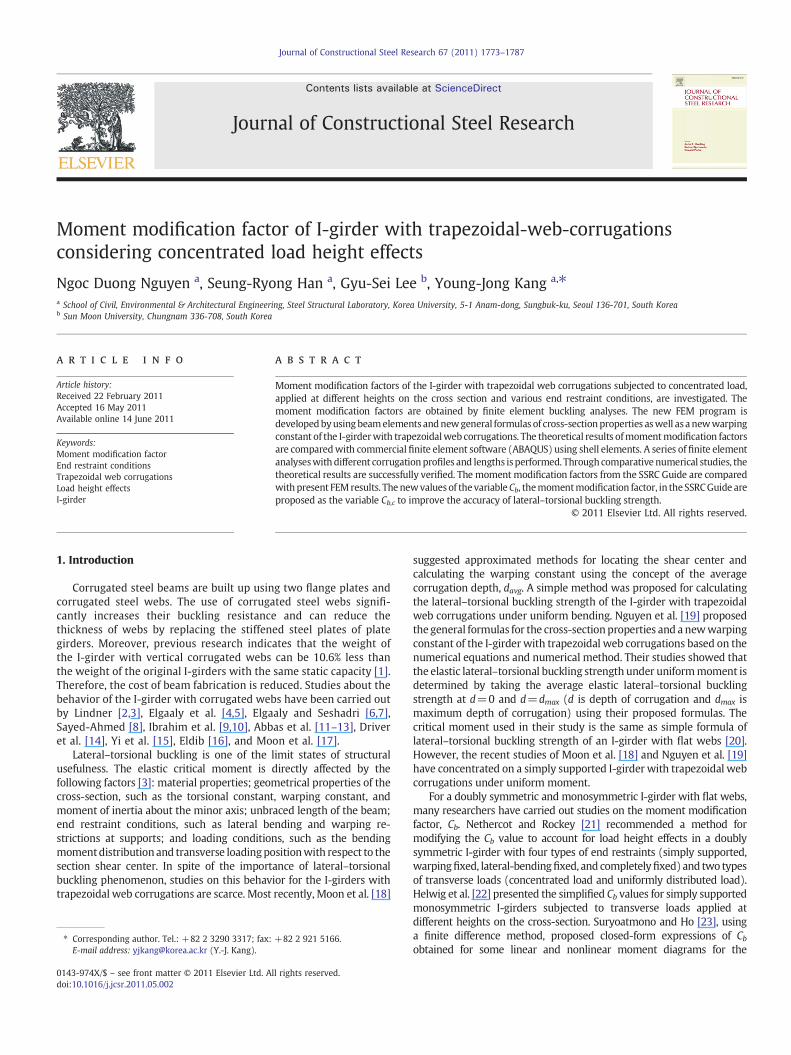
Journal of Constructional Steel Research 67 (2011) 1773–1787
Contents lists available at ScienceDirect
Journal of Constructional Steel Research
Moment modification factor of I-girder with trapezoidal-web-corrugationsconsidering concentrated load height effects
Ngoc Duong Nguyen a, Seung-Ryong Han a, Gyu-Sei Lee b, Young-Jong Kang a,⁎a School of Civil, Environmental & Architectural Engineering, Steel Structural Laboratory, Korea University, 5-1 Anam-dong, Sungbuk-ku, Seoul 136-701, South Koreab Sun Moon University, Chungnam 336-708, South Korea
⁎ Corresponding author. Tel.: +82 2 3290 3317; fax:E-mail address: [email protected] (Y.-J. Kang).
0143-974X/$ – see front matter © 2011 Elsevier Ltd. Adoi:10.1016/j.jcsr.2011.05.002
a b s t r a c t
a r t i c l e i n f oArticle history:Received 22 February 2011Accepted 16 May 2011Available online 14 June 2011
Keywords:Moment modification factorEnd restraint conditionsTrapezoidal web corrugationsLoad height effectsI-girder
Moment modification factors of the I-girder with trapezoidal web corrugations subjected to concentrated load,applied at different heights on the cross section and various end restraint conditions, are investigated. Themoment modification factors are obtained by finite element buckling analyses. The new FEM program isdevelopedbyusingbeamelements andnewgeneral formulas of cross-sectionproperties aswell as a newwarpingconstant of the I-girderwith trapezoidalweb corrugations. The theoretical results ofmomentmodification factorsare comparedwith commercial finite element software (ABAQUS) using shell elements. A series of finite elementanalyseswithdifferent corrugationprofiles and lengths isperformed. Throughcomparative numerical studies, thetheoretical results are successfully verified. The moment modification factors from the SSRC Guide are comparedwithpresent FEMresults. Thenewvalues of thevariableCb, themomentmodification factor, in the SSRCGuide areproposed as the variable Cb,c to improve the accuracy of lateral–torsional buckling strength.
+82 2 921 5166.
ll rights reserved.
© 2011 Elsevier Ltd. All rights reserved.
1. Introduction
Corrugated steel beams are built up using two flange plates andcorrugated steel webs. The use of corrugated steel webs signifi-cantly increases their buckling resistance and can reduce thethickness of webs by replacing the stiffened steel plates of plategirders. Moreover, previous research indicates that the weight ofthe I-girder with vertical corrugated webs can be 10.6% less thanthe weight of the original I-girders with the same static capacity [1].Therefore, the cost of beam fabrication is reduced. Studies about thebehavior of the I-girder with corrugated webs have been carried outby Lindner [2,3], Elgaaly et al. [4,5], Elgaaly and Seshadri [6,7],Sayed-Ahmed [8], Ibrahim et al. [9,10], Abbas et al. [11–13], Driveret al. [14], Yi et al. [15], Eldib [16], and Moon et al. [17].
Lateral–torsional buckling is one of the limit states of structuralusefulness. The elastic critical moment is directly affected by thefollowing factors [3]: material properties; geometrical properties of thecross-section, such as the torsional constant, warping constant, andmoment of inertia about the minor axis; unbraced length of the beam;end restraint conditions, such as lateral bending and warping re-strictions at supports; and loading conditions, such as the bendingmomentdistribution and transverse loadingpositionwith respect to thesection shear center. In spite of the importance of lateral–torsionalbuckling phenomenon, studies on this behavior for the I-girders withtrapezoidal web corrugations are scarce. Most recently, Moon et al. [18]
suggested approximated methods for locating the shear center andcalculating the warping constant using the concept of the averagecorrugation depth, davg. A simple method was proposed for calculatingthe lateral–torsional buckling strength of the I-girder with trapezoidalweb corrugations under uniform bending. Nguyen et al. [19] proposedthe general formulas for the cross-sectionproperties and a newwarpingconstant of the I-girder with trapezoidal web corrugations based on thenumerical equations and numerical method. Their studies showed thatthe elastic lateral–torsional buckling strength under uniformmoment isdetermined by taking the average elastic lateral–torsional bucklingstrength at d=0 and d=dmax (d is depth of corrugation and dmax ismaximum depth of corrugation) using their proposed formulas. Thecritical moment used in their study is the same as simple formula oflateral–torsional buckling strength of an I-girder with flat webs [20].However, the recent studies of Moon et al. [18] and Nguyen et al. [19]have concentrated on a simply supported I-girder with trapezoidal webcorrugations under uniform moment.
For a doubly symmetric and monosymmetric I-girder with flat webs,many researchers have carried out studies on the moment modificationfactor, Cb. Nethercot and Rockey [21] recommended a method formodifying the Cb value to account for load height effects in a doublysymmetric I-girder with four types of end restraints (simply supported,warpingfixed, lateral-bendingfixed, and completelyfixed) and two typesof transverse loads (concentrated load and uniformly distributed load).Helwig et al. [22] presented the simplified Cb values for simply supportedmonosymmetric I-girders subjected to transverse loads applied atdifferent heights on the cross-section. Suryoatmono and Ho [23], usinga finite difference method, proposed closed-form expressions of Cbobtained for some linear and nonlinear moment diagrams for the

Nomenclature
a length of flat webb projection length of inclined panelc length of inclined paneld depth of corrugationdmax maximum depth of corrugationdavg average depth of corrugation from result of Ref. [18]Lo corrugation wavelengthLb lateral buckling lengthL unbraced lengthbf width of flangetf thickness of flangetw thickness of webhw height of corrugated websE Young's modulus of elasticityν Poisson's ratioG shear modulus of elasticity of flat platesGc shear modulus of elasticity of corrugated platesJc pure torsional constant of I-girder with trapezoidal
web corrugationsJ pure torsional constant of I-girder with flat websIx,c, Iy,c moments of inertia of I-girder with trapezoidal web
corrugations about strong axis (x-axis) and weak axis(y-axis), respectively from result of Ref. [19]
Iy moment of inertia of I-girder with flat webs aboutweak axis (y-axis)
Cw,c warping constant of I-girder with trapezoidal webcorrugations from result of Ref. [19]
Cw warping constant of I-girder with flat websMocr elastic lateral–torsional buckling strength of I-girder
with trapezoidal web corrugations under uniformmoment from result of Ref. [19]
Mocr,flat elastic lateral–torsional buckling strength of I-girderwith flat webs under uniform moment [20]
Mcr,FEMA elastic lateral–torsional buckling strength of I-girderwith trapezoidal web corrugations under concentrat-ed load, considering load height effects and variousend restraint conditions from ABAQUS software [33]
Mcr,FEMB elastic lateral–torsional buckling strength of I-girderwith trapezoidal web corrugations under concentrat-ed load, considering load height effects and variousend restraint conditions from present FEM program
Cb moment modification factor of I-girder with flat websin the present design specifications
Cm moment modification factor of monosymmetric I-girder with flat webs from results of Ref. [25]
Cb,c moment modification factor of I-girder with trapezoi-dal web corrugations
Cb,FEMA moment modification factor of I-girder with trapezoi-dal web corrugations from ABAQUS software [33]
Cb,FEMB moment modification factor of I-girder with trapezoi-dal web corrugations from present FEM program
A, B coefficients for the Cb calculationAm, Bm, and Cm coefficients for the Cm calculationAc, Bc coefficients for the Cb, c calculation[KE] global elastic stiffness matrix from result of Ref. [27][KG] global geometric matrix from result of Ref. [27]λ load factor (eigenvalue)ρ degree of monosymmetric
1774 N.D. Nguyen et al. / Journal of Constructional Steel Research 67 (2011) 1773–1787
transverse loads applied at the shear center of the cross-section. Lim et al.[24], using the finite element and Bubnov–Galerkinmethod, investigatedthe elastic lateral–torsional buckling of the doubly symmetric and
monosymmetric I-girders under linear moment gradient. In their paper,they proposed new equations for calculating the moment modificationfactors, considering three different end support conditions: simplysupported, warping fixed and completely fixed. Park et al. [25] presentedamoreaccuratemomentmodification factor formonosymmetric I-beamswith two types of transverse loads (concentrated load and uniformlydistributed load) applied at different heights with respect to the mid-height of the cross-section. Four types of end restraints (simplysupported, warping fixed, lateral-bending fixed, and completely fixed)are also considered in their study. However, to date, the momentmodification factors of the I-girder with trapezoidal web corrugationsunder concentrated load, considering load height effects and various endrestraint conditions, have not been found. As a consequence, the aim ofthis study is to solve these problems.
The studies on lateral buckling for prismatic and nonprismatic beamsby using finite element ‘beam’ formulations are presented by Krajcihovic[26], Barsoum and Gallagher [27], Powell and Klinger [28], Hancock andTrahair [29], and Bradford [30]. Ronagh and Bradford [31,32] showed theshortcoming in the geometric matrix of Barsoum and Gallagher [27]because it omitted the boundary term. They concluded that the boundaryterm has opposite signs when it is counted for two successive elementsand thenet resultwouldbe zero except for the two far-endelements. Thisis the major difference between themethod of Ronagh and Bradford andthat of Barsoum and Gallagher in the global geometric matrix. However,in this study, for the I-girder with simply supported end restraintcondition in the plane of loading (warpingfixed and lateral bending fixedare out-of-plane of loading end restraint conditions) and underconcentrated load as shown in Fig. 1, the boundary term is zero at thetwo far-end elements [31,32]. Therefore, the finite element formulationsof Barsoum and Gallagher [27] when applying for themodel in this studygive the same results as those of other authors [31,32].
In this study, thenewgeneral approach for lateral–torsional bucklingstrength calculation that incorporates a new warping constant of the I-girder with trapezoidal web corrugations suggested by Nguyen et al.[19], and the finite element formulations of torsional–flexural stabilityproblems proposed by Barsoum and Gallagher [27], are suggested tostudy the moment modification factors of the I-girder with trapezoidalweb corrugations under concentrated load at different heights of thecross-section and four types of end supports (simply supported,warping fixed, lateral-bending fixed and completely fixed) as shownin Fig. 1. The FEM program to calculate critical buckling strength for theI-girder with trapezoidal web corrugations is developed by using beamelements including thewarpingdegrees of freedom, anda series offiniteelement analyseswith different corrugation profiles and lengths is thenperformed. The theoretical results of this study are verified throughcomparisonswith thefinite element results fromABAQUS software [33]by using shell elements (S4R5) for simply supported I-girder withtrapezoidal web corrugations. Through thorough comparisons betweenthe results of the developed FEM program and those of ABAQUSsoftware [33], the theoretical results are successfully verified. Finally, forthe purpose of design, the new moment modification factors Cb,c areproposed such as themomentmodification factors Cb in the SSRCGuide[34] through coefficients for Cb,c calculation, Ac and Bc.
2. Back ground and previous work
Generally, the shear modulus of corrugated webs is smaller thanthat of the flat plates [18]. In this study, the formula for calculatingshear modulus of corrugated webs proposed by Samanta andMukhopadhyay [35] is adopted as follows,
Gc =a + ba + c
G; ð1Þ
where G is the shear modulus of the flat plates and (a+b) is theprojection length of the actual length (a+c).

Fig. 2. (a) Dimensions of cross-section, (b) Dimensions of corrugation profiles.
(a)
(b)
Fig. 1. (a) Position of concentrated load, (b) End restraint conditions.
Table 1The values of the variables A and B in the SSRC Guide [34].
Restraint A B
(1) (2) (3)
I 1.350 1−0.180W2+0.649WII 1.430+0.485W2+0.463W 1−0.317W2+0.619WIII 2.000−0.074W2+0.304W 1−0.207W2+1.047WIV 1.916−0.424W2+1.851W 1−0.466W2+0.923W
Table 2The values of the variables Am, Bm and Dm in Ref. [25].
Restraint Am
(1) (2)
I 1.350II 1:430 + 0:485W
2+ 0:463W
III 2:000−0:074W2+ 0:304W
IV 1:916−0:424W2+ 1:851W
1775N.D. Nguyen et al. / Journal of Constructional Steel Research 67 (2011) 1773–1787
Fig. 2 shows the geometry data of the cross-section and corru-gation profiles.
Using studies in Lindner [2], the pure torsional constant Jc of a steelI-girder with trapezoidal web corrugations does not differ from abeam with a flat web. Therefore, Jc is given by
Jc =2bf t
3f + hwt
3w
3: ð2Þ
Bm Dm
(3) (4)
1−0:180W2+ 0:649W 1.0
1−0:317W2+ 0:619W 0.775−0.852ρ2+0.926ρ
1−0:207W2+ 1:047W 0.724−0.005ρ2+0.567ρ
1−0:466W2+ 0:923W 0.583−0.623ρ2+1.116ρ
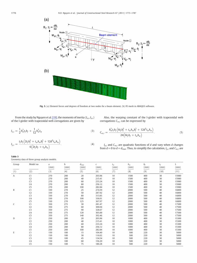
Fig. 3. (a) Element forces and degrees of freedom at two nodes for a beam element, (b) FE mesh in ABAQUS software.
1776 N.D. Nguyen et al. / Journal of Constructional Steel Research 67 (2011) 1773–1787
From the study byNguyen et al. [19], themoments of inertia (Ix,c, Iy,c)of the I-girder with trapezoidal web corrugations are given by
Ix;c =12h2wtf bf +
112
h3wtw ð3Þ
Iy;c =tf bf 2tf b
3f + twhwb
2f + 12d2twhw
� �6 2tf bf + twhw� � : ð4Þ
Table 3Geometry data of three group analysis models.
Group Model no a(mm)
b(mm)
dmax
(mm)c(mm
(1) (2) (3) (4) (5) (6)
A C1 270 200 20 203C2 270 200 40 215C3 270 200 60 233C4 270 200 80 256C5 270 200 100 282
B C1 330 270 25 274C2 330 270 50 287C3 330 270 80 313C4 330 270 100 336C5 330 270 125 367
C C1 350 275 30 281C2 350 275 60 300C3 350 275 90 328C4 350 275 120 365C5 350 275 140 392
D C1 250 200 20 203C2 250 200 40 215C3 250 200 60 233C4 250 200 80 256C5 250 200 100 282
E C1 150 100 15 104C2 150 100 30 116C3 150 100 45 134C4 150 100 60 156C5 150 100 75 180
Also, the warping constant of the I-girder with trapezoidal webcorrugations Cw,c can be expressed by
Cw;c =h2wtf bf 6tf b
3f + twhwb
2f + 12d2twhw
� �24 6tf bf + twhw
� � : ð5Þ
Iy,c and Cw,c are quadratic functions of d and vary when d changesfrom d=0 to d=dmax. Thus, to simplify the calculation, Iy,c and Cw,c are
)tw(mm)
hw(mm)
bf(mm)
tf(mm)
L(mm)
(7) (8) (9) (10) (11)
.96 10 1500 400 30 15980
.41 10 1500 400 30 15980
.24 10 1500 400 30 15980
.12 10 1500 400 30 15980
.84 10 1500 400 30 15980
.59 12 2000 500 40 16800
.92 12 2000 500 40 16800
.85 12 2000 500 40 16800
.01 12 2000 500 40 16800
.97 12 2000 500 40 16800
.47 12 2000 500 40 17500
.04 12 2000 500 40 17500
.67 12 2000 500 40 17500
.00 12 2000 500 40 17500
.46 12 2000 500 40 17500
.96 10 1000 400 30 15300
.41 10 1000 400 30 15300
.24 10 1000 400 30 15300
.12 10 1000 400 30 15300
.84 10 1000 400 30 15300
.40 10 500 220 30 5000
.62 10 500 220 30 5000
.54 10 500 220 30 5000
.20 10 500 220 30 5000
.28 10 500 220 30 5000
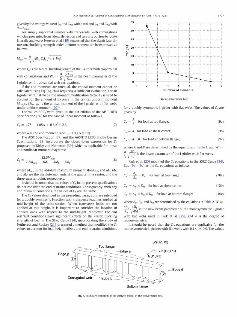
Fig. 5. Convergence test.
1777N.D. Nguyen et al. / Journal of Constructional Steel Research 67 (2011) 1773–1787
given by the average valueof Iy,c and Cw,cwithd=0and Iy,c and Cw,cwithd=dmax.
For simply supported I-girder with trapezoidal web corrugationswhich is prevented from lateral deflection and twisting but free to rotatelaterally and warp, Nguyen et al. [19] suggested that the elastic lateral–torsional buckling strength under uniformmoment can be expressed asfollows,
Mocr =πLb
ffiffiffiffiffiffiffiffiffiffiffiffiffiffiffiffiffiEIy;cGcJc
q ffiffiffiffiffiffiffiffiffiffiffiffiffiffiffiffiffiffi1 + W2
c
q; ð6Þ
where Lb is the lateral buckling length of the I-girder with trapezoidal
web corrugations and Wc =πLb
ffiffiffiffiffiffiffiffiffiffiffiECw;c
GcJc
sis the beam parameter of the
I-girder with trapezoidal web corrugations.If the end moments are unequal, the critical moment cannot be
calculated using Eq. (6), thus requiring a sufficient evaluation. For anI-girder with flat webs, the moment modification factor Cb is used toaccount for the amount of increase in the critical uniform momentMocr,flat (Mocr,flat is the critical moment of the I-girder with flat websunder uniform moment [20]).
The values of Cb were given in the 1st edition of the AISC LRFDSpecification [36] for the case of linear moment as follows,
Cb = 1:75 + 1:05α + 0:3α2 ≤ 2:3; ð7Þ
where α is the end moment ratio (−1.0≤α≤1.0).The AISC Specification [37] and the AASHTO LRFD Bridge Design
Specifications [38] incorporate the closed-form expression for Cbproposed by Kirby and Nethercot [39], which is applicable for linearand nonlinear moment diagrams:
Cb =12:5Mmax
2:5Mmax + 3MA + 4MB + 3MC; ð8Þ
where Mmax is the absolute maximum moment along Lb, and MA, MB,and MC are the absolute moments at the quarter, the center, and thethree-quarter point, respectively.
It should be noted that the values of Cb in the present specificationsdo not consider the end restraint conditions. Consequently, with anyend restraint conditions, the values of Cb are the same.
The Cb values described in the preceding paragraphs are intendedfor a doubly symmetric I-section with transverse loadings applied atmid-height of the cross-section. When transverse loads are notapplied at mid-height, it is important to consider the location ofapplied loads with respect to the mid-height. Moreover, the endrestraint conditions have significant effects on the elastic bucklingstrength of beams. The SSRC Guide [34], incorporating the study ofNethercot and Rockey [21], presented a method that modified the Cbvalues to account for load height effects and end restraint conditions
Fig. 4. Boundary condition of the analy
for a doubly symmetric I-girder with flat webs. The values of Cb aregiven by
Cb =AB
for load at top flange; ð9aÞ
Cb = A for load at shear center; ð9bÞ
Cb = A × B for load at bottom flange; ð9cÞ
where A and B are determined by the equations in Table 1, and W =πLb
ffiffiffiffiffiffiffiffiffiECw
GJ
sis the beam parameter of the I-girder with flat webs.
Park et al. [25] modified the Cb equations in the SSRC Guide [34],Eqs. (9a)–(9c) as the Cm equations as follows,
Cm =Am
Bm× Dm for load at top flange; ð10aÞ
Cm = Am × Dm for load at shear center; ð10bÞ
Cm = Am × Bm × Dm for load at bottom flange; ð10cÞ
where Am, Bm, and Dm are determined by the equations in Table 2,W =
πhwLb
ffiffiffiffiffiffiffiffiEIy4GJ
sis the new beam parameter of the monosymmetric I-girder
with flat webs used in Park et al. [25], and ρ is the degree ofmonosymmetry.
It should be noted that the Cm equations are applicable for themonosymmetric I-girders with flat webs with 0.1≤ρ≤0.9. The values
sis model in the convergence test.

1778 N.D. Nguyen et al. / Journal of Constructional Steel Research 67 (2011) 1773–1787
of Cb for the I-girder with trapezoidal web corrugations under concen-trated load, considering load height effects and end restraint con-ditions, have not yet been proposed.
Fig. 6. Comparison between Cb,FEMA and Cb,FEMB of groups A, B, and C.
3. Finite element model and verification
3.1. Finite element formulation
For elastic buckling, the critical load may be obtained from thefollowing determinantal equation
j KE½ � + λ KG½ �j = 0; ð11Þ
where [KE] is the global elastic stiffness matrix measuring theresistance of the beam to lateral–torsional displacements, [KG] is theglobal geometric matrix measuring the tendency of the stresses in thebeam to cause lateral displacements corresponding to unit appliedload and λ is the load factor (eigenvalue).
The matrices [KE] and [KG] presented by Barsoum and Gallagher[27] are used in this study.
3.2. Finite element model
The finite element program is developed, utilizing the direct finiteelement formulations of torsional–flexural stability problems asproposed by Barsoum and Gallagher [27] and new general formulasof cross-section properties as well as a new warping constant of theI-girder with trapezoidal web corrugations as proposed by Nguyen etal. [19]. I-girders with trapezoidal web corrugations are modeled byusing beam elements including the warping degrees of freedom.These elements have two nodes per element and seven nodal degreesof freedom as shown in Fig. 3a.
3.3. Verification FEM program
Three groups (groups A, B, and C) of I-girders with trapezoidal webcorrugations with different corrugation profiles and lengths aremodeled with ABAQUS software [33]. The geometry data are shownin Table 3. The material properties are Young's modulus of elasticity
E=200, 000N/mm2, shear modulus of elasticity G =E
2 1 + νð Þ, andPoisson's ratio ν=0.3. The models are built using four-node thin shellelements (S4R5) in ABAQUS software [33]. The girders are consideredto be simply supported in flexure and torsion for the convergence test.Point 1 is the hinged end where the displacements in directions 1, 2, 3and the rotation about the direction 3 are restrained. Point 2 is a rollerend where the displacements in directions 1, 2 and the rotation about
Fig. 7. Comparison between Cb,FEMB and Cb,c of groups A, B, and C for shear center loading(simply supported).

1779N.D. Nguyen et al. / Journal of Constructional Steel Research 67 (2011) 1773–1787
the direction 3 are restrained. Edges a and b are restrained in direction2. The displacements in direction 1 for edges c and d are restrained.The typical boundary conditions of the analysis models for conver-gence test are illustrated in Fig. 4.
For 3D model in ABAQUS software, the difference between theelastic lateral–torsional buckling strength when each flange of thebeam in Fig. 4 is divided into twenty six elements (aspect ratio=1.25)in the direction 1 axis and that when each flange of the beam isdivided into fourteen elements (aspect ratio=1.29) is 0.167%. Thecorrugated webs are modeled to have the similar mesh refinement as
Fig. 8. Comparison between Cb,FEMB, Cb,c, and Cb⁎ o
the flanges. Fig. 3b shows the finite element mesh in ABAQUSsoftware. Also, the error between the value of elastic critical momentwhen using the developed FEM program with eight beam-elementsand that when each flange of the beam in Fig. 4 is divided into twentysix elements in the direction 1 axis is 0.101%. Fig. 5 shows the resultsof convergence analysis of the model C3 in group B with the detailedgeometry data shown in Table 3 under concentrated load applied atthe shear center for beam element. Therefore, in this study, this typeof mesh refinement of finite element models (each flange of 3Dmodelis divided into twenty six elements in the direction 1 axis with aspect
f groups A, B, C, D, and E (simply supported).

Fig. 8 (continued).
1780 N.D. Nguyen et al. / Journal of Constructional Steel Research 67 (2011) 1773–1787
ratio equal to 1.25 in ABAQUS software and the beam is divided into8 elements in the developed FEM program) is reasonable to obtainaccurate numerical results.
For transverse load, the values of Cb,FEMA and Cb,FEMB (Cb,FEMA is themoment modification factor of the I-girder with trapezoidal webcorrugations under concentrated load from ABAQUS software [33]and Cb,FEMB is the moment modification factor of the I-girder withtrapezoidal web corrugations under concentrated load from thedeveloped FEM program in this study) are calculated by [34]
Cb;FEMA =Mcr;FEMA
Mocrð12aÞ
Cb;FEMB =Mcr;FEMB
Mocr; ð12bÞ
whereMocr, calculated by Eq. (6), is the critical moment of the I-girderwith trapezoidal web corrugations under uniform moment, Mcr,FEMA,calculated by ABAQUS software [33], and Mcr,FEMB, calculated by thepresent FEM program, are the critical moment of the I-girder withtrapezoidal web corrugations under concentrated load, consideringthe effects of load height and various end restraint conditions.
Fig. 6a–c shows the variations ofCb;FEMA
Cb;FEMBwith beam parameter Wc
(Wc is the beam parameter of the I-girder with trapezoidal webcorrugations) of groups A, B, and C, respectively. The X-axis representsthe beam parameter Wc and the Y-axis represents the ratio of Cb,FEMA
to Cb,FEMA or Cb,FEMA to Cb,FEMB. Those ratios can be expressed in thefollowing equations:
Cb;FEMA
Cb;FEMA= 1 ð13aÞ
Cb;FEMA
Cb;FEMB=
Mcr;FEMA
MocrMcr;FEMB
Mocr
=Mcr;FEMA
Mcr;FEMB: ð13bÞ
It is found that the values of Cb,FEMB are in good agreement withCb,FEMA. The maximum differences between Cb,FEMA and Cb,FEMB are
10.465%, 6.936%, and 8.39% for groups A, B, and C respectively, whenthe concentrated loads are applied at the top flange of the I-girderwith trapezoidal web corrugations.
4. Finite element results and design recommendations
4.1. Simply supported I-girder with trapezoidal web corrugations (Type I)
Fig. 7 shows the variations of Cb,FEMB with the beam parameter Wc
of three groups A, B, and C. In this figure, the values of Cb,FEMB arevery slightly changed with the changing of the beam parameter Wc,provided that the concentrated loads are applied at the shear centerof the I-girder with trapezoidal web corrugations. Therefore, in thissituation, the value of Cb,c (Cb,c is the proposed moment modificationfactor for the I-girder with trapezoidal web corrugations) is proposedas the same value of Cb in the SSRC Guide [34] as follows,
Cb;c = Ac = 1:35; ð14aÞ
where Ac is a coefficient for Cb,c calculation.When concentrated loads are applied at the top flange and bottom
flange, tobeapplicable to the simply supported I-girderwith trapezoidalweb corrugations, Cb,c equations are proposed via investigations thevalues of Cb,FEMB as follows,
Cb;c =Ac
Bcfor load at top flange; ð14bÞ
Cb;c = Ac × Bc for load at bottom flange; ð14cÞ
where Bc is a coefficient for the Cb,c calculation and Bc is chosen as afunction of Wc
Bc = −0:0059W2c + 0:2424Wc + 1:1584: ð15Þ
The equation for Bc is obtained by regression analysis [40] with thesame quadratic equation as that in the SSRC Guide [34].
Toverify the applicationofmomentmodification factorsCb in the SSRCGuide [34] to the I-girderwith trapezoidalweb corrugations, the values ofW in Table 1 are replaced byWc and the values of Cb are calculated as Cb⁎.Also, twogroups (groupsDandE)of the smaller I-girderswith trapezoidalwebcorrugations (500–1000 mmheights) areused toverify theproposedequations. Table 3 shows the geometry data of groups D and E. The valuesof Cb,FEMB, Cb,c, and Cb⁎ are plotted in Fig. 8a–e, respectively, when theconcentrated load is applied at the top flange, shear center, and bottomflange for groups A, B, C, D, and E, respectively. It can be seen that all thevalues of themomentmodification factors,Cb,c, fromEqs. (14a)–(14c) andthose of Cb⁎ from the SSRCGuide [34] are in good agreementwith those ofCb,FEMB from the developed FEM program. The maximum differencesbetween Cb,c, Cb⁎, and Cb,FEMB are not more than 5%.
4.2. Warping fixed I-girder with trapezoidal web corrugations (Type II)
From the results of the present FEM investigation, to be applicableto the warping fixed I-girder with trapezoidal web corrugations, Cb,cequations are suggested as follows,
Cb;c =Ac
Bcfor load at top flange; ð16aÞ
Cb;c = Ac for load at shear center; ð16bÞ
Cb;c = Ac × Bc for load at bottom flange; ð16cÞ

1781N.D. Nguyen et al. / Journal of Constructional Steel Research 67 (2011) 1773–1787
where Ac and Bc are the coefficients for Cb,c calculation. The values of Ac
and Bc are given by
Ac = −0:0945W2c + 0:5784Wc + 1:775 ð17Þ
Bc = 0:0066W2c + 0:0550Wc + 1:156: ð18Þ
The equations for Ac and Bc are calculated from regression analysis[40] such as Bc in Type I.
Fig. 9. Comparison between Cb,FEMB, Cb,c, and Cb⁎
The comparisons between Cb,FEMB, Cb,c (Eqs. (16a)–(16c)), and Cb⁎-SSRCGuide [34] are illustrated in Fig. 9a–ewhen the concentrated loadis applied at the top flange, shear center, and bottom flange for groupsA, B, C, D, and E, respectively. It can be observed that the values of Cb,cagree well with the values of Cb,FEMB (the maximum discrepancies arenot more than 4.69%) while there are disagreements between Cb,FEMB
and Cb⁎. This explains that the SSRC Guide [34] could not estimate theincreasing of the lateral–torsional buckling strength of the I-girderwith trapezoidal web corrugations when the girder is warping fixed atthe end supports because the shorter corrugation wave length and
of groups A, B, C, D, and E (warping fixed).

Fig. 9 (continued).
1782 N.D. Nguyen et al. / Journal of Constructional Steel Research 67 (2011) 1773–1787
the more restraint the support can deliver to the girder with webcorrugations, the higher the critical lateral buckling strength will be.All the values of Cb⁎ are larger than Cb,FEMB, which means they areunconservative. The maximum differences between Cb,FEMB based onthe developed FEM program and Cb⁎ from the SSRC Guide [34] arelarger than 6%.
4.3. Lateral bending fixed I-girder with trapezoidal web corrugations(Type III)
Similar to Type II, the Cb,c equations are the same as those ofEqs. (16a)–(16c). However, to be applicable to the lateral bendingfixed I-girder with trapezoidal web corrugations, the values of Ac andBc are proposed as follows,
Ac = 0:0265W2c −0:0872Wc + 1:5496 ð19Þ
Bc = −0:0063W2c + 0:2741Wc + 1:1822; ð20Þ
where Ac and Bc are the coefficients for the Cb,c calculation and arecalculated from regression analysis [40].
Fig. 10a–e are the graphs of Cb,FEMB, Cb,c (Eqs. (16a)–(16c)) and Cb⁎-SSRC Guide [34], versus the beam parameter Wc of groups A, B, C, D,and E, respectively with the proposed Ac and Bc for the lateral bendingfixed I-girder with trapezoidal web corrugations. Results from thepresent FEM program as well as from the SSRC Guide [34] are alsoshown in Fig. 10a–e. From these figures, it can be found that the valuesof the proposed Cb,c are close to Cb,FEMB. The values of Cb⁎ for the topflange loading case are rather good agreement with Cb,FEMB while theothers are not good. The maximum differences between the values ofCb,c from Eqs. (16a)–(16c) and the values of Cb,FEMB are not more than5.7%. This demonstrates that the Cb,c equations presented in this studyhave reasonable estimation compared to the SSRC Guide [34]. Similarto Type II, all the values of Cb⁎ are unconservative. The maximum
discrepancies between Cb,FEMB from the developed FEM program andCb⁎ based on the SSRC Guide [34] are larger than 13%.
4.4. Completely fixed I-girder with trapezoidal web corrugations (Type IV)
For a completely fixed I-girder with trapezoidal web corrugations(simply supported end restraint condition in the plane of loading andwarping fixed and lateral bending fixed end restraint conditions in theout-of-plane of loading), the equations of Cb,c are identical to those ofEqs. (16a)–(16c). In order to apply to the completely fixed I-girderwith trapezoidal web corrugations, the values of Ac and Bc are changedand are suggested as follows,
Ac = −0:1047W2c + 0:6412Wc + 1:9721 ð21Þ
Bc = 0:0079W2c + 0:0616Wc + 1:1869; ð22Þ
where Ac and Bc are the coefficients for the Cb,c calculation and arecalculated from regression analysis [40].
Variations of Cb,FEMB, Cb,c (Eqs. (16a)–(16c)), and Cb⁎-SSRC Guide[34] of groups A, B, C, D, and E are shown in Fig. 11a–e, respectively, fora completely fixed I-girder with trapezoidal web corrugations. It canbe seen in Fig. 11a–e that the values of Cb,c from Eqs. (16a)–(16c) arewell matched with Cb,FEMB, while the values of Cb⁎ show pooragreement with Cb,FEMB. The errors between the values of Cb,c fromEqs. (16a)–(16c) and the values of Cb,FEMB of all three groups are notmore than 5.04% for a completely fixed I-girder with trapezoidal webcorrugations. Also, these results are very similar to the results shownin Type II (warping fixed). The values of Cb,c are conservative while thevalues of Cb⁎ are unconservative. The maximum differences betweenCb,FEMB based on the developed FEM program and Cb⁎ from the SSRCGuide [34] are larger than 13.5%.
In conclusion, from the investigations for the above four types ofend restraints, when the concentrated loads are applied out of theshear center, they cause destabilizing effects (top flange loading) andstabilizing effects (bottom flange loading).The SSRC Guide [34] couldnot predict the lateral–torsional buckling strength of the I-girder withtrapezoidal web corrugations under concentrated load and variousend restraint conditions except for Type I (simply supported). Also,the current specifications do not include the increasing of the lateral–torsional buckling strength due to web corrugation and various endrestraint conditions, especially warping fixed, lateral bending fixed,and completely fixed end conditions. These explain why the criticalbuckling strengths corresponding to the top flange loading are thelowest values and those corresponding to the bottom flange loadingare the largest values among three positions of loading. In addition,due to the effects of types of end restraints, moment modificationfactors for Type IV are the largest values while those for Type I are thesmallest values.
5. Concluding remarks
The FEM program is developed to study the moment modificationfactors of the I-girder with trapezoidal web corrugations underconcentrated load. This FEM program considers the positions of aconcentrated load with respect to mid-height as well as various endrestraint conditions. A series of finite element analyses with differentcorrugation profiles and lengths is performed using the developedFEM program and ABAQUS software [33]. The theoretical results fromthe present FEM program are compared with the results fromABAQUS software [33]. Through comparative numerical studies, thepresent FEM program is successfully verified. From the investigationsof the present FEM results, the moment modification factors of the I-girder with trapezoidal web corrugations under concentrated load areproposed and compared with the SSRC Guide [34]. The momentmodification factors from the SSRC Guide [34] are non-conservative.

1783N.D. Nguyen et al. / Journal of Constructional Steel Research 67 (2011) 1773–1787
The formulas used to calculate the moment modification factors inthis study are suggested as follows,
Cb;c =Ac
Bcfor load at top flange; ð23Þ
Cb;c = Ac for load at shear center; ð24Þ
Cb;c = Ac × Bc for load at bottom flange; ð25Þ
Fig. 10. Comparison between Cb,FEMB, Cb,c, and Cb⁎ of
where Ac and Bc are given by the equations in Table 4, and
Wc =πLb
ffiffiffiffiffiffiffiffiffiffiffiECw;c
Gc Jc
sis the beam parameter of the I-girder with
trapezoidal web corrugations.Based on the differences between the developed FEM results and
the results of the present specifications SSRC Guide [34], specificationsfor lateral–torsional buckling strength should be suggested in steelbeam design for an I-girder with trapezoidal web corrugations under
groups A, B, C, D, and E (lateral bending fixed).

Fig. 10 (continued).
1784 N.D. Nguyen et al. / Journal of Constructional Steel Research 67 (2011) 1773–1787
concentrated load, considering load height effects and various endrestraint conditions.
Acknowledgments
This research was partially supported by a grant (code 07-Technology Innovation-A01) from Construction Technology Innova-tion Program funded by the Ministry of Construction & Transportationof Korean Government and partially supported by the KoreaUniversity Grant.
Appendix A
This appendix presents the element stiffness matrix and elementgeometric stiffness matrix in Barsoum and Gallagher [27]. It is notedthat all the cross-section properties are replaced by the new those forthe I-girder with trapezoidal web corrugations. In addition, the termsinvolving to distributed load are not considered in element geometricstiffness matrix because this study does not investigate distributedload.
Element stiffness matrix
[ke ]=
ui vi θi wi ψi φ i χ i uj vj θj wj ψj φ j χ j
ui a1vi 0 b1θ i 0 c1 d1wi 0 0 0 f1ψi 0 0 0 g1 h1φ i 0 0 0 0 0 j1χi 0 0 0 0 0 k1 l1 Symmetricuj − a1 0 0 0 0 0 0 a1vj 0 − b1 − c1 0 0 0 0 0 b1θ j 0 c1 e1 0 0 0 0 0 − c1 d1wj 0 0 0 − f1 − g1 0 0 0 0 0 f1ψj 0 0 0 g1 i1 0 0 0 0 0 − g1 h1φ j 0 0 0 0 0 − j1 − k1 0 0 0 0 0 j1χ j 0 0 0 0 0 k1 m1 0 0 0 0 0 − k1 l1
ðA:1Þ
in which
a1 =EAL; b1 =
12EIy;cL3
; c1 = −6EIy;cL2
; d1 =4EIy;cL
; e1 =2EIy;cL
;
f1 =12EIx;cL3
; g1 = −6EIx;cL2
; h1 =4EIx;cL
; i1 =2EIx;cL
;
j1 =12GcJc10L
+12ECw;c
L3; k1 = −GcJc
10−6ECw;c
L2;
l1 =4GcJcL30
+4ECw;c
L;
m1 = −GcJcL30
+2ECw;c
L.
Element geometric stiffness matrix
keg =
ui vi θi wi ψi φ i χ i uj vj θj wj ψj φ j χ j
ui 0vi 0 a2θ i 0 b2 c2wi 0 0 Q a2ψ i 0 − Q 0 b2 c2φ i 0 A B A B e2χ i 0 C D C D f2 g2 Symmetricuj 0 0 0 0 0 0 0 0vj 0 − a2 − b2 0 Q E F 0 a2θ j 0 b2 d2 − Q R G H 0 − b2 c2wj 0 0 − Q − a2 − b2 E F 0 0 Q a2ψ j 0 Q − R b2 d2 G H 0 − Q 0 − b2 c2φ j 0 I J I J h2 − i2 0 K L K L e2χ j 0 M N M N i2 j2 0 O P O P − f2 g2
ðA:2Þin which
a2 =12Fzi10L
; b2 = − Fzi10
; c2 =4FziL30
; d2 = − FziL30
;
e2 =12FziSo10L
; f2 = − FziSo10
; g2 =4FziSoL30
;
h2 = −12FziSo10L
; i2 = − FziSo10
; j2 = − FziSoL30
;
A =0:6 Mxi−Mxj
� �L
+ 0:05Vyi + 0:55Vyj;
B=−0.55(Mxi−Mxj)−0.1VyiL−0.45VyjL;C=−0.05(Mxi−Mxj)−0.05VyjL;
D =Mxi−Mxj� �
L15
+VyiL2
60+ 0:05VyjL2;
E =−0:6 Mxi−Mxj
� �L
−0:05Vyi−0:55Vyj;
F=0.05(Mxi−Mxj)+0.05VyjL;G=−0.05(Mxi−Mxj)+0.05VyiL−0.1VyjL;
H = − Mxi−Mxj� �
L60
−VyiL2
60;
I = −0:6 Mxi−Mxj� �
L−0:55Vyi−0:05Vyj;
J=0.05(Mxi−Mxj)+0.1VyiL−0.05VyjL;
K =0:6 Mxi−Mxj
� �L
+ 0:55Vyi + 0:05Vyj;
L=0.55(Mxi−Mxj)+0.45VyiL+0.1VyjL;
M=−0.05(Mxi−Mxj)−0.05VyiL;
N = − Mxi−Mxj� �
L60
−VyjL2
60;
O=0.05(Mxi−Mxj)+0.05VyiL;
P =Mxi−Mxj� �
L15
+ 0:05VyiL2 +VyjL2
60;
Q =Mzi
L;
R =Mzi
2;
A′, B′,…, P′ are obtained by switching subscripts x for y and y for x;

1785N.D. Nguyen et al. / Journal of Constructional Steel Research 67 (2011) 1773–1787
So =Io;cAc
+ exβ1 + eyβ2;
β1 =1Ix;c
∫A y3dA + ∫A x2ydA� �
−2yo
β2 =1Iy;c
∫A x3dA + ∫A y2xdA� �
−2xo;
Fz is the axial force; Vx and Vy are the shear forces; Mx and My arethe bending moment, Mz is the torsional moment, and Bi is thebimoment of element (see Fig. 3a).
Ac is the total area of whole section, xo and yo are the coordinates ofthe shear center S (see Fig. 2) in the x–y axes, and Io,c is the polarmoment inertia about the shear center S.
References
[1] Chan CL, Khalid YA, Sahari BB, Hamouda AMS. Finite element analysis ofcorrugated web beams under bending. J Constr Steel Res 2002;58(1):1391–406.
[2] Lindner J. Lateral torsional buckling of beams with trapezoidally corrugated webs.Stab Steel Struct Bp Hungary 1990:305–10.
[3] Lindner J. Design of steel beams and beam columns. Eng Struct 1997;19(5):378–84.
[4] Elgaaly M, Hamilton RW, Seshadri A. Shear strength of beams with corrugatedwebs. J Struct Eng, ASCE 1996;122(4):390–8.
[5] Elgaaly M, Seshadri A, Hamilton RW. Bending strength of steel beams withcorrugated webs. J Struct Eng, ASCE 1997;123(6):772–82.
[6] Elgaaly M, Seshadri A. Girders with corrugated webs under partial compressiveedge loading. J Struct Eng, ASCE 1997;123(6):782–91.
[7] Elgaaly M, Seshadri A. Depicting the behavior of girders with corrugated webs upto failure using non-linear finite element analysis. Adv Eng Softw 1998;29(3–6):195–208.
[8] Say-Ahmed EY. Lateral torsion–flexure buckling of corrugated web steel girders.Proc Inst Civ Eng Struct Build 2005;158(1):53–69.
[9] Ibrahim Sherif A, El-Dakhakhni Wael W, Elgaaly M. Fatigue of corrugated-webplate girders: analytical study. J Struct Eng, ASCE 2006;132(9):1381–92.
[10] Ibrahim Sherif A, El-DakhakhniWaelW, Elgaaly M. Behavior of bridge girders withcorrugated webs under monotonic and cyclic loading. Eng Struct 2006;28(14):1941–55.
[11] Abbas HH, Sause R, Driver RG. Behavior of corrugatedweb I-girders under in-planeloads. J Eng Mech, ASCE 2006;132(8):806–14.
[12] Abbas HH, Sause R, Driver RG. Analysis of flange transverse bending of corrugatedweb I-girders under in-plane loads. J Struct Eng, ASCE 2007;133(3):347–55.
[13] Abbas HH, Sause R, Driver RG. Simplified analysis of flange transverse bending ofcorrugated web I-girders under in-plane moment and shear. Eng Struct2007;29(11):2816–24.
[14] Driver RG, Abbas HH, Sause R. Shear behavior of corrugated web bridge girders. JStruct Eng, ASCE 2006;132(2):195–203.
[15] Yi J, Gil H, Youm K, Lee HE. Interactive shear buckling behavior of trapezoidallycorrugated steel webs. Eng Struct 2008;30(6):1659–66.
[16] Eldib MEA-H. Shear buckling strength and design of curved corrugated steel websfor bridges. J Constr Steel Res 2009;65(12):2129–39.
[17] Moon J, Yi J, Choi BH, Lee HE. Shear strength and design of trapezoidallycorrugated steel webs. J Constr Steel Res 2009;65(5):1198–205.
[18] Moon J, Yi J, Choi BH, Lee HE. Lateral–torsional buckling of I-girder with corrugatedwebs under uniform bending. Thin Wall Struct 2009;47(1):21–30.
[19] Nguyen ND, Kim SN, Han SR, Kang YJ. Elastic lateral–torsional buckling strength ofI-girder with trapezoidal web corrugations using new warping constant underuniform moment. Eng Struct 2010;32(8):2157–65.
[20] Chen WF, Lui EM. Structural stability. Theory and implementation. ElsevierScience Publishing Co, Inc.; 1987
[21] Nethercot DA, Rockey KC. A unified approach to the elastic lateral buckling ofbeams. AISC Eng J 1972;9(3):96–107.
[22] Helwig TA, Frank KH, Yura JA. Lateral–torsional buckling of singly symmetric I-beams. J Struct Eng, ASCE 1997;123(9):1172–9.
[23] Suryoatmono A, Ho D. The moment-gradient factor in lateral–torsional bucklingon the wide flange steel sections. J Constr Steel Res 2002;58(9):1247–64.
[24] Lim NH, Park NH, Kang YJ, Sung IH. Elastic buckling of I-beams under linearmoment gradient. Int J Solids Struct 2003;40(21):5635–47.
[25] Park NH, Kang YJ, Jo YM, Lim NH. Modification of C-equation in the SSRC Guidefor buckling of monosymmetric I-beams under transverse loads. Eng Struct2007;29(12):3293–300.
[26] Krajcihovic D. A consistent discrete element technique for thin-walled assem-blages. Int J Solids Struct 1969;5(7):639–62.
[27] Barsoum RS, Gallagher RH. Finite element analysis of torsional and torsional–flexural stability problems. Int J Num Meth Eng 1970;2(3):335–52.
[28] Powell GH, Klinger R. Elastic lateral buckling of steel beams. J Struct Div, ASCE1970;96(9):1919–32.
[29] Hancock GJ, Trahair NS. Finite element analysis of the lateral buckling ofcontinuously restrained beam column. Civ Eng Trans, IE, Aust CE 1978;20(2):120–7.
[30] BradfordMA, Cuk PE. Lateral buckling of taperedmonosymmetric I-beams. J StructEng, ASCE 1998;114(5):977–96.
[31] Ronagh HR, Bradford MA. Parameters affecting distorsional buckling of taperedsteel members. J Struct Eng, ASCE 1994;120(11):3137–55.
[32] Ronagh HR, Bradford MA. Some notes on finite element buckling formulations forbeams. Comput Struct 1994;52(6):1119–26.
[33] ABAQUS Standard User's Manual Verion 6.7. Hibbit, Karsson & Sorensen Inc.; 2007[34] Galambos TV. Guide to stability design criteria for metal structures. 5th ed. John
Wiley & Son Inc.; 1998[35] Samanta A, Mukhopadhyay M. Finite element static and dynamic analyses of
folded plates. Eng Struct 1999;21(3):227–87.[36] American Institute of Steel Construction (AISC). Load and resistance factor design.
1st ed. Chicago: AISC; 1986.[37] American Institute of Steel Construction (AISC). Specification for structural steel
buildings. Chicago: AISC; 2005.[38] American Association of State Highway and Transportation Official (AASHTO).
LRFD bridge design specifications. 2nd ed. Washington, DC: AASHTO; 1998.[39] Kirby PA, Nethercot DA. Design for structural stability. Granada Publishing; 1979.[40] Montgomery DC, Runger GC. Applied statistics and probability for engineers. 4th
ed. John Wiley & Sons, Inc.; 2007.

Fig. 11. Comparison between Cb,FEMB, Cb,c, and Cb* of groups A, B, C, D, and E (completely fixed).
1786 N.D. Nguyen et al. / Journal of Constructional Steel Research 67 (2011) 1773–1787

(e) Group E
Fig. 11 (continued).
Table 4The values of the variables Ac and Bc for I-girder with trapezoidal web corrugations.
Restraint Ac Bc
(1) (2) (3)
I 1.3500 1.1584−0.0059Wc2+0.2424Wc
II 1.7750−0.0945Wc2+0.5784Wc 1.1560+0.0066Wc
2+0.0550Wc
III 1.5496+0.0265Wc2−0.0872Wc 1.1822−0.0063Wc
2+0.2741Wc
IV 1.9721−0.1047Wc2+0.6412Wc 1.1869+0.0079Wc
2+0.0616Wc
1787N.D. Nguyen et al. / Journal of Constructional Steel Research 67 (2011) 1773–1787
Copyright © 2022 FDOKUMEN