MOHR – COULOMB FAILURE THEORY
7
Rohini college of engineering and technology CE8491 SOIL MECHANICS MOHR – COULOMB FAILURE THEORY: Of the many theories of failure that have been proposed the Mohr strength theory and Mohr theory have been well accepted by soil engineers. The following are the essential points of Mohr’s strength theory. i) Materials fails by shear ii) The ultimate strength of the material is determined by the stresses in the failure plane. iii) When the material subjected to three principal stresses (1, 2, 3),the intermediate principal stresses does not have any influence on the strength of the material. The theory was first expressed by coulomb and later generalized by Mohr. The Mohr theory can be expressed by the equation, τ f = S = F() τ f = Shear Resistance of material F () = Function of normal stress If the normal and shear corresponding to failure are plotted then a curve is obtained. The plot (or) the curve is called the sheen envelope. Coulomb defined the function F () as a linear function of and c. C- Cohesion ϕ - Angle of internal friction (or) Angle of shearing resistancerespectively. Coulomb considered, that the relationship between shear strength and normal stress, is represented by a straight line. In Mohr theory, the shear strength and normal stress gives non linear curve. the curved failure envelope of Mohr is referred to as a straight line for most cases. For an ideal pure friction material, straight line passes through the origin. S or τ = C + tan ϕ
-
Upload
khangminh22 -
Category
Documents
-
view
0 -
download
0
Transcript of MOHR – COULOMB FAILURE THEORY
Rohini college of engineering and technology
CE8491 SOIL MECHANICS
MOHR – COULOMB FAILURE THEORY:
Of the many theories of failure that have been proposed the Mohr strength theory
and Mohr theory have been well accepted by soil engineers. The following are the
essential points of Mohr’s strength theory.
i) Materials fails by shear
ii) The ultimate strength of the material is determined by the stresses in the failure
plane.
iii) When the material subjected to three principal stresses (𝜎1, 𝜎2, 𝜎3),the
intermediate principal stresses does not have any influence on the strength of
the material.
The theory was first expressed by coulomb and later generalized by Mohr.
The Mohr theory can be expressed by the equation,
τ f = S = F(𝜎)
τ f = Shear Resistance of material
F (𝜎) = Function of normal stress
If the normal and shear corresponding to failure are plotted then a curve is
obtained. The plot (or) the curve is called the sheen envelope.
Coulomb defined the function F (𝜎) as a linear function of 𝜎 and c.
C- Cohesion ϕ - Angle of internal friction (or) Angle of shearing
resistance respectively.
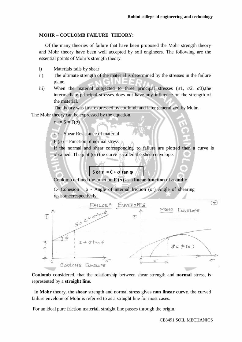
Coulomb considered, that the relationship between shear strength and normal stress, is
represented by a straight line.
In Mohr theory, the shear strength and normal stress gives non linear curve. the curved
failure envelope of Mohr is referred to as a straight line for most cases.
For an ideal pure friction material, straight line passes through the origin.
S or τ = C + 𝜎 tan ϕ
Rohini college of engineering and technology
CE8491 SOIL MECHANICS
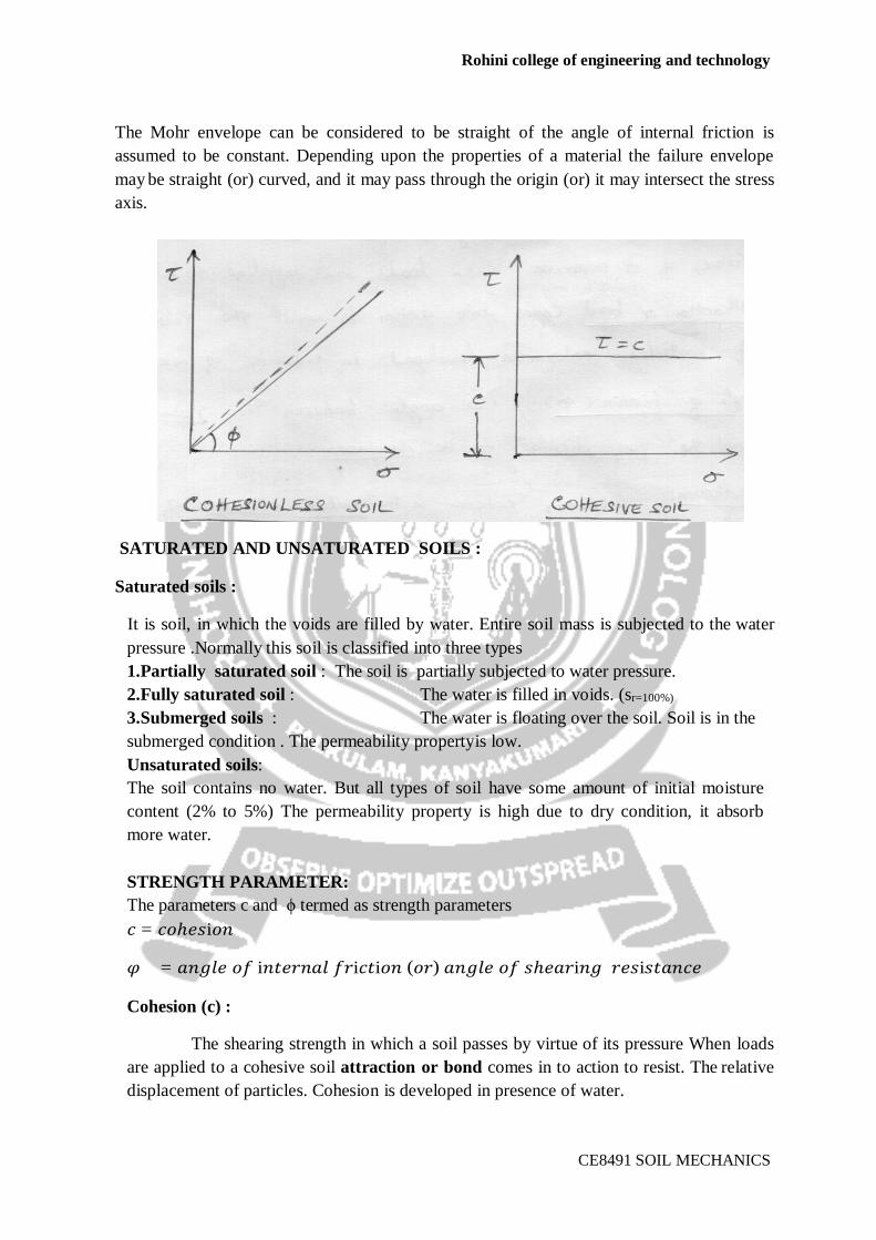
The Mohr envelope can be considered to be straight of the angle of internal friction is
assumed to be constant. Depending upon the properties of a material the failure envelope
may be straight (or) curved, and it may pass through the origin (or) it may intersect the stress
axis.
SATURATED AND UNSATURATED SOILS :
Saturated soils :
It is soil, in which the voids are filled by water. Entire soil mass is subjected to the water
pressure .Normally this soil is classified into three types
1.Partially saturated soil : The soil is partially subjected to water pressure.
2.Fully saturated soil : The water is filled in voids. (sr=100%)
3.Submerged soils : The water is floating over the soil. Soil is in the
submerged condition . The permeability property is low.
Unsaturated soils:
The soil contains no water. But all types of soil have some amount of initial moisture
content (2% to 5%) The permeability property is high due to dry condition, it absorb
more water.
STRENGTH PARAMETER:
The parameters c and ϕ termed as strength parameters
𝑐 = 𝑐𝑜ℎ𝑒𝑠i𝑜𝑛
𝜑 = 𝑎𝑛𝑔𝑙𝑒 𝑜𝑓 i𝑛𝑡𝑒𝑟𝑛𝑎𝑙 𝑓𝑟i𝑐𝑡i𝑜𝑛 (𝑜𝑟) 𝑎𝑛𝑔𝑙𝑒 𝑜𝑓 𝑠ℎ𝑒𝑎𝑟i𝑛𝑔 𝑟𝑒𝑠i𝑠𝑡𝑎𝑛𝑐𝑒
Cohesion (c) :
The shearing strength in which a soil passes by virtue of its pressure When loads
are applied to a cohesive soil attraction or bond comes in to action to resist. The relative
displacement of particles. Cohesion is developed in presence of water.
Rohini college of engineering and technology
CE8491 SOIL MECHANICS
Angle of friction (ɸ) : The angle between the resultant force and the perpendicular to the
surface.
Adhesion: where as cohesion is the mutual attraction of two different parts of a Clay mass
to each other, clay often also exhibit the property of ‘ adhesion’ which is a Propensity to
adhere to other materials at a common surface. This has no relation to the normal pressure. This is of
particular interest in relation to the supporting capacity of friction piling in clays and to the lateral
pressure on retaining walls.
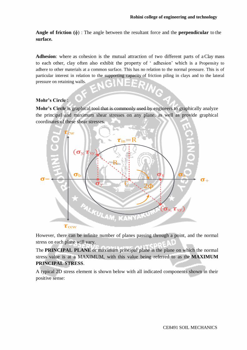
Mohr’s Circle :
Mohr’s Circle is graphical tool that is commonly used by engineers to graphically analyze
the principal and maximum shear stresses on any plane, as well as provide graphical
coordinates of these shear stresses.
However, there can be infinite number of planes passing through a point, and the normal
stress on each plane will vary.
The PRINCIPAL PLANE or maximum principal plane is the plane on which the normal
stress value is at a MAXIMUM, with this value being referred to as the MAXIMUM
PRINCIPAL STRESS.
A typical 2D stress element is shown below with all indicated components shown in their
positive sense:

Rohini college of engineering and technology
CE8491 SOIL MECHANICS
Using a graphical approach, we are able to determine the PRINCIPAL STRESSES on each
plane using a MOHR’S CIRCLE.
Mohr’s circle is a geometric representation of the 2-D transformation of stresses, in which
the component stresses and are found as the coordinates of a point whose location depends
upon the angle to determine the aspect of the cross section.
Mohr’s circle is used to determine the principle angles (orientations) of the principal
stresses without have to plug an angle into stress transformation equations
To draw a Mohr’s Circle for a typical 2-D element, we can use the following procedure to
determine the principal stresses.
1.Def ine The Shear St ress Coordinate System:
Define the coordinate system for the normal and shear axes – Tensile normal stress
components are plotted on the horizontal axis and are considered positive. Compressive
normal stress components are also plotted on the horizontal axis and are negative.
2.Define The Torsional Coordinate Syste m:
For the construction of a Mohr’s circle, shearing stresses are plotted ABOVE the normal stress
axis when the pair of shearing stresses, acting on opposite and parallel faces of an element, form a
Rohini college of engineering and technology
CE8491 SOIL MECHANICS
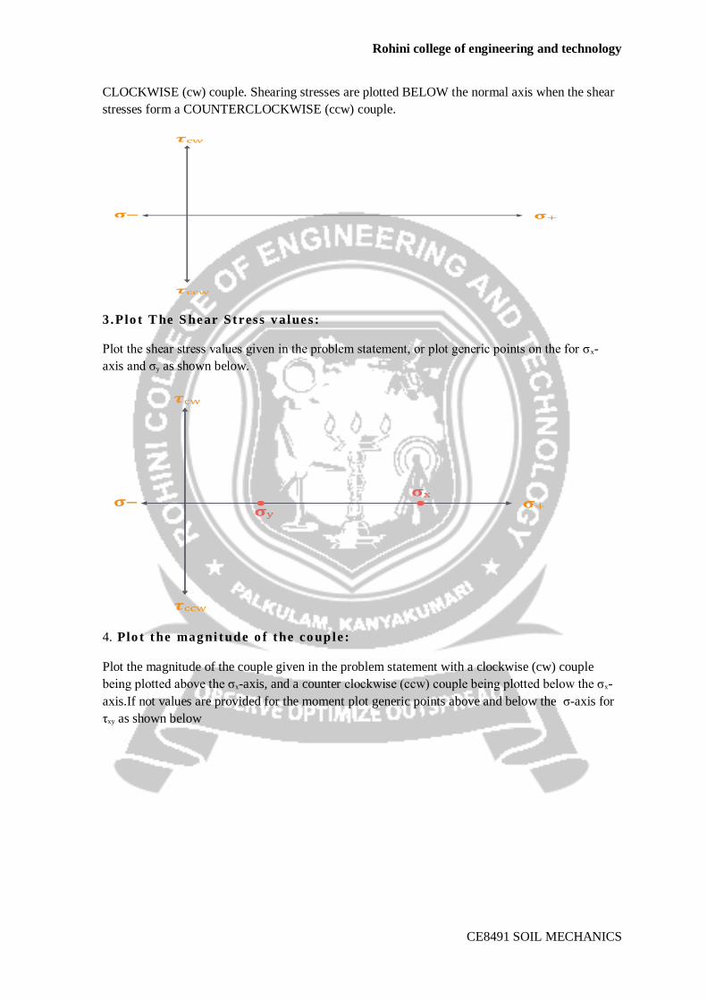
CLOCKWISE (cw) couple. Shearing stresses are plotted BELOW the normal axis when the shear
stresses form a COUNTERCLOCKWISE (ccw) couple.
3.Plo t T he S hear Stress v alues:
Plot the shear stress values given in the problem statement, or plot generic points on the for σx-
axis and σy as shown below.
4. Plo t the mag ni tude o f the co uple :
Plot the magnitude of the couple given in the problem statement with a clockwise (cw) couple
being plotted above the σx-axis, and a counter clockwise (ccw) couple being plotted below the σx-
axis.If not values are provided for the moment plot generic points above and below the σ-axis for
τxy as shown below
Rohini college of engineering and technology
CE8491 SOIL MECHANICS
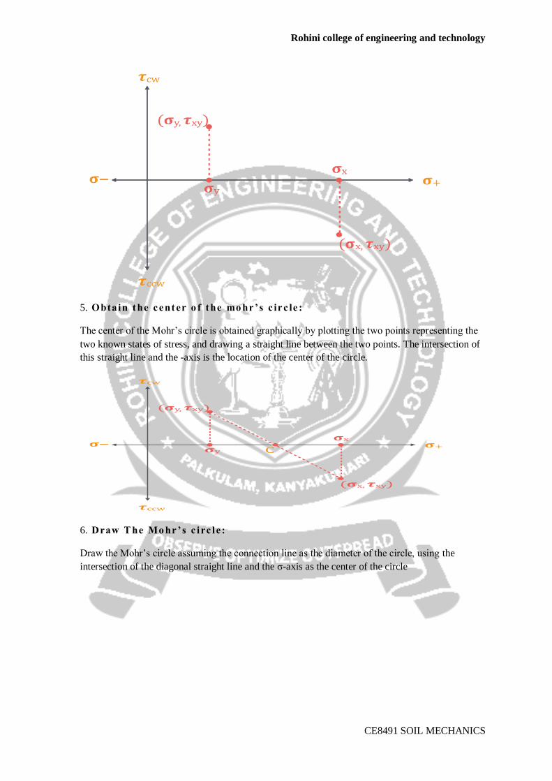
5. Obtain the center o f the mo hr’s c irc le :
The center of the Mohr’s circle is obtained graphically by plotting the two points representing the
two known states of stress, and drawing a straight line between the two points. The intersection of
this straight line and the -axis is the location of the center of the circle.
6. Draw T he Mo hr’s c irc le:
Draw the Mohr’s circle assuming the connection line as the diameter of the circle, using the
intersection of the diagonal straight line and the σ-axis as the center of the circle
Rohini college of engineering and technology
CE8491 SOIL MECHANICS
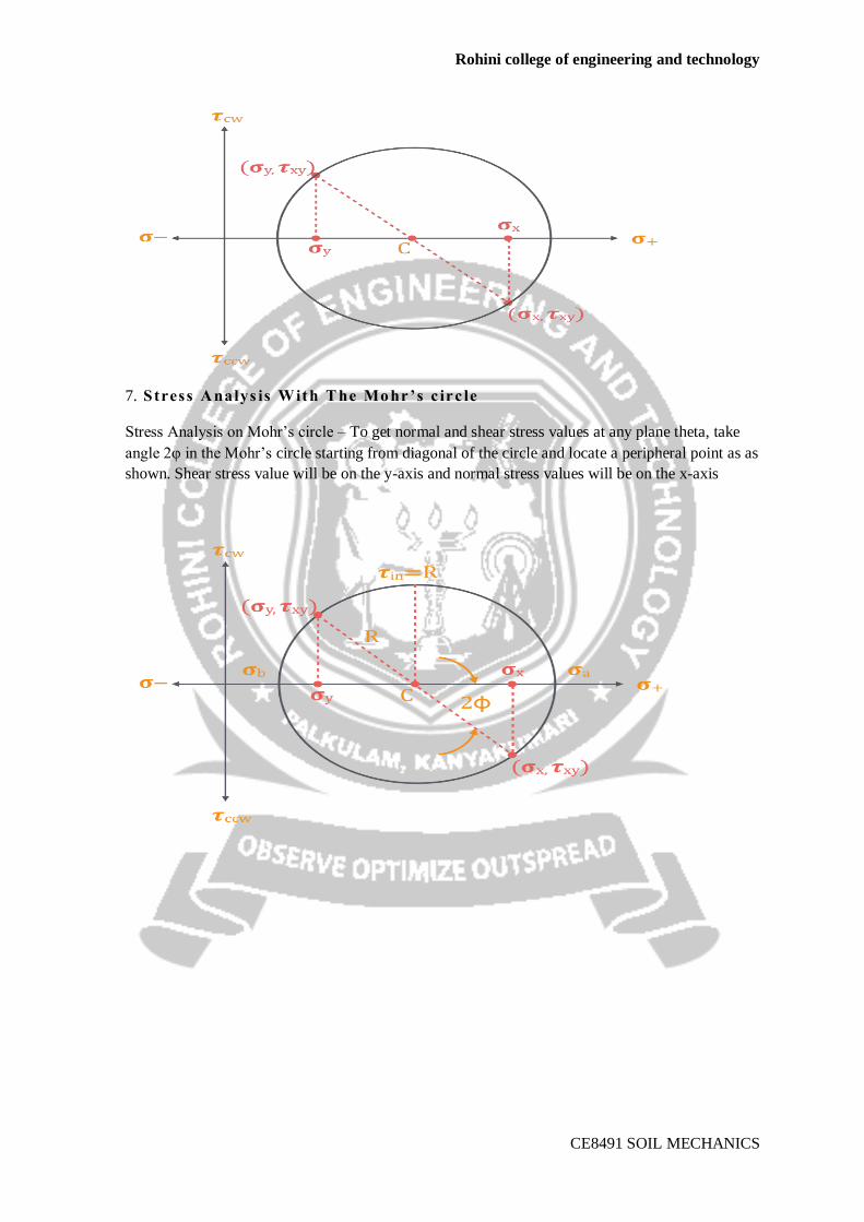
7. Stress Analys is W ith T he Mo hr’s c irc le
Stress Analysis on Mohr’s circle – To get normal and shear stress values at any plane theta, take
angle 2φ in the Mohr’s circle starting from diagonal of the circle and locate a peripheral point as as
shown. Shear stress value will be on the y-axis and normal stress values will be on the x-axis