Modicon Motion Development Software (MMDS) User Guide
152
Modicon Motion Development Software (MMDS) User Guide GM-MMDS-002 Rev. B February, 1997 Schneider Automation, Inc. One High Street North Andover, MA 01845
-
Upload
khangminh22 -
Category
Documents
-
view
4 -
download
0
Transcript of Modicon Motion Development Software (MMDS) User Guide

ModiconMotion Development Software (MMDS)
User GuideGM-MMDS-002 Rev. B
February, 1997
Schneider Automation, Inc.One High Street
North Andover, MA 01845

PrefaceGM-MMDS-002 iii
Preface
The data and illustrations found in this book are not binding. Wereserve the right to modify our products in line with our policy ofcontinuous product development. The information in this document issubject to change without notice and should not be construed as acommitment by Schneider Automation, Inc.
Schneider Automation assumes no responsibility for any errors thatmay appear in this document. If you have any suggestions forimprovements or amendments or have found errors in this publication,please notify us by using the form on the last page of this publication.
No part of this document may be reproduced in any form or by anymeans, electronic or mechanical, including photocopying, withoutexpress written permission of the Publisher, Schneider Automation,Inc.
Caution: All pertinent state, regional, and local safetyregulations must be observed when installing and using thisproduct. For reasons of safety and to assure compliance withdocumented system data, repairs to components should beperformed only by the manufacturer.
MODSOFT is a registered trademark of Schneider Automation, Inc.
The following are trademarks of Schneider Automation, Inc.:
Modbus Modbus PlusModicon 984
DIGITAL and DEC are registered trademarks of Digital EquipmentCorporation.
IBM and IBM AT are registered trademarks of InternationalBusiness Machines Corporation.
Microsoft and MS-DOS are registered trademarks of MicrosoftCorporation.
Copyright 1997, Schneider Automation, Inc.Printed in U.S.A.

ContentsGM-MMDS-002 v
Contents
1. . . . . . . . . . . . . . . . . . . . . . . . .
2. . . . . . . . . . . . . . . . . .1.3. . . . .4. . . . . . . . .
Chapter 1Introduction 1. . . . . . . . . . . . . . . . . . . . . . . . . . . . . . . . . . . . . . . . . . . . . . . .
1.1 What Is MMDS? 2. . . . . . . . . . . . . . . . . . . . . . . . . . . . . . . . . . . . . . . . . . . . . . . .1.2 Who Should Use this Manual 3. . . . . . . . . . . . . . . . . . . . . . . . . . . . . . . . . . . .1.3 How to Use this Manual 4. . . . . . . . . . . . . . . . . . . . . . . . . . . . . . . . . . . . . . . .
1.3.1 What this Manual Contains 4. . . . . . . . . . . . . . . . . . . . . . . . . .1.3.2 Related Publications 5. . . . . . . . . . . . . . . . . . . . . . . . . . . . . . . . .1.3.3 Typographical Conventions 7. . . . . . . . . . . . . . . . . . . . . . . . . .1.3.4 Hazards 8. . . . . . . . . . . . . . . . . . . . . . . . . . . . . . . . . . . . . . . . . . . .
Chapter 2Overview of MMDS 11. . . . . . . . . . . . . . . . . . . . . . . . . . . . . . . . . . . . . . . . .
2.1 Introduction 12. . . . . . . . . . . . . . . . . . . . . . . . . . . . . . . . . . . . . . . . . . . . . . . . . . .2.2 Some MMDS Advantages 13. . . . . . . . . . . . . . . . . . . . . . . . . . . . . . . . . . . . . . .2.3 What Makes MMDS Easy to Use 14. . . . . . . . . . . . . . . . . . . . . . . . . . . . . . . . .2.4 Hierarchy of an MMDS Work Environment 16. . . . . . . . . . . . . . . . . . . . . . .2.5 MMDS File Structure 17. . . . . . . . . . . . . . . . . . . . . . . . . . . . . . . . . . . . . . . . . . .
2.5.1 The .PRJ Project File 17. . . . . . . . . . . . . . . . . . . . . . . . . . . . . . . .2.5.2 The .MOD Module File 17. . . . . . . . . . . . . . . . . . . . . . . . . . . . . .2.5.3 The .CFG Configuration File 18. . . . . . . . . . . . . . . . . . . . . . . . .2.5.4 The .PGM Program File 18. . . . . . . . . . . . . . . . . . . . . . . . . . . . .2.5.5 The .DMT Documentation File 18. . . . . . . . . . . . . . . . . . . . . . .2.5.6 The .IMG Image File 19. . . . . . . . . . . . . . . . . . . . . . . . . . . . . . . .2.5.7 The .LST List File 19. . . . . . . . . . . . . . . . . . . . . . . . . . . . . . . . . . .
2.6 Typical MMDS Screen Display 20. . . . . . . . . . . . . . . . . . . . . . . . . . . . . . . . . . .
GM-MMDS-002Contentsvi
Chapter 3Installing and Initializing MMDS 21. . . . . . . . . . . . . . . . . . . . . . . . . . . . .
3.1 Installing MMDS 22. . . . . . . . . . . . . . . . . . . . . . . . . . . . . . . . . . . . . . . . . . . . . . .3.1.1 System Requirements 22. . . . . . . . . . . . . . . . . . . . . . . . . . . . . . .3.1.2 Installing MMDS on Hard Disk 24. . . . . . . . . . . . . . . . . . . . . . .
3.2 Initializing MMDS 26. . . . . . . . . . . . . . . . . . . . . . . . . . . . . . . . . . . . . . . . . . . . .
Chapter 4The Main Menu 27. . . . . . . . . . . . . . . . . . . . . . . . . . . . . . . . . . . . . . . . . . . . .
4.1 Main Menu Functions 28. . . . . . . . . . . . . . . . . . . . . . . . . . . . . . . . . . . . . . . . . .4.2 Hierarchy of MMDS Submenus 30. . . . . . . . . . . . . . . . . . . . . . . . . . . . . . . . . .
Chapter 5MMDS Setup 33. . . . . . . . . . . . . . . . . . . . . . . . . . . . . . . . . . . . . . . . . . . . . . .
5.1 Introduction 34. . . . . . . . . . . . . . . . . . . . . . . . . . . . . . . . . . . . . . . . . . . . . . . . . . .5.2 Computer Setup 36. . . . . . . . . . . . . . . . . . . . . . . . . . . . . . . . . . . . . . . . . . . . . . . .5.3 Communications Setup 38. . . . . . . . . . . . . . . . . . . . . . . . . . . . . . . . . . . . . . . . .5.4 Printer Setup 42. . . . . . . . . . . . . . . . . . . . . . . . . . . . . . . . . . . . . . . . . . . . . . . . . .
Chapter 6Project Manager 45. . . . . . . . . . . . . . . . . . . . . . . . . . . . . . . . . . . . . . . . . . . .
6.1 Introduction 46. . . . . . . . . . . . . . . . . . . . . . . . . . . . . . . . . . . . . . . . . . . . . . . . . . .6.2 Project Development 49. . . . . . . . . . . . . . . . . . . . . . . . . . . . . . . . . . . . . . . . . . . .6.3 Module Development 52. . . . . . . . . . . . . . . . . . . . . . . . . . . . . . . . . . . . . . . . . . .6.4 Program Development 56. . . . . . . . . . . . . . . . . . . . . . . . . . . . . . . . . . . . . . . . . .6.5 Program Editor 62. . . . . . . . . . . . . . . . . . . . . . . . . . . . . . . . . . . . . . . . . . . . . . . .6.6 Configuration File Editor 65. . . . . . . . . . . . . . . . . . . . . . . . . . . . . . . . . . . . . . .6.7 Additional Module Development Functions 68. . . . . . . . . . . . . . . . . . . . . . .6.8 Additional Program Development Functions 70. . . . . . . . . . . . . . . . . . . . . .6.9 Print Options 71. . . . . . . . . . . . . . . . . . . . . . . . . . . . . . . . . . . . . . . . . . . . . . . . . .
ContentsGM-MMDS-002 vii
Chapter 7Motion Mode 73. . . . . . . . . . . . . . . . . . . . . . . . . . . . . . . . . . . . . . . . . . . . . . .
7.1 Introduction 74. . . . . . . . . . . . . . . . . . . . . . . . . . . . . . . . . . . . . . . . . . . . . . . . . . .7.1.1 Direct Connect and PLC Bridge 75. . . . . . . . . . . . . . . . . . . . . .7.1.2 Motion Mode Menu 77. . . . . . . . . . . . . . . . . . . . . . . . . . . . . . . . . .
7.2 Establishing the Master (Local Lockout) 79. . . . . . . . . . . . . . . . . . . . . . . . . .7.2.1 When Communication Stops 79. . . . . . . . . . . . . . . . . . . . . . . . .
7.3 Startup Mode 80. . . . . . . . . . . . . . . . . . . . . . . . . . . . . . . . . . . . . . . . . . . . . . . . . .7.3.1 System Status Window 81. . . . . . . . . . . . . . . . . . . . . . . . . . . . . .7.3.2 Motion Control Window 81. . . . . . . . . . . . . . . . . . . . . . . . . . . . . .7.3.3 Servo Control Window 82. . . . . . . . . . . . . . . . . . . . . . . . . . . . . . .7.3.4 Miscellaneous Information Window 82. . . . . . . . . . . . . . . . . . .7.3.5 Function Keys 83. . . . . . . . . . . . . . . . . . . . . . . . . . . . . . . . . . . . . .
7.4 Immediate Mode 85. . . . . . . . . . . . . . . . . . . . . . . . . . . . . . . . . . . . . . . . . . . . . . .7.4.1 Picklist Window 85. . . . . . . . . . . . . . . . . . . . . . . . . . . . . . . . . . . . .7.4.2 Control/Status Window 86. . . . . . . . . . . . . . . . . . . . . . . . . . . . . .7.4.3 The To Module Window 86. . . . . . . . . . . . . . . . . . . . . . . . . . . . . .
7.5 Single Step Mode 88. . . . . . . . . . . . . . . . . . . . . . . . . . . . . . . . . . . . . . . . . . . . . . .7.5.1 Program Window 88. . . . . . . . . . . . . . . . . . . . . . . . . . . . . . . . . . . .7.5.2 Control/Status Window 89. . . . . . . . . . . . . . . . . . . . . . . . . . . . . .
7.6 Execute Mode 91. . . . . . . . . . . . . . . . . . . . . . . . . . . . . . . . . . . . . . . . . . . . . . . . . .7.6.1 Program Window 91. . . . . . . . . . . . . . . . . . . . . . . . . . . . . . . . . . . .7.6.2 Control/Status Window 92. . . . . . . . . . . . . . . . . . . . . . . . . . . . . .
7.7 Exiting Motion Mode 94. . . . . . . . . . . . . . . . . . . . . . . . . . . . . . . . . . . . . . . . . . .
Chapter 8File Transfers 97. . . . . . . . . . . . . . . . . . . . . . . . . . . . . . . . . . . . . . . . . . . . . .
8.1 Introduction 98. . . . . . . . . . . . . . . . . . . . . . . . . . . . . . . . . . . . . . . . . . . . . . . . . . .8.2 984 PLC Downloading 100. . . . . . . . . . . . . . . . . . . . . . . . . . . . . . . . . . . . . . . . . .8.3 Motion Module Downloading and Uploading 102. . . . . . . . . . . . . . . . . . . . . .
8.3.1 Delete 102. . . . . . . . . . . . . . . . . . . . . . . . . . . . . . . . . . . . . . . . . . . . . .8.3.2 Autoboot 103. . . . . . . . . . . . . . . . . . . . . . . . . . . . . . . . . . . . . . . . . . .8.3.3 Uploading Programs from Motion Module 103. . . . . . . . . . . . .8.3.4 Downloading Programs to Motion Module 104. . . . . . . . . . . . .8.3.5 Uploading MMDS Modules from Motion Module 105. . . . . . .8.3.6 Reading and Executing Configuration Files 106. . . . . . . . . . . .

GM-MMDS-002Contentsviii
Appendix AMMDS Command Flowcharts 107. . . . . . . . . . . . . . . . . . . . . . . . . . . . . . . .
Appendix BMMDS Error Messages 121. . . . . . . . . . . . . . . . . . . . . . . . . . . . . . . . . . . . . .
B.1 MMDS Error Codes 122. . . . . . . . . . . . . . . . . . . . . . . . . . . . . . . . . . . . . . . . . . . . .B.2 MMDS Error Messages 125. . . . . . . . . . . . . . . . . . . . . . . . . . . . . . . . . . . . . . . . .
Appendix CSample Program 139. . . . . . . . . . . . . . . . . . . . . . . . . . . . . . . . . . . . . . . . . . .
Index 147. . . . . . . . . . . . . . . . . . . . . . . . . . . . . . . . . . . . . . . . . . . . . . . . . . . . . .

IntroductionGM� MMDS�002 1
Chapter 1Introduction
V What is MMDS?
V Who should use this manual
V How to use this manual
Introduction GM�MMDS�0022
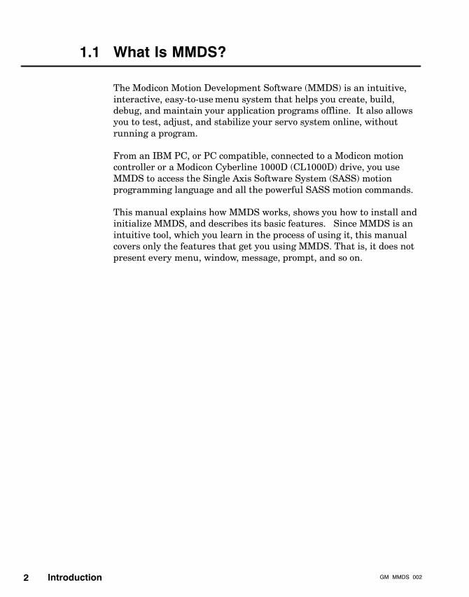
1.1 What Is MMDS?
The Modicon Motion Development Software (MMDS) is an intuitive,interactive, easy-to-use menu system that helps you create, build,debug, and maintain your application programs offline. It also allowsyou to test, adjust, and stabilize your servo system online, withoutrunning a program.
From an IBM PC, or PC compatible, connected to a Modicon motioncontroller or a Modicon Cyberline 1000D (CL1000D) drive, you useMMDS to access the Single Axis Software System (SASS) motionprogramming language and all the powerful SASS motion commands.
This manual explains how MMDS works, shows you how to install andinitialize MMDS, and describes its basic features. Since MMDS is anintuitive tool, which you learn in the process of using it, this manualcovers only the features that get you using MMDS. That is, it does notpresent every menu, window, message, prompt, and so on.

IntroductionGM� MMDS�002 3
1.2 Who Should Use this Manual
This manual is written for application developers who use MMDS towrite, develop, and maintain application programs that are executed ina Modicon single-axis motion module. It is also written forprogrammers responsible for stabilizing (tuning) the servo motor andconfiguring system parameters through a CL1000D drive.
This manual is targeted primarily toward first-time and inexperiencedMMDS users. Since MMDS is an intuitive, interactive tool, you mostlikely will not need this user guide after you have learned and becomeexperienced with MMDS.

Introduction GM�MMDS�0024
1.3 How to Use this Manual
To learn MMDS, use this manual as a roadmap to MMDS features asyou access MMDS menus interactively and become familiar with them.Read Chapters 1 through 8 in order, accessing the appendices asneeded. Before you install and bring up MMDS on your PC, readChapter 3, Installing and Initializing MMDS. After successfullyinitializing MMDS, turn to Chapter 4, The Main Menu, and workthrough the hierarchy of MMDS submenus. Access and familiarizeyourself with MMDS features on your computer as you read aboutthem in the manual.
1.3.1 What this Manual Contains
The following table describes the content of each chapter and appendixin this manual.
Chapter Title Description
CHAPTER 1 Presents a general description of this manual,Introduction including who should use, and how to use, the
manual, related publications, typographicalconventions, and so on.
CHAPTER 2 Presents an overview of MMDS capabilitiesOverview of MMDS and features.
CHAPTER 3 Presents instructions for installing MMDSInstalling and software, on hard disk and floppy systems,Initializing MMDS and for initializing MMDS.
CHAPTER 4 Presents a description of the Main Menu andThe Main Menu all its functions and submenus.
CHAPTER 5 Presents a description of the MMDS SetupMMDS Setup Menu, its functions, and its Computer, Printer,
and Communication Menus.
CHAPTER 6 Presents a description of the Project ManagerProject Manager Menu, its functions, and its Project
Development, Module Development, ProgramDevelopment, and Print Options Menus.

IntroductionGM� MMDS�002 5
CHAPTER 7 Presents a description of the Motion ModeMotion Mode Menu, its functions, and its Startup Mode,
Immediate Mode, Single Step Mode, andExecute Mode Menus.
CHAPTER 8 Presents a description of the File TransfersFile Transfers Menu, its functions, and its 984 and Motion
Module Menus.
APPENDIX A Presents a hierarchy of all SASS commands,MMDS Command and their keystroke accelerators, as they areFlowcharts grouped in the MMDS command Picklist.
APPENDIX B Presents a list and descriptions of all MMDSError Messages error messages.
APPENDIX C Presents a sample program along with anSample Program illustration of what it does.
1.3.2 Related Publications
If you are using MMDS to write application programs for a single�axismotion controller, such as the B885-1XX and MOT 20X motionmodules, you will need:
V Single Axis Software System (SASS) Motion User Guide,GM-MOTN-001
If you are using MMDS to configure the system and stabilize the servomotor and the velocity loop through a Cyberline 1000D (CL1000D)drive, you will need:
V Cyberline 1000D Drive User Guide, GM-CYBL-004
V Cyberline 1000A System Design and Installation Manual,GI-CYBL-002 (supplements the CL1000D manual)
If your system is configured with a B885-1XX motion module, you willneed:
V B885-1XX Motion Modules User Guide, GI-B885-1XX

Introduction GM�MMDS�0026
If your system is configured with a Quantum MSx motion module, youwill need:
V Quantum Automation Series 140 MSx 101 Single Axis MotionModule Reference Guide, 840 USE 105 00
If your system is configured with a MOT 20X motion module, you willneed:
V MOT 201, 202 Motion Modules User Guide, GI-BMOT-20X
If your system is configured with a Cyberline 1000A (CL1000A) drive,you will need:
V Cyberline 1000A System Design and Installation Manual,GI-CYBL-002
Other related documents include:
V Cyberline S and R Series Servo Motors Reference Guide,890 USE 135 00
V Modicon Ladder Logic Block Library User Guide, 840 USE 101 00
V Modsoft Programmer User Manual, GM-MSFT-001
V 984/IBM PC Programming Guide, GM-0984-IBM
Note: You may also want to order MODFAX document #4360, whichcontains an up-to-date listing of the motion product publications.
To access MODFAX, dial the Modicon customer service toll-freenumber, 1-800-468-5342 from anywhere in North America. (OutsideNorth America dial 1-978-794-0800.)
When calling the 800 number, you will get a recording asking you toenter a one-digit code for the type of service you request, provided youuse a touch tone telephone. Choose Option 3, MODFAX, then press 1to order document 4360. For a catalog of MODFAX documents, press2, then for a motion catalog, press 7. Follow the recordedinstructions.

IntroductionGM� MMDS�002 7
1.3.3 Typographical Conventions
Throughout this manual, the following visual aids highlight importantand/or special information.
Note: Important, useful, or interesting information is shown as aNote.
Caution: Cautions alert the reader of a possible hazard to theequipment or the product and then point out the properprocedure to avoid the hazard. Cautions also give the readerimportant instructions or strong suggestion to avert adverseconsequences.
Warning! Warnings alert the reader of a possible hazard topersonnel and then point out proper procedure to avoid thehazard.
See: Since cross references are important in the scope of this manual,this icon directs you to another chapter or section in this manual, or toanother manual, where you will find important related information.
Titles of cross-referenced sections, chapters, and manuals appear initalic.
Computer-user dialog appears as follows:
Things that the computer displays appear in thistype.
Things that you are to enter appear like this.
Keys that you press appear in square brackets, like this:
[ALT] [F2][M] [I] [P] [1] [0] [0] [ENTER]
If you have to press two keys together, such as the Control and C keys,it will appear like this:
[CONTROL-C]

Introduction GM�MMDS�0028
In the text, some hexadecimal numbers are followed by an “H” toidentify them as hexadecimal.
Figures and tables are not numbered in this manual. However, eachfigure and table is introduced in and referenced from the text.
1.3.4 Hazards
Warning! SHOCK HAZARD. Lethal voltages exist at theconnection points of the integrated automation system. TOAVOID SEVERE PERSONAL INJURY OR DEATH:
V Installation procedures should only be performed byskilled technical personnel. Such personnel should befamiliar with safe industrial wiring practices.
V DISCONNECT ALL POWER TO THE COMPLETE SYSTEMBEFORE INSTALLING OR REMOVING PARTS.
V All wiring must be in accordance with the NationalElectrical Code (NEC) or its national equivalent (CSA,CENELEC, etc.), as well as in accordance with allprevailing local codes.
V Always make certain that the wire sizes used are adequatefor the current they will carry.
V Never operate equipment with metal screens or coversremoved. Lethalvoltages exist within the equipment.
V Exercise extreme caution when using instruments such asoscilloscopes, chart recorders or volt�ohmmeters withequipment connected to line power. Special precautionsmust be exercised when one of the instrument leads isconnected to the case or other metal parts of theinstrument. If the case of the instrument is grounded, thislead may only be connected to grounded parts of thesystem. If this lead is connected to an ungrounded part ofthe system, the instrument must be isolated and its metalparts treated as live equipment. Use of instruments withboth leads isolated from the chassis permits grounding ofthe chassis even when measurements are made betweentwo live parts.

IntroductionGM� MMDS�002 9
V Ground the drive system common circuit at only onepoint: one central cabinet “star” connection. Thus, allmotor bases and other equipment enclosures should beconnected to the factory or facility earth groundingsystem.
V Read, understand and heed all WARNING, CAUTION,NOTE and other labels posted on the equipment.
V Always read and understand the complete instructionsbefore applying power to, or troubleshooting the system.Follow the start-up procedure step-by-step.

Overview of MMDSGM�MMDS�002 11
Chapter 2Overview of MMDS
V Introduction
V Some MMDS advantages
V What makes MMDS easy to use
V Hierarchy of an MMDS work environment
V MMDS file structure
V Typical MMDS screen display
Overview of MMDS GM�MMDS�00212
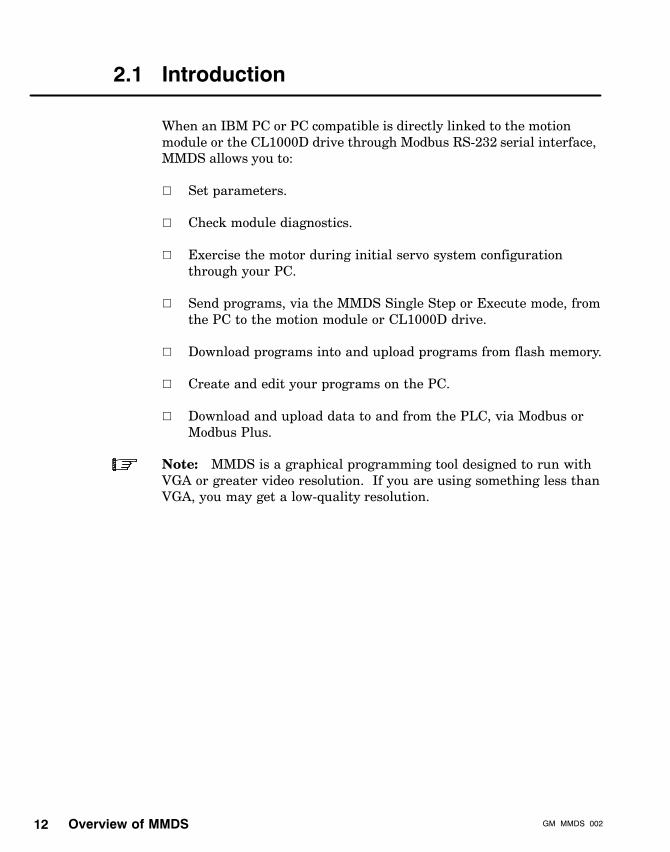
2.1 Introduction
When an IBM PC or PC compatible is directly linked to the motionmodule or the CL1000D drive through Modbus RS-232 serial interface,MMDS allows you to:
V Set parameters.
V Check module diagnostics.
V Exercise the motor during initial servo system configurationthrough your PC.
V Send programs, via the MMDS Single Step or Execute mode, fromthe PC to the motion module or CL1000D drive.
V Download programs into and upload programs from flash memory.
V Create and edit your programs on the PC.
V Download and upload data to and from the PLC, via Modbus orModbus Plus.
Note: MMDS is a graphical programming tool designed to run withVGA or greater video resolution. If you are using something less thanVGA, you may get a low-quality resolution.

Overview of MMDSGM�MMDS�002 13
2.2 Some MMDS Advantages
MMDS has many advantages:
V It is easy enough for the beginner to understand, yet sophisticatedenough for the advanced user.
V It enables you to write programs for the motion module ineasy-to-understand human terms, rather than in cryptic machinecode.
V It allows for quick and easy editing. Instead of searching throughmany lines of machine code, you just go to the appropriate placewithin the program, enter the new lines, and download.
V It allows you to create a program offline. If you are using a 984PLC, the 984 is not needed until all of the pieces of program aredebugged and ready to be downloaded.
Overview of MMDS GM�MMDS�00214
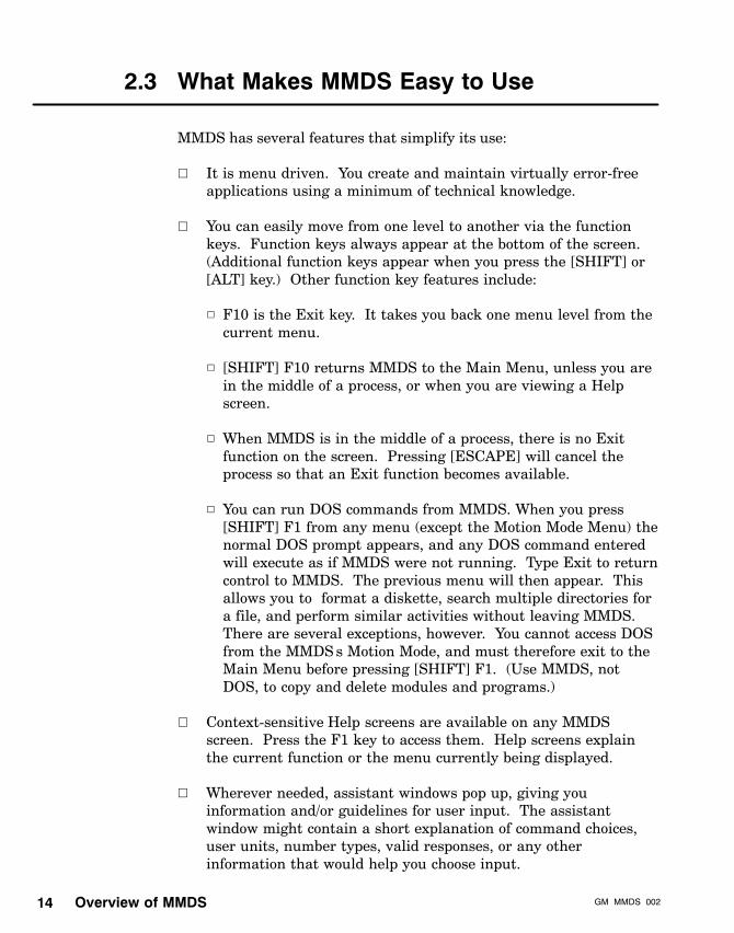
2.3 What Makes MMDS Easy to Use
MMDS has several features that simplify its use:
V It is menu driven. You create and maintain virtually error-freeapplications using a minimum of technical knowledge.
V You can easily move from one level to another via the functionkeys. Function keys always appear at the bottom of the screen.(Additional function keys appear when you press the [SHIFT] or[ALT] key.) Other function key features include:
h F10 is the Exit key. It takes you back one menu level from thecurrent menu.
h [SHIFT] F10 returns MMDS to the Main Menu, unless you arein the middle of a process, or when you are viewing a Helpscreen.
h When MMDS is in the middle of a process, there is no Exitfunction on the screen. Pressing [ESCAPE] will cancel theprocess so that an Exit function becomes available.
h You can run DOS commands from MMDS. When you press[SHIFT] F1 from any menu (except the Motion Mode Menu) thenormal DOS prompt appears, and any DOS command enteredwill execute as if MMDS were not running. Type Exit to returncontrol to MMDS. The previous menu will then appear. Thisallows you to format a diskette, search multiple directories fora file, and perform similar activities without leaving MMDS.There are several exceptions, however. You cannot access DOSfrom the MMDS’s Motion Mode, and must therefore exit to theMain Menu before pressing [SHIFT] F1. (Use MMDS, notDOS, to copy and delete modules and programs.)
V Context-sensitive Help screens are available on any MMDSscreen. Press the F1 key to access them. Help screens explainthe current function or the menu currently being displayed.
V Wherever needed, assistant windows pop up, giving youinformation and/or guidelines for user input. The assistantwindow might contain a short explanation of command choices,user units, number types, valid responses, or any otherinformation that would help you choose input.

Overview of MMDSGM�MMDS�002 15
V Programs (or files) are conveniently grouped by projects andmodules, allowing you to separate applications according touser-defined categories.
See: The next section for more information on the MMDS filestructure hierarchy.
Overview of MMDS GM�MMDS�00216
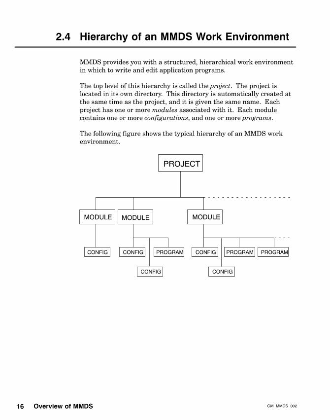
2.4 Hierarchy of an MMDS Work Environment
MMDS provides you with a structured, hierarchical work environmentin which to write and edit application programs.
The top level of this hierarchy is called the project. The project islocated in its own directory. This directory is automatically created atthe same time as the project, and it is given the same name. Eachproject has one or more modules associated with it. Each modulecontains one or more configurations, and one or more programs.
The following figure shows the typical hierarchy of an MMDS workenvironment.
MODULE
PROJECT
CONFIG
MODULE MODULE
CONFIG PROGRAM CONFIG PROGRAM PROGRAM
CONFIG CONFIG
Overview of MMDSGM�MMDS�002 17
2.5 MMDS File Structure
MMDS has a file structure that corresponds to the hierarchy shown inthe previous figure. Specifically, the file structure contains:
filename.PRJ (the project file)filename.MOD (the module file)filename.CFG (the configuration file)filename.PGM (the program file)
Other related files include:
filename.DMT (the documentation file)filename.IMG (the compiled image file)filename.LST (the list file)
Note: The filename must follow DOS filename conventions.
2.5.1 The .PRJ Project File
A project file contains information about the project, such as:
V Project description (two 80-character lines)
V Version of software
V Date and time created
V Date and time last edited
2.5.2 The .MOD Module File
The system uses the module file to keep track of the files that belong tothe module. It also includes the following information about themodule:
V Module description (two 80-character lines)
V Names of all programs
V Numbers of all programs
Overview of MMDS GM�MMDS�00218
V Version of software
V Date and time created
V Date and time last edited
V Control table address
V Module’s I/O register addresses
2.5.3 The .CFG Configuration File
For any given module, there must be a configuration file that containsa fixed list of commands. These commands actually contain the SASSservo configuration setup parameters, which are provided in the SASSMotion User Guide, GM-MOTN-001. The configuration file is createdautomatically, using default values, at the same time the module iscreated. You are then notified of the existence of the configuration andasked to name it at that time. To change the configuration fileparameters to fit your system, edit it under the Program DevelopmentMenu.
This default configuration file is a good starting point. When thesystem has been properly tuned (stabilized) and all parameters havebeen commissioned, refined, and finalized, the module should beuploaded to create a new configuration.
2.5.4 The .PGM Program File
A module contains one or more program files. Program files consist ofone or more command lines. On each command line you supply a SASScommand, zero to four values, and an optional comment. Once youname a program and save it, a Picklist of program command choicesappears. Once you pick a SASS command, its range of valid entriesand default values appears on the screen.
2.5.5 The .DMT Documentation File
There is one documentation file for each program file. Thedocumentation file contains:
V Author’s name and a brief description of the program
V Brief program description entered by the author at the time ofprogram creation

Overview of MMDSGM�MMDS�002 19
V Software version number
V Number of modules sharing its program
V Date and time created
V Date and time last edited
2.5.6 The .IMG Image File
The system creates an image file when the program file is compiled.The image file contains the machine code that is uploaded anddownloaded.
2.5.7 The .LST List File
The system also creates a list file when the program file is compiled.The list file is the actual printout you receive when you print a programfrom the Print Options Menu, which is a menu under the ProjectManager Menu. The list file contains:
V The program’s command line numbers
V Commands and comments
V Values, register offsets, and machine code equivalent values

Overview of MMDS GM�MMDS�00220
2.6 Typical MMDS Screen Display
The following figure shows a typical MMDS display (the Program Editscreen) with labels explaining the various functions of the display.
PROGRAM EDIT PROJECT: MODULE:
Errors/faultsGains:Input/output:Limits:mOdule commands:
PROGRAM WINDOW
PICKLIST
GO TOLINE
F2HELP
F1WINDOWSWITCH
F4EXPLAIN
F3CHANGE
F5SAVEEDITS
F6 F8DELETE
F7 F9EXITEDIT
F10
MASK VALUE STEP
MMDS mode
User’sLocation whereselected commandis entered and built
Switch between theprogram window andthe Picklist window
Picklist
Shows values thatyou enter for commandselected from Picklist.
Current projectselected
Currentmoduleselected
Currentprogramselected
PROGRAM:
Motion:moTor/feedback:program Flow:Programming:Register:storeD program cmds:Sync�ratio
COMMAND � � � VALUE
window
windowprogram
CommandSASS
The various parts of this screen are described in more detail later inthis manual.

Installing and Initializing MMDSGM�MMDS�002 21
Chapter 3Installing and InitializingMMDS
V Installing MMDS
V Initializing MMDS

Installing and Initializing MMDS GM�MMDS�00222
3.1 Installing MMDS
This section provides the basic information you will need to install theMMDS software. Specifically, this section covers these topics:
V System requirements
V Installing MMDS on hard disk
For more information, consult your customer service representative.
3.1.1 System Requirements
Your MMDS is shipped on a 1.44 Mbyte 3.5-inch diskette.
The minimum system requirements for MMDS are:
V IBM PC or 100 percent PC compatible
V VGA or greater video resolution
V 500K RAM available for application programs
V A minimum processing power that is equivalent to an 8MHzzero-wait state IBM AT for operation in MMDS’s Motion Mode.
V A system that has at least one floppy disk drive and a hard disk.One floppy drive must be 3.5-inch high-density.
Caution: Schneider Automation recommends that you do notrun Terminate and Stay Resident (TSR) programs whilerunning MMDS. TSR programs are programs such asSidekick, which stays in the background once loaded.

Installing and Initializing MMDSGM�MMDS�002 23
Your PC’s CONFIG.SYS file should contain the following lines:
BUFFERS=20FILES=20DEVICE=ANSI.SYS
ANSI.SYS needs a full path for your system.
The Modicon SA85 Modbus Plus Adapter is needed for Modbus Pluscommunication. The card uses software interrupt 5C by default.However, if the card is not using 5C, you must specify the correctsoftware interrupt. To do this, start MMDS with the followingcommand line syntax:
MMDS /Sn
where n is the software interrupt to use for the SA85 device driver.The default (and recommended) interrupt is 0x5C. For example:
MMDS /S5C
This enables the driver using software interrupt 0x5C.
After installing MMDS, go immediately into Computer Setup in theMMDS Setup Menu, where you must specify the drive and directory tohold your data files. Make sure that this matches the drive anddirectory specified during installation.
See: Chapter 5, MMDS Setup.

Installing and Initializing MMDS GM�MMDS�00224
3.1.2 Installing MMDS on Hard Disk
To install MMDS on your hard disk (C or D), install from drive A or B.
To begin installing MMDS from drive A or B to the hard disk (drive Cin the following example) insert the MMDS software disk into drive Aor B. Log onto that drive by typing A: [ENTER] or B: [ENTER]. Thentype:
INSTALL [ENTER]
You will see the message:
This program will install the Modicon MMDS softwarepackage from the current drive into the hard drivethat you will be prompted to select. The currentdrive is selected when you type the drive letterfollowed by a colon at the DOS prompt e.g. typing a:will switch the current drive to drive A.
Do you wish to continue? (Y or N):
N [ENTER] will take you back to DOS.
Y [ENTER] will give you:
Enter destination drive for MMDS system files (C orabove):
Drive C is the default when you press [ENTER]. For this example,type:
C [ENTER]
You will see:
Hit <ENTER> for default system files path MMDSEnter directory path for system files:
If the directory you want already exists, you will see:
System directory already exists, OK to overwrite ?(Y or N) :
Press Y to overwrite the directory and upgrade your software. Press Nto cancel the installation. If you press N you will get an ‘Installationaborted’ message.

Installing and Initializing MMDSGM�MMDS�002 25
If you do not get the overwrite message, press [ENTER] to accept thedefault directory (MMDS) to hold your MMDS software, or enter a newname if you prefer. (A directory name is limited to eight characters.)For this example, press [ENTER] for the default. You will see:
Enter destination drive for data files (C or above):
For this example, type:
C [ENTER]
You will then see:
Hit <Enter> for default data files path B885DATAEnter directory path for data files:
Press [ENTER] for the default directory, or enter a new name. For thisexample, press [ENTER] for the default. Next you will see:
System files will be placed on C:\MMDSData files will be placed on C:\B885DATA
The filenames that are being copied will appear on the screen.
You will then see:
MMDS Installation complete
Please edit your CONFIG.SYS file and make sure filesand buffers are set to 20 or more each.
If you wish to run MMDS now, type:
MMDS [ENTER]

Installing and Initializing MMDS GM�MMDS�00226
3.2 Initializing MMDS
This section provides instructions for initializing MMDS on a hard disksystem.
When installation is complete, the cursor will be in the current driveand directory. Just type MMDS to start. When you have just poweredup, you must change to the MMDS directory and then enter MMDS.
At the DOS prompt, change to the directory containing the systemsoftware.
For example, type:
CD \MMDS [ENTER]
At the MMDS prompt type:
MMDS [ENTER]
Note: If you wish to run MMDS from any directory on the hard disk,you must enter the name of the MMDS directory into the DOS PATHof your AUTOEXEC.BAT file.
The MMDS log on screen appears, and it remains on the screen whilememory and speed are being tested. If tests are successful, you are toldto press any key to continue. When you press any key, the MMDSMain Menu appears. At this point you may begin using MMDS.
If the memory test fails, you will see an error message. Press any keyto return to the DOS prompt. If the speed test fails, you will see anerror message warning you that you will not be permitted access to theMotion Mode Menu.
The next chapter describes the MMDS Main Menu.

The Main MenuGM�MMDS�002 27
Chapter 4The Main Menu
V Main Menu functions
V Hierarchy of submenus

The Main Menu GM�MMDS�00228
4.1 Main Menu Functions
The Main Menu is the central point-of-origin menu that controls allMMDS functions. You access all MMDS functions from the Main Menuby pressing the appropriate keys that are displayed at the bottom of theMain Menu. The following figure shows the Main Menu.
MAIN MENU PROJECT: MODULE:
SETUP
F2HELP
F1MOTION
F4PROJ MGR
F3FILE
F5 F6 F8F7 F9EXIT
MMDS
F10
TRANSFER
PROGRAM:
F2 = MMDS SETUP
F3 = PROJECT MANAGER
F4 = MOTION MODE
F5 = FILE TRANSFERS
Press Shift or Alt keys to display additionalcommand options when available.
The Main Menu selections are:
V F1 — Help
V F2 — MMDS Setup
V F3 — Project Manager
V F4 — Motion Mode
V F5 — File Transfers
V F10 — Exit MMDS
V Shift F1 — DOS commands

The Main MenuGM�MMDS�002 29
The main selections F2 through F5 comprise the major MMDS featuresthat govern all MMDS operations.
Press F1, Help, to access the Help screens that explain each of theMain Menu choices.
Press F10, Exit MMDS, to leave MMDS. When you press F10, MMDSprompts you to press F8 to confirm the exit or F6 to cancel the exit. F8returns you to DOS. F6 keeps you at the Main Menu.

The Main Menu GM�MMDS�00230
4.2 Hierarchy of MMDS Submenus
The following figure shows the hierarchy of MMDS submenus beneaththe Main Menu. All MMDS operations are accessed through thesemenus.
MAINMENU
NOTE: Each of the submenus under the Main Menu alsoprovide the Help function key and an Exit function key.In each of these submenus, [SHIFT] F1 invokes DOS,while [SHIFT] F10 returns operation to the Main Menu.
Communication
Printer Computer
StartupMode
ImmediateMode
SingleStepMode
ExecuteMode
ProjectDevelopment
ModuleDevelopment
ProgramDevelopment
PrintOptions
MMDSSETUP
PROJECTMANAGER
MOTIONMODE
FILETRANSFERS
984 MotionModule
You can press the [SHIFT] or [ALT] key to display additional commandoptions, when these options are available.

The Main MenuGM�MMDS�002 31
When you press the [SHIFT] key, F1 becomes the DOS function key.Press F1 with [SHIFT] depressed to access DOS. You can enter andexecute DOS commands at this point. When finished with DOS, typethe word EXIT to return to MMDS.
The following figure shows the Main Menu after you press the [SHIFT]key.
MAIN MENU PROJECT: MODULE: PROGRAM:
F2 = MMDS SETUP
F3 = PROJECT MANAGER
F4 = MOTION MODE
F5 = FILE TRANSFERS
Press Shift or Alt keys to display additionalcommand options when available.
F2DOS
F1 F4F3 F5 F6 F8F7 F9 F10
COMMANDS

The Main Menu GM�MMDS�00232
When you press F1, Help, from the Main Menu, you receive a briefdescription of Main Menu selections, as shown in the following figure.
MAIN MENU PROJECT: MODULE: PROGRAM:
F2F1 F4F3 F5 F6 F8F7 F9 F10
1
HELP SYSTEM � PRESS THE <ESCAPE> KEY TO LEAVE
<up arrow> <down arrow> <pgup> <pgdown> <home> <end>
MAIN MENUF1 - [HELP] - This is the mode you are currently in.F2 - [SETUP] - The Setup Menu allows the user to setup a computerto communicate with the B885�100 and the 984 controller. The SetupMenu also allows the user to specify the disk drive and subdirectorywhere the executable files are located, and allows the user toconfigure the computer for printer being used.F3 - [PROJ MGR] - The Project Manager is completely off�line. Itsfunction is to create the programs necessary to run the Motion Module.It contains a syntax-directed editor known as the pick list. The picklist guides the user through program development by allowing them to
As this Help screen shows, you can scroll one line at a time with the upand down cursor (arrow) keys. You can also move down one “page”(equivalent of one window) with the [Page Down] key and up one“page” with the [Page Up] key. You can also jump to the beginning ofthe Help screen with the [Home] key, and to the end with the [End] key.
The following chapters provide a summary of basic MMDS operations.These chapters present summaries of the most important MMDSfeatures. Since MMDS is a very intuitive, self explanatory tool, withintelligent prompts and context-sensitive online help, these chaptersdo not show every screen, window, message, prompt, and so on.Likewise, they do not not describe every function and every type ofvalue to enter for every command. As you interact with MMDS andwork your way through MMDS menus, you should acquire a goodunderstanding of what MMDS functions do and how to use thesefunctions.
The four major Main Menu selections are: MMDS Setup, ProjectManager, Motion Mode, and File Transfers.

MMDS SetupGM�MMDS�002 33
Chapter 5MMDS Setup
V Introduction
V Computer Setup
V Communications Setup
V Printer Setup
MMDS Setup GM�MMDS�00234
5.1 Introduction
MAINMENU
Communication
Printer Computer
MMDSSETUP
PROJECTMANAGER
MOTIONMODE
FILETRANSFERS
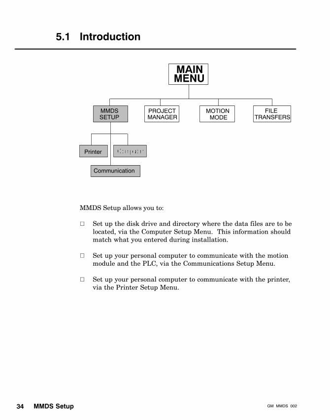
MMDS Setup allows you to:
V Set up the disk drive and directory where the data files are to belocated, via the Computer Setup Menu. This information shouldmatch what you entered during installation.
V Set up your personal computer to communicate with the motionmodule and the PLC, via the Communications Setup Menu.
V Set up your personal computer to communicate with the printer,via the Printer Setup Menu.

MMDS SetupGM�MMDS�002 35
The following figure shows the MMDS Setup Menu.
SETUP MENU PROJECT: MODULE:
COMM
F2HELP
F1COMPUTER
F4PRINTER
F3 F5 F6 F8F7 F9EXIT
SETUP
F10
PROGRAM:
F2 = COMMUNICATIONS SETUP
F3 = PRINTER SETUP
F4 = COMPUTER SETUP

MMDS Setup GM�MMDS�00236
5.2 Computer Setup
Press F4 of the Setup Menu for the Computer Setup Menu. TheComputer Setup Menu allows you to specify the drive and directory tohold files by entering the data from the keyboard.
Note: This directory must have already been created before it can bespecified. This is done during the installation. Make certain that theinformation entered here matches that entered during installation.
See: Chapter 3 Installing and Initializing MMDS.
The following figure shows the Computer Setup Menu.
COMPUTER SETUP PROJECT: MODULE:
DEFAULT
F2HELP
F1RECALL
F4F3 F5 F6 F8F7 F9EXIT CMP
SETUP
F10
PROGRAM:
VALUES VALUESSAVE
VALUES
C:DRIVE FOR DATA FILES:
DIRECTORY FOR DATA FILES: \b885data

MMDS SetupGM�MMDS�002 37
Computer Setup functions are:
FunctionKey Name Description
F1 Help Displays the Help screens.
F2 Default Values Reloads the original values supplied with thesystem.
F4 Recall Values Returns variables to the values last saved.
F6 Save Values Saves the current values, making them therecall values.
F10 Exit Cmp Setup Prompts you to choose: F6 to save valuesexit, F8 to confirm exit (no save), or F9 tocancel exit. F10 will exit directly if the valueshave been previously saved.
Note: When entering the drive for data files, do not enter the colon,just the letter representing the drive.
If you attempt to enter a directory name that does not already exist,you will receive an “Invalid Data Path” error. After removing thesystem error screen by pressing any key, press [SHIFT] F1 to enterDOS. Create the directory, choosing either the default name that cameup in Computer Setup, or some other name. Then type the word “exit”to return to MMDS. (If you do not know how to create a directory,consult the DOS manual that came with your computer.)
Note: If you exit MMDS by pressing [CTRL] [ALT] [DEL], instead ofexiting in the normal fashion, the MMDS program is not able to do itsnormal housekeeping. Therefore, you may find unusual files (withdigits for names) on your root directory. You can delete them usingDOS.

MMDS Setup GM�MMDS�00238
5.3 Communications Setup
When you press F2, Comm, the Communications Setup Menu appears,as shown in the following figure.
COMMUNICATIONS SETUP PROJECT: MODULE:
DEFAULT
F2HELP
F1RECALL
F4F3 F5 F6 F8F7 F9EXIT
COMM
F10
PROGRAM:
VALUES VALUESSAVE
VALUESSCAN
CHOICES
MODULE 984
DEVICE:
BAUDRATE:
PARITY:
STOP BITS:
MODBUS MODE:
ADDRESS:
COM1
9600
EVEN
1
ASCII
001
COM1
9600
EVEN
1
ASCII
001
The Communications Setup Menu allows you to choose communicationsparameters for the motion module and the 984 PLC. Standard defaultvalues are supplied to facilitate startup operations. The parametersunder MODULE are used when MMDS is connected to the motionmodule or a Modbus Plus bridge with the module connected to itsModbus port. The parameters under 984 are used when MMDS isconnected to a PLC — for downloading to the PLC or communicatingwith the motion module via the PLC backplane.
See: System Planning User’s Manual, ML-MBUS-PLN, and ModbusProtocol Reference Guide, PI-MBUS-300, for an explanation ofCommunication Setup parameters.
Note: If parameters are changed but not saved, the new values willbe in effect only until you exit MMDS.
COM1 and COM2 must be RS-232 serial ports.

MMDS SetupGM�MMDS�002 39
Communications Setup functions are:
FunctionKey Name Description
F1 Help Displays the Help screen.
F2 Default Values Reloads the original values supplied with thesystem. These values are embedded in thesystem software and cannot be changed.
F4 Recall Values Returns variables to the value last saved.
F6 Save Values Saves the current values, making them therecall values.
F8 Scan Choices Shows all valid entries for the currentlyhighlighted parameter, allowing you to choosefrom the list. The value displayed will be validuntil power down, unless you press F6, SaveValues, in which case it remains the validvalue even after power down.
F10 Exit Comm Prompts you with the following choices: F6 tosave values and exit, which saves thempermanently; F8 to exit without saving thenew values, which means any changes will bein effect until you exit MMDS; or F9 to cancelexit. If values have been previously saved,press F10 for a direct exit.
The communication port parameters are described as follows. If invaliddata is entered for any of these categories, the data will revert to theprevious setting. (A valid entry is not necessarily a correct value foryour system.)

MMDS Setup GM�MMDS�00240
Device Possible choices for COM1 and COM2, for Modbus RTU or ASCIImode, or for ADAP0 and ADAP1 for Modbus Plus mode. The devicesavailable are determined by your computer. If the computer has onlyone communications port, the cable must physically be changed whenyou switch from communication with the motion module tocommunication with the 984.
Baudrate The baud rate can be configured for 300, 600, 1200, 2400, 4800, or9600 baud. You can either type in the data directly, or press F8, ScanChoices, to loop through the baudrate selections. (The default value is9600.)
Parity The parity type can be NONE, ODD or EVEN. You can either type inthe data or press F8, Scan Choices, to scan the selections. (Thedefault value is EVEN.)
Stop Bits The stop bit selections are 1 and 2. Type in a valid entry, or press F8,Scan Choices, to toggle between the two values. (The default is 1.)
Data Bits The number of data bits may be 7 or 8. You can type in the value orpress F8, Scan Choices, to toggle the value. (The default value is 7and will automatically display if the Modbus mode setting is ASCII.The data bit number will change to 8 if the Modbus mode setting isRTU.) If an illegal entry is made, the value will automatically revertback to one that is valid.
Modbus Mode This communications mode may be ASCII, RTU, or Modbus Plus.You can either type in the name or press F8, Scan Choices, to togglethe value. (The default mode is ASCII.) The communications modefor the motion module is restricted to ASCII or Modbus Plus.However, it also lets you talk to the motion module over the backplaneof a controller if the controller is running and the module istraffic-copped correctly. It allows the computer to be connected to aModbus Plus bridge with the motion module connected to one of theModbus ports on the bridge.
MMDS SetupGM�MMDS�002 41
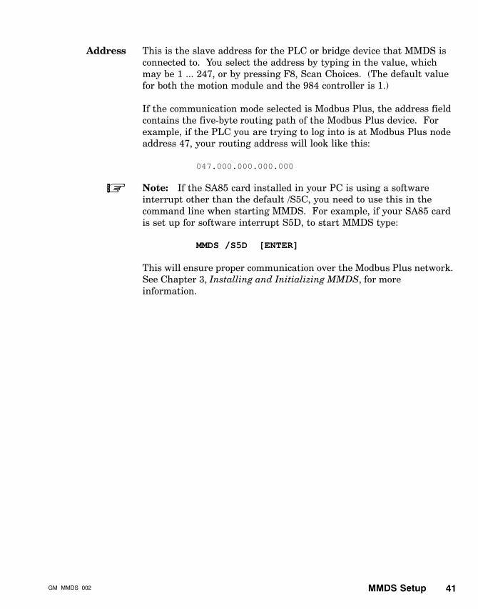
Address This is the slave address for the PLC or bridge device that MMDS isconnected to. You select the address by typing in the value, whichmay be 1 ... 247, or by pressing F8, Scan Choices. (The default valuefor both the motion module and the 984 controller is 1.)
If the communication mode selected is Modbus Plus, the address fieldcontains the five-byte routing path of the Modbus Plus device. Forexample, if the PLC you are trying to log into is at Modbus Plus nodeaddress 47, your routing address will look like this:
047.000.000.000.000
Note: If the SA85 card installed in your PC is using a softwareinterrupt other than the default /S5C, you need to use this in thecommand line when starting MMDS. For example, if your SA85 cardis set up for software interrupt S5D, to start MMDS type:
MMDS /S5D [ENTER]
This will ensure proper communication over the Modbus Plus network.See Chapter 3, Installing and Initializing MMDS, for moreinformation.
MMDS Setup GM�MMDS�00242
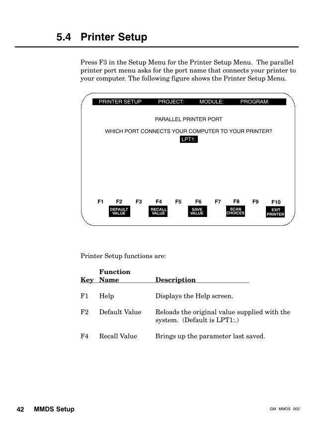
5.4 Printer Setup
Press F3 in the Setup Menu for the Printer Setup Menu. The parallelprinter port menu asks for the port name that connects your printer toyour computer. The following figure shows the Printer Setup Menu.
PRINTER SETUP PROJECT: MODULE:
DEFAULT
F2HELP
F1RECALL
F4F3 F5 F6 F8F7 F9EXIT
PRINTER
F10
PROGRAM:
VALUE VALUESAVE
VALUESCAN
CHOICES
PARALLEL PRINTER PORT
WHICH PORT CONNECTS YOUR COMPUTER TO YOUR PRINTER?
LPT1:
Printer Setup functions are:
FunctionKey Name Description
F1 Help Displays the Help screen.
F2 Default Value Reloads the original value supplied with thesystem. (Default is LPT1:.)
F4 Recall Value Brings up the parameter last saved.

MMDS SetupGM�MMDS�002 43
FunctionKey Name Description
F6 Save Value Saves the current value (making it the recallvalue).
F8 Scan Choices Shows valid entries in succession for thecurrently highlighted parameter. The onlyvalid port entries are:
LPT1:LPT2:FILE:
If FILE: is selected, the listing will be printedto the file MMDS.OUT in the current projectdirectory. Note that the colon must beincluded.
F10 Exit Printer Prompts you to choose: F6 to save value andexit, F8 to exit without saving, or F9 to cancelexit. F10 will be a direct exit if the value waspreviously saved.

Project ManagerGM�MMDS�002 45
Chapter 6Project Manager
V Introduction
V Project development
V Module development
V Program development
V Program editor
V Configuration file editor
V Additional module development features
V Additional program development features
V Print Options

Project Manager GM�MMDS�00246
6.1 Introduction
MAINMENU
ProjectDevelopment
ModuleDevelopment
ProgramDevelopment
PrintOptions
MMDSSETUP
PROJECTMANAGER
MOTIONMODE
FILETRANSFERS
Press F3 on the Main Menu for the Project Manager Menu. The ProjectManager is completely offline. It allows you to create and maintainprograms. First a project is developed for a particular job. Then themodules necessary to perform this job are created and kept within theproject, and the programs required are created and kept within themodules. This keeps jobs separate and well organized and reduces thechance of mixups between jobs. The Project Manager has foursubmenus:
V Project Development Menu — Allows you to create a project bynaming, describing, and saving it.
V Module Development Menu — Allows you to create a module,one for each motion module involved in an operation, aftercreating (or reentering) the project that will hold it. You areasked to name and describe it, as well as designate the addressesfor I/O and the MRTM function block control table.
V Program Development Menu — Allows you to create aprogram, after creating (or reentering) the module that will holdit. This menu contains the command Picklist. The Picklist guidesyou through program development by allowing you to select SASScommands during each step of the process.

Project ManagerGM�MMDS�002 47
V Print Options Menu — Allows you to print out a project,module, and program.
The Project Manager also activates a particular project, module, andprogram, via the its development menu.
The maximum number of files a module may contain is 35. Themaximum number of modules a project may contain and the maximumnumber of projects the MMDS can support is also 35.
The following figure shows the Project Manager Menu.
PROJECT MANAGER MENU PROJECT: MODULE:
F2HELP
F1PROGRAM
DEV
F4MODULE
F3PRINT
F5 F6 F8F7 F9EXIT
PROJ MGR
F10
DEV OPTIONS
PROGRAM:
F2 = PROJECT DEVELOPMENT
F3 = MODULE DEVELOPMENT
F4 = PROGRAM DEVELOPMENT
F5 = PRINT OPTIONS
PROJECTDEV
Project Manager functions are:
FunctionKey Name Description
F1 Help Displays the Help screen.
F2 Project Displays the Project Development Menu.Development If you create and save a project, the Module
Development Menu will be displayed next.
Project Manager GM�MMDS�00248
FunctionKey Name Description
F3 Module Displays the Module Development Menu. IfDevelopment you create and save a module, the Program
Development Menu will be displayed next(after you have named the configuration filethat was automatically created).
F4 Program Displays the Program Development menu.Development Name, describe, and save program to arrive
at the command entry (Picklist) screen, wherethe actual program is constructed.
F5 Print Displays the Print Options Menu.
F10 Exit Project Returns you to the Main Menu.Manager

Project ManagerGM�MMDS�002 49
6.2 Project Development
Press F2 from the Main Menu to access the Project Development Menu,shown in the following figure.
PROJECT DEVELOPMENT PROJECT: MODULE:
F2HELP
F1CREATE
F4F3 F5 F6 F8F7 F9EXIT
PROJ DEV
F10
PROGRAM:
DIRECTORY OF PROJECTS AVAILABLE ON C:\b885data
If this is the first time the MMDS has ever been used, Create will beyour only option, and there will be no existing projects listed.
Press F2 to access the Create Project Menu. MMDS prompts you for aproject name. Enter any project name, eight characters or less.
You will then see the description box that allows you to enter two linesof descriptive text, as shown in the following figure. If no text isdesired, just press [ENTER] twice.

Project Manager GM�MMDS�00250
CREATE PROJECT PROJECT: MODULE:
F2HELP
F1 F4F3 F5 F6 F8F7 F9 F10
PROGRAM:
ENTER PROJECT NAME: SMITH
PROJECT DESCRIPTION
This is the project for the Smith company,containing the peck drilling programs.
Please enter a two line descriptionPressing <ENTER> completes a line of the description.
In the description box, explain why you are creating the project. If youmake a mistake, press [ESC] to erase the text and begin again.
Note: Where there is no Exit function key, pressing [ESC] will takeyou back to a screen where Exit is accessible.
After the text is typed in, press [ENTER].
You will then be given the choice of pressing:
V F6 SAVE & EXIT — Display Module Development Menu.
V F8 EXIT, NO SAVE — Abandon project but remain in ProjectDevelopment.
V F9 CANCEL EXIT — Remain in the Create Project Menu.
Note: When you try to save a new project you will receive an“unable to open the given project file” error if the default directory fordata files does not exist on your computer, or was not specified underthe Setup Mode, Computer Setup. If this happens, exit the CreateProject Menu and use F1 to go into DOS to create a directory to holdyour data files. (Refer to your DOS manual for creating a directory.)After you create the directory, go to the Computer Setup Menu andspecify the directory there also.

Project ManagerGM�MMDS�002 51
Once a project is saved, it remains the active project and is listed at thetop of the screen. Once multiple projects exist, you can activateanother project by selecting it with the cursor keys and pressing[ENTER] when in Project Development mode.
Note: A project must be active before you can access its modules orprograms.
Projects that already exist are listed under the directory that was setup in the Computer Setup Mode. This is labeled the “Directory ofProjects Available.” Once projects exist, the edit function key, F3(EDIT), becomes available. Once you create or edit a project, you maypress F6 to save and exit to Module Development mode.

Project Manager GM�MMDS�00252
6.3 Module Development
After you create and/or edit a project and then save it, the MMDS takesyou directly into the Module Development Menu. (You can also pressF3, Module Development, from the Project Manager Menu.) If you tryto access Module Development without first creating a project, you willreceive a “cannot read data from project file” error.
If no module has yet been created for the selected project, your ModuleDevelopment Menu will look like the one in the following figure.
MODULE DEVELOPMENT PROJECT: SMITH MODULE:
CREATE
F2HELP
F1 F4F3 F5 F6 F8F7 F9
EXITMOD DEV
F10
PROGRAM:
DIRECTORY OF MODULES AVAILABLE ON C:\b885data\SMITH
Press F2 to create a new module. The Create Module Menu willappear. MMDS will prompt you for a module name, the way it did fora project name.
Enter the module name, then enter a two-line description of themodule, the way you entered a description of the project.
After the description is entered, the addresses for input to the module,output from the module, and the function block control table, ifapplicable, are entered next. MMDS enters default information whenyou press [ENTER] for each address, as shown in the following figure.

Project ManagerGM�MMDS�002 53
CREATE MODULE PROJECT: SMITH MODULE:
F2F1 F4F3 F5 F6 F8F7 F9 F10
PROGRAM:
ENTER MODULE NAME: SMITH1
MODULE DESCRIPTIONThis is module 1 for the Smith projectdesigned for the peck drilling cycles
DIRECTORY FOR FILES: C:\b885data\SMITH
MODULE 984 I/O REGISTERS
INPUT TO MODULE REGISTER: 40002OUTPUT FROM MODULE REGISTER: 30002FUNCTION BLOCK CONTROL TABLE REGISTER: 40007
CANCELEXIT
EXITNO SAVE
SAVE& EXIT
The definition of these three addresses is set per motion module. Theinput to module register and output from module register must be thesame as those assigned to the motion module in the traffic cop. (The984 must be stopped before traffic copping begins.) If you want todownload the motion program into the PLC registers, and then sendthe program from the PLC to the motion module, you must use theMulti Register Transfer Module (MRTM) function block. The addressesthat are entered here are for the setup of the MRTM only. They haveno other purpose.
The function block control table address is not traffic copped, but musthave five registers allocated for it as well.
See: The SASS Motion User Guide, GM-MOTN-001, for informationon MRTM.
The File Transfers (to 984) Menu (F5 on the Main Menu) will build acontrol table based on module development data. This data mustmatch what has been allocated in the 984, or the motion module willnot operate correctly.
Note: For information on traffic copping and register allocation,refer to the Modicon Ladder Logic Block Library User Guide, 840 USE101 00, and the Modsoft Programmer User Manual, GM-MSFT-001.
Project Manager GM�MMDS�00254
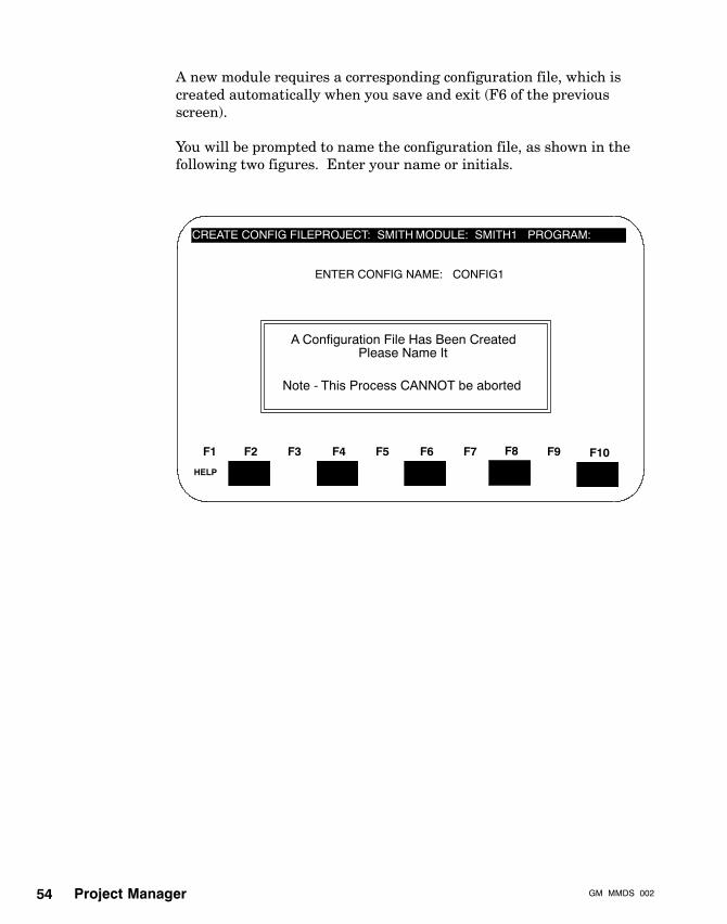
A new module requires a corresponding configuration file, which iscreated automatically when you save and exit (F6 of the previousscreen).
You will be prompted to name the configuration file, as shown in thefollowing two figures. Enter your name or initials.
CREATE CONFIG FILEPROJECT: SMITH MODULE: SMITH1
F2F1 F4F3 F5 F6 F8F7 F9 F10
PROGRAM:
ENTER CONFIG NAME: CONFIG1
HELP
A Configuration File Has Been CreatedPlease Name It
Note - This Process CANNOT be aborted

Project ManagerGM�MMDS�002 55
CREATE CONFIG FILE PROJECT: SMITHMODULE: SMITH1
F2F1 F4F3 F5 F6 F8F7 F9 F10
PROGRAM:
ENTER CONFIG NAME: CONFIG1
HELP
ENTER YOUR NAME: NAT
After entering your name or initials, you will be asked to give atwo-line description of the configuration file. To skip the description,press [ENTER] twice.
You will be given a chance to save and exit (F6) or cancel exit (F9).
The configuration file contains default information about the servosystem setup. It is valid, but not necessarily correct for your system.You edit the values of the commands in the configuration file via theConfiguration File Editor, discussed later in this chapter.
Although there are other Module Development functions, such as copyand delete, when you save and exit the configuration file, MMDSautomatically brings you to the Program Development Menu.

Project Manager GM�MMDS�00256
6.4 Program Development
After naming and saving the module and corresponding configurationfile, MMDS automatically brings you to the Program DevelopmentMenu. This menu can also be accessed by pressing F4 from the ProjectManager Menu.
Note: If you attempt to enter this menu without first creating aproject, you will receive a “cannot read data from the project file”error. If you attempt to enter this menu without first creating amodule, you will receive an “illegal file name” error.
If no program has yet been created for this module, only theconfiguration file is on the module’s list of programs, as shown in thefollowing figure.
PROGRAM DEVELOPMENT PROJECT: SMITH MODULE: SMITH1
CREATE
F2HELP
F1 F4F3 F5 F6 F8F7 F9
EXITPROG DEV
F10
PROGRAM:
DIRECTORY OF PROGRAMS AVAILABLE IN C:\b885data\SMITH
CONFIG1.CFG
EDIT COPY VIEW DELETE
A project must be active before you can access its modules, and amodule must be active before you can access its programs. To activatea project, module, or program, select it with the cursor keys and thenpress [ENTER].

Project ManagerGM�MMDS�002 57
Program Development functions are:
FunctionKey Name Description
F1 Help Accesses Help screens.
F2 Create Creates a program file. The correspondingdocumentation file will also be constructed andthen you will be prompted for pertinentinformation. The new program file willautomatically be entered into the activemodule.
F3 Edit Accesses the Program Editor. Move the cursorto the desired file in the directory listing andpress F3 [ENTER]. (Both configuration filesand program files can be edited.)
F4 Copy Copies a file. Highlight a file listed in theProgram Development Menu, and press theCopy function key. The screen will prompt forthe project, module, and filename to which tocopy the file. If copying to the same project,and the new program name chosen alreadyexists, an error message will appear and youmust select another name. If copying toanother project, the same name can be used.
F5 View Allows you to quickly view the Englishdescription of a program file, eliminating theneed to remember cryptic filenames in order tolocate the desired file. In addition, this level ofview provides an opportunity to edit thedocumentation file by pressing the F3 key.You will then be allowed to change the filedescription.
F7 Delete Deletes the selected file. A confirmation isrequired before this request is carried out.
F10 Exit Prog Dev Exits Program Development and returns toProgram Manager Menu.

Project Manager GM�MMDS�00258
Caution: Do not use the DOS Copy and Delete commands tocopy and delete a program, since files associated with theprogram will not be copied or deleted.
However, you may use the DOS Copy command to copy wholeprojects (each listed in the data files directory under its ownsubdirectory) onto diskettes for storage.
Press F2, Create, to start a new program.
Enter the program filename (for example, DRILL1) and press[ENTER]. The description box will appear. Enter the text, and press[ENTER] after each line. A choice to save or abandon is then given.
You may save and exit or exit without saving. If you press Exit/NoSave, you will remain in the Program Development Menu. If you pressExit and Save, you will be taken to the Program Edit Menu, where theprogram appears in a Program Window.
The Program Window of the Program Edit Menu will have nocommands listed. They appear there after you choose them from thePicklist and enter them. To see the Picklist, press F4, Window Switch.You will see a display similar to the one in the following figure.
F2HELP
F1 F4F3 F5 F6 F8F7 F9EXITEDIT
F10
PROGRAM EDIT PROJECT: SMITHMODULE: SMITH1
PROGRAM WINDOW
PROGRAM: DRILL1.PGM
COMMAND � � � �VALUE
Errors/faultsGains:Input/output:Limits:mOdule commands:
PICKLIST
Motion:moTor/feedback:program Flow:Programming:Register:storeD program cmds:Sync�ratio
WINDOWSWITCH

Project ManagerGM�MMDS�002 59
Enter commands from the Picklist by first selecting command groupnames and command names with the cursor keys and then pressing[ENTER]. You may also select a command group name or commandname by pressing its accelerator key — the capitalized letter in thename. Once a group is selected, the subpicklist listed beneath itappears, and you must then select the appropriate item. Then, ifapplicable, enter a value for the command, as well as a comment if youwish. To back out of any command without making a selection, justpress [ESC] until you have returned to the top-level Picklist.
See: Appendix A, MMDS Command Flowcharts, for a completehierarchical listing of all command group names and command names,including abbreviations, as they appear in the Picklist.
Project Manager GM�MMDS�00260
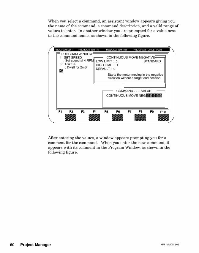
When you select a command, an assistant window appears giving youthe name of the command, a command description, and a valid range ofvalues to enter. In another window you are prompted for a value nextto the command name, as shown in the following figure.
1
PROGRAM EDIT PROJECT: SMITH MODULE: SMITH1 PROGRAM: DRILL1.PGM
COMMAND - - - - VALUE
=4
F2F1 F4F3 F5 F6 F8F7 F9
=2
CONTINUOUS MOVE NEGATIVE
CONTINUOUS MOVE NEG
F10
LOW LIMIT : 0HIGH LIMIT : 1DEFAULT : 0
Starts the motor moving in the negativedirection without a target end position
STANDARD
PROGRAM WINDOW1 SET SPEED
; Set speed at 4 RPMDWELL; Dwell for 2mS
2
3
After entering the values, a window appears prompting you for acomment for the command. When you enter the new command, itappears with its comment in the Program Window, as shown in thefollowing figure.

Project ManagerGM�MMDS�002 61
F2HELP
F1
WINDOWSWITCH
F4F3 F5 F6 F8F7 F9
EXITEDIT
F10
PROGRAM EDIT PROJECT: SMITH MODULE: SMITH1
PROGRAM WINDOW
PROGRAM: DRILL1.PGM
1
COMMAND � � � � VALUE
Errors/faultsGains:Input/output:Limits:mOdule commands:
PICKLIST
Motion:moTor/feedback:program Flow:Programming:Register:storeD program cmds:Sync�ratio
SET SPEED; Set speed at 4 RPMDWELL; Dwell for 2mS
2
3
4
CONTINUOUS MOVE NEG;Continuous negative move
Motion:
To edit the commands you have entered, press F4, Window Switch.Editing a program is covered in the next section.
However, if you wish to exit the Program Editor, press F10, Exit Edit.You are then given the chance to save (F6) or abandon (F8) theprogram. If you choose to Exit, No Save (F8) at this point, the programwill still exist, but the commands entered during the current editsession will not be included. In the above example, DRILL1.PGMwould still appear in the program file directory for module SMITH1,but it would not contain any commands.

Project Manager GM�MMDS�00262
6.5 Program Editor
This subsection tells you more about the Program Editor. If you areediting an unopened program, you must activate the appropriateproject and module so you can select the program to be edited.
If the desired project and module are already active, just go intoProgram Development Menu to select the program with the cursorkeys, and press F3 to Edit.
If the program is open and some commands have already been entered,just press Edit to begin to edit the existing commands.
Once Edit is pressed, the Program Window is highlighted. The functionkeys offer editing tools, as shown in the following figure.
F2F1 F4F3 F5 F6 F8F7 F9EXITEDIT
F10SAVEEDITS
GO TOLINE
WINDOWSWITCH
HELP EXPLAINMASK
CHANGEVALUE
DELETESTEP
PROGRAM EDIT PROJECT: SMITH MODULE: SMITH1
PROGRAM WINDOWPROGRAM: DRILL1.PGM
1 SET SPEED; Set speed at 4 RPMDWELL; Dwell for 2mS
2
3
4
CONTINUOUS MOVE NEG;Continuous negative move
4
2
1

Project ManagerGM�MMDS�002 63
The Program Editor contains the following:
V Program Window
V Picklist window
V Assistant window
V Command builder window: Command line and value lines
V Comment line
V Function key menu line
Note: F4, Window Switch, will shift the cursor between the ProgramWindow and the Picklist Window. Most of the following editingfunctions are accessible only when the cursor is in the ProgramWindow. If the cursor is in the Picklist Window, only Help, WindowSwitch, and Exit Edit are available.
Program Edit function keys are:
FunctionKey Name Description
F1 Help Displays the Help screen.
F2 Go to Line Allows you to specify the line number to whichto send the cursor (make it the current line).That command line is then highlighted.
F3 Explain Mask Overlays the screen with an explanation of thevalue in the current step, if the current valueis a bit mask. An explanation is given for eachof the bits.
F4 Window Switch Toggles the active window between the filewindow and the Picklist window. That is, thecursor keys will be effective only within theactive window. The Picklist appears on thescreen only when it is active.

Project Manager GM�MMDS�00264
FunctionKey Name Description
F5 Change Value Allows the value of a command to be alteredwithout changing the entire command. Whenit is pressed, the allowable range of validentries is also displayed within the assistantwindow.
F6 Save Edits Updates the active program file with anychanges made to it during this edit session.The Date Last Edited field in thecorresponding documentation file is changed totoday’s date.
F7 Delete Step Deletes the current highlighted command(only available when the program window isactive).
F10 Exit Edit Prompts you with the following choices: F6 tosave program and exit, F8 to confirm exitwithout save, or F9 to cancel exit. Note that ifF6, Save Edits, was pressed at any pointduring the edit session, those changes arealready saved to that point. If F8, exit withoutsave, is now pressed, only those changes madeafter F6 was pressed will be abandoned.

Project ManagerGM�MMDS�002 65
6.6 Configuration File Editor
The configuration file initializes a motion module and stabilizes theservo system. This happens only if the default values in theconfiguration file, which are automatically entered when theconfiguration file is created, are edited to reflect what is correct foryour system.
The configuration file is identical to a program file. It is automaticallygenerated when a module is created. It can also be uploaded from amodule. Configuration files cannot be created by the Create (F2)function key in the Program Development Menu.
Edit the configuration file through the Program Development Menu,just like a program file, by pressing F3, Edit. The parameters areinitialized to default values, which may or may not be accurate for yourapplication. Pressing F5, Change Value, will cause theCommand/Value box to appear. You can change values now, and maysave these changes for future use, by pressing F6, Save Edits. (SelectF8 to reenter the default values.)
See: The SASS Motion User Guide, GM-MOTN-001, to learn moreabout these parameters.

Project Manager GM�MMDS�00266
The following figure shows the configuration file in the ProgramWindow of the Configuration Editor.
CONFIGURATION EDIT PROJECT: SMITH MODULE: SMITH1
PROGRAM WINDOW
F2F1 F4F3 F5 F6 F8F7 F9EXITEDIT
F10
PROGRAM: CONFIG1.CFG
SET FAULT MASK5
SAVEEDITS
SET ANALOG OUT SETUP3
GO TOLINE
HELP EXPLAINMASK
CHANGEVALUE
= 1,2048,
1
SET I/O MASK= ffff
= E7ff,ffff,ffff,ffff
4
2 SET SERVO CONFIG = 33
6
78910111213
SET USER UNIT
SET CURRENT LMTSET SPEED LMTSET SPEEDSET JOG SPEEDSET MOTOR TYPESET MOTOR POLESSET MOTOR DIR
= 655361,1
= 100= 100= 0= 0= 1= 6= 0
WINDOWSWITCH
RECALLFILE
DEFAULTFILE
DELETESTEP
1 MEMORY TRANSFER
Caution: Make certain the configuration file has been editedcorrectly and sent to the motion module before operation. DONOT send the configuration file down to the motion modulebefore reviewing each value for accuracy.
The configuration file need only be saved once. It will then be retainedin memory, after a Memory Transfer command is executed in theImmediate Mode.
Configuration Edit consists of:
V Program window
V Assistant window
V Command builder: Command line and value lines
V Comment line
V Function key menu line

Project ManagerGM�MMDS�002 67
Configuration Edit functions are:
FunctionKey Name Description
F1 Help Displays the Help screen.
F2 Go to Line Allows you to specify the line number to sendthe cursor to (make it the current line). Thatcommand line is then highlighted.
F3 Explain Overlays the screen with an explanation of theMask value in the current step, if the current value
is a bit mask. An explanation is given for eachof the bits.
F5 Change Value Allows the value of a command to be alteredwithout changing the entire command. Whenit is pressed, the allowable range of validentries is also displayed within the assistantwindow.
F6 Save Edits Updates the configuration file with anychanges made to it during this edit session.The Date Last Edited field in thecorresponding documentation file is changed totoday’s date.
F7 Delete Step Deletes the current highlighted command(only available when the program window isactive).
F8 Recall File Returns the parameter settings in the activeconfiguration file to the values that were savedlast.
F9 Default File Returns the parameter settings in the activeconfiguration file to the factory default values.(Only the Edit Configuration File screen hasthis function.)
F10 Exit Edit Prompts you with the following choices:F6 — save program and exitF8 — confirm exit without saveF9 — cancel exit

Project Manager GM�MMDS�00268
6.7 Additional Module Development Functions
Once a module is created, you may edit, copy, view, and delete it.
Press F3 of the Project Manager Menu to enter the ModuleDevelopment Menu. If modules have already been created for a projectyou will see them listed.
A module does not have to be activated before you edit, copy, view, ordelete it, however. Just highlight the desired module name and pressthe function key for the desired function. The only time you need toactivate a module is when you wish to see the directory of programs fora module other than the current one.
A module will remain active until an operation (create, edit copy, view,or delete) is performed on a different module. For convenience, theactive module name is always displayed on the top of the screen,following the active project name.
Additional Module Development functions are:
FunctionKey Name Description
F1 Help Displays the Help screen.
F2 Create Creates a new module using systeminformation as well as your answers to variousprompts. In addition, a configuration file willbe built using default values. You will benotified of its existence and asked to name it.The documentation file associated with theconfiguration file will be created as well.(The newly created module will become theactive module.)
F3 Edit Contains some fields that you can edit. Theseare the description of the module, the 984register address of the control table, and themodule’s I/O register addresses.

Project ManagerGM�MMDS�002 69
FunctionKey Name Description
F4 Copy Copies the information from an existingmodule to a new one. You will automaticallybe prompted for the destination project. Ifanother project is named, then you are askedto choose names for the new module’s files.If copying to the same project, the files may beshared by both modules.
F5 View Allows you to quickly view the Englishdescription of a module file, eliminating theneed to remember a cryptic filename in orderto locate the desired file. Also displayed arethe module I/O addresses, control tableaddress, associated configuration and programfiles, and the date and time last edited.
F7 Delete Allows you to delete a module. Any programslisted under the deleted module are deleted aswell, unless they are shared by anothermodule.
F10 Exit Mod Dev Exits Module Development and returns toProject Manager Menu.
Caution: Do not use the DOS commands Copy and Delete tocopy and delete modules, since associated files may not becopied or deleted as well.
However, you may use the DOS Copy command to copy wholeprojects (each listed in the data files directory under its ownsubdirectory) onto diskettes for storage.

Project Manager GM�MMDS�00270
6.8 Additional Program DevelopmentFunctions
The Program Development Menu, in addition to letting you create andedit programs, allows you to:
V F4 — copy a program
V F5 — view a program file
V F7 — delete a program file
These functions work in very much the same ways as the ModuleDevelopment edit, copy, view, and delete functions do. The screens arevery similar and just as intuitive.
See: The previous section, Additional Module Development Functionsfor information.

Project ManagerGM�MMDS�002 71
6.9 Print Options
The last selection of the Project Development Menu is Print Options.The MMDS is capable of printing files without tying up the PC so thatyou can perform other tasks while printing. The reports generated bythis menu are 80 columns wide.
From the Print Options Menu, you can print a project, module, orprogram, as shown in the following figure.
PRINT OPTIONS MENU PROJECT: SMITH MODULE: SMITH1
FILE
F2HELP
F1PROJECT
F4MODULE
F3 F5 F6 F8F7 F9
EXITPRINT
F10
PROGRAM: DRILL1.PGM
F2 = PRINT PROGRAM
F3 = PRINT MODULE
F4 = PRINT PROJECT
Note: MMDS cannot print on some printer systems (for example,serial printers or parallel printers) without a hardware acknowledgesignal. If this applies to your system, use DOS to print. From DOS,enter the following print command:
PRINT FILENAME.LST
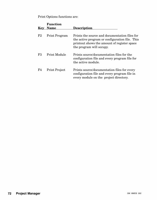
Project Manager GM�MMDS�00272
Print Options functions are:
FunctionKey Name Description
F2 Print Program Prints the source and documentation files forthe active program or configuration file. Thisprintout shows the amount of register spacethe program will occupy.
F3 Print Module Prints source/documentation files for theconfiguration file and every program file forthe active module.
F4 Print Project Prints source/documentation files for everyconfiguration file and every program file inevery module on the project directory.
Motion ModeGM�MMDS�002 73
Chapter 7Motion Mode
V Introduction
V Establishing the master (Local Lockout)
V Startup Mode
V Immediate Mode
V Single Step Mode
V Execute Mode
V Exiting Motion Mode

Motion Mode GM�MMDS�00274
7.1 Introduction
MAINMENU
StartupMode
ImmediateMode
SingleStepMode
ExecuteMode
MMDSSETUP
PROJECTMANAGER
MOTIONMODE
FILETRANSFERS
The Motion Mode is an online mode. It consists of:
V Startup Mode
V Immediate Mode
V Single Step Mode
V Execute Mode

Motion ModeGM�MMDS�002 75
7.1.1 Direct Connect and PLC Bridge
Whenever you select an online mode — Motion Mode or FileTransfers/Motion Module — you will be asked if you want to connect tothe motion module directly, as shown below.
Connect to Module Directly : Y
F2F1 F4F3 F5 F6 F8F7 F9
PROCEED
F10
CANCEL
COMMUNICATIONS SETUP PROJECT: SMITH MODULE: SMITH1 PROGRAM: DRILL1.PGM
EXIT
If you answer Yes, MMDS brings you to the Motion Mode Menu.However, if you enter N for No, you are asking MMDS to connect to themotion module over Modbus Plus through a bridge. This bridge is aconnection through a PLC and the backplane.
When you choose the PLC bridge, MMDS asks you for three registeraddresses:
V Register to disable normal I/O logic — This register will bewritten with a value of 1 before communication with the modulestarts. The register will be read back to verify that it indeedcontains 1. If you want to prohibit MMDS access, you can putuser logic in the PLC to force this register to 0. If MMDS doesnot read back a value of 1, MMDS will not enter the selectedonline mode.
V I/O map input register number — This is the traffic cop inputaddress of the motion module.
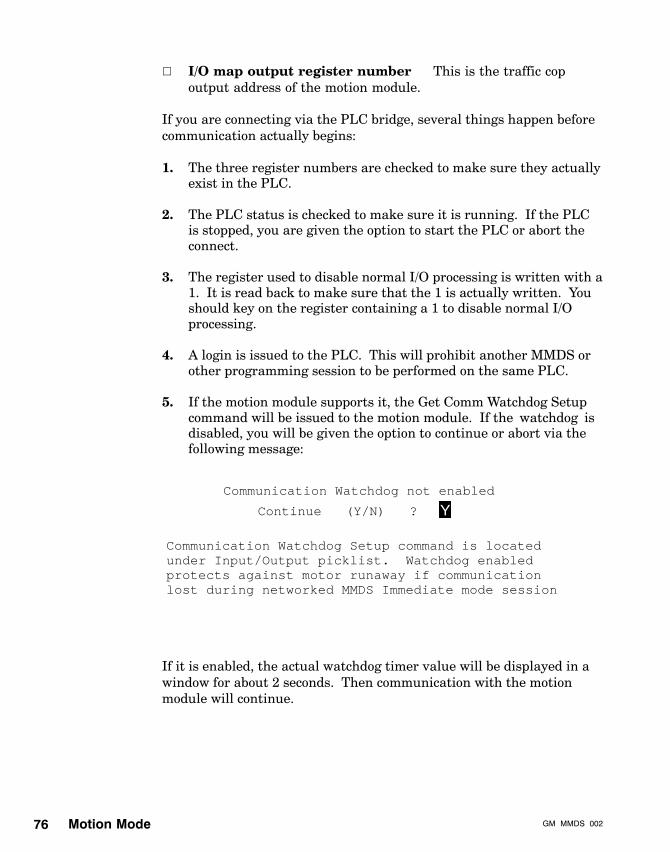
Motion Mode GM�MMDS�00276
V I/O map output register number — This is the traffic copoutput address of the motion module.
If you are connecting via the PLC bridge, several things happen beforecommunication actually begins:
1. The three register numbers are checked to make sure they actuallyexist in the PLC.
2. The PLC status is checked to make sure it is running. If the PLCis stopped, you are given the option to start the PLC or abort theconnect.
3. The register used to disable normal I/O processing is written with a1. It is read back to make sure that the 1 is actually written. Youshould key on the register containing a 1 to disable normal I/Oprocessing.
4. A login is issued to the PLC. This will prohibit another MMDS orother programming session to be performed on the same PLC.
5. If the motion module supports it, the Get Comm Watchdog Setupcommand will be issued to the motion module. If the ‘watchdog’ isdisabled, you will be given the option to continue or abort via thefollowing message:
Communication Watchdog not enabled
Continue (Y/N) ?
Communication Watchdog Setup command is locatedunder Input/Output picklist. Watchdog enabledprotects against motor runaway if communicationlost during networked MMDS Immediate mode session
Y
If it is enabled, the actual watchdog timer value will be displayed in awindow for about 2 seconds. Then communication with the motionmodule will continue.
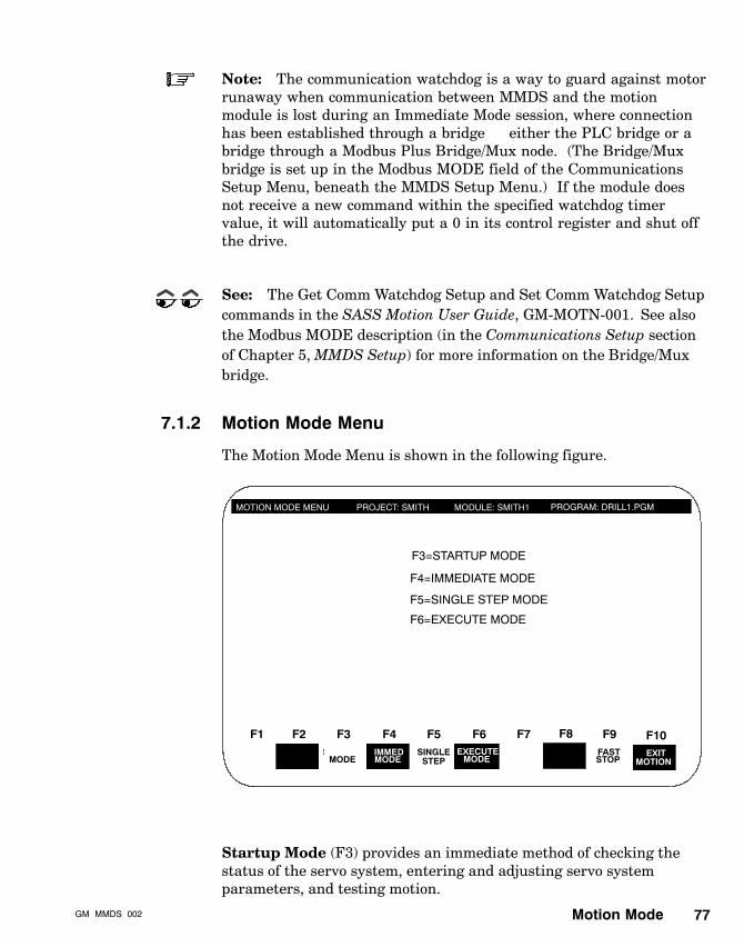
Motion ModeGM�MMDS�002 77
Note: The communication watchdog is a way to guard against motorrunaway when communication between MMDS and the motionmodule is lost during an Immediate Mode session, where connectionhas been established through a bridge — either the PLC bridge or abridge through a Modbus Plus Bridge/Mux node. (The Bridge/Muxbridge is set up in the Modbus MODE field of the CommunicationsSetup Menu, beneath the MMDS Setup Menu.) If the module doesnot receive a new command within the specified watchdog timervalue, it will automatically put a 0 in its control register and shut offthe drive.
See: The Get Comm Watchdog Setup and Set Comm Watchdog Setupcommands in the SASS Motion User Guide, GM-MOTN-001. See alsothe Modbus MODE description (in the Communications Setup sectionof Chapter 5, MMDS Setup) for more information on the Bridge/Muxbridge.
7.1.2 Motion Mode Menu
The Motion Mode Menu is shown in the following figure.
MOTION MODE MENU PROJECT: SMITH MODULE: SMITH1
F2HELP
F1 F4STARTUP
F3SINGLE
F5 F6 F8F7 F9
EXITMOTION
F10
STEP
PROGRAM: DRILL1.PGM
F3=STARTUP MODE
F4=IMMEDIATE MODE
F5=SINGLE STEP MODE
F6=EXECUTE MODE
MODEIMMEDMODE
EXECUTEMODE
FASTSTOP
Startup Mode (F3) provides an immediate method of checking thestatus of the servo system, entering and adjusting servo systemparameters, and testing motion.

Motion Mode GM�MMDS�00278
The Immediate Mode (F4) is used to:
V Test the motor.
V Execute a command before putting it into a program. This isuseful for adjusting servo system (configuration) parameters, suchas gains.
V Perform a memory transfer of the configuration file from themotion module’s RAM to its optional EEPROM.
Single Step Mode (F5) allows you to execute a motion program, oneline at a time.
Execute Mode (F6) allows you to execute an entire program. (It isalso used to download the configuration file to the motion module’sRAM.)
Fast Stop (F9) abandons all queued commands and stops the motor.F10, Exit Motion (F10) takes you out of Motion Mode and back to theMain Menu.
By entering Motion Mode, the motion module selects the PC as itsmaster if the motion module was set up for standalone operation.
Except for Startup Mode, the list of the control register bits and theirfunctions are visible within the Control/Status Window. In the motionmodes, the [SHIFT] and [ALT] keys are used to toggle the controlregister bits.
Note: Control register bits remain set until the user clears them.The function keys toggle the control bits off and on, except the FastStop (F9) key, which appears on the main function key list. It doesnot toggle off once it is set with the function key, as an added measureof safety. To undo Fast Stop, look at the list of control register bits onthe screen for Fast Stop’s control bit, which should be bit 11, thenpress and F4 to turn control bit 11 off. Fast Stop acts as a quickabort.
Single Step Mode or Execute Mode operate on an active program.Immediate Mode and Startup Mode do not.
Caution: Since Motion Mode operations run the motor,proceed with caution to ensure safety.

Motion ModeGM�MMDS�002 79
7.2 Establishing the Master (Local Lockout)
The motion module, based on the information loaded into RAM,determines whether the 984 or the MMDS is the master. Althoughboth the 984 and the PC running MMDS can retrieve data from themotion module, only the master can send (write) data to the motionmodule.
The first piece of information that establishes the master comes fromthe master (984/standalone) DIP switch in the motion module. TheDIP switches are read into RAM at powerup. The master DIP switchcan be set to either 984 or standalone mode.
See: Your motion module guide for more information on DIP switches.
Another setting comes from the Set Local Lockout command, which canonly be issued from the 984.
See: The Set Local Lockout command in the SASS Motion UserGuide, GM-MOTN-001.
To make certain whether the 984 or MMDS is master, look at the statusregister, bit 10.
7.2.1 When Communication Stops
If communications to the motion module stops (because of exitingmotion mode, rebooting the PC, or disconnecting a cable, for example)the motion module starts the timer. When the timer is done, themotion module reverts to the 984 as its master. If there is no 984connected, the motion module goes into shutdown mode and disablesthe drive, unless an internal program that had enabled the drive isrunning.
Caution: If a vertical axis is disabled, you may want to takeprecautions to prevent gravity from dropping this axis.

Motion Mode GM�MMDS�00280
7.3 Startup Mode
The Startup Mode provides a method for quickly adjusting servosystem gains and testing motion on the motor. It gives you aconvenient way to stabilize the motor by trying different values forsystem performance parameters. It also provides an easy way to checkwhat is happening in the servo; it displays continuous system statusinformation, such as position and speed.
To access Startup Mode, press F3 from the Motion Mode Menu. (LikeImmediate mode, Startup does not use a program to operate thesystem.) Startup Mode is shown in the following figure.
STARTUP MODE PROJECT: SMITH MODULE: SMITH1 PROGRAM: DRILL1.PGM
SYSTEM STATUS
ENABLEF.STOP HALT
HOLD FAULTFOL ERR DONE
IN�POSENABLED
MOVING POSNSPEED 0.00000000
�0.00001526CONTROL STATUS ACTUAL
MOTION CONTROL
MISC INFORMATIONMOTOR:UNITS:FAULTS:LIMITS:BANDS:MISC:
MOVE VALUESERVO PARAMETERS
ATC 64 MSECANTI�JERK 1VFF 0 %POS�LOOP OFF
SPEEDACCELDECEL
0.000000
18000.0000
REV/MINREV/MIN/SEC
OFFOFFVEL�LOOP OFF
RIG 300
TYPE DC # of POLES 6DIST REV TIME MINRMS CURRENT 9% for 1 SECCURRENT 100% SPEED 36000.000000 REV/MININ�POS 0.040000 REVJOG SPEED 15000.000000 REV/MIN
DIR CWCOUNTS/REV 10000FOLLOWING ERROR 100.000000 REV
FOL ERROR 100.000000 REV
ONON
0.0 REV
F2HELPF1 F4F3 F5 F6 F8F7 F9
EXITSTARTUP
F10FASTSTOP
READERROR
SAVE TOMODULE
RPG 150PIG 0
18000.0000REV/MIN/SEC
MSET MODE OFFMSET CURRENT 0%
VEL DRIVE SCALE FACTOR 39321.562500 REV/MIN
Note: Set User Unit values first, since the values of otherparameters are affected by User Units. Values that are displayed inthis screen are retrieved from the motion module and displayedcontinuously in User Units. Some rounding errors may occur duringthe display of these values, but the actual data used for theseparameters are not affected, and no inaccuracies occur.

Motion ModeGM�MMDS�002 81
MMDS continuously updates the system status information on theStartup screen. That is, as you look at them, the values keep changingto reflect changes in the servo motor and load.
The five major parts of this screen are:
V System Status Window
V Motion Control Window
V Servo Parameters Window
V Miscellaneous Information Window
V Three sets of function keys — one set for the main Startup Menu,one when [ALT] is pressed, and one when [SHIFT] is pressed.
7.3.1 System Status Window
The System Status Window contains read-only information, except forthe POSN field. This window shows the current state of the controlregister bits and the status register bits. It also shows the actualposition and speed of the motor. To turn these and other bits on andoff, use the function keys with either [ALT] or [SHIFT] pressed. Forexample, to disable the drive, press [ALT] and F2.
The System Status Window highlights a bit to show it is active.
7.3.2 Motion Control Window
The Motion Control Window allows you to set the distance and speed ofa move, as well as the rates of acceleration and deceleration, throughthe Startup Mode screen, rather than coding SASS commands.
See: The descriptions for motion, acceleration, and decelerationcommands in the SASS Motion User Guide, GM-MOTN-001.
Motion Mode GM�MMDS�00282
7.3.3 Servo Control Window
The Servo Control Window allows you to stabilize the motor by settingseveral servo data parameters via the Startup Mode screen. Theseparameters are: ATC, RIG, PIG, RPG, Anti-Jerk, and VFF. Thiswindow also shows the status (OFF or ON) of the position loop andvelocity loop.
Caution: Change these parameters only when a move is notbeing executed. Otherwise, the motor may jerk unexpectedly.
See: The SASS Motion User Guide, GM-MOTN-001, for descriptionsof all these parameters.
7.3.4 Miscellaneous Information Window
This window allows you to set the following system performanceparameters via the Startup Mode screen:
Motor TypeMotor PolesMotor DirectionUser UnitsRMS Current LimitCurrent LimitSpeed LimitFollowing Error LimitIn-Position BandFollowing Error BandJog SpeedMSET Parameters (MSET mode and MSET current)Velocity Mode Scaling (Velocity Drive Scale Factor)
See: The SASS Motion User Guide, GM-MOTN-001, for descriptionsof all these parameters.

Motion ModeGM�MMDS�002 83
7.3.5 Function Keys
As mentioned earlier, there are three groups of function keys for theStartup Menu:
V Startup’s main menu function keys
V Function keys displayed when [ALT] is pressed
V Function keys displayed when [SHIFT] is pressed
The Startup Menu functions are:
FunctionKey Name Description
F1 Help Displays the Help screen.
F7 Save in Saves values entered in the Startup menu toModule the optional EEPROM. This function key is
useless if you do not have the EEPROM option.
F8 Read Error Reads errors and faults and clears them fromwithin the Startup Menu. It allows you toclear all faults and reset the error log throughF5, Reset and Clear All, or go on to the nexterror through F8, Read Next Error, or clear thepresently displayed error from the log andthen exit through F10, Read Error and Exit.
F9 Fast Stop Acts as quick abort to stop motion.
F10 Exit Startup Exits Startup.
Startup’s [ALT] and [SHIFT] functions, which toggle each other, arelisted together as follows.
FunctionKey Name Description
F2 Drive Enable/ Toggles between enabling and disabling theDisable drive.
F3 Home Pos/Neg Sends axis to home in a positive or negativedirection.

Motion Mode GM�MMDS�00284
FunctionKey Name Description
F4 Inc Mov Moves incrementally in a positive or negativePos/Neg direction. F4 will add new value to current
target position. (The new position value will bethe number entered for MOVE VALUE inthe Motion Control Window.) Be aware of thefact that if you press this key twice whenthe axis is moving to its target position, thisposition will be incremented by twice its value,and yet it will appear to making onecontinuous move. You can use Halt or FastStop to stop an incremental move.
F5 Cont Move Moves continuously in positive or negativePos/Neg direction, with a target end position of the
respective software end-of-travel limit. Youcan use Halt or Fast Stop to stop a continuousmove.
F6 Halt/ Causes the current move to decelerate toClear Halt zero. When the halt is cleared, the move will
not continue, but any queued commands inthe buffer will begin execution.
F7 Hold/ Stops execution after the current commandClear Hold is finished. Commands will continue after
Hold is cleared.
F8 Rslvr Cal Performs a resolver strength calibration(shift only) diagnostic on the motion module. It is
equivalent to issuing a Self Test commandwith test type 4 (resolver strength calibration).
F9 Fast Stop/ Provides a quick abort and does not use linearClear Fst Stop deceleration to stop a current motion
command. It causes the target position to beset to the current Stop position, which causesan immediate and usually violent stop. Theoriginal target position is lost.
F10 Exit to Exits to the Main Menu.Main Menu

Motion ModeGM�MMDS�002 85
7.4 Immediate Mode
This mode allows you to send any SASS command to the motionmodule for immediate execution. (No program is necessary.) You selecta command from a picklist that is identical to the Program EditorPicklist, using the cursor keys or entering the capitalized abbreviationof the selection. The system prompts you for values, if required. Thesystem will then display the command translated into the motionmodule register format in the To Module Window.
The Immediate Mode is shown in the following figure.
IMMEDIATE MODEPROJECT: SMITH MODULE: SMITH1
F2HELP
F1REPEAT
COMMAND
F4F3 F5 F6 F8F7 F9EXIT
IMMED
F10
PROGRAM: DRILL1.PGM
CONTROL STATUS
+ LIMIT SW.� LIMIT SW.HOME SWITCHJOG +JOG �REG. INP. 6RESERVEDIMMED ECHODRIVE ENABLHOLD MOTIONFAST STOPFLUSH QUEUEHOLD COMNDSHALTRESPONSE 2RESPONSE 1
123456789
10111213141516
FAULTFOL. ERRORRESERVEDIN�POSITIONCURRENT_LMTMOVE DONEMOVINGPOS_TRIGGERDRV. ENABLEDSER. MASTERPRG_RUNNINGBUFFER FULLAXIS READYRESERVEDRESPONSE 2RESPONSE 1
TO MODULE0000 CONTROL
COMMANDDATA #1DATA #2DATA #3DATA #4
SHOWREPLY
READERROR
FASTSTOP
Errors/faultsGains:Input/output:Limits:mOdule commands:
PICKLIST
Motion:moTor/feedback:program Flow:Programming:Register:storeD program cmds:Sync-ratio
Motion:
COMMAND - - - -VALUE
7.4.1 Picklist Window
The Picklist Window displays the same top-level command categoriesthat are displayed in the Program Editor. From Immediate Mode, youcan select, send, and execute SASS commands from this PicklistWindow.

Motion Mode GM�MMDS�00286
7.4.2 Control/Status Window
The Control/Status Window lists the 16 bit functions of the controlregister and the status register. You can toggle any of these bits usingthe [SHIFT] and [ALT] keys. The function keys will then change torepresent each of the control bits. To show control register bits 1through 8 in function keys 2 through 10, press [SHIFT]. To show andaccess control register bits 9 through 16 in function keys 2 through 10,press [ALT]. Active bits are highlighted in the Control/Status Window.
Note: If status and control bits do not highlight when they should,check the input and output masks. Bits may have been reassigned, sothat the label you see on the screen may no longer be the truemeaning of a particular bit.
7.4.3 The To Module Window
The To Module Window provides the following information:
V The control registers that have been set (reflecting what is set inthe Control/Status Window)
V The command that has most recently been sent to the motionmodule (reflecting what has been chosen from the Picklist)
V The data that has been sent for the most recent command (shownin the hexadecimal equivalent of the value entered)
Immediate Mode functions are:
FunctionKey Name Description
F1 Help Displays the Help screen.
F2 Repeat Allows you to re-execute last command.Command
F6 Show Reply Displays data from last command executed.

Motion ModeGM�MMDS�002 87
FunctionKey Name Description
F8 Read Error Allows you to clear all faults and resetthe error log through F5, Reset and Clear All,or go on to the next error through F8, ReadNext Error, or clear the currently displayederror from the log and then exit through F10,Read Error and Exit.
F9 Fast Stop Causes all queued commands to beabandoned. Motor will stop.
F10 Exit Immed Returns operation to the main Motion ModeMenu.

Motion Mode GM�MMDS�00288
7.5 Single Step Mode
Single Step Mode allows you to run a program one instruction (step) ata time so that you can inspect program execution while it is frozen.This mode requires a project, module, and program to be selected (ifone has not already been activated). The system will update the statusregister. The screen consists of a Program Window, a Control/StatusWindow, and the function key menu line, as shown in the followingfigure.
SINGLE STEP MODE PROJECT: SMITH MODULE: SMITH1
HOME POSITIVE
F2F1EXECUTE
STEP
F4F3 F5 F6 F8F7 F9EXIT
SNGL STP
F10
PROGRAM: DRILL1.PGM
CONTROL STATUS
+ LIM SWTCH- LIM SWTCHHOME SWITCHJOG +JOG -REG. INPUT 6RESERVEDIMMED ECHODRIVE ENABLHOLD MOTIONFAST STOPFLUSH QUEUEHOLD COMNDSHALTRESPONSE 2RESPONSE 1
123456789
10111213141516
FAULTFOL. ERRORCURRENT_LMTIN�POSITIONRESERVEDMOVE DONEMOVINGPOS_TRIGGERDRV. ENABLEDSER. MASTERPRG_RUNNINGBUFFER FULLAXIS READYRESERVEDRESPONSE 2RESPONSE 1
SHOWREPLY
READERROR
FASTSTOP
EXPLAINMASK
SKIPSTEP
RESETPROGRAM
GO TOLINE
PROGRAM WINDOW
;Sent motor to home positionSET SPEED;Set speed at 5 rpmDWELL;Dwell for 2 mSSET ACCELABSOLUTE MOVE NEG
1
2
3
45
HELP
PRESS SPACE BAR TO CLEAR
Note: In Single Step Mode, branching instructions are not executed.Labels are used in EEPROM stored programs and are converted toabsolute memory addresses.
7.5.1 Program Window
The Program Window displays the commands that were entered intoyour program via the Program Editor. The current line is highlighted,and it is the one that will be executed when you press F2, or skippedwhen you press F3.
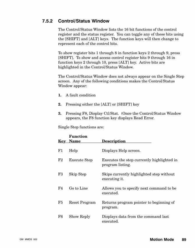
Motion ModeGM�MMDS�002 89
7.5.2 Control/Status Window
The Control/Status Window lists the 16 bit functions of the controlregister and the status register. You can toggle any of these bits usingthe [SHIFT] and [ALT] keys. The function keys will then change torepresent each of the control bits.
To show register bits 1 through 8 in function keys 2 through 9, press[SHIFT]. To show and access control register bits 9 through 16 infunction keys 2 through 10, press [ALT] key. Active bits arehighlighted in the Control/Status Window.
The Control/Status Window does not always appear on the Single Stepscreen. Any of the following conditions makes the Control/StatusWindow appear:
1. A fault condition
2. Pressing either the [ALT] or [SHIFT] key
3. Pressing F8, Display Ctl/Stat. (Once the Control/Status Windowappears, the F8 function key displays Read Error.
Single Step functions are:
FunctionKey Name Description
F1 Help Displays Help screen.
F2 Execute Step Executes the step currently highlighted inprogram listing.
F3 Skip Step Skips currently highlighted step withoutexecuting it.
F4 Go to Line Allows you to specify next command to beexecuted.
F5 Reset Program Returns program pointer to beginning ofprogram.
F6 Show Reply Displays data from the command lastexecuted.

Motion Mode GM�MMDS�00290
FunctionKey Name Description
F7 Explain Mask Explains the bit pattern definitions for aparticular command if its value is in binary.
F8 Display Ctl/Stat Displays the Control/Status window.Once it is displayed, you can remove it bypressing the space bar. Also, while thethe Control/Status Window is visible, F8becomes Read Error. Press F8 to clear allfaults and reset the error log through F5,Reset and Clear All, or go on to the next errorthrough F8, Read Next Error, or clear thepresently displayed error from the log andthen exit through F10, Read Error and Exit.
F9 Fast Stop Causes the current command to be abandonedimmediately, remove any queued commands,and stop the motor.
F10 Exit Single Step Returns operation to main Motion Mode Menu.

Motion ModeGM�MMDS�002 91
7.6 Execute Mode
Execute mode allows a program to run continuously. The system willupdate the status register. The screen consists of a Program Window, aControl/Status Window, and the function key menu line, as shown inthe following figure.
EXECUTE MODE PROJECT: SMITH MODULE: SMITH1
F2F1START
F4F3 F5 F6 F8F7 F9EXIT
F10
PROGRAM: DRILL1.PGM
SHOWREPLY
READERROR
FASTSTOP
EXPLAINMASK
RESETPROGRAM
GO TOLINE
HELP
HOME POSITIVE CONTROL STATUS
+ LIM SWTCH- LIM SWTCHHOME SWITCHJOG +JOG -REG. INPUT 6RESERVEDIMMED ECHODRIVE ENABLHOLD MOTIONFAST STOPFLUSH QUEUEHOLD COMNDSHALTRESPONSE 2RESPONSE 1
123456789
10111213141516
FAULTFOL. ERRORRESERVEDIN�POSITIONCURRENT_LMTMOVE DONEMOVINGPOS_TRIGGERDRV. ENABLEDSER. MASTERPRG�RUNNINGBUFFER FULLAXIS READYRESERVEDRESPONSE 2RESPONSE 1
PROGRAM WINDOW
;Sent motor to home positionSET SPEED;Set speed at 5 rpmDWELL;Dwell for 2 mSSET ACCELABSOLUTE MOVE NEG
1
2
3
45
PRESS SPACE BAR TO CLEAR
Note: Execute Mode does not process jumps to labels. Labels arevalid only in programs stored in the motion module’s nonvolatilememory area.
7.6.1 Program Window
The Program Window displays the commands that were entered via theProgram Editor. Each line is highlighted as it executes. Press F2,Start, to begin execution. Press F3, Stop, to stop execution.

Motion Mode GM�MMDS�00292
7.6.2 Control/Status Window
The Control/Status Window lists the 16 bit functions of the controlregister and the status register. You can toggle any of these bits usingthe [SHIFT] and [ALT] keys. The function keys will then change torepresent each of the control bits.
To show control register bits 1 through 8 in function keys 2 through 9,press [SHIFT]. To show and access control register bits 9 through 16 infunction keys 2 through 9, press [ALT] key. Active bits are highlightedin the Control/Status Window.
The Control/Status Window does not always appear on the ExecuteMode screen. Any of the following conditions makes the Control/StatusWindow appear:
1. A fault condition
2. Pressing either the [ALT] or [SHIFT] key
3. Pressing F8, Display Ctl/Stat. (Once the Control/Status Windowappears, the F8 function key displays Read Error.
Execute Mode functions are:
FunctionKey Name Description
F1 Help Displays the Help screen.
F2 Start Starts program from highlighted command.
F3 Stop Stops execution of active program.
F4 Go to Line Allows you to specify next command fromwhich to begin or continue execution.
F5 Reset Program Returns program pointer to beginning ofprogram.
F6 Show Reply Displays which command was executed last.
F7 Explain Mask Explains bit pattern definitions for aparticular command if its value is in binary.

Motion ModeGM�MMDS�002 93
FunctionKey Name Description
F8 Display Ctl/Stat Displays the Control/Status Window.Read Error Once displayed, you can remove it by
pressing the space bar. Also, while thiswindow is visible, F8 becomes Read Error.Press F8 to clear all faults and reset theerror log through F5, Reset and Clear All, orgo on to the next error through F8, Read NextError), or clear the presently displayed errorfrom the log and then exit through F10, ReadError and Exit.
F9 Fast Stop Causes current command to be abandonedimmediately, removes any queued commands,and stop the motor.
F10 Exit Returns operation to main Motion Mode.
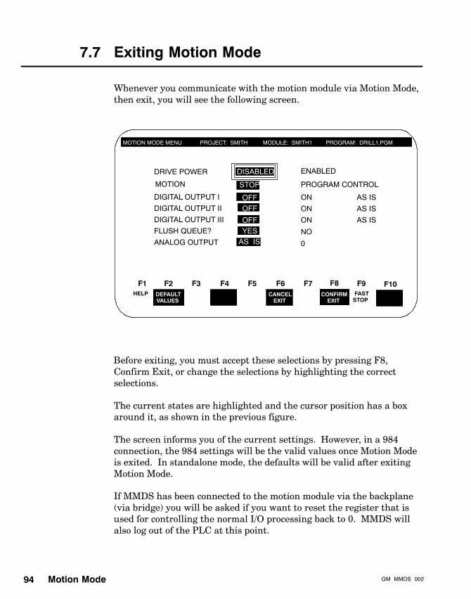
Motion Mode GM�MMDS�00294
7.7 Exiting Motion Mode
Whenever you communicate with the motion module via Motion Mode,then exit, you will see the following screen.
MOTION MODE MENU PROJECT: SMITH MODULE: SMITH1
F2F1 F4F3 F5 F6 F8F7 F9 F10
PROGRAM: DRILL1.PGM
DISABLED
CANCELEXIT
CONFIRMEXIT
FASTSTOP
DEFAULTVALUES
HELP
DRIVE POWER
MOTION
DIGITAL OUTPUT I
DIGITAL OUTPUT II
DIGITAL OUTPUT III
FLUSH QUEUE?
ANALOG OUTPUT
STOP
OFFOFF
OFFYES
AS IS
ENABLED
PROGRAM CONTROL
ON
ON
ON
NO
0
AS IS
AS IS
AS IS
Before exiting, you must accept these selections by pressing F8,Confirm Exit, or change the selections by highlighting the correctselections.
The current states are highlighted and the cursor position has a boxaround it, as shown in the previous figure.
The screen informs you of the current settings. However, in a 984connection, the 984 settings will be the valid values once Motion Modeis exited. In standalone mode, the defaults will be valid after exitingMotion Mode.
If MMDS has been connected to the motion module via the backplane(via bridge) you will be asked if you want to reset the register that isused for controlling the normal I/O processing back to 0. MMDS willalso log out of the PLC at this point.

Motion ModeGM�MMDS�002 95
In a 984 connection, make certain the 984 agrees with the statuses ofthe exit motion screen. If, for example, you say the drive should bedisabled and motion should stop when the motion module shuts down,and the 984 is programmed to do otherwise, the 984 will rule. Makecertain, therefore, that the motion module and the 984 are inagreement. If the 984 does not address an issue, such as digitaloutputs, the setting that you select in the exit motion mode screen willremain valid.
If in standalone mode (not connected to the 984), and if a user programis not executing, the motion module will perform shutdown whencommunication stops. Any selections made in the exit motion screenwill revert to defaults once the module performs shutdown.
Exit motion screen settings are described in the following list.
Status Description
Drive Power Power to the drive is enabled or disabled.(Disabled is default.)
Motion Motion will continue or stop (fast stop) afterthe motion module shuts down.(Stop is the default.)
Digital Output I Output 1 is off, on, or as is. (Off is the default.)
Digital Output II Output 2 is off, on, or as is. (Off is the default.)
Digital Output III Output 3 is off, on, or as is. (Off is the default.)
Flush Queue Commands are cleared from buffer - yes or no.(Yes is the default.)
Analog Output Analog output remains as is, or is zeroed.(“As is” is the default.) A 0 value in this caseis not necessarily 0 volts, but it is whatever 0had been set to in the sensitivity setting of theAnalog Output Setup parameter.
File TransfersGM�MMDS�002 97
Chapter 8File Transfers
V Introduction
V Downloading files to the 984 PLC
V Downloading files to and uploading files from the motion module

File Transfers GM�MMDS�00298
8.1 Introduction
MAINMENU
MMDSSETUP
PROJECTMANAGER
MOTIONMODE
FILETRANSFERS
984 MotionModule
Press F5, File Transfers, from the Main Menu to access the FileTransfers Menu. File Transfers allows you to download programs toeither the 984 or the motion module. You choose the devices you wantto transfer files to, as well as the type of transfer.
The File Transfers Menu also allows you to upload programs and entireMMDS modules, which are active in the motion module, from themotion module to your PC.

File TransfersGM�MMDS�002 99
The following figure shows the File Transfers Menu.
FILE TRANSFERS PROJECT: SMITHMODULE: SMITH1
F2HELP
F1 F4F3 F5 F6 F8F7 F9
EXIT
F10
PROGRAM: DRILL1.PGM
F4 = 984
984 TRANSFERS
F6 = MOTION MODULE
MOTIONMODULE

File Transfers GM�MMDS�002100
8.2 984 PLC Downloading
From the File Transfers Menu, press F4 to download one or moreprograms to the 984. A list of your projects will be displayed. Select aproject from this list. A message will flash briefly on the screen, statingthat the project you selected is now active. The modules within thatproject are listed in a box at the top half of the screen. With the arrowkeys, select the module to be downloaded and press [ENTER].Programs contained in that module are listed in another box in thelower half of the screen. Select the programs to be downloaded, oneprogram at a time, using the arrow keys and press [ENTER] after eachselection.
All selected programs will be moved into a new box at the upper half ofthe screen. Press F4, Download, after the last program has beenselected. (If you select all the files, there is no need to press F4. Thenext screen displays automatically.)
The next screen displays the beginning 984 register address default of40012. Press F4 to change this address or press F6 to begin thedownload.
See: The SASS Motion User Guide, GM-MOTN-001, theModicon Ladder Logic Block Library User Guide, 840 USE 101 00, andthe Modsoft Programmer User Manual, GM-MSFT-001, for moreinformation on registers, register allocation, and traffic copping.
Three fields will appear and prompt you for information:
Beginning 984 RegisterEnding 984 RegisterProgram
After choosing the Beginning 984 Register, press F6, Begin Download.The programs will first be compiled, and then downloaded. The endingaddress of the program will update on the screen as it downloads.When finished, beginning register, ending register, and program lengthwill display momentarily.

File TransfersGM�MMDS�002 101
If downloading multiple files, the ending register of the firstdownloaded file (plus one register) will be displayed as the beginningregister for the next file to be downloaded. Accept this register addressby choosing F6, Begin Download, or change it by pressing F4, Change984 Register.
To ensure you do not overwrite data in the 984 when downloading,print your program — the list file (.LST) — from the Print OptionsMenu to find out how many registers the program occupies. Todetermine this, look in the Register Offset Columns on the programprintout. The register offset addresses are listed here. To calculatehow many 984 registers the program will occupy, and where they willbe located, add the last Register Offset address to the Beginning 984Register address of the Download File screen, plus three registersmore. That is the number of registers the program will occupy, startingat the Beginning 984 Register. Information that already resides inthese registers will be overwritten when the program is downloaded.
While looking at the beginning register of your list (.LST) file, you willnotice that it is three registers greater than what is seen on thedownload screen as its Beginning 984 Register. This is because theheader of the program table that is used by the Multi-RegisterTransfer Module (MRTM) option occupies three registers.
See: The SASS Motion User Guide, GM-MOTN-001, for moreinformation on MRTM.

File Transfers GM�MMDS�002102
8.3 Motion Module Downloading andUploading
From the File Transfers Menu, press F6, Motion Module, to downloadfiles to and upload files from the motion module. When you press F6,the communication screen that comes up when Motion Mode isselected, is also displayed here. This screen also allows you to connectwith the motion module directly or over Modbus Plus through a bridge,such as a PLC.
See: The Introduction section in Chapter 7, Motion Mode, forcomplete information on this communication screen and this bridge.See also the Communications Setup section in Chapter 5, MMDSSetup.
The highlight bar is located in the Projects window, and the functionkeys are:
F1, HelpF2, Window SwitchF10, Exit
Programs that are stored in the motion module are displayed in thePrograms In Motion Module window, along with the amount of memoryavailable. They are listed by number only. Valid program numbers arefrom 1 to 255. Programs in the motion module may be deleted or usedas the autoboot program. Therefore, when you place the cursor in thePrograms In Motion Module window by pressing F2, Window Switch,three additional function keys are displayed:
F3, AutobootF5, Upload ProgramF6 , Delete
8.3.1 Delete
When you want to delete a program, highlight the program number inthe Programs In Motion Module window and then press Delete. Ifseveral programs are to be deleted at one time, highlight each andpress [ENTER] to select them. Next to each program selected fordeletion, you will see a right-pointed arrow (>) to the left of theprogram name. When you have selected all files to be deleted, press F6,Delete. You will be asked to confirm or cancel the delete.

File TransfersGM�MMDS�002 103
8.3.2 Autoboot
If there is an autoboot program, a left-pointing arrow (<) will appear tothe right of its program number. To select another autoboot program,highlight the file number in the Programs In Motion Module window,and press F3. The arrow will then move from the old autoboot filenumber to the new one. Highlighting the current autoboot programand pressing F3 toggles it off and on.
8.3.3 Uploading Programs from Motion Module
If you want to upload (copy the contents of) one or more activeprograms from the motion module to your PC, highlight each programin the Programs In Motion Module window and select it by pressing[ENTER]. Then press F5, Upload Program. A Program Uploadwindow will appear and display the names of the project and modulethat own the active programs that you have selected to upload. Thiswindow also prompts you to enter the new prefix for all the activeprograms:
Project Name :Module Name :Enter Program prefix:
After you enter the prefix, press [ENTER] to execute the upload.During the execution, another Program Upload window appears,showing you the upload in progress with messages like:
Uploading Program # 1Uploading Program # 2. . .
Note: If you do not select any program to upload and press F5,Upload Program, the system will upload the program that the cursoris on.
To abort the upload in progress, press the [ESC] key.

File Transfers GM�MMDS�002104
8.3.4 Downloading Programs to Motion Module
To select programs to download to the motion module or delete,highlight the project that contains the files to be downloaded or deleted,and press [ENTER]. The modules found in that particular project willbe displayed in the Modules window. The functions available are:
F1, HelpF2, Window SwitchF5, Upload ModuleF6, DeleteF10, Exit
To display this module’s programs, press [ENTER]. Programs withinthe selected module are then displayed in the Programs window, and anew list of functions appears at the bottom of the screen. Thesefunctions are:
F1, HelpF2, Window SwitchF3, Download All ProgramsF4, Download SelectedF5, Upload ModuleF6, DeleteF7, Read ConfigF8, Execute ConfigF10, Exit
If you want to download all the programs in the module, press F3,Download All Programs.
If you want to download only certain programs, use the [ENTER] key toselect programs to download. A right-pointing arrow (>) will appear tothe left of each selected program name. When finished selectingprograms, choose F4, Download Selected, to download them.
As each selected program is about to be downloaded, you will be askedfor the program to download and the program number to assign to thatprogram.

File TransfersGM�MMDS�002 105
The default number will be the next number available. For example,you will see:
Program to Download :
Program number :
As each file completes downloading, the mark next to its namedisappears. A timed message will inform you when the download hasfinished..
Note: You cannot download to the motion module if a program iscurrently running in the motion module. Stop the program beforedownloading.
Note: If at any time you want to delete one or more programs, pressF6, Delete, from any of these screens. Follow the instructions thatwere presented in the previous subsection, Delete. If at any time youwant to exit to the File Transfers Menu, press F10, Exit.
8.3.5 Uploading MMDS Modules from Motion Module
If you want to upload (copy the entire contents of) the active MMDSmodule from the motion module into a new MMDS module in your PC,press F5, Upload Module. You can press this F5 function key fromeither the Modules window or Programs window. An Upload Modulewindow appears, prompting you to enter the new name of the moduleand a new prefix for all its programs:
Enter New Module Name :
Enter Program Prefix :
After you enter new module name and program prefix, press [ENTER]to execute the upload. During the execution, another Module Uploadwindow appears, showing you the upload in progress with messageslike:
Uploading Program # 1Uploading Program # 2. . .
To abort the upload in progress, press the [ESC] key.
File Transfers GM�MMDS�002106
Note: If at any time you want to delete one or more programs, pressF6, Delete, from any of these screens. Follow the instructions thatwere presented in the previous subsection, Delete. If at any time youwant to exit to the File Transfers Menu, press F10, Exit.
8.3.6 Reading and Executing Configuration Files
If you want to read (retrieve the contents and current values of) theactive configuration file in the motion module and then write them to anew .CFG file in your PC, display the Programs Window and press F7,Read Config. A Read Module Config window appears, prompting youwith:
Enter File Name (.CFG appended):
Enter Template Name (.CFG appended):
First, enter the name of the new configuration file to which you want towrite the contents of whatever configuration file is active in the motionmodule — the file being read. Then, if you want the activeconfiguration file values to be written only to those parametersspecified in one of your customized configuration-file templates — apreviously created .CFG file that contains only a specified subset ofconfiguration parameters — enter that template name.
Note: If you do not have a template, or do not want to use atemplate, just press [ENTER] at the Template Name prompt. Bydefault, all the configuration parameter values active in the motionmodule will be read and then written to your new file.
Press [ENTER] again to execute the Read Config operation.
If you want the motion module to execute one of the configuration filesbelonging to the module that is currently selected, press F8, ExecuteConfig. An Execute Config window appears, listing the names of the.CFG files belonging to the module. Highlight the configuration fileyou want, and press [ENTER].
Caution: When you press enter, the selected configuration fileis compiled and executed immediately. This overwrites anyother configuration file that is stored in the motion module.
To abort the Execute Config operation, press the [ESC] key.
MMDS Command FlowchartsGM�MMDS�002 107
Appendix AMMDS Command Flowcharts
This appendix presents flowcharts for all SASS commands that appearin the MMDS command Picklist. Each flowchart represents a top-levelPicklist command group — error/fault commands, gains commands,input/output commands, and so on. Command group names andcommand names are written exactly as they appear in the MMDS.Uppercase letters in command group names and command names arePicklist keystroke accelerators.
After the flowcharts, this appendix presents bottom-level Picklistcommand entries (commands) in alphabetical order with theircorresponding upper-level Picklist hierarchical pathname — that is,how to get to the bottom-level command you are looking for via thePicklist.
Picklist command groups are:
Errors / faults moTor / feedbackGains program FlowInput / output ProgrammingLimits RegistermOdule storeD programMotion Sync ratio

MMDS Command Flowcharts108108 GM�MMDS�002
Errors / faults
Error logError Log reset
fault Clearfault Maskfault Read
force User fault
Get fault maskSet fault mask
Gains
anti-jerkAtc
Bandslinear accel/Decel
RigrPg
Velocity params
Get anti�jerkSet anti�jerk
Get atcSet atc
get Backlash gain compset backlash Gain compget Fol error bandset fol Error bandget In-position bandset in-Position bandlOad in-position bandsTore in-position bandget pos Loop deadbandset pos loop Deadband
Get linear accelSet linear accelLoad linear Accelstore linear aCcelget linear dEcelset linear DecelLoad linear decelsTore linear decel
Get rigSet rig
Get rpgSet rpg
Get vffSet vff
get vel Mode scalingset Vel mode scaling
pIg
Get pigSet pig
set velocity mode oFfsetget velocity mode Offset
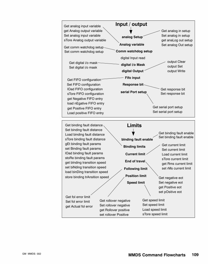
MMDS Command FlowchartsGM�MMDS�002 109
Input / output
analog Setup
Analog variable
digital Input read
digital i/o Mask
digital Output
Response bit
serial Port setup
Get analog in setupSet analog in setupget anaLog out setupSet analog Out setup
Get analog input variableget Analog output variable
Get comm watchdog setup
Get digital i/o maskSet digital i/o mask
output Clearoutput Setoutput Write
Get response bitSet response bit
Get serial port setupSet serial port setup
Fifo inputGet FIFO configurationSet FIFO configurationlOad FIFO configurationsTore FIFO configuration
get Positive FIFO entryLoad positive FIFO entry
get Negative FIFO entryload nEgative FIFO entry
Limits
bInding fault enable
Binding limits
Current limit
End of travel
Following limit
Position limit
Speed limit
Get binding fault enableSet binding fault enable
Get binding fault distanceSet binding fault distanceLoad binding fault distancesTore binding fault distancegEt binding fault paramsset Binding fault paramslOad binding fault paramsstoRe binding fault paramsget bInding transition speedset biNding transition speedload binDing transition speed
store binding trAnsition speed
Get current limitSet current limitLoad current limitsTore current limitget Rms current limitset rMs current limit
Get negative eotSet negative eotget Positive eotset pOsitive eot
Get fol error limitSet fol error limit Get rollover negative
Set rollover negativeget Rollover positiveset rollover Positive
Get speed limitSet speed limit
Comm watchdog setupSet comm watchdog setup
Set analog input variablesTore Analog output variable
get Actual fol errorLoad speed limitsTore speed limit

MMDS Command Flowcharts110110 GM�MMDS�002
mOdule
eeprom Writes counter
Format memory
memory Transfer
Module information
Self test
Motion
Continuous move
cuRrent
Home
Incremental move
Position
absolute move Negativeabsolute move negative (Reg)
Get adaptive feed modeSet adaptive feed modegEt adaptive feed paramsset Adaptive feed paramslOad adaptive feed paramsstoRe adaptive feed paramsget adaPtive feed profileload adaptiVe feed profile
Speed
adaptive Feed
absolute move Positiveabsolute move positive (reG)
continuous move Negativecontinuous move Positive
get Actual currentGet current profileLoad current profile
home Negativehome Positive
incremental move Negativeincremental move neg (Reg)incremental move Positiveincremental move pos (reG)get Actual speed
Load actual speedGet target speedloaD target speedSet speedstoRe speed
seT jog speed
get Actual positionLoad actual positioncalc taRget position
capture M/s positionget Commanded positionload commanded PositionSet positionsTore positionGet position trigger setupset posItion trigger setup
Absolute move
get Jog speed
get home switch placement Error
gEt target position
storE jog speedlOad Jog speed

MMDS Command FlowchartsGM�MMDS�002 111
moTor / feedback
program Flow
Base speed
Feedback
Motor
seCondary feedback
Servo config
Get base speedSet base speed
get feedBackGet feedback configSet feedback configget Feedback offsetset feedback Offsetget feedback Typeset feedback tYpe
Get motor directionSet motor directionget Motor polesset motor Polesget motor Typeset motor tYpe
Get feedback channelSet feedback channelget feedback Loss detectionset feedback loss Detection
Get servo configSet servo config
Branching / labels
Dwell / wait
Event flags
if Statements
InterruptsCancel all wheneverswhenever Expressionswhenever events - Andwhenever events - Orwhenever input (Rising edge)whenever input (Falling edge)
Equal toNot equal toGreater thangreater Than or equal toLess thanlesS than or equal to
Equal toNot equal toGreater thangreater Than or equal toLess thanlesS than or equal totest state - Andtest state - Or
Clear event flagsGet event flagsSet event flagsLoad event flagssTore event flags
Dwelldwell (Reg)
Wait andwait Or
goSubgosub (rEg)go Togo to (reG)LabelReturn
Drive enable parameters
commuTation setup
Get drive enable parametersSet drive enable parametersget Rapid decelset rapid deCel
Commutation setupGet mset parametersSet mset parameters
get Keyway offsetset keyWay offset
Keyway offset

MMDS Command Flowcharts112112 GM�MMDS�002
Programming
Register
Command buffer size
Control register
storeD program
Logical
Math
No operation
Shift operations
Timer control
User units
Fill register
Get register
Holding registers
Move register
Register block move
Autoboot programDelete program
End programget running Pgm number
Run programrun program (reG)
Store program
Get autoboot programSet autoboot program
Set control registerLoad control registersTore control register
get Accel / decel holding regset accel / Decel holding regget Position holding registerset position Holding registerGet speed holding registerSet speed holding register
Get command buffer sizeSet command buffer size
Andand (Reg)Oror (rEg)Xorxor (reG)Not (reg)
Addadd (Reg)Subtractsubtract (rEg)quick Multiplyquick multiply (reG)quick Dividequick diVide (reg)
Left shiftlEft shift (reg)Right shiftrIght shift (reg)
Get user unitsSet user units
Set timer control
Set register
Set registerset register as Positionset register as Velocityset register as Acceleration
Get registerget register as Positionget register as Velocityget register as Accelerationget register as master pOsitionget register as master vElocity
set register as master pOsitionset register as master vElocity
register eXchange

MMDS Command FlowchartsGM�MMDS�002 113
follower Ratio
master Positionand speed
sync Mode 1 cmds
sync-ratio Config
Sync ratio mode
Virtual speed
Get follower ratioSet follower ratioLoad follower ratiosTore follower ratio
Get master positionSet master positionLoad master positionsTore master position
Get sync ratio configSet sync ratio config
Get sync ratio modeSet sync ratio mode
get virtual Neg speedset Virtual neg speedloaD virtual neg speedstoRe virtual neg speedGet virtual pos speedSet virtual pos speedLoad virtual pos speedsTore virtual pos speed
point Lock
master Alignmentposition
slave alignmentPosition
slave Lockposition
Get master alignment positionSet master alignment positionLoad master alignment positionsTore master alignment position Get slave alignment position
Set slave alignment positionLoad slave alignment positionsTore slave alignment positionGet slave lock position
Set slave lock positionLoad slave lock positionsTore slave lock position
get master sPeed
master rOllovers
get master rollover Negativeset master rOllover negativeloaD master rollover negativestoRe master rollover negativeGet master rollover positiveSet master rollover positiveLoad master rollover positivesTore master rollover positive
master UnitsGet master unitsSet master units
Sync ratio
accel / Decel
Err correctn setup
maximum line Speed
% repeat Correction
repeat Length
sync-Adjust
get accel / decel Ratioset accel / Decel ratioget max Accelset Max accelGet max decelSet max decel
Get neg err correction setupset Neg err correction setupget Pos err correction setupSet pos err correction setup
Get max line speedSet max line speedLoad max line speedsTore max line speed
Get % repeat for correctionSet % repeat for correction
Get repeat lengthSet repeat lengthLoad repeat lengthsTore repeat length
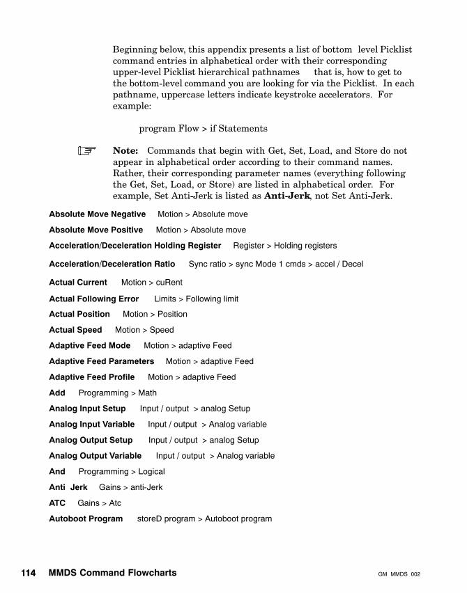
MMDS Command Flowcharts114114 GM�MMDS�002
Beginning below, this appendix presents a list of bottom�level Picklistcommand entries in alphabetical order with their correspondingupper-level Picklist hierarchical pathnames — that is, how to get tothe bottom-level command you are looking for via the Picklist. In eachpathname, uppercase letters indicate keystroke accelerators. Forexample:
program Flow > if Statements
Note: Commands that begin with Get, Set, Load, and Store do notappear in alphabetical order according to their command names.Rather, their corresponding parameter names (everything followingthe Get, Set, Load, or Store) are listed in alphabetical order. Forexample, Set Anti-Jerk is listed as Anti-Jerk, not Set Anti-Jerk.
Absolute Move Negative
Absolute Move Positive
Acceleration/Deceleration Holding Register
Acceleration/Deceleration Ratio
Actual Current
Actual Position
Actual Speed
Adaptive Feed Mode
Adaptive Feed Parameters
Adaptive Feed Profile
Add
Analog Input Setup
Analog Input Variable
Analog Output Setup
Analog Output Variable
And
Anti�Jerk
ATC
Autoboot Program
— Motion > Absolute move
— Motion > Absolute move
— Register > Holding registers
— Sync ratio > sync Mode 1 cmds > accel / Decel
— Motion > cuRent
— Motion > Position
— Motion > Speed
— Motion > adaptive Feed
— Motion > adaptive Feed
— Motion > adaptive Feed
— Programming > Math
— Input / output > analog Setup
— Input / output > Analog variable
— Input / output > analog Setup
— Input / output > Analog variable
— Programming > Logical
— Gains > anti-Jerk
— Gains > Atc
— storeD program > Autoboot program
Actual Following Error — Limits > Following limit

MMDS Command FlowchartsGM�MMDS�002 115
Backlash Gain Compensation
Base Speed
Binding Fault Distance
— Gains > Bands
— moTor / feedback > Base speed
— Limits > Binding limits
Binding Fault Enable
Binding Fault Parameters
Binding Transition Speed
Calculate Target Position
Cancel All Whenevers
— Limits > bInding fault enable
— Limits > Binding limits
— Limits > Binding limits
— Motion > Position
— program Flow > Interrupts
Capture M/S Position
Clear Event Flags
Comm Watchdog Setup
Command Buffer Size
Commanded Position
Commutation Setup
Continuous Move Negative
Continuous Move Positive
Control Register
Current Limit
Current Profile
Delete Program
Digital Input Read
Digital Input/Output Mask
Drive Enable Parameters
Dwell
— Motion > Position
— program Flow > Event flags
— Input / output > Comm watchdog setup
— Programming > Command buffer size
— Motion > Position
— moTor / feedback > commuTation setup
— Motion > Continuous move
— Motion > Continuous move
— Register > Control register
— Limits > Current limit
— Motion > cuRrent
— storeD program
— Input / output
— Input / output > digital i/o Mask
— moTor / feedback > Drive enable parameters
— program Flow > Dwell / wait
EEPROM Writes Counter
End Program
Equal To (if)
Equal To (whenever)
Error Log
Error Log Reset
— mOdule
— storeD program
— program Flow > if Statements
— program Flow > Interrupts > whenever Expressions
— Errors / faults
— Errors / faults
Event Flags — program Flow > Event flags

MMDS Command Flowcharts116116 GM�MMDS�002
Fault Clear
Fault Mask
Fault Read
Feedback
— Errors / faults
— Errors / faults > fault Mask
— Errors / faults
— moTor / feedback > Feedback
Feedback Channel
Feedback Configuration
Feedback Loss Detection
Feedback Offset
Feedback Type
FIFO Configuration
Fill Register
Follower Ratio
Following Error Band
Following Error Limit
Force User Fault
Format Memory
Gosub
Goto
Greater Than (if)
Greater Than (whenever)
Greater Than Or Equal To (if)
Greater Than Or Equal To (whenever)
Home Negative
Home Positive
Home Switch Placement Error
— moTor / feedback > seCondary feedback
— moTor / feedback > Feedback
— moTor / feedback > seCondary feedback
— moTor / feedback > Feedback
— moTor / feedback > Feedback
— Input / output > Fifo input
— Register
— Sync ratio > follower Ratio
— Gains > Bands
— Limits > Following limit
— Errors / faults
— mOdule
— program Flow > Branching / labels
— program Flow > Branching / labels
— program Flow > if Statements
— program Flow > Interrupts > whenever Expressions
— program Flow > if Statements
— program Flow > Interrupts > whenever Expressions
— Motion > Home
— Motion > Home
— Motion > Home
Incremental Move Negative — Motion > Incremental move
Incremental Move Positive
In�Position Band
Jog Speed
Keyway Offset
— Motion > Incremental move
— Gains > Bands
— Motion > Speed
— moTor / feedback > Keyway offset
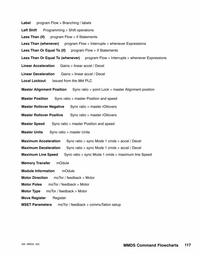
MMDS Command FlowchartsGM�MMDS�002 117
Label — program Flow > Branching / labels
Left Shift
Less Than (if)
Less Than (whenever)
Less Than Or Equal To (if)
Less Than Or Equal To (whenever)
Linear Acceleration
Linear Deceleration
Local Lockout
Master Position
Maximum Acceleration
Maximum Line Speed
Memory Transfer
Module Information
Motor Direction
Motor Poles
Motor Type
Move Register
MSET Parameters
— Programming > Shift operations
— program Flow > if Statements
— program Flow > Interrupts > whenever Expressions
— program Flow > if Statements
— program Flow > Interrupts > whenever Expressions
— Gains > linear accel / Decel
— Gains > linear accel / Decel
— Issued from the 984 PLC
— Sync ratio > master Position and speed
— Sync ratio > sync Mode 1 cmds > accel / Decel
— Sync ratio > sync Mode 1 cmds > accel / Decel
— Sync ratio > sync Mode 1 cmds > maximum line Speed
— mOdule
— mOdule
— moTor / feedback > Motor
— moTor / feedback > Motor
— moTor / feedback > Motor
— Register
— moTor / feedback > commuTation setup
Maximum Deceleration
Master Rollover Negative — Sync ratio > master rOllovers
Master Alignment Position — Sync ratio > point Lock > master Alignment position
Master Rollover Positive — Sync ratio > master rOllovers
Master Speed — Sync ratio > master Position and speed
Master Units — Sync ratio > master Units

MMDS Command Flowcharts118118 GM�MMDS�002
Negative EOT
Negative Error Correction Setup
Negative FIFO Entry
— Limits > End of travel
— Sync ratio > sync Mode 1 cmds > Err correctn setup
— Input / output > Fifo input
No Operation
Not (register)
Not Equal To (if)
Not Equal To (whenever)
Or
— Programming
— Programming > Logical
— program Flow > If Statements
— program Flow > Interrupts > whenever Expressions
— Programming > Logical
Output Clear
Output Set
Output Write
Percent Repeat for Correction
Position
Position Holding Register
Position Loop Deadband
Position Loop Integral Gain (PIG)
Position Trigger Setup
Positive EOT
Positive FIFO Entry
Program
Quick Divide
Quick Multiply
— Input / output > digital Output
— Input / output > digital Output
— Input / output > digital Output
— Sync ratio > sync Mode 1 cmds > % repeat Correction
— Motion > Position
— Register > Holding registers
— Gains > Bands
— Gains > pIg
— Motion > Position
— Limits > End of travel
— Sync ratio > sync Mode 1 cmds > Err correctn setup
— Input / output > Fifo input
— storeD program > Store program
— Programming > Math
— Programming > Math
Positive Error Correction Setup

MMDS Command FlowchartsGM�MMDS�002 119
Rapid Deceleration
Register
Register as Acceleration
Register as Position
Register as Velocity
Register Block Move
Repeat Length
— moTor / feedback > Drive enable parameters
— Register > (Get and Set) Register
— Register > (Get and Set) Register as Acceleration
— Register > (Get and Set) Register as Position
— Register > (Get and Set) Register as Velocity
— Register
— Sync ratio > sync Mode 1 cmds > repeat Length
Response Bit
Return
RIG
Right Shift
RMS Current Limit
— Input / output > Response bit
— program Flow > Branching / labels
— Gains > Rig
— Programming > Shift operations
— Limits > Current limit
Register as Master Position — Register > (Get and Set) Register as Master Position
Register as Master Velocity — Register > (Get and Set) Register as Master Velocity
Register Exchange — Register
Rollover Negative
Rollover Positive
RPG
Run Program
Running Program Number
— Limits > Position limit
— Limits > Position limit
— Gains > rPg
— storeD program
— storeD program > get running Pgm number

MMDS Command Flowcharts120120 GM�MMDS�002
Self Test
Serial Port Setup
Servo Configuration
Speed
Speed Holding Register
Subtract
Sync Adjust
Sync Ratio Configuration
Sync Ratio Mode
Target Speed
Test State
Timer Control
User Units
Velocity Feed Forward (VFF)
Velocity Mode Offset
Velocity Mode Scaling
— mOdule
— Input / output > serial Port setup
— moTor / feedback > Servo config
— Motion > Speed
— Register > Holding registers
— Limits > Speed limit
— Programming > Math
— Sync ratio > sync-Adjust
— Sync ratio > sync-ratio Config
— Sync ratio > Sync ratio mode
— Motion > Speed
— program Flow > if Statements
— Programming > Timer control
— Programming > User units
— Gains > Velocity params
— Gains > Velocity params
— Gains > Velocity params
Virtual Negative Speed
Virtual Positive Speed
Wait
Whenever Events
Whenever Input
— Sync ratio > Virtual speed
— Sync ratio > Virtual speed
— program Flow > Dwell / wait
— program Flow > Interrupts
— program Flow > Interrupts
Speed Limit
XOR — Programming > Logical
Slave Alignment Position — Sync ratio > point Lock > slave alignment Position
Slave Lock Position — Sync ratio > point Lock > slave Lock position
Target Position — Motion > Position
MMDS Error MessagesGM�MMDS�002 121
Appendix BMMDS Error Messages
The following table lists the error codes that may be displayed if anMMDS error occurs while you are using the MMDS. The full errormessages are provided on the following pages.
Note: Do not confuse these MMDS error messages with SASSexecutive errors.
See: The Single Axis Software System (SASS) Motion User Guide,GM-MOTN-001, for a list and description of SASS executive errors.

MMDS Error Messages122122 GM�MMDS�002
B.1 MMDS Error Codes
Error number Error
err_00 Invalid error code
err_01 Create project file error
err_02 Unused
err_03 Write project file error
err_04 Write to module file error
err_05 Close project file error
err_06 Read project file error
err_07 Cannot open source for compiler
err_08 Cannot open image for compiler
err_09 Cannot open list for compiler
err_10 Illegal internal pointer assignment
err_11 Create module file error
err_12 Compiler in use error
err_13 Hardware error
err_14 Illegal usage of a configuration file
err_15 Cannot make a file extension
err_16 Attempt to copy to a program that already exists
err_17 Illegal file named was entered
err_18 Too many files created (only 35 allowed)
err_19 Invalid data path
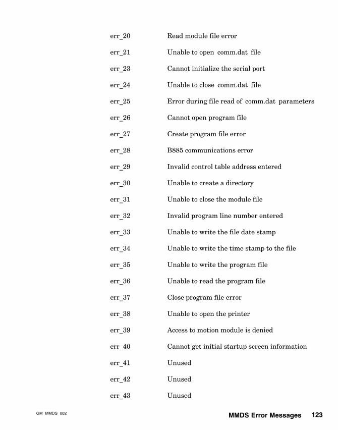
MMDS Error MessagesGM�MMDS�002 123
err_20 Read module file error
err_21 Unable to open ‘comm.dat’ file
err_23 Cannot initialize the serial port
err_24 Unable to close ‘comm.dat’ file
err_25 Error during file read of ‘comm.dat’ parameters
err_26 Cannot open program file
err_27 Create program file error
err_28 B885 communications error
err_29 Invalid control table address entered
err_30 Unable to create a directory
err_31 Unable to close the module file
err_32 Invalid program line number entered
err_33 Unable to write the file date stamp
err_34 Unable to write the time stamp to the file
err_35 Unable to write the program file
err_36 Unable to read the program file
err_37 Close program file error
err_38 Unable to open the printer
err_39 Access to motion module is denied
err_40 Cannot get initial startup screen information
err_41 Unused
err_42 Unused
err_43 Unused

MMDS Error Messages124124 GM�MMDS�002
err_44 Cannot allocate memory
err_45 Unable to copy the system configuration file
err_46 Cannot copy a given file
err_47 B984 communications error
err_48 Printer queue full
err_49 Unable to delete a given file
err_50 Project and module must be selected
err_51 Cannot find template file
err_52 No valid SET command in template file
err_53 Command not supported bit stuck
err_54 Module communication fault
err_55 Reference number out of range
err_56 Unable to log in to PLC
err_57 Unable to start PLC
err_58 Not enough registers in PLC
err_59 Invalid program step
err_60 Unable to disable normal I/O processing
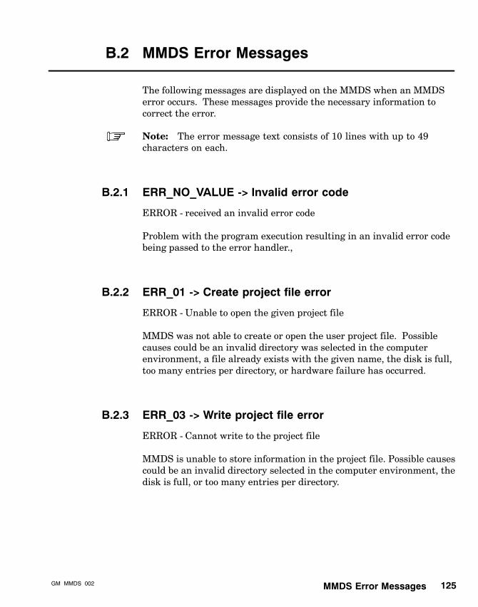
MMDS Error MessagesGM�MMDS�002 125
B.2 MMDS Error Messages
The following messages are displayed on the MMDS when an MMDSerror occurs. These messages provide the necessary information tocorrect the error.
Note: The error message text consists of 10 lines with up to 49characters on each.
B.2.1 ERR_NO_VALUE -> Invalid error code
ERROR - received an invalid error code
Problem with the program execution resulting in an invalid error codebeing passed to the error handler.,
B.2.2 ERR_01 -> Create project file error
ERROR - Unable to open the given project file
MMDS was not able to create or open the user project file. Possiblecauses could be an invalid directory was selected in the computerenvironment, a file already exists with the given name, the disk is full,too many entries per directory, or hardware failure has occurred.
B.2.3 ERR_03 -> Write project file error
ERROR - Cannot write to the project file
MMDS is unable to store information in the project file. Possible causescould be an invalid directory selected in the computer environment, thedisk is full, or too many entries per directory.

MMDS Error Messages126126 GM�MMDS�002
B.2.4 ERR_04 -> Write to module file error
ERROR - Cannot to write to the module file
MMDS is unable to store information in the module file. Possiblecauses could be an invalid directory selected in the computerenvironment, the correct PROJECT was not selected (from thePROJECT menu), or the disk is full.
B.2.5 ERR_05 -> Close project file error
ERROR - Unable to close the project file
Problems with writing data back to the project file. Possible causescould be an invalid directory selected in the computer environment, orthe disk is full.
B.2.6 ERR_06 -> Read project file error
ERROR - Cannot read data from the project file
Possible reasons: an invalid directory selected in the computerenvironment, project file no longer exists, data contained in the file wasaltered outside of MMDS, no project is active, or hardware failure hasoccurred.
B.2.7 ERR_07 -> Cannot open source for compiler
ERROR - Cannot open source file
The compiler was unable to access the user source file. Possible causescould be incorrect directory, file not present, data contained in the filewas altered, or hardware failure has occurred.

MMDS Error MessagesGM�MMDS�002 127
B.2.8 ERR_08 -> Cannot open image for compiler
ERROR - Cannot open image file
Problem with the given image file. Possible causes could be incorrectdirectory, file not present, or data contained in the file was altered.
B.2.9 ERR_09 -> Cannot open list for compiler
ERROR - Cannot create .LST file
Problem with opening the .LST listing file. Possible causes could be thedisk is full, too many entries per directory, hardware failure.
B.2.10 ERR_10 -> Illegal internal pointer assignment
ERROR � Illegal internal pointer assignment
Problems with software execution resulting in an illegal pointerassignment. Possible problems could be hardware failure, corruptedprogram data file.
B.2.11 ERR_11 -> Create module file error
ERROR - Unable to create the given module file
Possible reasons are: an invalid directory selected in the computerenvironment, the module file name already exists, the project file anddirectory no longer exist (they have been removed outside of MMDS), orhardware failure ha occurred.
B.2.12 ERR_12 -> Compiler in-use error
ERROR - Compiler currently in use
Program compiler is currently being used for some other purpose (e.g.print driver). Please resubmit request at a later time.

MMDS Error Messages128128 GM�MMDS�002
B.2.13 ERR_13 -> Hardware Error
”********** HARDWARE ERROR **********”
A hardware error of some type has occurred. Possible causes would bea disk drive door open, or use of an unformatted diskette.
B.2.14 ERR_14 -> Illegal Usage of a config file
ERROR - Illegal use of configuration file
An attempt has been made to copy or delete a module configuration file.These files are tied to the module file and may only be copied or deletedin conjunction with the module file.
B.2.15 ERR_15 -> Cannot make a file extension
ERROR - Unable to make a file extension.
Problem with the setup environment in attempting to create a fileextension. Possible cause could be an invalid extension name was given(must be alphanumeric only).
B.2.16 ERR_16 -> Attempt to copy to a program that alreadyexists
ERROR - File already exists
A program of the same name exists in some module of the destinationproject. The name of the program must be changed in order for theprogram to be copied successfully.

MMDS Error MessagesGM�MMDS�002 129
B.2.17 ERR_17 -> Illegal file name was entered
ERROR - Illegal file name
The file name must consist of 8 or less valid ASCII characters with nospaces, control characters, or any of the following:
? * . \” / \\ [ ] : |”, < > ; , + =”,
Note: This error may be generated by trying to select a programwithout an active project and/or an active module.
B.2.18 ERR_18 -> Too many files created ( only 35 allowed )
ERROR - Maximum number of files is 35.
Only 35 Projects, Modules, or Program files are allowed. A possiblesolution is to create another module under the same project.
B.2.19 ERR_19 -> Invalid Data Path
ERROR - An Invalid Data Path has been entered
Please choose a valid drive and a directory that exists, or use the DOSkey to create the desired directory.
B.2.20 ERR_20 -> Read module file error
ERROR - Cannot read data from the module file
Problems with reading the file containing the user module. Possiblecauses could be an invalid directory selected in the computerenvironment, the correct PROJECT was not selected (from thePROJECT menu), the file is not present, data contained in the file wasaltered.
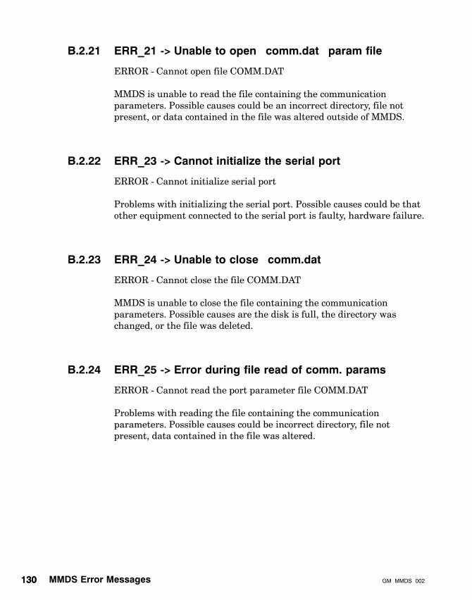
MMDS Error Messages130130 GM�MMDS�002
B.2.21 ERR_21 -> Unable to open ”comm.dat” param file
ERROR - Cannot open file COMM.DAT
MMDS is unable to read the file containing the communicationparameters. Possible causes could be an incorrect directory, file notpresent, or data contained in the file was altered outside of MMDS.
B.2.22 ERR_23 -> Cannot initialize the serial port
ERROR - Cannot initialize serial port
Problems with initializing the serial port. Possible causes could be thatother equipment connected to the serial port is faulty, hardware failure.
B.2.23 ERR_24 -> Unable to close ”comm.dat”
ERROR - Cannot close the file COMM.DAT
MMDS is unable to close the file containing the communicationparameters. Possible causes are the disk is full, the directory waschanged, or the file was deleted.
B.2.24 ERR_25 -> Error during file read of comm. params
ERROR - Cannot read the port parameter file COMM.DAT
Problems with reading the file containing the communicationparameters. Possible causes could be incorrect directory, file notpresent, data contained in the file was altered.

MMDS Error MessagesGM�MMDS�002 131
B.2.25 ERR_26 -> Cannot open the program file
ERROR - Unable to open the program file
MMDS cannot locate the necessary program(s). If you have selected anoption which requires an active program, there may not be anyprogram active (see top right of screen). If you are accessing data froma diskette, the wrong disk may be in the drive. Or, the program mayhave been deleted outside of the MMDS environment (using DOS).
B.2.26 ERR_27 -> Create program file error
ERROR - Unable to create the user program file
Possible causes of this error are that the disk being used to store data isfull, or that the file name selected already exists, either within thecurrent module or within another module in the current project.
B.2.27 ERR_28 -> Motion Module communications error
ERROR - Modbus communications fault
Problems with the communications to the Motion Module. Possiblecauses could be that the cable is not connected, the PLC is not running,problems with the PLC.
B.2.28 ERR_29 -> Invalid control table address entered
ERROR - Invalid Control Table Address
The Control Table would overlap the registers previously reserved forthe Input to the Module. Select a value greater than 6 registers pastthe Input to Module Address above, or 5 or more registers less than thebeginning of the Input to Module address (but not less than 40000).

MMDS Error Messages132132 GM�MMDS�002
B.2.29 ERR_30 -> Unable to create a directory
ERROR - Unable to create a new directory
Problem with the setup environment in attempting to create adirectory. Possible causes could be an invalid directory tree, or thedirectory already exits.
B.2.30 ERR_31 -> Unable to close the module file
ERROR - Unable to close the module file
Problems with writing data back to the module file. Possible causescould be an invalid directory selected in the computer environment, thecorrect PROJECT was not selected (from the PROJECT menu), thedisk is full.
B.2.31 ERR_32 -> Invalid program line number entered
ERROR - Invalid program line number entered
B.2.32 ERR_33 -> Unable to write the file date stamp
ERROR - Unable to write the file date
Problems with writing the file date stamp. Possible causes could bethat the disk is full, the directory was changed, or the file was deleted.
B.2.33 ERR_34 -> Unable to write the time stamp to the file
ERROR - Unable to write the file time stamp
Problems with writing the file time stamp. Possible causes could bethat the disk is full, the directory was changed, or the file was deleted.
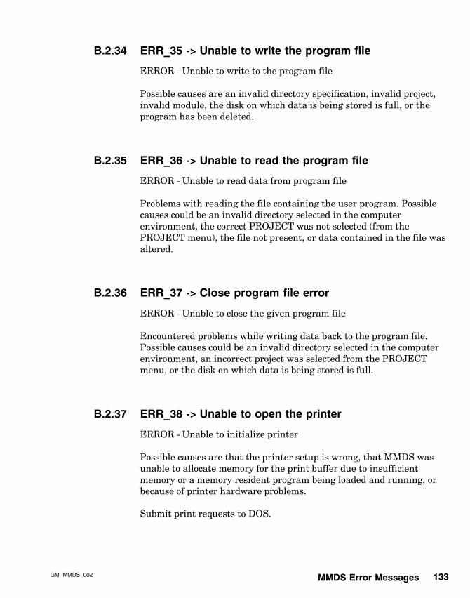
MMDS Error MessagesGM�MMDS�002 133
B.2.34 ERR_35 -> Unable to write the program file
ERROR - Unable to write to the program file
Possible causes are an invalid directory specification, invalid project,invalid module, the disk on which data is being stored is full, or theprogram has been deleted.
B.2.35 ERR_36 -> Unable to read the program file
ERROR - Unable to read data from program file
Problems with reading the file containing the user program. Possiblecauses could be an invalid directory selected in the computerenvironment, the correct PROJECT was not selected (from thePROJECT menu), the file not present, or data contained in the file wasaltered.
B.2.36 ERR_37 -> Close program file error
ERROR - Unable to close the given program file
Encountered problems while writing data back to the program file.Possible causes could be an invalid directory selected in the computerenvironment, an incorrect project was selected from the PROJECTmenu, or the disk on which data is being stored is full.
B.2.37 ERR_38 -> Unable to open the printer
ERROR - Unable to initialize printer
Possible causes are that the printer setup is wrong, that MMDS wasunable to allocate memory for the print buffer due to insufficientmemory or a memory resident program being loaded and running, orbecause of printer hardware problems.
Submit print requests to DOS.

MMDS Error Messages134134 GM�MMDS�002
B.2.38 ERR_39 -> Access to Motion Modes DENIED due toinsufficient speed
NOTICE - Access to Motion Modes is denied.
Your computer does not process information fast enough to allow safeoperation of the motion module from within MMDS. Refer to themanual for information on the minimum clock speed required for entryto Motion Modes.
B.2.39 ERR_40 -> Cannot GET initial startup screen info
ERROR - reading initial parameter info
Communications with the Motion Module have failed while reading theinitial parameter settings for display on the Startup screen.
B.2.40 ERR_43 -> General purpose internal system error
INTERNAL SYSTEM ERROR
Internal programming error - call the factory.
B.2.41 ERR_44 -> Cannot allocate memory
ERROR - Cannot allocate the system memory
The Personal Computer system does not have sufficient memoryavailable to run MMDS. Possible causes are that the computer is notequipped with enough memory, or that a memory-resident program isloaded and running.
B.2.42 ERR_45 -> Unable to copy the system Config file
ERROR - Unable to copy the default config file
Possible causes are removal of the system disk from the default drive,insufficient disk space, removal of the file sys_dflt.cfg from your MMDSdirectory, or MMDS is unable to find the path to the sys_dflt.cfg file.

MMDS Error MessagesGM�MMDS�002 135
B.2.43 ERR_46 -> Cannot Copy a given file
ERROR - Unable to copy program
Possible causes are that the destination module currently contains themaximum number of programs or that the destination module alreadycontains this program.
B.2.44 ERR_47 -> 984 communications error
ERROR - Modbus communications fault
Problems with the communications to the 984. Possible causes could bethat the cable is not connected, the PLC is not running, problems withthe PLC.
B.2.45 ERR_48 -> Printer Queue full
ERROR - Printer queue full
This function is being aborted because the printer queue has filled.Please submit request again at another time.
B.2.46 ERR_49 -> Unable to delete a given file
ERROR - Unable to delete the given file
Possible causes could be that an incorrect project was selected, themodule file is incorrect, the program file to be deleted does not exist, orthe module file to be changed may contain bad data.
B.2.47 ERR_50 -> Project and module must be selected
ERROR - Project and module must be selected
There must be a selected project and module into which a configurationfile or program file can be uploaded.

MMDS Error Messages136136 GM�MMDS�002
B.2.48 ERR_51 -> Cannot find template file
ERROR - Cannot find template file
The given template filename in the current project directory cannot belocated.
B.2.49 ERR_52 -> No valid SET commands in template file
ERROR - No valid SET commands in template file
There are no valid Set commands in the template file. Upload moduleconfiguration cannot be completed.
B.2.50 ERR_53 -> Command not supported bit stuck
ERROR - Command not supported bit stuck
Possible cause could be that the backplane is receiving illegalcommands from the PLC. Upload user parameter function cannot becompleted.
B.2.51 ERR_54 -> Module communication fault
ERROR - Module communication fault
There are problems with the communication to the motion module.MMDS is not receiving the expected echo from the module within thetimeout period. If communicating via the PLC, the module might havebeen removed from the I/O rack.
B.2.52 ERR_55 -> Reference number out of range
ERROR - Reference number out of range
The reference number for I/O map address for register to disablenormal I/O Processing is out of range.

MMDS Error MessagesGM�MMDS�002 137
B.2.53 ERR_56 -> Unable to log in to PLC
ERROR - Unable to log in to PLC
Another programming panel might have been logged in.
B.2.54 ERR_57 -> Unable to start PLC
ERROR - Unable to start PLC
The PLC might be memory-protected.
B.2.55 ERR_58 -> Not enough registers in PLC
ERROR - Not enough registers in PLC
The PLC does not have enough 4XXXX registers to store the motionprogram.
B.2.56 ERR_59 -> Invalid program step
ERROR - Invalid program step
Program execution terminated because of a syntax error in the programstep.
B.2.57 ERR_60 -> Unable to disable normal I/O processing
ERROR - Unable to disable normal I/O processing
User logic is overwriting the register used to disable normal I/Oprocessing.

Sample ProgramGM�MMDS�002 139
Appendix CSample Program
This appendix contains a generic program using one motion module toperform a peck drilling cycle.

Sample Program140140 GM�MMDS�002
To enter this sample program, first set the input and output masks to:
Data word 1 E100Data word 2 0000Data word 3 E7FFData word 4 FFFF
An illustration of what this program does appears at the end of thisappendix.
LINE NUMBER AND COMMAND VALUE REG.OFFSET VALUE
1 SET ACCEL 0 07F9
ACCEL RATE SET TO 50 REVS/SEC/SEC 50 1 0000
2 0032
3 0000
4 0000
2 SET DECEL 5 07FA
DECEL RATE SET TO 50 REVS/SEC/SEC 50 6 0000
7 0032
8 0000
9 0000
3 SET SPEED 10 0811
SET HOMING SPEED TO 5 RPS 50 11 0000
12 0005
13 0000
14 0000
4 HOME NEGATIVE 15 1791
HOME SYSTEM IN NEGATIVE POSITION 16 0000
17 0000
18 0000
19 0000
5 WAIT 20 0816
WAIT TIL MOTION IS IN�POSITION 0 21 0000
0 22 0000
1000 23 0000
24 0000
6 SET SPEED 25 0811
SET RAPID SPEED TO 25 RPS 26 0000
27 0019
28 0000
29 0000
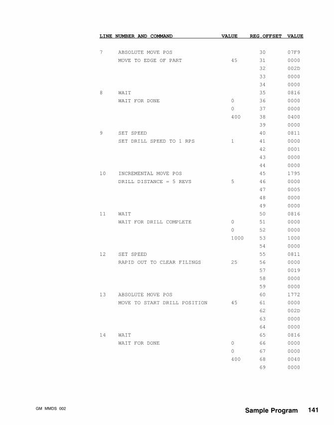
Sample ProgramGM�MMDS�002 141
LINE NUMBER AND COMMAND VALUE REG.OFFSET VALUE
7 ABSOLUTE MOVE POS 30 07F9
MOVE TO EDGE OF PART 45 31 0000
32 002D
33 0000
34 0000
8 WAIT 35 0816
WAIT FOR DONE 0 36 0000
0 37 0000
400 38 0400
39 0000
9 SET SPEED 40 0811
SET DRILL SPEED TO 1 RPS 1 41 0000
42 0001
43 0000
44 0000
10 INCREMENTAL MOVE POS 45 1795
DRILL DISTANCE = 5 REVS 5 46 0000
47 0005
48 0000
49 0000
11 WAIT 50 0816
WAIT FOR DRILL COMPLETE 0 51 0000
0 52 0000
1000 53 1000
54 0000
12 SET SPEED 55 0811
RAPID OUT TO CLEAR FILINGS 25 56 0000
57 0019
58 0000
59 0000
13 ABSOLUTE MOVE POS 60 1772
MOVE TO START DRILL POSITION 45 61 0000
62 002D
63 0000
64 0000
14 WAIT 65 0816
WAIT FOR DONE 0 66 0000
0 67 0000
400 68 0040
69 0000
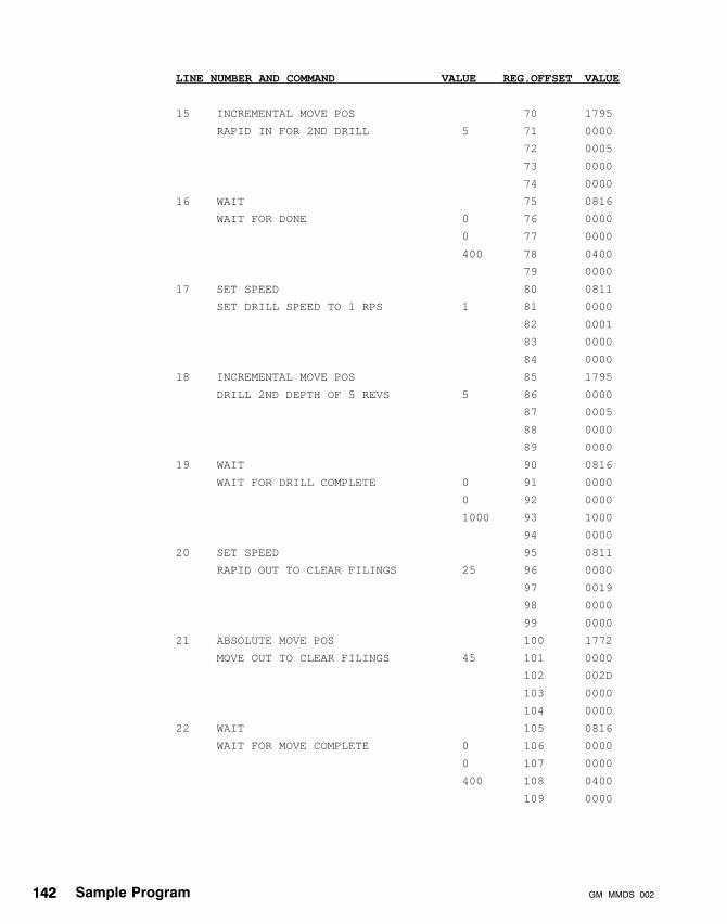
Sample Program142142 GM�MMDS�002
LINE NUMBER AND COMMAND VALUE REG.OFFSET VALUE
15 INCREMENTAL MOVE POS 70 1795
RAPID IN FOR 2ND DRILL 5 71 0000
72 0005
73 0000
74 0000
16 WAIT 75 0816
WAIT FOR DONE 0 76 0000
0 77 0000
400 78 0400
79 0000
17 SET SPEED 80 0811
SET DRILL SPEED TO 1 RPS 1 81 0000
82 0001
83 0000
84 0000
18 INCREMENTAL MOVE POS 85 1795
DRILL 2ND DEPTH OF 5 REVS 5 86 0000
87 0005
88 0000
89 0000
19 WAIT 90 0816
WAIT FOR DRILL COMPLETE 0 91 0000
0 92 0000
1000 93 1000
94 0000
20 SET SPEED 95 0811
RAPID OUT TO CLEAR FILINGS 25 96 0000
97 0019
98 0000
99 0000
21 ABSOLUTE MOVE POS 100 1772
MOVE OUT TO CLEAR FILINGS 45 101 0000
102 002D
103 0000
104 0000
22 WAIT 105 0816
WAIT FOR MOVE COMPLETE 0 106 0000
0 107 0000
400 108 0400
109 0000

Sample ProgramGM�MMDS�002 143
LINE NUMBER AND COMMAND VALUE REG.OFFSET VALUE
23 INCREMENTAL MOVE POS 110 1795
MOVE TO LAST DRILL POSITION 10 111 0000
112 000A
113 0000
114 0000
24 WAIT 115 0816
WAIT AT LAST DRILL POSITION 0 116 0000
0 117 0000
400 118 0400
119 0000
25 SET SPEED 120 0811
SET DRILL SPEED TO 1 RPS 1 121 0000
122 0001
123 0000
124 0000
26 INCREMENTAL MOVE POS 125 1795
LAST DRILL DEPTH 5 126 0000
127 0005
128 0000
129 0000
27 WAIT 130 0816
WAIT FOR DRILL COMPLETE 0 131 0000
0 132 0000
1000 133 1000
134 0000
28 OUTPUT SET 135 0803
TURN ON OUTPUT 1 (FULL DEPTH) 8000 136 8000
0 137 0000
138 0000
139 0000
29 DWELL 140 07E1
DELAY 1.5 SECONDS 1500 141 0000
142 05DC
143 0000
144 0000
30 OUTPUT CLEAR 145 0802
TURN OFF OUTPUT 1 (FULL DEPTH) 8000 146 8000
0 147 0000
148 0000
149 0000

Sample Program144144 GM�MMDS�002
LINE NUMBER AND COMMAND VALUE REG.OFFSET VALUE
31 SET SPEED 150 0811
RAPID RETURN SPEED 25 151 0000
152 0019
153 0000
154 0000
32 ABSOLUTE MOVE POS 155 1772
MOVE TO HOME POSITION 0 156 0000
157 0000
158 0000
159 0000
33 WAIT 160 0816
WAIT TIL IN�POSITION 0 161 0000
0 162 0000
1000 163 1000
164 0000
34 OUTPUT SET 165 0803
TURN ON CYCLE COMPLETE 4000 166 4000
0 167 0000
168 0000
169 0000
35 DWELL 170 07E1
WAIT 1 SEC 1000 171 0000
172 03E8
173 0000
174 0000
36 OUTPUT CLEAR 175 0803
TURN OFF CYCLE COMPLETE 4000 176 4000
0 177 0000
178 0000
179 0000
This program, a peck drilling cycle, is illustrated in the figure on thenext page.
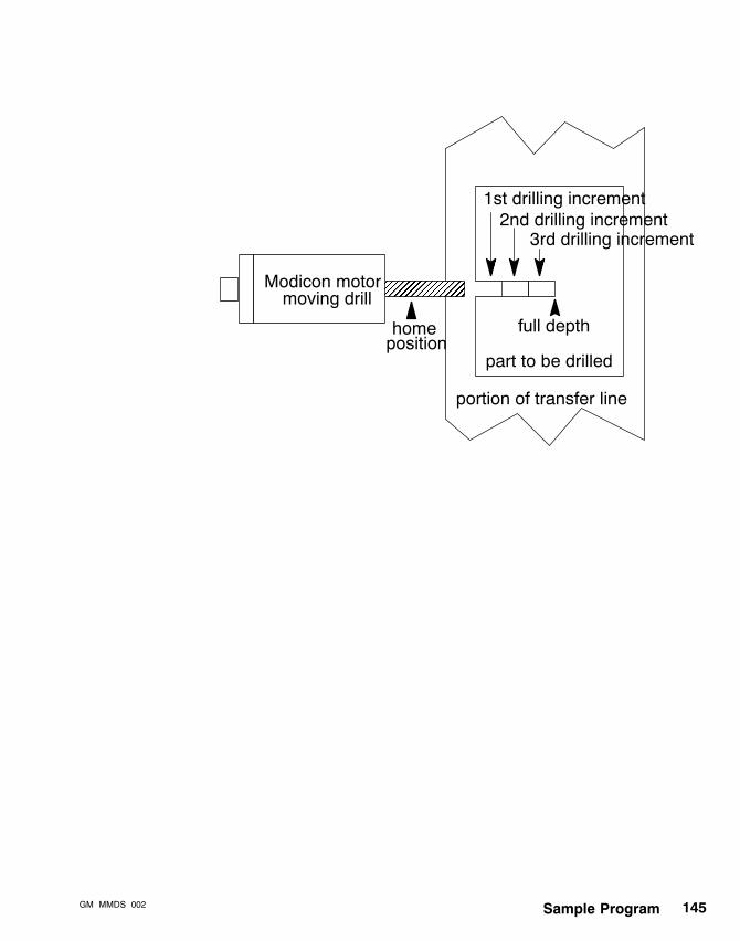
Sample ProgramGM�MMDS�002 145
homeposition
1st drilling increment2nd drilling increment
3rd drilling increment
full depth
part to be drilled
portion of transfer line
Modicon motormoving drill

IndexGM�MMDS�002 147
Index
AAddress, Modbus, 41Advantages of MMDS, 13Autoboot, 103
BBackplane, communicating over, 38, 75Baudrate, 40Bridge
Bridge Mux, 40Modbus Plus, 38, 75PLC/backplane, 75
CCodes, error, 121Comm Watchdog Setup, 76Command Flowcharts, Sync Ratio Modes,
113Commands, MMDS flowcharts, 107Communications
backplane, 38, 75baudrate, 40bridge, 38, 75Comm Watchdog Setup, 76data bits, 40device, 40direct connect, 75Modbus, 38Modbus address, 41Modbus Mode, 40parameters, 39parity, 40PLC, 75PLC/backplane registers, 75setup, 38stop bits, 40when communication stops, 79
Computer Setup Menu, 36Configuration .CFG file
creating, 54overview, 18reading and executing, 106
Configuration Edit Menu, 65Configuration file editor, 65Contents of manual, 4Control/Status Window, 86Control/Status Window (Execute Mode), 92Control/Status Window (Single Step), 89Conventions, typographical, 7Copy (module development) functions, 68Copy (program development) functions, 70Create Configuration File Menu, 54Create Module Menu, 52Create Project Menu, 50Creating
a module, 52a program, 56a project, 49
DData bits, 40Delete (module development) functions, 68Delete (program development) functions, 70Deleting programs, 102Device, communications, 40Display, screen, 20Documentation .DMT file, 18Downloading
to motion module, 102, 104to PLC, 100
EEase-of-use features, 14Edit (module development) functions, 68Editing
a configuration file, 66a program, 58
EditorConfiguration file, 65Program, 62
Error messages, 121Execute Mode Menu, 91Executing and reading .CFG files, 106Exiting Motion Mode, 94

GM�MMDS�002Index148
FFeatures, overview, 14File Transfers Menu
downloading to 984 PLC, 100downloading to motion module, 102hierarchy of submenus, 98introduction, 97uploading from motion module, 102
Files, MMDS.CFG configuration file, 18, 54.DMT documentation file, 18.IMG image file, 19.LST list file, 19.MOD module file, 17.PGM program file, 18.PRJ project file, 17downloading from motion module, 102downloading to 984 PLC, 100overview, 17reading and executing .CFG files, 106uploading from motion module, 102
Flowcharts, MMDS command, 107Function block, MRTM, 53Functions
984 PLC downloading, 100Communications Setup Menu, 39Computer Setup Menu, 37Configuration Editor Menu, 67Create Module Menu, 52Create Project Menu, 50Execute Mode Menu, 92File Transfers Menu, 99Help screens, 32Immediate Mode Menu, 86Main Menu, 28MMDS Setup Menu, 35Module Development Menu, 52Motion Mode Menu, 77motion module downloading, 104motion module uploading, 103Print Options Menu, 72Printer Setup Menu, 42Program Development Menu, 57Program Edit Menu, 63Project Development Menu, 49Project Manager Menu, 47
SHIFT and ALT, 30Single Step Mode Menu, 89Startup Mode Menu, 83
HHard disk installation, 24Hazards and warnings, 8Help screens, 32Hierarchy
of File Transfers submenus, 98of MMDS Setup submenus, 34of MMDS submenus, 30of MMDS work environment, 16of Motion Mode submenus, 74of Project Manager submenus, 46Picklist command pathnames, 114
How to use manual, 4
IImage .IMG file, 19Immediate Mode Menu, 85Initializing MMDS, 21, 26Installation on hard disk, 24Installing MMDS, 21, 22Introduction to manual, 1
LList .LST file, 19Local lockout (establishing master), 79
MMain Menu, 27Manual
contents, 4how to use, 4introduction, 1related publications, 5typographical conventions, 7who should use, 3
Master, establishing (local lockout), 79Menus
Communications Setup Menu, 38Computer Setup Menu, 36Configuration Edit Menu, 65Create Configuration File, 54

IndexGM�MMDS�002 149
Create Module Menu, 52Create Project Menu, 50Execute Mode Menu, 91File Transfers Menu, 97hierarchy of, 30Immediate Mode Menu, 85Main Menu, 27MMDS Setup Menu, 33Module Development Menu, 52Motion Mode Menu, 73Print Options Menu, 71Printer Setup Menu, 42Program Development Menu, 56Program Edit Menu, 58Project Development Menu, 49Project Manager Menu, 45Single Step Mode Menu, 88Startup Mode Menu, 80
Miscellaneous Information Window, 82MMDS
advantages, 13command flowcharts, 107definition, 2ease-of-use features, 14error messages, 121features, 14file structure, 17File Transfers, 97Help screens, 32hierarchy of submenus, 30hierarchy of work environment, 16initializing, 21, 26installing, 21, 22introduction, 1Main Menu, 27module uploading, 105Motion Mode, 73overview, 11Project Manager, 45related publications, 5system requirements, 22typical screen display, 20
MMDS Setup MenuCommunications Setup Menu, 38Computer Setup Menu, 36functions, 35
hierarchy, 34introduction, 33Printer Setup Menu, 42
Modbus mode, 40Modbus Plus bridge, 38, 75Module .MOD file, 17Module development, 52Module development functions, 68
edit, copy, view, delete, 68Module Development Menu, 52Modules, MMDS, uploading, 105Motion Control Window, 81Motion Mode Menu
Execute Mode Menu, 91exiting, 94functions, 77hierarchy of submenus, 74Immediate Mode Menu, 85introduction, 73local lockout (establishing master), 79Single Step Mode Menu, 88Startup Mode Menu, 80
Motion moduledownloading and uploading programs,
102uploading MMDS modules from, 105
MRTM, function block, 53
NNetworking. See Communications
OOverview
Main Menu, 27of easy-to-use features, 14of MMDS, 11screen display, 20
PParameters, communications, 39Parity, 40Pathnames, Picklist command, 114Picklist
command flowcharts, 107command pathnames, 114overview, 59, 85

GM�MMDS�002Index150
Picklist window, 85PLC
bridge, 75downloading to 984, 100
Print Options Menu, 71Printer Setup Menu, 42Program
autoboot, 103deleting, 102development, 56development functions, copy, view, delete,
70editing, 61sample, 139
Program .PGM file, 18Program Development Menu, 56Program Edit Menu, 58Program Editor, 62Program window, 59, 62Program Window (Execute Mode), 91Program Window (Single Step), 88Project .PRJ file, 17Project Manager Menu
Configuration Edit Menu, 65Create Configuration File Menu, 54Create Module Menu, 52Create Project Menu, 50functions, 47hierarchy of submenus, 46introduction, 45Module Development Menu, 52Print Options Menu, 71Program Development Menu, 56Program Edit Menu, 58Project Development Menu, 49
Project structure, hierarchy, 16Publications, related, 5
RReading and executing .CFG files, 106Registers for PLC/backplane communication,
75Related publications, 5Requirements, system, 22
SSample program, 139SASS commands, 107Screen display, overview, 20Servo Control Window, 82Setup Menu. See MMDS Setup MenuSetup, MMDS, 33SHIFT and ALT functions, 30Single Step Mode Menu, 88Starting MMDS, 26Startup Mode Menu, 80Stop bits, 40Submenus, MMDS, 30System requirements, 22System Status Window, 81
TTo Module Window, 86Typographical conventions, 7
UUploading
MMDS modules, 105programs from motion module, 103
Uploading from motion module, 102
VView (module development) functions, 68View (program development) functions, 70
WWarnings and hazards, 8What is MMDS?, 2Who should use manual, 3Windows
Configuration Editor, 66Control/Status Window, 86Control/Status Window (Execute Mode),
92Control/Status Window (Single Step), 89Picklist, 85Program Editor, 63Program Window (Execute Mode), 91

IndexGM�MMDS�002 151
Program Window (Single Step), 88Startup Mode, 81To Module Window, 86
Work environment, MMDS hierarchy, 16