
WOW! Software
48
Translation of the original operating instructions 2184-ENG V.201508 Operating Instructions as of 5.00.9 WOW! Software
-
Upload
khangminh22 -
Category
Documents
-
view
0 -
download
0
Transcript of WOW! Software

Translation of the original operating instructions
2184-ENG V.201508
Operating Instructions as of 5.00.9
WOW! Software
1-1Contents
Inhalt
1 Program Settings ............................................................................................................................................................. 21.1 Program ................................................................................................................................................................................21.2 Devices ..................................................................................................................................................................................41.3 Program functions ........................................................................................................................................................ 101.4 Interfaces ........................................................................................................................................................................... 141.5 WOW! software registration and enabling ......................................................................................................... 16
2 Program Overview ...................................................................................................................................................... 192.1 User interface overview ............................................................................................................................................... 192.2 Button description .......................................................................................................................................................... 202.3 Fault report ....................................................................................................................................................................... 23
3 Vehicle Selection ........................................................................................................................................................... 244 Diagnostic Functions .................................................................................................................................................. 274.1 EOBD diagnosis .............................................................................................................................................................. 274.2 Serial OBD Diagnosis ................................................................................................................................................... 304.3 Flight recorder ................................................................................................................................................................. 32
5 Technical Data and Inspection ........................................................................................................................... 366 Flat Rate Units ............................................................................................................................................................... 397 iQ memory ........................................................................................................................................................................ 42
2-3 Program Settings
1 Program Settings
1.1 Program
General settings
Keyboard settings When using a computer with a touchscreen monitor you can overlay a visual keyboard once you have clicked in an input box.Set the check/tick symbol to activate this function.
Printer settingsThe WOW! software uses the operating system's printer settings as standard.Activate menu in print preview
Use changed settings
ViewDisplay data in new index cardIf the function is activated, all the function selections are opened in a new tab window. If the function is deactivated, the current tab window is filled with new information.
Proxy settingsIf your computer is integrated in an internal, closed network, you may have to provide details of a proxy server to be able to establish a network connection. Contact your network administrator to configure the settings.Enter the data in the corresponding boxes.
Company dataHere you can enter and edit your contact details for registering the WOW! software. Client number and Contact person cannot be changed; they are a fixed integral part of the WOW! software registration.
If you have made changes, you must confirm them with Save.
Chapter contents
1.1 Program ................................................................................................................................................................................ 2General settings ......................................................................................................................................................................... 2Company data ............................................................................................................................................................................ 2Management of mechanics ........................................................................................................................................................ 3Version overview ........................................................................................................................................................................ 3Registration ................................................................................................................................................................................ 3Workshop data ........................................................................................................................................................................... 3
3-3Program Settings
Management of mechanicsThe names of the mechanics who are authorised to carry out an exhaust-emission test are specified here. The names entered here can be selected when the vehicle data are input for the exhaust-emission test and can thus be quickly selected and accepted.
To enter a new testing mechanic, click on New. Enter the name in the box that appears and confirm with Save. To change an already existing entry, highlight this entry and click on Edit. Accept the changes with Save.
Version overviewInformation on the current version of the WOW! software.
RegistrationHere you manage the WOW! software registration. Enhancements can easily be ordered from the shop (arrow to the right). See “1.5 software registration and enabling page 16”
Workshop dataHere you can enter or edit your company address and contact details. These details are used on the printout, Exhaust-emission test certificate, of the exhaust-emission test.To edit the contact details, click on Edit. If you have made changes, you must confirm them with Save.

4-5 Program Settings
1.2 Devices
Device setting
WGA3 device setting Program settings > Devices > Device settings > WGA3
WGA 3 boxcode:The BOXCODE is the identification number for the Blue-tooth connection setup. Read off the BOXCODE 1 on the WGA3 nameplate and enter in box 2 .
Please always enter all the digits without blanks of the BOXCODE, including the leading 0.
WGA3 device numberThe device number is relevant to registration and must be entered in the program.Read off the device number (Serial No.) on the WGA3 nameplate and enter in box 3 .
Replace firmwareThe firmware is the operating system of the WGA3.
The firmware should only be loaded by an authorised service technician.Procedure:
Enter the password: 7940 in box 4 and click on Replace firmware.The connection to the WGA3 is established.The procedure is described in the program run. The update procedure must be controlled via the WGA3 control panel.
Follow the instructions in the program and in the WGA3 display.
1
3
4
2
Chapter contents
1.2 Devices ................................................................................................................................................................................. 4Device setting ............................................................................................................................................................................. 4DTB device setting ..................................................................................................................................................................... 5E-Box device setting .................................................................................................................................................................. 5WDA3 Mobile device setting ...................................................................................................................................................... 6Device setting - Snooper (diagnostic box) ................................................................................................................................. 6Exhaust-emission test ................................................................................................................................................................ 7Device selection ......................................................................................................................................................................... 7Maintenance ............................................................................................................................................................................... 8Carrying out maintenance on the measuring devices ................................................................................................................ 8
5-5Program Settings
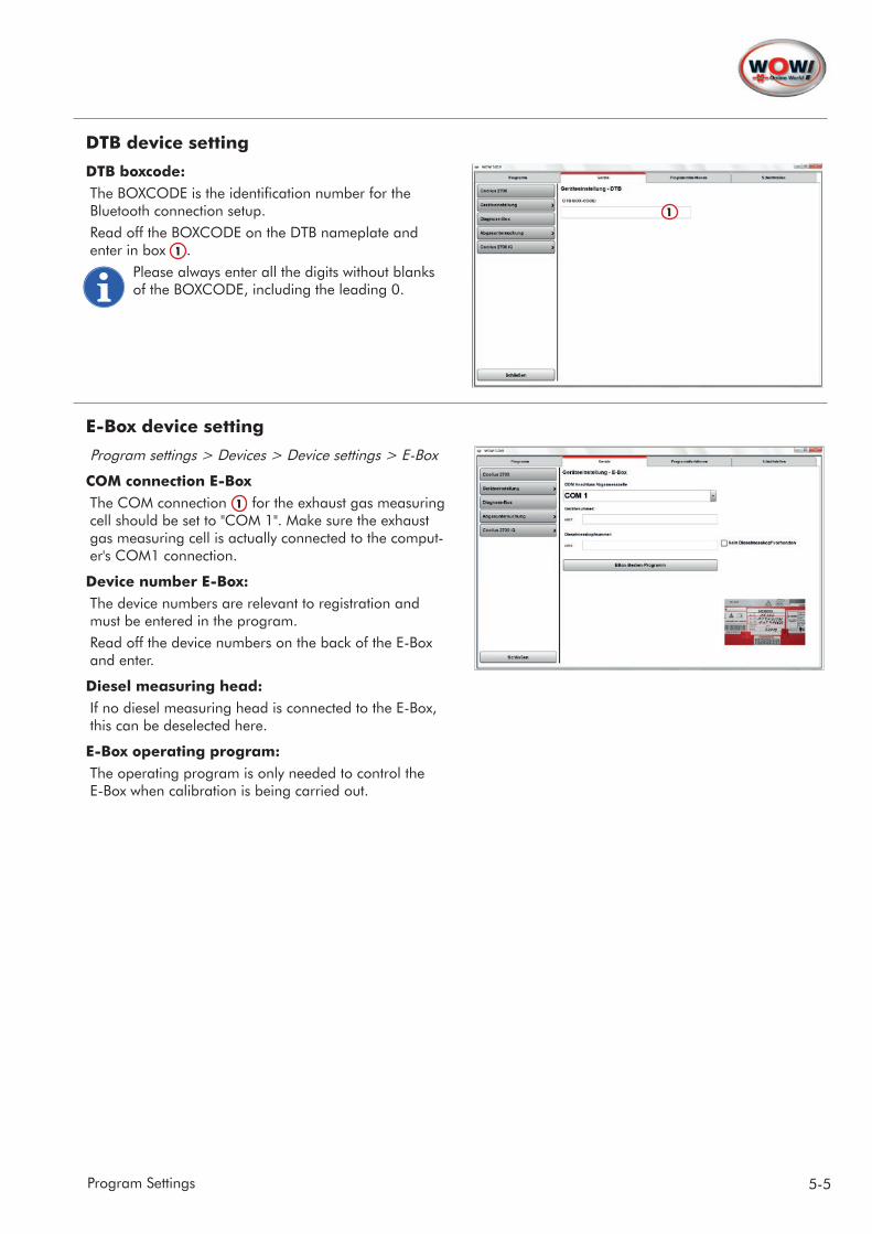
DTB device setting
DTB boxcode:The BOXCODE is the identification number for the Bluetooth connection setup. Read off the BOXCODE on the DTB nameplate and enter in box 1 .
Please always enter all the digits without blanks of the BOXCODE, including the leading 0.
E-Box device setting
Program settings > Devices > Device settings > E-Box
COM connection E-BoxThe COM connection 1 for the exhaust gas measuring cell should be set to "COM 1". Make sure the exhaust gas measuring cell is actually connected to the comput-er's COM1 connection.
Device number E-Box:The device numbers are relevant to registration and must be entered in the program.Read off the device numbers on the back of the E-Box and enter.
Diesel measuring head:If no diesel measuring head is connected to the E-Box, this can be deselected here.
E-Box operating program:The operating program is only needed to control the E-Box when calibration is being carried out.
1

6-9 Program Settings
2
WDA3 Mobile device setting
Program settings > Devices > Device settings > WDA3 Mobile
WGA 3 boxcode:The BOXCODE is the identification number for the Bluetooth connection setup. Read off the BOXCODE 1 on the WDA3 Mobile nameplate and enter in box 2 .
Please always enter all the digits without blanks of the BOXCODE, including the leading 0.
WGA3 device numberThe device number is relevant to registration and must be entered in the program.Read off the device number (Serial No.) on the WGA3 nameplate and enter in box 3 .
Device setting - Snooper (diagnostic box)
Program settings > Devices > Device settings > Snooper
Type of diagnostic boxSelecting the used Snooper diagnostic box.1. Select the used diagnostic box in the drop-down
box 1 .2. Click on Find 2 .
The connection wizard is launched. The application is described in detail in the program run. Please read and follow the instructions.
3. Connect the Snooper to the vehicle.
Note!
Connection to the Snooper device can be set-up using a USB cable or Bluetooth. If only the Bluetooth connection is to be used, skip the first step describing the USB connection 1 .
4. Confirm the instructions in the program in each case with Continue.
21
1
7-9Program Settings
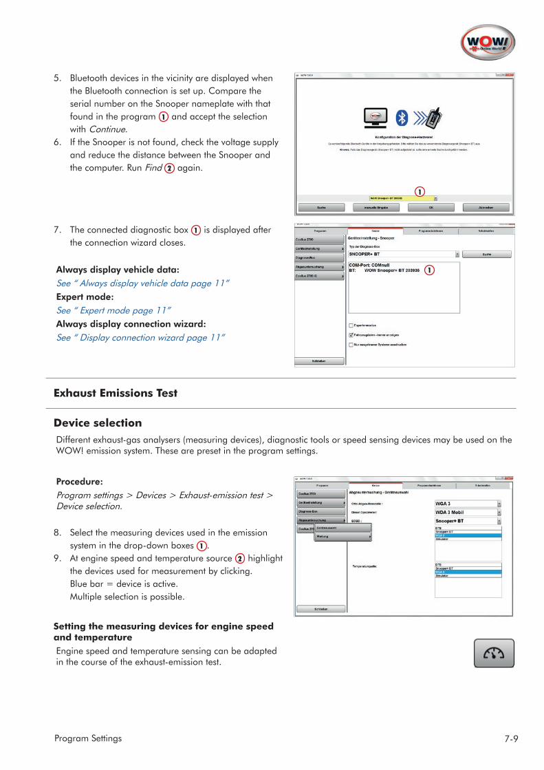
5. Bluetooth devices in the vicinity are displayed when the Bluetooth connection is set up. Compare the serial number on the Snooper nameplate with that found in the program 1 and accept the selection with Continue.
6. If the Snooper is not found, check the voltage supply and reduce the distance between the Snooper and the computer. Run Find 2 again.
7. The connected diagnostic box 1 is displayed after the connection wizard closes.
Always display vehicle data:See “ Always display vehicle data page 11”Expert mode:See “ Expert mode page 11”Always display connection wizard:See “ Display connection wizard page 11”
Exhaust Emissions Test
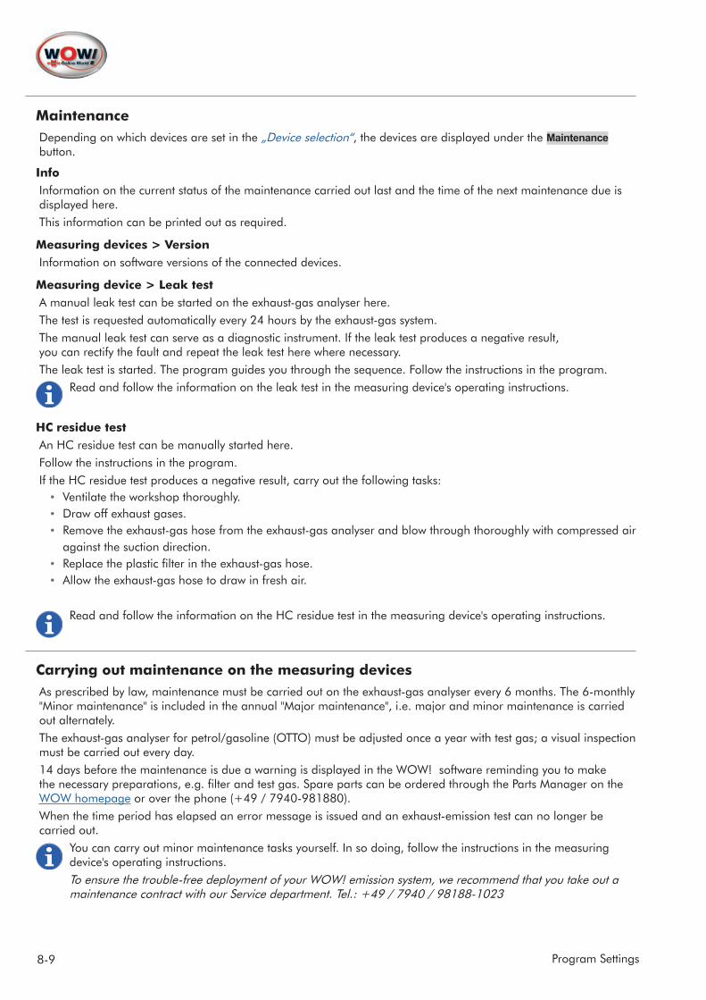
Device selectionDifferent exhaust-gas analysers (measuring devices), diagnostic tools or speed sensing devices may be used on the WOW! emission system. These are preset in the program settings.
Procedure:Program settings > Devices > Exhaust-emission test > Device selection.
8. Select the measuring devices used in the emission system in the drop-down boxes 1 .
9. At engine speed and temperature source 2 highlight the devices used for measurement by clicking. Blue bar = device is active. Multiple selection is possible.
Setting the measuring devices for engine speed and temperatureEngine speed and temperature sensing can be adapted in the course of the exhaust-emission test.
1
1
1
2
8-9 Program Settings
MaintenanceDepending on which devices are set in the „Device selection“, the devices are displayed under the Maintenance button.
InfoInformation on the current status of the maintenance carried out last and the time of the next maintenance due is displayed here. This information can be printed out as required.
Measuring devices > VersionInformation on software versions of the connected devices.
Measuring device > Leak testA manual leak test can be started on the exhaust-gas analyser here. The test is requested automatically every 24 hours by the exhaust-gas system. The manual leak test can serve as a diagnostic instrument. If the leak test produces a negative result, you can rectify the fault and repeat the leak test here where necessary. The leak test is started. The program guides you through the sequence. Follow the instructions in the program.
Read and follow the information on the leak test in the measuring device's operating instructions.
HC residue testAn HC residue test can be manually started here. Follow the instructions in the program.If the HC residue test produces a negative result, carry out the following tasks:
• Ventilate the workshop thoroughly.• Draw off exhaust gases.• Remove the exhaust-gas hose from the exhaust-gas analyser and blow through thoroughly with compressed air
against the suction direction.• Replace the plastic filter in the exhaust-gas hose.• Allow the exhaust-gas hose to draw in fresh air.
Read and follow the information on the HC residue test in the measuring device's operating instructions.
Carrying out maintenance on the measuring devicesAs prescribed by law, maintenance must be carried out on the exhaust-gas analyser every 6 months. The 6-monthly "Minor maintenance" is included in the annual "Major maintenance", i.e. major and minor maintenance is carried out alternately.The exhaust-gas analyser for petrol/gasoline (OTTO) must be adjusted once a year with test gas; a visual inspection must be carried out every day.14 days before the maintenance is due a warning is displayed in the WOW! software reminding you to make the necessary preparations, e.g. filter and test gas. Spare parts can be ordered through the Parts Manager on the WOW homepage or over the phone (+49 / 7940-981880). When the time period has elapsed an error message is issued and an exhaust-emission test can no longer be carried out.
You can carry out minor maintenance tasks yourself. In so doing, follow the instructions in the measuring device's operating instructions.To ensure the trouble-free deployment of your WOW! emission system, we recommend that you take out a maintenance contract with our Service department. Tel.: +49 / 7940 / 98188-1023
9-9Program Settings
Minor maintenanceThe minor maintenance sequence is described in detail in the WOW! software; read and follow the information and help texts.Carry out the maintenance operations described in the WOW! software and in the measuring device's operating instructions.A test certificate is generated for printing out once maintenance has been successfully completed. Print this test certificate and keep it safe for future reference.
Major maintenance The test gas adjustment sequence is described in detail in the WOW! software; read and follow the information and help texts.
Important! Major maintenance may only be carried out by authorised persons so as to avoid damage to the measuring devices! Access to Major maintenance is therefore password-protected.Password: Major maintenance: 7940
Carry out the maintenance operations as described in the measuring device's operating instructions.A test certificate is generated for printing out once test gas adjustment has been successfully completed. Print this certificate and keep it safe for future reference.
!
10-10 Program Settings
1.3 Program functions
Vehicle selection
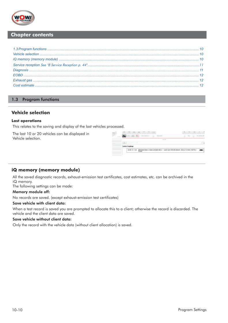
Last operations This relates to the saving and display of the last vehicles processed.
The last 10 or 20 vehicles can be displayed in Vehicle selection.
iQ memory (memory module)All the saved diagnostic records, exhaust-emission test certificates, cost estimates, etc. can be archived in the iQ memory. The following settings can be made:Memory module off: No records are saved. (except exhaust-emission test certificates)Save vehicle with client data:When a test record is saved you are prompted to allocate this to a client; otherwise the record is discarded. The vehicle and the client data are saved.Save vehicle without client data:Only the record with the vehicle data (without client allocation) is saved.
Chapter contents
1.3 Program functions .............................................................................................................................................................. 10Vehicle selection ...................................................................................................................................................................... 10iQ memory (memory module) .................................................................................................................................................. 10
Service reception See "8 Service Reception p. 44" ..............................................................................................................11Diagnosis ................................................................................................................................................................................. 11EOBD ....................................................................................................................................................................................... 12Exhaust gas ............................................................................................................................................................................. 12Cost estimate ........................................................................................................................................................................... 12

11-13Program Settings
Service reception See “8 Service Reception page 44”
Database for products and additional servicesThe data which can be selected in the sequence of the service reception checklists are managed here.Products and services are already stored in the data-bases. The prices for the individual products and addi-tional services can be adapted to your own prices.Procedure:Highlight the data record you would like to edit and then enter your own price. Click on Save to accept the data record.
DiagnosisProgram settings connected with vehicle diagnosis.
Always display vehicle dataWhen the test record is printed a dialogue window is displayed in which you can enter the vehicle data.
Print out only read-out systems In the system scan you are asked which systems are installed in the vehicle; if this setting is checked/ticked, only those systems which have also read out and an-swered are shown in the printout.
Expert modeExpert mode offers you the opportunity to select diagnostic records for the systems yourself. This can be used when related systems are installed in different vehicles which are not yet tested and released.
Important! When using "All systems" it is possible to select the type of connection to the installed system yourself; the displayed results may be incorrect!
Important! In the interests of avoiding damage to control units caused by incorrect operation, the Coding and Calibration functions are not accessible in Expert mode.
Set the check/tick symbol to activate Expert mode. See “ Expert mode: page 7”Note: Expert mode switches off automatically when the program is restarted!
Display connection wizardThe connection wizard is displayed before each connection setup to the vehicle. This contains handling and safety instructions which must be followed when the connection to the vehicle is set up.
Important! The connection wizard should only be deactivated by trained experts. We shall not be liable for damage caused by failure to follow the instructions!
!
!
!
12-13 Program Settings
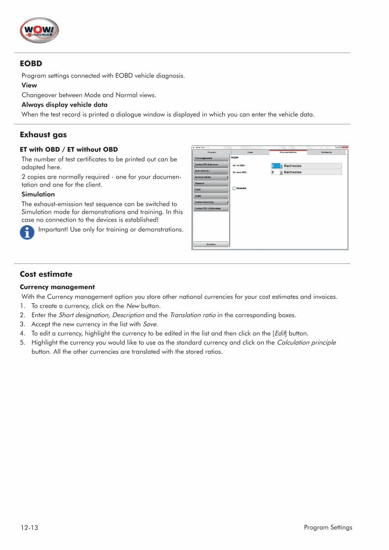
EOBDProgram settings connected with EOBD vehicle diagnosis.ViewChangeover between Mode and Normal views.Always display vehicle dataWhen the test record is printed a dialogue window is displayed in which you can enter the vehicle data.
Exhaust gas
ET with OBD / ET without OBDThe number of test certificates to be printed out can be adapted here. 2 copies are normally required - one for your documen-tation and one for the client.SimulationThe exhaust-emission test sequence can be switched to Simulation mode for demonstrations and training. In this case no connection to the devices is established!
Important! Use only for training or demonstrations.
Cost estimate
Currency managementWith the Currency management option you store other national currencies for your cost estimates and invoices.1. To create a currency, click on the New button.2. Enter the Short designation, Description and the Translation ratio in the corresponding boxes. 3. Accept the new currency in the list with Save.4. To edit a currency, highlight the currency to be edited in the list and then click on the [Edit] button.5. Highlight the currency you would like to use as the standard currency and click on the Calculation principle
button. All the other currencies are translated with the stored ratios.
13-13Program Settings
Cost estimate settingsHere you define your hourly cost rates and the applicable value-added tax. These settings are taken into account in the flat rate units.If you have defined other currencies in Currency management and select these here, the hourly rates are translated (converted) with the stored ratio.1. To create a new hourly rate, click on the New button and then enter Short designation, Designation and the
Hourly rate. Accept the new hourly rate in the list with the Save button.2. To edit an hourly rate, mark it in the list and then click on the Edit button. Make your changes in the entry boxes
and close these with [Save].3. Use the Delete button to delete the marked hourly rate from the list.4. Use the Standard rate button to make the marked hourly rate the default value.
Calculate associated flat rate unitsOnly in conjunction with WTI 20!Associated flat rate units takes into account associated work such as e.g. removing and fitting wheels when chang-ing brake pads and brake discs.
14-15 Program Settings
1.4 Interfaces
AU-Plus interfaceAn interface to the external program AU-Plus from TAK / ZDK is integrated for documenting and managing the tags of the exhaust-emission test.
Activate AU-Plus importSet the check/tick symbol if AU-Plus is to be used.
Use asanetworkIf WOW! software is integrated in an ASA network, set the check/tick symbol and then configure the ASA network interface. The documentation is then performed centrally in the network.
Use file transfer.If AU-Plus is only to be used on this exhaust emission system and not in a network, set the check/tick symbol.
Start AU-Plus import after every exhaust-emission test• Function deactivated = after every exhaust-emission test the data are buffered until the AU-Plus import
module can be manually started. All the accumulated files can then be processed in one go.• Function active = after every exhaust-emission test AU-Plus starts automatically and the data can be checked
immediately and transferred to AU-Plus.
Specify drive to be scannedTo set the directory on which AU-Plus is installed, select the corresponding AU-Plus installation path. To do so, click on "Select".
Directory for data communicationSetting the path for buffering the emission test results.The AU-Plus software retrieves the results of the exhaust-emission tests from this directory in order to adopt the data.
Define a directory on the computer and then search for this directory via the Select button.
Werbas interfaceThe connection interface to the Werbas workshop management program can be set here. The Werbas interface is optionally available and must be additionally enabled.To incorporate the diagnostic system in your network, please contact your network administrator.
Enter under "Werbas Connect IP" the IP address of the server on which Werbas Connect is installed. Contact your network administrator.Please refer to the Werbas settings for the Receive and Send ports.
Bear in mind that the ports must be entered in the WOW! software software in the opposite order to that in Werbas Connect.Example: Send port in Werbas = Receive port in WOW! software
15-15Program Settings
ASA interfaceTo incorporate the WOW! software in an ASA network (asanetwork), you must make the following settings.The ASA interface is optionally available and must be additionally enabled. See See “1.5 software registration and enabling page 16”. Contact your service partner.When you have enabled the ASA interface, the point "ASA-NETWORK" appears in the settings on the left under Interfaces.1. Set the check/tick symbol at "Use ASA interface"2. Enter under "Workstation DLOC" the network name which was assigned to your exhaust emission system.3. Click on Save.
TecDocThe interface to the TecDoc parts software is optionally available and can be activated here.To do so, set the check/tick symbol at "Use TecDoc interface".For further information on using the TecDoc interface:
16-18 Program Settings
1.5 WOW! software registration and enabling
Registration after new installation of the WOW! software.
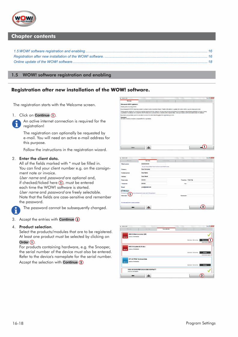
The registration starts with the Welcome screen.
1. Click on Continue 1 .An active internet connection is required for the registration!
The registration can optionally be requested by e-mail. You will need an active e-mail address for this purpose.
Follow the instructions in the registration wizard.
2. Enter the client data. All of the fields marked with * must be filled in. You can find your client number e.g. on the consign-ment note or invoice. User name and password are optional and, if checked/ticked here 1 , must be entered each time the WOW! software is started. User name and password are freely selectable. Note that the fields are case-sensitive and remember the password.
The password cannot be subsequently changed.
3. Accept the entries with Continue 2
4. Product selection. Select the products/modules that are to be registered. At least one product must be selected by clicking on Order 1 . For products containing hardware, e.g. the Snooper, the serial number of the device must also be entered. Refer to the device's nameplate for the serial number. Accept the selection with Continue 2
1
1
2
2
1
Chapter contents
1.5 WOW! software registration and enabling .......................................................................................................................... 16Registration after new installation of the WOW! software. ....................................................................................................... 16Online update of the WOW! software ....................................................................................................................................... 18
17-18Program Settings
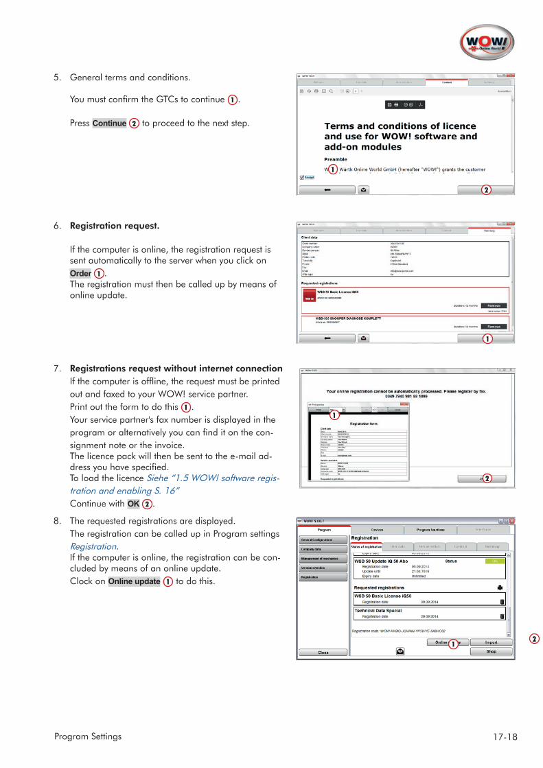
5. General terms and conditions. You must confirm the GTCs to continue 1 . Press Continue 2 to proceed to the next step.
6. Registration request. If the computer is online, the registration request is sent automatically to the server when you click on Order 1 . The registration must then be called up by means of online update.
7. Registrations request without internet connection If the computer is offline, the request must be printed out and faxed to your WOW! service partner. Print out the form to do this 1 . Your service partner's fax number is displayed in the program or alternatively you can find it on the con-signment note or the invoice. The licence pack will then be sent to the e-mail ad-dress you have specified. To load the licence Siehe “1.5 WOW! software regis-tration and enabling S. 16” Continue with OK 2 .
8. The requested registrations are displayed. The registration can be called up in Program settings Registration. If the computer is online, the registration can be con-cluded by means of an online update. Clock on Online update 1 to do this.
2
1
1
2
1
21
18-18 Program Settings
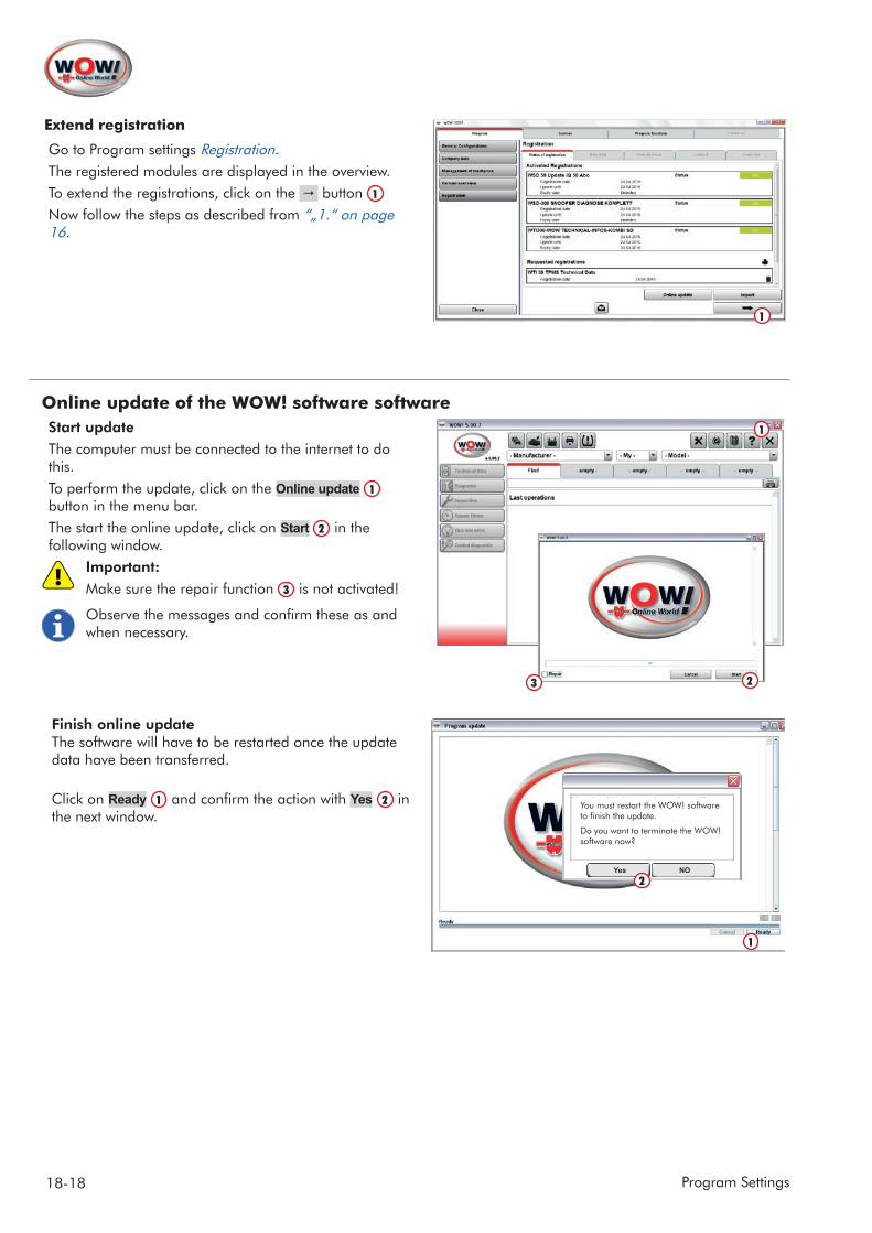
Extend registration
Go to Program settings Registration.The registered modules are displayed in the overview.To extend the registrations, click on the button 1
Now follow the steps as described from “„1.“ on page 16.
Online update of the WOW! software softwareStart updateThe computer must be connected to the internet to do this.To perform the update, click on the Online update 1 button in the menu bar.The start the online update, click on Start 2 in the following window.
Important: Make sure the repair function 3 is not activated!
Observe the messages and confirm these as and when necessary.
Finish online update The software will have to be restarted once the update data have been transferred.
Click on Ready 1 and confirm the action with Yes 2 in the next window.
1
!
1
2
1
Yes NO2
You must restart the WOW! software to finish the update.
Do you want to terminate the WOW! software now?
3

19-19Program Overview
2 Program Overview
2.1 User interface overview
1 Direct module selection
Call-up of the supplementary modules without vehicle selection. WOW! software functions for which a vehicle selection is not necessary.
2 Program functions
Management and settings for WOW! software
3 Vehicle selection To identify the vehicles to be processed. See "1 Vehicle Selection p. 1"
4 Module selection/ Module overview
Overview of the available contents, diagnosis types and technical data for the selected vehicle.Click on one of the buttons to extend the selection menus and display the available contents.
5 Display window The contents of the selected menu functions are shown in the display window.Up to 5 menu functions can be opened in parallel in the display window as index tabs.If all the index tabs are filled, you are prompted when opening a new menu function to close one index tab.Tip: By using several display windows, you can carry out several tasks at the same time and thereby work with greater speed and efficiency.Example: When you are performing a service reception, you can perform a service scan in parallel in the next index tab. You can switch at any time between the index tabs.The setting can also be switched to a single display window.See „ General settings page 2“
6 Action area These buttons are activated when actions have to be performed, e.g. during diagnosis, reading/deleting the fault memory
7 Home button The logo is the "Home" button. The vehicle selection is reset and all the display windows are closed.
71
4
2
3
5
6
20-22 Program Overview
2.2 Button description
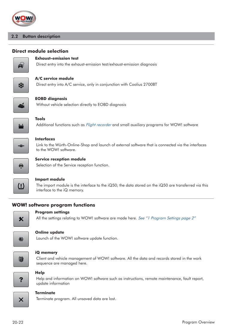
Direct module selectionExhaust-emission testDirect entry into the exhaust-emission test/exhaust-emission diagnosis
A/C service moduleDirect entry into A/C service, only in conjunction with Coolius 2700BT
EOBD diagnosisWithout vehicle selection directly to EOBD diagnosis
ToolsAdditional functions such as Flight recorder and small auxiliary programs for WOW! software
Interfaces Link to the Würth-Online-Shop and launch of external software that is connected via the interfaces to the WOW! software.
Service reception moduleSelection of the Service reception function.
Import moduleThe import module is the interface to the iQ50; the data stored on the iQ50 are transferred via this interface to the iQ memory.
WOW! software program functionsProgram settingsAll the settings relating to WOW! software are made here. See “1 Program Settings page 2”
Online update Launch of the WOW! software update function.
iQ memoryClient and vehicle management of WOW! software. All the data and records stored in the work sequence are managed here.
HelpHelp and information on WOW! software such as instructions, remote maintenance, fault report, update information
TerminateTerminate program. All unsaved data are lost.

21-22Program Overview
Vehicle selectionLast vehicles Call-up of the last 10/20 processed vehicles. See “ Vehicle selection page 10”
VINVehicle selection by reading out the vehicle identification number from the control unit. See “ Reading out the vehicle identification no. (VIN) from the control unit page 25”
Cars/Trucks onlyThe vehicle database can be confined to the respective vehicle types.
Function selectionDiagnosis
Technical data
Inspection
Flat rate units
Troubleshooting
Exhaust gas
Buttons in the program runTerminateClose index tab.
PrintPrint displayed content.
SaveSave performed action.
Enlarge viewThe index tab is increased in size to the full screen and module selection is removed from display.
Reduce viewThe index tab is reduced in size and module selection is displayed.
Control buttons The control buttons are called up in the enlarged view here.

22-22 Program Overview
Screen keyboardIf a touchscreen monitor is used, the screen keyboard can be displayed here.
FindDuring vehicle selection via text input in the power search the search process is started and the vehicle is accepted.
Additional information/ Rapid access buttonHere you obtain detailed information and extended technical data on the relevant module opened.
23-23Program Overview
2.3 Fault report
To improve and further develop the WOW! software there is the fault report. This is a tool for logging and docu-menting program faults. This documentation is saved and transmitted to our support team for analysis during the next online update.
If a problem arises during diagnosis or when working with the WOW! software, click on the Help button in the Pro-gram functions.
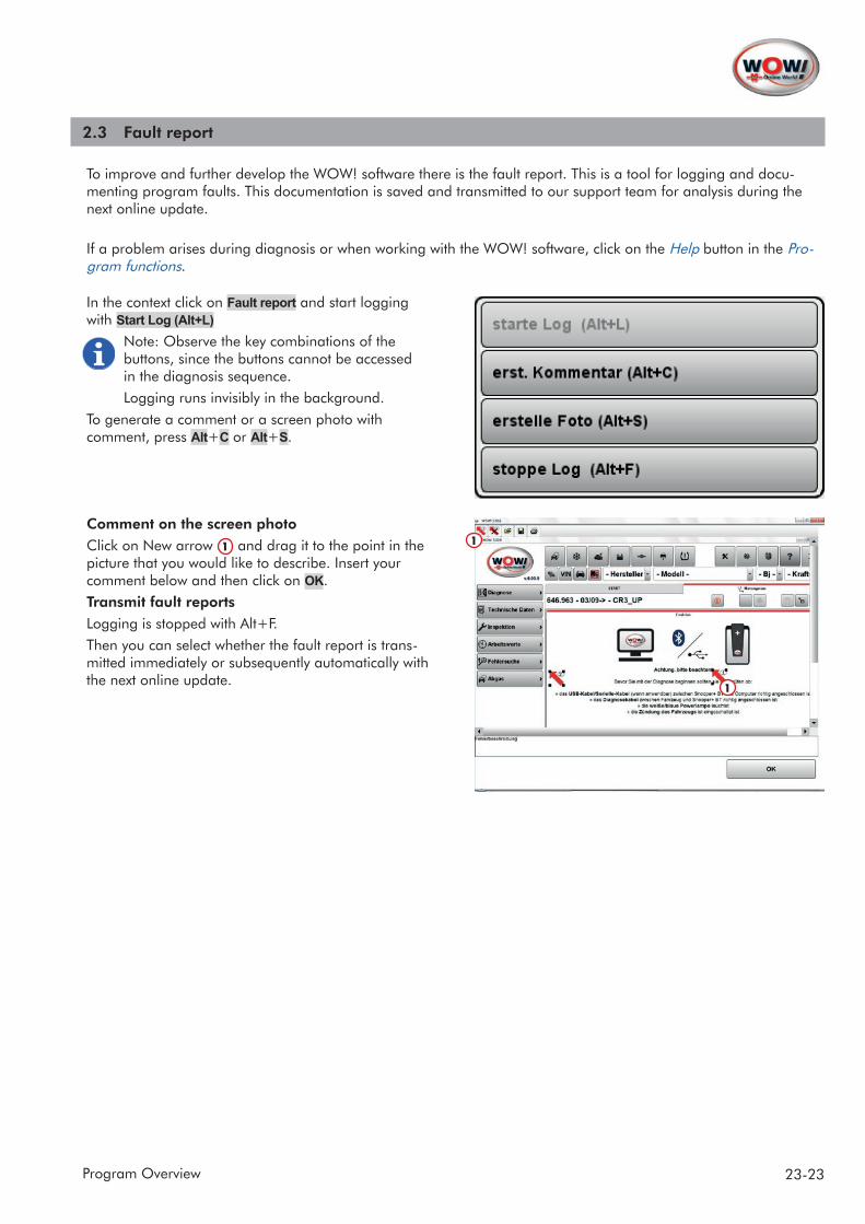
In the context click on Fault report and start logging with Start Log (Alt+L)
Note: Observe the key combinations of the buttons, since the buttons cannot be accessed in the diagnosis sequence.Logging runs invisibly in the background.
To generate a comment or a screen photo with comment, press Alt+C or Alt+S.
Comment on the screen photoClick on New arrow 1 and drag it to the point in the picture that you would like to describe. Insert your comment below and then click on OK.Transmit fault reportsLogging is stopped with Alt+F.Then you can select whether the fault report is trans-mitted immediately or subsequently automatically with the next online update.
1
1
24-26 Vehicle Selection
3 Vehicle Selection
Vehicle selection offers different ways of selecting a vehicle.
• Manufacturer / model / model year• Power search• Reading out the (VIN) vehicle identification no.• Last 10/20 processed vehicles• iQ memory (memory module)
Depending on the application the vehicle configuration should/must be selected with more or less detail. To main-tain the airbag system for example, it is not always necessary to select the engine version.
Manufacturer / model / model year
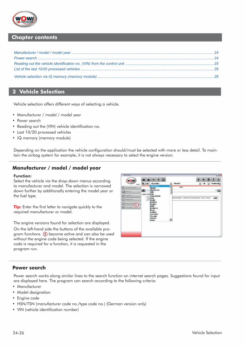
Function:Select the vehicle via the drop-down menus according to manufacturer and model. The selection is narrowed down further by additionally entering the model year or the fuel type.
Tip: Enter the first letter to navigate quickly to the required manufacturer or model.
The engine versions found for selection are displayed. On the left-hand side the buttons of the available pro-gram functions 1 become active and can also be used without the engine code being selected. If the engine code is required for a function, it is requested in the program run.
Power search
Power search works along similar lines to the search function on internet search pages. Suggestions found for input are displayed here. The program can search according to the following criteria:• Manufacturer• Model designation• Engine code• HSN/TSN (manufacturer code no./type code no.) (German version only)• VIN (vehicle identification number)
1
Chapter contents
Manufacturer / model / model year .......................................................................................................................................... 24Power search ........................................................................................................................................................................... 24Reading out the vehicle identification no. (VIN) from the control unit ...................................................................................... 25List of the last 10/20 processed vehicles ................................................................................................................................. 26
Vehicle selection via iQ memory (memory module) ................................................................................................................. 26
25-26Vehicle Selection
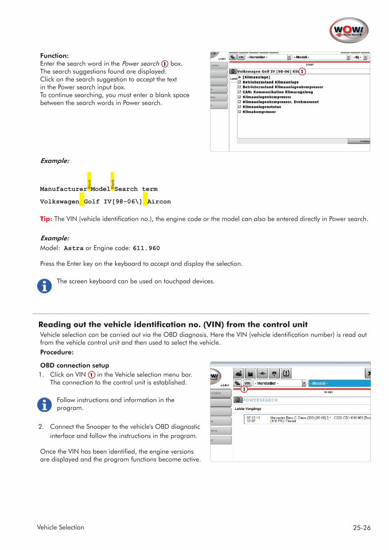
Function:Enter the search word in the Power search 1 box. The search suggestions found are displayed.Click on the search suggestion to accept the text in the Power search input box.To continue searching, you must enter a blank space between the search words in Power search.
Example:
Manufacturer Blan
k
Model Blan
k
Search term
Volkswagen Golf IV[98-06\] Aircon
Tip: The VIN (vehicle identification no.), the engine code or the model can also be entered directly in Power search.
Example:Model: Astra or Engine code: 611.960 Press the Enter key on the keyboard to accept and display the selection.
The screen keyboard can be used on touchpad devices.
Reading out the vehicle identification no. (VIN) from the control unitVehicle selection can be carried out via the OBD diagnosis. Here the VIN (vehicle identification number) is read out from the vehicle control unit and then used to select the vehicle.Procedure:
OBD connection setup1. Click on VIN 1 in the Vehicle selection menu bar.
The connection to the control unit is established.
Follow instructions and information in the program.
2. Connect the Snooper to the vehicle's OBD diagnostic interface and follow the instructions in the program.
Once the VIN has been identified, the engine versions are displayed and the program functions become active.
1
1

26-26 Vehicle Selection
Selection of engine codeThe accuracy of vehicle selection is vehicle-dependent and extends up to the identification of the engine code.If the engine code is not identified, this can be selected as a further step.
List of the last 10/20 processed vehicles
Call up the last 10 or 20 processed vehicles via the Last vehicles 1 button. Setting 10 or 20 vehicles, see „Vehicle selection“ on page 10
Vehicle selection via iQ memory (memory module)
Vehicle and client data are stored in the iQ memory. A stored vehicle can be selected from this memory.
Search in the iQ memory 1 for the stored vehicleiQ memory must be activated in the program settings for this purpose. See “„iQ memory (memory module)“ on page 10
1
1
27-31Diagnostic Functions
4 Diagnostic Functions
Diagnosis is modular in structure and can be put together as desired. Different diagnostic accessories are required, depending on the diagnosis type. Make the settings for the diagnosis boxes in the Program settings See “ Device setting - Snooper (diagnostic box) page 6”.The following diagnosis types are available:EOBD Diagnosis (European On-Board Diagnosis) The read-out data are exclusively exhaust-gas-related information from engine management and transmission control.OBD Diagnosis (On-Board Diagnosis)Manufacturer-specific system diagnosis of the systems installed in the vehicle.Flash diagnosis.Here help texts regarding the manual readout of flashing code are displayed in the program.
Before beginning diagnostic work, always check the settings for the diagnosis box used in the Program settings
4.1 EOBD diagnosis
It is not necessary to select a vehicle for EOBD diagnosis. The required diagnosis record is automatically detected by the system.
1. Start EOBD diagnosis via the EOBD diagnosis button. EOBD diagnosis can also be started from Exhaust-emission test.
The procedure is described in the program; always read and observe the instructions and messages in the program run.
2. Connect the diagnosis box to the vehicle and to the PC. Turn on the vehicle ignition and click on Continue. Communication to the control unit is established and the system status is read out.
To ensure that a correct diagnosis result is obtained, make sure there is a minimum voltage supply of 12 V as specified by the manufacturer. To ensure this, you may have to connect an external voltage supply or start the engine.
Chapter contents
4 Diagnostic Functions .......................................................................................................................................................... 274.1 EOBD diagnosis ................................................................................................................................................................. 27EOBD system status (Mode 1 and Mode 9) ............................................................................................................................ 28EOBD data lists (Mode 1) ........................................................................................................................................................ 28Data list (graphic) (Mode 1) ...................................................................................................................................................... 28Ambient data / Freeze Frames (Mode 2) ................................................................................................................................. 28EOBD fault memory (Mode 3 and Mode 7) .............................................................................................................................. 29Delete fault memory (Mode 4) .................................................................................................................................................. 29Oxygen sensors (Mode 5) ........................................................................................................................................................ 29Display of measured values (Mode 6/manufacturer-specific) .................................................................................................. 29Actuator test (Mode 8/Manufacturer-specific) .......................................................................................................................... 294.2 Serial OBD diagnosis ......................................................................................................................................................... 30Selection of diagnostic function ................................................................................................................................................ 30Action area ............................................................................................................................................................................... 30Status: ...................................................................................................................................................................................... 31

28-31 Diagnostic Functions
EOBD system status (Mode 1 and Mode 9) Overview of system status with display of the relevant information for the exhaust-emission test.The following information is displayed:
• Number of stored faults.• Status of the monitored components with display of the individual components.• Type of record.• Vehicle identification (only supported by a few control units).• MIL status indication (Black-white indication = signalled MIL status of the control unit is off.
Red indication = signalled MIL Status is on).• Display of the address and the addressed control unit.
Reconnect Re-establish connection to the control unit and read out the system status.
Action areaSystem status Re-establish connection to the control unit and read out the system status.Fault memory Read out and delete the fault memory. See “ EOBD fault memory (Mode 3 and Mode 7) page 29”Data lists Actual value (Selection) See “ EOBD data lists (Mode 1) page 28” Actual value (Graphic) See “ Data list (graphic) (Mode 1) page 28”Function Ambient data See “ Ambient data / Freeze Frames (Mode 2) page 28” Oxygen sensor See “ Oxygen sensors (Mode 5) page 29” Monitors See “ Display of measured values (Mode 6/manufacturer-specific) page 29” Vehicle data See “ EOBD system status (Mode 1 and Mode 9) page 28”
EOBD data lists (Mode 1)Display of the vehicle-specific data lists. Highlight the parameters to be displayed; these are then displayed on a blue background. All All the parameters are highlighted.Reset The selection of the parameters is reset.Display The selected parameters are displayed.The Minimum (Min.) and Maximum (Max.) values of the current measurement are displayed.Abbreviations The abbreviated parameter designations are described here.Select data lists Back to parameter selection.
Data list (graphic) (Mode 1)The parameters of the data lists are depicted in graphic form as a diagram. A maximum of 4 parameters can be displayed at one time. The required parameters can be set via the selection list boxes.Start Start display of the parameters.Stop Stop display of the parameters.
Tip: Click with the mouse in a diagram to display the precise measured value. Move the measuring point with the mouse to the position in the diagram that you would like to read off.t: = time in secondsy: = measured value (the unit is displayed together with the current measured value).
Ambient data / Freeze Frames (Mode 2)The control unit automatically sets the priority to one of the read-out faults. In this function this fault is displayed in the upper bar. At the same time the ambient data of the trouble code (= the conditions under which the trouble code was stored) are displayed in the lower area.

29-31Diagnostic Functions
EOBD fault memory (Mode 3 and Mode 7)Temporary and debounced faults are displayed with their P0 trouble codes here. Temporary faults:
If a fault is read out during diagnosis, it is initially stored in the temporary fault memory as a briefly occurred and unconfirmed fault. In the case of this fault type, the MI lamp is normally not activated.Debounced fault:
If a fault is categorised by the control unit as important or if the fault stored in the temporary fault memory occurs again and again in a specific start cycle, it is confirmed by the control unit and displayed as a debounced fault. In the case of this fault type, the MI lamp is normally activated. The fault can also be recategorised by the control unit to temporary status if it no longer occurs after further start attempts (usually after 40 starts).P0 trouble codes:
These are standardised trouble codes. You will find a corresponding explanatory text to these trouble codes, with a help text in the program display.P1 trouble codes:
These are manufacturer-specific codes which are read out from the control unit. You can display the descriptions for these codes by clicking on the Additional information button provided the vehicle has been selected in Vehicle selection and the specific vehicle lists are stored.
Delete fault memory (Mode 4)The faults of Modes 3 and 7 (temporary and debounced faults) can be deleted with this function.
The Delete function also deletes simultaneously the faults in Mode 2 with the associated ambient data and the sensor values from Mode 5 and resets the status of the component/readiness codes to "not tested" (1). It is therefore recommended to call up and archive the above-mentioned data before deletion.
Oxygen sensors (Mode 5)After the test cycle is completed, parameters of the discrete-level lambda oxygen sensors are displayed here. The values shown here are static (constant) ones. No values are displayed here if the test sequence is not complet-ed (readiness codes ≠ 0). This mode is not supported by all the control units. No value is output here in the case of wide-band sensors.The control units output many different parameters (max. 9 standardised values per oxygen sensor). Manufacturer-specific parameters are also output.
• $01: Threshold voltage - rich to lean• $02: Threshold voltage - lean to reach• $03: Lower voltage - constant for switching time calculation• $04: Upper voltage - constant for switching time calculation• $05: Switching time from rich to lean• $06: Switching time from lean to rich• $07: Lowest sensor voltage of driving cycle• $08: Highest sensor voltage of driving cycle• $09: Time between transitions
Display of measured values (Mode 6/manufacturer-specific)The parameters of functions of non-continuously monitored systems are displayed here.Parameters of temporarily tested manufacturer-specific functions are issued. These values are static ones.
Actuator test (Mode 8/manufacturer-specific)Still only supported by very few control units and serves to activate components in the vehicle.

30-31 Diagnostic Functions
4.2 Serial OBD Diagnosis
During OBD diagnosis (On-Board Diagnosis) the system control units are read out via the vehicle's diagnostic port. Depending on the vehicle, you can carry out the following diagnostic tests:
• Read out and delete system-related fault memories.• Read out data lists and system information.• Actuator test for activating and deactivating individual sensors and actuators. • Codings and settings of the systems in the control units.
In contrast to EOBD diagnosis a vehicle must be selected for OBD diagnosis. See “3 Vehicle Selection page 24”
Selection of diagnostic functionThe Diagnosis button becomes active once a vehicle has been selected. Depending on the vehicle, you can now choose from more or less system groups, to which the individual systems are distributed.Plug positionSystem identificationDrivetrainChassisBodySafetyServiceComfortFunctionsWhen you click on a system group, selection is widened as follows.Diagnosis > System group > System > Diagnosis record with system information.If a button is grey, no further functions are available.Tip: The situation may arise, if you change the vehicle selection slightly, e.g. select a different model year or if a vehicle was selected via HSN/TSN and then via the engine code, where missing systems will again be available for selection.
Diagnostic functions
Action areaThe Action area buttons appear on screen and become active when a system has been selected; the diagnostic func-tions are started via these buttons.
The sequences of the diagnostic functions are always described in detail in the program run.
To avoid damage to the vehicle and to the system, always read and following the instructions and help texts in the program run.
Fault memory Read out and delete the fault memory.Data lists The actual values, parameters from the control unit are read out and displayed.Function Flightrecorder See “4.3 Flight recorder page 32” Calibration Calibration functions are system-dependent and contain functions such as sensor/ actuator activations, system resets or parameter settings.
System identificationAll the systems in the vehicle are scanned during system identification. In this process the program checks:
• which systems are installed in the vehicle
!
31-31Diagnostic Functions
• whether the systems have with diagnostic capability• whether in the systems trouble codes are stored in the control unit
Normal scan List-based scan, all the control unit versions known to us are scanned in ordered form (according to system assemblies), regardless of whether they are installed in the vehicle or not, long waiting times (time out), trouble codes are scanned, individual diagnosis possible, delete trouble codes in the scan possible.
Power scan (new in the program from 5.00.10) CAN-based control unit scan, the CAN bus is scanned for existing control units and ones known
to us, a list of the control units found is displayed and the trouble code is scanned at high speed (advantage: no unnecessary scans of non-existing systems = extreme time savings), individual diagnosis can be started from the scan and trouble codes deleted.
Service scan Scan of data lists relevant to service. Keyword-based scan for service information (brake fluid, kilometre reading/mileage, etc.) in all known control units.
The sequences of the diagnostic functions are always described in detail in the program run.
To avoid damage to the vehicle and to the system, always read and following the instructions and help texts in the program run.
The scanned systems and the results of the diagnosis are listed and highlighted in colour.
Status:OK green Connection to the system established and no faults present.Number of faults red Connection to the system established and fault X stored.Assembly not responding! without No connection to the system possible, system not installed or several
possible diagnosis records are available.Details on the read-out system are displayed while the scan is still running. Click on a system in the list for this purpose. After the scan is finished you can switch directly to individual diagnosis without quitting the scan.The Action area buttons are displayed in the Display window. See “ Diagnostic functions page 30”
Tip: Further information on diagnosis can be requested via the Additional information/ Rapid access button button.
CalibrationDuring calibration activations or parameter changes to the systems can be performed, depending on the system.
The sequences of the diagnostic functions are always described in detail in the program run.
To avoid damage to the vehicle and to the system, always read and following the instructions and help texts in the program run.
!
!
32-35 Diagnostic Functions
4.3 Flight recorder
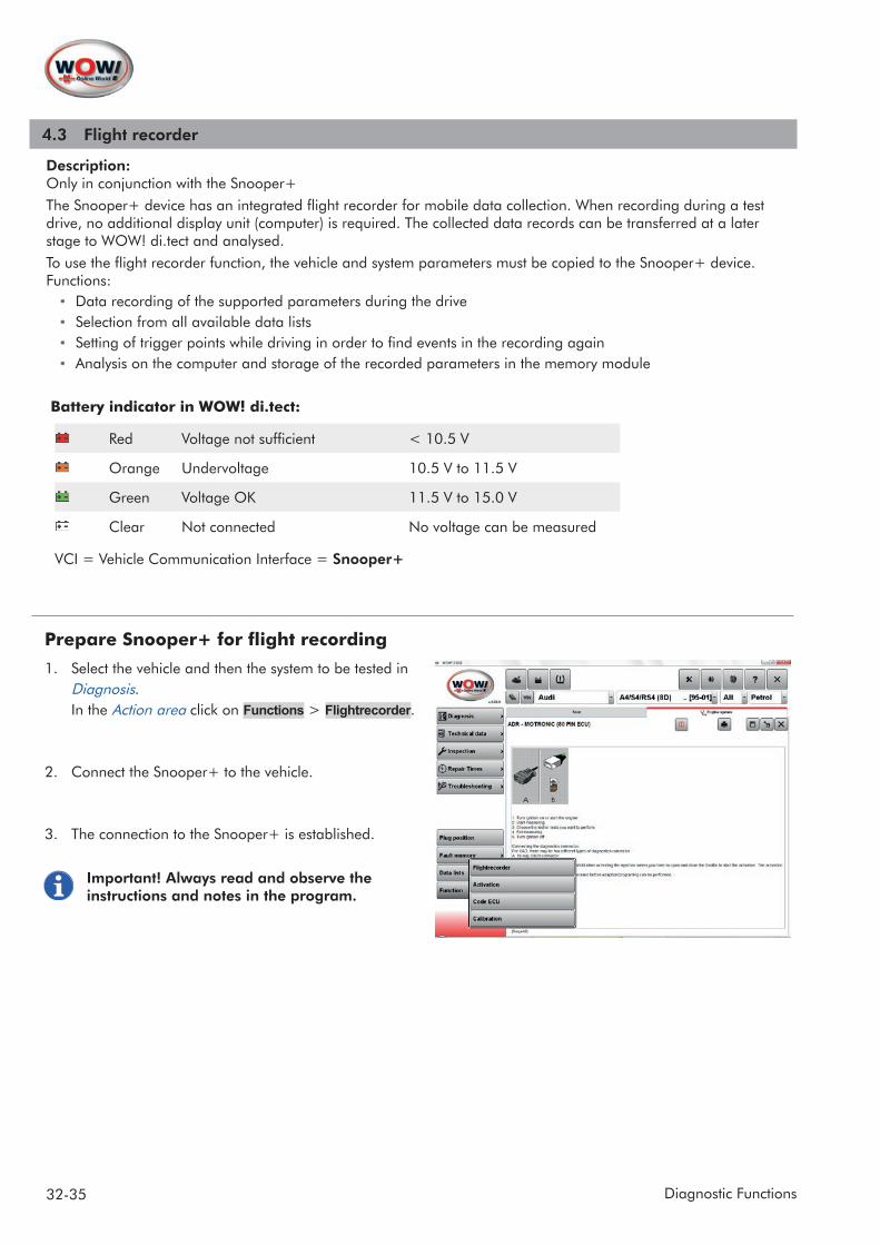
Description:Only in conjunction with the Snooper+The Snooper+ device has an integrated flight recorder for mobile data collection. When recording during a test drive, no additional display unit (computer) is required. The collected data records can be transferred at a later stage to WOW! di.tect and analysed.To use the flight recorder function, the vehicle and system parameters must be copied to the Snooper+ device.Functions:
• Data recording of the supported parameters during the drive • Selection from all available data lists• Setting of trigger points while driving in order to find events in the recording again• Analysis on the computer and storage of the recorded parameters in the memory module
Battery indicator in WOW! di.tect:
Red Voltage not sufficient < 10.5 V
Orange Undervoltage 10.5 V to 11.5 V
Green Voltage OK 11.5 V to 15.0 V
Clear Not connected No voltage can be measured
VCI = Vehicle Communication Interface = Snooper+
Prepare Snooper+ for flight recording
1. Select the vehicle and then the system to be tested in Diagnosis. In the Action area click on Functions > Flightrecorder.
2. Connect the Snooper+ to the vehicle.
3. The connection to the Snooper+ is established.
Important! Always read and observe the instructions and notes in the program.

33-35Diagnostic Functions
34-35 Diagnostic Functions
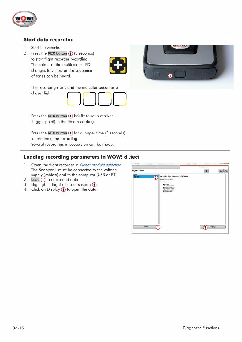
Start data recording
1. Start the vehicle.2. Press the REC button 1 (3 seconds)
to start flight recorder recording. The colour of the multicolour LED changes to yellow and a sequence of tones can be heard. The recording starts and the indicator becomes a chaser light. Press the REC button 1 briefly to set a marker (trigger point) in the data recording. Press the REC button 1 for a longer time (3 seconds) to terminate the recording. Several recordings in succession can be made.
Loading recording parameters in WOW! di.tect
1. Open the flight recorder in Direct module selection. The Snooper+ must be connected to the voltage supply (vehicle) and to the computer (USB or BT).
2. Load 1 the recorded data.3. Highlight a flight recorder session 2 .4. Click on Display 3 to open the data.
1
31
2

35-35Diagnostic Functions
Start data recording
1. Start the vehicle.2. Press the REC button 1 (3 seconds)
to start flight recorder recording. The colour of the multicolour LED changes to yellow and a sequence of tones can be heard. The recording starts and the indicator becomes a chaser light. Press the REC button 1 briefly to set a marker (trigger point) in the data recording. Press the REC button 1 for a longer time (3 seconds) to terminate the recording. Several recordings in succession can be made.
Loading recording parameters in WOW! di.tect
1. Open the flight recorder in Direct module selection. The Snooper+ must be connected to the voltage supply (vehicle) and to the computer (USB or BT).
2. Load 1 the recorded data.3. Highlight a flight recorder session 2 .4. Click on Display 3 to open the data.
1
31
2
Analysis of recording
Select the parameters to be displayed 1 .Click on the colour coding 2 to open a menu for colour selection.The parameters can be displayed individually, on top of each other, next to each other or in a system of coordinates. The setting is made via the symbols 3 .The control symbols 4 (Enlarge, Reduce, Jump, etc.) are intuitively comprehensible and supported by tool tips.
Save the recording in the client memory module
Display/remove the parameter selection
Trigger pointsAs already described, markers can be set in the form of trigger points during parameter recording. In this way you create the "blue" vertical marker lines 1 in the parameters. These markers are set simultaneously in all the para-meters so as to ensure that the event moment in all the parameters is comprehensible and retraceable. Click once with the left mouse button to create a vertical "red" line in the graphical representation. The created "event horizon" can be moved and reflects the current measured values. The event horizon is simultaneously displayed in all the graphs, regardless of which form of parameter representation has been selected. This ensures that the data are comparable.Click once with the right mouse button in the graphical representation to make the line disappear again.
4 3
2
1
1

36-38 Technical Data and Inspection
5 Technical Data and Inspection
OperationFor a selected vehicle the buttons of the registered modules become active Module selection/ Module overview 1 . Vehicle-specific, available contents can be selected. If individual modules are not active, they may have to be additionally enabled.
Click on a module 1 to select further information or functions.The selection of the respective module is extended 2 .To close the selection, click on the previous, higher-level button.
21
Detailed technical dataThe information is summarised in clearly laid-out cate-gories 1 in virtually all sections of the technical data. Extend a category by clicking on the text or the small symbol preceding the category.Click on Info to display additional illustrations or help texts.
1
1
Chapter
5 Technical Data and Inspection............................................................................................................................................ 36Detailed technical data ............................................................................................................................................................. 36Illustrations ............................................................................................................................................................................... 37Additional information on the test values ................................................................................................................................. 37Find components ...................................................................................................................................................................... 38Search function ........................................................................................................................................................................ 38
37-38Technical Data and Inspection
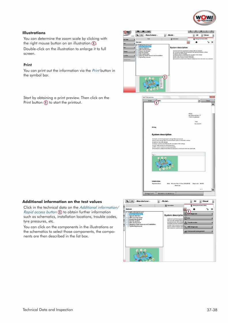
IllustrationsYou can determine the zoom scale by clicking with the right mouse button on an illustration 1 . Double-click on the illustration to enlarge it to full screen.
PrintYou can print out the information via the Print button in the symbol bar.
Start by obtaining a print preview. Then click on the Print button 1 to start the printout.
Additional information on the test valuesClick in the technical data on the Additional information/ Rapid access button 1 to obtain further information such as schematics, installation locations, trouble codes, tyre pressures, etc.You can click on the components in the illustrations or the schematics to select those components, the compo-nents are then described in the list box.
1
1
1
38-38 Technical Data and Inspection
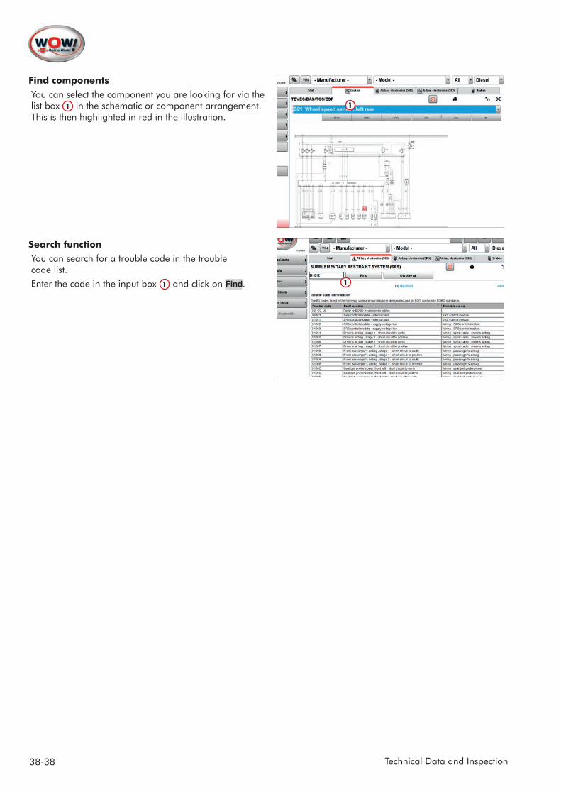
Find componentsYou can select the component you are looking for via the list box 1 in the schematic or component arrangement. This is then highlighted in red in the illustration.
Search functionYou can search for a trouble code in the trouble code list. Enter the code in the input box 1 and click on Find.
1
1
39-41Flat Rate Units
6 Flat Rate Units
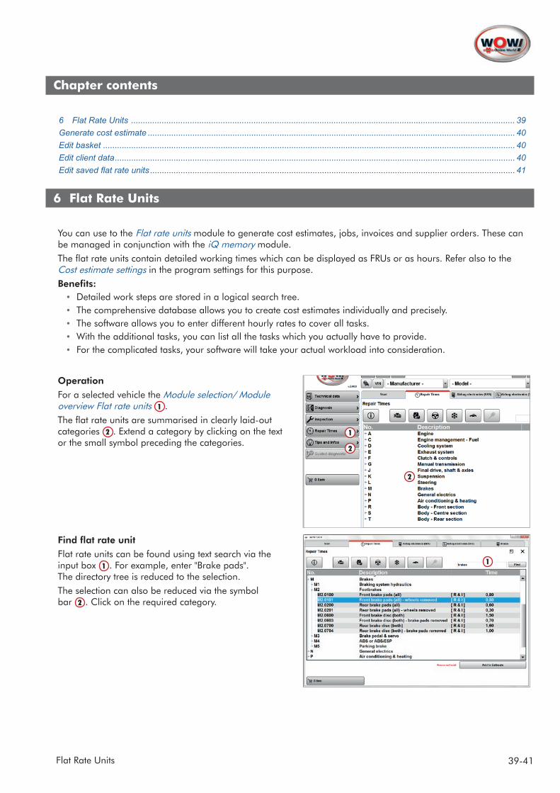
You can use to the Flat rate units module to generate cost estimates, jobs, invoices and supplier orders. These can be managed in conjunction with the iQ memory module. The flat rate units contain detailed working times which can be displayed as FRUs or as hours. Refer also to the Cost estimate settings in the program settings for this purpose.Benefits:
• Detailed work steps are stored in a logical search tree.• The comprehensive database allows you to create cost estimates individually and precisely.• The software allows you to enter different hourly rates to cover all tasks.• With the additional tasks, you can list all the tasks which you actually have to provide.• For the complicated tasks, your software will take your actual workload into consideration.
OperationFor a selected vehicle the Module selection/ Module overview Flat rate units 1 .The flat rate units are summarised in clearly laid-out categories 2 . Extend a category by clicking on the text or the small symbol preceding the categories.
Find flat rate unitFlat rate units can be found using text search via the input box 1 . For example, enter "Brake pads". The directory tree is reduced to the selection.The selection can also be reduced via the symbol bar 2 . Click on the required category.
2
1
1
2
Chapter contents
6 Flat Rate Units ................................................................................................................................................................... 39Generate cost estimate ............................................................................................................................................................ 40Edit basket ............................................................................................................................................................................... 40Edit client data .......................................................................................................................................................................... 40Edit saved flat rate units ........................................................................................................................................................... 41
40-41 Flat Rate Units
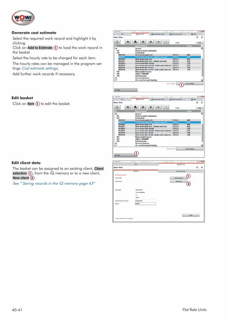
Generate cost estimate Select the required work record and highlight it by clicking. Click on Add to Estimate 1 to load the work record in the basket. Select the hourly rate to be charged for each item.The hourly rates can be managed in the program set-tings Cost estimate settings.Add further work records if necessary.
Edit basketClick on Item 1 to edit the basket.
Edit client dataThe basket can be assigned to an existing client, Client selection 1 , from the iQ memory or to a new client, New client 2 .See “ Saving records in the iQ memory page 43”
1
1
2
1
41-41Flat Rate Units
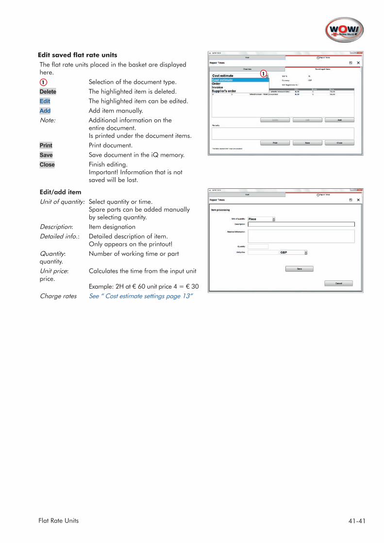
Edit saved flat rate unitsThe flat rate units placed in the basket are displayed here.
1 Selection of the document type.Delete The highlighted item is deleted.Edit The highlighted item can be edited.Add Add item manually.Note: Additional information on the entire document. Is printed under the document items.Print Print document.Save Save document in the iQ memory.Close Finish editing. Important! Information that is not
saved will be lost.
Edit/add itemUnit of quantity: Select quantity or time. Spare parts can be added manually by selecting quantity.Description: Item designationDetailed info.: Detailed description of item. Only appears on the printout!Quantity: Number of working time or part quantity.Unit price: Calculates the time from the input unit price. Example: 2H at € 60 unit price 4 = € 30Charge rates See “ Cost estimate settings page 13”
1
42-43 iQ memory
7 iQ memory
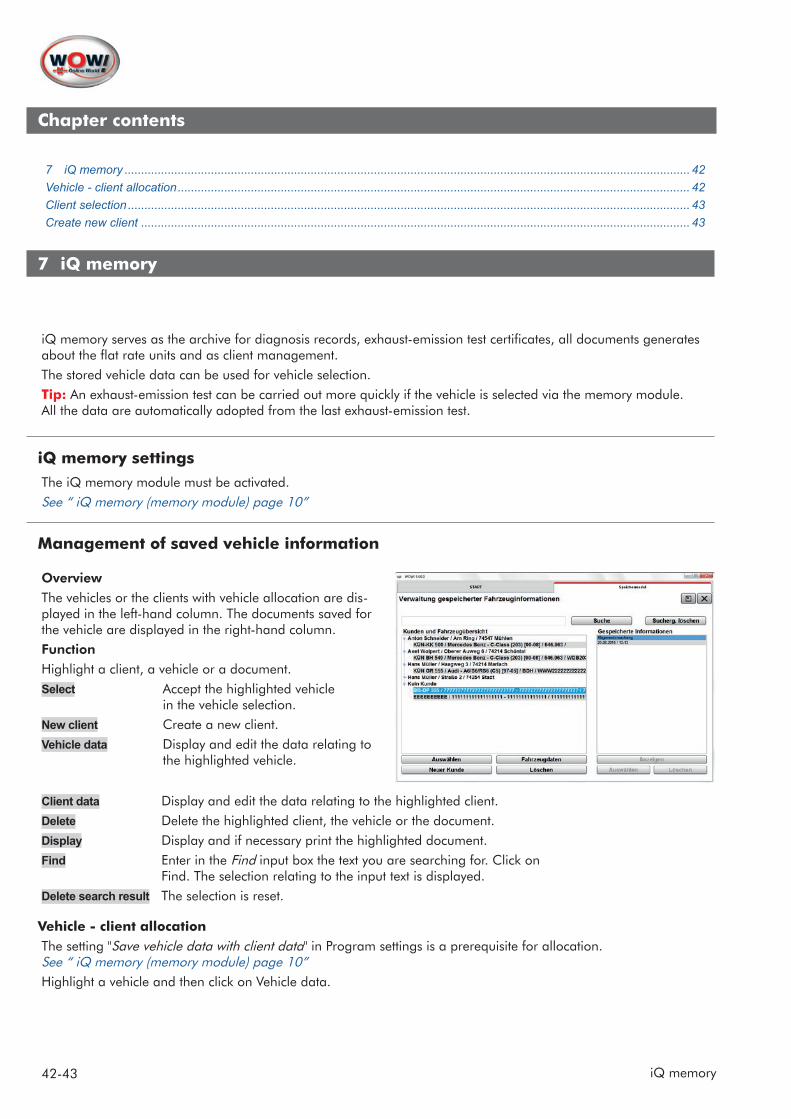
iQ memory serves as the archive for diagnosis records, exhaust-emission test certificates, all documents generates about the flat rate units and as client management.The stored vehicle data can be used for vehicle selection.Tip: An exhaust-emission test can be carried out more quickly if the vehicle is selected via the memory module. All the data are automatically adopted from the last exhaust-emission test.
iQ memory settingsThe iQ memory module must be activated.See “ iQ memory (memory module) page 10”
Management of saved vehicle information
OverviewThe vehicles or the clients with vehicle allocation are dis-played in the left-hand column. The documents saved for the vehicle are displayed in the right-hand column.FunctionHighlight a client, a vehicle or a document.Select Accept the highlighted vehicle in the vehicle selection.New client Create a new client.Vehicle data Display and edit the data relating to the highlighted vehicle.
Client data Display and edit the data relating to the highlighted client.Delete Delete the highlighted client, the vehicle or the document.Display Display and if necessary print the highlighted document.Find Enter in the Find input box the text you are searching for. Click on Find. The selection relating to the input text is displayed. Delete search result The selection is reset.
Vehicle - client allocationThe setting "Save vehicle data with client data" in Program settings is a prerequisite for allocation. See “ iQ memory (memory module) page 10”Highlight a vehicle and then click on Vehicle data.
Chapter contents
7 iQ memory .......................................................................................................................................................................... 42Vehicle - client allocation .......................................................................................................................................................... 42Client selection ......................................................................................................................................................................... 43Create new client ..................................................................................................................................................................... 43
43-43iQ memory
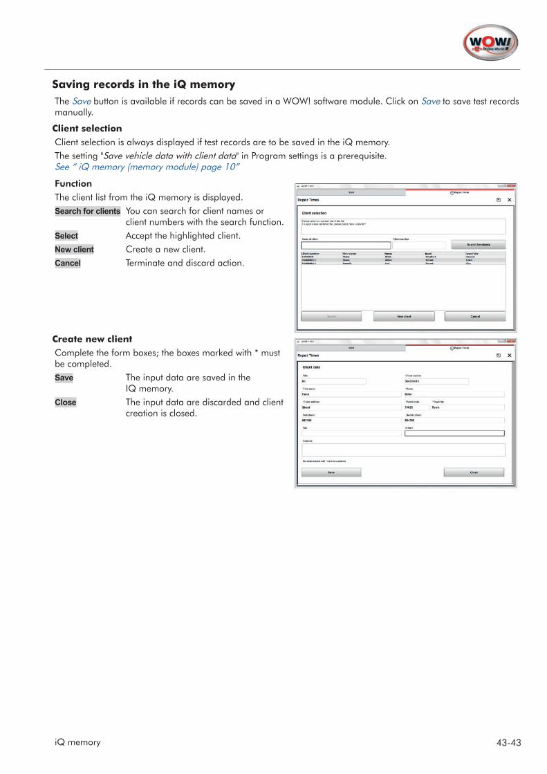
Saving records in the iQ memoryThe Save button is available if records can be saved in a WOW! software module. Click on Save to save test records manually.
Client selectionClient selection is always displayed if test records are to be saved in the iQ memory.The setting "Save vehicle data with client data" in Program settings is a prerequisite. See “ iQ memory (memory module) page 10”
FunctionThe client list from the iQ memory is displayed.Search for clients You can search for client names or
client numbers with the search function.Select Accept the highlighted client.New client Create a new client.Cancel Terminate and discard action.
Create new clientComplete the form boxes; the boxes marked with * must be completed.Save The input data are saved in the
IQ memory.Close The input data are discarded and client
creation is closed.
44-46 Service Reception
8 Service Reception
Transparency and fairness begin with service reception. When a job order is accepted you discuss all the work that is to be done with your client directly at the vehicle. This helps you to provide better advice and your client knows what is going to be done and why, and also what it is going to cost. Your client will thus be 100% assured of receiving the best service at a fair price. In addition, by consciously selling optional equipment and accessories, you are generating increased revenue and increasing your workshop capacity utilisation.Service reception consists of the following:Telephone reception: A checklist which can be used to clarify all the questions relating to the service appointment! Service reception: Step by step together with the client through the job order. Discuss together with your client the jobs that need to be done on the vehicle, create a list of
priorities for the jobs to be done. System identification: Use the diagnostic technology to provide your client with an overview of the electronic status
of their vehicle. Let the client look on over your shoulder and demonstrate your expertise.
Before opening the Service reception module, make sure the diagnosis box is connected to the vehicle interface. Turn on the ignition, and ensure that there is an adequate voltage supply of at least 12 V.Start system identification. After completing the diagnosis test, turn off the ignition and disconnect the diagnosis box from the vehicle.Print out the diagnosis results.Use the vehicle's technical data (jacking points, test values, maintenance schedules) to complete the work order.
8.1 Telephone reception
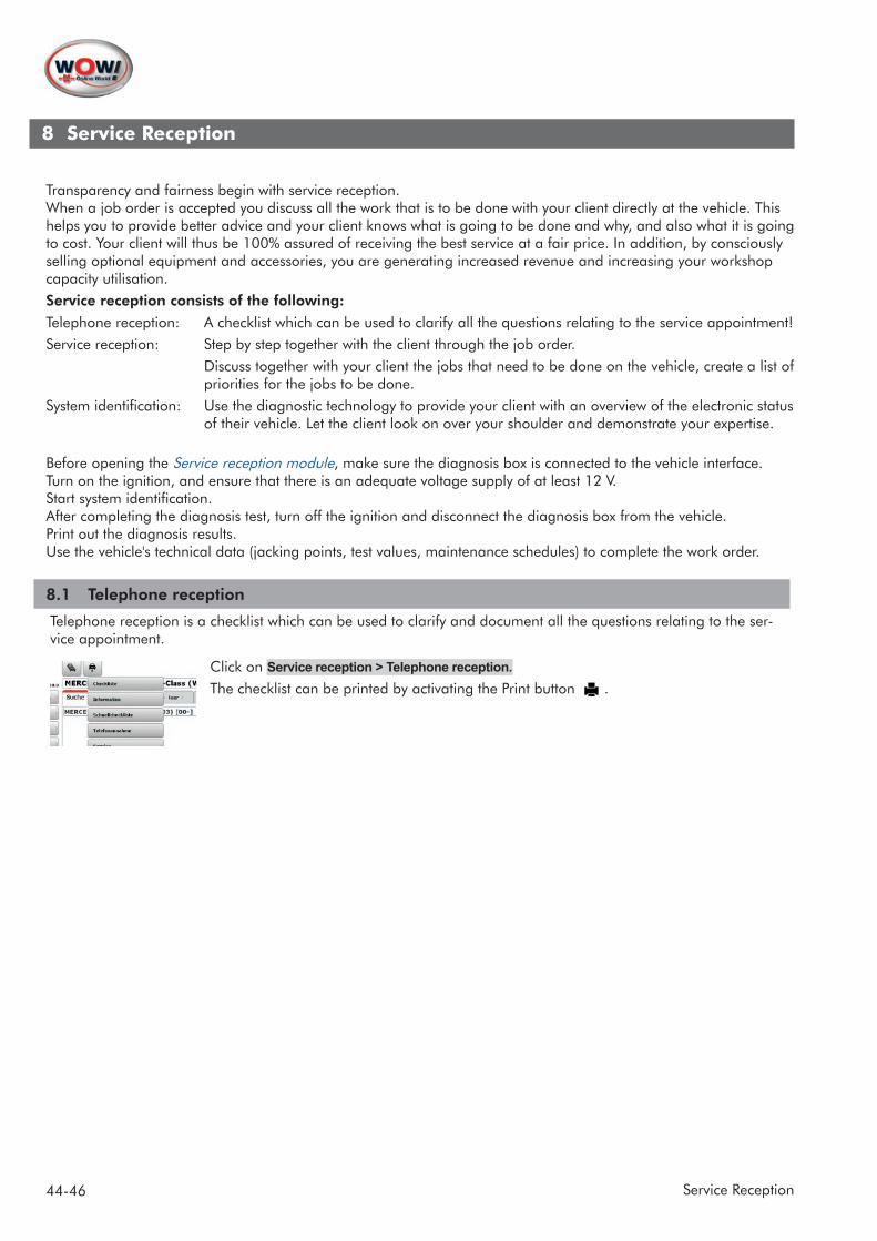
Telephone reception is a checklist which can be used to clarify and document all the questions relating to the ser-vice appointment.
Click on Service reception > Telephone reception.The checklist can be printed by activating the Print button .
45-46Service Reception
8.2 Checklist and quick checklist
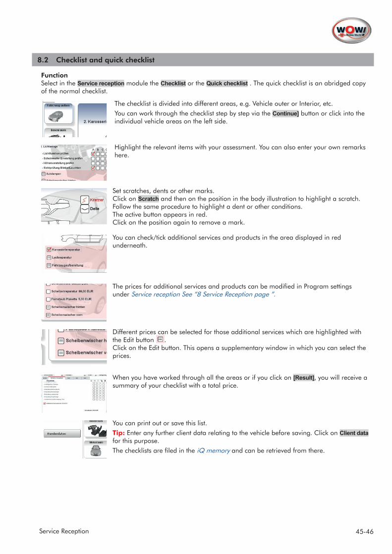
Function Select in the Service reception module the Checklist or the Quick checklist . The quick checklist is an abridged copy of the normal checklist.
The checklist is divided into different areas, e.g. Vehicle outer or Interior, etc.You can work through the checklist step by step via the Continue] button or click into the individual vehicle areas on the left side.
Highlight the relevant items with your assessment. You can also enter your own remarks here.
Set scratches, dents or other marks. Click on Scratch and then on the position in the body illustration to highlight a scratch. Follow the same procedure to highlight a dent or other conditions. The active button appears in red. Click on the position again to remove a mark.
You can check/tick additional services and products in the area displayed in red underneath.
The prices for additional services and products can be modified in Program settings under Service reception See “8 Service Reception page ”.
Different prices can be selected for those additional services which are highlighted with the Edit button . Click on the Edit button. This opens a supplementary window in which you can select the prices.
When you have worked through all the areas or if you click on [Result], you will receive a summary of your checklist with a total price.
You can print out or save this list.Tip: Enter any further client data relating to the vehicle before saving. Click on Client data for this purpose. The checklists are filed in the iQ memory and can be retrieved from there.
46-46 Service Reception
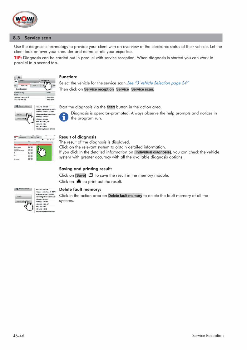
8.3 Service scan
Use the diagnostic technology to provide your client with an overview of the electronic status of their vehicle. Let the client look on over your shoulder and demonstrate your expertise.TIP: Diagnosis can be carried out in parallel with service reception. When diagnosis is started you can work in parallel in a second tab.
Function:Select the vehicle for the service scan.See “3 Vehicle Selection page 24”Then click on Service reception Service Service scan.
Start the diagnosis via the Start button in the action area.Diagnosis is operator-prompted. Always observe the help prompts and notices in the program run.
Result of diagnosisThe result of the diagnosis is displayed.Click on the relevant system to obtain detailed information. If you click in the detailed information on [Individual diagnosis], you can check the vehicle system with greater accuracy with all the available diagnosis options.
Saving and printing result:
Click on [Save] to save the result in the memory module. Click on to print out the result.
Delete fault memory:Click in the action area on Delete fault memory to delete the fault memory of all the systems.

Reproduction, even of extracts, with approval only.Doc. no.: 2184-ENG V.201508We reserve the right to make changes to the product at any time that in our view improve the quality,even without prior notice or notification. Illustrations may simply be examples that may differ from the delivered items in some details. Subject to correction in case of errors, we do not accept liability for misprints. Our generalgeneral terms and conditions will apply.
WOW! Würth Online World GmbH Schliffenstraße 2274653 Künzelsau, Germany [email protected]
© by WOW! Würth Online World GmbHAll rights reserved.Responsible for the contents: dept. Product