Software Manual TMflow
340
i Software Manual TMflow I626-E-06 Original Instruction
-
Upload
khangminh22 -
Category
Documents
-
view
1 -
download
0
Transcript of Software Manual TMflow
i
Software Manual TMflow
I626-E-06 Original Instruction

This Manual contains information of the Techman Robot product series (hereinafter referred to as the TM
Robot). The information contained herein is the property of Techman Robot Inc. (hereinafter referred to as
the Corporation). No part of this publication may be reproduced or copied in any way, shape or form without
prior authorization from the Corporation. No information contained herein shall be considered an offer or
commitment. It may be subject to change without notice. This Manual will be reviewed periodically. The
Corporation will not be liable for any error or omission.
logo is registered trademark of TECHMAN ROBOT INC. in Taiwan and other countries and the company reserves the ownership of this manual and its copy and its copyrights.

Software Manual TMflow Software version: 1.76 3
Revision History Table .................................................................................................................................. 19 1. General ..................................................................................................................................................... 20
Overview .......................................................................................................................................... 20 Warning and Caution Symbols ........................................................................................................ 20 Safety Precautions .......................................................................................................................... 21 Validation and Responsibility ........................................................................................................... 22 Limitation of Liability ........................................................................................................................ 22 Functional Note Symbol .................................................................................................................. 22
2. Start up and Activation .............................................................................................................................. 23 Overview .......................................................................................................................................... 23 Start Up ........................................................................................................................................... 23
Plug in the Power ...................................................................................................................... 23 Start up from Packing Pose ...................................................................................................... 23 Standard Start Up ..................................................................................................................... 27 TM Robot HMI TMflow Operation ............................................................................................. 28
Local Operation Method ..................................................................................................... 28 Wireless Access Point Connection Method ........................................................................ 29 Wired Network Connection Method .................................................................................... 30
3. Safety Settings .......................................................................................................................................... 32 Overview .......................................................................................................................................... 32 Safety Permission Settings .............................................................................................................. 32 Safety Setting .................................................................................................................................. 32
Performance Safety Settings .................................................................................................... 33 Human – Machine Safety Settings ............................................................................................ 34 Safety IO Settings ..................................................................................................................... 37
Resume Setting of User Connected External Safeguard Input Port .................................. 38 Resume Setting of User Connected External Safeguard Input Port for Human - Machine
Safety Settings ............................................................................................................................... 38 Safeguard Port Setting ....................................................................................................... 39 Enabling Device Setting (HW 3.2 or newer exclusive) ....................................................... 39
Cartesian Limit .......................................................................................................................... 40 Switch between Modes ............................................................................................................. 40
4. Start Your First Project .............................................................................................................................. 42 Overview .......................................................................................................................................... 42 Initial Setting .................................................................................................................................... 42
Contents

Software Manual TMflow Software version: 1.76 4
M/A Mode and FreeBot .................................................................................................................... 42 Build and Run Your First Project ...................................................................................................... 44 Shutdown ......................................................................................................................................... 47
5. Operation Interface ................................................................................................................................... 49 Overview .......................................................................................................................................... 49 Login/Logout .................................................................................................................................... 49 Connection ...................................................................................................................................... 50
Local Connection ...................................................................................................................... 50 Remote Connection .................................................................................................................. 50
View ................................................................................................................................................. 51 Display Board ............................................................................................................................ 51 Flow .......................................................................................................................................... 52 IO .............................................................................................................................................. 52 Simulator ................................................................................................................................... 53 Status ........................................................................................................................................ 53
Run Setting ...................................................................................................................................... 54 Project ............................................................................................................................................. 54
Project Editing Toolbar .............................................................................................................. 55 Create New Project ............................................................................................................ 56 Save Project ....................................................................................................................... 56 Open Project ...................................................................................................................... 56 Step Run ............................................................................................................................ 57 Point Manager .................................................................................................................... 58 Base Manager .................................................................................................................... 60 Controller ............................................................................................................................ 60 Variables ............................................................................................................................. 63 EditBlock ............................................................................................................................ 64
Current Base and Base List ............................................................................................. 64 Current TCP and TCP List ................................................................................................ 65 Display Manager .............................................................................................................. 65
Node Menu and Flow Editing Area ........................................................................................... 66 Project Function Menu .............................................................................................................. 68
Search Function ................................................................................................................. 68 Operation Space ................................................................................................................ 69 ModbusDev ........................................................................................................................ 69 Set IO while Project Error ................................................................................................... 69

Software Manual TMflow Software version: 1.76 5
Set IO while Project Stop ................................................................................................... 69 Stop Watch ......................................................................................................................... 69 View .................................................................................................................................... 70 F/T Sensor .......................................................................................................................... 71 Serial Port ........................................................................................................................... 71
Robot Setting ................................................................................................................................... 72 Wizard ....................................................................................................................................... 73 Vision Setting ............................................................................................................................ 73 TCP ........................................................................................................................................... 73 IO Setup .................................................................................................................................... 73 Safety ........................................................................................................................................ 74 Controller .................................................................................................................................. 74 Speech ...................................................................................................................................... 74 Gripper Button ........................................................................................................................... 75 Component ............................................................................................................................... 76
Operation Space ..................................................................................................................... 76 Command ................................................................................................................................ 76 Connection .............................................................................................................................. 76 Posture Setting ....................................................................................................................... 76 Global Variables ...................................................................................................................... 77 Text File Manager ................................................................................................................... 77
System Setting ................................................................................................................................ 77 Language .................................................................................................................................. 78 System Update ......................................................................................................................... 78 Group ........................................................................................................................................ 79 User Account ............................................................................................................................. 80 Network Setting ......................................................................................................................... 80 Import/Export ............................................................................................................................ 81 Date Time .................................................................................................................................. 82 Administrator Setting ................................................................................................................. 83 Network Service ........................................................................................................................ 83
Backup\Restore ...................................................................................................................... 85 Input/Display Devices .............................................................................................................. 85
Pop-out Keyboard ............................................................................................................. 85 Input Devices (HW 3.2 or newer exclusive) ...................................................................... 86
6. Point and Base ......................................................................................................................................... 87
Software Manual TMflow Software version: 1.76 6
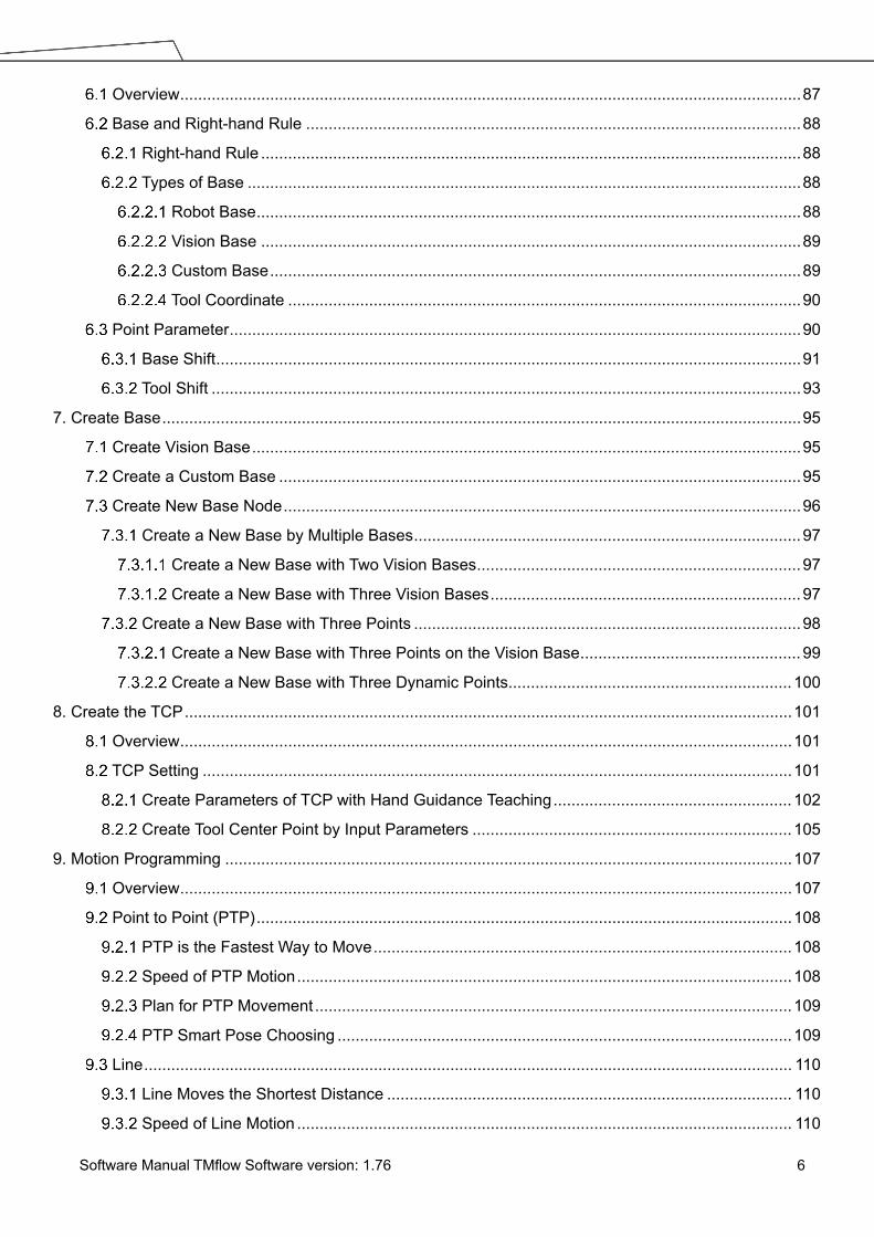
Overview .......................................................................................................................................... 87 Base and Right-hand Rule .............................................................................................................. 88
Right-hand Rule ........................................................................................................................ 88 Types of Base ........................................................................................................................... 88
Robot Base ......................................................................................................................... 88 Vision Base ........................................................................................................................ 89 Custom Base ...................................................................................................................... 89 Tool Coordinate .................................................................................................................. 90
Point Parameter ............................................................................................................................... 90 Base Shift .................................................................................................................................. 91 Tool Shift ................................................................................................................................... 93
7. Create Base .............................................................................................................................................. 95 Create Vision Base .......................................................................................................................... 95 Create a Custom Base .................................................................................................................... 95 Create New Base Node ................................................................................................................... 96
Create a New Base by Multiple Bases ...................................................................................... 97 Create a New Base with Two Vision Bases ........................................................................ 97 Create a New Base with Three Vision Bases ..................................................................... 97
Create a New Base with Three Points ...................................................................................... 98 Create a New Base with Three Points on the Vision Base ................................................. 99 Create a New Base with Three Dynamic Points............................................................... 100
8. Create the TCP ....................................................................................................................................... 101 Overview ........................................................................................................................................ 101 TCP Setting ................................................................................................................................... 101
Create Parameters of TCP with Hand Guidance Teaching ..................................................... 102 Create Tool Center Point by Input Parameters ....................................................................... 105
9. Motion Programming .............................................................................................................................. 107 Overview ........................................................................................................................................ 107 Point to Point (PTP) ....................................................................................................................... 108
PTP is the Fastest Way to Move ............................................................................................. 108 Speed of PTP Motion .............................................................................................................. 108 Plan for PTP Movement .......................................................................................................... 109 PTP Smart Pose Choosing ..................................................................................................... 109
Line ................................................................................................................................................ 110 Line Moves the Shortest Distance .......................................................................................... 110 Speed of Line Motion .............................................................................................................. 110

Software Manual TMflow Software version: 1.76 7
Plan for Line Movement ........................................................................................................... 111 Two-Steps Motion (WayPoint) ....................................................................................................... 112
WayPoint ................................................................................................................................. 112 Plan for WayPoint Movement .................................................................................................. 113
Blending ......................................................................................................................................... 114 Blending in Movement ............................................................................................................ 114 Blending Speed Change Chart ............................................................................................... 114 Set the Blending Percentage .................................................................................................. 114 Set the Blending by Radius ..................................................................................................... 115
Motion Nodes ................................................................................................................................ 115 Point Node .............................................................................................................................. 117
Generation Method of Point node .................................................................................... 117 Point Node Setting ........................................................................................................... 118
F-Point Node ........................................................................................................................... 118 Move Node .............................................................................................................................. 120
Plan for the Move Node .................................................................................................... 121 Circle Node ............................................................................................................................. 121
Circle Node Setting .......................................................................................................... 121 Set Angle= 0° ................................................................................................................... 122 Set Angle > 0° .................................................................................................................. 122
Path Node ............................................................................................................................... 123 Path and PLine ................................................................................................................. 123 Path Node Setting ............................................................................................................ 123 Path File Import and Export .............................................................................................. 124
Pallet Node ............................................................................................................................. 124 Listen Node ............................................................................................................................. 126
10. Logic Programming ............................................................................................................................... 128 Overview ...................................................................................................................................... 128 Variable System ........................................................................................................................... 128
Local Variables ...................................................................................................................... 128 Global Variables ............................................................................................................. 129
Logic Nodes ................................................................................................................................. 131 Start Node ............................................................................................................................. 131 SET Node ............................................................................................................................. 131 IF Node ................................................................................................................................. 134 WaitFor Node ........................................................................................................................ 136

Software Manual TMflow Software version: 1.76 8
Gateway Node ...................................................................................................................... 136 Process ........................................................................................................................................ 137
Process Nodes ...................................................................................................................... 137 Subflow Node ........................................................................................................................ 139 Thread ................................................................................................................................... 141
11. Vision Node ........................................................................................................................................... 143 12. Communication and Display ................................................................................................................. 145
Modbus ........................................................................................................................................ 145 Modbus System Hardware Structure .................................................................................... 145 Modbus System Software Structure ..................................................................................... 145
Set Modbus TCP ............................................................................................................ 145 Set Modbus RTU ............................................................................................................ 146
Application of Modbus in Project ........................................................................................... 146 Network ....................................................................................................................................... 150
Network Node ....................................................................................................................... 151 IO ................................................................................................................................................. 152
User Defined IO .................................................................................................................... 152 External IO ............................................................................................................................ 152 Status IO ............................................................................................................................... 153
Command Node .......................................................................................................................... 153 TmComm Instruction Set ...................................................................................................... 154 File Command ....................................................................................................................... 160
Log Node ..................................................................................................................................... 163 Display Node ............................................................................................................................... 165 Voice Node .................................................................................................................................. 165
13. Component ........................................................................................................................................... 167 14. Force Related Node .............................................................................................................................. 170
Compliance node ......................................................................................................................... 170 F/T Sensor ................................................................................................................................... 174
Communication Setting ......................................................................................................... 174 Position Setting ..................................................................................................................... 175 Import/Export Settings of F/T Sensor .................................................................................... 177 Force Value and Charts ........................................................................................................ 177
Touch Stop Node ......................................................................................................................... 178 Function Type: Compliance .................................................................................................. 178 Function Type: Line ............................................................................................................... 179

Software Manual TMflow Software version: 1.76 9
Touch Stop Function Type: Force Sensor ............................................................................. 181 Smart Insert Node ....................................................................................................................... 183
Approaching .......................................................................................................................... 183 Approaching principle description ................................................................................... 183 Approaching parameters setting ..................................................................................... 184
Searching .............................................................................................................................. 184 Method for searching: Sprial .......................................................................................... 186 Method for searching: Linear .......................................................................................... 187
Pushing ................................................................................................................................. 188 Parameter Setting .......................................................................................................... 188
Force Control Node ..................................................................................................................... 189 15. Operation Space ................................................................................................................................... 195
Overview ...................................................................................................................................... 195 Operation Space Setting Page .................................................................................................... 196 Add / Modify Page ....................................................................................................................... 197
Plane Page ........................................................................................................................... 197 Cube Page ............................................................................................................................ 198
Operation Space Setting Page in the Project Editing Page ......................................................... 199 Export/Import Operation Space ................................................................................................... 201
Export Operation Space ........................................................................................................ 201 Import Operation Space ........................................................................................................ 201
16. TM Component Editor ........................................................................................................................... 203 Starting to create your first component ........................................................................................ 203
Overview ............................................................................................................................... 203 TM Component Editor settings ............................................................................................. 203
Start node ....................................................................................................................... 203 Node settings ................................................................................................................. 206
TM Component Editor Naming Rule ..................................................................................... 207 Component Naming ....................................................................................................... 208 Global Variables Naming ................................................................................................ 209
Devices ........................................................................................................................................ 209 Modbus Devices ................................................................................................................... 209 Network Devices ................................................................................................................... 210 Force Sensing Devices ......................................................................................................... 210
Features & Applicable Examples ................................................................................................. 210 Global Variables .................................................................................................................... 210

Software Manual TMflow Software version: 1.76 10
Use component in TM Component Editor ............................................................................. 211 Component Inheritance ......................................................................................................... 212 The example of point parameterization application .............................................................. 212 The example of making parameterized devices ................................................................... 215 Use thread in TM Component Editor .................................................................................... 215 Use subflow in TM Component Editor .................................................................................. 216 Hide parameters ................................................................................................................... 216
Using your component ................................................................................................................. 216 Open the component ............................................................................................................ 216 Import/Export Components ................................................................................................... 217
Appendix A: Modbus List ............................................................................................................................ 218 Appendix B: Display of Indication Light Ring .............................................................................................. 231 Appendix C: Error Descriptions and Suggestions ....................................................................................... 235
Figures
Figure 1: Release the Emergency Switch ...................................................................................... 24 Figure 2: The Three Lights on The Robot Stick Flashing ............................................................... 24 Figure 3: The Indication Light Ring of The End Module Flashing in Light Blue .............................. 24 Figure 4: The Recommended Operating Sequence of Moving the Joints of TM Robot from Packing
Pose to Safe Posture .............................................................................................................. 25 Figure 5: The Recommended Operating Sequence of Moving the Joints of X series TM Robot from
Packing Pose to Safe Posture ................................................................................................ 25 Figure 6: The Indication Light Ring of The End Module Returns to Blue Light .............................. 26 Figure 7: The Normal Poses .......................................................................................................... 27 Figure 8: Release the Emergency Switch of Robot Stick ............................................................... 27 Figure 9: The Power Light on The Robot Stick Flashing ................................................................ 27 Figure 10: Wireless Access Point Connection Method (1/2) .......................................................... 29 Figure 11: Wireless Access Point Connection Method (2/2) .......................................................... 29 Figure 12: Wired Network Connection Method (1/2) ...................................................................... 31 Figure 13: Wired Network Connection Method (2/2) ...................................................................... 31 Figure 14: Safety Setting ................................................................................................................ 33 Figure 15: Angle Setting ................................................................................................................. 34 Figure 16: Human – Machine Safety Settings (1/2) ....................................................................... 35 Figure 17: Human – Machine Safety Settings (2/2) ....................................................................... 37 Figure 18: Safety IO Settings ......................................................................................................... 38 Figure 19: Auto Mode / Manual Mode (1/3) .................................................................................... 43

Software Manual TMflow Software version: 1.76 11
Figure 20: Auto Mode / Manual Mode (2/3) .................................................................................... 43 Figure 21: Auto Mode / Manual Mode (3/3) .................................................................................... 43 Figure 22: The Robot Stick for HW 3.2 or newer ........................................................................... 44 Figure 23: Build and Run Your First Project (1/5) .......................................................................... 45 Figure 24: Build and Run Your First Project (2/5) .......................................................................... 45 Figure 25: Build and Run Your First Project (3/5) .......................................................................... 46 Figure 26: Build and Run Your First Project (4/5) .......................................................................... 47 Figure 27: Build and Run Your First Project (5/5) .......................................................................... 47 Figure 28: Shutdown ...................................................................................................................... 48 Figure 29: Function Menu .............................................................................................................. 49 Figure 30: Get/Release Control (Local) .......................................................................................... 50 Figure 31: View .............................................................................................................................. 51 Figure 32: Display .......................................................................................................................... 52 Figure 33: IO .................................................................................................................................. 52 Figure 34: Simulator ....................................................................................................................... 53 Figure 35: Status ............................................................................................................................ 54 Figure 36: Single Project Icon ........................................................................................................ 54 Figure 37: Project Editing Page ...................................................................................................... 55 Figure 38: Open and Delete Project View ...................................................................................... 57 Figure 39: Step Run ....................................................................................................................... 58 Figure 40: Point Manager (1/2) ...................................................................................................... 59 Figure 41: Point Manager (2/2) ...................................................................................................... 59 Figure 42: Base Manager ............................................................................................................... 60 Figure 43: Controller ....................................................................................................................... 61 Figure 44: Controller (IO Control) ................................................................................................... 62 Figure 45: Controller (FreeBot Control) .......................................................................................... 62 Figure 46: EditBlock ....................................................................................................................... 64 Figure 47: Base List ....................................................................................................................... 65 Figure 48: Tool List ......................................................................................................................... 65 Figure 49: Display Manager ........................................................................................................... 66 Figure 50: Project Edit (1/3) ........................................................................................................... 66 Figure 51: Project Edit (2/3) ........................................................................................................... 67 Figure 52: Project Edit (3/3) ........................................................................................................... 68 Figure 53: Project Function Menu .................................................................................................. 68 Figure 54: Searching Pane ............................................................................................................. 69 Figure 55: Stop Watch Setting Page .............................................................................................. 70

Software Manual TMflow Software version: 1.76 12
Figure 56: View Tool Floating Window ........................................................................................... 71 Figure 57: Serial Port (1/2) ............................................................................................................. 71 Figure 58: Serial Port (2/2) ............................................................................................................. 72 Figure 59: Robot Setting ................................................................................................................ 73 Figure 60: Output Default Value Setting ......................................................................................... 74 Figure 61: Speech Setting .............................................................................................................. 75 Figure 62: Gripper Button ............................................................................................................... 75 Figure 63: Posture Setting .............................................................................................................. 77 Figure 64: System Setting .............................................................................................................. 78 Figure 65: Language Setting .......................................................................................................... 78 Figure 66: System Update (1/2) ..................................................................................................... 79 Figure 67: System Update (2/2) ..................................................................................................... 79 Figure 68: Group ............................................................................................................................ 80 Figure 69: User Account ................................................................................................................. 80 Figure 70: Network Setting (1/2) .................................................................................................... 81 Figure 71: Network Setting (2/2) .................................................................................................... 81 Figure 72: Date Time ...................................................................................................................... 83 Figure 73: Administrator Setting ..................................................................................................... 83 Figure 74: Network Services .......................................................................................................... 84 Figure 75: Backup\Restore ............................................................................................................. 85 Figure 76: Pop-out Keyboard ......................................................................................................... 86 Figure 77: Input Devices ................................................................................................................ 86 Figure 78: Base Value of the Point ................................................................................................. 87 Figure 79: Coordinate Axis Rotation .............................................................................................. 87 Figure 80: Right-Hand Base ........................................................................................................... 88 Figure 81: Robot Base ................................................................................................................... 89 Figure 82: Servoing Vision Base is on the Camera ........................................................................ 89 Figure 83: Fix-point Vision Base is on the Object .......................................................................... 89 Figure 84: Tool Coordinates ........................................................................................................... 90 Figure 85: Point Parameter Information ......................................................................................... 91 Figure 86: Shift Function of Point Node ......................................................................................... 91 Figure 87: Base Shift Schematic Diagram ..................................................................................... 92 Figure 88: Node with Base Shift ..................................................................................................... 92 Figure 89: Node with Tool Shift ...................................................................................................... 93 Figure 90: Tool Shift Using Keep Pose .......................................................................................... 93 Figure 91: Tool Shift Using Keep Path ........................................................................................... 94

Software Manual TMflow Software version: 1.76 13
Figure 92: Base Manager ............................................................................................................... 95 Figure 93: Build a Base by 3 Points ............................................................................................... 96 Figure 94: New Base Node ............................................................................................................ 97 Figure 95: Create a New Base with Two Vision Bases .................................................................. 97 Figure 96: Create a New Base with Three Vision Bases ............................................................... 98 Figure 97: Create a New Base with Three Points .......................................................................... 99 Figure 98: Create a New Base with Three Points on the Vision Base ........................................... 99 Figure 99: Create a New Base with Three Dynamic Points ......................................................... 100 Figure 100: TCP Definition ........................................................................................................... 101 Figure 101: TCP Setting ............................................................................................................... 102 Figure 102: Set the times of calibration ........................................................................................ 103 Figure 103: Teaching Screen ....................................................................................................... 103 Figure 104: The Robot Posture Needs to Change during Teaching (1/2) .................................... 104 Figure 105: The Robot Posture Needs to Change during Teaching (1/2) .................................... 104 Figure 106: Save Teaching Result ............................................................................................... 105 Figure 107: Manual Input TCP Values ......................................................................................... 106 Figure 108: TM Robot Motion Types ............................................................................................ 107 Figure 109: PTP Motion ............................................................................................................... 108 Figure 110: Speed of PTP Motion ................................................................................................ 109 Figure 111: PTP Application Examples ........................................................................................ 109 Figure 112: PTP Smart Pose Choosing ....................................................................................... 110 Figure 113: Line Motion Simulation .............................................................................................. 110 Figure 114: Speed of Line Motion ................................................................................................ 110 Figure 115: Link to Project Speed ................................................................................................ 111 Figure 116: Line Application Example .......................................................................................... 112 Figure 117: WayPoint Motion Status ............................................................................................ 112 Figure 118: WayPoint Setting ....................................................................................................... 113 Figure 119: WayPoint Application Examples ............................................................................... 113 Figure 120: Blending in Space ..................................................................................................... 114 Figure 121: Blending Speed Change Chart ................................................................................. 114 Figure 122: Set the Blending Percentage or Set the Blending by Radius .................................... 115 Figure 123: Motion Nodes Support Variable as the Inputs ........................................................... 116 Figure 124: Speed Adjust and Speed Indication on the Node. .................................................... 117 Figure 125: Point Node ................................................................................................................ 117 Figure 126: Point Node Setting .................................................................................................... 118 Figure 127: F-Point Node ............................................................................................................. 119

Software Manual TMflow Software version: 1.76 14
Figure 128: F-Point Node Setting ................................................................................................. 119 Figure 129: Adjust F-Point Parameter during Project Running .................................................... 120 Figure 130: Move Node Setting .................................................................................................... 120 Figure 131: Plan for the Move Node ............................................................................................ 121 Figure 132: The Circle Node Plans Arc Path with 3-Point Setting Circle ..................................... 121 Figure 133: Circle Node Setting ................................................................................................... 122 Figure 134: The Circle Motion Status of Set Angle = 0° ............................................................... 122 Figure 135: The Circle Motion Status of Set Angle =270° ............................................................ 123 Figure 136: PLine Blending Relationship Chart ........................................................................... 123 Figure 137: Path Node Setting ..................................................................................................... 124 Figure 138: Pallet Node (1/2) ....................................................................................................... 125 Figure 139: Pallet Node (2/2) ....................................................................................................... 125 Figure 140: Pallet Patterns ........................................................................................................... 125 Figure 141: Listen Node ............................................................................................................... 126 Figure 142: Variable System ........................................................................................................ 128 Figure 143: Global Variable Setting ............................................................................................. 130 Figure 144: Global Variables after Project Is Run ........................................................................ 130 Figure 145: SET Node .................................................................................................................. 131 Figure 146: Variable Count .......................................................................................................... 132 Figure 147: Expression Editor Parameters (1/2) .......................................................................... 133 Figure 148: Expression Editor Parameters (2/2) .......................................................................... 133 Figure 149: Add Expression ......................................................................................................... 134 Figure 150: Analog I/O Setting ..................................................................................................... 134 Figure 151: IF Node ..................................................................................................................... 135 Figure 152: IF Node Stop Criteria Setting .................................................................................... 136 Figure 153: Gateway Node Judges Five Conditions .................................................................... 136 Figure 154: IF Node Judge Four Conditions ................................................................................ 137 Figure 155: Stop Node Ends Project ............................................................................................ 138 Figure 156: Goto Node Flow Transfer .......................................................................................... 138 Figure 157: Goto Node Connection .............................................................................................. 138 Figure 158: Warp Node Transfers to another Project .................................................................. 139 Figure 159: Subflow Node Modularization Concept ..................................................................... 140 Figure 160: Menu to Create Subpages ........................................................................................ 140 Figure 161: Select a subflow in the subflow node (1/2) ................................................................ 141 Figure 162: Select a subflow in the subflow node (2/2) ................................................................ 141 Figure 163: Thread ....................................................................................................................... 142

Software Manual TMflow Software version: 1.76 15
Figure 164: Vision Node ............................................................................................................... 143 Figure 165: Vision Node Flow ...................................................................................................... 143 Figure 166: Vision Node Setting ................................................................................................... 144 Figure 167: Robot Modbus Protocol ............................................................................................. 145 Figure 168: ModbusDev Access .................................................................................................. 146 Figure 169: Modbus TCP Local IP ............................................................................................... 147 Figure 170: Modbus Device Setting ............................................................................................. 148 Figure 171: Modbus X Axis Position Parameter Setting .............................................................. 149 Figure 172: Save the Variable of Modbus Value .......................................................................... 149 Figure 173: Use the obtained variable of SET node to obtain the value of Modbus .................... 150 Figure 174: Display displays the value obtained by Modbus ....................................................... 150 Figure 175: Network Setting ......................................................................................................... 151 Figure 176: Status IO Setting (1/2) ............................................................................................... 153 Figure 177: Status IO Setting (2/2) ............................................................................................... 153 Figure 178: Instruction Set Communicates with HMI ................................................................... 154 Figure 179: Enable TmComm Instruction Set .............................................................................. 154 Figure 180: Directive Summary Flow ........................................................................................... 156 Figure 181: Command Node Gets RS-232 Information ............................................................... 157 Figure 182: Set and Open Serial Port (1/2) .................................................................................. 157 Figure 183: Set and Open Serial Port (2/2) .................................................................................. 158 Figure 184: Read Data and Receive as a Variable ...................................................................... 158 Figure 185: SET Node Setting ..................................................................................................... 159 Figure 186: Display Node Displays the Obtained Value .............................................................. 159 Figure 187: Remotely Add Notepad and Write information .......................................................... 162 Figure 188: Display Node Displays Received Variables .............................................................. 162 Figure 189: Remotely Delete Notepad File .................................................................................. 163 Figure 190: Log Node Gets the Current Angle ............................................................................. 163 Figure 191: Modbus Setting ......................................................................................................... 164 Figure 192: SET Node Setting and Log of Thread Page .............................................................. 165 Figure 193: Node Text Example ................................................................................................... 165 Figure 194: Display Node Displays the Robot's Position ............................................................. 165 Figure 195: Voice Node in TMflow Application ............................................................................. 166 Figure 196: Select Components ................................................................................................... 167 Figure 197: Robot Setting Page Component ............................................................................... 168 Figure 198: Gripper Button Setting Page ..................................................................................... 169 Figure 199: Compliance Node ...................................................................................................... 170

Software Manual TMflow Software version: 1.76 16
Figure 200: Compliance Node Teach Setting .............................................................................. 172 Figure 201: Line Direction ............................................................................................................ 173 Figure 202: Rotation Direction ...................................................................................................... 173 Figure 203: Compliance Variable Selection ................................................................................. 173 Figure 204: F/T Sensor ................................................................................................................ 174 Figure 205: Read Values after Setting F/T Sensor ...................................................................... 175 Figure 206: Position Setting ......................................................................................................... 176 Figure 207: Select Position Setting .............................................................................................. 176 Figure 208: Input Values .............................................................................................................. 177 Figure 209: Charts ........................................................................................................................ 177 Figure 210: Touch Stop-Compliance Settings .............................................................................. 178 Figure 211: Touch Stop-Line Settings .......................................................................................... 180 Figure 212: Force Sensor ............................................................................................................. 181 Figure 213: Force Sensor ............................................................................................................. 182 Figure 214: Approaching Principle ............................................................................................... 184 Figure 215: Approaching Parameter Setting ................................................................................ 184 Figure 216: Spiral Searching Method ........................................................................................... 185 Figure 217: Line Searching Method (1/2) ..................................................................................... 185 Figure 218: Line Searching Method (2/2) ..................................................................................... 186 Figure 219: Spiral Searching Parameter Setting Interface ........................................................... 187 Figure 220: Linear Searching Parameter Setting Interface .......................................................... 188 Figure 221: Pushing Parameter Interface .................................................................................... 189 Figure 222: Force Control Node Settings ..................................................................................... 189 Figure 223: Tool Coordinate System ............................................................................................ 190 Figure 224: Base Coordinate System .......................................................................................... 190 Figure 225: Trajectory Coordinate System ................................................................................... 191 Figure 226: Possible Conversion Error ........................................................................................ 191 Figure 227: F/T Operation Modes – Setpoint ............................................................................... 192 Figure 228: F/T Operation Modes – Trajectory (1/3) .................................................................... 193 Figure 229: F/T Operation Modes – Trajectory (2/3) .................................................................... 193 Figure 230: F/T Operation Modes – Trajectory (3/3) .................................................................... 194 Figure 231: Operation Space Setting ........................................................................................... 196 Figure 232: Plane ......................................................................................................................... 197 Figure 233: Cube (1/2) ................................................................................................................. 198 Figure 234: Cube (2/2) ................................................................................................................. 199 Figure 235: Project Editing Page and Operation Space Setting .................................................. 200

Software Manual TMflow Software version: 1.76 17
Figure 236: Click the Save Button to Save the File ...................................................................... 201 Figure 237: Start Node ................................................................................................................. 204 Figure 238: Component Icon Resolution ...................................................................................... 205 Figure 239: Node Setting (1/2) ..................................................................................................... 206 Figure 240: Node Setting (2/2) ..................................................................................................... 207 Figure 241: Global Variables Naming .......................................................................................... 209 Figure 242: Global Variables ........................................................................................................ 211 Figure 243: The Example of Point Parameterization Application (1/4) ......................................... 212 Figure 244: The Example of Point Parameterization Application (2/4) ......................................... 213 Figure 245: The Example of Point Parameterization Application (3/4) ......................................... 214 Figure 246: The Example of Point Parameterization Application (4/4) ......................................... 214 Figure 247: The Example of Making Parameterized Devices ...................................................... 215 Figure 248: Hide Parameters ....................................................................................................... 216 Figure 249: Open the Component ................................................................................................ 217
Tables
Table 1: Hardware Versions and Applicability ................................................................................ 20 Table 2: Warning and Caution Symbols ......................................................................................... 21 Table 3: Functional Note Symbols ................................................................................................. 22 Table 4: Keyboard Hot Keys in TMflow .......................................................................................... 55 Table 5: FreeBot Degree of Freedom Limitation ............................................................................ 63 Table 6: User Defined IO Setting Table ......................................................................................... 74 Table 7: Valid Blending Setting (Moving from P1 to P2) .............................................................. 115 Table 8: Variable Data Types ....................................................................................................... 129 Table 9: SET Syntax List .............................................................................................................. 132 Table 10: If Judgment Operators .................................................................................................. 135 Table 11: TM Robot Coordinates in the Modbus List ................................................................... 146 Table 12: User Defined IO Setting Table ..................................................................................... 152 Table 13: TmComm Instruction set .............................................................................................. 156 Table 14: File Commands ............................................................................................................ 161 Table 15: Spiral Searching Function Setting Parameters Definition ............................................ 186 Table 16: Linear Searching Function Setting Parameter Definition ............................................. 187 Table 17: Pushing Parameter Definitions ..................................................................................... 188 Table 18: Component Naming ..................................................................................................... 208 Table 19: Naming Rule for Items after Components .................................................................... 209 Table 20: Modbus – Classify ........................................................................................................ 218

Software Manual TMflow Software version: 1.76 18
Table 21: Modbus – Robot Status ................................................................................................ 218 Table 22: Modbus – End Module ................................................................................................. 219 Table 23: Modbus – Control Box DI/O ......................................................................................... 220 Table 24: Modbus – Control Box AI/O .......................................................................................... 220 Table 25: Modbus – External Module ........................................................................................... 220 Table 26: Modbus – Robot Coordinate ........................................................................................ 222 Table 27: Modbus – Robot Coordinate (When Touch Stop node is triggered) ............................ 224 Table 28: Modbus – Run Setting .................................................................................................. 224 Table 29: Modbus – Robot Speed ................................................................................................ 224 Table 30: Modbus – TCP Value ................................................................................................... 225 Table 31: Modbus – Robot Stick .................................................................................................. 226 Table 32: Modbus – TCP Force ................................................................................................... 226 Table 33: Modbus – Torque ......................................................................................................... 226 Table 34: Modbus – Safety Stop Criteria ..................................................................................... 227 Table 35: Modbus – User Connected External Safeguard Input Port for Human - Machine Safety
Settings ................................................................................................................................. 228 Table 36: Modbus – Others 1 ....................................................................................................... 229 Table 37: Modbus – Others 2 ....................................................................................................... 230 Table 38: Modbus – Others 3 ....................................................................................................... 230 Table 39: Modbus – Others 4 ....................................................................................................... 230 Table 40: Blinking Ratio ............................................................................................................... 232 Table 41: Light Indications ........................................................................................................... 233 Table 42: Quick References of Color/Blinking .............................................................................. 234

Software Manual TMflow Software version: 1.76 19
Revision History Table Revision Code Date Revised Content
01 October 2018 Original release
02 December 2018 Software update from 1.68.6000 to 1.68.6800. Redefined the LED light
color and added safety monitoring functions to hand guiding. Updated
Chapter 4. Minor test fixes. Added Appendix B for indication light ring
display.
03 July 2019 Added 1.72.3500 features
04 August 2019 Added X model information
05 December 2019 Added 1.76.3300 features
06 April 2020 Added 1.76.6300 features
Software Manual TMflow Software version: 1.76 20
1. General Overview
TMflow is a graphical HMI. Its purpose is to provide users with a complete, convenient and simple
interface for robot motion and logic programming environments. Through the graphical HMI, users can
simply manage and set the parameters of the robot, and use the graphical flow chart to plan the robot
movement and process logic. At the same time, the interface design of TMflow considers the use of
touch screens, allowing you to manage multiple robots from a single Windows tablet.
Users and system integrators of TM Robot must read and fully understand this chapter before using this
robot. In addition, before users perform any operation on the robot in accordance with this manual, it is
necessary to read and comply with the Safety Manual for the corresponding product's hardware and
software version, and the Hardware Installation Manual for the corresponding hardware version, before
the operation can be performed.
The applicability of this software to the hardware versions of each TM Robot is as follows:
Hardware Version Applicability
HW 3.0, 3.1, 3.2 Applicable
Table 1: Hardware Versions and Applicability
Warning and Caution Symbols
The Table below shows the definitions of the warning and caution levels used in this manual. Pay close
attention to them when reading each paragraph, and observe them to avoid personal injuries or
equipment damage.
DANGER: Identifies an imminently hazardous situation which, if not avoided, is likely to result in serious injury, and might result in death or severe property damage.
WARNING: Identifies a potentially hazardous situation which, if not avoided, will result in minor or moderate injury, and might result in serious injury, death, or significant property damage.
This manual applies to TMflow Version 1.76.6300 or above. Confirm your software version before
using and reading this manual. To check the software version, click on the interface on TMflow.

Software Manual TMflow Software version: 1.76 21
CAUTION: Identifies a potentially hazardous situation which, if not avoided, might result in minor injury, moderate injury, or property damage.
Table 2: Warning and Caution Symbols
Safety Precautions
DANGER: This product can cause serious injury or death, or damage to itself and other equipment, if the following safety precautions are not observed:
All personnel who install, operate, teach, program, or maintain the system must read the Hardware
Installation Manual, Software Manual, and Safety Manual for the software and hardware version of
this product, and complete a training course for their responsibilities in regard to the robot.
Read Manual Label Impact Warning
All personnel who design the robot system must read the Hardware Installation Manual, Software
Manual, and Safety Manual for the software and hardware version of this product, and must comply
with all local and national safety regulations for the location in which the robot is installed.
The TM Robot shall be used according to its intended use.
Results of the risk assessment may require the use of additional risk reduction measures.
Power to the robot and its power supply must be locked out and tagged out or have means to
control hazardous energy or implement energy isolation before any maintenance is performed.
Dispose of the product in accordance with the relevant rules and regulations of the country or
area where the product is used.

Software Manual TMflow Software version: 1.76 22
Validation and Responsibility
The information provided in this Manual does not include how to design, install and operate a complete
arm application, nor does it involve the peripheral devices that will affect the overall system safety. The
design and installation of the complete system must comply with the standards and regulations for
safety requirements in the country located. Users or integrators should understand safety laws and safety
regulations in the local country, and avoid major risks present in the entire system.
This includes but is not limited to:
Risk assessment of the whole system
Adding other machines and additional risk reduction measures based on the results of the risk
assessment
Using appropriate software safety features
Ensuring the user will not modify any safety measures
Ensuring all systems are correctly designed and installed
Clearly labeling user instructions
Clearly marked symbols for installation of the robot arm and the integrator contact details
Making accessible relevant documents, including the risk assessment and this manual.
Limitation of Liability
No safety-related information shall be considered a guarantee by the Corporation that a TM Robot will
not cause personnel injury or property damage.
Functional Note Symbol
The following table defines the functional note symbols used in this manual. Read the paragraphs
carefully.
IMPORTANT: This symbol represents the relevant functional details to assist the programming and use.
NOTE: This symbol represents the relevant functional use tips to assist programming efficiency
Table 3: Functional Note Symbols

Software Manual TMflow Software version: 1.76 23
2. Start up and Activation Overview
This manual instructs users of TM Robot to perform start up procedures for the first time. Users must
first read and follow the Safety Manual for the corresponding product's software and hardware version,
and the Hardware Installation Manual for the corresponding hardware version to install the TM Robot
correctly and properly before executing the operation of this chapter; otherwise, it may result in serious
risks.
Start Up
Plug in the Power
Plug the Power Cable of Control Box into the power socket.
Start up from Packing Pose
Step 1. Press the Emergency Switch of the Robot Stick.
WARNING: The following chapters of this manual will describe how to install the TM Robot after unpacking the box. If it is your first time to install TM Robot without learning all the installation process starting from unpacking the new product, especially when the robot has been installed in a working environment, pay attention to the following items in order to perform first time installation and startup operation according to this manual: 1. In order to avoid the risks of resuming work caused by the changes of the original
working environment and configuration, check with the responsible person for the working environment and keep all necessary configuration records, such as software settings and all hardware wirings.
2. Remove all IOs for the external connection of the Control Box, including analog IO, digital IO, EtherCAT connection port and network ports. Remove all air lines or external power lines connecting to the optional equipment before Commissioning.
3. Remove all Control Box external USB interface, serial port, and external connection / external storage device connections of the network interface.
4. Uninstall any added objects / end-effectors installed to the end flange and any electrical connections between the end effector and the End Module / Control Box.
5. Uninstall any hardware that is installed outside the robot body.
WARNING: For the procedure from product unpacking to plugging the Power Cable of the Control Box into the power socket, read and follow the corresponding contents of the Hardware Installation Manual.

Software Manual TMflow Software version: 1.76 24
Step 2. Press the Power Button of the Robot Stick to start the power supply of the Control
Box.
Step 3. Release the Emergency Switch of the Robot Stick by twisting it a quarter-turn
clockwise when the light on Robot Stick starts blinking.
Figure 1: Release the Emergency Switch
The three lights on the Robot Stick keep flashing. For the buttons, lights, and switch
on the Robot Stick, refer to the Hardware Installation Manual.
Figure 2: The Three Lights on The Robot Stick Flashing
CAUTION:
While booting up, if the Emergency Switch on the Robot Stick is kept pressed, the User Connected ESTOP Input is kept open, or the User Connected ESTOP Input Port without Robot ESTOP Output is kept open, the boot process cannot be complete. Follow the instructions shown on the screen to restart the robot.
Step 4. The Indication Light Ring of the End Module flashes in red during startup. After
the start up is completed, the Indication Light Ring of the End Module flashes in
light blue, representing that it is in the Safe Start Up Mode.
Figure 3: The Indication Light Ring of The End Module Flashing in Light Blue

Software Manual TMflow Software version: 1.76 25
Step 5. Hold the FREE Button on the End Module to release the brakes and manually
move the robot to a relatively safe position. If this is the first time unpacking the
robot, follow the illustrations below to release joints from initial posture.
Figure 4: The Recommended Operating Sequence of Moving the Joints of TM Robot
from Packing Pose to Safe Posture
Figure 5: The Recommended Operating Sequence of Moving the Joints of X series
TM Robot from Packing Pose to Safe Posture
DANGER: Pay attention when the FREE Button is pressed and the brake is released. The robot's body will sag due to gravity. When the FREE Button is pressed to unlock the brake, be sure to support the end of robot and expect some sagging, and hold the end of robot, to prevent harm such as pinching of the Operator. If there are any problems with the robot sagging, release the FREE Button immediately, and the brake of each robot joint will be locked again.
DANGER: There is no force compensation in Safe Start Up Mode. This means that it requires more force to move each joints directly against the motor drive.

Software Manual TMflow Software version: 1.76 26
CAUTION: If you do not follow the above instructions to move the robot to the safe posture shown in the above figure, but continue to operate downwards to release the Emergency Switch, it may cause certain joints of the robot (especially the fifth joint) to be outside the joint angle limit when the robot returns to a normal state. At this time, the robot will not be able to start correctly and the red light will be on. In this condition, press the Emergency Switch again and repeat this step to the correct safe posture as shown in the figure.
CAUTION: During Joint Position Calibration, each joint of the robot will perform a calibration motion. Make sure the robot pose is in a clear space of at least 5 degrees per joint to perform the calibration motion before calibration. At the same time, make sure the TCP, which may be a long distance from the robot flange, will not cause harm during the calibration motion.
Step 6. Press and hold the Stop Button on the Robot Stick for about three seconds, and
the robot will enter the calibration process. During calibration, joints of the robot may
move slightly. After the calibration is completed, the Indication Light Ring of the
End Module will return to blue light, indicating that the robot has entered the Auto
Mode successfully and it can be used normally.
Figure 6: The Indication Light Ring of The End Module Returns to Blue Light
CAUTION: When the startup from the Packing Pose is complete, use the TMflow controller page to move the robot posture to the origin first (each joint angle: 0, 0, 0, 0, 0, 0), and then use the FreeBot teaching to move the robot to the Normal Pose (each joint angle: 0, 0, 90, 0, 90, 0) as shown in the figure below. Note that the joint 2 pointing directions of the Normal Pose and the safe posture after unpacking the box are opposite.

Software Manual TMflow Software version: 1.76 27
Figure 7: The Normal Poses
Standard Start Up
Step 1. Check that the robot's posture is safe.
Step 2. Check that the Emergency Switch of Robot Stick is released.
Figure 8: Release the Emergency Switch of Robot Stick
Step 3. Press the Power Button on the Robot Stick to start the robot.
CAUTION: While booting up, if the Emergency Switch on the Robot Stick is kept pressed, the User Connected ESTOP Input is kept open, or the User Connected ESTOP Input Port without Robot ESTOP Output is kept open, the boot process cannot be complete. Follow the instructions shown on the screen to restart the robot.
Step 4. Check the screen on the Control Box. It should now indicate that the system
entered startup mode. The power light on the Robot Stick will keep flashing, too.
Figure 9: The Power Light on The Robot Stick Flashing

Software Manual TMflow Software version: 1.76 28
Step 5. When the controller is starting up, the Indication Light Ring of the End Module
displays flashing red light. During the process, the robot will run automatic
calibration, and each joint of the robot will move slightly to calibrate.
CAUTION: During Joint Position Calibration period, each point of the robot will perform a calibration motion. Make sure the robot pose is in a clear space of at least 5 degrees per joint to perform the calibration motion before calibration. At the same time, make sure the TCP, which may be a long distance to the robot flange, will not cause harm during the calibration motion.
Step 6. After the controller start up is done, the Indication Light Ring of the End Module will constantly display blue light. The robot can be used normally at this time.
TM Robot HMI TMflow Operation
TMflow and the TM Robot can be connected in ways as below:
Connect with the monitor, keyboard and mouse to the Control Box. This enables to start
TMflow.
Download the TMflow Client from customer area of the official website, and then install it on
a Windows-based computer (e.g. Windows Laptop/ Windows Tablet). Connect to the robot in
a wired or a wireless network.
NOTE: Minimum requirement of the client device to install TMflow are as follows:
Operating System: CPU: RAM: Hard Drive Space: Display Resolution: Peripherals: Supported Languages: Additional Requirements:
Windows 7 SP 1 Intel i5 series 4 GB 2 GB of available space 1366 by 768 USB ports and Ethernet ports English, Simplified Chinese, Traditional Chinese, Japanese, German, Korean, Vietnamese, Spanish, French, Italian, Danish, Dutch, Czech, Hungarian, Romanian, Portuguese, Turkish 1. 2010Redistributable_bcredist (x64/x86) 2. 2013Redistributable_bcredist (x64/x86) 3. 2015Redistributable_bcredist (x64/x86) 4. .Net Framework 4.52 or above.
Local Operation Method

Software Manual TMflow Software version: 1.76 29
Step 1. Connect the screen, mouse, and keyboard, to the Control Box.
Step 2. Navigate to ≡ and click Login.
Administrator by default is not set with password. Click OK to login directly.
Step 3. Click Get Control to get control of the robot.
Wireless Access Point Connection Method
Step 1. Install TMflow on client device.
Step 2. Connect the robot to the same physical AP or entity AP of the same network
segment.
Figure 10: Wireless Access Point Connection Method (1/2)
Step 3. Connect the client network to the above local area network.
Figure 11: Wireless Access Point Connection Method (2/2)
Step 4. Open TMflow on the client device, click the upper left corner to refresh the robot list, and wait for the corresponding Robot name to appear on the connection screen.
Step 5. Click the robot icon twice to connect with the robot. Ensure that all the robots in this network segment appear in the screen. Users can distinguish which robot to be connected by the robot's Robot ID (the number displayed below the QR code on the Robot Stick).
Physical AP
Physical AP

Software Manual TMflow Software version: 1.76 30
Step 6. When the robot connection is successful, the icon will appear in the screen on the robot and the robot icon will appear in the upper right corner.
Step 7. Click Get Control to control the robot.
CAUTION: Do not mistakenly insert the network cable into the dedicated EtherCAT port of the Control Box. This action will trigger a robot error.
NOTE: The connected device will display a green icon, and any other device will display a red icon.
Wired Network Connection Method
Step 1. Install TMflow on the client device. Step 2. Connect the robot and client device to the same physical AP or the physical AP
on the same network segment, or connect the two ends of the network wires to the robot Control Box and Client.
Step 3. Connect the client network to the above local area network. Step 4. Open TMflow on the client device, click the upper left corner to refresh the
robot list, and wait for the corresponding Robot ID to appear on the connection screen.
Step 5. Click the robot icon twice to connect with the robot. Ensure that all robots in this network segment appear in the screen. Users can distinguish which robot to be connected by the robot's Robot ID.
Step 6. When the robot connection is successful, the icon will appear on the robot in the screen and the icon of robot appears on the upper right corner.
Step 7. Click Get Control to control the robot.

Software Manual TMflow Software version: 1.76 31
Figure 12: Wired Network Connection Method (1/2)
Figure 13: Wired Network Connection Method (2/2)
Physical AP

Software Manual TMflow Software version: 1.76 32
3. Safety Settings Overview
This chapter will introduce the safety settings interface of the TM Robot, including the Safety Permission
Settings and Safety Setting.
Safety Permission Settings
Users and administrators of TM Robot must set appropriate account password permissions before
starting to use the TM Robot, with appropriate arrangements for access to operator permission for
safety configuration.
When users have completed the startup and activation according to the previous chapter, and entered
the TMflow interface with the default account password to get the control of robot, navigated to ≡ and
clicked Setting to enter the setting page, an option labelled Safety will appear on this page. This is the
safety setting operation area of the product as well as all important settings for the robot. If settings are
altered arbitrarily, it will cause danger during operation. For proper permission settings, refer to 5.8.3
Group and 5.8.4 User Account to create accounts for authorization to access the safety related setting
permissions and grant permission to access Setting, and set all other account and group privileges to
access Setting to change the safety permission settings.
Safety Setting
On the Safety Setting page, there are functions including Performance Safety Settings, Human –
Machine Safety Settings, Safety IO Settings, and Cartesian Limit. There is also a timestamp of the
last modified date and time at the bottom left of the screen. The timestamp is updated and expressed
according to ISO 8601 every time users click the Save button for new parameters.
NOTE: Upgrading the software with previous versions of hardware will not upgrade the version of the safety system.
NOTE: In TMflow Software version 1.74 and earlier versions: Performance Safety Settings is named Safety Stop Criteria. Human – Machine Safety Settings is named Collaborative Mode Setting. Safety IO Settings is named Safeguard Port Setting. Cartesian Limit is not available.

Software Manual TMflow Software version: 1.76 33
Figure 14: Safety Setting
Performance Safety Settings
On this page, users can set the TCP speed of the robot, the force of the TCP, the Hand Guide
TCP Speed Limit as an individual speed limit categorized as a cat.2 stop, as well as the speed,
the torque, and the position of each joint. For the related physical meanings and the definition of
the safety functions and the precautions that they represent, read and follow the instructions in
the Safety Manual before the operation or setting can be performed.
NOTE: When using with Hand Guide, if the pull speed by hand reaches to the Hand Guide TCP Speed Limit, users will feel the resistance feedback. Under such circumstances, lower the strength to pull to keep from triggering the protective stop.
The default value of the stop criteria is designed to provide a relatively safer working capability of
the robot. A higher upper limit can be set by users. If users want to reach 100% project speed
without triggering these stop criteria, set the limit to the upper limit for each input slot. Since the
capability of the robot is still related to the pose, motion, TCP length, and payload, without these
stop criteria, the robot is still protected by the maximum allowable torque of each joint and stops.
In addition, regarding the life of the robot, refer to the Hardware Installation Manual of the
respective model for the value of rated torque and the limit for repeated peak torque of each joint.
CAUTION: Angle Setting: For example, when the first joint position is set to 270° and -270°, then the angle range in 270°~ 271° and -270°~ -271° will become reducing range shown as the blue area in the figure. When joint 1 moves into this range, the basic moving speed of the robot will be switched to 250mm/sec for line motion and 5% for PTP motion, to form an angle buffer

Software Manual TMflow Software version: 1.76 34
region to prevent possible overshoot to the joint limit. At the same time, the angle range in 271°~ 274° and -271°~ -274° is the 2nd buffer range for joint limit as the red area in the figure. When the joint angle arrives this area robot will stop moving. Users can only operate the robot by pressing FREE Button to make the robot leave this area.
Figure 15: Angle Setting
CAUTION: For different TM Robot models the maximum angle limits of each joint may be different. Refer to the product specifications according to the product model and hardware version.
Human – Machine Safety Settings
When User Connected External Safeguard Input Port for Human – Machine Safety Settings is
triggered, TM Robot will run at a slower speed and a lower joint torque stop criteria by the users'
settings. At this time, a purple light will be added to the Indication Light Ring for users to
distinguish whether the robot is switch into Human – Machine Safety Settings.
DANGER: Note that the functions described in this section are only to assist users in setting the Human – Machine safety parameters and settings more conveniently. Users should still perform complete risk assessment according to the robot use environment and conditions before the robot is used. TM Robot clearly specifies the following potential residual risks: There is a risk that causes the robot to hit a human body at full speed due to improper use of safe space settings or by running incorrect projects.
DANGER: If using the Compliance function in TMflow, speed is not controlled in Human - Machine Safety Settings. The robot will still run Compliance function according to the force you set. If you want to use Compliance function with Human - Machine Safety Setting, complete a complete risk assessment and set appropriate force values.
The parameters of Human – Machine Safety Settings can be divided into two parts: one is
Body Region Risk Setting and the other is More Limit Setting. The Body Region Risk Setting

Software Manual TMflow Software version: 1.76 35
page is shown in the figure below.
Figure 16: Human – Machine Safety Settings (1/2)
For Body Region Risk Setting, users can set the human body region that may be in contact with
the robot in collaborative workspace according to the requirements. The calculation result on the
right side of this interface displays the robot's running speed in the collaborative workspace. The
setting value can be saved after being confirmed by users. The calculation result includes the
value of the automatic reduced moving speed, the value of the automatic reduced point-to-point
movement speed, and the minimum possible contact area between the robot's external device
and human body when entering the collaborative workspace. Users must check the confirmation
field in the lower right corner before saving the setting value, to confirm the area where the robot's
external device may be in contact with the human body is larger than or equal to the area
confirmation value.
This feature is designed for users to quickly set up an initial robot application in collaborative
workspace following the biomechanical limits of each body region listed in ISO/TS 15066*. Users
should still perform risk assessment on real application before deployment. Users shall take
responsibility for human body region which is not listed in this graph, and ensure the robot does
not have any chance to be in contact with any vulnerable body region such as spine and
hindbrain.
*Default parameters are recommended based on tests with tool length of 135mm and weight of 0.43kg.

Software Manual TMflow Software version: 1.76 36
NOTE: Users can set the deceleration time manually in the field after When robot enters
the collaborative workspace, the speed setting will be achieved within.
TM700/900 TM12/14 Default 150 ms 300 ms Available range 150~800 ms 300~800 ms
Check Enable G-Sensor to increase the robot’s sensitivity to collision detections.
This function alone is an auxiliary to increase sensitivity on top of the safety function and not safety rated, and this function works in all mounting poses. Once this function is enabled, the impact force will decrease, and the reduction of stopping time can be negligible. While practicing the risk assessment, users should disable this function.
DANGER: This function is designed to automatically adjust the speed of robot in the collaborative workspace following the biomechanical limits of each body region listed in ISO/TS 15066. Users should consider more and take responsibility for human body regions not listed separately in the graph by themselves. Also, make sure that the robot does not have any chance to come into contact with any particularly vulnerable body region like spine, neck, or head.
DANGER: The user connected external safeguard input for Human - Machine safety settings provide users a quick and initial robot application in collaborative workspace following the biomechanical limits of each body region listed in ISO/TS 15066. Though users can further adjust the TCP speed, TCP force, joint speed and the joint torque of robot, users should still perform risk assessment on real application before deployment. Also note that users shall take responsibility for human body region which is not listed in this graph, and ensure the robot does not have any chance to be in contact with any vulnerable body region such as spine and hindbrain.
For setting more detailed parameters, users can go to More Limit Setting page.

Software Manual TMflow Software version: 1.76 37
Figure 17: Human – Machine Safety Settings (2/2)
In the More Limit Setting page of Human – Machine Safety Settings, users can further adjust the TCP speed, TCP force, joint speed and the joint torque of robot. Note that the modified values higher than default values will be highlighted with blue borders, the minimum possible contact area calculation will be removed. In this case, it’s user’s responsibility and liability to perform risk assessment and validate safety parameters due to the modification. The values can be saved after confirmed by users.
Safety IO Settings This page is to set up the function of User Connected External Safeguard for the TM Robot. For
the electrical connection of the User Connected External Safeguard, refer to the relevant
section of the Hardware Installation Manual with the respective hardware version.
Safety IO Settings comes with User Connected External Safeguard Input Port and User
Connected External Safeguard Input Port for Human - Machine Safety Settings. For the
definition of each safeguard, refer to the Safety Manual for the respective software and hardware
version. Note that users should set up this item appropriately according to the risk assessment.

Software Manual TMflow Software version: 1.76 38
NOTE: In TMflow Software version 1.74 and earlier versions: User Connected External Safeguard Input Port is named Safeguard Port A:
Safeguard Pause or Safeguard Port Setting Pause. User Connected External Safeguard Input Port for Human - Machine Safety
Settings is named Safeguard Port B: Safeguard Collaborative Mode or Safeguard Port Setting Collaborative Mode.
Enabling Device Setting is not available.
Figure 18: Safety IO Settings
Resume Setting of User Connected External Safeguard Input Port
Manual Reset (recommended): For Manual Reset, after the robot has been paused
through User Connected External Safeguard Input Port, even if the trigger condition
is removed, users must manually use the Play/Pause Button on the Robot Stick to
release the pause and return to the original project process and project speed.
Auto Reset: For Auto Reset, after the robot has been paused through User
Connected External Safeguard Input Port and once the trigger condition is removed,
the robot will automatically release the pause and return to the original project process
and project speed.
Resume Setting of User Connected External Safeguard Input Port for Human - Machine
Safety Settings
Manual Reset: For Manual Reset, after the robot has been triggered into Human –
Machine Safety Settings, even if the triggered condition is removed, users must
manually use the Play/Pause Button to pause the robot motion and press the
Play/Pause Button again from the Robot Stick to return to the original project process

Software Manual TMflow Software version: 1.76 39
and project speed.
Auto Reset (by default for HW 3.0 or earlier): For Auto Reset, after the robot has been
triggered into Human – Machine Safety Settings, and once the triggered condition is
removed, the robot will automatically return to the original project process and project
speed.
Safeguard Port Setting
The former section refers to the setting of hardware version 3.2. The Safeguard Port has the
functions of switching to pause and triggering the Collaborative Mode. For the connection
and use, refer to the corresponding hardware version of the Hardware Installation Manual.
Users shall set up this item appropriately according to the risk assessment.
Pause: The Safeguard Port will trigger pause. The following settings will set up the
Safeguard Port to reset mechanism during the pause.
Manual Reset (recommended): When you choose Manual Reset, after the robot is
paused through Safeguard Port, even if the trigger condition is removed, users can only
operate the Play/Pause Button or the same action from the Robot Stick to release
pause and return to the original project process and project speed.
Auto Reset: When you choose Auto Reset, after the robot paused through Safeguard
Port. Once the trigger condition is removed, the robot will automatically return to the
original project process and project speed.
Collaborative Mode: Safeguard Port will trigger the Collaborative Mode. Once the
trigger condition is removed, the robot will automatically return to the original project
process and project speed.
Enabling Device Setting (HW 3.2 or newer exclusive)
Enabling Device provides the dual channel input ports for users to connect to a three-position
enabling device. Check to box to apply the setting. Note that the status of this safety setting
will not affect the operation in Auto Mode. When this setting is enabled and connected to the
enabling switch, in Manual Mode, all manual control operations are enabled only when users
press the three position enabling device in the middle position. If the Enabling Device is
released or fully pressed, the robot performs a protective stop. When starting a manual trial
run of the project pressing the PLAY button, the Enabling Device should be pressed in the
middle position. When Enabling Device is released or fully pressed during the Manual Trial
Run mode, the Project Speed will always automatically return to 5%. Connect this function
only to the three-position enabling device compliant with IEC60204-1. Note that the input of

Software Manual TMflow Software version: 1.76 40
this function has two input statuses only, so the Enabling Device should not have an enabled
output during the procedure from the fully pressed status to the fully released status.
Cartesian Limit
For users of HW 3.2 or newer, Cartesian Limit is available as a cube or a cylinder with Operation
Space disabled to set the bounds for the robot movement. Any violation to the safety plane from
TCP and/or elbow limits of position will result in a Cat.2 stop.
To use Cartesian Limit, follow the steps below.
1. Navigate to ≡ and click Setting > Safety > Cartesian Limit.
2. Check Enable Cartesian Limit & Disable Operation Space and check TCP or elbow for
Limits of position.
3. Select from Cube or Cylinder in Cartesian Setting.
For Cube, proceed to check the desired axes bounds, and, in the next fields, input the
integer values of the desired distance in millimeters. Be sure to make the difference
between the upper bound and the lower bound larger than 120 in millimeters.
For Cylinder, proceed to check the desired axis bounds or R for the radius, and, in the
next fields, input the integer values of the desired distance in millimeters. Be sure to
make the difference between the upper bound and the lower bound larger than 120 in
millimeters.
NOTE: For robots set with Cartesian Limits, it is not possible to run a project with an Operation Space.
Switch between Modes
Switching between Auto mode and Manual mode is prohibited/rejected by the system under
these conditions:
1. The project is running in Auto Mode.
2. The project is running in Manual High Speed Mode.
3. The robot is in Hand Guide Mode.
4. SF15 Enabling Device is triggered (Enabling Device is continuously held in middle position) in
Manual Mode.
5. A Cat. 0 or Cat. 1 stop is in effect.

Software Manual TMflow Software version: 1.76 41
To switch from Auto Mode to Manual Mode, first press the Stop Button to stop robot operation if
the project is running. Once the project is stopped, press the Mode Switch Button on the robot
Stick and the operation mode will be switched to Manual Mode.
To switch from Manual Mode to Auto Mode, press and hold the Mode Switch Button for a few
seconds. Once the Mode Indicators on the Robot Stick start blinking, press the +/- buttons on the
Robot Stick in this order: "+ - + + -" to change to Auto mode. Go to the pages of View, Run
Setting, or Connect to press and hold the M/A Mode Button and press the +/- buttons on the
Robot Stick in this order: "+ - + + -" to change to Auto mode. The robot will stay still in Auto mode
until you press the play button on the robot stick.
When the robot performs trial run in Manual Mode again, the project speed will start with the
initial speed at 5%. Refer to 4.4 Build and Run Your First Project for how to set the project speed.
DANGER: Prior to selecting automatic operation, any suspended safeguards must be set back to full functionality.
NOTE: To lock the robot stick in either Auto mode or Manual mode, press and hold the +
Button and the – Button at the same time until either the blue LED or the green LED blinks, and then press the +/- Button in the sequence of "-, +, -, -, +". The robot stick is now locked in the respective mode, and the system beeps when any button is pressed on the locked robot stick.
To unlock the robot stick in either Auto mode or Manual mode, press and hold the + Button and the – Button at the same time until either the blue LED or the green LED blinks, and then press the +/- Button in the sequence of "-, +, -, -, +". The robot stick is now unlocked in the respective mode.
Users can press and hold the power button on the robot stick to shut down the system.

Software Manual TMflow Software version: 1.76 42
4. Start Your First Project Overview
This chapter will describe how to create and run your first project. Only after users have read all
instructions and have a full understanding of the content of this manual and have correctly set the TM
Robots according to the contents of Chapters 2 and 3, can procedures in this chapter be performed.
IMPORTANT: Before starting the very first project, confirm that the User Connected External Safeguard Input Port for Human-Machine Safety Settings is OPEN and the robot is in the Human – Machine Safety Settings state as the Indication Light Ring of the End Module is flashing purple. Refer to the section of Safety Connection in corresponding hardware version of the Hardware Installation Manual for details.
Initial Setting
When your device is connected to the TM robot for the first time, follow the wizard steps to complete the
following settings:
Step 1. Follow the steps to set up the robot.
Step 2. Select the interface language.
Step 3. Set the system time.
Step 4. Set the Network settings.
Step 5. Perform voice settings.
Navigate to ≡, and click Setting > Wizard to reset if required.
M/A Mode and FreeBot Confirm the Operation Mode of the robot at this time. Check the mode Indicator on the Robot Stick,
and identify whether the lamp position is marked as MANUAL (manual mode) or AUTO (auto mode).
The mode can also be identified by the Indication Light Ring of the End Module, where green light is
Manual Mode, and the blue light is Auto Mode. If it is still in Auto Mode, press the M/A Mode Switch
Button on the Robot Stick to switch to the Manual Mode to perform the follow-up operations of this
chapter. When the indicator of the M/A Mode Switch Button is green and the Indication Light Ring of
the End Module is green, it is in Manual Mode.

Software Manual TMflow Software version: 1.76 43
Figure 19: Auto Mode / Manual Mode (1/3)
Auto Mode Manual Mode
Figure 20: Auto Mode / Manual Mode (2/3)
In Manual Mode, press the FREE Button to hand guide the robot. The hand guiding function is limited
to Manual Mode.
Figure 21: Auto Mode / Manual Mode (3/3)
NOTE: For users of HW 3.2 or newer, the robot stick comes with the speed indication LEDs as shown below.

Software Manual TMflow Software version: 1.76 44
Figure 22: The Robot Stick for HW 3.2 or newer
Build and Run Your First Project
If this is the first time you are unpacking the TM Robot, there will be no project in the robot. You can build
your first project according to the instructions of this section. The following project target is to run back
and forth between two points (P1 and P2). The setting method is as follows:
Step 1. Confirm the Operation Mode of the robot. If it is not in Manual Mode, press M/A Mode
Button to switch to Manual Mode.
Step 2. Navigate to ≡, and click Project to enter the Project Editing Page.
Step 3. Choose to create a new project and enter the project name.
IMPORTANT: The project naming supports Latin alphabet in upper case and lower case (A-Z, a-z), numbers (0-9), and the character “_”.
Step 4. Enter the project name. The maximum number of characters for naming a project is 100.
Step 5. Press the FREE Button to move the robot to any point by hand guiding and press the
POINT Button to let the project flow generate the point. You can see that the robot
automatically names this point as P1 and has been automatically added after the Start
Node and automatically highlighted.
DANGER: Only after users have read all instructions first and have a full understanding of the content of this manual and have correctly set the TM Robot according to the contents of Chapters 2 and 3, can procedures in of this chapter be performed.

Software Manual TMflow Software version: 1.76 45
Figure 23: Build and Run Your First Project (1/5)
Step 6. Press the FREE Button and move the robot to any other point by hand guiding. Press the
POINT Button to record this point and generate P2.
Step 7. Drag a Goto Node from the nodes menu onto the project flow.
Step 8. Click the pencil icon and click on Set Goto Target. Choose P1.
Step 9. Press the save icon to complete the project editing.
Step 10. Press the Play/Pause Button on the Robot Stick in the Project Editing Page to start
running the project. At this time, the Indication Light Ring will flash in green. Each time
you start running a project in Manual Mode, the Robot Stick looks as shown.
Figure 24: Build and Run Your First Project (2/5)
Step 11. In the trial run, the process speed of the project will start at initial speed of 5% as shown on
the top right of the Project Editing Page.
Step 12. Press the + button (increase running speed) / - button (decrease running speed) on the
Robot Stick, to increase or decrease the project speed of the robot. Adjust the speed of

Software Manual TMflow Software version: 1.76 46
the robot at this time for an appropriate speed. (You can read the set project speed from
the % number displayed at the top right of the operation interface.)
Figure 25: Build and Run Your First Project (3/5)
Step 13. After setting your preferred project speed, press and hold the M/A Mode Button to store
the project speed. Save, and label the project with Tested.
CAUTION: You cannot change project speed when running in Auto Mode.
Step 14. Press the Stop Button on the Robot Stick, and go to the Run Setting page to check your
current project file labeled with Tested. You can also go to the pages of View, Run
Setting, or Connect to press and hold the M/A Mode Button and press the +/- buttons on
the Robot Stick in this order: "+ - + + -" to change to Auto mode. The robot will stay still in
Auto Mode until you press the play button on the robot stick. Remember that if you
perform a trial run in Manual Mode again, the project speed will start with the initial speed
at 5%. You must perform the previous steps again to set the project speed.
Step 15. Press the Play/Pause Button in Auto Mode.
The speed remains at the project running speed you set, and the speed cannot be
changed in Auto Mode.

Software Manual TMflow Software version: 1.76 47
Figure 26: Build and Run Your First Project (4/5)
Step 16. Congratulations on your successful completion of project editing and running. Press the
Stop Button on the Robot Stick to stop running the project.
Figure 27: Build and Run Your First Project (5/5)
Step 17. Switch over to Manual Mode.
After stopped the project, you can press the M/A button on the Robot Stick to switch over
to Manual Mode.
WARNING: Running the self-constructing project before completing adequate training may lead to body collision or human injuries due to the unforeseen robot actions.
Shutdown
There are two shutdown methods:
Method 1: In TMflow, navigate to ≡, click Shutdown, and choose Shutdown. When the warning
message appears, click OK to shut the system down properly.

Software Manual TMflow Software version: 1.76 48
Method 2: Press and hold the power button of the Robot Stick, and release the button when you
hear a beep sound. The power indicator of the Robot Stick is flashing in red and the
robot performs shutdown.
Figure 28: Shutdown
DANGER: The following Shutdown methods are prohibited: 1. Unplugging the power plug directly 2. Loosening the power cord of Control Box directly 3. Loosening the power of robot body directly

Software Manual TMflow Software version: 1.76 49
5. Operation Interface Overview
The first chapter will introduce the operation interface of TMflow, including the icons in the function
menu: Login/Logout, Connect, View, Run Setting, Project, Setting, and System.
Navigate to ≡ and click to expand the function menu. The listed icons from top to bottom are:
Login/Logout: login/logout to start/stop using the robot
Connect: list the available robots
View: display page when the project is running
Run Setting: project list and the default project to run
Project: create or edit the project
Setting: the robot setting
System: the system setting
Shutdown: shutdown or restart the system
Figure 29: Function Menu
NOTE: When connected from a client device, there is another icon, Leave. The selection is available when the mouse cursor moves onto the immediate
vicinity of the icon or the text in the function menu.
Login/Logout
The login window will pop up when clicking Login. Enter your account number and password to start
using the robot.

Software Manual TMflow Software version: 1.76 50
CAUTION: The default account is administrator, and the default password is blank.
Refer to Chapter 2 for details, from start up to complete login: Start up and Activation.
Connection
Local Connection
To control the robot with the screen, keyboard and mouse via the Control Box, follow the
instructions below to log in and connect. After completing login, click Get Control as shown
below to control the robot. To release the control to the robot, click Release Control. Refer to
Chapter 2 for the details.
Figure 30: Get/Release Control (Local)
Remote Connection
To control the robot from a remote device (desktop, laptop, or tablet), follow the instructions below
before login. Click the upper left corner to refresh the robot list. Available robots will be displayed with their images, models, IDs, Nicknames, IP addresses, and occupancy in the list.
Double-click the available robot to bring up the Login pop-up window and allow for login. Click the
Get Control button below the robot to get control. To release the control, click Release Control
again. Refer to Chapter 2 for details.
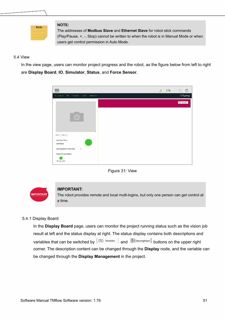
Software Manual TMflow Software version: 1.76 51
NOTE: The addresses of Modbus Slave and Ethernet Slave for robot stick commands (Play/Pause, +, -, Stop) cannot be written to when the robot is in Manual Mode or when users get control permission in Auto Mode.
View
In the view page, users can monitor project progress and the robot, as the figure below from left to right
are Display Board, IO, Simulator, Status, and Force Sensor.
Figure 31: View
IMPORTANT: The robot provides remote and local multi-logins, but only one person can get control at a time.
Display Board
In the Display Board page, users can monitor the project running status such as the vision job
result at left and the status display at right. The status display contains both descriptions and
variables that can be switched by and buttons on the upper right corner. The description content can be changed through the Display node, and the variable can
be changed through the Display Management in the project.

Software Manual TMflow Software version: 1.76 52
Figure 32: Display
Flow
In Manual Mode, the flow will be displayed and indicate the current process running position
when the project is running. Through this page, users can conveniently monitor the process as
well as properly optimize and modify the process. In Auto Mode, this page will not display.
IO
IO provides IO status monitoring and operation tools for users to monitor the status of the
digital/analog input and to operate the digital/analog outputs in this page. When the project is
running, the IO is controlled by the project and cannot be changed manually.
Figure 33: IO

Software Manual TMflow Software version: 1.76 53
Simulator
In Simulator, users can monitor the current robot posture. Press and hold Ctrl on the keyboard
and, with the right button of the mouse depressed, rotate the 3D model by dragging the mouse.
Press and hold Ctrl and, with the left button of the mouse depressed, zoom in and out of the 3D
model by dragging the mouse up or down. Press and hold Ctrl and, with the middle button
depressed, move the 3D model by dragging the mouse.
NOTE: If your mouse comes with a scroll wheel, it is the middle button. If your mouse does not come with a scroll wheel or a middle button, you can press the left and the right buttons simultaneously to function as the middle button.
Figure 34: Simulator
Status
In the Status view screen, Controller Temperature, Robot Voltage, Robot Power
Consumption, Robot Current, Control Box I/O Current, and Tool Side I/O Current can be
monitored. The currently running project or preset project will be displayed on the upper right
corner.

Software Manual TMflow Software version: 1.76 54
Figure 35: Status
Run Setting
In Run Setting, all executable projects can be viewed. For instance, displayed on the file
represents this project is running currently, displayed represents this project can be run in Auto Mode. If the project is to be run in Auto Mode, it must go through the Trial Run process. The running
method of Trial Run is performed in Manual Mode. After adjusting the speed, while the project is
running, press and hold the M/A Mode Button and press the +/- buttons on the Robot Stick in this
order: "+ - + + -" to change to Auto Mode and complete the project with complete Trial Run procedure
and ensure the safety while running. The robot will stay still in Auto mode until you press the play button
on the robot stick. Remember that if you perform trial run in Manual Mode again, the project speed will
start with the initial speed at 5%.
Figure 36: Single Project Icon
Project
Navigate to ≡ and click Project to start creating and editing the flow. As shown in the figure below, the
top is the Project Editing Toolbar, and the left is the node menu, the right sidebar contains system log
and system function menu. At the top right, icons at the right of the item separator line can be clicked for
more information by clicking to expand the system log folded at the right and to check the
TMflow version. Icons at the left of the item separator line are for indications only such as suggests
your device occupied the robot, , no one occupied the robot, and , someone occupied the robot.

Software Manual TMflow Software version: 1.76 55
The percentage suggests the project speed. For HW 3.2 users, the robot stick comes with the color LED
speed meter, and the speed meter syncs with the project speed of TMflow.
While editing the project, users can click to expand the system function menu folded at the right, and click to redo or click to undo changes of adding normal nodes, duplicating normal nodes,
or deleting normal nodes up to 5 steps.
NOTE: The 5 steps of redo or undo changes do not apply to adding, duplicating, and deleting of the Component, the Subflow, and the Thread as well as normal nodes that disappear due to the operations of the Component, the Subflow, and the Thread.
Hot Key Function Hot Key Function Hot Key Function Hot Key Function Ctrl shift P Play/Pause Esc X, escape Ctrl Z Undo F1 Step run
Ctrl shift M M/A Enter OK Ctrl Y Redo F2 Diagnosis
Ctrl shift [ - Ctrl N New project Ctrl C Copy F3 Point Manager
Ctrl shift ] + Ctrl S Save project
Ctrl V Paste F4 Base Manager
Ctrl shift 9 Info Ctrl O Open project
Delete Delete F5 Controller
Ctrl shift E Error Log F6 Variables
Table 4: Keyboard Hot Keys in TMflow
Figure 37: Project Editing Page
Project Editing Toolbar
The project editing toolbar is located at the top of the Project Editing Page. From left to right the

Software Manual TMflow Software version: 1.76 56
functions are Create New Project, Save Project, Open Project, Step Run, Diagnosis, Point Manager, Base Manager, Controller, Variables, EditBlock, Current Base and Base List, Current Tool and Tool List, and Display Manager.
Create New Project
Click to create a new project. The project naming supports Latin alphabet letters in upper case and lower case (A-Z, a-z), digits (0-9), and the character ‘_’. The maximum number of
characters can be used in naming a project is 100.
NOTE: Check Component Editor to create components. Refer to 16 TM Component Editor for
details. Check Conveyor Tracking to create projects for conveyor tracking. Refer to TM Conveyor
Tracking User Manual for details.
IMPORTANT: When saving the file, if there is a file with the same filename, it will be overwritten. Save the
file with care to avoid file loss.
Save Project
Click to save the project. The project naming supports Latin alphabet letters in upper case and lower case (A-Z, a-z), digits (0-9), and the character ‘_’. If the previous project is not
closed properly, a message will prompt when the project is opened. If select Yes, the last
saved file version will be opened and all subsequent modifications will be discarded. If select
No, the file will open with the last state before closing, and for users to perform the file saving
operation.
Open Project
Click to open existing projects. Projects are listed with the build date and the modified date. Users are able to sort projects alphabetically or by last day update with buttons.
Click to delete the projects. Click on the name of the project to select the project to
delete. Repeat the step if there are more projects to delete or check the box next to Select all
to select all projects, and click Delete button to delete the projects.

Software Manual TMflow Software version: 1.76 57
Figure 38: Open and Delete Project View
IMPORTANT: The currently opened project cannot be deleted and deleted projects cannot be restored.
Step Run
Step Run is used to confirm accuracy of the edited motion. The first node of a Step Run can
be a Start, a Point Node, or any node that is not grayed out. This allows users to easily
evaluate the correctness of the node/motion. Step Run can start running from the selected
node to have the robot moving by pressing and holding on the screen or the + button on
the Robot Stick. At any time, releasing on the screen or the + button on the Robot
Stick will stop the robot movement, and pressing and holding on the screen or the +
button on the Robot Stick again will start the robot moving from where it stopped. When the
Step Run pane displays (Node name)_finish, the node running is completed. Release
on the screen or the + button on the Robot Stick and press and hold again to continue to the
next node. If the Step Run window is open, the FREE button at the End Module cannot be
used to hand guide the robot. Also, both the variable system and the decision formula will not
operate. When there is a logical branch node (e.g., If Node, Gateway Node) the path of pass
or fail can be selected freely to check that each decision branch’s internal motion
programming is correct using Step Run.

Software Manual TMflow Software version: 1.76 58
Figure 39: Step Run
IMPORTANT: When using Step Run through a Subflow node, click RUN to enter the Subflow page, or click another node to skip the Subflow steps. Although the variable system will not operate, the Vision node will run. The Vision node parameter value and output value can be refreshed through a Step Run Vision node to facilitate subsequent programming and fine tuning. Since the variable system will not work, the Pallet node will only run for the first point.
Point Manager
Point Manager lists all points and their parameters including the category of points: General
point, fine-tuning point, dynamic point, the reference Base to which the point is attached,
and the tools used by the point. For the creation and applicable nodes of all categories of
points, refer to the Point node, F-Point node, and Touch Stop node. In the Point Manager,
represents Vision Base, and represents Custom Base. Click the on the right side of the point to go to the information page of the point where users can modify the point
name and find out the reference coordinates, tools, and detail coordinates of the point: [X, Y,
Z, Rx, Ry, Rz]. Users can set the type of motion with either PTP or Line and its speed at the
bottom.

Software Manual TMflow Software version: 1.76 59
Figure 40: Point Manager (1/2)
In the bottom half of the page, there are tools for point modification: Controller, Overwrite
new pose to this point, Re-recording on Another Base, Save as, and Delete This Point.
Figure 41: Point Manager (2/2)
Controller: Enable the Controller to operate robot.
Overwrite new pose to this point: Write the current robot position and posture at this
point and overwrite the original value.
Re-record on Another Base: re-record this point on another Base, change the
reference coordinate.
Save as: Save as other point with new name.
Delete This Point: Delete the selected point

Software Manual TMflow Software version: 1.76 60
IMPORTANT: The point system and the nodes are mutually independent. The changes made in the Point Manager will be applied to all the nodes that use this point. Before the change, check all the nodes sharing this point again to avoid the occurrence of unintended motion.
Base Manager
Base Manager will list all the Bases that can be used, the tag will indicate the Base
used by the robot at that time, represents Vision Base, and represents Custom
Base. Clicking on the right of the specific Base can access the information page of the Base. Clicking Set as the current base will change the current reference coordinate used by
the robot to this Base. Beneath that information, there are tools provided for users to operate
the Base. Refer to Chapter 6 Point and Base for the definition of Base and 7.2 Create a
Custom Base for the details on how to create a Custom Base.
Figure 42: Base Manager
Controller
Controller provides users with direct control of the robot from motion control, IO control and
FreeBot settings. Motion control includes three tabs: Joint, Base, and Tool, which
correspond respectively to “move according to the joint angle setting”, “move according to the
robot Base or the current Base”, and “move according to the Tool Coordinate”.

Software Manual TMflow Software version: 1.76 61
Figure 43: Controller
Motion Control: In the tab of Joint, Base, or Tool tabs, there are two kinds of motion
control methods:
Single-joint/single-axis movement
To use single joint/single-axis movement, click the joint/axis to be moved first, then
press or on the left bottom corner, or press the + or - button on the Robot Stick to move the joint/axis in a positive or negative direction.
Moving to a specific target
To move a specific target, enter the target in the textbox on the right, then press and
hold the Move button below to move the robot to the target position.
NOTE: The selections in the dropdowns, the solid circles, and the input values in the fields
will remain even after switching the tabs until users exit the Controller. Controller comes with the protection mechanism to prevent the joint to report the
hardware error with the oversized interpolations from sending the position command with a large gap.
IMPORTANT: The Base tab is used to move to a specified target with respect to the specified Base, and the Tool tab is used to move in a specified direction with respect to the Tool Coordinate.
IO Control: Click IO tab to open the IO control page. In the IO control, the output value
of each IO can be controlled independently, including Control Box IO, End Module IO,
and External Expansion IO. For detailed IO specifications and applications, refer to

Software Manual TMflow Software version: 1.76 62
Chapter 12.3 IO.
Figure 44: Controller (IO Control)
FreeBot Setting: In FreeBot Setting, the movement limits of the robot while pressing the
FREE Button can be set. The settings are divided into Free all joints, Free XYZ, Free
RXYZ, SCARA like and Custom Setting.
Figure 45: Controller (FreeBot Control)
Free all joint: Freely drag the robot while pressing the FREE Button.
Free XYZ: Use the FREE Button to make the robot performing translation-only
motion in Robot Base.
Free RXYZ: Use the FREE Button to make the robot performing rotation-only

Software Manual TMflow Software version: 1.76 63
motion in Robot Base.
SCARA like: Use the FREE Button to make the robot performing motion on X, Y, Z,
RZ directions of Robot Base as the traditional SCARA robots. This mode is
suitable for teaching simple pick and place jobs to avoid accidentally causing
unnecessary rotation in degrees of freedom when teaching.
Custom Setting: Freely set the degree of freedom to be released and fixed, to
facilitate hand guiding.
Button Function
Free all joint Six Degrees of Freedom, the robot end movement and posture change are not
restricted
Free XYZ Three Degrees of Freedom, the robot end can only move XYZ directions.
Free RXYZ Three Degrees of Freedom, the end can only change its orientation
SCARA Four Degrees of Freedom (X, Y, Z, RZ)
Custom
Setting Degrees of Freedom to be set by users.
Table 5: FreeBot Degree of Freedom Limitation
IMPORTANT: The FreeBot setting is still valid after the controller page is closed. Therefore, if you find that the robot cannot be moved in certain degree of freedom, check whether your FreeBot setting is correct.
Variables
TMflow has its own variable system. All types, names, and initial values of all variables can
be seen in the variable list. The variable types include both single variables and arrays, and
the new variables can be added through the Create Variable button or the Create Array
button. In the naming rule of variables, only the digits, underline and the upper case and
lower case Latin alphabets are supported. Users can click , , or to sort variables in the list with the order of reverse alphabetical, alphabetical, or chronological.
Users can use Import/Export to read text files as entities, and users can break them down
into pieces or trace them back to the plain code with programming. The text file to read must
be less than 2MB in the assigned path. Users can use Text File Manager in Robot Setting
to check text files in the list. Variables created with the type of string can read data in the text
files as values. Array, Global Variables, and Variables created with other types are not
supported.

Software Manual TMflow Software version: 1.76 64
IMPORTANT: Use " " to enclose the string when inputting the string value to avoid being treated as a variable.
EditBlock
By extending the EditBlock menu, multiple nodes can be selected, either by dragging the
mouse, while pressing the left mouse button, to draw a frame around the desired icons, or by
simply clicking each desired icon. Clicking a selected icon deselects it. Users can drag and
drop all the selections, click the Copy and Paste icon to copy and paste all selected nodes,
or perform Base Shift or Speed Adjust for all nodes. Moreover, users can set Payload with
a value or a variable in integer, float, or double, check the options in Blending to reduce the
number of robotic brakes and the cycle time, and Precise Positioning to set how nodes
locate in particular. All EditBlock related behaviors, including copy-and-paste function, can
only be performed under the same project.
Figure 46: EditBlock
Current Base and Base List
Base list will list all Bases for this project and also indicates the Current Base. In the base
list, the front symbol represents the type of Base, and represents Vision Base,
represents Custom Base. The Base displayed in the box is the Current Base and can be
replaced through clicking the list.

Software Manual TMflow Software version: 1.76 65
IMPORTANT: When users click on the Base List and add a new point, the point will be recorded on the Current Base.
Figure 47: Base List
Current TCP and TCP List
TCP list will list all the TCPs. In the TCP list, the front symbol represents the type of tool,
represents the general TCP, and represents the built-in TCP list of the hand-eye camera. The TCP displayed in the box is the current TCP, and can be replaced by clicking on
the list.
IMPORTANT:
When users click the TCP list and add a new point, the point will be recorded with the current TCP.
Figure 48: Tool List
Display Manager
In Display Manager, users can set the variables to be displayed on the display panel and
interact with users when the project is running. Variables are divided into two types: displayed
to users and input by users. The page where users may input variable value can be protected
with a password, to avoid unauthorized operators intervening with or modifying the robot's
motion behaviors by modifying the variables. On the top part of the display management
panel, the time period of the refreshing of the display of variables can be selected from 300,

Software Manual TMflow Software version: 1.76 66
500, or 1000 in milliseconds. The variable will update the display information according to the
set time. Set the refresh time appropriately to avoid users receiving wrong variable
information.
Figure 49: Display Manager
Node Menu and Flow Editing Area
In the Project Editing Page, users can create projects. The node menu in the left side is a list of
nodes that can be used. Drag the icon of each node to the Flow Editing Area to create Flow.
Users can click the pencil icon on the node to name the node in the field next to Node Name if
available. The maximum characters available in the field is 50.
Figure 50: Project Edit (1/3)

Software Manual TMflow Software version: 1.76 67
The green triangle at the top left of the tab denotes in use currently. At the top right of the project
editing page, users can click , , or to sort the tabs of the project editing pages in the
orders of reverse alphabetical, alphabetical, or chronological, and click as a dropdown to switch between subflows.
At the bottom right of the project editing page, users can click or to change display
percentage for easier reading, click to enable automatic connection mode by clicking any two nodes in the automatic connection mode to connect both of the nodes based on the clicking
order, and click again to exit the automatic connection mode upon completion of programming.
NOTE: Tabs will be sorted by types with colors in the order of the following.
Thread (pale yellow) > Subflow (pale blue) Identical user-defined names of threads are sorted chronologically. If you use a touch screen for project editing, automatic connection mode will
greatly simplify your connection process, dragging between each endpoint is no longer needed, simply enable the automatic connection mode and click on the nodes desired to be connected to connect.
Users can click at the top right, select nodes, and click the icon of the desired arrangement at the top right to align nodes in the page as shown below. The first selected node acts as the
alignment node for the other nodes. If the first node is deselected, the second selected node
becomes the alignment node.
Figure 51: Project Edit (2/3)

Software Manual TMflow Software version: 1.76 68
Figure 52: Project Edit (3/3)
Project Function Menu
The Project Function Menu will display the settings and tools related to the project, including
search function, Operation Space, ModbusDev, Set IO while Project Error, Set IO while
Project Stop, Stop Watch, View, F/T Sensor, and Serial Port.
Figure 53: Project Function Menu
Search Function
In Search Function, the search can be performed by the node name or variable name. Click
the first search box to determine the search target (searching with node name or variable
name used in the node). If searching with a node name, select , and input the keyword
in the search box behind it. If searching with a variable, select , and input

Software Manual TMflow Software version: 1.76 69
the variable in the input box. The in the input box can be clicked to input from the pop up
variable list, or input the keyword directly. The search limit condition can be specified below
the search box, for users to narrow the search range so that users can filter out the desired
targets. If you want to jump to a specific search result, click in front of the item in the result
list directly.
Figure 54: Searching Pane
Operation Space
Operation Space can be used to set the operation space configuration of the project. Refer
to Chapter 15 Operation Space for instructions.
ModbusDev
ModbusDev can be used to set the Modbus master/client in the project. Refer to 12.1
Modbus for instructions.
Set IO while Project Error
This tool can set the IO output status when the project has an error. Refer to 12.3 IO for
instructions.
Set IO while Project Stop
This tool can set the IO output status when the project stops. Refer to 12.3 IO for instructions.
Stop Watch
Through Stop Watch, users can calculate the running time elapsed between two nodes, plan

Software Manual TMflow Software version: 1.76 70
the motion, manage the production cycles more conveniently through the Stop Watch
runtime analysis tool, and optimize time for each flow. After clicking Stop Watch, click New to
add a stop watch. Stop Watch includes four parts, the beginning node, the ending node,
records in a specific variable, and the note description. Check the bullet before Start or End.
Then, click the note to be configured to complete the configuration. To save the variable,
when Stop Watch is running, the time result obtained while running can be output as the
variable to help users analyze this parameter. Select a double type variable in the variable list
and fill in the variable box to use this function.
Figure 55: Stop Watch Setting Page
View
View provides users with a quick view of the current camera's live image. The camera name
can be selected in the upper left corner of the image. Click below the image to bring up the camera adjustment parameters.

Software Manual TMflow Software version: 1.76 71
Figure 56: View Tool Floating Window
F/T Sensor
Refer to 14.2 F/T Sensor for instructions.
Serial Port
Users can add devices with serial communication interfaces in Serial Port. Simply click the
icon of Serial Port to manage the serial port devices.
Figure 57: Serial Port (1/2)

Software Manual TMflow Software version: 1.76 72
Figure 58: Serial Port (2/2)
To add a device, click Add and enter values for Device Name, Com port, Baud rate,
Data bit, Stop bit, Parity, and Time Out in the respective fields, then click OK.
To edit a device, click on the name of the device, and click on the pencil icon to edit.
Every field but Device Name is editable.
To delete a device, click on the name of the device, and click .
NOTE: The Modbus tab in Expression Editor is replaced by the Connection tab, and
Modbus is in the Protocol dropdown. The Baud rate dropdown offers choices of: 300, 1200, 2400, 4800, 9600, 14400,
19200, 38400, 57600, 115200. Users can also input a custom baud rate in the dropdown.
Robot Setting
The parameters related to the robot can be set in Robot Setting. The parameters, from left to right and
from top to bottom are: Wizard, Vision Setting, TCP, IO Setting, Safety, Controller, Speech, Gripper
Button, Component, Operation Space, Command, Connection, Posture Setting, TMmanager,
Global Variable, and Text File Manager.

Software Manual TMflow Software version: 1.76 73
Figure 59: Robot Setting
Wizard
The robot setting Wizard will guide users through robot basic settings step by step, including
language, time and date, network setting and speech setting.
Vision Setting
Vision Setting allows users to modify the camera parameters and manage vision files.
TCP
In TCP setting, users can create a TCP through FreeBot teaching and Manual-inputting
parameters. Refer to 8.2 TCP Setting for instructions.
IO Setup
In IO Setup, the default value of the output signal at the time of starting up, and the meaning
represented by the Self-Defined IO can be set. Using Self-Defined IO, users can trigger or read
the button on the Robot Stick with an external device through the IO port on the Control Box.
After the setting is complete, click the Save button in the lower right corner to save the setting.
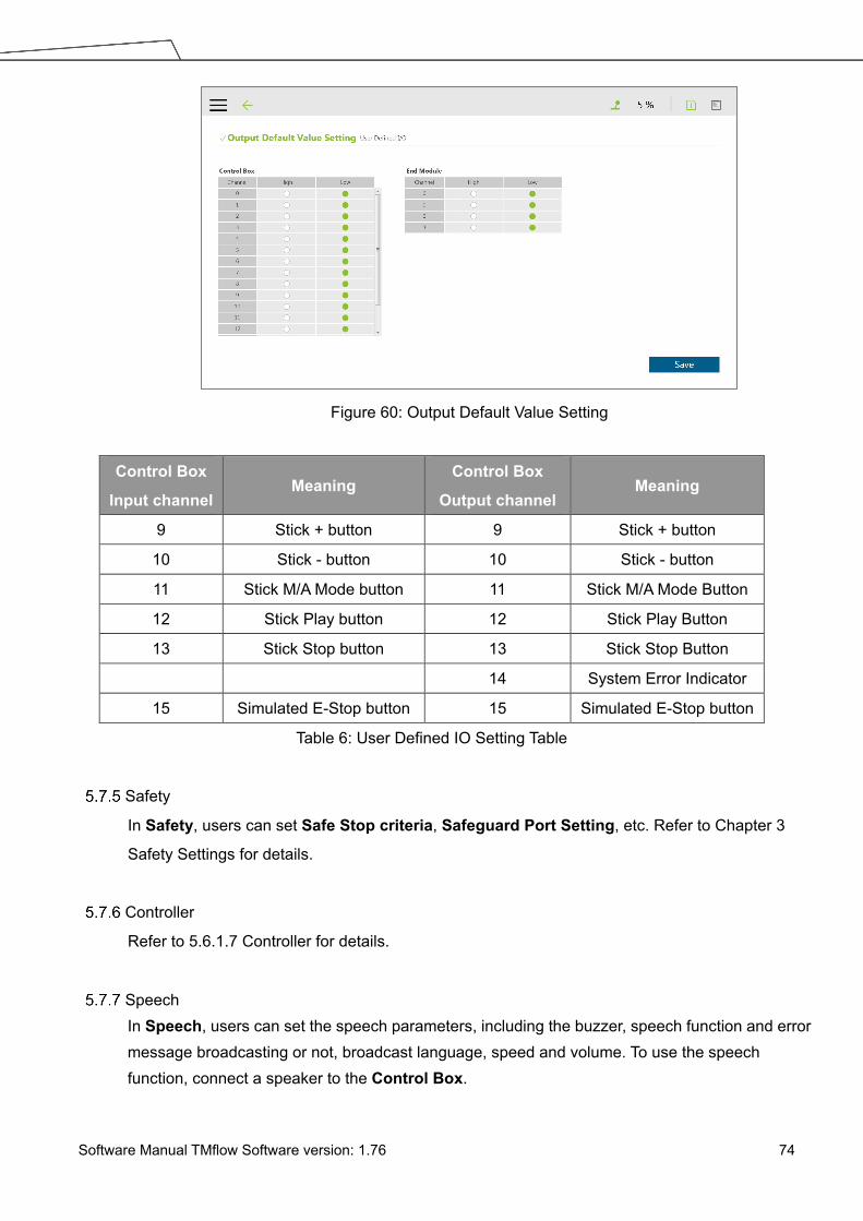
Software Manual TMflow Software version: 1.76 74
Figure 60: Output Default Value Setting
Control Box
Input channel Meaning
Control Box
Output channel Meaning
9 Stick + button 9 Stick + button
10 Stick - button 10 Stick - button
11 Stick M/A Mode button 11 Stick M/A Mode Button
12 Stick Play button 12 Stick Play Button
13 Stick Stop button 13 Stick Stop Button
14 System Error Indicator
15 Simulated E-Stop button 15 Simulated E-Stop button
Table 6: User Defined IO Setting Table
Safety
In Safety, users can set Safe Stop criteria, Safeguard Port Setting, etc. Refer to Chapter 3
Safety Settings for details.
Controller
Refer to 5.6.1.7 Controller for details.
Speech In Speech, users can set the speech parameters, including the buzzer, speech function and error message broadcasting or not, broadcast language, speed and volume. To use the speech function, connect a speaker to the Control Box.

Software Manual TMflow Software version: 1.76 75
Figure 61: Speech Setting
Gripper Button In Gripper Button, users can set the behavior when the GRIPPER Button on the End Module is pressed. If the gripper used is a general I/O type gripper, click Grip to set the IO signal required to close the gripper. Click Release to set the IO signal required to open the gripper. If the gripper in use needs TM Component to operate, select the user-defined component. Refer to Chapter 13 Component for use of TM Component.
Figure 62: Gripper Button
CAUTION: If using "Speak and Move", the speech will be saved into a buffer and deleted only if the system finished speaking it. That means, if the Voice is used in a Thread with a quick loop, the buffer size will increase quickly, that the robot might keep speaking without ever stopping.

Software Manual TMflow Software version: 1.76 76
Component In Component, users can select the component to be started from the Component List. Refer to 13 Component and 16 TM Component Editor for details. Operation Space For the method of using Operation Space, refer to Chapter 15 Operation Space. Command In Command, users can select and enable the command from the Component List. Refer to 12.4 Command for details. Connection
In Connection, users can set Modbus Slave related settings and TM Ethernet Slave.
For Modbus Slave, the system provides two Modbus communication methods: Modbus TCP
and Modbus RTU. Click on the top to turn on/off the mode. Once TCP is turned on,
the system works as a Modbus TCP server for user configured clients with IP filtered and
permissions to access robot data. If RTU is turned on, it is possible to access robot data with
configurations via serial connections. Click the Code Table button in the lower left corner to open
the Modbus slave encoding definition file.
To use TM Ethernet Slave, click on the top to turn on/off the mode. Once turned on,
the system works as a socket server for users to configure clients with IP filtered and permissions
to access robot data. TM Ethernet Slave follows the protocol introduced in the manual
Expression Editor and Listen Node.
Posture Setting Posture Setting provides a convenient tool for users to quickly move the robot to a commonly used pose. They are Packing Pose, Normal Pose, and Home Pose from top to bottom. Packing Pose can reduce the space occupied by the robot to help users pack and transport the robot. Normal Pose is the most common work starting pose of the TM Robot, and Home Pose is the pose with all joint rotation angles are 0 degrees.

Software Manual TMflow Software version: 1.76 77
Figure 63: Posture Setting
NOTE: Click on at top right of the 3D viewer for the instructions of the mouse operations.
Global Variables
The use of Global Variables is similar to the variable system in the project, but the variables in
this system can be used in all projects. Refer to 10.2.1.1 Global Variables for instructions on using
Global Variables.
Text File Manager
The Text File Manager contains a list of text files and IODD files that have been imported to the
control box. String variables from the Variables menu can be used to read data from imported
text files. Array, Global Variables, and Variables of other types do not support this feature.
System Setting
System Setting includes settings related to this software. From left to right and from top to bottom, they
are: Language, System Update, Group, User Account, Network, Import/Export, Date and Time,
Administrator Setting, Network Service, Backup/Restore, and Input/Display Device.

Software Manual TMflow Software version: 1.76 78
Figure 64: System Setting
Language
Select the icon of the language to display on the system. Click to update with the language pack if available.
Figure 65: Language Setting
System Update To update the TMflow on the robot, users need to download and unzip the update files from the
website of the Company. Then, place all the content generated from the unzipped files into the
root directory of the USB flash drive labeled with TMROBOT as shown, plug into the USB port on
the Control Box, and click the OK button on the System Update page to start the update.

Software Manual TMflow Software version: 1.76 79
Figure 66: System Update (1/2)
Figure 67: System Update (2/2)
Group
In this setting, the user group can be created. Enter the Group name in the right pane. Select the
scope of this Group's permissions when creating, including run setting, project, settings, view,
system. Press OK after settings are completed to create the Group. After creating the Group,
click to modify information, or click to delete a group.

Software Manual TMflow Software version: 1.76 80
Figure 68: Group
User Account
In this setting, the User Account can be created. Enter the Name and the Password in the right
pane to Add User. Users must select the Group to set the access permissions when creating the
User Account. After creating the User Account, click to modify information, or click to delete the User Account.
Figure 69: User Account
Network Setting
In Network Setting, the currently enabled connection list will be displayed. Click the item to set
its parameters. If users choose Get IP from DHCP, the current connection IP will be grayed out.

Software Manual TMflow Software version: 1.76 81
Figure 70: Network Setting (1/2)
Figure 71: Network Setting (2/2)
Import/Export
In Import/Export, users can import items from the flash drive or export items to the flash drive.
The label of the flash drive must be TMROBOT. Insert the flash drive to the Control Box before
using the function.
To use the Export function:
Click the Export button at the top left, and then select the desired file in the Select file box.
Click the item in this box to add the item to the Selected files box. After completing the new
addition, click Export at the bottom right to start the Export procedure.
To use the Import function:

Software Manual TMflow Software version: 1.76 82
Click on the Import button at the top left, select the robot of the data source in the flash drive
from the robot list, and then select the desired data from the Select file box. Click an item in
this box to add the item to the Selected files box. After completing the new addition, click
Import at the bottom right to start the Import procedure.
NOTE: While using Import/Export, if there are duplicated Project files in the Selected files box, after clicking either Import or Export at the bottom, users can choose from YES to overwrite, NO to save as, or CANCEL to cancel the Import or Export. Checking the box next to Apply to all folders will apply YES (overwrite) to all remaining duplicates.
Available data types to import or export:
Log, Hardware Record, Project, TCP, Command, Component, Point Base, Operation
Space, Global Variable, Path, Modbus, F/T Sensor, Network Service, Text file, IODD Files,
Ethernet Slave.
Examples:
To export the settings relative to the F/T
sensor along with the project:
To import the settings relative to the F/T
sensor along with the project:
1. Navigate to ≡, click System >
Import/Export.
2. Click Export on the top left, and click
Project.
3. Select the name of the project to export
in Select Files. Once selected, the
project to export will be listed in
Selected Files.
4. Repeat Step 3 if you wish to select more
projects to export.
5. Click Export at the bottom right to export
projects when done selecting.
1. Navigate to ≡, click System >
Import/Export.
2. Click Import on the top left, and click F/T
Sensor at the bottom left.
3. Select the robot to apply the imported
setting in the Robot List prompted and
click OK.
4. Select the project to apply the imported
setting in the Project List prompted and
click OK.
5. Select the project to import in the Import
Project List prompted and click OK.
6. Select the name of the setting listed in
Selected Files.
7. Click Import at the bottom right to import
the setting.
Date Time

Software Manual TMflow Software version: 1.76 83
In Date Time, users can change the date and time of the system as well as set the time zone with
the option to enable daylight saving.
Figure 72: Date Time
Administrator Setting
In Administrator Setting, the administrator password can be changed. The default password is
blank. To ensure the security of robot use and data, change the password after the first login.
Figure 73: Administrator Setting
Network Service
In Network Service, users can upload logs, robot data, and vision images to a remote host on a
timely basis with multiple connections and accounts.

Software Manual TMflow Software version: 1.76 84
To go to Network Service, navigate to ≡, and click System > Network Service.
Figure 74: Network Services
To set the remote host to upload, follow the steps below.
1. In the UNC field, use the uniform naming convention to input the address of the remote host.
If authentication is required, input the user account and the password in the respective fields.
Check Show if you wish to see the password in plain text. Use Login and Logout to test the
connection.
2. Check Auto Login if you wish to establish the connection when the system is on.
3. Select items to upload by checking the respective boxes, and set the interval or a specific
time to upload. Check On Error if you wish to upload when an error occurred.
4. Repeat step 1 through 3 if you have other hosts to upload.
NOTE: Users can set FTP protocol for the connection in the UNC field, for example: ftp://test:[email protected]:99. “test” stands for the account, “1234” after the colon is the respective password,
and “192.168.1.100:99” denotes the resource IP address and the port number.
To start a project to upload to the remote host, follow the steps below.
1. Navigate to ≡, and click Project. 2. Start a new project or open an existing one.
3. Drag a log node to the workspace, and click the pencil icon of the node.
4. In the Save Device field, select the desired item in the dropdown menu, and set the directory
to upload in the Save Directory field. Click OK when done.

Software Manual TMflow Software version: 1.76 85
5. Make sure the nodes in the workspace are connected properly, and run the project.
NOTE: Users have to attach the TM SSD to the system and store vision images to the TM SSD before uploading vision images via network service
Backup\Restore
This function allows users to backup and restore the current TMflow version, including projects,
TCPs, robot parameters and all other contents. A backup file will be generated by clicking the
Backup button. After users upgrade the TMflow version, the restore function can be used to
restore the previous version and the file content. When executing the Restore function, it will
show a window and display "After restoring the backup file, the current data will be removed.
Do you want to restore the backup file? (Yes / No)". Click Yes or No to proceed.
Figure 75: Backup\Restore
IMPORTANT: The number of backup files is limited to five.
Input/Display Devices
Pop-out Keyboard
Check the box next to Enable Pop-out Keyboard and click the keyboard icon at the top right
to toggle the pop-out keyboard as a means of characters input.

Software Manual TMflow Software version: 1.76 86
Figure 76: Pop-out Keyboard
Input Devices (HW 3.2 or newer exclusive)
This function provides users with options to set Input Devices with Keyboard or Tablet or
Pendant. Pendant comes with four more hot keys, Ctrl shift P (Play/Pause), Ctrl shift M
(M/A), Ctrl shift [ (-), and Ctrl shift ] (+), than Keyboard or Tablet does.
Figure 77: Input Devices

Software Manual TMflow Software version: 1.76 87
6. Point and Base Overview
In the projection of any point in three-dimensional space is the position of the point on the Base.
Figure 78: Base Value of the Point
To describe a point, in addition to X, Y, Z coordinate positions, it is also necessary to define its direction
in the space Rx, Ry, Rz to describe the posture of the point in the space.
Figure 79: Coordinate Axis Rotation
The Base is a system that defines the corresponding position and posture of the robot in
three-dimensional space. In the TM Robot, Base is divided into four categories: Robot Base, Custom
Base, Tool Coordinate, and Vision Base.
This Chapter will introduce the basic direction judgment method for the Base first, and define the
physical meaning of the Robot Base, so that users can understand the Base of robot, and use the
controller system to move the robot in the specified Base. Finally, how to convert between different
Bases will be introduced, which is for users to complete the work flow without reprogramming the
project in the situation of absolute position changes while relative positions do not change.

Software Manual TMflow Software version: 1.76 88
Base and Right-hand Rule
Right-hand Rule
The Right-hand Rule is a method of determining the direction of the three-dimensional Base. In
the system of Base of robot, the right-hand coordinate system can be used to determine the
positive direction of the Z-axis, as shown in the illustration, the thumb, index finger, and middle
finger represent the right hand coordinate X-axis, Y-axis, and Z-axis respectively, and three
fingers are perpendicular to each other. In addition, the Right-hand Rule also determines the
positive rotation direction of the coordinate axis in the three-dimensional space, bending finger.
The direction pointed by the finger is the positive rotation direction of the coordinate axis.
Figure 80: Right-Hand Base
Types of Base
The Bases defined in the robot are Robot Base, Custom Base, Vision Base and Tool
Coordinate according to the purpose. Users can complete the point planning and application in
the space using intuitive methods, according to these different base applications.
Robot Base
Robot Base is also called the world coordinate system. It is defined as the Base of the robot.
When the robot is running, no matter how the position or posture is changed, it will not affect
the direction and position of the initial point of the coordinates.

Software Manual TMflow Software version: 1.76 89
Figure 81: Robot Base
Vision Base
Vision Base can be further divided into visual servoing positioning and fixed-point positioning.
The concept of visual servoing positioning is to approach the object with camera, so the Base
is created on the camera. In fixed-point positioning, the relationship between the image
coordinate and the robot is known to calculate the positioning object with absolute
coordinates and its Base is created on the object.
Figure 82: Servoing Vision Base is on the
Camera
Figure 83: Fix-point Vision Base is on the
Object
The robot's vision can be simply built with the Base in parallel to the operation plane, allowing
users to complete assembly, processing, and other related applications on an inclined plane,
and can also use the Vision Base to position the robot in the space.
Custom Base
The Custom Base provides users with a method for creating the reference Base of the
motion node. Users can jog the robot to move to the origin, any point on the X-axis and XY

Software Manual TMflow Software version: 1.76 90
planes of the Base, to create a Custom Base, refer to 7.2 Create a Custom Base for details.
Tool Coordinate
Tool Coordinate is used to define the position and orientation of the robot TCP. Before using
the Tool Coordinate, the orientation and posture of the TCP must be defined (refer to
Chapter 8, “Create ”). If the TCP is not defined, the flange center point will be used as the
origin of the Base. In the same project, if the tool is worn out or the tool is changed, you only
need to redefine the Tool Coordinate without having to reprogram the flow.
Figure 84: Tool Coordinates
Point Parameter
For the robot-defined Point Parameter, in addition to defining the position and orientation of each point, it
will also regulate the recorded Base of each point and the tools it applies to. If the tool it applies is T0,
represents No Tool.

Software Manual TMflow Software version: 1.76 91
Figure 85: Point Parameter Information
If users need to apply different tools on the same project, or perform the same operation on different
operation planes, different information can be reassigned to the created point. This section explains the
advanced settings in the Point node as an example, this setting can be divided into two categories of
Base Shift and Tool Shift to modify the Base of point and the tool applied.
Figure 86: Shift Function of Point Node
Base Shift
The Base Shift is to transfer the point to another Base without changing the position and
orientation of its relative Base. In this example, the coordinate is rotated, translated, to convert to
another Base. In this new Base, the position and orientation of the point relative to its reference
Base is not changed. In the case of change in absolute position, the relative position is

Software Manual TMflow Software version: 1.76 92
maintained. This function allows users to complete the same job on different Bases.
Figure 87: Base Shift Schematic Diagram
Record point P1 on Base 1. At this time, use the Base Shift to change the reference coordinate
of the point to the new base, Base 2. This operation will not modify the data of original point, only
valid for this set node, and the modified node Base will be presented within a pink box.
Figure 88: Node with Base Shift
IMPORTANT: This function is different from re-record on another base in the Point Manager. The function of re-record on another base is to present the position and orientation of the point with respect to another Base. Therefore, the absolute position of the original point is not changed.

Software Manual TMflow Software version: 1.76 93
NOTE: Base Shift works on Robot Base, Vision Bases, and Custom Bases for motion nodes. Base Shift or Tool Shift does not reset after importing points from existing points in the
node.
Base Shift or Tool Shift is possible to shift to the current base or the current tool.
Tool Shift
Record point P1 on T1. At this time, use Tool Shift to change the tool T1 applied to P1 to tool T2.
In practical applications, this function can be used if the tool is worn out or the same path is
completed using different tools. This function is divided into two categories: Keep Pose and Keep
Path. The same as the Base Shift, this operation does not modify the data of the origin position,
is only valid for this set node, and the tool icon of the modified node will be rounded with pink
borders.
Figure 89: Node with Tool Shift
Keep Pose: If the tool selected when the robot records the path is incorrect, the Keep Pose
function of Tool Shift can be used to substitute the correct tool parameters of this node. This
setting will not cause changes to the robot's pose and position, that is, it overlaps with the
original track when running the project.
Figure 90: Tool Shift Using Keep Pose

Software Manual TMflow Software version: 1.76 94
Keep Path: The robot will try to make the point recorded with the new tool the same as the
old tool's point, and further change the robot's pose to conform to the new tool's setting;
however, it may not be achieved due to space or robot mechanism limitations.
Figure 91: Tool Shift Using Keep Path

Software Manual TMflow Software version: 1.76 95
7. Create Base Create Vision Base
Vision Base can be generated through Vision Node in the Flow, which can be defined based on the
target object or on the camera depending on which method is being chosen (Servoing or Fixed-Point).
Create a Custom Base
Click on the Base Manager above the Project Editing Page. Users can use three points to create a new
Base. Since the information of each point is recorded on the Base, only three points need to be
redefined when changing the work plane. It is possible to implement the motion on another plane
without reprogramming.
Figure 92: Base Manager
There are three buttons in the center of the three-point Base. From left to right, they are Set the Base
Origin, Set any Point on X-axis of the Base, and set the Base on any Point on the Positive X -
Positive Y Plane. Refer to 6.2 Base and Right-hand Rule to use the Base correctly.
Users can use the controller button below to enable the controller to operate the robot, or use the
FreeBot mode to pull the robot to the target position (“Pointing 0,0,0”, “Point on X-axis”, “Point on
Surface”). Pressing the corresponding button at this time will record the robot's current position at this
point. After the setting is completed, the exclamation mark in front of the button will disappear. Once all
three points are set, press "OK" to create the Base.

Software Manual TMflow Software version: 1.76 96
NOTE: Build a Base by 3 Points
Figure 93: Build a Base by 3 Points
There are 3 buttons representing the 3 points which define a base, i.e. Origin (0,0,0), Point on X-axis, and Point on Surface, refer to 6.2.1 Right-hand Rule. Users can use the controller button below to enable the controller to operate the robot, or use the FreeBot mode to pull the robot to the target position (Pointing 0,0,0, Point on X-axis, and Point on Surface). Press the corresponding button at this time will record the robot's current position at this point. After the setting is completed, the exclamation mark in front of the button will disappear. After all three points are set, press OK to create the base. This point is the TCP point.
Create New Base Node
Drag the New Base Node from the left side. After clicking Edit on the upper left of the node, users can
select to create a new base with vision bases or create a new base with three points.

Software Manual TMflow Software version: 1.76 97
Figure 94: New Base Node
Create a New Base by Multiple Bases
Create a New Base with Two Vision Bases
This function is to create a new Base with two Vision Bases. While the project is running, if
the relative distance between the two updated Vision Bases fall within the tolerance range
set by users, it is possible to create a new Base, or the node will go to the path of fail.
Figure 95: Create a New Base with Two Vision Bases
Create a New Base with Three Vision Bases
This function is to create a new Base with three Vision Bases, and use the position of the
first Vision Base as the initial position, the second Vision Base to set the direction the x axis,

Software Manual TMflow Software version: 1.76 98
and the third Vision Base to set the fiducially orientation. Since this function only uses the
position to create the new Base, it cannot be affected by the error of the visual recognition
angle, and it is applicable to situations where the angle is required to be highly stable. While
the project is running, users can set the tolerance ranges of the initial position to the second
Vision Base and the third Vision Base. If the calculated distance falls within the tolerance
range set by users, a new Base will be created, or the node will go to the path of fail.
Figure 96: Create a New Base with Three Vision Bases
Create a New Base with Three Points
This function is to create a new Base with the three points such as the points on the Vision
Bases, the Dynamic Points, and the points in general to be used together. The two common
situations create a new Base with three points on the Vision Base and create a new Base with
three Dynamic Points, are described below.

Software Manual TMflow Software version: 1.76 99
Figure 97: Create a New Base with Three Points
Create a New Base with Three Points on the Vision Base
In situations where it is not possible to create a new Base by visual recognitions, users can
create a new Base with the points recorded on the Vision Bases. By using the New Base
node, it is possible to launch the Point Manager and use the points in the Point Manager.
The first selected point sets the initial position of the Base, the second selected point sets the
direction the x axis, and the third selected point sets the fiducial orientation. As illustrated
below, P1, P2, and P3 are applied to create a new Base. Since the points are recorded on the
Vision Base, the newly created Base changes as the Vision Base changes.
Figure 98: Create a New Base with Three Points on the Vision Base

Software Manual TMflow Software version: 1.76 100
Create a New Base with Three Dynamic Points
Rather than using points on the Vision Bases, this function uses the Dynamic Points built
by the Touch Stop nodes to create a new base. In situations where it is not possible to create
a new Base by visual recognitions, users can create a new Base with the Dynamic Points
built by three Touch Stops. The first Touch Stop sets the initial position of the Base, the
second Touch Stop sets the direction the x axis, and the third Touch Stop sets the fiducial
orientation.
Figure 99: Create a New Base with Three Dynamic Points

Software Manual TMflow Software version: 1.76 101
8. Create the TCP Overview
The TCP (Tool Center Point) is the reference point for tool interaction with the workpiece. The TCP
includes six parameters: X Coordinate, Y Coordinate, Z Coordinate, Rx Coordinate, Ry Coordinate, and
Rz Coordinate. The TCP is attached to the end of the robot, and is referenced from the center
coordinates of the flange.
On the robot, apart from the position and orientation reference values of the six elements, the tool
weights and the inertia values can also be input to compensate the performance during operation to
avoid misreading the effect of the tool on the robot as an external force. The TCP Setting can be
accessed from the Robot Setting page.
Figure 100: TCP Definition
TCP Setting
This section describes how to get parameters of TCP from "Teaching" or "Manual Input or choose
from Saved File".

Software Manual TMflow Software version: 1.76 102
Figure 101: TCP Setting
Create Parameters of TCP with Hand Guidance Teaching
The principle of creating the TCP by teaching is to teach the robot to reach the same point in the
space through a different posture, to calculate the position of TCP relative to the robot end flange
automatically. The Calibration Pin Set sold by the Corporation or a custom-made calibration tool
can be used to calibrate the fixed calibration point in the space during the teaching process. The
number of calibrations varies depending on users' operation method and accuracy requirements.
The number of teachings on the TCP is at least 4 times.
Follow steps below to create a TCP by teaching:
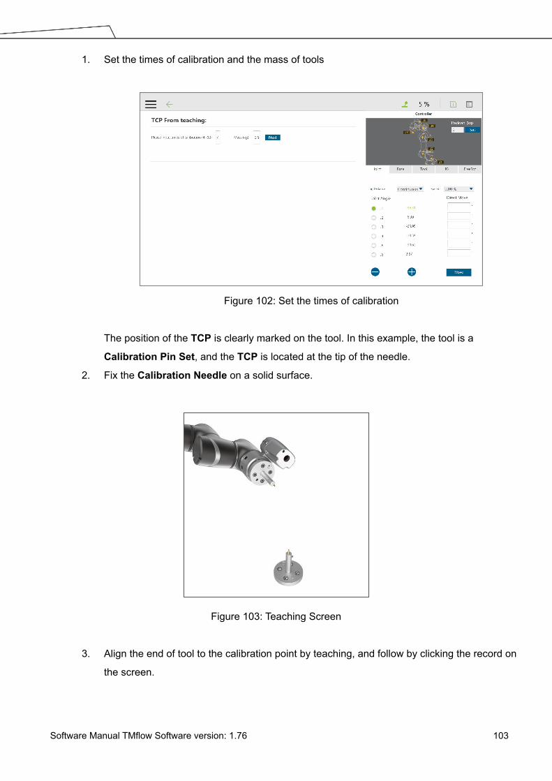
Software Manual TMflow Software version: 1.76 103
1. Set the times of calibration and the mass of tools
Figure 102: Set the times of calibration
The position of the TCP is clearly marked on the tool. In this example, the tool is a
Calibration Pin Set, and the TCP is located at the tip of the needle.
2. Fix the Calibration Needle on a solid surface.
Figure 103: Teaching Screen
3. Align the end of tool to the calibration point by teaching, and follow by clicking the record on
the screen.

Software Manual TMflow Software version: 1.76 104
Figure 104: The Robot Posture Needs to Change during Teaching (1/2)
Figure 105: The Robot Posture Needs to Change during Teaching (1/2)
4. Repeat this action until completed and the TCP numerical results and error values are
displayed. After confirming that there is no mistake, input the tool name to save the file, and
set it as the current tool for the robot.
5. After teaching is completed, the positioning result will be displayed.
NOTE: It is recommended to calibrate this value equal or less than 0.3 to ensure accuracy.

Software Manual TMflow Software version: 1.76 105
IMPORTANT: In addition to users' human errors and the number of calibrations, the error of establishing a TCP by teaching is also related to the selected teaching poses. The more joints that you change, and the more you change each one, the better. Between each teaching point, rotate each joint, to achieve the best calibration result.
NOTE: When using the Calibration Pin Set to teach TCP, the controller can be used to fine-tune the moving robot. Between each teaching point, it is still necessary to ensure that 1 to 6 joints are rotated.
6. The calibration result can be saved for future use.
Figure 106: Save Teaching Result
Create Tool Center Point by Input Parameters
If users clearly know the TCP relative to the position of robot end flange, the coordinate
parameters can be input manually. After the input is completed, click Save as to create a new
TCP. To modify the TCP parameter values, click Open to select the item to be modified from the
list, and after the modification is completed, click Apply in the lower right corner to save the
changes and set this TCP to the current TCP to be used by the robot. In this interface, all TCP
data on the robot can be managed. Click Open to open the TCP list of the robot. Click behind
the item to delete the TCP data.

Software Manual TMflow Software version: 1.76 106
Figure 107: Manual Input TCP Values
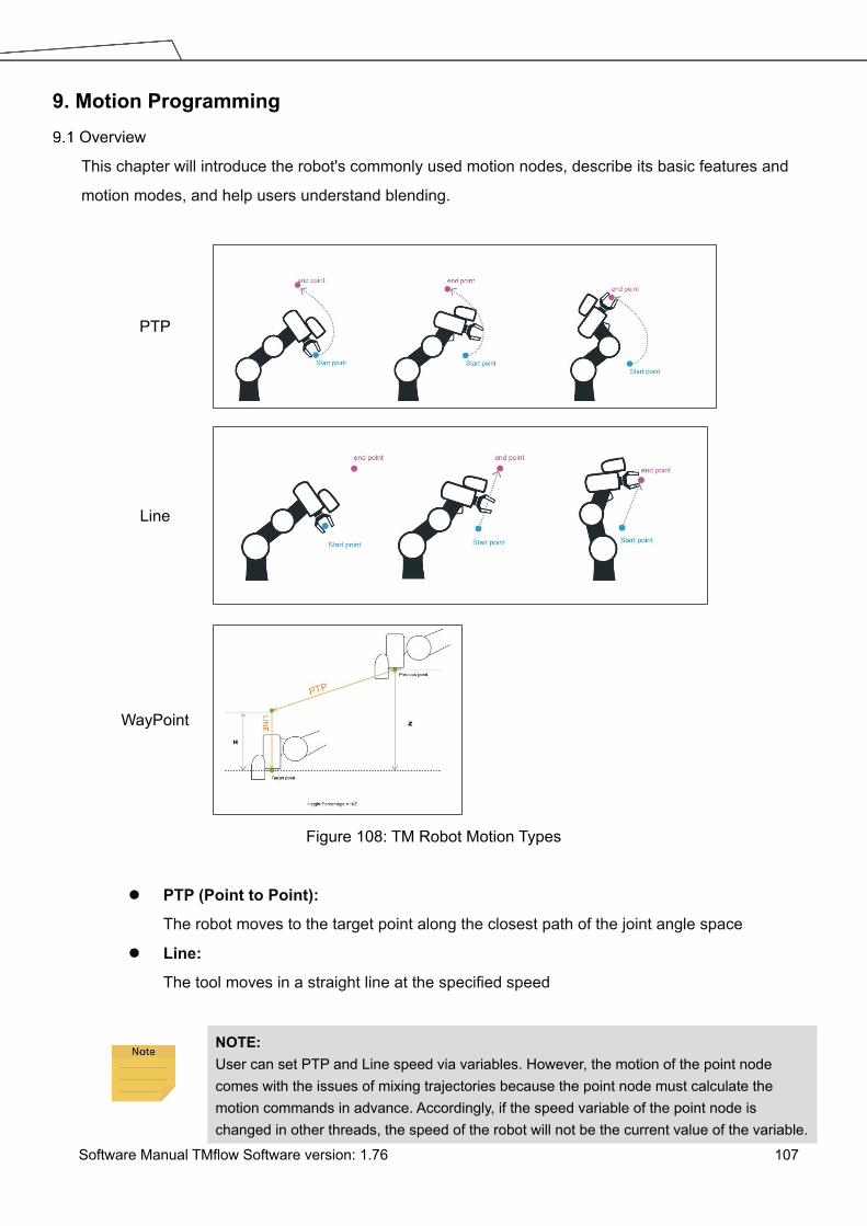
Software Manual TMflow Software version: 1.76 107
9. Motion Programming Overview
This chapter will introduce the robot's commonly used motion nodes, describe its basic features and
motion modes, and help users understand blending.
PTP
Line
WayPoint
Figure 108: TM Robot Motion Types
PTP (Point to Point):
The robot moves to the target point along the closest path of the joint angle space
Line:
The tool moves in a straight line at the specified speed
NOTE: User can set PTP and Line speed via variables. However, the motion of the point node comes with the issues of mixing trajectories because the point node must calculate the motion commands in advance. Accordingly, if the speed variable of the point node is changed in other threads, the speed of the robot will not be the current value of the variable.

Software Manual TMflow Software version: 1.76 108
To ensure the correctness of the speed variable in the motion command with the point node, users need to add a Wait For node or update the speed variable ahead of the point node in the same flow.
WayPoint:
The tool performs two-stage path movement at the set percentage of Z-axis height or distance, and
it is often used for pick and place applications.
NOTE: To maintain the smoothness and the continuity of the motion, the flow in process calculates and sets each value in the nodes with the logic and the sequence of the programming. The calculation is made much earlier than the time to actually perform the motion. If using variables as the parameters in the motion nodes, users must insert other nodes such as the Set nodes, the Network nodes, or the Listen nodes before the motion node to assign the correct values to the variables.
Point to Point (PTP) PTP is the Fastest Way to Move
The PTP mode determines the robot’s motion by calculating the angular variation of each axis,
and is not limited by the singularity point. If the robot’s motion is not limited, it is recommended to
select PTP movement.
IMPORTANT: Singular points are described in the Safety Manual.
Figure 109: PTP Motion
Speed of PTP Motion The PTP speed is based on the motion joint that takes the longest time. The PTP mode may
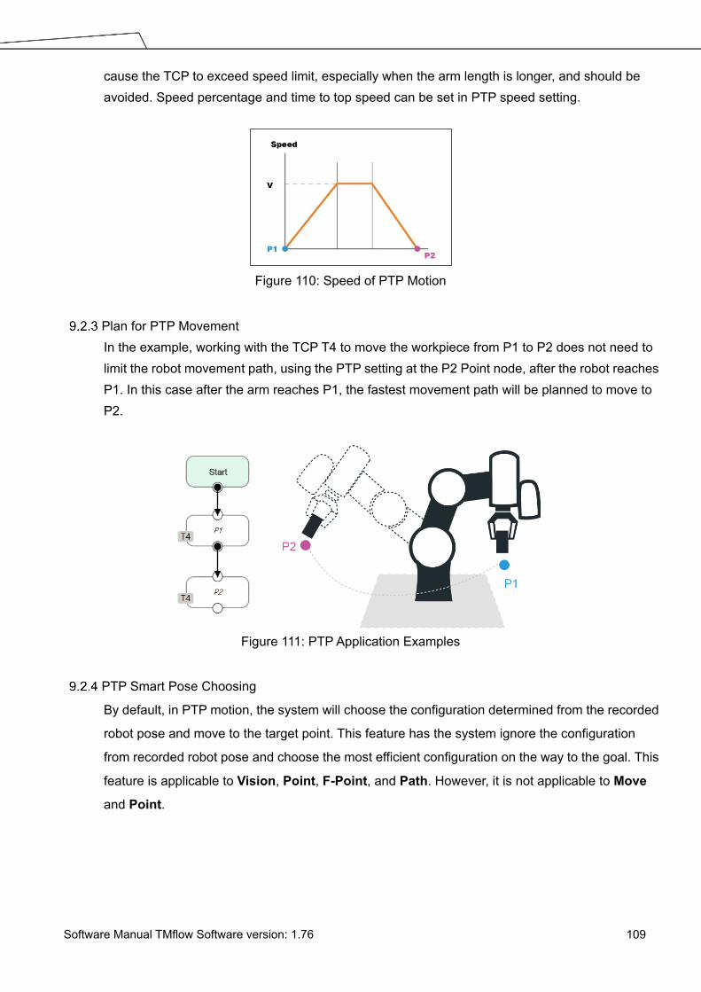
Software Manual TMflow Software version: 1.76 109
cause the TCP to exceed speed limit, especially when the arm length is longer, and should be avoided. Speed percentage and time to top speed can be set in PTP speed setting.
Figure 110: Speed of PTP Motion
Plan for PTP Movement In the example, working with the TCP T4 to move the workpiece from P1 to P2 does not need to limit the robot movement path, using the PTP setting at the P2 Point node, after the robot reaches P1. In this case after the arm reaches P1, the fastest movement path will be planned to move to P2.
Figure 111: PTP Application Examples
PTP Smart Pose Choosing
By default, in PTP motion, the system will choose the configuration determined from the recorded
robot pose and move to the target point. This feature has the system ignore the configuration
from recorded robot pose and choose the most efficient configuration on the way to the goal. This
feature is applicable to Vision, Point, F-Point, and Path. However, it is not applicable to Move
and Point.

Software Manual TMflow Software version: 1.76 110
Figure 112: PTP Smart Pose Choosing
Line
Line Moves the Shortest Distance
A straight line is the shortest distance between two points. The Line mode specifies that the path
between the two points is planned as a straight line.
Figure 113: Line Motion Simulation
Speed of Line Motion
Line mode may cause joint speeding. Try to avoid speeding close to a singularity point, or make
the posture large-angle movements over a short distance.
Figure 114: Speed of Line Motion

Software Manual TMflow Software version: 1.76 111
Percentage of Typical Speed and absolute speed value can be set in Line speed setting. The
available range of ABS Speed is from 0 to 4500 mm/s, and the available ABS Time to top speed
is from 150 to 9999 ms. Check the box next to Link to project speed to align the speed with the
project speed.
Figure 115: Link to Project Speed
The typical speed is the suggested maximum speed of a regular application, and is the linear
speed of the center of the tool flange of the robot, used in the specified cycles defined in these
specifications:
Repeatability
Maximum Payload
If users want to set higher speed, use the ABS setting in the node. The maximum speed of the
robot is highly dependent on the pose of the robot and joint motion. Refer to the maximum joint
speed in the specification for the composition of velocities of the tool end.
Plan for Line Movement
The figure below explains that this project sets two points P1, P2, and tool T22. Using the Line
setting at the P2 Point node, after the arm reaches P1, it will move to P2 with Line path.

Software Manual TMflow Software version: 1.76 112
Figure 116: Line Application Example
IMPORTANT: ABS (Absolute) speed setting, including Point, Path, Move, and nodes can be used when the speed is linked with Project Speed. When not clicked, the arm motion maintains the ABS set speed. The warning window will pop up when the speed setting exceeds 250mm/s, and check automatically, display "Speed exceeds 250mm/s, needs to be linked with Project Speed ".
Two-Steps Motion (WayPoint)
WayPoint
The two-step movement will maintain a part of Z-axis displacement on the point Base. When the
1st step XY axis is aligned and in position, the 2nd step will move toward the Z-axis. This is often
used in pick-and-place applications. To plan the motion from the 1st step to the 2nd step, users
can choose either PTP to Line or Line to Line motion.
Figure 117: WayPoint Motion Status
The movement is taken as approaching motions with moving sequence from the 1st step to the
2nd step when the target point direction is on the direction of +Z in the tool coordinate, and the
movement is taken as leaving motions with moving sequence from the 2nd step to the 1st step
when target point direction is on the direction of -Z in the tool coordinate.
The approach and departure of the WayPoint motion is set by the system automatically with the

Software Manual TMflow Software version: 1.76 113
following criteria:
For approaching motions, users have to set the target point on the same direction as the
Z-axis of the robot’s tool coordinate with the starting point.
For departing motions, users have to set the target point on the opposite direction from the
Z-axis of the robot’s tool coordinate with the starting point.
Figure 118: WayPoint Setting
Users can set the value of Percentage with the slider or the respective field, or Distance in mm
to maintain height with the respective field. Also, users can use the Var button to set the value
with a variable. If the variable for percentage is larger than 100, the system uses 100. If it is
smaller than 0, it equals to 0. The data type of the variable must be integer.
Plan for WayPoint Movement The following figure is an example to illustrate that if there are obstacles around the workpiece to be picked, extra care is needed to avoid a collision. This project creates a point P1, sets the WayPoint motion mode, retains a Z axis height before reaching P1 point, and then goes downward to pick the workpiece, to prevent a collision.
Figure 119: WayPoint Application Examples

Software Manual TMflow Software version: 1.76 114
Blending
NOTE: The robot cannot use blending before going to a WayPoint node.
Blending in Movement In the process of planning a trajectory, the robot will not exactly pass through each programmed point, which has the advantages of reducing the number of robotic brakes and reducing wear and shortening the cycle time. As shown in the figure below, a movement from P1 to P3 is planned, and P2 does not need to be exactly in the path. In this case, Blending can be set at P2 point.
Figure 120: Blending in Space
Blending Speed Change Chart The cycle time can be shortened by Blending as shown in the figure below.
speed
P1
A
B
BlendValue = Blending PercentBlending Percent = B / A
P2Blend = Yes
P2
+ final speed=
Time
Time
Figure 121: Blending Speed Change Chart
Set the Blending Percentage
Users can click By Percentage to set the blending percentage in Line, PTP, and Circle motion
modes.

Software Manual TMflow Software version: 1.76 115
Figure 122: Set the Blending Percentage or Set the Blending by Radius
Set the Blending by Radius
In Line mode, users can click By Radius to set the Blending by radius. Line is a commonly used
motion mode in Point Nodes. For details, refer to the sections with corresponding titles of this
manual.
IMPORTANT: As shown in the table below, blending can improve the smooth running of robot, but when the Blending radius has been set by Line motion, blending with Circle and PTP cannot be used.
P2
P1
PLine Line PTP Circle
% Radius
PLine X
Line % X X X X
Radius X X
PTP X X X
Circle X X X
Table 7: Valid Blending Setting (Moving from P1 to P2)
Motion Nodes Payloads of motion nodes support variables as inputs. The available data types of the variables include
integer, float, and double. This feature is applicable to Point, Pallet, Move, Circle, Path, F-Point,
Compliance, Touch Stop, and Force Control.

Software Manual TMflow Software version: 1.76 116
Figure 123: Motion Nodes Support Variable as the Inputs
Also, users can adjust the speed, the payload, the blending settings, and the precise positioning option
of motion nodes by selecting nodes to adjust in advance and clicking on the respective buttons in the
Edit Block menu to adjust in a batch. This feature is applicable to Vision (PTP, Line), Point (PTP, Line,
Waypoint), Pallet (PTP, Line, Waypoint), Move (PTP, Line, Joint), Circle (Line), F-Point (PTP, Line,
Waypoint), CVPoint (Line), CVCircle (Line), and Path (PTP, Line, Pline, %); however, it is not
applicable to Touch Stop, Compliance, Smart Insert.

Software Manual TMflow Software version: 1.76 117
Figure 124: Speed Adjust and Speed Indication on the Node.
Point Node Users can see the motion type of the point node at the right of the node as shown. Icons for the
motion types are for PTP, for Line, and for WayPoint.
Figure 125: Point Node
Generation Method of Point node TMflow currently has two methods to generate a Point. The point generated will be entered on the list of Point Manager. 1. Drag the Point Node from the node menu to the Project Editing Area to add the new
point. 2. Click POINT at the End Module to add the point.

Software Manual TMflow Software version: 1.76 118
Point Node Setting
The Point Node can be set to motion mode, Blending, Base Shift and Tool Shift. The robot will determine the mode of moving to this point according to the above setting.
Figure 126: Point Node Setting
Motion mode setting: Set motion type
Point Management: Can choose from a existing point or open the Point Manager
Blending setting: Set blending type
Advanced setting: Base shifting / Tool shifting
Payload: Load setting of robot end
Precise positioning: Whether moves to the point precisely
IMPORTANT: If you have not selected Precise Positioning, the robot arm will not stop at the Precision Point but instead directly move on to running the next command. If you select Precise Positioning, the robot arm will wait until motion along all axes has stabilized at the Precision Point before moving on to running the next command.
F-Point Node This Node can perform fine tuning of X, Y, Z Axis ±10mm and Rx, Ry, Rz±5° at the existing point. During the project execution, the F-Point variable can also be corrected in the View page. In addition, since inputting variable to fine tuning point is not a safe action when the project is running, the login password protection is designed on the interface. Set and use the settings appropriately.

Software Manual TMflow Software version: 1.76 119
Figure 127: F-Point Node
Figure 128: F-Point Node Setting
IMPORTANT: In a single project, the number of F-Points is limited to 20.

Software Manual TMflow Software version: 1.76 120
Figure 129: Adjust F-Point Parameter during Project Running
Move Node
In this node, users can set values from the Base X, Y, Z, RX, RY, RZ or six-axis angles J1~J6 to
determine robot movement distance/angle, and then perform relative movement from current
position.
Figure 130: Move Node Setting
Joint angles can be set to determine the relative movement of the robot
Relative movement of distance and angle can be set
The set relative movement distance can be replaced by a variable
To choose a base in this node:

Software Manual TMflow Software version: 1.76 121
1. Click the pencil icon on this node.
2. Click on Tool or Current Base below Choose Base.
3. When the list prompt is displayed, select an item and click OK.
Plan for the Move Node
As shown below, users can pick up the stack with a move node. By increasing the z value
with each cycle, using the variable, by 5 cm, the four objects can be moved in four cycles.
Figure 131: Plan for the Move Node
Circle Node
Circle Node Setting
The Circle node plans the path pass through point P2 and end point P3, and uses P1 as the
path start point, and plans an arc movement.
Figure 132: The Circle Node Plans Arc Path with 3-Point Setting Circle

Software Manual TMflow Software version: 1.76 122
Figure 133: Circle Node Setting
To use the circle node:
Step 1 Create a starting point before adding the circle node.
Step 2 In the circle node, set the pass through point and the end point.
Step 3 Define path arc length with angle.
Step 4 Configure the Speed Setting.
Set Angle= 0°
In 3-point setting circle, users can define the path arch length with angle after setting the
Circle. When set angle is 0°, the robot will move from P1 Start Point to P3 End Point
through P2. At this time, the robot posture will change with the point, as shown in the figure
below.
Figure 134: The Circle Motion Status of Set Angle = 0°
Set Angle > 0°
Define the path arc with angle, when set angle >0°, and with 3-point setting circle, the robot

Software Manual TMflow Software version: 1.76 123
moves the set angle from P1 Start Point through P2, P3. At this time, the robot posture will
not change from the P1 point posture.
Figure 135: The Circle Motion Status of Set Angle =270°
Path Node
This node can read and run the .Path path file and control the robot to move according to the path
in the .Path file.
Path and PLine
The Path file is a collection of points that can be generated by a third-party CAD-to-Path
software partnered with TM Plug&Play. PLine is a special motion mode of the Path file, and
its blending setting is different from that of the Line, providing that the robot can smoothly
move between dense points.
PLineP2
Blend = Yes
A
B
C
BlendValue = Blending PercentBlending Percent = R / Distance between A&B
R
From A to B to C
End Blending
Start Blending
Figure 136: PLine Blending Relationship Chart
Path Node Setting
Path File: Select Path to run from the Imported Path File
Speed: Set the speed percentage when the path is running. Applicable to the 1st point at
the same time.
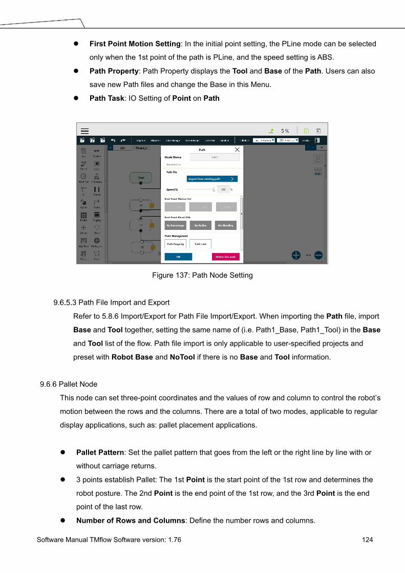
Software Manual TMflow Software version: 1.76 124
First Point Motion Setting: In the initial point setting, the PLine mode can be selected
only when the 1st point of the path is PLine, and the speed setting is ABS.
Path Property: Path Property displays the Tool and Base of the Path. Users can also
save new Path files and change the Base in this Menu.
Path Task: IO Setting of Point on Path
Figure 137: Path Node Setting
Path File Import and Export
Refer to 5.8.6 Import/Export for Path File Import/Export. When importing the Path file, import
Base and Tool together, setting the same name of (i.e. Path1_Base, Path1_Tool) in the Base
and Tool list of the flow. Path file import is only applicable to user-specified projects and
preset with Robot Base and NoTool if there is no Base and Tool information.
Pallet Node
This node can set three-point coordinates and the values of row and column to control the robot’s
motion between the rows and the columns. There are a total of two modes, applicable to regular
display applications, such as: pallet placement applications.
Pallet Pattern: Set the pallet pattern that goes from the left or the right line by line with or
without carriage returns.
3 points establish Pallet: The 1st Point is the start point of the 1st row and determines the
robot posture. The 2nd Point is the end point of the 1st row, and the 3rd Point is the end
point of the last row.
Number of Rows and Columns: Define the number rows and columns.

Software Manual TMflow Software version: 1.76 125
Figure 138: Pallet Node (1/2)
Figure 139: Pallet Node (2/2)
Figure 140: Pallet Patterns

Software Manual TMflow Software version: 1.76 126
Number of layers and the thickness of each layer: Set number of levels and height of
each level
The direction of the pallet: bottom-up or top-down
Pallet will automatically generate a set of variables of row, column, and layer numbers,
connected to Pallet movement position
NOTE: 1. Users can use the function of Correlate to variable to correlate the row and
column with variables. After variables are assigned to the row and column, the variables can be used to manipulate or display which slot in the Pallet is to be implemented.
2. Teaching points without following the sequence of the chosen pattern may result in the opposite of Z-axis.
IMPORTANT: Pallet needs to work with a Loop in order to move to the next position of the Pallet.
Listen Node
In the Listen Node, a socket server can be established and be connected by an external device to
communicate according to the defined protocol. All the functions available in Expression Editor
can also be executed in Listen Node.
Figure 141: Listen Node

Software Manual TMflow Software version: 1.76 127
Send Message: When entering this node, it will initiate a message
Print Log: Enable Communication Log (shown on the right)
Connection Timeout: When entering this node, if more than the Connection Timeout
(milliseconds) passes without connecting, it will timeout. If <= 0, no timeout
Data Timeout: When connected, the timeout will be exceeded if no communication packet
arrives in Data Timeout milliseconds. If <= 0, no timeout
Socket Server is set up after the project is running and closed after the project is stopped. When
the Socket Server is successfully established, the IP and Port will be displayed in the Notice Log
window on the right.
IP HMI System Network IP Address
Port 5890
When the process enters the Listen Node, it stays in the Listen Node until it triggers and leaves
with the exit condition.
Pass: Executes ScriptExit() or item stopped
Fail: 1. Connection Timeout
2. Data Timeout
3. Before the Socket Server been established successfully, the flow process has
entered the Listen Node
The commands received by the listen node will be executed in order. If the command is not valid,
an error message will be returned carrying the line number with errors. If the command is valid, it
will be executed.
The commands can be divided into two categories. The first category is commands which can be
accomplished in instance, like assigning variable value. The second category is commands that
need to be executed in sequence, like motion commands and IO value assignment. The second
category command will be placed in the queue and executed in order. Refer to the manual
Expression Editor and Listen Node for details on commands and communication format.
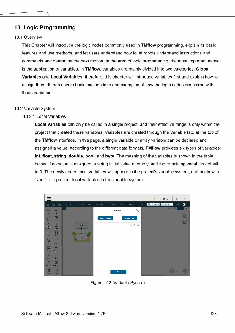
Software Manual TMflow Software version: 1.76 128
10. Logic Programming Overview
This Chapter will introduce the logic nodes commonly used in TMflow programming, explain its basic
features and use methods, and let users understand how to let robots understand instructions and
commands and determine the next motion. In the area of logic programming, the most important aspect
is the application of variables. In TMflow, variables are mainly divided into two categories: Global
Variables and Local Variables, therefore, this chapter will introduce variables first and explain how to
assign them. It then covers basic explanations and examples of how the logic nodes are paired with
these variables.
Variable System
Local Variables
Local Variables can only be called in a single project, and their effective range is only within the
project that created these variables. Variables are created through the Variable tab, at the top of
the TMflow interface. In this page, a single variable or array variable can be declared and
assigned a value. According to the different data formats, TMflow provides six types of variables:
int, float, string, double, bool, and byte. The meaning of the variables is shown in the table
below. If no value is assigned, a string initial value of empty, and the remaining variables default
to 0. The newly added local variables will appear in the project's variable system, and begin with
"var_" to represent local variables in the variable system.
Figure 142: Variable System
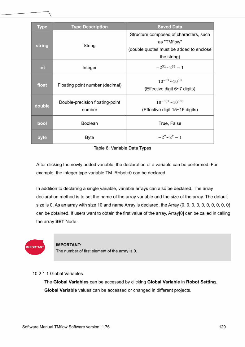
Software Manual TMflow Software version: 1.76 129
Type Type Description Saved Data
string String
Structure composed of characters, such as "TMflow"
(double quotes must be added to enclose the string)
int Integer −231~231 − 1
float Floating point number (decimal) 10−37~1038
(Effective digit 6~7 digits)
double Double-precision floating-point
number 10−307~10308
(Effective digit 15~16 digits)
bool Boolean True, False
byte Byte −27~27 − 1
Table 8: Variable Data Types
After clicking the newly added variable, the declaration of a variable can be performed. For
example, the integer type variable TM_Robot=0 can be declared.
In addition to declaring a single variable, variable arrays can also be declared. The array
declaration method is to set the name of the array variable and the size of the array. The default
size is 0. As an array with size 10 and name Array is declared, the Array {0, 0, 0, 0, 0, 0, 0, 0, 0, 0}
can be obtained. If users want to obtain the first value of the array, Array[0] can be called in calling
the array SET Node.
IMPORTANT: The number of first element of the array is 0.
Global Variables
The Global Variables can be accessed by clicking Global Variable in Robot Setting.
Global Variable values can be accessed or changed in different projects.

Software Manual TMflow Software version: 1.76 130
Figure 143: Global Variable Setting
As shown in the figure below, an integer type Global Variable is declared as a. The newly
added Global Variable will appear in the project's variable list, and it will be represented as a
Global Variable starting with "g_".
Figure 144: Global Variables after Project Is Run
If, for example, users create a global variable with a name of ‘a’, this will be displayed by
TMflow as “g_a”, indicating that it is a global variable. The global variable “g_a” defaults to a
value of zero. If the SET node increments the value of “g_a” by one each time it is executed,
after running the project 66 times the value of “g_a” will be 66. At this point, any other project
that accesses “g_a” will get the value 66 for the variable.

Software Manual TMflow Software version: 1.76 131
IMPORTANT:
Global variables will not be re-initialized when the system shuts down. They will retain their
value.
Logic Nodes
Start Node
In this node, users can view and set the initial state of the current project such as the initial project
running speed in Manual mode (the initial project running speed in manual mode is fixed at 5% by
default). Also, users can reset the states of DO and AO at the beginning of the project to initialize
DO and AO before the project starts. Check Enable continuous motion to prevent the IO writing
from interrupting the robot moving along the path of points for a smooth process of moving.
Enable continuous motion is unchecked by default.
SET Node
This node can set the states of IO, and change the type and value of variables. When passing
through this node, all parameters in the node will be changed to the set result.
Figure 145: SET Node
In the application of variables, the SET Node can add and subtract variables, associate with the
IF Node to select the path, or interrupt the infinite path of the project. As shown below, set an
integer type of variable count=0. Each time it passes through the SET Node, the count value is
incremented by 1. Users can use Display to show the number of times the project has been run.

Software Manual TMflow Software version: 1.76 132
Figure 146: Variable Count
Syntax Meaning
a+= b a = a + b
a−= b a = a − b
a ∗= b a = a ∗ b
a/= b a = a/b
a = b Specifies the value of a is b
Table 9: SET Syntax List
NOTE: Point, Base, TCP, VPoint, IO, Robot, and FTSensor in the flows are now parameterized, and users can write variables as parameters to the objects and read from the parameters for calculations or applications with their types, Name/IDs, and attributes. For more details, Refer to the manual of Expression Editor and Listen Node.

Software Manual TMflow Software version: 1.76 133
Figure 147: Expression Editor Parameters (1/2)
NOTE: 1. Using parameterized objects is the same as using user defined variables.
Parameterized objects can be used without declarations to get or modify point data through the syntax in the project operations and make the robot move with more flexibility. The expression comes with three parts: item, index, and attribute.
2. A base index is added to the base parameters to act as the choice of the bases, eg. Base[“(base name) ”,(base index) ].value[ ]. The default value is 0 if there is no number assigned to base index.
3. Writing to the bases parameters is added with the same syntax as shown above. Only the value is writable, and other properties are read only.
If there are multiple equations in Expression Editor, users can click on the equation to move,
and use the triangles to move the equation up and down for the process sequence.
Figure 148: Expression Editor Parameters (2/2)

Software Manual TMflow Software version: 1.76 134
In the box below, the existing variables can be selected and used for calculation.
Figure 149: Add Expression
The SET Node can also set the Analog IO such as enabling Analog IO while passing through
the SET Node and giving the external device a specific voltage until a different node stops the
output voltage.
Figure 150: Analog I/O Setting
IF Node
In real robot operations, different conditions may result from many factors. For example, job
failure, success, and communication errors may occur in various function nodes. These results
will return the corresponding variable values. Users can use the IF node to handle these

Software Manual TMflow Software version: 1.76 135
conditions according to different variables. The IF node can judge or compare the state of IO, the
state of a Variable, and judge the state of Compliance as well as take the Yes or No path
according to whether the condition of the judgment is reached.
Figure 151: IF Node
Operator Description
< Less than
> More than
== Equal to
<= Less than or Equal to
>= More than or Equal to
!= Not Equal to
Table 10: If Judgment Operators
In the judgment of stop criteria, as shown in the figure below, the variables obtained from the
result in this project are used to program the following flow.

Software Manual TMflow Software version: 1.76 136
Figure 152: IF Node Stop Criteria Setting
WaitFor Node The main function of the WaitFor Node is to hold the project, and continue to run after the set conditions are met. It can be set according to IO, Time, Variables and other conditions to judge whether to resume the run.
Gateway Node The Gateway node is a conditional judgment formula which is similar to IF Node. Instead of
output as YES or NO (IF Node), the Gateway node has a corresponding number of sub-nodes
called CASE. When the project flow reaches a Gateway node, CASE condition(s) would be
judged from left to right, if any condition is met, the project flow would continue from the output of
that CASE sub-node, and the judgment of the rest of the CASEs are skipped. As shown in figure
150, there are 4 conditioned CASEs (and 1 Default case) which is relevant to using 4 IF Nodes
as shown in figure 151. From the view point of simplicity, Gateway nodes can simplify the layout
and increase visibility of the flow.
Figure 153: Gateway Node Judges Five Conditions

Software Manual TMflow Software version: 1.76 137
NOTE: If no conditions are matched, the project flow would remain deadlocked at the Gateway node. Therefore, it is necessary to have a default case so that the project flow can continue which is practical by leaving the last case sub-node with no condition
Figure 154: IF Node Judge Four Conditions
Process
Process Nodes
Flow nodes are mainly divided into four major categories: Pause, Stop, Goto, and Warp. The
function of the Pause node is the same as the pause on the Robot Stick. If the project is running,
and passes the Pause node, the project is paused. The Robot Stick can be used to override the
Pause, so the project continues to run. Users can use voice function in a Pause node. The robot
will read out the content when reaches the node.
The function of the Stop Node is the same as the Stop Button on the Robot Stick, as shown in
the figure below. If the project is running, and passes the Stop Node, the project is ended. No
node can be connected after Stop. If a Stop node does not exist in the flow, the project will not
end automatically. It is necessary to press the Stop Button on the Robot Stick to end the
project.

Software Manual TMflow Software version: 1.76 138
Figure 155: Stop Node Ends Project
The Goto Node provides users with unconditional transfer in the TMflow. When passing through
this Node, it will directly transfer to the set target Node, as shown in the figure, to use the Goto
Node. If the condition of the judgment formula is met, the next step transfers to P1 directly.
Although the application of Goto can be achieved using the connection method, the complexity of
the line will reduce the readability of the flow. The Goto Node will display the connection path only
when the node is clicked, and the path of the connection will be displayed and indicated by red
lines.
Figure 156: Goto Node Flow Transfer
Figure 157: Goto Node Connection
The Warp Node transfers control the flow to another project and proceeds to run the target
project. Nodes in the original project that occur after the Warp are not executed. The parameters
of Variables, Base, and Tools will not pass to another project. If users want to transfer Variables
between two projects, Global Variables can be used. As shown in the figure, when the TMflow
of project runs beyond the Warp Node, the execution is transferred to another project.

Software Manual TMflow Software version: 1.76 139
Figure 158: Warp Node Transfers to another Project
Since the Warp node applies to transfer the flow between projects, the time consumed to warp
between projects varies from the mechanism for the initiations and the terminations of the
projects. To run the Warp node at its best efficiency, mind each of the following as listed:
1. No warning while the project is running.
2. Do not insert the dongle key.
3. Operate in auto mode.
4. The warp target speeds up after running for the second time.
Subflow Node
When the number of Nodes in the flow becomes large, certain blocks of the project may be used
repeatedly. If the Nodes in these repeated blocks need to be modified, it may cause
inconsistencies in the parameters; therefore, the Subflow Node of TMflow can be used. This
Node will create a new page, and share the Variables, Tool parameters, Bases with the original
page. The concept of modularization created with this method allows users to simplify the project
editing flow, and improves the readability of the flow. During flow programming, it is
recommended to use Subflow to simplify the whole flow, as shown in the figure, in this project the
nodes running the same action only need to be programmed once.

Software Manual TMflow Software version: 1.76 140
Figure 159: Subflow Node Modularization Concept
The Subflow Node can be dragged into the flow from the node menu. If the current project does
not have any Subflow pages, a new page will be added automatically. If the current project
already has Subflow pages, a query box will pop up, asking whether to create a new page. In
addition, users can click at the top left of the project editing page to add a new Subflow page, and connect the Subflow in the field of Select Subflow of the Subflow Node. If this page
needs to be deleted, click the Edit icon of the Start Node in the Subflow page to delete.
Figure 160: Menu to Create Subpages

Software Manual TMflow Software version: 1.76 141
Figure 161: Select a subflow in the subflow node (1/2)
Users can click next the field of Select Subflow to switch the tab of the flow editing page to the selected subflow in the background.
Figure 162: Select a subflow in the subflow node (2/2)
Thread
TMflow provides the function of Thread, allowing state monitoring and data acquisition to be
independent from the robot. Click the query box popped up on the top left of the flow tab to add a
Thread page.

Software Manual TMflow Software version: 1.76 142
Figure 163: Thread
Inside the Thread page, only these actions can be added to the Project Editing Page: the logic
to judge, and the value of the node to display. No motion node is available in the Thread page.
There are two types of thread pages, the Thread Page, and the Non-pause Thread Page. When
the project is paused, the Thread Page is also paused at the same time, and the Non-pause
Thread Page does not pause so that users can still read data or update variables in the
Non-pause Thread Page. To delete the page, click the Edit icon of the Start node in the
subpage to delete.

Software Manual TMflow Software version: 1.76 143
11. Vision Node The Vision Node provides the creation of a plane with fixed-point type, servo type, and object type as well
as a variety of AOI identification functions. The display of a Vision Node in flow, in the most complicated
situation, each affiliate icon is shown in the figure below: The Base icon on the right side is for which Base is
to record the Vision node of this Vision Job, and the Base icon on the left side is for which Base is to be
generated by this Vision Job.
Figure 164: Vision Node
TM Robot records the relative relationship of objects by recording the points on different Vision Bases. If
the environment changes, the robot can be compensated by coordinate transformation without re-teaching
the robot's point positions. The position, as shown in the following figure, records the point P1 on the Vision
Base to complete the task of pick, and performs the placement operation at the fixed position P2.
Figure 165: Vision Node Flow

Software Manual TMflow Software version: 1.76 144
Part of the vision functions can generate Variables such as the string of the barcode, the number of objects,
the color of identify, etc. The following is a multi-object recognition function, which outputs the number of
objects found.
Figure 166: Vision Node Setting
IMPORTANT: When using the Vision Bases, make sure to choose the correct Base from the list on the upper right corner as Current Base.
Refer to Software Manual: TMvision for further details.

Software Manual TMflow Software version: 1.76 145
12. Communication and Display Modbus
Modbus is a Master/Slave type communication protocol. Users can use Modbus Master to read or write
the parameters and save them in the robot register, such as position, posture and IO status. Users can
program with the obtained parameters or monitor the status of robot. TM Robot provides two protocol
versions of Modbus: Modbus TCP and Modbus RTU for users to get data from the external Modbus
device or robot register. The external device, such as IPC or PLC, can also send commends to the TM
Robot to get the related data as Master.
Figure 167: Robot Modbus Protocol
NOTE: Master is also called Client; Slave is also called Server.
Modbus System Hardware Structure
Modbus is divided into two protocol versions: Modbus TCP and Modbus RTU. Modbus TCP uses
RJ45 for communication. There is only one position in the Control Box that can use RJ45 to
perform communication of Modbus TCP: The “LAN” port marked in the Hardware Installation
Manual. On the other hand, Modbus RTU uses a serial port for communication. Regarding the
above connection approaches, refer to the instructions in the Hardware Installation Manual for the
location of the connectors.
Modbus System Software Structure
Set Modbus TCP
In the TMflow Setting page, click Connection to access the Modbus Slave Page, users
must confirm that the IP is obtained in order to enable the Modbus TCP function. IP filter can

Software Manual TMflow Software version: 1.76 146
set the network mask, and the communication with the robot must be in the set domain.
Set Modbus RTU
In the Modbus Slave RTU setting page, parameters need to be synchronized with the
external device before use. After the parameters are confirmed, Modbus RTU then can be
opened through the Serial Port, allowing the robot to communicate with different devices.
Application of Modbus in Project
The value obtained by Modbus can be used for many applications, such as writing the robot’s
status to an external device via Modbus. The settings inside the TCP / RTU devices are the same.
The following will use the Modbus TCP reading the robot's x direction coordinates as the example
for description.
Name FC 𝐀𝐀𝐀𝐀𝐀𝐀𝐀𝐀𝐀𝐀𝐀𝐀𝐀𝐀𝟏𝟏𝟏𝟏 𝐀𝐀𝐀𝐀𝐀𝐀𝐀𝐀𝐀𝐀𝐀𝐀𝐀𝐀𝟏𝟏𝟏𝟏 Type R/W
X 04 7001~7002 1B59~1B5A Float R
Y 04 7003~7004 1B5B~1B5C Float R
Z 04 7005~7006 1B5D~1B5E Float R
Table 11: TM Robot Coordinates in the Modbus List
First click ModbusDev from the list on the right side of TMflow to build the relevant parameters
for the TCP device.
Figure 168: ModbusDev Access
After adding a TCP device, users can set the parameters of the TCP device manually, such as
name, address and other related information, or import from IODD files supposed users have

Software Manual TMflow Software version: 1.76 147
imported items and checked files in Text File Manager. Users still have to add the Modbus
Devices and communication parameters manually. The only thing that IODD files do
automatically is create the Address (Signal) Settings. After completing the setting, press OK to
save. Using TMflow to get the robot parameters, users can directly use the preset local IP to
operate. Then, click Edit to add the pre-read/write location in this device.
NOTE: To import IODD Files, make sure the files store in the path
\TM_Export\RobotName\XmlFiles\IODD of a flash drive labeled TMROBOT where RobotName denotes the ID of the robot.
To apply the imported IODD files for IO Link applications: Click the pencil icon of the item listed in Modbus Device, and click Import from IODD. Click the field next to IODD File to select the imported IODD file, and click OK when done to view the functions in Modbus Device’s Setting.
Figure 169: Modbus TCP Local IP

Software Manual TMflow Software version: 1.76 148
Figure 170: Modbus Device Setting
IMPORTANT: If communicating with an external device, then it is necessary to set the IP address and related parameters of the external device.
Users can view the list of Modbus, in the lower left of the Modbus setting page, and input
address of 7001, variable type as Float according to the list. After setting, users can program the
Flow, and the subsequent maintenance can also be set using the ModbusDev on the right side.
The following will use these settings to program Flow, and read the current X coordinate position
of the robot. Users must create a variable to store the X coordinate value in the register.
IMPORTANT: Big-endian is the high byte stored at the lowest memory address and must be checked here.

Software Manual TMflow Software version: 1.76 149
Figure 171: Modbus X Axis Position Parameter Setting
In this example, a float type variable var_Position_X is created, so that the variable
var_Position_X gets the robot's coordinate value in the X direction. Use the Set Node to insert the
new Variables and the Variables obtained by Modbus into the upper text box, and use the
Display node to verify whether the X coordinate value obtained in the Modbus address is correct.
Figure 172: Save the Variable of Modbus Value

Software Manual TMflow Software version: 1.76 150
Figure 173: Use the obtained variable of SET node to obtain the value of Modbus
Figure 174: Display displays the value obtained by Modbus
NOTE: The Modbus addresses for robot stick commands (Play/Pause, +, -, Stop) cannot be written to when the robot is in Manual Mode.
Network
Once all network parameters in the Network setting are set, users can use the Network node to have
the robot communicate with the external devices through the network. It is recommended that the
external devices and the robot be on the same subnetwork.

Software Manual TMflow Software version: 1.76 151
Figure 175: Network Setting
Network Node
The Network node can be set to communicate with external devices.
To set the Network node, follow the steps below.
1. Drag a Network node in the node menu to the flow editing area.
2. Click the pencil icon on the node
3. In the field of Node Name, fill the desired name.
4. Select the device to communicate with in the box next to Choose Device.
To add a device: Click Add Device. Enter the name, the IP address, the port number of
the device into the respective fields, and click OK.
To edit a device, select the device in the box next to Choose Device and click Edit
Device. Fill the information to edit in the respective fields, and click OK.
To delete a device, select the device in the box next to Choose Device, click Edit
Device, and click Delete.
5. Click on the bullet to select from either Receive from variable or Send for inbound or
outbound traffic.
For Receive from variable, click on the box next to Variable to assign a variable to
store the inbound messages. In the box next to Maximum received data time, fill the
desired maximum time in milliseconds to receive data.
For Send, click on the bullet next to Typing to edit the desired message in the box
below or click on the pencil icon to add more expressions to the box as the outbound
message, or click on the bullet next to Variable and select a variable in the box to
assign a variable for the outbound message.

Software Manual TMflow Software version: 1.76 152
6. In the field of Wait Time, fill the desired time in milliseconds, or click the Var button and the
box next to Wait Time to select a variable.
7. If you wish to know the connection status, click on the box next to Connection Status, and
assign a variable from the list to have the variable store the connection status.
8. Click OK when done.
IO
TM Robot provides users with both digital IO and analog IO. Digital IO controls two states, represented
by H and L (High/Low). High represents the output voltage of the Control Box, which is 24 V. If Low,
then the output voltage will be pulled to GND.
The Control Box configures 16 sets of digital IOs and 6 sets of analog IOs. Users can use the SET
node to give the AO specific voltage (-10V~10V) to complete the job in actual operation.
User Defined IO
Using Self-Defined IO, users can trigger or read the button on the Robot Stick with external
devices through the IO ports on the Control Box. After the setting is complete, click Save in the
lower right corner to save the setting.
Control Box
Input channel
Meaning Control Box
Output channel
Meaning
9 Stick + button 9 Stick + button
10 Stick - button 10 Stick - button
11 Stick M/A Mode 11 Stick M/A Mode button
12 Stick Play button 12 Stick Play button
13 Stick Stop button 13 Stick Stop button
14 System Error Indicator
15 Simulated E-Stop
button
15 Simulated E-Stop
button
Table 12: User Defined IO Setting Table
External IO
TM Robot provides external IO extension functions, which can be extended by the TM Plug &Play
EtherCAT IO extension modules and the added IO interface port can be called by the controller to
test, and to complete the flow programming by the SET node.

Software Manual TMflow Software version: 1.76 153
Status IO
Status IO is used when the project is stopped or in error. The status of the IO is changed to the
set value according to these conditions and can be accessed from the Project Function Menu.
Click the icon “Set IO while Project Errors” or “Set IO while Project Stops” to access the
setting page.
Figure 176: Status IO Setting (1/2)
Figure 177: Status IO Setting (2/2)
Command Node For special applications, such as reading a file, RS232 data, and other functions, users can import the executable file into the robot and use the Command Node to call the Shadow Server. The Shadow Server should be slave while the Command node in the flow is Master. There are 2 built-in Shadow Servers: File and TmComm which will be introduced in the following section.

Software Manual TMflow Software version: 1.76 154
NOTE: Enabled or disabled items in the command list will take effect only after each power cycle.
Figure 178: Instruction Set Communicates with HMI
Navigate to ≡, and click Setting > Command to enable TmComm Instruction Set in Commmand List.
Figure 179: Enable TmComm Instruction Set
TmComm Instruction Set
The TmComm instruction set can read and write strings to the RS232 communication terminal.
Before use, it is necessary to ensure that the TmComm in the instruction set is enabled. After
confirming that it is enabled, click Command Port 36900 inside the flow and use the Command
node to send corresponding strings or variables to this Port, and create a string type variables to

Software Manual TMflow Software version: 1.76 155
accept the returned results.
ComSet
Function Set the serial port, the following parameters are port name, baud rate, parity, data bits, stop bits
Example
ComSet = 3 9600 n 8 1 3: Set as Com3 9600: baud rate [n | e | m | o | s]: Checking code, n:None, e: Even, M: Mark, o: Odd, s: Space 8: Length of data 1: stop bit
ComOpen Function Open the set Serial port, you must first open before you can transfer data
Example ComOpen = 3 3: Set as Com3
ComWrite
Function Write data to the serial port
Example
ComWrite = 3 John is good boy. 3: Set as Com3 John is good boy.: The first non-blank visible character after serial port number 3 is the data start command
ComRead
Function Read the data in the current serial port
Example
ComRead = 3 3: Set as Com3 * This command will read all data of the buffer in the command serial port number and send it back. It is recommended to first check whether there is enough data in the buffer to read, in order to avoid reading the data but unable to identify it.
ComReadAfter
Function Take serial port data and remove the starting specified string
Example
ComReadAfter = 3 abc 3: Set as Com3 abc: Specified string *This command will read all the data of the buffer in the command serial port number and send it back. It is recommended to check whether there is enough data in the buffer to read, in order to avoid reading the data but unable to identify it.
ComClose Function Close serial port
Example ComClose = 3 3: Set as Com3
ComCheckBuffer
Function Check the serial port buffer data length
Example
ComCheckBuffer = 3 eq 5 3: Set as Com3 [eq | le | ge | lt | gt] eq: =, le: <=, ge: >=, lt: <, gt: > 5: Data length Check whether the length of the data in the Com3 buffer is equal to 5 *return: [y | n]
ComClearBuffer Function Clear the unread data in the serial port
Example ComClearBuffer = 3 3: Set as Com3

Software Manual TMflow Software version: 1.76 156
ComReadPos
Function Take the serial port content, return the specified length of data after the specified address
Example
ComReadPos = 3 15 4 8 3: Set as Com3 15: Total read length 4: Return data from the fourth character (counting from 0) 8: Specify the length of returned data
Assume that there is information 123456789ABCDEFKKK in the buffer of the current serial port3
The instruction ComReadPos = 3 15 4 8 will read the first 15 (123456789ABCDEF) characters, leaving only KKK three characters in the buffer area. At the same time, the 8-character length data (56789ABC) will be returned from the 4th character.
Table 13: TmComm Instruction set
Figure 180: Directive Summary Flow
In this example, insert the RS-232 into Com1 of the TM Control Box, and communicate with the
robot using RS232. After the obtained values have been processed with data analysis, the results
will be displayed on the Display Node.

Software Manual TMflow Software version: 1.76 157
Figure 181: Command Node Gets RS-232 Information
ComSet is used to set the serial port. After setting, ComOpen will open the set serial port again.
In order to avoid overload, the process can be used with a WaitFor node as the interval, or use
the wait time in the Command node as the interval. After ComOpen is opened, if no more strings
are required to request data, then set the serial port to read and use the string to receive.
Figure 182: Set and Open Serial Port (1/2)

Software Manual TMflow Software version: 1.76 158
Figure 183: Set and Open Serial Port (2/2)
Figure 184: Read Data and Receive as a Variable

Software Manual TMflow Software version: 1.76 159
At this time, the variable var_receive will receive a string of characters. Users can conduct string
disassembly, type conversion, analysis conversion, etc., according to the protocol of product
specification to convert it into a readable state and use it as TMflow variables.
Figure 185: SET Node Setting
Finally, the obtained value is displayed on the screen using the Display node, and the Goto node
is used to update the value continuously.
Figure 186: Display Node Displays the Obtained Value

Software Manual TMflow Software version: 1.76 160
NOTE: The Network node can function exactly like the Command Node by using the localhost IP address (127.0.0.1) and the command port number (e.g. 36900 for TmComm command).
File Command
The File Command provides users with operations of reading, modifying, and deleting files in the
shared folder. Users can communicate with the robot through RJ45. Confirm that it is enabled
from Command List before using. After confirmed, use the Command node to send
corresponding strings or variables to this port, and create string type variables to accept the
returned results, and complete the flow programming with this concept.
Write
Function
And
Example
Add 001.txt to file folder on the remote computer and write test=001 Write = 1 1 \\169.254.158.75\file\001.txt test=001 1: mode, currently fixed at 1 1: Write mode, 1 is to genarate a new file for writing, 2 is to write an existing file \\169.254.158.75\file: write target (IP location and folder) 001.txt: text file name to be written Test=001: What to write Successful write will return: \\169.254.158.75\file\001.txt Error return content: Command length error:illegal parameter File path error: FILEEMPTY
Delete
Function
And
Example
Delete 001.txt in remote computer file folder Delete = 1 1 \\169.254.158.75\file\001.txt all 1: mode, currently fixed at 1 1: delete mode, 1 delete file, 2 delete the specified content in the file \\169.254.158.75\file: Delete target (IP location and folder) 001.txt: text file name to be deleted All: constant Example 2: 001.txt in the remote computer's file folder, delete test=001 Delete = 1 2 \\169.254.158.75\file\001.txt test Success return content: None Error return content: Command length error:illegal parameter File path error: FILEEMPTY No deletion specified in the file: Delete Failed

Software Manual TMflow Software version: 1.76 161
Read
Function
And
Example
Read Example 1: Reading the contents of 001.txt in the remote computer's file folder (example: test=001) Read = 1 \\169.254.158.75\file\001.txt test 1: Read variable value \\169.254.158.75\file: Read target (IP location and folder) 001.txt: text file name to read Test: content to read Success return content: Variable content, such as example 1 will return 001 Error return content: Command length error:illegal parameter File path error: FILEEMPTY No specified content read in file: KEYWORDEMPTY
Search
Function
And
Example
Search for the existence of 001.txt in the remote computer file folder Search = 1 \\169.254.158.75\file\001.txt Definitions: 1: search file \\169.254.158.75\file: Search target (IP location and folder) 001.txt: text file name to search for Success return content: File exist Error return content: File path error or file does not exist: FILEEMPTY
Table 14: File Commands
The method of using File Command, using write/delete as an example: In Command node, Send
Input writes instruction, then receives the Write return result through the new Variable. In this
example, a string type Variable, receive, is added. Use the Command1 node to create a text file
with filename of TM_Robot in the location of 168.254.158.74. The text file content is text=001,
and in Command2, use receive variable to receive File Command for the return value of
Command1. Use the Display node to display the received value receive on the screen.

Software Manual TMflow Software version: 1.76 162
Figure 187: Remotely Add Notepad and Write information
Figure 188: Display Node Displays Received Variables
In the example of figure below, In Command1, send delete command to delete text file with
filename of TM_Robot in the location of 168.254.158.74.

Software Manual TMflow Software version: 1.76 163
Figure 189: Remotely Delete Notepad File
NOTE: The Network node can function exactly like the Command Node by using the localhost IP address (127.0.0.1) and the command port number (e.g. 36900 for TmComm command).
Log Node
The Client end can set up the network to create shared folder and communicate with the robot through
the LAN. In the project, the set Variables and strings can be saved to this shared folder with this Node.
The customers can use their own computers to view the history messages stored in the Log Node in the
Shared Folder. As shown in the figure below, the robot motion is programmed in the main flow, and the
Thread constantly takes its angle information using Modbus to write the angle information into the text.
Figure 190: Log Node Gets the Current Angle

Software Manual TMflow Software version: 1.76 164
Figure 191: Modbus Setting

Software Manual TMflow Software version: 1.76 165
Figure 192: SET Node Setting and Log of Thread Page
Figure 193: Node Text Example
Display Node
The function of the Display Node is to display the specified variable or string on the screen according to
the format specified by users. For example, it can be used to display the state of variables, the value
obtained by the serial port, the parameters of the robot, or the results of running. In addition, the Display
area can change the background color and text color, users can change the color according to the
results, and seven colors are supported: red, green, blue, yellow, black, white and gray.
Figure 194: Display Node Displays the Robot's Position
Voice Node
When running through Voice Node, the speakers, headphones and other devices can be used to

Software Manual TMflow Software version: 1.76 166
broadcast the set of text or variables. According to different usage, it can be divided into talking while
moving (Speak and Move), or moving after finishing talking (Speak, then Move). The syntax is the
same as that of the Display Node.
Figure 195: Voice Node in TMflow Application
For example, users can create a string type variable Hello, and input the combination of Variable and
string in the Voice node. At this time, the external broadcast device will say “Hello World” according to
the setting. Be careful that if a space is not added in front of World, then it will become "HelloWorld", and
the result with this error will be different from the expected result.
IMPORTANT: If using Speak and Move, the speech will be saved into a buffer and deleted only if the system finished speaking it. That means, if the Voice is used in a Thread with a quick loop, the buffer size will increase rapidly, that the robot might keep speaking without end.

Software Manual TMflow Software version: 1.76 167
13. Component Component is an independent software package for the robot applications. For TM Plug&Play supported
items, users do not need to write additional programs or dig into technical documents of both parties before
integrating, but import the software package to use in TMflow directly. Place the downloaded component in
the folder named TM_Export in root directory of a USB drive labeled with TMROBOT. Insert the USB drive
into to Control Box and navigate to ≡ > System > Import/Export to import the component onto the robot.
NOTE: The file path for every type of file that can be Imported/Exported by the TM robot is as: TMROBOT:\TM_Export\RobotName\FileType\FileName\ . The path names in bold font must follow an exact, case-sensitive naming convention and the others can be named and renamed as users please.
Figure 196: Select Components
After importing, the software package must be activated in the Component List by navigating to ≡ > Setting
> Component before using. Once activated, the imported software package will be added to the left side of
TMflow, and users can use it directly by dragged it to the flow.

Software Manual TMflow Software version: 1.76 168
Figure 197: Robot Setting Page Component
The setting parameters of each component are not the same. Refer to 16.1.2 TM Component Editor
settings for details.
IMPORTANT: Certain Components need to use the Command to communicate with the robot. When the certain component is imported, the corresponding Command will be added in the Command list. Confirm whether the corresponding instruction set is enabled.
TMflow provides a simpler process programming method for the gripper-type software packages. On the
robot setting page, click the Gripper Button to set the job triggered by the Gripper Button at the End
Module. The concept is when pressing the Gripper Button, a set of Component is added in the flow
and executed once, and two Components are used in sequence (remember that some of the grippers
need to be executed with SET Component to be applicable). In practical applications, the robot uses
the FREE Button, working with the buttons of End Module record the gripper and point, to complete
flow programming without TMflow control.

Software Manual TMflow Software version: 1.76 169
Figure 198: Gripper Button Setting Page
For making components, refer to 16 TM Component Editor.

Software Manual TMflow Software version: 1.76 170
14. Force Related Node
NOTE: In the force related nodes, users can set the target force for the robot to operate based on the reference coordinate to. However, the reading of F/T graph and parameterized objects is the force sensed by the F/T sensor concerning the reference coordinate in the nodes. According to the law of action and reaction, the sensor reading will equal to a negative value of the target force for the robot to operate.
Compliance node
The Compliance node can set the force limit on the robot movement along a single axis. This setting
can be used for various applications of collision testing, object assembly, and object searching. Users
can determine the direction of robot motion based on the Tool or the Base.
Figure 199: Compliance Node
Choose Base: Select Tool or Current Base, and click OK to have the robot move
accordingly
Compliance Setting: Select Single Axis to define the direction (axis), distance, target
force/Torque, speed of the compliance, Teach to use manual teaching method, or
Advanced to define force/torque, distance limit, and target speed for applicable directions of
the compliance.
Single Axis
Direction: X, Y, Z, Rx, Ry, Rz
For (X, Y, Z), the parameters are in (mm, N, mm/s)

Software Manual TMflow Software version: 1.76 171
For (Rx, Ry, Rz), the parameters are in (degree, mNm, degree/s)
Force limit: 30~150 N Torque limit: 5000~15000 mNm
Linear speed limit: 30~100 m/s Angular speed limit: 30~180 degree/s
Stop Criteria:
Timeout: This node will be released if the set time is reached before or while running the
job
Resisted: When the resistance is sensed, the speed at the robot end is close to zero,
and the node is released
Digital Input: Set a digital input signal to release this node once a specific DI is triggered
Stroke % for DI Detection: Applicable to Single Axis and Teach. Detects DI along
the moving distance in the single axis. Stops and outputs the variable with Error (6) if DI
is detected below the stroke percentage. Stops and outputs the variable with IO
Triggered (4) if DI is detected above the stroke percentage.
Analog Input: Set an analog input signal, when met, this node is released
Others
Output Variable:
An int variable can be used to show the result of the Compliance, meaning which criteria
has been triggered in the first place, and should have the following possibilities:
2: Timeout
3: Distance Reach
4: Digital Input (or Analog Input) triggered after the Stroke %
5: Resisted
6: ERROR (including TCP speed over limit, incorrect timing of DI triggered, and etc.)
14: Over Speed
Change payload to: Define the payload on TCP if any payload existed
Compliance Duration when Stop: Set the length of the time to switch between force
control and position control. Defaults to 200, the value is valid between 0 and 1000 as an
integer and supports the variable setting.
Resistance on non-target motion direction: Reduce the vibration of the robot. Set to
High Resistance for applications with great reactions against the robot TCP.
Test: Test the performance. The robot will actually start moving at 3% of project speed when
this button is pressed.
The compliance settings of the Node comes with: Single Axis, Teach, and Advanced. Refer to the
example description in this Section for single axis. For teaching, the Compliance node can choose to

Software Manual TMflow Software version: 1.76 172
teach with line direction or rotation direction. Users can use the two points of teaching to perform relative
movement to complete the assembly, collision and other jobs. After setting the relevant parameters,
users can specify the speed of motion and other additional stop conditions in the motion mode, to
ensure that the tool will not be damaged. In the Compliance mode, the safety settings still function.
Figure 200: Compliance Node Teach Setting
Teaching setting: Teach in a line direction or rotation direction. Refer to the figures below
for details.
Teaching Point: Set two points and calculate the direction and distance. The two points are
not the actual recorded points, and the movement method is relative movement similar to the
Move node.
Range Adjustment: Provide Users with direct adjustment of distance or angle in the original
direction without resetting the teaching point.

Software Manual TMflow Software version: 1.76 173
Figure 201: Line Direction
Figure 202: Rotation Direction
Users can pre-program the solution for any possible situation according to the result of Variable
returned by the Compliance node, and coordinated with the IF node.
Figure 203: Compliance Variable Selection
NOTE: Users can use Advanced In Compliance Setting as a way to edit the force and the torque on each axis in compliance motions without force sensor and to function more practically to setup the application strategy. Users can choose axes as rigid or compliant and decide the target force. Advanced is useful for applications with high force/torque tolerances. The minimum force is 30 N, and the minimum torque is 5000 mNm.

Software Manual TMflow Software version: 1.76 174
F/T Sensor
TM Robot integrates F/T sensors from a variety of brands into TMflow for users to configure and utilize
instantly. Users can click the icon of F/T sensor at the right of the Project Editing Page to select and
configure F/T sensors as shown below.
Figure 204: F/T Sensor
After configuring the F/T Sensor communication and position settings, users can use the configured F/T
sensor.
Communication Setting
Users can configure the model numbers and the communication ports of the TM Robot supported
F/T sensors in the communication setting of F/T Sensor.
To configure the communication setting, follow the steps.

Software Manual TMflow Software version: 1.76 175
1. Click the icon of F/T sensor, and click Add Device.
2. Select Communication Setting.
3. Fill a desired name in the field of Device Name.
4. Select Vendor/Model and Com port of the F/T sensor in the respective dropdowns.
5. Click OK when done.
NOTE: Users can fill self-defined names in field of Device Name, select vendor/Model of the installed F/T sensor as well as Com port that the installed F/T sensor plugged in, and click OK to complete the setting. Baud Rate, Data Bit, Stop Bit, and Parity are for confirmations only and not configurable by users.
Once the setting is done, users are able to view the configured F/T sensor and values of axes on
each direction sensed by the F/T sensor listed in F/T sensor as shown.
Figure 205: Read Values after Setting F/T Sensor
NOTE: Click Automatic measuring mass center and mass will generate values in Tool Gravity Compensation Setting.
Position Setting
Users can define the position of the F/T sensor to the TM Robot flange in Position Setting to
convert the coordinates that the F/T sensor measured to the coordinates of the robot flange. The
calculation method of the F/T sensor position is as shown in the figure below. Users have to
measure the values of X, Y, and Z of the F/T sensor to the TM Robot flange and confirm the

Software Manual TMflow Software version: 1.76 176
rotation angle RX, RY, and RZ based on the angle the F/T sensor installed onto the TM Robot
flange.
Figure 206: Position Setting
After confirming the positions and the angles the F/T sensor installed onto the TM Robot flange,
users can fill the values of the positions and the angles in Position Setting as shown below.
Figure 207: Select Position Setting

Software Manual TMflow Software version: 1.76 177
Figure 208: Input Values
Import/Export Settings of F/T Sensor
TMflow supports import/export settings of F/T Sensor. Users can export the configured F/T
sensor settings and import to the other TM Robots. All users have to do is to export the projects
with F/T sensor settings configured and the settings relative to the F/T sensor will be exported
along. Refer to 5.8.6 Import/Export for details
Force Value and Charts
Once the settings of the F/T sensor are configured, users can observe lines of forces and torques
of the F/T sensor in the charts as shown below. Users can also view the fluctuations of forces and
torques in the running task while editing in TMflow. To show the charts, click the F/T Graph
button. Click the dropdown next Choose Device for the values read from the sensor or the
calculated by the node with the axis and the direction.
Figure 209: Charts
he line charts can float on the Project Page and show in the Display Board.

Software Manual TMflow Software version: 1.76 178
NOTE: F3D and T3D represent resultant force and resultant torque respectively, namely that
F3D = �𝐹𝐹𝑥𝑥2 + 𝐹𝐹𝑦𝑦2 + 𝐹𝐹𝑧𝑧2 T3D = �𝑇𝑇𝑥𝑥2 + 𝑇𝑇𝑦𝑦2 + 𝑇𝑇𝑧𝑧2
Touch Stop Node
The Touch Stop node comes with three function types: Compliance, Line, and Force Sensor.
Function Type: Compliance
Capable of setting the force limit when the robot moves along a single Base, this setting can be
used for various applications of object searching, creating a new Base, and recording the current
coordinate value of triggering Touch Stop.
Figure 210: Touch Stop-Compliance Settings
Choose Base: Select Tool or Current Base, and click OK to have the robot move
accordingly.
Setting: Select Single Axis to define the direction (axis), distance, target force/Torque,
speed of the compliance, Teach to use manual teaching method, or Advanced to define
force/torque, distance limit, and target speed for applicable directions of compliance.
Stop Criteria:
Timeout: Set the length of time to stop and release this node
Resisted: When the resistance is sensed, the speed at the robot end is close to zero,
and the node is released
Variable: Set rules to determine variables
Digital Input: Set a digital input signal to release this node once a specific DI is triggered

Software Manual TMflow Software version: 1.76 179
Stroke % for DI Detection: Applicable to Single Axis and Teach. Detects DI along
the moving distance in the single axis. Stops and outputs the variable with Error (6) if DI
is detected below the stroke percentage. Stops and outputs the variable with IO
Triggered (4) if DI is detected above the stroke percentage.
Analog Input: Set an analog input signal that, when met, the node is released.
Others:
Output Variable: Set Stroke % for DIO Detection Receiving Variable
Change payload to: If equipped, set the weight of the device at the end of the robot in
kilogram.
Compliance Duration when Stop: Set the length of time to switch between force
control and position control. Defaults to 200 milliseconds, the value is valid between 0
and 1000 milliseconds as an integer and supports the variable setting.
Resistance on non-target motion direction: Reduce the vibration of the robot. Set to
High Resistance for applications with great reactions against the robot TCP.
Record Stopping Position on POINT: Select from the Stopping position or the Triggered
position and fill the name in the field below to record the robot position at the time being as
a dynamic point when the robot puts on the brake. The dynamic point will be in Point
Manager when you have:
clicked Test
clicked OK or run/Step Run the flow
Test: Test the performance. The robot will actually start moving at 3% of project speed
when this button is pressed.
NOTE: On all stop criteria, the Touch Stop points recorded to Modbus devices. Refer to Table 27: Modbus – Robot Coordinate (When Touch Stop node is triggered) and Table 34: Modbus – Safety Stop Criteria for the Modbus addresses.
Function Type: Line
This function is designed to set the robot's line movement along a Sngle Axis, or direction Teach,
and works with the external signals to stop the robot motion. This setting can be used for sensors
on external tools to record the position. Users can determine the direction of robot motion based
on the Tool or the base.

Software Manual TMflow Software version: 1.76 180
Figure 211: Touch Stop-Line Settings
Choose Base: Select Tool or Current Base, and click OK to have the robot move
accordingly
Setting: Set the robot to move along the direction of a single axis, teach using manual
teaching.
Stop Criteria:
Variable: Set rules to judge from the outcomes of variables in expressions
Digital Input: Set a digital Input signal to release this node once a specific DI is
triggered
Analog Input: Set an analog input signal that, when met, the node is released.
Others:
Braking distance: Set the distance available from 0 to 5 mm for the robot putting the
brake on digital input or analog input. The maximum distance available is 5 mm. An input
value larger than 5 will give an error message.
Change payload to: If equipped, set the weight of the device at the end of the robot in
kilograms.
Record Stopping Position on POINT: Select from the Stopping position or the Triggered
position and enter the name in the field below to record the robot position, as a dynamic
point, at the time when the robot puts on the brake. The dynamic point will be in Point
Manager when you have:
clicked Test
clicked OK and Run/Step Run the flow
Test: Test the performance. The robot will actually start moving at 3% of project speed
when this button is pressed.

Software Manual TMflow Software version: 1.76 181
Touch Stop Function Type: Force Sensor
Of the three function types in a Touch Stop node, Force Sensor is the only one that uses the
force sensor to proceed with the force touch stop measurement. Once configured, users can
select Force Sensor to assign the desired device as shown below, and use the device to
measure the sensed force along the named directions.
Figure 212: Force Sensor
To select a configured force sensor, follow these steps.
1. Click the pencil icon of the Touch Stop node.
2. Click the Force sensor button in Function Type.
3. Click the box next to Choose device to select from the list of the configured force sensors.
4. Click OK when done.
Set to Zero for Force Sensor before Execution: For more precise measured values while
running force tasks, users can check this feature prior to running force tasks. This feature
sets zero to every current axis value of the force sensor, so the returned force values reflect
the actual force in the force tasks.
Choose Base: Select Tool or Current Base, and click OK to have the robot move
accordingly.
Setting: Set the robot to move along the direction of a single axis, teach using manual
teaching.
Stop Criteria:
Force Reached: There are three type of force reached to choose: Force, F3D, and T3D

Software Manual TMflow Software version: 1.76 182
as shown below.
Figure 213: Force Sensor
NOTE: Force will change the measurement unit based on users’ setting in Single Axis. In other words, if users set Direction to Rx, Ry, or Rz, the measurement unit will change from N to Nm. Force/Torque monitors the forces/torques along the named directions. Once it reaches the preset values of the forces/torques, the robot stops the detection movement to proceed with the next assigned movement, namely that forces/torques along the other directions but not the named directions will not fulfill the stop criteria of the Touch Stop node while the project is in progress.
Timeout: Set the length of time to stop and release this node
Variable: Set rules to judge from the outcomes of variables in expressions
Digital Input: Set a digital Input signal to release this node once a specific DI is
triggered
Analog Input: Set an analog input signal that, when met, the node is released.
Others:
Output Variable: Set Stroke % for DIO Detection Receiving Variable
Change payload to: If equipped, set the weight of the device at the end of the robot in
kilograms.
NOTE: Force and torque will be obtained when the tool of the robot collides with environment. The reaction force/torque will also operate at robot. If the robot switches to position control, the robot might generate a safety alarm due to reaction force/torque. In order to avoid the error safety alarm, the Touch Stop node will turn control mode to

Software Manual TMflow Software version: 1.76 183
Compliance when force/torque reaches users’ stop criteria. Users can set payload which is the weight from the robot flange to the end of the tool for having better Compliance operation.
Compliance Duration when Stop: Set the length of the time to switch between force
control and position control. Defaults to 200 milliseconds, the value is valid between 0
and 1000 milliseconds as an integer and supports the variable setting.
Record Stopping Position on POINT: Select from the Stopping position or the Triggered
position and enter the name in the field below to record the robot position, as a dynamic
point, at the time when the robot puts on the brake. The dynamic point will be in Point
Manager when you have:
clicked Test
clicked OK and Run/Step Run the flow
Test: Test the performance. The robot will actually start moving at 3% of project speed
when this button is pressed.
Smart Insert Node
The Smart Insert Node allows the robot to perform assembly/pushing jobs. The smart design enables
difficult object assembly/pushing jobs to be completed through simple and quick setting. The inserting
action of Smart Insert Node can be divided into three steps: Approaching, Searching, and Pushing.
This Node needs to be worked with the cooperating force sensor in TM Plug&Play for use. The following
describes the three steps of pushing.
Approaching
Approaching principle description
Before using the Smart Insert node, users should place the inserting object as close to the
assembly as possible. In the Approaching step, the robot will move in the z axis direction of
the Tool Coordinate until the force sensor detects 5 Newtons (N).

Software Manual TMflow Software version: 1.76 184
Figure 214: Approaching Principle
(a) Try to position the robot as close to the socket as possible
(b) When the contact force is 5 Newtons, the robot ends Approaching
IMPORTANT: Since the contact force needs to reach 5 Newtons, for the Approaching step to end, users need to confirm that the socket and object to be inserted are able to withstand at least 5 Newtons of force, so as not to damage the product.
Approaching parameters setting
The Approaching of the Smart Insert Node provides three setting parameters:
Approaching Speed
0.5 to 10 mm/s
Moving Distance Limit
1 to 100 mm
Time Out
1 to 20 s
Note that the approaching direction of the Smart Insert Node is the Z axis direction of the
Tool Coordinate.
Figure 215: Approaching Parameter Setting
Searching

Software Manual TMflow Software version: 1.76 185
After ending Approaching, the robot switches to Searching. Searching can be divided into two
strategies: Spiral and Linear. The figure below is the motion method of the Spiral strategy. This
searching strategy uses the Approaching contact point as the center of the spiral, and searches
outward in a spiral motion until the stop condition is met. If users select Linear for searching, the
robot will follow the selected axis to perform Line search until the stop condition is met, as shown
in the figure. Regardless of Spiral or Linear, the robot exerts the Contact Force as a constant
downward force in the Tool Z-axis direction during searching.
Figure 216: Spiral Searching Method
Figure 217: Line Searching Method (1/2)
The stop criteria of Searching comes with Completed Searching and Stop Searching. If the
plug enters the socket, the combined force of X-Y Plane will be greater than 5 Newtons (N), and
the contact force on the z-axis equals 0. This is judged as Completed Searching and goes to the
final stage of Inserting. Stop Searching is determined by the robot being unable to find the
socket within the search conditions, such as the searching time or distance being too long.

Software Manual TMflow Software version: 1.76 186
Figure 218: Line Searching Method (2/2)
When the XY combined force of collision is greater than 5 Newtons, it is judged as Completed
Searching.
Method for searching: Sprial
In Spiral searching, the Searching Radius, Circling Frequency or Tangential Speed,
Height Tolerance, and Time Out need to be set. These parameters are shown in the Table
below.
Terminology Definition Setting Range
Contact Force Tool Coordinate Z-axis contact force 5~10N
Searching Radius Maximum radius of spiral searching
motion 1~30mm
Circling
Frequency Number of circles per second 0.5~1.5Hz
Tangential
Speed Speed of circling per second 1~90mm/s
Height Tolerance Maximum height of the robot in Tool
Coordinate Z axis 1~100mm
Timeout Maximum searching time 1000~20000 ms
Table 15: Spiral Searching Function Setting Parameters Definition
Note that during the spiral searching process, the robot may move out of the boundary of the
socket, and misjudge it as Inserting Point Found. Setting a Height Tolerance can prevent
this from occurring.
NOTE: In general, if the geometry shape of the inserting object is circular, such as positioning pins, it is recommended to use the spiral searching method; if the geometry shape of the insert object is rectangular, it is recommended to set the searching method to Linear.

Software Manual TMflow Software version: 1.76 187
Figure 219: Spiral Searching Parameter Setting Interface
Method for searching: Linear
Different from the Spiral searching, the Linear searching can set the power of the Tool
Coordinate Z axis contact force and the Linear searching direction (Searching Direction).
The Linear searching parameters are defined as shown in the Table below.
Terminology Definition Setting Range
Contact Force Tool Coordinate Z-axis contact force 5~10N
Searching Direction Select Tool Coordinate X, Y, -X, or -Y
axis search direction -----
Searching Speed Speed of linear searching 0.5~10mm/s
Maximum searching
distance Maximum distance to search 1~100mm
Timeout Maximum Searching Time 1000~20000 ms
Table 16: Linear Searching Function Setting Parameter Definition

Software Manual TMflow Software version: 1.76 188
Figure 220: Linear Searching Parameter Setting Interface
Pushing
After completing steps in Searching, the plug has been aligned with the socket. During Pushing,
the robot will move in the Z-axis direction until the stop condition is reached, such as detecting the
Z-axis contact force or the stroke distance. If X, Y, RX, RY, and RZ detect external force
resistance, the Smart Insert node will automatically move smoothly in the opposite direction of
the collision to avoid causing interference during pushing.
Parameter Setting
Parameter setting of Pushing is similar to the Linear Searching. Users can set the Contact
Force, Pushing Speed, Moving Distance Limit and Time Out of the Pushing process. The
definition and setting of each parameter is shown in the Table below.
Terminology Definition Setting Range
Contact Force Tool Coordinate Z-axis contact force 5-150N
Pushing Speed Moving speed of linear pushing 0.5-10mm/s
Moving distance
Limit Maximum moving distance 1-100mm
Timeout Maximum searching time 1-20sec
Table 17: Pushing Parameter Definitions

Software Manual TMflow Software version: 1.76 189
Figure 221: Pushing Parameter Interface
Force Control Node
The Force Control node comes with three reference coordinates and two operation modes for
applications such as polishing, grinding, and deburring.
Figure 222: Force Control Node Settings
Choose device: Select a configured force sensor from the list
Set to zero for force sensor before execution:
This function will zero the value of each axis of the current force gauge. Therefore,
when entering the task force, the obtained force values can reflect the real physical
forces that occur.

Software Manual TMflow Software version: 1.76 190
Coordinate Systems
Define F/T sensor in one of the three coordinate systems.
Tool: Couple the coordinates of the force sensor and the coordinates of TCP
directionally.
Figure 223: Tool Coordinate System
Base: Record the current TCP pose and apply measured force built with this base. The
pose can record on another Base.
Figure 224: Base Coordinate System
In base system, users only need to move the robot into the measuring pose, record the
point of the pose, and select the point in Import from existing points to define the force
sensor coordinate system with the select point.
Trajectory: The coordinate of FT sensor changes along with the path (speed tangent
direction).

Software Manual TMflow Software version: 1.76 191
Figure 225: Trajectory Coordinate System
NOTE: 1. The direction of the trajectory movement cannot be parallel to the TCP of Tool Z. 2. When the TCP of the robot does not have the XYZ direction speed at two
consecutive machining points as shown in the figure below, the force sensor coordinate system may be incorrectly operated and resulting in unexpected results. It is recommended to change the machining path or select Tool or Base as the reference coordinate system.
Figure 226: Possible Conversion Error
The two consecutive processing points on the TCP position of the robot, if in
fixed-point motion, may cause the force sensor coordinate system conversion
error.
F/T Operation Modes
Select from two of the F/T operation modes.
Setpoint: Use Setpoint to set the XYZ axial force and the Rx, Ry, and RZ axial moments
as required as shown in the figure below. The positive and negative values set represent
the direction of force control. In the axial PID values of the force control, the parameters
of the five sets of PIDs are provided from weak to strong. Users can also click the
Advanced button to set the PID values according to each axial force control. In order to
avoid the robot movement control speed being too fast after adjusting the PID
parameters, users can set the maximum speed value of the robot movement in the
�⃗�𝑋: = 𝑀𝑀.𝐷𝐷.����������⃗ × 𝑇𝑇𝑇𝑇𝑇𝑇𝑇𝑇(𝑍𝑍)����������������⃗ (𝑇𝑇𝑇𝑇𝑇𝑇𝑇𝑇(𝑧𝑧) 𝑐𝑐𝑐𝑐𝑛𝑛′𝑡𝑡 𝑏𝑏𝑏𝑏 𝑝𝑝𝑐𝑐𝑝𝑝𝑐𝑐𝑇𝑇𝑇𝑇𝑏𝑏𝑇𝑇 𝑤𝑤𝑤𝑤𝑡𝑡ℎ 𝑀𝑀.𝐷𝐷.����������⃗ ) 𝑍𝑍: = �⃗�𝑋 × 𝑀𝑀.𝐷𝐷.����������⃗ 𝑌𝑌�⃗ : = 𝑀𝑀.𝐷𝐷.����������⃗

Software Manual TMflow Software version: 1.76 192
speed limit. If the robot exceeds the speed limit, the robot will immediately stop and
report the error.
To have the robot perform force control in a known safe space, users can set the range
of the robot movement. The system will move the robot in a cube with the length in
accordance with the set value. The available range is 0~4000mm.
Figure 227: F/T Operation Modes – Setpoint
NOTE: Users can adjust PID values for specific applications. However, self-adjusting the PID parameters may cause the robot to control the divergence and cause vibrations or errors. For the Kd (Derivative gain) value, the suggested initial value of adjustment is 0.001. During the adjustment, a joint error may occur for generating large deviation in the control command sent to the joint (e.g. error code 0x0005FFCB). To recover from the error, press and release the Emergency Switch of the Robot Stick to safely start up again.
Trajectory: When the robot task needs to follow a specific machining path and maintain
the force control while moving along the path, the operation mode Trajectory can be
selected. The force/torque, PID settings, and speed limits for each axis are the same as
Setpoint. To import the movement path of the force control, users can add or select
Subflow in the Choose F/T Subflow option as shown below.

Software Manual TMflow Software version: 1.76 193
Figure 228: F/T Operation Modes – Trajectory (1/3)
Figure 229: F/T Operation Modes – Trajectory (2/3)
In the F/T Subflow of the Trajectory, the TCP of the path needs to be consistent with
the TCP of the previous position of the Force Control node as shown in the figure below;
otherwise the robot will stop immediately and report an error that the difference is too
big.

Software Manual TMflow Software version: 1.76 194
Figure 230: F/T Operation Modes – Trajectory (3/3)
Stop Criteria:
Timeout: Set the length of time to stop and release this node
Allowable Position Tolerances: When the robot follows the machining path for force
control, because the position of the workpiece is not the same as the path planning, it
may cause the robot to move in the direction of force control resulting in machining
errors. Users can set the allowable machining error. If the actual machining path is
different from the planned path and exceeds the allowable machining error, the robot will
release the Force Control node.
Variable: Set rules to judge from the outcomes of variables in expressions
Digital Input: Set a digital Input signal to release this node once a specific DI is
triggered
Analog Input: Set an analog input signal that, when met, the node is released.
Others:
Output Variable: Set Stroke % for DIO Detection Receiving Variable
Change payload to: If equipped, set the weight of the device at the end of the robot in
kilograms.
Compliance Duration when Stop: Set the length of the time between force control and
position control. Defaults to 200 milliseconds, the value is valid between 0 and 1000
milliseconds as an integer and supports the variable setting.
Test: Test the performance. The robot will actually start moving at 3% of project speed when
this button is pressed.

Software Manual TMflow Software version: 1.76 195
15. Operation Space Overview
TMflow provides two spatial characteristics of plane and cube for operation space environment
construction. When the robot crosses different operation spaces while running, the robot will switch
between stop, Reduced Mode, and full speed mode. When calculating the position of the robot and its
related actions in Operation Spaces, the TCP is used as the reference point. In other words, the
position of the TCP decides the actions in Operation Spaces of the robot. When working in the
Reduced Mode, all the safety settings, including TCP speed, TCP force, joint torque etc. follows the
settings in Human – Machine Safety Settings. When working in the full speed mode, all the safety
settings includes TCP speed, TCP force, joint torque and etc. follows the settings in Performance
Safety Settings. However, pay attention that this function is not a safety function defined by TM Robot.
This function is only suitable for dividing operation space, assisting users in understanding the spatial
concept during teaching and programming, or letting the robot decelerate in advance to allow smoother
deceleration before the robot moves through a safety sensor installed in the space.
Regarding switching and triggering of Human - Machine Safety Settings, use the User Connected
External Safeguard Port for Human - Machine Safety Settings of this product. Add appropriate safety
devices such as appropriate installation and configuration of safety sensors connected to the safety
protection port with dual channel connections.
DANGER: This function cannot be mistakenly used as a safety function. Users must conduct a comprehensive risk assessment according to the environment and conditions of use, and configure equipment such as a grating, laser scanner and others that comply with the safety regulations, and work with the safety protection port of this product from the external device to trigger the Human - Machine Safety Settings or pause. Set the operation environment correctly, or use other appropriate safety designs to prevent people from entering the robot's full speed space. This function is only to assist users in understanding the space concept more easily during the teaching and programming process. The Reduced Plane / Space function should only be used in the teaching process to know the Reduced Space and full-speed running area, instead of being mistakenly used for switching between the Human - Machine Safety Settings and full speed mode, and mistakenly viewed as a safety function. While using Stop Plane/Space during teaching, users should take this function as a way to avoid setting the point or the motion across the prohibited area but not as a safety function. The Corporation clearly specifies the following potential residual risks: There is a risk that causes the robot to hit human body at full speed due to improper use of safe space settings or running incorrect projects.

Software Manual TMflow Software version: 1.76 196
Operation Space Setting Page
Click Operation Space in the Robot Setting Page to access the Operation Space Setting Page. As
shown in the figure below, the left side of this page provides space setting, the middle is the virtual robot
interface, and the right side is the controller interface.
Figure 231: Operation Space Setting
Add new plane: Add plane
Add new cube: Add cube
Delete: Delete the selected characteritics
Set Point: Reset characteristics
Reduced Plane: Switch to reduced plane
Stop Plane: Switch to stop plane
Reverse Stop Plane: Check to reverse stop plane
Pre-deceleration Distance Setting: Pre-deceleration distance
NOTE: Click on at top right of the 3D viewer for instructions on mouse operations.
The list will display all build-in characteristics. When users click on the characteristics in the list, the
robot virtual interface located in the center will display the selected characteristics in dark blue, and
users can delete, reset and perform other actions on the selected characteristics. When the robot is
about to enter the deceleration zone, the robot will start deceleration in advance, but the state of the
Indication Light Ring of the End Module will not change.
The linked image cannot be displayed. The file may have been moved, renamed, or deleted. Verify that the link points to the correct file and location.

Software Manual TMflow Software version: 1.76 197
Add / Modify Page
Plane Page
Figure 232: Plane
The Add/Modify Plane Page can be accessed by clicking the button to add a new plane or clicking
button to reset characteristics after selecting the plane characteristics. On this page, users can build a
plane by setting three points. The setting order of the three points can be random, and the robot virtual
interface will display the corresponding color ball. When the three points are set, a dark blue virtual
plane will appear. At this time, clicking OK will lead to building the plane. It is necessary to pay attention
that once the phenomenon of common point or collinearity occurs, it is not possible to build the virtual
plane. The button function list is shown below.
Set the 1st Point
Confirm build Plane
Set the 2nd Point
Cancel build Plane
Set the 3rd Point
OK
Cancel

Software Manual TMflow Software version: 1.76 198
Cube Page
Figure 233: Cube (1/2)
The Add/Modify Cube Page can be accessed by clicking the button to add cube or clicking the button
to reset characteristics after selecting the cube characteristics. On this page, users can build a cube with
the four points setting by TCP. The setting order of the four points can be random but in accordance with
relative relationships as illustrated on the screen. The robot virtual interface will display the
corresponding color ball. When the four points are set, a dark blue virtual cube will appear. At this time,
clicking the OK button will lead to building the cube. It is necessary to pay attention that once the
phenomenon of common point or collinearity occurs, it is not possible to build the cube. The button
function list is shown below.
Set the 1st Point
Confirm creating the cube
Set the 2nd Point
Cancel creating the cube
Set the 3rd Point
Set the 4th Point
Once completed building the operation space, users can identify objects in the 3D screen as shown
below. The whole sphere is the maximum movable range of the robot, the reduced space is in green, the
full speed space is in red, and the stop space is the space removed from the robot's movable range.
Confirm
Cancel

Software Manual TMflow Software version: 1.76 199
Figure 234: Cube (2/2)
DANGER: The convenient setting of the operation space is achieved by a complex spatial geometry algorithm, which may result in a space division that is not as expected by users under certain specific setting conditions. Users must fully check whether the result of the space sphere in the 3D image is as expected before saving the settings. Improper use of a safe space configuration, or saving unexpected settings, or an incorrectly run project, can all cause situations where the robot hits a human body at full speed.
Operation Space Setting Page in the Project Editing Page
After building the plane, users can go to the Project Editing Page and click Operation Space in the
project function menu for Operation Space Setting.

Software Manual TMflow Software version: 1.76 200
Figure 235: Project Editing Page and Operation Space Setting
The Intelligent Slowdown function in the lower left of the figure above provides the ability for the robot to
automatically pre-decelerate in the schedule of the project node. If this function is checked, when the
project is running, the system will calculate whether the robot's next node position crosses the space. If
the space is crossed, then the robot will start deceleration at the current node.
DANGER: The Intelligent Slowdown function only judges whether the initial position and end point of the robot TCP enters the deceleration zone from the full-speed zone or not. Therefore, if the initial position and the end point are both located in the full-speed zone, and the TCP position enters the deceleration zone during the operation, the smart pre-deceleration function will not activate.
In the Project Function Menu of Project Editing Page, click Operation Space > Preview to display
the 3D simulator with the selected operation space in Select Operation Space Setting and the base in
Choose binding base. To modify the operation space, click Edit. Users are responsible for checking
the correctness of the displayed operation space and maintaining its safety before saving it. If not
correct, click Edit to remove the last plane and set again. The system will save the operation space
displayed in the 3D simulator after clicking Save. Binding Base is a convenient function for users to
record the definition of the operations space in the ambient bases, but please note that binding is a
one-time action. If the Base is updated in other interfaces after binding, it is necessary to go back to this
page to bind again.
Preview: Display the generated operation space on the 3D simulator.
Edit: Delete, add, or edit planes to modify the operation space displayed in the 3D
simulator.

Software Manual TMflow Software version: 1.76 201
Save: Save the Operation Space displayed in the 3D Simulator.
After clicking the Preview button, if the set page needs to be modified, click the Edit button below to
modify the screen.
Figure 236: Click the Save Button to Save the File
If the modification is completed, click the Save button on the top left to save the file. If modification is not
required, then click the back arrow on the top left to return to the setting page without saving.
Export/Import Operation Space
Export Operation Space
Users can export the saved operation space for use in general or along with the project for use in
particular.
For use in general, opartation space links and related scenary files are exported
together as steps below.
1. Navigate to ≡, click System > Import/Export.
2. Click Export on the top left, and click Operation.
3. Click Export at the bottom right to export.
For use in particular with the project, opartation space links and related scenary files are
exported together along with the project file. Refer to examples in 5.8.6 Import/Export.
Import Operation Space
Users can import created operations spaces to use in TMflow.

Software Manual TMflow Software version: 1.76 202
To import operation spaces:
1. Navigate to ≡, click System > Import/Export.
2. Click Import on the top left, and click Operation Space at the bottom left.
3. Select the robot to apply the imported setting in the Robot List prompted and click OK.
4. Select the project to apply the imported setting in the Project List prompted and click OK.
5. Select the project to import in the Import Project List prompted and click OK.
6. Select the name of the setting listed in Selected Files.
7. Click Import at the bottom right to import the setting.

Software Manual TMflow Software version: 1.76 203
16. TM Component Editor TM Component Editor provides developers the capability to compile nodes into components,
which can be easily reused by other projects. It greatly simplifies the flow structure of repeating or
similar applications. In addition, based on the diversity of product features, developer can plan the
possible moving path of the robot in advance with TM Component Editor or design with the
positioning of TM Landmark to create a variety of components applicable to screw driving,
welding, polishing, and grinding.
IMPORTANT: TM Component is not designed for confidential encapsulation. Do not use TM Component in confidential usage.
Starting to create your first component
Overview
A component can consist of a variety of the features to make the flow structure simple as well as
reusable in other projects. TM Component Editor provides developers with a complete
mechanism to create components. Among the nodes, the Start node is able to configure the
component’s basic parameters such as its display icon, its usage, as well as its available Global
Variables and its instruments. Moreover, developers are able to provide users with the flexibility
to modify the parameters on demand. To help users to understand the usage scenarios of the
developer’s component quickly, TM Component Editor manages a naming rule.
TM Component Editor settings
Start node
Developers can click on the Start node for basic settings. In the basic settings, Provider is the
name of the developer, Name and Type stand for the name and the type of the node
respectively, and Icon is the image to represent the component. In addition, TM Component
Editor can pack available Global Variables and instruments together into the component,
and show the results in the branches of the Gateway node.

Software Manual TMflow Software version: 1.76 204
Figure 237: Start Node
Provider: Provider is the name of the developer or the company that packs the
component. When dragging a created component as a node in TMflow, the
information of the developer will be displayed in the field as the creator.
IMPORTANT: Components will not be saved if they do not follow the correct naming convention. This includes but is not limited to using “Omron” or “Techman” affiliated names as the provider.
Name: Name is the name of the currently selected node. Developers may edit the
name in the edit function of the node to optimize the visibility of the flow. This item
can be used by developers to check the correctness of the current modifying node.
Type: Type can be used by developers to check the correctness of the current
modifying node.
This component can be used in TM Component Editor: This item checks if the
component is available for using in TM Component Editor. Refer to 16.3.2 Use
component in TM Component Editor for the usage.
Icon: Developers can set up two different icons for “normal” and “clicked” status of
the component. Only image files in the USB drive labeled with TMROBOT can be
imported.
IMPORTANT: The component’s icon supports PNG image files only, and the suggested maximum resolution is 73 x 73 pixels to avoid distortion or blur.

Software Manual TMflow Software version: 1.76 205
Figure 238: Component Icon Resolution
Manual: Developers can import a manual file in XPS format, from the USB drive
labeled with TMROBOT, to guide users. Once imported the XPS file, users can
click the icon to check its correctness.
IMPORTANT: Make sure the file size of your XPS is less than 10MB or it will not be accepted.
Select Exit From Gateway nodes: This item sets the branches of the component.
Developers have to select a Gateway node as the exit of the component and the
possible results branch over the Gateway node exits according to the logic. Users
can process the flow with the respective programs provided by the developers.
IMPORTANT: You can change the variables in the results with the SET node while planning the flow, and use Case in the Gateway node to judge the variables in the results and lead the results to the different position. If the selected Gateway node as the exit comes with child nodes, the child nodes will be ignored.
Command List: This item sets the checked command sets embedded into the
Component. When users import the component, the checked command list will be
imported also.
TCP List: This item sets the checked TCP list embedded into the Component.
When users import the Component, the parameters will be imported also. The
prefix of the TCP has to go with the first two names (Application_Provider_) of the
project name in TM Component Editor; otherwise, they will not appear in TM
Component Editor.
Global Variable List: This item sets the Global Variables used by the developer

Software Manual TMflow Software version: 1.76 206
embedded into the Component, so the variable conveyance in different
Components is achievable. The first two names have to be identical to the names
in the project; otherwise, they will not appear in TM Component Editor. For the
naming rule of TM Component Editor, refer to 16.1.3 TM Component Editor
Naming Rule.
IMPORTANT: Inappropriate changes of the project names in TM Component may result in missing of the embedded Global Variables.
Node settings
Sort: This item sorts the orders of the nodes present in the Component. The
smaller the number is, the higher the order is.
IMPORTANT: The available input range of the order to sort is from 0 to 1024. If the input number is beyond the maximum, the returned value is 1024.
Are setting items in this node visible: This item sets the node in TM Component
Editor to be editable by users. When an IF node is set to Display and its flow is
packed in a component, clicking edit in the component will present the node in the
component as shown below.
.
Figure 239: Node Setting (1/2)
Displayed on Basic/Advanced setting list: This item sorts the nodes present in

Software Manual TMflow Software version: 1.76 207
the component. Developers of TM Component Editor can partition the levels of
the nodes present in the component. First-time users can begin with the basic
functions and the simplified interface, and advanced users can check Advanced
for more advanced applications.
IMPORTANT: Once Advanced is checked, the nodes present in the component will be rearranged by the input number of Sort.
Display Item: This item sets the items available for users to modify in the
Component. For example, if the IF node is set to Display as shown below and
Digital I/O and Analog I/O are both checked, after the component is dragged into
the project, users can select parameters of Digital I/O and Analog I/O to append or
modify by checking the boxes in Display Item of the IF node in the Component.
Figure 240: Node Setting (2/2)
DeviceReadOnly: This item is applicable to force control related nodes.
Developers can set the properties of the force sensing devices to
DeviceReadOnly to lock available force sensing devices and prevent users from
modifying them. Refer to 16.3.4 The example of point parameterization application
for detailed applications.
TM Component Editor Naming Rule
The naming rule is intended to help users understand the purpose of the component quickly and
completely. To help developers understand component development consistently and intuitively,

Software Manual TMflow Software version: 1.76 208
TM Component Editor regulates the naming in part of the parameters to enhance readability
with applicable categories of components, which will go through one by one in the following.
Component Naming
The naming rule of TM Component Editor goes by
Application_Provider_Model_Version_Function.
Name Description & Examples Application GRIPPER Provider Omron Model Adaptive Version V001 Function GRIP
Table 18: Component Naming
The maximum characters available in naming compounded with the component and the
vision task is 126, otherwise the vision task may not function normally.
Item Rule Examples Component Name
Item Name Name for Imported Component
Variable component name # _item name
A_B_C_V001_D var_A A_B_C_V001_D1_var_A
point component name # _item name
A_B_C_V001_D P1 A_B_C_V001_D1_P1
Set component name # _item name
A_B_C_V001_D SET A_B_C_V001_D1_SET
Base component name # _item name
A_B_C_V001_D Base1 A_B_C_V001_D1_Base1
Vision Base
vision_component name # _item name
A_B_C_V001_D vision_Landmark vision_A_B_C_V001_D1_Landmark
Device component name # _item name
A_B_C_V001_D mrtu_Gripper A_B_C_V001_D1_mrtu_Gripper
Global Variable
item name A_B_C_V001_D A_B_Variable A_B_Variable

Software Manual TMflow Software version: 1.76 209
TCP item name A_B_C_V001_D A_B_TCP A_B_TCP
Table 19: Naming Rule for Items after Components
Global Variables Naming
The prefix of a Global Variable has to be the first two names (Application_Provider_) of the
project name in TM Component Editor. Inappropriate naming of Global Variables may
result in existing Global Variables being overwritten. Refer to 16.3.1 Global Variables for
Global Variable applications.
Figure 241: Global Variables Naming
IMPORTANT: Inappropriate changes of project names in TM Component may result in missing of the embedded Global Variables.
Devices
In TM Component Editor, you can edit the devices in advance, such as F/T Sensor devices, Modbus
devices, Network devices, and embed the devices in the Component. The supported devices of TM
Robot will be covered one by one below.
Modbus Devices
In TM Component Editor, you can set the parameters of the Modbus TCP/RTU devices and
have the devices embedded in the Component. By dragging the Component in TMflow to have
a Modbus device added, users can configure the Modbus device in the list at the right of the
screen.

Software Manual TMflow Software version: 1.76 210
IMPORTANT: The local IP will not be embedded in the Modbus device of the component by default. To use a local IP, add a new device and input 127.0.0.1 and 502 as the IP address and port number respectively.
Network Devices
In TM Component Editor, users can add a new network device newly added by the Network
node embedded to the Component. Dragging the Component in TMflow will add a Network
device.
Force Sensing Devices
In TM Component Editor, you can have the parameters of communication and physics in the
force sensing devices embedded in the Component. By dragging the component in TMflow,
users can merely configure the serial port address to match the actually connected address for
making use of the Component established with the device in the flow. If DeviceReadOnly is
checked, users of the component will be limited to use the developer set devices. Refer to 16.3.5
The example of making parameterized devices for the method to limit available devices in the
component
Features & Applicable Examples
This section goes through the principal ideas of programming, techniques, examples including Global
Variables, Subflows, parameterizations, etc. The applicable methods and scenarios are introduced
below as a reference for developers to program in simple ways.
Global Variables
Users can click Global Variables in Robot Setting to enter the Global Variable system. With
Global Variables, TM Component Editor may deliver values to various Components. The
example below divides the components of the Gripper Button into SET, GRIP, and RELEASE.
SET is for setting parameters of the Gripper Button. GRIP and RELEASE go without parameter
settings but merely hold and free the object respectively.

Software Manual TMflow Software version: 1.76 211
Figure 242: Global Variables
If parameters of the Gripper Button are set in GRIP, the settings in GRIP will refresh to the
defaults when adding a new component, which means the parameters of GRIP of the Gripper
Button will return to the values set by the developer. However, if the parameters are changed in
SET as Global Variables, the Gripper Button will apply the user setting parameters while
executing GRIP and RELEASE.
IMPORTANT: Global Variables will not lose their values because of a system shutdown. When using a Global Variable, the prefix of the Global Variable has to go with the first two names (Application_Provider_) of the project name in TM Component Editor.
Use component in TM Component Editor
A TM Component Editor programmed component can check “This component can use in TM
Component Editor” in the right via the Start node. This feature is applicable to the secondary
development of Components such as the developers of force sensing devices, who can
integrate the existing Component of the Gripper Button to expand the component’s functions
and save time and development costs.
IMPORTANT: Once the component established by packing the project, the parameters of the component used in TMflow will apply the names, Application_Provider_Model_Version_Function, in order. Users have to define the prefixes of the Components used in TM Component Editor on their own.

Software Manual TMflow Software version: 1.76 212
NOTE: If variables of a Component in TM Component Editor are set for users’ modifications, developers can make the respective variables in the Component equal to custom variables and types in TM Component Editor, and have users modify the Variables by the SET node.
Component Inheritance
If there is a Component node in TMflow, then dragging another identical Component can select
whether to inherit the previous Component. If selected to inherit, the declared variables, devices,
coordinates, and TCP parameters will be shared; otherwise, different serial names will apply to
the declared variables, devices, coordinates, and TCP parameters. If the Component is
generated by the Gripper Button, it will inherit from the last inherited source first. If the last
operation is add or there is no source of the last inheritance, it will inherit from the last added item.
IMPORTANT: Inheritance merely shares variables, bases, positions, and TCP parameters from components, but not the modified values of the parameters in the node. (The setting values in the nodes will keep the defaults of the developers.)
The example of point parameterization application
If developers are unable to estimate the number of points in TM Component Editor, they can
achieve through parameterization and the string processing function in TMflow. As an example,
the component programming of the plugin illustrates below.
Figure 243: The Example of Point Parameterization Application (1/4)

Software Manual TMflow Software version: 1.76 213
Figure 244: The Example of Point Parameterization Application (2/4)
In the flow above, the coordinate of the Component plugin comes from a 3D CAD file. To
developers, the user’s coordinates and the number remain unknown. This example uses the
X-axis as an explanation. Developers can plan the string structure that users understand easily in
advance, and use the string processing function in TMflow to retrieve the position of the X-axis by
means of the matrix format. Then, developers can replace the position of a single point with the
parameterization function for the string returned. Finally, determine whether all plug-in processes
are completed according to the size of the matrix.
NOTE: Parameterization does not include the status of Operation Space, Set IO while Project Error, Set IO while Project Stop, and Stop Watch.

Software Manual TMflow Software version: 1.76 214
Figure 245: The Example of Point Parameterization Application (3/4)
With this architecture, the algorithm is programmed by TMflow to disassemble the string to deal
with the number of points unknown. The following figure shows users an example of a string
structure in this component. Users can change the point as needed.
Figure 246: The Example of Point Parameterization Application (4/4)
NOTE: The point positions required in the example above can be achieved by using the Command node to read the notepad in the network shared folder or by importing from a text file in Variable if the data type is string.

Software Manual TMflow Software version: 1.76 215
The example of making parameterized devices
As shown below, developers can use the device parameterization function to restrict modules
under the name of the device and use the DeviceReadOnly property to prohibit users from
changing devices. This method can limit available devices in the component.
Figure 247: The Example of Making Parameterized Devices
Use thread in TM Component Editor
The thread function is available in TM Component Editor, so status monitoring and data
acquisition are independent of the robot, and the thread page precedes data interception and
analysis. Users are able to read the data or renew the variables in the thread page. Components
cannot be dragged into thread pages of the project. If needed, users can delete the page by
selecting delete at the edit window of the Start node in the child page.
IMPORTANT:
If there is a component coming with the thread page in TMflow, no new thread page will come into being when clicking inherit. However, a new thread page will come into being when clicking add a new component. Developers have to be careful to plan the flow to avoid logical conflicts resulted from threads between components.
NOTE: Non-pause Thread is applicable to a component.

Software Manual TMflow Software version: 1.76 216
Use subflow in TM Component Editor
While programming components in TM Component Editor, as the number of nodes increases,
some blocks in the Component could be reused or nodes in the blocks could be categorized. It is
possible that the poor modifications in the nodes of the block results in inconsistent parameters.
Therefore, using the Subflow node page to frame the concept of modularization, users can
simplify the flow of the component programming as well as enhance the readability of the logic in
the programming. It is recommended to use the Subflow pages as much as possible while
programming the Component. To delete the page, select delete at the edit window of the Start
node in the child page.
Hide parameters
TM Component Editor lets developers cover part of parameters. After selecting variables, bases,
and points in TM Component Editor, developers can select whether to show parameters in the
base manager, the base list, the point manager, and the variable list in TMflow after dragging the
packed Component in the flow.
Figure 248: Hide Parameters
Using your component
Once you have completed the Component programming, you can export the Component to various
projects or make the Component available to others. The following goes through how to open the
Component and use it in the Project Page as well as how to make it available to others.
Open the component

Software Manual TMflow Software version: 1.76 217
When selecting the Gateway node as the exit in TM Component Editor and clicking save,
TMflow will create a component with the project. In the meantime, users can activate the created
Component in the Component List by navigating to ≡ > Setting > Component, and the
Component should come out as a node to the left of flow.
Figure 249: Open the Component
Import/Export Components
Navigate to ≡ > System > Import/Export to export the component to the USB driver labeled
with TMROBOT and import the component onto the users’ TM control box and to make it
available to users.
IMPORTANT: After being imported, it is required to activate the component in the
Component List by navigating to ≡ > Setting > Component before using.
A component that is imported with the same name as a component in use will overwrite the settings of the component in use.
NOTE: Components created in newer versions of TMflow are not applicable to older versions of TMflow.

Software Manual TMflow Software version: 1.76 218
Appendix A: Modbus List Classify Function Code Signal Type R/W Note
Read coils 01 Digital Output R
TMflow Modbus
signal type and
Modbus function
code table.
Read discrete inputs 02 Digital Input R
Read holding registers 03 Register Output R
Read input registers 04 Register Input R
Write single coil 05 Digital Output W
Write singe register 06 Register Output W
Write multiple coils 15 Digital Output W
Write multiple registers 16 Register Output W
Table 20: Modbus – Classify
Robot Status FC 𝐀𝐀𝐀𝐀𝐀𝐀𝐀𝐀𝐀𝐀𝐀𝐀𝐀𝐀𝟏𝟏𝟏𝟏 𝐀𝐀𝐀𝐀𝐀𝐀𝐀𝐀𝐀𝐀𝐀𝐀𝐀𝐀𝟏𝟏𝟏𝟏 Type R/W Note
Error or Not 02 7201 1C21 Bool R Yes:1
No: 0
Project Running or Not 02 7202 1C22 Bool R Yes:1
No: 0
Project Editing or Not 02 7203 1C23 Bool R Yes:1
No: 0
Project Pause or Not 02 7204 1C24 Bool R Yes:1
No: 0
Get Control or Not 02 7205 1C25 Bool R Yes:1
No: 0
Light 01/05 7206 1C26 Bool R/W Enable: 1
Disable: 0
Safety IO
(User Connected External
Safeguard Input Port)
02 7207 1C27 Bool R Triggered: 1 Restored: 0
E-Stop 02 7208 1C28 Bool R Triggered: 1
Restored: 0
Table 21: Modbus – Robot Status
End Module FC 𝐀𝐀𝐀𝐀𝐀𝐀𝐀𝐀𝐀𝐀𝐀𝐀𝐀𝐀𝟏𝟏𝟏𝟏 𝐀𝐀𝐀𝐀𝐀𝐀𝐀𝐀𝐀𝐀𝐀𝐀𝐀𝐀𝟏𝟏𝟏𝟏 Type R/W Note
DI 0 02 0800 0320 Bool R High: 1
Low: 0 DI 1 02 0801 0321 Bool R

Software Manual TMflow Software version: 1.76 219
DI 2 02 0802 0322 Bool R
DO 0 01/05 0800 0320 Bool R/W
DO 1 01/05 0801 0321 Bool R/W
DO 2 01/05 0802 0322 Bool R/W
DO 3 01/05 0803 0323 Bool R/W
AI 0 04 0800~0801 0320~0321 Float R
Table 22: Modbus – End Module
Control Box DI/O FC 𝐀𝐀𝐀𝐀𝐀𝐀𝐀𝐀𝐀𝐀𝐀𝐀𝐀𝐀𝟏𝟏𝟏𝟏 𝐀𝐀𝐀𝐀𝐀𝐀𝐀𝐀𝐀𝐀𝐀𝐀𝐀𝐀𝟏𝟏𝟏𝟏 Type R/W Note
DO 0 01/05 0000 0000 Bool R/W
High: 1
Low: 0
DO 1 01/05 0001 0001 Bool R/W
DO 2 01/05 0002 0002 Bool R/W
DO 3 01/05 0003 0003 Bool R/W
DO 4 01/05 0004 0004 Bool R/W
DO 5 01/05 0005 0005 Bool R/W
DO 6 01/05 0006 0006 Bool R/W
DO 7 01/05 0007 0007 Bool R/W
DO 8 01/05 0008 0008 Bool R/W
DO 9 01/05 0009 0009 Bool R/W
DO 10 01/05 0010 000A Bool R/W
DO 11 01/05 0011 000B Bool R/W
DO 12 01/05 0012 000C Bool R/W
DO 13 01/05 0013 000D Bool R/W
DO 14 01/05 0014 000E Bool R/W
DO 15 01/05 0015 000F Bool R/W
DI 0 02 0000 0000 Bool R
DI 1 02 0001 0001 Bool R
DI 2 02 0002 0002 Bool R
DI 3 02 0003 0003 Bool R
DI 4 02 0004 0004 Bool R
DI 5 02 0005 0005 Bool R
DI 6 02 0006 0006 Bool R
DI 7 02 0007 0007 Bool R
DI 8 02 0008 0008 Bool R
DI 9 02 0009 0009 Bool R

Software Manual TMflow Software version: 1.76 220
DI 10 02 0010 000A Bool R
DI 11 02 0011 000B Bool R
DI 12 02 0012 000C Bool R
DI 13 02 0013 000D Bool R
DI 14 02 0014 000E Bool R
DI 15 02 0015 000F Bool R
Table 23: Modbus – Control Box DI/O
Control Box AI/O FC 𝐀𝐀𝐀𝐀𝐀𝐀𝐀𝐀𝐀𝐀𝐀𝐀𝐀𝐀𝟏𝟏𝟏𝟏 𝐀𝐀𝐀𝐀𝐀𝐀𝐀𝐀𝐀𝐀𝐀𝐀𝐀𝐀𝟏𝟏𝟏𝟏 Type R/W Note
AO 0 03/16 0000~0001 0000~0001 Float R/W
AI 0 04 0000~0001 0000~0001 Float R
AI 1 04 0002~0003 0002~0003 Float R
Table 24: Modbus – Control Box AI/O
External Module FC 𝐀𝐀𝐀𝐀𝐀𝐀𝐀𝐀𝐀𝐀𝐀𝐀𝐀𝐀𝟏𝟏𝟏𝟏 𝐀𝐀𝐀𝐀𝐀𝐀𝐀𝐀𝐀𝐀𝐀𝐀𝐀𝐀𝟏𝟏𝟏𝟏 Type R/W Note
AO 03/16
starting with
0900~0901
(Max:1698~1699)
starting with
0384 ~0385
(Max: 06A2~06A3)
Float R/W
AI 04
starting with
0900~0901
(Max:1698~1699)
starting with
0384 ~0385
(Max: 06A2~06A3)
Float R
DO 01/05
starting with
0900
(Max:1699)
starting with
0384
(Max: 06A2)
Bool R/W
DI 02
starting with
0900
(Max:1699)
starting with
0384
(Max: 06A2)
Bool R
Table 25: Modbus – External Module
NOTE: (A𝐼𝐼𝐼𝐼 𝐴𝐴𝐴𝐴𝐴𝐴𝑝𝑝𝑏𝑏𝐴𝐴𝐴𝐴10 = 0900 + 100 × 𝑀𝑀 + 𝑁𝑁 ~ 0901 + 100 × 𝑀𝑀 + 𝑁𝑁)
(𝐷𝐷𝐼𝐼𝐼𝐼 𝐴𝐴𝐴𝐴𝐴𝐴𝑝𝑝𝑏𝑏𝐴𝐴𝐴𝐴10 = 0900 + 100 × 𝑀𝑀 + 𝑁𝑁) 0900 is the starting address for all external modules, and each module comes an
interval of 100 between its starting address and the starting address of the other external modules.
M = the external module number starting with 0.

Software Manual TMflow Software version: 1.76 221
N = the number of expansion I/Os on the external module starting with 0. Suppose you have 2 external modules with 64 expansion I/Os on each. The external module numbers will be 0 and 1 respectively. The addresses in decimal of the first external module are ranging from 0900 to 0963, and the addresses in decimal of the second external module are ranging from 1000 to 1063.
Robot Coordinate FC 𝐀𝐀𝐀𝐀𝐀𝐀𝐀𝐀𝐀𝐀𝐀𝐀𝐀𝐀𝟏𝟏𝟏𝟏 𝐀𝐀𝐀𝐀𝐀𝐀𝐀𝐀𝐀𝐀𝐀𝐀𝐀𝐀𝟏𝟏𝟏𝟏 Type R/W Note1 Note2
X (Cartesian coordinate w.r.t.
current Base without tool) 04 7001~7002 1B59~1B5A Float R Dword mm
Y (Cartesian coordinate w.r.t.
current Base without tool) 04 7003~7004 1B5B~1B5C Float R Dword mm
Z (Cartesian coordinate w.r.t.
current Base without tool) 04 7005~7006 1B5D~1B5E Float R Dword mm
Rx (Cartesian coordinate w.r.t.
current Base without tool) 04 7007~7008 1B5F~1B60 Float R Dword degree
Ry (Cartesian coordinate w.r.t.
current Base without tool) 04 7009~7010 1B61~1B62 Float R Dword degree
Rz (Cartesian coordinate w.r.t.
current Base without tool) 04 7011~7012 1B63~1B64 Float R Dword degree
Joint 1 04 7013~7014 1B65~1B66 Float R Dword degree
Joint 2 04 7015~7016 1B67~1B68 Float R Dword degree
Joint 3 04 7017~7018 1B69~1B6A Float R Dword degree
Joint 4 04 7019~7020 1B6B~1B6C Float R Dword degree
Joint 5 04 7021~7022 1B6D~1B6E Float R Dword degree
Joint 6 04 7023~7024 1B6F~1B70 Float R Dword degree
X (Cartesian coordinate w.r.t.
current Base with tool) 04 7025~7026 1B71~1B72 Float R Dword mm
Y(Cartesian coordinate w.r.t.
current Base with tool) 04 7027~7028 1B73~1B74 Float R Dword mm
Z (Cartesian coordinate w.r.t.
current Base with tool) 04 7029~7030 1B75~1B76 Float R Dword mm
Rx (Cartesian coordinate w.r.t.
current Base with tool) 04 7031~7032 1B77~1B78 Float R Dword degree
Ry (Cartesian coordinate w.r.t.
current Base with tool) 04 7033~7034 1B79~1B7A Float R Dword degree
Rz (Cartesian coordinate w.r.t. 04 7035~7036 1B7B~1B7C Float R Dword degree

Software Manual TMflow Software version: 1.76 222
current Base with tool)
X (Cartesian coordinate w.r.t.
Robot Base without tool) 04 7037~7038 1B7D~1B7E Float R Dword mm
Y (Cartesian coordinate w.r.t.
Robot Base without tool) 04 7039~7040 1B7F~1B80 Float R Dword mm
Z (Cartesian coordinate w.r.t.
Robot Base without tool) 04 7041~7042 1B81~1B82 Float R Dword mm
Rx (Cartesian coordinate w.r.t.
Robot Base without tool) 04 7043~7044 1B83~1B84 Float R Dword degree
Ry (Cartesian coordinate w.r.t.
Robot Base without tool) 04 7045~7046 1B85~1B86 Float R Dword degree
Rz (Cartesian coordinate w.r.t.
Robot Base without tool) 04 7047~7048 1B87~1B88 Float R Dword degree
X (Cartesian coordinate w.r.t.
Robot Base with tool) 04 7049~7050 1B89~1B8A Float R Dword mm
Y (Cartesian coordinate w.r.t.
Robot Base with tool) 04 7051~7052 1B8B~1B8C Float R Dword mm
Z (Cartesian coordinate w.r.t.
Robot Base with tool) 04 7053~7054 1B8D~1B8E Float R Dword mm
Rx (Cartesian coordinate w.r.t.
Robot Base with tool) 04 7055~7056 1B8F~1B90 Float R Dword degree
Ry (Cartesian coordinate w.r.t.
Robot Base with tool) 04 7057~7058 1B91~1B92 Float R Dword degree
Rz (Cartesian coordinate w.r.t.
Robot Base with tool) 04 7059~7060 1B93~1B94 Float R Dword degree
Table 26: Modbus – Robot Coordinate
Robot Coordinate
(When Touch Stop node is
triggered)
FC 𝐀𝐀𝐀𝐀𝐀𝐀𝐀𝐀𝐀𝐀𝐀𝐀𝐀𝐀𝟏𝟏𝟏𝟏 𝐀𝐀𝐀𝐀𝐀𝐀𝐀𝐀𝐀𝐀𝐀𝐀𝐀𝐀𝟏𝟏𝟏𝟏 Type R/W Note1 Note2
X (Cartesian coordinate w.r.t.
current Base without tool) 04 7401~7402 1CE9~1CEA Float R Dword mm
Y (Cartesian coordinate w.r.t.
current Base without tool) 04 7403~7404 1CEB~1CEC Float R Dword mm
Z (Cartesian coordinate w.r.t.
current Base without tool) 04 7405~7406 1CED~1CEE Float R Dword mm

Software Manual TMflow Software version: 1.76 223
Rx (Cartesian coordinate w.r.t.
current Base without tool) 04 7407~7408 1CEF~1CF0 Float R Dword degree
Ry (Cartesian coordinate w.r.t.
current Base without tool) 04 7409~7410 1CF1~1CF2 Float R Dword degree
Rz (Cartesian coordinate w.r.t.
current Base without tool) 04 7411~7412 1CF3~1CF4 Float R Dword degree
Joint 1 04 7413~7414 1CF5~1CF6 Float R Dword degree
Joint 2 04 7415~7416 1CF7~1CF8 Float R Dword degree
Joint 3 04 7417~7418 1CF9~1CFA Float R Dword degree
Joint 4 04 7419~7420 1CFB~1CFC Float R Dword degree
Joint 5 04 7421~7422 1CFD~1CFE Float R Dword degree
Joint 6 04 7423~7424 1CFF~1D00 Float R Dword degree
X (Cartesian coordinate w.r.t.
current Base with tool) 04 7425~7426 1D01~1D02 Float R Dword mm
Y (Cartesian coordinate w.r.t.
current Base with tool) 04 7427~7428 1D03~1D04 Float R Dword mm
Z (Cartesian coordinate w.r.t.
current Base with tool) 04 7429~7430 1D05~1D06 Float R Dword mm
Rx (Cartesian coordinate w.r.t.
current Base with tool) 04 7431~7432 1D07~1D08 Float R Dword degree
Ry (Cartesian coordinate w.r.t.
current Base with tool) 04 7433~7434 1D09~1D0A Float R Dword degree
Rz (Cartesian coordinate w.r.t.
current Base with tool) 04 7435~7436 1D0B~1D0C Float R Dword degree
X (Cartesian coordinate w.r.t.
Robot Base without tool) 04 7437~7438 1D0D~1D0E Float R Dword mm
Y (Cartesian coordinate w.r.t.
Robot Base without tool)
04 7439~7440 1D0F~1D10 Float R Dword mm
Z (Cartesian coordinate w.r.t.
Robot Base without tool)
04 7441~7442 1D11~1D12 Float R Dword mm
Rx (Cartesian coordinate w.r.t.
Robot Base without tool)
04 7443~7444 1D13~1D14 Float R Dword degree
Ry (Cartesian coordinate w.r.t.
Robot Base without tool)
04 7445~7446 1D15~1D16 Float R Dword degree
Rz (Cartesian coordinate w.r.t.
Robot Base without tool)
04 7447~7448 1D17~1D18 Float R Dword degree

Software Manual TMflow Software version: 1.76 224
X (Cartesian coordinate w.r.t.
Robot Base with tool)
04 7449~7450 1D19~1D1A Float R Dword mm
Y (Cartesian coordinate w.r.t.
Robot Base with tool)
04 7451~7452 1D1B~1D1C Float R Dword mm
Z (Cartesian coordinate w.r.t.
Robot Base with tool)
04 7453~7454 1D1D~1D1E Float R Dword mm
Rx (Cartesian coordinate w.r.t.
Robot Base with tool)
04 7455~7456 1D1F~1D20 Float R Dword degree
Ry (Cartesian coordinate w.r.t.
Robot Base with tool)
04 7457~7458 1D21~1D22 Float R Dword degree
Rz (Cartesian coordinate w.r.t.
Robot Base with tool)
04 7459~7460 1D23~1D24 Float R Dword degree
Table 27: Modbus – Robot Coordinate (When Touch Stop node is triggered)
Run Setting FC 𝐀𝐀𝐀𝐀𝐀𝐀𝐀𝐀𝐀𝐀𝐀𝐀𝐀𝐀𝟏𝟏𝟏𝟏 𝐀𝐀𝐀𝐀𝐀𝐀𝐀𝐀𝐀𝐀𝐀𝐀𝐀𝐀𝟏𝟏𝟏𝟏 Type R/W Note
Current Project 04 7701~7799 1E15~1E77 String R Use \0 to mark the end of
the string.
Change Current
Project
(Auto Mode only)
06/16 7701~7799 1E15~1E77 String W (Auto Mode only)
Table 28: Modbus – Run Setting
NOTE: Users can change the “default” project in auto mode via Modbus.
Use \0 for reading as the suffix for the ending symbol such as TMflow\0 for the project named TMflow. The \0 denotes 0x00 but not 0x5C 0x30.
The write command is available only when in auto mode and the robot is inactive.
Robot Speed FC 𝐀𝐀𝐀𝐀𝐀𝐀𝐀𝐀𝐀𝐀𝐀𝐀𝐀𝐀𝟏𝟏𝟏𝟏 𝐀𝐀𝐀𝐀𝐀𝐀𝐀𝐀𝐀𝐀𝐀𝐀𝐀𝐀𝟏𝟏𝟏𝟏 Type R/W Note1 Note2
TCP Speed 04 7871~7872 1EBF~1EC0 Float R Dword mm/s (According
to current tool)
Table 29: Modbus – Robot Speed
NOTE: Check the current TCP speed as a composite speed of the robot base x, y, and z.

Software Manual TMflow Software version: 1.76 225
TCP Value FC 𝐀𝐀𝐀𝐀𝐀𝐀𝐀𝐀𝐀𝐀𝐀𝐀𝐀𝐀𝟏𝟏𝟏𝟏 𝐀𝐀𝐀𝐀𝐀𝐀𝐀𝐀𝐀𝐀𝐀𝐀𝐀𝐀𝟏𝟏𝟏𝟏 Type R/W Note1 Note2
X (TCP Value) 04 7354~7355 1CBA~1CBB Float R Dword mm
Y (TCP Value) 04 7356~7357 1CBC~1CBD Float R Dword mm
Z (TCP Value) 04 7358~7359 1CBE~1CBF Float R Dword mm
RX (TCP Value) 04 7360~7361 1CC0~1CC1 Float R Dword degree
RY (TCP Value) 04 7362~7363 1CC2~1CC3 Float R Dword degree
RZ (TCP Value) 04 7364~7365 1CC4~1CC5 Float R Dword degree
Mass (TCP Value) 04 7366~7367 1CC6~1CC7 Float R Dword Kg
Ixx (Principal moments of
inertia) 04 7368~7369 1CC8~1CC9 Float R Dword
Iyy (Principal moments of
inertia) 04 7370~7371 1CCA~1CCB Float R Dword
Izz (Principal moments of
inertia) 04 7372~7373 1CCC~1CCD Float R Dword
X (Mass center frames
with principal axes w.r.t.
tool frame)
04 7374~7375 1CCE~1CCF Float R Dword mm
Y (Mass center frames
with principal axes w.r.t.
tool frame)
04 7376~7377 1CD0~1CD1 Float R Dword mm
Z (Mass center frames
with principal axes w.r.t.
tool frame)
04 7378~7379 1CD2~1CD3 Float R Dword mm
RX (Mass center frames
with principal axes w.r.t.
tool frame)
04 7380~7381 1CD4~1CD5 Float R Dword degree
RY (Mass center frames
with principal axes w.r.t.
tool frame)
04 7382~7383 1CD6~1CD7 Float R Dword degree
RZ (Mass center frames
with principal axes w.r.t.
tool frame)
04 7384~7385 1CD8~1CD9 Float R Dword degree
Table 30: Modbus – TCP Value
Robot Stick FC 𝐀𝐀𝐀𝐀𝐀𝐀𝐀𝐀𝐀𝐀𝐀𝐀𝐀𝐀𝟏𝟏𝟏𝟏 𝐀𝐀𝐀𝐀𝐀𝐀𝐀𝐀𝐀𝐀𝐀𝐀𝐀𝐀𝟏𝟏𝟏𝟏 Type R/W Note

Software Manual TMflow Software version: 1.76 226
Project Running Speed 04 7101 1BBD Int16 R %
M/A Mode 04 7102 1BBE Int16 R A:1; M:2
Play/Pause 05 7104 1BC0 Bool W
Triggered as 1 received. Stop 05 7105 1BC1 Bool W
Stick+ 05 7106 1BC2 Bool W
Stick- 05 7107 1BC3 Bool W
Table 31: Modbus – Robot Stick
TCP Force FC 𝐀𝐀𝐀𝐀𝐀𝐀𝐀𝐀𝐀𝐀𝐀𝐀𝐀𝐀𝟏𝟏𝟏𝟏 𝐀𝐀𝐀𝐀𝐀𝐀𝐀𝐀𝐀𝐀𝐀𝐀𝐀𝐀𝟏𝟏𝟏𝟏 Type R/W Note1 Note2
FX 04 7801~7802 1E79~1E7A Float R Dword N
FY 04 7803~7804 1E7B~1E7C Float R Dword N
FZ 04 7805~7806 1E7D~1E7E Float R Dword N
F3D 04 7807~7808 1E7F~1E80 Float R Dword N
Table 32: Modbus – TCP Force
Torque FC 𝐀𝐀𝐀𝐀𝐀𝐀𝐀𝐀𝐀𝐀𝐀𝐀𝐀𝐀𝟏𝟏𝟏𝟏 𝐀𝐀𝐀𝐀𝐀𝐀𝐀𝐀𝐀𝐀𝐀𝐀𝐀𝐀𝟏𝟏𝟏𝟏 Type R/W Note1 Note2
Joint 1 04 7901~7902 1EDD~1EDE Float R Dword mNm
Joint 2 04 7903~7904 1EDF~1EE0 Float R Dword mNm
Joint 3 04 7905~7906 1EE1~1EE2 Float R Dword mNm
Joint 4 04 7907~7908 1EE3~1EE4 Float R Dword mNm
Joint 5 04 7909~7910 1EE5~1EE6 Float R Dword mNm
Joint 6 04 7911~7912 1EE7~1EE8 Float R Dword mNm
Table 33: Modbus – Torque
Safety Stop Criteria FC 𝐀𝐀𝐀𝐀𝐀𝐀𝐀𝐀𝐀𝐀𝐀𝐀𝐀𝐀𝟏𝟏𝟏𝟏 𝐀𝐀𝐀𝐀𝐀𝐀𝐀𝐀𝐀𝐀𝐀𝐀𝐀𝐀𝟏𝟏𝟏𝟏 Type R/W Note1 Note2
TCP Speed 04 8001~8002 1F41~1F42 Float R Dword m/sec
TCP Speed under
Hand Guide Mode 04 8003~8004 1F43~1F44 Float R Dword m/sec
TCP Force 04 8005~8006 1F45~1F46 Float R Dword N
Joint 1 Speed 04 8007~8008 1F47~1F48 Float R Dword degree/s
Joint 2 Speed 04 8009~8010 1F49~1F4A Float R Dword degree/s
Joint 3 Speed 04 8011~8012 1F4B~1F4C Float R Dword degree/s
Joint 4 Speed 04 8013~8014 1F4D~1F4E Float R Dword degree/s
Joint 5 Speed 04 8015~8016 1F4F~1F50 Float R Dword degree/s
Joint 6 Speed 04 8017~8018 1F51~1F52 Float R Dword degree/s

Software Manual TMflow Software version: 1.76 227
Joint 1 Torque 04 8019~8020 1F53~1F54 Float R Dword Nm
Joint 2 Torque 04 8021~8022 1F55~1F56 Float R Dword Nm
Joint 3 Torque 04 8023~8024 1F57~1F58 Float R Dword Nm
Joint 4 Torque 04 8025~8026 1F59~1F5A Float R Dword Nm
Joint 5 Torque 04 8027~8028 1F5B~1F5C Float R Dword Nm
Joint 6 Torque 04 8029~8030 1F5D~1F5E Float R Dword Nm
Min Joint 1 Position 04 8031~8032 1F5F~1F60 Float R Dword degree
Max Joint 1 Position 04 8033~8034 1F61~1F62 Float R Dword degree
Min Joint 2 Position 04 8035~8036 1F63~1F64 Float R Dword degree
Max Joint 2 Position 04 8037~8038 1F65~1F66 Float R Dword degree
Min Joint 3 Position 04 8039~8040 1F67~1F68 Float R Dword degree
Max Joint 3 Position 04 8041~8042 1F69~1F6A Float R Dword degree
Min Joint 4 Position 04 8043~8044 1F6B~1F6C Float R Dword degree
Max Joint 4 Position 04 8045~8046 1F6D~1F6E Float R Dword degree
Min Joint 5 Position 04 8047~8048 1F6F~1F70 Float R Dword degree
Max Joint 5 Position 04 8049~8050 1F71~1F72 Float R Dword degree
Min Joint 6 Position 04 8051~8052 1F73~1F74 Float R Dword degree
Max Joint 6 Position 04 8053~8054 1F75~1F76 Float R Dword degree
Table 34: Modbus – Safety Stop Criteria
User Connected
External Safeguard
Input Port for
Human - Machine
Safety Settings
FC 𝐀𝐀𝐀𝐀𝐀𝐀𝐀𝐀𝐀𝐀𝐀𝐀𝐀𝐀𝟏𝟏𝟏𝟏 𝐀𝐀𝐀𝐀𝐀𝐀𝐀𝐀𝐀𝐀𝐀𝐀𝐀𝐀𝟏𝟏𝟏𝟏 Type R/W Note1 Note2
TCP Speed 04 8101~8102 1FA5~1FA6 Float R Dword m/sec
TCP Speed under
Hand Guide Mode 04 8103~8104 1FA7~1FA8 Float R Dword m/sec
TCP Force 04 8105~8106 1FA9~1FAA Float R Dword N
Joint 1 Speed 04 8107~8108 1FAB~1FAC Float R Dword degree/s
Joint 2 Speed 04 8109~8110 1FAD~1FAE Float R Dword degree/s
Joint 3 Speed 04 8111~8112 1FAF~1FB0 Float R Dword degree/s
Joint 4 Speed 04 8113~8114 1FB1~1FB2 Float R Dword degree/s
Joint 5 Speed 04 8115~8116 1FB3~1FB4 Float R Dword degree/s
Joint 6 Speed 04 8117~8118 1FB5~1FB6 Float R Dword degree/s

Software Manual TMflow Software version: 1.76 228
Joint 1 Torque 04 8119~8120 1FB7~1FB8 Float R Dword Nm
Joint 2 Torque 04 8121~8122 1FB9~1FBA Float R Dword Nm
Joint 3 Torque 04 8123~8124 1FBB~1FBC Float R Dword Nm
Joint 4 Torque 04 8125~8126 1FBD~1FBE Float R Dword Nm
Joint 5 Torque 04 8127~8128 1FBF~1FC0 Float R Dword Nm
Joint 6 Torque 04 8129~8130 1FC1~1FC2 Float R Dword Nm
Motion Speed 04 8155~8156 1FDB~1FDC Float R Dword mm/sec
PTP Speed 04 8157~8158 1FDD~1FDE Float R Dword %
Minimum possible
contact area 04 8159~8160 1FDF~1FE0 Float R Dword cm ×cm
GSensor 02 8161 1FE1 Bool R Enable: 1 Disable: 0
Deceleration Time 04 8162 1FE2 Int16 R ms
Table 35: Modbus – User Connected External Safeguard Input Port for Human - Machine Safety Settings
Others 1 FC 𝐀𝐀𝐀𝐀𝐀𝐀𝐀𝐀𝐀𝐀𝐀𝐀𝐀𝐀𝟏𝟏𝟏𝟏 𝐀𝐀𝐀𝐀𝐀𝐀𝐀𝐀𝐀𝐀𝐀𝐀𝐀𝐀𝟏𝟏𝟏𝟏 Type R/W Note
Current Time: Year 04 7301 1C85 Int16 R
Current Time: Month 04 7302 1C86 Int16 R
Current Time: Date 04 7303 1C87 Int16 R
Current Time: Hour 04 7304 1C88 Int16 R
Current Time: Minute 04 7305 1C89 Int16 R
Current Time: Second 04 7306 1C8A Int16 R
IPC Connect Number 04 7307 1C8B Int16 R ≦ User Connect Limit
HMI Version 04 7308~7312 1C8C~1C90 String R
User Connect Limit 04 7330 1CA2 Int16 R 0: No limit
Modbus Proxy Port 04 7319 1C97 Int16 R 5432
Last Error Code 04 7320~7321 1C98~1C99 Int32 R Dword
Last Error Time: Year 04 7322 1C9A Int16 R
Last Error Time: Month 04 7323 1C9B Int16 R
Last Error Time: Date 04 7324 1C9C Int16 R
Last Error Time: Hour 04 7325 1C9D Int16 R
Last Error Time: Minute 04 7326 1C9E Int16 R
Last Error Time: Second 04 7327 1C9F Int16 R
Control Box Serial
Number 04 7561~7570 1D89~ 1D92 String R

Software Manual TMflow Software version: 1.76 229
Table 36: Modbus – Others 1
Others 2 FC 𝐀𝐀𝐀𝐀𝐀𝐀𝐀𝐀𝐀𝐀𝐀𝐀𝐀𝐀𝟏𝟏𝟏𝟏 𝐀𝐀𝐀𝐀𝐀𝐀𝐀𝐀𝐀𝐀𝐀𝐀𝐀𝐀𝟏𝟏𝟏𝟏 Type R/W Note1 Note2
Controller Temperature 04 7340~7341 1CAC~1CAD Float R Dword Celsius
Manipulator Voltage 04 7342~7343 1CAE~1CAF Float R Dword Voltage
Manipulator Power
Consumption 04 7344~7345 1CB0~1CB1 Float R Dword Watt
Manipulator Current 04 7346~7347 1CB2~1CB3 Float R Dword A
Control Box IO Current 04 7348~7349 1CB4~1CB5 Float R Dword mA
End Module IO Current 04 7350~7351 1CB6~1CB7 Float R Dword mA
Sreserve 1 04 7501~7502 1D4D~1D4E Float R Dword
Sreserve 2 04 7503~7504 1D4F~1D50 Float R Dword
Sreserve 3 04 7505~7506 1D51~1D52 Float R Dword
Sreserve 4 04 7507~7508 1D53~1D54 Float R Dword
Sreserve 5 04 7509~7510 1D55~1D56 Float R Dword
Sreserve 6 04 7511~7512 1D57~1D58 Float R Dword
Sreserve 7 04 7513~7514 1D59~1D5A Float R Dword
Sreserve 8 04 7515~7516 1D5B~1D5C Float R Dword
Sreserve 9 04 7517~7518 1D5D~1D5E Float R Dword
Sreserve 10 04 7519~7520 1D5F~1D60 Float R Dword
Sreserve 11 04 7521~7522 1D61~1D62 Float R Dword
Sreserve 12 04 7523~7524 1D63~1D64 Float R Dword
Sreserve 13 04 7525~7526 1D65~1D66 Float R Dword
Sreserve 14 04 7527~7528 1D67~1D68 Float R Dword
Sreserve 15 04 7529~7530 1D69~1D6A Float R Dword
Sreserve 16 04 7531~7532 1D6B~1D6C Float R Dword
Sreserve 17 04 7533~7534 1D6D~1D6E Float R Dword
Sreserve 18 04 7535~7536 1D6F~1D70 Float R Dword
Sreserve 19 04 7537~7538 1D71~1D72 Float R Dword
Sreserve 20 04 7539~7540 1D73~1D74 Float R Dword
Sreserve 21 04 7541~7542 1D75~1D76 Float R Dword
Sreserve 22 04 7543~7544 1D77~1D78 Float R Dword
Sreserve 23 04 7545~7546 1D79~1D7A Float R Dword
Sreserve 24 04 7547~7548 1D7B~1D7C Float R Dword
Sreserve 25 04 7549~7550 1D7D~1D7E Float R Dword

Software Manual TMflow Software version: 1.76 230
Table 37: Modbus – Others 2
Table 38: Modbus – Others 3
Table 39: Modbus – Others 4
Sreserve 26 04 7551~7552 1D7F~1D80 Float R Dword
Sreserve 27 04 7553~7554 1D81~1D82 Float R Dword
Sreserve 28 04 7555~7556 1D83~1D84 Float R Dword
Sreserve 29 04 7557~7558 1D85~1D86 Float R Dword
Sreserve 30 04 7559~7560 1D87~1D88 Float R Dword
Others 3 FC 𝐀𝐀𝐀𝐀𝐀𝐀𝐀𝐀𝐀𝐀𝐀𝐀𝐀𝐀𝟏𝟏𝟏𝟏 𝐀𝐀𝐀𝐀𝐀𝐀𝐀𝐀𝐀𝐀𝐀𝐀𝐀𝐀𝟏𝟏𝟏𝟏 Type R/W Note
Robot
Light 04 7332 1CA4 Int16 R
0: Light off, when the emergency stop buttion is pressed. 1: Solid Red, fatal error. 2: Flashing Red, Robot is initializing. 3: Solid Blue, standby in Auto Mode. 4. Flashing Blue, in Auto Mode. 5: Solid Green, standby in Manual Mode. 6. Flashing Green, in Manual Mode. 9: Alternating Blue&Red, Auto Mode error. 10: Alternating Green&Red, Manual Mode error. 13. Alternating Purple&Green, in Manual Mode ( User Connected External Safeguard Input Port for Human - Machine Safety Settings trigger). 14. Alternating Purple&Blue, in Auto Mode ( User Connected External Safeguard Input Port for Human - Machine Safety Settings trigger). 17. Alternating White&Green, in Manual Mode & Reduced Space. 18. Alternating White&Blue, in Auto Mode & Reduced Space. 19. Flashing light blue, representing that it enters the Safe Startup Mode.
Others 4 FC 𝐀𝐀𝐀𝐀𝐀𝐀𝐀𝐀𝐀𝐀𝐀𝐀𝐀𝐀𝟏𝟏𝟏𝟏 𝐀𝐀𝐀𝐀𝐀𝐀𝐀𝐀𝐀𝐀𝐀𝐀𝐀𝐀𝟏𝟏𝟏𝟏 Type R/W Note
User Define Area 01/03/05/06 9000~9999 2328~270F User-define R/W

Software Manual TMflow Software version: 1.76 231
Appendix B: Display of Indication Light Ring Users can recognize the operation mode and status of TM Robot from the Indication Light Ring. Each light
indication is the combination of a maximum 2 different colors. The colors are additionally combined with
different ratios of blinking time period to provide additional status information of the robot. There are 2 main
categories of light indication: Special Light Indication and Regular Light Indication.
Special Light Indication
Initializing: Alternating between Red and Light Off equally
Updating: Alternating between Red and Light Off equally (doubled speed)
Safe Start Up Mode: Alternating between Light Blue and Light Off equally
Fatal Error(Need to re-boot): Solid Red Light (Buzzer emits a long beep)
Regular Light Indication
The regular Light Indication is alternating between 2 categories of light indication: Operation Mode Light
Indication and Auxiliary Light Indication. The ratio of blinking time period of these 2 light indications indicates
different status of the robot. In addition, the display color of Auxiliary Light Indication is prioritized according
to the status.
Operation Mode Light Indication
Auto Mode: Blue
Manual Mode: Green
Not in Operation: Light Off
Auxiliary Light Indication (Sort by display priority)
Error: Red
Trip User Connected External Safeguard Input Port for Human - Machine Safety Settings: Purple
Entering Reduced Space: White
Normal: Light Off

Software Manual TMflow Software version: 1.76 232
Ratio of blinking time period
The table below shows the rule of ratio of blinking time period between Operation Mode Light Color and
Auxiliary Light Color.
Status
Blinking Ratio
Operation Mode
Light Indication
Auxiliary Light
Indication
Error 50% 50%
Paused
(Trip User Connected External Safeguard Input Port or
paused in project)
10% 90%
Not Paused
Project is not running (Incl. Step Run)
Normal 100% -
Trip User Connected
External Safeguard Input
Port for Human -
Machine Safety Settings
or entering Reduced
Space
90% 10%
Project is running (Incl. Trial Run) 50% 50%
Table 40: Blinking Ratio
The table below shows all combination of Regular Light Indication
Operation
mode Running status Space/Status of Safety
Trigger Operation Mode Light Indication
Auxiliary Light Indication
Manual Mode
Project is not running (Incl. Step Run) (Manual Control Mode)
Full Speed Space /Normal Green (100%) -
Reduced Space Green (90%) White (10%)
Trip User Connected External Safeguard Input Port for Human - Machine Safety Settings
Green (90%)
Purple (10%)
Error Green (50%) Red (50%)
Project is running (Manual Trial Run Mode )
Full Speed Space /Normal Green (50%) Light Off (50%)
Reduced Space Green (50%) White (50%)
Trip User Connected External Safeguard Input Port for Human - Machine Safety Settings
Green (50%)
Purple (50%)
Error Green (50%) Red (50%)

Software Manual TMflow Software version: 1.76 233
Operation mode
Running status Space/Status of Safety Trigger
Operation Mode Light Indication
Auxiliary Light Indication
Paused (Trip User Connected External Safeguard Input Port Port or paused in Trial Run)
Full Speed Space /Normal Green (10%) Light Off (90%)
Reduced Space Green (10%) White (90%)
Trip User Connected External Safeguard Input Port for Human - Machine Safety Settings
Green (10%)
Purple (90%)
Error Green (50%) Red (50%)
Auto Mode
Project is not running
Full Speed Space /Normal Blue (100%) -
Reduced Space Blue (90%) White (10%)
Trip User Connected External Safeguard Input Port for Human - Machine Safety Settings
Blue (90%)
Purple (10%)
Error Blue (50%) Red (50%)
Project is running
Full Speed Space /Normal Blue (50%) Light Off (50%)
Reduced Space Blue (50%) White (50%)
Trip User Connected External Safeguard Input Port for Human - Machine Safety Settings
Blue (50%)
Purple (50%)
Error Blue (50%) Red (50%)
Paused (Trip User Connected External Safeguard Input Port or paused in project)
Full Speed Space /Normal Blue (10%) Light Off (90%)
Reduced Space Blue (10%) White (90%)
Trip User Connected External Safeguard Input Port for Human - Machine Safety Settings
Blue (10%)
Purple (90%)
Error Blue (50%) Red (50%)
Table 41: Light Indications
The color of Entering Reduced Space is Purple in the software version prior to 1.68.6800

Software Manual TMflow Software version: 1.76 234
The table below is a quick reference of how to recover from different kinds of error/ status.
Color/Blinking Description Troubleshooting
Alternating between Green/Red light (with 2 beeps from buzzer)
Manual Mode Error Press the FREE Button in the End Module or the Stop Button on Robot Stick to troubleshoot the error.
Alternating between Blue/Red light (with 2 beeps from buzzer)
Auto Mode Error After switching to Manual Mode, press the FREE Button in the End Module or the Stop Button on Robot Stick to troubleshoot.
Light blue light Safe Start up Mode Press Stop Button for 3 seconds to return to original Mode
Flashing red light Robot is initializing. Not Applicable
Light off Emergency stop pressed
Release the Emergency Switch to turn to Safe Start up Mode
Light off Buzzer emits a long beep
Category 0 stop Shutdown and Restart required
Solid red light Buzzer emits a long beep
Fatal error Shutdown and Restart required
Table 42: Quick References of Color/Blinking

Software Manual TMflow Software version: 1.76 235
Appendix C: Error Descriptions and Suggestions ErrorDescription00000000 No Alarm
ErrorDescription00000001 Inverse Kinematics Failure, Working Range Issue
ErrorDescription00000005 Stop Motion Command
ErrorDescription00000009 Robot Controller Function Library Issue
ErrorDescription0000000A Cartesian Space Move Failure From Robot Base Space
ErrorDescription00000010 Tool Connected Failure With Robot
ErrorDescription00000011 Inverse Kinematics Failure, Motion Blending Issue
ErrorDescription00000012 Inverse Kinematics Failure, Interpolation Points Issue
ErrorDescription00000013 PTP function Failure in Driver
ErrorDescription00000014 Over Range Between the Interpolation Points
ErrorDescription00000015 Create Circle Path Failed
ErrorDescription00000016 Motion Failure due to Max Points Counts Issue in the NURBS
ErrorDescription00000017 Forward Kinematics Failure, Interpolation Points Issue
ErrorDescription00000018 Inverse Jacobian Matrices Failure jacobian
ErrorDescription00000019 Timeout in Steady State Error in Motion Process.
ErrorDescription0000001A Motion Failure when Moving at Constant Speed
ErrorDescription00000021 Velocity or Angular Velocity Over Range
ErrorDescription00000022 Force or Torque Over Range
ErrorDescription00000023 Both Alarm in Error(HEX)21 and Error(HEX)22
ErrorDescription00000024 Shock Alarm in the Robot
ErrorDescription0000002D Joint Signature mismatch with vendor
ErrorDescription0000002E gear ratio is not match the model
ErrorDescription0000002F Pose error by g-sensor g sensor
ErrorDescription00000030 Over Current in the Power Supply 24V, I/O Board Alarm
ErrorDescription00000031 Safety function initialized failure
ErrorDescription00000032 Disconnect with safety monitor module
ErrorDescription00000033 TCP Speed over the criterion on the manual mode
ErrorDescription00000035 Joint Drivers Alarm
ErrorDescription0000003B The Joint Numbers of the Robot does not match the Default Setting
ErrorDescription0000003C This Model is not supported
ErrorDescription0000003E the 48V power NG on the ESM-PreOP mode
ErrorDescription00000040 Joint ESI does not match the Default Setting
ErrorDescription00000041 Failed to execute SDO command
ErrorDescription00000042 Failed to read Manufacturer ID

Software Manual TMflow Software version: 1.76 236
ErrorDescription00000043 Failed to initialize EtherCAT
ErrorDescription00000044 Failed to turn into DC SYNC in the EtherCAT Loop
ErrorDescription00000045 Joint in the boot mode is waiting for flash the firmware.
ErrorDescription00000048 the 48V power NG on the ESM-OP mode
ErrorDescription00000049 Power supply 48V failure
ErrorDescription0000004B The Slave Numbers does not Match the Default Numbers
ErrorDescription0000004C Failed to Access EEPROM Data in the Power Board
ErrorDescription0000004D Failed to Access Live Data
ErrorDescription0000004E The S/N of the Joints does not match the default setting
ErrorDescription0000004F Power Board is Missing
ErrorDescription00000050 Power Board Lost Connection
ErrorDescription00000051 Power Board Over Heat
ErrorDescription00000052 “Robot performed Cat.1 stop.”
ErrorDescription00000053 The Current or Voltage in the 48V Power Supply is out of range
ErrorDescription00000054 The Current is still out of range under current limit constrain
ErrorDescription00000055 The Current is out of range in the 24V Power Supply
ErrorDescription00000056 I/O Board Lost Connection
ErrorDescription00000057 Joints Lost Connection
ErrorDescription00000058 HMI Lost Connection with Robot Controller
ErrorDescription00000059 System Reset
ErrorDescription0000005A System Shut Down
ErrorDescription0000005B Motion Stopped by Robot Stick key
ErrorDescription0000005C Buzzer Failure in the Robot Stick Key
ErrorDescription0000005D EtherCAT Loop Lost Connection EtherCAT 斷線
ErrorDescription0000005E An alarm occurs in the Safety Monitor Board
ErrorDescription0000005F An Alarm is triggered by Input Pin in the Safety Monitor Board
ErrorDescription00000060 The Motion Command Executed with manual mode at the same time
ErrorDescription00000061 The Motion Command Executed with Compliance Mode at the same time
ErrorDescription00000062 The Pose of the Robot is closer to the singularity in the manual mode
ErrorDescription0000006A It is a test command to disconnect with safety monitor board
ErrorDescription0000006F 3D Viewer Lost Connection
ErrorDescription00000070 Vision Servoing Failure
ErrorDescription00000072 The Pose of the Robot Over the Position or Close to the Singularity during Vision Servoing Process
ErrorDescription00000073 Alarms occurred in Data Flow in Vision Servoing
ErrorDescription00000074 Operation Mode Switching Failure occurred in the Joint Drivers during Vision Servoing
ErrorDescription00000075 Vision Servoing failed to get image

Software Manual TMflow Software version: 1.76 237
ErrorDescription00000076 There is an Alarm in Blending Process in the Vision Servoing Block
ErrorDescription00000080 TmSync : Group Members Over Specification
ErrorDescription00000081 TmSync : Group Members Alarm
ErrorDescription00000082 TmSync : Group Members Lost Connection
ErrorDescription00000083 TmSync : Robot Lost connection
ErrorDescription00000084 TmSync : Robot ID Conflict In The Group
ErrorDescription00000085 TmSync : MacID Conflict In The Group
ErrorDescription00000086 TmSync : Enable networking with specified NIC Failure
ErrorDescription00000090 Process Line Motion Failure
ErrorDescription000000A0 [Error][Safety Function]Violate Encoder Standstill when no motion is allowed.
ErrorDescription000000A1 [Error][Safety Function]Violate Encoder Standstill when error occurred.
ErrorDescription000000A2 [Error][Safety Function]Violate Encoder Standstill when Safeguard Port A triggered
ErrorDescription000000A3 [Error][Safety Function]Violate Encoder Standstill when no motion is allowed.
ErrorDescription000000A4 [Error][Safety Function]Violate Encoder Standstill in stop area
ErrorDescription000000A6 [Error][Safety Function] Discrapency was detected between dual channels Internal Protective Output.
ErrorDescription000000A7 [Error][Safety Function] Discrapency was detected between dual channels Encoder Standstill Output.
ErrorDescription000000A8 [Warning][External Device] Discrapency was detected between dual channels of Emergency Stop Port.
ErrorDescription000000A9 [Warning][External Device] Discrapency was detected between dual channels of Safeguard Port A.
ErrorDescription000000AA [Warning][External Device] Discrapency was detected between dual channels of Safeguard Port B.
ErrorDescription000000AB [Warning][External Device] Discrapency was detected between dual channels of Enabling Device Ports.
ErrorDescription000000AD [Error][Safety Function] Discrapency was detected between dual channels of Emergency Stop Output.
ErrorDescription000000AE [Error][Safety Function] Discrapency was detected between dual channels of Safeguard Port A Output.
ErrorDescription000000AF [Error][Safety Function] Discrapency was detected between dual channels of Safeguard Port B Output.
ErrorDescription000000B0 HMI SerialPort COM Lost Connection with Robot Controller
ErrorDescription000000F0 HIM Command to shout down the robot system
ErrorDescription00008000 [Warning][External Device] Discrepancy was detected between dual channels of Emergency Stop Port.
ErrorDescription00008001 [Warning][External Device] Discrepancy was detected between dual channels of Emergency Stop Port.
ErrorDescription00008002 [Warning][External Device] Discrepancy was detected between dual channels of Safeguard Port A.
ErrorDescription00008003 [Warning][External Device] Discrepancy was detected between dual channels of Safeguard Port B.
ErrorDescription00008004 [Warning][External Device] Discrepancy was detected between dual channels of Enabling Device Ports.
ErrorDescription00008005 [Warning][External Device] Discrepancy was detected between dual channels of System Emergency Stop Ports.
ErrorDescription00008006 [Warning][External Device] Discrepancy was detected between dual channels of Safeguard Port.
ErrorDescription00008007 [Warning][External Device] Discrepancy was detected between dual channels of Safeguard Port.
ErrorDescription00008008 [Error][Safety Function] Discrepancy was detected between dual channels of Emergency Stop Output.
ErrorDescription00008009 [Error][Safety Function] Discrepancy was detected between dual channels of Safeguard Port A Output.
ErrorDescription0000800A [Error][Safety Function] Discrepancy was detected between dual channels of Safeguard Port B Output.

Software Manual TMflow Software version: 1.76 238
ErrorDescription0000800B [Error][Safety Function] Discrepancy was detected between dual channels Internal Protective Output.
ErrorDescription0000800C [Error][Safety Function] Discrepancy was detected between dual channels Encoder Standstill Output.
ErrorDescription0000FF00 Self-Collision
ErrorDescription0000FF01 [Error][Safety Function]Momentum exceeds limit
ErrorDescription0000FF02 [Error][Safety Function]Power exceeds limit
ErrorDescription0000FF03 Collaboration Area
ErrorDescription0000FF04 [Error][Safety Function]TCP speed exceeds limit
ErrorDescription0000FF05 [Error][Safety Function]TCP force exceeds limit
ErrorDescription0000FF06 [Error][Safety Function]J1 Position exceeds limit
ErrorDescription0000FF07 [Error][Safety Function]J1 Velocity exceeds limit
ErrorDescription0000FF08 [Error][Safety Function]J1 Torque exceeds limit
ErrorDescription0000FF09 [Error][Safety Function]J2 Position exceeds limit
ErrorDescription0000FF0A [Error][Safety Function]J2 Velocity exceeds limit
ErrorDescription0000FF0B [Error][Safety Function]J2 Torque exceeds limit
ErrorDescription0000FF0C [Error][Safety Function]J3 Position exceeds limit
ErrorDescription0000FF0D [Error][Safety Function]J3 Velocity exceeds limit
ErrorDescription0000FF0E [Error][Safety Function]J3 Torque exceeds limit
ErrorDescription0000FF0F [Error][Safety Function]J4 Position exceeds limit
ErrorDescription0000FF10 [Error][Safety Function]J4 Velocity exceeds limit
ErrorDescription0000FF11 [Error][Safety Function]J4 Torque exceeds limit
ErrorDescription0000FF12 [Error][Safety Function]J5 Position exceeds limit
ErrorDescription0000FF13 [Error][Safety Function]J5 Velocity exceeds limit
ErrorDescription0000FF14 [Error][Safety Function]J5 Torque exceeds limit
ErrorDescription0000FF15 [Error][Safety Function]J6 Position exceeds limit
ErrorDescription0000FF16 [Error][Safety Function]J6 Velocity exceeds limit
ErrorDescription0000FF17 [Error][Safety Function]J6 Torque exceeds limit
ErrorDescription0000FF18 J7 Position exceeds limit
ErrorDescription0000FF19 J7 Velocity exceeds limit
ErrorDescription0000FF1A J7 Torque exceeds limit
ErrorDescription0000FF20 [Error][Hardware]Solenoid current is NG
ErrorDescription0000FF21 [Error][Hardware]Joint movement range is NG in brake release status
ErrorDescription0000FFA0 [Error][Hardware]The voltage on DCBUS is too low (40V)
ErrorDescription0000FFA1 [Error][Hardware]The voltage on DCBUS is too high (60V)
ErrorDescription0000FFA2 The acceleration on X direction of G sensor is out of range
ErrorDescription0000FFA3 The acceleration on Y direction of G sensor is out of range
ErrorDescription0000FFA4 The acceleration on Z direction of G sensor is out of range

Software Manual TMflow Software version: 1.76 239
ErrorDescription0000FFA5 [Error][Hardware]The temperature on PCB is too high (90 degree Celsius)
ErrorDescription0000FFA6 [Error][Hardware]The current in U phase of motor is too high
ErrorDescription0000FFA7 [Error][Hardware]The current in V phase of motor is too high
ErrorDescription0000FFA8 [Error][Hardware]The current in W phase of motor is too high
ErrorDescription0000FFA9 The overcurrent is protected by current sensor of U phase
ErrorDescription0000FFAA The overcurrent is protected by current sensor of V phase
ErrorDescription0000FFAB [Error][Hardware]The protection is on for motor hold
ErrorDescription0000FFAC The initial angle of three phase of motor is not correct
ErrorDescription0000FFAD The index angle of encoder is not calibrated
ErrorDescription0000FFAE [Error][Hardware]Overcurrent in DCBUS
ErrorDescription0000FFAF [Error][System]The communication of EtherCAT is timeout
ErrorDescription0000FFB1 [Error][System]The communication of SPI is timeout
ErrorDescription0000FFB2 Illegal interrupt to MCU
ErrorDescription0000FFB3 The watch dog of MCU is timeout
ErrorDescription0000FFB4 The initialization of joint coordinate is timeout
ErrorDescription0000FFB5 FW version doesn't match HW version
ErrorDescription0000FFB6 The process in main loop is timeout
ErrorDescription0000FFB7 Brake release failed.
ErrorDescription0000FFB8 [Error][Hardware]Gate Driver NG
ErrorDescription0000FFB9 [Error][Hardware]MOFSET NG
ErrorDescription0000FFBA [Error][Hardware]Current Sensor NG
ErrorDescription0000FFC0 The deviation is too high when initializing joint coordinate
ErrorDescription0000FFC1 Runin process R2: Z index miss
ErrorDescription0000FFC2 Runin process R2: multi Z index happened
ErrorDescription0000FFC3 Runin process R2: U signal NG
ErrorDescription0000FFC4 Runin process R2: V signal NG
ErrorDescription0000FFC5 Runin process R2: W signal NG
ErrorDescription0000FFC6 Runin process R2: the sequence of UVW is NG
ErrorDescription0000FFC7 Runin process R2: AB signal is NG
ErrorDescription0000FFC8 Failure in loading data from EEPROM
ErrorDescription0000FFC9 The electrical angle of motor is not correct (warning)
ErrorDescription0000FFCA [Error][Hardware]Multi Z index happened in encoder output
ErrorDescription0000FFCB The deviation between command and current position is too high
ErrorDescription0000FFCC [Error][Hardware]The Z index signal is missing
ErrorDescription0000FFCD [Error][Hardware]Encoder connection failed
ErrorDescription0000FFCE [Error][Hardware]The compensation of encoder signal is too high

Software Manual TMflow Software version: 1.76 240
ErrorDescription0000FFCF [Error][Hardware]The protection is on for motor hold (type 2)
ErrorDescription0000FFD0 The UVW signal of encoder is NG
ErrorDescription0000FFD1 [Error][Hardware]The data is abnormal when reading magnetic encoder.
ErrorDescription0000FFD2 [Error][Hardware]The magnet is NG judged by magnetic encoder
ErrorDescription0000FFD3 [Error][Hardware]The origin of joint module is out of preset
ErrorDescription0000FFD4 The data in EEPROM is dislocated
ErrorDescription0000FFD5 The parameters for joint module are abnormal
ErrorDescription0000FFD6 The process of I2C control flow is out of control
ErrorDescription0000FFD7 Runin process R2: index calibration failed
ErrorDescription0000FFD8 [Hardware][Error]The resistance of UVW of motor is abnormal
ErrorDescription0000FFD9 [Hardware][Error]The connection sequence of UVW of motor is not correct
ErrorDescription0000FFDA Runin process R2: the current in UVW phase is NG
ErrorDescription0000FFDB Runin process R4: UVW calibration result is out of limit
ErrorDescription0000FFDC Runin process : G sensor calibration result is out of limit
ErrorDescription0000FFDD An error occurs when command changes the control mode.
ErrorDescription0000FFDE Changing EtherCAT ESM when PDS is in OP mode
ErrorDescription0000FFDF Unknown EtherCAT ESM command
ErrorDescription0000FFE0 [Hardware][Error]The voltage of DC bus is low in EtherCAT OP mode
ErrorDescription0000FFE1 Online multiturn calibration failed
ErrorDescription0000FFE2 The magnetic encoder data is not stable in the position initialization process
ErrorDescription0000FFE3 The joint angle between "power on" and "position initialization" exceeds limit
ErrorDescription0000FFE4 [Error][System]The position initialization process is timeout ("Z search" is not finished)
ErrorDescription0000FFE5 The position initialization process is timeout
ErrorDescription0000FFE6 The result is NG in position initialization process
ErrorDescription0000FFE7 Runin process: the process of g sensor calibration is NG
ErrorDescription0000FFE8 [Hardware][Error]The output of g sensor is NG
ErrorDescription0000FFE9 The check sum result from EEPROM data is abnormal
ErrorDescription0000FFEA [Hardware][Error]The voltage of 5V is NG
ErrorDescription0000FFEB [Hardware][Error]The voltage of 12V is NG
ErrorDescription0000FFEC The ADC compensation is out of limit
ErrorDescription0000FFED [Error][Hardware]The compensation of encoder signal is too high in ABS mode
ErrorDescription0000FFEE The deviation is too high between latching index and position initialization process
ErrorDescription0000FFEF The parameters of magnetic encoder are abnormal
ErrorDescription00013880 Illegal dimension of a matrix or vector
ErrorDescription00013881 At least one element of a matrix or vector is with illegal index
ErrorDescription00013882 Illegal rotation matrix

Software Manual TMflow Software version: 1.76 241
ErrorDescription00013883 Illegal homogeneous transformation
ErrorDescription00013884 Illegal skew matrix
ErrorDescription00013885 Illegal square matrix
ErrorDescription00013886 Matrix inverse failed
ErrorDescription00013887 Illegal norm value
ErrorDescription00013888 Householder transformation failed
ErrorDescription00013889 Eigen value calculation failed
ErrorDescription0001388A Illegal number of Eigen values
ErrorDescription0001388B Matrix is singular
ErrorDescription0001388C Illegal upper/lower triangular matrix
ErrorDescription0001388D Elementary matrix operation failed
ErrorDescription0001388E Gaussian Elimination failed
ErrorDescription0001388F Null space does not exist
ErrorDescription00013890 QR decomposition failed
ErrorDescription00013891 QR iteration diverged
ErrorDescription00013892 Circle path center calculation failed
ErrorDescription00013893 Circle path planning initialization failed
ErrorDescription00013894 Kalman gain calculation failed
ErrorDescription00013895 Kalman filter initialization need to be done
ErrorDescription00013896 Illegal index to get/set a component of a matrix/vector
ErrorDescription00013897 Illegal size/format of function input variables
ErrorDescription00013898 Illegal size/format of function returned variables
ErrorDescription00013899 Solve A sin(x) + B cos(x) = C failed
ErrorDescription0001389A Solve AX = XB failed
ErrorDescription0001389B Effective data is not enough
ErrorDescription0001389C Specific axis are parallel
ErrorDescription0001389D Solve A =XBY failed
ErrorDescription0001389E No initial guessing matrix
ErrorDescription0001389F Transform type mismatch
ErrorDescription000138A0 Illegal dimension of a quaternion
ErrorDescription000138A1 Illegal string format of a quaternion
ErrorDescription000138A2 Quaternion setting failed
ErrorDescription000138A3 Quaternion transfer to angle-axis failed
ErrorDescription000138A4 Failed to get rotation vector via quaternion
ErrorDescription000138A5 Failed to solve sub-block Eigen value
ErrorDescription00013C68 End effector data file does not yet been loaded

Software Manual TMflow Software version: 1.76 242
ErrorDescription00013C69 The end effector has existed already
ErrorDescription00013C6A At least one end effector should be selected for your task
ErrorDescription00013C6B Illegal end effector data format
ErrorDescription00013C6C Illegal end effector serial number
ErrorDescription00013C6D This end effector is not on our list
ErrorDescription00013C6E End effector should be connected
ErrorDescription00013C6F End effector should be disconnected
ErrorDescription00013C70 Setting end effector parameters to robot object failed
ErrorDescription00013C71 End effector parameters acquisition from end effector object failed
ErrorDescription00013C72 End effector connection with robot failed
ErrorDescription00013C73 End effector has connected with robot
ErrorDescription00013C74 End effector reconnection with robot failed
ErrorDescription00013C75 End effector data lost
ErrorDescription00014050 Illegal DOF of robot
ErrorDescription00014051 The total number of robot parameters is illegal
ErrorDescription00014052 Illegal DOF of generalized Cartesian position, velocity, or acceleration
ErrorDescription00014053 Illegal DOF of joint position, velocity, or acceleration
ErrorDescription00014054 Joint type mismatch
ErrorDescription00014055 Illegal link frame SN
ErrorDescription00014056 Forward kinematics calculation failed
ErrorDescription00014057 Illegal robot configuration (dimension or content)
ErrorDescription00014058 Inverse kinematics calculation failed
ErrorDescription00014059 Illegal Robot ID
ErrorDescription0001405A At least one joint position is not in its working range
ErrorDescription0001405B This function supports only robots with 6 DOF or above
ErrorDescription0001405C Robot status update failed
ErrorDescription0001405D Load robot configure file failed
ErrorDescription0001405E Save robot configure file failed
ErrorDescription0001405F Illegal robot configuration number
ErrorDescription00014060 This function is dummy, just used for override
ErrorDescription00014061 Jacobian calculation failed
ErrorDescription00014062 Jacobian inverse failed
ErrorDescription00014063 Speed transfer via Jacobian failed
ErrorDescription00014064 Robot is at singular point
ErrorDescription00014065 Differential orientation transfer failed
ErrorDescription00014066 The transfer between geometric and analytical Jacobian failed

Software Manual TMflow Software version: 1.76 243
ErrorDescription00014067 Forward dynamics computation failed
ErrorDescription00014068 Inertia tensor computation failed
ErrorDescription00014069 Inverse dynamics computation failed
ErrorDescription0001406A Robot dynamic parameter ID matrix computation failed
ErrorDescription0001406B End effector dynamic parameter ID matrix computation failed
ErrorDescription0001406C ID parameter format can not be formed
ErrorDescription0001406D Cartesian/Joint space trajectory transfer failed
ErrorDescription0001406E Acquiring equivalent axis-angle rotation matrix between two frames failed
ErrorDescription0001406F Task/object frame establishing failed
ErrorDescription00014070 TCP calibration process initialization failed
ErrorDescription00014071 TCP calibration process initialization has done
ErrorDescription00014072 Illegal number of changing robot postures for TCP calibration
ErrorDescription00014073 TCP calibration process initialization has not done yet
ErrorDescription00014074 Record Robot posture failed in TCP calibration
ErrorDescription00014075 TCP computation failed
ErrorDescription00014076 Task frame establishing process initialization has not yet been done
ErrorDescription00014077 Task frame establishing calculation failed
ErrorDescription00014078 At least one of Position, Px, or Py is not recorded in task frame establishing process
ErrorDescription00014079 Linking task frame failed
ErrorDescription0001407A Illegal number of task parameters
ErrorDescription0001407B Task space coordinates transfer failed : from RTX to HMI
ErrorDescription0001407C Task space coordinates transfer failed : from HMI to RTX
ErrorDescription0001407D teach point transfer on task space failed
ErrorDescription0001407E Target approaching failed
ErrorDescription0001407F Move to target with respect to tool base failed
ErrorDescription00014080 Move to target with respect to base failed
ErrorDescription00014081 DH compensation failed
ErrorDescription00014082 DH compensation stops, this will not affect robot moving
ErrorDescription00014083 Move distance with respect to base frame failed
ErrorDescription00014084 Robot flipping failed
ErrorDescription00014085 Failed to check whether robot can flip
ErrorDescription00014086 IK solution jumping
ErrorDescription00014087 Inner workspace limit
ErrorDescription00014088 Outer workspace limit
ErrorDescription00014089 Wrist singularity
ErrorDescription0001408A Out of outer workspace

Software Manual TMflow Software version: 1.76 244
ErrorDescription0001408B Out of inner workspace
ErrorDescription0001408C Infinite solution. No solution is selected
ErrorDescription0001408D Undefined error
ErrorDescription0001408E Homing check failed
ErrorDescription0001408F Modify IK solution failed
ErrorDescription00014090 At least one joint position will reach boundary
ErrorDescription00014091 Check robot configuration failed
ErrorDescription000140AA Set robot parameter from string failed
ErrorDescription000140AB Acquiring robot flange generalized position failed
ErrorDescription000140AC Acquiring robot tool generalized position failed
ErrorDescription000140AD Series frames transform failed
ErrorDescription000140AE Failed to calculate Jacobian due to DH error
ErrorDescription000140AF Generalized Cartesian position transfer between frames failed
ErrorDescription000140B0 Load delta DH file failed
ErrorDescription000140B1 At least one joint position is not in the range , -180 deg~ 180 deg
ErrorDescription00014438 Illegal DOF of eye in hand transform
ErrorDescription00014439 Initialization of EIH calibration process failed
ErrorDescription0001443A Initialization of EIH calibration process has not yet been done
ErrorDescription0001443B Obtaining initial posture 'P0' failed in EIH calibration
ErrorDescription0001443C Moving to next posture 'Pi' failed in EIH calibration
ErrorDescription0001443D Data pattern processing failed in SCARA's EIH calibration
ErrorDescription0001443E Forward/Inverse indexing of data pattern processing failed in SCARA's EIH calibration
ErrorDescription0001443F EIH transform calculation failed
ErrorDescription00014440 Camera is attached with the translational axis, and it does not move
ErrorDescription00014441 Camera does not move, but image changes
ErrorDescription00014442 Current image data is invalid
ErrorDescription00014443 Initialization of camera intrinsic parameter calibration process failed
ErrorDescription00014444 There are constraints on the effective robot moving area, please change the initial robot posture or the virtual
radius
ErrorDescription00014445 Initialization of camera intrinsic parameter calibration process failed
ErrorDescription00014446 Initialization of camera intrinsic parameter calibration process has not yet been done
ErrorDescription00014447 Get current robot Cartesian posture failed
ErrorDescription00014448 Change tool parameters failed
ErrorDescription00014449 Change robot tip's orientation failed
ErrorDescription0001444A Visual move01 failed
ErrorDescription0001444B Visual move11 failed

Software Manual TMflow Software version: 1.76 245
ErrorDescription0001444C Visual move02 failed
ErrorDescription0001444D EIH calibration should be done first
ErrorDescription0001444E Inverse the interaction matrix failed
ErrorDescription0001444F Visual move03 failed
ErrorDescription00014450 Visual move04 failed
ErrorDescription00014451 Visual move05 failed
ErrorDescription00014452 Visual move15 failed
ErrorDescription00014453 Visual move06 failed
ErrorDescription00014454 Visual move07 failed
ErrorDescription00014455 Visual move17 failed
ErrorDescription00014456 Illegal number of taking image data
ErrorDescription00014457 The link frame attached with EIH camera does not match user's definition
ErrorDescription00014458 Record each robot and camera posture in EIH calibration failed
ErrorDescription00014459 Illegal camera extrinsic parameter matrix
ErrorDescription0001445A Illegal number of changing robot posture
ErrorDescription0001445B Rotate around Y axis failed
ErrorDescription0001445C Move along X axis failed
ErrorDescription0001445D Rotate around Z axis failed
ErrorDescription0001445E Get EIH transform failed
ErrorDescription0001445F Set EIH transform failed
ErrorDescription00014820 Move camera to target failed
ErrorDescription00014C08 Feature point coordinates transfer (robot base frame to image frame) failed
ErrorDescription00014C09 Feature point coordinates transfer (robot base frame to camera frame) failed
ErrorDescription00014C0A Establishing interaction matrix of a single image point failed
ErrorDescription00014C0B The working depth on optic axis can not be zero
ErrorDescription00014C0C The camera focus can not be zero
ErrorDescription00014C0D Acquiring joint velocity command failed
ErrorDescription00014C0E Illegal number of feature points
ErrorDescription00014C0F Illegal number of image errors
ErrorDescription00014C10 The DOF of image point must be 2
ErrorDescription00014C11 Camera should be attached with flange/tool frame
ErrorDescription00014C12 The visual servo damping factor should be positive
ErrorDescription00014C13 Acquiring joint velocity command (via two feature points) failed
ErrorDescription00014C14 Visual servo simulation test failed
ErrorDescription00014FF0 Initialization of DH calibration process failed
ErrorDescription00014FF1 Initialization of DH calibration process has not yet been done

Software Manual TMflow Software version: 1.76 246
ErrorDescription00014FF2 Record Robot posture failed in DH calibration
ErrorDescription00014FF3 Transfer between frame 0 and (i-1) failed
ErrorDescription00014FF4 Transfer between frame i and N failed
ErrorDescription00014FF5 Transfer between frame 0 and i failed
ErrorDescription00014FF6 DH calibration calculation (for SCARA type robot) failed
ErrorDescription00014FF7 DH calibration calculation (for 6DOF type robot) failed
ErrorDescription00014FF8 Calculate DH compensation terms failed
ErrorDescription00014FF9 DH compensation failed
ErrorDescription00014FFA DH calibration moving guided by vision failed
ErrorDescription00014FFB TCP calibration move failed
ErrorDescription00014FFC DH align error over 0.3 mm
ErrorDescription00014FFD Error on joint 1-5 over 1 degree!
ErrorDescription000153D8 Acquiring parallel list position failed
ErrorDescription000153D9 In parallel list application, at least two points coincides
ErrorDescription000153DA Parallel list number should be large than 1 in one dimension
ErrorDescription000153DB Align the x-y plane of tool frame with that of base frame failed
ErrorDescription000153DC Illegal geometric plane data
ErrorDescription000153DD Align the x-y plane of tool frame with that of user defined frame failed
ErrorDescription000153DE Align the x-y plane of tool frame with that of task frame failed
ErrorDescription000153DF Acquiring object avoidance point failed
ErrorDescription000153E0 The robot configuration does not match that used in vision system
ErrorDescription000153E1 Acquiring robot's joint position corresponding to its flange's generalized Cartesian position failed
ErrorDescription000153E2 Calculating the generalized Cartesian force acting on robot's TCP failed
ErrorDescription000153E3 Calculating the effective norm of the generalized Cartesian force acting on robot's TCP failed
ErrorDescription000157C0 Right arm failed
ErrorDescription000157C1 Left arm failed
ErrorDescription00020000 [Error][Hardware]Camera NOT found
ErrorDescription00020001 Camera in use
ErrorDescription00020002 Unexpected error
ErrorDescription00020003 [Error][Hardware]Camera is disconnected. Please check whether the connection of camera is broken or the USB
slots are overloaded.
ErrorDescription00020004 Unmatched job version. The job was made by PreAPR version but current Vision is APR version
ErrorDescription00020005 [Warning][User Setting]Missing Dongle Key: …
ErrorDescription00020006 Grab image failed
ErrorDescription00020007 Vision error
ErrorDescription00020008 [Error][Vision]Job NOT found

Software Manual TMflow Software version: 1.76 247
ErrorDescription00020009 [Error][Vision]Actioner is busy
ErrorDescription0002000A This job can only be run on X64 platform
ErrorDescription0002000B Servoing and Vision-IO threads conflict
ErrorDescription00030001 [Error][User Setting]Invalid plane points
ErrorDescription00030002 [Error][User Setting]Invalid cube points
ErrorDescription00030003 [Error][User Setting]Failed to build operation space with the new plane
ErrorDescription00030004 [Error][User Setting]Failed to build operation space with the new stop plane
ErrorDescription00030005 Invalid selected planes
ErrorDescription00030006 Incorrect command format
ErrorDescription00030007 Detection point is out of safety space
ErrorDescription00031000 [Error][System]Can not connect to Viewer
ErrorDescription00031001 Send data to Viewer failed
ErrorDescription00031002 Receive data from Viewer failed
ErrorDescription00031003 Get invalid data from Viewer
ErrorDescription00031004 Get no data from Viewer
ErrorDescription00031005 Invalid Point
ErrorDescription00031006 Invalid Parameter
ErrorDescription00031007 Over angle limit
ErrorDescription00040000 Client is not connected to any proxy server
ErrorDescription00040001 Undefined error code
ErrorDescription00040002 HMI server error
ErrorDescription00040003 Robot is unlocked
ErrorDescription00040004 Undefined Signal
ErrorDescription00040005 [Error][Flow]Program Exception
ErrorDescription00040006 Write SystemFile.ini failed
ErrorDescription00040007 [Hardware][Error]Robot is not connected
ErrorDescription00040008 Illegal Privilege
ErrorDescription00040009 Log In/Out failed
ErrorDescription0004000A [info.]Robot is locked
ErrorDescription0004000B Set System Time failed
ErrorDescription0004000C Set TCP failed
ErrorDescription0004000D File Transfer failed
ErrorDescription0004000E Under FreeBot
ErrorDescription0004000F [Error][Software]Delete project failed
ErrorDescription00040010 Generate file error
ErrorDescription00040011 [Error][Motion]Step run failed

Software Manual TMflow Software version: 1.76 248
ErrorDescription00040012 Changed base failed
ErrorDescription00040013 [Error][Motion]Change TCP failed
ErrorDescription00040014 [Error][System]Generate Prog File failed
ErrorDescription00040015 [Warning][Hardware]Fan rpm less than 1000
ErrorDescription00040016 [User Setting][Error]Invalid Parameter
ErrorDescription00040017 Base Not Found
ErrorDescription00040018 [Error][Software]Base is in use
ErrorDescription00040019 Point Not Found
ErrorDescription0004001A Operation Space Binding failed
ErrorDescription0004001B Set Component List failed
ErrorDescription0004001C [Error][Flow]Start Node Not Connected
ErrorDescription0004001D Failed to re-record the point to another base
ErrorDescription0004001E [Error][User Setting]User number over limit
ErrorDescription0004001F [Error][User Setting]Ownership has been acquired
ErrorDescription00040020 Only can owner delete ownership
ErrorDescription00040021 [Error][Software]New Base failed
ErrorDescription00040022 [Error][User Setting]Compliance teach failed
ErrorDescription00040023 [Error][User Setting]Line teach failed
ErrorDescription00040024 Internal Error
ErrorDescription00040025 Incorrect Control Mode
ErrorDescription00040026 Robot Cmd failed
ErrorDescription00040027 [Error][External Device]USB Error
ErrorDescription00040028 Project Is Running
ErrorDescription00040029 Project Is Editing
ErrorDescription0004002A [Error][Flow]Project does not exist
ErrorDescription0004002B [System][Error]Project File Load Error
ErrorDescription0004002C [System][Error]Project Compile failed
ErrorDescription0004002D [Error][System]Project Run failed
ErrorDescription0004002E [info.][System]Project Locked
ErrorDescription0004002F [info.]Connected to a new Proxy Server
ErrorDescription00040030 Force-Torque sensor is not found
ErrorDescription00040031 [Error][External Device]Force-Torque sensor open failed
ErrorDescription00040032 Set Modbus Device failed
ErrorDescription00040033 Delete Modbus Device failed
ErrorDescription00040034 Force-Torque sensor data is not updated
ErrorDescription00040035 [Error][External Device]Force-Torque sensor data does not response

Software Manual TMflow Software version: 1.76 249
ErrorDescription00040036 [info.]Point Type is Offline
ErrorDescription00040037 [Error][System]Set watch node failed
ErrorDescription00040038 [Error]Node is in offline mode
ErrorDescription00040039 Base name is not accepted
ErrorDescription0004003A [Error][User Setting]Over maximum loading
ErrorDescription0004003B [Error][User Setting]Over maximum loading with TCP loading
ErrorDescription0004003C NotActive
ErrorDescription0004003D SendDataFail
ErrorDescription0004003E ReceiveDataFail
ErrorDescription0004003F InvalidReturnValue
ErrorDescription00040040 GetNoDataFromEmulator
ErrorDescription00040041 CheckOptimalSpeed
ErrorDescription00040042 Move Pose for F/T Sensor error
ErrorDescription00040043 Compute Tool Mass and Centroid for F/T Sensor error
ErrorDescription00040044 Save Tool to F/T Sensor error
ErrorDescription00040045 Step run failed because of variables parameter
ErrorDescription00040046 Out of Cartesian limits set. Please check if the TCP or elbow is out of the Cartesian limits
ErrorDescription00040047 Robot TCP and/or elbow exceeds Cartesian limit
ErrorDescription00040048 This project has existed, could not create new project
ErrorDescription00040100 Certification does not match
Please download the latest certification file from website to start the installation process.
The installation process will not proceed.
ErrorDescription00040101 Certification does not match
Please request the certification file from the product provider, and put it under TMflow folder located under the
installation directory to enable TMflow Editor.
Program will be terminated automatically.
ErrorDescription00040102 [Warning][User Setting]Host and client versions conflict
[Cause]The software version between the robot (host) and Tmflow.exe (client) is not matched
[Caution]Check both versions of the robot (host) and the Tmflow.exe on PC (client) if they are matched or not
[Precaution] If the versions are not matched, there would be possibly to trigger unexpected errors for certain
functions
[Solution]Click OK to close the pop up window
Make sure both versions of the robot (host) and the Tmflow.exe on PC (client) are matched before login
ErrorDescription00040103 [Error][User Setting]Certification does not match. Please get the certification file from the product provider, and put
it under TMflow folder located under the installation directory to enable TMflow Editor.
Program will be closed automatically.

Software Manual TMflow Software version: 1.76 250
[Cause]Certification for the corresponding HMI does not match
[Caution]1. Check if the certification file on Techman folder is the correct version if this happens on Tmflow.exe
2. Check if the certification file on the USB drive exists or if it is the correct version for HMI update
[Solution]1. Click OK to close the pop up window
2. Replace the file with the correct one
Make sure the certification file is correct
ErrorDescription00040104 MD5 file is not existed.
ErrorDescription00040105 MD5 is not matched, the file may be damaged.
ErrorDescription00040F80 ProxyServer initialize failure
ErrorDescription00040F81 ProxyServer initialize failure, TcpListener error
ErrorDescription00040F82 ProxyServer initialize failure, ServerParams error
ErrorDescription00040F83 ProxyServer initialize failure, ConfigData error
ErrorDescription00040F84 ProxyServer initialize failure, SystemFile error
ErrorDescription00040F85 ProxyServer initialize failure, OpenActioner error
ErrorDescription00040F86 ProxyServer initialize failure, OpenService error
ErrorDescription00041000 EtherCAT mode error
ErrorDescription00041001 FreeBot error
ErrorDescription00041002 [Error][System]Internal high speed communication failure
ErrorDescription00041003 [Error][Motion]Robot motion error
ErrorDescription00041004 EtherCAT command error
ErrorDescription00041005 EtherCAT error
ErrorDescription00041006 RETEX4 build failed
ErrorDescription00041007 Simulate mode error
ErrorDescription00041008 [Error][Motion]Over Working Area
ErrorDescription00041009 Rtx start failure
ErrorDescription0004100A Rtx lincense failure
ErrorDescription00042000 Actioner Start failed
ErrorDescription00042001 Actioner Run failed
ErrorDescription00042002 Actioner Pause failed
ErrorDescription00042003 Actioner Warning
ErrorDescription00042004 Actioner exception when Start Or Pause
ErrorDescription00042005 Actioner exception when Stop
ErrorDescription00042006 Actioner write file error
ErrorDescription00042007 Actioner code error
ErrorDescription00042008 Actioner variable type mismatch
ErrorDescription00042009 Actioner execute robot failed

Software Manual TMflow Software version: 1.76 251
ErrorDescription0004200A Error during project warp
ErrorDescription0004200B Variable is not found
ErrorDescription00043000 Vision server error
ErrorDescription00043001 Vision is not initialized
ErrorDescription00043002 Vision SmartPick error
ErrorDescription00043003 [Vision][Error]Vision Job file error
ErrorDescription00043004 [Vision][Error]Vison job file not found
ErrorDescription00043005 Vision command format error
ErrorDescription00043006 [Error][Hardware]Vision reply message error
ErrorDescription00043007 Vision job is not started
ErrorDescription00043008 Vision unknown command received
ErrorDescription00043009 Vision found nothing
ErrorDescription0004300A Vision actioner time-out
ErrorDescription0004300B [Error][VISION]Vision actioner reply data is not applicable
ErrorDescription0004300C Vision job is already running
ErrorDescription0004300D Vision actioner initialization fail
ErrorDescription0004300E Vision calibration error
ErrorDescription00044000 [info.]Modbus object initializing
ErrorDescription00044001 Modbus socket read
ErrorDescription00044002 Modbus error
ErrorDescription00044003 [info.][com.]Modbus data wrote
ErrorDescription00044004 Modbus data received
ErrorDescription00044005 [info.]Modbus serial port open
ErrorDescription00044200 CIFX enable
ErrorDescription00044201 CIFX disable
ErrorDescription00044202 CIFX enable fail
ErrorDescription00044203 CIFX disable fail
ErrorDescription00044204 CIFX enable/disable fail
ErrorDescription00044205 CIFX general error
ErrorDescription00044206 CIFX driver error
ErrorDescription00044207 CIFX communication error
ErrorDescription00044208 CIFX exception error
ErrorDescription00044209 No setup CIFX physical device
ErrorDescription0004420A No setup CIFX device driver
ErrorDescription0004420B No setup CIFX physical device and device driver
ErrorDescription0004420C Setup the wrong CIFX firmware or config

Software Manual TMflow Software version: 1.76 252
ErrorDescription00044280 [Error][Com.]Profinet read fail
ErrorDescription00044281 [Error][Com.]Profinet write fail
ErrorDescription00045000 [Error][External Device]USB with correct name does not exist.
ErrorDescription00045001 [Error][Software]No Space for External Device
ErrorDescription00045002 No support offered
ErrorDescription00045003 [Error][com.]Data exchange failed. File may be accessed.
ErrorDescription00045004 [Error][Com.]File not found
ErrorDescription00045005 [Error][Com.]Read data file failed
ErrorDescription00045006 [Error][Com.]Client connect server failed
ErrorDescription00045007 [Error][Com.]Client connection failed
ErrorDescription00045008 [Error][Com.]Client send command failed
ErrorDescription00045009 Command timeout
ErrorDescription0004500A [Error][Com.]TCP listener error
ErrorDescription0004500B [Error][Com.]Configure network failed
ErrorDescription0004500C [Hardware][Error]No Space for Application Directory
ErrorDescription0004500D UNC path could not be access
ErrorDescription00045100 [Error][Software]Incomplete update
ErrorDescription00045101 Application update is not executed
ErrorDescription00046000 Web command error
ErrorDescription00047000 TMManager object initialization error
ErrorDescription00048000 [Error][Flow]Invalid syntax error
ErrorDescription00048001 [Flow][Error]Invalid number format
ErrorDescription00048002 [Flow][Error]Duplicated cases of switch
ErrorDescription00048003 [Flow][Error]Duplicate declaration
ErrorDescription00048004 [Error][Flow]Invalid expression error
ErrorDescription00048005 Undefined variables
ErrorDescription00048006 [Error][Flow]Undefined functions
ErrorDescription00048007 [Flow][Error]Function operation is not allowed
ErrorDescription00048008 [Error][Flow]Array operation is not allowed
ErrorDescription00048009 [Error][Flow]Array Index is not an integer number
ErrorDescription0004800A [Error][Flow]Calculation is not a Number
ErrorDescription0004800B [Error][Flow]Calculation is not an Integer Number
ErrorDescription0004800C [Error][Flow]Calculation is not a Variables
ErrorDescription0004800D [Flow][Error]Calculation is not an Integer Variables
ErrorDescription0004800E [Error][Software]Calculation is not a Boolean
ErrorDescription0004800F [Error][Flow]Data type is different, can not assign operation

Software Manual TMflow Software version: 1.76 253
ErrorDescription00048010 [Error][Software]Data type is different, can not compare operation
ErrorDescription00048011 [Error][Flow]Invalid Number Range
ErrorDescription00048012 [Error][Software]Missing Right Parentheses
ErrorDescription00048013 [Error][Flow]Missing Right Brackets
ErrorDescription00048014 [Error][Flow]Missing Right Brace
ErrorDescription00048015 [Error][Flow]Target Node is not exist
ErrorDescription00048016 [info.][Flow]Division by Zero
ErrorDescription00048017 [info.][Flow]Modulo by Zero
ErrorDescription00048018 [Error][Flow]Invalid Array Index
ErrorDescription00048019 Invalid Type Value
ErrorDescription0004801A Invalid Index Value
ErrorDescription0004801B [Error][Flow]Invalid Number Value
ErrorDescription0004801C [Error][External Device]Force-Torque sensor open failed
ErrorDescription0004801D [Error][Com.]Modbus open failed
ErrorDescription0004801E Serial Port open failed
ErrorDescription0004801F [Error][Flow]Exception Error
ErrorDescription00048020 [Error][Com.]Modbus read failed
ErrorDescription00048021 [Error][Com.]Modbus write failed
ErrorDescription00048022 Parameter key is not exist
ErrorDescription00048023 Parameter value is invalid
ErrorDescription00048024 File does not exist
ErrorDescription00048025 File size is too large
ErrorDescription00048026 File is read only
ErrorDescription00048027 File is exists, could not write
ErrorDescription00048028 File create error
ErrorDescription00048029 File delete error
ErrorDescription0004802A File operation error
ErrorDescription0004802B Array datatype is different, could not operation
ErrorDescription0004802C Array size is max
ErrorDescription0004802D Array start index is invalid
ErrorDescription0004802E Ethernet Slave is disabled
ErrorDescription0004802F Ethernet Slave Item name does not exist
ErrorDescription00048030 Ethernet Slave Item value is error
ErrorDescription00048601 [Warning][Flow]Warning Counter
ErrorDescription00048602 [Warning][Flow]Warning for String Format
ErrorDescription00048603 [Warning][Flow]Warning for Number Value maybe missing

Software Manual TMflow Software version: 1.76 254
ErrorDescription00048604 [Flow][Warning]Warning for String Format include Variables
ErrorDescription00048605 [Flow][Warning]Warning for Network path could not be access
ErrorDescription00048A00 Could not Play if Previous Project is not stopped
ErrorDescription0004F000 Common Info
ErrorDescription00050000 No Error
ErrorDescription0005FF20 Solenoid current is NG
ErrorDescription0005FF21 Joint movement range is NG in brake release status
ErrorDescription0005FFA0 The voltage on DCBUS is too low (40V)
ErrorDescription0005FFA1 The voltage on DCBUS is too high (60V)
ErrorDescription0005FFA2 The acceleration on X direction of G sensor is out of range
ErrorDescription0005FFA3 The acceleration on Y direction of G sensor is out of range
ErrorDescription0005FFA4 The acceleration on Z direction of G sensor is out of range
ErrorDescription0005FFA5 The temperature on PCB is too high (90 degree Celsius)
ErrorDescription0005FFA6 The current in U phase of motor is too high
ErrorDescription0005FFA7 The current in V phase of motor is too high
ErrorDescription0005FFA8 The current in W phase of motor is too high
ErrorDescription0005FFA9 The overcurrent is protected by current sensor of U phase
ErrorDescription0005FFAA The overcurrent is protected by current sensor of V phase
ErrorDescription0005FFAB The protection is on for motor hold
ErrorDescription0005FFAC The initial angle of three phase of motor is not correct
ErrorDescription0005FFAD The index angle of encoder is not calibrated
ErrorDescription0005FFAE Overcurrent in DCBUS
ErrorDescription0005FFAF The communication of EtherCAT is timeout
ErrorDescription0005FFB1 The communication of SPI is timeout
ErrorDescription0005FFB2 Illegal interrupt to MCU
ErrorDescription0005FFB3 The watch dog of MCU is timeout
ErrorDescription0005FFB4 The initialization of joint coordinate is timeout
ErrorDescription0005FFB5 FW version doesn't match HW version
ErrorDescription0005FFB6 The process in main loop is timeout
ErrorDescription0005FFB7 Brake release failed.
ErrorDescription0005FFB8 Gate Driver NG
ErrorDescription0005FFB9 MOFSET NG
ErrorDescription0005FFBA Current Sensor NG
ErrorDescription0005FFC0 The deviation is too high when initializing joint coordinate
ErrorDescription0005FFC1 Runin process R2: Z index miss
ErrorDescription0005FFC2 Runin process R2: multi Z index happened

Software Manual TMflow Software version: 1.76 255
ErrorDescription0005FFC3 Runin process R2: U signal NG
ErrorDescription0005FFC4 Runin process R2: V signal NG
ErrorDescription0005FFC5 Runin process R2: W signal NG
ErrorDescription0005FFC6 Runin process R2: the sequence of UVW is NG
ErrorDescription0005FFC7 Runin process R2: AB signal is NG
ErrorDescription0005FFC8 Failure in loading data from EEPROM
ErrorDescription0005FFC9 The electrical angle of motor is not correct (warning)
ErrorDescription0005FFCA Multi Z index happened in encoder output
ErrorDescription0005FFCB The deviation between command and current position is too high
ErrorDescription0005FFCC The Z index signal is missing
ErrorDescription0005FFCD Encoder connection failed
ErrorDescription0005FFCE The compensation of encoder signal is too high
ErrorDescription0005FFCF The protection is on for motor hold (type 2)
ErrorDescription0005FFD0 The UVW signal of encoder is NG
ErrorDescription0005FFD1 The data is abnormal when reading magnetic encoder.
ErrorDescription0005FFD2 The magnet is NG judged by magnetic encoder
ErrorDescription0005FFD3 The origin of joint module is out of preset
ErrorDescription0005FFD4 The data in EEPROM is dislocated
ErrorDescription0005FFD5 The parameters for joint module are abnormal
ErrorDescription0005FFD6 The process of I2C control flow is out of control
ErrorDescription0005FFD7 Runin process R2: index calibration failed
ErrorDescription0005FFD8 The resistance of UVW of motor is abnormal
ErrorDescription0005FFD9 The connection sequence of UVW of motor is not correct
ErrorDescription0005FFDA Runin process R2: the current in UVW phase is NG
ErrorDescription0005FFDB Runin process R4: UVW calibration result is out of limit
ErrorDescription0005FFDC Runin process : G sensor calibration result is out of limit
ErrorDescription0005FFDD An error occurs when command changes the control mode.
ErrorDescription0005FFDE Changing EtherCAT ESM when PDS is in OP mode
ErrorDescription0005FFDF Unknown EtherCAT ESM command
ErrorDescription0005FFE0 The voltage of DC bus is low in EtherCAT OP mode
ErrorDescription0005FFE1 Online multiturn calibration failed
ErrorDescription0005FFE2 The magnetic encoder data is not stable in the position initialization process
ErrorDescription0005FFE3 The joint angle between "power on" and "position initialization" exceeds limit
ErrorDescription0005FFE4 The position initialization process is timeout ("Z search" is not finished)
ErrorDescription0005FFE5 The position initialization process is timeout
ErrorDescription0005FFE6 The result is NG in position initialization process

Software Manual TMflow Software version: 1.76 256
ErrorDescription0005FFE7 Runin process: the process of g sensor calibration is NG
ErrorDescription0005FFE8 The output of g sensor is NG
ErrorDescription0005FFE9 The check sum result from EEPROM data is abnormal
ErrorDescription0005FFEA The voltage of 5V is NG
ErrorDescription0005FFEB The voltage of 12V is NG
ErrorDescription0005FFEC The ADC compensation is out of limit
ErrorDescription0005FFED The compensation of encoder signal is too high in ABS mode
ErrorDescription0005FFEE The deviation is too high between latching index and position initialization process
ErrorDescription0005FFEF The parameters of magnetic encoder are abnormal
ErrorDescriptionF0000000
ErrorDescriptionF0000020 Network Service Command Error
ErrorDescriptionF0000021 UNC format is wrong
ErrorDescriptionF0000022 Invalid Period
ErrorDescriptionF0000023 Invalid Time
ErrorDescriptionF0000024 Login pass
ErrorDescriptionF0000025 Login fail
ErrorDescriptionF0000026 Logout pass
ErrorDescriptionF0000027 Logout fail
ErrorDescriptionF0000028 Over the number of log upload allowed
ErrorDescriptionF0000029 Over the number of robot data allowed
ErrorDescriptionF000002A Over the number of vision images allowed
ErrorDescriptionF000002B Over the number of UNC Setting
ErrorDescriptionF000002C UNC is duplicated
ErrorDescriptionF0000060 File checksum or form type error
ErrorDescriptionF0000061 File path/name error
ErrorDescriptionF0000062 Program object error
ErrorDescriptionF0000063 File's version error
ErrorDescriptionF0000064 File's form type error
ErrorDescriptionF0000065 Communicate Mode error
ErrorDescriptionF0000066 User-defined item exceeds limit
ErrorDescriptionF0000067 Item's name is invalid
ErrorDescriptionF0000068 Item's name is duplicate
ErrorDescriptionF0000069 Item's data type is invalid
ErrorDescriptionF000006A Item's data length is invalid
ErrorDescriptionF000006B Item's data accessibility is invalid
ErrorDescriptionF000006C Item's data writable mode is invalid

Software Manual TMflow Software version: 1.76 257
ErrorDescriptionF000006D File save fail
ErrorDescriptionF000006E Program Exception
ErrorDescriptionF0000080 Error while IODD xml file loading
ErrorDescriptionF0000081 Invalid IODD xml file format
ErrorDescriptionF0000082 IODD xml file contains invalid value
ErrorSuggestion00000001 [Cause]Motion assigned is invalid, mostly because of over working range
[Caution]1. Check if the robot is under Singularity
2. Check if the motion assigned in MOVE node is out of specification
[Additional Explanation] This error is not likely happens, instead, the system will report error code 0x00000009
[Additional Explanation] If the settings of MOVE node is out of specification, such as, moving along X axis by
99999 mm
[Additional Explanation] If the motion assigned is sure to be correct but with this error occurs, contact and report to
Techman Robot Inc.
[Solution]To restore the robot from error status:
1. Press the STOP button on the robot stick, or
2. Press the FREE button
Adjust the motion related nodes in the current project
1. Make sure the points used in a Project would not lead to any Singularity
2. Make sure the motion (distance, rotation) assigned in move is available
ErrorSuggestion00000005 Clear this error and keep on going
ErrorSuggestion00000009 [Cause]Motion assigned is invalid
[Caution]1. Check if the robot is under Singularity
2. Check if the motion assigned in MOVE node is out of specification
[Additional Explanation] If the settings of MOVE node is out of specification, such as, moving along X axis by
99999 mm
[Additional Explanation] If the motion assigned is sure to be correct but with this error occurs, contact and report to
Techman Robot Inc.
[Solution]To restore the robot from error status:
1. Press the STOP button on the robot stick, or
2. Press the FREE button
Adjust the motion related nodes in the current project
1. Make sure the points used in a Project would not lead to any Singularity
2. Make sure the motion (distance, rotation) assigned in move is available
ErrorSuggestion0000000A [Cause]1. 3 points which build a coordinate frame are on the same line
2. Motion path set at the position that Robot arm cannot reach.
3. End point set at the singularity.

Software Manual TMflow Software version: 1.76 258
[Caution]1. Check if the custom base is set properly
2. Check if the path used is reachable or not
[Precaution] Improper custom base or path might lead to unexpected risk to safety
[Solution]1. Click Stop on the robot stick to restore the error status
2. Correct the invalid settings
3. if this problem still occurs, contact a qualified service engineer for further analysis with log files
Make sure that these 3 points which build a coordinate frame were not on the same line or adjust the flow to let
motion path in the working range and away from the singularity
ErrorSuggestion00000010 Please make sure that motion path is in the working range and the path is far away from the singularity
ErrorSuggestion00000011 Please make sure that motion path is in the working range and the path is far away from the singularity
ErrorSuggestion00000012 [Cause]Motion assigned is invalid, mostly because of singularity
[Caution]1. Check if the robot is under Singularity
2. Check if the motion assigned in MOVE node may lead to any singularity
[Additional Explanation] This error is not likely happens, instead, the system will report error code 0x00000009
[Additional Explanation] If the motion assigned is sure to be correct but with this error occurs, contact and report to
Techman Robot Inc.
[Solution]To restore the robot from error status:
1. Press the STOP button on the robot stick, or
2. Press the FREE button
Adjust the motion related nodes in the current project
1. Make sure the points used in a Project would not lead to any Singularity
2. Make sure the motion (distance, rotation) assigned in move is available
ErrorSuggestion00000013 Please contact the original purchase of the manufacturer or a third party designated maintenance unit.
ErrorSuggestion00000014 [Cause]The current approaching action requires a huge variation of joint angles which is over the ability that the
motors can do in a single servo command.
[Caution]1. Check if the current posture or the destination point is near a singularity point.
2. Check if the motion path would likely pass through an internal singularity point.
3. Check if the project speed or speed settings of the points are too fast.
[Additional Explanation] If the robot moves under the circumstances of singularity (both internal and external) with
LINE on motion setting, that may easily cause this error.
[Solution]Stop Category: 2
To restore the robot from error status:
1. Press the STOP button on the robot stick, or
2. Press the FREE button.
1. Avoid postures or motion paths near singularities.
2. Decrease speed If you want to keep the posture or motion path smooth.

Software Manual TMflow Software version: 1.76 259
ErrorSuggestion00000015 Please make sure that these 3 points which build the circular path are not on the line.
ErrorSuggestion00000016 Please contact the original purchase of the manufacturer or a third party designated maintenance unit.
ErrorSuggestion00000017 Please contact the original purchase of the manufacturer or a third party designated maintenance unit.
ErrorSuggestion00000018 Please make sure that motion path is in the working range and the path is far away from the singularity
ErrorSuggestion00000019 [Cause]Robot can not be stop at the assigned point position with Precise positioning option is checked.
[Caution]
[Additional Explanations] Since the joint driver can not move to the assigned point position successfully, it would
cause this error.
[Solution]To restore the robot from Error Status :
1. Press STOP button on the robot stick, or
2. Press FREE button.
ErrorSuggestion0000001A [Cause]Robot detects the LINE motion can not be executed successfully.
[Caution]Check if the motion is LINE while the blending radius is set to 0
[Additional Explanations] Robot detects the user input the invalid values in the By Radius settings which can not be
executed successfully.
[Additional Explanation] This could probably happens on POINT or MOVE node
[Solution]To restore the robot from Error Status :
1. Press STOP button on the robot stick, or
2. Press FREE button.
Before running project, check if there is any motion related nodes set to be LINE while the blending radius is set
to 0
ErrorSuggestion00000021 [Cause]The robot detected an exceeding TCP speed or Joint speed which is over the limit of the Safety Settings
[Caution]1. Check and make sure the TCP speed limit or Joint speed limit on Settings\Safety Settings\Safety Stop
Criteria is suitable.
2. Check and make sure the TCP speed limit or Joint speed limit on, Settings\Safety Settings\Collaborative
Setting\More Limit Setting, is suitable for Collaborative Mode
3. Make sure the settings of TCP used are correct, especially the Pose of TCP.
4. Check if the issued point is PTP on motion setting.
5. Check if the issued point is LINE on motion setting(ABS).
[Precaution] This error message would only show in the servo log and would be read by system's voice. It will
not be displayed in an HMI error window.
[Additional Explanation] If the robot moves under the circumstances of singularity (both internal and external) with
PTP on motion setting, that may easily cause this error.
[Solution]Stop Category: 2
To restore the robot from error status:

Software Manual TMflow Software version: 1.76 260
1. Press the STOP button on the robot stick, or
2. Press the FREE button.
1. Avoid postures or motion paths near singularities.
2. Decrease the speed If you want to keep the posture or motion path smooth.
3. Make sure the speed limit values of the Safety Settings are suitable in both Manual/Auto Mode and
Collaborative Mode.
ErrorSuggestion00000022 [Cause]The robot detected an exceeding TCP force or Joint torque which is over the limit of the Safety Setting
[Caution]1. Check if the robot collides with anything.
2. Check and make sure the TCP force limit or Joint torque on Settings\Safety Settings\Safety Stop Criteria is
suitable.
3. Check and make sure the TCP force limit or Joint torque on Settings\Safety Settings\Collaborative
Setting\More Limit Setting is suitable for Collaborative Mode
4. Make sure the settings of all TCP/Joint torque used are correct including the pose of TCP, Mass, Mass
Center Frame and Principal Moments of Inertia.
5. Make sure the payload setting is correct on every motion related node of the flow, e.g. Point, Move, Pallet,
etc.
6. Make sure there are no sudden pauses/stops in the project while the robot is moving at high speed.
[Precaution] Tool with Mass Center Frame far from the flange will add heavy external torque onto the robot.
Without the correct TCP settings (including, TCP pose, Mass, Mass Center Frame and Principal Moments of
Inertia), the Servo System would likely mistake this for an error.
[Precaution] This error message would only show in the servo log and would be read by system's voice. It will
not be displayed in an HMI error window.
[Additional Explanation] The result of TCP force is achieved by calculation. This calculation will be dysfunctional
when the robot passes through a singularity zone, and could mistakenly trigger this error.
[Solution]Stop Category: 2
To restore the robot from error status:
1. Press the STOP button on the robot stick, or
2. Press the FREE button.
1. Avoid postures or motion paths near singularities.
2. Decrease the speed If you want to keep the posture or motion path smooth.
3. Make sure the speed limit values of the Safety Settings are suitable in both Manual/Auto Mode and
Collaborative Mode.
ErrorSuggestion00000023 [Cause]TCP speed and force are both over limit at the same time.
[Caution]1. Check if the robot has been moving too fast currently
2. Check if the robot has collided to anything
[Additional Explanation] This error code is not likely happen, low possibility, since it always trigger either 0x21 or

Software Manual TMflow Software version: 1.76 261
0x22 at the first place
[Precaution] Assess if it is necessary to drag the robot to a safer space by safe startup mode
[Solution]1. Click Stop on the robot stick to restore the error status
2. Reduce the payload or the motion speed
3. Revise the safety criteria
1. Make sure the speed of the current is within specification
2. Make sure the robot would not collide with the surroundings during project run
ErrorSuggestion00000024 [Cause]The robot detected an intense shake.
[Caution]1. Check if the robot collided with anything in Collaborative Mode.
2. Check the robot stability while the project is running.
[Precaution] The environment or location of the robot should be stable.
[Solution]1. Ensure that the robot's posture, location and motion does not collide with anything
2. Move or place the robot in a location where it is stable while a project is running
1. Ensure that the robot's posture, location and motion does not collide with anything.
2. Move or place the robot in a location where it is stable while a project is running.
ErrorSuggestion0000002D [Cause] joint type is not match the product of the vendor.
ErrorSuggestion0000002E gear ratio is not match the model
ErrorSuggestion0000002F Please reboot the robot. If the error still occurs, please contact the original purchase of the manufacturer or a third
party designated maintenance unit.
ErrorSuggestion00000030 [Cause]I/O Board's current over the spec range(1.5A).
[Caution]
[Additional Explanations] If the external devices are abnormal that cause current are too large, it would cause this
error.
[Solution]1. Remove all external devices first
2. After restart the robot, the problem still occurs, contact a qualified service engineer for further analysis.
Make sure all external device will not consumed over 1.5A from Control box IO
ErrorSuggestion00000031 Please reboot the robot. If the error still occurs, please contact the original purchase of the manufacturer or a third
party designated maintenance unit.
ErrorSuggestion00000032 Please reboot the robot. If the error still occurs, please contact the original purchase of the manufacturer or a third
party designated maintenance unit.
ErrorSuggestion00000033 [Cause]The TCP speed is too high and over safety setting during any operation in manual mode
[Caution]Check if the TCP speed is too low on Safety Settings
Check if the TCP position is too far away from the flange
[Additional Explanation] This error is not likely happen, usually, other error safety related error code might be
triggered first

Software Manual TMflow Software version: 1.76 262
[Solution]1. Click Stop on the robot stick to restore the error status
2. Adjust the TCP setting and the Safety Setting
3. Decrease the setting of the velocity and the setting of the angular velocity on the manual mode.
Make sure the safety settings is suitable
Make sure any motion related operation (Hand-guiding, step-run, Controller) moves within the safety settings
ErrorSuggestion00000035 [Cause]System has detected an error on joint driver
[Caution]Check the other error code come along with it.
[Additional Explanation] If there is any joint's driver component error occur.it world all report this error code but user
can check the next error code which along with tis error to get the further information.
[Solution]To restore the robot from Error Status :
1. Depend on the error code after this error, find the corresponding error code description in the error code table.
Depend on the error code after this error, find the corresponding error code description in the error code table.
ErrorSuggestion00000036 Please reboot the robot. If the error still occurs, please contact the original purchase of the manufacturer or a third
party designated maintenance unit.
ErrorSuggestion00000037 Please reboot the robot. If the error still occurs, please contact the original purchase of the manufacturer or a third
party designated maintenance unit.
ErrorSuggestion00000038 Please reboot the robot. If the error still occurs, please contact the original purchase of the manufacturer or a third
party designated maintenance unit.
ErrorSuggestion00000039 Please reboot the robot. If the error still occurs, please contact the original purchase of the manufacturer or a third
party designated maintenance unit.
ErrorSuggestion0000003A Please reboot the robot. If the error still occurs, please contact the original purchase of the manufacturer or a third
party designated maintenance unit.
ErrorSuggestion0000003B [Cause]The Joint number will be different with the joint number in setting
[Caution]Check if any Robot Joint has been replaced recently
[Additional Explanation] This often occurs if the robot joint(s) been replaced or fixed but without proper update on
EEPROM
[Solution]Contact a qualified service engineer for further analysis
[Agent-only] Make sure EEPROM be updated after replacing a Joint module or Power board
ErrorSuggestion0000003C [Cause]EtherCAT connection failure during power on
[Caution]1. Check if the robot cable is connected or not
2. If the robot cable is well connected, have a qualified service engineer to check if the Ethernet cable between
Power Control Board and IPC Board is connected properly
[Restriction] Power off the system and also un-plug the power cable before opening the control box
[Additional Explanation] This error would only happen during power on, and is shown on the HMI Error Page only.
[Solution]1. Power off the system first
2. Check and confirm the corresponding wire/cable is connected properly

Software Manual TMflow Software version: 1.76 263
3. Power on the system
Before power on the system, you could double check robot cable is well connected to the Control Box
ErrorSuggestion0000003D Please release the emergency button and reboot the robot. If the error still occurred, please contact the original
purchase of the manufacturer or a third party designated maintenance unit.
ErrorSuggestion0000003E [Cause]The robot detected that voltage is over the specified range (43V~45V) in PreOP mode.
[Caution]1. Power eater board malfunction.
2. Power supply abnormal.
3. Robot power cable short-circuited.
[Additional Explanation] When a robot is equipped with a power eater board, a short circuit in the power supply or
power cable would cause this error.
[Additional Explanation] The threshold to trigger the PreOP error is lower than 40V(Electric motor),power eater
board is lower than 36.
[Solution]To restore the robot from error status :
1. Perform the robot restart procedure.
2. If an error still occurs after the restart, please contact a qualified service engineer for additional support.
Ensure a secure connection at the power cable terminals.
ErrorSuggestion0000003F N/A
ErrorSuggestion00000040 [Cause]1. ESI returned unexpected data
2. Joint PCB is abnormal
[Caution]
[Additional Explanations] When Joint ESI does not match the default setting, it will report this error
[Solution]After restart the robot, the problem still occurs, contact a qualified service engineer for further analysis
with log files
ErrorSuggestion00000041 [Cause]1. EtherCAT related components are abnormal
2. Joint PCB is abnormal
[Caution]
[Additional Explanation] When Joint abnormal response SDO command, it will report this error
[Solution]
ErrorSuggestion00000042 Please reboot the robot. If the error still occurs, please contact the original purchase of the manufacturer or a third
party designated maintenance unit.
ErrorSuggestion00000043 [Cause]TCP/IP stack abnormal.
[Caution]
[Additional Explanation] This may happen if quality of the network is unstable
[Solution]After restart the robot, the problem still occurs, contact a qualified service engineer for further analysis
with log files

Software Manual TMflow Software version: 1.76 264
Make sure the network is stable
ErrorSuggestion00000044 [Cause]1. EtherCAT related components are abnormal
2. Joint PCB is abnormal
[Caution]
[Additional Explanations] When failed to turn into DC SYNC in the EtherCAT loop, it will report this error
[Solution]After restart the robot, the problem still occurs, contact a qualified service engineer for further analysis
with log files
ErrorSuggestion00000045 Please reboot the robot. If the error still occurs, please contact the original purchase of the manufacturer or a third
party designated maintenance unit.
ErrorSuggestion00000046 Please reboot the robot. If the error still occurs, please contact the original purchase of the manufacturer or a third
party designated maintenance unit.
ErrorSuggestion00000047 Please reboot the robot. If the error still occurs, please contact the original purchase of the manufacturer or a third
party designated maintenance unit.
ErrorSuggestion00000048 [Cause]The robot detect the voltage is over the spec(48V)range in ESM-OP mode.
[Caution]
[Additional Explanation] When robot has power supply or power cable short-circuited because of poor contact
which would cause this error.
[Additional Explanation] The threshold to trigger this error is power board's voltage lower than 48.
[Solution]After restart the robot, the problem still occurs, contact a qualified service engineer for further analysis
1.Make sure and regularly check if power cable are connected to the robot are firmed enough.
2.Before using robot, make sure the power supply is robust for robot running.
ErrorSuggestion00000049 [Cause]Check the power supply is robust for robot running.
[Caution]
[Additional Explanation] The threshold to trigger this error is power board's voltage lower than 48.
[Solution]After restart the robot, the problem still occurs, contact a qualified service engineer for further analysis
Before using robot, make sure the power supply is robust for robot running.
ErrorSuggestion0000004A Please reboot the robot. If the error still occurs, please contact the original purchase of the manufacturer or a third
party designated maintenance unit.
ErrorSuggestion0000004B [Cause]EtherCAT communication has been cut off while the robot is on
[Caution]Check if there is any external EtherCAT devices, and if the Ethernet cable is loosen or if they are power
off accidentally
[Additional Explanation] This usually happens if any EtherCAT devices is cut off, for example, Ethernet cable is
loosen or power-off accidentally
[Precaution] Power-off and unplug the power cable when checking inside the control box is necessary
[Additional Explanation] This may happens if the robot or control box has been placed on a unstable platform or
having violent collision.

Software Manual TMflow Software version: 1.76 265
[Solution]1. Shutdown the robot
2. Restore the external EtherCAT devices and then reboot the robot
3. If this still happens, contact a qualified service engineer for further analysis
1. Make sure all external EtherCAT devices are well connected and functional
2. Make sure the robot would not be collided and be placed on an unstable platform.
ErrorSuggestion0000004C [Cause]1. EEPROM in Power Board is abnormal
2. Power Board is abnormal
[Caution]
[Additional Explanation] When failed to access EEPROM Data in the Power Board, it will report this error
[Solution]
ErrorSuggestion0000004D [Cause]1. EtherCAT related components are abnormal
2. Joint PCB is abnormal
[Caution]
[Additional Explanation] When failed to access live data from Joint, it will report this error
[Solution]
ErrorSuggestion0000004E [Cause]System has detected a mismatch of S/N between the robot and the control box
[Caution]1. Check if the S/N (Serial Number) of the robot arm matches the one on the control box
[Additional Explanation] If the S/Ns are correctly matched, there would other possibilities, such as:
1. The Power Control Board is damaged
2. The EEPROM is not updated correctly after replacing the Robot Joint or Power Control Board
[Solution]1. Confirm and make sure the S/Ns are matched between the robot and the control box
2. Else, contact a qualified service engineer for further analysis
1. Before powering on the system, you could double check the connection about robot cable, and a suitable S/N
match about robot arm and control box
2. Service Engineers should follow the correct process when replacing the Robot Joints or Power Control Board
ErrorSuggestion0000004F [Cause]The power control board is not detected during power on
[Caution]
[Precaution] Power-off and unplug the power cable when checking inside the control box is necessary.
[Additional Explanation] This usually happens if the control box has been placed on a unstable platform or having
violent collision.
[Additional Explanation] This error is less likely happens.
[Solution]Contact a qualified service engineer for further analysis

Software Manual TMflow Software version: 1.76 266
Make sure the robot would not be collided and be placed on an unstable platform.
ErrorSuggestion00000050 [Cause]The system could not detect the power control board, or the EtherCAT communication fails
[Caution]Check if there is any external EtherCAT devices, and if the Ethernet cable is loosen or if they are power
off accidentally
[Additional Explanation] This usually happens if any EtherCAT devices is cut off, for example, Ethernet cable is
loosen or power-off accidentally
[Precaution] Power-off and unplug the power cable when checking inside the control box is necessary
[Additional Explanation] This may happens if the robot or control box has been placed on a unstable platform or
having violent collision.
[Solution]1. Shutdown the robot
2. Restore the external EtherCAT devices and then reboot the robot
3. If this still happens, contact a qualified service engineer for further analysis
1. Make sure all external EtherCAT devices are well connected and functional
2. Make sure the robot would not be collided and be placed on an unstable platform.
ErrorSuggestion00000051 [Cause]Power board's temperature is too high because of the environment is too hot or power board is abnormal.
[Caution]
[Additional Explanation] The servo would trigger this error if the power board's temperature is higher than 80 ℃.
[Solution]1. Power off the robot and let it cool down for a while (suggest at least half an hour)
2. Restart the robot, if the problem still occurs, contact a qualified service engineer for further analysis.
Make sure the environment temperature is within the specification (0~50 ℃) when robot is running.
ErrorSuggestion00000052 [Cause]1. Emergency Stop Button on the robot stick has been pressed.
2. The extension port(s) for Emergency Stop has been triggered.
3. The external safety device input discrepancy.
[Caution]1. Check that the wire between the robot stick and the control box is securely connected and is not
triggered.
2. Check if the wire on the extension port(s) for emergency stop is securely connected and is not triggered.
3. Check if the wire on the exteranl safety device port(s) is securely fastened.
[Precaution] When the situation above is triggered, the robot will enter cat.1 stop, which means the power is cut off
after the robot speed has been decreased to zero. If there are any payloads on the TCP, without drive power, the
TCP will tend to droop a little bit before coming to a complete stop. Please be aware of the tool (payload) colliding
with objects in close proximity.
[Solution]If the emergency stop button on the robot stick has been pressed:
1. Release the e-stop button.
a. The robot mode indicator lights will blink red.

Software Manual TMflow Software version: 1.76 267
b. After a few seconds, the robot mode indicator will blink light blue, indicating the robot has
entered safe start-up mode.
c. Long press STOP button for few seconds and release to back to robot normal operationl
mode.
If an external emergency stop button has been pressed:
1. Release the external e-stop button.
a. The robot mode indicator lights will blink red.
b. After a few seconds, the robot mode indicator will blink light blue, indicating the robot has
entered safe start-up mode.
c. Long press STOP button for few seconds and release to back to robot normal operationl
mode.
If discreapncy happends in external safety device input:
1. Plug the wire back in to the port.
2. Trigger (and or untrigger) the external safety input device.
a. The robot mode indicator lights will blink red.
b. After a few seconds, the robot mode indicator will blink light blue, indicating the robot has
entered safe start-up mode.
c. Long press STOP button for few seconds and release to back to robot normal operationl
mode.
1. Place the robot stick or the external emergency stop button in a location to make sure it is reachable while not
being pressed accidentally.
2. Check if the robot stick cable and the wire connected to the emergency stop ports are firmly connected.
3.Ensure that all wires connected to the external safety device port(s) are securely connected.
ErrorSuggestion00000053 [Cause]The robot detected that voltage is over the specified range.
[Caution]Ensure that the input power is within the working range.
[Additional Explanation] Error can be caused when the payload is large, and the ABS speed is very fast.
[Additional Explanation] A power eater board malfunction, power supply abnormality or a short circuited power
cable can also be the cause of this error.
[Solution]To restore the robot from error status:
1. Perform the robot restart procedure.
2. If there are any problems on the hardware after the restart procedure, please contact a qualified service
engineer for additional support.
1. Avoid setting the ABS speed to fast in point nodes. This is especially important when the robot is
moving with large payloads.
2. Ensure the power cables are securely connected.

Software Manual TMflow Software version: 1.76 268
ErrorSuggestion00000054 [Cause]Power supply is abnormal
[Caution]
[Additional Explanation] 48V Power Supply over current may possibly caused by the following reasons:
1. There may have short circuit within the system (power supply, power board, joint)
2. The current project is with payload and speed over specification
3. The Joint is abnormal
[Solution]1. Restart the robot.
2. Remove the payload or slow down the project speed
3. If the problem still occur, contact a qualified service engineer for further analysis.
1. Avoid and make sure the robot would not collided with the surroundings during running project or carrying.
2. Prevent to use the robot with high speed and heavy payload that are out of specification
ErrorSuggestion00000055 [Cause]The robot detect the current is over the range from 24V Power Supply.
[Caution]
[Additional Explanation] 24V Power Supply over current may possibly caused by the following reasons:
1. Power board is abnormal
2. IO is accidentally shorten
3. IO is connected with a over spec. load (1.5 A)
4. etc.
[Solution]1. Remove all IO connection and restart the robot.
2. If the problem still occur, contact a qualified service engineer for further analysis.
1. Beware and prevent short circuit on IO connection
2. Not to have over loading on IO power supply
ErrorSuggestion00000056 [Cause]Robot detects an connection error on I/O Board
[Caution]
[Additional Explanation] If the control box is placed on an unstable platform, it may cause the cables loosen.
[Precaution] Power off and unplug the power cable before opening the control box for items checking
[Solution]After restart the robot, the problem still occur, contact a qualified service engineer for further analysis
Make sure the robot would not be collided and be placed on an unstable platform.
ErrorSuggestion00000057 [Cause]Motor driver connection is abnormal
[Caution]
[Precaution] Shutdown the robot before checking the inside of the joint
[Solution]After restart the robot, the problem still occurs, contact a qualified service engineer for further analysis
with log files
Make sure the robot is working on a stable platform
ErrorSuggestion00000058 Please reboot the robot. If the error still occurs, please contact the original purchase of the manufacturer or a third
party designated maintenance unit.

Software Manual TMflow Software version: 1.76 269
ErrorSuggestion00000059 Please reboot the robot. If the error still occurs, please contact the original purchase of the manufacturer or a third
party designated maintenance unit.
ErrorSuggestion0000005A Please reboot the robot. If the error still occurs, please contact the original purchase of the manufacturer or a third
party designated maintenance unit.
ErrorSuggestion0000005B Press the play button on the stick to clear the alarm.
ErrorSuggestion0000005C [Cause]1. Stick buzzer is abnormal
2. Power Board is abnormal
[Caution]
[Additional Explanation] When system get abnormal return data of stick buzzer, it will report this error
[Solution]
ErrorSuggestion0000005D [Cause]EtherCAT BUS is lost.
[Caution]
[Additional Explanations] Usually, it requires 1ms to complete a communication cycle, but the last signal delayed
for more than 5 ms.
[Solution]After restart the robot, the problem still occurs, contact a qualified service engineer for further analysis
with log files
ErrorSuggestion0000005E [Cause]Safety Monitor Board detects some hardware or component are abnormal.
[Caution]
[Additional Explanations] Safety Monitor Board is responsible for monitoring whether each component has normal
communication.
[Solution]After restart the robot, the problem still occurs, contact a qualified service engineer for further analysis.
ErrorSuggestion0000005F It is a test input pin triggered.
ErrorSuggestion00000060 [Cause]When user press FREE Button and using Controller at same time, it would cause this issue.
[Caution]Check the FREE Button or Controller are both pressed by something or someone at the same time
[Additional Explanations] When user press FREE Button and using Controller at the same time, it means user send
the motion command to robot, it would cause the conflict.
[Solution]To restore the robot from Error Status :
Stop pressing one of the free button or controller.
Check and avoid the FREE Button and the Controller are pressed at same time.
ErrorSuggestion00000061 Motion command is not allowed with compliance mode at the same time
ErrorSuggestion00000062 [Cause]Robot reaches Singularity during Hand-Guiding
[Caution]Check the FREEBOT settings on Controller, see if there are any axes is disable
[Additional Explanation] In Controller\FREEBOT\Custom Setting, if some of the axe or joints are disable,
hand-guiding may trigger this error
[Solution]1. Go to Controller\FREEBOT and change the setting to "Free all Joints"
2. Press the FREE Button to drag the robot back from singularity position

Software Manual TMflow Software version: 1.76 270
Make sure the motion of the robot will not trigger singularity before disable the axes or joints for Hand-guiding
ErrorSuggestion00000063 please set to "free all joints" in the teach mode and move the pose of the robot away from singularity.
ErrorSuggestion0000006A It is a test command
ErrorSuggestion0000006E [Cause]An unintended motion is detected while the robot is still in Cat. 2 Stop status.
[Caution]1. Check the log for any Cat. 2 stop codes prior to the current error code.
2. Check if a collision occurred or if a joint is jammed
[Additional Explanation] This safety function is automatically activated after every Cat.2 Stop. Encoders of each
joint are monitored continuously to check if there is any unintended motion, until the user acknowledges and
manually recovers the robot from Cat.2 Stop status. If there is any unintended motion, this safety function will
trigger a Cat.0 Stop, cutting the power supply directly to the robot.
[Precaution] When the Encoder Standstill is triggered, the robot will enter Cat.0 stop, which means the power is cut
off immediately; If there is any payload on the TCP, without drive power, the TCP will drop a little before coming to
a complete stop. Please be aware that the tool (payload) does not collide with nearby objects.
[Solution]1. Press the Stop Button on the robot stick to disengage the “Funct. Alarm Stop” (which is shown on the
LCD on the control box”
2. The LED signals on the robot stick will switch from slow blinking red to fast blinking of all 3 LEDs
3. Hold the Power Button on the robot stick for a few seconds to shut down the robot.
4. Press the power button on the robot stick to power on the system again.
Remember there should be no motion before the protective stop (Cat. 2) is disengaged.
ErrorSuggestion0000006F Please reboot the robot. If the error still occurs, please contact the original purchase of the manufacturer or a third
party designated maintenance unit.
ErrorSuggestion00000070 [Cause]Robot detects an unexpected error of vision servoing.
[Caution]
[Additional Explanation] This error should not likely happen.
[Solution]If this error happens, contact to your agent or Techman Robot Inc. with the issued Project file.
ErrorSuggestion00000071 Please make sure the Image is recognized and the vision servoing is keep working
ErrorSuggestion00000072 [Cause]Robot is too close or at singularity during serving process.
[Caution]Check if the pose of the robot is too close or at singularity during vision serving process.
[Additional Explanation] The possibility of robot moves into singularity depends of the initial (view) point chosen or
the Moving Range settings of Visual Servoing
[Precaution] Please assess the risk of collision during servoing during project editing
[Solution]To restore the robot from Error Status :
1. Press the STOP button on the robot stick to stop the project.
2. Press FREE button to remove the robot from Singularity.
1. Set up the initial (view) point of the vision job properly to make sure the robot would not enter Singularity
2. Set up the Moving Range of Servoing properly to make sure the robot would not enter Singularity or hit anything

Software Manual TMflow Software version: 1.76 271
of the layout
3. It is suggested to use Fixed Point for object localization instead of Visual Servoing for non-open workspace (too
narrow for servoing movement)
ErrorSuggestion00000073 Please calibrated the vision again.
ErrorSuggestion00000074 Please reboot the robot. If the error still occurs, please contact the original purchase of the manufacturer or a third
party designated maintenance unit.
ErrorSuggestion00000075 Please make sure the Image is recognized stably.
ErrorSuggestion00000076 Please reboot the robot. If the error still occurs, please contact the original purchase of the manufacturer or a third
party designated maintenance unit.
ErrorSuggestion00000080 Please contact the original purchase of the manufacturer or a third party designated maintenance unit.
ErrorSuggestion00000081 Please contact the original purchase of the manufacturer or a third party designated maintenance unit.
ErrorSuggestion00000082 Please contact the original purchase of the manufacturer or a third party designated maintenance unit.
ErrorSuggestion00000083 Please contact the original purchase of the manufacturer or a third party designated maintenance unit.
ErrorSuggestion00000084 Please contact the original purchase of the manufacturer or a third party designated maintenance unit.
ErrorSuggestion00000085 Please contact the original purchase of the manufacturer or a third party designated maintenance unit.
ErrorSuggestion00000086 Please contact the original purchase of the manufacturer or a third party designated maintenance unit.
ErrorSuggestion00000090 [Cause]Path execution error on PATH node
[Caution]Check if the path would approaches any singularity
[Additional Explanations] If the continuous point planned by user then execute occur error, it would cause this error
[Solution]1. Press STOP button on the robot stick to stop the project
2. Adjust the path before usage
Make sure the path used would not approaches any singularity
ErrorSuggestion000000A0 [Cause]Violate Encoder Standstill when no motion is allowed.
[Caution]Check whether there are others error log along with this error.
[Solution]1. Restart the robot.
2. If the problem still occur, contact a qualified service engineer for further analysis
ErrorSuggestion000000A1 [Cause]Violate Encoder Standstill when error occurred.
[Caution]Check whether there are others error log along with this error.
[Solution]1. Restart the robot.
2. If the problem still occur, contact a qualified service engineer for further analysis
ErrorSuggestion000000A2 [Cause]Violate Encoder Standstill when Safeguard Port A triggered
[Caution]Check whether there are others error log along with this error.
[Solution]1. Restart the robot.
2. If the problem still occur, contact a qualified service engineer for further analysis
ErrorSuggestion000000A3 [Cause]Violate Encoder Standstill when no motion is allowed.
[Caution]Check whether there are others error log along with this error.

Software Manual TMflow Software version: 1.76 272
[Solution]1. Restart the robot.
2. If the problem still occur, contact a qualified service engineer for further analysis
ErrorSuggestion000000A4 [Cause]Violate Encoder Standstill in stop area.
[Caution]Check whether there are others error log along with this error.
[Solution]1. Restart the robot.
2. If the problem still occur, contact a qualified service engineer for further analysis
ErrorSuggestion000000A6 [Cause] Dual channel Internal Protective Output do not trigger at the same time.
[Caution] Fault(s) occurs in the internal system.
[Solution]1. Restart the robot.
2. If the problem still occur, contact a qualified service engineer for further analysis
ErrorSuggestion000000A7 [Cause] Dual channel Encoder Standstill Output do not trigger at the same time.
[Caution] Fault(s) occurs in the internal system.
[Solution]1. Restart the robot.
2. If the problem still occur, contact a qualified service engineer for further analysis
ErrorSuggestion000000A8 [Cause]Dual channel emergency stop ports do not trigger at the same time.
[Caution]Check if the wire on the extension port(s) for emergency stop is securely fastened.
[Additional Explanations] In order to comply with safety regulations, the emergency button external ports were
designed to be simultaneously triggered.
[Solution]1. Plug the wire back in to the port.
2. Press (and or release) the external emergency stop button.
a. The robot mode indicator lights will blink red.
b. After a few seconds, the robot mode indicator will blink light blue, indicating the robot has
entered safe start-up mode.
Ensure that all wires connected to the emergency stop ports are securely connected.
ErrorSuggestion000000A9 [Cause] Dual channel safeguard port A do not trigger at the same time.
[Caution] Check if the wire on the exteranl port(s) is securely fastened.
[Solution]1. Plug the wire back in to the port.
2. Trigger (and or untrigger) the external safety input device.
Ensure that all wires connected to Safeguard Port A are securely connected.
ErrorSuggestion000000AA [Cause] Dual channel safeguard port B do not trigger at the same time.
[Caution] Check if the wire on the exteranl port(s) is securely fastened.
[Solution]1. Plug the wire back in to the port.
2. Trigger (and or untrigger) the external safety input device.
Ensure that all wires connected to Safeguard Port B are securely connected.
ErrorSuggestion000000AB [Cause] Dual channel Enabling Device Ports do not trigger at the same time.
[Caution] Check if the wire on the exteranl port(s) is securely fastened.

Software Manual TMflow Software version: 1.76 273
[Solution]1. Plug the wire back in to the port.
2. Trigger (and or untrigger) the external safety input device.
Ensure that all wires connected to Enabling Device Ports are securely connected.
ErrorSuggestion000000AD [Cause] Dual channel Emergency Stop Output do not trigger at the same time.
[Caution] Fault(s) occurs in the internal system.
[Solution]1. Restart the robot.
2. If the problem still occur, contact a qualified service engineer for further analysis
ErrorSuggestion000000AE [Cause] Dual channel Safeguard Port A Output do not trigger at the same time.
[Caution] Fault(s) occurs in the internal system.
[Solution]1. Restart the robot.
2. If the problem still occur, contact a qualified service engineer for further analysis
ErrorSuggestion000000AF [Cause] Dual channel Safeguard Port B Output do not trigger at the same time.
[Caution] Fault(s) occurs in the internal system.
[Solution]1. Restart the robot.
2. If the problem still occur, contact a qualified service engineer for further analysis
ErrorSuggestion000000B0 1. Please backup the HMI Log.
2. Please contact the original purchase of the manufacturer or a third party designated maintenance unit.
ErrorSuggestion000000F0 N/A
ErrorSuggestion00008000 [Cause]Dual channel emergency stop ports do not trigger at the same time.
[Caution]Check if the wire on the extension port(s) for emergency stop is securely fastened.
[Additional Explanations] In order to comply with safety regulations, the emergency button external ports were
designed to be simultaneously triggered.
[Solution]1. Plug the wire back in to the port.
2. Press (and or release) the emergency stop button.
a. The robot mode indicator lights will blink red.
b. After a few seconds, the robot mode indicator will blink light blue, indicating the robot has
entered safe start-up mode.
c. Long press STOP button for few seconds and release to back to robot normal operationl
mode.
Ensure that all wires connected to the emergency stop ports are securely connected.
ErrorSuggestion00008001 [Cause]Dual channel emergency stop ports do not trigger at the same time.
[Caution]Check if the wire on the extension port(s) for emergency stop is securely fastened.
[Additional Explanations] In order to comply with safety regulations, the emergency button external ports were
designed to be simultaneously triggered.
[Solution]1. Plug the wire back in to the port.
2. Press (and or release) the emergency stop button.

Software Manual TMflow Software version: 1.76 274
a. The robot mode indicator lights will blink red.
b. After a few seconds, the robot mode indicator will blink light blue, indicating the robot has
entered safe start-up mode.
c. Long press STOP button for few seconds and release to back to robot normal operationl
mode.
Ensure that all wires connected to the emergency stop ports are securely connected.
ErrorSuggestion00008002 [Cause] Dual channel safeguard port A do not trigger at the same time.
[Caution] Check if the wire on the external port(s) is securely fastened.
[Solution]1. Plug the wire back in to the port.
2. Trigger (and or untrigger) the external safety input device.
a. The robot mode indicator lights will blink red.
b. After a few seconds, the robot mode indicator will blink light blue, indicating the robot has
entered safe start-up mode.
c. Long press STOP button for few seconds and release to back to robot normal operation
mode.
Ensure that all wires connected to the safeguard port A ports are securely connected.
ErrorSuggestion00008003 [Cause] Dual channel safeguard port B do not trigger at the same time.
[Caution] Check if the wire on the external port(s) is securely fastened.
[Solution]1. Plug the wire back in to the port.
2. Trigger (and or untrigger) the external safety input device.
a. The robot mode indicator lights will blink red.
b. After a few seconds, the robot mode indicator will blink light blue, indicating the robot has
entered safe start-up mode.
c. Long press STOP button for few seconds and release to back to robot normal operation
mode.
Ensure that all wires connected to the safeguard port B ports are securely connected.
ErrorSuggestion00008004 [Cause] Dual channel Enabling Device Ports do not trigger at the same time.
[Caution] Check if the wire on the external port(s) is securely fastened.
[Solution]1. Plug the wire back in to the port.
2. Trigger (and or untrigger) the external safety input device.
a. The robot mode indicator lights will blink red.
b. After a few seconds, the robot mode indicator will blink light blue, indicating the robot has
entered safe start-up mode.
c. Long press STOP button for few seconds and release to back to robot normal operation
mode.
Ensure that all wires connected to Enabling Device Ports are securely connected.

Software Manual TMflow Software version: 1.76 275
ErrorSuggestion00008005 [Cause] Dual channel System Emergency Stop Ports do not trigger at the same time.
[Caution] Check if the wire on the external port(s) is securely fastened.
[Solution]1. Plug the wire back in to the port.
2. Press (and or release) the System Emergency Stop Ports input device.
a. The robot mode indicator lights will blink red.
b. After a few seconds, the robot mode indicator will blink light blue, indicating the robot has
entered safe start-up mode.
c. Long press STOP button for few seconds and release to back to robot normal operationl
mode.
Ensure that all wires connected to System Emergency Stop Ports are securely connected.
ErrorSuggestion00008006 [Cause] Dual channel safeguard port do not trigger at the same time.
[Caution] Check if the wire on the exteranl port(s) is securely fastened.
[Solution]1. Plug the wire back in to the port.
2. Trigger (and or untrigger) the external safety input device.
Ensure that all wires connected to Safeguard Port are securely connected.
ErrorSuggestion00008007 [Cause] Dual channel safeguard port do not trigger at the same time.
[Caution] Check if the wire on the exteranl port(s) is securely fastened.
[Solution]1. Plug the wire back in to the port.
2. Trigger (and or untrigger) the external safety input device.
Ensure that all wires connected to Safeguard Port are securely connected.
ErrorSuggestion00008008 [Cause] Dual channel Emergency Stop Output do not trigger at the same time.
[Caution] Fault(s) occurs in the internal system.
[Solution]1. Restart the robot.
2. If the problem still occur, contact a qualified service engineer for further analysis
ErrorSuggestion00008009 [Cause] Dual channel Safeguard Port A Output do not trigger at the same time.
[Caution] Fault(s) occurs in the internal system.
[Solution]1. Restart the robot.
2. If the problem still occur, contact a qualified service engineer for further analysis
ErrorSuggestion0000800A [Cause] Dual channel Safeguard Port B Output do not trigger at the same time.
[Caution] Fault(s) occurs in the internal system.
[Solution]1. Restart the robot.
2. If the problem still occur, contact a qualified service engineer for further analysis
ErrorSuggestion0000800B [Cause] Dual channel Internal Protective Output do not trigger at the same time.
[Caution] Fault(s) occurs in the internal system.
[Solution]1. Restart the robot.
2. If the problem still occur, contact a qualified service engineer for further analysis

Software Manual TMflow Software version: 1.76 276
ErrorSuggestion0000800C [Cause] Dual channel Encoder Standstill Output do not trigger at the same time.
[Caution] Fault(s) occurs in the internal system.
[Solution]1. Restart the robot.
2. If the problem still occur, contact a qualified service engineer for further analysis
ErrorSuggestion0000FF00 Please try the other motion path.
ErrorSuggestion0000FF01 [Cause]Payload and speed are over specification
[Caution]1. Check if the TCP setting of the current tool is correct
2. Check if the payload setting on each motion node is correct
3. Check if the speed of the current project is too fast
[Additional Explanation] Momentum is defined as mass (tool + payload) x TCP speed
[Additional Explanation] This error is not likely happen if both payload and speed is within specification
[Solution]1. Press STOP button on the robot stick to restore from error status
2. Modified the TCP settings or motion settings; or remove the payload first
3. Run the project again; if this error still occurs, contact a qualified service engineer for further analysis
Make sure both payload and speed is within specification
ErrorSuggestion0000FF02 [Cause]1. Current motion of the robot is too fast
2. Hardware issue
[Caution]1. Check if the TCP setting of the current tool is correct
2. Check if the payload setting on each motion node is correct
3. Check if the speed of the current project is too fast
[Additional Explanation] This error does not likely happen since other error code should be triggered first, such as
0x00000049, 0x00000053, 0x00000054
[Solution]1. Press STOP button on the robot stick to restore from error status
2. Modified the TCP settings or motion settings; or remove the payload first
3. Run the project again; if this error still occurs, contact a qualified service engineer for further analysis
Make sure both payload and speed is within specification
ErrorSuggestion0000FF03 Please adjust the Collaboration space.
ErrorSuggestion0000FF04 [Cause]The robot detects a TCP speed which exceeds the limit of the safety settings.
[Caution]1. Check and make sure the TCP speed limit on Settings\Safety Settings\Safety Criteria is suitable
2. Check and make sure the TCP speed limit on Settings\Safety Settings\Collaborative Setting\More Limit Setting
is suitable for Collaborative Mode
3. Make sure the settings of TCP used are correct, especially the Pose of TCP.
4. Check if the issued point is PTP on motion setting.
[Additional Explanation] If the robot moves under the circumstances of singularity (both internal and external) with
PTP on motion setting, that may easily cause this error.
[Solution]To restore the robot from Error Status :

Software Manual TMflow Software version: 1.76 277
1. Press the STOP button on the robot stick, or
2. Press the FREE button.
1. Avoid postures or motion paths near singularities.
2. Decrease the speed if you want to keep the posture or motion path smooth.
3. Make sure the force limit value of the Safety Settings is suitable in both Manual/Auto Mode and Collaborative
Mode.
ErrorSuggestion0000FF05 [Cause]The robot detects an exceeding TCP force which is over the limit of the Safety Setting.
[Caution]1. Check if the robot will collide with anything.
2. Check and make sure the TCP force limit on Settings\Safety Settings\Safety Criteria is suitable
3. Check and make sure the TCP force limit on Settings\Safety Settings\Collaborative Setting\More Limit Setting is
suitable for collaborative mode
4. Make sure the settings of all TCP used are correct, including the pose of TCP, Mass, Mass Center Frame,
Principal Moments of Inertia.
5. Make sure the payload setting is correct on every motion related node of the flow, e.g. Point, Move, Pallet, etc.
[Precaution] Tools with a mass center frame far from the flange will add large external torques onto the robot.
Without the correct TCP settings (including, TCP pose, Mass, Mass Center Frame, Principal Moments of Inertia),
the servo system would mistake this for an error.
[Additional Explanation] The result of TCP forces achieved is by calculations. This calculation will be
dysfunctional when the robot passes through the singularity zone, and will mistakenly trigger this error.
[Solution]To restore the robot from Error Status :
1. Press the STOP button on the robot stick, or
2. Press the FREE button.
1. Avoid postures or motion paths near singularities.
2. Decrease the speed if you want to keep the posture or motion path smooth.
3. Make sure the force limit value of the Safety Settings is suitable in both Manual/Auto Mode and Collaborative
Mode.
ErrorSuggestion0000FF06 [Cause]Joint 1 Position exceeds the value of the safety setting threshold.
[Caution]1. Check that the safety threshold angle of the axis is appropriate.
2. Check that the project flow has not set a position that the TM robot cannot reach (for example, using a TM5 to
run TM12 project).
[Solution]To restore the robot from error status:
1. Press the STOP button on the robot stick, or
2. Press the FREE button
1. Set the safety threshold to a more suitable value.
2. Revise the project flow.

Software Manual TMflow Software version: 1.76 278
ErrorSuggestion0000FF07 [Cause]Joint 1 Velocity exceeds the value of the safety setting threshold.
[Caution]1. Check that the safety threshold speed of the axis is appropriate.
2. Check the line speed setting.
[Solution]To restore the robot from error status:
1. Press the STOP button on the robot stick, or
2. Press the FREE button.
1. Make sure the safety settings are suitable for current application
2. Make sure the motion of the project would be trigger this error
ErrorSuggestion0000FF08 [Cause]Joint 1 Torque exceeds the value of the safety setting threshold. This maybe caused by:
1. Improper payload settings
2. A collision has occurred
3. The brake is abnormal
[Caution]1. Check that the payload setting is correct
2. Check if there has been a collision
3. Check whether the first axis brake is abnormal
[Solution]To restore the robot from Error Status :
1. Press the STOP button on the robot stick, or
2. Press the FREE button.
1. Make sure the payload setting or payload used is suitable
2. Make sure the safety settings are suitable for current application
3. Assess the working environment, avoid any violent collision onto the robot
ErrorSuggestion0000FF09 [Cause]Joint 2 Position exceeds the value of the safety setting threshold.
[Caution]1. Check that the safety threshold angle of the axis is appropriate.
2. Check that the project flow has not set a position that the TM robot cannot reach (for example, using a TM5 to
run TM12 project).
[Solution]To restore the robot from error status:
1. Press the STOP button on the robot stick, or
2. Press the FREE button
1. Set the safety threshold to a more suitable value.
2. Revise the project flow.
ErrorSuggestion0000FF0A [Cause]Joint 2 Velocity exceeds the value of the safety setting threshold.
[Caution]1. Check that the safety threshold speed of the axis is appropriate.
2. Check the line speed setting.

Software Manual TMflow Software version: 1.76 279
[Solution]To restore the robot from error status:
1. Press the STOP button on the robot stick, or
2. Press the FREE button.
1. Make sure the safety settings are suitable for current application
2. Make sure the motion of the project would be trigger this error
ErrorSuggestion0000FF0B [Cause]Joint 2 Torque exceeds the value of the safety setting threshold. This maybe caused by:
1. Improper payload settings
2. A collision has occurred
3. The brake is abnormal
[Caution]1. Check that the payload setting is correct
2. Check if there has been a collision
3. Check whether the first axis brake is abnormal
[Solution]To restore the robot from Error Status :
1. Press the STOP button on the robot stick, or
2. Press the FREE button.
1. Make sure the payload setting or payload used is suitable
2. Make sure the safety settings are suitable for current application
3. Assess the working environment, avoid any violent collision onto the robot
ErrorSuggestion0000FF0C [Cause]Joint 3 Position exceeds the value of the safety setting threshold.
[Caution]1. Check that the safety threshold angle of the axis is appropriate.
2. Check that the project flow has not set a position that the TM robot cannot reach (for example, using a TM5 to
run TM12 project).
[Solution]To restore the robot from error status:
1. Press the STOP button on the robot stick, or
2. Press the FREE button
1. Set the safety threshold to a more suitable value.
2. Revise the project flow.
ErrorSuggestion0000FF0D [Cause]Joint 3 Velocity exceeds the value of the safety setting threshold.
[Caution]1. Check that the safety threshold speed of the axis is appropriate.
2. Check the line speed setting.
[Solution]To restore the robot from error status:
1. Press the STOP button on the robot stick, or

Software Manual TMflow Software version: 1.76 280
2. Press the FREE button.
1. Make sure the safety settings are suitable for current application
2. Make sure the motion of the project would be trigger this error
ErrorSuggestion0000FF0E [Cause]Joint 3 Torque exceeds the value of the safety setting threshold. This maybe caused by:
1. Improper payload settings
2. A collision has occurred
3. The brake is abnormal
[Caution]1. Check that the payload setting is correct
2. Check if there has been a collision
3. Check whether the first axis brake is abnormal
[Solution]To restore the robot from Error Status :
1. Press the STOP button on the robot stick, or
2. Press the FREE button.
1. Make sure the payload setting or payload used is suitable
2. Make sure the safety settings are suitable for current application
3. Assess the working environment, avoid any violent collision onto the robot
ErrorSuggestion0000FF0F [Cause]Joint 4 Position exceeds the value of the safety setting threshold.
[Caution]1. Check that the safety threshold angle of the axis is appropriate.
2. Check that the project flow has not set a position that the TM robot cannot reach (for example, using a TM5 to
run TM12 project).
[Solution]To restore the robot from error status:
1. Press the STOP button on the robot stick, or
2. Press the FREE button
1. Set the safety threshold to a more suitable value.
2. Revise the project flow.
ErrorSuggestion0000FF10 [Cause]Joint 4 Velocity exceeds the value of the safety setting threshold.
[Caution]1. Check that the safety threshold speed of the axis is appropriate.
2. Check the line speed setting.
[Solution]To restore the robot from error status:
1. Press the STOP button on the robot stick, or
2. Press the FREE button.
1. Make sure the safety settings are suitable for current application
2. Make sure the motion of the project would be trigger this error

Software Manual TMflow Software version: 1.76 281
ErrorSuggestion0000FF11 [Cause]Joint 4 Torque exceeds the value of the safety setting threshold. This maybe caused by:
1. Improper payload settings
2. A collision has occurred
3. The brake is abnormal
[Caution]1. Check that the payload setting is correct
2. Check if there has been a collision
3. Check whether the first axis brake is abnormal
[Solution]To restore the robot from Error Status :
1. Press the STOP button on the robot stick, or
2. Press the FREE button.
1. Make sure the payload setting or payload used is suitable
2. Make sure the safety settings are suitable for current application
3. Assess the working environment, avoid any violent collision onto the robot
ErrorSuggestion0000FF12 [Cause]Joint 5 Position exceeds the value of the safety setting threshold.
[Caution]1. Check that the safety threshold angle of the axis is appropriate.
2. Check that the project flow has not set a position that the TM robot cannot reach (for example, using a TM5 to
run TM12 project).
[Solution]To restore the robot from error status:
1. Press the STOP button on the robot stick, or
2. Press the FREE button
1. Set the safety threshold to a more suitable value.
2. Revise the project flow.
ErrorSuggestion0000FF13 [Cause]Joint 5 Velocity exceeds the value of the safety setting threshold.
[Caution]1. Check that the safety threshold speed of the axis is appropriate.
2. Check the line speed setting.
[Solution]To restore the robot from error status:
1. Press the STOP button on the robot stick, or
2. Press the FREE button.
1. Make sure the safety settings are suitable for current application
2. Make sure the motion of the project would be trigger this error
ErrorSuggestion0000FF14 [Cause]Joint 5 Torque exceeds the value of the safety setting threshold. This maybe caused by:
1. Improper payload settings
2. A collision has occurred

Software Manual TMflow Software version: 1.76 282
3. The brake is abnormal
[Caution]1. Check that the payload setting is correct
2. Check if there has been a collision
3. Check whether the first axis brake is abnormal
[Solution]To restore the robot from Error Status :
1. Press the STOP button on the robot stick, or
2. Press the FREE button.
1. Make sure the payload setting or payload used is suitable
2. Make sure the safety settings are suitable for current application
3. Assess the working environment, avoid any violent collision onto the robot
ErrorSuggestion0000FF15 [Cause]Joint 6 Position exceeds the value of the safety setting threshold.
[Caution]1. Check that the safety threshold angle of the axis is appropriate.
2. Check that the project flow has not set a position that the TM robot cannot reach (for example, using a TM5 to
run TM12 project).
[Solution]To restore the robot from error status:
1. Press the STOP button on the robot stick, or
2. Press the FREE button
1. Set the safety threshold to a more suitable value.
2. Revise the project flow.
ErrorSuggestion0000FF16 [Cause]Joint 6 Velocity exceeds the value of the safety setting threshold.
[Caution]1. Check that the safety threshold speed of the axis is appropriate.
2. Check the line speed setting.
[Solution]To restore the robot from error status:
1. Press the STOP button on the robot stick, or
2. Press the FREE button.
1. Make sure the safety settings are suitable for current application
2. Make sure the motion of the project would be trigger this error
ErrorSuggestion0000FF17 [Cause]Joint 6 Torque exceeds the value of the safety setting threshold. This maybe caused by:
1. Improper payload settings
2. A collision has occurred
3. The brake is abnormal
[Caution]1. Check that the payload setting is correct
2. Check if there has been a collision

Software Manual TMflow Software version: 1.76 283
3. Check whether the first axis brake is abnormal
[Solution]To restore the robot from Error Status :
1. Press the STOP button on the robot stick, or
2. Press the FREE button.
1. Make sure the payload setting or payload used is suitable
2. Make sure the safety settings are suitable for current application
3. Assess the working environment, avoid any violent collision onto the robot
ErrorSuggestion0000FF18 Please check the safety threshold of the seventh axis angle is appropriate.
ErrorSuggestion0000FF19 Please check the safety threshold of the seventh axis speed is appropriate.
ErrorSuggestion0000FF1A 1. Check whether the Payload setting is correct
2. Check whether there is a collision during the seventh axis
3. Check whether the seventh axis brake is abnormal
ErrorSuggestion0000FF20 [Cause]Current for solenoid is over specification during brake release process
[Caution]
[Additional Explanation] System will detect the current for solenoid during brake releasing process, when it find the
value over specification, it will report this error
[Solution]1. Please press E-stop and release E-stop to resume Robot to see the issue is still occurred or not.
2. If this still occurs, contact a qualified service engineer for further analysis
ErrorSuggestion0000FF21 [Cause]Joint movement range is over range during brake release process
[Caution]Check if the payload is too that out of specification, including the mass, center of mass, inertia, etc.
[Additional Explanation] System will detect the movement range while brake release process, when the value is
over expected, it will report this error.
[Solution]1. Power off the robot
2. Remove all payload and restart the robot
3. If this issue still happens, have a qualified service engineer for further analysis
1. Make sure the payload is within specification (including the center of mass and inertia)
2. Make sure there is no unexpected force acting on the robot during brake release process
ErrorSuggestion0000FFA0 [Cause]Robot detect a low voltage on DCBUS.
[Caution]
[Additional Explanation] There maybe a variety of reasons that cause a low voltage, for example:
1. The power source is not stable on customer-site
2. Power supply is abnormal
3. etc.
[Precaution] Power off and unplug the power cable before opening the control box for items checking
[Solution]Shut down the robot, make sure the power source is stable then power on. If the same issue still occurs,

Software Manual TMflow Software version: 1.76 284
contact a qualified service engineer for further analysis
Make sure the power source is robust for robot running.
ErrorSuggestion0000FFA1 [Cause]Robot detect the voltage on DCBUS is higher than spec.
[Caution]Check whether there are others error log along with this error.
[Additional Explanation] There maybe a variety of reasons that cause a high voltage, for example:
1. The robot move too fast with the current project (with heavy payload)
2. Power eater modules is abnormal
3. etc.
[Precaution] Power off and unplug the power cable before opening the control box for items checking
[Solution]After restart the robot, the problem still occur, contact a qualified service engineer for further analysis
1. Make sure the robot would not be collided and be placed on an unstable platform.
2. Make sure project speed with payload is within the specification.
ErrorSuggestion0000FFA2 Be careful! G sensor overload on X direction.
ErrorSuggestion0000FFA3 Be careful! G sensor overload on Y direction.
ErrorSuggestion0000FFA4 Be careful! G sensor overload on Z direction.
ErrorSuggestion0000FFA5 [Cause]Robot detect the temperature on PCB is higher than spec.
[Caution]1. Check if the environment temperature is higher than the spec. while robot moving.
2. Check the temperature on View->Status
[Additional Explanation] The temperature would rise during robot operating and the work space temperature will
affect as well.
[Solution]Shut down the robot, and keep it cool for a while before start up again. If this issue still occurs, please
contact a qualified service engineer for further analysis
1. Make sure the temperature of the working environment is within the specification.
2. Make sure the payload or the project speed is within the specification
ErrorSuggestion0000FFA6 [Cause]Robot has detected a overshoot of U phase current on the motor
[Caution]1. Check the header of the error code to see which motor is with this issue
2. Check if the robot is run with payload out of spec. and also in high speed
3. Check if the safety settings of the robot
[Additional Explanation] If the robot is driven and accelerate fast, current of the motor will overshoot and trigger this
error
[Additional Explanation] This is usually be triggered when running the robot with a heavy payload with high speed
which is nearly or already out of spec.
[Additional Explanation] Another reason may be there is dysfunction on the electronics on the motors
[Solution]1. Shut down and reboot the robot
2. Adjust the payload, safety settings, speed and see if the issue still happens
3. If it still happens, export the Logs, Project and TCP used, and contact to your service engineer

Software Manual TMflow Software version: 1.76 285
1. Make sure the payload (including the tool) is within the spec.
2. Adjust the speed or movement to prevent the risk of having a single joint accelerate too fast
ErrorSuggestion0000FFA7 [Cause]Robot has detected a overshoot of V phase current on the motor
[Caution]1. Check the header of the error code to see which motor is with this issue
2. Check if the robot is run with payload out of spec. and also in high speed
3. Check if the safety settings of the robot
[Additional Explanation] If the robot is driven and accelerate fast, current of the motor will overshoot and trigger this
error
[Additional Explanation] This is usually be triggered when running the robot with a heavy payload with high speed
which is nearly or already out of spec.
[Additional Explanation] Another reason may be there is dysfunction on the electronics on the motors
[Solution]1. Shut down and reboot the robot
2. Adjust the payload, safety settings, speed and see if the issue still happens
3. If it still happens, export the Logs, Project and TCP used, and contact to your service engineer
1. Make sure the payload (including the tool) is within the spec.
2. Adjust the speed or movement to prevent the risk of having a single joint accelerate too fast
ErrorSuggestion0000FFA8 [Cause]Robot has detected a overshoot of W phase current on the motor
[Caution]1. Check the header of the error code to see which motor is with this issue
2. Check if the robot is run with payload out of spec. and also in high speed
3. Check if the safety settings of the robot
[Additional Explanation] If the robot is driven and accelerate fast, current of the motor will overshoot and trigger this
error
[Additional Explanation] This is usually be triggered when running the robot with a heavy payload with high speed
which is nearly or already out of spec.
[Additional Explanation] Another reason may be there is dysfunction on the electronics on the motors
[Solution]1. Shut down and reboot the robot
2. Adjust the payload, safety settings, speed and see if the issue still happens
3. If it still happens, export the Logs, Project and TCP used, and contact to your service engineer
1. Make sure the payload (including the tool) is within the spec.
2. Adjust the speed or movement to prevent the risk of having a single joint accelerate too fast
ErrorSuggestion0000FFA9 Be careful! Motor current protection on U phase trigged, which may be caused by impact.
ErrorSuggestion0000FFAA Be careful! Motor current protection on V phase trigged, which may be caused by impact.
ErrorSuggestion0000FFAB [Cause]The motor current rises suddenly and triggers motor hold protection
[Caution]1. Check if there robot has collided to the surroundings seriously
2. Check the description of this error code to see which joint it belongs to
[Additional Explanation] When the robot collides to a solid object in a high speed, some of the joints may suffer a

Software Manual TMflow Software version: 1.76 286
great torque on them and this causes the motor current raise rapidly and trigger this error
[Precaution] If the robot is closed to any thing or surface, using ordinary start-up may cause collision again during
the joint calibration; therefore, use should use Safe Start-up Mode to restore the robot
[Precaution] When manually driving the robot in Safe Start-up Mode, there is no drive power but just release the
brakes of all joints, if there is tool or payload on the end-effector, it is suggest to have more than one person to
hold the end-effector.
[Precaution] Do not drive the joint manually when this error occurs, which might damage the joint
[Solution]1. Trigger the Emergency Switch (Button) and then shutdown the robot
2. Reboot the robot
3. Release the Emergency Switch (Button) when the Control Box starts working
4. The system will enter Safe Start-up Mode (light blue on LED)
5. Press FREE button and drive the robot to a safe region or pose
6. Hold the STOP button of the robot stick and switch the system to AUTO mode
Make sure the robot will not collide with the surroundings during project run
ErrorSuggestion0000FFAC An error occurred in the UVW signal on optical encoder
ErrorSuggestion0000FFAD The index of encoder is not calibrated.
ErrorSuggestion0000FFAE [Cause]Robot has detected the current on DCBUS went too high suddenly.
[Caution]1. The speed(ABS/project speed) is too fast.
2. Check whether there is any collision while robot moving.
[Additional Explanations] If robot is moving in a high speed in some movement or pose, it would cause this error.
And if robot has collisions, it would cause the current became abnormal.
[Solution][General User] After restart the robot, the problem still occur, contact a qualified service engineer for
further analysis.
1.Slow down the speed(ABS/project speed).
2. Avoid any collision while robot is moving.
ErrorSuggestion0000FFAF [Cause]The communication time of EtherCAT is timeout
[Caution]Check if any external EtherCAT device used has lost connection
[Additional Explanation] System will periodic check the EtherCAT communication, if communication timeout, it will
report this error.
[Solution]Contact a qualified service engineer for further analysis
external
ErrorSuggestion0000FFB1 [Cause]The communication time of SPI is timeout
[Caution]
[Additional Explanation] It may possibly because the SPI IC is dysfunction which is not likely to happen
[Solution]
ErrorSuggestion0000FFB2 1. Please check grounding line is normal or not.

Software Manual TMflow Software version: 1.76 287
2. Please contact the original purchase of the manufacturer or a third party designated maintenance unit.
ErrorSuggestion0000FFB3 Please contact the original purchase of the manufacturer or a third party designated maintenance unit.
ErrorSuggestion0000FFB4 1. Please try to restart the robot.
2. If the restart is invalid, please contact the original purchase or third-party designated maintenance units.
ErrorSuggestion0000FFB5 1. Please try to restart the robot.
2. If the restart is invalid, please contact the original purchase or third-party designated maintenance units.
ErrorSuggestion0000FFB6 Please contact the original purchase of the manufacturer or a third party designated maintenance unit.
ErrorSuggestion0000FFB7 Please check the functionality of break unit
ErrorSuggestion0000FFB8 [Cause]Hardware Failure
[Caution]
[Additional Explanation] This error is not likely happens, mostly because of hardware issue
[Solution]1. Export the Logs
2. Contact a qualified service engineer for further analysis
ErrorSuggestion0000FFB9 [Cause]Hardware Failure
[Caution]
[Additional Explanation] This error is not likely happens, mostly because of hardware issue
[Solution]1. Export the Logs
2. Contact a qualified service engineer for further analysis
ErrorSuggestion0000FFBA [Cause]Hardware Failure
[Caution]
[Restriction] Do not drive the joint with or without drive power
[Solution]1. Export the Logs
2. Contact a qualified service engineer for further analysis
Make sure the power source is robust for robot running.
ErrorSuggestion0000FFC0 An error occurred in transit to absolute position
ErrorSuggestion0000FFC1 Please contact the original purchase of the manufacturer or a third party designated maintenance unit.
ErrorSuggestion0000FFC2 Please contact the original purchase of the manufacturer or a third party designated maintenance unit.
ErrorSuggestion0000FFC3 Please contact the original purchase of the manufacturer or a third party designated maintenance unit.
ErrorSuggestion0000FFC4 Please contact the original purchase of the manufacturer or a third party designated maintenance unit.
ErrorSuggestion0000FFC5 Please contact the original purchase of the manufacturer or a third party designated maintenance unit.
ErrorSuggestion0000FFC6 Please contact the original purchase of the manufacturer or a third party designated maintenance unit.
ErrorSuggestion0000FFC7 Please contact the original purchase of the manufacturer or a third party designated maintenance unit.
ErrorSuggestion0000FFC8 Please contact the original purchase of the manufacturer or a third party designated maintenance unit.
ErrorSuggestion0000FFC9 Please contact the original purchase of the manufacturer or a third party designated maintenance unit.
ErrorSuggestion0000FFCA [Cause]Encoder is dysfunctional
[Caution]

Software Manual TMflow Software version: 1.76 288
[Additional Explanation] This error is not likely happens, mostly because of hardware issue
[Solution]1. Export the log,
2. Contact a qualified service engineer for further analysis
ErrorSuggestion0000FFCB Please reduce the motion speed, check the flow and the speed and posture in each node
ErrorSuggestion0000FFCC [Cause]Encoder is dysfunctional
[Caution]
[Additional Explanation] This error is not likely happens, mostly because of hardware issue
[Solution]1. Export the log,
2. Contact a qualified service engineer for further analysis
ErrorSuggestion0000FFCD [Cause]Hardware Failure
[Caution]
[Restriction] Do not drive the joint with or without drive power when this issue happens
[Solution]1. Export the Logs
2. Contact a qualified service engineer for further analysis
Make sure the robot would not collided with the surroundings during project run or robot shifting
ErrorSuggestion0000FFCE [Cause]Hardware Failure
[Caution]
[Restriction] Do not drive the joint with or without drive power
[Solution]1. Export the Logs
2. Contact a qualified service engineer for further analysis
ErrorSuggestion0000FFCF [Cause]The motor current rises suddenly and triggers motor hold protection
[Caution]1. Check if there robot has collided to the surroundings seriously
2. Check the description of this error code to see which joint it belongs to
[Additional Explanation] When the robot collides to a solid object in a high speed, some of the joints may suffer a
great torque on them and this causes the motor current raise rapidly and trigger this error
[Precaution] If the robot is closed to any thing or surface, using ordinary start-up may cause collision again during
the joint calibration; therefore, use should use Safe Start-up Mode to restore the robot
[Precaution] When manually driving the robot in Safe Start-up Mode, there is no drive power but just release the
brakes of all joints, if there is tool or payload on the end-effector, it is suggest to have more than one person to
hold the end-effector.
[Precaution] Do not drive the joint manually when this error occurs, which might damage the joint
[Solution]1. Trigger the Emergency Switch (Button) and then shutdown the robot
2. Reboot the robot
3. Release the Emergency Switch (Button) when the Control Box starts working
4. The system will enter Safe Start-up Mode (light blue on LED)
5. Press FREE button and drive the robot to a safe region or pose

Software Manual TMflow Software version: 1.76 289
6. Hold the STOP button of the robot stick and switch the system to AUTO mode
Make sure the robot will not collide with the surroundings during project run
ErrorSuggestion0000FFD0 Please check the UVW signal on encoder
ErrorSuggestion0000FFD1 [Cause]Hardware Failure
[Caution]Check if the robot is placed near any device with strong magnetic field
[Additional Explanation] Under a strong magnetic field may affect the readings of the magnetic encoder
[Solution]1. Export the Logs
2. Make sure the robot is not under any strong magnetic field and then reboot the robot
3. If this still does not work, Contact a qualified service engineer for further analysis
Make sure the robot is not under any strong magnetic field
ErrorSuggestion0000FFD2 [Cause]Hardware Failure
[Caution]Check if the robot is placed near any device with strong magnetic field
[Additional Explanation] Under a strong magnetic field may affect the readings of the magnetic encoder
[Solution]1. Export the Logs
2. Make sure the robot is not under any strong magnetic field and then reboot the robot
3. If this still does not work, Contact a qualified service engineer for further analysis
Make sure the robot is not under any strong magnetic field
ErrorSuggestion0000FFD3 [Cause]1.The robot may be disassembled abnormally. Please check the warranty sticker and thread-locking fluid
are both broken or not
2. Joint gear wear out
[Caution]
[Additional Explanation] When the origin of joint module is not detected, it will report this error
[Solution]1. Export the log file
2. Contact a qualified service engineer
ErrorSuggestion0000FFD4 Please contact the original purchase of the manufacturer or a third party designated maintenance unit.
ErrorSuggestion0000FFD5 Please contact the original purchase of the manufacturer or a third party designated maintenance unit.
ErrorSuggestion0000FFD6 Please contact the original purchase of the manufacturer or a third party designated maintenance unit.
ErrorSuggestion0000FFD7 Please contact the original purchase of the manufacturer or a third party designated maintenance unit.
ErrorSuggestion0000FFD8 [Cause]1. Motor is damaged
2. Joint PCB is damaged
[Caution]
[Additional Explanation] When the resistance of UVW current of motor is abnormal, it will report this error
[Solution]1. Export the log file
2. Contact a qualified service engineer
ErrorSuggestion0000FFD9 [Cause]Hardware Failure
[Caution]

Software Manual TMflow Software version: 1.76 290
[Additional Explanation] The cables connection sequence of UVW of motor is not correct. Qualilty issue or the
robot may be disassembled abnormally.
[Solution]1. Export the log file
2. Contact a qualified service engineer
Make sure the robot is not being disassembled illegally
ErrorSuggestion0000FFDA Please contact the original purchase of the manufacturer or a third party designated maintenance unit.
ErrorSuggestion0000FFDB Please contact the original purchase of the manufacturer or a third party designated maintenance unit.
ErrorSuggestion0000FFDC Please contact the original purchase of the manufacturer or a third party designated maintenance unit.
ErrorSuggestion0000FFDD 1. Please restart the robot.
2. If the restart is invalid, please contact the original purchase or third-party designated maintenance units.
ErrorSuggestion0000FFDE 1. Please restart the robot.
2. If the restart is invalid, please contact the original purchase or third-party designated maintenance units.
ErrorSuggestion0000FFDF 1. Please restart the robot.
2. If the restart is invalid, please contact the original purchase or third-party designated maintenance units.
ErrorSuggestion0000FFE0 [Cause]1. Power supply is not stable.
2. Robot moves in high speed, current is higher, voltage loss getting higher.(Vinput-Vloss=V for DC bus)
3. Power connector problem, consume too much power
[Caution]
[Additional Explanation] When robot is working and detects the voltage of DC bus is low, it will report this error
[Solution]1. Power off the robot
2. Check Robot Cable and its connector before power on again
3. Reduce Robot speed if necessary
Make sure power source is stable
ErrorSuggestion0000FFE1 Please contact the original purchase of the manufacturer or a third party designated maintenance unit.
ErrorSuggestion0000FFE2 1. Please restart the robot.
2. If the restart is invalid, please contact the original purchase or third-party designated maintenance units.
ErrorSuggestion0000FFE3 1. Please restart the robot.
2. If the restart is invalid, please contact the original purchase or third-party designated maintenance units.
ErrorSuggestion0000FFE4 [Cause]Encoder is abnormal
[Caution]
[Additional Explanation] This error is not likely happens, mostly because of hardware issue
[Solution]1. Export the log,
2. Contact a qualified service engineer for further analysis
ErrorSuggestion0000FFE5 1. Please restart the robot.
2. If the restart is invalid, please contact the original purchase or third-party designated maintenance units.
ErrorSuggestion0000FFE6 1. Please restart the robot.
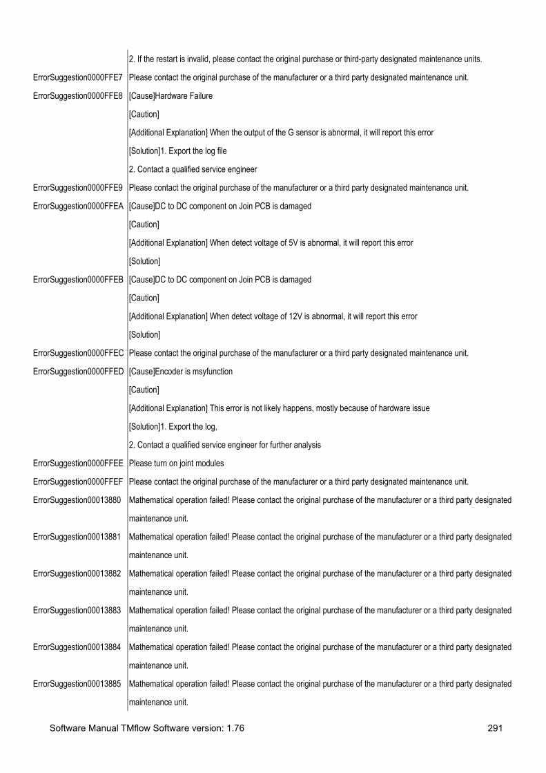
Software Manual TMflow Software version: 1.76 291
2. If the restart is invalid, please contact the original purchase or third-party designated maintenance units.
ErrorSuggestion0000FFE7 Please contact the original purchase of the manufacturer or a third party designated maintenance unit.
ErrorSuggestion0000FFE8 [Cause]Hardware Failure
[Caution]
[Additional Explanation] When the output of the G sensor is abnormal, it will report this error
[Solution]1. Export the log file
2. Contact a qualified service engineer
ErrorSuggestion0000FFE9 Please contact the original purchase of the manufacturer or a third party designated maintenance unit.
ErrorSuggestion0000FFEA [Cause]DC to DC component on Join PCB is damaged
[Caution]
[Additional Explanation] When detect voltage of 5V is abnormal, it will report this error
[Solution]
ErrorSuggestion0000FFEB [Cause]DC to DC component on Join PCB is damaged
[Caution]
[Additional Explanation] When detect voltage of 12V is abnormal, it will report this error
[Solution]
ErrorSuggestion0000FFEC Please contact the original purchase of the manufacturer or a third party designated maintenance unit.
ErrorSuggestion0000FFED [Cause]Encoder is msyfunction
[Caution]
[Additional Explanation] This error is not likely happens, mostly because of hardware issue
[Solution]1. Export the log,
2. Contact a qualified service engineer for further analysis
ErrorSuggestion0000FFEE Please turn on joint modules
ErrorSuggestion0000FFEF Please contact the original purchase of the manufacturer or a third party designated maintenance unit.
ErrorSuggestion00013880 Mathematical operation failed! Please contact the original purchase of the manufacturer or a third party designated
maintenance unit.
ErrorSuggestion00013881 Mathematical operation failed! Please contact the original purchase of the manufacturer or a third party designated
maintenance unit.
ErrorSuggestion00013882 Mathematical operation failed! Please contact the original purchase of the manufacturer or a third party designated
maintenance unit.
ErrorSuggestion00013883 Mathematical operation failed! Please contact the original purchase of the manufacturer or a third party designated
maintenance unit.
ErrorSuggestion00013884 Mathematical operation failed! Please contact the original purchase of the manufacturer or a third party designated
maintenance unit.
ErrorSuggestion00013885 Mathematical operation failed! Please contact the original purchase of the manufacturer or a third party designated
maintenance unit.

Software Manual TMflow Software version: 1.76 292
ErrorSuggestion00013886 Mathematical operation failed! Please contact the original purchase of the manufacturer or a third party designated
maintenance unit.
ErrorSuggestion00013887 Mathematical operation failed! Please contact the original purchase of the manufacturer or a third party designated
maintenance unit.
ErrorSuggestion00013888 Mathematical operation failed! Please contact the original purchase of the manufacturer or a third party designated
maintenance unit.
ErrorSuggestion00013889 Mathematical operation failed! Please contact the original purchase of the manufacturer or a third party designated
maintenance unit.
ErrorSuggestion0001388A Mathematical operation failed! Please contact the original purchase of the manufacturer or a third party designated
maintenance unit.
ErrorSuggestion0001388B Mathematical operation failed! Please contact the original purchase of the manufacturer or a third party designated
maintenance unit.
ErrorSuggestion0001388C Mathematical operation failed! Please contact the original purchase of the manufacturer or a third party designated
maintenance unit.
ErrorSuggestion0001388D Mathematical operation failed! Please contact the original purchase of the manufacturer or a third party designated
maintenance unit.
ErrorSuggestion0001388E Mathematical operation failed! Please contact the original purchase of the manufacturer or a third party designated
maintenance unit.
ErrorSuggestion0001388F Mathematical operation failed! Please contact the original purchase of the manufacturer or a third party designated
maintenance unit.
ErrorSuggestion00013890 Mathematical operation failed! Please contact the original purchase of the manufacturer or a third party designated
maintenance unit.
ErrorSuggestion00013891 Mathematical operation failed! Please contact the original purchase of the manufacturer or a third party designated
maintenance unit.
ErrorSuggestion00013892 Mathematical operation failed! Please contact the original purchase of the manufacturer or a third party designated
maintenance unit.
ErrorSuggestion00013893 Mathematical operation failed! Please contact the original purchase of the manufacturer or a third party designated
maintenance unit.
ErrorSuggestion00013894 Mathematical operation failed! Please contact the original purchase of the manufacturer or a third party designated
maintenance unit.
ErrorSuggestion00013895 Mathematical operation failed! Please contact the original purchase of the manufacturer or a third party designated
maintenance unit.
ErrorSuggestion00013896 Mathematical operation failed! Please contact the original purchase of the manufacturer or a third party designated
maintenance unit.
ErrorSuggestion00013897 Mathematical operation failed! Please contact the original purchase of the manufacturer or a third party designated
maintenance unit.

Software Manual TMflow Software version: 1.76 293
ErrorSuggestion00013898 Mathematical operation failed! Please contact the original purchase of the manufacturer or a third party designated
maintenance unit.
ErrorSuggestion00013899 Mathematical operation failed! Please contact the original purchase of the manufacturer or a third party designated
maintenance unit.
ErrorSuggestion0001389A Mathematical operation failed! Please contact the original purchase of the manufacturer or a third party designated
maintenance unit.
ErrorSuggestion0001389B Mathematical operation failed! Please contact the original purchase of the manufacturer or a third party designated
maintenance unit.
ErrorSuggestion0001389C Mathematical operation failed! Please contact the original purchase of the manufacturer or a third party designated
maintenance unit.
ErrorSuggestion0001389D Mathematical operation failed! Please contact the original purchase of the manufacturer or a third party designated
maintenance unit.
ErrorSuggestion0001389E Mathematical operation failed! Please contact the original purchase of the manufacturer or a third party designated
maintenance unit.
ErrorSuggestion0001389F Mathematical operation failed! Please contact the original purchase of the manufacturer or a third party designated
maintenance unit.
ErrorSuggestion000138A0 Mathematical operation failed! Please contact the original purchase of the manufacturer or a third party designated
maintenance unit.
ErrorSuggestion000138A1 Mathematical operation failed! Please contact the original purchase of the manufacturer or a third party designated
maintenance unit.
ErrorSuggestion000138A2 Mathematical operation failed! Please contact the original purchase of the manufacturer or a third party designated
maintenance unit.
ErrorSuggestion000138A3 Mathematical operation failed! Please contact the original purchase of the manufacturer or a third party designated
maintenance unit.
ErrorSuggestion000138A4 Mathematical operation failed! Please contact the original purchase of the manufacturer or a third party designated
maintenance unit.
ErrorSuggestion000138A5 Mathematical operation failed! Please contact the original purchase of the manufacturer or a third party designated
maintenance unit.
ErrorSuggestion00013C68 Mathematical operation failed! Please contact the original purchase of the manufacturer or a third party designated
maintenance unit.
ErrorSuggestion00013C69 Mathematical operation failed! Please contact the original purchase of the manufacturer or a third party designated
maintenance unit.
ErrorSuggestion00013C6A Mathematical operation failed! Please contact the original purchase of the manufacturer or a third party designated
maintenance unit.
ErrorSuggestion00013C6B Mathematical operation failed! Please contact the original purchase of the manufacturer or a third party designated
maintenance unit.

Software Manual TMflow Software version: 1.76 294
ErrorSuggestion00013C6C Mathematical operation failed! Please contact the original purchase of the manufacturer or a third party designated
maintenance unit.
ErrorSuggestion00013C6D Mathematical operation failed! Please contact the original purchase of the manufacturer or a third party designated
maintenance unit.
ErrorSuggestion00013C6E Mathematical operation failed! Please contact the original purchase of the manufacturer or a third party designated
maintenance unit.
ErrorSuggestion00013C6F Mathematical operation failed! Please contact the original purchase of the manufacturer or a third party designated
maintenance unit.
ErrorSuggestion00013C70 Mathematical operation failed! Please contact the original purchase of the manufacturer or a third party designated
maintenance unit.
ErrorSuggestion00013C71 Mathematical operation failed! Please contact the original purchase of the manufacturer or a third party designated
maintenance unit.
ErrorSuggestion00013C72 Mathematical operation failed! Please contact the original purchase of the manufacturer or a third party designated
maintenance unit.
ErrorSuggestion00013C73 Mathematical operation failed! Please contact the original purchase of the manufacturer or a third party designated
maintenance unit.
ErrorSuggestion00013C74 Mathematical operation failed! Please contact the original purchase of the manufacturer or a third party designated
maintenance unit.
ErrorSuggestion00013C75 Mathematical operation failed! Please contact the original purchase of the manufacturer or a third party designated
maintenance unit.
ErrorSuggestion00014050 Mathematical operation failed! Please contact the original purchase of the manufacturer or a third party designated
maintenance unit.
ErrorSuggestion00014051 Mathematical operation failed! Please contact the original purchase of the manufacturer or a third party designated
maintenance unit.
ErrorSuggestion00014052 Mathematical operation failed! Please contact the original purchase of the manufacturer or a third party designated
maintenance unit.
ErrorSuggestion00014053 Mathematical operation failed! Please contact the original purchase of the manufacturer or a third party designated
maintenance unit.
ErrorSuggestion00014054 Mathematical operation failed! Please contact the original purchase of the manufacturer or a third party designated
maintenance unit.
ErrorSuggestion00014055 Mathematical operation failed! Please contact the original purchase of the manufacturer or a third party designated
maintenance unit.
ErrorSuggestion00014056 Mathematical operation failed! Please contact the original purchase of the manufacturer or a third party designated
maintenance unit.
ErrorSuggestion00014057 Mathematical operation failed! Please contact the original purchase of the manufacturer or a third party designated
maintenance unit.

Software Manual TMflow Software version: 1.76 295
ErrorSuggestion00014058 Mathematical operation failed! Please contact the original purchase of the manufacturer or a third party designated
maintenance unit.
ErrorSuggestion00014059 Mathematical operation failed! Please contact the original purchase of the manufacturer or a third party designated
maintenance unit.
ErrorSuggestion0001405A Mathematical operation failed! Please contact the original purchase of the manufacturer or a third party designated
maintenance unit.
ErrorSuggestion0001405B Mathematical operation failed! Please contact the original purchase of the manufacturer or a third party designated
maintenance unit.
ErrorSuggestion0001405C Mathematical operation failed! Please contact the original purchase of the manufacturer or a third party designated
maintenance unit.
ErrorSuggestion0001405D Mathematical operation failed! Please contact the original purchase of the manufacturer or a third party designated
maintenance unit.
ErrorSuggestion0001405E Mathematical operation failed! Please contact the original purchase of the manufacturer or a third party designated
maintenance unit.
ErrorSuggestion0001405F Mathematical operation failed! Please contact the original purchase of the manufacturer or a third party designated
maintenance unit.
ErrorSuggestion00014060 Mathematical operation failed! Please contact the original purchase of the manufacturer or a third party designated
maintenance unit.
ErrorSuggestion00014061 Mathematical operation failed! Please contact the original purchase of the manufacturer or a third party designated
maintenance unit.
ErrorSuggestion00014062 Mathematical operation failed! Please contact the original purchase of the manufacturer or a third party designated
maintenance unit.
ErrorSuggestion00014063 Mathematical operation failed! Please contact the original purchase of the manufacturer or a third party designated
maintenance unit.
ErrorSuggestion00014064 Mathematical operation failed! Please contact the original purchase of the manufacturer or a third party designated
maintenance unit.
ErrorSuggestion00014065 Mathematical operation failed! Please contact the original purchase of the manufacturer or a third party designated
maintenance unit.
ErrorSuggestion00014066 Mathematical operation failed! Please contact the original purchase of the manufacturer or a third party designated
maintenance unit.
ErrorSuggestion00014067 Mathematical operation failed! Please contact the original purchase of the manufacturer or a third party designated
maintenance unit.
ErrorSuggestion00014068 Mathematical operation failed! Please contact the original purchase of the manufacturer or a third party designated
maintenance unit.
ErrorSuggestion00014069 Mathematical operation failed! Please contact the original purchase of the manufacturer or a third party designated
maintenance unit.

Software Manual TMflow Software version: 1.76 296
ErrorSuggestion0001406A Mathematical operation failed! Please contact the original purchase of the manufacturer or a third party designated
maintenance unit.
ErrorSuggestion0001406B Mathematical operation failed! Please contact the original purchase of the manufacturer or a third party designated
maintenance unit.
ErrorSuggestion0001406C Mathematical operation failed! Please contact the original purchase of the manufacturer or a third party designated
maintenance unit.
ErrorSuggestion0001406D Mathematical operation failed! Please contact the original purchase of the manufacturer or a third party designated
maintenance unit.
ErrorSuggestion0001406E Mathematical operation failed! Please contact the original purchase of the manufacturer or a third party designated
maintenance unit.
ErrorSuggestion0001406F Mathematical operation failed! Please contact the original purchase of the manufacturer or a third party designated
maintenance unit.
ErrorSuggestion00014070 Mathematical operation failed! Please contact the original purchase of the manufacturer or a third party designated
maintenance unit.
ErrorSuggestion00014071 Mathematical operation failed! Please contact the original purchase of the manufacturer or a third party designated
maintenance unit.
ErrorSuggestion00014072 Mathematical operation failed! Please contact the original purchase of the manufacturer or a third party designated
maintenance unit.
ErrorSuggestion00014073 Mathematical operation failed! Please contact the original purchase of the manufacturer or a third party designated
maintenance unit.
ErrorSuggestion00014074 Mathematical operation failed! Please contact the original purchase of the manufacturer or a third party designated
maintenance unit.
ErrorSuggestion00014075 Mathematical operation failed! Please contact the original purchase of the manufacturer or a third party designated
maintenance unit.
ErrorSuggestion00014076 Mathematical operation failed! Please contact the original purchase of the manufacturer or a third party designated
maintenance unit.
ErrorSuggestion00014077 Mathematical operation failed! Please contact the original purchase of the manufacturer or a third party designated
maintenance unit.
ErrorSuggestion00014078 Mathematical operation failed! Please contact the original purchase of the manufacturer or a third party designated
maintenance unit.
ErrorSuggestion00014079 Mathematical operation failed! Please contact the original purchase of the manufacturer or a third party designated
maintenance unit.
ErrorSuggestion0001407A Mathematical operation failed! Please contact the original purchase of the manufacturer or a third party designated
maintenance unit.
ErrorSuggestion0001407B Mathematical operation failed! Please contact the original purchase of the manufacturer or a third party designated
maintenance unit.

Software Manual TMflow Software version: 1.76 297
ErrorSuggestion0001407C Mathematical operation failed! Please contact the original purchase of the manufacturer or a third party designated
maintenance unit.
ErrorSuggestion0001407D Mathematical operation failed! Please contact the original purchase of the manufacturer or a third party designated
maintenance unit.
ErrorSuggestion0001407E Mathematical operation failed! Please contact the original purchase of the manufacturer or a third party designated
maintenance unit.
ErrorSuggestion0001407F Mathematical operation failed! Please contact the original purchase of the manufacturer or a third party designated
maintenance unit.
ErrorSuggestion00014080 Mathematical operation failed! Please contact the original purchase of the manufacturer or a third party designated
maintenance unit.
ErrorSuggestion00014081 Mathematical operation failed! Please contact the original purchase of the manufacturer or a third party designated
maintenance unit.
ErrorSuggestion00014082 Mathematical operation failed! Please contact the original purchase of the manufacturer or a third party designated
maintenance unit.
ErrorSuggestion00014083 Mathematical operation failed! Please contact the original purchase of the manufacturer or a third party designated
maintenance unit.
ErrorSuggestion00014084 Mathematical operation failed! Please contact the original purchase of the manufacturer or a third party designated
maintenance unit.
ErrorSuggestion00014085 Mathematical operation failed! Please contact the original purchase of the manufacturer or a third party designated
maintenance unit.
ErrorSuggestion00014086 Mathematical operation failed! Please contact the original purchase of the manufacturer or a third party designated
maintenance unit.
ErrorSuggestion00014087 Mathematical operation failed! Please contact the original purchase of the manufacturer or a third party designated
maintenance unit.
ErrorSuggestion00014088 Mathematical operation failed! Please contact the original purchase of the manufacturer or a third party designated
maintenance unit.
ErrorSuggestion00014089 Mathematical operation failed! Please contact the original purchase of the manufacturer or a third party designated
maintenance unit.
ErrorSuggestion0001408A Mathematical operation failed! Please contact the original purchase of the manufacturer or a third party designated
maintenance unit.
ErrorSuggestion0001408B Mathematical operation failed! Please contact the original purchase of the manufacturer or a third party designated
maintenance unit.
ErrorSuggestion0001408C Mathematical operation failed! Please contact the original purchase of the manufacturer or a third party designated
maintenance unit.
ErrorSuggestion0001408D Mathematical operation failed! Please contact the original purchase of the manufacturer or a third party designated
maintenance unit.

Software Manual TMflow Software version: 1.76 298
ErrorSuggestion0001408E Mathematical operation failed! Please contact the original purchase of the manufacturer or a third party designated
maintenance unit.
ErrorSuggestion0001408F Mathematical operation failed! Please contact the original purchase of the manufacturer or a third party designated
maintenance unit.
ErrorSuggestion00014090 Mathematical operation failed! Please contact the original purchase of the manufacturer or a third party designated
maintenance unit.
ErrorSuggestion00014091 Mathematical operation failed! Please contact the original purchase of the manufacturer or a third party designated
maintenance unit.
ErrorSuggestion000140AA Mathematical operation failed! Please contact the original purchase of the manufacturer or a third party designated
maintenance unit.
ErrorSuggestion000140AB Mathematical operation failed! Please contact the original purchase of the manufacturer or a third party designated
maintenance unit.
ErrorSuggestion000140AC Mathematical operation failed! Please contact the original purchase of the manufacturer or a third party designated
maintenance unit.
ErrorSuggestion000140AD Mathematical operation failed! Please contact the original purchase of the manufacturer or a third party designated
maintenance unit.
ErrorSuggestion000140AE Mathematical operation failed! Please contact the original purchase of the manufacturer or a third party designated
maintenance unit.
ErrorSuggestion000140AF Mathematical operation failed! Please contact the original purchase of the manufacturer or a third party designated
maintenance unit.
ErrorSuggestion000140B0 Mathematical operation failed! Please contact the original purchase of the manufacturer or a third party designated
maintenance unit.
ErrorSuggestion000140B1 Mathematical operation failed! Please contact the original purchase of the manufacturer or a third party designated
maintenance unit.
ErrorSuggestion00014438 Mathematical operation failed! Please contact the original purchase of the manufacturer or a third party designated
maintenance unit.
ErrorSuggestion00014439 Mathematical operation failed! Please contact the original purchase of the manufacturer or a third party designated
maintenance unit.
ErrorSuggestion0001443A Mathematical operation failed! Please contact the original purchase of the manufacturer or a third party designated
maintenance unit.
ErrorSuggestion0001443B Mathematical operation failed! Please contact the original purchase of the manufacturer or a third party designated
maintenance unit.
ErrorSuggestion0001443C Mathematical operation failed! Please contact the original purchase of the manufacturer or a third party designated
maintenance unit.
ErrorSuggestion0001443D Mathematical operation failed! Please contact the original purchase of the manufacturer or a third party designated
maintenance unit.

Software Manual TMflow Software version: 1.76 299
ErrorSuggestion0001443E Mathematical operation failed! Please contact the original purchase of the manufacturer or a third party designated
maintenance unit.
ErrorSuggestion0001443F Mathematical operation failed! Please contact the original purchase of the manufacturer or a third party designated
maintenance unit.
ErrorSuggestion00014440 Mathematical operation failed! Please contact the original purchase of the manufacturer or a third party designated
maintenance unit.
ErrorSuggestion00014441 Mathematical operation failed! Please contact the original purchase of the manufacturer or a third party designated
maintenance unit.
ErrorSuggestion00014442 Mathematical operation failed! Please contact the original purchase of the manufacturer or a third party designated
maintenance unit.
ErrorSuggestion00014443 Mathematical operation failed! Please contact the original purchase of the manufacturer or a third party designated
maintenance unit.
ErrorSuggestion00014444 Mathematical operation failed! Please contact the original purchase of the manufacturer or a third party designated
maintenance unit.
ErrorSuggestion00014445 Mathematical operation failed! Please contact the original purchase of the manufacturer or a third party designated
maintenance unit.
ErrorSuggestion00014446 Mathematical operation failed! Please contact the original purchase of the manufacturer or a third party designated
maintenance unit.
ErrorSuggestion00014447 Mathematical operation failed! Please contact the original purchase of the manufacturer or a third party designated
maintenance unit.
ErrorSuggestion00014448 Mathematical operation failed! Please contact the original purchase of the manufacturer or a third party designated
maintenance unit.
ErrorSuggestion00014449 Mathematical operation failed! Please contact the original purchase of the manufacturer or a third party designated
maintenance unit.
ErrorSuggestion0001444A Mathematical operation failed! Please contact the original purchase of the manufacturer or a third party designated
maintenance unit.
ErrorSuggestion0001444B Mathematical operation failed! Please contact the original purchase of the manufacturer or a third party designated
maintenance unit.
ErrorSuggestion0001444C Mathematical operation failed! Please contact the original purchase of the manufacturer or a third party designated
maintenance unit.
ErrorSuggestion0001444D Mathematical operation failed! Please contact the original purchase of the manufacturer or a third party designated
maintenance unit.
ErrorSuggestion0001444E Mathematical operation failed! Please contact the original purchase of the manufacturer or a third party designated
maintenance unit.
ErrorSuggestion0001444F Mathematical operation failed! Please contact the original purchase of the manufacturer or a third party designated
maintenance unit.

Software Manual TMflow Software version: 1.76 300
ErrorSuggestion00014450 Mathematical operation failed! Please contact the original purchase of the manufacturer or a third party designated
maintenance unit.
ErrorSuggestion00014451 Mathematical operation failed! Please contact the original purchase of the manufacturer or a third party designated
maintenance unit.
ErrorSuggestion00014452 Mathematical operation failed! Please contact the original purchase of the manufacturer or a third party designated
maintenance unit.
ErrorSuggestion00014453 Mathematical operation failed! Please contact the original purchase of the manufacturer or a third party designated
maintenance unit.
ErrorSuggestion00014454 Mathematical operation failed! Please contact the original purchase of the manufacturer or a third party designated
maintenance unit.
ErrorSuggestion00014455 Mathematical operation failed! Please contact the original purchase of the manufacturer or a third party designated
maintenance unit.
ErrorSuggestion00014456 Mathematical operation failed! Please contact the original purchase of the manufacturer or a third party designated
maintenance unit.
ErrorSuggestion00014457 Mathematical operation failed! Please contact the original purchase of the manufacturer or a third party designated
maintenance unit.
ErrorSuggestion00014458 Mathematical operation failed! Please contact the original purchase of the manufacturer or a third party designated
maintenance unit.
ErrorSuggestion00014459 Mathematical operation failed! Please contact the original purchase of the manufacturer or a third party designated
maintenance unit.
ErrorSuggestion0001445A Mathematical operation failed! Please contact the original purchase of the manufacturer or a third party designated
maintenance unit.
ErrorSuggestion0001445B Mathematical operation failed! Please contact the original purchase of the manufacturer or a third party designated
maintenance unit.
ErrorSuggestion0001445C Mathematical operation failed! Please contact the original purchase of the manufacturer or a third party designated
maintenance unit.
ErrorSuggestion0001445D Mathematical operation failed! Please contact the original purchase of the manufacturer or a third party designated
maintenance unit.
ErrorSuggestion0001445E Mathematical operation failed! Please contact the original purchase of the manufacturer or a third party designated
maintenance unit.
ErrorSuggestion0001445F Mathematical operation failed! Please contact the original purchase of the manufacturer or a third party designated
maintenance unit.
ErrorSuggestion00014820 Mathematical operation failed! Please contact the original purchase of the manufacturer or a third party designated
maintenance unit.
ErrorSuggestion00014C08 Mathematical operation failed! Please contact the original purchase of the manufacturer or a third party designated
maintenance unit.

Software Manual TMflow Software version: 1.76 301
ErrorSuggestion00014C09 Mathematical operation failed! Please contact the original purchase of the manufacturer or a third party designated
maintenance unit.
ErrorSuggestion00014C0A Mathematical operation failed! Please contact the original purchase of the manufacturer or a third party designated
maintenance unit.
ErrorSuggestion00014C0B Mathematical operation failed! Please contact the original purchase of the manufacturer or a third party designated
maintenance unit.
ErrorSuggestion00014C0C Mathematical operation failed! Please contact the original purchase of the manufacturer or a third party designated
maintenance unit.
ErrorSuggestion00014C0D Mathematical operation failed! Please contact the original purchase of the manufacturer or a third party designated
maintenance unit.
ErrorSuggestion00014C0E Mathematical operation failed! Please contact the original purchase of the manufacturer or a third party designated
maintenance unit.
ErrorSuggestion00014C0F Mathematical operation failed! Please contact the original purchase of the manufacturer or a third party designated
maintenance unit.
ErrorSuggestion00014C10 Mathematical operation failed! Please contact the original purchase of the manufacturer or a third party designated
maintenance unit.
ErrorSuggestion00014C11 Mathematical operation failed! Please contact the original purchase of the manufacturer or a third party designated
maintenance unit.
ErrorSuggestion00014C12 Mathematical operation failed! Please contact the original purchase of the manufacturer or a third party designated
maintenance unit.
ErrorSuggestion00014C13 Mathematical operation failed! Please contact the original purchase of the manufacturer or a third party designated
maintenance unit.
ErrorSuggestion00014C14 Mathematical operation failed! Please contact the original purchase of the manufacturer or a third party designated
maintenance unit.
ErrorSuggestion00014FF0 Mathematical operation failed! Please contact the original purchase of the manufacturer or a third party designated
maintenance unit.
ErrorSuggestion00014FF1 Mathematical operation failed! Please contact the original purchase of the manufacturer or a third party designated
maintenance unit.
ErrorSuggestion00014FF2 Mathematical operation failed! Please contact the original purchase of the manufacturer or a third party designated
maintenance unit.
ErrorSuggestion00014FF3 Mathematical operation failed! Please contact the original purchase of the manufacturer or a third party designated
maintenance unit.
ErrorSuggestion00014FF4 Mathematical operation failed! Please contact the original purchase of the manufacturer or a third party designated
maintenance unit.
ErrorSuggestion00014FF5 Mathematical operation failed! Please contact the original purchase of the manufacturer or a third party designated
maintenance unit.

Software Manual TMflow Software version: 1.76 302
ErrorSuggestion00014FF6 Mathematical operation failed! Please contact the original purchase of the manufacturer or a third party designated
maintenance unit.
ErrorSuggestion00014FF7 Mathematical operation failed! Please contact the original purchase of the manufacturer or a third party designated
maintenance unit.
ErrorSuggestion00014FF8 Mathematical operation failed! Please contact the original purchase of the manufacturer or a third party designated
maintenance unit.
ErrorSuggestion00014FF9 Mathematical operation failed! Please contact the original purchase of the manufacturer or a third party designated
maintenance unit.
ErrorSuggestion00014FFA Mathematical operation failed! Please contact the original purchase of the manufacturer or a third party designated
maintenance unit.
ErrorSuggestion00014FFB Mathematical operation failed! Please contact the original purchase of the manufacturer or a third party designated
maintenance unit.
ErrorSuggestion00014FFC Mathematical operation failed! Please contact the original purchase of the manufacturer or a third party designated
maintenance unit.
ErrorSuggestion00014FFD Mathematical operation failed! Please contact the original purchase of the manufacturer or a third party designated
maintenance unit.
ErrorSuggestion000153D8 Mathematical operation failed! Please contact the original purchase of the manufacturer or a third party designated
maintenance unit.
ErrorSuggestion000153D9 Mathematical operation failed! Please contact the original purchase of the manufacturer or a third party designated
maintenance unit.
ErrorSuggestion000153DA Mathematical operation failed! Please contact the original purchase of the manufacturer or a third party designated
maintenance unit.
ErrorSuggestion000153DB Mathematical operation failed! Please contact the original purchase of the manufacturer or a third party designated
maintenance unit.
ErrorSuggestion000153DC Mathematical operation failed! Please contact the original purchase of the manufacturer or a third party designated
maintenance unit.
ErrorSuggestion000153DD Mathematical operation failed! Please contact the original purchase of the manufacturer or a third party designated
maintenance unit.
ErrorSuggestion000153DE Mathematical operation failed! Please contact the original purchase of the manufacturer or a third party designated
maintenance unit.
ErrorSuggestion000153DF Mathematical operation failed! Please contact the original purchase of the manufacturer or a third party designated
maintenance unit.
ErrorSuggestion000153E0 Mathematical operation failed! Please contact the original purchase of the manufacturer or a third party designated
maintenance unit.
ErrorSuggestion000153E1 Mathematical operation failed! Please contact the original purchase of the manufacturer or a third party designated
maintenance unit.

Software Manual TMflow Software version: 1.76 303
ErrorSuggestion000153E2 Mathematical operation failed! Please contact the original purchase of the manufacturer or a third party designated
maintenance unit.
ErrorSuggestion000153E3 Mathematical operation failed! Please contact the original purchase of the manufacturer or a third party designated
maintenance unit.
ErrorSuggestion000157C0 Mathematical operation failed! Please contact the original purchase of the manufacturer or a third party designated
maintenance unit.
ErrorSuggestion000157C1 Mathematical operation failed! Please contact the original purchase of the manufacturer or a third party designated
maintenance unit.
ErrorSuggestion00020000 [Cause] The robot can not detect or recognize the camera.
[Caution]1. Check if there is a camera icon in the vision job page.
2. Check whether the USB connection of the camera is broken on the control box or inside the robot arm.
[Precaution] Causes a camera malfunction and VISION job\task will not be available.
[Precaution] Importing the project within the vision job to a non-vision robot will also cause this error.
[Solution]Refer to the related service manual for proper USB plugin methods.
Ensure that all USB cables are securely connected to the camera and the control box.
ErrorSuggestion00020001 The camera is busy when the flow try to use it. Check the flow where user may misuse multi-thread flow to use the
sample camera.
ErrorSuggestion00020002 Unexpected errors occurred. Reboot the robot and try to use fewer or simpler vision jobs. If it keeps happening,
please contact your support windows.
ErrorSuggestion00020003 [Cause] The connection between camera and robot is unstable.
[Caution]1. Check the USB connection to the camera and control box is secure.
2. Check if the USB slots are overloaded.
[Precaution] Causes a camera malfunction and VISION job\task will not be available.
[Precaution] The USB cable's transmission signal would become weak gradually because of the normal
consumption of wire.
[Additional Explanations] Signal attenuation cause by too many USB cable plug on the control box.
Sometimes, if the signal attenuation became worse it will cause the error "0x00020000 Camera NOT found "
[Solution]1. Please refer to the service manual which related Robot arm which would teach you how to dismantle
and plug the USB cable properly.
2. Please refer to the service manual which related control box which would teach you how to plug the USB cable
properly.
3. Please check the USB slots are overloaded on the control box and please plug out the USB which is not

Software Manual TMflow Software version: 1.76 304
required.
Please regularly check if the USB Cable connected to the camera and control box are all fine.
ErrorSuggestion00020004 The vision job is not compatible to the current version of HMI.
ErrorSuggestion00020005 [Cause]Dongle key is not detected while edit the corresponding function on a project or run that project
[Caution]Check if the dongle is plugged onto the Control Box
[Solution]1. Press STOP button on the robot stick to restore from error status
2. Connect the corresponding Dongle onto the Control box and run the project again
3. Run the project again; if this error still occurs, contact a qualified service engineer for further analysis
Make sure having the corresponding Dongle key plugged before running or editing the project with license
functions
ErrorSuggestion00020006 This message is only for TM's production line.
ErrorSuggestion00020007 Error occurs in the flow of vision's designer. Try to re-edit the vision job. If it keeps happening, please contact our
official windows.
ErrorSuggestion00020008 [Cause]Vision job can not be found during executing the VISION node
[Caution]Check if the vision job is exist or not.
[Solution]1. Press STOP button on the robot stick and
2. Re-create the vision job
Make sure the vision job is exist before executes the project.
ErrorSuggestion00020009 [Cause]The same camera is simultaneously accessed by multiple threads.
[Caution]Check if there are multi- threads using the same camera while running the project.
[Solution]Press STOP button on the robot stick to stop the project.
Make sure a camera is being used by only one thread
ErrorSuggestion0002000A This job can only be run on X64 platform
ErrorSuggestion0002000B Servoing and Vision-IO threads conflict
ErrorSuggestion00030001 [Cause]Points setting error during creating a plane for Operation Space
[Caution]Check if more than 2 of the three points of the plane are the same
[Additional Explanation]
A plane could only be created by 3 different points
[Solution]To restore the robot from Error Status :
1. Click on the OK button on the pop up windows.
2. Reset the 3 points in following steps:

Software Manual TMflow Software version: 1.76 305
Setting > Operation Space > Select project name of plane > Set Point
Before creating a plane, make sure the 3 points are set well, and should not be repeated.
ErrorSuggestion00030002 [Cause]Points setting error during creating a cube for Operation Space
[Caution]Check if more than 2 of the four points of the cube are the same
[Additional Explanation]
A cube could only be created by 4 different points
[Solution]To restore the robot from Error Status :
1. Click on the OK button on the pop up windows.
2. Reset the 4 points in following steps:
Setting > Operation Space > Select project name of cube > Set Point
Before creating a cube, make sure the 4 points are set well, and should not be repeated.
ErrorSuggestion00030003 [Cause]The system fails to combine this plane with other planes.
[Caution]Check if the three points set by the user when adding this plane, the center point of the circle falls on the
outside of plane.
[Solution]Re-create a plane which is suitable
Check if the three points are set up when adding this plane, the center point of the circle falls on the inside of
plane.
ErrorSuggestion00030004 [Cause]The system fails to combine this stop plane with other planes.
[Caution]Check if the three points set by the user when adding this stop plane, the center point of the circle falls on
the outside of plane.
[Solution]Re-create a stop plane which is suitable
Check if the three points are set up when adding this stop plane, the center point of the circle falls on the inside of
plane.
ErrorSuggestion00030005 Re-Build Safety Space
ErrorSuggestion00030006 Please contact the original purchase of the manufacturer or a third party designated maintenance unit.
ErrorSuggestion00030007 N/A
ErrorSuggestion00031000 [Cause]The 3D Viewer function has been terminated
[Caution]Check any 3D viewer on TMflow (such as Setting/Controller) if it is functional
[Additional Explanation] This error does not likely happen unless there is a software issue
[Solution]1. Export the log
2. Have the robot power cycling to see if this error still occurs
3. Report to the service engineer with the log file
ErrorSuggestion00031001 Please contact the original purchase of the manufacturer or a third party designated maintenance unit.
ErrorSuggestion00031002 Please contact the original purchase of the manufacturer or a third party designated maintenance unit.

Software Manual TMflow Software version: 1.76 306
ErrorSuggestion00031003 Please contact the original purchase of the manufacturer or a third party designated maintenance unit.
ErrorSuggestion00031004 Please contact the original purchase of the manufacturer or a third party designated maintenance unit.
ErrorSuggestion00031005 Invalid point for collision check node
ErrorSuggestion00031006 Invalid parameter for collisioin check node
ErrorSuggestion00031007 Over angle limit for collision check node
ErrorSuggestion00040000 1. Please try to restart the robot.
2. If the restart is invalid, please contact the original purchase or third-party designated maintenance units.
ErrorSuggestion00040001 1. Please backup the HMI Log.
2. Please contact the original purchase of the manufacturer or a third party designated maintenance unit.
ErrorSuggestion00040002 1. Please backup the HMI Log.
2. Please contact the original purchase of the manufacturer or a third party designated maintenance unit.
ErrorSuggestion00040003 1. Please backup the HMI Log.
2. Please contact the original purchase of the manufacturer or a third party designated maintenance unit.
ErrorSuggestion00040004 1. Please backup the HMI Log.
2. Please contact the original purchase of the manufacturer or a third party designated maintenance unit.
ErrorSuggestion00040005 [Cause]The HMI found that an unexpected exception error.
[Caution]1. Check if there is other error message describe the location of the issue node
2. Check if there is other error message describe more detail of this issue
[Additional Explanation] This error usually happens if there is an unexpected software issue
[Solution]1. Export the log file and the project file
2. Contact a qualified service engineer
ErrorSuggestion00040006 1. Please backup the HMI Log.
2. Please contact the original purchase of the manufacturer or a third party designated maintenance unit.
ErrorSuggestion00040007 [Cause]ESTOP mode is triggered, and the power of the robot is cut off. HMI can't connect the robot.
[Caution]Check if ESTOP mode is triggered:
1. The ESTOP button of the stick is pressed.
2. The ESTOP wire of the control box is not connected.
Check if the LED light of the robot is turn off.
[Additional Explanation] This error usually appears as a popped up message on HMI
[Additional Explanation] This error usually happens because the power of the robot is cut off by ESTOP mode
triggered while doing the one of the following cases:
1. When open and close the camera IO LED, the HMI will pop up a window message「Robot is not connected」
2. In Project, click the "Step Run" button, the HMI will pop up a window message「Set Speed Fail :Robot is not
connected」
3. Leave the project and enter the project again, the HMI will pop up a window message「error code : Robot is

Software Manual TMflow Software version: 1.76 307
not connected」
4. etc.
[Solution]If the emergency stop button has been pressed on the robot stick:
1. Release the e-stop button.
a. The robot mode indicator lights will blink red.
b. After a few seconds, the robot mode indicator will blink light blue, indicating the robot has
entered safe start-up mode.
If an external emergency stop button has been pressed:
1. Release the external e-stop button.
a. The robot mode indicator lights will blink red.
b. After a few seconds, the robot mode indicator will blink light blue, indicating the robot has
entered safe start-up mode.
If an one of the emergency stop ports has been tripped:
1. Plug the wire back to the port.
2. Press, then release the external emergency stop button.
a. The robot mode indicator lights will blink red.
b. After a few seconds, the robot mode indicator will blink light blue, indicating the robot has
entered safe start-up mode.
Make sure the robot is connected while using HMI
ErrorSuggestion00040008 Please confirm user permissions.
ErrorSuggestion00040009 Please check whether the user account, password are correct.
ErrorSuggestion0004000A [Cause]ESTOP mode is triggered, and the power of the robot is cut off. HMI can't connect the robot.
[Caution]Check if ESTOP mode is triggered:
1. The ESTOP button of the stick is pressed.
2. The ESTOP wire of the control box is not connected.
Check if the LED light of the robot is turn off.
[Additional Explanation] This error usually appears as a popped up message in HMI
[Additional Explanation] This error usually happens because the power of the robot is cut off by ESTOP mode
triggered.
1. When operator the controller ,the HMI will pop up a window message「System fault: Lock Robot{{0}}」
[Solution]If the emergency stop button has been pressed on the robot stick:
1. Release the e-stop button.
a. The robot mode indicator lights will blink red.
b. After a few seconds, the robot mode indicator will blink light blue, indicating the robot has
entered safe start-up mode.

Software Manual TMflow Software version: 1.76 308
If an external emergency stop button has been pressed:
1. Release the external e-stop button.
a. The robot mode indicator lights will blink red.
b. After a few seconds, the robot mode indicator will blink light blue, indicating the robot has
entered safe start-up mode.
If an one of the emergency stop ports has been tripped:
1. Plug the wire back to the port.
2. Press, then release the external emergency stop button.
a. The robot mode indicator lights will blink red.
b. After a few seconds, the robot mode indicator will blink light blue, indicating the robot has
entered safe start-up mode.
Make sure the robot is connected while using HMI
ErrorSuggestion0004000B 1. Please reboot robot and try to set it again.
2. 2. If the restart is invalid, please contact the original purchase or third-party designated maintenance units.
ErrorSuggestion0004000C 1. Please check whether the setting of TCP is correct.
2. If the restart is invalid, please contact the original purchase or third-party designated maintenance units.
ErrorSuggestion0004000D 1. Please backup the HMI Log.
2. Please contact the original purchase of the manufacturer or a third party designated maintenance unit.
ErrorSuggestion0004000E Please check whether the robot is running and try it again.
ErrorSuggestion0004000F [Cause]The project is broken or does not exists.
[Caution]Check the project list again whether the project is not existing.
[Precaution] This error would only show on the pop up window, not in the HMI log.
[Solution]To restore the robot from Error Status :
Click on the OK button on the pop up window.
Make sure project is exported successfully before un-plug the usb drive
ErrorSuggestion00040010 Please check whether the component exists or is damaged.
ErrorSuggestion00040011 [Cause]The current node has not been set up correctly
[Caution]1. Check if the issued node is grey in color which means it is still in offline mode
2. Check if the setting of the current node is abnormal
[Additional Explanation] Motion related node built by TMFlow Editor has no position information which need further
set up on a robot
[Solution]1. Press Stop Button on the robot stick to restore the error status
2. Complete the set up of the current node
1. Make sure all motion related nodes built from TMFlow Editor has complete settings before step run
2. Make sure all nodes of the project has been set up correctly
ErrorSuggestion00040012 Please check whether the coordinate system settings are correct and complete.

Software Manual TMflow Software version: 1.76 309
ErrorSuggestion00040013 [Cause]When the TCP data is lost, or the servo check and the TCP data exchange error occurred.
[Caution]Check if the TCP Setting UI could open that TCP
[Solution]1. Import the project or TCP data again or
2. Re-et the TCP settings
1.Make sure the USB devices and import process are stable during importing project and TCP data.
2.Check if the TCP data is existed before uses it.
ErrorSuggestion00040014 [Cause]System has detected settings of the certain node is invalid
[Caution]1. Check the error message followed and locate the issued node
2. Check if the issued node is grey in color which means it is still in offline mode
3. Check if the setting of any nodes is abnormal
[Additional Explanation] Motion related node built by TMFlow Editor has no position information which need further
set up on a robot
[Solution]1. Click Stop on the robot stick to restore the error status
2. Complete the set up of the current node
1. Make sure all motion related nodes built from TMFlow Editor has complete settings before project run
2. Make sure all nodes of the project has been set up correctly
ErrorSuggestion00040015 [Cause]System has detected a dysfunction on the CPU Fan
[Caution]Check if there is any werid noise coming from the Control box
[Additional Explanation] If CPU fan is being stuck or the power cable of the fan is loosen, this error might happen
[Solution]Contact a qualified service engineer for further analysis
Make sure the robot is installed on a stable platform
ErrorSuggestion00040016 [Cause] Input the invalid value in the field in user setting.
[Caution]Check if
1. The Field of setting is empty
2. The format type of value in the field is invalid
[Additional Explanation]
This error usually appears as an pop up window when using,
1. HMI Setting Page
2. Project Flow
[Solution]Click OK and close the pop up window
Make sure the value in the field is valid during setting
ErrorSuggestion00040017 Please check whether the coordinate system settings are correct and complete.
ErrorSuggestion00040018 [Cause]The base is currently used by other nodes, deleting this base will trigger this error
[Caution]Check if the base is currently used by any nodes

Software Manual TMflow Software version: 1.76 310
[Additional Explanations] The base is currently used by other nodes (POINTS, NEW BASE, etc.) , deleting this
base will trigger this error
[Additional Explanation] This error code will only appears on HMI as a pop up window
[Solution]To restore the robot from Error Status :
Click on the OK button on the pop up window.
Make sure the base is not being used by any nodes before deleting it
ErrorSuggestion00040019 1. Check that the Point is present.
2. Check that the Point setting is abnormal.
ErrorSuggestion0004001A 1. Please backup the HMI Log.
2. Please contact the original purchase of the manufacturer or a third party designated maintenance unit.
ErrorSuggestion0004001B 1. Please backup the HMI Log.
2. Please contact the original purchase of the manufacturer or a third party designated maintenance unit.
ErrorSuggestion0004001C [Cause]There is no nodes connected to the Start Node in the Project Flow
[Caution]1. Check if there is no nodes connected to the Start Node in the Project Flow
[Solution]1. To restore the robot from Error Status :
Press the STOP button on the robot stick, or press the FREE button.
2. Connect the next process Node to the Start Node
Be careful when editing Project Flow
ErrorSuggestion0004001D Please check whether the coordinate system settings are correct and complete.
ErrorSuggestion0004001E [Cause]user account has already been login by other client device
[Caution]Check if someone else has already login with the same account
[Additional Explanation] This error is not likely happens, instead, 0x00040009 (Log In/Out failed) is more often.
[Solution]Click OK and close the pop up window
Make sure you are the only one use this account while logging in
ErrorSuggestion0004001F [Cause]Another account gets the Control ownership
[Caution]Check if there is someone else get the Control ownership with another account
[Additional Explanation] This could only happen if multiple accounts try to get the Control ownership at the same
time (nearly)
[Additional Explanation] Usually, if one account has already get the Control ownership, the ownership button on
other accounts would disable
[Solution]1. Have the current ownership account release the control first
2. Try getting the Control ownership again
Make sure only one account would get the Control ownership at once

Software Manual TMflow Software version: 1.76 311
ErrorSuggestion00040020 Please confirm user permissions.
ErrorSuggestion00040021 [Cause]If user edit an exist base which using "by pointing 3 points" function in Base Manager without manual
teaching and click OK directly, it might cause this error.
[Caution]In "Build a Base by 3 points" page, if user did not teach the one of three axis direction in the both option
"Point on X axis" and "Point on Surface".
[Additional Explanations] User must to choose and teach one of three axis direction(X,Y,Z) in the settings "Point
on X axis" and "Point on Surface".
[Solution]To restore the robot from Error Status :
Click on the OK button on the pop up windows.
Check the base is set correctly by manual operation in the "by pointing 3 points" function page .
ErrorSuggestion00040022 [Cause]Teach points in Compliance or Touch Stop node are not able to generate a legal motion
[Caution]In Compliance or Touch Stop Node, check if the teach points are at the same position or impossible to
generate a legal motion
[Precaution] This error would only show the "Calculation failed" on the pop up window, not in the HMI log.
[Solution]Click on the OK and close the pop window
Make sure the teach points are all suitable and correct.
ErrorSuggestion00040023 [Cause]Teach points in Compliance or Touch Stop node are not able to generate a legal linear motion
[Caution]In Compliance or Touch Stop Node, check if the teach points are at the same position or impossible to
generate a legal linear motion
[Precaution] This error would only show the "Calculation failed" on the pop up window, not in the HMI log.
[Solution]Click on the OK and close the pop window
Make sure the teach points are all suitable and correct.
ErrorSuggestion00040024 1. Please backup the HMI Log.
2. Please contact the original purchase of the manufacturer or a third party designated maintenance unit.
ErrorSuggestion00040025 Please check whether the SystimeFile.ini is correct.
ErrorSuggestion00040026 1. Please backup the HMI Log.
2. Please contact the original purchase of the manufacturer or a third party designated maintenance unit.
ErrorSuggestion00040027 [Cause]Project cannot run in Auto Mode when USB device plugged in the control box.
[Caution]Check if there is no USB devices plugged on the control box
[Additional Explanation] This error usually happens because the user forgets to remove the USB device from the
control box before run the project in Auto Mode
[Solution]To restore the robot from error status:
1. Press the STOP button on the robot stick, or
2. Press the FREE button.
3. Remove the USB device from the control box

Software Manual TMflow Software version: 1.76 312
Make sure all USB devices are removed from the control box before the project runs in Auto Mode.
ErrorSuggestion00040028 Please check whether the project is running.
ErrorSuggestion00040029 Please check whether the project is editing.
ErrorSuggestion0004002A [Cause]The target project is not found while running function WARP
[Caution]Please check if the target project selected in WARP function node is still exist
[Solution]If the target project of the WARP function node has been deleted or renamed, please reset or erase the
node
Please remind when deleting or renaming a project if it is related to other project with WARP function
ErrorSuggestion0004002B [Cause]Warp project failed
[Caution]Check if the target project of the WARP node is damaged or deleted
[Additional Explanation] This project are not likely to be damaged, possibly because of software issue
[Solution]
1. Press the STOP button on the robot stick to restore from error status
2. Export both project files and log file
3. Contact a qualified service engineer for further analysis
Make sure the project used by WARP node exists
ErrorSuggestion0004002C [Cause]Unexpected software issue during project compiling
[Caution]Check if there is any error messages followed
[Additional Explanation] This error occurs if and only if there is an unexpected issue on software
[Solution]
1. Press the STOP button on the robot stick to restore from error status
2. Export the project file and log file
3. Contact a qualified service engineer for further analysis
ErrorSuggestion0004002D [Cause]System detected an error on Project Flow while the it is running
[Caution]1. Check the message with this error code; it should specify which node has error
2. Check if there is another error code also occurs
[Additional Explanation] There are lot of cases for this error, such as:
1. Any variables being used in the Project is deleted.
2. Incorrect settings on Pallet node, Circle node, etc.
3. Expressions or settings of If node, Waitfor node, Gateway node are incorrect
4. etc.
[Solution]To restore the robot from Error Status :
1. Press the STOP button on the robot stick, or
2. Press the FREE button.

Software Manual TMflow Software version: 1.76 313
Follow the message of the error code and correct the error
1. Be careful when deleting variables in Variable Manager.
2. Study and have a full understanding on Node Function, make sure the settings are correct
ErrorSuggestion0004002E [Cause]Fail to get control of the robot during the project running.
[Caution]1. Check if the robot is controlled by other user
2. Check if the robot is running a project
3. Check if the robot has been released control
[Additional Explanation] This error usually appears as a popped up message in HMI
[Additional Explanation] This error usually happens when user wants to use the robot (Project Editing or Controller)
while it is running a project.
[Solution]To restore the robot from Error Status :
1. Click on the OK button on the pop up windows.
2. Stop the running project through pressing the Stop button on Stick
3. Recover to get control of the robot by following steps in HMI : Log in --> Get control
1. Check if the robot is controlled by other user before using the robot.
2. Don't release control of the robot during project-running.
ErrorSuggestion00040030 Please check whether Force-Torque sensor device is exist within SmartInsert Node
ErrorSuggestion00040031 [Cause]Robot detect the Force-Torque sensor occurred error during opening COM port.
[Caution]Check if the COM port is correct in the Force-Torque sensor devices settings page.
[Precaution] This error would only show on the pop up window, not in the HMI log.
[Solution]Click on the OK and close the pop window
Make sure the COM port setting is correct before use the Force-Torque sensor.
ErrorSuggestion00040032 Please check Modbus device setting are correct
ErrorSuggestion00040033 Please retry delete Modbus device
ErrorSuggestion00040034 Please check Force-Torque sensor is workable
ErrorSuggestion00040035 [Cause]Robot detect the Force-Torque sensor does not respond.
[Caution]Check if the COM port cable is loose.
[Additional Explanation] While the Force-Torque sensor is working, if the COM port cable is loose, it would cause
this error.
[Solution]Re-Plug the COM port cable on the robot.
Make sure the COM port cable is stable during robot and Force-Torque sensor are working.
ErrorSuggestion00040036 [Cause]The issued Point node built by TMFlow Editor has not been complete yet
[Caution]Check if the issued Point node is grey in color which means it is still in offline mode
[Additional Explanation] Point node built by TMFlow Editor has no position information which need further set up on
a robot
[Solution]1. Click Stop on the robot stick to restore the error status

Software Manual TMflow Software version: 1.76 314
2. Complete the set up of the point node
Make sure all motion related nodes built from TMFlow Editor has complete settings before project run or step run
ErrorSuggestion00040037 [Cause]System memory is not enough
[Caution]
[Solution]After restart the robot, if the problem still occurs, contact a qualified service engineer for further analysis.
ErrorSuggestion00040038 [Cause]The current node function created by offline editor has not been complete editing yet
[Caution]1. Check if the error message following with this error and locate the issue node
2. Check if the node is grey in color which means it is in offline mode
[Additional Explanation] Motion related nodes are all in offline mode if they are created by offline editor, user need
to complete the settings before usage
[Additional Explanation] This error would be trigger during step run or project run
[Solution]1. Press STOP button on the robot stick to restore the error status
2. Finish the setting of the node on HMI
Make sure all offline nodes are complete setting on HMI
ErrorSuggestion00040039 Please don't use vision keyword as a custom base prefix name
ErrorSuggestion0004003A [Cause]The payload value set exceeds the maximum payload limit
[Caution]Check if the payload value set exceeds the maximum payload limit
[Precaution] This error would only show on the pop up window, not in the HMI log.
[Solution]Click on the OK and close the pop window
Check and make sure the payload value set on a node is within the maximum payload limit
ErrorSuggestion0004003B [Cause]TCP loading (including Payload setting) is over limit
[Caution]1. Check the mass of the TCP
2. Check the Payload setting of the related motion node
[Additional Explanation] This error usually shows as a pop up window
[Additional Explanation] TCP load is defined as the mass of TCP used plus the Payload setting
[Additional Explanation] Instead of motion related nodes, this will also happens on Controller if the Payload setting
is over limit
[Solution]1. Click OK to close the pop up window
2. Modified the related settings
Make sure the mass of TCP and Payload setting are within specification
ErrorSuggestion0004003C NotActive
ErrorSuggestion0004003D SendDataFail
ErrorSuggestion0004003E ReceiveDataFail
ErrorSuggestion0004003F InvalidReturnValue
ErrorSuggestion00040040 GetNoDataFromEmulator

Software Manual TMflow Software version: 1.76 315
ErrorSuggestion00040041 CheckOptimalSpeed
ErrorSuggestion00040042 Please move robot by free robot
ErrorSuggestion00040043 Please re-record robot point
ErrorSuggestion00040044 Please re-record robot point
ErrorSuggestion00040045 Please modify parameter of node
ErrorSuggestion00040046 Out of Cartesian limits set. Please check if the TCP or elbow is out of the Cartesian limits
ErrorSuggestion00040047 Robot TCP and/or elbow exceeds Cartesian limit
ErrorSuggestion00040048 Please enter another new project name
ErrorSuggestion00040100 Certification does not match
Please download the latest certification file from website to start the installation process.
The installation process will not proceed.
ErrorSuggestion00040101 Certification does not match
Please request the certification file from the product provider, and put it under TMflow folder located under the
installation directory to enable TMflow Editor.
Program will be terminated automatically.
ErrorSuggestion00040102 [Warning][User Setting]Host and client versions conflict
[Cause]The software version between the robot (host) and Tmflow.exe (client) is not matched
[Caution]Check both versions of the robot (host) and the Tmflow.exe on PC (client) if they are matched or not
[Precaution] If the versions are not matched, there would be possibly to trigger unexpected errors for certain
functions
[Solution]Click OK to close the pop up window
Make sure both versions of the robot (host) and the Tmflow.exe on PC (client) are matched before login
ErrorSuggestion00040103 [Error][User Setting]Certification does not match. Please get the certification file from the product provider, and put
it under TMflow folder located under the installation directory to enable TMflow Editor.
Program will be closed automatically.
[Cause]Certification for the corresponding HMI does not match
[Caution]1. Check if the certification file on Techman folder is the correct version if this happens on Tmflow.exe
2. Check if the certification file on the USB drive exists or if it is the correct version for HMI update
[Solution]1. Click OK to close the pop up window
2. Replace the file with the correct one
Make sure the certification file is correct
ErrorSuggestion00040104 Please download the MD5 file to check the integrity of file.
ErrorSuggestion00040105 Please check or redownload the file.
ErrorSuggestion00040F80 ProxyServer initialize failure
ErrorSuggestion00040F81 ProxyServer initialize failure, TcpListener error
ErrorSuggestion00040F82 ProxyServer initialize failure, ServerParams error

Software Manual TMflow Software version: 1.76 316
ErrorSuggestion00040F83 ProxyServer initialize failure, ConfigData error
ErrorSuggestion00040F84 ProxyServer initialize failure, SystemFile error
ErrorSuggestion00040F85 ProxyServer initialize failure, OpenActioner error
ErrorSuggestion00040F86 ProxyServer initialize failure, OpenService error
ErrorSuggestion00041000 Communication error, please restart the robot.
ErrorSuggestion00041002 [Cause]Emergency Stop has been triggered during resuming from a Cat.1 stop
[Caution]1. Check if the Emergency Switch of the robot stick has been pressed
2. Check if the Emergency port is being tripped
[Additional explanation]
1. Cat. 1 stop usually means Emergency Switch of the robot stick or the Emergency port on the Control Box being
tripped
2. During the resuming Cat. 1 (robot LED blinks red), the EtherCAT communication starts initializing and
connecting all slaves, if any Emergency Switches are being tripped, power through the robot will cut off which
makes the communication can no longer be available.
[Solution]1. Makes sure any Emergency Related switches have been restored, then reboot the robot
2. If the this issue still occurs, contact your service engineer for further analysis
Prevent to trigger any Emergency Stop switch(es) during the resuming of Cat.1 stop
ErrorSuggestion00041003 [Cause]Inverse Kinematics failure
[Caution]Check if there is any custom base in the current project which may be badly assigned
[Additional Explanation] If the inverse kinematics of the target point is failed to be solved, it may trigger this error
[Additional Explanation] This may possibly because the custom base used is badly assigned, e.g., 3 points on the
same line
[Solution]1. To restore the robot from error status:
Press the STOP button on the robot stick, or press the FREE button
2. Export the project file and log file to a qualified service engineer for further analysis
Make sure the custom base is well assigned
ErrorSuggestion00041004 1. Please backup the HMI Log.
2. Please contact the original purchase of the manufacturer or a third party designated maintenance unit.
ErrorSuggestion00041005 Communication error, please restart the robot.
ErrorSuggestion00041008 [Cause]The joint is rotating over its degree setting range or the robot's position exceeds the defined working area.
[Caution]1. Check to see if the Joint Position on Settings\Safety Settings\Safety Stop Criteria\Joint Position is set
with the correct limits
2. Check to see if the Working Area on Settings\Operation Space\Stop Plane is set correctly
[Precaution] It's would also show which joint is exceeds the limit to notice the user to check the Joint Position

Software Manual TMflow Software version: 1.76 317
setting.
[Solution]To restore the robot from Error Status :
1. Press the STOP button on the robot stick, or
2. Press the FREE button.
1. Make sure the Joint Position on Settings\Safety Settings\Safety Stop Criteria\Joint Position is set with the correct
limits
2. Make sure the Working Area on Settings\Operation Space\Stop Plane is set correctly
ErrorSuggestion00041009 Rtx start failure
ErrorSuggestion0004100A Rtx lincense failure
ErrorSuggestion00042000 Please check whether the project file is present or damaged.
ErrorSuggestion00042001 1. Please backup the HMI Log.
2. Please contact the original purchase of the manufacturer or a third party designated maintenance unit.
ErrorSuggestion00042002 1. Please backup the HMI Log.
2. Please contact the original purchase of the manufacturer or a third party designated maintenance unit.
ErrorSuggestion00042003 1. Please backup the HMI Log.
2. Please contact the original purchase of the manufacturer or a third party designated maintenance unit.
ErrorSuggestion00042004 1. Please backup the HMI Log.
2. Please contact the original purchase of the manufacturer or a third party designated maintenance unit.
ErrorSuggestion00042005 1. Please backup the HMI Log.
2. Please contact the original purchase of the manufacturer or a third party designated maintenance unit.
ErrorSuggestion00042006 Please check whether the space on the disk is insufficient.
ErrorSuggestion00042007 1. Please backup the HMI Log.
2. Please contact the original purchase of the manufacturer or a third party designated maintenance unit.
ErrorSuggestion00042008 Please check whether the type of variable set in the project is correct.
ErrorSuggestion00042009 1. Please backup the HMI Log.
2. Please contact the original purchase of the manufacturer or a third party designated maintenance unit.
ErrorSuggestion0004200A 1. Please backup the HMI Log.
2. Please contact the original purchase of the manufacturer or a third party designated maintenance unit.
ErrorSuggestion0004200B Please check whether the variable settings in the project are correct.
ErrorSuggestion00043000 1. Please backup the HMI Log.
2. Please contact the original purchase of the manufacturer or a third party designated maintenance unit.
ErrorSuggestion00043001 Please check whether the SystimeFile.ini is correct.
ErrorSuggestion00043002 1. Please backup the HMI Log.
2. Please contact the original purchase of the manufacturer or a third party designated maintenance unit.
ErrorSuggestion00043003 [Cause]HMI detected that the vision job file is damaged
[Caution]Check if the vision job can still be edited through HMI

Software Manual TMflow Software version: 1.76 318
[Additional Explanation] This error is not likely to happen
[Additional Explanation] The vision job file might be damaged if there is an software issue
[Solution]1. Click Stop on the robot stick to restore the error status
2. Export the project file and log file
3. Contact with a qualified service engineer for further analysis
ErrorSuggestion00043004 [Cause]vision job file is damaged or deleted
[Caution]Check if the vision job can still be edited through HMI
[Additional Explanation] This error is not likely to happen
[Additional Explanation] The vision job file might be damaged or deleted if there is an software issue
[Solution]1. Click Stop on the robot stick to restore the error status
2. Export the project file and log file
3. Contact with a qualified service engineer for further analysis
ErrorSuggestion00043005 1. Please backup the HMI Log.
2. Please contact the original purchase of the manufacturer or a third party designated maintenance unit.
ErrorSuggestion00043006 [Cause]The camera's usb cable connection is loosen during project running.
[Caution]
[Additional Explanations] This error is not likely to happen if the robot is not being dismantling illegally
[Solution]1. Export the Logs
2. Contact a qualified service engineer for further analysis
Make sure only the qualified engineer could do any repairing on the hardware
ErrorSuggestion00043007 1. Please backup the HMI Log.
2. Please contact the original purchase of the manufacturer or a third party designated maintenance unit.
ErrorSuggestion00043008 1. Please backup the HMI Log.
2. Please contact the original purchase of the manufacturer or a third party designated maintenance unit.
ErrorSuggestion00043009 Vision job failed, please check vision job setting.
ErrorSuggestion0004300A 1. Please backup the HMI Log.
2. Please contact the original purchase of the manufacturer or a third party designated maintenance unit.
ErrorSuggestion0004300B [Cause]Calculation of coordinate or arm posture correction occurs error.
[Caution]Check the other error code come along with it.
[Additional Explanation] This error does not likely happen, low possibility.
[Solution]1. Click Stop on the robot stick to restore the error status
2. Run the project again
3. If this error still happens, contact a qualified service engineer for further analysis
ErrorSuggestion0004300C 1. Please backup the HMI Log.
2. Please contact the original purchase of the manufacturer or a third party designated maintenance unit.
ErrorSuggestion0004300D 1. Please backup the HMI Log.

Software Manual TMflow Software version: 1.76 319
2. Please contact the original purchase of the manufacturer or a third party designated maintenance unit.
ErrorSuggestion0004300E 1. Please backup the HMI Log.
2. Please contact the original purchase of the manufacturer or a third party designated maintenance unit.
ErrorSuggestion00044000 [Cause]Modbus-TCP failed to initialize during power-on
[Caution]1. Check if the Ethernet cable is loosen
2. Check if the Ethernet Connection is not on the general usage LAN port (not those 2 for GigE Camera)
[Additional Explanation] Modbus can only be initialized if the general usage LAN port (not those 2 for GigE
Camera) is activated during power-on
[Solution]1. Connect the general usage LAN with Ethernet
2. Disable and then Enable Modbus at Setting/Modbus
Make sure the general usage LAN port (not those 2 for GigE Camera) has been connected to Ethernet before
power-on
ErrorSuggestion00044001 Read failed. Please check whether the data is correct.(Head)
ErrorSuggestion00044002 Please contact the original purchase of the manufacturer or a third party designated maintenance unit.
ErrorSuggestion00044003 [Cause]Program exception during Modbus writing
[Caution]1. Export the log and project file
2. Contact a qualified service engineer
[Additional Explanation] This error is not likely happens, only if there is a software issue
[Solution]
ErrorSuggestion00044004 Read address failed. Please check whether the data is correct.
ErrorSuggestion00044005 [Cause]Modbus-RTU failed to initialize during power-on
[Caution]1. Check if the Serial Port cable is loosen
2. Check if any Rs232 related device is loosen
[Additional Explanation] This usually happens if USB - Rs232 convertor is used that an extra COM port is used for
Modbus-RTU. If the cable or converter is unplugged, the extra COM-port would be disable and trigger this error
[Solution]1. Connect all related rs232 cable or convertor onto the Control Box
2. Disable and then Enable Modbus at Setting/Modbus
1. It is suggested not to use USB-Rs232 convertor for Modbus-RTU
2. Make sure cable or convertor used is plug well before power on
ErrorSuggestion00044200 None.
ErrorSuggestion00044201 None.
ErrorSuggestion00044202 1. Please backup the HMI Log.
2. Please contact the original purchase of the manufacturer or a third party designated maintenance unit.
ErrorSuggestion00044203 1. Please backup the HMI Log.
2. Please contact the original purchase of the manufacturer or a third party designated maintenance unit.
ErrorSuggestion00044204 1. Please backup the HMI Log.

Software Manual TMflow Software version: 1.76 320
2. Please contact the original purchase of the manufacturer or a third party designated maintenance unit.
ErrorSuggestion00044205 [Cause] CIFX Communication Card Software Program Error
[Warning] 1. Please check if CIFX communication card is installed or loose
[Solution] 1. Turn off the function and re-enable it.
2. Please contact the original purchaser or a third-party designated maintenance organization to confirm whether
the driver software for the CIFX communication card is installed.
3. Please contact the original purchase manufacturer or a third-party designated maintenance unit to confirm that
the firmware and configuration files of the CIFX communication card are installed correctly.
4. If this error still occurs, please backup the HMI Log and contact the engineer for further analysis.
ErrorSuggestion00044206 [Cause] An error occurred in the driver of the CIFX communication card
[Warning] 1. Please check if CIFX communication card is installed or loose
[Solution] 1. Turn off the function and re-enable it.
2. Please contact the original purchaser or a third-party designated maintenance organization to confirm whether
the driver software for the CIFX communication card is installed.
3. Please contact the original purchase manufacturer or a third-party designated maintenance unit to confirm that
the firmware and configuration files of the CIFX communication card are installed correctly.
4. If this error still occurs, please backup the HMI Log and contact the engineer for further analysis.
ErrorSuggestion00044207 [Cause] CIFX communication failed
[Warning] 1. Please check if the network port used is the network port on the CIFX communication card.
2. Please check if the network cable is loose.
3. Please check whether the physical wiring of the actual application field is correct.
4. Please check whether the settings of the communication card (for example: IP, device ID, device name) are
correct.
5. Please check whether the software settings and files of the controller (eg PLC) are correct.
[Solution] 1. Turn off the function and re-enable it.
2. Please contact the original purchaser or a third-party designated maintenance unit to confirm that the firmware
and configuration files of the CIFX communication card are installed correctly.
3. If this error still occurs, please backup the HMI Log and contact the engineer for further analysis.
ErrorSuggestion00044208 1. Please backup the HMI Log.
2. Please contact the original purchase of the manufacturer or a third party designated maintenance unit.
ErrorSuggestion00044209 Please setup CIFX communication card.
ErrorSuggestion0004420A Please setup the driver of CIFX communication card.
ErrorSuggestion0004420B Please setup CIFX communication card and driver.
ErrorSuggestionn0004420C Please setup firmware and config file.
ErrorSuggestion00044280 [Cause] The system could not read the data through the Profinet function
[Warning] 1. Please check if CIFX communication card supports Profinet communication protocol.

Software Manual TMflow Software version: 1.76 321
2. Please check if Profinet communication function is enabled.
3. Please check if the function name and parameters are correct.
[Solution] 1. Enter the correct function name and parameters, and run the project again.
2. Please contact the original purchaser or a third-party designated maintenance unit to confirm that the firmware
and configuration files of the CIFX communication card are installed correctly.
3. If this error still occurs, please backup the HMI Log and contact the engineer for further analysis.
ErrorSuggestion00044281 [Cause] The system could not read the data through the Profinet function
[Warning] 1. Please check if CIFX communication card supports Profinet communication protocol.
2. Please check if Profinet communication function is enabled.
3. Please check if the function name and parameters are correct.
[Solution] 1. Enter the correct function name and parameters, and run the project again.
2. Please contact the original purchaser or a third-party designated maintenance unit to confirm that the firmware
and configuration files of the CIFX communication card are installed correctly.
3. If this error still occurs, please backup the HMI Log and contact the engineer for further analysis.
ErrorSuggestion00045000 [Cause]The system detected a disconnection on the USB drive during the process of Import/Export
[Caution]1. Check if the USB drive is plugged well onto the control box.
2. If the USB drive is plugged well, try another USB drive and see if the same issue happens during Export/Import.
3. Check if there are other USB devices on the control box, remove them and try again
[Additional Explanation] If the USB drive is confirmed to be plugged well, that means this error maybe caused by
USB or USB port hardware/firmware issue
[Solution]1. To restore the robot from Error Status : Press the STOP button on the robot stick, or press the FREE
button.
2. Make sure the USB drive is well connected to the control box
3. Try Import/Export again
1. Avoid removing the USB drive during the process of Import/Export
2. After finishing the process of export/ import job, wait for a few seconds before unplugging the USB drive
ErrorSuggestion00045001 [Cause]External drive do not have enough free space for user export data.
[Caution]Check if the disk space is insufficient.
[Additional Explanations] If user wants to export a very large data from robot, the external devices needs a
sufficient free space.
[Solution]To restore the robot from Error Status :
Find another usb which has enough space for data export.
Check the external devices which has enough space for data export.
ErrorSuggestion00045002 Files are held. Please try again after restart
ErrorSuggestion00045003 [Cause]The compressed file in the USB drive had been damaged and the system failed to import it
[Caution]1. Check if the compressed file in the USB drive is damaged by trying to unzip; if it is damaged, there

Software Manual TMflow Software version: 1.76 322
would be a related message.
2. Check if that file fails to be imported to this robot only.
3. Check if other files in the USB drive also have the same issue.
[Additional Explanation]
1. Removing the USB drive too quickly just after exporting a file (even with the message of "Export successfully")
might damage it
[Solution]1. To restore the robot from Error Status :
Press the STOP button on the robot stick, or
Press the FREE button.
1. After exporting the file, keep the USB drive still for a few seconds before unplugging it from the control box
ErrorSuggestion00045004 [Cause]Robot detect the file can not be accessed or executed.
[Caution]
[Additional Explanation] When the robot can not access the data from project 、 system update、
backup/recovery、Path node file …etc, it would cause this error.
[Solution]1. Click on the OK button on the pop windows.
2. Press STOP button on the robot stick.
3. Contact your service engineer and export the Logs for further analysis.
ErrorSuggestion00045005 [Cause]Robot detect the file can not be accessed or executed.
[Caution]
[Precaution] This error would only show on the pop up window, not in the HMI log.
[Solution]1.Click on the OK and close the pop window.
2.Contact your service engineer and export the Logs for further analysis.
ErrorSuggestion00045006 [Cause]TM client fails to connect to the robot(server)
[Caution]Check if the network connection/cable between robot and client is stable.
[Additional Explanation] Abnormal socket disconnection would cause program error exception while the program is
running between robot and client.
[Solution]Press STOP button on the robot stick
Make sure the network connection/cable is stable during the connection process.
ErrorSuggestion00045007 [Cause]The connection between robot and the TM clients is failed.
[Caution]Check if the network connection/cable between robot and client is stable.
[Additional Explanation] Abnormal socket disconnection would cause program error exception while the program is
running between robot and client.
[Solution]Press STOP button on the robot stick
Make sure the network connection/cable is stable during the connection process.
ErrorSuggestion00045008 [Cause]The communication between robot and the TM client is failed.

Software Manual TMflow Software version: 1.76 323
[Caution]Check if the network connection/cable between robot and client is stable.
[Additional Explanation] Abnormal socket disconnection would cause program error exception while the program is
running between robot and client.
[Solution]Press STOP button on the robot stick
Make sure the network connection/cable is stable during the connection process.
ErrorSuggestion00045009 1. Please backup the HMI Log.
2. Please contact the original purchase of the manufacturer or a third party designated maintenance unit.
ErrorSuggestion0004500A [Cause]HMI client and HMI server is disconnection.
[Caution]Check if there is any follow up error logs or messages with this error code.
[Solution]1. Press STOP button on the robot stick.
2. Contact your service engineer and export the Logs for further analysis.
ErrorSuggestion0004500B [Cause]Robot detect the network path settings is wrong or can not be accessed.
[Caution]1.Check if the network path in the export/import is correct.
2.Check if the network cable is loose.
[Additional Explanation] Abnormal network disconnection would cause data transfer failed.
[Solution]1. Click on the OK button and close the pop window.
2. Press STOP button on the robot stick.
Make sure the network setting/cable are correct and stable before/during the data transfer process.
ErrorSuggestion0004500C [Cause]The space of system drive is not enough.
[Caution]Check if have the enough space of the system drive (for TMFlow.exe on PC)
[Additional Explanation] This error usually appears in HMI during Import/Export files if there is not enough space in
the system
[Solution]To restore the robot from Error Status :
(Import/Export)
1. Click on the OK button on the pop up windows.
2. Stop the running project through pressing the Stop button on Stick
3. Clear some data and reserve enough free space for use.
Make sure there is enough space for storage on the system
ErrorSuggestion0004500D Please check whether the UNC path is correct include username and password
ErrorSuggestion00045100 [Cause]HMI update failed
[Caution]1. Shutdown and power on the system again to see if this error still appears
[Additional Explanation] If the update is interrupted during process, such as, closing the execution windows, restart
or power off the system manually, power cut-off, etc.; this might cause the control box and robot's firmware update
incomplete and failed.

Software Manual TMflow Software version: 1.76 324
[Solution]Contact a qualified service engineer for further analysis
Avoid any interruption during HMI update:
1. Do not cut off the power during process
2. Do not close the execution windows during process
3. Do not close or restart the system manually during process
ErrorSuggestion00045101 Please contact the original purchase of the manufacturer or a third party designated maintenance unit.
ErrorSuggestion00048000 [Cause]HMI detected an array assignment error.
[Caution]Check if any array has been assigned with the different data type variables
[Additional Explanation] This error usually appears as a popped up message in HMI
[Additional Explanation] This error usually happens because the user assign ( "=" ) the mismatching data type to
array in the flow.
i.e. int[]/ var_arrayA = bool[]/var_arrayB
i.e. int[]/ var_arrayA = bool/var_b
i.e. bool[]/ var_arrayB = int[]/ var_arrayA
i.e. bool[]/ var_arrayB = int/var_i
[Solution]To restore the robot from Error Status :
1. Click on the OK button on the pop up windows.
Make sure all arrays are assigned correctly by data type, such as
(1) int[]/ var_arrayA = int[]/var_arrayB
==> (arrayA == arrayB)
(2) int[]/ var_arrayA = int[]/var_arrayB[0]
==> (arrayA == arrayB[0])
ErrorSuggestion00048001 [Cause]Value assigned is in invalid number format
[Caution]Check if the value assigned to a variable is valid format type.
[Additional Explanation] For number format,
Incorrect:
0x12CG // Hex includes values(0-9, A-F).「G」is invalid.
0b1212 // Binary includes values(0, 1). 「2」is invalid.
Correct:
0x12CF // Hex value is valid.
0b1110 // Binary value is valid.
[Additional Explanation]
This error usually appears in
1. The project file is generated by 3rd party flow editor
2. The input format error in Listen Node

Software Manual TMflow Software version: 1.76 325
3. In flow editing, it usually appears with a pop-up windows with warning message「Invalid Value」
[Solution]To restore the robot from error status:
1. Press the STOP button on the robot stick, or
2. Press the FREE button
3. Input the valid number format
if it appears the pop-up windows with warning message「Invalid Value」, click OK to close it
Make sure the variables used are with a valid number format.
ErrorSuggestion00048002 [Cause]There are repeated cases in the conditional expression in project.
[Caution]Check if this error is triggered in the following items
1. SET Node
2. Listen Node
[Additional Explanation]
This error usually appears if
1. The project file is generated by 3rd party flow editor
2. The input format to Listen Node is incorrect
[Solution]1. Click Stop on the robot stick to restore the error status
2. Remove the repeated cases in the conditional expression
Make sure there is no repeated cases in the conditional expressions in the project.
ErrorSuggestion00048003 [Cause]There are variables created with the repeated name in project.
[Caution]Check if there are variables with the same name.
[Additional Explanation]
This error usually appears if
1. The project file is generated by 3rd party flow editor
2. The input format to Listen Node is incorrect
3. In flow editing, it usually appears with a pop-up windows with warning message「Variable Name Repeat」
[Solution]1. Press the STOP button on the robot stick, or
2. if this error appears as a pop-up windows with the error message「Variable Name Repeat」, click OK to close it
3. Remove the variable with repeated name
Make sure there is no repeated variables in the project.
ErrorSuggestion00048004 [Cause]An invalid expression is found within the current Project
[Caution]1. Check the description with this error, which shows the error node and the expression with it
2. Check if that expression is invalid or not
[Additional Explanation] This error would be shown on either pop out window on HMI or Notice Log
[Solution]To restore the robot from Error Status :
1. Click on the OK button on the pop up windows.
2. Correct the expression

Software Manual TMflow Software version: 1.76 326
1. Have fully understanding on expression functions before programming
2. Make sure all expressions are correct
3. Make sure the variables used in expressions would not set to invalid value during project run
ErrorSuggestion00048005 Please check variable manager, this variable is undefined.
ErrorSuggestion00048006 [Cause]Undefined functions in the expression editor
[Caution]1. Follow the description on the log and check to see if the variable names and function syntax are correct
2. Check to see if any variables used in the expression editor have been deleted from the Variable Manager
[Additional Explanation] This error usually appears as a popped up message in HMI
[Solution]Confirm that the variables used in the expression editor exist and that the proper function syntax has
been followed
1. Make sure to use proper variable names and syntax within the expression editor according to the current HMI
version
2. Avoid deleting variables that are still in use
ErrorSuggestion00048007 [Cause]Invalid expression
[Caution]In SET node,
It is invalid in the expression with the form:
int\var_i= GetNow()+=10
(Functions with the following operands:
「+=」、「 -=」、「 *=」、「 /=」)
[Additional Explanation]
This error usually appears in
1. The project file is generated by 3rd party flow editor
2. In flow editing, it usually appears with a pop-up windows with warning message「Function operation is not
allowed」
[Solution]1. Press the STOP button on the robot stick, or
2. if this error appears as pop-up windows with the error message「Function operation is not allowed」, click OK to
close it
3. Remove the invalid operant (「+=」、「 -=」、「 *=」、「 /=」) triggering the error
Make sure all expressions all correct
ErrorSuggestion00048008 [Cause]The expression is assigned with an invalid operator in array operations.
[Caution]Check if there is any missing index of the array.
Or an incorrect operator has been chosen
[Precaution] This error would only show on the pop up windows, not in the HMI log.
[Additional Explanations]
The error code is often triggered between two arrays' operation without index assigning:
In assignment expression of project node (SET).

Software Manual TMflow Software version: 1.76 327
Incorrect operators: (" += ", " -= ", " *= ", " /= ")
(i.e. var_array_A += var_array_B)
Correct operators: (" = ")
(i.e. var_array_A = var_array_B)
In comparison expression of project node (IF).
Incorrect operators: (" > ", " >= ", " < ", " <= ")
(i.e. var_array_A >= var_array_B)
Correct operators: ("==" or "!=")
(i.e. var_array_A == var_array_B)
[Solution]To restore the robot from Error Status :
Click on the OK button on the pop up windows then assign the suitable operators.
Makes sure all assignment and comparison expressions have the valid operator.
ErrorSuggestion00048009 [Cause]The index used on a array variable is not a integer
[Caution]Check if any variables used as an array index in the project is assigned to be a null value or a
non-integral value
[Additional explanation] The variable used as an array index is invalid in value possibly by initialization or assigned
by SET node during project run
[Additional Explanation] If the variable used as an array index is deleted, the value will become null
[Solution]1. Press STOP button on the robot stick, or press free robot button.
2. Then you can find the robot LED shows green color
Make sure before you delete any variable in the project, check if it is as an array index or not
ErrorSuggestion0004800A [Cause]The expression is assigned with an invalid operand.
[Caution]Check if the operands of the related expression (which operators are: "==", ">=", "<==", etc.) are
assigned the number type value or variable in the current project node (SET, IF, etc.)
[Precaution] This error would only show on the pop up windows, not in the HMI log.
[Solution]To restore the robot from Error Status :
Click on the OK button on the pop up windows then assign the number type value or variable to the operands.
Makes sure all expressions have the valid operand.
ErrorSuggestion0004800B [Cause]The expression is assigned with an invalid operand.
[Caution]Check if the value or variable is integer type after the complement operator (" ~ ") in the current project
node (SET, IF, etc.)
[Precaution] This error would only show on the pop up windows, not in the HMI log.
[Solution]To restore the robot from Error Status :
Click on the OK button on the pop up windows then assign the integer type value or variable to the operand after
the complement operator.
Makes sure all expressions with the complement operator have the valid operand.

Software Manual TMflow Software version: 1.76 328
ErrorSuggestion0004800C [Cause]System detected an error on Project Flow while the it is running, which is mostly because some variables
are missing.
[Caution]1. Check the message with this error code; it should specify which node has error
2. Check if there is another error code also occurs
[Additional Explanation] Remind of the following cases:
1. Variables created by Pallet node have been deleted manually.
2. Variables used in any expression (If, Waitfor, Gateway, etc.) have been deleted manually.
3. Global variables used in the current robot will not be exported with the project; user need to create the same
Global variable or export them separately
4. etc.
[Solution]To restore the robot from Error Status :
1. Press the STOP button on the robot stick, or
2. Press the FREE button.
Follow the message of the error code and correct the error
1. Be careful when deleting variables in Variable Manager.
2. Study and have a full understanding on Node Function, make sure the settings are correct
ErrorSuggestion0004800D [Cause]In the expression, the data type of variable assignment error.
[Caution]Check if the operant 「++」or「- -」are used properly with integer data type
[Additional Explanation]
This error usually happens in a SET Node.
The operands 「++」、「- -」are only used by integer variable.
(i.e. var A: A++、A--、++A、--A)
[Solution]1. Click OK and close the popped up windows
2. Correct the data type of variable as integer type in expression
Make sure the operant 「++」or「- -」are used properly with integer data type
ErrorSuggestion0004800E [Cause]the item following the symbol "!" is invalid in an expression which is supposed to be a Boolean type object
(or variable)
[Caution]Check if the subject after the symbol "!" is a Boolean type object or not
[Precaution] This error would only show on the pop up windows, not in the HMI log.
[Solution]To restore the robot from Error Status :
1. Click on the OK button on the pop up windows.
2. Correct the expression
Check and confirm the type is correct while creating an expression.
ErrorSuggestion0004800F [Cause]The expression is assigned with an invalid operand.
[Caution]Check if the operand in the left side of the assignment operator (" = ") is type matching with the right side

Software Manual TMflow Software version: 1.76 329
one in the current project node (SET)
[Precaution] This error would only show on the pop up windows, not in the HMI log.
[Solution]To restore the robot from Error Status :
Click on the OK button on the pop up windows then assign the same type value or variable to the operand in the
expression.
Makes sure all assignment of expressions have the valid type-matching operand.
ErrorSuggestion00048010 [Cause]There is an invalid usage on an expression
[Caution]Check if the data type is matched from both sides of an expression, especially on an IF node
[Precaution] This error would only show on the pop up windows, not in the HMI log.
[Additional Explanation] This error would be triggered if there is an invalid symbol usage and only have it on an
expression, for example:
string == ###
[Solution]To restore the robot from Error Status :
1. Click on the OK button on the pop up windows.
2. Correct the expression
Check and confirm the type is correct while creating an expression.
ErrorSuggestion00048011 [Cause]The operand in the expression is assigned a number out of range .
[Caution]Check if an integer type operand is assigned a number large than 2147483647 in the current project node
(SET).
[Precaution] This error would possibly show on the pop up windows.
[Solution]To restore the robot from Error Status :
Click on the OK button on the pop up windows then assign an integer number less than 2147483648 to the
operand.
Makes sure all assignment of expressions have the valid operand with the appropriate value.
ErrorSuggestion00048012 [Cause]The expression has missing the right parentheses.
[Caution]Check the expression in the current project node (SET, IF, WAITFOR, etc.) whether the expression
misses any parentheses.
[Precaution] This error would only show on the pop up windows, not in the HMI log.
[Solution]To restore the robot from Error Status :
Click on the OK button on the pop up windows then make up a right parentheses.
Makes sure all expressions has the right parentheses.
ErrorSuggestion00048013 [Cause]The expression has missing the right Bracket when access the array data with index.
[Caution]Check the expression in the current project node (SET, IF, WAITFOR, etc.) whether the expression
misses any bracket on the right side.
[Precaution] This error would only show on the pop up windows, not in the HMI log.

Software Manual TMflow Software version: 1.76 330
[Solution]To restore the robot from Error Status :
Click on the OK button on the pop up windows then make up a right Brackets.
Makes sure all expressions has right Brackets.
ErrorSuggestion00048014 [Cause]The expression has missing the right Brace.
[Caution]Check the expression in the current project node (SET, IF, WAITFOR, etc.) whether the expression
misses any Brace.
[Precaution] This error would only show on the pop up windows, not in the HMI log.
[Solution]To restore the robot from Error Status :
Click on the OK button on the pop up windows then make up a right Brace.
Makes sure all expressions has the right Brace.
ErrorSuggestion00048015 [Cause]PLAY being triggered just after stopping a project
[Caution]1. Check if the PLAY button has been triggered just after stopping a project
2. Check if there is any external device trigger PLAY with I/O or Modbus
[Additional Explanation] This error does not likely happen, low possibility
[Additional Explanation] PLAY can be triggered by either robot stick, configurable IO or Modbus
[Solution]1. Click Stop on the robot stick to restore the error status
2. Run the project again
3. If this error still happens, contact a qualified service engineer for further analysis
Make sure not to trigger PLAY just after stopping a project, have a buffer of few seconds
ErrorSuggestion00048016 [Cause]The HMI detected a division calculation error during the project running
[Caution]1. Check if any variables as a divisor in the project is assigned a value zero by initial setting or during
process
[Additional Explanation] It often occurs in the division expression of SET and Display Node, or in the Boolean
expression of IF and Gateway Node in the project flow
[Solution]To restore the robot from Error Status :
Press the STOP button on the robot stick, or press the FREE button.
1. Designing a program mechanism examines that every variable as a divisor and prevent it running if it is
assigned zero
ErrorSuggestion00048017 [Cause]Project Flow contains expression modulo by zero
[Caution]1. Check if any variable used as the divisor of a modulo expression could possibly change to zero during
project run
[Additional Explanation]
Usually, HMI will block the expression (warning message) if it is directly as, e.g., "var_result = var_num1%0";
however, if the expression is written as, e.g., "var_result = var_num1%var_num2", if var_num changes to 0
during project run will trigger this error.
[Solution]1. To restore the robot from Error Status :

Software Manual TMflow Software version: 1.76 331
Press the STOP button on the robot stick, or press the FREE button.
2. Correct the issued expression(s)
Make sure the variables used as the divisor will never be zero, either by initialization or
ErrorSuggestion00048018 [Cause]The HMI detected an invalid index used on a array variable during project run
[Caution]Check if the value any variables used as an array index is out of range or a negative quantity
[Additional explanation] The variable used as an array index is invalid in value possibly by initialization or assigned
by SET node during project run
[Solution]To restore the robot from Error Status :
1. Press the STOP button on the robot stick, or
2. Press the FREE button.
1. Make the initial value of all index variables is correct
2. Make sure the value of all index variables would not be change incorrectly by any SET node
ErrorSuggestion00048019 1. Please backup the HMI Log and Projects.
2. Please contact the original purchase of the manufacturer or a third party designated maintenance unit.
ErrorSuggestion0004801A 1. Please backup the HMI Log and Projects.
2. Please contact the original purchase of the manufacturer or a third party designated maintenance unit.
ErrorSuggestion0004801B [Cause]The operand in the assignment expression is assigned with a different type number.
[Caution]Check if the operand on the left side of the assignment operator (" = ") is type matching with the right side
one in the current project node (SET)
[Precaution] An error message『Warning for Number Value maybe missing』would show on the pop up windows
when project is edited.
If ignore it, this error code would show with the warning message in the HMI log during project running.
[Additional Explanation]
Number related expression should have the following instruction when using different types, i.e. :
Correct :
1. double = int
2. float = int
3. double = float
Incorrect :
1. int = double
2. int = float
3. float = double
[Solution]To restore the robot from Error Status :
1. Press the STOP button on the robot stick, or
2. Press the FREE button.
3. Then assign the same type number value or variable to the operands in the expression.

Software Manual TMflow Software version: 1.76 332
Makes sure all assignment expressions have the valid type-matching number operands.
ErrorSuggestion0004801C [Cause]System cannot detect the sensor through serial port
[Caution]Check if the USB-Serial converter cable is loosen
[Additional Explanation] This error only happens on force control related node (smart insert, polish, etc) using force
torque with rs232 interface
[Additional Explanation] COM Port generated by USB-Serial convertor would be deleted if the cable is loosen
[Precaution] The Serial Port number might change if the convertor is plugged onto a different usb port
[Solution]1. Press Stop Button on the robot stick to restore the error status
2. Reconnect the convertor back to the SAME usb port
1. It is not suggested to use USB-Serial convertor
2. If it is necessary, please make sure the convertor is always plugged well
ErrorSuggestion0004801D [Cause]System failed to open a Modbus master
[Caution]1. Check if the robot is connected to the network, including wire connection, and the quality of the network
2. Check if the Setting\Network Setting is correct or not (if using Modbus TCP)
3. Check if the settings on Modbus TCP Device is correct or not , including: ip address, port, address, signal type,
etc.
4. Check if the settings on Modbus RTU Device is correct or not , including: ComPort, BaulRate, DataBits,
StopBits, ParityCheck, address, signal type, etc.
[Additional Explanation] For Modbus TCP, this usually happens because the robot is not connected to the network
or network settings (especially, IP Address and Port)
[Additional Explanation] For Modbus RTU, this usually happens because the ComPort selected has already been
used by other functions (normal usage on Serial Port)
[Solution]1. Confirm and restore the network, then enable Modbus again on Settings\Modbus
2. Confirm and correct the settings of Modbus Devices, then enable Modbus again on Settings\Modbus
1. Regularly check the quality of the network, including hardware.
2. It is suggested to have knowledge on Modbus before usage
ErrorSuggestion0004801E Please check whether COM port settings of Serial Port are correct.
ErrorSuggestion0004801F [Cause]Unexpected software issue
[Caution]Check if there is any error messages followed
[Additional Explanation] This error occurs if and only if there is an unexpected issue on software
[Solution]1. Export the project file and log file
2. Contact with a qualified service engineer for further analysis
ErrorSuggestion00048020 [Cause]System failed to read data through Modbus
[Caution]1. Check if the robot is connected to the network, including wire connection, and the quality of the network
2. Check if the Setting\Network Setting is correct or not (if using Modbus TCP)
3. Check if the settings on Modbus TCP Device is correct or not , including: ip address, port, address, signal type,

Software Manual TMflow Software version: 1.76 333
etc.
4. Check if the settings on Modbus RTU Device is correct or not , including: ComPort, BaulRate, DataBits,
StopBits, ParityCheck, address, signal type, etc.
[Solution]1. Confirm and restore the network, then enable Modbus again on Settings\Modbus
2. Confirm and correct the settings of Modbus Devices, then enable Modbus again on Settings\Modbus
1. Regularly check the quality of the network, including hardware.
2. It is suggested to have knowledge on Modbus before usage
ErrorSuggestion00048021 [Cause]System failed to write data through Modbus
[Caution]1. Check if the robot is connected to the network, including wire connection, and the quality of the network
2. Check if the Setting\Network Setting is correct or not (if using Modbus TCP)
3. Check if the settings on Modbus TCP Device is correct or not , including: ip address, port, address, signal type,
etc.
4. Check if the settings on Modbus RTU Device is correct or not , including: ComPort, BaulRate, DataBits,
StopBits, ParityCheck, address, signal type, etc.
[Solution]1. Confirm and restore the network, then enable Modbus again on Settings\Modbus
2. Confirm and correct the settings of Modbus Devices, then enable Modbus again on Settings\Modbus
1. Regularly check the quality of the network, including hardware.
2. It is suggested to have knowledge on Modbus before usage
ErrorSuggestion00048022 Please check parameter key is exist
ErrorSuggestion00048023 Please check parameter value is valid
ErrorSuggestion00048024 Please check file is exist
ErrorSuggestion00048025 Please check file size
ErrorSuggestion00048026 Please check file attribute is not read only
ErrorSuggestion00048027 Please check file does not exist
ErrorSuggestion00048028 Please check disk partition attribute information
ErrorSuggestion00048029 Please check disk partition attribute information
ErrorSuggestion0004802A Please check disk partition attribute information
ErrorSuggestion0004802B Please check array function datatype
ErrorSuggestion0004802C Please check array size
ErrorSuggestion0004802D Please check array function start index
ErrorSuggestion0004802E Please check Ethernet Slave is enabled
ErrorSuggestion0004802F Please check Ethernet Slave item name is valid

Software Manual TMflow Software version: 1.76 334
ErrorSuggestion00048030 Please check Ethernet Slave item value is valid
ErrorSuggestion00048601 [Cause]HMI detected that one or more Warning situations during the project running.
[Caution]The value of n in the string "Warning Counter(n)" showing in the HMI log displays that how many
warning situations have during the project running.
[Additional Explanation] Some warning information usually appears as a popped up message during flow editing,
but the HMI could endure these warnings.
If ignore it, the HMI log still shows these warnings to user during running the project.
These warnings may be the following below:
(1) Warning for String Format
(2) Warning for Number Value maybe missing
(3) ..etc.
[Solution]To restore the robot from Warning Status :
(in flow editing)
Click on the OK button on the pop up windows.
(in project running)
Stop the running project through pressing the Stop button on Stick
3. Check these warnings one by one and clear them.
Check if data type mismatch of assignment variables in the flow.
ErrorSuggestion00048602 [Cause]System detected the text characters that may be strings but are without double quotes
[Caution]1. Check if there are any strings used in the expression editor that have no double quotes
2. Check to see if any variables used in the expression editor have been deleted from the Variable Manager
[Additional Explanation] This error usually appears as a popped up message in HMI
[Solution]Confirm that there are double quotes around all strings and that all variables used in the expression
editor exist
1. Make sure to use double quotes when defining strings
2. Avoid deleting variables that are still in use
ErrorSuggestion00048603 [Cause]The operand in the assignment expression is assigned with a different type number.
[Caution]Check if the operand in the left side of the assignment operator (" = ") is type matching with the right side
one in the current project node (SET)
[Precaution] This error would show on the pop up windows, not in the HMI log.
[Additional Explanation]
Number related expression should have the following instruction when using different types, i.e. :
Correct :
1. double = int,
2. float = int
3. double = float

Software Manual TMflow Software version: 1.76 335
Incorrect :
1. int = double
2. int = float
3. float = double
[Solution]To restore the robot from Error Status :
Click on the OK button on the pop up windows then assign the same type number value or variable to the
operands in the expression.
Makes sure all assignment expressions have the valid type-matching number operands.
ErrorSuggestion00048604 [Cause]A string type variable with single quotation marks(' ')
[Caution]Check if there is any single quotation marks is used in the issued expression
[Additional Explanation] This error usually appears as a popped up message in HMI
[Additional Explanation] This error usually happens in a SET Node, a variable with single quotation marks
(i.e. String s1 = 'var_s2')
If ignore the warning message window, and running the project, this error code will show in the HMI log with the
warning message「Warning for String Format」
[Solution]To restore the robot from error status:
Flow editing
1.Click OK on the popped up windows
2. Delete the single quotation marks, or ignore it
Project running
1.Click the stop button on the stick
2. Delete the single quotation marks in a SET node, or ignore it
When editing in flow or before project running, make sure why to use a variable with the single quotation marks.
ErrorSuggestion00048605 [Cause]Network address is not available on Log node
[Caution]1. Check the network setting on Log node if the address is accessible
2. Check if the network target requires any advanced authority
3. Check if there is any other issue on the network, such as loosen Ethernet cable
[Additional Explanation]
This error usually appears in
1. Log node in project flow
2. The local network path format
(i.e. \\192.168.1.1\sharedfolder)
This error would be triggered when system fails to connect to the network path
[Solution]To restore the robot from error status:
1. Press the STOP button on the robot stick, or

Software Manual TMflow Software version: 1.76 336
2. Press the FREE button
3. Make sure the network path could be access
Make sure the network is accessible
ErrorSuggestion00048A00 Please wait some time, and retry to play project
ErrorSuggestion0004F000 General information
ErrorSuggestion00050000 No Error
ErrorSuggestion0005FF20 Please call own maintenance department and check items 1 & 2. If haven't, execute the third item.
1. Check the conection status of solenoid.
2. Check the surface of solenoid is abnormal , and the insulation plastic deformation
3. Please contact the original purchase of a manufacturer or a third party designated maintenance unit.
ErrorSuggestion0005FF21 1. Please restart the robot.
2. If the restart is invalid, please contact the original purchase or third-party designated maintenance units.
ErrorSuggestion0005FFA0 Please call own maintenance department and check items 1 & 2. If haven't, execute the third item.
1. Check the power line of joint modules are loose or not.
2. Check static/dynamic power supply is stable or not
3. Please contact the original purchase of a manufacturer or a third party designated maintenance unit.
ErrorSuggestion0005FFA1 Please call own maintenance department and check items 1. If haven't, execute the second item.
1. Check the Power Eater modules is normal or not.
2. Please contact the original purchase of a manufacturer or a third party designated maintenance unit.
ErrorSuggestion0005FFA2 Be careful! G sensor overload on X direction.
ErrorSuggestion0005FFA3 Be careful! G sensor overload on Y direction.
ErrorSuggestion0005FFA4 Be careful! G sensor overload on Z direction.
ErrorSuggestion0005FFA5 1. Make sure environment temperature is lower than 40 degrees Celsius.
2. Please check environment temperature is lower than 40 degrees Celsius while robot moving.
3. Please contact the original purchase of the manufacturer or a third party designated maintenance unit.
ErrorSuggestion0005FFA6 1. Please slow down then check whether error is triggered again or not.
2. Please check whether there is any collision while robot moving.
3. Please contact the original purchase of the manufacturer or a third party designated maintenance unit.
ErrorSuggestion0005FFA7 1. Please slow down then check whether error is triggered again or not.
2. Please check whether there is any collision while robot moving.
3. Please contact the original purchase of the manufacturer or a third party designated maintenance unit.
ErrorSuggestion0005FFA8 1. Please slow down then check whether error is triggered again or not.
2. Please check whether there is any collision while robot moving.
3. Please contact the original purchase of the manufacturer or a third party designated maintenance unit.
ErrorSuggestion0005FFA9 Be careful! Motor current protection on U phase trigged, which may be caused by impact.
ErrorSuggestion0005FFAA Be careful! Motor current protection on V phase trigged, which may be caused by impact.

Software Manual TMflow Software version: 1.76 337
ErrorSuggestion0005FFAB 1. Please slow down then check whether error is triggered again or not.
2. Please check whether there is any collision while robot moving.
3. Please contact the original purchase of the manufacturer or a third party designated maintenance unit.
ErrorSuggestion0005FFAC An error occurred in the UVW signal on optical encoder
ErrorSuggestion0005FFAD The index of encoder is not calibrated.
ErrorSuggestion0005FFAE 1. Please restart and check again.
2. Please slow down then check whether error is triggered again or not.
3. Please check whether there is any collision while robot moving.
4. Please contact the original purchase of the manufacturer or a third party designated maintenance unit.
ErrorSuggestion0005FFAF 1. Please restart and check again.
2. Please slow down then check whether error is triggered again or not.
3. Please check whether there is any collision while robot moving.
4. Please contact the original purchase of the manufacturer or a third party designated maintenance unit.
ErrorSuggestion0005FFB1 1. Please restart and check again.
2. Please slow down then check whether error is triggered again or not.
3. Please check whether there is any collision while robot moving.
4. Please contact the original purchase of the manufacturer or a third party designated maintenance unit.
ErrorSuggestion0005FFB2 1. Please check grounding line is normal or not.
2. Please contact the original purchase of the manufacturer or a third party designated maintenance unit.
ErrorSuggestion0005FFB3 Please contact the original purchase of the manufacturer or a third party designated maintenance unit.
ErrorSuggestion0005FFB4 1. Please try to restart the robot.
2. If the restart is invalid, please contact the original purchase or third-party designated maintenance units.
ErrorSuggestion0005FFB5 1. Please try to restart the robot.
2. If the restart is invalid, please contact the original purchase or third-party designated maintenance units.
ErrorSuggestion0005FFB6 Please contact the original purchase of the manufacturer or a third party designated maintenance unit.
ErrorSuggestion0005FFB7 Please check the functionality of break unit
ErrorSuggestion0005FFB8 1.Please restart and check again.
2.Please contact the original purchase of the manufacturer or a third party designated maintenance unit.
ErrorSuggestion0005FFB9 1.Please restart and check again.
2.Please contact the original purchase of the manufacturer or a third party designated maintenance unit.
ErrorSuggestion0005FFBA 1.Please restart and check again.
2.Please contact the original purchase of the manufacturer or a third party designated maintenance unit.
ErrorSuggestion0005FFC0 An error occurred in transit to absolute position
ErrorSuggestion0005FFC1 Please contact the original purchase of the manufacturer or a third party designated maintenance unit.
ErrorSuggestion0005FFC2 Please contact the original purchase of the manufacturer or a third party designated maintenance unit.
ErrorSuggestion0005FFC3 Please contact the original purchase of the manufacturer or a third party designated maintenance unit.

Software Manual TMflow Software version: 1.76 338
ErrorSuggestion0005FFC4 Please contact the original purchase of the manufacturer or a third party designated maintenance unit.
ErrorSuggestion0005FFC5 Please contact the original purchase of the manufacturer or a third party designated maintenance unit.
ErrorSuggestion0005FFC6 Please contact the original purchase of the manufacturer or a third party designated maintenance unit.
ErrorSuggestion0005FFC7 Please contact the original purchase of the manufacturer or a third party designated maintenance unit.
ErrorSuggestion0005FFC8 Please contact the original purchase of the manufacturer or a third party designated maintenance unit.
ErrorSuggestion0005FFC9 Please contact the original purchase of the manufacturer or a third party designated maintenance unit.
ErrorSuggestion0005FFCA Please contact the original purchase of the manufacturer or a third party designated maintenance unit.
ErrorSuggestion0005FFCB Please reduce the motion speed, check the flow and the speed and posture in each node
ErrorSuggestion0005FFCC Please contact the original purchase of the manufacturer or a third party designated maintenance unit.
ErrorSuggestion0005FFCD Please contact the original purchase of the manufacturer or a third party designated maintenance unit.
ErrorSuggestion0005FFCE Please contact the original purchase of the manufacturer or a third party designated maintenance unit.
ErrorSuggestion0005FFCF 1. Please check whether output torque is too large. Slow down if it is.
2. Please check whether there is any collision while robot moving.
3. Please contact the original purchase of the manufacturer or a third party designated maintenance unit.
ErrorSuggestion0005FFD0 Please check the UVW signal on encoder
ErrorSuggestion0005FFD1 Please contact the original purchase of the manufacturer or a third party designated maintenance unit.
ErrorSuggestion0005FFD2 Please contact the original purchase of the manufacturer or a third party designated maintenance unit.
ErrorSuggestion0005FFD3 The robot may be disassembled abnormally. Please check the warranty sticker and thread-locking fluid are both
broken or not.
Please contact the original purchase of the manufacturer or a third party designated maintenance unit.
ErrorSuggestion0005FFD4 Please contact the original purchase of the manufacturer or a third party designated maintenance unit.
ErrorSuggestion0005FFD5 Please contact the original purchase of the manufacturer or a third party designated maintenance unit.
ErrorSuggestion0005FFD6 Please contact the original purchase of the manufacturer or a third party designated maintenance unit.
ErrorSuggestion0005FFD7 Please contact the original purchase of the manufacturer or a third party designated maintenance unit.
ErrorSuggestion0005FFD8 Please contact the original purchase of the manufacturer or a third party designated maintenance unit.
ErrorSuggestion0005FFD9 1. The robot may be disassembled abnormally. Please check the warranty sticker and thread-locking fluid are both
broken or not.
2. The order of motor line, UVW, are abnormal. Please take the cover apart and make sure the order is correct.
3. Please contact the original purchase of a manufacturer or a third party designated maintenance unit.
ErrorSuggestion0005FFDA Please contact the original purchase of the manufacturer or a third party designated maintenance unit.
ErrorSuggestion0005FFDB Please contact the original purchase of the manufacturer or a third party designated maintenance unit.
ErrorSuggestion0005FFDC Please contact the original purchase of the manufacturer or a third party designated maintenance unit.
ErrorSuggestion0005FFDD 1. Please restart the robot.
2. If the restart is invalid, please contact the original purchase or third-party designated maintenance units.
ErrorSuggestion0005FFDE 1. Please restart the robot.
2. If the restart is invalid, please contact the original purchase or third-party designated maintenance units.

Software Manual TMflow Software version: 1.76 339
ErrorSuggestion0005FFDF 1. Please restart the robot.
2. If the restart is invalid, please contact the original purchase or third-party designated maintenance units.
ErrorSuggestion0005FFE0 Please contact the original purchase of the manufacturer or a third party designated maintenance unit.
ErrorSuggestion0005FFE1 Please contact the original purchase of the manufacturer or a third party designated maintenance unit.
ErrorSuggestion0005FFE2 1. Please restart the robot.
2. If the restart is invalid, please contact the original purchase or third-party designated maintenance units.
ErrorSuggestion0005FFE3 1. Please restart the robot.
2. If the restart is invalid, please contact the original purchase or third-party designated maintenance units.
ErrorSuggestion0005FFE4 1. Please restart the robot.
2. If the restart is invalid, please contact the original purchase or third-party designated maintenance units.
ErrorSuggestion0005FFE5 1. Please restart the robot.
2. If the restart is invalid, please contact the original purchase or third-party designated maintenance units.
ErrorSuggestion0005FFE6 1. Please restart the robot.
2. If the restart is invalid, please contact the original purchase or third-party designated maintenance units.
ErrorSuggestion0005FFE7 Please contact the original purchase of the manufacturer or a third party designated maintenance unit.
ErrorSuggestion0005FFE8 Please contact the original purchase of the manufacturer or a third party designated maintenance unit.
ErrorSuggestion0005FFE9 Please contact the original purchase of the manufacturer or a third party designated maintenance unit.
ErrorSuggestion0005FFEA Please contact the original purchase of the manufacturer or a third party designated maintenance unit.
ErrorSuggestion0005FFEB Please contact the original purchase of the manufacturer or a third party designated maintenance unit.
ErrorSuggestion0005FFEC Please contact the original purchase of the manufacturer or a third party designated maintenance unit.
ErrorSuggestion0005FFED Please contact the original purchase of the manufacturer or a third party designated maintenance unit.
ErrorSuggestion0005FFEE Please turn on joint modules
ErrorSuggestion0005FFEF Please contact the original purchase of the manufacturer or a third party designated maintenance unit.

Software Manual TMflow Software version: 1.76 340
I626-E-06
19888-400 F
0420 (1018)