IA-32 Intel® Architecture Software Developer's Manual
580
IA-32 Intel ® Architecture Software Developer’s Manual Volume 2A: Instruction Set Reference, A-M NOTE: The IA-32 Intel Architecture Software Developer’s Manual consists of four volumes: Basic Architecture, Order Number 253665; Instruction Set Reference A-M, Order Number 253666; Instruction Set Reference N-Z, Order Number 253667; and the System Programming Guide, Order Number 253668. Refer to all four volumes when evaluating your design needs. 2004
-
Upload
khangminh22 -
Category
Documents
-
view
0 -
download
0
Transcript of IA-32 Intel® Architecture Software Developer's Manual

IA-32 Intel® ArchitectureSoftware Developer’s
ManualVolume 2A:
Instruction Set Reference, A-M
NOTE: The IA-32 Intel Architecture Software Developer’s Manualconsists of four volumes: Basic Architecture, Order Number253665; Instruction Set Reference A-M, Order Number 253666;Instruction Set Reference N-Z, Order Number 253667; and theSystem Programming Guide, Order Number 253668. Refer to allfour volumes when evaluating your design needs.
2004

INFORMATION IN THIS DOCUMENT IS PROVIDED IN CONNECTION WITH INTEL PRODUCTS. NO LICENSE,EXPRESS OR IMPLIED, BY ESTOPPEL OR OTHERWISE, TO ANY INTELLECTUAL PROPERTY RIGHTS ISGRANTED BY THIS DOCUMENT. EXCEPT AS PROVIDED IN INTEL’S TERMS AND CONDITIONS OF SALE FORSUCH PRODUCTS, INTEL ASSUMES NO LIABILITY WHATSOEVER, AND INTEL DISCLAIMS ANY EXPRESS ORIMPLIED WARRANTY, RELATING TO SALE AND/OR USE OF INTEL PRODUCTS INCLUDING LIABILITY ORWARRANTIES RELATING TO FITNESS FOR A PARTICULAR PURPOSE, MERCHANTABILITY, OR INFRINGEMENTOF ANY PATENT, COPYRIGHT OR OTHER INTELLECTUAL PROPERTY RIGHT. INTEL PRODUCTS ARE NOTINTENDED FOR USE IN MEDICAL, LIFE SAVING, OR LIFE SUSTAINING APPLICATIONS.
Intel may make changes to specifications and product descriptions at any time, without notice.
Developers must not rely on the absence or characteristics of any features or instructions marked "reserved" or"undefined." Improper use of reserved or undefined features or instructions may cause unpredictable behavior orfailure in developer's software code when running on an Intel processor. Intel reserves these features or instructionsfor future definition and shall have no responsibility whatsoever for conflicts or incompatibilities arising from theirunauthorized use.
The Intel® IA-32 architecture processors (e.g., Pentium® 4 and Pentium III processors) may contain design defects orerrors known as errata. Current characterized errata are available on request.
Hyper-Threading Technology requires a computer system with an Intel® Pentium® 4 processor supporting Hyper-Threading Technology and an HT Technology enabled chipset, BIOS and operating system. Performance will varydepending on the specific hardware and software you use. See http://www.intel.com/info/hyperthreading/ for moreinformation including details on which processors support HT Technology.
Intel, Intel386, Intel486, Pentium, Intel Xeon, Intel NetBurst, Intel SpeedStep, OverDrive, MMX, Celeron, and Itaniumare trademarks or registered trademarks of Intel Corporation and its subsidiaries in the United States and othercountries.
*Other names and brands may be claimed as the property of others.
Contact your local Intel sales office or your distributor to obtain the latest specifications and before placing yourproduct order.
Copies of documents which have an ordering number and are referenced in this document, or other Intel literature,may be obtained from:
Intel CorporationP.O. Box 5937 Denver, CO 80217-9808
or call 1-800-548-4725or visit Intel’s website at http://www.intel.com
Copyright © 1997 - 2004 Intel Corporation

CONTENTS FOR VOLUME 2A AND 2BPAGE
CHAPTER 1ABOUT THIS MANUAL1.1. IA-32 PROCESSORS COVERED IN THIS MANUAL . . . . . . . . . . . . . . . . . . . . . . . 1-11.2. OVERVIEW OF THE IA-32 INTEL® ARCHITECTURE SOFTWARE
DEVELOPER’S MANUAL, VOLUMES 2A & 2B: INSTRUCTION SET REFERENCE . . . . . . . . . . . . . . . . . . . . . . . . . . . . . . . . . . . . . . . . . . . . . . . . . . . . . . 1-2
1.3. NOTATIONAL CONVENTIONS. . . . . . . . . . . . . . . . . . . . . . . . . . . . . . . . . . . . . . . . 1-21.3.1. Bit and Byte Order . . . . . . . . . . . . . . . . . . . . . . . . . . . . . . . . . . . . . . . . . . . . . . . . .1-21.3.2. Reserved Bits and Software Compatibility . . . . . . . . . . . . . . . . . . . . . . . . . . . . . .1-31.3.3. Instruction Operands . . . . . . . . . . . . . . . . . . . . . . . . . . . . . . . . . . . . . . . . . . . . . . .1-41.3.4. Hexadecimal and Binary Numbers . . . . . . . . . . . . . . . . . . . . . . . . . . . . . . . . . . . .1-41.3.5. Segmented Addressing . . . . . . . . . . . . . . . . . . . . . . . . . . . . . . . . . . . . . . . . . . . . .1-51.3.6. Exceptions. . . . . . . . . . . . . . . . . . . . . . . . . . . . . . . . . . . . . . . . . . . . . . . . . . . . . . .1-51.4. RELATED LITERATURE . . . . . . . . . . . . . . . . . . . . . . . . . . . . . . . . . . . . . . . . . . . . . 1-6
CHAPTER 2INSTRUCTION FORMAT2.1. GENERAL INSTRUCTION FORMAT . . . . . . . . . . . . . . . . . . . . . . . . . . . . . . . . . . . 2-12.2. SUMMARY OF INSTRUCTION PREFIXES. . . . . . . . . . . . . . . . . . . . . . . . . . . . . . . 2-22.3. OPCODES . . . . . . . . . . . . . . . . . . . . . . . . . . . . . . . . . . . . . . . . . . . . . . . . . . . . . . . . 2-32.4. MODR/M AND SIB BYTES . . . . . . . . . . . . . . . . . . . . . . . . . . . . . . . . . . . . . . . . . . . 2-42.5. DISPLACEMENT AND IMMEDIATE BYTES. . . . . . . . . . . . . . . . . . . . . . . . . . . . . . 2-42.6. ADDRESSING-MODE ENCODING OF MODR/M AND SIB BYTES . . . . . . . . . . . . 2-5
CHAPTER 3INSTRUCTION SET REFERENCE, A-M3.1. INTERPRETING THE INSTRUCTION REFERENCE PAGES . . . . . . . . . . . . . . . . 3-13.1.1. Instruction Format . . . . . . . . . . . . . . . . . . . . . . . . . . . . . . . . . . . . . . . . . . . . . . . . .3-13.1.1.1. Opcode Column . . . . . . . . . . . . . . . . . . . . . . . . . . . . . . . . . . . . . . . . . . . . . . . .3-13.1.1.2. Instruction Column . . . . . . . . . . . . . . . . . . . . . . . . . . . . . . . . . . . . . . . . . . . . . .3-23.1.1.3. Description Column . . . . . . . . . . . . . . . . . . . . . . . . . . . . . . . . . . . . . . . . . . . . .3-53.1.1.4. Description . . . . . . . . . . . . . . . . . . . . . . . . . . . . . . . . . . . . . . . . . . . . . . . . . . . .3-53.1.2. Operation. . . . . . . . . . . . . . . . . . . . . . . . . . . . . . . . . . . . . . . . . . . . . . . . . . . . . . . .3-53.1.3. Intel® C/C++ Compiler Intrinsics Equivalents . . . . . . . . . . . . . . . . . . . . . . . . . . . .3-93.1.3.1. The Intrinsics API . . . . . . . . . . . . . . . . . . . . . . . . . . . . . . . . . . . . . . . . . . . . . . .3-93.1.3.2. MMX™ Technology Intrinsics . . . . . . . . . . . . . . . . . . . . . . . . . . . . . . . . . . . . . .3-93.1.3.3. SSE/SSE2/SSE3 Intrinsics . . . . . . . . . . . . . . . . . . . . . . . . . . . . . . . . . . . . . . .3-103.1.4. Flags Affected . . . . . . . . . . . . . . . . . . . . . . . . . . . . . . . . . . . . . . . . . . . . . . . . . . .3-113.1.5. FPU Flags Affected . . . . . . . . . . . . . . . . . . . . . . . . . . . . . . . . . . . . . . . . . . . . . . .3-123.1.6. Protected Mode Exceptions. . . . . . . . . . . . . . . . . . . . . . . . . . . . . . . . . . . . . . . . .3-123.1.7. Real-Address Mode Exceptions . . . . . . . . . . . . . . . . . . . . . . . . . . . . . . . . . . . . .3-143.1.8. Virtual-8086 Mode Exceptions. . . . . . . . . . . . . . . . . . . . . . . . . . . . . . . . . . . . . . .3-143.1.9. Floating-Point Exceptions . . . . . . . . . . . . . . . . . . . . . . . . . . . . . . . . . . . . . . . . . .3-143.1.10. SIMD Floating-Point Exceptions . . . . . . . . . . . . . . . . . . . . . . . . . . . . . . . . . . . . .3-143.2. INSTRUCTION REFERENCE . . . . . . . . . . . . . . . . . . . . . . . . . . . . . . . . . . . . . . . . 3-15
AAA—ASCII Adjust After Addition. . . . . . . . . . . . . . . . . . . . . . . . . . . . . . . . . . . .3-16AAD—ASCII Adjust AX Before Division . . . . . . . . . . . . . . . . . . . . . . . . . . . . . . .3-17AAM—ASCII Adjust AX After Multiply . . . . . . . . . . . . . . . . . . . . . . . . . . . . . . . . .3-18
Vol. 2A iii

CONTENTS
PAGE
AAS—ASCII Adjust AL After Subtraction . . . . . . . . . . . . . . . . . . . . . . . . . . . . . .3-19ADC—Add with Carry . . . . . . . . . . . . . . . . . . . . . . . . . . . . . . . . . . . . . . . . . . . . .3-20ADD—Add. . . . . . . . . . . . . . . . . . . . . . . . . . . . . . . . . . . . . . . . . . . . . . . . . . . . . .3-22ADDPD—Add Packed Double-Precision Floating-Point Values . . . . . . . . . . . . .3-24ADDPS—Add Packed Single-Precision Floating-Point Values . . . . . . . . . . . . . .3-26ADDSD—Add Scalar Double-Precision Floating-Point Values . . . . . . . . . . . . . .3-28ADDSS—Add Scalar Single-Precision Floating-Point Values. . . . . . . . . . . . . . .3-30ADDSUBPD: Packed Double-FP Add/Subtract. . . . . . . . . . . . . . . . . . . . . . . . . .3-32ADDSUBPS: Packed Single-FP Add/Subtract . . . . . . . . . . . . . . . . . . . . . . . . . .3-35AND—Logical AND . . . . . . . . . . . . . . . . . . . . . . . . . . . . . . . . . . . . . . . . . . . . . . .3-38ANDPD—Bitwise Logical AND of Packed Double-Precision
Floating-Point Values. . . . . . . . . . . . . . . . . . . . . . . . . . . . . . . . . . . . . . . . .3-40ANDPS—Bitwise Logical AND of Packed Single-Precision
Floating-Point Values. . . . . . . . . . . . . . . . . . . . . . . . . . . . . . . . . . . . . . . . .3-42ANDNPD—Bitwise Logical AND NOT of Packed Double-Precision
Floating-Point Values. . . . . . . . . . . . . . . . . . . . . . . . . . . . . . . . . . . . . . . . .3-44ANDNPS—Bitwise Logical AND NOT of Packed Single-Precision
Floating-Point Values. . . . . . . . . . . . . . . . . . . . . . . . . . . . . . . . . . . . . . . . .3-46ARPL—Adjust RPL Field of Segment Selector . . . . . . . . . . . . . . . . . . . . . . . . . .3-48BOUND—Check Array Index Against Bounds . . . . . . . . . . . . . . . . . . . . . . . . . .3-50BSF—Bit Scan Forward . . . . . . . . . . . . . . . . . . . . . . . . . . . . . . . . . . . . . . . . . . .3-52BSR—Bit Scan Reverse . . . . . . . . . . . . . . . . . . . . . . . . . . . . . . . . . . . . . . . . . . .3-54BSWAP—Byte Swap. . . . . . . . . . . . . . . . . . . . . . . . . . . . . . . . . . . . . . . . . . . . . .3-56BT—Bit Test . . . . . . . . . . . . . . . . . . . . . . . . . . . . . . . . . . . . . . . . . . . . . . . . . . . .3-57BTC—Bit Test and Complement . . . . . . . . . . . . . . . . . . . . . . . . . . . . . . . . . . . . .3-59BTR—Bit Test and Reset . . . . . . . . . . . . . . . . . . . . . . . . . . . . . . . . . . . . . . . . . .3-61BTS—Bit Test and Set . . . . . . . . . . . . . . . . . . . . . . . . . . . . . . . . . . . . . . . . . . . .3-63CALL—Call Procedure . . . . . . . . . . . . . . . . . . . . . . . . . . . . . . . . . . . . . . . . . . . .3-65CBW/CWDE—Convert Byte to Word/Convert Word to Doubleword. . . . . . . . . .3-76CDQ—Convert Double to Quad . . . . . . . . . . . . . . . . . . . . . . . . . . . . . . . . . . . . .3-77CLC—Clear Carry Flag . . . . . . . . . . . . . . . . . . . . . . . . . . . . . . . . . . . . . . . . . . . .3-78CLD—Clear Direction Flag . . . . . . . . . . . . . . . . . . . . . . . . . . . . . . . . . . . . . . . . .3-79CLFLUSH—Flush Cache Line. . . . . . . . . . . . . . . . . . . . . . . . . . . . . . . . . . . . . . .3-80CLI — Clear Interrupt Flag . . . . . . . . . . . . . . . . . . . . . . . . . . . . . . . . . . . . . . . . .3-82CLTS—Clear Task-Switched Flag in CR0. . . . . . . . . . . . . . . . . . . . . . . . . . . . . .3-84CMC—Complement Carry Flag. . . . . . . . . . . . . . . . . . . . . . . . . . . . . . . . . . . . . .3-85CMOVcc—Conditional Move. . . . . . . . . . . . . . . . . . . . . . . . . . . . . . . . . . . . . . . .3-86CMP—Compare Two Operands . . . . . . . . . . . . . . . . . . . . . . . . . . . . . . . . . . . . .3-89CMPPD—Compare Packed Double-Precision Floating-Point Values. . . . . . . . .3-91CMPPS—Compare Packed Single-Precision Floating-Point Values . . . . . . . . .3-95CMPS/CMPSB/CMPSW/CMPSD—Compare String Operands . . . . . . . . . . . . .3-99CMPSD—Compare Scalar Double-Precision Floating-Point Values . . . . . . . .3-102CMPSS—Compare Scalar Single-Precision Floating-Point Values . . . . . . . . .3-106CMPXCHG—Compare and Exchange . . . . . . . . . . . . . . . . . . . . . . . . . . . . . . .3-110CMPXCHG8B—Compare and Exchange 8 Bytes . . . . . . . . . . . . . . . . . . . . . .3-112COMISD—Compare Scalar Ordered Double-Precision Floating-Point
Values and Set EFLAGS . . . . . . . . . . . . . . . . . . . . . . . . . . . . . . . . . . . . .3-114
iv Vol. 2A

CONTENTS
PAGE
COMISS—Compare Scalar Ordered Single-Precision Floating-Point Values and Set EFLAGS . . . . . . . . . . . . . . . . . . . . . . . . . . . . . . . . . . . . 3-117
CPUID—CPU Identification . . . . . . . . . . . . . . . . . . . . . . . . . . . . . . . . . . . . . . . 3-120CVTDQ2PD—Convert Packed Doubleword Integers to Packed
Double-Precision Floating-Point Values. . . . . . . . . . . . . . . . . . . . . . . . . 3-142CVTDQ2PS—Convert Packed Doubleword Integers to Packed
Single-Precision Floating-Point Values . . . . . . . . . . . . . . . . . . . . . . . . . 3-144CVTPD2DQ—Convert Packed Double-Precision Floating-Point Values
to Packed Doubleword Integers . . . . . . . . . . . . . . . . . . . . . . . . . . . . . . . 3-146CVTPD2PI—Convert Packed Double-Precision Floating-Point Values
to Packed Doubleword Integers . . . . . . . . . . . . . . . . . . . . . . . . . . . . . . . 3-148CVTPD2PS—Convert Packed Double-Precision Floating-Point Values
to Packed Single-Precision Floating-Point Values . . . . . . . . . . . . . . . . . 3-150CVTPI2PD—Convert Packed Doubleword Integers to Packed
Double-Precision Floating-Point Values. . . . . . . . . . . . . . . . . . . . . . . . . 3-152CVTPI2PS—Convert Packed Doubleword Integers to Packed
Single-Precision Floating-Point Values . . . . . . . . . . . . . . . . . . . . . . . . . 3-154CVTPS2DQ—Convert Packed Single-Precision Floating-Point Values
to Packed Doubleword Integers . . . . . . . . . . . . . . . . . . . . . . . . . . . . . . . 3-156CVTPS2PD—Convert Packed Single-Precision Floating-Point Values
to Packed Double-Precision Floating-Point Values . . . . . . . . . . . . . . . . 3-158CVTPS2PI—Convert Packed Single-Precision Floating-Point Values
to Packed Doubleword Integers . . . . . . . . . . . . . . . . . . . . . . . . . . . . . . . 3-160CVTSD2SI—Convert Scalar Double-Precision Floating-Point Value
to Doubleword Integer . . . . . . . . . . . . . . . . . . . . . . . . . . . . . . . . . . . . . . 3-162CVTSD2SS—Convert Scalar Double-Precision Floating-Point Value
to Scalar Single-Precision Floating-Point Value. . . . . . . . . . . . . . . . . . . 3-164CVTSI2SD—Convert Doubleword Integer to Scalar Double-Precision
Floating-Point Value. . . . . . . . . . . . . . . . . . . . . . . . . . . . . . . . . . . . . . . . 3-166CVTSI2SS—Convert Doubleword Integer to Scalar Single-Precision
Floating-Point Value. . . . . . . . . . . . . . . . . . . . . . . . . . . . . . . . . . . . . . . . 3-168CVTSS2SD—Convert Scalar Single-Precision Floating-Point Value to
Scalar Double-Precision Floating-Point Value . . . . . . . . . . . . . . . . . . . . 3-170CVTSS2SI—Convert Scalar Single-Precision Floating-Point Value to
Doubleword Integer . . . . . . . . . . . . . . . . . . . . . . . . . . . . . . . . . . . . . . . . 3-172CVTTPD2PI—Convert with Truncation Packed Double-Precision
Floating-Point Values to Packed Doubleword Integers . . . . . . . . . . . . . 3-174CVTTPD2DQ—Convert with Truncation Packed Double-Precision
Floating-Point Values to Packed Doubleword Integers . . . . . . . . . . . . . 3-176CVTTPS2DQ—Convert with Truncation Packed Single-Precision
Floating-Point Values to Packed Doubleword Integers . . . . . . . . . . . . . 3-178CVTTPS2PI—Convert with Truncation Packed Single-Precision
Floating-Point Values to Packed Doubleword Integers . . . . . . . . . . . . . 3-180CVTTSD2SI—Convert with Truncation Scalar Double-Precision
Floating-Point Value to Signed Doubleword Integer . . . . . . . . . . . . . . . 3-182CVTTSS2SI—Convert with Truncation Scalar Single-Precision
Floating-Point Value to Doubleword Integer . . . . . . . . . . . . . . . . . . . . . 3-184
Vol. 2A v

CONTENTS
PAGE
CWD/CDQ—Convert Word to Doubleword/Convert Doubleword to Quadword . . . . . . . . . . . . . . . . . . . . . . . . . . . . . . . . . . . . . . . . . . . . . .3-186
CWDE—Convert Word to Doubleword . . . . . . . . . . . . . . . . . . . . . . . . . . . . . . .3-187DAA—Decimal Adjust AL after Addition . . . . . . . . . . . . . . . . . . . . . . . . . . . . . .3-188DAS—Decimal Adjust AL after Subtraction. . . . . . . . . . . . . . . . . . . . . . . . . . . .3-190DEC—Decrement by 1 . . . . . . . . . . . . . . . . . . . . . . . . . . . . . . . . . . . . . . . . . . .3-192DIV—Unsigned Divide. . . . . . . . . . . . . . . . . . . . . . . . . . . . . . . . . . . . . . . . . . . .3-194DIVPD—Divide Packed Double-Precision Floating-Point Values . . . . . . . . . . .3-197DIVPS—Divide Packed Single-Precision Floating-Point Values . . . . . . . . . . . .3-199DIVSD—Divide Scalar Double-Precision Floating-Point Values . . . . . . . . . . . .3-201DIVSS—Divide Scalar Single-Precision Floating-Point Values. . . . . . . . . . . . .3-203EMMS—Empty MMX Technology State . . . . . . . . . . . . . . . . . . . . . . . . . . . . . .3-205ENTER—Make Stack Frame for Procedure Parameters . . . . . . . . . . . . . . . . .3-206F2XM1—Compute 2x–1 . . . . . . . . . . . . . . . . . . . . . . . . . . . . . . . . . . . . . . . . . .3-209FABS—Absolute Value . . . . . . . . . . . . . . . . . . . . . . . . . . . . . . . . . . . . . . . . . . .3-211FADD/FADDP/FIADD—Add . . . . . . . . . . . . . . . . . . . . . . . . . . . . . . . . . . . . . . .3-212FBLD—Load Binary Coded Decimal . . . . . . . . . . . . . . . . . . . . . . . . . . . . . . . . .3-215FBSTP—Store BCD Integer and Pop . . . . . . . . . . . . . . . . . . . . . . . . . . . . . . . .3-217FCHS—Change Sign . . . . . . . . . . . . . . . . . . . . . . . . . . . . . . . . . . . . . . . . . . . .3-220FCLEX/FNCLEX—Clear Exceptions . . . . . . . . . . . . . . . . . . . . . . . . . . . . . . . . .3-221FCMOVcc—Floating-Point Conditional Move . . . . . . . . . . . . . . . . . . . . . . . . . .3-223FCOM/FCOMP/FCOMPP—Compare Floating Point Values . . . . . . . . . . . . . .3-225FCOMI/FCOMIP/ FUCOMI/FUCOMIP—Compare Floating Point Values
and Set EFLAGS . . . . . . . . . . . . . . . . . . . . . . . . . . . . . . . . . . . . . . . . . . .3-228FCOS—Cosine . . . . . . . . . . . . . . . . . . . . . . . . . . . . . . . . . . . . . . . . . . . . . . . . .3-231FDECSTP—Decrement Stack-Top Pointer. . . . . . . . . . . . . . . . . . . . . . . . . . . .3-233FDIV/FDIVP/FIDIV—Divide . . . . . . . . . . . . . . . . . . . . . . . . . . . . . . . . . . . . . . . .3-234FDIVR/FDIVRP/FIDIVR—Reverse Divide. . . . . . . . . . . . . . . . . . . . . . . . . . . . .3-237FFREE—Free Floating-Point Register . . . . . . . . . . . . . . . . . . . . . . . . . . . . . . .3-240FICOM/FICOMP—Compare Integer . . . . . . . . . . . . . . . . . . . . . . . . . . . . . . . . .3-241FILD—Load Integer . . . . . . . . . . . . . . . . . . . . . . . . . . . . . . . . . . . . . . . . . . . . . .3-243FINCSTP—Increment Stack-Top Pointer . . . . . . . . . . . . . . . . . . . . . . . . . . . . .3-245FINIT/FNINIT—Initialize Floating-Point Unit . . . . . . . . . . . . . . . . . . . . . . . . . . .3-246FIST/FISTP—Store Integer . . . . . . . . . . . . . . . . . . . . . . . . . . . . . . . . . . . . . . . .3-248FISTTP: Store Integer with Truncation . . . . . . . . . . . . . . . . . . . . . . . . . . . . . . .3-251FLD—Load Floating Point Value . . . . . . . . . . . . . . . . . . . . . . . . . . . . . . . . . . . .3-253FLD1/FLDL2T/FLDL2E/FLDPI/FLDLG2/FLDLN2/FLDZ—Load Constant . . . .3-255FLDCW—Load x87 FPU Control Word . . . . . . . . . . . . . . . . . . . . . . . . . . . . . . .3-257FLDENV—Load x87 FPU Environment. . . . . . . . . . . . . . . . . . . . . . . . . . . . . . .3-259FMUL/FMULP/FIMUL—Multiply . . . . . . . . . . . . . . . . . . . . . . . . . . . . . . . . . . . .3-261FNOP—No Operation . . . . . . . . . . . . . . . . . . . . . . . . . . . . . . . . . . . . . . . . . . . .3-264FPATAN—Partial Arctangent . . . . . . . . . . . . . . . . . . . . . . . . . . . . . . . . . . . . . .3-265FPREM—Partial Remainder . . . . . . . . . . . . . . . . . . . . . . . . . . . . . . . . . . . . . . .3-267FPREM1—Partial Remainder . . . . . . . . . . . . . . . . . . . . . . . . . . . . . . . . . . . . . .3-270FPTAN—Partial Tangent. . . . . . . . . . . . . . . . . . . . . . . . . . . . . . . . . . . . . . . . . .3-273FRNDINT—Round to Integer . . . . . . . . . . . . . . . . . . . . . . . . . . . . . . . . . . . . . .3-275FRSTOR—Restore x87 FPU State . . . . . . . . . . . . . . . . . . . . . . . . . . . . . . . . . .3-276
vi Vol. 2A

CONTENTS
PAGE
FSAVE/FNSAVE—Store x87 FPU State . . . . . . . . . . . . . . . . . . . . . . . . . . . . . 3-278FSCALE—Scale . . . . . . . . . . . . . . . . . . . . . . . . . . . . . . . . . . . . . . . . . . . . . . . 3-281FSIN—Sine . . . . . . . . . . . . . . . . . . . . . . . . . . . . . . . . . . . . . . . . . . . . . . . . . . . 3-283FSINCOS—Sine and Cosine . . . . . . . . . . . . . . . . . . . . . . . . . . . . . . . . . . . . . . 3-285FSQRT—Square Root . . . . . . . . . . . . . . . . . . . . . . . . . . . . . . . . . . . . . . . . . . . 3-287FST/FSTP—Store Floating Point Value. . . . . . . . . . . . . . . . . . . . . . . . . . . . . . 3-289FSTCW/FNSTCW—Store x87 FPU Control Word . . . . . . . . . . . . . . . . . . . . . 3-292FSTENV/FNSTENV—Store x87 FPU Environment. . . . . . . . . . . . . . . . . . . . . 3-294FSTSW/FNSTSW—Store x87 FPU Status Word . . . . . . . . . . . . . . . . . . . . . . 3-297FSUB/FSUBP/FISUB—Subtract . . . . . . . . . . . . . . . . . . . . . . . . . . . . . . . . . . . 3-299FSUBR/FSUBRP/FISUBR—Reverse Subtract . . . . . . . . . . . . . . . . . . . . . . . . 3-302FTST—TEST . . . . . . . . . . . . . . . . . . . . . . . . . . . . . . . . . . . . . . . . . . . . . . . . . . 3-305FUCOM/FUCOMP/FUCOMPP—Unordered Compare Floating Point
Values . . . . . . . . . . . . . . . . . . . . . . . . . . . . . . . . . . . . . . . . . . . . . . . . . . 3-307FWAIT—Wait . . . . . . . . . . . . . . . . . . . . . . . . . . . . . . . . . . . . . . . . . . . . . . . . . . 3-310FXAM—Examine . . . . . . . . . . . . . . . . . . . . . . . . . . . . . . . . . . . . . . . . . . . . . . . 3-311FXCH—Exchange Register Contents . . . . . . . . . . . . . . . . . . . . . . . . . . . . . . . 3-313FXRSTOR—Restore x87 FPU, MMX Technology, SSE, and SSE2 State . . . 3-315FXSAVE—Save x87 FPU, MMX Technology, SSE, and SSE2 State . . . . . . . 3-318FXTRACT—Extract Exponent and Significand . . . . . . . . . . . . . . . . . . . . . . . . 3-325FYL2X—Compute y * log2x . . . . . . . . . . . . . . . . . . . . . . . . . . . . . . . . . . . . . . . 3-327FYL2XP1—Compute y * log2(x +1) . . . . . . . . . . . . . . . . . . . . . . . . . . . . . . . . . 3-329HADDPD: Packed Double-FP Horizontal Add . . . . . . . . . . . . . . . . . . . . . . . . . 3-331HADDPS: Packed Single-FP Horizontal Add. . . . . . . . . . . . . . . . . . . . . . . . . . 3-334HLT—Halt . . . . . . . . . . . . . . . . . . . . . . . . . . . . . . . . . . . . . . . . . . . . . . . . . . . . 3-338HSUBPD: Packed Double-FP Horizontal Subtract . . . . . . . . . . . . . . . . . . . . . 3-339HSUBPS: Packed Single-FP Horizontal Subtract . . . . . . . . . . . . . . . . . . . . . . 3-342IDIV—Signed Divide . . . . . . . . . . . . . . . . . . . . . . . . . . . . . . . . . . . . . . . . . . . . 3-346IMUL—Signed Multiply . . . . . . . . . . . . . . . . . . . . . . . . . . . . . . . . . . . . . . . . . . 3-349IN—Input from Port . . . . . . . . . . . . . . . . . . . . . . . . . . . . . . . . . . . . . . . . . . . . . 3-352INC—Increment by 1 . . . . . . . . . . . . . . . . . . . . . . . . . . . . . . . . . . . . . . . . . . . . 3-354INS/INSB/INSW/INSD—Input from Port to String . . . . . . . . . . . . . . . . . . . . . . 3-356INT n/INTO/INT 3—Call to Interrupt Procedure . . . . . . . . . . . . . . . . . . . . . . . . 3-359INVD—Invalidate Internal Caches . . . . . . . . . . . . . . . . . . . . . . . . . . . . . . . . . . 3-370INVLPG—Invalidate TLB Entry . . . . . . . . . . . . . . . . . . . . . . . . . . . . . . . . . . . . 3-372IRET/IRETD—Interrupt Return . . . . . . . . . . . . . . . . . . . . . . . . . . . . . . . . . . . . 3-373Jcc—Jump if Condition Is Met . . . . . . . . . . . . . . . . . . . . . . . . . . . . . . . . . . . . . 3-380JMP—Jump . . . . . . . . . . . . . . . . . . . . . . . . . . . . . . . . . . . . . . . . . . . . . . . . . . . 3-384LAHF—Load Status Flags into AH Register . . . . . . . . . . . . . . . . . . . . . . . . . . 3-391LAR—Load Access Rights Byte . . . . . . . . . . . . . . . . . . . . . . . . . . . . . . . . . . . 3-392LDDQU: Load Unaligned Integer 128 Bits . . . . . . . . . . . . . . . . . . . . . . . . . . . . 3-395LDMXCSR—Load MXCSR Register . . . . . . . . . . . . . . . . . . . . . . . . . . . . . . . . 3-397LDS/LES/LFS/LGS/LSS—Load Far Pointer . . . . . . . . . . . . . . . . . . . . . . . . . . 3-399LEA—Load Effective Address . . . . . . . . . . . . . . . . . . . . . . . . . . . . . . . . . . . . . 3-402LEAVE—High Level Procedure Exit . . . . . . . . . . . . . . . . . . . . . . . . . . . . . . . . 3-404LES—Load Far Pointer . . . . . . . . . . . . . . . . . . . . . . . . . . . . . . . . . . . . . . . . . . 3-406LFENCE—Load Fence . . . . . . . . . . . . . . . . . . . . . . . . . . . . . . . . . . . . . . . . . . 3-407
Vol. 2A vii

CONTENTS
PAGE
LFS—Load Far Pointer . . . . . . . . . . . . . . . . . . . . . . . . . . . . . . . . . . . . . . . . . . .3-408LGDT/LIDT—Load Global/Interrupt Descriptor Table Register . . . . . . . . . . . . .3-409LLDT—Load Local Descriptor Table Register. . . . . . . . . . . . . . . . . . . . . . . . . .3-411LIDT—Load Interrupt Descriptor Table Register . . . . . . . . . . . . . . . . . . . . . . . .3-413LMSW—Load Machine Status Word. . . . . . . . . . . . . . . . . . . . . . . . . . . . . . . . .3-414LOCK—Assert LOCK# Signal Prefix . . . . . . . . . . . . . . . . . . . . . . . . . . . . . . . . .3-416LODS/LODSB/LODSW/LODSD—Load String . . . . . . . . . . . . . . . . . . . . . . . . .3-418LOOP/LOOPcc—Loop According to ECX Counter . . . . . . . . . . . . . . . . . . . . . .3-421LSL—Load Segment Limit. . . . . . . . . . . . . . . . . . . . . . . . . . . . . . . . . . . . . . . . .3-423LSS—Load Far Pointer . . . . . . . . . . . . . . . . . . . . . . . . . . . . . . . . . . . . . . . . . . .3-426LTR—Load Task Register . . . . . . . . . . . . . . . . . . . . . . . . . . . . . . . . . . . . . . . . .3-427MASKMOVDQU—Store Selected Bytes of Double Quadword . . . . . . . . . . . . .3-429MASKMOVQ—Store Selected Bytes of Quadword. . . . . . . . . . . . . . . . . . . . . .3-431MAXPD—Return Maximum Packed Double-Precision Floating-Point
Values . . . . . . . . . . . . . . . . . . . . . . . . . . . . . . . . . . . . . . . . . . . . . . . . . . .3-434MAXPS—Return Maximum Packed Single-Precision Floating-Point
Values . . . . . . . . . . . . . . . . . . . . . . . . . . . . . . . . . . . . . . . . . . . . . . . . . . .3-437MAXSD—Return Maximum Scalar Double-Precision Floating-Point
Value . . . . . . . . . . . . . . . . . . . . . . . . . . . . . . . . . . . . . . . . . . . . . . . . . . . .3-440MAXSS—Return Maximum Scalar Single-Precision Floating-Point Value . . . .3-442MFENCE—Memory Fence . . . . . . . . . . . . . . . . . . . . . . . . . . . . . . . . . . . . . . . .3-444MINPD—Return Minimum Packed Double-Precision Floating-Point Values . .3-445MINPS—Return Minimum Packed Single-Precision Floating-Point Values . . .3-448MINSD—Return Minimum Scalar Double-Precision Floating-Point Value . . . .3-451MINSS—Return Minimum Scalar Single-Precision Floating-Point Value . . . . .3-453MONITOR: Setup Monitor Address . . . . . . . . . . . . . . . . . . . . . . . . . . . . . . . . . .3-455MOV—Move . . . . . . . . . . . . . . . . . . . . . . . . . . . . . . . . . . . . . . . . . . . . . . . . . . .3-458MOV—Move to/from Control Registers . . . . . . . . . . . . . . . . . . . . . . . . . . . . . . .3-462MOV—Move to/from Debug Registers . . . . . . . . . . . . . . . . . . . . . . . . . . . . . . .3-464MOVAPD—Move Aligned Packed Double-Precision Floating-Point
Values . . . . . . . . . . . . . . . . . . . . . . . . . . . . . . . . . . . . . . . . . . . . . . . . . . .3-466MOVAPS—Move Aligned Packed Single-Precision Floating-Point
Values . . . . . . . . . . . . . . . . . . . . . . . . . . . . . . . . . . . . . . . . . . . . . . . . . . .3-468MOVD—Move Doubleword . . . . . . . . . . . . . . . . . . . . . . . . . . . . . . . . . . . . . . . .3-470MOVDDUP: Move One Double-FP and Duplicate . . . . . . . . . . . . . . . . . . . . . .3-473MOVDQA—Move Aligned Double Quadword . . . . . . . . . . . . . . . . . . . . . . . . . .3-476MOVDQU—Move Unaligned Double Quadword. . . . . . . . . . . . . . . . . . . . . . . .3-478MOVDQ2Q—Move Quadword from XMM to MMX Technology Register . . . . .3-480MOVHLPS— Move Packed Single-Precision Floating-Point Values
High to Low . . . . . . . . . . . . . . . . . . . . . . . . . . . . . . . . . . . . . . . . . . . . . . .3-481MOVHPD—Move High Packed Double-Precision Floating-Point Value . . . . . .3-482MOVHPS—Move High Packed Single-Precision Floating-Point Values . . . . . .3-484MOVLHPS—Move Packed Single-Precision Floating-Point Values Low
to High . . . . . . . . . . . . . . . . . . . . . . . . . . . . . . . . . . . . . . . . . . . . . . . . . . .3-486MOVLPD—Move Low Packed Double-Precision Floating-Point Value. . . . . . .3-487MOVLPS—Move Low Packed Single-Precision Floating-Point Values . . . . . .3-489MOVMSKPD—Extract Packed Double-Precision Floating-Point Sign Mask . .3-491
viii Vol. 2A

CONTENTS
PAGE
MOVMSKPS—Extract Packed Single-Precision Floating-Point Sign Mask . . 3-492MOVNTDQ—Store Double Quadword Using Non-Temporal Hint. . . . . . . . . . 3-493MOVNTI—Store Doubleword Using Non-Temporal Hint . . . . . . . . . . . . . . . . . 3-495MOVNTPD—Store Packed Double-Precision Floating-Point Values
Using Non-Temporal Hint. . . . . . . . . . . . . . . . . . . . . . . . . . . . . . . . . . . . 3-497MOVNTPS—Store Packed Single-Precision Floating-Point Values
Using Non-Temporal Hint. . . . . . . . . . . . . . . . . . . . . . . . . . . . . . . . . . . . 3-499MOVNTQ—Store of Quadword Using Non-Temporal Hint . . . . . . . . . . . . . . . 3-501MOVSHDUP: Move Packed Single-FP High and Duplicate . . . . . . . . . . . . . . 3-503MOVSLDUP: Move Packed Single-FP Low and Duplicate . . . . . . . . . . . . . . . 3-506MOVQ—Move Quadword . . . . . . . . . . . . . . . . . . . . . . . . . . . . . . . . . . . . . . . . 3-509MOVQ2DQ—Move Quadword from MMX Technology to XMM Register . . . . 3-511MOVS/MOVSB/MOVSW/MOVSD—Move Data from String to String . . . . . . . 3-512MOVSD—Move Scalar Double-Precision Floating-Point Value . . . . . . . . . . . 3-515MOVSS—Move Scalar Single-Precision Floating-Point Values . . . . . . . . . . . 3-517MOVSX—Move with Sign-Extension . . . . . . . . . . . . . . . . . . . . . . . . . . . . . . . . 3-519MOVUPD—Move Unaligned Packed Double-Precision Floating-Point
Values . . . . . . . . . . . . . . . . . . . . . . . . . . . . . . . . . . . . . . . . . . . . . . . . . . 3-520MOVUPS—Move Unaligned Packed Single-Precision Floating-Point
Values . . . . . . . . . . . . . . . . . . . . . . . . . . . . . . . . . . . . . . . . . . . . . . . . . . 3-522MOVZX—Move with Zero-Extend . . . . . . . . . . . . . . . . . . . . . . . . . . . . . . . . . . 3-524MUL—Unsigned Multiply . . . . . . . . . . . . . . . . . . . . . . . . . . . . . . . . . . . . . . . . . 3-525MULPD—Multiply Packed Double-Precision Floating-Point Values . . . . . . . . 3-527MULPS—Multiply Packed Single-Precision Floating-Point Values . . . . . . . . . 3-529MULSD—Multiply Scalar Double-Precision Floating-Point Values . . . . . . . . . 3-531MULSS—Multiply Scalar Single-Precision Floating-Point Values . . . . . . . . . . 3-533MWAIT: Monitor Wait. . . . . . . . . . . . . . . . . . . . . . . . . . . . . . . . . . . . . . . . . . . . 3-535
CHAPTER 4INSTRUCTION SET REFERENCE, N-Z
NEG—Two's Complement Negation . . . . . . . . . . . . . . . . . . . . . . . . . . . . . . . . . . 4-1NOP—No Operation . . . . . . . . . . . . . . . . . . . . . . . . . . . . . . . . . . . . . . . . . . . . . . 4-3NOT—One's Complement Negation . . . . . . . . . . . . . . . . . . . . . . . . . . . . . . . . . . 4-4OR—Logical Inclusive OR . . . . . . . . . . . . . . . . . . . . . . . . . . . . . . . . . . . . . . . . . . 4-6ORPD—Bitwise Logical OR of Double-Precision Floating-Point Values . . . . . . . 4-8ORPS—Bitwise Logical OR of Single-Precision Floating-Point Values. . . . . . . 4-10OUT—Output to Port . . . . . . . . . . . . . . . . . . . . . . . . . . . . . . . . . . . . . . . . . . . . . 4-12OUTS/OUTSB/OUTSW/OUTSD—Output String to Port . . . . . . . . . . . . . . . . . . 4-14PACKSSWB/PACKSSDW—Pack with Signed Saturation . . . . . . . . . . . . . . . . 4-17PACKUSWB—Pack with Unsigned Saturation . . . . . . . . . . . . . . . . . . . . . . . . . 4-21PADDB/PADDW/PADDD—Add Packed Integers . . . . . . . . . . . . . . . . . . . . . . . 4-24PADDQ—Add Packed Quadword Integers . . . . . . . . . . . . . . . . . . . . . . . . . . . . 4-27PADDSB/PADDSW—Add Packed Signed Integers with Signed Saturation . . . 4-29PADDUSB/PADDUSW—Add Packed Unsigned Integers with Unsigned
Saturation. . . . . . . . . . . . . . . . . . . . . . . . . . . . . . . . . . . . . . . . . . . . . . . . . 4-32PAND—Logical AND . . . . . . . . . . . . . . . . . . . . . . . . . . . . . . . . . . . . . . . . . . . . . 4-35PANDN—Logical AND NOT . . . . . . . . . . . . . . . . . . . . . . . . . . . . . . . . . . . . . . . 4-37
Vol. 2A ix

CONTENTS
PAGE
PAUSE—Spin Loop Hint . . . . . . . . . . . . . . . . . . . . . . . . . . . . . . . . . . . . . . . . . . .4-39PAVGB/PAVGW—Average Packed Integers . . . . . . . . . . . . . . . . . . . . . . . . . . .4-40PCMPEQB/PCMPEQW/PCMPEQD— Compare Packed Data for Equal . . . . . .4-43PCMPGTB/PCMPGTW/PCMPGTD—Compare Packed Signed Integers
for Greater Than . . . . . . . . . . . . . . . . . . . . . . . . . . . . . . . . . . . . . . . . . . . .4-47PEXTRW—Extract Word. . . . . . . . . . . . . . . . . . . . . . . . . . . . . . . . . . . . . . . . . . .4-51PINSRW—Insert Word . . . . . . . . . . . . . . . . . . . . . . . . . . . . . . . . . . . . . . . . . . . .4-53PMADDWD—Multiply and Add Packed Integers . . . . . . . . . . . . . . . . . . . . . . . .4-55PMAXSW—Maximum of Packed Signed Word Integers . . . . . . . . . . . . . . . . . .4-58PMAXUB—Maximum of Packed Unsigned Byte Integers. . . . . . . . . . . . . . . . . .4-61PMINSW—Minimum of Packed Signed Word Integers. . . . . . . . . . . . . . . . . . . .4-64PMINUB—Minimum of Packed Unsigned Byte Integers . . . . . . . . . . . . . . . . . . .4-67PMOVMSKB—Move Byte Mask . . . . . . . . . . . . . . . . . . . . . . . . . . . . . . . . . . . . .4-70PMULHUW—Multiply Packed Unsigned Integers and Store High Result . . . . . .4-72PMULHW—Multiply Packed Signed Integers and Store High Result . . . . . . . . .4-75PMULLW—Multiply Packed Signed Integers and Store Low Result. . . . . . . . . .4-78PMULUDQ—Multiply Packed Unsigned Doubleword Integers . . . . . . . . . . . . . .4-81POP—Pop a Value from the Stack . . . . . . . . . . . . . . . . . . . . . . . . . . . . . . . . . . .4-83POPA/POPAD—Pop All General-Purpose Registers . . . . . . . . . . . . . . . . . . . . .4-88POPF/POPFD—Pop Stack into EFLAGS Register . . . . . . . . . . . . . . . . . . . . . . .4-90POR—Bitwise Logical OR . . . . . . . . . . . . . . . . . . . . . . . . . . . . . . . . . . . . . . . . . .4-93PREFETCHh—Prefetch Data Into Caches . . . . . . . . . . . . . . . . . . . . . . . . . . . . .4-95PSADBW—Compute Sum of Absolute Differences . . . . . . . . . . . . . . . . . . . . . .4-97PSHUFD—Shuffle Packed Doublewords . . . . . . . . . . . . . . . . . . . . . . . . . . . . .4-100PSHUFHW—Shuffle Packed High Words. . . . . . . . . . . . . . . . . . . . . . . . . . . . .4-102PSHUFLW—Shuffle Packed Low Words . . . . . . . . . . . . . . . . . . . . . . . . . . . . .4-104PSHUFW—Shuffle Packed Words . . . . . . . . . . . . . . . . . . . . . . . . . . . . . . . . . .4-106PSLLDQ—Shift Double Quadword Left Logical . . . . . . . . . . . . . . . . . . . . . . . .4-108PSLLW/PSLLD/PSLLQ—Shift Packed Data Left Logical . . . . . . . . . . . . . . . . .4-109PSRAW/PSRAD—Shift Packed Data Right Arithmetic . . . . . . . . . . . . . . . . . . .4-113PSRLDQ—Shift Double Quadword Right Logical . . . . . . . . . . . . . . . . . . . . . . .4-117PSRLW/PSRLD/PSRLQ—Shift Packed Data Right Logical . . . . . . . . . . . . . . .4-118PSUBB/PSUBW/PSUBD—Subtract Packed Integers. . . . . . . . . . . . . . . . . . . .4-122PSUBQ—Subtract Packed Quadword Integers . . . . . . . . . . . . . . . . . . . . . . . .4-125PSUBSB/PSUBSW—Subtract Packed Signed Integers with Signed
Saturation. . . . . . . . . . . . . . . . . . . . . . . . . . . . . . . . . . . . . . . . . . . . . . . . .4-127PSUBUSB/PSUBUSW—Subtract Packed Unsigned Integers with
Unsigned Saturation . . . . . . . . . . . . . . . . . . . . . . . . . . . . . . . . . . . . . . . .4-130PUNPCKHBW/PUNPCKHWD/PUNPCKHDQ/PUNPCKHQDQ—
Unpack High Data . . . . . . . . . . . . . . . . . . . . . . . . . . . . . . . . . . . . . . . . . .4-133PUNPCKLBW/PUNPCKLWD/PUNPCKLDQ/PUNPCKLQDQ—
Unpack Low Data. . . . . . . . . . . . . . . . . . . . . . . . . . . . . . . . . . . . . . . . . . .4-137PUSH—Push Word or Doubleword Onto the Stack . . . . . . . . . . . . . . . . . . . . .4-141PUSHA/PUSHAD—Push All General-Purpose Registers. . . . . . . . . . . . . . . . .4-144PUSHF/PUSHFD—Push EFLAGS Register onto the Stack . . . . . . . . . . . . . . .4-146PXOR—Logical Exclusive OR. . . . . . . . . . . . . . . . . . . . . . . . . . . . . . . . . . . . . .4-148RCL/RCR/ROL/ROR-—Rotate . . . . . . . . . . . . . . . . . . . . . . . . . . . . . . . . . . . . .4-150
x Vol. 2A

CONTENTS
PAGE
RCPPS—Compute Reciprocals of Packed Single-Precision Floating-Point Values . . . . . . . . . . . . . . . . . . . . . . . . . . . . . . . . . . . . . . . 4-154
RCPSS—Compute Reciprocal of Scalar Single-Precision Floating-Point Values . . . . . . . . . . . . . . . . . . . . . . . . . . . . . . . . . . . . . . 4-156
RDMSR—Read from Model Specific Register. . . . . . . . . . . . . . . . . . . . . . . . . 4-158RDPMC—Read Performance-Monitoring Counters . . . . . . . . . . . . . . . . . . . . 4-159RDTSC—Read Time-Stamp Counter . . . . . . . . . . . . . . . . . . . . . . . . . . . . . . . 4-162REP/REPE/REPZ/REPNE /REPNZ—Repeat String Operation Prefix . . . . . . 4-164RET—Return from Procedure . . . . . . . . . . . . . . . . . . . . . . . . . . . . . . . . . . . . . 4-167ROL/ROR—Rotate . . . . . . . . . . . . . . . . . . . . . . . . . . . . . . . . . . . . . . . . . . . . . 4-173RSM—Resume from System Management Mode. . . . . . . . . . . . . . . . . . . . . . 4-174RSQRTPS—Compute Reciprocals of Square Roots of Packed
Single-Precision Floating-Point Values . . . . . . . . . . . . . . . . . . . . . . . . . 4-175RSQRTSS—Compute Reciprocal of Square Root of Scalar
Single-Precision Floating-Point Value . . . . . . . . . . . . . . . . . . . . . . . . . . 4-177SAHF—Store AH into Flags. . . . . . . . . . . . . . . . . . . . . . . . . . . . . . . . . . . . . . . 4-179SAL/SAR/SHL/SHR—Shift . . . . . . . . . . . . . . . . . . . . . . . . . . . . . . . . . . . . . . . 4-180SBB—Integer Subtraction with Borrow . . . . . . . . . . . . . . . . . . . . . . . . . . . . . . 4-184SCAS/SCASB/SCASW/SCASD—Scan String . . . . . . . . . . . . . . . . . . . . . . . . 4-186SETcc—Set Byte on Condition . . . . . . . . . . . . . . . . . . . . . . . . . . . . . . . . . . . . 4-189SFENCE—Store Fence . . . . . . . . . . . . . . . . . . . . . . . . . . . . . . . . . . . . . . . . . . 4-191SGDT—Store Global Descriptor Table Register . . . . . . . . . . . . . . . . . . . . . . . 4-192SHL/SHR—Shift Instructions . . . . . . . . . . . . . . . . . . . . . . . . . . . . . . . . . . . . . . 4-194SHLD—Double Precision Shift Left . . . . . . . . . . . . . . . . . . . . . . . . . . . . . . . . . 4-195SHRD—Double Precision Shift Right . . . . . . . . . . . . . . . . . . . . . . . . . . . . . . . 4-197SHUFPD—Shuffle Packed Double-Precision Floating-Point Values. . . . . . . . 4-199SHUFPS—Shuffle Packed Single-Precision Floating-Point Values . . . . . . . . 4-201SIDT—Store Interrupt Descriptor Table Register . . . . . . . . . . . . . . . . . . . . . . 4-204SLDT—Store Local Descriptor Table Register . . . . . . . . . . . . . . . . . . . . . . . . 4-206SMSW—Store Machine Status Word . . . . . . . . . . . . . . . . . . . . . . . . . . . . . . . 4-208SQRTPD—Compute Square Roots of Packed Double-Precision
Floating-Point Values . . . . . . . . . . . . . . . . . . . . . . . . . . . . . . . . . . . . . . . 4-210SQRTPS—Compute Square Roots of Packed Single-Precision
Floating-Point Values . . . . . . . . . . . . . . . . . . . . . . . . . . . . . . . . . . . . . . 4-212SQRTSD—Compute Square Root of Scalar Double-Precision
Floating-Point Value. . . . . . . . . . . . . . . . . . . . . . . . . . . . . . . . . . . . . . . . 4-214SQRTSS—Compute Square Root of Scalar Single-Precision
Floating-Point Value. . . . . . . . . . . . . . . . . . . . . . . . . . . . . . . . . . . . . . . . 4-216STC—Set Carry Flag . . . . . . . . . . . . . . . . . . . . . . . . . . . . . . . . . . . . . . . . . . . . 4-218STD—Set Direction Flag . . . . . . . . . . . . . . . . . . . . . . . . . . . . . . . . . . . . . . . . . 4-219STI—Set Interrupt Flag . . . . . . . . . . . . . . . . . . . . . . . . . . . . . . . . . . . . . . . . . . 4-220STMXCSR—Store MXCSR Register State . . . . . . . . . . . . . . . . . . . . . . . . . . . 4-223STOS/STOSB/STOSW/STOSD—Store String . . . . . . . . . . . . . . . . . . . . . . . . 4-225STR—Store Task Register . . . . . . . . . . . . . . . . . . . . . . . . . . . . . . . . . . . . . . . 4-228SUB—Subtract. . . . . . . . . . . . . . . . . . . . . . . . . . . . . . . . . . . . . . . . . . . . . . . . . 4-229SUBPD—Subtract Packed Double-Precision Floating-Point Values . . . . . . . . 4-231SUBPS—Subtract Packed Single-Precision Floating-Point Values. . . . . . . . . 4-233
Vol. 2A xi

CONTENTS
PAGE
SUBSD—Subtract Scalar Double-Precision Floating-Point Values . . . . . . . . .4-235SUBSS—Subtract Scalar Single-Precision Floating-Point Values . . . . . . . . . .4-237SYSENTER—Fast System Call . . . . . . . . . . . . . . . . . . . . . . . . . . . . . . . . . . . .4-239SYSEXIT—Fast Return from Fast System Call. . . . . . . . . . . . . . . . . . . . . . . . .4-243TEST—Logical Compare. . . . . . . . . . . . . . . . . . . . . . . . . . . . . . . . . . . . . . . . . .4-246UCOMISD—Unordered Compare Scalar Double-Precision
Floating-Point Values and Set EFLAGS . . . . . . . . . . . . . . . . . . . . . . . . .4-248UCOMISS—Unordered Compare Scalar Single-Precision
Floating-Point Values and Set EFLAGS . . . . . . . . . . . . . . . . . . . . . . . . .4-251UD2—Undefined Instruction . . . . . . . . . . . . . . . . . . . . . . . . . . . . . . . . . . . . . . .4-254UNPCKHPD—Unpack and Interleave High Packed Double-Precision
Floating-Point Values. . . . . . . . . . . . . . . . . . . . . . . . . . . . . . . . . . . . . . . .4-255UNPCKHPS—Unpack and Interleave High Packed Single-Precision
Floating-Point Values. . . . . . . . . . . . . . . . . . . . . . . . . . . . . . . . . . . . . . . .4-257UNPCKLPD—Unpack and Interleave Low Packed Double-Precision
Floating-Point Values. . . . . . . . . . . . . . . . . . . . . . . . . . . . . . . . . . . . . . . .4-259UNPCKLPS—Unpack and Interleave Low Packed Single-Precision
Floating-Point Values . . . . . . . . . . . . . . . . . . . . . . . . . . . . . . . . . . . . . . .4-261VERR, VERW—Verify a Segment for Reading or Writing. . . . . . . . . . . . . . . . .4-263WAIT/FWAIT—Wait. . . . . . . . . . . . . . . . . . . . . . . . . . . . . . . . . . . . . . . . . . . . . .4-265WBINVD—Write Back and Invalidate Cache . . . . . . . . . . . . . . . . . . . . . . . . . .4-266WRMSR—Write to Model Specific Register . . . . . . . . . . . . . . . . . . . . . . . . . . .4-268XADD—Exchange and Add. . . . . . . . . . . . . . . . . . . . . . . . . . . . . . . . . . . . . . . .4-270XCHG—Exchange Register/Memory with Register . . . . . . . . . . . . . . . . . . . . .4-272XLAT/XLATB—Table Look-up Translation . . . . . . . . . . . . . . . . . . . . . . . . . . . .4-274XOR—Logical Exclusive OR . . . . . . . . . . . . . . . . . . . . . . . . . . . . . . . . . . . . . . .4-276XORPD—Bitwise Logical XOR for Double-Precision Floating-Point
Values . . . . . . . . . . . . . . . . . . . . . . . . . . . . . . . . . . . . . . . . . . . . . . . . . . .4-278XORPS—Bitwise Logical XOR for Single-Precision Floating-Point
Values . . . . . . . . . . . . . . . . . . . . . . . . . . . . . . . . . . . . . . . . . . . . . . . . . . .4-280
APPENDIX AOPCODE MAPA.1. NOTES ON USING OPCODE TABLES. . . . . . . . . . . . . . . . . . . . . . . . . . . . . . . . . . A-1A.2. KEY TO ABBREVIATIONS . . . . . . . . . . . . . . . . . . . . . . . . . . . . . . . . . . . . . . . . . . . A-1A.2.1. Codes for Addressing Method. . . . . . . . . . . . . . . . . . . . . . . . . . . . . . . . . . . . . . . A-2A.2.2. Codes for Operand Type. . . . . . . . . . . . . . . . . . . . . . . . . . . . . . . . . . . . . . . . . . . A-3A.2.3. Register Codes . . . . . . . . . . . . . . . . . . . . . . . . . . . . . . . . . . . . . . . . . . . . . . . . . . A-3A.3. OPCODE LOOK-UP EXAMPLES . . . . . . . . . . . . . . . . . . . . . . . . . . . . . . . . . . . . . . A-4A.3.1. One-Byte Opcode Instructions . . . . . . . . . . . . . . . . . . . . . . . . . . . . . . . . . . . . . . A-4A.3.2. Two-Byte Opcode Instructions . . . . . . . . . . . . . . . . . . . . . . . . . . . . . . . . . . . . . . A-5A.3.3. Opcode Map Notes . . . . . . . . . . . . . . . . . . . . . . . . . . . . . . . . . . . . . . . . . . . . . . . A-6A.3.4. Opcode Extensions For One- And Two-byte Opcodes . . . . . . . . . . . . . . . . . . . A-13A.3.5. Escape Opcode Instructions . . . . . . . . . . . . . . . . . . . . . . . . . . . . . . . . . . . . . . . A-14A.3.5.1. Opcodes with ModR/M Bytes in the 00H through BFH Range. . . . . . . . . . . A-15A.3.5.2. Opcodes with ModR/M Bytes outside the 00H through BFH Range . . . . . . A-15A.3.5.3. Escape Opcodes with D8 as First Byte . . . . . . . . . . . . . . . . . . . . . . . . . . . . A-15A.3.5.4. Escape Opcodes with D9 as First Byte . . . . . . . . . . . . . . . . . . . . . . . . . . . . A-17A.3.5.5. Escape Opcodes with DA as First Byte . . . . . . . . . . . . . . . . . . . . . . . . . . . . A-18
xii Vol. 2A

CONTENTS
PAGE
A.3.5.6. Escape Opcodes with DB as First Byte . . . . . . . . . . . . . . . . . . . . . . . . . . . . A-19A.3.5.7. Escape Opcodes with DC as First Byte . . . . . . . . . . . . . . . . . . . . . . . . . . . . A-20A.3.5.8. Escape Opcodes with DD as First Byte . . . . . . . . . . . . . . . . . . . . . . . . . . . . A-21A.3.5.9. Escape Opcodes with DE as First Byte . . . . . . . . . . . . . . . . . . . . . . . . . . . . A-22A.3.5.10. Escape Opcodes with DF As First Byte . . . . . . . . . . . . . . . . . . . . . . . . . . . . A-23
APPENDIX BINSTRUCTION FORMATS AND ENCODINGSB.1. MACHINE INSTRUCTION FORMAT . . . . . . . . . . . . . . . . . . . . . . . . . . . . . . . . . . . . B-1B.1.1. Reg Field (reg) . . . . . . . . . . . . . . . . . . . . . . . . . . . . . . . . . . . . . . . . . . . . . . . . . . . B-2B.1.2. Encoding of Operand Size Bit (w) . . . . . . . . . . . . . . . . . . . . . . . . . . . . . . . . . . . . B-3B.1.3. Sign Extend (s) Bit . . . . . . . . . . . . . . . . . . . . . . . . . . . . . . . . . . . . . . . . . . . . . . . . B-3B.1.4. Segment Register Field (sreg) . . . . . . . . . . . . . . . . . . . . . . . . . . . . . . . . . . . . . . . B-4B.1.5. Special-Purpose Register (eee) Field . . . . . . . . . . . . . . . . . . . . . . . . . . . . . . . . . B-4B.1.6. Condition Test Field (tttn) . . . . . . . . . . . . . . . . . . . . . . . . . . . . . . . . . . . . . . . . . . B-5B.1.7. Direction (d) Bit . . . . . . . . . . . . . . . . . . . . . . . . . . . . . . . . . . . . . . . . . . . . . . . . . . B-5B.1.8. Other Notes . . . . . . . . . . . . . . . . . . . . . . . . . . . . . . . . . . . . . . . . . . . . . . . . . . . . . B-6B.2. GENERAL-PURPOSE INSTRUCTION FORMATS AND ENCODINGS . . . . . . . . . B-6B.3. PENTIUM FAMILY INSTRUCTION FORMATS AND ENCODINGS . . . . . . . . . . . B-19B.4. MMX INSTRUCTION FORMATS AND ENCODINGS . . . . . . . . . . . . . . . . . . . . . . B-20B.4.1. Granularity Field (gg) . . . . . . . . . . . . . . . . . . . . . . . . . . . . . . . . . . . . . . . . . . . . . B-20B.4.2. MMX Technology and General-Purpose Register Fields (mmxreg
and reg) . . . . . . . . . . . . . . . . . . . . . . . . . . . . . . . . . . . . . . . . . . . . . . . . . . . . . . . B-20B.4.3. MMX Instruction Formats and Encodings Table . . . . . . . . . . . . . . . . . . . . . . . . B-20B.5. P6 FAMILY INSTRUCTION FORMATS AND ENCODINGS . . . . . . . . . . . . . . . . . B-24B.6. SSE INSTRUCTION FORMATS AND ENCODINGS. . . . . . . . . . . . . . . . . . . . . . . B-25B.7. SSE2 INSTRUCTION FORMATS AND ENCODINGS. . . . . . . . . . . . . . . . . . . . . . B-33B.7.1. Granularity Field (gg) . . . . . . . . . . . . . . . . . . . . . . . . . . . . . . . . . . . . . . . . . . . . . B-33B.7.2. SSE3 Formats and Encodings Table. . . . . . . . . . . . . . . . . . . . . . . . . . . . . . . . . B-46B.8. FLOATING-POINT INSTRUCTION FORMATS AND ENCODINGS. . . . . . . . . . . B-48
APPENDIX CINTEL® C/C++ COMPILER INTRINSICS AND FUNCTIONAL EQUIVALENTSC.1. SIMPLE INTRINSICS . . . . . . . . . . . . . . . . . . . . . . . . . . . . . . . . . . . . . . . . . . . . . . . . C-3C.2. COMPOSITE INTRINSICS. . . . . . . . . . . . . . . . . . . . . . . . . . . . . . . . . . . . . . . . . . . C-32
Vol. 2A xiii

CONTENTS
PAGE
xiv Vol. 2A

FIGURESPAGE
Figure 1-1. Bit and Byte Order . . . . . . . . . . . . . . . . . . . . . . . . . . . . . . . . . . . . . . . . . . . . . .1-3Figure 2-1. IA-32 Instruction Format . . . . . . . . . . . . . . . . . . . . . . . . . . . . . . . . . . . . . . . . . .2-1Figure 3-1. Bit Offset for BIT[EAX,21] . . . . . . . . . . . . . . . . . . . . . . . . . . . . . . . . . . . . . . . . .3-8Figure 3-2. Memory Bit Indexing. . . . . . . . . . . . . . . . . . . . . . . . . . . . . . . . . . . . . . . . . . . . .3-8Figure 3-3. ADDSUBPD: Packed Double-FP Add/Subtract . . . . . . . . . . . . . . . . . . . . . . .3-32Figure 3-4. ADDSUBPS: Packed Single-FP Add/Subtract . . . . . . . . . . . . . . . . . . . . . . . .3-35Figure 3-5. Version Information Returned by CPUID in EAX . . . . . . . . . . . . . . . . . . . . .3-125Figure 3-6. Extended Feature Information Returned in the ECX Register . . . . . . . . . . .3-127Figure 3-7. Feature Information Returned in the EDX Register . . . . . . . . . . . . . . . . . . .3-128Figure 3-8. Determination of Support for the Processor Brand String . . . . . . . . . . . . . .3-135Figure 3-9. Algorithm for Extracting Maximum Processor Frequency. . . . . . . . . . . . . . .3-137Figure 3-10. HADDPD: Packed Double-FP Horizontal Add . . . . . . . . . . . . . . . . . . . . . . .3-331Figure 3-11. HADDPS: Packed Single-FP Horizontal Add . . . . . . . . . . . . . . . . . . . . . . . .3-335Figure 3-12. HSUBPD: Packed Double-FP Horizontal Subtract . . . . . . . . . . . . . . . . . . . .3-339Figure 3-13. HSUBPS: Packed Single-FP Horizontal Subtract. . . . . . . . . . . . . . . . . . . . .3-343Figure 3-14. MOVDDUP: Move One Double-FP and Duplicate . . . . . . . . . . . . . . . . . . . .3-473Figure 3-15. MOVSHDUP: Move Packed Single-FP High and Duplicate . . . . . . . . . . . . .3-503Figure 3-16. MOVSLDUP: Move Packed Single-FP Low and Duplicate . . . . . . . . . . . . .3-506Figure 4-1. Operation of the PACKSSDW Instruction Using 64-bit Operands.. . . . . . . . .4-17Figure 4-2. PMADDWD Execution Model Using 64-bit Operands . . . . . . . . . . . . . . . . . .4-55Figure 4-3. PMULHUW and PMULHW Instruction Operation Using 64-bit Operands . . .4-72Figure 4-4. PMULLU Instruction Operation Using 64-bit Operands . . . . . . . . . . . . . . . . .4-78Figure 4-5. PSADBW Instruction Operation Using 64-bit Operands. . . . . . . . . . . . . . . . .4-98Figure 4-6. PSHUFD Instruction Operation. . . . . . . . . . . . . . . . . . . . . . . . . . . . . . . . . . .4-100Figure 4-7. PSLLW, PSLLD, and PSLLQ Instruction Operation Using 64-bit
Operand . . . . . . . . . . . . . . . . . . . . . . . . . . . . . . . . . . . . . . . . . . . . . . . . . . . .4-109Figure 4-8. PSRAW and PSRAD Instruction Operation Using a 64-bit Operand . . . . . .4-113Figure 4-9. PSRLW, PSRLD, and PSRLQ Instruction Operation Using 64-bit
Operand . . . . . . . . . . . . . . . . . . . . . . . . . . . . . . . . . . . . . . . . . . . . . . . . . . . .4-118Figure 4-10. PUNPCKHBW Instruction Operation Using 64-bit Operands . . . . . . . . . . . .4-133Figure 4-11. PUNPCKLBW Instruction Operation Using 64-bit Operands . . . . . . . . . . . .4-137Figure 4-12. SHUFPD Shuffle Operation . . . . . . . . . . . . . . . . . . . . . . . . . . . . . . . . . . . . .4-199Figure 4-13. SHUFPS Shuffle Operation . . . . . . . . . . . . . . . . . . . . . . . . . . . . . . . . . . . . .4-201Figure 4-14. UNPCKHPD Instruction High Unpack and Interleave Operation . . . . . . . . .4-255Figure 4-15. UNPCKHPS Instruction High Unpack and Interleave Operation . . . . . . . . .4-257Figure 4-16. UNPCKLPD Instruction Low Unpack and Interleave Operation . . . . . . . . . .4-259Figure 4-17. UNPCKLPS Instruction Low Unpack and Interleave Operation . . . . . . . . . .4-261Figure A-1. ModR/M Byte nnn Field (Bits 5, 4, and 3). . . . . . . . . . . . . . . . . . . . . . . . . . . A-13Figure B-1. General Machine Instruction Format . . . . . . . . . . . . . . . . . . . . . . . . . . . . . . . B-1
Vol. 2A xv

TABLE OF FIGURES
PAGE
xvi Vol. 2A

TABLESPAGE
Table 2-1. 16-Bit Addressing Forms with the ModR/M Byte . . . . . . . . . . . . . . . . . . . . . . .2-6Table 2-2. 32-Bit Addressing Forms with the ModR/M Byte . . . . . . . . . . . . . . . . . . . . . . .2-7Table 2-3. 32-Bit Addressing Forms with the SIB Byte . . . . . . . . . . . . . . . . . . . . . . . . . . .2-8Table 3-1. Register Encodings Associated with the +rb, +rw, and +rd Nomenclature. . . .3-2Table 3-2. IA-32 General Exceptions. . . . . . . . . . . . . . . . . . . . . . . . . . . . . . . . . . . . . . . .3-13Table 3-3. x87 FPU Floating-Point Exceptions . . . . . . . . . . . . . . . . . . . . . . . . . . . . . . . .3-14Table 3-4. SIMD Floating-Point Exceptions . . . . . . . . . . . . . . . . . . . . . . . . . . . . . . . . . . .3-15Table 3-5. Decision Table for CLI Results . . . . . . . . . . . . . . . . . . . . . . . . . . . . . . . . . . . .3-82Table 3-6. Comparison Predicate for CMPPD and CMPPS Instructions. . . . . . . . . . . . .3-91Table 3-7. Pseudo-Op and CMPPD Implementation . . . . . . . . . . . . . . . . . . . . . . . . . . . .3-92Table 3-8. Pseudo-Ops and CMPPS. . . . . . . . . . . . . . . . . . . . . . . . . . . . . . . . . . . . . . . .3-96Table 3-9. Pseudo-Ops and CMPSD. . . . . . . . . . . . . . . . . . . . . . . . . . . . . . . . . . . . . . .3-103Table 3-10. Pseudo-Ops and CMPSS. . . . . . . . . . . . . . . . . . . . . . . . . . . . . . . . . . . . . . .3-107Table 3-11. Information Returned by CPUID Instruction . . . . . . . . . . . . . . . . . . . . . . . . .3-121Table 3-12. Highest CPUID Source Operand for IA-32 Processors . . . . . . . . . . . . . . . .3-123Table 3-13. Processor Type Field . . . . . . . . . . . . . . . . . . . . . . . . . . . . . . . . . . . . . . . . . .3-125Table 3-14. More on Extended Feature Information Returned in the ECX Register . . . .3-127Table 3-15. More on Feature Information Returned in the EDX Register . . . . . . . . . . . .3-128Table 3-16. Encoding of Cache and TLB Descriptors . . . . . . . . . . . . . . . . . . . . . . . . . . .3-132Table 3-17. Processor Brand String Returned with Pentium 4 Processor . . . . . . . . . . . .3-135Table 3-18. Mapping of Brand Indices and IA-32 Processor Brand Strings . . . . . . . . . .3-138Table 3-19. DIV Action. . . . . . . . . . . . . . . . . . . . . . . . . . . . . . . . . . . . . . . . . . . . . . . . . . .3-194Table 3-20. Results Obtained from F2XM1 . . . . . . . . . . . . . . . . . . . . . . . . . . . . . . . . . . .3-209Table 3-21. Results Obtained from FABS . . . . . . . . . . . . . . . . . . . . . . . . . . . . . . . . . . . .3-211Table 3-22. FADD/FADDP/FIADD Results . . . . . . . . . . . . . . . . . . . . . . . . . . . . . . . . . . .3-213Table 3-23. FBSTP Results . . . . . . . . . . . . . . . . . . . . . . . . . . . . . . . . . . . . . . . . . . . . . . .3-217Table 3-24. FCHS Results . . . . . . . . . . . . . . . . . . . . . . . . . . . . . . . . . . . . . . . . . . . . . . . .3-220Table 3-25. FCOM/FCOMP/FCOMPP Results . . . . . . . . . . . . . . . . . . . . . . . . . . . . . . . .3-225Table 3-26. FCOMI/FCOMIP/ FUCOMI/FUCOMIP Results . . . . . . . . . . . . . . . . . . . . . .3-228Table 3-27. FCOS Results. . . . . . . . . . . . . . . . . . . . . . . . . . . . . . . . . . . . . . . . . . . . . . . .3-231Table 3-28. FDIV/FDIVP/FIDIV Results. . . . . . . . . . . . . . . . . . . . . . . . . . . . . . . . . . . . . .3-235Table 3-29. FDIVR/FDIVRP/FIDIVR Results . . . . . . . . . . . . . . . . . . . . . . . . . . . . . . . . . .3-238Table 3-30. FICOM/FICOMP Results . . . . . . . . . . . . . . . . . . . . . . . . . . . . . . . . . . . . . . .3-241Table 3-31. FIST/FISTP Results . . . . . . . . . . . . . . . . . . . . . . . . . . . . . . . . . . . . . . . . . . .3-248Table 3-32. FISTTP Results . . . . . . . . . . . . . . . . . . . . . . . . . . . . . . . . . . . . . . . . . . . . . .3-251Table 3-33. FMUL/FMULP/FIMUL Results . . . . . . . . . . . . . . . . . . . . . . . . . . . . . . . . . . .3-262Table 3-34. FPATAN Results. . . . . . . . . . . . . . . . . . . . . . . . . . . . . . . . . . . . . . . . . . . . . .3-265Table 3-35. FPREM Results . . . . . . . . . . . . . . . . . . . . . . . . . . . . . . . . . . . . . . . . . . . . . .3-267Table 3-36. FPREM1 Results . . . . . . . . . . . . . . . . . . . . . . . . . . . . . . . . . . . . . . . . . . . . .3-270Table 3-37. FPTAN Results . . . . . . . . . . . . . . . . . . . . . . . . . . . . . . . . . . . . . . . . . . . . . . .3-273Table 3-38. FSCALE Results. . . . . . . . . . . . . . . . . . . . . . . . . . . . . . . . . . . . . . . . . . . . . .3-281Table 3-39. FSIN Results. . . . . . . . . . . . . . . . . . . . . . . . . . . . . . . . . . . . . . . . . . . . . . . . .3-283Table 3-40. FSINCOS Results. . . . . . . . . . . . . . . . . . . . . . . . . . . . . . . . . . . . . . . . . . . . .3-285Table 3-41. FSQRT Results. . . . . . . . . . . . . . . . . . . . . . . . . . . . . . . . . . . . . . . . . . . . . . .3-287Table 3-42. FSUB/FSUBP/FISUB Results. . . . . . . . . . . . . . . . . . . . . . . . . . . . . . . . . . . .3-300Table 3-43. FSUBR/FSUBRP/FISUBR Results. . . . . . . . . . . . . . . . . . . . . . . . . . . . . . . .3-303Table 3-44. FTST Results . . . . . . . . . . . . . . . . . . . . . . . . . . . . . . . . . . . . . . . . . . . . . . . .3-305Table 3-45. FUCOM/FUCOMP/FUCOMPP Results . . . . . . . . . . . . . . . . . . . . . . . . . . . .3-307Table 3-46. FXAM Results. . . . . . . . . . . . . . . . . . . . . . . . . . . . . . . . . . . . . . . . . . . . . . . .3-311
Vol. 2A xvii
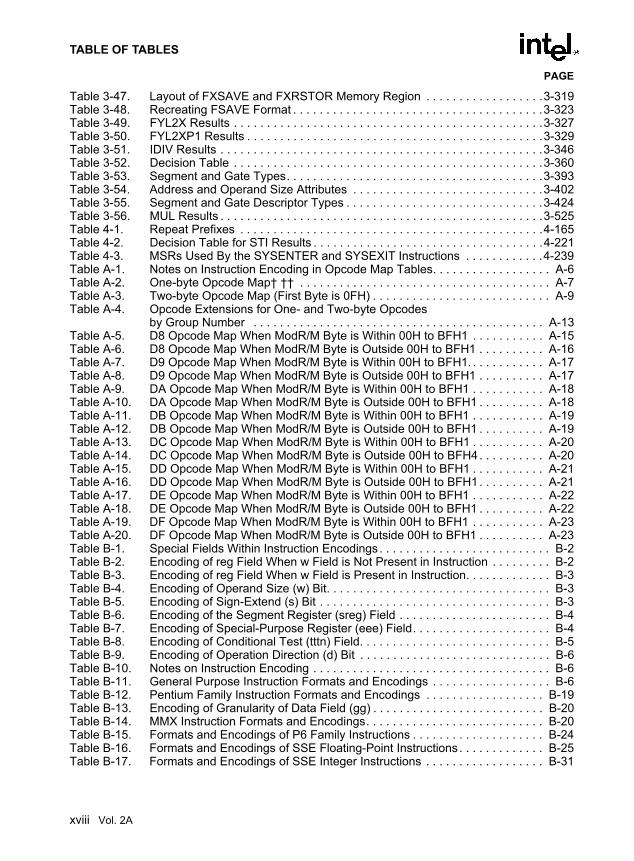
TABLE OF TABLES
PAGE
Table 3-47. Layout of FXSAVE and FXRSTOR Memory Region . . . . . . . . . . . . . . . . . .3-319Table 3-48. Recreating FSAVE Format . . . . . . . . . . . . . . . . . . . . . . . . . . . . . . . . . . . . . .3-323Table 3-49. FYL2X Results . . . . . . . . . . . . . . . . . . . . . . . . . . . . . . . . . . . . . . . . . . . . . . .3-327Table 3-50. FYL2XP1 Results . . . . . . . . . . . . . . . . . . . . . . . . . . . . . . . . . . . . . . . . . . . . .3-329Table 3-51. IDIV Results . . . . . . . . . . . . . . . . . . . . . . . . . . . . . . . . . . . . . . . . . . . . . . . . .3-346Table 3-52. Decision Table . . . . . . . . . . . . . . . . . . . . . . . . . . . . . . . . . . . . . . . . . . . . . . .3-360Table 3-53. Segment and Gate Types. . . . . . . . . . . . . . . . . . . . . . . . . . . . . . . . . . . . . . .3-393Table 3-54. Address and Operand Size Attributes . . . . . . . . . . . . . . . . . . . . . . . . . . . . .3-402Table 3-55. Segment and Gate Descriptor Types . . . . . . . . . . . . . . . . . . . . . . . . . . . . . .3-424Table 3-56. MUL Results . . . . . . . . . . . . . . . . . . . . . . . . . . . . . . . . . . . . . . . . . . . . . . . . .3-525Table 4-1. Repeat Prefixes . . . . . . . . . . . . . . . . . . . . . . . . . . . . . . . . . . . . . . . . . . . . . .4-165Table 4-2. Decision Table for STI Results . . . . . . . . . . . . . . . . . . . . . . . . . . . . . . . . . . .4-221Table 4-3. MSRs Used By the SYSENTER and SYSEXIT Instructions . . . . . . . . . . . .4-239Table A-1. Notes on Instruction Encoding in Opcode Map Tables. . . . . . . . . . . . . . . . . . A-6Table A-2. One-byte Opcode Map† †† . . . . . . . . . . . . . . . . . . . . . . . . . . . . . . . . . . . . . . A-7Table A-3. Two-byte Opcode Map (First Byte is 0FH) . . . . . . . . . . . . . . . . . . . . . . . . . . . A-9Table A-4. Opcode Extensions for One- and Two-byte Opcodes
by Group Number . . . . . . . . . . . . . . . . . . . . . . . . . . . . . . . . . . . . . . . . . . . . A-13Table A-5. D8 Opcode Map When ModR/M Byte is Within 00H to BFH1 . . . . . . . . . . . A-15Table A-6. D8 Opcode Map When ModR/M Byte is Outside 00H to BFH1 . . . . . . . . . . A-16Table A-7. D9 Opcode Map When ModR/M Byte is Within 00H to BFH1. . . . . . . . . . . . A-17Table A-8. D9 Opcode Map When ModR/M Byte is Outside 00H to BFH1 . . . . . . . . . . A-17Table A-9. DA Opcode Map When ModR/M Byte is Within 00H to BFH1 . . . . . . . . . . . A-18Table A-10. DA Opcode Map When ModR/M Byte is Outside 00H to BFH1 . . . . . . . . . . A-18Table A-11. DB Opcode Map When ModR/M Byte is Within 00H to BFH1 . . . . . . . . . . . A-19Table A-12. DB Opcode Map When ModR/M Byte is Outside 00H to BFH1 . . . . . . . . . . A-19Table A-13. DC Opcode Map When ModR/M Byte is Within 00H to BFH1 . . . . . . . . . . . A-20Table A-14. DC Opcode Map When ModR/M Byte is Outside 00H to BFH4. . . . . . . . . . A-20Table A-15. DD Opcode Map When ModR/M Byte is Within 00H to BFH1 . . . . . . . . . . . A-21Table A-16. DD Opcode Map When ModR/M Byte is Outside 00H to BFH1. . . . . . . . . . A-21Table A-17. DE Opcode Map When ModR/M Byte is Within 00H to BFH1 . . . . . . . . . . . A-22Table A-18. DE Opcode Map When ModR/M Byte is Outside 00H to BFH1 . . . . . . . . . . A-22Table A-19. DF Opcode Map When ModR/M Byte is Within 00H to BFH1 . . . . . . . . . . . A-23Table A-20. DF Opcode Map When ModR/M Byte is Outside 00H to BFH1 . . . . . . . . . . A-23Table B-1. Special Fields Within Instruction Encodings . . . . . . . . . . . . . . . . . . . . . . . . . . B-2Table B-2. Encoding of reg Field When w Field is Not Present in Instruction . . . . . . . . . B-2Table B-3. Encoding of reg Field When w Field is Present in Instruction. . . . . . . . . . . . . B-3Table B-4. Encoding of Operand Size (w) Bit. . . . . . . . . . . . . . . . . . . . . . . . . . . . . . . . . . B-3Table B-5. Encoding of Sign-Extend (s) Bit . . . . . . . . . . . . . . . . . . . . . . . . . . . . . . . . . . . B-3Table B-6. Encoding of the Segment Register (sreg) Field . . . . . . . . . . . . . . . . . . . . . . . B-4Table B-7. Encoding of Special-Purpose Register (eee) Field. . . . . . . . . . . . . . . . . . . . . B-4Table B-8. Encoding of Conditional Test (tttn) Field. . . . . . . . . . . . . . . . . . . . . . . . . . . . . B-5Table B-9. Encoding of Operation Direction (d) Bit . . . . . . . . . . . . . . . . . . . . . . . . . . . . . B-6Table B-10. Notes on Instruction Encoding . . . . . . . . . . . . . . . . . . . . . . . . . . . . . . . . . . . . B-6Table B-11. General Purpose Instruction Formats and Encodings . . . . . . . . . . . . . . . . . . B-6Table B-12. Pentium Family Instruction Formats and Encodings . . . . . . . . . . . . . . . . . . B-19Table B-13. Encoding of Granularity of Data Field (gg) . . . . . . . . . . . . . . . . . . . . . . . . . . B-20Table B-14. MMX Instruction Formats and Encodings. . . . . . . . . . . . . . . . . . . . . . . . . . . B-20Table B-15. Formats and Encodings of P6 Family Instructions . . . . . . . . . . . . . . . . . . . . B-24Table B-16. Formats and Encodings of SSE Floating-Point Instructions . . . . . . . . . . . . . B-25Table B-17. Formats and Encodings of SSE Integer Instructions . . . . . . . . . . . . . . . . . . B-31
xviii Vol. 2A

TABLE OF TABLES
PAGE
Table B-18. Format and Encoding of SSE Cacheability and Memory Ordering Instructions . . . . . . . . . . . . . . . . . . . . . . . . . . . . . . . . . . . . . . . . . . . . . . . . . . B-32
Table B-19. Encoding of Granularity of Data Field (gg) . . . . . . . . . . . . . . . . . . . . . . . . . . B-33Table B-20. Formats and Encodings of SSE2 Floating-Point Instructions . . . . . . . . . . . . B-33Table B-21. Formats and Encodings of SSE2 Integer Instructions . . . . . . . . . . . . . . . . . B-40Table B-22. Format and Encoding of SSE2 Cacheability Instructions . . . . . . . . . . . . . . . B-45Table B-23. Formats and Encodings of SSE3 Floating-Point Instructions . . . . . . . . . . . . B-46Table B-24. Formats and Encodings for SSE3 Event Management Instructions . . . . . . . B-47Table B-25. Formats and Encodings for SSE3 Integer and Move Instructions . . . . . . . . B-47Table B-26. General Floating-Point Instruction Formats . . . . . . . . . . . . . . . . . . . . . . . . . B-48Table B-27. Floating-Point Instruction Formats and Encodings . . . . . . . . . . . . . . . . . . . . B-49Table C-1. Simple Intrinsics . . . . . . . . . . . . . . . . . . . . . . . . . . . . . . . . . . . . . . . . . . . . . . . C-3Table C-2. Composite Intrinsics . . . . . . . . . . . . . . . . . . . . . . . . . . . . . . . . . . . . . . . . . . . C-32
Vol. 2A xix

TABLE OF TABLES
PAGE
xx Vol. 2A

1
About This Manual

CHAPTER 1ABOUT THIS MANUAL
The IA-32 Intel® Architecture Software Developer’s Manual, Volumes 2A & 2B: Instruction SetReference (Order Numbers 253666 and 253667) are part of a set that describes the architectureand programming environment of all IA-32 Intel Architecture processors. Other volumes in thisset are:
• The IA-32 Intel Architecture Software Developer’s Manual, Volume 1: Basic Architecture(Order Number 253665).
• The IA-32 Intel Architecture Software Developer’s Manual, Volume 3: System ProgramingGuide (Order Number 253668).
The IA-32 Intel Architecture Software Developer’s Manual, Volume 1 describes the basic archi-tecture and programming environment of an IA-32 processor. The IA-32 Intel Architecture Soft-ware Developer’s Manual, Volumes 2A & 2B describe the instructions set of the processor andthe opcode structure. These volumes are aimed at application programmers who are writingprograms to run under existing operating systems or executives. The IA-32 Intel ArchitectureSoftware Developer’s Manual, Volume 3 describes the operating-system support environmentof an IA-32 processor and IA-32 processor compatibility information. This volume is aimed atoperating-system and BIOS designers.
1.1. IA-32 PROCESSORS COVERED IN THIS MANUALThis manual includes information pertaining primarily to the most recent IA-32 processors,which include the Pentium® processors, the P6 family processors, the Pentium 4 processors, theIntel® Xeon™ processors, and the Pentium M processors. The P6 family processors are thoseIA-32 processors based on the P6 family microarchitecture, which include the Pentium Pro,Pentium II, and Pentium III processors. The Pentium 4 and Intel Xeon processors are based onthe Intel NetBurst® microarchitecture.
Vol. 2A 1-1

ABOUT THIS MANUAL
1.2. OVERVIEW OF THE IA-32 INTEL® ARCHITECTURE SOFTWARE DEVELOPER’S MANUAL, VOLUMES 2A & 2B: INSTRUCTION SET REFERENCE
A description of IA-32 Intel Architecture Software Developer’s Manual, Volumes 2A & 2Bcontent follows:
Chapter 1 — About This Manual. Gives an overview of all three volumes of the IA-32 IntelArchitecture Software Developer’s Manual. It also describes the notational conventions in thesemanuals and lists related Intel manuals and documentation of interest to programmers and hard-ware designers.
Chapter 2 — Instruction Format. Describes the machine-level instruction format used for allIA-32 instructions and gives the allowable encodings of prefixes, the operand-identifier byte(ModR/M byte), the addressing-mode specifier byte (SIB byte), and the displacement andimmediate bytes.
Chapter 3 — Instruction Set Reference, A-M. Describes IA-32 instructions in detail,including an algorithmic description of operations, the effect on flags, the effect of operand- andaddress-size attributes, and the exceptions that may be generated. The instructions are arrangedin alphabetical order. General-purpose, x87 FPU, Intel MMX™ technology, SSE/SSE2/SSE3extensions, and system instructions are included.
Chapter 4 — Instruction Set Reference, N-Z. This chapter continues the description of IA-32instructions started in Chapter 3. It provides the balance of the alphabetized list of instructionsand starts IA-32 Intel Architecture Software Developer’s Manual, Volume 2B.
Appendix A — Opcode Map. Gives an opcode map for the IA-32 instruction set.
Appendix B — Instruction Formats and Encodings. Gives the binary encoding of each formof each IA-32 instruction.
Appendix C — Intel C/C++ Compiler Intrinsics and Functional Equivalents. Lists the IntelC/C++ compiler intrinsics and their assembly code equivalents for each of the IA-32 MMX andSSE/SSE2/SSE3 instructions.
1.3. NOTATIONAL CONVENTIONSThis manual uses specific notation for data-structure formats, for symbolic representation ofinstructions, and for hexadecimal and binary numbers. A review of this notation makes themanual easier to read.
1.3.1. Bit and Byte OrderIn illustrations of data structures in memory, smaller addresses appear toward the bottom of thefigure; addresses increase toward the top. Bit positions are numbered from right to left. Thenumerical value of a set bit is equal to two raised to the power of the bit position. IA-32 proces-
1-2 Vol. 2A

ABOUT THIS MANUAL
sors are “little endian” machines; this means the bytes of a word are numbered starting from theleast significant byte. Figure 1-1 illustrates these conventions.
1.3.2. Reserved Bits and Software CompatibilityIn many register and memory layout descriptions, certain bits are marked as reserved. Whenbits are marked as reserved, it is essential for compatibility with future processors that softwaretreat these bits as having a future, though unknown, effect. The behavior of reserved bits shouldbe regarded as not only undefined, but unpredictable. Software should follow these guidelinesin dealing with reserved bits:
• Do not depend on the states of any reserved bits when testing the values of registers whichcontain such bits. Mask out the reserved bits before testing.
• Do not depend on the states of any reserved bits when storing to memory or to a register.
• Do not depend on the ability to retain information written into any reserved bits.
• When loading a register, always load the reserved bits with the values indicated in thedocumentation, if any, or reload them with values previously read from the same register.
NOTEAvoid any software dependence upon the state of reserved bits in IA-32registers. Depending upon the values of reserved register bits will makesoftware dependent upon the unspecified manner in which the processorhandles these bits. Programs that depend upon reserved values risk incompat-ibility with future processors.
Figure 1-1. Bit and Byte Order
Byte 3
HighestData Structure
Byte 1Byte 2 Byte 0
31 24 23 16 15 8 7 0Address
Lowest
Bit offset2824201612840 Address
Byte Offset
Vol. 2A 1-3

ABOUT THIS MANUAL
1.3.3. Instruction OperandsWhen instructions are represented symbolically, a subset of the IA-32 assembly language isused. In this subset, an instruction has the following format:label: mnemonic argument1, argument2, argument3
where:
• A label is an identifier which is followed by a colon.
• A mnemonic is a reserved name for a class of instruction opcodes which have the samefunction.
• The operands argument1, argument2, and argument3 are optional. There may be from zeroto three operands, depending on the opcode. When present, they take the form of eitherliterals or identifiers for data items. Operand identifiers are either reserved names ofregisters or are assumed to be assigned to data items declared in another part of theprogram (which may not be shown in the example).
When two operands are present in an arithmetic or logical instruction, the right operand is thesource and the left operand is the destination.
For example:LOADREG: MOV EAX, SUBTOTAL
In this example, LOADREG is a label, MOV is the mnemonic identifier of an opcode, EAX isthe destination operand, and SUBTOTAL is the source operand. Some assembly languages putthe source and destination in reverse order.
1.3.4. Hexadecimal and Binary NumbersBase 16 (hexadecimal) numbers are represented by a string of hexadecimal digits followed bythe character H (for example, F82EH). A hexadecimal digit is a character from the followingset: 0, 1, 2, 3, 4, 5, 6, 7, 8, 9, A, B, C, D, E, and F.
Base 2 (binary) numbers are represented by a string of 1s and 0s, sometimes followed by thecharacter B (for example, 1010B). The “B” designation is only used in situations where confu-sion as to the type of number might arise.
1-4 Vol. 2A

ABOUT THIS MANUAL
1.3.5. Segmented AddressingThe processor uses byte addressing. This means memory is organized and accessed as asequence of bytes. Whether one or more bytes are being accessed, a byte address is used tolocate the byte or bytes in memory. The range of memory that can be addressed is called anaddress space.
The processor also supports segmented addressing. This is a form of addressing where aprogram may have many independent address spaces, called segments. For example, a programcan keep its code (instructions) and stack in separate segments. Code addresses would alwaysrefer to the code space, and stack addresses would always refer to the stack space. The followingnotation is used to specify a byte address within a segment:Segment-register:Byte-address
For example, the following segment address identifies the byte at address FF79H in the segmentpointed by the DS register:DS:FF79H
The following segment address identifies an instruction address in the code segment. The CSregister points to the code segment and the EIP register contains the address of the instruction.
CS:EIP
1.3.6. ExceptionsAn exception is an event that typically occurs when an instruction causes an error. For example,an attempt to divide by zero generates an exception. However, some exceptions, such as break-points, occur under other conditions. Some types of exceptions may provide error codes. Anerror code reports additional information about the error. An example of the notation used toshow an exception and error code is shown below.#PF(fault code)
This example refers to a page-fault exception under conditions where an error code naming atype of fault is reported. Under some conditions, exceptions which produce error codes may notbe able to report an accurate code. In this case, the error code is zero, as shown below for ageneral-protection exception.#GP(0)
Vol. 2A 1-5

ABOUT THIS MANUAL
1.4. RELATED LITERATURELiterature related to IA-32 processors is listed on-line at this link:
http://developer.intel.com/design/processor/
Some of the documents listed at this web site can be viewed on-line; others can be ordered. Theliterature available is listed by Intel processor and then by the following literature types: appli-cations notes, data sheets, manuals, papers, and specification updates.
See also:
• The data sheet for a particular Intel IA-32 processor
• The specification update for a particular Intel IA-32 processor
• AP-485, Intel Processor Identification and the CPUID Instruction, Order Number 241618
• IA-32 Intel® Architecture Optimization Reference Manual, Order Number 248966
1-6 Vol. 2A

2
Instruction Format

CHAPTER 2INSTRUCTION FORMAT
This chapter describes the instruction format for all IA-32 processors.
2.1. GENERAL INSTRUCTION FORMATAll IA-32 instruction encodings are subsets of the format shown in Figure 2-1. Instructionsconsist of optional instruction prefixes (in any order), primary opcode bytes of up to threeopcode bytes, an addressing-form specifier (if required) consisting of the ModR/M byte andsometimes the SIB (Scale-Index-Base) byte, a displacement (if required), and an immediate datafield (if required).
Figure 2-1. IA-32 Instruction Format
InstructionPrefixes Opcode ModR/M SIB Displacement Immediate
Mod R/MReg/Opcode
027 6 5 3
Scale Base
027 6 5 3
Index
Immediatedata of
1, 2, or 4bytes or none
Addressdisplacementof 1, 2, or 4
bytes or none
1 byte(if required)
1 byte(if required)
1-, 2-, or 3-byteopcode
Up to fourprefixes of
1 byte each(optional)
Vol. 2A 2-1

INSTRUCTION FORMAT
2.2. SUMMARY OF INSTRUCTION PREFIXESThe instruction prefixes are divided into four groups, each with a set of allowable prefix codes.For each instruction, one prefix may be used from each of four groups (Groups 1, 2, 3, 4) andbe placed in any order.
NOTEDevelopers must not rely on the absence or characteristics of any features orinstructions marked reserved or undefined. Improper use of reserved featuresmay cause code to exhibit unpredictable behavior or fail when the code isrunning on an Intel processor.
• Group 1
— Lock and repeat prefixes:
• F0H—LOCK
• F2H—REPNE/REPNZ (used only with string instructions; when used with theescape opcode 0FH, this prefix is treated as a mandatory prefix for some SIMDinstructions)
• F3H—REP or REPE/REPZ (used only with string instructions; when used withthe escape opcode 0FH, this prefix is treated as an mandatory prefix for someSIMD instructions)
• Group 2
— Segment override prefixes:
• 2EH—CS segment override (use with any branch instruction is reserved)
• 36H—SS segment override prefix (use with any branch instruction is reserved)
• 3EH—DS segment override prefix (use with any branch instruction is reserved)
• 26H—ES segment override prefix (use with any branch instruction is reserved)
• 64H—FS segment override prefix (use with any branch instruction is reserved)
• 65H—GS segment override prefix (use with any branch instruction is reserved)
— Branch hints:
• 2EH—Branch not taken (used only with Jcc instructions)
• 3EH—Branch taken (used only with Jcc instructions)
• Group 3
• 66H—Operand-size override prefix (when used with the escape opcode 0FH, thisis treated as a mandatory prefix for some SIMD instructions)
2-2 Vol. 2A
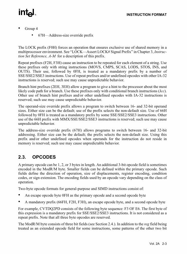
INSTRUCTION FORMAT
• Group 4
• 67H—Address-size override prefix
The LOCK prefix (F0H) forces an operation that ensures exclusive use of shared memory in amultiprocessor environment. See “LOCK—Assert LOCK# Signal Prefix” in Chapter 3, Instruc-tion Set Reference, A-M for a description of this prefix.
Repeat prefixes (F2H, F3H) cause an instruction to be repeated for each element of a string. Usethese prefixes only with string instructions (MOVS, CMPS, SCAS, LODS, STOS, INS, andOUTS). Their use, followed by 0FH, is treated as a mandatory prefix by a number ofSSE/SSE2/SSE3 instructions. Use of repeat prefixes and/or undefined opcodes with other IA-32instructions is reserved; such use may cause unpredictable behavior.
Branch hint prefixes (2EH, 3EH) allow a program to give a hint to the processor about the mostlikely code path for a branch. Use these prefixes only with conditional branch instructions (Jcc).Other use of branch hint prefixes and/or other undefined opcodes with IA-32 instructions isreserved; such use may cause unpredictable behavior.
The operand-size override prefix allows a program to switch between 16- and 32-bit operandsizes. Either size can be the default; use of the prefix selects the non-default size. Use of 66Hfollowed by 0FH is treated as a mandatory prefix by some SSE/SSE2/SSE3 instructions. Otheruse of the 66H prefix with MMX/SSE/SSE2/SSE3 instructions is reserved; such use may causeunpredictable behavior.
The address-size override prefix (67H) allows programs to switch between 16- and 32-bitaddressing. Either size can be the default; the prefix selects the non-default size. Using thisprefix and/or other undefined opcodes when operands for the instruction do not reside inmemory is reserved; such use may cause unpredictable behavior.
2.3. OPCODESA primary opcode can be 1, 2, or 3 bytes in length. An additional 3-bit opcode field is sometimesencoded in the ModR/M byte. Smaller fields can be defined within the primary opcode. Suchfields define the direction of operation, size of displacements, register encoding, conditioncodes, or sign extension. The encoding fields used by an opcode vary depending on the class ofoperation.
Two-byte opcode formats for general-purpose and SIMD instructions consist of:
• An escape opcode byte 0FH as the primary opcode and a second opcode byte
• A mandatory prefix (66FH, F2H, F3H), an escape opcode byte, and a second opcode byte
For example, CVTDQ2PD consists of the following byte sequence: F3 OF E6. The first byte ofthis expression is a mandatory prefix for SSE/SSE2/SSE3 instructions. It is not considered as arepeat prefix. Note that all three byte opcodes are reserved.
The ModR/M byte consists of three bit fields (see Section 2.4.). In addition to the reg field beingtreated as an extended opcode field for some instructions, some patterns of the other two bit
Vol. 2A 2-3

INSTRUCTION FORMAT
fields in the ModR/M byte may also be used to express opcode information. Using undefinedexpression of the primary opcode bytes, and/or undefined expression in the opcode extensionfield in the ModR/M byte, and/or undefined expression in other bit fields of the ModR/M byteis reserved. Valid opcode expressions are defined in Appendix A and Appendix B. Use of anyof reserved opcode expression can cause unpredictable behavior.
2.4. MODR/M AND SIB BYTESMany instructions that refer to an operand in memory have an addressing-form specifier byte(called the ModR/M byte) following the primary opcode. The ModR/M byte contains threefields of information:
• The mod field combines with the r/m field to form 32 possible values: eight registers and24 addressing modes.
• The reg/opcode field specifies either a register number or three more bits of opcode infor-mation. The purpose of the reg/opcode field is specified in the primary opcode.
• The r/m field can specify a register as an operand or it can be combined with the mod fieldto encode an addressing mode. Sometimes, certain combinations of the mod field and ther/m field is used to express opcode information for some instructions.
Certain encodings of the ModR/M byte require a second addressing byte (the SIB byte). Thebase-plus-index and scale-plus-index forms of 32-bit addressing require the SIB byte. The SIBbyte includes the following fields:
• The scale field specifies the scale factor.
• The index field specifies the register number of the index register.
• The base field specifies the register number of the base register.
See Section 2.6., “Addressing-Mode Encoding of ModR/M and SIB Bytes” for the encodingsof the ModR/M and SIB bytes.
2.5. DISPLACEMENT AND IMMEDIATE BYTESSome addressing forms include a displacement immediately following the ModR/M byte (or theSIB byte if one is present). If a displacement is required, it can require 1, 2, or 4 bytes.
If the instruction specifies an immediate operand, the operand always follows any displacementbytes. An immediate operand can be 1, 2 or 4 bytes.
2-4 Vol. 2A

INSTRUCTION FORMAT
2.6. ADDRESSING-MODE ENCODING OF MODR/M AND SIB BYTES
The values and the corresponding addressing forms of the ModR/M and SIB bytes are shown inTable 2-1 through Table 2-3. The 16-bit addressing forms specified by the ModR/M byte are inTable 2-1, 32-bit addressing forms are in Table 2-2. Table 2-3 shows the 32-bit addressing formsspecified by the SIB byte. In cases where the reg/opcode field in the ModR/M byte representsan extended opcode, valid instruction encodings are shown in Appendix B.
In Table 2-1 and Table 2-2, the first column (labeled “Effective Address”) lists 32 effectiveaddresses that can be assigned to one operand of an instruction by using the Mod and R/M fieldsof the ModR/M byte. The first 24 effective addresses provide ways of specifying a memorylocation; the last eight (Mod = 11B) provide ways of specifying general-purpose, MMX tech-nology, and XMM registers. For example, the first register-encoding (Mod = 11B, R/M = 000B)indicates general-purpose registers EAX, AX or AL; MMX technology register MM0; or XMMregister XMM0. The register used is determined by the opcode byte and the operand-sizeattribute. These may select either the EAX register (32 bits) or AX register (16 bits).
The second and third columns in Table 2-1 and 2-2 gives the binary encodings of the Mod andR/M fields in the ModR/M byte, respectively, required to obtain the associated effective addresslisted in the first column. All 32 possible combinations of the Mod and R/M fields are listed.
Across the top of Table 2-1 and 2-2, the eight possible values of the 3-bit Reg/Opcode field arelisted, in decimal (sixth row from top) and in binary (seventh row from top). The seventh row islabeled “REG =”, which represents the use of these 3 bits to give the location of a secondoperand, which must be a general-purpose, MMX technology, or XMM register. If the instruc-tion does not require a second operand to be specified, then the 3 bits of the Reg/Opcode fieldmay be used as an extension of the opcode, which is represented by the sixth row, labeled “/digit(Opcode)”. The five rows above give the byte, word, and doubleword general-purpose registers,the MMX technology registers, and the XMM registers that correspond to the register numbers,with the same assignments as for the R/M field when Mod field encoding is 11B. As with theR/M field register options, which of the five possible registers is used is determined by theopcode byte along with the operand-size attribute.
The body of Table 2-1 and 2-2 (under the label “Value of ModR/M Byte (in Hexadecimal)”)contains a 32 by 8 array giving all of the 256 values of the ModR/M byte, in hexadecimal. Bits3, 4 and 5 are specified by the column of the table in which a byte resides. The row specifies bits0, 1 and 2; also bits 6 and 7.
Vol. 2A 2-5

INSTRUCTION FORMAT
NOTES:1. The default segment register is SS for the effective addresses containing a BP index, DS for other effec-
tive addresses.2. The disp16 nomenclature denotes a 16-bit displacement that follows the ModR/M byte and that is added
to the index. 3. The disp8 nomenclature denotes an 8-bit displacement that follows the ModR/M byte and that is sign-
extended and added to the index.
Table 2-1. 16-Bit Addressing Forms with the ModR/M Byter8(/r)r16(/r)r32(/r)mm(/r)xmm(/r)/digit (Opcode)REG =
ALAXEAXMM0XMM00000
CLCXECXMM1XMM11001
DLDXEDXMM2XMM22010
BLBXEBXMM3XMM33011
AHSPESPMM4XMM44100
CHBP1
EBPMM5XMM55101
DHSIESIMM6XMM66110
BHDIEDIMM7XMM77111
EffectiveAddress Mod R/M Value of ModR/M Byte (in Hexadecimal)
[BX+SI][BX+DI][BP+SI][BP+DI][SI][DI]disp162
[BX]
00 000001010011100101110111
0001020304050607
08090A0B0C0D0E0F
1011121314151617
18191A1B1C1D1E1F
2021222324252627
28292A2B2C2D2E2F
3031323334353637
38393A3B3C3D3E3F
[BX+SI]+disp83
[BX+DI]+disp8[BP+SI]+disp8[BP+DI]+disp8[SI]+disp8[DI]+disp8[BP]+disp8[BX]+disp8
01 000001010011100101110111
4041424344454647
48494A4B4C4D4E4F
5051525354555657
58595A5B5C5D5E5F
6061626364656667
68696A6B6C6D6E6F
7071727374757677
78797A7B7C7D7E7F
[BX+SI]+disp16[BX+DI]+disp16[BP+SI]+disp16[BP+DI]+disp16[SI]+disp16[DI]+disp16[BP]+disp16[BX]+disp16
10 000001010011100101110111
8081828384858687
88898A8B8C8D8E8F
9091929394959697
98999A9B9C9D9E9F
A0A1A2A3A4A5A6A7
A8A9AAABACADAEAF
B0B1B2B3B4B5B6B7
B8B9BABBBCBDBEBF
EAX/AX/AL/MM0/XMM0ECX/CX/CL/MM1/XMM1EDX/DX/DL/MM2/XMM2EBX/BX/BL/MM3/XMM3ESP/SP/AHMM4/XMM4EBP/BP/CH/MM5/XMM5ESI/SI/DH/MM6/XMM6EDI/DI/BH/MM7/XMM7
11 000001010011100101110111
C0C1C2C3C4C5C6C7
C8C9CACBCCCDCECF
D0D1D2D3D4D5D6D7
D8D9DADBDCDDDEDF
E0EQE2E3E4E5E6E7
E8E9EAEBECEDEEEF
F0F1F2F3F4F5F6F7
F8F9FAFBFCFDFEFF
2-6 Vol. 2A

INSTRUCTION FORMAT
NOTES:1. The [--][--] nomenclature means a SIB follows the ModR/M byte.2. The disp32 nomenclature denotes a 32-bit displacement that follows the ModR/M byte (or the SIB byte if
one is present) and that is added to the index.3. The disp8 nomenclature denotes an 8-bit displacement that follows the ModR/M byte (or the SIB byte if
one is present) and that is sign-extended and added to the index.
Table 2-2. 32-Bit Addressing Forms with the ModR/M Byter8(/r)r16(/r)r32(/r)mm(/r)xmm(/r)/digit (Opcode)REG =
ALAXEAXMM0XMM00000
CLCXECXMM1XMM11001
DLDXEDXMM2XMM22010
BLBXEBXMM3XMM33011
AHSPESPMM4XMM44100
CHBPEBPMM5XMM55101
DHSIESIMM6XMM66110
BHDIEDIMM7XMM77111
EffectiveAddress Mod R/M Value of ModR/M Byte (in Hexadecimal)
[EAX][ECX][EDX][EBX][--][--]1disp322
[ESI][EDI]
00 000001010011100101110111
0001020304050607
08090A0B0C0D0E0F
1011121314151617
18191A1B1C1D1E1F
2021222324252627
28292A2B2C2D2E2F
3031323334353637
38393A3B3C3D3E3F
[EAX]+disp83
[ECX]+disp8[EDX]+disp8[EBX]+disp8[--][--]+disp8[EBP]+disp8[ESI]+disp8[EDI]+disp8
01 000001010011100101110111
4041424344454647
48494A4B4C4D4E4F
5051525354555657
58595A5B5C5D5E5F
6061626364656667
68696A6B6C6D6E6F
7071727374757677
78797A7B7C7D7E7F
[EAX]+disp32[ECX]+disp32[EDX]+disp32[EBX]+disp32[--][--]+disp32[EBP]+disp32[ESI]+disp32[EDI]+disp32
10 000001010011100101110111
8081828384858687
88898A8B8C8D8E8F
9091929394959697
98999A9B9C9D9E9F
A0A1A2A3A4A5A6A7
A8A9AAABACADAEAF
B0B1B2B3B4B5B6B7
B8B9BABBBCBDBEBF
EAX/AX/AL/MM0/XMM0ECX/CX/CL/MM/XMM1EDX/DX/DL/MM2/XMM2EBX/BX/BL/MM3/XMM3ESP/SP/AH/MM4/XMM4EBP/BP/CH/MM5/XMM5ESI/SI/DH/MM6/XMM6EDI/DI/BH/MM7/XMM7
11 000001010011100101110111
C0C1C2C3C4C5C6C7
C8C9CACBCCCDCECF
D0D1D2D3D4D5D6D7
D8D9DADBDCDDDEDF
E0E1E2E3E4E5E6E7
E8E9EAEBECEDEEEF
F0F1F2F3F4F5F6F7
F8F9FAFBFCFDFEFF
Vol. 2A 2-7

INSTRUCTION FORMAT
Table 2-3 is organized similarly to Tables 2-1 and 2-2, except that its body gives the 256 possiblevalues of the SIB byte, in hexadecimal. Which of the eight general-purpose registers will be usedas base is indicated across the top of the table, along with the corresponding values of the basefield (bits 0, 1 and 2) in decimal and binary. The rows indicate which register is used as the index(determined by bits 3, 4 and 5) along with the scaling factor (determined by bits 6 and 7).
NOTE:1. The [*] nomenclature means a disp32 with no base if the MOD is 00B. Otherwise, [*] means disp8 or
disp32 + [EBP]. This provides the following address modes:MOD bits Effective Address00 [scaled index] + disp32 01 [scaled index] + disp8 + [EBP]10 [scaled index] + disp32 + [EBP]
Table 2-3. 32-Bit Addressing Forms with the SIB Byter32Base =Base =
EAX0000
ECX1001
EDX2010
EBX3011
ESP4100
[*]5101
ESI6110
EDI7111
Scaled Index SS Index Value of SIB Byte (in Hexadecimal)
[EAX][ECX][EDX][EBX]none[EBP][ESI][EDI]
00 000001010011100101110111
0008101820283038
0109111921293139
020A121A222A323A
030B131B232B333B
040C141C242C343C
050D151D252D353D
060E161E262E363E
070F171F272F373F
[EAX*2][ECX*2][EDX*2][EBX*2]none[EBP*2][ESI*2][EDI*2]
01 000001010011100101110111
4048505860687078
4149515961697179
424A525A626A727A
434B535B636B737B
444C545C646C747C
454D555D656D757D
464E565E666E767E
474F575F676F777F
[EAX*4][ECX*4][EDX*4][EBX*4]none[EBP*4][ESI*4][EDI*4]
10 000001010011100101110111
80889098A0A8B0B8
81899189A1A9B1B9
828A929AA2AAB2BA
838B939BA3ABB3BB
848C949CA4ACB4BC
858D959DA5ADB5BD
868E969EA6AEB6BE
878F979FA7AFB7BF
[EAX*8][ECX*8][EDX*8][EBX*8]none[EBP*8][ESI*8][EDI*8]
11 000001010011100101110111
C0C8D0D8E0E8F0F8
C1C9D1D9E1E9F1F9
C2CAD2DAE2EAF2FA
C3CBD3DBE3EBF3FB
C4CCD4DCE4ECF4FC
C5CDD5DDE5EDF5FD
C6CED6DEE6EEF6FE
C7CFD7DFE7EFF7FF
2-8 Vol. 2A

3
Instruction Set Reference, A-M

CHAPTER 3INSTRUCTION SET REFERENCE, A-M
This chapter describes the IA-32 instruction set, including the general-purpose, x87 FPU, MMX,SSE/SSE2/SSE3, and system instructions. The descriptions in this chapter are arranged in alpha-betical order (A-M). This discussion is continued in Chapter 4 for the balance of the IA-32instruction set (N-Z). See also Chapter 4, IA-32 Intel Architecture Software Developer’s Manual,Volume 2B.
For each instruction, the forms are given for each operand combination, including the opcode,operands required, and a description. Also given for each instruction are a description of theinstruction and its operands, an operational description, a description of the effect of the instruc-tions on flags in the EFLAGS register, and a summary of the exceptions that can be generated.
3.1. INTERPRETING THE INSTRUCTION REFERENCE PAGESThis section describes the information contained in the various sections of the instruction refer-ence pages that make up the majority of this chapter. It also explains the notational conventionsand abbreviations used in these sections.
3.1.1. Instruction FormatThe following is an example of the format used for each IA-32 instruction description in thischapter. Each heading is followed by a usage description.
CMC—Complement Carry Flag [this is an example with usage description]
3.1.1.1. OPCODE COLUMN
The “Opcode” column gives the complete object code produced for each form of the instruction.When possible, the codes are given as hexadecimal bytes, in the same order in which they appearin memory. Definitions of entries other than hexadecimal bytes are as follows:
• /digit—A digit between 0 and 7 indicates that the ModR/M byte of the instruction usesonly the r/m (register or memory) operand. The reg field contains the digit that provides anextension to the instruction's opcode.
Opcode Instruction DescriptionF5 CMC Complement carry flag
Vol. 2A 3-1

INSTRUCTION SET REFERENCE, A-M
• /r—Indicates that the ModR/M byte of the instruction contains both a register operand andan r/m operand.
• cb, cw, cd, cp—A 1-byte (cb), 2-byte (cw), 4-byte (cd), or 6-byte (cp) value following theopcode that is used to specify a code offset and possibly a new value for the code segmentregister.
• ib, iw, id—A 1-byte (ib), 2-byte (iw), or 4-byte (id) immediate operand to the instructionthat follows the opcode, ModR/M bytes or scale-indexing bytes. The opcode determines ifthe operand is a signed value. All words and doublewords are given with the low-orderbyte first.
• +rb, +rw, +rd—A register code, from 0 through 7, added to the hexadecimal byte givenat the left of the plus sign to form a single opcode byte. The register codes are given inTable 3-1.
• +i—A number used in floating-point instructions when one of the operands is ST(i) fromthe FPU register stack. The number i (which can range from 0 to 7) is added to thehexadecimal byte given at the left of the plus sign to form a single opcode byte.
3.1.1.2. INSTRUCTION COLUMN
The “Instruction” column gives the syntax of the instruction statement as it would appear in anASM386 program. The following is a list of the symbols used to represent operands in theinstruction statements:
• rel8—A relative address in the range from 128 bytes before the end of the instruction to127 bytes after the end of the instruction.
• rel16 and rel32—A relative address within the same code segment as the instructionassembled. The rel16 symbol applies to instructions with an operand-size attribute of 16bits; the rel32 symbol applies to instructions with an operand-size attribute of 32 bits.
• ptr16:16 and ptr16:32—A far pointer, typically in a code segment different from that ofthe instruction. The notation 16:16 indicates that the value of the pointer has two parts. The
Table 3-1. Register Encodings Associated with the +rb, +rw, and +rd Nomenclaturerb rw rd
AL = 0 AX = 0 EAX = 0
CL = 1 CX = 1 ECX = 1
DL = 2 DX = 2 EDX = 2
BL = 3 BX = 3 EBX = 3
rb rw rd
AH = 4 SP = 4 ESP = 4
CH = 5 BP = 5 EBP = 5
DH = 6 SI = 6 ESI = 6
BH = 7 DI = 7 EDI = 7
3-2 Vol. 2A

INSTRUCTION SET REFERENCE, A-M
value to the left of the colon is a 16-bit selector or value destined for the code segmentregister. The value to the right corresponds to the offset within the destination segment.The ptr16:16 symbol is used when the instruction's operand-size attribute is 16 bits; theptr16:32 symbol is used when the operand-size attribute is 32 bits.
• r8—One of the byte general-purpose registers AL, CL, DL, BL, AH, CH, DH, or BH.
• r16—One of the word general-purpose registers AX, CX, DX, BX, SP, BP, SI, or DI.
• r32—One of the doubleword general-purpose registers EAX, ECX, EDX, EBX, ESP,EBP, ESI, or EDI.
• imm8—An immediate byte value. The imm8 symbol is a signed number between –128and +127 inclusive. For instructions in which imm8 is combined with a word ordoubleword operand, the immediate value is sign-extended to form a word or doubleword.The upper byte of the word is filled with the topmost bit of the immediate value.
• imm16—An immediate word value used for instructions whose operand-size attribute is16 bits. This is a number between –32,768 and +32,767 inclusive.
• imm32—An immediate doubleword value used for instructions whose operand-size attribute is 32 bits. It allows the use of a number between +2,147,483,647 and–2,147,483,648 inclusive.
• r/m8—A byte operand that is either the contents of a byte general-purpose register (AL,BL, CL, DL, AH, BH, CH, and DH), or a byte from memory.
• r/m16—A word general-purpose register or memory operand used for instructions whoseoperand-size attribute is 16 bits. The word general-purpose registers are: AX, BX, CX,DX, SP, BP, SI, and DI. The contents of memory are found at the address provided by theeffective address computation.
• r/m32—A doubleword general-purpose register or memory operand used for instructionswhose operand-size attribute is 32 bits. The doubleword general-purpose registers are:EAX, EBX, ECX, EDX, ESP, EBP, ESI, and EDI. The contents of memory are found atthe address provided by the effective address computation.
• m—A 16- or 32-bit operand in memory.
• m8—A byte operand in memory, usually expressed as a variable or array name, butpointed to by the DS:(E)SI or ES:(E)DI registers. This nomenclature is used only with thestring instructions and the XLAT instruction.
• m16—A word operand in memory, usually expressed as a variable or array name, butpointed to by the DS:(E)SI or ES:(E)DI registers. This nomenclature is used only with thestring instructions.
• m32—A doubleword operand in memory, usually expressed as a variable or array name,but pointed to by the DS:(E)SI or ES:(E)DI registers. This nomenclature is used only withthe string instructions.
• m64—A memory quadword operand in memory. This nomenclature is used only with theCMPXCHG8B instruction.
Vol. 2A 3-3

INSTRUCTION SET REFERENCE, A-M
• m128—A memory double quadword operand in memory. This nomenclature is used onlywith the SSE/SSE2/SSE3 instructions.
• m16:16, m16:32—A memory operand containing a far pointer composed of two numbers.The number to the left of the colon corresponds to the pointer's segment selector. Thenumber to the right corresponds to its offset.
• m16&32, m16&16, m32&32—A memory operand consisting of data item pairs whosesizes are indicated on the left and the right side of the ampersand. All memory addressingmodes are allowed. The m16&16 and m32&32 operands are used by the BOUNDinstruction to provide an operand containing an upper and lower bounds for array indices.The m16&32 operand is used by LIDT and LGDT to provide a word with which to loadthe limit field, and a doubleword with which to load the base field of the correspondingGDTR and IDTR registers.
• moffs8, moffs16, moffs32—A simple memory variable (memory offset) of type byte,word, or doubleword used by some variants of the MOV instruction. The actual address isgiven by a simple offset relative to the segment base. No ModR/M byte is used in theinstruction. The number shown with moffs indicates its size, which is determined by theaddress-size attribute of the instruction.
• Sreg—A segment register. The segment register bit assignments are ES=0, CS=1, SS=2,DS=3, FS=4, and GS=5.
• m32fp, m64fp, m80fp—A single-precision, double-precision, and double extended-precision (respectively) floating-point operand in memory. These symbols designatefloating-point values that are used as operands for x87 FPU floating-point instructions.
• m16int, m32int, m64int—A word, doubleword, and quadword integer (respectively)operand in memory. These symbols designate integers that are used as operands for x87FPU integer instructions.
• ST or ST(0)—The top element of the FPU register stack.
• ST(i)—The ith element from the top of the FPU register stack. (i ← 0 through 7)
• mm—An MMX technology register. The 64-bit MMX technology registers are: MM0through MM7.
• mm/m32—The low order 32 bits of an MMX technology register or a 32-bit memoryoperand. The 64-bit MMX technology registers are: MM0 through MM7. The contents ofmemory are found at the address provided by the effective address computation.
• mm/m64—An MMX technology register or a 64-bit memory operand. The 64-bit MMXtechnology registers are: MM0 through MM7. The contents of memory are found at theaddress provided by the effective address computation.
• xmm—An XMM register. The 128-bit XMM registers are: XMM0 through XMM7.
• xmm/m32—An XMM register or a 32-bit memory operand. The 128-bit XMM registersare XMM0 through XMM7. The contents of memory are found at the address provided bythe effective address computation.
3-4 Vol. 2A

INSTRUCTION SET REFERENCE, A-M
• xmm/m64—An XMM register or a 64-bit memory operand. The 128-bit SIMD floating-point registers are XMM0 through XMM7. The contents of memory are found at theaddress provided by the effective address computation.
• xmm/m128—An XMM register or a 128-bit memory operand. The 128-bit XMMregisters are XMM0 through XMM7. The contents of memory are found at the addressprovided by the effective address computation.
3.1.1.3. DESCRIPTION COLUMN
The “Description” column following the “Instruction” column briefly explains the variousforms of the instruction. The following “Description” and “Operation” sections contain moredetails of the instruction's operation.
3.1.1.4. DESCRIPTION
The “Description” section describes the purpose of the instructions and the required operands.It also discusses the effect of the instruction on flags.
3.1.2. OperationThe “Operation” section contains an algorithmic description (written in pseudo-code) of theinstruction. The pseudo-code uses a notation similar to the Algol or Pascal language. The algo-rithms are composed of the following elements:
• Comments are enclosed within the symbol pairs “(*” and “*)”.
• Compound statements are enclosed in keywords, such as IF, THEN, ELSE, and FI for an ifstatement, DO and OD for a do statement, or CASE ... OF and ESAC for a case statement.
• A register name implies the contents of the register. A register name enclosed in bracketsimplies the contents of the location whose address is contained in that register. Forexample, ES:[DI] indicates the contents of the location whose ES segment relative addressis in register DI. [SI] indicates the contents of the address contained in register SI relativeto the SI register’s default segment (DS) or overridden segment.
• Parentheses around the “E” in a general-purpose register name, such as (E)SI, indicatesthat an offset is read from the SI register if the current address-size attribute is 16 or is readfrom the ESI register if the address-size attribute is 32.
• Brackets are also used for memory operands, where they mean that the contents of thememory location is a segment-relative offset. For example, [SRC] indicates that thecontents of the source operand is a segment-relative offset.
• A ← B; indicates that the value of B is assigned to A.
• The symbols =, ≠, ≥, and ≤ are relational operators used to compare two values, meaningequal, not equal, greater or equal, and less or equal, respectively. A relational expressionsuch as A = B is TRUE if the value of A is equal to B; otherwise it is FALSE.
Vol. 2A 3-5

INSTRUCTION SET REFERENCE, A-M
• The expression “<< COUNT” and “>> COUNT” indicates that the destination operandshould be shifted left or right, respectively, by the number of bits indicated by the countoperand.
The following identifiers are used in the algorithmic descriptions:
• OperandSize and AddressSize—The OperandSize identifier represents the operand-sizeattribute of the instruction, which is either 16 or 32 bits. The AddressSize identifierrepresents the address-size attribute, which is either 16 or 32 bits. For example, thefollowing pseudo-code indicates that the operand-size attribute depends on the form of theCMPS instruction used.
IF instruction = CMPSWTHEN OperandSize ← 16;ELSE
IF instruction = CMPSDTHEN OperandSize ← 32;
FI;FI;
See “Operand-Size and Address-Size Attributes” in Chapter 3 of the IA-32 Intel Archi-tecture Software Developer’s Manual, Volume 1, for general guidelines on how theseattributes are determined.
• StackAddrSize—Represents the stack address-size attribute associated with theinstruction, which has a value of 16 or 32 bits (see “Address-Size Attribute for Stack” inChapter 6 of the IA-32 Intel Architecture Software Developer’s Manual, Volume 1).
• SRC—Represents the source operand.
• DEST—Represents the destination operand.
The following functions are used in the algorithmic descriptions:
• ZeroExtend(value)—Returns a value zero-extended to the operand-size attribute of theinstruction. For example, if the operand-size attribute is 32, zero extending a byte value of–10 converts the byte from F6H to a doubleword value of 000000F6H. If the value passedto the ZeroExtend function and the operand-size attribute are the same size, ZeroExtendreturns the value unaltered.
• SignExtend(value)—Returns a value sign-extended to the operand-size attribute of theinstruction. For example, if the operand-size attribute is 32, sign extending a bytecontaining the value –10 converts the byte from F6H to a doubleword value ofFFFFFFF6H. If the value passed to the SignExtend function and the operand-size attributeare the same size, SignExtend returns the value unaltered.
• SaturateSignedWordToSignedByte—Converts a signed 16-bit value to a signed 8-bitvalue. If the signed 16-bit value is less than –128, it is represented by the saturated value –128 (80H); if it is greater than 127, it is represented by the saturated value 127 (7FH).
• SaturateSignedDwordToSignedWord—Converts a signed 32-bit value to a signed 16-bit value. If the signed 32-bit value is less than –32768, it is represented by the saturated
3-6 Vol. 2A

INSTRUCTION SET REFERENCE, A-M
value –32768 (8000H); if it is greater than 32767, it is represented by the saturated value32767 (7FFFH).
• SaturateSignedWordToUnsignedByte—Converts a signed 16-bit value to an unsigned8-bit value. If the signed 16-bit value is less than zero, it is represented by the saturatedvalue zero (00H); if it is greater than 255, it is represented by the saturated value 255(FFH).
• SaturateToSignedByte—Represents the result of an operation as a signed 8-bit value. Ifthe result is less than –128, it is represented by the saturated value –128 (80H); if it isgreater than 127, it is represented by the saturated value 127 (7FH).
• SaturateToSignedWord—Represents the result of an operation as a signed 16-bit value.If the result is less than –32768, it is represented by the saturated value –32768 (8000H); ifit is greater than 32767, it is represented by the saturated value 32767 (7FFFH).
• SaturateToUnsignedByte—Represents the result of an operation as a signed 8-bit value.If the result is less than zero, it is represented by the saturated value zero (00H); if it isgreater than 255, it is represented by the saturated value 255 (FFH).
• SaturateToUnsignedWord—Represents the result of an operation as a signed 16-bitvalue. If the result is less than zero, it is represented by the saturated value zero (00H); if itis greater than 65535, it is represented by the saturated value 65535 (FFFFH).
• RoundTowardsZero()—Returns the operand rounded towards zero to the nearest integralvalue.
• LowOrderWord(DEST * SRC)—Multiplies a word operand by a word operand andstores the least significant word of the doubleword result in the destination operand.
• HighOrderWord(DEST * SRC)—Multiplies a word operand by a word operand andstores the most significant word of the doubleword result in the destination operand.
• Push(value)—Pushes a value onto the stack. The number of bytes pushed is determined bythe operand-size attribute of the instruction. See the “Operation” section in “PUSH—PushWord or Doubleword Onto the Stack” in Chapter 4 for more information on the pushoperation.
• Pop() removes the value from the top of the stack and returns it. The statement EAX ←Pop(); assigns to EAX the 32-bit value from the top of the stack. Pop will return either aword or a doubleword depending on the operand-size attribute. See the “Operation”section in Chapter 4, “POP—Pop a Value from the Stack” for more information on the popoperation.
• PopRegisterStack—Marks the FPU ST(0) register as empty and increments the FPUregister stack pointer (TOP) by 1.
• Switch-Tasks—Performs a task switch.
• Bit(BitBase, BitOffset)—Returns the value of a bit within a bit string, which is a sequenceof bits in memory or a register. Bits are numbered from low-order to high-order withinregisters and within memory bytes. If the base operand is a register, the offset can be in the
Vol. 2A 3-7

INSTRUCTION SET REFERENCE, A-M
range 0..31. This offset addresses a bit within the indicated register. An example, thefunction Bit [EAX, 21] is illustrated in Figure 3-1.
If BitBase is a memory address, BitOffset can range from –2 GBits to 2 GBits. Theaddressed bit is numbered (Offset MOD 8) within the byte at address (BitBase + (BitOffsetDIV 8)), where DIV is signed division with rounding towards negative infinity, and MODreturns a positive number. This operation is illustrated in Figure 3-2.
Figure 3-1. Bit Offset for BIT[EAX,21]
Figure 3-2. Memory Bit Indexing
02131
BitOffset ← 21
BitBase + 1
0777 5 0 0
BitBase − 2
0777 50 0
BitBase BitBase − 1
BitOffset ←
BitOffset ← −
BitBase − 1BitBase
3-8 Vol. 2A

INSTRUCTION SET REFERENCE, A-M
3.1.3. Intel® C/C++ Compiler Intrinsics EquivalentsThe Intel C/C++ compiler intrinsics equivalents are special C/C++ coding extensions that allowusing the syntax of C function calls and C variables instead of hardware registers. Using theseintrinsics frees programmers from having to manage registers and assembly programming.Further, the compiler optimizes the instruction scheduling so that executable run faster.
The following sections discuss the intrinsics API and the MMX technology and SIMD floating-point intrinsics. Each intrinsic equivalent is listed with the instruction description. There may beadditional intrinsics that do not have an instruction equivalent. It is strongly recommended thatthe reader reference the compiler documentation for the complete list of supported intrinsics.
Please refer to the Intel C/C++ Compiler User’s Guide With Support for the Streaming SIMDExtensions 2 (Order Number 718195-2001). See Appendix C, Intel C/C++ Compiler Intrinsicsand Functional Equivalents for more information on using intrinsics.
3.1.3.1. THE INTRINSICS API
The benefit of coding with MMX technology intrinsics and the SSE/SSE2/SSE3 intrinsics isthat you can use the syntax of C function calls and C variables instead of hardware registers.This frees you from managing registers and programming assembly. Further, the compiler opti-mizes the instruction scheduling so that your executable runs faster. For each computational anddata manipulation instruction in the new instruction set, there is a corresponding C intrinsic thatimplements it directly. The intrinsics allow you to specify the underlying implementation(instruction selection) of an algorithm yet leave instruction scheduling and register allocation tothe compiler.
3.1.3.2. MMX™ TECHNOLOGY INTRINSICS
The MMX technology intrinsics are based on a __m64 data type that represents the specificcontents of an MMX technology register. You can specify values in bytes, short integers, 32-bitvalues, or a 64-bit object. The __m64 data type, however, is not a basic ANSI C data type, andtherefore you must observe the following usage restrictions:
• Use __m64 data only on the left-hand side of an assignment, as a return value, or as aparameter. You cannot use it with other arithmetic expressions (“+”, “>>”, and so on).
• Use __m64 objects in aggregates, such as unions to access the byte elements andstructures; the address of an __m64 object may be taken.
• Use __m64 data only with the MMX technology intrinsics described in this manual and theIntel C/C++ Compiler User’s Guide With Support for the Streaming SIMD Extensions 2(Order Number 718195-2001). Refer to Appendix C, Intel C/C++ Compiler Intrinsics andFunctional Equivalents for more information on using intrinsics.
Vol. 2A 3-9

INSTRUCTION SET REFERENCE, A-M
3.1.3.3. SSE/SSE2/SSE3 INTRINSICS
SSE/SSE2/SSE3 intrinsics all make use of the XMM registers of the Pentium III, Pentium 4, andIntel Xeon processors. There are three data types supported by these intrinsics: __m128,__m128d, and __m128i.
• The __m128 data type is used to represent the contents of an XMM register used by anSSE intrinsic. This is either four packed single-precision floating-point values or a scalarsingle-precision floating-point value.
• The __m128d data type holds two packed double-precision floating-point values or ascalar double-precision floating-point value.
• The __m128i data type can hold sixteen byte, eight word, or four doubleword, or twoquadword integer values.
The compiler aligns __m128, __m128d, and __m128i local and global data to 16-byte bound-aries on the stack. To align integer, float, or double arrays, you can use the declspec statementas described in the Intel C/C++ Compiler User’s Guide With Support for the Streaming SIMDExtensions 2 (Order Number 718195-2001).
The __m128, __m128d, and __m128i data types are not basic ANSI C data types and thereforesome restrictions are placed on its usage:
• Use __m128, __m128d, and __m128i only on the left-hand side of an assignment, as areturn value, or as a parameter. Do not use it in other arithmetic expressions such as “+”and “>>.”
• Do not initialize __m128, __m128d, and __m128i with literals; there is no way to express128-bit constants.
• Use __m128, __m128d, and __m128i objects in aggregates, such as unions (for example,to access the float elements) and structures. The address of these objects may be taken.
• Use __m128, __m128d, and __m128i data only with the intrinsics described in this user’sguide. Refer to Appendix C, Intel C/C++ Compiler Intrinsics and Functional Equivalentsfor more information on using intrinsics.
The compiler aligns __m128, __m128d, and __m128i local data to 16-byte boundaries on thestack. Global __m128 data is also aligned on 16-byte boundaries. (To align float arrays, you canuse the alignment declspec described in the following section.) Because the new instruction settreats the SIMD floating-point registers in the same way whether you are using packed or scalardata, there is no __m32 data type to represent scalar data as you might expect. For scalar oper-ations, you should use the __m128 objects and the “scalar” forms of the intrinsics; the compilerand the processor implement these operations with 32-bit memory references.
3-10 Vol. 2A
INSTRUCTION SET REFERENCE, A-M
The suffixes ps and ss are used to denote “packed single” and “scalar single” precision opera-tions. The packed floats are represented in right-to-left order, with the lowest word (right-most)being used for scalar operations: [z, y, x, w]. To explain how memory storage reflects this,consider the following example.
The operationfloat a[4] ← { 1.0, 2.0, 3.0, 4.0 };__m128 t ← _mm_load_ps(a);
produces the same result as follows:__m128 t ← _mm_set_ps(4.0, 3.0, 2.0, 1.0);
In other words,
t ← [ 4.0, 3.0, 2.0, 1.0 ]
where the “scalar” element is 1.0.
Some intrinsics are “composites” because they require more than one instruction to implementthem. You should be familiar with the hardware features provided by the SSE, SSE2, SSE3, andMMX technology when writing programs with the intrinsics.
Keep the following important issues in mind:
• Certain intrinsics, such as _mm_loadr_ps and _mm_cmpgt_ss, are not directly supportedby the instruction set. While these intrinsics are convenient programming aids, be mindfulof their implementation cost.
• Data loaded or stored as __m128 objects must generally be 16-byte-aligned.
• Some intrinsics require that their argument be immediates, that is, constant integers(literals), due to the nature of the instruction.
• The result of arithmetic operations acting on two NaN (Not a Number) arguments isundefined. Therefore, floating-point operations using NaN arguments may not match theexpected behavior of the corresponding assembly instructions.
For a more detailed description of each intrinsic and additional information related to its usage,refer to the Intel C/C++ Compiler User’s Guide With Support for the Streaming SIMD Exten-sions 2 (Order Number 718195-2001). Refer to Appendix C, Intel C/C++ Compiler Intrinsicsand Functional Equivalents for more information on using intrinsics.
3.1.4. Flags AffectedThe “Flags Affected” section lists the flags in the EFLAGS register that are affected by theinstruction. When a flag is cleared, it is equal to 0; when it is set, it is equal to 1. The arithmeticand logical instructions usually assign values to the status flags in a uniform manner (seeAppendix A, EFLAGS Cross-Reference, in the IA-32 Intel Architecture Software Developer’sManual, Volume 1). Non-conventional assignments are described in the “Operation” section.The values of flags listed as undefined may be changed by the instruction in an indeterminatemanner. Flags that are not listed are unchanged by the instruction.
Vol. 2A 3-11

INSTRUCTION SET REFERENCE, A-M
3.1.5. FPU Flags AffectedThe floating-point instructions have an “FPU Flags Affected” section that describes how eachinstruction can affect the four condition code flags of the FPU status word.
3.1.6. Protected Mode ExceptionsThe “Protected Mode Exceptions” section lists the exceptions that can occur when the instruc-tion is executed in protected mode and the reasons for the exceptions. Each exception is givena mnemonic that consists of a pound sign (#) followed by two letters and an optional error codein parentheses. For example, #GP(0) denotes a general protection exception with an error codeof 0. Table 3-2 associates each two-letter mnemonic with the corresponding interrupt vectornumber and exception name. See Chapter 5, Interrupt and Exception Handling, in the IA-32Intel Architecture Software Developer’s Manual, Volume 3, for a detailed description of theexceptions.
Application programmers should consult the documentation provided with their operatingsystems to determine the actions taken when exceptions occur.
3-12 Vol. 2A

INSTRUCTION SET REFERENCE, A-M
NOTE:* In the real-address mode, vector 13 is the segment overrun exception.
Table 3-2. IA-32 General Exceptions
Vector No. Name Source
Protected Mode
Real Address
Mode
Virtual 8086 Mode
0 #DE—Divide Error DIV and IDIV instructions. Yes Yes Yes
1 #DB—Debug Any code or data reference. Yes Yes Yes
3 #BP—Breakpoint INT 3 instruction. Yes Yes Yes
4 #OF—Overflow INTO instruction. Yes Yes Yes
5 #BR—BOUND Range Exceeded
BOUND instruction. Yes Yes Yes
6 #UD—Invalid Opcode (Undefined Opcode)
UD2 instruction or reserved opcode.
Yes Yes Yes
7 #NM—Device Not Available (No Math Coprocessor)
Floating-point or WAIT/FWAIT instruction.
Yes Yes Yes
8 #DF—Double Fault Any instruction that can generate an exception, an NMI, or an INTR.
Yes Yes Yes
10 #TS—Invalid TSS Task switch or TSS access. Yes Reserved Yes
11 #NP—Segment Not Present
Loading segment registers or accessing system segments.
Yes Reserved Yes
12 #SS—Stack Segment Fault
Stack operations and SS register loads.
Yes Yes Yes
13 #GP—General Protection*
Any memory reference and other protection checks.
Yes Yes Yes
14 #PF—Page Fault Any memory reference. Yes Reserved Yes
16 #MF—Floating-Point Error (Math Fault)
Floating-point or WAIT/FWAIT instruction.
Yes Yes Yes
17 #AC—Alignment Check
Any data reference in memory. Yes Reserved Yes
18 #MC—Machine Check
Model dependent machine check errors.
Yes Yes Yes
19 #XF—SIMD Floating-Point Numeric Error
SSE/SSE2/SSE3 floating-point instructions.
Yes Yes Yes
Vol. 2A 3-13

INSTRUCTION SET REFERENCE, A-M
3.1.7. Real-Address Mode ExceptionsThe “Real-Address Mode Exceptions” section lists the exceptions that can occur when theinstruction is executed in real-address mode (see Table 3-2).
3.1.8. Virtual-8086 Mode ExceptionsThe “Virtual-8086 Mode Exceptions” section lists the exceptions that can occur when theinstruction is executed in virtual-8086 mode (see Table 3-2).
3.1.9. Floating-Point ExceptionsThe “Floating-Point Exceptions” section lists exceptions that can occur when an x87 FPUfloating-point instruction is executed. All of these exception conditions result in a floating-pointerror exception (#MF, vector number 16) being generated. Table 3-3 associates a one- or two-letter mnemonic with the corresponding exception name. See “Floating-Point Exception Condi-tions” in Chapter 8 of the IA-32 Intel Architecture Software Developer’s Manual, Volume 1, fora detailed description of these exceptions.
3.1.10. SIMD Floating-Point ExceptionsThe “SIMD Floating-Point Exceptions” section lists exceptions that can occur when anSSE/SSE2/SSE3 floating-point instruction is executed. All of these exception conditions resultin an SIMD floating-point error exception (#XF, vector number 19) being generated. Table 3-4associates a one-letter mnemonic with the corresponding exception name. For a detailed descrip-tion of these exceptions, refer to ”SSE and SSE2 Exceptions”, in Chapter 11 of the IA-32 IntelArchitecture Software Developer’s Manual, Volume 1.
Table 3-3. x87 FPU Floating-Point ExceptionsMnemonic Name Source
#IS#IA
Floating-point invalid operation:- Stack overflow or underflow- Invalid arithmetic operation
- x87 FPU stack overflow or underflow- Invalid FPU arithmetic operation
#Z Floating-point divide-by-zero Divide-by-zero
#D Floating-point denormal operand Source operand that is a denormal number
#O Floating-point numeric overflow Overflow in result
#U Floating-point numeric underflow Underflow in result
#P Floating-point inexact result (precision) Inexact result (precision)
3-14 Vol. 2A

INSTRUCTION SET REFERENCE, A-M
3.2. INSTRUCTION REFERENCEThe remainder of this chapter provides detailed descriptions of IA-32 instruction.
Table 3-4. SIMD Floating-Point ExceptionsMnemonic Name Source
#I Floating-point invalid operation Invalid arithmetic operation or source operand
#Z Floating-point divide-by-zero Divide-by-zero
#D Floating-point denormal operand Source operand that is a denormal number
#O Floating-point numeric overflow Overflow in result
#U Floating-point numeric underflow Underflow in result
#P Floating-point inexact result Inexact result (precision)
Vol. 2A 3-15

INSTRUCTION SET REFERENCE, A-M
AAA—ASCII Adjust After Addition
DescriptionAdjusts the sum of two unpacked BCD values to create an unpacked BCD result. The ALregister is the implied source and destination operand for this instruction. The AAA instructionis only useful when it follows an ADD instruction that adds (binary addition) two unpackedBCD values and stores a byte result in the AL register. The AAA instruction then adjusts thecontents of the AL register to contain the correct 1-digit unpacked BCD result.
If the addition produces a decimal carry, the AH register increments by 1, and the CF and AFflags are set. If there was no decimal carry, the CF and AF flags are cleared and the AH registeris unchanged. In either case, bits 4 through 7 of the AL register are set to 0.
OperationIF ((AL AND 0FH) > 9) OR (AF = 1)
THENAL ← AL + 6;AH ← AH + 1;AF ← 1;CF ← 1;
ELSEAF ← 0;CF ← 0;
FI;AL ← AL AND 0FH;
Flags AffectedThe AF and CF flags are set to 1 if the adjustment results in a decimal carry; otherwise they areset to 0. The OF, SF, ZF, and PF flags are undefined.
Exceptions (All Operating Modes)None.
Opcode Instruction Description37 AAA ASCII adjust AL after addition
3-16 Vol. 2A

INSTRUCTION SET REFERENCE, A-M
AAD—ASCII Adjust AX Before Division
DescriptionAdjusts two unpacked BCD digits (the least-significant digit in the AL register and the most-significant digit in the AH register) so that a division operation performed on the result will yielda correct unpacked BCD value. The AAD instruction is only useful when it precedes a DIVinstruction that divides (binary division) the adjusted value in the AX register by an unpackedBCD value.
The AAD instruction sets the value in the AL register to (AL + (10 * AH)), and then clears theAH register to 00H. The value in the AX register is then equal to the binary equivalent of theoriginal unpacked two-digit (base 10) number in registers AH and AL.
The generalized version of this instruction allows adjustment of two unpacked digits of anynumber base (see the “Operation” section below), by setting the imm8 byte to the selectednumber base (for example, 08H for octal, 0AH for decimal, or 0CH for base 12 numbers). TheAAD mnemonic is interpreted by all assemblers to mean adjust ASCII (base 10) values. Toadjust values in another number base, the instruction must be hand coded in machine code (D5imm8).
OperationtempAL ← AL;tempAH ← AH;AL ← (tempAL + (tempAH ∗ imm8)) AND FFH; (* imm8 is set to 0AH for the AAD mnemonic *)AH ← 0
The immediate value (imm8) is taken from the second byte of the instruction.
Flags AffectedThe SF, ZF, and PF flags are set according to the resulting binary value in the AL register; theOF, AF, and CF flags are undefined.
Exceptions (All Operating Modes)None.
Opcode Instruction DescriptionD5 0A AAD ASCII adjust AX before divisionD5 ib (No mnemonic) Adjust AX before division to number base imm8
Vol. 2A 3-17

INSTRUCTION SET REFERENCE, A-M
AAM—ASCII Adjust AX After Multiply
DescriptionAdjusts the result of the multiplication of two unpacked BCD values to create a pair of unpacked(base 10) BCD values. The AX register is the implied source and destination operand for thisinstruction. The AAM instruction is only useful when it follows an MUL instruction that multi-plies (binary multiplication) two unpacked BCD values and stores a word result in the AXregister. The AAM instruction then adjusts the contents of the AX register to contain the correct2-digit unpacked (base 10) BCD result.
The generalized version of this instruction allows adjustment of the contents of the AX to createtwo unpacked digits of any number base (see the “Operation” section below). Here, the imm8byte is set to the selected number base (for example, 08H for octal, 0AH for decimal, or 0CHfor base 12 numbers). The AAM mnemonic is interpreted by all assemblers to mean adjust toASCII (base 10) values. To adjust to values in another number base, the instruction must be handcoded in machine code (D4 imm8).
OperationtempAL ← AL;AH ← tempAL / imm8; (* imm8 is set to 0AH for the AAM mnemonic *)AL ← tempAL MOD imm8;
The immediate value (imm8) is taken from the second byte of the instruction.
Flags AffectedThe SF, ZF, and PF flags are set according to the resulting binary value in the AL register. TheOF, AF, and CF flags are undefined.
Exceptions (All Operating Modes)None with the default immediate value of 0AH. If, however, an immediate value of 0 is used, itwill cause a #DE (divide error) exception.
Opcode Instruction DescriptionD4 0A AAM ASCII adjust AX after multiplyD4 ib (No mnemonic) Adjust AX after multiply to number base imm8
3-18 Vol. 2A

INSTRUCTION SET REFERENCE, A-M
AAS—ASCII Adjust AL After Subtraction
DescriptionAdjusts the result of the subtraction of two unpacked BCD values to create a unpacked BCDresult. The AL register is the implied source and destination operand for this instruction. TheAAS instruction is only useful when it follows a SUB instruction that subtracts (binary subtrac-tion) one unpacked BCD value from another and stores a byte result in the AL register. TheAAA instruction then adjusts the contents of the AL register to contain the correct 1-digitunpacked BCD result.
If the subtraction produced a decimal carry, the AH register decrements by 1, and the CF andAF flags are set. If no decimal carry occurred, the CF and AF flags are cleared, and the AHregister is unchanged. In either case, the AL register is left with its top nibble set to 0.
OperationIF ((AL AND 0FH) > 9) OR (AF = 1)THEN
AL ← AL – 6;AH ← AH – 1;AF ← 1;CF ← 1;
ELSECF ← 0;AF ← 0;
FI;AL ← AL AND 0FH;
Flags AffectedThe AF and CF flags are set to 1 if there is a decimal borrow; otherwise, they are set to 0. TheOF, SF, ZF, and PF flags are undefined.
Exceptions (All Operating Modes)None.
Opcode Instruction Description3F AAS ASCII adjust AL after subtraction
Vol. 2A 3-19

INSTRUCTION SET REFERENCE, A-M
ADC—Add with Carry
DescriptionAdds the destination operand (first operand), the source operand (second operand), and the carry(CF) flag and stores the result in the destination operand. The destination operand can be aregister or a memory location; the source operand can be an immediate, a register, or a memorylocation. (However, two memory operands cannot be used in one instruction.) The state of theCF flag represents a carry from a previous addition. When an immediate value is used as anoperand, it is sign-extended to the length of the destination operand format.
The ADC instruction does not distinguish between signed or unsigned operands. Instead, theprocessor evaluates the result for both data types and sets the OF and CF flags to indicate a carryin the signed or unsigned result, respectively. The SF flag indicates the sign of the signed result.
The ADC instruction is usually executed as part of a multibyte or multiword addition in whichan ADD instruction is followed by an ADC instruction.
This instruction can be used with a LOCK prefix to allow the instruction to be executed atomi-cally.
Operation
DEST ← DEST + SRC + CF;
Flags AffectedThe OF, SF, ZF, AF, CF, and PF flags are set according to the result.
Opcode Instruction Description14 ib ADC AL,imm8 Add with carry imm8 to AL15 iw ADC AX,imm16 Add with carry imm16 to AX15 id ADC EAX,imm32 Add with carry imm32 to EAX80 /2 ib ADC r/m8,imm8 Add with carry imm8 to r/m881 /2 iw ADC r/m16,imm16 Add with carry imm16 to r/m1681 /2 id ADC r/m32,imm32 Add with CF imm32 to r/m3283 /2 ib ADC r/m16,imm8 Add with CF sign-extended imm8 to r/m1683 /2 ib ADC r/m32,imm8 Add with CF sign-extended imm8 into r/m3210 /r ADC r/m8,r8 Add with carry byte register to r/m811 /r ADC r/m16,r16 Add with carry r16 to r/m1611 /r ADC r/m32,r32 Add with CF r32 to r/m3212 /r ADC r8,r/m8 Add with carry r/m8 to byte register13 /r ADC r16,r/m16 Add with carry r/m16 to r1613 /r ADC r32,r/m32 Add with CF r/m32 to r32
3-20 Vol. 2A

INSTRUCTION SET REFERENCE, A-M
Protected Mode Exceptions#GP(0) If the destination is located in a non-writable segment.
If a memory operand effective address is outside the CS, DS, ES, FS, or GS segment limit.
If the DS, ES, FS, or GS register is used to access memory and it contains a null segment selector.
#SS(0) If a memory operand effective address is outside the SS segment limit.
#PF(fault-code) If a page fault occurs.
#AC(0) If alignment checking is enabled and an unaligned memory reference is made while the current privilege level is 3.
Real-Address Mode Exceptions#GP If a memory operand effective address is outside the CS, DS, ES, FS, or
GS segment limit.
#SS If a memory operand effective address is outside the SS segment limit.
Virtual-8086 Mode Exceptions#GP(0) If a memory operand effective address is outside the CS, DS, ES, FS, or
GS segment limit.
#SS(0) If a memory operand effective address is outside the SS segment limit.
#PF(fault-code) If a page fault occurs.
#AC(0) If alignment checking is enabled and an unaligned memory reference is made.
Vol. 2A 3-21

INSTRUCTION SET REFERENCE, A-M
ADD—Add
DescriptionAdds the first operand (destination operand) and the second operand (source operand) and storesthe result in the destination operand. The destination operand can be a register or a memorylocation; the source operand can be an immediate, a register, or a memory location. (However,two memory operands cannot be used in one instruction.) When an immediate value is used asan operand, it is sign-extended to the length of the destination operand format.
The ADD instruction performs integer addition. It evaluates the result for both signed andunsigned integer operands and sets the OF and CF flags to indicate a carry (overflow) in thesigned or unsigned result, respectively. The SF flag indicates the sign of the signed result.
This instruction can be used with a LOCK prefix to allow the instruction to be executed atomi-cally.
OperationDEST ← DEST + SRC;
Flags AffectedThe OF, SF, ZF, AF, CF, and PF flags are set according to the result.
Protected Mode Exceptions#GP(0) If the destination is located in a non-writable segment.
If a memory operand effective address is outside the CS, DS, ES, FS, or GS segment limit.
Opcode Instruction Description04 ib ADD AL,imm8 Add imm8 to AL05 iw ADD AX,imm16 Add imm16 to AX05 id ADD EAX,imm32 Add imm32 to EAX80 /0 ib ADD r/m8,imm8 Add imm8 to r/m881 /0 iw ADD r/m16,imm16 Add imm16 to r/m1681 /0 id ADD r/m32,imm32 Add imm32 to r/m32 83 /0 ib ADD r/m16,imm8 Add sign-extended imm8 to r/m1683 /0 ib ADD r/m32,imm8 Add sign-extended imm8 to r/m3200 /r ADD r/m8,r8 Add r8 to r/m801 /r ADD r/m16,r16 Add r16 to r/m1601 /r ADD r/m32,r32 Add r32 to r/m3202 /r ADD r8,r/m8 Add r/m8 to r803 /r ADD r16,r/m16 Add r/m16 to r1603 /r ADD r32,r/m32 Add r/m32 to r32
3-22 Vol. 2A

INSTRUCTION SET REFERENCE, A-M
If the DS, ES, FS, or GS register is used to access memory and it contains a null segment selector.
#SS(0) If a memory operand effective address is outside the SS segment limit.
#PF(fault-code) If a page fault occurs.
#AC(0) If alignment checking is enabled and an unaligned memory reference is made while the current privilege level is 3.
Real-Address Mode Exceptions#GP If a memory operand effective address is outside the CS, DS, ES, FS, or
GS segment limit.
#SS If a memory operand effective address is outside the SS segment limit.
Virtual-8086 Mode Exceptions#GP(0) If a memory operand effective address is outside the CS, DS, ES, FS, or
GS segment limit.
#SS(0) If a memory operand effective address is outside the SS segment limit.
#PF(fault-code) If a page fault occurs.
#AC(0) If alignment checking is enabled and an unaligned memory reference is made.
Vol. 2A 3-23

INSTRUCTION SET REFERENCE, A-M
ADDPD—Add Packed Double-Precision Floating-Point Values
DescriptionPerforms an SIMD add of the two packed double-precision floating-point values from the sourceoperand (second operand) and the destination operand (first operand), and stores the packeddouble-precision floating-point results in the destination operand. The source operand can be anXMM register or a 128-bit memory location. The destination operand is an XMM register. SeeFigure 11-3 in the IA-32 Intel Architecture Software Developer’s Manual, Volume 1 for an illus-tration of an SIMD double-precision floating-point operation.
Operation
DEST[63-0] ← DEST[63-0] + SRC[63-0];DEST[127-64] ← DEST[127-64] + SRC[127-64];
Intel C/C++ Compiler Intrinsic EquivalentADDPD __m128d _mm_add_pd (m128d a, m128d b)
SIMD Floating-Point ExceptionsOverflow, Underflow, Invalid, Precision, Denormal.
Protected Mode Exceptions
#GP(0) For an illegal memory operand effective address in the CS, DS, ES, FS or GS segments.
If a memory operand is not aligned on a 16-byte boundary, regardless of segment.
#SS(0) For an illegal address in the SS segment.
#PF(fault-code) For a page fault.
#NM If TS in CR0 is set.
#XM If an unmasked SIMD floating-point exception and OSXMMEXCPT in CR4 is 1.
#UD If an unmasked SIMD floating-point exception and OSXMMEXCPT in CR4 is 0.
If EM in CR0 is set.
If OSFXSR in CR4 is 0.
Opcode Instruction Description66 0F 58 /r ADDPD xmm1, xmm2/m128 Add packed double-precision floating-point values
from xmm2/m128 to xmm1.
3-24 Vol. 2A

INSTRUCTION SET REFERENCE, A-M
If CPUID feature flag SSE2 is 0.
Real-Address Mode Exceptions
#GP(0) If a memory operand is not aligned on a 16-byte boundary, regardless of segment.
If any part of the operand lies outside the effective address space from 0 to FFFFH.
#NM If TS in CR0 is set.
#XM If an unmasked SIMD floating-point exception and OSXMMEXCPT in CR4 is 1.
#UD If an unmasked SIMD floating-point exception and OSXMMEXCPT in CR4 is 0.
If EM in CR0 is set.
If OSFXSR in CR4 is 0.
If CPUID feature flag SSE2 is 0.
Virtual-8086 Mode Exceptions
Same exceptions as in Real Address Mode.
#PF(fault-code) For a page fault.
Vol. 2A 3-25

INSTRUCTION SET REFERENCE, A-M
ADDPS—Add Packed Single-Precision Floating-Point Values
DescriptionPerforms an SIMD add of the four packed single-precision floating-point values from the sourceoperand (second operand) and the destination operand (first operand), and stores the packedsingle-precision floating-point results in the destination operand. The source operand can be anXMM register or a 128-bit memory location. The destination operand is an XMM register. SeeFigure 10-5 in the IA-32 Intel Architecture Software Developer’s Manual, Volume 1 for an illus-tration of an SIMD single-precision floating-point operation.
OperationDEST[31-0] ← DEST[31-0] + SRC[31-0];DEST[63-32] ← DEST[63-32] + SRC[63-32];DEST[95-64] ← DEST[95-64] + SRC[95-64];DEST[127-96] ← DEST[127-96] + SRC[127-96];
Intel C/C++ Compiler Intrinsic EquivalentADDPS __m128 _mm_add_ps(__m128 a, __m128 b)
SIMD Floating-Point ExceptionsOverflow, Underflow, Invalid, Precision, Denormal.
Protected Mode Exceptions
#GP(0) For an illegal memory operand effective address in the CS, DS, ES, FS or GS segments.
If a memory operand is not aligned on a 16-byte boundary, regardless of segment.
#SS(0) For an illegal address in the SS segment.
#PF(fault-code) For a page fault.
#NM If TS in CR0 is set.
#XM If an unmasked SIMD floating-point exception and OSXMMEXCPT in CR4 is 1.
#UD If an unmasked SIMD floating-point exception and OSXMMEXCPT in CR4 is 0.
If EM in CR0 is set.
Opcode Instruction Description0F 58 /r ADDPS xmm1, xmm2/m128 Add packed single-precision floating-point values from
xmm2/m128 to xmm1.
3-26 Vol. 2A

INSTRUCTION SET REFERENCE, A-M
If OSFXSR in CR4 is 0.
If CPUID feature flag SSE is 0.
Real-Address Mode Exceptions
#GP(0) If a memory operand is not aligned on a 16-byte boundary, regardless of segment.
If any part of the operand lies outside the effective address space from 0 to FFFFH.
#NM If TS in CR0 is set.
#XM If an unmasked SIMD floating-point exception and OSXMMEXCPT in CR4 is 1.
#UD If an unmasked SIMD floating-point exception and OSXMMEXCPT in CR4 is 0.
If EM in CR0 is set.
If OSFXSR in CR4 is 0.
If CPUID feature flag SSE is 0.
Virtual-8086 Mode Exceptions
Same exceptions as in Real Address Mode.
#PF(fault-code) For a page fault.
Vol. 2A 3-27
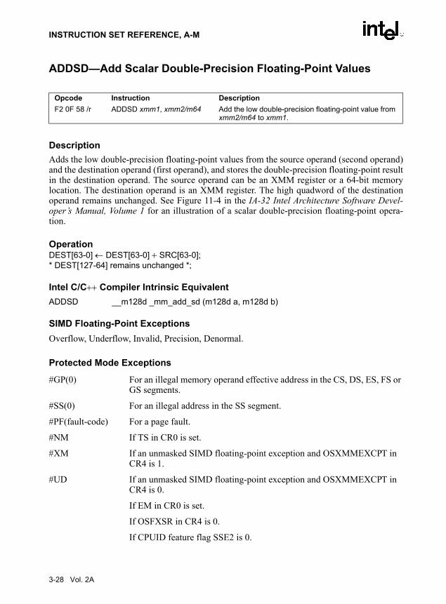
INSTRUCTION SET REFERENCE, A-M
ADDSD—Add Scalar Double-Precision Floating-Point Values
DescriptionAdds the low double-precision floating-point values from the source operand (second operand)and the destination operand (first operand), and stores the double-precision floating-point resultin the destination operand. The source operand can be an XMM register or a 64-bit memorylocation. The destination operand is an XMM register. The high quadword of the destinationoperand remains unchanged. See Figure 11-4 in the IA-32 Intel Architecture Software Devel-oper’s Manual, Volume 1 for an illustration of a scalar double-precision floating-point opera-tion.
OperationDEST[63-0] ← DEST[63-0] + SRC[63-0];* DEST[127-64] remains unchanged *;
Intel C/C++ Compiler Intrinsic EquivalentADDSD __m128d _mm_add_sd (m128d a, m128d b)
SIMD Floating-Point ExceptionsOverflow, Underflow, Invalid, Precision, Denormal.
Protected Mode Exceptions
#GP(0) For an illegal memory operand effective address in the CS, DS, ES, FS or GS segments.
#SS(0) For an illegal address in the SS segment.
#PF(fault-code) For a page fault.
#NM If TS in CR0 is set.
#XM If an unmasked SIMD floating-point exception and OSXMMEXCPT in CR4 is 1.
#UD If an unmasked SIMD floating-point exception and OSXMMEXCPT in CR4 is 0.
If EM in CR0 is set.
If OSFXSR in CR4 is 0.
If CPUID feature flag SSE2 is 0.
Opcode Instruction DescriptionF2 0F 58 /r ADDSD xmm1, xmm2/m64 Add the low double-precision floating-point value from
xmm2/m64 to xmm1.
3-28 Vol. 2A

INSTRUCTION SET REFERENCE, A-M
#AC(0) If alignment checking is enabled and an unaligned memory reference is made while the current privilege level is 3.
Real-Address Mode Exceptions
GP(0) If any part of the operand lies outside the effective address space from 0 to FFFFH.
#NM If TS in CR0 is set.
#XM If an unmasked SIMD floating-point exception and OSXMMEXCPT in CR4 is 1.
#UD If an unmasked SIMD floating-point exception and OSXMMEXCPT in CR4 is 0.
If EM in CR0 is set.
If OSFXSR in CR4 is 0.
If CPUID feature flag SSE2 is 0.
Virtual-8086 Mode Exceptions
Same exceptions as in Real Address Mode.
#PF(fault-code) For a page fault.
#AC(0) If alignment checking is enabled and an unaligned memory reference is made.
Vol. 2A 3-29

INSTRUCTION SET REFERENCE, A-M
ADDSS—Add Scalar Single-Precision Floating-Point Values
DescriptionAdds the low single-precision floating-point values from the source operand (second operand)and the destination operand (first operand), and stores the single-precision floating-point resultin the destination operand. The source operand can be an XMM register or a 32-bit memorylocation. The destination operand is an XMM register. The three high-order doublewords of thedestination operand remain unchanged. See Figure 10-6 in the IA-32 Intel Architecture SoftwareDeveloper’s Manual, Volume 1 for an illustration of a scalar single-precision floating-pointoperation.
OperationDEST[31-0] ← DEST[31-0] + SRC[31-0];* DEST[127-32] remain unchanged *;
Intel C/C++ Compiler Intrinsic EquivalentADDSS __m128 _mm_add_ss(__m128 a, __m128 b)
SIMD Floating-Point ExceptionsOverflow, Underflow, Invalid, Precision, Denormal.
Protected Mode Exceptions
#GP(0) For an illegal memory operand effective address in the CS, DS, ES, FS or GS segments.
#SS(0) For an illegal address in the SS segment.
#PF(fault-code) For a page fault.
#NM If TS in CR0 is set.
#XM If an unmasked SIMD floating-point exception and OSXMMEXCPT in CR4 is 1.
#UD If an unmasked SIMD floating-point exception and OSXMMEXCPT in CR4 is 0.
If EM in CR0 is set.
If OSFXSR in CR4 is 0.
If CPUID feature flag SSE is 0.
Opcode Instruction DescriptionF3 0F 58 /r ADDSS xmm1, xmm2/m32 Add the low single-precision floating-point value from
xmm2/m32 to xmm1.
3-30 Vol. 2A

INSTRUCTION SET REFERENCE, A-M
#AC(0) If alignment checking is enabled and an unaligned memory reference is made while the current privilege level is 3.
Real-Address Mode Exceptions
GP(0) If any part of the operand lies outside the effective address space from 0 to FFFFH.
#NM If TS in CR0 is set.
#XM If an unmasked SIMD floating-point exception and OSXMMEXCPT in CR4 is 1.
#UD If an unmasked SIMD floating-point exception and OSXMMEXCPT in CR4 is 0.
If EM in CR0 is set.
If OSFXSR in CR4 is 0.
If CPUID feature flag SSE is 0.
Virtual-8086 Mode Exceptions
Same exceptions as in Real Address Mode.
#PF(fault-code) For a page fault.
#AC(0) If alignment checking is enabled and an unaligned memory reference is made.
Vol. 2A 3-31

INSTRUCTION SET REFERENCE, A-M
ADDSUBPD: Packed Double-FP Add/Subtract
DescriptionAdds the double-precision floating-point values in the high quadword of the source and desti-nation operands and stores the result in the high quadword of the destination operand.
Subtracts the double-precision floating-point value in the low quadword of the source operandfrom the low quadword of the destination operand and stores the result in the low quadword ofthe destination operand. See
Operationxmm1[63-0] = xmm1[63-0] - xmm2/m128[63-0];xmm1[127-64] = xmm1[127-64] + xmm2/m128[127-64];
Intel C/C++ Compiler Intrinsic EquivalentADDSUBPD __m128d _mm_addsub_pd(__m128d a, __m128d b)
ExceptionsWhen the source operand is a memory operand, it must be aligned on a 16-byte boundary or ageneral-protection exception (#GP) will be generated.
Numeric ExceptionsOverflow, Underflow, Invalid, Precision, Denormal.
Opcode Instruction Description66,0F,D0,/r ADDSUBPD xmm1, xmm2/m128 Add/Subtract packed DP FP numbers from
xmm2/m128 to xmm1.
Figure 3-3. ADDSUBPD: Packed Double-FP Add/Subtract
[127-64]
xmm1[127-64] + xmm2/m128[127-64] xmm1[63-0] - xmm2/m128[63-0]
[63-0]
[127-64] [63-0]
ADDSUBPD xmm1, xmm2/m128
RESULT:xmm1
xmm2/m128
3-32 Vol. 2A

INSTRUCTION SET REFERENCE, A-M
Protected Mode Exceptions#GP(0) For an illegal memory operand effective address in the CS, DS, ES, FS or
GS segments.
If a memory operand is not aligned on a 16-byte boundary, regardless of segment.
#SS(0) For an illegal address in the SS segment.
#PF(fault-code) For a page fault.
#NM If TS bit in CR0 is set.
#XM For an unmasked Streaming SIMD Extensions numeric exception (CR4.OSXMMEXCPT = 1).
#UD If CR0.EM = 1.
For an unmasked Streaming SIMD Extensions numeric exception (CR4.OSXMMEXCPT = 0);
If CR4.OSFXSR(bit 9) = 0.
If CPUID.SSE3(ECX bit 0) = 0.
Real Address Mode ExceptionsGP(0) If any part of the operand would lie outside of the effective address space
from 0 to 0FFFFH.
If a memory operand is not aligned on a 16-byte boundary, regardless of segment.
#NM If TS bit in CR0 is set.
#XM For an unmasked Streaming SIMD Extensions numeric exception (CR4.OSXMMEXCPT = 1).
#UD If CR0.EM = 1.
For an unmasked Streaming SIMD Extensions numeric exception (CR4.OSXMMEXCPT = 0).
If CR4.OSFXSR(bit 9) = 0.
If CPUID.SSE3(ECX bit 0) = 0.
Virtual 8086 Mode ExceptionsGP(0) If any part of the operand would lie outside of the effective address space
from 0 to 0FFFFH.
If a memory operand is not aligned on a 16-byte boundary, regardless of segment.
#NM If TS bit in CR0 is set.
Vol. 2A 3-33

INSTRUCTION SET REFERENCE, A-M
#XM For an unmasked Streaming SIMD Extensions numeric exception (CR4.OSXMMEXCPT = 1).
#UD If CR0.EM = 1.
For an unmasked Streaming SIMD Extensions numeric exception (CR4.OSXMMEXCPT = 0).
If CR4.OSFXSR(bit 9) = 0.
If CPUID.SSE3(ECX bit 0) = 0.
#PF(fault-code) For a page fault.
3-34 Vol. 2A

INSTRUCTION SET REFERENCE, A-M
ADDSUBPS: Packed Single-FP Add/Subtract
DescriptionAdds odd-numbered single-precision floating-point values of the source operand (secondoperand) with the corresponding single-precision floating-point values from the destinationoperand (first operand); stores the result in the odd-numbered values of the destination operand.
Subtracts the even-numbered single-precision floating-point values in the source operand fromthe corresponding single-precision floating values in the destination operand; stores the resultinto the even-numbered values of the destination operand. See Figure 3-4.
Operationxmm1[31-0] = xmm1[31-0] - xmm2/m128[31-0];xmm1[63-32] = xmm1[63-32] + xmm2/m128[63-32];xmm1[95-64] = xmm1[95-64] - xmm2/m128[95-64];xmm1[127-96] = xmm1[127-96] + xmm2/m128[127-96];
Intel C/C++ Compiler Intrinsic EquivalentADDSUBPS __m128 _mm_addsub_ps(__m128 a, __m128 b)
Opcode Instruction DescriptionF2,0F,D0,/r ADDSUBPS xmm1, xmm2/m128 Add/Subtract packed SP FP numbers from
xmm2/m128 to xmm1.
Figure 3-4. ADDSUBPS: Packed Single-FP Add/Subtract
OM15992
ADDSUBPS xmm1, xmm2/m128
RESULT:xmm1
xmm2/m128
xmm1[31-0] -xmm2/m128[31-0]
[31-0]
xmm1[63-32] +xmm2/m128[63-32]
[63-32]
xmm1[95-64] - xmm2/m128[95-64]
[95-64]
xmm1[127-96] +xmm2/m128[127-96]
[127-96]
[127-96] [95-64] [63-32] [31-0]
Vol. 2A 3-35

INSTRUCTION SET REFERENCE, A-M
ExceptionsWhen the source operand is a memory operand, the operand must be aligned on a 16-byteboundary or a general-protection exception (#GP) will be generated.
Numeric ExceptionsOverflow, Underflow, Invalid, Precision, Denormal.
Protected Mode Exceptions#GP(0) For an illegal memory operand effective address in the CS, DS, ES, FS or
GS segments.
If a memory operand is not aligned on a 16-byte boundary, regardless of segment.
#SS(0) For an illegal address in the SS segment.
#PF(fault-code) For a page fault.
#NM If TS bit in CR0 is set.
#XM For an unmasked Streaming SIMD Extensions numeric exception (CR4.OSXMMEXCPT = 1).
#UD If CR0.EM = 1.
For an unmasked Streaming SIMD Extensions numeric exception (CR4.OSXMMEXCPT = 0).
If CR4.OSFXSR(bit 9) = 0.
If CPUID.SSE3(ECX bit 0) = 0.
Real Address Mode ExceptionsGP(0) If any part of the operand would lie outside of the effective address space
from 0 to 0FFFFH.
If a memory operand is not aligned on a 16-byte boundary, regardless of segment.
#NM If TS bit in CR0 is set.
#XM For an unmasked Streaming SIMD Extensions numeric exception (CR4.OSXMMEXCPT = 1).
#UD If CR0.EM = 1.
For an unmasked Streaming SIMD Extensions numeric exception (CR4.OSXMMEXCPT = 0).
3-36 Vol. 2A

INSTRUCTION SET REFERENCE, A-M
If CR4.OSFXSR(bit 9) = 0.
If CPUID.SSE3(ECX bit 0) = 0.
Virtual 8086 Mode ExceptionsGP(0) If any part of the operand would lie outside of the effective address space
from 0 to 0FFFFH.
If a memory operand is not aligned on a 16-byte boundary, regardless of segment.
#NM If TS bit in CR0 is set.
#XM For an unmasked Streaming SIMD Extensions numeric exception (CR4.OSXMMEXCPT = 1).
#UD If CR0.EM = 1.
For an unmasked Streaming SIMD Extensions numeric exception (CR4.OSXMMEXCPT = 0).
If CR4.OSFXSR(bit 9) = 0.
If CPUID.SSE3(ECX bit 0) = 0.
#PF(fault-code) For a page fault.
Vol. 2A 3-37
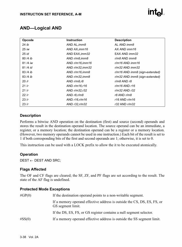
INSTRUCTION SET REFERENCE, A-M
AND—Logical AND
DescriptionPerforms a bitwise AND operation on the destination (first) and source (second) operands andstores the result in the destination operand location. The source operand can be an immediate, aregister, or a memory location; the destination operand can be a register or a memory location.(However, two memory operands cannot be used in one instruction.) Each bit of the result is set to1 if both corresponding bits of the first and second operands are 1; otherwise, it is set to 0.
This instruction can be used with a LOCK prefix to allow the it to be executed atomically.
OperationDEST ← DEST AND SRC;
Flags AffectedThe OF and CF flags are cleared; the SF, ZF, and PF flags are set according to the result. Thestate of the AF flag is undefined.
Protected Mode Exceptions#GP(0) If the destination operand points to a non-writable segment.
If a memory operand effective address is outside the CS, DS, ES, FS, or GS segment limit.
If the DS, ES, FS, or GS register contains a null segment selector.
#SS(0) If a memory operand effective address is outside the SS segment limit.
Opcode Instruction Description24 ib AND AL,imm8 AL AND imm825 iw AND AX,imm16 AX AND imm1625 id AND EAX,imm32 EAX AND imm3280 /4 ib AND r/m8,imm8 r/m8 AND imm881 /4 iw AND r/m16,imm16 r/m16 AND imm1681 /4 id AND r/m32,imm32 r/m32 AND imm3283 /4 ib AND r/m16,imm8 r/m16 AND imm8 (sign-extended)83 /4 ib AND r/m32,imm8 r/m32 AND imm8 (sign-extended)20 /r AND r/m8,r8 r/m8 AND r821 /r AND r/m16,r16 r/m16 AND r1621 /r AND r/m32,r32 r/m32 AND r3222 /r AND r8,r/m8 r8 AND r/m823 /r AND r16,r/m16 r16 AND r/m1623 /r AND r32,r/m32 r32 AND r/m32
3-38 Vol. 2A

INSTRUCTION SET REFERENCE, A-M
#PF(fault-code) If a page fault occurs.
#AC(0) If alignment checking is enabled and an unaligned memory reference is made while the current privilege level is 3.
Real-Address Mode Exceptions#GP If a memory operand effective address is outside the CS, DS, ES, FS, or
GS segment limit.
#SS If a memory operand effective address is outside the SS segment limit.
Virtual-8086 Mode Exceptions#GP(0) If a memory operand effective address is outside the CS, DS, ES, FS, or
GS segment limit.
#SS(0) If a memory operand effective address is outside the SS segment limit.
#PF(fault-code) If a page fault occurs.
#AC(0) If alignment checking is enabled and an unaligned memory reference is made.
Vol. 2A 3-39
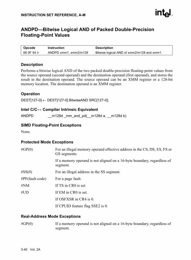
INSTRUCTION SET REFERENCE, A-M
ANDPD—Bitwise Logical AND of Packed Double-Precision Floating-Point Values
DescriptionPerforms a bitwise logical AND of the two packed double-precision floating-point values fromthe source operand (second operand) and the destination operand (first operand), and stores theresult in the destination operand. The source operand can be an XMM register or a 128-bitmemory location. The destination operand is an XMM register.
OperationDEST[127-0] ← DEST[127-0] BitwiseAND SRC[127-0];
Intel C/C++ Compiler Intrinsic EquivalentANDPD __m128d _mm_and_pd(__m128d a, __m128d b)
SIMD Floating-Point ExceptionsNone.
Protected Mode Exceptions
#GP(0) For an illegal memory operand effective address in the CS, DS, ES, FS or GS segments.
If a memory operand is not aligned on a 16-byte boundary, regardless of segment.
#SS(0) For an illegal address in the SS segment.
#PF(fault-code) For a page fault.
#NM If TS in CR0 is set.
#UD If EM in CR0 is set.
If OSFXSR in CR4 is 0.
If CPUID feature flag SSE2 is 0.
Real-Address Mode Exceptions
#GP(0) If a memory operand is not aligned on a 16-byte boundary, regardless of segment.
Opcode Instruction Description66 0F 54 /r ANDPD xmm1, xmm2/m128 Bitwise logical AND of xmm2/m128 and xmm1.
3-40 Vol. 2A
INSTRUCTION SET REFERENCE, A-M
If any part of the operand lies outside the effective address space from 0 to FFFFH.
#NM If TS in CR0 is set.
#UD If EM in CR0 is set.
If OSFXSR in CR4 is 0.
If CPUID feature flag SSE2 is 0.
Virtual-8086 Mode Exceptions
Same exceptions as in Real Address Mode
#PF(fault-code) For a page fault.
Vol. 2A 3-41

INSTRUCTION SET REFERENCE, A-M
ANDPS—Bitwise Logical AND of Packed Single-Precision Floating-Point Values
DescriptionPerforms a bitwise logical AND of the four packed single-precision floating-point values fromthe source operand (second operand) and the destination operand (first operand), and stores theresult in the destination operand. The source operand can be an XMM register or a 128-bitmemory location. The destination operand is an XMM register.
OperationDEST[127-0] ← DEST[127-0] BitwiseAND SRC[127-0];
Intel C/C++ Compiler Intrinsic EquivalentANDPS __m128 _mm_and_ps(__m128 a, __m128 b)
SIMD Floating-Point ExceptionsNone.
Protected Mode Exceptions
#GP(0) For an illegal memory operand effective address in the CS, DS, ES, FS or GS segments.
If a memory operand is not aligned on a 16-byte boundary, regardless of segment.
#SS(0) For an illegal address in the SS segment.
#PF(fault-code) For a page fault.
#NM If TS in CR0 is set.
#UD If EM in CR0 is set.
If OSFXSR in CR4 is 0.
If CPUID feature flag SSE is 0.
Real-Address Mode Exceptions
#GP(0) If a memory operand is not aligned on a 16-byte boundary, regardless of segment.
Opcode Instruction Description0F 54 /r ANDPS xmm1, xmm2/m128 Bitwise logical AND of xmm2/m128 and xmm1.
3-42 Vol. 2A

INSTRUCTION SET REFERENCE, A-M
If any part of the operand lies outside the effective address space from 0 to FFFFH.
#NM If TS in CR0 is set.
#UD If EM in CR0 is set.
If OSFXSR in CR4 is 0.
If CPUID feature flag SSE is 0.
Virtual-8086 Mode Exceptions
Same exceptions as in Real Address Mode
#PF(fault-code) For a page fault.
Vol. 2A 3-43

INSTRUCTION SET REFERENCE, A-M
ANDNPD—Bitwise Logical AND NOT of Packed Double-Precision Floating-Point Values
DescriptionInverts the bits of the two packed double-precision floating-point values in the destinationoperand (first operand), performs a bitwise logical AND of the two packed double-precisionfloating-point values in the source operand (second operand) and the temporary inverted result,and stores the result in the destination operand. The source operand can be an XMM register ora 128-bit memory location. The destination operand is an XMM register.
OperationDEST[127-0] ← (NOT(DEST[127-0])) BitwiseAND (SRC[127-0]);
Intel C/C++ Compiler Intrinsic EquivalentANDNPD __m128d _mm_andnot_pd(__m128d a, __m128d b)
SIMD Floating-Point ExceptionsNone.
Protected Mode Exceptions
#GP(0) For an illegal memory operand effective address in the CS, DS, ES, FS or GS segments.
If a memory operand is not aligned on a 16-byte boundary, regardless of segment.
#SS(0) For an illegal address in the SS segment.
#PF(fault-code) For a page fault.
#NM If TS in CR0 is set.
#UD If EM in CR0 is set.
If OSFXSR in CR4 is 0.
If CPUID feature flag SSE2 is 0.
Real-Address Mode Exceptions
#GP(0) If a memory operand is not aligned on a 16-byte boundary, regardless of segment.
Opcode Instruction Description66 0F 55 /r ANDNPD xmm1, xmm2/m128 Bitwise logical AND NOT of xmm2/m128 and xmm1.
3-44 Vol. 2A

INSTRUCTION SET REFERENCE, A-M
If any part of the operand lies outside the effective address space from 0 to FFFFH.
#NM If TS in CR0 is set.
#UD If EM in CR0 is set.
If OSFXSR in CR4 is 0.
If CPUID feature flag SSE2 is 0.
Virtual-8086 Mode Exceptions
Same exceptions as in Real Address Mode
#PF(fault-code) For a page fault.
Vol. 2A 3-45

INSTRUCTION SET REFERENCE, A-M
ANDNPS—Bitwise Logical AND NOT of Packed Single-Precision Floating-Point Values
DescriptionInverts the bits of the four packed single-precision floating-point values in the destinationoperand (first operand), performs a bitwise logical AND of the four packed single-precisionfloating-point values in the source operand (second operand) and the temporary inverted result,and stores the result in the destination operand. The source operand can be an XMM register ora 128-bit memory location. The destination operand is an XMM register.
OperationDEST[127-0] ← (NOT(DEST[127-0])) BitwiseAND (SRC[127-0]);
Intel C/C++ Compiler Intrinsic EquivalentANDNPS __m128 _mm_andnot_ps(__m128 a, __m128 b)
SIMD Floating-Point ExceptionsNone.
Protected Mode Exceptions
#GP(0) For an illegal memory operand effective address in the CS, DS, ES, FS or GS segments.
If a memory operand is not aligned on a 16-byte boundary, regardless of segment.
#SS(0) For an illegal address in the SS segment.
#PF(fault-code) For a page fault.
#NM If TS in CR0 is set.
#UD If EM in CR0 is set.
If OSFXSR in CR4 is 0.
A If CPUID feature flag SSE is 0.
Real-Address Mode Exceptions
#GP(0) If a memory operand is not aligned on a 16-byte boundary, regardless of segment.
Opcode Instruction Description0F 55 /r ANDNPS xmm1, xmm2/m128 Bitwise logical AND NOT of xmm2/m128 and xmm1.
3-46 Vol. 2A

INSTRUCTION SET REFERENCE, A-M
If any part of the operand lies outside the effective address space from 0 to FFFFH.
#NM If TS in CR0 is set.
#UD If EM in CR0 is set.
If OSFXSR in CR4 is 0.
If CPUID feature flag SSE is 0.
Virtual-8086 Mode Exceptions
Same exceptions as in Real Address Mode
#PF(fault-code) For a page fault.
Vol. 2A 3-47

INSTRUCTION SET REFERENCE, A-M
ARPL—Adjust RPL Field of Segment Selector
DescriptionCompares the RPL fields of two segment selectors. The first operand (the destination operand)contains one segment selector and the second operand (source operand) contains the other. (TheRPL field is located in bits 0 and 1 of each operand.) If the RPL field of the destination operandis less than the RPL field of the source operand, the ZF flag is set and the RPL field of the desti-nation operand is increased to match that of the source operand. Otherwise, the ZF flag is clearedand no change is made to the destination operand. (The destination operand can be a wordregister or a memory location; the source operand must be a word register.)
The ARPL instruction is provided for use by operating-system procedures (however, it can alsobe used by applications). It is generally used to adjust the RPL of a segment selector that hasbeen passed to the operating system by an application program to match the privilege level ofthe application program. Here the segment selector passed to the operating system is placed inthe destination operand and segment selector for the application program’s code segment isplaced in the source operand. (The RPL field in the source operand represents the privilege levelof the application program.) Execution of the ARPL instruction then insures that the RPL of thesegment selector received by the operating system is no lower (does not have a higher privilege)than the privilege level of the application program (the segment selector for the applicationprogram’s code segment can be read from the stack following a procedure call).
See “Checking Caller Access Privileges” in Chapter 4 of the IA-32 Intel Architecture SoftwareDeveloper’s Manual, Volume 3, for more information about the use of this instruction.
OperationIF DEST[RPL) < SRC[RPL)THEN
ZF ← 1;DEST[RPL) ← SRC[RPL);
ELSEZF ← 0;
FI;
Flags AffectedThe ZF flag is set to 1 if the RPL field of the destination operand is less than that of the sourceoperand; otherwise, it is set to 0.
Protected Mode Exceptions#GP(0) If the destination is located in a non-writable segment.
Opcode Instruction Description63 /r ARPL r/m16,r16 Adjust RPL of r/m16 to not less than RPL of r16
3-48 Vol. 2A

INSTRUCTION SET REFERENCE, A-M
If a memory operand effective address is outside the CS, DS, ES, FS, or GS segment limit.
If the DS, ES, FS, or GS register is used to access memory and it contains a null segment selector.
#SS(0) If a memory operand effective address is outside the SS segment limit.
#PF(fault-code) If a page fault occurs.
#AC(0) If alignment checking is enabled and an unaligned memory reference is made while the current privilege level is 3.
Real-Address Mode Exceptions#UD The ARPL instruction is not recognized in real-address mode.
Virtual-8086 Mode Exceptions#UD The ARPL instruction is not recognized in virtual-8086 mode.
Vol. 2A 3-49

INSTRUCTION SET REFERENCE, A-M
BOUND—Check Array Index Against Bounds
DescriptionDetermines if the first operand (array index) is within the bounds of an array specified thesecond operand (bounds operand). The array index is a signed integer located in a register. Thebounds operand is a memory location that contains a pair of signed doubleword-integers (whenthe operand-size attribute is 32) or a pair of signed word-integers (when the operand-sizeattribute is 16). The first doubleword (or word) is the lower bound of the array and the seconddoubleword (or word) is the upper bound of the array. The array index must be greater than orequal to the lower bound and less than or equal to the upper bound plus the operand size in bytes.If the index is not within bounds, a BOUND range exceeded exception (#BR) is signaled. Whenthis exception is generated, the saved return instruction pointer points to the BOUNDinstruction.
The bounds limit data structure (two words or doublewords containing the lower and upperlimits of the array) is usually placed just before the array itself, making the limits addressablevia a constant offset from the beginning of the array. Because the address of the array alreadywill be present in a register, this practice avoids extra bus cycles to obtain the effective addressof the array bounds.
OperationIF (ArrayIndex < LowerBound OR ArrayIndex > UpperBound)
(* Below lower bound or above upper bound *)THEN
#BR;FI;
Flags AffectedNone.
Protected Mode Exceptions#BR If the bounds test fails.
#UD If second operand is not a memory location.
#GP(0) If a memory operand effective address is outside the CS, DS, ES, FS, or GS segment limit.
If the DS, ES, FS, or GS register contains a null segment selector.
Opcode Instruction Description62 /r BOUND r16, m16&16 Check if r16 (array index) is within bounds specified by
m16&1662 /r BOUND r32, m32&32 Check if r32 (array index) is within bounds specified by
m32&32
3-50 Vol. 2A

INSTRUCTION SET REFERENCE, A-M
#SS(0) If a memory operand effective address is outside the SS segment limit.
#PF(fault-code) If a page fault occurs.
#AC(0) If alignment checking is enabled and an unaligned memory reference is made while the current privilege level is 3.
Real-Address Mode Exceptions#BR If the bounds test fails.
#UD If second operand is not a memory location.
#GP If a memory operand effective address is outside the CS, DS, ES, FS, or GS segment limit.
#SS If a memory operand effective address is outside the SS segment limit.
Virtual-8086 Mode Exceptions#BR If the bounds test fails.
#UD If second operand is not a memory location.
#GP(0) If a memory operand effective address is outside the CS, DS, ES, FS, or GS segment limit.
#SS(0) If a memory operand effective address is outside the SS segment limit.
#PF(fault-code) If a page fault occurs.
#AC(0) If alignment checking is enabled and an unaligned memory reference is made.
Vol. 2A 3-51

INSTRUCTION SET REFERENCE, A-M
BSF—Bit Scan Forward
DescriptionSearches the source operand (second operand) for the least significant set bit (1 bit). If a leastsignificant 1 bit is found, its bit index is stored in the destination operand (first operand). Thesource operand can be a register or a memory location; the destination operand is a register. Thebit index is an unsigned offset from bit 0 of the source operand. If the content of the sourceoperand is 0, the content of the destination operand is undefined.
OperationIF SRC = 0
THENZF ← 1;DEST is undefined;
ELSEZF ← 0;temp ← 0;
WHILE Bit(SRC, temp) = 0DO
temp ← temp + 1;DEST ← temp;
OD;FI;
Flags AffectedThe ZF flag is set to 1 if all the source operand is 0; otherwise, the ZF flag is cleared. The CF,OF, SF, AF, and PF, flags are undefined.
Protected Mode Exceptions#GP(0) If a memory operand effective address is outside the CS, DS, ES, FS, or
GS segment limit.
If the DS, ES, FS, or GS register contains a null segment selector.
#SS(0) If a memory operand effective address is outside the SS segment limit.
#PF(fault-code) If a page fault occurs.
#AC(0) If alignment checking is enabled and an unaligned memory reference is made while the current privilege level is 3.
Opcode Instruction Description0F BC BSF r16,r/m16 Bit scan forward on r/m160F BC BSF r32,r/m32 Bit scan forward on r/m32
3-52 Vol. 2A

INSTRUCTION SET REFERENCE, A-M
Real-Address Mode Exceptions#GP If a memory operand effective address is outside the CS, DS, ES, FS, or
GS segment limit.
#SS If a memory operand effective address is outside the SS segment limit.
Virtual-8086 Mode Exceptions#GP(0) If a memory operand effective address is outside the CS, DS, ES, FS, or
GS segment limit.
#SS(0) If a memory operand effective address is outside the SS segment limit.
#PF(fault-code) If a page fault occurs.
#AC(0) If alignment checking is enabled and an unaligned memory reference is made.
Vol. 2A 3-53

INSTRUCTION SET REFERENCE, A-M
BSR—Bit Scan Reverse
DescriptionSearches the source operand (second operand) for the most significant set bit (1 bit). If a mostsignificant 1 bit is found, its bit index is stored in the destination operand (first operand). Thesource operand can be a register or a memory location; the destination operand is a register. Thebit index is an unsigned offset from bit 0 of the source operand. If the content source operand is0, the content of the destination operand is undefined.
OperationIF SRC = 0
THENZF ← 1;DEST is undefined;
ELSEZF ← 0;temp ← OperandSize – 1;
WHILE Bit(SRC, temp) = 0DO
temp ← temp − 1;DEST ← temp;
OD;FI;
Flags AffectedThe ZF flag is set to 1 if all the source operand is 0; otherwise, the ZF flag is cleared. The CF,OF, SF, AF, and PF, flags are undefined.
Protected Mode Exceptions#GP(0) If a memory operand effective address is outside the CS, DS, ES, FS, or
GS segment limit.
If the DS, ES, FS, or GS register contains a null segment selector.
#SS(0) If a memory operand effective address is outside the SS segment limit.
#PF(fault-code) If a page fault occurs.
#AC(0) If alignment checking is enabled and an unaligned memory reference is made while the current privilege level is 3.
Opcode Instruction Description0F BD BSR r16,r/m16 Bit scan reverse on r/m160F BD BSR r32,r/m32 Bit scan reverse on r/m32
3-54 Vol. 2A

INSTRUCTION SET REFERENCE, A-M
Real-Address Mode Exceptions#GP If a memory operand effective address is outside the CS, DS, ES, FS, or
GS segment limit.
#SS If a memory operand effective address is outside the SS segment limit.
Virtual-8086 Mode Exceptions#GP(0) If a memory operand effective address is outside the CS, DS, ES, FS, or
GS segment limit.
#SS(0) If a memory operand effective address is outside the SS segment limit.
#PF(fault-code) If a page fault occurs.
#AC(0) If alignment checking is enabled and an unaligned memory reference is made.
Vol. 2A 3-55

INSTRUCTION SET REFERENCE, A-M
BSWAP—Byte Swap
DescriptionReverses the byte order of a 32-bit (destination) register: bits 0 through 7 are swapped with bits24 through 31, and bits 8 through 15 are swapped with bits 16 through 23. This instruction isprovided for converting little-endian values to big-endian format and vice versa.
To swap bytes in a word value (16-bit register), use the XCHG instruction. When the BSWAPinstruction references a 16-bit register, the result is undefined.
IA-32 Architecture CompatibilityThe BSWAP instruction is not supported on IA-32 processors earlier than the Intel486processor family. For compatibility with this instruction, include functionally equivalentcode for execution on Intel processors earlier than the Intel486 processor family.
OperationTEMP ← DESTDEST[7..0] ← TEMP(31..24]DEST[15..8] ← TEMP(23..16]DEST[23..16] ← TEMP(15..8]DEST[31..24] ← TEMP(7..0]
Flags AffectedNone.
Exceptions (All Operating Modes)None.
Opcode Instruction Description0F C8+rd BSWAP r32 Reverses the byte order of a 32-bit register.
3-56 Vol. 2A

INSTRUCTION SET REFERENCE, A-M
BT—Bit Test
DescriptionSelects the bit in a bit string (specified with the first operand, called the bit base) at the bit-position designated by the bit offset operand (second operand) and stores the value of the bit inthe CF flag. The bit base operand can be a register or a memory location; the bit offset operandcan be a register or an immediate value. If the bit base operand specifies a register, the instruc-tion takes the modulo 16 or 32 (depending on the register size) of the bit offset operand, allowingany bit position to be selected in a 16- or 32-bit register, respectively (see Figure 3-1). If the bitbase operand specifies a memory location, it represents the address of the byte in memory thatcontains the bit base (bit 0 of the specified byte) of the bit string (see Figure 3-2). The offsetoperand then selects a bit position within the range −231 to 231 − 1 for a register offset and 0 to31 for an immediate offset.
Some assemblers support immediate bit offsets larger than 31 by using the immediate bit offsetfield in combination with the displacement field of the memory operand. In this case, the low-order 3 or 5 bits (3 for 16-bit operands, 5 for 32-bit operands) of the immediate bit offset arestored in the immediate bit offset field, and the high-order bits are shifted and combined withthe byte displacement in the addressing mode by the assembler. The processor will ignore thehigh order bits if they are not zero.
When accessing a bit in memory, the processor may access 4 bytes starting from the memoryaddress for a 32-bit operand size, using by the following relationship:Effective Address + (4 ∗ (BitOffset DIV 32))
Or, it may access 2 bytes starting from the memory address for a 16-bit operand, using this rela-tionship:
Effective Address + (2 ∗ (BitOffset DIV 16))
It may do so even when only a single byte needs to be accessed to reach the given bit. Whenusing this bit addressing mechanism, software should avoid referencing areas of memory closeto address space holes. In particular, it should avoid references to memory-mapped I/O registers.Instead, software should use the MOV instructions to load from or store to these addresses, anduse the register form of these instructions to manipulate the data.
OperationCF ← Bit(BitBase, BitOffset)
Opcode Instruction Description0F A3 BT r/m16,r16 Store selected bit in CF flag0F A3 BT r/m32,r32 Store selected bit in CF flag0F BA /4 ib BT r/m16,imm8 Store selected bit in CF flag0F BA /4 ib BT r/m32,imm8 Store selected bit in CF flag
Vol. 2A 3-57

INSTRUCTION SET REFERENCE, A-M
Flags AffectedThe CF flag contains the value of the selected bit. The OF, SF, ZF, AF, and PF flags areundefined.
Protected Mode Exceptions#GP(0) If a memory operand effective address is outside the CS, DS, ES, FS, or
GS segment limit.
If the DS, ES, FS, or GS register contains a null segment selector.
#SS(0) If a memory operand effective address is outside the SS segment limit.
#PF(fault-code) If a page fault occurs.
#AC(0) If alignment checking is enabled and an unaligned memory reference is made while the current privilege level is 3.
Real-Address Mode Exceptions#GP If a memory operand effective address is outside the CS, DS, ES, FS, or
GS segment limit.
#SS If a memory operand effective address is outside the SS segment limit.
Virtual-8086 Mode Exceptions#GP(0) If a memory operand effective address is outside the CS, DS, ES, FS, or
GS segment limit.
#SS(0) If a memory operand effective address is outside the SS segment limit.
#PF(fault-code) If a page fault occurs.
#AC(0) If alignment checking is enabled and an unaligned memory reference is made.
3-58 Vol. 2A

INSTRUCTION SET REFERENCE, A-M
BTC—Bit Test and Complement
DescriptionSelects the bit in a bit string (specified with the first operand, called the bit base) at the bit-position designated by the bit offset operand (second operand), stores the value of the bit in theCF flag, and complements the selected bit in the bit string. The bit base operand can be a registeror a memory location; the bit offset operand can be a register or an immediate value. If the bitbase operand specifies a register, the instruction takes the modulo 16 or 32 (depending on theregister size) of the bit offset operand, allowing any bit position to be selected in a 16- or 32-bitregister, respectively (see Figure 3-1). If the bit base operand specifies a memory location, itrepresents the address of the byte in memory that contains the bit base (bit 0 of the specifiedbyte) of the bit string (see Figure 3-2). The offset operand then selects a bit position within therange −231 to 231 − 1 for a register offset and 0 to 31 for an immediate offset.
Some assemblers support immediate bit offsets larger than 31 by using the immediate bit offsetfield in combination with the displacement field of the memory operand. See “BT—Bit Test” inthis chapter for more information on this addressing mechanism.
This instruction can be used with a LOCK prefix to allow the instruction to be executed atomi-cally.
OperationCF ← Bit(BitBase, BitOffset)Bit(BitBase, BitOffset) ← NOT Bit(BitBase, BitOffset);
Flags AffectedThe CF flag contains the value of the selected bit before it is complemented. The OF, SF, ZF,AF, and PF flags are undefined.
Protected Mode Exceptions#GP(0) If the destination operand points to a non-writable segment.
If a memory operand effective address is outside the CS, DS, ES, FS, or GS segment limit.
If the DS, ES, FS, or GS register contains a null segment selector.
#SS(0) If a memory operand effective address is outside the SS segment limit.
#PF(fault-code) If a page fault occurs.
Opcode Instruction Description0F BB BTC r/m16,r16 Store selected bit in CF flag and complement0F BB BTC r/m32,r32 Store selected bit in CF flag and complement0F BA /7 ib BTC r/m16,imm8 Store selected bit in CF flag and complement0F BA /7 ib BTC r/m32,imm8 Store selected bit in CF flag and complement
Vol. 2A 3-59

INSTRUCTION SET REFERENCE, A-M
#AC(0) If alignment checking is enabled and an unaligned memory reference is made while the current privilege level is 3.
Real-Address Mode Exceptions#GP If a memory operand effective address is outside the CS, DS, ES, FS, or
GS segment limit.
#SS If a memory operand effective address is outside the SS segment limit.
Virtual-8086 Mode Exceptions#GP(0) If a memory operand effective address is outside the CS, DS, ES, FS, or
GS segment limit.
#SS(0) If a memory operand effective address is outside the SS segment limit.
#PF(fault-code) If a page fault occurs.
#AC(0) If alignment checking is enabled and an unaligned memory reference is made.
3-60 Vol. 2A

INSTRUCTION SET REFERENCE, A-M
BTR—Bit Test and Reset
DescriptionSelects the bit in a bit string (specified with the first operand, called the bit base) at the bit-position designated by the bit offset operand (second operand), stores the value of the bit in theCF flag, and clears the selected bit in the bit string to 0. The bit base operand can be a registeror a memory location; the bit offset operand can be a register or an immediate value. If the bitbase operand specifies a register, the instruction takes the modulo 16 or 32 (depending on theregister size) of the bit offset operand, allowing any bit position to be selected in a 16- or 32-bitregister, respectively (see Figure 3-1). If the bit base operand specifies a memory location, itrepresents the address of the byte in memory that contains the bit base (bit 0 of the specifiedbyte) of the bit string (see Figure 3-2). The offset operand then selects a bit position within therange −231 to 231 − 1 for a register offset and 0 to 31 for an immediate offset.
Some assemblers support immediate bit offsets larger than 31 by using the immediate bit offsetfield in combination with the displacement field of the memory operand. See “BT—Bit Test” inthis chapter for more information on this addressing mechanism.
This instruction can be used with a LOCK prefix to allow the instruction to be executed atomi-cally.
OperationCF ← Bit(BitBase, BitOffset)Bit(BitBase, BitOffset) ← 0;
Flags AffectedThe CF flag contains the value of the selected bit before it is cleared. The OF, SF, ZF, AF, andPF flags are undefined.
Protected Mode Exceptions#GP(0) If the destination operand points to a non-writable segment.
If a memory operand effective address is outside the CS, DS, ES, FS, or GS segment limit.
If the DS, ES, FS, or GS register contains a null segment selector.
#SS(0) If a memory operand effective address is outside the SS segment limit.
#PF(fault-code) If a page fault occurs.
Opcode Instruction Description0F B3 BTR r/m16,r16 Store selected bit in CF flag and clear0F B3 BTR r/m32,r32 Store selected bit in CF flag and clear0F BA /6 ib BTR r/m16,imm8 Store selected bit in CF flag and clear0F BA /6 ib BTR r/m32,imm8 Store selected bit in CF flag and clear
Vol. 2A 3-61

INSTRUCTION SET REFERENCE, A-M
#AC(0) If alignment checking is enabled and an unaligned memory reference is made while the current privilege level is 3.
Real-Address Mode Exceptions#GP If a memory operand effective address is outside the CS, DS, ES, FS, or
GS segment limit.
#SS If a memory operand effective address is outside the SS segment limit.
Virtual-8086 Mode Exceptions#GP(0) If a memory operand effective address is outside the CS, DS, ES, FS, or
GS segment limit.
#SS(0) If a memory operand effective address is outside the SS segment limit.
#PF(fault-code) If a page fault occurs.
#AC(0) If alignment checking is enabled and an unaligned memory reference is made.
3-62 Vol. 2A
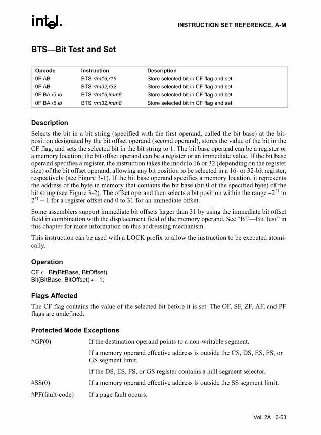
INSTRUCTION SET REFERENCE, A-M
BTS—Bit Test and Set
DescriptionSelects the bit in a bit string (specified with the first operand, called the bit base) at the bit-position designated by the bit offset operand (second operand), stores the value of the bit in theCF flag, and sets the selected bit in the bit string to 1. The bit base operand can be a register ora memory location; the bit offset operand can be a register or an immediate value. If the bit baseoperand specifies a register, the instruction takes the modulo 16 or 32 (depending on the registersize) of the bit offset operand, allowing any bit position to be selected in a 16- or 32-bit register,respectively (see Figure 3-1). If the bit base operand specifies a memory location, it representsthe address of the byte in memory that contains the bit base (bit 0 of the specified byte) of thebit string (see Figure 3-2). The offset operand then selects a bit position within the range −231 to231 − 1 for a register offset and 0 to 31 for an immediate offset.
Some assemblers support immediate bit offsets larger than 31 by using the immediate bit offsetfield in combination with the displacement field of the memory operand. See “BT—Bit Test” inthis chapter for more information on this addressing mechanism.
This instruction can be used with a LOCK prefix to allow the instruction to be executed atomi-cally.
OperationCF ← Bit(BitBase, BitOffset)Bit(BitBase, BitOffset) ← 1;
Flags AffectedThe CF flag contains the value of the selected bit before it is set. The OF, SF, ZF, AF, and PFflags are undefined.
Protected Mode Exceptions#GP(0) If the destination operand points to a non-writable segment.
If a memory operand effective address is outside the CS, DS, ES, FS, or GS segment limit.
If the DS, ES, FS, or GS register contains a null segment selector.
#SS(0) If a memory operand effective address is outside the SS segment limit.
#PF(fault-code) If a page fault occurs.
Opcode Instruction Description0F AB BTS r/m16,r16 Store selected bit in CF flag and set0F AB BTS r/m32,r32 Store selected bit in CF flag and set0F BA /5 ib BTS r/m16,imm8 Store selected bit in CF flag and set0F BA /5 ib BTS r/m32,imm8 Store selected bit in CF flag and set
Vol. 2A 3-63

INSTRUCTION SET REFERENCE, A-M
#AC(0) If alignment checking is enabled and an unaligned memory reference is made while the current privilege level is 3.
Real-Address Mode Exceptions#GP If a memory operand effective address is outside the CS, DS, ES, FS, or
GS segment limit.
#SS If a memory operand effective address is outside the SS segment limit.
Virtual-8086 Mode Exceptions#GP If a memory operand effective address is outside the CS, DS, ES, FS, or
GS segment limit.
#SS If a memory operand effective address is outside the SS segment limit.
#PF(fault-code) If a page fault occurs.
#AC(0) If alignment checking is enabled and an unaligned memory reference is made.
3-64 Vol. 2A

INSTRUCTION SET REFERENCE, A-M
CALL—Call Procedure
DescriptionSaves procedure linking information on the stack and branches to the procedure (called proce-dure) specified with the destination (target) operand. The target operand specifies the address ofthe first instruction in the called procedure. This operand can be an immediate value, a general-purpose register, or a memory location.
This instruction can be used to execute four different types of calls:
• Near call — A call to a procedure within the current code segment (the segment currentlypointed to by the CS register), sometimes referred to as an intrasegment call.
• Far call — A call to a procedure located in a different segment than the current codesegment, sometimes referred to as an intersegment call.
• Inter-privilege-level far call — A far call to a procedure in a segment at a differentprivilege level than that of the currently executing program or procedure.
• Task switch — A call to a procedure located in a different task.
The latter two call types (inter-privilege-level call and task switch) can only be executed inprotected mode. See the section titled “Calling Procedures Using Call and RET” in Chapter 6 ofthe IA-32 Intel Architecture Software Developer’s Manual, Volume 1, for additional informationon near, far, and inter-privilege-level calls. See Chapter 6, Task Management, in the IA-32 IntelArchitecture Software Developer’s Manual, Volume 3, for information on performing taskswitches with the CALL instruction.
Near Call. When executing a near call, the processor pushes the value of the EIP register(which contains the offset of the instruction following the CALL instruction) onto the stack (foruse later as a return-instruction pointer). The processor then branches to the address in thecurrent code segment specified with the target operand. The target operand specifies either anabsolute offset in the code segment (that is an offset from the base of the code segment) or arelative offset (a signed displacement relative to the current value of the instruction pointer inthe EIP register, which points to the instruction following the CALL instruction). The CSregister is not changed on near calls.
Opcode Instruction DescriptionE8 cw CALL rel16 Call near, relative, displacement relative to next instructionE8 cd CALL rel32 Call near, relative, displacement relative to next instructionFF /2 CALL r/m16 Call near, absolute indirect, address given in r/m16FF /2 CALL r/m32 Call near, absolute indirect, address given in r/m329A cd CALL ptr16:16 Call far, absolute, address given in operand9A cp CALL ptr16:32 Call far, absolute, address given in operandFF /3 CALL m16:16 Call far, absolute indirect, address given in m16:16FF /3 CALL m16:32 Call far, absolute indirect, address given in m16:32
Vol. 2A 3-65

INSTRUCTION SET REFERENCE, A-M
For a near call, an absolute offset is specified indirectly in a general-purpose register or amemory location (r/m16 or r/m32). The operand-size attribute determines the size of the targetoperand (16 or 32 bits). Absolute offsets are loaded directly into the EIP register. If the operand-size attribute is 16, the upper two bytes of the EIP register are cleared, resulting in a maximuminstruction pointer size of 16 bits. (When accessing an absolute offset indirectly using the stackpointer [ESP] as a base register, the base value used is the value of the ESP before the instructionexecutes.)
A relative offset (rel16 or rel32) is generally specified as a label in assembly code, but at themachine code level, it is encoded as a signed, 16- or 32-bit immediate value. This value is addedto the value in the EIP register. As with absolute offsets, the operand-size attribute determinesthe size of the target operand (16 or 32 bits).
Far Calls in Real-Address or Virtual-8086 Mode. When executing a far call in real-address or virtual-8086 mode, the processor pushes the current value of both the CS and EIPregisters onto the stack for use as a return-instruction pointer. The processor then performs a “farbranch” to the code segment and offset specified with the target operand for the called proce-dure. Here the target operand specifies an absolute far address either directly with a pointer(ptr16:16 or ptr16:32) or indirectly with a memory location (m16:16 or m16:32). With thepointer method, the segment and offset of the called procedure is encoded in the instruction,using a 4-byte (16-bit operand size) or 6-byte (32-bit operand size) far address immediate. Withthe indirect method, the target operand specifies a memory location that contains a 4-byte (16-bitoperand size) or 6-byte (32-bit operand size) far address. The operand-size attribute determinesthe size of the offset (16 or 32 bits) in the far address. The far address is loaded directly into theCS and EIP registers. If the operand-size attribute is 16, the upper two bytes of the EIP registerare cleared.
Far Calls in Protected Mode. When the processor is operating in protected mode, the CALLinstruction can be used to perform the following three types of far calls:
• Far call to the same privilege level• Far call to a different privilege level (inter-privilege level call)• Task switch (far call to another task)
In protected mode, the processor always uses the segment selector part of the far address toaccess the corresponding descriptor in the GDT or LDT. The descriptor type (code segment, callgate, task gate, or TSS) and access rights determine the type of call operation to be performed.
If the selected descriptor is for a code segment, a far call to a code segment at the same privilegelevel is performed. (If the selected code segment is at a different privilege level and the codesegment is non-conforming, a general-protection exception is generated.) A far call to the sameprivilege level in protected mode is very similar to one carried out in real-address or virtual-8086mode. The target operand specifies an absolute far address either directly with a pointer(ptr16:16 or ptr16:32) or indirectly with a memory location (m16:16 or m16:32). The operand-size attribute determines the size of the offset (16 or 32 bits) in the far address. The new codesegment selector and its descriptor are loaded into CS register, and the offset from the instruc-tion is loaded into the EIP register.
3-66 Vol. 2A

INSTRUCTION SET REFERENCE, A-M
Note that a call gate (described in the next paragraph) can also be used to perform a far call to acode segment at the same privilege level. Using this mechanism provides an extra level of indi-rection and is the preferred method of making calls between 16-bit and 32-bit code segments.
When executing an inter-privilege-level far call, the code segment for the procedure being calledmust be accessed through a call gate. The segment selector specified by the target operand iden-tifies the call gate. Here again, the target operand can specify the call gate segment selectoreither directly with a pointer (ptr16:16 or ptr16:32) or indirectly with a memory location(m16:16 or m16:32). The processor obtains the segment selector for the new code segment andthe new instruction pointer (offset) from the call gate descriptor. (The offset from the targetoperand is ignored when a call gate is used.) On inter-privilege-level calls, the processorswitches to the stack for the privilege level of the called procedure. The segment selector for thenew stack segment is specified in the TSS for the currently running task. The branch to the newcode segment occurs after the stack switch. (Note that when using a call gate to perform a farcall to a segment at the same privilege level, no stack switch occurs.) On the new stack, theprocessor pushes the segment selector and stack pointer for the calling procedure’s stack, an(optional) set of parameters from the calling procedures stack, and the segment selector andinstruction pointer for the calling procedure’s code segment. (A value in the call gate descriptordetermines how many parameters to copy to the new stack.) Finally, the processor branches tothe address of the procedure being called within the new code segment.
Executing a task switch with the CALL instruction, is somewhat similar to executing a callthrough a call gate. Here the target operand specifies the segment selector of the task gate forthe task being switched to (and the offset in the target operand is ignored.) The task gate in turnpoints to the TSS for the task, which contains the segment selectors for the task’s code and stacksegments. The TSS also contains the EIP value for the next instruction that was to be executedbefore the task was suspended. This instruction pointer value is loaded into the EIP register sothat the task begins executing again at this next instruction.
The CALL instruction can also specify the segment selector of the TSS directly, which elimi-nates the indirection of the task gate. See Chapter 6, Task Management, in the IA-32 Intel Archi-tecture Software Developer’s Manual, Volume 3, for detailed information on the mechanics ofa task switch.
Note that when you execute at task switch with a CALL instruction, the nested task flag (NT) isset in the EFLAGS register and the new TSS’s previous task link field is loaded with the oldtasks TSS selector. Code is expected to suspend this nested task by executing an IRET instruc-tion, which, because the NT flag is set, will automatically use the previous task link to return tothe calling task. (See “Task Linking” in Chapter 6 of the IA-32 Intel Architecture SoftwareDeveloper’s Manual, Volume 3, for more information on nested tasks.) Switching tasks with theCALL instruction differs in this regard from the JMP instruction which does not set the NT flagand therefore does not expect an IRET instruction to suspend the task.
Mixing 16-Bit and 32-Bit Calls. When making far calls between 16-bit and 32-bit codesegments, the calls should be made through a call gate. If the far call is from a 32-bit codesegment to a 16-bit code segment, the call should be made from the first 64 KBytes of the 32-bit code segment. This is because the operand-size attribute of the instruction is set to 16, so onlya 16-bit return address offset is saved. Also, the call should be made using a 16-bit call gate sothat 16-bit values will be pushed on the stack. See Chapter 17, Mixing 17-Bit and 32-Bit Code,in IA-32 Intel Architecture Software Developer’s Manual, Volume 3 for more information.
Vol. 2A 3-67

INSTRUCTION SET REFERENCE, A-M
OperationIF near call
THEN IF near relative call IF the instruction pointer is not within code segment limit THEN #GP(0); FI;
THEN IF OperandSize = 32THEN
IF stack not large enough for a 4-byte return address THEN #SS(0); FI;Push(EIP);EIP ← EIP + DEST; (* DEST is rel32 *)
ELSE (* OperandSize = 16 *)IF stack not large enough for a 2-byte return address THEN #SS(0); FI;Push(IP);EIP ← (EIP + DEST) AND 0000FFFFH; (* DEST is rel16 *)
FI; FI;
ELSE (* near absolute call *)IF the instruction pointer is not within code segment limit THEN #GP(0); FI;IF OperandSize = 32
THENIF stack not large enough for a 4-byte return address THEN #SS(0); FI;Push(EIP); EIP ← DEST; (* DEST is r/m32 *)
ELSE (* OperandSize = 16 *) IF stack not large enough for a 2-byte return address THEN #SS(0); FI;Push(IP);EIP ← DEST AND 0000FFFFH; (* DEST is r/m16 *)
FI; FI:
FI;
IF far call AND (PE = 0 OR (PE = 1 AND VM = 1)) (* real-address or virtual-8086 mode *)THEN
IF OperandSize = 32THEN
IF stack not large enough for a 6-byte return address THEN #SS(0); FI;IF the instruction pointer is not within code segment limit THEN #GP(0); FI;Push(CS); (* padded with 16 high-order bits *)Push(EIP);CS ← DEST[47:32]; (* DEST is ptr16:32 or [m16:32] *)EIP ← DEST[31:0]; (* DEST is ptr16:32 or [m16:32] *)
ELSE (* OperandSize = 16 *)IF stack not large enough for a 4-byte return address THEN #SS(0); FI;IF the instruction pointer is not within code segment limit THEN #GP(0); FI;Push(CS);Push(IP);CS ← DEST[31:16]; (* DEST is ptr16:16 or [m16:16] *)EIP ← DEST[15:0]; (* DEST is ptr16:16 or [m16:16] *)
3-68 Vol. 2A

INSTRUCTION SET REFERENCE, A-M
EIP ← EIP AND 0000FFFFH; (* clear upper 16 bits *)FI;
FI;
IF far call AND (PE = 1 AND VM = 0) (* Protected mode, not virtual-8086 mode *)THEN
IF segment selector in target operand null THEN #GP(0); FI;IF segment selector index not within descriptor table limits
THEN #GP(new code segment selector);FI;Read type and access rights of selected segment descriptor;IF segment type is not a conforming or nonconforming code segment, call gate,
task gate, or TSS THEN #GP(segment selector); FI;Depending on type and access rights
GO TO CONFORMING-CODE-SEGMENT;GO TO NONCONFORMING-CODE-SEGMENT;GO TO CALL-GATE;GO TO TASK-GATE;GO TO TASK-STATE-SEGMENT;
FI;
CONFORMING-CODE-SEGMENT:IF DPL > CPL THEN #GP(new code segment selector); FI;IF segment not present THEN #NP(new code segment selector); FI;IF OperandSize = 32
THENIF stack not large enough for a 6-byte return address THEN #SS(0); FI;IF the instruction pointer is not within code segment limit THEN #GP(0); FI;Push(CS); (* padded with 16 high-order bits *)Push(EIP);CS ← DEST[NewCodeSegmentSelector); (* segment descriptor information also loaded *)CS(RPL) ← CPLEIP ← DEST(Offset);
ELSE (* OperandSize = 16 *)IF stack not large enough for a 4-byte return address THEN #SS(0); FI;IF the instruction pointer is not within code segment limit THEN #GP(0); FI;Push(CS);Push(IP);CS ← DEST[NewCodeSegmentSelector); (* segment descriptor information also loaded *)CS(RPL) ← CPLEIP ← DEST(Offset) AND 0000FFFFH; (* clear upper 16 bits *)
FI;END;
NONCONFORMING-CODE-SEGMENT:
Vol. 2A 3-69

INSTRUCTION SET REFERENCE, A-M
IF (RPL > CPL) OR (DPL ≠ CPL) THEN #GP(new code segment selector); FI;IF segment not present THEN #NP(new code segment selector); FI;IF stack not large enough for return address THEN #SS(0); FI;tempEIP ← DEST(Offset)IF OperandSize=16
THENtempEIP ← tempEIP AND 0000FFFFH; (* clear upper 16 bits *)
FI;IF tempEIP outside code segment limit THEN #GP(0); FI;IF OperandSize = 32
THENPush(CS); (* padded with 16 high-order bits *)Push(EIP);CS ← DEST[NewCodeSegmentSelector); (* segment descriptor information also loaded *)CS(RPL) ← CPL;EIP ← tempEIP;
ELSE (* OperandSize = 16 *)Push(CS);Push(IP);CS ← DEST[NewCodeSegmentSelector); (* segment descriptor information also loaded *)CS(RPL) ← CPL;EIP ← tempEIP;
FI;END;
CALL-GATE:IF call gate DPL < CPL or RPL THEN #GP(call gate selector); FI;IF call gate not present THEN #NP(call gate selector); FI;IF call gate code-segment selector is null THEN #GP(0); FI;IF call gate code-segment selector index is outside descriptor table limits
THEN #GP(code segment selector); FI;Read code segment descriptor;IF code-segment segment descriptor does not indicate a code segmentOR code-segment segment descriptor DPL > CPL
THEN #GP(code segment selector); FI;IF code segment not present THEN #NP(new code segment selector); FI;IF code segment is non-conforming AND DPL < CPL
THEN go to MORE-PRIVILEGE;ELSE go to SAME-PRIVILEGE;
FI;END;
MORE-PRIVILEGE:IF current TSS is 32-bit TSS
THEN
3-70 Vol. 2A

INSTRUCTION SET REFERENCE, A-M
TSSstackAddress ← new code segment (DPL ∗ 8) + 4IF (TSSstackAddress + 7) > TSS limit
THEN #TS(current TSS selector); FI;newSS ← TSSstackAddress + 4;newESP ← stack address;
ELSE (* TSS is 16-bit *)TSSstackAddress ← new code segment (DPL ∗ 4) + 2IF (TSSstackAddress + 4) > TSS limit
THEN #TS(current TSS selector); FI;newESP ← TSSstackAddress;newSS ← TSSstackAddress + 2;
FI;IF stack segment selector is null THEN #TS(stack segment selector); FI;IF stack segment selector index is not within its descriptor table limits
THEN #TS(SS selector); FIRead code segment descriptor;IF stack segment selector's RPL ≠ DPL of code segment
OR stack segment DPL ≠ DPL of code segment OR stack segment is not a writable data segment
THEN #TS(SS selector); FIIF stack segment not present THEN #SS(SS selector); FI;IF CallGateSize = 32
THENIF stack does not have room for parameters plus 16 bytes
THEN #SS(SS selector); FI;IF CallGate(InstructionPointer) not within code segment limit THEN #GP(0); FI;SS ← newSS; (* segment descriptor information also loaded *)ESP ← newESP; CS:EIP ← CallGate(CS:InstructionPointer); (* segment descriptor information also loaded *)Push(oldSS:oldESP); (* from calling procedure *)temp ← parameter count from call gate, masked to 5 bits;Push(parameters from calling procedure’s stack, temp)Push(oldCS:oldEIP); (* return address to calling procedure *)
ELSE (* CallGateSize = 16 *)IF stack does not have room for parameters plus 8 bytes
THEN #SS(SS selector); FI;IF (CallGate(InstructionPointer) AND FFFFH) not within code segment limit
THEN #GP(0); FI;SS ← newSS; (* segment descriptor information also loaded *)ESP ← newESP; CS:IP ← CallGate(CS:InstructionPointer);(* segment descriptor information also loaded *)Push(oldSS:oldESP); (* from calling procedure *)temp ← parameter count from call gate, masked to 5 bits;
Vol. 2A 3-71

INSTRUCTION SET REFERENCE, A-M
Push(parameters from calling procedure’s stack, temp)Push(oldCS:oldEIP); (* return address to calling procedure *)
FI;CPL ← CodeSegment(DPL)CS(RPL) ← CPL
END;
SAME-PRIVILEGE:IF CallGateSize = 32
THENIF stack does not have room for 8 bytes
THEN #SS(0); FI;IF EIP not within code segment limit then #GP(0); FI;CS:EIP ← CallGate(CS:EIP) (* segment descriptor information also loaded *)Push(oldCS:oldEIP); (* return address to calling procedure *)
ELSE (* CallGateSize = 16 *)IF stack does not have room for 4 bytes
THEN #SS(0); FI;IF IP not within code segment limit THEN #GP(0); FI;CS:IP ← CallGate(CS:instruction pointer) (* segment descriptor information also loaded *)Push(oldCS:oldIP); (* return address to calling procedure *)
FI;CS(RPL) ← CPL
END;TASK-GATE:
IF task gate DPL < CPL or RPL THEN #GP(task gate selector);
FI;IF task gate not present
THEN #NP(task gate selector); FI;Read the TSS segment selector in the task-gate descriptor;IF TSS segment selector local/global bit is set to local
OR index not within GDT limitsTHEN #GP(TSS selector);
FI;Access TSS descriptor in GDT;
IF TSS descriptor specifies that the TSS is busy (low-order 5 bits set to 00001)THEN #GP(TSS selector);
FI;IF TSS not present
THEN #NP(TSS selector);FI;SWITCH-TASKS (with nesting) to TSS;IF EIP not within code segment limit
3-72 Vol. 2A

INSTRUCTION SET REFERENCE, A-M
THEN #GP(0); FI;
END;
TASK-STATE-SEGMENT:IF TSS DPL < CPL or RPLOR TSS descriptor indicates TSS not available
THEN #GP(TSS selector);FI;IF TSS is not present
THEN #NP(TSS selector); FI;SWITCH-TASKS (with nesting) to TSSIF EIP not within code segment limit
THEN #GP(0); FI;
END;
Flags AffectedAll flags are affected if a task switch occurs; no flags are affected if a task switch does not occur.
Protected Mode Exceptions#GP(0) If the target offset in destination operand is beyond the new code segment
limit.
If the segment selector in the destination operand is null.
If the code segment selector in the gate is null.
If a memory operand effective address is outside the CS, DS, ES, FS, or GS segment limit.
If the DS, ES, FS, or GS register is used to access memory and it contains a null segment selector.
#GP(selector) If a code segment or gate or TSS selector index is outside descriptor table limits.
If the segment descriptor pointed to by the segment selector in the destination operand is not for a conforming-code segment, noncon-forming-code segment, call gate, task gate, or task state segment.
If the DPL for a nonconforming-code segment is not equal to the CPL or the RPL for the segment’s segment selector is greater than the CPL.
If the DPL for a conforming-code segment is greater than the CPL.
If the DPL from a call-gate, task-gate, or TSS segment descriptor is less than the CPL or than the RPL of the call-gate, task-gate, or TSS’s segment selector.
Vol. 2A 3-73

INSTRUCTION SET REFERENCE, A-M
If the segment descriptor for a segment selector from a call gate does not indicate it is a code segment.
If the segment selector from a call gate is beyond the descriptor table limits.
If the DPL for a code-segment obtained from a call gate is greater than the CPL.
If the segment selector for a TSS has its local/global bit set for local.
If a TSS segment descriptor specifies that the TSS is busy or not available.
#SS(0) If pushing the return address, parameters, or stack segment pointer onto the stack exceeds the bounds of the stack segment, when no stack switch occurs.
If a memory operand effective address is outside the SS segment limit.
#SS(selector) If pushing the return address, parameters, or stack segment pointer onto the stack exceeds the bounds of the stack segment, when a stack switch occurs.
If the SS register is being loaded as part of a stack switch and the segment pointed to is marked not present.
If stack segment does not have room for the return address, parameters, or stack segment pointer, when stack switch occurs.
#NP(selector) If a code segment, data segment, stack segment, call gate, task gate, or TSS is not present.
#TS(selector) If the new stack segment selector and ESP are beyond the end of the TSS.
If the new stack segment selector is null.
If the RPL of the new stack segment selector in the TSS is not equal to the DPL of the code segment being accessed.
If DPL of the stack segment descriptor for the new stack segment is not equal to the DPL of the code segment descriptor.
If the new stack segment is not a writable data segment.
If segment-selector index for stack segment is outside descriptor table limits.
#PF(fault-code) If a page fault occurs.
#AC(0) If alignment checking is enabled and an unaligned memory reference is made while the current privilege level is 3.
3-74 Vol. 2A

INSTRUCTION SET REFERENCE, A-M
Real-Address Mode Exceptions#GP If a memory operand effective address is outside the CS, DS, ES, FS, or
GS segment limit.
If the target offset is beyond the code segment limit.
Virtual-8086 Mode Exceptions#GP(0) If a memory operand effective address is outside the CS, DS, ES, FS, or
GS segment limit.
If the target offset is beyond the code segment limit.
#PF(fault-code) If a page fault occurs.
#AC(0) If alignment checking is enabled and an unaligned memory reference is made.
Vol. 2A 3-75

INSTRUCTION SET REFERENCE, A-M
CBW/CWDE—Convert Byte to Word/Convert Word to Doubleword
DescriptionDouble the size of the source operand by means of sign extension (see Figure 7-6 in the IA-32Intel Architecture Software Developer’s Manual, Volume 1). The CBW (convert byte to word)instruction copies the sign (bit 7) in the source operand into every bit in the AH register. TheCWDE (convert word to doubleword) instruction copies the sign (bit 15) of the word in the AXregister into the higher 16 bits of the EAX register.
The CBW and CWDE mnemonics reference the same opcode. The CBW instruction is intendedfor use when the operand-size attribute is 16 and the CWDE instruction for when the operand-size attribute is 32. Some assemblers may force the operand size to 16 when CBW is used andto 32 when CWDE is used. Others may treat these mnemonics as synonyms (CBW/CWDE) anduse the current setting of the operand-size attribute to determine the size of values to beconverted, regardless of the mnemonic used.
The CWDE instruction is different from the CWD (convert word to double) instruction. TheCWD instruction uses the DX:AX register pair as a destination operand; whereas, the CWDEinstruction uses the EAX register as a destination.
OperationIF OperandSize = 16 (* instruction = CBW *)
THEN AX ← SignExtend(AL);ELSE (* OperandSize = 32, instruction = CWDE *)
EAX ← SignExtend(AX);FI;
Flags AffectedNone.
Exceptions (All Operating Modes)None.
Opcode Instruction Description98 CBW AX ← sign-extend of AL98 CWDE EAX ← sign-extend of AX
3-76 Vol. 2A

INSTRUCTION SET REFERENCE, A-M
CDQ—Convert Double to Quad
See entry for CWD/CDQ — Convert Word to Doubleword/Convert Doubleword to Quadword.
Vol. 2A 3-77

INSTRUCTION SET REFERENCE, A-M
CLC—Clear Carry Flag
DescriptionClears the CF flag in the EFLAGS register.
OperationCF ← 0;
Flags AffectedThe CF flag is set to 0. The OF, ZF, SF, AF, and PF flags are unaffected.
Exceptions (All Operating Modes)None.
Opcode Instruction DescriptionF8 CLC Clear CF flag.
3-78 Vol. 2A

INSTRUCTION SET REFERENCE, A-M
CLD—Clear Direction Flag
DescriptionClears the DF flag in the EFLAGS register. When the DF flag is set to 0, string operations incre-ment the index registers (ESI and/or EDI).
OperationDF ← 0;
Flags AffectedThe DF flag is set to 0. The CF, OF, ZF, SF, AF, and PF flags are unaffected.
Exceptions (All Operating Modes)None.
Opcode Instruction DescriptionFC CLD Clear DF flag.
Vol. 2A 3-79

INSTRUCTION SET REFERENCE, A-M
CLFLUSH—Flush Cache Line
DescriptionInvalidates the cache line that contains the linear address specified with the source operand fromall levels of the processor cache hierarchy (data and instruction). The invalidation is broadcastthroughout the cache coherence domain. If, at any level of the cache hierarchy, the line is incon-sistent with memory (dirty) it is written to memory before invalidation. The source operand is abyte memory location.
The availability of CLFLUSH is indicated by the presence of the CPUID feature flag CLFSH(bit 19 of the EDX register, see Section , CPUID—CPU Identification). The aligned cache linesize affected is also indicated with the CPUID instruction (bits 8 through 15 of the EBX registerwhen the initial value in the EAX register is 1).
The memory attribute of the page containing the affected line has no effect on the behavior ofthis instruction. It should be noted that processors are free to speculatively fetch and cache datafrom system memory regions assigned a memory-type allowing for speculative reads (such as,the WB, WC, and WT memory types). PREFETCHh instructions can be used to provide theprocessor with hints for this speculative behavior. Because this speculative fetching can occurat any time and is not tied to instruction execution, the CLFLUSH instruction is not ordered withrespect to PREFETCHh instructions or any of the speculative fetching mechanisms (that is, datacan be speculatively loaded into a cache line just before, during, or after the execution of aCLFLUSH instruction that references the cache line).
CLFLUSH is only ordered by the MFENCE instruction. It is not guaranteed to be ordered byany other fencing or serializing instructions or by another CLFLUSH instruction. For example,software can use an MFENCE instruction to insure that previous stores are included in the write-back.
The CLFLUSH instruction can be used at all privilege levels and is subject to all permissionchecking and faults associated with a byte load (and in addition, a CLFLUSH instruction isallowed to flush a linear address in an execute-only segment). Like a load, the CLFLUSHinstruction sets the A bit but not the D bit in the page tables.
The CLFLUSH instruction was introduced with the SSE2 extensions; however, because it hasits own CPUID feature flag, it can be implemented in IA-32 processors that do not include theSSE2 extensions. Also, detecting the presence of the SSE2 extensions with the CPUID instruc-tion does not guarantee that the CLFLUSH instruction is implemented in the processor.
OperationFlush_Cache_Line(SRC)
Opcode Instruction Description0F AE /7 CLFLUSH m8 Flushes cache line containing m8.
3-80 Vol. 2A

INSTRUCTION SET REFERENCE, A-M
Intel C/C++ Compiler Intrinsic EquivalentsCLFLUSH void_mm_clflush(void const *p)
Protected Mode Exceptions
#GP(0) For an illegal memory operand effective address in the CS, DS, ES, FS or GS segments.
#SS(0) For an illegal address in the SS segment.
#PF(fault-code) For a page fault.
#UD If CPUID feature flag CLFSH is 0.
Real-Address Mode Exceptions
GP(0) If any part of the operand lies outside the effective address space from 0 to FFFFH.
#UD If CPUID feature flag CLFSH is 0.
Virtual-8086 Mode Exceptions
Same exceptions as in Real Address Mode
#PF(fault-code) For a page fault.
Vol. 2A 3-81

INSTRUCTION SET REFERENCE, A-M
CLI — Clear Interrupt Flag
DescriptionIf protected-mode virtual interrupts are not enabled, CLI clears the IF flag in the EFLAGSregister. No other flags are affected. Clearing the IF flag causes the processor to ignore maskableexternal interrupts. The IF flag and the CLI and STI instruction have no affect on the generationof exceptions and NMI interrupts.
When protected-mode virtual interrupts are enabled, CPL is 3, and IOPL is less than 3; CLIclears the VIF flag in the EFLAGS register, leaving IF unaffected.
Table 3-5 indicates the action of the CLI instruction depending on the processor operating modeand the CPL/IOPL of the running program or procedure.
OperationIF PE = 0
THENIF ← 0; (* Reset Interrupt Flag *)
ELSEIF VM = 0;
THENIF IOPL ≥ CPL
THENIF ← 0; (* Reset Interrupt Flag *)
ELSEIF ((IOPL < CPL) AND (CPL < 3) AND (PVI = 1))
THEN
Opcode Instruction DescriptionFA CLI Clear interrupt flag; interrupts disabled when interrupt flag
cleared.
Table 3-5. Decision Table for CLI ResultsPE VM IOPL CPL PVI VIP VME CLI Result
0 X X X X X X IF = 01 0 ≥ CPL X X X X IF = 0
1 0 < CPL 3 1 X X VIF = 0
1 0 < CPL < 3 X X X GP Fault
1 0 < CPL X 0 X X GP Fault
1 1 3 X X X X IF = 0
1 1 < 3 X X X 1 VIF = 01 1 < 3 X X X 0 GP Fault
X = This setting has no impact.
3-82 Vol. 2A

INSTRUCTION SET REFERENCE, A-M
VIF ← 0; (* Reset Virtual Interrupt Flag *)ELSE
#GP(0);FI;
FI;ELSE
IF IOPL = 3THEN
IF ← 0; (* Reset Interrupt Flag *)ELSE
IF (IOPL < 3) AND (VME = 1)THEN
VIF ← 0; (* Reset Virtual Interrupt Flag *)ELSE
#GP(0);FI;
FI;FI;
FI;
Flags AffectedIf protected-mode virtual interrupts are not enabled, IF is set to 0 if the CPL is equal to or lessthan the IOPL; otherwise, it is not affected. The other flags in the EFLAGS register are unaf-fected.
When protected-mode virtual interrupts are enabled, CPL is 3, and IOPL is less than 3; CLIclears the VIF flag in the EFLAGS register, leaving IF unaffected.
Protected Mode Exceptions#GP(0) If the CPL is greater (has less privilege) than the IOPL of the current
program or procedure.
Real-Address Mode ExceptionsNone.
Virtual-8086 Mode Exceptions#GP(0) If the CPL is greater (has less privilege) than the IOPL of the current
program or procedure.
Vol. 2A 3-83

INSTRUCTION SET REFERENCE, A-M
CLTS—Clear Task-Switched Flag in CR0
DescriptionClears the task-switched (TS) flag in the CR0 register. This instruction is intended for use inoperating-system procedures. It is a privileged instruction that can only be executed at a CPL of0. It is allowed to be executed in real-address mode to allow initialization for protected mode.
The processor sets the TS flag every time a task switch occurs. The flag is used to synchronizethe saving of FPU context in multitasking applications. See the description of the TS flag in thesection titled “Control Registers” in Chapter 2 of the IA-32 Intel Architecture Software Devel-oper’s Manual, Volume 3, for more information about this flag.
OperationCR0(TS) ← 0;
Flags AffectedThe TS flag in CR0 register is cleared.
Protected Mode Exceptions#GP(0) If the current privilege level is not 0.
Real-Address Mode ExceptionsNone.
Virtual-8086 Mode Exceptions#GP(0) CLTS is not recognized in virtual-8086 mode.
Opcode Instruction Description0F 06 CLTS Clears TS flag in CR0.
3-84 Vol. 2A

INSTRUCTION SET REFERENCE, A-M
CMC—Complement Carry Flag
DescriptionComplements the CF flag in the EFLAGS register.
OperationCF ← NOT CF;
Flags AffectedThe CF flag contains the complement of its original value. The OF, ZF, SF, AF, and PF flagsare unaffected.
Exceptions (All Operating Modes)None.
Opcode Instruction DescriptionF5 CMC Complement CF flag.
Vol. 2A 3-85

INSTRUCTION SET REFERENCE, A-M
CMOVcc—Conditional Move
Opcode Instruction Description0F 47 /r CMOVA r16, r/m16 Move if above (CF=0 and ZF=0).0F 47 /r CMOVA r32, r/m32 Move if above (CF=0 and ZF=0).0F 43 /r CMOVAE r16, r/m16 Move if above or equal (CF=0).0F 43 /r CMOVAE r32, r/m32 Move if above or equal (CF=0).0F 42 /r CMOVB r16, r/m16 Move if below (CF=1).0F 42 /r CMOVB r32, r/m32 Move if below (CF=1).0F 46 /r CMOVBE r16, r/m16 Move if below or equal (CF=1 or ZF=1).0F 46 /r CMOVBE r32, r/m32 Move if below or equal (CF=1 or ZF=1).0F 42 /r CMOVC r16, r/m16 Move if carry (CF=1).0F 42 /r CMOVC r32, r/m32 Move if carry (CF=1).0F 44 /r CMOVE r16, r/m16 Move if equal (ZF=1).0F 44 /r CMOVE r32, r/m32 Move if equal (ZF=1).0F 4F /r CMOVG r16, r/m16 Move if greater (ZF=0 and SF=OF).0F 4F /r CMOVG r32, r/m32 Move if greater (ZF=0 and SF=OF).0F 4D /r CMOVGE r16, r/m16 Move if greater or equal (SF=OF).0F 4D /r CMOVGE r32, r/m32 Move if greater or equal (SF=OF).0F 4C /r CMOVL r16, r/m16 Move if less (SF<>OF).0F 4C /r CMOVL r32, r/m32 Move if less (SF<>OF).0F 4E /r CMOVLE r16, r/m16 Move if less or equal (ZF=1 or SF<>OF).0F 4E /r CMOVLE r32, r/m32 Move if less or equal (ZF=1 or SF<>OF).0F 46 /r CMOVNA r16, r/m16 Move if not above (CF=1 or ZF=1).0F 46 /r CMOVNA r32, r/m32 Move if not above (CF=1 or ZF=1).0F 42 /r CMOVNAE r16, r/m16 Move if not above or equal (CF=1).0F 42 /r CMOVNAE r32, r/m32 Move if not above or equal (CF=1).0F 43 /r CMOVNB r16, r/m16 Move if not below (CF=0).0F 43 /r CMOVNB r32, r/m32 Move if not below (CF=0).0F 47 /r CMOVNBE r16, r/m16 Move if not below or equal (CF=0 and ZF=0).0F 47 /r CMOVNBE r32, r/m32 Move if not below or equal (CF=0 and ZF=0).0F 43 /r CMOVNC r16, r/m16 Move if not carry (CF=0).0F 43 /r CMOVNC r32, r/m32 Move if not carry (CF=0).0F 45 /r CMOVNE r16, r/m16 Move if not equal (ZF=0).0F 45 /r CMOVNE r32, r/m32 Move if not equal (ZF=0).0F 4E /r CMOVNG r16, r/m16 Move if not greater (ZF=1 or SF<>OF).0F 4E /r CMOVNG r32, r/m32 Move if not greater (ZF=1 or SF<>OF).0F 4C /r CMOVNGE r16, r/m16 Move if not greater or equal (SF<>OF.)0F 4C /r CMOVNGE r32, r/m32 Move if not greater or equal (SF<>OF).0F 4D /r CMOVNL r16, r/m16 Move if not less (SF=OF).0F 4D /r CMOVNL r32, r/m32 Move if not less (SF=OF).0F 4F /r CMOVNLE r16, r/m16 Move if not less or equal (ZF=0 and SF=OF).0F 4F /r CMOVNLE r32, r/m32 Move if not less or equal (ZF=0 and SF=OF).
3-86 Vol. 2A

INSTRUCTION SET REFERENCE, A-M
DescriptionThe CMOVcc instructions check the state of one or more of the status flags in the EFLAGSregister (CF, OF, PF, SF, and ZF) and perform a move operation if the flags are in a specifiedstate (or condition). A condition code (cc) is associated with each instruction to indicate thecondition being tested for. If the condition is not satisfied, a move is not performed and execu-tion continues with the instruction following the CMOVcc instruction.
These instructions can move a 16- or 32-bit value from memory to a general-purpose register orfrom one general-purpose register to another. Conditional moves of 8-bit register operands arenot supported.
The conditions for each CMOVcc mnemonic is given in the description column of the abovetable. The terms “less” and “greater” are used for comparisons of signed integers and the terms“above” and “below” are used for unsigned integers.
Because a particular state of the status flags can sometimes be interpreted in two ways, twomnemonics are defined for some opcodes. For example, the CMOVA (conditional move ifabove) instruction and the CMOVNBE (conditional move if not below or equal) instruction arealternate mnemonics for the opcode 0F 47H.
The CMOVcc instructions were introduced in the P6 family processors; however, these instruc-tions may not be supported by all IA-32 processors. Software can determine if the CMOVccinstructions are supported by checking the processor’s feature information with the CPUID
0F 41 /r CMOVNO r16, r/m16 Move if not overflow (OF=0).0F 41 /r CMOVNO r32, r/m32 Move if not overflow (OF=0).0F 4B /r CMOVNP r16, r/m16 Move if not parity (PF=0).0F 4B /r CMOVNP r32, r/m32 Move if not parity (PF=0).0F 49 /r CMOVNS r16, r/m16 Move if not sign (SF=0).0F 49 /r CMOVNS r32, r/m32 Move if not sign (SF=0).0F q5 /r CMOVNZ r16, r/m16 Move if not zero (ZF=0).0F 45 /r CMOVNZ r32, r/m32 Move if not zero (ZF=0).0F 40 /r CMOVO r16, r/m16 Move if overflow (OF=1).0F 40 /r CMOVO r32, r/m32 Move if overflow (OF=1).0F 4A /r CMOVP r16, r/m16 Move if parity (PF=1).0F 4A /r CMOVP r32, r/m32 Move if parity (PF=1).0F 4A /r CMOVPE r16, r/m16 Move if parity even (PF=1).0F 4A /r CMOVPE r32, r/m32 Move if parity even (PF=1).0F 4B /r CMOVPO r16, r/m16 Move if parity odd (PF=0).0F 4B /r CMOVPO r32, r/m32 Move if parity odd (PF=0).0F 48 /r CMOVS r16, r/m16 Move if sign (SF=1).0F 48 /r CMOVS r32, r/m32 Move if sign (SF=1).0F 44 /r CMOVZ r16, r/m16 Move if zero (ZF=1).0F 44 /r CMOVZ r32, r/m32 Move if zero (ZF=1).
Opcode Instruction Description
Vol. 2A 3-87

INSTRUCTION SET REFERENCE, A-M
instruction (see “COMISS—Compare Scalar Ordered Single-Precision Floating-Point Valuesand Set EFLAGS” in this chapter).
Operationtemp ← SRCIF condition TRUE
THENDEST ← temp
FI;
Flags AffectedNone.
Protected Mode Exceptions#GP(0) If a memory operand effective address is outside the CS, DS, ES, FS, or
GS segment limit.
If the DS, ES, FS, or GS register contains a null segment selector.
#SS(0) If a memory operand effective address is outside the SS segment limit.
#PF(fault-code) If a page fault occurs.
#AC(0) If alignment checking is enabled and an unaligned memory reference is made while the current privilege level is 3.
Real-Address Mode Exceptions#GP If a memory operand effective address is outside the CS, DS, ES, FS, or
GS segment limit.
#SS If a memory operand effective address is outside the SS segment limit.
Virtual-8086 Mode Exceptions#GP(0) If a memory operand effective address is outside the CS, DS, ES, FS, or
GS segment limit.
#SS(0) If a memory operand effective address is outside the SS segment limit.
#PF(fault-code) If a page fault occurs.
#AC(0) If alignment checking is enabled and an unaligned memory reference is made.
3-88 Vol. 2A

INSTRUCTION SET REFERENCE, A-M
CMP—Compare Two Operands
DescriptionCompares the first source operand with the second source operand and sets the status flags inthe EFLAGS register according to the results. The comparison is performed by subtracting thesecond operand from the first operand and then setting the status flags in the same manner as theSUB instruction. When an immediate value is used as an operand, it is sign-extended to thelength of the first operand.
The CMP instruction is typically used in conjunction with a conditional jump (Jcc), conditionmove (CMOVcc), or SETcc instruction. The condition codes used by the Jcc, CMOVcc, andSETcc instructions are based on the results of a CMP instruction. Appendix B, EFLAGS Condi-tion Codes, in the IA-32 Intel Architecture Software Developer’s Manual, Volume 1, shows therelationship of the status flags and the condition codes.
Operationtemp ← SRC1 − SignExtend(SRC2); ModifyStatusFlags; (* Modify status flags in the same manner as the SUB instruction*)
Flags AffectedThe CF, OF, SF, ZF, AF, and PF flags are set according to the result.
Protected Mode Exceptions#GP(0) If a memory operand effective address is outside the CS, DS, ES, FS, or
GS segment limit.
If the DS, ES, FS, or GS register contains a null segment selector.
Opcode Instruction Description3C ib CMP AL, imm8 Compare imm8 with AL.3D iw CMP AX, imm16 Compare imm16 with AX.3D id CMP EAX, imm32 Compare imm32 with EAX.80 /7 ib CMP r/m8, imm8 Compare imm8 with r/m8.81 /7 iw CMP r/m16, imm16 Compare imm16 with r/m16.81 /7 id CMP r/m32,imm32 Compare imm32 with r/m32.83 /7 ib CMP r/m16,imm8 Compare imm8 with r/m16.83 /7 ib CMP r/m32,imm8 Compare imm8 with r/m32.38 /r CMP r/m8,r8 Compare r8 with r/m8.39 /r CMP r/m16,r16 Compare r16 with r/m16.39 /r CMP r/m32,r32 Compare r32 with r/m32.3A /r CMP r8,r/m8 Compare r/m8 with r8.3B /r CMP r16,r/m16 Compare r/m16 with r16.3B /r CMP r32,r/m32 Compare r/m32 with r32.
Vol. 2A 3-89

INSTRUCTION SET REFERENCE, A-M
#SS(0) If a memory operand effective address is outside the SS segment limit.
#PF(fault-code) If a page fault occurs.
#AC(0) If alignment checking is enabled and an unaligned memory reference is made while the current privilege level is 3.
Real-Address Mode Exceptions#GP If a memory operand effective address is outside the CS, DS, ES, FS, or
GS segment limit.
#SS If a memory operand effective address is outside the SS segment limit.
Virtual-8086 Mode Exceptions#GP(0) If a memory operand effective address is outside the CS, DS, ES, FS, or
GS segment limit.
#SS(0) If a memory operand effective address is outside the SS segment limit.
#PF(fault-code) If a page fault occurs.
#AC(0) If alignment checking is enabled and an unaligned memory reference is made.
3-90 Vol. 2A

INSTRUCTION SET REFERENCE, A-M
CMPPD—Compare Packed Double-Precision Floating-Point Values
DescriptionPerforms an SIMD compare of the two packed double-precision floating-point values in thesource operand (second operand) and the destination operand (first operand) and returns theresults of the comparison to the destination operand. The comparison predicate operand (thirdoperand) specifies the type of comparison performed on each of the pairs of packed values. Theresult of each comparison is a quadword mask of all 1s (comparison true) or all 0s (comparisonfalse). The source operand can be an XMM register or a 128-bit memory location. The destina-tion operand is an XMM register. The comparison predicate operand is an 8-bit immediate thefirst 3 bits of which define the type of comparison to be made (see Table 3-6); bits 4 through 7of the immediate are reserved.
Opcode Instruction Description66 0F C2 /r ib CMPPD xmm1, xmm2/m128, imm8 Compare packed double-precision floating-
point values in xmm2/m128 and xmm1 using imm8 as comparison predicate.
Table 3-6. Comparison Predicate for CMPPD and CMPPS Instructions
Predi-cate
imm8 Encod-ing Description
Relation where:A Is 1st OperandB Is 2nd Operand Emulation
Result if NaN Operand
QNaN Oper-and Signals Invalid
EQ 000B Equal A = B False No
LT 001B Less-than A < B False Yes
LE 010B Less-than-or-equal A ≤ B False Yes
Greater than A > B Swap Operands, Use LT
False Yes
Greater-than-or-equal A ≥ B Swap Operands, Use LE
False Yes
UNORD 011B Unordered A, B = Unordered True No
NEQ 100B Not-equal A ≠ B True No
NLT 101B Not-less-than NOT(A < B) True Yes
NLE 110B Not-less-than-or-equal
NOT(A ≤ B) True Yes
Not-greater-than NOT(A > B) Swap Operands, Use NLT
True Yes
Vol. 2A 3-91

INSTRUCTION SET REFERENCE, A-M
The unordered relationship is true when at least one of the two source operands being comparedis a NaN; the ordered relationship is true when neither source operand is a NaN.
A subsequent computational instruction that uses the mask result in the destination operand asan input operand will not generate an exception, because a mask of all 0s corresponds to afloating-point value of +0.0 and a mask of all 1s corresponds to a QNaN.
Note that the processor does not implement the greater-than, greater-than-or-equal, not-greater-than, and not-greater-than-or-equal relations. These comparisons can be made either by usingthe inverse relationship (that is, use the “not-less-than-or-equal” to make a “greater-than”comparison) or by using software emulation. When using software emulation, the program mustswap the operands (copying registers when necessary to protect the data that will now be in thedestination), and then perform the compare using a different predicate. The predicate to be usedfor these emulations is listed in Table 3-6 under the heading Emulation.
Compilers and assemblers may implement the following two-operand pseudo-ops in addition tothe three-operand CMPPD instruction. See Table 3-7.
:
The greater-than relations that the processor does not implement require more than one instruc-tion to emulate in software and therefore should not be implemented as pseudo-ops. (For these,the programmer should reverse the operands of the corresponding less than relations and usemove instructions to ensure that the mask is moved to the correct destination register and thatthe source operand is left intact.)
Not-greater-than-or-equal
NOT(A ≥ B) Swap Operands, Use NLE
True Yes
ORD 111B Ordered A , B = Ordered False No
Table 3-7. Pseudo-Op and CMPPD ImplementationPseudo-Op CMPPD Implementation
CMPEQPD xmm1, xmm2 CMPPD xmm1, xmm2, 0
CMPLTPD xmm1, xmm2 CMPPD xmm1, xmm2, 1
CMPLEPD xmm1, xmm2 CMPPD xmm1, xmm2, 2
CMPUNORDPD xmm1, xmm2 CMPPD xmm1, xmm2, 3
CMPNEQPD xmm1, xmm2 CMPPD xmm1, xmm2, 4
CMPNLTPD xmm1, xmm2 CMPPD xmm1, xmm2, 5
CMPNLEPD xmm1, xmm2 CMPPD xmm1, xmm2, 6
CMPORDPD xmm1, xmm2 CMPPD xmm1, xmm2, 7
Table 3-6. Comparison Predicate for CMPPD and CMPPS Instructions (Contd.)
Predi-cate
imm8 Encod-ing Description
Relation where:A Is 1st OperandB Is 2nd Operand Emulation
Result if NaN Operand
QNaN Oper-and Signals Invalid
3-92 Vol. 2A

INSTRUCTION SET REFERENCE, A-M
OperationCASE (COMPARISON PREDICATE) OF
0: OP ← EQ;1: OP ← LT;2: OP ← LE;3: OP ← UNORD;
4: OP ← NEQ;5: OP ← NLT;6: OP ← NLE;7: OP ← ORD;DEFAULT: Reserved;
CMP0 ← DEST[63-0] OP SRC[63-0];CMP1 ← DEST[127-64] OP SRC[127-64];IF CMP0 = TRUE
THEN DEST[63-0] ← FFFFFFFFFFFFFFFFHELSE DEST[63-0] ← 0000000000000000H; FI;
IF CMP1 = TRUETHEN DEST[127-64] ← FFFFFFFFFFFFFFFFHELSE DEST[127-64] ← 0000000000000000H; FI;
Intel C/C++ Compiler Intrinsic EquivalentsCMPPD for equality __m128d _mm_cmpeq_pd(__m128d a, __m128d b)
CMPPD for less-than __m128d _mm_cmplt_pd(__m128d a, __m128d b)
CMPPD for less-than-or-equal __m128d _mm_cmple_pd(__m128d a, __m128d b)
CMPPD for greater-than __m128d _mm_cmpgt_pd(__m128d a, __m128d b)
CMPPD for greater-than-or-equal __m128d _mm_cmpge_pd(__m128d a, __m128d b)
CMPPD for inequality __m128d _mm_cmpneq_pd(__m128d a, __m128d b)
CMPPD for not-less-than __m128d _mm_cmpnlt_pd(__m128d a, __m128d b)
CMPPD for not-greater-than __m128d _mm_cmpngt_pd(__m128d a, __m128d b)
CMPPD for not-greater-than-or-equal __m128d _mm_cmpnge_pd(__m128d a, __m128d b)
CMPPD for ordered __m128d _mm_cmpord_pd(__m128d a, __m128d b)
CMPPD for unordered __m128d _mm_cmpunord_pd(__m128d a, __m128d b)
CMPPD for not-less-than-or-equal __m128d _mm_cmpnle_pd(__m128d a, __m128d b)
SIMD Floating-Point ExceptionsInvalid if SNaN operand and invalid if QNaN and predicate as listed in above table, Denormal.
Protected Mode Exceptions
#GP(0) For an illegal memory operand effective address in the CS, DS, ES, FS or GS segments.
Vol. 2A 3-93

INSTRUCTION SET REFERENCE, A-M
If a memory operand is not aligned on a 16-byte boundary, regardless of segment.
#SS(0) For an illegal address in the SS segment. #PF(fault-code)
For a page fault.
#NM If TS in CR0 is set.
#XM If an unmasked SIMD floating-point exception and OSXMMEXCPT in CR4 is 1.
#UD If an unmasked SIMD floating-point exception and OSXMMEXCPT in CR4 is 0.
If EM in CR0 is set.
If OSFXSR in CR4 is 0.
If CPUID feature flag SSE2 is 0.
Real-Address Mode Exceptions
#GP(0) If a memory operand is not aligned on a 16-byte boundary, regardless of segment.
If any part of the operand lies outside the effective address space from 0 to FFFFH.
#NM If TS in CR0 is set.
#XM If an unmasked SIMD floating-point exception and OSXMMEXCPT in CR4 is 1.
#UD If an unmasked SIMD floating-point exception and OSXMMEXCPT in CR4 is 0.
If EM in CR0 is set.
If OSFXSR in CR4 is 0.
If CPUID feature flag SSE2 is 0.
Virtual-8086 Mode Exceptions
Same exceptions as in Real Address Mode
#PF(fault-code) For a page fault.
3-94 Vol. 2A

INSTRUCTION SET REFERENCE, A-M
CMPPS—Compare Packed Single-Precision Floating-Point Values
DescriptionPerforms an SIMD compare of the four packed single-precision floating-point values in thesource operand (second operand) and the destination operand (first operand) and returns theresults of the comparison to the destination operand. The comparison predicate operand (thirdoperand) specifies the type of comparison performed on each of the pairs of packed values. Theresult of each comparison is a doubleword mask of all 1s (comparison true) or all 0s (comparisonfalse). The source operand can be an XMM register or a 128-bit memory location. The destina-tion operand is an XMM register. The comparison predicate operand is an 8-bit immediate thefirst 3 bits of which define the type of comparison to be made (see Table 3-6); bits 4 through 7of the immediate are reserved.
The unordered relationship is true when at least one of the two source operands being comparedis a NaN; the ordered relationship is true when neither source operand is a NaN.
A subsequent computational instruction that uses the mask result in the destination operand asan input operand will not generate a fault, because a mask of all 0s corresponds to a floating-point value of +0.0 and a mask of all 1s corresponds to a QNaN.
Some of the comparisons listed in Table 3-6 (such as the greater-than, greater-than-or-equal, not-greater-than, and not-greater-than-or-equal relations) can be made only through software emula-tion. For these comparisons the program must swap the operands (copying registers when neces-sary to protect the data that will now be in the destination), and then perform the compare usinga different predicate. The predicate to be used for these emulations is listed in Table 3-6 underthe heading Emulation.
Compilers and assemblers may implement the following two-operand pseudo-ops in addition tothe three-operand CMPPS instruction. See Table 3-8.
Opcode Instruction Description0F C2 /r ib CMPPS xmm1, xmm2/m128, imm8 Compare packed single-precision floating-point
values in xmm2/mem and xmm1 using imm8 as comparison predicate.
Vol. 2A 3-95

INSTRUCTION SET REFERENCE, A-M
The greater-than relations not implemented by the processor require more than one instructionto emulate in software and therefore should not be implemented as pseudo-ops. (For these, theprogrammer should reverse the operands of the corresponding less than relations and use moveinstructions to ensure that the mask is moved to the correct destination register and that thesource operand is left intact.)
OperationCASE (COMPARISON PREDICATE) OF
0: OP ← EQ;1: OP ← LT;2: OP ← LE;3: OP ← UNORD;4: OP ← NE;5: OP ← NLT;6: OP ← NLE;7: OP ← ORD;
EASCCMP0 ← DEST[31-0] OP SRC[31-0];CMP1 ← DEST[63-32] OP SRC[63-32];CMP2 ← DEST [95-64] OP SRC[95-64];CMP3 ← DEST[127-96] OP SRC[127-96];IF CMP0 = TRUE
THEN DEST[31-0] ← FFFFFFFFHELSE DEST[31-0] ← 00000000H; FI;
IF CMP1 = TRUETHEN DEST[63-32] ← FFFFFFFFHELSE DEST[63-32] ← 00000000H; FI;
IF CMP2 = TRUETHEN DEST95-64] ← FFFFFFFFHELSE DEST[95-64] ← 00000000H; FI;
IF CMP3 = TRUETHEN DEST[127-96] ← FFFFFFFFHELSE DEST[127-96] ← 00000000H; FI;
Table 3-8. Pseudo-Ops and CMPPSPseudo-Op Implementation
CMPEQPS xmm1, xmm2 CMPPS xmm1, xmm2, 0
CMPLTPS xmm1, xmm2 CMPPS xmm1, xmm2, 1
CMPLEPS xmm1, xmm2 CMPPS xmm1, xmm2, 2
CMPUNORDPS xmm1, xmm2 CMPPS xmm1, xmm2, 3
CMPNEQPS xmm1, xmm2 CMPPS xmm1, xmm2, 4
CMPNLTPS xmm1, xmm2 CMPPS xmm1, xmm2, 5
CMPNLEPS xmm1, xmm2 CMPPS xmm1, xmm2, 6
CMPORDPS xmm1, xmm2 CMPPS xmm1, xmm2, 7
3-96 Vol. 2A
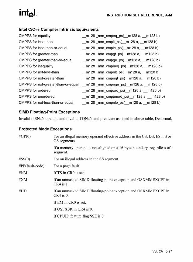
INSTRUCTION SET REFERENCE, A-M
Intel C/C++ Compiler Intrinsic EquivalentsCMPPS for equality __m128 _mm_cmpeq_ps(__m128 a, __m128 b)
CMPPS for less-than __m128 _mm_cmplt_ps(__m128 a, __m128 b)
CMPPS for less-than-or-equal __m128 _mm_cmple_ps(__m128 a, __m128 b)
CMPPS for greater-than __m128 _mm_cmpgt_ps(__m128 a, __m128 b)
CMPPS for greater-than-or-equal __m128 _mm_cmpge_ps(__m128 a, __m128 b)
CMPPS for inequality __m128 _mm_cmpneq_ps(__m128 a, __m128 b)
CMPPS for not-less-than __m128 _mm_cmpnlt_ps(__m128 a, __m128 b)
CMPPS for not-greater-than __m128 _mm_cmpngt_ps(__m128 a, __m128 b)
CMPPS for not-greater-than-or-equal __m128 _mm_cmpnge_ps(__m128 a, __m128 b)
CMPPS for ordered __m128 _mm_cmpord_ps(__m128 a, __m128 b)
CMPPS for unordered __m128 _mm_cmpunord_ps(__m128 a, __m128 b)
CMPPS for not-less-than-or-equal __m128 _mm_cmpnle_ps(__m128 a, __m128 b)
SIMD Floating-Point ExceptionsInvalid if SNaN operand and invalid if QNaN and predicate as listed in above table, Denormal.
Protected Mode Exceptions
#GP(0) For an illegal memory operand effective address in the CS, DS, ES, FS or GS segments.
If a memory operand is not aligned on a 16-byte boundary, regardless of segment.
#SS(0) For an illegal address in the SS segment.
#PF(fault-code) For a page fault.
#NM If TS in CR0 is set.
#XM If an unmasked SIMD floating-point exception and OSXMMEXCPT in CR4 is 1.
#UD If an unmasked SIMD floating-point exception and OSXMMEXCPT in CR4 is 0.
If EM in CR0 is set.
If OSFXSR in CR4 is 0.
If CPUID feature flag SSE is 0.
Vol. 2A 3-97

INSTRUCTION SET REFERENCE, A-M
Real-Address Mode Exceptions
#GP(0) If a memory operand is not aligned on a 16-byte boundary, regardless of segment.
If any part of the operand lies outside the effective address space from 0 to FFFFH.
#NM If TS in CR0 is set.
#XM If an unmasked SIMD floating-point exception and OSXMMEXCPT in CR4 is 1.
#UD If an unmasked SIMD floating-point exception and OSXMMEXCPT in CR4 is 0.
If EM in CR0 is set.
If OSFXSR in CR4 is 0.
If CPUID feature flag SSE is 0.
Virtual-8086 Mode Exceptions
Same exceptions as in Real Address Mode
#PF(fault-code) For a page fault.
3-98 Vol. 2A

INSTRUCTION SET REFERENCE, A-M
CMPS/CMPSB/CMPSW/CMPSD—Compare String Operands
DescriptionCompares the byte, word, or double word specified with the first source operand with the byte,word, or double word specified with the second source operand and sets the status flags in theEFLAGS register according to the results. Both source operands are located in memory. Theaddress of the first source operand is read from either the DS:ESI or the DS:SI registers(depending on the address-size attribute of the instruction, 32 or 16, respectively). The addressof the second source operand is read from either the ES:EDI or the ES:DI registers (againdepending on the address-size attribute of the instruction). The DS segment may be overriddenwith a segment override prefix, but the ES segment cannot be overridden.
At the assembly-code level, two forms of this instruction are allowed: the “explicit-operands”form and the “no-operands” form. The explicit-operands form (specified with the CMPSmnemonic) allows the two source operands to be specified explicitly. Here, the source operandsshould be symbols that indicate the size and location of the source values. This explicit-operandsform is provided to allow documentation; however, note that the documentation provided by thisform can be misleading. That is, the source operand symbols must specify the correct type (size)of the operands (bytes, words, or doublewords), but they do not have to specify the correct loca-tion. The locations of the source operands are always specified by the DS:(E)SI and ES:(E)DIregisters, which must be loaded correctly before the compare string instruction is executed.
The no-operands form provides “short forms” of the byte, word, and doubleword versions of theCMPS instructions. Here also the DS:(E)SI and ES:(E)DI registers are assumed by the processorto specify the location of the source operands. The size of the source operands is selected withthe mnemonic: CMPSB (byte comparison), CMPSW (word comparison), or CMPSD (double-word comparison).
After the comparison, the (E)SI and (E)DI registers increment or decrement automaticallyaccording to the setting of the DF flag in the EFLAGS register. (If the DF flag is 0, the (E)SIand (E)DI register increment; if the DF flag is 1, the (E)SI and (E)DI registers decrement.) Theregisters increment or decrement by 1 for byte operations, by 2 for word operations, or by 4 fordoubleword operations.
Opcode Instruction DescriptionA6 CMPS m8, m8 Compares byte at address DS:(E)SI with byte at address
ES:(E)DI and sets the status flags accordingly.A7 CMPS m16, m16 Compares word at address DS:(E)SI with word at address
ES:(E)DI and sets the status flags accordingly.A7 CMPS m32, m32 Compares doubleword at address DS:(E)SI with doubleword
at address ES:(E)DI and sets the status flags accordingly.A6 CMPSB Compares byte at address DS:(E)SI with byte at address
ES:(E)DI and sets the status flags accordingly.A7 CMPSW Compares word at address DS:(E)SI with word at address
ES:(E)DI and sets the status flags accordingly.A7 CMPSD Compares doubleword at address DS:(E)SI with doubleword
at address ES:(E)DI and sets the status flags accordingly.
Vol. 2A 3-99

INSTRUCTION SET REFERENCE, A-M
The CMPS, CMPSB, CMPSW, and CMPSD instructions can be preceded by the REP prefix forblock comparisons of ECX bytes, words, or doublewords. More often, however, these instruc-tions will be used in a LOOP construct that takes some action based on the setting of the statusflags before the next comparison is made. See “REP/REPE/REPZ/REPNE /REPNZ—RepeatString Operation Prefix” in Chapter 4 for a description of the REP prefix.
Operationtemp ←SRC1 − SRC2;SetStatusFlags(temp);IF (byte comparison)
THEN IF DF = 0THEN
(E)SI ← (E)SI + 1; (E)DI ← (E)DI + 1;
ELSE (E)SI ← (E)SI – 1; (E)DI ← (E)DI – 1;
FI;ELSE IF (word comparison)
THEN IF DF = 0(E)SI ← (E)SI + 2; (E)DI ← (E)DI + 2;
ELSE (E)SI ← (E)SI – 2; (E)DI ← (E)DI – 2;
FI;ELSE (* doubleword comparison*)
THEN IF DF = 0(E)SI ← (E)SI + 4; (E)DI ← (E)DI + 4;
ELSE (E)SI ← (E)SI – 4; (E)DI ← (E)DI – 4;
FI;FI;
Flags AffectedThe CF, OF, SF, ZF, AF, and PF flags are set according to the temporary result of the compar-ison.
Protected Mode Exceptions#GP(0) If a memory operand effective address is outside the CS, DS, ES, FS, or
GS segment limit.
If the DS, ES, FS, or GS register contains a null segment selector.
3-100 Vol. 2A

INSTRUCTION SET REFERENCE, A-M
#SS(0) If a memory operand effective address is outside the SS segment limit.
#PF(fault-code) If a page fault occurs.
#AC(0) If alignment checking is enabled and an unaligned memory reference is made while the current privilege level is 3.
Real-Address Mode Exceptions#GP If a memory operand effective address is outside the CS, DS, ES, FS, or
GS segment limit.
#SS If a memory operand effective address is outside the SS segment limit.
Virtual-8086 Mode Exceptions#GP(0) If a memory operand effective address is outside the CS, DS, ES, FS, or
GS segment limit.
#SS(0) If a memory operand effective address is outside the SS segment limit.
#PF(fault-code) If a page fault occurs.
#AC(0) If alignment checking is enabled and an unaligned memory reference is made.
Vol. 2A 3-101

INSTRUCTION SET REFERENCE, A-M
CMPSD—Compare Scalar Double-Precision Floating-Point Values
DescriptionCompares the low double-precision floating-point values in the source operand (secondoperand) and the destination operand (first operand) and returns the results of the comparison tothe destination operand. The comparison predicate operand (third operand) specifies the type ofcomparison performed. The comparison result is a quadword mask of all 1s (comparison true)or all 0s (comparison false). The source operand can be an XMM register or a 64-bit memorylocation. The destination operand is an XMM register. The result is stored in the low quadwordof the destination operand; the high quadword remains unchanged. The comparison predicateoperand is an 8-bit immediate the first 3 bits of which define the type of comparison to be made(see Table 3-6); bits 4 through 7 of the immediate are reserved.
The unordered relationship is true when at least one of the two source operands being comparedis a NaN; the ordered relationship is true when neither source operand is a NaN.
A subsequent computational instruction that uses the mask result in the destination operand asan input operand will not generate a fault, because a mask of all 0s corresponds to a floating-point value of +0.0 and a mask of all 1s corresponds to a QNaN.
Some of the comparisons listed in Table 3-6 can be achieved only through software emulation.For these comparisons the program must swap the operands (copying registers when necessaryto protect the data that will now be in the destination operand), and then perform the compareusing a different predicate. The predicate to be used for these emulations is listed in Table 3-6under the heading Emulation.
Compilers and assemblers may implement the following two-operand pseudo-ops in addition tothe three-operand CMPSD instruction. See Table 3-9.
Opcode Instruction DescriptionF2 0F C2 /r ib CMPSD xmm1, xmm2/m64, imm8 Compare low double-precision floating-point
value in xmm2/m64 and xmm1 using imm8 as comparison predicate.
3-102 Vol. 2A

INSTRUCTION SET REFERENCE, A-M
.
The greater-than relations not implemented in the processor require more than one instructionto emulate in software and therefore should not be implemented as pseudo-ops. (For these, theprogrammer should reverse the operands of the corresponding less than relations and use moveinstructions to ensure that the mask is moved to the correct destination register and that thesource operand is left intact.)
OperationCASE (COMPARISON PREDICATE) OF
0: OP ← EQ;1: OP ← LT;2: OP ← LE;3: OP ← UNORD;4: OP ← NEQ;5: OP ← NLT;6: OP ← NLE;7: OP ← ORD;DEFAULT: Reserved;
CMP0 ← DEST[63-0] OP SRC[63-0];IF CMP0 = TRUE
THEN DEST[63-0] ← FFFFFFFFFFFFFFFFHELSE DEST[63-0] ← 0000000000000000H; FI;
* DEST[127-64] remains unchanged *;
Intel C/C++ Compiler Intrinsic EquivalentsCMPSD for equality __m128d _mm_cmpeq_sd(__m128d a, __m128d b)
CMPSD for less-than __m128d _mm_cmplt_sd(__m128d a, __m128d b)
CMPSD for less-than-or-equal __m128d _mm_cmple_sd(__m128d a, __m128d b)
CMPSD for greater-than __m128d _mm_cmpgt_sd(__m128d a, __m128d b)
CMPSD for greater-than-or-equal __m128d _mm_cmpge_sd(__m128d a, __m128d b)
CMPSD for inequality __m128d _mm_cmpneq_sd(__m128d a, __m128d b)
Table 3-9. Pseudo-Ops and CMPSDPseudo-Op Implementation
CMPEQSD xmm1, xmm2 CMPSD xmm1,xmm2, 0
CMPLTSD xmm1, xmm2 CMPSD xmm1,xmm2, 1
CMPLESD xmm1, xmm2 CMPSD xmm1,xmm2, 2
CMPUNORDSD xmm1, xmm2 CMPSD xmm1,xmm2, 3
CMPNEQSD xmm1, xmm2 CMPSD xmm1,xmm2, 4
CMPNLTSD xmm1, xmm2 CMPSD xmm1,xmm2, 5
CMPNLESD xmm1, xmm2 CMPSD xmm1,xmm2, 6
CMPORDSD xmm1, xmm2 CMPSD xmm1,xmm2, 7
Vol. 2A 3-103

INSTRUCTION SET REFERENCE, A-M
CMPSD for not-less-than __m128d _mm_cmpnlt_sd(__m128d a, __m128d b)
CMPSD for not-greater-than __m128d _mm_cmpngt_sd(__m128d a, __m128d b)
CMPSD for not-greater-than-or-equal __m128d _mm_cmpnge_sd(__m128d a, __m128d b)
CMPSD for ordered __m128d _mm_cmpord_sd(__m128d a, __m128d b)
CMPSD for unordered __m128d _mm_cmpunord_sd(__m128d a, __m128d b)
CMPSD for not-less-than-or-equal __m128d _mm_cmpnle_sd(__m128d a, __m128d b)
SIMD Floating-Point ExceptionsInvalid if SNaN operand, Invalid if QNaN and predicate as listed in above table, Denormal.
Protected Mode Exceptions
#GP(0) For an illegal memory operand effective address in the CS, DS, ES, FS or GS segments.
#SS(0) For an illegal address in the SS segment.
#PF(fault-code) For a page fault.
#NM If TS in CR0 is set.
#XM If an unmasked SIMD floating-point exception and OSXMMEXCPT in CR4 is 1.
#UD If an unmasked SIMD floating-point exception and OSXMMEXCPT in CR4 is 0.
If EM in CR0 is set.
If OSFXSR in CR4 is 0.
If CPUID feature flag SSE2 is 0.
#AC(0) If alignment checking is enabled and an unaligned memory reference is made while the current privilege level is 3.
Real-Address Mode Exceptions
#GP(0) If any part of the operand lies outside the effective address space from 0 to FFFFH.
#NM If TS in CR0 is set.
#XM If an unmasked SIMD floating-point exception and OSXMMEXCPT in CR4 is 1.
#UD If an unmasked SIMD floating-point exception and OSXMMEXCPT in CR4 is 0.
If EM in CR0 is set.
3-104 Vol. 2A

INSTRUCTION SET REFERENCE, A-M
If OSFXSR in CR4 is 0.
If CPUID feature flag SSE2 is 0.
Virtual-8086 Mode Exceptions
Same exceptions as in Real Address Mode
#PF(fault-code) For a page fault.
#AC(0) If alignment checking is enabled and an unaligned memory reference is made.
Vol. 2A 3-105

INSTRUCTION SET REFERENCE, A-M
CMPSS—Compare Scalar Single-Precision Floating-Point Values
DescriptionCompares the low single-precision floating-point values in the source operand (second operand)and the destination operand (first operand) and returns the results of the comparison to the desti-nation operand. The comparison predicate operand (third operand) specifies the type of compar-ison performed. The comparison result is a doubleword mask of all 1s (comparison true) or all0s (comparison false). The source operand can be an XMM register or a 32-bit memory location.The destination operand is an XMM register. The result is stored in the low doubleword of thedestination operand; the 3 high-order doublewords remain unchanged. The comparison predi-cate operand is an 8-bit immediate the first 3 bits of which define the type of comparison to bemade (see Table 3-6); bits 4 through 7 of the immediate are reserved.
The unordered relationship is true when at least one of the two source operands being comparedis a NaN; the ordered relationship is true when neither source operand is a NaN
A subsequent computational instruction that uses the mask result in the destination operand asan input operand will not generate a fault, since a mask of all 0s corresponds to a floating-pointvalue of +0.0 and a mask of all 1s corresponds to a QNaN.
Some of the comparisons listed in Table 3-6 can be achieved only through software emulation.For these comparisons the program must swap the operands (copying registers when necessaryto protect the data that will now be in the destination operand), and then perform the compareusing a different predicate. The predicate to be used for these emulations is listed in Table 3-6under the heading Emulation.
Compilers and assemblers may implement the following two-operand pseudo-ops in addition tothe three-operand CMPSS instruction. See Table 3-10
Opcode Instruction DescriptionF3 0F C2 /r ib CMPSS xmm1, xmm2/m32, imm8 Compare low single-precision floating-point
value in xmm2/m32 and xmm1 using imm8 as comparison predicate.
3-106 Vol. 2A

INSTRUCTION SET REFERENCE, A-M
The greater-than relations not implemented in the processor require more than one instructionto emulate in software and therefore should not be implemented as pseudo-ops. (For these, theprogrammer should reverse the operands of the corresponding less than relations and use moveinstructions to ensure that the mask is moved to the correct destination register and that thesource operand is left intact.)
OperationCASE (COMPARISON PREDICATE) OF
0: OP ← EQ;1: OP ← LT;2: OP ← LE;3: OP ← UNORD;4: OP ← NEQ;5: OP ← NLT;6: OP ← NLE;7: OP ← ORD;DEFAULT: Reserved;
CMP0 ← DEST[31-0] OP SRC[31-0];IF CMP0 = TRUE
THEN DEST[31-0] ← FFFFFFFFHELSE DEST[31-0] ← 00000000H; FI;
* DEST[127-32] remains unchanged *;
Intel C/C++ Compiler Intrinsic EquivalentsCMPSS for equality __m128 _mm_cmpeq_ss(__m128 a, __m128 b)
CMPSS for less-than __m128 _mm_cmplt_ss(__m128 a, __m128 b)
CMPSS for less-than-or-equal __m128 _mm_cmple_ss(__m128 a, __m128 b)
CMPSS for greater-than __m128 _mm_cmpgt_ss(__m128 a, __m128 b)
CMPSS for greater-than-or-equal __m128 _mm_cmpge_ss(__m128 a, __m128 b)
CMPSS for inequality __m128 _mm_cmpneq_ss(__m128 a, __m128 b)
Table 3-10. Pseudo-Ops and CMPSSPseudo-Op CMPSS Implementation
CMPEQSS xmm1, xmm2 CMPSS xmm1, xmm2, 0
CMPLTSS xmm1, xmm2 CMPSS xmm1, xmm2, 1
CMPLESS xmm1, xmm2 CMPSS xmm1, xmm2, 2
CMPUNORDSS xmm1, xmm2 CMPSS xmm1, xmm2, 3
CMPNEQSS xmm1, xmm2 CMPSS xmm1, xmm2, 4
CMPNLTSS xmm1, xmm2 CMPSS xmm1, xmm2, 5
CMPNLESS xmm1, xmm2 CMPSS xmm1, xmm2, 6
CMPORDSS xmm1, xmm2 CMPSS xmm1, xmm2, 7
Vol. 2A 3-107

INSTRUCTION SET REFERENCE, A-M
CMPSS for not-less-than __m128 _mm_cmpnlt_ss(__m128 a, __m128 b)
CMPSS for not-greater-than __m128 _mm_cmpngt_ss(__m128 a, __m128 b)
CMPSS for not-greater-than-or-equal __m128 _mm_cmpnge_ss(__m128 a, __m128 b)
CMPSS for ordered __m128 _mm_cmpord_ss(__m128 a, __m128 b)
CMPSS for unordered __m128 _mm_cmpunord_ss(__m128 a, __m128 b)
CMPSS for not-less-than-or-equal __m128 _mm_cmpnle_ss(__m128 a, __m128 b)
SIMD Floating-Point ExceptionsInvalid if SNaN operand, Invalid if QNaN and predicate as listed in above table, Denormal.
Protected Mode Exceptions
#GP(0) For an illegal memory operand effective address in the CS, DS, ES, FS or GS segments.
#SS(0) For an illegal address in the SS segment.
#PF(fault-code) For a page fault.
#NM If TS in CR0 is set.
#XM If an unmasked SIMD floating-point exception and OSXMMEXCPT in CR4 is 1.
#UD If an unmasked SIMD floating-point exception and OSXMMEXCPT in CR4 is 0.
If EM in CR0 is set.
If OSFXSR in CR4 is 0.
If CPUID feature flag SSE is 0.
#AC(0) If alignment checking is enabled and an unaligned memory reference is made while the current privilege level is 3.
Real-Address Mode Exceptions
#GP(0) If any part of the operand lies outside the effective address space from 0 to FFFFH.
#NM If TS in CR0 is set.
#XM If an unmasked SIMD floating-point exception and OSXMMEXCPT in CR4 is 1.
#UD If an unmasked SIMD floating-point exception and OSXMMEXCPT in CR4 is 0.
If EM in CR0 is set.
3-108 Vol. 2A

INSTRUCTION SET REFERENCE, A-M
If OSFXSR in CR4 is 0.
If CPUID feature flag SSE is 0.
Virtual-8086 Mode Exceptions
Same exceptions as in Real Address Mode
#PF(fault-code) For a page fault.
#AC(0) If alignment checking is enabled and an unaligned memory reference is made.
Vol. 2A 3-109

INSTRUCTION SET REFERENCE, A-M
CMPXCHG—Compare and Exchange
DescriptionCompares the value in the AL, AX, or EAX register (depending on the size of the operand) withthe first operand (destination operand). If the two values are equal, the second operand (sourceoperand) is loaded into the destination operand. Otherwise, the destination operand is loadedinto the AL, AX, or EAX register.
This instruction can be used with a LOCK prefix to allow the instruction to be executed atomi-cally. To simplify the interface to the processor’s bus, the destination operand receives a writecycle without regard to the result of the comparison. The destination operand is written back ifthe comparison fails; otherwise, the source operand is written into the destination. (Theprocessor never produces a locked read without also producing a locked write.)
IA-32 Architecture CompatibilityThis instruction is not supported on Intel processors earlier than the Intel486 processors.
Operation(* accumulator = AL, AX, or EAX, depending on whether *)(* a byte, word, or doubleword comparison is being performed*)IF accumulator = DEST
THENZF ← 1DEST ← SRC
ELSEZF ← 0accumulator ← DEST
FI;
Flags AffectedThe ZF flag is set if the values in the destination operand and register AL, AX, or EAX are equal;otherwise it is cleared. The CF, PF, AF, SF, and OF flags are set according to the results of thecomparison operation.
Opcode Instruction Description0F B0/r CMPXCHG r/m8,r8 Compare AL with r/m8. If equal, ZF is set and r8 is loaded
into r/m8. Else, clear ZF and load r/m8 into AL.0F B1/r CMPXCHG r/m16,r16 Compare AX with r/m16. If equal, ZF is set and r16 is
loaded into r/m16. Else, clear ZF and load r/m16 into AX0F B1/r CMPXCHG r/m32,r32 Compare EAX with r/m32. If equal, ZF is set and r32 is
loaded into r/m32. Else, clear ZF and load r/m32 into EAX
3-110 Vol. 2A

INSTRUCTION SET REFERENCE, A-M
Protected Mode Exceptions#GP(0) If the destination is located in a non-writable segment.
If a memory operand effective address is outside the CS, DS, ES, FS, or GS segment limit.If the DS, ES, FS, or GS register contains a null segment selector.
#SS(0) If a memory operand effective address is outside the SS segment limit.
#PF(fault-code) If a page fault occurs.
#AC(0) If alignment checking is enabled and an unaligned memory reference is made while the current privilege level is 3.
Real-Address Mode Exceptions#GP If a memory operand effective address is outside the CS, DS, ES, FS, or
GS segment limit.
#SS If a memory operand effective address is outside the SS segment limit.
Virtual-8086 Mode Exceptions#GP(0) If a memory operand effective address is outside the CS, DS, ES, FS, or
GS segment limit.
#SS(0) If a memory operand effective address is outside the SS segment limit.
#PF(fault-code) If a page fault occurs.
#AC(0) If alignment checking is enabled and an unaligned memory reference is made.
Vol. 2A 3-111

INSTRUCTION SET REFERENCE, A-M
CMPXCHG8B—Compare and Exchange 8 Bytes
DescriptionCompares the 64-bit value in EDX:EAX with the operand (destination operand). If the valuesare equal, the 64-bit value in ECX:EBX is stored in the destination operand. Otherwise, thevalue in the destination operand is loaded into EDX:EAX. The destination operand is an 8-bytememory location. For the EDX:EAX and ECX:EBX register pairs, EDX and ECX contain thehigh-order 32 bits and EAX and EBX contain the low-order 32 bits of a 64-bit value.
This instruction can be used with a LOCK prefix to allow the instruction to be executed atomi-cally. To simplify the interface to the processor’s bus, the destination operand receives a writecycle without regard to the result of the comparison. The destination operand is written back ifthe comparison fails; otherwise, the source operand is written into the destination. (Theprocessor never produces a locked read without also producing a locked write.)
IA-32 Architecture CompatibilityThis instruction is not supported on Intel processors earlier than the Pentium processors.
OperationIF (EDX:EAX = DEST)
ZF ← 1DEST ← ECX:EBX
ELSEZF ← 0EDX:EAX ← DEST
Flags AffectedThe ZF flag is set if the destination operand and EDX:EAX are equal; otherwise it is cleared.The CF, PF, AF, SF, and OF flags are unaffected.
Protected Mode Exceptions#UD If the destination operand is not a memory location.
#GP(0) If the destination is located in a non-writable segment.
If a memory operand effective address is outside the CS, DS, ES, FS, or GS segment limit.
If the DS, ES, FS, or GS register contains a null segment selector.
Opcode Instruction Description0F C7 /1 m64 CMPXCHG8B m64 Compare EDX:EAX with m64. If equal, set ZF and load
ECX:EBX into m64. Else, clear ZF and load m64 into EDX:EAX.
3-112 Vol. 2A

INSTRUCTION SET REFERENCE, A-M
#SS(0) If a memory operand effective address is outside the SS segment limit.
#PF(fault-code) If a page fault occurs.
#AC(0) If alignment checking is enabled and an unaligned memory reference is made while the current privilege level is 3.
Real-Address Mode Exceptions#UD If the destination operand is not a memory location.
#GP If a memory operand effective address is outside the CS, DS, ES, FS, or GS segment limit.
#SS If a memory operand effective address is outside the SS segment limit.
Virtual-8086 Mode Exceptions#UD If the destination operand is not a memory location.
#GP(0) If a memory operand effective address is outside the CS, DS, ES, FS, or GS segment limit.
#SS(0) If a memory operand effective address is outside the SS segment limit.
#PF(fault-code) If a page fault occurs.
#AC(0) If alignment checking is enabled and an unaligned memory reference is made.
Vol. 2A 3-113

INSTRUCTION SET REFERENCE, A-M
COMISD—Compare Scalar Ordered Double-Precision Floating-Point Values and Set EFLAGS
DescriptionCompares the double-precision floating-point values in the low quadwords of source operand 1(first operand) and source operand 2 (second operand), and sets the ZF, PF, and CF flags in theEFLAGS register according to the result (unordered, greater than, less than, or equal). The OF,SF and AF flags in the EFLAGS register are set to 0. The unordered result is returned if eithersource operand is a NaN (QNaN or SNaN).
Source operand 1 is an XMM register; source operand 2 can be an XMM register or a 64 bitmemory location.
The COMISD instruction differs from the UCOMISD instruction in that it signals an SIMDfloating-point invalid operation exception (#I) when a source operand is either a QNaN orSNaN. The UCOMISD instruction signals an invalid numeric exception only if a source operandis an SNaN.
The EFLAGS register is not updated if an unmasked SIMD floating-point exception is gener-ated.
OperationRESULT ← OrderedCompare(DEST[63-0] <> SRC[63-0]) {* Set EFLAGS *CASE (RESULT) OF
UNORDERED: ZF,PF,CF ← 111;GREATER_THAN: ZF,PF,CF ← 000;LESS_THAN: ZF,PF,CF ← 001;EQUAL: ZF,PF,CF ← 100;
ESAC;OF,AF,SF ← 0;
Intel C/C++ Compiler Intrinsic Equivalentsint_mm_comieq_sd(__m128d a, __m128d b)
int_mm_comilt_sd(__m128d a, __m128d b)
int_mm_comile_sd(__m128d a, __m128d b)
int_mm_comigt_sd(__m128d a, __m128d b)
int_mm_comige_sd(__m128d a, __m128d b)
int_mm_comineq_sd(__m128d a, __m128d b)
Opcode Instruction Description66 0F 2F /r COMISD xmm1, xmm2/m64 Compare low double-precision floating-point values in
xmm1 and xmm2/mem64 and set the EFLAGS flags accordingly.
3-114 Vol. 2A

INSTRUCTION SET REFERENCE, A-M
SIMD Floating-Point ExceptionsInvalid (if SNaN or QNaN operands), Denormal.
Protected Mode Exceptions
#GP(0) For an illegal memory operand effective address in the CS, DS, ES, FS or GS segments.
#SS(0) For an illegal address in the SS segment.
#PF(fault-code) For a page fault.
#NM If TS in CR0 is set.
#XM If an unmasked SIMD floating-point exception and OSXMMEXCPT in CR4 is 1.
#UD If an unmasked SIMD floating-point exception and OSXMMEXCPT in CR4 is 0.
If EM in CR0 is set.
If OSFXSR in CR4 is 0.
If CPUID feature flag SSE2 is 0.
#AC(0) If alignment checking is enabled and an unaligned memory reference is made while the current privilege level is 3.
Real-Address Mode Exceptions
GP(0) If any part of the operand lies outside the effective address space from 0 to FFFFH.
#NM If TS in CR0 is set.
#XM If an unmasked SIMD floating-point exception and OSXMMEXCPT in CR4 is 1.
#UD If an unmasked SIMD floating-point exception and OSXMMEXCPT in CR4 is 0.
If EM in CR0 is set.
If OSFXSR in CR4 is 0.
If CPUID feature flag SSE2 is 0.
Vol. 2A 3-115

INSTRUCTION SET REFERENCE, A-M
Virtual-8086 Mode Exceptions
Same exceptions as in Real Address Mode
#PF(fault-code) For a page fault.
#AC(0) If alignment checking is enabled and an unaligned memory reference is made.
3-116 Vol. 2A

INSTRUCTION SET REFERENCE, A-M
COMISS—Compare Scalar Ordered Single-Precision Floating-Point Values and Set EFLAGS
DescriptionCompares the single-precision floating-point values in the low doublewords of source operand1 (first operand) and source operand 2 (second operand), and sets the ZF, PF, and CF flags inthe EFLAGS register according to the result (unordered, greater than, less than, or equal). TheOF, SF, and AF flags in the EFLAGS register are set to 0. The unordered result is returned ifeither source operand is a NaN (QNaN or SNaN).
Source operand 1 is an XMM register; source operand 2 can be an XMM register or a 32 bitmemory location.
The COMISS instruction differs from the UCOMISS instruction in that it signals an SIMDfloating-point invalid operation exception (#I) when a source operand is either a QNaN orSNaN. The UCOMISS instruction signals an invalid numeric exception only if a source operandis an SNaN.
The EFLAGS register is not updated if an unmasked SIMD floating-point exception is gener-ated.
OperationRESULT ← OrderedCompare(SRC1[31-0] <> SRC2[31-0]) {* Set EFLAGS *CASE (RESULT) OF
UNORDERED: ZF,PF,CF ← 111;GREATER_THAN: ZF,PF,CF ← 000;LESS_THAN: ZF,PF,CF ← 001;EQUAL: ZF,PF,CF ← 100;
ESAC;OF,AF,SF ← 0;
Intel C/C++ Compiler Intrinsic Equivalentsint_mm_comieq_ss(__m128 a, __m128 b)
int_mm_comilt_ss(__m128 a, __m128 b)
int_mm_comile_ss(__m128 a, __m128 b)
int_mm_comigt_ss(__m128 a, __m128 b)
int_mm_comige_ss(__m128 a, __m128 b)
int_mm_comineq_ss(__m128 a, __m128 b)
Opcode Instruction Description0F 2F /r COMISS xmm1, xmm2/m32 Compare low single-precision floating-point values in
xmm1 and xmm2/mem32 and set the EFLAGS flags accordingly.
Vol. 2A 3-117

INSTRUCTION SET REFERENCE, A-M
SIMD Floating-Point ExceptionsInvalid (if SNaN or QNaN operands), Denormal.
Protected Mode Exceptions
#GP(0) For an illegal memory operand effective address in the CS, DS, ES, FS or GS segments.
#SS(0) For an illegal address in the SS segment.
#PF(fault-code) For a page fault.
#NM If TS in CR0 is set.
#XM If an unmasked SIMD floating-point exception and OSXMMEXCPT in CR4 is 1.
#UD If an unmasked SIMD floating-point exception and OSXMMEXCPT in CR4 is 0.
If EM in CR0 is set.
If OSFXSR in CR4 is 0.
If CPUID feature flag SSE is 0.
#AC(0) If alignment checking is enabled and an unaligned memory reference is made while the current privilege level is 3.
Real-Address Mode Exceptions
GP(0) If any part of the operand lies outside the effective address space from 0 to FFFFH.
#NM If TS in CR0 is set.
#XM If an unmasked SIMD floating-point exception and OSXMMEXCPT in CR4 is 1.
#UD If an unmasked SIMD floating-point exception and OSXMMEXCPT in CR4 is 0.
If EM in CR0 is set.
If OSFXSR in CR4 is 0.
If CPUID feature flag SSE is 0.
3-118 Vol. 2A

INSTRUCTION SET REFERENCE, A-M
Virtual-8086 Mode Exceptions
Same exceptions as in Real Address Mode
#PF(fault-code) For a page fault.
#AC(0) If alignment checking is enabled and an unaligned memory reference is made.
Vol. 2A 3-119

INSTRUCTION SET REFERENCE, A-M
CPUID—CPU Identification
DescriptionThe ID flag (bit 21) in the EFLAGS register indicates support for the CPUID instruction. If asoftware procedure can set and clear this flag, the processor executing the procedure supportsthe CPUID instruction.
CPUID returns processor identification and feature information in the EAX, EBX, ECX, andEDX registers. The instruction’s output is dependent on the contents of the EAX register uponexecution. For example, the following pseudocode loads EAX with 00H and causes CPUID toreturn a Maximum Return Value and the Vendor Identification String in the appropriate regis-ters:
MOV EAX, 00HCPUID
Table 3-11 shows information returned, depending on the initial value loaded into the EAXregister. Table 3-12 shows the maximum CPUID input value recognized for each family of IA-32 processors on which CPUID is implemented.
Two types of information are returned: basic and extended function information. If a highervalue entered than is valid for a particular processor, the information for the highest useful basicinformation value is returned. For example, if an input value of 5 is entered in EAX for aPentium 4 processor, the information for an input value of 2 is returned. The exception to thisrule is the input values that return extended function information. For a Pentium 4 processor,entering an input value of 80000005H or above returns the information for an input value of 2.
CPUID can be executed at any privilege level to serialize instruction execution. Serializinginstruction execution guarantees that any modifications to flags, registers, and memory forprevious instructions are completed before the next instruction is fetched and executed.
See also:
“Serializing Instructions” in Chapter 7 of the IA-32 Intel Architecture Software Devel-oper’s Manual, Volume 3
AP-485, Intel Processor Identification and the CPUID Instruction (Order Number241618)
Opcode Instruction Description0F A2 CPUID Returns processor identification and feature information
to the EAX, EBX, ECX, and EDX registers, according to the input value entered initially in the EAX register.
3-120 Vol. 2A

INSTRUCTION SET REFERENCE, A-M
Table 3-11. Information Returned by CPUID InstructionInitial EAX
Value Information Provided about the Processor
Basic CPUID Information
0H EAXEBXECXEDX
Maximum Input Value for Basic CPUID Information (see Table 3-12)“Genu”“ntel”“ineI”
01H EAXEBX
ECXEDX
Version Information: Type, Family, Model, and Stepping ID (see Figure 3-5)Bits 7-0: Brand IndexBits 15-8: CLFLUSH line size (Value ∗ 8 = cache line size in bytes)Bits 23-16: Number of logical processors per physical processor; two for the Pentium 4 processor supporting Hyper-Threading TechnologyBits 31-24: Local APIC IDExtended Feature Information (see Figure 3-6 and Table 3-14)Feature Information (see Figure 3-7 and Table 3-15)
02H EAXEBXECXEDX
Cache and TLB Information (see Table 3-16)Cache and TLB InformationCache and TLB InformationCache and TLB Information
03H EAXEBXECX
EDX
Reserved.Reserved.Bits 00-31 of 96 bit processor serial number. (Available in Pentium III processor only; otherwise, the value in this register is reserved.)Bits 32-63 of 96 bit processor serial number. (Available in Pentium III processor only; otherwise, the value in this register is reserved.)
NOTE: Processor serial number (PSN) is not supported in the Pentium 4 processor or later. On all models, use the PSN flag (returned using CPUID) to check for PSN support before accessing the feature. See AP-485, Intel Processor Identification and the CPUID Instruction (Order Number 241618) for more information on PSN.
04HEAX
EBX
ECX
Deterministic Cache Parameters Leaf Bits 4-0: Cache Type** Bits 7-5: Cache Level (starts at 1) Bits 8: Self Initializing cache level (does not need SW initialization) Bits 9: Fully Associative cache Bits 13-10: Reserved Bits 25-14: Number of threads sharing this cache* Bits 31-26: Number of processor cores on this die (Multicore)*Bits 11-00: L = System Coherency Line Size* Bits 21-12: P = Physical Line partitions* Bits 31-22: W = Ways of associativity*Bits 31-00: S = Number of Sets*
Vol. 2A 3-121

INSTRUCTION SET REFERENCE, A-M
EDX Reserved = 0
*Add one to the value in the register file to get the number. For example, the number of processor cores is EAX[31:26]+1.** Cache Types fields
0 = Null - No more caches1 = Data Cache2 = Instruction Cache3 = Unified Cache4-31 = Reserved
NOTE: CPUID leaves > 3 < 80000000 are only visible when IA32_CR_MISC_ENABLES.BOOT_NT4 (bit 22) is clear (Default)
5HEAX
EBX
ECXEDX
MONITOR/MWAIT Leaf Bits 15-00: Smallest monitor-line size in bytes (default is processor's monitor granularity) Bits 31-16: Reserved = 0Bits 15-00: Largest monitor-line size in bytes (default is processor's monitor granularity) Bits 31-16: Reserved = 0Reserved = 0Reserved = 0
Extended Function CPUID Information
80000000H EAX
EBXECXEDX
Maximum Input Value for Extended Function CPUID Information (see Table 3-12).ReservedReservedReserved
80000001H EAX
EBXECXEDX
Extended Processor Signature and Extended Feature Bits. (Currently ReservedReservedReservedReserved
80000002H EAXEBXECXEDX
Processor Brand StringProcessor Brand String ContinuedProcessor Brand String ContinuedProcessor Brand String Continued
80000003H EAXEBXECXEDX
Processor Brand String ContinuedProcessor Brand String ContinuedProcessor Brand String ContinuedProcessor Brand String Continued
80000004H EAXEBXECXEDX
Processor Brand String ContinuedProcessor Brand String ContinuedProcessor Brand String ContinuedProcessor Brand String Continued
80000005H EAXEBXECXEDX
Reserved = 0Reserved = 0Reserved = 0Reserved = 0
Table 3-11. Information Returned by CPUID Instruction (Contd.)Initial EAX
Value Information Provided about the Processor
3-122 Vol. 2A
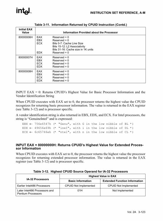
INSTRUCTION SET REFERENCE, A-M
INPUT EAX = 0: Returns CPUID’s Highest Value for Basic Processor Information and theVendor Identification String
When CPUID executes with EAX set to 0, the processor returns the highest value the CPUIDrecognizes for returning basic processor information. The value is returned in the EAX register(see Table 3-12) and is processor specific.
A vendor identification string is also returned in EBX, EDX, and ECX. For Intel processors, thestring is “GenuineIntel” and is expressed:
EBX ← 756e6547h (* "Genu", with G in the low nibble of BL *)EDX ← 49656e69h (* "ineI", with i in the low nibble of DL *)ECX ← 6c65746eh (* "ntel", with n in the low nibble of CL *)
INPUT EAX = 80000000H: Returns CPUID’s Highest Value for Extended Proces-sor InformationWhen CPUID executes with EAX set to 0, the processor returns the highest value the processorrecognizes for returning extended processor information. The value is returned in the EAXregister (see Table 3-12) and is processor specific.
80000006H EAXEBXECX
EDX
Reserved = 0Reserved = 0Bits 0-7: Cache Line SizeBits 15-12: L2 Associativity Bits 31-16: Cache size in 1K unitsReserved = 0
80000007H EAXEBXECXEDX
Reserved = 0Reserved = 0Reserved = 0Reserved = 0
80000008H EAXEBXECXEDX
Reserved = 0Reserved = 0Reserved = 0Reserved = 0
Table 3-12. Highest CPUID Source Operand for IA-32 Processors
IA-32 ProcessorsHighest Value in EAX
Basic Information Extended Function Information
Earlier Intel486 Processors CPUID Not Implemented CPUID Not Implemented
Later Intel486 Processors and Pentium Processors
01H Not Implemented
Table 3-11. Information Returned by CPUID Instruction (Contd.)Initial EAX
Value Information Provided about the Processor
Vol. 2A 3-123

INSTRUCTION SET REFERENCE, A-M
Returns Microcode Update SignatureFor processors that support the microcode update facility, the IA32_BIOS_SIGN_ID MSR isloaded with the update signature whenever CPUID executes. The signature is returned in theupper DWORD. For details, see Chapter 9 in the IA-32 Intel Architecture Software Developer’sManual, Volume 3.
INPUT EAX = 1: Returns Model, Family, Stepping Information\When CPUID executes with EAX set to 1, version information is returned in EAX (see Figure3-5). For example: model, family, and processor type for the first processor in the Intel Pentium4 family is returned as follows:
• Model—0000B
• Family—1111B
• Processor Type—00B
See Table 3-13 for available processor type values. Stepping IDs are provided as needed.
Pentium Pro and Pentium II Processors, Intel® Celeron™ Processors
02H Not Implemented
Pentium III Processors 03H Not Implemented
Pentium 4 Processors 02H 80000004H
Intel Xeon Processors 02H 80000004H
Pentium M Processor 02H 80000004H
Pentium 4 Processor supporting Hyper-Threading Technology
05H 80000008H
Table 3-12. Highest CPUID Source Operand for IA-32 Processors (Contd.)
IA-32 ProcessorsHighest Value in EAX
Basic Information Extended Function Information
3-124 Vol. 2A

INSTRUCTION SET REFERENCE, A-M
NOTESee AP-485, Intel Processor Identification and the CPUID Instruction(Order Number 241618) and Chapter 14 in the IA-32 Intel ArchitectureSoftware Developer’s Manual, Volume 1, for information on identifyingearlier IA-32 processors.
The Extended Family ID and Extended Model ID need be examined only if the Family ID reaches0FH. Always display processor information as a combination of family, model, and stepping.
Integrate the ID fields into a display as:
Displayed family = ((Extended Family ID(4-bits) << 4)) (8-bits) + Family ID (4-bits zero extended to 8-bits)
Figure 3-5. Version Information Returned by CPUID in EAX
Table 3-13. Processor Type FieldType Encoding
Original OEM Processor 00B
Intel OverDrive® Processor 01B
Dual processor (not applicable to Intel486 processors)
10B
Intel reserved 11B
OM16525
Processor Type
034781112131415161920272831
EAX
Family (0FH for the Pentium 4 Processor FamilyModel
ExtendedFamily ID
ExtendedModel ID
FamilyID Model Stepping
ID
Extended Family ID (0)Extended Model ID (0)
Reserved
Vol. 2A 3-125

INSTRUCTION SET REFERENCE, A-M
Compute the displayed model from the Model ID and the Extended Model ID as:
Displayed Model = ((Extended Model ID (4-bits) << 4))(8-bits)+ Model (4-bits zero extended to 8-bits)
INPUT EAX = 1: Returns Additional Information in EBXWhen CPUID executes with EAX set to 1, additional information is returned to the EBXregister:
• Brand index (low byte of EBX) — this number provides an entry into a brand string tablethat contains brand strings for IA-32 processors. More information about this field isprovided later in this section.
• CLFLUSH instruction cache line size (second byte of EBX) — this number indicates thesize of the cache line flushed with CLFLUSH instruction in 8-byte increments. This fieldwas introduced in the Pentium 4 processor.
• Local APIC ID (high byte of EBX) — this number is the 8-bit ID that is assigned to thelocal APIC on the processor during power up. This field was introduced in the Pentium 4processor.
INPUT EAX = 1: Returns Feature Information in ECX and EDXWhen CPUID executes with EAX set to 1, feature information is returned in ECX and EDX.
• Figure 3-6 and Table 3-14 show encodings for ECX.
• Figure 3-7 and Table 3-15 show encodings for EDX.
For all feature flags, a 1 indicates that the feature is supported. Use Intel to properly interpretfeature flags.
NOTESoftware must confirm that a processor feature is present using feature flagsreturned by CPUID prior to using the feature. Software should not depend onfuture offerings retaining all features.
3-126 Vol. 2A

INSTRUCTION SET REFERENCE, A-M
Figure 3-6. Extended Feature Information Returned in the ECX Register
Table 3-14. More on Extended Feature Information Returned in the ECX RegisterBit # Mnemonic Description
0 SSE3 Streaming SIMD Extensions 3 (SSE3). A value of 1 indicates the processor supports this technology.
3 MONITOR MONITOR/MWAIT. A value of 1 indicates the processor supports this feature.
4 DS-CPL CPL Qualified Debug Store. A value of 1 indicates the processor supports the extensions to the Debug Store feature to allow for branch message storage qualified by CPL.
7 EST Enhanced Intel SpeedStep® technology. A value of 1 indicates that the processor supports this technology.
8 TM2 Thermal Monitor 2. A value of 1 indicates whether the processor supports this technology.
10 CNXT-ID L1 Context ID. A value of 1 indicates the L1 data cache mode can be set to either adaptive mode or shared mode. A value of 0 indicates this feature is not supported. See definition of the IA32_MISC_ENABLE MSR Bit 24 (L1 Data Cache Context Mode) for details.
OM16524
CNXT-ID — L1 Context ID
012345678910111213141516171819202122232425262728293031
ECX
TM2 — Thermal Monitor 2EST — Enhanced Intel SpeedStep® technologyDS-CPL — CPL Qualified Debug StoreMONITOR — MONITOR/MWAITSSE3 — SSE3 extensions
Reserved
Vol. 2A 3-127

INSTRUCTION SET REFERENCE, A-M
Figure 3-7. Feature Information Returned in the EDX Register
Table 3-15. More on Feature Information Returned in the EDX RegisterBit # Mnemonic Description
0 FPU Floating Point Unit On-Chip. The processor contains an x87 FPU.
1 VME Virtual 8086 Mode Enhancements. Virtual 8086 mode enhancements, including CR4.VME for controlling the feature, CR4.PVI for protected mode virtual interrupts, software interrupt indirection, expansion of the TSS with the software indirection bitmap, and EFLAGS.VIF and EFLAGS.VIP flags.
OM16523
PBE–Pend. Brk. EN.
012345678910111213141516171819202122232425262728293031
EDX
TM–Therm. MonitorHTT–Hyper-Threading Tech.SS–Self SnoopSSE2–SSE2 ExtensionsSSE–SSE ExtensionsFXSR–FXSAVE/FXRSTORMMX–MMX TechnologyACPI–Thermal Monitor and Clock CtrlDS–Debug StoreCLFSH–CFLUSH instructionPSN–Processor Serial NumberPSE-36 – Page Size ExtensionPAT–Page Attribute TableCMOV–Conditional Move/Compare InstructionMCA–Machine Check ArchitecturePGE–PTE Global BitMTRR–Memory Type Range RegistersSEP–SYSENTER and SYSEXITAPIC–APIC on ChipCX8–CMPXCHG8B Inst.MCE–Machine Check ExceptionPAE–Physical Address ExtensionsMSR–RDMSR and WRMSR SupportTSC–Time Stamp CounterPSE–Page Size ExtensionsDE–Debugging ExtensionsVME–Virtual-8086 Mode EnhancementFPU–x87 FPU on Chip
Reserved
3-128 Vol. 2A

INSTRUCTION SET REFERENCE, A-M
2 DE Debugging Extensions. Support for I/O breakpoints, including CR4.DE for controlling the feature, and optional trapping of accesses to DR4 and DR5.
3 PSE Page Size Extension. Large pages of size 4 MByte are supported, including CR4.PSE for controlling the feature, the defined dirty bit in PDE (Page Directory Entries), optional reserved bit trapping in CR3, PDEs, and PTEs.
4 TSC Time Stamp Counter. The RDTSC instruction is supported, including CR4.TSD for controlling privilege.
5 MSR Model Specific Registers RDMSR and WRMSR Instructions. The RDMSR and WRMSR instructions are supported. Some of the MSRs are implementation dependent.
6 PAE Physical Address Extension. Physical addresses greater than 32 bits are supported: extended page table entry formats, an extra level in the page translation tables is defined, 2-MByte pages are supported instead of 4 Mbyte pages if PAE bit is 1. The actual number of address bits beyond 32 is not defined, and is implementation specific.
7 MCE Machine Check Exception. Exception 18 is defined for Machine Checks, including CR4.MCE for controlling the feature. This feature does not define the model-specific implementations of machine-check error logging, reporting, and processor shutdowns. Machine Check exception handlers may have to depend on processor version to do model specific processing of the exception, or test for the presence of the Machine Check feature.
8 CX8 CMPXCHG8B Instruction. The compare-and-exchange 8 bytes (64 bits) instruction is supported (implicitly locked and atomic).
9 APIC APIC On-Chip. The processor contains an Advanced Programmable Interrupt Controller (APIC), responding to memory mapped commands in the physical address range FFFE0000H to FFFE0FFFH (by default - some processors permit the APIC to be relocated).
10 Reserved Reserved
11 SEP SYSENTER and SYSEXIT Instructions. The SYSENTER and SYSEXIT and associated MSRs are supported.
12 MTRR Memory Type Range Registers. MTRRs are supported. The MTRRcap MSR contains feature bits that describe what memory types are supported, how many variable MTRRs are supported, and whether fixed MTRRs are supported.
13 PGE PTE Global Bit. The global bit in page directory entries (PDEs) and page table entries (PTEs) is supported, indicating TLB entries that are common to different processes and need not be flushed. The CR4.PGE bit controls this feature.
14 MCA Machine Check Architecture. The Machine Check Architecture, which provides a compatible mechanism for error reporting in P6 family, Pentium 4, Intel Xeon processors, and future processors, is supported. The MCG_CAP MSR contains feature bits describing how many banks of error reporting MSRs are supported.
15 CMOV Conditional Move Instructions. The conditional move instruction CMOV is supported. In addition, if x87 FPU is present as indicated by the CPUID.FPU feature bit, then the FCOMI and FCMOV instructions are supported
16 PAT Page Attribute Table. Page Attribute Table is supported. This feature augments the Memory Type Range Registers (MTRRs), allowing an operating system to specify attributes of memory on a 4K granularity through a linear address.
Table 3-15. More on Feature Information Returned in the EDX Register (Contd.)Bit # Mnemonic Description
Vol. 2A 3-129

INSTRUCTION SET REFERENCE, A-M
17 PSE-36 36-Bit Page Size Extension. Extended 4-MByte pages that are capable of addressing physical memory beyond 4 GBytes are supported. This feature indicates that the upper four bits of the physical address of the 4-MByte page is encoded by bits 13-16 of the page directory entry.
18 PSN Processor Serial Number. The processor supports the 96-bit processor identification number feature and the feature is enabled.
19 CLFSH CLFLUSH Instruction. CLFLUSH Instruction is supported.
20 Reserved Reserved
21 DS Debug Store. The processor supports the ability to write debug information into a memory resident buffer. This feature is used by the branch trace store (BTS) and precise event-based sampling (PEBS) facilities (see Chapter 15, Debugging and Performance Monitoring, in the IA-32 Intel Architecture Software Developer’s Manual, Volume 3).
22 ACPI Thermal Monitor and Software Controlled Clock Facilities. The processor implements internal MSRs that allow processor temperature to be monitored and processor performance to be modulated in predefined duty cycles under software control.
23 MMX Intel MMX Technology. The processor supports the Intel MMX technology.
24 FXSR FXSAVE and FXRSTOR Instructions. The FXSAVE and FXRSTOR instructions are supported for fast save and restore of the floating point context. Presence of this bit also indicates that CR4.OSFXSR is available for an operating system to indicate that it supports the FXSAVE and FXRSTOR instructions.
25 SSE SSE. The processor supports the SSE extensions.
26 SSE2 SSE2. The processor supports the SSE2 extensions.
27 SS Self Snoop. The processor supports the management of conflicting memory types by performing a snoop of its own cache structure for transactions issued to the bus.
Table 3-15. More on Feature Information Returned in the EDX Register (Contd.)Bit # Mnemonic Description
3-130 Vol. 2A

INSTRUCTION SET REFERENCE, A-M
INPUT EAX = 2: Cache and TLB Information Returned in EAX, EBX, ECX, EDXWhen CPUID executes with EAX set to 2, the processor returns information about theprocessor’s internal caches and TLBs in the EAX, EBX, ECX, and EDX registers.
The encoding is as follows:
• The least-significant byte in register EAX (register AL) indicates the number of times theCPUID instruction must be executed with an input value of 2 to get a complete descriptionof the processor’s caches and TLBs. The first member of the family of Pentium 4processors will return a 1.
• The most significant bit (bit 31) of each register indicates whether the register containsvalid information (set to 0) or is reserved (set to 1).
• If a register contains valid information, the information is contained in 1 byte descriptors.Table 3-16 shows the encoding of these descriptors. Note that the order of descriptors inthe EAX, EBX, ECX, and EDX registers is not defined; that is, specific bytes are notdesignated to contain descriptors for specific cache or TLB types. The descriptors mayappear in any order.
28 HTT Hyper-Threading Technology. The processor supports Hyper-Threading Technology.
29 TM Thermal Monitor. The processor implements the thermal monitor automatic thermal control circuitry (TCC).
30 Reserved Reserved
31 PBE Pending Break Enable. The processor supports the use of the FERR#/PBE# pin when the processor is in the stop-clock state (STPCLK# is asserted) to signal the processor that an interrupt is pending and that the processor should return to normal operation to handle the interrupt. Bit 10 (PBE enable) in the IA32_MISC_ENABLE MSR enables this capability.
Table 3-15. More on Feature Information Returned in the EDX Register (Contd.)Bit # Mnemonic Description
Vol. 2A 3-131
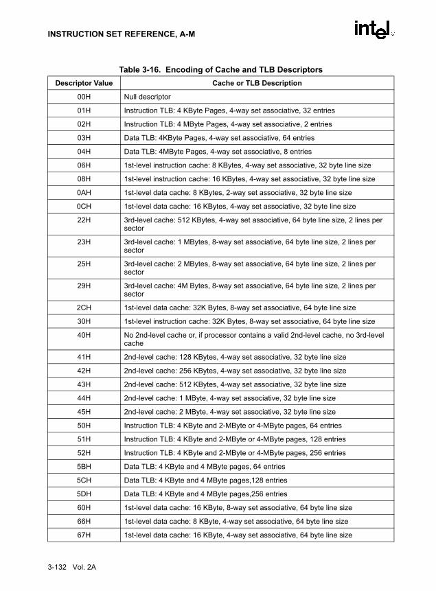
INSTRUCTION SET REFERENCE, A-M
Table 3-16. Encoding of Cache and TLB Descriptors Descriptor Value Cache or TLB Description
00H Null descriptor
01H Instruction TLB: 4 KByte Pages, 4-way set associative, 32 entries
02H Instruction TLB: 4 MByte Pages, 4-way set associative, 2 entries
03H Data TLB: 4KByte Pages, 4-way set associative, 64 entries
04H Data TLB: 4MByte Pages, 4-way set associative, 8 entries
06H 1st-level instruction cache: 8 KBytes, 4-way set associative, 32 byte line size
08H 1st-level instruction cache: 16 KBytes, 4-way set associative, 32 byte line size
0AH 1st-level data cache: 8 KBytes, 2-way set associative, 32 byte line size
0CH 1st-level data cache: 16 KBytes, 4-way set associative, 32 byte line size
22H 3rd-level cache: 512 KBytes, 4-way set associative, 64 byte line size, 2 lines per sector
23H 3rd-level cache: 1 MBytes, 8-way set associative, 64 byte line size, 2 lines per sector
25H 3rd-level cache: 2 MBytes, 8-way set associative, 64 byte line size, 2 lines per sector
29H 3rd-level cache: 4M Bytes, 8-way set associative, 64 byte line size, 2 lines per sector
2CH 1st-level data cache: 32K Bytes, 8-way set associative, 64 byte line size
30H 1st-level instruction cache: 32K Bytes, 8-way set associative, 64 byte line size
40H No 2nd-level cache or, if processor contains a valid 2nd-level cache, no 3rd-level cache
41H 2nd-level cache: 128 KBytes, 4-way set associative, 32 byte line size
42H 2nd-level cache: 256 KBytes, 4-way set associative, 32 byte line size
43H 2nd-level cache: 512 KBytes, 4-way set associative, 32 byte line size
44H 2nd-level cache: 1 MByte, 4-way set associative, 32 byte line size
45H 2nd-level cache: 2 MByte, 4-way set associative, 32 byte line size
50H Instruction TLB: 4 KByte and 2-MByte or 4-MByte pages, 64 entries
51H Instruction TLB: 4 KByte and 2-MByte or 4-MByte pages, 128 entries
52H Instruction TLB: 4 KByte and 2-MByte or 4-MByte pages, 256 entries
5BH Data TLB: 4 KByte and 4 MByte pages, 64 entries
5CH Data TLB: 4 KByte and 4 MByte pages,128 entries
5DH Data TLB: 4 KByte and 4 MByte pages,256 entries
60H 1st-level data cache: 16 KByte, 8-way set associative, 64 byte line size
66H 1st-level data cache: 8 KByte, 4-way set associative, 64 byte line size
67H 1st-level data cache: 16 KByte, 4-way set associative, 64 byte line size
3-132 Vol. 2A
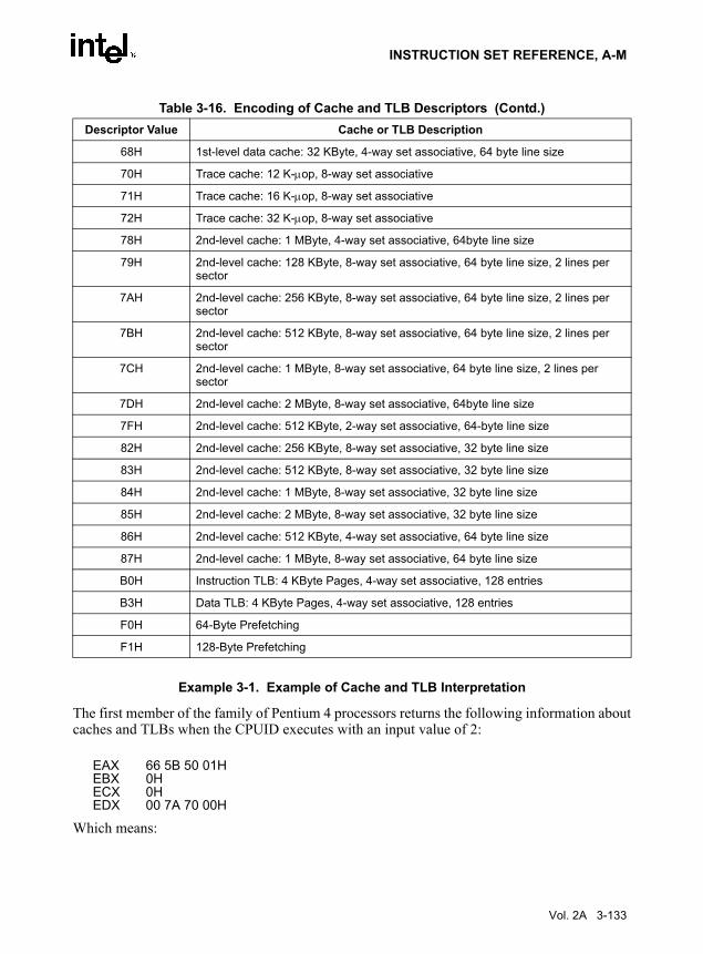
INSTRUCTION SET REFERENCE, A-M
Example 3-1. Example of Cache and TLB Interpretation
The first member of the family of Pentium 4 processors returns the following information aboutcaches and TLBs when the CPUID executes with an input value of 2:
EAX 66 5B 50 01HEBX 0HECX 0HEDX 00 7A 70 00H
Which means:
68H 1st-level data cache: 32 KByte, 4-way set associative, 64 byte line size
70H Trace cache: 12 K-µop, 8-way set associative
71H Trace cache: 16 K-µop, 8-way set associative
72H Trace cache: 32 K-µop, 8-way set associative
78H 2nd-level cache: 1 MByte, 4-way set associative, 64byte line size
79H 2nd-level cache: 128 KByte, 8-way set associative, 64 byte line size, 2 lines per sector
7AH 2nd-level cache: 256 KByte, 8-way set associative, 64 byte line size, 2 lines per sector
7BH 2nd-level cache: 512 KByte, 8-way set associative, 64 byte line size, 2 lines per sector
7CH 2nd-level cache: 1 MByte, 8-way set associative, 64 byte line size, 2 lines per sector
7DH 2nd-level cache: 2 MByte, 8-way set associative, 64byte line size
7FH 2nd-level cache: 512 KByte, 2-way set associative, 64-byte line size
82H 2nd-level cache: 256 KByte, 8-way set associative, 32 byte line size
83H 2nd-level cache: 512 KByte, 8-way set associative, 32 byte line size
84H 2nd-level cache: 1 MByte, 8-way set associative, 32 byte line size
85H 2nd-level cache: 2 MByte, 8-way set associative, 32 byte line size
86H 2nd-level cache: 512 KByte, 4-way set associative, 64 byte line size
87H 2nd-level cache: 1 MByte, 8-way set associative, 64 byte line size
B0H Instruction TLB: 4 KByte Pages, 4-way set associative, 128 entries
B3H Data TLB: 4 KByte Pages, 4-way set associative, 128 entries
F0H 64-Byte Prefetching
F1H 128-Byte Prefetching
Table 3-16. Encoding of Cache and TLB Descriptors (Contd.)Descriptor Value Cache or TLB Description
Vol. 2A 3-133

INSTRUCTION SET REFERENCE, A-M
• The least-significant byte (byte 0) of register EAX is set to 01H. This indicates that CPUIDneeds to be executed once with an input value of 2 to retrieve complete information aboutcaches and TLBs.
• The most-significant bit of all four registers (EAX, EBX, ECX, and EDX) is set to 0,indicating that each register contains valid 1-byte descriptors.
• Bytes 1, 2, and 3 of register EAX indicate that the processor has:
— 50H - a 64-entry instruction TLB, for mapping 4-KByte and 2-MByte or 4-MBytepages.
— 5BH - a 64-entry data TLB, for mapping 4-KByte and 4-MByte pages.
— 66H - an 8-KByte 1st level data cache, 4-way set associative, with a 64-Byte cacheline size.
• The descriptors in registers EBX and ECX are valid, but contain NULL descriptors.
• Bytes 0, 1, 2, and 3 of register EDX indicate that the processor has:
— 00H - NULL descriptor.
— 70H - a 12-KByte 1st level code cache, 4-way set associative, with a 64-byte cacheline size.
— 7AH - a 256-KByte 2nd level cache, 8-way set associative, with a sectored, 64-bytecache line size.
— 00H - NULL descriptor.
METHODS FOR RETURNING BRANDING INFORMATIONUse the following techniques to access branding information:
1. Processor brand string method; this method also returns the processor’s maximumoperating frequency
2. Processor brand index; this method uses a software supplied brand string table.
These two methods are discussed in the following sections. For methods that are available inearly processors, see Section: “Identification of Earlier IA-32 Processors” in Chapter 14 of theIA-32 Intel Architecture Software Developer’s Manual, Volume 1.
The Processor Brand String MethodFigure 3-8 describes the algorithm used for detection of the brand string. Processor brand iden-tification software should execute this algorithm on all IA-32 architecture compatible proces-sors.
This method (introduced with Pentium 4 processors) returns an ASCII brand identificationstring and the maximum operating frequency of the processor to the EAX, EBX, ECX, and EDXregisters.
3-134 Vol. 2A

INSTRUCTION SET REFERENCE, A-M
How Brand Strings WorkTo use the brand string method, execute CPUID with EAX input of 8000002H through80000004H. For each input value, CPUID returns 16 ASCII characters using EAX, EBX, ECX,and EDX. The returned string will be NULL terminated.
Table 3-17 shows the brand string that is returned by the first processor in the Pentium 4processor family.
Figure 3-8. Determination of Support for the Processor Brand String
Table 3-17. Processor Brand String Returned with Pentium 4 ProcessorEAX Input Value Return Values ASCII Equivalent
80000002H EAX = 20202020HEBX = 20202020HECX = 20202020HEDX = 6E492020H
“ ” “ ”“ ”“nI ”
OM15194
IF (EAX & 0x80000000)
CPUID
IF (EAX Return Value>= 0x80000004)
CPUIDFunction
Supported
True =>Extended
EAX Return Value =Max. Extended CPUID
Function Index
Input: EAX=1
Processor BrandString NotSupported
False
Processor BrandString Supported
True
Vol. 2A 3-135

INSTRUCTION SET REFERENCE, A-M
Extracting the Maximum Processor Frequency from Brand StringsFigure 3-9 provides an algorithm which software can use to extract the maximum processoroperating frequency from the processor brand string.
NOTEWhen a frequency is given in a brand string, it is the maximum qualifiedfrequency of the processor, not the frequency at which the processor iscurrently running.
80000003H EAX = 286C6574HEBX = 50202952HECX = 69746E65HEDX = 52286D75H
“(let”“P )R”“itne”“R(mu”
80000004H EAX = 20342029HEBX = 20555043HECX = 30303531HEDX = 007A484DH
“ 4 )”“ UPC”“0051”“\0zHM”
Table 3-17. Processor Brand String Returned with Pentium 4 Processor
3-136 Vol. 2A

INSTRUCTION SET REFERENCE, A-M
The Processor Brand Index MethodThe brand index method (introduced with Pentium III Xeon processors) provides an entry pointinto a brand identification table that is maintained in memory by system software and is acces-sible from system- and user-level code. In this table, each brand index is associate with an ASCIIbrand identification string that identifies the official Intel family and model number of aprocessor.
When CPUID executes with EAX set to 1, the processor returns a brand index to the low bytein EBX. Software can then use this index to locate the brand identification string for theprocessor in the brand identification table. The first entry (brand index 0) in this table is
Figure 3-9. Algorithm for Extracting Maximum Processor Frequency
OM15195
IF Substring Matched
"zHM", or"zHG", or
"zHT"
Determine "Freq"and "Multiplier"
True
Determine "Multiplier"
Scan "Brand String" inReverse Byte Order
Report ErrorFalse
Scan DigitsUntil Blank
MatchSubstring
Determine "Freq" Reverse DigitsTo Decimal Value
Max. QualifiedFrequency =
"Freq" x "Multiplier" "Freq" = XY.Z ifDigits = "Z.YX"
In Reverse Order
If "zHM"
If "zHG"
If "zHT"Multiplier = 1 x 10¹²
Multiplier = 1 x 10⁹
Multiplier = 1 x 10⁶
Vol. 2A 3-137
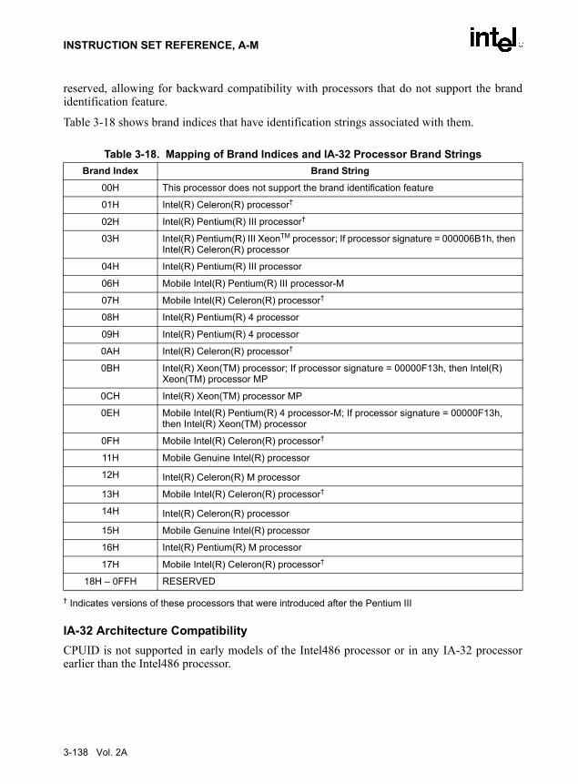
INSTRUCTION SET REFERENCE, A-M
reserved, allowing for backward compatibility with processors that do not support the brandidentification feature.
Table 3-18 shows brand indices that have identification strings associated with them.
† Indicates versions of these processors that were introduced after the Pentium III
IA-32 Architecture CompatibilityCPUID is not supported in early models of the Intel486 processor or in any IA-32 processorearlier than the Intel486 processor.
Table 3-18. Mapping of Brand Indices and IA-32 Processor Brand Strings Brand Index Brand String
00H This processor does not support the brand identification feature
01H Intel(R) Celeron(R) processor†
02H Intel(R) Pentium(R) III processor†
03H Intel(R) Pentium(R) III XeonTM processor; If processor signature = 000006B1h, then Intel(R) Celeron(R) processor
04H Intel(R) Pentium(R) III processor
06H Mobile Intel(R) Pentium(R) III processor-M
07H Mobile Intel(R) Celeron(R) processor†
08H Intel(R) Pentium(R) 4 processor
09H Intel(R) Pentium(R) 4 processor
0AH Intel(R) Celeron(R) processor†
0BH Intel(R) Xeon(TM) processor; If processor signature = 00000F13h, then Intel(R) Xeon(TM) processor MP
0CH Intel(R) Xeon(TM) processor MP
0EH Mobile Intel(R) Pentium(R) 4 processor-M; If processor signature = 00000F13h, then Intel(R) Xeon(TM) processor
0FH Mobile Intel(R) Celeron(R) processor†
11H Mobile Genuine Intel(R) processor
12H Intel(R) Celeron(R) M processor
13H Mobile Intel(R) Celeron(R) processor†
14H Intel(R) Celeron(R) processor
15H Mobile Genuine Intel(R) processor
16H Intel(R) Pentium(R) M processor
17H Mobile Intel(R) Celeron(R) processor†
18H – 0FFH RESERVED
3-138 Vol. 2A

INSTRUCTION SET REFERENCE, A-M
OperationIA32_BIOS_SIGN_ID MSR ← Update with installed microcode revision number.CASE (EAX) OF
EAX = 0:EAX ← highest basic function input value understood by CPUID;EBX ← Vendor identification string;EDX ← Vendor identification string;ECX ← Vendor identification string;
BREAK;EAX = 1H:
EAX[3:0] ← Stepping ID; EAX[7:4] ← Model; EAX[11:8] ← Family; EAX[13:12] ← Processor type; EAX[15:14] ← Reserved;EAX[19:16] ← Extended Model;EAX[23:20] ← Extended Family;EAX[31:24] ← Reserved;EBX[7:0] ← Brand Index;EBX[15:8] ← CLFLUSH Line Size;EBX[16:23] ← Reserved;EBX[24:31] ← Initial APIC ID;ECX ← Feature flags; (* See Figure 3-6 *)EDX ← Feature flags; (* See Figure 3-7 *)
BREAK;EAX = 2H:
EAX ← Cache and TLB information; EBX ← Cache and TLB information; ECX ← Cache and TLB information;
EDX ← Cache and TLB information; BREAK;EAX = 3H:
EAX ← Reserved; EBX ← Reserved; ECX ← ProcessorSerialNumber[31:0];
(* Pentium III processors only, otherwise reserved *)EDX ← ProcessorSerialNumber[63:32]; (* Pentium III processors only, otherwise reserved *
BREAKEAX = 4H:
EAX ← Deterministic Cache Parameters Leaf; /* see page 3-121 */EBX ← Deterministic Cache Parameters Leaf;
ECX ← Deterministic Cache Parameters Leaf; EDX ← Deterministic Cache Parameters Leaf;
BREAK;EAX = 5H:
EAX ← MONITOR/MWAIT Leaf; /* see page 3-122 */
Vol. 2A 3-139
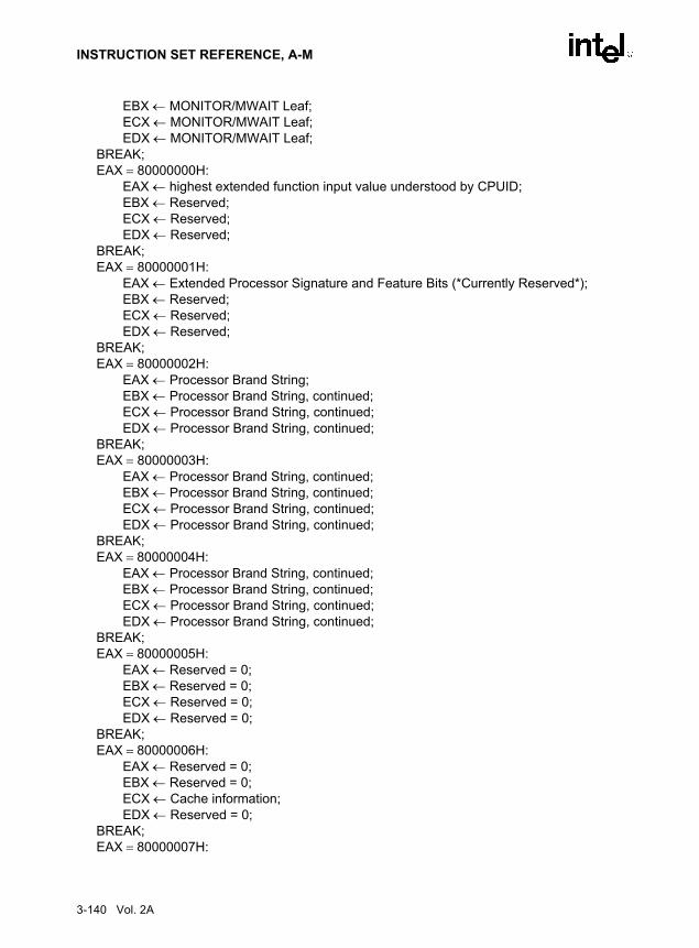
INSTRUCTION SET REFERENCE, A-M
EBX ← MONITOR/MWAIT Leaf; ECX ← MONITOR/MWAIT Leaf;
EDX ← MONITOR/MWAIT Leaf; BREAK;EAX = 80000000H:
EAX ← highest extended function input value understood by CPUID;EBX ← Reserved; ECX ← Reserved; EDX ← Reserved;
BREAK;EAX = 80000001H:
EAX ← Extended Processor Signature and Feature Bits (*Currently Reserved*); EBX ← Reserved; ECX ← Reserved; EDX ← Reserved;
BREAK;EAX = 80000002H:
EAX ← Processor Brand String; EBX ← Processor Brand String, continued;ECX ← Processor Brand String, continued; EDX ← Processor Brand String, continued;
BREAK;EAX = 80000003H:
EAX ← Processor Brand String, continued; EBX ← Processor Brand String, continued; ECX ← Processor Brand String, continued; EDX ← Processor Brand String, continued;
BREAK;EAX = 80000004H:
EAX ← Processor Brand String, continued; EBX ← Processor Brand String, continued; ECX ← Processor Brand String, continued; EDX ← Processor Brand String, continued;
BREAK;EAX = 80000005H:
EAX ← Reserved = 0; EBX ← Reserved = 0; ECX ← Reserved = 0; EDX ← Reserved = 0;
BREAK;EAX = 80000006H:
EAX ← Reserved = 0; EBX ← Reserved = 0; ECX ← Cache information; EDX ← Reserved = 0;
BREAK;EAX = 80000007H:
3-140 Vol. 2A

INSTRUCTION SET REFERENCE, A-M
EAX ← Reserved = 0; EBX ← Reserved = 0; ECX ← Reserved = 0; EDX ← Reserved = 0;
BREAK;EAX = 80000008H:
EAX ← Reserved = 0; EBX ← Reserved = 0; ECX ← Reserved = 0; EDX ← Reserved = 0;
BREAK;DEFAULT: (* EAX > highest value recognized by CPUID *)
EAX ← Reserved; (* undefined*) EBX ← Reserved; (* undefined*) ECX ← Reserved; (* undefined*)EDX ← Reserved; (* undefined*)
BREAK;ESAC;
Flags AffectedNone.
Exceptions (All Operating Modes)None.
NOTEIn earlier IA-32 processors that do not support the CPUID instruction,execution of the instruction results in an invalid opcode (#UD) exceptionbeing generated.
Vol. 2A 3-141

INSTRUCTION SET REFERENCE, A-M
CVTDQ2PD—Convert Packed Doubleword Integers to Packed Double-Precision Floating-Point Values
DescriptionConverts two packed signed doubleword integers in the source operand (second operand) to twopacked double-precision floating-point values in the destination operand (first operand). Thesource operand can be an XMM register or a 64-bit memory location. The destination operandis an XMM register. When the source operand is an XMM register, the packed integers arelocated in the low quadword of the register.
OperationDEST[63-0] ← Convert_Integer_To_Double_Precision_Floating_Point(SRC[31-0]);DEST[127-64] ← Convert_Integer_To_Double_Precision_Floating_Point(SRC[63-32]);
Intel C/C++ Compiler Intrinsic EquivalentCVTDQ2PD __m128d _mm_cvtepi32_pd(__m128di a)
SIMD Floating-Point Exceptions
None.
Protected Mode Exceptions
#GP(0) For an illegal memory operand effective address in the CS, DS, ES, FS or GS segments.
#SS(0) For an illegal address in the SS segment.
#PF(fault-code) For a page fault.
#NM If TS in CR0 is set.
#UD If EM in CR0 is set.
If OSFXSR in CR4 is 0.
If CPUID feature flag SSE2 is 0.
#AC(0) If alignment checking is enabled and an unaligned memory reference is made while the current privilege level is 3.
Opcode Instruction DescriptionF3 0F E6 CVTDQ2PD xmm1, xmm2/m64 Convert two packed signed doubleword integers from
xmm2/m128 to two packed double-precision floating-point values in xmm1.
3-142 Vol. 2A

INSTRUCTION SET REFERENCE, A-M
Real-Address Mode Exceptions
GP(0) If any part of the operand lies outside the effective address space from 0 to FFFFH.
#NM If TS in CR0 is set.
#UD If EM in CR0 is set.
If OSFXSR in CR4 is 0.
If CPUID feature flag SSE2 is 0.
Virtual-8086 Mode Exceptions
Same exceptions as in Real Address Mode
#PF(fault-code) For a page fault.
#AC(0) If alignment checking is enabled and an unaligned memory reference is made.
Vol. 2A 3-143

INSTRUCTION SET REFERENCE, A-M
CVTDQ2PS—Convert Packed Doubleword Integers to Packed Single-Precision Floating-Point Values
DescriptionConverts four packed signed doubleword integers in the source operand (second operand) tofour packed single-precision floating-point values in the destination operand (first operand). Thesource operand can be an XMM register or a 128-bit memory location. The destination operandis an XMM register. When a conversion is inexact, rounding is performed according to therounding control bits in the MXCSR register.
OperationDEST[31-0] ← Convert_Integer_To_Single_Precision_Floating_Point(SRC[31-0]);DEST[63-32] ← Convert_Integer_To_Single_Precision_Floating_Point(SRC[63-32]);DEST[95-64] ← Convert_Integer_To_Single_Precision_Floating_Point(SRC[95-64]);DEST[127-96] ← Convert_Integer_To_Single_Precision_Floating_Point(SRC[127-96]);
Intel C/C++ Compiler Intrinsic EquivalentCVTDQ2PS __m128d _mm_cvtepi32_ps(__m128di a)
SIMD Floating-Point Exceptions
Precision.
Protected Mode Exceptions
#GP(0) For an illegal memory operand effective address in the CS, DS, ES, FS or GS segments.
If a memory operand is not aligned on a 16-byte boundary, regardless of segment.
#SS(0) For an illegal address in the SS segment.
#PF(fault-code) For a page fault.
#NM If TS in CR0 is set.
#XM If an unmasked SIMD floating-point exception and OSXMMEXCPT in CR4 is 1.
#UD If an unmasked SIMD floating-point exception and OSXMMEXCPT in CR4 is 0.
Opcode Instruction Description0F 5B /r CVTDQ2PS xmm1, xmm2/m128 Convert four packed signed doubleword integers
from xmm2/m128 to four packed single-precision floating-point values in xmm1.
3-144 Vol. 2A

INSTRUCTION SET REFERENCE, A-M
If EM in CR0 is set.
If OSFXSR in CR4 is 0.
If CPUID feature flag SSE2 is 0.
Real-Address Mode Exceptions
#GP(0) If a memory operand is not aligned on a 16-byte boundary, regardless of segment.
If any part of the operand lies outside the effective address space from 0 to FFFFH.
#NM If TS in CR0 is set.
#XM If an unmasked SIMD floating-point exception and OSXMMEXCPT in CR4 is 1.
#UD If an unmasked SIMD floating-point exception and OSXMMEXCPT in CR4 is 0.
If EM in CR0 is set.
If OSFXSR in CR4 is 0.
If CPUID feature flag SSE2 is 0.
Virtual-8086 Mode Exceptions
Same exceptions as in Real Address Mode
#PF(fault-code) For a page fault.
Vol. 2A 3-145

INSTRUCTION SET REFERENCE, A-M
CVTPD2DQ—Convert Packed Double-Precision Floating-Point Values to Packed Doubleword Integers
Converts two packed double-precision floating-point values in the source operand (secondoperand) to two packed signed doubleword integers in the destination operand (first operand).The source operand can be an XMM register or a 128-bit memory location. The destinationoperand is an XMM register. The result is stored in the low quadword of the destination operandand the high quadword is cleared to all 0s.
When a conversion is inexact, the value returned is rounded according to the rounding controlbits in the MXCSR register. If a converted result is larger than the maximum signed doublewordinteger, the floating-point invalid exception is raised, and if this exception is masked, the indef-inite integer value (80000000H) is returned.
OperationDEST[31-0] ← Convert_Double_Precision_Floating_Point_To_Integer(SRC[63-0]);DEST[63-32] ← Convert_Double_Precision_Floating_Point_To_Integer(SRC[127-64]);DEST[127-64] ← 0000000000000000H;
Intel C/C++ Compiler Intrinsic EquivalentCVTPD2DQ __m128d _mm_cvtpd_epi32(__m128d a)
SIMD Floating-Point Exceptions
Invalid, Precision.
Protected Mode Exceptions
#GP(0) For an illegal memory operand effective address in the CS, DS, ES, FS or GS segments.segments.
If a memory operand is not aligned on a 16-byte boundary, regardless of segment.
#SS(0) For an illegal address in the SS segment.
#PF(fault-code) For a page fault.
#NM If TS in CR0 is set.
#XM If an unmasked SIMD floating-point exception and OSXMMEXCPT in CR4 is 1.
Opcode Instruction DescriptionF2 0F E6 CVTPD2DQ xmm1, xmm2/m128 Convert two packed double-precision floating-point
values from xmm2/m128 to two packed signed doubleword integers in xmm1.
3-146 Vol. 2A

INSTRUCTION SET REFERENCE, A-M
#UD If an unmasked SIMD floating-point exception and OSXMMEXCPT in CR4 is 0.
If EM in CR0 is set.
If OSFXSR in CR4 is 0.
If CPUID feature flag SSE2 is 0.
Real-Address Mode Exceptions
#GP(0) If a memory operand is not aligned on a 16-byte boundary, regardless of segment.
If any part of the operand lies outside the effective address space from 0 to FFFFH.
#NM If TS in CR0 is set.
#XM If an unmasked SIMD floating-point exception and OSXMMEXCPT in CR4 is 1.
#UD If an unmasked SIMD floating-point exception and OSXMMEXCPT in CR4 is 0.
If EM in CR0 is set.
If OSFXSR in CR4 is 0.
If CPUID feature flag SSE2 is 0.
Virtual-8086 Mode Exceptions
Same exceptions as in Real Address Mode
#PF(fault-code) For a page fault.
Vol. 2A 3-147

INSTRUCTION SET REFERENCE, A-M
CVTPD2PI—Convert Packed Double-Precision Floating-Point Values to Packed Doubleword Integers
DescriptionConverts two packed double-precision floating-point values in the source operand (secondoperand) to two packed signed doubleword integers in the destination operand (first operand).The source operand can be an XMM register or a 128-bit memory location. The destinationoperand is an MMX technology register.
When a conversion is inexact, the value returned is rounded according to the rounding controlbits in the MXCSR register. If a converted result is larger than the maximum signed doublewordinteger, the floating-point invalid exception is raised, and if this exception is masked, the indef-inite integer value (80000000H) is returned.
This instruction causes a transition from x87 FPU to MMX technology operation (that is, thex87 FPU top-of-stack pointer is set to 0 and the x87 FPU tag word is set to all 0s [valid]). If thisinstruction is executed while an x87 FPU floating-point exception is pending, the exception ishandled before the CVTPD2PI instruction is executed.
OperationDEST[31-0] ← Convert_Double_Precision_Floating_Point_To_Integer(SRC[63-0]);DEST[63-32] ← Convert_Double_Precision_Floating_Point_To_Integer(SRC[127-64]);
Intel C/C++ Compiler Intrinsic EquivalentCVTPD1PI __m64 _mm_cvtpd_pi32(__m128d a)
SIMD Floating-Point Exceptions
Invalid, Precision.
Protected Mode Exceptions
#GP(0) For an illegal memory operand effective address in the CS, DS, ES, FS or GS segments.
If a memory operand is not aligned on a 16-byte boundary, regardless of segment.
#SS(0) For an illegal address in the SS segment.
#PF(fault-code) For a page fault.
Opcode Instruction Description66 0F 2D /r CVTPD2PI mm, xmm/m128 Convert two packed double-precision floating-point
values from xmm/m128 to two packed signed doubleword integers in mm.
3-148 Vol. 2A

INSTRUCTION SET REFERENCE, A-M
#MF If there is a pending x87 FPU exception.
#NM If TS in CR0 is set.
#XM If an unmasked SIMD floating-point exception and OSXMMEXCPT in CR4 is 1.
#UD If an unmasked SIMD floating-point exception and OSXMMEXCPT in CR4 is 0.
If EM in CR0 is set.
If OSFXSR in CR4 is 0.
If CPUID feature flag SSE2 is 0.
Real-Address Mode Exceptions
#GP(0) If a memory operand is not aligned on a 16-byte boundary, regardless of segment.
If any part of the operand lies outside the effective address space from 0 to FFFFH.
#NM If TS in CR0 is set.
#MF If there is a pending x87 FPU exception.
#XM If an unmasked SIMD floating-point exception and OSXMMEXCPT in CR4 is 1.
#UD If an unmasked SIMD floating-point exception and OSXMMEXCPT in CR4 is 0.
If EM in CR0 is set.
If OSFXSR in CR4 is 0.
If CPUID feature flag SSE2 is 0.
Virtual-8086 Mode Exceptions
Same exceptions as in Real Address Mode
#PF(fault-code) For a page fault.
Vol. 2A 3-149

INSTRUCTION SET REFERENCE, A-M
CVTPD2PS—Convert Packed Double-Precision Floating-Point Values to Packed Single-Precision Floating-Point Values
DescriptionConverts two packed double-precision floating-point values in the source operand (secondoperand) to two packed single-precision floating-point values in the destination operand (firstoperand). The source operand can be an XMM register or a 128-bit memory location. The desti-nation operand is an XMM register. The result is stored in the low quadword of the destinationoperand, and the high quadword is cleared to all 0s. When a conversion is inexact, the valuereturned is rounded according to the rounding control bits in the MXCSR register.
OperationDEST[31-0] ← Convert_Double_Precision_To_Single_Precision_Floating_Point(SRC[63-0]);DEST[63-32] ← Convert_Double_Precision_To_Single_Precision_
Floating_Point(SRC[127-64]);DEST[127-64] ← 0000000000000000H;
Intel C/C++ Compiler Intrinsic EquivalentCVTPD2PS __m128d _mm_cvtpd_ps(__m128d a)
SIMD Floating-Point Exceptions
Overflow, Underflow, Invalid, Precision, Denormal.
Protected Mode Exceptions
#GP(0) For an illegal memory operand effective address in the CS, DS, ES, FS or GS segments.
If a memory operand is not aligned on a 16-byte boundary, regardless of segment.
#SS(0) For an illegal address in the SS segment.
#PF(fault-code) For a page fault.
#NM If TS in CR0 is set.
#XM If an unmasked SIMD floating-point exception and OSXMMEXCPT in CR4 is 1.
Opcode Instruction Description66 0F 5A /r CVTPD2PS xmm1, xmm2/m128 Convert two packed double-precision floating-point
values in xmm2/m128 to two packed single-precision floating-point values in xmm1.
3-150 Vol. 2A

INSTRUCTION SET REFERENCE, A-M
#UD If an unmasked SIMD floating-point exception and OSXMMEXCPT in CR4 is 0.
If EM in CR0 is set.
If OSFXSR in CR4 is 0.
If CPUID feature flag SSE2 is 0.
Real-Address Mode Exceptions
#GP(0) If a memory operand is not aligned on a 16-byte boundary, regardless of segment.
If any part of the operand lies outside the effective address space from 0 to FFFFH.
#NM If TS in CR0 is set.
#XM If an unmasked SIMD floating-point exception and OSXMMEXCPT in CR4 is 1.
#UD If an unmasked SIMD floating-point exception and OSXMMEXCPT in CR4 is 0.
If EM in CR0 is set.
If OSFXSR in CR4 is 0.
If CPUID feature flag SSE2 is 0.
Virtual-8086 Mode Exceptions
Same exceptions as in Real Address Mode
#PF(fault-code) For a page fault.
Vol. 2A 3-151
INSTRUCTION SET REFERENCE, A-M
CVTPI2PD—Convert Packed Doubleword Integers to Packed Double-Precision Floating-Point Values
DescriptionConverts two packed signed doubleword integers in the source operand (second operand) to twopacked double-precision floating-point values in the destination operand (first operand). Thesource operand can be an MMX technology register or a 64-bit memory location. The destina-tion operand is an XMM register.
This instruction causes a transition from x87 FPU to MMX technology operation (that is, thex87 FPU top-of-stack pointer is set to 0 and the x87 FPU tag word is set to all 0s [valid]). If thisinstruction is executed while an x87 FPU floating-point exception is pending, the exception ishandled before the CVTPI2PD instruction is executed.
OperationDEST[63-0] ← Convert_Integer_To_Double_Precision_Floating_Point(SRC[31-0]);DEST[127-64] ← Convert_Integer_To_Double_Precision_Floating_Point(SRC[63-32]);
Intel C/C++ Compiler Intrinsic EquivalentCVTPI2PD __m128d _mm_cvtpi32_pd(__m64 a)
SIMD Floating-Point Exceptions
None.
Protected Mode Exceptions
#GP(0) For an illegal memory operand effective address in the CS, DS, ES, FS or GS segments.
#SS(0) For an illegal address in the SS segment.
#PF(fault-code) For a page fault.
#NM If TS in CR0 is set.
#MF If there is a pending x87 FPU exception.
#UD If EM in CR0 is set.
If OSFXSR in CR4 is 0.
If CPUID feature flag SSE2 is 0.
Opcode Instruction Description66 0F 2A /r CVTPI2PD xmm, mm/m64 Convert two packed signed doubleword integers from
mm/mem64 to two packed double-precision floating-point values in xmm.
3-152 Vol. 2A

INSTRUCTION SET REFERENCE, A-M
#AC(0) If alignment checking is enabled and an unaligned memory reference is made while the current privilege level is 3.
Real-Address Mode Exceptions
GP(0) If any part of the operand lies outside the effective address space from 0 to FFFFH.
#NM If TS in CR0 is set.
#MF If there is a pending x87 FPU exception.
#UD If EM in CR0 is set.
If OSFXSR in CR4 is 0.
If CPUID feature flag SSE2 is 0.
Virtual-8086 Mode Exceptions
Same exceptions as in Real Address Mode
#PF(fault-code) For a page fault.
#AC(0) If alignment checking is enabled and an unaligned memory reference is made.
Vol. 2A 3-153

INSTRUCTION SET REFERENCE, A-M
CVTPI2PS—Convert Packed Doubleword Integers to Packed Single-Precision Floating-Point Values
DescriptionConverts two packed signed doubleword integers in the source operand (second operand) to twopacked single-precision floating-point values in the destination operand (first operand). Thesource operand can be an MMX technology register or a 64-bit memory location. The destina-tion operand is an XMM register. The results are stored in the low quadword of the destinationoperand, and the high quadword remains unchanged. When a conversion is inexact, the valuereturned is rounded according to the rounding control bits in the MXCSR register.
This instruction causes a transition from x87 FPU to MMX technology operation (that is, thex87 FPU top-of-stack pointer is set to 0 and the x87 FPU tag word is set to all 0s [valid]). If thisinstruction is executed while an x87 FPU floating-point exception is pending, the exception ishandled before the CVTPI2PS instruction is executed.
OperationDEST[31-0] ← Convert_Integer_To_Single_Precision_Floating_Point(SRC[31-0]);DEST[63-32] ← Convert_Integer_To_Single_Precision_Floating_Point(SRC[63-32]);* high quadword of destination remains unchanged *;
Intel C/C++ Compiler Intrinsic EquivalentCVTPI2PS __m128 _mm_cvtpi32_ps(__m128 a, __m64 b)
SIMD Floating-Point Exceptions
Precision.
Protected Mode Exceptions
#GP(0) For an illegal memory operand effective address in the CS, DS, ES, FS or GS segments.
#SS(0) For an illegal address in the SS segment.
#PF(fault-code) For a page fault.
#NM If TS in CR0 is set.
#MF If there is a pending x87 FPU exception.
#XM If an unmasked SIMD floating-point exception and OSXMMEXCPT in CR4 is 1.
Opcode Instruction Description0F 2A /r CVTPI2PS xmm, mm/m64 Convert two signed doubleword integers from mm/m64 to two
single-precision floating-point values in xmm.
3-154 Vol. 2A

INSTRUCTION SET REFERENCE, A-M
#UD If an unmasked SIMD floating-point exception and OSXMMEXCPT in CR4 is 0.
If EM in CR0 is set.
If OSFXSR in CR4 is 0.
If CPUID feature flag SSE is 0.
#AC(0) If alignment checking is enabled and an unaligned memory reference is made while the current privilege level is 3.
Real-Address Mode Exceptions
GP(0) If any part of the operand lies outside the effective address space from 0 to FFFFH.
#NM If TS in CR0 is set.
#MF If there is a pending x87 FPU exception.
#XM If an unmasked SIMD floating-point exception and OSXMMEXCPT in CR4 is 1.
#UD If an unmasked SIMD floating-point exception and OSXMMEXCPT in CR4 is 0.
If EM in CR0 is set.
If OSFXSR in CR4 is 0.
If CPUID feature flag SSE is 0.
Virtual-8086 Mode Exceptions
Same exceptions as in Real Address Mode
#PF(fault-code) For a page fault.
#AC(0) If alignment checking is enabled and an unaligned memory reference is made.
Vol. 2A 3-155

INSTRUCTION SET REFERENCE, A-M
CVTPS2DQ—Convert Packed Single-Precision Floating-Point Values to Packed Doubleword Integers
DescriptionConverts four packed single-precision floating-point values in the source operand (secondoperand) to four packed signed doubleword integers in the destination operand (first operand).The source operand can be an XMM register or a 128-bit memory location. The destinationoperand is an XMM register.
When a conversion is inexact, the value returned is rounded according to the rounding controlbits in the MXCSR register. If a converted result is larger than the maximum signed doublewordinteger, the floating-point invalid exception is raised, and if this exception is masked, the indef-inite integer value (80000000H) is returned.
OperationDEST[31-0] ← Convert_Single_Precision_Floating_Point_To_Integer(SRC[31-0]);DEST[63-32] ← Convert_Single_Precision_Floating_Point_To_Integer(SRC[63-32]);DEST[95-64] ← Convert_Single_Precision_Floating_Point_To_Integer(SRC[95-64]);DEST[127-96] ← Convert_Single_Precision_Floating_Point_To_Integer(SRC[127-96]);
Intel C/C++ Compiler Intrinsic Equivalent__m128d _mm_cvtps_epi32(__m128d a)
SIMD Floating-Point Exceptions
Invalid, Precision.
Protected Mode Exceptions
#GP(0) For an illegal memory operand effective address in the CS, DS, ES, FS or GS segments.
If a memory operand is not aligned on a 16-byte boundary, regardless of segment.
#SS(0) For an illegal address in the SS segment.
#PF(fault-code) For a page fault.
#NM If TS in CR0 is set.
Opcode Instruction Description66 0F 5B /r CVTPS2DQ xmm1, xmm2/m128 Convert four packed single-precision floating-
point values from xmm2/m128 to four packed signed doubleword integers in xmm1.
3-156 Vol. 2A

INSTRUCTION SET REFERENCE, A-M
#XM If an unmasked SIMD floating-point exception and OSXMMEXCPT in CR4 is 1.
#UD If an unmasked SIMD floating-point exception and OSXMMEXCPT in CR4 is 0.
If EM in CR0 is set.
If OSFXSR in CR4 is 0.
If CPUID feature flag SSE2 is 0.
Real-Address Mode Exceptions
#GP(0) If a memory operand is not aligned on a 16-byte boundary, regardless of segment.
If any part of the operand lies outside the effective address space from 0 to FFFFH.
#NM If TS in CR0 is set.
#XM If an unmasked SIMD floating-point exception and OSXMMEXCPT in CR4 is 1.
#UD If an unmasked SIMD floating-point exception and OSXMMEXCPT in CR4 is 0.
If EM in CR0 is set.
If OSFXSR in CR4 is 0.
If CPUID feature flag SSE2 is 0.
Virtual-8086 Mode Exceptions
Same exceptions as in Real Address Mode
#PF(fault-code) For a page fault.
Vol. 2A 3-157

INSTRUCTION SET REFERENCE, A-M
CVTPS2PD—Convert Packed Single-Precision Floating-Point Values to Packed Double-Precision Floating-Point Values
DescriptionConverts two packed single-precision floating-point values in the source operand (secondoperand) to two packed double-precision floating-point values in the destination operand (firstoperand). The source operand can be an XMM register or a 64-bit memory location. The desti-nation operand is an XMM register. When the source operand is an XMM register, the packedsingle-precision floating-point values are contained in the low quadword of the register.
OperationDEST[63-0] ← Convert_Single_Precision_To_Double_Precision_Floating_Point(SRC[31-0]);DEST[127-64] ← Convert_Single_Precision_To_Double_Precision_
Floating_Point(SRC[63-32]);
Intel C/C++ Compiler Intrinsic EquivalentCVTPS2PD __m128d _mm_cvtps_pd(__m128 a)
SIMD Floating-Point Exceptions
Invalid, Denormal.
Protected Mode Exceptions
#GP(0) For an illegal memory operand effective address in the CS, DS, ES, FS or GS segments.
#SS(0) For an illegal address in the SS segment.
#PF(fault-code) For a page fault.
#NM If TS in CR0 is set.
#XM If an unmasked SIMD floating-point exception and OSXMMEXCPT in CR4 is 1.
#UD If an unmasked SIMD floating-point exception and OSXMMEXCPT in CR4 is 0.
If EM in CR0 is set.
Opcode Instruction Description0F 5A /r CVTPS2PD xmm1, xmm2/m64 Convert two packed single-precision floating-point
values in xmm2/m64 to two packed double-precision floating-point values in xmm1.
3-158 Vol. 2A

INSTRUCTION SET REFERENCE, A-M
If OSFXSR in CR4 is 0.
If CPUID feature flag SSE2 is 0.
#AC(0) If alignment checking is enabled and an unaligned memory reference is made while the current privilege level is 3.
Real-Address Mode Exceptions
GP(0) If any part of the operand lies outside the effective address space from 0 to FFFFH.
#NM If TS in CR0 is set.
#XM If an unmasked SIMD floating-point exception and OSXMMEXCPT in CR4 is 1.
#UD If an unmasked SIMD floating-point exception and OSXMMEXCPT in CR4 is 0.
If EM in CR0 is set.
If OSFXSR in CR4 is 0.
If CPUID feature flag SSE2 is 0.
Virtual-8086 Mode Exceptions
Same exceptions as in Real Address Mode
#PF(fault-code) For a page fault.
#AC(0) If alignment checking is enabled and an unaligned memory reference is made.
Vol. 2A 3-159
INSTRUCTION SET REFERENCE, A-M
CVTPS2PI—Convert Packed Single-Precision Floating-Point Values to Packed Doubleword Integers
DescriptionConverts two packed single-precision floating-point values in the source operand (secondoperand) to two packed signed doubleword integers in the destination operand (first operand).The source operand can be an XMM register or a 128-bit memory location. The destinationoperand is an MMX technology register. When the source operand is an XMM register, the twosingle-precision floating-point values are contained in the low quadword of the register.
When a conversion is inexact, the value returned is rounded according to the rounding controlbits in the MXCSR register. If a converted result is larger than the maximum signed doublewordinteger, the floating-point invalid exception is raised, and if this exception is masked, the indef-inite integer value (80000000H) is returned.
This instruction causes a transition from x87 FPU to MMX technology operation (that is, thex87 FPU top-of-stack pointer is set to 0 and the x87 FPU tag word is set to all 0s [valid]). If thisinstruction is executed while an x87 FPU floating-point exception is pending, the exception ishandled before the CVTPS2PI instruction is executed.
OperationDEST[31-0] ← Convert_Single_Precision_Floating_Point_To_Integer(SRC[31-0]);DEST[63-32] ← Convert_Single_Precision_Floating_Point_To_Integer(SRC[63-32]);
Intel C/C++ Compiler Intrinsic Equivalent__m64 _mm_cvtps_pi32(__m128 a)
SIMD Floating-Point Exceptions
Invalid, Precision.
Protected Mode Exceptions
#GP(0) For an illegal memory operand effective address in the CS, DS, ES, FS or GS segments.
#SS(0) For an illegal address in the SS segment.
#PF(fault-code) For a page fault.
#MF If there is a pending x87 FPU exception.
Opcode Instruction Description0F 2D /r CVTPS2PI mm, xmm/m64 Convert two packed single-precision floating-point values
from xmm/m64 to two packed signed doubleword integers in mm.
3-160 Vol. 2A

INSTRUCTION SET REFERENCE, A-M
#NM If TS in CR0 is set.
#XM If an unmasked SIMD floating-point exception and OSXMMEXCPT in CR4 is 1.
#UD If an unmasked SIMD floating-point exception and OSXMMEXCPT in CR4 is 0.
If EM in CR0 is set.
If OSFXSR in CR4 is 0.
If CPUID feature flag SSE is 0.
#AC(0) If alignment checking is enabled and an unaligned memory reference is made while the current privilege level is 3.
Real-Address Mode Exceptions
GP(0) If any part of the operand lies outside the effective address space from 0 to FFFFH.
#NM If TS in CR0 is set.
#MF If there is a pending x87 FPU exception.
#XM If an unmasked SIMD floating-point exception and OSXMMEXCPT in CR4 is 1.
#UD If an unmasked SIMD floating-point exception and OSXMMEXCPT in CR4 is 0.
If EM in CR0 is set.
If OSFXSR in CR4 is 0.
If CPUID feature flag SSE is 0.
Virtual-8086 Mode Exceptions
Same exceptions as in Real Address Mode
#PF(fault-code) For a page fault.
#AC(0) If alignment checking is enabled and an unaligned memory reference is made.
Vol. 2A 3-161

INSTRUCTION SET REFERENCE, A-M
CVTSD2SI—Convert Scalar Double-Precision Floating-Point Value to Doubleword Integer
DescriptionConverts a double-precision floating-point value in the source operand (second operand) to asigned doubleword integer in the destination operand (first operand). The source operand can bean XMM register or a 64-bit memory location. The destination operand is a general-purposeregister. When the source operand is an XMM register, the double-precision floating-point valueis contained in the low quadword of the register.
When a conversion is inexact, the value returned is rounded according to the rounding controlbits in the MXCSR register. If a converted result is larger than the maximum signed doublewordinteger, the floating-point invalid exception is raised, and if this exception is masked, the indef-inite integer value (80000000H) is returned.
OperationDEST[31-0] ← Convert_Double_Precision_Floating_Point_To_Integer(SRC[63-0]);
Intel C/C++ Compiler Intrinsic Equivalentint_mm_cvtsd_si32(__m128d a)
SIMD Floating-Point Exceptions
Invalid, Precision.
Protected Mode Exceptions
#GP(0) For an illegal memory operand effective address in the CS, DS, ES, FS or GS segments.
#SS(0) For an illegal address in the SS segment.
#PF(fault-code) For a page fault.
#NM If TS in CR0 is set.
#XM If an unmasked SIMD floating-point exception and OSXMMEXCPT in CR4 is 1.
#UD If an unmasked SIMD floating-point exception and OSXMMEXCPT in CR4 is 0.
If EM in CR0 is set.
Opcode Instruction DescriptionF2 0F 2D /r CVTSD2SI r32, xmm/m64 Convert one double-precision floating-point value from
xmm/m64 to one signed doubleword integer r32.
3-162 Vol. 2A

INSTRUCTION SET REFERENCE, A-M
If OSFXSR in CR4 is 0.
If CPUID feature flag SSE2 is 0.
#AC(0) If alignment checking is enabled and an unaligned memory reference is made while the current privilege level is 3.
Real-Address Mode Exceptions
GP(0) If any part of the operand lies outside the effective address space from 0 to FFFFH.
#NM If TS in CR0 is set.
#XM If an unmasked SIMD floating-point exception and OSXMMEXCPT in CR4 is 1.
#UD If an unmasked SIMD floating-point exception and OSXMMEXCPT in CR4 is 0.
If EM in CR0 is set.
If OSFXSR in CR4 is 0.
If CPUID feature flag SSE2 is 0.
Virtual-8086 Mode Exceptions
Same exceptions as in Real Address Mode
#PF(fault-code) For a page fault.
#AC(0) If alignment checking is enabled and an unaligned memory reference is made.
Vol. 2A 3-163
INSTRUCTION SET REFERENCE, A-M
CVTSD2SS—Convert Scalar Double-Precision Floating-Point Value to Scalar Single-Precision Floating-Point Value
DescriptionConverts a double-precision floating-point value in the source operand (second operand) to asingle-precision floating-point value in the destination operand (first operand). The sourceoperand can be an XMM register or a 64-bit memory location. The destination operand is anXMM register. When the source operand is an XMM register, the double-precision floating-point value is contained in the low quadword of the register. The result is stored in the lowdoubleword of the destination operand, and the upper 3 doublewords are left unchanged. Whenthe conversion is inexact, the value returned is rounded according to the rounding control bits inthe MXCSR register.
OperationDEST[31-0] ← Convert_Double_Precision_To_Single_Precision_Floating_Point(SRC[63-0]);* DEST[127-32] remains unchanged *;
Intel C/C++ Compiler Intrinsic EquivalentCVTSD2SS __m128_mm_cvtsd_ss(__m128d a, __m128d b)
SIMD Floating-Point Exceptions
Overflow, Underflow, Invalid, Precision, Denormal.
Protected Mode Exceptions
#GP(0) For an illegal memory operand effective address in the CS, DS, ES, FS or GS segments.
#SS(0) For an illegal address in the SS segment.
#PF(fault-code) For a page fault.
#NM If TS in CR0 is set.
#XM If an unmasked SIMD floating-point exception and OSXMMEXCPT in CR4 is 1.
Opcode Instruction DescriptionF2 0F 5A /r CVTSD2SS xmm1, xmm2/m64 Convert one double-precision floating-point value in
xmm2/m64 to one single-precision floating-point value in xmm1.
3-164 Vol. 2A
INSTRUCTION SET REFERENCE, A-M
#UD If an unmasked SIMD floating-point exception and OSXMMEXCPT in CR4 is 0.
If EM in CR0 is set.
If OSFXSR in CR4 is 0.
If CPUID feature flag SSE2 is 0.
#AC(0) If alignment checking is enabled and an unaligned memory reference is made while the current privilege level is 3.
Real-Address Mode Exceptions
GP(0) If any part of the operand lies outside the effective address space from 0 to FFFFH.
#NM If TS in CR0 is set.
#XM If an unmasked SIMD floating-point exception and OSXMMEXCPT in CR4 is 1.
#UD If an unmasked SIMD floating-point exception and OSXMMEXCPT in CR4 is 0.
If EM in CR0 is set.
If OSFXSR in CR4 is 0.
If CPUID feature flag SSE2 is 0.
Virtual-8086 Mode Exceptions
Same exceptions as in Real Address Mode
#PF(fault-code) For a page fault.
#AC(0) If alignment checking is enabled and an unaligned memory reference is made.
Vol. 2A 3-165

INSTRUCTION SET REFERENCE, A-M
CVTSI2SD—Convert Doubleword Integer to Scalar Double-Precision Floating-Point Value
DescriptionConverts a signed doubleword integer in the source operand (second operand) to a double-preci-sion floating-point value in the destination operand (first operand). The source operand can bea general-purpose register or a 32-bit memory location. The destination operand is an XMMregister. The result is stored in the low quadword of the destination operand, and the high quad-word left unchanged.
OperationDEST[63-0] ← Convert_Integer_To_Double_Precision_Floating_Point(SRC[31-0]);* DEST[127-64] remains unchanged *;
Intel C/C++ Compiler Intrinsic Equivalentint_mm_cvtsd_si32(__m128d a)
SIMD Floating-Point Exceptions
None.
Protected Mode Exceptions
#GP(0) For an illegal memory operand effective address in the CS, DS, ES, FS or GS segments.
#SS(0) For an illegal address in the SS segment.
#PF(fault-code) For a page fault.
#NM If TS in CR0 is set.
#XM If an unmasked SIMD floating-point exception and OSXMMEXCPT in CR4 is 1.
#UD If an unmasked SIMD floating-point exception and OSXMMEXCPT in CR4 is 0.
If EM in CR0 is set.
If OSFXSR in CR4 is 0.
If CPUID feature flag SSE2 is 0.
Opcode Instruction DescriptionF2 0F 2A /r CVTSI2SD xmm, r/m32 Convert one signed doubleword integer from r/m32 to one
double-precision floating-point value in xmm.
3-166 Vol. 2A

INSTRUCTION SET REFERENCE, A-M
#AC(0) If alignment checking is enabled and an unaligned memory reference is made while the current privilege level is 3.
Real-Address Mode Exceptions
GP(0) If any part of the operand lies outside the effective address space from 0 to FFFFH.
#NM If TS in CR0 is set.
#XM If an unmasked SIMD floating-point exception and OSXMMEXCPT in CR4 is 1.
#UD If an unmasked SIMD floating-point exception and OSXMMEXCPT in CR4 is 0.
If EM in CR0 is set.
If OSFXSR in CR4 is 0.
If CPUID feature flag SSE2 is 0.
Virtual-8086 Mode Exceptions
Same exceptions as in Real Address Mode
#PF(fault-code) For a page fault.
#AC(0) If alignment checking is enabled and an unaligned memory reference is made.
Vol. 2A 3-167

INSTRUCTION SET REFERENCE, A-M
CVTSI2SS—Convert Doubleword Integer to Scalar Single-Precision Floating-Point Value
DescriptionConverts a signed doubleword integer in the source operand (second operand) to a single-preci-sion floating-point value in the destination operand (first operand). The source operand can bea general-purpose register or a 32-bit memory location. The destination operand is an XMMregister. The result is stored in the low doubleword of the destination operand, and the upperthree doublewords are left unchanged. When a conversion is inexact, the value returned isrounded according to the rounding control bits in the MXCSR register.
OperationDEST[31-0] ← Convert_Integer_To_Single_Precision_Floating_Point(SRC[31-0]);* DEST[127-32] remains unchanged *;
Intel C/C++ Compiler Intrinsic Equivalent__m128_mm_cvtsi32_ss(__m128d a, int b)
SIMD Floating-Point Exceptions
Precision.
Protected Mode Exceptions
#GP(0) For an illegal memory operand effective address in the CS, DS, ES, FS or GS segments.
#SS(0) For an illegal address in the SS segment.
#PF(fault-code) For a page fault.
#NM If TS in CR0 is set.
#XM If an unmasked SIMD floating-point exception and OSXMMEXCPT in CR4 is 1.
#UD If an unmasked SIMD floating-point exception and OSXMMEXCPT in CR4 is 0.
If EM in CR0 is set.
If OSFXSR in CR4 is 0.
If CPUID feature flag SSE is 0.
Opcode Instruction DescriptionF3 0F 2A /r CVTSI2SS xmm, r/m32 Convert one signed doubleword integer from r/m32 to one
single-precision floating-point value in xmm.
3-168 Vol. 2A

INSTRUCTION SET REFERENCE, A-M
#AC(0) If alignment checking is enabled and an unaligned memory reference is made while the current privilege level is 3.
Real-Address Mode Exceptions
GP(0) If any part of the operand lies outside the effective address space from 0 to FFFFH.
#NM If TS in CR0 is set.
#XM If an unmasked SIMD floating-point exception and OSXMMEXCPT in CR4 is 1.
#UD If an unmasked SIMD floating-point exception and OSXMMEXCPT in CR4 is 0.
If EM in CR0 is set.
If OSFXSR in CR4 is 0.
If CPUID feature flag SSE is 0.
Virtual-8086 Mode Exceptions
Same exceptions as in Real Address Mode
#PF(fault-code) For a page fault.
#AC(0) If alignment checking is enabled and an unaligned memory reference is made.
Vol. 2A 3-169

INSTRUCTION SET REFERENCE, A-M
CVTSS2SD—Convert Scalar Single-Precision Floating-Point Value to Scalar Double-Precision Floating-Point Value
DescriptionConverts a single-precision floating-point value in the source operand (second operand) to adouble-precision floating-point value in the destination operand (first operand). The sourceoperand can be an XMM register or a 32-bit memory location. The destination operand is anXMM register. When the source operand is an XMM register, the single-precision floating-pointvalue is contained in the low doubleword of the register. The result is stored in the low quadwordof the destination operand, and the high quadword is left unchanged.
OperationDEST[63-0] ← Convert_Single_Precision_To_Double_Precision_Floating_Point(SRC[31-0]);* DEST[127-64] remains unchanged *;
Intel C/C++ Compiler Intrinsic EquivalentCVTSS2SD __m128d_mm_cvtss_sd(__m128d a, __m128 b)
SIMD Floating-Point Exceptions
Invalid, Denormal.
Protected Mode Exceptions
#GP(0) For an illegal memory operand effective address in the CS, DS, ES, FS or GS segments.
#SS(0) For an illegal address in the SS segment.
#PF(fault-code) For a page fault.
#NM If TS in CR0 is set.
#XM If an unmasked SIMD floating-point exception and OSXMMEXCPT in CR4 is 1.
#UD If an unmasked SIMD floating-point exception and OSXMMEXCPT in CR4 is 0.
If EM in CR0 is set.
Opcode Instruction DescriptionF3 0F 5A /r CVTSS2SD xmm1, xmm2/m32 Convert one single-precision floating-point value in
xmm2/m32 to one double-precision floating-point value in xmm1.
3-170 Vol. 2A

INSTRUCTION SET REFERENCE, A-M
If OSFXSR in CR4 is 0.
If CPUID feature flag SSE2 is 0.
#AC(0) If alignment checking is enabled and an unaligned memory reference is made while the current privilege level is 3.
Real-Address Mode Exceptions
GP(0) If any part of the operand lies outside the effective address space from 0 to FFFFH.
#NM If TS in CR0 is set.
#XM If an unmasked SIMD floating-point exception and OSXMMEXCPT in CR4 is 1.
#UD If an unmasked SIMD floating-point exception and OSXMMEXCPT in CR4 is 0.
If EM in CR0 is set.
If OSFXSR in CR4 is 0.
If CPUID feature flag SSE2 is 0.
Virtual-8086 Mode Exceptions
Same exceptions as in Real Address Mode
#PF(fault-code) For a page fault.
#AC(0) If alignment checking is enabled and an unaligned memory reference is made.
Vol. 2A 3-171

INSTRUCTION SET REFERENCE, A-M
CVTSS2SI—Convert Scalar Single-Precision Floating-Point Value to Doubleword Integer
DescriptionConverts a single-precision floating-point value in the source operand (second operand) to asigned doubleword integer in the destination operand (first operand). The source operand can bean XMM register or a 32-bit memory location. The destination operand is a general-purposeregister. When the source operand is an XMM register, the single-precision floating-point valueis contained in the low doubleword of the register.
When a conversion is inexact, the value returned is rounded according to the rounding controlbits in the MXCSR register. If a converted result is larger than the maximum signed doublewordinteger, the floating-point invalid exception is raised, and if this exception is masked, the indef-inite integer value (80000000H) is returned.
OperationDEST[31-0] ← Convert_Single_Precision_Floating_Point_To_Integer(SRC[31-0]);
Intel C/C++ Compiler Intrinsic Equivalentint_mm_cvtss_si32(__m128d a)
SIMD Floating-Point Exceptions
Invalid, Precision.
Protected Mode Exceptions
#GP(0) For an illegal memory operand effective address in the CS, DS, ES, FS or GS segments.
#SS(0) For an illegal address in the SS segment.
#PF(fault-code) For a page fault.
#NM If TS in CR0 is set.
#XM If an unmasked SIMD floating-point exception and OSXMMEXCPT in CR4 is 1.
#UD If an unmasked SIMD floating-point exception and OSXMMEXCPT in CR4 is 0.
If EM in CR0 is set.
If OSFXSR in CR4 is 0.
Opcode Instruction DescriptionF3 0F 2D /r CVTSS2SI r32, xmm/m32 Convert one single-precision floating-point value from
xmm/m32 to one signed doubleword integer in r32.
3-172 Vol. 2A

INSTRUCTION SET REFERENCE, A-M
If CPUID feature flag SSE is 0.
#AC(0) If alignment checking is enabled and an unaligned memory reference is made while the current privilege level is 3.
Real-Address Mode Exceptions
GP(0) If any part of the operand lies outside the effective address space from 0 to FFFFH.
#NM If TS in CR0 is set.
#XM If an unmasked SIMD floating-point exception and OSXMMEXCPT in CR4 is 1.
#UD If an unmasked SIMD floating-point exception and OSXMMEXCPT in CR4 is 0.
If EM in CR0 is set.
If OSFXSR in CR4 is 0.
If CPUID feature flag SSE is 0.
Virtual-8086 Mode Exceptions
Same exceptions as in Real Address Mode
#PF(fault-code) For a page fault.
#AC(0) If alignment checking is enabled and an unaligned memory reference is made.
Vol. 2A 3-173
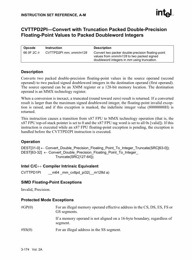
INSTRUCTION SET REFERENCE, A-M
CVTTPD2PI—Convert with Truncation Packed Double-Precision Floating-Point Values to Packed Doubleword Integers
DescriptionConverts two packed double-precision floating-point values in the source operand (secondoperand) to two packed signed doubleword integers in the destination operand (first operand).The source operand can be an XMM register or a 128-bit memory location. The destinationoperand is an MMX technology register.
When a conversion is inexact, a truncated (round toward zero) result is returned. If a convertedresult is larger than the maximum signed doubleword integer, the floating-point invalid excep-tion is raised, and if this exception is masked, the indefinite integer value (80000000H) isreturned.
This instruction causes a transition from x87 FPU to MMX technology operation (that is, thex87 FPU top-of-stack pointer is set to 0 and the x87 FPU tag word is set to all 0s [valid]). If thisinstruction is executed while an x87 FPU floating-point exception is pending, the exception ishandled before the CVTTPD2PI instruction is executed.
OperationDEST[31-0] ← Convert_Double_Precision_Floating_Point_To_Integer_Truncate(SRC[63-0]);DEST[63-32] ← Convert_Double_Precision_Floating_Point_To_Integer_
Truncate(SRC[127-64]);
Intel C/C++ Compiler Intrinsic EquivalentCVTTPD1PI __m64 _mm_cvttpd_pi32(__m128d a)
SIMD Floating-Point Exceptions
Invalid, Precision.
Protected Mode Exceptions
#GP(0) For an illegal memory operand effective address in the CS, DS, ES, FS or GS segments.
If a memory operand is not aligned on a 16-byte boundary, regardless of segment.
#SS(0) For an illegal address in the SS segment.
Opcode Instruction Description66 0F 2C /r CVTTPD2PI mm, xmm/m128 Convert two packer double-precision floating-point
values from xmm/m128 to two packed signed doubleword integers in mm using truncation.
3-174 Vol. 2A

INSTRUCTION SET REFERENCE, A-M
#PF(fault-code) For a page fault.
#MF If there is a pending x87 FPU exception.
#NM If TS in CR0 is set.
#XM If an unmasked SIMD floating-point exception and OSXMMEXCPT in CR4 is 1.
#UD If an unmasked SIMD floating-point exception and OSXMMEXCPT in CR4 is 0.
If EM in CR0 is set.
If OSFXSR in CR4 is 0.
If CPUID feature flag SSE2 is 0.
Real-Address Mode Exceptions
#GP(0) If a memory operand is not aligned on a 16-byte boundary, regardless of segment.
If any part of the operand lies outside the effective address space from 0 to FFFFH.
#NM If TS in CR0 is set.
#MF If there is a pending x87 FPU exception.
#XM If an unmasked SIMD floating-point exception and OSXMMEXCPT in CR4 is 1.
#UD If an unmasked SIMD floating-point exception and OSXMMEXCPT in CR4 is 0.
If EM in CR0 is set.
If OSFXSR in CR4 is 0.
If CPUID feature flag SSE2 is 0.
Virtual-8086 Mode Exceptions
Same exceptions as in Real Address Mode
#PF(fault-code) For a page fault.
Vol. 2A 3-175

INSTRUCTION SET REFERENCE, A-M
CVTTPD2DQ—Convert with Truncation Packed Double-Precision Floating-Point Values to Packed Doubleword Integers
Converts two packed double-precision floating-point values in the source operand (secondoperand) to two packed signed doubleword integers in the destination operand (first operand).The source operand can be an XMM register or a 128-bit memory location. The destinationoperand is an XMM register. The result is stored in the low quadword of the destination operandand the high quadword is cleared to all 0s.
When a conversion is inexact, a truncated (round toward zero) result is returned. If a convertedresult is larger than the maximum signed doubleword integer, the floating-point invalid excep-tion is raised, and if this exception is masked, the indefinite integer value (80000000H) isreturned.
OperationDEST[31-0] ← Convert_Double_Precision_Floating_Point_To_Integer_Truncate(SRC[63-0]);DEST[63-32] ← Convert_Double_Precision_Floating_Point_To_Integer_
Truncate(SRC[127-64]);DEST[127-64] ← 0000000000000000H;
Intel C/C++ Compiler Intrinsic EquivalentCVTTPD2DQ __m128i _mm_cvttpd_epi32(__m128d a)
SIMD Floating-Point Exceptions
Invalid, Precision.
Protected Mode Exceptions
#GP(0) For an illegal memory operand effective address in the CS, DS, ES, FS or GS segments.
If a memory operand is not aligned on a 16-byte boundary, regardless of segment.
#SS(0) For an illegal address in the SS segment.
#PF(fault-code) For a page fault.
#NM If TS in CR0 is set.
Opcode Instruction Description66 0F E6 CVTTPD2DQ xmm1, xmm2/m128 Convert two packed double-precision floating-point
values from xmm2/m128 to two packed signed doubleword integers in xmm1 using truncation.
3-176 Vol. 2A

INSTRUCTION SET REFERENCE, A-M
#XM If an unmasked SIMD floating-point exception and OSXMMEXCPT in CR4 is 1.
#UD If an unmasked SIMD floating-point exception and OSXMMEXCPT in CR4 is 0.
If EM in CR0 is set.
If OSFXSR in CR4 is 0.
If CPUID feature flag SSE2 is 0.
Real-Address Mode Exceptions
#GP(0) If a memory operand is not aligned on a 16-byte boundary, regardless of segment.
If any part of the operand lies outside the effective address space from 0 to FFFFH.
#NM If TS in CR0 is set.
#XM If an unmasked SIMD floating-point exception and OSXMMEXCPT in CR4 is 1.
#UD If an unmasked SIMD floating-point exception and OSXMMEXCPT in CR4 is 0.
If EM in CR0 is set.
If OSFXSR in CR4 is 0.
If CPUID feature flag SSE2 is 0.
Virtual-8086 Mode Exceptions
Same exceptions as in Real Address Mode
#PF(fault-code) For a page fault.
Vol. 2A 3-177

INSTRUCTION SET REFERENCE, A-M
CVTTPS2DQ—Convert with Truncation Packed Single-Precision Floating-Point Values to Packed Doubleword Integers
Converts four packed single-precision floating-point values in the source operand (secondoperand) to four packed signed doubleword integers in the destination operand (first operand).The source operand can be an XMM register or a 128-bit memory location. The destinationoperand is an XMM register. When a conversion is inexact, a truncated (round toward zero)result is returned. If a converted result is larger than the maximum signed doubleword integer,the floating-point invalid exception is raised, and if this exception is masked, the indefiniteinteger value (80000000H) is returned.
OperationDEST[31-0] ← Convert_Single_Precision_Floating_Point_To_Integer_Truncate(SRC[31-0]);DEST[63-32] ← Convert_Single_Precision_Floating_Point_To_Integer_Truncate(SRC[63-32]);DEST[95-64] ← Convert_Single_Precision_Floating_Point_To_Integer_Truncate(SRC[95-64]);DEST[127-96] ← Convert_Single_Precision_Floating_Point_To_Integer_
Truncate(SRC[127-96]);
Intel C/C++ Compiler Intrinsic Equivalent__m128d _mm_cvttps_epi32(__m128d a)
SIMD Floating-Point Exceptions
Invalid, Precision.
Protected Mode Exceptions
#GP(0) For an illegal memory operand effective address in the CS, DS, ES, FS or GS segments.
If a memory operand is not aligned on a 16-byte boundary, regardless of segment.
#SS(0) For an illegal address in the SS segment.
#PF(fault-code) For a page fault.
#NM If TS in CR0 is set.
#XM If an unmasked SIMD floating-point exception and OSXMMEXCPT in CR4 is 1.
Opcode Instruction DescriptionF3 0F 5B /r CVTTPS2DQ xmm1, xmm2/m128 Convert four single-precision floating-point
values from xmm2/m128 to four signed doubleword integers in xmm1 using truncation.
3-178 Vol. 2A
INSTRUCTION SET REFERENCE, A-M
#UD If an unmasked SIMD floating-point exception and OSXMMEXCPT in CR4 is 0.
If EM in CR0 is set.
If OSFXSR in CR4 is 0.
If CPUID feature flag SSE2 is 0.
Real-Address Mode Exceptions
#GP(0) If a memory operand is not aligned on a 16-byte boundary, regardless of segment.
If any part of the operand lies outside the effective address space from 0 to FFFFH.
#NM If TS in CR0 is set.
#XM If an unmasked SIMD floating-point exception and OSXMMEXCPT in CR4 is 1.
#UD If an unmasked SIMD floating-point exception and OSXMMEXCPT in CR4 is 0.
If EM in CR0 is set.
If OSFXSR in CR4 is 0.
If CPUID feature flag SSE2 is 0.
Virtual-8086 Mode Exceptions
Same exceptions as in Real Address Mode
#PF(fault-code) For a page fault.
Vol. 2A 3-179

INSTRUCTION SET REFERENCE, A-M
CVTTPS2PI—Convert with Truncation Packed Single-Precision Floating-Point Values to Packed Doubleword Integers
DescriptionConverts two packed single-precision floating-point values in the source operand (secondoperand) to two packed signed doubleword integers in the destination operand (first operand).The source operand can be an XMM register or a 64-bit memory location. The destinationoperand is an MMX technology register. When the source operand is an XMM register, the twosingle-precision floating-point values are contained in the low quadword of the register.
When a conversion is inexact, a truncated (round toward zero) result is returned. If a convertedresult is larger than the maximum signed doubleword integer, the floating-point invalid excep-tion is raised, and if this exception is masked, the indefinite integer value (80000000H) isreturned.
This instruction causes a transition from x87 FPU to MMX technology operation (that is, thex87 FPU top-of-stack pointer is set to 0 and the x87 FPU tag word is set to all 0s [valid]). If thisinstruction is executed while an x87 FPU floating-point exception is pending, the exception ishandled before the CVTTPS2PI instruction is executed.
OperationDEST[31-0] ← Convert_Single_Precision_Floating_Point_To_Integer_Truncate(SRC[31-0]);DEST[63-32] ← Convert_Single_Precision_Floating_Point_To_Integer_Truncate(SRC[63-32]);
Intel C/C++ Compiler Intrinsic Equivalent__m64 _mm_cvttps_pi32(__m128 a)
SIMD Floating-Point Exceptions
Invalid, Precision.
Protected Mode Exceptions
#GP(0) For an illegal memory operand effective address in the CS, DS, ES, FS or GS segments.
#SS(0) For an illegal address in the SS segment.
#PF(fault-code) For a page fault.
#MF If there is a pending x87 FPU exception.
Opcode Instruction Description0F 2C /r CVTTPS2PI mm, xmm/m64 Convert two single-precision floating-point values from
xmm/m64 to two signed doubleword signed integers in mm using truncation.
3-180 Vol. 2A

INSTRUCTION SET REFERENCE, A-M
#NM If TS in CR0 is set.
#XM If an unmasked SIMD floating-point exception and OSXMMEXCPT in CR4 is 1.
#UD If an unmasked SIMD floating-point exception and OSXMMEXCPT in CR4 is 0.
If EM in CR0 is set.
If OSFXSR in CR4 is 0.
If CPUID feature flag SSE is 0.
#AC(0) If alignment checking is enabled and an unaligned memory reference is made while the current privilege level is 3.
Real-Address Mode Exceptions
GP(0) If any part of the operand lies outside the effective address space from 0 to FFFFH.
#NM If TS in CR0 is set.
#MF If there is a pending x87 FPU exception.
#XM If an unmasked SIMD floating-point exception and OSXMMEXCPT in CR4 is 1.
#UD If an unmasked SIMD floating-point exception and OSXMMEXCPT in CR4 is 0.
If EM in CR0 is set.
If OSFXSR in CR4 is 0.
If CPUID feature flag SSE is 0.
Virtual-8086 Mode Exceptions
Same exceptions as in Real Address Mode
#PF(fault-code) For a page fault.
#AC(0) If alignment checking is enabled and an unaligned memory reference is made.
Vol. 2A 3-181

INSTRUCTION SET REFERENCE, A-M
CVTTSD2SI—Convert with Truncation Scalar Double-Precision Floating-Point Value to Signed Doubleword Integer
DescriptionConverts a double-precision floating-point value in the source operand (second operand) to asigned doubleword integer in the destination operand (first operand). The source operand can bean XMM register or a 64-bit memory location. The destination operand is a general-purposeregister. When the source operand is an XMM register, the double-precision floating-point valueis contained in the low quadword of the register.
When a conversion is inexact, a truncated (round toward zero) result is returned. If a convertedresult is larger than the maximum signed doubleword integer, the floating-point invalid excep-tion is raised, and if this exception is masked, the indefinite integer value (80000000H) isreturned.
OperationDEST[31-0] ← Convert_Double_Precision_Floating_Point_To_Integer_Truncate(SRC[63-0]);
Intel C/C++ Compiler Intrinsic Equivalentint_mm_cvttsd_si32(__m128d a)
SIMD Floating-Point Exceptions
Invalid, Precision.
Protected Mode Exceptions
#GP(0) For an illegal memory operand effective address in the CS, DS, ES, FS or GS segments.
#SS(0) For an illegal address in the SS segment.
#PF(fault-code) For a page fault.
#NM If TS in CR0 is set.
#XM If an unmasked SIMD floating-point exception and OSXMMEXCPT in CR4 is 1.
Opcode Instruction DescriptionF2 0F 2C /r CVTTSD2SI r32, xmm/m64 Convert one double-precision floating-point value from
xmm/m64 to one signed doubleword integer in r32 using truncation.
3-182 Vol. 2A

INSTRUCTION SET REFERENCE, A-M
#UD If an unmasked SIMD floating-point exception and OSXMMEXCPT in CR4 is 0.
If EM in CR0 is set.
If OSFXSR in CR4 is 0.
If CPUID feature flag SSE2 is 0.
#AC(0) If alignment checking is enabled and an unaligned memory reference is made while the current privilege level is 3.
Real-Address Mode Exceptions
GP(0) If any part of the operand lies outside the effective address space from 0 to FFFFH.
#NM If TS in CR0 is set.
#XM If an unmasked SIMD floating-point exception and OSXMMEXCPT in CR4 is 1.
#UD If an unmasked SIMD floating-point exception and OSXMMEXCPT in CR4 is 0.
If EM in CR0 is set.
If OSFXSR in CR4 is 0.
If CPUID feature flag SSE2 is 0.
Virtual-8086 Mode Exceptions
Same exceptions as in Real Address Mode
#PF(fault-code) For a page fault.
#AC(0) If alignment checking is enabled and an unaligned memory reference is made.
Vol. 2A 3-183

INSTRUCTION SET REFERENCE, A-M
CVTTSS2SI—Convert with Truncation Scalar Single-Precision Floating-Point Value to Doubleword Integer
DescriptionConverts a single-precision floating-point value in the source operand (second operand) to asigned doubleword integer in the destination operand (first operand). The source operand can bean XMM register or a 32-bit memory location. The destination operand is a general-purposeregister. When the source operand is an XMM register, the single-precision floating-point valueis contained in the low doubleword of the register.
When a conversion is inexact, a truncated (round toward zero) result is returned. If a convertedresult is larger than the maximum signed doubleword integer, the floating-point invalid excep-tion is raised, and if this exception is masked, the indefinite integer value (80000000H) isreturned.
OperationDEST[31-0] ← Convert_Single_Precision_Floating_Point_To_Integer_Truncate(SRC[31-0]);
Intel C/C++ Compiler Intrinsic Equivalentint_mm_cvttss_si32(__m128d a)
SIMD Floating-Point Exceptions
Invalid, Precision.
Protected Mode Exceptions
#GP(0) For an illegal memory operand effective address in the CS, DS, ES, FS or GS segments.
#SS(0) For an illegal address in the SS segment.
#PF(fault-code) For a page fault.
#NM If TS in CR0 is set.
#XM If an unmasked SIMD floating-point exception and OSXMMEXCPT in CR4 is 1.
#UD If an unmasked SIMD floating-point exception and OSXMMEXCPT in CR4 is 0.
Opcode Instruction DescriptionF3 0F 2C /r CVTTSS2SI r32, xmm/m32 Convert one single-precision floating-point value from
xmm/m32 to one signed doubleword integer in r32 using truncation.
3-184 Vol. 2A

INSTRUCTION SET REFERENCE, A-M
If EM in CR0 is set.
If OSFXSR in CR4 is 0.
If CPUID feature flag SSE is 0.
#AC(0) If alignment checking is enabled and an unaligned memory reference is made while the current privilege level is 3.
Real-Address Mode Exceptions
GP(0) If any part of the operand lies outside the effective address space from 0 to FFFFH.
#NM If TS in CR0 is set.
#XM If an unmasked SIMD floating-point exception and OSXMMEXCPT in CR4 is 1.
#UD If an unmasked SIMD floating-point exception and OSXMMEXCPT in CR4 is 0.
If EM in CR0 is set.
If OSFXSR in CR4 is 0.
If CPUID feature flag SSE is 0.
Virtual-8086 Mode Exceptions
Same exceptions as in Real Address Mode
#PF(fault-code) For a page fault.
#AC(0) If alignment checking is enabled and an unaligned memory reference is made.
Vol. 2A 3-185

INSTRUCTION SET REFERENCE, A-M
CWD/CDQ—Convert Word to Doubleword/Convert Doubleword to Quadword
DescriptionDoubles the size of the operand in register AX or EAX (depending on the operand size) bymeans of sign extension and stores the result in registers DX:AX or EDX:EAX, respectively.The CWD instruction copies the sign (bit 15) of the value in the AX register into every bit posi-tion in the DX register (see Figure 7-6 in the IA-32 Intel Architecture Software Developer’sManual, Volume 1). The CDQ instruction copies the sign (bit 31) of the value in the EAXregister into every bit position in the EDX register.
The CWD instruction can be used to produce a doubleword dividend from a word before a worddivision, and the CDQ instruction can be used to produce a quadword dividend from a double-word before doubleword division.
The CWD and CDQ mnemonics reference the same opcode. The CWD instruction is intendedfor use when the operand-size attribute is 16 and the CDQ instruction for when the operand-sizeattribute is 32. Some assemblers may force the operand size to 16 when CWD is used and to 32when CDQ is used. Others may treat these mnemonics as synonyms (CWD/CDQ) and use thecurrent setting of the operand-size attribute to determine the size of values to be converted,regardless of the mnemonic used.
OperationIF OperandSize = 16 (* CWD instruction *)
THEN DX ← SignExtend(AX);ELSE (* OperandSize = 32, CDQ instruction *)
EDX ← SignExtend(EAX);FI;
Flags AffectedNone.
Exceptions (All Operating Modes)None.
Opcode Instruction Description99 CWD DX:AX ← sign-extend of AX99 CDQ EDX:EAX ← sign-extend of EAX
3-186 Vol. 2A

INSTRUCTION SET REFERENCE, A-M
CWDE—Convert Word to Doubleword
See the entry for CBW/CWDE—Convert Byte to Word/Convert Word to Doubleword.
Vol. 2A 3-187

INSTRUCTION SET REFERENCE, A-M
DAA—Decimal Adjust AL after Addition
DescriptionAdjusts the sum of two packed BCD values to create a packed BCD result. The AL register isthe implied source and destination operand. The DAA instruction is only useful when it followsan ADD instruction that adds (binary addition) two 2-digit, packed BCD values and stores a byteresult in the AL register. The DAA instruction then adjusts the contents of the AL register tocontain the correct 2-digit, packed BCD result. If a decimal carry is detected, the CF and AFflags are set accordingly.
Operation
old_AL ← AL;old_CF ← CF;CF ← 0;IF (((AL AND 0FH) > 9) OR AF = 1) THEN AL ← AL + 6; CF ← old_CF OR (Carry from AL ← AL + 6); AF ← 1; ELSE AF ← 0;FI;IF ((old_AL > 99H) OR (old_CF = 1)) THEN AL ← AL + 60H; CF ← 1; ELSE CF ← 0;FI;
ExampleADD AL, BL Before: AL=79H BL=35H EFLAGS(OSZAPC)=XXXXXX
After: AL=AEH BL=35H EFLAGS(0SZAPC)=110000DAA Before: AL=AEH BL=35H EFLAGS(OSZAPC)=110000
After: AL=14H BL=35H EFLAGS(0SZAPC)=X00111DAA Before: AL=2EH BL=35H EFLAGS(OSZAPC)=110000
After: AL=34H BL=35H EFLAGS(0SZAPC)=X00101
Opcode Instruction Description27 DAA Decimal adjust AL after addition.
3-188 Vol. 2A

INSTRUCTION SET REFERENCE, A-M
Flags AffectedThe CF and AF flags are set if the adjustment of the value results in a decimal carry in eitherdigit of the result (see the “Operation” section above). The SF, ZF, and PF flags are set accordingto the result. The OF flag is undefined.
Exceptions (All Operating Modes)None.
Vol. 2A 3-189

INSTRUCTION SET REFERENCE, A-M
DAS—Decimal Adjust AL after Subtraction
DescriptionAdjusts the result of the subtraction of two packed BCD values to create a packed BCD result.The AL register is the implied source and destination operand. The DAS instruction is onlyuseful when it follows a SUB instruction that subtracts (binary subtraction) one 2-digit, packedBCD value from another and stores a byte result in the AL register. The DAS instruction thenadjusts the contents of the AL register to contain the correct 2-digit, packed BCD result. If adecimal borrow is detected, the CF and AF flags are set accordingly.
Operation
old_AL ← AL;old_CF ← CF;CF ← 0;IF (((AL AND 0FH) > 9) OR AF = 1) THEN AL ← AL − 6; CF ← old_CF OR (Borrow from AL ← AL − 6); AF ← 1; ELSE AF ← 0;FI;IF ((old_AL > 99H) OR (old_CF = 1)) THEN AL ← AL − 60H; CF ← 1; ELSE CF ← 0;FI;
ExampleSUB AL, BL Before: AL=35H BL=47H EFLAGS(OSZAPC)=XXXXXX
After: AL=EEH BL=47H EFLAGS(0SZAPC)=010111DAA Before: AL=EEH BL=47H EFLAGS(OSZAPC)=010111
After: AL=88H BL=47H EFLAGS(0SZAPC)=X10111
Opcode Instruction Description2F DAS Decimal adjust AL after subtraction.
3-190 Vol. 2A

INSTRUCTION SET REFERENCE, A-M
Flags AffectedThe CF and AF flags are set if the adjustment of the value results in a decimal borrow in eitherdigit of the result (see the “Operation” section above). The SF, ZF, and PF flags are set accordingto the result. The OF flag is undefined.
Exceptions (All Operating Modes)None.
Vol. 2A 3-191
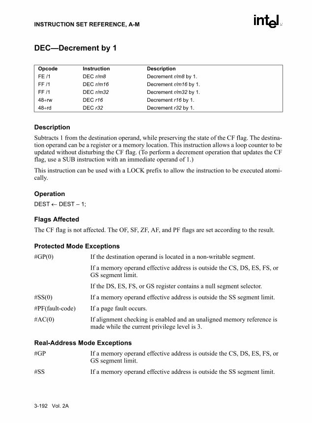
INSTRUCTION SET REFERENCE, A-M
DEC—Decrement by 1
DescriptionSubtracts 1 from the destination operand, while preserving the state of the CF flag. The destina-tion operand can be a register or a memory location. This instruction allows a loop counter to beupdated without disturbing the CF flag. (To perform a decrement operation that updates the CFflag, use a SUB instruction with an immediate operand of 1.)
This instruction can be used with a LOCK prefix to allow the instruction to be executed atomi-cally.
OperationDEST ← DEST – 1;
Flags AffectedThe CF flag is not affected. The OF, SF, ZF, AF, and PF flags are set according to the result.
Protected Mode Exceptions#GP(0) If the destination operand is located in a non-writable segment.
If a memory operand effective address is outside the CS, DS, ES, FS, or GS segment limit.
If the DS, ES, FS, or GS register contains a null segment selector.
#SS(0) If a memory operand effective address is outside the SS segment limit.
#PF(fault-code) If a page fault occurs.
#AC(0) If alignment checking is enabled and an unaligned memory reference is made while the current privilege level is 3.
Real-Address Mode Exceptions#GP If a memory operand effective address is outside the CS, DS, ES, FS, or
GS segment limit.
#SS If a memory operand effective address is outside the SS segment limit.
Opcode Instruction DescriptionFE /1 DEC r/m8 Decrement r/m8 by 1.FF /1 DEC r/m16 Decrement r/m16 by 1.FF /1 DEC r/m32 Decrement r/m32 by 1.48+rw DEC r16 Decrement r16 by 1.48+rd DEC r32 Decrement r32 by 1.
3-192 Vol. 2A

INSTRUCTION SET REFERENCE, A-M
Virtual-8086 Mode Exceptions#GP(0) If a memory operand effective address is outside the CS, DS, ES, FS, or
GS segment limit.
#SS(0) If a memory operand effective address is outside the SS segment limit.
#PF(fault-code) If a page fault occurs.
#AC(0) If alignment checking is enabled and an unaligned memory reference is made.
Vol. 2A 3-193

INSTRUCTION SET REFERENCE, A-M
DIV—Unsigned Divide
DescriptionDivides (unsigned) the value in the AX, DX:AX, or EDX:EAX registers (dividend) by thesource operand (divisor) and stores the result in the AX (AH:AL), DX:AX, or EDX:EAX regis-ters. The source operand can be a general-purpose register or a memory location. The action ofthis instruction depends on the operand size (dividend/divisor). See Table 3-19.
Non-integral results are truncated (chopped) towards 0. The remainder is always less than thedivisor in magnitude. Overflow is indicated with the #DE (divide error) exception rather thanwith the CF flag.
OperationIF SRC = 0
THEN #DE; (* divide error *) FI;IF OperandSize = 8 (* word/byte operation *)
THENtemp ← AX / SRC;IF temp > FFH
THEN #DE; (* divide error *) ;ELSE
AL ← temp;AH ← AX MOD SRC;
FI;ELSE
IF OperandSize = 16 (* doubleword/word operation *)THEN
Opcode Instruction DescriptionF6 /6 DIV r/m8 Unsigned divide AX by r/m8, with result stored in
AL ← Quotient, AH ← Remainder.F7 /6 DIV r/m16 Unsigned divide DX:AX by r/m16, with result stored in
AX ← Quotient, DX ← Remainder.F7 /6 DIV r/m32 Unsigned divide EDX:EAX by r/m32, with result stored in
EAX ← Quotient, EDX ← Remainder.
Table 3-19. DIV Action
Operand Size Dividend Divisor Quotient RemainderMaximum Quotient
Word/byte AX r/m8 AL AH 255
Doubleword/word DX:AX r/m16 AX DX 65,535
Quadword/doubleword EDX:EAX r/m32 EAX EDX 232 − 1
3-194 Vol. 2A

INSTRUCTION SET REFERENCE, A-M
temp ← DX:AX / SRC;
IF temp > FFFFHTHEN #DE; (* divide error *) ;ELSE
AX ← temp;DX ← DX:AX MOD SRC;
FI;ELSE (* quadword/doubleword operation *)
temp ← EDX:EAX / SRC;IF temp > FFFFFFFFH
THEN #DE; (* divide error *) ;ELSE
EAX ← temp;EDX ← EDX:EAX MOD SRC;
FI;FI;
FI;
Flags AffectedThe CF, OF, SF, ZF, AF, and PF flags are undefined.
Protected Mode Exceptions#DE If the source operand (divisor) is 0
If the quotient is too large for the designated register.
#GP(0) If a memory operand effective address is outside the CS, DS, ES, FS, or GS segment limit.
If the DS, ES, FS, or GS register contains a null segment selector.
#SS(0) If a memory operand effective address is outside the SS segment limit.
#PF(fault-code) If a page fault occurs.
#AC(0) If alignment checking is enabled and an unaligned memory reference is made while the current privilege level is 3.
Real-Address Mode Exceptions#DE If the source operand (divisor) is 0.
If the quotient is too large for the designated register.
#GP If a memory operand effective address is outside the CS, DS, ES, FS, or GS segment limit.
If the DS, ES, FS, or GS register contains a null segment selector.
#SS(0) If a memory operand effective address is outside the SS segment limit.
Vol. 2A 3-195

INSTRUCTION SET REFERENCE, A-M
Virtual-8086 Mode Exceptions#DE If the source operand (divisor) is 0.
If the quotient is too large for the designated register.
#GP(0) If a memory operand effective address is outside the CS, DS, ES, FS, or GS segment limit.
#SS If a memory operand effective address is outside the SS segment limit.
#PF(fault-code) If a page fault occurs.
#AC(0) If alignment checking is enabled and an unaligned memory reference is made.
3-196 Vol. 2A

INSTRUCTION SET REFERENCE, A-M
DIVPD—Divide Packed Double-Precision Floating-Point Values
DescriptionPerforms an SIMD divide of the four packed double-precision floating-point values in the desti-nation operand (first operand) by the four packed double-precision floating-point values in thesource operand (second operand), and stores the packed double-precision floating-point resultsin the destination operand. The source operand can be an XMM register or a 128-bit memorylocation. The destination operand is an XMM register. See Figure 11-3 in the IA-32 Intel Archi-tecture Software Developer’s Manual, Volume 1 for an illustration of an SIMD double-precisionfloating-point operation.
OperationDEST[63-0] ← DEST[63-0] / (SRC[63-0]);DEST[127-64] ← DEST[127-64] / (SRC[127-64]);
Intel C/C++ Compiler Intrinsic EquivalentDIVPD __m128 _mm_div_pd(__m128 a, __m128 b)
SIMD Floating-Point ExceptionsOverflow, Underflow, Invalid, Divide-by-Zero, Precision, Denormal.
Protected Mode Exceptions
#GP(0) For an illegal memory operand effective address in the CS, DS, ES, FS or GS segments.
If a memory operand is not aligned on a 16-byte boundary, regardless of segment.
#SS(0) For an illegal address in the SS segment.
#PF(fault-code) For a page fault.
#NM If TS in CR0 is set.
#XM If an unmasked SIMD floating-point exception and OSXMMEXCPT in CR4 is 1.
Opcode Instruction Description66 0F 5E /r DIVPD xmm1, xmm2/m128 Divide packed double-precision floating-point values in
xmm1 by packed double-precision floating-point values xmm2/m128.
Vol. 2A 3-197

INSTRUCTION SET REFERENCE, A-M
#UD If an unmasked SIMD floating-point exception and OSXMMEXCPT in CR4 is 0.
If EM in CR0 is set.
If OSFXSR in CR4 is 0.
If CPUID feature flag SSE2 is 0.
Real-Address Mode Exceptions
#GP(0) If a memory operand is not aligned on a 16-byte boundary, regardless of segment.
If any part of the operand lies outside the effective address space from 0 to FFFFH.
#NM If TS in CR0 is set.
#XM If an unmasked SIMD floating-point exception and OSXMMEXCPT in CR4 is 1.
#UD If an unmasked SIMD floating-point exception and OSXMMEXCPT in CR4 is 0.
If EM in CR0 is set.
If OSFXSR in CR4 is 0.
If CPUID feature flag SSE2 is 0.
Virtual-8086 Mode Exceptions
Same exceptions as in Real Address Mode
#PF(fault-code) For a page fault.
3-198 Vol. 2A

INSTRUCTION SET REFERENCE, A-M
DIVPS—Divide Packed Single-Precision Floating-Point Values
DescriptionPerforms an SIMD divide of the two packed single-precision floating-point values in the desti-nation operand (first operand) by the two packed single-precision floating-point values in thesource operand (second operand), and stores the packed single-precision floating-point resultsin the destination operand. The source operand can be an XMM register or a 128-bit memorylocation. The destination operand is an XMM register. See Figure 10-5 in the IA-32 Intel Archi-tecture Software Developer’s Manual, Volume 1 for an illustration of an SIMD single-precisionfloating-point operation.
OperationDEST[31-0] ← DEST[31-0] / (SRC[31-0]);DEST[63-32] ← DEST[63-32] / (SRC[63-32]);DEST[95-64] ← DEST[95-64] / (SRC[95-64]);DEST[127-96] ← DEST[127-96] / (SRC[127-96]);
Intel C/C++ Compiler Intrinsic EquivalentDIVPS __m128 _mm_div_ps(__m128 a, __m128 b)
SIMD Floating-Point ExceptionsOverflow, Underflow, Invalid, Divide-by-Zero, Precision, Denormal.
Protected Mode Exceptions
#GP(0) For an illegal memory operand effective address in the CS, DS, ES, FS or GS segments.
If a memory operand is not aligned on a 16-byte boundary, regardless of segment.
#SS(0) For an illegal address in the SS segment.
#PF(fault-code) For a page fault.
#NM If TS in CR0 is set.
#XM If an unmasked SIMD floating-point exception and OSXMMEXCPT in CR4 is 1.
#UD If an unmasked SIMD floating-point exception and OSXMMEXCPT in CR4 is 0.
Opcode Instruction Description0F 5E /r DIVPS xmm1, xmm2/m128 Divide packed single-precision floating-point values in
xmm1 by packed single-precision floating-point values xmm2/m128.
Vol. 2A 3-199

INSTRUCTION SET REFERENCE, A-M
If EM in CR0 is set.
If OSFXSR in CR4 is 0.
If CPUID feature flag SSE is 0.
Real-Address Mode Exceptions
#GP(0) If a memory operand is not aligned on a 16-byte boundary, regardless of segment.
If any part of the operand lies outside the effective address space from 0 to FFFFH.
#NM If TS in CR0 is set.
#XM If an unmasked SIMD floating-point exception and OSXMMEXCPT in CR4 is 1.
#UD If an unmasked SIMD floating-point exception and OSXMMEXCPT in CR4 is 0.
If EM in CR0 is set.
If OSFXSR in CR4 is 0.
If CPUID feature flag SSE is 0.
Virtual-8086 Mode Exceptions
Same exceptions as in Real Address Mode
#PF(fault-code) For a page fault.
3-200 Vol. 2A

INSTRUCTION SET REFERENCE, A-M
DIVSD—Divide Scalar Double-Precision Floating-Point Values
DescriptionDivides the low double-precision floating-point value in the destination operand (first operand)by the low double-precision floating-point value in the source operand (second operand), andstores the double-precision floating-point result in the destination operand. The source operandcan be an XMM register or a 64-bit memory location. The destination operand is an XMMregister. The high quadword of the destination operand remains unchanged. See Figure 11-4 inthe IA-32 Intel Architecture Software Developer’s Manual, Volume 1 for an illustration of ascalar double-precision floating-point operation.
OperationDEST[63-0] ← DEST[63-0] / SRC[63-0];* DEST[127-64] remains unchanged *;
Intel C/C++ Compiler Intrinsic EquivalentDIVSD __m128d _mm_div_sd (m128d a, m128d b)
SIMD Floating-Point ExceptionsOverflow, Underflow, Invalid, Divide-by-Zero, Precision, Denormal.
Protected Mode Exceptions
#GP(0) For an illegal memory operand effective address in the CS, DS, ES, FS or GS segments.
#SS(0) For an illegal address in the SS segment.
#PF(fault-code) For a page fault.
#NM If TS in CR0 is set.
#XM If an unmasked SIMD floating-point exception and OSXMMEXCPT in CR4 is 1.
#UD If an unmasked SIMD floating-point exception and OSXMMEXCPT in CR4 is 0.
If EM in CR0 is set.
If OSFXSR in CR4 is 0.
If CPUID feature flag SSE2 is 0.
Opcode Instruction DescriptionF2 0F 5E /r DIVSD xmm1, xmm2/m64 Divide low double-precision floating-point value n xmm1
by low double-precision floating-point value in xmm2/mem64.
Vol. 2A 3-201
INSTRUCTION SET REFERENCE, A-M
#AC(0) If alignment checking is enabled and an unaligned memory reference is made while the current privilege level is 3.
Real-Address Mode Exceptions
GP(0) If any part of the operand lies outside the effective address space from 0 to FFFFH.
#NM If TS in CR0 is set.
#XM If an unmasked SIMD floating-point exception and OSXMMEXCPT in CR4 is 1.
#UD If an unmasked SIMD floating-point exception and OSXMMEXCPT in CR4 is 0.
If EM in CR0 is set.
If OSFXSR in CR4 is 0.
If CPUID feature flag SSE2 is 0.
Virtual-8086 Mode Exceptions
Same exceptions as in Real Address Mode
#PF(fault-code) For a page fault.
#AC(0) If alignment checking is enabled and an unaligned memory reference is made.
3-202 Vol. 2A

INSTRUCTION SET REFERENCE, A-M
DIVSS—Divide Scalar Single-Precision Floating-Point Values
DescriptionDivides the low single-precision floating-point value in the destination operand (first operand)by the low single-precision floating-point value in the source operand (second operand), andstores the single-precision floating-point result in the destination operand. The source operandcan be an XMM register or a 32-bit memory location. The destination operand is an XMMregister. The three high-order doublewords of the destination operand remain unchanged. SeeFigure 10-6 in the IA-32 Intel Architecture Software Developer’s Manual, Volume 1 for an illus-tration of a scalar single-precision floating-point operation.
OperationDEST[31-0] ← DEST[31-0] / SRC[31-0];* DEST[127-32] remains unchanged *;
Intel C/C++ Compiler Intrinsic EquivalentDIVSS __m128 _mm_div_ss(__m128 a, __m128 b)
SIMD Floating-Point ExceptionsOverflow, Underflow, Invalid, Divide-by-Zero, Precision, Denormal.
Protected Mode Exceptions
#GP(0) For an illegal memory operand effective address in the CS, DS, ES, FS or GS segments.
#SS(0) For an illegal address in the SS segment.
#PF(fault-code) For a page fault.
#NM If TS in CR0 is set.
#XM If an unmasked SIMD floating-point exception and OSXMMEXCPT in CR4 is 1.
#UD If an unmasked SIMD floating-point exception and OSXMMEXCPT in CR4 is 0.
If EM in CR0 is set.
If OSFXSR in CR4 is 0.
If CPUID feature flag SSE is 0.
Opcode Instruction DescriptionF3 0F 5E /r DIVSS xmm1, xmm2/m32 Divide low single-precision floating-point value in xmm1
by low single-precision floating-point value in xmm2/m32.
Vol. 2A 3-203

INSTRUCTION SET REFERENCE, A-M
#AC(0) If alignment checking is enabled and an unaligned memory reference is made while the current privilege level is 3.
Real-Address Mode Exceptions
GP(0) If any part of the operand lies outside the effective address space from 0 to FFFFH.
#NM If TS in CR0 is set.
#XM If an unmasked SIMD floating-point exception and OSXMMEXCPT in CR4 is 1.
#UD If an unmasked SIMD floating-point exception and OSXMMEXCPT in CR4 is 0.
If EM in CR0 is set.
If OSFXSR in CR4 is 0.
If CPUID feature flag SSE is 0.
Virtual-8086 Mode Exceptions
Same exceptions as in Real Address Mode
#PF(fault-code) For a page fault.
#AC(0) If alignment checking is enabled and an unaligned memory reference is made.
3-204 Vol. 2A

INSTRUCTION SET REFERENCE, A-M
EMMS—Empty MMX Technology State
Description Sets the values of all the tags in the x87 FPU tag word to empty (all 1s). This operation marksthe x87 FPU data registers (which are aliased to the MMX technology registers) as available foruse by x87 FPU floating-point instructions. (See Figure 8-7 in the IA-32 Intel Architecture Soft-ware Developer’s Manual, Volume 1, for the format of the x87 FPU tag word.) All other MMXinstructions (other than the EMMS instruction) set all the tags in x87 FPU tag word to valid (all0s).The EMMS instruction must be used to clear the MMX technology state at the end of all MMXtechnology procedures or subroutines and before calling other procedures or subroutines thatmay execute x87 floating-point instructions. If a floating-point instruction loads one of the regis-ters in the x87 FPU data register stack before the x87 FPU tag word has been reset by the EMMSinstruction, an x87 floating-point register stack overflow can occur that will result in an x87floating-point exception or incorrect result.
Operationx87FPUTagWord ← FFFFH;
Intel C/C++ Compiler Intrinsic Equivalentvoid_mm_empty()
Flags AffectedNone.
Protected Mode Exceptions#UD If EM in CR0 is set.
#NM If TS in CR0 is set.
#MF If there is a pending FPU exception.
Real-Address Mode Exceptions Same as for protected mode exceptions.
Virtual-8086 Mode ExceptionsSame as for protected mode exceptions.
Opcode Instruction Description0F 77 EMMS Set the x87 FPU tag word to empty.
Vol. 2A 3-205

INSTRUCTION SET REFERENCE, A-M
ENTER—Make Stack Frame for Procedure Parameters
DescriptionCreates a stack frame for a procedure. The first operand (size operand) specifies the size of thestack frame (that is, the number of bytes of dynamic storage allocated on the stack for the proce-dure). The second operand (nesting level operand) gives the lexical nesting level (0 to 31) of theprocedure. The nesting level determines the number of stack frame pointers that are copied intothe “display area” of the new stack frame from the preceding frame. Both of these operands areimmediate values.
The stack-size attribute determines whether the BP (16 bits) or EBP (32 bits) register specifiesthe current frame pointer and whether SP (16 bits) or ESP (32 bits) specifies the stack pointer.
The ENTER and companion LEAVE instructions are provided to support block structuredlanguages. The ENTER instruction (when used) is typically the first instruction in a procedureand is used to set up a new stack frame for a procedure. The LEAVE instruction is then used atthe end of the procedure (just before the RET instruction) to release the stack frame.
If the nesting level is 0, the processor pushes the frame pointer from the EBP register onto thestack, copies the current stack pointer from the ESP register into the EBP register, and loads theESP register with the current stack-pointer value minus the value in the size operand. For nestinglevels of 1 or greater, the processor pushes additional frame pointers on the stack beforeadjusting the stack pointer. These additional frame pointers provide the called procedure withaccess points to other nested frames on the stack. See “Procedure Calls for Block-StructuredLanguages” in Chapter 6 of the IA-32 Intel Architecture Software Developer’s Manual, Volume1, for more information about the actions of the ENTER instruction.
OperationNestingLevel ← NestingLevel MOD 32IF StackSize = 32
THEN Push(EBP) ;FrameTemp ← ESP;
ELSE (* StackSize = 16*)Push(BP); FrameTemp ← SP;
FI;IF NestingLevel = 0
THEN GOTO CONTINUE;FI;IF (NestingLevel > 0)
Opcode Instruction DescriptionC8 iw 00 ENTER imm16,0 Create a stack frame for a procedure.C8 iw 01 ENTER imm16,1 Create a nested stack frame for a procedure.C8 iw ib ENTER imm16,imm8 Create a nested stack frame for a procedure.
3-206 Vol. 2A

INSTRUCTION SET REFERENCE, A-M
FOR i ← 1 TO (NestingLevel − 1)DO
IF OperandSize = 32THEN
IF StackSize = 32EBP ← EBP − 4;Push([EBP]); (* doubleword push *)
ELSE (* StackSize = 16*)BP ← BP − 4;Push([BP]); (* doubleword push *)
FI;ELSE (* OperandSize = 16 *)
IF StackSize = 32THEN
EBP ← EBP − 2;Push([EBP]); (* word push *)
ELSE (* StackSize = 16*)BP ← BP − 2;Push([BP]); (* word push *)
FI;FI;
OD;IF OperandSize = 32
THEN Push(FrameTemp); (* doubleword push *)
ELSE (* OperandSize = 16 *)Push(FrameTemp); (* word push *)
FI;GOTO CONTINUE;
FI;CONTINUE:IF StackSize = 32
THENEBP ← FrameTempESP ← EBP − Size;
ELSE (* StackSize = 16*)BP ← FrameTempSP ← BP − Size;
FI;END;
Flags AffectedNone.
Vol. 2A 3-207

INSTRUCTION SET REFERENCE, A-M
Protected Mode Exceptions#SS(0) If the new value of the SP or ESP register is outside the stack segment
limit.
#PF(fault-code) If a page fault occurs.
Real-Address Mode Exceptions#SS(0) If the new value of the SP or ESP register is outside the stack segment
limit.
Virtual-8086 Mode Exceptions#SS(0) If the new value of the SP or ESP register is outside the stack segment
limit.
#PF(fault-code) If a page fault occurs.
3-208 Vol. 2A

INSTRUCTION SET REFERENCE, A-M
F2XM1—Compute 2x–1
DescriptionComputes the exponential value of 2 to the power of the source operand minus 1. The sourceoperand is located in register ST(0) and the result is also stored in ST(0). The value of the sourceoperand must lie in the range –1.0 to +1.0. If the source value is outside this range, the result isundefined.
The following table shows the results obtained when computing the exponential value of variousclasses of numbers, assuming that neither overflow nor underflow occurs.
Values other than 2 can be exponentiated using the following formula:xy ← 2(y ∗ log2x)
OperationST(0) ← (2ST(0) − 1);
FPU Flags AffectedC1 Set to 0 if stack underflow occurred.
Set if result was rounded up; cleared otherwise.
C0, C2, C3 Undefined.
Floating-Point Exceptions#IS Stack underflow occurred.
#IA Source operand is an SNaN value or unsupported format.
#D Source is a denormal value.
#U Result is too small for destination format.
Opcode Instruction DescriptionD9 F0 F2XM1 Replace ST(0) with (2ST(0) – 1).
Table 3-20. Results Obtained from F2XM1ST(0) SRC ST(0) DEST
−1.0 to −0 −0.5 to −0
−0 −0
+0 +0
+0 to +1.0 +0 to 1.0
Vol. 2A 3-209
INSTRUCTION SET REFERENCE, A-M
#P Value cannot be represented exactly in destination format.
Protected Mode Exceptions#NM EM or TS in CR0 is set.
Real-Address Mode Exceptions#NM EM or TS in CR0 is set.
Virtual-8086 Mode Exceptions#NM EM or TS in CR0 is set.
3-210 Vol. 2A

INSTRUCTION SET REFERENCE, A-M
FABS—Absolute Value
DescriptionClears the sign bit of ST(0) to create the absolute value of the operand. The following tableshows the results obtained when creating the absolute value of various classes of numbers.
NOTE:F Means finite floating-point value.
OperationST(0) ← |ST(0)|
FPU Flags AffectedC1 Set to 0 if stack underflow occurred; otherwise, set to 0.C0, C2, C3 Undefined.
Floating-Point Exceptions#IS Stack underflow occurred.
Protected Mode Exceptions#NM EM or TS in CR0 is set.
Real-Address Mode Exceptions#NM EM or TS in CR0 is set.
Virtual-8086 Mode Exceptions#NM EM or TS in CR0 is set.
Opcode Instruction DescriptionD9 E1 FABS Replace ST with its absolute value.
Table 3-21. Results Obtained from FABS ST(0) SRC ST(0) DEST
−∞ +∞
−F +F
−0 +0
+0 +0
+F +F
+∞ +∞
NaN NaN
Vol. 2A 3-211

INSTRUCTION SET REFERENCE, A-M
FADD/FADDP/FIADD—Add
DescriptionAdds the destination and source operands and stores the sum in the destination location. Thedestination operand is always an FPU register; the source operand can be a register or a memorylocation. Source operands in memory can be in single-precision or double-precision floating-point format or in word or doubleword integer format.
The no-operand version of the instruction adds the contents of the ST(0) register to the ST(1)register. The one-operand version adds the contents of a memory location (either a floating-point or an integer value) to the contents of the ST(0) register. The two-operand version, addsthe contents of the ST(0) register to the ST(i) register or vice versa. The value in ST(0) can bedoubled by coding:
FADD ST(0), ST(0);
The FADDP instructions perform the additional operation of popping the FPU register stackafter storing the result. To pop the register stack, the processor marks the ST(0) register as emptyand increments the stack pointer (TOP) by 1. (The no-operand version of the floating-point addinstructions always results in the register stack being popped. In some assemblers, themnemonic for this instruction is FADD rather than FADDP.)
The FIADD instructions convert an integer source operand to double extended-precisionfloating-point format before performing the addition.
The table on the following page shows the results obtained when adding various classes ofnumbers, assuming that neither overflow nor underflow occurs.
When the sum of two operands with opposite signs is 0, the result is +0, except for the roundtoward −∞ mode, in which case the result is −0. When the source operand is an integer 0, it istreated as a +0.
When both operand are infinities of the same sign, the result is ∞ of the expected sign. If bothoperands are infinities of opposite signs, an invalid-operation exception is generated. See Table3-22.
Opcode Instruction DescriptionD8 /0 FADD m32fp Add m32fp to ST(0) and store result in ST(0).DC /0 FADD m64fp Add m64fp to ST(0) and store result in ST(0).D8 C0+i FADD ST(0), ST(i) Add ST(0) to ST(i) and store result in ST(0).DC C0+i FADD ST(i), ST(0) Add ST(i) to ST(0) and store result in ST(i).DE C0+i FADDP ST(i), ST(0) Add ST(0) to ST(i), store result in ST(i), and pop the
register stack.DE C1 FADDP Add ST(0) to ST(1), store result in ST(1), and pop the
register stack.DA /0 FIADD m32int Add m32int to ST(0) and store result in ST(0).DE /0 FIADD m16int Add m16int to ST(0) and store result in ST(0).
3-212 Vol. 2A

INSTRUCTION SET REFERENCE, A-M
.
NOTES:F Means finite floating-point value.I Means integer.* Indicates floating-point invalid-arithmetic-operand (#IA) exception.
OperationIF instruction is FIADD
THENDEST ← DEST + ConvertToDoubleExtendedPrecisionFP(SRC);
ELSE (* source operand is floating-point value *)DEST ← DEST + SRC;
FI;IF instruction = FADDP
THEN PopRegisterStack;
FI;
FPU Flags AffectedC1 Set to 0 if stack underflow occurred.
Set if result was rounded up; cleared otherwise.
C0, C2, C3 Undefined.
Floating-Point Exceptions#IS Stack underflow occurred.
#IA Operand is an SNaN value or unsupported format.
Operands are infinities of unlike sign.
#D Source operand is a denormal value.
#U Result is too small for destination format.
Table 3-22. FADD/FADDP/FIADD ResultsDEST
−∞ −F −0 +0 +F +∞ NaN
-∞ -∞ -∞ -∞ -∞ -∞ * NaN
−F or −I -∞ −F SRC SRC ±F or ±0 +∞ NaN
SRC −0 -∞ DEST −0 ±0 DEST +∞ NaN
+0 -∞ DEST ±0 +0 DEST +∞ NaN
+F or +I -∞ ±F or ±0 SRC SRC +F +∞ NaN
+∞ * +∞ +∞ +∞ +∞ +∞ NaN
NaN NaN NaN NaN NaN NaN NaN NaN
Vol. 2A 3-213

INSTRUCTION SET REFERENCE, A-M
#O Result is too large for destination format.
#P Value cannot be represented exactly in destination format.
Protected Mode Exceptions#GP(0) If a memory operand effective address is outside the CS, DS, ES, FS, or
GS segment limit.
If the DS, ES, FS, or GS register contains a null segment selector.
#SS(0) If a memory operand effective address is outside the SS segment limit.
#NM EM or TS in CR0 is set.
#PF(fault-code) If a page fault occurs.
#AC(0) If alignment checking is enabled and an unaligned memory reference is made while the current privilege level is 3.
Real-Address Mode Exceptions#GP If a memory operand effective address is outside the CS, DS, ES, FS, or
GS segment limit.
#SS If a memory operand effective address is outside the SS segment limit.
#NM EM or TS in CR0 is set.
Virtual-8086 Mode Exceptions#GP(0) If a memory operand effective address is outside the CS, DS, ES, FS, or
GS segment limit.
#SS(0) If a memory operand effective address is outside the SS segment limit.
#NM EM or TS in CR0 is set.
#PF(fault-code) If a page fault occurs.
#AC(0) If alignment checking is enabled and an unaligned memory reference is made.
3-214 Vol. 2A

INSTRUCTION SET REFERENCE, A-M
FBLD—Load Binary Coded Decimal
DescriptionConverts the BCD source operand into double extended-precision floating-point format andpushes the value onto the FPU stack. The source operand is loaded without rounding errors. Thesign of the source operand is preserved, including that of −0.
The packed BCD digits are assumed to be in the range 0 through 9; the instruction does notcheck for invalid digits (AH through FH). Attempting to load an invalid encoding produces anundefined result.
OperationTOP ← TOP − 1;ST(0) ← ConvertToDoubleExtendedPrecisionFP(SRC);
FPU Flags AffectedC1 Set to 1 if stack overflow occurred; otherwise, set to 0.
C0, C2, C3 Undefined.
Floating-Point Exceptions#IS Stack overflow occurred.
Protected Mode Exceptions#GP(0) If a memory operand effective address is outside the CS, DS, ES, FS, or
GS segment limit.
If the DS, ES, FS, or GS register contains a null segment selector.
#SS(0) If a memory operand effective address is outside the SS segment limit.
#NM EM or TS in CR0 is set.
#PF(fault-code) If a page fault occurs.
#AC(0) If alignment checking is enabled and an unaligned memory reference is made while the current privilege level is 3.
Real-Address Mode Exceptions#GP If a memory operand effective address is outside the CS, DS, ES, FS, or
GS segment limit.
Opcode Instruction DescriptionDF /4 FBLD m80 dec Convert BCD value to floating-point and push onto the
FPU stack.
Vol. 2A 3-215

INSTRUCTION SET REFERENCE, A-M
#SS If a memory operand effective address is outside the SS segment limit.
#NM EM or TS in CR0 is set.
Virtual-8086 Mode Exceptions#GP(0) If a memory operand effective address is outside the CS, DS, ES, FS, or
GS segment limit.
#SS(0) If a memory operand effective address is outside the SS segment limit.
#NM EM or TS in CR0 is set.
#PF(fault-code) If a page fault occurs.
#AC(0) If alignment checking is enabled and an unaligned memory reference is made.
3-216 Vol. 2A

INSTRUCTION SET REFERENCE, A-M
FBSTP—Store BCD Integer and Pop
DescriptionConverts the value in the ST(0) register to an 18-digit packed BCD integer, stores the result inthe destination operand, and pops the register stack. If the source value is a non-integral value,it is rounded to an integer value, according to rounding mode specified by the RC field of theFPU control word. To pop the register stack, the processor marks the ST(0) register as emptyand increments the stack pointer (TOP) by 1.
The destination operand specifies the address where the first byte destination value is to bestored. The BCD value (including its sign bit) requires 10 bytes of space in memory.
The following table shows the results obtained when storing various classes of numbers inpacked BCD format.
NOTES:F Means finite floating-point value.D Means packed-BCD number.* Indicates floating-point invalid-operation (#IA) exception.** ±0 or ±1, depending on the rounding mode.
If the converted value is too large for the destination format, or if the source operand is an ∞,SNaN, QNAN, or is in an unsupported format, an invalid-arithmetic-operand condition issignaled. If the invalid-operation exception is not masked, an invalid-arithmetic-operand excep-tion (#IA) is generated and no value is stored in the destination operand. If the invalid-operationexception is masked, the packed BCD indefinite value is stored in memory.
Opcode Instruction DescriptionDF /6 FBSTP m80bcd Store ST(0) in m80bcd and pop ST(0).
Table 3-23. FBSTP ResultsST(0) DEST
-∞ or Value Too Large for DEST Format *
F ≤ −1 −D
−1 < F < −0 **
−0 −0
+0 +0
+0 < F < +1 **
F ≥ +1 +D
+∞ or Value Too Large for DEST Format *
NaN *
Vol. 2A 3-217

INSTRUCTION SET REFERENCE, A-M
OperationDEST ← BCD(ST(0));PopRegisterStack;
FPU Flags AffectedC1 Set to 0 if stack underflow occurred.
Set if result was rounded up; cleared otherwise.
C0, C2, C3 Undefined.
Floating-Point Exceptions#IS Stack underflow occurred.
#IA Converted value that exceeds 18 BCD digits in length.
Source operand is an SNaN, QNaN, ±∞, or in an unsupported format.
#P Value cannot be represented exactly in destination format.
Protected Mode Exceptions#GP(0) If a segment register is being loaded with a segment selector that points to
a non-writable segment.
If a memory operand effective address is outside the CS, DS, ES, FS, or GS segment limit.
If the DS, ES, FS, or GS register contains a null segment selector.
#SS(0) If a memory operand effective address is outside the SS segment limit.
#NM EM or TS in CR0 is set.
#PF(fault-code) If a page fault occurs.
#AC(0) If alignment checking is enabled and an unaligned memory reference is made while the current privilege level is 3.
Real-Address Mode Exceptions#GP If a memory operand effective address is outside the CS, DS, ES, FS, or
GS segment limit.
#SS If a memory operand effective address is outside the SS segment limit.
#NM EM or TS in CR0 is set.
3-218 Vol. 2A

INSTRUCTION SET REFERENCE, A-M
Virtual-8086 Mode Exceptions#GP(0) If a memory operand effective address is outside the CS, DS, ES, FS, or
GS segment limit.
#SS(0) If a memory operand effective address is outside the SS segment limit.
#NM EM or TS in CR0 is set.
#PF(fault-code) If a page fault occurs.
#AC(0) If alignment checking is enabled and an unaligned memory reference is made.
Vol. 2A 3-219

INSTRUCTION SET REFERENCE, A-M
FCHS—Change Sign
DescriptionComplements the sign bit of ST(0). This operation changes a positive value into a negative valueof equal magnitude or vice versa. The following table shows the results obtained when changingthe sign of various classes of numbers.
NOTE:F Means finite floating-point value.
OperationSignBit(ST(0)) ← NOT (SignBit(ST(0)))
FPU Flags AffectedC1 Set to 0 if stack underflow occurred; otherwise, set to 0.C0, C2, C3 Undefined.
Floating-Point Exceptions#IS Stack underflow occurred.
Protected Mode Exceptions#NM EM or TS in CR0 is set.
Real-Address Mode Exceptions#NM EM or TS in CR0 is set.
Virtual-8086 Mode Exceptions#NM EM or TS in CR0 is set.
Opcode Instruction DescriptionD9 E0 FCHS Complements sign of ST(0)
Table 3-24. FCHS ResultsST(0) SRC ST(0) DEST
−∞ +∞
−F +F
−0 +0
+0 −0
+F −F
+∞ −∞
NaN NaN
3-220 Vol. 2A

INSTRUCTION SET REFERENCE, A-M
FCLEX/FNCLEX—Clear Exceptions
DescriptionClears the floating-point exception flags (PE, UE, OE, ZE, DE, and IE), the exception summarystatus flag (ES), the stack fault flag (SF), and the busy flag (B) in the FPU status word. TheFCLEX instruction checks for and handles any pending unmasked floating-point exceptionsbefore clearing the exception flags; the FNCLEX instruction does not.
The assembler issues two instructions for the FCLEX instruction (an FWAIT instructionfollowed by an FNCLEX instruction), and the processor executes each of these instructionsseparately. If an exception is generated for either of these instructions, the save EIP points to theinstruction that caused the exception.
IA-32 Architecture CompatibilityWhen operating a Pentium or Intel486 processor in MS-DOS* compatibility mode, it is possible(under unusual circumstances) for an FNCLEX instruction to be interrupted prior to beingexecuted to handle a pending FPU exception. See the section titled “No-Wait FPU InstructionsCan Get FPU Interrupt in Window” in Appendix D of the IA-32 Intel Architecture SoftwareDeveloper’s Manual, Volume 1, for a description of these circumstances. An FNCLEX instruc-tion cannot be interrupted in this way on a Pentium 4, Intel Xeon, or P6 family processor.
This instruction affects only the x87 FPU floating-point exception flags. It does not affect theSIMD floating-point exception flags in the MXCRS register.
OperationFPUStatusWord[0..7] ← 0;FPUStatusWord[15] ← 0;
FPU Flags AffectedThe PE, UE, OE, ZE, DE, IE, ES, SF, and B flags in the FPU status word are cleared. The C0,C1, C2, and C3 flags are undefined.
Floating-Point ExceptionsNone.
Protected Mode Exceptions#NM EM or TS in CR0 is set.
Opcode Instruction Description9B DB E2 FCLEX Clear floating-point exception flags after checking for
pending unmasked floating-point exceptions.DB E2 FNCLEX* Clear floating-point exception flags without checking for
pending unmasked floating-point exceptions. See the IA-32 Architecture Compatibility section below.
Vol. 2A 3-221

INSTRUCTION SET REFERENCE, A-M
Real-Address Mode Exceptions#NM EM or TS in CR0 is set.
Virtual-8086 Mode Exceptions#NM EM or TS in CR0 is set.
3-222 Vol. 2A

INSTRUCTION SET REFERENCE, A-M
FCMOVcc—Floating-Point Conditional Move
DescriptionTests the status flags in the EFLAGS register and moves the source operand (second operand)to the destination operand (first operand) if the given test condition is true. The condition foreach mnemonic os given in the Description column above and in Table 7-4 in the IA-32 IntelArchitecture Software Developer’s Manual, Volume 1. The source operand is always in theST(i) register and the destination operand is always ST(0).
The FCMOVcc instructions are useful for optimizing small IF constructions. They also helpeliminate branching overhead for IF operations and the possibility of branch mispredictions bythe processor.
A processor may not support the FCMOVcc instructions. Software can check if the FCMOVccinstructions are supported by checking the processor’s feature information with the CPUIDinstruction (see “COMISS—Compare Scalar Ordered Single-Precision Floating-Point Valuesand Set EFLAGS” in this chapter). If both the CMOV and FPU feature bits are set, theFCMOVcc instructions are supported.
IA-32 Architecture CompatibilityThe FCMOVcc instructions were introduced to the IA-32 Architecture in the P6 family proces-sors and are not available in earlier IA-32 processors.
OperationIF condition TRUE
ST(0) ← ST(i)FI;
FPU Flags AffectedC1 Set to 0 if stack underflow occurred.
C0, C2, C3 Undefined.
Opcode Instruction DescriptionDA C0+i FCMOVB ST(0), ST(i) Move if below (CF=1).DA C8+i FCMOVE ST(0), ST(i) Move if equal (ZF=1).DA D0+i FCMOVBE ST(0), ST(i) Move if below or equal (CF=1 or ZF=1).DA D8+i FCMOVU ST(0), ST(i) Move if unordered (PF=1).DB C0+i FCMOVNB ST(0), ST(i) Move if not below (CF=0).DB C8+i FCMOVNE ST(0), ST(i) Move if not equal (ZF=0).DB D0+i FCMOVNBE ST(0), ST(i) Move if not below or equal (CF=0 and ZF=0).DB D8+i FCMOVNU ST(0), ST(i) Move if not unordered (PF=0).
Vol. 2A 3-223

INSTRUCTION SET REFERENCE, A-M
Floating-Point Exceptions#IS Stack underflow occurred.
Integer Flags AffectedNone.
Protected Mode Exceptions#NM EM or TS in CR0 is set.
Real-Address Mode Exceptions#NM EM or TS in CR0 is set.
Virtual-8086 Mode Exceptions#NM EM or TS in CR0 is set.
3-224 Vol. 2A
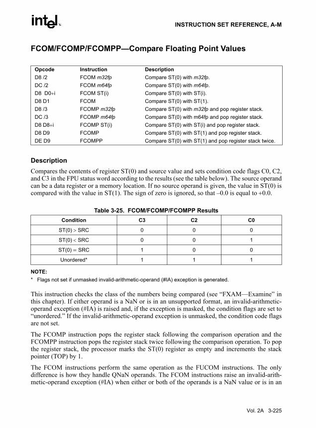
INSTRUCTION SET REFERENCE, A-M
FCOM/FCOMP/FCOMPP—Compare Floating Point Values
DescriptionCompares the contents of register ST(0) and source value and sets condition code flags C0, C2,and C3 in the FPU status word according to the results (see the table below). The source operandcan be a data register or a memory location. If no source operand is given, the value in ST(0) iscompared with the value in ST(1). The sign of zero is ignored, so that –0.0 is equal to +0.0.
NOTE:* Flags not set if unmasked invalid-arithmetic-operand (#IA) exception is generated.
This instruction checks the class of the numbers being compared (see “FXAM—Examine” inthis chapter). If either operand is a NaN or is in an unsupported format, an invalid-arithmetic-operand exception (#IA) is raised and, if the exception is masked, the condition flags are set to“unordered.” If the invalid-arithmetic-operand exception is unmasked, the condition code flagsare not set.
The FCOMP instruction pops the register stack following the comparison operation and theFCOMPP instruction pops the register stack twice following the comparison operation. To popthe register stack, the processor marks the ST(0) register as empty and increments the stackpointer (TOP) by 1.
The FCOM instructions perform the same operation as the FUCOM instructions. The onlydifference is how they handle QNaN operands. The FCOM instructions raise an invalid-arith-metic-operand exception (#IA) when either or both of the operands is a NaN value or is in an
Opcode Instruction DescriptionD8 /2 FCOM m32fp Compare ST(0) with m32fp.DC /2 FCOM m64fp Compare ST(0) with m64fp.D8 D0+i FCOM ST(i) Compare ST(0) with ST(i).D8 D1 FCOM Compare ST(0) with ST(1).D8 /3 FCOMP m32fp Compare ST(0) with m32fp and pop register stack.DC /3 FCOMP m64fp Compare ST(0) with m64fp and pop register stack.D8 D8+i FCOMP ST(i) Compare ST(0) with ST(i) and pop register stack.D8 D9 FCOMP Compare ST(0) with ST(1) and pop register stack.DE D9 FCOMPP Compare ST(0) with ST(1) and pop register stack twice.
Table 3-25. FCOM/FCOMP/FCOMPP ResultsCondition C3 C2 C0
ST(0) > SRC 0 0 0
ST(0) < SRC 0 0 1
ST(0) = SRC 1 0 0
Unordered* 1 1 1
Vol. 2A 3-225

INSTRUCTION SET REFERENCE, A-M
unsupported format. The FUCOM instructions perform the same operation as the FCOMinstructions, except that they do not generate an invalid-arithmetic-operand exception forQNaNs.
OperationCASE (relation of operands) OF
ST > SRC: C3, C2, C0 ← 000;ST < SRC: C3, C2, C0 ← 001;ST = SRC: C3, C2, C0 ← 100;
ESAC;IF ST(0) or SRC = NaN or unsupported format
THEN #IAIF FPUControlWord.IM = 1
THEN C3, C2, C0 ← 111;
FI;FI;IF instruction = FCOMP
THEN PopRegisterStack;
FI;IF instruction = FCOMPP
THEN PopRegisterStack;PopRegisterStack;
FI;
FPU Flags AffectedC1 Set to 0 if stack underflow occurred; otherwise, set to 0.
C0, C2, C3 See table on previous page.
Floating-Point Exceptions#IS Stack underflow occurred.
#IA One or both operands are NaN values or have unsupported formats.
Register is marked empty.
#D One or both operands are denormal values.
Protected Mode Exceptions#GP(0) If a memory operand effective address is outside the CS, DS, ES, FS, or
GS segment limit.
If the DS, ES, FS, or GS register contains a null segment selector.
3-226 Vol. 2A

INSTRUCTION SET REFERENCE, A-M
#SS(0) If a memory operand effective address is outside the SS segment limit.
#NM EM or TS in CR0 is set.
#PF(fault-code) If a page fault occurs.
#AC(0) If alignment checking is enabled and an unaligned memory reference is made while the current privilege level is 3.
Real-Address Mode Exceptions#GP If a memory operand effective address is outside the CS, DS, ES, FS, or
GS segment limit.
#SS If a memory operand effective address is outside the SS segment limit.
#NM EM or TS in CR0 is set.
Virtual-8086 Mode Exceptions#GP(0) If a memory operand effective address is outside the CS, DS, ES, FS, or
GS segment limit.
#SS(0) If a memory operand effective address is outside the SS segment limit.
#NM EM or TS in CR0 is set.
#PF(fault-code) If a page fault occurs.
#AC(0) If alignment checking is enabled and an unaligned memory reference is made.
Vol. 2A 3-227

INSTRUCTION SET REFERENCE, A-M
FCOMI/FCOMIP/ FUCOMI/FUCOMIP—Compare Floating Point Values and Set EFLAGS
DescriptionPerforms an unordered comparison of the contents of registers ST(0) and ST(i) and sets thestatus flags ZF, PF, and CF in the EFLAGS register according to the results (see the tablebelow). The sign of zero is ignored for comparisons, so that –0.0 is equal to +0.0.
NOTE:* Flags not set if unmasked invalid-arithmetic-operand (#IA) exception is generated.
An unordered comparison checks the class of the numbers being compared (see“FXAM—Examine” in this chapter). The FUCOMI/FUCOMIP instructions perform the sameoperations as the FCOMI/FCOMIP instructions. The only difference is that theFUCOMI/FUCOMIP instructions raise the invalid-arithmetic-operand exception (#IA) onlywhen either or both operands are an SNaN or are in an unsupported format; QNaNs cause thecondition code flags to be set to unordered, but do not cause an exception to be generated. TheFCOMI/FCOMIP instructions raise an invalid-operation exception when either or both of theoperands are a NaN value of any kind or are in an unsupported format.
If the operation results in an invalid-arithmetic-operand exception being raised, the status flagsin the EFLAGS register are set only if the exception is masked.
The FCOMI/FCOMIP and FUCOMI/FUCOMIP instructions clear the OF flag in the EFLAGSregister (regardless of whether an invalid-operation exception is detected).
The FCOMIP and FUCOMIP instructions also pop the register stack following the comparisonoperation. To pop the register stack, the processor marks the ST(0) register as empty and incre-ments the stack pointer (TOP) by 1.
Opcode Instruction DescriptionDB F0+i FCOMI ST, ST(i) Compare ST(0) with ST(i) and set status flags accordingly.DF F0+i FCOMIP ST, ST(i) Compare ST(0) with ST(i), set status flags accordingly, and
pop register stack.DB E8+i FUCOMI ST, ST(i) Compare ST(0) with ST(i), check for ordered values, and
set status flags accordingly.DF E8+i FUCOMIP ST, ST(i) Compare ST(0) with ST(i), check for ordered values, set
status flags accordingly, and pop register stack.
Table 3-26. FCOMI/FCOMIP/ FUCOMI/FUCOMIP ResultsComparison Results ZF PF CF
ST0 > ST(i) 0 0 0
ST0 < ST(i) 0 0 1
ST0 = ST(i) 1 0 0
Unordered* 1 1 1
3-228 Vol. 2A

INSTRUCTION SET REFERENCE, A-M
IA-32 Architecture CompatibilityThe FCOMI/FCOMIP/FUCOMI/FUCOMIP instructions were introduced to the IA-32 Archi-tecture in the P6 family processors and are not available in earlier IA-32 processors.
OperationCASE (relation of operands) OF
ST(0) > ST(i): ZF, PF, CF ← 000;ST(0) < ST(i): ZF, PF, CF ← 001;ST(0) = ST(i): ZF, PF, CF ← 100;
ESAC;IF instruction is FCOMI or FCOMIP
THENIF ST(0) or ST(i) = NaN or unsupported format
THEN #IAIF FPUControlWord.IM = 1
THEN ZF, PF, CF ← 111;
FI;FI;
FI;IF instruction is FUCOMI or FUCOMIP
THENIF ST(0) or ST(i) = QNaN, but not SNaN or unsupported format
THEN ZF, PF, CF ← 111;
ELSE (* ST(0) or ST(i) is SNaN or unsupported format *) #IA;IF FPUControlWord.IM = 1
THEN ZF, PF, CF ← 111;
FI;FI;
FI;IF instruction is FCOMIP or FUCOMIP
THEN PopRegisterStack;
FI;
FPU Flags AffectedC1 Set to 0 if stack underflow occurred; otherwise, set to 0.
C0, C2, C3 Not affected.
Vol. 2A 3-229
INSTRUCTION SET REFERENCE, A-M
Floating-Point Exceptions#IS Stack underflow occurred.
#IA (FCOMI or FCOMIP instruction) One or both operands are NaN values or have unsupported formats.
(FUCOMI or FUCOMIP instruction) One or both operands are SNaN values (but not QNaNs) or have undefined formats. Detection of a QNaN value does not raise an invalid-operand exception.
Protected Mode Exceptions#NM EM or TS in CR0 is set.
Real-Address Mode Exceptions#NM EM or TS in CR0 is set.
Virtual-8086 Mode Exceptions#NM EM or TS in CR0 is set.
3-230 Vol. 2A

INSTRUCTION SET REFERENCE, A-M
FCOS—Cosine
DescriptionComputes the cosine of the source operand in register ST(0) and stores the result in ST(0). Thesource operand must be given in radians and must be within the range −263 to +263. The followingtable shows the results obtained when taking the cosine of various classes of numbers.
NOTES:F Means finite floating-point value.* Indicates floating-point invalid-arithmetic-operand (#IA) exception.
If the source operand is outside the acceptable range, the C2 flag in the FPU status word is set,and the value in register ST(0) remains unchanged. The instruction does not raise an exceptionwhen the source operand is out of range. It is up to the program to check the C2 flag for out-of-range conditions. Source values outside the range −263 to +263 can be reduced to the range of theinstruction by subtracting an appropriate integer multiple of 2π or by using the FPREM instruc-tion with a divisor of 2π. See the section titled “Pi” in Chapter 8 of the IA-32 Intel ArchitectureSoftware Developer’s Manual, Volume 1, for a discussion of the proper value to use for π inperforming such reductions.
OperationIF |ST(0)| < 263
THENC2 ← 0;ST(0) ← cosine(ST(0));
ELSE (*source operand is out-of-range *)C2 ← 1;
FI;
Opcode Instruction DescriptionD9 FF FCOS Replace ST(0) with its cosine.
Table 3-27. FCOS ResultsST(0) SRC ST(0) DEST
−∞ *
−F −1 to +1
−0 +1
+0 +1
+F −1 to +1
+∞ *
NaN NaN
Vol. 2A 3-231

INSTRUCTION SET REFERENCE, A-M
FPU Flags AffectedC1 Set to 0 if stack underflow occurred.
Set if result was rounded up; cleared otherwise.
Undefined if C2 is 1.
C2 Set to 1 if outside range (−263 < source operand < +263); otherwise, set to 0.
C0, C3 Undefined.
Floating-Point Exceptions#IS Stack underflow occurred.
#IA Source operand is an SNaN value, ∞, or unsupported format.
#D Source is a denormal value.
#P Value cannot be represented exactly in destination format.
Protected Mode Exceptions#NM EM or TS in CR0 is set.
Real-Address Mode Exceptions#NM EM or TS in CR0 is set.
Virtual-8086 Mode Exceptions#NM EM or TS in CR0 is set.
3-232 Vol. 2A

INSTRUCTION SET REFERENCE, A-M
FDECSTP—Decrement Stack-Top Pointer
DescriptionSubtracts one from the TOP field of the FPU status word (decrements the top-of-stack pointer).If the TOP field contains a 0, it is set to 7. The effect of this instruction is to rotate the stack byone position. The contents of the FPU data registers and tag register are not affected.
OperationIF TOP = 0
THEN TOP ← 7;ELSE TOP ← TOP – 1;
FI;
FPU Flags AffectedThe C1 flag is set to 0. The C0, C2, and C3 flags are undefined.
Floating-Point ExceptionsNone.
Protected Mode Exceptions#NM EM or TS in CR0 is set.
Real-Address Mode Exceptions#NM EM or TS in CR0 is set.
Virtual-8086 Mode Exceptions#NM EM or TS in CR0 is set.
Opcode Instruction DescriptionD9 F6 FDECSTP Decrement TOP field in FPU status word.
Vol. 2A 3-233
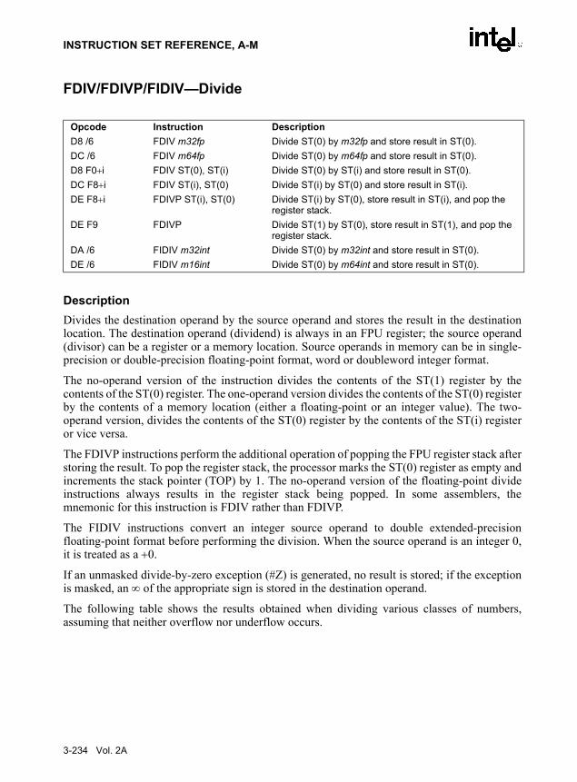
INSTRUCTION SET REFERENCE, A-M
FDIV/FDIVP/FIDIV—Divide
DescriptionDivides the destination operand by the source operand and stores the result in the destinationlocation. The destination operand (dividend) is always in an FPU register; the source operand(divisor) can be a register or a memory location. Source operands in memory can be in single-precision or double-precision floating-point format, word or doubleword integer format.
The no-operand version of the instruction divides the contents of the ST(1) register by thecontents of the ST(0) register. The one-operand version divides the contents of the ST(0) registerby the contents of a memory location (either a floating-point or an integer value). The two-operand version, divides the contents of the ST(0) register by the contents of the ST(i) registeror vice versa.
The FDIVP instructions perform the additional operation of popping the FPU register stack afterstoring the result. To pop the register stack, the processor marks the ST(0) register as empty andincrements the stack pointer (TOP) by 1. The no-operand version of the floating-point divideinstructions always results in the register stack being popped. In some assemblers, themnemonic for this instruction is FDIV rather than FDIVP.
The FIDIV instructions convert an integer source operand to double extended-precisionfloating-point format before performing the division. When the source operand is an integer 0,it is treated as a +0.
If an unmasked divide-by-zero exception (#Z) is generated, no result is stored; if the exceptionis masked, an ∞ of the appropriate sign is stored in the destination operand.
The following table shows the results obtained when dividing various classes of numbers,assuming that neither overflow nor underflow occurs.
Opcode Instruction DescriptionD8 /6 FDIV m32fp Divide ST(0) by m32fp and store result in ST(0).DC /6 FDIV m64fp Divide ST(0) by m64fp and store result in ST(0).D8 F0+i FDIV ST(0), ST(i) Divide ST(0) by ST(i) and store result in ST(0).DC F8+i FDIV ST(i), ST(0) Divide ST(i) by ST(0) and store result in ST(i).DE F8+i FDIVP ST(i), ST(0) Divide ST(i) by ST(0), store result in ST(i), and pop the
register stack.DE F9 FDIVP Divide ST(1) by ST(0), store result in ST(1), and pop the
register stack.DA /6 FIDIV m32int Divide ST(0) by m32int and store result in ST(0).DE /6 FIDIV m16int Divide ST(0) by m64int and store result in ST(0).
3-234 Vol. 2A

INSTRUCTION SET REFERENCE, A-M
NOTES:F Means finite floating-point value.I Means integer.* Indicates floating-point invalid-arithmetic-operand (#IA) exception.** Indicates floating-point zero-divide (#Z) exception.
OperationIF SRC = 0
THEN#Z
ELSEIF instruction is FIDIV
THENDEST ← DEST / ConvertToDoubleExtendedPrecisionFP(SRC);
ELSE (* source operand is floating-point value *)DEST ← DEST / SRC;
FI;FI;IF instruction = FDIVP
THEN PopRegisterStack
FI;
FPU Flags AffectedC1 Set to 0 if stack underflow occurred.
Set if result was rounded up; cleared otherwise.
C0, C2, C3 Undefined.
Table 3-28. FDIV/FDIVP/FIDIV ResultsDEST
−∞ −F −0 +0 +F +∞ NaN
-∞ * +0 +0 −0 −0 * NaN
−F +∞ +F +0 −0 −F −∞ NaN
−I +∞ +F +0 −0 −F −∞ NaN
SRC −0 +∞ ** * * ** −∞ NaN
+0 −∞ ** * * ** +∞ NaN
+I −∞ −F −0 +0 +F +∞ NaN
+F −∞ −F −0 +0 +F +∞ NaN
+∞ * −0 −0 +0 +0 * NaN
NaN NaN NaN NaN NaN NaN NaN NaN
Vol. 2A 3-235

INSTRUCTION SET REFERENCE, A-M
Floating-Point Exceptions#IS Stack underflow occurred.
#IA Operand is an SNaN value or unsupported format.
±∞ / ±∞; ±0 / ±0
#D Source is a denormal value.
#Z DEST / ±0, where DEST is not equal to ±0.
#U Result is too small for destination format.
#O Result is too large for destination format.
#P Value cannot be represented exactly in destination format.
Protected Mode Exceptions#GP(0) If a memory operand effective address is outside the CS, DS, ES, FS, or
GS segment limit.
If the DS, ES, FS, or GS register contains a null segment selector.
#SS(0) If a memory operand effective address is outside the SS segment limit.
#NM EM or TS in CR0 is set.
#PF(fault-code) If a page fault occurs.
#AC(0) If alignment checking is enabled and an unaligned memory reference is made while the current privilege level is 3.
Real-Address Mode Exceptions#GP If a memory operand effective address is outside the CS, DS, ES, FS, or
GS segment limit.
#SS If a memory operand effective address is outside the SS segment limit.
#NM EM or TS in CR0 is set.
Virtual-8086 Mode Exceptions#GP(0) If a memory operand effective address is outside the CS, DS, ES, FS, or
GS segment limit.
#SS(0) If a memory operand effective address is outside the SS segment limit.
#NM EM or TS in CR0 is set.
#PF(fault-code) If a page fault occurs.
#AC(0) If alignment checking is enabled and an unaligned memory reference is made.
3-236 Vol. 2A

INSTRUCTION SET REFERENCE, A-M
FDIVR/FDIVRP/FIDIVR—Reverse Divide
DescriptionDivides the source operand by the destination operand and stores the result in the destinationlocation. The destination operand (divisor) is always in an FPU register; the source operand(dividend) can be a register or a memory location. Source operands in memory can be in single-precision or double-precision floating-point format, word or doubleword integer format.
These instructions perform the reverse operations of the FDIV, FDIVP, and FIDIV instructions.They are provided to support more efficient coding.
The no-operand version of the instruction divides the contents of the ST(0) register by thecontents of the ST(1) register. The one-operand version divides the contents of a memory loca-tion (either a floating-point or an integer value) by the contents of the ST(0) register. The two-operand version, divides the contents of the ST(i) register by the contents of the ST(0) registeror vice versa.
The FDIVRP instructions perform the additional operation of popping the FPU register stackafter storing the result. To pop the register stack, the processor marks the ST(0) register as emptyand increments the stack pointer (TOP) by 1. The no-operand version of the floating-pointdivide instructions always results in the register stack being popped. In some assemblers, themnemonic for this instruction is FDIVR rather than FDIVRP.
The FIDIVR instructions convert an integer source operand to double extended-precisionfloating-point format before performing the division.
If an unmasked divide-by-zero exception (#Z) is generated, no result is stored; if the exceptionis masked, an ∞ of the appropriate sign is stored in the destination operand.
The following table shows the results obtained when dividing various classes of numbers,assuming that neither overflow nor underflow occurs.
Opcode Instruction DescriptionD8 /7 FDIVR m32fp Divide m32fp by ST(0) and store result in ST(0)DC /7 FDIVR m64fp Divide m64fp by ST(0) and store result in ST(0)D8 F8+i FDIVR ST(0), ST(i) Divide ST(i) by ST(0) and store result in ST(0)DC F0+i FDIVR ST(i), ST(0) Divide ST(0) by ST(i) and store result in ST(i)DE F0+i FDIVRP ST(i), ST(0) Divide ST(0) by ST(i), store result in ST(i), and pop the
register stackDE F1 FDIVRP Divide ST(0) by ST(1), store result in ST(1), and pop the
register stackDA /7 FIDIVR m32int Divide m32int by ST(0) and store result in ST(0)DE /7 FIDIVR m16int Divide m16int by ST(0) and store result in ST(0)
Vol. 2A 3-237

INSTRUCTION SET REFERENCE, A-M
NOTES:F Means finite floating-point value.I Means integer.* Indicates floating-point invalid-arithmetic-operand (#IA) exception.** Indicates floating-point zero-divide (#Z) exception.
When the source operand is an integer 0, it is treated as a +0.
OperationIF DEST = 0
THEN#Z
ELSEIF instruction is FIDIVR
THENDEST ← ConvertToDoubleExtendedPrecisionFP(SRC) / DEST;
ELSE (* source operand is floating-point value *)DEST ← SRC / DEST;
FI;FI;IF instruction = FDIVRP
THEN PopRegisterStack
FI;
FPU Flags AffectedC1 Set to 0 if stack underflow occurred.
Set if result was rounded up; cleared otherwise.
C0, C2, C3 Undefined.
Table 3-29. FDIVR/FDIVRP/FIDIVR ResultsDEST
−∞ −F −0 +0 +F +∞ NaN
−∞ * +∞ +∞ −∞ −∞ * NaN
SRC −F +0 +F ** ** -F −0 NaN
−I +0 +F ** ** -F −0 NaN
−0 +0 +0 * * −0 −0 NaN
+0 −0 −0 * * +0 +0 NaN
+I −0 -F ** ** +F +0 NaN
+F −0 -F ** ** +F +0 NaN
+∞ * −∞ −∞ +∞ +∞ * NaN
NaN NaN NaN NaN NaN NaN NaN NaN
3-238 Vol. 2A

INSTRUCTION SET REFERENCE, A-M
Floating-Point Exceptions#IS Stack underflow occurred.
#IA Operand is an SNaN value or unsupported format.
±∞ / ±∞; ±0 / ±0
#D Source is a denormal value.
#Z SRC / ±0, where SRC is not equal to ±0.
#U Result is too small for destination format.
#O Result is too large for destination format.
#P Value cannot be represented exactly in destination format.
Protected Mode Exceptions#GP(0) If a memory operand effective address is outside the CS, DS, ES, FS, or
GS segment limit.
If the DS, ES, FS, or GS register contains a null segment selector.
#SS(0) If a memory operand effective address is outside the SS segment limit.
#NM EM or TS in CR0 is set.
#PF(fault-code) If a page fault occurs.
#AC(0) If alignment checking is enabled and an unaligned memory reference is made while the current privilege level is 3.
Real-Address Mode Exceptions#GP If a memory operand effective address is outside the CS, DS, ES, FS, or
GS segment limit.
#SS If a memory operand effective address is outside the SS segment limit.
#NM EM or TS in CR0 is set.
Virtual-8086 Mode Exceptions#GP(0) If a memory operand effective address is outside the CS, DS, ES, FS, or
GS segment limit.
#SS(0) If a memory operand effective address is outside the SS segment limit.
#NM EM or TS in CR0 is set.
#PF(fault-code) If a page fault occurs.
#AC(0) If alignment checking is enabled and an unaligned memory reference is made.
Vol. 2A 3-239

INSTRUCTION SET REFERENCE, A-M
FFREE—Free Floating-Point Register
DescriptionSets the tag in the FPU tag register associated with register ST(i) to empty (11B). The contentsof ST(i) and the FPU stack-top pointer (TOP) are not affected.
OperationTAG(i) ← 11B;
FPU Flags AffectedC0, C1, C2, C3 undefined.
Floating-Point ExceptionsNone.
Protected Mode Exceptions#NM EM or TS in CR0 is set.
Real-Address Mode Exceptions#NM EM or TS in CR0 is set.
Virtual-8086 Mode Exceptions#NM EM or TS in CR0 is set.
Opcode Instruction DescriptionDD C0+i FFREE ST(i) Sets tag for ST(i) to empty.
3-240 Vol. 2A

INSTRUCTION SET REFERENCE, A-M
FICOM/FICOMP—Compare Integer
DescriptionCompares the value in ST(0) with an integer source operand and sets the condition code flagsC0, C2, and C3 in the FPU status word according to the results (see table below). The integervalue is converted to double extended-precision floating-point format before the comparison ismade.
These instructions perform an “unordered comparison.” An unordered comparison also checksthe class of the numbers being compared (see “FXAM—Examine” in this chapter). If eitheroperand is a NaN or is in an undefined format, the condition flags are set to “unordered.”
The sign of zero is ignored, so that –0.0 ← +0.0.
The FICOMP instructions pop the register stack following the comparison. To pop the registerstack, the processor marks the ST(0) register empty and increments the stack pointer (TOP) by 1.
OperationCASE (relation of operands) OF
ST(0) > SRC: C3, C2, C0 ← 000;ST(0) < SRC: C3, C2, C0 ← 001;ST(0) = SRC: C3, C2, C0 ← 100;Unordered: C3, C2, C0 ← 111;
ESAC;IF instruction = FICOMP
THEN PopRegisterStack;
FI;
Opcode Instruction DescriptionDE /2 FICOM m16int Compare ST(0) with m16int.DA /2 FICOM m32int Compare ST(0) with m32int.DE /3 FICOMP m16int Compare ST(0) with m16int and pop stack register.DA /3 FICOMP m32int Compare ST(0) with m32int and pop stack register.
Table 3-30. FICOM/FICOMP ResultsCondition C3 C2 C0
ST(0) > SRC 0 0 0
ST(0) < SRC 0 0 1
ST(0) = SRC 1 0 0
Unordered 1 1 1
Vol. 2A 3-241

INSTRUCTION SET REFERENCE, A-M
FPU Flags AffectedC1 Set to 0 if stack underflow occurred; otherwise, set to 0.
C0, C2, C3 See table on previous page.
Floating-Point Exceptions#IS Stack underflow occurred.
#IA One or both operands are NaN values or have unsupported formats.
#D One or both operands are denormal values.
Protected Mode Exceptions#GP(0) If a memory operand effective address is outside the CS, DS, ES, FS, or
GS segment limit.
If the DS, ES, FS, or GS register contains a null segment selector.
#SS(0) If a memory operand effective address is outside the SS segment limit.
#NM EM or TS in CR0 is set.
#PF(fault-code) If a page fault occurs.
#AC(0) If alignment checking is enabled and an unaligned memory reference is made while the current privilege level is 3.
Real-Address Mode Exceptions#GP If a memory operand effective address is outside the CS, DS, ES, FS, or
GS segment limit.
#SS If a memory operand effective address is outside the SS segment limit.
#NM EM or TS in CR0 is set.
Virtual-8086 Mode Exceptions#GP(0) If a memory operand effective address is outside the CS, DS, ES, FS, or
GS segment limit.
#SS(0) If a memory operand effective address is outside the SS segment limit.
#NM EM or TS in CR0 is set.
#PF(fault-code) If a page fault occurs.
#AC(0) If alignment checking is enabled and an unaligned memory reference is made.
3-242 Vol. 2A

INSTRUCTION SET REFERENCE, A-M
FILD—Load Integer
DescriptionConverts the signed-integer source operand into double extended-precision floating-pointformat and pushes the value onto the FPU register stack. The source operand can be a word,doubleword, or quadword integer. It is loaded without rounding errors. The sign of the sourceoperand is preserved.
OperationTOP ← TOP − 1;ST(0) ← ConvertToDoubleExtendedPrecisionFP(SRC);
FPU Flags AffectedC1 Set to 1 if stack overflow occurred; set to 0 otherwise.
C0, C2, C3 Undefined.
Floating-Point Exceptions#IS Stack overflow occurred.
Protected Mode Exceptions#GP(0) If a memory operand effective address is outside the CS, DS, ES, FS, or
GS segment limit.
If the DS, ES, FS, or GS register contains a null segment selector.
#SS(0) If a memory operand effective address is outside the SS segment limit.
#NM EM or TS in CR0 is set.
#PF(fault-code) If a page fault occurs.
#AC(0) If alignment checking is enabled and an unaligned memory reference is made while the current privilege level is 3.
Real-Address Mode Exceptions#GP If a memory operand effective address is outside the CS, DS, ES, FS, or
GS segment limit.
#SS If a memory operand effective address is outside the SS segment limit.
Opcode Instruction DescriptionDF /0 FILD m16int Push m16int onto the FPU register stack.DB /0 FILD m32int Push m32int onto the FPU register stack.DF /5 FILD m64int Push m64int onto the FPU register stack.
Vol. 2A 3-243

INSTRUCTION SET REFERENCE, A-M
#NM EM or TS in CR0 is set.
Virtual-8086 Mode Exceptions#GP(0) If a memory operand effective address is outside the CS, DS, ES, FS, or
GS segment limit.
#SS(0) If a memory operand effective address is outside the SS segment limit.
#NM EM or TS in CR0 is set.
#PF(fault-code) If a page fault occurs.
#AC(0) If alignment checking is enabled and an unaligned memory reference is made.
3-244 Vol. 2A

INSTRUCTION SET REFERENCE, A-M
FINCSTP—Increment Stack-Top Pointer
DescriptionAdds one to the TOP field of the FPU status word (increments the top-of-stack pointer). If theTOP field contains a 7, it is set to 0. The effect of this instruction is to rotate the stack by oneposition. The contents of the FPU data registers and tag register are not affected. This operationis not equivalent to popping the stack, because the tag for the previous top-of-stack register isnot marked empty.
OperationIF TOP = 7
THEN TOP ← 0;ELSE TOP ← TOP + 1;
FI;
FPU Flags AffectedThe C1 flag is set to 0. The C0, C2, and C3 flags are undefined.
Floating-Point ExceptionsNone.
Protected Mode Exceptions#NM EM or TS in CR0 is set.
Real-Address Mode Exceptions#NM EM or TS in CR0 is set.
Virtual-8086 Mode Exceptions#NM EM or TS in CR0 is set.
Opcode Instruction DescriptionD9 F7 FINCSTP Increment the TOP field in the FPU status register.
Vol. 2A 3-245

INSTRUCTION SET REFERENCE, A-M
FINIT/FNINIT—Initialize Floating-Point Unit
DescriptionSets the FPU control, status, tag, instruction pointer, and data pointer registers to their defaultstates. The FPU control word is set to 037FH (round to nearest, all exceptions masked, 64-bitprecision). The status word is cleared (no exception flags set, TOP is set to 0). The data registersin the register stack are left unchanged, but they are all tagged as empty (11B). Both the instruc-tion and data pointers are cleared.
The FINIT instruction checks for and handles any pending unmasked floating-point exceptionsbefore performing the initialization; the FNINIT instruction does not.
The assembler issues two instructions for the FINIT instruction (an FWAIT instruction followedby an FNINIT instruction), and the processor executes each of these instructions in separately.If an exception is generated for either of these instructions, the save EIP points to the instructionthat caused the exception.
IA-32 Architecture CompatibilityWhen operating a Pentium or Intel486 processor in MS-DOS compatibility mode, it is possible(under unusual circumstances) for an FNINIT instruction to be interrupted prior to beingexecuted to handle a pending FPU exception. See the section titled “No-Wait FPU InstructionsCan Get FPU Interrupt in Window” in Appendix D of the IA-32 Intel Architecture SoftwareDeveloper’s Manual, Volume 1, for a description of these circumstances. An FNINIT instructioncannot be interrupted in this way on a Pentium 4, Intel Xeon, or P6 family processor.
In the Intel387 math coprocessor, the FINIT/FNINIT instruction does not clear the instructionand data pointers.
This instruction affects only the x87 FPU. It does not affect the XMM and MXCSR registers.
OperationFPUControlWord ← 037FH;FPUStatusWord ← 0;FPUTagWord ← FFFFH;FPUDataPointer ← 0;FPUInstructionPointer ← 0;FPULastInstructionOpcode ← 0;
Opcode Instruction Description9B DB E3 FINIT Initialize FPU after checking for pending unmasked
floating-point exceptions.DB E3 FNINIT Initialize FPU without checking for pending unmasked
floating-point exceptions. See the IA-32 Architecture Compatibility section below.
3-246 Vol. 2A

INSTRUCTION SET REFERENCE, A-M
FPU Flags AffectedC0, C1, C2, C3 set to 0.
Floating-Point ExceptionsNone.
Protected Mode Exceptions#NM EM or TS in CR0 is set.
Real-Address Mode Exceptions#NM EM or TS in CR0 is set.
Virtual-8086 Mode Exceptions#NM EM or TS in CR0 is set.
Vol. 2A 3-247

INSTRUCTION SET REFERENCE, A-M
FIST/FISTP—Store Integer
DescriptionThe FIST instruction converts the value in the ST(0) register to a signed integer and stores theresult in the destination operand. Values can be stored in word or doubleword integer format.The destination operand specifies the address where the first byte of the destination value is tobe stored.
The FISTP instruction performs the same operation as the FIST instruction and then pops theregister stack. To pop the register stack, the processor marks the ST(0) register as empty andincrements the stack pointer (TOP) by 1. The FISTP instruction also stores values in quadwordinteger format.
The following table shows the results obtained when storing various classes of numbers ininteger format.
NOTES:F Means finite floating-point value.I Means integer.* Indicates floating-point invalid-operation (#IA) exception.** 0 or ±1, depending on the rounding mode.
Opcode Instruction DescriptionDF /2 FIST m16int Store ST(0) in m16int.DB /2 FIST m32int Store ST(0) in m32int.DF /3 FISTP m16int Store ST(0) in m16int and pop register stack.DB /3 FISTP m32int Store ST(0) in m32int and pop register stack.DF /7 FISTP m64int Store ST(0) in m64int and pop register stack.
Table 3-31. FIST/FISTP ResultsST(0) DEST
−∞ or Value Too Large for DEST Format *
F ≤ −1 −I
−1 < F < −0 **
−0 0
+0 0
+0 < F < +1 **
F ≥ +1 +I
+∞ or Value Too Large for DEST Format *
NaN *
3-248 Vol. 2A

INSTRUCTION SET REFERENCE, A-M
If the source value is a non-integral value, it is rounded to an integer value, according to therounding mode specified by the RC field of the FPU control word.
If the converted value is too large for the destination format, or if the source operand is an ∞,SNaN, QNAN, or is in an unsupported format, an invalid-arithmetic-operand condition issignaled. If the invalid-operation exception is not masked, an invalid-arithmetic-operand excep-tion (#IA) is generated and no value is stored in the destination operand. If the invalid-operationexception is masked, the integer indefinite value is stored in memory.
OperationDEST ← Integer(ST(0));IF instruction = FISTP
THEN PopRegisterStack;
FI;
FPU Flags AffectedC1 Set to 0 if stack underflow occurred.
Indicates rounding direction of if the inexact exception (#P) is generated: 0 ← not roundup; 1 ← roundup.
Set to 0 otherwise.
C0, C2, C3 Undefined.
Floating-Point Exceptions#IS Stack underflow occurred.
#IA Converted value is too large for the destination format.
Source operand is an SNaN, QNaN, ±∞, or unsupported format.
#P Value cannot be represented exactly in destination format.
Protected Mode Exceptions#GP(0) If the destination is located in a non-writable segment.
If a memory operand effective address is outside the CS, DS, ES, FS, or GS segment limit.
If the DS, ES, FS, or GS register is used to access memory and it contains a null segment selector.
#SS(0) If a memory operand effective address is outside the SS segment limit.
#NM EM or TS in CR0 is set.
#PF(fault-code) If a page fault occurs.
Vol. 2A 3-249

INSTRUCTION SET REFERENCE, A-M
#AC(0) If alignment checking is enabled and an unaligned memory reference is made while the current privilege level is 3.
Real-Address Mode Exceptions#GP If a memory operand effective address is outside the CS, DS, ES, FS, or
GS segment limit.
#SS If a memory operand effective address is outside the SS segment limit.
#NM EM or TS in CR0 is set.
Virtual-8086 Mode Exceptions#GP(0) If a memory operand effective address is outside the CS, DS, ES, FS, or
GS segment limit.
#SS(0) If a memory operand effective address is outside the SS segment limit.
#NM EM or TS in CR0 is set.
#PF(fault-code) If a page fault occurs.
#AC(0) If alignment checking is enabled and an unaligned memory reference is made.
3-250 Vol. 2A

INSTRUCTION SET REFERENCE, A-M
FISTTP: Store Integer with Truncation
DescriptionFISTTP converts the value in ST into a signed integer using truncation (chop) as rounding mode,transfers the result to the destination, and pop ST. FISTTP accepts word, short integer, and longinteger destinations.
The following table shows the results obtained when storing various classes of numbers ininteger format.
Notes:F Means finite floating-point value.Ι Means integer.∗ Indicates floating-point invalid-operation (#IA) exception.
OperationDEST ← ST;pop ST;
Flags AffectedC1 is cleared; C0, C2, C3 undefined.
Numeric ExceptionsInvalid, Stack Invalid (stack underflow), Precision.
Opcode Instruction DescriptionDF /1DB /1DD /1
FISTTP m16intFISTTP m32intFISTTP m64int
Store ST as a signed integer (truncate) in m16int and pop ST.Store ST as a signed integer (truncate) in m32int and pop ST.Store ST as a signed integer (truncate) in m64int and pop ST.
Table 3-32. FISTTP ResultsST(0) DEST
− ∞ or Value Too Large for DEST Format ∗
F ≤ − 1 − Ι
− 1 < F < +1 0
F ≥ +1 + Ι
+ ∞ or Value Too Large for DEST Format ∗
NaN ∗
Vol. 2A 3-251

INSTRUCTION SET REFERENCE, A-M
Protected Mode Exceptions#GP(0) If the destination is in a nonwritable segment.
For an illegal memory operand effective address in the CS, DS, ES, FS or GS segments.
#SS(0) For an illegal address in the SS segment.
#PF(fault-code) For a page fault.
#AC(0) If alignment checking is enabled and an unaligned memory reference is made while the current privilege level is 3.
#NM If CR0.EM = 1.
If TS bit in CR0 is set.
#UD If CPUID.SSE3(ECX bit 0) = 0.
Real Address Mode ExceptionsGP(0) If any part of the operand would lie outside of the effective address space
from 0 to 0FFFFH.
#NM If CR0.EM = 1.
If TS bit in CR0 is set.
#UD If CPUID.SSE3(ECX bit 0) = 0.
Virtual 8086 Mode ExceptionsGP(0) If any part of the operand would lie outside of the effective address space
from 0 to 0FFFFH.
#NM If CR0.EM = 1.
If TS bit in CR0 is set.
#UD If CPUID.SSE3(ECX bit 0) = 0.
#PF(fault-code) For a page fault.
#AC(0) For unaligned memory reference if the current privilege is 3.
3-252 Vol. 2A

INSTRUCTION SET REFERENCE, A-M
FLD—Load Floating Point Value
DescriptionPushes the source operand onto the FPU register stack. The source operand can be in single-precision, double-precision, or double extended-precision floating-point format. If the sourceoperand is in single-precision or double-precision floating-point format, it is automaticallyconverted to the double extended-precision floating-point format before being pushed on thestack.
The FLD instruction can also push the value in a selected FPU register [ST(i)] onto the stack.Here, pushing register ST(0) duplicates the stack top.
OperationIF SRC is ST(i)
THENtemp ← ST(i)
FI;TOP ← TOP − 1;IF SRC is memory-operand
THENST(0) ← ConvertToDoubleExtendedPrecisionFP(SRC);
ELSE (* SRC is ST(i) *)ST(0) ← temp;
FI;
FPU Flags AffectedC1 Set to 1 if stack overflow occurred; otherwise, set to 0.
C0, C2, C3 Undefined.
Floating-Point Exceptions#IS Stack overflow occurred.
#IA Source operand is an SNaN. Does not occur if the source operand is in double extended-precision floating-point format (FLD m80fp or FLD ST(i)).
Opcode Instruction DescriptionD9 /0 FLD m32fp Push m32fp onto the FPU register stack.DD /0 FLD m64fp Push m64fp onto the FPU register stack.DB /5 FLD m80fp Push m80fp onto the FPU register stack.D9 C0+i FLD ST(i) Push ST(i) onto the FPU register stack.
Vol. 2A 3-253

INSTRUCTION SET REFERENCE, A-M
Protected Mode Exceptions#D Source operand is a denormal value. Does not occur if the source operand
is in double extended-precision floating-point format.
#GP(0) If destination is located in a non-writable segment.
If a memory operand effective address is outside the CS, DS, ES, FS, or GS segment limit.
If the DS, ES, FS, or GS register is used to access memory and it contains a null segment selector.
#SS(0) If a memory operand effective address is outside the SS segment limit.
#NM EM or TS in CR0 is set.
#PF(fault-code) If a page fault occurs.
#AC(0) If alignment checking is enabled and an unaligned memory reference is made while the current privilege level is 3.
Real-Address Mode Exceptions#GP If a memory operand effective address is outside the CS, DS, ES, FS, or
GS segment limit.
#SS If a memory operand effective address is outside the SS segment limit.
#NM EM or TS in CR0 is set.
Virtual-8086 Mode Exceptions#GP(0) If a memory operand effective address is outside the CS, DS, ES, FS, or
GS segment limit.
#SS(0) If a memory operand effective address is outside the SS segment limit.
#NM EM or TS in CR0 is set.
#PF(fault-code) If a page fault occurs.
#AC(0) If alignment checking is enabled and an unaligned memory reference is made.
3-254 Vol. 2A

INSTRUCTION SET REFERENCE, A-M
FLD1/FLDL2T/FLDL2E/FLDPI/FLDLG2/FLDLN2/FLDZ—Load Constant
DescriptionPush one of seven commonly used constants (in double extended-precision floating-pointformat) onto the FPU register stack. The constants that can be loaded with these instructionsinclude +1.0, +0.0, log210, log2e, π, log102, and loge2. For each constant, an internal 66-bitconstant is rounded (as specified by the RC field in the FPU control word) to double extended-precision floating-point format. The inexact-result exception (#P) is not generated as a result ofthe rounding, nor is the C1 flag set in the x87 FPU status word if the value is rounded up.
See the section titled “Pi” in Chapter 8 of the IA-32 Intel Architecture Software Developer’sManual, Volume 1, for a description of the π constant.
OperationTOP ← TOP − 1;ST(0) ← CONSTANT;
FPU Flags AffectedC1 Set to 1 if stack overflow occurred; otherwise, set to 0.
C0, C2, C3 Undefined.
Floating-Point Exceptions#IS Stack overflow occurred.
Protected Mode Exceptions#NM EM or TS in CR0 is set.
Real-Address Mode Exceptions#NM EM or TS in CR0 is set.
Opcode Instruction DescriptionD9 E8 FLD1 Push +1.0 onto the FPU register stack.D9 E9 FLDL2T Push log210 onto the FPU register stack.D9 EA FLDL2E Push log2e onto the FPU register stack.D9 EB FLDPI Push π onto the FPU register stack.D9 EC FLDLG2 Push log102 onto the FPU register stack.D9 ED FLDLN2 Push loge2 onto the FPU register stack.D9 EE FLDZ Push +0.0 onto the FPU register stack.
Vol. 2A 3-255

INSTRUCTION SET REFERENCE, A-M
Virtual-8086 Mode Exceptions#NM EM or TS in CR0 is set.
IA-32 Architecture CompatibilityWhen the RC field is set to round-to-nearest, the FPU produces the same constants that isproduced by the Intel 8087 and Intel 287 math coprocessors.
3-256 Vol. 2A
INSTRUCTION SET REFERENCE, A-M
FLDCW—Load x87 FPU Control Word
DescriptionLoads the 16-bit source operand into the FPU control word. The source operand is a memorylocation. This instruction is typically used to establish or change the FPU’s mode of operation.
If one or more exception flags are set in the FPU status word prior to loading a new FPU controlword and the new control word unmasks one or more of those exceptions, a floating-pointexception will be generated upon execution of the next floating-point instruction (except for theno-wait floating-point instructions, see the section titled “Software Exception Handling” inChapter 8 of the IA-32 Intel Architecture Software Developer’s Manual, Volume 1). To avoidraising exceptions when changing FPU operating modes, clear any pending exceptions (usingthe FCLEX or FNCLEX instruction) before loading the new control word.
OperationFPUControlWord ← SRC;
FPU Flags AffectedC0, C1, C2, C3 undefined.
Floating-Point ExceptionsNone; however, this operation might unmask a pending exception in the FPU status word. Thatexception is then generated upon execution of the next “waiting” floating-point instruction.
Protected Mode Exceptions#GP(0) If a memory operand effective address is outside the CS, DS, ES, FS, or
GS segment limit.
If the DS, ES, FS, or GS register is used to access memory and it contains a null segment selector.
#SS(0) If a memory operand effective address is outside the SS segment limit.
#NM EM or TS in CR0 is set.
#PF(fault-code) If a page fault occurs.
#AC(0) If alignment checking is enabled and an unaligned memory reference is made while the current privilege level is 3.
Opcode Instruction DescriptionD9 /5 FLDCW m2byte Load FPU control word from m2byte.
Vol. 2A 3-257

INSTRUCTION SET REFERENCE, A-M
Real-Address Mode Exceptions#GP If a memory operand effective address is outside the CS, DS, ES, FS, or
GS segment limit.
#SS If a memory operand effective address is outside the SS segment limit.
#NM EM or TS in CR0 is set.
Virtual-8086 Mode Exceptions#GP(0) If a memory operand effective address is outside the CS, DS, ES, FS, or
GS segment limit.
#SS(0) If a memory operand effective address is outside the SS segment limit.
#NM EM or TS in CR0 is set.
#PF(fault-code) If a page fault occurs.
#AC(0) If alignment checking is enabled and an unaligned memory reference is made.
3-258 Vol. 2A
INSTRUCTION SET REFERENCE, A-M
FLDENV—Load x87 FPU Environment
DescriptionLoads the complete x87 FPU operating environment from memory into the FPU registers. Thesource operand specifies the first byte of the operating-environment data in memory. This datais typically written to the specified memory location by a FSTENV or FNSTENV instruction.
The FPU operating environment consists of the FPU control word, status word, tag word,instruction pointer, data pointer, and last opcode. Figures 8-9 through 8-12 in the IA-32 IntelArchitecture Software Developer’s Manual, Volume 1, show the layout in memory of the loadedenvironment, depending on the operating mode of the processor (protected or real) and thecurrent operand-size attribute (16-bit or 32-bit). In virtual-8086 mode, the real mode layouts areused.
The FLDENV instruction should be executed in the same operating mode as the correspondingFSTENV/FNSTENV instruction.
If one or more unmasked exception flags are set in the new FPU status word, a floating-pointexception will be generated upon execution of the next floating-point instruction (except for theno-wait floating-point instructions, see the section titled “Software Exception Handling” inChapter 8 of the IA-32 Intel Architecture Software Developer’s Manual, Volume 1). To avoidgenerating exceptions when loading a new environment, clear all the exception flags in the FPUstatus word that is being loaded.
If a page or limit fault occurs during the execution of this instruction, the state of the x87 FPUregisters as seen by the fault handler may be different than the state being loaded from memory.In such situations, the fault handler should ignore the status of the x87 FPU registers, handle thefault, and return. The FLDENV instruction will then complete the loading of the x87 FPU regis-ters with no resulting context inconsistency.
OperationFPUControlWord ← SRC[FPUControlWord);FPUStatusWord ← SRC[FPUStatusWord);FPUTagWord ← SRC[FPUTagWord);FPUDataPointer ← SRC[FPUDataPointer);FPUInstructionPointer ← SRC[FPUInstructionPointer);FPULastInstructionOpcode ← SRC[FPULastInstructionOpcode);
FPU Flags AffectedThe C0, C1, C2, C3 flags are loaded.
Opcode Instruction DescriptionD9 /4 FLDENV m14/28byte Load FPU environment from m14byte or m28byte.
Vol. 2A 3-259

INSTRUCTION SET REFERENCE, A-M
Floating-Point ExceptionsNone; however, if an unmasked exception is loaded in the status word, it is generated uponexecution of the next “waiting” floating-point instruction.
Protected Mode Exceptions#GP(0) If a memory operand effective address is outside the CS, DS, ES, FS, or
GS segment limit.
If the DS, ES, FS, or GS register is used to access memory and it contains a null segment selector.
#SS(0) If a memory operand effective address is outside the SS segment limit.
#NM EM or TS in CR0 is set.
#PF(fault-code) If a page fault occurs.
#AC(0) If alignment checking is enabled and an unaligned memory reference is made while the current privilege level is 3.
Real-Address Mode Exceptions#GP If a memory operand effective address is outside the CS, DS, ES, FS, or
GS segment limit.
#SS If a memory operand effective address is outside the SS segment limit.
#NM EM or TS in CR0 is set.
Virtual-8086 Mode Exceptions#GP(0) If a memory operand effective address is outside the CS, DS, ES, FS, or
GS segment limit.
#SS(0) If a memory operand effective address is outside the SS segment limit.
#NM EM or TS in CR0 is set.
#PF(fault-code) If a page fault occurs.
#AC(0) If alignment checking is enabled and an unaligned memory reference is made.
3-260 Vol. 2A

INSTRUCTION SET REFERENCE, A-M
FMUL/FMULP/FIMUL—Multiply
DescriptionMultiplies the destination and source operands and stores the product in the destination location.The destination operand is always an FPU data register; the source operand can be an FPU dataregister or a memory location. Source operands in memory can be in single-precision or double-precision floating-point format or in word or doubleword integer format.
The no-operand version of the instruction multiplies the contents of the ST(1) register by thecontents of the ST(0) register and stores the product in the ST(1) register. The one-operandversion multiplies the contents of the ST(0) register by the contents of a memory location (eithera floating point or an integer value) and stores the product in the ST(0) register. The two-operandversion, multiplies the contents of the ST(0) register by the contents of the ST(i) register, or viceversa, with the result being stored in the register specified with the first operand (the destinationoperand).
The FMULP instructions perform the additional operation of popping the FPU register stackafter storing the product. To pop the register stack, the processor marks the ST(0) register asempty and increments the stack pointer (TOP) by 1. The no-operand version of the floating-point multiply instructions always results in the register stack being popped. In some assem-blers, the mnemonic for this instruction is FMUL rather than FMULP.
The FIMUL instructions convert an integer source operand to double extended-precisionfloating-point format before performing the multiplication.
The sign of the result is always the exclusive-OR of the source signs, even if one or more of thevalues being multiplied is 0 or ∞. When the source operand is an integer 0, it is treated as a +0.
The following table shows the results obtained when multiplying various classes of numbers,assuming that neither overflow nor underflow occurs.
Opcode Instruction DescriptionD8 /1 FMUL m32fp Multiply ST(0) by m32fp and store result in ST(0)DC /1 FMUL m64fp Multiply ST(0) by m64fp and store result in ST(0)D8 C8+i FMUL ST(0), ST(i) Multiply ST(0) by ST(i) and store result in ST(0)DC C8+i FMUL ST(i), ST(0) Multiply ST(i) by ST(0) and store result in ST(i)DE C8+i FMULP ST(i), ST(0) Multiply ST(i) by ST(0), store result in ST(i), and pop the
register stackDE C9 FMULP Multiply ST(1) by ST(0), store result in ST(1), and pop the
register stackDA /1 FIMUL m32int Multiply ST(0) by m32int and store result in ST(0)DE /1 FIMUL m16int Multiply ST(0) by m16int and store result in ST(0)
Vol. 2A 3-261
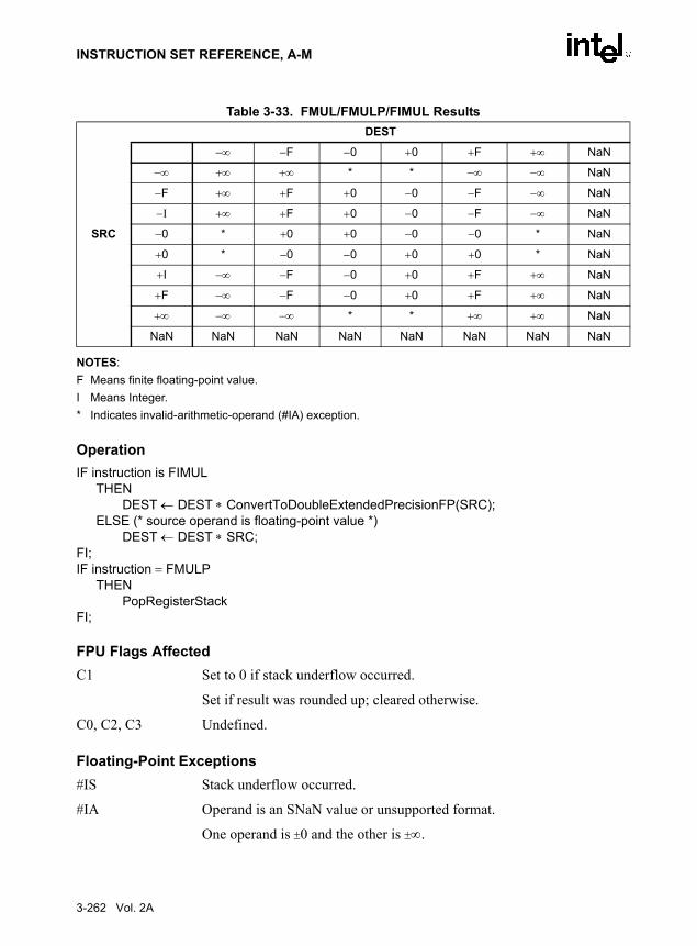
INSTRUCTION SET REFERENCE, A-M
NOTES:F Means finite floating-point value.I Means Integer.* Indicates invalid-arithmetic-operand (#IA) exception.
OperationIF instruction is FIMUL
THENDEST ← DEST ∗ ConvertToDoubleExtendedPrecisionFP(SRC);
ELSE (* source operand is floating-point value *)DEST ← DEST ∗ SRC;
FI;IF instruction = FMULP
THEN PopRegisterStack
FI;
FPU Flags AffectedC1 Set to 0 if stack underflow occurred.
Set if result was rounded up; cleared otherwise.
C0, C2, C3 Undefined.
Floating-Point Exceptions#IS Stack underflow occurred.
#IA Operand is an SNaN value or unsupported format.
One operand is ±0 and the other is ±∞.
Table 3-33. FMUL/FMULP/FIMUL ResultsDEST
−∞ −F −0 +0 +F +∞ NaN
−∞ +∞ +∞ * * −∞ −∞ NaN
−F +∞ +F +0 −0 −F −∞ NaN
−I +∞ +F +0 −0 −F −∞ NaN
SRC −0 * +0 +0 −0 −0 * NaN
+0 * −0 −0 +0 +0 * NaN
+I −∞ −F −0 +0 +F +∞ NaN
+F −∞ −F −0 +0 +F +∞ NaN
+∞ −∞ −∞ * * +∞ +∞ NaN
NaN NaN NaN NaN NaN NaN NaN NaN
3-262 Vol. 2A

INSTRUCTION SET REFERENCE, A-M
#D Source operand is a denormal value.
#U Result is too small for destination format.
#O Result is too large for destination format.
#P Value cannot be represented exactly in destination format.
Protected Mode Exceptions#GP(0) If a memory operand effective address is outside the CS, DS, ES, FS, or
GS segment limit.
If the DS, ES, FS, or GS register is used to access memory and it contains a null segment selector.
#SS(0) If a memory operand effective address is outside the SS segment limit.
#NM EM or TS in CR0 is set.
#PF(fault-code) If a page fault occurs.
#AC(0) If alignment checking is enabled and an unaligned memory reference is made while the current privilege level is 3.
Real-Address Mode Exceptions#GP If a memory operand effective address is outside the CS, DS, ES, FS, or
GS segment limit.
#SS If a memory operand effective address is outside the SS segment limit.
#NM EM or TS in CR0 is set.
Virtual-8086 Mode Exceptions#GP(0) If a memory operand effective address is outside the CS, DS, ES, FS, or
GS segment limit.
#SS(0) If a memory operand effective address is outside the SS segment limit.
#NM EM or TS in CR0 is set.
#PF(fault-code) If a page fault occurs.
#AC(0) If alignment checking is enabled and an unaligned memory reference is made.
Vol. 2A 3-263

INSTRUCTION SET REFERENCE, A-M
FNOP—No Operation
DescriptionPerforms no FPU operation. This instruction takes up space in the instruction stream but doesnot affect the FPU or machine context, except the EIP register.
FPU Flags AffectedC0, C1, C2, C3 undefined.
Floating-Point ExceptionsNone.
Protected Mode Exceptions#NM EM or TS in CR0 is set.
Real-Address Mode Exceptions#NM EM or TS in CR0 is set.
Virtual-8086 Mode Exceptions#NM EM or TS in CR0 is set.
Opcode Instruction DescriptionD9 D0 FNOP No operation is performed.
3-264 Vol. 2A

INSTRUCTION SET REFERENCE, A-M
FPATAN—Partial Arctangent
DescriptionComputes the arctangent of the source operand in register ST(1) divided by the source operandin register ST(0), stores the result in ST(1), and pops the FPU register stack. The result in registerST(0) has the same sign as the source operand ST(1) and a magnitude less than +π.
The FPATAN instruction returns the angle between the X axis and the line from the origin tothe point (X,Y), where Y (the ordinate) is ST(1) and X (the abscissa) is ST(0). The angledepends on the sign of X and Y independently, not just on the sign of the ratio Y/X. This isbecause a point (−X,Y) is in the second quadrant, resulting in an angle between π/2 and π, whilea point (X,−Y) is in the fourth quadrant, resulting in an angle between 0 and −π/2. A point (−X,−Y) is in the third quadrant, giving an angle between −π/2 and −π.
The following table shows the results obtained when computing the arctangent of variousclasses of numbers, assuming that underflow does not occur.
NOTES:F Means finite floating-point value.
* Table 8-10 in the IA-32 Intel Architecture Software Developer’s Manual, Volume 1, specifies that theratios 0/0 and ∞/∞ generate the floating-point invalid arithmetic-operation exception and, if this exceptionis masked, the floating-point QNaN indefinite value is returned. With the FPATAN instruction, the 0/0 or∞/∞ value is actually not calculated using division. Instead, the arctangent of the two variables is derivedfrom a standard mathematical formulation that is generalized to allow complex numbers as arguments. Inthis complex variable formulation, arctangent(0,0) etc. has well defined values. These values are neededto develop a library to compute transcendental functions with complex arguments, based on the FPUfunctions that only allow floating-point values as arguments.
There is no restriction on the range of source operands that FPATAN can accept.
Opcode Instruction DescriptionD9 F3 FPATAN Replace ST(1) with arctan(ST(1)/ST(0)) and pop the register stack.
Table 3-34. FPATAN ResultsST(0)
−∞ −F −0 +0 +F +∞ NaN
−∞ −3π/4* −π/2 −π/2 −π/2 −π/2 −π/4* NaN
ST(1) −F −π −π to −π/2 −π/2 −π/2 −π/2 to −0 -0 NaN
−0 −π −π −π* −0* −0 −0 NaN
+0 +π +π +π* +0* +0 +0 NaN
+F +π +π to +π/2 +π/2 +π/2 +π/2 to +0 +0 NaN
+∞ +3π/4* +π/2 +π/2 +π/2 +π/2 +π/4* NaN
NaN NaN NaN NaN NaN NaN NaN NaN
Vol. 2A 3-265

INSTRUCTION SET REFERENCE, A-M
IA-32 Architecture CompatibilityThe source operands for this instruction are restricted for the 80287 math coprocessor to thefollowing range:
0 ≤ |ST(1)| < |ST(0)| < +∞
OperationST(1) ← arctan(ST(1) / ST(0));PopRegisterStack;
FPU Flags AffectedC1 Set to 0 if stack underflow occurred.
Set if result was rounded up; cleared otherwise.
C0, C2, C3 Undefined.
Floating-Point Exceptions#IS Stack underflow occurred.
#IA Source operand is an SNaN value or unsupported format.
#D Source operand is a denormal value.
#U Result is too small for destination format.
#P Value cannot be represented exactly in destination format.
Protected Mode Exceptions#NM EM or TS in CR0 is set.
Real-Address Mode Exceptions#NM EM or TS in CR0 is set.
Virtual-8086 Mode Exceptions#NM EM or TS in CR0 is set.
3-266 Vol. 2A

INSTRUCTION SET REFERENCE, A-M
FPREM—Partial Remainder
DescriptionComputes the remainder obtained from dividing the value in the ST(0) register (the dividend)by the value in the ST(1) register (the divisor or modulus), and stores the result in ST(0). Theremainder represents the following value:
Remainder ← ST(0) − (Q ∗ ST(1))
Here, Q is an integer value that is obtained by truncating the floating-point number quotient of[ST(0) / ST(1)] toward zero. The sign of the remainder is the same as the sign of the dividend.The magnitude of the remainder is less than that of the modulus, unless a partial remainder wascomputed (as described below).
This instruction produces an exact result; the inexact-result exception does not occur and therounding control has no effect. The following table shows the results obtained when computingthe remainder of various classes of numbers, assuming that underflow does not occur.
NOTES:F Means finite floating-point value.* Indicates floating-point invalid-arithmetic-operand (#IA) exception.** Indicates floating-point zero-divide (#Z) exception.
When the result is 0, its sign is the same as that of the dividend. When the modulus is ∞, theresult is equal to the value in ST(0).
The FPREM instruction does not compute the remainder specified in IEEE Std 754. The IEEEspecified remainder can be computed with the FPREM1 instruction. The FPREM instruction isprovided for compatibility with the Intel 8087 and Intel287 math coprocessors.
Opcode Instruction DescriptionD9 F8 FPREM Replace ST(0) with the remainder obtained from
dividing ST(0) by ST(1).
Table 3-35. FPREM ResultsST(1)
−∞ −F −0 +0 +F +∞ NaN
−∞ * * * * * * NaN
ST(0) −F ST(0) −F or −0 ** ** −F or −0 ST(0) NaN
−0 −0 −0 * * −0 −0 NaN
+0 +0 +0 * * +0 +0 NaN
+F ST(0) +F or +0 ** ** +F or +0 ST(0) NaN
+∞ * * * * * * NaN
NaN NaN NaN NaN NaN NaN NaN NaN
Vol. 2A 3-267

INSTRUCTION SET REFERENCE, A-M
The FPREM instruction gets its name “partial remainder” because of the way it computes theremainder. This instructions arrives at a remainder through iterative subtraction. It can,however, reduce the exponent of ST(0) by no more than 63 in one execution of the instruction.If the instruction succeeds in producing a remainder that is less than the modulus, the operationis complete and the C2 flag in the FPU status word is cleared. Otherwise, C2 is set, and the resultin ST(0) is called the partial remainder. The exponent of the partial remainder will be less thanthe exponent of the original dividend by at least 32. Software can re-execute the instruction(using the partial remainder in ST(0) as the dividend) until C2 is cleared. (Note that whileexecuting such a remainder-computation loop, a higher-priority interrupting routine that needsthe FPU can force a context switch in-between the instructions in the loop.)
An important use of the FPREM instruction is to reduce the arguments of periodic functions.When reduction is complete, the instruction stores the three least-significant bits of the quotientin the C3, C1, and C0 flags of the FPU status word. This information is important in argumentreduction for the tangent function (using a modulus of π/4), because it locates the original anglein the correct one of eight sectors of the unit circle.
OperationD ← exponent(ST(0)) – exponent(ST(1));IF D < 64
THENQ ← Integer(TruncateTowardZero(ST(0) / ST(1)));ST(0) ← ST(0) – (ST(1) ∗ Q);C2 ← 0;C0, C3, C1 ← LeastSignificantBits(Q); (* Q2, Q1, Q0 *)
ELSEC2 ← 1;N ← an implementation-dependent number between 32 and 63;QQ ← Integer(TruncateTowardZero((ST(0) / ST(1)) / 2(D − N)));ST(0) ← ST(0) – (ST(1) ∗ QQ ∗ 2(D − N));
FI;
FPU Flags AffectedC0 Set to bit 2 (Q2) of the quotient.
C1 Set to 0 if stack underflow occurred; otherwise, set to least significant bit of quotient (Q0).
C2 Set to 0 if reduction complete; set to 1 if incomplete.
C3 Set to bit 1 (Q1) of the quotient.
Floating-Point Exceptions#IS Stack underflow occurred.
#IA Source operand is an SNaN value, modulus is 0, dividend is ∞, or unsup-ported format.
3-268 Vol. 2A

INSTRUCTION SET REFERENCE, A-M
#D Source operand is a denormal value.
#U Result is too small for destination format.
Protected Mode Exceptions#NM EM or TS in CR0 is set.
Real-Address Mode Exceptions#NM EM or TS in CR0 is set.
Virtual-8086 Mode Exceptions#NM EM or TS in CR0 is set.
Vol. 2A 3-269

INSTRUCTION SET REFERENCE, A-M
FPREM1—Partial Remainder
DescriptionComputes the IEEE remainder obtained from dividing the value in the ST(0) register (the divi-dend) by the value in the ST(1) register (the divisor or modulus), and stores the result in ST(0).The remainder represents the following value:
Remainder ← ST(0) − (Q ∗ ST(1))
Here, Q is an integer value that is obtained by rounding the floating-point number quotient of[ST(0) / ST(1)] toward the nearest integer value. The magnitude of the remainder is less than orequal to half the magnitude of the modulus, unless a partial remainder was computed (asdescribed below).
This instruction produces an exact result; the precision (inexact) exception does not occur andthe rounding control has no effect. The following table shows the results obtained whencomputing the remainder of various classes of numbers, assuming that underflow does notoccur.
NOTES:F Means finite floating-point value.* Indicates floating-point invalid-arithmetic-operand (#IA) exception.** Indicates floating-point zero-divide (#Z) exception.
When the result is 0, its sign is the same as that of the dividend. When the modulus is ∞, theresult is equal to the value in ST(0).
Opcode Instruction DescriptionD9 F5 FPREM1 Replace ST(0) with the IEEE remainder obtained from
dividing ST(0) by ST(1).
Table 3-36. FPREM1 ResultsST(1)
−∞ −F −0 +0 +F +∞ NaN
−∞ * * * * * * NaN
ST(0) −F ST(0) ±F or −0 ** ** ±F or −0 ST(0) NaN
−0 −0 −0 * * −0 −0 NaN
+0 +0 +0 * * +0 +0 NaN
+F ST(0) ±F or +0 ** ** ±F or +0 ST(0) NaN
+∞ * * * * * * NaN
NaN NaN NaN NaN NaN NaN NaN NaN
3-270 Vol. 2A

INSTRUCTION SET REFERENCE, A-M
The FPREM1 instruction computes the remainder specified in IEEE Standard 754. This instruc-tion operates differently from the FPREM instruction in the way that it rounds the quotient ofST(0) divided by ST(1) to an integer (see the “Operation” section below).
Like the FPREM instruction, FPREM1 computes the remainder through iterative subtraction,but can reduce the exponent of ST(0) by no more than 63 in one execution of the instruction. Ifthe instruction succeeds in producing a remainder that is less than one half the modulus, theoperation is complete and the C2 flag in the FPU status word is cleared. Otherwise, C2 is set,and the result in ST(0) is called the partial remainder. The exponent of the partial remainderwill be less than the exponent of the original dividend by at least 32. Software can re-executethe instruction (using the partial remainder in ST(0) as the dividend) until C2 is cleared. (Notethat while executing such a remainder-computation loop, a higher-priority interrupting routinethat needs the FPU can force a context switch in-between the instructions in the loop.)
An important use of the FPREM1 instruction is to reduce the arguments of periodic functions.When reduction is complete, the instruction stores the three least-significant bits of the quotientin the C3, C1, and C0 flags of the FPU status word. This information is important in argumentreduction for the tangent function (using a modulus of π/4), because it locates the original anglein the correct one of eight sectors of the unit circle.
Operation D ← exponent(ST(0)) – exponent(ST(1));IF D < 64
THENQ ← Integer(RoundTowardNearestInteger(ST(0) / ST(1)));ST(0) ← ST(0) – (ST(1) ∗ Q);C2 ← 0;C0, C3, C1 ← LeastSignificantBits(Q); (* Q2, Q1, Q0 *)
ELSEC2 ← 1;N ← an implementation-dependent number between 32 and 63;QQ ← Integer(TruncateTowardZero((ST(0) / ST(1)) / 2(D − N)));ST(0) ← ST(0) – (ST(1) ∗ QQ ∗ 2(D − N));
FI;
FPU Flags AffectedC0 Set to bit 2 (Q2) of the quotient.
C1 Set to 0 if stack underflow occurred; otherwise, set to least significant bit of quotient (Q0).
C2 Set to 0 if reduction complete; set to 1 if incomplete.
C3 Set to bit 1 (Q1) of the quotient.
Floating-Point Exceptions#IS Stack underflow occurred.
Vol. 2A 3-271

INSTRUCTION SET REFERENCE, A-M
#IA Source operand is an SNaN value, modulus (divisor) is 0, dividend is ∞, or unsupported format.
#D Source operand is a denormal value.
#U Result is too small for destination format.
Protected Mode Exceptions#NM EM or TS in CR0 is set.
Real-Address Mode Exceptions#NM EM or TS in CR0 is set.
Virtual-8086 Mode Exceptions#NM EM or TS in CR0 is set.
3-272 Vol. 2A

INSTRUCTION SET REFERENCE, A-M
FPTAN—Partial Tangent
DescriptionComputes the tangent of the source operand in register ST(0), stores the result in ST(0), andpushes a 1.0 onto the FPU register stack. The source operand must be given in radians and mustbe less than ±263. The following table shows the unmasked results obtained when computing thepartial tangent of various classes of numbers, assuming that underflow does not occur.
NOTES:F Means finite floating-point value.* Indicates floating-point invalid-arithmetic-operand (#IA) exception.
If the source operand is outside the acceptable range, the C2 flag in the FPU status word is set,and the value in register ST(0) remains unchanged. The instruction does not raise an exceptionwhen the source operand is out of range. It is up to the program to check the C2 flag for out-of-range conditions. Source values outside the range −263 to +263 can be reduced to the range of theinstruction by subtracting an appropriate integer multiple of 2π or by using the FPREM instruc-tion with a divisor of 2π. See the section titled “Pi” in Chapter 8 of the IA-32 Intel ArchitectureSoftware Developer’s Manual, Volume 1, for a discussion of the proper value to use for π inperforming such reductions.
The value 1.0 is pushed onto the register stack after the tangent has been computed to maintaincompatibility with the Intel 8087 and Intel287 math coprocessors. This operation also simplifiesthe calculation of other trigonometric functions. For instance, the cotangent (which is the recip-rocal of the tangent) can be computed by executing a FDIVR instruction after the FPTANinstruction.
Opcode Instruction DescriptionD9 F2 FPTAN Replace ST(0) with its tangent and push 1 onto the FPU stack.
Table 3-37. FPTAN ResultsST(0) SRC ST(0) DEST
−∞ *
−F −F to +F
−0 −0
+0 +0
+F −F to +F
+∞ *
NaN NaN
Vol. 2A 3-273
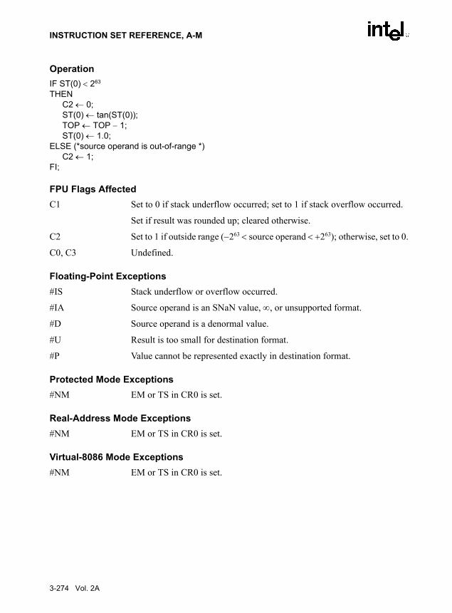
INSTRUCTION SET REFERENCE, A-M
OperationIF ST(0) < 263
THENC2 ← 0;ST(0) ← tan(ST(0));TOP ← TOP − 1;ST(0) ← 1.0;
ELSE (*source operand is out-of-range *)C2 ← 1;
FI;
FPU Flags AffectedC1 Set to 0 if stack underflow occurred; set to 1 if stack overflow occurred.
Set if result was rounded up; cleared otherwise.
C2 Set to 1 if outside range (−263 < source operand < +263); otherwise, set to 0.
C0, C3 Undefined.
Floating-Point Exceptions#IS Stack underflow or overflow occurred.
#IA Source operand is an SNaN value, ∞, or unsupported format.
#D Source operand is a denormal value.
#U Result is too small for destination format.
#P Value cannot be represented exactly in destination format.
Protected Mode Exceptions#NM EM or TS in CR0 is set.
Real-Address Mode Exceptions#NM EM or TS in CR0 is set.
Virtual-8086 Mode Exceptions#NM EM or TS in CR0 is set.
3-274 Vol. 2A
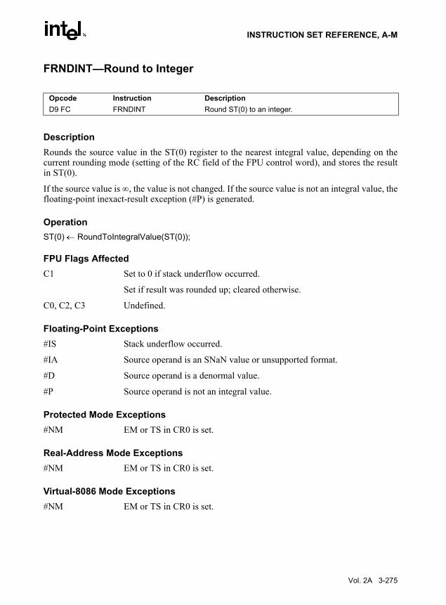
INSTRUCTION SET REFERENCE, A-M
FRNDINT—Round to Integer
DescriptionRounds the source value in the ST(0) register to the nearest integral value, depending on thecurrent rounding mode (setting of the RC field of the FPU control word), and stores the resultin ST(0).
If the source value is ∞, the value is not changed. If the source value is not an integral value, thefloating-point inexact-result exception (#P) is generated.
OperationST(0) ← RoundToIntegralValue(ST(0));
FPU Flags AffectedC1 Set to 0 if stack underflow occurred.
Set if result was rounded up; cleared otherwise.
C0, C2, C3 Undefined.
Floating-Point Exceptions#IS Stack underflow occurred.
#IA Source operand is an SNaN value or unsupported format.
#D Source operand is a denormal value.
#P Source operand is not an integral value.
Protected Mode Exceptions#NM EM or TS in CR0 is set.
Real-Address Mode Exceptions#NM EM or TS in CR0 is set.
Virtual-8086 Mode Exceptions#NM EM or TS in CR0 is set.
Opcode Instruction DescriptionD9 FC FRNDINT Round ST(0) to an integer.
Vol. 2A 3-275

INSTRUCTION SET REFERENCE, A-M
FRSTOR—Restore x87 FPU State
DescriptionLoads the FPU state (operating environment and register stack) from the memory area specifiedwith the source operand. This state data is typically written to the specified memory location bya previous FSAVE/FNSAVE instruction.
The FPU operating environment consists of the FPU control word, status word, tag word,instruction pointer, data pointer, and last opcode. Figures 8-9 through 8-12 in the IA-32 IntelArchitecture Software Developer’s Manual, Volume 1, show the layout in memory of the storedenvironment, depending on the operating mode of the processor (protected or real) and thecurrent operand-size attribute (16-bit or 32-bit). In virtual-8086 mode, the real mode layouts areused. The contents of the FPU register stack are stored in the 80 bytes immediately followingthe operating environment image.
The FRSTOR instruction should be executed in the same operating mode as the correspondingFSAVE/FNSAVE instruction.
If one or more unmasked exception bits are set in the new FPU status word, a floating-pointexception will be generated. To avoid raising exceptions when loading a new operating environ-ment, clear all the exception flags in the FPU status word that is being loaded.
OperationFPUControlWord ← SRC[FPUControlWord);FPUStatusWord ← SRC[FPUStatusWord);FPUTagWord ← SRC[FPUTagWord);FPUDataPointer ← SRC[FPUDataPointer);FPUInstructionPointer ← SRC[FPUInstructionPointer);FPULastInstructionOpcode ← SRC[FPULastInstructionOpcode);ST(0) ← SRC[ST(0));ST(1) ← SRC[ST(1));ST(2) ← SRC[ST(2));ST(3) ← SRC[ST(3));ST(4) ← SRC[ST(4));ST(5) ← SRC[ST(5));ST(6) ← SRC[ST(6));ST(7) ← SRC[ST(7));
FPU Flags AffectedThe C0, C1, C2, C3 flags are loaded.
Opcode Instruction DescriptionDD /4 FRSTOR m94/108byte Load FPU state from m94byte or m108byte.
3-276 Vol. 2A

INSTRUCTION SET REFERENCE, A-M
Floating-Point ExceptionsNone; however, this operation might unmask an existing exception that has been detected butnot generated, because it was masked. Here, the exception is generated at the completion of theinstruction.
Protected Mode Exceptions#GP(0) If a memory operand effective address is outside the CS, DS, ES, FS, or
GS segment limit.
If the DS, ES, FS, or GS register is used to access memory and it contains a null segment selector.
#SS(0) If a memory operand effective address is outside the SS segment limit.
#NM EM or TS in CR0 is set.
#PF(fault-code) If a page fault occurs.
#AC(0) If alignment checking is enabled and an unaligned memory reference is made while the current privilege level is 3.
Real-Address Mode Exceptions#GP If a memory operand effective address is outside the CS, DS, ES, FS, or
GS segment limit.
#SS If a memory operand effective address is outside the SS segment limit.
#NM EM or TS in CR0 is set.
Virtual-8086 Mode Exceptions#GP(0) If a memory operand effective address is outside the CS, DS, ES, FS, or
GS segment limit.
#SS(0) If a memory operand effective address is outside the SS segment limit.
#NM EM or TS in CR0 is set.
#PF(fault-code) If a page fault occurs.
#AC(0) If alignment checking is enabled and an unaligned memory reference is made.
Vol. 2A 3-277

INSTRUCTION SET REFERENCE, A-M
FSAVE/FNSAVE—Store x87 FPU State
DescriptionStores the current FPU state (operating environment and register stack) at the specified destina-tion in memory, and then re-initializes the FPU. The FSAVE instruction checks for and handlespending unmasked floating-point exceptions before storing the FPU state; the FNSAVE instruc-tion does not.
The FPU operating environment consists of the FPU control word, status word, tag word,instruction pointer, data pointer, and last opcode. Figures 8-9 through 8-12 in the IA-32 IntelArchitecture Software Developer’s Manual, Volume 1, show the layout in memory of the storedenvironment, depending on the operating mode of the processor (protected or real) and thecurrent operand-size attribute (16-bit or 32-bit). In virtual-8086 mode, the real mode layouts areused. The contents of the FPU register stack are stored in the 80 bytes immediately follow theoperating environment image.
The saved image reflects the state of the FPU after all floating-point instructions preceding theFSAVE/FNSAVE instruction in the instruction stream have been executed.
After the FPU state has been saved, the FPU is reset to the same default values it is set to withthe FINIT/FNINIT instructions (see “FINIT/FNINIT—Initialize Floating-Point Unit” in thischapter).
The FSAVE/FNSAVE instructions are typically used when the operating system needs toperform a context switch, an exception handler needs to use the FPU, or an application programneeds to pass a “clean” FPU to a procedure.
The assembler issues two instructions for the FSAVE instruction (an FWAIT instructionfollowed by an FNSAVE instruction), and the processor executes each of these instructionsseparately. If an exception is generated for either of these instructions, the save EIP points to theinstruction that caused the exception.
IA-32 Architecture CompatibilityFor Intel math coprocessors and FPUs prior to the Intel Pentium processor, an FWAIT instruc-tion should be executed before attempting to read from the memory image stored with a priorFSAVE/FNSAVE instruction. This FWAIT instruction helps insure that the storage operationhas been completed.
When operating a Pentium or Intel486 processor in MS-DOS compatibility mode, it is possible(under unusual circumstances) for an FNSAVE instruction to be interrupted prior to being
Opcode Instruction Description9B DD /6 FSAVE m94/108byte Store FPU state to m94byte or m108byte after checking for
pending unmasked floating-point exceptions. Then re-initialize the FPU.
DD /6 FNSAVE m94/108byte Store FPU environment to m94byte or m108byte without checking for pending unmasked floating-point exceptions. Then re-initialize the FPU. See the IA-32 Architecture Compatibility section below.
3-278 Vol. 2A

INSTRUCTION SET REFERENCE, A-M
executed to handle a pending FPU exception. See the section titled “No-Wait FPU InstructionsCan Get FPU Interrupt in Window” in Appendix D of the IA-32 Intel Architecture SoftwareDeveloper’s Manual, Volume 1, for a description of these circumstances. An FNSAVE instruc-tion cannot be interrupted in this way on a Pentium 4, Intel Xeon, or P6 family processor.
Operation(* Save FPU State and Registers *)DEST[FPUControlWord) ← FPUControlWord;DEST[FPUStatusWord) ← FPUStatusWord;DEST[FPUTagWord) ← FPUTagWord;DEST[FPUDataPointer) ← FPUDataPointer;DEST[FPUInstructionPointer) ← FPUInstructionPointer;DEST[FPULastInstructionOpcode) ← FPULastInstructionOpcode;DEST[ST(0)) ← ST(0);DEST[ST(1)) ← ST(1);DEST[ST(2)) ← ST(2);DEST[ST(3)) ← ST(3);DEST[ST(4)) ← ST(4);DEST[ST(5)) ← ST(5);DEST[ST(6)) ← ST(6);DEST[ST(7)) ← ST(7);(* Initialize FPU *)FPUControlWord ← 037FH;FPUStatusWord ← 0;FPUTagWord ← FFFFH;FPUDataPointer ← 0;FPUInstructionPointer ← 0;FPULastInstructionOpcode ← 0;
FPU Flags AffectedThe C0, C1, C2, and C3 flags are saved and then cleared.
Floating-Point ExceptionsNone.
Protected Mode Exceptions#GP(0) If destination is located in a non-writable segment.
If a memory operand effective address is outside the CS, DS, ES, FS, or GS segment limit.
If the DS, ES, FS, or GS register is used to access memory and it contains a null segment selector.
#SS(0) If a memory operand effective address is outside the SS segment limit.
Vol. 2A 3-279

INSTRUCTION SET REFERENCE, A-M
#NM EM or TS in CR0 is set.
#PF(fault-code) If a page fault occurs.
#AC(0) If alignment checking is enabled and an unaligned memory reference is made while the current privilege level is 3.
Real-Address Mode Exceptions#GP If a memory operand effective address is outside the CS, DS, ES, FS, or
GS segment limit.
#SS If a memory operand effective address is outside the SS segment limit.
#NM EM or TS in CR0 is set.
Virtual-8086 Mode Exceptions#GP(0) If a memory operand effective address is outside the CS, DS, ES, FS, or
GS segment limit.
#SS(0) If a memory operand effective address is outside the SS segment limit.
#NM EM or TS in CR0 is set.
#PF(fault-code) If a page fault occurs.
#AC(0) If alignment checking is enabled and an unaligned memory reference is made.
3-280 Vol. 2A

INSTRUCTION SET REFERENCE, A-M
FSCALE—Scale
DescriptionTruncates the value in the source operand (toward 0) to an integral value and adds that value tothe exponent of the destination operand. The destination and source operands are floating-pointvalues located in registers ST(0) and ST(1), respectively. This instruction provides rapid multi-plication or division by integral powers of 2. The following table shows the results obtainedwhen scaling various classes of numbers, assuming that neither overflow nor underflow occurs.
NOTES:F Means finite floating-point value.
In most cases, only the exponent is changed and the mantissa (significand) remains unchanged.However, when the value being scaled in ST(0) is a denormal value, the mantissa is also changedand the result may turn out to be a normalized number. Similarly, if overflow or underflowresults from a scale operation, the resulting mantissa will differ from the source’s mantissa.
The FSCALE instruction can also be used to reverse the action of the FXTRACT instruction, asshown in the following example:
FXTRACT;FSCALE;FSTP ST(1);
In this example, the FXTRACT instruction extracts the significand and exponent from the valuein ST(0) and stores them in ST(0) and ST(1) respectively. The FSCALE then scales the signif-icand in ST(0) by the exponent in ST(1), recreating the original value before the FXTRACToperation was performed. The FSTP ST(1) instruction overwrites the exponent (extracted by the
Opcode Instruction DescriptionD9 FD FSCALE Scale ST(0) by ST(1).
Table 3-38. FSCALE ResultsST(1)
−∞ −F −0 +0 +F +∞ NaN
−∞ NaN −∞ −∞ −∞ −∞ −∞ NaN
ST(0) −F −0 −F −F −F −F −∞ NaN
−0 −0 −0 −0 −0 −0 NaN NaN
+0 +0 +0 +0 +0 +0 NaN NaN
+F +0 +F +F +F +F +∞ NaN
+∞ NaN +∞ +∞ +∞ +∞ +∞ NaN
NaN NaN NaN NaN NaN NaN NaN NaN
Vol. 2A 3-281

INSTRUCTION SET REFERENCE, A-M
FXTRACT instruction) with the recreated value, which returns the stack to its original state withonly one register [ST(0)] occupied.
OperationST(0) ← ST(0) ∗ 2RoundTowardZero(ST(1));
FPU Flags AffectedC1 Set to 0 if stack underflow occurred.
Set if result was rounded up; cleared otherwise.
C0, C2, C3 Undefined.
Floating-Point Exceptions#IS Stack underflow occurred.
#IA Source operand is an SNaN value or unsupported format.
#D Source operand is a denormal value.
#U Result is too small for destination format.
#O Result is too large for destination format.
#P Value cannot be represented exactly in destination format.
Protected Mode Exceptions#NM EM or TS in CR0 is set.
Real-Address Mode Exceptions#NM EM or TS in CR0 is set.
Virtual-8086 Mode Exceptions#NM EM or TS in CR0 is set.
3-282 Vol. 2A

INSTRUCTION SET REFERENCE, A-M
FSIN—Sine
DescriptionComputes the sine of the source operand in register ST(0) and stores the result in ST(0). Thesource operand must be given in radians and must be within the range −263 to +263. Thefollowing table shows the results obtained when taking the sine of various classes of numbers,assuming that underflow does not occur.
NOTES:F Means finite floating-point value.* Indicates floating-point invalid-arithmetic-operand (#IA) exception.
If the source operand is outside the acceptable range, the C2 flag in the FPU status word is set,and the value in register ST(0) remains unchanged. The instruction does not raise an exceptionwhen the source operand is out of range. It is up to the program to check the C2 flag for out-of-range conditions. Source values outside the range −263 to +263 can be reduced to the range of theinstruction by subtracting an appropriate integer multiple of 2π or by using the FPREM instruc-tion with a divisor of 2π. See the section titled “Pi” in Chapter 8 of the IA-32 Intel ArchitectureSoftware Developer’s Manual, Volume 1, for a discussion of the proper value to use for π inperforming such reductions.
Opcode Instruction DescriptionD9 FE FSIN Replace ST(0) with its sine.
Table 3-39. FSIN ResultsSRC (ST(0)) DEST (ST(0))
−∞ *
−F −1 to +1
−0 −0
+0 +0
+F −1 to +1
+∞ *
NaN NaN
Vol. 2A 3-283
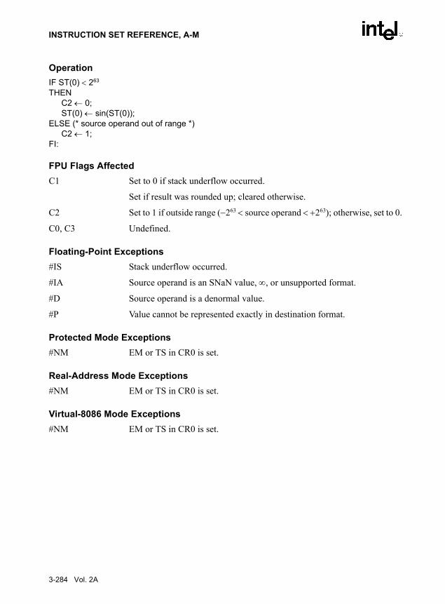
INSTRUCTION SET REFERENCE, A-M
OperationIF ST(0) < 263
THENC2 ← 0;ST(0) ← sin(ST(0));
ELSE (* source operand out of range *)C2 ← 1;
FI:
FPU Flags AffectedC1 Set to 0 if stack underflow occurred.
Set if result was rounded up; cleared otherwise.
C2 Set to 1 if outside range (−263 < source operand < +263); otherwise, set to 0.
C0, C3 Undefined.
Floating-Point Exceptions#IS Stack underflow occurred.
#IA Source operand is an SNaN value, ∞, or unsupported format.
#D Source operand is a denormal value.
#P Value cannot be represented exactly in destination format.
Protected Mode Exceptions#NM EM or TS in CR0 is set.
Real-Address Mode Exceptions#NM EM or TS in CR0 is set.
Virtual-8086 Mode Exceptions#NM EM or TS in CR0 is set.
3-284 Vol. 2A

INSTRUCTION SET REFERENCE, A-M
FSINCOS—Sine and Cosine
DescriptionComputes both the sine and the cosine of the source operand in register ST(0), stores the sine inST(0), and pushes the cosine onto the top of the FPU register stack. (This instruction is fasterthan executing the FSIN and FCOS instructions in succession.)
The source operand must be given in radians and must be within the range −263 to +263. Thefollowing table shows the results obtained when taking the sine and cosine of various classes ofnumbers, assuming that underflow does not occur.
NOTES:F Means finite floating-point value.* Indicates floating-point invalid-arithmetic-operand (#IA) exception.
If the source operand is outside the acceptable range, the C2 flag in the FPU status word is set,and the value in register ST(0) remains unchanged. The instruction does not raise an exceptionwhen the source operand is out of range. It is up to the program to check the C2 flag for out-of-range conditions. Source values outside the range −263 to +263 can be reduced to the range of theinstruction by subtracting an appropriate integer multiple of 2π or by using the FPREM instruc-tion with a divisor of 2π. See the section titled “Pi” in Chapter 8 of the IA-32 Intel ArchitectureSoftware Developer’s Manual, Volume 1, for a discussion of the proper value to use for π inperforming such reductions.
Opcode Instruction DescriptionD9 FB FSINCOS Compute the sine and cosine of ST(0); replace ST(0) with
the sine, and push the cosine onto the register stack.
Table 3-40. FSINCOS ResultsSRC DEST
ST(0) ST(1) Cosine ST(0) Sine
−∞ * *
−F −1 to +1 −1 to +1
−0 +1 −0
+0 +1 +0
+F −1 to +1 −1 to +1
+∞ * *
NaN NaN NaN
Vol. 2A 3-285

INSTRUCTION SET REFERENCE, A-M
OperationIF ST(0) < 263
THENC2 ← 0;TEMP ← cosine(ST(0));ST(0) ← sine(ST(0));
TOP ← TOP − 1;ST(0) ← TEMP;
ELSE (* source operand out of range *)C2 ← 1;
FI:
FPU Flags AffectedC1 Set to 0 if stack underflow occurred; set to 1 of stack overflow occurs.
Set if result was rounded up; cleared otherwise.
C2 Set to 1 if outside range (−263 < source operand < +263); otherwise, set to 0.
C0, C3 Undefined.
Floating-Point Exceptions#IS Stack underflow or overflow occurred.
#IA Source operand is an SNaN value, ∞, or unsupported format.
#D Source operand is a denormal value.
#U Result is too small for destination format.
#P Value cannot be represented exactly in destination format.
Protected Mode Exceptions#NM EM or TS in CR0 is set.
Real-Address Mode Exceptions#NM EM or TS in CR0 is set.
Virtual-8086 Mode Exceptions#NM EM or TS in CR0 is set.
3-286 Vol. 2A

INSTRUCTION SET REFERENCE, A-M
FSQRT—Square Root
DescriptionComputes the square root of the source value in the ST(0) register and stores the result in ST(0).
The following table shows the results obtained when taking the square root of various classes ofnumbers, assuming that neither overflow nor underflow occurs.
NOTES:F Means finite floating-point value.* Indicates floating-point invalid-arithmetic-operand (#IA) exception.
OperationST(0) ← SquareRoot(ST(0));
FPU Flags AffectedC1 Set to 0 if stack underflow occurred.
Set if result was rounded up; cleared otherwise.
C0, C2, C3 Undefined.
Floating-Point Exceptions#IS Stack underflow occurred.
#IA Source operand is an SNaN value or unsupported format.
Source operand is a negative value (except for −0).
Opcode Instruction DescriptionD9 FA FSQRT Computes square root of ST(0) and stores the result in
ST(0).
Table 3-41. FSQRT ResultsSRC (ST(0)) DEST (ST(0))
−∞ *
−F *
−0 −0
+0 +0
+F +F
+∞ +∞
NaN NaN
Vol. 2A 3-287

INSTRUCTION SET REFERENCE, A-M
#D Source operand is a denormal value.
#P Value cannot be represented exactly in destination format.
Protected Mode Exceptions#NM EM or TS in CR0 is set.
Real-Address Mode Exceptions#NM EM or TS in CR0 is set.
Virtual-8086 Mode Exceptions#NM EM or TS in CR0 is set.
3-288 Vol. 2A

INSTRUCTION SET REFERENCE, A-M
FST/FSTP—Store Floating Point Value
DescriptionThe FST instruction copies the value in the ST(0) register to the destination operand, which canbe a memory location or another register in the FPU register stack. When storing the value inmemory, the value is converted to single-precision or double-precision floating-point format.
The FSTP instruction performs the same operation as the FST instruction and then pops theregister stack. To pop the register stack, the processor marks the ST(0) register as empty andincrements the stack pointer (TOP) by 1. The FSTP instruction can also store values in memoryin double extended-precision floating-point format.
If the destination operand is a memory location, the operand specifies the address where the firstbyte of the destination value is to be stored. If the destination operand is a register, the operandspecifies a register in the register stack relative to the top of the stack.
If the destination size is single-precision or double-precision, the significand of the value beingstored is rounded to the width of the destination (according to the rounding mode specified bythe RC field of the FPU control word), and the exponent is converted to the width and bias ofthe destination format. If the value being stored is too large for the destination format, a numericoverflow exception (#O) is generated and, if the exception is unmasked, no value is stored in thedestination operand. If the value being stored is a denormal value, the denormal exception (#D)is not generated. This condition is simply signaled as a numeric underflow exception (#U)condition.
If the value being stored is ±0, ±∞, or a NaN, the least-significant bits of the significand and theexponent are truncated to fit the destination format. This operation preserves the value’s identityas a 0, ∞, or NaN.
If the destination operand is a non-empty register, the invalid-operation exception is notgenerated.
OperationDEST ← ST(0);IF instruction = FSTP
THEN PopRegisterStack; FI;
Opcode Instruction DescriptionD9 /2 FST m32fp Copy ST(0) to m32fp.DD /2 FST m64fp Copy ST(0) to m64fp.DD D0+i FST ST(i) Copy ST(0) to ST(i).D9 /3 FSTP m32fp Copy ST(0) to m32fp and pop register stack.DD /3 FSTP m64fp Copy ST(0) to m64fp and pop register stack.DB /7 FSTP m80fp Copy ST(0) to m80fp and pop register stack.DD D8+i FSTP ST(i) Copy ST(0) to ST(i) and pop register stack.
Vol. 2A 3-289

INSTRUCTION SET REFERENCE, A-M
FPU Flags AffectedC1 Set to 0 if stack underflow occurred.
Indicates rounding direction of if the floating-point inexact exception (#P) is generated: 0 ← not roundup; 1 ← roundup.
C0, C2, C3 Undefined.
Floating-Point Exceptions#IS Stack underflow occurred.
#IA Source operand is an SNaN value or unsupported format. Does not occur if the source operand is in double extended-precision floating-point format.
#U Result is too small for the destination format.
#O Result is too large for the destination format.
#P Value cannot be represented exactly in destination format.
Protected Mode Exceptions#GP(0) If the destination is located in a non-writable segment.
If a memory operand effective address is outside the CS, DS, ES, FS, or GS segment limit.
If the DS, ES, FS, or GS register is used to access memory and it contains a null segment selector.
#SS(0) If a memory operand effective address is outside the SS segment limit.
#NM EM or TS in CR0 is set.
#PF(fault-code) If a page fault occurs.
#AC(0) If alignment checking is enabled and an unaligned memory reference is made while the current privilege level is 3.
Real-Address Mode Exceptions#GP If a memory operand effective address is outside the CS, DS, ES, FS, or
GS segment limit.
#SS If a memory operand effective address is outside the SS segment limit.
#NM EM or TS in CR0 is set.
Virtual-8086 Mode Exceptions#GP(0) If a memory operand effective address is outside the CS, DS, ES, FS, or
GS segment limit.
3-290 Vol. 2A

INSTRUCTION SET REFERENCE, A-M
#SS(0) If a memory operand effective address is outside the SS segment limit.
#NM EM or TS in CR0 is set.
#PF(fault-code) If a page fault occurs.
#AC(0) If alignment checking is enabled and an unaligned memory reference is made.
Vol. 2A 3-291

INSTRUCTION SET REFERENCE, A-M
FSTCW/FNSTCW—Store x87 FPU Control Word
NOTE:*
DescriptionStores the current value of the FPU control word at the specified destination in memory. TheFSTCW instruction checks for and handles pending unmasked floating-point exceptions beforestoring the control word; the FNSTCW instruction does not.
The assembler issues two instructions for the FSTCW instruction (an FWAIT instructionfollowed by an FNSTCW instruction), and the processor executes each of these instructions inseparately. If an exception is generated for either of these instructions, the save EIP points to theinstruction that caused the exception.
IA-32 Architecture CompatibilityWhen operating a Pentium or Intel486 processor in MS-DOS compatibility mode, it is possible(under unusual circumstances) for an FNSTCW instruction to be interrupted prior to beingexecuted to handle a pending FPU exception. See the section titled “No-Wait FPU InstructionsCan Get FPU Interrupt in Window” in Appendix D of the IA-32 Intel Architecture SoftwareDeveloper’s Manual, Volume 1, for a description of these circumstances. An FNSTCW instruc-tion cannot be interrupted in this way on a Pentium 4, Intel Xeon, or P6 family processor.
OperationDEST ← FPUControlWord;
FPU Flags AffectedThe C0, C1, C2, and C3 flags are undefined.
Floating-Point ExceptionsNone.
Protected Mode Exceptions#GP(0) If the destination is located in a non-writable segment.
If a memory operand effective address is outside the CS, DS, ES, FS, or GS segment limit.
Opcode Instruction Description9B D9 /7 FSTCW m2byte Store FPU control word to m2byte after checking for
pending unmasked floating-point exceptions.D9 /7 FNSTCW m2byte Store FPU control word to m2byte without checking for
pending unmasked floating-point exceptions. See IA-32 Architecture Compatibility section below.
3-292 Vol. 2A

INSTRUCTION SET REFERENCE, A-M
If the DS, ES, FS, or GS register is used to access memory and it contains a null segment selector.
#SS(0) If a memory operand effective address is outside the SS segment limit.
#NM EM or TS in CR0 is set.
#PF(fault-code) If a page fault occurs.
#AC(0) If alignment checking is enabled and an unaligned memory reference is made while the current privilege level is 3.
Real-Address Mode Exceptions#GP If a memory operand effective address is outside the CS, DS, ES, FS, or
GS segment limit.
#SS If a memory operand effective address is outside the SS segment limit.
#NM EM or TS in CR0 is set.
Virtual-8086 Mode Exceptions#GP(0) If a memory operand effective address is outside the CS, DS, ES, FS, or
GS segment limit.
#SS(0) If a memory operand effective address is outside the SS segment limit.
#NM EM or TS in CR0 is set.
#PF(fault-code) If a page fault occurs.
#AC(0) If alignment checking is enabled and an unaligned memory reference is made.
Vol. 2A 3-293

INSTRUCTION SET REFERENCE, A-M
FSTENV/FNSTENV—Store x87 FPU Environment
DescriptionSaves the current FPU operating environment at the memory location specified with the desti-nation operand, and then masks all floating-point exceptions. The FPU operating environmentconsists of the FPU control word, status word, tag word, instruction pointer, data pointer, andlast opcode. Figures 8-9 through 8-12 in the IA-32 Intel Architecture Software Developer’sManual, Volume 1, show the layout in memory of the stored environment, depending on theoperating mode of the processor (protected or real) and the current operand-size attribute (16-bit or 32-bit). In virtual-8086 mode, the real mode layouts are used.
The FSTENV instruction checks for and handles any pending unmasked floating-point excep-tions before storing the FPU environment; the FNSTENV instruction does not. The savedimage reflects the state of the FPU after all floating-point instructions preceding theFSTENV/FNSTENV instruction in the instruction stream have been executed.
These instructions are often used by exception handlers because they provide access to the FPUinstruction and data pointers. The environment is typically saved in the stack. Masking allexceptions after saving the environment prevents floating-point exceptions from interrupting theexception handler.
The assembler issues two instructions for the FSTENV instruction (an FWAIT instructionfollowed by an FNSTENV instruction), and the processor executes each of these instructionsseparately. If an exception is generated for either of these instructions, the save EIP points to theinstruction that caused the exception.
IA-32 Architecture CompatibilityWhen operating a Pentium or Intel486 processor in MS-DOS compatibility mode, it is possible(under unusual circumstances) for an FNSTENV instruction to be interrupted prior to beingexecuted to handle a pending FPU exception. See the section titled “No-Wait FPU InstructionsCan Get FPU Interrupt in Window” in Appendix D of the IA-32 Intel Architecture SoftwareDeveloper’s Manual, Volume 1, for a description of these circumstances. An FNSTENVinstruction cannot be interrupted in this way on a Pentium 4, Intel Xeon, or P6 family processor.
Opcode Instruction Description9B D9 /6 FSTENV m14/28byte Store FPU environment to m14byte or m28byte after
checking for pending unmasked floating-point exceptions. Then mask all floating-point exceptions.
D9 /6 FNSTENV* m14/28byte Store FPU environment to m14byte or m28byte withoutchecking for pending unmasked floating-point excep-tions. Then mask all floating-point exceptions. See theIA-32 Architecture Compatibility section below.
3-294 Vol. 2A

INSTRUCTION SET REFERENCE, A-M
OperationDEST[FPUControlWord) ← FPUControlWord;DEST[FPUStatusWord) ← FPUStatusWord;DEST[FPUTagWord) ← FPUTagWord;DEST[FPUDataPointer) ← FPUDataPointer;DEST[FPUInstructionPointer) ← FPUInstructionPointer;DEST[FPULastInstructionOpcode) ← FPULastInstructionOpcode;
FPU Flags AffectedThe C0, C1, C2, and C3 are undefined.
Floating-Point ExceptionsNone.
Protected Mode Exceptions#GP(0) If the destination is located in a non-writable segment.
If a memory operand effective address is outside the CS, DS, ES, FS, or GS segment limit.
If the DS, ES, FS, or GS register is used to access memory and it contains a null segment selector.
#SS(0) If a memory operand effective address is outside the SS segment limit.
#NM EM or TS in CR0 is set.
#PF(fault-code) If a page fault occurs.
#AC(0) If alignment checking is enabled and an unaligned memory reference is made while the current privilege level is 3.
Real-Address Mode Exceptions#GP If a memory operand effective address is outside the CS, DS, ES, FS, or
GS segment limit.
#SS If a memory operand effective address is outside the SS segment limit.
#NM EM or TS in CR0 is set.
Virtual-8086 Mode Exceptions#GP(0) If a memory operand effective address is outside the CS, DS, ES, FS, or
GS segment limit.
#SS(0) If a memory operand effective address is outside the SS segment limit.
#NM EM or TS in CR0 is set.
Vol. 2A 3-295
INSTRUCTION SET REFERENCE, A-M
#PF(fault-code) If a page fault occurs.
#AC(0) If alignment checking is enabled and an unaligned memory reference is made.
3-296 Vol. 2A

INSTRUCTION SET REFERENCE, A-M
FSTSW/FNSTSW—Store x87 FPU Status Word
NOTE:* See IA-32 Architecture Compatibility section below.
DescriptionStores the current value of the x87 FPU status word in the destination location. The destinationoperand can be either a two-byte memory location or the AX register. The FSTSW instructionchecks for and handles pending unmasked floating-point exceptions before storing the statusword; the FNSTSW instruction does not.
The FNSTSW AX form of the instruction is used primarily in conditional branching (forinstance, after an FPU comparison instruction or an FPREM, FPREM1, or FXAM instruction),where the direction of the branch depends on the state of the FPU condition code flags. (See thesection titled “Branching and Conditional Moves on FPU Condition Codes” in Chapter 8 of theIA-32 Intel Architecture Software Developer’s Manual, Volume 1.) This instruction can also beused to invoke exception handlers (by examining the exception flags) in environments that donot use interrupts. When the FNSTSW AX instruction is executed, the AX register is updatedbefore the processor executes any further instructions. The status stored in the AX register isthus guaranteed to be from the completion of the prior FPU instruction.
The assembler issues two instructions for the FSTSW instruction (an FWAIT instructionfollowed by an FNSTSW instruction), and the processor executes each of these instructionsseparately. If an exception is generated for either of these instructions, the save EIP points to theinstruction that caused the exception.
IA-32 Architecture CompatibilityWhen operating a Pentium or Intel486 processor in MS-DOS compatibility mode, it is possible(under unusual circumstances) for an FNSTSW instruction to be interrupted prior to beingexecuted to handle a pending FPU exception. See the section titled “No-Wait FPU InstructionsCan Get FPU Interrupt in Window” in Appendix D of the IA-32 Intel Architecture SoftwareDeveloper’s Manual, Volume 1, for a description of these circumstances. An FNSTSW instruc-tion cannot be interrupted in this way on a Pentium 4, Intel Xeon, or P6 family processor.
OperationDEST ← FPUStatusWord;
Opcode Instruction Description9B DD /7 FSTSW m2byte Store FPU status word at m2byte after checking for
pending unmasked floating-point exceptions.9B DF E0 FSTSW AX Store FPU status word in AX register after checking for
pending unmasked floating-point exceptions.DD /7 FNSTSW* m2byte Store FPU status word at m2byte without checking for
pending unmasked floating-point exceptions.DF E0 FNSTSW* AX Store FPU status word in AX register without checking for
pending unmasked floating-point exceptions.
Vol. 2A 3-297

INSTRUCTION SET REFERENCE, A-M
FPU Flags AffectedThe C0, C1, C2, and C3 are undefined.
Floating-Point ExceptionsNone.
Protected Mode Exceptions#GP(0) If the destination is located in a non-writable segment.
If a memory operand effective address is outside the CS, DS, ES, FS, or GS segment limit.
If the DS, ES, FS, or GS register is used to access memory and it contains a null segment selector.
#SS(0) If a memory operand effective address is outside the SS segment limit.
#NM EM or TS in CR0 is set.
#PF(fault-code) If a page fault occurs.
#AC(0) If alignment checking is enabled and an unaligned memory reference is made while the current privilege level is 3.
Real-Address Mode Exceptions#GP If a memory operand effective address is outside the CS, DS, ES, FS, or
GS segment limit.
#SS If a memory operand effective address is outside the SS segment limit.
#NM EM or TS in CR0 is set.
Virtual-8086 Mode Exceptions#GP(0) If a memory operand effective address is outside the CS, DS, ES, FS, or
GS segment limit.
#SS(0) If a memory operand effective address is outside the SS segment limit.
#NM EM or TS in CR0 is set.
#PF(fault-code) If a page fault occurs.
#AC(0) If alignment checking is enabled and an unaligned memory reference is made.
3-298 Vol. 2A

INSTRUCTION SET REFERENCE, A-M
FSUB/FSUBP/FISUB—Subtract
DescriptionSubtracts the source operand from the destination operand and stores the difference in the desti-nation location. The destination operand is always an FPU data register; the source operand canbe a register or a memory location. Source operands in memory can be in single-precision ordouble-precision floating-point format or in word or doubleword integer format.
The no-operand version of the instruction subtracts the contents of the ST(0) register from theST(1) register and stores the result in ST(1). The one-operand version subtracts the contents ofa memory location (either a floating-point or an integer value) from the contents of the ST(0)register and stores the result in ST(0). The two-operand version, subtracts the contents of theST(0) register from the ST(i) register or vice versa.
The FSUBP instructions perform the additional operation of popping the FPU register stackfollowing the subtraction. To pop the register stack, the processor marks the ST(0) register asempty and increments the stack pointer (TOP) by 1. The no-operand version of the floating-point subtract instructions always results in the register stack being popped. In some assemblers,the mnemonic for this instruction is FSUB rather than FSUBP.
The FISUB instructions convert an integer source operand to double extended-precisionfloating-point format before performing the subtraction.
Table 3-42 shows the results obtained when subtracting various classes of numbers from oneanother, assuming that neither overflow nor underflow occurs. Here, the SRC value is subtractedfrom the DEST value (DEST − SRC = result).
When the difference between two operands of like sign is 0, the result is +0, except for the roundtoward −∞ mode, in which case the result is −0. This instruction also guarantees that +0 − (−0)= +0, and that −0 − (+0) = −0. When the source operand is an integer 0, it is treated as a +0.
When one operand is ∞, the result is ∞ of the expected sign. If both operands are ∞ of the samesign, an invalid-operation exception is generated.
Opcode Instruction DescriptionD8 /4 FSUB m32fp Subtract m32fp from ST(0) and store result in ST(0).DC /4 FSUB m64fp Subtract m64fp from ST(0) and store result in ST(0).D8 E0+i FSUB ST(0), ST(i) Subtract ST(i) from ST(0) and store result in ST(0).DC E8+i FSUB ST(i), ST(0) Subtract ST(0) from ST(i) and store result in ST(i).DE E8+i FSUBP ST(i), ST(0) Subtract ST(0) from ST(i), store result in ST(i), and pop
register stack.DE E9 FSUBP Subtract ST(0) from ST(1), store result in ST(1), and pop
register stack.DA /4 FISUB m32int Subtract m32int from ST(0) and store result in ST(0).DE /4 FISUB m16int Subtract m16int from ST(0) and store result in ST(0).
Vol. 2A 3-299

INSTRUCTION SET REFERENCE, A-M
NOTES:F Means finite floating-point value.I Means integer.* Indicates floating-point invalid-arithmetic-operand (#IA) exception.
OperationIF instruction is FISUB
THENDEST ← DEST − ConvertToDoubleExtendedPrecisionFP(SRC);
ELSE (* source operand is floating-point value *)DEST ← DEST − SRC;
FI;IF instruction is FSUBP
THEN PopRegisterStack
FI;
FPU Flags AffectedC1 Set to 0 if stack underflow occurred.
Set if result was rounded up; cleared otherwise.
C0, C2, C3 Undefined.
Floating-Point Exceptions#IS Stack underflow occurred.
#IA Operand is an SNaN value or unsupported format.
Operands are infinities of like sign.
#D Source operand is a denormal value.
#U Result is too small for destination format.
Table 3-42. FSUB/FSUBP/FISUB ResultsSRC
−∞ −F or −I −0 +0 +F or +I +∞ NaN
−∞ * −∞ −∞ −∞ −∞ −∞ NaN
−F +∞ ±F or ±0 DEST DEST −F −∞ NaN
DEST −0 +∞ −SRC ±0 −0 −SRC −∞ NaN
+0 +∞ −SRC +0 ±0 −SRC −∞ NaN
+F +∞ +F DEST DEST ±F or ±0 −∞ NaN
+∞ +∞ +∞ +∞ +∞ +∞ * NaN
NaN NaN NaN NaN NaN NaN NaN NaN
3-300 Vol. 2A

INSTRUCTION SET REFERENCE, A-M
#O Result is too large for destination format.
#P Value cannot be represented exactly in destination format.
Protected Mode Exceptions#GP(0) If a memory operand effective address is outside the CS, DS, ES, FS, or
GS segment limit.
If the DS, ES, FS, or GS register is used to access memory and it contains a null segment selector.
#SS(0) If a memory operand effective address is outside the SS segment limit.
#NM EM or TS in CR0 is set.
#PF(fault-code) If a page fault occurs.
#AC(0) If alignment checking is enabled and an unaligned memory reference is made while the current privilege level is 3.
Real-Address Mode Exceptions#GP If a memory operand effective address is outside the CS, DS, ES, FS, or
GS segment limit.
#SS If a memory operand effective address is outside the SS segment limit.
#NM EM or TS in CR0 is set.
Virtual-8086 Mode Exceptions#GP(0) If a memory operand effective address is outside the CS, DS, ES, FS, or
GS segment limit.
#SS(0) If a memory operand effective address is outside the SS segment limit.
#NM EM or TS in CR0 is set.
#PF(fault-code) If a page fault occurs.
#AC(0) If alignment checking is enabled and an unaligned memory reference is made.
Vol. 2A 3-301
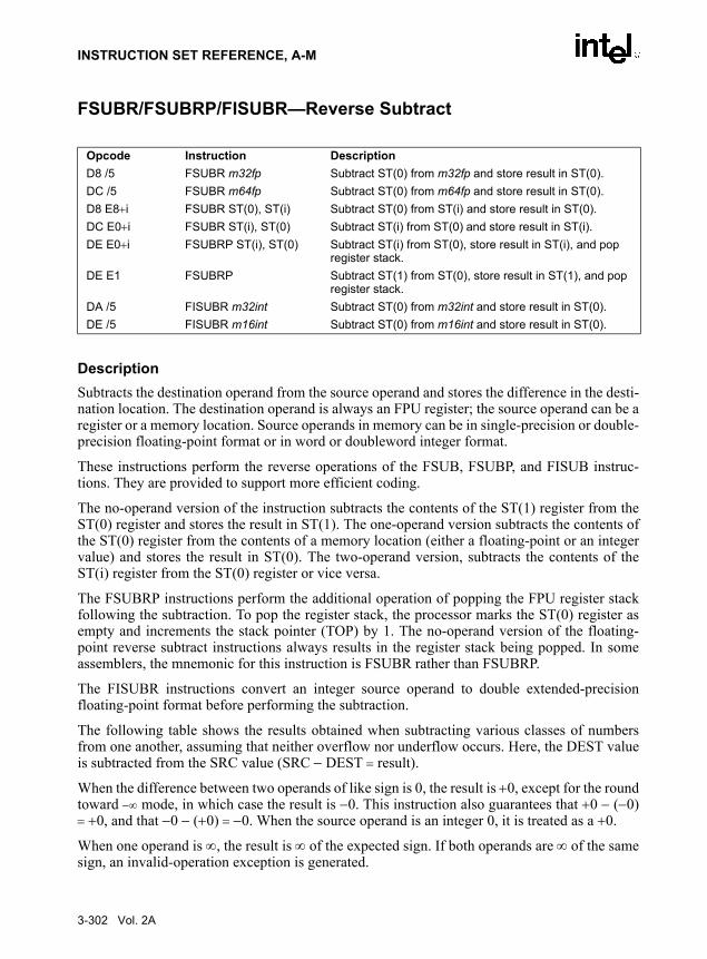
INSTRUCTION SET REFERENCE, A-M
FSUBR/FSUBRP/FISUBR—Reverse Subtract
DescriptionSubtracts the destination operand from the source operand and stores the difference in the desti-nation location. The destination operand is always an FPU register; the source operand can be aregister or a memory location. Source operands in memory can be in single-precision or double-precision floating-point format or in word or doubleword integer format.
These instructions perform the reverse operations of the FSUB, FSUBP, and FISUB instruc-tions. They are provided to support more efficient coding.
The no-operand version of the instruction subtracts the contents of the ST(1) register from theST(0) register and stores the result in ST(1). The one-operand version subtracts the contents ofthe ST(0) register from the contents of a memory location (either a floating-point or an integervalue) and stores the result in ST(0). The two-operand version, subtracts the contents of theST(i) register from the ST(0) register or vice versa.
The FSUBRP instructions perform the additional operation of popping the FPU register stackfollowing the subtraction. To pop the register stack, the processor marks the ST(0) register asempty and increments the stack pointer (TOP) by 1. The no-operand version of the floating-point reverse subtract instructions always results in the register stack being popped. In someassemblers, the mnemonic for this instruction is FSUBR rather than FSUBRP.
The FISUBR instructions convert an integer source operand to double extended-precisionfloating-point format before performing the subtraction.
The following table shows the results obtained when subtracting various classes of numbersfrom one another, assuming that neither overflow nor underflow occurs. Here, the DEST valueis subtracted from the SRC value (SRC − DEST = result).
When the difference between two operands of like sign is 0, the result is +0, except for the roundtoward −∞ mode, in which case the result is −0. This instruction also guarantees that +0 − (−0)= +0, and that −0 − (+0) = −0. When the source operand is an integer 0, it is treated as a +0.
When one operand is ∞, the result is ∞ of the expected sign. If both operands are ∞ of the samesign, an invalid-operation exception is generated.
Opcode Instruction DescriptionD8 /5 FSUBR m32fp Subtract ST(0) from m32fp and store result in ST(0).DC /5 FSUBR m64fp Subtract ST(0) from m64fp and store result in ST(0).D8 E8+i FSUBR ST(0), ST(i) Subtract ST(0) from ST(i) and store result in ST(0).DC E0+i FSUBR ST(i), ST(0) Subtract ST(i) from ST(0) and store result in ST(i).DE E0+i FSUBRP ST(i), ST(0) Subtract ST(i) from ST(0), store result in ST(i), and pop
register stack.DE E1 FSUBRP Subtract ST(1) from ST(0), store result in ST(1), and pop
register stack.DA /5 FISUBR m32int Subtract ST(0) from m32int and store result in ST(0).DE /5 FISUBR m16int Subtract ST(0) from m16int and store result in ST(0).
3-302 Vol. 2A
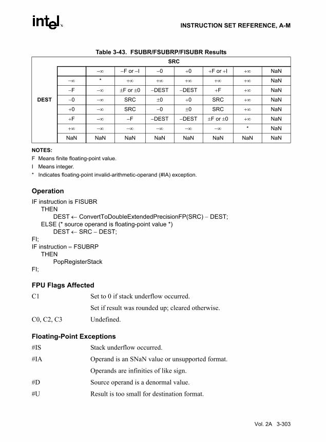
INSTRUCTION SET REFERENCE, A-M
NOTES:F Means finite floating-point value.I Means integer.* Indicates floating-point invalid-arithmetic-operand (#IA) exception.
OperationIF instruction is FISUBR
THENDEST ← ConvertToDoubleExtendedPrecisionFP(SRC) − DEST;
ELSE (* source operand is floating-point value *)DEST ← SRC − DEST;
FI;IF instruction = FSUBRP
THEN PopRegisterStack
FI;
FPU Flags AffectedC1 Set to 0 if stack underflow occurred.
Set if result was rounded up; cleared otherwise.
C0, C2, C3 Undefined.
Floating-Point Exceptions#IS Stack underflow occurred.
#IA Operand is an SNaN value or unsupported format.
Operands are infinities of like sign.
#D Source operand is a denormal value.
#U Result is too small for destination format.
Table 3-43. FSUBR/FSUBRP/FISUBR ResultsSRC
−∞ −F or −I −0 +0 +F or +I +∞ NaN
−∞ * +∞ +∞ +∞ +∞ +∞ NaN
−F −∞ ±F or ±0 −DEST −DEST +F +∞ NaN
DEST −0 −∞ SRC ±0 +0 SRC +∞ NaN
+0 −∞ SRC −0 ±0 SRC +∞ NaN
+F −∞ −F −DEST −DEST ±F or ±0 +∞ NaN
+∞ −∞ −∞ −∞ −∞ −∞ * NaN
NaN NaN NaN NaN NaN NaN NaN NaN
Vol. 2A 3-303

INSTRUCTION SET REFERENCE, A-M
#O Result is too large for destination format.
#P Value cannot be represented exactly in destination format.
Protected Mode Exceptions#GP(0) If a memory operand effective address is outside the CS, DS, ES, FS, or
GS segment limit.
If the DS, ES, FS, or GS register is used to access memory and it contains a null segment selector.
#SS(0) If a memory operand effective address is outside the SS segment limit.
#NM EM or TS in CR0 is set.
#PF(fault-code) If a page fault occurs.
#AC(0) If alignment checking is enabled and an unaligned memory reference is made while the current privilege level is 3.
Real-Address Mode Exceptions#GP If a memory operand effective address is outside the CS, DS, ES, FS, or
GS segment limit.
#SS If a memory operand effective address is outside the SS segment limit.
#NM EM or TS in CR0 is set.
Virtual-8086 Mode Exceptions#GP(0) If a memory operand effective address is outside the CS, DS, ES, FS, or
GS segment limit.
#SS(0) If a memory operand effective address is outside the SS segment limit.
#NM EM or TS in CR0 is set.
#PF(fault-code) If a page fault occurs.
#AC(0) If alignment checking is enabled and an unaligned memory reference is made.
3-304 Vol. 2A

INSTRUCTION SET REFERENCE, A-M
FTST—TEST
DescriptionCompares the value in the ST(0) register with 0.0 and sets the condition code flags C0, C2, andC3 in the FPU status word according to the results (see table below).
This instruction performs an “unordered comparison.” An unordered comparison also checksthe class of the numbers being compared (see “FXAM—Examine” in this chapter). If the valuein register ST(0) is a NaN or is in an undefined format, the condition flags are set to “unordered”and the invalid operation exception is generated.
The sign of zero is ignored, so that –0.0 ← +0.0.
OperationCASE (relation of operands) OF
Not comparable: C3, C2, C0 ← 111;ST(0) > 0.0: C3, C2, C0 ← 000;ST(0) < 0.0: C3, C2, C0 ← 001;ST(0) = 0.0: C3, C2, C0 ← 100;
ESAC;
FPU Flags AffectedC1 Set to 0 if stack underflow occurred; otherwise, set to 0.
C0, C2, C3 See Table 3-44.
Floating-Point Exceptions#IS Stack underflow occurred.
#IA The source operand is a NaN value or is in an unsupported format.
#D The source operand is a denormal value.
Opcode Instruction DescriptionD9 E4 FTST Compare ST(0) with 0.0.
Table 3-44. FTST ResultsCondition C3 C2 C0
ST(0) > 0.0 0 0 0
ST(0) < 0.0 0 0 1
ST(0) = 0.0 1 0 0
Unordered 1 1 1
Vol. 2A 3-305

INSTRUCTION SET REFERENCE, A-M
Protected Mode Exceptions#NM EM or TS in CR0 is set.
Real-Address Mode Exceptions#NM EM or TS in CR0 is set.
Virtual-8086 Mode Exceptions#NM EM or TS in CR0 is set.
3-306 Vol. 2A

INSTRUCTION SET REFERENCE, A-M
FUCOM/FUCOMP/FUCOMPP—Unordered Compare Floating Point Values
DescriptionPerforms an unordered comparison of the contents of register ST(0) and ST(i) and sets conditioncode flags C0, C2, and C3 in the FPU status word according to the results (see the table below).If no operand is specified, the contents of registers ST(0) and ST(1) are compared. The sign ofzero is ignored, so that –0.0 is equal to +0.0.
NOTE:* Flags not set if unmasked invalid-arithmetic-operand (#IA) exception is generated.
An unordered comparison checks the class of the numbers being compared (see“FXAM—Examine” in this chapter). The FUCOM/FUCOMP/FUCOMPP instructions performthe same operations as the FCOM/FCOMP/FCOMPP instructions. The only difference is thatthe FUCOM/FUCOMP/FUCOMPP instructions raise the invalid-arithmetic-operand exception(#IA) only when either or both operands are an SNaN or are in an unsupported format; QNaNscause the condition code flags to be set to unordered, but do not cause an exception to be gener-ated. The FCOM/FCOMP/FCOMPP instructions raise an invalid-operation exception wheneither or both of the operands are a NaN value of any kind or are in an unsupported format.
As with the FCOM/FCOMP/FCOMPP instructions, if the operation results in an invalid-arith-metic-operand exception being raised, the condition code flags are set only if the exception ismasked.
The FUCOMP instruction pops the register stack following the comparison operation and theFUCOMPP instruction pops the register stack twice following the comparison operation. Topop the register stack, the processor marks the ST(0) register as empty and increments the stackpointer (TOP) by 1.
Opcode Instruction DescriptionDD E0+i FUCOM ST(i) Compare ST(0) with ST(i).DD E1 FUCOM Compare ST(0) with ST(1).DD E8+i FUCOMP ST(i) Compare ST(0) with ST(i) and pop register stack.DD E9 FUCOMP Compare ST(0) with ST(1) and pop register stack.DA E9 FUCOMPP Compare ST(0) with ST(1) and pop register stack twice.
Table 3-45. FUCOM/FUCOMP/FUCOMPP ResultsComparison Results C3 C2 C0
ST0 > ST(i) 0 0 0
ST0 < ST(i) 0 0 1
ST0 = ST(i) 1 0 0
Unordered 1 1 1
Vol. 2A 3-307

INSTRUCTION SET REFERENCE, A-M
OperationCASE (relation of operands) OF
ST > SRC: C3, C2, C0 ← 000;ST < SRC: C3, C2, C0 ← 001;ST = SRC: C3, C2, C0 ← 100;
ESAC;IF ST(0) or SRC = QNaN, but not SNaN or unsupported format
THEN C3, C2, C0 ← 111;
ELSE (* ST(0) or SRC is SNaN or unsupported format *) #IA;IF FPUControlWord.IM = 1
THEN C3, C2, C0 ← 111;
FI;FI;IF instruction = FUCOMP
THEN PopRegisterStack;
FI;IF instruction = FUCOMPP
THEN PopRegisterStack; PopRegisterStack;
FI;
FPU Flags AffectedC1 Set to 0 if stack underflow occurred.
C0, C2, C3 See Table 3-45.
Floating-Point Exceptions#IS Stack underflow occurred.
#IA One or both operands are SNaN values or have unsupported formats. Detection of a QNaN value in and of itself does not raise an invalid-operand exception.
#D One or both operands are denormal values.
Protected Mode Exceptions#NM EM or TS in CR0 is set.
Real-Address Mode Exceptions#NM EM or TS in CR0 is set.
3-308 Vol. 2A
INSTRUCTION SET REFERENCE, A-M
Virtual-8086 Mode Exceptions#NM EM or TS in CR0 is set.
Vol. 2A 3-309

INSTRUCTION SET REFERENCE, A-M
FWAIT—Wait
See entry for WAIT/FWAIT—Wait.
3-310 Vol. 2A
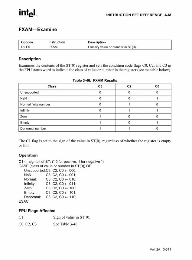
INSTRUCTION SET REFERENCE, A-M
FXAM—Examine
DescriptionExamines the contents of the ST(0) register and sets the condition code flags C0, C2, and C3 inthe FPU status word to indicate the class of value or number in the register (see the table below).
.
The C1 flag is set to the sign of the value in ST(0), regardless of whether the register is emptyor full.
OperationC1 ← sign bit of ST; (* 0 for positive, 1 for negative *)CASE (class of value or number in ST(0)) OF
Unsupported:C3, C2, C0 ← 000;NaN: C3, C2, C0 ← 001;Normal: C3, C2, C0 ← 010;Infinity: C3, C2, C0 ← 011;Zero: C3, C2, C0 ← 100;Empty: C3, C2, C0 ← 101;Denormal: C3, C2, C0 ← 110;
ESAC;
FPU Flags AffectedC1 Sign of value in ST(0).
C0, C2, C3 See Table 3-46.
Opcode Instruction DescriptionD9 E5 FXAM Classify value or number in ST(0).
Table 3-46. FXAM ResultsClass C3 C2 C0
Unsupported 0 0 0
NaN 0 0 1
Normal finite number 0 1 0
Infinity 0 1 1
Zero 1 0 0
Empty 1 0 1
Denormal number 1 1 0
Vol. 2A 3-311

INSTRUCTION SET REFERENCE, A-M
Floating-Point ExceptionsNone.
Protected Mode Exceptions#NM EM or TS in CR0 is set.
Real-Address Mode Exceptions#NM EM or TS in CR0 is set.
Virtual-8086 Mode Exceptions#NM EM or TS in CR0 is set.
3-312 Vol. 2A
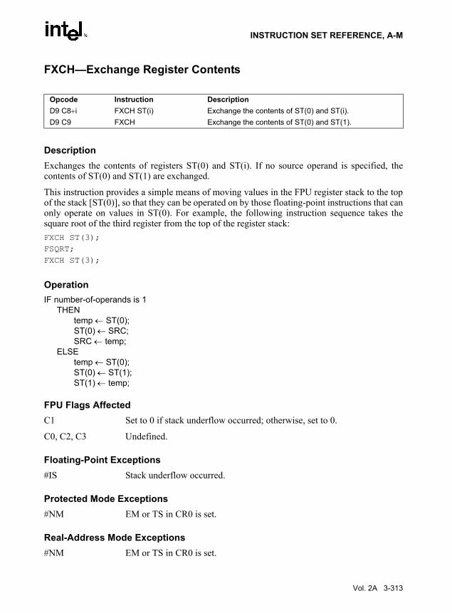
INSTRUCTION SET REFERENCE, A-M
FXCH—Exchange Register Contents
DescriptionExchanges the contents of registers ST(0) and ST(i). If no source operand is specified, thecontents of ST(0) and ST(1) are exchanged.
This instruction provides a simple means of moving values in the FPU register stack to the topof the stack [ST(0)], so that they can be operated on by those floating-point instructions that canonly operate on values in ST(0). For example, the following instruction sequence takes thesquare root of the third register from the top of the register stack:FXCH ST(3);FSQRT;FXCH ST(3);
OperationIF number-of-operands is 1
THENtemp ← ST(0);ST(0) ← SRC;SRC ← temp;
ELSEtemp ← ST(0);ST(0) ← ST(1);ST(1) ← temp;
FPU Flags AffectedC1 Set to 0 if stack underflow occurred; otherwise, set to 0.
C0, C2, C3 Undefined.
Floating-Point Exceptions#IS Stack underflow occurred.
Protected Mode Exceptions#NM EM or TS in CR0 is set.
Real-Address Mode Exceptions#NM EM or TS in CR0 is set.
Opcode Instruction DescriptionD9 C8+i FXCH ST(i) Exchange the contents of ST(0) and ST(i).D9 C9 FXCH Exchange the contents of ST(0) and ST(1).
Vol. 2A 3-313

INSTRUCTION SET REFERENCE, A-M
Virtual-8086 Mode Exceptions#NM EM or TS in CR0 is set.
3-314 Vol. 2A
INSTRUCTION SET REFERENCE, A-M
FXRSTOR—Restore x87 FPU, MMX Technology, SSE, and SSE2 State
DescriptionReloads the x87 FPU, MMX technology, XMM, and MXCSR registers from the 512-bytememory image specified in the source operand. This data should have been written to memorypreviously using the FXSAVE instruction, and the first byte of the data should be located on a16-byte boundary. Table 3-47 shows the layout of the state information in memory and describesthe fields in the memory image for the FXRSTOR and FXSAVE instructions.
The state image referenced with an FXRSTOR instruction must have been saved using anFXSAVE instruction or be in the same format as that shown in Table 3-47. Referencing a stateimage saved with an FSAVE or FNSAVE instruction will result in an incorrect state restoration.
The FXRSTOR instruction does not flush pending x87 FPU exceptions. To check and raiseexceptions when loading x87 FPU state information with the FXRSTOR instruction, use anFWAIT instruction after the FXRSTOR instruction.
If the OSFXSR bit in control register CR4 is not set, the FXRSTOR instruction may not restorethe states of the XMM and MXCSR registers. This behavior is implementation dependent.
If the MXCSR state contains an unmasked exception with a corresponding status flag also set,loading the register with the FXRSTOR instruction will not result in an SIMD floating-pointerror condition being generated. Only the next occurrence of this unmasked exception will resultin the exception being generated.
Bit 6 and bits 16 through 32 of the MXCSR register are defined as reserved and should be set to0. Attempting to write a 1 in any of these bits from the saved state image will result in a generalprotection exception (#GP) being generated.
Operation(x87 FPU, MMX, XMM7-XMM0, MXCSR) ← Load(SRC);
x87 FPU and SIMD Floating-Point Exceptions
None.
Opcode Instruction Description0F AE /1 FXRSTOR m512byte Restore the x87 FPU, MMX technology, XMM, and MXCSR
register state from m512byte.
Vol. 2A 3-315

INSTRUCTION SET REFERENCE, A-M
Protected Mode Exceptions
#GP(0) For an illegal memory operand effective address in the CS, DS, ES, FS or GS segments.
If a memory operand is not aligned on a 16-byte boundary, regardless of segment. (See alignment check exception [#AC] below.)
#SS(0) For an illegal address in the SS segment.
#PF(fault-code) For a page fault.
#NM If TS in CR0 is set.
#UD If EM in CR0 is set.
If CPUID feature flag FXSR is 0.
If instruction is preceded by a LOCK prefix.
#AC If this exception is disabled a general protection exception (#GP) is signaled if the memory operand is not aligned on a 16-byte boundary, as described above. If the alignment check exception (#AC) is enabled (and the CPL is 3), signaling of #AC is not guaranteed and may vary with implementation, as follows. In all implementations where #AC is not signaled, a general protection exception is signaled in its place. In addi-tion, the width of the alignment check may also vary with implementation. For instance, for a given implementation, an alignment check exception might be signaled for a 2-byte misalignment, whereas a general protection exception might be signaled for all other misalignments (4-, 8-, or 16-byte misalignments).
Real-Address Mode Exceptions
#GP(0) If a memory operand is not aligned on a 16-byte boundary, regardless of segment.
If any part of the operand lies outside the effective address space from 0 to FFFFH.
#NM If TS in CR0 is set.
#UD If EM in CR0 is set.
If CPUID feature flag SSE2 is 0.
If instruction is preceded by a LOCK override prefix.
3-316 Vol. 2A

INSTRUCTION SET REFERENCE, A-M
Virtual-8086 Mode Exceptions
Same exceptions as in Real Address Mode
#PF(fault-code) For a page fault.
#AC For unaligned memory reference.
Vol. 2A 3-317

INSTRUCTION SET REFERENCE, A-M
FXSAVE—Save x87 FPU, MMX Technology, SSE, and SSE2 State
DescriptionSaves the current state of the x87 FPU, MMX technology, XMM, and MXCSR registers to a512-byte memory location specified in the destination operand. Table 3-47 shows the layout ofthe state information in memory.
Opcode Instruction Description0F AE /0 FXSAVE m512byte Save the x87 FPU, MMX technology, XMM, and MXCSR register
state to m512byte.
3-318 Vol. 2A
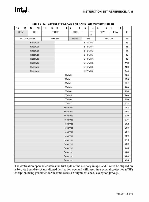
INSTRUCTION SET REFERENCE, A-M
The destination operand contains the first byte of the memory image, and it must be aligned ona 16-byte boundary. A misaligned destination operand will result in a general-protection (#GP)exception being generated (or in some cases, an alignment check exception [#AC]).
Table 3-47. Layout of FXSAVE and FXRSTOR Memory Region15 14 13 12 11 10 9 8 7 6 5 4 3 2 1 0
Rsrvd CS FPU IP FOP FTW
FSW FCW 0
MXCSR_MASK MXCSR Rsrvd DS FPU DP 16
Reserved ST0/MM0 32
Reserved ST1/MM1 48
Reserved ST2/MM2 64
Reserved ST3/MM3 80
Reserved ST4/MM4 96
Reserved ST5/MM5 112
Reserved ST6/MM6 128
Reserved ST7/MM7 144
XMM0 160
XMM1 176
XMM2 192
XMM3 208
XMM4 224
XMM5 240
XMM6 256
XMM7 272
Reserved 288
Reserved 304
Reserved 320
Reserved 336
Reserved 352
Reserved 368
Reserved 384
Reserved 400
Reserved 416
Reserved 432
Reserved 448
Reserved 464
Reserved 480
Reserved 496
Vol. 2A 3-319

INSTRUCTION SET REFERENCE, A-M
The FXSAVE instruction is used when an operating system needs to perform a context switchor when an exception handler needs to save and examine the current state of the x87 FPU, MMXtechnology, and/or XMM and MXCSR registers.
The fields in Table 3-47 are as follows:
FCW x87 FPU Control Word (16 bits). See Figure 8-6 in the IA-32 Intel Architec-ture Software Developer’s Manual, Volume 1, for the layout of the x87 FPUcontrol word.
FSW x87 FPU Status Word (16 bits). See Figure 8-4 in the IA-32 Intel Architec-ture Software Developer’s Manual, Volume 1, for the layout of the x87 FPUstatus word.
FTW x87 FPU Tag Word (8 bits). The tag information saved here is abridged, asdescribed in the following paragraphs. See Figure 8-7 in the IA-32 IntelArchitecture Software Developer’s Manual, Volume 1, for the layout of thex87 FPU tag word.
FOP x87 FPU Opcode (16 bits). The lower 11 bits of this field contain theopcode, upper 5 bits are reserved. See Figure 8-8 in the IA-32 Intel Archi-tecture Software Developer’s Manual, Volume 1, for the layout of the x87FPU opcode field.
FPU IP x87 FPU Instruction Pointer Offset (32 bits). The contents of this field differdepending on the current addressing mode (32-bit or 16-bit) of theprocessor when the FXSAVE instruction was executed:
• 32-bit mode—32-bit IP offset.
• 16-bit mode—low 16 bits are IP offset; high 16 bits are reserved.
See “x87 FPU Instruction and Operand (Data) Pointers” in Chapter 8 of theIA-32 Intel Architecture Software Developer’s Manual, Volume 1, for adescription of the x87 FPU instruction pointer.
CS x87 FPU Instruction Pointer Selector (16 bits).
3-320 Vol. 2A

INSTRUCTION SET REFERENCE, A-M
The FXSAVE instruction saves an abridged version of the x87 FPU tag word in the FTW field(unlike the FSAVE instruction, which saves the complete tag word). The tag information issaved in physical register order (R0 through R7), rather than in top-of-stack (TOS) order. Withthe FXSAVE instruction, however, only a single bit (1 for valid or 0 for empty) is saved for eachtag. For example, assume that the tag word is currently set as follows:
R7 R6 R5 R4 R3 R2 R1 R0
11 xx xx xx 11 11 11 11
FPU DP x87 FPU Instruction Operand (Data) Pointer Offset (32 bits). The contentsof this field differ depending on the current addressing mode (32-bit or 16-bit) of the processor when the FXSAVE instruction was executed:
• 32-bit mode—32-bit IP offset.
• 16-bit mode—low 16 bits are IP offset; high 16 bits are reserved.
See “x87 FPU Instruction and Operand (Data) Pointers” in Chapter 8 of theIA-32 Intel Architecture Software Developer’s Manual, Volume 1, for adescription of the x87 FPU operand pointer.
DS x87 FPU Instruction Operand (Data) Pointer Selector (16 bits).MXCSR MXCSR Register State (32 bits). See Figure 10-3 in the IA-32 Intel Archi-
tecture Software Developer’s Manual, Volume 1, for the layout of theMXCSR register. If the OSFXSR bit in control register CR4 is not set, theFXSAVE instruction may not save this register. This behavior is implemen-tation dependent.
MXCSR_MASK
MXCSR_MASK (32 bits). This mask can be used to adjust values writtento the MXCSR register, ensuring that reserved bits are set to 0. Set the maskbits and flags in MXCSR to the mode of operation desired for SSE andSSE2 SIMD floating-point instructions. See “Guidelines for Writing to theMXCSR Register” in Chapter 11 of the IA-32 Intel Architecture SoftwareDeveloper’s Manual, Volume 1, for instructions for how to determine anduse the MXCSR_MASK value.
ST0/MM0 through ST7/MM7
x87 FPU or MMX technology registers. These 80-bit fields contain the x87FPU data registers or the MMX technology registers, depending on the stateof the processor prior to the execution of the FXSAVE instruction. If theprocessor had been executing x87 FPU instruction prior to the FXSAVEinstruction, the x87 FPU data registers are saved; if it had been executingMMX instructions (or SSE or SSE2 instructions that operated on the MMXtechnology registers), the MMX technology registers are saved. When theMMX technology registers are saved, the high 16 bits of the field arereserved.
XMM0 through XMM7
XMM registers (128 bits per field). If the OSFXSR bit in control registerCR4 is not set, the FXSAVE instruction may not save these registers. Thisbehavior is implementation dependent.
Vol. 2A 3-321

INSTRUCTION SET REFERENCE, A-M
Here, 11B indicates empty stack elements and “xx” indicates valid (00B), zero (01B), or special(10B).
For this example, the FXSAVE instruction saves only the following 8 bits of information:
R7 R6 R5 R4 R3 R2 R1 R0
0 1 1 1 0 0 0 0
Here, a 1 is saved for any valid, zero, or special tag, and a 0 is saved for any empty tag.
The operation of the FXSAVE instruction differs from that of the FSAVE instruction, the asfollows:
• FXSAVE instruction does not check for pending unmasked floating-point exceptions. (TheFXSAVE operation in this regard is similar to the operation of the FNSAVE instruction).
• After the FXSAVE instruction has saved the state of the x87 FPU, MMX technology,XMM, and MXCSR registers, the processor retains the contents of the registers. Becauseof this behavior, the FXSAVE instruction cannot be used by an application program topass a “clean” x87 FPU state to a procedure, since it retains the current state. To clean thex87 FPU state, an application must explicitly execute an FINIT instruction after anFXSAVE instruction to reinitialize the x87 FPU state.
• The format of the memory image saved with the FXSAVE instruction is the sameregardless of the current addressing mode (32-bit or 16-bit) and operating mode (protected,real address, or system management). This behavior differs from the FSAVE instructions,where the memory image format is different depending on the addressing mode andoperating mode. Because of the different image formats, the memory image saved with theFXSAVE instruction cannot be restored correctly with the FRSTOR instruction, andlikewise the state saved with the FSAVE instruction cannot be restored correctly with theFXRSTOR instruction.
Note that The FSAVE format for FTW can be recreated from the FTW valid bits and the stored80-bit FP data (assuming the stored data was not the contents of MMX technology registers)using Table 3-48:
3-322 Vol. 2A

INSTRUCTION SET REFERENCE, A-M
The J-bit is defined to be the 1-bit binary integer to the left of the decimal place in the signifi-cand. The M-bit is defined to be the most significant bit of the fractional portion of the signifi-cand (i.e., the bit immediately to the right of the decimal place).
When the M-bit is the most significant bit of the fractional portion of the significand, it must be0 if the fraction is all 0’s.
OperationDEST ← Save(x87 FPU, MMX, XMM7-XMM0, MXCSR);
Protected Mode Exceptions
#GP(0) For an illegal memory operand effective address in the CS, DS, ES, FS or GS segments.
If a memory operand is not aligned on a 16-byte boundary, regardless of segment. (See the description of the alignment check exception [#AC] below.)
#SS(0) For an illegal address in the SS segment.
#PF(fault-code) For a page fault.
#NM If TS in CR0 is set.
#UD If EM in CR0 is set.
If CPUID feature flag FXSR is 0.
If instruction is preceded by a LOCK override prefix.
Table 3-48. Recreating FSAVE Format
Exponentall 1’s
Exponentall 0’s
Fractionall 0’s
J and Mbits
FTW valid bit x87 FTW
0 0 0 0x 1 Special 100 0 0 1x 1 Valid 000 0 1 00 1 Special 100 0 1 10 1 Valid 000 1 0 0x 1 Special 100 1 0 1x 1 Special 100 1 1 00 1 Zero 010 1 1 10 1 Special 101 0 0 1x 1 Special 101 0 0 1x 1 Special 101 0 1 00 1 Special 101 0 1 10 1 Special 10
For all legal combinations above 0 Empty 11
Vol. 2A 3-323

INSTRUCTION SET REFERENCE, A-M
#AC If this exception is disabled a general protection exception (#GP) is signaled if the memory operand is not aligned on a 16-byte boundary, as described above. If the alignment check exception (#AC) is enabled (and the CPL is 3), signaling of #AC is not guaranteed and may vary with implementation, as follows. In all implementations where #AC is not signaled, a general protection exception is signaled in its place. In addi-tion, the width of the alignment check may also vary with implementation. For instance, for a given implementation, an alignment check exception might be signaled for a 2-byte misalignment, whereas a general protection exception might be signaled for all other misalignments (4-, 8-, or 16-byte misalignments).
Real-Address Mode Exceptions
#GP(0) If a memory operand is not aligned on a 16-byte boundary, regardless of segment.
If any part of the operand lies outside the effective address space from 0 to FFFFH.
#NM If TS in CR0 is set.
#UD If EM in CR0 is set.
If CPUID feature flag FXSR is 0.
If instruction is preceded by a LOCK override prefix.
Virtual-8086 Mode Exceptions
Same exceptions as in Real Address Mode
#PF(fault-code) For a page fault.
#AC For unaligned memory reference.
Implementation Note
The order in which the processor signals general-protection (#GP) and page-fault (#PF) excep-tions when they both occur on an instruction boundary is given in Table 5-2 in the IA-32 IntelArchitecture Software Developer’s Manual, Volume 3. This order vary for the FXSAVE instruc-tion for different IA-32 processor implementations.
3-324 Vol. 2A

INSTRUCTION SET REFERENCE, A-M
FXTRACT—Extract Exponent and Significand
DescriptionSeparates the source value in the ST(0) register into its exponent and significand, stores theexponent in ST(0), and pushes the significand onto the register stack. Following this operation,the new top-of-stack register ST(0) contains the value of the original significand expressed as afloating-point value. The sign and significand of this value are the same as those found in thesource operand, and the exponent is 3FFFH (biased value for a true exponent of zero). The ST(1)register contains the value of the original operand’s true (unbiased) exponent expressed as afloating-point value. (The operation performed by this instruction is a superset of the IEEE-recommended logb(x) function.)
This instruction and the F2XM1 instruction are useful for performing power and range scalingoperations. The FXTRACT instruction is also useful for converting numbers in doubleextended-precision floating-point format to decimal representations (e.g., for printing ordisplaying).
If the floating-point zero-divide exception (#Z) is masked and the source operand is zero, anexponent value of –∞ is stored in register ST(1) and 0 with the sign of the source operand isstored in register ST(0).
OperationTEMP ← Significand(ST(0));ST(0) ← Exponent(ST(0));TOP← TOP − 1;ST(0) ← TEMP;
FPU Flags AffectedC1 Set to 0 if stack underflow occurred; set to 1 if stack overflow occurred.
C0, C2, C3 Undefined.
Floating-Point Exceptions#IS Stack underflow or overflow occurred.
#IA Source operand is an SNaN value or unsupported format.
#Z ST(0) operand is ±0.
#D Source operand is a denormal value.
Opcode Instruction DescriptionD9 F4 FXTRACT Separate value in ST(0) into exponent and significand,
store exponent in ST(0), and push the significand onto the register stack.
Vol. 2A 3-325

INSTRUCTION SET REFERENCE, A-M
Protected Mode Exceptions#NM EM or TS in CR0 is set.
Real-Address Mode Exceptions#NM EM or TS in CR0 is set.
Virtual-8086 Mode Exceptions#NM EM or TS in CR0 is set.
3-326 Vol. 2A

INSTRUCTION SET REFERENCE, A-M
FYL2X—Compute y ∗ log2x
DescriptionComputes (ST(1) ∗ log2 (ST(0))), stores the result in resister ST(1), and pops the FPU registerstack. The source operand in ST(0) must be a non-zero positive number.
The following table shows the results obtained when taking the log of various classes ofnumbers, assuming that neither overflow nor underflow occurs.
NOTES:F Means finite floating-point value.* Indicates floating-point invalid-operation (#IA) exception.** Indicates floating-point zero-divide (#Z) exception.
If the divide-by-zero exception is masked and register ST(0) contains ±0, the instruction returns∞ with a sign that is the opposite of the sign of the source operand in register ST(1).
The FYL2X instruction is designed with a built-in multiplication to optimize the calculation oflogarithms with an arbitrary positive base (b):logbx ← (log2b)–1 ∗ log2x
OperationST(1) ← ST(1) ∗ log2ST(0);PopRegisterStack;
Opcode Instruction DescriptionD9 F1 FYL2X Replace ST(1) with (ST(1) ∗ log2ST(0)) and pop the
register stack.
Table 3-49. FYL2X ResultsST(0)
−∞ −F ±0 +0 < +F < +1 +1 +F > +1 +∞ NaN
−∞ * * +∞ +∞ * −∞ −∞ NaN
ST(1) −F * * ** +F −0 −F −∞ NaN
−0 * * * +0 −0 −0 * NaN
+0 * * * −0 +0 +0 * NaN
+F * * ** −F +0 +F +∞ NaN
+∞ * * −∞ −∞ ∗ +∞ +∞ NaN
NaN NaN NaN NaN NaN NaN NaN NaN NaN
Vol. 2A 3-327

INSTRUCTION SET REFERENCE, A-M
FPU Flags AffectedC1 Set to 0 if stack underflow occurred.
Set if result was rounded up; cleared otherwise.
C0, C2, C3 Undefined.
Floating-Point Exceptions#IS Stack underflow occurred.
#IA Either operand is an SNaN or unsupported format.
Source operand in register ST(0) is a negative finite value (not −0).
#Z Source operand in register ST(0) is ±0.
#D Source operand is a denormal value.
#U Result is too small for destination format.
#O Result is too large for destination format.
#P Value cannot be represented exactly in destination format.
Protected Mode Exceptions#NM EM or TS in CR0 is set.
Real-Address Mode Exceptions#NM EM or TS in CR0 is set.
Virtual-8086 Mode Exceptions#NM EM or TS in CR0 is set.
3-328 Vol. 2A

INSTRUCTION SET REFERENCE, A-M
FYL2XP1—Compute y ∗ log2(x +1)
DescriptionComputes (ST(1) ∗ log2(ST(0) + 1.0)), stores the result in register ST(1), and pops the FPUregister stack. The source operand in ST(0) must be in the range:
The source operand in ST(1) can range from −∞ to +∞. If the ST(0) operand is outside of itsacceptable range, the result is undefined and software should not rely on an exception beinggenerated. Under some circumstances exceptions may be generated when ST(0) is out of range,but this behavior is implementation specific and not guaranteed.
The following table shows the results obtained when taking the log epsilon of various classes ofnumbers, assuming that underflow does not occur.
NOTES:F Means finite floating-point value.* Indicates floating-point invalid-operation (#IA) exception.
This instruction provides optimal accuracy for values of epsilon [the value in register ST(0)] thatare close to 0. For small epsilon (ε) values, more significant digits can be retained by using theFYL2XP1 instruction than by using (ε+1) as an argument to the FYL2X instruction. The (ε+1)expression is commonly found in compound interest and annuity calculations. The result can besimply converted into a value in another logarithm base by including a scale factor in the ST(1)source operand. The following equation is used to calculate the scale factor for a particular loga-rithm base, where n is the logarithm base desired for the result of the FYL2XP1 instruction:
scale factor ← logn 2
Opcode Instruction DescriptionD9 F9 FYL2XP1 Replace ST(1) with ST(1) ∗ log2(ST(0) + 1.0) and pop the
register stack.
Table 3-50. FYL2XP1 ResultsST(0)
−(1 − ( )) to −0 −0 +0 +0 to +(1 − ( )) NaN
−∞ +∞ * * −∞ NaN
ST(1) −F +F +0 −0 −F NaN
−0 +0 +0 −0 −0 NaN
+0 −0 −0 +0 +0 NaN
+F −F −0 +0 +F NaN
+∞ −∞ * * +∞ NaN
NaN NaN NaN NaN NaN NaN
1 2 2⁄–( ) )to 1 2 2⁄–( )–
2 2⁄ 2 2⁄
Vol. 2A 3-329

INSTRUCTION SET REFERENCE, A-M
OperationST(1) ← ST(1) ∗ log2(ST(0) + 1.0);PopRegisterStack;
FPU Flags AffectedC1 Set to 0 if stack underflow occurred.
Set if result was rounded up; cleared otherwise.
C0, C2, C3 Undefined.
Floating-Point Exceptions#IS Stack underflow occurred.
#IA Either operand is an SNaN value or unsupported format.
#D Source operand is a denormal value.
#U Result is too small for destination format.
#O Result is too large for destination format.
#P Value cannot be represented exactly in destination format.
Protected Mode Exceptions#NM EM or TS in CR0 is set.
Real-Address Mode Exceptions#NM EM or TS in CR0 is set.
Virtual-8086 Mode Exceptions#NM EM or TS in CR0 is set.
3-330 Vol. 2A

INSTRUCTION SET REFERENCE, A-M
HADDPD: Packed Double-FP Horizontal Add
DescriptionAdds the double-precision floating-point values in the high and low quadwords of the destina-tion operand and stores the result in the low quadword of the destination operand.
Adds the double-precision floating-point values in the high and low quadwords of the sourceoperand and stores the result in the high quadword of the destination operand.
See Figure 3-10.
Operationxmm1[63-0] = xmm1[63-0] + xmm1[127-64];xmm1[127-64] = xmm2/m128[63-0] + xmm2/m128[127-64];
Opcode Instruction Description66,0F,7C,/r HADDPD xmm1, xmm2/m128 Add horizontally packed DP FP numbers from
xmm2/m128 to xmm1.
Figure 3-10. HADDPD: Packed Double-FP Horizontal Add
OM15993
HADDPD xmm1, xmm2/m128
xmm1
xmm2/m128
[63-0][127-64]
[127-64] [63-0]
[63-0][127-64]
Result:xmm1
xmm2/m128[63-0] +xmm2/m128[127-64]
xmm1[63-0] + xmm1[127-64]
Vol. 2A 3-331

INSTRUCTION SET REFERENCE, A-M
Intel C/C++ Compiler Intrinsic EquivalentHADDPD __m128d _mm_hadd_pd(__m128d a, __m128d b)
ExceptionsWhen the source operand is a memory operand, the operand must be aligned on a 16-byteboundary or a general-protection exception (#GP) will be generated.
Numeric ExceptionsOverflow, Underflow, Invalid, Precision, Denormal.
Protected Mode Exceptions#GP(0) For an illegal memory operand effective address in the CS, DS, ES, FS or
GS segments.
If a memory operand is not aligned on a 16-byte boundary, regardless of segment.
#SS(0) For an illegal address in the SS segment.
#PF(fault-code) For a page fault.
#NM If TS bit in CR0 is set.
#XM For an unmasked Streaming SIMD Extensions numeric exception (CR4.OSXMMEXCPT = 1).
#UD If CR0.EM = 1.
For an unmasked Streaming SIMD Extensions numeric exception (CR4.OSXMMEXCPT = 0);
If CR4.OSFXSR(bit 9) = 0.
If CPUID.SSE3(ECX bit 0) = 0.
Real Address Mode ExceptionsGP(0) If any part of the operand would lie outside of the effective address space
from 0 to 0FFFFH.
If a memory operand is not aligned on a 16-byte boundary, regardless of segment.
#NM If TS bit in CR0 is set.
#XM For an unmasked Streaming SIMD Extensions numeric exception (CR4.OSXMMEXCPT = 1).
#UD If CR0.EM = 1.
For an unmasked Streaming SIMD Extensions numeric exception (CR4.OSXMMEXCPT = 0).
3-332 Vol. 2A

INSTRUCTION SET REFERENCE, A-M
If CR4.OSFXSR(bit 9) = 0.
If CPUID.SSE3(ECX bit 0) = 0.
Virtual 8086 Mode ExceptionsGP(0) If any part of the operand would lie outside of the effective address space
from 0 to 0FFFFH.
If a memory operand is not aligned on a 16-byte boundary, regardless of segment.
#NM If TS bit in CR0 is set.
#XM For an unmasked Streaming SIMD Extensions numeric exception (CR4.OSXMMEXCPT = 1).
#UD If CR0.EM = 1.
For an unmasked Streaming SIMD Extensions numeric exception (CR4.OSXMMEXCPT = 0).
If CR4.OSFXSR(bit 9) = 0.
If CPUID.SSE3(ECX bit 0) = 0.
#PF(fault-code) For a page fault.
Vol. 2A 3-333

INSTRUCTION SET REFERENCE, A-M
HADDPS: Packed Single-FP Horizontal Add
DescriptionAdds the single-precision floating-point values in the first and second dwords of the destinationoperand and stores the result in the first dword of the destination operand.
Adds single-precision floating-point values in the third and fourth dword of the destinationoperand and stores the result in the second dword of the destination operand.
Adds single-precision floating-point values in the first and second dword of the source operandand stores the result in the third dword of the destination operand.
Adds single-precision floating-point values in the third and fourth dword of the source operandand stores the result in the fourth dword of the destination operand.
See Figure 3-11.
Opcode Instruction DescriptionF2,0F,7C,/r HADDPS xmm1, xmm2/m128 Add horizontally packed SP FP numbers from
xmm2/m128 to xmm1.
3-334 Vol. 2A

INSTRUCTION SET REFERENCE, A-M
Operationxmm1[31-0] = xmm1[31-0] + xmm1[63-32];xmm1[63-32] = xmm1[95-64] + xmm1[127-96];xmm1[95-64] = xmm2/m128[31-0] + xmm2/m128[63-32];xmm1[127-96] = xmm2/m128[95-64] + xmm2/m128[127-96];
Intel C/C++ Compiler Intrinsic EquivalentHADDPS __m128 _mm_hadd_ps(__m128 a, __m128 b)
ExceptionsWhen the source operand is a memory operand, the operand must be aligned on a 16-byteboundary or a general-protection exception (#GP) will be generated.
Numeric ExceptionsOverflow, Underflow, Invalid, Precision, Denormal.
Figure 3-11. HADDPS: Packed Single-FP Horizontal Add
OM15994
HADDPS xmm1, xmm2/m128
RESULT:xmm1
xmm2/m128
x mm1 [ 3 1 - 0 ] +x mm1 [ 6 3 - 3 2 ]
[31-0]
x mm1 [ 9 5 - 6 4 ] +x mm1 [ 1 2 7 - 9 6 ]
[63-32]
[63-32] [31-0]
xmm1[31-0][63-32]
x m m 2 / m 1 2 8[31 -0 ] + xmm2/
m1 2 8 [ 6 3 - 3 2 ]
[95-64]
x m m 2 / m 1 2 8[95 -64 ] + xmm2/
m1 2 8 [ 1 2 7 - 9 6 ]
[127-96]
[127-96] [95-64]
[95-64][127-96]
Vol. 2A 3-335

INSTRUCTION SET REFERENCE, A-M
Protected Mode Exceptions#GP(0) For an illegal memory operand effective address in the CS, DS, ES, FS or
GS segments.
If a memory operand is not aligned on a 16-byte boundary, regardless of segment.
#SS(0) For an illegal address in the SS segment.
#PF(fault-code) For a page fault.
#NM If TS bit in CR0 is set.
#XM For an unmasked Streaming SIMD Extensions numeric exception (CR4.OSXMMEXCPT = 1).
#UD If CR0.EM = 1.
For an unmasked Streaming SIMD Extensions numeric exception (CR4.OSXMMEXCPT = 0).
If CR4.OSFXSR(bit 9) = 0.
If CPUID.SSE3(ECX bit 0) = 0.
Real Address Mode ExceptionsGP(0) If any part of the operand would lie outside of the effective address space
from 0 to 0FFFFH.
If a memory operand is not aligned on a 16-byte boundary, regardless of segment.
#NM If TS bit in CR0 is set.
#XM For an unmasked Streaming SIMD Extensions numeric exception (CR4.OSXMMEXCPT = 1).
#UD If CR0.EM = 1.
For an unmasked Streaming SIMD Extensions numeric exception (CR4.OSXMMEXCPT = 0).
If CR4.OSFXSR(bit 9) = 0.
If CPUID.SSE3(ECX bit 0) = 0.
Virtual 8086 Mode ExceptionsGP(0) If any part of the operand would lie outside of the effective address space
from 0 to 0FFFFH.
If a memory operand is not aligned on a 16-byte boundary, regardless of segment.
#NM If TS bit in CR0 is set.
3-336 Vol. 2A

INSTRUCTION SET REFERENCE, A-M
#XM For an unmasked Streaming SIMD Extensions numeric exception (CR4.OSXMMEXCPT = 1).
#UD If CR0.EM = 1.
For an unmasked Streaming SIMD Extensions numeric exception (CR4.OSXMMEXCPT = 0).
If CR4.OSFXSR(bit 9) = 0.
If CPUID.SSE3(ECX bit 0) = 0.
#PF(fault-code) For a page fault.
Vol. 2A 3-337
INSTRUCTION SET REFERENCE, A-M
HLT—Halt
DescriptionStops instruction execution and places the processor in a HALT state. An enabled interrupt(including NMI and SMI), a debug exception, the BINIT# signal, the INIT# signal, or theRESET# signal will resume execution. If an interrupt (including NMI) is used to resume execu-tion after a HLT instruction, the saved instruction pointer (CS:EIP) points to the instructionfollowing the HLT instruction.
When a HLT instruction is executed on an IA-32 processor supporting Hyper-Threading Tech-nology, only the logical processor that executes the instruction is halted. The other logicalprocessors in the physical processor remain active, unless they are each individually halted byexecuting a HLT instruction.
The HLT instruction is a privileged instruction. When the processor is running in protected orvirtual-8086 mode, the privilege level of a program or procedure must be 0 to execute the HLTinstruction.
OperationEnter Halt state;
Flags AffectedNone.
Protected Mode Exceptions#GP(0) If the current privilege level is not 0.
Real-Address Mode ExceptionsNone.
Virtual-8086 Mode Exceptions#GP(0) If the current privilege level is not 0.
Opcode Instruction DescriptionF4 HLT Halt.
3-338 Vol. 2A

INSTRUCTION SET REFERENCE, A-M
HSUBPD: Packed Double-FP Horizontal Subtract
DescriptionThe HSUBPD instruction subtracts horizontally the packed DP FP numbers of both operands.
Subtracts the double-precision floating-point value in the high quadword of the destinationoperand from the low quadword of the destination operand and stores the result in the low quad-word of the destination operand.
Subtracts the double-precision floating-point value in the high quadword of the source operandfrom the low quadword of the source operand and stores the result in the high quadword of thedestination operand.
See Figure 3-12.
Operationxmm1[63-0] = xmm1[63-0] - xmm1[127-64];
Opcode Instruction Description66,0F,7D,/r HSUBPD xmm1, xmm2/m128 Subtract horizontally packed DP FP numbers
in xmm2/m128 from xmm1.
Figure 3-12. HSUBPD: Packed Double-FP Horizontal Subtract
OM15995
HSUBPD xmm1, xmm2/m128
xmm1
xmm2/m128
[63-0][127-64]
[127-64] [63-0]
[63-0][127-64]
Result:xmm1
xmm2/m128[63-0] -xmm2/m128[127-64]
xmm1[63-0] - xmm1[127-64]
Vol. 2A 3-339

INSTRUCTION SET REFERENCE, A-M
xmm1[127-64] = xmm2/m128[63-0] - xmm2/m128[127-64];
Intel C/C++ Compiler Intrinsic EquivalentHSUBPD __m128d _mm_hsub_pd(__m128d a, __m128d b)
ExceptionsWhen the source operand is a memory operand, the operand must be aligned on a 16-byteboundary or a general-protection exception (#GP) will be generated.
Numeric ExceptionsOverflow, Underflow, Invalid, Precision, Denormal.
Protected Mode Exceptions#GP(0) For an illegal memory operand effective address in the CS, DS, ES, FS or
GS segments.
If a memory operand is not aligned on a 16-byte boundary, regardless of segment.
#SS(0) For an illegal address in the SS segment.
#PF(fault-code) For a page fault.
#NM If TS bit in CR0 is set.
#XM For an unmasked Streaming SIMD Extensions numeric exception (CR4.OSXMMEXCPT = 1).
#UD If CR0.EM = 1.
For an unmasked Streaming SIMD Extensions numeric exception (CR4.OSXMMEXCPT = 0).
If CR4.OSFXSR(bit 9) = 0.
If CPUID.SSE3(ECX bit 0) = 0.
Real Address Mode ExceptionsGP(0) If any part of the operand would lie outside of the effective address space
from 0 to 0FFFFH.
If a memory operand is not aligned on a 16-byte boundary, regardless of segment.
#NM If TS bit in CR0 is set.
#XM For an unmasked Streaming SIMD Extensions numeric exception (CR4.OSXMMEXCPT = 1).
#UD If CR0.EM = 1.
3-340 Vol. 2A

INSTRUCTION SET REFERENCE, A-M
For an unmasked Streaming SIMD Extensions numeric exception (CR4.OSXMMEXCPT = 0).
If CR4.OSFXSR(bit 9) = 0.
If CPUID.SSE3(ECX bit 0) = 0.
Virtual 8086 Mode ExceptionsGP(0) If any part of the operand would lie outside of the effective address space
from 0 to 0FFFFH.
If a memory operand is not aligned on a 16-byte boundary, regardless of segment.
#NM If TS bit in CR0 is set.
#XM For an unmasked Streaming SIMD Extensions numeric exception (CR4.OSXMMEXCPT = 1).
#UD If CR0.EM = 1.
For an unmasked Streaming SIMD Extensions numeric exception (CR4.OSXMMEXCPT = 0).
If CR4.OSFXSR(bit 9) = 0.
If CPUID.SSE3(ECX bit 0) = 0.
#PF(fault-code) For a page fault.
Vol. 2A 3-341

INSTRUCTION SET REFERENCE, A-M
HSUBPS: Packed Single-FP Horizontal Subtract
DescriptionSubtracts the single-precision floating-point value in the second dword of the destinationoperand from the first dword of the destination operand and stores the result in the first dwordof the destination operand.
Subtracts the single-precision floating-point value in the fourth dword of the destination operandfrom the third dword of the destination operand and stores the result in the second dword of thedestination operand.
Subtracts the single-precision floating-point value in the second dword of the source operandfrom the first dword of the source operand and stores the result in the third dword of the desti-nation operand.
Subtracts the single-precision floating-point value in the fourth dword of the source operandfrom the third dword of the source operand and stores the result in the fourth dword of the desti-nation operand.
See Figure 3-13.
Opcode Instruction DescriptionF2,0F,7D,/r HSUBPS xmm1, xmm2/m128 Subtract horizontally packed SP FP numbers
in xmm2/m128 from xmm1.
3-342 Vol. 2A
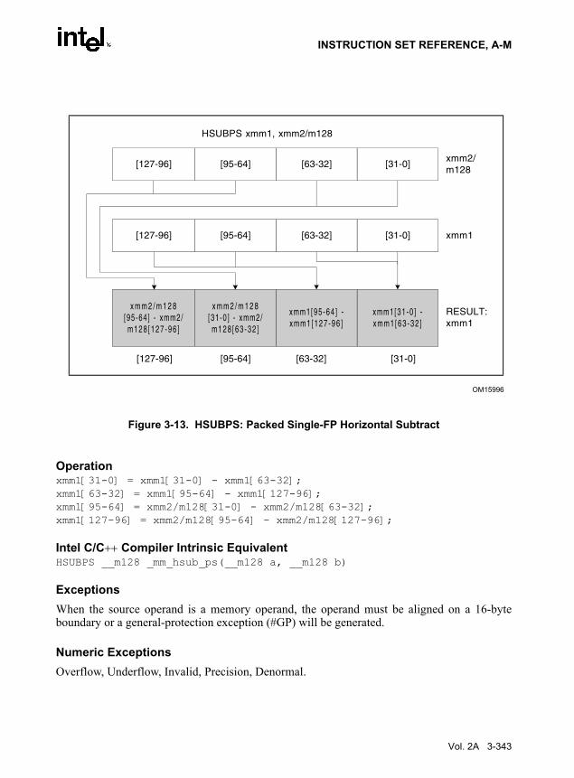
INSTRUCTION SET REFERENCE, A-M
Operationxmm1[31-0] = xmm1[31-0] - xmm1[63-32];xmm1[63-32] = xmm1[95-64] - xmm1[127-96];xmm1[95-64] = xmm2/m128[31-0] - xmm2/m128[63-32];xmm1[127-96] = xmm2/m128[95-64] - xmm2/m128[127-96];
Intel C/C++ Compiler Intrinsic EquivalentHSUBPS __m128 _mm_hsub_ps(__m128 a, __m128 b)
ExceptionsWhen the source operand is a memory operand, the operand must be aligned on a 16-byteboundary or a general-protection exception (#GP) will be generated.
Numeric ExceptionsOverflow, Underflow, Invalid, Precision, Denormal.
Figure 3-13. HSUBPS: Packed Single-FP Horizontal Subtract
OM15996
HSUBPS xmm1, xmm2/m128
RESULT:xmm1
xmm2/m128
xmm1[31-0 ] -x mm1 [ 6 3 - 3 2 ]
[31-0]
xmm1[95-64 ] -x mm1 [ 1 2 7 - 9 6 ]
[63-32]
[63-32] [31-0]
xmm1[31-0][63-32]
x m m 2 / m 1 2 8[31-0 ] - xmm2/m1 2 8 [ 6 3 - 3 2 ]
[95-64]
x m m 2 / m 1 2 8[95-64] - xmm2/m1 2 8 [ 1 2 7 - 9 6 ]
[127-96]
[127-96] [95-64]
[95-64][127-96]
Vol. 2A 3-343

INSTRUCTION SET REFERENCE, A-M
Protected Mode Exceptions#GP(0) For an illegal memory operand effective address in the CS, DS, ES, FS or
GS segments.
If a memory operand is not aligned on a 16-byte boundary, regardless of segment.
#SS(0) For an illegal address in the SS segment.
#PF(fault-code) For a page fault.
#NM If TS bit in CR0 is set.
#XM For an unmasked Streaming SIMD Extensions numeric exception (CR4.OSXMMEXCPT = 1).
#UD If CR0.EM = 1.
For an unmasked Streaming SIMD Extensions numeric exception (CR4.OSXMMEXCPT = 0).
If CR4.OSFXSR(bit 9) = 0.
If CPUID.SSE3(ECX bit 0) = 0.
Real Address Mode ExceptionsGP(0) If any part of the operand would lie outside of the effective address space
from 0 to 0FFFFH.
If a memory operand is not aligned on a 16-byte boundary, regardless of segment.
#NM If TS bit in CR0 is set.
#XM For an unmasked Streaming SIMD Extensions numeric exception (CR4.OSXMMEXCPT = 1).
#UD If CR0.EM = 1.
For an unmasked Streaming SIMD Extensions numeric exception (CR4.OSXMMEXCPT = 0).
If CR4.OSFXSR(bit 9) = 0.
If CPUID.SSE3(ECX bit 0) = 0.
Virtual 8086 Mode ExceptionsGP(0) If any part of the operand would lie outside of the effective address space
from 0 to 0FFFFH.
If a memory operand is not aligned on a 16-byte boundary, regardless of segment.
#NM If TS bit in CR0 is set.
3-344 Vol. 2A

INSTRUCTION SET REFERENCE, A-M
#XM For an unmasked Streaming SIMD Extensions numeric exception (CR4.OSXMMEXCPT = 1).
#UD If CR0.EM = 1.
For an unmasked Streaming SIMD Extensions numeric exception (CR4.OSXMMEXCPT = 0).
If CR4.OSFXSR(bit 9) = 0.
If CPUID.SSE3(ECX bit 0) = 0.
#PF(fault-code) For a page fault.
Vol. 2A 3-345

INSTRUCTION SET REFERENCE, A-M
IDIV—Signed Divide
DescriptionDivides (signed) the value in the AX, DX:AX, or EDX:EAX registers (dividend) by the sourceoperand (divisor) and stores the result in the AX (AH:AL), DX:AX, or EDX:EAX registers. Thesource operand can be a general-purpose register or a memory location. The action of thisinstruction depends on the operand size (dividend/divisor), as shown in the following table:
Non-integral results are truncated (chopped) towards 0. The sign of the remainder is always thesame as the sign of the dividend. The absolute value of the remainder is always less than theabsolute value of the divisor. Overflow is indicated with the #DE (divide error) exception ratherthan with the OF (overflow) flag.
OperationIF SRC = 0
THEN #DE; (* divide error *) FI;IF OperandSize = 8 (* word/byte operation *)
THENtemp ← AX / SRC; (* signed division *)IF (temp > 7FH) OR (temp < 80H) (* if a positive result is greater than 7FH or a negative result is less than 80H *)
THEN #DE; (* divide error *) ;ELSE
AL ← temp;AH ← AX SignedModulus SRC;
FI;ELSE
IF OperandSize = 16 (* doubleword/word operation *)
Opcode Instruction DescriptionF6 /7 IDIV r/m8 Signed divide AX by r/m8, with result stored in
AL ← Quotient, AH ← Remainder.F7 /7 IDIV r/m16 Signed divide DX:AX by r/m16, with result stored in
AX ← Quotient, DX ← Remainder.F7 /7 IDIV r/m32 Signed divide EDX:EAX by r/m32, with result stored in
EAX ← Quotient, EDX ← Remainder.
Table 3-51. IDIV ResultsOperand Size Dividend Divisor Quotient Remainder Quotient Range
Word/byte AX r/m8 AL AH −128 to +127
Doubleword/word DX:AX r/m16 AX DX −32,768 to +32,767
Quadword/doubleword EDX:EAX r/m32 EAX EDX −231 to 232 − 1
3-346 Vol. 2A

INSTRUCTION SET REFERENCE, A-M
THENtemp ← DX:AX / SRC; (* signed division *)IF (temp > 7FFFH) OR (temp < 8000H) (* if a positive result is greater than 7FFFH *)(* or a negative result is less than 8000H *)
THEN #DE; (* divide error *) ;ELSE
AX ← temp;DX ← DX:AX SignedModulus SRC;
FI;ELSE (* quadword/doubleword operation *)
temp ← EDX:EAX / SRC; (* signed division *)IF (temp > 7FFFFFFFH) OR (temp < 80000000H) (* if a positive result is greater than 7FFFFFFFH *)(* or a negative result is less than 80000000H *)
THEN #DE; (* divide error *) ;ELSE
EAX ← temp;EDX ← EDXE:AX SignedModulus SRC;
FI;FI;
FI;
Flags AffectedThe CF, OF, SF, ZF, AF, and PF flags are undefined.
Protected Mode Exceptions#DE If the source operand (divisor) is 0.
The signed result (quotient) is too large for the destination.
#GP(0) If a memory operand effective address is outside the CS, DS, ES, FS, or GS segment limit.
If the DS, ES, FS, or GS register is used to access memory and it contains a null segment selector.
#SS(0) If a memory operand effective address is outside the SS segment limit.
#PF(fault-code) If a page fault occurs.
#AC(0) If alignment checking is enabled and an unaligned memory reference is made while the current privilege level is 3.
Real-Address Mode Exceptions#DE If the source operand (divisor) is 0.
The signed result (quotient) is too large for the destination.
Vol. 2A 3-347

INSTRUCTION SET REFERENCE, A-M
#GP If a memory operand effective address is outside the CS, DS, ES, FS, or GS segment limit.
#SS If a memory operand effective address is outside the SS segment limit.
Virtual-8086 Mode Exceptions#DE If the source operand (divisor) is 0.
The signed result (quotient) is too large for the destination.
#GP(0) If a memory operand effective address is outside the CS, DS, ES, FS, or GS segment limit.
#SS(0) If a memory operand effective address is outside the SS segment limit.
#PF(fault-code) If a page fault occurs.
#AC(0) If alignment checking is enabled and an unaligned memory reference is made.
3-348 Vol. 2A

INSTRUCTION SET REFERENCE, A-M
IMUL—Signed Multiply
DescriptionPerforms a signed multiplication of two operands. This instruction has three forms, dependingon the number of operands.
• One-operand form. This form is identical to that used by the MUL instruction. Here, thesource operand (in a general-purpose register or memory location) is multiplied by thevalue in the AL, AX, or EAX register (depending on the operand size) and the product isstored in the AX, DX:AX, or EDX:EAX registers, respectively.
• Two-operand form. With this form the destination operand (the first operand) ismultiplied by the source operand (second operand). The destination operand is a general-purpose register and the source operand is an immediate value, a general-purpose register,or a memory location. The product is then stored in the destination operand location.
• Three-operand form. This form requires a destination operand (the first operand) and twosource operands (the second and the third operands). Here, the first source operand (whichcan be a general-purpose register or a memory location) is multiplied by the second sourceoperand (an immediate value). The product is then stored in the destination operand (ageneral-purpose register).
When an immediate value is used as an operand, it is sign-extended to the length of the destina-tion operand format.
Opcode Instruction DescriptionF6 /5 IMUL r/m8 AX← AL ∗ r/m byte.F7 /5 IMUL r/m16 DX:AX ← AX ∗ r/m word.F7 /5 IMUL r/m32 EDX:EAX ← EAX ∗ r/m doubleword.0F AF /r IMUL r16,r/m16 word register ← word register ∗ r/m word.0F AF /r IMUL r32,r/m32 doubleword register ← doubleword register ∗ r/m
doubleword.6B /r ib IMUL r16,r/m16,imm8 word register ← r/m16 ∗ sign-extended immediate byte.6B /r ib IMUL r32,r/m32,imm8 doubleword register ← r/m32 ∗ sign-extended immediate
byte.6B /r ib IMUL r16,imm8 word register ← word register ∗ sign-extended immediate
byte.6B /r ib IMUL r32,imm8 doubleword register ← doubleword register ∗ sign-
extended immediate byte.69 /r iw IMUL r16,r/
m16,imm16word register ← r/m16 ∗ immediate word.
69 /r id IMUL r32,r/m32,imm32
doubleword register ← r/m32 ∗ immediate doubleword.
69 /r iw IMUL r16,imm16 word register ← r/m16 ∗ immediate word.69 /r id IMUL r32,imm32 doubleword register ← r/m32 ∗ immediate doubleword.
Vol. 2A 3-349

INSTRUCTION SET REFERENCE, A-M
The CF and OF flags are set when significant bit (including the sign bit) are carried into theupper half of the result. The CF and OF flags are cleared when the result (including the sign bit)fits exactly in the lower half of the result.
The three forms of the IMUL instruction are similar in that the length of the product is calculatedto twice the length of the operands. With the one-operand form, the product is stored exactly inthe destination. With the two- and three- operand forms, however, the result is truncated to thelength of the destination before it is stored in the destination register. Because of this truncation,the CF or OF flag should be tested to ensure that no significant bits are lost.
The two- and three-operand forms may also be used with unsigned operands because the lowerhalf of the product is the same regardless if the operands are signed or unsigned. The CF and OFflags, however, cannot be used to determine if the upper half of the result is non-zero.
OperationIF (NumberOfOperands = 1)
THEN IF (OperandSize = 8)THEN
AX ← AL ∗ SRC (* signed multiplication *)IF AL = AX
THEN CF ← 0; OF ← 0;ELSE CF ← 1; OF ← 1;
FI;ELSE IF OperandSize = 16
THEN DX:AX ← AX ∗ SRC (* signed multiplication *)IF sign_extend_to_32 (AX) = DX:AX
THEN CF ← 0; OF ← 0;ELSE CF ← 1; OF ← 1;
FI;ELSE (* OperandSize = 32 *)
EDX:EAX ← EAX ∗ SRC (* signed multiplication *)IF EAX = EDX:EAX
THEN CF ← 0; OF ← 0;ELSE CF ← 1; OF ← 1;
FI;FI;
ELSE IF (NumberOfOperands = 2)THEN
temp ← DEST ∗ SRC (* signed multiplication; temp is double DEST size*)DEST ← DEST ∗ SRC (* signed multiplication *)IF temp ≠ DEST
THEN CF ← 1; OF ← 1;ELSE CF ← 0; OF ← 0;
FI;
ELSE (* NumberOfOperands = 3 *)DEST ← SRC1 ∗ SRC2 (* signed multiplication *)
3-350 Vol. 2A

INSTRUCTION SET REFERENCE, A-M
temp ← SRC1 ∗ SRC2 (* signed multiplication; temp is double SRC1 size *)IF temp ≠ DEST
THEN CF ← 1; OF ← 1;ELSE CF ← 0; OF ← 0;
FI;FI;
FI;
Flags AffectedFor the one operand form of the instruction, the CF and OF flags are set when significant bitsare carried into the upper half of the result and cleared when the result fits exactly in the lowerhalf of the result. For the two- and three-operand forms of the instruction, the CF and OF flagsare set when the result must be truncated to fit in the destination operand size and cleared whenthe result fits exactly in the destination operand size. The SF, ZF, AF, and PF flags are unde-fined.
Protected Mode Exceptions#GP(0) If a memory operand effective address is outside the CS, DS, ES, FS, or
GS segment limit.
If the DS, ES, FS, or GS register is used to access memory and it contains a null segment selector.
#SS(0) If a memory operand effective address is outside the SS segment limit.
#PF(fault-code) If a page fault occurs.
#AC(0) If alignment checking is enabled and an unaligned memory reference is made while the current privilege level is 3.
Real-Address Mode Exceptions#GP If a memory operand effective address is outside the CS, DS, ES, FS, or
GS segment limit.
#SS If a memory operand effective address is outside the SS segment limit.
Virtual-8086 Mode Exceptions#GP(0) If a memory operand effective address is outside the CS, DS, ES, FS, or
GS segment limit.
#SS(0) If a memory operand effective address is outside the SS segment limit.
#PF(fault-code) If a page fault occurs.
#AC(0) If alignment checking is enabled and an unaligned memory reference is made.
Vol. 2A 3-351

INSTRUCTION SET REFERENCE, A-M
IN—Input from Port
DescriptionCopies the value from the I/O port specified with the second operand (source operand) to thedestination operand (first operand). The source operand can be a byte-immediate or the DXregister; the destination operand can be register AL, AX, or EAX, depending on the size of theport being accessed (8, 16, or 32 bits, respectively). Using the DX register as a source operandallows I/O port addresses from 0 to 65,535 to be accessed; using a byte immediate allows I/Oport addresses 0 to 255 to be accessed.
When accessing an 8-bit I/O port, the opcode determines the port size; when accessing a 16- and32-bit I/O port, the operand-size attribute determines the port size.
At the machine code level, I/O instructions are shorter when accessing 8-bit I/O ports. Here, theupper eight bits of the port address will be 0.
This instruction is only useful for accessing I/O ports located in the processor’s I/O addressspace. See Chapter 13, Input/Output, in the IA-32 Intel Architecture Software Developer’sManual, Volume 1, for more information on accessing I/O ports in the I/O address space.
OperationIF ((PE = 1) AND ((CPL > IOPL) OR (VM = 1)))
THEN (* Protected mode with CPL > IOPL or virtual-8086 mode *)IF (Any I/O Permission Bit for I/O port being accessed = 1)
THEN (* I/O operation is not allowed *)#GP(0);
ELSE ( * I/O operation is allowed *) DEST ← SRC; (* Reads from selected I/O port *)
FI;ELSE (Real Mode or Protected Mode with CPL ≤ IOPL *)
DEST ← SRC; (* Reads from selected I/O port *)FI;
Flags AffectedNone.
Opcode Instruction DescriptionE4 ib IN AL,imm8 Input byte from imm8 I/O port address into AL.E5 ib IN AX,imm8 Input byte from imm8 I/O port address into AX.E5 ib IN EAX,imm8 Input byte from imm8 I/O port address into EAX.EC IN AL,DX Input byte from I/O port in DX into AL.ED IN AX,DX Input word from I/O port in DX into AX.ED IN EAX,DX Input doubleword from I/O port in DX into EAX.
3-352 Vol. 2A

INSTRUCTION SET REFERENCE, A-M
Protected Mode Exceptions#GP(0) If the CPL is greater than (has less privilege) the I/O privilege level (IOPL)
and any of the corresponding I/O permission bits in TSS for the I/O port being accessed is 1.
Real-Address Mode ExceptionsNone.
Virtual-8086 Mode Exceptions#GP(0) If any of the I/O permission bits in the TSS for the I/O port being accessed
is 1.
Vol. 2A 3-353
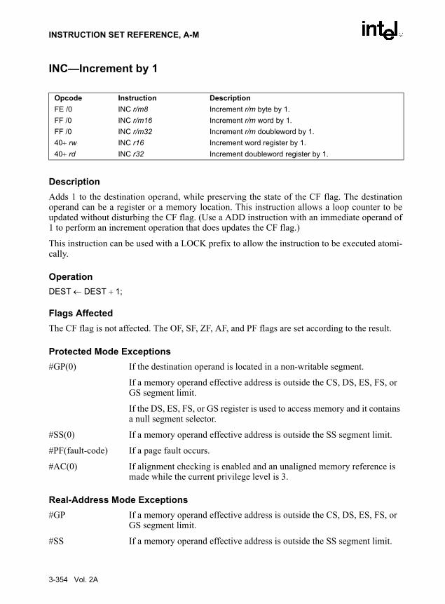
INSTRUCTION SET REFERENCE, A-M
INC—Increment by 1
DescriptionAdds 1 to the destination operand, while preserving the state of the CF flag. The destinationoperand can be a register or a memory location. This instruction allows a loop counter to beupdated without disturbing the CF flag. (Use a ADD instruction with an immediate operand of1 to perform an increment operation that does updates the CF flag.)
This instruction can be used with a LOCK prefix to allow the instruction to be executed atomi-cally.
OperationDEST ← DEST + 1;
Flags AffectedThe CF flag is not affected. The OF, SF, ZF, AF, and PF flags are set according to the result.
Protected Mode Exceptions#GP(0) If the destination operand is located in a non-writable segment.
If a memory operand effective address is outside the CS, DS, ES, FS, or GS segment limit.
If the DS, ES, FS, or GS register is used to access memory and it contains a null segment selector.
#SS(0) If a memory operand effective address is outside the SS segment limit.
#PF(fault-code) If a page fault occurs.
#AC(0) If alignment checking is enabled and an unaligned memory reference is made while the current privilege level is 3.
Real-Address Mode Exceptions#GP If a memory operand effective address is outside the CS, DS, ES, FS, or
GS segment limit.
#SS If a memory operand effective address is outside the SS segment limit.
Opcode Instruction DescriptionFE /0 INC r/m8 Increment r/m byte by 1.FF /0 INC r/m16 Increment r/m word by 1.FF /0 INC r/m32 Increment r/m doubleword by 1.40+ rw INC r16 Increment word register by 1.40+ rd INC r32 Increment doubleword register by 1.
3-354 Vol. 2A

INSTRUCTION SET REFERENCE, A-M
Virtual-8086 Mode Exceptions#GP(0) If a memory operand effective address is outside the CS, DS, ES, FS, or
GS segment limit.
#SS(0) If a memory operand effective address is outside the SS segment limit.
#PF(fault-code) If a page fault occurs.
#AC(0) If alignment checking is enabled and an unaligned memory reference is made.
Vol. 2A 3-355

INSTRUCTION SET REFERENCE, A-M
INS/INSB/INSW/INSD—Input from Port to String
DescriptionCopies the data from the I/O port specified with the source operand (second operand) to thedestination operand (first operand). The source operand is an I/O port address (from 0 to 65,535)that is read from the DX register. The destination operand is a memory location, the address ofwhich is read from either the ES:EDI or the ES:DI registers (depending on the address-sizeattribute of the instruction, 32 or 16, respectively). (The ES segment cannot be overridden witha segment override prefix.) The size of the I/O port being accessed (that is, the size of the sourceand destination operands) is determined by the opcode for an 8-bit I/O port or by the operand-size attribute of the instruction for a 16- or 32-bit I/O port.
At the assembly-code level, two forms of this instruction are allowed: the “explicit-operands”form and the “no-operands” form. The explicit-operands form (specified with the INSmnemonic) allows the source and destination operands to be specified explicitly. Here, thesource operand must be “DX,” and the destination operand should be a symbol that indicates thesize of the I/O port and the destination address. This explicit-operands form is provided to allowdocumentation; however, note that the documentation provided by this form can be misleading.That is, the destination operand symbol must specify the correct type (size) of the operand (byte,word, or doubleword), but it does not have to specify the correct location. The location is alwaysspecified by the ES:(E)DI registers, which must be loaded correctly before the INS instructionis executed.
The no-operands form provides “short forms” of the byte, word, and doubleword versions of theINS instructions. Here also DX is assumed by the processor to be the source operand andES:(E)DI is assumed to be the destination operand. The size of the I/O port is specified with thechoice of mnemonic: INSB (byte), INSW (word), or INSD (doubleword).
After the byte, word, or doubleword is transfer from the I/O port to the memory location, the(E)DI register is incremented or decremented automatically according to the setting of the DFflag in the EFLAGS register. (If the DF flag is 0, the (E)DI register is incremented; if the DFflag is 1, the (E)DI register is decremented.) The (E)DI register is incremented or decrementedby 1 for byte operations, by 2 for word operations, or by 4 for doubleword operations.
Opcode Instruction Description6C INS m8, DX Input byte from I/O port specified in DX into memory
location specified in ES:(E)DI.6D INS m16, DX Input word from I/O port specified in DX into memory
location specified in ES:(E)DI.6D INS m32, DX Input doubleword from I/O port specified in DX into
memory location specified in ES:(E)DI.6C INSB Input byte from I/O port specified in DX into memory
location specified with ES:(E)DI.6D INSW Input word from I/O port specified in DX into memory
location specified in ES:(E)DI.6D INSD Input doubleword from I/O port specified in DX into
memory location specified in ES:(E)DI.
3-356 Vol. 2A

INSTRUCTION SET REFERENCE, A-M
The INS, INSB, INSW, and INSD instructions can be preceded by the REP prefix for blockinput of ECX bytes, words, or doublewords. See “REP/REPE/REPZ/REPNE /REPNZ—RepeatString Operation Prefix” in this chapter for a description of the REP prefix.
These instructions are only useful for accessing I/O ports located in the processor’s I/O addressspace. See Chapter 13, Input/Output, in the IA-32 Intel Architecture Software Developer’sManual, Volume 1, for more information on accessing I/O ports in the I/O address space.
OperationIF ((PE = 1) AND ((CPL > IOPL) OR (VM = 1)))
THEN (* Protected mode with CPL > IOPL or virtual-8086 mode *)IF (Any I/O Permission Bit for I/O port being accessed = 1)
THEN (* I/O operation is not allowed *)#GP(0);
ELSE ( * I/O operation is allowed *) DEST ← SRC; (* Reads from I/O port *)
FI;ELSE (Real Mode or Protected Mode with CPL ≤ IOPL *)
DEST ← SRC; (* Reads from I/O port *)FI;IF (byte transfer)
THEN IF DF = 0THEN (E)DI ← (E)DI + 1; ELSE (E)DI ← (E)DI – 1;
FI;ELSE IF (word transfer)
THEN IF DF = 0THEN (E)DI ← (E)DI + 2; ELSE (E)DI ← (E)DI – 2;
FI;ELSE (* doubleword transfer *)
THEN IF DF = 0THEN (E)DI ← (E)DI + 4; ELSE (E)DI ← (E)DI – 4;
FI;FI;
FI;
Flags AffectedNone.
Protected Mode Exceptions#GP(0) If the CPL is greater than (has less privilege) the I/O privilege level (IOPL)
and any of the corresponding I/O permission bits in TSS for the I/O port being accessed is 1.
Vol. 2A 3-357

INSTRUCTION SET REFERENCE, A-M
If the destination is located in a non-writable segment.
If an illegal memory operand effective address in the ES segments is given.
#PF(fault-code) If a page fault occurs.
#AC(0) If alignment checking is enabled and an unaligned memory reference is made while the current privilege level is 3.
Real-Address Mode Exceptions#GP If a memory operand effective address is outside the CS, DS, ES, FS, or
GS segment limit.
#SS If a memory operand effective address is outside the SS segment limit.
Virtual-8086 Mode Exceptions#GP(0) If any of the I/O permission bits in the TSS for the I/O port being accessed
is 1.
#PF(fault-code) If a page fault occurs.
#AC(0) If alignment checking is enabled and an unaligned memory reference is made.
3-358 Vol. 2A

INSTRUCTION SET REFERENCE, A-M
INT n/INTO/INT 3—Call to Interrupt Procedure
DescriptionThe INT n instruction generates a call to the interrupt or exception handler specified with thedestination operand (see the section titled “Interrupts and Exceptions” in Chapter 6 of the IA-32Intel Architecture Software Developer’s Manual, Volume 1). The destination operand specifiesan interrupt vector number from 0 to 255, encoded as an 8-bit unsigned intermediate value. Eachinterrupt vector number provides an index to a gate descriptor in the IDT. The first 32 interruptvector numbers are reserved by Intel for system use. Some of these interrupts are used for inter-nally generated exceptions.
The INT n instruction is the general mnemonic for executing a software-generated call to aninterrupt handler. The INTO instruction is a special mnemonic for calling overflow exception(#OF), interrupt vector number 4. The overflow interrupt checks the OF flag in the EFLAGSregister and calls the overflow interrupt handler if the OF flag is set to 1.
The INT 3 instruction generates a special one byte opcode (CC) that is intended for calling thedebug exception handler. (This one byte form is valuable because it can be used to replace thefirst byte of any instruction with a breakpoint, including other one byte instructions, withoutover-writing other code). To further support its function as a debug breakpoint, the interruptgenerated with the CC opcode also differs from the regular software interrupts as follows:
• Interrupt redirection does not happen when in VME mode; the interrupt is handled by aprotected-mode handler.
• The virtual-8086 mode IOPL checks do not occur. The interrupt is taken without faultingat any IOPL level.
Note that the “normal” 2-byte opcode for INT 3 (CD03) does not have these special features.Intel and Microsoft assemblers will not generate the CD03 opcode from any mnemonic, but thisopcode can be created by direct numeric code definition or by self-modifying code.
The action of the INT n instruction (including the INTO and INT 3 instructions) is similar to thatof a far call made with the CALL instruction. The primary difference is that with the INT ninstruction, the EFLAGS register is pushed onto the stack before the return address. (The returnaddress is a far address consisting of the current values of the CS and EIP registers.) Returnsfrom interrupt procedures are handled with the IRET instruction, which pops the EFLAGSinformation and return address from the stack.
The interrupt vector number specifies an interrupt descriptor in the interrupt descriptor table(IDT); that is, it provides index into the IDT. The selected interrupt descriptor in turn containsa pointer to an interrupt or exception handler procedure. In protected mode, the IDT containsan array of 8-byte descriptors, each of which is an interrupt gate, trap gate, or task gate. In real-address mode, the IDT is an array of 4-byte far pointers (2-byte code segment selector and
Opcode Instruction DescriptionCC INT 3 Interrupt 3—trap to debugger.CD ib INT imm8 Interrupt vector number specified by immediate byte.CE INTO Interrupt 4—if overflow flag is 1.
Vol. 2A 3-359

INSTRUCTION SET REFERENCE, A-M
a 2-byte instruction pointer), each of which point directly to a procedure in the selected segment.(Note that in real-address mode, the IDT is called the interrupt vector table, and its pointersare called interrupt vectors.)
The following decision table indicates which action in the lower portion of the table is takengiven the conditions in the upper portion of the table. Each Y in the lower section of the decisiontable represents a procedure defined in the “Operation” section for this instruction (except #GP).
NOTES:− Don't Care.Y Yes, Action Taken.Blank Action Not Taken.
When the processor is executing in virtual-8086 mode, the IOPL determines the action of theINT n instruction. If the IOPL is less than 3, the processor generates a general protection excep-tion (#GP); if the IOPL is 3, the processor executes a protected mode interrupt to privilege level0. The interrupt gate's DPL must be set to 3 and the target CPL of the interrupt handler proceduremust be 0 to execute the protected mode interrupt to privilege level 0.
The interrupt descriptor table register (IDTR) specifies the base linear address and limit of theIDT. The initial base address value of the IDTR after the processor is powered up or reset is 0.
Table 3-52. Decision TablePE 0 1 1 1 1 1 1 1
VM – – – – – 0 1 1
IOPL – – – – – – <3 =3
DPL/CPL RELATIONSHIP
– DPL<CPL
– DPL>CPL
DPL=CPL or C
DPL<CPL & NC
– –
INTERRUPT TYPE – S/W – – – – – –
GATE TYPE – – Task Trap or Interrupt
Trap or Interrupt
Trap or Interrupt
Trap or Interrupt
Trap or Interrupt
REAL-ADDRESS-MODE
Y
PROTECTED-MODE Y Y Y Y Y Y Y
TRAP-OR-INTERRUPT-GATE
Y Y Y Y Y
INTER-PRIVILEGE-LEVEL-INTERRUPT
Y
INTRA-PRIVILEGE-LEVEL-INTERRUPT
Y
INTERRUPT-FROM-VIRTUAL-8086-MODE
Y
TASK-GATE Y
#GP Y Y Y
3-360 Vol. 2A

INSTRUCTION SET REFERENCE, A-M
OperationThe following operational description applies not only to the INT n and INTO instructions, butalso to external interrupts and exceptions.IF PE = 0
THEN GOTO REAL-ADDRESS-MODE;
ELSE (* PE = 1 *)IF (VM = 1 AND IOPL < 3 AND INT n)
THEN #GP(0);
ELSE (* protected mode or virtual-8086 mode interrupt *)GOTO PROTECTED-MODE;
FI;FI;
REAL-ADDRESS-MODE:IF ((DEST ∗ 4) + 3) is not within IDT limit THEN #GP; FI;IF stack not large enough for a 6-byte return information THEN #SS; FI;Push (EFLAGS[15:0]);IF ← 0; (* Clear interrupt flag *)TF ← 0; (* Clear trap flag *)AC ← 0; (*Clear AC flag*)Push(CS);Push(IP);(* No error codes are pushed *)CS ← IDT(Descriptor (vector_number ∗ 4), selector));EIP ← IDT(Descriptor (vector_number ∗ 4), offset)); (* 16 bit offset AND 0000FFFFH *)
END;
PROTECTED-MODE:IF ((DEST ∗ 8) + 7) is not within IDT limits
OR selected IDT descriptor is not an interrupt-, trap-, or task-gate typeTHEN #GP((DEST ∗ 8) + 2 + EXT);(* EXT is bit 0 in error code *)
FI;IF software interrupt (* generated by INT n, INT 3, or INTO *)
THENIF gate descriptor DPL < CPL
THEN #GP((vector_number ∗ 8) + 2 ); (* PE = 1, DPL<CPL, software interrupt *)
FI;FI;IF gate not present THEN #NP((vector_number ∗ 8) + 2 + EXT); FI;IF task gate (* specified in the selected interrupt table descriptor *)
THEN GOTO TASK-GATE;ELSE GOTO TRAP-OR-INTERRUPT-GATE; (* PE = 1, trap/interrupt gate *)
Vol. 2A 3-361

INSTRUCTION SET REFERENCE, A-M
FI;END;
TASK-GATE: (* PE = 1, task gate *)Read segment selector in task gate (IDT descriptor);
IF local/global bit is set to localOR index not within GDT limits
THEN #GP(TSS selector); FI;Access TSS descriptor in GDT;IF TSS descriptor specifies that the TSS is busy (low-order 5 bits set to 00001)
THEN #GP(TSS selector); FI;IF TSS not present
THEN #NP(TSS selector); FI;
SWITCH-TASKS (with nesting) to TSS;IF interrupt caused by fault with error code
THENIF stack limit does not allow push of error code
THEN #SS(0);FI;Push(error code);
FI;IF EIP not within code segment limit
THEN #GP(0); FI;
END;TRAP-OR-INTERRUPT-GATE
Read segment selector for trap or interrupt gate (IDT descriptor);IF segment selector for code segment is null
THEN #GP(0H + EXT); (* null selector with EXT flag set *)FI;IF segment selector is not within its descriptor table limits
THEN #GP(selector + EXT);FI;Read trap or interrupt handler descriptor;IF descriptor does not indicate a code segment
OR code segment descriptor DPL > CPLTHEN #GP(selector + EXT);
FI;IF trap or interrupt gate segment is not present,
THEN #NP(selector + EXT);FI;IF code segment is non-conforming AND DPL < CPL
THEN IF VM=0THEN
3-362 Vol. 2A

INSTRUCTION SET REFERENCE, A-M
GOTO INTER-PRIVILEGE-LEVEL-INTERRUPT; (* PE = 1, interrupt or trap gate, nonconforming *)(* code segment, DPL<CPL, VM = 0 *)
ELSE (* VM = 1 *)IF code segment DPL ≠ 0 THEN #GP(new code segment selector); FI;GOTO INTERRUPT-FROM-VIRTUAL-8086-MODE; (* PE = 1, interrupt or trap gate, DPL<CPL, VM = 1 *)
FI;ELSE (* PE = 1, interrupt or trap gate, DPL ≥ CPL *)
IF VM = 1 THEN #GP(new code segment selector); FI;IF code segment is conforming OR code segment DPL = CPL
THEN GOTO INTRA-PRIVILEGE-LEVEL-INTERRUPT;
ELSE #GP(CodeSegmentSelector + EXT); (* PE = 1, interrupt or trap gate, nonconforming *)(* code segment, DPL>CPL *)
FI;FI;
END;
INTER-PRIVILEGE-LEVEL-INTERRUPT(* PE=1, interrupt or trap gate, non-conforming code segment, DPL<CPL *)(* Check segment selector and descriptor for stack of new privilege level in current TSS *)IF current TSS is 32-bit TSS
THEN TSSstackAddress ← (new code segment DPL ∗ 8) + 4IF (TSSstackAddress + 7) > TSS limit
THEN #TS(current TSS selector); FI;NewSS ← TSSstackAddress + 4;NewESP ← stack address;
ELSE (* TSS is 16-bit *)TSSstackAddress ← (new code segment DPL ∗ 4) + 2IF (TSSstackAddress + 4) > TSS limit
THEN #TS(current TSS selector); FI;NewESP ← TSSstackAddress;NewSS ← TSSstackAddress + 2;
FI;IF segment selector is null THEN #TS(EXT); FI;IF segment selector index is not within its descriptor table limits
OR segment selector's RPL ≠ DPL of code segment, THEN #TS(SS selector + EXT);
FI;Read segment descriptor for stack segment in GDT or LDT;
IF stack segment DPL ≠ DPL of code segment, OR stack segment does not indicate writable data segment,
THEN #TS(SS selector + EXT);
Vol. 2A 3-363

INSTRUCTION SET REFERENCE, A-M
FI;IF stack segment not present THEN #SS(SS selector+EXT); FI;IF 32-bit gate
THENIF new stack does not have room for 24 bytes (error code pushed)
OR 20 bytes (no error code pushed)THEN #SS(segment selector + EXT);
FI;ELSE (* 16-bit gate *)
IF new stack does not have room for 12 bytes (error code pushed) OR 10 bytes (no error code pushed);
THEN #SS(segment selector + EXT); FI;
FI;IF instruction pointer is not within code segment limits THEN #GP(0); FI;SS:ESP ← TSS(NewSS:NewESP) (* segment descriptor information also loaded *)IF 32-bit gate
THEN CS:EIP ← Gate(CS:EIP); (* segment descriptor information also loaded *)
ELSE (* 16-bit gate *)CS:IP ← Gate(CS:IP); (* segment descriptor information also loaded *)
FI;IF 32-bit gate
THENPush(far pointer to old stack); (* old SS and ESP, 3 words padded to 4 *);Push(EFLAGS);Push(far pointer to return instruction); (* old CS and EIP, 3 words padded to 4*);Push(ErrorCode); (* if needed, 4 bytes *)
ELSE(* 16-bit gate *)Push(far pointer to old stack); (* old SS and SP, 2 words *);Push(EFLAGS(15..0]);Push(far pointer to return instruction); (* old CS and IP, 2 words *);Push(ErrorCode); (* if needed, 2 bytes *)
FI;CPL ← CodeSegmentDescriptor(DPL);CS(RPL) ← CPL;IF interrupt gate
THEN IF ← 0 (*interrupt flag set to 0: disabled*); FI;TF ← 0;VM ← 0;RF ← 0;NT ← 0;
END;INTERRUPT-FROM-VIRTUAL-8086-MODE:
(* Check segment selector and descriptor for privilege level 0 stack in current TSS *)IF current TSS is 32-bit TSS
3-364 Vol. 2A

INSTRUCTION SET REFERENCE, A-M
THEN TSSstackAddress ← (new code segment DPL ∗ 8) + 4IF (TSSstackAddress + 7) > TSS limit
THEN #TS(current TSS selector); FI;NewSS ← TSSstackAddress + 4;NewESP ← stack address;
ELSE (* TSS is 16-bit *)TSSstackAddress ← (new code segment DPL ∗ 4) + 2IF (TSSstackAddress + 4) > TSS limit
THEN #TS(current TSS selector); FI;NewESP ← TSSstackAddress;NewSS ← TSSstackAddress + 2;
FI;IF segment selector is null THEN #TS(EXT); FI;IF segment selector index is not within its descriptor table limits
OR segment selector's RPL ≠ DPL of code segment, THEN #TS(SS selector + EXT);
FI;Access segment descriptor for stack segment in GDT or LDT;IF stack segment DPL ≠ DPL of code segment,
OR stack segment does not indicate writable data segment, THEN #TS(SS selector + EXT);
FI;IF stack segment not present
THEN #SS(SS selector+EXT); FI;IF 32-bit gate
THENIF new stack does not have room for 40 bytes (error code pushed)
OR 36 bytes (no error code pushed);THEN #SS(segment selector + EXT);
FI;ELSE (* 16-bit gate *)
IF new stack does not have room for 20 bytes (error code pushed) OR 18 bytes (no error code pushed);
THEN #SS(segment selector + EXT); FI;
FI;IF instruction pointer is not within code segment limits
THEN #GP(0); FI;tempEFLAGS ← EFLAGS;VM ← 0;TF ← 0;RF ← 0;NT ← 0;IF service through interrupt gate
Vol. 2A 3-365

INSTRUCTION SET REFERENCE, A-M
THEN IF = 0; FI;TempSS ← SS;TempESP ← ESP;SS:ESP ← TSS(SS0:ESP0); (* Change to level 0 stack segment *)(* Following pushes are 16 bits for 16-bit gate and 32 bits for 32-bit gates *)(* Segment selector pushes in 32-bit mode are padded to two words *)Push(GS);Push(FS);Push(DS);Push(ES);Push(TempSS);Push(TempESP);Push(TempEFlags);Push(CS);Push(EIP);GS ← 0; (*segment registers nullified, invalid in protected mode *)FS ← 0;DS ← 0;ES ← 0;CS ← Gate(CS);IF OperandSize = 32
THENEIP ← Gate(instruction pointer);
ELSE (* OperandSize is 16 *)EIP ← Gate(instruction pointer) AND 0000FFFFH;
FI;(* Starts execution of new routine in Protected Mode *)
END;
INTRA-PRIVILEGE-LEVEL-INTERRUPT:(* PE=1, DPL = CPL or conforming segment *)IF 32-bit gate
THENIF current stack does not have room for 16 bytes (error code pushed)
OR 12 bytes (no error code pushed); THEN #SS(0);FI;
ELSE (* 16-bit gate *)IF current stack does not have room for 8 bytes (error code pushed)
OR 6 bytes (no error code pushed); THEN #SS(0);FI;
FI;IF instruction pointer not within code segment limit
THEN #GP(0); FI;IF 32-bit gate
THEN
3-366 Vol. 2A

INSTRUCTION SET REFERENCE, A-M
Push (EFLAGS);Push (far pointer to return instruction); (* 3 words padded to 4 *)CS:EIP ← Gate(CS:EIP); (* segment descriptor information also loaded *)Push (ErrorCode); (* if any *)
ELSE (* 16-bit gate *)Push (FLAGS);Push (far pointer to return location); (* 2 words *)CS:IP ← Gate(CS:IP); (* segment descriptor information also loaded *)Push (ErrorCode); (* if any *)
FI;CS(RPL) ← CPL;IF interrupt gate
THEN IF ← 0; (*interrupt flag set to 0: disabled*)FI;TF ← 0;NT ← 0;VM ← 0;RF ← 0;
END;
Flags AffectedThe EFLAGS register is pushed onto the stack. The IF, TF, NT, AC, RF, and VM flags may becleared, depending on the mode of operation of the processor when the INT instruction isexecuted (see the “Operation” section). If the interrupt uses a task gate, any flags may be set orcleared, controlled by the EFLAGS image in the new task’s TSS.
Protected Mode Exceptions#GP(0) If the instruction pointer in the IDT or in the interrupt-, trap-, or task gate
is beyond the code segment limits.
#GP(selector) If the segment selector in the interrupt-, trap-, or task gate is null.
If an interrupt-, trap-, or task gate, code segment, or TSS segment selector index is outside its descriptor table limits.
If the interrupt vector number is outside the IDT limits.
If an IDT descriptor is not an interrupt-, trap-, or task-descriptor.
If an interrupt is generated by the INT n, INT 3, or INTO instruction and the DPL of an interrupt-, trap-, or task-descriptor is less than the CPL.
If the segment selector in an interrupt- or trap-gate does not point to a segment descriptor for a code segment.
If the segment selector for a TSS has its local/global bit set for local.
If a TSS segment descriptor specifies that the TSS is busy or not available.
Vol. 2A 3-367

INSTRUCTION SET REFERENCE, A-M
#SS(0) If pushing the return address, flags, or error code onto the stack exceeds the bounds of the stack segment and no stack switch occurs.
#SS(selector) If the SS register is being loaded and the segment pointed to is marked not present.
If pushing the return address, flags, error code, or stack segment pointer exceeds the bounds of the new stack segment when a stack switch occurs.
#NP(selector) If code segment, interrupt-, trap-, or task gate, or TSS is not present.
#TS(selector) If the RPL of the stack segment selector in the TSS is not equal to the DPL of the code segment being accessed by the interrupt or trap gate.
If DPL of the stack segment descriptor pointed to by the stack segment selector in the TSS is not equal to the DPL of the code segment descriptor for the interrupt or trap gate.
If the stack segment selector in the TSS is null.
If the stack segment for the TSS is not a writable data segment.
If segment-selector index for stack segment is outside descriptor table limits.
#PF(fault-code) If a page fault occurs.
Real-Address Mode Exceptions#GP If a memory operand effective address is outside the CS, DS, ES, FS, or
GS segment limit.
If the interrupt vector number is outside the IDT limits.
#SS If stack limit violation on push.
If pushing the return address, flags, or error code onto the stack exceeds the bounds of the stack segment.
Virtual-8086 Mode Exceptions#GP(0) (For INT n, INTO, or BOUND instruction) If the IOPL is less than 3 or
the DPL of the interrupt-, trap-, or task-gate descriptor is not equal to 3.
If the instruction pointer in the IDT or in the interrupt-, trap-, or task gate is beyond the code segment limits.
#GP(selector) If the segment selector in the interrupt-, trap-, or task gate is null.
If a interrupt-, trap-, or task gate, code segment, or TSS segment selector index is outside its descriptor table limits.
If the interrupt vector number is outside the IDT limits.
If an IDT descriptor is not an interrupt-, trap-, or task-descriptor.
3-368 Vol. 2A

INSTRUCTION SET REFERENCE, A-M
If an interrupt is generated by the INT n instruction and the DPL of an interrupt-, trap-, or task-descriptor is less than the CPL.
If the segment selector in an interrupt- or trap-gate does not point to a segment descriptor for a code segment.
If the segment selector for a TSS has its local/global bit set for local.
#SS(selector) If the SS register is being loaded and the segment pointed to is marked not present.
If pushing the return address, flags, error code, stack segment pointer, or data segments exceeds the bounds of the stack segment.
#NP(selector) If code segment, interrupt-, trap-, or task gate, or TSS is not present.
#TS(selector) If the RPL of the stack segment selector in the TSS is not equal to the DPL of the code segment being accessed by the interrupt or trap gate.
If DPL of the stack segment descriptor for the TSS’s stack segment is not equal to the DPL of the code segment descriptor for the interrupt or trap gate.
If the stack segment selector in the TSS is null.
If the stack segment for the TSS is not a writable data segment.
If segment-selector index for stack segment is outside descriptor table limits.
#PF(fault-code) If a page fault occurs.
#BP If the INT 3 instruction is executed.
#OF If the INTO instruction is executed and the OF flag is set.
Vol. 2A 3-369

INSTRUCTION SET REFERENCE, A-M
INVD—Invalidate Internal Caches
DescriptionInvalidates (flushes) the processor’s internal caches and issues a special-function bus cycle thatdirects external caches to also flush themselves. Data held in internal caches is not written backto main memory.
After executing this instruction, the processor does not wait for the external caches to completetheir flushing operation before proceeding with instruction execution. It is the responsibility ofhardware to respond to the cache flush signal.
The INVD instruction is a privileged instruction. When the processor is running in protectedmode, the CPL of a program or procedure must be 0 to execute this instruction.
Use this instruction with care. Data cached internally and not written back to main memory willbe lost. Unless there is a specific requirement or benefit to flushing caches without writing backmodified cache lines (for example, testing or fault recovery where cache coherency with mainmemory is not a concern), software should use the WBINVD instruction.
IA-32 Architecture CompatibilityThe INVD instruction is implementation dependent; it may be implemented differently ondifferent families of IA-32 processors. This instruction is not supported on IA-32 processorsearlier than the Intel486 processor.
OperationFlush(InternalCaches);SignalFlush(ExternalCaches);Continue (* Continue execution);
Flags AffectedNone.
Protected Mode Exceptions#GP(0) If the current privilege level is not 0.
Real-Address Mode ExceptionsNone.
Opcode Instruction Description0F 08 INVD Flush internal caches; initiate flushing of external caches.
3-370 Vol. 2A

INSTRUCTION SET REFERENCE, A-M
Virtual-8086 Mode Exceptions#GP(0) The INVD instruction cannot be executed in virtual-8086 mode.
Vol. 2A 3-371
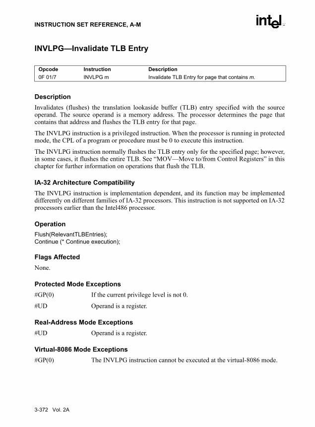
INSTRUCTION SET REFERENCE, A-M
INVLPG—Invalidate TLB Entry
DescriptionInvalidates (flushes) the translation lookaside buffer (TLB) entry specified with the sourceoperand. The source operand is a memory address. The processor determines the page thatcontains that address and flushes the TLB entry for that page.
The INVLPG instruction is a privileged instruction. When the processor is running in protectedmode, the CPL of a program or procedure must be 0 to execute this instruction.
The INVLPG instruction normally flushes the TLB entry only for the specified page; however,in some cases, it flushes the entire TLB. See “MOV—Move to/from Control Registers” in thischapter for further information on operations that flush the TLB.
IA-32 Architecture CompatibilityThe INVLPG instruction is implementation dependent, and its function may be implementeddifferently on different families of IA-32 processors. This instruction is not supported on IA-32processors earlier than the Intel486 processor.
OperationFlush(RelevantTLBEntries);Continue (* Continue execution);
Flags AffectedNone.
Protected Mode Exceptions#GP(0) If the current privilege level is not 0.
#UD Operand is a register.
Real-Address Mode Exceptions#UD Operand is a register.
Virtual-8086 Mode Exceptions#GP(0) The INVLPG instruction cannot be executed at the virtual-8086 mode.
Opcode Instruction Description0F 01/7 INVLPG m Invalidate TLB Entry for page that contains m.
3-372 Vol. 2A

INSTRUCTION SET REFERENCE, A-M
IRET/IRETD—Interrupt Return
DescriptionReturns program control from an exception or interrupt handler to a program or procedure thatwas interrupted by an exception, an external interrupt, or a software-generated interrupt. Theseinstructions are also used to perform a return from a nested task. (A nested task is created whena CALL instruction is used to initiate a task switch or when an interrupt or exception causes atask switch to an interrupt or exception handler.) See the section titled “Task Linking” inChapter 6 of the IA-32 Intel Architecture Software Developer’s Manual, Volume 3.
IRET and IRETD are mnemonics for the same opcode. The IRETD mnemonic (interrupt returndouble) is intended for use when returning from an interrupt when using the 32-bit operand size;however, most assemblers use the IRET mnemonic interchangeably for both operand sizes.
In Real-Address Mode, the IRET instruction preforms a far return to the interrupted program orprocedure. During this operation, the processor pops the return instruction pointer, return codesegment selector, and EFLAGS image from the stack to the EIP, CS, and EFLAGS registers,respectively, and then resumes execution of the interrupted program or procedure.
In Protected Mode, the action of the IRET instruction depends on the settings of the NT (nestedtask) and VM flags in the EFLAGS register and the VM flag in the EFLAGS image stored onthe current stack. Depending on the setting of these flags, the processor performs the followingtypes of interrupt returns:
• Return from virtual-8086 mode.
• Return to virtual-8086 mode.
• Intra-privilege level return.
• Inter-privilege level return.
• Return from nested task (task switch).
If the NT flag (EFLAGS register) is cleared, the IRET instruction performs a far return from theinterrupt procedure, without a task switch. The code segment being returned to must be equallyor less privileged than the interrupt handler routine (as indicated by the RPL field of the codesegment selector popped from the stack). As with a real-address mode interrupt return, the IRETinstruction pops the return instruction pointer, return code segment selector, and EFLAGSimage from the stack to the EIP, CS, and EFLAGS registers, respectively, and then resumesexecution of the interrupted program or procedure. If the return is to another privilege level, theIRET instruction also pops the stack pointer and SS from the stack, before resuming programexecution. If the return is to virtual-8086 mode, the processor also pops the data segment regis-ters from the stack.
If the NT flag is set, the IRET instruction performs a task switch (return) from a nested task (atask called with a CALL instruction, an interrupt, or an exception) back to the calling or inter-
Opcode Instruction DescriptionCF IRET Interrupt return (16-bit operand size).CF IRETD Interrupt return (32-bit operand size).
Vol. 2A 3-373

INSTRUCTION SET REFERENCE, A-M
rupted task. The updated state of the task executing the IRET instruction is saved in its TSS. Ifthe task is re-entered later, the code that follows the IRET instruction is executed.
OperationIF PE = 0
THEN GOTO REAL-ADDRESS-MODE;
ELSE GOTO PROTECTED-MODE;
FI;
REAL-ADDRESS-MODE;IF OperandSize = 32
THENIF top 12 bytes of stack not within stack limits THEN #SS; FI;IF instruction pointer not within code segment limits THEN #GP(0); FI;EIP ← Pop();CS ← Pop(); (* 32-bit pop, high-order 16 bits discarded *)tempEFLAGS ← Pop();EFLAGS ← (tempEFLAGS AND 257FD5H) OR (EFLAGS AND 1A0000H);
ELSE (* OperandSize = 16 *)IF top 6 bytes of stack are not within stack limits THEN #SS; FI;IF instruction pointer not within code segment limits THEN #GP(0); FI;EIP ← Pop();EIP ← EIP AND 0000FFFFH;CS ← Pop(); (* 16-bit pop *)EFLAGS[15:0] ← Pop();
FI;END;
PROTECTED-MODE:IF VM = 1 (* Virtual-8086 mode: PE=1, VM=1 *)
THEN GOTO RETURN-FROM-VIRTUAL-8086-MODE; (* PE=1, VM=1 *)
FI;IF NT = 1
THEN GOTO TASK-RETURN;( *PE=1, VM=0, NT=1 *)
FI;IF OperandSize=32
THENIF top 12 bytes of stack not within stack limits
THEN #SS(0)FI;tempEIP ← Pop();tempCS ← Pop();tempEFLAGS ← Pop();
ELSE (* OperandSize = 16 *)
3-374 Vol. 2A

INSTRUCTION SET REFERENCE, A-M
IF top 6 bytes of stack are not within stack limitsTHEN #SS(0);
FI;tempEIP ← Pop();tempCS ← Pop();tempEFLAGS ← Pop();tempEIP ← tempEIP AND FFFFH;tempEFLAGS ← tempEFLAGS AND FFFFH;
FI;IF tempEFLAGS(VM) = 1 AND CPL=0
THEN GOTO RETURN-TO-VIRTUAL-8086-MODE; (* PE=1, VM=1 in EFLAGS image *)
ELSE GOTO PROTECTED-MODE-RETURN;(* PE=1, VM=0 in EFLAGS image *)
FI;
RETURN-FROM-VIRTUAL-8086-MODE: (* Processor is in virtual-8086 mode when IRET is executed and stays in virtual-8086 mode *)
IF IOPL=3 (* Virtual mode: PE=1, VM=1, IOPL=3 *)THEN IF OperandSize = 32
THENIF top 12 bytes of stack not within stack limits THEN #SS(0); FI;IF instruction pointer not within code segment limits THEN #GP(0); FI;EIP ← Pop();CS ← Pop(); (* 32-bit pop, high-order 16 bits discarded *)EFLAGS ← Pop();(*VM,IOPL,VIP,and VIF EFLAGS bits are not modified by pop *)
ELSE (* OperandSize = 16 *)IF top 6 bytes of stack are not within stack limits THEN #SS(0); FI;IF instruction pointer not within code segment limits THEN #GP(0); FI;EIP ← Pop();EIP ← EIP AND 0000FFFFH;CS ← Pop(); (* 16-bit pop *)EFLAGS[15:0] ← Pop(); (* IOPL in EFLAGS is not modified by pop *)
FI;ELSE
#GP(0); (* trap to virtual-8086 monitor: PE=1, VM=1, IOPL<3 *)FI;
END;
RETURN-TO-VIRTUAL-8086-MODE: (* Interrupted procedure was in virtual-8086 mode: PE=1, VM=1 in flags image *)
IF top 24 bytes of stack are not within stack segment limitsTHEN #SS(0);
FI;
Vol. 2A 3-375
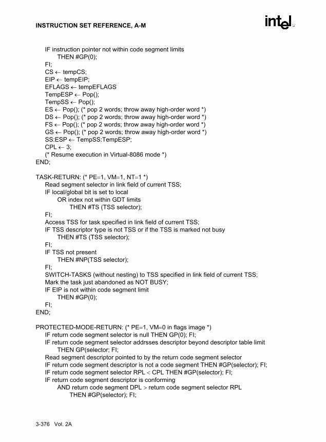
INSTRUCTION SET REFERENCE, A-M
IF instruction pointer not within code segment limitsTHEN #GP(0);
FI;CS ← tempCS;EIP ← tempEIP;EFLAGS ← tempEFLAGSTempESP ← Pop();TempSS ← Pop();ES ← Pop(); (* pop 2 words; throw away high-order word *)DS ← Pop(); (* pop 2 words; throw away high-order word *)FS ← Pop(); (* pop 2 words; throw away high-order word *)GS ← Pop(); (* pop 2 words; throw away high-order word *)SS:ESP ← TempSS:TempESP;CPL ← 3;(* Resume execution in Virtual-8086 mode *)
END;
TASK-RETURN: (* PE=1, VM=1, NT=1 *)Read segment selector in link field of current TSS;IF local/global bit is set to local
OR index not within GDT limitsTHEN #TS (TSS selector);
FI;Access TSS for task specified in link field of current TSS;IF TSS descriptor type is not TSS or if the TSS is marked not busy
THEN #TS (TSS selector); FI;IF TSS not present
THEN #NP(TSS selector); FI;SWITCH-TASKS (without nesting) to TSS specified in link field of current TSS;Mark the task just abandoned as NOT BUSY;IF EIP is not within code segment limit
THEN #GP(0);FI;
END;
PROTECTED-MODE-RETURN: (* PE=1, VM=0 in flags image *)IF return code segment selector is null THEN GP(0); FI;IF return code segment selector addrsses descriptor beyond descriptor table limit
THEN GP(selector; FI;Read segment descriptor pointed to by the return code segment selectorIF return code segment descriptor is not a code segment THEN #GP(selector); FI;IF return code segment selector RPL < CPL THEN #GP(selector); FI;IF return code segment descriptor is conforming
AND return code segment DPL > return code segment selector RPLTHEN #GP(selector); FI;
3-376 Vol. 2A

INSTRUCTION SET REFERENCE, A-M
IF return code segment descriptor is not present THEN #NP(selector); FI:IF return code segment selector RPL > CPL
THEN GOTO RETURN-OUTER-PRIVILEGE-LEVEL;ELSE GOTO RETURN-TO-SAME-PRIVILEGE-LEVEL
FI;END;
RETURN-TO-SAME-PRIVILEGE-LEVEL: (* PE=1, VM=0 in flags image, RPL=CPL *)IF EIP is not within code segment limits THEN #GP(0); FI;EIP ← tempEIP;CS ← tempCS; (* segment descriptor information also loaded *)EFLAGS (CF, PF, AF, ZF, SF, TF, DF, OF, NT) ← tempEFLAGS;IF OperandSize=32
THENEFLAGS(RF, AC, ID) ← tempEFLAGS;
FI;IF CPL ≤ IOPL
THENEFLAGS(IF) ← tempEFLAGS;
FI;IF CPL = 0
THENEFLAGS(IOPL) ← tempEFLAGS;IF OperandSize=32
THEN EFLAGS(VM, VIF, VIP) ← tempEFLAGS;FI;
FI;END;
RETURN-TO-OUTER-PRIVILGE-LEVEL:IF OperandSize=32
THENIF top 8 bytes on stack are not within limits THEN #SS(0); FI;
ELSE (* OperandSize=16 *)IF top 4 bytes on stack are not within limits THEN #SS(0); FI;
FI;Read return segment selector;IF stack segment selector is null THEN #GP(0); FI;IF return stack segment selector index is not within its descriptor table limits
THEN #GP(SSselector); FI;Read segment descriptor pointed to by return segment selector;IF stack segment selector RPL ≠ RPL of the return code segment selector
IF stack segment selector RPL ≠ RPL of the return code segment selectorOR the stack segment descriptor does not indicate a a writable data segment;OR stack segment DPL ≠ RPL of the return code segment selector
THEN #GP(SS selector); FI;
Vol. 2A 3-377

INSTRUCTION SET REFERENCE, A-M
IF stack segment is not present THEN #SS(SS selector); FI;IF tempEIP is not within code segment limit THEN #GP(0); FI;EIP ← tempEIP;CS ← tempCS;EFLAGS (CF, PF, AF, ZF, SF, TF, DF, OF, NT) ← tempEFLAGS;IF OperandSize=32
THENEFLAGS(RF, AC, ID) ← tempEFLAGS;
FI;IF CPL ≤ IOPL
THENEFLAGS(IF) ← tempEFLAGS;
FI;IF CPL = 0
THENEFLAGS(IOPL) ← tempEFLAGS;IF OperandSize=32
THEN EFLAGS(VM, VIF, VIP) ← tempEFLAGS;FI;
FI;CPL ← RPL of the return code segment selector;FOR each of segment register (ES, FS, GS, and DS)
DO;IF segment register points to data or non-conforming code segmentAND CPL > segment descriptor DPL (* stored in hidden part of segment register *)
THEN (* segment register invalid *)SegmentSelector ← 0; (* null segment selector *)
FI;OD;
END:
Flags AffectedAll the flags and fields in the EFLAGS register are potentially modified, depending on the modeof operation of the processor. If performing a return from a nested task to a previous task, theEFLAGS register will be modified according to the EFLAGS image stored in the previous task’sTSS.
Protected Mode Exceptions#GP(0) If the return code or stack segment selector is null.
If the return instruction pointer is not within the return code segment limit.
#GP(selector) If a segment selector index is outside its descriptor table limits.
If the return code segment selector RPL is greater than the CPL.
If the DPL of a conforming-code segment is greater than the return code segment selector RPL.
3-378 Vol. 2A

INSTRUCTION SET REFERENCE, A-M
If the DPL for a nonconforming-code segment is not equal to the RPL of the code segment selector.
If the stack segment descriptor DPL is not equal to the RPL of the return code segment selector.
If the stack segment is not a writable data segment.
If the stack segment selector RPL is not equal to the RPL of the return code segment selector.
If the segment descriptor for a code segment does not indicate it is a code segment.
If the segment selector for a TSS has its local/global bit set for local.
If a TSS segment descriptor specifies that the TSS is not busy.
If a TSS segment descriptor specifies that the TSS is not available.
#SS(0) If the top bytes of stack are not within stack limits.
#NP(selector) If the return code or stack segment is not present.
#PF(fault-code) If a page fault occurs.
#AC(0) If an unaligned memory reference occurs when the CPL is 3 and alignment checking is enabled.
Real-Address Mode Exceptions#GP If the return instruction pointer is not within the return code segment limit.
#SS If the top bytes of stack are not within stack limits.
Virtual-8086 Mode Exceptions#GP(0) If the return instruction pointer is not within the return code segment limit.
IF IOPL not equal to 3.
#PF(fault-code) If a page fault occurs.
#SS(0) If the top bytes of stack are not within stack limits.
#AC(0) If an unaligned memory reference occurs and alignment checking is enabled.
Vol. 2A 3-379

INSTRUCTION SET REFERENCE, A-M
Jcc—Jump if Condition Is Met
Opcode Instruction Description77 cb JA rel8 Jump short if above (CF=0 and ZF=0).73 cb JAE rel8 Jump short if above or equal (CF=0).72 cb JB rel8 Jump short if below (CF=1).76 cb JBE rel8 Jump short if below or equal (CF=1 or ZF=1).72 cb JC rel8 Jump short if carry (CF=1).E3 cb JCXZ rel8 Jump short if CX register is 0.E3 cb JECXZ rel8 Jump short if ECX register is 0.74 cb JE rel8 Jump short if equal (ZF=1).7F cb JG rel8 Jump short if greater (ZF=0 and SF=OF).7D cb JGE rel8 Jump short if greater or equal (SF=OF).7C cb JL rel8 Jump short if less (SF<>OF).7E cb JLE rel8 Jump short if less or equal (ZF=1 or SF<>OF).76 cb JNA rel8 Jump short if not above (CF=1 or ZF=1).72 cb JNAE rel8 Jump short if not above or equal (CF=1).73 cb JNB rel8 Jump short if not below (CF=0).77 cb JNBE rel8 Jump short if not below or equal (CF=0 and ZF=0).73 cb JNC rel8 Jump short if not carry (CF=0).75 cb JNE rel8 Jump short if not equal (ZF=0).7E cb JNG rel8 Jump short if not greater (ZF=1 or SF<>OF).7C cb JNGE rel8 Jump short if not greater or equal (SF<>OF).7D cb JNL rel8 Jump short if not less (SF=OF).7F cb JNLE rel8 Jump short if not less or equal (ZF=0 and SF=OF).71 cb JNO rel8 Jump short if not overflow (OF=0).7B cb JNP rel8 Jump short if not parity (PF=0).79 cb JNS rel8 Jump short if not sign (SF=0).75 cb JNZ rel8 Jump short if not zero (ZF=0).70 cb JO rel8 Jump short if overflow (OF=1).7A cb JP rel8 Jump short if parity (PF=1).7A cb JPE rel8 Jump short if parity even (PF=1).7B cb JPO rel8 Jump short if parity odd (PF=0).78 cb JS rel8 Jump short if sign (SF=1).74 cb JZ rel8 Jump short if zero (ZF = 1).0F 87 cw/cd JA rel16/32 Jump near if above (CF=0 and ZF=0).0F 83 cw/cd JAE rel16/32 Jump near if above or equal (CF=0).0F 82 cw/cd JB rel16/32 Jump near if below (CF=1).0F 86 cw/cd JBE rel16/32 Jump near if below or equal (CF=1 or ZF=1).0F 82 cw/cd JC rel16/32 Jump near if carry (CF=1).0F 84 cw/cd JE rel16/32 Jump near if equal (ZF=1).0F 84 cw/cd JZ rel16/32 Jump near if 0 (ZF=1).0F 8F cw/cd JG rel16/32 Jump near if greater (ZF=0 and SF=OF).
3-380 Vol. 2A

INSTRUCTION SET REFERENCE, A-M
DescriptionChecks the state of one or more of the status flags in the EFLAGS register (CF, OF, PF, SF, andZF) and, if the flags are in the specified state (condition), performs a jump to the target instruc-tion specified by the destination operand. A condition code (cc) is associated with each instruc-tion to indicate the condition being tested for. If the condition is not satisfied, the jump is notperformed and execution continues with the instruction following the Jcc instruction.
The target instruction is specified with a relative offset (a signed offset relative to the currentvalue of the instruction pointer in the EIP register). A relative offset (rel8, rel16, or rel32) isgenerally specified as a label in assembly code, but at the machine code level, it is encoded as asigned, 8-bit or 32-bit immediate value, which is added to the instruction pointer. Instructioncoding is most efficient for offsets of –128 to +127. If the operand-size attribute is 16, the uppertwo bytes of the EIP register are cleared, resulting in a maximum instruction pointer size of 16bits.
The conditions for each Jcc mnemonic are given in the “Description” column of the table on thepreceding page. The terms “less” and “greater” are used for comparisons of signed integers andthe terms “above” and “below” are used for unsigned integers.
Opcode Instruction Description0F 8D cw/cd JGE rel16/32 Jump near if greater or equal (SF=OF).0F 8C cw/cd JL rel16/32 Jump near if less (SF<>OF).0F 8E cw/cd JLE rel16/32 Jump near if less or equal (ZF=1 or SF<>OF).0F 86 cw/cd JNA rel16/32 Jump near if not above (CF=1 or ZF=1).0F 82 cw/cd JNAE rel16/32 Jump near if not above or equal (CF=1).0F 83 cw/cd JNB rel16/32 Jump near if not below (CF=0).0F 87 cw/cd JNBE rel16/32 Jump near if not below or equal (CF=0 and ZF=0).0F 83 cw/cd JNC rel16/32 Jump near if not carry (CF=0).0F 85 cw/cd JNE rel16/32 Jump near if not equal (ZF=0).0F 8E cw/cd JNG rel16/32 Jump near if not greater (ZF=1 or SF<>OF).0F 8C cw/cd JNGE rel16/32 Jump near if not greater or equal (SF<>OF).0F 8D cw/cd JNL rel16/32 Jump near if not less (SF=OF).0F 8F cw/cd JNLE rel16/32 Jump near if not less or equal (ZF=0 and SF=OF).0F 81 cw/cd JNO rel16/32 Jump near if not overflow (OF=0).0F 8B cw/cd JNP rel16/32 Jump near if not parity (PF=0).0F 89 cw/cd JNS rel16/32 Jump near if not sign (SF=0).0F 85 cw/cd JNZ rel16/32 Jump near if not zero (ZF=0).0F 80 cw/cd JO rel16/32 Jump near if overflow (OF=1).0F 8A cw/cd JP rel16/32 Jump near if parity (PF=1).0F 8A cw/cd JPE rel16/32 Jump near if parity even (PF=1).0F 8B cw/cd JPO rel16/32 Jump near if parity odd (PF=0).0F 88 cw/cd JS rel16/32 Jump near if sign (SF=1).0F 84 cw/cd JZ rel16/32 Jump near if 0 (ZF=1).
Vol. 2A 3-381

INSTRUCTION SET REFERENCE, A-M
Because a particular state of the status flags can sometimes be interpreted in two ways, twomnemonics are defined for some opcodes. For example, the JA (jump if above) instruction andthe JNBE (jump if not below or equal) instruction are alternate mnemonics for the opcode 77H.
The Jcc instruction does not support far jumps (jumps to other code segments). When the targetfor the conditional jump is in a different segment, use the opposite condition from the conditionbeing tested for the Jcc instruction, and then access the target with an unconditional far jump(JMP instruction) to the other segment. For example, the following conditional far jump isillegal:JZ FARLABEL;
To accomplish this far jump, use the following two instructions:JNZ BEYOND;JMP FARLABEL;BEYOND:
The JECXZ and JCXZ instructions differ from the other Jcc instructions because they do notcheck the status flags. Instead they check the contents of the ECX and CX registers, respec-tively, for 0. Either the CX or ECX register is chosen according to the address-size attribute.These instructions are useful at the beginning of a conditional loop that terminates with a condi-tional loop instruction (such as LOOPNE). They prevent entering the loop when the ECX or CXregister is equal to 0, which would cause the loop to execute 232 or 64K times, respectively,instead of zero times.
All conditional jumps are converted to code fetches of one or two cache lines, regardlessof jump address or cacheability.
OperationIF condition
THEN EIP ← EIP + SignExtend(DEST);
IF OperandSize = 16THEN
EIP ← EIP AND 0000FFFFH;FI;
ELSE (* OperandSize = 32 *)IF EIP < CS.Base OR EIP > CS.Limit
#GPFI;
FI;
Flags AffectedNone.
Protected Mode Exceptions#GP(0) If the offset being jumped to is beyond the limits of the CS segment.
3-382 Vol. 2A

INSTRUCTION SET REFERENCE, A-M
Real-Address Mode Exceptions#GP If the offset being jumped to is beyond the limits of the CS segment or is
outside of the effective address space from 0 to FFFFH. This condition can occur if a 32-bit address size override prefix is used.
Virtual-8086 Mode ExceptionsSame exceptions as in Real Address Mode
Vol. 2A 3-383

INSTRUCTION SET REFERENCE, A-M
JMP—Jump
DescriptionTransfers program control to a different point in the instruction stream without recording returninformation. The destination (target) operand specifies the address of the instruction beingjumped to. This operand can be an immediate value, a general-purpose register, or a memorylocation.
This instruction can be used to execute four different types of jumps:
• Near jump—A jump to an instruction within the current code segment (the segmentcurrently pointed to by the CS register), sometimes referred to as an intrasegment jump.
• Short jump—A near jump where the jump range is limited to –128 to +127 from thecurrent EIP value.
• Far jump—A jump to an instruction located in a different segment than the current codesegment but at the same privilege level, sometimes referred to as an intersegment jump.
• Task switch—A jump to an instruction located in a different task.
A task switch can only be executed in protected mode (see Chapter 6, Task Management, in theIA-32 Intel Architecture Software Developer’s Manual, Volume 3, for information onperforming task switches with the JMP instruction).
Near and Short Jumps. When executing a near jump, the processor jumps to the address(within the current code segment) that is specified with the target operand. The target operandspecifies either an absolute offset (that is an offset from the base of the code segment) or a rela-tive offset (a signed displacement relative to the current value of the instruction pointer in theEIP register). A near jump to a relative offset of 8-bits (rel8) is referred to as a short jump. TheCS register is not changed on near and short jumps.
An absolute offset is specified indirectly in a general-purpose register or a memory location(r/m16 or r/m32). The operand-size attribute determines the size of the target operand (16 or 32bits). Absolute offsets are loaded directly into the EIP register. If the operand-size attribute is16, the upper two bytes of the EIP register are cleared, resulting in a maximum instructionpointer size of 16 bits.
Opcode Instruction DescriptionEB cb JMP rel8 Jump short, relative, displacement relative to next instruction.E9 cw JMP rel16 Jump near, relative, displacement relative to next instruction.E9 cd JMP rel32 Jump near, relative, displacement relative to next instruction.FF /4 JMP r/m16 Jump near, absolute indirect, address given in r/m16.FF /4 JMP r/m32 Jump near, absolute indirect, address given in r/m32.EA cd JMP ptr16:16 Jump far, absolute, address given in operand.EA cp JMP ptr16:32 Jump far, absolute, address given in operand.FF /5 JMP m16:16 Jump far, absolute indirect, address given in m16:16.FF /5 JMP m16:32 Jump far, absolute indirect, address given in m16:32.
3-384 Vol. 2A

INSTRUCTION SET REFERENCE, A-M
A relative offset (rel8, rel16, or rel32) is generally specified as a label in assembly code, but atthe machine code level, it is encoded as a signed 8-, 16-, or 32-bit immediate value. This valueis added to the value in the EIP register. (Here, the EIP register contains the address of theinstruction following the JMP instruction). When using relative offsets, the opcode (for short vs.near jumps) and the operand-size attribute (for near relative jumps) determines the size of thetarget operand (8, 16, or 32 bits).
Far Jumps in Real-Address or Virtual-8086 Mode. When executing a far jump in real-address or virtual-8086 mode, the processor jumps to the code segment and offset specified withthe target operand. Here the target operand specifies an absolute far address either directly witha pointer (ptr16:16 or ptr16:32) or indirectly with a memory location (m16:16 or m16:32). Withthe pointer method, the segment and address of the called procedure is encoded in the instruc-tion, using a 4-byte (16-bit operand size) or 6-byte (32-bit operand size) far address immediate.With the indirect method, the target operand specifies a memory location that contains a 4-byte(16-bit operand size) or 6-byte (32-bit operand size) far address. The far address is loadeddirectly into the CS and EIP registers. If the operand-size attribute is 16, the upper two bytes ofthe EIP register are cleared.
Far Jumps in Protected Mode. When the processor is operating in protected mode, the JMPinstruction can be used to perform the following three types of far jumps:
• A far jump to a conforming or non-conforming code segment.
• A far jump through a call gate.
• A task switch.
(The JMP instruction cannot be used to perform inter-privilege-level far jumps.)
In protected mode, the processor always uses the segment selector part of the far address toaccess the corresponding descriptor in the GDT or LDT. The descriptor type (code segment, callgate, task gate, or TSS) and access rights determine the type of jump to be performed.
If the selected descriptor is for a code segment, a far jump to a code segment at the same privi-lege level is performed. (If the selected code segment is at a different privilege level and the codesegment is non-conforming, a general-protection exception is generated.) A far jump to the sameprivilege level in protected mode is very similar to one carried out in real-address or virtual-8086mode. The target operand specifies an absolute far address either directly with a pointer(ptr16:16 or ptr16:32) or indirectly with a memory location (m16:16 or m16:32). The operand-size attribute determines the size of the offset (16 or 32 bits) in the far address. The new codesegment selector and its descriptor are loaded into CS register, and the offset from the instruc-tion is loaded into the EIP register. Note that a call gate (described in the next paragraph) canalso be used to perform far call to a code segment at the same privilege level. Using this mech-anism provides an extra level of indirection and is the preferred method of making jumpsbetween 16-bit and 32-bit code segments.
When executing a far jump through a call gate, the segment selector specified by the targetoperand identifies the call gate. (The offset part of the target operand is ignored.) The processorthen jumps to the code segment specified in the call gate descriptor and begins executing theinstruction at the offset specified in the call gate. No stack switch occurs. Here again, the target
Vol. 2A 3-385

INSTRUCTION SET REFERENCE, A-M
operand can specify the far address of the call gate either directly with a pointer (ptr16:16 orptr16:32) or indirectly with a memory location (m16:16 or m16:32).
Executing a task switch with the JMP instruction is somewhat similar to executing a jumpthrough a call gate. Here the target operand specifies the segment selector of the task gate forthe task being switched to (and the offset part of the target operand is ignored). The task gate inturn points to the TSS for the task, which contains the segment selectors for the task’s code andstack segments. The TSS also contains the EIP value for the next instruction that was to beexecuted before the task was suspended. This instruction pointer value is loaded into the EIPregister so that the task begins executing again at this next instruction.
The JMP instruction can also specify the segment selector of the TSS directly, which eliminatesthe indirection of the task gate. See Chapter 6, Task Management, in IA-32 Intel ArchitectureSoftware Developer’s Manual, Volume 3, for detailed information on the mechanics of a taskswitch.
Note that when you execute at task switch with a JMP instruction, the nested task flag (NT) isnot set in the EFLAGS register and the new TSS’s previous task link field is not loaded with theold task’s TSS selector. A return to the previous task can thus not be carried out by executingthe IRET instruction. Switching tasks with the JMP instruction differs in this regard from theCALL instruction which does set the NT flag and save the previous task link information,allowing a return to the calling task with an IRET instruction.
OperationIF near jump
THEN IF near relative jumpTHEN
tempEIP ← EIP + DEST; (* EIP is instruction following JMP instruction*)ELSE (* near absolute jump *)
tempEIP ← DEST;FI;IF tempEIP is beyond code segment limit THEN #GP(0); FI;IF OperandSize = 32
THEN EIP ← tempEIP;
ELSE (* OperandSize=16 *)EIP ← tempEIP AND 0000FFFFH;
FI;FI:
IF far jump AND (PE = 0 OR (PE = 1 AND VM = 1)) (* real-address or virtual-8086 mode *)THEN
tempEIP ← DEST(Offset); (* DEST is ptr16:32 or [m16:32] *)IF tempEIP is beyond code segment limit THEN #GP(0); FI;CS ← DEST[segment selector); (* DEST is ptr16:32 or [m16:32] *)IF OperandSize = 32
THENEIP ← tempEIP; (* DEST is ptr16:32 or [m16:32] *)
3-386 Vol. 2A
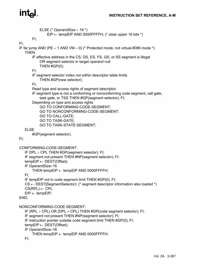
INSTRUCTION SET REFERENCE, A-M
ELSE (* OperandSize = 16 *)EIP ← tempEIP AND 0000FFFFH; (* clear upper 16 bits *)
FI;FI;IF far jump AND (PE = 1 AND VM = 0) (* Protected mode, not virtual-8086 mode *)
THENIF effective address in the CS, DS, ES, FS, GS, or SS segment is illegal
OR segment selector in target operand nullTHEN #GP(0);
FI;IF segment selector index not within descriptor table limits
THEN #GP(new selector);FI;Read type and access rights of segment descriptor;IF segment type is not a conforming or nonconforming code segment, call gate,
task gate, or TSS THEN #GP(segment selector); FI;Depending on type and access rights
GO TO CONFORMING-CODE-SEGMENT;GO TO NONCONFORMING-CODE-SEGMENT;GO TO CALL-GATE;GO TO TASK-GATE;GO TO TASK-STATE-SEGMENT;
ELSE #GP(segment selector);
FI;
CONFORMING-CODE-SEGMENT:IF DPL > CPL THEN #GP(segment selector); FI;IF segment not present THEN #NP(segment selector); FI;tempEIP ← DEST(Offset);IF OperandSize=16
THEN tempEIP ← tempEIP AND 0000FFFFH; FI;IF tempEIP not in code segment limit THEN #GP(0); FI;CS ← DEST[SegmentSelector); (* segment descriptor information also loaded *)CS(RPL) ← CPLEIP ← tempEIP;
END;
NONCONFORMING-CODE-SEGMENT:IF (RPL > CPL) OR (DPL ≠ CPL) THEN #GP(code segment selector); FI;IF segment not present THEN #NP(segment selector); FI;IF instruction pointer outside code segment limit THEN #GP(0); FI;tempEIP ← DEST(Offset);IF OperandSize=16
THEN tempEIP ← tempEIP AND 0000FFFFH; FI;
Vol. 2A 3-387

INSTRUCTION SET REFERENCE, A-M
IF tempEIP not in code segment limit THEN #GP(0); FI;CS ← DEST[SegmentSelector); (* segment descriptor information also loaded *)CS(RPL) ← CPLEIP ← tempEIP;
END;
CALL-GATE:IF call gate DPL < CPL
OR call gate DPL < call gate segment-selector RPL THEN #GP(call gate selector); FI;
IF call gate not present THEN #NP(call gate selector); FI;IF call gate code-segment selector is null THEN #GP(0); FI;IF call gate code-segment selector index is outside descriptor table limits
THEN #GP(code segment selector); FI;Read code segment descriptor;IF code-segment segment descriptor does not indicate a code segment
OR code-segment segment descriptor is conforming and DPL > CPLOR code-segment segment descriptor is non-conforming and DPL ≠ CPL
THEN #GP(code segment selector); FI;IF code segment is not present THEN #NP(code-segment selector); FI;IF instruction pointer is not within code-segment limit THEN #GP(0); FI;tempEIP ← DEST(Offset);IF GateSize=16
THEN tempEIP ← tempEIP AND 0000FFFFH; FI;IF tempEIP not in code segment limit THEN #GP(0); FI;CS ← DEST[SegmentSelector); (* segment descriptor information also loaded *)CS(RPL) ← CPLEIP ← tempEIP;
END;
TASK-GATE:IF task gate DPL < CPL
OR task gate DPL < task gate segment-selector RPL THEN #GP(task gate selector); FI;
IF task gate not present THEN #NP(gate selector); FI;Read the TSS segment selector in the task-gate descriptor;IF TSS segment selector local/global bit is set to local
OR index not within GDT limitsOR TSS descriptor specifies that the TSS is busy
THEN #GP(TSS selector); FI;IF TSS not present THEN #NP(TSS selector); FI;SWITCH-TASKS to TSS;IF EIP not within code segment limit THEN #GP(0); FI;
END;
3-388 Vol. 2A

INSTRUCTION SET REFERENCE, A-M
TASK-STATE-SEGMENT:IF TSS DPL < CPL
OR TSS DPL < TSS segment-selector RPL OR TSS descriptor indicates TSS not available
THEN #GP(TSS selector); FI;IF TSS is not present THEN #NP(TSS selector); FI;SWITCH-TASKS to TSSIF EIP not within code segment limit THEN #GP(0); FI;
END;
Flags AffectedAll flags are affected if a task switch occurs; no flags are affected if a task switch does not occur.
Protected Mode Exceptions#GP(0) If offset in target operand, call gate, or TSS is beyond the code segment
limits.
If the segment selector in the destination operand, call gate, task gate, or TSS is null.
If a memory operand effective address is outside the CS, DS, ES, FS, or GS segment limit.
If the DS, ES, FS, or GS register is used to access memory and it contains a null segment selector.
#GP(selector) If the segment selector index is outside descriptor table limits.
If the segment descriptor pointed to by the segment selector in the destination operand is not for a conforming-code segment, noncon-forming-code segment, call gate, task gate, or task state segment.
If the DPL for a nonconforming-code segment is not equal to the CPL
(When not using a call gate.) If the RPL for the segment’s segment selector is greater than the CPL.
If the DPL for a conforming-code segment is greater than the CPL.
If the DPL from a call-gate, task-gate, or TSS segment descriptor is less than the CPL or than the RPL of the call-gate, task-gate, or TSS’s segment selector.
If the segment descriptor for selector in a call gate does not indicate it is a code segment.
If the segment descriptor for the segment selector in a task gate does not indicate an available TSS.
If the segment selector for a TSS has its local/global bit set for local.
If a TSS segment descriptor specifies that the TSS is busy or not available.
Vol. 2A 3-389

INSTRUCTION SET REFERENCE, A-M
#SS(0) If a memory operand effective address is outside the SS segment limit.
#NP (selector) If the code segment being accessed is not present.
If call gate, task gate, or TSS not present.
#PF(fault-code) If a page fault occurs.
#AC(0) If alignment checking is enabled and an unaligned memory reference is made while the current privilege level is 3. (Only occurs when fetching target from memory.)
Real-Address Mode Exceptions#GP If a memory operand effective address is outside the CS, DS, ES, FS, or
GS segment limit.
If a memory operand effective address is outside the CS, DS, ES, FS, or GS segment limit.
#SS If a memory operand effective address is outside the SS segment limit.
Virtual-8086 Mode Exceptions#GP(0) If the target operand is beyond the code segment limits.
If a memory operand effective address is outside the CS, DS, ES, FS, or GS segment limit.
#SS(0) If a memory operand effective address is outside the SS segment limit.
#PF(fault-code) If a page fault occurs.
#AC(0) If alignment checking is enabled and an unaligned memory reference is made. (Only occurs when fetching target from memory.)
3-390 Vol. 2A

INSTRUCTION SET REFERENCE, A-M
LAHF—Load Status Flags into AH Register
DescriptionMoves the low byte of the EFLAGS register (which includes status flags SF, ZF, AF, PF, andCF) to the AH register. Reserved bits 1, 3, and 5 of the EFLAGS register are set in the AHregister as shown in the “Operation” section below.
OperationAH ← EFLAGS(SF:ZF:0:AF:0:PF:1:CF);
Flags AffectedNone (that is, the state of the flags in the EFLAGS register is not affected).
Exceptions (All Operating Modes)None.
Opcode Instruction Description9F LAHF Load: AH ← EFLAGS(SF:ZF:0:AF:0:PF:1:CF).
Vol. 2A 3-391

INSTRUCTION SET REFERENCE, A-M
LAR—Load Access Rights Byte
DescriptionLoads the access rights from the segment descriptor specified by the second operand (sourceoperand) into the first operand (destination operand) and sets the ZF flag in the EFLAGSregister. The source operand (which can be a register or a memory location) contains thesegment selector for the segment descriptor being accessed. The destination operand is ageneral-purpose register.
The processor performs access checks as part of the loading process. Once loaded in the desti-nation register, software can perform additional checks on the access rights information.
When the operand size is 32 bits, the access rights for a segment descriptor include the type andDPL fields and the S, P, AVL, D/B, and G flags, all of which are located in the second double-word (bytes 4 through 7) of the segment descriptor. The doubleword is masked by 00FXFF00Hbefore it is loaded into the destination operand. When the operand size is 16 bits, the accessrights include the type and DPL fields. Here, the two lower-order bytes of the doubleword aremasked by FF00H before being loaded into the destination operand.
This instruction performs the following checks before it loads the access rights in the destinationregister:
• Checks that the segment selector is not null.
• Checks that the segment selector points to a descriptor that is within the limits of the GDTor LDT being accessed
• Checks that the descriptor type is valid for this instruction. All code and data segmentdescriptors are valid for (can be accessed with) the LAR instruction. The valid systemsegment and gate descriptor types are given in Table 3-53.
• If the segment is not a conforming code segment, it checks that the specified segmentdescriptor is visible at the CPL (that is, if the CPL and the RPL of the segment selector areless than or equal to the DPL of the segment selector).
If the segment descriptor cannot be accessed or is an invalid type for the instruction, the ZF flagis cleared and no access rights are loaded in the destination operand.
The LAR instruction can only be executed in protected mode.
Opcode Instruction Description0F 02 /r LAR r16,r/m16 r16 ← r/m16 masked by FF00H.0F 02 /r LAR r32,r/m32 r32 ← r/m32 masked by 00FxFF00H.
3-392 Vol. 2A

INSTRUCTION SET REFERENCE, A-M
OperationIF SRC(Offset) > descriptor table limit THEN ZF = 0; FI;Read segment descriptor;IF SegmentDescriptor(Type) ≠ conforming code segment
AND (CPL > DPL) OR (RPL > DPL)OR Segment type is not valid for instruction
THENZF ← 0
ELSEIF OperandSize = 32
THENDEST ← [SRC] AND 00FxFF00H;
ELSE (*OperandSize = 16*)DEST ← [SRC] AND FF00H;
FI;FI;
Flags AffectedThe ZF flag is set to 1 if the access rights are loaded successfully; otherwise, it is set to 0.
Table 3-53. Segment and Gate TypesType Name Valid
0 Reserved No
1 Available 16-bit TSS Yes
2 LDT Yes
3 Busy 16-bit TSS Yes
4 16-bit call gate Yes
5 16-bit/32-bit task gate Yes
6 16-bit interrupt gate No
7 16-bit trap gate No
8 Reserved No
9 Available 32-bit TSS Yes
A Reserved No
B Busy 32-bit TSS Yes
C 32-bit call gate Yes
D Reserved No
E 32-bit interrupt gate No
F 32-bit trap gate No
Vol. 2A 3-393

INSTRUCTION SET REFERENCE, A-M
Protected Mode Exceptions#GP(0) If a memory operand effective address is outside the CS, DS, ES, FS, or
GS segment limit.
If the DS, ES, FS, or GS register is used to access memory and it contains a null segment selector.
#SS(0) If a memory operand effective address is outside the SS segment limit.
#PF(fault-code) If a page fault occurs.
#AC(0) If alignment checking is enabled and an unaligned memory reference is made while the current privilege level is 3. (Only occurs when fetching target from memory.)
Real-Address Mode Exceptions#UD The LAR instruction is not recognized in real-address mode.
Virtual-8086 Mode Exceptions#UD The LAR instruction cannot be executed in virtual-8086 mode.
3-394 Vol. 2A

INSTRUCTION SET REFERENCE, A-M
LDDQU: Load Unaligned Integer 128 Bits
DescriptionThe instruction is functionally similar to MOVDQU xmm, m128 for loading from memory. Thatis: 16 bytes of data starting at an address specified by the source memory operand (secondoperand) are fetched from memory and placed in a destination register (first operand). Thesource operand need not be aligned on a 16-byte boundary. Up to 32 bytes may be loaded frommemory; this is implementation dependent.
This instruction may improve performance relative to MOVDQU if the source operand crossesa cache line boundary. In situations that require the data loaded by LDDQU be modified andstored to the same location, use MOVDQU or MOVDQA instead of LDDQU. To move a doublequadword to or from memory locations that are known to be aligned on 16-byte boundaries, usethe MOVDQA instruction.
Implementation Notes• If the source is aligned to a 16-byte boundary, based on the implementation, the 16 bytes
may be loaded more than once. For that reason, the usage of LDDQU should be avoidedwhen using uncached or write-combining (WC) memory regions. For uncached or WCmemory regions, keep using MOVDQU.
• This instruction is a replacement for MOVDQU (load) in situations where cache line splitssignificantly affect performance. It should not be used in situations where store-loadforwarding is performance critical. If performance of store-load forwarding is critical tothe application, use MOVDQA store-load pairs when data is 128-bit aligned or MOVDQUstore-load pairs when data is 128-bit unaligned.
• If the memory address is not aligned on 16-byte boundary, some implementations mayload up to 32 bytes and return 16 bytes in the destination. Some processor implementationsmay issue multiple loads to access the appropriate 16 bytes. Developers of multi-threadedor multi-processor software should be aware that on these processors the loads will beperformed in a non-atomic way.
Operationxmm[127-0] = m128;
Intel C/C++ Compiler Intrinsic EquivalentHADDPS __m128i _mm_lddqu_si128(__m128i const *p)
Numeric ExceptionsNone.
Opcode Instruction DescriptionF2,0F,F0,/r LDDQU xmm, mem Load data from mem and return 128 bits in
an xmm register.
Vol. 2A 3-395

INSTRUCTION SET REFERENCE, A-M
Protected Mode Exceptions#GP(0) For an illegal memory operand effective address in the CS, DS, ES, FS or
GS segments.
#SS(0) For an illegal address in the SS segment.
#PF(fault-code) For a page fault.
#NM If TS bit in CR0 is set.
#UD If CR4.OSFXSR(bit 9) = 0.
If CR0.EM = 1.
If CPUID.SSE3(ECX bit 0) = 0.
#AC(0) If alignment checking is enabled and an unaligned memory reference is made while the current privilege level is 3.
Real Address Mode ExceptionsGP(0) If any part of the operand would lie outside of the effective address space
from 0 to 0FFFFH.
#NM If TS bit in CR0 is set.
#UD If CR0.EM = 1.
If CR4.OSFXSR(bit 9) = 0.
If CPUID.SSE3(ECX bit 0) = 0.
Virtual 8086 Mode ExceptionsGP(0) If any part of the operand would lie outside of the effective address space
from 0 to 0FFFFH.
#NM If TS bit in CR0 is set.
#UD If CR0.EM = 1.
If CR4.OSFXSR(bit 9) = 0.
If CPUID.SSE3(ECX bit 0) = 0.
#PF(fault-code) For a page fault.
#AC(0) If alignment checking is enabled and an unaligned memory reference is made.
3-396 Vol. 2A

INSTRUCTION SET REFERENCE, A-M
LDMXCSR—Load MXCSR Register
DescriptionLoads the source operand into the MXCSR control/status register. The source operand is a 32-bit memory location. See “MXCSR Control and Status Register” in Chapter 10, of the IA-32Intel Architecture Software Developer’s Manual, Volume 1, for a description of the MXCSRregister and its contents.
The LDMXCSR instruction is typically used in conjunction with the STMXCSR instruction,which stores the contents of the MXCSR register in memory.
The default MXCSR value at reset is 1F80H.
If a LDMXCSR instruction clears an SIMD floating-point exception mask bit and sets the corre-sponding exception flag bit, an SIMD floating-point exception will not be immediately gener-ated. The exception will be generated only upon the execution of the next SSE or SSE2instruction that causes that particular SIMD floating-point exception to be reported.
OperationMXCSR ← m32;
C/C++ Compiler Intrinsic Equivalent_mm_setcsr(unsigned int i)
Numeric ExceptionsNone.
Protected Mode Exceptions#GP(0) For an illegal memory operand effective address in the CS, DS, ES, FS, or
GS segments.
For an attempt to set reserved bits in MXCSR.
#SS(0) For an illegal address in the SS segment.
#PF(fault-code) For a page fault.
#NM If TS in CR0 is set.
#UD If EM in CR0 is set.
If OSFXSR in CR4 is 0.
If CPUID feature flag SSE is 0.
Opcode Instruction Description0F AE /2 LDMXCSR m32 Load MXCSR register from m32.
Vol. 2A 3-397

INSTRUCTION SET REFERENCE, A-M
#AC(0) If alignment checking is enabled and an unaligned memory reference is made while the current privilege level is 3.
Real Address Mode Exceptions
GP(0) If any part of the operand would lie outside of the effective address space from 0 to FFFFH.
For an attempt to set reserved bits in MXCSR.
#NM If TS in CR0 is set.
#UD If EM in CR0 is set.
If OSFXSR in CR4 is 0.
If CPUID feature flag SSE is 0.
Virtual 8086 Mode Exceptions
Same exceptions as in Real Address Mode.
#PF(fault-code) For a page fault.
#AC(0) If alignment checking is enabled and an unaligned memory reference is made.
3-398 Vol. 2A

INSTRUCTION SET REFERENCE, A-M
LDS/LES/LFS/LGS/LSS—Load Far Pointer
DescriptionLoads a far pointer (segment selector and offset) from the second operand (source operand) intoa segment register and the first operand (destination operand). The source operand specifies a48-bit or a 32-bit pointer in memory depending on the current setting of the operand-sizeattribute (32 bits or 16 bits, respectively). The instruction opcode and the destination operandspecify a segment register/general-purpose register pair. The 16-bit segment selector from thesource operand is loaded into the segment register specified with the opcode (DS, SS, ES, FS,or GS). The 32-bit or 16-bit offset is loaded into the register specified with the destinationoperand.
If one of these instructions is executed in protected mode, additional information from thesegment descriptor pointed to by the segment selector in the source operand is loaded in thehidden part of the selected segment register.
Also in protected mode, a null selector (values 0000 through 0003) can be loaded into DS, ES,FS, or GS registers without causing a protection exception. (Any subsequent reference to asegment whose corresponding segment register is loaded with a null selector, causes a general-protection exception (#GP) and no memory reference to the segment occurs.)
OperationIF ProtectedMode
THEN IF SS is loaded THEN IF SegementSelector = null
THEN #GP(0); FI;ELSE IF Segment selector index is not within descriptor table limitsOR Segment selector RPL ≠ CPLOR Access rights indicate nonwritable data segmentOR DPL ≠ CPL
THEN #GP(selector);FI;
Opcode Instruction DescriptionC5 /r LDS r16,m16:16 Load DS:r16 with far pointer from memory.C5 /r LDS r32,m16:32 Load DS:r32 with far pointer from memory.0F B2 /r LSS r16,m16:16 Load SS:r16 with far pointer from memory.0F B2 /r LSS r32,m16:32 Load SS:r32 with far pointer from memory.C4 /r LES r16,m16:16 Load ES:r16 with far pointer from memory.C4 /r LES r32,m16:32 Load ES:r32 with far pointer from memory.0F B4 /r LFS r16,m16:16 Load FS:r16 with far pointer from memory.0F B4 /r LFS r32,m16:32 Load FS:r32 with far pointer from memory.0F B5 /r LGS r16,m16:16 Load GS:r16 with far pointer from memory.0F B5 /r LGS r32,m16:32 Load GS:r32 with far pointer from memory.
Vol. 2A 3-399

INSTRUCTION SET REFERENCE, A-M
ELSE IF Segment marked not presentTHEN #SS(selector);
FI;SS ← SegmentSelector(SRC);SS ← SegmentDescriptor([SRC]);
ELSE IF DS, ES, FS, or GS is loaded with non-null segment selectorTHEN IF Segment selector index is not within descriptor table limitsOR Access rights indicate segment neither data nor readable code segmentOR (Segment is data or nonconforming-code segment
AND both RPL and CPL > DPL)THEN #GP(selector);
FI;ELSE IF Segment marked not present
THEN #NP(selector);FI;SegmentRegister ← SegmentSelector(SRC) AND RPL;SegmentRegister ← SegmentDescriptor([SRC]);
ELSE IF DS, ES, FS, or GS is loaded with a null selector:SegmentRegister ← NullSelector;SegmentRegister(DescriptorValidBit) ← 0; (*hidden flag; not accessible by software*)
FI;FI;IF (Real-Address or Virtual-8086 Mode)
THENSegmentRegister ← SegmentSelector(SRC);
FI;DEST ← Offset(SRC);
Flags AffectedNone.
Protected Mode Exceptions#UD If source operand is not a memory location.
#GP(0) If a null selector is loaded into the SS register.
If a memory operand effective address is outside the CS, DS, ES, FS, or GS segment limit.
If the DS, ES, FS, or GS register is used to access memory and it contains a null segment selector.
#GP(selector) If the SS register is being loaded and any of the following is true: the segment selector index is not within the descriptor table limits, the segment selector RPL is not equal to CPL, the segment is a non-writable data segment, or DPL is not equal to CPL.
3-400 Vol. 2A
INSTRUCTION SET REFERENCE, A-M
If the DS, ES, FS, or GS register is being loaded with a non-null segment selector and any of the following is true: the segment selector index is not within descriptor table limits, the segment is neither a data nor a readable code segment, or the segment is a data or nonconforming-code segment and both RPL and CPL are greater than DPL.
#SS(0) If a memory operand effective address is outside the SS segment limit.
#SS(selector) If the SS register is being loaded and the segment is marked not present.
#NP(selector) If DS, ES, FS, or GS register is being loaded with a non-null segment selector and the segment is marked not present.
#PF(fault-code) If a page fault occurs.
#AC(0) If alignment checking is enabled and an unaligned memory reference is made while the current privilege level is 3.
Real-Address Mode Exceptions#GP If a memory operand effective address is outside the CS, DS, ES, FS, or
GS segment limit.
#SS If a memory operand effective address is outside the SS segment limit.
#UD If source operand is not a memory location.
Virtual-8086 Mode Exceptions#UD If source operand is not a memory location.
#GP(0) If a memory operand effective address is outside the CS, DS, ES, FS, or GS segment limit.
#SS(0) If a memory operand effective address is outside the SS segment limit.
#PF(fault-code) If a page fault occurs.
#AC(0) If alignment checking is enabled and an unaligned memory reference is made.
Vol. 2A 3-401

INSTRUCTION SET REFERENCE, A-M
LEA—Load Effective Address
DescriptionComputes the effective address of the second operand (the source operand) and stores it in thefirst operand (destination operand). The source operand is a memory address (offset part) spec-ified with one of the processors addressing modes; the destination operand is a general-purposeregister. The address-size and operand-size attributes affect the action performed by this instruc-tion, as shown in the following table. The operand-size attribute of the instruction is determinedby the chosen register; the address-size attribute is determined by the attribute of the codesegment.
Different assemblers may use different algorithms based on the size attribute and symbolicreference of the source operand.
OperationIF OperandSize = 16 AND AddressSize = 16
THENDEST ← EffectiveAddress(SRC); (* 16-bit address *)
ELSE IF OperandSize = 16 AND AddressSize = 32THEN
temp ← EffectiveAddress(SRC); (* 32-bit address *)DEST ← temp[0..15]; (* 16-bit address *)
ELSE IF OperandSize = 32 AND AddressSize = 16THEN
temp ← EffectiveAddress(SRC); (* 16-bit address *)DEST ← ZeroExtend(temp); (* 32-bit address *)
ELSE IF OperandSize = 32 AND AddressSize = 32THEN
Opcode Instruction Description8D /r LEA r16,m Store effective address for m in register r16.8D /r LEA r32,m Store effective address for m in register r32.
Table 3-54. Address and Operand Size AttributesOperand Size Address Size Action Performed
16 16 16-bit effective address is calculated and stored in requested 16-bit register destination.
16 32 32-bit effective address is calculated. The lower 16 bits of the address are stored in the requested 16-bit register destination.
32 16 16-bit effective address is calculated. The 16-bit address is zero-extended and stored in the requested 32-bit register destination.
32 32 32-bit effective address is calculated and stored in the requested 32-bit register destination.
3-402 Vol. 2A

INSTRUCTION SET REFERENCE, A-M
DEST ← EffectiveAddress(SRC); (* 32-bit address *)FI;
FI;
Flags AffectedNone.
Protected Mode Exceptions#UD If source operand is not a memory location.
Real-Address Mode Exceptions#UD If source operand is not a memory location.
Virtual-8086 Mode Exceptions#UD If source operand is not a memory location.
Vol. 2A 3-403

INSTRUCTION SET REFERENCE, A-M
LEAVE—High Level Procedure Exit
DescriptionReleases the stack frame set up by an earlier ENTER instruction. The LEAVE instruction copiesthe frame pointer (in the EBP register) into the stack pointer register (ESP), which releases thestack space allocated to the stack frame. The old frame pointer (the frame pointer for the callingprocedure that was saved by the ENTER instruction) is then popped from the stack into the EBPregister, restoring the calling procedure’s stack frame.
A RET instruction is commonly executed following a LEAVE instruction to return programcontrol to the calling procedure.
See “Procedure Calls for Block-Structured Languages” in Chapter 6 of the IA-32 Intel Architec-ture Software Developer’s Manual, Volume 1, for detailed information on the use of the ENTERand LEAVE instructions.
OperationIF StackAddressSize = 32
THENESP ← EBP;
ELSE (* StackAddressSize = 16*)SP ← BP;
FI;IF OperandSize = 32
THENEBP ← Pop();
ELSE (* OperandSize = 16*)BP ← Pop();
FI;
Flags AffectedNone.
Protected Mode Exceptions#SS(0) If the EBP register points to a location that is not within the limits of the
current stack segment.
#PF(fault-code) If a page fault occurs.
#AC(0) If alignment checking is enabled and an unaligned memory reference is made while the current privilege level is 3.
Opcode Instruction DescriptionC9 LEAVE Set SP to BP, then pop BP.C9 LEAVE Set ESP to EBP, then pop EBP.
3-404 Vol. 2A

INSTRUCTION SET REFERENCE, A-M
Real-Address Mode Exceptions#GP If the EBP register points to a location outside of the effective address
space from 0 to FFFFH.
Virtual-8086 Mode Exceptions#GP(0) If the EBP register points to a location outside of the effective address
space from 0 to FFFFH.
#PF(fault-code) If a page fault occurs.
#AC(0) If alignment checking is enabled and an unaligned memory reference is made.
Vol. 2A 3-405

INSTRUCTION SET REFERENCE, A-M
LES—Load Far Pointer
See entry for LDS/LES/LFS/LGS/LSS—Load Far Pointer.
3-406 Vol. 2A

INSTRUCTION SET REFERENCE, A-M
LFENCE—Load Fence
DescriptionPerforms a serializing operation on all load-from-memory instructions that were issued prior theLFENCE instruction. This serializing operation guarantees that every load instruction thatprecedes in program order the LFENCE instruction is globally visible before any load instruc-tion that follows the LFENCE instruction is globally visible. The LFENCE instruction isordered with respect to load instructions, other LFENCE instructions, any MFENCE instruc-tions, and any serializing instructions (such as the CPUID instruction). It is not ordered withrespect to store instructions or the SFENCE instruction.
Weakly ordered memory types can be used to achieve higher processor performance throughsuch techniques as out-of-order issue and speculative reads. The degree to which a consumer ofdata recognizes or knows that the data is weakly ordered varies among applications and may beunknown to the producer of this data. The LFENCE instruction provides a performance-efficientway of insuring load ordering between routines that produce weakly-ordered results androutines that consume that data.
It should be noted that processors are free to speculatively fetch and cache data from systemmemory regions that are assigned a memory-type that permits speculative reads (that is, the WB,WC, and WT memory types). The PREFETCHh instruction is considered a hint to this specula-tive behavior. Because this speculative fetching can occur at any time and is not tied to instruc-tion execution, the LFENCE instruction is not ordered with respect to PREFETCHh instructionsor any other speculative fetching mechanism (that is, data could be speculative loaded into thecache just before, during, or after the execution of an LFENCE instruction).
OperationWait_On_Following_Loads_Until(preceding_loads_globally_visible);
Intel C/C++ Compiler Intrinsic Equivalentvoid_mm_lfence(void)
Exceptions (All Modes of Operation)None.
Opcode Instruction Description0F AE /5 LFENCE Serializes load operations.
Vol. 2A 3-407

INSTRUCTION SET REFERENCE, A-M
LFS—Load Far Pointer
See entry for LDS/LES/LFS/LGS/LSS—Load Far Pointer.
3-408 Vol. 2A

INSTRUCTION SET REFERENCE, A-M
LGDT/LIDT—Load Global/Interrupt Descriptor Table Register
DescriptionLoads the values in the source operand into the global descriptor table register (GDTR) or theinterrupt descriptor table register (IDTR). The source operand specifies a 6-byte memory loca-tion that contains the base address (a linear address) and the limit (size of table in bytes) of theglobal descriptor table (GDT) or the interrupt descriptor table (IDT). If operand-size attribute is32 bits, a 16-bit limit (lower 2 bytes of the 6-byte data operand) and a 32-bit base address (upper4 bytes of the data operand) are loaded into the register. If the operand-size attribute is 16bits, a 16-bit limit (lower 2 bytes) and a 24-bit base address (third, fourth, and fifth byte) areloaded. Here, the high-order byte of the operand is not used and the high-order byte of the baseaddress in the GDTR or IDTR is filled with zeros.
The LGDT and LIDT instructions are used only in operating-system software; they are not usedin application programs. They are the only instructions that directly load a linear address (thatis, not a segment-relative address) and a limit in protected mode. They are commonly executedin real-address mode to allow processor initialization prior to switching to protected mode.
See “SGDT—Store Global Descriptor Table Register” in Chapter 4 for information on storingthe contents of the GDTR and IDTR.
OperationIF instruction is LIDT
THENIF OperandSize = 16
THEN IDTR(Limit) ← SRC[0:15];IDTR(Base) ← SRC[16:47] AND 00FFFFFFH;
ELSE (* 32-bit Operand Size *)IDTR(Limit) ← SRC[0:15];IDTR(Base) ← SRC[16:47];
FI;ELSE (* instruction is LGDT *)
IF OperandSize = 16THEN
GDTR(Limit) ← SRC[0:15];GDTR(Base) ← SRC[16:47] AND 00FFFFFFH;
ELSE (* 32-bit Operand Size *)GDTR(Limit) ← SRC[0:15];GDTR(Base) ← SRC[16:47];
FI; FI;
Opcode Instruction Description0F 01 /2 LGDT m16&32 Load m into GDTR.0F 01 /3 LIDT m16&32 Load m into IDTR.
Vol. 2A 3-409

INSTRUCTION SET REFERENCE, A-M
Flags AffectedNone.
Protected Mode Exceptions#UD If source operand is not a memory location.
#GP(0) If the current privilege level is not 0.
If a memory operand effective address is outside the CS, DS, ES, FS, or GS segment limit.
If the DS, ES, FS, or GS register is used to access memory and it contains a null segment selector.
#SS(0) If a memory operand effective address is outside the SS segment limit.
#PF(fault-code) If a page fault occurs.
Real-Address Mode Exceptions#UD If source operand is not a memory location.
#GP If a memory operand effective address is outside the CS, DS, ES, FS, or GS segment limit.
#SS If a memory operand effective address is outside the SS segment limit.
Virtual-8086 Mode Exceptions#GP(0) The LGDT and LIDT instructions are not recognized in virtual-8086
mode.
#GP If the current privilege level is not 0.
3-410 Vol. 2A

INSTRUCTION SET REFERENCE, A-M
LLDT—Load Local Descriptor Table Register
DescriptionLoads the source operand into the segment selector field of the local descriptor table register(LDTR). The source operand (a general-purpose register or a memory location) contains asegment selector that points to a local descriptor table (LDT). After the segment selector isloaded in the LDTR, the processor uses the segment selector to locate the segment descriptor forthe LDT in the global descriptor table (GDT). It then loads the segment limit and base addressfor the LDT from the segment descriptor into the LDTR. The segment registers DS, ES, SS, FS,GS, and CS are not affected by this instruction, nor is the LDTR field in the task state segment(TSS) for the current task.
If the source operand is 0, the LDTR is marked invalid and all references to descriptors in theLDT (except by the LAR, VERR, VERW or LSL instructions) cause a general protection excep-tion (#GP).
The operand-size attribute has no effect on this instruction.
The LLDT instruction is provided for use in operating-system software; it should not be used inapplication programs. Also, this instruction can only be executed in protected mode.
OperationIF SRC(Offset) > descriptor table limit THEN #GP(segment selector); FI;Read segment descriptor;IF SegmentDescriptor(Type) ≠ LDT THEN #GP(segment selector); FI;IF segment descriptor is not present THEN #NP(segment selector);LDTR(SegmentSelector) ← SRC;LDTR(SegmentDescriptor) ← GDTSegmentDescriptor;
Flags AffectedNone.
Protected Mode Exceptions#GP(0) If the current privilege level is not 0.
If a memory operand effective address is outside the CS, DS, ES, FS, or GS segment limit.
If the DS, ES, FS, or GS register contains a null segment selector.
#GP(selector) If the selector operand does not point into the Global Descriptor Table or if the entry in the GDT is not a Local Descriptor Table.
Segment selector is beyond GDT limit.
Opcode Instruction Description0F 00 /2 LLDT r/m16 Load segment selector r/m16 into LDTR.
Vol. 2A 3-411

INSTRUCTION SET REFERENCE, A-M
#SS(0) If a memory operand effective address is outside the SS segment limit.
#NP(selector) If the LDT descriptor is not present.
#PF(fault-code) If a page fault occurs.
Real-Address Mode Exceptions#UD The LLDT instruction is not recognized in real-address mode.
Virtual-8086 Mode Exceptions#UD The LLDT instruction is not recognized in virtual-8086 mode.
3-412 Vol. 2A

INSTRUCTION SET REFERENCE, A-M
LIDT—Load Interrupt Descriptor Table Register
See entry for LGDT/LIDT—Load Global/Interrupt Descriptor Table Register.
Vol. 2A 3-413
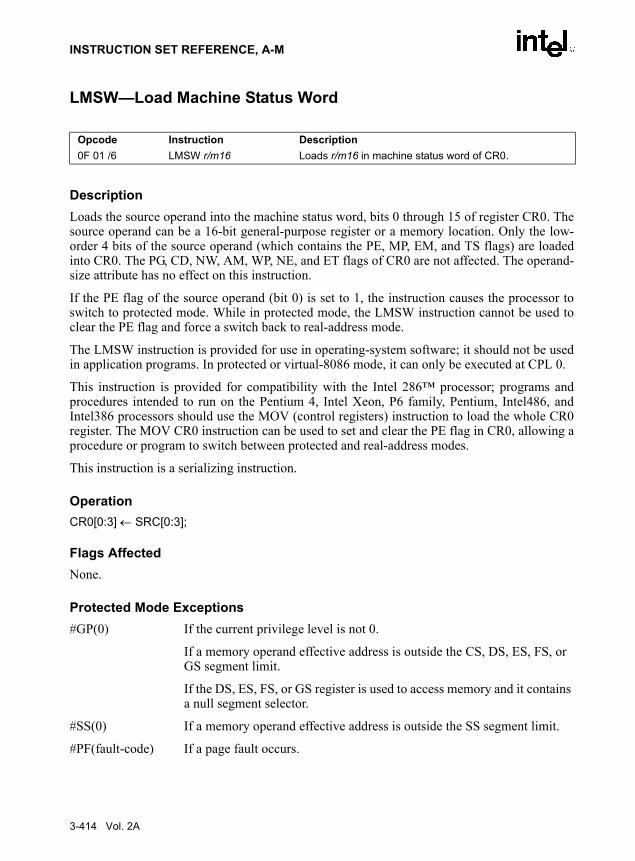
INSTRUCTION SET REFERENCE, A-M
LMSW—Load Machine Status Word
DescriptionLoads the source operand into the machine status word, bits 0 through 15 of register CR0. Thesource operand can be a 16-bit general-purpose register or a memory location. Only the low-order 4 bits of the source operand (which contains the PE, MP, EM, and TS flags) are loadedinto CR0. The PG, CD, NW, AM, WP, NE, and ET flags of CR0 are not affected. The operand-size attribute has no effect on this instruction.
If the PE flag of the source operand (bit 0) is set to 1, the instruction causes the processor toswitch to protected mode. While in protected mode, the LMSW instruction cannot be used toclear the PE flag and force a switch back to real-address mode.
The LMSW instruction is provided for use in operating-system software; it should not be usedin application programs. In protected or virtual-8086 mode, it can only be executed at CPL 0.
This instruction is provided for compatibility with the Intel 286™ processor; programs andprocedures intended to run on the Pentium 4, Intel Xeon, P6 family, Pentium, Intel486, andIntel386 processors should use the MOV (control registers) instruction to load the whole CR0register. The MOV CR0 instruction can be used to set and clear the PE flag in CR0, allowing aprocedure or program to switch between protected and real-address modes.
This instruction is a serializing instruction.
OperationCR0[0:3] ← SRC[0:3];
Flags AffectedNone.
Protected Mode Exceptions#GP(0) If the current privilege level is not 0.
If a memory operand effective address is outside the CS, DS, ES, FS, or GS segment limit.
If the DS, ES, FS, or GS register is used to access memory and it contains a null segment selector.
#SS(0) If a memory operand effective address is outside the SS segment limit.
#PF(fault-code) If a page fault occurs.
Opcode Instruction Description0F 01 /6 LMSW r/m16 Loads r/m16 in machine status word of CR0.
3-414 Vol. 2A

INSTRUCTION SET REFERENCE, A-M
Real-Address Mode Exceptions#GP If a memory operand effective address is outside the CS, DS, ES, FS, or
GS segment limit.
Virtual-8086 Mode Exceptions#GP(0) If a memory operand effective address is outside the CS, DS, ES, FS, or
GS segment limit.
#SS(0) If a memory operand effective address is outside the SS segment limit.
#PF(fault-code) If a page fault occurs.
Vol. 2A 3-415

INSTRUCTION SET REFERENCE, A-M
LOCK—Assert LOCK# Signal Prefix
DescriptionCauses the processor’s LOCK# signal to be asserted during execution of the accompanyinginstruction (turns the instruction into an atomic instruction). In a multiprocessor environment,the LOCK# signal insures that the processor has exclusive use of any shared memory while thesignal is asserted.
Note that in later IA-32 processors (including the Pentium 4, Intel Xeon, and P6 family proces-sors), locking may occur without the LOCK# signal being asserted. See IA-32 ArchitectureCompatibility below.
The LOCK prefix can be prepended only to the following instructions and only to those formsof the instructions where the destination operand is a memory operand: ADD, ADC, AND,BTC, BTR, BTS, CMPXCHG, CMPXCH8B, DEC, INC, NEG, NOT, OR, SBB, SUB, XOR,XADD, and XCHG. If the LOCK prefix is used with one of these instructions and the sourceoperand is a memory operand, an undefined opcode exception (#UD) may be generated. Anundefined opcode exception will also be generated if the LOCK prefix is used with any instruc-tion not in the above list. The XCHG instruction always asserts the LOCK# signal regardless ofthe presence or absence of the LOCK prefix.
The LOCK prefix is typically used with the BTS instruction to perform a read-modify-writeoperation on a memory location in shared memory environment.
The integrity of the LOCK prefix is not affected by the alignment of the memory field. Memorylocking is observed for arbitrarily misaligned fields.
IA-32 Architecture CompatibilityBeginning with the P6 family processors, when the LOCK prefix is prefixed to an instructionand the memory area being accessed is cached internally in the processor, the LOCK# signal isgenerally not asserted. Instead, only the processor’s cache is locked. Here, the processor’s cachecoherency mechanism insures that the operation is carried out atomically with regards tomemory. See “Effects of a Locked Operation on Internal Processor Caches” in Chapter 7 of IA-32 Intel Architecture Software Developer’s Manual, Volume 3, the for more information onlocking of caches.
OperationAssertLOCK#(DurationOfAccompaningInstruction)
Flags AffectedNone.
Opcode Instruction DescriptionF0 LOCK Asserts LOCK# signal for duration of the accompanying
instruction.
3-416 Vol. 2A
INSTRUCTION SET REFERENCE, A-M
Protected Mode Exceptions#UD If the LOCK prefix is used with an instruction not listed in the “Descrip-
tion” section above. Other exceptions can be generated by the instruction that the LOCK prefix is being applied to.
Real-Address Mode Exceptions#UD If the LOCK prefix is used with an instruction not listed in the “Descrip-
tion” section above. Other exceptions can be generated by the instruction that the LOCK prefix is being applied to.
Virtual-8086 Mode Exceptions#UD If the LOCK prefix is used with an instruction not listed in the “Descrip-
tion” section above. Other exceptions can be generated by the instruction that the LOCK prefix is being applied to.
Vol. 2A 3-417

INSTRUCTION SET REFERENCE, A-M
LODS/LODSB/LODSW/LODSD—Load String
DescriptionLoads a byte, word, or doubleword from the source operand into the AL, AX, or EAX register,respectively. The source operand is a memory location, the address of which is read from theDS:EDI or the DS:SI registers (depending on the address-size attribute of the instruction, 32 or16, respectively). The DS segment may be overridden with a segment override prefix.
At the assembly-code level, two forms of this instruction are allowed: the “explicit-operands”form and the “no-operands” form. The explicit-operands form (specified with the LODSmnemonic) allows the source operand to be specified explicitly. Here, the source operand shouldbe a symbol that indicates the size and location of the source value. The destination operand isthen automatically selected to match the size of the source operand (the AL register for byteoperands, AX for word operands, and EAX for doubleword operands). This explicit-operandsform is provided to allow documentation; however, note that the documentation provided by thisform can be misleading. That is, the source operand symbol must specify the correct type (size)of the operand (byte, word, or doubleword), but it does not have to specify the correct location.The location is always specified by the DS:(E)SI registers, which must be loaded correctlybefore the load string instruction is executed.
The no-operands form provides “short forms” of the byte, word, and doubleword versions of theLODS instructions. Here also DS:(E)SI is assumed to be the source operand and the AL, AX, orEAX register is assumed to be the destination operand. The size of the source and destinationoperands is selected with the mnemonic: LODSB (byte loaded into register AL), LODSW (wordloaded into AX), or LODSD (doubleword loaded into EAX).
After the byte, word, or doubleword is transferred from the memory location into the AL, AX,or EAX register, the (E)SI register is incremented or decremented automatically according tothe setting of the DF flag in the EFLAGS register. (If the DF flag is 0, the (E)SI register is incre-mented; if the DF flag is 1, the ESI register is decremented.) The (E)SI register is incrementedor decremented by 1 for byte operations, by 2 for word operations, or by 4 for doubleword oper-ations.
The LODS, LODSB, LODSW, and LODSD instructions can be preceded by the REP prefix forblock loads of ECX bytes, words, or doublewords. More often, however, these instructionsare used within a LOOP construct because further processing of the data moved into the registeris usually necessary before the next transfer can be made. See “REP/REPE/REPZ/REPNE/REPNZ—Repeat String Operation Prefix” in Chapter 4 for a description of the REP prefix.
Opcode Instruction DescriptionAC LODS m8 Load byte at address DS:(E)SI into AL.AD LODS m16 Load word at address DS:(E)SI into AX.AD LODS m32 Load doubleword at address DS:(E)SI into EAX.AC LODSB Load byte at address DS:(E)SI into AL.AD LODSW Load word at address DS:(E)SI into AX.AD LODSD Load doubleword at address DS:(E)SI into EAX.
3-418 Vol. 2A

INSTRUCTION SET REFERENCE, A-M
OperationIF (byte load)
THENAL ← SRC; (* byte load *)
THEN IF DF = 0THEN (E)SI ← (E)SI + 1; ELSE (E)SI ← (E)SI – 1;
FI;ELSE IF (word load)
THENAX ← SRC; (* word load *)
THEN IF DF = 0THEN (E)SI ← (E)SI + 2; ELSE (E)SI ← (E)SI – 2;
FI;ELSE (* doubleword transfer *)
EAX ← SRC; (* doubleword load *)THEN IF DF = 0
THEN (E)SI ← (E)SI + 4; ELSE (E)SI ← (E)SI – 4;
FI;FI;
FI;
Flags AffectedNone.
Protected Mode Exceptions#GP(0) If a memory operand effective address is outside the CS, DS, ES, FS, or
GS segment limit.
If the DS, ES, FS, or GS register contains a null segment selector.
#SS(0) If a memory operand effective address is outside the SS segment limit.
#PF(fault-code) If a page fault occurs.
#AC(0) If alignment checking is enabled and an unaligned memory reference is made while the current privilege level is 3.
Real-Address Mode Exceptions#GP If a memory operand effective address is outside the CS, DS, ES, FS, or
GS segment limit.
#SS If a memory operand effective address is outside the SS segment limit.
Vol. 2A 3-419

INSTRUCTION SET REFERENCE, A-M
Virtual-8086 Mode Exceptions#GP(0) If a memory operand effective address is outside the CS, DS, ES, FS, or
GS segment limit.
#SS(0) If a memory operand effective address is outside the SS segment limit.
#PF(fault-code) If a page fault occurs.
#AC(0) If alignment checking is enabled and an unaligned memory reference is made.
3-420 Vol. 2A

INSTRUCTION SET REFERENCE, A-M
LOOP/LOOPcc—Loop According to ECX Counter
DescriptionPerforms a loop operation using the ECX or CX register as a counter. Each time the LOOPinstruction is executed, the count register is decremented, then checked for 0. If the count is 0,the loop is terminated and program execution continues with the instruction following the LOOPinstruction. If the count is not zero, a near jump is performed to the destination (target) operand,which is presumably the instruction at the beginning of the loop. If the address-size attribute is32 bits, the ECX register is used as the count register; otherwise the CX register is used.
The target instruction is specified with a relative offset (a signed offset relative to the currentvalue of the instruction pointer in the EIP register). This offset is generally specified as a labelin assembly code, but at the machine code level, it is encoded as a signed, 8-bit immediate value,which is added to the instruction pointer. Offsets of –128 to +127 are allowed with this instruc-tion.
Some forms of the loop instruction (LOOPcc) also accept the ZF flag as a condition for termi-nating the loop before the count reaches zero. With these forms of the instruction, a conditioncode (cc) is associated with each instruction to indicate the condition being tested for. Here, theLOOPcc instruction itself does not affect the state of the ZF flag; the ZF flag is changed by otherinstructions in the loop.
OperationIF AddressSize = 32
THEN Count is ECX;
ELSE (* AddressSize = 16 *) Count is CX;
FI;Count ← Count – 1;
IF instruction is not LOOPTHEN
IF (instruction ← LOOPE) OR (instruction ← LOOPZ)THEN
IF (ZF =1) AND (Count ≠ 0)THEN BranchCond ← 1;ELSE BranchCond ← 0;
Opcode Instruction DescriptionE2 cb LOOP rel8 Decrement count; jump short if count ≠ 0.E1 cb LOOPE rel8 Decrement count; jump short if count ≠ 0 and ZF=1.E1 cb LOOPZ rel8 Decrement count; jump short if count ≠ 0 and ZF=1.E0 cb LOOPNE rel8 Decrement count; jump short if count ≠ 0 and ZF=0.E0 cb LOOPNZ rel8 Decrement count; jump short if count ≠ 0 and ZF=0.
Vol. 2A 3-421

INSTRUCTION SET REFERENCE, A-M
FI;FI;IF (instruction = LOOPNE) OR (instruction = LOOPNZ)
THEN IF (ZF =0 ) AND (Count ≠ 0)
THEN BranchCond ← 1;ELSE BranchCond ← 0;
FI;FI;
ELSE (* instruction = LOOP *)IF (Count ≠ 0)
THEN BranchCond ← 1;ELSE BranchCond ← 0;
FI;FI;IF BranchCond = 1
THEN EIP ← EIP + SignExtend(DEST);
IF OperandSize = 16THEN
EIP ← EIP AND 0000FFFFH;ELSE (* OperandSize = 32 *)
IF EIP < CS.Base OR EIP > CS.Limit#GP
FI;ELSE
Terminate loop and continue program execution at EIP;FI;
Flags AffectedNone.
Protected Mode Exceptions#GP(0) If the offset being jumped to is beyond the limits of the CS segment.
Real-Address Mode Exceptions#GP If the offset being jumped to is beyond the limits of the CS segment or is
outside of the effective address space from 0 to FFFFH. This condition can occur if a 32-bit address size override prefix is used.
Virtual-8086 Mode ExceptionsSame exceptions as in Real Address Mode
3-422 Vol. 2A

INSTRUCTION SET REFERENCE, A-M
LSL—Load Segment Limit
DescriptionLoads the unscrambled segment limit from the segment descriptor specified with the secondoperand (source operand) into the first operand (destination operand) and sets the ZF flag in theEFLAGS register. The source operand (which can be a register or a memory location) containsthe segment selector for the segment descriptor being accessed. The destination operand is ageneral-purpose register.
The processor performs access checks as part of the loading process. Once loaded in the desti-nation register, software can compare the segment limit with the offset of a pointer.
The segment limit is a 20-bit value contained in bytes 0 and 1 and in the first 4 bits of byte 6 ofthe segment descriptor. If the descriptor has a byte granular segment limit (the granularity flagis set to 0), the destination operand is loaded with a byte granular value (byte limit). If thedescriptor has a page granular segment limit (the granularity flag is set to 1), the LSL instructionwill translate the page granular limit (page limit) into a byte limit before loading it into the desti-nation operand. The translation is performed by shifting the 20-bit “raw” limit left 12 bits andfilling the low-order 12 bits with 1s.
When the operand size is 32 bits, the 32-bit byte limit is stored in the destination operand. Whenthe operand size is 16 bits, a valid 32-bit limit is computed; however, the upper 16 bits are trun-cated and only the low-order 16 bits are loaded into the destination operand.
This instruction performs the following checks before it loads the segment limit into the desti-nation register:
• Checks that the segment selector is not null.
• Checks that the segment selector points to a descriptor that is within the limits of the GDTor LDT being accessed
• Checks that the descriptor type is valid for this instruction. All code and data segmentdescriptors are valid for (can be accessed with) the LSL instruction. The valid specialsegment and gate descriptor types are given in the following table.
• If the segment is not a conforming code segment, the instruction checks that the specifiedsegment descriptor is visible at the CPL (that is, if the CPL and the RPL of the segmentselector are less than or equal to the DPL of the segment selector).
If the segment descriptor cannot be accessed or is an invalid type for the instruction, the ZF flagis cleared and no value is loaded in the destination operand.
Opcode Instruction Description0F 03 /r LSL r16,r/m16 Load: r16 ← segment limit, selector r/m16.0F 03 /r LSL r32,r/m32 Load: r32 ← segment limit, selector r/m32).
Vol. 2A 3-423
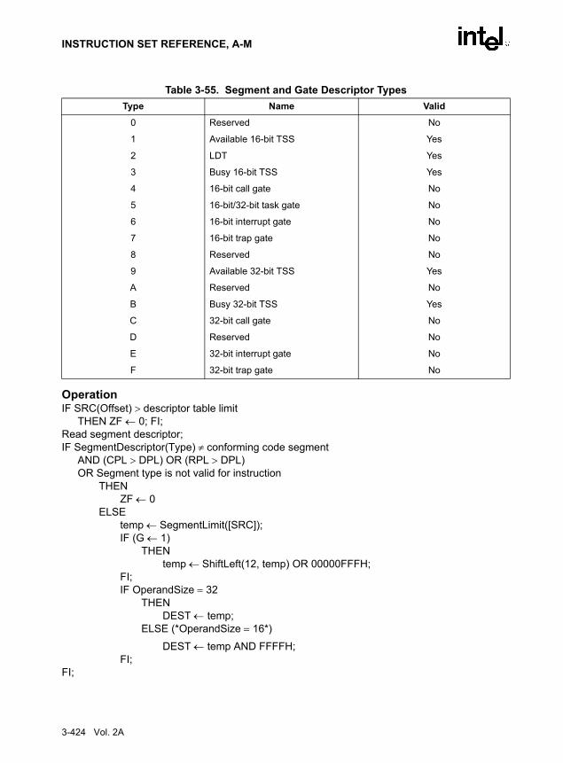
INSTRUCTION SET REFERENCE, A-M
OperationIF SRC(Offset) > descriptor table limit
THEN ZF ← 0; FI;Read segment descriptor;IF SegmentDescriptor(Type) ≠ conforming code segment
AND (CPL > DPL) OR (RPL > DPL)OR Segment type is not valid for instruction
THENZF ← 0
ELSEtemp ← SegmentLimit([SRC]);IF (G ← 1)
THENtemp ← ShiftLeft(12, temp) OR 00000FFFH;
FI;IF OperandSize = 32
THENDEST ← temp;
ELSE (*OperandSize = 16*)
DEST ← temp AND FFFFH;FI;
FI;
Table 3-55. Segment and Gate Descriptor TypesType Name Valid
0 Reserved No
1 Available 16-bit TSS Yes
2 LDT Yes
3 Busy 16-bit TSS Yes
4 16-bit call gate No
5 16-bit/32-bit task gate No
6 16-bit interrupt gate No
7 16-bit trap gate No
8 Reserved No
9 Available 32-bit TSS Yes
A Reserved No
B Busy 32-bit TSS Yes
C 32-bit call gate No
D Reserved No
E 32-bit interrupt gate No
F 32-bit trap gate No
3-424 Vol. 2A

INSTRUCTION SET REFERENCE, A-M
Flags AffectedThe ZF flag is set to 1 if the segment limit is loaded successfully; otherwise, it is set to 0.
Protected Mode Exceptions#GP(0) If a memory operand effective address is outside the CS, DS, ES, FS, or
GS segment limit.
If the DS, ES, FS, or GS register is used to access memory and it contains a null segment selector.
#SS(0) If a memory operand effective address is outside the SS segment limit.
#PF(fault-code) If a page fault occurs.
#AC(0) If alignment checking is enabled and an unaligned memory reference is made while the current privilege level is 3.
Real-Address Mode Exceptions#UD The LSL instruction is not recognized in real-address mode.
Virtual-8086 Mode Exceptions#UD The LSL instruction is not recognized in virtual-8086 mode.
Vol. 2A 3-425

INSTRUCTION SET REFERENCE, A-M
LSS—Load Far Pointer
See entry for LDS/LES/LFS/LGS/LSS—Load Far Pointer.
3-426 Vol. 2A

INSTRUCTION SET REFERENCE, A-M
LTR—Load Task Register
DescriptionLoads the source operand into the segment selector field of the task register. The source operand(a general-purpose register or a memory location) contains a segment selector that points to atask state segment (TSS). After the segment selector is loaded in the task register, the processoruses the segment selector to locate the segment descriptor for the TSS in the global descriptortable (GDT). It then loads the segment limit and base address for the TSS from the segmentdescriptor into the task register. The task pointed to by the task register is marked busy, but aswitch to the task does not occur.
The LTR instruction is provided for use in operating-system software; it should not be used inapplication programs. It can only be executed in protected mode when the CPL is 0. It iscommonly used in initialization code to establish the first task to be executed.
The operand-size attribute has no effect on this instruction.
OperationIF SRC(Offset) > descriptor table limit OR IF SRC(type) ≠ global
THEN #GP(segment selector); FI;Read segment descriptor;IF segment descriptor is not for an available TSS THEN #GP(segment selector); FI;IF segment descriptor is not present THEN #NP(segment selector);TSSsegmentDescriptor(busy) ← 1; (* Locked read-modify-write operation on the entire descriptor when setting busy flag *)TaskRegister(SegmentSelector) ← SRC;TaskRegister(SegmentDescriptor) ← TSSSegmentDescriptor;
Flags AffectedNone.
Protected Mode Exceptions#GP(0) If the current privilege level is not 0.
If a memory operand effective address is outside the CS, DS, ES, FS, or GS segment limit.
If the DS, ES, FS, or GS register is used to access memory and it contains a null segment selector.
#GP(selector) If the source selector points to a segment that is not a TSS or to one for a task that is already busy.
Opcode Instruction Description0F 00 /3 LTR r/m16 Load r/m16 into task register.
Vol. 2A 3-427

INSTRUCTION SET REFERENCE, A-M
If the selector points to LDT or is beyond the GDT limit.
#NP(selector) If the TSS is marked not present.
#SS(0) If a memory operand effective address is outside the SS segment limit.
#PF(fault-code) If a page fault occurs.
Real-Address Mode Exceptions#UD The LTR instruction is not recognized in real-address mode.
Virtual-8086 Mode Exceptions#UD The LTR instruction is not recognized in virtual-8086 mode.
3-428 Vol. 2A

INSTRUCTION SET REFERENCE, A-M
MASKMOVDQU—Store Selected Bytes of Double Quadword
DescriptionStores selected bytes from the source operand (first operand) into an 128-bit memory location.The mask operand (second operand) selects which bytes from the source operand are written tomemory. The source and mask operands are XMM registers. The location of the first byte of thememory location is specified by DI/EDI and DS registers. The memory location does not needto be aligned on a natural boundary. (The size of the store address depends on the address-sizeattribute.)
The most significant bit in each byte of the mask operand determines whether the correspondingbyte in the source operand is written to the corresponding byte location in memory: 0 indicatesno write and 1 indicates write.
The MASKMOVEDQU instruction generates a non-temporal hint to the processor to minimizecache pollution. The non-temporal hint is implemented by using a write combining (WC)memory type protocol (see “Caching of Temporal vs. Non-Temporal Data” in Chapter 10, of theIA-32 Intel Architecture Software Developer’s Manual, Volume 1). Because the WC protocoluses a weakly-ordered memory consistency model, a fencing operation implemented with theSFENCE or MFENCE instruction should be used in conjunction with MASKMOVEDQUinstructions if multiple processors might use different memory types to read/write the destina-tion memory locations.
Behavior with a mask of all 0s is as follows:
• No data will be written to memory.
• Signaling of breakpoints (code or data) is not guaranteed; different processor implementa-tions may signal or not signal these breakpoints.
• Exceptions associated with addressing memory and page faults may still be signaled(implementation dependent).
• If the destination memory region is mapped as UC or WP, enforcement of associatedsemantics for these memory types is not guaranteed (that is, is reserved) and is implemen-tation-specific.
The MASKMOVDQU instruction can be used to improve performance of algorithms that needto merge data on a byte-by-byte basis. MASKMOVDQU should not cause a read for ownership;doing so generates unnecessary bandwidth since data is to be written directly using the byte-mask without allocating old data prior to the store.
Opcode Instruction Description66 0F F7 /r MASKMOVDQU xmm1, xmm2 Selectively write bytes from xmm1 to memory
location using the byte mask in xmm2.
Vol. 2A 3-429

INSTRUCTION SET REFERENCE, A-M
OperationIF (MASK[7] = 1)
THEN DEST[DI/EDI] ← SRC[7-0] ELSE * memory location unchanged *; FI;IF (MASK[15] = 1)
THEN DEST[DI/EDI+1] ← SRC[15-8] ELSE * memory location unchanged *; FI;* Repeat operation for 3rd through 14th bytes in source operand *;
IF (MASK[127] = 1) THEN DEST[DI/EDI+15] ← SRC[127-120] ELSE * memory location unchanged *; FI;
Intel C/C++ Compiler Intrinsic Equivalentvoid_mm_maskmoveu_si128(__m128i d, __m128i n, char * p)
Protected Mode Exceptions
#GP(0) For an illegal memory operand effective address in the CS, DS, ES, FS or GS segments. (even if mask is all 0s).
If the destination operand is in a nonwritable segment.
If the DS, ES, FS, or GS register contains a null segment selector.
#SS(0) For an illegal address in the SS segment (even if mask is all 0s).
#PF(fault-code) For a page fault (implementation specific).
#NM If TS in CR0 is set.
#UD If EM in CR0 is set.
If OSFXSR in CR4 is 0.
If CPUID feature flag SSE2 is 0.
Real-Address Mode Exceptions
GP(0) If any part of the operand lies outside the effective address space from 0 to FFFFH. (even if mask is all 0s).
#NM If TS in CR0 is set.
#UD If EM in CR0 is set.
If OSFXSR in CR4 is 0.
If CPUID feature flag SSE2 is 0.
Virtual-8086 Mode Exceptions
Same exceptions as in Real Address Mode
#PF(fault-code) For a page fault (implementation specific).
3-430 Vol. 2A
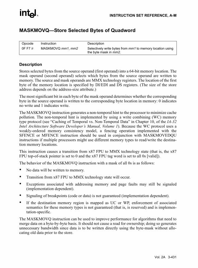
INSTRUCTION SET REFERENCE, A-M
MASKMOVQ—Store Selected Bytes of Quadword
DescriptionStores selected bytes from the source operand (first operand) into a 64-bit memory location. Themask operand (second operand) selects which bytes from the source operand are written tomemory. The source and mask operands are MMX technology registers. The location of the firstbyte of the memory location is specified by DI/EDI and DS registers. (The size of the storeaddress depends on the address-size attribute.)
The most significant bit in each byte of the mask operand determines whether the correspondingbyte in the source operand is written to the corresponding byte location in memory: 0 indicatesno write and 1 indicates write.
The MASKMOVQ instruction generates a non-temporal hint to the processor to minimize cachepollution. The non-temporal hint is implemented by using a write combining (WC) memorytype protocol (see “Caching of Temporal vs. Non-Temporal Data” in Chapter 10, of the IA-32Intel Architecture Software Developer’s Manual, Volume 1). Because the WC protocol uses aweakly-ordered memory consistency model, a fencing operation implemented with theSFENCE or MFENCE instruction should be used in conjunction with MASKMOVEDQUinstructions if multiple processors might use different memory types to read/write the destina-tion memory locations.
This instruction causes a transition from x87 FPU to MMX technology state (that is, the x87FPU top-of-stack pointer is set to 0 and the x87 FPU tag word is set to all 0s [valid]).
The behavior of the MASKMOVQ instruction with a mask of all 0s is as follows:
• No data will be written to memory.
• Transition from x87 FPU to MMX technology state will occur.
• Exceptions associated with addressing memory and page faults may still be signaled(implementation dependent).
• Signaling of breakpoints (code or data) is not guaranteed (implementation dependent).
• If the destination memory region is mapped as UC or WP, enforcement of associatedsemantics for these memory types is not guaranteed (that is, is reserved) and is implemen-tation-specific.
The MASKMOVQ instruction can be used to improve performance for algorithms that need tomerge data on a byte-by-byte basis. It should not cause a read for ownership; doing so generatesunnecessary bandwidth since data is to be written directly using the byte-mask without allo-cating old data prior to the store.
Opcode Instruction Description0F F7 /r MASKMOVQ mm1, mm2 Selectively write bytes from mm1 to memory location using
the byte mask in mm2.
Vol. 2A 3-431

INSTRUCTION SET REFERENCE, A-M
OperationIF (MASK[7] = 1)
THEN DEST[DI/EDI] ← SRC[7-0] ELSE * memory location unchanged *; FI;IF (MASK[15] = 1)
THEN DEST[DI/EDI+1] ← SRC[15-8] ELSE * memory location unchanged *; FI;* Repeat operation for 3rd through 6th bytes in source operand *;
IF (MASK[63] = 1) THEN DEST[DI/EDI+15] ← SRC[63-56] ELSE * memory location unchanged *; FI;
Intel C/C++ Compiler Intrinsic Equivalentvoid_mm_maskmove_si64(__m64d, __m64n, char * p)
Protected Mode Exceptions#GP(0) For an illegal memory operand effective address in the CS, DS, ES, FS or
GS segments. (even if mask is all 0s).
If the destination operand is in a nonwritable segment.
If the DS, ES, FS, or GS register contains a null segment selector.
#SS(0) For an illegal address in the SS segment (even if mask is all 0s).
#PF(fault-code) For a page fault (implementation specific).
#NM If TS in CR0 is set.
#MF If there is a pending FPU exception.
#UD If EM in CR0 is set.
If OSFXSR in CR4 is 0.
If CPUID feature flag SSE is 0.
If Mod field of the ModR/M byte not 11B
#AC(0) If alignment checking is enabled and an unaligned memory reference is made while the current privilege level is 3.
Real-Address Mode Exceptions
GP(0) If any part of the operand lies outside the effective address space from 0 to FFFFH. (even if mask is all 0s).
#NM If TS in CR0 is set.
#MF If there is a pending FPU exception.
#UD If EM in CR0 is set.
If OSFXSR in CR4 is 0.
If CPUID feature flag SSE is 0.
3-432 Vol. 2A

INSTRUCTION SET REFERENCE, A-M
Virtual-8086 Mode Exceptions
Same exceptions as in Real Address Mode
#PF(fault-code) For a page fault (implementation specific).
#AC(0) If alignment checking is enabled and an unaligned memory reference is made.
Vol. 2A 3-433

INSTRUCTION SET REFERENCE, A-M
MAXPD—Return Maximum Packed Double-Precision Floating-Point Values
DescriptionPerforms an SIMD compare of the packed double-precision floating-point values in the destina-tion operand (first operand) and the source operand (second operand), and returns the maximumvalue for each pair of values to the destination operand. The source operand can be an XMMregister or a 128-bit memory location. The destination operand is an XMM register.
If the values being compared are both 0.0s (of either sign), the value in the second operand(source operand) is returned. If a value in the second operand is an SNaN, that SNaN isforwarded unchanged to the destination (that is, a QNaN version of the SNaN is not returned).
If only one value is a NaN (SNaN or QNaN) for this instruction, the second operand (sourceoperand), either a NaN or a valid floating-point value, is written to the result. If instead of thisbehavior, it is required that the NaN source operand (from either the first or second operand) bereturned, the action of MAXPD can be emulated using a sequence of instructions, such as, acomparison followed by AND, ANDN and OR.
OperationDEST[63-0] ← IF ((DEST[63-0] = 0.0) AND (SRC[63-0] = 0.0)) THEN SRC[63-0]
ELSE IF (DEST[63-0] = SNaN) THEN SRC[63-0]; ELSE IF SRC[63-0] = SNaN) THEN SRC[63-0];
ELSE IF (DEST[63-0] > SRC[63-0]) THEN DEST[63-0] ELSE SRC[63-0];
FI;DEST[127-64] ← IF ((DEST[127-64] = 0.0) AND (SRC[127-64] = 0.0))
THEN SRC[127-64]ELSE IF (DEST[127-64] = SNaN) THEN SRC[127-64];
ELSE IF SRC[127-64] = SNaN) THEN SRC[127-64]; ELSE IF (DEST[127-64] > SRC[63-0])
THEN DEST[127-64] ELSE SRC[127-64];
FI;
Intel C/C++ Compiler Intrinsic Equivalent__m128d _mm_max_pd(__m128d a, __m128d b)
Opcode Instruction Description66 0F 5F /r MAXPD xmm1, xmm2/m128 Return the maximum double-precision floating-point
values between xmm2/m128 and xmm1.
3-434 Vol. 2A

INSTRUCTION SET REFERENCE, A-M
SIMD Floating-Point Exceptions
Invalid (including QNaN source operand), Denormal.
Protected Mode Exceptions
#GP(0) For an illegal memory operand effective address in the CS, DS, ES, FS or GS segments.
If a memory operand is not aligned on a 16-byte boundary, regardless of segment.
#SS(0) If a memory operand effective address is outside the SS segment limit.
#PF(fault-code) For a page fault.
#NM If TS in CR0 is set.
#XM If an unmasked SIMD floating-point exception and OSXMMEXCPT in CR4 is 1.
#UD If an unmasked SIMD floating-point exception and OSXMMEXCPT in CR4 is 0.
If EM in CR0 is set.
If OSFXSR in CR4 is 0.
If CPUID feature flag SSE2 is 0.
Real-Address Mode Exceptions
#GP(0) If a memory operand is not aligned on a 16-byte boundary, regardless of segment.
If any part of the operand lies outside the effective address space from 0 to FFFFH.
#NM If TS in CR0 is set.
#XM If an unmasked SIMD floating-point exception and OSXMMEXCPT in CR4 is 1.
#UD If an unmasked SIMD floating-point exception and OSXMMEXCPT in CR4 is 0.
If EM in CR0 is set.
If OSFXSR in CR4 is 0.
If CPUID feature flag SSE2 is 0.
Vol. 2A 3-435

INSTRUCTION SET REFERENCE, A-M
Virtual-8086 Mode Exceptions
Same exceptions as in Real Address Mode
#PF(fault-code) For a page fault.
3-436 Vol. 2A

INSTRUCTION SET REFERENCE, A-M
MAXPS—Return Maximum Packed Single-Precision Floating-Point Values
DescriptionPerforms an SIMD compare of the packed single-precision floating-point values in the destina-tion operand (first operand) and the source operand (second operand), and returns the maximumvalue for each pair of values to the destination operand. The source operand can be an XMMregister or a 128-bit memory location. The destination operand is an XMM register.
If the values being compared are both 0.0s (of either sign), the value in the second operand(source operand) is returned. If a value in the second operand is an SNaN, that SNaN is returnedunchanged to the destination (that is, a QNaN version of the SNaN is not returned).
If only one value is a NaN (SNaN or QNaN) for this instruction, the second operand (sourceoperand), either a NaN or a valid floating-point value, is written to the result. If instead of thisbehavior, it is required that the NaN source operand (from either the first or second operand) bereturned, the action of MAXPS can be emulated using a sequence of instructions, such as, acomparison followed by AND, ANDN and OR.
OperationDEST[31-0] ← IF ((DEST[31-0] = 0.0) AND (SRC[31-0] = 0.0)) THEN SRC[31-0]
ELSE IF (DEST[31-0] = SNaN) THEN SRC[31-0]; ELSE IF SRC[31-0] = SNaN) THEN SRC[31-0];
ELSE IF (DEST[31-0] > SRC[31-0]) THEN DEST[31-0] ELSE SRC[31-0];
FI;* repeat operation for 2nd and 3rd doublewords *;DEST[127-64] ← IF ((DEST[127-96] = 0.0) AND (SRC[127-96] = 0.0))
THEN SRC[127-96]ELSE IF (DEST[127-96] = SNaN) THEN SRC[127-96];
ELSE IF SRC[127-96] = SNaN) THEN SRC[127-96]; ELSE IF (DEST[127-96] > SRC[127-96])
THEN DEST[127-96] ELSE SRC[127-96];
FI;
Intel C/C++ Compiler Intrinsic Equivalent__m128d _mm_max_ps(__m128d a, __m128d b)
Opcode Instruction Description0F 5F /r MAXPS xmm1, xmm2/m128 Return the maximum single-precision floating-point
values between xmm2/m128 and xmm1.
Vol. 2A 3-437
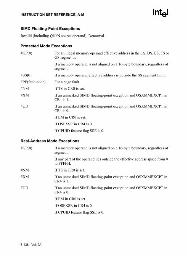
INSTRUCTION SET REFERENCE, A-M
SIMD Floating-Point Exceptions
Invalid (including QNaN source operand), Denormal.
Protected Mode Exceptions
#GP(0) For an illegal memory operand effective address in the CS, DS, ES, FS or GS segments.
If a memory operand is not aligned on a 16-byte boundary, regardless of segment.
#SS(0) If a memory operand effective address is outside the SS segment limit.
#PF(fault-code) For a page fault.
#NM If TS in CR0 is set.
#XM If an unmasked SIMD floating-point exception and OSXMMEXCPT in CR4 is 1.
#UD If an unmasked SIMD floating-point exception and OSXMMEXCPT in CR4 is 0.
If EM in CR0 is set.
If OSFXSR in CR4 is 0.
If CPUID feature flag SSE is 0.
Real-Address Mode Exceptions
#GP(0) If a memory operand is not aligned on a 16-byte boundary, regardless of segment.
If any part of the operand lies outside the effective address space from 0 to FFFFH.
#NM If TS in CR0 is set.
#XM If an unmasked SIMD floating-point exception and OSXMMEXCPT in CR4 is 1.
#UD If an unmasked SIMD floating-point exception and OSXMMEXCPT in CR4 is 0.
If EM in CR0 is set.
If OSFXSR in CR4 is 0.
If CPUID feature flag SSE is 0.
3-438 Vol. 2A

INSTRUCTION SET REFERENCE, A-M
Virtual-8086 Mode Exceptions
Same exceptions as in Real Address Mode
#PF(fault-code) For a page fault.
Vol. 2A 3-439

INSTRUCTION SET REFERENCE, A-M
MAXSD—Return Maximum Scalar Double-Precision Floating-Point Value
DescriptionCompares the low double-precision floating-point values in the destination operand (firstoperand) and the source operand (second operand), and returns the maximum value to the lowquadword of the destination operand. The source operand can be an XMM register or a 64-bitmemory location. The destination operand is an XMM register. When the source operand is amemory operand, only 64 bits are accessed. The high quadword of the destination operandremains unchanged.
If the values being compared are both 0.0s (of either sign), the value in the second operand(source operand) is returned. If a value in the second operand is an SNaN, that SNaN is returnedunchanged to the destination (that is, a QNaN version of the SNaN is not returned).
If only one value is a NaN (SNaN or QNaN) for this instruction, the second operand (sourceoperand), either a NaN or a valid floating-point value, is written to the result. If instead of thisbehavior, it is required that the NaN source operand (from either the first or second operand) bereturned, the action of MAXSD can be emulated using a sequence of instructions, such as, acomparison followed by AND, ANDN and OR.
OperationDEST[63-0] ← IF ((DEST[63-0] = 0.0) AND (SRC[63-0] = 0.0)) THEN SRC[63-0]
IF (DEST[63-0] = SNaN) THEN SRC[63-0]; ELSE IF SRC[63-0] = SNaN) THEN SRC[63-0];
ELSE IF (DEST[63-0] > SRC[63-0]) THEN DEST[63-0] ELSE SRC[63-0];
FI;* DEST[127-64] is unchanged *;
Intel C/C++ Compiler Intrinsic Equivalent__m128d _mm_max_sd(__m128d a, __m128d b)
SIMD Floating-Point Exceptions
Invalid (including QNaN source operand), Denormal.
Opcode Instruction DescriptionF2 0F 5F /r MAXSD xmm1, xmm2/m64 Return the maximum scalar double-precision floating-
point value between xmm2/mem64 and xmm1.
3-440 Vol. 2A

INSTRUCTION SET REFERENCE, A-M
Protected Mode Exceptions
#GP(0) For an illegal memory operand effective address in the CS, DS, ES, FS or GS segments.
#SS(0) If a memory operand effective address is outside the SS segment limit.
#PF(fault-code) For a page fault.
#NM If TS in CR0 is set.
#XM If an unmasked SIMD floating-point exception and OSXMMEXCPT in CR4 is 1.
#UD If an unmasked SIMD floating-point exception and OSXMMEXCPT in CR4 is 0.
If EM in CR0 is set.
If OSFXSR in CR4 is 0.
If CPUID feature flag SSE2 is 0.
#AC(0) If alignment checking is enabled and an unaligned memory reference is made while the current privilege level is 3.
Real-Address Mode Exceptions
GP(0) If any part of the operand lies outside the effective address space from 0 to FFFFH.
#NM If TS in CR0 is set.
#XM If an unmasked SIMD floating-point exception and OSXMMEXCPT in CR4 is 1.
#UD If an unmasked SIMD floating-point exception and OSXMMEXCPT in CR4 is 0.
If EM in CR0 is set.
If OSFXSR in CR4 is 0.
If CPUID feature flag SSE2 is 0.
Virtual-8086 Mode Exceptions
Same exceptions as in Real Address Mode
#PF(fault-code) For a page fault.
#AC(0) If alignment checking is enabled and an unaligned memory reference is made.
Vol. 2A 3-441

INSTRUCTION SET REFERENCE, A-M
MAXSS—Return Maximum Scalar Single-Precision Floating-Point Value
DescriptionCompares the low single-precision floating-point values in the destination operand (firstoperand) and the source operand (second operand), and returns the maximum value to the lowdoubleword of the destination operand. The source operand can be an XMM register or a 32-bitmemory location. The destination operand is an XMM register. When the source operand is amemory operand, only 32 bits are accessed. The three high-order doublewords of the destinationoperand remain unchanged.
If the values being compared are both 0.0s (of either sign), the value in the second operand(source operand) is returned. If a value in the second operand is an SNaN, that SNaN is returnedunchanged to the destination (that is, a QNaN version of the SNaN is not returned).
If only one value is a NaN (SNaN or QNaN) for this instruction, the second operand (sourceoperand), either a NaN or a valid floating-point value, is written to the result. If instead of thisbehavior, it is required that the NaN source operand (from either the first or second operand) bereturned, the action of MAXSS can be emulated using a sequence of instructions, such as, acomparison followed by AND, ANDN and OR.
OperationDEST[63-0] ← IF ((DEST[31-0] = 0.0) AND (SRC[31-0] = 0.0)) THEN SRC[31-0]
ELSE IF (DEST[31-0] = SNaN) THEN SRC[31-0]; ELSE IF SRC[31-0] = SNaN) THEN SRC[31-0];
ELSE IF (DEST[31-0] > SRC[31-0]) THEN DEST[31-0] ELSE SRC[31-0];
FI;* DEST[127-32] is unchanged *;
Intel C/C++ Compiler Intrinsic Equivalent__m128d _mm_max_ss(__m128d a, __m128d b)
SIMD Floating-Point Exceptions
Invalid (including QNaN source operand), Denormal.
Opcode Instruction DescriptionF3 0F 5F /r MAXSS xmm1, xmm2/m32 Return the maximum scalar single-precision floating-
point value between xmm2/mem32 and xmm1.
3-442 Vol. 2A

INSTRUCTION SET REFERENCE, A-M
Protected Mode Exceptions
#GP(0) For an illegal memory operand effective address in the CS, DS, ES, FS or GS segments.
#SS(0) If a memory operand effective address is outside the SS segment limit.
#PF(fault-code) For a page fault.
#NM If TS in CR0 is set.
#XM If an unmasked SIMD floating-point exception and OSXMMEXCPT in CR4 is 1.
#UD If an unmasked SIMD floating-point exception and OSXMMEXCPT in CR4 is 0.
If EM in CR0 is set.
If OSFXSR in CR4 is 0.
If CPUID feature flag SSE is 0.
#AC(0) If alignment checking is enabled and an unaligned memory reference is made while the current privilege level is 3.
Real-Address Mode Exceptions
GP(0) If any part of the operand lies outside the effective address space from 0 to FFFFH.
#NM If TS in CR0 is set.
#XM If an unmasked SIMD floating-point exception and OSXMMEXCPT in CR4 is 1.
#UD If an unmasked SIMD floating-point exception and OSXMMEXCPT in CR4 is 0.
If EM in CR0 is set.
If OSFXSR in CR4 is 0.
If CPUID feature flag SSE is 0.
Virtual-8086 Mode Exceptions
Same exceptions as in Real Address Mode
#PF(fault-code) For a page fault.
#AC(0) If alignment checking is enabled and an unaligned memory reference is made.
Vol. 2A 3-443

INSTRUCTION SET REFERENCE, A-M
MFENCE—Memory Fence
DescriptionPerforms a serializing operation on all load-from-memory and store-to-memory instructions thatwere issued prior the MFENCE instruction. This serializing operation guarantees that every loadand store instruction that precedes in program order the MFENCE instruction is globally visiblebefore any load or store instruction that follows the MFENCE instruction is globally visible. TheMFENCE instruction is ordered with respect to all load and store instructions, other MFENCEinstructions, any SFENCE and LFENCE instructions, and any serializing instructions (such asthe CPUID instruction).
Weakly ordered memory types can be used to achieve higher processor performance throughsuch techniques as out-of-order issue, speculative reads, write-combining, and write-collapsing.The degree to which a consumer of data recognizes or knows that the data is weakly orderedvaries among applications and may be unknown to the producer of this data. The MFENCEinstruction provides a performance-efficient way of ensuring load and store ordering betweenroutines that produce weakly-ordered results and routines that consume that data.
It should be noted that processors are free to speculatively fetch and cache data from systemmemory regions that are assigned a memory-type that permits speculative reads (that is, the WB,WC, and WT memory types). The PREFETCHh instruction is considered a hint to this specula-tive behavior. Because this speculative fetching can occur at any time and is not tied to instruc-tion execution, the MFENCE instruction is not ordered with respect to PREFETCHhinstructions or any other speculative fetching mechanism (that is, data could be speculativelyloaded into the cache just before, during, or after the execution of an MFENCE instruction).
OperationWait_On_Following_Loads_And_Stores_Until(preceding_loads_and_stores_globally_visible);
Intel C/C++ Compiler Intrinsic Equivalentvoid_mm_mfence(void)
Exceptions (All Modes of Operation)None.
Opcode Instruction Description0F AE /6 MFENCE Serializes load and store operations.
3-444 Vol. 2A

INSTRUCTION SET REFERENCE, A-M
MINPD—Return Minimum Packed Double-Precision Floating-Point Values
DescriptionPerforms an SIMD compare of the packed double-precision floating-point values in the destina-tion operand (first operand) and the source operand (second operand), and returns the minimumvalue for each pair of values to the destination operand. The source operand can be an XMMregister or a 128-bit memory location. The destination operand is an XMM register.
If the values being compared are both 0.0s (of either sign), the value in the second operand(source operand) is returned. If a value in the second operand is an SNaN, that SNaN is returnedunchanged to the destination (that is, a QNaN version of the SNaN is not returned).
If only one value is a NaN (SNaN or QNaN) for this instruction, the second operand (sourceoperand), either a NaN or a valid floating-point value, is written to the result. If instead of thisbehavior, it is required that the NaN source operand (from either the first or second operand) bereturned, the action of MINPD can be emulated using a sequence of instructions, such as, acomparison followed by AND, ANDN and OR.
OperationDEST[63-0] ← IF ((DEST[63-0] = 0.0) AND (SRC[63-0] = 0.0)) THEN SRC[63-0]
ELSE IF (DEST[63-0] = SNaN) THEN SRC[63-0]; ELSE IF SRC[63-0] = SNaN) THEN SRC[63-0];
ELSE IF (DEST[63-0] < SRC[63-0]) THEN DEST[63-0] ELSE SRC[63-0];
FI;DEST[127-64] ← IF ((DEST[127-64] = 0.0) AND (SRC[127-64] = 0.0))
THEN SRC[127-64]ELSE IF (DEST[127-64] = SNaN) THEN SRC[127-64];
ELSE IF SRC[127-64] = SNaN) THEN SRC[127-64]; ELSE IF (DEST[127-64] < SRC[63-0])
THEN DEST[127-64] ELSE SRC[127-64];
FI;
Intel C/C++ Compiler Intrinsic Equivalent__m128d _mm_min_pd(__m128d a, __m128d b)
Opcode Instruction Description66 0F 5D /r MINPD xmm1, xmm2/m128 Return the minimum double-precision floating-point
values between xmm2/m128 and xmm1.
Vol. 2A 3-445

INSTRUCTION SET REFERENCE, A-M
SIMD Floating-Point Exceptions
Invalid (including QNaN source operand), Denormal.
Protected Mode Exceptions
#GP(0) For an illegal memory operand effective address in the CS, DS, ES, FS or GS segments.
If a memory operand is not aligned on a 16-byte boundary, regardless of segment.
#SS(0) If a memory operand effective address is outside the SS segment limit.
#PF(fault-code) For a page fault.
#NM If TS in CR0 is set.
#XM If an unmasked SIMD floating-point exception and OSXMMEXCPT in CR4 is 1.
#UD If an unmasked SIMD floating-point exception and OSXMMEXCPT in CR4 is 0.
If EM in CR0 is set.
If OSFXSR in CR4 is 0.
If CPUID feature flag SSE2 is 0.
Real-Address Mode Exceptions
#GP(0) If a memory operand is not aligned on a 16-byte boundary, regardless of segment.
If any part of the operand lies outside the effective address space from 0 to FFFFH.
#NM If TS in CR0 is set.
#XM If an unmasked SIMD floating-point exception and OSXMMEXCPT in CR4 is 1.
#UD If an unmasked SIMD floating-point exception and OSXMMEXCPT in CR4 is 0.
If EM in CR0 is set.
If OSFXSR in CR4 is 0.
If CPUID feature flag SSE2 is 0.
3-446 Vol. 2A

INSTRUCTION SET REFERENCE, A-M
Virtual-8086 Mode Exceptions
Same exceptions as in Real Address Mode
#PF(fault-code) For a page fault.
Vol. 2A 3-447

INSTRUCTION SET REFERENCE, A-M
MINPS—Return Minimum Packed Single-Precision Floating-Point Values
DescriptionPerforms an SIMD compare of the packed single-precision floating-point values in the destina-tion operand (first operand) and the source operand (second operand), and returns the minimumvalue for each pair of values to the destination operand. The source operand can be an XMMregister or a 128-bit memory location. The destination operand is an XMM register.
If the values being compared are both 0.0s (of either sign), the value in the second operand(source operand) is returned. If a value in the second operand is an SNaN, that SNaN is returnedunchanged to the destination (that is, a QNaN version of the SNaN is not returned).
If only one value is a NaN (SNaN or QNaN) for this instruction, the second operand (sourceoperand), either a NaN or a valid floating-point value, is written to the result. If instead of thisbehavior, it is required that the NaN source operand (from either the first or second operand) bereturned, the action of MINPS can be emulated using a sequence of instructions, such as, acomparison followed by AND, ANDN and OR.
OperationDEST[63-0] ← IF ((DEST[31-0] = 0.0) AND (SRC[31-0] = 0.0)) THEN SRC[31-0]
ELSE IF (DEST[31-0] = SNaN) THEN SRC[31-0]; ELSE IF SRC[31-0] = SNaN) THEN SRC[31-0];
ELSE IF (DEST[31-0] > SRC[31-0]) THEN DEST[31-0] ELSE SRC[31-0];
FI;* repeat operation for 2nd and 3rd doublewords *;DEST[127-64] ← IF ((DEST127-96] = 0.0) AND (SRC[127-96] = 0.0))
THEN SRC[127-96]ELSE IF (DEST[127-96] = SNaN) THEN SRC[127-96];
ELSE IF SRC[127-96] = SNaN) THEN SRC[127-96]; ELSE IF (DEST[127-96] < SRC[127-96])
THEN DEST[127-96] ELSE SRC[127-96];
FI;
Intel C/C++ Compiler Intrinsic Equivalent__m128d _mm_min_ps(__m128d a, __m128d b)
Opcode Instruction Description0F 5D /r MINPS xmm1, xmm2/m128 Return the minimum single-precision floating-point
values between xmm2/m128 and xmm1.
3-448 Vol. 2A

INSTRUCTION SET REFERENCE, A-M
SIMD Floating-Point Exceptions
Invalid (including QNaN source operand), Denormal.
Protected Mode Exceptions
#GP(0) For an illegal memory operand effective address in the CS, DS, ES, FS or GS segments.
If a memory operand is not aligned on a 16-byte boundary, regardless of segment.
#SS(0) If a memory operand effective address is outside the SS segment limit.
#PF(fault-code) For a page fault.
#NM If TS in CR0 is set.
#XM If an unmasked SIMD floating-point exception and OSXMMEXCPT in CR4 is 1.
#UD If an unmasked SIMD floating-point exception and OSXMMEXCPT in CR4 is 0.
If EM in CR0 is set.
If OSFXSR in CR4 is 0.
If CPUID feature flag SSE is 0.
Real-Address Mode Exceptions
#GP(0) If a memory operand is not aligned on a 16-byte boundary, regardless of segment.
If any part of the operand lies outside the effective address space from 0 to FFFFH.
#NM If TS in CR0 is set.
#XM If an unmasked SIMD floating-point exception and OSXMMEXCPT in CR4 is 1.
#UD If an unmasked SIMD floating-point exception and OSXMMEXCPT in CR4 is 0.
If EM in CR0 is set.
If OSFXSR in CR4 is 0.
If CPUID feature flag SSE is 0.
Vol. 2A 3-449

INSTRUCTION SET REFERENCE, A-M
Virtual-8086 Mode Exceptions
Same exceptions as in Real Address Mode
#PF(fault-code) For a page fault.
3-450 Vol. 2A

INSTRUCTION SET REFERENCE, A-M
MINSD—Return Minimum Scalar Double-Precision Floating-Point Value
DescriptionCompares the low double-precision floating-point values in the destination operand (firstoperand) and the source operand (second operand), and returns the minimum value to the lowquadword of the destination operand. The source operand can be an XMM register or a 64-bitmemory location. The destination operand is an XMM register. When the source operand is amemory operand, only the 64 bits are accessed. The high quadword of the destination operandremains unchanged.
If the values being compared are both 0.0s (of either sign), the value in the second operand(source operand) is returned. If a value in the second operand is an SNaN, that SNaN is returnedunchanged to the destination (that is, a QNaN version of the SNaN is not returned).
If only one value is a NaN (SNaN or QNaN) for this instruction, the second operand (sourceoperand), either a NaN or a valid floating-point value, is written to the result. If instead of thisbehavior, it is required that the NaN source operand (from either the first or second operand) bereturned, the action of MINSD can be emulated using a sequence of instructions, such as, acomparison followed by AND, ANDN and OR.
OperationDEST[63-0] ← IF ((DEST[63-0] = 0.0) AND (SRC[63-0] = 0.0)) THEN SRC[63-0]
ELSE IF (DEST[63-0] = SNaN) THEN SRC[63-0]; ELSE IF SRC[63-0] = SNaN) THEN SRC[63-0];
ELSE IF (DEST[63-0] < SRC[63-0]) THEN DEST[63-0] ELSE SRC[63-0];
FI;* DEST[127-64] is unchanged *;
Intel C/C++ Compiler Intrinsic Equivalent__m128d _mm_min_sd(__m128d a, __m128d b)
SIMD Floating-Point Exceptions
Invalid (including QNaN source operand), Denormal.
Opcode Instruction DescriptionF2 0F 5D /r MINSD xmm1, xmm2/m64 Return the minimum scalar double-precision floating-point
value between xmm2/mem64 and xmm1.
Vol. 2A 3-451

INSTRUCTION SET REFERENCE, A-M
Protected Mode Exceptions
#GP(0) For an illegal memory operand effective address in the CS, DS, ES, FS or GS segments.
#SS(0) If a memory operand effective address is outside the SS segment limit.
#PF(fault-code) For a page fault.
#NM If TS in CR0 is set.
#XM If an unmasked SIMD floating-point exception and OSXMMEXCPT in CR4 is 1.
#UD If an unmasked SIMD floating-point exception and OSXMMEXCPT in CR4 is 0.
If EM in CR0 is set.
If OSFXSR in CR4 is 0.
If CPUID feature flag SSE2 is 0.
#AC(0) If alignment checking is enabled and an unaligned memory reference is made while the current privilege level is 3.
Real-Address Mode Exceptions
GP(0) If any part of the operand lies outside the effective address space from 0 to FFFFH.
#NM If TS in CR0 is set.
#XM If an unmasked SIMD floating-point exception and OSXMMEXCPT in CR4 is 1.
#UD If an unmasked SIMD floating-point exception and OSXMMEXCPT in CR4 is 0.
If EM in CR0 is set.
If OSFXSR in CR4 is 0.
If CPUID feature flag SSE2 is 0.
Virtual-8086 Mode Exceptions
Same exceptions as in Real Address Mode
#PF(fault-code) For a page fault.
#AC(0) If alignment checking is enabled and an unaligned memory reference is made.
3-452 Vol. 2A

INSTRUCTION SET REFERENCE, A-M
MINSS—Return Minimum Scalar Single-Precision Floating-Point Value
DescriptionCompares the low single-precision floating-point values in the destination operand (firstoperand) and the source operand (second operand), and returns the minimum value to the lowdoubleword of the destination operand. The source operand can be an XMM register or a 32-bitmemory location. The destination operand is an XMM register. When the source operand is amemory operand, only 32 bits are accessed. The three high-order doublewords of the destinationoperand remain unchanged.
If the values being compared are both 0.0s (of either sign), the value in the second operand(source operand) is returned. If a value in the second operand is an SNaN, that SNaN is returnedunchanged to the destination (that is, a QNaN version of the SNaN is not returned).
If only one value is a NaN (SNaN or QNaN) for this instruction, the second operand (sourceoperand), either a NaN or a valid floating-point value, is written to the result. If instead of thisbehavior, it is required that the NaN source operand (from either the first or second operand) bereturned, the action of MINSD can be emulated using a sequence of instructions, such as, acomparison followed by AND, ANDN and OR.
OperationDEST[63-0] ← IF ((DEST[31-0] = 0.0) AND (SRC[31-0] = 0.0)) THEN SRC[31-0]
ELSE IF (DEST[31-0] = SNaN) THEN SRC[31-0]; ELSE IF SRC[31-0] = SNaN) THEN SRC[31-0];
ELSE IF (DEST[31-0] < SRC[31-0]) THEN DEST[31-0] ELSE SRC[31-0];
FI;* DEST[127-32] is unchanged *;
Intel C/C++ Compiler Intrinsic Equivalent__m128d _mm_min_ss(__m128d a, __m128d b)
SIMD Floating-Point Exceptions
Invalid (including QNaN source operand), Denormal.
Opcode Instruction DescriptionF3 0F 5D /r MINSS xmm1, xmm2/m32 Return the minimum scalar single-precision floating-
point value between xmm2/mem32 and xmm1.
Vol. 2A 3-453

INSTRUCTION SET REFERENCE, A-M
Protected Mode Exceptions
#GP(0) For an illegal memory operand effective address in the CS, DS, ES, FS or GS segments.
#SS(0) If a memory operand effective address is outside the SS segment limit.
#PF(fault-code) For a page fault.
#NM If TS in CR0 is set.
#XM If an unmasked SIMD floating-point exception and OSXMMEXCPT in CR4 is 1.
#UD If an unmasked SIMD floating-point exception and OSXMMEXCPT in CR4 is 0.
If EM in CR0 is set.
If OSFXSR in CR4 is 0.
If CPUID feature flag SSE is 0.
#AC(0) If alignment checking is enabled and an unaligned memory reference is made while the current privilege level is 3.
Real-Address Mode Exceptions
GP(0) If any part of the operand lies outside the effective address space from 0 to FFFFH.
#NM If TS in CR0 is set.
#XM If an unmasked SIMD floating-point exception and OSXMMEXCPT in CR4 is 1.
#UD If an unmasked SIMD floating-point exception and OSXMMEXCPT in CR4 is 0.
If EM in CR0 is set.
If OSFXSR in CR4 is 0.
If CPUID feature flag SSE is 0.
Virtual-8086 Mode Exceptions
Same exceptions as in Real Address Mode
#PF(fault-code) For a page fault.
#AC(0) If alignment checking is enabled and an unaligned memory reference is made.
3-454 Vol. 2A

INSTRUCTION SET REFERENCE, A-M
MONITOR: Setup Monitor Address
DescriptionThe MONITOR instruction arms the address monitoring hardware using the address specifiedin EAX. The address range that the monitoring hardware will check for store operations can bedetermined by the CPUID instruction. The monitoring hardware will detect stores to an addresswithin the address range and triggers the monitor hardware when the write is detected. The stateof the monitor hardware is used by the MWAIT instruction.
The content of EAX is an effective address. By default, the DS segment is used to create a linearaddress that is then monitored. Segment overrides can be used with the MONITOR instruction.
ECX and EDX are used to communicate other information to the MONITOR instruction. ECXspecifies optional extensions for the MONITOR instruction. EDX specifies optional hints forthe MONITOR instruction and does not change the architectural behavior of the instruction. Forthe Pentium 4 processor with CPUID signature of family = 15 and model = 3, no extensions orhints are defined. Specifying undefined hints in EDX are ignored by the processor, whereasspecifying undefined extensions in ECX will raise a general protection fault exception on theexecution of the MONITOR instruction.
The address range must be in memory of write-back type. Only write-back memory type storesto the monitored address range will trigger the monitoring hardware. If the address range is notin memory of write-back type, the address monitor hardware may not be armed properly. TheMONITOR instruction is ordered as a load operation with respect to other memory transactions.Additional information for determining the address range to prevent false wake-ups is describedin Chapter 7 of the IA-32 Intel Architecture Software Developer’s Manual, Volume 3.
The MONITOR instruction can be used at all privilege levels and is subject to all permissionchecking and faults associated with a byte load. Like a load, the MONITOR instruction sets theA-bit but not the D-bit in the page tables. The MONITOR CPUID feature flag (bit 3 of ECXwhen CPUID is executed with EAX=1) indicates the availability of MONITOR and MWAITinstructions in the processor. When set, the unconditional execution of MONITOR is supportedat privilege levels 0 and conditional execution at privilege levels 1 through 3 (software shouldtest for the appropriate support of these instructions before unconditional use). The operatingsystem or system BIOS may disable this instruction through the IA32_MISC_ENABLES MSR;disabling the instruction clears the CPUID feature flag and causes execution of the MONITORinstruction to generate an illegal opcode exception.
Opcode Instruction Description0F,01,C8 MONITOR Sets up a linear address range to be monitored by
hardware and activates the monitor. The address range should be of a write-back memory caching type.
Vol. 2A 3-455

INSTRUCTION SET REFERENCE, A-M
OperationMONITOR sets up an address range for the monitor hardware using the content of EAX as aneffective address and puts the monitor hardware in armed state. The memory address rangeshould be within memory of the write-back caching type. A store to the specified address rangewill trigger the monitor hardware. The content of ECX and EDX are used to communicate otherinformation to the monitor hardware.
Intel C/C++ Compiler Intrinsic EquivalentMONITOR void _mm_monitor(void const *p, unsigned extensions,unsigned hints)
ExceptionsNone
Protected Mode Exceptions#GP(0) For an illegal memory operand effective address in the CS, DS, ES, FS or
GS segments.
#GP(0) For ECX has a value other than 0.
#SS(0) For an illegal address in the SS segment.
#PF(fault-code) For a page fault (TBD).
#UD If CPUID feature flag MONITOR is 0.
If executed at privilege level 1 through 3 when the instruction is not avail-able.
If LOCK, REP, REPNE/NZ and Operand Size override prefixes are used.
Real Address Mode Exceptions#GP If any part of the operand lies outside of the effective address space from
0 to FFFFH.
#GP(0) For ECX has a value other than 0.
#UD If CPUID feature flag MONITOR is 0.
If LOCK, REP, REPNE/NZ and Operand Size override prefixes are used.
Virtual 8086 Mode Exceptions#GP If any part of the operand lies outside of the effective address space from
0 to FFFFH.
#GP(0) For ECX has a value other than 0.
3-456 Vol. 2A

INSTRUCTION SET REFERENCE, A-M
#UD If CPUID feature flag MONITOR is 0.
If executed at privilege level 1 through 3 when the instruction is not avail-able.
If LOCK, REP, REPNE/NZ and Operand Size override prefixes are used.
#PF(fault-code) For a page fault.
Vol. 2A 3-457
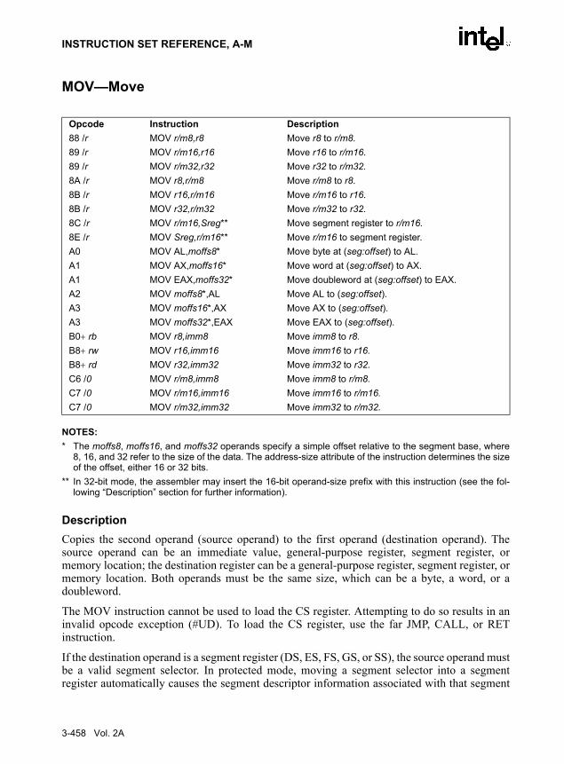
INSTRUCTION SET REFERENCE, A-M
MOV—Move
NOTES: * The moffs8, moffs16, and moffs32 operands specify a simple offset relative to the segment base, where
8, 16, and 32 refer to the size of the data. The address-size attribute of the instruction determines the sizeof the offset, either 16 or 32 bits.
** In 32-bit mode, the assembler may insert the 16-bit operand-size prefix with this instruction (see the fol-lowing “Description” section for further information).
DescriptionCopies the second operand (source operand) to the first operand (destination operand). Thesource operand can be an immediate value, general-purpose register, segment register, ormemory location; the destination register can be a general-purpose register, segment register, ormemory location. Both operands must be the same size, which can be a byte, a word, or adoubleword.
The MOV instruction cannot be used to load the CS register. Attempting to do so results in aninvalid opcode exception (#UD). To load the CS register, use the far JMP, CALL, or RETinstruction.
If the destination operand is a segment register (DS, ES, FS, GS, or SS), the source operand mustbe a valid segment selector. In protected mode, moving a segment selector into a segmentregister automatically causes the segment descriptor information associated with that segment
Opcode Instruction Description88 /r MOV r/m8,r8 Move r8 to r/m8.89 /r MOV r/m16,r16 Move r16 to r/m16.89 /r MOV r/m32,r32 Move r32 to r/m32.8A /r MOV r8,r/m8 Move r/m8 to r8.8B /r MOV r16,r/m16 Move r/m16 to r16.8B /r MOV r32,r/m32 Move r/m32 to r32.8C /r MOV r/m16,Sreg** Move segment register to r/m16.8E /r MOV Sreg,r/m16** Move r/m16 to segment register.A0 MOV AL,moffs8* Move byte at (seg:offset) to AL.A1 MOV AX,moffs16* Move word at (seg:offset) to AX.A1 MOV EAX,moffs32* Move doubleword at (seg:offset) to EAX.A2 MOV moffs8*,AL Move AL to (seg:offset).A3 MOV moffs16*,AX Move AX to (seg:offset).A3 MOV moffs32*,EAX Move EAX to (seg:offset).B0+ rb MOV r8,imm8 Move imm8 to r8.B8+ rw MOV r16,imm16 Move imm16 to r16.B8+ rd MOV r32,imm32 Move imm32 to r32.C6 /0 MOV r/m8,imm8 Move imm8 to r/m8.C7 /0 MOV r/m16,imm16 Move imm16 to r/m16.C7 /0 MOV r/m32,imm32 Move imm32 to r/m32.
3-458 Vol. 2A

INSTRUCTION SET REFERENCE, A-M
selector to be loaded into the hidden (shadow) part of the segment register. While loading thisinformation, the segment selector and segment descriptor information is validated (see the“Operation” algorithm below). The segment descriptor data is obtained from the GDT or LDTentry for the specified segment selector.
A null segment selector (values 0000-0003) can be loaded into the DS, ES, FS, and GS registerswithout causing a protection exception. However, any subsequent attempt to reference asegment whose corresponding segment register is loaded with a null value causes a generalprotection exception (#GP) and no memory reference occurs.
Loading the SS register with a MOV instruction inhibits all interrupts until after the executionof the next instruction. This operation allows a stack pointer to be loaded into the ESP registerwith the next instruction (MOV ESP, stack-pointer value) before an interrupt occurs1. Be awarethat the LSS instruction offers a more efficient method of loading the SS and ESP registers.
When operating in 32-bit mode and moving data between a segment register and a general-purpose register, the 32-bit IA-32 processors do not require the use of the 16-bit operand-sizeprefix (a byte with the value 66H) with this instruction, but most assemblers will insert it if thestandard form of the instruction is used (for example, MOV DS, AX). The processor willexecute this instruction correctly, but it will usually require an extra clock. With most assem-blers, using the instruction form MOV DS, EAX will avoid this unneeded 66H prefix. When theprocessor executes the instruction with a 32-bit general-purpose register, it assumes that the 16least-significant bits of the general-purpose register are the destination or source operand. If theregister is a destination operand, the resulting value in the two high-order bytes of the registeris implementation dependent. For the Pentium 4, Intel Xeon, and P6 family processors, the twohigh-order bytes are filled with zeros; for earlier 32-bit IA-32 processors, the two high orderbytes are undefined.
OperationDEST ← SRC;
Loading a segment register while in protected mode results in special checks and actions, asdescribed in the following listing. These checks are performed on the segment selector and thesegment descriptor it points to.IF SS is loaded;
1. If a code instruction breakpoint (for debug) is placed on an instruction located immediately after a MOV SS instruction, the breakpoint may not be triggered.
Note that in a sequence of instructions that individually delay interrupts past the following instruction, onlythe first instruction in the sequence is guaranteed to delay the interrupt, but subsequent interrupt-delayinginstructions may not delay the interrupt. Thus, in the following instruction sequence:
STIMOV SS, EAXMOV ESP, EBP
interrupts may be recognized before MOV ESP, EBP executes, because STI also delays interrupts forone instruction.
Vol. 2A 3-459

INSTRUCTION SET REFERENCE, A-M
THENIF segment selector is null
THEN #GP(0);FI;IF segment selector index is outside descriptor table limits
OR segment selector's RPL ≠ CPL OR segment is not a writable data segmentOR DPL ≠ CPL
THEN #GP(selector);FI;IF segment not marked present
THEN #SS(selector);ELSE
SS ← segment selector;SS ← segment descriptor;
FI;FI;IF DS, ES, FS, or GS is loaded with non-null selector;THEN
IF segment selector index is outside descriptor table limitsOR segment is not a data or readable code segmentOR ((segment is a data or nonconforming code segment)
AND (both RPL and CPL > DPL))THEN #GP(selector);
IF segment not marked presentTHEN #NP(selector);
ELSESegmentRegister ← segment selector;SegmentRegister ← segment descriptor;
FI;FI;IF DS, ES, FS, or GS is loaded with a null selector;
THENSegmentRegister ← segment selector;SegmentRegister ← segment descriptor;
FI;
Flags AffectedNone.
Protected Mode Exceptions#GP(0) If attempt is made to load SS register with null segment selector.
If the destination operand is in a non-writable segment.
If a memory operand effective address is outside the CS, DS, ES, FS, or GS segment limit.
3-460 Vol. 2A

INSTRUCTION SET REFERENCE, A-M
If the DS, ES, FS, or GS register contains a null segment selector.
#GP(selector) If segment selector index is outside descriptor table limits.
If the SS register is being loaded and the segment selector's RPL and the segment descriptor’s DPL are not equal to the CPL.
If the SS register is being loaded and the segment pointed to is a non-writable data segment.
If the DS, ES, FS, or GS register is being loaded and the segment pointed to is not a data or readable code segment.
If the DS, ES, FS, or GS register is being loaded and the segment pointed to is a data or nonconforming code segment, but both the RPL and the CPL are greater than the DPL.
#SS(0) If a memory operand effective address is outside the SS segment limit.
#SS(selector) If the SS register is being loaded and the segment pointed to is marked not present.
#NP If the DS, ES, FS, or GS register is being loaded and the segment pointed to is marked not present.
#PF(fault-code) If a page fault occurs.
#AC(0) If alignment checking is enabled and an unaligned memory reference is made while the current privilege level is 3.
#UD If attempt is made to load the CS register.
Real-Address Mode Exceptions#GP If a memory operand effective address is outside the CS, DS, ES, FS, or
GS segment limit.
#SS If a memory operand effective address is outside the SS segment limit.
#UD If attempt is made to load the CS register.
Virtual-8086 Mode Exceptions#GP(0) If a memory operand effective address is outside the CS, DS, ES, FS, or
GS segment limit.
#SS(0) If a memory operand effective address is outside the SS segment limit.
#PF(fault-code) If a page fault occurs.
#AC(0) If alignment checking is enabled and an unaligned memory reference is made.
#UD If attempt is made to load the CS register.
Vol. 2A 3-461

INSTRUCTION SET REFERENCE, A-M
MOV—Move to/from Control Registers
DescriptionMoves the contents of a control register (CR0, CR2, CR3, or CR4) to a general-purpose registeror vice versa. The operand size for these instructions is always 32 bits, regardless of the operand-size attribute. (See “Control Registers” in Chapter 2 of the IA-32 Intel Architecture SoftwareDeveloper’s Manual, Volume 3, for a detailed description of the flags and fields in the controlregisters.) This instruction can be executed only when the current privilege level is 0.
When loading control registers, programs should not attempt to change the reserved bits; that is,always set reserved bits to the value previously read. An attempt to change CR4's reserved bitswill cause a general protection fault. Reserved bits in CR0 and CR3 remain clear after any loadof those registers; attempts to set them have no impact. On Pentium 4, Intel Xeon and P6 familyprocessors, CR0.ET remains set after any load of CR0; attempts to clear this bit have no impact.
At the opcode level, the reg field within the ModR/M byte specifies which of the control regis-ters is loaded or read. The 2 bits in the mod field are always 11B. The r/m field specifies thegeneral-purpose register loaded or read.
These instructions have the following side effect:
• When writing to control register CR3, all non-global TLB entries are flushed (see “Trans-lation Lookaside Buffers (TLBs)” in Chapter 3 of the IA-32 Intel Architecture SoftwareDeveloper’s Manual, Volume 3).
The following side effects are implementation specific for the Pentium 4, Intel Xeon, and P6family processors. Software should not depend on this functionality in all IA-32 processors:
• When modifying any of the paging flags in the control registers (PE and PG in registerCR0 and PGE, PSE, and PAE in register CR4), all TLB entries are flushed, includingglobal entries.
• If the PG flag is set to 1 and control register CR4 is written to set the PAE flag to 1 (toenable the physical address extension mode), the pointers in the page-directory pointerstable (PDPT) are loaded into the processor (into internal, non-architectural registers).
• If the PAE flag is set to 1 and the PG flag set to 1, writing to control register CR3 willcause the PDPTRs to be reloaded into the processor. If the PAE flag is set to 1 and controlregister CR0 is written to set the PG flag, the PDPTRs are reloaded into the processor.
Opcode Instruction Description0F 22 /r MOV CR0,r32 Move r32 to CR0.0F 22 /r MOV CR2,r32 Move r32 to CR2.0F 22 /r MOV CR3,r32 Move r32 to CR3.0F 22 /r MOV CR4,r32 Move r32 to CR4.0F 20 /r MOV r32,CR0 Move CR0 to r32.0F 20 /r MOV r32,CR2 Move CR2 to r32.0F 20 /r MOV r32,CR3 Move CR3 to r32.0F 20 /r MOV r32,CR4 Move CR4 to r32.
3-462 Vol. 2A

INSTRUCTION SET REFERENCE, A-M
OperationDEST ← SRC;
Flags AffectedThe OF, SF, ZF, AF, PF, and CF flags are undefined.
Protected Mode Exceptions#GP(0) If the current privilege level is not 0.
If an attempt is made to write invalid bit combinations in CR0 (such as setting the PG flag to 1 when the PE flag is set to 0, or setting the CD flag to 0 when the NW flag is set to 1).
If an attempt is made to write a 1 to any reserved bit in CR4.
If any of the reserved bits are set in the page-directory pointers table (PDPT) and the loading of a control register causes the PDPT to be loaded into the processor.
Real-Address Mode Exceptions#GP If an attempt is made to write a 1 to any reserved bit in CR4.
If an attempt is made to write invalid bit combinations in CR0 (such as setting the PG flag to 1 when the PE flag is set to 0).
Virtual-8086 Mode Exceptions#GP(0) These instructions cannot be executed in virtual-8086 mode.
Vol. 2A 3-463

INSTRUCTION SET REFERENCE, A-M
MOV—Move to/from Debug Registers
DescriptionMoves the contents of a debug register (DR0, DR1, DR2, DR3, DR4, DR5, DR6, or DR7) to ageneral-purpose register or vice versa. The operand size for these instructions is always 32 bits,regardless of the operand-size attribute. (See Chapter 15, Debugging and Performance Moni-toring, of the IA-32 Intel Architecture Software Developer’s Manual, Volume 3, for a detaileddescription of the flags and fields in the debug registers.)
The instructions must be executed at privilege level 0 or in real-address mode.
When the debug extension (DE) flag in register CR4 is clear, these instructions operate on debugregisters in a manner that is compatible with Intel386 and Intel486 processors. In this mode,references to DR4 and DR5 refer to DR6 and DR7, respectively. When the DE flag in CR4 isset, attempts to reference DR4 and DR5 result in an undefined opcode (#UD) exception. (TheCR4 register was added to the IA-32 Architecture beginning with the Pentium processor.)
At the opcode level, the reg field within the ModR/M byte specifies which of the debug registersis loaded or read. The two bits in the mod field are always 11. The r/m field specifies the general-purpose register loaded or read.
OperationIF ((DE = 1) and (SRC or DEST = DR4 or DR5))THEN
#UD;ELSE
DEST ← SRC;
Flags AffectedThe OF, SF, ZF, AF, PF, and CF flags are undefined.
Protected Mode Exceptions#GP(0) If the current privilege level is not 0.
#UD If the DE (debug extensions) bit of CR4 is set and a MOV instruction is executed involving DR4 or DR5.
#DB If any debug register is accessed while the GD flag in debug register DR7 is set.
Opcode Instruction Description0F 21/r MOV r32, DR0-DR7 Move debug register to r32.0F 23 /r MOV DR0-DR7,r32 Move r32 to debug register.
3-464 Vol. 2A
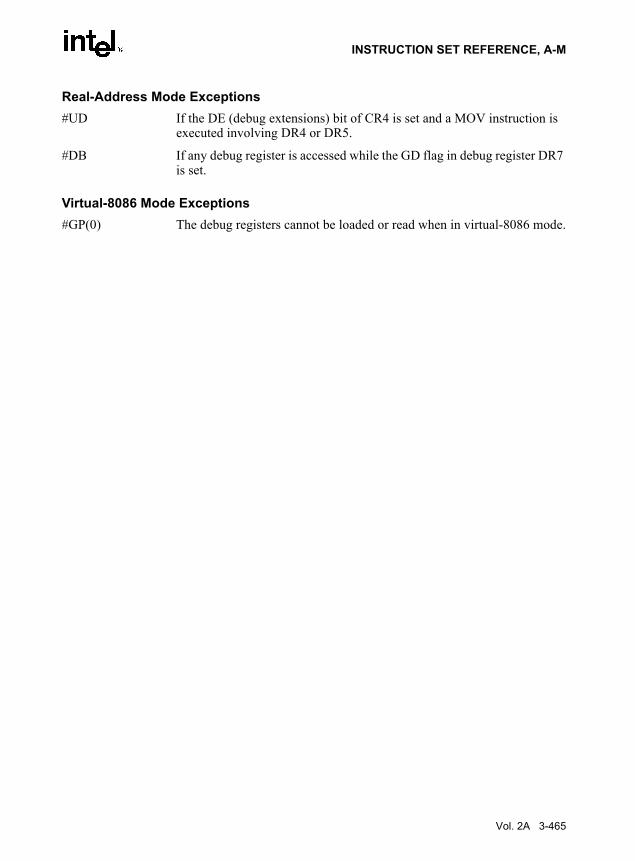
INSTRUCTION SET REFERENCE, A-M
Real-Address Mode Exceptions#UD If the DE (debug extensions) bit of CR4 is set and a MOV instruction is
executed involving DR4 or DR5.
#DB If any debug register is accessed while the GD flag in debug register DR7 is set.
Virtual-8086 Mode Exceptions#GP(0) The debug registers cannot be loaded or read when in virtual-8086 mode.
Vol. 2A 3-465

INSTRUCTION SET REFERENCE, A-M
MOVAPD—Move Aligned Packed Double-Precision Floating-Point Values
DescriptionMoves a double quadword containing two packed double-precision floating-point values fromthe source operand (second operand) to the destination operand (first operand). This instructioncan be used to load an XMM register from a 128-bit memory location, to store the contents ofan XMM register into a 128-bit memory location, or to move data between two XMM registers.When the source or destination operand is a memory operand, the operand must be aligned ona 16-byte boundary or a general-protection exception (#GP) will be generated.
To move double-precision floating-point values to and from unaligned memory locations, usethe MOVUPD instruction.
OperationDEST ← SRC;* #GP if SRC or DEST unaligned memory operand *;
Intel C/C++ Compiler Intrinsic Equivalent__m128 _mm_load_pd(double * p)
void_mm_store_pd(double *p, __m128 a)
SIMD Floating-Point ExceptionsNone.
Protected Mode Exceptions
#GP(0) For an illegal memory operand effective address in the CS, DS, ES, FS or GS segments.
If a memory operand is not aligned on a 16-byte boundary, regardless of segment.
#SS(0) For an illegal address in the SS segment.
#PF(fault-code) For a page fault.
#NM If TS in CR0 is set.
#UD If EM in CR0 is set.
Opcode Instruction Description66 0F 28 /r MOVAPD xmm1, xmm2/m128 Move packed double-precision floating-point values
from xmm2/m128 to xmm1.66 0F 29 /r MOVAPD xmm2/m128, xmm1 Move packed double-precision floating-point values
from xmm1 to xmm2/m128.
3-466 Vol. 2A

INSTRUCTION SET REFERENCE, A-M
If OSFXSR in CR4 is 0.
If CPUID feature flag SSE2 is 0.
Real-Address Mode Exceptions
#GP(0) If a memory operand is not aligned on a 16-byte boundary, regardless of segment.
If any part of the operand lies outside the effective address space from 0 to FFFFH.
#NM If TS in CR0 is set.
#UD If EM in CR0 is set.
If OSFXSR in CR4 is 0.
If CPUID feature flag SSE2 is 0.
Virtual-8086 Mode Exceptions
Same exceptions as in Real Address Mode
#PF(fault-code) For a page fault.
Vol. 2A 3-467

INSTRUCTION SET REFERENCE, A-M
MOVAPS—Move Aligned Packed Single-Precision Floating-Point Values
DescriptionMoves a double quadword containing four packed single-precision floating-point values fromthe source operand (second operand) to the destination operand (first operand). This instructioncan be used to load an XMM register from a 128-bit memory location, to store the contents ofan XMM register into a 128-bit memory location, or to move data between two XMM registers.When the source or destination operand is a memory operand, the operand must be aligned ona 16-byte boundary or a general-protection exception (#GP) is generated.
To move packed single-precision floating-point values to or from unaligned memory locations,use the MOVUPS instruction.
OperationDEST ← SRC;* #GP if SRC or DEST unaligned memory operand *;
Intel C/C++ Compiler Intrinsic Equivalent__m128 _mm_load_ps (float * p)
void_mm_store_ps (float *p, __m128 a)
SIMD Floating-Point ExceptionsNone.
Protected Mode Exceptions
#GP(0) For an illegal memory operand effective address in the CS, DS, ES, FS or GS segments.
If a memory operand is not aligned on a 16-byte boundary, regardless of segment.
#SS(0) For an illegal address in the SS segment.
#PF(fault-code) For a page fault.
#NM If TS in CR0 is set.
Opcode Instruction Description0F 28 /r MOVAPS xmm1, xmm2/m128 Move packed single-precision floating-point values from
xmm2/m128 to xmm1.0F 29 /r MOVAPS xmm2/m128, xmm1 Move packed single-precision floating-point values from
xmm1 to xmm2/m128.
3-468 Vol. 2A

INSTRUCTION SET REFERENCE, A-M
#UD If EM in CR0 is set.
If OSFXSR in CR4 is 0.
If CPUID feature flag SSE is 0.
Real-Address Mode Exceptions
#GP(0) If a memory operand is not aligned on a 16-byte boundary, regardless of segment.
If any part of the operand lies outside the effective address space from 0 to FFFFH.
#NM If TS in CR0 is set.
#UD If EM in CR0 is set.
If OSFXSR in CR4 is 0.
If CPUID feature flag SSE is 0.
Virtual-8086 Mode Exceptions
Same exceptions as in Real Address Mode
#PF(fault-code) For a page fault.
Vol. 2A 3-469

INSTRUCTION SET REFERENCE, A-M
MOVD—Move Doubleword
DescriptionCopies a doubleword from the source operand (second operand) to the destination operand (firstoperand). The source and destination operands can be general-purpose registers, MMX tech-nology registers, XMM registers, or 32-bit memory locations. This instruction can be used tomove a doubleword to and from the low doubleword of an MMX technology register and ageneral-purpose register or a 32-bit memory location, or to and from the low doubleword of anXMM register and a general-purpose register or a 32-bit memory location. The instructioncannot be used to transfer data between MMX technology registers, between XMM registers,between general-purpose registers, or between memory locations.
When the destination operand is an MMX technology register, the source operand is written tothe low doubleword of the register, and the register is zero-extended to 64 bits. When the desti-nation operand is an XMM register, the source operand is written to the low doubleword of theregister, and the register is zero-extended to 128 bits.
OperationMOVD instruction when destination operand is MMX technology register:
DEST[31-0] ← SRC;DEST[63-32] ← 00000000H;
MOVD instruction when destination operand is XMM register:DEST[31-0] ← SRC;DEST[127-32] ← 000000000000000000000000H;
MOVD instruction when source operand is MMX technology or XMM register:DEST ← SRC[31-0];
Intel C/C++ Compiler Intrinsic EquivalentMOVD __m64 _mm_cvtsi32_si64 (int i )
MOVD int _mm_cvtsi64_si32 ( __m64m )
MOVD __m128i _mm_cvtsi32_si128 (int a)
MOVD int _mm_cvtsi128_si32 ( __m128i a)
Flags AffectedNone.
Opcode Instruction Description0F 6E /r MOVD mm, r/m32 Move doubleword from r/m32 to mm.0F 7E /r MOVD r/m32, mm Move doubleword from mm to r/m32.66 0F 6E /r MOVD xmm, r/m32 Move doubleword from r/m32 to xmm.66 0F 7E /r MOVD r/m32, xmm Move doubleword from xmm register to r/m32.
3-470 Vol. 2A

INSTRUCTION SET REFERENCE, A-M
SIMD Floating-Point ExceptionsNone.
Protected Mode Exceptions#GP(0) If the destination operand is in a non-writable segment.
If a memory operand effective address is outside the CS, DS, ES, FS, or GS segment limit.
#SS(0) If a memory operand effective address is outside the SS segment limit.
#UD If EM in CR0 is set.
128-bit operations will generate #UD only if OSFXSR in CR4 is 0. Execu-tion of 128-bit instructions on a non-SSE2 capable processor (one that is MMX technology capable) will result in the instruction operating on the mm registers, not #UD.
#NM If TS in CR0 is set.
#MF (MMX technology register operations only.) If there is a pending FPU exception.
#PF(fault-code) If a page fault occurs.
#AC(0) If alignment checking is enabled and an unaligned memory reference is made while the current privilege level is 3.
Real-Address Mode Exceptions #GP If any part of the operand lies outside of the effective address space from
0 to FFFFH.
#UD If EM in CR0 is set.
128-bit operations will generate #UD only if OSFXSR in CR4 is 0. Execu-tion of 128-bit instructions on a non-SSE2 capable processor (one that is MMX technology capable) will result in the instruction operating on the mm registers, not #UD.
#NM If TS in CR0 is set.
#MF (MMX technology register operations only.) If there is a pending FPU exception.
Vol. 2A 3-471

INSTRUCTION SET REFERENCE, A-M
Virtual-8086 Mode ExceptionsSame exceptions as in Real Address Mode
#PF(fault-code) If a page fault occurs.
#AC(0) If alignment checking is enabled and an unaligned memory reference is made.
3-472 Vol. 2A

INSTRUCTION SET REFERENCE, A-M
MOVDDUP: Move One Double-FP and Duplicate
DescriptionThe linear address corresponds to the address of the least-significant byte of the referencedmemory data. When a memory address is indicated, the 8 bytes of data at memory location m64are loaded. When the register-register form of this operation is used, the lower half of the 128-bit source register is duplicated and copied into the 128-bit destination register. See Figure 3-14.
Operationif (source == m64) {
// load instruction xmm1[63-0] = m64;xmm1[127-64] = m64;
}else {
// move instructionxmm1[63-0] = xmm2[63-0];xmm1[127-64] = xmm2[63-0];
}
Opcode Instruction DescriptionF2,0F,12,/r MOVDDUP xmm1, xmm2/m64 Move 64 bits representing the lower DP
data element from xmm2/m64 to xmm1 register and duplicate.
Figure 3-14. MOVDDUP: Move One Double-FP and Duplicate
OM15997
xmm1[127-64] xmm2/m64[63-0] xmm1[63-0] xmm2/m64[63-0]
[63-0]
[127-64] [63-0]
MOVDDUP xmm1, xmm2/m64
RESULT:xmm1
xmm2/m64
Vol. 2A 3-473

INSTRUCTION SET REFERENCE, A-M
Intel C/C++ Compiler Intrinsic EquivalentMOVDDUP __m128d _mm_movedup_pd(__m128d a)
__m128d _mm_loaddup_pd(double const * dp)
ExceptionsNone
Numeric ExceptionsNone
Protected Mode Exceptions#GP(0) For an illegal memory operand effective address in the CS, DS, ES, FS or
GS segments.
#SS(0) For an illegal address in the SS segment.
#PF(fault-code) For a page fault.
#NM If TS bit in CR0 is set.
#UD If CR0.EM = 1.
If CR4.OSFXSR(bit 9) = 0.
If CPUID.SSE3(ECX bit 0) = 0.
#AC(0) If alignment checking is enabled and an unaligned memory reference is made while the current privilege level is 3.
Real Address Mode ExceptionsGP(0) If any part of the operand would lie outside of the effective address space
from 0 to 0FFFFH.
#NM If TS bit in CR0 is set.
#UD If CR0.EM = 1.
If CR4.OSFXSR(bit 9) = 0.
If CPUID.SSE3(ECX bit 0) = 0.
Virtual 8086 Mode ExceptionsGP(0) If any part of the operand would lie outside of the effective address space
from 0 to 0FFFFH.
#NM If TS bit in CR0 is set.
3-474 Vol. 2A

INSTRUCTION SET REFERENCE, A-M
#UD If CR0.EM = 1.
If CR4.OSFXSR(bit 9) = 0.
If CPUID.SSE3(ECX bit 0) = 0.
#PF(fault-code) For a page fault.
#AC(0) If alignment checking is enabled and an unaligned memory reference is made.
Vol. 2A 3-475

INSTRUCTION SET REFERENCE, A-M
MOVDQA—Move Aligned Double Quadword
DescriptionMoves a double quadword from the source operand (second operand) to the destination operand(first operand). This instruction can be used to load an XMM register from a 128-bit memorylocation, to store the contents of an XMM register into a 128-bit memory location, or to movedata between two XMM registers. When the source or destination operand is a memory operand,the operand must be aligned on a 16-byte boundary or a general-protection exception (#GP) willbe generated.
To move a double quadword to or from unaligned memory locations, use the MOVDQU instruc-tion.
OperationDEST ← SRC;* #GP if SRC or DEST unaligned memory operand *;
Intel C/C++ Compiler Intrinsic EquivalentMOVDQA __m128i _mm_load_si128 ( __m128i *p)
MOVDQA void _mm_store_si128 ( __m128i *p, __m128i a)
SIMD Floating-Point ExceptionsNone.
Protected Mode Exceptions
#PF(fault-code) If a page fault occurs.
#GP(0) If a memory operand effective address is outside the CS, DS, ES, FS, or GS segment limit.
If a memory operand is not aligned on a 16-byte boundary, regardless of segment.
#SS(0) If a memory operand effective address is outside the SS segment limit.
#NM If TS in CR0 is set.
Opcode Instruction Description66 0F 6F /r MOVDQA xmm1, xmm2/m128 Move aligned double quadword from xmm2/m128 to
xmm1.66 0F 7F /r MOVDQA xmm2/m128, xmm1 Move aligned double quadword from xmm1 to
xmm2/m128.
3-476 Vol. 2A

INSTRUCTION SET REFERENCE, A-M
#UD If EM in CR0 is set.
If OSFXSR in CR4 is 0.
If CPUID.SSE2 = 0
Real-Address Mode Exceptions #GP(0) If a memory operand is not aligned on a 16-byte boundary, regardless of
segment.
If any part of the operand lies outside of the effective address space from 0 to FFFFH.
#NM If TS in CR0 is set.
#UD If EM in CR0 is set.
If OSFXSR in CR4 is 0.
If CPUID.SSE2 = 0.
Virtual-8086 Mode ExceptionsSame exceptions as in Real Address Mode
#PF(fault-code) For a page fault.
Vol. 2A 3-477

INSTRUCTION SET REFERENCE, A-M
MOVDQU—Move Unaligned Double Quadword
DescriptionMoves a double quadword from the source operand (second operand) to the destination operand(first operand). This instruction can be used to load an XMM register from a 128-bit memorylocation, to store the contents of an XMM register into a 128-bit memory location, or to movedata between two XMM registers. When the source or destination operand is a memory operand,the operand may be unaligned on a 16-byte boundary without causing a general-protectionexception (#GP) to be generated.
To move a double quadword to or from memory locations that are known to be aligned on 16-byte boundaries, use the MOVDQA instruction.
While executing in 16-bit addressing mode, a linear address for a 128-bit data access that over-laps the end of a 16-bit segment is not allowed and is defined as reserved behavior. A specificprocessor implementation may or may not generate a general-protection exception (#GP) in thissituation, and the address that spans the end of the segment may or may not wrap around to thebeginning of the segment.
OperationDEST ← SRC;
Intel C/C++ Compiler Intrinsic EquivalentMOVDQU void _mm_storeu_si128 ( __m128i *p, __m128i a)
MOVDQU __m128i _mm_loadu_si128 ( __m128i *p)
SIMD Floating-Point ExceptionsNone.
Protected Mode Exceptions
#GP(0) If a memory operand effective address is outside the CS, DS, ES, FS, or GS segment limit.
#SS(0) If a memory operand effective address is outside the SS segment limit.
#NM If TS in CR0 is set.
Opcode Instruction DescriptionF3 0F 6F /r MOVDQU xmm1, xmm2/m128 Move unaligned double quadword from
xmm2/m128 to xmm1.F3 0F 7F /r MOVDQU xmm2/m128, xmm1 Move unaligned double quadword from xmm1 to
xmm2/m128.
3-478 Vol. 2A

INSTRUCTION SET REFERENCE, A-M
#UD If EM in CR0 is set.
If OSFXSR in CR4 is 0.
If CPUID.SSE = 0.
#PF(fault-code) If a page fault occurs.
Real-Address Mode Exceptions #GP(0) If any part of the operand lies outside of the effective address space from
0 to FFFFH.
#NM If TS in CR0 is set.
#UD If EM in CR0 is set.
If OSFXSR in CR4 is 0.
If CPUID.SSE = 0.
Virtual-8086 Mode ExceptionsSame exceptions as in Real Address Mode
#PF(fault-code) For a page fault.
Vol. 2A 3-479

INSTRUCTION SET REFERENCE, A-M
MOVDQ2Q—Move Quadword from XMM to MMX Technology Register
DescriptionMoves the low quadword from the source operand (second operand) to the destination operand(first operand). The source operand is an XMM register and the destination operand is an MMXtechnology register.
This instruction causes a transition from x87 FPU to MMX technology operation (that is, thex87 FPU top-of-stack pointer is set to 0 and the x87 FPU tag word is set to all 0s [valid]). If thisinstruction is executed while an x87 FPU floating-point exception is pending, the exception ishandled before the MOVDQ2Q instruction is executed.
OperationDEST ← SRC[63-0]
Intel C/C++ Compiler Intrinsic EquivalentMOVDQ2Q __m64 _mm_movepi64_pi64 ( __m128i a)
SIMD Floating-Point ExceptionsNone.
Protected Mode Exceptions
#NM If TS in CR0 is set.
#UD If EM in CR0 is set.
If OSFXSR in CR4 is 0.
If CPUID feature flag SSE2 is 0.
#MF If there is a pending x87 FPU exception.
Real-Address Mode Exceptions
Same exceptions as in Protected Mode
Virtual-8086 Mode Exceptions
Same exceptions as in Protected Mode
Opcode Instruction DescriptionF2 0F D6 MOVDQ2Q mm, xmm Move low quadword from xmm to MMX technology register.
3-480 Vol. 2A

INSTRUCTION SET REFERENCE, A-M
MOVHLPS— Move Packed Single-Precision Floating-Point Values High to Low
DescriptionMoves two packed single-precision floating-point values from the high quadword of the sourceoperand (second operand) to the low quadword of the destination operand (first operand). Thehigh quadword of the destination operand is left unchanged.
OperationDEST[63-0] ← SRC[127-64];* DEST[127-64] unchanged *;
Intel C/C++ Compiler Intrinsic EquivalentMOVHLPS __m128 _mm_movehl_ps(__m128 a, __m128 b)
SIMD Floating-Point ExceptionsNone.
Protected Mode Exceptions
#NM If TS in CR0 is set.
#UD If EM in CR0 is set.
If OSFXSR in CR4 is 0.
If CPUID feature flag SSE is 0.
Real Address Mode ExceptionsSame exceptions as in Protected Mode.
Virtual 8086 Mode ExceptionsSame exceptions as in Protected Mode.
Opcode Instruction Description0F 12 /r MOVHLPS xmm1, xmm2 Move two packed single-precision floating-point values from
high quadword of xmm2 to low quadword of xmm1.
Vol. 2A 3-481

INSTRUCTION SET REFERENCE, A-M
MOVHPD—Move High Packed Double-Precision Floating-Point Value
DescriptionMoves a double-precision floating-point value from the source operand (second operand) to thedestination operand (first operand). The source and destination operands can be an XMMregister or a 64-bit memory location. This instruction allows a double-precision floating-pointvalue to be moved to and from the high quadword of an XMM register and memory. It cannotbe used for register to register or memory to memory moves. When the destination operand isan XMM register, the low quadword of the register remains unchanged.
OperationMOVHPD instruction for memory to XMM move:
DEST[127-64] ← SRC ;* DEST[63-0] unchanged *;
MOVHPD instruction for XMM to memory move:DEST ← SRC[127-64] ;
Intel C/C++ Compiler Intrinsic EquivalentMOVHPD __m128d _mm_loadh_pd ( __m128d a, double *p)
MOVHPD void _mm_storeh_pd (double *p, __m128d a)
SIMD Floating-Point ExceptionsNone.
Protected Mode Exceptions
#GP(0) For an illegal memory operand effective address in the CS, DS, ES, FS or GS segments.
#SS(0) For an illegal address in the SS segment.
#PF(fault-code) For a page fault.
#NM If TS in CR0 is set.
Opcode Instruction Description66 0F 16 /r MOVHPD xmm, m64 Move double-precision floating-point value from m64 to high
quadword of xmm.66 0F 17 /r MOVHPD m64, xmm Move double-precision floating-point value from high quadword
of xmm to m64.
3-482 Vol. 2A
INSTRUCTION SET REFERENCE, A-M
#UD If EM in CR0 is set.
If OSFXSR in CR4 is 0.
If CPUID feature flag SSE2 is 0.
#AC(0) If alignment checking is enabled and an unaligned memory reference is made while the current privilege level is 3.
Real-Address Mode Exceptions
GP(0) If any part of the operand lies outside the effective address space from 0 to FFFFH.
#NM If TS in CR0 is set.
#UD If EM in CR0 is set.
If OSFXSR in CR4 is 0.
If CPUID feature flag SSE2 is 0.
Virtual-8086 Mode ExceptionsSame exceptions as in Real Address Mode
#PF(fault-code) For a page fault.
#AC(0) If alignment checking is enabled and an unaligned memory reference is made.
Vol. 2A 3-483

INSTRUCTION SET REFERENCE, A-M
MOVHPS—Move High Packed Single-Precision Floating-Point Values
DescriptionMoves two packed single-precision floating-point values from the source operand (secondoperand) to the destination operand (first operand). The source and destination operands can bean XMM register or a 64-bit memory location. This instruction allows two single-precisionfloating-point values to be moved to and from the high quadword of an XMM register andmemory. It cannot be used for register to register or memory to memory moves. When the desti-nation operand is an XMM register, the low quadword of the register remains unchanged.
OperationMOVHPD instruction for memory to XMM move:
DEST[127-64] ← SRC ;* DEST[63-0] unchanged *;
MOVHPD instruction for XMM to memory move:DEST ← SRC[127-64] ;
Intel C/C++ Compiler Intrinsic EquivalentMOVHPS __m128d _mm_loadh_pi ( __m128d a, __m64 *p)
MOVHPS void _mm_storeh_pi (__m64 *p, __m128d a)
SIMD Floating-Point ExceptionsNone.
Protected Mode Exceptions
#GP(0) For an illegal memory operand effective address in the CS, DS, ES, FS or GS segments.
#SS(0) For an illegal address in the SS segment.
#PF(fault-code) For a page fault.
#NM If TS in CR0 is set.
Opcode Instruction Description0F 16 /r MOVHPS xmm, m64 Move two packed single-precision floating-point values
from m64 to high quadword of xmm.0F 17 /r MOVHPS m64, xmm Move two packed single-precision floating-point values
from high quadword of xmm to m64.
3-484 Vol. 2A

INSTRUCTION SET REFERENCE, A-M
#UD If EM in CR0 is set.
If OSFXSR in CR4 is 0.
If CPUID feature flag SSE is 0.
#AC(0) If alignment checking is enabled and an unaligned memory reference is made while the current privilege level is 3.
Real-Address Mode Exceptions
GP(0) If any part of the operand lies outside the effective address space from 0 to FFFFH.
#NM If TS in CR0 is set.
#UD If EM in CR0 is set.
If OSFXSR in CR4 is 0.
If CPUID feature flag SSE is 0.
Virtual-8086 Mode ExceptionsSame exceptions as in Real Address Mode
#PF(fault-code) For a page fault.
#AC(0) If alignment checking is enabled and an unaligned memory reference is made.
Vol. 2A 3-485

INSTRUCTION SET REFERENCE, A-M
MOVLHPS—Move Packed Single-Precision Floating-Point Values Low to High
DescriptionMoves two packed single-precision floating-point values from the low quadword of the sourceoperand (second operand) to the high quadword of the destination operand (first operand). Thelow quadword of the destination operand is left unchanged.
OperationDEST[127-64] ← SRC[63-0];* DEST[63-0] unchanged *;
Intel C/C++ Compiler Intrinsic EquivalentMOVHLPS __m128 _mm_movelh_ps(__m128 a, __m128 b)
SIMD Floating-Point ExceptionsNone.
Protected Mode Exceptions
#NM If TS in CR0 is set.
#UD If EM in CR0 is set.
If OSFXSR in CR4 is 0.
If CPUID feature flag SSE is 0.
Real Address Mode ExceptionsSame exceptions as in Protected Mode.
Virtual 8086 Mode ExceptionsSame exceptions as in Protected Mode.
Opcode Instruction Description0F 16 /r MOVLHPS xmm1, xmm2 Move two packed single-precision floating-point values from
low quadword of xmm2 to high quadword of xmm1.
3-486 Vol. 2A

INSTRUCTION SET REFERENCE, A-M
MOVLPD—Move Low Packed Double-Precision Floating-Point Value
DescriptionMoves a double-precision floating-point value from the source operand (second operand) to thedestination operand (first operand). The source and destination operands can be an XMMregister or a 64-bit memory location. This instruction allows a double-precision floating-pointvalue to be moved to and from the low quadword of an XMM register and memory. It cannot beused for register to register or memory to memory moves. When the destination operand is anXMM register, the high quadword of the register remains unchanged.
OperationMOVLPD instruction for memory to XMM move:
DEST[63-0] ← SRC ;* DEST[127-64] unchanged *;
MOVLPD instruction for XMM to memory move:DEST ← SRC[63-0] ;
Intel C/C++ Compiler Intrinsic EquivalentMOVLPD __m128d _mm_loadl_pd ( __m128d a, double *p)
MOVLPD void _mm_storel_pd (double *p, __m128d a)
SIMD Floating-Point ExceptionsNone.
Protected Mode Exceptions
#GP(0) For an illegal memory operand effective address in the CS, DS, ES, FS or GS segments.
#SS(0) For an illegal address in the SS segment.
#PF(fault-code) For a page fault.
#NM If TS in CR0 is set.
Opcode Instruction Description66 0F 12 /r MOVLPD xmm, m64 Move double-precision floating-point value from m64 to low
quadword of xmm register.66 0F 13 /r MOVLPD m64, xmm Move double-precision floating-point nvalue from low quadword
of xmm register to m64.
Vol. 2A 3-487

INSTRUCTION SET REFERENCE, A-M
#UD If EM in CR0 is set.
If OSFXSR in CR4 is 0.
If CPUID feature flag SSE2 is 0.
#AC(0) If alignment checking is enabled and an unaligned memory reference is made while the current privilege level is 3.
Real-Address Mode Exceptions
GP(0) If any part of the operand lies outside the effective address space from 0 to FFFFH.
#NM If TS in CR0 is set.
#UD If EM in CR0 is set.
If OSFXSR in CR4 is 0.
If CPUID feature flag SSE2 is 0.
Virtual-8086 Mode ExceptionsSame exceptions as in Real Address Mode
#PF(fault-code) For a page fault.
#AC(0) If alignment checking is enabled and an unaligned memory reference is made.
3-488 Vol. 2A

INSTRUCTION SET REFERENCE, A-M
MOVLPS—Move Low Packed Single-Precision Floating-Point Values
DescriptionMoves two packed single-precision floating-point values from the source operand (secondoperand) and the destination operand (first operand). The source and destination operands canbe an XMM register or a 64-bit memory location. This instruction allows two single-precisionfloating-point values to be moved to and from the low quadword of an XMM register andmemory. It cannot be used for register to register or memory to memory moves. When the desti-nation operand is an XMM register, the high quadword of the register remains unchanged.
OperationMOVLPD instruction for memory to XMM move:
DEST[63-0] ← SRC ;* DEST[127-64] unchanged *;
MOVLPD instruction for XMM to memory move:DEST ← SRC[63-0] ;
Intel C/C++ Compiler Intrinsic EquivalentMOVLPS __m128 _mm_loadl_pi ( __m128 a, __m64 *p)
MOVLPS void _mm_storel_pi (__m64 *p, __m128 a)
SIMD Floating-Point ExceptionsNone.
Protected Mode Exceptions
#GP(0) For an illegal memory operand effective address in the CS, DS, ES, FS or GS segments.
#SS(0) For an illegal address in the SS segment.
#PF(fault-code) For a page fault.
#NM If TS in CR0 is set.
Opcode Instruction Description0F 12 /r MOVLPS xmm, m64 Move two packed single-precision floating-point values
from m64 to low quadword of xmm.0F 13 /r MOVLPS m64, xmm Move two packed single-precision floating-point values
from low quadword of xmm to m64.
Vol. 2A 3-489

INSTRUCTION SET REFERENCE, A-M
#UD If EM in CR0 is set.
If OSFXSR in CR4 is 0.
If CPUID feature flag SSE is 0.
#AC(0) If alignment checking is enabled and an unaligned memory reference is made while the current privilege level is 3.
Real-Address Mode Exceptions
GP(0) If any part of the operand lies outside the effective address space from 0 to FFFFH.
#NM If TS in CR0 is set.
#UD If EM in CR0 is set.
If OSFXSR in CR4 is 0.
If CPUID feature flag SSE is 0.
Virtual-8086 Mode ExceptionsSame exceptions as in Real Address Mode
#PF(fault-code) For a page fault.
#AC(0) If alignment checking is enabled and an unaligned memory reference is made.
3-490 Vol. 2A

INSTRUCTION SET REFERENCE, A-M
MOVMSKPD—Extract Packed Double-Precision Floating-Point Sign Mask
DescriptionExtracts the sign bits from the packed double-precision floating-point values in the sourceoperand (second operand), formats them into a 2-bit mask, and stores the mask in the destinationoperand (first operand). The source operand is an XMM register, and the destination operand isa general-purpose register. The mask is stored in the 2 low-order bits of the destination operand.
OperationDEST[0] ← SRC[63]; DEST[1] ← SRC[127]; DEST[3-2] ← 00B; DEST[31-4] ← 0000000H;
Intel C/C++ Compiler Intrinsic EquivalentMOVMSKPD int _mm_movemask_pd ( __m128 a)
SIMD Floating-Point Exceptions
None.
Protected Mode Exceptions
#NM If TS in CR0 is set.
#UD If EM in CR0 is set.
If OSFXSR in CR4 is 0.
If CPUID feature flag SSE2 is 0.
Real-Address Mode Exceptions
Same exceptions as in Protected Mode
Virtual-8086 Mode Exceptions
Same exceptions as in Protected Mode
Opcode Instruction Description66 0F 50 /r MOVMSKPD r32, xmm Extract 2-bit sign mask of from xmm and store in r32.
Vol. 2A 3-491

INSTRUCTION SET REFERENCE, A-M
MOVMSKPS—Extract Packed Single-Precision Floating-Point Sign Mask
DescriptionExtracts the sign bits from the packed single-precision floating-point values in the sourceoperand (second operand), formats them into a 4-bit mask, and stores the mask in the destinationoperand (first operand). The source operand is an XMM register, and the destination operand isa general-purpose register. The mask is stored in the 4 low-order bits of the destination operand.
OperationDEST[0] ← SRC[31]; DEST[1] ← SRC[63]; DEST[2] ← SRC[95]; DEST[3] ← SRC[127]; DEST[31-4] ← 000000H;
Intel C/C++ Compiler Intrinsic Equivalentint_mm_movemask_ps(__m128 a)
SIMD Floating-Point Exceptions
None.
Protected Mode Exceptions
#NM If TS in CR0 is set.
#UD If EM in CR0 is set.
If OSFXSR in CR4 is 0.
If CPUID feature flag SSE is 0.
Real-Address Mode Exceptions
Same exceptions as in Protected Mode
Virtual 8086 Mode Exceptions
Same exceptions as in Protected Mode.
Opcode Instruction Description0F 50 /r MOVMSKPS r32, xmm Extract 4-bit sign mask of from xmm and store in r32.
3-492 Vol. 2A

INSTRUCTION SET REFERENCE, A-M
MOVNTDQ—Store Double Quadword Using Non-Temporal Hint
DescriptionMoves the double quadword in the source operand (second operand) to the destination operand(first operand) using a non-temporal hint to prevent caching of the data during the write tomemory. The source operand is an XMM register, which is assumed to contain integer data(packed bytes, words, doublewords, or quadwords). The destination operand is a 128-bitmemory location.
The non-temporal hint is implemented by using a write combining (WC) memory type protocolwhen writing the data to memory. Using this protocol, the processor does not write the data intothe cache hierarchy, nor does it fetch the corresponding cache line from memory into the cachehierarchy. The memory type of the region being written to can override the non-temporal hint,if the memory address specified for the non-temporal store is in an uncacheable (UC) or writeprotected (WP) memory region. For more information on non-temporal stores, see “Caching ofTemporal vs. Non-Temporal Data” in Chapter 10 in the IA-32 Intel Architecture SoftwareDeveloper’s Manual, Volume 1.
Because the WC protocol uses a weakly-ordered memory consistency model, a fencing opera-tion implemented with the SFENCE or MFENCE instruction should be used in conjunction withMOVNTDQ instructions if multiple processors might use different memory types to read/writethe destination memory locations.
OperationDEST ← SRC;
Intel C/C++ Compiler Intrinsic EquivalentMOVNTDQ void_mm_stream_si128 ( __m128i *p, __m128i a)
SIMD Floating-Point ExceptionsNone.
Protected Mode Exceptions
#GP(0) For an illegal memory operand effective address in the CS, DS, ES, FS or GS segments.
If a memory operand is not aligned on a 16-byte boundary, regardless of segment.
#SS(0) For an illegal address in the SS segment.
Opcode Instruction Description66 0F E7 /r MOVNTDQ m128, xmm Move double quadword from xmm to m128 using non-
temporal hint.
Vol. 2A 3-493

INSTRUCTION SET REFERENCE, A-M
#PF(fault-code) For a page fault.
#NM If TS in CR0 is set.
#UD If EM in CR0 is set.
If OSFXSR in CR4 is 0.
If CPUID feature flag SSE2 is 0.
Real-Address Mode Exceptions
#GP(0) If a memory operand is not aligned on a 16-byte boundary, regardless of segment.
If any part of the operand lies outside the effective address space from 0 to FFFFH.
#NM If TS in CR0 is set.
#UD If EM in CR0 is set.
If OSFXSR in CR4 is 0.
If CPUID feature flag SSE2 is 0.
Virtual-8086 Mode Exceptions
Same exceptions as in Real Address Mode
#PF(fault-code) For a page fault.
3-494 Vol. 2A

INSTRUCTION SET REFERENCE, A-M
MOVNTI—Store Doubleword Using Non-Temporal Hint
DescriptionMoves the doubleword integer in the source operand (second operand) to the destinationoperand (first operand) using a non-temporal hint to minimize cache pollution during the writeto memory. The source operand is a general-purpose register. The destination operand is a 32-bit memory location.
The non-temporal hint is implemented by using a write combining (WC) memory type protocolwhen writing the data to memory. Using this protocol, the processor does not write the data intothe cache hierarchy, nor does it fetch the corresponding cache line from memory into the cachehierarchy. The memory type of the region being written to can override the non-temporal hint,if the memory address specified for the non-temporal store is in an uncacheable (UC) or writeprotected (WP) memory region. For more information on non-temporal stores, see “Caching ofTemporal vs. Non-Temporal Data” in Chapter 10 in the IA-32 Intel Architecture SoftwareDeveloper’s Manual, Volume 1.
Because the WC protocol uses a weakly-ordered memory consistency model, a fencing opera-tion implemented with the SFENCE or MFENCE instruction should be used in conjunction withMOVNTI instructions if multiple processors might use different memory types to read/write thedestination memory locations.
OperationDEST ← SRC;
Intel C/C++ Compiler Intrinsic EquivalentMOVNTDQ void_mm_stream_si32 (int *p, int a)
SIMD Floating-Point ExceptionsNone.
Protected Mode Exceptions
#GP(0) For an illegal memory operand effective address in the CS, DS, ES, FS or GS segments.
#SS(0) For an illegal address in the SS segment.
#PF(fault-code) For a page fault.
#UD If CPUID feature flag SSE2 is 0.
Opcode Instruction Description0F C3 /r MOVNTI m32, r32 Move doubleword from r32 to m32 using non-temporal hint.
Vol. 2A 3-495

INSTRUCTION SET REFERENCE, A-M
Real-Address Mode Exceptions
#GP(0) If a memory operand is not aligned on a 16-byte boundary, regardless of segment.
If any part of the operand lies outside the effective address space from 0 to FFFFH.
#UD If CPUID feature flag SSE2 is 0.
Virtual-8086 Mode Exceptions
Same exceptions as in Real Address Mode
#PF(fault-code) For a page fault.
3-496 Vol. 2A

INSTRUCTION SET REFERENCE, A-M
MOVNTPD—Store Packed Double-Precision Floating-Point Values Using Non-Temporal Hint
DescriptionMoves the double quadword in the source operand (second operand) to the destination operand(first operand) using a non-temporal hint to minimize cache pollution during the write tomemory. The source operand is an XMM register, which is assumed to contain two packeddouble-precision floating-point values. The destination operand is a 128-bit memory location.
The non-temporal hint is implemented by using a write combining (WC) memory type protocolwhen writing the data to memory. Using this protocol, the processor does not write the data intothe cache hierarchy, nor does it fetch the corresponding cache line from memory into the cachehierarchy. The memory type of the region being written to can override the non-temporal hint,if the memory address specified for the non-temporal store is in an uncacheable (UC) or writeprotected (WP) memory region. For more information on non-temporal stores, see “Caching ofTemporal vs. Non-Temporal Data” in Chapter 10 in the IA-32 Intel Architecture SoftwareDeveloper’s Manual, Volume 1.
Because the WC protocol uses a weakly-ordered memory consistency model, a fencing opera-tion implemented with the SFENCE or MFENCE instruction should be used in conjunction withMOVNTPD instructions if multiple processors might use different memory types to read/writethe destination memory locations.
OperationDEST ← SRC;
Intel C/C++ Compiler Intrinsic EquivalentMOVNTDQ void_mm_stream_pd(double *p, __m128i a)
SIMD Floating-Point ExceptionsNone.
Protected Mode Exceptions
#GP(0) For an illegal memory operand effective address in the CS, DS, ES, FS or GS segments.
If a memory operand is not aligned on a 16-byte boundary, regardless of segment.
#SS(0) For an illegal address in the SS segment.
Opcode Instruction Description66 0F 2B /r MOVNTPD m128, xmm Move packed double-precision floating-point values from
xmm to m128 using non-temporal hint.
Vol. 2A 3-497

INSTRUCTION SET REFERENCE, A-M
#PF(fault-code) For a page fault.
#NM If TS in CR0 is set.
#UD If EM in CR0 is set.
If OSFXSR in CR4 is 0.
If CPUID feature flag SSE2 is 0.
Real-Address Mode Exceptions
#GP(0) If a memory operand is not aligned on a 16-byte boundary, regardless of segment.
If any part of the operand lies outside the effective address space from 0 to FFFFH.
#NM If TS in CR0 is set.
#UD If EM in CR0 is set.
If OSFXSR in CR4 is 0.
If CPUID feature flag SSE2 is 0.
Virtual-8086 Mode Exceptions
Same exceptions as in Real Address Mode
#PF(fault-code) For a page fault.
3-498 Vol. 2A

INSTRUCTION SET REFERENCE, A-M
MOVNTPS—Store Packed Single-Precision Floating-Point Values Using Non-Temporal Hint
DescriptionMoves the double quadword in the source operand (second operand) to the destination operand(first operand) using a non-temporal hint to minimize cache pollution during the write tomemory. The source operand is an XMM register, which is assumed to contain four packedsingle-precision floating-point values. The destination operand is a 128-bit memory location.
The non-temporal hint is implemented by using a write combining (WC) memory type protocolwhen writing the data to memory. Using this protocol, the processor does not write the data intothe cache hierarchy, nor does it fetch the corresponding cache line from memory into the cachehierarchy. The memory type of the region being written to can override the non-temporal hint,if the memory address specified for the non-temporal store is in an uncacheable (UC) or writeprotected (WP) memory region. For more information on non-temporal stores, see “Caching ofTemporal vs. Non-Temporal Data” in Chapter 10 in the IA-32 Intel Architecture SoftwareDeveloper’s Manual, Volume 1.
Because the WC protocol uses a weakly-ordered memory consistency model, a fencing opera-tion implemented with the SFENCE or MFENCE instruction should be used in conjunction withMOVNTPS instructions if multiple processors might use different memory types to read/writethe destination memory locations.
OperationDEST ← SRC;
Intel C/C++ Compiler Intrinsic EquivalentMOVNTDQ void_mm_stream_ps(float * p, __m128 a)
SIMD Floating-Point ExceptionsNone.
Protected Mode Exceptions
#GP(0) For an illegal memory operand effective address in the CS, DS, ES, FS or GS segments.
If a memory operand is not aligned on a 16-byte boundary, regardless of segment.
#SS(0) For an illegal address in the SS segment.
Opcode Instruction Description0F 2B /r MOVNTPS m128, xmm Move packed single-precision floating-point values from xmm
to m128 using non-temporal hint.
Vol. 2A 3-499

INSTRUCTION SET REFERENCE, A-M
#PF(fault-code) For a page fault.
#NM If TS in CR0 is set.
#UD If EM in CR0 is set.
If OSFXSR in CR4 is 0.
If CPUID feature flag SSE is 0.
Real-Address Mode Exceptions
#GP(0) If a memory operand is not aligned on a 16-byte boundary, regardless of segment.
If any part of the operand lies outside the effective address space from 0 to FFFFH.
#NM If TS in CR0 is set.
#UD If EM in CR0 is set.
If OSFXSR in CR4 is 0.
If CPUID feature flag SSE2 is 0.
Virtual-8086 Mode Exceptions
Same exceptions as in Real Address Mode
#PF(fault-code) For a page fault.
3-500 Vol. 2A

INSTRUCTION SET REFERENCE, A-M
MOVNTQ—Store of Quadword Using Non-Temporal Hint
DescriptionMoves the quadword in the source operand (second operand) to the destination operand (firstoperand) using a non-temporal hint to minimize cache pollution during the write to memory.The source operand is an MMX technology register, which is assumed to contain packed integerdata (packed bytes, words, or doublewords). The destination operand is a 64-bit memory loca-tion.
The non-temporal hint is implemented by using a write combining (WC) memory type protocolwhen writing the data to memory. Using this protocol, the processor does not write the data intothe cache hierarchy, nor does it fetch the corresponding cache line from memory into the cachehierarchy. The memory type of the region being written to can override the non-temporal hint,if the memory address specified for the non-temporal store is in an uncacheable (UC) or writeprotected (WP) memory region. For more information on non-temporal stores, see “Caching ofTemporal vs. Non-Temporal Data” in Chapter 10 in the IA-32 Intel Architecture SoftwareDeveloper’s Manual, Volume 1.
Because the WC protocol uses a weakly-ordered memory consistency model, a fencing opera-tion implemented with the SFENCE or MFENCE instruction should be used in conjunction withMOVNTQ instructions if multiple processors might use different memory types to read/writethe destination memory locations.
OperationDEST ← SRC;
Intel C/C++ Compiler Intrinsic EquivalentMOVNTQ void_mm_stream_pi(__m64 * p, __m64 a)
SIMD Floating-Point ExceptionsNone.
Protected Mode Exceptions
#GP(0) For an illegal memory operand effective address in the CS, DS, ES, FS or GS segments.
#SS(0) For an illegal address in the SS segment.
#PF(fault-code) For a page fault.
#NM If TS in CR0 is set.
Opcode Instruction Description0F E7 /r MOVNTQ m64, mm Move quadword from mm to m64 using non-temporal hint.
Vol. 2A 3-501

INSTRUCTION SET REFERENCE, A-M
#MF If there is a pending x87 FPU exception.
#UD If EM in CR0 is set.
If CPUID feature flag SSE is 0.
#AC(0) If alignment checking is enabled and an unaligned memory reference is made while the current privilege level is 3.
Real-Address Mode Exceptions
#GP(0) If a memory operand is not aligned on a 16-byte boundary, regardless of segment.
If any part of the operand lies outside the effective address space from 0 to FFFFH.
#NM If TS in CR0 is set.
#MF If there is a pending x87 FPU exception.
#UD If EM in CR0 is set.
If CPUID feature flag SSE2 is 0.
Virtual-8086 Mode Exceptions
Same exceptions as in Real Address Mode
#PF(fault-code) For a page fault.
#AC(0) If alignment checking is enabled and an unaligned memory reference is made.
3-502 Vol. 2A

INSTRUCTION SET REFERENCE, A-M
MOVSHDUP: Move Packed Single-FP High and Duplicate
DescriptionThe linear address corresponds to the address of the least-significant byte of the referencedmemory data. When a memory address is indicated, the 16 bytes of data at memory locationm128 are loaded and the single-precision elements in positions 1 and 3 are duplicated. When theregister-register form of this operation is used, the same operation is performed but with datacoming from the 128-bit source register. See Figure 3-15.
Operationif (source == m128) {
// load instruction xmm1[31-0] = m128[63-32];xmm1[63-32] = m128[63-32]xmm1[95-64] = m128[127-96];xmm1[127-96] = m128[127-96];
}else {
Opcode Instruction DescriptionF3,0F,16,/r MOVSHDUP xmm1, xmm2/m128 Move two single-precision floating-point
values from the higher 32-bit operand of each qword in xmm2/m128 to xmm1 and duplicate each 32-bit operand to the lower 32-bits of each qword.
Figure 3-15. MOVSHDUP: Move Packed Single-FP High and Duplicate
OM15998
MOVSHDUP xmm1, xmm2/m128
RESULT:xmm1
xmm2/m128
x mm1 [ 3 1 - 0 ] xmm2/
m1 2 8 [ 6 3 - 3 2 ]
[31-0]
x mm1 [ 6 3 - 3 2 ] xmm2/m1 2 8 [ 6 3 - 3 2 ]
[63-32]
x mm1 [ 9 5 - 6 4 ] xmm2/m1 2 8 [ 1 2 7 - 9 6 ]
[95-64]
x mm1 [ 1 2 7 - 9 6 ] xmm2/m1 2 8 [ 1 2 7 - 9 6 ]
[127-96]
[127-96] [95-64] [63-32] [31-0]
Vol. 2A 3-503

INSTRUCTION SET REFERENCE, A-M
// move instructionxmm1[31-0] = xmm2[63-32];xmm1[63-32] = xmm2[63-32];xmm1[95-64] = xmm2[127-96];xmm1[127-96] = xmm2[127-96];
}
Intel C/C++ Compiler Intrinsic EquivalentMOVSHDUP __m128 _mm_movehdup_ps(__m128 a)
ExceptionsGeneral protection exception if not aligned on 16-byte boundary, regardless of segment.
Numeric ExceptionsNone
Protected Mode Exceptions#GP(0) For an illegal memory operand effective address in the CS, DS, ES, FS or
GS segments.
#SS(0) For an illegal address in the SS segment.
#PF(fault-code) For a page fault.
#NM If TS bit in CR0 is set.
#UD If CR0.EM = 1.
If CR4.OSFXSR(bit 9) = 0.
If CPUID.SSE3(ECX bit 0) = 0.
Real Address Mode ExceptionsGP(0) If any part of the operand would lie outside of the effective address space
from 0 to 0FFFFH.
#NM If TS bit in CR0 is set.
#UD If CR0.EM = 1.
If CR4.OSFXSR(bit 9) = 0.
If CPUID.SSE3(ECX bit 0) = 0.
Virtual 8086 Mode ExceptionsGP(0) If any part of the operand would lie outside of the effective address space
from 0 to 0FFFFH.
#NM If TS bit in CR0 is set.
3-504 Vol. 2A

INSTRUCTION SET REFERENCE, A-M
#UD If CR0.EM = 1.
If CR4.OSFXSR(bit 9) = 0.
If CPUID.SSE3(ECX bit 0) = 0.
#PF(fault-code) For a page fault.
Vol. 2A 3-505

INSTRUCTION SET REFERENCE, A-M
MOVSLDUP: Move Packed Single-FP Low and Duplicate
DescriptionThe linear address corresponds to the address of the least-significant byte of the referencedmemory data. When a memory address is indicated, the 16 bytes of data at memory locationm128 are loaded and the single-precision elements in positions 0 and 2 are duplicated. When theregister-register form of this operation is used, the same operation is performed but with datacoming from the 128-bit source register. Figure 3-16.
Operationif (source == m128) {
// load instruction xmm1[31-0] = m128[31-0];xmm1[63-32] = m128[31-0]xmm1[95-64] = m128[95-64];xmm1[127-96] = m128[95-64];
}else {
// move instruction
Opcode Instruction DescriptionF3,0F,12,/r MOVSLDUP xmm1, xmm2/m128 Move 128 bits representing packed SP
data elements from xmm2/m128 to xmm1 register and duplicate low.
Figure 3-16. MOVSLDUP: Move Packed Single-FP Low and Duplicate
OM15999
MOVSLDUP xmm1, xmm2/m128
RESULT:xmm1
xmm2/m128
x mm1 [ 3 1 - 0 ] xmm2/m1 2 8 [ 3 1 - 0 ]
[31-0]
x mm1 [ 6 3 - 3 2 ] xmm2/m1 2 8 [ 3 1 - 0 ]
[63-32]
x mm1 [ 9 5 - 6 4 ] xmm2/m1 2 8 [ 9 5 - 6 4 ]
[95-64]
x mm1 [ 1 2 7 - 9 6 ] xmm2/m1 2 8 [ 9 5 - 6 4 ]
[127-96]
[127-96] [95-64] [63-32] [31-0]
3-506 Vol. 2A

INSTRUCTION SET REFERENCE, A-M
xmm1[31-0] = xmm2[31-0];xmm1[63-32] = xmm2[31-0];xmm1[95-64] = xmm2[95-64];xmm1[127-96] = xmm2[95-64];
}
Intel C/C++ Compiler Intrinsic EquivalentMOVSLDUP__m128 _mm_moveldup_ps(__m128 a)
ExceptionsGeneral protection exception if not aligned on 16-byte boundary, regardless of segment.
Numeric ExceptionsNone
Protected Mode Exceptions#GP(0) For an illegal memory operand effective address in the CS, DS, ES, FS or
GS segments.
#SS(0) For an illegal address in the SS segment.
#PF(fault-code) For a page fault.
#NM If TS bit in CR0 is set.
#UD If CR0.EM = 1.
If CR4.OSFXSR(bit 9) = 0.
If CPUID.SSE3(ECX bit 0) = 0.
Real Address Mode ExceptionsGP(0) If any part of the operand would lie outside of the effective address space
from 0 to 0FFFFH.
#NM If TS bit in CR0 is set.
#UD If CR0.EM = 1.
If CR4.OSFXSR(bit 9) = 0.
If CPUID.SSE3(ECX bit 0) = 0.
Virtual 8086 Mode ExceptionsGP(0) If any part of the operand would lie outside of the effective address space
from 0 to 0FFFFH.
#NM If TS bit in CR0 is set.
Vol. 2A 3-507

INSTRUCTION SET REFERENCE, A-M
#UD If CR0.EM = 1.
If CR4.OSFXSR(bit 9) = 0.
If CPUID.SSE3(ECX bit 0) = 0.
#PF(fault-code) For a page fault.
3-508 Vol. 2A

INSTRUCTION SET REFERENCE, A-M
MOVQ—Move Quadword
DescriptionCopies a quadword from the source operand (second operand) to the destination operand (firstoperand). The source and destination operands can be MMX technology registers, XMM regis-ters, or 64-bit memory locations. This instruction can be used to move a quadword between twoMMX technology registers or between an MMX technology register and a 64-bit memory loca-tion, or to move data between two XMM registers or between an XMM register and a 64-bitmemory location. The instruction cannot be used to transfer data between memory locations.
When the source operand is an XMM register, the low quadword is moved; when the destinationoperand is an XMM register, the quadword is stored to the low quadword of the register, and thehigh quadword is cleared to all 0s.
OperationMOVQ instruction when operating on MMX technology registers and memory locations:
DEST ← SRC;MOVQ instruction when source and destination operands are XMM registers:
DEST[63-0] ← SRC[63-0];MOVQ instruction when source operand is XMM register and destinationoperand is memory location:
DEST ← SRC[63-0];MOVQ instruction when source operand is memory location and destinationoperand is XMM register:
DEST[63-0] ← SRC;DEST[127-64] ← 0000000000000000H;
Flags AffectedNone.
SIMD Floating-Point ExceptionsNone.
Opcode Instruction Description0F 6F /r MOVQ mm, mm/m64 Move quadword from mm/m64 to mm.0F 7F /r MOVQ mm/m64, mm Move quadword from mm to mm/m64.F3 0F 7E MOVQ xmm1, xmm2/m64 Move quadword from xmm2/mem64 to xmm1.66 0F D6 MOVQ xmm2/m64, xmm1 Move quadword from xmm1 to xmm2/mem64.
Vol. 2A 3-509

INSTRUCTION SET REFERENCE, A-M
Protected Mode Exceptions#GP(0) If the destination operand is in a non-writable segment.
If a memory operand effective address is outside the CS, DS, ES, FS, or GS segment limit.
#SS(0) If a memory operand effective address is outside the SS segment limit.
#UD If EM in CR0 is set.
128-bit operations will generate #UD only if OSFXSR in CR4 is 0. Execu-tion of 128-bit instructions on a non-SSE2 capable processor (one that is MMX technology capable) will result in the instruction operating on the mm registers, not #UD.
#NM If TS in CR0 is set.
#MF (MMX technology register operations only.) If there is a pending FPU exception.
#PF(fault-code) If a page fault occurs.
#AC(0) If alignment checking is enabled and an unaligned memory reference is made while the current privilege level is 3.
Real-Address Mode Exceptions #GP If any part of the operand lies outside of the effective address space from
0 to FFFFH.
#UD If EM in CR0 is set.
128-bit operations will generate #UD only if OSFXSR in CR4 is 0. Execu-tion of 128-bit instructions on a non-SSE2 capable processor (one that is MMX technology capable) will result in the instruction operating on the mm registers, not #UD.
#NM If TS in CR0 is set.
#MF (MMX technology register operations only.) If there is a pending FPU exception.
Virtual-8086 Mode ExceptionsSame exceptions as in Real Address Mode
#PF(fault-code) If a page fault occurs.
#AC(0) If alignment checking is enabled and an unaligned memory reference is made.
3-510 Vol. 2A

INSTRUCTION SET REFERENCE, A-M
MOVQ2DQ—Move Quadword from MMX Technology to XMM Register
DescriptionMoves the quadword from the source operand (second operand) to the low quadword of thedestination operand (first operand). The source operand is an MMX technology register and thedestination operand is an XMM register.
This instruction causes a transition from x87 FPU to MMX technology operation (that is, thex87 FPU top-of-stack pointer is set to 0 and the x87 FPU tag word is set to all 0s [valid]). If thisinstruction is executed while an x87 FPU floating-point exception is pending, the exception ishandled before the MOVQ2DQ instruction is executed.
OperationDEST[63-0] ← SRC[63-0];DEST[127-64] ← 00000000000000000H;
Intel C/C++ Compiler Intrinsic EquivalentMOVQ2DQ __128i _mm_movpi64_pi64 ( __m64 a)
SIMD Floating-Point ExceptionsNone.
Protected Mode Exceptions
#NM If TS in CR0 is set.
#UD If EM in CR0 is set.
If OSFXSR in CR4 is 0.
If CPUID feature flag SSE2 is 0.
#MF If there is a pending x87 FPU exception.
Real-Address Mode Exceptions
Same exceptions as in Protected Mode
Virtual-8086 Mode Exceptions
Same exceptions as in Protected Mode
Opcode Instruction DescriptionF3 0F D6 MOVQ2DQ xmm, mm Move quadword from mmx to low quadword of xmm.
Vol. 2A 3-511
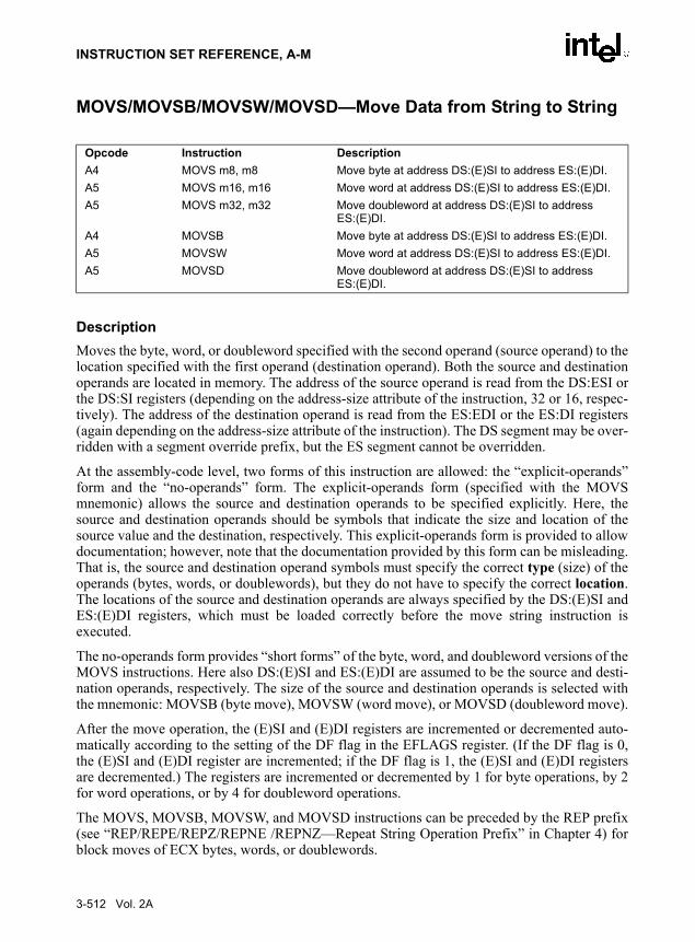
INSTRUCTION SET REFERENCE, A-M
MOVS/MOVSB/MOVSW/MOVSD—Move Data from String to String
DescriptionMoves the byte, word, or doubleword specified with the second operand (source operand) to thelocation specified with the first operand (destination operand). Both the source and destinationoperands are located in memory. The address of the source operand is read from the DS:ESI orthe DS:SI registers (depending on the address-size attribute of the instruction, 32 or 16, respec-tively). The address of the destination operand is read from the ES:EDI or the ES:DI registers(again depending on the address-size attribute of the instruction). The DS segment may be over-ridden with a segment override prefix, but the ES segment cannot be overridden.
At the assembly-code level, two forms of this instruction are allowed: the “explicit-operands”form and the “no-operands” form. The explicit-operands form (specified with the MOVSmnemonic) allows the source and destination operands to be specified explicitly. Here, thesource and destination operands should be symbols that indicate the size and location of thesource value and the destination, respectively. This explicit-operands form is provided to allowdocumentation; however, note that the documentation provided by this form can be misleading.That is, the source and destination operand symbols must specify the correct type (size) of theoperands (bytes, words, or doublewords), but they do not have to specify the correct location.The locations of the source and destination operands are always specified by the DS:(E)SI andES:(E)DI registers, which must be loaded correctly before the move string instruction isexecuted.
The no-operands form provides “short forms” of the byte, word, and doubleword versions of theMOVS instructions. Here also DS:(E)SI and ES:(E)DI are assumed to be the source and desti-nation operands, respectively. The size of the source and destination operands is selected withthe mnemonic: MOVSB (byte move), MOVSW (word move), or MOVSD (doubleword move).
After the move operation, the (E)SI and (E)DI registers are incremented or decremented auto-matically according to the setting of the DF flag in the EFLAGS register. (If the DF flag is 0,the (E)SI and (E)DI register are incremented; if the DF flag is 1, the (E)SI and (E)DI registersare decremented.) The registers are incremented or decremented by 1 for byte operations, by 2for word operations, or by 4 for doubleword operations.
The MOVS, MOVSB, MOVSW, and MOVSD instructions can be preceded by the REP prefix(see “REP/REPE/REPZ/REPNE /REPNZ—Repeat String Operation Prefix” in Chapter 4) forblock moves of ECX bytes, words, or doublewords.
Opcode Instruction DescriptionA4 MOVS m8, m8 Move byte at address DS:(E)SI to address ES:(E)DI.A5 MOVS m16, m16 Move word at address DS:(E)SI to address ES:(E)DI.A5 MOVS m32, m32 Move doubleword at address DS:(E)SI to address
ES:(E)DI.A4 MOVSB Move byte at address DS:(E)SI to address ES:(E)DI.A5 MOVSW Move word at address DS:(E)SI to address ES:(E)DI.A5 MOVSD Move doubleword at address DS:(E)SI to address
ES:(E)DI.
3-512 Vol. 2A

INSTRUCTION SET REFERENCE, A-M
OperationDEST ←SRC;IF (byte move)
THEN IF DF = 0THEN
(E)SI ← (E)SI + 1; (E)DI ← (E)DI + 1;
ELSE (E)SI ← (E)SI – 1; (E)DI ← (E)DI – 1;
FI;ELSE IF (word move)
THEN IF DF = 0(E)SI ← (E)SI + 2; (E)DI ← (E)DI + 2;
ELSE (E)SI ← (E)SI – 2; (E)DI ← (E)DI – 2;
FI;ELSE (* doubleword move*)
THEN IF DF = 0(E)SI ← (E)SI + 4; (E)DI ← (E)DI + 4;
ELSE (E)SI ← (E)SI – 4; (E)DI ← (E)DI – 4;
FI;FI;
Flags AffectedNone.
Protected Mode Exceptions#GP(0) If the destination is located in a non-writable segment.
If a memory operand effective address is outside the CS, DS, ES, FS, or GS segment limit.
If the DS, ES, FS, or GS register contains a null segment selector.
#SS(0) If a memory operand effective address is outside the SS segment limit.
#PF(fault-code) If a page fault occurs.
#AC(0) If alignment checking is enabled and an unaligned memory reference is made while the current privilege level is 3.
Vol. 2A 3-513

INSTRUCTION SET REFERENCE, A-M
Real-Address Mode Exceptions#GP If a memory operand effective address is outside the CS, DS, ES, FS, or
GS segment limit.
#SS If a memory operand effective address is outside the SS segment limit.
Virtual-8086 Mode Exceptions#GP(0) If a memory operand effective address is outside the CS, DS, ES, FS, or
GS segment limit.
#SS(0) If a memory operand effective address is outside the SS segment limit.
#PF(fault-code) If a page fault occurs.
#AC(0) If alignment checking is enabled and an unaligned memory reference is made.
3-514 Vol. 2A

INSTRUCTION SET REFERENCE, A-M
MOVSD—Move Scalar Double-Precision Floating-Point Value
DescriptionMoves a scalar double-precision floating-point value from the source operand (second operand)to the destination operand (first operand). The source and destination operands can be XMMregisters or 64-bit memory locations. This instruction can be used to move a double-precisionfloating-point value to and from the low quadword of an XMM register and a 64-bit memorylocation, or to move a double-precision floating-point value between the low quadwords of twoXMM registers. The instruction cannot be used to transfer data between memory locations.
When the source and destination operands are XMM registers, the high quadword of the desti-nation operand remains unchanged. When the source operand is a memory location and desti-nation operand is an XMM registers, the high quadword of the destination operand is cleared toall 0s.
OperationMOVSD instruction when source and destination operands are XMM registers:
DEST[63-0] ← SRC[63-0];* DEST[127-64] remains unchanged *;
MOVSD instruction when source operand is XMM register and destinationoperand is memory location:
DEST ← SRC[63-0];MOVSD instruction when source operand is memory location and destinationoperand is XMM register:
DEST[63-0] ← SRC;DEST[127-64] ← 0000000000000000H;
Intel C/C++ Compiler Intrinsic EquivalentMOVSD __m128d _mm_load_sd (double *p)
MOVSD void _mm_store_sd (double *p, __m128d a)
MOVSD __m128d _mm_store_sd (__m128d a, __m128d b)
SIMD Floating-Point ExceptionsNone.
Opcode Instruction DescriptionF2 0F 10 /r MOVSD xmm1, xmm2/m64 Move scalar double-precision floating-point value from
xmm2/m64 to xmm1 register.F2 0F 11 /r MOVSD xmm2/m64, xmm Move scalar double-precision floating-point value from
xmm1 register to xmm2/m64.
Vol. 2A 3-515

INSTRUCTION SET REFERENCE, A-M
Protected Mode Exceptions
#GP(0) For an illegal memory operand effective address in the CS, DS, ES, FS or GS segments.
#SS(0) For an illegal address in the SS segment.
#PF(fault-code) For a page fault.
#NM If TS in CR0 is set.
#UD If EM in CR0 is set.
If OSFXSR in CR4 is 0.
If CPUID feature flag SSE2 is 0.
#AC(0) If alignment checking is enabled and an unaligned memory reference is made while the current privilege level is 3.
Real-Address Mode Exceptions
GP(0) If any part of the operand lies outside the effective address space from 0 to FFFFH.
#NM If TS in CR0 is set.
#UD If EM in CR0 is set.
If OSFXSR in CR4 is 0.
If CPUID feature flag SSE2 is 0.
Virtual-8086 Mode ExceptionsSame exceptions as in Real Address Mode
#PF(fault-code) For a page fault.
#AC(0) If alignment checking is enabled and an unaligned memory reference is made.
3-516 Vol. 2A

INSTRUCTION SET REFERENCE, A-M
MOVSS—Move Scalar Single-Precision Floating-Point Values
DescriptionMoves a scalar single-precision floating-point value from the source operand (second operand)to the destination operand (first operand). The source and destination operands can be XMMregisters or 32-bit memory locations. This instruction can be used to move a single-precisionfloating-point value to and from the low doubleword of an XMM register and a 32-bit memorylocation, or to move a single-precision floating-point value between the low doublewords of twoXMM registers. The instruction cannot be used to transfer data between memory locations.
When the source and destination operands are XMM registers, the three high-order doublewordsof the destination operand remain unchanged. When the source operand is a memory locationand destination operand is an XMM registers, the three high-order doublewords of the destina-tion operand are cleared to all 0s.
OperationMOVSS instruction when source and destination operands are XMM registers:
DEST[31-0] ← SRC[31-0];* DEST[127-32] remains unchanged *;
MOVSS instruction when source operand is XMM register and destinationoperand is memory location:
DEST ← SRC[31-0];MOVSS instruction when source operand is memory location and destinationoperand is XMM register:
DEST[31-0] ← SRC;DEST[127-32] ← 000000000000000000000000H;
Intel C/C++ Compiler Intrinsic EquivalentMOVSS __m128 _mm_load_ss(float * p)
MOVSS void_mm_store_ss(float * p, __m128 a)
MOVSS __m128 _mm_move_ss(__m128 a, __m128 b)
SIMD Floating-Point ExceptionsNone.
Opcode Instruction DescriptionF3 0F 10 /r MOVSS xmm1, xmm2/m32 Move scalar single-precision floating-point value from
xmm2/m32 to xmm1 register.F3 0F 11 /r MOVSS xmm2/m32, xmm1 Move scalar single-precision floating-point value from
xmm1 register to xmm2/m32.
Vol. 2A 3-517

INSTRUCTION SET REFERENCE, A-M
Protected Mode Exceptions
#GP(0) For an illegal memory operand effective address in the CS, DS, ES, FS or GS segments.
#SS(0) For an illegal address in the SS segment.
#PF(fault-code) For a page fault.
#NM If TS in CR0 is set.
#UD If EM in CR0 is set.
If OSFXSR in CR4 is 0.
If CPUID feature flag SSE is 0.
#AC(0) If alignment checking is enabled and an unaligned memory reference is made while the current privilege level is 3.
Real-Address Mode Exceptions
GP(0) If any part of the operand lies outside the effective address space from 0 to FFFFH.
#NM If TS in CR0 is set.
#UD If EM in CR0 is set.
If OSFXSR in CR4 is 0.
If CPUID feature flag SSE is 0.
Virtual-8086 Mode ExceptionsSame exceptions as in Real Address Mode
#PF(fault-code) For a page fault.
#AC(0) If alignment checking is enabled and an unaligned memory reference is made.
3-518 Vol. 2A
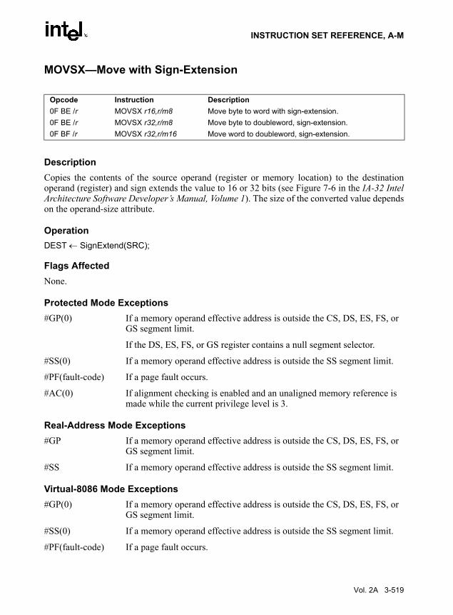
INSTRUCTION SET REFERENCE, A-M
MOVSX—Move with Sign-Extension
DescriptionCopies the contents of the source operand (register or memory location) to the destinationoperand (register) and sign extends the value to 16 or 32 bits (see Figure 7-6 in the IA-32 IntelArchitecture Software Developer’s Manual, Volume 1). The size of the converted value dependson the operand-size attribute.
OperationDEST ← SignExtend(SRC);
Flags AffectedNone.
Protected Mode Exceptions#GP(0) If a memory operand effective address is outside the CS, DS, ES, FS, or
GS segment limit.
If the DS, ES, FS, or GS register contains a null segment selector.
#SS(0) If a memory operand effective address is outside the SS segment limit.
#PF(fault-code) If a page fault occurs.
#AC(0) If alignment checking is enabled and an unaligned memory reference is made while the current privilege level is 3.
Real-Address Mode Exceptions#GP If a memory operand effective address is outside the CS, DS, ES, FS, or
GS segment limit.
#SS If a memory operand effective address is outside the SS segment limit.
Virtual-8086 Mode Exceptions#GP(0) If a memory operand effective address is outside the CS, DS, ES, FS, or
GS segment limit.
#SS(0) If a memory operand effective address is outside the SS segment limit.
#PF(fault-code) If a page fault occurs.
Opcode Instruction Description0F BE /r MOVSX r16,r/m8 Move byte to word with sign-extension.0F BE /r MOVSX r32,r/m8 Move byte to doubleword, sign-extension.0F BF /r MOVSX r32,r/m16 Move word to doubleword, sign-extension.
Vol. 2A 3-519

INSTRUCTION SET REFERENCE, A-M
MOVUPD—Move Unaligned Packed Double-Precision Floating-Point Values
DescriptionMoves a double quadword containing two packed double-precision floating-point values fromthe source operand (second operand) to the destination operand (first operand). This instructioncan be used to load an XMM register from a 128-bit memory location, store the contents of anXMM register into a 128-bit memory location, or move data between two XMM registers. Whenthe source or destination operand is a memory operand, the operand may be unaligned on a 16-byte boundary without causing a general-protection exception (#GP) to be generated.
To move double-precision floating-point values to and from memory locations that are knownto be aligned on 16-byte boundaries, use the MOVAPD instruction.
While executing in 16-bit addressing mode, a linear address for a 128-bit data access that over-laps the end of a 16-bit segment is not allowed and is defined as reserved behavior. A specificprocessor implementation may or may not generate a general-protection exception (#GP) in thissituation, and the address that spans the end of the segment may or may not wrap around to thebeginning of the segment.
OperationDEST ← SRC;
Intel C/C++ Compiler Intrinsic EquivalentMOVUPD __m128 _mm_loadu_pd(double * p)
MOVUPD void_mm_storeu_pd(double *p, __m128 a)
SIMD Floating-Point ExceptionsNone.
Protected Mode Exceptions
#GP(0) For an illegal memory operand effective address in the CS, DS, ES, FS or GS segments.
#SS(0) For an illegal address in the SS segment.
#PF(fault-code) For a page fault.
Opcode Instruction Description66 0F 10 /r MOVUPD xmm1, xmm2/m128 Move packed double-precision floating-point values
from xmm2/m128 to xmm1.66 0F 11 /r MOVUPD xmm2/m128, xmm Move packed double-precision floating-point values
from xmm1 to xmm2/m128.
3-520 Vol. 2A

INSTRUCTION SET REFERENCE, A-M
#NM If TS in CR0 is set.
#UD If EM in CR0 is set.
If OSFXSR in CR4 is 0.
If CPUID feature flag SSE2 is 0.
Real-Address Mode Exceptions
GP(0) If any part of the operand lies outside the effective address space from 0 to FFFFH.
#NM If TS in CR0 is set.
#UD If EM in CR0 is set.
If OSFXSR in CR4 is 0.
If CPUID feature flag SSE2 is 0.
Virtual-8086 Mode Exceptions
Same exceptions as in Real Address Mode
#PF(fault-code) For a page fault.
Vol. 2A 3-521

INSTRUCTION SET REFERENCE, A-M
MOVUPS—Move Unaligned Packed Single-Precision Floating-Point Values
DescriptionMoves a double quadword containing four packed single-precision floating-point values fromthe source operand (second operand) to the destination operand (first operand). This instructioncan be used to load an XMM register from a 128-bit memory location, store the contents of anXMM register into a 128-bit memory location, or move data between two XMM registers. Whenthe source or destination operand is a memory operand, the operand may be unaligned on a 16-byte boundary without causing a general-protection exception (#GP) to be generated.
To move packed single-precision floating-point values to and from memory locations that areknown to be aligned on 16-byte boundaries, use the MOVAPS instruction.
While executing in 16-bit addressing mode, a linear address for a 128-bit data access that over-laps the end of a 16-bit segment is not allowed and is defined as reserved behavior. A specificprocessor implementation may or may not generate a general-protection exception (#GP) in thissituation, and the address that spans the end of the segment may or may not wrap around to thebeginning of the segment.
OperationDEST ← SRC;
Intel C/C++ Compiler Intrinsic EquivalentMOVUPS __m128 _mm_loadu_ps(double * p)
MOVUPS void_mm_storeu_ps(double *p, __m128 a)
SIMD Floating-Point ExceptionsNone.
Protected Mode Exceptions
#GP(0) For an illegal memory operand effective address in the CS, DS, ES, FS or GS segments.
#SS(0) For an illegal address in the SS segment.
#PF(fault-code) For a page fault.
Opcode Instruction Description0F 10 /r MOVUPS xmm1, xmm2/m128 Move packed single-precision floating-point values
from xmm2/m128 to xmm1.0F 11 /r MOVUPS xmm2/m128, xmm1 Move packed single-precision floating-point values
from xmm1 to xmm2/m128.
3-522 Vol. 2A

INSTRUCTION SET REFERENCE, A-M
#NM If TS in CR0 is set.
#UD If EM in CR0 is set.
If OSFXSR in CR4 is 0.
If CPUID feature flag SSE is 0.
Real-Address Mode Exceptions
GP(0) If any part of the operand lies outside the effective address space from 0 to FFFFH.
#NM If TS in CR0 is set.
#UD If EM in CR0 is set.
If OSFXSR in CR4 is 0.
If CPUID feature flag SSE is 0.
Virtual-8086 Mode Exceptions
Same exceptions as in Real Address Mode
#PF(fault-code) For a page fault.
Vol. 2A 3-523

INSTRUCTION SET REFERENCE, A-M
MOVZX—Move with Zero-Extend
DescriptionCopies the contents of the source operand (register or memory location) to the destinationoperand (register) and zero extends the value to 16 or 32 bits. The size of the converted valuedepends on the operand-size attribute.
OperationDEST ← ZeroExtend(SRC);
Flags AffectedNone.
Protected Mode Exceptions#GP(0) If a memory operand effective address is outside the CS, DS, ES, FS, or
GS segment limit.If the DS, ES, FS, or GS register contains a null segment selector.
#SS(0) If a memory operand effective address is outside the SS segment limit.#PF(fault-code) If a page fault occurs.#AC(0) If alignment checking is enabled and an unaligned memory reference is
made while the current privilege level is 3.
Real-Address Mode Exceptions#GP If a memory operand effective address is outside the CS, DS, ES, FS, or
GS segment limit.#SS If a memory operand effective address is outside the SS segment limit.
Virtual-8086 Mode Exceptions#GP(0) If a memory operand effective address is outside the CS, DS, ES, FS, or
GS segment limit.#SS(0) If a memory operand effective address is outside the SS segment limit.#PF(fault-code) If a page fault occurs.#AC(0) If alignment checking is enabled and an unaligned memory reference is
made.
Opcode Instruction Description0F B6 /r MOVZX r16,r/m8 Move byte to word with zero-extension.0F B6 /r MOVZX r32,r/m8 Move byte to doubleword, zero-extension.0F B7 /r MOVZX r32,r/m16 Move word to doubleword, zero-extension.
3-524 Vol. 2A

INSTRUCTION SET REFERENCE, A-M
MUL—Unsigned Multiply
DescriptionPerforms an unsigned multiplication of the first operand (destination operand) and the secondoperand (source operand) and stores the result in the destination operand. The destinationoperand is an implied operand located in register AL, AX or EAX (depending on the size of theoperand); the source operand is located in a general-purpose register or a memory location. Theaction of this instruction and the location of the result depends on the opcode and the operandsize as shown in Table 3-56.
:
The result is stored in register AX, register pair DX:AX, or register pair EDX:EAX (dependingon the operand size), with the high-order bits of the product contained in register AH, DX, orEDX, respectively. If the high-order bits of the product are 0, the CF and OF flags are cleared;otherwise, the flags are set.
OperationIF byte operation
THEN AX ← AL ∗ SRC
ELSE (* word or doubleword operation *)IF OperandSize = 16
THEN DX:AX ← AX ∗ SRC
ELSE (* OperandSize = 32 *)EDX:EAX ← EAX ∗ SRC
FI;FI;
Opcode Instruction DescriptionF6 /4 MUL r/m8 Unsigned multiply (AX ← AL ∗ r/m8).F7 /4 MUL r/m16 Unsigned multiply (DX:AX ← AX ∗ r/m16).F7 /4 MUL r/m32 Unsigned multiply (EDX:EAX ← EAX ∗ r/m32).
Table 3-56. MUL ResultsOperand Size Source 1 Source 2 Destination
Byte AL r/m8 AX
Word AX r/m16 DX:AX
Doubleword EAX r/m32 EDX:EAX
Vol. 2A 3-525
INSTRUCTION SET REFERENCE, A-M
Flags AffectedThe OF and CF flags are set to 0 if the upper half of the result is 0; otherwise, they are set to 1.The SF, ZF, AF, and PF flags are undefined.
Protected Mode Exceptions#GP(0) If a memory operand effective address is outside the CS, DS, ES, FS, or
GS segment limit.
If the DS, ES, FS, or GS register contains a null segment selector.
#SS(0) If a memory operand effective address is outside the SS segment limit.
#PF(fault-code) If a page fault occurs.
#AC(0) If alignment checking is enabled and an unaligned memory reference is made while the current privilege level is 3.
Real-Address Mode Exceptions#GP If a memory operand effective address is outside the CS, DS, ES, FS, or
GS segment limit.
#SS If a memory operand effective address is outside the SS segment limit.
Virtual-8086 Mode Exceptions#GP(0) If a memory operand effective address is outside the CS, DS, ES, FS, or
GS segment limit.
#SS(0) If a memory operand effective address is outside the SS segment limit.
#PF(fault-code) If a page fault occurs.
#AC(0) If alignment checking is enabled and an unaligned memory reference is made.
3-526 Vol. 2A

INSTRUCTION SET REFERENCE, A-M
MULPD—Multiply Packed Double-Precision Floating-Point Values
DescriptionPerforms an SIMD multiply of the two packed double-precision floating-point values from thesource operand (second operand) and the destination operand (first operand), and stores thepacked double-precision floating-point results in the destination operand. The source operandcan be an XMM register or a 128-bit memory location. The destination operand is an XMMregister. See Figure 11-3 in the IA-32 Intel Architecture Software Developer’s Manual, Volume1 for an illustration of an SIMD double-precision floating-point operation.
OperationDEST[63-0] ← DEST[63-0] ∗ SRC[63-0];DEST[127-64] ← DEST[127-64] ∗ SRC[127-64];
Intel C/C++ Compiler Intrinsic EquivalentMULPD __m128d _mm_mul_pd (m128d a, m128d b)
SIMD Floating-Point ExceptionsOverflow, Underflow, Invalid, Precision, Denormal.
Protected Mode Exceptions
#GP(0) For an illegal memory operand effective address in the CS, DS, ES, FS or GS segments.
If a memory operand is not aligned on a 16-byte boundary, regardless of segment.
#SS(0) For an illegal address in the SS segment.
#PF(fault-code) For a page fault.
#NM If TS in CR0 is set.
#XM If an unmasked SIMD floating-point exception and OSXMMEXCPT in CR4 is 1.
Opcode Instruction Description66 0F 59 /r MULPD xmm1, xmm2/m128 Multiply packed double-precision floating-point values in
xmm2/m128 by xmm1.
Vol. 2A 3-527

INSTRUCTION SET REFERENCE, A-M
#UD If an unmasked SIMD floating-point exception and OSXMMEXCPT in CR4 is 0.
If EM in CR0 is set.
If OSFXSR in CR4 is 0.
If CPUID feature flag SSE2 is 0.
Real-Address Mode Exceptions
#GP(0) If a memory operand is not aligned on a 16-byte boundary, regardless of segment.
GP(0) If any part of the operand lies outside the effective address space from 0 to FFFFH.
#NM If TS in CR0 is set.
#XM If an unmasked SIMD floating-point exception and OSXMMEXCPT in CR4 is 1.
#UD If an unmasked SIMD floating-point exception and OSXMMEXCPT in CR4 is 0.
If EM in CR0 is set.
If OSFXSR in CR4 is 0.
If CPUID feature flag SSE2 is 0.
Virtual-8086 Mode Exceptions
Same exceptions as in Real Address Mode
#PF(fault-code) For a page fault.
3-528 Vol. 2A

INSTRUCTION SET REFERENCE, A-M
MULPS—Multiply Packed Single-Precision Floating-Point Values
DescriptionPerforms an SIMD multiply of the four packed single-precision floating-point values from thesource operand (second operand) and the destination operand (first operand), and stores thepacked single-precision floating-point results in the destination operand. The source operandcan be an XMM register or a 128-bit memory location. The destination operand is an XMMregister. See Figure 10-5 in the IA-32 Intel Architecture Software Developer’s Manual, Volume1 for an illustration of an SIMD single-precision floating-point operation.
OperationDEST[31-0] ← DEST[31-0] ∗ SRC[31-0];DEST[63-32] ← DEST[63-32] ∗ SRC[63-32];DEST[95-64] ← DEST[95-64] ∗ SRC[95-64];DEST[127-96] ← DEST[127-96] ∗ SRC[127-96];
Intel C/C++ Compiler Intrinsic EquivalentMULPS __m128 _mm_mul_ps(__m128 a, __m128 b)
SIMD Floating-Point ExceptionsOverflow, Underflow, Invalid, Precision, Denormal.
Protected Mode Exceptions
#GP(0) For an illegal memory operand effective address in the CS, DS, ES, FS or GS segments.
If a memory operand is not aligned on a 16-byte boundary, regardless of segment.
#SS(0) For an illegal address in the SS segment.
#PF(fault-code) For a page fault.
#NM If TS in CR0 is set.
#XM If an unmasked SIMD floating-point exception and OSXMMEXCPT in CR4 is 1.
#UD If an unmasked SIMD floating-point exception and OSXMMEXCPT in CR4 is 0.
If EM in CR0 is set.
Opcode Instruction Description0F 59 /r MULPS xmm1, xmm2/m128 Multiply packed single-precision floating-point values in
xmm2/mem by xmm1.
Vol. 2A 3-529

INSTRUCTION SET REFERENCE, A-M
If OSFXSR in CR4 is 0.
If CPUID feature flag SSE is 0.
Real-Address Mode Exceptions
#GP(0) If a memory operand is not aligned on a 16-byte boundary, regardless of segment.
If any part of the operand lies outside the effective address space from 0 to FFFFH.
#NM If TS in CR0 is set.
#XM If an unmasked SIMD floating-point exception and OSXMMEXCPT in CR4 is 1.
#UD If an unmasked SIMD floating-point exception and OSXMMEXCPT in CR4 is 0.
If EM in CR0 is set.
If OSFXSR in CR4 is 0.
If CPUID feature flag SSE is 0.
Virtual-8086 Mode Exceptions
Same exceptions as in Real Address Mode
#PF(fault-code) For a page fault.
3-530 Vol. 2A

INSTRUCTION SET REFERENCE, A-M
MULSD—Multiply Scalar Double-Precision Floating-Point Values
DescriptionMultiplies the low double-precision floating-point value in the source operand (second operand)by the low double-precision floating-point value in the destination operand (first operand), andstores the double-precision floating-point result in the destination operand. The source operandcan be an XMM register or a 64-bit memory location. The destination operand is an XMMregister. The high quadword of the destination operand remains unchanged. See Figure 11-4 inthe IA-32 Intel Architecture Software Developer’s Manual, Volume 1 for an illustration of ascalar double-precision floating-point operation.
OperationDEST[63-0] ← DEST[63-0] * xmm2/m64[63-0];* DEST[127-64] remains unchanged *;
Intel C/C++ Compiler Intrinsic EquivalentMULSD __m128d _mm_mul_sd (m128d a, m128d b)
SIMD Floating-Point ExceptionsOverflow, Underflow, Invalid, Precision, Denormal.
Protected Mode Exceptions
#GP(0) For an illegal memory operand effective address in the CS, DS, ES, FS or GS segments.
#SS(0) For an illegal address in the SS segment.
#PF(fault-code) For a page fault.
#NM If TS in CR0 is set.
#XM If an unmasked SIMD floating-point exception and OSXMMEXCPT in CR4 is 1.
Opcode Instruction DescriptionF2 0F 59 /r MULSD xmm1, xmm2/m64 Multiply the low double-precision floating-point value in
xmm2/mem64 by low double-precision floating-point value in xmm1.
Vol. 2A 3-531

INSTRUCTION SET REFERENCE, A-M
#UD If an unmasked SIMD floating-point exception and OSXMMEXCPT in CR4 is 0.
If EM in CR0 is set.
If OSFXSR in CR4 is 0.
If CPUID feature flag SSE2 is 0.
#AC(0) If alignment checking is enabled and an unaligned memory reference is made while the current privilege level is 3.
Real-Address Mode Exceptions
GP(0) If any part of the operand lies outside the effective address space from 0 to FFFFH.
#NM If TS in CR0 is set.
#XM If an unmasked SIMD floating-point exception and OSXMMEXCPT in CR4 is 1.
#UD If an unmasked SIMD floating-point exception and OSXMMEXCPT in CR4 is 0.
If EM in CR0 is set.
If OSFXSR in CR4 is 0.
If CPUID feature flag SSE2 is 0.
Virtual-8086 Mode Exceptions
Same exceptions as in Real Address Mode
#PF(fault-code) For a page fault.
#AC For unaligned memory reference.
3-532 Vol. 2A

INSTRUCTION SET REFERENCE, A-M
MULSS—Multiply Scalar Single-Precision Floating-Point Values
DescriptionMultiplies the low single-precision floating-point value from the source operand (secondoperand) by the low single-precision floating-point value in the destination operand (firstoperand), and stores the single-precision floating-point result in the destination operand. Thesource operand can be an XMM register or a 32-bit memory location. The destination operandis an XMM register. The three high-order doublewords of the destination operand remainunchanged. See Figure 10-6 in the IA-32 Intel Architecture Software Developer’s Manual,Volume 1 for an illustration of a scalar single-precision floating-point operation.
OperationDEST[31-0] ← DEST[31-0] ∗ SRC[31-0];* DEST[127-32] remains unchanged *;
Intel C/C++ Compiler Intrinsic EquivalentMULSS __m128 _mm_mul_ss(__m128 a, __m128 b)
SIMD Floating-Point ExceptionsOverflow, Underflow, Invalid, Precision, Denormal.
Protected Mode Exceptions
#GP(0) For an illegal memory operand effective address in the CS, DS, ES, FS or GS segments.
#SS(0) For an illegal address in the SS segment.
#PF(fault-code) For a page fault.
#NM If TS in CR0 is set.
#XM If an unmasked SIMD floating-point exception and OSXMMEXCPT in CR4 is 1.
#UD If an unmasked SIMD floating-point exception and OSXMMEXCPT in CR4 is 0.
If EM in CR0 is set.
Opcode Instruction DescriptionF3 0F 59 /r MULSS xmm1, xmm2/m32 Multiply the low single-precision floating-point value in
xmm2/mem by the low single-precision floating-point value in xmm1.
Vol. 2A 3-533

INSTRUCTION SET REFERENCE, A-M
If OSFXSR in CR4 is 0.
If CPUID feature flag SSE is 0.
#AC(0) If alignment checking is enabled and an unaligned memory reference is made while the current privilege level is 3.
Real-Address Mode Exceptions
GP(0) If any part of the operand lies outside the effective address space from 0 to FFFFH.
#NM If TS in CR0 is set.
#XM If an unmasked SIMD floating-point exception and OSXMMEXCPT in CR4 is 1.
#UD If an unmasked SIMD floating-point exception and OSXMMEXCPT in CR4 is 0.
If EM in CR0 is set.
If OSFXSR in CR4 is 0.
If CPUID feature flag SSE is 0.
Virtual-8086 Mode Exceptions
Same exceptions as in Real Address Mode
#PF(fault-code) For a page fault.
#AC For unaligned memory reference.
3-534 Vol. 2A

INSTRUCTION SET REFERENCE, A-M
MWAIT: Monitor Wait
DescriptionThe MWAIT instruction is designed to operate with the MONITOR instruction. The twoinstructions allow the definition of an address at which to ‘wait’ (MONITOR) and an instructionthat causes a predefined ‘implementation-dependent-optimized operation’ to commence at the‘wait’ address (MWAIT). The execution of MWAIT is a hint to the processor that it can enteran implementation-dependent-optimized state while waiting for an event or a store operation tothe address range armed by the preceding MONITOR instruction in program flow.
EAX and ECX is used to communicate other information to the MWAIT instruction, such as thekind of optimized state the processor should enter. ECX specifies optional extensions for theMWAIT instruction. EAX may contain hints such as the preferred optimized state the processorshould enter. For Pentium 4 processors with CPUID signature family = 15 and model = 3, allnon-zero values for EAX and ECX are reserved. The processor will raise a general protectionfault on the execution of MWAIT with reserved values in ECX, whereas it ignores the settingof reserved bits in EAX.
A store to the address range armed by the MONITOR instruction, an interrupt, an NMI or SMI,a debug exception, a machine check exception, the BINIT# signal, the INIT# signal, or theRESET# signal will exit the implementation-dependent-optimized state. Note that an interruptwill cause the processor to exit only if the state was entered with interrupts enabled.
If a store to the address range causes the processor to exit, execution will resume at the instruc-tion following the MWAIT instruction. If an interrupt (including NMI) caused the processor toexit the implementation-dependent-optimized state, the processor will exit the state and handlethe interrupt. If an SMI caused the processor to exit the implementation-dependent-optimizedstate, execution will resume at the instruction following MWAIT after handling of the SMI.Unlike the HLT instruction, the MWAIT instruction does not support a restart at the MWAITinstruction. There may also be other implementation-dependent events or time-outs that maytake the processor out of the implementation-dependent-optimized state and resume executionat the instruction following the MWAIT.
If the preceding MONITOR instruction did not successfully arm an address range or if theMONITOR instruction has not been executed prior to executing MWAIT, then the processorwill not enter the implementation-dependent-optimized state. Execution will resume at theinstruction following the MWAIT.
The MWAIT instruction can be executed at any privilege level. The MONITOR CPUID featureflag (ECX[bit 3] when CPUID is executed with EAX = 1) indicates the availability of theMONITOR and MWAIT instruction in a processor. When set, the unconditional execution ofMWAIT is supported at privilege level 0 and conditional execution is supported at privilege
Opcode Instruction Description0F,01,C9 MWAIT A hint that allows the processor to stop instruction
execution and enter an implementation-dependent optimized state until occurrence of a class of events; it is architecturally identical to a NOP instruction.
Vol. 2A 3-535
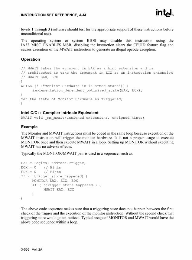
INSTRUCTION SET REFERENCE, A-M
levels 1 through 3 (software should test for the appropriate support of these instructions beforeunconditional use).
The operating system or system BIOS may disable this instruction using theIA32_MISC_ENABLES MSR; disabling the instruction clears the CPUID feature flag andcauses execution of the MWAIT instruction to generate an illegal opcode exception.
Operation
// MWAIT takes the argument in EAX as a hint extension and is // architected to take the argument in ECX as an instruction extension// MWAIT EAX, ECX{WHILE (! ("Monitor Hardware is in armed state")) {
implementation_dependent_optimized_state(EAX, ECX);}Set the state of Monitor Hardware as Triggered;}
Intel C/C++ Compiler Intrinsic EquivalentMWAIT void _mm_mwait(unsigned extensions, unsigned hints)
ExampleThe Monitor and MWAIT instructions must be coded in the same loop because execution of theMWAIT instruction will trigger the monitor hardware. It is not a proper usage to executeMONITOR once and then execute MWAIT in a loop. Setting up MONITOR without executingMWAIT has no adverse effects.
Typically the MONITOR/MWAIT pair is used in a sequence, such as:
EAX = Logical Address(Trigger)ECX = 0 // HintsEDX = 0 // HintsIf ( !trigger_store_happened) {
MONITOR EAX, ECX, EDXIf ( !trigger_store_happened ) {
MWAIT EAX, ECX}
}
The above code sequence makes sure that a triggering store does not happen between the firstcheck of the trigger and the execution of the monitor instruction. Without the second check thattriggering store would go un-noticed. Typical usage of MONITOR and MWAIT would have theabove code sequence within a loop.
3-536 Vol. 2A

INSTRUCTION SET REFERENCE, A-M
ExceptionsNone
Numeric ExceptionsNone
Protected Mode Exceptions#GP(0) For ECX has a value other than 0.
#UD If CPUID feature flag MONITOR is 0.
If executed at privilege level 1 through 3 when the instruction is not avail-able.
If LOCK prefixes are used.
If REPE, REPNE or operand size prefixes are used.
Real Address Mode Exceptions#GP(0) For ECX has a value other than 0.
#UD If CPUID feature flag MONITOR is 0;
If LOCK prefix is used.
If REPE, REPNE or operand size prefixes are used.
Virtual 8086 Mode Exceptions#GP(0) For ECX has a value other than 0.
#UD If CPUID feature flag MONITOR is 0; or instruction is executed at privi-lege level 1-2-3 when the instruction is not available.
If LOCK prefix is used.
If REPE, REPNE or operand size prefixes are used.
Vol. 2A 3-537

INSTRUCTION SET REFERENCE, A-M
3-538 Vol. 2A

INTEL SALES OFFICES
ASIA PACIFICAustraliaIntel Corp.Level 2448 St Kilda Road Melbourne VIC3004AustraliaFax:613-9862 5599ChinaIntel Corp.Rm 709, Shaanxi Zhongda Int'l BldgNo.30 Nandajie Street Xian AX710002ChinaFax:(86 29) 7203356
Intel Corp.Rm 2710, Metropolian Tower68 Zourong Rd Chongqing CQ400015China
Intel Corp.C1, 15 Flr, Fujian Oriental HotelNo. 96 East Street Fuzhou FJ350001China
Intel Corp.Rm 5803 CITIC Plaza233 Tianhe Rd Guangzhou GD510613China
Intel Corp.Rm 1003, Orient PlazaNo. 235 Huayuan Street Nangang DistrictHarbin HL150001China
Intel Corp.Rm 1751 World Trade Center, No 2Han Zhong Rd Nanjing JS210009China
Intel Corp.Hua Xin International Tower215 Qing Nian St. ShenYang LN110015China
Intel Corp.Suite 1128 CITIC Plaza Jinan150 Luo Yuan St. Jinan SNChina
Intel Corp.Suite 412, Holiday Inn Crowne Plaza31, Zong Fu Street Chengdu SU610041ChinaFax:86-28-6785965
Intel Corp.Room 0724, White Rose HotelNo 750, MinZhu Road WuChang DistrictWuhan UB430071China
IndiaIntel Corp.Paharpur Business Centre21 Nehru Place New Delhi DH110019India
Intel Corp.Hotel Rang Sharda, 6th FloorBandra Reclamation Mumbai MH400050IndiaFax:91-22-6415578
Intel Corp.DBS Corporate Club31A Cathedral Garden Road Chennai TD600034India
Intel Corp.DBS Corporate Club2nd Floor, 8 A.A.C. Bose Road Calcutta WB700017India
JapanIntel Corp.Kokusai Bldg 5F, 3-1-1, MarunouchiChiyoda-Ku, Tokyo 1000005Japan
Intel Corp.2-4-1 TerauchiToyonaka-Shi Osaka 5600872Japan
MalaysiaIntel Corp.Lot 102 1/F Block A Wisma Semantan12 Jalan Gelenggang Damansara HeightsKuala Lumpur SL50490Malaysia
ThailandIntel Corp.87 M. Thai Tower, 9th Fl.All Seasons Place, Wireless Road Lumpini, PatumwanBangkok 10330Thailand
Viet NamIntel Corp.Hanoi Tung Shing Square, Ste #11062 Ngo Quyen St Hoan Kiem DistrictHanoi Viet Nam
EUROPE & AFRICABelgiumIntel Corp.Woluwelaan 158Diegem 1831Belgium
Czech RepIntel Corp.Nahorni 14Brno 61600Czech Rep
DenmarkIntel Corp.Soelodden 13Maaloev DK2760Denmark
GermanyIntel Corp.Sandstrasse 4Aichner 86551Germany
Intel Corp.Dr Weyerstrasse 2Juelich 52428Germany
Intel Corp.Buchenweg 4Wildberg 72218Germany
Intel Corp.Kemnader Strasse 137Bochum 44797Germany
Intel Corp.Klaus-Schaefer Strasse 16-18Erfstadt NW50374Germany
Intel Corp.Heldmanskamp 37Lemgo NW32657Germany
ItalyIntel Corp Italia SpaMilanofiori Palazzo E/4Assago Milan 20094ItalyFax:39-02-57501221
NetherlandIntel Corp.Strausslaan 31Heesch 5384CWNetherland
PolandIntel Poland Developments, IncJerozolimskie Business ParkJerozolimskie 146c Warsaw 2305PolandFax:+48-22-570 81 40
PortugalIntel Corp.PO Box 20Alcabideche 2765Portugal
SpainIntel Corp.Calle Rioja, 9Bajo F Izquierda Madrid 28042Spain
South AfricaIntel SA CorporationBldg 14, South Wing, 2nd FloorUplands, The Woodlands Western Services RoadWoodmead 2052Sth AfricaFax:+27 11 806 4549
Intel Corp.19 Summit Place, Halfway HouseCnr 5th and Harry Galaun Streets Midrad 1685Sth Africa
United KingdomIntel Corp.The ManseSilver Lane Needingworth CAMBSPE274SLUK
Intel Corp.2 Cameron CloseLong Melford SUFFKCO109TSUK
IsraelIntel Corp.MTM Industrial Center, P.O.Box 498Haifa 31000IsraelFax:972-4-8655444
LATIN AMERICA & CANADAArgentinaIntel Corp.Dock IV - Bldg 3 - Floor 3Olga Cossentini 240Buenos AiresC1107BVAArgentina
BrazilIntel Corp.Rua Carlos Gomez 111/403Porto Alegre 90480-003Brazil
Intel Corp.Av. Dr. Chucri Zaidan940 - 10th FloorSan Paulo04583-904Brazil
Intel Corp.Av. Rio Branco,1 - Sala 1804Rio de Janeiro20090-003Brazil
ColumbiaIntel Corp.Carrera 7 No. 71021Torre B, Oficina 603Santefe de BogotaColumbia
MexicoIntel Corp.Av. Mexico No. 2798-9B, S.H.Guadalajara 44680Mexico
Intel Corp.Torre Esmeralda II, 7th FloorBlvd. Manuel Avila Comacho #36Mexico Cith DF11000Mexico
Intel Corp.Piso 19, Suite 4Av. Batallon de San Patricio No 111Monterrey, Nuevo le66269Mexico
CanadaIntel Corp.168 Bonis Ave, Suite 202Scarborough MIT3V6CanadaFax:416-335-7695
Intel Corp.3901 Highway #7, Suite 403Vaughan L4L 8L5CanadaFax:905-856-8868

Intel Corp.999 CANADA PLACE, Suite 404,#11Vancouver BCV6C 3E2CanadaFax:604-844-2813
Intel Corp.2650 Queensview Drive, Suite 250Ottawa ONK2B 8H6CanadaFax:613-820-5936
Intel Corp.190 Attwell Drive, Suite 500Rexcdale ONM9W 6H8CanadaFax:416-675-2438
Intel Corp.171 St. Clair Ave. E, Suite 6Toronto ONCanada
Intel Corp.1033 Oak Meadow RoadOakville ONL6M 1J6Canada
USACaliforniaIntel Corp.551 Lundy PlaceMilpitas CA95035-6833USAFax:408-451-8266
Intel Corp.1551 N. Tustin Avenue, Suite 800Santa Ana CA92705USAFax:714-541-9157
Intel Corp.Executive Center del Mar12230 El Camino Real Suite 140San Diego CA92130USAFax:858-794-5805
Intel Corp.1960 E. Grand Avenue, Suite 150El Segundo CA90245USAFax:310-640-7133
Intel Corp.23120 Alicia Parkway, Suite 215Mission Viejo CA92692USAFax:949-586-9499
Intel Corp.30851 Agoura RoadSuite 202 Agoura Hills CA91301USAFax:818-874-1166
Intel Corp.28202 Cabot Road, Suite #363 & #371Laguna Niguel CA92677USA
Intel Corp.657 S Cendros AvenueSolana Beach CA90075USA
Intel Corp.43769 Abeloe TerraceFremont CA94539USA
Intel Corp.1721 Warburton, #6Santa Clara CA95050USA
ColoradoIntel Corp.600 S. Cherry Street, Suite 700Denver CO80222USAFax:303-322-8670
ConnecticutIntel Corp.Lee Farm Corporate Pk83 Wooster Heights Road Danbury CT6810USAFax:203-778-2168
FloridaIntel Corp.7777 Glades RoadSuite 310BBoca Raton FL33434USAFax:813-367-5452
GeorgiaIntel Corp.20 Technology Park, Suite 150Norcross GA30092USAFax:770-448-0875
Intel Corp.Three Northwinds Center2500 Northwinds Parkway, 4th FloorAlpharetta GA30092USAFax:770-663-6354
IdahoIntel Corp.910 W. Main Street, Suite 236Boise ID83702USAFax:208-331-2295
IllinoisIntel Corp.425 N. Martingale Road Suite 1500Schaumburg IL60173USAFax:847-605-9762
Intel Corp.999 Plaza Drive Suite 360Schaumburg IL60173USA
Intel Corp.551 Arlington LaneSouth Elgin IL60177USA
IndianaIntel Corp.9465 Counselors Row, Suite 200Indianapolis IN46240USAFax:317-805-4939
MassachusettsIntel Corp.125 Nagog ParkActon MA01720USAFax:978-266-3867
Intel Corp.59 Composit Waysuite 202Lowell MA01851USA
Intel Corp.800 South Street, Suite 100Waltham MA02154USA
MarylandIntel Corp.131 National Business Parkway, Suite 200Annapolis Junction MD20701USAFax:301-206-3678
MichiganIntel Corp.32255 Northwestern Hwy., Suite 212Farmington Hills MI48334USAFax:248-851-8770
MInnesotaIntel Corp.3600 W 80Th StSuite 450 Bloomington MN55431USAFax:952-831-6497
North CarolinaIntel Corp.2000 CentreGreen Way, Suite 190Cary NC27513USAFax:919-678-2818
New HampshireIntel Corp.7 Suffolk ParkNashua NH03063USA
New JerseyIntel Corp.90 Woodbridge Center Dr, Suite. 240Woodbridge NJ07095USAFax:732-602-0096
New YorkIntel Corp.628 Crosskeys Office PkFairport NY14450USAFax:716-223-2561
Intel Corp.888 Veterans Memorial HighwaySuite 530 Hauppauge NY11788USAFax:516-234-5093
OhioIntel Corp.3401 Park Center Drive Suite 220Dayton OH45414USAFax:937-890-8658
Intel Corp.56 Milford DriveSuite 205Hudson OH44236USAFax:216-528-1026
OregonIntel Corp.15254 NW Greenbrier Parkway, Building BBeaverton OR97006USAFax:503-645-8181
PennsylvaniaIntel Corp.925 Harvest DriveSuite 200Blue Bell PA19422USAFax:215-641-0785
Intel Corp.7500 BrooktreeSuite 213Wexford PA15090USAFax:714-541-9157
TexasIntel Corp.5000 Quorum Drive, Suite 750Dallas TX75240USAFax:972-233-1325
Intel Corp.20445 State Highway 249, Suite 300Houston TX77070USAFax:281-376-2891
Intel Corp.8911 Capital of Texas Hwy, Suite 4230Austin TX78759USAFax:512-338-9335
Intel Corp.7739 La Verdura DriveDallas TX75248USA
Intel Corp.77269 La Cabeza DriveDallas TX75249USA
Intel Corp.3307 Northland DriveAustin TX78731USA
Intel Corp.15190 Prestonwood Blvd. #925Dallas TX75248USAIntel Corp.
WashingtonIntel Corp.2800 156Th Ave. SESuite 105 Bellevue WA98007USAFax:425-746-4495
Intel Corp.550 Kirkland WaySuite 200Kirkland WA98033USA
WisconsinIntel Corp.405 Forest StreetSuites 109/112Oconomowoc Wi53066USA