
AVEVA™ Communication Drivers Pack – Modicon - ASTOR
71
AVEVA™ Communication Drivers Pack – Modicon - MBTCP Driver User Guide
-
Upload
khangminh22 -
Category
Documents
-
view
5 -
download
0
Transcript of AVEVA™ Communication Drivers Pack – Modicon - ASTOR

AVEVA™
Communication Drivers Pack – Modicon - MBTCP Driver
User Guide

© 2020 AVEVA Group plc and its subsidiaries. All rights reserved.
No part of this documentation shall be reproduced, stored in a ret rieval system, or transmitted by any means, electronic, mechanical, photocopying, recording, or otherwise, without the prior written permission of AVEVA. No liability is assumed with respect to the use of the information contained herein.
Although precaution has been taken in the preparation of this documentation, AVEVA assumes no responsibility for errors or omissions. The information in this documentation is subject to change without notice and does not represent a commitment on the part of AVEVA. The software described in this
documentation is furnished under a license agreement. This software may be used or copied only in accordance with the terms of such license agreement.
ArchestrA, Aquis, Avantis, Citect, DYNSIM, eDNA, EYESIM, InBatch, InduSoft, InStep, IntelaTrac,
InTouch, OASyS, PIPEPHASE, PRiSM, PRO/II, PROVISION, ROMeo, SIM4ME, SimCentral, SimSci, Skelta, SmartGlance, Spiral Software, Termis, WindowMaker, WindowViewer, and Wonderware are trademarks of AVEVA and/or its subsidiaries. An extensive listing of AVEVA trademarks can be found at:
https://sw.aveva.com/legal. All other brands may be trademarks of their respective owners.
Publication date: Friday, November 20, 2020
Contact Information
AVEVA Group plc High Cross Madingley Road
Cambridge CB3 0HB. UK
https://sw.aveva.com/
For information on how to contact sales and customer training, see https://sw.aveva.com/contact.
For information on how to contact technical support, see https://sw.aveva.com/support.

AVEVA™ Communication Drivers Pack – Modicon - MBTCP Driver User Guide
3
Chapter 1 Introduction to the MBTCP Communication Driver........................................ 5
About the MBTCP Communication Driver ................................................................................... 5
Generic Modbus Controllers ...................................................................................................... 5
Supported Client Protocols ........................................................................................................ 6
OPC ................................................................................................................................... 6 SuiteLink ............................................................................................................................ 6 DDE/FastDDE..................................................................................................................... 6
DDE ............................................................................................................................. 7 FastDDE ....................................................................................................................... 7
Supported Device Protocols....................................................................................................... 7
Modbus TCP/IP Ethernet Protocol ........................................................................................ 7
Chapter 2 Configuring the MBTCP Communication Driver............................................. 9
Configuring the MBTCP Communication Driver ........................................................................... 9
Preparing the MBTCP Communication Driver ........................................................................ 9 MBTCP Hierarchy in the OI Server Manager ....................................................................... 10
Configuring TCPIP_PORT Object ................................................................................. 11 Configuring Connections to TCPIP_Port Object ............................................................. 12 String-Data Handling ................................................................................................... 39 Message Optimization ................................................................................................. 40
Configuring Device Redundancy .............................................................................................. 40
Device Group Definitions ......................................................................................................... 41
Device Item Definitions ............................................................................................................ 44
Exporting and Importing Communication Driver Item Data ......................................................... 45
Scan-Based Message Handling ......................................................................................... 47 Unsolicited Message Handling ........................................................................................... 47
Unsolicited Message Behavior...................................................................................... 47 Unsolicited Message Configuration ............................................................................... 47
MBTCP OI Reference............................................................................................................ 49
Data Types ............................................................................................................................. 49
Support for 64-bit Data Types ............................................................................................ 49
Data and Register Types ......................................................................................................... 50
Modbus Item Naming .............................................................................................................. 51
Register-Number Item Names ............................................................................................ 51 Item Names Using the Modicon PLC Register Addresses .................................................... 54 Absolute Notation Item Names ........................................................................................... 54 Modulo-10000 Point Item Names ....................................................................................... 55 Modulo-10000 Items, BCD Register Type, and Concept Data Structures .............................. 56
Zero- and One-Based Addressing ............................................................................................ 57
Contents

AVEVA™ Communication Drivers Pack – Modicon - MBTCP Driver User Guide Contents
4
Generic OPC Syntax ............................................................................................................... 57
Supported MBTCP OI Server Hardware and Firmware .............................................................. 57
Controller Function Codes ....................................................................................................... 58
Modbus Exception Codes ........................................................................................................ 59
TCP Port ................................................................................................................................ 60
Troubleshooting the MBTCP Communication Driver ....................................................... 61
Error Messages and Codes ..................................................................................................... 61
Communication Driver Error Messages ............................................................................... 61 Server-Specific Error Codes ............................................................................................... 71
AVEVA™ Communication Drivers Pack – Modicon - MBTCP Driver User Guide
5
About the MBTCP Communication Driver The MBTCP Communication Driver is a Microsoft Windows
application program that acts as a
communications protocol server. It allows other Windows application programs access to data in the Modicon-family of controllers (also referred to as devices), including the TSX Premium, TSX Quantum,
and TSX Momentum that are connected to the Communicati on Driver through the computers’ Ethernet ports using the Modbus TCP/IP protocol.
This Communication Driver is hosted by the OI Server Manager, a Microsoft Management Console
(MMC) snap-in, which is a part of the ArchestrA System Management Console (SMC) suite of utilities. Many high-level functions and user-interface elements of the OI Server Manager are universal to all Communication Drivers, and only the documentation for the OI Server Manager contains descriptions of
those universal functions/UI elements. Therefore, reading the documentation for both the MMC and the OI Server Manager is critical to understanding this user’s guide. To read the documentation about the MMC and OI Server Manager, right-click the OI Server Manager icon and select the Help menu. Both the
MMC Help and the Communication Drivers Pack Help are displayed.
The shortcut menu items described in this document typically represent only a subset of any actual shortcut menu. Most items in each shortcut menu are standard Windows commands. For more
information about those commands, please see Help, by right-clicking the System Management Console icon.
Generic Modbus Controllers Starting in version 1.1 of the MBTCP Communication Driver, additional Modbus devices that are not listed in the supported hardware will be supported. These Modbus devices, referred to as Generic Modbus devices/controllers in this document and in the implementation of the Communication Driver,
must be capable of supporting the Modbus Controller Function Codes on page 58, Modbus Exception Codes on page 59, and Data Types on page 49.
Compared to the PLCs listed in Supported MBTCP OI Server Hardware and Firmware on page 57, the
Generic Modbus devices/controllers offer the following additional capabilities:
Configurable TCP Port Number.
Support of Modbus devices that cannot handle multiple-coil write in one message.
Support of Modbus devices that cannot handle multiple-holding-register write in one message.
Configurable 4-digit, 5-digit, or 6-digit addressing.
The maximum addressable register range will be verified by the Modbus devices and does not need to be configured into the Communication Driver.
Access to data in Modbus PLCs that support 64-bit data types such as integer and floating point
value data types. In support of accessing 64-bit data types, the order of the PLC memory registers written to and read from are configurable.
CHAPTER 1
Introduction to the MBTCP Communication
Driver
AVEVA™ Communication Drivers Pack – Modicon - MBTCP Driver User GuideIntroduction to the MBTCP Communication Driver
6
Configurable Zero Based Addressing to enable addressing both in Modbus PLCs that are zero-based, such as the TSX Premium, and in Modbus PLCs that are one -based. Zero-based addressing means that the first address bit (character) begins at 0 rather than at 1.
Supported Client Protocols The MBTCP Communication Driver communicates with clients and PLCs using the following different communications protocols:
OPC on page 6
SuiteLink on page 6
DDE/FastDDE on page 6
OPC
OPC (OLE for Process Control) is a non-proprietary set of standard interfaces based upon Microsoft ’s
OLE/COM technology. This standard makes possible interoperability between automation/control applications, field systems/ devices and business/office applications. Avoiding the traditional requirement of software/application developers to write custom d rivers to exchange data with field
devices, OPC defines a common, high performance interface that permits this work to be done once, and then easily reused by HMI, SCADA, control and custom applications. Over the network, OPC uses DCOM (Distributed COM) for remote communications.
SuiteLink
SuiteLink uses a TCP/IP-based protocol and is designed specifically to meet industrial needs such as
data integrity, high throughput, and easier diagnostics. This TCP/IP standard is supported on Windows NT and Windows NT-technology-based operating systems (for example, Windows 2000, Windows XP, and Windows 2003).
SuiteLink is not a replacement for DDE, FastDDE, or NetDDE. The protocol used between a client and a server depends on your network connections and configurations. SuiteLink provides the following features:
Value Time Quality (VTQ) places a timestamp and quality indicator on all data values delivered to VTQ-aware clients.
Extensive diagnostics of the data throughput, server loading, computer resource consumption, and network transport are made accessible through the operating system’s performance monitor. This
feature is critical for the operation and maintenance of distributed industrial networks.
Consistent high data volumes can be maintained between applications regardless if the applications are on a single node or distributed over a large node count.
The network transport protocol is TCP/IP using Microsoft’s standard WinSock interface.
DDE/FastDDE
The DDE/FastDDE communication protocols allow communication between a client and a server. For
DDE/FastDDE communications the Communication Driver must be activated in Desktop mode (must start from command line).

Introduction to the MBTCP Communication DriverAVEVA™ Communication Drivers Pack – Modicon - MBTCP Driver User Guide
7
DDE
DDE is a communications protocol that allow applications in the Windows environment to send/receive
data and instructions to/from each other. It implements a Client-Server relationship between two concurrently running applications.
The server application provides data and accepts requests from any other application interested in its
data. Requesting applications are called clients. Some applications such as InTouch and Microsoft Excel can simultaneously be both a client and a server.
Note: On Windows Vista and later operating systems, Local DDE is supported only when the
Communication Driver is activated from its executable file or launched from InTouch. Local DDE is not supported when the Communication Driver is activated from the SMC.
FastDDE
FastDDE provides a means of packing multiple DDE messages into a single message. This packing
improves efficiency and performance by reducing the total number of DDE transactions required between a client and a server.
Although FastDDE has extended the usefulness of DDE for our industry, this extension is being pushed
to its performance constraints in distributed environments.
Supported Device Protocols The Modbus Ethernet (MBTCP) Communication Driver is designed to provide connectivity to the family
of Modicon controllers through the following supported network communications protocol:
Modbus TCP/IP Ethernet protocol
Note: The MBTCP Communication Driver is capable of supporting dual network (NIC) cards in a system.
Modbus TCP/IP Ethernet Protocol
The Modbus TCP/IP Ethernet protocol is a part of the MBTCP Communication Driver, which must be
installed on your computer and configured for the PLC with which you wish to communicate. The Modb us TCP/IP Ethernet protocol can be used in a network with up to 1024 slave devices.
Direct Connectivity
The Modbus TCP/IP Ethernet protocol is utilized to directly connect to the following Modicon
controllers through the TCP/IP port.
o TSX Quantum controllers
o TSX Momentum controllers
o TSX Premium controllers
o Generic Modbus TCP (4-Digit, 5-Digit, and 6-Digit) controllers
Indirect Connectivity
The TCP/IP Ethernet protocol, through the TCP/IP port and down to either a Modbus Bridge or NR&D Pen-T Bridge is used to communicate with the following controllers:
o Compact 984 controllers (via RS232)
o Modicon Micro controllers (via RS232)
o TSX Momentum controllers (via RS232 or RS485)
o Generic Modbus Serial (4-Digit, 5-Digit, 6-Digit) controllers (via Serial RS485)

AVEVA™ Communication Drivers Pack – Modicon - MBTCP Driver User GuideIntroduction to the MBTCP Communication Driver
8
For more information about Modbus Bridge models and other supported hardware, see Supported MBTCP OI Server Hardware and Firmware on page 57.
Note: For more information on the Modbus protocol and to better understand how to read and write data
to the different Modicon controllers, please refer to the Modicon "Modbus Protocol Reference Guide" (PI-MBUS-300).

AVEVA™ Communication Drivers Pack – Modicon - MBTCP Driver User Guide
9
Configuring the MBTCP Communication Driver Network Communication Bridge/Interface Modules are the communication links between the MBTCP Communication Driver and its supported Modicon-family of controllers (also referred to as devices), including the TSX Premium, TSX Quantum, and TSX Momentum that are connected to the
Communication Driver through the computers’ Ethernet ports using the Modbus TCP/IP protocol. You must create these links within the OI Server Manager hierarchy to bridge/route control and information data between different networks to target controllers.
This is accomplished by creating Port Objects. These Port Objects simulate the physical hardware layout and must be built to establish communications to each of the controllers. Once you have built the MBTCP hierarchy, you can configure the respective devices for communications. Finally, you can create the
desired Device Groups for each controller.
Before you add these Ports in the SMC, you must identify your hardware topology to the devices being connected.
Note: For more information on the Modbus protocol and to better understand how to read and write data to the different Modicon controllers, please refer to the Modicon Modbus Protocol Reference Guide
(PI-MBUS-300).
Preparing the MBTCP Communication Driver
To prepare the MBTCP Communication Driver
1. The MBTCP Communication Driver is installed along with the Communication Drivers Pack. It is a selectable option during the Communication Drivers Pack installation.
2. After the installation, start the System Manager Console by clicking the Start button on the Windows
taskbar and pointing to Programs.
3. Point to the AVEVA folder that contains the System Management Console, then click System Management Console.
4. From the System Management Console tree, click on Operations Integration Server Manager.
5. Click on Default Group, then the Local node.
o Under the Local node, the Communication Driver name is OI.MBTCP
Note: See the Communication Drivers Pack Help for general information about working in this snap-in environment.
6. Before the Communication Driver is started, you must first build the device hierarchy to establish communications to each of the controllers.
CHAPTER 2
Configuring the MBTCP Communication
Driver

AVEVA™ Communication Drivers Pack – Modicon - MBTCP Driver User GuideConfiguring the MBTCP Communication Driver
10
Important: For step-by-step procedures on how to build the device hierarchy, see MBTCP Hierarchy in the OI Server Manager on page 10.
Note: Selecting the Configuration object of the hierarchy tree displays the Global Parameters
configuration view for this Communication Driver. The default Poke Mode settings for the Communication Driver is Optimization mode. Configure all other global parameters as required for
this Communication Driver. For more information about the Global Parameters configuration view, including descriptions of the different Poke Modes, see the Communication Drivers Pack Help. You can access that documentation by right-clicking the OI Server Manager icon and selecting the Help
menu, and then navigating through the Communication Drivers Pack Help.
Important: Any Global Parameters that appear dimmed are either not supported or cannot be configured for this Communication Driver. Simulation Mode is not supported.
7. When the MBTCP hierarchy build has been completed, you can start configuring the respective devices for communications.
8. You may create the desired Device Groups for each controller by:
o Navigating to the object of interest in the OI Server Manager tree view.
o Clicking on the Device Groups tab.
o Right -clicking in the Device Groups dialog box and selecting the Add command from the shortcut menu.
Important: For step-by-step procedures on configuring Device Groups, see Device Group
Definitions on page 41.
9. Finally, you may create the desired Device Items for each controller by:
o Navigating to the object of interest in the OI Server Manager tree view.
o Clicking on the Device Items tab.
o Right -clicking in the Device Items dialog box and selecting the Add command from the shortcut
menu.
Note: When any configuration view is in an open state and you open the same server the second
time, the Communication Driver locks the second instance of this same-server access for any update or configuration activities. Access to this second opening instance will resume after the first one has been closed.
The Communication Driver is now ready for use. In order to use the Communication Driver, you must activate it.
If you are using an OPC Client, the Communication Driver can be auto -started.
If you are using DDE/SuiteLink, you must start the Communication Driver either as a manual or automatic service.
To activate the Communication Driver, right-click on the appropriate serve instance, such as OI.MBTCP.4, and select Activate Server from the shortcut menu.
MBTCP Hierarchy in the OI Server Manager
Before attempting to configure your Communication Driver, you should determine the hierarchical
structure of your network/PLC environment.

Configuring the MBTCP Communication DriverAVEVA™ Communication Drivers Pack – Modicon - MBTCP Driver User Guide
11
Note: The default name created from adding a hierarchy object is in the format of New_ObjectName_###, where ObjectName is the name of the object type and ### is a numeric value
starting from "000" enumerated sequentially per hierarchy object. The hierarchy object name is up to 32 characters long. The link name for the OPC items is constructed by assembling the respective object names of the nodes along the hierarchy tree in the logical order, starting from this Communication
Driver’s TCPIP_PORT root down to the leaf. Therefore, the link name is always unique for the Communication Driver.
Configuring TCPIP_PORT Object
The configuration specific the MBTCP Communication Driver hierarchy tree under the OI Server Manager starts at the TCPIP_PORT object.
1. Configure the TCPIP_PORT object from the Configuration branch of the hierarchy after the Communication Driver has been installed.
2. Rename this object as appropriate.
Important: If you subsequently clear your configuration hierarchy, you must create this TCPIP_PORT object from the Configuration branch of the hierarchy. From this point, all of the
following instructions apply.
To create a TCPIP_PORT object from the Configuration branch
1. Right -click on Configuration.
2. Select Add TCPIP_PORT Connection from the shortcut menu.
o A new TCPIP_PORT object is created as a node in the hierarchy tree.
o Default name is New_TCPIP_PORT_000.
3. Rename the newly created object as appropriate.
o The New_TCPIP_PORT_000 Parameters configuration view (right pane) is displayed.
This configuration view has one element:

AVEVA™ Communication Drivers Pack – Modicon - MBTCP Driver User GuideConfiguring the MBTCP Communication Driver
12
o Port number: Displays the default port (socket) number, which is 502.
Note: The MBTCP Communication Driver uses port 502 as the default port number to contact the
PLC. The port number in this display is dimmed and is not changeable in this view. However, the actual port to be used by the Generic Modbus PLCs can be configured in the ModbusPLC object. This setting will override the port setting in the TCPIP_PORT object. Controllers configured under
the ModbusBridge object will always use port number 502.
From the New_PORT_TCPIP_000 branch of the Communication Driver hierarchy, the following
objects can be created:
o ModbusBridge Object
o TSXQuantum Object (representing the TSXQuantum controller)
o TSXMomentum Object (representing the TSXMomentum controller)
o TSXPremium Object (representing the TSXPremium controller)
o ModbusPLC Object (representing the Modbus Generic 4-Digit, 5-Digit, or 6-Digit controller)
Important: Each hardware configured has a limitation to the number of connections it can support at one time. Please refer to the respective hardware’s documentation for the maximum number of
simultaneous Modbus/TCP server connections it can support.
Note: The TSXQuantum, TSXMomentum, TSXPremium, and ModbusPLC objects represent the logical endpoint to the hardware hierarchy. If you add a ModbusBridge object, you must configure an
additional leaf on the hierarchy.
Configuring Connections to TCPIP_Port Object
For all topics within a book that are not Chapter topics.
ModbusBridge Connection
To add ModbusBridge connection to your MBTCP hierarchy
1. Right -click on the TCPIP_PORT branch, and select Add ModbusBridge Connection from the shortcut menu.
A new ModbusBridge object is created. Default name is New_ModbusBridge_000.
Note: You can add up to 247 objects of each type to the hierarchy. However, the bridge itself limits
the number of PLCs that can be connected to the serial line.
2. Rename as appropriate.

Configuring the MBTCP Communication DriverAVEVA™ Communication Drivers Pack – Modicon - MBTCP Driver User Guide
13
The New_ModbusBridge_000 Parameters configuration view is displayed.
This configuration view has four configurable elements.
Bridge Type: From the drop-down menu, select the type of communications bridge to use for the
connection to the TCP/IP Port.
o Modbus Bridge: (Default) This attribute is editable. For this selection, the default value of Maximum outstanding messages is 2. The maximum value is 4, and the minimum value is 1.
o NR&D Pen-T Bridge: (Alternative bridge type) This attribute is not editable. For this selection, the default value of Maximum outstanding messages is 1. The Port number and Maximum outstanding messages fields are disabled.
Network address: Enter the host name or IP address of the bridge.
o The number of characters should not exceed 255.
o The field cannot be blank (number of characters cannot be zero).
o The default value is 1.0.0.0.
Port number: Displays the default port (socket) number, which is 502.
Maximum outstanding messages: Enter the maximum number of queued messages allowed in the Modbus Bridge.
Note: The Bridge Type used governs the value configured.
From the ModbusBridge branch of the Communication Driver hierarchy, the following objects can be created:
o Compact984 Object
o ModiconMicro Object
o TSXMomentumRS Object
o ModbusPLCRS Object
Compact984 Connection
The Compact984 connection can be created only from the ModbusBridge branch.

AVEVA™ Communication Drivers Pack – Modicon - MBTCP Driver User GuideConfiguring the MBTCP Communication Driver
14
To add Compact984 Connection to your MBTCP hierarchy
1. Right -click on your ModbusBridge branch, and select Add Compact984 Connection from the shortcut menu.
o A new Compact984 object is created as a node in the hierarchy tree.
o Default name is New_Compact984_000.
Note: You can add up to 247 objects of this type to the hierarchy.
2. Rename as appropriate.
o The New_Compact984_000 Parameters configuration view is displayed.
This configuration view has 11 configurable elements.
PLC unit ID: Enter the PLC unit ID. The Bridge's internal configuration contains a Unit ID parameter which can be set to override the Unit_ID address received in the message from the server. In other words, when the Unit_ID box is 0
(zero) the bridge routes the message to its configured Slave device. If the server's Unit_ID is set to 0 (zero), the message will be delivered to the Slave device whose address is defined in the UnitID box of the Bridge. If the server's Unit_ID is set to a non-zero value (range 1…255), the message will be
delivered to the Slave device at that numerical address, regardless of the contents of the Unit ID box in the Bridge.
o The minimum value is 0 (zero).
o The maximum value is 255.
o The default value is 1 (one).

Configuring the MBTCP Communication DriverAVEVA™ Communication Drivers Pack – Modicon - MBTCP Driver User Guide
15
Reply timeout (sec): Enter the amount of time the server will wait for an acknowledgment.
o The minimum value is 1 (one).
o The maximum value is 60.
o The default value is 3 (three).
Use Concept data structures (Longs): Select to read data from the PLC in concept data structure format for Long item types. If checked, the DAServer will process the data in the same register order
as the Concept programming software.
o Checked – selected (Default)
o Not checked – not selected
Use Concept data structures (Reals): Select to read data from the PLC in concept data structure format for Real item types. If checked, the DAServer will process the data in the same register order as the Concept programming software.
o Checked – selected (Default)
o Not checked – not selected
Bit order format: The format of the bit order entered into the PLC. There are four bit order formats available for selection.
o B1 B2 … B16: (Default) Bit order is left to right (MSB = Bit 1; LSB = Bit 16)
o B16 B15 … B1: Bit order is right to left (MSB = Bit 16; LSB = Bit 1)
o B0 B1 … B15: Bit order is left to right (MSB = Bit 0; LSB = Bit 15)
o B15 B14 … B0: Bit order is right to left (MSB = Bit 15; LSB = Bit 0)
Register Order: The order of the PLC memory registers written to and read from, used to support 64-bit data types.
o Order 1: R1 R2 R3 R4 (Default)
o Order 2: R2 R1 R4 R3
o Order 3: R3 R4 R1 R2
o Order 4: R4 R3 R2 R1
where R1, R2, R3, and R4 are the relative register addresses in the PLC.
Register size (digits): Select the correct register size for addressing the PLC.
o 5-digit register size (applies to 984-145 Compact PLCs).
o 6-digit register size (applies to 984-265 Compact PLCs).
o The default value is 5, for the 984-145 Compact PLCs.
String variable style: PLC string-data format. Select the option for the style used by the device to
store strings in its registers.
o Full length (space padded) (Default)
o C style (null terminated)
o Pascal style (includes length specifier)
Register type: Select either Binary or BCD for the register type being used.
o Binary
o BCD
o The default register type is Binary.

AVEVA™ Communication Drivers Pack – Modicon - MBTCP Driver User GuideConfiguring the MBTCP Communication Driver
16
Maximum address range : There are five sub-elements in this Maximum addressable registers box. The maximum addressable registers can be obtained from the Modicon Concept or Modsoft configuration programs. The PLC will return an error if a register outside of this range is used to read
data. The MBTCP DAServer filters out registers outside of this range and logs error messages.
Element Description Minimum Value Maximum Value
Discrete input Enter the maximum number of addressable discrete inputs (read coils) in the PLC
Min = 1 (one)
For 984-145 compact PLCs:
Max = 9999 (Default)
For 984-265
compact PLCs: Max = 65536
Coil Enter the maximum number of addressable write coils in the PLC.
Min = 1 (one)
For 984-145 compact PLCs:
Max = 9999 (Default)
For 984-265
compact PLCs: Max = 65536
Input register Enter the maximum number of addressable input registers in the PLC.
Min = 1 (one)
For 984-145 compact PLCs:
Max = 9999 (Default)
For 984-265
compact PLCs: Max = 65536
Holding register Enter the maximum number of addressable holding registers in the PLC.
Min = 1 (one)
For 984-145 compact PLCs:
Max = 9999 (Default)
For 984-265
compact PLCs: Max = 65536
Extended register
Enter the maximum number of addressable extended registers in the PLC.
Note: This option is not available if you set Register size to 6.
Min = 1 (one) For 984-145 compact PLCs:
Max = 9999 (Default)
For 984-265
compact PLCs: Max = 65536
Block I/O size: This Block I/O Sizes box contains seven sub-elements. The DAServer uses the block I/O sizes to maximize data throughput. The MBTCP DAServer uses a 256 -byte buffer to read or write data to the PLC. The maximum value is the maximum number of registers that can be read
or written from/to the PLC in one command.

Configuring the MBTCP Communication DriverAVEVA™ Communication Drivers Pack – Modicon - MBTCP Driver User Guide
17
Element Description Minimum Value Maximum Value
Discrete input/coil read
Enter the maximum number of discrete inputs or coils to read at one time.
Min = 1 (one) Max = 1976 (Default)
Coil write Enter the maximum number of coils to write at one time.
Min = 1 (one) Max = 800 (Default)
Holding register read
Enter the maximum number of holding registers to read at one time.
Min = 1 (one) Max = 123 (Default)
Holding register
write
Enter the maximum number of holding registers
to write at one time.
Min = 1 (one) Max = 100
(Default)
Input register read
Enter the maximum number of input registers to read at one time.
Min = 1 (one) Max = 123 (Default)
Extended register read
Enter the maximum number of extended registers to read at one time.
Min = 1 (one) Max = 122 (Default)
Extended register write
Enter the maximum number of extended registers to write at one time.
Note: This option is unavailable if you set
Register size to 6.
Min = 1 (one) Max = 120 (Default)
ModiconMicro Connection
From the ModbusBridge branch of the Communication Driver hierarchy, the ModiconMicro connection can be created.
To add ModiconMicro Connection to your MBTCP hierarchy
1. Right -click on your ModbusBridge branch, and select Add ModiconMicro Connection from the
shortcut menu.
o A new ModiconMicro object is created as a node in the hierarchy tree.
o Default name is New_ModiconMicro_000.
Note: You can add up to 247 objects of this type to the hierarchy.
2. Rename as appropriate.

AVEVA™ Communication Drivers Pack – Modicon - MBTCP Driver User GuideConfiguring the MBTCP Communication Driver
18
o The New_ModiconMicro_000 Parameters configuration view is displayed.
This configuration view has 10 elements that are configurable.
PLC unit ID: Enter the PLC unit ID. The Bridge's internal configuration contains a Unit ID parameter which can be set to override the
Unit_ID address received in the message from the server. In other words, when the Unit_ID box is 0 (zero) the bridge routes the message to its configured Slave device. If the server's Unit_ID is set to 0 (zero), the message will be delivered to the Slave device whose address is defined in the UnitID box
of the Bridge. If the server's Unit_ID is set to a non-zero value (range 1…255), the message will be delivered to the Slave device at that numerical address, regardless of the contents of the Unit ID box in the Bridge.
o The minimum value is 0 (zero).
o The maximum value is 255.
o The default value is 1 (one).
Reply timeout (sec): Enter the amount of time the server will wait for an acknowledgment.
o The minimum value is 1 (one).
o The maximum value is 60.
o The default value is 3 (three).
Use Concept data structures (Longs): Select to read data from the PLC in concept data structure format for Long item types. If checked, the Communication Driver will process the data in the same
register order as the Concept programming software.

Configuring the MBTCP Communication DriverAVEVA™ Communication Drivers Pack – Modicon - MBTCP Driver User Guide
19
o Checked – selected (Default)
o Not checked – not selected
Use Concept data structures (Reals): Select to read data from the PLC in concept data structure
format for Real item types. If checked, the Communication Driver will process the data in the same register order as the Concept programming software.
o Checked – selected (Default)
o Not checked – not selected
Bit order format: The format of the bit order entered into the PLC. There are four bit order formats available for selection.
o B1 B2 … B16: (Default) Bit order is left to right (MSB = Bit 1; LSB = Bit 16)
o B16 B15 … B1: Bit order is right to left (MSB = Bit 16; LSB = Bit 1)
o B0 B1 … B15: Bit order is left to right (MSB = Bit 0; LSB = Bit 15)
o B15 B14 … B0: Bit order is right to left (MSB = Bit 15; LSB = Bit 0)
Register Order: The order of the PLC memory registers written to and read from, used to support 64-bit data types.
o Order 1: R1 R2 R3 R4 (Default)
o Order 2: R2 R1 R4 R3
o Order 3: R3 R4 R1 R2
o Order 4: R4 R3 R2 R1
where R1, R2, R3, and R4 are the relative register addresses in the PLC.
String variable style: PLC string-data format. Select the option for the style used by the device to store strings in its registers.
o Full length (space padded) (Default)
o C style (null terminated)
o Pascal style (includes length specifier)
Register type: Select either Binary or BCD for the register type being used.
o Binary (Default)
o BCD
Maximum address range : There are four sub-elements in this Maximum addressable registers box. The maximum addressable registers can be obtained from the Modicon Concept or Modsoft configuration programs. The PLC will return an error if a register outside of this range is used to read data. The MBTCP Communication Driver filters out registers outside of this range and logs error
messages.
Element Description Minimum Value Maximum Value
Discrete input Enter the maximum number of addressable discrete inputs/read coils in the PLC
Min = 1 (one)
Max = 9999 (Default)
Coil Enter the maximum number of addressable write coils in the PLC.
Min = 1 (one)
Max = 9999 (Default)

AVEVA™ Communication Drivers Pack – Modicon - MBTCP Driver User GuideConfiguring the MBTCP Communication Driver
20
Input register Enter the maximum number of addressable input registers in the PLC.
Min = 1 (one)
Max = 9999 (Default)
Holding register Enter the maximum number of addressable holding registers in the PLC.
Min = 1 (one)
Max = 9999 (Default)
Block I/O size: This Block I/O Sizes box contains five sub-elements. The Communication Driver uses the Block I/O sizes to maximize data throughput. The MBTCP Communication Driver uses a
256-byte buffer to read or write data to the PLC. The maximum value is the maximum number of registers that can be read or written from/to the PLC in one command.
Element Description Minimum Value Maximum Value
Discrete input/coil read
Enter the maximum number of discrete inputs or coils to read at one time.
Min = 1 (one) Max = 1976 (Default)
Coil write Enter the maximum number of coils to write at one time.
Min = 1 (one)
Max = 800 (Default)
Holding register
read
Enter the maximum number of holding registers
to read at one time.
Min = 1 (one) Max = 123
(Default)
Holding register write
Enter the maximum number of holding registers to write at one time.
Min = 1 (one) Max = 100 (Default)
Input register read
Enter the maximum number of input registers to read at one time.
Min = 1 (one) Max = 123 (Default)
TSXMomentumRS Connection
The TSXMomentumRS connection is created from the ModbusBridge branch of the OI Server Manager hierarchy.
To add TSXMomentumRS Connection to your MBTCP hierarchy
1. Right -click on your ModbusBridge branch, and select Add TSXMomentumRS Connection from the
shortcut menu.
o A new TSXMomentumRS object is created as a node in the hierarchy tree.
o Default name is New_TSXMomentumRS_000.
Note: You can add up to 247 objects of this type to the hierarchy.
2. Rename as appropriate.

Configuring the MBTCP Communication DriverAVEVA™ Communication Drivers Pack – Modicon - MBTCP Driver User Guide
21
o The New_TSXMomentumRS_000 Parameters configuration view is displayed.
This configuration view has 10 elements that are configurable.
PLC unit ID: Enter the PLC unit ID.
The Bridge's internal configuration contains a Unit ID parameter which can be set to override the Unit_ID address received in the message from the server. In other words, when the Unit_ID box is 0 (zero) the bridge routes the message to its configured Slave device. If the server's Unit_ID is set to 0
(zero), the message will be delivered to the Slave device whose address is defined in the UnitID box of the Bridge. If the server's Unit_ID is set to a non-zero value (range 1…255), the message will be delivered to the Slave device at that numerical address, regardless of the contents of the Unit ID box
in the Bridge.
o The minimum value is 0 (zero).
o The maximum value is 255.
o The default value is 1 (one).
Reply timeout (sec): Enter the amount of time the server will wait for an acknowledgment.
o The minimum value is 1 (one).
o The maximum value is 60.
o The default value is 3 (three).
Use Concept data structures (Longs): Select to read data from the PLC in concept data structure format for Long item types. If checked, the Communication Driver will process the data in the same
register order as the Concept programming software.

AVEVA™ Communication Drivers Pack – Modicon - MBTCP Driver User GuideConfiguring the MBTCP Communication Driver
22
o Checked – selected (Default)
o Not checked – not selected
Use Concept data structures (Reals): Select to read data from the PLC in concept data structure
format for Real item types. If checked, the Communication Driver will process the data in the same register order as the Concept programming software.
o Checked – selected (Default)
o Not checked – not selected
Bit order format: The format of the bit order entered into the PLC. There are four bit order formats available for selection.
o B1 B2 … B16: (Default) Bit order is left to right (MSB = Bit 1; LSB = Bit 16)
o B16 B15 … B1: Bit order is right to left (MSB = Bit 16; LSB = Bit 1)
o B0 B1 … B15: Bit order is left to right (MSB = Bit 0; LSB = Bit 15)
o B15 B14 … B0: Bit order is right to left (MSB = Bit 15; LSB = Bit 0)
Register Order: The order of the PLC memory registers written to and read from, used to support 64-bit data types.
o Order 1: R1 R2 R3 R4 (Default)
o Order 2: R2 R1 R4 R3
o Order 3: R3 R4 R1 R2
o Order 4: R4 R3 R2 R1
where R1, R2, R3, and R4 are the relative register addresses in the PLC.
String variable style: PLC string-data format. Select the option for the style used by the device to store strings in its registers.
o Full length (space padded) (Default)
o C style (null terminated)
o Pascal style (includes length specifier)
Register type: Select either Binary or BCD for the register type being used.
o Binary (Default)
o BCD
Maximum address range : There are five sub-elements in this Maximum addressable registers box. The maximum addressable registers can be obtained from the Modicon Concept or Modsoft configuration programs. The PLC will return an error if a register outside of this range is used to read data. The MBTCP Communication Driver filters out registers outside of this range and logs error
messages.
Element Description Minimum Value Maximum Value
Discrete input Enter the maximum number of addressable discrete inputs or read coils in the PLC
Min = 1 (one)
Max = 65536 (Default)
Coil Enter the maximum number of addressable write coils in the PLC.
Min = 1 (one)
Max = 65536 (Default)

Configuring the MBTCP Communication DriverAVEVA™ Communication Drivers Pack – Modicon - MBTCP Driver User Guide
23
Input register Enter the maximum number of addressable input registers in the PLC.
Min = 1 (one)
Max = 65536 (Default)
Holding register Enter the maximum number of addressable holding registers in the PLC.
Min = 1 (one)
Max = 65536 (Default)
Extended register
Enter the maximum number of addressable extended registers in the PLC.
Note: This option is not available if you set Register size to 6.
Min = 1 (one) Max = 98303 (Default)
Block I/O size: The Block I/O Sizes box contains seven sub-elements. The Communication Driver uses Block I/O Sizes to maximize data throughput. The MBTCP Communication Driver uses a
256-byte buffer to read or write data to the PLC. The maximum value is the maximum number of registers that can be read or written from/to the PLC in one command.
Element Description Minimum Value Maximum Value
Discrete input/coil read
Enter the maximum number of discrete inputs or coils to read at one time.
Min = 1 (one) Max = 1976 (Default)
Coil write Enter the maximum number of coils to write at one time.
Min = 1 (one) Max = 800 (Default)
Holding register
read
Enter the maximum number of holding
registers to read at one time.
Min = 1 (one) Max = 123
(Default)
Holding register write
Enter the maximum number of holding registers to write at one time.
Min = 1 (one) Max = 100 (Default)
Input register read
Enter the maximum number of input registers to read at one time.
Min = 1 (one) Max = 123 (Default)
Extended register read
Enter the maximum number of extended registers to read at one time.
Note: This option is unavailable if you set Register size to 6.
Min = 1 (one) Max = 122 (Default)
Extended register write
Enter the maximum number of extended registers to write at one time.
Note: This option is unavailable if you set Register size to 6.
Min = 1 (one) Max = 120 (Default)
ModbusPLCRS Connection
The ModbusPLCRS connection is added to the Communication Driver hierarchy from the ModbusBridge branch.
To add ModbusPLCRS Connection to your MBTCP hierarchy
1. Right -click on your ModbusBridge branch, and select Add ModbusPLCRS Connection from the
shortcut menu.
o A new ModbusPLCRS object is created as a node in the hierarchy tree.

AVEVA™ Communication Drivers Pack – Modicon - MBTCP Driver User GuideConfiguring the MBTCP Communication Driver
24
o Default name is New_ModbusPLCRS_000.
Note: You can add up to 247 objects of this type to the hierarchy.
2. Rename as appropriate.
o The New_ModbusPLCRS_000 Parameters configuration view is displayed.
This configuration view has 13 configurable elements.
PLC unit ID: Enter the PLC unit ID.
The Bridge's internal configuration contains a Unit ID parameter which can be set to override the Unit_ID address received in the message from the server. In other words, when the Unit_ID box is 0 (zero) the bridge routes the message to its configured Slave device. If the server's Unit_ID is set to 0
(zero), the message will be delivered to the Slave device whose address is defined in the UnitID box of the Bridge. If the server's Unit_ID is set to a non-zero value (range 1…255), the message will be delivered to the Slave device at that numerical address, regardless of the contents of the Unit ID box
in the Bridge.
o The minimum value is 0 (zero).
o The maximum value is 255.
o The default value is 1 (one).
Reply timeout (sec): Enter the amount of time the server will wait for an acknowledgment.
o The minimum value is 1 (one).
o The maximum value is 60.

Configuring the MBTCP Communication DriverAVEVA™ Communication Drivers Pack – Modicon - MBTCP Driver User Guide
25
o The default value is 3 (three).
Use Concept data structures (Longs): Select to read data from the PLC in concept data structure format for Long item types. If checked, the Communication Driver will process the data in the same
register order as the Concept programming software.
o Checked – selected (Default)
o Not checked – not selected
Use Concept data structures (Reals): Select to read data from the PLC in concept data structure format for Real item types. If checked, the Communication Driver will process the data in the same register order as the Concept programming software.
o Checked – selected (Default)
o Not checked – not selected
Support multiple coil write : Select for the PLC to write to multiple coils in one message. If not selected, the PLC will write to a single coil in one message.
o Checked – selected (Default)
o Not checked – not selected
Support multiple register write : Select for the PLC to write to multiple registers in one message. If
not selected, the PLC will write to a single register in one message.
o Checked – selected (Default)
o Not checked – not selected
Note: When the Support Multiple Register Write Parameter is not selected in the Generic PLC configuration, it implies that the PLC does not support multiple register writes and the server will only
write single registers to the PLC. This means that items that contain more than one register cannot be written either. For example, items such as 4xxxxx L, 4xxxxx I, 4xxxxx U, 4xxxxx F, 4xxxxx-4xxxxx M, 5 HRL, 5 HRF, 5 PV, 5
HRU, and 4xxxxx-4xxxxx cannot be written. When you try to write to the PLC with this parameter not selected, the following error message will be logged to the logger, "Cannot write to multiple register item: 4xxxxx L on Node: TCPPort.GenPLC. The PLC configurable parameter Support Multiple
Register Write is not checked."
Use Zero Based Addressing: Select to choose 0-based addressing.
o Checked – selected, use 0-based addressing
o Unchecked – not selected, use 1-based addressing (Default)
Swap bytes: Select to swap bytes on data read and data poked.
o Checked - selected (Default)
o Not checked - not selected
Bit order format: The format of the bit order entered into the PLC. There are four bit order formats available for selection.
o B1 B2 … B16: (Default) Bit order is left to right (MSB = Bit 1; LSB = Bit 16)
o B16 B15 … B1: Bit order is right to left (MSB = Bit 16; LSB = Bit 1)
o B0 B1 … B15: Bit order is left to right (MSB = Bit 0; LSB = Bit 15)
o B15 B14 … B0: Bit order is right to left (MSB = Bit 15; LSB = Bit 0)
Register Order: The order of the PLC memory registers written to and read from, used to support 64-bit data types.

AVEVA™ Communication Drivers Pack – Modicon - MBTCP Driver User GuideConfiguring the MBTCP Communication Driver
26
o Order 1: R1 R2 R3 R4 (Default)
o Order 2: R2 R1 R4 R3
o Order 3: R3 R4 R1 R2
o Order 4: R4 R3 R2 R1
where R1, R2, R3, and R4 are the relative register addresses in the PLC.
Register size (digits): Select the correct register size for addressing the PLC.
o 4-digit is used for addressing the Modbus Generic 4-Digit PLCs.
o 5-digit applies to the Modbus Generic 5-Digit PLCs.
o 6-digit is used for addressing the Modbus Generic 6-Digit PLCs (default ).
Note: The selection for the Register size determines the maximum address range. They are changeable as in other supported PLCs listed in Supported MBTCP OI Server Hardware and
Firmware on page 57. For 4-digit, the maximum value is 999; for 5-digit, the maximum value is 9999; for 6-digit, the maximum value is 65536 (default).
String variable style: PLC string-data format. Select the option for the style used by the device to store strings in its registers.
o Full length (space padded) (Default)
o C style (null terminated)
o Pascal style (includes length specifier)
Register type: Select either Binary or BCD for the register type being used.
o Binary (Default)
o BCD
Block I/O size: This Block I/O Sizes box contains four sub-elements. The Communication Driver
uses Block I/O Sizes to maximize data throughput. The MBTCP Communication Driver uses a 256-byte buffer to read or write data to the PLC. The maximum value is the maximum number of registers that can be read or written from/to the PLC in one command.
Element Description Minimum Value Maximum Value
Discrete input/coil read
Enter the maximum number of discrete inputs or coils to read at one time.
Min = 1 (one) Max = 1976 (Default)
Coil write Enter the maximum number of coils to write at one time.
Min = 1 (one) Max = 800 (Default)
Register read Enter the maximum number of extended registers to read at one time.
Min = 1 (one) Max = 122 (Default)
Register write Enter the maximum number of holding registers
to write at one time.
Min = 1 (one) Max = 100
(Default)
The logical endpoint for each branch of the MBTCP hierarchy tree is a hardware device (PLC).
Note: In order to use the Communication Driver, you must activate it. See the OI Server Manager
documentation for information about how to activate and deactivate the Communication Driver.

Configuring the MBTCP Communication DriverAVEVA™ Communication Drivers Pack – Modicon - MBTCP Driver User Guide
27
TSXQuantum Connection
To add TSXQuantum Connection to your MBTCP hierarchy
1. Right -click on the TCPIP_PORT branch, and select Add TSXQuantum Connection from the shortcut menu.
o A new TSXQuantum object is created as a node in the hierarchy tree.
o Default name is New_TSXQuantum_000.
2. Rename as appropriate.
o The New_TSXQuantum_000 Parameters configuration view is displayed.
This configuration view has 11 elements that are configurable:
Network address: Enter the host name or the IP address of the PLC.
o The number of characters cannot be more than 255.
o The field cannot be blank (the number of characters cannot be zero).
o The default value is 1.0.0.0.
Reply timeout (sec): Enter the amount of time the server will wait for an acknowledgment.
o The minimum value is 1 (one).
o The maximum value is 60.
o The default value is 3 (three).

AVEVA™ Communication Drivers Pack – Modicon - MBTCP Driver User GuideConfiguring the MBTCP Communication Driver
28
Maximum outstanding messages: Enter the maximum number of messages allowed in the queue.
o The minimum value is 1 (one).
o The maximum value is 20.
o The default value is 4 (four).
Use Concept data structures (Longs): Select to read data from the PLC in concept data structure format for Long item types. If checked, the Communication Driver will process the data in the same
register order as the Concept programming software.
o Checked – selected (Default)
o Not checked – not selected
Use Concept data structures (Reals): Select to read data from the PLC in concept data structure format for Real item types. If checked, the Communication Driver will process the data in the same register order as the Concept programming software.
o Checked – selected (Default)
o Not checked – not selected
Bit order format: The format of the bit order entered into the PLC. There are four bit order formats available for selection.
o B1 B2 … B16: (Default) Bit order is left to right (MSB = Bit 1; LSB = Bit 16)
o B16 B15 … B1: Bit order is right to left (MSB = Bit 16; LSB = Bit 1)
o B0 B1 … B15: Bit order is left to right (MSB = Bit 0; LSB = Bit 15)
o B15 B14 … B0: Bit order is right to left (MSB = Bit 15; LSB = Bit 0)
Register Order: The order of the PLC memory registers written to and read from, used to support 64-bit data types.
o Order 1: R1 R2 R3 R4 (Default)
o Order 2: R2 R1 R4 R3
o Order 3: R3 R4 R1 R2
o Order 4: R4 R3 R2 R1
where R1, R2, R3, and R4 are the relative register addresses in the PLC.
String variable style: PLC string-data format. Select the option for the style used by the device to store strings in its registers.
o Full length (space padded) (Default)
o C style (null terminated)
o Pascal style (includes length specifier)
Register type: Select either Binary or BCD for the register type being used.
o Binary (Default)
o BCD
Maximum address range : There are five sub-elements in this Maximum addressable registers box. The maximum addressable registers can be obtained from the Modicon Concept or Modsoft configuration programs. The PLC will return an error i f a register within the configured range is used
to read data but does not exist in the PLC. The MBTCP Communication Driver filters out registers outside of this range and logs error messages.

Configuring the MBTCP Communication DriverAVEVA™ Communication Drivers Pack – Modicon - MBTCP Driver User Guide
29
Element Description Minimum Value Maximum Value
Discrete input Enter the maximum number of addressable
discrete inputs (read coils) in the PLC
Min = 1 (one)
(Default)
Max = 65536
Coil Enter the maximum number of addressable
write coils in the PLC.
Min = 1 (one)
(Default)
Max = 65536
Input register Enter the maximum number of addressable input registers in the PLC.
Min = 1 (one) (Default)
Max = 65536
Holding register Enter the maximum number of addressable
holding registers in the PLC.
Min = 1 (one)
(Default)
Max = 65536
Extended register Enter the maximum number of addressable
extended registers in the PLC.
Min = 1 (one)
(Default)
Max = 98303
Block I/O size: The Block I/O Sizes box contains seven sub-elements. The Communication Driver uses the Block I/O sizes to maximize data throughput. The MBTCP uses a 256 -byte buffer to read or write data
to the PLC. The maximum value is the maximum number of registers that can be read or written from/to the PLC in one command.
Element Description Minimum Value Maximum Value
Discrete input/coil read
Enter the maximum number of discrete inputs or coils to read at one time.
Min = 1 (one) Max = 1976 (Default)
Coil write
Enter the maximum number of coils to write at one time.
Min = 1 (one)
Max = 800 (Default)
Holding register
read
Enter the maximum number of holding
registers to read at one time.
Min = 1 (one) Max = 123
(Default)
Holding register write
Enter the maximum number of holding registers to write at one time.
Min = 1 (one) Max = 100 (Default)
Input register read Enter the maximum number of input registers to read at one time.
Min = 1 (one) Max = 123 (Default)
Extended register read
Enter the maximum number of extended registers to read at one time.
Min = 1 (one) Max = 122 (Default)
Extended register write
Enter the maximum number of extended registers to write at one time.
Min = 1 (one) Max = 120 (Default)
TSXMomentum Connection
From the TCPIP_PORT branch of the Communication Driver hierarchy, you can also create a TSXMomentum Connection.
To add TSXMomentum Connection to your MBTCP hierarchy
1. Right -click on your TCPIP_PORT branch, and select Add TSXMomentum Connection.

AVEVA™ Communication Drivers Pack – Modicon - MBTCP Driver User GuideConfiguring the MBTCP Communication Driver
30
o A new TSXMomentum object is created as a node in the hierarchy tree.
o Default name is New_TSXMomentum_000.
2. Rename as appropriate.
o The New_TSXMomentum_000 Parameters configuration view is displayed.
This configuration view has 11 elements that are configurable.
Network address: Enter the host name or IP address of the PLC.
o The number of characters cannot be more than 255.
o The field cannot be blank. (The number of characters cannot be zero (0).
o The default value is 1.0.0.0.
Reply timeout (sec): Enter the amount of time the server will wait for an acknowledgment.
o The minimum value is 1 (one).
o The maximum value is 60.
o The default value is 3 (three).
Maximum outstanding messages: Enter the maximum number of outstanding messages that can be in the queue for the PLC.
o The minimum value is 1 (one).
o The maximum value is 20.
o The default value is 4 (four).

Configuring the MBTCP Communication DriverAVEVA™ Communication Drivers Pack – Modicon - MBTCP Driver User Guide
31
Use Concept data structures (Longs): Select to read data from the PLC in concept data structure format for Long item types. If checked, the Communication Driver will process the data in the same register order as the Concept programming software.
o Checked – selected (Default)
o Not checked – not selected
Use Concept data structures (Reals): Select to read data from the PLC in concept data structure
format for Real item types. If checked, the Communication Driver will process the data in the same register order as the Concept programming software.
o Checked – selected (Default)
o Not checked – not selected
Bit order format: The format of the bit order entered into the PLC. There are four bit order formats available for selection.
o B1 B2 … B16: (Default) Bit order is left to right (MSB = Bit 1; LSB = Bit 16)
o B16 B15 … B1: Bit order is right to left (MSB = Bit 16; LSB = Bit 1)
o B0 B1 … B15: Bit order is left to right (MSB = Bit 0; LSB = Bit 15)
o B15 B14 … B0: Bit order is right to left (MSB = Bit 15; LSB = Bit 0)
Register Order: The order of the PLC memory registers written to and read from, used to support 64-bit data types.
o Order 1: R1 R2 R3 R4 (Default)
o Order 2: R2 R1 R4 R3
o Order 3: R3 R4 R1 R2
o Order 4: R4 R3 R2 R1
where R1, R2, R3, and R4 are the relative register addresses in the PLC.
String variable style: PLC string-data format. Select the option for the style used by the device to store strings in its registers.
o Full length (space padded) (Default)
o C style (null terminated)
o Pascal style (includes length specifier)
Register type: Select either Binary or BCD for the register type being used.
o Binary (Default)
o BCD
Maximum address range : There are five sub-elements in this Maximum addressable registers box.
The maximum addressable registers can be obtained from the Modicon Concept or Modsoft configuration programs. The PLC will return an error if a register outside of this range is used to read data. The MBTCP Communication Driver filters out registers outside of this range and logs error
messages.
Element Description Minimum Value Maximum Value
Discrete input Enter the maximum number of addressable discrete inputs (read coils) in the PLC
Min = 1 (one) (Default)
Max = 65536

AVEVA™ Communication Drivers Pack – Modicon - MBTCP Driver User GuideConfiguring the MBTCP Communication Driver
32
Coil Enter the maximum number of addressable write coils in the PLC.
Min = 1 (one) (Default)
Max = 65536
Input register Enter the maximum number of addressable
input registers in the PLC.
Min = 1 (one)
(Default)
Max = 65536
Holding register Enter the maximum number of addressable holding registers in the PLC.
Min = 1 (one) (Default)
Max = 65536
Extended register Enter the maximum number of addressable extended registers in the PLC.
Min = 1 (one) (Default)
Max = 98303
Block I/O size: This Block I/O Sizes box contains seven sub-elements. The Communication Driver uses the block I/O sizes to maximize data throughput. The MBTCP Communication Driver uses a
256-byte buffer to read or write data to the PLC. The maximum value is the maximum number of registers that can be read or written from/to the PLC in one command.
Element Description Minimum Value Maximum Value
Discrete input/coil read
Enter the maximum number of discrete inputs or coils to read at one time.
Min = 1 (one) Max = 1976 (Default)
Coil write
Enter the maximum number of coils to write at one time.
Min = 1 (one)
Max = 800 (Default)
Holding register
read
Enter the maximum number of holding
registers to read at one time.
Min = 1 (one) Max = 123
(Default)
Holding register write
Enter the maximum number of holding registers to write at one time.
Min = 1 (one) Max = 100 (Default)
Input register read Enter the maximum number of input registers to read at one time.
Min = 1 (one) Max = 123 (Default)
Extended register
read
Enter the maximum number of extended
registers to read at one time.
Min = 1 (one) Max = 122
(Default)
Extended register
write
Enter the maximum number of extended
registers to write at one time.
Min = 1 (one) Max = 120
(Default)
TSXPremium Connection
From the TCPIP_PORT branch of the Communication Driver hierarchy, you can also create a TSXPremium Connection.
To add TSXPremium objecConnection ts to your MBTCP hierarchy
1. Right -click on your TCPIP_PORT branch, and select Add TSXPremium Connection.
o A new TSXPremium object is created as a node in the hierarchy tree.
o Default name is New_TSXPremium_000.
Note: You can add up to 1024 objects of this type to the hierarchy.
2. Rename as appropriate.

Configuring the MBTCP Communication DriverAVEVA™ Communication Drivers Pack – Modicon - MBTCP Driver User Guide
33
o The New_TSXPremium_000 Parameters configuration view is displayed.
This configuration view has 12 elements that are configurable.
Network address: Enter the host name or IP address of the PLC.
o The number of characters cannot be more than 255.
o The field cannot be blank. (The number of characters cannot be zero (0).
o The default value is 1.0.0.0.
Reply timeout (sec): Enter the amount of time the server will wait for an acknowledgment.
o The minimum value is 1 (one).
o The maximum value is 60.
o The default value is 3 (three).
Maximum outstanding messages: Enter the maximum number of outstanding messages in the queue for the PLC.
o The minimum value is 1 (one).
o The maximum value is 20.
o The default value is 4 (four).
Use Concept data structures (Longs): Select to read data from the PLC in concept data structure format for Long item types. If checked, the Communication Driver will process the data in the same register order as the Concept programming software.
AVEVA™ Communication Drivers Pack – Modicon - MBTCP Driver User GuideConfiguring the MBTCP Communication Driver
34
o Checked – selected (Default)
o Not checked – not selected
Use Concept data structures (Reals): Select to read data from the PLC in concept data structure
format for Real item types. If checked, the Communication Driver will process the data in the same register order as the Concept programming software.
o Checked – selected (Default)
o Not checked – not selected
Use Zero Based Addressing: Select to choose 0-based addressing.
o Checked – selected, use 0-based addressing
o Unchecked – not selected, use 1-based addressing (Default)
Bit order format: The format of the bit order entered into the PLC. There are four bit order formats available for selection.
o B1 B2 … B16: (Default) Bit order is left to right (MSB = Bit 1; LSB = Bit 16)
o B16 B15 … B1: Bit order is right to left (MSB = Bit 16; LSB = Bit 1)
o B0 B1 … B15: Bit order is left to right (MSB = Bit 0; LSB = Bit 15)
o B15 B14 … B0: Bit order is right to left (MSB = Bit 15; LSB = Bit 0)
Register Order: The order of the PLC memory registers written to and read from, used to support 64-bit data types.
o Order 1: R1 R2 R3 R4 (Default)
o Order 2: R2 R1 R4 R3
o Order 3: R3 R4 R1 R2
o Order 4: R4 R3 R2 R1
where R1, R2, R3, and R4 are the relative register addresses in the PLC.
String variable style: PLC string-data format. Select the option for the style used by the device to store strings in its registers.
o Full length (space padded) (Default)
o C style (null terminated)
o Pascal style (includes length specifier)
Register type: Select either Binary or BCD for the register type being used.
o Binary (Default)
o BCD
Maximum address range : There are four sub-elements in this Maximum addressable registers box.
The maximum addressable registers can be obtained from the Modicon Concept or Modsoft configuration programs. The PLC will return an error if a register outside o f this range is used to read data. The MBTCP Communication Driver filters out registers outside of this range and logs error
messages.

Configuring the MBTCP Communication DriverAVEVA™ Communication Drivers Pack – Modicon - MBTCP Driver User Guide
35
Element Description 1-based (Default)
Addressing
Zero-based
Addressing
Discrete input Enter the maximum number of addressable discrete inputs (read coils) in the PLC
Min = 1 (Default) Max = 65536
Min = 0 Max = 65535
Coil Enter the maximum number of addressable write coils in the PLC.
Min = 1 (Default) Max = 65536
Min = 0 Max = 65535
Input register Enter the maximum number of addressable
input registers in the PLC.
Min = 1 (Default)
Max = 65536
Min = 0
Max = 65535
Holding register Enter the maximum number of addressable holding registers in the PLC.
Min = 1 (Default) Max = 65536
Min = 0 Max = 65535
Block I/O size: The Block I/O Sizes box contains five sub-elements. The Communication Driver uses the block I/O sizes to maximize data throughput. The MBTCP Communication Driver uses a 256-byte buffer to read or write data to the PLC. The maximum value is the maximum number of
registers that can be read or written from/to the PLC in one command.
Element Description Minimum Value Maximum Value
Discrete input/coil read
Enter the maximum number of discrete inputs or coils to read at one time.
Min = 1 (one) Max = 1000 (Default)
Coil write Enter the maximum number of coils to write at one time.
Min = 1 (one) Max = 800 (Default)
Holding register read
Enter the maximum number of holding registers to read at one time.
Min = 1 (one) Max = 123 (Default)
Holding register
write
Enter the maximum number of holding
registers to write at one time.
Min = 1 (one) Max = 100
(Default)
Input register read
Enter the maximum number of input registers to read at one time.
Min = 1 (one) Max = 123 (Default)
ModbusPLC Connection
The ModbusPLC connection is created from the TCPIP_PORT branch of the Communication Driver
hierarchy. It is intended for PLCs/controllers that use the Modbus protocol but not in the list of Supported MBTCP OI Server Hardware and Firmware on page 57. However, the PLCs/controllers need to conform to and comply with the Modbus specifications as listed in Controller Function Codes on page 58, Modbus
Exception Codes on page 59, Controller Function Codes on page 58, and Data Types on page 49.
To add ModbusPLC Connection to your MBTCP hierarchy
1. Right -click on your TCPIP_PORT branch, and select Add ModbusPLC Connection.
o A new ModbusPLC object is created as a node in the hierarchy tree.
o It is named New_ModbusPLC_000 by default.
2. Rename as appropriate.

AVEVA™ Communication Drivers Pack – Modicon - MBTCP Driver User GuideConfiguring the MBTCP Communication Driver
36
o The New_ModbusPLC_000 Parameters configuration view is displayed.
This configuration view has 17 elements that are configurable.
Network address: Enter the host name or IP address of the PLC.
o The number of characters cannot be more than 255.
o The field cannot be blank. (The number of characters cannot be zero (0).
Port number: Enter the port (socket) number.
o The default port number is 502.
Note: The MBTCP Communication Driver uses port 502 as the default port number to contact the PLC.
The port number is configurable in this object. This will override the port setting in the parent TCPIP_PORT object for this connectivity.
Reply timeout (sec): Enter the amount of time the server will wait for an acknowledgment.
o The minimum value is 1 (one).
o The maximum value is 60.
o The default value is 3 (three).
Maximum outstanding messages: Enter the maximum number of outstanding messages in the queue for the PLC.
o The minimum value is 1 (one).
o The maximum value is 20.

Configuring the MBTCP Communication DriverAVEVA™ Communication Drivers Pack – Modicon - MBTCP Driver User Guide
37
o The default value is 1 (one).
Use Concept data structures (Longs): Select to read data from the PLC in concept data structure format for Long item types. If checked, the Communication Driver will process the data in the same
register order as the Concept programming software.
o Checked – selected (Default)
o Not checked – not selected
Use Concept data structures (Reals): Select to read data from the PLC in concept data structure format for Real item types. If checked, the Communication Driver will process the data in the same register order as the Concept programming software.
o Checked – selected (Default)
o Not checked – not selected
Support multiple coil write : Select for the PLC to write to multiple coils in one message with the Modbus protocol function code 15 (0x0F). If not selected, the PLC will write to a single coil in one
message with the Modbus protocol function code 5 (0x05).
o Checked – selected (Default)
o Not checked – not selected
Support multiple register write : Select for the PLC to write to multiple registers in one message with the Modbus protocol function code 16 (0x10). If not selected, the PLC will write to a single register in one message with the Modbus protocol function code 6 (0x06).
o Checked – selected (Default)
o Not checked – not selected
Note: When the Support Multiple Register Write Parameter is not selected in the Generic PLC
configuration, it implies that the PLC does not support multiple register writes and the server will only write single registers to the PLC.
This means items that contain more than one register cannot be written either. For example, items such as 4xxxxx L, 4xxxxx I, 4xxxxx U, 4xxxxx F, 4xxxxx-4xxxxx M, 5 HRL, 5 HRF, 5 PV, 5 HRU, and 4xxxxx-4xxxxx cannot be written. When you try to write to the PLC with this parameter not selected, the
following error message will be logged to the logger, "Cannot write to multiple register item: 4xxxxx L on Node: TCPPort.GenPLC. The PLC configurable parameter Support Multiple Register Write is not checked."
Use Zero Based Addressing: Select to choose 0-based addressing.
o Checked – selected, use 0-based addressing
o Unchecked – not selected, use 1-based addressing (Default)
Swap bytes: Select to swap bytes on data read and data poked.
o Checked - selected (Default)
o Not checked - not selected
Close Ethernet connection when no activity: Select this option to close the socket connection if no item is advised to the device (Hierarchy). This can happen when the client has removed all items advised to the hierarchy.
Bit order format: The format of the bit order entered into the PLC. There are four bit order formats available for selection.
o B1 B2 … B16: (Default) Bit order is left to right (MSB = Bit 1; LSB = Bit 16)
o B16 B15 … B1: Bit order is right to left (MSB = Bit 16; LSB = Bit 1)

AVEVA™ Communication Drivers Pack – Modicon - MBTCP Driver User GuideConfiguring the MBTCP Communication Driver
38
o B0 B1 … B15: Bit order is left to right (MSB = Bit 0; LSB = Bit 15)
o B15 B14 … B0: Bit order is right to left (MSB = Bit 15; LSB = Bit 0)
Register Order: The order of the PLC memory registers written to and read from, used to support
64-bit data types.
o Order 1: R1 R2 R3 R4 (Default)
o Order 2: R2 R1 R4 R3
o Order 3: R3 R4 R1 R2
o Order 4: R4 R3 R2 R1
where R1, R2, R3, and R4 are the relative register addresses in the PLC.
Register size (digits): Select the correct register size for addressing the PLC.
o 4-digit is used for addressing the Modbus Generic 4-Digit PLCs.
o 5-digit applies to the Modbus Generic 5-Digit PLCs.
o 6-digit is used for addressing the Modbus Generic 6-Digit PLCs. (Default )
Note: The selection for the Register size determines the maximum address range. They are changeable
as in other supported PLCs listed in Supported MBTCP OI Server Hardware and Firmware on page 57. For 4-digit, the maximum value is 999; for 5-digit, the maximum value is 9999; for 6-digit, the maximum value is 65536.
String variable style: PLC string-data format. Select the option for the style used by the device to store strings in its registers.
o Full length ( space padded) (Default )
o C style (null terminated)
o Pascal style (includes length specifier)
Register type: Select either Binary or BCD for the register type being used.
o Binary (Default)
o BCD
Block I/O size: This Block I/O Sizes box contains four sub-elements. The Communication Driver
uses the block I/O sizes to maximize data throughput. The MBTCP Communication Driver uses a 256 byte buffer to read or write data to the PLC. The maximum value is the maximum number of registers that can be read or written from/to the PLC in one command.
Element Description Minimum Value Maximum Value
Discrete input/coil read
Enter the maximum number of discrete inputs or coils to read at one time.
Min = 1 (one) Max = 1976 (Default)
Coil write Enter the maximum number of coils to write at one time.
Min = 1 (one) Max = 800 (Default)
Holding register read
Enter the maximum number of holding registers to read at one time.
Min = 1 (one) Max = 123 (Default)
Holding register
write
Enter the maximum number of holding
registers to write at one time.
Min = 1 (one) Max = 100
(Default)
Configuring the MBTCP Communication DriverAVEVA™ Communication Drivers Pack – Modicon - MBTCP Driver User Guide
39
String-Data Handling
The MBTCP Communication Driver can process three different configurable string variable styles:
Full Length
C Style
Pascal
Depending on what string style the PLC is using, you can configure the server using the user interface in
the PLC configuration view in order to use the appropriate string variable style.
Full Length Style
If strings are read using the Full Length Style, each string always uses all of the registers allocated. The PLC string is stored in the server string as is.
If a string is written and the string is shorter than the allocation of registers, it is padded with ASCII space characters (hex 20).
For example:
If the string "Communications" is stored in the string item "400001-400010 m," registers 400001 through 400005 contain the string "Communications" and registers 400006 through 400010 contain spaces. If the string "Communications" is stored in the string item "400001-400005 m," registers 400001 through
400005 contain the string "Communications" and no spaces are stored. If the string "Communications" is stored in the string item "400001-400005 m," registers 400001 through 400005 contain the string "Communications" and no spaces are stored.
A message is placed in the logger indicating that the string was truncated.
C Style
If a string is read using the C Style, the string always uses all of the registers allocated. The PLC stri ng is
stored in the server string as is, except that the last character contained in the last register of the string is replaced with a null character (hex 00).
If a string is written and the string is shorter than the allocation of registers, it is padded with ASCII null
characters (hex 00).
For example:
If the string "Communications" is stored in the string item "400001-400010 m," registers 400001 through
400005 contain the string "Communications" and registers 400006 through 400010 contain nulls. If the string "Communications" is stored in the string item "400001-400005 m," registers 400001 through 400005 contain the truncated string "Wonderwar0" with a null character replacing the last character "e."
A message is placed in the logger indicating that the string was truncated.
Pascal Style
If strings are read using the Pascal Style, each string uses a length obtained from the first byte of the string to store data in the server. The PLC string is stored in the server string as is, up to the length
obtained from the first byte of the string. If the length is greater than the number of registers defined in the item, then the PLC string is stored in the server string as is, up to the maximum number of registers.
The first byte written of any string of this style contains the character count. The string being written starts
in the second byte. If a string is written and the string plus the character count are shorter than the allocation of registers, it is padded with ASCII null characters (hex 00).
For example:
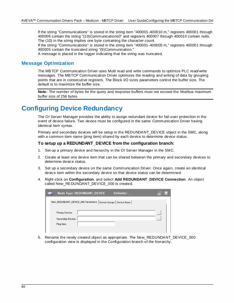
AVEVA™ Communication Drivers Pack – Modicon - MBTCP Driver User GuideConfiguring the MBTCP Communication Driver
40
If the string "Communications" is stored in the string item "400001-400010 m," registers 400001 through 400006 contain the string "(10)Communications0" and registers 400007 through 400010 contain nulls. The (10) in the string implies one byte containing the character count.
If the string "Communications" is stored in the string item "400001-400005 m," registers 400001 through 400005 contain the truncated string "(9)Communication." A message is placed in the logger indicating that the string was truncated.
Message Optimization
The MBTCP Communication Driver uses Multi read and write commands to optimize PLC read/write messages. The MBTCP Communication Driver optimizes the reading and writing of data by grouping
points that are in consecutive registers. The Block I/O sizes parameters control the buffer size. The default is to maximize the buffer size.
Note: The number of bytes for the query and response buffers must not exceed the Modbus maximum
buffer size of 256 bytes.
Configuring Device Redundancy The OI Server Manager provides the ability to assign redundant device for fail -over protection in the event of device failure. Two device must be configured in the same Communication Driver having
identical item syntax.
Primary and secondary devices will be setup in the REDUNDANT_DEVICE object in the SMC, along with a common item name (ping item) shared by each device to determine device status.
To setup up a REDUNDANT_DEVICE from the configuration branch:
1. Set-up a primary device and hierarchy in the OI Server Manager in the SMC.
2. Create at least one device item that can be shared between the primary and secondary devices to determine device status.
3. Set up a secondary device on the same Communication Driver. Once again, create an identical
device item within the secondary device so that device status can be determined.
4. Right -click on Configuration, and select Add REDUNDANT_DEVICE Connection. An object called New_REDUNDANT_DEVICE_000 is created.
5. Rename the newly created object as appropriate. The New_REDUNDANT_DEVICE_000 configuration view is displayed in the Configuration branch of the hierarchy.

Configuring the MBTCP Communication DriverAVEVA™ Communication Drivers Pack – Modicon - MBTCP Driver User Guide
41
6. Enter or use the device browser to select the primary and secondary devices. Save the hierarchy node configuration by clicking on the save icon.
Note: The primary device and secondary device must be a PLC object, and not the Port or Bridge
objects.
Note: Unsolicited message configuration is not supported from the device redundant hierarchy.
Important: A Ping item must be specified and be a valid tag in both the primary and secondary
controllers to determine the connection status for $SYS$Status. The Ping item can be a static item in the device such as a firmware version or processor type. If the Ping item is invalid or does not exist in the controller, the failover operation may not work correctly as the value of $SYS$Status may continue to
stay as FALSE in the standby device.
Device Group Definitions The Device Groups tab in the OI Server Manager user interface is used to create new, modify, or delete device group definitions for an object. For DDE/SuiteLink communications, one or more device group definitions must exist for each PLC that the Communication Driver will communicate with.
Important: For DDE/SuiteLink, it is strongly recommended that each device group (topic) definition contain a unique name for the PLC associated with it. The OPC, however, has the flexibility to use any
names, including duplicate names, for the device group definitions.
Each device group (topic) definition should contain a unique name for the PLC associated with it.
The Device Groups dialog box, which is displayed by clicking the Device Groups tab in the New_<Name>PLC_000 Parameters configuration view, is used to perform the following activities:
Adding, defining, and deleting device groups.

AVEVA™ Communication Drivers Pack – Modicon - MBTCP Driver User GuideConfiguring the MBTCP Communication Driver
42
Note: When you add a new device group, enter a unique name.
Configuring the Communication Driver to receive unsolicited messages.
Configuring default update intervals.
Editing update intervals for the device groups.
Note: When you select another part of the Communication Driver tree hierarchy, you are prompted to save the modifications to the configuration set.
To create or add device groups
1. Right -click in the Device Groups dialog box.
2. Select the Add command from the shortcut menu.
o When you add a new device group, enter a unique name (up to 32 characters long).
To make changes on device groups’ names
Change a device group’s name for an object as follows:
In the Name column, double-click on the device group’s name to be modified and make the change.
To delete device groups
Deleting a device group from the list can be performed as follows:
1. Right -click on the device group to be deleted.
2. Select the Delete command from the shortcut menu.
Note: When you select another part of the MBTCP Communication Driver tree hierarchy, you are
prompted to save the modifications to the configuration set.
To configure the MBTCP Communication Driver to receive unsolicited messages
This option is available only to the PLC nodes that are directly connected to the TCPIP_Port node. PLC
nodes that are connected underneath the ModbusBridge node do not have this capability.
Some PLCs, for example the TSX Premium PLC, can send Holding Register and Coil unsolicited data to the MBTCP DASever, while other PLCs, for example the TSX Quantum PLC, can send the Holding
Register unsolicited data only to the Communication Driver.
Note: If you have globally disabled unsolicited messages using the DASMBTCP.aarul file, configuring
Device Group parameters to support unsolicited messages will have no effect. For more information about enabling and disabling unsolicited messages, see Unsolicited Message Handling on page 47.
1. Click on the PLC’s name in the PLC branch of the Communication Driver hierarchy.
2. Select the Device Group tab of the configuration view pane at right.
3. Add a new device group or select an existing device group.
4. Right -click on the device group name, then select Edit from the shortcut menu.

Configuring the MBTCP Communication DriverAVEVA™ Communication Drivers Pack – Modicon - MBTCP Driver User Guide
43
o The Device Group Parameters dialog box is displayed.
5. In the Device Group Parameters dialog box, select the Support Unsolicited Messages check box.
6. Click the OK button to close the dialog box.
Note: Since the status of Support Unsolicited Messages check box cannot be readily viewed from the Device Groups tab, proper naming of device groups which support unsolicited messages is strongly
recommended. Unsolicited messages are only supported in the base instance of the Communication Driver (the instance of the Communication Driver without the custom name).
7. Save the configuration change by clicking the Save icon located at the upper-right corner of the configuration view pane.
Note: For more information on unsolicited messages, see Unsolicited Message Handling on page 47.
To configure default update intervals
1. To configure a default update interval for the object, right-click in the Device Groups dialog box.
2. Select Config Default Update Interval from the shortcut menu.
To make changes on update intervals
A change on an update interval for an object can be made as follows:
Double-click on the value to be modified in the Update Interval column and make the change.
o Update Interval is the frequency (in milliseconds) that the Communication Driver acquires data
from the topics associated with that device group.
o Different topics can be polled at different rates in a PLC by defining multiple device-group names for the same PLC and setting a different Update Interval for each device group.
o If you also select the "Support Unsolicited Message" checkbox as described ab ove, duplicate updates could be received by the items associated with the device group. To avoid duplicate updates, set the Update Interval to 0 (zero).
Note: When you select another part of the MBTCP Communication Driver tree hierarchy, you are prompted to save the modifications to the configuration set.
Each configuration view associated with nodes/objects in the Communication Driver hierarchy tree has a common feature, the Save button.
AVEVA™ Communication Drivers Pack – Modicon - MBTCP Driver User GuideConfiguring the MBTCP Communication Driver
44
1. When you modify any parameters in the Device Groups dialog box, click Save to save and implement the new modifications.
o If you do not click Save, the configuration is reset to its original condition (since the last save).
2. After all modifications, you must save when prompted for the new data to be saved to the configuration set.
Device Item Definitions The Device Items tab in the New_<Name>PLC_000 Parameters configuration view is used to define aliases to actual PLC items. The Device Items dialog box is the place where the following activities are performed:
Creating new device item definitions for PLC items.
Modifying the existing device items.
Deleting device items.
Archiving the created list of device items to a .csv file, a file with values separated by commas.
Importing a .csv file into the Device Items tab.
Each device item definition should contain a unique name for the PLC associated with it.
The Device Items dialog box has the following two columns:
Name: This column defines the alias names to actual PLC items.
Item Reference: The actual PLC item names, linked to the created aliases, are defined in this column.
For example:
For Modicon holding registers 400001 and 400010, the following entries can be created.
Name Item Reference
Holding1 400001
Holding10F 400010 F
Note: When you create or add a new device item, a unique name needs to be entered for it.
Once the Device Items feature is utilized to configure item names, the Communication Driver gains the capability to browse OPC Items. When the Communication Driver is running and an OPC client requests
item information, the configured items will show up under the PLC hierarchy node.
To create or add device items
1. Right -click in the Device Items dialog box.
2. Select the Add command from the shortcut menu.
o A device item is created in the Name column, and it is numerically named by default. For example, Item_0, Item_1, and so on.
3. Change the default name by double-clicking on it and entering the new name.
o Enter a unique name for the new device item. For example, "Holding1."
To add item references
Item references for each of the device items that have been created can be added as follows:

Configuring the MBTCP Communication DriverAVEVA™ Communication Drivers Pack – Modicon - MBTCP Driver User Guide
45
1. In the Item Reference column, double-click on the area in the same horizontal line as the selected device item.
2. Type in the actual PLC item name in the frame that appears.
o For example, "400001."
3. Click anywhere in the dialog box or press the ENTER key to have the change take effect.
Note: System items are not valid item references, but Communication Driver -specific system items are
valid.
To rename a device item from the list
1. Right -click on the device item to be renamed.
2. Select the Rename command from the shortcut menu and enter the new device item name.
3. Click anywhere in the dialog box or press the ENTER key to apply the change.
To delete a device item from the list
1. Right -click on the device item to be deleted.
2. Select the Delete command from the shortcut menu.
o The device item and its corresponding actual PLC item name will be deleted from the dialog box.
Note: When you select another part of the MBTCP Communication Driver tree hierarchy, you are prompted to save the modifications to the configuration set.
To clear all device items
1. Right -click anywhere in the Device Items dialog box.
2. Select the Clear All command from the shortcut menu.
o All the device items listed in the dialog box, including their corresponding actual PLC item
names, will be deleted.Related Topics
Exporting and Importing Communication Driver Item Data The Export and Import commands on the shortcut menu enable you to export and import the
Communication Driver item data to and from a CSV file, after the configuration of the Device Items has been completed. These commands will allow you to perform an off-line, large-scale edit on the item data configured for a controller, and import what has been edited back into the controller configuration. Import
what has been edited back into the PLC configuration.
The Export and Import features on the shortcut menu of the Device Items dialog box enable you to export and import the Communication Driver device item data to and from a CSV file, after the configuration of
the Device Items has been completed. These features provide you with the following capabilities:
Archive lists of device items.
Import an archived list of device items into the Device Items dialog box when you need to utilize or reconfigure any of the device items on the archived list.
Perform an off-line, large-scale edit on the item data configured for a device item list.
Import what has been edited back into the Device Items configuration.
To export device items
1. Right -click anywhere in the Device Items dialog box.
2. Select the Export command from the shortcut menu.
o The standard Save As dialog box appears.

AVEVA™ Communication Drivers Pack – Modicon - MBTCP Driver User GuideConfiguring the MBTCP Communication Driver
46
o The file name has defaulted into "PLC Hierarchyname.csv," within the current-system-configured default directory.
3. Accept the defaults to save the file.
o The file is saved as New_<PLC Name>_000.csv.
o It is editable in Microsoft Excel.
However, if you prefer to save the list someplace else and rename it, perform the following steps
after step 2.
4. Select the folder into which the list is to be saved.
5. Name the list to be archived.
6. Click the Save button.
o The whole list will be saved as a .csv file in Excel.
The file can now be edited off-line. It contains one row for each item configured with two
columns, Name and Item Reference, respectively.
To import device items
1. To import the list, right-click anywhere in the Device Items dialog box.
2. Select the Import command from the shortcut menu.
3. Select the archived list (.csv file) to be imported from the folder in which it is saved.
4. Click the Open button.
o The whole list will be brought into the Device Items dialog box.
Note: When the list to be imported contains duplicate names as found in the current list but the Item References are different, a dialog box will appear to prompt you to make a selection.
To import device item data that has been edited off-line
1. Right -click anywhere in the Device Items dialog box.
2. Clear all the item data you wish to replace with the edited .csv file by selecting the Clear All command.
o The data will be cleared after you click on Yes to confirm the deletion.
3. Select the Import command from the shortcut menu.
o The standard Open dialog box appears.
o It defaults to the .csv file extension within the current -system-configured default directory.
4. Browse for the specific CSV file you want to import, select it, then click on the Open button.
o The OI Server Manager will import the edited file and deposit it in the Device Items dialog box.
o While imported files are processed, new item references will be added, based on unique names.

Configuring the MBTCP Communication DriverAVEVA™ Communication Drivers Pack – Modicon - MBTCP Driver User Guide
47
If there are duplicate names, you will be provided with the option to replace the existing entry with the new entry, or ignore the new entry.
Scan-Based Message Handling
The Communication Drivers are based on the concept of polling a hard ware device for information. This polling is driven by a need which is expressed in the form of requests from one or more clients. Once a particular piece of information has been requested by a client, the Communication Driver formulates its
own request and sends that request to the hardware device. The Communication Driver then waits for a response to its request. Once the information has been received, the Communication Driver passes that information back to the client, and repeats the process until all c lients have ceased requesting
information.
The rate at which the Communication Driver will poll a particular device for a specific piece of information is defined in the device group (topic definition) inside the Communication Driver, using a parameter
called the Update Interval. When setting this parameter, there is always a trade -off between the update speed of the device group and the resulting decrease in system responsiveness.
Since a fast response is generally wanted, you may be tempted to set the Update Interval to a value
close to 0 (zero) seconds. However, if every point is polled at this rate, the entire system will slow down. Therefore, it is recommended that you set the Update Interval to a more reasonable value. You could also create multiple device groups for each device, setting the Update Interval to different values, then
assigning different items to different device groups depending on how quickly the values change and how quickly you want to see an update of those changes.
Some items, like alarms, change very infrequently but because of their importance require very fast
updates. For these items, set the Update Interval at a very small value. For an immediate respons e, set the Update Interval at 1 (one).
Unsolicited Message Handling
A PLC typically registers a critical event before the Communication Driver has had a chance to poll for that data. To mitigate the potential information lag, the PLC shoul d have the capability to inform the Communication Driver immediately, without having to wait for the Communication Driver to poll it.
This is the role of an unsolicited message. Once a PLC has determined that a critical condition (such as
an alarm event) exists, it can generate a message that is immediately sent to the Communication Driver without a prior request from the Communication Driver. Compared to polling the PLC for an irregular event at fixed intervals, sending unsolicited messages from the PLC to the Communication Driver when
the event occurs not only reduces network traffic, but may also get the data to the server more promptly.
Unsolicited Message Behavior
The unsolicited messaging feature is available only to controllers that a re directly connected to the
TCPIP_PORT. Controllers under the ModbusBridge Object hierarchy cannot use this feature.
In accordance with the protocol, the receiver of unsolicited messages must acknowledge the receipt of unsolicited messages.
Unsolicited Message Configuration
In order to support unsolicited messages from the devices, the MBTCP Communication Driver by default listens on Ethernet port 502.
To facilitate testing with software simulators residing on the same machine, listening on this Ethernet port can be disabled by setting the EnableListeningPort property in the TCPIP_PORT hierarchy of the MBTCP Communication Driver rule file (DASMBTCP.aarul).

AVEVA™ Communication Drivers Pack – Modicon - MBTCP Driver User GuideConfiguring the MBTCP Communication Driver
48
With unsolicited messaging enabled (the default), you can use the Device Groups dialog to configure unsolicited messaging as a Device Group parameter for the PLC nodes directly connected to the TCPIP_Port node.
For the step-by-step procedure to configure the Device Group to receive unsolicited messages, see Device Group Definitions on page 41.

AVEVA™ Communication Drivers Pack – Modicon - MBTCP Driver User Guide
49
Data Types The MBTCP Communication Driver supports the following generic data types:
Boolean
16-bit signed integer
16-bit unsigned integer
32-bit signed integer
32-bit unsigned integer
ASCII string
32-bit single precision floating point
64-bit floating point
64-bit unsigned integer
64-bit signed integer
Support for 64-bit Data Types
The MBTCP Communication Driver supports the following 64 -bit data types:
Data Type Variant Type
64-bit floating point (double)
VT_R8
64-bit signed integer
(long long)
VT_I8
64-bit unsigned integer (unsigned long long)
VT_UI8
Clients advising data values from the MBTCP Communication Driver can subscribe to tags in these
64-bit data-types using specific item syntax. The MBTCP Communication Driver reads four consecutive registers in the PLC to get a 64-bit value. These registers are read in four register orders:
o Order 1: R1 R2 R3 R4 (Default)
o Order 2: R2 R1 R4 R3
o Order 3: R3 R4 R1 R2
o Order 4: R4 R3 R2 R1
where R1, R2, R3, R4 are the registers. You can select the order in which the registers are to be read.
Comparison examples of zero- and one-based addressing:
CHAPTER 3
MBTCP OI Reference
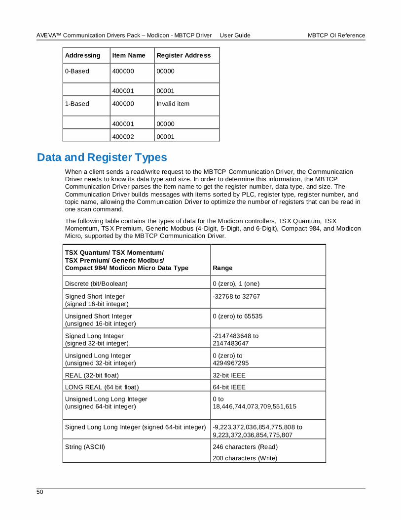
AVEVA™ Communication Drivers Pack – Modicon - MBTCP Driver User Guide MBTCP OI Reference
50
Addressing Item Name Register Address
0-Based 400000 00000
400001 00001
1-Based 400000 Invalid item
400001 00000
400002 00001
Data and Register Types When a client sends a read/write request to the MBTCP Communication Driver, the Communication Driver needs to know its data type and size. In order to determine this information, the MBTCP Communication Driver parses the item name to get the register number, data type, and size. The
Communication Driver builds messages with items sorted by PLC, register type, register number, and topic name, allowing the Communication Driver to optimize the number of registers that can be read in one scan command.
The following table contains the types of data for the Modicon controllers, TSX Quantum, TSX Momentum, TSX Premium, Generic Modbus (4-Digit, 5-Digit, and 6-Digit), Compact 984, and Modicon Micro, supported by the MBTCP Communication Driver.
TSX Quantum/ TSX Momentum/
TSX Premium/ Generic Modbus/ Compact 984/ Modicon Micro Data Type Range
Discrete (bit/Boolean) 0 (zero), 1 (one)
Signed Short Integer (signed 16-bit integer)
-32768 to 32767
Unsigned Short Integer (unsigned 16-bit integer)
0 (zero) to 65535
Signed Long Integer (signed 32-bit integer)
-2147483648 to 2147483647
Unsigned Long Integer (unsigned 32-bit integer)
0 (zero) to 4294967295
REAL (32-bit float) 32-bit IEEE
LONG REAL (64 bit float) 64-bit IEEE
Unsigned Long Long Integer (unsigned 64-bit integer)
0 to 18,446,744,073,709,551,615
Signed Long Long Integer (signed 64-bit integer) -9,223,372,036,854,775,808 to
9,223,372,036,854,775,807
String (ASCII) 246 characters (Read)
200 characters (Write)
MBTCP OI Reference AVEVA™ Communication Drivers Pack – Modicon - MBTCP Driver User Guide
51
Note: The unsigned integer data type "U" has a valid range of 0 (zero) to 2147483647 when accessed through DDE/SL client; for OPC clients the valid range is from 0 to 4294967295. System-defined types
are not supported as block reads. A read on any of these data types returns only the first element.
The following table lists the PLC register types, the data types contained in the registers, and what each
is processed as.
PLC Register Type Data Type Contained in the Register Processed As
Discrete Output (Coil) Discrete Real Time Data
Discrete Input Discrete Real Time Data
Holding Register Discrete, Integer, Float, and String Real Time Data
Input Register Discrete, Integer, Float, and String Real Time Data
Extended Register Discrete, Integer, Float, and String Real Time Data
Modbus Item Naming The Modbus -family controllers store data in the Registers. The MBTCP Communication Driver supports item names that are consistent with the point naming conventions used by the Modicon PLCs.
The following item naming conventions are described in this section:
Register-Number Item Names
Item Names Using the Modicon PLC Register Addresses
Item Names Using the Absolute Naming Convention
Item Names Using the Modulo-10000 Naming Convention
Modulo-10000 Items, BCD Register Type, and Concept Data Structures
Note: The tag-name length with SuiteLink is limited to 32 characters.
Register-Number Item Names
The register number, which is consistent with the point naming convention used by Modicon PLCs, is used as the item name. The Modbus-family PLC address ranges, supported by the Communication Driver, for the TSX Quantum, TSX Momentum, TSX Premium, Generic Modbus (4 -Digit, 5-Digit, and
6-Digit), Compact 984, and Modicon Micro PLCs are shown in the following tables.
The MBTCP Communication Driver will adhere to this address range for native mode.
Register Type
TSX Quantum/ TSX Momentum
Modicon Micro
Compact 984-265
Compact 984-145
Tag Type Access
Output Coils
1-65536 1-9999 1-65536 1-9999 Discrete Read Write
Contacts 100001-165536 10001-19999 100001-165536 10001-19999 Discrete Read- Only

AVEVA™ Communication Drivers Pack – Modicon - MBTCP Driver User Guide MBTCP OI Reference
52
Register
Type
TSX Quantum/
TSX Momentum
Modicon
Micro
Compact
984-265
Compact
984-145
Tag
Type Access
Input 300001-365536 30001-39999 300001-365536 30001-39999 Analog Read- Only
Holding 400001-465536 40001-49999 400001-465536 40001-49999 Analog Read
Write
Extended 6x0001-6x9998 6x000-6x999 Analog Read Write
Register Type
TSX Premium
(1-based addressing) [Default]
TSX Premium (0-based addressing) Tag Type Access
Output Coils
1-65536 0-65535 Discrete Read/Write. Mapped to %M PLC object; that is, Output Coils and Contacts Registers are the same.
Contacts 100001-165536 100000-16553
5
Discrete Read-Only. Mapped to %I PLC object; that
is, Output Coils and Contacts Registers are the same.
Input 300001-365536 300000-365535
Analog Read-Only. Mapped to %IW PLC object; that is, Input Registers and Holding Registers are the same.
Holding 400001-465536 400000-465535
Analog Read/Write. Mapped to %MW PLC object; that is, Input Registers and Holding Registers are the same.
Poking a value to a particular bit in the Holding register in this TSX Premium PLC is not supported.
Register Type
Generic Modbus (6-Digit)
Generic Modbus (5-Digit)
Generic Modbus (4-Digit) Tag Type Access
Output Coils
1-65536 [Default] with 1-based addressing
0-65535 if 0-based addressing
selected
1-9999 [Default] with 1-based addressing
0-9998 if 0-based addressing selected
1-999 [Default] with 1-based addressing
0-998 if 0-based addressing selected
Discrete Read Write

MBTCP OI Reference AVEVA™ Communication Drivers Pack – Modicon - MBTCP Driver User Guide
53
Register Type
Generic Modbus (6-Digit)
Generic Modbus (5-Digit)
Generic Modbus (4-Digit) Tag Type Access
Contacts 100001-165536
[Default] with 1-based addressing
100000-165535 if 0-based addressing is
selected
10001-19999
[Default] with 1-based addressing
10000-19998 if 0-based addressing is selected
1001-1999 [Default]
with 1-based addressing
1000-1998
if 0-based addressing is selected
Discrete Read-
Only
Input 300001-365536 [Default]
with 1-based addressing
300000-365535
if 0-based addressing is selected
30001-39999 [Default]
with 1-based addressing
30000-39998
if 0-based addressing is selected
3001-3999 [Default] with 1-based
addressing
3000-3998
if 0-based addressing is selected
Analog Read- Only
Holding 400001-465536 [Default] with 1-based
addressing
400000-465535 if 0-based
addressing is selected
40001-49999 [Default] with 1-based
addressing
40000-49998 if 0-based addressing
is selected
4001-4999 [Default] with 1-based addressing
4000-4998 if 0-based addressing is selected
Analog Read Write
Extended 6x0001-6x9999
[Default] with 1-based addressing
0-based addressing is not supported for this
Register Type.
6x001-6x999 [Default]
with 1-based addressing
0-based addressing is
not supported for this Register Type.
Not supported Analog Read
Write
Note: The x in the Extended register number indicates the file number, where x = 0 implies file number 1,
x = 1 implies file number 2, up to x = 9 implies file number 10. The extended memory size in the PLC determines how many extended memory files exist. Each file contains up to 10000 registers. The last file
in the PLC will always contain less than 10000 registers.
For example:
A 24K-extended-memory-size PLC contains three (3) files, where the last file contains 4576 registers. A 72K-extended-memory-size PLC contains eight (8) files, where the last file contains 3728
registers. A 96K-extended-memory-size PLC contains 10 files, where the last file contains 8304 registers. 1K is 1024 registers.

AVEVA™ Communication Drivers Pack – Modicon - MBTCP Driver User Guide MBTCP OI Reference
54
Item Names Using the Modicon PLC Register Addresses
The following table lists other item name formats that are consistent with the point naming convention
with the MBTCP Communication Driver suffix.
Item Name Description
400001 When no spaces and no letters follow the register number, the register contents
are treated as a 16-bit unsigned quantity.
400001 S When a space and the letter "S" follow the register number, the register contents are treated as a 16-bit signed quantity.
400001 I When a space and the letter "I" follow the register number, the register contents are treated as a 32-bit signed quantity. This takes up two consecutive registers.
400001 L When a space and the letter "L" follow the register number, the register contents are treated as a 32-bit signed quantity. This takes up two consecutive registers.
400001 F When a space and the letter "F" follow the register number, the register contents are treated as a floating-point quantity. This takes up two consecutive registers.
400001 U When a space and the letter "U" follow the register number, the register contents are treated as a 32-bit unsigned quantity. This takes up two consecutive registers.
400001 LF When a space and the letter "LF", follows the register number, the register contents are treated as a 64-bit floating-point quantity. This takes up four consecutive registers.
400001 LL When a space and the letter "LL", follows the register number, the register contents are treated as a 64-bit signed quantity. This takes up four consecutive registers.
400001 UL When a space and the letter "UL", follows the register number, the register contents are treated as a 64-bit unsigned quantity. This takes up four consecutive registers.
400001-400003 M
When a space and the letter "M" follow the register number or register number pair separated by a dash, the register contents are treated as ASCII data. Each register contains up to two (2) ASCII characters.
This example represents six (6) ASCII characters.
300001:10 When a colon and a number from 1 (one) to 16 follow the register number, the register contents are treated as discrete data.
This example represents bit 10 of the input register 300001.
Absolute Notation Item Names
The MBTCP Communication Driver also uses another naming convention called the Absolute Notation.
This naming convention is independent of the PLC model numbers.
The Absolute naming convention allows access to the four Modbus data types, each with an address from 0 to 65535. The data types are indicated by the item name suffix characters.

MBTCP OI Reference AVEVA™ Communication Drivers Pack – Modicon - MBTCP Driver User Guide
55
Item Name Description Range
nnnnn DO Discrete Output
Refers to the same data Modbus calls "coils."
0 (zero) DO through 65535 DO
nnnnn DI Discrete Input
Refers to the same data called "contacts" by Modbus.
0 (zero) DI through 65535 DI
nnnnn IR Input Register
Refers to the same data called "input register."
(zero) IR through 65535 IR
nnnnn HR Holding Register
Refers to the same data Modbus calls "holding register."
0 (zero) HR through 65535 HR
nnnnn PV Process Variable
Refers to holding register, but treated as floating points and assumes two (2) registers
per floating-point number.
0 (zero) PV through 65535 PV
The IR and HR absolute notation can also be combined with the following conversions: L (long), F
(floating), S (signed), or U (unsigned).
For example:
219 HRS 16-bit signed integer
000 HRL 32-bit signed integer
100 HRF 32-bit floating point
000 HRU 32-bit unsigned integer
100 HRLF 64-bit floating point
000 HRLL 64-bit signed integer
000 HRUL 64-bit unsigned integer
Modulo-10000 Point Item Names
The MBTCP OI Server uses the Modulo-10000 Points naming convention, where the item name is two registers separated by a dash, with no spaces and no letters following the registers.
Two or three consecutive registers may be interpreted as a single numeric quantity, and each of the component registers must be in the range of 0-9999.
Item Name Description
400001-400002 Can represent numbers between 0 and 99,999,999. Register 400001 = <9999> and Register 400002 = <9999>.
400005-400007 Can represent numbers between 0 and 2,147,483,646. Register 400005 = <21>, Register 400006 = <4748>, and Register 400007 = <3646>.

AVEVA™ Communication Drivers Pack – Modicon - MBTCP Driver User Guide MBTCP OI Reference
56
When grouping three consecutive registers for interpretation as a single numeric quantity, overflow becomes a possibility.
The largest number that may be represented in the PLC with three consecutive Modulo -10000
registers is 999,999,999,999; however, the largest number that can be contained in an integer -type variable is 2,147,483,647. The latter number is used by the OI Server to represent an overflow condition.
Therefore, the maximum usable value represented in three Modulo -10000 registers is 2,147,483,646 or (<21><4748><3646>). Any number larger than this will be clamped at 2,147,483,647.
Modulo-10000 Items, BCD Register Type, and Concept Data Structures
All the integer holding registers, 16- and 32-bit, signed and unsigned, and Modulo-10000 item types honor the configuration parameters Register type and Concept data structures.
When the Register type parameter is BCD and the Use Concept data structures (Longs) parameter is
selected, the data is displayed in BCD and written to the PLC in the BCD format. In addition, data that takes up two registers (Longs), except Reals, is displayed and written in the Concept-data-structure format.
The same applies when the Register type parameter is Binary and the Use Concept data structures (Longs) parameter is selected; the data is displayed in Binary and written to the PLC in the Binary format. In addition, data that takes up two registers (Longs), except Reals, are displayed and written in the
Concept-data-structure format.
When the Register type parameter is BCD and the Use Concept data structures (Longs) parameter is not selected, the data is displayed in BCD and written to the PLC in the BCD format. In addition, data that
takes up two registers (Longs), except Reals, is displayed and written in the non-Concept-data-structure format.
The same applies when the Register type parameter is Binary and the Use Concept data structures
(Longs) parameter is not selected; the data is displayed in Binary and written to the PLC in the B inary format. In addition, data that takes up two registers (Longs), except Reals, is displayed and written in the non-Concept-data-structure format.
The Concept-data-structure format implies that data is displayed and written the same way that the Concept program handles data.
Concept-data-structure format is where the data is displayed and written in the
last-register-to-first-register order. For example: When writing the value 2147483646 to the Modulo-10000 item 400001-400003, the value 21 is written
first to register 400003, then the value 4748 is written to register 400002, and then the value 3646 is written to register 400001.
The non-Concept -data-structure format is the opposite of the Concept-data-structure format.
The value 21 is written first to register 400001, then the value 4748 is written to register 400002, and then the value 3646 is written to register 400003.
Modulo-10000 items can be displayed and written in the BCD and Binary formats. When the
Modulo-10000 item occupies two registers, the maximum value that can be displayed and written is 99999999. When the Modulo-10000 item occupies three registers, the maximum value that can be displayed and written is 2147483646.
Warning messages are logged and the client value status is updated when data is clamped high when reading or writing data. Warning messages will also be displayed when the PLC data does not convert to BCD correctly.

MBTCP OI Reference AVEVA™ Communication Drivers Pack – Modicon - MBTCP Driver User Guide
57
Zero- and One-Based Addressing PLCs in which the address of the register is equivalent to the subscribed tag address are known as
zero-based PLCs (also written as "0-based"). In zero-based PLCs, the tag 400000 corresponds to the holding register address 00000 in the PLC. In one-based PLCs, the tag 400001 corresponds to the holding register address 00000 in the PLC. The TSX Premium model PLC is zero-based.
To support zero-based PLCs, the MBTCP OI Server has implemented a configurable zero -based and one-based addressing scheme. The TSX Premium, Generic ModbusPLC, and the ModbusPLCRS PLC hierarchies have the zero-based addressing option.
The default addressing scheme in the MBTCP OI Server is one-based.
Generic OPC Syntax A OI Server serves as a container for the OPC Groups, which provide the mechanism for containing and
logically organizing OPC items. Within each OPC Group, an OPC-compliant client can register OPC items, which represent connections to devices in the field device. In other words, all access to OPC items is maintained through the OPC Group.
The fully qualified name for an OPC item is called the Item ID (equivalent to Item Name). The syntax for specifying a unique Item ID is OI Server-dependent. In OPC data acquisition OI Servers, the syntax can be as follows:
AREA10.VESSEL1.TIC1.PLC.400001
where each component (delimited by a period) represents a branch or leaf of the field device’s hierarchy.
In this example:
AREA10.VESSEL1.TIC1 is the link name for a OI Server.
PLC is the name of the target PLC.
400001 is the specific data point (Item) desired.
An item is typically a single value such as an analog, digital, or string value.
Where Item ID describes the syntax for defining the desired data point, OPC provides for another
parameter, called Access Path, that defines optional specifications for obtaining that data.
In OI Servers, Access Paths are equivalent to Device Groups; it is this parameter that is used to define the update interval between the OI Server and the field device for accessing the values of data points in
the PLC.
Supported MBTCP OI Server Hardware and Firmware The following table lists the Modbus hardware and firmware supported by the MBTCP OI Server.
Legend Model Description Firmware
TSX Quantum 140 CPU 21304 Controller Exec ID 0871 HID 0405 Rev 02.10
140 NOE 771 00 Ethernet TCP/IP Option Module
140 NOE 21100 Ethernet TCP/IP Module
TSX Momentum Controller

AVEVA™ Communication Drivers Pack – Modicon - MBTCP Driver User Guide MBTCP OI Reference
58
Legend Model Description Firmware
170 ENT 110 01 Ethernet TCP/IP Module
TSX Premium TSX P57 402 Controller
TSX P57 4823 Controller
TSX ETY 110 EtherNet TCP/IP Module
TSX Momentum
(RS232) Controller
171 CCC 980 20 Ethernet TCP/IP Module
and Modbus Ports
TSX Momentum (RS485)
Controller
171 CCC 980 20 Ethernet TCP/IP Module and Modbus Ports
Compact 984 (RS232, 5-Digit Addressing)
PC-A984-145 Controller Exec ID 084E Model A145
Compact 984 (RS232, 6-Digit Addressing)
PC-E984-265 Controller
Modicon Micro (RS232)
110 CPU 311 01 Controller Exec ID 0863 HID 0701 Rev 01.10 Model 311/01
Generic Modbus
Controller (4-Digit, 5-Digit, 6-Digit)
Generic Modbus
Controller. Controller must conform to the Modbus "Application
Protocol specifications."
The Generic Modbus
controller will be simulated with the Modbus Simulator version 1.05 developed by
Wingpath Ltd.
NR&D Bridge Pen-T Ethernet-to-Serial Bridge
Modbus Bridge Power Logic EGX
100
TSX ETG 100
Bridge
Controller Function Codes The MBTCP Communication Driver uses function codes to communicate with the various controllers supporting the Modbus protocol. The implementation for the MBTCP Communication Driver uses the document, " Open Modbus/TCP Specification," Release 1.1, dated December 6, 2002 as a reference.
These function codes and their descriptions are listed in the following table.

MBTCP OI Reference AVEVA™ Communication Drivers Pack – Modicon - MBTCP Driver User Guide
59
Note: In communicating with the Generic Modbus PLCs, the MBTCP Communication Driver acts as a master and sends out the function codes to the PLCs.
Code Name Description
01 (0x01) Read Coils Reads the ON/OFF status of discrete outputs (0X references, coils) in the slave.
02 (0x02) Read Discrete
Inputs
Reads the ON/OFF status of discrete inputs (1XXXXX references) in
the slave.
03 (0x03) Read Holding Registers
Reads the binary contents of holding registers (4XXXXX references) in the slave.
04 (0x04) Read Input Registers
Reads the binary contents of input registers (3XXXXX references) in the slave.
05 (0x05) Write Single
Coil
Forces a single coil (0X reference) to either ON or OFF.
06 (0x06) Write Single Register
Presets a value into a single holding register (4XXXXX reference).
15 (0x0F) Write Multiple Coils
Forces each coil (0XXXXX reference) in a sequence of coils to either ON or OFF.
16 (0x10) Write Multiple
Registers
Presets values into a sequence of holding registers (4XXXXX
references).
20 (0x14) Read General Reference
Returns the contents of registers in the Extended Memory file (6XXXXX) references.
21 (0x15) Write General Reference
Writes the contents of registers in the Extended Memory file (6XXXXX) references.
22 (0x16) Mask Write
Holding Register
Modifies the contents of a specified (4XXXXX reference) holding
register using a combination of an AND mask, an OR mask, and the register’s current contents. The function can be used to set or clear individual bits in the register.
Modbus Exception Codes Additionally, there are exception codes generated by Modbus. The accompanying table shows these exceptions and their explanations.
Exception
Code (Hex) Name Explanation
01 ILLEGAL
FUNCTION
The function code received in the query is not an allowable action for the
slave. This may be because the function code is only applicable to newer controllers, and was not implemented in the unit selected. It could also indicate that the slave is in the wrong state to process a request of this
type; for example, because it is unconfigured and is being asked to return register values.

AVEVA™ Communication Drivers Pack – Modicon - MBTCP Driver User Guide MBTCP OI Reference
60
Exception Code (Hex) Name Explanation
02 ILLEGAL DATA ADDRESS
The data address received in the query is not an allowable address for the slave. More specifically, the combination of reference number and transfer length is invalid. For a controller with 100 registers, a request
with offset 96 and length 4 would succeed, a request with offset 96 and length 5 will generate exception 02.
03 ILLEGAL DATA
VALUE
A value contained in the query data field is not an allowable value for the
slave. This indicates a fault in the structure of the remainder of a complex request, such as that the implied length is incorrect. It specifically does NOT mean that a data item submitted for storage in a register has a
value outside the expectation of the application program, since the MODBUS protocol is unaware of the significance of any particular value of any particular register.
04 ILLEGAL RESPONSE LENGTH
Indicates that the request as framed would generate a response whose size exceeds the available MODBUS data size. Used only by functions generating a multi-part response, such as functions 20 and 21.
05 ACKNOWLEDGE Specialized use in conjunction with programming commands.
06 SLAVE DEVICE BUSY
Specialized use in conjunction with programming commands.
07 NEGATIVE ACKNOWLEDGE
Specialized use in conjunction with programming commands.
08 MEMORY
PARITY ERROR
Specialized use in conjunction with function codes 20 and 21 to indicate
that the extended file area failed to pass a consistency check.
0A GATEWAY PATH
UNAVAILABLE
Specialized use in conjunction with gateways; it indicates that the
gateway was unable to allocate a Modbus Plus PATH to use to process the request. It usually means that the gateway is misconfigured.
0B GATEWAY TARGET
DEVICE FAILED TO RESPOND
Specialized use in conjunction with gateways; it indicates that no response was obtained from the target device. It usually means that the
device is not present on the network.
TCP Port The MBTCP Communication Driver uses port 502 as the default to contact all PLCs. This includes the port used for unsolicited messages from the PLCs that are programmed to provide unsolicited data (that is, the PLCs that are directly connected to the TCPIP_PORT; controllers under the ModbusBridge Object
hierarchy cannot utilize this unsolicited messaging feature).
However, you have the option to configure the actual port to be used through the ModbusPLC object. When a non-502 port is used by the Generic Modbus PLC to communicate with the MBTCP
Communication Driver, it will not be able to send unsolicited data to the Communication Driver.

AVEVA™ Communication Drivers Pack – Modicon - MBTCP Driver User Guide
61
Error Messages and Codes Generic Communication Driver error messages and MBTCP -OI Server-specific messages are supported. Use the Log Flag data to customize the messages logged to the Log Vie wer. See the Log Viewer online documentation for more information about using log flags.
To troubleshoot Communication Driver problems, use the following error messages together with the OI Server Manager Diagnostics root data.
In the following Communication Driver Error Messages table:
<Message ID> corresponds to the message ID displayed in the Communication Driver’s Diagnostics root in the OI Server Manager.
<Device> refers to the node name of the device.
Communication Driver Error Messages
The following table lists all the generic-Communication Driver and MBTCP--specific error messages that are logged to the Log Viewer.
Error Message Explanation Probable Cause Solution Log Flag
"CoilRead" is missing from the DASMBTCP.AAcfg
file under <PLC name>.
The mandatory <CoilRead> field is absent from the
DeviceNode named <PLC Name> in the configuration file.
The entry is deleted from the file manually.
Use the OI Server Manager to
rebuild the file.
DASProtFail
"CoilWrite" is
missing from the DASMBTCP.AAcfg file under <PLC
name>.
The mandatory
<CoilWrite> field is absent from the DeviceNode named
<PLC Name> in the configuration file.
The entry is
deleted from the file manually.
Use the OI
Server Manager to rebuild the file.
DASProtFail
"ExtendedRegisterRead" is missing from
the DASMBTCP.AAcfg file under <PLC
name>.
The mandatory <ExtendedRegisterRe
ad> field is absent from the DeviceNode named <PLC Name>
in the configuration file.
The entry is deleted from the
file manually.
Use the OI Server
Manager to rebuild the file.
DASProtFail
CHAPTER 4
Troubleshooting the MBTCP
Communication Driver

AVEVA™ Communication Drivers Pack – Modicon - MBTCP Driver User GuideTroubleshooting the MBTCP Communication Driver
62
Error Message Explanation Probable Cause Solution Log Flag
"ExtendedRegisterWrite" is missing from
the DASMBTCP.AAcfg file under <PLC
name>.
The mandatory <ExtendedRegisterWri
te> field is absent from the DeviceNode named <PLC Name>
in the configuration file.
The entry is deleted from the
file manually.
Use the OI Server
Manager to rebuild the file.
DASProtFail
"HoldingRegisterRead" is missing from the
DASMBTCP.AAcfg file under <PLC name>.
The mandatory <HoldingRegisterRead> field is absent from
the DeviceNode named <PLC Name> in the configuration file.
The entry is deleted from the file manually.
Use the OI Server Manager to
rebuild the file.
DASProtFail
"HoldingRegisterWrit
e" is missing from the DASMBTCP.AAcfg
file under <PLC name>.
The mandatory
<HoldingRegisterWrite> field is absent from the DeviceNode
named <PLC Name> in the configuration file.
The entry is
deleted from the file manually.
Use the OI
Server Manager to rebuild the file.
DASProtFail
"InputRegisterRead" is missing from the
DASMBTCP.AAcfg file under <PLC name>.
The mandatory <InputRegisterRead>
field is absent from the DeviceNode named <PLC Name> in the
configuration file.
The entry is deleted from the
file manually.
Use the OI Server
Manager to rebuild the file.
DASProtFail
"IPAddress" is missing from the DASMBTCP.AAcfg
file under <PLC name>.
The mandatory <IPAddress> field is absent from the
DeviceNode named <PLC Name> in the Configuration file.
The entry is deleted from the file manually.
Use the OI Server Manager to
build the file.
DASProtFail
"MaxAddrExtended
Registers" is missing from the DASMBTCP.AAcfg
file under <PLC name>.
The mandatory
<MaxAddrExtendedRegisters> field is absent from the DeviceNode
named <PLC Name> in the configuration file.
The entry is
deleted from the file manually.
Use the OI
Server Manager to rebuild the file.
DASProtFail
"MaxAddrHoldingRegisters" is missing
from the DASMBTCP.AAcfg file under <PLC
name>.
The mandatory <MaxAddrHoldingRegi
sters> field is absent from the DeviceNode named <PLC Name>
in the configuration file.
The entry is deleted from the
file manually.
Use the OI Server
Manager to rebuild the file.
DASProtFail
"MaxAddrInputRegisters" is missing from the
DASMBTCP.AAcfg file under <PLC name>.
The mandatory <MaxAddrInputRegisters> field is absent
from the DeviceNode named <PLC Name> in the configuration file.
The entry is deleted from the file manually.
Use the OI Server Manager to
rebuild the file.
DASProtFail

Troubleshooting the MBTCP Communication DriverAVEVA™ Communication Drivers Pack – Modicon - MBTCP Driver User Guide
63
Error Message Explanation Probable Cause Solution Log Flag
"MaxAddrReadCoils" is missing from the
DASMBTCP.AAcfg file under <PLC name>.
The mandatory <MaxAddrReadCoils>
field is absent from the DeviceNode named <PLC Name> in the
configuration file.
The entry is deleted from the
file manually.
Use the OI Server
Manager to rebuild the file.
DASProtFail
"MaxAddrWriteCoils" is missing from the DASMBTCP.AAcfg
file under <PLC name>.
The mandatory <MaxAddrWriteCoils> field is absent from the
DeviceNode named <PLC Name> in the configuration file.
The entry is deleted from the file manually.
Use the OI Server Manager to
rebuild the file.
DASProtFail
"MaxQueuedMsgs"
is missing from the DASMBTCP.AAcfg file under <PLC
name>.
The mandatory
<MaxQueuedMsgs> field is absent from the DeviceNode named
<PLC Name> in the configuration file.
The entry is
deleted from the file manually.
Use the OI
Server Manager to rebuild the file.
DASProtFail
"RegisterSize" is missing from the DASMBTCP.AAcfg
file under <PLC name>.
The mandatory <RegisterSize> field is absent from the
DeviceNode named <PLC Name> in the configuration file.
The entry is deleted from the file manually.
Use the OI Server Manager to
rebuild the file.
DASProtFail
"RegisterType" is
missing from the DASMBTCP.AAcfg file under <PLC
name>.
The mandatory
<RegisterType> field is absent from the DeviceNode named
<PLC Name> in the configuration file.
The entry is
deleted from the file manually.
Use the OI
Server Manager to rebuild the file.
DASProtFail
"ReplyTimeout" is missing from the
DASMBTCP.AAcfg file under <PLC name>."
The mandatory <ReplyTimeout> field
is absent from the DeviceNode named <PLC Name> in the
Configuration file.
The entry is deleted from the
file manually.
Use the OI Server
Manager to build the file.
DASProtFail
"StringVariableStyle" is missing from the DASMBTCP.AAcfg
file under <PLC name>.
The mandatory <StringVariableStyle> field is absent from the
DeviceNode named <PLC Name> in the configuration file.
The entry is deleted from the file manually.
Use the OI Server Manager to
rebuild the file.
DASProtFail
"UnitID" is missing
from the DASMBTCP.AAcfg file under <PLC
name>.
The mandatory
<UnitID> field is absent from the DeviceNode named <PLC Name>
in the Configuration file.
The entry is
deleted from the file manually.
Use the OI
Server Manager to build the file.
DASProtFail

AVEVA™ Communication Drivers Pack – Modicon - MBTCP Driver User GuideTroubleshooting the MBTCP Communication Driver
64
Error Message Explanation Probable Cause Solution Log Flag
"UseLongConceptDataStruct" is missing
from the DASMBTCP.AAcfg file under <PLC
name>.
The mandatory <UseLongConceptDat
aStruct> field is absent from the DeviceNode named <PLC Name>
in the configuration file.
The entry is deleted from the
file manually.
Use the OI Server
Manager to rebuild the file.
DASProtFail
"UseRealConceptDataStruct" is missing from the
DASMBTCP.AAcfg file under <PLC name>.
The mandatory <UseRealConceptDataStruct> field is absent
from the DeviceNode named <PLC Name> in the configuration file.
The entry is deleted from the file manually.
Use the OI Server Manager to
rebuild the file.
DASProtFail
<PLC Name> does
not allow extended register <Item name>.
The PLC does support
extended registers.
The client defined
an extended register and it is not supported.
Remove
extended register from client.
DASProtFail
<PLC Name>:
Clamping a write to <Item Name> - Received <client
value>, writing <clamped value>.
The client wrote a
value that exceeded the item limits.
The client wrote
an invalid value.
The client must
write a smaller value.
DASProtWar
n
An invalid floating point value was
returned by the PLC for item name <PLC Name>.<Item
Name>. The value was converted to a negative 3.4e38.
Invalid floating-point number (Negative
Infinity). Set the item value to Negative Infinity 3.4e+38.
The values read from the PLC
registers cannot be converted to a valid float
number.
Check the PLC for the value in
the registers.
DASProtFail
An invalid floating
point value was returned by the PLC for item name <PLC
Name>.<Item Name>. The value was converted to a
positive 3.4e38.
Invalid floating-point
number (Positive Infinity). Set the item value to Positive
Infinity 3.4e+38.
The values read
from the PLC registers cannot be converted to a
valid float number.
Check the PLC
for the value in the registers.
DASProtFail
Connection to PLC <PLC name> at IP Address <Host
name> closed, error code = <Error code>.
The PLC closed the connection.
The PLC may be having problems.
Check the PLC. DASProtFail
CreateItem failed <PLC name>.<Item
Name>.
The server encountered an invalid
item name.
An invalid item name was
defined by the client.
Correct the item name defined
by the client.
DASProtFail
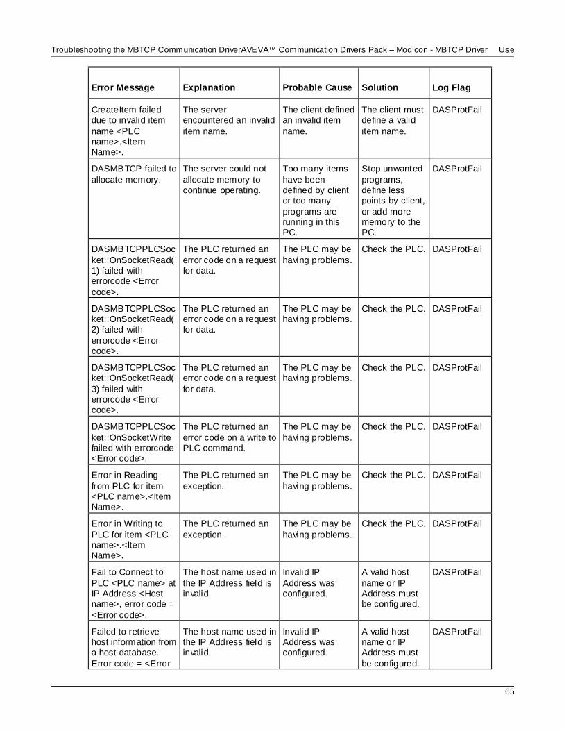
Troubleshooting the MBTCP Communication DriverAVEVA™ Communication Drivers Pack – Modicon - MBTCP Driver User Guide
65
Error Message Explanation Probable Cause Solution Log Flag
CreateItem failed due to invalid item
name <PLC name>.<Item Name>.
The server encountered an invalid
item name.
The client defined an invalid item
name.
The client must define a valid
item name.
DASProtFail
DASMBTCP failed to
allocate memory.
The server could not
allocate memory to continue operating.
Too many items
have been defined by client or too many
programs are running in this PC.
Stop unwanted
programs, define less points by client,
or add more memory to the PC.
DASProtFail
DASMBTCPPLCSoc
ket::OnSocketRead(1) failed with errorcode <Error
code>.
The PLC returned an
error code on a request for data.
The PLC may be
having problems.
Check the PLC. DASProtFail
DASMBTCPPLCSocket::OnSocketRead(2) failed with
errorcode <Error code>.
The PLC returned an error code on a request for data.
The PLC may be having problems.
Check the PLC. DASProtFail
DASMBTCPPLCSocket::OnSocketRead(
3) failed with errorcode <Error code>.
The PLC returned an error code on a request
for data.
The PLC may be having problems.
Check the PLC. DASProtFail
DASMBTCPPLCSoc
ket::OnSocketWrite failed with errorcode <Error code>.
The PLC returned an
error code on a write to PLC command.
The PLC may be
having problems.
Check the PLC. DASProtFail
Error in Reading
from PLC for item <PLC name>.<Item Name>.
The PLC returned an
exception.
The PLC may be
having problems.
Check the PLC. DASProtFail
Error in Writing to
PLC for item <PLC name>.<Item Name>.
The PLC returned an
exception.
The PLC may be
having problems.
Check the PLC. DASProtFail
Fail to Connect to
PLC <PLC name> at IP Address <Host name>, error code =
<Error code>.
The host name used in
the IP Address field is invalid.
Invalid IP
Address was configured.
A valid host
name or IP Address must be configured.
DASProtFail
Failed to retrieve host information from a host database.
Error code = <Error
The host name used in the IP Address field is invalid.
Invalid IP Address was configured.
A valid host name or IP Address must
be configured.
DASProtFail

AVEVA™ Communication Drivers Pack – Modicon - MBTCP Driver User GuideTroubleshooting the MBTCP Communication Driver
66
Error Message Explanation Probable Cause Solution Log Flag
number>.
Failed to split the
message from ReceiveBuffer for Sequence Number
<Sequence Number>, message possibly revoked.
A message returned by
the PLC was not found in the requested messages queue.
The message
may have timed out and was removed from the
queue.
Increase the
ReplyTimeout timer.
DASProtFail
Invalid value read for
Mod 10000 register: <Item Name> on Node: <PLC Name>.
Not a valid BCD-value. Convert to
2147483647.
The Modulo-10000
point value overflows. The value is clamped to 2147483647 to
indicate overflow condition.
The maximum
usable value represented in three
Modulo-10000 registers is 2,147,483,646.
Check the PLC
for the value in the registers.
DASProtWar
n
Read value beyond limits for Mod 10000 register: <Item
Name> on Node: <PLC Name>. Value clamped to 9999.
The Modulo-10000 point value overflows. The value is clamped
to 9999.
The maximum usable value represented in
one Modulo-10000 registers is 9999.
Check the PLC for the value in the registers.
DASProtWarn
recv() failed with errorcode <Error Code>.
The PLC responded with an error.
The PLC may be down or there is a communications
problem.
Check the PLC and the communication
s link.
DASProtFail
Register Type is ’BCD’. Value clamped to 9999.
The Modulo-10000 point output value overflows. The value is
clamped.
The Modulo-10000 value written to
the PLC exceeded the max limit.
The client must write a smaller value.
DASProtWarn
Register Type is hot-configured to
<Register type>.
The Register Type parameter was
modified at run time.
The user modified the Register Type
parameter while the server was running.
The Register Type parameter
can be modified at run time.
DASProtWarn
Reply Timeout is
hot-configured to <Reply timeout value>.
The Reply Timeout
parameter was modified at run time.
The user modified
the Reply Timeout parameter while
the server was running.
The Reply
Timeout parameter can be modified at
run time.
DASProtWar
n
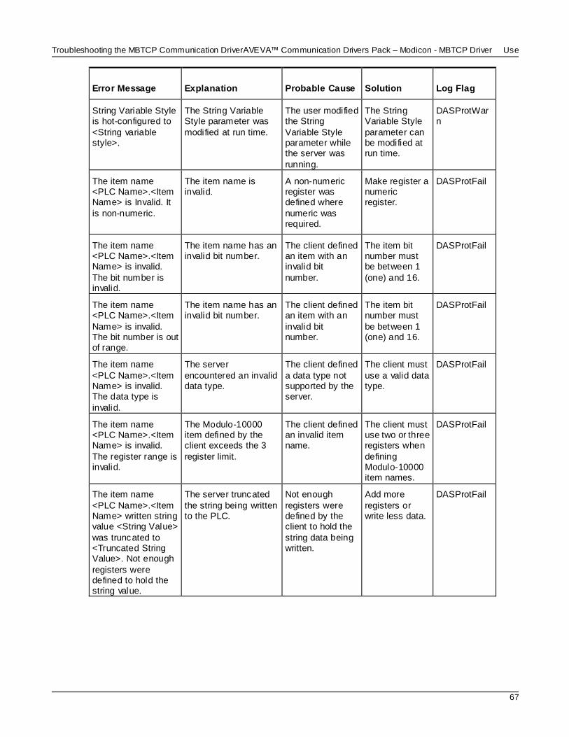
Troubleshooting the MBTCP Communication DriverAVEVA™ Communication Drivers Pack – Modicon - MBTCP Driver User Guide
67
Error Message Explanation Probable Cause Solution Log Flag
String Variable Style is hot-configured to
<String variable style>.
The String Variable Style parameter was
modified at run time.
The user modified the String
Variable Style parameter while the server was
running.
The String Variable Style
parameter can be modified at run time.
DASProtWarn
The item name <PLC Name>.<Item Name> is Invalid. It
is non-numeric.
The item name is invalid.
A non-numeric register was defined where
numeric was required.
Make register a numeric register.
DASProtFail
The item name <PLC Name>.<Item Name> is invalid.
The bit number is invalid.
The item name has an invalid bit number.
The client defined an item with an invalid bit
number.
The item bit number must be between 1
(one) and 16.
DASProtFail
The item name <PLC Name>.<Item
Name> is invalid. The bit number is out of range.
The item name has an invalid bit number.
The client defined an item with an
invalid bit number.
The item bit number must
be between 1 (one) and 16.
DASProtFail
The item name
<PLC Name>.<Item Name> is invalid. The data type is
invalid.
The server
encountered an invalid data type.
The client defined
a data type not supported by the server.
The client must
use a valid data type.
DASProtFail
The item name <PLC Name>.<Item Name> is invalid.
The register range is invalid.
The Modulo-10000 item defined by the client exceeds the 3
register limit.
The client defined an invalid item name.
The client must use two or three registers when
defining Modulo-10000 item names.
DASProtFail
The item name
<PLC Name>.<Item Name> written string value <String Value>
was truncated to <Truncated String Value>. Not enough
registers were defined to hold the string value.
The server truncated
the string being written to the PLC.
Not enough
registers were defined by the client to hold the
string data being written.
Add more
registers or write less data.
DASProtFail

AVEVA™ Communication Drivers Pack – Modicon - MBTCP Driver User GuideTroubleshooting the MBTCP Communication Driver
68
Error Message Explanation Probable Cause Solution Log Flag
The PLC <PLC Name> message
timed out (OnPLCReceiverTimeout), revoking
message <Message ID>.
The server did not get a response from the
PLC in the <ReplyTimeout> allotted time.
The PLC is offline or the data
request has an invalid register number obtained
from the configuration file.
Check PLC's network
connection or configuration file.
DASProtFail
The PLC <PLC name> reported
receiving an ILLEGAL FUNCTION code
from the OI Server. PLC errorcode 01.
The function code received in the query is
not an allowable action for the slave.
This may be because the
function code is only applicable to newer controllers,
and was not implemented in the unit selected.
It could also indicate that the slave is in the
wrong state to process a request of this type; for
example, because it is unconfigured and
is being asked to return register values.
Check the item definition and
PLC configuration.
DASProtFail
The PLC <PLC
name> reported receiving an ILLEGAL DATA
ADDRESS from the OI Server. PLC errorcode 02.
The data address
received in the query is not an allowable address for the slave.
The item address
is out of the configured-slave address range, or
the combination of reference number and
transfer length is invalid. For a controller with
100 registers, a request with offset 96 and
length 4 would succeed, a request with
offset 96 and length 5 will generate
exception 02.
Check the item
definition and PLC configuration.
DASProtFail
The PLC <PLC name> reported receiving an
ILLEGAL DATA
A value contained in the query data field is not an allowable value
for the slave.
This indicates a fault in the structure of the
remainder of a
Check the data value sent to the PLC.
DASProtFail

Troubleshooting the MBTCP Communication DriverAVEVA™ Communication Drivers Pack – Modicon - MBTCP Driver User Guide
69
Error Message Explanation Probable Cause Solution Log Flag
VALUE from the OI Server. PLC
errorcode 03.
complex request. For example, the
implied length is incorrect.
The PLC <PLC name> reported
ILLEGAL RESPONSE LENGTH while
working on the current request. PLC errorcode 04.
An unrecoverable error occurred while the
slave was attempting to perform the requested action.
Indicates that the request as
framed would generate a response whose
size exceeds the available MODBUS data
size.
Check the PLC. DASProtFail
The PLC <PLC name> reported ACKNOWLEDGE
while working on the current request. PLC errorcode 05.
The slave has accepted the request and is processing it,
but a long duration of time will be required to do so.
This response is returned to prevent a timeout
error from occurring in the client (or master).
Check the PLC. DASProtFail
The PLC <PLC
name> reported SLAVE DEVICE BUSY and cannot
process the current request. PLC errorcode 06.
The slave is engaged
in processing a long-duration program command.
The PLC program
is taking too long to respond to the OI Server.
Check the PLC. DASProtFail
The PLC <PLC name> reported
NEGATIVE ACKNOWLEDGE and cannot process
the current request. PLC errorcode 07.
The slave cannot perform the program
function received in the query.
The communications
data is corrupted or a OI Server problem is
encountered.
Check the PLC. DASProtFail
The PLC <PLC name> reported
MEMORY PARITY ERROR while attempting to read
extended memory. PLC errorcode 08.
The slave attempted to read extended
memory, but detected a parity error in the memory.
The PLC may need to be
serviced.
Check the PLC's extended
memory.
DASProtFail
The PLC <PLC name> reported
GATEWAY PATH UNAVAILABLE while attempting to
read extended memory. PLC
Specialized use in conjunction with
gateways; it indicates that the gateway was unable to allocate a
Modbus Plus PATH to use to process the
It usually means that the gateway
is misconfigured.
Check the Bridge
connected to the PLC.
DASProtFail
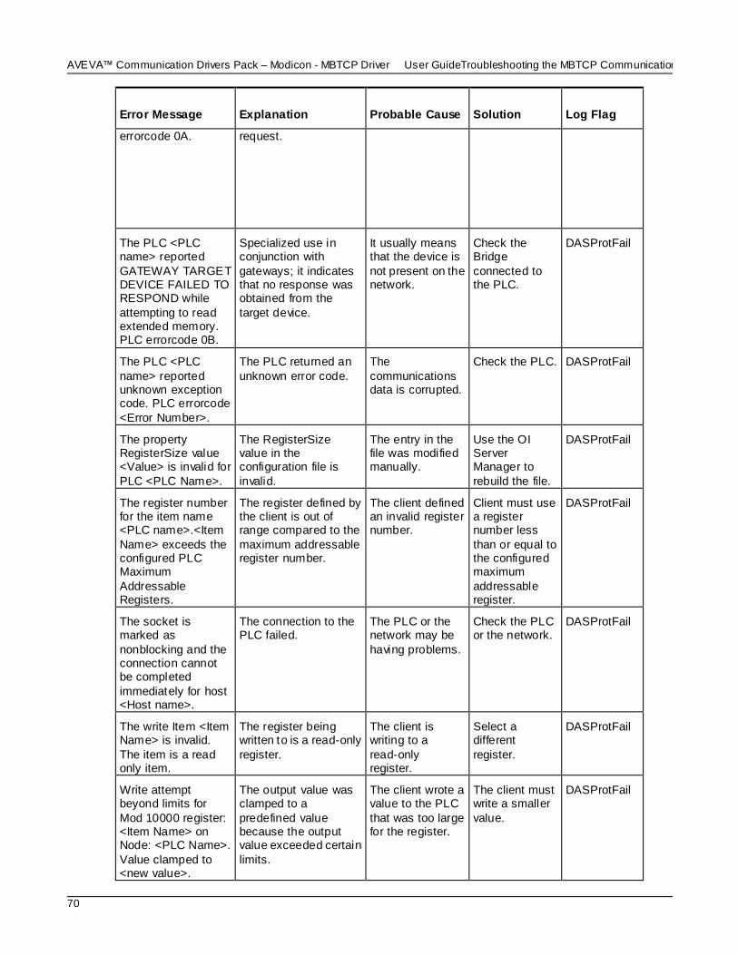
AVEVA™ Communication Drivers Pack – Modicon - MBTCP Driver User GuideTroubleshooting the MBTCP Communication Driver
70
Error Message Explanation Probable Cause Solution Log Flag
errorcode 0A. request.
The PLC <PLC name> reported
GATEWAY TARGET DEVICE FAILED TO RESPOND while
attempting to read extended memory. PLC errorcode 0B.
Specialized use in conjunction with
gateways; it indicates that no response was obtained from the
target device.
It usually means that the device is
not present on the network.
Check the Bridge
connected to the PLC.
DASProtFail
The PLC <PLC
name> reported unknown exception code. PLC errorcode
<Error Number>.
The PLC returned an
unknown error code.
The
communications data is corrupted.
Check the PLC. DASProtFail
The property RegisterSize value <Value> is invalid for
PLC <PLC Name>.
The RegisterSize value in the configuration file is
invalid.
The entry in the file was modified manually.
Use the OI Server Manager to
rebuild the file.
DASProtFail
The register number for the item name <PLC name>.<Item
Name> exceeds the configured PLC Maximum
Addressable Registers.
The register defined by the client is out of range compared to the
maximum addressable register number.
The client defined an invalid register number.
Client must use a register number less
than or equal to the configured maximum
addressable register.
DASProtFail
The socket is marked as
nonblocking and the connection cannot be completed
immediately for host <Host name>.
The connection to the PLC failed.
The PLC or the network may be
having problems.
Check the PLC or the network.
DASProtFail
The write Item <Item Name> is invalid.
The item is a read only item.
The register being written to is a read-only
register.
The client is writing to a
read-only register.
Select a different
register.
DASProtFail
Write attempt beyond limits for
Mod 10000 register: <Item Name> on Node: <PLC Name>.
Value clamped to <new value>.
The output value was clamped to a
predefined value because the output value exceeded certain
limits.
The client wrote a value to the PLC
that was too large for the register.
The client must write a smaller
value.
DASProtFail

Troubleshooting the MBTCP Communication DriverAVEVA™ Communication Drivers Pack – Modicon - MBTCP Driver User Guide
71
Server-Specific Error Codes
There are two server-specific error codes, shown in the following table, that augment those provided by
the Toolkit.
Error Code Logger Message Log Flag
-10001 PLC not connected DASProtFail
-10002 PLC timeout DASProtFail