MFB for Modicon M340 Using Unity Pro - Start-up Guide
202
35013563.08 www.schneider-electric.com MFB for Modicon M340 Using Unity Pro 35013563 04/2015 MFB for Modicon M340 Using Unity Pro Start-up Guide 04/2015
-
Upload
khangminh22 -
Category
Documents
-
view
1 -
download
0
Transcript of MFB for Modicon M340 Using Unity Pro - Start-up Guide

MFB for Modicon M340 Using Unity Pro
35013563 04/2015
3501
3563
.08
www.schneider-electric.com
MFB for Modicon M340 Using Unity ProStart-up Guide
04/2015

The information provided in this documentation contains general descriptions and/or technical characteristics of the performance of the products contained herein. This documentation is not intended as a substitute for and is not to be used for determining suitability or reliability of these products for specific user applications. It is the duty of any such user or integrator to perform the appropriate and complete risk analysis, evaluation and testing of the products with respect to the relevant specific application or use thereof. Neither Schneider Electric nor any of its affiliates or subsidiaries shall be responsible or liable for misuse of the information contained herein. If you have any suggestions for improvements or amendments or have found errors in this publication, please notify us.
No part of this document may be reproduced in any form or by any means, electronic or mechanical, including photocopying, without express written permission of Schneider Electric.
All pertinent state, regional, and local safety regulations must be observed when installing and using this product. For reasons of safety and to help ensure compliance with documented system data, only the manufacturer should perform repairs to components.
When devices are used for applications with technical safety requirements, the relevant instructions must be followed.
Failure to use Schneider Electric software or approved software with our hardware products may result in injury, harm, or improper operating results.
Failure to observe this information can result in injury or equipment damage.
© 2015 Schneider Electric. All rights reserved.
2 35013563 04/2015

Document Set
Related Documents
The following related documentation may be consulted: Unity Pro Online Help MFB library on Unity Pro Online Help CD Documentation Lexium 15 delivered with the product CD Documentation Lexium 05 delivered with the product Unilink L for Lexium 15LP and Unilink MH for Lexium 15MP/HP Online Help PowerSuite for ATV Online Help PowerSuite for Lexium 05 Online Help Lexium CT for Lexium 32 Online Help SoMove for ATV 32 Online Help
35013563 04/2015 3

4 35013563 04/2015

Table of Contents
Safety Information . . . . . . . . . . . . . . . . . . . . . . . . . . . . . 9About the Book. . . . . . . . . . . . . . . . . . . . . . . . . . . . . . . . 11
Part I Start-up Guide for a Single Axis Application. . . . 13Chapter 1 Foreword . . . . . . . . . . . . . . . . . . . . . . . . . . . . . . . . . . . . . 15
General . . . . . . . . . . . . . . . . . . . . . . . . . . . . . . . . . . . . . . . . . . . . . . . . 16Availability of Blocks on the Various Servodrives . . . . . . . . . . . . . . . . 17Methodology . . . . . . . . . . . . . . . . . . . . . . . . . . . . . . . . . . . . . . . . . . . . 19
Chapter 2 Application Configuration . . . . . . . . . . . . . . . . . . . . . . . 212.1 Hardware and Software Environments . . . . . . . . . . . . . . . . . . . . . . . . 22
Application Architecture with a Lexium 05. . . . . . . . . . . . . . . . . . . . . . 23Software Requirements . . . . . . . . . . . . . . . . . . . . . . . . . . . . . . . . . . . . 24Hardware Requirements . . . . . . . . . . . . . . . . . . . . . . . . . . . . . . . . . . . 25
2.2 Configuration of the Application using Unity Pro . . . . . . . . . . . . . . . . . 26Creating the Project. . . . . . . . . . . . . . . . . . . . . . . . . . . . . . . . . . . . . . . 27Master Task Configuration . . . . . . . . . . . . . . . . . . . . . . . . . . . . . . . . . 28
2.3 CANopen Bus Configuration . . . . . . . . . . . . . . . . . . . . . . . . . . . . . . . . 29Implementation Methodology for a CANopen Bus . . . . . . . . . . . . . . . 30Configuration of the CANopen port . . . . . . . . . . . . . . . . . . . . . . . . . . . 31Configuration of the CANopen Slave. . . . . . . . . . . . . . . . . . . . . . . . . . 33Checking the CANopen Bus Configuration . . . . . . . . . . . . . . . . . . . . . 36
2.4 Axis Configuration using the Motion Tree Manager . . . . . . . . . . . . . . 37Motion Directory . . . . . . . . . . . . . . . . . . . . . . . . . . . . . . . . . . . . . . . . . 38Axis Creation and Configuration . . . . . . . . . . . . . . . . . . . . . . . . . . . . . 40The objects Axis_Ref, Can_Handler, AxisParamDesc and Recipe. . . 43Motion Directory Configuration Result . . . . . . . . . . . . . . . . . . . . . . . . . 45
2.5 Configuring the Lexium 05. . . . . . . . . . . . . . . . . . . . . . . . . . . . . . . . . . 47Configuring the Lexium 05 in PowerSuite . . . . . . . . . . . . . . . . . . . . . . 48Configuring the Lexium 05 with the User Interface . . . . . . . . . . . . . . . 52
Chapter 3 Application Programming . . . . . . . . . . . . . . . . . . . . . . . 55Declaration of Variables . . . . . . . . . . . . . . . . . . . . . . . . . . . . . . . . . . . 56Programming the Example . . . . . . . . . . . . . . . . . . . . . . . . . . . . . . . . . 57The CAN_HANDLER Function Block . . . . . . . . . . . . . . . . . . . . . . . . . . . 59Management of the Axis’ Operating and Stop Modes . . . . . . . . . . . . . 62Motion Control . . . . . . . . . . . . . . . . . . . . . . . . . . . . . . . . . . . . . . . . . . . 63
35013563 04/2015 5

Motion Monitoring. . . . . . . . . . . . . . . . . . . . . . . . . . . . . . . . . . . . . . . . . 65Status and Axis Error Code Section. . . . . . . . . . . . . . . . . . . . . . . . . . . 66Backup and Transfer of the Servodrive Parameters . . . . . . . . . . . . . . 68Transferring the Project between the Terminal and the PLC . . . . . . . . 69
Chapter 4 Application Debugging . . . . . . . . . . . . . . . . . . . . . . . . . 71Tuning the Lexium 05 with PowerSuite . . . . . . . . . . . . . . . . . . . . . . . . 72Using Data via the Animation Tables . . . . . . . . . . . . . . . . . . . . . . . . . . 73Program Debugging . . . . . . . . . . . . . . . . . . . . . . . . . . . . . . . . . . . . . . . 75Using Data via the Operator Screens . . . . . . . . . . . . . . . . . . . . . . . . . 77
Chapter 5 Operating the Application . . . . . . . . . . . . . . . . . . . . . . . 79Management of the Recipes . . . . . . . . . . . . . . . . . . . . . . . . . . . . . . . . 79
Chapter 6 Application Maintenance. . . . . . . . . . . . . . . . . . . . . . . . 81Error Example . . . . . . . . . . . . . . . . . . . . . . . . . . . . . . . . . . . . . . . . . . . 82Replacing a Faulty Servodrive . . . . . . . . . . . . . . . . . . . . . . . . . . . . . . . 84
Part II Multi-Axis Application . . . . . . . . . . . . . . . . . . . . . . 87Chapter 7 Foreword. . . . . . . . . . . . . . . . . . . . . . . . . . . . . . . . . . . . . 89
Application Architecture with All Servodrives . . . . . . . . . . . . . . . . . . . . 89Chapter 8 Compatibility of Motion Applications with Unity Pro
Versions . . . . . . . . . . . . . . . . . . . . . . . . . . . . . . . . . . . . . 91 91
Chapter 9 Lexium 32 Implementation for Motion Function Blocks . . . . . . . . . . . . . . . . . . . . . . . . . . . . . . . . . . . . . . . 93
9.1 Adapting the Application to the Lexium 32. . . . . . . . . . . . . . . . . . . . . . 94Application Architecture with Lexium 32 . . . . . . . . . . . . . . . . . . . . . . . 95Software Requirements . . . . . . . . . . . . . . . . . . . . . . . . . . . . . . . . . . . . 96Hardware Requirements . . . . . . . . . . . . . . . . . . . . . . . . . . . . . . . . . . . 97CANopen Bus Configuration Lexium 32 . . . . . . . . . . . . . . . . . . . . . . . 98
9.2 Configuring the Lexium 32 . . . . . . . . . . . . . . . . . . . . . . . . . . . . . . . . . . 102Basic Parameters for Lexium 32 using Lexium CT . . . . . . . . . . . . . . . 102
9.3 Tuning the Lexium 32. . . . . . . . . . . . . . . . . . . . . . . . . . . . . . . . . . . . . . 106Tuning the Lexium 32. . . . . . . . . . . . . . . . . . . . . . . . . . . . . . . . . . . . . . 107Debugging the Lexium 32 . . . . . . . . . . . . . . . . . . . . . . . . . . . . . . . . . . 108
Chapter 10 Lexium 15MP/HP/LP Implementation for Motion Function Blocks . . . . . . . . . . . . . . . . . . . . . . . . . . . . . . . 113
10.1 Adapting the Application to the Lexium 15MP/HP/LP . . . . . . . . . . . . . 114Application Architecture with Lexium 15MP/HP/LP . . . . . . . . . . . . . . . 115Software Requirements . . . . . . . . . . . . . . . . . . . . . . . . . . . . . . . . . . . . 116Hardware Requirements . . . . . . . . . . . . . . . . . . . . . . . . . . . . . . . . . . . 117
6 35013563 04/2015

10.2 CANopen Bus Configuration Lexium 15MP/HP/LP . . . . . . . . . . . . . . . 118Configuration of the CANopen Slave on CANopen bus . . . . . . . . . . . 118
10.3 Configuring the Lexium 15MP/HP/LP . . . . . . . . . . . . . . . . . . . . . . . . . 121Basic Parameters for Lexium 15MP using Unilink MH . . . . . . . . . . . . 122Basic Parameters for Lexium 15LP using Unilink L. . . . . . . . . . . . . . . 125Specific Parameters for Lexium 15 MP/HP/LP using Unilink . . . . . . . 130
10.4 Tuning the Lexium 15MP/HP/LP . . . . . . . . . . . . . . . . . . . . . . . . . . . . . 132Debugging the axis . . . . . . . . . . . . . . . . . . . . . . . . . . . . . . . . . . . . . . . 132
Chapter 11 ATV 31 Implementation for Motion Function Blocks . 13511.1 Adapting the Application to the ATV 31. . . . . . . . . . . . . . . . . . . . . . . . 136
Application Architecture with an ATV 31 . . . . . . . . . . . . . . . . . . . . . . . 137Software Requirements . . . . . . . . . . . . . . . . . . . . . . . . . . . . . . . . . . . . 138Hardware Requirements . . . . . . . . . . . . . . . . . . . . . . . . . . . . . . . . . . . 139
11.2 CANopen Bus Configuration ATV 31 . . . . . . . . . . . . . . . . . . . . . . . . . 140Configuration of the CANopen Slave (ATV 31) on CANopen bus. . . . 140
11.3 Configuring the ATV 31 . . . . . . . . . . . . . . . . . . . . . . . . . . . . . . . . . . . . 143Configuring the ATV 31 in PowerSuite . . . . . . . . . . . . . . . . . . . . . . . . 144Configuring the ATV 31 with the User Interface . . . . . . . . . . . . . . . . . 147
11.4 Tuning the ATV 31. . . . . . . . . . . . . . . . . . . . . . . . . . . . . . . . . . . . . . . . 149Tuning the ATV 31 with PowerSuite . . . . . . . . . . . . . . . . . . . . . . . . . . 149
Chapter 12 ATV 32 Implementation for Motion Function Blocks . 15112.1 Adapting the Application to the ATV 32. . . . . . . . . . . . . . . . . . . . . . . . 152
Application Architecture with an ATV 32 . . . . . . . . . . . . . . . . . . . . . . . 153Software Requirements . . . . . . . . . . . . . . . . . . . . . . . . . . . . . . . . . . . . 154Hardware Requirements . . . . . . . . . . . . . . . . . . . . . . . . . . . . . . . . . . . 155
12.2 CANopen Bus Configuration ATV 32 . . . . . . . . . . . . . . . . . . . . . . . . . 156Configuration of the CANopen Slave (ATV 32) on CANopen Bus . . . 156
12.3 Configuring the ATV 32 . . . . . . . . . . . . . . . . . . . . . . . . . . . . . . . . . . . . 159Configuring the ATV 32 with SoMove . . . . . . . . . . . . . . . . . . . . . . . . . 160Configuring the ATV 32 with the User Interface . . . . . . . . . . . . . . . . . 163
Chapter 13 ATV 71 Implementation for Motion Function Blocks . 16713.1 Adapting the Application to the ATV 71. . . . . . . . . . . . . . . . . . . . . . . . 168
Application Architecture with an ATV 71 . . . . . . . . . . . . . . . . . . . . . . . 169Software Requirements . . . . . . . . . . . . . . . . . . . . . . . . . . . . . . . . . . . . 170Hardware Requirements . . . . . . . . . . . . . . . . . . . . . . . . . . . . . . . . . . . 171
13.2 CANopen Bus Configuration ATV 71 . . . . . . . . . . . . . . . . . . . . . . . . . 172Configuration of the CANopen Slave (ATV 71) on CANopen bus. . . . 172
35013563 04/2015 7

13.3 Configuring the ATV 71 . . . . . . . . . . . . . . . . . . . . . . . . . . . . . . . . . . . . 175Configuring the ATV 71 in PowerSuite. . . . . . . . . . . . . . . . . . . . . . . . . 176Configuring the ATV 71 with the User Interface. . . . . . . . . . . . . . . . . . 179
13.4 Tuning the ATV 71 . . . . . . . . . . . . . . . . . . . . . . . . . . . . . . . . . . . . . . . . 181Tuning the ATV 71 with PowerSuite . . . . . . . . . . . . . . . . . . . . . . . . . . 181
Chapter 14 IclA Implementation for Motion Function Blocks . . . . 18314.1 Adapting the Application to the IclA . . . . . . . . . . . . . . . . . . . . . . . . . . . 184
Application Architecture with an IclA . . . . . . . . . . . . . . . . . . . . . . . . . . 185Software Requirements . . . . . . . . . . . . . . . . . . . . . . . . . . . . . . . . . . . . 186Hardware Requirements . . . . . . . . . . . . . . . . . . . . . . . . . . . . . . . . . . . 187
14.2 CANopen Bus Configuration IclA . . . . . . . . . . . . . . . . . . . . . . . . . . . . . 188Configuration of the CANopen Slave (IclA) on CANopen bus . . . . . . . 188
14.3 Configuring the IclA . . . . . . . . . . . . . . . . . . . . . . . . . . . . . . . . . . . . . . . 191Configuring the IclA with DIP Switches . . . . . . . . . . . . . . . . . . . . . . . . 191
14.4 Tuning the IclA . . . . . . . . . . . . . . . . . . . . . . . . . . . . . . . . . . . . . . . . . . . 193Configuring the IclA in IclA Easy . . . . . . . . . . . . . . . . . . . . . . . . . . . . . 194Tuning the IclA with IclA Easy . . . . . . . . . . . . . . . . . . . . . . . . . . . . . . . 198
Index . . . . . . . . . . . . . . . . . . . . . . . . . . . . . . . . . . . . . . . . . 201
8 35013563 04/2015

Safety Information
Important Information
NOTICE
Read these instructions carefully, and look at the equipment to become familiar with the device before trying to install, operate, or maintain it. The following special messages may appear throughout this documentation or on the equipment to warn of potential hazards or to call attention to information that clarifies or simplifies a procedure.
35013563 04/2015 9

PLEASE NOTE
Electrical equipment should be installed, operated, serviced, and maintained only by qualified personnel. No responsibility is assumed by Schneider Electric for any consequences arising out of the use of this material.
A qualified person is one who has skills and knowledge related to the construction and operation of electrical equipment and its installation, and has received safety training to recognize and avoid the hazards involved.
10 35013563 04/2015

About the Book
At a Glance
Document Scope
This manual presents, using a documented example, how to use motion function blocks (MFB) with Modicon M340 using Unity Pro. These blocks enable simplified management of servodrives and servo-amplifiers using the CANopen bus.
Expert knowledge of Unity Pro software is required in order to use MFBs with it, since their implementation requires use of its standard functions (data editor, IODDT, etc.).
Moreover, it is advisable to have expert knowledge of the specialist area of motion control before developing and commissioning an application involving implementation of axis movements.
Validity Note
This document is valid for Unity Pro 10.0 or later.
35013563 04/2015 11

12 35013563 04/2015

MFB for Modicon M340 Using Unity Pro
Single Axis Application
35013563 04/2015
Start-up Guide for a Single Axis Application
Part IStart-up Guide for a Single Axis Application
Subject of this Part
This Part presents, in the form of a tutorial, an example of a motion control application implementing MFBs using Unity Pro.
What Is in This Part?
This part contains the following chapters:
Chapter Chapter Name Page
1 Foreword 15
2 Application Configuration 21
3 Application Programming 55
4 Application Debugging 71
5 Operating the Application 79
6 Application Maintenance 81
35013563 04/2015 13

Single Axis Application
14 35013563 04/2015

MFB for Modicon M340 Using Unity Pro
Foreword
35013563 04/2015
Foreword
Chapter 1Foreword
Subject of this Chapter
This chapter presents the specifications of the application as well as the methodology used in its development.
What Is in This Chapter?
This chapter contains the following topics:
Topic Page
General 16
Availability of Blocks on the Various Servodrives 17
Methodology 19
35013563 04/2015 15

Foreword
General
Introduction
The MFB using Unity Pro offer is a new motion control functionality. Using the CANopen bus, it provides you with simplified access to the basic functions on servodrives and variable speed drive (VSD).
This functionality, which may be accessed via the project browser, allows you to: declare and configure axes in Unity Pro create motion control variables control the axes by using motion control elementary function blocks.
Specifications
The purpose of the proposed application is to: manage the operating modes of a linear axis using a Lexium 05-type servodrive. move the axis to the home position, carry out reversing movements or move the axis to various
positions provide the possibility of interrupting the motion in progress with a Stop command.
All provisions shall be taken to perform fault diagnostics and acknowledgement.
Standards
The MFB library blocks comply with:
PLCopen standard
16 35013563 04/2015

Foreword
Availability of Blocks on the Various Servodrives
Motion Function Blocks
The motion function blocks availability can be found in the following tables.
Type Block name ATV 31ATV312 (7.)
ATV 32 ATV 71 Lexium 32, 32i
Lexium 05
Lexium 15 HP, MP, LP
IclAIFA, IFE, IFS
PLCopenmotioncontrol V1.1
MC_ReadParameter X X X X X X X
MC_WriteParameter X X X X X X X
MC_ReadActualPosition X X X X
MC_ReadActualVelocity (1.)
X X X X X X X
MC_Reset X X X X X X X
MC_Stop X X X X X X X
MC_Power X X X X X X X
MC_MoveAbsolute X X X X
MC_MoveRelative X X X
MC_MoveAdditive X X X
MC_Home X X X X
MC_MoveVelocity X X X X X X X
MC_ReadAxisError X X X X X X X
MC_ReadStatus X X X X X X X
MC_TorqueControl (1.) X X X X (3.)
MC_ReadActualTorque (1.)
X X X X X X
MC_Jog (2.) X X X (3.), except 15 LP
X
Parameter set save and restore functions for management of recipes or replacement of faulty servodrives
TE_UploadDriveParam X X X X(6.), except 32i
X X X
TE_DownloadDriveParam X X X X(6.), except 32i
X X X
35013563 04/2015 17

Foreword
Advanced functions for the Lexium
Lxm_GearPos X(4.) X(5.)
Lxm_GearPosS X X(4.) X(5.)
Lxm_UploadMTask X
Lxm_DownloadMTask X
Lxm_StartMTask X X
System function
CAN_Handler X X X X X X X
1. PLCopen V0.99 extension part 22. Not PLCopen standard3. Only for firmware version >= 6.734. Only for firmware version >= 1.4035. Only for firmware version >= 2.366. The parameter list is a Lexium32Advanced drive parameter list7. Through an ATV 31 V1.7 CANopen Device configuration.
Type Block name ATV 31ATV312 (7.)
ATV 32 ATV 71 Lexium 32, 32i
Lexium 05
Lexium 15 HP, MP, LP
IclAIFA, IFE, IFS
18 35013563 04/2015

Foreword
Methodology
Overview
The flowchart below lists the various stages involved in installing the application:
35013563 04/2015 19
Foreword
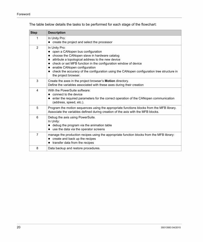
The table below details the tasks to be performed for each stage of the flowchart:
Step Description
1 In Unity Pro: create the project and select the processor
2 In Unity Pro: open a CANopen bus configuration choose the CANopen slave in hardware catalog attribute a topological address to the new device check or set MFB function in the configuration window of device enable CANopen configuration check the accuracy of the configuration using the CANopen configuration tree structure in
the project browser.
3 Create the axes in the project browser’s Motion directory.Define the variables associated with these axes during their creation
4 With the PowerSuite software: connect to the device enter the required parameters for the correct operation of the CANopen communication
(address, speed, etc.).
5 Program the motion sequences using the appropriate functions blocks from the MFB library.Associate the variables defined during creation of the axis with the MFB blocks.
6 Debug the axis using PowerSuite.In Unity: debug the program via the animation table use the data via the operator screens
7 manage the production recipes using the appropriate function blocks from the MFB library: create and back up the recipes transfer data from the recipes
8 Data backup and restore procedures.
20 35013563 04/2015

MFB for Modicon M340 Using Unity Pro
Application Configuration
35013563 04/2015
Application Configuration
Chapter 2Application Configuration
Subject of this Chapter
This chapter describes the various stages involved in configuring the application.
What Is in This Chapter?
This chapter contains the following sections:
Section Topic Page
2.1 Hardware and Software Environments 22
2.2 Configuration of the Application using Unity Pro 26
2.3 CANopen Bus Configuration 29
2.4 Axis Configuration using the Motion Tree Manager 37
2.5 Configuring the Lexium 05 47
35013563 04/2015 21

Application Configuration
Hardware and Software Environments
Section 2.1Hardware and Software Environments
Subject of this Section
This sub-section describes the hardware and software environments used in the application.
What Is in This Section?
This section contains the following topics:
Topic Page
Application Architecture with a Lexium 05 23
Software Requirements 24
Hardware Requirements 25
22 35013563 04/2015

Application Configuration
Application Architecture with a Lexium 05
Overview
The proposed architecture is simple and designed to assimilate the implementation principles of motion control.
Other equipment can be added to this realistic architecture in order to manage several axes.
Illustration
The following figure shows the architecture used in the application that includes a Lexium 05.
35013563 04/2015 23

Application Configuration
Software Requirements
Overview
To implement the example, it is essential to have certain items of software on single PC. In particular, this will allow you to configure, set parameters for and operate the various devices used.
The software architecture is composed of:
Unity Pro, which is used to control the servodrive via the CANopen bus by programming movements
Powersuite, which is used to set parameters and adjust the Lexium 05 servodrive
It is nonetheless possible to go without PowerSuite in certain cases by using the Lexium 05 front panel user interface (see page 52).
Versions
The following table lists the hardware and software versions used in the architecture (see page 23), enabling the use of MFBs in Unity Pro.
Hardware Softvare version used in the example Firmware Version
Modicon M340 Unity Pro V5.0 -
Lexium 05 PowerSuite for Unity V5.0 V2.5, patch V2.2.0B V1.403
24 35013563 04/2015

Application Configuration
Hardware Requirements
References of the Hardware Used
The following table lists the hardware used in the architecture (see page 23), enabling implemen-tation of Lexium 05 MFBs in Unity Pro.
NOTE: The terminating resistor is integrated in the Lexium 05.
Hardware Reference
Modicon M340 PLC BMX P34 2030
Modicon M340 power supply BMX CPS 2000
Modicon M340 rack BMX XBP 0800
CANopen junction box between the Modicon M340 and Lexium 05 servodrive VW3CANTAP2
RJ45 programming cable with RS485/RS232 adapter between the junction box and servodrive
ACC2CRAAEF030
Lexium 05 servodrive LXM05AD10M2
Lexium 05 motor BSH0551T
35013563 04/2015 25

Application Configuration
Configuration of the Application using Unity Pro
Section 2.2Configuration of the Application using Unity Pro
Subject of this Section
This sub-section describes the hardware configuration using Unity Pro.
What Is in This Section?
This section contains the following topics:
Topic Page
Creating the Project 27
Master Task Configuration 28
26 35013563 04/2015

Application Configuration
Creating the Project
At a Glance
Developing an application using Unity Pro involves creating a project associated with a PLC.
Procedure for Creating a Project
The table below shows the procedure for creating the project using Unity Pro.
Step Action
1 Launch the Unity Pro software,
2 Click on File then New then select a PLC,
3 To see all PLC versions, click on the box Show all versions.
4 Select the processor you wish to use from those proposed.
5 To create a project with specific values of project settings, check the box Settings File and use the browser button to localize the .XSO file (Project Settings file). It is also possible to create a new one.If the Settings File box is not checked , default values of project settings are used.
6 Confirm by clicking OK. The application inserts a rack and a power supply by default.
35013563 04/2015 27

Application Configuration
Master Task Configuration
General
The first operation you need to perform to create a program is to select the type of Tasks.
You are advised to program the servodrive movements using MFB blocks in the MAST task. This task must be scanned at regular intervals.
Configuration
The following table describes the procedure for setting the parameters of the MAST task:
CAUTIONMFB BLOCKS UNEXPECTED BEHAVIOR
Do not mixe MAST and FAST tasks. It is possible to use the FAST task to program the MFBs.
Failure to follow these instructions can result in injury or equipment damage.
Step Action
1 In the Project Browser, expand the Program directory.The MAST directory is displayed.
2 Right-click on the MAST directory and then execute the Properties command in the contextual menu.
3 Click on Properties and the following dialog box appears:
4 Select the Periodic type of scanning.
5 Set the task period to 20.
6 Set the Watchdog value, which must be greater than the period value.
7 Click on OK to confirm the configuration.
28 35013563 04/2015

Application Configuration
CANopen Bus Configuration
Section 2.3CANopen Bus Configuration
Subject of this Section
This section presents the CANopen bus configuration methodology.
What Is in This Section?
This section contains the following topics:
Topic Page
Implementation Methodology for a CANopen Bus 30
Configuration of the CANopen port 31
Configuration of the CANopen Slave 33
Checking the CANopen Bus Configuration 36
35013563 04/2015 29

Application Configuration
Implementation Methodology for a CANopen Bus
Overview
The following flowchart shows the implementation methodology for a CANopen bus using Modicon M340.
30 35013563 04/2015

Application Configuration
Configuration of the CANopen port
At a Glance
With Unity Pro you can define the CANopen bus.
The CANopen bus master is a port integrated in the CPU.
First, the bus master must be configured.
How to Configure the CANopen Bus Master
This table describes the procedure to configure the CANopen port using Unity Pro.
Step Action
1 In the Unity Pro Project Browser, fully expand the Configuration directory and then double-click on PLC bus.
2 Double-click on CANopen port of PLC.Result: The port configuration window appears:
3 In the Bus parameters area, set 500 kBaud for the transmission speed.In the Task area, select MAST.In the Outputs area select Reset radio-button. (Strongly recommended)
35013563 04/2015 31

Application Configuration
4 Validate the configuration.
5 Note: We recommend using the IODDT T_COM_CO_BMX that corresponds to the CANopen port for the rest of the programming. Enter CAN for the prefix name.Close the window.
Step Action
32 35013563 04/2015

Application Configuration
Configuration of the CANopen Slave
How to Configure the CANopen Slave
This table describes the procedure to configure the CANopen slave.
Step Action
1 In the Unity Pro Project Browser, fully expand the Configuration directory and then double-click on CANopen.Result: The CANopen window appears:
35013563 04/2015 33

Application Configuration
2 Select Edit → New device.Result: The New Device window appears:
3 Set 2 in Topological Address.Choose Lexium05_MFB for the slave device.
Step Action
34 35013563 04/2015

Application Configuration
4 Click on OK to confirm the choice.Result: The CANopen window appears with the new device selected:
5 Select Edit → Open module.If MFB has not already been selected, choose it in the Function area.
6 Select the tab Error Control.Verify that Node Heartbeat Producer time value is equal to 300ms.
7 You will be asked to validate your modifications when closing the Device and CANopen windows.
Step Action
35013563 04/2015 35

Application Configuration
Checking the CANopen Bus Configuration
At a Glance
The CANopen bus is represented in the Configuration directory of the project browser.
After having selected and enabled the CANopen configuration, the CANopen slaves appear in the Project Browser.
The topological address of the CANopen bus is calculated automatically by Unity Pro. This value cannot be modified.
The diagram below shows the CANopen bus with slave device from the tutorial example:
36 35013563 04/2015

Application Configuration
Axis Configuration using the Motion Tree Manager
Section 2.4Axis Configuration using the Motion Tree Manager
Subject of this Section
This sub-section describes the Motion directory added to Unity Pro’s project browser. It also presents a procedure for creating the axis in this directory.
What Is in This Section?
This section contains the following topics:
Topic Page
Motion Directory 38
Axis Creation and Configuration 40
The objects Axis_Ref, Can_Handler, AxisParamDesc and Recipe 43
Motion Directory Configuration Result 45
35013563 04/2015 37

Application Configuration
Motion Directory
At a Glance
The Motion directory of the structural view of the project allows you to access the declaration and configuration of the servodrives.
When declaring a servodrive, various information is required, such as:
the name given to the servodrive the type of servodrive the CANopen address of the servodrive the reference of the servodrive the version of the servodrive the input of variable names associated to the axis.
The following diagram shows an example of a tree structure for the Motion directory:
In this diagram, the name given to the servodrive is ‘Axis_Z’.
A recipe is linked, by default, each time an axis is created. It is possible to create several recipes (see page 68).
38 35013563 04/2015

Application Configuration
Accessible Services
The Motion directory gives you access to the following services, which can be reached via the contextual menu:
Directory Service
Motion New axis: allows you to create a new axis.
Axis New recipe: allows you to create a new recipe.Delete: allows you to delete an axis.Properties: allows you to access the axis properties.
Recipe Delete: allows you to delete a recipe.Properties: allows you to access the recipe properties.
35013563 04/2015 39
Application Configuration
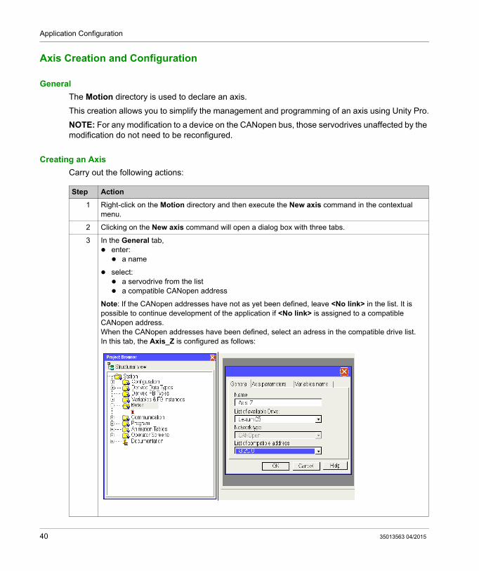
Axis Creation and Configuration
General
The Motion directory is used to declare an axis.
This creation allows you to simplify the management and programming of an axis using Unity Pro.
NOTE: For any modification to a device on the CANopen bus, those servodrives unaffected by the modification do not need to be reconfigured.
Creating an Axis
Carry out the following actions:
Step Action
1 Right-click on the Motion directory and then execute the New axis command in the contextual menu.
2 Clicking on the New axis command will open a dialog box with three tabs.
3 In the General tab, enter: a name
select: a servodrive from the list a compatible CANopen address
Note: If the CANopen addresses have not as yet been defined, leave <No link> in the list. It is possible to continue development of the application if <No link> is assigned to a compatible CANopen address.When the CANopen addresses have been defined, select an adress in the compatible drive list.In this tab, the Axis_Z is configured as follows:
40 35013563 04/2015
Application Configuration
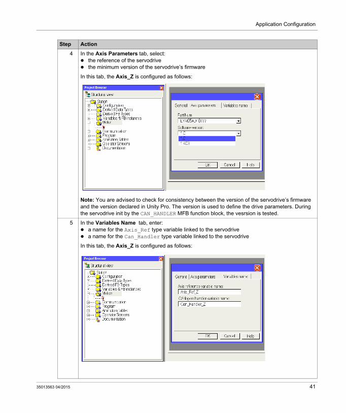
4 In the Axis Parameters tab, select: the reference of the servodrive the minimum version of the servodrive’s firmware
In this tab, the Axis_Z is configured as follows:
Note: You are advised to check for consistency between the version of the servodrive’s firmware and the version declared in Unity Pro. The version is used to define the drive parameters. During the servodrive init by the CAN_HANDLER MFB function block, the vesrsion is tested.
5 In the Variables Name tab, enter: a name for the Axis_Ref type variable linked to the servodrive a name for the Can_Handler type variable linked to the servodrive
In this tab, the Axis_Z is configured as follows:
Step Action
35013563 04/2015 41

Application Configuration
NOTE: It is possible to create several recipes for the same axis (there is one by default). Loading of the required recipe, depending on the request, is performed by the TE_DOWNLOADDRIVEPARAMETER (see Unity Pro, Motion Function Blocks, Block Library) block.This MFB library block is used to: load parameters to a new servodrive if the previous one is faulty. load a new recipe to a servodrive during a production change, for example
You can delete the recipe if you can not use it.
NOTE: The memory size of unlocated data for the management of a recipe by servodrive type is around 2 Kwords.
6 Click on OK to confirm the selections.
7 Right-click on the Recipe_0 sub-directory and then select Properties in the contextual menu. It is then possible to modify the recipe and parameter variables created by default when creating the axis.Notes : Tick the Initial Values saving Enabled checkbox allows to include the recipe in the application. This functionality is available for M340 V2.0 or later firmware versions, see the recipe variable. (see page 43)In this window, the variables for the Axis_Z are named by default as follows:
8 Click on OK to confirm the configuration.
Step Action
42 35013563 04/2015

Application Configuration
The objects Axis_Ref, Can_Handler, AxisParamDesc and Recipe
At a Glance
For each axis creation, 1 function block and 3 variables are created:
A Can_Handler-type function block automaticaly created by motion browser, which can be renamed using the axis directory
An Axis_Ref-type variable which can be renamed using the axis directory
A byte table type variable (ARRAY[....] OF BYTE) named by default Recipe_x (where x is a value) but which can be renamed using the Recipe_x directory
An unsigned integer table type variable (ARRAY[....] OF UINT) named AxisParamDesc_x (where x is a value) and which may not be renamed
Can_Handler
This variable is an EFB. It is named after the CANopen manager variable.
It is declared in the Function Block tab during Axis Creation (see page 40).
It must be used in the program as the instance of the CAN_HANDLER (see page 59) function block.
Axis_Ref
This variable is an AXIS_REF-type structured variable named after the axis reference variable.
It is declared in the Variables Name tab during Axis Creation (see page 40).
It must be specified in the input parameter for each MFB block used by the axis.
AxisParamDesc
This variable is an unsigned integer table type variable (ARRAY[....] OF UNIT). It is automatically created during Axis Creation (see page 40). It is named after the parameter description variable which can be seen in the Recipe_x properties of the axis.
This variable must be specified in the TE_UPLOADDRIVEPARAMETER (see Unity Pro, Motion Function Blocks, Block Library) and TE_DOWNLOADDRIVEPARAMETER (see Unity Pro, Motion Function Blocks, Block Library) blocks’ PARAMETERLIST input parameter taken from the MFB library and useful for recipe creation or for replacing the axis if it is faulty.
This variable: cannot be modified, is identical if the axes declared in the application have the same references and firmware
version.
35013563 04/2015 43

Application Configuration
Recipe
This variable is a byte table type variable (ARRAY[....] OF BYTE). It is automatically created during Axis Creation (see page 40). It is named after the recipe variable which can be seen in the Recipe_x properties of the axis.
This variable must be specified in the TE_UPLOADDRIVEPARAMETER (see Unity Pro, Motion Function Blocks, Block Library) or TE_DOWNLOADDRIVEPARAMETER (see Unity Pro, Motion Function Blocks, Block Library) block’s PARAMETERSET input parameter taken from the MFB library and useful for recipe creation or for replacing the axis if it is faulty.
The variable name may be modified using the Recipe_x properties of the axis.
The recipe can be included in the application :
The application can be updated with a storage in the inital values either with ‘update Init Values with Current values’ command or using the %S94 bit. Consequently, the STU or XEF file will include the values got from the drive after a TE_Upload calling . Finally, tick the ‘Initial Values saving Enabled’ checkbox to make this functionality available.
NOTE: By default, Initial Value saving Enabled checkbox is not ticked.
NOTE: Initial Values saving Enabled functionality is available for M340 V2.0 or later firmware versions.
44 35013563 04/2015

Application Configuration
Motion Directory Configuration Result
In the Project Browser
The following diagram shows the tree structure for the Motion directory after configuration:
35013563 04/2015 45
Application Configuration
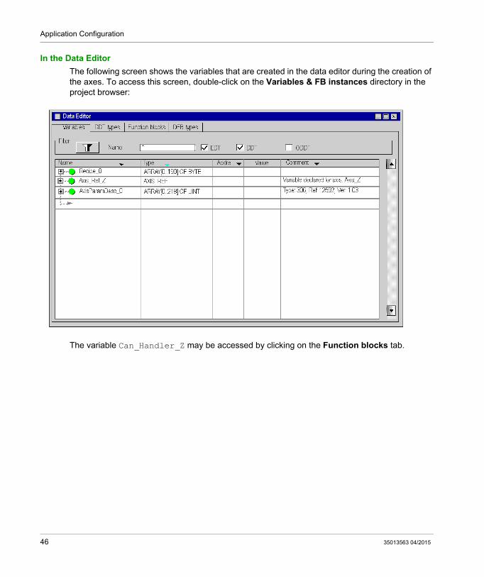
In the Data Editor
The following screen shows the variables that are created in the data editor during the creation of the axes. To access this screen, double-click on the Variables & FB instances directory in the project browser:
The variable Can_Handler_Z may be accessed by clicking on the Function blocks tab.
46 35013563 04/2015

Application Configuration
Configuring the Lexium 05
Section 2.5Configuring the Lexium 05
Aim of this Section
This section describes the basic servodrive configurations using PowerSuite for Lexium 05 and the servodrive’s front panel user interface.
What Is in This Section?
This section contains the following topics:
Topic Page
Configuring the Lexium 05 in PowerSuite 48
Configuring the Lexium 05 with the User Interface 52
35013563 04/2015 47

Application Configuration
Configuring the Lexium 05 in PowerSuite
Overview
With PowerSuite, users can define installed device bases, and describe their associated configurations and communication settings.
PowerSuite then gives access to a group of actions for editing or transferring the configurations and for connecting to the devices.
PowerSuite’s navigation principle associates a configuration interface with each device type, making it possible to control, tune and monitor them.
NOTE: The required signals, i.e LIMN, LIMP, REF must be wired or deactived by the tuning software.
Connecting to the Lexium 05
This table describes the procedure for connecting to the Lexium 05:
Step Action
1 Connect your PC, on which PowerSuite for Lexium 05 is installed, to the RJ45 connector on the servodrive to be configured.
2 Start PowerSuite for Lexium 05,Result: the following start-up screen is displayed:
48 35013563 04/2015

Application Configuration
3 Choose Action and then Connect.Result: a text box is displayed.
4 Type a project name (Lexium05_MFB) and then click on OK.Result: a transfer confirmation window is displayed.
5 Press Alt F to start transferring data from the servodrive to the connected work station.
Step Action
35013563 04/2015 49

Application Configuration
Basic Lexium 05 Configuration
This table describes the procedure for entering basic settings:
Step Action
1 Following a connection and transfer of the device’s configurations, PowerSuite displays a configuration screen in a new window that gives access to device control, tuning and monitoring functions.In the tree structure displayed, choose CANopen in the Communication directory.Result: the following window is displayed:
2 Double-click on the value in the ID_COAD line, Current Value column, and type the Lexium 05 CANopen address.
3 Double-click on the value in the ID_COBD line, Current Value column and choose the CANopen bus baud rate.
4 Save the CANopen settings to EEprom with the command Configuration → Save to EEprom.Note: it is possible to adjust the servodrive’s settings with the same procedure.
50 35013563 04/2015

Application Configuration
5 Once the settings have been adjusted, use the command Configuration → Disconnect to disconnect.Result: the following screen is displayed, showing the data saved locally:
6 The Lexium 05 must be turned off and then turned back on in order to apply the new settings.
Step Action
35013563 04/2015 51

Application Configuration
Configuring the Lexium 05 with the User Interface
Overview
A user interface is integrated in the Lexium 05. With this interface, you can:
put the device online configure the device carry out a diagnostic
Interface Menu Structure
The following graphic presents an overview of access to the interface’s main menus:
52 35013563 04/2015

Application Configuration
Basic Settings
The following table describes the procedure for entering basic settings (CANopen address and speed) with the interface.
Step Action
1 Press the ENT button on the interface.Result: the SET (Setting) menu is displayed on the interface’s status indicator.
2
Press the button several times to access the COM menu.Result: the COM (Communication) menu is displayed on the interface’s status indicator.
3 Press the ENT button on the interface.Result: the COAD (CANopen Address) submenu is displayed on the interface’s status indicator.
4 Press ENT again.Result: a value corresponding to the device’s CANopen address is displayed.
5
Press the button to decrease, or the button to increase the CANopen address value.Press ENT when the desired CANopen address is displayed (3).Result: the value is confirmed and the COAD (CANopen Address) submenu is displayed again.
6 Press ESC once to return to the COAD submenu.
7
Press the button to access the COBD (CANopen Baud) submenu.Press ENT.Result: a value corresponding to the device’s CANopen speed is displayed.
8
Press the button to decrease, or the button to increase the CANopen baud rate value.Press ENT when the desired CANopen speed is displayed (500).Result: the value is confirmed and the COBD (CANopen Baud) submenu is displayed again.
9 Press ESC several times to return to the main display (RDY by default).
35013563 04/2015 53

Application Configuration
54 35013563 04/2015

MFB for Modicon M340 Using Unity Pro
Application Programming
35013563 04/2015
Application Programming
Chapter 3Application Programming
Subject of this Chapter
This chapter describes the various development phases of the application program.
What Is in This Chapter?
This chapter contains the following topics:
Topic Page
Declaration of Variables 56
Programming the Example 57
The CAN_HANDLER Function Block 59
Management of the Axis’ Operating and Stop Modes 62
Motion Control 63
Motion Monitoring 65
Status and Axis Error Code Section 66
Backup and Transfer of the Servodrive Parameters 68
Transferring the Project between the Terminal and the PLC 69
35013563 04/2015 55

Application Programming
Declaration of Variables
At a Glance
In addition to the variables associated with the axis when it is created in the Motion directory, other variables must be declared.
They must be assigned to:
Input or output parameters of the MFB blocs Operator Screen (see page 77) objects.
They allow you to use certain data and to control the axis with blocks from the MotionFunctionBlock library.
Declaration in the Data Editor
The table below summarizes the variables to be created in the data editor for the tutorial example:
NOTE: the size of the recipe management table complies with that of the recipes created by the Motion directory.
Name Type Comment
Cmd_Home_Z BOOL Return axis to home position command
Cmd_Mvt_Z BOOL Move axis command
Cmd_Run_Z BOOL Run axis command
Cmd_Stop_Z BOOL Stop axis command
Cmd_Reset_Z BOOL Acknowledge axis command
Cmd_Upload_Z BOOL Save axis data in a recipe table command
Cmd_Download_Z BOOL Transfer data from recipe table to axis command
Axis_OK_Z BOOL Axis recognized by CANopen bus
Position_Z DINT Value of axis position
Velocity_Z DINT Value of axis speed
Recipe_Z ARRAY[0..190] OF BYTE Buffer variable for management of recipes
CAN T_COM_CO_BMX IODDT that manages CANOpen port
56 35013563 04/2015

Application Programming
Programming the Example
At a Glance
Just after declaration and parameter setting of the hardware, motion programming is the second development phase of the tutorial example.
Axis programming is divided up into:
declaration of variables an operator screen which is used to view and control the axis structured programming in several sections
Declaring the Sections
The table below presents a summary of the program sections to create
Section name Language Description
CAN_Handler (see page 59)
FBD This section allows you to check that the parameters of the axis correspond to reality.
Operating_mode (see page 62)
FBD This section allows you to power up the servodrives and to check the axes.
Cmd_Mvt (see page 63)
FBD This section allows you to set a homing reference point for the axis and to then control it in absolute motion.
Control_Mvt (see page 65)
FBD This section is used to determine the position and speed of the axis.
Status_Axes (see page 66)
FBD This section is used to determine the status of the axis and to carry out diagnostics for an event.
Recipe (see page 68) FBD This section allows you to save or restore a servodrive’s data.
35013563 04/2015 57

Application Programming
The diagram below shows the program structure after the programming sections have been created:
58 35013563 04/2015

Application Programming
The CAN_HANDLER Function Block
At a Glance
The use of the CAN_HANDLER (see Unity Pro, Motion Function Blocks, Block Library) MFB function block is essential and mandatory in the programming of the axis. The program section with this MFB function block must be associated with the same task of the CANopen bus master (see page 31).
It allows you to check:
the CANopen communication consistency between the software configuration and the connected physical device.
This block uses the two variables that belong to the axis’ directory. The Can_Handler_Z variable must be used as instance and the Axis_Ref_Z variable must be assigned to the block’s AXIS input parameter.
Inserting and Instantiating a Block
This table describes the procedure for inserting and select the instance of a block in a program section:
Step Action
1 Right click in an empty field in the FBD section to display the contextual menu.
2 Execute the FFB Input Assistant.. command in the contextual menu.Result: The Function Input Assistant opens.
3 Click on the ... icon on the FFB Type line.Result: the FFB Type Selection window opens.
4 Expand Libraries → MotionFunctionBlock and click on MFB.Result: all of the blocks from the MotionFunctionBlock library are displayed on the right-hand side of the FFB Type Selection window.
5 Select the CAN_HANDLER block and confirm your choice by clicking on OK.Result: The FFB Input Assistant.. window is displayed, set up by the CAN_HANDLER block.
6 Click on the ... icon on the Instance line.Result: the FB Instance Selection window opens.
35013563 04/2015 59

Application Programming
Contents
The screen below shows the section result:
7 Select the Can_Handler_Z instance and confirm your choice by clicking on OK.Result: The Can_Handler_Z variable is displayed in the Instance field:
8 Confirm the block configuration by clicking on OK.Result: the FBD section is displayed again. A symbol is added to the mouse cursor.
9 Click on an empty field in the FBD section.Result: the CAN_HANDLER block, instantiated by the Can_Handler_Z variable is inserted in the FBD section.
10 Specify the input and output parameters as defined in the contents.
Step Action
60 35013563 04/2015

Application Programming
The input parameter NETWORKOPERATIONAL must be assigned to a bit that validates the correct operation of the CANopen network.
The assignment of this parameter left to the discretion of the developer. It depends on the philosophy of the process and the way the bus is managed.
For example, this parameter may be connected to an object or to a T_COM_CO_BMX (see Modicon M340 with Unity Pro, CANopen, User Manual)-type IODDT equation.
35013563 04/2015 61

Application Programming
Management of the Axis’ Operating and Stop Modes
At a Glance
This section is made up of the following MFB blocks:
MC_POWER (see Unity Pro, Motion Function Blocks, Block Library), which is used to disable or enable the servodrives
MC_STOP (see Unity Pro, Motion Function Blocks, Block Library), which is used to stop any movement in progress
MC_RESET (see Unity Pro, Motion Function Blocks, Block Library), which is used to initialize the function blocks and to acknowledge servodrive faults.
Contents
The screen below shows a part of the section to develop:
The blocks are instantiated to variables input directly in the Instance zone of the FFB Input Assistant to facilitate subsequent diagnostics using the animation tables.
62 35013563 04/2015

Application Programming
Motion Control
At a Glance
This programming section is made up of the following MFB blocks:
MC_HOME (see Unity Pro, Motion Function Blocks, Block Library), which allows a homing reference point to be set for the axis before then launching it in absolute motion
MC_MOVEABSOLUTE (see Unity Pro, Motion Function Blocks, Block Library), which allows the axis to make an absolute movement.
35013563 04/2015 63

Application Programming
Contents
The screen below shows the part of the section:
For the tutorial example, the section is made up of a type of sequence of reversing movements.
The outward motion is conditioned by the Cmd_Mvt_Z bit from the operator screen (see page 77).
The return motion is conditioned by the end of the outward motion.
The position unit is USR and the velocity unit is rpm.
The Homing type HTYPE value (34) corresponds to an homing within a single turn, positive direction of rotation.
64 35013563 04/2015

Application Programming
Motion Monitoring
At a Glance
This section is made up of the MC_READACTUALPOSITION (see Unity Pro, Motion Function Blocks, Block Library) and MC_READACTUALVELOCITY (see Unity Pro, Motion Function Blocks, Block Library) MFB blocks.
These blocks are used to determine the exact position and speed of the axis.
Contents
The screen below shows a part of the section to develop:
Whilst the Axis_OK_Z bit is enabled, the position and speed values are continuously displayed on the operator screen (see page 77).
35013563 04/2015 65

Application Programming
Status and Axis Error Code Section
At a Glance
This section is made up of the following MFB blocks:
MC_READSTATUS (see Unity Pro, Motion Function Blocks, Block Library), which is used to determine the drive status (see Unity Pro, Motion Function Blocks, Block Library)
MC_READAXISERROR (see Unity Pro, Motion Function Blocks, Block Library), which is used to determine the error values according to the type of errors on the drive and to deduce their causes (see Unity Pro, Motion Function Blocks, Block Library).
66 35013563 04/2015

Application Programming
Contents
The screen below shows a part of the section:
The UPLOAD_Z.ERROR and DOWNLOAD_Z.ERROR variables must be added to the OR block after the recipe (see page 68) section has been created.
35013563 04/2015 67

Application Programming
Backup and Transfer of the Servodrive Parameters
At a Glance
This programming section is made up of the following MFB blocks:
TE_UPLOADDRIVEPARAM (see Unity Pro, Motion Function Blocks, Block Library), which is used to back up the configuration of a servodrive in a data table
TE_DOWNLOADDRIVEPARAM (see Unity Pro, Motion Function Blocks, Block Library), which is used to transfer the data table parameters to a servodrive.
Contents
The screen below shows the Recipe section:
If Cmd_Upload_Z is enabled, the servodrive configuration is saved in the data table Recipe_Z (buffer variable for the recipes).
If Cmd_Download_Z is enabled, the servodrive configuration is restored by the data table Recipe_Z.
68 35013563 04/2015

Application Programming
Transferring the Project between the Terminal and the PLC
At a Glance
Transferring a project allows you to copy the current project from the terminal to the current PLC’s memory (PLC that has its address selected).
Project Analysis and Generation
To perform analysis and generation of a project at the same time, carry out the following actions:
Project Backup
To back up the project, carry out the following actions:
Transferring the Project to the PLC
You must carry out the following actions to transfer the current project to a PLC:
Step Action
1 Activate the Rebuild All Project command in the Build menu.Result: the project is analyzed and generated by the software.
2 Any errors detected are displayed in the information window at the bottom of your screen.
Step Action
1 Activate the Save As command in the File menu.
2 If necessary, select the directory to which the project will be saved (disk and path).
3 Enter the file name: MFB_Lexium05.
4 Confirm with Save.Result: the project is saved as MFB_Lexium05.STU.
Step Action
1 Use the PLC → Define the address command. Enter SYS if you are using a USB media that is directly connected from the PC (terminal) to the PLC.
2 Switch to online mode using the PLC → Connection command.
35013563 04/2015 69

Application Programming
3 Activate the PLC → Transfer Project to PLC command.Result: the screen used to transfer the project between the terminal and the PLC is displayed:
4 Activate the Transfer command.
5 If the project has not been generated in advance, the screen below will be displayed allowing you to generate it before the transfer (Rebuild All then Transfer) or interrupt the transfer (Cancel Transfer).
6 Transfer progress is displayed on screen. At any moment, you can interrupt the transfer by using the Esc key. In this case, the PLC project will be invalid.Note: In the event that the project is transferred to a Flash Eprom memory card, the transfer can take several minutes.
Step Action
70 35013563 04/2015

MFB for Modicon M340 Using Unity Pro
Application Debugging
35013563 04/2015
Application Debugging
Chapter 4Application Debugging
Subject of this Chapter
This chapter describes the possibilities for debugging the application using Unity Pro and PowerSuite for Lexium 05.
What Is in This Chapter?
This chapter contains the following topics:
Topic Page
Tuning the Lexium 05 with PowerSuite 72
Using Data via the Animation Tables 73
Program Debugging 75
Using Data via the Operator Screens 77
35013563 04/2015 71

Application Debugging
Tuning the Lexium 05 with PowerSuite
In Advance
We recommend tuning the axis kinematic before the program automatically starts it.
Tuning Example
The following table gives an example of kinematic tuning:
Step Action
1 Connect (see page 48) to the Lexium 05.
2 After a connection and transfer of the device’s configurations, PowerSuite opens a new window with the configuration screen, which gives access to device control, tuning and monitoring functions.The following figure shows part of the new window. This lower window provides access to Lexium 05 command functions:
3 Place the Command zone cursor on Active.
4 Place the Enable zone cursor on On.
5 Click the Reset button to clear any problems.
6 Click the Test Run button.
7 Enter the value 0,1 in the CUR_I_target zone.
8 Place the CURref zone cursor on On.Result: the motor runs and the sub-window is animated:
9 Place the Command zone cursor on Inactive once tuning has been finalized.
72 35013563 04/2015

Application Debugging
Using Data via the Animation Tables
At a Glance
The animation table is the Unity Pro’ basic tool for viewing and forcing the status of variables.
NOTE: Unity Pro also offers a graphic tool called Operator Screens which is designed to facilitate use of the application (see page 77).
An animation table is divided into 3 areas that include:
the Mode area the Command area the Display area
Animation table:
Creating an Animation Table
The table below presents the procedure for creating an animation table:
Step Action
1 Right-click on the Animation Tables directory in the project browser.Result: the contextual menu is displayed.
2 Select New Animation Table.Result: a table properties window is displayed.
3 Click on OK to create the table, which is given a default name.Result: the animation table is displayed.
35013563 04/2015 73

Application Debugging
Adding Data to the Animation Table
The table below presents the procedure for creating data to view or force in the animation table:
Step Action
1 In the Table window, click on the empty line in the Name column.
2 There are two possible ways of adding data: Enter the variable directly
Click on the icon to display the instance selection window in order to select the variable
3 Enter or select the respective variables. Cmd_Home_Z to issue an return axis to home position command Cmd_Mvt_Z to issue a move axis command Cmd_Run_Z to issue a run axis command Cmd_Stop_Z to issue a stop axis command Cmd_Reset_Z to issue an axis acknowledgement command Cmd_Upload_Z to issue a save axis data to a recipe table command Cmd_Download_Z to issue a transfer data from the recipe table to the axis command Axis_OK_Z to view the axis recognized by the CANopen bus Position_Z to determine the value of the axis position Velocity_Z to determine the value of the axis speed
Result: the animation table looks like this.
74 35013563 04/2015

Application Debugging
Program Debugging
At a Glance
After transferring the program and running the axis using Powersuite for Lexium 05, the process is commissioned.
An animation table is a commissioning solution used to monitor, modify and/or force the values of variables.
The sets of parameters of the axis may be accessed and modified in Unity Pro using the MFB messaging blocks MC_READPARAMETER (see Unity Pro, Motion Function Blocks, Block Library) and MC_WRITEPARAMETER (see Unity Pro, Motion Function Blocks, Block Library).
Modification Mode
The following screen shows the animation table in modification mode:
This table is used to determine the status of the MC_POWER block’s input and output parameters.
To access this mode, click on the Modify button in the mode selection zone.
NOTE: this operation may be assigned to other function blocks.
NOTE: the animation table is dynamic only in online mode (display of variable values).
35013563 04/2015 75

Application Debugging
Modifying Values
The tutorial example uses Boolean variables. To modify a Boolean value, carry out the following actions:
Starting the System
The following table describes the procedure for starting the system used in the example:
Step Action
1 Use the mouse to select the Boolean variable you wish to modify.
2
Click on the button corresponding to the desired value, or execute the Set to 0 or Set to 1 commands in the contextual menu.
Step Action
1 Set the variable Cmd_Run_Z to 1.Result: the variable Axis_OK_Z changes to 1.
2 Set the variable Cmd_Reset_Z to 1.
3 Set the variable Cmd_Home_Z to 1.Result: the axis is referenced.
4 To rotate the axis, set the variable Cmd_Mvt_Z to 1.Result: the axis starts to turn and the values of the variables Position_Z and Velocity_Z are no longer set to 0.
5 To stop the axis from rotating: set the variable Cmd_Stop_Z to 1 set the variable Cmd_Mvt_Z to 0
Result : the axis stops rotating.
6 To start to rotate the axis again and complete the movement: set the variable Cmd_Stop_Z to 0 set the variable Cmd_Mvt_Z to 1
Result: the axis starts to rotate again and completes its movement.
76 35013563 04/2015

Application Debugging
Using Data via the Operator Screens
At a Glance
When a project is created without input cards, output cards or supervision, the Unity Pro operator screen (associated with unlocated bits and words) allows to carry out initial debugging of the program.
In the tutorial example, the operator screen is used to:
view data from the servodrives send commands to the servodrives
Representation
The representation below symbolizes the operating example which is used to control the axis and indicate the variables to be assigned to the objects (push button, LED and text):
35013563 04/2015 77

Application Debugging
78 35013563 04/2015

MFB for Modicon M340 Using Unity Pro
Operating the Application
35013563 04/2015
Operating the Application
Chapter 5Operating the Application
Management of the Recipes
At a Glance
The TE_UPLOADDRIVEPARAM (see Unity Pro, Motion Function Blocks, Block Library) and TE_DOWNLOADDRIVEPARAM (see Unity Pro, Motion Function Blocks, Block Library) blocks are used to manage the production recipes.
An example of the procedure for creating and managing recipes is described in this section.
NOTE: for flexible machines, it is possible to manage several parameter recipes.
Creating and backing up the recipes
The table describes the procedure for creating recipes:
Step Action
1 Create the recipes (see page 40) using the Axis_Z directory.Result: new recipe variables (Recipe_0, Recipe_1, etc.) are automatically created in the Data Editor (see page 46).
2 Create a variable corresponding to the type of recipe variables.This variable is named in the Recipe_Z tutorial example.Recipe_Z acts as a buffer when backing up or transferring data.Note: it is essential to check Allow dynamic arrays [ANY_ARRAY_XXX] located in Tools → Project options → Tab: Language extensions → Zone: Data type to be able to use table type variables such as the recipes.
3 Configure the servodrive’s parameters using Powersuite (see page 48).These initial settings are used to configure a recipe.
4 Perform a backup of the parameters using the TE_UPLOADDRIVEPARAM (see Unity Pro, Motion Function Blocks, Block Library) block in the buffer variable Recipe_Z.The backup was successful if the bits of the MC_READSTATUS (see Unity Pro, Motion Function Blocks, Block Library) block are as follows: DOWNLOADING (see Unity Pro, Motion Function Blocks, Block Library) is set to 0 STANDSTILL (see Unity Pro, Motion Function Blocks, Block Library) is set to 1
5 Transfer the data backed up in the Recipe_Z buffer variable to the Recipe_0 variable.
35013563 04/2015 79

Operating the Application
Transfer Data from the Recipes
The table describes the procedure to transfer recipe data to the servodrive (for a production change, for example):
6 Repeat steps 3 and 4 to transfer the data backed up in the Recipe_Z buffer variable to the Recipe_1 variable.The following programming presents a data transfer example based on the value of PRODUCTION:IF UPLOAD_Z.DONE AND PRODUCTION=0 THENRecipe_0:=Recipe_Z;END_IF; IF UPLOAD_Z.DONE AND PRODUCTION=1 THENRecipe_1:=Recipe_Z;END_IF;
Step Action
Step Action
1 Reload the Recipe_Z buffer variable based on the value of PRODUCTION (type of production requested).IF Cmd_Download_Z AND PRODUCTION=0 THENRecipe_Z:=Recipe_0;END_IF; IF Cmd_Download_Z AND PRODUCTION=1 THENRecipe_Z:=Recipe_1;END_IF;
2 Transfer the parameter data, using the Recipe_Zbuffer variable’s TE_DOWNLOADDRIVEPARAM (see Unity Pro, Motion Function Blocks, Block Library) block, to the servodrive.
3 The transfer was successful if the bits of the MC_READSTATUS (see Unity Pro, Motion Function Blocks, Block Library) block are as follows: DOWNLOADING (see Unity Pro, Motion Function Blocks, Block Library) is set to 0 STANDSTILL (see Unity Pro, Motion Function Blocks, Block Library) is set to 1
80 35013563 04/2015

MFB for Modicon M340 Using Unity Pro
Maintenance
35013563 04/2015
Application Maintenance
Chapter 6Application Maintenance
Subject of this Chapter
This chapter describes the procedure involved in replacing a servodrive after a fault has been diagnosed.
What Is in This Chapter?
This chapter contains the following topics:
Topic Page
Error Example 82
Replacing a Faulty Servodrive 84
35013563 04/2015 81

Maintenance
Error Example
At a Glance
The MC_ReadAxisError function is used to recover system errors.
If an error or warning occurs, the block specifies a code by applying a value to the AXISFAULTID, AXISDIAGID and AXISWARNINGID output parameters.
Error Codes
The following table shows the Lexium 05 error codes:
NOTE: refer to the CANopen documentation for Lexium 05 to identify the error.
Finding Errors
The table below describes a procedure for finding faults following an error or warning code.
Lexium 05
AxisFaultId SigLatched 301C:08
AxisDiagId WarnLatched 301C:0C
AxisWarningId StopFault 603F:0
Step Action
1 The AxisFault output parameter equals 1.The AxisFaultId output parameter displays an error value.The graph below shows the error generated:
2 Refer to the CANopen documentation of the Lexium 05 and look for the code SigLatched 301C:08.
82 35013563 04/2015

Maintenance
3 The AxisFaultID value is set to 4194304. This binary value means that bit 22 is set to one.Refer to the CANopen documentation of the Lexium 05 and look for the code ‘SigLatched’ 301C:08.Bit 22 for ‘SigLatched’ designates a lag error.
4 Reduce the speed constants in absolute block or external load or acceleration.
5 Execute the MC_Reset block.
Step Action
35013563 04/2015 83

Maintenance
Replacing a Faulty Servodrive
At a Glance
If the servodrive fails, it may be necessary to swap it for an identical servodrive (reference). To do this, you are advised to save the adjustment parameters to a data table using the TE_UPLOADDRIVEPARAMETER (see Unity Pro, Motion Function Blocks, Block Library) block.
The TE_DOWNLOADDRIVEPARAM (see page 68) block then allows you to restore the saved data to a new servodrive.
Data Backup
The table below describes the procedure used to back up the servodrive’s data using the TE_UPLOADDRIVEPARAMETER (see Unity Pro, Motion Function Blocks, Block Library) block:
Restoring Data
The table below describes the procedure used to restore the servodrive’s data using the TE_DOWNLOADDRIVEPARAM (see page 68) block:
Step Action
1 Disable the Enable parameter, which belongs to the MC_POWER (see Unity Pro, Motion Function Blocks, Block Library) block.Result: the servodrive switches to Disable (see Unity Pro, Motion Function Blocks, Block Library) mode.
2 Enable the input parameter Execute.Result: the servodrive switches to Downloading (see Unity Pro, Motion Function Blocks, Block Library) mode.The data table assigned to the output parameter PARAMETERSET is filled in.Note: Please back up data to a .DAT file using PLC → Transfer PLC data to the file if the PLC has no memory card.
Step Action
1 Disable the Enable parameter, which belongs to the MC_POWER (see Unity Pro, Motion Function Blocks, Block Library) block.Result: the servodrive switches to Disable (see Unity Pro, Motion Function Blocks, Block Library) mode.
2 Change the servodrive. The new servodrive must have the same references as the faulty servodrive.Note: make sure you take all the necessary precautions when changing the servodrive.
3 Configure the new servodrive with the basic parameters (see page 48) (CANopen address, speed) or using the keypad on the front panel.
84 35013563 04/2015

Maintenance
4 Enable the block’s input parameter Execute.Result: the servodrive switches to Downloading (see Unity Pro, Motion Function Blocks, Block Library) mode.The data table assigned to the input parameter PARAMETERSET loads the input PARAMETERLIST which corresponds to the servodrive parameter.
Step Action
35013563 04/2015 85

Maintenance
86 35013563 04/2015

MFB for Modicon M340 Using Unity Pro
Multi-Axis Application
35013563 04/2015
Multi-Axis Application
Part IIMulti-Axis Application
Aim of this Part
This part describes the other hardware available for the Motion Function Blocks offer with a Modicon M340 running Unity Pro.
The Lexium 05 servodrive was used in the previous part to carry out an example. This part begins with a presentation of the following servodrives in a full architecture:
Lexium 32 Lexium 15 ATV 31 ATV 32 ATV 71 IclA
Following this presentation, configuration of each of the servodrives is described, detailing differences with the Lexium 05 so as to carry out the same example.
What Is in This Part?
This part contains the following chapters:
Chapter Chapter Name Page
7 Foreword 89
8 Compatibility of Motion Applications with Unity Pro Versions 91
9 Lexium 32 Implementation for Motion Function Blocks 93
10 Lexium 15MP/HP/LP Implementation for Motion Function Blocks 113
11 ATV 31 Implementation for Motion Function Blocks 135
12 ATV 32 Implementation for Motion Function Blocks 151
13 ATV 71 Implementation for Motion Function Blocks 167
14 IclA Implementation for Motion Function Blocks 183
35013563 04/2015 87

Multi-Axis Application
88 35013563 04/2015

MFB for Modicon M340 Using Unity Pro
Foreword
35013563 04/2015
Foreword
Chapter 7Foreword
Application Architecture with All Servodrives
Overview
Following is a presentation of the usage of available hardware (servodrives), via an architecture, for implementing Motion Function Blocks in Unity Pro.
35013563 04/2015 89

Foreword
Illustration
The following figure shows the architecture used in the application that includes all servodrives:
ATV 31LEXIUM 05
UnityPro
LEXIUM 15
CANopen
ATV 71
IclA
EasyIclA
PowerSuitefor ATV 71 Lexium CT
for Lexium 32
Lexium 32
PowerSuitefor ATV 31
andfor Lexium 05
Unilink
ID 2
ID 3 ID 4
ID 5
ID 6
ID 7
Junction box
Modicon M340
90 35013563 04/2015

MFB for Modicon M340 Using Unity Pro
35013563 04/2015
Compatibility of Motion Applications with Unity Pro Versions
Chapter 8Compatibility of Motion Applications with Unity Pro Versions
Compatibility of XEF files
NOTE: 1. : The news EFB causes errors in the sections using them.
NOTE: 2. : Processor M340 >= V2.0: initial value saving enabled support.
Compatibility of STA files
Unity Target version Unity Source version
V3.x/V4.0 M340 Proc < V2.0
>= V4.0 M340 Proc >= V2.0
V3.x M340 < V2.0
Partially compatible in case of usage of Lexium15. NC.
>= V4.0 PC. FC.
NC : Not compatible. The motion parts are ignored during the import.PC : Partially compatible : the new axis type are ignored with an error message during the import : the application is imported by the sections using the drives that are in error. The new firmware version are downgraded to the highest available in the Unity version with a warning during import, if the drives is present in the catalog for Mirano CPU. If not, the import is aborted.FC : Fully compatible.
Unity Target Version
Unity Souce Version
V3.x/V4.0 application without motion V3.x/V4.0 with M340 < V2.0
>= V4.0 with M340 >= V2.0
V3.x FC PC NC
>= V4.0 FC FC FC
NC: Not compatiblePC: Partially compatible: compatible only for applications with drive supported by the Unity which is opening the application, in case of drives type or firmwire versions evolutions. The application can be opened but can not be modified deeply.FC: Full compatible.
35013563 04/2015 91

92 35013563 04/2015

MFB for Modicon M340 Using Unity Pro
Lexium 32 for MFBs
35013563 04/2015
Lexium 32 Implementation for Motion Function Blocks
Chapter 9Lexium 32 Implementation for Motion Function Blocks
Aim of this Chapter
This chapter presents the implementation of Lexium 32 servodrives according to the methodology (see page 19) described in the quick start guide (see page 13) with a Lexium 05. It only details the differences and actions for Lexium 32.
What Is in This Chapter?
This chapter contains the following sections:
Section Topic Page
9.1 Adapting the Application to the Lexium 32 94
9.2 Configuring the Lexium 32 102
9.3 Tuning the Lexium 32 106
35013563 04/2015 93

Lexium 32 for MFBs
Adapting the Application to the Lexium 32
Section 9.1Adapting the Application to the Lexium 32
Aim of this Section
This section presents adaptation of an application to the Lexium 32 with an architecture, hardware and software requirements.
In this section Lexium 32 means else a Lexium 32 Advanced reference (LXM 32A...) else a Lexium 32 Modular reference (LXM 32 M...)
What Is in This Section?
This section contains the following topics:
Topic Page
Application Architecture with Lexium 32 95
Software Requirements 96
Hardware Requirements 97
CANopen Bus Configuration Lexium 32 98
94 35013563 04/2015

Lexium 32 for MFBs
Application Architecture with Lexium 32
At a Glance
The proposed structure represents a simple structure which is designed to demonstrate motion control implementation principles.
This realistic structure may well be expanded upon with other devices in order to manage several axes.
Illustration
The figure below shows the structure used in the application:
Line terminator
LexiumCT
Lexium 32
CANopen
BSH
Unity Pro
Modicon M340
35013563 04/2015 95
Lexium 32 for MFBs
Software Requirements
Overview
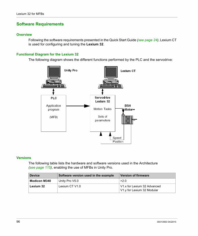
Following the software requirements presented in the Quick Start Guide (see page 24), Lexium CT is used for configuring and tuning the Lexium 32.
Functional Diagram for the Lexium 32
The following diagram shows the different functions performed by the PLC and the servodrive:
Versions
The following table lists the hardware and software versions used in the Architecture (see page 115), enabling the use of MFBs in Unity Pro.
Device Software version used in the example Version of firmware
Modicon M340 Unity Pro V5.0 >2.0
Lexium 32 Lexium CT V1.0 V1.x for Lexium 32 AdvancedV1.y for Lexium 32 Modular
96 35013563 04/2015

Lexium 32 for MFBs
Hardware Requirements
References of the Hardware Used
The following table lists the hardware used in the architecture (see page 95), enabling implemen-tation of Lexium 32 MFBs in Unity Pro.
Hardware Reference
Modicon M340 PLC BMX P34 20302
Modicon M340 power supply BMX CPS 2000
Modicon M340 rack BMX XBP 0800
Lexium 32 Advanced LXM32AU90M2
Lexium 32 connection cable to CANopen port of the PLC
TCSCCN4F 3M3T/CAN
CANopen Line terminator TCSCAR013M120
Motor for Lexium 32 BSH055••
35013563 04/2015 97

Lexium 32 for MFBs
CANopen Bus Configuration Lexium 32
Overview
The implementation methodology for a CANopen bus using Modicon M340 is to:
Upgrade the hardware catalog Configure (see page 31) the CANopen port of the CPU Declare the slave chosen from the hardware catalog (see paragraph below) Configure the slave Enable the configuration using Unity Pro Check (see page 36) the CANopen bus in the Project browser
How to Upgrade the Hardware Catalog
This table describes the procedure to configure the CANopen slave.
Step Action
1 Open the Hardware CatalogStart → Program → Schneider Electric → Socollaborative → UnityPro → Hardware Catalog ManagerResult:The Hardware Catalog Manager window appears:
98 35013563 04/2015

Lexium 32 for MFBs
How to Configure the CANopen Slave
This table describes the procedure to configure the CANopen slave.
2 In the menu tab, click on File ==>Import User Devices, then import the LXM32_MFB.cpx file in the directory ...\Application Data\Schneider Electric\ConfCatalog\Database\Motion (this file can be located in a hidden directory).
Step Action
Step Action
1 In the Unity Pro Project Browser, fully expand the Configuration directory and then double-click on CANopen.Result: The CANopen window appears:
35013563 04/2015 99
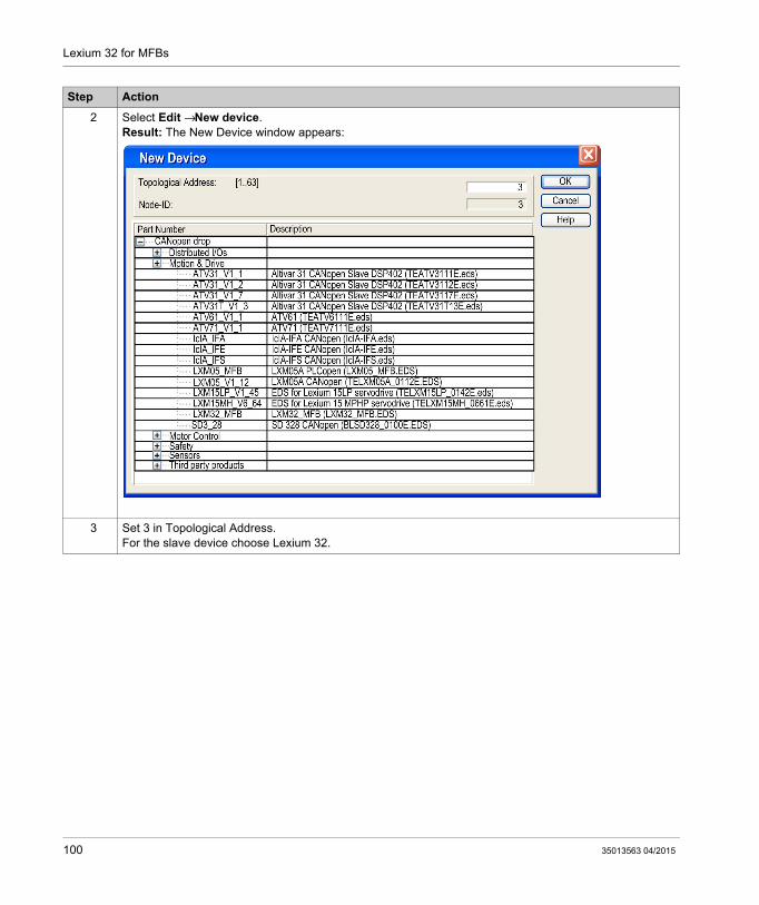
Lexium 32 for MFBs
2 Select Edit → New device.Result: The New Device window appears:
3 Set 3 in Topological Address.For the slave device choose Lexium 32.
Step Action
100 35013563 04/2015

Lexium 32 for MFBs
4 Click on OK to confirm the choice.Result: The CANopen window appears with the new device selected:
5 Select Edit → Open module.If MFB has not already been selected, choose it in the Function area.
6 You will be asked to validate your modifications when closing the Device and CANopen windows.
Step Action
CANopen
Bus: CANopen comm head 01.003 Connections configured: 1
3 0
...
35013563 04/2015 101

Lexium 32 for MFBs
Configuring the Lexium 32
Section 9.2Configuring the Lexium 32
Basic Parameters for Lexium 32 using Lexium CT
At a Glance
Lexium CT is a commissioning tool for axes intended for motion control applications.
Its graphic user interface provides a simple method for configuring the parameters of a Lexium 32-type servodrive.
102 35013563 04/2015

Lexium 32 for MFBs
Connecting to Lexium 32
This table describes the procedure for connecting to Lexium 32.
Step Action
1 Start Lexium CT.Click on Connection and then select ModbusSerialLine connection connection.The Connection window is displayed:
Select the COM-PortValidate by OKThe following screen appears:
Connection
COM-Port
Baudrate
Parameter
Protocol
Serial interface
COM1
19200
E,8,1
Modbus Point-to-Point
De-activate
Value in seconds
don’t show again
Connection supervision
5
OK Abbrechen
Loading configuration...
Schneider Electric - 3606480076831 - P091200V003401
35013563 04/2015 103

Lexium 32 for MFBs
2 When configuration has been established, this general screen appears:
Step Action
Name Value Unit Description Range ModbusIOfunct_DI0 Function Input DI0
Function Input DI1Function Input DI2Function Input DI3Function Input DI4Function Input DI5
..
..
..
..
..
..
1794
IOfunct_DQ0
1/min1/min
Function Output DQ0 .. 1810IOfunct_DQ1 Function Output DQ1 .. 1812IOfunct_DQ2
%
Function Output DQ2 .. 1814SPVn_lim Speed limitation via input 1..9999 1596SPVz_clmp Speed limit for Zero Clamp 0..1000 1616SPVi_lim Current limitation via input 0..3000 1614SPVChkWinTin Monitoring of time window 0..9999 1594SPVp_DiffWin Monitoring of position deviation 0..0,9999 1586SPVn_DiffWin Monitoring of speed deviation 1..9999 1588
17961798180018021804
1590
12981316131813141294129613221485214850156815661564154215461544
159215116151181512015122
SPVn_Thresho
RESint_extRESext_PRESext_RRESext_tonBRK_treleaseBRK_tcloseESIMscaleHMIDispParaHMIlockedIOsigLimPIOsigLimNIOdigRefSPV_SW_LimitSPVswLimNusrSPVswLimPusr
SPVi_ThresholSPVSelError1SPVSelError2SPVSelWarn1SPVSelWarn2
IOfunct_DI3IOfunct_DI4IOfunct_DI5
IOfunct_DI1IOfunct_DI2
TouchProbe_1Reference switch (REF)Positive limit switch (LIMP)Negative limit switch (LIMN)Free availableFree availableNo faultActiveFree available101010,000,00101010
internal Resistor10100,001004096DeviceStatusnot lockednormally closednormally closednormally closednone-21474836482147483647
1,00000
1/min
WOhmmsmsmsInc
usrusr
%
msrevolutio1/min
Monitoring of speed value
Braking resistor controlNominal power of external braking resistorResistance value of external braking resistorMax. permissible switch-on time of external braking Time delay during opening/releasing the holding braTime delay during closing of holding brakeEncoder simulation - setting of resolutionHMI display when motor rotatesLock HMISignal evaluation LIMPSignal evaluation LIMNSignal evaluation REFMonitoring of software limit switchesNegative position limit for software limit switchPositive position limit for software limit switch
Monitoring of current valueFirst selective error entrySecond selective error entryFirst selective warning entrySecond selective warning entry
1..9999
0..11..327671.327,671..300000..10000..10008..655350..20..10..20..21..20..3....
0..30000..655350..655350..655350..65535
All parameterSimply start
Lexium 32
Basic configurationIn Pulse controlIn Position control
Configuration
IO parametersIO functions
External braking resistor
Encoder simulation (ESIM)Holding brake
HMI
NameSettings
Regulation loop (1)Regulation loop
Regulation loop (2)
StandstillLimitations
Motion
Electronic gearMotion Sequence config
HomingJog
Communication
CANopenDrivecom
ModbusDeviceNet
Datasheet
DeviceInternal braking resistor
MotorDrive
Position scalingReference and limit switches
Profile generator
Power amplifierSupervision
Not connected
POWER
Stop ResetPress to clear list
DISABLEDSTOPOn
Off
CommandOnOff
Enable
[Use double-click to clear thid display!]
[Use double-click to clear thid display!]Halt=inactive_p_usr=0Lexium CT M2DEVcmdinterf=none
104 35013563 04/2015

Lexium 32 for MFBs
Basic Parameters
This table describes the procedure for inputting the basic parameters:
NOTE: For information on how to adjust parameters correctly, please refer to the drive documentation
Step Action
1 Click on the Basic Configuration The Basic Configuration window appears:
This screen is used to set parameters for the servodrive’s CANopen address, the bus speed and the units used for acceleration, speed and position.
2 For the tutorial example, from this screen set or select the following: In the servodrive zone: The CANopen address to 2 The baud rate of the bus to 500 Kbaud (see MFB using Unity Pro, Start-
up Guide)
3 Click Items → Parameter → Save device parameters in EEPROM to confirm the SIMPLYSTART_BASICCONFIGURATION.Result: The SIMPLYSTART_BASICCONFIGURATION is saved and the main screen is displayed again.
4 Click on Exit.
Name Value Unit Description Range ModbusIOposlnterfac Signal selection position interface
DeviceNet address (node number)Modbus addressModbus Baud rateCANopen address (node number)CANopen Baud rate
0..11..631..2479600..384001..12750..1000
1284
CTRL_n_max 1/min Speed limitation 0..13200 4384CTRL_I_max % Current limitation 0..3000 4376LIM_I_maxQST % Current limitation for Quick Stop 0..3000 4378LIM_I_maxHalt % Current limitation for Halt 0..3000 4380EsimActive Desable/Enable ESIM functionality 0..2 1342ESIMscale inc Encoder simulation - setting of resolution 8..65535 1322Mains_choke Mains choke 0..1 1344POSdirOfRotat Definition of direction of rotation 0..1 1560Umains_reduce Reduced input mains voltage on 1 phase devices 0..1 1346
16898564056381664416646
MBbaudCANadrCANbaud
DVNadrMBadr
ABinput0119.2KB2125KB8000400,0400,0400,0EsimOff4096noclockwiseoff
All parameterSimply start
Lexium 32
Basic configurationIn Pulse controlIn Position control
Configuration
IO parametersIO functions
External braking resistor
Encoder simulation (ESIM)Holding brake
HMI
NameSettings
Regulation loop (1)Regulation loop
Regulation loop (2)
StandstillLimitations
Motion
Electronic gearMotion Sequence config
HomingJog
Communication
CANopenDrivecom
ModbusDeviceNet
Datasheet
DeviceInternal braking resistor
MotorDrive
Position scalingReference and limit switches
Profile generator
Power amplifierSupervision
35013563 04/2015 105

Lexium 32 for MFBs
Tuning the Lexium 32
Section 9.3Tuning the Lexium 32
Aim of this Section
This section gives an example of tuning the Lexium 32 with Lexium CT.
What Is in This Section?
This section contains the following topics:
Topic Page
Tuning the Lexium 32 107
Debugging the Lexium 32 108
106 35013563 04/2015

Lexium 32 for MFBs
Tuning the Lexium 32
Operating modes
The various operating modes can be selected from the tabs in the Operating modes windows.
The windows is subdivided into two sections:
Tabs for the selected operating mode and for setting specific parameters (top section)
Display of status information (bottom section)
The user can switch between the tabs in the Operating Modes window without interfering with a currently active operating mode.
Profile Velocity
In the operating mode Profile Velocity, the drive accelerates to an adjustable target speed of rotation. You can set a motion profile with values for acceleration and deceleration ramps
Speed modePoint-to-point Homing Manual movement Electr. gear Oscillator
Speed: 1/min
-3000 0 3000
v=0Ok
Operating modes
0
35013563 04/2015 107

Lexium 32 for MFBs
Debugging the Lexium 32
Pre-requisite
You are recommended to debug the axis dynamics before it is automatically started by the program.
Description
The commissioning software provides the “Recording / Tuning” function for visualizing internal device data during movements. The connected device stores the movement data to an internal memory for a defined recording period and then sends it to the PC. The PC processes the data and displays it in the form of charts or tables.
Recorded data can be saved on the PC, and can be archived or printed for documentation purposes.
Use the menu Item” → Functions → Record / Tuning...” to start the “record” function.
108 35013563 04/2015

Lexium 32 for MFBs
Illustration
The screen below can be accessed by clicking on the Oscilloscope tab:
Description Buttons
The buttons below can be accessed by clicking:
1. Start recording2. Stop recording3. Zoom in, y axis4. Zoom out, y axis5. Infinitely variable zoom, x axis and y axis
Signal_n_act_ldq_act_p_act
Available signals
<-Double-click to delete signal from the list.
Timebase10 ms
Recording TuningTrigger
Connected: COM1,#248,19200,3606480076831,P091200V003401,3400
POWER
Stop[6] Op Enable ResetPress to clear list
ENABLEDSTOPOn
Off
CommandOnOff
Enable
[Use double-click to clear thid display!]
[Use double-click to clear thid display!]Halt=inactive_p_actusr=56310814Exclusive Lexium CT M2DEVcmdinterf=Modbus
Stopped
100
100
150
200
50
200 300 400 500 600 700 800 900 1000 1100 1200Time [ms]
1 2 3 4 5 6 7 8 9 10 11 12 13 14 15 16
35013563 04/2015 109

Lexium 32 for MFBs
6. Zoom selected rectangle.7. 1nd display of values for a specific time8. Change displayed values for first display9. 2nd display of values for a specific time.10.Change displayed values for second display11.Restore original display12.Invert y axis13.Display table of recorded values14.Enter description15.Show/hide configuration16.Print recording
Recording
The desired parameters are selected in the “Available signals” input field. A maximum of 4 parameters can be selected. If a parameter is no longer required, it can be deselected by a double-click on the name of the parameter.
The desired recording increment is select in the “Timebase” input field. The smaller the “Time base”, the smaller the maximum recording time will be.
Tuning
Tuning can only be started if the “Access” and “Enable” switches are set to “On”.
The “Amplitude” field is used to set the maximum amplitude of the reference value The offset of the amplitude in positive or negative direction can be set in the “Offset” field. The duration of a period is set in the “Period” field. The signal type for the reference value is set in the “Signal ” dropdown list. The controller to be used is set in the “Type” dropdown list. The number of periods is specified in the “Count” field. The maximum number of revolutions that can be triggered by tuning can be set in the “Range”
field. This value can, for example, help to avoid a movement to block. The “auto-start” radio buttons allow you to link the execution of the tuning movement and the
start of recording. If the option is set to “Off” , the software displays a Start button. The Start button lets you trigger the tuning movement separately from starting the recording.NOTE: Settings that you may have made on the “Trigger” tab are lost if you set “auto-start” to “On”.
Signal
_n_act_ldq_act_p_act
Available signals
<-Double-click to delete signal from the list.
Timebase
10 ms
Recording TuningTrigger
110 35013563 04/2015

Lexium 32 for MFBs
NOTE: For further information, please refer to the Lexium CT software user manual.
Reference Amplitude -
Control Type
1/mn Offset -
Count =
TUNE only possible, if ‘Command-Active’ and ‘Enable-Active’
Period -0 1/mn0 ms50
Range =
Signal square symetric
auto-start Off On1.0period0Speed control
Recording TuningTrigger
Start
35013563 04/2015 111

Lexium 32 for MFBs
112 35013563 04/2015

MFB for Modicon M340 Using Unity Pro
Lexium 15MP/HP/LP for MFBs
35013563 04/2015
Lexium 15MP/HP/LP Implementation for Motion Function Blocks
Chapter 10Lexium 15MP/HP/LP Implementation for Motion Function Blocks
Aim of this Chapter
This chapter presents the implementation of Lexium 15MP/HP/LP servodrives according to the methodology (see page 19) described in the quick start guide (see page 13) with a Lexium 05. It only details the differences and actions for Lexium 15MP/HP/LP.
What Is in This Chapter?
This chapter contains the following sections:
Section Topic Page
10.1 Adapting the Application to the Lexium 15MP/HP/LP 114
10.2 CANopen Bus Configuration Lexium 15MP/HP/LP 118
10.3 Configuring the Lexium 15MP/HP/LP 121
10.4 Tuning the Lexium 15MP/HP/LP 132
35013563 04/2015 113

Lexium 15MP/HP/LP for MFBs
Adapting the Application to the Lexium 15MP/HP/LP
Section 10.1Adapting the Application to the Lexium 15MP/HP/LP
Aim of this Section
This section presents adaptation of the application to the Lexium 15MP/HP/LP with an architecture, and hardware and software requirements.
What Is in This Section?
This section contains the following topics:
Topic Page
Application Architecture with Lexium 15MP/HP/LP 115
Software Requirements 116
Hardware Requirements 117
114 35013563 04/2015

Lexium 15MP/HP/LP for MFBs
Application Architecture with Lexium 15MP/HP/LP
At a Glance
The proposed structure represents a simple structure which is designed to assimilate the motion control implementation principles.
This realistic structure may well be expanded upon with other devices in order to manage several axes.
Illustration
The figure below shows the structure used in the application:
35013563 04/2015 115

Lexium 15MP/HP/LP for MFBs
Software Requirements
Overview
As regards the software requirements presented in the quick start guide (see page 24), PowerSuite is used for configuring and tuning the Lexium 05.
PowerSuite for Lexium 05 enables tuning of the axis and guarantees a simple method for configuring the parameters of a Lexium 05 servodrive.
Unilink L/MH for Lexium 15•• does the same, but for Lexium 15•• servodrive.
Functional Diagram for the Lexium 15••
The following diagram shows the different functions performed by the PLC and the servodrive:
Versions
The following table lists the hardware and software versions used in the architecture (see page 115), enabling the use of MFBs in Unity Pro.
Device Software version used in the example Version of firmware
Modicon M340 Unity Pro V4.0 -
Lexium 15LP Unilink V1.5 V1.45 only MFB FunctionV2.36 Managed by MTM
Lexium 15MH Unilink V4.0 Compatible sInce V6.64
116 35013563 04/2015

Lexium 15MP/HP/LP for MFBs
Hardware Requirements
References of the Hardware Used
The following table lists the hardware used in the architecture (see page 115), enabling implemen-tation of Lexium 15MP MFBs in Unity Pro.
The following table lists the hardware used in the architecture (see page 115), enabling implemen-tation of Lexium 15LP MFBs in Unity Pro.
NOTE: the line terminator is an interrupter built into the AM0 2CA 001 V000 CANopen connector.
Hardware Reference
Modicon M340 PLC BMX P34 2030
Modicon M340 power supply BMX CPS 2000
Modicon M340 rack BMX XBP 0800
Lexium 15MP Servodrive LXM15MD28N4
Lexium 15MP connection cable to CANopen port of the PLC TLA CD CBA •••
CANopen connector for Lexium 15MP AM0 2CA 001 V000
Motor for Lexium 15MP BPH055••
Hardware Reference
Modicon M340 PLC BMX P34 2030
Modicon M340 power supply BMX CPS 2000
Modicon M340 rack BMX XBP 0800
Lexium 15LP Servodrive LXM15LD13M3
Lexium 15MP connection cable to CANopen port of the PLC TLA CD CBA •••
CANopen connector for Lexium 15LP AM0 2CA 001 V000
Motor for Lexium 15LP AKM 31E
35013563 04/2015 117

Lexium 15MP/HP/LP for MFBs
CANopen Bus Configuration Lexium 15MP/HP/LP
Section 10.2CANopen Bus Configuration Lexium 15MP/HP/LP
Configuration of the CANopen Slave on CANopen bus
Overview
The implementation methodology for a CANopen bus using Modicon M340 is to:
configure (see page 31) the CANopen port of the CPU, declarate the slave chosen from the hardware catalog (see paragraph bellow), configure the slave, enable the configuration using Unity Pro, check (see page 36) the CANopen bus in the Project browser.
How to Configure the CANopen Slave
This table describes the procedure to configure the CANopen slave.
Step Action
1 In the Unity Pro Project Browser, fully expand the Configuration directory and then double-click on CANopen.Result: The CANopen window appears:
118 35013563 04/2015

Lexium 15MP/HP/LP for MFBs
2 Select Edit → New device.Result: The New Device window appears:
3 Set 3 in Topological Address.For the slave device choose Lexium15LP_V1_4 for a Lexium 15LP or Lexium15MH_V6_61for a Lexium 15MP.
Step Action
35013563 04/2015 119

Lexium 15MP/HP/LP for MFBs
4 Click on OK to confirm the choice.Result: The CANopen window appears with the new device selected:
5 Select Edit → Open module.If MFB has not already been selected, choose it in the Function area.
6 You will be asked to validate your modifications when closing the Device and CANopen windows.
Step Action
120 35013563 04/2015

Lexium 15MP/HP/LP for MFBs
Configuring the Lexium 15MP/HP/LP
Section 10.3Configuring the Lexium 15MP/HP/LP
Aim of this Section
This section describes the basic servodrive configurations using Unilink L/MH for Lexium 15MP/HP/LP.
What Is in This Section?
This section contains the following topics:
Topic Page
Basic Parameters for Lexium 15MP using Unilink MH 122
Basic Parameters for Lexium 15LP using Unilink L 125
Specific Parameters for Lexium 15 MP/HP/LP using Unilink 130
35013563 04/2015 121

Lexium 15MP/HP/LP for MFBs
Basic Parameters for Lexium 15MP using Unilink MH
At a Glance
Unilink is a commissioning tool for axes intended for motion control applications.
Its graphic user interface provides a simple method for configuring the parameters of a Lexium 15MP-type servodrive.
Connecting to Lexium 15MP
This table describes the procedure for connecting to Lexium 15MP :
Step Action
1 Start Unilink MH via Start → Program → Unilink → Unilink MH.A communication window is displayed on main window of Unilink MH:
If the port that you are using is available (i.e. is not being used by other devices or programs), the name COM1, COM2, COM3, COM4, COM5, COM6, COM7, COM 8, COM9, COM10 appears in black. Otherwise, it appears in grey.
122 35013563 04/2015

Lexium 15MP/HP/LP for MFBs
2 Click on one of these communication ports (the port that you use on your PC) to transfer the values of the servodrive parameters to your PC. When communication has been established, this general screen appears:
Step Action
35013563 04/2015 123

Lexium 15MP/HP/LP for MFBs
Basic Parameters
This table describes the procedure for inputting the basic parameters:
Step Action
1 Click on the Basic Setup button in the general screen.The Basic Setup window appears:
This screen is used to set parameters for the servodrive’s CANopen address, the bus speed and the units used for acceleration, speed and position.
2 For the tutorial example, from this screen set or select the following: In the servodrive zone: the CANopen address to 2 the baud rate of the bus to 500 Kbaud (see page 31)
In the Unit (see Unity Pro, Motion Function Blocks, Block Library) zone: the acceleration in ms->VLIM the speed in rpm the position in μm
3 Click on the Motor Selection, Current, Resolver buttons to declare the motor and the feedback parameters.Note: for information on how to declare the motor correctly, please refer to the motor documentation.
4 Click OK to confirm the basic configuration.Result: the basic setup is saved and the main screen is displayed again.Note: when certain ASCII parameters have been enabled, a window appears asking you to save changes to the servodrive’s EEPROM memory. Click on OK to restart the servodrive and update the memory.
5 Click on Exit.
124 35013563 04/2015

Lexium 15MP/HP/LP for MFBs
Basic Parameters for Lexium 15LP using Unilink L
At a Glance
Unilink is a commissioning tool for axes intended for motion control applications.
Its graphic user interface provides a simple method for configuring the parameters of a Lexium 15LP-type servodrive.
Connecting to Lexium 15LP
This table describes the procedure for connecting to Lexium 15LP :
Step Action
1 Start Unilink L via Start → Program → Unilink → Unilink L.Result: a window ask you if you would like to connect to the drive
2 Click on the Yes button.Result: a window to select the device appears.
3 Select RS-232 and click on the OK button.Result: a window of RS-232 settings appears.
4 Set the serial port (COM1 to COM10), the Baud Rate (38400), the Timeout (2000ms).
35013563 04/2015 125

Lexium 15MP/HP/LP for MFBs
5 Click on the OK button.Result: Unilink L software appears.
Step Action
126 35013563 04/2015

Lexium 15MP/HP/LP for MFBs
Basic Parameters
This table describes the procedure for inputting the basic parameters:
Step Action
1 Click on the Setup wizard on the browser.Result:the Drive Setup screen in the main frame appears:
2 Select the Complete Setup on the screen.Result: the browser with all configurations links appears.
3 Click on the Basic Setup on the browser.Result: the Basic Setup screen in the main frame appears:
This screen is used to set parameters of the power supply.
35013563 04/2015 127

Lexium 15MP/HP/LP for MFBs
4 Click on the Units/Mechanical on the browser.The Units/Mechanical screen in the main frame appears:
For the tutorial example, from this screen set or select the following: In the User Units zone: the acceleration in ms->VLIM the speed in rpm the position in μm
Step Action
128 35013563 04/2015

Lexium 15MP/HP/LP for MFBs
5 Click on the CAN / Field Bus Settings on the browser.The CAN / Field Bus Settings screen in the main frame appears:
For the tutorial example, from this screen set or select the following: In the General Field Bus and CAN Bus Settings zones: the CANopen address to 3 the baud rate of the bus to 500 Kbauds
6 Click on the Motor, Resolver folders on the browser to declare the motor and the feedback parameters.Note: for information on how to declare the motor correctly, please refer to the motor documentation.
7 Save the parameters via Drive → Save to EEPROM.Result: the basic setup is saved and the main screen is displayed again.
Step Action
35013563 04/2015 129

Lexium 15MP/HP/LP for MFBs
Specific Parameters for Lexium 15 MP/HP/LP using Unilink
At a Glance
Specific parameters are entered in addition to the basic (see MFB using Unity Pro, Start-up Guide)parameters. These specific parameters supplement the configuration of Lexium 15 MP/HP/LP by modifying certain ASCII codes using the Terminal window.
Specific Parameters
This table describes the procedure for inputting the specific parameters of Lexium 15 MP/HP/LP:
Step Action
1
Click on the Terminal icon on the general page.The Terminal window is displayed:
This screen is used to fully configure the connection point of a Lexium 15MP/HP/LP.
2 For Lexium 15 MP/HP i enter in the Command field: DRVCNFG 1050670
For Lexium 15 LP enter in the Command field: INPT2 x1.5 task time, or IN20Mode42 either MAST or FAST
3 Click on Apply to confirm the configuration of this ASCII parameter.
4 For Lexium 15 MP/HP repeat the steps by entering in the Command field: DRVCNFG2 64 INPT x1.5 task time MAST or FAST ENGAGE 1
130 35013563 04/2015

Lexium 15MP/HP/LP for MFBs
Command
Enter the ASCII command here, with the corresponding parameters. Confirm the entry with RETURN or press the APPLY button to start the transmission.
5 Click on OK to confirm the last Command and return to the general page.
6
Click on the Save icon on the general page to save the basic and specific parameters to the servodrive’s EEPROM memory.
7 Close the general window and click on DIS to disconnect from the servodrive.
Step Action
CAUTIONUNEXPECTED APPLICATION BEHAVIOR
Before sending the ASCII command , ensure that is appropriate to the equipment.
Failure to follow these instructions can result in injury or equipment damage.
35013563 04/2015 131

Lexium 15MP/HP/LP for MFBs
Tuning the Lexium 15MP/HP/LP
Section 10.4Tuning the Lexium 15MP/HP/LP
Debugging the axis
Pre-requisite
You are recommended to debug the axis dynamics before it is automatically started by the program.
Description
The oscilloscope is one way of carrying out the debug operation.
It allows you to:
display up to three variables simultaneously, as a function of time
save the recorded measurements to a data medium in CSV format (can be used with MS-Excel)
load a CSV data file and restore the curves on the oscilloscope diagram
use certain services
Illustration for Lexium 15MH
The screen below can be accessed by clicking on the Unilink MH menu’s Tools → Oscilloscope:
132 35013563 04/2015

Lexium 15MP/HP/LP for MFBs
How to start service for Lexium 15MH
The table below explains how to use a service function with a Lexium 15MH:
Illustration for Lexium 15LP
The screen below can be accessed by clicking the folder Oscilloscope on the Unilink L browser’s:
Step Action
1 On the field Service, select one of the service functions (see page 134) described below.
2 Click on the Parameters button.
3 Set the corresponding parameter.
4 Then start the function by using the Start button.
5 The function will continue to be performed until you click on the Stop button or press the function key F9.
35013563 04/2015 133

Lexium 15MP/HP/LP for MFBs
How to start service for Lexium 15LP
The table below explains how to use a service function with a Lexium 15LP:
Service Functions
The table below explains how to use a service function:
NOTE: For further information, please refer to the Unilink software user manual.
NOTE: Once the parameters have been correctly set, you are advised to save them in EEPROM and to make a backup copy of them in a file.
Step Action
1 Click on the Motion Services tab..
2 Select one of the service functions (see page 134) described below.
3 Click on the Parameters button.
4 Set the corresponding parameter.
5 Then start the function by using the Start button.
6 The function will continue to be performed until you click on the Stop button.
Direct current Apply a direct current to the motor with adjustable size and electrical field-vector angle. The changeover from speed control to current control is made automatically, commutation is made independently of the feedback (resolver or similar). The rotor locks onto a stator pole.
Speed Operates the drive at constant speed. An internal digital setpoint is provided (speed is adjustable).
Torque Operates the drive with constant current. An internal digital setpoint is provided (current is adjustable). The changeover from speed control to current control is made automatically, commutation is made independently of the feedback (resolver or similar).
Reversing mode
Operates the drive in reversing mode, with separately adjustable speed and reversing time for each direction of rotation.
Motion task Starts the motion task that is selected in the screen page "Entry of service parameters".
Zero Function used for feedback setting in conjunction with the positioning phase. This function can only be accessed in OMODE2.
134 35013563 04/2015

MFB for Modicon M340 Using Unity Pro
ATV 31 for MFBs
35013563 04/2015
ATV 31 Implementation for Motion Function Blocks
Chapter 11ATV 31 Implementation for Motion Function Blocks
Aim of this Chapter
This chapter presents the implementation of an ATV 31 servodrive according to the methodology (see page 19) described in the quick start guide (see page 13) with a Lexium 05. It only details the differences and actions for an ATV 31.
What Is in This Chapter?
This chapter contains the following sections:
Section Topic Page
11.1 Adapting the Application to the ATV 31 136
11.2 CANopen Bus Configuration ATV 31 140
11.3 Configuring the ATV 31 143
11.4 Tuning the ATV 31 149
35013563 04/2015 135

ATV 31 for MFBs
Adapting the Application to the ATV 31
Section 11.1Adapting the Application to the ATV 31
Aim of this Section
This section presents adaptation of the application to the ATV 31 with an architecture, and hardware and software requirements.
What Is in This Section?
This section contains the following topics:
Topic Page
Application Architecture with an ATV 31 137
Software Requirements 138
Hardware Requirements 139
136 35013563 04/2015

ATV 31 for MFBs
Application Architecture with an ATV 31
Overview
The proposed architecture is simple and designed to assimilate the implementation principles of motion control.
Other equipment can be added to this realistic architecture in order to manage several axes.
Illustration
The following figure shows the architecture used in the application that includes an ATV 31.
35013563 04/2015 137

ATV 31 for MFBs
Software Requirements
Overview
As regards the software requirements presented in the quick start guide (see page 13), PowerSuite is used for configuring and tuning the ATV 31.
Powersuite for Lexium 05 enables tuning of the axis and guarantees a simple method for configuring the parameters of a Lexium 05 servodrive.
PowerSuite for ATV 31 does the same, but for an ATV 31 servodrive.
It is possible to configure certain parameters withlout using PowerSuite by using the ATV 31 front panel, user interface (see page 147).
Versions
The following table lists the hardware and software versions used in the architecture (see page 137), enabling the use of MFBs in Unity Pro.
NOTE: ATV31 V1.7 is compatible with V1.2 functions.
Hardware Earliest version of software Version of firmware
Modicon M340 Unity Pro V4.0 -
ATV 31 PowerSuite for ATV 31 V2.00 V1.7 : Entry existing on Unity V3.1 + new MFB profile for V4.0
138 35013563 04/2015

ATV 31 for MFBs
Hardware Requirements
References of the Hardware Used
The following table lists the hardware used in the architecture (see page 137), enabling implemen-tation of ATV 31 MFBs in Unity Pro.
NOTE: The terminating resistor is integrated in the junction box and must be ON.
Hardware Reference
Modicon M340 PLC BMX P34 2030
Modicon M340 power supply BMX CPS 2000
Modicon M340 rack BMX XBP 0800
CANopen junction box between the Modicon M340 and ATV 31 servodrive
VW3CANTAP2
PC connection kit VW3A8106
ATV 31 servodrive ATV31H037M2
35013563 04/2015 139

ATV 31 for MFBs
CANopen Bus Configuration ATV 31
Section 11.2CANopen Bus Configuration ATV 31
Configuration of the CANopen Slave (ATV 31) on CANopen bus
Overview
The implementation methodology for a CANopen bus using Modicon M340 is to:
configure (see page 31) the CANopen port of the CPU, declarate the slave chosen from the hardware catalog (see paragraph bellow), configure the slave, enable the configuration using Unity Pro, check (see page 36) the CANopen bus in the Project browser.
How to Configure the CANopen Slave
This table describes the procedure to configure the CANopen slave.
Step Action
1 In the Unity Pro Project Browser, fully expand the Configuration directory and then double-click on CANopen.Result: The CANopen window appears:
140 35013563 04/2015

ATV 31 for MFBs
2 Select Edit → New device.Result: The New Device window appears:
3 Set 4 in Topological Address.For the slave device choose ATV31_V1_2.
Step Action
35013563 04/2015 141

ATV 31 for MFBs
4 Click on OK to confirm the choice.Result: The CANopen window appears with the new device selected:
5 Select Edit → Open module.If MFB has not already been selected, choose it in the Function area.
6 You will be asked to validate your modifications when closing the Device and CANopen windows.
Step Action
142 35013563 04/2015

ATV 31 for MFBs
Configuring the ATV 31
Section 11.3Configuring the ATV 31
Aim of this Section
This section describes the basic servodrive configurations using PowerSuite for ATV 31 and the servodrive’s front panel user interface.
What Is in This Section?
This section contains the following topics:
Topic Page
Configuring the ATV 31 in PowerSuite 144
Configuring the ATV 31 with the User Interface 147
35013563 04/2015 143

ATV 31 for MFBs
Configuring the ATV 31 in PowerSuite
Overview
With PowerSuite, users can define installed device bases, and describe their associated configurations and communication settings.
PowerSuite then gives access to a group of actions for editing or transferring the configurations and for connecting to the devices.
PowerSuite’s navigation principle associates a configuration interface with each device type, making it possible to control, tune and monitor them.
Connecting to the ATV 31
This table describes the procedure for connecting to the ATV 31:
Step Action
1 Connect your PC, on which PowerSuite for ATV 31 is installed, to the RJ45 connector on the servodrive to be configured.
2 Start PowerSuite for ATV 31,Result: the following start-up screen is displayed:
3 Choose Action and then Connect.Result: a text box is displayed.
4 Type a project name (ATV31_MFB) and then click on OK.Result: a transfer confirmation window is displayed.
5 Press Alt F to start transferring data from the servodrive to the connected work station.
144 35013563 04/2015

ATV 31 for MFBs
Basic ATV 31 Configuration
This table describes the procedure for entering basic settings:
Step Action
1 Following a connection and transfer of the device’s configurations, PowerSuite displays a configuration screen in a new window that gives access to device control, tuning and monitoring functions.Use the command Display → Configuration.In the tree structure displayed, choose Communication in the Communication directory.Result: the following window is displayed:
2 In the ADCO line, the CANopen address must be set to 4.
3 In the BDCO line, the CANopen bus speed must be set to 500.
35013563 04/2015 145
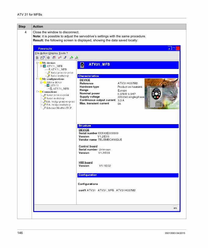
ATV 31 for MFBs
4 Close the window to disconnect.Note: it is possible to adjust the servodrive’s settings with the same procedure.Result: the following screen is displayed, showing the data saved locally:
Step Action
146 35013563 04/2015

ATV 31 for MFBs
Configuring the ATV 31 with the User Interface
Overview
A user interface is integrated in the ATV 31. With this interface, you can:
put the device online configure the device carry out a diagnostic
Interface Menu Structure
The following graphic presents an overview of access to the interface’s main menus:
35013563 04/2015 147

ATV 31 for MFBs
Basic Settings
The following table describes the procedure for entering basic settings (CANopen address and speed) with the interface.
Step Action
1 Press the ENT button on the interface.Result: the SET (Setting) menu is displayed on the interface’s status indicator.
2
Press the button several times to access the COM menu.Result: the COM (Communication) menu is displayed on the interface’s status indicator.
3 Press the ENT button on the interface.Result: the COAD (CANopen Address) submenu is displayed on the interface’s status indicator.
4 Press ENT again.Result: a value corresponding to the device’s CANopen address is displayed.
5
Press the button to decrease, or the button to increase the CANopen address value.Press ENT when the desired CANopen address is displayed (4).Result: the value is confirmed and the COAD (CANopen Address) submenu is displayed again.
6
Press the button to access the COBD (CANopen Baud) submenu.Press ENT.Result: a value corresponding to the device’s CANopen speed is displayed.
7
Press the button to increase, or the button to decrease the CANopen baud rate value.Press ENT when the desired CANopen speed is displayed (500).Result: the value is confirmed and the COBD (CANopen Baud) submenu is displayed again.
8 Press ESC several times to return to the main display (RDY by default).
148 35013563 04/2015

ATV 31 for MFBs
Tuning the ATV 31
Section 11.4Tuning the ATV 31
Tuning the ATV 31 with PowerSuite
In Advance
We recommend tuning the axis kinematic before the program automatically starts it.
Tuning Example
The following table gives an example of kinematic tuning:
Step Action
1 Connect (see page 144) to the ATV 31.
2 After a connection and transfer of the device’s configurations, PowerSuite opens a new window with the configuration screen, which gives access to device control, tuning and monitoring functions.The following figure shows part of the new window. This lower window provides access to ATV 31 command functions:
3 Place the Command zone cursor on Active.
4 Click the Reset button to clear any problems (if status is red).
5 Enter the value 1 in the Frequency reference zone.
6 Click the Test Run button.Result: the motor runs and the sub-window is animated:
7 Place the Command zone cursor on Inactive once tuning has been finalized.
35013563 04/2015 149

ATV 31 for MFBs
150 35013563 04/2015

MFB for Modicon M340 Using Unity Pro
ATV 32 for MFBs
35013563 04/2015
ATV 32 Implementation for Motion Function Blocks
Chapter 12ATV 32 Implementation for Motion Function Blocks
Aim of this Chapter
This chapter presents the implementation of an ATV 32 servodrive according to the methodology (see page 19) described in the quick start guide (see page 13) with a Lexium 05. It only details the differences and actions for an ATV 32.
What Is in This Chapter?
This chapter contains the following sections:
Section Topic Page
12.1 Adapting the Application to the ATV 32 152
12.2 CANopen Bus Configuration ATV 32 156
12.3 Configuring the ATV 32 159
35013563 04/2015 151

ATV 32 for MFBs
Adapting the Application to the ATV 32
Section 12.1Adapting the Application to the ATV 32
Aim of this Section
This section presents adaptation of the application to the ATV 32 with an architecture, and hardware and software requirements.
What Is in This Section?
This section contains the following topics:
Topic Page
Application Architecture with an ATV 32 153
Software Requirements 154
Hardware Requirements 155
152 35013563 04/2015

ATV 32 for MFBs
Application Architecture with an ATV 32
Overview
The proposed architecture is simple and designed to assimilate the implementation principles of motion control.
Other equipment can be added to this architecture to manage several axes.
Illustration
The following figure shows the architecture used in the application that includes an ATV 32.
1 Junction box2 SoMove
35013563 04/2015 153

ATV 32 for MFBs
Software Requirements
Overview
As regards the software requirements presented in the quick start guide (see page 13), SoMove is used for configuring and tuning the ATV 32.
PowerSuite for Lexium 05 enables a simple method for configuring the parameters of a Lexium 05 servodrive.
SoMove does the same for an ATV 32 servodrive.
Without using SoMove, it is possible for certain parameters to be configured by using the ATV 32 front panel, the user interface (see page 163).
NOTE: ATV 32 servodrive does not support the torque operating mode.
Versions
The following table lists the hardware and software versions used in the architecture (see page 153), enabling the use of MFBs in Unity Pro:
Hardware Earliest version of software Version of firmware
Modicon M340 Unity Pro V6.0 or higher -
ATV 32 SoMove V1.2
154 35013563 04/2015

ATV 32 for MFBs
Hardware Requirements
References of the Hardware Used
The following table lists the hardware used in the architecture (see page 153), enabling implemen-tation of ATV 32 MFBs in Unity Pro:
NOTE: The terminating resistor is integrated in the junction box and must be ON.
Hardware Reference
Modicon M340 PLC BMX P34 2030
Modicon M340 power supply BMX CPS 2000
Modicon M340 rack BMX XBP 0800
CANopen junction box between the Modicon M340 and ATV 32 servodrive VW3CANTAP2
PC connection kit VW3A8106
ATV 32 servodrive ATV32 ••••••
35013563 04/2015 155
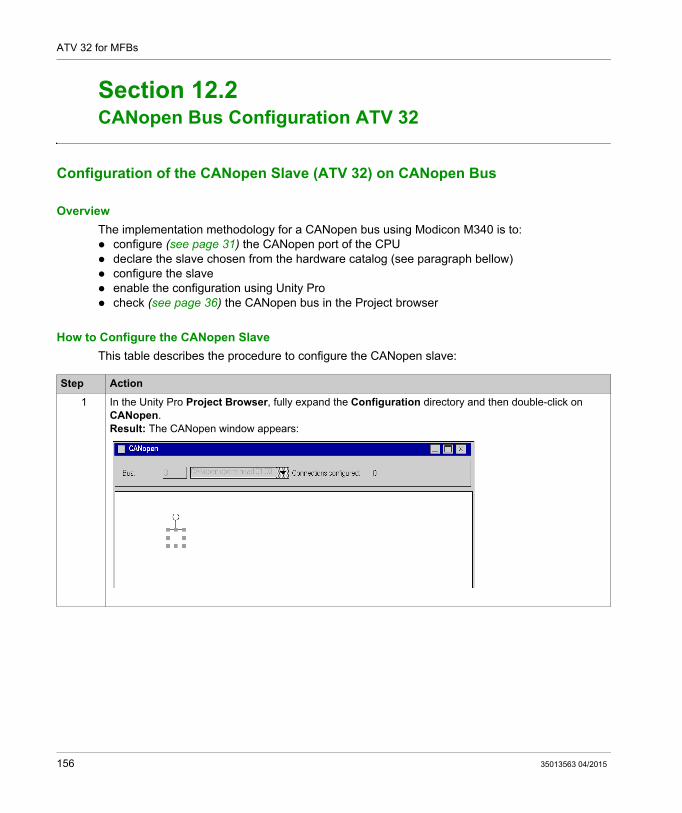
ATV 32 for MFBs
CANopen Bus Configuration ATV 32
Section 12.2CANopen Bus Configuration ATV 32
Configuration of the CANopen Slave (ATV 32) on CANopen Bus
Overview
The implementation methodology for a CANopen bus using Modicon M340 is to: configure (see page 31) the CANopen port of the CPU declare the slave chosen from the hardware catalog (see paragraph bellow) configure the slave enable the configuration using Unity Pro check (see page 36) the CANopen bus in the Project browser
How to Configure the CANopen Slave
This table describes the procedure to configure the CANopen slave:
Step Action
1 In the Unity Pro Project Browser, fully expand the Configuration directory and then double-click on CANopen.Result: The CANopen window appears:
156 35013563 04/2015

ATV 32 for MFBs
2 Select Edit → New device.Result: The New Device window appears:
3 Set 4 in Topological Address.For the slave device choose ATV32_V1_2.
Step Action
35013563 04/2015 157

ATV 32 for MFBs
4 Click on OK to confirm the choice.Result: The CANopen window appears with the new device selected:
5 Select Edit → Open module.If MFB has not already been selected, choose it in the Function area.
6 Validate your modifications when closing the Device and CANopen windows.
Step Action
158 35013563 04/2015

ATV 32 for MFBs
Configuring the ATV 32
Section 12.3Configuring the ATV 32
Aim of this Section
This section describes the basic servodrive configurations using SoMove and the servodrive’s front panel user interface.
What Is in This Section?
This section contains the following topics:
Topic Page
Configuring the ATV 32 with SoMove 160
Configuring the ATV 32 with the User Interface 163
35013563 04/2015 159

ATV 32 for MFBs
Configuring the ATV 32 with SoMove
Overview
With SoMove, users can define installed device bases and describe their associated configurations and communication settings.
SoMove then gives access to a group of actions for editing or transferring the configurations and for connecting to the devices.
The SoMove navigation principle associates a configuration interface with each device type making it possible to control, tune and monitor them.
Connecting to the ATV 32
This table describes the procedure for connecting to the ATV 32:
Step Action
1 Connect your PC, that has SoMove for ATV 32 installed, to the RJ45 connector on the servodrive to be configured.
2 Start SoMove.Result: The following start-up screen is displayed:
160 35013563 04/2015

ATV 32 for MFBs
3 Choose Connect.Result: The following screen is displayed:
4 If you are agree to follow these instructions, press Alt+F.Result: The following screen is displayed:
Step Action
35013563 04/2015 161

ATV 32 for MFBs
5 Open the Communication tab → CANopen tabResult: The following screen is displayed:
6 In the ADCO line, set the CANopen address to 4
7 In the BCDO line, set the CANopen baud rate to 500 kbps.
8 Disconnect your workstation from the servodrive.
9 Save the project using ATV32_MFB as the project name.
Step Action
162 35013563 04/2015

ATV 32 for MFBs
Configuring the ATV 32 with the User Interface
Overview
A user interface is integrated in the ATV 32. With this interface, you can: put the device online configure the device adjust the settings carry out a diagnostic
35013563 04/2015 163

ATV 32 for MFBs
Interface Menu Structure
The following graphic shows how to the access to the Configuration menus using the Jog Dial to go to the COnF menu:
ENT EnterESC Escape
164 35013563 04/2015

ATV 32 for MFBs
Basic CANopen Settings
This table gives the procedure for entering the basic CANopen address and speed settings through the User Interface:
Step Action
1 Use the Jog dial to select COnF.Result: The COnF (CANopen configuration) menu is displayed.
2 Press the ENT key.Result: a rolling list of sub-menus is displayed.
3 Use the Jog dial to select FULL.Result: The FULL (non-preloaded parameters) menu is displayed.
4 Press the ENT key.Result: A rolling list of sub-menus is displayed.
5 Use the Jog dial to select COM.Result: The COM (Communication) menu is displayed.
6 Press the ENT key.Result: A rolling list of sub-menus is displayed.
7 Use the Jog dial to select CnO.Result: The CnO (CANopen) menu is displayed.
8 Press the ENT key.Result: A rolling list of parameters is displayed
9 Use the Jog dial to select AdCO.Result: The AdCO (CANopen address) parameter is displayed.
10 Press the ENT key.Result: A value corresponding to the default CANopen address is displayed.
11 Use the Jog dial to choose the CANopen address (4).Result: The selected CANopen address is displayed.
12 Press the ENT key.Result: The AdCO (CANopen address) parameter is displayed.
13 Use the Jog dial to select bdCO.Result: The bdCO (CANopen speed) parameter is displayed
14 Press the ENT key.Result: A value corresponding to the default CANopen speed is displayed.
15 Use the Jog dial to choose the CANopen speed (500).Result: the selected CANopen speed is displayed.
16 Press the ENT key.Result: The bdCO (CANopen speed) parameter is displayed.
17 Press ESC several times to return to the main menu.
35013563 04/2015 165

ATV 32 for MFBs
166 35013563 04/2015

MFB for Modicon M340 Using Unity Pro
ATV 71 for MFBs
35013563 04/2015
ATV 71 Implementation for Motion Function Blocks
Chapter 13ATV 71 Implementation for Motion Function Blocks
Aim of this Chapter
This chapter presents the implementation of an ATV 71 servodrive according to the methodology (see page 19) described in the quick start guide (see page 13) with a Lexium 05. It only details the differences and actions for an ATV 71.
What Is in This Chapter?
This chapter contains the following sections:
Section Topic Page
13.1 Adapting the Application to the ATV 71 168
13.2 CANopen Bus Configuration ATV 71 172
13.3 Configuring the ATV 71 175
13.4 Tuning the ATV 71 181
35013563 04/2015 167

ATV 71 for MFBs
Adapting the Application to the ATV 71
Section 13.1Adapting the Application to the ATV 71
Aim of this Section
This section presents adaptation of the application to the ATV 71 with an architecture, and hardware and software requirements.
What Is in This Section?
This section contains the following topics:
Topic Page
Application Architecture with an ATV 71 169
Software Requirements 170
Hardware Requirements 171
168 35013563 04/2015

ATV 71 for MFBs
Application Architecture with an ATV 71
Overview
The proposed architecture is simple and designed to assimilate the implementation principles of motion control.
Other equipment can be added to this realistic architecture in order to manage several axes.
Illustration
The following figure shows the architecture used in the application that includes an ATV 71.
35013563 04/2015 169

ATV 71 for MFBs
Software Requirements
Overview
As regards the software requirements presented in the quick start guide (see page 13), PowerSuite is used for configuring and tuning the ATV 71.
PowerSuite for Lexium 05 enables tuning of the axis and guarantees a simple method for configuring the parameters of a Lexium 05 servodrive.
PowerSuite for ATV 71 does the same for an ATV 71 servodrive.
It is possible to configure certain permaters without PowerSuite cases by using the ATV 71 front panel, user interface (see page 179).
Versions
The following table lists the hardware and software versions used in the architecture (see page 169), enabling the use of MFBs in Unity Pro.
Hardware Earliest version of software Version of firmware
Modicon M340 Unity Pro V4.0 -
ATV 71 PowerSuite for ATV 71 V2.00 Compatible since V1.1, V 1.7 managed by MTM
170 35013563 04/2015

ATV 71 for MFBs
Hardware Requirements
References of the Hardware Used
The following table lists the hardware used in the architecture (see page 169), enabling implemen-tation of ATV 71 MFBs in Unity Pro.
NOTE: The terminating resistor is integrated in the junction box and must be ON.
Hardware Reference
Modicon M340 PLC BMX P34 2030
Modicon M340 power supply BMX CPS 2000
Modicon M340 rack BMX XBP 0800
CANopen junction box between the Modicon M340 and ATV 71 servodrive VW3CANTAP2
RJ45 programming cable with RS485/RS232 adapter between the junction box and servodrive
ACC2CRAAEF030
ATV 71 servodrive ATV71H075N2Z
35013563 04/2015 171

ATV 71 for MFBs
CANopen Bus Configuration ATV 71
Section 13.2CANopen Bus Configuration ATV 71
Configuration of the CANopen Slave (ATV 71) on CANopen bus
Overview
The implementation methodology for a CANopen bus using Modicon M340 is to:
configure (see page 31) the CANopen port of the CPU, declarate the slave chosen from the hardware catalog (see paragraph bellow), configure the slave, enable the configuration using Unity Pro, check (see page 36) the CANopen bus in the Project browser.
How to Configure the CANopen Slave
This table describes the procedure to configure the CANopen slave.
Step Action
1 In the Unity Pro Project Browser, fully expand the Configuration directory and then double-click on CANopen.Result: The CANopen window appears:
172 35013563 04/2015

ATV 71 for MFBs
2 Select Edit → New device.Result: The New Device window appears:
3 Set 5 in Topological Address.For the slave device choose ATV71_V1_1.
Step Action
35013563 04/2015 173
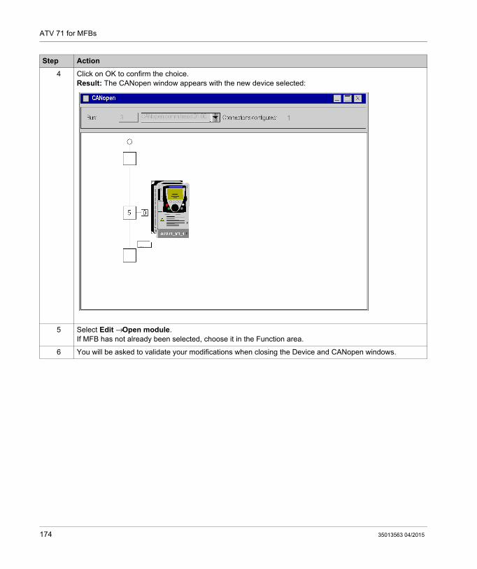
ATV 71 for MFBs
4 Click on OK to confirm the choice.Result: The CANopen window appears with the new device selected:
5 Select Edit → Open module.If MFB has not already been selected, choose it in the Function area.
6 You will be asked to validate your modifications when closing the Device and CANopen windows.
Step Action
174 35013563 04/2015

ATV 71 for MFBs
Configuring the ATV 71
Section 13.3Configuring the ATV 71
Aim of this Section
This section describes the basic servodrive configurations using PowerSuite for ATV 71 and the servodrive’s front panel user interface.
What Is in This Section?
This section contains the following topics:
Topic Page
Configuring the ATV 71 in PowerSuite 176
Configuring the ATV 71 with the User Interface 179
35013563 04/2015 175

ATV 71 for MFBs
Configuring the ATV 71 in PowerSuite
Overview
With PowerSuite, users can define installed device bases, and describe their associated configurations and communication settings.
PowerSuite then gives access to a group of actions for editing or transferring the configurations and for connecting to the devices.
PowerSuite’s navigation principle associates a configuration interface with each device type, making it possible to control, tune and monitor them.
Connecting to the ATV 71
This table describes the procedure for connecting to the ATV 71:
Step Action
1 Connect your PC, on which PowerSuite for ATV 71 is installed, to the RJ45 connector on the servodrive to be configured.
2 Start PowerSuite for ATV 71,Result: the following start-up screen is displayed:
176 35013563 04/2015

ATV 71 for MFBs
Basic ATV 71 Configuration
This table describes the procedure for entering basic settings:
3 Choose Action and then Connect.Result: a text box is displayed.
4 Type a project name (ATV71_MFB) and then click on OK.Result: a transfer confirmation window is displayed.
5 Press Alt F to start transferring data from the servodrive to the connected work station.
Step Action
Step Action
1 Following a connection and transfer of the device’s configurations, PowerSuite displays a configuration screen in a new window that gives access to device control, tuning and monitoring functions.In the tree structure displayed, choose Communication in the Communication directory.Result: the following window is displayed:
35013563 04/2015 177

ATV 71 for MFBs
2 In the ADCO line, the CANopen address must be set to 5.
3 In the BDCO line, the CANopen bus speed must be set to 500.Note: it is possible to adjust the servodrive’s settings with the same procedure.
4 Once the settings have been adjusted, use the command Configuration → Disconnect to disconnect.Result: the following screen is displayed, showing the data saved locally:
Step Action
178 35013563 04/2015

ATV 71 for MFBs
Configuring the ATV 71 with the User Interface
Overview
A user interface is integrated in the ATV 71. With this interface, you can:
put the device online configure the device carry out a diagnostic
NOTE: There is a more user-friendly graphic display terminal, for instance for diagnosing faults.
Interface Menu Structure
The following graphic presents an overview of access to the interface’s main menus:
35013563 04/2015 179

ATV 71 for MFBs
Basic Settings
The following table describes the procedure for entering basic settings (CANopen address and speed) with the interface.
Step Action
1 Press the ENT button on the interface.Result: the SET (Setting) menu is displayed on the interface’s status indicator.
2
Press the button several times to access the COM menu.Result: the COM (Communication) menu is displayed on the interface’s status indicator.
3 Press the ENT button on the interface.Result: the COAD (CANopen Address) submenu is displayed on the interface’s status indicator.
4 Press ENT again.Result: a value corresponding to the device’s CANopen address is displayed.
5
Press the button to decrease, or the button to increase the CANopen address value.Press ENT when the desired CANopen address is displayed (5).Result: the value is confirmed and the COAD (CANopen Address) submenu is displayed again.
6
Press the button to access the COBD (CANopen Baud) submenu.Press ENT.Result: a value corresponding to the device’s CANopen speed is displayed.
7
Press the button to increase, or the button to decrease the CANopen baud rate value.Press ENT when the desired CANopen speed is displayed (500).Result: the value is confirmed and the COBD (CANopen Baud) submenu is displayed again.
8 Press ESC several times to return to the main display (RDY by default).
180 35013563 04/2015

ATV 71 for MFBs
Tuning the ATV 71
Section 13.4Tuning the ATV 71
Tuning the ATV 71 with PowerSuite
In Advance
We recommend tuning the axis kinematic before the program automatically starts it.
Tuning Example
The following table gives an example of kinematic tuning:
Step Action
1 Connect (see page 176) to the ATV 71.
2 After a connection and transfer of the device’s configurations, PowerSuite opens a new window with the configuration screen, which gives access to device control, tuning and monitoring functions.The following figure shows part of the new window. This lower window provides access to ATV 71 command functions:
n
3 Place the Command zone cursor on Active.
4 Click the Reset button to clear any problems.
5 Enter the value 10 in the Frequency reference zone.
6 Click the Test Run button.Result: the motor runs and the sub-window is animated:
7 Place the Command zone cursor on Inactive once tuning has been finalized.
35013563 04/2015 181

ATV 71 for MFBs
182 35013563 04/2015

MFB for Modicon M340 Using Unity Pro
IclA for MFBs
35013563 04/2015
IclA Implementation for Motion Function Blocks
Chapter 14IclA Implementation for Motion Function Blocks
Aim of this Chapter
This chapter presents the implementation of an IclA servodrive according to the methodology (see page 19) described in the quick start guide (see page 13) with a Lexium 05. It only details the differences and actions for an IclA.
What Is in This Chapter?
This chapter contains the following sections:
Section Topic Page
14.1 Adapting the Application to the IclA 184
14.2 CANopen Bus Configuration IclA 188
14.3 Configuring the IclA 191
14.4 Tuning the IclA 193
35013563 04/2015 183

IclA for MFBs
Adapting the Application to the IclA
Section 14.1Adapting the Application to the IclA
Aim of this Section
This section presents adaptation of the application to the IclA with an architecture, and hardware and software requirements.
What Is in This Section?
This section contains the following topics:
Topic Page
Application Architecture with an IclA 185
Software Requirements 186
Hardware Requirements 187
184 35013563 04/2015

IclA for MFBs
Application Architecture with an IclA
Overview
The proposed architecture is simple and designed to assimilate the implementation principles of motion control.
Other equipment can be added to this realistic architecture in order to manage several axes.
Illustration
The following figure shows the architecture used in the application that includes an IclA IFS.
35013563 04/2015 185

IclA for MFBs
Software Requirements
Overview
As regards the software requirements presented in the quick start guide (see page 13), IclA Easy is used for configuring and tuning the IclA.
PowerSuite for Lexium 05 enables tuning of the axis and guarantees a simple method for configuring the parameters of a Lexium 05 servodrive.
IclA Easy does the same for an IclA servodrive.
It is necessary to configure certain parameters without Icla Easy by using the IclA switches (see page 191), since this is the only way to configure these parameters.
Versions
The following table lists the hardware and software versions used in the architecture (see page 185), enabling the use of MFBs in Unity Pro.
Hardware Earliest version of software Version of firmware
Modicon M340 Unity Pro V4.0 -
IclA EasyIclA V1.104 IclA IFA compatible since V1.1007IclA IFE compatible since V1.1007IclA IFS compatible since V1.1007
186 35013563 04/2015

IclA for MFBs
Hardware Requirements
References of the Hardware Used
The following table lists the hardware used in the architecture (see page 185), enabling implemen-tation of IclA MFBs in Unity Pro.
NOTE: The terminating resistor is integrated in the IclA and must be ON (see page 191).
Hardware Reference
Modicon M340 PLC BMX P34 2030
Modicon M340 power supply BMX CPS 2000
Modicon M340 rack BMX XBP 0800
CANopen SUB-D9-Way female connector (bended at 90° + additional SUB-D9-Way connector to connect a PC on the bus)
TSX CAN KCDF 90TP
CANopen preassembled cordset with moulded female SUB-D9-Way connectors at both end
TSX CAN CADD03
Dongle PCAN PS/2 for IclA Easy (parallel-to-CAN converter)
IPEH-002019
CANopen cable TSX CAN CA50
IclA servodrive IFS61/2-CAN-DS/-I-B54/0-001RPP41
35013563 04/2015 187

IclA for MFBs
CANopen Bus Configuration IclA
Section 14.2CANopen Bus Configuration IclA
Configuration of the CANopen Slave (IclA) on CANopen bus
Overview
The implementation methodology for a CANopen bus using Modicon M340 is to:
configure (see page 31) the CANopen port of the CPU, declarate the slave chosen from the hardware catalog (see paragraph bellow), configure the slave, enable the configuration using Unity Pro, check (see page 36) the CANopen bus in the Project browser.
How to Configure the CANopen Slave
This table describes the procedure to configure the CANopen slave.
Step Action
1 In the Unity Pro Project Browser, fully expand the Configuration directory and then double-click on CANopen.Result: The CANopen window appears:
188 35013563 04/2015

IclA for MFBs
2 Select Edit → New device.Result: The New Device window appears:
3 Set 6 in Topological Address.For the slave device choose IclA_IFS.
Step Action
35013563 04/2015 189

IclA for MFBs
4 Click on OK to confirm the choice.Result: The CANopen window appears with the new device selected:
5 Select Edit → Open module.If MFB has not already been selected, choose it in the Function area.
6 You will be asked to validate your modifications when closing the Device and CANopen windows.
Step Action
190 35013563 04/2015

IclA for MFBs
Configuring the IclA
Section 14.3Configuring the IclA
Configuring the IclA with DIP Switches
Overview
The address and baud rate are set with DIP switches on the IclA IFX drive.
DIP Switches
The following graphic presents the DIP switches inside the drive:
35013563 04/2015 191

IclA for MFBs
Basic Settings
The baud rate is set with the S4 switch on position 5 for a baud rate of 500.
The CANopen address is set with the S1 and S2 switches. Set S2.3 and S2.2 ON for the drive to have address 6. By default, as shown in the graphic above, all the switches on S1 and S2 are set ON except the first switch on S1, which gives address 127.
Set S3.2 ON to activate the terminating resistor.
192 35013563 04/2015

IclA for MFBs
Tuning the IclA
Section 14.4Tuning the IclA
Aim of this Section
This section gives an example of tuning the IclA with IclA Easy.
What Is in This Section?
This section contains the following topics:
Topic Page
Configuring the IclA in IclA Easy 194
Tuning the IclA with IclA Easy 198
35013563 04/2015 193

IclA for MFBs
Configuring the IclA in IclA Easy
Overview
With IclA Easy, users can define installed device bases, and describe their associated configurations and communication settings.
IclA Easy then gives access to a group of actions for editing or transferring the configurations and for connecting to the devices.
IclA Easy’s navigation principle associates a configuration interface with each device type, making it possible to control, tune and monitor them.
NOTE: The required signals, i.e LIMN, LIMP, REF must be wired or deactived by the tuning software.
Connecting to the IclA
This table describes the procedure for connecting to the IclA:
Step Action
1 Connect your PC, on which IclA Easy is installed, to the Dongle PCAN PS/2 connector on the servodrive to be configured.
194 35013563 04/2015
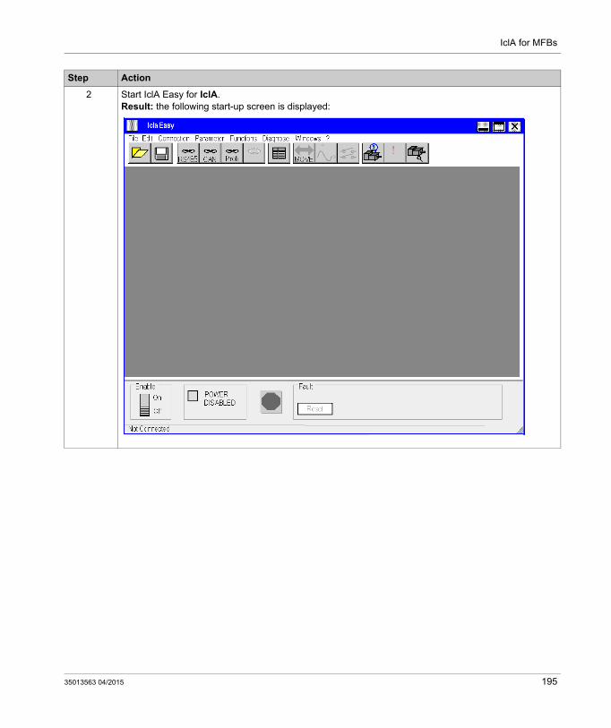
IclA for MFBs
2 Start IclA Easy for IclA.Result: the following start-up screen is displayed:
Step Action
35013563 04/2015 195

IclA for MFBs
3 Choose the command Connection → CAN Connection.Result: a text box is displayed.
4 The Baudrate must be set to 500 Kbaud.The CAN address must be set to 6.The Hardware must be set to LPT1 (Dongle PCAN PS/2).Result: a data transfer from the servodrive to the connected work station is begun.
Step Action
196 35013563 04/2015

IclA for MFBs
Basic IclA Configuration
An example is given to illustrate modification of the acceleration value. This table describes the procedure for entering this setting:
Step Action
1 Following a connection and transfer of the device’s configurations, IclA Easy displays a screen that gives access to device control, tuning and monitoring functions.
2 Choose the Motion parameter in the Parameter Groups.Result: the Parameter window is displayed.
3 In the acc line, the acceleration can be set to 1000.
4 Save the CANopen settings to EEprom with the command Parameter → Send parameter group to drive.Note: it is possible to adjust the servodrive’s settings with the same procedure.
5 Once the settings have been adjusted, use the command File → Close to disconnect.
35013563 04/2015 197

IclA for MFBs
Tuning the IclA with IclA Easy
In Advance
We recommend tuning the axis kinematic before the program automatically starts it.
Tuning Example
The following table gives an example of kinematic tuning:
Step Action
1 Connect (see page 194) to the IclA.
2 The following figure shows part of the new window. This lower window provides access to IclA command functions:
3 Click the Reset button to clear any problems.
4 Place the Enable zone cursor on ON.
5 Choose the command Functions → Operating modes.Result: Operating modes windows is displayed.
198 35013563 04/2015

IclA for MFBs
6 Choose the Speed mode tabEnter the value 200 in the Setpoint value zone.Result: the motor runs and the sub-window is animated:
7 Place the Enable zone cursor on OFF once tuning has been finalized.
Step Action
35013563 04/2015 199

IclA for MFBs
200 35013563 04/2015

MFB for Modicon M340 Using Unity Pro
Index
35013563 04/2015
Index
Cconfiguring the application
ATV 31, 135ATV 32, 151ATV 71, 167IclA, 183Lexium 05, 21Lexium 15LP/MP/HP, 113Lexium 32, 93
configuring the axis, 37configuring the CANopen bus, 29configuring the servodrives
ATV 31, 143ATV 32, 159ATV 71, 175IclA, 191Lexium 05, 47Lexium 15LP/MP/HP, 121Lexium 32, 102
Ddebugging the application, 71
Mmotion function blocks, 13
ATV 31, 135ATV 32, 151ATV 71, 167IclA, 183Lexium 05, 21Lexium 15LP/MP/HP, 113Lexium 32, 93methodology, 19quick start, 13
Ooscilloscope, 108
35013563 04/2015
Pprogramming the application, 55
Rrecipes, 79replacing servodrives, 84
Ttuning the servodrives
ATV 31, 149ATV 71, 181IclA, 193Lexium 05, 72Lexium 15LP/MP/HP, 132Lexium 32, 106
201

Index
202
35013563 04/2015