A Review of Guidance Laws Applicable to Unmanned Underwater Vehicles

Ad Hoc Networks xxx (2014) xxx–xxx
Contents lists available at ScienceDirect
Ad Hoc Networks
journal homepage: www.elsevier .com/locate /adhoc
Modeling position uncertainty of networked autonomousunderwater vehicles
http://dx.doi.org/10.1016/j.adhoc.2014.09.0031570-8705/� 2014 Elsevier B.V. All rights reserved.
⇑ Corresponding author.E-mail addresses: [email protected] (B. Chen),
[email protected] (D. Pompili).
Please cite this article in press as: B. Chen, D. Pompili, Modeling position uncertainty of networked autonomous underwater vehiHoc Netw. (2014), http://dx.doi.org/10.1016/j.adhoc.2014.09.003
Baozhi Chen, Dario Pompili ⇑Department of Electrical and Computer Engineering, Rutgers University, New Brunswick, NJ, United States
a r t i c l e i n f o
Article history:Received 1 March 2014Received in revised form 13 August 2014Accepted 2 September 2014Available online xxxx
Keywords:Underwater sensor networksPosition uncertaintyAutonomous underwater vehiclesUnscented Kalman Filter
a b s t r a c t
Recently there has been increasing engineering activity in the deployment of AutonomousUnderwater Vehicles (AUVs). Different types of AUVs are being used for applications rang-ing from ocean exploration to coastal tactical surveillance. These AUVs generally follow apredictable trajectory specified by the mission requirements. Inaccuracies in models forderiving position estimates and the drift caused by ocean currents, however, lead to uncer-tainty when estimating an AUV’s position. In this article, two forms of position uncertainty– internal and external – are studied, which are the position uncertainty associated with aparticular AUV as seen by itself and that as seen by others, respectively. Then, a statisticalmodel to estimate the internal uncertainty for a general AUV is proposed. Based on thismodel, a novel mathematical framework using Unscented Kalman Filtering is developedto estimate the external uncertainty. Finally, the benefits of this framework for severallocation-sensitive applications are shown via emulations.
� 2014 Elsevier B.V. All rights reserved.
1. Introduction
Recently UnderWater Acoustic Sensor Networks(UW-ASNs) [1] have been deployed to carry out collabora-tive monitoring missions such as oceanographic datacollection, disaster prevention, and navigation. To ensurecoverage of the vast undersampled 3D aquatic environ-ment, Autonomous Underwater Vehicles (AUVs) endowedwith sensing and wireless communication capabilitiesbecome essential. These AUVs – which can be divided intotwo classes, propeller-less/buoyancy-driven (e.g., gliders)and Propeller-Driven Vehicles (PDVs) – rely on local intelli-gence with minimal onshore operator dependence. Dueto propagation limitations of radio frequency and opticalwaves, i.e., high medium absorption and scattering, respec-tively, acoustic communication technology is employed to
transfer vital information (data and control) multi-hoppingbetween AUVs underwater and, ultimately, to a surface oronshore station where this information is collected andanalyzed.
In terrestrial sensor networks, the position of a node canbe characterized by a single point because localizationerror can be made small by using the Global PositioningSystem (GPS), which, however, does not work underwater.In contrast, underwater inaccuracies in localization modelsand the drift caused by ocean currents will significantlyincrease the position uncertainty of AUVs. Hence, using adeterministic point is not sufficient to pinpoint theposition of underwater vehicles. Furthermore, in the water,such a deterministic approach may cause problems such aserrors in inter-vehicle communications, vehicle collisions,loss of synchronization – all possibly leading to missionfailures [2].
To address the problems caused by position uncer-tainty, we introduce a probability region to characterizestochastically a node’s position. Depending on the view
cles, Ad

2 B. Chen, D. Pompili / Ad Hoc Networks xxx (2014) xxx–xxx
of the different nodes, we define two forms of positionuncertainty, i.e., internal uncertainty, the position uncer-tainty associated with a particular entity/node (such asan AUV) as seen by itself; and external uncertainty, theuncertainty associated with a particular entity/node asseen by others. These two notions introduce a shift inAUV localization – from a deterministic to a probabilisticview – which can be leveraged to improve the performanceof solutions for a variety of problems. For example, in UW-ASNs, by using the external-uncertainty notion, error fail-ures in geographical routing protocols can be decreased,and the output power at the transmitting node can be opti-mized with the constraint to guarantee a certain Signal-to-Noise Ratio (SNR) at the receiver (taking into account notonly channel impairments but also position uncertainty).This notion can also be used in underwater robotics to min-imize the risk of vehicle collisions, in underwater localiza-tion to increase the position accuracy by selecting asubset of nodes characterized by a low external uncer-tainty to be used as ‘‘anchors’’ (i.e., reference nodesemployed in ‘‘trilateration’’), and in task allocation, i.e.,the problem of selecting a subset of AUVs to accomplisha mission, to geocast the mission details to the AUVswithin a certain region. Finally, this notion plays a majorrole in data processing/visualization to improve the qualityof 3D data reconstruction as the AUV deviation from theoriginal mission path can be estimated and factored in.
To enable these applications, each node needs to esti-mate the external uncertainty of other nodes. To do this,the nodes need to first estimate their internal uncertaintyand then broadcast it to the neighbors. Due to the largenetwork latency (including communication transmissionand propagation delay) and information loss, this receiveduncertainty information is a delayed version of a node’sinternal uncertainty and is used as the base for the neigh-bors to estimate the sender’s uncertainty (i.e., externaluncertainty). As a result, these two forms of uncertaintyare generally different. To estimate the external uncer-tainty, we first propose a statistical approach to modelthe internal uncertainty of AUVs following predictable tra-jectories. Based on this internal uncertainty, we then pro-pose a solution using the Unscented Kalman Filter (UKF)algorithm to predict the external uncertainty associatedwith any localization technique and leverage this informa-tion for performance improvement. Note that in [3] weintroduced and used the notion of external uncertainty,whose region for simplicity was considered to be equalto that characterizing the internal uncertainty (its lowerbound). Here we remove that simplifying assumption andrigorously model the external uncertainty by incorporatingnetwork latency and packet loss, which brings great bene-fits to a variety of problems.
The remainder of this article is organized as follows: inSection 2, we present the notions of internal and externaluncertainty and discuss the benefits of using these twonotions. We then propose our solution for modeling theseuncertainties in Sections 3 and 4, followed by a thoroughperformance evaluation in Section 5; conclusions arefinally drawn in Section 6.
Please cite this article in press as: B. Chen, D. Pompili, Modeling positioHoc Netw. (2014), http://dx.doi.org/10.1016/j.adhoc.2014.09.003
2. The external uncertainty and its benefits in UW-ASNs
We define here the two types of position uncertainty,discuss the relationship between them, and comment onthe benefits of using the external uncertainty in a varietyof research areas and problems.
2.1. Internal uncertainty
This represents the position uncertainty associatedwith a particular entity/node (such as an AUV) as seenby itself. Many approaches such as those using KalmanFilter (KF) [4,5] have been proposed to estimate thisuncertainty assuming that the variables to be estimatedhave linear relationships among them, and that the noiseis additive and Gaussian. While simple and robust, KF isnot optimal when the linearity assumption among thevariables does not hold. On the other hand, approachesusing nonlinear filters such as the extended or unscentedKF attempt to minimize the mean squared errors in esti-mates by jointly considering the navigation location andthe sensed states such as underwater terrain features,which is non-trivial, especially in the unstructured under-water environment.
2.2. External uncertainty
This represents the position uncertainty associated witha particular entity/node as seen by others. Let us denote theinternal uncertainty, a 3D region associated with any nodej 2 N , the set of network nodes, as U jj; and the externaluncertainties, 3D regions associated with j as seen byi; k 2 N , as U ij and Ukj, respectively (i – j – k). In general,U jj;U ij, and Ukj are different from each other; also, due toasymmetry, U ij is in general different from U ji. Externaluncertainties may be derived from the broadcast/propa-gated internal-uncertainty estimates (e.g., using one-hopor multi-hop neighbor discovery mechanisms) and, hence,will be affected by the end-to-end (e2e) network latencyand information loss. The estimation of the external-uncer-tainty region U ij of a generic node j at node i (with i – j)involves the participation of both i and j. Fig. 1(a) illus-trates the internal- and external-uncertainty regions andtheir difference; j’s uncertainty regions seen by j itself(U jj, i.e., the internal uncertainty), by i (i.e., U ij) and by k(i.e., Ukj) are all depicted to be different (general case). Notethat, as shown in Fig. 1(b), in general, the longer an AUVremains underwater, the larger its external and internaluncertainties. Estimating U ij involves estimating thechange of U jj with time; hence, in this work we propose asolution to predict U ij based on the statistical estimationof U jj.
2.3. Benefits to underwater applications
We present here applications and research areas wherethe proposed notion of external uncertainty can be appliedto improve performance.
n uncertainty of networked autonomous underwater vehicles, Ad

Fig. 1. Illustration of the external-uncertainty concept (note that superscript t, used in this work only when needed, indicates time instant t).
Fig. 2. Research areas and problems that benefit from the notion of external uncertainty (broken-line circles denote external uncertainty while broken-dotted-line circles denote internal uncertainty; note that, for the sake of visualization simplicity, we use circles instead of 3D shapes).
B. Chen, D. Pompili / Ad Hoc Networks xxx (2014) xxx–xxx 3
2.3.1 Communication protocols for UW-ASNsIn UW-ASNs, the external uncertainty can be used to
improve the performance of networking solutions. Forexample, as shown in [3], a solution that considers externaluncertainty can be used for Delay-Tolerant Networks(DTNs). As shown in Fig. 2(a), by leveraging the predictabil-ity of AUVs’ trajectories, delaying packet transmissions insuch a way as to wait for the optimal network topology(thus trading e2e delay for throughput and/or energyconsumption) can minimize communication energy con-sumption for delay-tolerant traffic. Also, by optimizing sta-tistically the transmission output power, routing errors/failures can be reduced, which decreases the overallenergy/bandwidth utilization.
2.3.2. Underwater roboticsIn underwater robotics, a team of AUVs can collaborate
to explore a 3D region and take measurements in spaceand time. To derive the spatio-temporal correlation of themeasurements, these AUVs need to keep a geometric for-mation and steer through the region (Fig. 2(b)). They alsoneed to keep a distance between each other in order toavoid vehicle collisions. In [6], a solution is proposed tominimize the time to form the geometric formation whileavoiding collisions. However, that solution assumes thegliders to have correct location information, which is astrong requirement in the underwater environment. Thesolution can be made more robust against ocean currentsand acoustic channel impairments by exploiting the con-cept of external uncertainty, e.g., a control algorithm canbe designed to minimize the probability that two AUVs
Please cite this article in press as: B. Chen, D. Pompili, Modeling positioHoc Netw. (2014), http://dx.doi.org/10.1016/j.adhoc.2014.09.003
are within the collision region. This concept can also beused to adapt the sampling strategy based on the variationof the measurements.
2.3.3. Underwater localizationTo perform self-localization, AUVs may need to rely on
other anchor nodes (e.g., AUVs) whose positions may notbe accurate, as in Fig. 2(c). Localization errors, however,may increase if an AUV relies on anchors with large posi-tion uncertainty. The external-uncertainty notion cantherefore be used to decrease errors and computation com-plexity, e.g., by selecting the optimal subset of anchors(with small external uncertainty) so to minimize the newinternal uncertainty.
2.3.4. Task allocationOur notion of uncertainty can also be applied in task
allocation, whose objective is to choose a subset of vehiclesto accomplish reliably a mission with specific require-ments while trying to maximize the remaining energyafter the mission or to minimize the time to completethe mission itself [7]. By using the external-uncertaintynotion, a team of AUVs that are ‘‘closer’’ to the target canbe selected, which may lead probabilistically to less timeand/or energy to complete the mission.
2.3.5. Data processing and visualizationOnce the measurements are received by the onshore
station, oceanographers need to visualize and analyze sen-sor data for a multitude of ocean science studies. The exter-nal-uncertainty notion can improve the quality of 3D data
n uncertainty of networked autonomous underwater vehicles, Ad

4 B. Chen, D. Pompili / Ad Hoc Networks xxx (2014) xxx–xxx
reconstruction because it provides vehicles’ deviation fromtheir mission path.
3. Modeling the internal uncertainty
To obtain the external uncertainty U ij; j needs to esti-mate its internal-uncertainty region U jj first; then, U jj isbroadcast to its neighbors. Upon receiving this informa-tion, i will derive U ij based on U jj. Therefore, it is necessaryto estimate U jj before U ij can be derived. For this reason,here we first provide a statistical model for internal-uncer-tainty estimation; then, we propose an UKF-based solutionto predict the external uncertainty.
Our internal-uncertainty model works for any localiza-tion algorithm as it relies on a statistical approach to esti-mate the confidence region using the position estimates ofan AUV. We assume that each AUV follows a predictabletrajectory, which is reasonable as AUVs generally need tofollow the pre-planned path(s) to take measurements.The advance in mechanical, electrical, and computer engi-neering technologies has made it possible for AUVs to steerautonomously close to (or on) the pre-planned path(s)under disturbance such as ocean currents. Moreover, AUVsare designed to follow some regular movement pattern(e.g., saw-tooth trajectories for glider). Assume withoutloss of generality that the trajectory of an AUV can bedescribed by a function ðx; y; zÞ ¼ fðt; hÞ, where h is the listof p parameters that needs to be specified by the AUV’s tra-jectory (note that a point on the ocean surface, e.g., the ini-tial position of the vehicle before going underwater, istaken as the coordinate origin). Also, assume f is differen-tiable except at a countable set of discrete points. Thisassumption generally holds since AUVs rely on forces suchas mechanical propulsion and/or buoyancy for accelera-tion, which results in a differentiable trajectory except atpoints where abrupt change is made. For example, anunderwater glider follows a saw-tooth pattern, whosepiecewise trajectory can be described as a line (differentia-ble) segment ðx; y; zÞ ¼ ðat þ x0; bt þ y0; ct þ z0Þ. In thiscase, h ¼ ða; b; c; x0; y0; z0Þ. Assume AUV j estimates itsown coordinates, Pn ¼ ðxn; yn; znÞ, at sampling times tn
(n ¼ 1 . . . N), and its trajectory segment is of the formPðtÞ ¼ fðt; hÞ: we need to estimate h so that the trajectorycan be determined. Note that Pn can be estimated usingexisting localization techniques such as dead reckoning,particle filtering, or long baseline navigation [8]. Conse-quently, based on the derived trajectory, j’s internal uncer-tainty (i.e., confidence region) can be estimated, as detailedbelow.
From nonlinear regression theory in statistics, weestimate a vehicle’s trajectory using the Gauss–NewtonAlgorithm [9], which relies on the linear approximationusing the Taylor expansion fðt; hÞ � fðt; hð0ÞÞ þ Z0ðh� hð0ÞÞ,where Z0 ¼ Zjh¼hð0Þ ¼ @f
@hjh¼hð0Þand hð0Þ is the vector that pro-
vides the initial values of these parameters in order to startthe algorithm. The objective of our estimation is to find the
best h such that SðhÞ ¼PN
n¼1kPn � fðtn; hÞk2 is minimized.
The idea of the Gauss–Newton Algorithm is to find h
through iteration, i.e., to update hðqÞ iteratively until con-
Please cite this article in press as: B. Chen, D. Pompili, Modeling positioHoc Netw. (2014), http://dx.doi.org/10.1016/j.adhoc.2014.09.003
vergence. From nonlinear regression theory, it has been
shown that h� hð0Þ ¼ ðZT ZÞ�1ZT�ð0Þ, where �ð0Þ ¼ PðtÞ�
fðt; hð0ÞÞ. Starting from the initial position, we have the fol-lowing iterative formula to estimate hðqÞ, i.e., hðqþ1Þ ¼
hðqÞ þ dðqÞ, where dðqÞ ¼ ½ðZqÞT Zq��1
Zq�ðqÞ and �ðqÞ ¼ PðtÞ�fðt; hðqÞÞ.
From statistical inference theory, we obtain asymptoti-cally h � Nðh;r2C�1Þ, where NðÞ is the normal distribu-tion, C ¼ ZT Z, and r2 is the variance; this leads to
aT h�aT h
rðaT C�1aÞ1=2 � tN�p, where tN�p is the t-distribution with
N � p degrees of freedom [9], aT ¼ ½0; 0; . . . ;0;1;0; . . . ;0� isa vector with p elements, r ¼ SðhÞ=ðN � pÞ. Note that thisactually gives the confidence interval for each element inh. It is also proven in [9] that asymptotically
fðtN ; hÞ � fðtN ; hÞ
r 1þ ðZNÞT ZTZ�1ZN
h i1=2 � tN�p: ð1Þ
Finally, the internal-uncertainty region is given by theapproximate 100ð1� aÞ% confidence interval at tN as,
fðtN ; hÞ � ta=2N�pr 1þ ðZNÞT ZTZ�1ZN
h i1=2; ð2Þ
where ta=2N�p is the 100ð1� a=2Þ% of the t-distribution with
N � p degrees of freedom and ZN ¼ @fðtN ;hÞ@h
is the Jacobianmatrix of fð Þ at tN .
3.1. Note
Our solution is based on the first-order Taylor expan-sion. This method is known as Delta Method in statistics.This basic method can be extended to second-order Taylorexpansion. However, to use second-order Delta method, itis generally required that the first-order derivative@f@hjh¼hð0Þ
¼ 0 and the second-order derivative be non-zero
[10]. Under such conditions, fðtN; hÞ � fðt; hÞ will convergein distribution to v2
jhj. If the first-order derivative is nonzero, estimating the distribution of the second-order Tay-lor expansion is more complicated as we need to considerthe first and second power of the random variablestogether. Extending to higher-order Taylor expansion willbe far more complicated. In general, adding higher-orderexpansion achieves more prediction accuracy; however, italso makes the prediction far more complicated and theextra accuracy achieved is often not worth the increasedcomplexity.
4. Modeling the external uncertainty
To present our external-uncertainty model, we startfrom the estimation of the one-hop external uncertainty;then, we show how this estimate can be used to adjustdynamically the update interval; last, but not least, weextend the one-hop estimate to the case in which a nodeis multiple hops away. Note that in this work we focuson algorithms to model the external uncertainty. Weassume that the vehicles are synchronized in time initially
n uncertainty of networked autonomous underwater vehicles, Ad

B. Chen, D. Pompili / Ad Hoc Networks xxx (2014) xxx–xxx 5
through GPS (when on the surface) and time synchroniza-tion algorithms are run to maintain a coarse synchroniza-tion when underwater, i.e., the nodes synchronize thetime with a selected reference node (which may have timedrifting).
4.1. One-hop external uncertainty estimation
After receiving j’s trajectory and the internal-uncertainty region parameters, i.e., h; fðtN; hÞ, and
ta=2N�pr½1þ ðZNÞT ZTZ�1ZN�1=2, AUV i can update the estimate
of j’s external-uncertainty region. Due to packet delaysand losses in the network, j’s external-uncertainty regionsas seen by single- and multi-hop neighbors are delayed ver-sions of j’s own internal uncertainty. Hence, when usingmulti-hop neighbor discovery schemes, the internaluncertainty U jj provides a lower bound for all the externaluncertainties associated with that node, U ij;8i 2 N . Conse-quently, we derive U ij based on the received U jj.
We use UKF to predict how the internal uncertainty‘propagates’ (and in general ‘deteriorates’) through the net-work. This is done in two steps, as detailed below: (1)Region prediction, to predict the current position of anAUV assuming that its previous location is at a point inthe internal-uncertainty region; then, the external-uncer-tainty region is obtained by taking the set containing thesepredicted positions and (2) Distribution estimation, to cal-culate the probability density function (pdf) of the currentposition by integrating the internal-uncertainty pdf overpoints with the same predicted position.
4.1.1. Region predictionAUV i first predicts j’s position assuming j is located at a
point in U jj and then considers the union of all these pre-dicted points. The movement model of j can be describedusing the following nonlinear dynamical system (note thatthe equivalent discrete-time dynamic equation can bederived as in [11] by means of the state-space methodusing iterations); AUV i estimates the state from stepq ¼ 1 whenever U jj is received, where q is incrementeduntil a new U jj is received (in which case q is reset to 1).Hence,
sqj ¼ Fjs
q�1j þ oðsq�1
j Þ þ Guq�1j þ Bwq�1
j ð3Þ
represents the state-transition equation for the systemdescribing the motion of AUV j between steps q� 1 and q(spaced T ½s� apart). Here, sq
j ¼ ½xqj ; y
qj ; z
qj ; _xq
j ; _yqj ; _zq
j ;vocj;x;voc
j;y;
vocj;z�
T represents 3D position, velocity, and ocean-current
velocity of AUV j at step q;oðsq�1j Þ is the ocean-current pre-
diction function (which is generally nonlinear),
uq�1j ¼ ½uq�1;x
j ; uq�1;yj ; uq�1;z
j �T is the control input fort 2 ½ðq� 1ÞT; qTÞ (which is used not to offset the drifting,but to steer the AUV to move along its trajectory), and
wq�1j ¼ ½wq�1;x
j ;wq�1;yj ;wq�1;z
j ;wq�1;xoc;j ;wq�1;y
oc;j ;wq�1;zoc;j �
Trepre-
sents the discrete random acceleration caused by non-idealnoise in the control input and/or the variation in ocean cur-rent speed. Throughout this article, when used as super-script, T indicates matrix transpose; otherwise, it
Please cite this article in press as: B. Chen, D. Pompili, Modeling positioHoc Netw. (2014), http://dx.doi.org/10.1016/j.adhoc.2014.09.003
represents the time interval. Note that oðsq�1j Þ can be pre-
dicted using ocean-current models or data from real-timeonshore ocean observing systems; also, note that, as AUVsare spaced a few kilometers apart, the currents affectingthe AUVs are generally different. Ocean current is affectedby many complicated factors (which are global informa-tion) including (but not limited to) surface wind, Corioliseffect, temperature and salinity differences, gravitationalpull of the Moon and the Sun, depth contours, shorelineconfigurations and interaction with other currents. It isunrealistic for the resource-limited AUV to get all theseglobal data and run complex models that considers allthese factors to predict the current velocity, even thoughsimplified model may probably be used (in this case it willincur more prediction errors). On the other hand, theonshore systems can use powerful super-computers ordata centers to finish such estimation and send back theprediction to the AUV through the acoustic communicationnetworks.
In (3), Fj;G, and B are matrices to adjust the state sqj
according to the previous state, control input, and randomacceleration noise, respectively, and are defined as,
Fj ¼I3 T 0jI3 T 0jI3
0 I3 I3
0 0 I3
264
375; G ¼
0I3
0
264
375; B ¼
0 0I3 00 I3
264
375;
where I3 is the 3� 3 identity matrix, T 0j ½s� is the differencebetween the current time and the last time when U jj wasestimated or the last update time that UKF was run, i.e.,T 0j ¼ tnow � tU jj
if i receives j’s updated internal uncertainty
after the last UKF update, whereas T 0j ¼ T if i does notreceive j’s update message, where tU jj
is the time whenU jj is estimated by j and T is the UKF update interval.
The variable wq�1j represents 3D samples of discrete-
time white Gaussian noise; hence, wq�1j � Nð0;Q Þ, where
Q P 0 is the covariance matrix of the process. The randomacceleration is also assumed to be independent on thethree axes. Here we assume that an AUV can measurethe ocean-current velocity using sensors such as AcousticDoppler Current Profiler (ADCP), which are, however,expensive. For AUVs without ADCP, we can force the statefor ocean current to be zero; in this case, the model wouldreduce to a linear KF and the effect of ocean current shouldbe treated as noise, which is accounted by wq�1
j .It is worth noting that (3) includes delays due to trans-
mission, propagation, reception, and packet loss. As theocean-current velocity is generally nonlinear, (3) expressesa nonlinear relationship between sq
j and sq�1j . Therefore, a
nonlinear Kalman filter should be used. In this work weuse UKF because this filter can provide more accurate pre-diction than the extended KF (another type for nonlinearprediction) while having the same computation complex-ity of OðL3Þ for state estimation, where L (9 in our case)is the dimension of the state variable, as proven in [12].
The position observed by the AUV at step q is related to
the state by the measurement equation, Pqj ¼ Hsq
j þ T 0jeCvq�1j ,
where Pqj ¼ ½P
q;xj ; Pq;y
j ; Pq;zj � represents the observed position
n uncertainty of networked autonomous underwater vehicles, Ad

6 B. Chen, D. Pompili / Ad Hoc Networks xxx (2014) xxx–xxx
of the AUV at step q; here, H ¼ I3 0 0½ � is the matrix that
extracts the position, whereas eC ¼ 0 I3 0½ �T adds the
noise. The variable vq�1j ¼ ½vq�1;x
j ; vq�1;yj ;vq�1;z
j �T representsthe measurement noise in velocity, expressed as 3D samplesof discrete-time white Gaussian noise. Hence,vq
j � Nð0;RÞ, where R P 0 is the covariance matrix of
the process. The observed position of the AUV Pqj is there-
fore the actual position of the AUV affected by a measure-ment noise, which we represent as a Gaussian variable.
The UKF algorithm provides a computationally efficientset of recursive equations to estimate the state of such pro-cess, and can be proven to be the optimal filter in the min-imum square sense [13]. To implement the UKF algorithm,we need to extend the state vector to the augmented vector
sq;þj ¼ ½ðsq
j ÞT; ðwq�1
j ÞT ; ðvq�1j ÞT �
Tand use the corresponding
covariance matrix Vq;þj ¼ E½sq;þ
j ðsq;þj Þ
T �. The use of UKF atAUV i reduces the number of necessary location updates.In fact, the filter is used to estimate the position at the AUVbased on measurements, which is a common practice inrobotics, and to predict the position of the AUVs thus limit-ing message exchange (i.e., reducing the need for frequentposition updates). The position of j can be estimated andpredicted at i based on past estimates Pq
j . To update thestate vector, i needs to calculate a so-called L� ð2Lþ 1Þsigma point matrix vj;q�1 with the following column vectors
vmj;q�1 (m ¼ 0; . . . ;2L), i.e., for m ¼ 0, v0
j;q�1 ¼ sq;þj ; for
m ¼ 1; . . . ; L, vmj;q�1 ¼ sq;þ
j þ ðLþ kÞVq;þj
h i1=2
m; for m ¼ Lþ
1; . . . ;2L, vmj;q�1 ¼ sq;þ
j � ðLþ kÞVq;þj
h i1=2
m.
Here ½ðLþ kÞVq;þj �
1=2
mis the m-th column of the matrix
square root of ðLþ kÞVq;þj , where k ¼ 12ðLþ jÞ � L is a scal-
ing factor depending on 1 and j that controls the spread ofthe sigma points. These sigma vectors vm
j;q�1 (m ¼ 0; . . . ;2L)are propagated through the nonlinear state estimate, i.e.,(3), denoted by T here, Ym
j;q�1 ¼ T ðvmj;q�1Þ. The state and
covariance are predicted by recombining these weightedsigma points, i.e.,
sq�j ¼
X2L
m¼0
Wms vm
j;q�1; ð4Þ
Yq�1j ¼
X2L
m¼0
Wms Ym
j;q�1; ð5Þ
Vq�j ¼
X2L
m¼0
Wmc ½Ym
j;q�1 � sqj �½Y
mj;q�1 � sq
j �T; ð6Þ
where W0s ¼ k=ðLþ kÞ;W0
c ¼ k=ðLþ kÞ � ð1� 12 þ bÞ, andWm
s ¼Wmc ¼ 1=½2ðLþ kÞ� for m ¼ 1; . . . ;2L; b is related to
the distribution of s. Normal values are 1 ¼ 10�3; j ¼ 1,and b ¼ 2. If the distribution of s is Gaussian, b ¼ 2 is opti-mal. Here the superscript q-means that the state sq�
j or Vq�j
covariance estimate is a priori estimate. Eqs. (5) and (6)describe how i predicts the state of AUV j before receivingthe measurement (a priori estimate). Then, i projects thecovariance matrix ahead. Once received the measurementPq
j ; i updates the Kalman gain Kqj , and corrects the state
Please cite this article in press as: B. Chen, D. Pompili, Modeling positioHoc Netw. (2014), http://dx.doi.org/10.1016/j.adhoc.2014.09.003
estimate and covariance matrix according to the measure-ment, i.e.,
Vj;~Yq ~Yq¼X2L
m¼0
Wms ½Ym
j;q � Ymj;q�1�½Ym
j;q � Ymj;q�1�
T;
Vj;~sq ~Yq¼X2L
m¼0
Wms ½s
q;mj � sq�1;m
j �½Ymj;q � Ym
j;q�1�T;
Kqj ¼ Vj;~sq ~Yq
ðVj;~Yq ~YqÞ�1
; ð7Þ
sqj ¼ sq�
j þ Kqj ðY
qj � Y
q�1j Þ; ð8Þ
Vqj ¼ Vq�
j � Kqj Vj;~Yq ~Yq
ðKqj Þ
T; ð9Þ
where (7) updates the Kalman gain, (8) calculates the newstate (a posteriori estimate), and (9) updates the covariancematrix. Note that the complexity of the above computa-tions is the same as in the extended KF [12] and that theprocessing cost at i is much lower than the communicationcost (the output power used by acoustic transmittersunderwater is in the order of tens of Watts).
Finally, if we denote the UKF filtering at time tq fromposition p at tq�1 as hUKFðtq;p; tq�1Þ, the predicted exter-nal-uncertainty region at step q is Uq
ij ¼ fhUKFðqT;p;
ðq� 1ÞTÞjp 2 Uq�1ij g, which, for simplicity, we further sim-
plify in Uqij ¼ hUKFðqT;Uq�1
ij ; ðq� 1ÞTÞ.
4.1.2. Distribution estimationAssume p 2 Uq
ij is predicted from point p0 at step q� 1,
i.e., p ¼ hUKFðqT;p0; ðq� 1ÞTÞ; p0 2 Uq�1ij . The pdf gq
ijðpÞ of
the external uncertainty Uqij at step q can be derived from
the pdf gq�1ij ðpÞ of Uq�1
ij as
gqijðpÞ ¼
Zp¼hUKF ðqT;p0 ;ðq�1ÞTÞ;p02Uq�1
ij
gq�1ij ðp
0Þdp0:
With the help of UKF and the probability theory, we canderive the external uncertainty and its pdf. Note that theinitial pdf g0
ijðpÞ is the t-distribution on U jj (i.e., U0jj) received
from j. To reduce the complexity, we convert an uncer-tainty region (internal or external) into its discrete coun-terparts, i.e., we divide an uncertainty region into a finitenumber of equal-size small regions. When the number ofsmall regions is sufficiently large, the UKF filtering on eachsmall region can be approximated by the UKF filtering on apoint – e.g., the centroid – in this small region. Hence, thepredicted external-uncertainty region can be approxi-mated as the region contained in the hull of these pre-dicted points. The pdf functions are also approximated bythe probability mass functions on discrete points, whichsimplifies the pdf estimation after UKF filtering.
4.2. Adjustment of the UKF update interval
So far, we have assumed the update interval T for theUKF algorithm to be fixed. A small T determines frequentupdates, i.e., the estimation error is corrected in a timelymanner; however, frequent external-uncertainty estima-tions lead to waste of computation resources and energy,causing large network overhead. On the other hand, a largeT would save such resources; yet, it may lead to large
n uncertainty of networked autonomous underwater vehicles, Ad
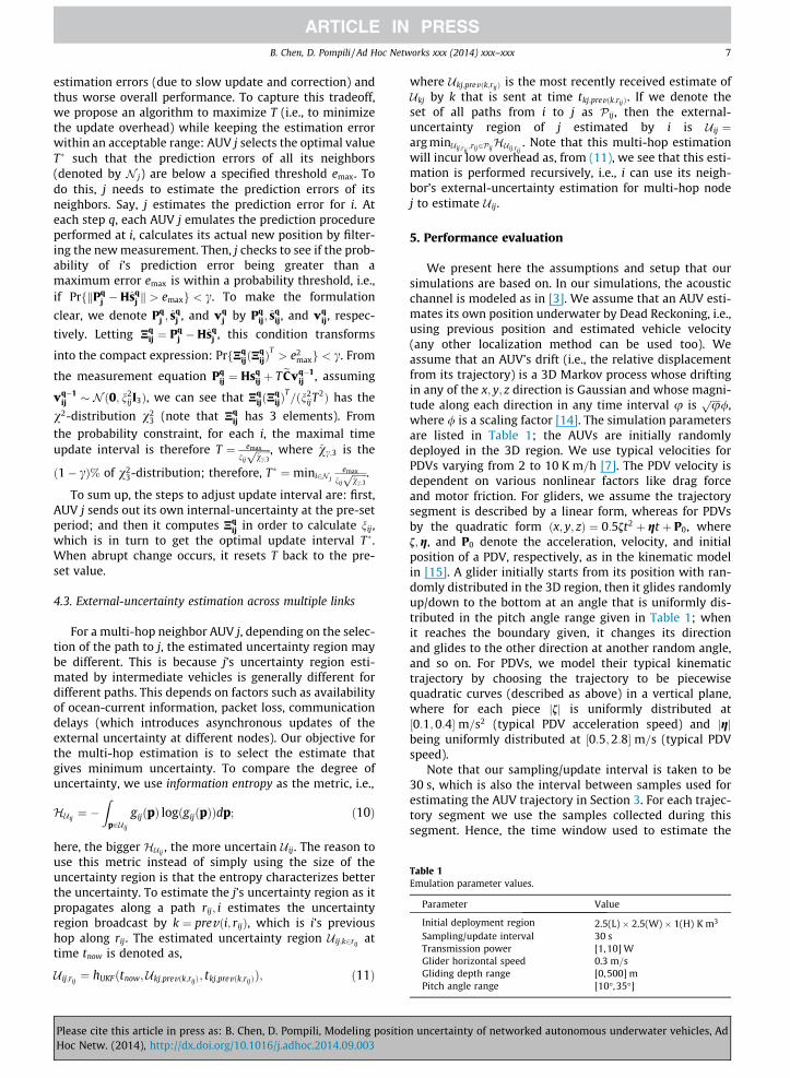
Table 1Emulation parameter values.
Parameter Value
Initial deployment region 2.5(L) � 2.5(W) � 1(H) K m3
Sampling/update interval 30 sTransmission power [1,10] WGlider horizontal speed 0.3 m=sGliding depth range [0, 500] m
B. Chen, D. Pompili / Ad Hoc Networks xxx (2014) xxx–xxx 7
estimation errors (due to slow update and correction) andthus worse overall performance. To capture this tradeoff,we propose an algorithm to maximize T (i.e., to minimizethe update overhead) while keeping the estimation errorwithin an acceptable range: AUV j selects the optimal valueT� such that the prediction errors of all its neighbors(denoted by N j) are below a specified threshold emax. Todo this, j needs to estimate the prediction errors of itsneighbors. Say, j estimates the prediction error for i. Ateach step q, each AUV j emulates the prediction procedureperformed at i, calculates its actual new position by filter-ing the new measurement. Then, j checks to see if the prob-ability of i’s prediction error being greater than amaximum error emax is within a probability threshold, i.e.,if PrfkPq
j �Hsqj k > emaxg < c. To make the formulation
clear, we denote Pqj ; s
qj , and vq
j by Pqij; s
qij, and vq
ij, respec-
tively. Letting Nqij ¼ Pq
j �Hsqj , this condition transforms
into the compact expression: PrfNqijðN
qijÞ
T> e2
maxg < c. From
the measurement equation Pqij ¼ Hsq
ij þ TeCvq�1ij , assuming
vq�1ij � Nð0; n2
ijI3Þ, we can see that NqijðN
qijÞ
T=ðn2
ijT2Þ has the
v2-distribution v23 (note that Nq
ij has 3 elements). Fromthe probability constraint, for each i, the maximal timeupdate interval is therefore T ¼ emax
nij
ffiffiffiffiffiffivc;3p , where vc;3 is the
ð1� cÞ% of v23-distribution; therefore, T� ¼ mini2N j
emax
nij
ffiffiffiffiffiffivc;3p .
To sum up, the steps to adjust update interval are: first,AUV j sends out its own internal-uncertainty at the pre-setperiod; and then it computes Nq
ij in order to calculate nij,which is in turn to get the optimal update interval T�.When abrupt change occurs, it resets T back to the pre-set value.
4.3. External-uncertainty estimation across multiple links
For a multi-hop neighbor AUV j, depending on the selec-tion of the path to j, the estimated uncertainty region maybe different. This is because j’s uncertainty region esti-mated by intermediate vehicles is generally different fordifferent paths. This depends on factors such as availabilityof ocean-current information, packet loss, communicationdelays (which introduces asynchronous updates of theexternal uncertainty at different nodes). Our objective forthe multi-hop estimation is to select the estimate thatgives minimum uncertainty. To compare the degree ofuncertainty, we use information entropy as the metric, i.e.,
HU ij¼ �
Zp2U ij
gijðpÞ logðgijðpÞÞdp; ð10Þ
here, the bigger HU ij, the more uncertain U ij. The reason to
use this metric instead of simply using the size of theuncertainty region is that the entropy characterizes betterthe uncertainty. To estimate the j’s uncertainty region as itpropagates along a path rij; i estimates the uncertaintyregion broadcast by k ¼ prevði; rijÞ, which is i’s previoushop along rij. The estimated uncertainty region U ij;k2rij
attime tnow is denoted as,
U ij;rij¼ hUKFðtnow;Ukj;prevðk;rijÞ; tkj;prevðk;rijÞÞ; ð11Þ
Please cite this article in press as: B. Chen, D. Pompili, Modeling positioHoc Netw. (2014), http://dx.doi.org/10.1016/j.adhoc.2014.09.003
where Ukj;prevðk;rijÞ is the most recently received estimate ofUkj by k that is sent at time tkj;prevðk;rijÞ. If we denote theset of all paths from i to j as Pij, then the external-uncertainty region of j estimated by i is U ij ¼arg minU ij;rij
;rij2PijHU ij;rij
. Note that this multi-hop estimationwill incur low overhead as, from (11), we see that this esti-mation is performed recursively, i.e., i can use its neigh-bor’s external-uncertainty estimation for multi-hop nodej to estimate U ij.
5. Performance evaluation
We present here the assumptions and setup that oursimulations are based on. In our simulations, the acousticchannel is modeled as in [3]. We assume that an AUV esti-mates its own position underwater by Dead Reckoning, i.e.,using previous position and estimated vehicle velocity(any other localization method can be used too). Weassume that an AUV’s drift (i.e., the relative displacementfrom its trajectory) is a 3D Markov process whose driftingin any of the x; y; z direction is Gaussian and whose magni-tude along each direction in any time interval u is
ffiffiffiffiup /,where / is a scaling factor [14]. The simulation parametersare listed in Table 1; the AUVs are initially randomlydeployed in the 3D region. We use typical velocities forPDVs varying from 2 to 10 K m=h [7]. The PDV velocity isdependent on various nonlinear factors like drag forceand motor friction. For gliders, we assume the trajectorysegment is described by a linear form, whereas for PDVsby the quadratic form ðx; y; zÞ ¼ 0:5ft2 þ gt þ P0, wheref;g, and P0 denote the acceleration, velocity, and initialposition of a PDV, respectively, as in the kinematic modelin [15]. A glider initially starts from its position with ran-domly distributed in the 3D region, then it glides randomlyup/down to the bottom at an angle that is uniformly dis-tributed in the pitch angle range given in Table 1; whenit reaches the boundary given, it changes its directionand glides to the other direction at another random angle,and so on. For PDVs, we model their typical kinematictrajectory by choosing the trajectory to be piecewisequadratic curves (described as above) in a vertical plane,where for each piece jfj is uniformly distributed at½0:1;0:4�m=s2 (typical PDV acceleration speed) and jgjbeing uniformly distributed at ½0:5;2:8�m=s (typical PDVspeed).
Note that our sampling/update interval is taken to be30 s, which is also the interval between samples used forestimating the AUV trajectory in Section 3. For each trajec-tory segment we use the samples collected during thissegment. Hence, the time window used to estimate the
Pitch angle range [10�,35�]
n uncertainty of networked autonomous underwater vehicles, Ad

0 0.5 1 1.5 2 2.5 3 3.50
50
100
150
200
250
300
350
time [hour]
dist
ribut
ion
size
in x
−axi
s [m
]SimulatedGlider (UKF)Glider (KF)PDV (UKF)PDV (KF)
(a) Estimated sizes along the x coordinate
0
100
200
300
400
500
600
dist
ribut
ion
size
in y
−axi
s [m
]
SimulatedGlider (UKF)Glider (KF)PDV (UKF)PDV (KF)
(b) Estimated sizes along the y coordinate
0
50
100
150
200
250
300
350
400
450
500
dist
ribut
ion
size
in z
−axi
s [m
]
SimulatedGlider (UKF)Glider (KF)PDV (UKF)PDV (KF)
(c) Estimated sizes along the z coordinate
0 0.5 1 1.5 2 2.5 3 3.5time [hour]
0 0.5 1 1.5 2 2.5 3 3.5time [hour]
Fig. 3. External-uncertainty prediction accuracy: estimated 3D region sizes.
−250 −200 −150 −100 −50 0 50 100 150 200 2500
0.05
0.1
0.15
0.2
0.25
0.3
0.35
x [m]
pmf
SimulatedGlider (UKF)Glider (KF)PDV (UKF)PDV (KF)
(a) pmf along the x coordinate
−500 −400 −300 −200 −100 0 100 200 300 400 5000
0.05
0.1
0.15
0.2
0.25
0.3
0.35
0.4
y [m]
pmf
SimulatedGlider (UKF)Glider (KF)PDV (UKF)PDV (KF)
(b) pmf along the y coordinate
−400 −300 −200 −100 0 100 200 300 4000
0.05
0.1
0.15
0.2
0.25
0.3
0.35
0.4
0.45
z [m]
pmf
SimulatedGlider (UKF)Glider (KF)PDV (UKF)PDV (KF)
(c) pmf along the z coordinate
Fig. 4. External-uncertainty prediction accuracy: estimated 3D region probability mass functions (pmfs).
8 B. Chen, D. Pompili / Ad Hoc Networks xxx (2014) xxx–xxx
AUV location starts from the time when the AUV changesthe current trajectory. Further investigation can be doneusing a fixed number of the last samples to estimate thelocation and its associated uncertainty, and then derivethe optimal value for this number.
5.1. External-uncertainty prediction accuracy
We are interested in comparing the external-uncer-tainty prediction accuracy of our proposed UKF algorithmwith that predicted using a simple KF. We compare the3D sizes and probability mass functions (pmfs) betweenthose obtained in simulations and those predicted by ourmodel. To obtain statistical relevance in the results, simu-lations of 100 rounds were performed for predictions ofgliders and PDVs, and the average results are plotted inFigs. 3 and 4. Note that by ‘Glider (UKF)’ and ‘Glider (KF)’we denote the uncertainty for a glider predicted usingthe UKF and KF, respectively; a similar notation is also usedfor PDVs. From these figures, we can see that our external-uncertainty model using UKF gives more accurate predic-tions than that using KF on the region sizes and distribu-tion functions for both types of vehicles. In any of theseaxis, the vehicle may be randomly located in a range½s� q=2; sþ q=2�, where s is the expected location of thisvehicle in this direction. We call q the size of the uncer-tainty region as it determines the range the AUV may bedistributed in. Fig. 3 plots these sizes at different times,where the horizontal axis is the time duration that anAUV remains underwater. We assume that at time 0 there
Please cite this article in press as: B. Chen, D. Pompili, Modeling positioHoc Netw. (2014), http://dx.doi.org/10.1016/j.adhoc.2014.09.003
is no position uncertainty (e.g., AUVs are on the ocean sur-face where GPS is accessible) and that estimations of theexternal uncertainty are run at the same time. To comparethe distribution functions, in Fig. 4 we also align the pmfs(i.e., move the expected positions of the vehicle in thesethree cases to 0). Each pmf value at a discrete position,say x0, is calculated by checking if the vehicle lies in½x0 � w=2; x0 þ w=2�, where w is the interval size. Note thatthe prediction accuracy for gliders is generally better thanthat for PDVs: this is because gliders follow saw-tooth tra-jectories (piecewise line segments), which are easier topredict than the nonlinear trajectories followed by PDVs.This is because parametric uncertainties like ocean currentuncertainty make it more difficult to estimate nonlinearfunction (i.e., trajectory of PDVs) than linear function (i.e.,trajectory of gliders) [16]. Also, note that the longer anAUV stays underwater, the less accurate the predictionis: provided an accuracy threshold, our model can be usedfor AUVs to decide when to surface for position correction(e.g., to get a GPS fix).
5.2. Impact on UW-ASNs
To appreciate the impact of using the external uncer-tainty on underwater communications and networking,we implemented the external-uncertainty model in QUOVADIS [3], a Quality of Service (QoS)-aware communica-tion optimization framework we developed for UW-ASNs.Using our position-prediction model, QUO VADIS mini-mizes energy consumption for communication by delaying
n uncertainty of networked autonomous underwater vehicles, Ad

Fig. 5. SLOCUM glider with a BT-25UF transducer on top of the payload (left); horizontal plane radiation pattern of the BT-25UF (right).
B. Chen, D. Pompili / Ad Hoc Networks xxx (2014) xxx–xxx 9
packet transmissions in order to wait for a favorable net-work topology (thus trading e2e delay for energy and/orthroughput). QUO VADIS leverages the predictability ofAUV trajectories to estimate the best future positions ofother AUVs and forwards the packet at the optimal timeso to minimize the e2e communication energy. We com-pare QUO VADIS with well-known DTN solutions, i.e.,RAPID [17], MaxProp [18], and Spray and Wait [19], whichdo not consider the position uncertainty of AUVs. QUOVADIS is proposed to serve two classes of traffic: Class I,i.e., delay-tolerant, loss-tolerant traffic, and Class II, i.e.,delay-tolerant, loss-sensitive traffic. We denote QUO VADISfor Class I traffic using the BT-25UF acoustic transducer(a device to convert acoustic into electrical energy andviceversa – see Fig. 5), for Class I traffic using the idealomni-directional transducer, for Class II traffic using theBT-25UF transducer, for Class I traffic using the idealomni-directional transducer, and the solution with nodelaying of the transmission as ‘QUO VADIS I’, ‘QUO VADISI–OMNI’, ‘QUO VADIS II’, ‘QUO VADIS II–OMNI’, and ‘QUOVADIS–ND’, respectively. Also, we denote the RAPID solu-tion with Class I constraints as ‘RAPID I’ and the solutionwith Class II constraints as ‘RAPID II’. Last, we are inter-ested to see the theoretical performance of our QUO VADIS(denoted by ‘QUO VADIS–THEORY’), i.e., AUVs stay well onthe planned trajectory and there is no localizationuncertainty.
These existing DTN solutions have been proposed forcommunications within extreme and performance-chal-lenged environments where continuous e2e connectivitydoes not hold most of the time [20,21]. Many approachessuch as Resource Allocation Protocol for Intentional DTN(RAPID) routing [17], Spray and Wait [19], and MaxProp[18], are solutions mainly for intermittently connectedterrestrial networks. RAPID [17] translates the e2e routingmetric requirement such as minimizing average delay,minimizing worst-case delay, and maximizing the numberof packets delivered before a deadline into per-packetutilities. At a transfer opportunity, it replicates a packetthat locally results in the highest increase in utility. Toestimate the minimum average delay, worst-case delayor number of packets delivered, the nodes needs to esti-mate delay distribution among nodes based on thesequence of packet forwarding and number of bufferedpackets in each node, which may lead to exponential com-putation complexity (to reduce complexity, exponential
Please cite this article in press as: B. Chen, D. Pompili, Modeling positioHoc Netw. (2014), http://dx.doi.org/10.1016/j.adhoc.2014.09.003
distribution is used to approximate the calculation in[17]). Spray and Wait [19] ‘‘sprays’’ a number of copiesper packet into the network, and then ‘‘waits’’ until oneof these nodes meets the destination. In this way it bal-ances the tradeoff between the energy consumptionincurred by flooding-based routing schemes and the delayincurred by spraying only one copy per packet in onetransmission. The computation complexity of Spray andWait is Oð1Þ as it does randomly decide whether to for-ward packet without using any network information.MaxProp [18] prioritizes both the schedule of packetstransmissions and the schedule of packets to be dropped,based on the path likelihoods to peers estimated from his-torical data and complementary mechanisms includingacknowledgments, a head-start for new packets, and listsof previous intermediaries. The computation complexityof MaxProp is OðN2
nodeÞ per node per contact, where Nnode
is the number of nodes. It is shown that MaxProp per-forms better than protocols that know the meeting sche-dule between peers. These terrestrial DTN solutions maynot achieve the optimal performance underwater as thecharacteristics of underwater communications are notconsidered. Hence, in the rest of this section, we focuson related solutions for UW-ASNs.
As shown in Figs. 6 and 7, QUO VADIS outperformsRAPID, MaxProp, and Spray and Wait as these solutionstransfer packets once the neighbors are in the transmitter’srange. They perform well for a scenario where the connec-tivity is intermittent. However, the performance may notbe optimal as in such scenario the link performance maybe low. In contrast, by using the notion of external uncer-tainty, QUO VADIS predicts and waits for the best networkconfiguration, where nodes move closer for the best com-munications; consequently, both e2e delivery ratio andlink bit rate of QUO VADIS are the highest while its energyconsumption is minimal. If the prediction is perfect, theperformance (QUO VADIS–THEORY) has better perfor-mance than non-perfect scenarios. Note that among these3 DTN solutions, RAPID performs the best: this is becauseRAPID prioritizes old packets so they will not be dropped.MaxProp gives priority to new packets; older, undeliveredpackets are dropped in the middle. Spray and Wait worksin a similar way, i.e., it does not give priority to older pack-ets. On the other hand, Spray and Wait is slightly betterthan MaxProp: this is because in our scenario the networkconnectivity is generally not disrupted.
n uncertainty of networked autonomous underwater vehicles, Ad

0 5 10 15 20 25 30 35 40 45 500
0.1
0.2
0.3
0.4
0.5
0.6
0.7
0.8
0.9
1
Number of Gliders
Del
iver
y R
atio
QUO VADIS − NDQUO VADIS IQUO VADIS I − OMNIQUO VADIS I − THEORYRAPID IMaxProp ISpray & Wait I
(a) Delivery ratio
0 5 10 15 20 25 30 35 40 45 500
200
400
600
800
1000
1200
1400
1600
Number of Gliders
Ene
rgy
Con
sum
ptio
n (m
J/bi
t)
QUO VADIS − NDQUO VADIS IQUO VADIS I − OMNIQUO VADIS I − THEORYRAPID IMaxProp ISpray & Wait I
(b) Energy consumption
0 5 10 15 20 25 30 35 40 45 500
500
1000
1500
2000
Number of Gliders
Link
Bit
Rat
e (b
its/s
)
QUO VADIS − NDQUO VADIS IQUO VADIS I − OMNIQUO VADIS I − THEORYRAPID IMaxProp ISpray & Wait I
(c) Link bit rate
Fig. 6. Impact on UW-ASNs: performance comparison for Class I traffic with DTN protocols.
0 5 10 15 20 25 30 35 40 45 500
0.1
0.2
0.3
0.4
0.5
0.6
0.7
0.8
0.9
1
Number of Gliders
Del
iver
y R
atio
QUO VADIS − NDQUO VADIS IIQUO VADIS II − OMNIQUO VADIS II − THEORYRAPID IIMaxProp IISpray & Wait II
(a) Delivery ratio
0 5 10 15 20 25 30 35 40 45 500
200
400
600
800
1000
1200
1400
1600
Number of Gliders
Ene
rgy
Con
sum
ptio
n (m
J/bi
t)
QUO VADIS − NDQUO VADIS IQUO VADIS I − OMNIQUO VADIS I − THEORYRAPID IIMaxProp IISpray & Wait II
(b) Energy consumption
0 5 10 15 20 25 30 35 40 45 500
500
1000
1500
2000
Number of Gliders
Link
Bit
Rat
e (b
its/s
)
QUO VADIS − NDQUO VADIS IIQUO VADIS II − OMNIQUO VADIS II − THEORYRAPID IIMaxProp IISpray & Wait II
(c) Link bit rate
Fig. 7. Impact on UW-ASNs: performance comparison for Class II traffic with DTN protocols.
0 5 10 15 20 25 30 35 40 45 500
500
1000
1500
2000
2500
3000
Number of Gliders
Del
ay [s
]
QUO VADIS − NDQUO VADIS IQUO VADIS I − OMNIQUO VADIS I − THEORYRAPID IMaxProp ISpray & Wait I
(a) Class I traffic: e2e delay
0 5 10 15 20 25 30 35 40 45 500
500
1000
1500
2000
2500
3000
3500
Number of Gliders
Del
ay [s
]
QUO VADIS − NDQUO VADIS IIQUO VADIS II − OMNIQUO VADIS II − THEORYRAPID IIMaxProp IISpray & Wait II
(b) Class II traffic: e2e delay
0 5 10 15 20 25 30 35 40 45 500
500
1000
1500
2000
2500
3000
3500
Number of Gliders
Ove
rhea
d [b
ytes
per
hou
r]
QUO VADISQUO VADIS − DYNRAPIDMaxPropSpray & Wait
(c) Overhead per node
Fig. 8. Impact on UW-ASNs: comparison of e2e delay and overhead.
10 B. Chen, D. Pompili / Ad Hoc Networks xxx (2014) xxx–xxx
To see whether QUO VADIS can meet the delay require-ment of the delay-tolerant traffic, we plot the e2e delays ofthese solutions. As shown in Fig. 8(a) and (b), QUO VADIS–ND gives the lowest e2e delay of the non-perfect cases.Compared to QUO VADIS and QUO VADIS–OMNI, QUOVADIS–ND does not wait for the vehicles to move to theoptimal configuration, which results in more retransmis-sions. Still, as the vehicle speed is much lower than theunderwater acoustic speed, QUO VADIS–ND needs muchless time than QUO VADIS and QUO VADIS–OMNI eventhough more retransmissions are needed (thus resultingin higher communication delay). Similarly, the huge differ-ence between vehicle and acoustic speed leads to the resultthat QUO VADIS and QUO VADIS–OMNI need more time
Please cite this article in press as: B. Chen, D. Pompili, Modeling positioHoc Netw. (2014), http://dx.doi.org/10.1016/j.adhoc.2014.09.003
than the DTN protocols, especially when the number ofvehicles is small (i.e., where average inter-vehicle distanceis large). On the other hand, by taking the position uncer-tainty into account, communications using QUO VADIS–ND are more reliable than those using RAPID, MaxProp orSpray and Wait, so lower e2e delay is incurred. QUO VADIShas lower delay than QUO VADIS–OMNI due to theimprovement in communications by exploiting the direc-tional transducer gain. Also, Class II traffic generally suffersfrom higher e2e delay than Class I due to the need forretransmissions. Finally, note that as the number of glidersincreases the delays of QUO VADIS and QUO VADIS–OMNIdrop quickly: this is because average inter-vehicle dis-tances become smaller and the number of close neighbors
n uncertainty of networked autonomous underwater vehicles, Ad

600 m
2000 m
(a) Lawn-mower style to sample a region
2 Gliders 3 Gliders 4 Gliders
l
l
l
l
l
l
L2
L3
T3
L4
T4
Q4
(b) Formation of AUVs
L2 L3 T3 L4 Q4 T40
20
40
60
80
100
120
140
Formations
Num
ber o
f col
lisio
ns
Glider w/o EUGlider w/ EUPDV w/o EUPDV w/ EU
(c) Number of AUV collisions
Fig. 9. Impact on underwater robotics: simulation scenario and results for different vehicle geometry formations.
B. Chen, D. Pompili / Ad Hoc Networks xxx (2014) xxx–xxx 11
increases, which reduces the need for a glider to wait along time until a neighbor moves close.
To quantify the networking cost of all these solutions, inFig. 8(c) we compare their overhead; even though QUOVADIS achieves the best network performance, its over-head is not the highest. The protocols with the higher over-head are in fact RAPID and MaxProp. In order to work,RAPID needs much control information – average size ofpast transfer opportunities, expected meeting times withnodes, list of packets delivered since last exchange,updated delivery delay estimate based on current bufferstate, and information about other packets if modifiedsince last exchange with the peer – which takes a largenumber of bytes. MaxProp needs to exchange a list of val-ues including probabilities of meeting every other node oneach contact, which basically corresponds to gathering glo-bal information achievable only through high neighbor dis-covery overhead. Compared to RAPID and MaxProp, QUOVADIS only needs to exchange the external-uncertaintyinformation of itself and that of the destination node. TheSpray and Wait protocol reduces transmission overheadby spreading only a few data packets to the neighbors.The source node then stops forwarding and lets each nodecarry a copy and perform direct transmissions. In our sim-ulations, we selected the number of copies (sent to neigh-bors) to be one so to make the comparison fair and keepthe overhead low. Last, but not least, we also implementedthe dynamic adjustment of update intervals, which isdenoted by ‘QUO VADIS–DYN’. Compared with QUO VADIS,by using the external-uncertainty notion the proposeddynamic adjustment algorithm saves a significant amountof overhead. Note that here it is not necessary to differen-tiate the two classes of traffic as the overhead difference issmall.
5.3. Impact on underwater robotics
Our approach brings appreciable benefits also to under-water robotics, where AUVs need to form a team in a spe-cific formation, steer through the 3D region of interest, andtake application-dependent measurements such as tem-perature and salinity. In [6], team formation and steeringalgorithms relying on underwater acoustic communica-tions are proposed to enable glider swarming that is robustagainst ocean currents and acoustic channel impairments
Please cite this article in press as: B. Chen, D. Pompili, Modeling positioHoc Netw. (2014), http://dx.doi.org/10.1016/j.adhoc.2014.09.003
(e.g., high propagation and transmission delay, and lowcommunication reliability). Given the number of AUVs toform the team and the formation geometry (whichdepends on the monitoring application), the gliders needto reach their positions in the specified formation; then,once the formation has been formed, they need to movethrough the region along a predefined trajectory whilemaintaining the formation. Algorithms for the AUVs tominimize the time to form the specified geometry forma-tion and to steer the team through the 3D underwater areawhile keeping the team formation are proposed in [6](Fig. 2(b)); without considering position uncertainty, vehi-cle collision is simply defined deterministically to occurwhen the inter-vehicle distance is below a predefinedthreshold. Conversely, using our external-uncertaintynotion, we can improve the collision avoidance algorithmsby adopting a probabilistic approach, i.e., we require theprobability of two vehicles having a distance below athreshold be less than a given probability. This can makecollision avoidance algorithms more robust in the under-water environment where position information is notaccurate.
We implement the team formation and steering algo-rithms proposed in [6] for a simulated 10-h long missionwhere the team moves in a lawn-mower style to scan anarea, as shown in Fig. 9(a). During the mission, the AUVsare required to form horizontal formations, as shown inFig. 9(b), where ‘L’, ‘T’, and ‘Q’ denote ‘Linear’, ‘Triangular’,and ‘Quadrangular’ formations, respectively, and the num-ber following these letters represents the number of AUVsin use. The closest inter-vehicle distance is set as 200 m.Two AUVs are defined to collide if the probability of theirdistance being within 10 m is greater than 0:1. We furtherassume that the displacement of the vehicles is incurred byrandom horizontal currents whose speeds follow the 2DGaussian distribution Nð0;r2
0I2Þ, where r0 ¼ 0:05 m=sand I2 is the 2� 2 identity matrix. The number of collisionsare counted and plotted in Fig. 9(c). We can see that theexternal-uncertainty-aware algorithms can effectivelyreduce the number of vehicle collisions, and the higherthe number of vehicles used, the more collisions the exter-nal-uncertainty-aware algorithms can prevent. Here, ‘Gli-der w/o EU’, ‘Glider w/ EU’, ‘PDV w/o EU’, and ‘PDV w/oEU’ denote algorithms used for a team of gliders usingthe above external-uncertainty-aware constraints, a team
n uncertainty of networked autonomous underwater vehicles, Ad
12 B. Chen, D. Pompili / Ad Hoc Networks xxx (2014) xxx–xxx
of gliders not using the above external-uncertainty-awareconstraints, a team of PDVs using the above external-uncertainty-aware constraints, and a team of PDVs notusing the above external-uncertainty-aware constraints,respectively.
6. Conclusion and future work
We defined two forms of position uncertainty forautonomous underwater vehicles – internal and external(depending on the view of the vehicles). We introduced astatistical model for internal-uncertainty estimation thatworks with any underwater localization scheme; basedon this model, we designed an Unscented Kalman Filterto estimate the external uncertainty, and showed its effec-tiveness on several location-sensitive applications rangingfrom underwater acoustic communication and localizationto distributed robotics and data processing/visualization.As future work, we plan to implement these solutions onunderwater acoustic modems and field test them on asmall fleet of autonomous vehicles performing adaptivesampling.
Acknowledgement
This work was supported by the NSF CAREER Award No.OCI-1054234.
References
[1] I.F. Akyildiz, D. Pompili, T. Melodia, Underwater acoustic sensornetworks: research challenges, Ad Hoc Networks, vol. 3, Elsevier,2005, pp. 257–279. no. 3.
[2] X. Xiang, Z. Zhou, X. Wang, Self-adaptive on demand geographicrouting protocols for mobile ad hoc networks, in: Proc. of IEEEInternational Conference on Computer Communications (INFOCOM),Anchorage, AL, May 2007.
[3] B. Chen, D. Pompili, QUO VADIS: QoS-aware underwateroptimization framework for inter-vehicle communication usingacoustic directional transducers, in: Proc. of IEEE CommunicationsSociety Conference on Sensor, Mesh, and Ad Hoc Communicationsand Networks (SECON), Salt Lake City, UT, June 2011.
[4] M. Blain, S. Lemieux, R. Houde, Implementation of a ROV navigationsystem using acoustic/Doppler sensors and Kalman filtering, in: Proc.of IEEE International Conference on Engineering in the OceanEnvironment (OCEANS), San Diego, CA, September 2003.
[5] S. Williams, I. Mahon, Simultaneous localisation and mapping on theGreat Barrier Reef, in: Proc. of IEEE International Conference onRobotics and Automation (ICRA), New Orleans, LA, April 2004.
[6] B. Chen, D. Pompili, Team formation and steering algorithms forunderwater gliders using acoustic communication, ComputerCommunications, vol. 35, Elsevier, 2012, pp. 1017–1028. no. 9.
[7] I.S. Kulkarni, D. Pompili, Task allocation for networked underwatervehicles in critical missions, IEEE J. Sel. Areas Commun. 28 (5) (2010)716–727.
[8] J.C. Kinsey, R.M. Eustice, L.L. Whitcomb, A survey of underwatervehicle navigation: recent advances and new challenges, in: Proc. ofIFAC Conference of Manoeuvering and Control of Marine Craft,Lisbon, Portugal, September 2006.
[9] G.A.F. Seber, C.J. Wild, Nonlinear Regression, John Wiley & Sons,1989.
[10] G. Casella, R.L. Berger, Statistical Inference, second ed., DuxburyPress, 2001.
[11] P.S. Maybeck, Stochastic Models, Estimation, and Control, vol. 1,Academic Press, New York, 1979.
[12] R.V.D. Merwe, E.A. Wan, The square-root unscented Kalman filter forstate and parameter-estimation, in: Proc. of International
Please cite this article in press as: B. Chen, D. Pompili, Modeling positioHoc Netw. (2014), http://dx.doi.org/10.1016/j.adhoc.2014.09.003
Conference on Acoustics, Speech, and Signal Processing (ICASSP),Salt Lake City, UT, May 2001.
[13] R.G. Brown, P.Y.C. Hwang, Introduction to Random Signals andApplied Kalman Filtering, third ed., John Wiley & Sons, Inc., Hoboken,NJ, 1996.
[14] S.M. Ross, Introduction to Probability Models, eighth ed., AcademicPress, 2003.
[15] K.A. Morgansen, B.I. Triplett, D.J. Klein, Geometric methods formodeling and control of free-swimming fin-actuated underwatervehicles, IEEE Trans. Robot. 23 (6) (2007) 1184–1199.
[16] R.F. Stengel, Optimal Control and Estimation, Dover Publications,New York, 1994.
[17] A. Balasubramanian, B. Levine, A. Venkataramani, DTN routing as aresource allocation problem, in: Proc. of ACM Special Interest Groupon Data Communication (SIGCOMM), August 2007.
[18] J. Burgess, B. Gallagher, D. Jensen, B.N. Levine, MaxProp: routing forvehicle-based disruption-tolerant networks, in: Proc. of Conferenceon Computer Communications (INFOCOM), Barcelona, Spain, April2006.
[19] T. Spyropoulos, K. Psounis, C.S. Raghavendra, Spray and wait: anefficient routing scheme for intermittently connected mobilenetworks, in: Proc. of the ACM SIGCOMM Workshop on Delay-Tolerant Networking (WDTN), Philadelphia, PA, August 2005.
[20] K. Fall, A delay-tolerant network architecture for challengedinternets, in: Proc. of ACM Special Interest Group on DataCommunication (SIGCOMM), Karlsruhe, Germany, August 2003.
[21] S. Burleigh, A. Hooke, L. Torgerson, K. Fall, V. Cerf, B. Durst, K. Scott,H. Weiss, Delay-tolerant networking: an approach to interplanetaryinternet, IEEE Commun. Mag. 41 (6) (2003) 128C136.
Baozhi Chen received his B.S. degree fromBeijing University of Posts and Telecommu-nications, Beijing, China, in 2000. He receivedhis M.S. degree from Columbia University inNew York City in 2003. In 2012, he receivedhis Ph.D. degree in Electrical and ComputerEngineering at Rutgers, the State University ofNew Jersey – New Brunswick, under thesupervision of Prof. D. Pompili. His researchinterests lie in underwater communicationsand networking, communication and coordi-nation of autonomous underwater vehicles,
and wireless communications and networking, wireless sensor networks,and wireless body-area networks. He was a co-chair of work-in-progressposter session in ACM WUWNet’12. He also served as technical program
committee member in BodyNets’10, GreenNets’ll, and GreenNets’12, andas reviewer for ACM and IEEE journals and conferences.Dario Pompili is an Assoc. Prof, in the Dept. ofElectrical and Computer Engineering (ECE) atRutgers University, where he is the director ofthe Cyber-Physical Systems Laboratory (CPSLab) and the site co-director of the NSF Centerfor Cloud and Autonomic Computing (CAC).He received a Ph.D. in ECE from the GeorgiaInstitute of Technology (GaTech) in 2007. In2005, he was awarded GaTech BWN-LabResearcher of the Year. He had previouslyreceived his ‘Laurea’ (integrated B.S./M.S.) andDoctorate degrees in Telecommunications
and Systems Engineering from the University of Rome ‘‘La Sapienza’’,Italy, in 2001 and 2004, respectively. In 2011, Dr. Pompili received theNSF CAREER award to design efficient communication solutions for
underwater multimedia applications and the Rutgers/ECE OutstandingYoung Researcher award. In 2012, he received the ONR Young Investi-gator Program (YIP) award to develop an uncertainty-aware autonomicmobile computing grid framework as well as the DARPA Young FacultyAward (YFA) to enable complex real-time information processing basedon compute-intensive models for operational neuroscience. He is a SeniorMember of both the IEEE Communications Society and the ACM.n uncertainty of networked autonomous underwater vehicles, Ad
Copyright © 2022 FDOKUMEN