A Review of Guidance Laws Applicable to Unmanned Underwater Vehicles
27
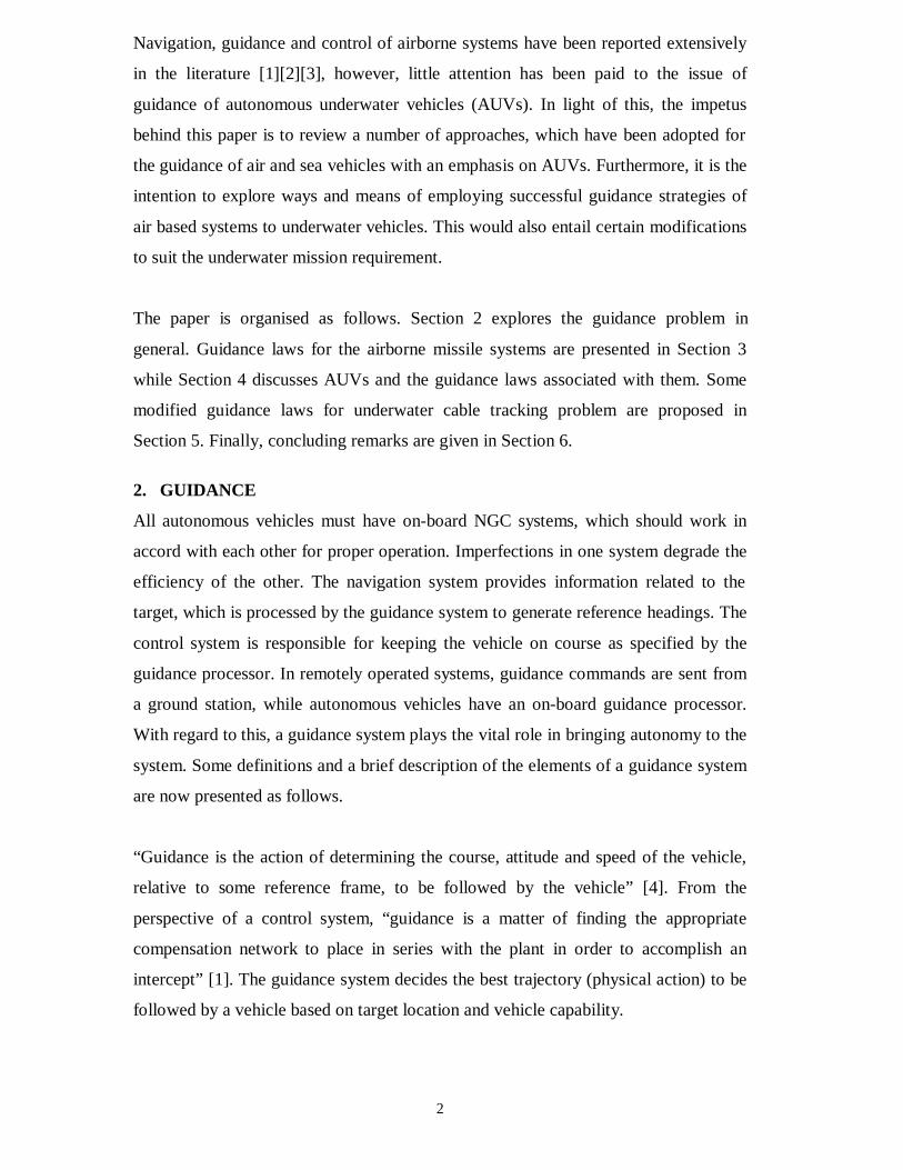
1 A Review of Guidance Laws Applicable to Unmanned Underwater Vehicles W. Naeem, R. Sutton, S. M. Ahmad and R. S. Burns Marine and Industrial Dynamic Analysis Group Department of Mechanical and Marine Engineering The University of Plymouth, PL4 8AA, UK Abstract The main problem in bringing autonomy to any vehicle lies in the design of a suitable guidance law. For a truly autonomous operation, the vehicle needs to have a reliable Navigation, Guidance and Control (NGC) system of which the guidance system is the key element, which generates suitable trajectories to be followed. In this survey paper, various guidance laws found in the literature and their relevance to autonomous underwater vehicles (AUVs) are discussed. Since existing guidance laws for underwater vehicles have emulated from tactical airborne missile systems, a number of approaches for the missile guidance systems are considered. Finally, potential guidance strategies for AUVs are proposed. 1. INTRODUCTION In recent years, control systems have assumed an increasingly important role in the development and advancement of modern civilisation and technology. In particular, the burgeoning in the field of navigation, guidance and control (NGC) systems, spurred on mainly by the challenges of unsolved aerospace problems, contributed significantly to progress achieved in the development of modern systems and control theories. The success of the Soviet Union’s satellite technology in the 1950s stimulated the United States to develop their own aerospace technology thus creating between the two of them new concepts in the field of control system design. The Apollo programme in the 1960s is a classical example of the translation of various NGC concepts into working systems. The early success of NGC systems soon led to advances in such diverse areas as industrial manufacturing, energy management [1] and underwater vehicles. Although applications of NGC in these areas have shown a profound impact in control theory in general, the majority of research and development in NGC continues to find its main application in the aerospace industry.
-
Upload
independent -
Category
Documents
-
view
0 -
download
0
Transcript of A Review of Guidance Laws Applicable to Unmanned Underwater Vehicles
1
A Review of Guidance Laws Applicable toUnmanned Underwater VehiclesW. Naeem, R. Sutton, S. M. Ahmad and R. S. Burns
Marine and Industrial Dynamic Analysis GroupDepartment of Mechanical and Marine Engineering
The University of Plymouth, PL4 8AA, UK
Abstract
The main problem in bringing autonomy to any vehicle lies in the design of a suitable
guidance law. For a truly autonomous operation, the vehicle needs to have a reliable
Navigation, Guidance and Control (NGC) system of which the guidance system is the
key element, which generates suitable trajectories to be followed. In this survey paper,
various guidance laws found in the literature and their relevance to autonomous
underwater vehicles (AUVs) are discussed. Since existing guidance laws for
underwater vehicles have emulated from tactical airborne missile systems, a number
of approaches for the missile guidance systems are considered. Finally, potential
guidance strategies for AUVs are proposed.
1. INTRODUCTION
In recent years, control systems have assumed an increasingly important role in the
development and advancement of modern civilisation and technology. In particular,
the burgeoning in the field of navigation, guidance and control (NGC) systems,
spurred on mainly by the challenges of unsolved aerospace problems, contributed
significantly to progress achieved in the development of modern systems and control
theories. The success of the Soviet Union’s satellite technology in the 1950s
stimulated the United States to develop their own aerospace technology thus creating
between the two of them new concepts in the field of control system design. The
Apollo programme in the 1960s is a classical example of the translation of various
NGC concepts into working systems. The early success of NGC systems soon led to
advances in such diverse areas as industrial manufacturing, energy management [1]
and underwater vehicles. Although applications of NGC in these areas have shown a
profound impact in control theory in general, the majority of research and
development in NGC continues to find its main application in the aerospace industry.
2
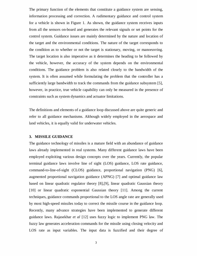
Navigation, guidance and control of airborne systems have been reported extensively
in the literature [1][2][3], however, little attention has been paid to the issue of
guidance of autonomous underwater vehicles (AUVs). In light of this, the impetus
behind this paper is to review a number of approaches, which have been adopted for
the guidance of air and sea vehicles with an emphasis on AUVs. Furthermore, it is the
intention to explore ways and means of employing successful guidance strategies of
air based systems to underwater vehicles. This would also entail certain modifications
to suit the underwater mission requirement.
The paper is organised as follows. Section 2 explores the guidance problem in
general. Guidance laws for the airborne missile systems are presented in Section 3
while Section 4 discusses AUVs and the guidance laws associated with them. Some
modified guidance laws for underwater cable tracking problem are proposed in
Section 5. Finally, concluding remarks are given in Section 6.
2. GUIDANCE
All autonomous vehicles must have on-board NGC systems, which should work in
accord with each other for proper operation. Imperfections in one system degrade the
efficiency of the other. The navigation system provides information related to the
target, which is processed by the guidance system to generate reference headings. The
control system is responsible for keeping the vehicle on course as specified by the
guidance processor. In remotely operated systems, guidance commands are sent from
a ground station, while autonomous vehicles have an on-board guidance processor.
With regard to this, a guidance system plays the vital role in bringing autonomy to the
system. Some definitions and a brief description of the elements of a guidance system
are now presented as follows.
“Guidance is the action of determining the course, attitude and speed of the vehicle,
relative to some reference frame, to be followed by the vehicle” [4]. From the
perspective of a control system, “guidance is a matter of finding the appropriate
compensation network to place in series with the plant in order to accomplish an
intercept” [1]. The guidance system decides the best trajectory (physical action) to be
followed by a vehicle based on target location and vehicle capability.
3
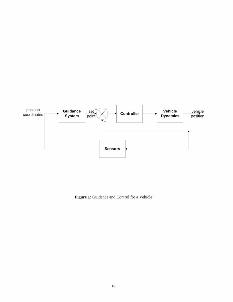
The primary function of the elements that constitute a guidance system are sensing,
information processing and correction. A rudimentary guidance and control system
for a vehicle is shown in Figure 1. As shown, the guidance system receives inputs
from all the sensors on-board and generates the relevant signals or set points for the
control system. Guidance issues are mainly determined by the nature and location of
the target and the environmental conditions. The nature of the target corresponds to
the condition as to whether or not the target is stationary, moving, or manoeuvring.
The target location is also imperative as it determines the heading to be followed by
the vehicle, however, the accuracy of the system depends on the environmental
conditions. The guidance problem is also related closely to the bandwidth of the
system. It is often assumed while formulating the problem that the controller has a
sufficiently large bandwidth to track the commands from the guidance subsystem [5],
however, in practice, true vehicle capability can only be measured in the presence of
constraints such as system dynamics and actuator limitations.
The definitions and elements of a guidance loop discussed above are quite generic and
refer to all guidance mechanisms. Although widely employed in the aerospace and
land vehicles, it is equally valid for underwater vehicles.
3. MISSILE GUIDANCE
The guidance technology of missiles is a mature field with an abundance of guidance
laws already implemented in real systems. Many different guidance laws have been
employed exploiting various design concepts over the years. Currently, the popular
terminal guidance laws involve line of sight (LOS) guidance, LOS rate guidance,
command-to-line-of-sight (CLOS) guidance, proportional navigation (PNG) [6],
augmented proportional navigation guidance (APNG) [7] and optimal guidance law
based on linear quadratic regulator theory [8],[9], linear quadratic Gaussian theory
[10] or linear quadratic exponential Gaussian theory [11]. Among the current
techniques, guidance commands proportional to the LOS angle rate are generally used
by most high-speed missiles today to correct the missile course in the guidance loop.
Recently, many advance strategies have been implemented to generate different
guidance laws. Rajasekhar et al [12] uses fuzzy logic to implement PNG law. The
fuzzy law generates acceleration commands for the missile using closing velocity and
LOS rate as input variables. The input data is fuzzified and their degree of
4
membership to the output fuzzy sets is evaluated which is then defuzzified to get the
acceleration command. A fuzzy based guidance law for missiles has also been
proposed by Creaser et al [13] using an evolutionary computing based approach. The
proposed law uses a genetic algorithm to generate a set of rules for the missile
guidance law. Menon et al [14] uses fuzzy logic weightings to blend three well-
known guidance laws to obtain enhanced homing performance. The composite law
evaluates the weights on each of the guidance laws to obtain a blended guidance
command for the missile. In reference [15], the authors have implemented an H∞
based guidance law. Unlike other guidance laws, it does not require the information of
target acceleration, while ensuring acceptable interceptive performance for arbitrary
target with finite acceleration.
3.1 LOS Guidance
LOS is the most widely used guidance strategy today. In fact, almost all guidance
laws in use today have some form of LOS guidance because of its simplicity and ease
of implementation. The LOS guidance employs the line of sight angle λ between the
vehicle and the target which can easily be evaluated using Equation 1.
−−
= −
12
121tanxx
yyλ (1)
where (x1,y1), (x2,y2) are the missile and target position co-ordinates respectively.
The objective of the guidance system is to constrain the missile to lie as nearly as
possible on the LOS. Since the missile ideally always lies on the line joining it to the
target, the flight path will be a curved one. LOS guidance does not work well with
manoeuvring targets. Also, the interception time is high which can be abridged using
different strategies as discussed in the following sections.
3.2 Proportional Navigation Guidance (PNG) and Its Variants
The Lark missile that was tested in 1950 was the first missile to use PNG. Since then
the PNG law has been used virtually in all of the world’s tactical radar, infra-red and
TV guided missiles [12]. It is the most common and effective technique in case of
non-manoeuvring targets that seeks to nullify the angular velocity of the LOS angle.
The missile heading rate is made proportional to the LOS rate from the missile to the
5
target. The rotation of the LOS is measured by a sensor (either onboard or from a
ground station), which causes commands to be generated to turn the missile in the
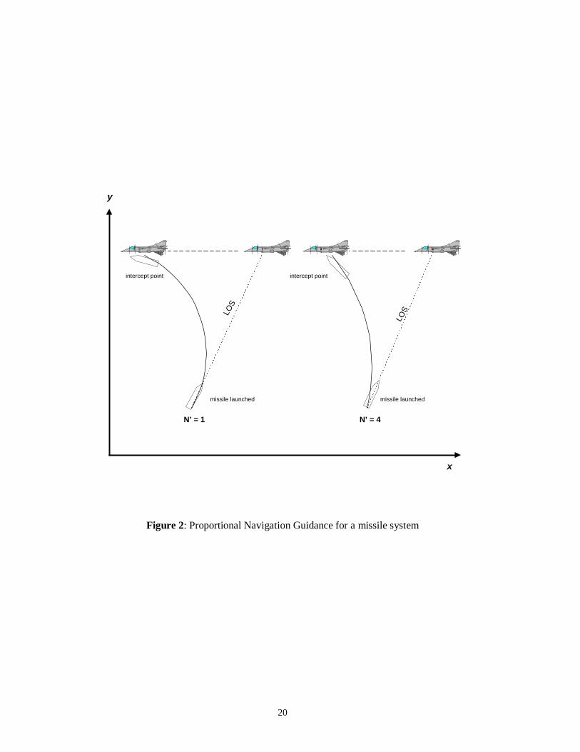
direction of the target. Mathematically the PNG law can be stated as
.
’ λη cc VN= (2)
where cη is the acceleration command, ’N is the navigation ratio, Vc is the closing
velocity and .
λ is the LOS angle rate. The advantage of using PNG over LOS
guidance is that the interception time can be greatly reduced by adjusting the
navigation constant as shown in Figure 2 for the case of ’N = 1 and ’N = 4. In the
latter case, the missile steering commands are four times as great. As a result the
missile veers off much more to the left resulting in engagement.
PNG like LOS guidance does not work well in the case of non-manoeuvring targets.
However, the interception time is reduced. Augmented PNG (APNG) is a modified
form of PNG to deal with target manoeuvres.
Other forms of PNG are velocity compensated PNG (VCPNG), pursuit plus PNG, and
dynamic lead guidance [1].
3.3 Optimal Guidance Law
Recently, great interest has been shown in using optimal control theory in the missile
guidance problem. The two important mission parameters i.e. missile target
engagement time and the energy needed can be reduced by utilising optimal control.
Tsao and Lin [16] proposed an optimal guidance law for short-range homing missiles
to intercept highly manoeuvrable targets. The guidance problem that needs to be
solved for the interception is to find the optimal missile trajectory such that the total
time for the interception is minimised. The performance index J used in the proposed
optimal law is
∫==ft
f dttJ0
(3)
where tf is the interception time.
The proposed guidance law achieves the best performance in terms of the miss
distance and interception time in comparison to the true proportional navigation
6
guidance (TPNG) and APNG. However, a major disadvantage of this law is that the
target’s future trajectory must be known in advance which is impossible to evaluate in
a realistic environment [16].
A comprehensive review of optimal guidance laws is presented in [1].
4. AUTONOMOUS UNDERWATER VEHICLES
The AUVs are no longer engineering curiosities. They have been under development
for over three decades and in the last few years there have been significant advances
towards their use in operational missions [17]. Although remotely operated vehicles
(ROVs) play an important role in the offshore industry, their operational effectiveness
is limited by the tethered cable and the reliance and cost of some kind of support
platform. Given these limitations, developments in advance control engineering
theory and the computation hardware for analysis, design and implementation, interest
in the viability of employing AUVs in operational missions has been revived. The use
of AUVs is increasingly being considered for applications such as cable/pipeline
tracking, mines clearing operations, deep sea exploration, feature tracking etc. The
potential usage of AUVs is restricted by two main factors. The first is the limitation of
battery power, which confines the AUVs for long duration missions. Most of the
vehicles in use, uses car batteries that need to be recharged every few hours and that
makes them unsuitable for long duration missions. The second limiting factor is
associated with the current generation of onboard NGC systems. The vehicle must
have a reliable and well integrated NGC system of which guidance is the key element.
4.1 Guidance Laws for AUVs
The classical autopilots for AUVs are designed by controlling the heading or course
angle in the control loop. By including an additional loop in the control system with
position feedback from the sensors, an AUV guidance system can be designed. The
guidance system generates reference trajectories to be followed by the vehicle
utilising the data gathered by the navigation system.
The following section presents some important guidance laws found in the literature
as given below.
• Way Point Guidance by LOS
7
• Vision Based Guidance
• Lyapunov Based Guidance
• Guidance Using Chemical Signals
• Proportional Navigation Guidance for AUVs
• Guidance using Magnetometers for Cable Tracking
• Electromagnetic Guidance
4.1.1 Way Point Guidance by LOS
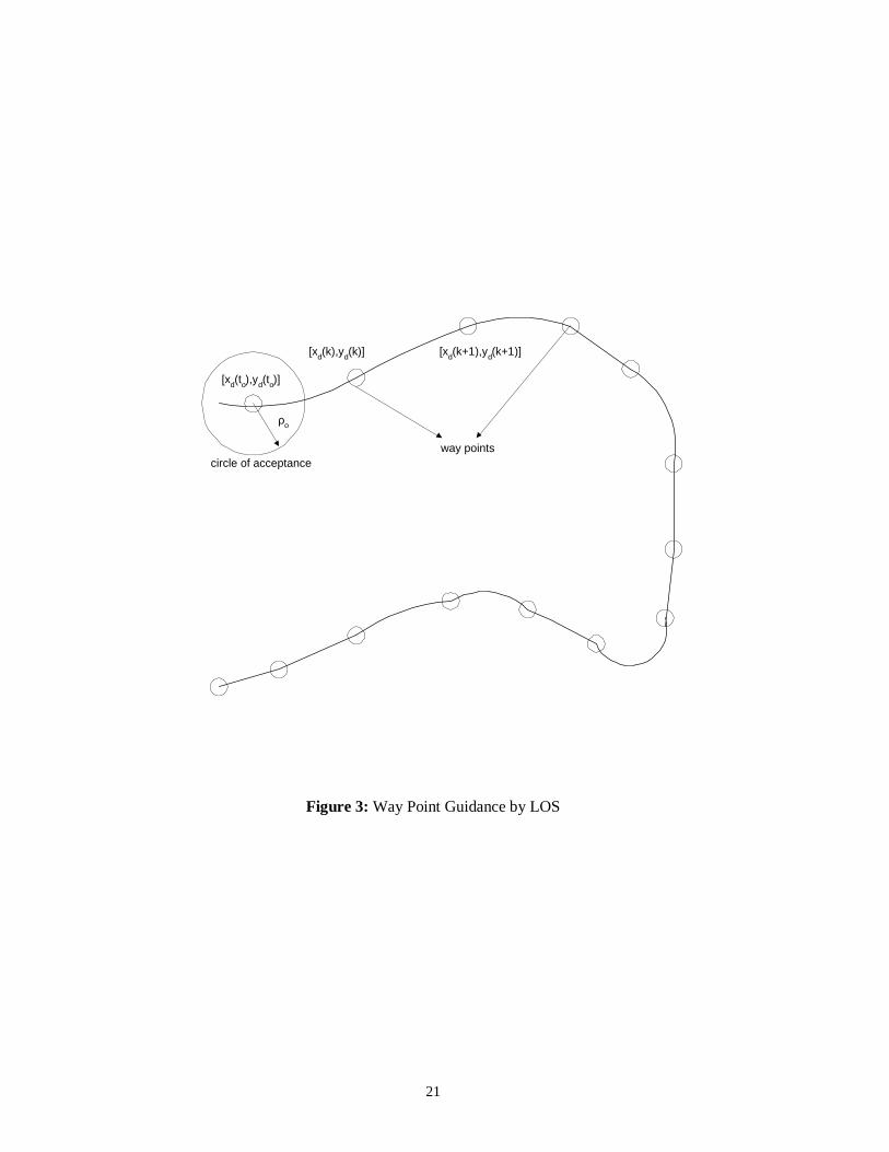
Way Point Guidance is the most widely used scheme in the field of AUVs. In the key
paper by Healey and Lienard [18], guidance is achieved between two points [xd(to),
yd(to)] and [xd(tf), yd(tf)] by splitting the path between them into a number of way
points [xd(k), yd(k)] for k = 1, 2, …, N as shown in Figure 3. It is assumed that the
vehicle is moving forward with speed U, then the LOS in terms of desired heading
angle λ can be defined as
−−
= −
)()(
)()(tan 1
txkx
tyky
d
dλ (4)
where [x(t),y(t)] is the current location of the vehicle. Care must be exercised to
ensure that the heading angle λ is in the proper quadrant. When the vehicle reaches in
the vicinity of the way point which is determined by checking if the AUV lies within
a circle of acceptance with radius ρo around the way point [xd(k), yd(k)]. If the
vehicle’s current location [x(t), y(t)] satisfies
2222 )]()([)]()([ odd tykytxkx ρρ ≤−+−= (5)
the next way point [xd(k+1), yd(k+1)] is selected. The circle of acceptance could be
taken as two times the length of the vehicle [18].
If on the other hand, dtdρ goes from negative to positive without the above
condition being met, than the way point has not reached. At this point, the guidance
law must decide whether to keep the same destination way point and directing the
vehicle to the circle or choose the next depending on a mission planning decision. A
major disadvantage of the way point guidance is that, undesirable control energy
consumption due to overshoot can be made during the change of trajectory. So,
8
selection of the reference trajectory for tracking is important to reduce the overshoot
width of path and thus to decrease the control energy consumption. Yeo et al [19]
employ turning simulation to determine modified way points to avoid overshoot.
Aguiar and others [20][21] proposed a modification in the way point guidance to deal
with the presence of ocean currents. A current compensation for the heading autopilot
has been developed which aligns the total vehicle velocity direction with the heading
command.
4.1.2 Vision Based Guidance
The vision based guidance technique has been inspired from the work of ROV
operators, which utilise or rely on the visual information to perform tasks thus making
a strong argument that visual imagery could be used to guide an underwater vehicle.
Vision based guidance has been mainly employed for cable tracking and docking
problems [22],[23],[24],[25]. In reference [24], an optical terminal guidance scheme
is suggested for the docking of an AUV using a beacon. The beacon could be a light
emitting device, which can be identified using photo detectors onboard the AUV. This
scheme is analogous to a heat seeking air-to-air missile when locked on to its target.
The disadvantage of using a beacon is that in shallow waters especially during the
daylight, the photo detectors can be locked on to the sunlight. The remedy could be to
adjust the frequency of the light emitted by the beacon.
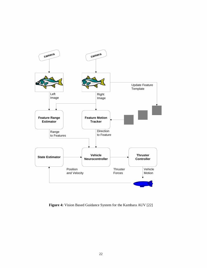
Gaskett et al [22] proposed vision based guidance for an AUV named Kambara using
two cameras. The authors demonstrated that guidance can be achieved by a feature
tracker algorithm which requires two correlation operations within the feature tracker
as shown in Figure 4. The feature motion tracker follows each feature between
previous and current images from a single camera while the feature range estimator
correlates between the left and right camera images. The feature motion tracker
correlates stored feature templates to determine the image location and thus direction
to each feature. Range is determined by correlating the features in both images to find
their pixel disparity. This pixel disparity is related to an absolute range using camera
extrinsic and intrinsic parameters, which are determined by calibration. The direction
and range to each feature is then fed to the controller which determines a set of
thruster commands. To guide the AUV, thruster commands become a function of the
9
position of visual features. A major drawback of using visual systems in underwater
guidance is that the performance degrades in case of turbid water or when a cable is
burried or there might be other similar cables appearing in the image. For such cases,
a multisensor fusion technique has been proposed [26],[27],[28],[29]. The proposed
sensor fusion technique uses deadreckoning position uncertainty with a 2D-position
model of the cable to predict the region of interest in the image captured by a camera
mounted on an AUV. The 2D position model of the layout of the cable is generated
by taking the position co-ordinates (xi,yi) of a few points along the cable which is then
used to predict the most likely region of the cable in the image.
As opposed to two cameras, Balasuriya et al [23] proposed a vision based guidance
law using a single camera. The technique has been implemented in a test bed
underwater robot, Twin-Burger 2, at the University of Tokyo for cable tracking and a
moving object. The basic idea underlying these schemes is that, the feature to be
tracked introduces a particular geometric feature in the image captured by the CCD
camera. The vision processor than label these features, extract their location in the
image and interpret the appearance into a guidance parameter as shown in Figure 5.
For example, an underwater cable introduces a line feature in the image and the edges
of a cylinder introduce a rectangle. The vision processor derives the equation of the
line representing the cable in the image plane given by Equation 6, which gives the
direction ‘q’ and position ‘r’ parameters.
)sin()cos( qyqxr += (6)
where (x,y) are the co-ordinates of the straight line equation. In the case of a
cylindrical object, the co-ordinates of the centroid of the object (rectangle) in the
image plane and the area A covered by the object are derived. These parameters are
then fused with other sensory parameters to determine the control references for the
underwater vehicle.
Rock et al [25] devised a vision based system to track a dot of light generated by a
laser. The hardware is comprised of two cameras, one of which is used to locate the
target. The vision system works by scanning the image from the last known location
of the target, or from the centre of the screen if the target was not previously in view.
The pixels are examined row by row, expanding outward towards the edge. If a target
10
is found, its angle and elevation with respect to the centre of the image is evaluated
and transmitted to the vision processor, while range can be found using successive
images from both cameras. The proposed law has been proved to be valid only in the
case of a single distinguishable target.
4.1.3 Lyapunov Based Guidance
A Lyapunov function can be considered as a generalisation of the concept of distance
or energy. The Lyapunov theorem states that if the distance of the state along any
trajectory of Axx =.
decreases with time, then x(t) must tend to 0 as t → ∞ [30].
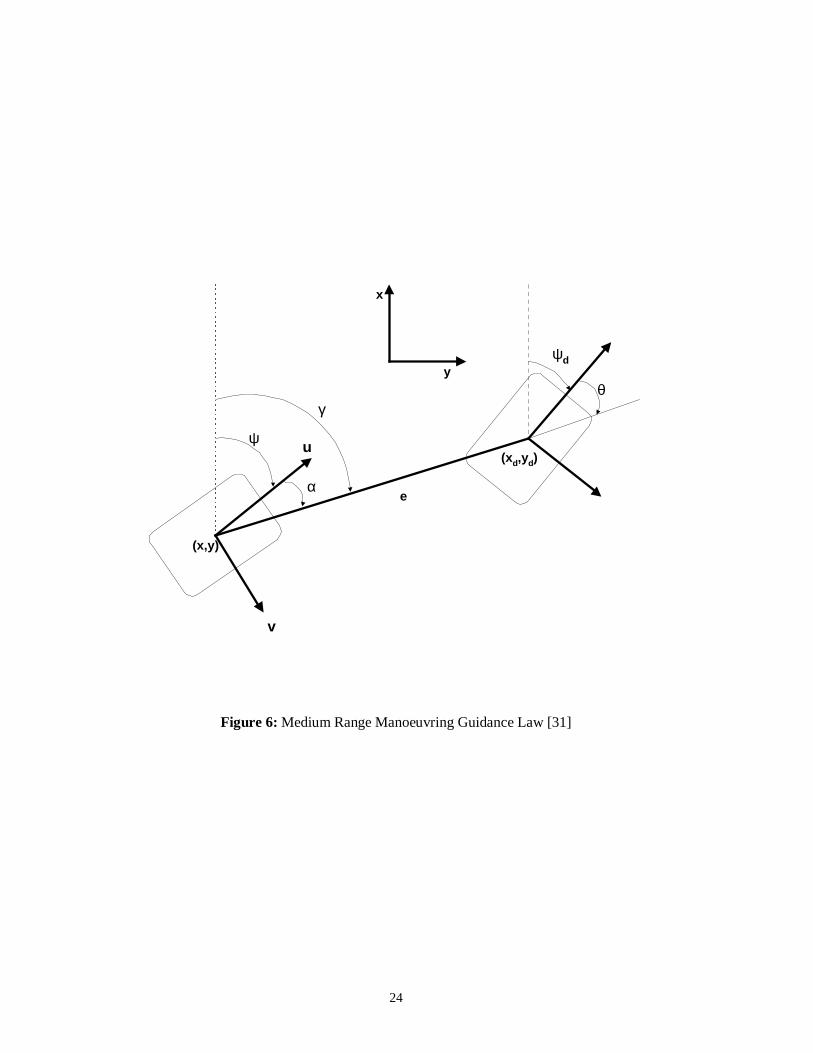
Caccia et al [31] uses the concept to develop a new guidance law for unmanned
underwater vehicles for testing on a prototype ROV, Romeo. This law is termed as
medium range manoeuvring guidance law. In this law, the vehicle is allowed to move
from point (x, y) to (xd,yd) with a desired orientation ψd as shown in Figure 6. By
choosing the desired vehicle speeds
αζ coseud = (7)
0=dv (8)
)(sincos θα
αααζµα hrd ++= (9)
where ζ, µ, and h are the tuning parameters, a Lyapunov function is suggested given
by Equation 10, which makes the distance e between the two points converges to zero
for increasing time.
)(2
1
2
1 222 θα heV ++= (10)
where
22 )()( yyxxe dd −+−= (11)
dψγθ −= (12)
ψγα −= (13)
ud, vd and rd are the desired vehicle’s surge, sway and yaw velocities respectively. If
an obstacle is detected along the way by the sensors with some orientation δ and
range d from the robot, the vehicle follows its profile until a suitable detaching
condition is verified and the vehicle then continues its free space manoeuvring. For
11
feature following, the proposed law does not require the control of the vehicle sway
velocity while controlling the surge and yaw velocities.
4.1.4 Guidance with Chemical Signals
Using the fact that marine animals make extensive use of underwater chemical signals
to avoid predators and to locate food sources etc., an interesting guidance scheme for
AUVs using chemical signals has been proposed by Consi et al [32]. The authors
have built a small underwater robot, which mimics the chemical sensing abilities of a
lobster. This class of robots is named as biomimics, which are designed to mimic
certain features of animals and act as animal substitutes in behavioral and
neurobiological studies.
The goal of the paper was to use the information in chemical signals to locate the
source of a chemical discharge. In this respect, it has a number of scientific,
environmental, commercial and defence related applications. The sensors used in the
biomimic are the conductivity sensors and they are used to enable the AUV to follow
a plume of saltwater in a freshwater flow-through flume. Simple gradient following
algorithm is implemented to locate the source of discharge, which has the obvious
disadvantage of getting trapped in local concentration minima and maxima.
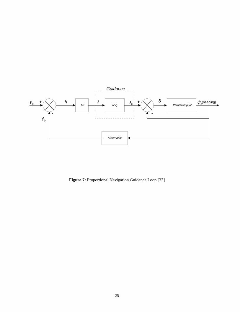
4.1.5 Proportional Navigation Guidance for AUVs
Although PNG is widely used for missile guidance systems but Ahmad et al [33]
demonstrated that it can be tailored to work for AUVs as well. The authors proposed a
two-stage problem formulation to retrieve a returning AUV to the mother submarine.
In the first stage, interception of the target (mother submarine) by the AUV is
considered using PNG law, which is the theme of the paper. In the second stage, the
docking of the AUV is considered when in close proximity to the mother submarine
and is an area of current investigation. The idea behind using PNG is that if the AUV
is made to lie on the LOS and hold it there as well, a constant relative bearing
between the AUV and target is ensured i.e., the LOS does not rotate and interception
will occur. The PNG law can be stated as
λ∝cu (14)
λkuc = (15)

12
where k is the navigation constant, λ is the LOS angle and uc is the command input,
therefore
λcc NVu = (16)
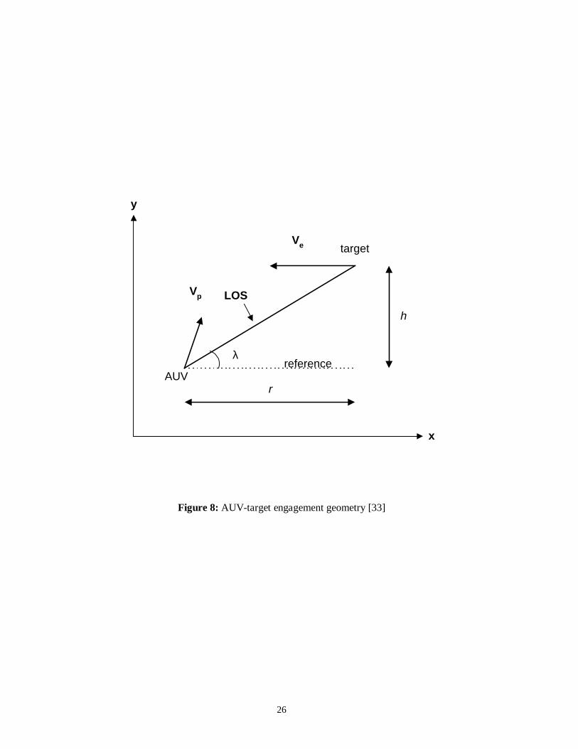
where Vc is the closing velocity and N is an important tuning parameter. The block
diagram of the proposed guidance and control system is shown in Figure 7 and the
AUV target engagement geometry is shown in Figure 8. The guidance system used is
PNG, which generate commands for the control system. Different engagement
scenarios have been considered. For stationary targets, the scheme is analogous to the
way point guidance. For mobile targets, the PNG law generates suitable trajectories to
be followed by the AUV for docking purposes.
4.1.6 Guidance using Magnetometers for Cable Tracking
The underwater cable network and its capacity are expanding very rapidly, and its
installation and maintenance becoming more important. AUVs could be a potential
tool for underwater cable tracking especially in case of deep waters where human
intervention is not possible. Different schemes have been proposed for underwater
cable tracking. Balasuriya and Ura [23], proposed vision based guidance for
cable/pipeline tracking as outlined in Section 4.1.2, but in the case of shallow waters,
where cables are buried to avoid being damaged by fishing gears or anchors, the
performance degrades. For buried electrical or telecommunications cables, the remedy
is to use on-board magnetometers, which can detect the magnetic field induced from
the current flowing in the cable. The data from the magnetometer is fed to a cable
locator which estimates the direction, burial depth and the distance of the vehicle from
the cable. The data from the cable locator is then used to guide the vehicle. The Aqua
Explorer 1000 is an example of a successful implementation of magnetometer based
guidance for underwater cable tracking [34],[35],[36]. Guidance using magnetometers
has limited applications as it can only be used to guide the vehicle towards the source
of the magnetic field.
4.1.7 Electromagnetic Guidance
A major disadvantage of using optical or visual guidance systems is that the response
is only good in nonturbid, clear environments and it is limited over a wide range of
13
background lighting and water turbidity conditions. Also, the AUV must lie within the
field of light emitted by the beacon on the cable or dock and should be oriented in
such a way so that the optical sensors can detect the light. Feezor et al [37] employed
an electromagnetic guidance (EM) technique during the homing/docking mode of an
AUV. The EM guidance system uses a magnetic field generated by the coils on the
dock which is sensed by the coils in the AUV. The guidance system provides to the
AUV not only the bearing to the dock, but also the angle of the AUV relative to the
field lines and thus the angle relative to the dock entrance. The accuracy of the
proposed system is less than 20 cm but the range is limited to 25-30 m. The proposed
system is quite robust under almost all oceanographic phenomena.
5. DISCUSSION
This section presents some modifications in the guidance design for AUVs. It can be
stated that the way point guidance or specifically the LOS guidance is likely to remain
a key feature of all present guidance systems and the systems to follow. By utilising
it, several other guidance laws can be conceptualised. For example, way point
guidance could be utilised for cable following problem considering several way points
on the cable by introducing beacons at different lengths and then follow the beacons
on the cable using onboard sensors. Inexpensive photodetectors could be employed to
detect the light, which can be tuned to operate over different frequencies. However,
the major drawback as discussed in Section 4.1.7 is that the performance degrades in
case of turbid water or when there is light coming from other sources. This approach
is analogous to the heat seeking air-to-air missile.
Another strategy to accomplish a cable tracking mission is to pose the guidance as a
two-stage problem i.e. using way point guidance while on the surface and vision
based guidance or any other existing guidance scheme while submerged. In this
manner, the vehicle would have precise position co-ordinates on the surface from the
Global Positioning System (GPS) so that it can accurately reach the vicinity of the
target area. Dead reckoning could be employed to estimate the position of the AUV
under water. A similar approach has been adopted by the Southampton Oceanography
centre’s AUTOSUB-1 [38], which utilises GPS for position fixes on the surface and
dead reckoning is employed using an acoustic doppler current profiler, providing
velocity measurement, while submerged.
14
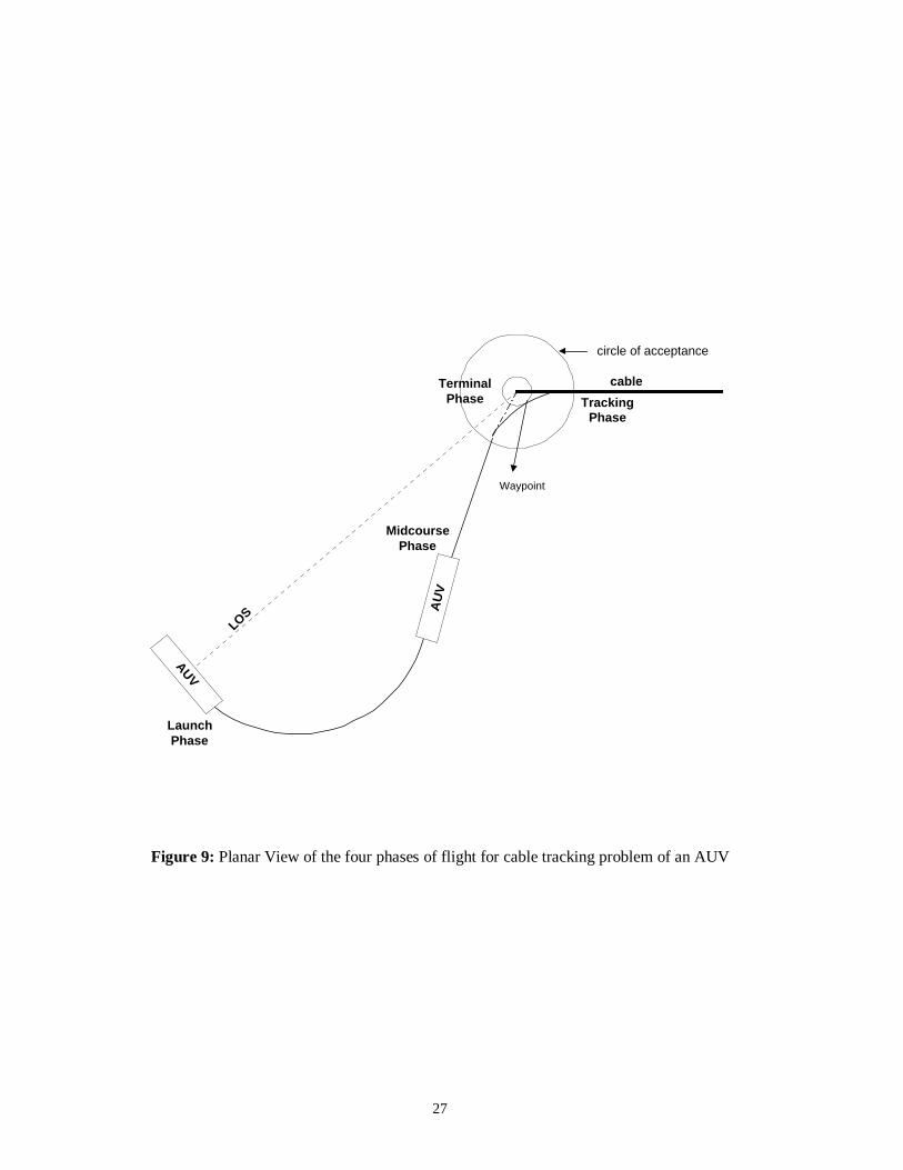
A complete mission scenario for underwater cable tracking problem could be to
classify it into four different phases utilising different guidance laws. These are i)
launch phase, ii) midcourse phase, iii) terminal phase, and iv) tracking phase as shown
in Figure 9. In the first phase called the launch phase or the boost phase, the vehicle is
launched from a boat or from a mother submarine and guided in the direction of the
LOS with maximum speed, using the LOS guidance only. The heading command can
be generated using Equation 4. Once the vehicle is inline with the LOS, midcourse
guidance could be invoked. In midcourse phase, the vehicle follows the LOS angle
with maximum speed using the way point guidance, Section 4.1.1. During this part of
the flight, changes may be required to bring the vehicle onto the desired course and to
make certain that it stays on that course. The midcourse guidance system is used to
place the vehicle near the target area, where the system to be used in the final phase of
guidance can take over. It should be noted that there is no need for the vehicle to
submerge at this stage, as the objective is to approach the target area with maximum
accuracy regardless of the orientation of the vehicle with respect to the cable. When
the vehicle reaches within the circle of acceptance, the third phase called the terminal
phase is invoked. In this phase the vehicle must be slowed down and submerged in
order to line up with the cable/pipeline as shown in Figure 9. The circle of acceptance
in this case as opposed to [18] should be taken at least the minimum turning radius of
the vehicle in order to avoid overshoot. Finally the fourth phase called the tracking
phase is launched utilising any existing guidance law. For example, the vehicle could
use vision based guidance system to follow the cable outlined in Section 4.1.2. If the
cable to be followed is an electrical/communication cable, then magnetometers could
be used to detect the radiation from the cable and guide the vehicle in the appropriate
direction.
6. CONCLUDING REMARKS
This paper presents several guidance laws for autonomous vehicles with emphasis on
AUVs. Guidance laws for airborne missile systems are also explored. It has been
shown that the guidance system plays the vital role in bringing autonomy to the whole
system. It is observed that most of the current AUV systems employ either the
classical way point guidance to reach a target area or the more advanced vision based
guidance for cable/pipeline tracking. As a matter of fact, the LOS guidance is the key

15
element of all guidance systems. Some hybrid guidance schemes are also proposed
based on existing airborne and underwater guidance laws.
16
References
[1] C. F. Lin. Modern Navigation, Guidance and Control Processing, Volume II.Prentice Hall, 1991.
[2] J. R. Cloutier, J. H. Evers and J. J. Feeley. Assessment of Air-to Air MissileGuidance and Control Technology. IEEE Control Systems Magazine, 9(6): pp.27-34, October 1989.
[3] C. L. Lin and H. W. Su. Intelligent Control Theory in Guidance and ControlSystem Design: and Overview. Proc. Natl. Sci. Counc. ROC(A), (Invited ReviewPaper), 24(1): pp. 15-30, 2000.
[4] T. I. Fossen. Guidance and Control of Ocean Vehicles. John Wiley & Sons, 1994.
[5] R. Sutton, R. S. Burns and P. J. Craven. Intelligent Steering Control of anAutonomous Underwater Vehicle. Journal of Navigation, 53(3): pp. 511-525,September 2000.
[6] A. S. Locke. Guidance. D. Van Nostrand Co., Princeton, NJ, USA, 1955.
[7] P. Zarchan. Tactical and Strategic Missile Guidance, 2nd Ed. AIAA, Inc.,Washington DC, USA, 1994.
[8] A. E. Bryson Jr. and Y. C. Ho. Applied Optimal Control. Blaisdell, Waltham,MA, USA, 1969.
[9] G. J. Nazaroff. An Optimal Terminal Guidance Law. IEEE Trans. Automat.Contr., 21(6), pp. 407-408, 1976.
[10] J. E. Potter. A Guidance-Navigation Separation Theorem. AIAA Paper 64-653,AIAA, Washington DC, USA, 1964.
[11] J. L. Speyer, W. M. Greenwell and D. G. Hull. Adaptive noise estimation andguidance for homing missile. AIAA Guid. And Contr. Conf., Washington DC,USA, 1982.
[12] V. Rajasekhar and A. G. Sreenatha. Fuzzy Logic Implementation of ProportionalNavigation Guidance. Acta Astronautica, Elsevier Science Ltd., 46(1): pp. 17-24,2000.
[13] P. A. Creaser, B. A. Stacey and B. A. White. Evolutionary Generation of FuzzyGuidance Laws. UKACC International Conference on Control’ 98, UK, vol. II,no. 455: pp. 883-888, September 1-4, 1998.
[14] P. K. Menon and V. R. Iragavarapu. Blended Homing Guidance Law UsingFuzzy Logic. AIAA Guidance, Navigation and Control Conference, Boston MA,August 10-12, 1998.
17
[15] C. D. Yang and H. Y. Chen. Three-Dimensional nonlinear H-Infinity GuidanceLaw. International Journal of Robust and Nonlinear Control, 11(2): pp. 109-129,2001.
[16] L. P. Tsao and C. S. Lin. A New Optimal Guidance Law for Short- RangeHoming Missiles. Proceedings of the National Science Council, Republic ofChina, 24(6): pp. 422-426, 2000.
[17] N. W. Millard, G. Griffiths et al. Versatile Autonomous Submersibles- therealising and testing of a practical vehicle. Journal of the Society for UnderwaterTechnology, 23(1), pp. 7-17, 1998.
[18] A. J. Healey and D. Lienard. Multivariable Sliding Model Control forAutonomous Diving and Steering of Unmanned Underwater Vehicles. IEEEJournal of Oceanic Engineering, 18(3): pp. 327-339, July 1993.
[19] D. J. Yeo. Design of AUV Tracking System using the Sliding Mode Control andthe Optimal Control Theory. MS Thesis, Department of Naval Architecture andOcean Engineering, Seoul National University, Korea, 1999.
[20] A. Aguiar, P. Oliveira, C. Silvertre and A. Pascoal. Guidance and Control of theSIRENE Underwater Vehicle: from System Design to Tests at Sea. In Proc. OfOceans’98, Nice, France, Vols. 1-3, pp. 1043-1048, September 1998.
[21] A. Aguiar and A. Pascoal. Modelling and Control of an Autonomous UnderwaterShuttle for the Transport of Benthic Laboratories. Oceans’97, MTS/IEEEConference Proceedings, Halifax, Canada, Vols. 1 & 2, pp. 888-895, October1997.
[22] C. Gaskett, D. Wettergreen and A. Zelinsky. Autonomous Guidance and Controlfor an Underwater Robotic Vehicle. International Conference on Field andService Robotics, FSR’99, Pittsburgh, USA, 29-31 August, 1999.
[23] A. Balasuriya and T. Ura. Autonomous target tracking by underwater robotsbased on vision. Proceedings of IEEE UT’98, pp. 191-197, Tokyo, Japan, April1998.
[24] S. Briest, S. Cowen and J. Dombrowski. Underwater docking of autonomousundersea vehicles using optical terminal guidance. Oceans’97 MTS/IEEEConference Proceedings, Halifax, Canada, Vols 1&2, pp. 1143-1147, October,1997.
[25] S. M. Rock, M. J. Lee, H. H. Wang, R. L. Marks and R. C. Burton. Combinedcamera and vehicle tracking of underwater objects. In Proceedings of ROV’92,San Diego, CA, USA, pp. 1-8, June 1992.
[26] A. Balasuriya and T. Ura. Multisensor Fusion for Autonomous Underwater CableTracking. Oceans’ 99 MTS/IEEE, pp. 209-215, 1999.

18
[27] A. Balasuriya and T. Ura. Sensor Fusion Technique for Cable Following byAutonomous Underwater Vehicles. Proceedings of the 1999 IEEE InternationalConference on Control Application, Kohala Coast-Island of Hawai’I, USA, pp.1779-1784, 1999.
[28] A. Balasuriya and T. Ura. Autonomous Target Tracking by Twin-Burger 2.Proceedings of the 2000 IEEE/RSJ International Conference on IntelligentRobots and Systems, pp. 849-854, 2000.
[29] A. Balasuriya and T. Ura. Underwater Cable Following by Twin-Burger 2.Proceedings of the 2001 IEEE International Conference on Robotics andAutomation, Seoul, Korea, pp. 920-925, 2001.
[30] C. T. Chen. Linear System Theory and Design. CBS College Publishing, 1984.
[31] M. Caccia, G. Bruzzone and G. Veruggio. Guidance of unmanned underwatervehicles: experimental results. In Proceedings of the 2000 IEEE InternationalConference on Robotics and Automation, pp. 1799-1904. IEEE, April 2000.
[32] T. R. Consi, C. A. Goudey, J. Cho, J. Atema and C. Chryssostomidis. AUVGuidance with Chemical Signals. In Proceedings of the 1994 Symposium onAutonomous Underwater Vehicle Technology, pp. 450-455, July 1994.
[33] S. M. Ahmad, R. Sutton and R. S. Burns. Retrieval of an AutonomousUnderwater Vehicle: An Interception Approach. Submitted to the Journal ofUnderwater Technology.
[34] K. Asakawa, J. Kojima, Y. Ito, S. Takagi. Autonomous Underwater VehicleAQUA EXPLORER 1000 for Inspection of Underwater Cables. Proc. of the1996 Symposium on Autonomous Underwater Vehicle Technology, pp. 10-17,IEEE, 1996.
[35] Y. Ito, N. Kato, J. Kojima and S. Takagi. Cable Tracking for AutonomousUnderwater Vehicle. Proc. of the 1994 Symposium on Autonomous UnderwaterVehicle Technology, pp. 218-224, IEEE, 1994.
[36] N. Kato, Y. Ito, J. Kojima, S. Takagi et al. Control Performance of AutonomousUnderwater Vehicle “AQUA EXPLORER 1000” for Inspection of UnderwaterCables. In Proc. Oceans Engineering for Today’s Technology and Tomorrow’sPresentation, vol. 1, pp. I/135 – I/140, IEEE, 1994.
[37] M. D. Feezor, F. Y. Sorrell, P. R. Blankinship and J. G. Bellingham. AutonomousUnderwater Vehicle Homing/Docking via Electromagnetic Guidance, IEEEJournal of Oceanic Engineering, 26(4): pp. 515-521, October 2001.
[38] S. D. Mcphail and M. Pebody. Navigation and Control of an AutonomousUnderwater Vehicle using a Distributed, Networked Control Architecture.Journal of the Society for Underwater Technology, 23(1), pp. 19-30, 1998.
19
Figure 1: Guidance and Control for a Vehicle
ControllerVehicle
DynamicsGuidanceSystem
+
-
Sensors
positioncoordinates
setpoint
vehicleposition
20
Figure 2: Proportional Navigation Guidance for a missile system
N’ = 1 N’ = 4
x
y
LOS
LOS
missile launched missile launched
intercept point intercept point
21
Figure 3: Way Point Guidance by LOS
ρο
circle of acceptanceway points
[xd(to),yd(to)]
[xd(k),yd(k)] [xd(k+1),yd(k+1)]
22
Figure 4: Vision Based Guidance System for the Kambara AUV [22]
Feature RangeEstimator
Feature MotionTracker
State EstimatorVehicle
NeurocontrollerThruster
Controller
LeftImage
RightImage
Rangeto Features
Directionto Feature
Positionand Velocity
ThrusterForces
VehicleMotion
Update FeatureTemplate
cameracamera

23
Figure 5: Vision Based Guidance System for the Twin-Burger 2 AUV [23]
CCD Camera
Labelling of Features
Groupingand FeatureExtraction
Reasoning ofParameters
24
Figure 6: Medium Range Manoeuvring Guidance Law [31]
x
(x,y)
(xd,yd)
y
u
v
α
θγ
ψd
e
ψ
25
Figure 7: Proportional Navigation Guidance Loop [33]
1/r NVc Plant/autopilot
Kinematics
ye h λ
yp
ucδ
Guidance
+
-
+
-
ψp(heading)
26
Figure 8: AUV-target engagement geometry [33]
Vp
x
y
LOS
Ve
λ
rAUV
target
reference
h
27
Figure 9: Planar View of the four phases of flight for cable tracking problem of an AUV
AUV
LOS
cable
LaunchPhase
MidcoursePhase
TerminalPhase Tracking
Phase
Waypoint
AU
V
circle of acceptance