Modeling of active control of external magnetohydrodynamic instabilities
11
Modeling of active control of external magnetohydrodynamic instabilities* James Bialek, ² Allen H. Boozer, M. E. Mauel, and G. A. Navratil Department of Applied Physics and Applied Mathematics, Columbia University, New York, New York 10027 ~Received 27 October 2000; accepted 26 December 2000! A general circuit formulation of resistive wall mode ~RWM! feedback stabilization developed by Boozer @Phys. Plasmas 5, 3350 ~1998!# has been used as the basis for the VALEN computer code that calculates the performance of an active control system in arbitrary geometry. The code uses a finite element representation of a thin shell structure in an integral formulation to model arbitrary conducting walls. This is combined with a circuit representation of stable and unstable plasma modes. Benchmark comparisons of VALEN results with large aspect ratio analytic model of the current driven kink mode are in very good agreement. VALEN also models arbitrary sensors, control coils, and the feedback logic connecting these sensors and control coils to provide a complete simulation capability for feedback control of plasma instabilities. VALEN modeling is in good agreement with experimental results on DIII-D @Garofalo et al., Nucl. Fusion 40, 1491 ~2000!# and HBT-EP @Cates et al., Phys. Plasmas 7, 3133 ~2000!#. VALEN feedback simulations have also been used to evaluate and optimize the sensor/coil configurations for present and planned RWM experiments on DIII-D. These studies have shown a clear advantage for the use of local poloidal field sensors driving a ‘‘mode control’’ feedback logic control loop and configurations which minimize the control coil coupling to the stabilizing resistive wall. © 2001 American Institute of Physics. @DOI: 10.1063/1.1362532# I. INTRODUCTION Control of long-wavelength magnetohydrodynamic ~MHD! instabilities using a conducting wall near the plasma boundary and application of external magnetic perturbations is one of the most important routes to improved reliability and improved performance of magnetic fusion confinement devices. Conducting walls are known to prevent or reduce the growth of harmful, long-wavelength MHD instabilities in tokamaks 1 and spherical tori, 2 and they are essential to the operation of reversed field pinches ~RFPs! 3 and spheromaks. Most attractive fusion power scenarios require wall stabili- zation to reach high fusion power density and operate con- tinuously with low recirculating power. 4–6 Long-wavelength modes are stabilized by close fitting conducting walls be- cause wall eddy currents oppose the helical perturbations created by these instabilities. However, for slowly growing instabilities, passive wall stabilization will fail when the eddy currents decay due to the finite resistivity of the wall. This allows resistive wall modes ~RWMs! to grow on the time scale of magnetic diffusion through the wall, t w . RWMs have been identified in RFPs 7,8 and in tokamaks. 9–14 Since the initial observations in DIII-D of the effective- ness of wall stabilization, high-performance, wall-stabilized plasmas have been produced transiently which satisfy the requirements for attractive high-b steady-state tokamak operation. 12,15 However, the onset of the RWM has been observed to be the limiting factor in the lifetime and b achieved in DIII-D advanced tokamak regimes with low in- ternal inductance 16,17 and in HBT-EP. 13 Two schemes to control the unstable RWM have been proposed: ~1! the plasma rotation with respect to the walls can be maintained ~e.g., with neutral beam injection!; 18 and ~2! a network of active feedback coils can be configured so as to simulate: ~i! a perfectly conducting wall 19,20 , or ~ii! a ‘‘fake’’ rotating wall, 21 or ~iii! to provide direct feedback on the RWM amplitude. 22,23 In DIII-D the plasma rotation is observed to slow down when b .b no wall resulting in the failure of pas- sive rotational stabilization, 12 hence, the development of ac- tive feedback systems may be essential if these modes are to be controlled. The computer code VALEN has been developed to predict the performance of active feedback systems. The code mod- els arbitrary conducting walls via a finite element represen- tation using a thin shell integral formulation. This yields a circuit representation of all conducting structures. VALEN has a circuit representation for stable, and unstable plasma modes, and also models arbitrary magnetic sensors, control coils, and simple power supplies. The ability to simulate the effect of various feedback strategies among the sensors, power supplies, and control coils provides a complete simu- lation capability to accurately model active control of exter- nal MHD instabilities. In Sec. II A we briefly describe the techniques used to model arbitrary conducting structures. In Sec. II B we review the formulations used to model the plasma instability in a circuit representation. The plasma model is exact within an ideal MHD linear mode analysis. Although these techniques may be extended to model rotating plasma instabilities we limit this paper to nonrotating instabilities. A simple example *Paper GI1 4, Bull. Am. Phys. Soc. 45, 118 ~2000!. ² Invited speaker. PHYSICS OF PLASMAS VOLUME 8, NUMBER 5 MAY 2001 2170 1070-664X/2001/8(5)/2170/11/$18.00 © 2001 American Institute of Physics
Transcript of Modeling of active control of external magnetohydrodynamic instabilities

PHYSICS OF PLASMAS VOLUME 8, NUMBER 5 MAY 2001
Modeling of active control of external magnetohydrodynamicinstabilities *
James Bialek,† Allen H. Boozer, M. E. Mauel, and G. A. NavratilDepartment of Applied Physics and Applied Mathematics, Columbia University, New York, New York 10027
~Received 27 October 2000; accepted 26 December 2000!
A general circuit formulation of resistive wall mode~RWM! feedback stabilization developed byBoozer@Phys. Plasmas5, 3350~1998!# has been used as the basis for theVALEN computer code thatcalculates the performance of an active control system in arbitrary geometry. The code uses a finiteelement representation of a thin shell structure in an integral formulation to model arbitraryconducting walls. This is combined with a circuit representation of stable and unstable plasmamodes. Benchmark comparisons ofVALEN results with large aspect ratio analytic model of thecurrent driven kink mode are in very good agreement.VALEN also models arbitrary sensors, controlcoils, and the feedback logic connecting these sensors and control coils to provide a completesimulation capability for feedback control of plasma instabilities.VALEN modeling is in goodagreement with experimental results on DIII-D@Garofaloet al., Nucl. Fusion40, 1491~2000!# andHBT-EP @Cateset al., Phys. Plasmas7, 3133~2000!#. VALEN feedback simulations have also beenused to evaluate and optimize the sensor/coil configurations for present and planned RWMexperiments on DIII-D. These studies have shown a clear advantage for the use of local poloidalfield sensors driving a ‘‘mode control’’ feedback logic control loop and configurations whichminimize the control coil coupling to the stabilizing resistive wall. ©2001 American Institute ofPhysics. @DOI: 10.1063/1.1362532#
ica
onityenucine.ilio
beiongeal
-edth
kn
n-
ned
:
o
-re to
ctod-
en-a
mantroltheors,u-r-
toew
aaneswele
I. INTRODUCTION
Control of long-wavelength magnetohydrodynam~MHD! instabilities using a conducting wall near the plasmboundary and application of external magnetic perturbatiis one of the most important routes to improved reliabiland improved performance of magnetic fusion confinemdevices. Conducting walls are known to prevent or redthe growth of harmful, long-wavelength MHD instabilitiestokamaks1 and spherical tori,2 and they are essential to thoperation of reversed field pinches~RFPs!3 and spheromaksMost attractive fusion power scenarios require wall stabzation to reach high fusion power density and operate ctinuously with low recirculating power.4–6 Long-wavelengthmodes are stabilized by close fitting conducting wallscause wall eddy currents oppose the helical perturbatcreated by these instabilities. However, for slowly growiinstabilities, passive wall stabilization will fail when theddy currents decay due to the finite resistivity of the wThis allows resistive wall modes~RWMs! to grow on thetime scale of magnetic diffusion through the wall,tw .RWMs have been identified in RFPs7,8 and in tokamaks.9–14
Since the initial observations in DIII-D of the effectiveness of wall stabilization, high-performance, wall-stabilizplasmas have been produced transiently which satisfyrequirements for attractive high-b steady-state tokamaoperation.12,15 However, the onset of the RWM has beeobserved to be the limiting factor in the lifetime andbachieved in DIII-D advanced tokamak regimes with low i
*Paper GI1 4, Bull. Am. Phys. Soc.45, 118 ~2000!.†Invited speaker.
2171070-664X/2001/8(5)/2170/11/$18.00
s
te
-n-
-ns
l.
e
ternal inductance16,17 and in HBT-EP.13 Two schemes tocontrol the unstable RWM have been proposed:~1! theplasma rotation with respect to the walls can be maintai~e.g., with neutral beam injection!;18 and ~2! a network ofactive feedback coils can be configured so as to simulate~i!a perfectly conducting wall19,20, or ~ii ! a ‘‘fake’’ rotatingwall,21 or ~iii ! to provide direct feedback on the RWMamplitude.22,23 In DIII-D the plasma rotation is observed tslow down whenb.bno wall resulting in the failure of pas-sive rotational stabilization,12 hence, the development of active feedback systems may be essential if these modes abe controlled.
The computer codeVALEN has been developed to predithe performance of active feedback systems. The code mels arbitrary conducting walls via a finite element represtation using a thin shell integral formulation. This yieldscircuit representation of all conducting structures.VALEN hasa circuit representation for stable, and unstable plasmodes, and also models arbitrary magnetic sensors, cocoils, and simple power supplies. The ability to simulateeffect of various feedback strategies among the senspower supplies, and control coils provides a complete simlation capability to accurately model active control of extenal MHD instabilities.
In Sec. II A we briefly describe the techniques usedmodel arbitrary conducting structures. In Sec. II B we revithe formulations used to model the plasma instability incircuit representation. The plasma model is exact withinideal MHD linear mode analysis. Although these techniqumay be extended to model rotating plasma instabilitieslimit this paper to nonrotating instabilities. A simple examp
0 © 2001 American Institute of Physics

t
netrb
in
sirt
rare
ib-
lu
i.ern
insees
uahqu
ba
hefo
hcan
thfohear.xnrr
ardn
aluit-les.
is-ent
she
ting-ofnce
ag-
r
lt-
-otx-s ofhe
2171Phys. Plasmas, Vol. 8, No. 5, May 2001 Modeling of active control of external magnetohydrodynamic . . .
with one degree of freedom for each major componenpresented in Sec. II C. Section II D indicates howVALEN
brings these techniques together for addressing the geproblem of active feedback control. In Sec. III we presenstudy that examines the passive stabilizing effect of a neaconducting wall in a large aspect ratio tokamak comparthe predictions of theVALEN code with analytic calculationsfrom the single mode model. In Sec. IV we present baVALEN predictions for active feedback using the ‘‘smashell’’ feedback logic. Section V discusses approachesoptimization of the feedback sensor/control coil configution in the HBT-EP tokamak and in DIII-D. Conclusions agiven in Sec. VI.
II. PHYSICS MODEL FOR ACTIVE FEEDBACKCONTROL
A. Circuit model for induced currents in conductingstructures
The VALEN code models the induced currents in distruted conducting structures as a set ofR-L circuit equations.This is similar to theSPARK24 code. The formulation allowsanalysis in the time domain, and also provides eigenvaand eigenvector information.
Fields and currents are assumed to be quasistatic,the circuit approximation is valid, and we ignore displacment currents. The distributed conducting structure is repsented by a collection of simple elements. Within the coducting structure current density is expressed as
J~r ,t !5(k
I k~ t !wk~r !. ~1!
The divergence free shape/weight functionswk(r ) corre-spond to macroscopic loops of current, usually a circulatcurrent in each element. The shape functions define clovector paths with units of inverse area. When elements arphysical contact, adjacent element currents are shared rtively on the common edge or surface. TheI k(t) have unitsof amperes and are functions of time. Our final circuit eqtions will be expressed in terms of these variables. Tchoice of basis functions guarantees that the resulting etions will satisfy current conservation, i.e.,“"J50. If theglobal geometry is multiply connected a few special gloloops of current may be required to complete the spacepossible solutions. For example, in a complete toroidal stwo additional global loops of current are required, onenet poloidal current and another for net toroidal current.
In VALEN we use a thin shell approximation in whiccurrents and fields are assumed to vary on a spatial smuch larger than the thickness of a typical conductor andeffort is made to model skin current penetration throughthickness of an element. Currents are assumed to be unithrough the thickness of these thin elements. The thin sapproximation is accurate if the conducting structuresthin compared to 1/k with k the wave number of the modeThis approximation is adequate for almost all existing eperimental fusion devices. In this approximation the curreare analogous to a surface stream function, and are refeto as mesh currents.
is
ralay
g
c
to-
e
e.,-e--
gedinis-
-isa-
lofllr
leoermlle
-tsed
The circuit equations can be derived by making standsubstitutions intoE1A1“f50. Each term is expressed iterms of the mesh currentsI k(t) and the basis functions fromEq. ~1!. We use Ohm’s law,E5hJ, the familiar expression
A~r !5m0
4p Evol8
J~r 8!
ur2r 8udv8
for the vector potential~which assumes the Coulomb gauge!,multiply by wi(r ), and integrate over all space. This integrformulation gives the basic equation for distributed circanalysis, Eq.~2!, and the current distribution is now described in terms of mesh currents instead of field variabThe shape/weight functionswk(r ) essentially define finiteelements
Evol
wi~r !"S h(k
I k~ t !wk~r !
1m0
4p Evol8
(kI k~ t !wk~r !
ur2r 8udv81“f D dv50. ~2!
Equation~2! produces the standard circuit equation for dtributed conducting structures. Collecting terms dependon I (t) and I (t) we obtain
@L#$ I ~ t !%1@R#$I ~ t !%5$V~ t !%. ~3!
Here the square brackets@ # are used to represent matriceand the notation$ % is used to represent a column vector. Tinductance matrix@L# has terms
Li j 5m0
4p EvolE
vol8
wi~r !"wj~r 8!
ur2r 8udv8 dv ~4!
and the resistance matrix@R# is
Ri j 5Evol
hwi~r !"wj~r !dv. ~5!
These matrices are constants for a particular conducstructure. Equations~4! and ~5! are generalizations of Neuman’s formula for inductance, and the standard definitionlumped resistance. Since the basis functions are divergefree, the integral*volwi(r )"“fdv50 in general. The right-hand side of Eq.~3!, $V(t)%, is the applied voltage
Vi~ t !52Evol
wi~r !"~Aext~r ,t !1“f!dv. ~6!
For example, if there are exterior sources of changing mnetic field then the applied~loop! voltage is Vi(t)52*volwi(r )"Aext(r ,t)dv. If there are voltage powesupplies present then Vi(t)52*volwi(r )"“f(t)dv52rf(t)wi(r )"da for those paths that pass through a voage power supply.
B. Plasma circuit formulation
If a plasma instability is completely internal with no exterior magnetic signature, then feedback stabilization will ncontrol the instability. When a plasma instability has an eternal magnetic signature, the external magnetic propertiea MHD perturbation are completely described by giving t

ctioc-ilifo
eev
eein
s-e
pell
bacsu
da
b
bhe
gytiti
tiath
s.mathation,
ve
f thee
heabi-d
a
w,
ed
nceen-d
odet in
naltheira to
-as
2172 Phys. Plasmas, Vol. 8, No. 5, May 2001 Bialek et al.
normal component of the magnetic perturbation at the lotion of the surface of the unperturbed plasma. The interacof an external MHD instability with all surrounding condutors and coils may be modeled by representing the instabin terms of a scalar magnetic potential. The circuit modelthe plasma instability has been formulated by Boozer.22 Thisformulation was designed to combine with the circuit modused for distributed conducting structures described prously.
Let ~r,u,w! be a set of toroidal coordinates in which thsurface of the plasma is defined byr equal to a constant. Thnormal component of the magnetic field for the plasmastability may be written in terms of flux asJB"“r5(F i(t) f i(u,w) with J the Jacobian of the coordinate sytem. The eigenfunctionsf i(u,w) are chosen do diagonalizthe operator,
dW51
2 ( Ã iF i2, ~7!
which gives thechange in the energyin the region occupiedby the plasma and a surrounding vacuum. The plasmaturbation is unstable in the presence of a conducting waany of the eigenvalues ofdW, the à i , are negative. Theeigenfunctionsf i(u,w) of dW are orthonormal* f i f jdu dw5d i j . This implies that the F i are given by F i
5* f i(u,w)B"da whereda5J¹rd udw.The perturbed magnetic field outside a plasma can
defined by a surface current distribution on a control surfjust outside the surface of the unperturbed plasma. Theface current distributionK ~u,w! may be obtained via theequationsbB"“rc50 and“ÃbBc5m0K , with b c meaning thejump across the control surface. This surface current isvergence free and tangential to the control surface so it mbe written as
K5“kÓrd~r2rs! ~8!
with
k~u,w,t !5( I i~ t !gi~u,w!. ~9!
Eachgi(u,w) is chosen so the field it produces, in the asence of any other currents, is the normal fieldJB"“r5F i(t) f i(u,w). TheF i and the currentI i are proportional,so the effective inductance for a plasma perturbation maydefined byF i5LiI i . The surface current associated with tplasma perturbation is defined by a set of currents,I i
p . SinceI i
n is proportional to theF i ,22
LiI ip5( ~d i j 1sil i j !F j , ~10!
where si are constants such thatsi52Ã iL i , and l i j21
5* f igjd ud w. Equation~10! connects the stability of theplasma perturbations to the circuit equations that follow.
In standard MHD stability analysis the potential enerreleased by the instability is transferred into plasma kineenergy. Growth rates of an instability are frequently esmated by finding the extremal value for the ratio of potento kinetic energy. The use of kinetic energy as a sink for
a-n
tyr
li-
-
r-if
eer-
i-y
-
e
c-le
potential energy is inconvenient in a study of wall modeWe use a dissipative shell lying on the surface of the plasto serve this purpose. The current in the dissipative shellis associated with a given mode has the spatial distributgi(u,w) of Eq. ~9!, and an amplitudeI i
d . The current in thedissipative shellI i
d is determined by Ohm’s law,
dF i /dt52RiI id , ~11!
with Ri an assumed resistivity in ohms for the dissipatishell. The value ofRi is chosen soRi /Li simulates thegrowth rate of the ideal mode. The total currentI i flowing inthe surface current on the plasma boundary is the sum operturbed plasma currentI i
p and the current in the dissipativshell I i
d ,
I i5I ip1I i
d . ~12!
The effects of currents in walls and coils external to tplasma are important factors in the study of feedback stlization. We define theith component of the flux associatewith an external magnetic field,Bext by
F iext5E f i~u,w!Bext"da ~13!
evaluated on the plasma surface. TheF iext are proportional to
the currents in the walls and coilsI jw , and may be written in
the form F iext5(Mi j I j
w . The normal field on the plasmsurface in each of the modes is given by the sumF i5LiI i
1F iext, or
F i5Li I i1( Mi j I jw . ~14!
The wall or coil currents are also determined by Ohm’s La
dFw
dt52( RwkI k
w1Vw~ t !, ~15!
with the flux through the wall or coil circuits given by
Fw5( LwkI kw1( MwiI i , ~16!
and the applied voltage on the external coils~if any! speci-fied byVw(t). These equations define the circuit model usin VALEN.
The plasma perturbation eigenfunctions are defined oEq. ~7! has been specified. At present only one plasma eigfunction is used inVALEN—the eigenfunction associatewith the least stable perturbation~most positives!. This isequivalent to assuming that the plasma perturbation mstructure is rigid, and only changes in amplitude and nospatial form. It is planned to generalizeVALEN to implementmultiple plasma mode eigenfunctions. These additioeigenmodes can be excited by the feedback system andinclusion would give an accurate response of the plasmfeedback. However, as noted by Okabayashi25 the approxi-mation of a rigid plasma perturbation~a single plasma eigenfunction! appears to be accurate for the plasmas suchthose of the RWM studies in DIII-D.
tio
l-
he
he
a,r-oe
1,
i-ll
e-ght
le-g-ngad-on-or-
all,been
ntontlsoor
th
2173Phys. Plasmas, Vol. 8, No. 5, May 2001 Modeling of active control of external magnetohydrodynamic . . .
C. Single mode example
Consider the idealized passive case, i.e., the interacof a single plasma eigenmode with a wall. The responsethe wall is approximated by one circuit, i.e., one currentI w.The strength of this eigenmode is characterized byI w or theassociated magnetic flux penetrating the wall,Fw . We char-acterize the plasma perturbation as a single currentI p withflux F. The perturbed plasma current,I p, is determined bythe stability equation,LI p5(11s)F. On this same controsurface there is also a currentI d, associated with the dissipative circuit. The total current in this surface isI 5I p1I d.Collecting the expressions for magnetic flux in the wall, tnormal field on the plasma~in terms of flux!, and the stabil-ity equation,
LwI w1MwpId1MwpI
p5Fw ,
M pwI w1LI d1LI p5F, ~17!
LI p~11s!5F,
dFw
dt1RwI w50,
~18!dF
dt1RdI d50.
Since the plasma perturbation fluxF occurs in the secondand third parts of Eq.~17! we may eliminateI p and define anew pair of inductance equations that implicitly contain tstability equation from Sec. II B,
S Lw2Mwp
1
L S 11s
s D M pwD I w
1S Mwp2Mwp
1
L S 11s
s DL D I d5Fw ,
~19!S M pw2LS 11s
s D 1
LM pwD I w1S L2LS 11s
s D 1
LL D I d5F,
where, as before,s52ÃL.Whens is positive, the plasma perturbation produces
unstable mode in these circuit equations. The growth raten,~inverse time constant! of the unstable eigenvalue characteizes the growth of the plasma instability in the presencethe conducting structure and is given by a quadratic dispsion relation:22
~12C!n21gdD~12C!n2gdgw50, ~20!
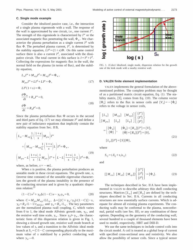
where C5M pwMwp /LLw , D5@(C1gw /gd)/(12C)#2s,gd5Rd /L;1/tAlfven , andgw5Rw /Lw . The key parametersare the normalized plasma–wall coupling,C, which variesfrom 0 to 1, the ideal mode Alfve´nic growth rate,gd , andthe resistive wall time scale,gw . Sincegd@gw , the charac-teristic form of this dispersion relation is given in Fig.showing a slowed growth rate, resistive wall mode branchlow values ofs, and a transition to the Alfve´nic ideal modebranch atSc5C/12C corresponding physically to the maxmum value of s stabilized by a perfect conducting wawheregw→0.
nof
n
fr-
at
D. VALEN finite element implementation
VALEN implements the general formulation of the abovmentioned problem. The complete problem may be thouof as a partitioned matrix circuit equation, Eq.~1!. The sta-bility matrix, @S#, comes from Eq.~10!. The column vector$Fs% refers to the flux in sensor coils and$Vs%52$Fs%refers to the voltage in sensor coils,
F @Lw# @Mwp# @Mwp#
@M pw# @Lp# @Lp#G H $I w%
$I d%$I p%
J5 H $Fw%
$F% J ,$Fw%1@Rw#$I w%5$V%,
$F%1@Rd#$I d%5$0%,~21!
@Lp#$I p%5@S#$F%,
where
Si j 5~d i j 1sil i j ! ~22!
and
@@Msw# @Msd# @Msp##H $I w%$I d%$I p%
J 5$Fs%. ~23!
The techniques described in Sec. II A have been impmented inVALEN to describe arbitrary thin shell conductinstructures. Matrices@Lw# and @Rw# are defined by the techniques described in Sec. II A. Currents in all conductistructures are now essentially surface currents. Which isequate for almost all existing plasma experiments. The cducting walls may be conformal to the plasma, nonconfmal, partial walls~see Sec. III!, or any combination of theseoptions. Depending on the geometry of the conducting wseveral hundred to a couple of thousand elements haveused to model, respectively, HBT and DIII-D.
We use the same techniques to include control coils ithe circuit model. A coil is treated as a global loop of currewith specified cross-sectional area and resistivity. We aallow the possibility of sensor coils. Since a typical sens
FIG. 1. ~Color! Idealized, single mode, dispersion relation for the growrate of the kink mode with a nearby resistive wall.
ouenreixby
is
d
n
depra-
i
r-nth
omshf
sthere
sm
t dwhe
ityc
gll
n
-n
eris-xtracur-
ntalue.n-
ux
be
thisthe
ing
ableuc-. Aesis-od-etheng
esivea
ale-
ll
the
ble
on-
2174 Phys. Plasmas, Vol. 8, No. 5, May 2001 Bialek et al.
coil would have negligible current we exclude sensor ccurrents from the eddy current formulation. This avoids nmerical problems produced by great differences in currmagnitudes. Sensor coils are included in the eddy curformulation only as a mutual inductance matr@@Msw# @Msd# @Msp## which has size number of sensorsthe total number of currents, Eq.~22!. In VALEN, the geom-etry of active coils or sensor coils is described by piecewlinear paths in space. The cross-sectional area, resistivity~foractive coils!, and number of turns must also be specifie@Msw# is derived by a straightforward application of Eq.~4!.
The plasma perturbations representing the eigenfutions of the operatordW must be supplied toVALEN. Theseeigenfunctions specify the external magnetic field andpend on typical plasma parameters such as current andsure.DCON26 produces this type of information. Usually stbility codes calculate the most unstable eigenvector andgrowth rate~eigenvalue!. This is different from the desiredeigenvectors ofdW. Boozer argues that at the point of maginal stability, growth rate eigenvectors, which depend okinetic energy operator, approach arbitrarily closely toeigenvectors describing the change in energy thatVALEN re-quires. In this manner we have used input information frGATO27 in some VALEN calculations. Other stability codecould also be used forVALEN input. When such an approacis taken we extrapolate the range of validity by the use oqualitatively correct expression for the stability constant,
s}^b&2^b& free
^b&fixed2^b&. ~24!
Plasma perturbations need to be described in termthe normal magnetic field on a control surface placed atlocation of the unperturbed plasma. This information is thused to solve for a surface current distribution that bestproduces that normal magnetic field. Equation~4! is againused to define the self- and mutual inductances of the plaperturbation. When using Eq.~4! in this situation, one of theshape functions represents the complete surface currentribution and the other shape function represents either afinite element, an active control coil, a sensor coil, or anotcomplete surface current distribution.
As in the simple example given previously the stabilinformation must be incorporated back into the inductanmatrix. The stability matrix,@S#, is used to eliminate$I p%from the problem formulation. We substitute the followinexpression for$I p% into Eq. ~20!. This again incorporates athe stability information into the circuit equations,
$I p%5~@S#21@Lp#2@Lp# !21~@M pw#$I w%2@Lp#$I p%!.~25!
A very important aspect of theVALEN implementation isthe ability to specify feedback strategy. InVALEN we havethe ability to specify the voltage on any active coil. In geeral a coil forcing voltage has the following form:
il-t
nt
e
.
c-
-es-
ts
ae
a
ofen-
a
is-allr
e
-
Vc5( GciP F i
S~ t2tciP !1( Gci
DViS~ t2tci
D !
1( GIiPI i~ t2t i
P!1( GIiDI i~ t2t i
D!, ~26!
whereVc is the applied voltage,F iS is a sensor flux,Vi
S is asensor voltage,I i and I i , are any current or its time derivative, Gci
P and GciD are the proportional or derivative gain i
the active coil ‘‘c,’’ GIiP andGIi
D are proportional or deriva-tive gain for any current, and a time delayt may be appliedto any term. The gain terms have user specified characttics. Current power supplies may be modeled as an efeedback expression between power supply voltage andrent through the power supply circuit.
If we limit ourselves to zero time delays and constagains a feedback strategy may be studied as an eigenvproblem in Eq.~3!. For example, if all time delays in Eq~24! are identically zero, and the gain coefficients are costants, then Eq.~22! may be used to express the sensor flF i
S and its time derivatives in terms of theI k(t) and itsderivatives. In this situation, all these dependencies maycollected on the left-hand side of Eq.~3! to produce a well-defined eigenvalue problem. The unstable eigenvalues ofgeneralized circuit equation are reciprocal growth rates ofunstable modes.
All of these capabilities have been implemented usFORTRAN 90 and the Numerical Algorithms Library~NAG!mathematical library. TheVALEN program is not a singleexecutable code but rather a collection of several executmodules. For example, the first module computes the indtance and resistance matrix for all conductors and coilssecond module computes the additional inductance and rtance contributions from all the plasma modes. Other mules then are used to:~1! calculate transients in the timdomain,~2! examine the eigenvalues and eigenvectors ofmodel, and~3! produce graphical summaries of the resulticurrent distributions.
III. VALEN PASSIVE STABILIZATION STUDIES ATLARGE RÕa
Our first example ofVALEN results uses the eigenvaluformulation described previously and examines the passtabilization provided by a resistive wall concentric withlarge aspect ratio,R/a57.66, circular cross-section plasmwith minor radiusa. The helical perturbation of the unstabmode describes anm/n53/1 external kink. The toroidal resistive wall ~taken as a cylindrical aluminum wall, radiusband thickness 0.01 m! was examined for two plasma waradii, one close to the plasma surface withb/a51.08 and theother relatively far away withb/a51.7. Figure 2 illustratesthe results of this study as a plot of growth rate versusstrength of the unstable mode,s, as defined in Eq.~10!.VALEN calculations show the characteristic two unstabranches~RWM and ideal kink! illustrated in Fig. 1 for thesingle mode analytic model. The expected result that strger unstable modes~i.e., largers! can be slowed to the RWM

he
nive
if
heoftheth
n-
eand
hisionr-. Ints ofati-loi-cedas
ahbe-o
atdeen
are
een
r-troln-sis-ng’ra-an
pli-
a-r aforemethe
dial
d-
l
r-all
dero
Wec
2175Phys. Plasmas, Vol. 8, No. 5, May 2001 Modeling of active control of external magnetohydrodynamic . . .
branch for a close fitting wall is clearly recovered, with ttransition value ofs identified asSc5the stability limit for anideally conducting wall.
In order to provide a quantitative benchmark forVALEN,we compare the values ofSc presented in Fig. 2 with theresults of an analytic calculation of ideal wall stabilizatiobased on a circular cross plasma for an ideal, current drkink published by Wesson.28 The circular cross-sectionplasma in the Wesson model has minor radius ‘‘a,’’ and thesurrounding aluminum resistive wall was placed at two dferent radii, ‘‘b.’’ We see in Fig. 3 that the values ofSc from
FIG. 2. ~Color! VALEN calculation of the growth rate for anm/n53/1 kinkmode at largeR/a surrounded by a concentric conducting wall at two nomalized wall radii,b/a. Both the original plasma and the surrounding whave a circular cross section. ‘‘a’’ is the plasma minor radius and ‘‘b’’ is thewall minor radius.
FIG. 3. ~Color! Comparison ofVALEN largeR/a calculation of kink modegrowth rate shown in Fig. 2 with an analytic result using the Wesson moBoth the original plasma and the surrounding walls have a circular csection. ‘‘a’’ is the plasma minor radius and ‘‘b’’ is the wall minor radius.The VALEN results are shown in blue and the Wesson results in red.compare the inflection point for the resistive Wesson model with the infltion point for theVALEN structure with approximate perfect conductivity.
n
-
the VALEN calculation are in very good agreement with tvalues ofSc from the analytic Wesson model. The valueSc is obtained from the Wesson calculation by estimatingvalue of s where the inflection point occurs in the growrate. The value ofSc is obtained from theVALEN calculationsby altering the wall resistivity to approximate a perfect coductor and then estimating the value ofs where the inflectionpoint occurs. In theVALEN results the region to the left of thappropriate blue curve have extremely slow growth ratesare essentially stabilized.
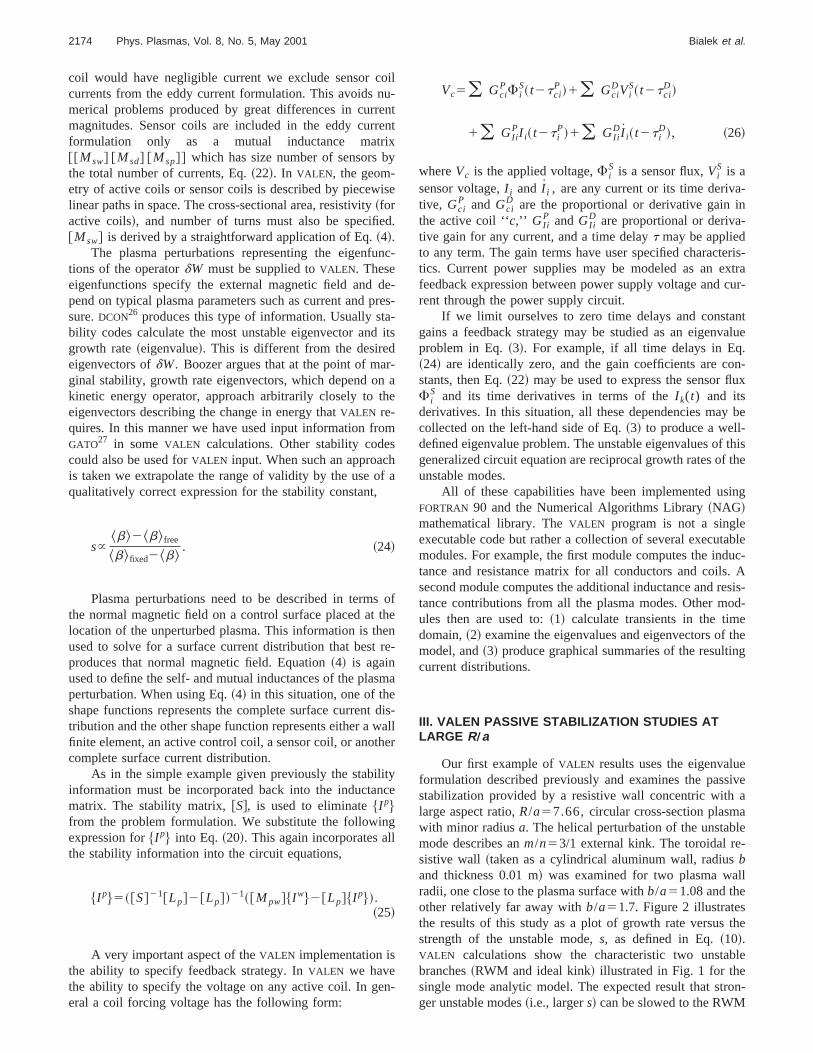
An important feature of theVALEN code is that the wallneed not be conformal or simply connected. To illustrate tcapability, Fig. 4 summarizes the results for the situatwhere theb/a51.08 and the 0.01-m-thick aluminum confomal wall modeled in Fig. 2 was cut into isolated segmentsone sequence of calculations, equally spaced poloidal cu1°, 5°, and 10° toroidally were applied as shown schemcally in the figure. In another sequence the inner 180° podally of the wall was removed and the same equally spapoloidal cuts of 1°, 5°, and 10° toroidally were appliedshown schematically in Fig. 4. TheVALEN calculation of thevalue ofSc for these configurations is plotted in Fig. 4 asfunction of the fractional % of conducting wall area whicremains for each configuration. We see that the relationtweenSc and wall fraction is roughly linear. This result is tbe expected since we are modeling a current driven kinklarge aspect ratio which has little poloidal variation in moamplitude. In the case of a lower aspect ratio beta drivkink with ballooning character the outer wall segmentsseen to have a greater relative stabilizing effect.
IV. VALEN MODELING OF BASIC SMART SHELLSTABILIZATION
Two approaches to active feedback control have bexplored with the VALEN code: the ‘‘smart shell’’ and‘‘mode control.’’ In the ‘‘smart shell’’ approach, originallyproposed by Bishop29 for the reversed field pinch, an extenally generated radial magnetic field is applied by a concoil to the resistive stabilizing wall which cancels the ustable mode generated radial flux soaking through the retive wall. In this way the response of a perfectly conductiwall is simulated. Alternatively, the ‘‘mode control’approach22,23 to feedback control seeks to cancel out thedial mode flux at the plasma surface by application ofexternally generated field proportional to the mode amtude.
Boozer22 showed that in the idealized limit of one eqution for the plasma mode, one for the wall, and one fosingle active feedback control coil, the dispersion relationa plasma mode stabilized by a smart shell feedback schmay be described by a quadratic dispersion relation. Heresensor coil located on the resistive wall measures a raflux, Fs , and this flux signal determines a voltageVf appliedto the active feedback control coil. If the single active feeback control coil has self inductanceL f , resistanceRf , g f
5Rf /L f , mutual inductanceMw f between the resistive waland the control coil, mutual inductanceM p f between theplasma mode and the control coil, and a proportional gainGp
l.ss
e-
a-
.
a
i-ls
2176 Phys. Plasmas, Vol. 8, No. 5, May 2001 Bialek et al.
FIG. 4. ~Color! VALEN model appliedto a sequence of complex passive stbilizing structures for the kink modeof Fig. 2. with both toroidal and poloi-dal gaps in the conducting structureThe value ofSc as a function of %conducting wall coverage showsroughly linear relation for this largeaspect ratio geometry. Both the orignal plasma and the surrounding walhave a circular cross section.
n
tivm
o
-
far-the
edll
tes
olncemait
d-art
iveg-alents
a
-5.
er-s-thatdelof
allyra-
ue
ra-tesentith
so thatVf52L fgwGpFs /M p f then the dispersion relatiohas the form
a2n21a1n1a050, ~27!
where a0 /g f52g f1gw(D1Cf)Gp ; a15Dg f2gw ; anda25D. The key parameters which characterize the accontrol system are the normalized coupling of the plasmode to the wall,C5M pwMwp /LLw , defined earlier andwhich varies between 0 and 1. A new parameter is the nmalized feedback system coupling,
Cf512M pwMw f /LwLp f ,
which can be positive or negative, and the functionD(s)5@(11s)C/s21# which is large and positive for small instability drive s, and decreases to 0 ass rises to ideal walllimit, Sc . SinceD(s)5a2 is positive on the RWM branch othe dispersion relation and the Hurwitz condition requirescoefficients,a2 , a1 , anda0 to have the same sign to guaanty no unstable roots, this gives three conditions onmaximum value ofs which can be stabilized by the activfeedback system. The maximum stable values ofs are set bythe lowest of the three conditions,
a2.0: s,C
12C5Sc , ~28!
a1.0: s,C
12C1gw /g f,Sc , ~29!
a2.0: s,C
12C2Cf1@g f /gw#Gp21 . ~30!
The first condition of Eq.~28! limits us to stabilization up tothe ideal wall limit. The second condition of Eq.~29! onlyapproaches the ideal limit if the response time of the feback system,L f /Rf , is much faster than the resistive watime constantLw /Rw . The third condition of Eq.~30! shows
ea
r-
ll
e
-
that the effect of large values of proportional gain saturaasGp→` and thats can approachSc only if Cf.0. Since inthe case of a typical ‘‘smart shell’’ configuration the contrcoils are located outside the vacuum vessel wall and heare coupled more strongly to the vessel wall than the plasmode,Cf is usually negative and this condition sets the limon basic smart shell performance.
TheVALEN code was applied to modeling the basic feeback control performance of the three-dimensional smshell configuration in the HBT-EP tokamak,13,30 which isshown in Fig. 5. The system in HBT-EP uses a resiststabilizing shell which is cut into ten 26° wide toroidal sements covering only roughly the outer 180° of the poloidcross section. In feedback studies five of these wall segmare thick aluminum and are withdrawn far from the plasmand the other five thin stainless-steel segments~tw;0.3 ms!are placed atb/a51.08 and have been fitted with 30 independent sensor/control coil pairs as shown in the Fig.Shown in Fig. 6 is a summary of theVALEN modeling of thisHBT-EP smart shell active feedback system for three diffent gains,Gp , and compared with the result if the stainlessteel wall segments were perfect conductors. We seethese results are in good agreement with the analytic modescribed previously. First, we note that the applicationfeedback gain not only reduces the growth rate but actufully stabilizes the RWM. Second, the effect of gain satution is readily apparent asGp is increased from 53104 to13105 V/W. Finally, we note that the largest value ofswhich is stabilized is smaller than theSc result for a perfectconductor, in agreement with Eq.~30!, since the value ofCf
for the HBT-EP smart shell configuration is less than 0 dto strong control coil/wall coupling.
Experiments using this HBT-EP smart shell configution to stabilize the RWMs have been reported by Caet al.13 and showed that the gain required in the experimto achieve RWM suppression was in good agreement wthe VALEN model result of 105 V/W.

-
2177Phys. Plasmas, Vol. 8, No. 5, May 2001 Modeling of active control of external magnetohydrodynamic . . .
FIG. 5. ~Color! Smart shell feedbackcontrol system in the HBT-EP experiment.
g
ti-itohths
i-onmdht
acet
too
icasudyofof
ken
in-ix
thetheintdalded
e
tsithument
et of
V. VALEN MODELING OF OPTIMIZED FEEDBACKCONFIGURATIONS
Following on the initial success reported in stabilizinthe RWM with active feedback control on HBT-EP13 and inDIII-D, 17,31 the VALEN code has been used to explore opmization of the feedback configuration on both devices wthe objective of finding configurations and feedback algrithms which are projected to stabilize the RWM at the higest values ofs and approaching as close as possible toideal wall beta limit,Sc . Examples of design choice issuefor the ‘‘smart shell’’ configuration include: extent of polodal coverage of radial flux sensors; optimal number of ctrol coils and sensors, optimal sensor locations, and optisize for sensors. In the case of application of the ‘‘mocontrol’’ approach to feedback, it is critical to obtain a higaccuracy measure of the RWM amplitude and phase to beinput into the active feedback loop. One promising approhas been found to be the use of multiple poloidal magnfield, Bp , sensor coils to identify amplitude and phase anduse midplaneBp sensors to minimize inductive coupling tthe control coils. This scheme for ‘‘mode control’’ was alsstudied systematically withVALEN.
FIG. 6. ~Color! VALEN calculation of basic smart shell stabilization in thgeometry of HBT-EP using proportional gain,Gp , feedback.
h--e
-ale
hehico
In the context of DIII-D the performance of the bas‘‘smart shell’’ feedback scheme with proportional gain wstudied. Shown in Fig. 7 is a summary of a systematic stof the effect of adding additional poloidal segmentssensor/control coils to provide more complete coveragethe resistive vacuum vessel wall~b/a;1.3 andtw;5 ms!which provides stabilization of the idealn51 external kink.The unstable RWM structure used in these studies was tafrom a GATO calculation of the RWM instability in DIII-Dshot number 92544. The feedback control coils presentlystalled on DIII-D consist of a single poloidal segment of s60° wide control coils on the midplane located outsidetoroidal field coils. Six radial flux sensors are mounted onDIII-D vacuum vessel each directly under the radial footprof one of the control coils. In these studies, additional polisegments of six control coils and six sensors were ad
FIG. 7. ~Color! VALEN calculation of effect of additional poloidal segmenof feedback sensor/control coil elements in DIII-D for a smart shell wproportional gain feedback, showing that improvements in the maximstable value ofs saturate after about three segments. Each blue line segmis a set of six control segments and each exterior red line segment is a ssix radial flux sensors.
andhe
-
2178 Phys. Plasmas, Vol. 8, No. 5, May 2001 Bialek et al.
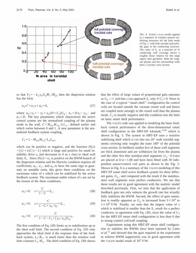
FIG. 8. ~Color! VALEN calculation showing the effect ofvarying the distance between the plasma surfaceradial flux sensors. The outermost segment of tvacuum vessel is located atR52.445 m. The midplane‘‘outside VV’’ sensors are located atR52.474 m (z560.599 m), midplane ‘‘inside VV’’ sensors are located at R52.420 m (z560.420 m), and midplane‘‘sensors between VV and plasma’’ are located atR52.350 m (z560.510 m). The maximum radius of theplasma surface is 2.285 m.
wndenctetoth
sonore
na
artlono
ctothoelnttera
po
g-il
sut
ra-ltsmas
rolol
themu-andra-ed
r
.
eth aain
re-roltheemlldist-
vertically above and vertically below the midplane as shoschematically in Fig. 7. In Fig. 7 the icons illustrate 3, 5, a7 poloidal segments for the control coils and radial flux ssors. Each straight line segment in blue represents an acontrol coil segment and each exterior straight line segmin red represents a radial flux sensor segment. We seethe addition of either a single segment vertically abovebelow the present single midplane segment improvesmaximum stable value ofs, and that further improvement iobtained with two additional segments, one above andbelow the midplane segment for a total of 3 segments csisting of 18 sensor/control coil pairs. The addition of mosegments up to a total of 7 showed relatively little additioimprovement in the maximum stable value ofs. Since theRWM induced eddy currents in the vacuum vessel walllargest on the outboard midplane and diminish significanon the top and bottom of the vacuum vessel due to the strballooning nature of the mode structure, this result isunexpected.
Further optimization studies in the smart shell feedbascheme show little benefit for the addition of finer scaleroidal segmentation in the control coils which make upadditional poloidal segments. There was also no benefitserved to having the toroidal segments rotated in angle rtive to the six control coils in the midplane poloidal segmeHowever, there was significant improvement in projecperformance when the radial field flux sensors were ‘‘shoened’’ to subtend a smaller poloidal angle by providingbetter mode amplitude signal with less averaging of theloidal mode structure.
Using this optimal configuration of three poloidal sements consisting of 18 control coils outside the toroidal costructure, the location of the 18 sensor loops, which mearadial flux, was varied in theVALEN modeling of basic smar
n
-iventhatre
en-
l
eyngt
k-eb-a-.dt-
-
sre
shell performance with proportional gain for three sensordial positions as shown in Fig. 8. It is clear from the resuin Fig. 8 that significant improvements in the maximustable value ofs are possible if the sensors are locatedclose to the plasma surface as possible.
Additional improvements in projected feedback contperformance in DIII-D are found when the mode contrfeedback scheme is modeled. Mode control uses tinyBp sen-sor coils located on the outboard midplane just insidevacuum vessel wall. Since these coils have nearly zerotual inductive coupling to the control coils, they providehigh quality measure of the unstable RWM amplitude aphase.VALEN modeling of this feedback scheme showed dmatically improved performance relative to that obtainwith the smart shell approach usingBr flux sensors near thevacuum vessel wall.
The results of these optimization studies in DIII-D foboth single poloidal segment~6 control coils! and three po-loidal segment~18 control coils! are summarized in Fig. 9The results of theVALEN model are plotted withs mapped tob using the approximate relation given in Eq.~24!, and nor-malized to the difference between the ideal wallb limit ( s5Sc) and the no-wall beta limit (s50). For the presentcontrol coils geometry of six midplane coils on DIII-D, wsee the projected performance of the existing system wibasic smart shell feedback scheme with proportional glimited to improvingb to about 20% toward the ideal wallblimit, consistent with the modest feedback performanceported for this system on experiments showing RWM conton DIII-D.17 The use of shorter sensors located insidevacuum vessel and the existing six control coil systprojects improvements to about 30% toward the ideal wablimit. And the use of a toroidal array of midplane mounteBp sensors improves the projected performance of the ex

alD
-ou
oroe-ale
g
he
troltsseall
n in
a-
tre-i-
Fi-
beiliz-rerfect
thei-ic-
ideofi-allic.
elyticna-
he
-ic
2179Phys. Plasmas, Vol. 8, No. 5, May 2001 Modeling of active control of external magnetohydrodynamic . . .
ing six control coil set further to about 50% toward the idewall b limit. For an 18 control coil set in three poloidasegments which is proposed for future installation on DIII-the basic smart shell projected performance is improved50% toward the ideal wallb limit, while the use of a toroidalarray of midplane mountedBp sensors improves the projected performance of an 18 control coil set further to ab80% toward the ideal wallb limit.
Finally, a study of optimal feedback configurations fthe HBT-EP tokamak investigated changes in control cgeometry which would minimize the inductive coupling btween the control coils and the passive stabilizing wMw f , while maintaining strong control coil coupling to th
FIG. 9. ~Color! Summary ofVALEN calculations of optimized feedback configurations in DIII-D for both smart shell and mode control feedback log
l
,to
t
il
l,
plasma,M p f . In this way the normalized feedback couplincoefficient, Cf512M pwMw f /LwLp f , in the single modemodel @Eq. ~27!# can be made greater than 0 allowing tmaximum value ofs to approach the ideal wall limit,Sc .Shown in Fig. 10 is a proposed improved feedback congeometry for HBT-EP. Five of the thick aluminum segmenare withdrawn and the control coils are moved into thetoroidal gaps. The five passive stainless steel stabilizing wsegments~shown shaded! still haveBr flux sensors mountedon the back of these remaining wall segments. Also showFig. 10 are the results of severalVALEN calculations. The‘‘No Feedback’’ curve is a prediction for passive stabiliztion in the existent HBT-EP geometry~five close fittingstainless steel passive segments!. The curve labeled ‘‘PresenHBT-EP’’ illustrates the best smart shell performance pdicted for the existent geometry. The curve labeled ‘‘Minmum Mw f Configuration’’ illustrates theVALEN predictionfor active control in the proposed improved geometry.nally the curve labeled ‘‘Ideal wallb limit’’ illustrates theVALEN prediction for the passive stabilization that wouldproduced by the configuration where all ten passive stabing wall segments in the existing HBT-EP configuration aas close as possible to the plasma and approximate peconductors. The projected maximum stable value ofs for theproposed active feedback configuration is very close toideal wall limit Sc for a configuration with ten passive stablizing wall segments. This result is in agreement with predtions of the single mode analytic model.
VI. CONCLUSIONS AND FUTURE PLANS
TheVALEN code has been developed as a tool to prova complete simulation capability for feedback controllong-wavelength external MHD plasma instabilities in arbtrary three-dimensional geometry of passive resistive wstabilizers, sensor coils, control coils, and feedback logPredictions of theVALEN code for passive stabilization havbeen benchmarked qualitatively against single mode anamodel of the RWM and quantitatively against Wesson’s alytic model of a largeR/a current driven kink mode. TheVALEN model is also in good qualitative agreement with t
.
zationcehes
FIG. 10. ~Color! VALEN calculation of a proposed feedback configuration in HBT-EP which minimizes the control coil–wall coupling allowing stabiliup the ideal wall limit ofs. The curves labeled ‘‘No Feedback’’ and ‘‘Present HBT-EP’’ illustrate theVALEN predictions for passive and active performanin the existent HBT-EP. The curve labeled ‘‘MinimumMw f Configuration’’ illustrates theVALEN prediction for the proposed configuration illustrated. Tcurve labeled ‘‘Ideal wallb limit’’ is the VALEN prediction for perfect conducting plates as close to the plasma as possible in all possible location~seeFig. 5!.

ait
te
edDth
p-mra
tioti
dcssy
i-ngrod
ortsf-
izblne
cs
orn
yickh
ar
v.
,
S.
r-
ly,
at-
No.or-
un.
R..
2180 Phys. Plasmas, Vol. 8, No. 5, May 2001 Bialek et al.
predictions of the analytic single mode model for basic smshell feedback stabilization, and qualitative agreement wthe experimental results on RWM feedback control reporfor the HBT-EP tokamak13 and DIII-D.17,27
TheVALEN code has been used to model improved feback control configurations for both HBT-EP and DIII-with projected performance for both systems approachingideal wall stability limit. For the smart shell feedback aproach, factors which were found to result in significant iprovement in feedback performance included better coveon the outboard vacuum vessel~passive stabilizing wall! areawhere the RWM induced eddy currents are largest, locaof Br flux sensors closer to the plasma surface, and reducin the poloidal angle subtended byBr flux sensors. For themode control feedback approach factors which were founresult in significant improvement in feedback performanincluded better coverage on the outboard vacuum ve~passive stabilizing wall! area where the RWM induced eddcurrents are largest, the use of midplaneBp sensor coils withminimal inductive coupling to the control coils, and minimzation of the control coil coupling to the passive stabiliziwall. For the mode control approach performance is pjected to approach the ideal wall stability limit in optimizeconfigurations for both HBT-EP and DIII-D.
In the present application of the code a single modeused. This approximation appears to be accurate as repby Okabayashi.25 In the future we plan several improvemenin the VALEN model to better model additional realistic efects in feedback applications. These include:~i! the additionof multiple plasma modes to investigate possible destabiltion of other, near-marginal modes and to allow for possichanges in the plasma mode structure under applicatiofeedback control,~ii ! the addition of plasma rotation to thunstable plasma model inVALEN as formulated by Boozer;32
and~iii ! realistic nonideal feedback amplifier characteristi
ACKNOWLEDGMENTS
We would like to thank PPPL and General Atomics ftheir support of this work as part of the RWM collaboratioon the DIII-D National Fusion Facility. We also gratefullacknowledge useful discussion and input from R. FitzpatrA. M. Garofalo, T. H. Jensen, R. J. Lahaye, M. OkabayasS. Sabbagh, E. J. Strait, T. Taylor, and A. D. Turnbull.
This work was supported by the United States Depment of Energy.
rthd
-
e
-ge
non
toeel
-
isted
a-eof
.
,i,
t-
1E. J. Strait, Phys. Plasmas1, 1415~1994!.2T. C. Hender, S. J. Allfrey, R. Akerset al., Phys. Plasmas6, 1958~1999!.3H. A. B. Bodin, Nucl. Fusion30, 1717~1990!.4A. D. Turnbull, T. S. Taylor, Y. R. Lin-Liu, and H. St. John, Phys. ReLett. 74, 718 ~1995!.
5C. Kessel, J. Manickam, G. Rewoldt, and T. M. Tang, Phys. Rev. Lett.72,1212 ~1994!.
6R. L. Miller, Y. R. Lin-Liu, A. D. Turnbull, V. S. Chan, L. D. PearlsteinO. Sauter, and L. Villard, Phys. Plasmas4, 1062~1997!.
7B. Alper, Phys. Fluids B2, 1338~1990!.8P. Greene and S. Robertson, Phys. Fluids B5, 556 ~1993!.9E. J. Strait, T. S. Taylor, A. D. Turnbull, L. L. Lao, B. Rice, O. Sauter,J. Thompson, and D. Wroblewski, Phys. Rev. Lett.74, 2483~1995!.
10T. H. Ivers, E. Eisner, A. Garafaloet al., Phys. Plasmas3, 1926~1996!.11M. Okabayashi, N. Pomphrey, and J. Manickam, Nucl. Fusion36, 1167
~1996!.12A. M. Garofalo, A. D. Turnbull, E. J. Straitet al., Phys. Plasmas6, 1893
~1999!.13C. Cates, M. Shilov, M. E. Mauel, G. A. Navratil, D. Maurer, S. Mukhe
jee, D. Nadle, J. Bialek, and A. Boozer, Phys. Plasmas7, 3133~2000!.14S. Takeji et al., IAEA Fusion Energy Conference 2000, Sorrento, Ita
Paper EX7/01~International Atomic Energy Agency, Vienna, 2000!.15E. J. Strait, L. L. Lao, M. E. Mauelet al., Phys. Rev. Lett.75, 4421
~1995!.16C. C. Pettyet al., 27th EPS Conference on Controlled Fusion and Plasm
Physics, Budapest, Hungary, 2000~European Physical Society, PetiLancy, 2000!.
17A. M. Garofalo, E. J. Strait, J. M. Bialeket al., Nucl. Fusion40, 1491~2000!.
18A. Bondeson and D. J. Ward, Phys. Rev. Lett.72, 2709~1994!.19C. M. Bishop, Plasma Phys. Controlled Fusion31, 1179~1989!.20T. H. Jensen and R. Fitzpatrick, Phys. Plasmas4, 2997~1997!.21R. Fitzpatrick and T. H. Jensen, Phys. Plasmas3, 2641~1996!.22A. H. Boozer, Phys. Plasmas5, 3350~1998!.23M. Okabayashi, N. Pomphrey, and R. E. Hatcher, Nucl. Fusion38, 1607
~1998!.24D. W. Weissenburger, Princeton Plasma Physics Laboratory Report
PPPL-2494, January 1988. Available from the National Technical Infmation Service, 5285 Port Royal Road, Springfield, VA 22161.
25M. Okabayashi, J. Bialek, M. S. Chanceet al., Phys. Plasmas8, 2071~2001!.
26A. H. Glasser and M. S. Chance, Bull. Am. Phys. Soc.42, 1848~1997!.27L. C. Bernard, F. J. Helton, and R. W. Moore, Comput. Phys. Comm
24, 377 ~1981!.28J. Wesson, Nucl. Fusion18, 87 ~1978!.29C. M. Bishop, Plasma Phys. Controlled Fusion31, 1179~1989!.30M. K. V. Sankar, E. Eisner, A. Garofalo, D. Gates, T. H. Ivers,
Kombargi, M. E. Mauel, D. Maurer, D. Nadle, G. A. Navratil, and QXiao, J. Fusion Energy12, 303 ~1993!.
31J. L. Luxon and L. G. Davis, Fusion Technol.8, 441 ~1985!.32A. H. Boozer, Phys. Plasmas6, 3180~1999!.