External Control
53
1 / 53 External Control 1. Application 2. Connectors and wiring 2.1. RS-232C Remote control 2.2. LAN control 3. Communication Parameter 3.1. RS-232C Remote control 3.1.1. Communication timing 3.2. LAN control 3.2.1. Communication timing 4. Communication Format 4.1. Header block format (fixed length) 4.1.1. Header format 4.2. Message block format 4.2.1. Get current parameter 4.2.2. Get Parameter reply 4.2.3. Set parameter 4.2.4. Set Parameter reply 4.2.5. Command 4.2.6. Command reply 4.3. Check code 4.3.1. Formatted and calculate. 4.4. Delimiter 5. Message type 5.1. Get current Parameter from a monitor 5.1.1. Get current parameter format 5.2. “Get parameter” reply 5.2.1. Get parameter reply format 5.3. Set parameter 5.3.1. Set parameter format 5.4. “Set parameter” reply 5.4.1. Set parameter reply format 5.5. Commands 5.5.1. Save Current Settings 5.5.2. Get Timing Report and Timing reply 5.5.3. NULL Message 6. Typical procedure example 6.1. How to change the “Backlight” setting. 6.2. How to read the measurement value of the built-in temperature sensors. 7. CTL commands 7.1. System Command 7.1.1. CTL-0C. Save Current Settings 7.1.2. CTL-07. Get Timing Report and Timing reply 7.2. Power control procedure
-
Upload
khangminh22 -
Category
Documents
-
view
0 -
download
0
Transcript of External Control
1 / 53
External Control1. Application2. Connectors and wiring
2.1. RS-232C Remote control2.2. LAN control
3. Communication Parameter3.1. RS-232C Remote control
3.1.1. Communication timing3.2. LAN control
3.2.1. Communication timing4. Communication Format
4.1. Header block format (fixed length)4.1.1. Header format
4.2. Message block format4.2.1. Get current parameter4.2.2. Get Parameter reply4.2.3. Set parameter4.2.4. Set Parameter reply4.2.5. Command4.2.6. Command reply
4.3. Check code4.3.1. Formatted and calculate.
4.4. Delimiter5. Message type
5.1. Get current Parameter from a monitor5.1.1. Get current parameter format
5.2. “Get parameter” reply5.2.1. Get parameter reply format
5.3. Set parameter5.3.1. Set parameter format
5.4. “Set parameter” reply5.4.1. Set parameter reply format
5.5. Commands5.5.1. Save Current Settings5.5.2. Get Timing Report and Timing reply5.5.3. NULL Message
6. Typical procedure example6.1. How to change the “Backlight” setting.6.2. How to read the measurement value of the built-in temperature sensors.
7. CTL commands7.1. System Command
7.1.1. CTL-0C. Save Current Settings7.1.2. CTL-07. Get Timing Report and Timing reply
7.2. Power control procedure
2 / 53
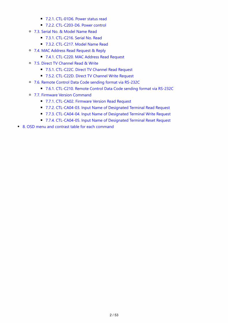
7.2.1. CTL-01D6. Power status read7.2.2. CTL-C203-D6. Power control
7.3. Serial No. & Model Name Read7.3.1. CTL-C216. Serial No. Read7.3.2. CTL-C217. Model Name Read
7.4. MAC Address Read Request & Reply7.4.1. CTL-C220. MAC Address Read Request
7.5. Direct TV Channel Read & Write7.5.1. CTL-C22C. Direct TV Channel Read Request7.5.2. CTL-C22D. Direct TV Channel Write Request
7.6. Remote Control Data Code sending format via RS-232C7.6.1. CTL-C210. Remote Control Data Code sending format via RS-232C
7.7. Firmware Version Command7.7.1. CTL-CA02. Firmware Version Read Request7.7.2. CTL-CA04-03. Input Name of Designated Terminal Read Request7.7.3. CTL-CA04-04. Input Name of Designated Terminal Write Request7.7.4. CTL-CA04-05. Input Name of Designated Terminal Reset Request
8. OSD menu and contrast table for each command

3 / 53
1. Application
This document defines the communications method for control of the NEC LCD monitor, when using an externalcontroller.
2. Connectors and wiring
2.1. RS-232C Remote control
(1) Connector 9-pin D-Sub (2) Cable Cross (reversed) cable or null modem cable
(Please refer “Controlling the LCD monitor via RS-232C Remote control” on User’s manual.)
4 / 53
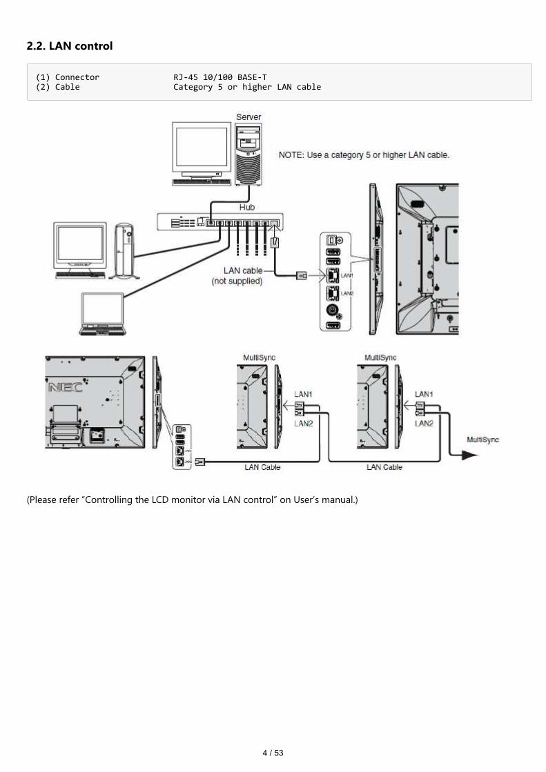
2.2. LAN control
(1) Connector RJ-45 10/100 BASE-T (2) Cable Category 5 or higher LAN cable
(Please refer “Controlling the LCD monitor via LAN control” on User’s manual.)

5 / 53
3. Communication Parameter
3.1. RS-232C Remote control
(1) Communication system Asynchronous (2) Interface RS-232C (3) Baud rate 9600bps (4) Data length 8bits (5) Parity None (6) Stop bit 1 bit (7) Communication code ASCII
3.1.1. Communication timing
The controller should wait for a packet interval before next command is sent. The packet interval needs to be longer than 600msec for the LCD monitor.
3.2. LAN control
(1) Communication system TCP/IP (Internet protocol suite) (2) Interface Ethernet (CSMA/CD) (3) Communication layer Transport layer (TCP) * Using the payload of TCP segment. (4) IP address (Default) DHCP:On * If you need to change, Please refer “Network settings” on User’s manual. (5) Port No. 7142 (Fixed)
【Note】
The monitor will disconnect the connection if no packet data is received for 15 minutes. And the controller (PC) has to re-connect to control the monitor again, after 15 minutes or more.
3.2.1. Communication timing
The controller should wait for a packet interval before next command is sent.The packet interval needs to be longer than 600msec for the LCD monitor.

6 / 53
4. Communication Format
There are two types of external control commands: VCP and CTL.The command consists of four parts: Header, Message, Check code, and Delimiter.The contents of Message vary depending on the type of command.
┌────────────────┬─────────────────────────────┬────────────┬───────────┐ │ Header │ Message │ Check Code │ Delimiter │ └────────────────┴─────────────────────────────┴────────────┴───────────┘
Follow the instructions below for more information on each.Messages and other common components of the VCP command are described in this chapter.
■ Detailed description of message for VCP command
See the part 4.2. Message block format
■ Detailed description of message for CTL command
See the part 7. CTL commands
7 / 53
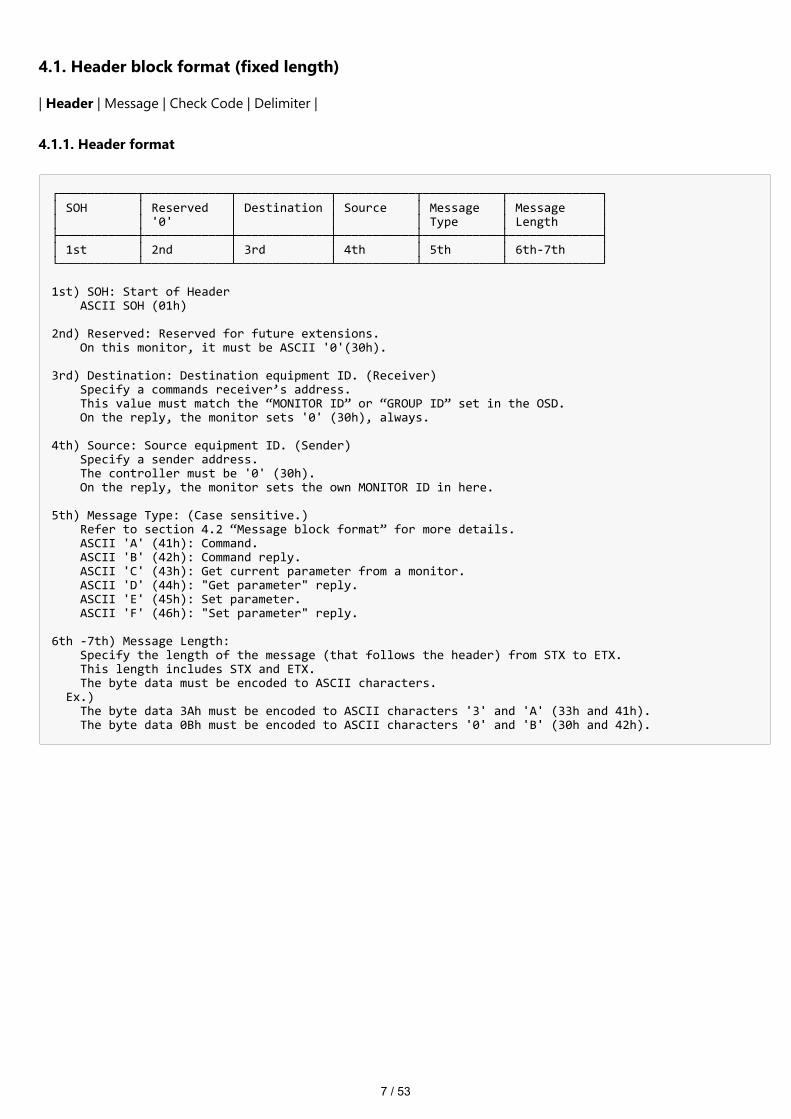
4.1. Header block format (fixed length)
| Header | Message | Check Code | Delimiter |
4.1.1. Header format
┌───────────┬────────────┬─────────────┬───────────┬───────────┬─────────────┐ │ SOH │ Reserved │ Destination │ Source │ Message │ Message │ │ │ '0' │ │ │ Type │ Length │ ├───────────┼────────────┼─────────────┼───────────┼───────────┼─────────────┤ │ 1st │ 2nd │ 3rd │ 4th │ 5th │ 6th-7th │ └───────────┴────────────┴─────────────┴───────────┴───────────┴─────────────┘ 1st) SOH: Start of Header ASCII SOH (01h) 2nd) Reserved: Reserved for future extensions. On this monitor, it must be ASCII '0'(30h). 3rd) Destination: Destination equipment ID. (Receiver) Specify a commands receiver’s address. This value must match the “MONITOR ID” or “GROUP ID” set in the OSD. On the reply, the monitor sets '0' (30h), always. 4th) Source: Source equipment ID. (Sender) Specify a sender address. The controller must be '0' (30h). On the reply, the monitor sets the own MONITOR ID in here. 5th) Message Type: (Case sensitive.) Refer to section 4.2 “Message block format” for more details. ASCII 'A' (41h): Command. ASCII 'B' (42h): Command reply. ASCII 'C' (43h): Get current parameter from a monitor. ASCII 'D' (44h): "Get parameter" reply. ASCII 'E' (45h): Set parameter. ASCII 'F' (46h): "Set parameter" reply. 6th -7th) Message Length: Specify the length of the message (that follows the header) from STX to ETX. This length includes STX and ETX. The byte data must be encoded to ASCII characters. Ex.) The byte data 3Ah must be encoded to ASCII characters '3' and 'A' (33h and 41h). The byte data 0Bh must be encoded to ASCII characters '0' and 'B' (30h and 42h).
8 / 53
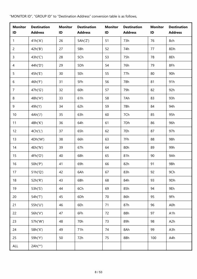
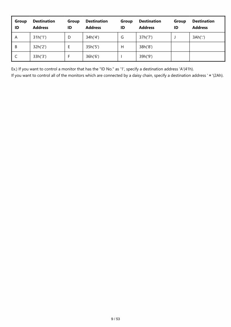
“MONITOR ID”, “GROUP ID” to “Destination Address” conversion table is as follows,
MonitorID
DestinationAddress
MonitorID
DestinationAddress
MonitorID
DestinationAddress
MonitorID
DestinationAddress
1 41h('A') 26 5Ah('Z') 51 73h 76 8ch
2 42h('B') 27 5Bh 52 74h 77 8Dh
3 43h('C') 28 5Ch 53 75h 78 8Eh
4 44h('D') 29 5Dh 54 76h 79 8Fh
5 45h('E') 30 5Eh 55 77h 80 90h
6 46h('F') 31 5Fh 56 78h 81 91h
7 47h('G') 32 60h 57 79h 82 92h
8 48h('H') 33 61h 58 7Ah 83 93h
9 49h('I') 34 62h 59 7Bh 84 94h
10 4Ah('J') 35 63h 60 7Ch 85 95h
11 4Bh('K') 36 64h 61 7Dh 86 96h
12 4Ch('L') 37 65h 62 7Eh 87 97h
13 4Dh('M') 38 66h 63 7Fh 88 98h
14 4Eh('N') 39 67h 64 80h 89 99h
15 4Fh('O') 40 68h 65 81h 90 9Ah
16 50h('P') 41 69h 66 82h 91 9Bh
17 51h('Q') 42 6Ah 67 83h 92 9Ch
18 52h('R') 43 6Bh 68 84h 93 9Dh
19 53h('S') 44 6Ch 69 85h 94 9Eh
20 54h('T') 45 6Dh 70 86h 95 9Fh
21 55h('U') 46 6Eh 71 87h 96 A0h
22 56h('V') 47 6Fh 72 88h 97 A1h
23 57h('W') 48 70h 73 89h 98 A2h
24 58h('X') 49 71h 74 8Ah 99 A3h
25 59h('Y') 50 72h 75 8Bh 100 A4h
ALL 2Ah('*')
9 / 53
GroupID
DestinationAddress
GroupID
DestinationAddress
GroupID
DestinationAddress
GroupID
DestinationAddress
A 31h('1') D 34h('4') G 37h('7') J 3Ah(':')
B 32h('2') E 35h('5') H 38h('8')
C 33h('3') F 36h('6') I 39h('9')
Ex.) If you want to control a monitor that has the "ID No." as '1', specify a destination address 'A'(41h).If you want to control all of the monitors which are connected by a daisy chain, specify a destination address '*'(2Ah).

10 / 53
4.2. Message block format
| Header | Message | Check Code | Delimiter |
“Message block format” is allied to the “Message Type” in the “Header”.
Refer to the section 4.1 “Header block format” for more detail.
4.2.1. Get current parameter
The controller sends this message when you want to get the status of the monitor. For the status that you want to get,specify the “OP code page” and “OP code”, refer to chapter 8.“Message format” of the “Get current parameter” is as follows.
4.2.1.1. Get current parameter format
┌─────────┬────────────┬────────────┬──────────┐ │ STX │ OP Code │ OP Code │ ETX │ │ │ Page │ │ │ │ ├──────┬─────┼──────┬─────┤ │ │ │ Hi │ Lo │ Hi │ Lo │ │ └─────────┴──────┴─────┴──────┴─────┴──────────┘
Refer to section 5.1 “Get current parameter from a monitor.” for more details.
4.2.2. Get Parameter reply
The monitor will reply with the status of the requested item specified by the controller in the “Get parameter message”.“Message format” of the “Get parameter reply” is as follows.
4.2.2.1. Get Parameter reply format
┌───┬─────────┬─────────┬─────────┬─────────┬──────────────┬───────────────┬───┐ │STX│ Result │ OP Code │ OP code │ Type │ Max value │ Current Value │ETX│ │ │ │ Page │ │ │ │ │ │ │ ├────┬────┼────┬────┼────┬────┼────┬────┼─────┬───┬────┼─────┬───┬─────┤ │ │ │ Hi │ Lo │ Hi │ Lo │ Hi │ Lo │ Hi │ Lo │ MSB │...│LSB │ MSB │...│LSB │ │ └───┴────┴────┴────┴────┴────┴────┴────┴────┴─────┴───┴────┴─────┴───┴─────┴───┘
Refer to section 5.2 “Get parameter reply” for more details.
11 / 53
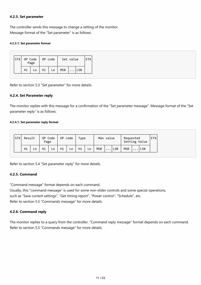
4.2.3. Set parameter
The controller sends this message to change a setting of the monitor.Message format of the “Set parameter” is as follows.
4.2.3.1. Set parameter format
┌───┬─────────┬─────────┬──────────────┬───┐ │STX│ OP Code │ OP code │ Set value │ETX│ │ │ Page │ │ │ │ │ ├────┬────┼────┬────┼─────┬───┬────┤ │ │ │ Hi │ Lo │ Hi │ Lo │ MSB │...│LSB │ │ └───┴────┴────┴────┴────┴─────┴───┴────┴───┘
Refer to section 5.3 “Set parameter” for more details.
4.2.4. Set Parameter reply
The monitor replies with this message for a confirmation of the “Set parameter message”. Message format of the “Setparameter reply” is as follows.
4.2.4.1. Set parameter reply format
┌───┬─────────┬─────────┬─────────┬─────────┬──────────────┬───────────────┬───┐ │STX│ Result │ OP Code │ OP code │ Type │ Max value │ Requested │ETX│ │ │ │ Page │ │ │ │ Setting Value │ │ │ ├────┬────┼────┬────┼────┬────┼────┬────┼─────┬───┬────┼─────┬───┬─────┤ │ │ │ Hi │ Lo │ Hi │ Lo │ Hi │ Lo │ Hi │ Lo │ MSB │...│LSB │ MSB │...│LSB │ │ └───┴────┴────┴────┴────┴────┴────┴────┴────┴─────┴───┴────┴─────┴───┴─────┴───┘
Refer to section 5.4 “Set parameter reply” for more details.
4.2.5. Command
“Command message” format depends on each command.Usually, this “command message” is used for some non-slider controls and some special operations,such as “Save current settings”, “Get timing report”, “Power control”, “Schedule”, etc.Refer to section 5.5 “Commands message” for more details.
4.2.6. Command reply
The monitor replies to a query from the controller. “Command reply message” format depends on each command.Refer to section 5.5 “Commands message” for more details.

12 / 53
4.3. Check code
| Header | Message | Check code | Delimiter |
4.3.1. Formatted and calculate.
Use the figure below to learn how check code is formatted and calculated.First, place the check code format after ETX in the command.Therefore, place the Check code at the position of 'D9' in the figure below.
┌────────────────────────────────────┬────────────────────────────────────┐ │ Header │ Message │ ├─────┬─────┬─────┬─────┬─────┬──────┼─────┬─────┬───┬───┬─────┬──────────┤ │ SOH │Resv.│Dest │ Src │Type │Length│ STX │Data │ - │ - │ ETX │Check code│ ├─────┼─────┼─────┼─────┼─────┼──────┼─────┼─────┼───┼───┼─────┼──────────┤ │ D0 │ D1 │ D2 │ D3 │ D4 │ D5 │ D6 │ D7 │ - │ - │ D8 │ D9 │ └─────┴─────┴─────┴─────┴─────┴──────┴─────┴─────┴───┴───┴─────┴──────────┘
Next, as an example of calculating Check code, sum the values listed above each column from 'D1' to 'D16' in thefigure below.Therefore, we calculate the total value from '30' (30h) to '03' (03h) in the figure below.As a result of the calculation, the check code of the command in the figure below is '77'(77h), so set it to Check code.
※ Check code may be described as Block Check Code (BCC) in the command details described below.
┌───────────────────────────────┬────────────────────────────────────────────┬─────┬─────────┐ │ Header │ Message │Check│Delimiter│ ├───┬─────┬────┬───┬────┬───────┼───┬────────────┬───────┬───────────────┬───┤ code│ │ │SOH│Resv.│Dest│Src│Type│Length │STX│OP Code Page│OP Code│ Set Value │ETX│(BCC)│ │ ├───┼─────┼────┼───┼────┼───┬───┼───┼─────┬──────┼───┬───┼───┬───┬───┬───┼───┼─────┼─────────┤ │01h│ 30h │ 41h│30h│ 45h│30h│41h│02h│ 30h │ 30h │31h│30h│30h│30h│36h│34h│03h│ 77h │ 0Dh │ ├───┼─────┼────┼───┼────┼───┼───┼───┼─────┼──────┼───┼───┼───┼───┼───┼───┼───┼─────┼─────────┤ │D0 │ D1 │ D2 │ D3│ D4 │D5 │D6 │D7 │ D8 │ D9 │D10│D11│D12│D13│D14│D15│D16│ D17 │ D18 │ └───┴─────┴────┴───┴────┴───┴───┴───┴─────┴──────┴───┴───┴───┴───┴───┴───┴───┴─────┴─────────┘ Check code (BCC) D17 = D1 xor D2 xor D3 xor … xor D14 xor D15 xor D16 = 30h xor 41h xor 30h xor 45h xor 30h xor 41h xor 02h xor 30h xor 30h xor 31h xor 30h xor 30h xor 30h xor 36h xor 34h xor 03h = 77h
4.4. Delimiter
| Header | Message | Check code | Delimiter |
Delimiter does not have the formats and calculations described so far.Specify 'CR'(0Dh) in ASCII for the Command Delimiter.

13 / 53
5. Message type
5.1. Get current Parameter from a monitor
5.1.1. Get current parameter format
┌─────────┬────────────┬────────────┬──────────┐ │ STX │ OP Code │ OP Code │ ETX │ │ │ Page │ │ │ │ ├──────┬─────┼──────┬─────┤ │ │ │ Hi │ Lo │ Hi │ Lo │ │ ├─────────┼──────┴─────┼──────┴─────┼──────────┤ │ 1st │ 2nd - 3rd │ 4th - 5th │ 6th │ └─────────┴────────────┴────────────┴──────────┘
Send this message when you want to get the status of a monitor.For the status that you want to get, specify the “OP code page” the “OP code”, refer to chapter 8.
* 1st byte) STX: Start of Message ASCII STX (02h) * 2nd-3rd bytes) OP code page: Operation code page. Specify the “OP code page” for the control which you want to get the status. Refer to chapter 8 for each item. OP code page data must be encoded to ASCII characters. Ex.) The byte data 02h must be encoded to ASCII characters '0' and '2' (30h and 32h). OP code page 02h -> OP code page (Hi) = ASCII '0' (30h) OP code page (Lo) = ASCII '2' (32h) Refer to chapter 8. * 4th-5th bytes) OP code: Operation code Refer to “VcpTable” for each item. OP code data must be encoded to ASCII characters. Ex.) The byte data 3Ah must be encoded to ASCII characters '3' and 'A' (33h and 41h). OP code 3Ah -> OP code (Hi) = ASCII '3' (33h) OP code (Lo) = ASCII 'A' (41h) Refer to chapter 8. * 6th byte) ETX: End of Message ASCII ETX (03h)

14 / 53
5.2. “Get parameter” reply
5.2.1. Get parameter reply format
┌───┬─────────┬─────────┬─────────┬─────────┬──────────────┬───────────────┬────┐ │STX│ Result │ OP Code │ OP code │ Type │ Max value │ Current Value │ETX │ │ │ │ Page │ │ │ │ │ │ │ ├────┬────┼────┬────┼────┬────┼────┬────┼─────┬───┬────┼─────┬───┬─────┤ │ │ │ Hi │ Lo │ Hi │ Lo │ Hi │ Lo │ Hi │ Lo │ MSB │...│LSB │ MSB │...│LSB │ │ ├───┼────┴────┼────┴────┼────┴────┼────┴────┼─────┴───┴────┼─────┴───┴─────┼────┤ │1st│ 2nd-3rd │ 4th-5th │ 6th-7th │ 8th-9th │ 10th- 13th │ 14th - 17th │18th│ └───┴─────────┴─────────┴─────────┴─────────┴──────────────┴───────────────┴────┘
The monitor replies with a current value and the status of the requested item (operation code).
* 1st byte) STX: Start of Message ASCII STX (02h) * 2nd-3rd bytes) Result:Result code. These bytes indicate a result of the requested commands as follows. 00h: No Error. 01h: Unsupported operation with this monitor or unsupported operation under current condition. This result code from the monitor is encoded to ASCII characters. Ex.) The byte data 01h is encoded to ASCII character '0' and '1' (30h and 31h). * 4th-5th bytes) OP code page: Operation code page. These bytes indicate a replying item's OP code page. This returned value from the monitor is encoded to ASCII characters. Ex.) The byte data 02h is encoded to ASCII character '0' and '2' (30h and 32h). Refer to the “VcpTable”. * 6th-7th bytes) OP code: Operation code These bytes indicate a replying item's OP code. This returned value from the monitor is encoded to ASCII characters. Refer to the “VcpTable”. Ex.) The byte data 1Ah is encoded to ASCII character '1' and 'A' (31h and 41h). * 8th-9th bytes) Type: Operation type code 00h: Set parameter 01h: Momentary Like the Auto Setup function which automatically changes the parameter. This returned value from the monitor is encoded to ASCII characters. Ex.) The byte data 01h is encoded to ASCII character '0' and '1' (30h and 31h). * 10th-13th bytes) Max. value: Maximum value which monitor can accept. (16bits) This returned value from the monitor is encoded to ASCII characters. Ex.) '0','1','2' and '3' means 0123h (291) * 14th-17th bytes) Current Value: (16bits) This returned value from the monitor is encoded to ASCII characters. Ex.) '0','1','2' and '3' means 0123h (291) * 18th byte) ETX: End of Message ASCII ETX (03h)

15 / 53
5.3. Set parameter
5.3.1. Set parameter format
┌───┬─────────┬─────────┬───────────────────────┬────┐ │STX│ OP Code │ OP code │ Set value │ETX │ │ │ Page │ │ │ │ │ ├────┬────┼────┬────┼─────┬─────┬─────┬─────┤ │ │ │ Hi │ Lo │ Hi │ Lo │ MSB │ │ │ LSB │ │ ├───┼────┴────┼────┴────┼─────┴─────┴─────┴─────┼────┤ │1st│ 2nd-3rd │ 4th-5th │ 6th-9th │10th│ └───┴─────────┴─────────┴───────────────────────┴────┘
Send this message to change monitor’s adjustment and so on.The controller requests a monitor to change value.
* 1st byte) STX: Start of Message ASCII STX (02h) * 2nd-3rd bytes) OP code page: Operation code page This OP code page data must be encoded to ASCII characters. Ex.) The byte data 02h must be encoded to ASCII '0' and '2' (30h and 32h). Refer to the “VcpTable”. * 4th-5th bytes) OP code: Operation code This OP code data must be encoded to ASCII characters. Ex.) OP code 1Ah -> OP code (Hi) = ASCII '1' (31h) OP code (Lo) = ASCII 'A' (41h) Refer to the “VcpTable”. * 6th-9th bytes) Set value: (16bit) This data must be encoded to ASCII characters. Ex.) 0123h -> 1st(MSB) = ASCII '0' (30h) 2nd = ASCII '1' (31h) 3rd = ASCII '2' (32h) 4th(LSB) = ASCII '3' (33h) * 10th byte) ETX: End of Message ASCII ETX (03h)

16 / 53
5.4. “Set parameter” reply
5.4.1. Set parameter reply format
┌───┬─────────┬─────────┬─────────┬─────────┬──────────────┬───────────────┬────┐ │STX│ Result │ OP Code │ OP code │ Type │ Max value │ Requested │ETX │ │ │ │ Page │ │ │ │ Setting Value │ │ │ ├────┬────┼────┬────┼────┬────┼────┬────┼─────┬───┬────┼─────┬───┬─────┤ │ │ │ Hi │ Lo │ Hi │ Lo │ Hi │ Lo │ Hi │ Lo │ MSB │...│LSB │ MSB │...│LSB │ │ ├───┼────┴────┼────┴────┼────┴────┼────┴────┼─────┴───┴────┼─────┴───┴─────┼────┤ │1st│ 2nd-3rd │ 4th-5th │ 6th-7th │ 8th-9th │ 10th-13th │ 14th-17th │18th│ └───┴─────────┴─────────┴─────────┴─────────┴──────────────┴───────────────┴────┘
The Monitor echoes back the parameter and status of the requested operation code.
* 1st byte) STX: Start of Message ASCII STX (02h) * 2nd-3rd bytes) Result code ASCII '0''0' (30h, 30h): No Error. ASCII '0''1' (30h, 31h): Unsupported operation with this monitor or unsupported operation under current condition. * 4th-5th bytes) OP code page: Echoes back the Operation code page for confirmation. Reply data from the monitor is encoded to ASCII characters. Ex.) OP code page 02h -> OP code page = ASCII '0' and '2' (30h and 32h) Refer to “VcpTable”. * 6th-7th bytes) OP code: Echoes back the Operation code for confirmation. Reply data from the monitor is encoded to ASCII characters. Ex.) OP code 1Ah -> OP code (Hi) = ASCII '1' (31h) OP code (Lo) = ASCII 'A' (41h) Refer to “VcpTable”. * 8th-9th bytes) Type: Operation type code ASCII '0''0' (30h, 30h): Set parameter ASCII '0''1' (30h, 31h): Momentary Like Auto Setup function, that automatically changes the parameter. * 10th-13th bytes) Max. value: Maximum value that monitor can accept. (16bits) Reply data from the monitor is encoded to ASCII characters. Ex.) '0''1''2''3' means 0123h (291) * 14th-17th bytes) Requested setting Value: Echoes back the parameter for confirmation. (16bits) Reply data from the monitor is encoded to ASCII characters. Ex.) '0''1''2''3' means 0123h (291) * 18th byte) ETX: End of Message ASCII ETX (03h)
17 / 53
5.5. Commands
"Command message format" depends on each command.
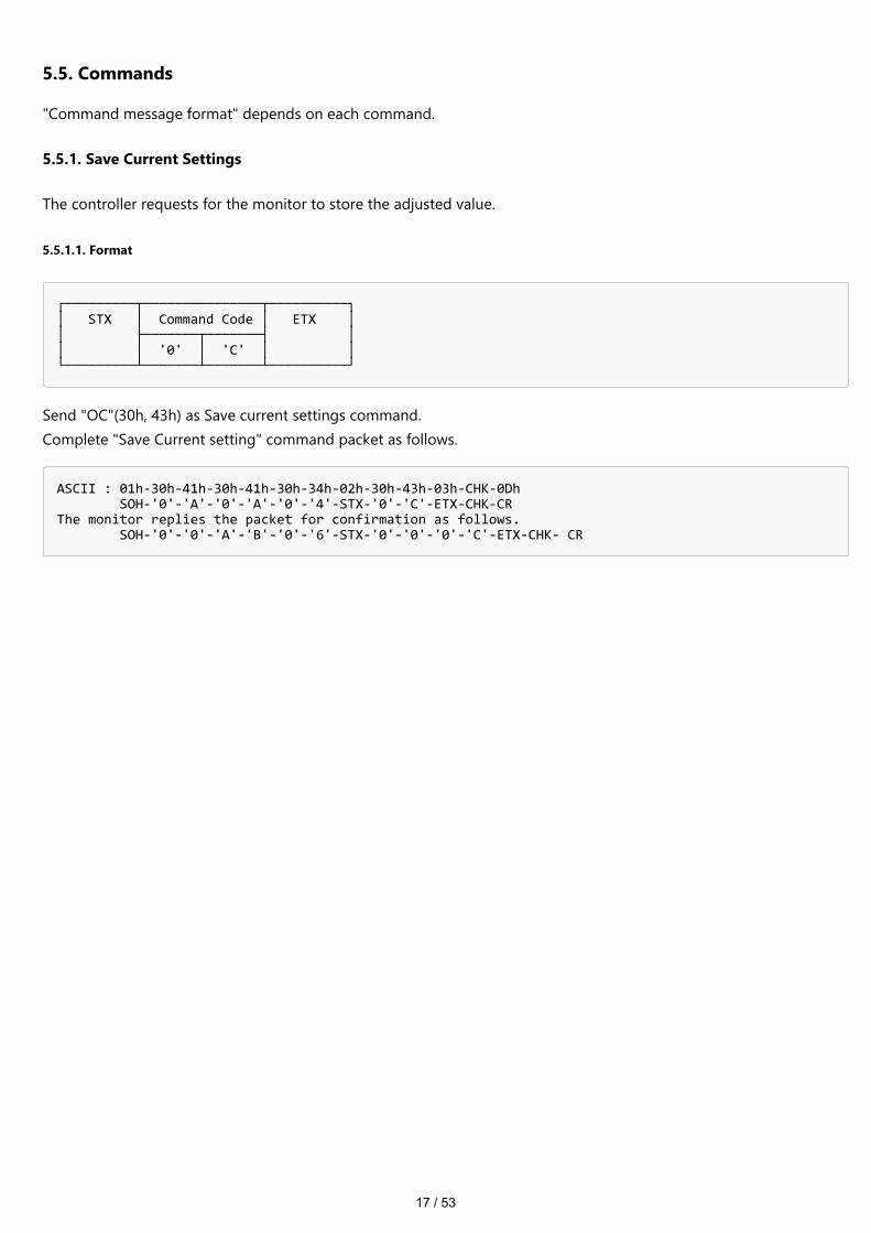
5.5.1. Save Current Settings
The controller requests for the monitor to store the adjusted value.
5.5.1.1. Format
┌─────────┬───────────────┬──────────┐ │ STX │ Command Code │ ETX │ │ ├───────┬───────┤ │ │ │ '0' │ 'C' │ │ └─────────┴───────┴───────┴──────────┘
Send "OC"(30h, 43h) as Save current settings command.Complete "Save Current setting" command packet as follows.
ASCII : 01h-30h-41h-30h-41h-30h-34h-02h-30h-43h-03h-CHK-0Dh SOH-'0'-'A'-'0'-'A'-'0'-'4'-STX-'0'-'C'-ETX-CHK-CR The monitor replies the packet for confirmation as follows. SOH-'0'-'0'-'A'-'B'-'0'-'6'-STX-'0'-'0'-'0'-'C'-ETX-CHK- CR
18 / 53
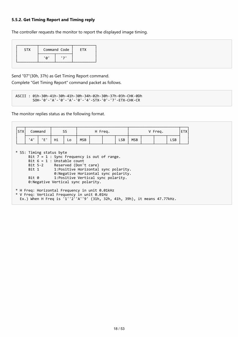
5.5.2. Get Timing Report and Timing reply
The controller requests the monitor to report the displayed image timing.
┌─────────┬───────────────┬──────────┐ │ STX │ Command Code │ ETX │ │ ├───────┬───────┤ │ │ │ '0' │ '7' │ │ └─────────┴───────┴───────┴──────────┘
Send "07"(30h, 37h) as Get Timing Report command.Complete "Get Timing Report" command packet as follows.
ASCII : 01h-30h-41h-30h-41h-30h-34h-02h-30h-37h-03h-CHK-0Dh SOH-'0'-'A'-'0'-'A'-'0'-'4'-STX-'0'-'7'-ETX-CHK-CR
The monitor replies status as the following format.
┌───┬───────────┬───────────┬───────────────────────┬───────────────────────┬───┐ │STX│ Command │ SS │ H Freq. │ V Freq. │ETX│ │ ├─────┬─────┼─────┬─────┼─────┬─────┬─────┬─────┼─────┬─────┬─────┬─────┤ │ │ │ '4' │ 'E' │ Hi │ Lo │ MSB │ │ │ LSB │ MSB │ │ │ LSB │ │ └───┴─────┴─────┴─────┴─────┴─────┴─────┴─────┴─────┴─────┴─────┴─────┴─────┴───┘ * SS: Timing status byte Bit 7 = 1 : Sync Frequency is out of range. Bit 6 = 1 : Unstable count Bit 5-2 Reserved (Don't care) Bit 1 1:Positive Horizontal sync polarity. 0:Negative Horizontal sync polarity. Bit 0 1:Positive Vertical sync polarity. 0:Negative Vertical sync polarity. * H Freq: Horizontal Frequency in unit 0.01kHz * V Freq: Vertical Frequency in unit 0.01Hz Ex.) When H Freq is '1''2''A''9' (31h, 32h, 41h, 39h), it means 47.77kHz.
19 / 53
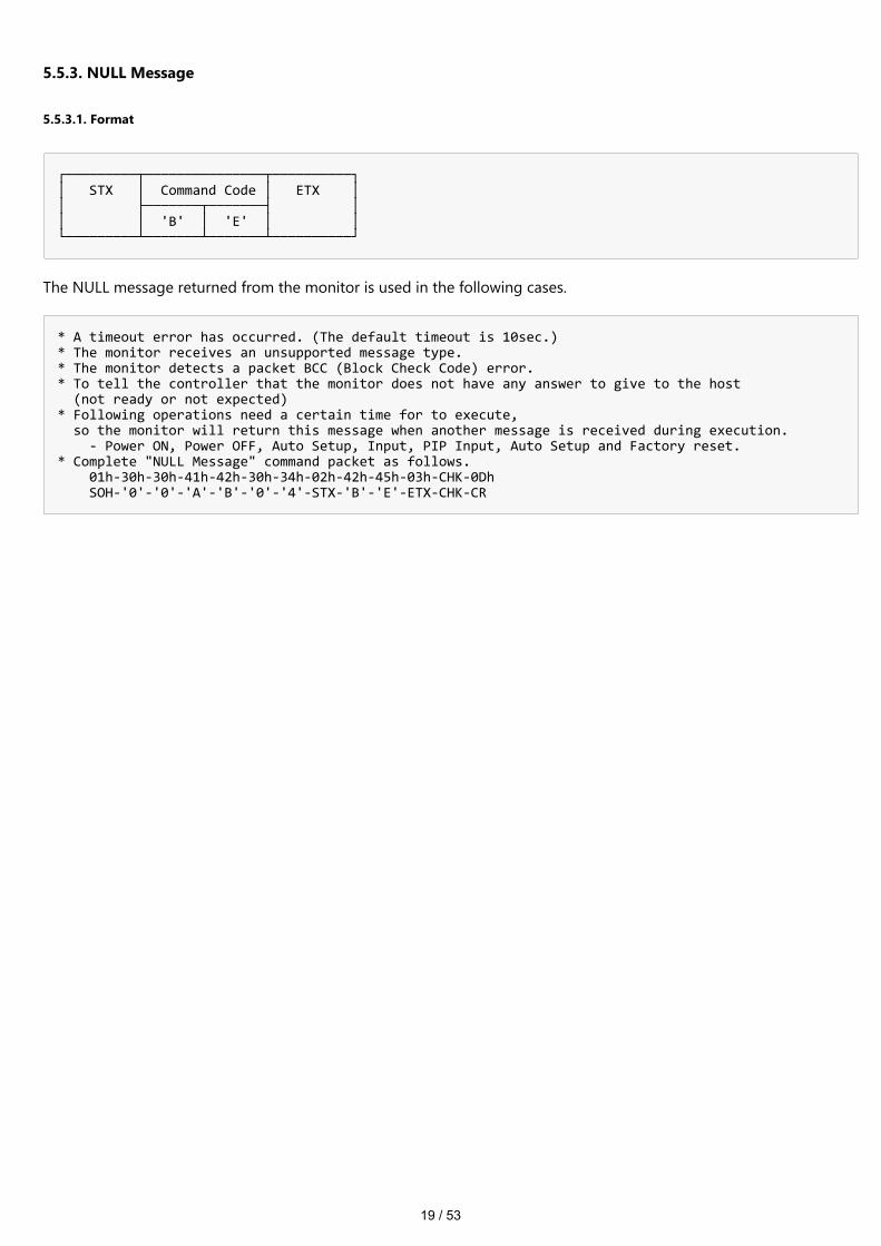
5.5.3. NULL Message
5.5.3.1. Format
┌─────────┬───────────────┬──────────┐ │ STX │ Command Code │ ETX │ │ ├───────┬───────┤ │ │ │ 'B' │ 'E' │ │ └─────────┴───────┴───────┴──────────┘
The NULL message returned from the monitor is used in the following cases.
* A timeout error has occurred. (The default timeout is 10sec.) * The monitor receives an unsupported message type. * The monitor detects a packet BCC (Block Check Code) error. * To tell the controller that the monitor does not have any answer to give to the host (not ready or not expected) * Following operations need a certain time for to execute, so the monitor will return this message when another message is received during execution. - Power ON, Power OFF, Auto Setup, Input, PIP Input, Auto Setup and Factory reset. * Complete "NULL Message" command packet as follows. 01h-30h-30h-41h-42h-30h-34h-02h-42h-45h-03h-CHK-0Dh SOH-'0'-'0'-'A'-'B'-'0'-'4'-STX-'B'-'E'-ETX-CHK-CR
20 / 53
6. Typical procedure example
The following is a sample of procedures to control the monitor, these are examples of "Get parameter", "Setparameter" and "Save current settings".
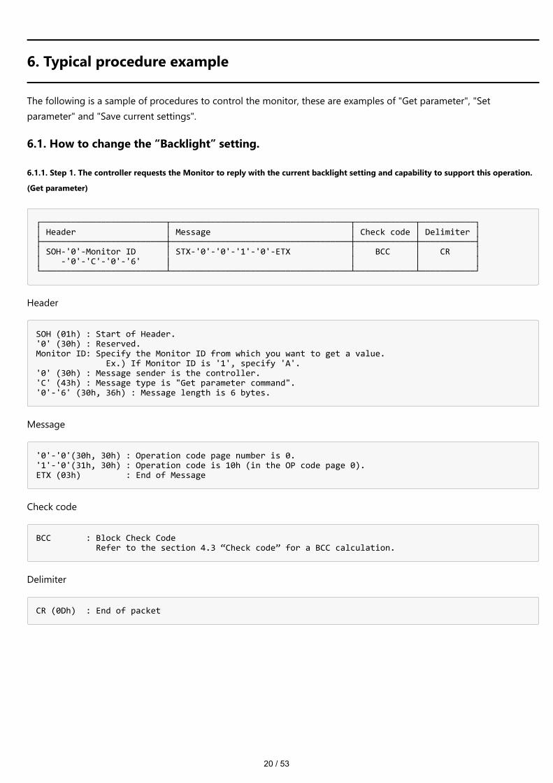
6.1. How to change the “Backlight” setting.
6.1.1. Step 1. The controller requests the Monitor to reply with the current backlight setting and capability to support this operation.
(Get parameter)
┌─────────────────────────┬────────────────────────────────────┬────────────┬───────────┐ │ Header │ Message │ Check code │ Delimiter │ ├─────────────────────────┼────────────────────────────────────┼────────────┼───────────┤ │ SOH-'0'-Monitor ID │ STX-'0'-'0'-'1'-'0'-ETX │ BCC │ CR │ │ -'0'-'C'-'0'-'6' | │ │ │ └─────────────────────────┴────────────────────────────────────┴────────────┴───────────┘
Header
SOH (01h) : Start of Header. '0' (30h) : Reserved. Monitor ID: Specify the Monitor ID from which you want to get a value. Ex.) If Monitor ID is '1', specify 'A'. '0' (30h) : Message sender is the controller. 'C' (43h) : Message type is "Get parameter command". '0'-'6' (30h, 36h) : Message length is 6 bytes.
Message
'0'-'0'(30h, 30h) : Operation code page number is 0. '1'-'0'(31h, 30h) : Operation code is 10h (in the OP code page 0). ETX (03h) : End of Message
Check code
BCC : Block Check Code Refer to the section 4.3 “Check code” for a BCC calculation.
Delimiter
CR (0Dh) : End of packet

21 / 53
6.1.2. Step 2. The monitor replies with current Backlight setting and capability to support this operation.
┌─────────────────────────┬─────────────────────────────────────────┬────────────┬───────────┐ │ Header │ Message │ Check code │ Delimiter │ ├─────────────────────────┼─────────────────────────────────────────┼────────────┼───────────┤ │ SOH-'0'-'0'-Monitor ID │ STX-'0'-'0'-'0'-'0'-'1'-'0'-'0-''0' │ BCC │ CR │ │ -'D'-'1'-'2' │ -'0'-'0'-'6'-'4'-'0'-'0'-'3'-'2'-ETX │ │ │ └─────────────────────────┴─────────────────────────────────────────┴────────────┴───────────┘
Header
SOH (01h) : Start of Header '0' (30h) : Reserved '0' (30h) : Message receiver is the controller. Monitor ID: Indicate a replying Monitor ID. Ex.) When this byte is set to 'A', the replying Monitor ID is '1'. 'D' (44h) : Message Type is "Get parameter reply". '1'-'2' (31h, 32h) : Message length is 18 bytes.
Message
'0'-'0'(30h, 30h) : Result code. No error. '0'-'0'(30h, 30h) : Operation code page number is 0. '1'-'0'(31h, 30h) : Operation code is 10h (in the page 0). '0'-'0'(30h, 30h) : This operation is "Set parameter" type. '0'-'0'-'6'-'4'(30h, 30h, 36h, 34h) : Backlight max value is 100(0064h). '0'-'0'-'3'-'2'(30h, 30h, 33h, 32h) : Current Backlight setting is 50(0032h) . ETX (03h) : End of Message
Check code
BCC : Block Check Code Refer to the section 4.3 “Check code” for a BCC calculation.
Delimiter
CR (0Dh) : End of packet

22 / 53
6.1.3. Step 3. The controller request the monitor to change the Backlight setting
┌─────────────────────────┬────────────────────────────────────┬────────────┬───────────┐ │ Header │ Message │ Check code │ Delimiter │ ├─────────────────────────┼────────────────────────────────────┼────────────┼───────────┤ │ SOH-'0'-Monitor ID │ STX-'0'-'0'-'1'-'0' │ BCC │ CR │ │ -'0'-'E'-'0'-'A' │ -'0'-'0'-'5'-'0'-ETX │ │ │ └─────────────────────────┴────────────────────────────────────┴────────────┴───────────┘
Header
SOH (01h) : Start of Header '0' (30h) : Reserved Monitor ID: Specify the Monitor ID of which you want to change a setting. Ex.) If Monitor ID is '1', specify 'A'. '0' (30h) : Message sender is the controller. 'E' (45h) : Message Type is "Set parameter command". '0'-'A' (30h, 41h) : Message length is 10 bytes.
Message
'0'-'0'(30h, 30h) : Operation code page number is 0. '1'-'0'(31h, 30h) : Operation code is 10h (in the page 0). '0'-'0'-'5'-'0'(30h, 30h, 35h, 30h) : Set Backlight setting 80(0050h). ETX (03h) : End of Message
Check code
BCC : Block Check Code Refer to the section 4.3 “Check code” for a BCC calculation.
Delimiter
CR (0Dh) : End of packet
23 / 53
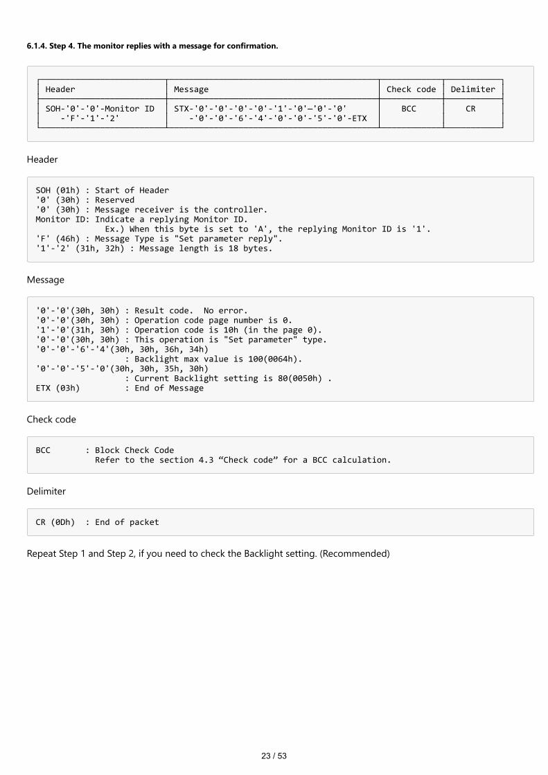
6.1.4. Step 4. The monitor replies with a message for confirmation.
┌─────────────────────────┬──────────────────────────────────────────┬────────────┬───────────┐ │ Header │ Message │ Check code │ Delimiter │ ├─────────────────────────┼──────────────────────────────────────────┼────────────┼───────────┤ │ SOH-'0'-'0'-Monitor ID │ STX-'0'-'0'-'0'-'0'-'1'-'0'—'0'-'0' │ BCC │ CR │ │ -'F'-'1'-'2' │ -'0'-'0'-'6'-'4'-'0'-'0'-'5'-'0'-ETX │ │ │ └─────────────────────────┴──────────────────────────────────────────┴────────────┴───────────┘
Header
SOH (01h) : Start of Header '0' (30h) : Reserved '0' (30h) : Message receiver is the controller. Monitor ID: Indicate a replying Monitor ID. Ex.) When this byte is set to 'A', the replying Monitor ID is '1'. 'F' (46h) : Message Type is "Set parameter reply". '1'-'2' (31h, 32h) : Message length is 18 bytes.
Message
'0'-'0'(30h, 30h) : Result code. No error. '0'-'0'(30h, 30h) : Operation code page number is 0. '1'-'0'(31h, 30h) : Operation code is 10h (in the page 0). '0'-'0'(30h, 30h) : This operation is "Set parameter" type. '0'-'0'-'6'-'4'(30h, 30h, 36h, 34h) : Backlight max value is 100(0064h). '0'-'0'-'5'-'0'(30h, 30h, 35h, 30h) : Current Backlight setting is 80(0050h) . ETX (03h) : End of Message
Check code
BCC : Block Check Code Refer to the section 4.3 “Check code” for a BCC calculation.
Delimiter
CR (0Dh) : End of packet
Repeat Step 1 and Step 2, if you need to check the Backlight setting. (Recommended)

24 / 53
6.1.5. Step 5. Request the monitor to store the Backlight setting. (Save Current Settings Command)
┌─────────────────────────┬────────────────────────────────────┬────────────┬───────────┐ │ Header │ Message │ Check code │ Delimiter │ ├─────────────────────────┼────────────────────────────────────┼────────────┼───────────┤ │ SOH-'0'-Monitor ID │ STX-'0'-'C'-ETX │ BCC │ CR │ │ -'0'-'A'-'0'-'4' │ │ │ │ └─────────────────────────┴────────────────────────────────────┴────────────┴───────────┘
Header
SOH (01h) : Start of Header '0' (30h) : Reserved Monitor ID: Specify the Monitor ID which you want to store the setting. Ex.) If Monitor ID is '1', specify 'A'. '0' (30h) : Message sender is the controller. 'A' (41h) : Message type is "Command". '0'-'4' (30h, 34h) : Message length is 4 bytes.
Message
'0'-'C'(30h, 43h) : Command code is 0Ch as "Save current settings". ETX (03h) : End of Message
Check code
BCC : Block Check Code Refer to the section 4.3 “Check code” for a BCC calculation.
Delimiter
CR (0Dh) : End of packet

25 / 53
6.2. How to read the measurement value of the built-in temperature sensors.
If the display has a built-in temperature sensor, the controller uses these sensors through external control.You can monitor the internal temperature.The temperature read procedure is shown below as an example of how to use it.
6.2.1. Step 1. Select a temperature sensor which you want to read.
┌─────────────────────────┬────────────────────────────────────┬────────────┬───────────┐ │ Header │ Message │ Check code │ Delimiter │ ├─────────────────────────┼────────────────────────────────────┼────────────┼───────────┤ │ SOH-'0'-Monitor ID │ STX-'0'-'2'-'7'-'8' │ BCC │ CR │ │ -'0'-'E'-'0'-'A' │ -'0'-'0'-'0'-'1'-ETX │ │ │ └─────────────────────────┴────────────────────────────────────┴────────────┴───────────┘
Header
SOH (01h) : Start of Header '0' (30h) : Reserved Monitor ID: Specify the Monitor ID which you want to get a value. Ex.) If Monitor ID is '1', specify 'A'. '0' (30h) : Message sender is the controller. 'E' (45h) : Message Type is "Set parameter command". '0'-'A' (30h, 41h) : Message length is 10 bytes
Message
'0'-'2'(30h, 32h) : Operation code page number is 2. '7'-'8'(37h, 38h) : Operation code is 78h (in the page 2). '0'-'0'-'0'-'1'(30h, 30h, 30h, 31h) : Select the temperature sensor #1 (01h). ETX (03h) : End of Message
Check code
BCC : Block Check Code Refer to the section 4.3 “Check code” for a BCC calculation.
Delimiter
CR (0Dh) : End of packet
26 / 53
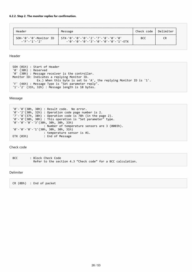
6.2.2. Step 2. The monitor replies for confirmation.
┌─────────────────────────┬──────────────────────────────────────────┬────────────┬───────────┐ │ Header │ Message │ Check code │ Delimiter │ ├─────────────────────────┼──────────────────────────────────────────┼────────────┼───────────┤ │ SOH-'0'-'0'-Monitor ID │ STX-'0'-'0'-'0'-'2'-'7'-'8'-'0'-'0' │ BCC │ CR │ │ -'F'-'1'-'2' │ -'0'-'0'-'0'-'3'-'0'-'0'-'0'-'1'-ETX │ │ │ └─────────────────────────┴──────────────────────────────────────────┴────────────┴───────────┘
Header
SOH (01h) : Start of Header '0' (30h) : Reserved '0' (30h) : Message receiver is the controller. Monitor ID: Indicates a replying Monitor ID. Ex.) When this byte is set to 'A', the replying Monitor ID is '1'. 'F' (46h) : Message Type is "Set parameter reply". '1'-'2' (31h, 32h) : Message length is 18 bytes.
Message
'0'-'0'(30h, 30h) : Result code. No error. '0'-'2'(30h, 32h) : Operation code page number is 2. '7'-'8'(37h, 38h) : Operation code is 78h (in the page 2). '0'-'0'(30h, 30h) : This operation is "Set parameter" type. '0'-'0'-'0'-'3'(30h, 30h, 30h, 33h) : Number of temperature sensors are 3 (0003h). '0'-'0'-'0'-'1'(30h, 30h, 30h, 31h) : temperature sensor is #1. ETX (03h) : End of Message
Check code
BCC : Block Check Code Refer to the section 4.3 “Check code” for a BCC calculation.
Delimiter
CR (0Dh) : End of packet

27 / 53
6.2.3. Step 3. The controller requests the monitor to send the temperature from the selected sensor.
┌─────────────────────────┬────────────────────────────────────┬────────────┬───────────┐ │ Header │ Message │ Check code │ Delimiter │ ├─────────────────────────┼────────────────────────────────────┼────────────┼───────────┤ │ SOH-'0'-Monitor ID │ STX-'0'-'2'-'7'-'9'-ETX │ BCC │ CR │ │ -'0'-'C'-'0'-'6' │ │ │ │ └─────────────────────────┴────────────────────────────────────┴────────────┴───────────┘
Header
SOH (01h) : Start of Header '0' (30h) : Reserved Monitor ID: Specify the Monitor ID which you want to get a value. Ex.) If Monitor ID is '1', specify 'A'. '0' (30h) : Message sender is the controller. 'C' (43h) : Message Type is "Get parameter". '0'-'6' (30h, 36h) : Message length is 6 bytes.
Message
'0'-'2'(30h, 32h) : Operation code page number is 2. '7'-'9'(37h, 39h) : Operation code is 79h (in the OP code page 2). ETX (03h) : End of Message
Check code
BCC : Block Check Code Refer to the section 4.3 “Check code” for a BCC calculation.
Delimiter
CR (0Dh) : End of packet

28 / 53
6.2.4. Step 4. The monitor replies a temperature of selected sensor.
┌─────────────────────────┬──────────────────────────────────────────┬────────────┬───────────┐ │ Header │ Message │ Check code │ Delimiter │ ├─────────────────────────┼──────────────────────────────────────────┼────────────┼───────────┤ │ SOH-'0'-'0'-Monitor ID │ STX-'0'-'0'-'0'-'2'-'7'-'9'-'0'-'0' │ BCC │ CR │ │ -'D'-'1'-'2' │ -'F'-'F'-'F'-'F'-'0'-'0'-'3'-'2'-ETX │ │ │ └─────────────────────────┴──────────────────────────────────────────┴────────────┴───────────┘
Header
SOH (01h) : Start of Header '0' (30h) : Reserved '0' (30h) : Message receiver is the controller. Monitor ID: Indicate a replying Monitor ID. Ex.) When this byte is set to 'A', the replying Monitor ID is '1'. 'D' (44h) : Message Type is "Get parameter reply". '1'-'2' (31h, 32h) : Message length is 18 bytes.
Message
'0'-'0'(30h, 30h) : Result code. No error. '0'-'2'(30h, 32h) : Operation code page number is 2. '7'-'9'(37h, 39h) : Operation code is 79h (in the page 2). '0'-'0'(30h, 30h) : This operation is "Set parameter" type. 'F'-'F'-'F'-'F'(46h, 46h, 46h, 46h) : Maximum value. '0'-'0'-'3'-'2'(30h, 30h, 33h, 32h) : The temperature is 25 degrees Celsius. ETX (03h) : End of Message Readout value is 2's complement. ┌───────────────────────────┬───────────────────────────────────┐ │ Temperature [Celsius] │ Readout value │ │ ├─────────────────────┬─────────────┤ │ │ Binary │ Hexadecimal │ ├───────────────────────────┼─────────────────────┼─────────────┤ │ +125.0 | 0000 0000 1111 1010 │ 00FAh │ │ + 25.0 | 0000 0000 0011 0010 │ 0032h │ │ + 0.5 | 0000 0000 0000 0001 │ 0001h │ │ 0 | 0000 0000 0000 0000 │ 0000h │ │ - 0.5 | 1111 1111 1111 1111 │ FFFFh │ │ - 25.0 | 1111 1111 1100 1110 │ FFCEh │ │ - 55.0 | 1111 1111 1001 0010 │ FF92h │ └───────────────────────────┴─────────────────────┴─────────────┘
Check code
BCC : Block Check Code Refer to the section 4.3 “Check code” for a BCC calculation.
Delimiter
CR (0Dh) : End of packet
29 / 53
7. CTL commands
7.1. System Command
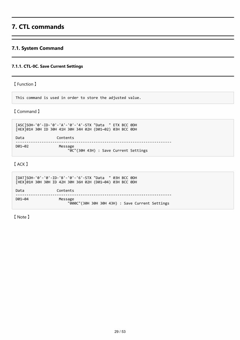
7.1.1. CTL-0C. Save Current Settings
【 Function 】
This command is used in order to store the adjusted value.
【 Command 】
[ASC]SOH-'0'-ID-'0'-'A'-'0'-'4'-STX "Data " ETX BCC 0DH [HEX]01H 30H ID 30H 41H 30H 34H 02H (D01~02) 03H BCC 0DH Data Contents ------------------------------------------------------------------------ D01~02 Message "0C"(30H 43H) : Save Current Settings
【 ACK 】
[DAT]SOH-'0'-'0'-ID-'B'-'0'-'6'-STX "Data " 03H BCC 0DH [HEX]01H 30H 30H ID 42H 30H 36H 02H (D01~04) 03H BCC 0DH Data Contents ------------------------------------------------------------------------ D01~04 Message "000C"(30H 30H 30H 43H) : Save Current Settings
【 Note 】
30 / 53
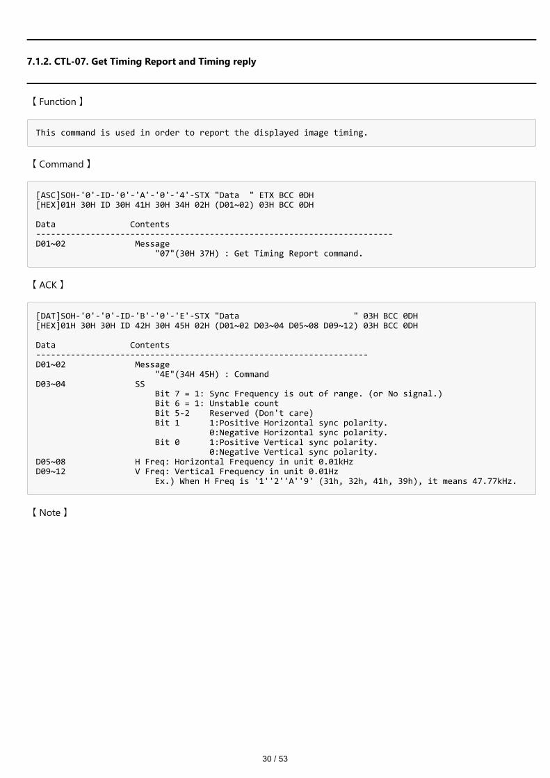
7.1.2. CTL-07. Get Timing Report and Timing reply
【 Function 】
This command is used in order to report the displayed image timing.
【 Command 】
[ASC]SOH-'0'-ID-'0'-'A'-'0'-'4'-STX "Data " ETX BCC 0DH [HEX]01H 30H ID 30H 41H 30H 34H 02H (D01~02) 03H BCC 0DH Data Contents ------------------------------------------------------------------------ D01~02 Message "07"(30H 37H) : Get Timing Report command.
【 ACK 】
[DAT]SOH-'0'-'0'-ID-'B'-'0'-'E'-STX "Data " 03H BCC 0DH [HEX]01H 30H 30H ID 42H 30H 45H 02H (D01~02 D03~04 D05~08 D09~12) 03H BCC 0DH Data Contents ------------------------------------------------------------------- D01~02 Message "4E"(34H 45H) : Command D03~04 SS Bit 7 = 1: Sync Frequency is out of range. (or No signal.) Bit 6 = 1: Unstable count Bit 5-2 Reserved (Don't care) Bit 1 1:Positive Horizontal sync polarity. 0:Negative Horizontal sync polarity. Bit 0 1:Positive Vertical sync polarity. 0:Negative Vertical sync polarity. D05~08 H Freq: Horizontal Frequency in unit 0.01kHz D09~12 V Freq: Vertical Frequency in unit 0.01Hz Ex.) When H Freq is '1''2''A''9' (31h, 32h, 41h, 39h), it means 47.77kHz.
【 Note 】
31 / 53
7.2. Power control procedure
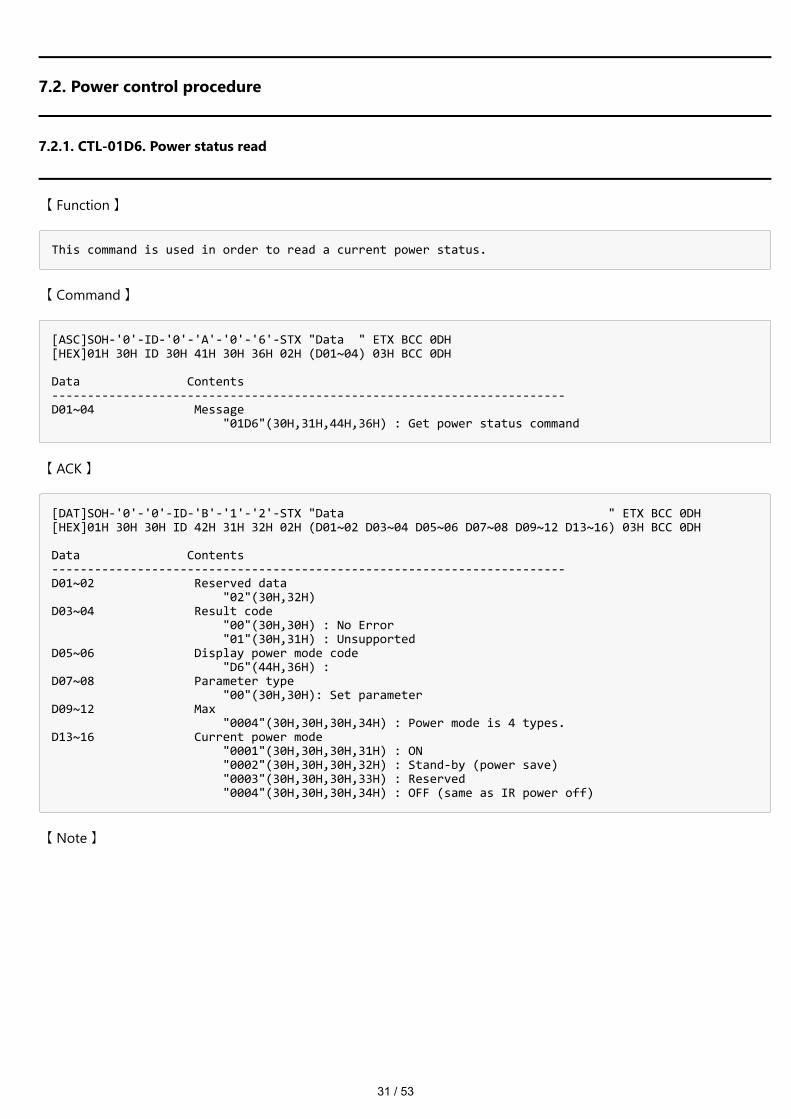
7.2.1. CTL-01D6. Power status read
【 Function 】
This command is used in order to read a current power status.
【 Command 】
[ASC]SOH-'0'-ID-'0'-'A'-'0'-'6'-STX "Data " ETX BCC 0DH [HEX]01H 30H ID 30H 41H 30H 36H 02H (D01~04) 03H BCC 0DH Data Contents ------------------------------------------------------------------------ D01~04 Message "01D6"(30H,31H,44H,36H) : Get power status command
【 ACK 】
[DAT]SOH-'0'-'0'-ID-'B'-'1'-'2'-STX "Data " ETX BCC 0DH [HEX]01H 30H 30H ID 42H 31H 32H 02H (D01~02 D03~04 D05~06 D07~08 D09~12 D13~16) 03H BCC 0DH Data Contents ------------------------------------------------------------------------ D01~02 Reserved data "02"(30H,32H) D03~04 Result code "00"(30H,30H) : No Error "01"(30H,31H) : Unsupported D05~06 Display power mode code "D6"(44H,36H) : D07~08 Parameter type "00"(30H,30H): Set parameter D09~12 Max "0004"(30H,30H,30H,34H) : Power mode is 4 types. D13~16 Current power mode "0001"(30H,30H,30H,31H) : ON "0002"(30H,30H,30H,32H) : Stand-by (power save) "0003"(30H,30H,30H,33H) : Reserved "0004"(30H,30H,30H,34H) : OFF (same as IR power off)
【 Note 】

32 / 53
7.2.2. CTL-C203-D6. Power control
【 Function 】
This command is used in order to control monitor power.
【 Command 】
[ASC]SOH-'0'-ID-'0'-'A'-'0'-'C'-STX "Data " ETX BCC 0DH [HEX]01H 30H ID 30H 41H 30H 43H 02H (D01~06) (D07~10) 03H BCC 0DH Data Contents ------------------------------------------------------------------------ D01~06 Message "C203D6"(43H 32H 30H 33H 44H 36H) : power control command D07~10 Power mode "0001"(30H 30H 30H 31H) : ON "0002"(30H 30H 30H 32H) : Do not set "0003"(30H 30H 30H 33H) : Do not set "0004"(30H 30H 30H 34H) : OFF (same as IR power off)
【 ACK 】
[DAT]SOH-'0'-'0'-ID-'B'-'0'-'E'-STX "Data " ETX BCC 0DH [HEX]01H 30H 30H ID 42H 30H 45H 02H (D01~02) (D03~08) (D09~12) 03H BCC 0DH Data Contents ------------------------------------------------------------------------ D01~02 Result code "00"(30H 30H) : No Error D03~08 Message "C203D6"(43H 32H 30H 33H 44H 36H) : power control reply command D09~12 Power mode "0001"(30H 30H 30H 31H) : ON "0002"(30H 30H 30H 32H) : Do not set "0003"(30H 30H 30H 33H) : Do not set "0004"(30H 30H 30H 34H) : OFF (same as IR power off)
【 Note 】

33 / 53
7.3. Serial No. & Model Name Read
7.3.1. CTL-C216. Serial No. Read
【 Function 】
This command is used in order to read a serial number.
【 Command 】
[ASC]SOH-'0'-ID-'0'-'A'-'0'-'6'-STX "Data " ETX BCC 0DH [HEX]01H 30H ID 30H 41H 30H 36H 02H (D01~04) 03H BCC 0DH Data Contents ------------------------------------------------------------------------ D01~04 Message "C216"(43H 32H 31H 36H) : Serial No. command
【 ACK 】
[DAT]SOH-'0'-'0'-ID-'B'- N - N -STX "Data " ETX BCC 0DH [HEX]01H 30H 30H ID 42H LEN LEN 02H (D01~04) (D05~XX) 03H BCC 0DH Data Contents ------------------------------------------------------------------------ D01~04 Message "C316"(43H 33H 31H 36H) : Serial No. reply command D05~XX Serial Number(XX Max=30) * The byte data 20h is encoded as ASCII characters '2' and '0' (32h and 30h). Ex.) For example when receiving Serial Number data 33h 31h 33h 32h 33h 33h 33h 34h Step1: Serial Number data is encoded as character string. Example: 33h 31h 33h 32h 33h 33h 33h 34h -> '3','1','3','2','3','3','3','4' Step2: Decode pairs of ASCII characters to hexadecimal values. Example: '3','1','3','2','3','3','3','4' -> 31h , 32h , 33h , 34h Step3: Byte data represents the ASCII string data. Example: 31h 32h 33h 34h -> "1234" Result: Serial Number is "1234". Note: No null termination character is sent.
【 Note 】

34 / 53
7.3.2. CTL-C217. Model Name Read
【 Function 】
This command is used in order to read the Model Name.
【 Command 】
[ASC]SOH-'0'-ID-'0'-'A'-'0'-'6'-STX "Data " ETX BCC 0DH [HEX]01H 30H ID 30H 41H 30H 36H 02H (D01~04) 03H BCC 0DH Data Contents ------------------------------------------------------------------------ D01~04 Message "C217"(43H 32H 31H 37H) : Model Name command
【 ACK 】
[DAT]SOH-'0'-'0'-ID-'B'- N - N -STX "Data " ETX BCC 0DH [HEX]01H 30H 30H ID 42H LEN LEN 02H (D01~04) (D05~XX) 03H BCC 0DH Data Contents ------------------------------------------------------------------------ D01~04 Message "C317"(43H 33H 31H 37H) : Model Name reply Command D05~XX Model name(XX Max=36) * The byte data 20h is encoded as ASCII characters '2' and '0' (32h and 30h). Ex.) For example when receiving Model Name data 35h 30h 33h 34h 33h 30h 33h 33h Step1: Model Name data is encoded character string. Example: 35h 30h 33h 34h 33h 30h 33h 33h -> '5','0','3','4','3','0','3','3' Step2: Decode pairs of ASCII characters to hexadecimal values. Example: '5','0','3','4','3','0','3','3' -> 50h , 34h , 30h , 33h Step3: Byte data represents the ASCII string data. Example: 50h 34h 30h 33h -> "P403" Result: Model Name is "P403". Note: No null termination character is sent.
【 Note 】
35 / 53
7.4. MAC Address Read Request & Reply
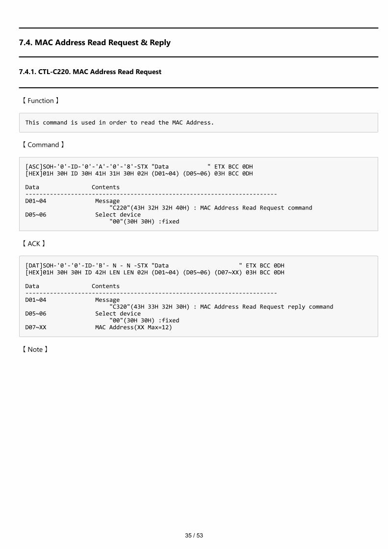
7.4.1. CTL-C220. MAC Address Read Request
【 Function 】
This command is used in order to read the MAC Address.
【 Command 】
[ASC]SOH-'0'-ID-'0'-'A'-'0'-'8'-STX "Data " ETX BCC 0DH [HEX]01H 30H ID 30H 41H 31H 30H 02H (D01~04) (D05~06) 03H BCC 0DH Data Contents ------------------------------------------------------------------------ D01~04 Message "C220"(43H 32H 32H 40H) : MAC Address Read Request command D05~06 Select device "00"(30H 30H) :fixed
【 ACK 】
[DAT]SOH-'0'-'0'-ID-'B'- N - N -STX "Data " ETX BCC 0DH [HEX]01H 30H 30H ID 42H LEN LEN 02H (D01~04) (D05~06) (D07~XX) 03H BCC 0DH Data Contents ------------------------------------------------------------------------ D01~04 Message "C320"(43H 33H 32H 30H) : MAC Address Read Request reply command D05~06 Select device "00"(30H 30H) :fixed D07~XX MAC Address(XX Max=12)
【 Note 】

36 / 53
7.5. Direct TV Channel Read & Write
7.5.1. CTL-C22C. Direct TV Channel Read Request
【 Function 】
This command is used in order to read the Direct TV Channel.
【 Command 】
[ASC]SOH-'0'-ID-'0'-'A'-'0'-'6'-STX "Data " ETX BCC 0DH [HEX]01H 30H ID 30H 41H 30H 36H 02H (D01~04) 03H BCC 0DH Data Contents ------------------------------------------------------------------------ D01~04 Message "C22C"(43H 32H 32H 43H) : Direct TV Channel read request command
【 ACK 】
[DAT]SOH-'0'-'0'-ID-'B'-'1'-'2'-STX "Data " ETX BCC 0DH [HEX]01H 30H 30H ID 42H 31H 32H 02H (D01~04) (D05~08) (D09~12) (D13~16) 03H BCC 0DH Data Contents ------------------------------------------------------------------------ D01~04 Message "C32C"(43H 33H 32H 43H) : Direct TV Channel read request reply command D05~08 Major Channel High(H)(L) D09~12 Major Channel Low (H)(L) D13~16 Minor Channel (H)(L)
【 Note 】
This function is available model as follows. TV tuner model for US only supported
37 / 53
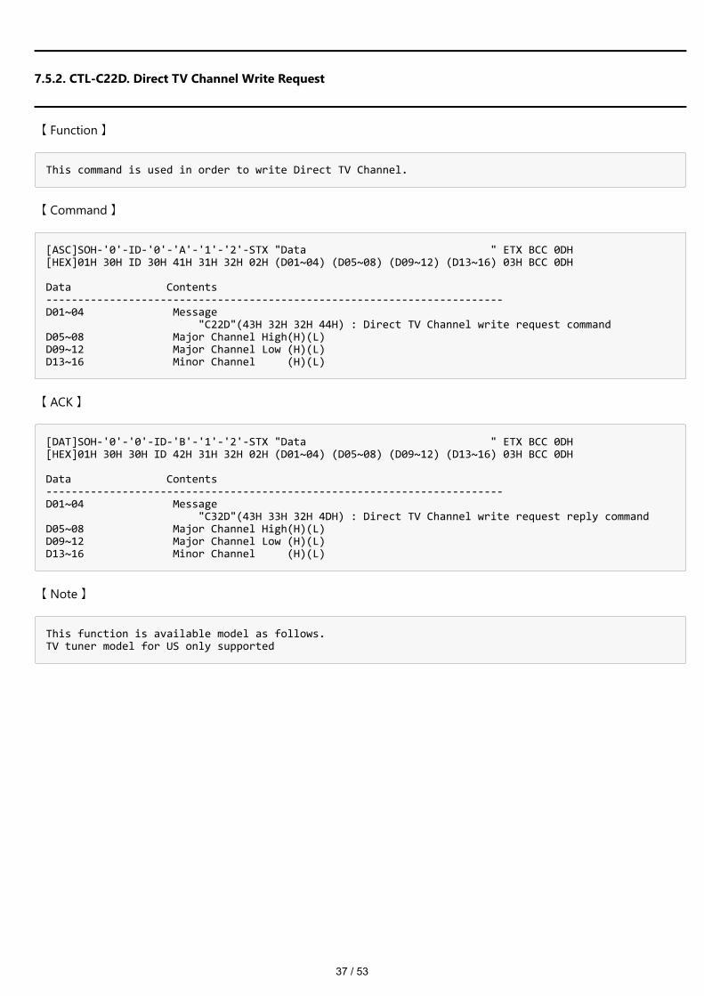
7.5.2. CTL-C22D. Direct TV Channel Write Request
【 Function 】
This command is used in order to write Direct TV Channel.
【 Command 】
[ASC]SOH-'0'-ID-'0'-'A'-'1'-'2'-STX "Data " ETX BCC 0DH [HEX]01H 30H ID 30H 41H 31H 32H 02H (D01~04) (D05~08) (D09~12) (D13~16) 03H BCC 0DH Data Contents ------------------------------------------------------------------------ D01~04 Message "C22D"(43H 32H 32H 44H) : Direct TV Channel write request command D05~08 Major Channel High(H)(L) D09~12 Major Channel Low (H)(L) D13~16 Minor Channel (H)(L)
【 ACK 】
[DAT]SOH-'0'-'0'-ID-'B'-'1'-'2'-STX "Data " ETX BCC 0DH [HEX]01H 30H 30H ID 42H 31H 32H 02H (D01~04) (D05~08) (D09~12) (D13~16) 03H BCC 0DH Data Contents ------------------------------------------------------------------------ D01~04 Message "C32D"(43H 33H 32H 4DH) : Direct TV Channel write request reply command D05~08 Major Channel High(H)(L) D09~12 Major Channel Low (H)(L) D13~16 Minor Channel (H)(L)
【 Note 】
This function is available model as follows. TV tuner model for US only supported

38 / 53
7.6. Remote Control Data Code sending format via RS-232C
7.6.1. CTL-C210. Remote Control Data Code sending format via RS-232C
【 Function 】
This command is used in order to send the Remote Control Data Code.
【 Command 】
[ASC]SOH-'0'-ID-'0'-'A'-'0'-'C'-STX "Data " ETX BCC 0DH [HEX]01H 30H ID 30H 41H 30H 43H 02H (D01~04) (D05~06) (D07~08) (D09~10) 03H BCC 0DH Data Contents ------------------------------------------------------------------------ D01~04 Message "C210"(43H 32H 31H 30H) : Remote Control Data Code command D05~06 remote control data code upper byte(High) "00"(30H 30H) D07~08 remote control data code upper byte(Low) "1D"(31H 44H) : PICTURE "29"(32H 39H) : ASPECT "43"(34H 33H) : SOUND "08"(30H 38H) : 1 "09"(30H 39H) : 2 "0A"(30H 41H) : 3 "0B"(30H 42H) : 4 "0C"(30H 43H) : 5 "0D"(30H 44H) : 6 "0E"(30H 45H) : 7 "0F"(30H 46H) : 8 "10"(31H 30H) : 9 "44"(34H 34H) : DASH "12"(31H 32H) : 0 "19"(31H 39H) : INFO "20"(32H 30H) : MENU "1F"(31H 46H) : EXIT "15"(31H 35H) : UP "14"(31H 34H) : DOWN "21"(32H 31H) : LEFT "22"(32H 32H) : RIGHT "23"(32H 33H) : OK "17"(31H 37H) : VOL + "16"(31H 36H) : VOL - "33"(33H 33H) : CH + "32"(33H 32H) : CH - "1B"(31H 42H) : MUTE "27"(32H 37H) : FREEZE "2C"(32H 43H) : CC "1A"(31H 41H) : MTS D09~10 repeat times(HL)
【 ACK 】
[DAT]SOH-'0'-'0'-ID-'B'-'0'-'A'-STX "Data " ETX BCC 0DH [HEX]01H 30H 30H ID 42H 30H 38H 02H (D01~04) (D05~06) (D07~08) 03H BCC 0DH Data Contents ------------------------------------------------------------------------ D01~04 Message "C310"(43H 33H 31H 30H) : Remote Control Data Code reply command
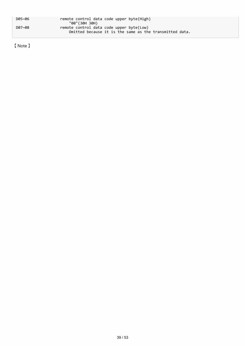
39 / 53
D05~06 remote control data code upper byte(High) "00"(30H 30H) D07~08 remote control data code upper byte(Low) Omitted because it is the same as the transmitted data.
【 Note 】

40 / 53
7.7. Firmware Version Command
7.7.1. CTL-CA02. Firmware Version Read Request
【 Function 】
This command is used in order to read Firmware Version.
【 Command 】
[ASC]SOH-'0'-ID-'0'-'A'-'0'-'8'-STX "Data " ETX BCC 0DH [HEX]01H 30H ID 30H 41H 30H 38H 02H (D01~04) (D05~06) 03H BCC 0DH Data Contents ------------------------------------------------------------------------ D01~04 Message "CA02"(43H 41H 30H 32H) : Firmware Version Read Command D05~06 Firmware Type "00"(30H 30H) : F/W Revision
【 ACK 】
[DAT]SOH-'0'-'0'-ID-'B'-'1'-'2'-STX "Data " ETX BCC 0DH [HEX]01H 30H 30H ID 42H 31H 32H 02H (D01~04) (D05~06) (D07~08) (D09~16) 03H BCC 0DH Data Contents ------------------------------------------------------------------------ D01~04 Message "CB02"(43H 42H 30H 31H) : Firmware Version Read reply command D05~06 Result code "00"(30H 30H) : No Error "01"(30H 31H) : Error D07~08 Firmware Type "00"(30H 30H) : Firmware revision D09~16 Firmware Version String D09 : R D10 : Major Version "0"(30H) 〜 "9"(39H) D11 : Period 2EH (fixed) D12 : Minor (Basic) Version1 "0"(30H) 〜 "9"(39H) D13 : Minor (Basic) Version2 "0"(30H) 〜 "9"(39H) D14 : Minor (Basic) Version3 "0"(30H) 〜 "9"(39H) D15 : Branch Version1 "A"(41H) 〜 "Z"(5AH) D16 : Branch Version2 "A"(41H) 〜 "Z"(5AH)
【 Note 】
The version information section is an ASCII character string.
41 / 53
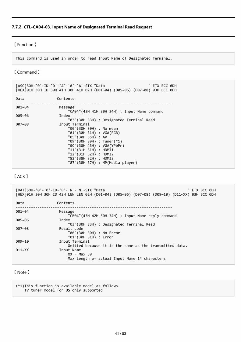
7.7.2. CTL-CA04-03. Input Name of Designated Terminal Read Request
【 Function 】
This command is used in order to read Input Name of Designated Terminal.
【 Command 】
[ASC]SOH-'0'-ID-'0'-'A'-'0'-'A'-STX "Data " ETX BCC 0DH [HEX]01H 30H ID 30H 41H 30H 41H 02H (D01~04) (D05~06) (D07~08) 03H BCC 0DH Data Contents ------------------------------------------------------------------------ D01~04 Message "CA04"(43H 41H 30H 34H) : Input Name command D05~06 Index "03"(30H 33H) : Designated Terminal Read D07~08 Input Terminal "00"(30H 30H) : No mean "01"(30H 31H) : VGA(RGB) "05"(30H 35H) : AV "09"(30H 39H) : Tuner(*1) "0C"(30H 43H) : VGA(YPbPr) "11"(31H 31H) : HDMI1 "12"(31H 32H) : HDMI2 "82"(38H 32H) : HDMI3 "87"(38H 37H) : MP(Media player)
【 ACK 】
[DAT]SOH-'0'-'0'-ID-'B'- N - N -STX "Data " ETX BCC 0DH [HEX]01H 30H 30H ID 42H LEN LEN 02H (D01~04) (D05~06) (D07~08) (D09~10) (D11~XX) 03H BCC 0DH Data Contents ------------------------------------------------------------------------ D01~04 Message "CB04"(43H 42H 30H 34H) : Input Name reply command D05~06 Index "03"(30H 33H) : Designated Terminal Read D07~08 Result code "00"(30H 30H) : No Error "01"(30H 31H) : Error D09~10 Input Terminal Omitted because it is the same as the transmitted data. D11~XX Input Name XX = Max 39 Max length of actual Input Name 14 characters
【 Note 】
(*1)This function is available model as follows. TV tuner model for US only supported

42 / 53
7.7.3. CTL-CA04-04. Input Name of Designated Terminal Write Request
【 Function 】
This command is used in order to write Input Name of Designated Terminal.
【 Command 】
[ASC]SOH-'0'-ID-'0'-'A'- N - N -STX "Data " ETX BCC 0DH [HEX]01H 30H ID 30H 41H LEN LEN 02H (D01~04) (D05~06) (D07~08) (D09~XX) 03H BCC 0DH Data Contents ------------------------------------------------------------------------ D01~04 Message "CA04"(43H 41H 30H 34H) : Input Name command D05~06 Index "04"(30H 34H) : Designated Terminal Write D07~08 Input Terminal "00"(30H 30H) : No mean "01"(30H 31H) : VGA(RGB) "05"(30H 35H) : AV "09"(30H 39H) : Tuner(*1) "0C"(30H 43H) : VGA(YPbPr) "11"(31H 31H) : HDMI1 "12"(31H 32H) : HDMI2 "82"(38H 32H) : HDMI3 "87"(38H 37H) : MP(Media player) D09~XX Input Name XX = Max 37 Max length of actual Input Name 14 characters
【 ACK 】
[DAT]SOH-'0'-'0'-ID-'B'-'0'-'A'-STX "Data " ETX BCC 0DH [HEX]01H 30H 30H ID 42H 30H 41H 02H (D01~04) (D05~06) (D07~08) 03H BCC 0DH Data Contents ------------------------------------------------------------------------ D01~04 Message "CB04"(43H 42H 30H 34H) : Input Name reply command D05~06 Index "04"(30H 34H) : Designated Terminal Write D07~08 Result code "00"(30H 30H) : No Error "01"(30H 31H) : Error
【 Note 】
(*1)This function is available model as follows. TV tuner model for US only supported

43 / 53
7.7.4. CTL-CA04-05. Input Name of Designated Terminal Reset Request
【 Function 】
This command is used in order to reset Input Name of Designated Terminal.
【 Command 】
[ASC]SOH-'0'-ID-'0'-'A'-'0'-'A'-STX "Data " ETX BCC 0DH [HEX]01H 30H ID 30H 41H 30H 41H 02H (D01~04) (D05~06) (D07~08) 03H BCC 0DH Data Contents ------------------------------------------------------------------------ D01~04 Message "CA04"(43H 41H 30H 34H) : Input Name command D05~06 Index "05"(30H 35H) : Designated Terminal Reset D07~08 Input Terminal "00"(30H 30H) : ALL Terminal "00"(30H 30H) : No mean "01"(30H 31H) : VGA(RGB) "05"(30H 35H) : AV "09"(30H 39H) : Tuner(*1) "0C"(30H 43H) : VGA(YPbPr) "11"(31H 31H) : HDMI1 "12"(31H 32H) : HDMI2 "82"(38H 32H) : HDMI3 "87"(38H 37H) : MP(Media player)
【 ACK 】
[DAT]SOH-'0'-'0'-ID-'B'-'0'-'A'-STX "Data " ETX BCC 0DH [HEX]01H 30H 30H ID 42H 30H 41H 02H (D01~04) (D05~06) (D07~08) 03H BCC 0DH Data Contents ------------------------------------------------------------------------ D01~04 Message "CB04"(43H 42H 30H 34H) : Input Name reply D05~06 Index "05"(30H 35H) : Designated Terminal Reset D07~08 Result code "00"(30H 30H) : No Error "01"(30H 31H) : Error
【 Note 】
(*1)This function is available model as follows. TV tuner model for US only supported

44 / 53
8. OSD menu and contrast table for each command
A table of settings that exist in the OSD menu of the monitor versus each command. Some commands that do not exist in the OSD menu are listed in the "Other" section of the comparison table.
【VCP command format】
VCP - "OP code page" - "OP code" Ex.) VCP-00-60 OP code page: 00 OP code: 60
OSD Command Parameter
Video
Picture Mode VCP-02-1A
0003H : HighBright0004H : Standard0008H : Custom0017H : Dynamic0018H : Energy Savings001BH : HDR Video001DH : Conferencing
AdvancedVideo
Aspect Ratio VCP-02-70
0001H : NORMAL0002H : FULL0004H : ZOOM0007H : 1:1
Overscan VCP-02-E30001H : Off0002H : On0003H : Auto
Dimming Setting VCP-11-4E0001H : OFF0002H : Dynamic Backlight0003H : Local Dimming (*3)
ColorTemperature
Color TemperatureVCP-00-0CVCP-00-14
VCP-00-0C0023H : Warm003FH : Normal005AH : Cool
VCP-00-140002H : Native000BH : Custom
R VCP-00-160000H - 0064H( Dark ) - ( Bright )
G VCP-00-18 0000H - 0064H( Dark ) - ( Bright )
45 / 53
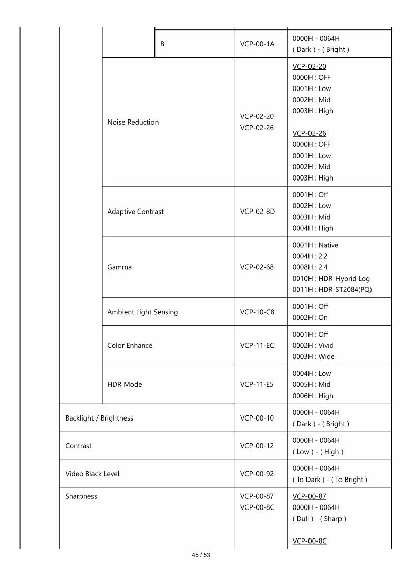
B VCP-00-1A0000H - 0064H( Dark ) - ( Bright )
Noise ReductionVCP-02-20VCP-02-26
VCP-02-200000H : OFF0001H : Low0002H : Mid0003H : High
VCP-02-260000H : OFF0001H : Low0002H : Mid0003H : High
Adaptive Contrast VCP-02-8D
0001H : Off0002H : Low0003H : Mid0004H : High
Gamma VCP-02-68
0001H : Native0004H : 2.20008H : 2.40010H : HDR-Hybrid Log0011H : HDR-ST2084(PQ)
Ambient Light Sensing VCP-10-C80001H : Off0002H : On
Color Enhance VCP-11-EC0001H : Off0002H : Vivid0003H : Wide
HDR Mode VCP-11-E50004H : Low0005H : Mid0006H : High
Backlight / Brightness VCP-00-100000H - 0064H( Dark ) - ( Bright )
Contrast VCP-00-120000H - 0064H( Low ) - ( High )
Video Black Level VCP-00-920000H - 0064H( To Dark ) - ( To Bright )
Sharpness VCP-00-87VCP-00-8C
VCP-00-870000H - 0064H( Dull ) - ( Sharp )
VCP-00-8C
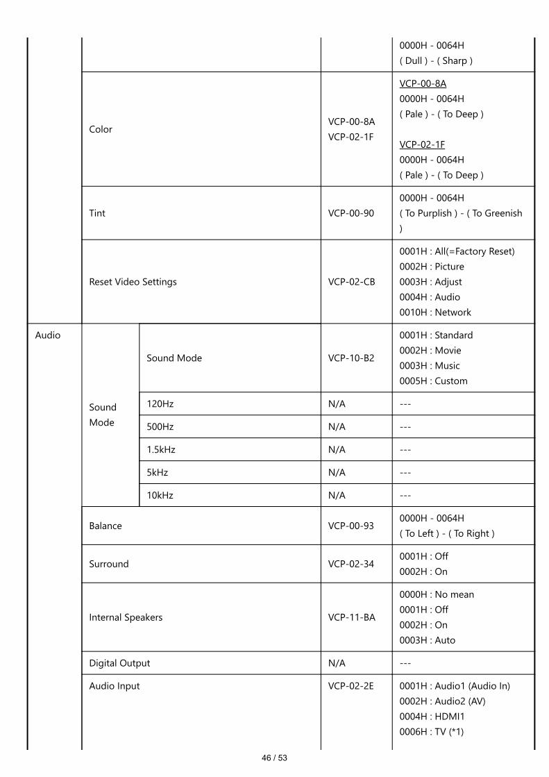
46 / 53
0000H - 0064H( Dull ) - ( Sharp )
ColorVCP-00-8AVCP-02-1F
VCP-00-8A0000H - 0064H( Pale ) - ( To Deep )
VCP-02-1F0000H - 0064H( Pale ) - ( To Deep )
Tint VCP-00-900000H - 0064H( To Purplish ) - ( To Greenish)
Reset Video Settings VCP-02-CB
0001H : All(=Factory Reset)0002H : Picture0003H : Adjust0004H : Audio0010H : Network
Audio
SoundMode
Sound Mode VCP-10-B2
0001H : Standard0002H : Movie0003H : Music0005H : Custom
120Hz N/A ---
500Hz N/A ---
1.5kHz N/A ---
5kHz N/A ---
10kHz N/A ---
Balance VCP-00-930000H - 0064H( To Left ) - ( To Right )
Surround VCP-02-340001H : Off0002H : On
Internal Speakers VCP-11-BA
0000H : No mean0001H : Off0002H : On0003H : Auto
Digital Output N/A ---
Audio Input VCP-02-2E 0001H : Audio1 (Audio In)0002H : Audio2 (AV)0004H : HDMI10006H : TV (*1)

47 / 53
000AH : HDMI2000BH : HDMI3000DH : MP
Audio Delay VCP-10-CB0000H - 0064H( Small ) - ( Large )
Audio Source (MTS) (*1) VCP-02-2C
0000H : No mean0001H : main0002H : sub0003H : main+sub0004H : stereo0005H : mono0006H : dual0007H : SAP
Visually Impaired (*1) N/A ---
MenuSpeech(TTS) (*1)
Menu Speech (TTS) N/A ---
Volume N/A ---
Speed N/A ---
Pitch N/A ---
Audio Language (*1) VCP-10-B30002H : English0003H : Français000AH : Español
Reset Audio SettingsVCP-02-31VCP-02-CB
VCP-02-310001H : Reset
VCP-02-CB0001H : All(=Factory Reset)0002H : Picture0003H : Adjust0004H : Audio0010H : Network
Channels(*1)
Auto Channel Scan N/A ---
Add / Skip Channels N/A ---
Favorite Channels N/A ---
Channel Labels N/A ---
Time Zone N/A ---
Setup OSDSettings
Language VCP-00-68 0001H : English0002H : Deutsch (*2)0003H : Français0004H : Español
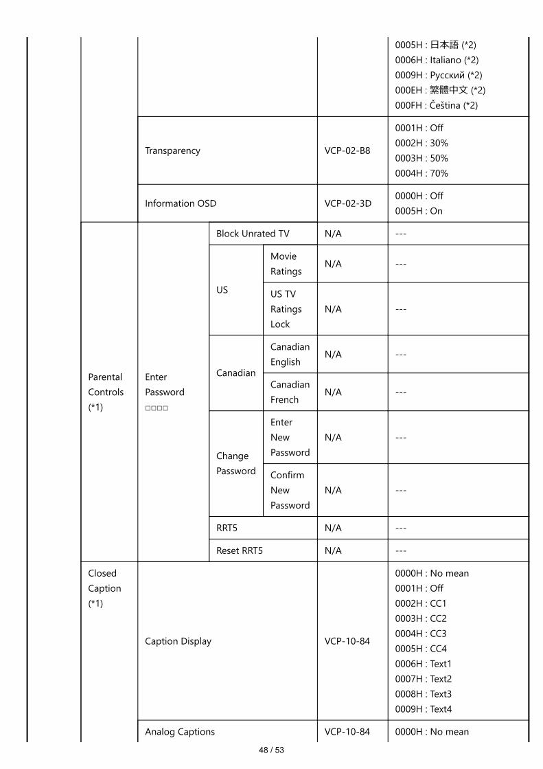
48 / 53
0005H : ⽇本語 (*2)0006H : Italiano (*2)0009H : Русский (*2)000EH : 繁體中⽂ (*2)000FH : Čeština (*2)
Transparency VCP-02-B8
0001H : Off0002H : 30%0003H : 50%0004H : 70%
Information OSD VCP-02-3D0000H : Off0005H : On
ParentalControls(*1)
EnterPassword□□□□
Block Unrated TV N/A ---
US
MovieRatings
N/A ---
US TVRatingsLock
N/A ---
Canadian
CanadianEnglish
N/A ---
CanadianFrench
N/A ---
ChangePassword
EnterNewPassword
N/A ---
ConfirmNewPassword
N/A ---
RRT5 N/A ---
Reset RRT5 N/A ---
ClosedCaption(*1)
Caption Display VCP-10-84
0000H : No mean0001H : Off0002H : CC10003H : CC20004H : CC30005H : CC40006H : Text10007H : Text20008H : Text30009H : Text4
Analog Captions VCP-10-84 0000H : No mean

49 / 53
0001H : Off0002H : CC10003H : CC20004H : CC30005H : CC40006H : Text10007H : Text20008H : Text30009H : Text4
Digital Captions VCP-10-A1
0000H : No mean0001H : Off0002H : CS10003H : CS20004H : CS30005H : CS40006H : CS50007H : CS6
Digital CCSettings
Style N/A ---
Size N/A ---
Font N/A ---
Text Color N/A ---
Text Opacity N/A ---
Background Color N/A ---
Background Opacity N/A ---
Edge Effect N/A ---
Edge Color N/A ---
Powersavesettings
Energy Mode N/A ---
Power Save N/A ---
Quick Start VCP-11-EA0001H : Off0002H : On
Auto Power Down N/A ---
AutoInputChange
Auto Input Change VCP-02-400000H : First0002H : None0004H : Custom
Input 1 VCP-10-2E 0001H : VGA0005H : Video1(AV)000CH :DVD/HD1(VGA(YPbPr))
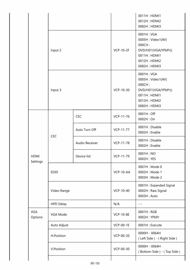
50 / 53
0011H : HDMI10012H : HDMI20082H : HDMI3
Input 2 VCP-10-2F
0001H : VGA0005H : Video1(AV)000CH :DVD/HD1(VGA(YPbPr))0011H : HDMI10012H : HDMI20082H : HDMI3
Input 3 VCP-10-30
0001H : VGA0005H : Video1(AV)000CH :DVD/HD1(VGA(YPbPr))0011H : HDMI10012H : HDMI20082H : HDMI3
HDMISettings
CEC
CEC VCP-11-760001H : Off0002H : On
Auto Turn Off VCP-11-770001H : Disable0002H : Enable
Audio Receiver VCP-11-780001H : Disable0002H : Enable
Device list VCP-11-790001H : NO0002H : YES
EDID VCP-10-AA0001H : Mode 00002H : Mode 10003H : Mode 2
Video Range VCP-10-400001H : Expanded Signal0002H : Raw Signal0003H : Auto
HPD Delay N/A ---
VGAOptions
VGA Mode VCP-10-8E0001H : RGB0002H : YPbPr
Auto Adjust VCP-00-1E 0001H : Execute
H.Position VCP-00-200000H - 0064H( Left Side ) - ( Right Side )
V.Position VCP-00-300000H - 0064H( Bottom Side ) - ( Top Side )
51 / 53
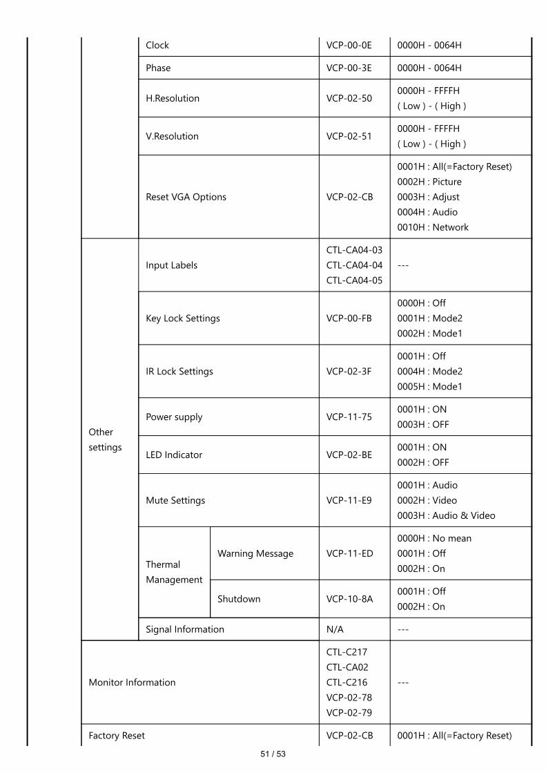
Clock VCP-00-0E 0000H - 0064H
Phase VCP-00-3E 0000H - 0064H
H.Resolution VCP-02-500000H - FFFFH( Low ) - ( High )
V.Resolution VCP-02-510000H - FFFFH( Low ) - ( High )
Reset VGA Options VCP-02-CB
0001H : All(=Factory Reset)0002H : Picture0003H : Adjust0004H : Audio0010H : Network
Othersettings
Input LabelsCTL-CA04-03CTL-CA04-04CTL-CA04-05
---
Key Lock Settings VCP-00-FB0000H : Off0001H : Mode20002H : Mode1
IR Lock Settings VCP-02-3F0001H : Off0004H : Mode20005H : Mode1
Power supply VCP-11-750001H : ON0003H : OFF
LED Indicator VCP-02-BE0001H : ON0002H : OFF
Mute Settings VCP-11-E90001H : Audio0002H : Video0003H : Audio & Video
ThermalManagement
Warning Message VCP-11-ED0000H : No mean0001H : Off0002H : On
Shutdown VCP-10-8A0001H : Off0002H : On
Signal Information N/A ---
Monitor Information
CTL-C217CTL-CA02CTL-C216VCP-02-78VCP-02-79
---
Factory Reset VCP-02-CB 0001H : All(=Factory Reset)
52 / 53
0002H : Picture0003H : Adjust0004H : Audio0010H : Network
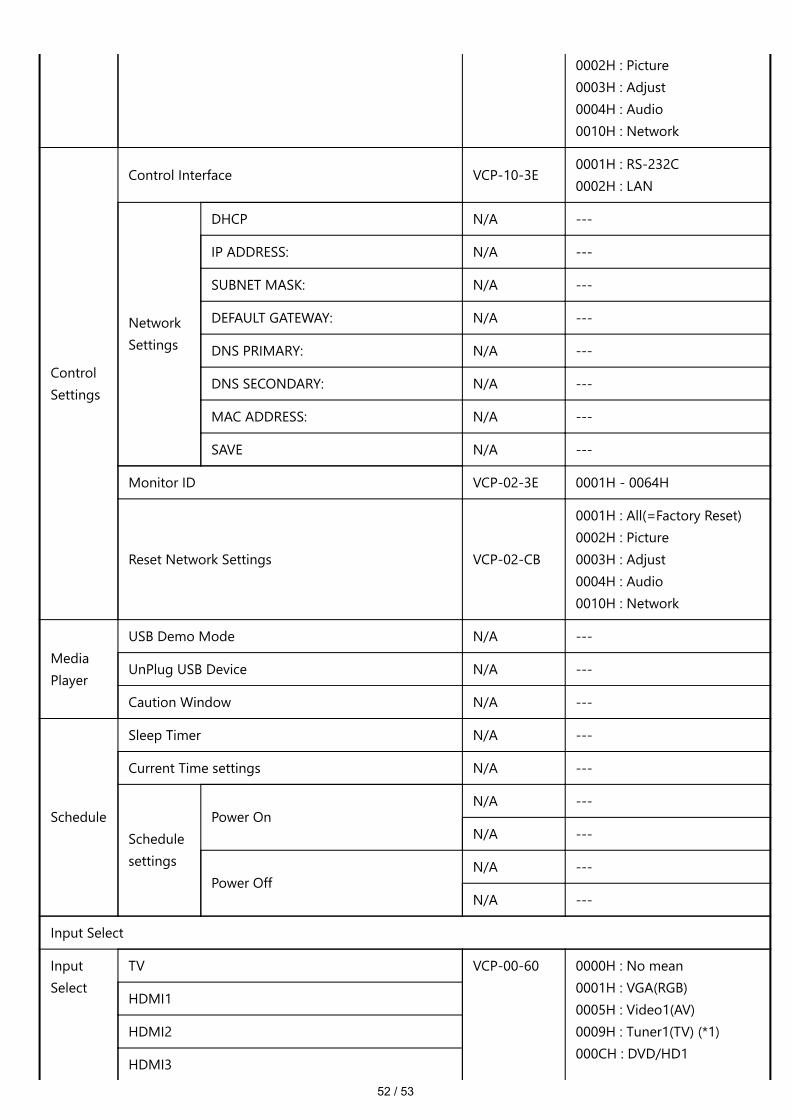
ControlSettings
Control Interface VCP-10-3E0001H : RS-232C0002H : LAN
NetworkSettings
DHCP N/A ---
IP ADDRESS: N/A ---
SUBNET MASK: N/A ---
DEFAULT GATEWAY: N/A ---
DNS PRIMARY: N/A ---
DNS SECONDARY: N/A ---
MAC ADDRESS: N/A ---
SAVE N/A ---
Monitor ID VCP-02-3E 0001H - 0064H
Reset Network Settings VCP-02-CB
0001H : All(=Factory Reset)0002H : Picture0003H : Adjust0004H : Audio0010H : Network
MediaPlayer
USB Demo Mode N/A ---
UnPlug USB Device N/A ---
Caution Window N/A ---
Schedule
Sleep Timer N/A ---
Current Time settings N/A ---
Schedulesettings
Power OnN/A ---
N/A ---
Power OffN/A ---
N/A ---
Input Select
InputSelect
TV VCP-00-60 0000H : No mean0001H : VGA(RGB)0005H : Video1(AV)0009H : Tuner1(TV) (*1)000CH : DVD/HD1
HDMI1
HDMI2
HDMI3

53 / 53
(VGA(YPbPr))0011H : HDMI10012H : HDMI20082H : HDMI30087H : MP(Media Player)
VGA(RGB)
VGA(YPbPr)
AV
Media Player
(*1) TV tuner model for US only supported(*2) TV tuner model for US not supported(*3) E328 model not supported