Model V-C3 Machine Code: D081/D082 Field Service Manual
1092
Model V-C3 Machine Code: D081/D082 Field Service Manual 30 November, 2009
-
Upload
khangminh22 -
Category
Documents
-
view
0 -
download
0
Transcript of Model V-C3 Machine Code: D081/D082 Field Service Manual
Model V-C3 Machine Code: D081/D082
Field Service Manual
30 November, 2009

Safety, Conventions, Trademarks
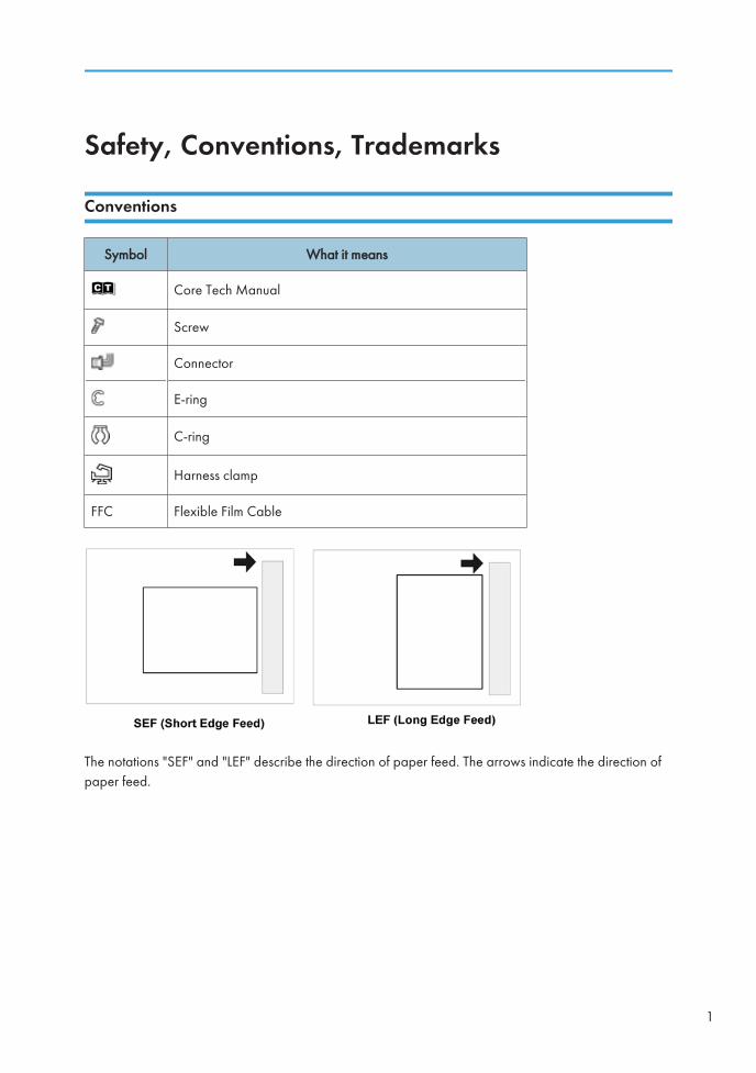
Conventions
Symbol What it means
Core Tech Manual
Screw
Connector
E-ring
C-ring
Harness clamp
FFC Flexible Film Cable
The notations "SEF" and "LEF" describe the direction of paper feed. The arrows indicate the direction ofpaper feed.
1
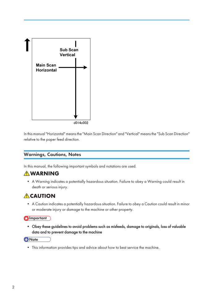
In this manual "Horizontal" means the "Main Scan Direction" and "Vertical" means the "Sub Scan Direction"relative to the paper feed direction.
Warnings, Cautions, Notes
In this manual, the following important symbols and notations are used.
• A Warning indicates a potentially hazardous situation. Failure to obey a Warning could result indeath or serious injury.
• A Caution indicates a potentially hazardous situation. Failure to obey a Caution could result in minoror moderate injury or damage to the machine or other property.
• Obey these guidelines to avoid problems such as misfeeds, damage to originals, loss of valuabledata and to prevent damage to the machine
• This information provides tips and advice about how to best service the machine.
2
Commonly Used Terms
In the SP tables, some of the finishers are referred to by number (Fin1, Fin2, etc.), and some SP codes mayappear for options that are not supported overseas:
Fin12000/3000-Sheet Finisher D373/D374. The D373 supports both corner and bookletfolding and stapling. The D374 supports corner stapling only.
Fin2 3000-Sheet Finisher B830
Fin3 Japan Only. Please Ignore.
Fin4 Ring Binder D392
Z-Fold This refers to the Z-Folding unit. The Z-Folding unit is available in Japan only.
ITB Image Transfer Belt
PTR Paper Transfer Roller
General Safety Instructions
For your safety, please read this manual carefully before you use this product. Keep this manual handy forfuture reference.
Safety Information
Always obey the following safety precautions when using this product.
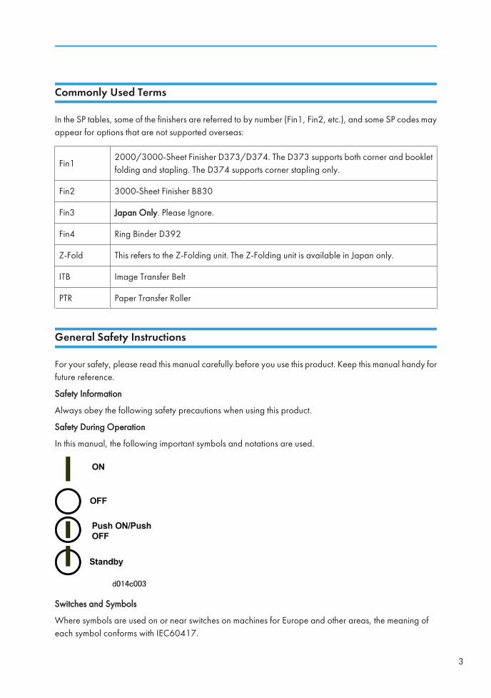
Safety During Operation
In this manual, the following important symbols and notations are used.
Switches and Symbols
Where symbols are used on or near switches on machines for Europe and other areas, the meaning ofeach symbol conforms with IEC60417.
3

Responsibilities of the Customer Engineer
Customer Engineer
Maintenance shall be done only by trained customer engineers who have completed service training forthe machine and all optional devices designed for use with the machine.
Reference Material for Maintenance
• Maintenance shall be done using the special tools and procedures prescribed for maintenance of themachine described in the reference materials (service manuals, technical bulletins, operatinginstructions, and safety guidelines for customer engineers).
• In regard to other safety issues not described in this document, all customer engineers shall strictlyobey procedures and recommendations described the "CE Safety Guide".
• Use only consumable supplies and replacement parts designed for use with the machine.
Before Installation, Maintenance
Shipping and Moving the Machine
• Work carefully when lifting or moving the machine. If the machine is heavy, two or more customerengineers may be required to prevent injuries (muscle strains, spinal injuries, etc.) or damage to themachine if it is dropped or tipped over.
• Personnel moving or working around the machine should always wear proper clothing and footwear.Never wear loose fitting clothing or accessories (neckties, loose sweaters, bracelets, etc. ) or casualfootwear (slippers, sandals, etc.) when lifting or moving the machine.
• Always unplug the power cord from the power source before you move the machine. Before youmove the product, arrange the power cord so it will not fall under the machine.
Power
• Always disconnect the power plug before doing any maintenance procedure. After switching off themachine, power is still supplied to the main machine and other devices. To prevent electrical shock,switch the machine off, wait for a few seconds, then unplug the machine from the power source.
4
• Before you do any checks or adjustments after turning the machine off, work carefully to avoid injury.After removing covers or opening the machine to do checks or adjustments, never touch electricalcomponents or moving parts (gears, timing belts, etc.).
• After turning the machine on with any cover removed, keep your hands away from electricalcomponents and moving parts. Never touch the cover of the fusing unit, gears, timing belts, etc.
Installation, Disassembly, and Adjustments
• After installation, maintenance, or adjustment, always check the operation of the machine to makesure that it is operating normally. This ensures that all shipping materials, protective materials, wiresand tags, metal brackets, etc., removed for installation, have been removed and that no tools remaininside the machine. This also ensures that all release interlock switches have been restored to normaloperation.
• Never use your fingers to check moving parts causing spurious noise. Never use your fingers tolubricate moving parts while the machine is operating.
Special Tools
• Use only standard tools approved for machine maintenance.
• For special adjustments, use only the special tools and lubricants described in the service manual.Using tools incorrectly, or using tools that could damage parts, could damage the machine or causeinjuries.
During Maintenance
General
• Before you begin a maintenance procedure: 1) Switch the machine off, 2) Disconnect the power plugfrom the power source, 3) Allow the machine to cool for at least 10 minutes.
• Avoid touching the components inside the machine that are labeled as hot surfaces.
5

Safety Devices
• Never remove any safety device unless it requires replacement. Always replace safety devicesimmediately.
• Never do any procedure that defeats the function of any safety device. Modification or removal of asafety device (fuse, switch, etc.) could lead to a fire and personal injury. Always test the operation ofthe machine to ensure that it is operating normally and safely after removal and replacement of anysafety device.
• For replacements use only the correct fuses or circuit breakers rated for use with the machine. Usingreplacement devices not designed for use with the machine could lead to a fire and personal injuries.
Organic Cleaners
• During preventive maintenance, never use any organic cleaners (alcohol, etc.) other than thosedescribed in the service manual.
• Make sure the room is well ventilated before using any organic cleaner. Use organic solvents in smallamounts to avoid breathing the fumes and becoming nauseous.
• Switch the machine off, unplug it, and allow it to cool before doing preventive maintenance. To avoidfire or explosion, never use an organic cleaner near any part that generates heat.
• Wash your hands thoroughly after cleaning parts with an organic cleaner to contamination of food,drinks, etc. which could cause illness.
• Clean the floor completely after accidental spillage of silicone oil or other materials to prevent slipperysurfaces that could cause accidents leading to hand or leg injuries. Use "My Ace" Silicone Oil Remover(or dry rags) to soak up spills.
Lithium Batteries
• Always replace a lithium battery on a PCB with the same type of battery prescribed for use on thatboard. Replacing a lithium battery with any type other than the one prescribed for use on the boardcould lead to an explosion or damage to the PCB.
• Never discard used batteries by mixing them with other trash. Remove them from the work site anddispose of them in accordance with local laws and regulations regarding the disposal of such items.
6
Ozone Filters
• Always replace ozone filters as soon as their service life expires (as described in the service manual).
• An excessive amount of ozone can build up around machines that use ozone filters if they are notreplaced at the prescribed time. Excessive ozone could cause personnel working around the machineto feel unwell.
Power Plug and Power Cord
• Before servicing the machine (especially when responding to a service call), always make sure thatthe power plug has been inserted completely into the power source. A partially inserted plug couldlead to heat generation (due to a power surge caused by high resistance) and cause a fire or otherproblems.
• Always check the power plug and make sure that it is free of dust and lint. Clean it if necessary. Adirty plug can generate heat which could cause a fire.
• Inspect the length of the power cord for cuts or other damage. Replace the power cord if necessary.A frayed or otherwise damaged power cord can cause a short circuit which could lead to a fire orpersonal injury from electrical shock.
• Check the length of the power cord between the machine and power supply. Make sure the powercord is not coiled or wrapped around any object such as a table leg. Coiling the power cord cancause excessive heat to build up and could cause a fire.
• Make sure that the area around the power source is free of obstacles so the power cord can beremoved quickly in case of an emergency.
• Make sure that the power cord is grounded (earthed) at the power source with the ground wire onthe plug.
• Connect the power cord directly into the power source. Never use an extension cord.
• When you disconnect the power plug from the power source, always pull on the plug, not the cable.
After Installation, Servicing
Disposal of Used Items
• Never incinerate used toner or toner cartridges.
7
• Toner or toner cartridges thrown into a fire can ignite or explode and cause serious injury. At the worksite always carefully wrap used toner and toner cartridges with plastic bags to avoid spillage beforedisposal or removal.
• Always dispose of used items (developer, toner, toner cartridges, OPC drums, etc.) in accordancewith the local laws and regulations regarding the disposal of such items.
• To protect the environment, never dispose of this product or any kind of waste from consumables ata household waste collection point. Dispose of these items at one of our dealers or at an authorizedcollection site.
• Return used selenium drums to the service center for handling in accordance with company policyregarding the recycling or disposal of such items.
Points to Confirm with Operators
At the end of installation or a service call, instruct the user about use of the machine. Emphasize the followingpoints.
• Show operators how to remove jammed paper and troubleshoot other minor problems by followingthe procedures described in the operating instructions.
• Point out the parts inside the machine that they should never touch or attempt to remove.
• Confirm that operators know how to store and dispose of consumables.
• Make sure that all operators have access to an operating instruction manual for the machine.
• Confirm that operators have read and understand all the safety instructions described in the operatinginstructions.
• Demonstrate how to turn off the power and disconnect the power plug (by pulling the plug, not thecord) if any of the following events occur: 1) something has spilled into the product, 2) service orrepair of the product is necessary, 3) the product cover has been damaged.
• Caution operators about removing paper fasteners around the machine. They should never allowpaper clips, staples, or any other small metallic objects to fall into the machine.
Special Safety Instructions for Toner
Accidental Physical Exposure
• Work carefully when removing paper jams or replacing toner bottles or cartridges to avoid spillingtoner on clothing or the hands.
8
• If toner is inhaled, immediately gargle with large amounts of cold water and move to a well ventilatedlocation. If there are signs of irritation or other problems, seek medical attention.
• If toner gets on the skin, wash immediately with soap and cold running water.
• If toner gets into the eyes, flush the eyes with cold running water or eye wash. If there are signs ofirritation or other problems, seek medical attention.
• If toner is swallowed, drink a large amount of cold water to dilute the ingested toner. If there are signsof any problem, seek medical attention.
• If toner spills on clothing, wash the affected area immediately with soap and cold water. Never usehot water! Hot water can cause toner to set and permanently stain fabric.
Handling and Storing Toner
• Toner, used toner, and developer are extremely flammable.
• Never store toner, developer, toner cartridges, or toner bottles (including empty toner bottles orcartridges) in a location where they will be exposed to high temperature or an open flame.
• Always store toner and developer supplies such as toner and developer packages, cartridges, andbottles (including used toner and empty bottles and cartridges) out of the reach of children.
• Always store fresh toner supplies or empty bottles or cartridges in a cool, dry location that is notexposed to direct sunlight.
Toner Disposal
• Never attempt to incinerate toner, used toner, or empty toner containers (bottles or cartridges). Burningtoner can explode and scatter, causing serious burns.
• Always wrap used toner and empty toner bottles and cartridges in plastic bags to avoid spillage.Follow the local laws and regulations regarding the disposal of such items.
• Dispose of used toner and toner cartridges at one of our dealers or at an authorized collection site.Always dispose of used toner cartridges and toner bottles in accordance with the local laws andregulations regarding the disposal of such items.
9
Safety Instructions for this Machine
Prevention of Physical Injury
1. Before disassembling or assembling parts of the machine and peripherals, make sure that the machineand peripheral power cords are unplugged.
2. The plug should be near the machine and easily accessible.
3. Note that some components of the machine and the paper tray unit are supplied with electrical voltageeven if the main power switch is turned off.
4. If any adjustment or operation check has to be made with exterior covers off or open while the mainswitch is turned on, keep hands away from electrified or mechanically driven components.
5. If the [Start] key is pressed before the machine completes the warm-up period (the [Start] key startsblinking red and green ), keep hands away from the mechanical and the electrical components asthe machine starts making copies as soon as the warm-up period is completed.
6. The inside and the metal parts of the fusing unit become extremely hot while the machine is operating.Be careful to avoid touching those components with your bare hands.
7. To prevent a fire or explosion, keep the machine away from flammable liquids, gases, and aerosols.
Health Safety Conditions
1. Never operate the machine without the ozone filters installed.
2. Always replace the ozone filters with the specified types at the proper intervals.
3. Toner and developer are non-toxic, but if you get either of them in your eyes by accident, it may causetemporary eye discomfort. Try to remove with eye drops or flush with water as first aid. If unsuccessful,get medical attention.
Observance of Electrical Safety Standards
1. The machine and its peripherals must be installed and maintained by a customer service representativewho has completed the training course on those models.
2. The NVRAM on the system control board has a lithium battery which can explode if replacedincorrectly. Replace the NVRAM only with an identical one. The manufacturer recommends replacingthe entire NVRAM. Do not recharge or burn this battery. Used NVRAM must be handled in accordancewith local regulations.
Safety and Ecological Notes for Disposal
1. Do not incinerate toner bottles or used toner. Toner dust may ignite suddenly when exposed to anopen flame.
10
2. Dispose of used toner, developer, and organic photoconductors in accordance with local regulations.(These are non-toxic supplies.)
3. Dispose of replaced parts in accordance with local regulations.
4. When keeping used lithium batteries in order to dispose of them later, do not put more than 100batteries per sealed box. Storing larger numbers or not sealing them apart may lead to chemicalreactions and heat build-up.
• The danger of explosion exists if a battery of this type is incorrectly replaced.
• Replace only with the same or an equivalent type recommended by the manufacturer. Discard usedbatteries in accordance with the manufacturer's instructions.
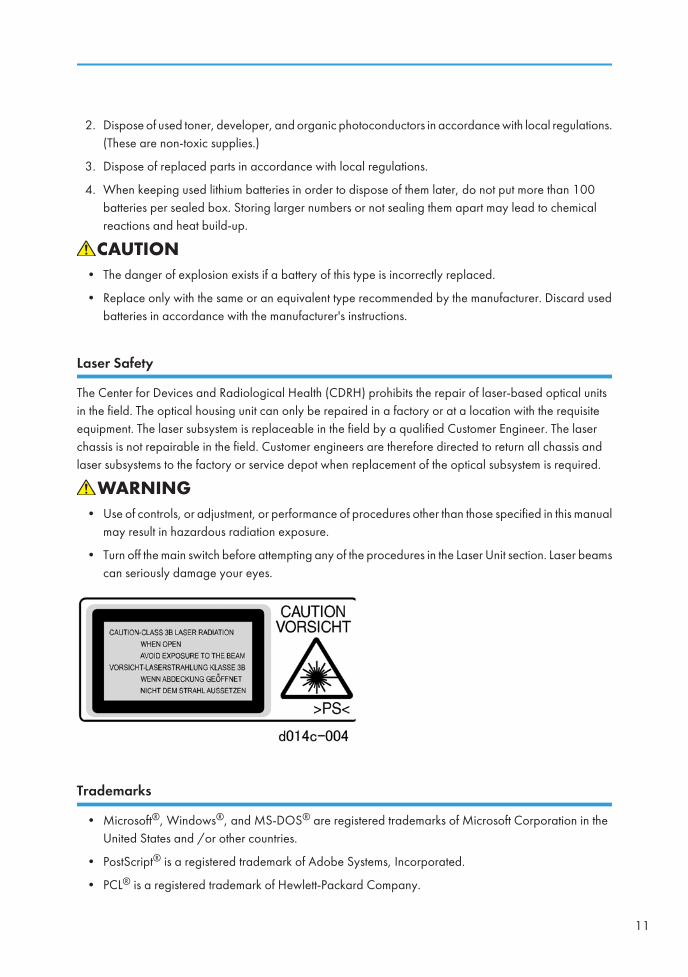
Laser Safety
The Center for Devices and Radiological Health (CDRH) prohibits the repair of laser-based optical unitsin the field. The optical housing unit can only be repaired in a factory or at a location with the requisiteequipment. The laser subsystem is replaceable in the field by a qualified Customer Engineer. The laserchassis is not repairable in the field. Customer engineers are therefore directed to return all chassis andlaser subsystems to the factory or service depot when replacement of the optical subsystem is required.
• Use of controls, or adjustment, or performance of procedures other than those specified in this manualmay result in hazardous radiation exposure.
• Turn off the main switch before attempting any of the procedures in the Laser Unit section. Laser beamscan seriously damage your eyes.
Trademarks
• Microsoft®, Windows®, and MS-DOS® are registered trademarks of Microsoft Corporation in theUnited States and /or other countries.
• PostScript® is a registered trademark of Adobe Systems, Incorporated.
• PCL® is a registered trademark of Hewlett-Packard Company.
11

• Ethernet® is a registered trademark of Xerox Corporation.
• PowerPC® is a registered trademark of International Business Machines Corporation.
• Other product names used herein are for identification purposes only and may be trademarks of theirrespective companies. We disclaim any and all rights involved with those marks.
12
New Features of D081/D082
Overview
Appearance
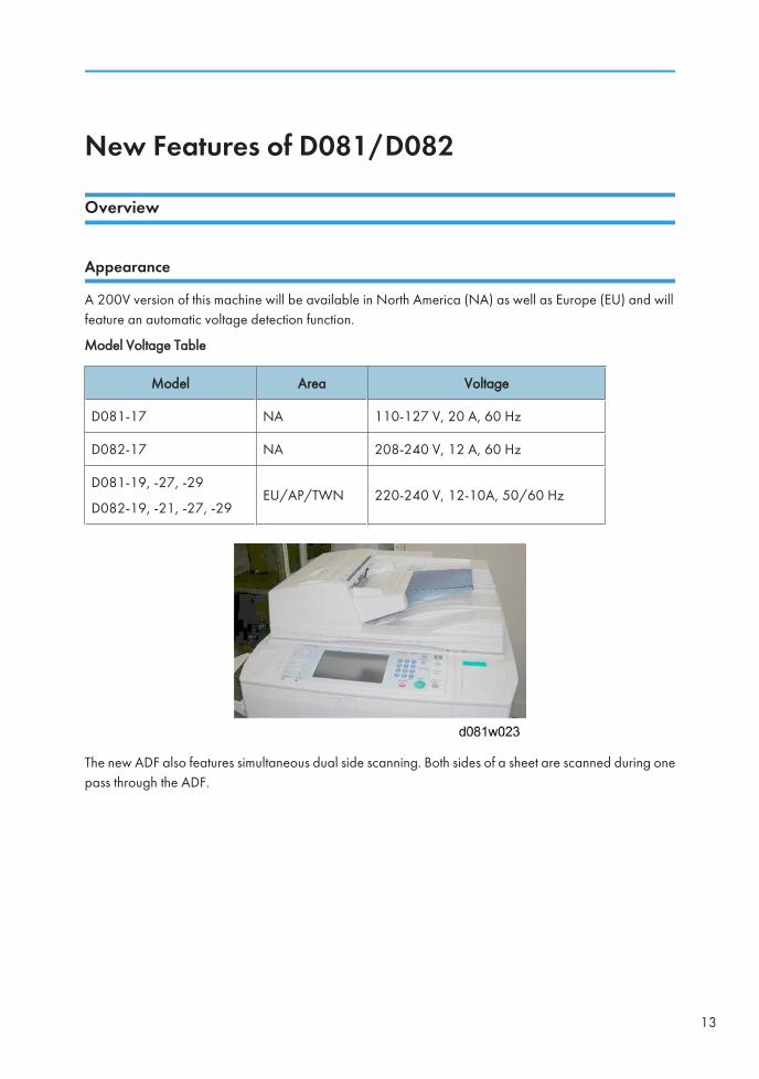
A 200V version of this machine will be available in North America (NA) as well as Europe (EU) and willfeature an automatic voltage detection function.
Model Voltage Table
Model Area Voltage
D081-17 NA 110-127 V, 20 A, 60 Hz
D082-17 NA 208-240 V, 12 A, 60 Hz
D081-19, -27, -29
D082-19, -21, -27, -29EU/AP/TWN 220-240 V, 12-10A, 50/60 Hz
The new ADF also features simultaneous dual side scanning. Both sides of a sheet are scanned during onepass through the ADF.
13
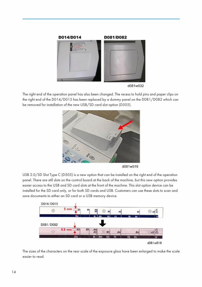
The right end of the operation panel has also been changed. The recess to hold pins and paper clips onthe right end of the D014/D015 has been replaced by a dummy panel on the D081/D082 which canbe removed for installation of the new USB/SD card slot option (D505).
USB 2.0/SD Slot Type C (D505) is a new option that can be installed on the right end of the operationpanel. There are still slots on the control board at the back of the machine, but this new option provideseasier access to the USB and SD card slots at the front of the machine. This slot option device can beinstalled for the SD card only, or for both SD cards and USB. Customers can use these slots to scan andsave documents to either an SD card or a USB memory device.
The sizes of the characters on the rear scale of the exposure glass have been enlarged to make the scaleeasier to read.
14
Specifications
Here is a quick summary of the differences between the D014/D015 and D081/D082.
Specification Summary
Feature D014/D015 D081/D082 Comments
cpm (BW/FC)a: 60/55
b: 75/70
a: 65/60
b: 75/70:Faster print speed in B&W mode.
Warm-up timea: 90 s
b: 75 s
a: 70 s
b: 60 sMuch shorter warm-up time.
First copy time (BW)a: 5.7 s
b: 4.9 s
a: 5.7 s
b: 4.9 s
First copy time (FC)a: 7.5 s
b: 6.4 s
a: 7.5 s
b: 6.4 s
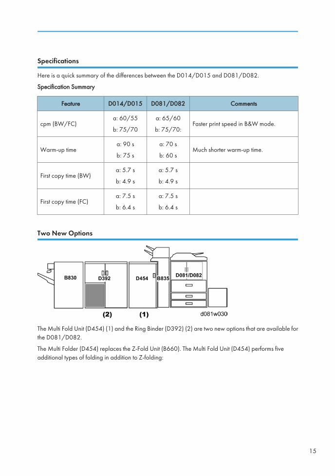
Two New Options
The Multi Fold Unit (D454) (1) and the Ring Binder (D392) (2) are two new options that are available forthe D081/D082.
The Multi Folder (D454) replaces the Z-Fold Unit (B660). The Multi Fold Unit (D454) performs fiveadditional types of folding in addition to Z-folding:
15
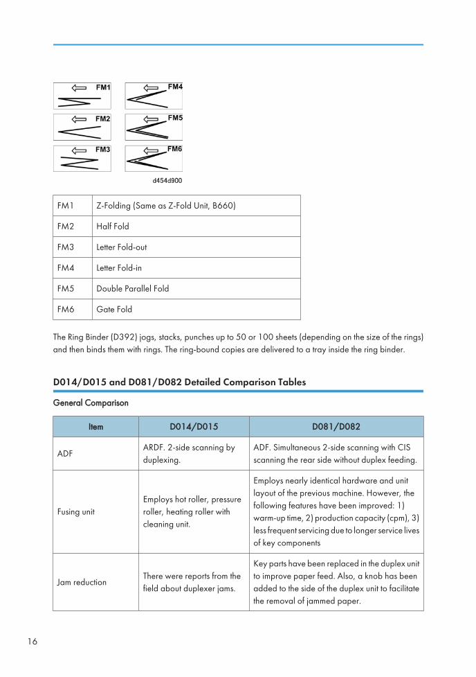
FM1 Z-Folding (Same as Z-Fold Unit, B660)
FM2 Half Fold
FM3 Letter Fold-out
FM4 Letter Fold-in
FM5 Double Parallel Fold
FM6 Gate Fold
The Ring Binder (D392) jogs, stacks, punches up to 50 or 100 sheets (depending on the size of the rings)and then binds them with rings. The ring-bound copies are delivered to a tray inside the ring binder.
D014/D015 and D081/D082 Detailed Comparison Tables
General Comparison
Item D014/D015 D081/D082
ADFARDF. 2-side scanning byduplexing.
ADF. Simultaneous 2-side scanning with CISscanning the rear side without duplex feeding.
Fusing unitEmploys hot roller, pressureroller, heating roller withcleaning unit.
Employs nearly identical hardware and unitlayout of the previous machine. However, thefollowing features have been improved: 1)warm-up time, 2) production capacity (cpm), 3)less frequent servicing due to longer service livesof key components
Jam reductionThere were reports from thefield about duplexer jams.
Key parts have been replaced in the duplex unitto improve paper feed. Also, a knob has beenadded to the side of the duplex unit to facilitatethe removal of jammed paper.
16
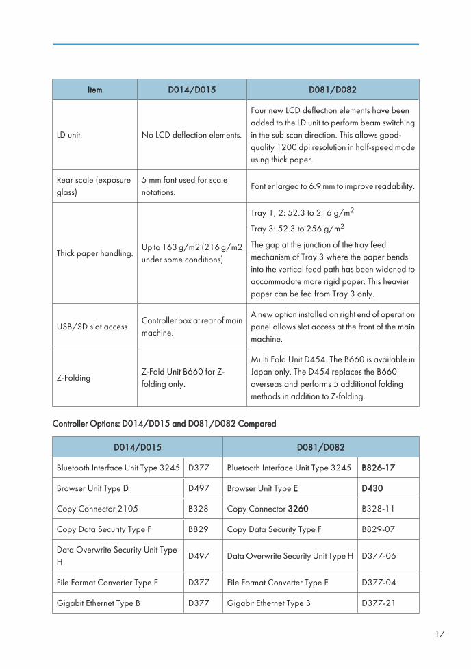
Item D014/D015 D081/D082
LD unit. No LCD deflection elements.
Four new LCD deflection elements have beenadded to the LD unit to perform beam switchingin the sub scan direction. This allows good-quality 1200 dpi resolution in half-speed modeusing thick paper.
Rear scale (exposureglass)
5 mm font used for scalenotations.
Font enlarged to 6.9 mm to improve readability.
Thick paper handling.Up to 163 g/m2 (216 g/m2under some conditions)
Tray 1, 2: 52.3 to 216 g/m2
Tray 3: 52.3 to 256 g/m2
The gap at the junction of the tray feedmechanism of Tray 3 where the paper bendsinto the vertical feed path has been widened toaccommodate more rigid paper. This heavierpaper can be fed from Tray 3 only.
USB/SD slot accessController box at rear of mainmachine.
A new option installed on right end of operationpanel allows slot access at the front of the mainmachine.
Z-FoldingZ-Fold Unit B660 for Z-folding only.
Multi Fold Unit D454. The B660 is available inJapan only. The D454 replaces the B660overseas and performs 5 additional foldingmethods in addition to Z-folding.
Controller Options: D014/D015 and D081/D082 Compared
D014/D015 D081/D082
Bluetooth Interface Unit Type 3245 D377 Bluetooth Interface Unit Type 3245 B826-17
Browser Unit Type D D497 Browser Unit Type E D430
Copy Connector 2105 B328 Copy Connector 3260 B328-11
Copy Data Security Type F B829 Copy Data Security Type F B829-07
Data Overwrite Security Unit TypeH
D497 Data Overwrite Security Unit Type H D377-06
File Format Converter Type E D377 File Format Converter Type E D377-04
Gigabit Ethernet Type B D377 Gigabit Ethernet Type B D377-21
17
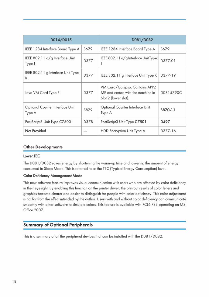
D014/D015 D081/D082
IEEE 1284 Interface Board Type A B679 IEEE 1284 Interface Board Type A B679
IEEE 802.11 a/g Interface UnitType J
D377IEEE 802.11 a/g Interface Unit TypeJ
D377-01
IEEE 802.11 g Interface Unit TypeK
D377 IEEE 802.11 g Interface Unit Type K D377-19
Java VM Card Type E D377VM Card/Calypso. Contains APP2ME and comes with the machine inSlot 2 (lower slot).
D0815790C
Optional Counter Interface UnitType A
B879Optional Counter Interface UnitType A
B870-11
PostScript3 Unit Type C7500 D378 PostScript3 Unit Type C7501 D497
Not Provided --- HDD Encryption Unit Type A D377-16
Other Developments
Lower TEC
The D081/D082 saves energy by shortening the warm-up time and lowering the amount of energyconsumed in Sleep Mode. This is referred to as the TEC (Typical Energy Consumption) level.
Color Deficiency Management Mode
This new software feature improves visual communication with users who are affected by color deficiencyin their eyesight. By enabling this function on the printer driver, the printout results of color letters andgraphics become clearer and easier to distinguish for people with color deficiency. This color adjustmentis not far from the effect intended by the author. Users with and without color deficiency can communicatesmoothly with other software to simulate colors. This feature is available with PCL6 PS3 operating on MSOffice 2007.
Summary of Optional Peripherals
This is a summary of all the peripheral devices that can be installed with the D081/D082.
18
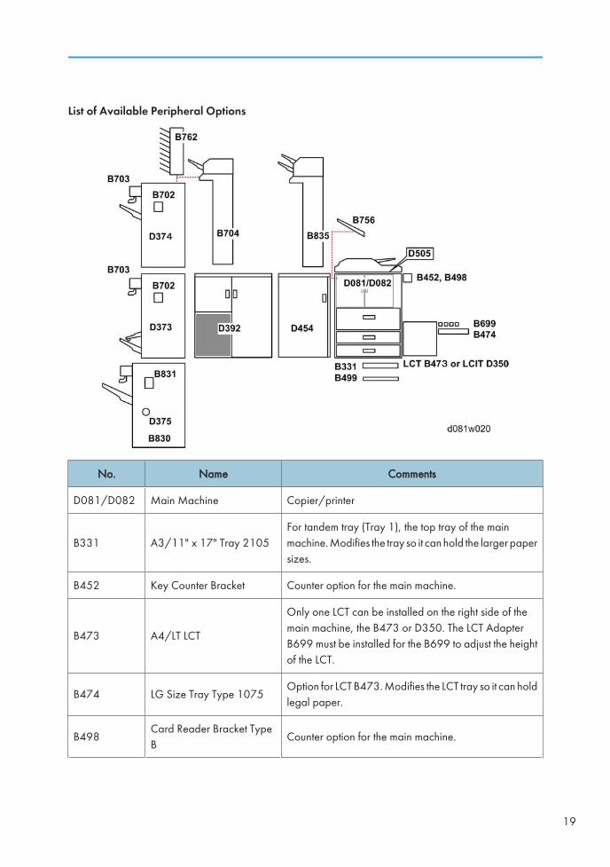
List of Available Peripheral Options
No. Name Comments
D081/D082 Main Machine Copier/printer
B331 A3/11" x 17" Tray 2105For tandem tray (Tray 1), the top tray of the mainmachine. Modifies the tray so it can hold the larger papersizes.
B452 Key Counter Bracket Counter option for the main machine.
B473 A4/LT LCT
Only one LCT can be installed on the right side of themain machine, the B473 or D350. The LCT AdapterB699 must be installed for the B699 to adjust the heightof the LCT.
B474 LG Size Tray Type 1075Option for LCT B473. Modifies the LCT tray so it can holdlegal paper.
B498Card Reader Bracket TypeB
Counter option for the main machine.
19
No. Name Comments
B499Tab Sheet Holder Type3260
For tandem tray (Tray 1), the top tray of the mainmachine.
B699 LCT Adapter Required for installation of LCT B473.
B702 Punch Unit Type 3260For either finisher D373 or D374. Three models areavailable (NA, EU, or SC).
B703Output Jogger Unit Type3260
Optional jogger unit attached to the left side of thefinisher. It can be attached to either finisher D373 orD374 finisher.
B704 Cover Interposer
Installed on top of either finisher D373 or D374. MailBox CS391 (B762) is also installed on the top of thefinisher, so the cover interposer and mailbox cannot beinstalled together.
B756 Copy TrayHolds paper output from the main machine. Must beused if no finishers are installed on the left side of themain machine.
B762 Mail Box CS391
Install on top of either the D373 or D374. CoverInterposer (B704) is also installed on the top on thefinisher, so the cover interposer and mailbox cannot beinstalled together.
B830 Finisher SR5000
3000 sheet capacity, 100 staples. External jogger isprovided pre-installed. Finisher Adapter Type C (D375)is required. The output jogger is pre-installed on thisfinisher (provided as standard).
B831 Punch Unit PU 5000Designed for the SR5000 (B830). Three types areavailable (EU, NA, or SC).
B835Cover Interposer TrayCI5000
Two source trays for feeding covers. Can be installedand used for the SR5000 (B830) only. This coverinterposer tray can be installed on the Multi Folder(D454) as well as the B830
D350 LCIT 4000Only one LCT can be installed on the right side of themachine, the B473 or D350.
D373 Finisher SR40402000-sheet tray capacity, corner stapling, saddle-stitchstapling, booklet folding and stapling.
20
No. Name Comments
D374 Finisher SR40303000-sheet tray capacity, corner stapling only (nosaddle-stitch stapling).
D375 Finisher Adapter Type CInstalled in the SR5000 (B830) to adapt the speed ofthe finisher. Required for this machine.
D392 Ring BinderThis is a new option for the D081/D082. RequiresFinisher SR5000 (B830) and cannot be used with eitherthe SR4040 (D373) or SR4030 (D374).
D454 Multi Fold Unit
This is a new option for the D081/D082. Executes sixtypes of folding. Can be used with either the SR4040(D373) or SR5000 (B830). Cannot be used with theSR4030 (D374).
D505 USB 2.0/SD Slot Type DAttached to the right end of the operation panel on themain machine.
Controller Options (Installed on Main Machine)
Option No. Shape
Bluetooth Interface Unit Type 3245 B826 Board
Browser Unit Type E D497 SD card
Copy Connector Type 3260 B328 Board
Copy Data Security Type F B829 Board
Data Overwrite Security Unit Type H D497 SD card
File Format Converter Type E D377-04 Board
Gigabit Ethernet Type B*1 D377-21 Board
HDD Encryption Unit Type A D377-16 SD card
IEEE 1284 Interface Board Type A B679 Board
IEEE 802.11 a/g Interface Unit Type J D377-01 Board
Optional Counter Interface Unit Type A B870-11 Board
PostScript 3 Unit Type C7501 D378 SD card
*1: The EFI (Fiery) Controller is connected through the Gigabit Ethernet Board.
21
New ADF
ADF Overview
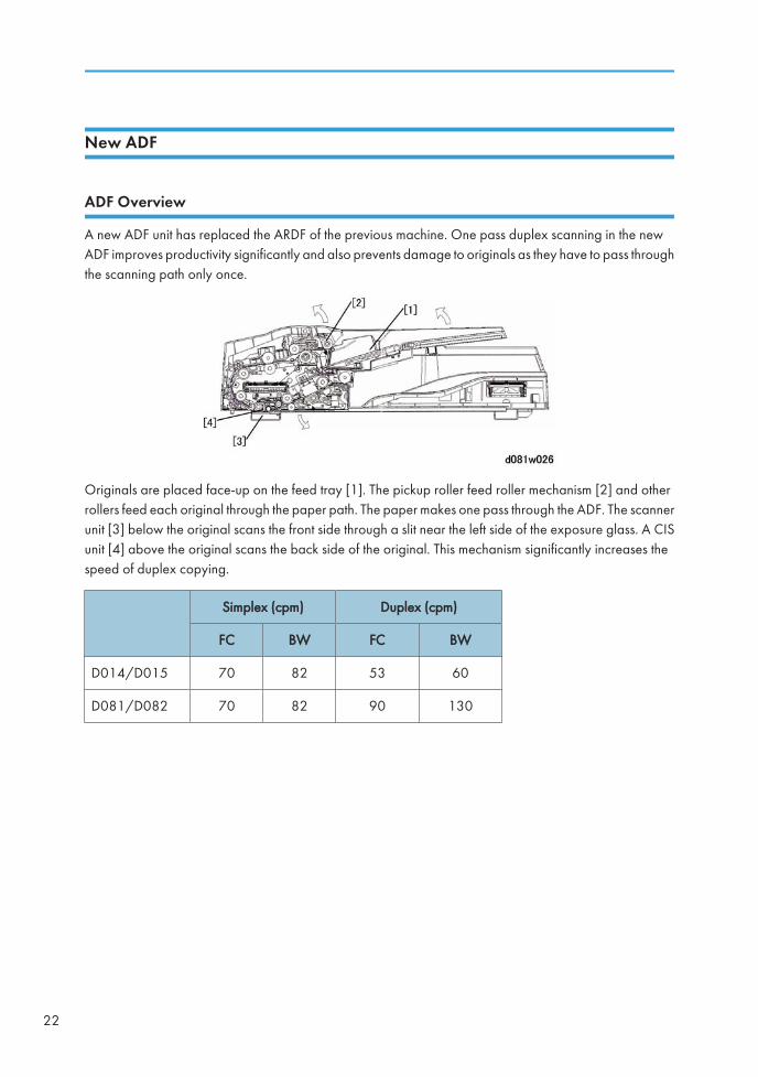
A new ADF unit has replaced the ARDF of the previous machine. One pass duplex scanning in the newADF improves productivity significantly and also prevents damage to originals as they have to pass throughthe scanning path only once.
Originals are placed face-up on the feed tray [1]. The pickup roller feed roller mechanism [2] and otherrollers feed each original through the paper path. The paper makes one pass through the ADF. The scannerunit [3] below the original scans the front side through a slit near the left side of the exposure glass. A CISunit [4] above the original scans the back side of the original. This mechanism significantly increases thespeed of duplex copying.
Simplex (cpm) Duplex (cpm)
FC BW FC BW
D014/D015 70 82 53 60
D081/D082 70 82 90 130
22
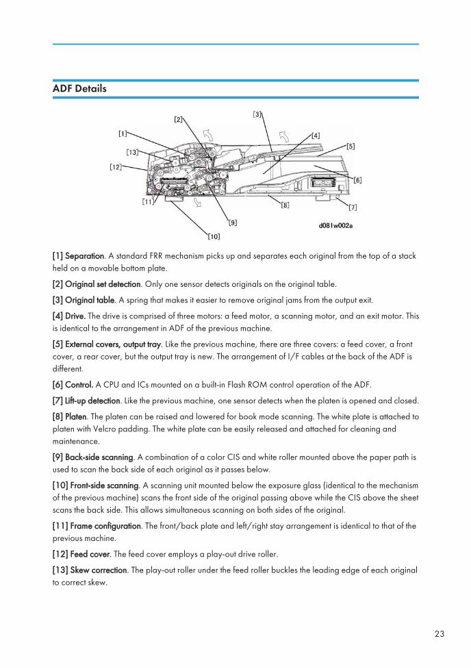
ADF Details
[1] Separation. A standard FRR mechanism picks up and separates each original from the top of a stackheld on a movable bottom plate.
[2] Original set detection. Only one sensor detects originals on the original table.
[3] Original table. A spring that makes it easier to remove original jams from the output exit.
[4] Drive. The drive is comprised of three motors: a feed motor, a scanning motor, and an exit motor. Thisis identical to the arrangement in ADF of the previous machine.
[5] External covers, output tray. Like the previous machine, there are three covers: a feed cover, a frontcover, a rear cover, but the output tray is new. The arrangement of I/F cables at the back of the ADF isdifferent.
[6] Control. A CPU and ICs mounted on a built-in Flash ROM control operation of the ADF.
[7] Lift-up detection. Like the previous machine, one sensor detects when the platen is opened and closed.
[8] Platen. The platen can be raised and lowered for book mode scanning. The white plate is attached toplaten with Velcro padding. The white plate can be easily released and attached for cleaning andmaintenance.
[9] Back-side scanning. A combination of a color CIS and white roller mounted above the paper path isused to scan the back side of each original as it passes below.
[10] Front-side scanning. A scanning unit mounted below the exposure glass (identical to the mechanismof the previous machine) scans the front side of the original passing above while the CIS above the sheetscans the back side. This allows simultaneous scanning on both sides of the original.
[11] Frame configuration. The front/back plate and left/right stay arrangement is identical to that of theprevious machine.
[12] Feed cover. The feed cover employs a play-out drive roller.
[13] Skew correction. The play-out roller under the feed roller buckles the leading edge of each originalto correct skew.
23
Improved Paper Feed
This section describes some changes that were done to improve paper feed and reduce the occurrence ofpaper jams.
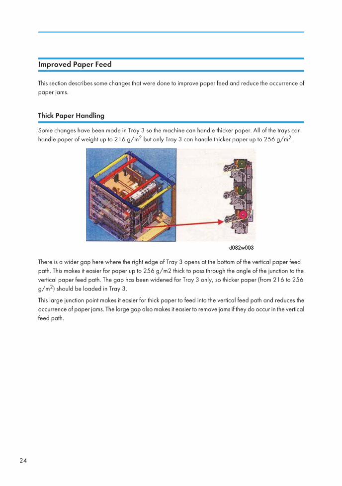
Thick Paper Handling
Some changes have been made in Tray 3 so the machine can handle thicker paper. All of the trays canhandle paper of weight up to 216 g/m2 but only Tray 3 can handle thicker paper up to 256 g/m2.
There is a wider gap here where the right edge of Tray 3 opens at the bottom of the vertical paper feedpath. This makes it easier for paper up to 256 g/m2 thick to pass through the angle of the junction to thevertical paper feed path. The gap has been widened for Tray 3 only, so thicker paper (from 216 to 256g/m2) should be loaded in Tray 3.
This large junction point makes it easier for thick paper to feed into the vertical feed path and reduces theoccurrence of paper jams. The large gap also makes it easier to remove jams if they do occur in the verticalfeed path.
24
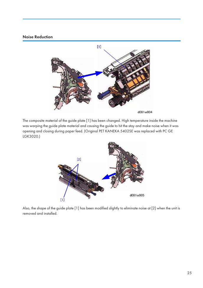
Noise Reduction
The composite material of the guide plate [1] has been changed. High temperature inside the machinewas warping the guide plate material and causing the guide to hit the stay and make noise when it wasopening and closing during paper feed. (Original PET KANEKA 5402SE was replaced with PC GELGK3020.)
Also, the shape of the guide plate [1] has been modified slightly to eliminate noise at [2] when the unit isremoved and installed.
25
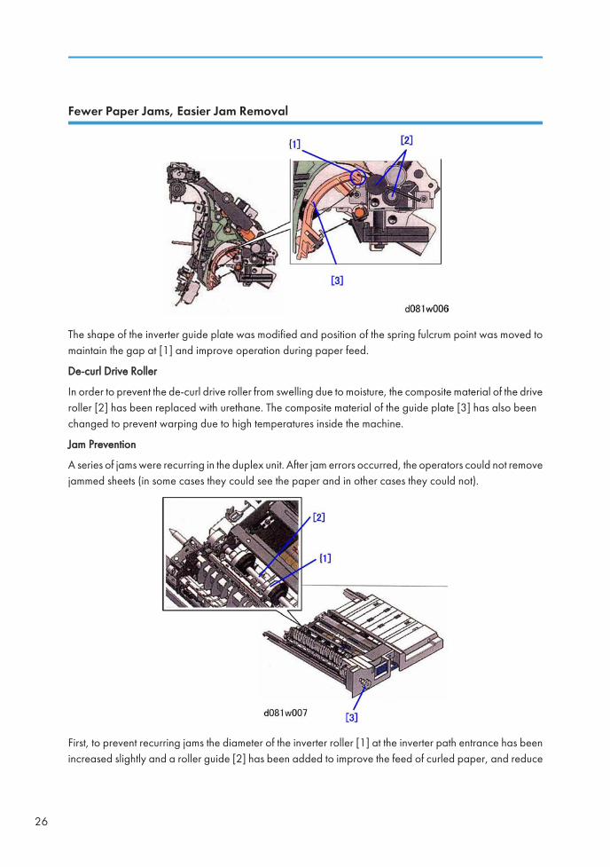
Fewer Paper Jams, Easier Jam Removal
The shape of the inverter guide plate was modified and position of the spring fulcrum point was moved tomaintain the gap at [1] and improve operation during paper feed.
De-curl Drive Roller
In order to prevent the de-curl drive roller from swelling due to moisture, the composite material of the driveroller [2] has been replaced with urethane. The composite material of the guide plate [3] has also beenchanged to prevent warping due to high temperatures inside the machine.
Jam Prevention
A series of jams were recurring in the duplex unit. After jam errors occurred, the operators could not removejammed sheets (in some cases they could see the paper and in other cases they could not).
First, to prevent recurring jams the diameter of the inverter roller [1] at the inverter path entrance has beenincreased slightly and a roller guide [2] has been added to improve the feed of curled paper, and reduce
26
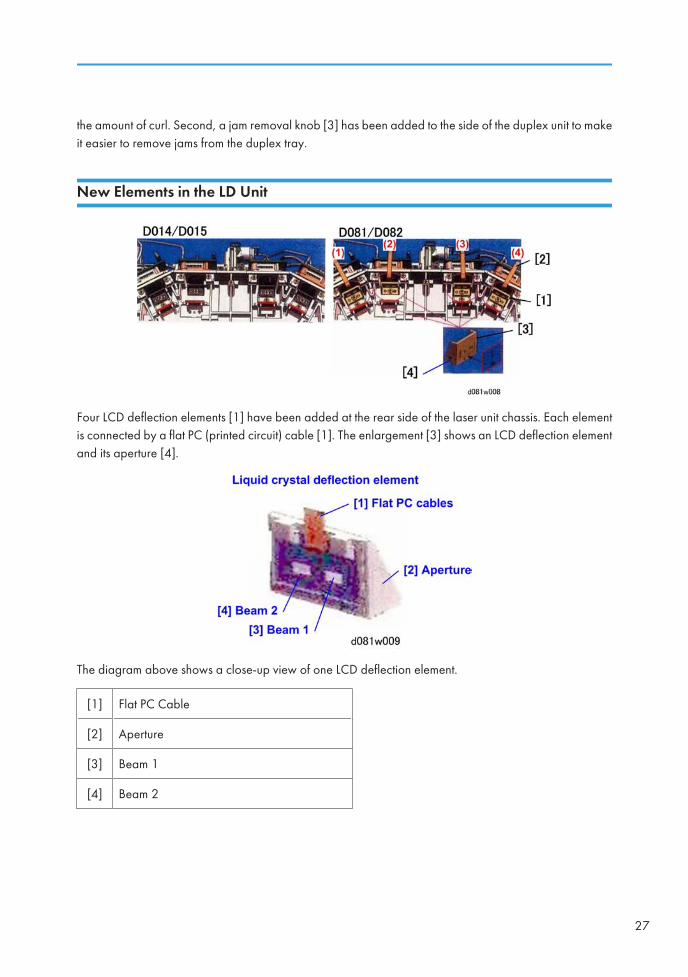
the amount of curl. Second, a jam removal knob [3] has been added to the side of the duplex unit to makeit easier to remove jams from the duplex tray.
New Elements in the LD Unit
Four LCD deflection elements [1] have been added at the rear side of the laser unit chassis. Each elementis connected by a flat PC (printed circuit) cable [1]. The enlargement [3] shows an LCD deflection elementand its aperture [4].
The diagram above shows a close-up view of one LCD deflection element.
[1] Flat PC Cable
[2] Aperture
[3] Beam 1
[4] Beam 2
27
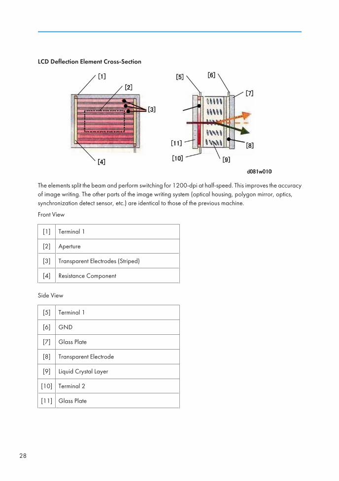
LCD Deflection Element Cross-Section
The elements split the beam and perform switching for 1200-dpi at half-speed. This improves the accuracyof image writing. The other parts of the image writing system (optical housing, polygon mirror, optics,synchronization detect sensor, etc.) are identical to those of the previous machine.
Front View
[1] Terminal 1
[2] Aperture
[3] Transparent Electrodes (Striped)
[4] Resistance Component
Side View
[5] Terminal 1
[6] GND
[7] Glass Plate
[8] Transparent Electrode
[9] Liquid Crystal Layer
[10] Terminal 2
[11] Glass Plate
28
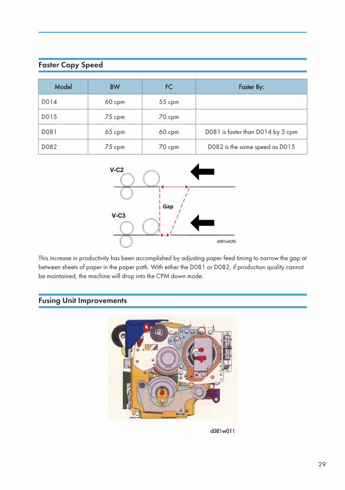
Faster Copy Speed
Model BW FC Faster By:
D014 60 cpm 55 cpm
D015 75 cpm 70 cpm
D081 65 cpm 60 cpm D081 is faster than D014 by 5 cpm
D082 75 cpm 70 cpm D082 is the same speed as D015
This increase in productivity has been accomplished by adjusting paper feed timing to narrow the gap atbetween sheets of paper in the paper path. With either the D081 or D082, if production quality cannotbe maintained, the machine will drop into the CPM down mode.
Fusing Unit Improvements
29
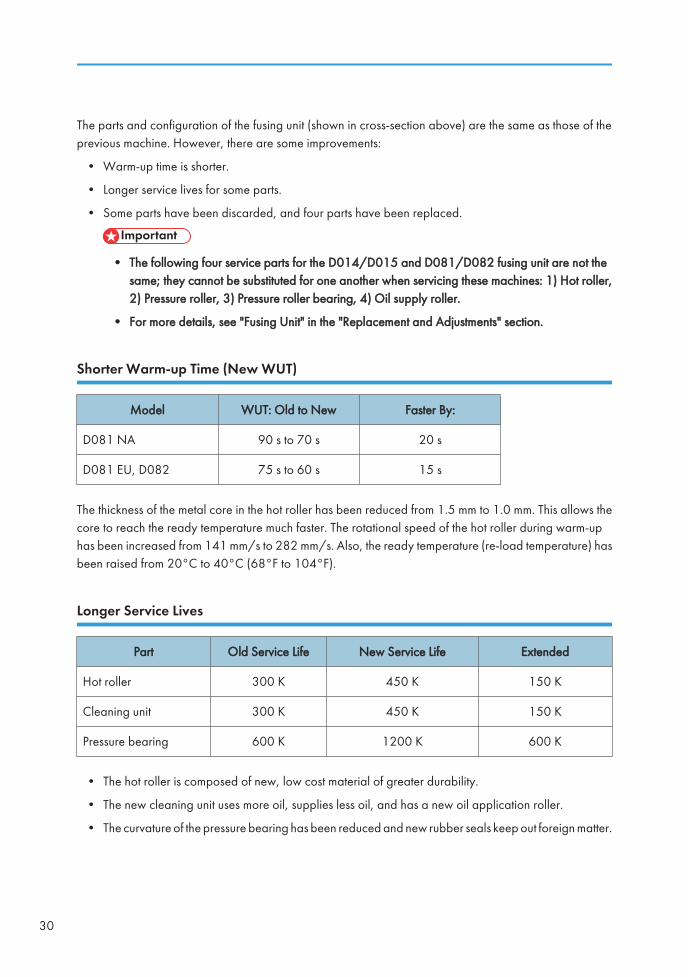
The parts and configuration of the fusing unit (shown in cross-section above) are the same as those of theprevious machine. However, there are some improvements:
• Warm-up time is shorter.
• Longer service lives for some parts.
• Some parts have been discarded, and four parts have been replaced.
• The following four service parts for the D014/D015 and D081/D082 fusing unit are not thesame; they cannot be substituted for one another when servicing these machines: 1) Hot roller,2) Pressure roller, 3) Pressure roller bearing, 4) Oil supply roller.
• For more details, see "Fusing Unit" in the "Replacement and Adjustments" section.
Shorter Warm-up Time (New WUT)
Model WUT: Old to New Faster By:
D081 NA 90 s to 70 s 20 s
D081 EU, D082 75 s to 60 s 15 s
The thickness of the metal core in the hot roller has been reduced from 1.5 mm to 1.0 mm. This allows thecore to reach the ready temperature much faster. The rotational speed of the hot roller during warm-uphas been increased from 141 mm/s to 282 mm/s. Also, the ready temperature (re-load temperature) hasbeen raised from 20°C to 40°C (68°F to 104°F).
Longer Service Lives
Part Old Service Life New Service Life Extended
Hot roller 300 K 450 K 150 K
Cleaning unit 300 K 450 K 150 K
Pressure bearing 600 K 1200 K 600 K
• The hot roller is composed of new, low cost material of greater durability.
• The new cleaning unit uses more oil, supplies less oil, and has a new oil application roller.
• The curvature of the pressure bearing has been reduced and new rubber seals keep out foreign matter.
30
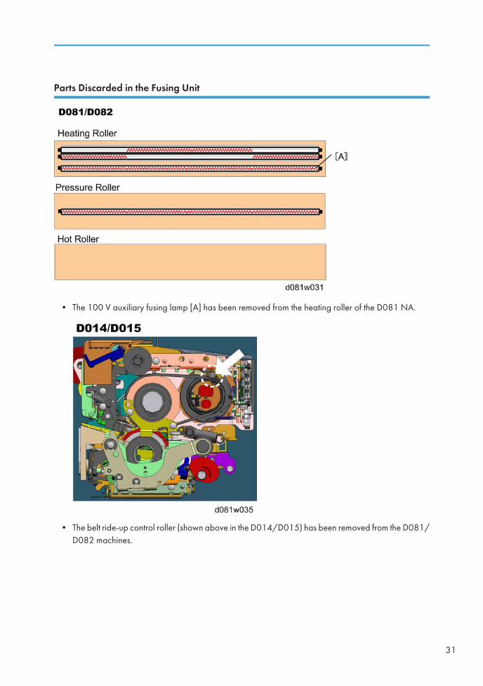
Parts Discarded in the Fusing Unit
• The 100 V auxiliary fusing lamp [A] has been removed from the heating roller of the D081 NA.
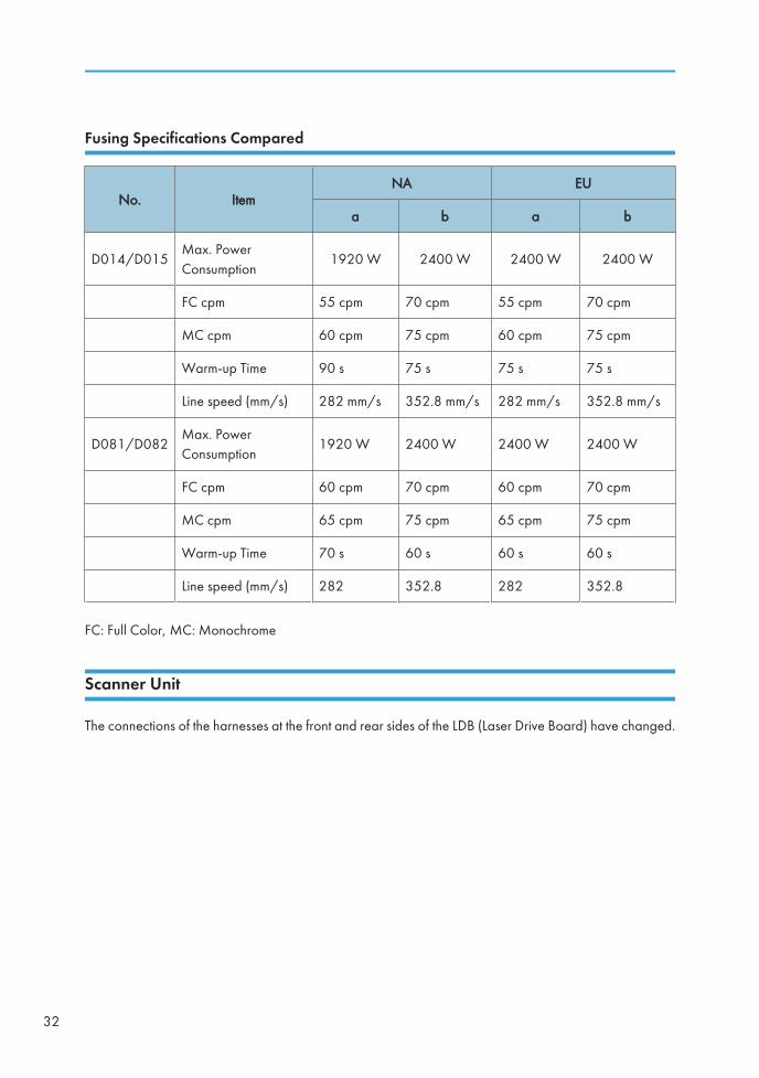
• The belt ride-up control roller (shown above in the D014/D015) has been removed from the D081/D082 machines.
31
Fusing Specifications Compared
No. ItemNA EU
a b a b
D014/D015Max. PowerConsumption
1920 W 2400 W 2400 W 2400 W
FC cpm 55 cpm 70 cpm 55 cpm 70 cpm
MC cpm 60 cpm 75 cpm 60 cpm 75 cpm
Warm-up Time 90 s 75 s 75 s 75 s
Line speed (mm/s) 282 mm/s 352.8 mm/s 282 mm/s 352.8 mm/s
D081/D082Max. PowerConsumption
1920 W 2400 W 2400 W 2400 W
FC cpm 60 cpm 70 cpm 60 cpm 70 cpm
MC cpm 65 cpm 75 cpm 65 cpm 75 cpm
Warm-up Time 70 s 60 s 60 s 60 s
Line speed (mm/s) 282 352.8 282 352.8
FC: Full Color, MC: Monochrome
Scanner Unit
The connections of the harnesses at the front and rear sides of the LDB (Laser Drive Board) have changed.
32
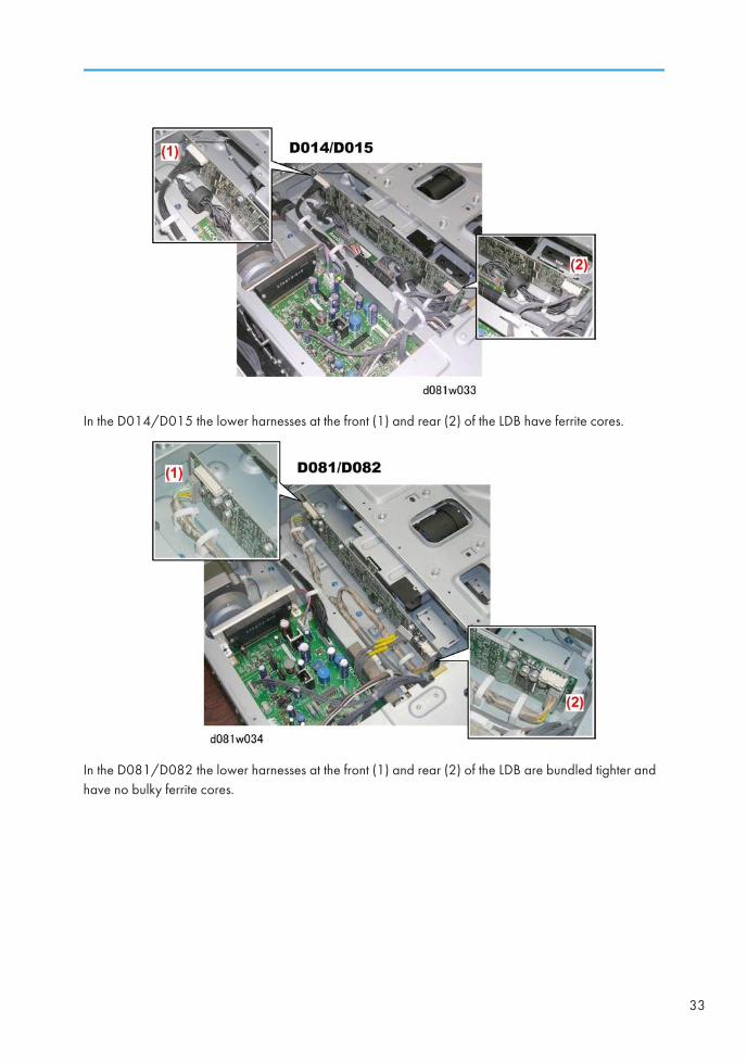
In the D014/D015 the lower harnesses at the front (1) and rear (2) of the LDB have ferrite cores.
In the D081/D082 the lower harnesses at the front (1) and rear (2) of the LDB are bundled tighter andhave no bulky ferrite cores.
33
TABLE OF CONTENTSSafety, Conventions, Trademarks......................................................................................................................1
Conventions....................................................................................................................................................1
Warnings, Cautions, Notes...........................................................................................................................2
Commonly Used Terms..................................................................................................................................3
General Safety Instructions............................................................................................................................3
Responsibilities of the Customer Engineer....................................................................................................4
Before Installation, Maintenance..................................................................................................................4
During Maintenance......................................................................................................................................5
After Installation, Servicing............................................................................................................................7
Special Safety Instructions for Toner.............................................................................................................8
Safety Instructions for this Machine............................................................................................................10
New Features of D081/D082.......................................................................................................................13
Overview......................................................................................................................................................13
Summary of Optional Peripherals..............................................................................................................18
New ADF......................................................................................................................................................22
ADF Details...................................................................................................................................................23
Improved Paper Feed..................................................................................................................................24
New Elements in the LD Unit.......................................................................................................................27
Faster Copy Speed......................................................................................................................................29
Fusing Unit Improvements............................................................................................................................29
Scanner Unit.................................................................................................................................................32
1. Product Information
Specifications....................................................................................................................................................45
Main Machine and Peripherals......................................................................................................................46
Main System Configurations.......................................................................................................................46
Controller Options.......................................................................................................................................47
Guidance for Those Who are Familiar with Predecessor Products..............................................................49
Overview..........................................................................................................................................................50
Main Machine.............................................................................................................................................50
2. Installation
Installation Requirements.................................................................................................................................53
Operating Environment...............................................................................................................................53
Machine Level..............................................................................................................................................54
34
Minimum Space Requirements...................................................................................................................55
Dimensions...................................................................................................................................................55
Power Requirements....................................................................................................................................56
Main Machine D081/D082..........................................................................................................................58
Accessories...................................................................................................................................................58
Installation....................................................................................................................................................59
Copy Tray (B756-01).....................................................................................................................................91
Accessories...................................................................................................................................................91
Installation....................................................................................................................................................92
A3/11" X 17" Paper Size Tray Type 2105 (B331-01)..............................................................................94
Accessories...................................................................................................................................................94
Installation....................................................................................................................................................94
Counters............................................................................................................................................................98
Accessories...................................................................................................................................................98
Installation..................................................................................................................................................100
USB2.0/SD Slot Type D (D505-01)...........................................................................................................105
Accessories................................................................................................................................................105
Installation..................................................................................................................................................105
LCT (B473), LCT Adapter Type B (B699)...................................................................................................120
Accessories................................................................................................................................................120
Installation..................................................................................................................................................121
LG Size Tray Type 1075 (B474).................................................................................................................129
Accessories................................................................................................................................................129
Installation..................................................................................................................................................129
LCIT RT4000 (D350)....................................................................................................................................134
Accessories................................................................................................................................................134
LCT Installation...........................................................................................................................................135
Anti-Condensation Heater Type B: 120V...............................................................................................140
Anti-Condensation Heater Type B: 240V...............................................................................................143
Cover Interposer Tray CI5000 (B835-57) ................................................................................................147
Accessories................................................................................................................................................147
Installation..................................................................................................................................................148
Docking the Cover Interposer Tray B835...............................................................................................156
35
Multi Folding Unit (D454).............................................................................................................................157
Accessories................................................................................................................................................157
Installation..................................................................................................................................................158
Ring Binder (D392) Installation....................................................................................................................166
Accessories................................................................................................................................................166
Before You Begin.......................................................................................................................................167
Installation Requirements..........................................................................................................................168
Installation Procedure................................................................................................................................170
Centering Paper in the Paper Path...........................................................................................................176
After Installation.........................................................................................................................................181
Cover Interposer Tray Type 3260 (B704-17)............................................................................................183
Accessories................................................................................................................................................183
Installation..................................................................................................................................................184
2000/3000 Sheet Finishers (D373/D374)..............................................................................................192
Accessories................................................................................................................................................192
Installation..................................................................................................................................................193
Punch Unit (B702-17, -27, -28)..................................................................................................................203
Accessories................................................................................................................................................203
Installation..................................................................................................................................................203
Output Jogger Unit Type 3260 (B703).......................................................................................................208
Accessories................................................................................................................................................208
Installation..................................................................................................................................................208
Mail Box (B762)............................................................................................................................................211
Accessories................................................................................................................................................211
Installation..................................................................................................................................................211
3000-Sheet Finisher (B830-17), Finisher Adapter Type C (D375).........................................................214
Accessories................................................................................................................................................214
Finisher Adapter Kit D375 Installation....................................................................................................216
Finisher Installation....................................................................................................................................220
Updating the Firmware.............................................................................................................................225
SP Setting...................................................................................................................................................227
Punch Unit PU5000 (B831).........................................................................................................................228
Accessories................................................................................................................................................228
36
Installation..................................................................................................................................................229
Common Adjustments....................................................................................................................................234
Height and Level Adjustment....................................................................................................................234
Skew and Side-to-Side Registration........................................................................................................235
Breaker Switch Testing..............................................................................................................................242
MFP Controller Options................................................................................................................................244
Overview....................................................................................................................................................244
Enabling USB.............................................................................................................................................246
Accessory Cards........................................................................................................................................246
SD Card Applications...............................................................................................................................247
Handling DIMMs and SD Cards.............................................................................................................248
Moving Applications to One SD Card....................................................................................................249
IEEE 1284 Interface Board (B679) (Centronics)...................................................................................253
Bluetooth Interface Unit Type 3245 (B826-17).....................................................................................254
IEEE 802.11a/g Interface Unit Type J (D377-01)................................................................................256
File Format Converter Type E (D377-04)...............................................................................................259
HDD Encryption Unit Type A (D377-16)................................................................................................260
Postscript3 Unit Type 7501 (D497-01, -03, -04).................................................................................265
Data Overwrite Security Unit Type H (D497)........................................................................................265
Copy Connector Type 3260 (B328-11)................................................................................................269
Gigabit Ethernet Type B (D377-21)........................................................................................................270
Browser Unit Type E (D497)....................................................................................................................272
Copy Data Security Unit Type F (B829-07)...........................................................................................273
3. Preventive Maintenance
Overview........................................................................................................................................................275
Required Materials....................................................................................................................................275
PM Counter....................................................................................................................................................277
Displaying the PM Counter.......................................................................................................................277
PM Parts Screen Details............................................................................................................................278
PM Tables.......................................................................................................................................................281
4. Replacement and Adjustments
General Cautions..........................................................................................................................................283
Drum...........................................................................................................................................................283
37
PCU.............................................................................................................................................................283
Transfer Belt Unit........................................................................................................................................284
Scanner Unit..............................................................................................................................................285
Laser Unit....................................................................................................................................................285
Development..............................................................................................................................................285
Cleaning.....................................................................................................................................................286
Fusing Unit..................................................................................................................................................286
Paper Feed.................................................................................................................................................286
Used Toner.................................................................................................................................................286
Common Procedures.....................................................................................................................................287
ADF.............................................................................................................................................................287
Operation Panel, Top Covers..................................................................................................................289
Left Covers..................................................................................................................................................290
Front Door..................................................................................................................................................291
Right Covers...............................................................................................................................................292
Rear Covers...............................................................................................................................................293
Toner Hopper, Faceplate, PCU...............................................................................................................293
Image Transfer Unit...................................................................................................................................299
Drawer Unit................................................................................................................................................301
Duplex Unit................................................................................................................................................303
Opening, Locking the Controller Box Cover...........................................................................................303
SD Card Storage.......................................................................................................................................304
Before Removing and Re-installing the VM Card...................................................................................305
Scanner Unit...................................................................................................................................................307
Exposure Glass..........................................................................................................................................307
Lens Block, Paper Size Sensors................................................................................................................308
Exposure Lamp..........................................................................................................................................309
Scanner Motor...........................................................................................................................................310
Scanner HP Sensor....................................................................................................................................311
Scanner Interface Board (SIOB)..............................................................................................................312
Scanner Wire.............................................................................................................................................313
Laser Unit........................................................................................................................................................316
Caution Decals..........................................................................................................................................316
38

Polygon Motor...........................................................................................................................................316
Laser Unit....................................................................................................................................................318
SP Adjustments After Laser Unit Replacement.........................................................................................322
LD Unit........................................................................................................................................................323
PCU.................................................................................................................................................................325
Before You Begin.......................................................................................................................................325
Charge Units..............................................................................................................................................325
Separating Drum/Cleaning Unit, Removing the OPC Drum.................................................................342
PCU Blades and Rollers............................................................................................................................345
Developer Replacement...........................................................................................................................352
New PCU...................................................................................................................................................366
Toner Supply..................................................................................................................................................369
STC Port Cleaning.....................................................................................................................................369
Connector Board (CNB)...........................................................................................................................370
Toner Pump................................................................................................................................................370
Toner End Sensor......................................................................................................................................371
Toner Supply Motor..................................................................................................................................372
PTR Unit...........................................................................................................................................................373
Relay Sensor..............................................................................................................................................373
Double-Feed Detection Photo-sensor, Registration Sensor...................................................................374
PTR Unit......................................................................................................................................................375
Paper Transfer Roller, Discharge Plate....................................................................................................377
Lubricant Bar, Brush Roller........................................................................................................................378
Cleaning Blade..........................................................................................................................................379
Cleaning Brush Roller................................................................................................................................380
Paper Transport Belt, Paper Separation Power Pack.............................................................................381
Registration Motor.....................................................................................................................................382
Double-Feed Detection LED.....................................................................................................................383
Image Transfer Unit.......................................................................................................................................384
Emptying the Dust Collection Unit............................................................................................................384
Separating the Belt Unit and Belt Cleaning Unit.....................................................................................384
Reassembling the Belt Unit and Belt Cleaning Unit................................................................................386
ITB Cleaning Unit.......................................................................................................................................390
39
MUSIC and ID Sensors.............................................................................................................................395
Image Transfer Power Pack......................................................................................................................396
Belt Position Sensor...................................................................................................................................397
Fusing Unit......................................................................................................................................................398
Before Servicing the Fusing Unit...............................................................................................................398
Removing the Fusing Unit..........................................................................................................................402
Fusing Exit Sensor, Accordion Jam Sensor..............................................................................................404
Pressure Roller Thermostats, Thermistor...................................................................................................405
Fusing Cleaning Unit.................................................................................................................................406
Fusing Belt Thermostats.............................................................................................................................409
Fusing Thermistors, Heating Roller Temperature Sensors......................................................................410
Pressure Roller Separation Pawls.............................................................................................................411
Fusing Lamps, Dividing the Fusing Unit....................................................................................................412
Fusing Unit Rollers, Fusing Belt.................................................................................................................415
Important Warning about Thermostats....................................................................................................420
Feed-out Exit Sensor..................................................................................................................................421
Feed-out Unit.............................................................................................................................................421
Duplex Unit.....................................................................................................................................................424
Duplex Inverter Motor...............................................................................................................................424
Duplex Transport Motor...........................................................................................................................425
Duplex Unit Sensors..................................................................................................................................425
Duplex Jogger Motor................................................................................................................................429
Duplex Jogger Belt ...................................................................................................................................429
Tandem Tray (Tray 1)....................................................................................................................................431
Tandem Tray..............................................................................................................................................431
Rear Fence Return Sensor Replacement..................................................................................................432
Rear Fence HP Sensor Replacement........................................................................................................433
Tandem Right Tray Paper Sensor Replacement......................................................................................434
Paper Height Sensors................................................................................................................................435
Bottom Plate Lift Wire Replacement.........................................................................................................435
Side Fence Sensors...................................................................................................................................437
Tandem Tray Paper Size Change............................................................................................................438
Side-to-Side Registration Correction.......................................................................................................440
40
Paper Feed (Trays 2, 3)................................................................................................................................441
Pickup, Feed, Reverse Rollers...................................................................................................................441
Paper Feed Unit.........................................................................................................................................442
Separation Roller Pressure Adjustment....................................................................................................443
Paper End, Tray Lift, Paper Feed Sensors................................................................................................444
Vertical Transport Sensor..........................................................................................................................445
Feed Motor................................................................................................................................................445
Paper Size Switches..................................................................................................................................446
Bypass Unit.....................................................................................................................................................447
Bypass Pickup, Feed, Reverse Rollers......................................................................................................447
Bypass Auto Paper Size Detection Switches...........................................................................................448
Bypass Unit................................................................................................................................................449
Bypass Paper End Sensor, Feed Sensor..................................................................................................449
Bypass Feed Clutch...................................................................................................................................450
Boards............................................................................................................................................................451
PCB Layout.................................................................................................................................................451
Controller...................................................................................................................................................454
IPU/VBCU.................................................................................................................................................456
PFB..............................................................................................................................................................458
HVPS...........................................................................................................................................................459
Charge Roller Power Pack........................................................................................................................459
Potential Sensor Power Pack....................................................................................................................460
DRB.............................................................................................................................................................461
DTMB.........................................................................................................................................................462
PSU.............................................................................................................................................................463
AC Drive Board.........................................................................................................................................464
Memory......................................................................................................................................................465
NVRAM......................................................................................................................................................465
ADF.................................................................................................................................................................468
ADF Covers................................................................................................................................................468
Feed Unit....................................................................................................................................................469
Pick-Up Roller and Feed Belt....................................................................................................................470
Separation Roller.......................................................................................................................................472
41
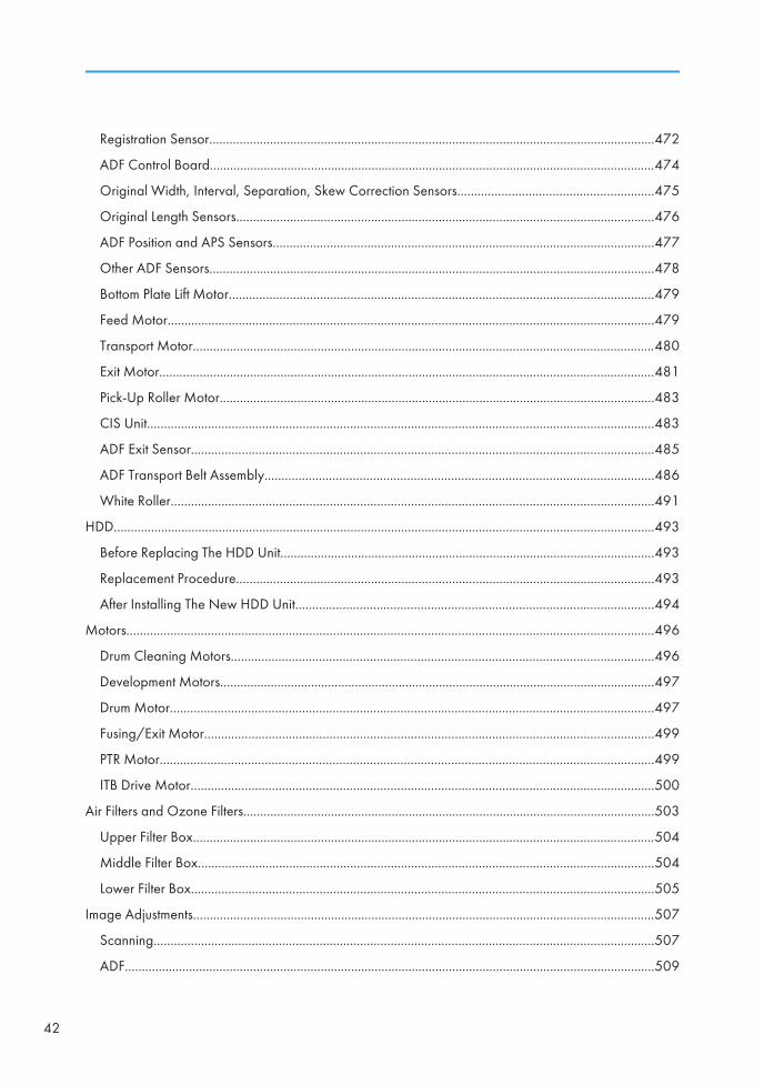
Registration Sensor....................................................................................................................................472
ADF Control Board....................................................................................................................................474
Original Width, Interval, Separation, Skew Correction Sensors..........................................................475
Original Length Sensors............................................................................................................................476
ADF Position and APS Sensors.................................................................................................................477
Other ADF Sensors....................................................................................................................................478
Bottom Plate Lift Motor..............................................................................................................................479
Feed Motor................................................................................................................................................479
Transport Motor.........................................................................................................................................480
Exit Motor...................................................................................................................................................481
Pick-Up Roller Motor.................................................................................................................................483
CIS Unit......................................................................................................................................................483
ADF Exit Sensor.........................................................................................................................................485
ADF Transport Belt Assembly...................................................................................................................486
White Roller...............................................................................................................................................491
HDD................................................................................................................................................................493
Before Replacing The HDD Unit...............................................................................................................493
Replacement Procedure............................................................................................................................493
After Installing The New HDD Unit..........................................................................................................494
Motors............................................................................................................................................................496
Drum Cleaning Motors.............................................................................................................................496
Development Motors.................................................................................................................................497
Drum Motor...............................................................................................................................................497
Fusing/Exit Motor.....................................................................................................................................499
PTR Motor..................................................................................................................................................499
ITB Drive Motor.........................................................................................................................................500
Air Filters and Ozone Filters..........................................................................................................................503
Upper Filter Box.........................................................................................................................................504
Middle Filter Box.......................................................................................................................................504
Lower Filter Box.........................................................................................................................................505
Image Adjustments.........................................................................................................................................507
Scanning....................................................................................................................................................507
ADF.............................................................................................................................................................509
42
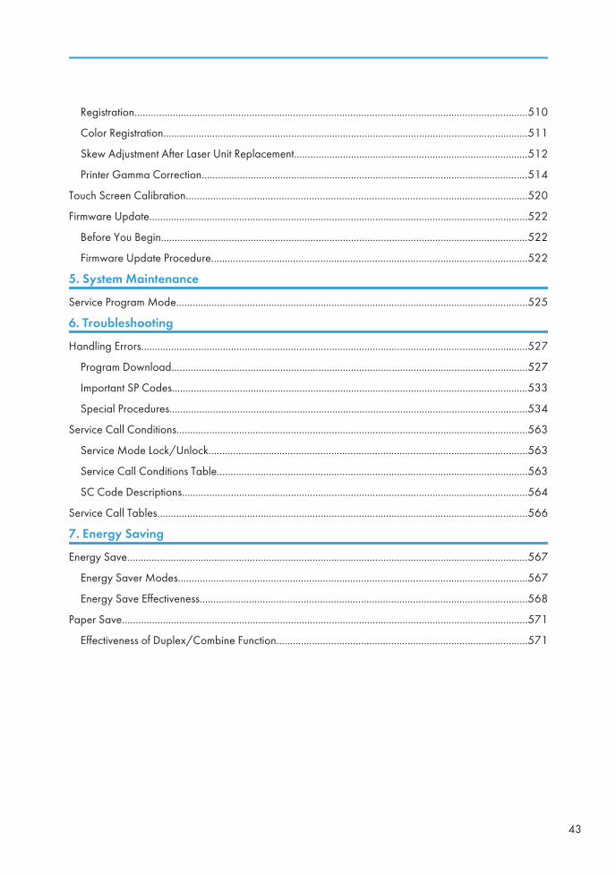
Registration................................................................................................................................................510
Color Registration......................................................................................................................................511
Skew Adjustment After Laser Unit Replacement......................................................................................512
Printer Gamma Correction........................................................................................................................514
Touch Screen Calibration.............................................................................................................................520
Firmware Update...........................................................................................................................................522
Before You Begin.......................................................................................................................................522
Firmware Update Procedure....................................................................................................................522
5. System Maintenance
Service Program Mode.................................................................................................................................525
6. Troubleshooting
Handling Errors..............................................................................................................................................527
Program Download...................................................................................................................................527
Important SP Codes...................................................................................................................................533
Special Procedures....................................................................................................................................534
Service Call Conditions.................................................................................................................................563
Service Mode Lock/Unlock.....................................................................................................................563
Service Call Conditions Table..................................................................................................................563
SC Code Descriptions...............................................................................................................................564
Service Call Tables........................................................................................................................................566
7. Energy Saving
Energy Save...................................................................................................................................................567
Energy Saver Modes................................................................................................................................567
Energy Save Effectiveness........................................................................................................................568
Paper Save.....................................................................................................................................................571
Effectiveness of Duplex/Combine Function............................................................................................571
43

44

1. Product Information
SpecificationsSee "Appendices" for the following information:
• Specifications
45
1
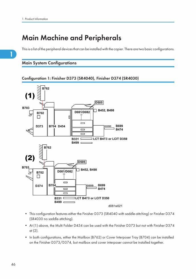
Main Machine and PeripheralsThis is a list of the peripheral devices that can be installed with the copier. There are two basic configurations.
Main System Configurations
Configuration 1: Finisher D373 (SR4040), Finisher D374 (SR4030)
• This configuration features either the Finisher D373 (SR4040 with saddle-stitching) or Finisher D374(SR4030 no saddle-stitching).
• At (1) above, the Multi Folder D454 can be used with the Finisher D373 but not with Finisher D374at (2).
• In both configurations, either the Mailbox (B762) or Cover Interposer Tray (B704) can be installedon the Finisher D373/D374, but mailbox and cover interposer cannot be installed together.
1. Product Information
46
1
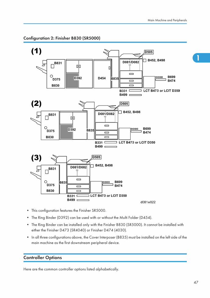
Configuration 2: Finisher B830 (SR5000)
• This configuration features the Finisher SR5000.
• The Ring Binder (D392) can be used with or without the Multi Folder (D454).
• The Ring Binder can be installed only with the Finisher B830 (SR5000). It cannot be installed witheither the Finisher D473 (SR4040) or Finisher D474 (4030).
• In all three configurations above, the Cover Interposer (B835) must be installed on the left side of themain machine as the first downstream peripheral device.
Controller Options
Here are the common controller options listed alphabetically.
Main Machine and Peripherals
47
1
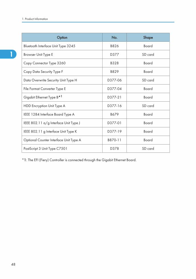
Option No. Shape
Bluetooth Interface Unit Type 3245 B826 Board
Browser Unit Type E D377 SD card
Copy Connector Type 3260 B328 Board
Copy Data Security Type F B829 Board
Data Overwrite Security Unit Type H D377-06 SD card
File Format Converter Type E D377-04 Board
Gigabit Ethernet Type B*1 D377-21 Board
HDD Encryption Unit Type A D377-16 SD card
IEEE 1284 Interface Board Type A B679 Board
IEEE 802.11 a/g Interface Unit Type J D377-01 Board
IEEE 802.11 g Interface Unit Type K D377-19 Board
Optional Counter Interface Unit Type A B870-11 Board
PostScript 3 Unit Type C7501 D378 SD card
*1: The EFI (Fiery) Controller is connected through the Gigabit Ethernet Board.
1. Product Information
48
1
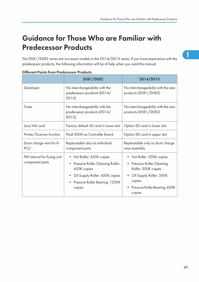
Guidance for Those Who are Familiar withPredecessor ProductsThe D081/D082 series are successor models to the D014/D015 series. If you have experience with thepredecessor products, the following information will be of help when you read this manual.
Different Points from Predecessor Products
D081/D082 D014/D015
Developer No interchangeability with thepredecessor products (D014/D015)
No interchangeability with the newproducts (D081/D082)
Toner No interchangeability with thepredecessor products (D014/D015)
No interchangeability with the newproducts (D081/D082)
Java VM card Factory default SD card in lower slot Option SD card in lower slot
Printer/Scanner function Flash ROM on Controller Board Option SD card in upper slot
Drum charge wire for K-PCU
Replaceable also as individualcomponent parts
Replaceable only as drum chargewire assembly
PM interval for fusing unitcomponent parts
• Hot Roller: 450K copies
• Pressure Roller Cleaning Roller:450K copies
• Oil Supply Roller: 450K copies
• Pressure Roller Bearing: 1200Kcopies
• Hot Roller: 300K copies
• Pressure Roller CleaningRoller: 300K copies
• Oil Supply Roller: 300Kcopies
• Pressure Roller Bearing: 600Kcopies
Guidance for Those Who are Familiar with Predecessor Products
49
1
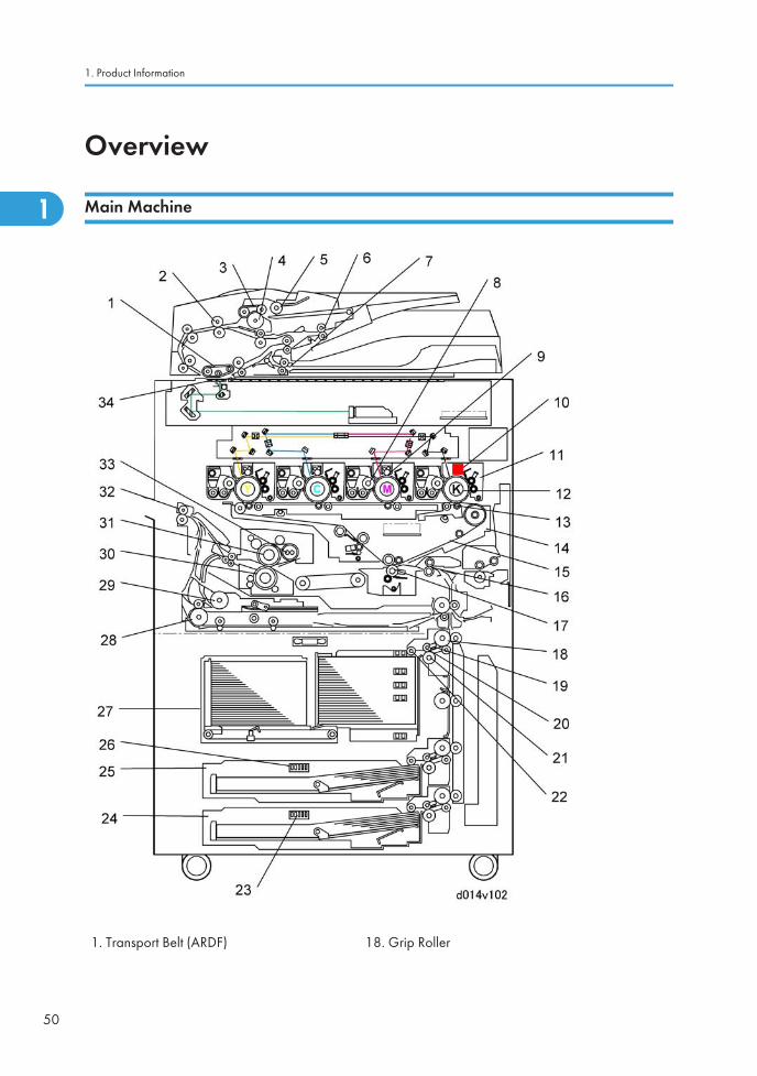
Overview
Main Machine
1. Transport Belt (ARDF) 18. Grip Roller
1. Product Information
50
1
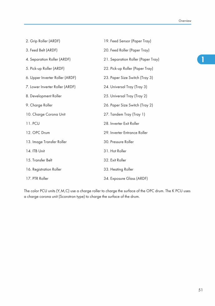
2. Grip Roller (ARDF) 19. Feed Sensor (Paper Tray)
3. Feed Belt (ARDF) 20. Feed Roller (Paper Tray)
4. Separation Roller (ARDF) 21. Separation Roller (Paper Tray)
5. Pick-up Roller (ARDF) 22. Pick-up Roller (Paper Tray)
6. Upper Inverter Roller (ARDF) 23. Paper Size Switch (Tray 3)
7. Lower Inverter Roller (ARDF) 24. Universal Tray (Tray 3)
8. Development Roller 25. Universal Tray (Tray 2)
9. Charge Roller 26. Paper Size Switch (Tray 2)
10. Charge Corona Unit 27. Tandem Tray (Tray 1)
11. PCU 28. Inverter Exit Roller
12. OPC Drum 29. Inverter Entrance Roller
13. Image Transfer Roller 30. Pressure Roller
14. ITB Unit 31. Hot Roller
15. Transfer Belt 32. Exit Roller
16. Registration Roller 33. Heating Roller
17. PTR Roller 34. Exposure Glass (ARDF)
The color PCU units (Y,M,C) use a charge roller to charge the surface of the OPC drum. The K PCU usesa charge corona unit (Scorotron type) to charge the surface of the drum.
Overview
51
1

1. Product Information
52
1
2. Installation
Installation Requirements
Operating Environment
1. Temperature Range
• Recommended Temp.: 23°C (73.4°F)
• Allowed Temp.: 10°C to 32°C (50°F to 90°F) – See the Note below
2. Humidity Range: 15% to 80% Rh
3. Ambient Illumination: Less than 1,500 lux (do not expose to direct sunlight or strong light.)
4. Ventilation: Air must be replaced a minimum of 3 times per hour
5. Ambient Dust: Less than 0.10 mg/m3
• If the machine is installed in a location where the ambient temperature is more than 30°C (86°F).
• Do not run full color copying longer than 2 hours, and never turn the main power switch offimmediately after a long copy job.
• Leave the machine on so the fans can expel the hot air from the machine and cool the electroniccomponents.
53
2
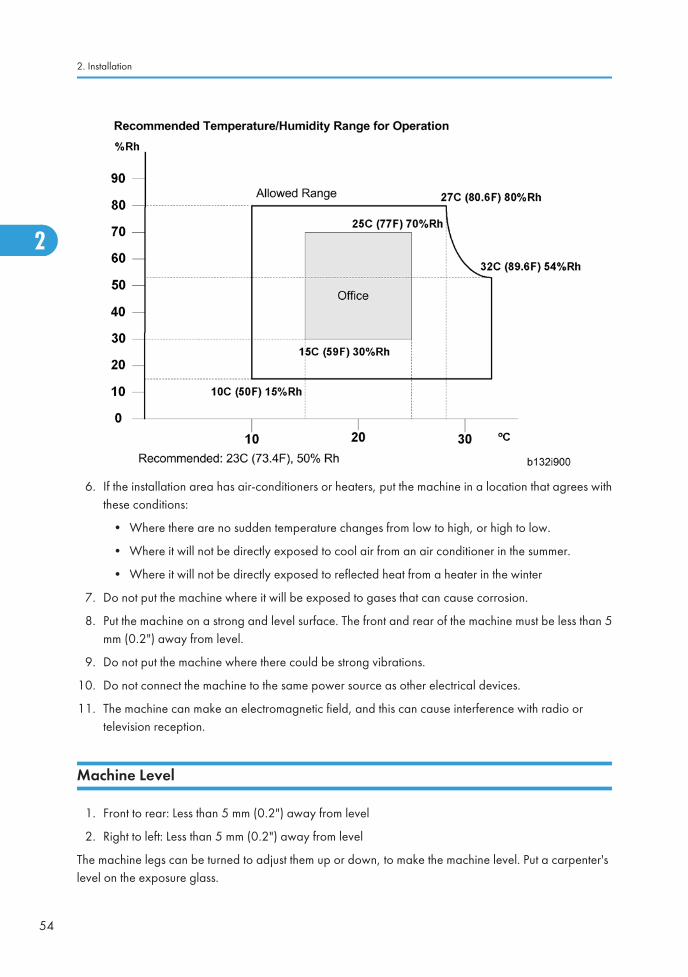
6. If the installation area has air-conditioners or heaters, put the machine in a location that agrees withthese conditions:
• Where there are no sudden temperature changes from low to high, or high to low.
• Where it will not be directly exposed to cool air from an air conditioner in the summer.
• Where it will not be directly exposed to reflected heat from a heater in the winter
7. Do not put the machine where it will be exposed to gases that can cause corrosion.
8. Put the machine on a strong and level surface. The front and rear of the machine must be less than 5mm (0.2") away from level.
9. Do not put the machine where there could be strong vibrations.
10. Do not connect the machine to the same power source as other electrical devices.
11. The machine can make an electromagnetic field, and this can cause interference with radio ortelevision reception.
Machine Level
1. Front to rear: Less than 5 mm (0.2") away from level
2. Right to left: Less than 5 mm (0.2") away from level
The machine legs can be turned to adjust them up or down, to make the machine level. Put a carpenter'slevel on the exposure glass.
2. Installation
54
2
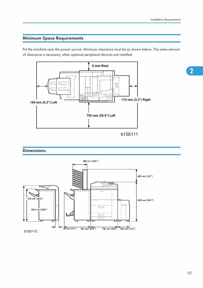
Minimum Space Requirements
Put the machine near the power source. Minimum clearance must be as shown below. The same amountof clearance is necessary when optional peripheral devices are installed.
Dimensions
Installation Requirements
55
2
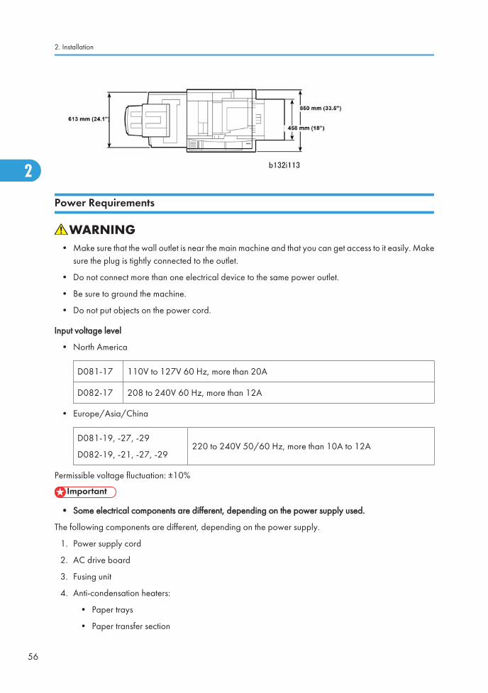
Power Requirements
• Make sure that the wall outlet is near the main machine and that you can get access to it easily. Makesure the plug is tightly connected to the outlet.
• Do not connect more than one electrical device to the same power outlet.
• Be sure to ground the machine.
• Do not put objects on the power cord.
Input voltage level
• North America
D081-17 110V to 127V 60 Hz, more than 20A
D082-17 208 to 240V 60 Hz, more than 12A
• Europe/Asia/China
D081-19, -27, -29
D082-19, -21, -27, -29220 to 240V 50/60 Hz, more than 10A to 12A
Permissible voltage fluctuation: ±10%
• Some electrical components are different, depending on the power supply used.
The following components are different, depending on the power supply.
1. Power supply cord
2. AC drive board
3. Fusing unit
4. Anti-condensation heaters:
• Paper trays
• Paper transfer section
2. Installation
56
2
• Scanner heater (option)
• LCT (B473) heater (option)
• LCIT (D350) heater (option)
• Do not turn off the main power switch when the power LED is lit or flashing. To prevent damage to thehard disk or memory, push the operation switch to turn the power off, then do nothing until the powerLED goes off, and then turn the main power switch off.
There are two power switches on the machine:
Main Power Switch
This is located on the front left corner of the machine and has a plastic cover. This switch must always beon unless a technician does work on the machine.
Operation Switch
This is located on the right side of the operation panel. This is the switch that the customer uses to turn themachine on and off.
Installation Requirements
57
2
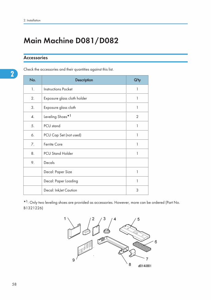
Main Machine D081/D082
Accessories
Check the accessories and their quantities against this list.
No. Description Q'ty
1. Instructions Pocket 1
2. Exposure glass cloth holder 1
3. Exposure glass cloth 1
4. Leveling Shoes*1 2
5. PCU stand 1
6. PCU Cap Set (not used) 1
7. Ferrite Core 1
8. PCU Stand Holder 1
9. Decals
Decal: Paper Size 1
Decal: Paper Loading 1
Decal: InkJet Caution 3
*1: Only two leveling shoes are provided as accessories. However, more can be ordered (Part No.B1321226)
2. Installation
58
2
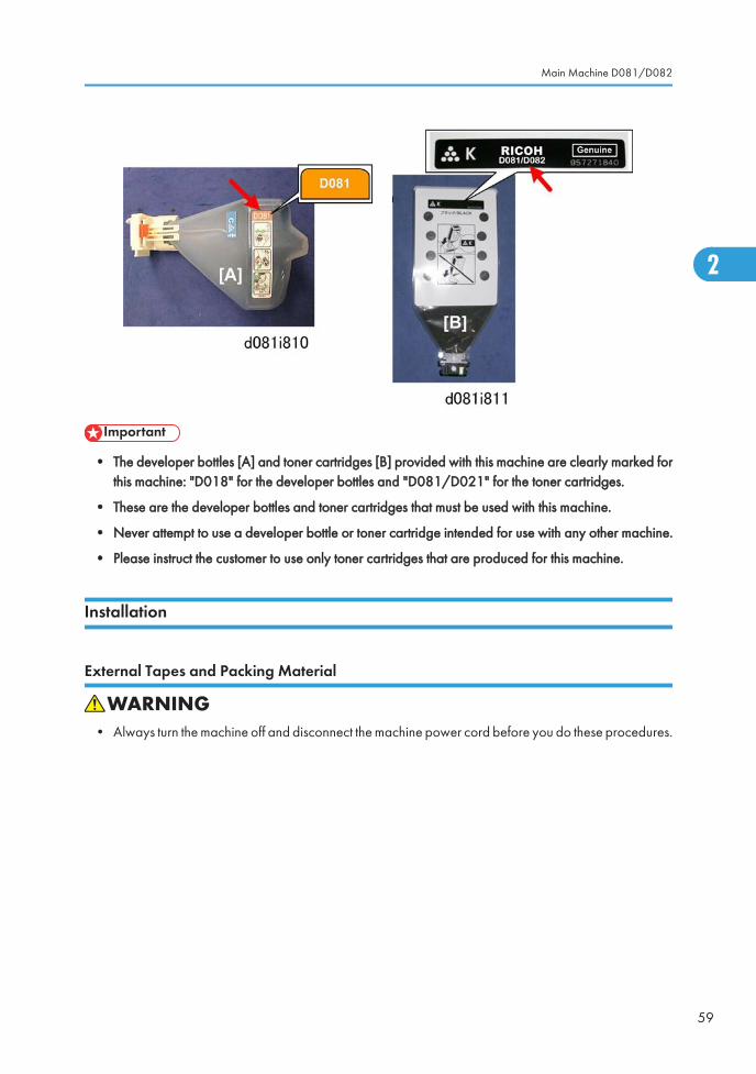
• The developer bottles [A] and toner cartridges [B] provided with this machine are clearly marked forthis machine: "D018" for the developer bottles and "D081/D021" for the toner cartridges.
• These are the developer bottles and toner cartridges that must be used with this machine.
• Never attempt to use a developer bottle or toner cartridge intended for use with any other machine.
• Please instruct the customer to use only toner cartridges that are produced for this machine.
Installation
External Tapes and Packing Material
• Always turn the machine off and disconnect the machine power cord before you do these procedures.
Main Machine D081/D082
59
2

Remove all tapes and packing material from the main machine:
1. Remove:
[A]: ADF, right side
[B]: Packing block inside ADF
[C]: Accessories bag. Remove other accessory bags from Tray 2, Tray 3.
[D]: ADF, left side
[E]: Power cord
2. Raise the ADF and remove the "SP Mode Factory Setting" sheet. Keep this sheet for future reference.
2. Installation
60
2
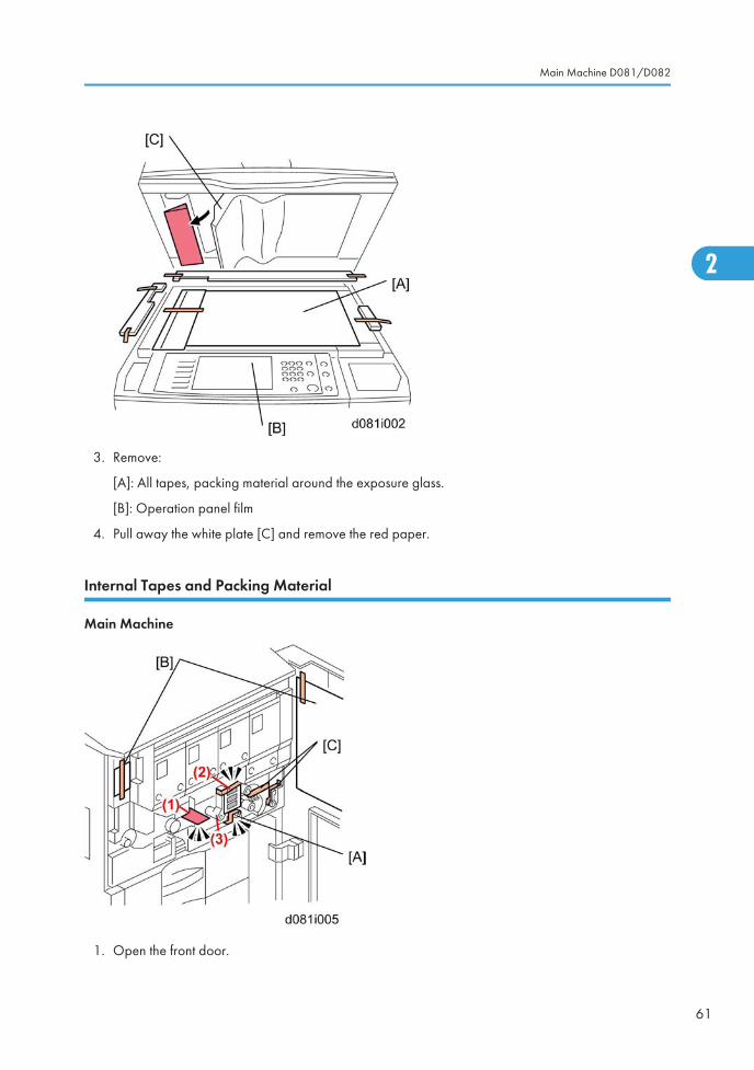
3. Remove:
[A]: All tapes, packing material around the exposure glass.
[B]: Operation panel film
4. Pull away the white plate [C] and remove the red paper.
Internal Tapes and Packing Material
Main Machine
1. Open the front door.
Main Machine D081/D082
61
2
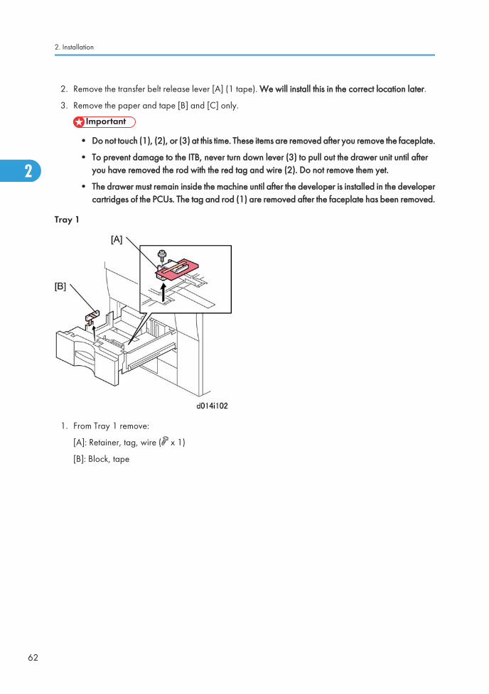
2. Remove the transfer belt release lever [A] (1 tape). We will install this in the correct location later.
3. Remove the paper and tape [B] and [C] only.
• Do not touch (1), (2), or (3) at this time. These items are removed after you remove the faceplate.
• To prevent damage to the ITB, never turn down lever (3) to pull out the drawer unit until afteryou have removed the rod with the red tag and wire (2). Do not remove them yet.
• The drawer must remain inside the machine until after the developer is installed in the developercartridges of the PCUs. The tag and rod (1) are removed after the faceplate has been removed.
Tray 1
1. From Tray 1 remove:
[A]: Retainer, tag, wire ( x 1)
[B]: Block, tape
2. Installation
62
2
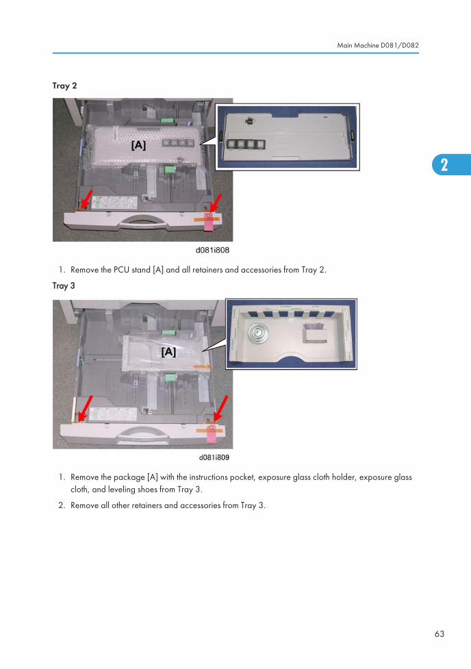
Tray 2
1. Remove the PCU stand [A] and all retainers and accessories from Tray 2.
Tray 3
1. Remove the package [A] with the instructions pocket, exposure glass cloth holder, exposure glasscloth, and leveling shoes from Tray 3.
2. Remove all other retainers and accessories from Tray 3.
Main Machine D081/D082
63
2
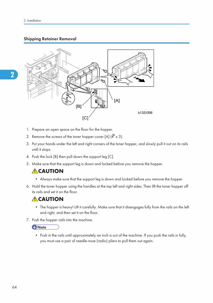
Shipping Retainer Removal
1. Prepare an open space on the floor for the hopper.
2. Remove the screws of the toner hopper cover [A] ( x 3).
3. Put your hands under the left and right corners of the toner hopper, and slowly pull it out on its railsuntil it stops.
4. Push the lock [B] then pull down the support leg [C].
5. Make sure that the support leg is down and locked before you remove the hopper.
• Always make sure that the support leg is down and locked before you remove the hopper.
6. Hold the toner hopper using the handles at the top left and right sides. Then lift the toner hopper offits rails and set it on the floor.
• The hopper is heavy! Lift it carefully. Make sure that it disengages fully from the rails on the leftand right, and then set it on the floor.
7. Push the hopper rails into the machine.
• Push in the rails until approximately an inch is out of the machine. If you push the rails in fully,you must use a pair of needle-nose (radio) pliers to pull them out again.
2. Installation
64
2
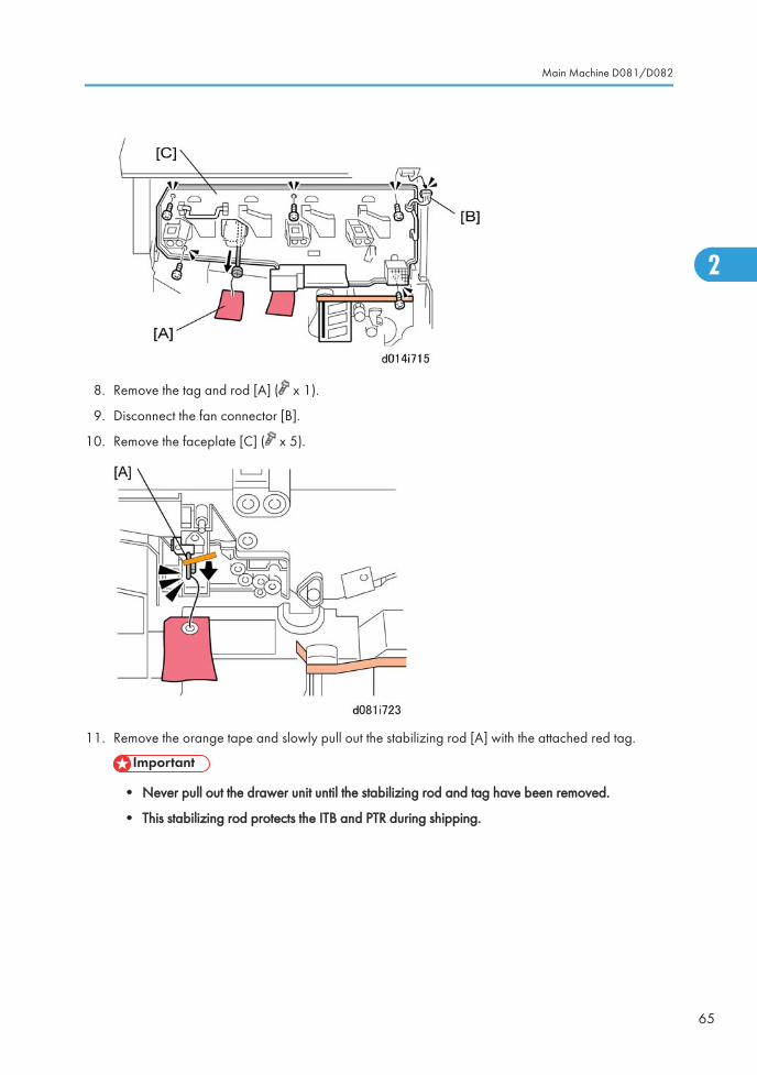
8. Remove the tag and rod [A] ( x 1).
9. Disconnect the fan connector [B].
10. Remove the faceplate [C] ( x 5).
11. Remove the orange tape and slowly pull out the stabilizing rod [A] with the attached red tag.
• Never pull out the drawer unit until the stabilizing rod and tag have been removed.
• This stabilizing rod protects the ITB and PTR during shipping.
Main Machine D081/D082
65
2
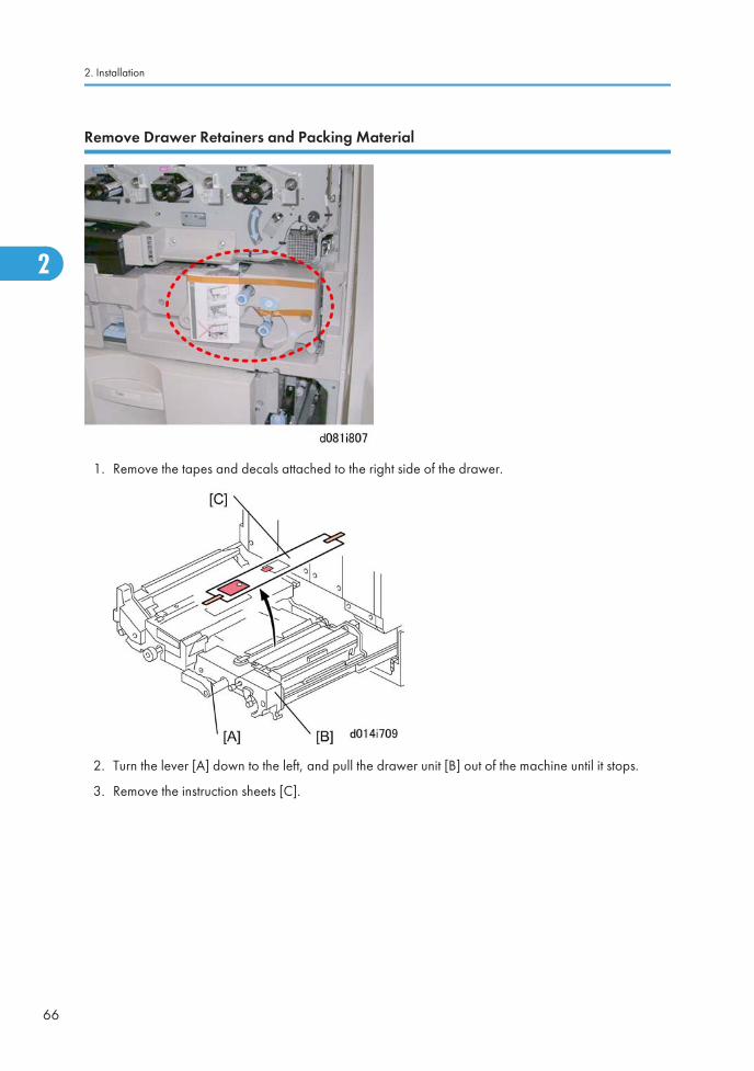
Remove Drawer Retainers and Packing Material
1. Remove the tapes and decals attached to the right side of the drawer.
2. Turn the lever [A] down to the left, and pull the drawer unit [B] out of the machine until it stops.
3. Remove the instruction sheets [C].
2. Installation
66
2
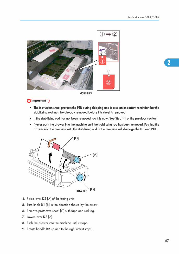
• The instruction sheet protects the PTR during shipping and is also an important reminder that thestabilizing rod must be already removed before this sheet is removed.
• If the stabilizing rod has not been removed, do this now. See Step 11 of the previous section.
• Never push the drawer into the machine until the stabilizing rod has been removed. Pushing thedrawer into the machine with the stabilizing rod in the machine will damage the ITB and PTR.
4. Raise lever D2 [A] of the fusing unit.
5. Turn knob D1 [B] in the direction shown by the arrow.
6. Remove protective sheet [C] with tape and red tag.
7. Lower lever D2 [A].
8. Push the drawer into the machine until it stops.
9. Rotate handle B2 up and to the right until it stops.
Main Machine D081/D082
67
2
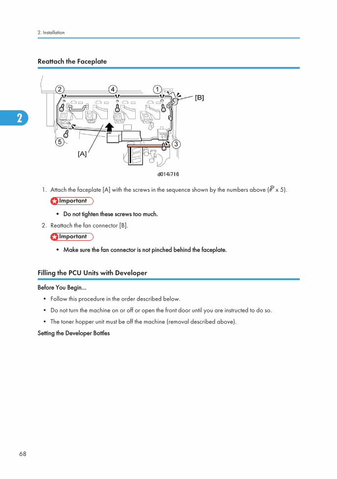
Reattach the Faceplate
1. Attach the faceplate [A] with the screws in the sequence shown by the numbers above ( x 5).
• Do not tighten these screws too much.
2. Reattach the fan connector [B].
• Make sure the fan connector is not pinched behind the faceplate.
Filling the PCU Units with Developer
Before You Begin…
• Follow this procedure in the order described below.
• Do not turn the machine on or off or open the front door until you are instructed to do so.
• The toner hopper unit must be off the machine (removal described above).
Setting the Developer Bottles
2. Installation
68
2
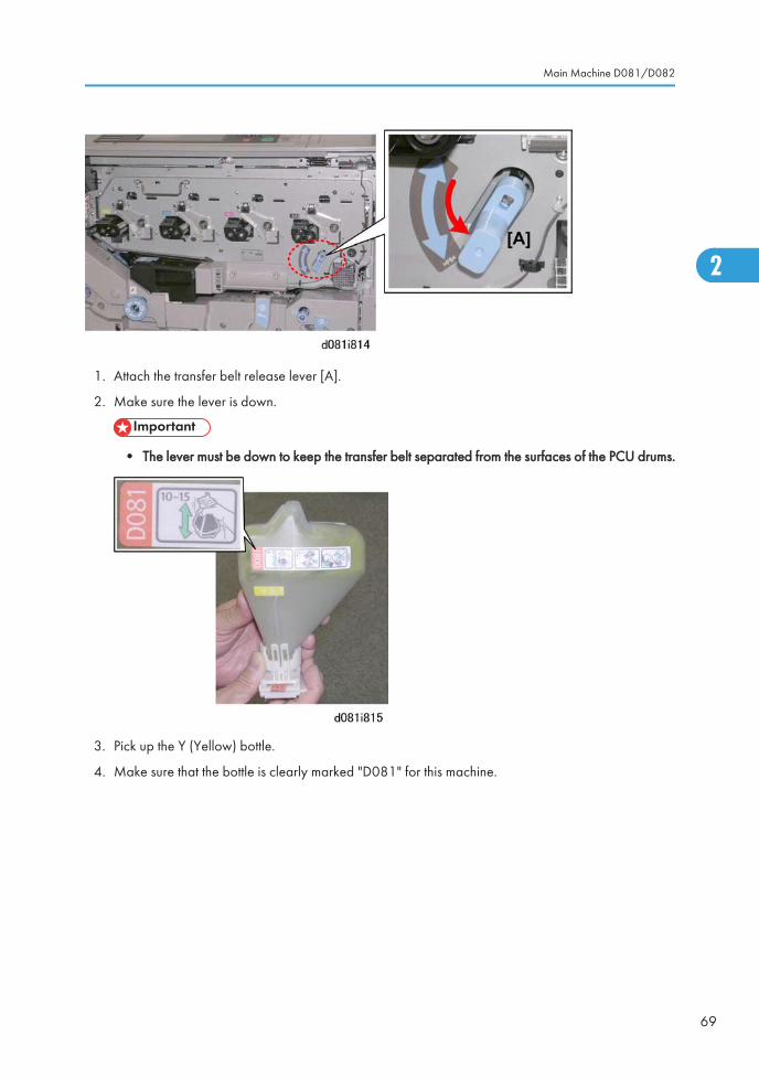
1. Attach the transfer belt release lever [A].
2. Make sure the lever is down.
• The lever must be down to keep the transfer belt separated from the surfaces of the PCU drums.
3. Pick up the Y (Yellow) bottle.
4. Make sure that the bottle is clearly marked "D081" for this machine.
Main Machine D081/D082
69
2
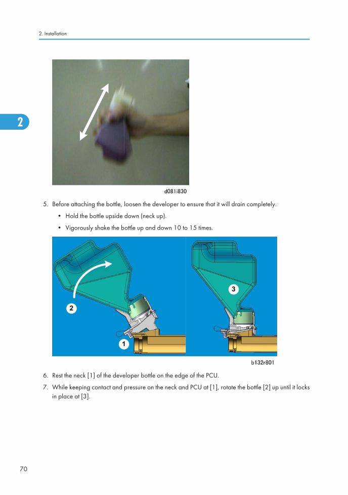
5. Before attaching the bottle, loosen the developer to ensure that it will drain completely.
• Hold the bottle upside down (neck up).
• Vigorously shake the bottle up and down 10 to 15 times.
6. Rest the neck [1] of the developer bottle on the edge of the PCU.
7. While keeping contact and pressure on the neck and PCU at [1], rotate the bottle [2] up until it locksin place at [3].
2. Installation
70
2

8. Check the tab on the side of the neck [1] to make sure that the bottle is locked. The neck of the bottleshould be perfectly flat on top of the PCU.
• There should be no gap between the developer bottle and the PCU.
• If the bottle is not locked in place, developer will spill from the bottle.
9. Repeat Steps 3 to 8 to install and lock the other bottles (M, C, K).
10. Remove the heat seal from each bottle.
• Hold the bottle [1] with one hand, slowly pull the heat seal [2] out of the developer bottle andremove it.
• Do this for each bottle.
Main Machine D081/D082
71
2
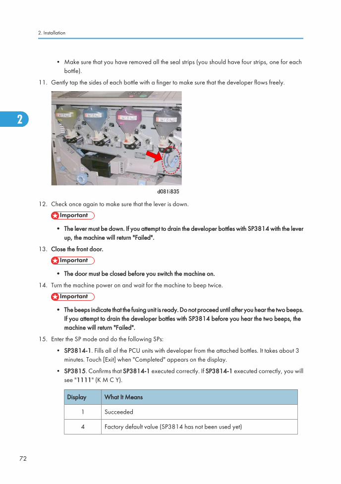
• Make sure that you have removed all the seal strips (you should have four strips, one for eachbottle).
11. Gently tap the sides of each bottle with a finger to make sure that the developer flows freely.
12. Check once again to make sure that the lever is down.
• The lever must be down. If you attempt to drain the developer bottles with SP3814 with the leverup, the machine will return "Failed".
13. Close the front door.
• The door must be closed before you switch the machine on.
14. Turn the machine power on and wait for the machine to beep twice.
• The beeps indicate that the fusing unit is ready. Do not proceed until after you hear the two beeps.If you attempt to drain the developer bottles with SP3814 before you hear the two beeps, themachine will return "Failed".
15. Enter the SP mode and do the following SPs:
• SP3814-1. Fills all of the PCU units with developer from the attached bottles. It takes about 3minutes. Touch [Exit] when "Completed" appears on the display.
• SP3815. Confirms that SP3814-1 executed correctly. If SP3814-1 executed correctly, you willsee "1111" (K M C Y).
Display What It Means
1 Succeeded
4 Factory default value (SP3814 has not been used yet)
2. Installation
72
2
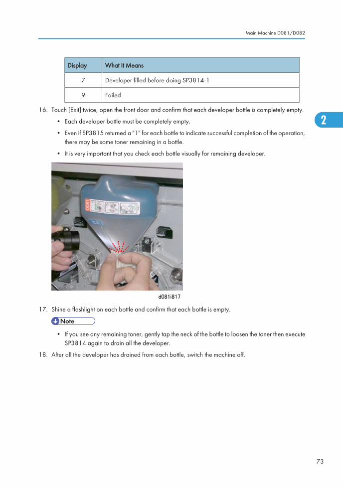
Display What It Means
7 Developer filled before doing SP3814-1
9 Failed
16. Touch [Exit] twice, open the front door and confirm that each developer bottle is completely empty.
• Each developer bottle must be completely empty.
• Even if SP3815 returned a "1" for each bottle to indicate successful completion of the operation,there may be some toner remaining in a bottle.
• It is very important that you check each bottle visually for remaining developer.
17. Shine a flashlight on each bottle and confirm that each bottle is empty.
• If you see any remaining toner, gently tap the neck of the bottle to loosen the toner then executeSP3814 again to drain all the developer.
18. After all the developer has drained from each bottle, switch the machine off.
Main Machine D081/D082
73
2
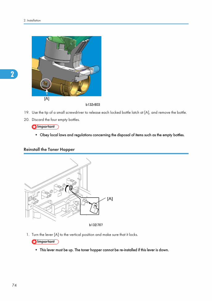
19. Use the tip of a small screwdriver to release each locked bottle latch at [A], and remove the bottle.
20. Discard the four empty bottles.
• Obey local laws and regulations concerning the disposal of items such as the empty bottles.
Reinstall the Toner Hopper
1. Turn the lever [A] to the vertical position and make sure that it locks.
• This lever must be up. The toner hopper cannot be re-installed if this lever is down.
2. Installation
74
2
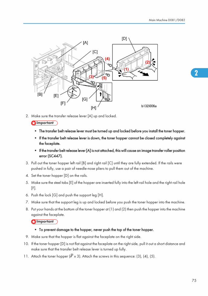
2. Make sure the transfer release lever [A] up and locked.
• The transfer belt release lever must be turned up and locked before you install the toner hopper.
• If the transfer belt release lever is down, the toner hopper cannot be closed completely againstthe faceplate.
• If the transfer belt release lever [A] is not attached, this will cause an image transfer roller positionerror (SC447).
3. Pull out the toner hopper left rail [B] and right rail [C] until they are fully extended. If the rails werepushed in fully, use a pair of needle-nose pliers to pull them out of the machine.
4. Set the toner hopper [D] on the rails.
5. Make sure the steel tabs [E] of the hopper are inserted fully into the left rail hole and the right rail hole[F].
6. Push the lock [G] and push the support leg [H].
7. Make sure that the support leg is up and locked before you push the toner hopper into the machine.
8. Put your hands at the bottom of the toner hopper at (1) and (2) then push the hopper into the machineagainst the faceplate.
• To prevent damage to the hopper, never push the top of the toner hopper.
9. Make sure that the hopper is flat against the faceplate on the right side.
10. If the toner hopper [D] is not flat against the faceplate on the right side, pull it out a short distance andmake sure that the transfer belt release lever is turned up fully.
11. Attach the toner hopper ( x 3). Attach the screws in this sequence: (3), (4), (5).
Main Machine D081/D082
75
2
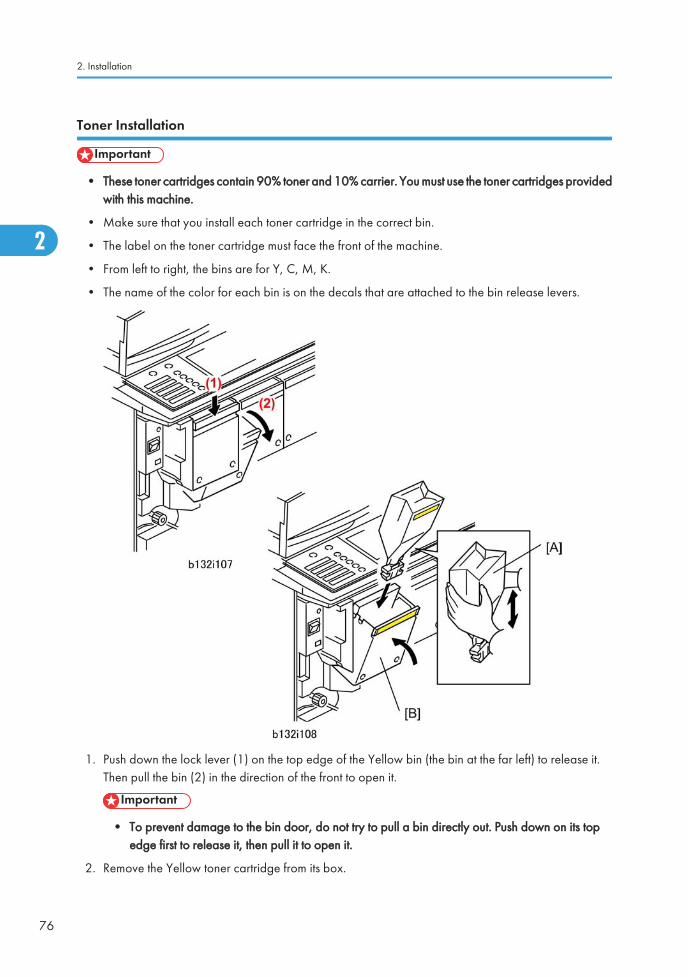
Toner Installation
• These toner cartridges contain 90% toner and 10% carrier. You must use the toner cartridges providedwith this machine.
• Make sure that you install each toner cartridge in the correct bin.
• The label on the toner cartridge must face the front of the machine.
• From left to right, the bins are for Y, C, M, K.
• The name of the color for each bin is on the decals that are attached to the bin release levers.
1. Push down the lock lever (1) on the top edge of the Yellow bin (the bin at the far left) to release it.Then pull the bin (2) in the direction of the front to open it.
• To prevent damage to the bin door, do not try to pull a bin directly out. Push down on its topedge first to release it, then pull it to open it.
2. Remove the Yellow toner cartridge from its box.
2. Installation
76
2
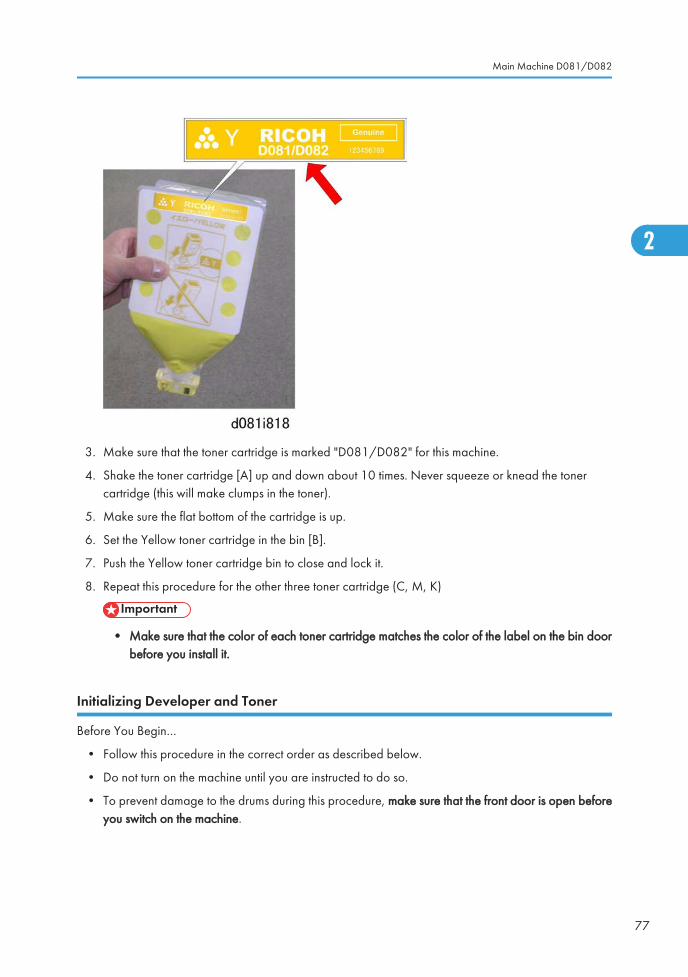
3. Make sure that the toner cartridge is marked "D081/D082" for this machine.
4. Shake the toner cartridge [A] up and down about 10 times. Never squeeze or knead the tonercartridge (this will make clumps in the toner).
5. Make sure the flat bottom of the cartridge is up.
6. Set the Yellow toner cartridge in the bin [B].
7. Push the Yellow toner cartridge bin to close and lock it.
8. Repeat this procedure for the other three toner cartridge (C, M, K)
• Make sure that the color of each toner cartridge matches the color of the label on the bin doorbefore you install it.
Initializing Developer and Toner
Before You Begin…
• Follow this procedure in the correct order as described below.
• Do not turn on the machine until you are instructed to do so.
• To prevent damage to the drums during this procedure, make sure that the front door is open beforeyou switch on the machine.
Main Machine D081/D082
77
2
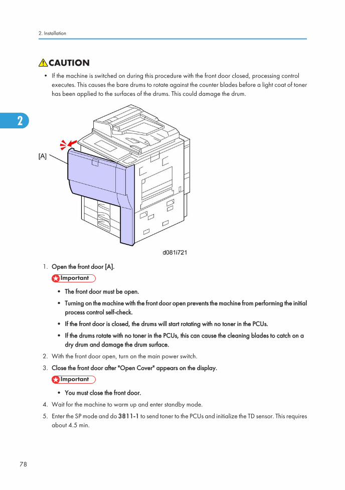
• If the machine is switched on during this procedure with the front door closed, processing controlexecutes. This causes the bare drums to rotate against the counter blades before a light coat of tonerhas been applied to the surfaces of the drums. This could damage the drum.
1. Open the front door [A].
• The front door must be open.
• Turning on the machine with the front door open prevents the machine from performing the initialprocess control self-check.
• If the front door is closed, the drums will start rotating with no toner in the PCUs.
• If the drums rotate with no toner in the PCUs, this can cause the cleaning blades to catch on adry drum and damage the drum surface.
2. With the front door open, turn on the main power switch.
3. Close the front door after "Open Cover" appears on the display.
• You must close the front door.
4. Wait for the machine to warm up and enter standby mode.
5. Enter the SP mode and do 3811-1 to send toner to the PCUs and initialize the TD sensor. This requiresabout 4.5 min.
2. Installation
78
2
• If 'Failed' appears immediately after you start SP3811-1, the machine has not warmed up. Wait2 minutes, and then do SP3811-1 again.
• Do SP3811-1 only once. Executing SP3811-1 more than once can cause toner spill inside themachine. SP3811-1 initializes not only the TD sensor but initializes the developer as well.
• SP3811 does a number of things, including initialization of the TD sensor. You must not initializethe TD sensor again. Do SP3811-1 only once. SP 3801 also initializes the TD sensor.
• Never do SP3801-1 (Init TD Sensor) after doing SP3811. If the TD sensor is initialized twice thiswill cause a fatal error in toner supply control.
6. When the message tells you that the initialization is completed, touch [Close].
7. Do SP3812-1 to confirm that SP3811-1 executed correctly.
• If you see "1111" (K M C Y), this means SP3811-1 executed correctly.
• If you see any number other than "1111", this means an error. (See SP3812 Errors.)
• For a complete list of errors and how to solve problems related these SP codes and light images,please see "Special Procedures" in the Troubleshooting section..
8. Do SP 3821-1 to check that process control was completed successfully.
• For each color, there is a two-digit code, in the order K,M,C,Y. '10' means that process controlwas completed successfully. '10101010' means that all 4 colors completed process controlsuccessfully.
Load the Paper Trays
For each paper cassette tray:
1. Move the side fence and bottom fence to the correct positions for the paper.
2. Add paper to the trays.
3. Attach the paper size decals to the front of the three trays.
• It is not necessary to input the paper size setting for trays 2 and 3. This is detected automatically.
Make a Test Color Print
1. Make sure that A3 or DLT paper is in one of the trays.
• Use the same type of paper that the customer normally uses for color outputs.
2. Put a "Color Chart C-4" on the exposure glass.
Main Machine D081/D082
79
2

3. Select full color mode and print one copy of the chart. You will use this in the ACC procedure, if ACCis necessary.
4. Check the results of the copy with the customer.
5. With a pencil or pen, mark this copy "Before ACC".
• If the quality of the color is satisfactory, ACC adjustment is not necessary.
• If the quality of the color is not satisfactory, do the ACC adjustment described below.
ACC (Automatic Color Calibration) Adjustment
Automatic color calibration is done at the factory with the procedure given below. Do this procedure onlyif the color quality is not satisfactory for the customer.
1. Push [User Tools].
2. To print a color pattern, select Maintenance> Auto Color Calibration
3. Touch [Start] for "Copier Function"
Machine will start self-check before
printing Test Pattern
Press [Start Printing].
4. Touch [Start Printing].
Now self-checking.
Test pattern will be printed.
Please wait.
The machine does process control for a few seconds and it prints the test pattern.
2. Installation
80
2
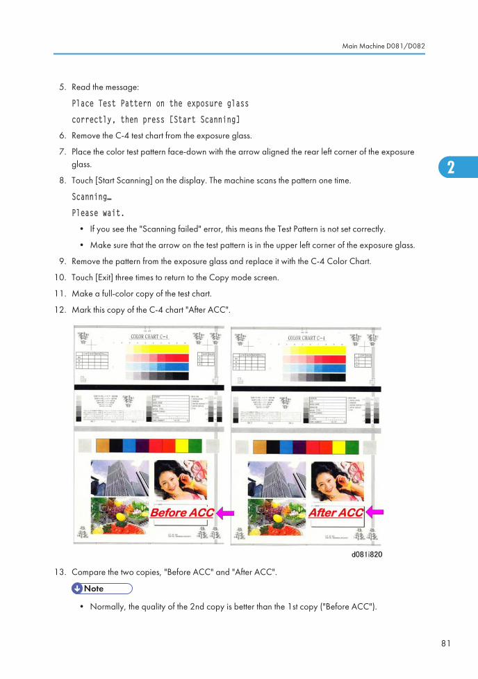
5. Read the message:
Place Test Pattern on the exposure glass
correctly, then press [Start Scanning]
6. Remove the C-4 test chart from the exposure glass.
7. Place the color test pattern face-down with the arrow aligned the rear left corner of the exposureglass.
8. Touch [Start Scanning] on the display. The machine scans the pattern one time.
Scanning…
Please wait.
• If you see the "Scanning failed" error, this means the Test Pattern is not set correctly.
• Make sure that the arrow on the test pattern is in the upper left corner of the exposure glass.
9. Remove the pattern from the exposure glass and replace it with the C-4 Color Chart.
10. Touch [Exit] three times to return to the Copy mode screen.
11. Make a full-color copy of the test chart.
12. Mark this copy of the C-4 chart "After ACC".
13. Compare the two copies, "Before ACC" and "After ACC".
• Normally, the quality of the 2nd copy is better than the 1st copy ("Before ACC").
Main Machine D081/D082
81
2
14. If the results of the 2nd copy are better than the results of the 1st copy, you are finished.
-or-
If the customer prefers the result of the 1st copy:
• Push the [User Tools] key
• Touch Maintenance> Auto Color Calibration> Previous Setting.
15. Remove the color chart from the exposure glass.
16. If the customer is not satisfied with the 1st copy or the 2nd copy, do the printer gamma adjustment( p.514 "Printer Gamma Correction").
Do the Color Registration Procedure for MUSIC
1. Push [User Tools].
2. Touch [Maintenance]> [Color Registration].
3. Touch [OK].
This completes color registration.
Counter Display Setting
The default setting for the counter is "0" (development). Do the SP setting below to set the counter for copy/print (paper count).
1. Enter the SP mode.
2. Do SP5045-1.
3. Select the counter to use:
• 0: Development counter (Default)
• 1: Page counter
• This setting can be switched for the D081/D082 at any time as necessary. (This setting couldbe done only once with the D014/D015 machines.)
2. Installation
82
2
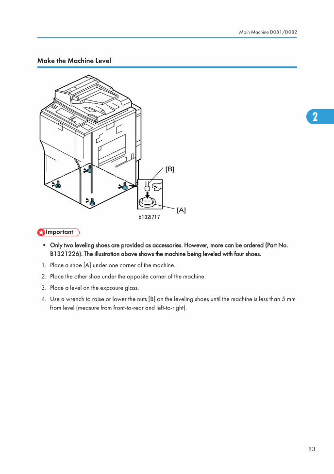
Make the Machine Level
• Only two leveling shoes are provided as accessories. However, more can be ordered (Part No.B1321226). The illustration above shows the machine being leveled with four shoes.
1. Place a shoe [A] under one corner of the machine.
2. Place the other shoe under the opposite corner of the machine.
3. Place a level on the exposure glass.
4. Use a wrench to raise or lower the nuts [B] on the leveling shoes until the machine is less than 5 mmfrom level (measure from front-to-rear and left-to-right).
Main Machine D081/D082
83
2
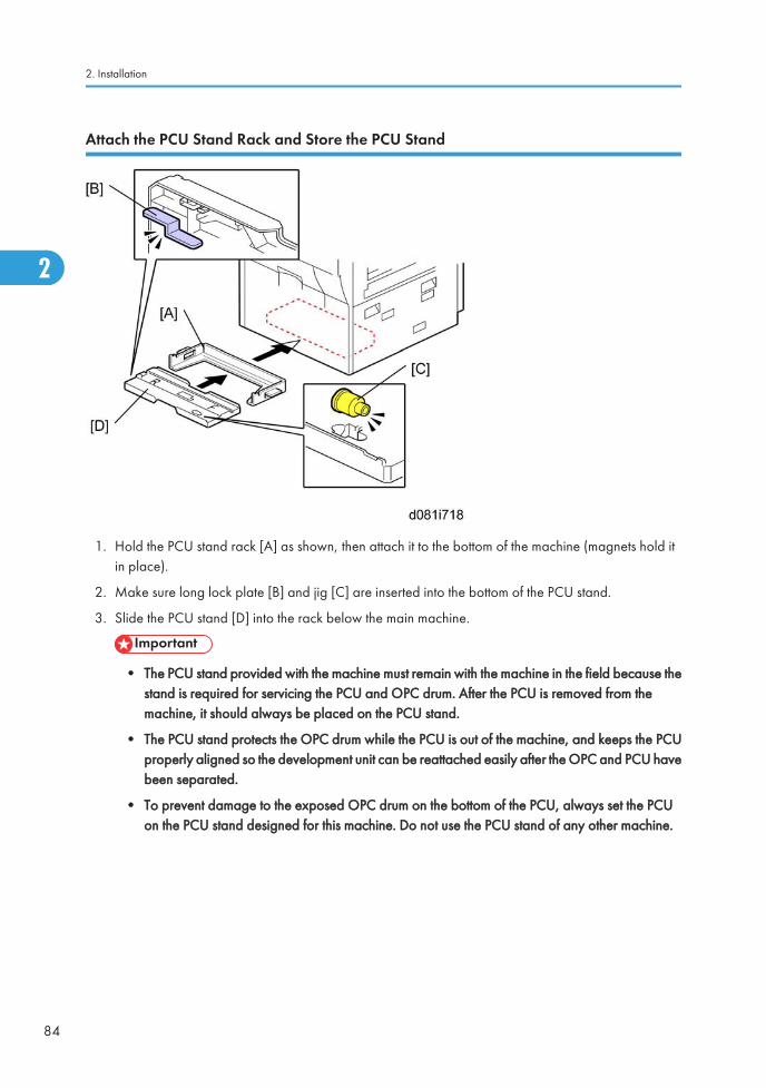
Attach the PCU Stand Rack and Store the PCU Stand
1. Hold the PCU stand rack [A] as shown, then attach it to the bottom of the machine (magnets hold itin place).
2. Make sure long lock plate [B] and jig [C] are inserted into the bottom of the PCU stand.
3. Slide the PCU stand [D] into the rack below the main machine.
• The PCU stand provided with the machine must remain with the machine in the field because thestand is required for servicing the PCU and OPC drum. After the PCU is removed from themachine, it should always be placed on the PCU stand.
• The PCU stand protects the OPC drum while the PCU is out of the machine, and keeps the PCUproperly aligned so the development unit can be reattached easily after the OPC and PCU havebeen separated.
• To prevent damage to the exposed OPC drum on the bottom of the PCU, always set the PCUon the PCU stand designed for this machine. Do not use the PCU stand of any other machine.
2. Installation
84
2
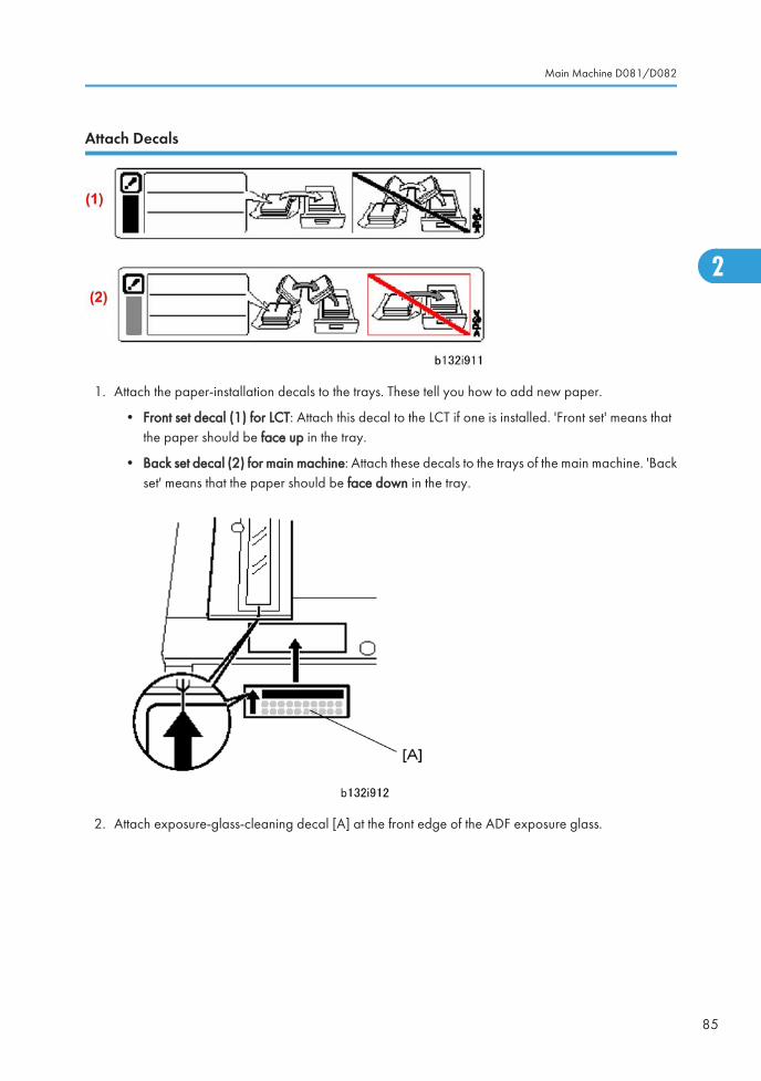
Attach Decals
1. Attach the paper-installation decals to the trays. These tell you how to add new paper.
• Front set decal (1) for LCT: Attach this decal to the LCT if one is installed. 'Front set' means thatthe paper should be face up in the tray.
• Back set decal (2) for main machine: Attach these decals to the trays of the main machine. 'Backset' means that the paper should be face down in the tray.
2. Attach exposure-glass-cleaning decal [A] at the front edge of the ADF exposure glass.
Main Machine D081/D082
85
2
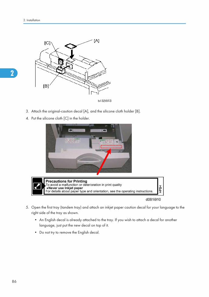
3. Attach the original-caution decal [A], and the silicone cloth holder [B].
4. Put the silicone cloth [C] in the holder.
5. Open the first tray (tandem tray) and attach an inkjet paper caution decal for your language to theright side of the tray as shown.
• An English decal is already attached to the tray. If you wish to attach a decal for anotherlanguage, just put the new decal on top of it.
• Do not try to remove the English decal.
2. Installation
86
2
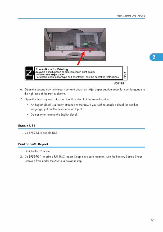
6. Open the second tray (universal tray) and attach an inkjet paper caution decal for your language tothe right side of the tray as shown.
7. Open the third tray and attach an identical decal at the same location.
• An English decal is already attached to the tray. If you wish to attach a decal for anotherlanguage, just put the new decal on top of it.
• Do not try to remove the English decal.
Enable USB
1. Do SP5985 to enable USB.
Print an SMC Report
1. Go into the SP mode.
2. Do SP5990-1 to print a full SMC report. Keep it in a safe location, with the Factory Setting Sheetremoved from under the ADF in a previous step.
Main Machine D081/D082
87
2
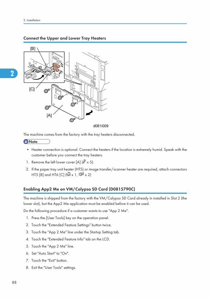
Connect the Upper and Lower Tray Heaters
The machine comes from the factory with the tray heaters disconnected.
• Heater connection is optional. Connect the heaters if the location is extremely humid. Speak with thecustomer before you connect the tray heaters.
1. Remove the left lower cover [A] ( x 5).
2. If the paper tray unit heater (HTS) or image transfer/scanner heater are required, attach connectorsHT5 [B] and HT6 [C] ( x 1, x 2)
Enabling App2 Me on VM/Calypso SD Card (D0815790C)
The machine is shipped from the factory with the VM/Calypso SD Card already in installed in Slot 2 (thelower slot), but the App2 Me application must be enabled before it can be used.
Do the following procedure if a customer wants to use "App 2 Me".
1. Press the [User Tools] key on the operation panel.
2. Touch the "Extended Feature Settings" button twice.
3. Touch the "App 2 Me" line under the Startup Setting tab.
4. Touch the "Extended Feature Info" tab on the LCD.
5. Touch the "App 2 Me" line.
6. Set "Auto Start" to "On".
7. Touch the "Exit" button.
8. Exit the "User Tools" settings.
2. Installation
88
2
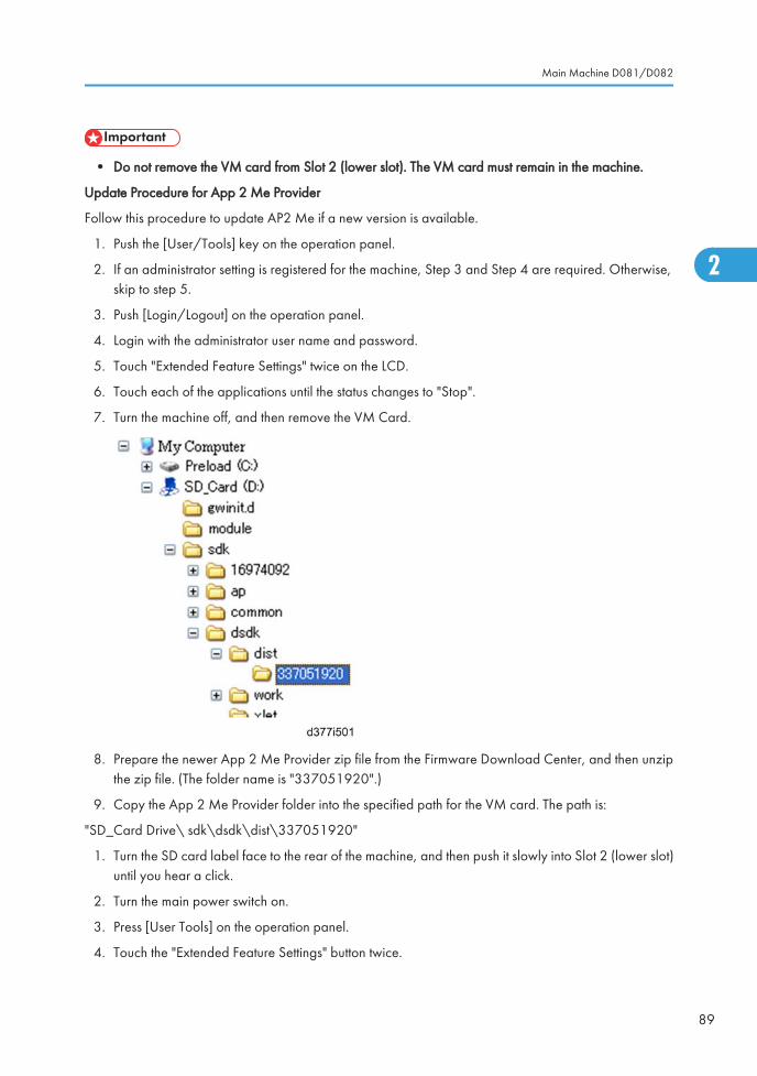
• Do not remove the VM card from Slot 2 (lower slot). The VM card must remain in the machine.
Update Procedure for App 2 Me Provider
Follow this procedure to update AP2 Me if a new version is available.
1. Push the [User/Tools] key on the operation panel.
2. If an administrator setting is registered for the machine, Step 3 and Step 4 are required. Otherwise,skip to step 5.
3. Push [Login/Logout] on the operation panel.
4. Login with the administrator user name and password.
5. Touch "Extended Feature Settings" twice on the LCD.
6. Touch each of the applications until the status changes to "Stop".
7. Turn the machine off, and then remove the VM Card.
8. Prepare the newer App 2 Me Provider zip file from the Firmware Download Center, and then unzipthe zip file. (The folder name is "337051920".)
9. Copy the App 2 Me Provider folder into the specified path for the VM card. The path is:
"SD_Card Drive\ sdk\dsdk\dist\337051920"
1. Turn the SD card label face to the rear of the machine, and then push it slowly into Slot 2 (lower slot)until you hear a click.
2. Turn the main power switch on.
3. Press [User Tools] on the operation panel.
4. Touch the "Extended Feature Settings" button twice.
Main Machine D081/D082
89
2

5. Touch the "Extended Feature Info" tab on the LCD.
6. Touch the "App2Me" line.
7. Set the setting of the "Auto Start" to "On".
8. Touch the "Exit" button.
9. Exit the [User Tools/Counter] settings.
• App2 Me and all other running applications on the VM card must be shut down before theremoving the VM card in order to update the main machine software, backing up NVRAM, orexecuting application move or undo with SP58973.
• After the VM card is re-inserted, App2 Me (and any other VM card applications used by thecustomer) must be switched on after the machine is switched on.
• For more about shutting down and re-starting App2 Me and other VM card applications, see"Before Removing and Re-installing the VM Card".
2. Installation
90
2
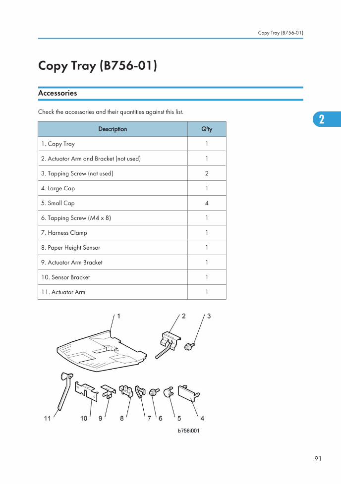
Copy Tray (B756-01)
Accessories
Check the accessories and their quantities against this list.
Description Q'ty
1. Copy Tray 1
2. Actuator Arm and Bracket (not used) 1
3. Tapping Screw (not used) 2
4. Large Cap 1
5. Small Cap 4
6. Tapping Screw (M4 x 8) 1
7. Harness Clamp 1
8. Paper Height Sensor 1
9. Actuator Arm Bracket 1
10. Sensor Bracket 1
11. Actuator Arm 1
Copy Tray (B756-01)
91
2
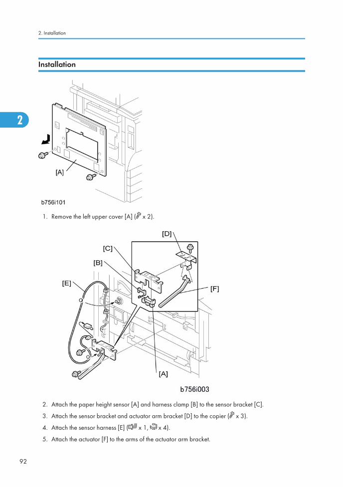
Installation
1. Remove the left upper cover [A] ( x 2).
2. Attach the paper height sensor [A] and harness clamp [B] to the sensor bracket [C].
3. Attach the sensor bracket and actuator arm bracket [D] to the copier ( x 3).
4. Attach the sensor harness [E] ( x 1, x 4).
5. Attach the actuator [F] to the arms of the actuator arm bracket.
2. Installation
92
2
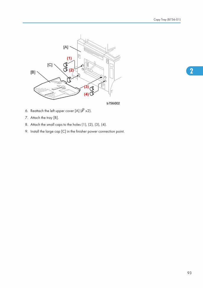
6. Reattach the left upper cover [A] ( x2).
7. Attach the tray [B].
8. Attach the small caps to the holes (1), (2), (3), (4).
9. Install the large cap [C] in the finisher power connection point.
Copy Tray (B756-01)
93
2
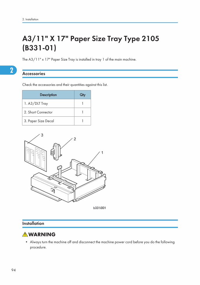
A3/11" X 17" Paper Size Tray Type 2105(B331-01)The A3/11" x 17" Paper Size Tray is installed in tray 1 of the main machine.
Accessories
Check the accessories and their quantities against this list.
Description Qty
1. A3/DLT Tray 1
2. Short Connector 1
3. Paper Size Decal 1
Installation
• Always turn the machine off and disconnect the machine power cord before you do the followingprocedure.
2. Installation
94
2
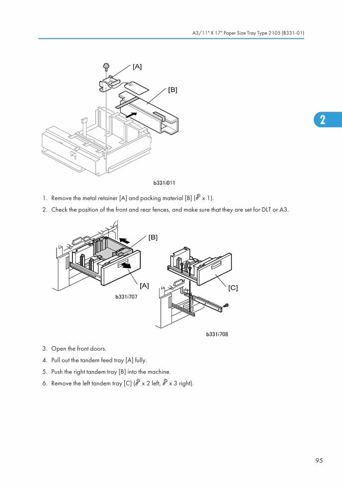
1. Remove the metal retainer [A] and packing material [B] ( x 1).
2. Check the position of the front and rear fences, and make sure that they are set for DLT or A3.
3. Open the front doors.
4. Pull out the tandem feed tray [A] fully.
5. Push the right tandem tray [B] into the machine.
6. Remove the left tandem tray [C] ( x 2 left, x 3 right).
A3/11" X 17" Paper Size Tray Type 2105 (B331-01)
95
2
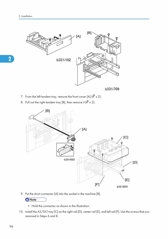
7. From the left tandem tray, remove the front cover [A] ( x 2).
8. Pull out the right tandem tray [B], then remove it ( x 2).
9. Put the short connector [A] into the socket in the machine [B].
• Hold the connector as shown in the illustration.
10. Install the A3/DLT tray [C] on the right rail [D], center rail [E], and left rail [F]. Use the screws that youremoved in Steps 6 and 8.
2. Installation
96
2
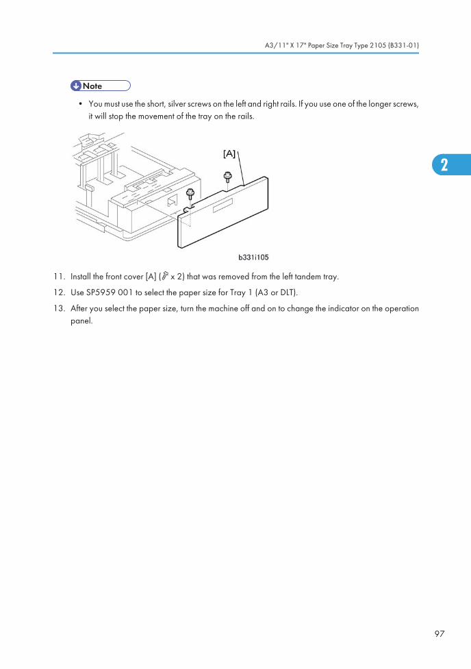
• You must use the short, silver screws on the left and right rails. If you use one of the longer screws,it will stop the movement of the tray on the rails.
11. Install the front cover [A] ( x 2) that was removed from the left tandem tray.
12. Use SP5959 001 to select the paper size for Tray 1 (A3 or DLT).
13. After you select the paper size, turn the machine off and on to change the indicator on the operationpanel.
A3/11" X 17" Paper Size Tray Type 2105 (B331-01)
97
2
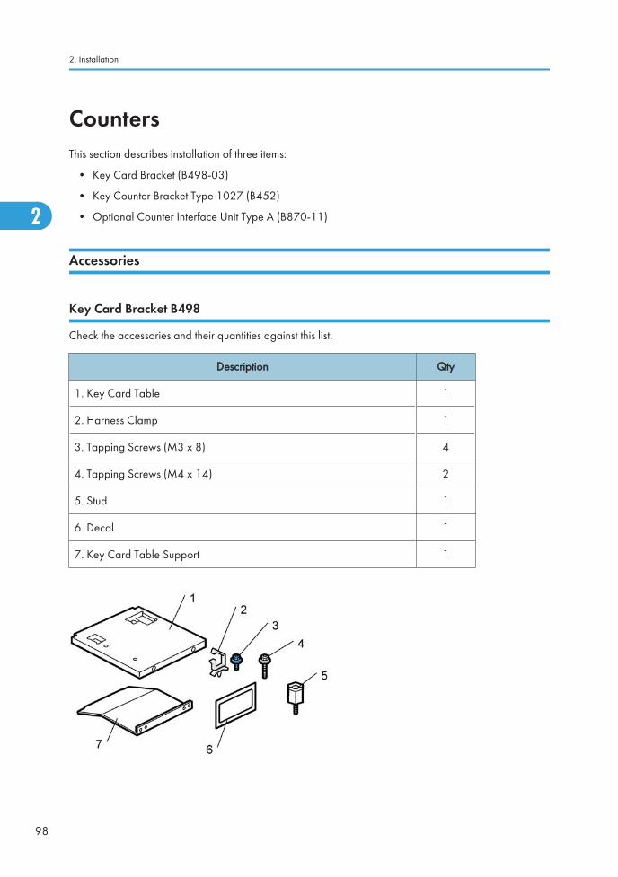
CountersThis section describes installation of three items:
• Key Card Bracket (B498-03)
• Key Counter Bracket Type 1027 (B452)
• Optional Counter Interface Unit Type A (B870-11)
Accessories
Key Card Bracket B498
Check the accessories and their quantities against this list.
Description Qty
1. Key Card Table 1
2. Harness Clamp 1
3. Tapping Screws (M3 x 8) 4
4. Tapping Screws (M4 x 14) 2
5. Stud 1
6. Decal 1
7. Key Card Table Support 1
2. Installation
98
2
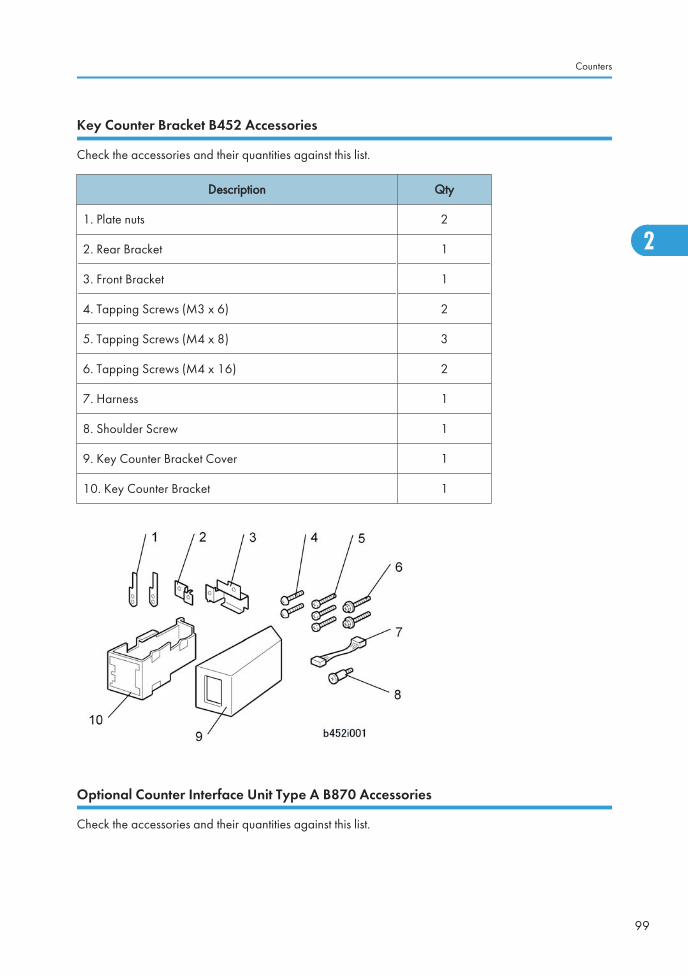
Key Counter Bracket B452 Accessories
Check the accessories and their quantities against this list.
Description Qty
1. Plate nuts 2
2. Rear Bracket 1
3. Front Bracket 1
4. Tapping Screws (M3 x 6) 2
5. Tapping Screws (M4 x 8) 3
6. Tapping Screws (M4 x 16) 2
7. Harness 1
8. Shoulder Screw 1
9. Key Counter Bracket Cover 1
10. Key Counter Bracket 1
Optional Counter Interface Unit Type A B870 Accessories
Check the accessories and their quantities against this list.
Counters
99
2
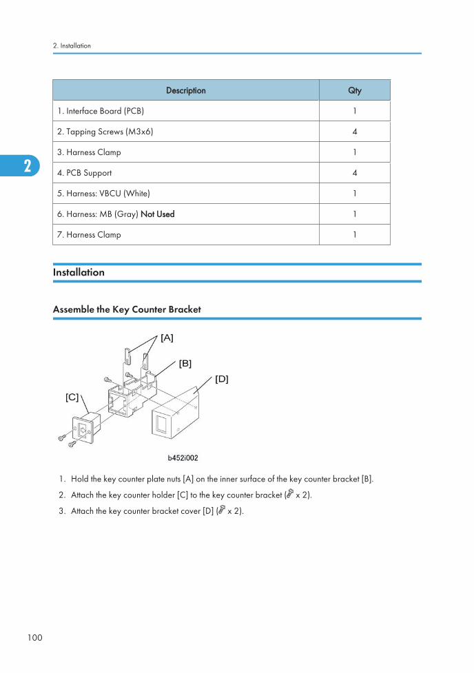
Description Qty
1. Interface Board (PCB) 1
2. Tapping Screws (M3x6) 4
3. Harness Clamp 1
4. PCB Support 4
5. Harness: VBCU (White) 1
6. Harness: MB (Gray) Not Used 1
7. Harness Clamp 1
Installation
Assemble the Key Counter Bracket
1. Hold the key counter plate nuts [A] on the inner surface of the key counter bracket [B].
2. Attach the key counter holder [C] to the key counter bracket ( x 2).
3. Attach the key counter bracket cover [D] ( x 2).
2. Installation
100
2
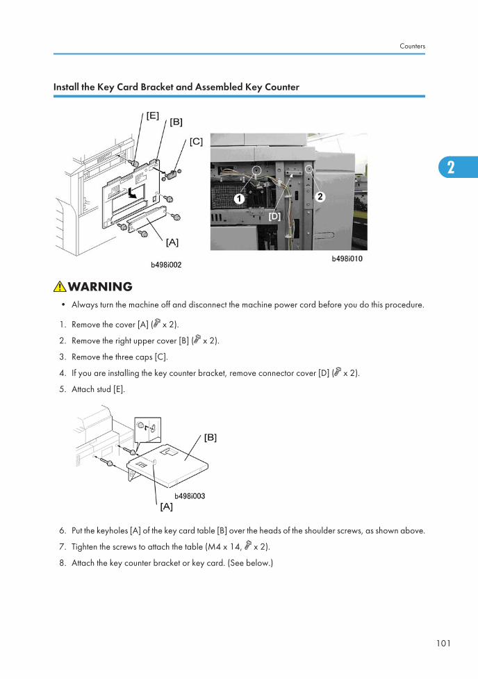
Install the Key Card Bracket and Assembled Key Counter
• Always turn the machine off and disconnect the machine power cord before you do this procedure.
1. Remove the cover [A] ( x 2).
2. Remove the right upper cover [B] ( x 2).
3. Remove the three caps [C].
4. If you are installing the key counter bracket, remove connector cover [D] ( x 2).
5. Attach stud [E].
6. Put the keyholes [A] of the key card table [B] over the heads of the shoulder screws, as shown above.
7. Tighten the screws to attach the table (M4 x 14, x 2).
8. Attach the key counter bracket or key card. (See below.)
Counters
101
2
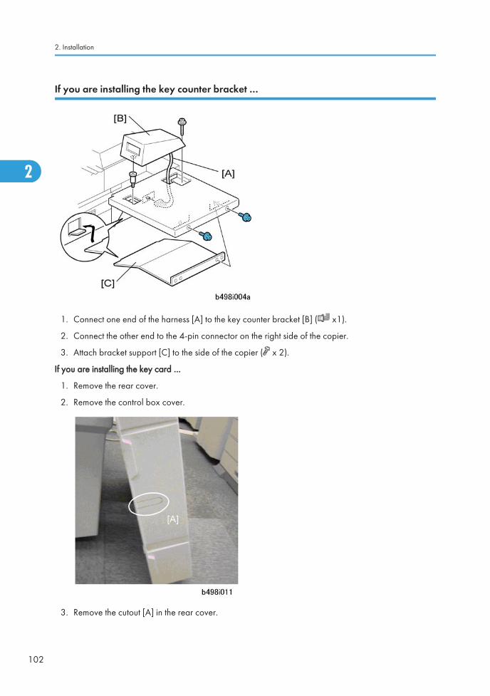
If you are installing the key counter bracket …
1. Connect one end of the harness [A] to the key counter bracket [B] ( x1).
2. Connect the other end to the 4-pin connector on the right side of the copier.
3. Attach bracket support [C] to the side of the copier ( x 2).
If you are installing the key card …
1. Remove the rear cover.
2. Remove the control box cover.
3. Remove the cutout [A] in the rear cover.
2. Installation
102
2
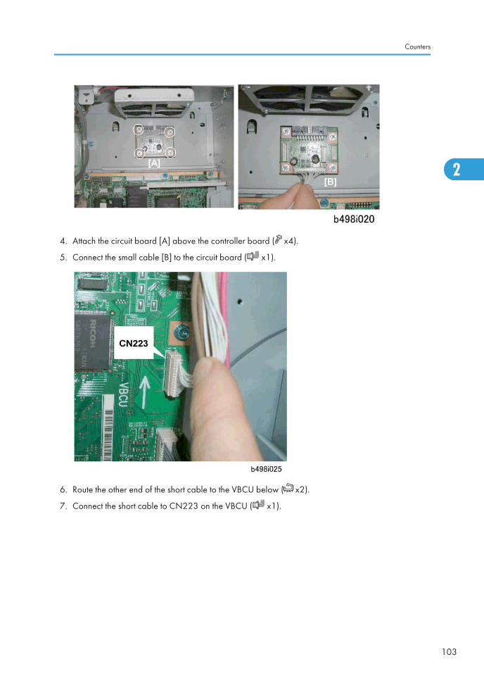
4. Attach the circuit board [A] above the controller board ( x4).
5. Connect the small cable [B] to the circuit board ( x1).
6. Route the other end of the short cable to the VBCU below ( x2).
7. Connect the short cable to CN223 on the VBCU ( x1).
Counters
103
2
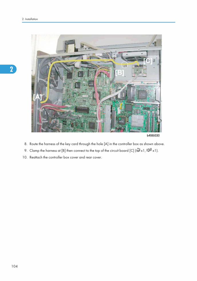
8. Route the harness of the key card through the hole [A] in the controller box as shown above.
9. Clamp the harness at [B] then connect to the top of the circuit board [C] ( x1, x1).
10. Reattach the controller box cover and rear cover.
2. Installation
104
2
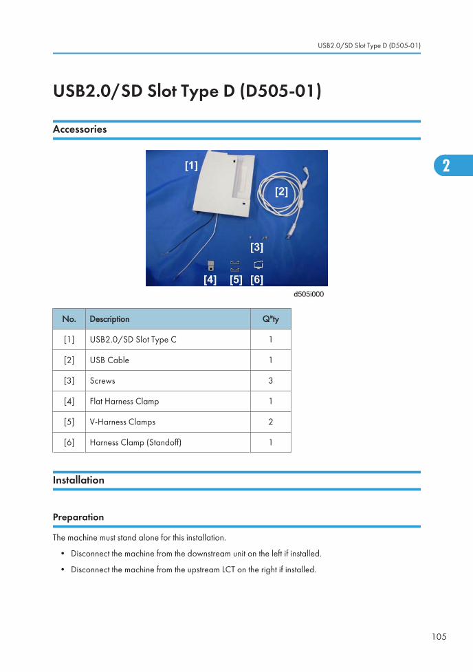
USB2.0/SD Slot Type D (D505-01)
Accessories
No. Description Q"ty
[1] USB2.0/SD Slot Type C 1
[2] USB Cable 1
[3] Screws 3
[4] Flat Harness Clamp 1
[5] V-Harness Clamps 2
[6] Harness Clamp (Standoff) 1
Installation
Preparation
The machine must stand alone for this installation.
• Disconnect the machine from the downstream unit on the left if installed.
• Disconnect the machine from the upstream LCT on the right if installed.
USB2.0/SD Slot Type D (D505-01)
105
2
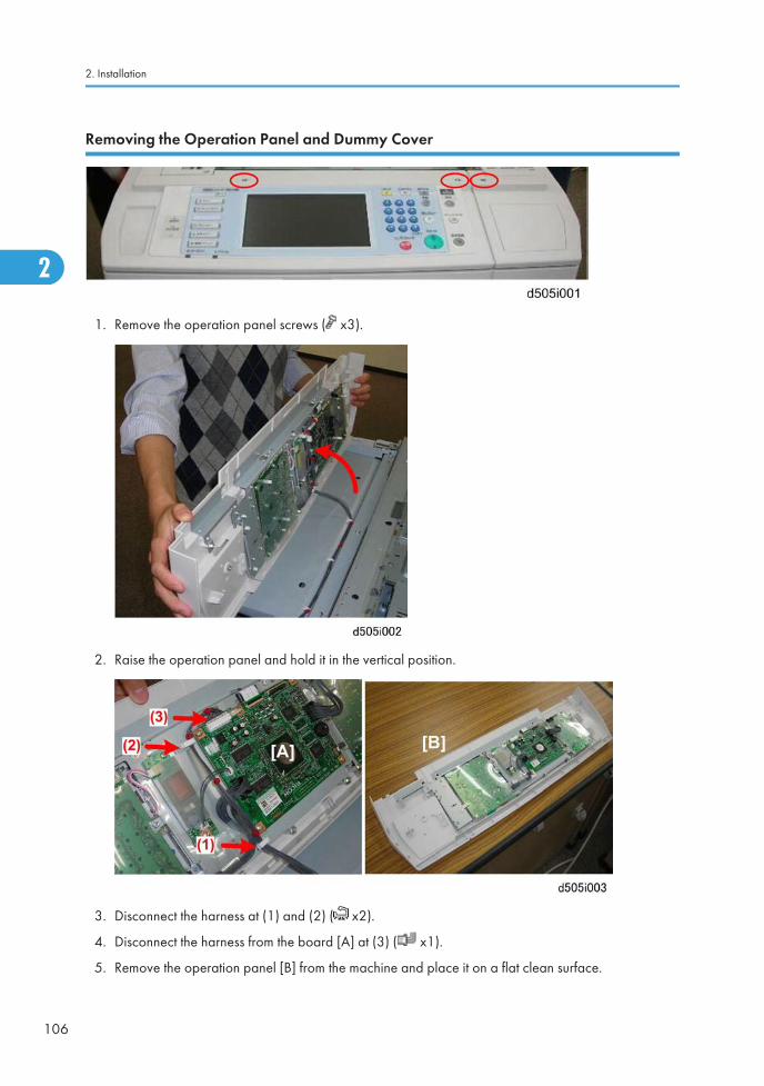
Removing the Operation Panel and Dummy Cover
1. Remove the operation panel screws ( x3).
2. Raise the operation panel and hold it in the vertical position.
3. Disconnect the harness at (1) and (2) ( x2).
4. Disconnect the harness from the board [A] at (3) ( x1).
5. Remove the operation panel [B] from the machine and place it on a flat clean surface.
2. Installation
106
2
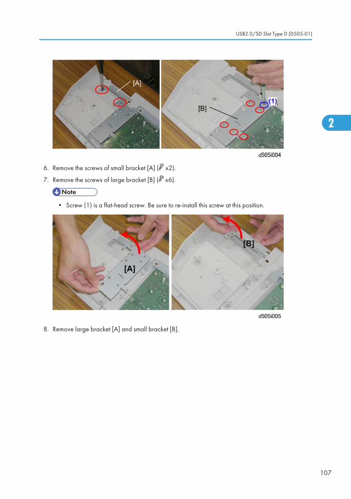
6. Remove the screws of small bracket [A] ( x2).
7. Remove the screws of large bracket [B] ( x6).
• Screw (1) is a flat-head screw. Be sure to re-install this screw at this position.
8. Remove large bracket [A] and small bracket [B].
USB2.0/SD Slot Type D (D505-01)
107
2
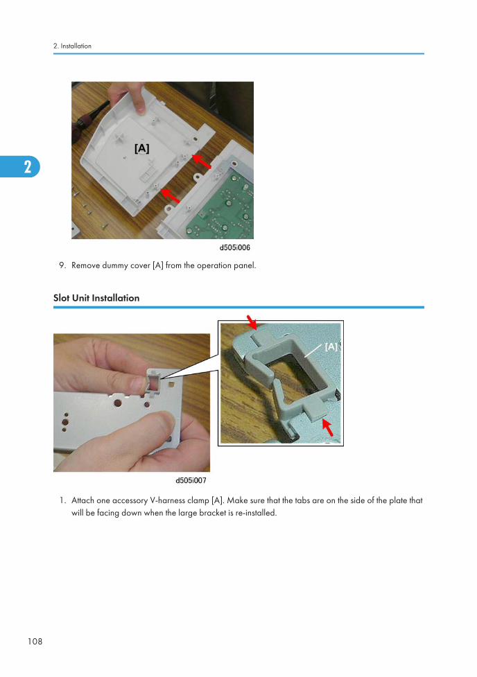
9. Remove dummy cover [A] from the operation panel.
Slot Unit Installation
1. Attach one accessory V-harness clamp [A]. Make sure that the tabs are on the side of the plate thatwill be facing down when the large bracket is re-installed.
2. Installation
108
2
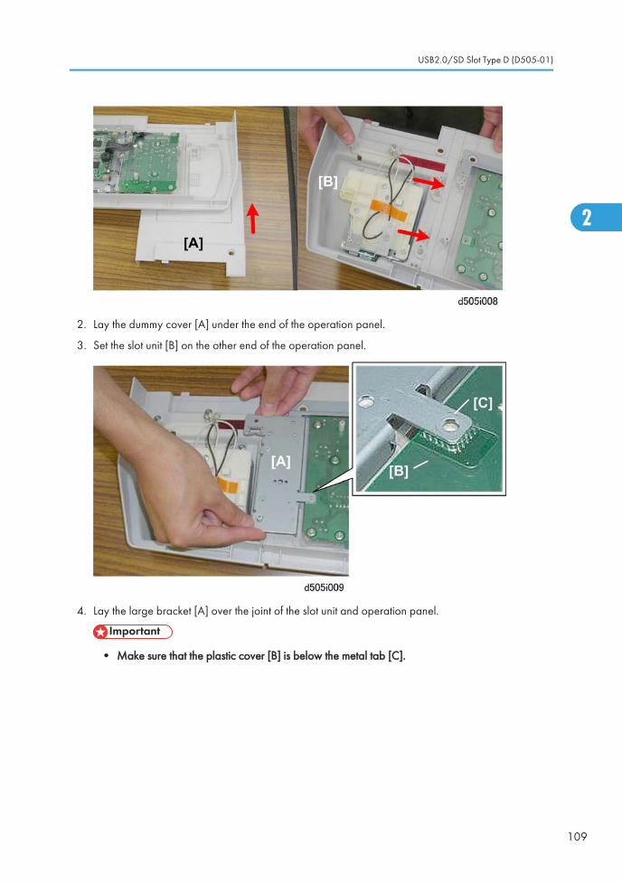
2. Lay the dummy cover [A] under the end of the operation panel.
3. Set the slot unit [B] on the other end of the operation panel.
4. Lay the large bracket [A] over the joint of the slot unit and operation panel.
• Make sure that the plastic cover [B] is below the metal tab [C].
USB2.0/SD Slot Type D (D505-01)
109
2
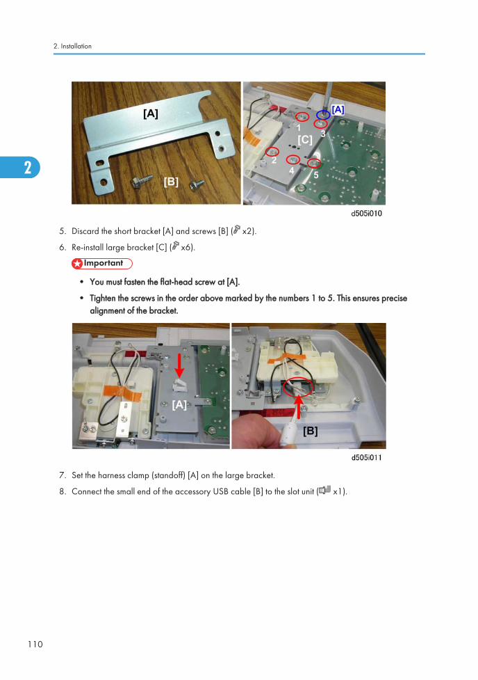
5. Discard the short bracket [A] and screws [B] ( x2).
6. Re-install large bracket [C] ( x6).
• You must fasten the flat-head screw at [A].
• Tighten the screws in the order above marked by the numbers 1 to 5. This ensures precisealignment of the bracket.
7. Set the harness clamp (standoff) [A] on the large bracket.
8. Connect the small end of the accessory USB cable [B] to the slot unit ( x1).
2. Installation
110
2
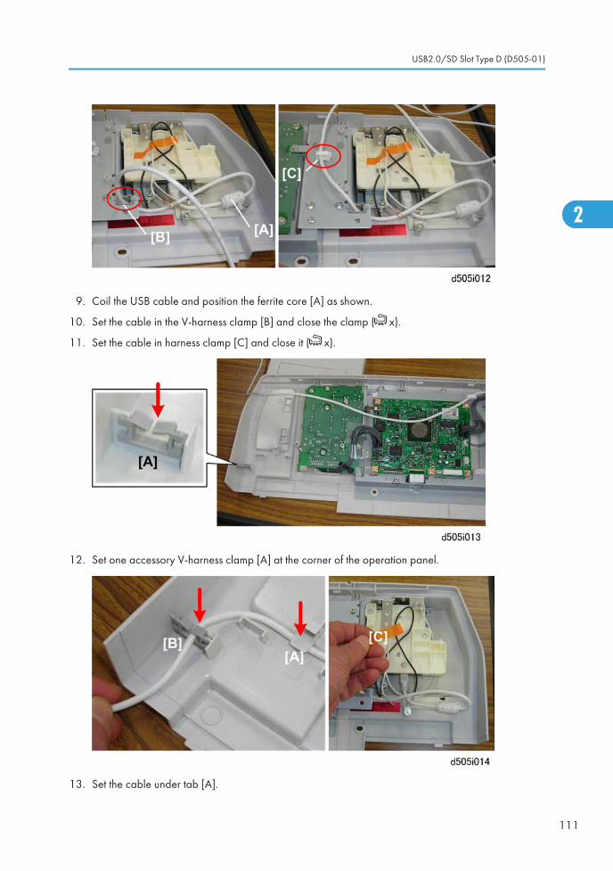
9. Coil the USB cable and position the ferrite core [A] as shown.
10. Set the cable in the V-harness clamp [B] and close the clamp ( x).
11. Set the cable in harness clamp [C] and close it ( x).
12. Set one accessory V-harness clamp [A] at the corner of the operation panel.
13. Set the cable under tab [A].
USB2.0/SD Slot Type D (D505-01)
111
2
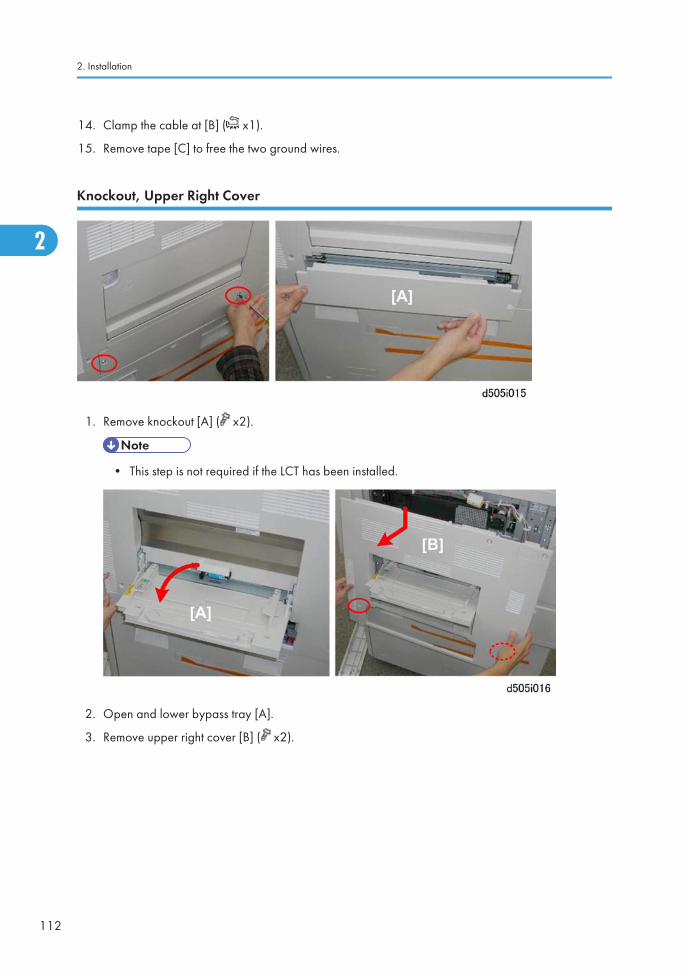
14. Clamp the cable at [B] ( x1).
15. Remove tape [C] to free the two ground wires.
Knockout, Upper Right Cover
1. Remove knockout [A] ( x2).
• This step is not required if the LCT has been installed.
2. Open and lower bypass tray [A].
3. Remove upper right cover [B] ( x2).
2. Installation
112
2
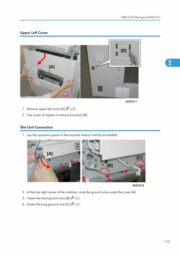
Upper Left Cover
1. Remove upper left cover [A] ( x 2).
2. Use a pair of nippers to remove knockout [B].
Slot Unit Connection
1. Lay the operation panel on the machine where it will be re-installed.
2. At the top right corner of the machine, route the ground wires under the cover [A].
3. Fasten the short ground wire [B] ( x1).
4. Fasten the long ground wire [C] ( x1).
USB2.0/SD Slot Type D (D505-01)
113
2

5. Raise the operation panel on the machine to the vertical position, and then connect the board [A]( x1, x2).
6. At the right side of the operation panel, make sure that the ground wires [B] are not pinched betweenthe main machine and operation panel.
7. At the left side of the operation panel, make sure that the USB cable [A] is below the edge of theoperation panel as shown.
• Make sure that the cable is not pinched as shown at [B].
2. Installation
114
2
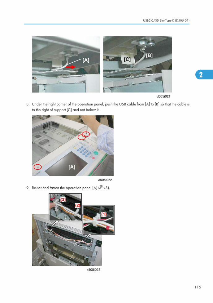
8. Under the right corner of the operation panel, push the USB cable from [A] to [B] so that the cable isto the right of support [C] and not below it.
9. Re-set and fasten the operation panel [A] ( x3).
USB2.0/SD Slot Type D (D505-01)
115
2
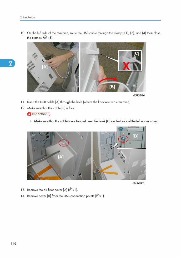
10. On the left side of the machine, route the USB cable through the clamps (1), (2), and (3) then closethe clamps ( x3).
11. Insert the USB cable [A] through the hole (where the knockout was removed).
12. Make sure that the cable [B] is free.
• Make sure that the cable is not looped over the hook [C] on the back of the left upper cover.
13. Remove the air filter cover [A] ( x1).
14. Remove cover [B] from the USB connection points ( x1).
2. Installation
116
2
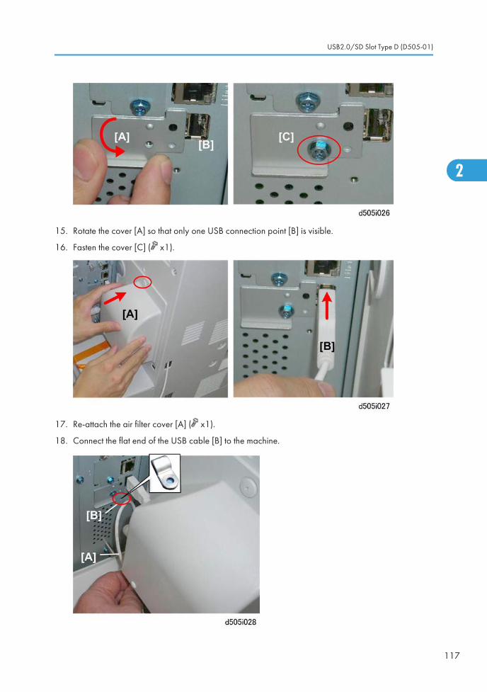
15. Rotate the cover [A] so that only one USB connection point [B] is visible.
16. Fasten the cover [C] ( x1).
17. Re-attach the air filter cover [A] ( x1).
18. Connect the flat end of the USB cable [B] to the machine.
USB2.0/SD Slot Type D (D505-01)
117
2
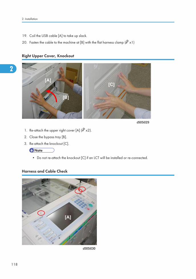
19. Coil the USB cable [A] to take up slack.
20. Fasten the cable to the machine at [B] with the flat harness clamp ( x1)
Right Upper Cover, Knockout
1. Re-attach the upper right cover [A] ( x2).
2. Close the bypass tray [B].
3. Re-attach the knockout [C].
• Do not re-attach the knockout [C] if an LCT will be installed or re-connected.
Harness and Cable Check
2. Installation
118
2

1. Remove the operation panel screws ( x3).
2. Lift the operation panel slightly to confirm that the operation panel harness and USB cable are nothung up.
3. Plug in the machine and turn it on.
4. Enter the Scanner SP mode and change the setting of SP1013 from "0" to "1".
5. Exit the SP mode and check the operation of the installed unit.
USB2.0/SD Slot Type D (D505-01)
119
2
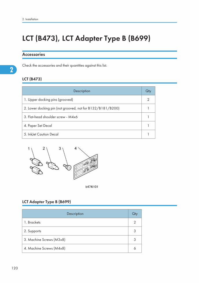
LCT (B473), LCT Adapter Type B (B699)
Accessories
Check the accessories and their quantities against this list.
LCT (B473)
Description Qty
1. Upper docking pins (grooved) 2
2. Lower docking pin (not grooved, not for B132/B181/B200) 1
3. Flat-head shoulder screw - M4x6 1
4. Paper Set Decal 1
5. InkJet Caution Decal 1
LCT Adapter Type B (B699)
Description Qty
1. Brackets 2
2. Supports 3
3. Machine Screws (M3x8) 3
4. Machine Screws (M4x8) 6
2. Installation
120
2
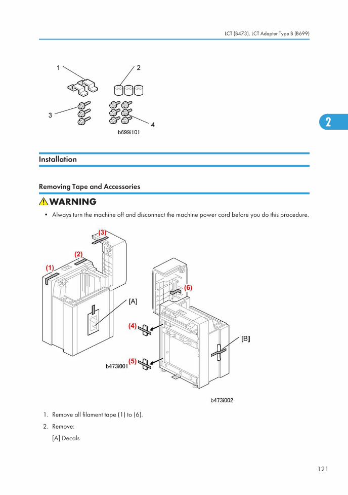
Installation
Removing Tape and Accessories
• Always turn the machine off and disconnect the machine power cord before you do this procedure.
1. Remove all filament tape (1) to (6).
2. Remove:
[A] Decals
LCT (B473), LCT Adapter Type B (B699)
121
2
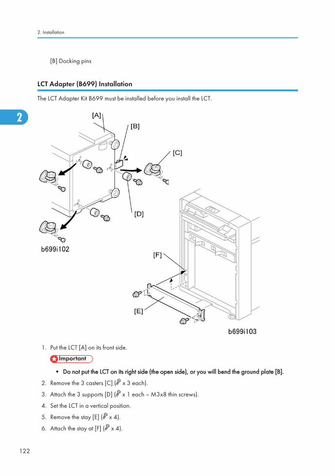
[B] Docking pins
LCT Adapter (B699) Installation
The LCT Adapter Kit B699 must be installed before you install the LCT.
1. Put the LCT [A] on its front side.
• Do not put the LCT on its right side (the open side), or you will bend the ground plate [B].
2. Remove the 3 casters [C] ( x 3 each).
3. Attach the 3 supports [D] ( x 1 each – M3x8 thin screws).
4. Set the LCT in a vertical position.
5. Remove the stay [E] ( x 4).
6. Attach the stay at [F] ( x 4).
2. Installation
122
2
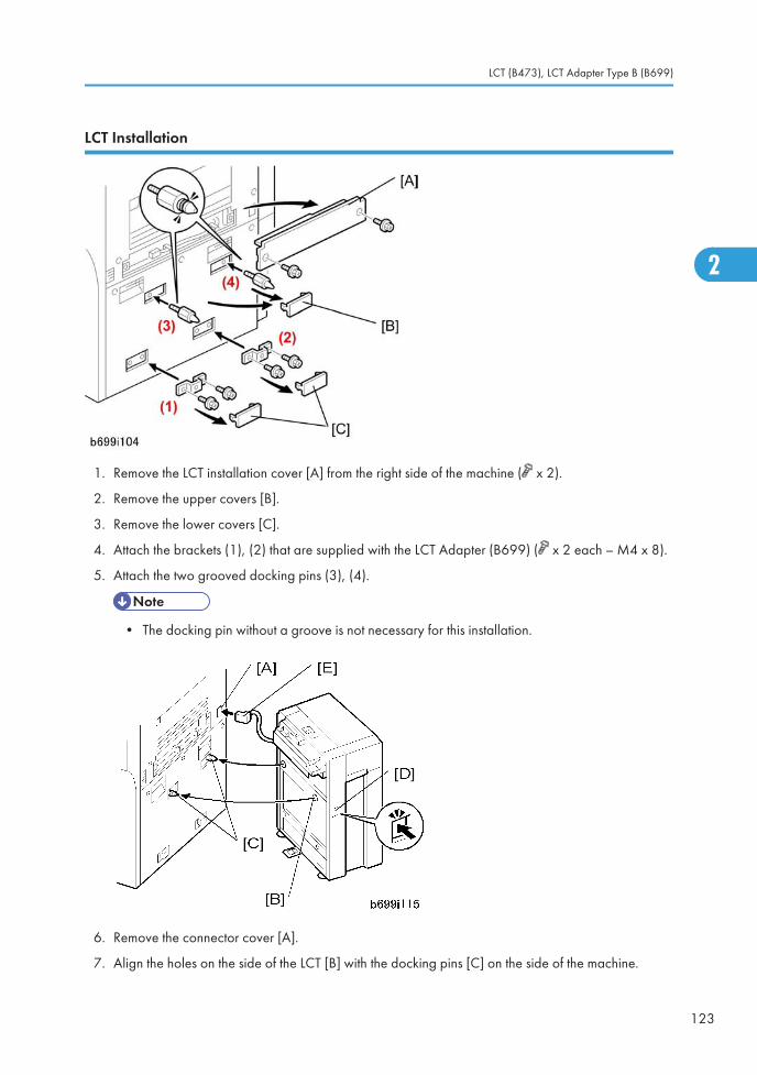
LCT Installation
1. Remove the LCT installation cover [A] from the right side of the machine ( x 2).
2. Remove the upper covers [B].
3. Remove the lower covers [C].
4. Attach the brackets (1), (2) that are supplied with the LCT Adapter (B699) ( x 2 each – M4 x 8).
5. Attach the two grooved docking pins (3), (4).
• The docking pin without a groove is not necessary for this installation.
6. Remove the connector cover [A].
7. Align the holes on the side of the LCT [B] with the docking pins [C] on the side of the machine.
LCT (B473), LCT Adapter Type B (B699)
123
2
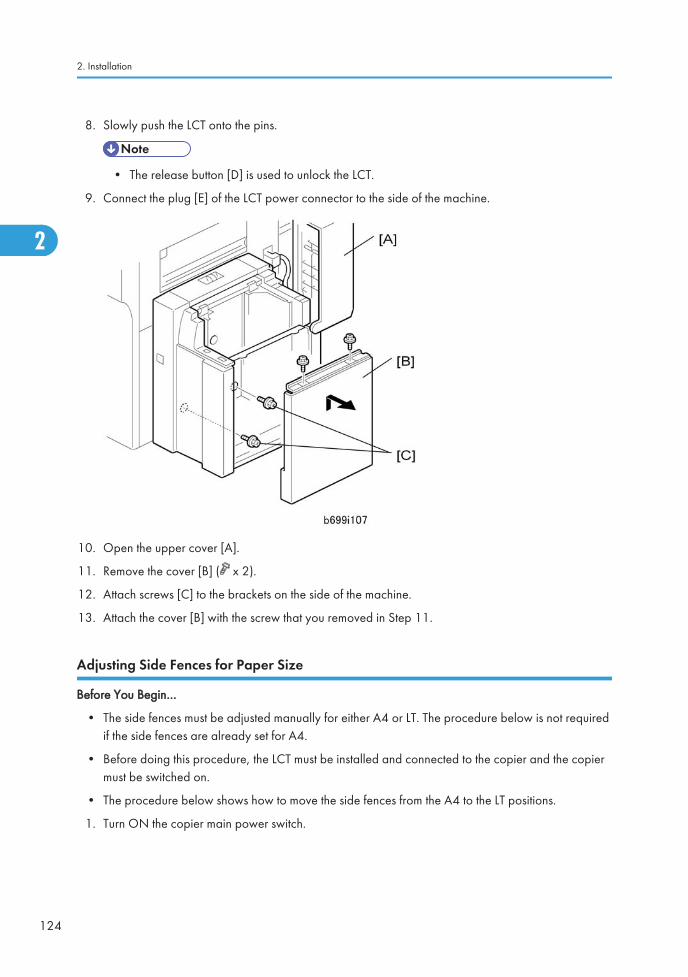
8. Slowly push the LCT onto the pins.
• The release button [D] is used to unlock the LCT.
9. Connect the plug [E] of the LCT power connector to the side of the machine.
10. Open the upper cover [A].
11. Remove the cover [B] ( x 2).
12. Attach screws [C] to the brackets on the side of the machine.
13. Attach the cover [B] with the screw that you removed in Step 11.
Adjusting Side Fences for Paper Size
Before You Begin…
• The side fences must be adjusted manually for either A4 or LT. The procedure below is not requiredif the side fences are already set for A4.
• Before doing this procedure, the LCT must be installed and connected to the copier and the copiermust be switched on.
• The procedure below shows how to move the side fences from the A4 to the LT positions.
1. Turn ON the copier main power switch.
2. Installation
124
2
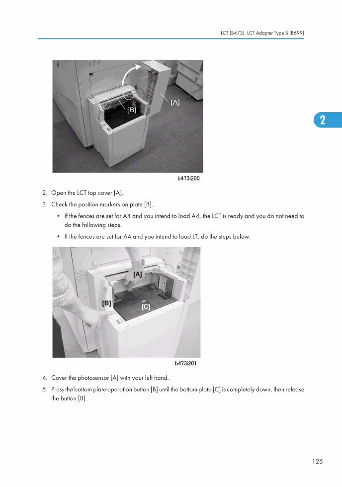
2. Open the LCT top cover [A].
3. Check the position markers on plate [B].
• If the fences are set for A4 and you intend to load A4, the LCT is ready and you do not need todo the following steps.
• If the fences are set for A4 and you intend to load LT, do the steps below.
4. Cover the photosensor [A] with your left hand.
5. Press the bottom plate operation button [B] until the bottom plate [C] is completely down, then releasethe button [B].
LCT (B473), LCT Adapter Type B (B699)
125
2
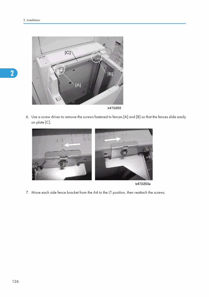
6. Use a screw driver to remove the screws fastened to fences [A] and [B] so that the fences slide easilyon plate [C].
7. Move each side fence bracket from the A4 to the LT position, then reattach the screws.
2. Installation
126
2
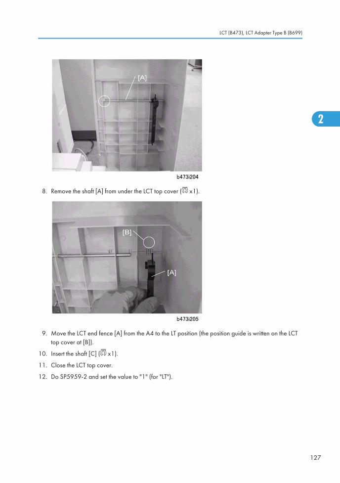
8. Remove the shaft [A] from under the LCT top cover ( x1).
9. Move the LCT end fence [A] from the A4 to the LT position (the position guide is written on the LCTtop cover at [B]).
10. Insert the shaft [C] ( x1).
11. Close the LCT top cover.
12. Do SP5959-2 and set the value to "1" (for "LT").
LCT (B473), LCT Adapter Type B (B699)
127
2
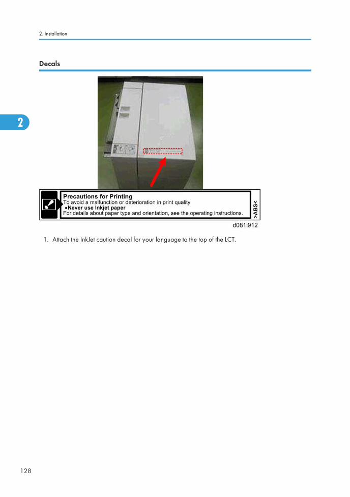
Decals
1. Attach the InkJet caution decal for your language to the top of the LCT.
2. Installation
128
2
LG Size Tray Type 1075 (B474)The option can be installed in the LCT (B473).
Accessories
Check the accessories and their quantities against this list.
Description Q'ty
1. Tapping screws - M4x8 4
2. Tapping hex screws - M4x8 6
3. Harness clamp 1
4. B4/LG frame 1
5. Front bracket 1
6. Rear bracket 1
7. Bottom plate extension 1
8. Cover 1
Installation
LCT Connected to the Machine
• Turn the machine off and disconnect the machine power cord before you start this procedure.
LG Size Tray Type 1075 (B474)
129
2

1. If the LCT is connected to the copier:
• Open the cover and remove the paper.
• Close the cover.
• Turn the main power switch off.
• Disconnect the LCT from the copier.
2. Remove the LCT cover [A] ( x 1).
3. Remove the right cover [B] ( x 2).
4. Remove the right stay [C] and attach it below ( x 2).
5. Change the position of the lower limit sensor [D] ( x 1).
6. Attach the harness clamp (not shown) to the rear of the plate. Use this clamp to hold the sensorconnector wire.
2. Installation
130
2
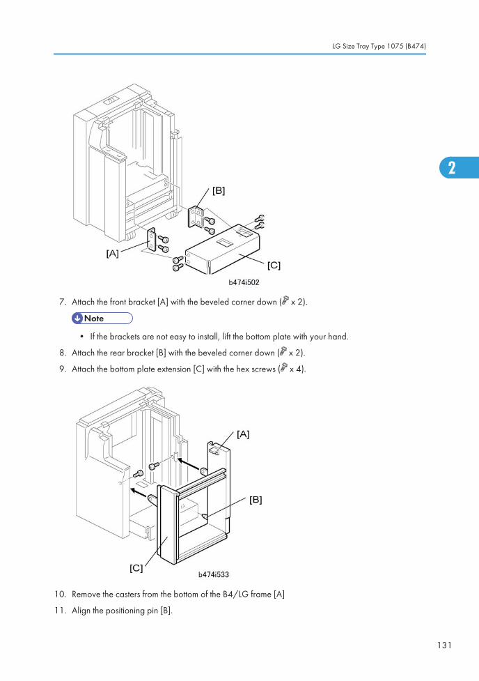
7. Attach the front bracket [A] with the beveled corner down ( x 2).
• If the brackets are not easy to install, lift the bottom plate with your hand.
8. Attach the rear bracket [B] with the beveled corner down ( x 2).
9. Attach the bottom plate extension [C] with the hex screws ( x 4).
10. Remove the casters from the bottom of the B4/LG frame [A]
11. Align the positioning pin [B].
LG Size Tray Type 1075 (B474)
131
2

12. Attach the B4/LG frame [C] with the hex screws ( x 2).
13. Move the front side fence [A] and rear side fence [B] to the B4 or 8.5" position and attach it ( x 1).
14. Attach the cover [A] (8.5" x 14"/B4) ( x 1).
15. Attach the right cover [B] ( x 2).
16. Connect the LCT to the machine.
17. Turn the machine on.
18. Go into the SP mode and do SP5959-2.
2. Installation
132
2

19. Input "5" for B4 SEF or "6" for 8.5" x 14" SEF.
LG Size Tray Type 1075 (B474)
133
2
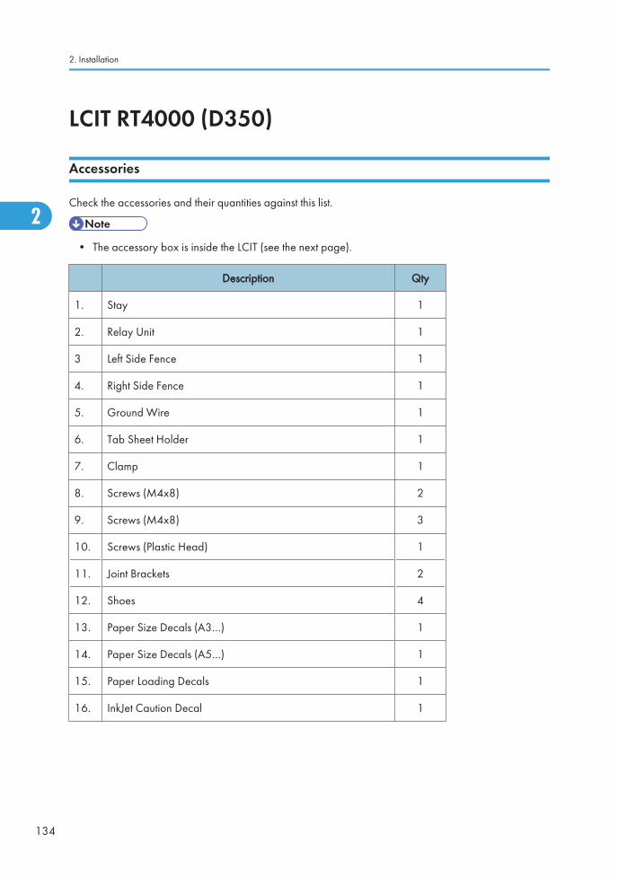
LCIT RT4000 (D350)
Accessories
Check the accessories and their quantities against this list.
• The accessory box is inside the LCIT (see the next page).
Description Qty
1. Stay 1
2. Relay Unit 1
3 Left Side Fence 1
4. Right Side Fence 1
5. Ground Wire 1
6. Tab Sheet Holder 1
7. Clamp 1
8. Screws (M4x8) 2
9. Screws (M4x8) 3
10. Screws (Plastic Head) 1
11. Joint Brackets 2
12. Shoes 4
13. Paper Size Decals (A3…) 1
14. Paper Size Decals (A5…) 1
15. Paper Loading Decals 1
16. InkJet Caution Decal 1
2. Installation
134
2
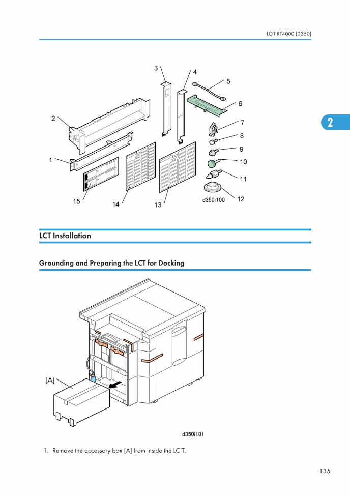
LCT Installation
Grounding and Preparing the LCT for Docking
1. Remove the accessory box [A] from inside the LCIT.
LCIT RT4000 (D350)
135
2

2. Remove all tapes.
3. Remove the paper entrance cover [A] ( x2).
4. Remove the connector cover [B].
5. Remove the right upper cover [C] ( x2).
6. Remove the plate [A] ( x2).
7. Disconnect the bypass unit connectors [B] ( x2).
8. Remove the bypass unit [C] (keep the screws) ( x4).
• Do not throw away the bypass tray. The customer may need it again later.
2. Installation
136
2
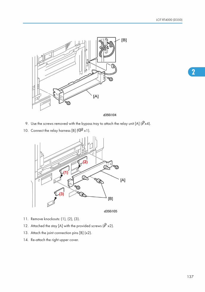
9. Use the screws removed with the bypass tray to attach the relay unit [A] ( x4).
10. Connect the relay harness [B] ( x1).
11. Remove knockouts: (1), (2), (3).
12. Attached the stay [A] with the provided screws ( x2).
13. Attach the joint connection pins [B] (x2).
14. Re-attach the right upper cover.
LCIT RT4000 (D350)
137
2
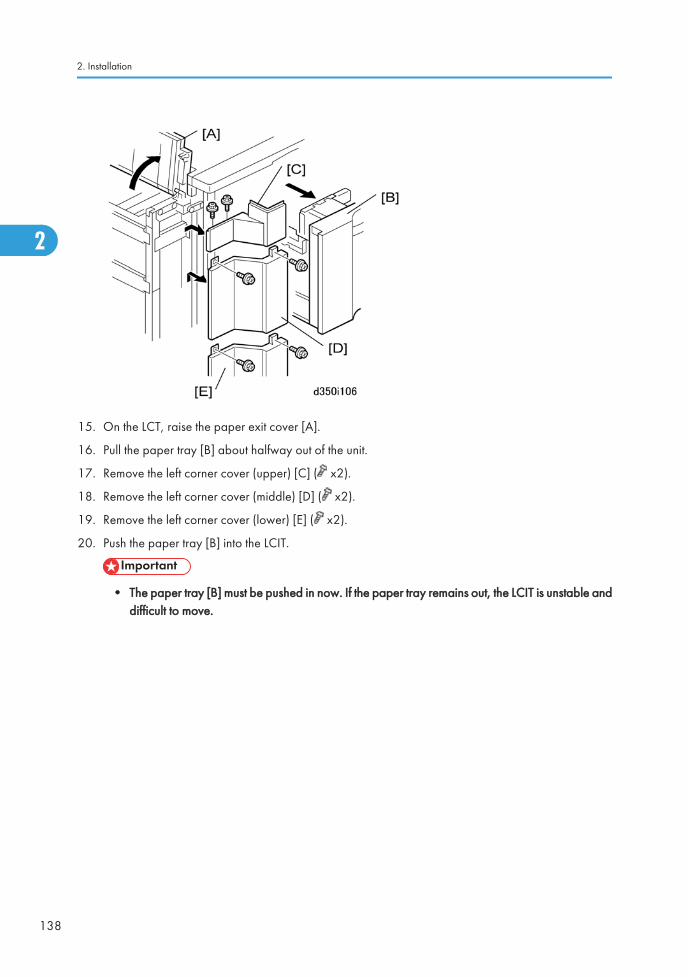
15. On the LCT, raise the paper exit cover [A].
16. Pull the paper tray [B] about halfway out of the unit.
17. Remove the left corner cover (upper) [C] ( x2).
18. Remove the left corner cover (middle) [D] ( x2).
19. Remove the left corner cover (lower) [E] ( x2).
20. Push the paper tray [B] into the LCIT.
• The paper tray [B] must be pushed in now. If the paper tray remains out, the LCIT is unstable anddifficult to move.
2. Installation
138
2
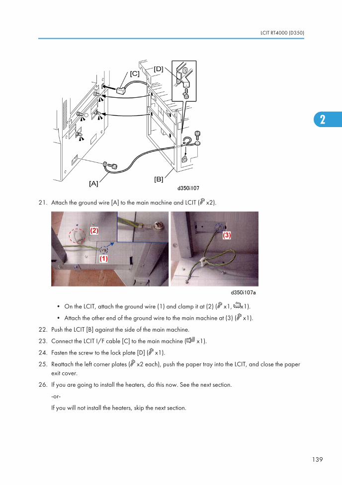
21. Attach the ground wire [A] to the main machine and LCIT ( x2).
• On the LCIT, attach the ground wire (1) and clamp it at (2) ( x1, x1).
• Attach the other end of the ground wire to the main machine at (3) ( x1).
22. Push the LCIT [B] against the side of the main machine.
23. Connect the LCIT I/F cable [C] to the main machine ( x1).
24. Fasten the screw to the lock plate [D] ( x1).
25. Reattach the left corner plates ( x2 each), push the paper tray into the LCIT, and close the paperexit cover.
26. If you are going to install the heaters, do this now. See the next section.
-or-
If you will not install the heaters, skip the next section.
LCIT RT4000 (D350)
139
2
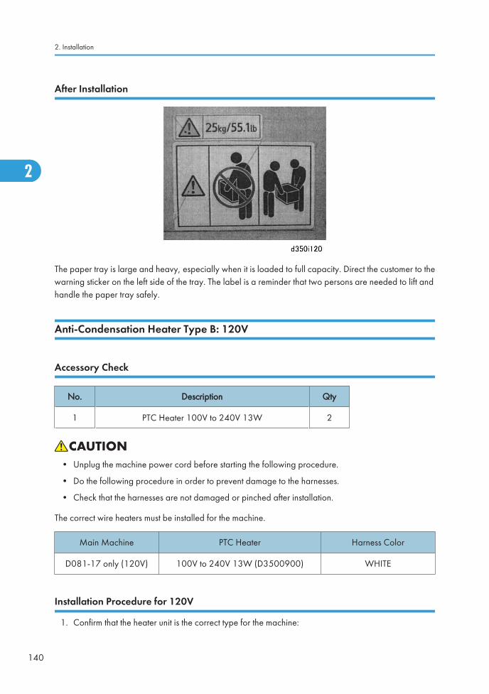
After Installation
The paper tray is large and heavy, especially when it is loaded to full capacity. Direct the customer to thewarning sticker on the left side of the tray. The label is a reminder that two persons are needed to lift andhandle the paper tray safely.
Anti-Condensation Heater Type B: 120V
Accessory Check
No. Description Qty
1 PTC Heater 100V to 240V 13W 2
• Unplug the machine power cord before starting the following procedure.
• Do the following procedure in order to prevent damage to the harnesses.
• Check that the harnesses are not damaged or pinched after installation.
The correct wire heaters must be installed for the machine.
Main Machine PTC Heater Harness Color
D081-17 only (120V) 100V to 240V 13W (D3500900) WHITE
Installation Procedure for 120V
1. Confirm that the heater unit is the correct type for the machine:
2. Installation
140
2
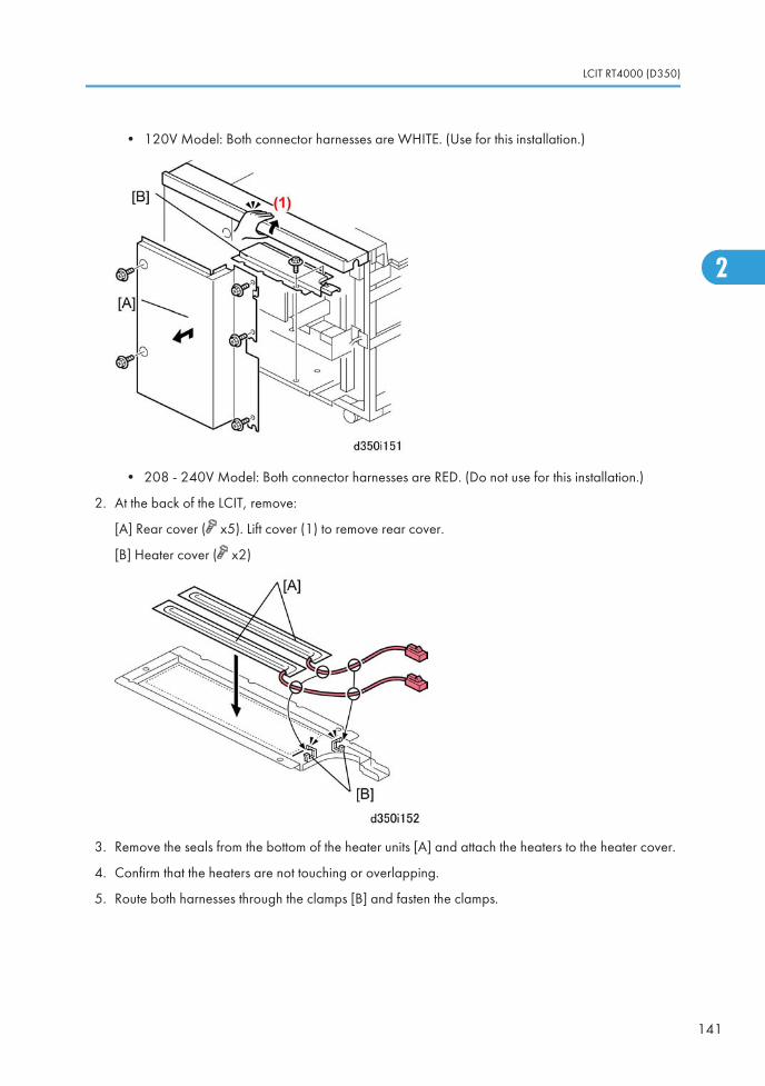
• 120V Model: Both connector harnesses are WHITE. (Use for this installation.)
• 208 - 240V Model: Both connector harnesses are RED. (Do not use for this installation.)
2. At the back of the LCIT, remove:
[A] Rear cover ( x5). Lift cover (1) to remove rear cover.
[B] Heater cover ( x2)
3. Remove the seals from the bottom of the heater units [A] and attach the heaters to the heater cover.
4. Confirm that the heaters are not touching or overlapping.
5. Route both harnesses through the clamps [B] and fasten the clamps.
LCIT RT4000 (D350)
141
2
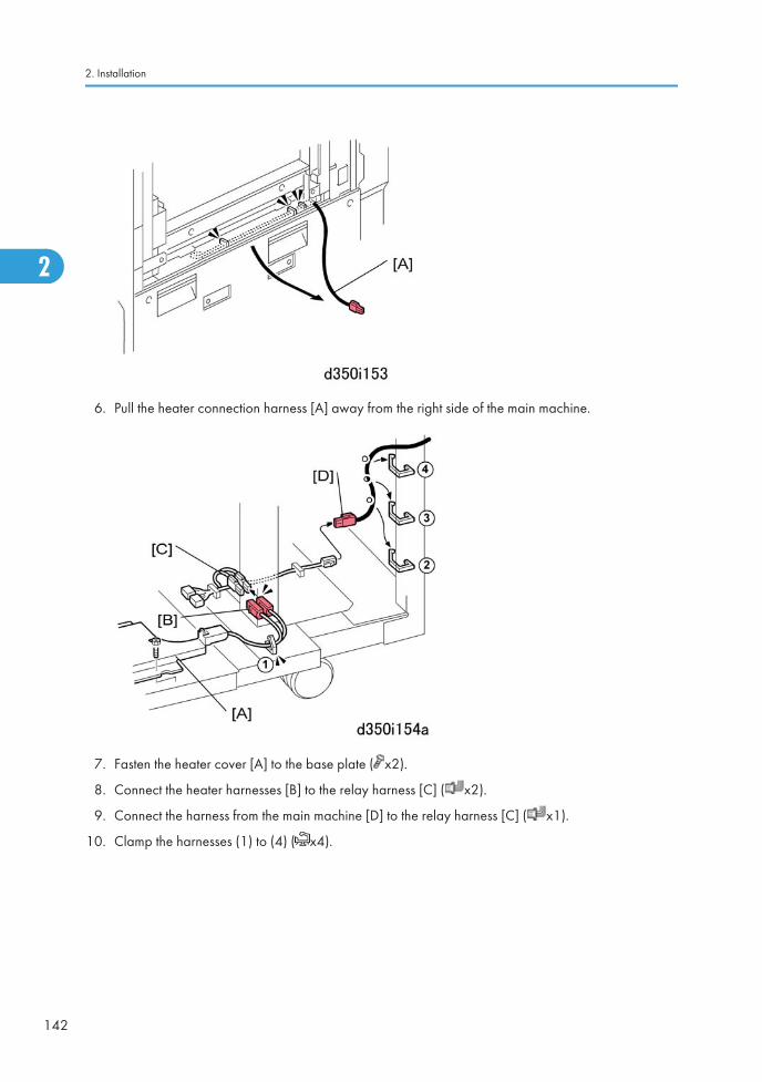
6. Pull the heater connection harness [A] away from the right side of the main machine.
7. Fasten the heater cover [A] to the base plate ( x2).
8. Connect the heater harnesses [B] to the relay harness [C] ( x2).
9. Connect the harness from the main machine [D] to the relay harness [C] ( x1).
10. Clamp the harnesses (1) to (4) ( x4).
2. Installation
142
2
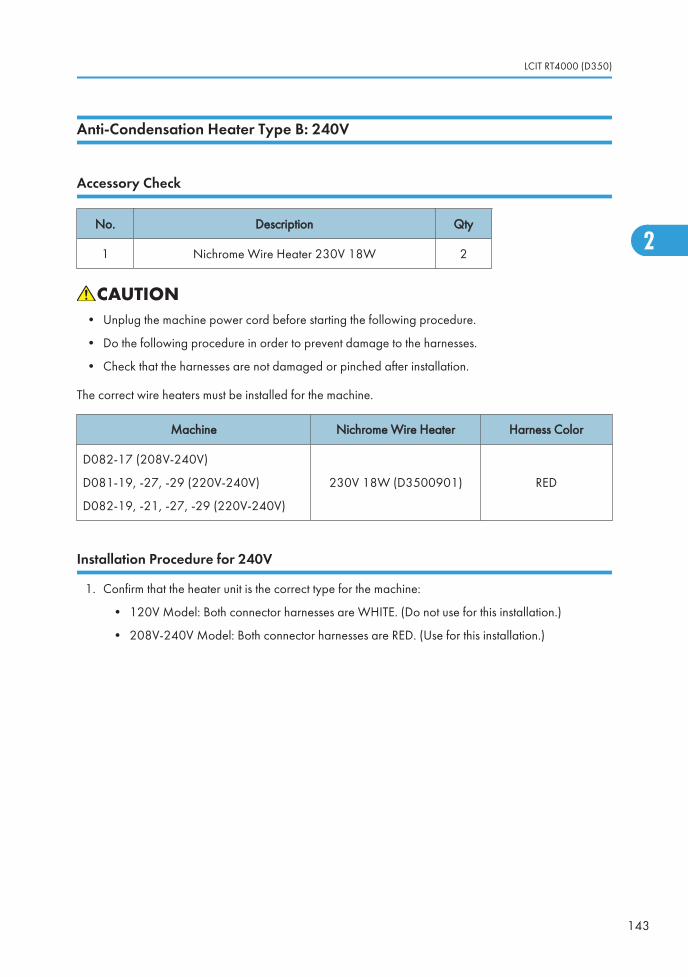
Anti-Condensation Heater Type B: 240V
Accessory Check
No. Description Qty
1 Nichrome Wire Heater 230V 18W 2
• Unplug the machine power cord before starting the following procedure.
• Do the following procedure in order to prevent damage to the harnesses.
• Check that the harnesses are not damaged or pinched after installation.
The correct wire heaters must be installed for the machine.
Machine Nichrome Wire Heater Harness Color
D082-17 (208V-240V)
D081-19, -27, -29 (220V-240V)
D082-19, -21, -27, -29 (220V-240V)
230V 18W (D3500901) RED
Installation Procedure for 240V
1. Confirm that the heater unit is the correct type for the machine:
• 120V Model: Both connector harnesses are WHITE. (Do not use for this installation.)
• 208V-240V Model: Both connector harnesses are RED. (Use for this installation.)
LCIT RT4000 (D350)
143
2
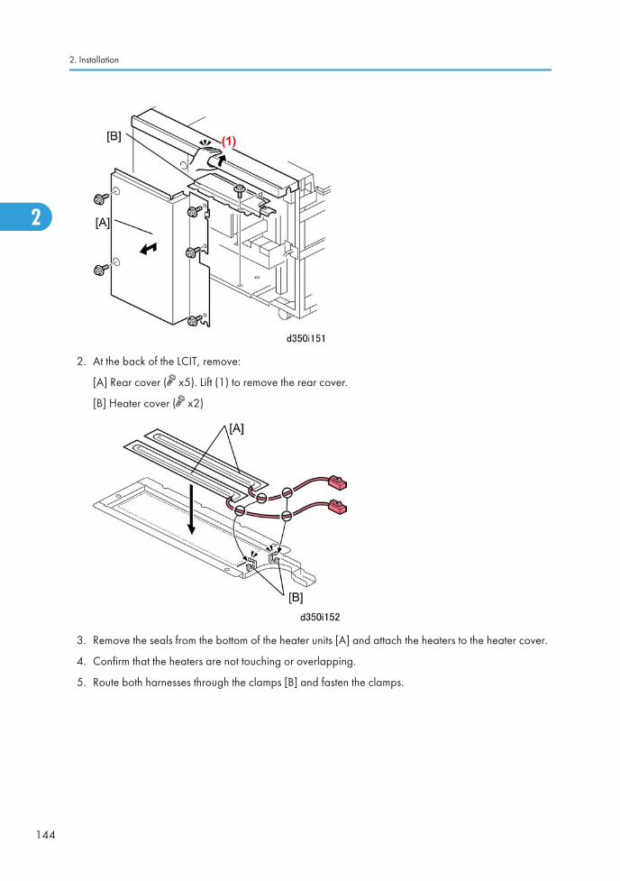
2. At the back of the LCIT, remove:
[A] Rear cover ( x5). Lift (1) to remove the rear cover.
[B] Heater cover ( x2)
3. Remove the seals from the bottom of the heater units [A] and attach the heaters to the heater cover.
4. Confirm that the heaters are not touching or overlapping.
5. Route both harnesses through the clamps [B] and fasten the clamps.
2. Installation
144
2
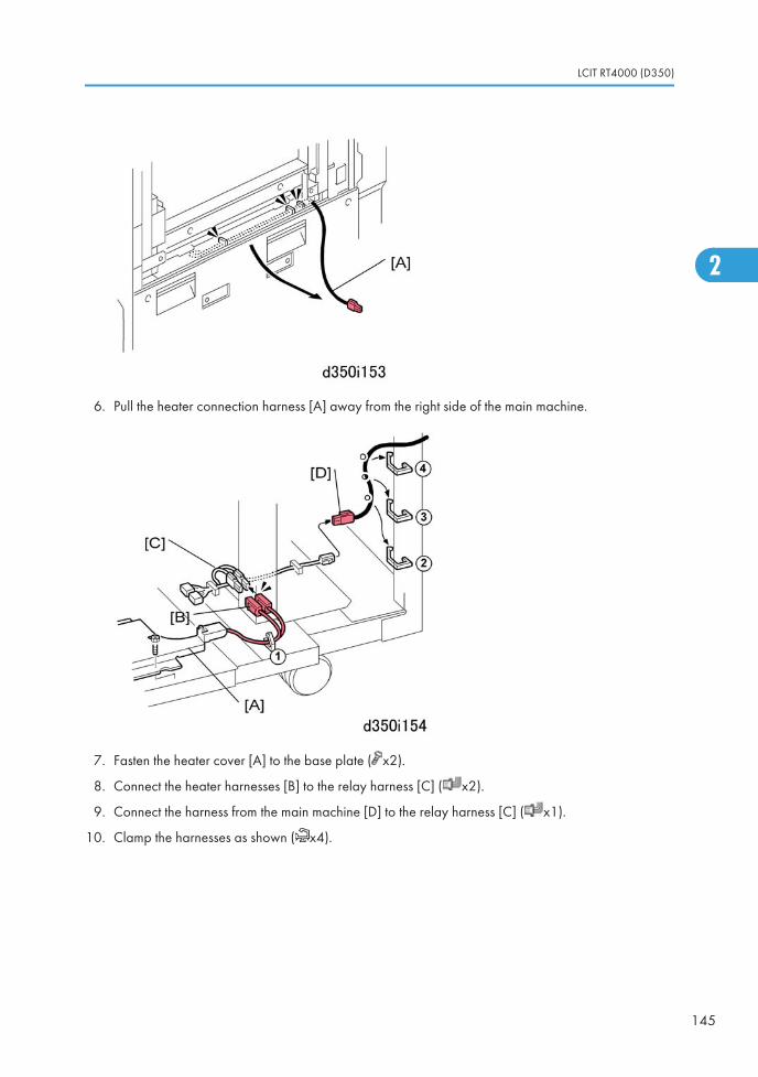
6. Pull the heater connection harness [A] away from the right side of the main machine.
7. Fasten the heater cover [A] to the base plate ( x2).
8. Connect the heater harnesses [B] to the relay harness [C] ( x2).
9. Connect the harness from the main machine [D] to the relay harness [C] ( x1).
10. Clamp the harnesses as shown ( x4).
LCIT RT4000 (D350)
145
2
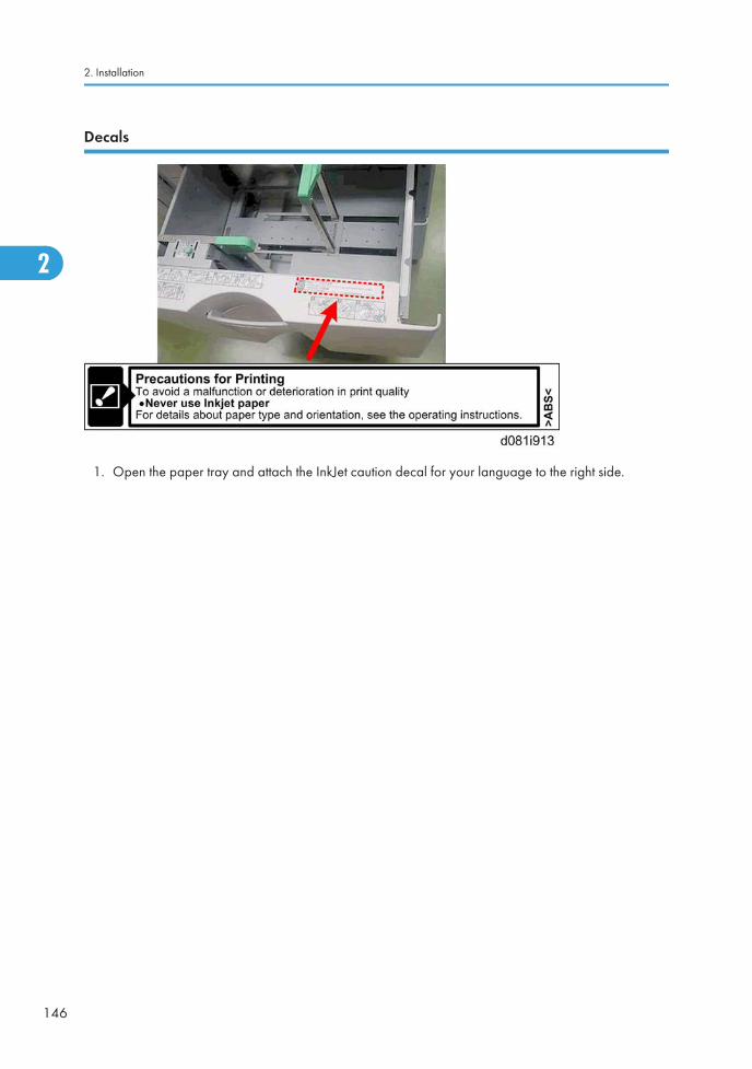
Decals
1. Open the paper tray and attach the InkJet caution decal for your language to the right side.
2. Installation
146
2
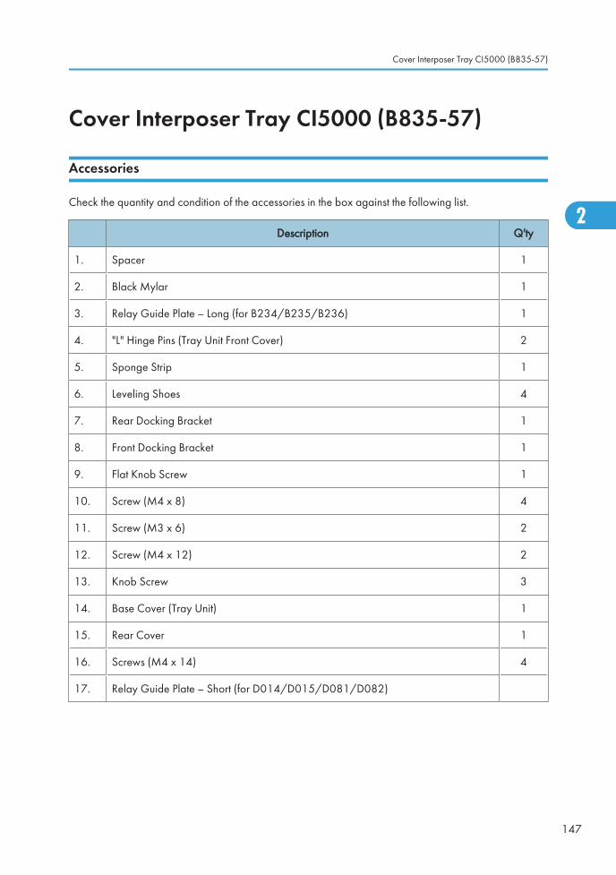
Cover Interposer Tray CI5000 (B835-57)
Accessories
Check the quantity and condition of the accessories in the box against the following list.
Description Q'ty
1. Spacer 1
2. Black Mylar 1
3. Relay Guide Plate – Long (for B234/B235/B236) 1
4. "L" Hinge Pins (Tray Unit Front Cover) 2
5. Sponge Strip 1
6. Leveling Shoes 4
7. Rear Docking Bracket 1
8. Front Docking Bracket 1
9. Flat Knob Screw 1
10. Screw (M4 x 8) 4
11. Screw (M3 x 6) 2
12. Screw (M4 x 12) 2
13. Knob Screw 3
14. Base Cover (Tray Unit) 1
15. Rear Cover 1
16. Screws (M4 x 14) 4
17. Relay Guide Plate – Short (for D014/D015/D081/D082)
Cover Interposer Tray CI5000 (B835-57)
147
2
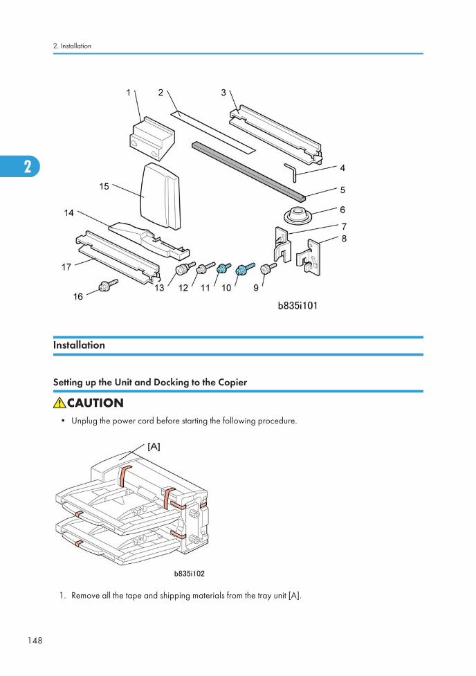
Installation
Setting up the Unit and Docking to the Copier
• Unplug the power cord before starting the following procedure.
1. Remove all the tape and shipping materials from the tray unit [A].
2. Installation
148
2
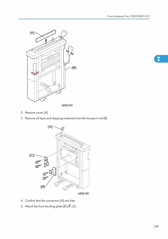
2. Remove cover [A].
3. Remove all tape and shipping materials from the transport unit [B].
4. Confirm that the connectors [A] are free.
5. Attach the front docking plate [B] ( x2).
Cover Interposer Tray CI5000 (B835-57)
149
2
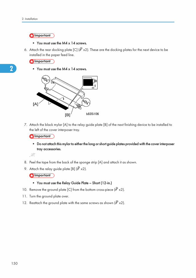
• You must use the M4 x 14 screws.
6. Attach the rear docking plate [C] ( x2). These are the docking plates for the next device to beinstalled in the paper feed line.
• You must use the M4 x 14 screws.
7. Attach the black mylar [A] to the relay guide plate [B] of the next finishing device to be installed tothe left of the cover interposer tray.
• Do not attach this mylar to either the long or short guide plates provided with the cover interposertray accessories.
.
8. Peel the tape from the back of the sponge strip [A] and attach it as shown.
9. Attach the relay guide plate [B] ( x2).
• You must use the Relay Guide Plate – Short (12-in.)
10. Remove the ground plate [C] from the bottom cross-piece ( x2).
11. Turn the ground plate over.
12. Reattach the ground plate with the same screws as shown ( x2).
2. Installation
150
2
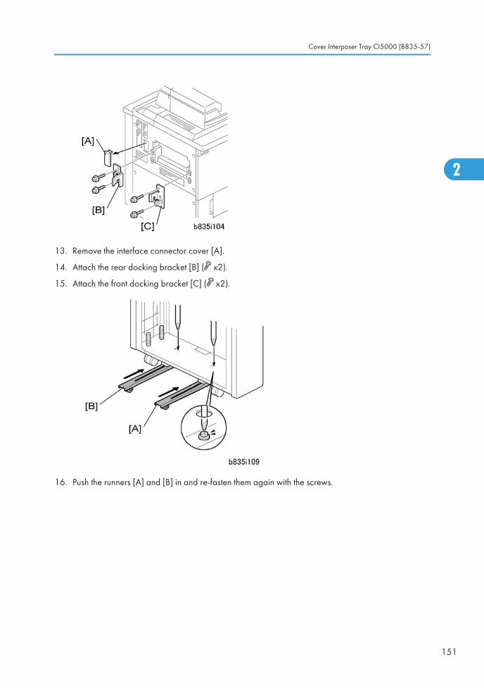
13. Remove the interface connector cover [A].
14. Attach the rear docking bracket [B] ( x2).
15. Attach the front docking bracket [C] ( x2).
16. Push the runners [A] and [B] in and re-fasten them again with the screws.
Cover Interposer Tray CI5000 (B835-57)
151
2
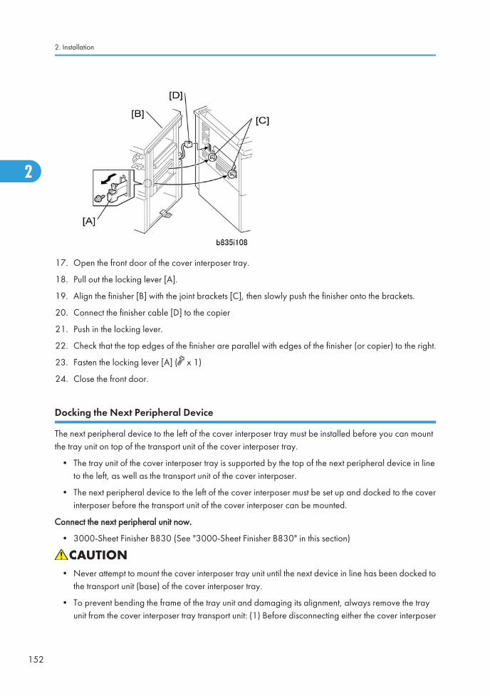
17. Open the front door of the cover interposer tray.
18. Pull out the locking lever [A].
19. Align the finisher [B] with the joint brackets [C], then slowly push the finisher onto the brackets.
20. Connect the finisher cable [D] to the copier
21. Push in the locking lever.
22. Check that the top edges of the finisher are parallel with edges of the finisher (or copier) to the right.
23. Fasten the locking lever [A] ( x 1)
24. Close the front door.
Docking the Next Peripheral Device
The next peripheral device to the left of the cover interposer tray must be installed before you can mountthe tray unit on top of the transport unit of the cover interposer tray.
• The tray unit of the cover interposer tray is supported by the top of the next peripheral device in lineto the left, as well as the transport unit of the cover interposer.
• The next peripheral device to the left of the cover interposer must be set up and docked to the coverinterposer before the transport unit of the cover interposer can be mounted.
Connect the next peripheral unit now.
• 3000-Sheet Finisher B830 (See "3000-Sheet Finisher B830" in this section)
• Never attempt to mount the cover interposer tray unit until the next device in line has been docked tothe transport unit (base) of the cover interposer tray.
• To prevent bending the frame of the tray unit and damaging its alignment, always remove the trayunit from the cover interposer tray transport unit: (1) Before disconnecting either the cover interposer
2. Installation
152
2
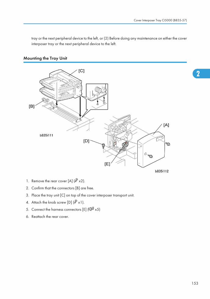
tray or the next peripheral device to the left, or (2) Before doing any maintenance on either the coverinterposer tray or the next peripheral device to the left.
Mounting the Tray Unit
1. Remove the rear cover [A] ( x2).
2. Confirm that the connectors [B] are free.
3. Place the tray unit [C] on top of the cover interposer transport unit.
4. Attach the knob screw [D] ( x1).
5. Connect the harness connectors [E] ( x5)
6. Reattach the rear cover.
Cover Interposer Tray CI5000 (B835-57)
153
2
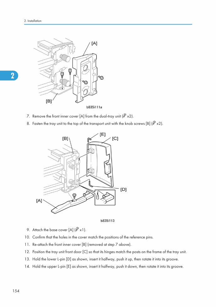
7. Remove the front inner cover [A] from the dual-tray unit ( x2).
8. Fasten the tray unit to the top of the transport unit with the knob screws [B] ( x2).
9. Attach the base cover [A] ( x1).
10. Confirm that the holes in the cover match the positions of the reference pins.
11. Re-attach the front inner cover [B] (removed at step 7 above).
12. Position the tray unit front door [C] so that its hinges match the posts on the frame of the tray unit.
13. Hold the lower L-pin [D] as shown, insert it halfway, push it up, then rotate it into its groove.
14. Hold the upper L-pin [E] as shown, insert it halfway, push it down, then rotate it into its groove.
2. Installation
154
2
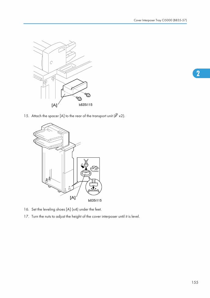
15. Attach the spacer [A] to the rear of the transport unit ( x2).
16. Set the leveling shoes [A] (x4) under the feet.
17. Turn the nuts to adjust the height of the cover interposer until it is level.
Cover Interposer Tray CI5000 (B835-57)
155
2
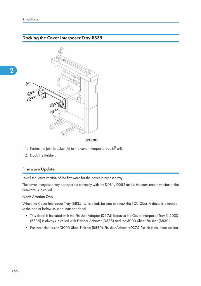
Docking the Cover Interposer Tray B835
1. Fasten the joint bracket [A] to the cover interposer tray ( x4).
2. Dock the finisher.
Firmware Update
Install the latest version of the firmware for the cover interposer tray.
The cover interposer may not operate correctly with the D081/D082 unless the most recent version of thefirmware is installed.
North America Only
When the Cover Interposer Tray (B835) is installed, be sure to check the FCC Class-A decal is attachedto the copier below its serial number decal.
• This decal is included with the Finisher Adapter (D375) because the Cover Interposer Tray CI5000(B835) is always installed with Finisher Adapter (D375) and the 3000-Sheet Finisher (B830).
• For more details see "3000-Sheet Finisher (B830), Finisher Adapter (D375)" in this installation section.
2. Installation
156
2
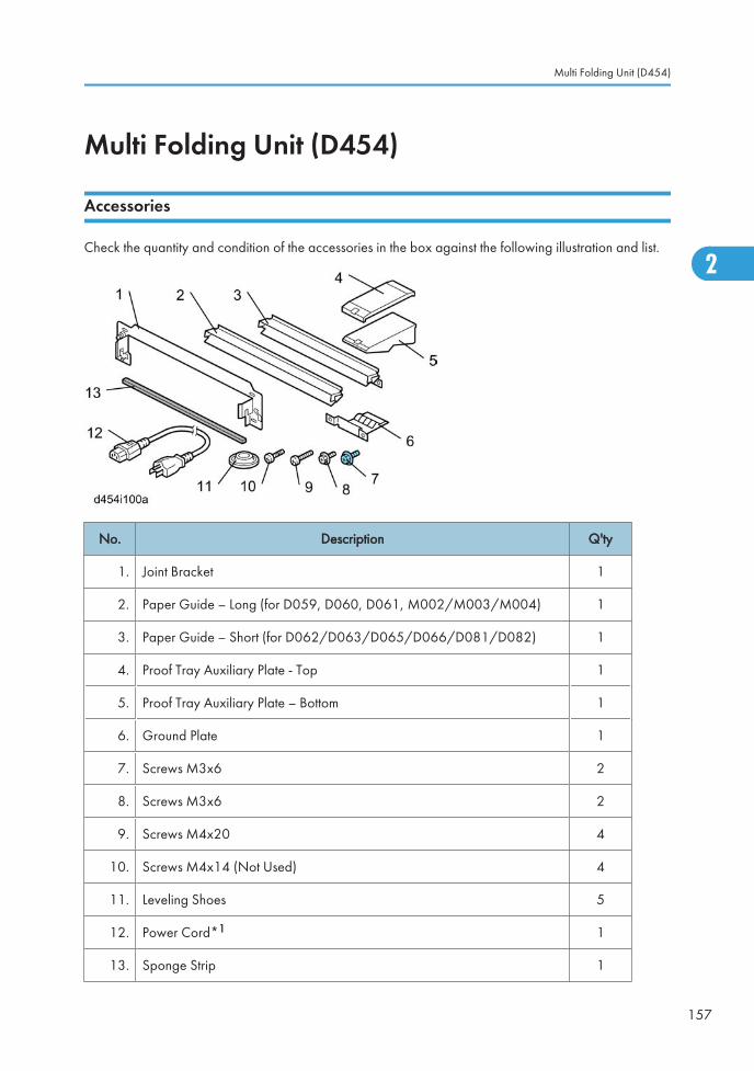
Multi Folding Unit (D454)
Accessories
Check the quantity and condition of the accessories in the box against the following illustration and list.
No. Description Q'ty
1. Joint Bracket 1
2. Paper Guide – Long (for D059, D060, D061, M002/M003/M004) 1
3. Paper Guide – Short (for D062/D063/D065/D066/D081/D082) 1
4. Proof Tray Auxiliary Plate - Top 1
5. Proof Tray Auxiliary Plate – Bottom 1
6. Ground Plate 1
7. Screws M3x6 2
8. Screws M3x6 2
9. Screws M4x20 4
10. Screws M4x14 (Not Used) 4
11. Leveling Shoes 5
12. Power Cord*1 1
13. Sponge Strip 1
Multi Folding Unit (D454)
157
2
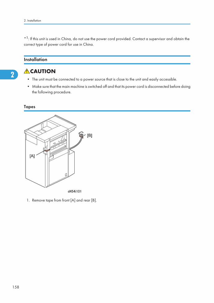
*1: If this unit is used in China, do not use the power cord provided. Contact a supervisor and obtain thecorrect type of power cord for use in China.
Installation
• The unit must be connected to a power source that is close to the unit and easily accessible.
• Make sure that the main machine is switched off and that its power cord is disconnected before doingthe following procedure.
Tapes
1. Remove tape from front [A] and rear [B].
2. Installation
158
2
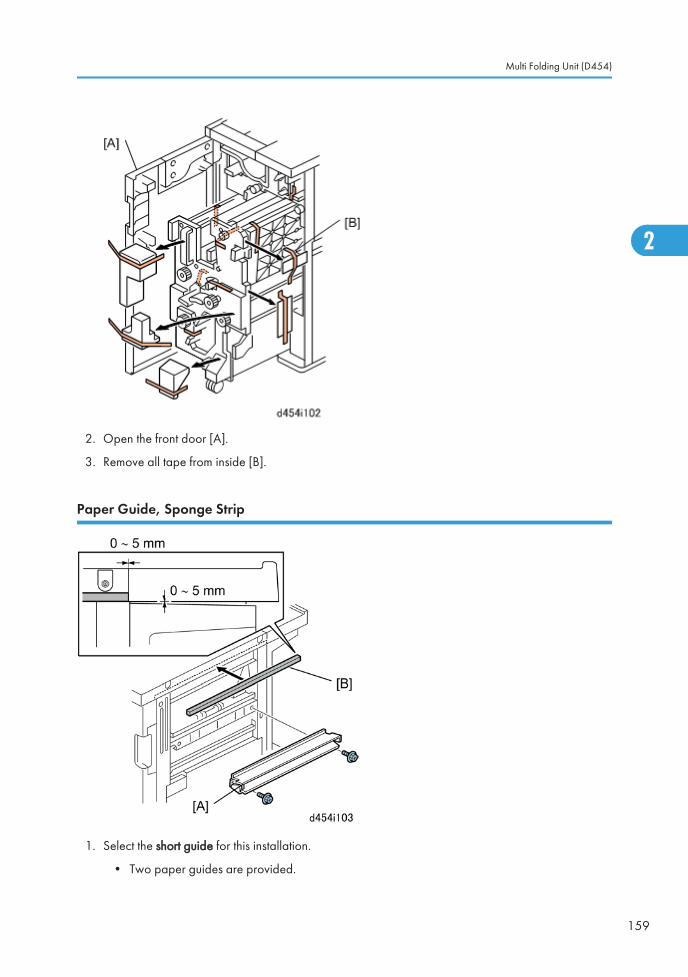
2. Open the front door [A].
3. Remove all tape from inside [B].
Paper Guide, Sponge Strip
1. Select the short guide for this installation.
• Two paper guides are provided.
Multi Folding Unit (D454)
159
2
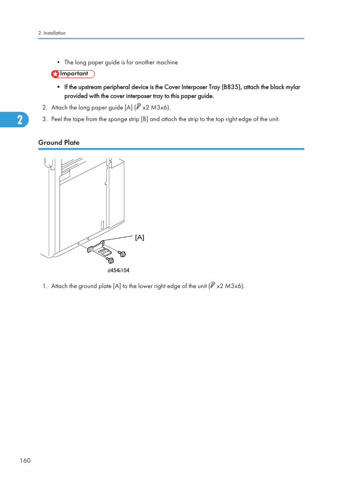
• The long paper guide is for another machine
• If the upstream peripheral device is the Cover Interposer Tray (B835), attach the black mylarprovided with the cover interposer tray to this paper guide.
2. Attach the long paper guide [A] ( x2 M3x6).
3. Peel the tape from the sponge strip [B] and attach the strip to the top right edge of the unit.
Ground Plate
1. Attach the ground plate [A] to the lower right edge of the unit ( x2 M3x6).
2. Installation
160
2
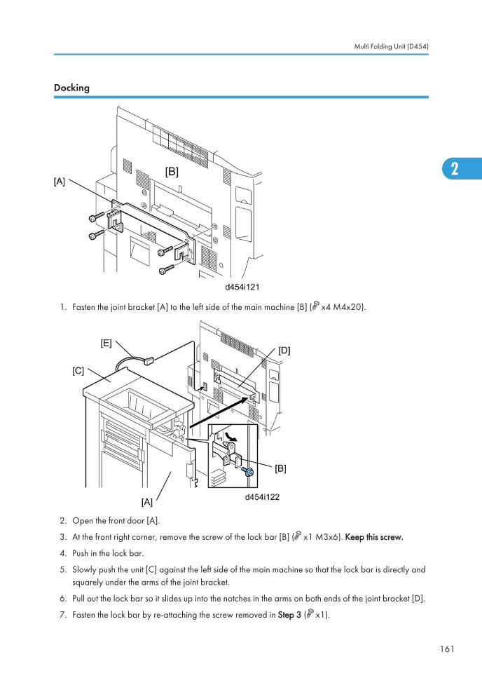
Docking
1. Fasten the joint bracket [A] to the left side of the main machine [B] ( x4 M4x20).
2. Open the front door [A].
3. At the front right corner, remove the screw of the lock bar [B] ( x1 M3x6). Keep this screw.
4. Push in the lock bar.
5. Slowly push the unit [C] against the left side of the main machine so that the lock bar is directly andsquarely under the arms of the joint bracket.
6. Pull out the lock bar so it slides up into the notches in the arms on both ends of the joint bracket [D].
7. Fasten the lock bar by re-attaching the screw removed in Step 3 ( x1).
Multi Folding Unit (D454)
161
2
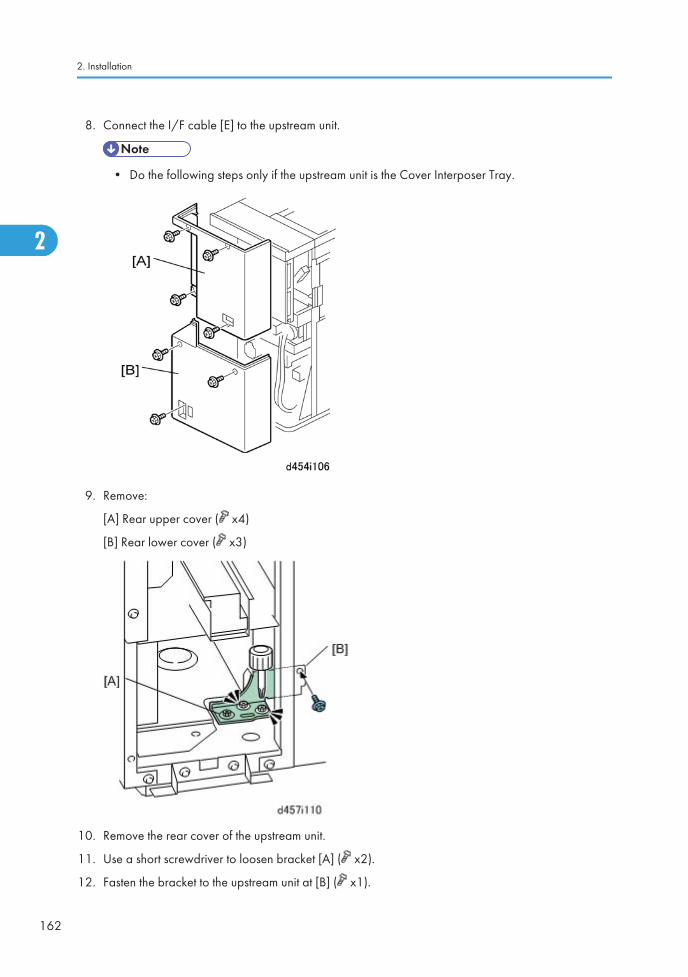
8. Connect the I/F cable [E] to the upstream unit.
• Do the following steps only if the upstream unit is the Cover Interposer Tray.
9. Remove:
[A] Rear upper cover ( x4)
[B] Rear lower cover ( x3)
10. Remove the rear cover of the upstream unit.
11. Use a short screwdriver to loosen bracket [A] ( x2).
12. Fasten the bracket to the upstream unit at [B] ( x1).
2. Installation
162
2
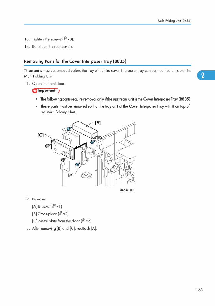
13. Tighten the screws ( x3).
14. Re-attach the rear covers.
Removing Parts for the Cover Interposer Tray (B835)
Three parts must be removed before the tray unit of the cover interposer tray can be mounted on top of theMulti Folding Unit.
1. Open the front door.
• The following parts require removal only if the upstream unit is the Cover Interposer Tray (B835).
• These parts must be removed so that the tray unit of the Cover Interposer Tray will fit on top ofthe Multi Folding Unit.
2. Remove:
[A] Bracket ( x1)
[B] Cross-piece ( x2)
[C] Metal plate from the door ( x2)
3. After removing [B] and [C], reattach [A].
Multi Folding Unit (D454)
163
2
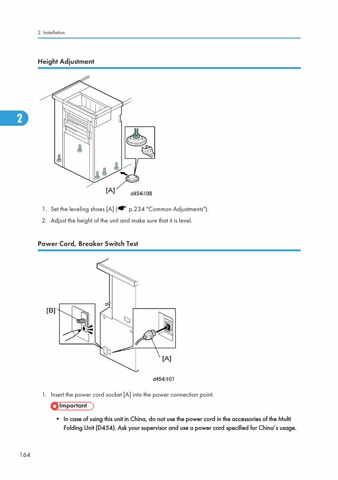
Height Adjustment
1. Set the leveling shoes [A] ( p.234 "Common Adjustments").
2. Adjust the height of the unit and make sure that it is level.
Power Cord, Breaker Switch Test
1. Insert the power cord socket [A] into the power connection point.
• In case of using this unit in China, do not use the power cord in the accessories of the MultiFolding Unit (D454). Ask your supervisor and use a power cord specified for China’s usage.
2. Installation
164
2
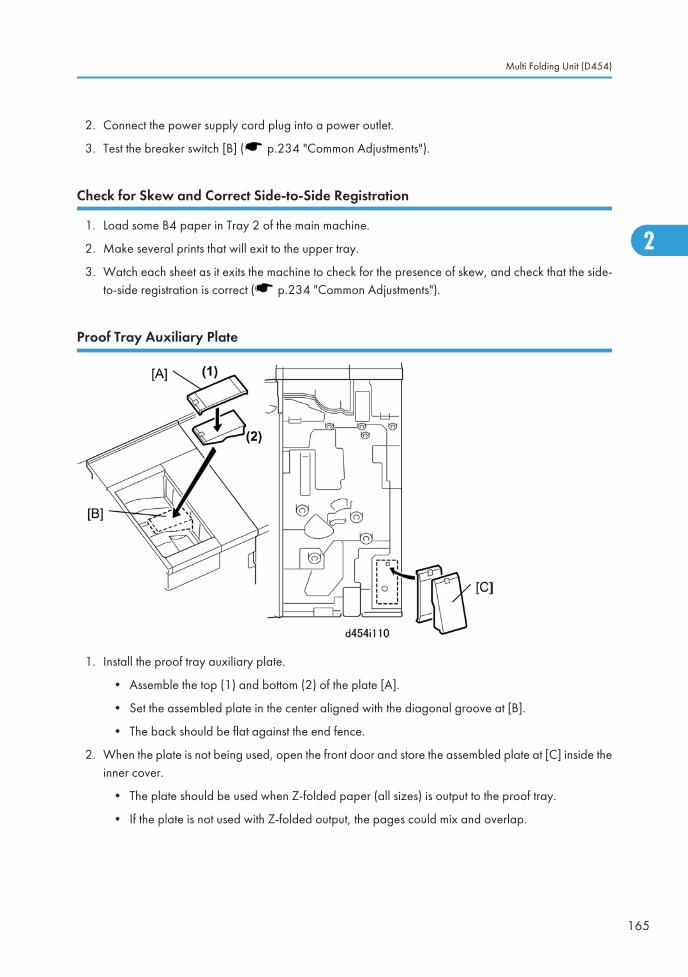
2. Connect the power supply cord plug into a power outlet.
3. Test the breaker switch [B] ( p.234 "Common Adjustments").
Check for Skew and Correct Side-to-Side Registration
1. Load some B4 paper in Tray 2 of the main machine.
2. Make several prints that will exit to the upper tray.
3. Watch each sheet as it exits the machine to check for the presence of skew, and check that the side-to-side registration is correct ( p.234 "Common Adjustments").
Proof Tray Auxiliary Plate
1. Install the proof tray auxiliary plate.
• Assemble the top (1) and bottom (2) of the plate [A].
• Set the assembled plate in the center aligned with the diagonal groove at [B].
• The back should be flat against the end fence.
2. When the plate is not being used, open the front door and store the assembled plate at [C] inside theinner cover.
• The plate should be used when Z-folded paper (all sizes) is output to the proof tray.
• If the plate is not used with Z-folded output, the pages could mix and overlap.
Multi Folding Unit (D454)
165
2
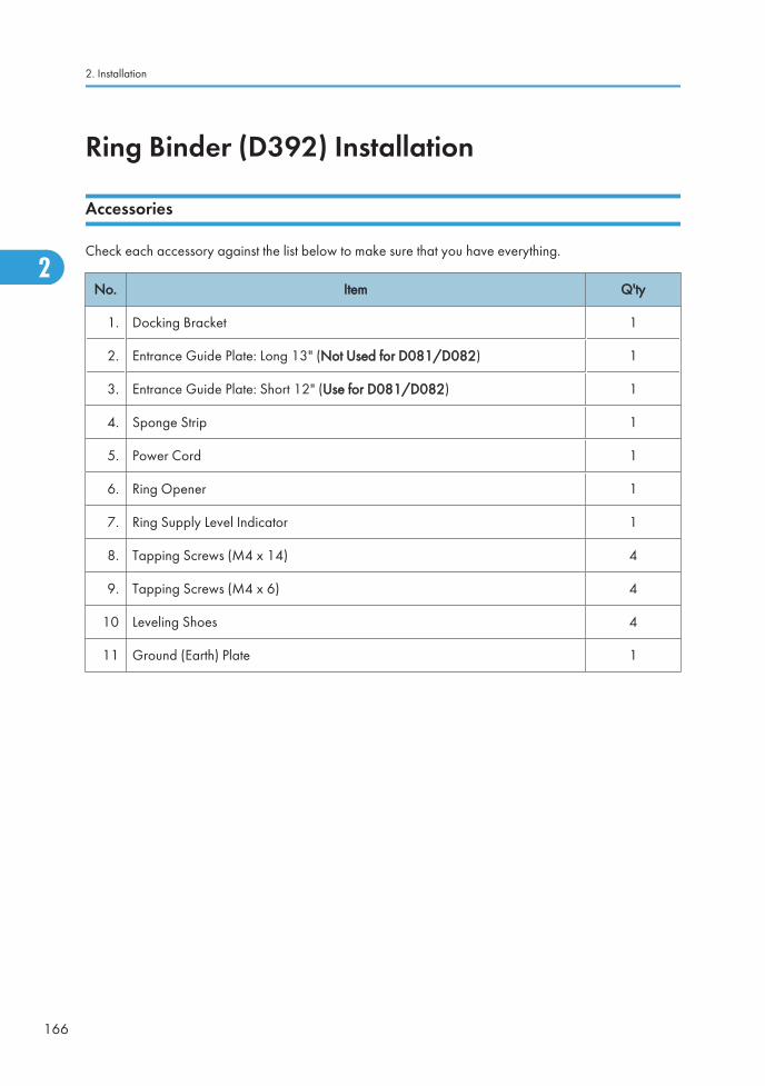
Ring Binder (D392) Installation
Accessories
Check each accessory against the list below to make sure that you have everything.
No. Item Q'ty
1. Docking Bracket 1
2. Entrance Guide Plate: Long 13" (Not Used for D081/D082) 1
3. Entrance Guide Plate: Short 12" (Use for D081/D082) 1
4. Sponge Strip 1
5. Power Cord 1
6. Ring Opener 1
7. Ring Supply Level Indicator 1
8. Tapping Screws (M4 x 14) 4
9. Tapping Screws (M4 x 6) 4
10 Leveling Shoes 4
11 Ground (Earth) Plate 1
2. Installation
166
2
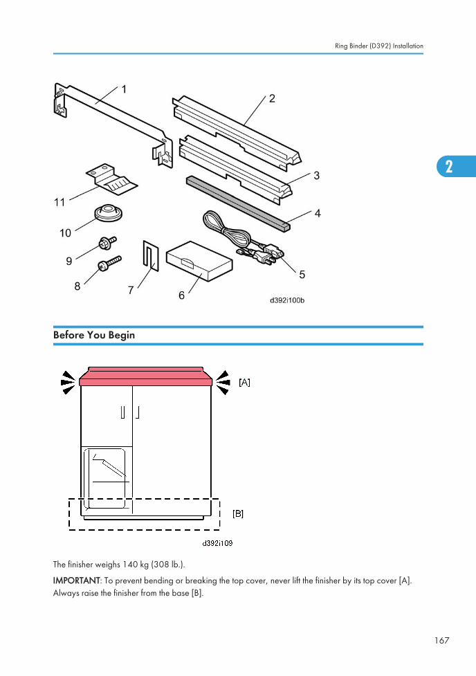
Before You Begin
The finisher weighs 140 kg (308 lb.).
IMPORTANT: To prevent bending or breaking the top cover, never lift the finisher by its top cover [A].Always raise the finisher from the base [B].
Ring Binder (D392) Installation
167
2
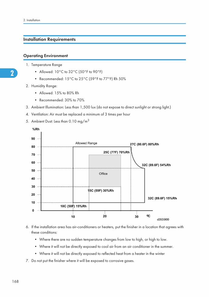
Installation Requirements
Operating Environment
1. Temperature Range
• Allowed: 10°C to 32°C (50°F to 90°F)
• Recommended: 15°C to 25°C (59°F to 77°F) Rh 50%
2. Humidity Range:
• Allowed: 15% to 80% Rh
• Recommended: 30% to 70%
3. Ambient Illumination: Less than 1,500 lux (do not expose to direct sunlight or strong light.)
4. Ventilation: Air must be replaced a minimum of 3 times per hour
5. Ambient Dust: Less than 0.10 mg/m3
6. If the installation area has air-conditioners or heaters, put the finisher in a location that agrees withthese conditions:
• Where there are no sudden temperature changes from low to high, or high to low.
• Where it will not be directly exposed to cool air from an air conditioner in the summer.
• Where it will not be directly exposed to reflected heat from a heater in the winter
7. Do not put the finisher where it will be exposed to corrosive gases.
2. Installation
168
2
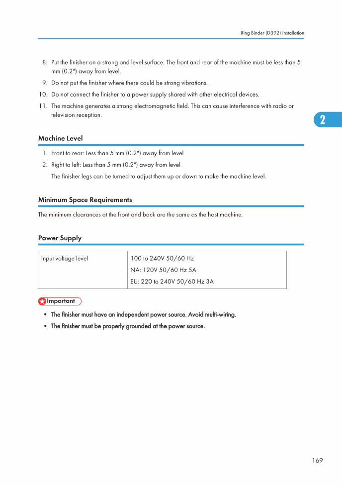
8. Put the finisher on a strong and level surface. The front and rear of the machine must be less than 5mm (0.2") away from level.
9. Do not put the finisher where there could be strong vibrations.
10. Do not connect the finisher to a power supply shared with other electrical devices.
11. The machine generates a strong electromagnetic field. This can cause interference with radio ortelevision reception.
Machine Level
1. Front to rear: Less than 5 mm (0.2") away from level
2. Right to left: Less than 5 mm (0.2") away from level
The finisher legs can be turned to adjust them up or down to make the machine level.
Minimum Space Requirements
The minimum clearances at the front and back are the same as the host machine.
Power Supply
Input voltage level 100 to 240V 50/60 Hz
NA: 120V 50/60 Hz 5A
EU: 220 to 240V 50/60 Hz 3A
• The finisher must have an independent power source. Avoid multi-wiring.
• The finisher must be properly grounded at the power source.
Ring Binder (D392) Installation
169
2
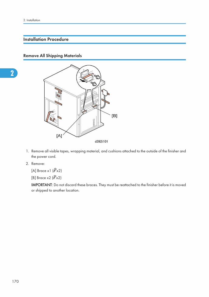
Installation Procedure
Remove All Shipping Materials
1. Remove all visible tapes, wrapping material, and cushions attached to the outside of the finisher andthe power cord.
2. Remove:
[A] Brace x1 ( x2)
[B] Brace x2 ( x2)
IMPORTANT: Do not discard these braces. They must be reattached to the finisher before it is movedor shipped to another location.
2. Installation
170
2
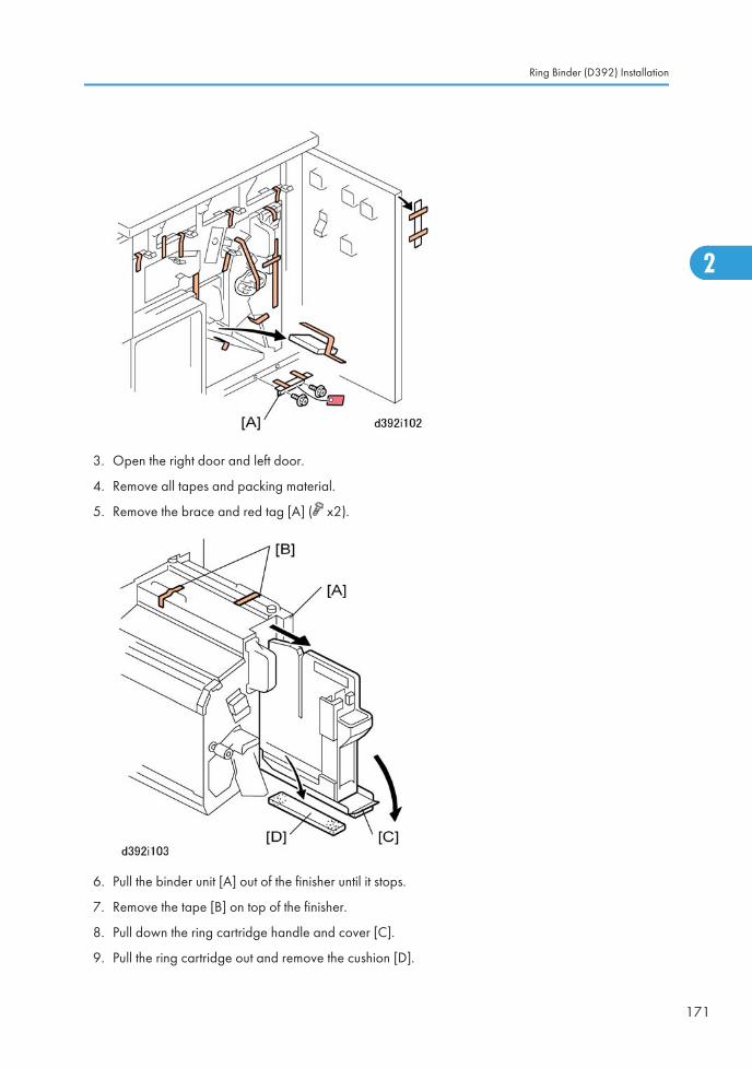
3. Open the right door and left door.
4. Remove all tapes and packing material.
5. Remove the brace and red tag [A] ( x2).
6. Pull the binder unit [A] out of the finisher until it stops.
7. Remove the tape [B] on top of the finisher.
8. Pull down the ring cartridge handle and cover [C].
9. Pull the ring cartridge out and remove the cushion [D].
Ring Binder (D392) Installation
171
2
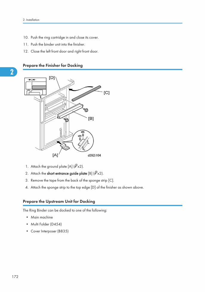
10. Push the ring cartridge in and close its cover.
11. Push the binder unit into the finisher.
12. Close the left front door and right front door.
Prepare the Finisher for Docking
1. Attach the ground plate [A] ( x2).
2. Attach the short entrance guide plate [B] ( x2).
3. Remove the tape from the back of the sponge strip [C].
4. Attach the sponge strip to the top edge [D] of the finisher as shown above.
Prepare the Upstream Unit for Docking
The Ring Binder can be docked to one of the following:
• Main machine
• Multi Folder (D454)
• Cover Interposer (B835)
2. Installation
172
2
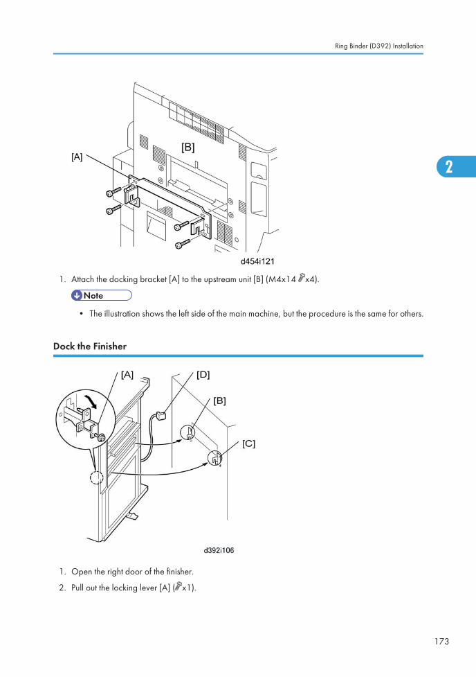
1. Attach the docking bracket [A] to the upstream unit [B] (M4x14 x4).
• The illustration shows the left side of the main machine, but the procedure is the same for others.
Dock the Finisher
1. Open the right door of the finisher.
2. Pull out the locking lever [A] ( x1).
Ring Binder (D392) Installation
173
2
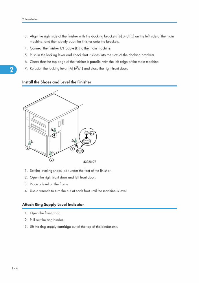
3. Align the right side of the finisher with the docking brackets [B] and [C] on the left side of the mainmachine, and then slowly push the finisher onto the brackets.
4. Connect the finisher I/F cable [D] to the main machine.
5. Push in the locking lever and check that it slides into the slots of the docking brackets.
6. Check that the top edge of the finisher is parallel with the left edge of the main machine.
7. Refasten the locking lever [A] ( x1) and close the right front door.
Install the Shoes and Level the Finisher
1. Set the leveling shoes (x4) under the feet of the finisher.
2. Open the right front door and left front door.
3. Place a level on the frame
4. Use a wrench to turn the nut at each foot until the machine is level.
Attach Ring Supply Level Indicator
1. Open the front door.
2. Pull out the ring binder.
3. Lift the ring supply cartridge out of the top of the binder unit.
2. Installation
174
2
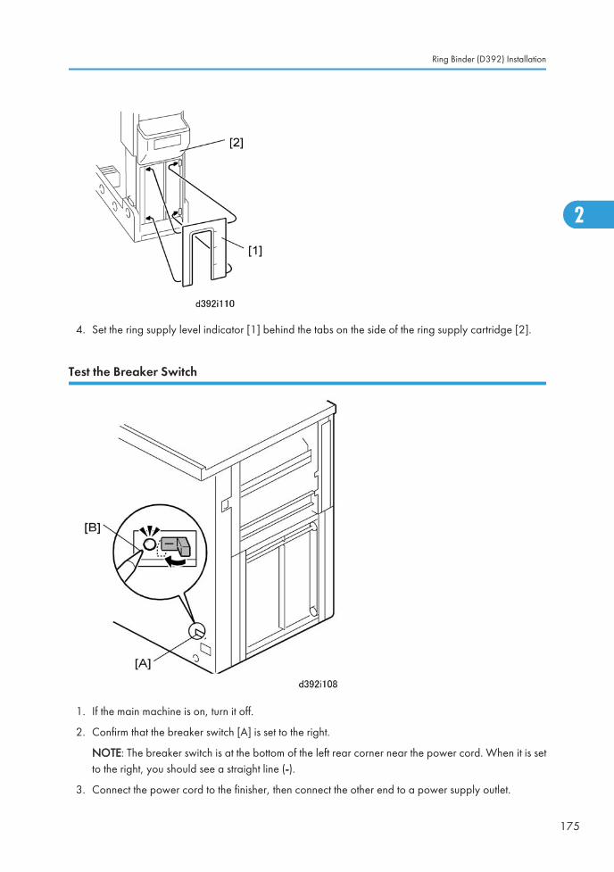
4. Set the ring supply level indicator [1] behind the tabs on the side of the ring supply cartridge [2].
Test the Breaker Switch
1. If the main machine is on, turn it off.
2. Confirm that the breaker switch [A] is set to the right.
NOTE: The breaker switch is at the bottom of the left rear corner near the power cord. When it is setto the right, you should see a straight line (-).
3. Connect the power cord to the finisher, then connect the other end to a power supply outlet.
Ring Binder (D392) Installation
175
2
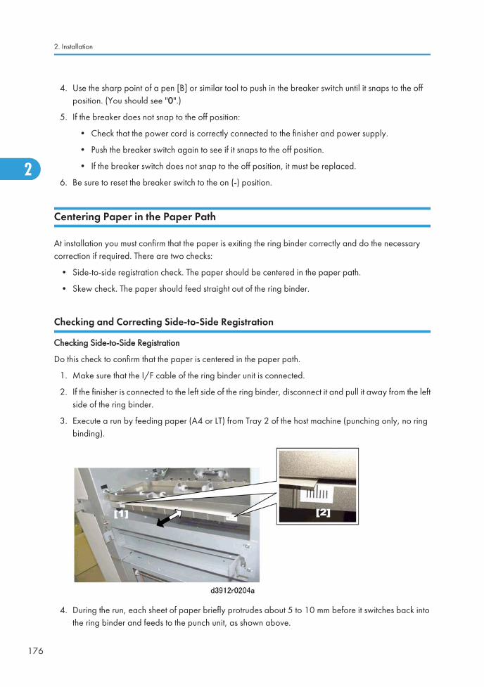
4. Use the sharp point of a pen [B] or similar tool to push in the breaker switch until it snaps to the offposition. (You should see "0".)
5. If the breaker does not snap to the off position:
• Check that the power cord is correctly connected to the finisher and power supply.
• Push the breaker switch again to see if it snaps to the off position.
• If the breaker switch does not snap to the off position, it must be replaced.
6. Be sure to reset the breaker switch to the on (-) position.
Centering Paper in the Paper Path
At installation you must confirm that the paper is exiting the ring binder correctly and do the necessarycorrection if required. There are two checks:
• Side-to-side registration check. The paper should be centered in the paper path.
• Skew check. The paper should feed straight out of the ring binder.
Checking and Correcting Side-to-Side Registration
Checking Side-to-Side Registration
Do this check to confirm that the paper is centered in the paper path.
1. Make sure that the I/F cable of the ring binder unit is connected.
2. If the finisher is connected to the left side of the ring binder, disconnect it and pull it away from the leftside of the ring binder.
3. Execute a run by feeding paper (A4 or LT) from Tray 2 of the host machine (punching only, no ringbinding).
4. During the run, each sheet of paper briefly protrudes about 5 to 10 mm before it switches back intothe ring binder and feeds to the punch unit, as shown above.
2. Installation
176
2
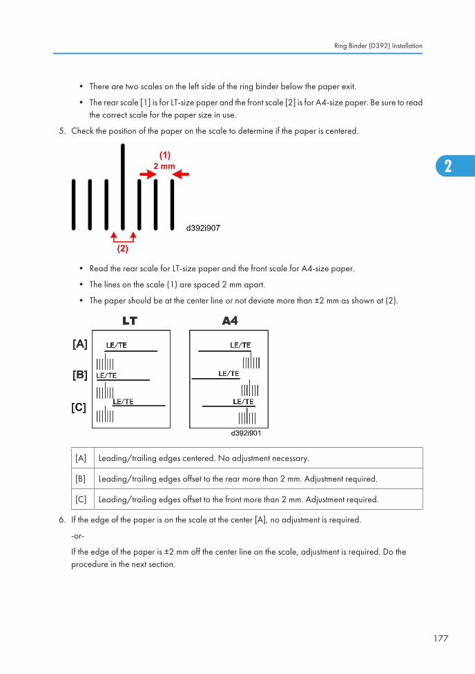
• There are two scales on the left side of the ring binder below the paper exit.
• The rear scale [1] is for LT-size paper and the front scale [2] is for A4-size paper. Be sure to readthe correct scale for the paper size in use.
5. Check the position of the paper on the scale to determine if the paper is centered.
• Read the rear scale for LT-size paper and the front scale for A4-size paper.
• The lines on the scale (1) are spaced 2 mm apart.
• The paper should be at the center line or not deviate more than ±2 mm as shown at (2).
[A] Leading/trailing edges centered. No adjustment necessary.
[B] Leading/trailing edges offset to the rear more than 2 mm. Adjustment required.
[C] Leading/trailing edges offset to the front more than 2 mm. Adjustment required.
6. If the edge of the paper is on the scale at the center [A], no adjustment is required.
-or-
If the edge of the paper is ±2 mm off the center line on the scale, adjustment is required. Do theprocedure in the next section.
Ring Binder (D392) Installation
177
2
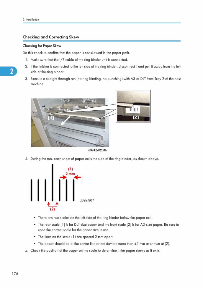
Checking and Correcting Skew
Checking for Paper Skew
Do this check to confirm that the paper is not skewed in the paper path.
1. Make sure that the I/F cable of the ring binder unit is connected.
2. If the finisher is connected to the left side of the ring binder, disconnect it and pull it away from the leftside of the ring binder.
3. Execute a straight-through run (no ring binding, no punching) with A3 or DLT from Tray 2 of the hostmachine.
4. During the run, each sheet of paper exits the side of the ring binder, as shown above.
• There are two scales on the left side of the ring binder below the paper exit.
• The rear scale [1] is for DLT-size paper and the front scale [2] is for A3-size paper. Be sure toread the correct scale for the paper size in use.
• The lines on the scale (1) are spaced 2 mm apart.
• The paper should be at the center line or not deviate more than ±2 mm as shown at (2).
5. Check the position of the paper on the scale to determine if the paper skews as it exits.
2. Installation
178
2
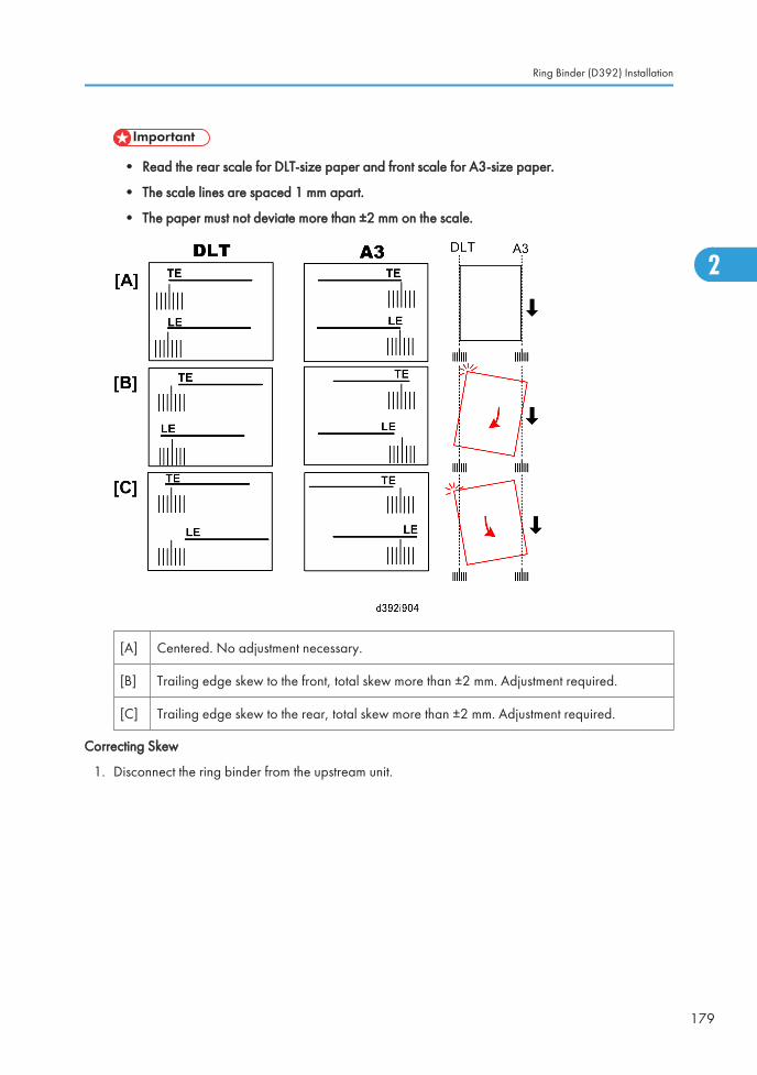
• Read the rear scale for DLT-size paper and front scale for A3-size paper.
• The scale lines are spaced 1 mm apart.
• The paper must not deviate more than ±2 mm on the scale.
[A] Centered. No adjustment necessary.
[B] Trailing edge skew to the front, total skew more than ±2 mm. Adjustment required.
[C] Trailing edge skew to the rear, total skew more than ±2 mm. Adjustment required.
Correcting Skew
1. Disconnect the ring binder from the upstream unit.
Ring Binder (D392) Installation
179
2
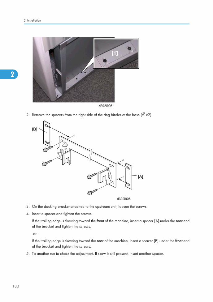
2. Remove the spacers from the right side of the ring binder at the base ( x2).
3. On the docking bracket attached to the upstream unit, loosen the screws.
4. Insert a spacer and tighten the screws.
If the trailing edge is skewing toward the front of the machine, insert a spacer [A] under the rear endof the bracket and tighten the screws.
-or-
If the trailing edge is skewing toward the rear of the machine, insert a spacer [B] under the front endof the bracket and tighten the screws.
5. To another run to check the adjustment. If skew is still present, insert another spacer.
2. Installation
180
2
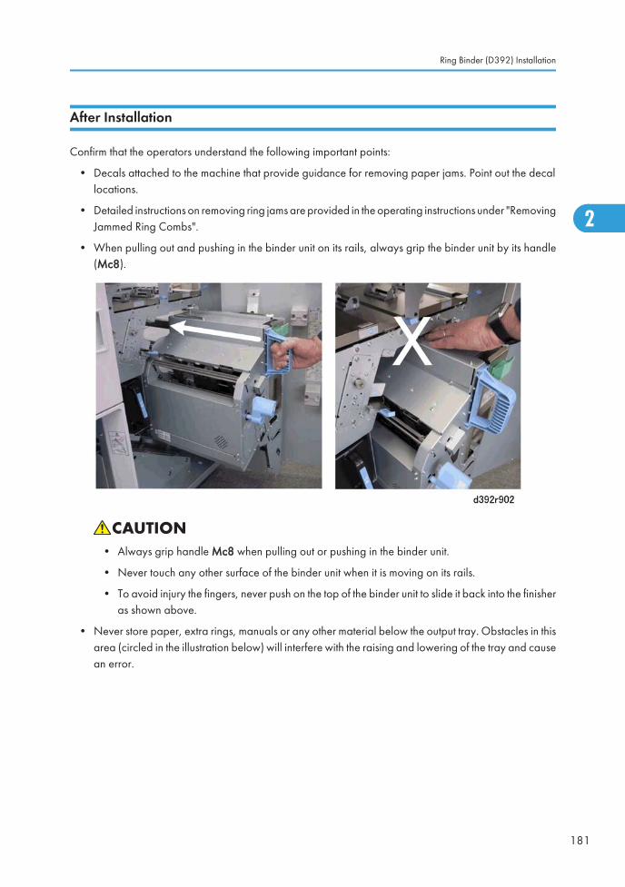
After Installation
Confirm that the operators understand the following important points:
• Decals attached to the machine that provide guidance for removing paper jams. Point out the decallocations.
• Detailed instructions on removing ring jams are provided in the operating instructions under "RemovingJammed Ring Combs".
• When pulling out and pushing in the binder unit on its rails, always grip the binder unit by its handle(Mc8).
• Always grip handle Mc8 when pulling out or pushing in the binder unit.
• Never touch any other surface of the binder unit when it is moving on its rails.
• To avoid injury the fingers, never push on the top of the binder unit to slide it back into the finisheras shown above.
• Never store paper, extra rings, manuals or any other material below the output tray. Obstacles in thisarea (circled in the illustration below) will interfere with the raising and lowering of the tray and causean error.
Ring Binder (D392) Installation
181
2
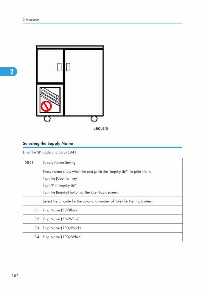
Selecting the Supply Name
Enter the SP mode and do SP5841.
5841 Supply Name Setting
These names show when the user prints the "Inquiry List". To print this list:
Push the [Counter] key
Push "Print Inquiry List".
Push the [Inquiry] button on the User Tools screen.
Select the SP code for the color and number of holes for the ring binders.
31 Ring Name (50/Black)
32 Ring Name (50/White)
33 Ring Name (100/Black)
34 Ring Name (100/White)
2. Installation
182
2
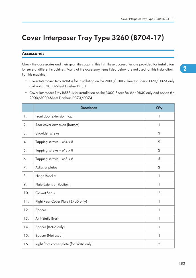
Cover Interposer Tray Type 3260 (B704-17)
Accessories
Check the accessories and their quantities against this list. These accessories are provided for installationfor several different machines. Many of the accessory items listed below are not used for this installation.For this machine:
• Cover Interposer Tray B704 is for installation on the 2000/3000-Sheet Finishers D373/D374 onlyand not on 3000-Sheet Finisher D830
• Cover Interposer Tray B835 is for installation on the 3000-Sheet Finisher D830 only and not on the2000/3000-Sheet Finishers D373/D374.
Description Q'ty
1. Front door extension (top) 1
2. Rear cover extension (bottom) 1
3. Shoulder screws 3
4. Tapping screws – M4 x 8 9
5. Tapping screws – M3 x 8 2
6. Tapping screws – M3 x 6 5
7. Adjuster plates 2
8. Hinge Bracket 1
9. Plate Extension (bottom) 1
10. Gasket Seals 2
11. Right Rear Cover Plate (B706 only) 1
12. Spacer 1
13. Anti-Static Brush 1
14. Spacer (B706 only) 1
15. Spacer (Not used ) 1
16. Right front corner plate (for B706 only) 2
Cover Interposer Tray Type 3260 (B704-17)
183
2
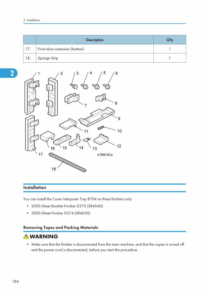
Description Q'ty
17. Front door extension (bottom) 1
18, Sponge Strip 1
Installation
You can install the Cover Interposer Tray B704 on these finishers only:
• 2000-Sheet Booklet Finisher D373 (SR4040)
• 3000-Sheet Finisher D374 (SR4030)
Removing Tapes and Packing Materials
• Make sure that the finisher is disconnected from the main machine, and that the copier is turned offand the power cord is disconnected, before you start this procedure.
2. Installation
184
2
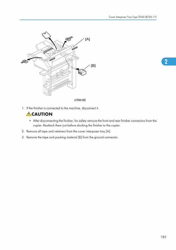
1. If the finisher is connected to the machine, disconnect it.
• After disconnecting the finisher, for safety remove the front and rear finisher connectors from thecopier. Reattach them just before docking the finisher to the copier.
2. Remove all tape and retainers from the cover interposer tray [A].
3. Remove the tape and packing material [B] from the ground connector.
Cover Interposer Tray Type 3260 (B704-17)
185
2
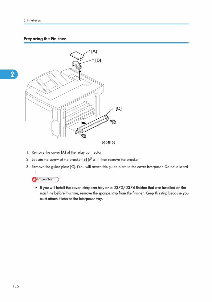
Preparing the Finisher
1. Remove the cover [A] of the relay connector.
2. Loosen the screw of the bracket [B] ( x 1) then remove the bracket.
3. Remove the guide plate [C]. (You will attach this guide plate to the cover interposer. Do not discardit.)
• If you will install the cover interposer tray on a D373/D374 finisher that was installed on themachine before this time, remove the sponge strip from the finisher. Keep this strip because youmust attach it later to the interposer tray.
2. Installation
186
2
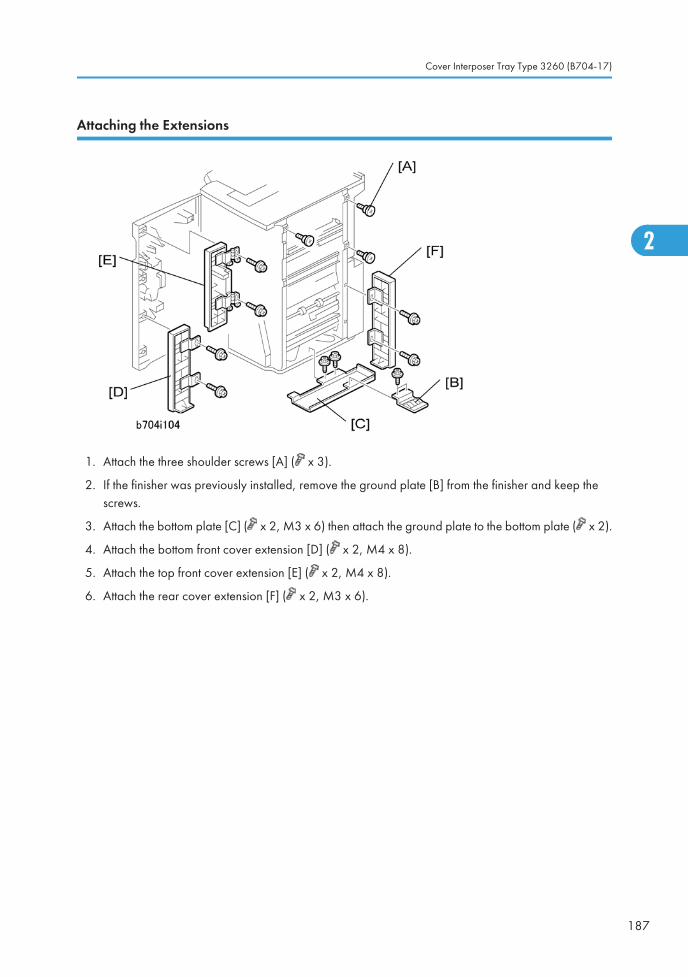
Attaching the Extensions
1. Attach the three shoulder screws [A] ( x 3).
2. If the finisher was previously installed, remove the ground plate [B] from the finisher and keep thescrews.
3. Attach the bottom plate [C] ( x 2, M3 x 6) then attach the ground plate to the bottom plate ( x 2).
4. Attach the bottom front cover extension [D] ( x 2, M4 x 8).
5. Attach the top front cover extension [E] ( x 2, M4 x 8).
6. Attach the rear cover extension [F] ( x 2, M3 x 6).
Cover Interposer Tray Type 3260 (B704-17)
187
2
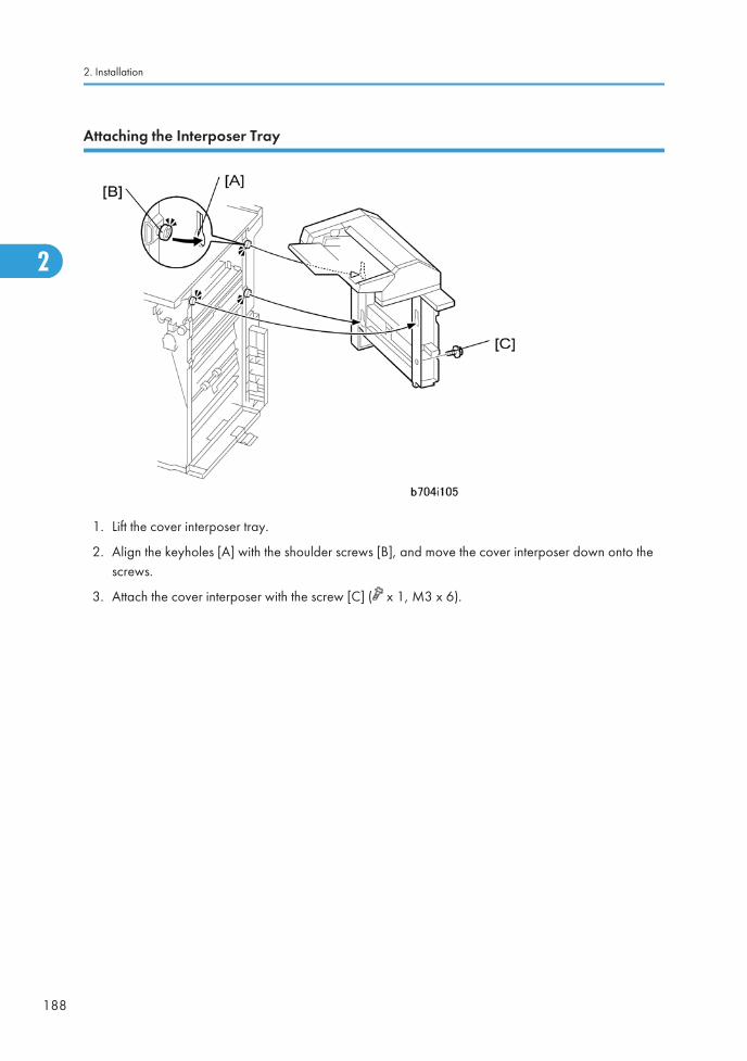
Attaching the Interposer Tray
1. Lift the cover interposer tray.
2. Align the keyholes [A] with the shoulder screws [B], and move the cover interposer down onto thescrews.
3. Attach the cover interposer with the screw [C] ( x 1, M3 x 6).
2. Installation
188
2
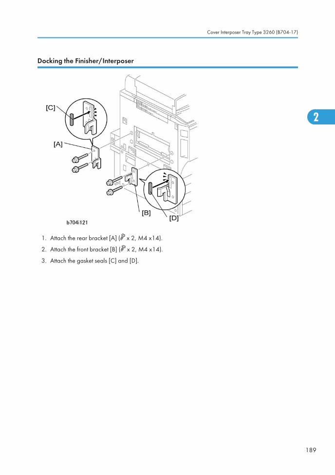
Docking the Finisher/Interposer
1. Attach the rear bracket [A] ( x 2, M4 x14).
2. Attach the front bracket [B] ( x 2, M4 x14).
3. Attach the gasket seals [C] and [D].
Cover Interposer Tray Type 3260 (B704-17)
189
2
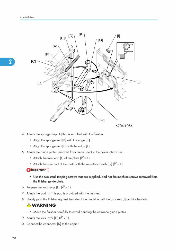
4. Attach the sponge strip [A] that is supplied with the finisher.
• Align the sponge end [B] with the edge [C].
• Align the sponge end [D] with the edge [E].
5. Attach the guide plate (removed from the finisher) to the cover interposer.
• Attach the front end [F] of the plate ( x 1).
• Attach the rear end of the plate with the anti-static brush [G] ( x 1).
• Use the two small tapping screws that are supplied, and not the machine screws removed fromthe finisher guide plate.
6. Release the lock lever [H] ( x 1).
7. Attach the pad [I]. This pad is provided with the finisher.
8. Slowly push the finisher against the side of the machine until the brackets [J] go into the slots.
• Move the finisher carefully to avoid bending the entrance guide plates.
9. Attach the lock lever [H] ( x 1).
10. Connect the connector [K] to the copier.
2. Installation
190
2
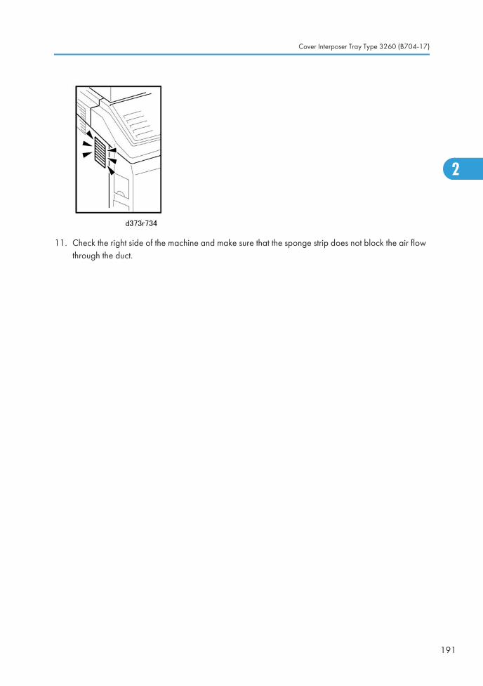
11. Check the right side of the machine and make sure that the sponge strip does not block the air flowthrough the duct.
Cover Interposer Tray Type 3260 (B704-17)
191
2
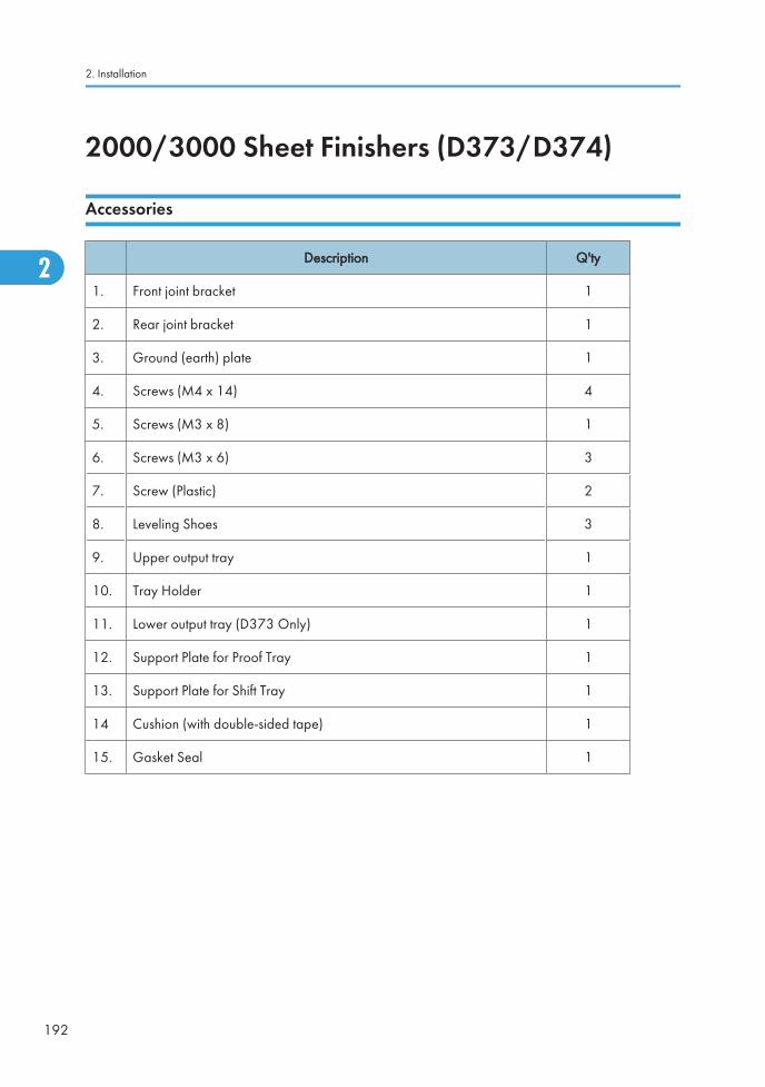
2000/3000 Sheet Finishers (D373/D374)
Accessories
Description Q'ty
1. Front joint bracket 1
2. Rear joint bracket 1
3. Ground (earth) plate 1
4. Screws (M4 x 14) 4
5. Screws (M3 x 8) 1
6. Screws (M3 x 6) 3
7. Screw (Plastic) 2
8. Leveling Shoes 3
9. Upper output tray 1
10. Tray Holder 1
11. Lower output tray (D373 Only) 1
12. Support Plate for Proof Tray 1
13. Support Plate for Shift Tray 1
14 Cushion (with double-sided tape) 1
15. Gasket Seal 1
2. Installation
192
2
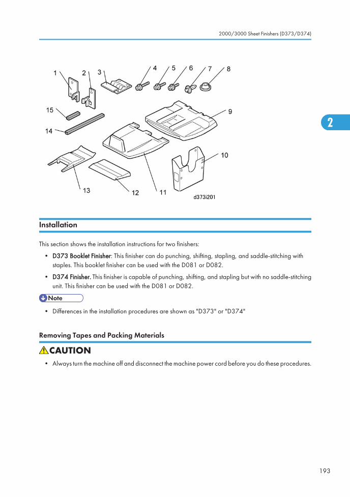
Installation
This section shows the installation instructions for two finishers:
• D373 Booklet Finisher: This finisher can do punching, shifting, stapling, and saddle-stitching withstaples. This booklet finisher can be used with the D081 or D082.
• D374 Finisher. This finisher is capable of punching, shifting, and stapling but with no saddle-stitchingunit. This finisher can be used with the D081 or D082.
• Differences in the installation procedures are shown as "D373" or "D374"
Removing Tapes and Packing Materials
• Always turn the machine off and disconnect the machine power cord before you do these procedures.
2000/3000 Sheet Finishers (D373/D374)
193
2
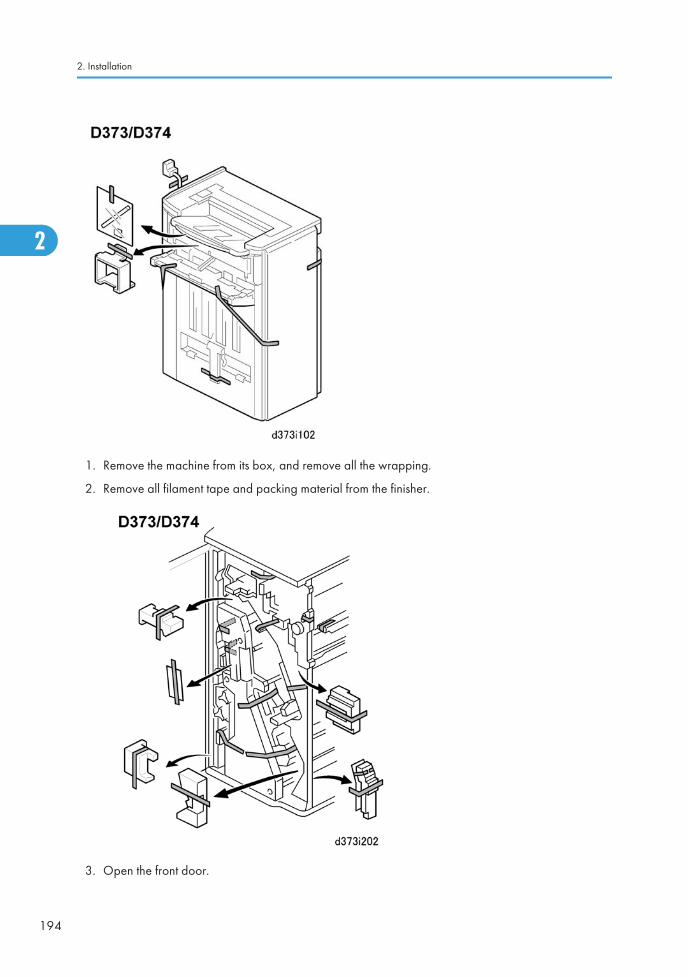
1. Remove the machine from its box, and remove all the wrapping.
2. Remove all filament tape and packing material from the finisher.
3. Open the front door.
2. Installation
194
2
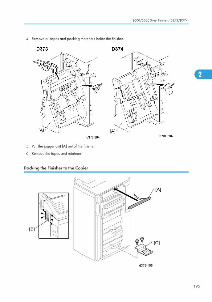
4. Remove all tapes and packing materials inside the finisher.
5. Pull the jogger unit [A] out of the finisher.
6. Remove the tapes and retainers.
Docking the Finisher to the Copier
2000/3000 Sheet Finishers (D373/D374)
195
2
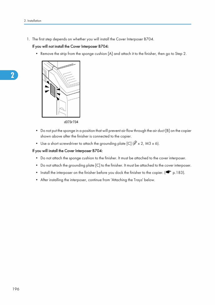
1. The first step depends on whether you will install the Cover Interposer B704.
If you will not install the Cover Interposer B704:
• Remove the strip from the sponge cushion [A] and attach it to the finisher, then go to Step 2.
• Do not put the sponge in a position that will prevent air flow through the air duct [B] on the copiershown above after the finisher is connected to the copier.
• Use a short screwdriver to attach the grounding plate [C] ( x 2, M3 x 6).
If you will install the Cover Interposer B704:
• Do not attach the sponge cushion to the finisher. It must be attached to the cover interposer.
• Do not attach the grounding plate [C] to the finisher. It must be attached to the cover interposer.
• Install the interposer on the finisher before you dock the finisher to the copier. ( p.183).
• After installing the interposer, continue from 'Attaching the Trays' below.
2. Installation
196
2
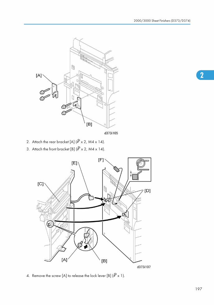
2. Attach the rear bracket [A] ( x 2, M4 x 14).
3. Attach the front bracket [B] ( x 2, M4 x 14).
4. Remove the screw [A] to release the lock lever [B] ( x 1).
2000/3000 Sheet Finishers (D373/D374)
197
2
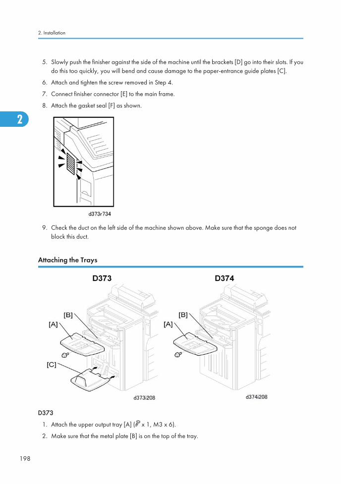
5. Slowly push the finisher against the side of the machine until the brackets [D] go into their slots. If youdo this too quickly, you will bend and cause damage to the paper-entrance guide plates [C].
6. Attach and tighten the screw removed in Step 4.
7. Connect finisher connector [E] to the main frame.
8. Attach the gasket seal [F] as shown.
9. Check the duct on the left side of the machine shown above. Make sure that the sponge does notblock this duct.
Attaching the Trays
D373
1. Attach the upper output tray [A] ( x 1, M3 x 6).
2. Make sure that the metal plate [B] is on the top of the tray.
2. Installation
198
2
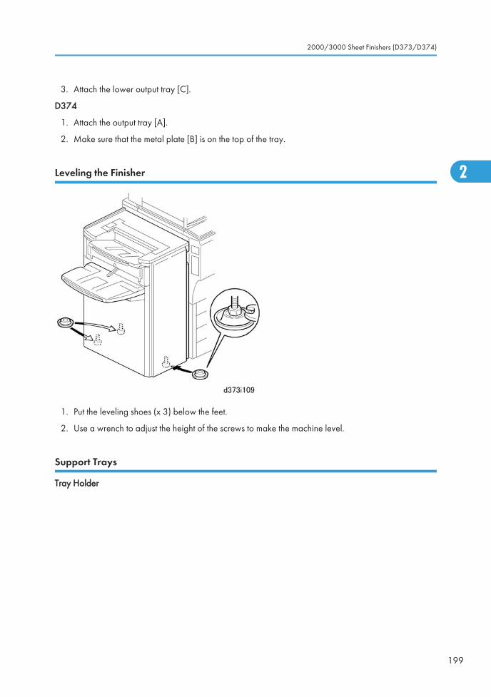
3. Attach the lower output tray [C].
D374
1. Attach the output tray [A].
2. Make sure that the metal plate [B] is on the top of the tray.
Leveling the Finisher
1. Put the leveling shoes (x 3) below the feet.
2. Use a wrench to adjust the height of the screws to make the machine level.
Support Trays
Tray Holder
2000/3000 Sheet Finishers (D373/D374)
199
2
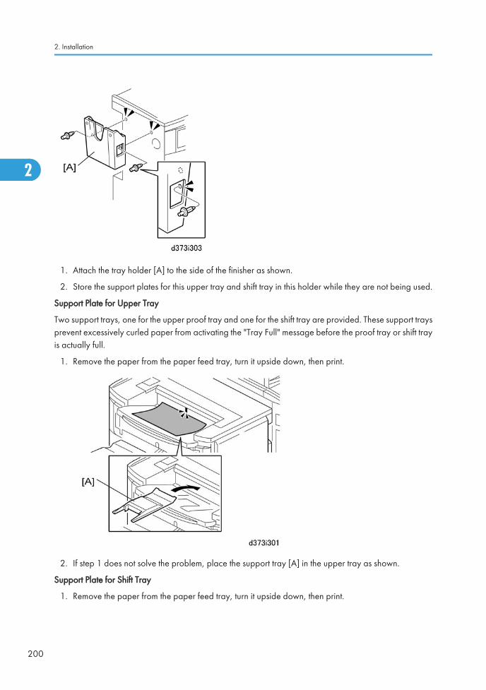
1. Attach the tray holder [A] to the side of the finisher as shown.
2. Store the support plates for this upper tray and shift tray in this holder while they are not being used.
Support Plate for Upper Tray
Two support trays, one for the upper proof tray and one for the shift tray are provided. These support traysprevent excessively curled paper from activating the "Tray Full" message before the proof tray or shift trayis actually full.
1. Remove the paper from the paper feed tray, turn it upside down, then print.
2. If step 1 does not solve the problem, place the support tray [A] in the upper tray as shown.
Support Plate for Shift Tray
1. Remove the paper from the paper feed tray, turn it upside down, then print.
2. Installation
200
2
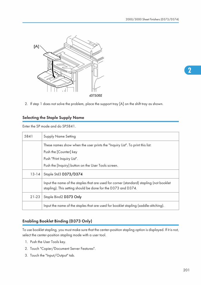
2. If step 1 does not solve the problem, place the support tray [A] on the shift tray as shown.
Selecting the Staple Supply Name
Enter the SP mode and do SP5841.
5841 Supply Name Setting
These names show when the user prints the "Inquiry List". To print this list:
Push the [Counter] key
Push "Print Inquiry List".
Push the [Inquiry] button on the User Tools screen.
13-14 Staple Std3 D373/D374
Input the name of the staples that are used for corner (standard) stapling (not bookletstapling). This setting should be done for the D373 and D374.
21-23 Staple Bind2 D373 Only
Input the name of the staples that are used for booklet stapling (saddle-stitching).
Enabling Booklet Binding (D373 Only)
To use booklet stapling, you must make sure that the center-position stapling option is displayed. If it is not,select the center-position stapling mode with a user tool.
1. Push the User Tools key.
2. Touch "Copier/Document Server Features".
3. Touch the "Input/Output" tab.
2000/3000 Sheet Finishers (D373/D374)
201
2

4. Select "Staple Position".
5. Touch a "Staple Position" button and touch the center (saddle-stitch) stapling symbol.
6. Go out from the User Tools mode. Set the number of copies, touch the center stapling symbol on theoperation panel, then start the print job.
2. Installation
202
2

Punch Unit (B702-17, -27, -28)The Punch Unit B702 is installed in the 2000/3000 Sheet Finisher D373/D374 (SR4040/SR4030).
Accessories
Check the accessories and their quantities against this list.
Description Qty
1. Punchout Waste Unit 1
2. Slide Drive Unit 1
3. Punch Waste Hopper 1
4. Screws (M3 x 6) 5
5. Side-to-Side Detection Unit 1
6. Punching Unit 1
Installation
• Always turn the machine off and disconnect the machine power cord before you do this procedure.
Punch Unit (B702-17, -27, -28)
203
2
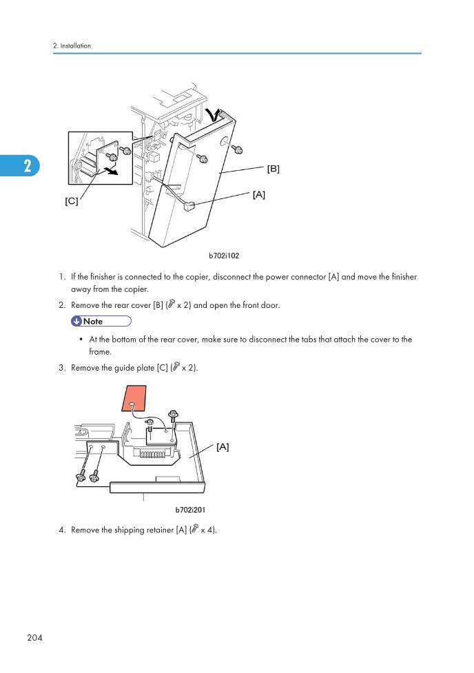
1. If the finisher is connected to the copier, disconnect the power connector [A] and move the finisheraway from the copier.
2. Remove the rear cover [B] ( x 2) and open the front door.
• At the bottom of the rear cover, make sure to disconnect the tabs that attach the cover to theframe.
3. Remove the guide plate [C] ( x 2).
4. Remove the shipping retainer [A] ( x 4).
2. Installation
204
2
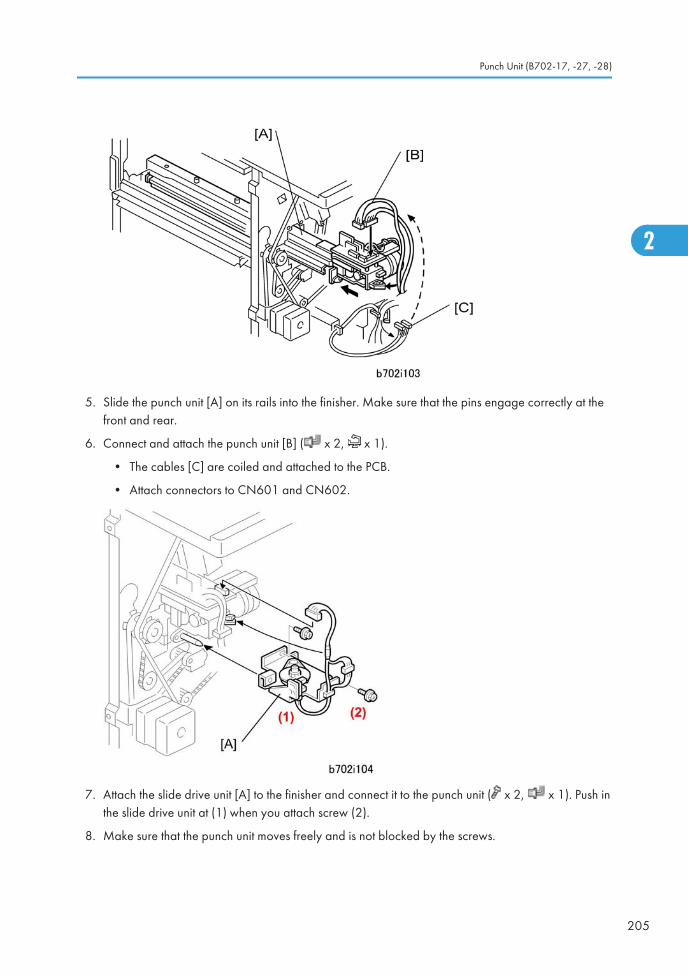
5. Slide the punch unit [A] on its rails into the finisher. Make sure that the pins engage correctly at thefront and rear.
6. Connect and attach the punch unit [B] ( x 2, x 1).
• The cables [C] are coiled and attached to the PCB.
• Attach connectors to CN601 and CN602.
7. Attach the slide drive unit [A] to the finisher and connect it to the punch unit ( x 2, x 1). Push inthe slide drive unit at (1) when you attach screw (2).
8. Make sure that the punch unit moves freely and is not blocked by the screws.
Punch Unit (B702-17, -27, -28)
205
2
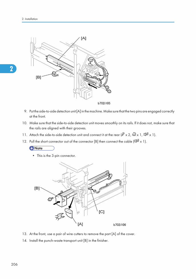
9. Put the side-to-side detection unit [A] in the machine. Make sure that the two pins are engaged correctlyat the front.
10. Make sure that the side-to-side detection unit moves smoothly on its rails. If it does not, make sure thatthe rails are aligned with their grooves.
11. Attach the side-to-side detection unit and connect it at the rear ( x 2, x 1, x 1).
12. Pull the short connector out of the connector [B] then connect the cable ( x 1).
• This is the 3-pin connector.
13. At the front, use a pair of wire cutters to remove the part [A] of the cover.
14. Install the punch-waste transport unit [B] in the finisher.
2. Installation
206
2
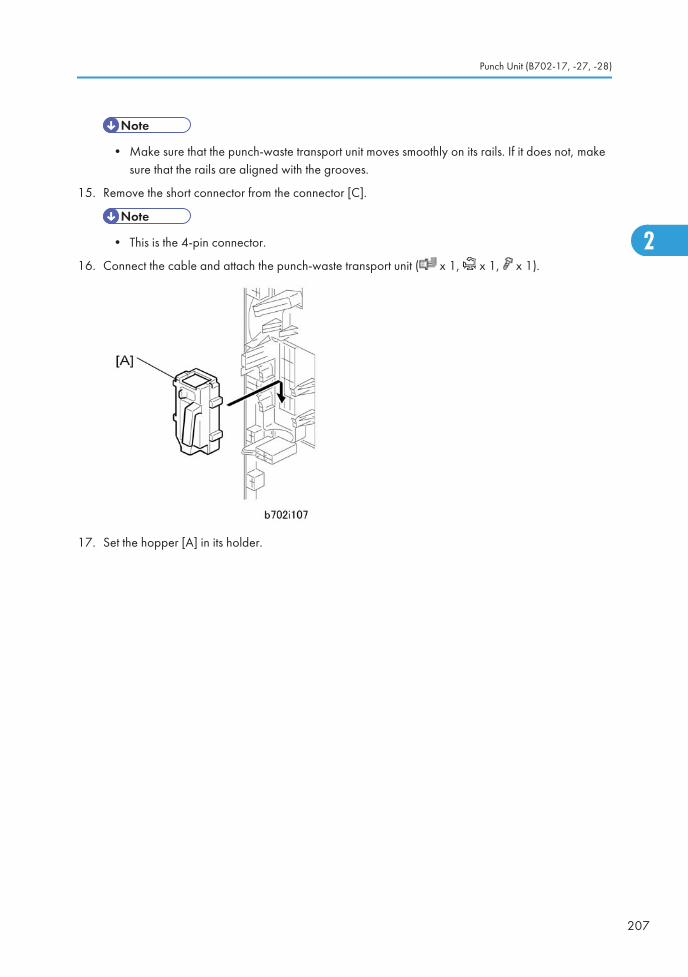
• Make sure that the punch-waste transport unit moves smoothly on its rails. If it does not, makesure that the rails are aligned with the grooves.
15. Remove the short connector from the connector [C].
• This is the 4-pin connector.
16. Connect the cable and attach the punch-waste transport unit ( x 1, x 1, x 1).
17. Set the hopper [A] in its holder.
Punch Unit (B702-17, -27, -28)
207
2
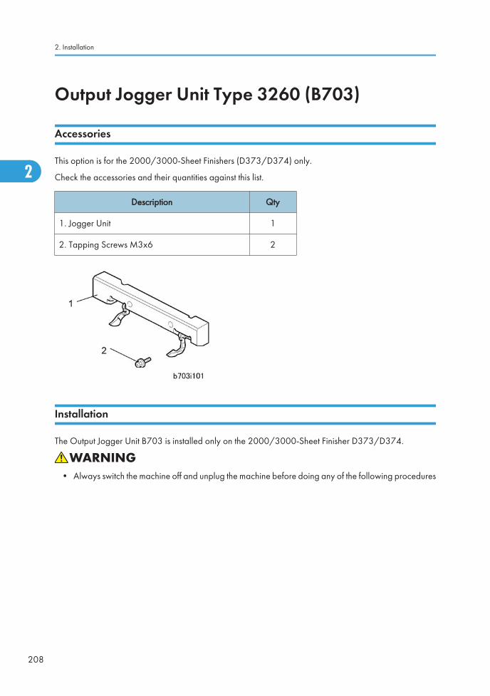
Output Jogger Unit Type 3260 (B703)
Accessories
This option is for the 2000/3000-Sheet Finishers (D373/D374) only.
Check the accessories and their quantities against this list.
Description Qty
1. Jogger Unit 1
2. Tapping Screws M3x6 2
Installation
The Output Jogger Unit B703 is installed only on the 2000/3000-Sheet Finisher D373/D374.
• Always switch the machine off and unplug the machine before doing any of the following procedures
2. Installation
208
2
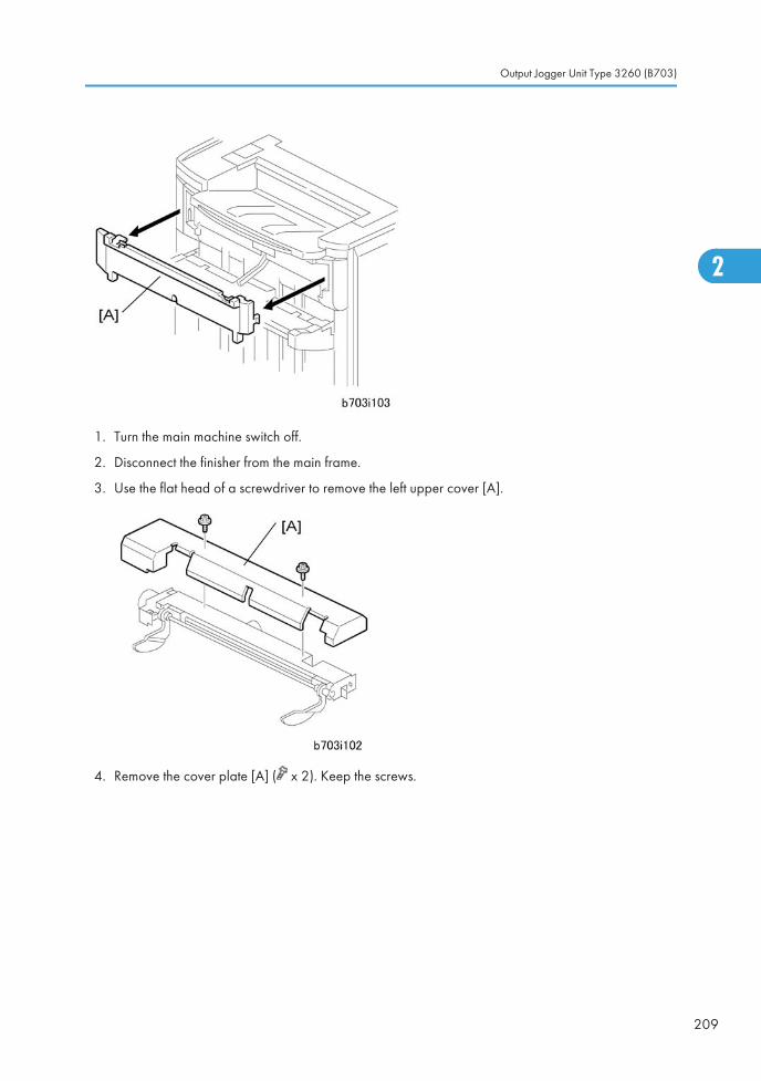
1. Turn the main machine switch off.
2. Disconnect the finisher from the main frame.
3. Use the flat head of a screwdriver to remove the left upper cover [A].
4. Remove the cover plate [A] ( x 2). Keep the screws.
Output Jogger Unit Type 3260 (B703)
209
2
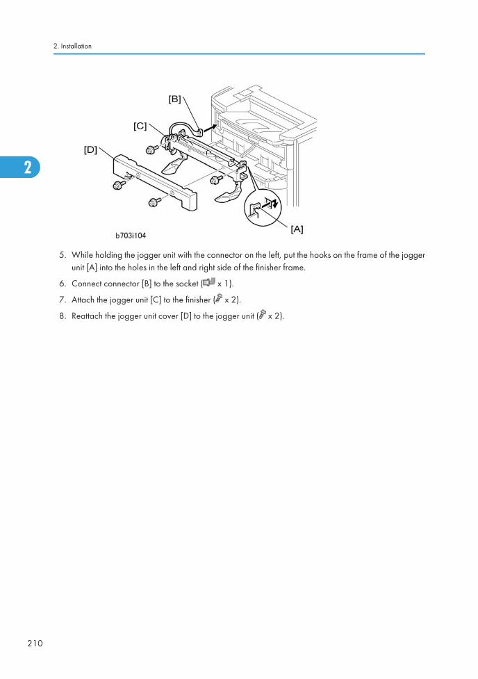
5. While holding the jogger unit with the connector on the left, put the hooks on the frame of the joggerunit [A] into the holes in the left and right side of the finisher frame.
6. Connect connector [B] to the socket ( x 1).
7. Attach the jogger unit [C] to the finisher ( x 2).
8. Reattach the jogger unit cover [D] to the jogger unit ( x 2).
2. Installation
210
2
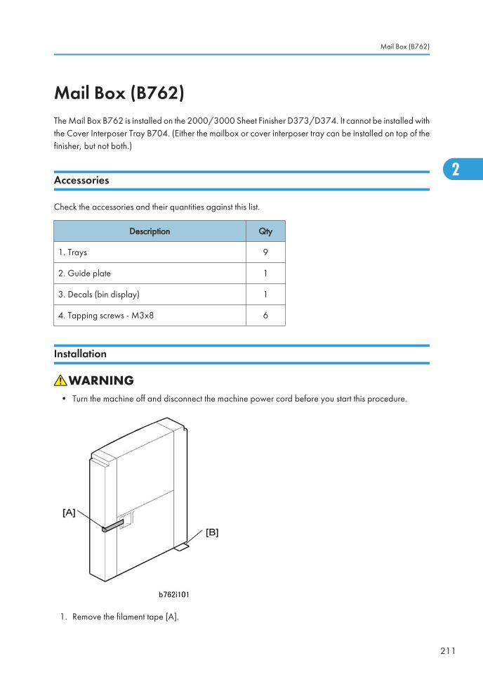
Mail Box (B762)The Mail Box B762 is installed on the 2000/3000 Sheet Finisher D373/D374. It cannot be installed withthe Cover Interposer Tray B704. (Either the mailbox or cover interposer tray can be installed on top of thefinisher, but not both.)
Accessories
Check the accessories and their quantities against this list.
Description Qty
1. Trays 9
2. Guide plate 1
3. Decals (bin display) 1
4. Tapping screws - M3x8 6
Installation
• Turn the machine off and disconnect the machine power cord before you start this procedure.
1. Remove the filament tape [A].
Mail Box (B762)
211
2

• Move the mailbox carefully. It is easy to cause damage to the corner leaf plate [B].
2. If the Cover Interposer Tray B704 is installed on the D373/D374, remove it.
• The cover interposer tray and mailbox cannot be installed on the finisher at the same time.
3. Remove the top cover [A] of the finisher ( x 1).
4. Remove the bracket [B] ( x 1).
2. Installation
212
2
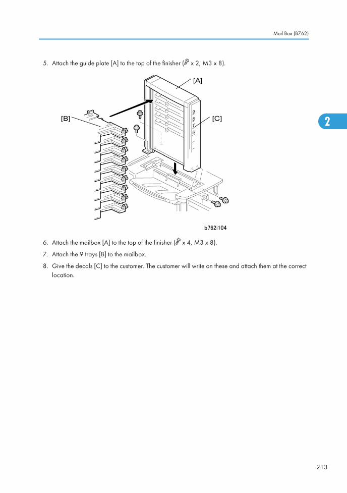
5. Attach the guide plate [A] to the top of the finisher ( x 2, M3 x 8).
6. Attach the mailbox [A] to the top of the finisher ( x 4, M3 x 8).
7. Attach the 9 trays [B] to the mailbox.
8. Give the decals [C] to the customer. The customer will write on these and attach them at the correctlocation.
Mail Box (B762)
213
2
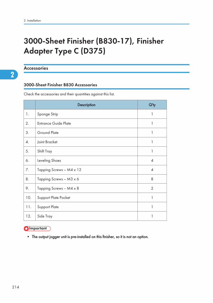
3000-Sheet Finisher (B830-17), FinisherAdapter Type C (D375)
Accessories
3000-Sheet Finisher B830 Accessories
Check the accessories and their quantities against this list.
Description Q'ty
1. Sponge Strip 1
2. Entrance Guide Plate 1
3. Ground Plate 1
4. Joint Bracket 1
5. Shift Tray 1
6. Leveling Shoes 4
7. Tapping Screws – M4 x 12 4
8. Tapping Screws – M3 x 6 8
9. Tapping Screws – M4 x 8 2
10. Support Plate Pocket 1
11. Support Plate 1
12. Side Tray 1
• The output jogger unit is pre-installed on this finisher, so it is not an option.
2. Installation
214
2
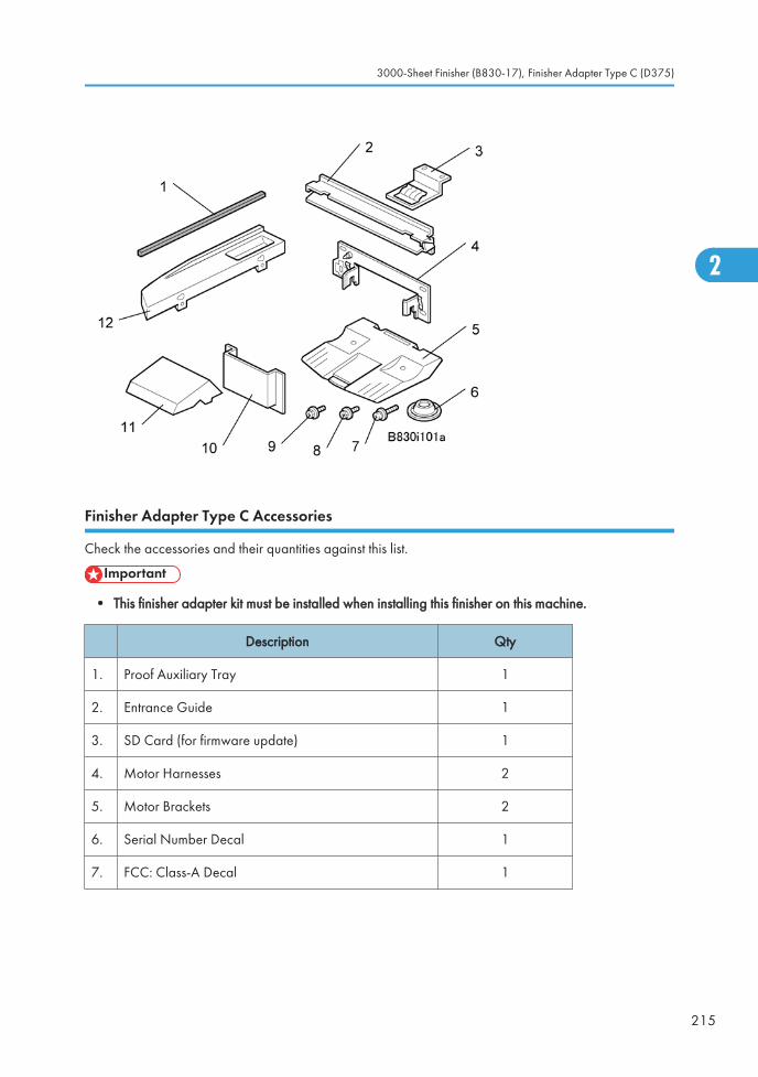
Finisher Adapter Type C Accessories
Check the accessories and their quantities against this list.
• This finisher adapter kit must be installed when installing this finisher on this machine.
Description Qty
1. Proof Auxiliary Tray 1
2. Entrance Guide 1
3. SD Card (for firmware update) 1
4. Motor Harnesses 2
5. Motor Brackets 2
6. Serial Number Decal 1
7. FCC: Class-A Decal 1
3000-Sheet Finisher (B830-17), Finisher Adapter Type C (D375)
215
2
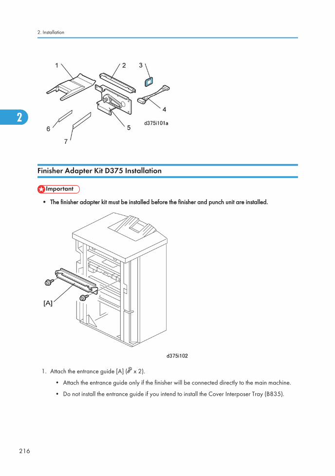
Finisher Adapter Kit D375 Installation
• The finisher adapter kit must be installed before the finisher and punch unit are installed.
1. Attach the entrance guide [A] ( x 2).
• Attach the entrance guide only if the finisher will be connected directly to the main machine.
• Do not install the entrance guide if you intend to install the Cover Interposer Tray (B835).
2. Installation
216
2
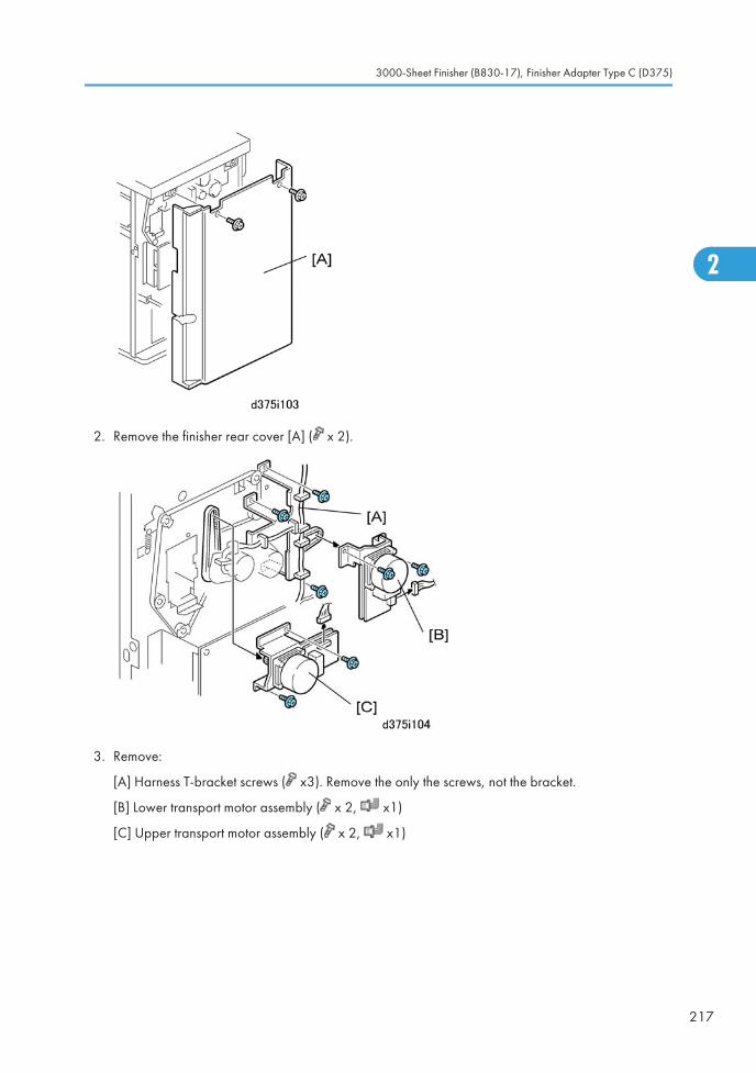
2. Remove the finisher rear cover [A] ( x 2).
3. Remove:
[A] Harness T-bracket screws ( x3). Remove the only the screws, not the bracket.
[B] Lower transport motor assembly ( x 2, x1)
[C] Upper transport motor assembly ( x 2, x1)
3000-Sheet Finisher (B830-17), Finisher Adapter Type C (D375)
217
2
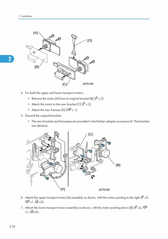
4. For both the upper and lower transport motors:
• Remove the motor [A] from its original bracket [B] ( x 2)
• Attach the motor to the new bracket [C] ( x 2).
• Attach the new harness [D] ( x 1).
5. Discard the original brackets.
• The new brackets and harnesses are provided in the finisher adapter accessory kit. The bracketsare identical.
6. Attach the upper transport motor [A] assembly as shown, with the motor pointing to the right ( x2, x1, x3).
7. Attach the lower transport motor assembly as shown, with the motor pointing down [B] ( x2, x1, x3).
2. Installation
218
2
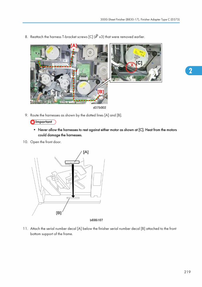
8. Reattach the harness T-bracket screws [C] ( x3) that were removed earlier.
9. Route the harnesses as shown by the dotted lines [A] and [B].
• Never allow the harnesses to rest against either motor as shown at [C]. Heat from the motorscould damage the harnesses.
10. Open the front door.
11. Attach the serial number decal [A] below the finisher serial number decal [B] attached to the frontbottom support of the frame.
3000-Sheet Finisher (B830-17), Finisher Adapter Type C (D375)
219
2
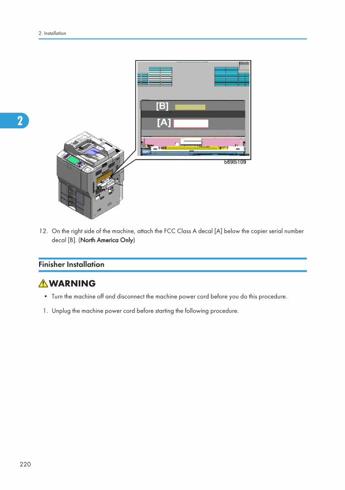
12. On the right side of the machine, attach the FCC Class A decal [A] below the copier serial numberdecal [B]. (North America Only)
Finisher Installation
• Turn the machine off and disconnect the machine power cord before you do this procedure.
1. Unplug the machine power cord before starting the following procedure.
2. Installation
220
2
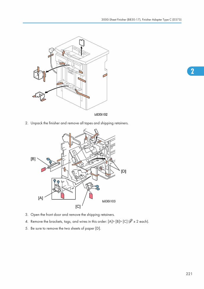
2. Unpack the finisher and remove all tapes and shipping retainers.
3. Open the front door and remove the shipping retainers.
4. Remove the brackets, tags, and wires in this order: [A]> [B]> [C] ( x 2 each).
5. Be sure to remove the two sheets of paper [D].
3000-Sheet Finisher (B830-17), Finisher Adapter Type C (D375)
221
2
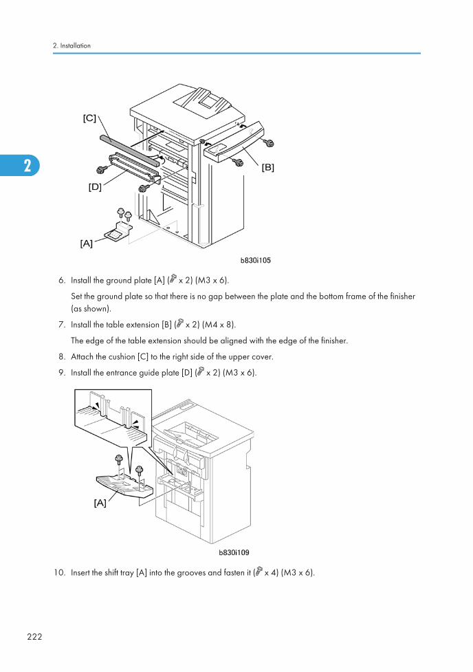
6. Install the ground plate [A] ( x 2) (M3 x 6).
Set the ground plate so that there is no gap between the plate and the bottom frame of the finisher(as shown).
7. Install the table extension [B] ( x 2) (M4 x 8).
The edge of the table extension should be aligned with the edge of the finisher.
8. Attach the cushion [C] to the right side of the upper cover.
9. Install the entrance guide plate [D] ( x 2) (M3 x 6).
10. Insert the shift tray [A] into the grooves and fasten it ( x 4) (M3 x 6).
2. Installation
222
2
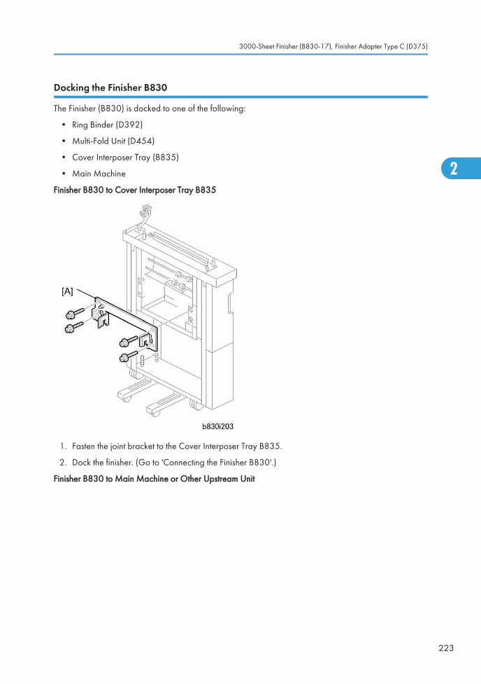
Docking the Finisher B830
The Finisher (B830) is docked to one of the following:
• Ring Binder (D392)
• Multi-Fold Unit (D454)
• Cover Interposer Tray (B835)
• Main Machine
Finisher B830 to Cover Interposer Tray B835
1. Fasten the joint bracket to the Cover Interposer Tray B835.
2. Dock the finisher. (Go to 'Connecting the Finisher B830'.)
Finisher B830 to Main Machine or Other Upstream Unit
3000-Sheet Finisher (B830-17), Finisher Adapter Type C (D375)
223
2
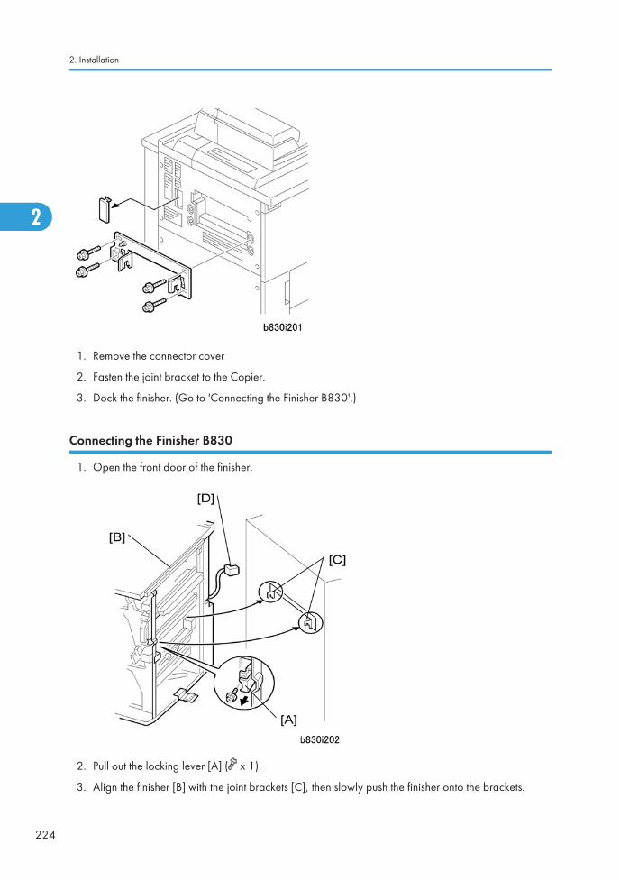
1. Remove the connector cover
2. Fasten the joint bracket to the Copier.
3. Dock the finisher. (Go to 'Connecting the Finisher B830'.)
Connecting the Finisher B830
1. Open the front door of the finisher.
2. Pull out the locking lever [A] ( x 1).
3. Align the finisher [B] with the joint brackets [C], then slowly push the finisher onto the brackets.
2. Installation
224
2
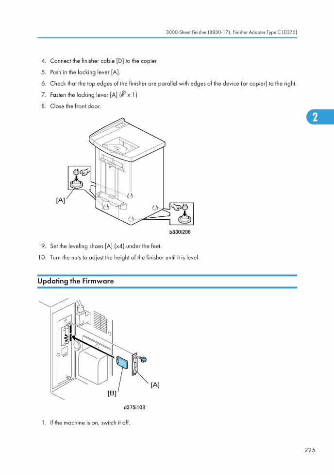
4. Connect the finisher cable [D] to the copier
5. Push in the locking lever [A].
6. Check that the top edges of the finisher are parallel with edges of the device (or copier) to the right.
7. Fasten the locking lever [A] ( x 1)
8. Close the front door.
9. Set the leveling shoes [A] (x4) under the feet.
10. Turn the nuts to adjust the height of the finisher until it is level.
Updating the Firmware
1. If the machine is on, switch it off.
3000-Sheet Finisher (B830-17), Finisher Adapter Type C (D375)
225
2
2. Remove the SD card slot cover [A] from the main machine ( x 1).
3. Insert an SD card [B] that contains the latest firmware for this finisher, downloaded from the web site.Insert this SD card into the service slot (lower slot).
• If you do not have the latest firmware, use the SD card that is provided with the finisher adapterkit. However, the firmware on this card may be old.
4. Open the front door of the main machine.
5. Switch on the machine. A message prompts you to wait for the update procedure to begin, then theinitial screen appears.
6. Write down the NEW version numbers. (You will need these later to confirm the success of the firmwareupdate.)
7. Touch "Finisher" then touch "Update".
8. Wait for the update procedure to begin.
• The update may not start for 2 or 3 minutes.
• When the first asterisk (*) appears in the progress bar this means the update has started.
• The update procedure is very slow. Wait for all the hyphens (-) to be replaced by asterisks (*)in the progress bar.
• Never switch off the machine while the update is in progress.
9. After asterisks have replaced all the hyphens in the progress bar, switch off the machine.
10. Remove the SD card from the SD card slot and reattach the SD card slot cover.
11. Close the front door.
12. Switch on the machine.
13. Enter the SP mode and do SP5990-5 to print the self-diagnostic report.
14. Confirm that the finisher firmware updated successfully.
• For "Finisher 1", you should see the numbers that you saw for the NEW column in the initialscreen at Step 6.
• If you see these numbers, the update has executed successfully.
• If the update fails, turn the machine off and try the procedure again.
15. Switch the machine off and remove the SD card.
16. Switch the machine on.
This completes the firmware update procedure.
2. Installation
226
2

SP Setting
1. Enter the SP mode.
2. Do SP5841-12 and enter the name of the staples used for corner stapling.
• This is the name that shows when the user prints the Inquiry List.
• To print this list push User Tools> [Inquiry]> [Print Inquiry List]> [Start].
3000-Sheet Finisher (B830-17), Finisher Adapter Type C (D375)
227
2
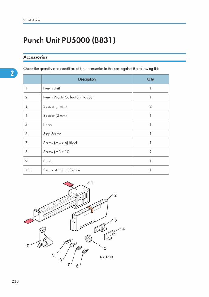
Punch Unit PU5000 (B831)
Accessories
Check the quantity and condition of the accessories in the box against the following list:
Description Q'ty
1. Punch Unit 1
2. Punch Waste Collection Hopper 1
3. Spacer (1 mm) 2
4. Spacer (2 mm) 1
5. Knob 1
6. Step Screw 1
7. Screw (M4 x 6) Black 1
8. Screw (M3 x 10) 2
9. Spring 1
10. Sensor Arm and Sensor 1
2. Installation
228
2
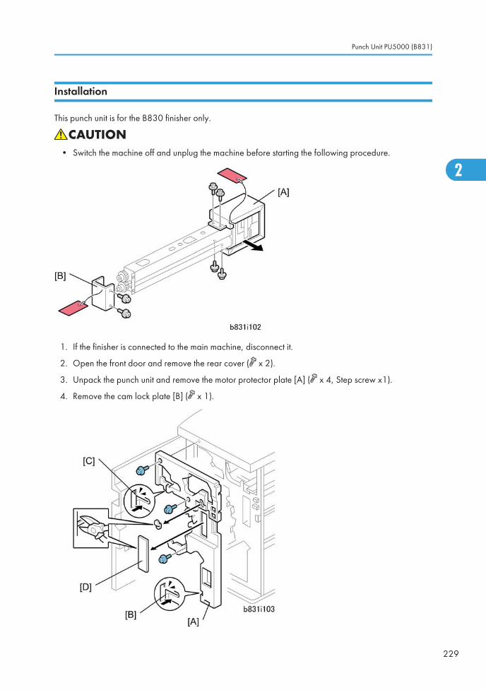
Installation
This punch unit is for the B830 finisher only.
• Switch the machine off and unplug the machine before starting the following procedure.
1. If the finisher is connected to the main machine, disconnect it.
2. Open the front door and remove the rear cover ( x 2).
3. Unpack the punch unit and remove the motor protector plate [A] ( x 4, Step screw x1).
4. Remove the cam lock plate [B] ( x 1).
Punch Unit PU5000 (B831)
229
2
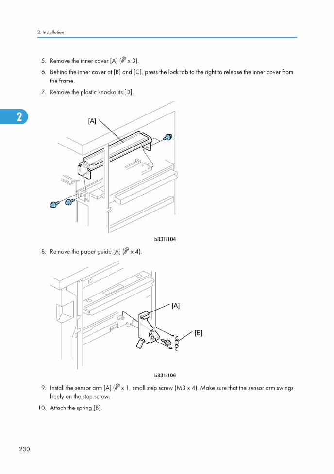
5. Remove the inner cover [A] ( x 3).
6. Behind the inner cover at [B] and [C], press the lock tab to the right to release the inner cover fromthe frame.
7. Remove the plastic knockouts [D].
8. Remove the paper guide [A] ( x 4).
9. Install the sensor arm [A] ( x 1, small step screw (M3 x 4). Make sure that the sensor arm swingsfreely on the step screw.
10. Attach the spring [B].
2. Installation
230
2
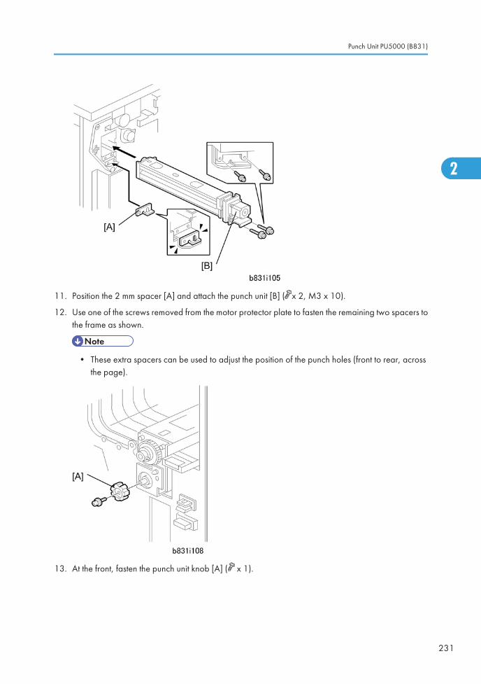
11. Position the 2 mm spacer [A] and attach the punch unit [B] ( x 2, M3 x 10).
12. Use one of the screws removed from the motor protector plate to fasten the remaining two spacers tothe frame as shown.
• These extra spacers can be used to adjust the position of the punch holes (front to rear, acrossthe page).
13. At the front, fasten the punch unit knob [A] ( x 1).
Punch Unit PU5000 (B831)
231
2
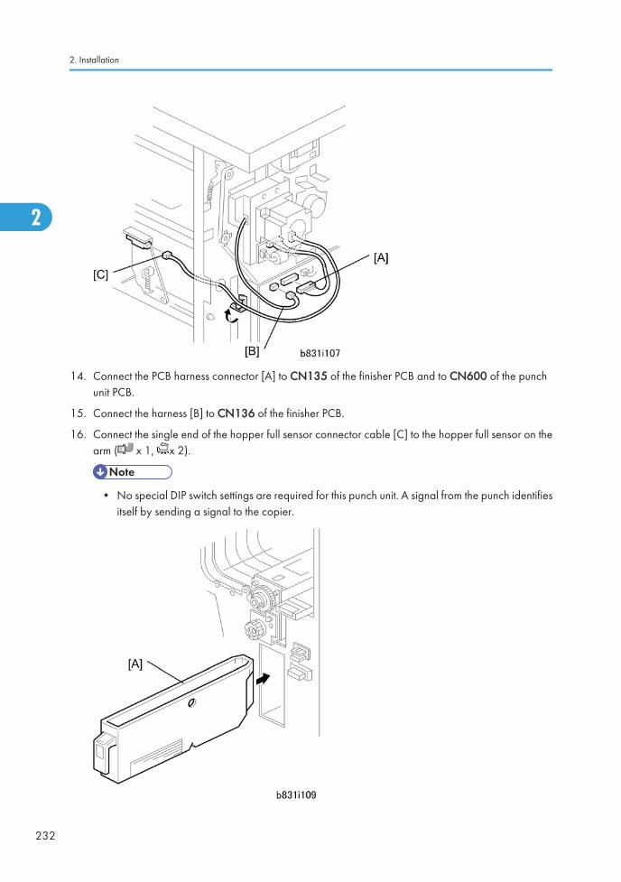
14. Connect the PCB harness connector [A] to CN135 of the finisher PCB and to CN600 of the punchunit PCB.
15. Connect the harness [B] to CN136 of the finisher PCB.
16. Connect the single end of the hopper full sensor connector cable [C] to the hopper full sensor on thearm ( x 1, x 2).
• No special DIP switch settings are required for this punch unit. A signal from the punch identifiesitself by sending a signal to the copier.
2. Installation
232
2

17. Slide the punch waste collection hopper [D] into the finisher.
18. Re-attach the inner cover and rear cover.
19. Close the front door and re-connect the finisher to the machine.
Punch Unit PU5000 (B831)
233
2
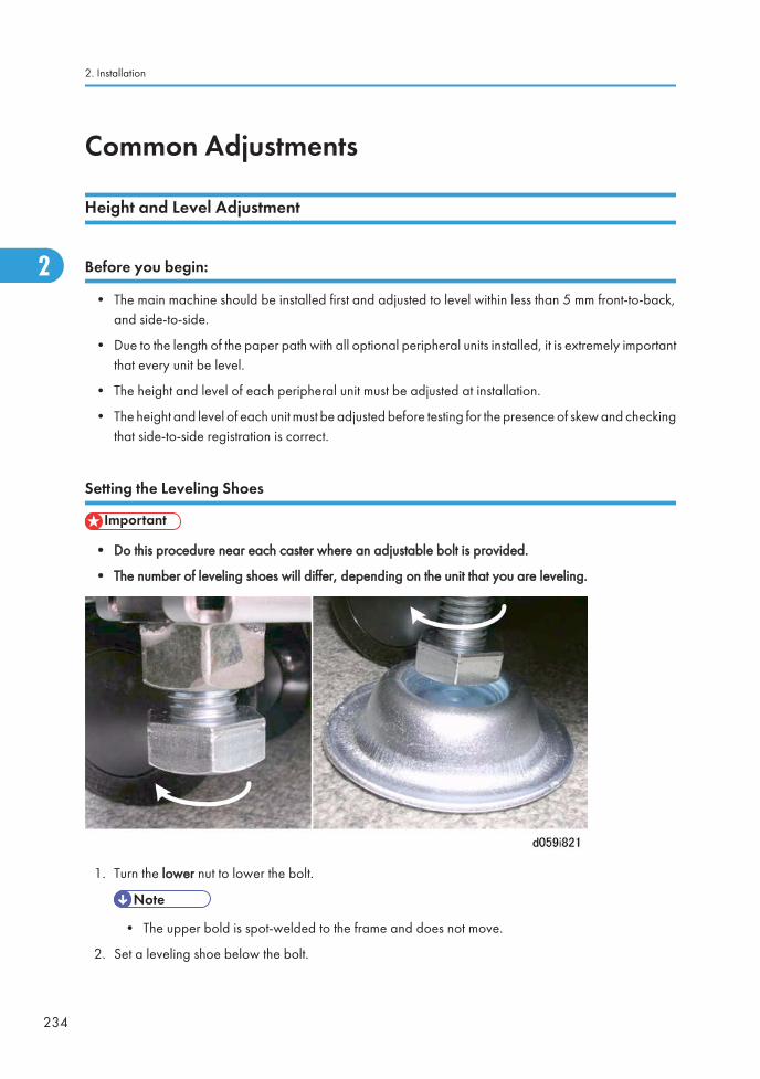
Common Adjustments
Height and Level Adjustment
Before you begin:
• The main machine should be installed first and adjusted to level within less than 5 mm front-to-back,and side-to-side.
• Due to the length of the paper path with all optional peripheral units installed, it is extremely importantthat every unit be level.
• The height and level of each peripheral unit must be adjusted at installation.
• The height and level of each unit must be adjusted before testing for the presence of skew and checkingthat side-to-side registration is correct.
Setting the Leveling Shoes
• Do this procedure near each caster where an adjustable bolt is provided.
• The number of leveling shoes will differ, depending on the unit that you are leveling.
1. Turn the lower nut to lower the bolt.
• The upper bold is spot-welded to the frame and does not move.
2. Set a leveling shoe below the bolt.
2. Installation
234
2
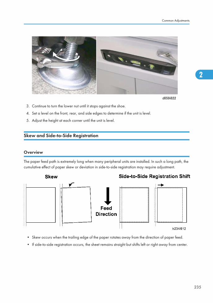
3. Continue to turn the lower nut until it stops against the shoe.
4. Set a level on the front, rear, and side edges to determine if the unit is level.
5. Adjust the height at each corner until the unit is level.
Skew and Side-to-Side Registration
Overview
The paper feed path is extremely long when many peripheral units are installed. In such a long path, thecumulative effect of paper skew or deviation in side-to-side registration may require adjustment.
• Skew occurs when the trailing edge of the paper rotates away from the direction of paper feed.
• If side-to-side registration occurs, the sheet remains straight but shifts left or right away from center.
Common Adjustments
235
2
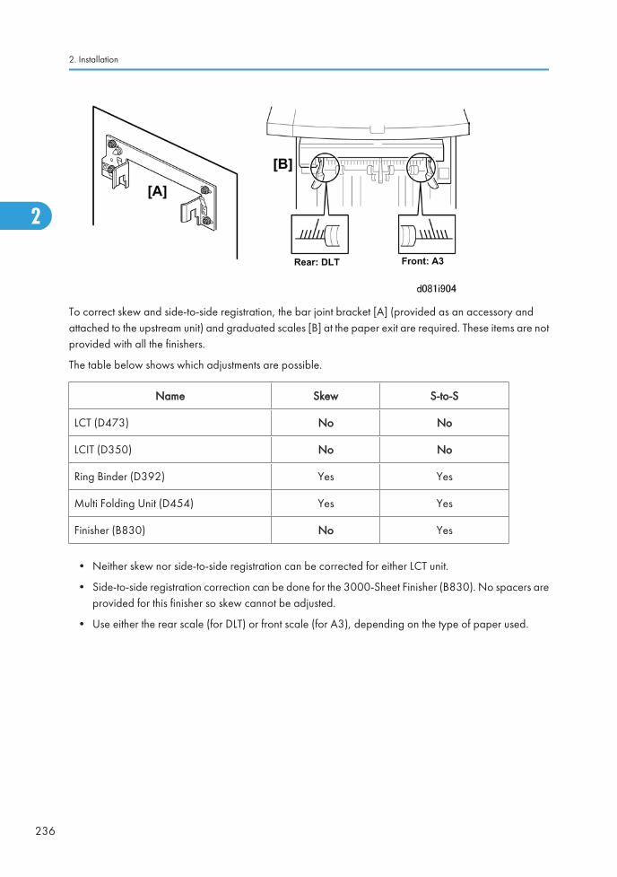
To correct skew and side-to-side registration, the bar joint bracket [A] (provided as an accessory andattached to the upstream unit) and graduated scales [B] at the paper exit are required. These items are notprovided with all the finishers.
The table below shows which adjustments are possible.
Name Skew S-to-S
LCT (D473) No No
LCIT (D350) No No
Ring Binder (D392) Yes Yes
Multi Folding Unit (D454) Yes Yes
Finisher (B830) No Yes
• Neither skew nor side-to-side registration can be corrected for either LCT unit.
• Side-to-side registration correction can be done for the 3000-Sheet Finisher (B830). No spacers areprovided for this finisher so skew cannot be adjusted.
• Use either the rear scale (for DLT) or front scale (for A3), depending on the type of paper used.
2. Installation
236
2
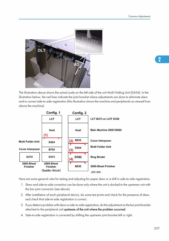
The illustration above shows the actual scale on the left side of the unit Multi Folding Unit (D454). In theillustration below, the red lines indicate the joint bracket where adjustments are done to eliminate skewand to correct side-to-side registration (this illustration shows the machine and peripherals as viewed fromabove the machine).
Here are some general rules for testing and adjusting for paper skew or a shift in side-to-side registration.
1. Skew and side-to-side correction can be done only where the unit is docked to the upstream unit withthe bar joint connector (see above).
2. After installation of each peripheral device, do some test prints and check for the presence of skew,and check that side-to-side registration is correct.
3. If you detect a problem with skew or side-to-side registration, do the adjustment on the bar joint bracketattached to the peripheral unit upstream of the unit where the problem occurred.
4. Side-to-side registration is corrected by shifting the upstream joint bracket left or right.
Common Adjustments
237
2
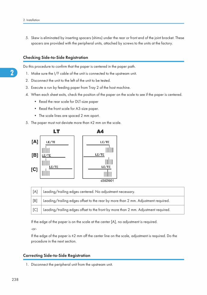
5. Skew is eliminated by inserting spacers (shims) under the rear or front end of the joint bracket. Thesespacers are provided with the peripheral units, attached by screws to the units at the factory.
Checking Side-to-Side Registration
Do this procedure to confirm that the paper is centered in the paper path.
1. Make sure the I/F cable of the unit is connected to the upstream unit.
2. Disconnect the unit to the left of the unit to be tested.
3. Execute a run by feeding paper from Tray 2 of the host machine.
4. When each sheet exits, check the position of the paper on the scale to see if the paper is centered.
• Read the rear scale for DLT-size paper
• Read the front scale for A3-size paper.
• The scale lines are spaced 2 mm apart.
5. The paper must not deviate more than ±2 mm on the scale.
[A] Leading/trailing edges centered. No adjustment necessary.
[B] Leading/trailing edges offset to the rear by more than 2 mm. Adjustment required.
[C] Leading/trailing edges offset to the front by more than 2 mm. Adjustment required.
If the edge of the paper is on the scale at the center [A], no adjustment is required.
-or-
If the edge of the paper is ±2 mm off the center line on the scale, adjustment is required. Do theprocedure in the next section.
Correcting Side-to-Side Registration
1. Disconnect the peripheral unit from the upstream unit.
2. Installation
238
2
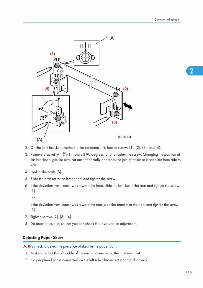
2. On the joint bracket attached to the upstream unit, loosen screws (1), (2), (3), and (4).
3. Remove bracket [A] ( x1), rotate it 90 degrees, and re-fasten the screw. Changing the position ofthis bracket aligns the oval cut-out horizontally and frees the joint bracket so it can slide from side toside.
4. Look at the scale [B].
5. Slide the bracket to the left or right and tighten the screw.
6. If the deviation from center was toward the front, slide the bracket to the rear and tighten the screw(1).
-or-
If the deviation from center was toward the rear, side the bracket to the front and tighten the screw(1).
7. Tighten screws (2), (3), (4).
8. Do another test run, so that you can check the results of the adjustment.
Detecting Paper Skew
Do this check to detect the presence of skew in the paper path.
1. Make sure that the I/F cable of the unit is connected to the upstream unit.
2. If a peripheral unit is connected on the left side, disconnect it and pull it away.
Common Adjustments
239
2
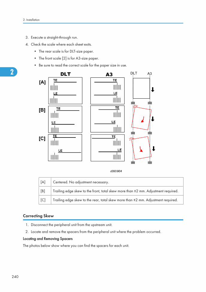
3. Execute a straight-through run.
4. Check the scale where each sheet exits.
• The rear scale is for DLT-size paper.
• The front scale [2] is for A3-size paper.
• Be sure to read the correct scale for the paper size in use.
[A] Centered. No adjustment necessary.
[B] Trailing edge skew to the front, total skew more than ±2 mm. Adjustment required.
[C] Trailing edge skew to the rear, total skew more than ±2 mm. Adjustment required.
Correcting Skew
1. Disconnect the peripheral unit from the upstream unit.
2. Locate and remove the spacers from the peripheral unit where the problem occurred.
Locating and Removing Spacers
The photos below show where you can find the spacers for each unit.
2. Installation
240
2
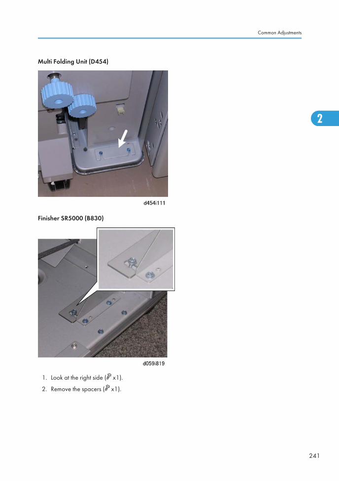
Multi Folding Unit (D454)
Finisher SR5000 (B830)
1. Look at the right side ( x1).
2. Remove the spacers ( x1).
Common Adjustments
241
2
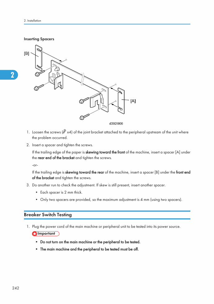
Inserting Spacers
1. Loosen the screws ( x4) of the joint bracket attached to the peripheral upstream of the unit wherethe problem occurred.
2. Insert a spacer and tighten the screws.
If the trailing edge of the paper is skewing toward the front of the machine, insert a spacer [A] underthe rear end of the bracket and tighten the screws.
-or-
If the trailing edge is skewing toward the rear of the machine, insert a spacer [B] under the front endof the bracket and tighten the screws.
3. Do another run to check the adjustment. If skew is still present, insert another spacer.
• Each spacer is 2 mm thick.
• Only two spacers are provided, so the maximum adjustment is 4 mm (using two spacers).
Breaker Switch Testing
1. Plug the power cord of the main machine or peripheral unit to be tested into its power source.
• Do not turn on the main machine or the peripheral to be tested.
• The main machine and the peripheral to be tested must be off.
2. Installation
242
2

2. Use the tip of a small screwdriver or pen to push the breaker test button [A].
• The breaker switch should flip to the "O" position [B]. This indicates that the breaker switch isoperating normally.
• If the breaker switch does not flip to the "O" position, the switch must be replaced.
3. Return the switch to the "|" position [C] for normal operation.
• The main machine will not turn on if the breaker switch is not returned to the "|" position.
• All breaker switches must be checked at installation, and once a year.
Common Adjustments
243
2
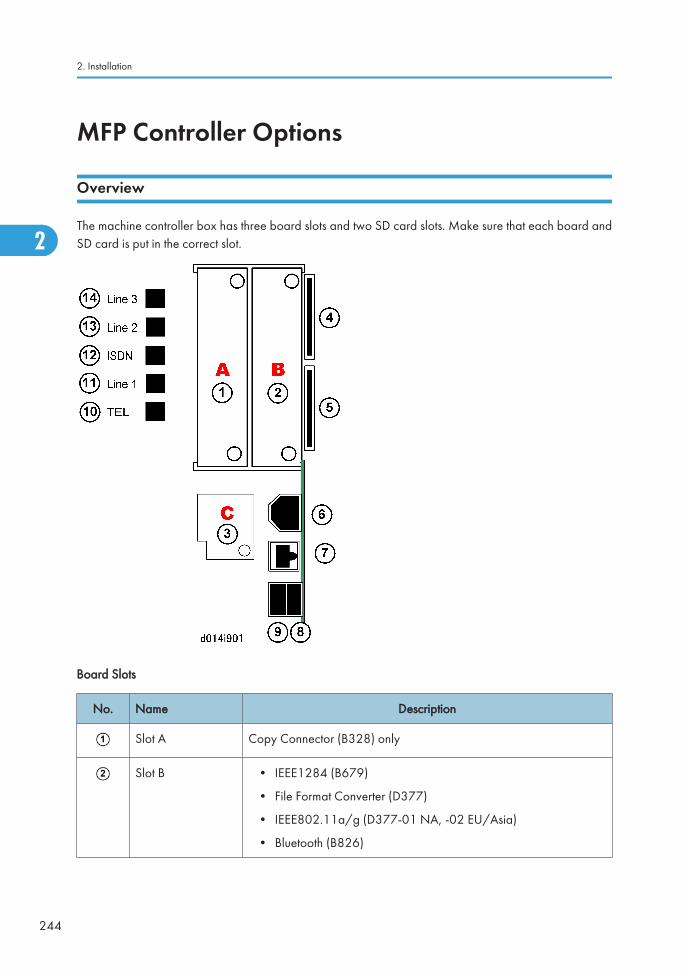
MFP Controller Options
Overview
The machine controller box has three board slots and two SD card slots. Make sure that each board andSD card is put in the correct slot.
Board Slots
No. Name Description
Slot A Copy Connector (B328) only
Slot B • IEEE1284 (B679)
• File Format Converter (D377)
• IEEE802.11a/g (D377-01 NA, -02 EU/Asia)
• Bluetooth (B826)
2. Installation
244
2
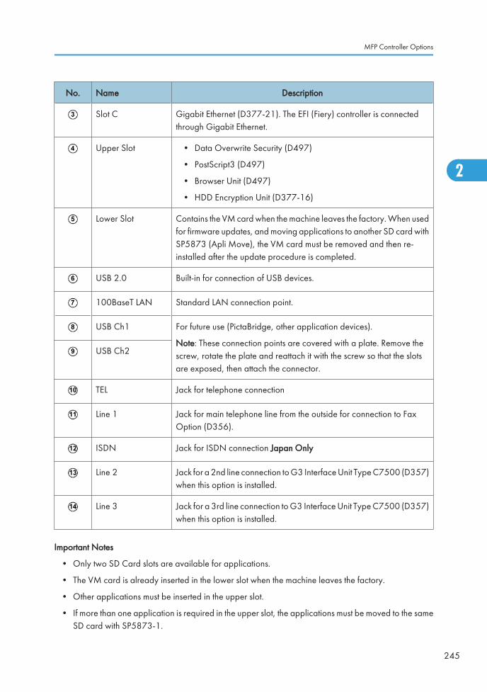
No. Name Description
Slot C Gigabit Ethernet (D377-21). The EFI (Fiery) controller is connectedthrough Gigabit Ethernet.
Upper Slot • Data Overwrite Security (D497)
• PostScript3 (D497)
• Browser Unit (D497)
• HDD Encryption Unit (D377-16)
Lower Slot Contains the VM card when the machine leaves the factory. When usedfor firmware updates, and moving applications to another SD card withSP5873 (Apli Move), the VM card must be removed and then re-installed after the update procedure is completed.
USB 2.0 Built-in for connection of USB devices.
100BaseT LAN Standard LAN connection point.
USB Ch1 For future use (PictaBridge, other application devices).
Note: These connection points are covered with a plate. Remove thescrew, rotate the plate and reattach it with the screw so that the slotsare exposed, then attach the connector.
USB Ch2
TEL Jack for telephone connection
Line 1 Jack for main telephone line from the outside for connection to FaxOption (D356).
ISDN Jack for ISDN connection Japan Only
Line 2 Jack for a 2nd line connection to G3 Interface Unit Type C7500 (D357)when this option is installed.
Line 3 Jack for a 3rd line connection to G3 Interface Unit Type C7500 (D357)when this option is installed.
Important Notes
• Only two SD Card slots are available for applications.
• The VM card is already inserted in the lower slot when the machine leaves the factory.
• Other applications must be inserted in the upper slot.
• If more than one application is required in the upper slot, the applications must be moved to the sameSD card with SP5873-1.
MFP Controller Options
245
2
Ed
Typewritten Text
RTB 23: Corrected
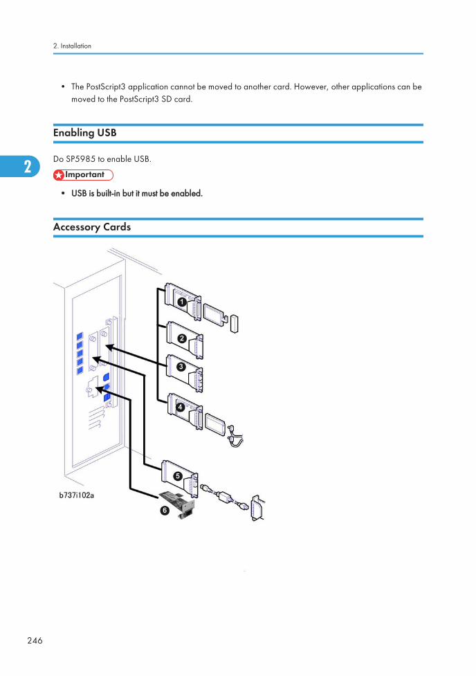
• The PostScript3 application cannot be moved to another card. However, other applications can bemoved to the PostScript3 SD card.
Enabling USB
Do SP5985 to enable USB.
• USB is built-in but it must be enabled.
Accessory Cards
2. Installation
246
2
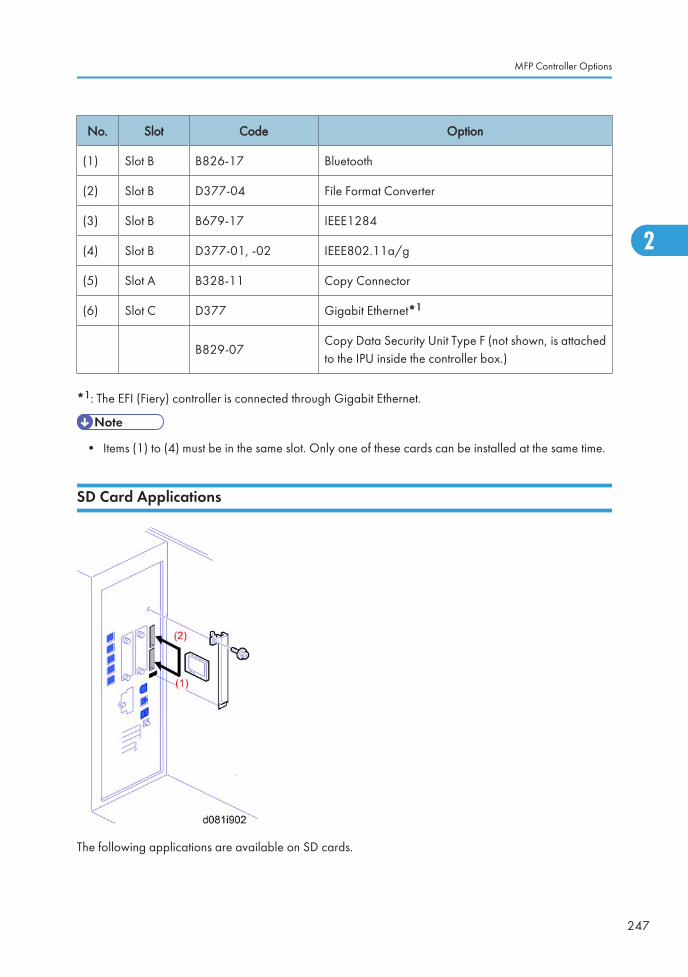
No. Slot Code Option
(1) Slot B B826-17 Bluetooth
(2) Slot B D377-04 File Format Converter
(3) Slot B B679-17 IEEE1284
(4) Slot B D377-01, -02 IEEE802.11a/g
(5) Slot A B328-11 Copy Connector
(6) Slot C D377 Gigabit Ethernet*1
B829-07Copy Data Security Unit Type F (not shown, is attachedto the IPU inside the controller box.)
*1: The EFI (Fiery) controller is connected through Gigabit Ethernet.
• Items (1) to (4) must be in the same slot. Only one of these cards can be installed at the same time.
SD Card Applications
The following applications are available on SD cards.
MFP Controller Options
247
2
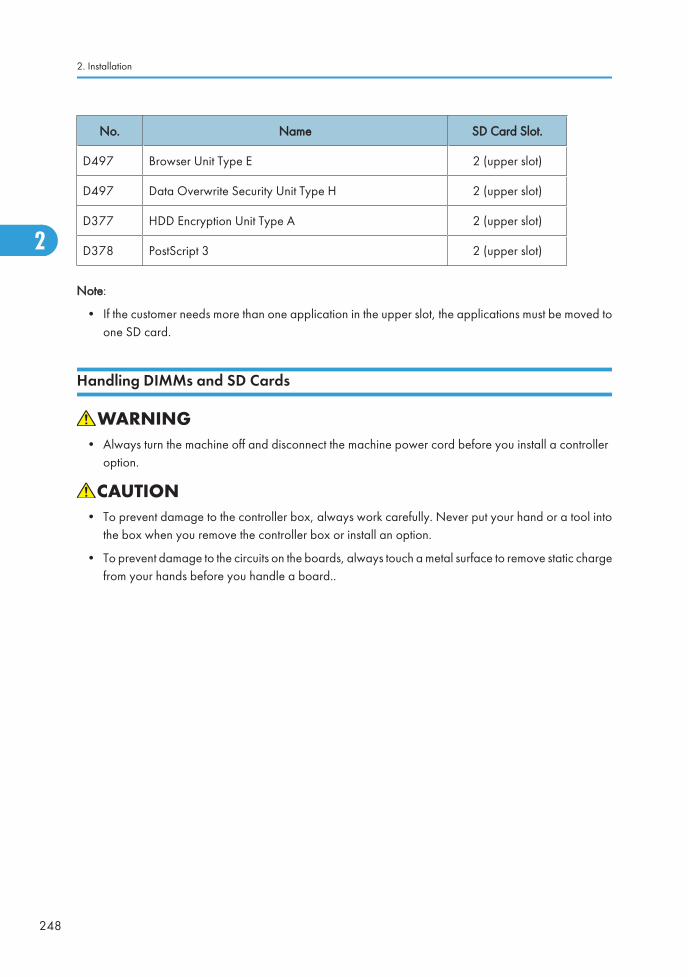
No. Name SD Card Slot.
D497 Browser Unit Type E 2 (upper slot)
D497 Data Overwrite Security Unit Type H 2 (upper slot)
D377 HDD Encryption Unit Type A 2 (upper slot)
D378 PostScript 3 2 (upper slot)
Note:
• If the customer needs more than one application in the upper slot, the applications must be moved toone SD card.
Handling DIMMs and SD Cards
• Always turn the machine off and disconnect the machine power cord before you install a controlleroption.
• To prevent damage to the controller box, always work carefully. Never put your hand or a tool intothe box when you remove the controller box or install an option.
• To prevent damage to the circuits on the boards, always touch a metal surface to remove static chargefrom your hands before you handle a board..
2. Installation
248
2
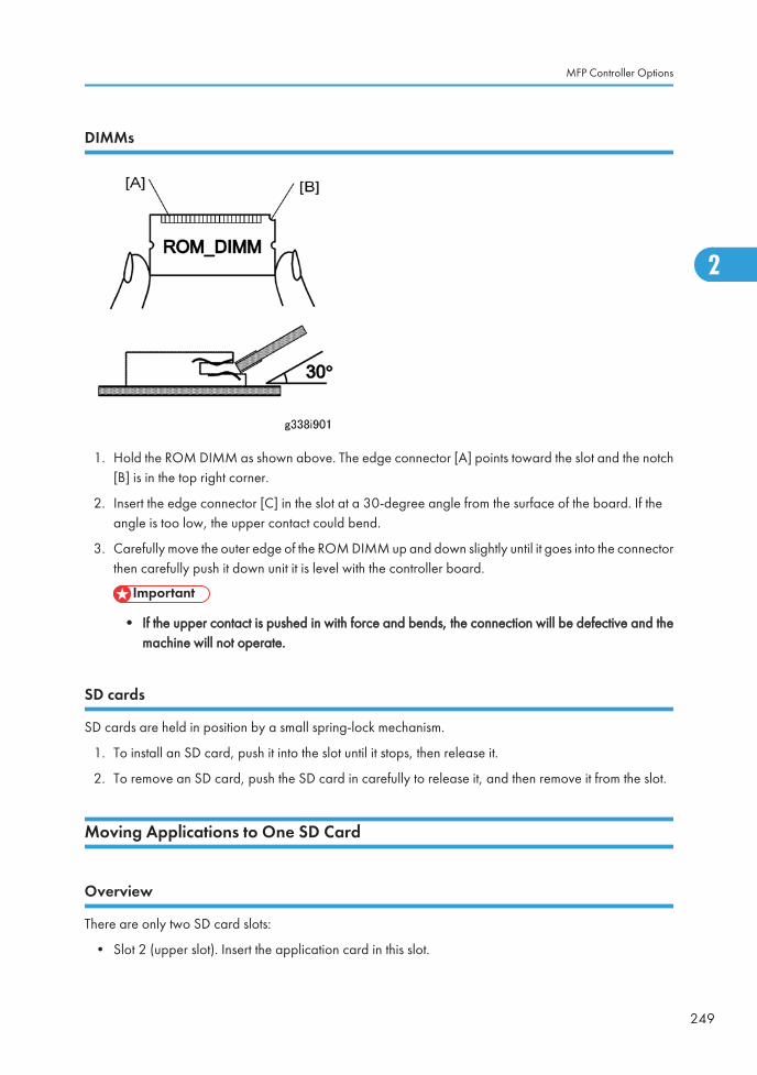
DIMMs
1. Hold the ROM DIMM as shown above. The edge connector [A] points toward the slot and the notch[B] is in the top right corner.
2. Insert the edge connector [C] in the slot at a 30-degree angle from the surface of the board. If theangle is too low, the upper contact could bend.
3. Carefully move the outer edge of the ROM DIMM up and down slightly until it goes into the connectorthen carefully push it down unit it is level with the controller board.
• If the upper contact is pushed in with force and bends, the connection will be defective and themachine will not operate.
SD cards
SD cards are held in position by a small spring-lock mechanism.
1. To install an SD card, push it into the slot until it stops, then release it.
2. To remove an SD card, push the SD card in carefully to release it, and then remove it from the slot.
Moving Applications to One SD Card
Overview
There are only two SD card slots:
• Slot 2 (upper slot). Insert the application card in this slot.
MFP Controller Options
249
2
• If more than one application is required, the applications must be moved to one SD card withSP5873-1.
Here are some important points you should keep in mind about SD cards and their applications:
• The SD card in the upper slot (target) must be another application SD card for this machine. The SDcard in the upper slot cannot be a blank SD.
• The data necessary for authentication is transferred with the application program to the target SDcard.
• Do not use an SD card if it has previously been used with a computer. Correct operation is notguaranteed if such an SD card is used.
• The SD card is the only evidence that the customer is licensed to use the application program. Theservice technician may occasionally need to check the SD card and its contents to solve problems.Although copied SD cards are disabled for use, they must be stored in the machine door for futureuse and reference. (See "Storing SD Application Cards on Site" in this section)
• A licensing agreement prohibits copying of a PostScript3 SD card. However, you can move otherapplications to the PS3 SD card.
• Once an SD card has been used to hold several applications, it should not be used for any otherpurpose.
Moving Applications
Do this procedure to put more than one application on one SD card.
1. Remove the SD card slot cover ( x 2).
2. Remove the VM card from Slot 1 (lower slot).
• Before removing the VM card from Slot 1 (lower slot) you must shut down the App2 Meapplication (and any other VM card applications) if it is running. See "Before Removing and Re-installing the VM Card...".
3. Turn off the main machine.
2. Installation
250
2
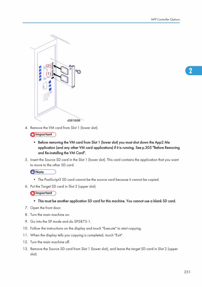
4. Remove the VM card from Slot 1 (lower slot).
• Before removing the VM card from Slot 1 (lower slot) you must shut down the App2 Meapplication (and any other VM card applications) if it is running. See p.305 "Before Removingand Re-installing the VM Card".
5. Insert the Source SD card in the Slot 1 (lower slot). This card contains the application that you wantto move to the other SD card.
• The PostScript3 SD card cannot be the source card because it cannot be copied.
6. Put the Target SD card in Slot 2 (upper slot).
• This must be another application SD card for this machine. You cannot use a blank SD card.
7. Open the front door.
8. Turn the main machine on.
9. Go into the SP mode and do SP5873-1.
10. Follow the instructions on the display and touch "Execute" to start copying.
11. When the display tells you copying is completed, touch "Exit".
12. Turn the main machine off.
13. Remove the Source SD card from Slot 1 (lower slot), and leave the target SD card in Slot 2 (upperslot).
MFP Controller Options
251
2
14. Turn the main machine on.
15. Go into the User Tools mode and confirm that all the applications on the SD card in Slot 2 (upper slot)are enabled.
User Tools> System Settings> Administrator Tools> Firmware Version> Next...
16. Turn the main machine off.
17. Remove the cover from the front door, and store the SD card that was copied. (See "Storing SDApplication Cards on Site"). The SD card must be stored with the machine for these reasons:
• Once an SD card has been copied, it can no longer be used. But it must be stored in the frontdoor to serve as proof of purchase by the customer.
• Also, at a later time the stored SD cards can be restored to full use with SP5873-2 (describedin the next section).
• Before you put the card in the front cover, label it so that it can be easily identified.
18. If the client is using App2 Me or any other applications on the VM card, do the procedure to re-startthese applications. ( p.305 "Before Removing and Re-installing the VM Card")
Undo Exec
1. Remove the SD card slot cover ( x 2).
• Before removing the VM card from Slot 1 (lower slot) you must shut down the App2 Meapplication (and any other VM card applications) if it is running. See p.305 "Before Removingand Re-installing the VM Card".
2. Turn the main switch off.
3. Put the SD card with the applications in Slot 2 (upper slot).
4. Put the original destination SD card (the one stored in the front door) in Slot 1 (lower slot).
• The SD card in the lower slot must be the original (empty) SD card of the application that youwant to move from the upper slot to the lower slot.
• You cannot use any blank SD card in the lower slot. The application can be moved only to anoriginal SD card.
5. Turn the main switch on.
6. Go into the SP mode and do SP5873-2 (Undo Exec)
7. Follow the messages on the operation panel to complete the procedure.
8. Turn the main switch off.
9. Remove the SD cards from the slots.
10. Insert the VM card in Slot 1 (lower slot).
2. Installation
252
2
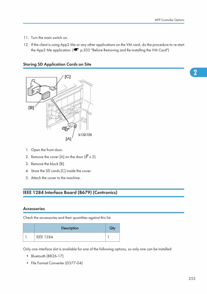
11. Turn the main switch on.
12. If the client is using App2 Me or any other applications on the VM card, do the procedure to re-startthe App2 Me application. ( p.305 "Before Removing and Re-installing the VM Card")
Storing SD Application Cards on Site
1. Open the front door.
2. Remove the cover [A] on the door ( x 2).
3. Remove the block [B].
4. Store the SD cards [C] inside the cover.
5. Attach the cover to the machine.
IEEE 1284 Interface Board (B679) (Centronics)
Accessories
Check the accessories and their quantities against this list.
Description Qty
1. IEEE 1284 1
Only one interface slot is available for one of the following options, so only one can be installed:
• Bluetooth (B826-17)
• File Format Converter (D377-04)
MFP Controller Options
253
2
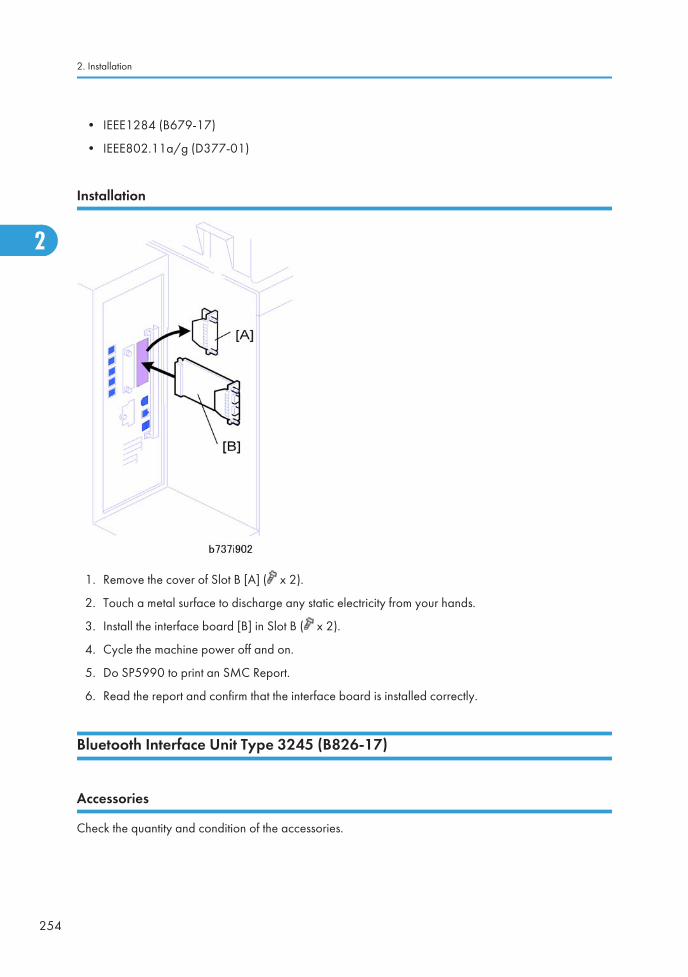
• IEEE1284 (B679-17)
• IEEE802.11a/g (D377-01)
Installation
1. Remove the cover of Slot B [A] ( x 2).
2. Touch a metal surface to discharge any static electricity from your hands.
3. Install the interface board [B] in Slot B ( x 2).
4. Cycle the machine power off and on.
5. Do SP5990 to print an SMC Report.
6. Read the report and confirm that the interface board is installed correctly.
Bluetooth Interface Unit Type 3245 (B826-17)
Accessories
Check the quantity and condition of the accessories.
2. Installation
254
2
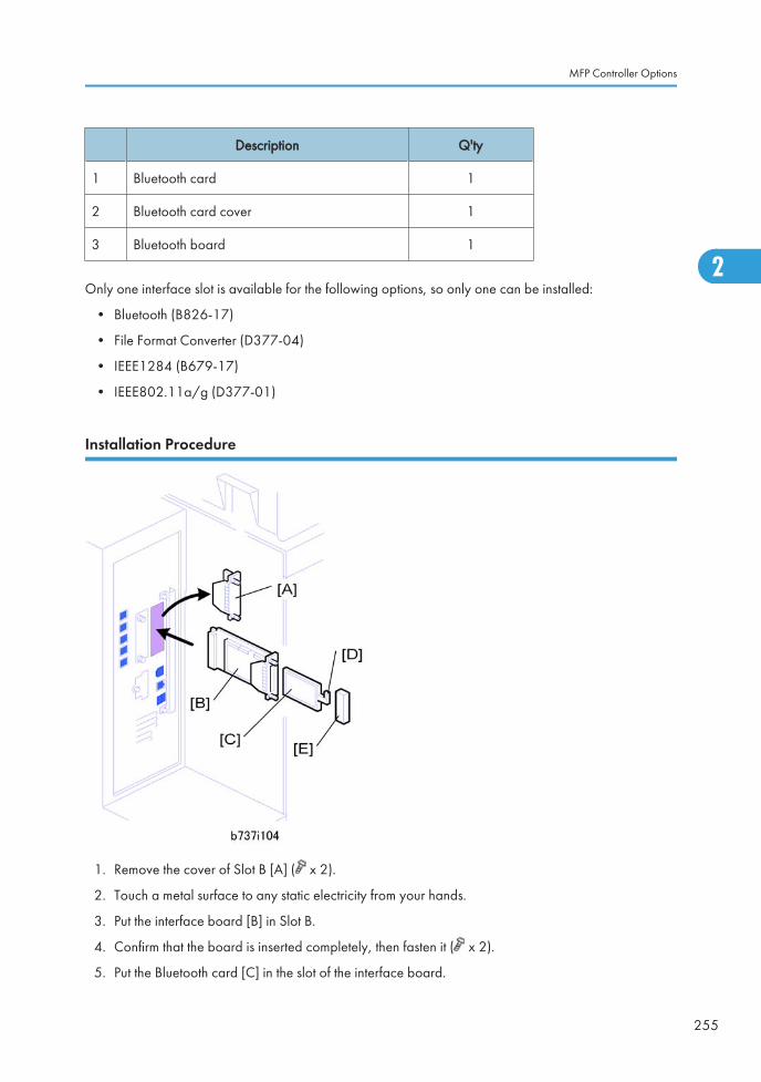
Description Q'ty
1 Bluetooth card 1
2 Bluetooth card cover 1
3 Bluetooth board 1
Only one interface slot is available for the following options, so only one can be installed:
• Bluetooth (B826-17)
• File Format Converter (D377-04)
• IEEE1284 (B679-17)
• IEEE802.11a/g (D377-01)
Installation Procedure
1. Remove the cover of Slot B [A] ( x 2).
2. Touch a metal surface to any static electricity from your hands.
3. Put the interface board [B] in Slot B.
4. Confirm that the board is inserted completely, then fasten it ( x 2).
5. Put the Bluetooth card [C] in the slot of the interface board.
MFP Controller Options
255
2
6. Push the antenna cap [D] to extend it.
7. Attach the card cover [E] (used to prevent static electricity).
8. Turn the machine off and on.
9. Enter the SP mode and do SP5990 to print an SMC.
10. Read the report and confirm that the interface board is installed correctly.
IEEE 802.11a/g Interface Unit Type J (D377-01)
Accessories
Check the accessories and their quantities against this list.
Description Qty
1. Wireless LAN PCB (GW-WLAN) 1
2. Card (GW-WLAN) 1
3. Wireless LAN Instructions 1
Only one interface slot is available for the following options, so only one can be installed:
• Bluetooth (B826-17)
• File Format Converter (D377-04)
• IEEE1284 (B679-17)
• IEEE802.11a/g (D377-01)
2. Installation
256
2

Installation
1. Remove the cover of Slot B [A] ( x 2).
2. Touch a metal surface to discharge any static electricity from your hands.
3. Put the interface board in Slot B [B].
4. Confirm that the board is inserted completely, then fasten it ( x 2).
5. Pull the antennas [C] away from machine and make sure that they are not tangled.
6. Look at the markings on the antenna bracket.
• ANT1. Antenna 1 transmits and receives. It must be installed on the left front corner of the mainmachine. (The core on the Antenna 1 cable is black.)
• ANT2. Antenna 2 only receives. It is installed on the right rear corner of the machine.
MFP Controller Options
257
2
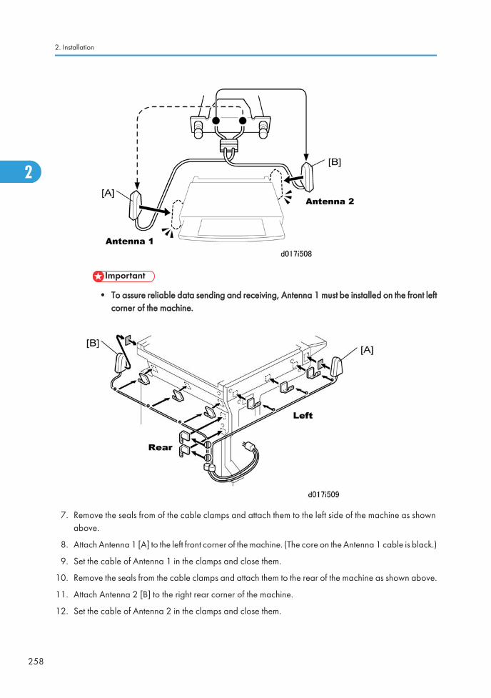
• To assure reliable data sending and receiving, Antenna 1 must be installed on the front leftcorner of the machine.
7. Remove the seals from of the cable clamps and attach them to the left side of the machine as shownabove.
8. Attach Antenna 1 [A] to the left front corner of the machine. (The core on the Antenna 1 cable is black.)
9. Set the cable of Antenna 1 in the clamps and close them.
10. Remove the seals from the cable clamps and attach them to the rear of the machine as shown above.
11. Attach Antenna 2 [B] to the right rear corner of the machine.
12. Set the cable of Antenna 2 in the clamps and close them.
2. Installation
258
2
SP Mode Settings for 802.11a/g Wireless LAN
The following SP commands can be set for 802.11a/g
1. Go into the SP mode
2. Touch "Copy SP" on the touch-panel to open the SP command selection screen.
3. Do SP5840-11.
SP No. Name Function
5840 011 WEP Key Select Used to select the WEP key (Default: 00).
File Format Converter Type E (D377-04)
Accessory Check
Check the accessories and their quantities against this list:
Description Q'ty
1. File Format Converter (MLB: Media Link Board) 1
MFP Controller Options
259
2
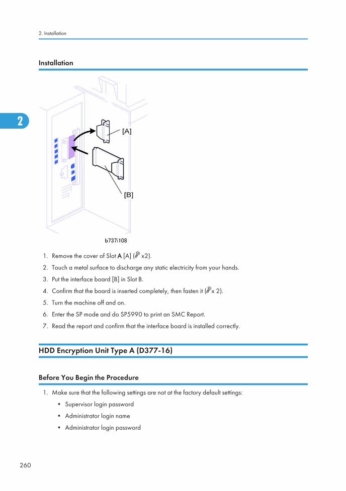
Installation
1. Remove the cover of Slot A [A] ( x2).
2. Touch a metal surface to discharge any static electricity from your hands.
3. Put the interface board [B] in Slot B.
4. Confirm that the board is inserted completely, then fasten it ( x 2).
5. Turn the machine off and on.
6. Enter the SP mode and do SP5990 to print an SMC Report.
7. Read the report and confirm that the interface board is installed correctly.
HDD Encryption Unit Type A (D377-16)
Before You Begin the Procedure
1. Make sure that the following settings are not at the factory default settings:
• Supervisor login password
• Administrator login name
• Administrator login password
2. Installation
260
2
Ed
Typewritten Text
RTB 35 Delete these steps
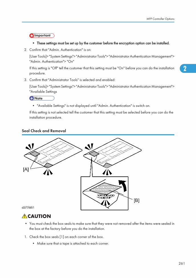
• These settings must be set up by the customer before the encryption option can be installed.
2. Confirm that "Admin. Authentication" is on:
[User Tools]> "System Settings"> "Administrator Tools"> "Administrator Authentication Management">"Admin. Authentication"> "On"
If this setting is "Off" tell the customer that this setting must be "On" before you can do the installationprocedure.
3. Confirm that "Administrator Tools" is selected and enabled:
[User Tools]> "System Settings"> "Administrator Tools"> "Administrator Authentication Management">"Available Settings
• "Available Settings" is not displayed until "Admin. Authentication" is switch on.
If this setting is not selected tell the customer that this setting must be selected before you can do theinstallation procedure.
Seal Check and Removal
• You must check the box seals to make sure that they were not removed after the items were sealed inthe box at the factory before you do the installation.
1. Check the box seals [1] on each corner of the box.
• Make sure that a tape is attached to each corner.
MFP Controller Options
261
2
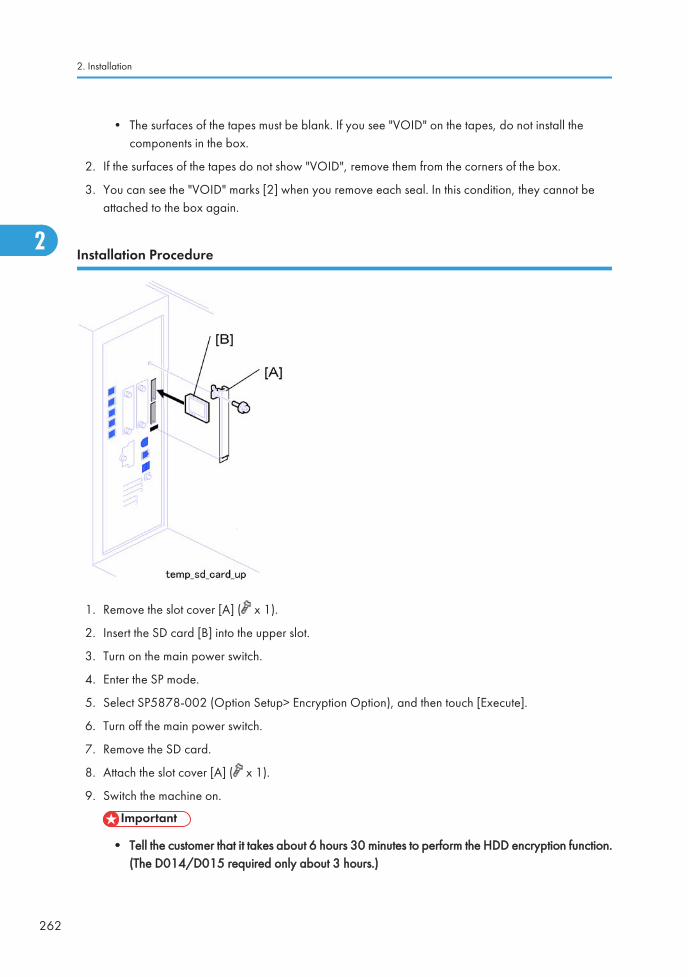
• The surfaces of the tapes must be blank. If you see "VOID" on the tapes, do not install thecomponents in the box.
2. If the surfaces of the tapes do not show "VOID", remove them from the corners of the box.
3. You can see the "VOID" marks [2] when you remove each seal. In this condition, they cannot beattached to the box again.
Installation Procedure
1. Remove the slot cover [A] ( x 1).
2. Insert the SD card [B] into the upper slot.
3. Turn on the main power switch.
4. Enter the SP mode.
5. Select SP5878-002 (Option Setup> Encryption Option), and then touch [Execute].
6. Turn off the main power switch.
7. Remove the SD card.
8. Attach the slot cover [A] ( x 1).
9. Switch the machine on.
• Tell the customer that it takes about 6 hours 30 minutes to perform the HDD encryption function.(The D014/D015 required only about 3 hours.)
2. Installation
262
2
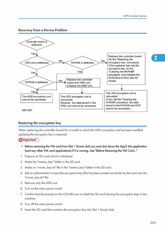
Recovery from a Device Problem
Restoring the encryption key
When replacing the controller board for a model in which the HDD encryption unit has been installed,updating the encryption key is required.
• Before removing the VM card from Slot 1 (lower slot) you must shut down the App2 Me application(and any other VM card applications) if it is running. See "Before Removing the VM Card..."
1. Prepare an SD card which is initialized.
2. Make the "restore_key" folder in the SD card.
3. Make an "nvram_key.txt" file in the "restore_key" folder in the SD card.
4. Ask an administrator to input the encryption key (this has been printed out earlier by the user) into the"nvram_key.txt" file.
5. Remove only the HDD unit.
6. Turn on the main power switch.
7. Confirm that the prompt on the LCD tells you to install the SD card (storing the encryption key) in themachine.
8. Turn off the main power switch.
9. Insert the SD card that contains the encryption key into Slot 1 (lower slot).
MFP Controller Options
263
2
10. Turn on the main power switch, and the machine automatically restores the encryption key in the flashmemory on the controller board.
11. Turn off the main power switch after the machine has returned to normal status.
12. Remove the SD card from Slot 1 (lower slot).
13. Reinstall the HDD unit.
Clearing the NVRAM
When replacing the controller board for a model in which the HDD encryption unit has been installed anda customer has lost the encryption key, clearing the NVRAM is required to recover the HDD encryptionunit.
1. Prepare an SD card which is initialized.
2. Make the "restore_key" folder in the SD card.
3. Make an "nvram_key.txt" file in the "restore_key" folder in the SD card.
4. Input "nvclear" into the "nvram_key.txt" file.
5. Turn on the main power switch.
6. Confirm that the prompt on the LCD tells you to install the SD card (storing the encryption key) in themachine.
7. Turn off the main power switch.
8. Insert the SD card that contains "nvclear" into Slot 1 (lower slot).
9. Turn on the main power switch, and the machine automatically restores the encryption key in the flashmemory on the controller board.
10. Turn off the main power switch after the machine has returned to normal status.
11. Remove the SD card from Slot 1 (lower slot).
12. Turn on the main power switch.
13. Initialize the NVRAM (SP5801-001) and HDD unit (SP5832-001) with SP mode.
14. The user must enable the HDD encryption unit with a user tool.
2. Installation
264
2
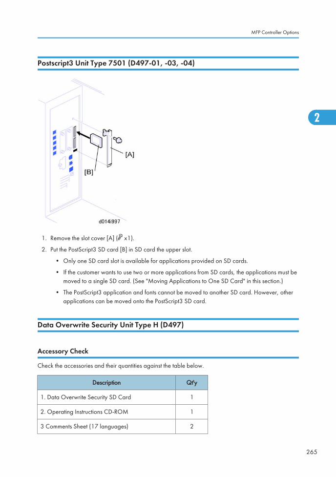
Postscript3 Unit Type 7501 (D497-01, -03, -04)
1. Remove the slot cover [A] ( x1).
2. Put the PostScript3 SD card [B] in SD card the upper slot.
• Only one SD card slot is available for applications provided on SD cards.
• If the customer wants to use two or more applications from SD cards, the applications must bemoved to a single SD card. (See "Moving Applications to One SD Card" in this section.)
• The PostScript3 application and fonts cannot be moved to another SD card. However, otherapplications can be moved onto the PostScript3 SD card.
Data Overwrite Security Unit Type H (D497)
Accessory Check
Check the accessories and their quantities against the table below.
Description Qt'y
1. Data Overwrite Security SD Card 1
2. Operating Instructions CD-ROM 1
3 Comments Sheet (17 languages) 2
MFP Controller Options
265
2
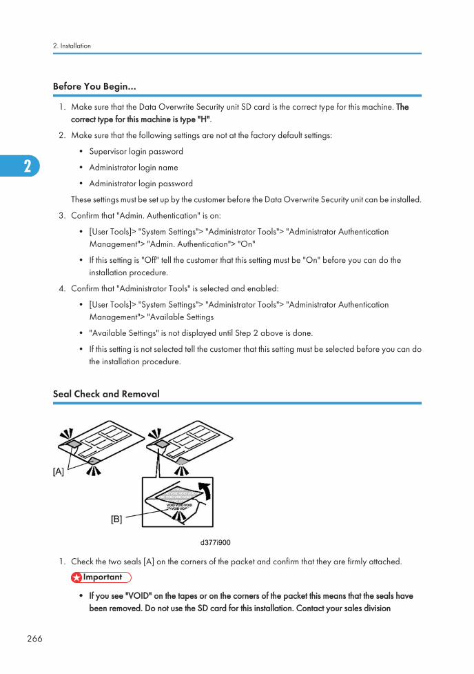
Before You Begin…
1. Make sure that the Data Overwrite Security unit SD card is the correct type for this machine. Thecorrect type for this machine is type "H".
2. Make sure that the following settings are not at the factory default settings:
• Supervisor login password
• Administrator login name
• Administrator login password
These settings must be set up by the customer before the Data Overwrite Security unit can be installed.
3. Confirm that "Admin. Authentication" is on:
• [User Tools]> "System Settings"> "Administrator Tools"> "Administrator AuthenticationManagement"> "Admin. Authentication"> "On"
• If this setting is "Off" tell the customer that this setting must be "On" before you can do theinstallation procedure.
4. Confirm that "Administrator Tools" is selected and enabled:
• [User Tools]> "System Settings"> "Administrator Tools"> "Administrator AuthenticationManagement"> "Available Settings
• "Available Settings" is not displayed until Step 2 above is done.
• If this setting is not selected tell the customer that this setting must be selected before you can dothe installation procedure.
Seal Check and Removal
1. Check the two seals [A] on the corners of the packet and confirm that they are firmly attached.
• If you see "VOID" on the tapes or on the corners of the packet this means that the seals havebeen removed. Do not use the SD card for this installation. Contact your sales division
2. Installation
266
2
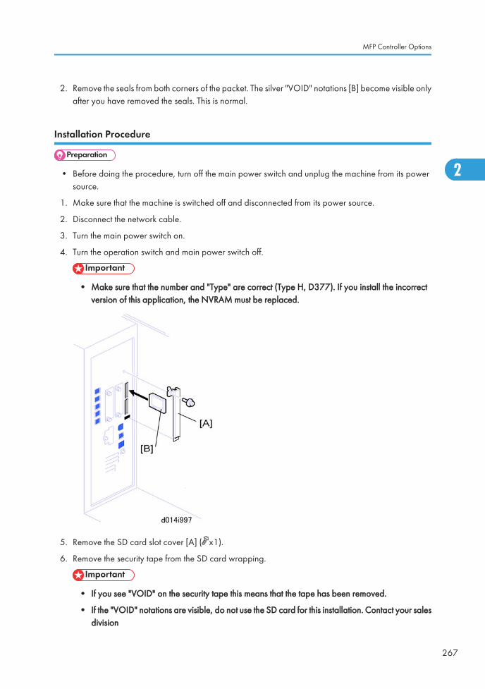
2. Remove the seals from both corners of the packet. The silver "VOID" notations [B] become visible onlyafter you have removed the seals. This is normal.
Installation Procedure
• Before doing the procedure, turn off the main power switch and unplug the machine from its powersource.
1. Make sure that the machine is switched off and disconnected from its power source.
2. Disconnect the network cable.
3. Turn the main power switch on.
4. Turn the operation switch and main power switch off.
• Make sure that the number and "Type" are correct (Type H, D377). If you install the incorrectversion of this application, the NVRAM must be replaced.
5. Remove the SD card slot cover [A] ( x1).
6. Remove the security tape from the SD card wrapping.
• If you see "VOID" on the security tape this means that the tape has been removed.
• If the "VOID" notations are visible, do not use the SD card for this installation. Contact your salesdivision
MFP Controller Options
267
2
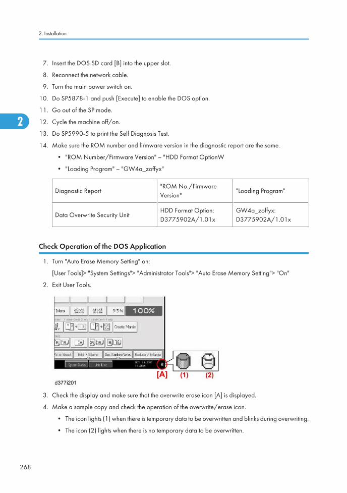
7. Insert the DOS SD card [B] into the upper slot.
8. Reconnect the network cable.
9. Turn the main power switch on.
10. Do SP5878-1 and push [Execute] to enable the DOS option.
11. Go out of the SP mode.
12. Cycle the machine off/on.
13. Do SP5990-5 to print the Self Diagnosis Test.
14. Make sure the ROM number and firmware version in the diagnostic report are the same.
• "ROM Number/Firmware Version" – "HDD Format OptionW
• "Loading Program" – "GW4a_zoffyx"
Diagnostic Report"ROM No./FirmwareVersion"
"Loading Program"
Data Overwrite Security UnitHDD Format Option:D3775902A/1.01x
GW4a_zoffyx:D3775902A/1.01x
Check Operation of the DOS Application
1. Turn "Auto Erase Memory Setting" on:
[User Tools]> "System Settings"> "Administrator Tools"> "Auto Erase Memory Setting"> "On"
2. Exit User Tools.
3. Check the display and make sure that the overwrite erase icon [A] is displayed.
4. Make a sample copy and check the operation of the overwrite/erase icon.
• The icon lights (1) when there is temporary data to be overwritten and blinks during overwriting.
• The icon (2) lights when there is no temporary data to be overwritten.
2. Installation
268
2
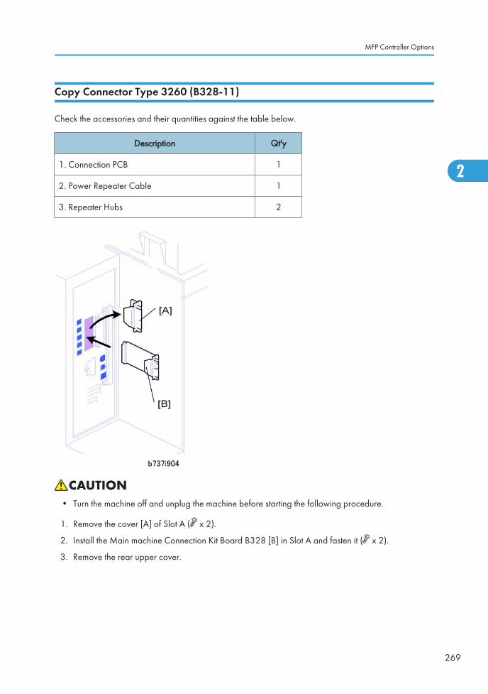
Copy Connector Type 3260 (B328-11)
Check the accessories and their quantities against the table below.
Description Qt'y
1. Connection PCB 1
2. Power Repeater Cable 1
3. Repeater Hubs 2
• Turn the machine off and unplug the machine before starting the following procedure.
1. Remove the cover [A] of Slot A ( x 2).
2. Install the Main machine Connection Kit Board B328 [B] in Slot A and fasten it ( x 2).
3. Remove the rear upper cover.
MFP Controller Options
269
2
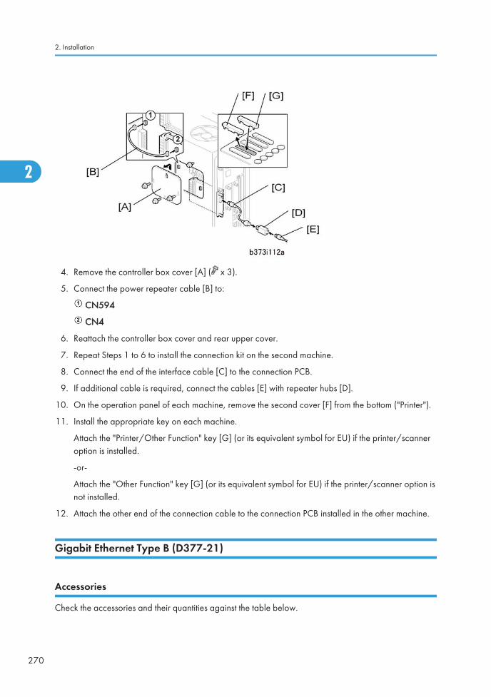
4. Remove the controller box cover [A] ( x 3).
5. Connect the power repeater cable [B] to:
CN594
CN4
6. Reattach the controller box cover and rear upper cover.
7. Repeat Steps 1 to 6 to install the connection kit on the second machine.
8. Connect the end of the interface cable [C] to the connection PCB.
9. If additional cable is required, connect the cables [E] with repeater hubs [D].
10. On the operation panel of each machine, remove the second cover [F] from the bottom ("Printer").
11. Install the appropriate key on each machine.
Attach the "Printer/Other Function" key [G] (or its equivalent symbol for EU) if the printer/scanneroption is installed.
-or-
Attach the "Other Function" key [G] (or its equivalent symbol for EU) if the printer/scanner option isnot installed.
12. Attach the other end of the connection cable to the connection PCB installed in the other machine.
Gigabit Ethernet Type B (D377-21)
Accessories
Check the accessories and their quantities against the table below.
2. Installation
270
2
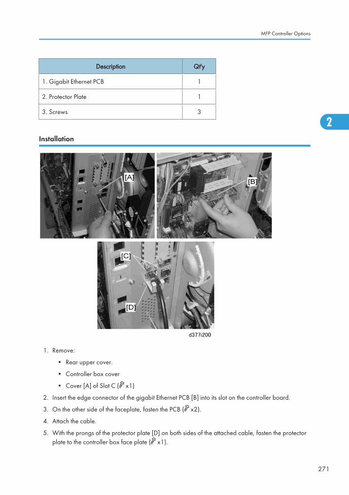
Description Qt'y
1. Gigabit Ethernet PCB 1
2. Protector Plate 1
3. Screws 3
Installation
1. Remove:
• Rear upper cover.
• Controller box cover
• Cover [A] of Slot C ( x1)
2. Insert the edge connector of the gigabit Ethernet PCB [B] into its slot on the controller board.
3. On the other side of the faceplate, fasten the PCB ( x2).
4. Attach the cable.
5. With the prongs of the protector plate [D] on both sides of the attached cable, fasten the protectorplate to the controller box face plate ( x1).
MFP Controller Options
271
2
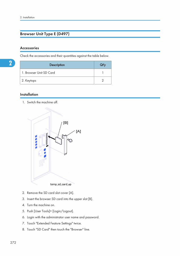
Browser Unit Type E (D497)
Accessories
Check the accessories and their quantities against the table below.
Description Qt'y
1. Browser Unit SD Card 1
2. Keytops 2
Installation
1. Switch the machine off.
2. Remove the SD card slot cover [A].
3. Insert the browser SD card into the upper slot [B].
4. Turn the machine on.
5. Push [User Tools]> [Login/Logout].
6. Login with the administrator user name and password.
7. Touch "Extended Feature Settings" twice.
8. Touch "SD Card" then touch the "Browser" line.
2. Installation
272
2
Ed
Typewritten Text
Browser unit RTB 2 Installation procedure was modified
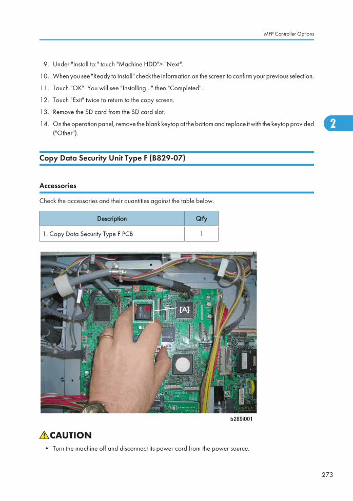
9. Under "Install to:" touch "Machine HDD"> "Next".
10. When you see "Ready to Install" check the information on the screen to confirm your previous selection.
11. Touch "OK". You will see "Installing…" then "Completed".
12. Touch "Exit" twice to return to the copy screen.
13. Remove the SD card from the SD card slot.
14. On the operation panel, remove the blank keytop at the bottom and replace it with the keytop provided("Other").
Copy Data Security Unit Type F (B829-07)
Accessories
Check the accessories and their quantities against the table below.
Description Qt'y
1. Copy Data Security Type F PCB 1
• Turn the machine off and disconnect its power cord from the power source.
MFP Controller Options
273
2
1. Remove
• Rear upper cover
• Controller box cover
2. Touch a metal surface to discharge any static electricity from your hands.
3. Push the connector on the underside of the Copy Data Security PCB [A] into its slot on the IPU.
4. Carefully fasten the Copy Data Security PCB to the IPU ( x2).
• Do not touch the surface of any other board with the tip of the screwdriver.
User Tool Setting
1. Plug in and turn on the main power switch.
2. Go into the User Tools mode, and select System Settings > Administrator Tools > Data Security forCopying > "On".
3. Exit the User Tools.
4. Check the operation.
• The machine will issue an SC165 error if the machine is powered on with the ICIB-1 removedand the "Data Security for Copying" feature is set to "ON".
• When you remove this option from the machine, first set the setting to "OFF" with the user toolbefore removing this board. If you forget to do this, "Data Security for Copying" feature cannotappear in the user tool settings. And then SC165 will appear every time the machine is switchedon, and the machine cannot be used.
5. Make sure that the machine can recognize the option ( "Check All Connections" at the end of thissection).
2. Installation
274
2
3. Preventive Maintenance
OverviewThe amounts mentioned (K=1,000) as the PM interval indicate the number of prints or copies unless statedotherwise. These numbers are based on the PM counter.
Required Materials
You must use these materials to service the machine:
• Optical Cloth (A0129111)
• Alcohol
• Exposure Glass Cleaner (A1939310)
• Barrierta S552R
• Grease KS660B (D0149800)
• G104 Yellow Toner (D0159500)
• Zinc Stearate (D0159501)
Notes:
• The G104 Yellow Toner and Zinc Stearate are specially designed for this machine.
• Grease KS660B is a new conductive grease specially designed for servicing this machine. Previousgrease compounds (Grease KS660, Silicone Grease 501, Grease Barierta S552R) are non-conductive.
• Always use G104 Yellow Toner and Zinc Stearate to lubricate the ITB and drum. These compoundsare specially designed for this purpose.
• Never use the yellow toner of the D014/D015/D081/D082 to lubricate the ITB or drum. The yellowtoner contains developer which could damage the ITB or drum and cause problems with imageprinting.
• Never use the previous Setting Powder (54429101) used for previous machines in any serviceprocedure for the D081/D082. The composition of this powder is completely different. If you useSetting Powder (5442910) to service this machine, you will damage the drum charge roller andcause problems with image quality.
• Turn off the main power switch and unplug the machine before performing any procedure in thissection. Laser beams can seriously damage the eyes.
275
3

• After you do the PM, do the forced music adjustment with SP 2111 001.
3. Preventive Maintenance
276
3
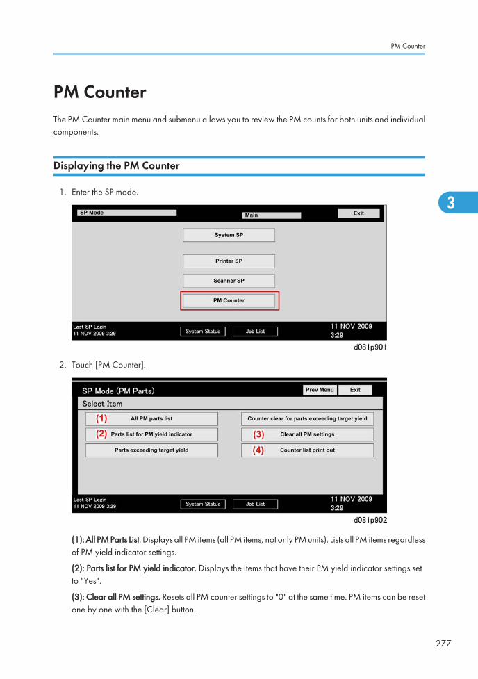
PM CounterThe PM Counter main menu and submenu allows you to review the PM counts for both units and individualcomponents.
Displaying the PM Counter
1. Enter the SP mode.
2. Touch [PM Counter].
(1): All PM Parts List. Displays all PM items (all PM items, not only PM units). Lists all PM items regardlessof PM yield indicator settings.
(2): Parts list for PM yield indicator. Displays the items that have their PM yield indicator settings setto "Yes".
(3): Clear all PM settings. Resets all PM counter settings to "0" at the same time. PM items can be resetone by one with the [Clear] button.
PM Counter
277
3
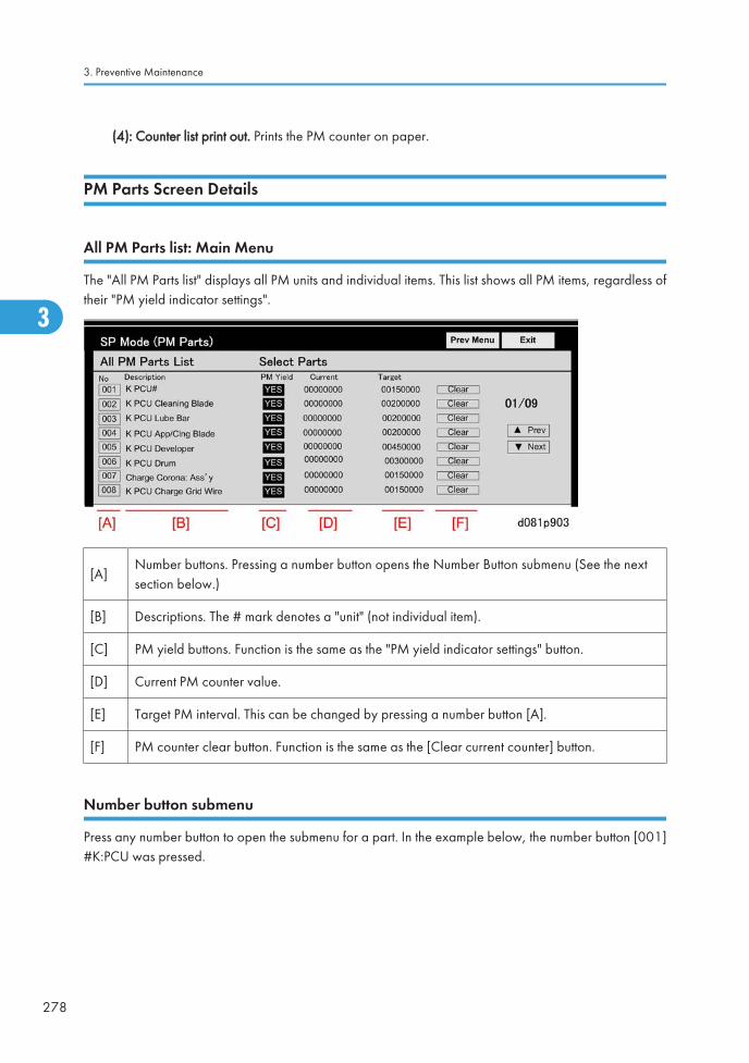
(4): Counter list print out. Prints the PM counter on paper.
PM Parts Screen Details
All PM Parts list: Main Menu
The "All PM Parts list" displays all PM units and individual items. This list shows all PM items, regardless oftheir "PM yield indicator settings".
[A]Number buttons. Pressing a number button opens the Number Button submenu (See the nextsection below.)
[B] Descriptions. The # mark denotes a "unit" (not individual item).
[C] PM yield buttons. Function is the same as the "PM yield indicator settings" button.
[D] Current PM counter value.
[E] Target PM interval. This can be changed by pressing a number button [A].
[F] PM counter clear button. Function is the same as the [Clear current counter] button.
Number button submenu
Press any number button to open the submenu for a part. In the example below, the number button [001]#K:PCU was pressed.
3. Preventive Maintenance
278
3
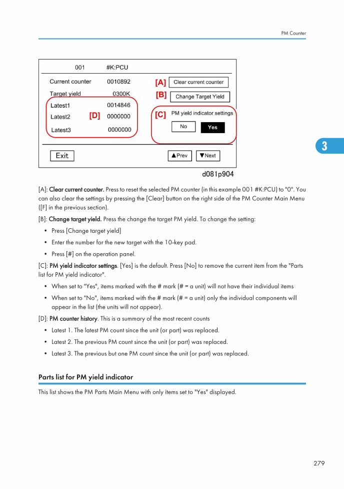
[A]: Clear current counter. Press to reset the selected PM counter (in this example 001 #K:PCU) to "0". Youcan also clear the settings by pressing the [Clear] button on the right side of the PM Counter Main Menu([F] in the previous section).
[B]: Change target yield. Press the change the target PM yield. To change the setting:
• Press [Change target yield]
• Enter the number for the new target with the 10-key pad.
• Press [#] on the operation panel.
[C]: PM yield indicator settings. [Yes] is the default. Press [No] to remove the current item from the "Partslist for PM yield indicator".
• When set to "Yes", items marked with the # mark (# = a unit) will not have their individual items
• When set to "No", items marked with the # mark (# = a unit) only the individual components willappear in the list (the units will not appear).
[D]: PM counter history. This is a summary of the most recent counts
• Latest 1. The latest PM count since the unit (or part) was replaced.
• Latest 2. The previous PM count since the unit (or part) was replaced.
• Latest 3. The previous but one PM count since the unit (or part) was replaced.
Parts list for PM yield indicator
This list shows the PM Parts Main Menu with only items set to "Yes" displayed.
PM Counter
279
3
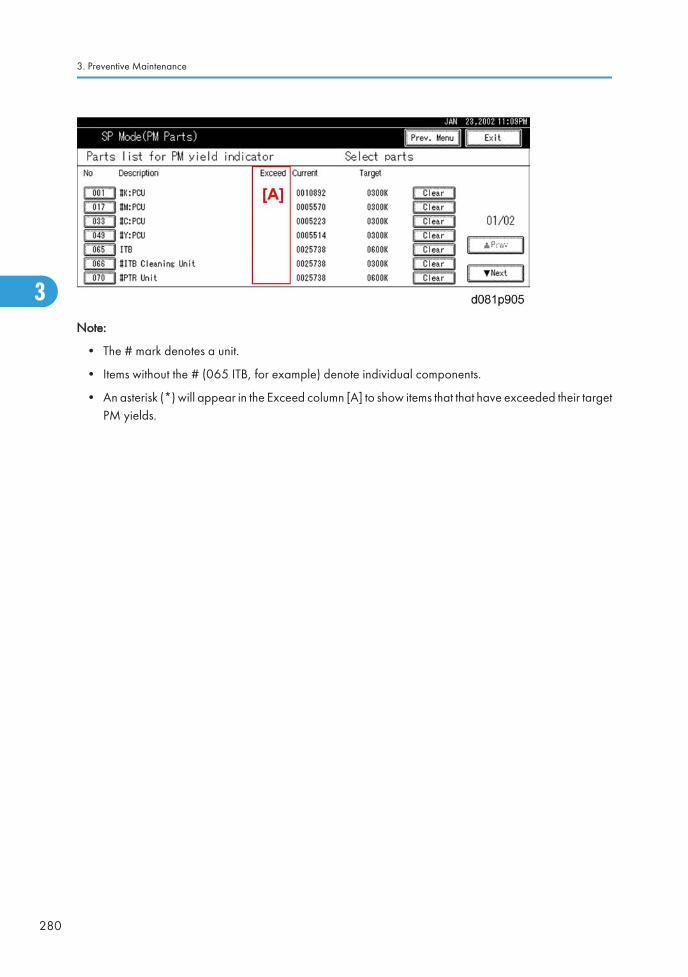
Note:
• The # mark denotes a unit.
• Items without the # (065 ITB, for example) denote individual components.
• An asterisk (*) will appear in the Exceed column [A] to show items that that have exceeded their targetPM yields.
3. Preventive Maintenance
280
3

PM TablesSee "Appendices" for the following information:
• PM Tables
PM Tables
281
3

3. Preventive Maintenance
282
3
4. Replacement and Adjustments
General Cautions
• Never switch off either power switch while any of the electrical components are operating. Doing somight cause damage to units such as the transfer belt, drum, and development unit when they arepulled out of or put back into the main machine.
Drum
An organic photoconductor (OPC) drums are more sensitive to light and ammonia gas than a seleniumdrum. Follow the cautions below when handling an OPC drum.
1. When a PCU unit is removed from the machine, always place it on the PCU stand provided with themachine.
2. Never expose a drum to direct sunlight.
3. Never expose a drum to direct light of more than 1,000 Lux for more than a minute.
4. Never touch a drum surface with bare hands. If the drum surface is touched with a finger or becomesdirty, wipe it with a dry cloth or clean it with wet cotton. Wipe with a dry cloth after cleaning with wetcotton.
5. Never use alcohol to clean the drum (alcohol dissolves the drum surface).
6. Store drums in a cool, dry place away from heat.
7. Take care not to scratch the drum as the drum layer is thin and is easily damaged.
8. Never expose a drum to corrosive gases such as ammonia gas.
9. Dispose of used drums in accordance with local regulations.
PCU
1. The PCU stand is stored in a rack attached to the bottom of the machine with strong magnets.
2. Before pulling a PCU unit out of the machine, spread some clean paper to catch spilt toner, removethe PCU stand from the bottom of the machine, clean it with a clean cloth, and then set the PCU standon the paper to hold the PCU as soon as it is removed from the machine.
3. To prevent drum scratches, always set the PCU on the stand and leave it there as long as it is out ofthe machine.
4. Remove only one PCU at a time for servicing. Only one PCU stand is provided with the machine.
283
4
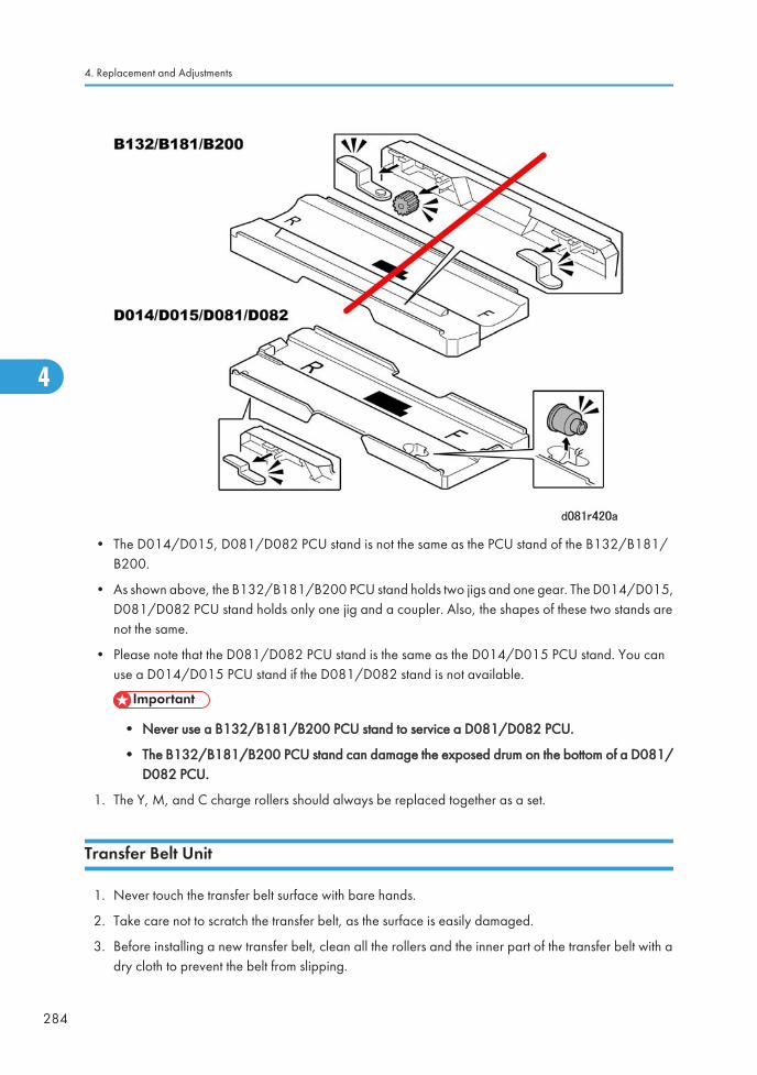
• The D014/D015, D081/D082 PCU stand is not the same as the PCU stand of the B132/B181/B200.
• As shown above, the B132/B181/B200 PCU stand holds two jigs and one gear. The D014/D015,D081/D082 PCU stand holds only one jig and a coupler. Also, the shapes of these two stands arenot the same.
• Please note that the D081/D082 PCU stand is the same as the D014/D015 PCU stand. You canuse a D014/D015 PCU stand if the D081/D082 stand is not available.
• Never use a B132/B181/B200 PCU stand to service a D081/D082 PCU.
• The B132/B181/B200 PCU stand can damage the exposed drum on the bottom of a D081/D082 PCU.
1. The Y, M, and C charge rollers should always be replaced together as a set.
Transfer Belt Unit
1. Never touch the transfer belt surface with bare hands.
2. Take care not to scratch the transfer belt, as the surface is easily damaged.
3. Before installing a new transfer belt, clean all the rollers and the inner part of the transfer belt with adry cloth to prevent the belt from slipping.
4. Replacement and Adjustments
284
4
Scanner Unit
1. When installing a new exposure glass, make sure that the white paint mark is at the rear left corner.
2. Clean the exposure glass with alcohol or glass cleaner to reduce the amount of static electricity onthe glass surface.
3. Use a cotton pad with water or a blower brush to clean the mirrors and lenses.
4. Never bend or crease the exposure lamp cables.
5. Never disassemble the lens unit. Doing so will throw the lens and the copy image out of focus.
6. Never adjust any CCD positioning screw. Doing so will throw the CCD out of position.
Laser Unit
1. Never loosen the screws that secure the LD drive board to the laser diode casing. Doing so wouldthrow the LD unit out of adjustment.
2. Never adjust the variable resistors on the LD unit, as they are adjusted in the factory.
3. Never open the optical housing unit. The polygon mirror and lenses are sensitive to dust.
4. Never touch the glass surface of the polygon mirror motor unit with bare hands.
Development
1. Avoid nicking or scratching the development roller.
2. Place a development unit on a sheet of paper after removing it from a PCU.
3. Always clean the drive gears after removing used developer.
4. Always dispose of used developer in accordance with local regulations.
5. Never load types of developer and toner into the development unit other than specified for this model.Doing so will cause poor copy quality and toner scattering.
6. Immediately after installing new developer or toner during the machine installation procedure, dothe SPs as described in the installation procedure.
7. Immediately after replacing the developer, do the SPs as described in the "SP Codes afterReplacement" section of PCU replacement.
8. Never do SP3801 or SP3811 with used developer.
9. When using a vacuum cleaner to clean the development unit casing, always ground the casing withyour fingers to avoid damaging the toner density sensor with static electricity.
10. The TD sensor must be initialized:
• At installation, exactly as described in the installation procedure
General Cautions
285
4
• After replacing developer. (Initialize the TD sensor only for the PCU where the developer wasreplaced.)
• Never initialize the TD sensor more than once. Initializing the TD sensor more than once cancause toner scatter inside the machine.
Cleaning
1. When servicing cleaning components, avoid nicking the edges of the cleaning blades.
2. Never handle a cleaning blade with bare hands.
3. Before disassembling a cleaning section, place a sheet of paper under it to catch any toner falling.
Fusing Unit
1. Never handle fusing lamps and rollers with bare hands.
2. Make sure that the fusing lamps are positioned correctly and do not touch the inner surface of therollers.
Paper Feed
1. Do not touch the surfaces of the pick-up, feed, and separation rollers.
2. To avoid paper misfeeds, the side fences and end fence of the paper trays must be positioned correctlyto align with the actual paper size.
Used Toner
1. Check the amount of used toner at every service visit.
2. Always dispose of used toner in accordance with local regulations.
3. Never throw toner into an open flame.
4. Replacement and Adjustments
286
4
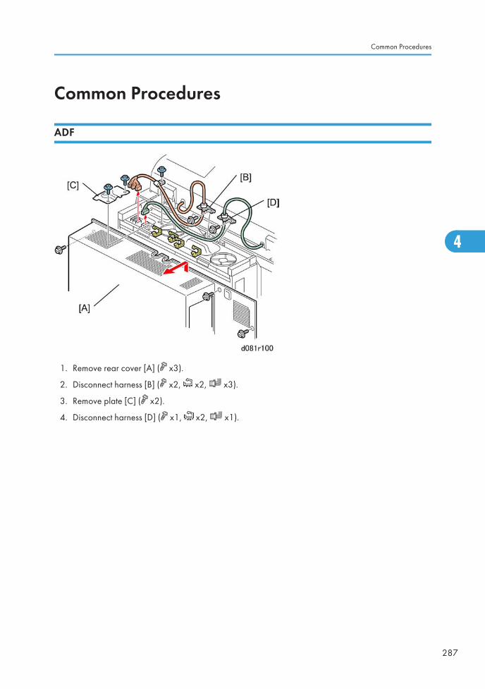
Common Procedures
ADF
1. Remove rear cover [A] ( x3).
2. Disconnect harness [B] ( x2, x2, x3).
3. Remove plate [C] ( x2).
4. Disconnect harness [D] ( x1, x2, x1).
Common Procedures
287
4

• The ADF is very heavy.
5. Raise the ADF [A] to the vertical position.
6. At the rear left corner of the machine, disconnect the ADF cable.
7. Remove the left screw [B] and right screw [C].
8. Slide the ADF back until the heads of the screws are in the large end of the keyholes, and then lift theADF off the machine.
4. Replacement and Adjustments
288
4
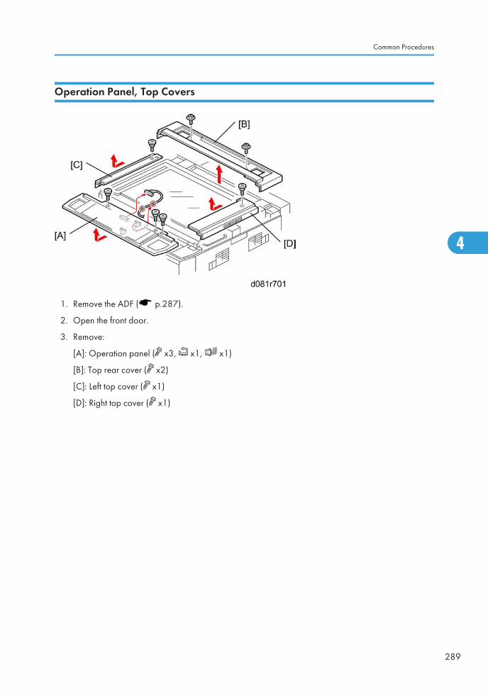
Operation Panel, Top Covers
1. Remove the ADF ( p.287).
2. Open the front door.
3. Remove:
[A]: Operation panel ( x3, x1, x1)
[B]: Top rear cover ( x2)
[C]: Left top cover ( x1)
[D]: Right top cover ( x1)
Common Procedures
289
4
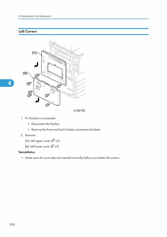
Left Covers
1. If a finisher is connected:
• Disconnect the finisher.
• Remove the front and back finisher connection brackets.
2. Remove:
[A]: Left upper cover ( x2)
[B]: Left lower cover ( x5)
Reinstallation
• Make sure all cover tabs are inserted correctly before you fasten the screws.
4. Replacement and Adjustments
290
4

Front Door
1. Grip the front door [A] with one hand.
2. Press down the hinge bracket [B].
3. Lift the front door slightly to remove it.
• If you must replace the front door, make sure that you put the SD cards from the storage location inthe old front door into the storage location in the new front door.
Common Procedures
291
4
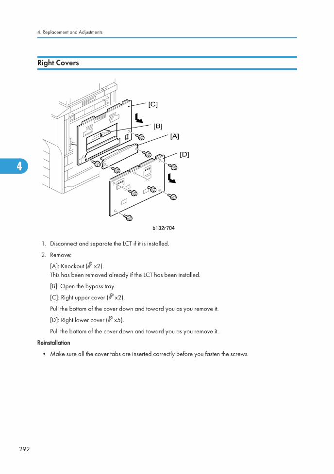
Right Covers
1. Disconnect and separate the LCT if it is installed.
2. Remove:
[A]: Knockout ( x2).This has been removed already if the LCT has been installed.
[B]: Open the bypass tray.
[C]: Right upper cover ( x2).
Pull the bottom of the cover down and toward you as you remove it.
[D]: Right lower cover ( x5).
Pull the bottom of the cover down and toward you as you remove it.
Reinstallation
• Make sure all the cover tabs are inserted correctly before you fasten the screws.
4. Replacement and Adjustments
292
4
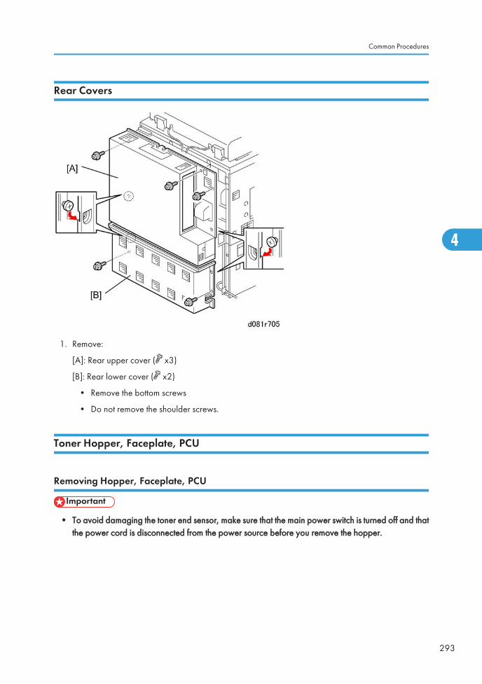
Rear Covers
1. Remove:
[A]: Rear upper cover ( x3)
[B]: Rear lower cover ( x2)
• Remove the bottom screws
• Do not remove the shoulder screws.
Toner Hopper, Faceplate, PCU
Removing Hopper, Faceplate, PCU
• To avoid damaging the toner end sensor, make sure that the main power switch is turned off and thatthe power cord is disconnected from the power source before you remove the hopper.
Common Procedures
293
4
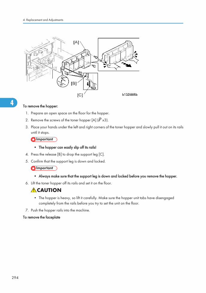
To remove the hopper:
1. Prepare an open space on the floor for the hopper.
2. Remove the screws of the toner hopper [A] ( x3).
3. Place your hands under the left and right corners of the toner hopper and slowly pull it out on its railsuntil it stops.
• The hopper can easily slip off its rails!
4. Press the release [B] to drop the support leg [C].
5. Confirm that the support leg is down and locked.
• Always make sure that the support leg is down and locked before you remove the hopper.
6. Lift the toner hopper off its rails and set it on the floor.
• The hopper is heavy, so lift it carefully. Make sure the hopper unit tabs have disengagedcompletely from the rails before you try to set the unit on the floor.
7. Push the hopper rails into the machine.
To remove the faceplate
4. Replacement and Adjustments
294
4
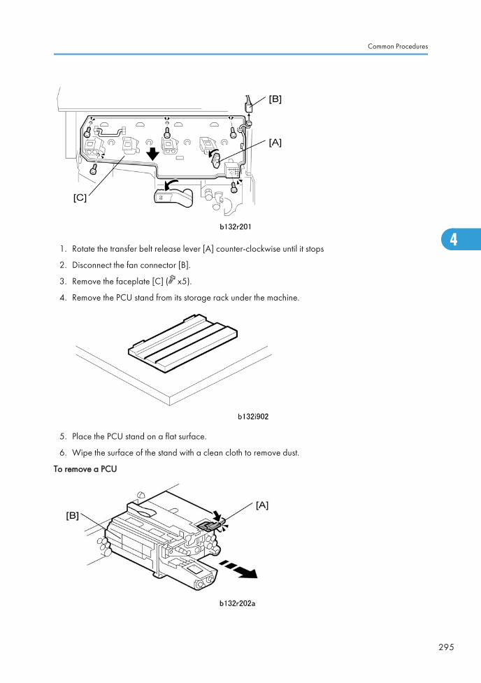
1. Rotate the transfer belt release lever [A] counter-clockwise until it stops
2. Disconnect the fan connector [B].
3. Remove the faceplate [C] ( x5).
4. Remove the PCU stand from its storage rack under the machine.
5. Place the PCU stand on a flat surface.
6. Wipe the surface of the stand with a clean cloth to remove dust.
To remove a PCU
Common Procedures
295
4
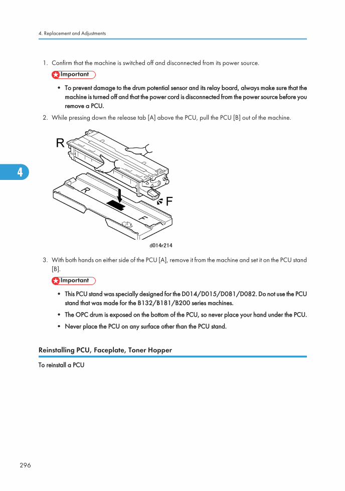
1. Confirm that the machine is switched off and disconnected from its power source.
• To prevent damage to the drum potential sensor and its relay board, always make sure that themachine is turned off and that the power cord is disconnected from the power source before youremove a PCU.
2. While pressing down the release tab [A] above the PCU, pull the PCU [B] out of the machine.
3. With both hands on either side of the PCU [A], remove it from the machine and set it on the PCU stand[B].
• This PCU stand was specially designed for the D014/D015/D081/D082. Do not use the PCUstand that was made for the B132/B181/B200 series machines.
• The OPC drum is exposed on the bottom of the PCU, so never place your hand under the PCU.
• Never place the PCU on any surface other than the PCU stand.
Reinstalling PCU, Faceplate, Toner Hopper
To reinstall a PCU
4. Replacement and Adjustments
296
4
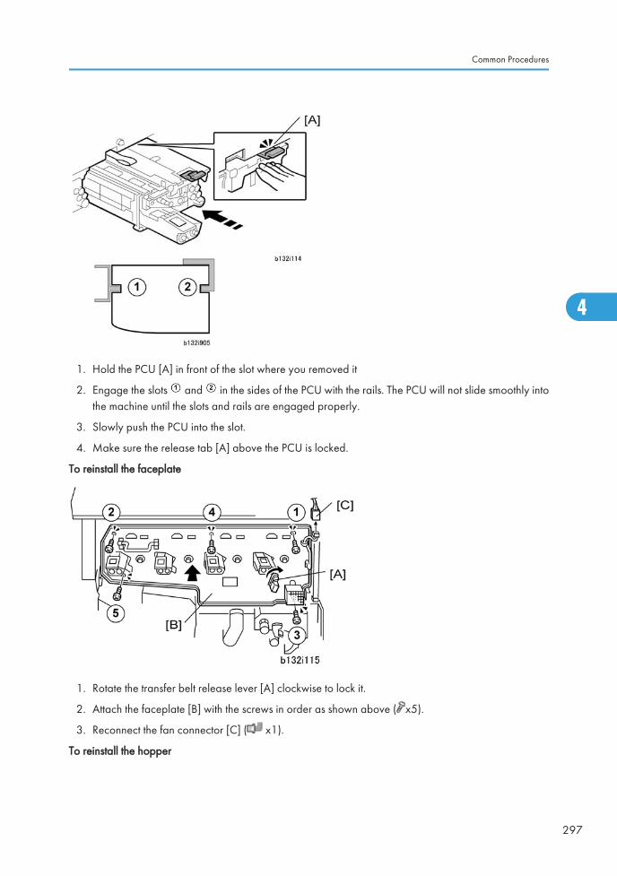
1. Hold the PCU [A] in front of the slot where you removed it
2. Engage the slots and in the sides of the PCU with the rails. The PCU will not slide smoothly intothe machine until the slots and rails are engaged properly.
3. Slowly push the PCU into the slot.
4. Make sure the release tab [A] above the PCU is locked.
To reinstall the faceplate
1. Rotate the transfer belt release lever [A] clockwise to lock it.
2. Attach the faceplate [B] with the screws in order as shown above ( x5).
3. Reconnect the fan connector [C] ( x1).
To reinstall the hopper
Common Procedures
297
4
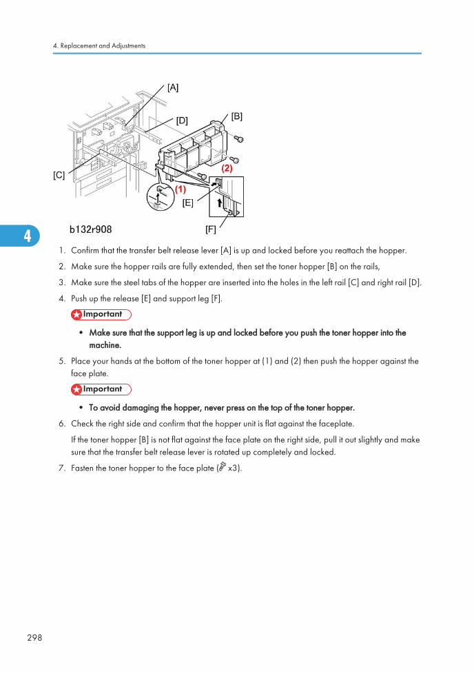
1. Confirm that the transfer belt release lever [A] is up and locked before you reattach the hopper.
2. Make sure the hopper rails are fully extended, then set the toner hopper [B] on the rails,
3. Make sure the steel tabs of the hopper are inserted into the holes in the left rail [C] and right rail [D].
4. Push up the release [E] and support leg [F].
• Make sure that the support leg is up and locked before you push the toner hopper into themachine.
5. Place your hands at the bottom of the toner hopper at (1) and (2) then push the hopper against theface plate.
• To avoid damaging the hopper, never press on the top of the toner hopper.
6. Check the right side and confirm that the hopper unit is flat against the faceplate.
If the toner hopper [B] is not flat against the face plate on the right side, pull it out slightly and makesure that the transfer belt release lever is rotated up completely and locked.
7. Fasten the toner hopper to the face plate ( x3).
4. Replacement and Adjustments
298
4
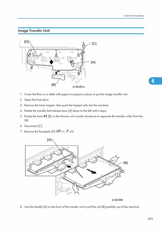
Image Transfer Unit
1. Cover the floor or a table with paper to prepare a place to put the image transfer unit.
2. Open the front door.
3. Remove the toner hopper, then push the hopper rails into the machine.
4. Rotate the transfer belt release lever [A] down to the left until it stops.
5. Rotate the lever B2 [B] on the drawer unit counter-clockwise to separate the transfer roller from theITB.
6. Disconnect [C].
7. Remove the faceplate [D] ( x1, x5).
8. Use the handle [A] on the front of the transfer unit to pull the unit [B] partially out of the machine.
Common Procedures
299
4
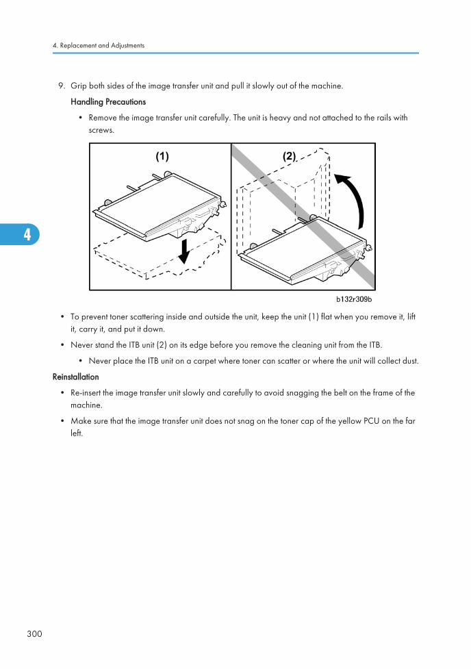
9. Grip both sides of the image transfer unit and pull it slowly out of the machine.
Handling Precautions
• Remove the image transfer unit carefully. The unit is heavy and not attached to the rails withscrews.
• To prevent toner scattering inside and outside the unit, keep the unit (1) flat when you remove it, liftit, carry it, and put it down.
• Never stand the ITB unit (2) on its edge before you remove the cleaning unit from the ITB.
• Never place the ITB unit on a carpet where toner can scatter or where the unit will collect dust.
Reinstallation
• Re-insert the image transfer unit slowly and carefully to avoid snagging the belt on the frame of themachine.
• Make sure that the image transfer unit does not snag on the toner cap of the yellow PCU on the farleft.
4. Replacement and Adjustments
300
4
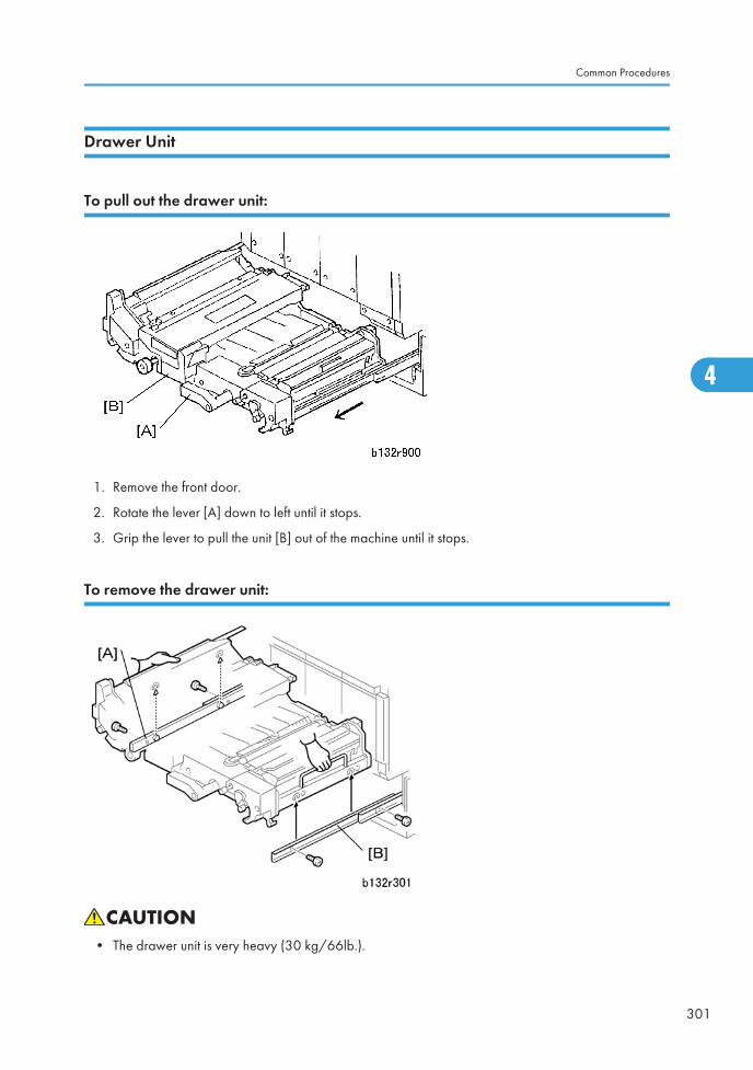
Drawer Unit
To pull out the drawer unit:
1. Remove the front door.
2. Rotate the lever [A] down to left until it stops.
3. Grip the lever to pull the unit [B] out of the machine until it stops.
To remove the drawer unit:
• The drawer unit is very heavy (30 kg/66lb.).
Common Procedures
301
4
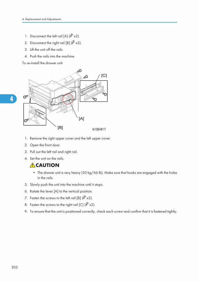
1. Disconnect the left rail [A] ( x2).
2. Disconnect the right rail [B] ( x2).
3. Lift the unit off the rails.
4. Push the rails into the machine.
To re-install the drawer unit
1. Remove the right upper cover and the left upper cover.
2. Open the front door.
3. Pull out the left rail and right rail.
4. Set the unit on the rails.
• The drawer unit is very heavy (30 kg/66 lb). Make sure that hooks are engaged with the holesin the rails.
5. Slowly push the unit into the machine until it stops.
6. Rotate the lever [A] to the vertical position.
7. Fasten the screws to the left rail [B] ( x2).
8. Fasten the screws to the right rail [C] ( x2).
9. To ensure that the unit is positioned correctly, check each screw and confirm that it is fastened tightly.
4. Replacement and Adjustments
302
4
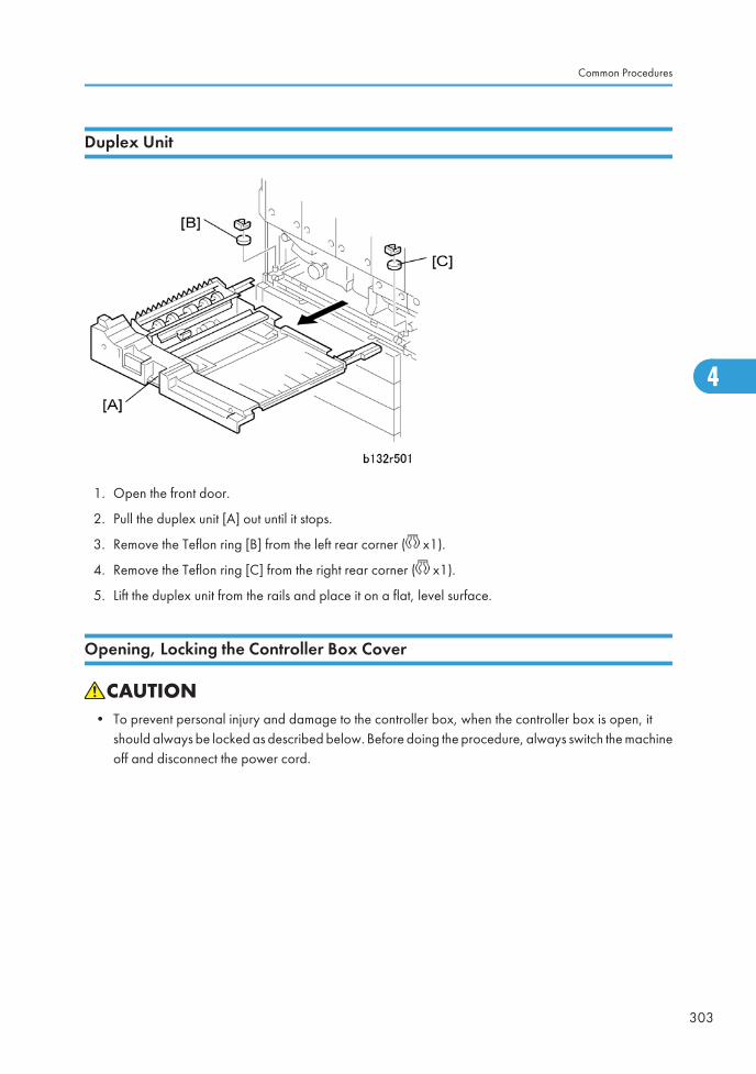
Duplex Unit
1. Open the front door.
2. Pull the duplex unit [A] out until it stops.
3. Remove the Teflon ring [B] from the left rear corner ( x1).
4. Remove the Teflon ring [C] from the right rear corner ( x1).
5. Lift the duplex unit from the rails and place it on a flat, level surface.
Opening, Locking the Controller Box Cover
• To prevent personal injury and damage to the controller box, when the controller box is open, itshould always be locked as described below. Before doing the procedure, always switch the machineoff and disconnect the power cord.
Common Procedures
303
4
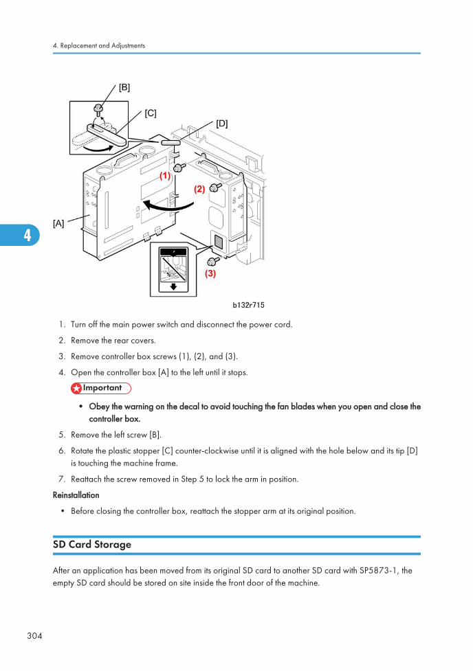
1. Turn off the main power switch and disconnect the power cord.
2. Remove the rear covers.
3. Remove controller box screws (1), (2), and (3).
4. Open the controller box [A] to the left until it stops.
• Obey the warning on the decal to avoid touching the fan blades when you open and close thecontroller box.
5. Remove the left screw [B].
6. Rotate the plastic stopper [C] counter-clockwise until it is aligned with the hole below and its tip [D]is touching the machine frame.
7. Reattach the screw removed in Step 5 to lock the arm in position.
Reinstallation
• Before closing the controller box, reattach the stopper arm at its original position.
SD Card Storage
After an application has been moved from its original SD card to another SD card with SP5873-1, theempty SD card should be stored on site inside the front door of the machine.
4. Replacement and Adjustments
304
4
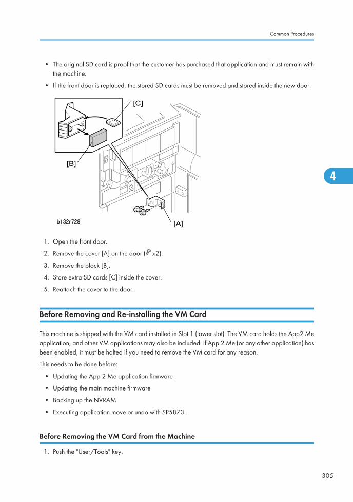
• The original SD card is proof that the customer has purchased that application and must remain withthe machine.
• If the front door is replaced, the stored SD cards must be removed and stored inside the new door.
1. Open the front door.
2. Remove the cover [A] on the door ( x2).
3. Remove the block [B].
4. Store extra SD cards [C] inside the cover.
5. Reattach the cover to the door.
Before Removing and Re-installing the VM Card
This machine is shipped with the VM card installed in Slot 1 (lower slot). The VM card holds the App2 Meapplication, and other VM applications may also be included. If App 2 Me (or any other application) hasbeen enabled, it must be halted if you need to remove the VM card for any reason.
This needs to be done before:
• Updating the App 2 Me application firmware .
• Updating the main machine firmware
• Backing up the NVRAM
• Executing application move or undo with SP5873.
Before Removing the VM Card from the Machine
1. Push the "User/Tools" key.
Common Procedures
305
4

If an administrator setting is registered for the machine, Step 2 and 3 are required. Otherwise, skipto Step 4.
2. Push [Login/Logout] on the operation panel.
3. Login with the administrator user name and password.
4. Touch "Extended Feature Settings" twice on the LCD.
5. Touch the icon for each application until the status changes to "Stop".
• All applications must be stopped before the machine is switched off.
6. Turn the machine off, and then remove the VM Card from Slot 1 (lower slot).
7. Do the procedure:
• Updating the App 2 Me application firmware.
• Updating the main machine firmware
• Backing up the NVRAM
• Executing application move or undo with SP5873.
Starting Up After the VM Card Has Been Removed
1. Insert the VM card in Slot 1 (lower slot).
If an administrator setting is registered for the machine, Step 2 and 3 are required. Otherwise, skipto Step 4.
2. Push [Login/Logout] on the operation panel.
3. Login with the administrator user name and password.
4. Touch "Extended Feature Settings" twice on the LCD.
5. Touch the icon for each application that you want to start. You will see the "Starting up" status messagefor each application that you start.
6. Touch "Exit" on the screen.
7. Exit the "User Tools/Counter" settings.
4. Replacement and Adjustments
306
4
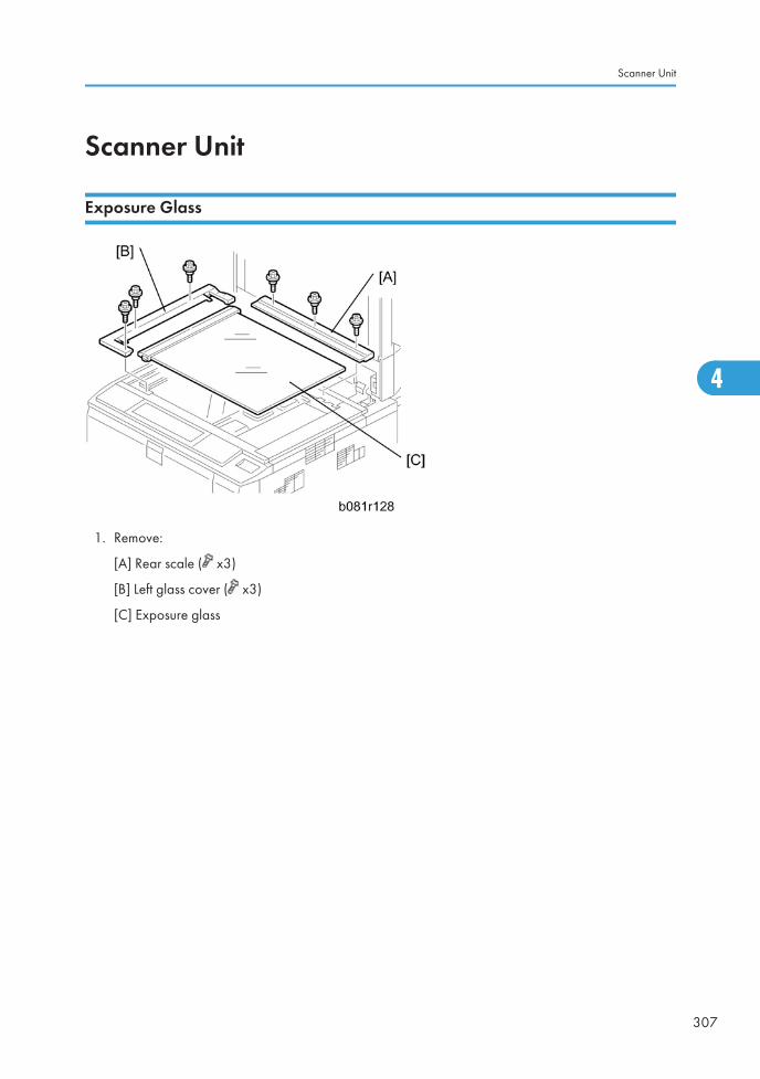
Scanner Unit
Exposure Glass
1. Remove:
[A] Rear scale ( x3)
[B] Left glass cover ( x3)
[C] Exposure glass
Scanner Unit
307
4
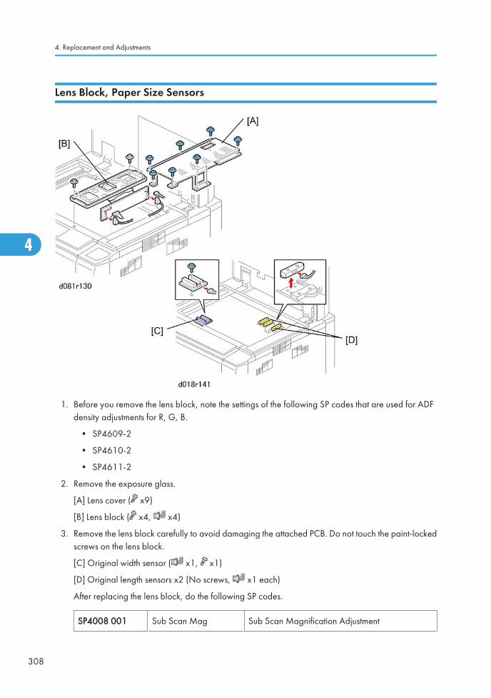
Lens Block, Paper Size Sensors
1. Before you remove the lens block, note the settings of the following SP codes that are used for ADFdensity adjustments for R, G, B.
• SP4609-2
• SP4610-2
• SP4611-2
2. Remove the exposure glass.
[A] Lens cover ( x9)
[B] Lens block ( x4, x4)
3. Remove the lens block carefully to avoid damaging the attached PCB. Do not touch the paint-lockedscrews on the lens block.
[C] Original width sensor ( x1, x1)
[D] Original length sensors x2 (No screws, x1 each)
After replacing the lens block, do the following SP codes.
SP4008 001 Sub Scan Mag Sub Scan Magnification Adjustment
4. Replacement and Adjustments
308
4
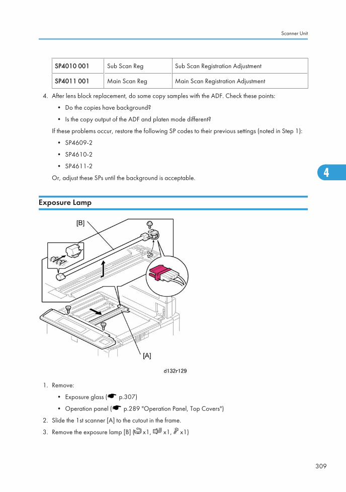
SP4010 001 Sub Scan Reg Sub Scan Registration Adjustment
SP4011 001 Main Scan Reg Main Scan Registration Adjustment
4. After lens block replacement, do some copy samples with the ADF. Check these points:
• Do the copies have background?
• Is the copy output of the ADF and platen mode different?
If these problems occur, restore the following SP codes to their previous settings (noted in Step 1):
• SP4609-2
• SP4610-2
• SP4611-2
Or, adjust these SPs until the background is acceptable.
Exposure Lamp
1. Remove:
• Exposure glass ( p.307)
• Operation panel ( p.289 "Operation Panel, Top Covers")
2. Slide the 1st scanner [A] to the cutout in the frame.
3. Remove the exposure lamp [B] ( x1, x1, x1)
Scanner Unit
309
4
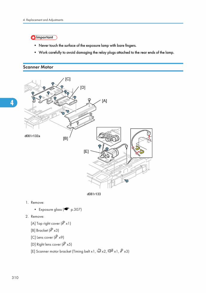
• Never touch the surface of the exposure lamp with bare fingers.
• Work carefully to avoid damaging the relay plugs attached to the rear ends of the lamp.
Scanner Motor
1. Remove:
• Exposure glass ( p.307)
2. Remove:
[A] Top right cover ( x1)
[B] Bracket ( x3)
[C] Lens cover ( x9)
[D] Right lens cover ( x5)
[E] Scanner motor bracket (Timing belt x1, x2, x1, x3)
4. Replacement and Adjustments
310
4
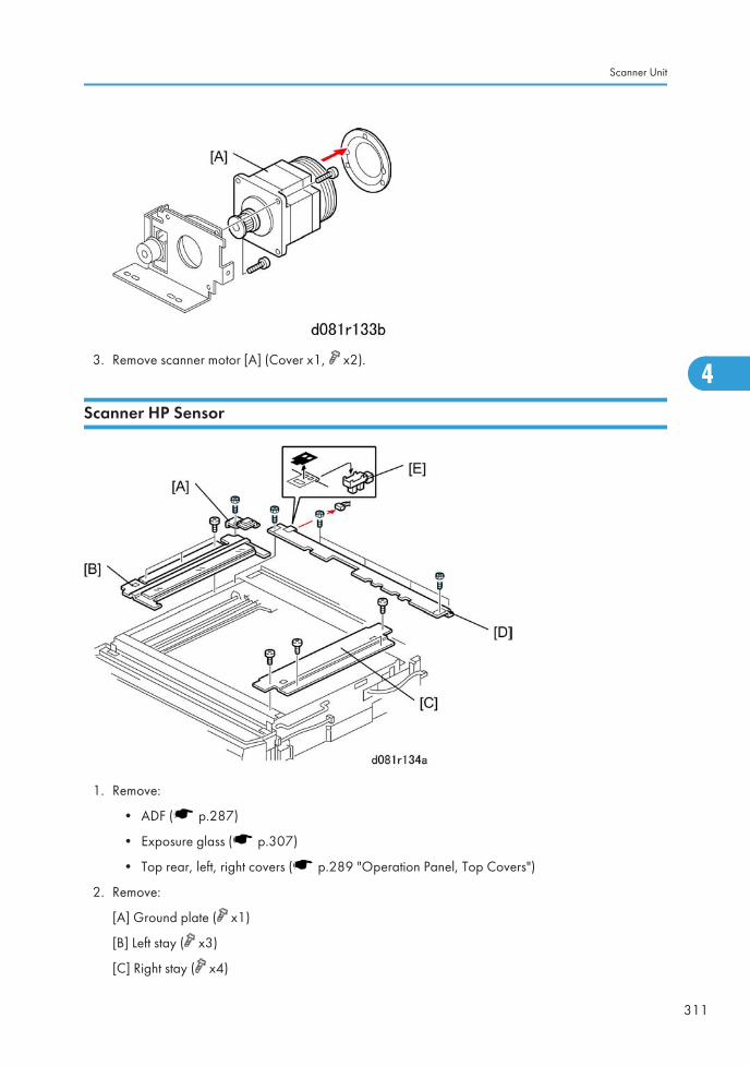
3. Remove scanner motor [A] (Cover x1, x2).
Scanner HP Sensor
1. Remove:
• ADF ( p.287)
• Exposure glass ( p.307)
• Top rear, left, right covers ( p.289 "Operation Panel, Top Covers")
2. Remove:
[A] Ground plate ( x1)
[B] Left stay ( x3)
[C] Right stay ( x4)
Scanner Unit
311
4
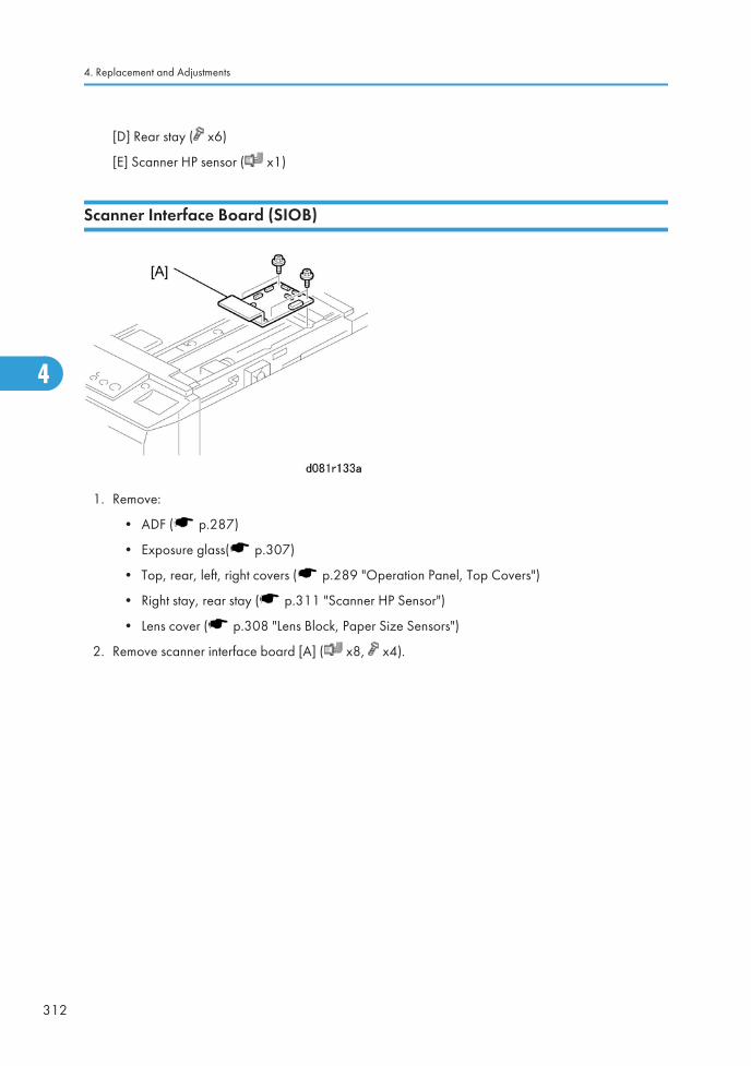
[D] Rear stay ( x6)
[E] Scanner HP sensor ( x1)
Scanner Interface Board (SIOB)
1. Remove:
• ADF ( p.287)
• Exposure glass( p.307)
• Top, rear, left, right covers ( p.289 "Operation Panel, Top Covers")
• Right stay, rear stay ( p.311 "Scanner HP Sensor")
• Lens cover ( p.308 "Lens Block, Paper Size Sensors")
2. Remove scanner interface board [A] ( x8, x4).
4. Replacement and Adjustments
312
4
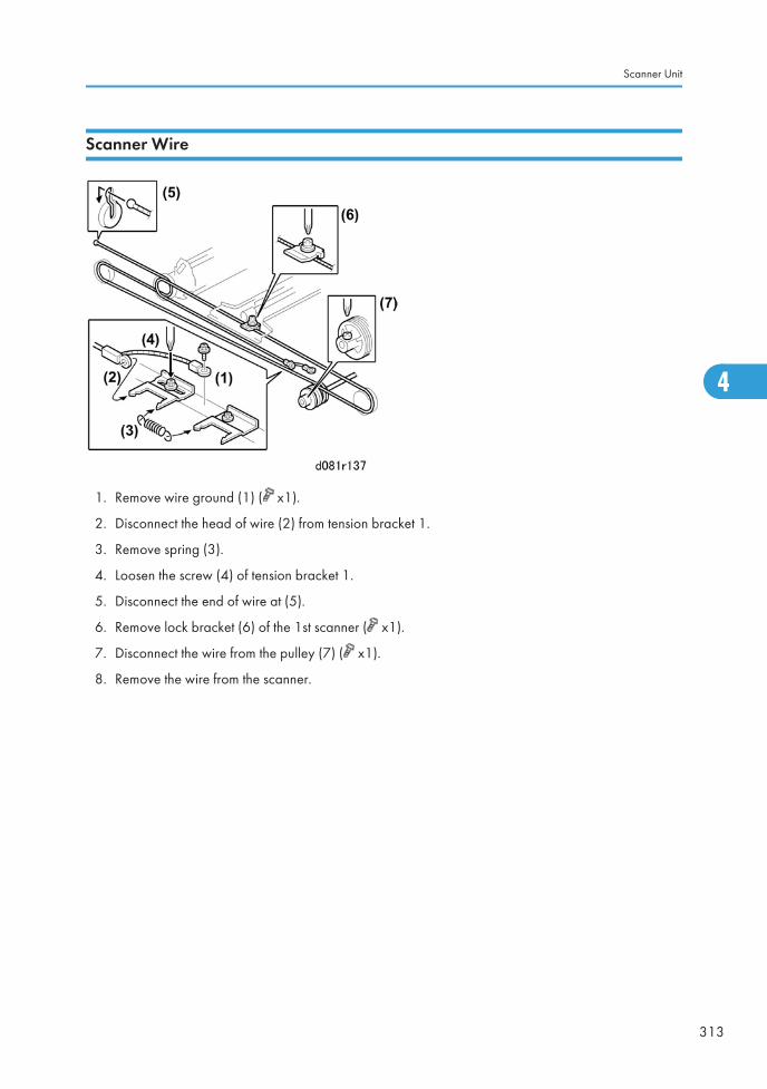
Scanner Wire
1. Remove wire ground (1) ( x1).
2. Disconnect the head of wire (2) from tension bracket 1.
3. Remove spring (3).
4. Loosen the screw (4) of tension bracket 1.
5. Disconnect the end of wire at (5).
6. Remove lock bracket (6) of the 1st scanner ( x1).
7. Disconnect the wire from the pulley (7) ( x1).
8. Remove the wire from the scanner.
Scanner Unit
313
4
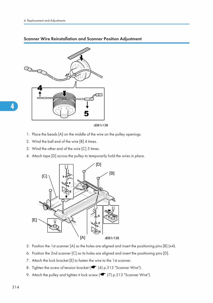
Scanner Wire Reinstallation and Scanner Position Adjustment
1. Place the beads [A] on the middle of the wire on the pulley openings.
2. Wind the ball end of the wire [B] 4 times.
3. Wind the other end of the wire [C] 5 times.
4. Attach tape [D] across the pulley to temporarily hold the wires in place.
5. Position the 1st scanner [A] so the holes are aligned and insert the positioning pins [B] (x4).
6. Position the 2nd scanner [C] so its holes are aligned and insert the positioning pins [D].
7. Attach the lock bracket [E] to fasten the wire to the 1st scanner.
8. Tighten the screw of tension bracket ( (4) p.313 "Scanner Wire").
9. Attach the pulley and tighten it lock screw ( (7) p.313 "Scanner Wire").
4. Replacement and Adjustments
314
4

10. Remove the positioning pins (x4).
11. Remove the tape from the pulley.
12. Slowly push the scanner left and right to confirm that the wires are engaged correctly. The 1st and2nd scanners should move smoothly.
Scanner Unit
315
4
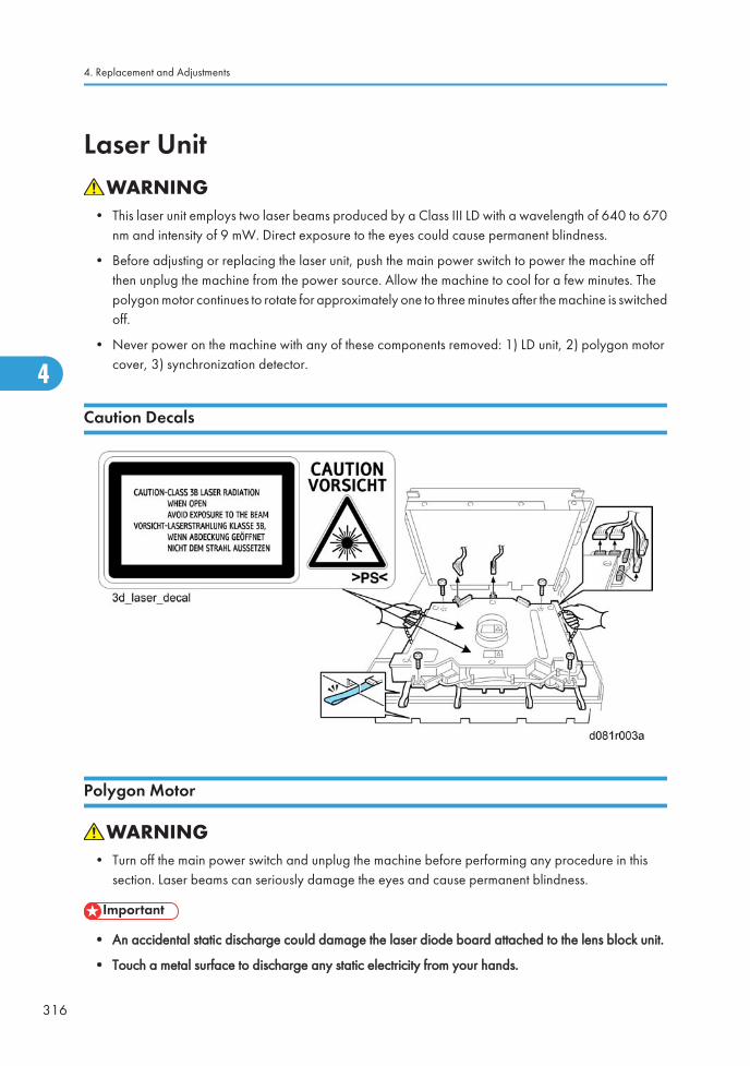
Laser Unit
• This laser unit employs two laser beams produced by a Class III LD with a wavelength of 640 to 670nm and intensity of 9 mW. Direct exposure to the eyes could cause permanent blindness.
• Before adjusting or replacing the laser unit, push the main power switch to power the machine offthen unplug the machine from the power source. Allow the machine to cool for a few minutes. Thepolygon motor continues to rotate for approximately one to three minutes after the machine is switchedoff.
• Never power on the machine with any of these components removed: 1) LD unit, 2) polygon motorcover, 3) synchronization detector.
Caution Decals
Polygon Motor
• Turn off the main power switch and unplug the machine before performing any procedure in thissection. Laser beams can seriously damage the eyes and cause permanent blindness.
• An accidental static discharge could damage the laser diode board attached to the lens block unit.
• Touch a metal surface to discharge any static electricity from your hands.
4. Replacement and Adjustments
316
4
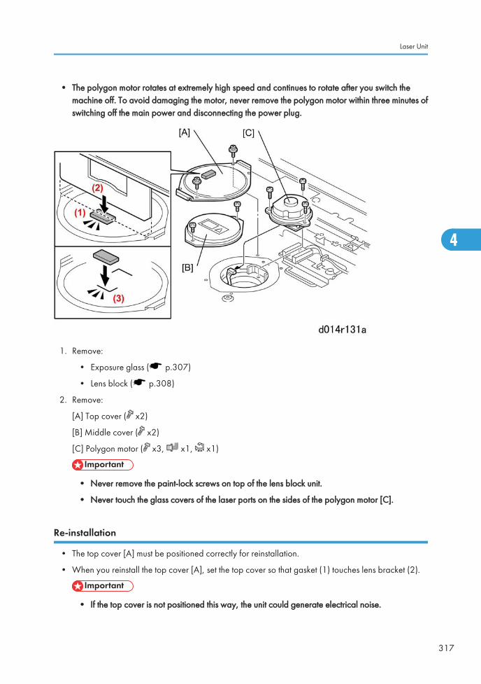
• The polygon motor rotates at extremely high speed and continues to rotate after you switch themachine off. To avoid damaging the motor, never remove the polygon motor within three minutes ofswitching off the main power and disconnecting the power plug.
1. Remove:
• Exposure glass ( p.307)
• Lens block ( p.308)
2. Remove:
[A] Top cover ( x2)
[B] Middle cover ( x2)
[C] Polygon motor ( x3, x1, x1)
• Never remove the paint-lock screws on top of the lens block unit.
• Never touch the glass covers of the laser ports on the sides of the polygon motor [C].
Re-installation
• The top cover [A] must be positioned correctly for reinstallation.
• When you reinstall the top cover [A], set the top cover so that gasket (1) touches lens bracket (2).
• If the top cover is not positioned this way, the unit could generate electrical noise.
Laser Unit
317
4
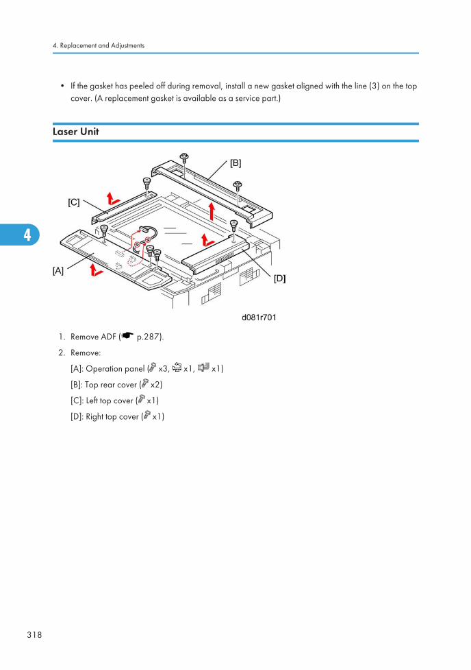
• If the gasket has peeled off during removal, install a new gasket aligned with the line (3) on the topcover. (A replacement gasket is available as a service part.)
Laser Unit
1. Remove ADF ( p.287).
2. Remove:
[A]: Operation panel ( x3, x1, x1)
[B]: Top rear cover ( x2)
[C]: Left top cover ( x1)
[D]: Right top cover ( x1)
4. Replacement and Adjustments
318
4
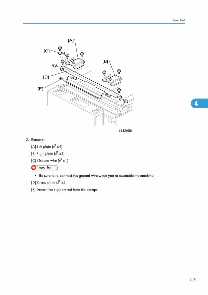
3. Remove:
[A] Left plate ( x4)
[B] Right plate ( x4)
[C] Ground wire ( x1)
• Be sure to re-connect this ground wire when you re-assemble the machine.
[D] Cross piece ( x4)
[E] Detach the support rod from the clamps.
Laser Unit
319
4
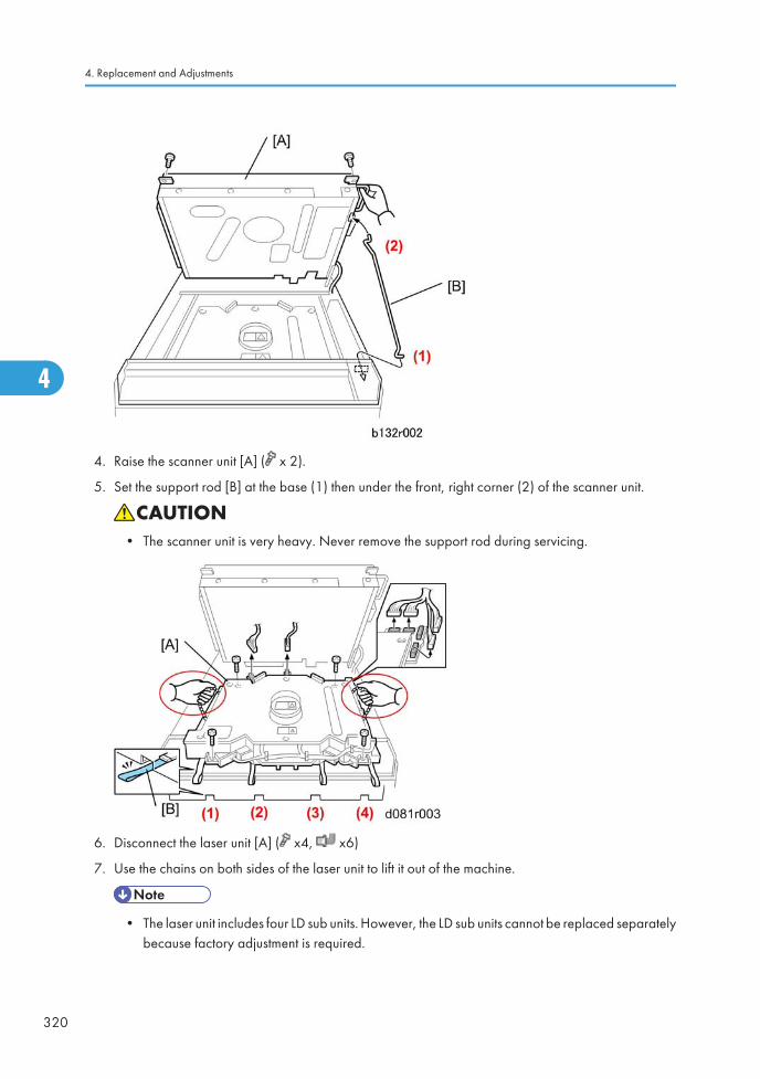
4. Raise the scanner unit [A] ( x 2).
5. Set the support rod [B] at the base (1) then under the front, right corner (2) of the scanner unit.
• The scanner unit is very heavy. Never remove the support rod during servicing.
6. Disconnect the laser unit [A] ( x4, x6)
7. Use the chains on both sides of the laser unit to lift it out of the machine.
• The laser unit includes four LD sub units. However, the LD sub units cannot be replaced separatelybecause factory adjustment is required.
4. Replacement and Adjustments
320
4
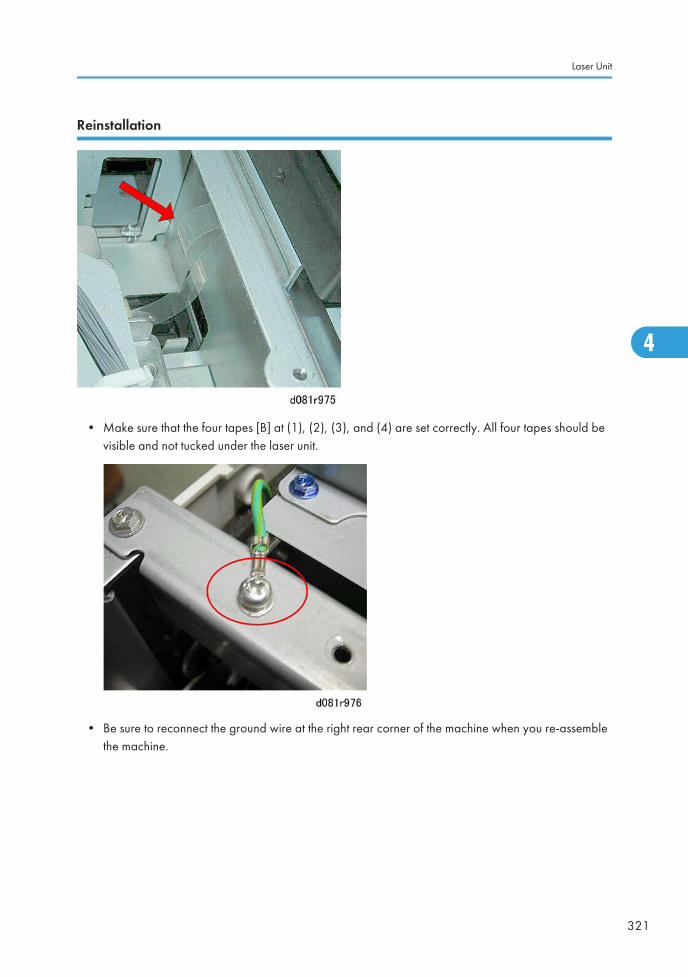
Reinstallation
• Make sure that the four tapes [B] at (1), (2), (3), and (4) are set correctly. All four tapes should bevisible and not tucked under the laser unit.
• Be sure to reconnect the ground wire at the right rear corner of the machine when you re-assemblethe machine.
Laser Unit
321
4
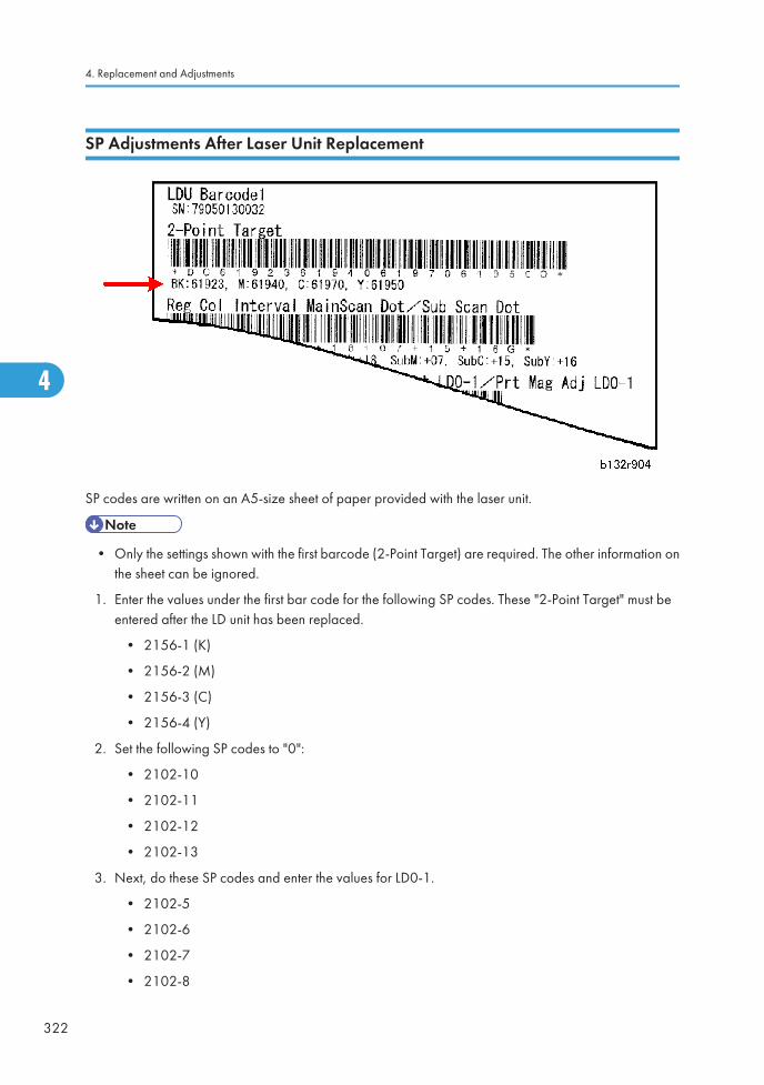
SP Adjustments After Laser Unit Replacement
SP codes are written on an A5-size sheet of paper provided with the laser unit.
• Only the settings shown with the first barcode (2-Point Target) are required. The other information onthe sheet can be ignored.
1. Enter the values under the first bar code for the following SP codes. These "2-Point Target" must beentered after the LD unit has been replaced.
• 2156-1 (K)
• 2156-2 (M)
• 2156-3 (C)
• 2156-4 (Y)
2. Set the following SP codes to "0":
• 2102-10
• 2102-11
• 2102-12
• 2102-13
3. Next, do these SP codes and enter the values for LD0-1.
• 2102-5
• 2102-6
• 2102-7
• 2102-8
4. Replacement and Adjustments
322
4
4. Do SP2109-014, select Pattern 14, and print a test pattern. ( >Printing Test Patterns)
Color Registration Errors
• In addition to the SP adjustments printed on the seal attached to the LD unit, if color registration errorsoccur immediately after you change the laser unit, an additional adjustment is required.
• This additional adjustment is normally not required in the field. Do it only if you see color registrationerrors in test prints.
• See "Color Registration Test and Error Adjustment" in p.511 "Color Registration" for instructions onhow to do this adjustment.
Skew
• If skew occurs immediately after you change the laser unit, do the skew adjustment. (See p.512 "SkewAdjustment After Laser Unit Replacement").
LD Unit
There is an LD unit for each color, and each LD unit uses a two-beam system. A photo diode (PD) in eachLD unit detects the light emitted from the LD unit. The output of the PD is fed back to the LD control board.The LD control board uses this information to control the amount of light to make sure that it remains at thecorrect level.
Dual Beam Writing
In each LD unit, two beams move across the drum in the main scan direction.
The use of two beams:
• Makes the machine print faster.
• Reduces the number of turns of the polygon mirror for a page to prolong the service life of the motor.
• Reduces the amount motor noise.
The beam pitch is fixed at 600 dpi and is not adjustable.
LD Safety Switches
To ensure the safety of customers and customer engineers, two switches inside the cover prevent the laserbeams from switching on accidentally. When the front cover is open, the +5V line connecting each LDdriver on the LD control board is disconnected.
Laser Unit
323
4
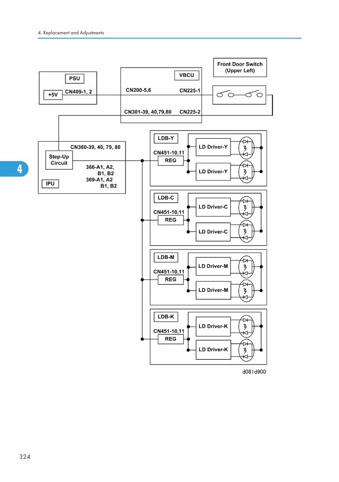
4. Replacement and Adjustments
324
4
PCU
Before You Begin
The items that are replaced determine which SP codes must be done after the machine is re-assembled andturned on. Here are some important rules that you should follow.
1. Initialize the TD sensor only once with SP3801-1 to -6.
• Never initialize the TD sensor more than once. Initializing the TD sensor more than once cancause toner scatter inside the machine.
2. If you replace the developer for one or more colors, do the developer set up for each color asdescribed in this section.
3. Initialize the TD sensor only at the following times:
• At installation, exactly as explained in the installation procedure.
• After you replace developer (only initialize the TD sensor for the color that you replaced) asinstructed below.
Here is a summary of the important differences between SP3801 001-006 (Init TD sensor) andSP3811 001-006 (Dev Setup Exe):
• SP3801 001-006 (Init TD sensor) only initializes the TD sensor.
• SP3811 001-006 (Dev Setup Exe) initializes the TD sensor and sends toner to the sub hopperof each PCU. This covers the PCU drum with a layer of toner. Covering the drum with tonerprevents the cleaning blades from scratching or bending the drums.
• SP3811 is necessary only at installation or in a replacement procedure when both the developerand cleaning blade are replaced together. If you use SP3811 for any other procedure, the tonersent to the PCU is wasted.
Charge Units
The procedure for removing the drum charge components in the K PCU and YMC PCUs is different.
• The YMC PCUs use a charge roller to charge the OPC drum.
• The K PCU uses a charge wire unit to charge the OPC drum.
Preparation
1. Remove the PCU stand from the bottom of the machine.
PCU
325
4
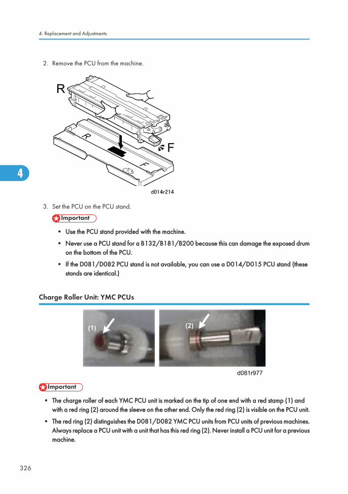
2. Remove the PCU from the machine.
3. Set the PCU on the PCU stand.
• Use the PCU stand provided with the machine.
• Never use a PCU stand for a B132/B181/B200 because this can damage the exposed drumon the bottom of the PCU.
• If the D081/D082 PCU stand is not available, you can use a D014/D015 PCU stand (thesestands are identical.)
Charge Roller Unit: YMC PCUs
• The charge roller of each YMC PCU unit is marked on the tip of one end with a red stamp (1) andwith a red ring (2) around the sleeve on the other end. Only the red ring (2) is visible on the PCU unit.
• The red ring (2) distinguishes the D081/D082 YMC PCU units from PCU units of previous machines.Always replace a PCU unit with a unit that has this red ring (2). Never install a PCU unit for a previousmachine.
4. Replacement and Adjustments
326
4
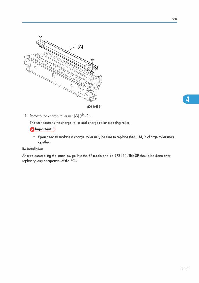
1. Remove the charge roller unit [A] ( x2).
This unit contains the charge roller and charge roller cleaning roller.
• If you need to replace a charge roller unit, be sure to replace the C, M, Y charge roller unitstogether.
Re-installation
After re-assembling the machine, go into the SP mode and do SP2111. This SP should be done afterreplacing any component of the PCU.
PCU
327
4
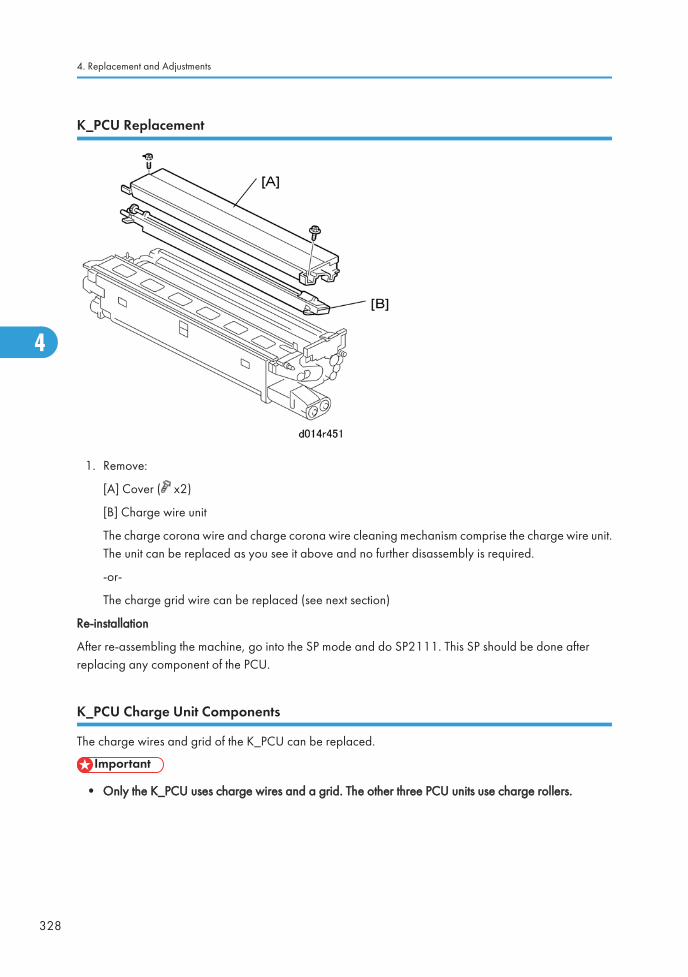
K_PCU Replacement
1. Remove:
[A] Cover ( x2)
[B] Charge wire unit
The charge corona wire and charge corona wire cleaning mechanism comprise the charge wire unit.The unit can be replaced as you see it above and no further disassembly is required.
-or-
The charge grid wire can be replaced (see next section)
Re-installation
After re-assembling the machine, go into the SP mode and do SP2111. This SP should be done afterreplacing any component of the PCU.
K_PCU Charge Unit Components
The charge wires and grid of the K_PCU can be replaced.
• Only the K_PCU uses charge wires and a grid. The other three PCU units use charge rollers.
4. Replacement and Adjustments
328
4
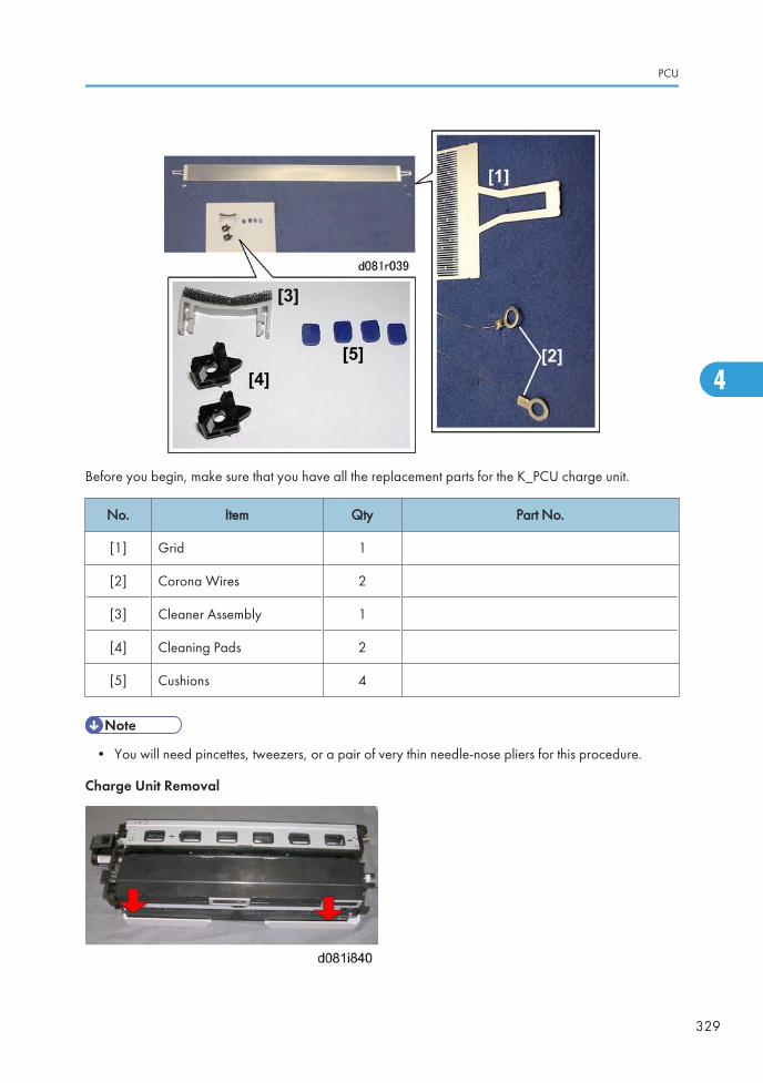
Before you begin, make sure that you have all the replacement parts for the K_PCU charge unit.
No. Item Qty Part No.
[1] Grid 1
[2] Corona Wires 2
[3] Cleaner Assembly 1
[4] Cleaning Pads 2
[5] Cushions 4
• You will need pincettes, tweezers, or a pair of very thin needle-nose pliers for this procedure.
Charge Unit Removal
PCU
329
4
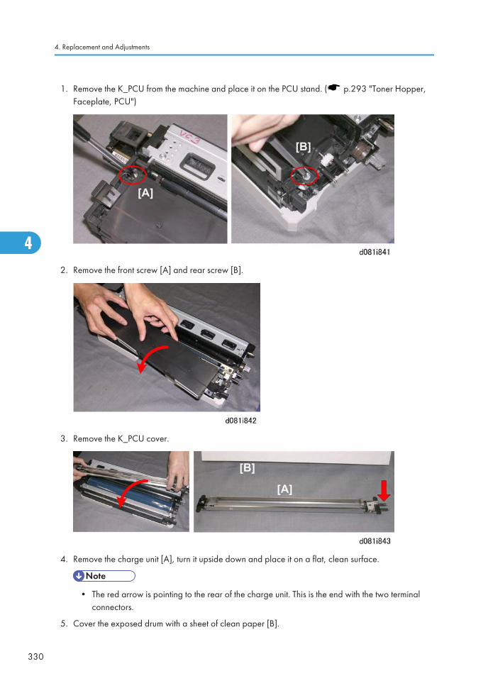
1. Remove the K_PCU from the machine and place it on the PCU stand. ( p.293 "Toner Hopper,Faceplate, PCU")
2. Remove the front screw [A] and rear screw [B].
3. Remove the K_PCU cover.
4. Remove the charge unit [A], turn it upside down and place it on a flat, clean surface.
• The red arrow is pointing to the rear of the charge unit. This is the end with the two terminalconnectors.
5. Cover the exposed drum with a sheet of clean paper [B].
4. Replacement and Adjustments
330
4
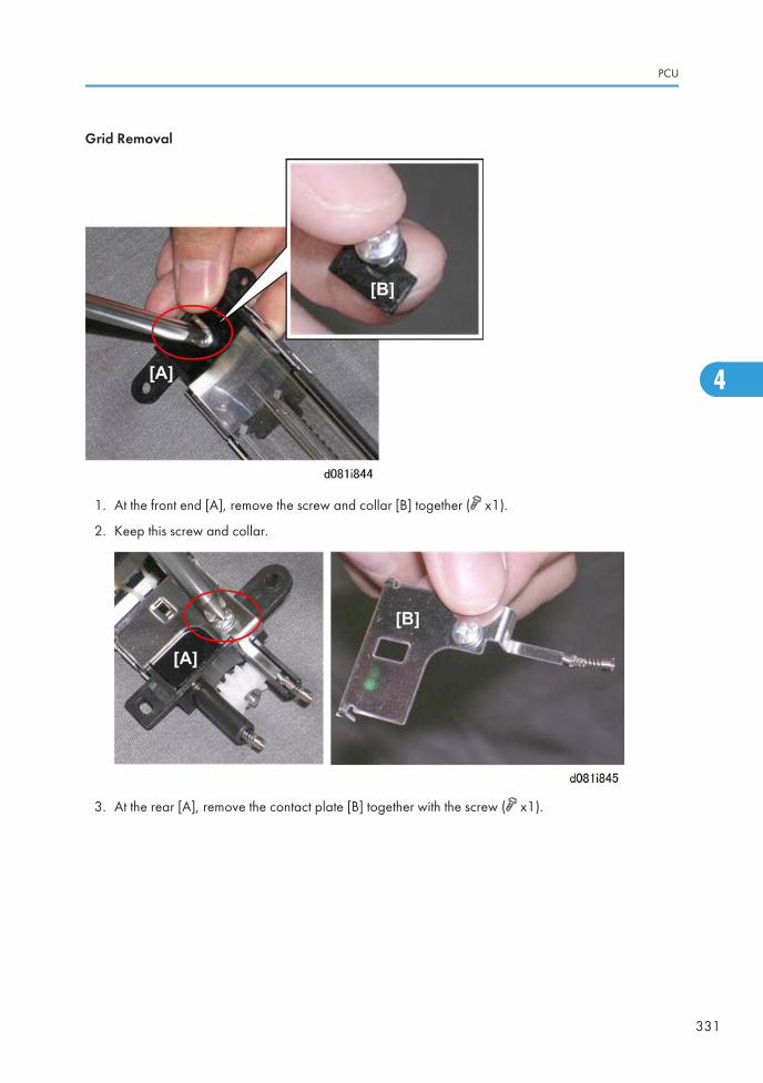
Grid Removal
1. At the front end [A], remove the screw and collar [B] together ( x1).
2. Keep this screw and collar.
3. At the rear [A], remove the contact plate [B] together with the screw ( x1).
PCU
331
4
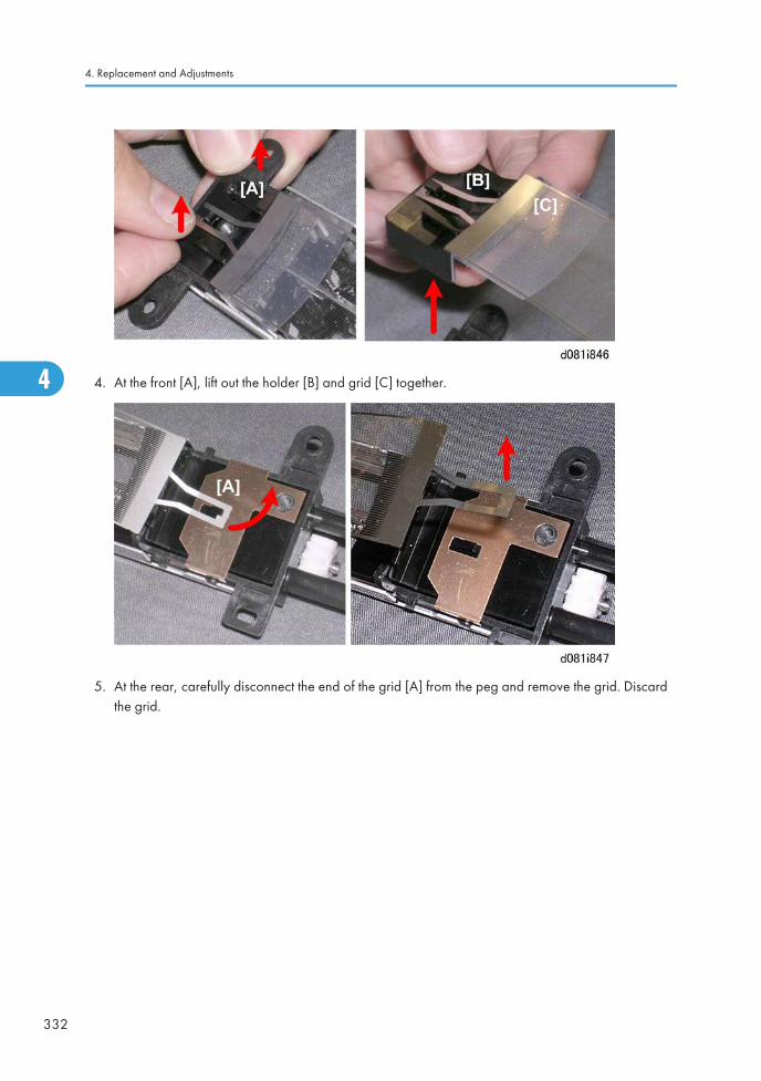
4. At the front [A], lift out the holder [B] and grid [C] together.
5. At the rear, carefully disconnect the end of the grid [A] from the peg and remove the grid. Discardthe grid.
4. Replacement and Adjustments
332
4
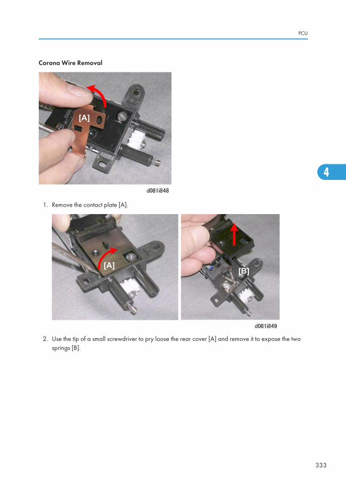
Corona Wire Removal
1. Remove the contact plate [A].
2. Use the tip of a small screwdriver to pry loose the rear cover [A] and remove it to expose the twosprings [B].
PCU
333
4
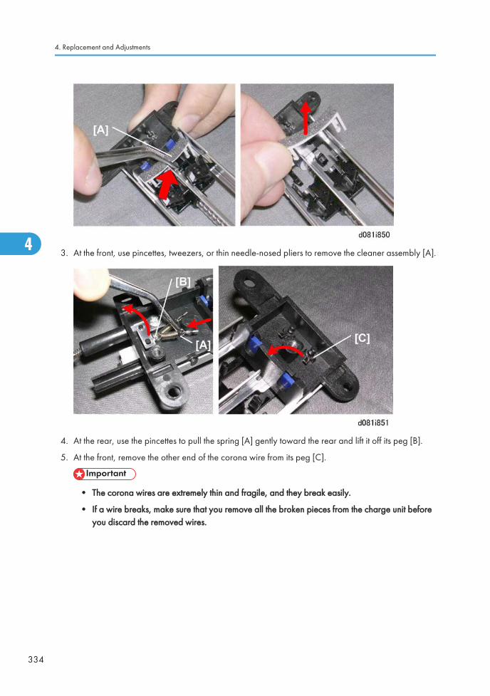
3. At the front, use pincettes, tweezers, or thin needle-nosed pliers to remove the cleaner assembly [A].
4. At the rear, use the pincettes to pull the spring [A] gently toward the rear and lift it off its peg [B].
5. At the front, remove the other end of the corona wire from its peg [C].
• The corona wires are extremely thin and fragile, and they break easily.
• If a wire breaks, make sure that you remove all the broken pieces from the charge unit beforeyou discard the removed wires.
4. Replacement and Adjustments
334
4
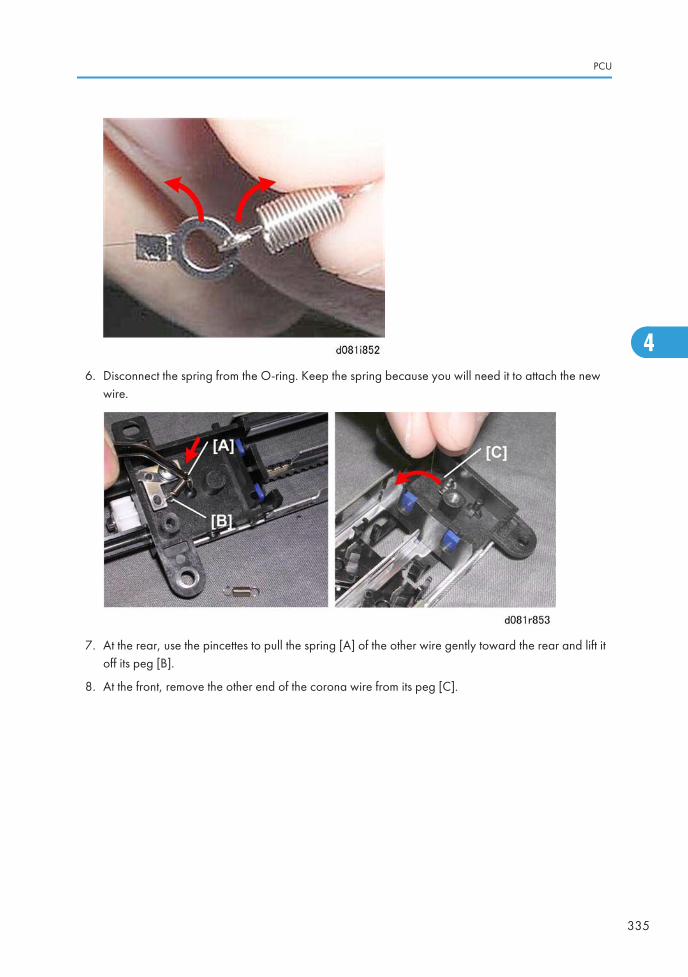
6. Disconnect the spring from the O-ring. Keep the spring because you will need it to attach the newwire.
7. At the rear, use the pincettes to pull the spring [A] of the other wire gently toward the rear and lift itoff its peg [B].
8. At the front, remove the other end of the corona wire from its peg [C].
PCU
335
4
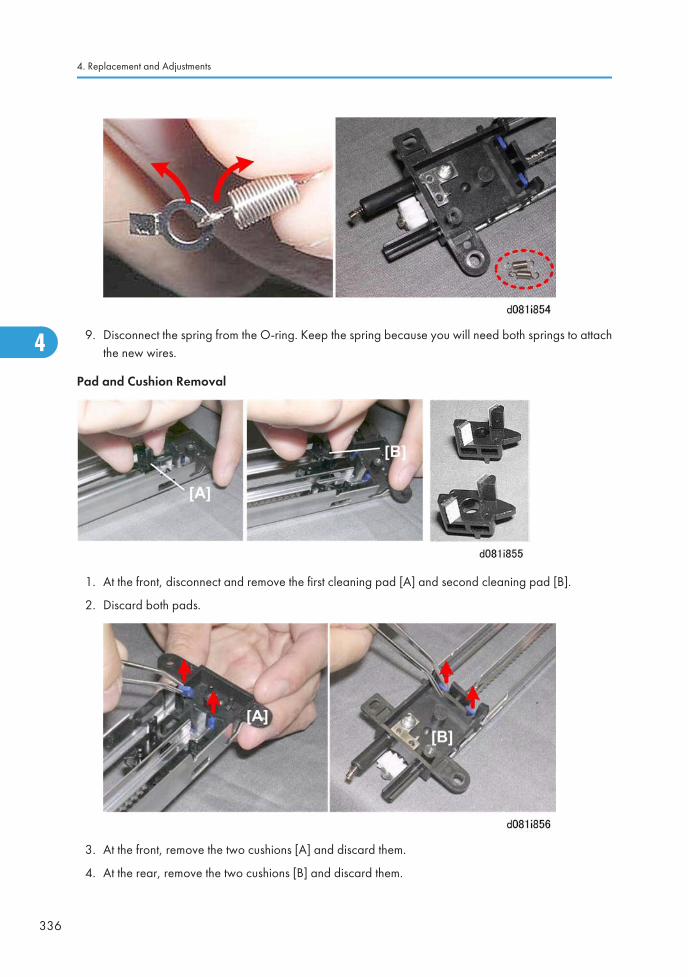
9. Disconnect the spring from the O-ring. Keep the spring because you will need both springs to attachthe new wires.
Pad and Cushion Removal
1. At the front, disconnect and remove the first cleaning pad [A] and second cleaning pad [B].
2. Discard both pads.
3. At the front, remove the two cushions [A] and discard them.
4. At the rear, remove the two cushions [B] and discard them.
4. Replacement and Adjustments
336
4
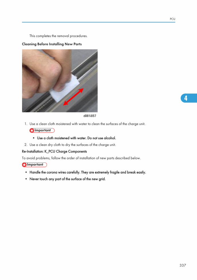
This completes the removal procedures.
Cleaning Before Installing New Parts
1. Use a clean cloth moistened with water to clean the surfaces of the charge unit.
• Use a cloth moistened with water. Do not use alcohol.
2. Use a clean dry cloth to dry the surfaces of the charge unit.
Re-Installation: K_PCU Charge Components
To avoid problems, follow the order of installation of new parts described below.
• Handle the corona wires carefully. They are extremely fragile and break easily.
• Never touch any part of the surface of the new grid.
PCU
337
4
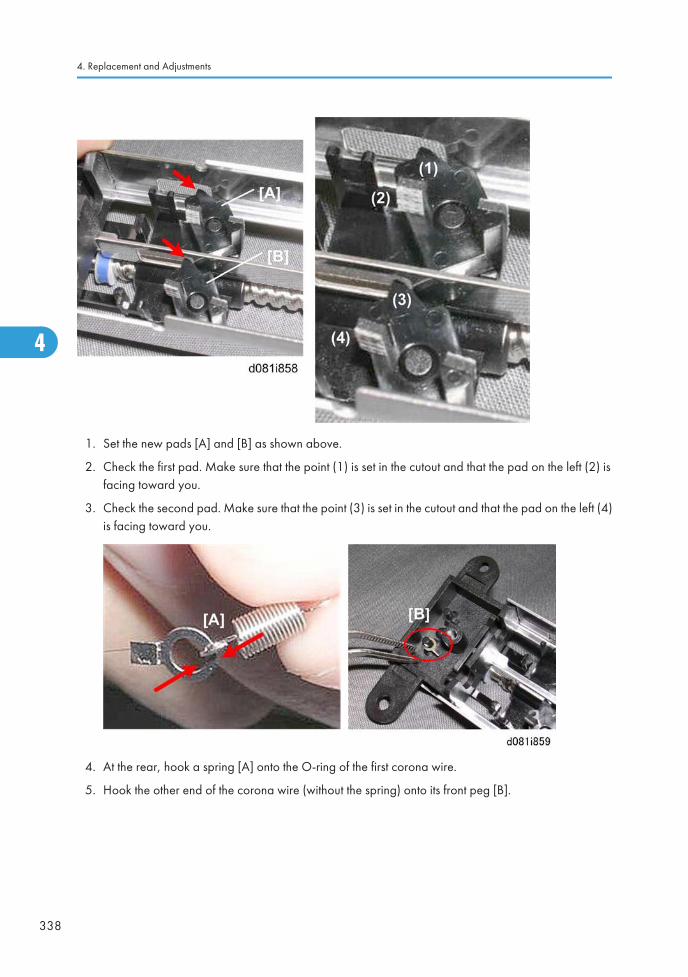
1. Set the new pads [A] and [B] as shown above.
2. Check the first pad. Make sure that the point (1) is set in the cutout and that the pad on the left (2) isfacing toward you.
3. Check the second pad. Make sure that the point (3) is set in the cutout and that the pad on the left (4)is facing toward you.
4. At the rear, hook a spring [A] onto the O-ring of the first corona wire.
5. Hook the other end of the corona wire (without the spring) onto its front peg [B].
4. Replacement and Adjustments
338
4
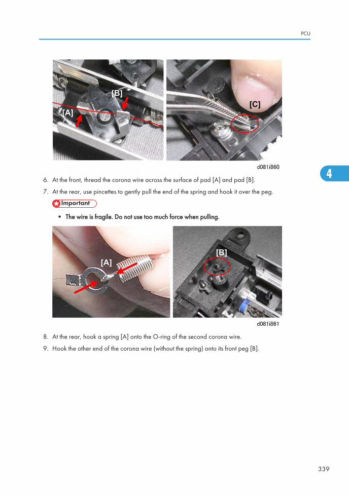
6. At the front, thread the corona wire across the surface of pad [A] and pad [B].
7. At the rear, use pincettes to gently pull the end of the spring and hook it over the peg.
• The wire is fragile. Do not use too much force when pulling.
8. At the rear, hook a spring [A] onto the O-ring of the second corona wire.
9. Hook the other end of the corona wire (without the spring) onto its front peg [B].
PCU
339
4

10. At the front, thread the corona wire across the surface of pad [A] and pad [B].
11. At the rear, use pincettes to gently pull the end of the spring and hook it over the peg.
• The wire is fragile. Do not use too much force when pulling.
12. Double-check both pads [A] and confirm that both wires are arranged correctly as shown above.
13. Make sure both springs [B] are securely attached at the rear.
4. Replacement and Adjustments
340
4
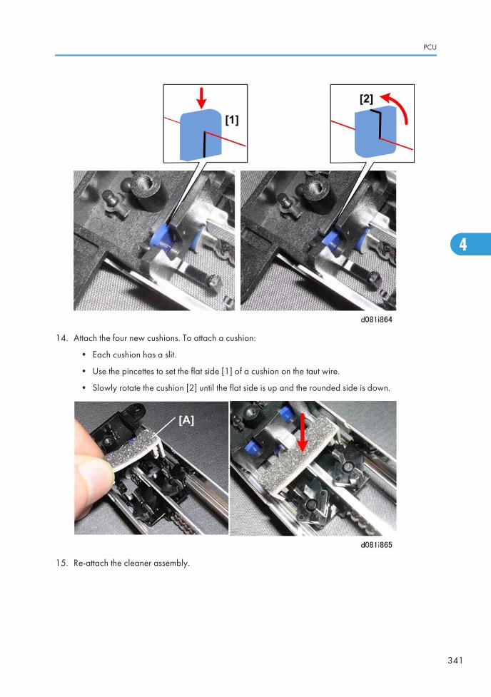
14. Attach the four new cushions. To attach a cushion:
• Each cushion has a slit.
• Use the pincettes to set the flat side [1] of a cushion on the taut wire.
• Slowly rotate the cushion [2] until the flat side is up and the rounded side is down.
15. Re-attach the cleaner assembly.
PCU
341
4
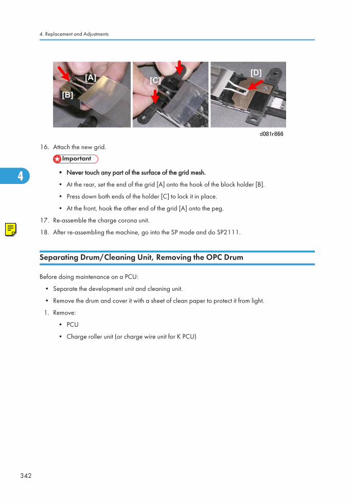
16. Attach the new grid.
• Never touch any part of the surface of the grid mesh.
• At the rear, set the end of the grid [A] onto the hook of the block holder [B].
• Press down both ends of the holder [C] to lock it in place.
• At the front, hook the other end of the grid [A] onto the peg.
17. Re-assemble the charge corona unit.
18. After re-assembling the machine, go into the SP mode and do SP2111.
Separating Drum/Cleaning Unit, Removing the OPC Drum
Before doing maintenance on a PCU:
• Separate the development unit and cleaning unit.
• Remove the drum and cover it with a sheet of clean paper to protect it from light.
1. Remove:
• PCU
• Charge roller unit (or charge wire unit for K PCU)
4. Replacement and Adjustments
342
4
O'Brien
RTB 26 After replacing the grid and/or corona wire, also do SP 2222-1 to test the components.
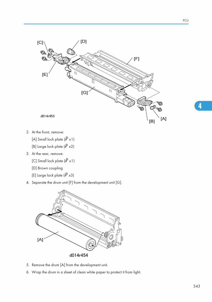
2. At the front, remove:
[A] Small lock plate ( x1)
[B] Large lock plate ( x2)
3. At the rear, remove:
[C] Small lock plate ( x1)
[D] Brown coupling
[E] Large lock plate ( x3)
4. Separate the drum unit [F] from the development unit [G].
5. Remove the drum [A] from the development unit.
6. Wrap the drum in a sheet of clean white paper to protect it from light.
PCU
343
4

Re-installation of the Drum
This procedure is the same for the YMC PCUs and the K PCU.
• Always dust the surface of a new drum before you install it.
• If you have removed the drum and intend to re-install the same drum, the surface of this drum shouldbe dusted as well.
Before you begin…
• Make sure that you have the correct type of dusting powder for the drum. Use only Lubricant PowderB1329700 (specially designed for this machine).
• Never use Setting Powder 54429101 because it could damage the drum and charge roller.
• Never use the yellow toner of the D081/D082 or D014/D015 copiers because it containsdeveloper that could damage the drum and ITB.
To dust the drum:
1. Spread a small amount of lubricant powder on a clean sheet of paper.
2. Dip a clean, dry cloth into the lubricant powder.
3. Dust the surface of the drum with the cloth until the entire surface is covered.
4. When you reinstall the drum:
• Reinstall the front end of the drum first.
• Never rotate the drum manually after reinstalling it.
Reinstallation: Drum
1. After re-installation, turn the machine on and do the appropriate SP settings, based on what wasreplaced.
4. Replacement and Adjustments
344
4
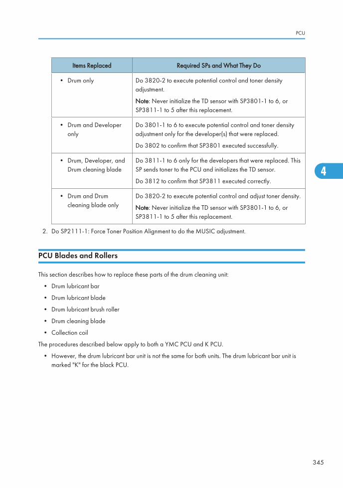
Items Replaced Required SPs and What They Do
• Drum only Do 3820-2 to execute potential control and toner densityadjustment.
Note: Never initialize the TD sensor with SP3801-1 to 6, orSP3811-1 to 5 after this replacement.
• Drum and Developeronly
Do 3801-1 to 6 to execute potential control and toner densityadjustment only for the developer(s) that were replaced.
Do 3802 to confirm that SP3801 executed successfully.
• Drum, Developer, andDrum cleaning blade
Do 3811-1 to 6 only for the developers that were replaced. ThisSP sends toner to the PCU and initializes the TD sensor.
Do 3812 to confirm that SP3811 executed correctly.
• Drum and Drumcleaning blade only
Do 3820-2 to execute potential control and adjust toner density.
Note: Never initialize the TD sensor with SP3801-1 to 6, orSP3811-1 to 5 after this replacement.
2. Do SP2111-1: Force Toner Position Alignment to do the MUSIC adjustment.
PCU Blades and Rollers
This section describes how to replace these parts of the drum cleaning unit:
• Drum lubricant bar
• Drum lubricant blade
• Drum lubricant brush roller
• Drum cleaning blade
• Collection coil
The procedures described below apply to both a YMC PCU and K PCU.
• However, the drum lubricant bar unit is not the same for both units. The drum lubricant bar unit ismarked "K" for the black PCU.
PCU
345
4
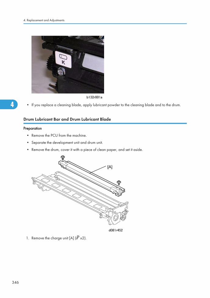
• If you replace a cleaning blade, apply lubricant powder to the cleaning blade and to the drum.
Drum Lubricant Bar and Drum Lubricant Blade
Preparation
• Remove the PCU from the machine.
• Separate the development unit and drum unit.
• Remove the drum, cover it with a piece of clean paper, and set it aside.
1. Remove the charge unit [A] ( x2).
4. Replacement and Adjustments
346
4

2. Remove the drum lubricant blade [A] ( x3).
3. Remove plastic cover [A] and metal stay [B] ( x2).
4. Remove the drum lubricant bar unit cover [C] ( x2).
PCU
347
4
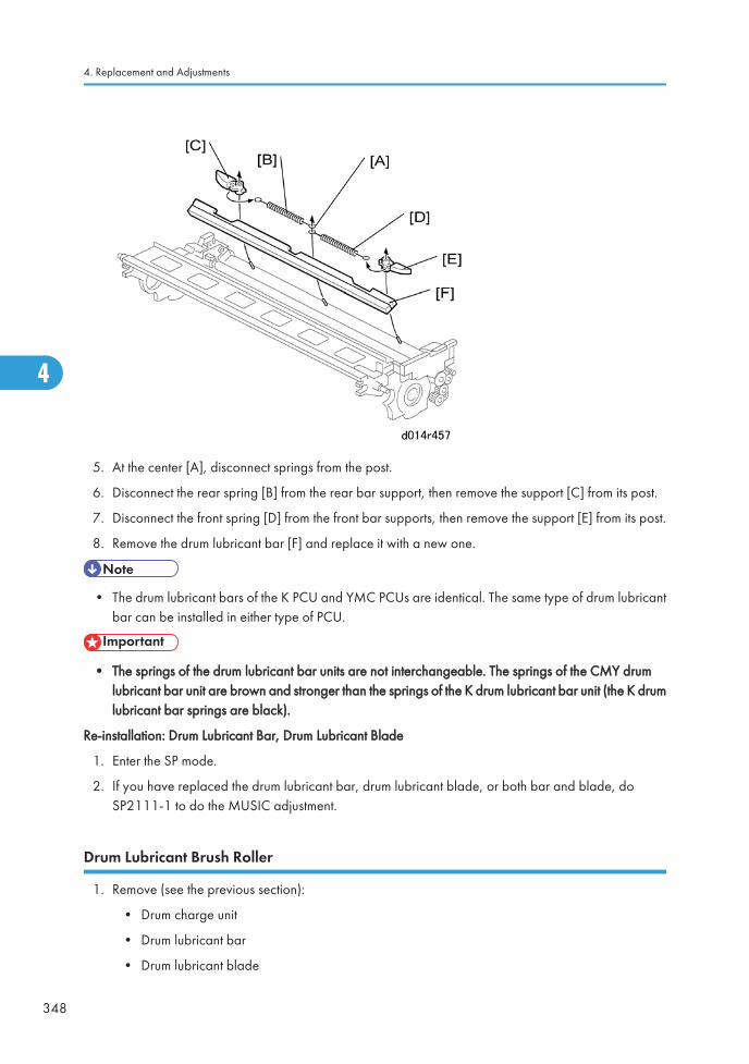
5. At the center [A], disconnect springs from the post.
6. Disconnect the rear spring [B] from the rear bar support, then remove the support [C] from its post.
7. Disconnect the front spring [D] from the front bar supports, then remove the support [E] from its post.
8. Remove the drum lubricant bar [F] and replace it with a new one.
• The drum lubricant bars of the K PCU and YMC PCUs are identical. The same type of drum lubricantbar can be installed in either type of PCU.
• The springs of the drum lubricant bar units are not interchangeable. The springs of the CMY drumlubricant bar unit are brown and stronger than the springs of the K drum lubricant bar unit (the K drumlubricant bar springs are black).
Re-installation: Drum Lubricant Bar, Drum Lubricant Blade
1. Enter the SP mode.
2. If you have replaced the drum lubricant bar, drum lubricant blade, or both bar and blade, doSP2111-1 to do the MUSIC adjustment.
Drum Lubricant Brush Roller
1. Remove (see the previous section):
• Drum charge unit
• Drum lubricant bar
• Drum lubricant blade
4. Replacement and Adjustments
348
4
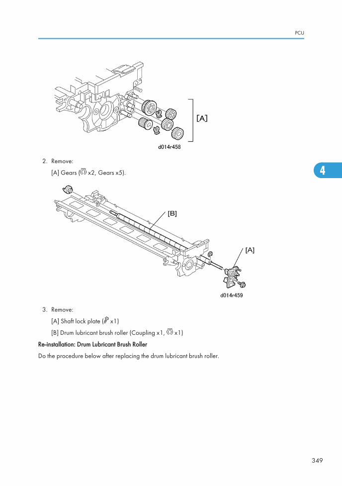
2. Remove:
[A] Gears ( x2, Gears x5).
3. Remove:
[A] Shaft lock plate ( x1)
[B] Drum lubricant brush roller (Coupling x1, x1)
Re-installation: Drum Lubricant Brush Roller
Do the procedure below after replacing the drum lubricant brush roller.
PCU
349
4

1. Place a sheet of clean paper on a flat surface.
2. Pour a small amount of G104 Yellow Toner (D0159500) [A] onto the paper.
3. Pour an equal amount of Zinc Stearate (D0159501) [B] into the yellow toner.
4. Mix the G104 Yellow Toner and Zinc Stearate together with your finger on the paper.
• Always use the G014 Yellow Toner, not the yellow toner of the D081/D082 or D014/D015.
• The D081/D082/D014/D015 yellow toner contains developer that could damage thesurface of the drum and ITB.
5. While rotating gear [A] in the direction of the arrow, use your finger to apply the mixture of yellowtoner and zinc stearate from the paper across the surface of the PCU drum lubricant brush roller [B].
• You must rotate gear [A] in the direction shown above.
• Use a brush to apply the mixture if one is available.
4. Replacement and Adjustments
350
4
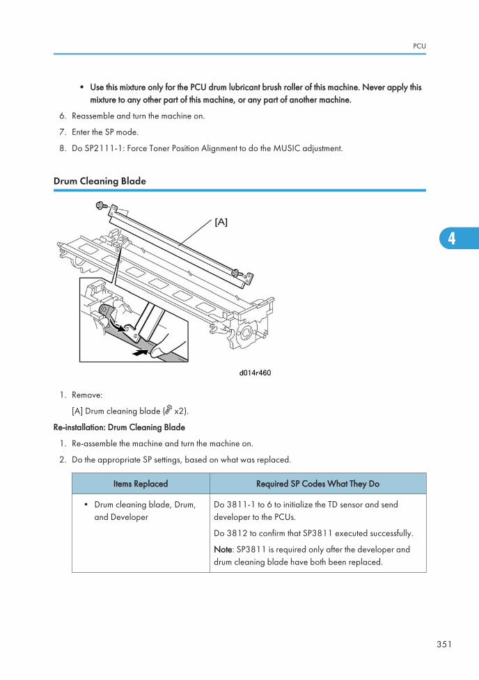
• Use this mixture only for the PCU drum lubricant brush roller of this machine. Never apply thismixture to any other part of this machine, or any part of another machine.
6. Reassemble and turn the machine on.
7. Enter the SP mode.
8. Do SP2111-1: Force Toner Position Alignment to do the MUSIC adjustment.
Drum Cleaning Blade
1. Remove:
[A] Drum cleaning blade ( x2).
Re-installation: Drum Cleaning Blade
1. Re-assemble the machine and turn the machine on.
2. Do the appropriate SP settings, based on what was replaced.
Items Replaced Required SP Codes What They Do
• Drum cleaning blade, Drum,and Developer
Do 3811-1 to 6 to initialize the TD sensor and senddeveloper to the PCUs.
Do 3812 to confirm that SP3811 executed successfully.
Note: SP3811 is required only after the developer anddrum cleaning blade have both been replaced.
PCU
351
4
Items Replaced Required SP Codes What They Do
• Drum cleaning blade and Drumonly
Do 3820-2 to execute potential control and toner densityadjustment.
Note: Never initialize the TD sensor with SP3801-1 to 6, orSP3811-1 to 5 after this replacement.
• Drum cleaning blade and/ordrum cleaning roller (withoutchanging the drum ordeveloper)
Do SP 3810.
3. Do SP2111-1: Force Toner Position Alignment to do the MUSIC adjustment.
Developer Replacement
The developer replacement procedure is the same for the YMC PCUs and the K PCU.
• Developer must be replaced for each PCU every 450K.
• However, developer can be replaced for only one PCU if a problem occurs. For example, the C_PCUcan be replaced if Cyan is too light.
Preparation
1. Spread some paper on a flat surface to hold developer that will be dumped from the developmentunit.
4. Replacement and Adjustments
352
4
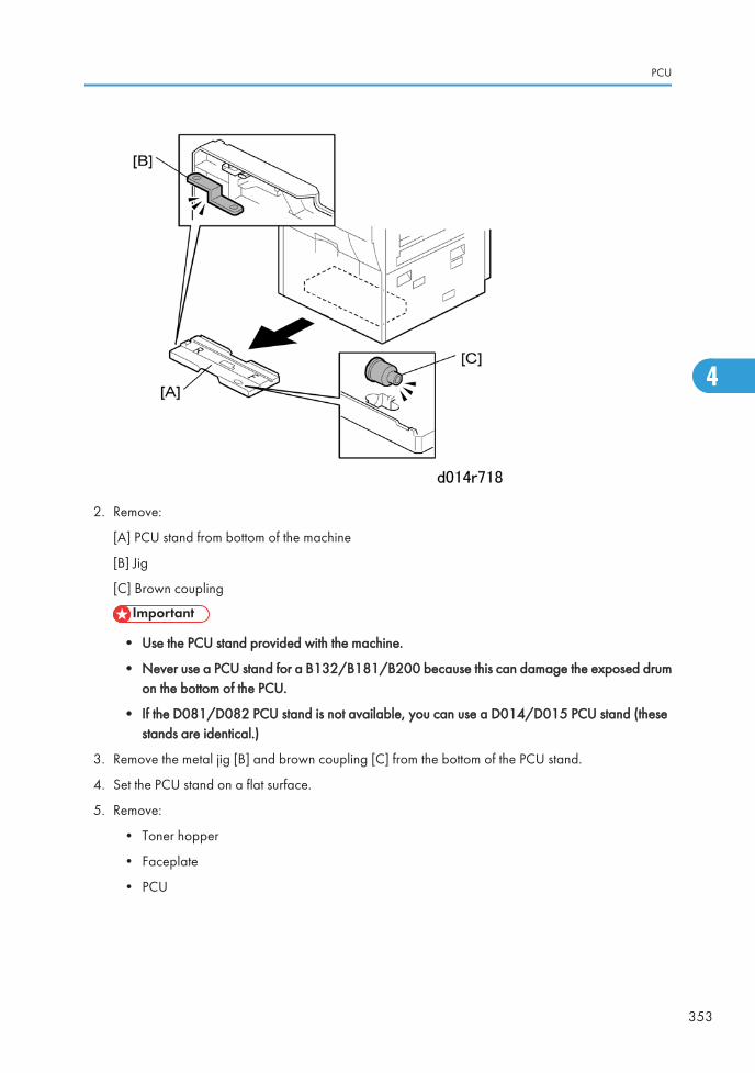
2. Remove:
[A] PCU stand from bottom of the machine
[B] Jig
[C] Brown coupling
• Use the PCU stand provided with the machine.
• Never use a PCU stand for a B132/B181/B200 because this can damage the exposed drumon the bottom of the PCU.
• If the D081/D082 PCU stand is not available, you can use a D014/D015 PCU stand (thesestands are identical.)
3. Remove the metal jig [B] and brown coupling [C] from the bottom of the PCU stand.
4. Set the PCU stand on a flat surface.
5. Remove:
• Toner hopper
• Faceplate
• PCU
PCU
353
4
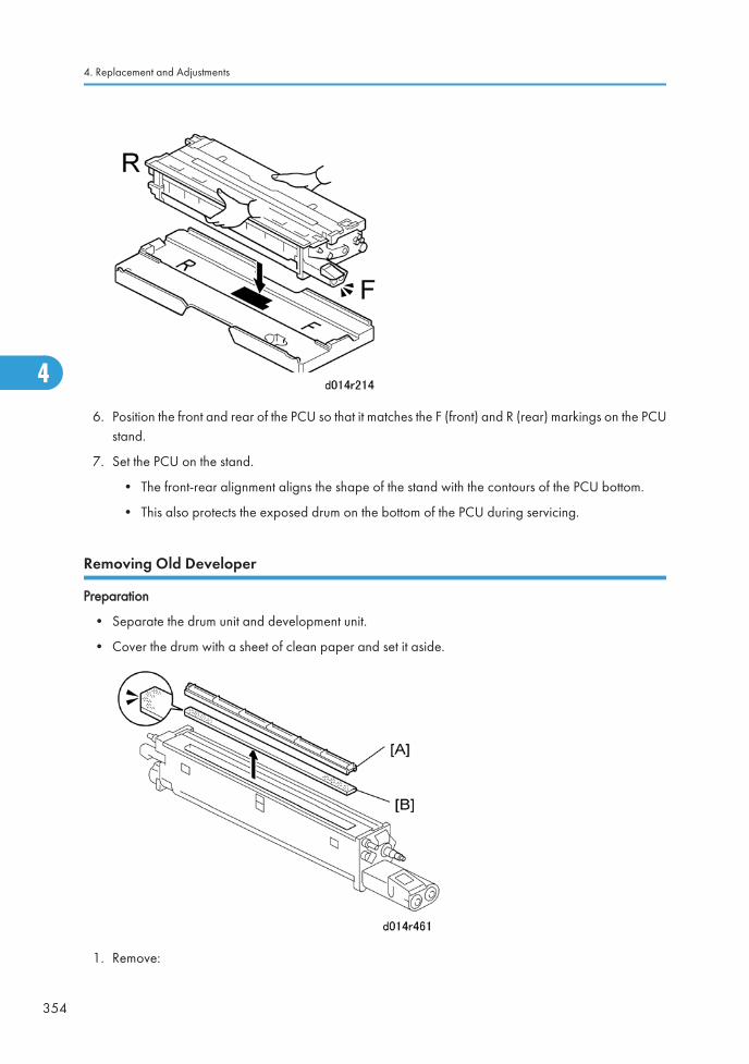
6. Position the front and rear of the PCU so that it matches the F (front) and R (rear) markings on the PCUstand.
7. Set the PCU on the stand.
• The front-rear alignment aligns the shape of the stand with the contours of the PCU bottom.
• This also protects the exposed drum on the bottom of the PCU during servicing.
Removing Old Developer
Preparation
• Separate the drum unit and development unit.
• Cover the drum with a sheet of clean paper and set it aside.
1. Remove:
4. Replacement and Adjustments
354
4
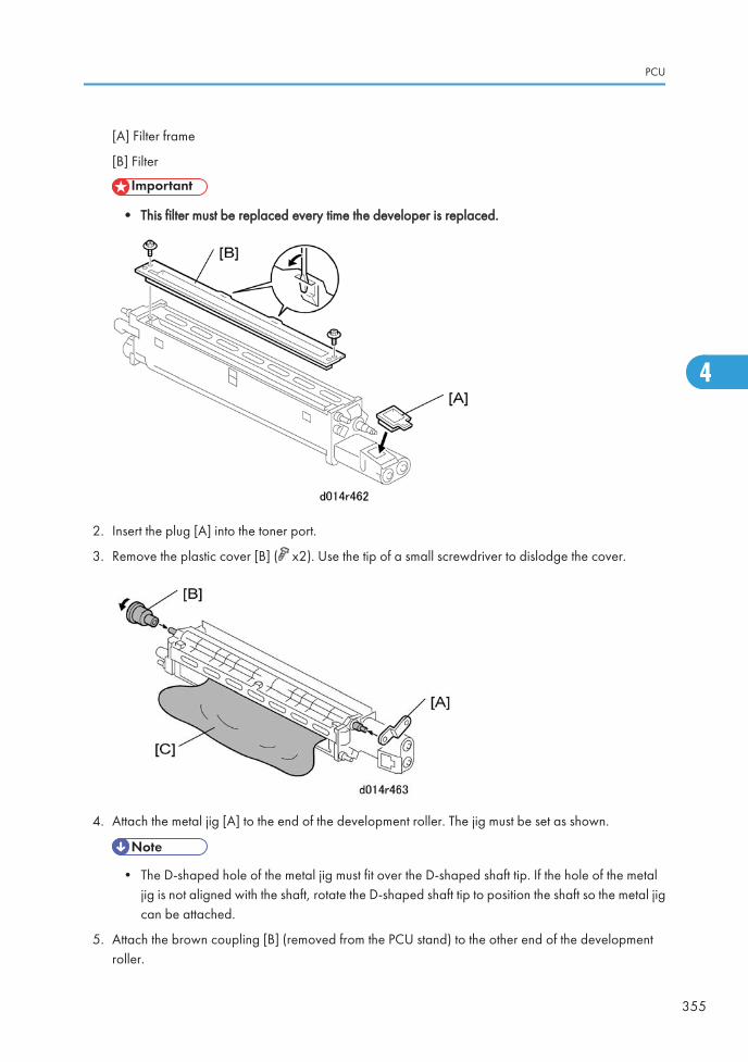
[A] Filter frame
[B] Filter
• This filter must be replaced every time the developer is replaced.
2. Insert the plug [A] into the toner port.
3. Remove the plastic cover [B] ( x2). Use the tip of a small screwdriver to dislodge the cover.
4. Attach the metal jig [A] to the end of the development roller. The jig must be set as shown.
• The D-shaped hole of the metal jig must fit over the D-shaped shaft tip. If the hole of the metaljig is not aligned with the shaft, rotate the D-shaped shaft tip to position the shaft so the metal jigcan be attached.
5. Attach the brown coupling [B] (removed from the PCU stand) to the other end of the developmentroller.
PCU
355
4
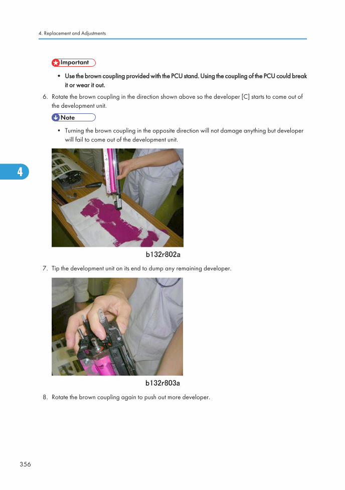
• Use the brown coupling provided with the PCU stand. Using the coupling of the PCU could breakit or wear it out.
6. Rotate the brown coupling in the direction shown above so the developer [C] starts to come out ofthe development unit.
• Turning the brown coupling in the opposite direction will not damage anything but developerwill fail to come out of the development unit.
7. Tip the development unit on its end to dump any remaining developer.
8. Rotate the brown coupling again to push out more developer.
4. Replacement and Adjustments
356
4
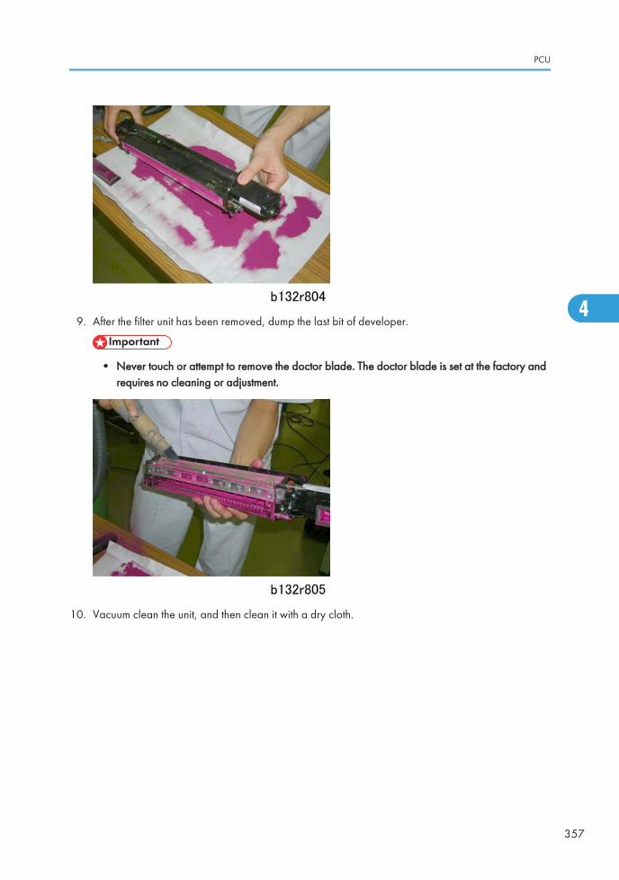
9. After the filter unit has been removed, dump the last bit of developer.
• Never touch or attempt to remove the doctor blade. The doctor blade is set at the factory andrequires no cleaning or adjustment.
10. Vacuum clean the unit, and then clean it with a dry cloth.
PCU
357
4
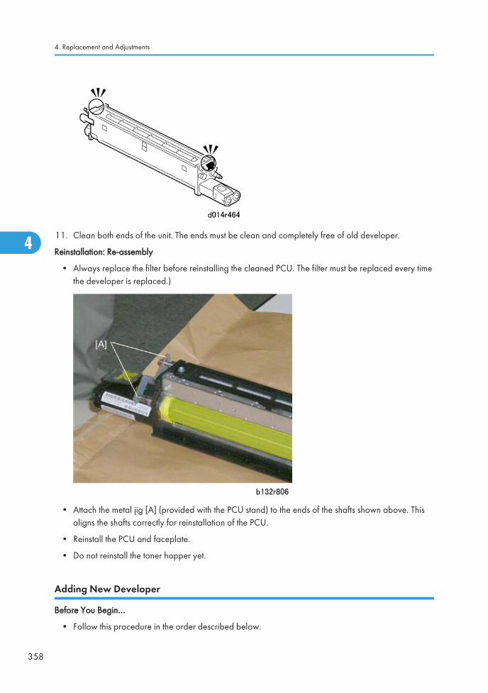
11. Clean both ends of the unit. The ends must be clean and completely free of old developer.
Reinstallation: Re-assembly
• Always replace the filter before reinstalling the cleaned PCU. The filter must be replaced every timethe developer is replaced.)
• Attach the metal jig [A] (provided with the PCU stand) to the ends of the shafts shown above. Thisaligns the shafts correctly for reinstallation of the PCU.
• Reinstall the PCU and faceplate.
• Do not reinstall the toner hopper yet.
Adding New Developer
Before You Begin…
• Follow this procedure in the order described below.
4. Replacement and Adjustments
358
4
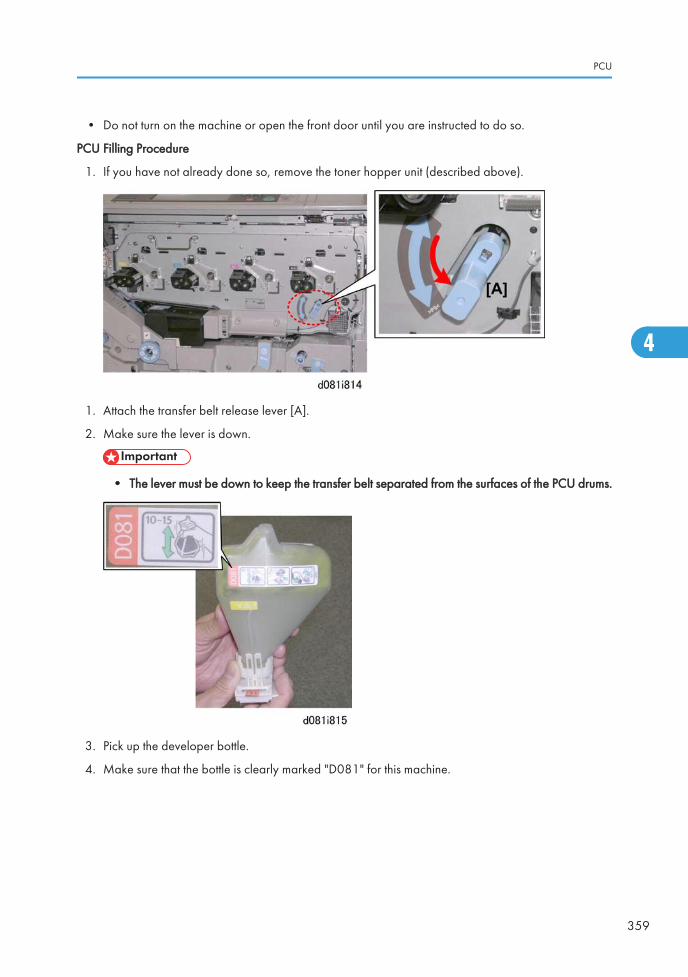
• Do not turn on the machine or open the front door until you are instructed to do so.
PCU Filling Procedure
1. If you have not already done so, remove the toner hopper unit (described above).
1. Attach the transfer belt release lever [A].
2. Make sure the lever is down.
• The lever must be down to keep the transfer belt separated from the surfaces of the PCU drums.
3. Pick up the developer bottle.
4. Make sure that the bottle is clearly marked "D081" for this machine.
PCU
359
4
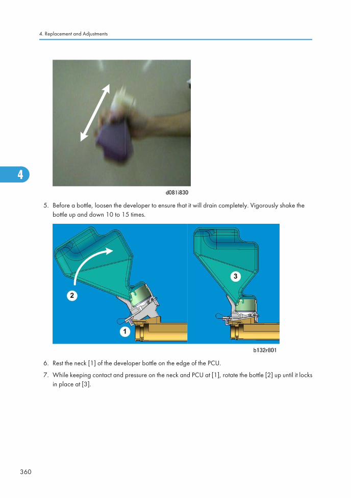
5. Before a bottle, loosen the developer to ensure that it will drain completely. Vigorously shake thebottle up and down 10 to 15 times.
6. Rest the neck [1] of the developer bottle on the edge of the PCU.
7. While keeping contact and pressure on the neck and PCU at [1], rotate the bottle [2] up until it locksin place at [3].
4. Replacement and Adjustments
360
4
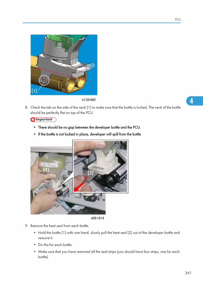
8. Check the tab on the side of the neck [1] to make sure that the bottle is locked. The neck of the bottleshould be perfectly flat on top of the PCU.
• There should be no gap between the developer bottle and the PCU.
• If the bottle is not locked in place, developer will spill from the bottle
9. Remove the heat seal from each bottle.
• Hold the bottle [1] with one hand, slowly pull the heat seal [2] out of the developer bottle andremove it.
• Do this for each bottle.
• Make sure that you have removed all the seal strips (you should have four strips, one for eachbottle).
PCU
361
4
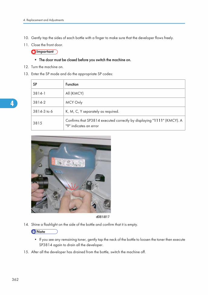
10. Gently tap the sides of each bottle with a finger to make sure that the developer flows freely.
11. Close the front door.
• The door must be closed before you switch the machine on.
12. Turn the machine on.
13. Enter the SP mode and do the appropriate SP codes:
SP Function
3814-1 All (KMCY)
3814-2 MCY Only
3814-3 to 6 K, M, C, Y separately as required.
3815Confirms that SP3814 executed correctly by displaying "1111" (KMCY). A"9" indicates an error
14. Shine a flashlight on the side of the bottle and confirm that it is empty.
• If you see any remaining toner, gently tap the neck of the bottle to loosen the toner then executeSP3814 again to drain all the developer.
15. After all the developer has drained from the bottle, switch the machine off.
4. Replacement and Adjustments
362
4
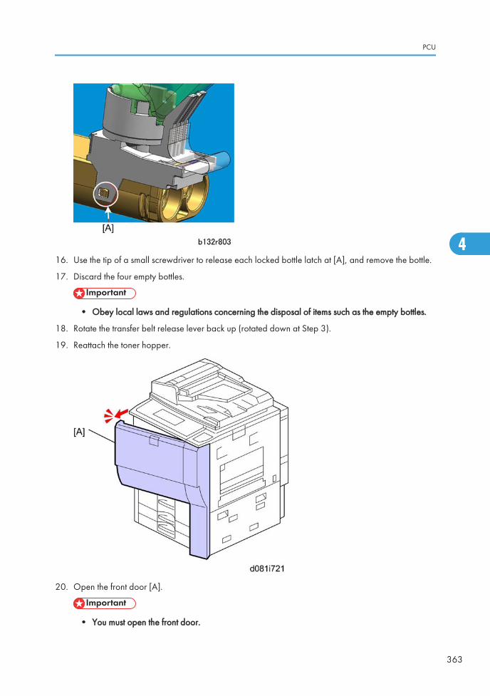
16. Use the tip of a small screwdriver to release each locked bottle latch at [A], and remove the bottle.
17. Discard the four empty bottles.
• Obey local laws and regulations concerning the disposal of items such as the empty bottles.
18. Rotate the transfer belt release lever back up (rotated down at Step 3).
19. Reattach the toner hopper.
20. Open the front door [A].
• You must open the front door.
PCU
363
4
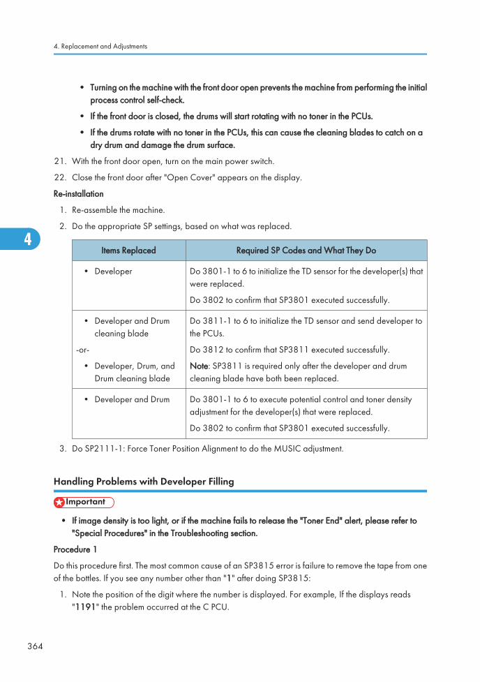
• Turning on the machine with the front door open prevents the machine from performing the initialprocess control self-check.
• If the front door is closed, the drums will start rotating with no toner in the PCUs.
• If the drums rotate with no toner in the PCUs, this can cause the cleaning blades to catch on adry drum and damage the drum surface.
21. With the front door open, turn on the main power switch.
22. Close the front door after "Open Cover" appears on the display.
Re-installation
1. Re-assemble the machine.
2. Do the appropriate SP settings, based on what was replaced.
Items Replaced Required SP Codes and What They Do
• Developer Do 3801-1 to 6 to initialize the TD sensor for the developer(s) thatwere replaced.
Do 3802 to confirm that SP3801 executed successfully.
• Developer and Drumcleaning blade
-or-
• Developer, Drum, andDrum cleaning blade
Do 3811-1 to 6 to initialize the TD sensor and send developer tothe PCUs.
Do 3812 to confirm that SP3811 executed successfully.
Note: SP3811 is required only after the developer and drumcleaning blade have both been replaced.
• Developer and Drum Do 3801-1 to 6 to execute potential control and toner densityadjustment for the developer(s) that were replaced.
Do 3802 to confirm that SP3801 executed successfully.
3. Do SP2111-1: Force Toner Position Alignment to do the MUSIC adjustment.
Handling Problems with Developer Filling
• If image density is too light, or if the machine fails to release the "Toner End" alert, please refer to"Special Procedures" in the Troubleshooting section.
Procedure 1
Do this procedure first. The most common cause of an SP3815 error is failure to remove the tape from oneof the bottles. If you see any number other than "1" after doing SP3815:
1. Note the position of the digit where the number is displayed. For example, If the displays reads"1191" the problem occurred at the C PCU.
4. Replacement and Adjustments
364
4
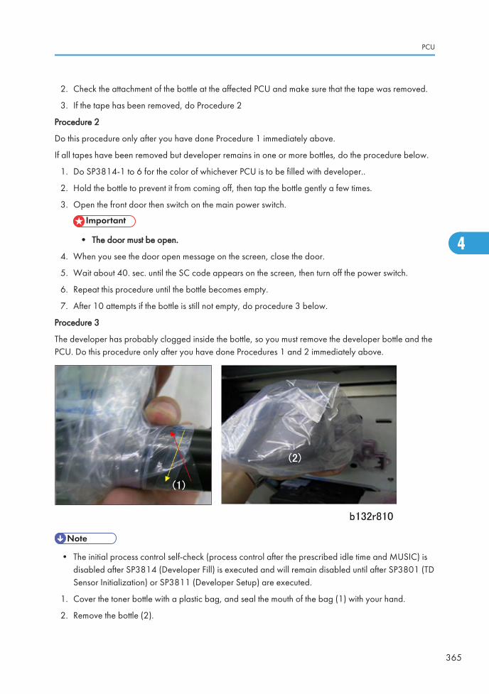
2. Check the attachment of the bottle at the affected PCU and make sure that the tape was removed.
3. If the tape has been removed, do Procedure 2
Procedure 2
Do this procedure only after you have done Procedure 1 immediately above.
If all tapes have been removed but developer remains in one or more bottles, do the procedure below.
1. Do SP3814-1 to 6 for the color of whichever PCU is to be filled with developer..
2. Hold the bottle to prevent it from coming off, then tap the bottle gently a few times.
3. Open the front door then switch on the main power switch.
• The door must be open.
4. When you see the door open message on the screen, close the door.
5. Wait about 40. sec. until the SC code appears on the screen, then turn off the power switch.
6. Repeat this procedure until the bottle becomes empty.
7. After 10 attempts if the bottle is still not empty, do procedure 3 below.
Procedure 3
The developer has probably clogged inside the bottle, so you must remove the developer bottle and thePCU. Do this procedure only after you have done Procedures 1 and 2 immediately above.
• The initial process control self-check (process control after the prescribed idle time and MUSIC) isdisabled after SP3814 (Developer Fill) is executed and will remain disabled until after SP3801 (TDSensor Initialization) or SP3811 (Developer Setup) are executed.
1. Cover the toner bottle with a plastic bag, and seal the mouth of the bag (1) with your hand.
2. Remove the bottle (2).
PCU
365
4
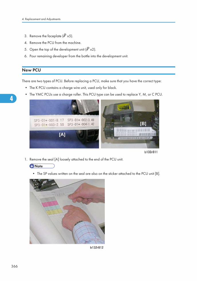
3. Remove the faceplate ( x5).
4. Remove the PCU from the machine.
5. Open the top of the development unit ( x2).
6. Pour remaining developer from the bottle into the development unit.
New PCU
There are two types of PCU. Before replacing a PCU, make sure that you have the correct type:
• The K PCU contains a charge wire unit, used only for black.
• The YMC PCUs use a charge roller. This PCU type can be used to replace Y, M, or C PCU.
1. Remove the seal [A] loosely attached to the end of the PCU unit.
• The SP values written on the seal are also on the sticker attached to the PCU unit [B].
4. Replacement and Adjustments
366
4
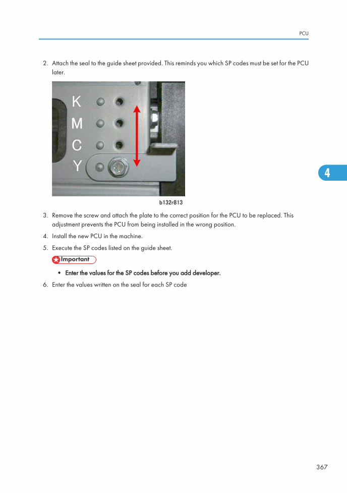
2. Attach the seal to the guide sheet provided. This reminds you which SP codes must be set for the PCUlater.
3. Remove the screw and attach the plate to the correct position for the PCU to be replaced. Thisadjustment prevents the PCU from being installed in the wrong position.
4. Install the new PCU in the machine.
5. Execute the SP codes listed on the guide sheet.
• Enter the values for the SP codes before you add developer.
6. Enter the values written on the seal for each SP code
PCU
367
4
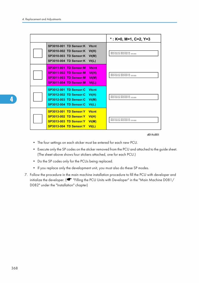
• The four settings on each sticker must be entered for each new PCU.
• Execute only the SP codes on the sticker removed from the PCU and attached to the guide sheet.(The sheet above shows four stickers attached, one for each PCU.)
• Do the SP codes only for the PCUs being replaced.
• If you replace only the development unit, you must also do these SP modes.
7. Follow the procedure in the main machine installation procedure to fill the PCU with developer andinitialize the developer. ( "Filling the PCU Units with Developer" in the "Main Machine D081/D082" under the "Installation" chapter)
4. Replacement and Adjustments
368
4
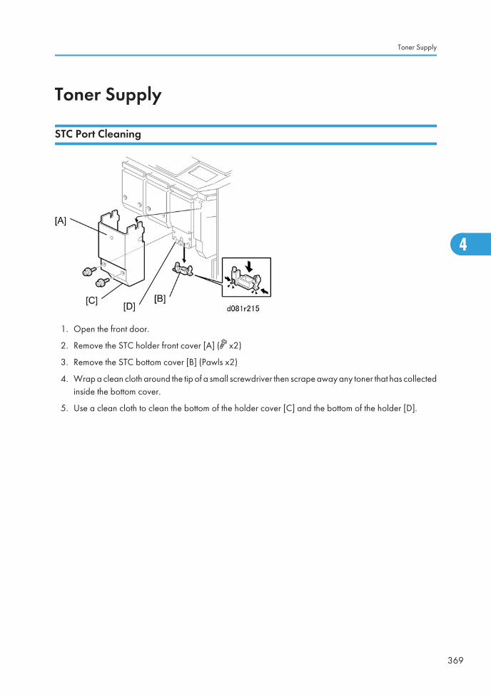
Toner Supply
STC Port Cleaning
1. Open the front door.
2. Remove the STC holder front cover [A] ( x2)
3. Remove the STC bottom cover [B] (Pawls x2)
4. Wrap a clean cloth around the tip of a small screwdriver then scrape away any toner that has collectedinside the bottom cover.
5. Use a clean cloth to clean the bottom of the holder cover [C] and the bottom of the holder [D].
Toner Supply
369
4
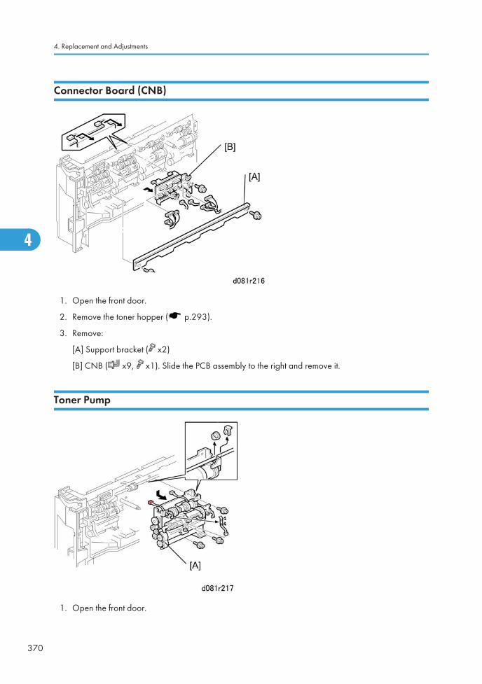
Connector Board (CNB)
1. Open the front door.
2. Remove the toner hopper ( p.293).
3. Remove:
[A] Support bracket ( x2)
[B] CNB ( x9, x1). Slide the PCB assembly to the right and remove it.
Toner Pump
1. Open the front door.
4. Replacement and Adjustments
370
4
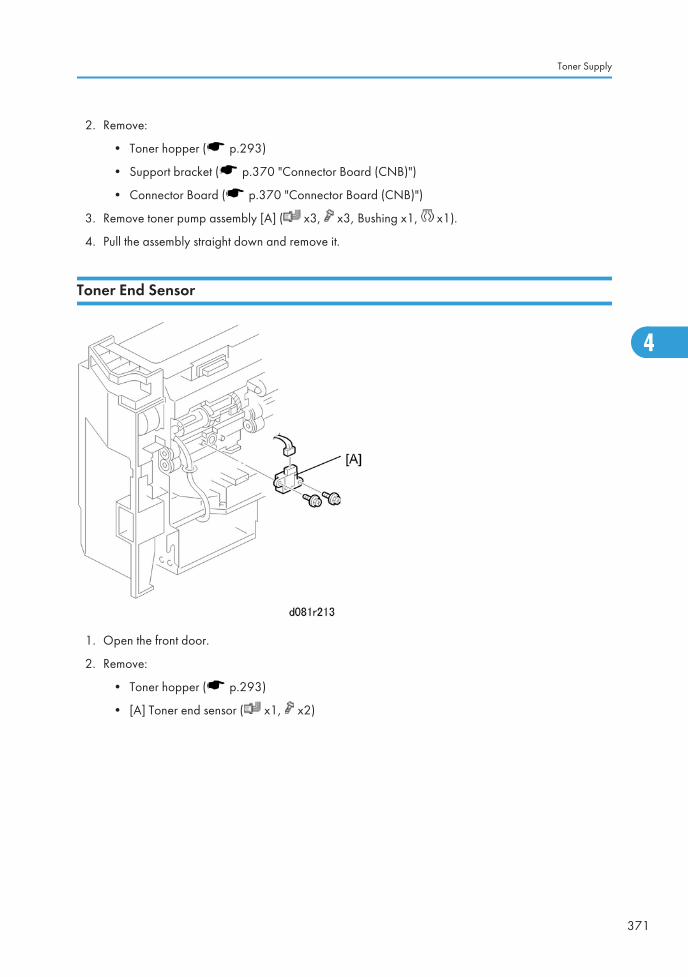
2. Remove:
• Toner hopper ( p.293)
• Support bracket ( p.370 "Connector Board (CNB)")
• Connector Board ( p.370 "Connector Board (CNB)")
3. Remove toner pump assembly [A] ( x3, x3, Bushing x1, x1).
4. Pull the assembly straight down and remove it.
Toner End Sensor
1. Open the front door.
2. Remove:
• Toner hopper ( p.293)
• [A] Toner end sensor ( x1, x2)
Toner Supply
371
4
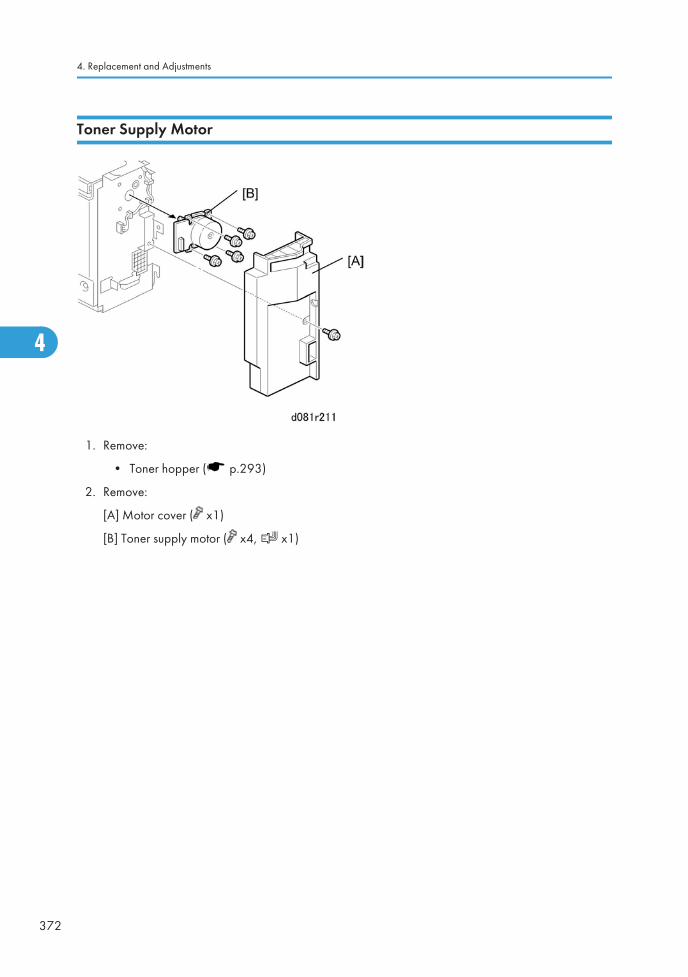
Toner Supply Motor
1. Remove:
• Toner hopper ( p.293)
2. Remove:
[A] Motor cover ( x1)
[B] Toner supply motor ( x4, x1)
4. Replacement and Adjustments
372
4
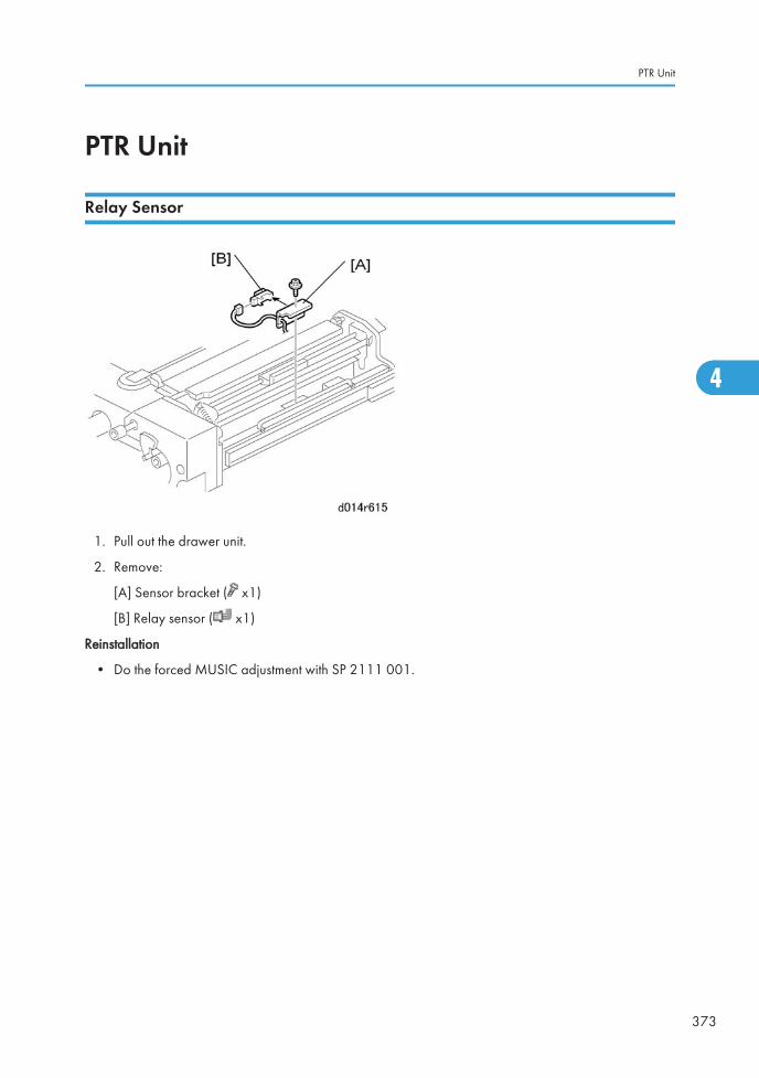
PTR Unit
Relay Sensor
1. Pull out the drawer unit.
2. Remove:
[A] Sensor bracket ( x1)
[B] Relay sensor ( x1)
Reinstallation
• Do the forced MUSIC adjustment with SP 2111 001.
PTR Unit
373
4
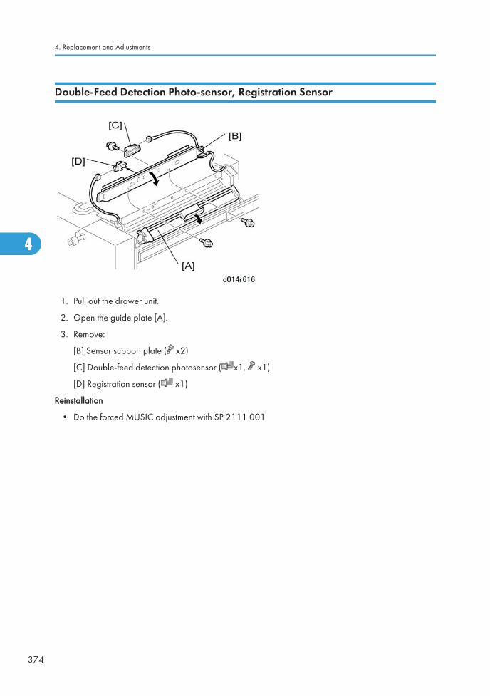
Double-Feed Detection Photo-sensor, Registration Sensor
1. Pull out the drawer unit.
2. Open the guide plate [A].
3. Remove:
[B] Sensor support plate ( x2)
[C] Double-feed detection photosensor ( x1, x1)
[D] Registration sensor ( x1)
Reinstallation
• Do the forced MUSIC adjustment with SP 2111 001
4. Replacement and Adjustments
374
4
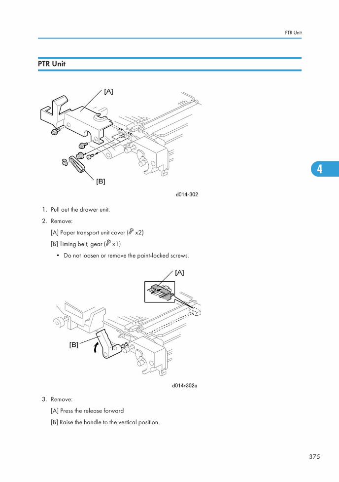
PTR Unit
1. Pull out the drawer unit.
2. Remove:
[A] Paper transport unit cover ( x2)
[B] Timing belt, gear ( x1)
• Do not loosen or remove the paint-locked screws.
3. Remove:
[A] Press the release forward
[B] Raise the handle to the vertical position.
PTR Unit
375
4
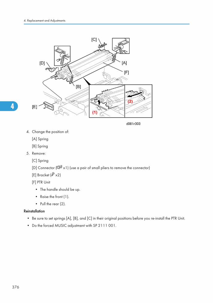
4. Change the position of:
[A] Spring
[B] Spring
5. Remove:
[C] Spring
[D] Connector ( x1) (use a pair of small pliers to remove the connector)
[E] Bracket ( x2)
[F] PTR Unit
• The handle should be up.
• Raise the front (1).
• Pull the rear (2).
Reinstallation
• Be sure to set springs [A], [B], and [C] in their original positions before you re-install the PTR Unit.
• Do the forced MUSIC adjustment with SP 2111 001.
4. Replacement and Adjustments
376
4

Paper Transfer Roller, Discharge Plate
1. Remove:
• PTR Unit
[A] Paper transfer discharge plate ( x2)
[B] Paper transfer roller ( x2, Gear x1, Shaft bearings x2)
Reinstallation
• When you install the roller, the long end [C] is at the rear.
• Do the forced MUSIC adjustment with SP 2111 001.
PTR Unit
377
4
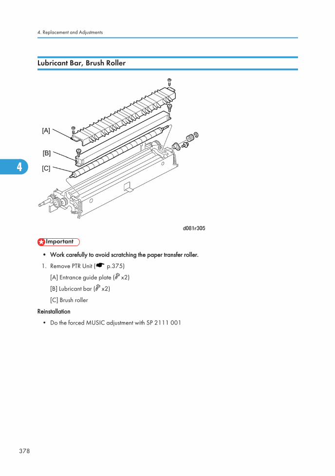
Lubricant Bar, Brush Roller
• Work carefully to avoid scratching the paper transfer roller.
1. Remove PTR Unit ( p.375)
[A] Entrance guide plate ( x2)
[B] Lubricant bar ( x2)
[C] Brush roller
Reinstallation
• Do the forced MUSIC adjustment with SP 2111 001
4. Replacement and Adjustments
378
4
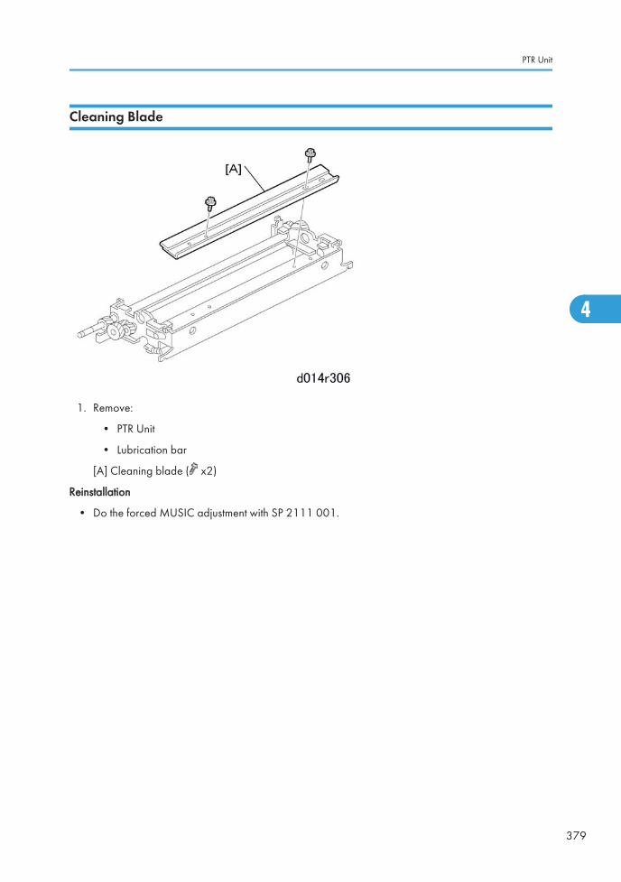
Cleaning Blade
1. Remove:
• PTR Unit
• Lubrication bar
[A] Cleaning blade ( x2)
Reinstallation
• Do the forced MUSIC adjustment with SP 2111 001.
PTR Unit
379
4
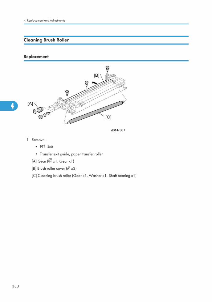
Cleaning Brush Roller
Replacement
1. Remove:
• PTR Unit
• Transfer exit guide, paper transfer roller
[A] Gear ( x1, Gear x1)
[B] Brush roller cover ( x3)
[C] Cleaning brush roller (Gear x1, Washer x1, Shaft bearing x1)
4. Replacement and Adjustments
380
4
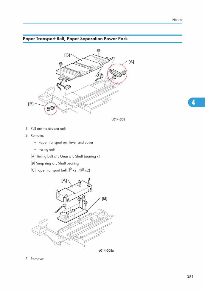
Paper Transport Belt, Paper Separation Power Pack
1. Pull out the drawer unit
2. Remove:
• Paper transport unit lever and cover
• Fusing unit
[A] Timing belt x1, Gear x1, Shaft bearing x1
[B] Snap ring x1, Shaft bearing
[C] Paper transport belt ( x2, x2)
3. Remove:
PTR Unit
381
4
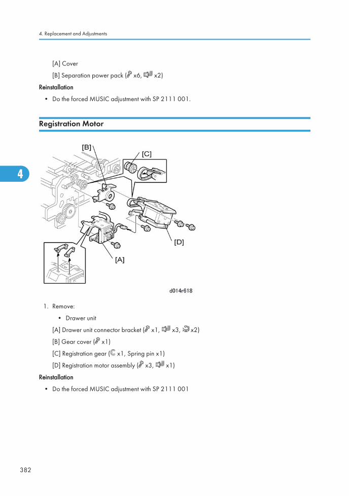
[A] Cover
[B] Separation power pack ( x6, x2)
Reinstallation
• Do the forced MUSIC adjustment with SP 2111 001.
Registration Motor
1. Remove:
• Drawer unit
[A] Drawer unit connector bracket ( x1, x3, x2)
[B] Gear cover ( x1)
[C] Registration gear ( x1, Spring pin x1)
[D] Registration motor assembly ( x3, x1)
Reinstallation
• Do the forced MUSIC adjustment with SP 2111 001
4. Replacement and Adjustments
382
4
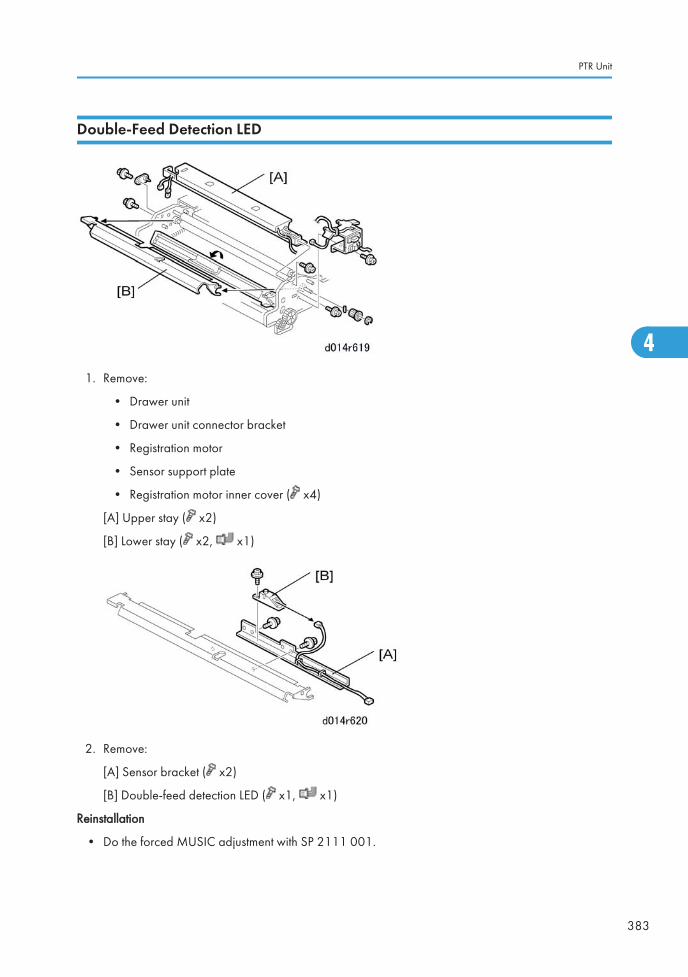
Double-Feed Detection LED
1. Remove:
• Drawer unit
• Drawer unit connector bracket
• Registration motor
• Sensor support plate
• Registration motor inner cover ( x4)
[A] Upper stay ( x2)
[B] Lower stay ( x2, x1)
2. Remove:
[A] Sensor bracket ( x2)
[B] Double-feed detection LED ( x1, x1)
Reinstallation
• Do the forced MUSIC adjustment with SP 2111 001.
PTR Unit
383
4
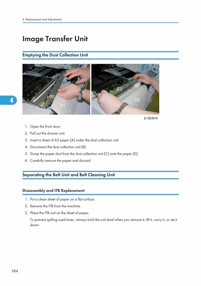
Image Transfer Unit
Emptying the Dust Collection Unit
1. Open the front door.
2. Pull out the drawer unit.
3. Insert a sheet of A3 paper [A] under the dust collection unit.
4. Disconnect the dust collection unit [B].
5. Dump the paper dust from the dust collection unit [C] onto the paper [D].
6. Carefully remove the paper and discard.
Separating the Belt Unit and Belt Cleaning Unit
Disassembly and ITB Replacement
1. Put a clean sheet of paper on a flat surface.
2. Remove the ITB from the machine.
3. Place the ITB unit on the sheet of paper.
To prevent spilling used toner, always hold the unit level when you remove it, lift it, carry it, or set itdown.
4. Replacement and Adjustments
384
4
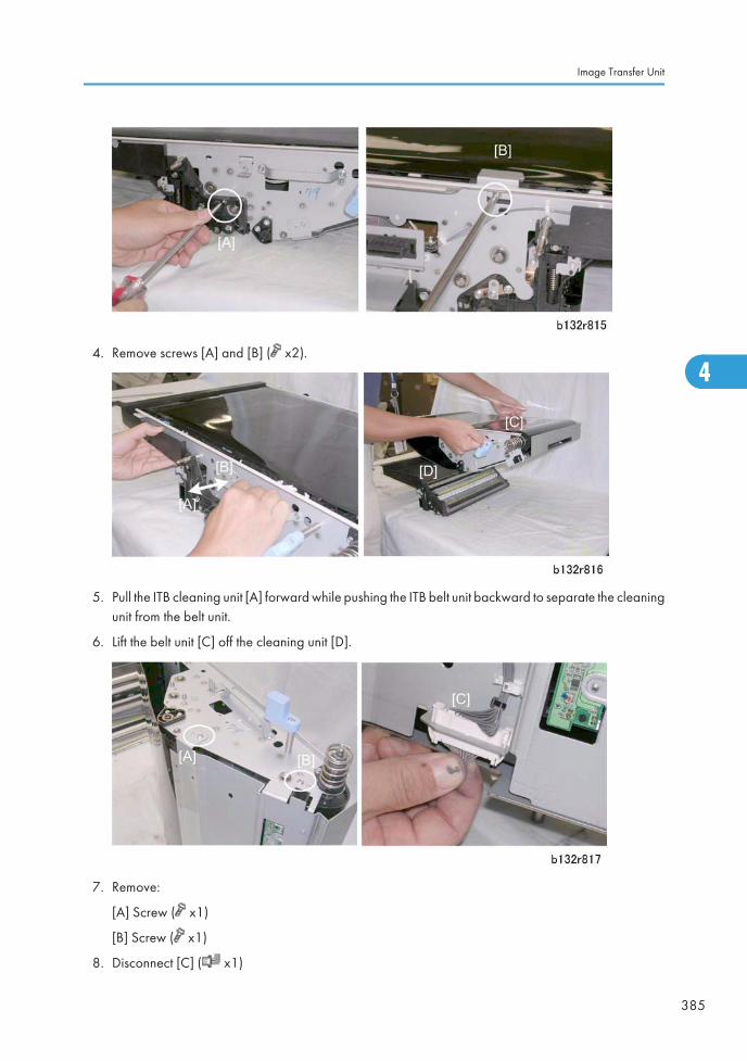
4. Remove screws [A] and [B] ( x2).
5. Pull the ITB cleaning unit [A] forward while pushing the ITB belt unit backward to separate the cleaningunit from the belt unit.
6. Lift the belt unit [C] off the cleaning unit [D].
7. Remove:
[A] Screw ( x1)
[B] Screw ( x1)
8. Disconnect [C] ( x1)
Image Transfer Unit
385
4
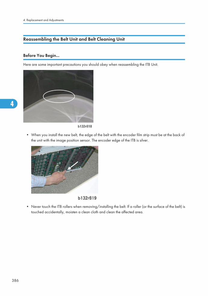
Reassembling the Belt Unit and Belt Cleaning Unit
Before You Begin...
Here are some important precautions you should obey when reassembling the ITB Unit.
• When you install the new belt, the edge of the belt with the encoder film strip must be at the back ofthe unit with the image position sensor. The encoder edge of the ITB is silver.
• Never touch the ITB rollers when removing/installing the belt. If a roller (or the surface of the belt) istouched accidentally, moisten a clean cloth and clean the affected area.
4. Replacement and Adjustments
386
4
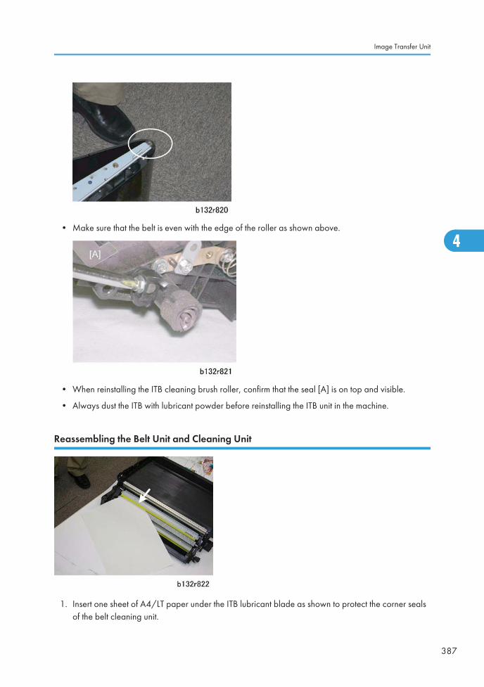
• Make sure that the belt is even with the edge of the roller as shown above.
• When reinstalling the ITB cleaning brush roller, confirm that the seal [A] is on top and visible.
• Always dust the ITB with lubricant powder before reinstalling the ITB unit in the machine.
Reassembling the Belt Unit and Cleaning Unit
1. Insert one sheet of A4/LT paper under the ITB lubricant blade as shown to protect the corner sealsof the belt cleaning unit.
Image Transfer Unit
387
4
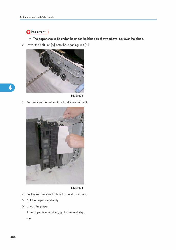
• The paper should be under the under the blade as shown above, not over the blade.
2. Lower the belt unit [A] onto the cleaning unit [B].
3. Reassemble the belt unit and belt cleaning unit.
4. Set the reassembled ITB unit on end as shown.
5. Pull the paper out slowly.
6. Check the paper.
If the paper is unmarked, go to the next step.
-or-
4. Replacement and Adjustments
388
4
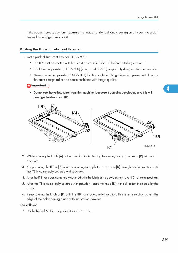
If the paper is creased or torn, separate the image transfer belt and cleaning unit. Inspect the seal. Ifthe seal is damaged, replace it.
Dusting the ITB with Lubricant Powder
1. Get a pack of Lubricant Powder B1329700.
• The ITB must be coated with lubricant powder B1329700 before installing a new ITB.
• The lubricant powder (B1329700) (composed of ZnSt) is specially designed for this machine.
• Never use setting powder (54429101) for this machine. Using this setting power will damagethe drum charge roller and cause problems with image quality.
• Do not use the yellow toner from this machine, because it contains developer, and this willdamage the drum and ITB.
2. While rotating the knob [A] in the direction indicated by the arrow, apply powder at [B] with a softdry cloth.
3. Keep rotating the ITB at [A] while continuing to apply the powder at [B] through one full rotation untilthe ITB is completely covered with powder.
4. After the ITB has been completely covered with the lubricating powder, turn lever [C] to the up position.
5. After the ITB is completely covered with powder, rotate the knob [D] in the direction indicated by thearrow.
6. Keep rotating the knob at [D] until the ITB has made one full rotation. This reverse rotation covers theedge of the belt cleaning blade with lubrication powder.
Reinstallation
• Do the forced MUSIC adjustment with SP2111-1.
Image Transfer Unit
389
4
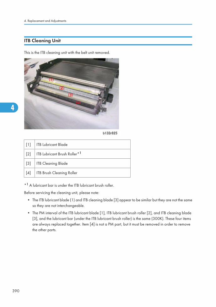
ITB Cleaning Unit
This is the ITB cleaning unit with the belt unit removed.
[1] ITB Lubricant Blade
[2] ITB Lubricant Brush Roller*1
[3] ITB Cleaning Blade
[4] ITB Brush Cleaning Roller
*1 A lubricant bar is under the ITB lubricant brush roller.
Before servicing the cleaning unit, please note:
• The ITB lubricant blade (1) and ITB cleaning blade [3] appear to be similar but they are not the sameso they are not interchangeable.
• The PM interval of the ITB lubricant blade [1], ITB lubricant brush roller [2], and ITB cleaning blade[3], and the lubricant bar (under the ITB lubricant brush roller) is the same (300K). These four itemsare always replaced together. Item [4] is not a PM part, but it must be removed in order to removethe other parts.
4. Replacement and Adjustments
390
4
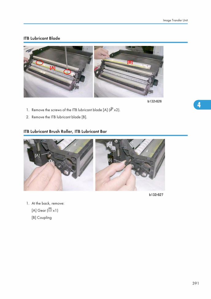
ITB Lubricant Blade
1. Remove the screws of the ITB lubricant blade [A] ( x2).
2. Remove the ITB lubricant blade [B].
ITB Lubricant Brush Roller, ITB Lubricant Bar
1. At the back, remove:
[A] Gear ( x1)
[B] Coupling
Image Transfer Unit
391
4
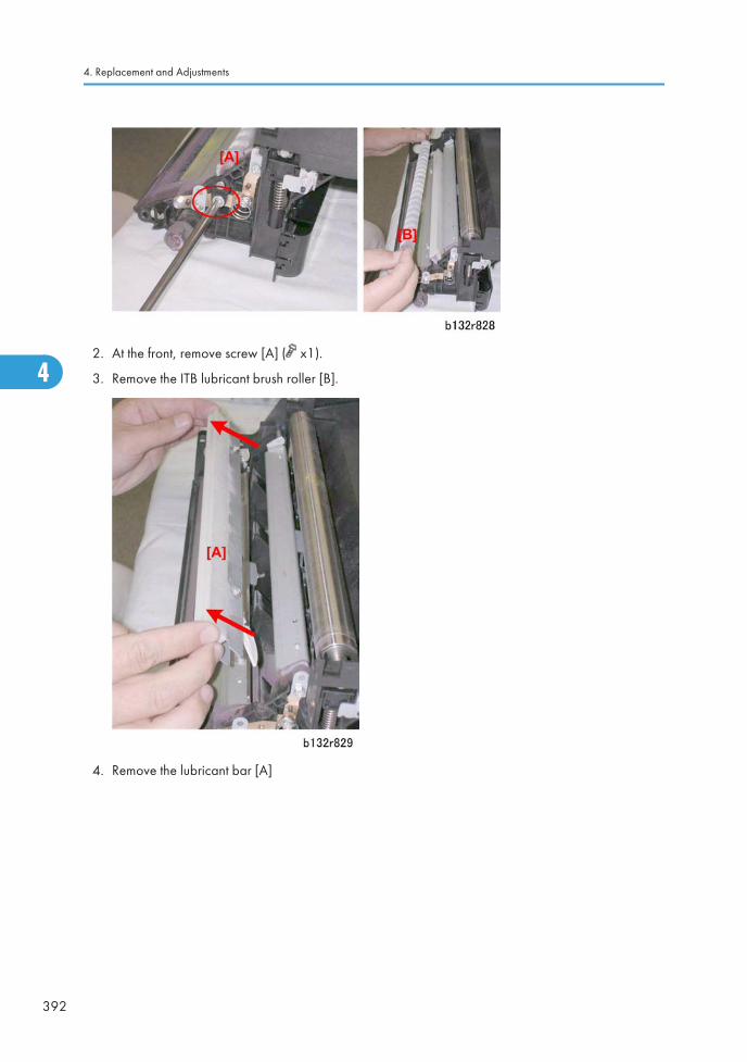
2. At the front, remove screw [A] ( x1).
3. Remove the ITB lubricant brush roller [B].
4. Remove the lubricant bar [A]
4. Replacement and Adjustments
392
4
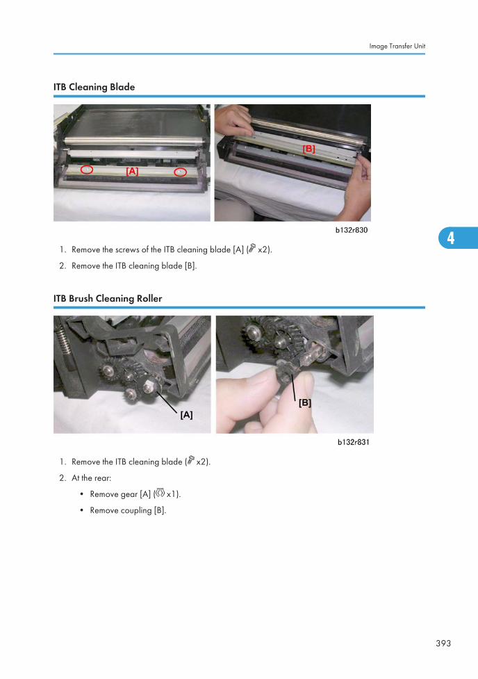
ITB Cleaning Blade
1. Remove the screws of the ITB cleaning blade [A] ( x2).
2. Remove the ITB cleaning blade [B].
ITB Brush Cleaning Roller
1. Remove the ITB cleaning blade ( x2).
2. At the rear:
• Remove gear [A] ( x1).
• Remove coupling [B].
Image Transfer Unit
393
4
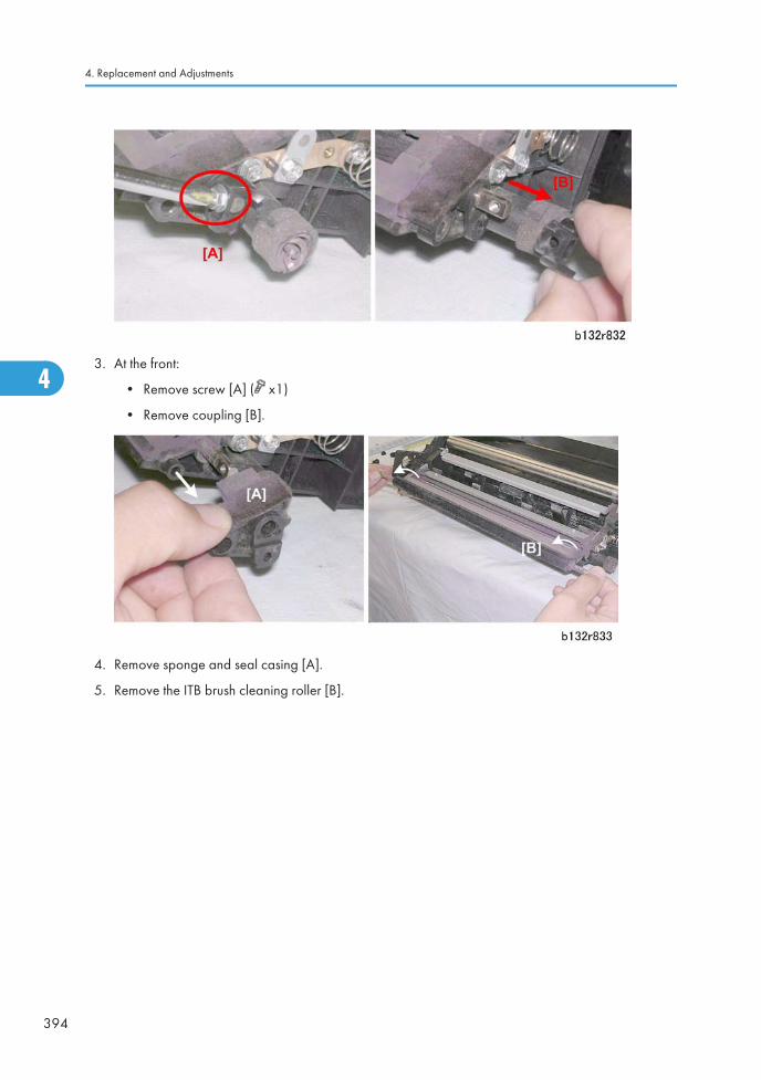
3. At the front:
• Remove screw [A] ( x1)
• Remove coupling [B].
4. Remove sponge and seal casing [A].
5. Remove the ITB brush cleaning roller [B].
4. Replacement and Adjustments
394
4
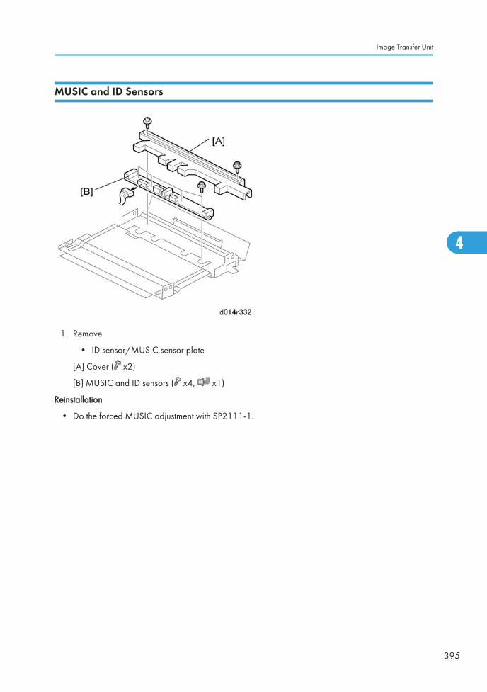
MUSIC and ID Sensors
1. Remove
• ID sensor/MUSIC sensor plate
[A] Cover ( x2)
[B] MUSIC and ID sensors ( x4, x1)
Reinstallation
• Do the forced MUSIC adjustment with SP2111-1.
Image Transfer Unit
395
4
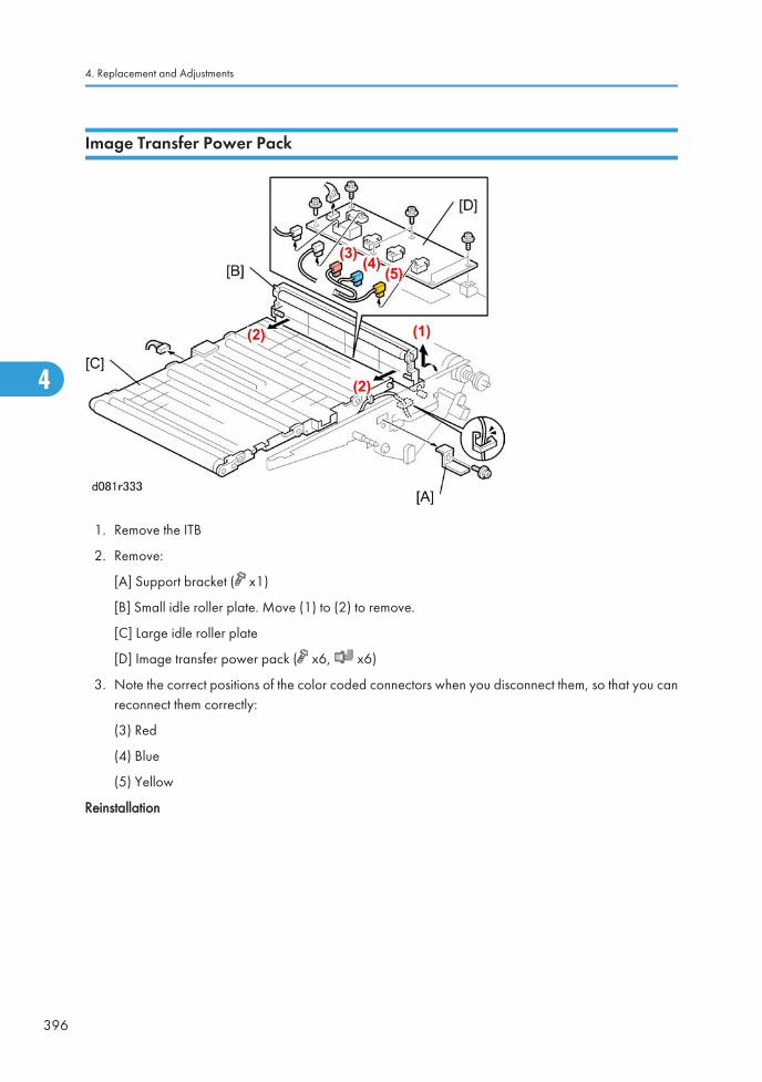
Image Transfer Power Pack
1. Remove the ITB
2. Remove:
[A] Support bracket ( x1)
[B] Small idle roller plate. Move (1) to (2) to remove.
[C] Large idle roller plate
[D] Image transfer power pack ( x6, x6)
3. Note the correct positions of the color coded connectors when you disconnect them, so that you canreconnect them correctly:
(3) Red
(4) Blue
(5) Yellow
Reinstallation
4. Replacement and Adjustments
396
4
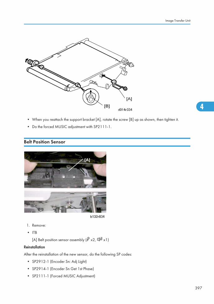
• When you reattach the support bracket [A], rotate the screw [B] up as shown, then tighten it.
• Do the forced MUSIC adjustment with SP2111-1.
Belt Position Sensor
1. Remove:
• ITB
[A] Belt position sensor assembly ( x2, x1)
Reinstallation
After the reinstallation of the new sensor, do the following SP codes:
• SP2912-1 (Encoder Sn: Adj Light)
• SP2914-1 (Encoder Sn Get 1st Phase)
• SP2111-1 (Forced MUSIC Adjustment)
Image Transfer Unit
397
4
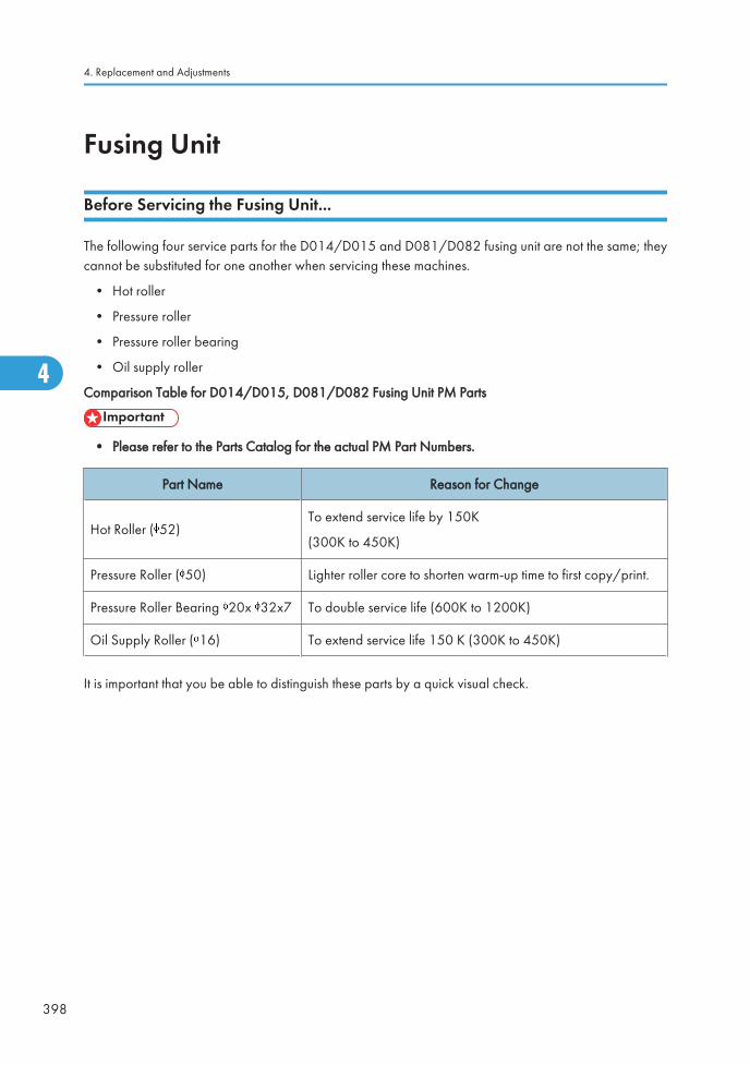
Fusing Unit
Before Servicing the Fusing Unit...
The following four service parts for the D014/D015 and D081/D082 fusing unit are not the same; theycannot be substituted for one another when servicing these machines.
• Hot roller
• Pressure roller
• Pressure roller bearing
• Oil supply roller
Comparison Table for D014/D015, D081/D082 Fusing Unit PM Parts
• Please refer to the Parts Catalog for the actual PM Part Numbers.
Part Name Reason for Change
Hot Roller ( 52)To extend service life by 150K
(300K to 450K)
Pressure Roller ( 50) Lighter roller core to shorten warm-up time to first copy/print.
Pressure Roller Bearing 20x 32x7 To double service life (600K to 1200K)
Oil Supply Roller ( 16) To extend service life 150 K (300K to 450K)
It is important that you be able to distinguish these parts by a quick visual check.
4. Replacement and Adjustments
398
4
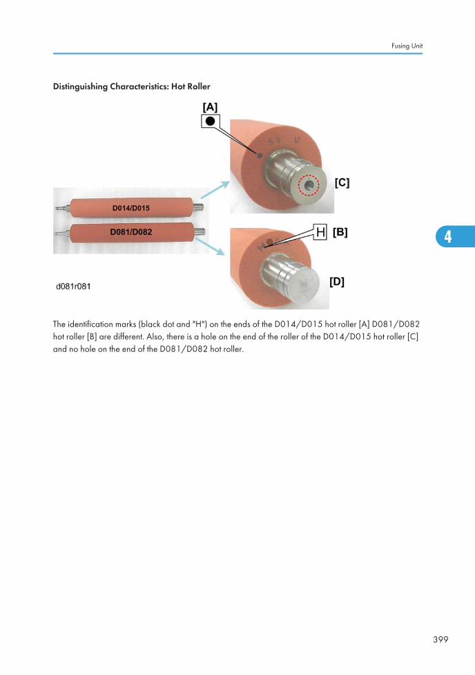
Distinguishing Characteristics: Hot Roller
The identification marks (black dot and "H") on the ends of the D014/D015 hot roller [A] D081/D082hot roller [B] are different. Also, there is a hole on the end of the roller of the D014/D015 hot roller [C]and no hole on the end of the D081/D082 hot roller.
Fusing Unit
399
4
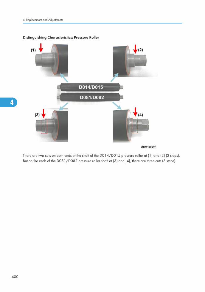
Distinguishing Characteristics: Pressure Roller
There are two cuts on both ends of the shaft of the D014/D015 pressure roller at (1) and (2) (2 steps).But on the ends of the D081/D082 pressure roller shaft at (3) and (4), there are three cuts (3 steps).
4. Replacement and Adjustments
400
4
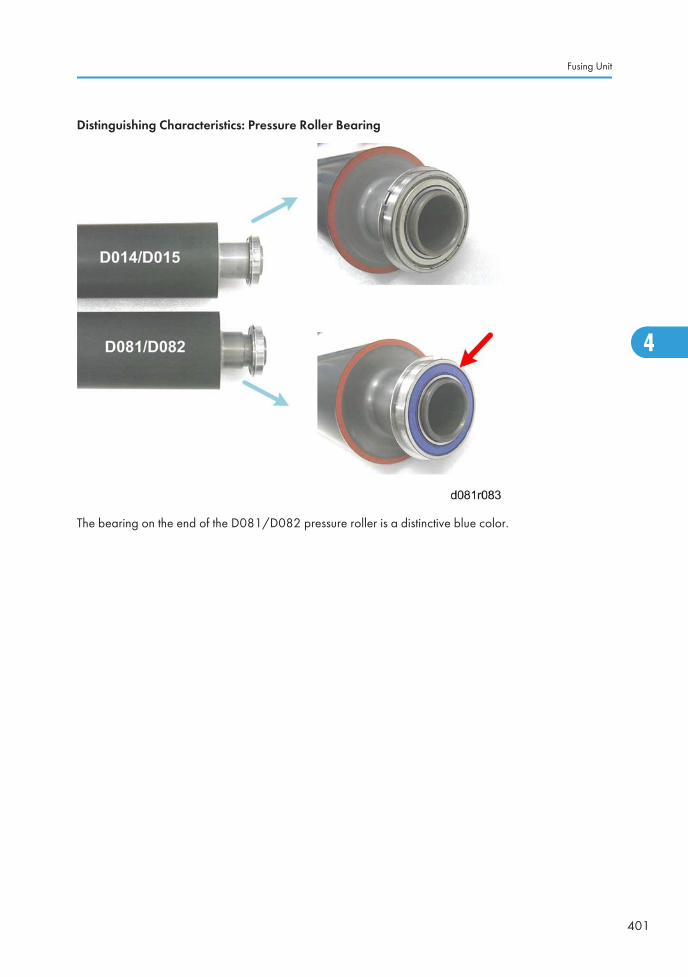
Distinguishing Characteristics: Pressure Roller Bearing
The bearing on the end of the D081/D082 pressure roller is a distinctive blue color.
Fusing Unit
401
4
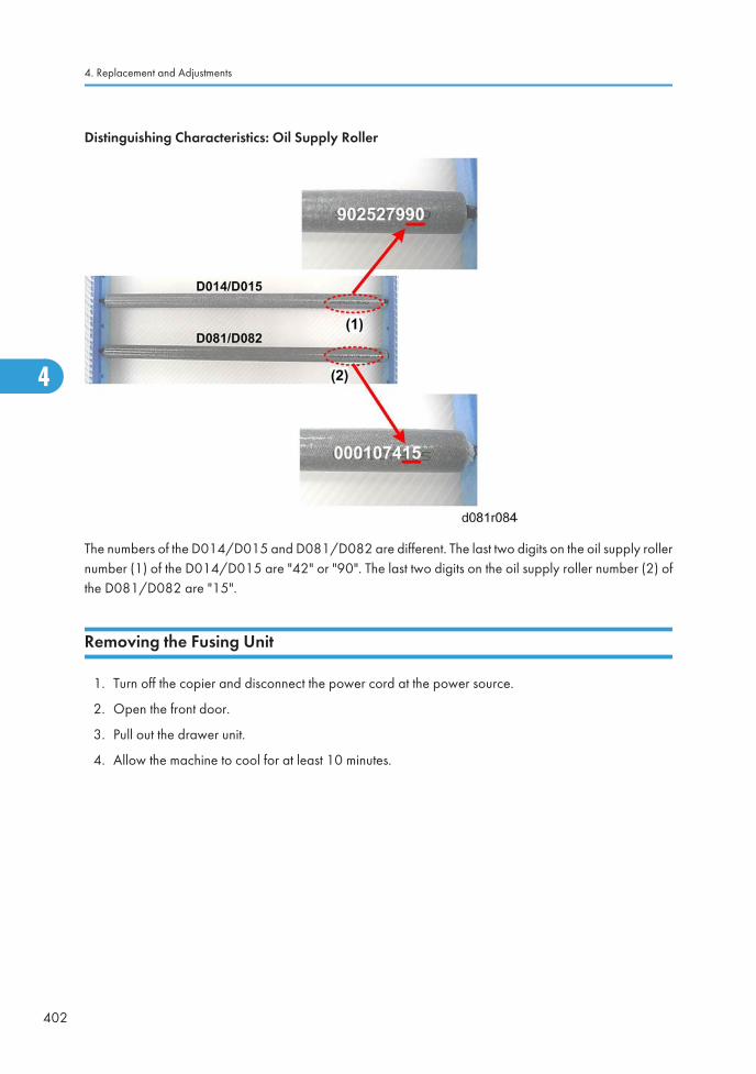
Distinguishing Characteristics: Oil Supply Roller
The numbers of the D014/D015 and D081/D082 are different. The last two digits on the oil supply rollernumber (1) of the D014/D015 are "42" or "90". The last two digits on the oil supply roller number (2) ofthe D081/D082 are "15".
Removing the Fusing Unit
1. Turn off the copier and disconnect the power cord at the power source.
2. Open the front door.
3. Pull out the drawer unit.
4. Allow the machine to cool for at least 10 minutes.
4. Replacement and Adjustments
402
4
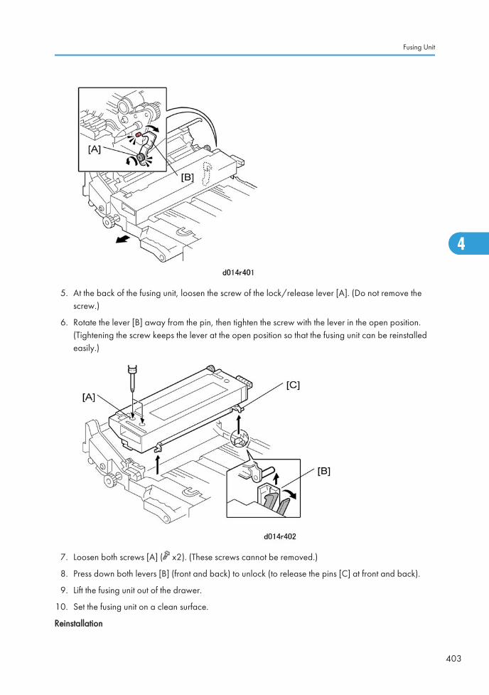
5. At the back of the fusing unit, loosen the screw of the lock/release lever [A]. (Do not remove thescrew.)
6. Rotate the lever [B] away from the pin, then tighten the screw with the lever in the open position.(Tightening the screw keeps the lever at the open position so that the fusing unit can be reinstalledeasily.)
7. Loosen both screws [A] ( x2). (These screws cannot be removed.)
8. Press down both levers [B] (front and back) to unlock (to release the pins [C] at front and back).
9. Lift the fusing unit out of the drawer.
10. Set the fusing unit on a clean surface.
Reinstallation
Fusing Unit
403
4
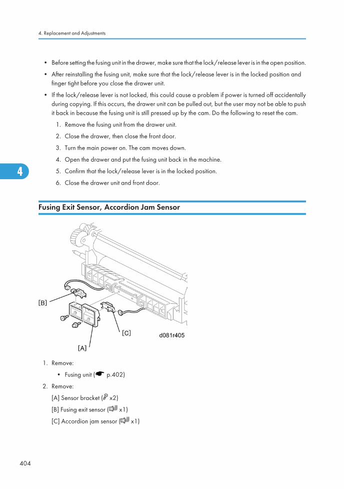
• Before setting the fusing unit in the drawer, make sure that the lock/release lever is in the open position.
• After reinstalling the fusing unit, make sure that the lock/release lever is in the locked position andfinger tight before you close the drawer unit.
• If the lock/release lever is not locked, this could cause a problem if power is turned off accidentallyduring copying. If this occurs, the drawer unit can be pulled out, but the user may not be able to pushit back in because the fusing unit is still pressed up by the cam. Do the following to reset the cam.
1. Remove the fusing unit from the drawer unit.
2. Close the drawer, then close the front door.
3. Turn the main power on. The cam moves down.
4. Open the drawer and put the fusing unit back in the machine.
5. Confirm that the lock/release lever is in the locked position.
6. Close the drawer unit and front door.
Fusing Exit Sensor, Accordion Jam Sensor
1. Remove:
• Fusing unit ( p.402)
2. Remove:
[A] Sensor bracket ( x2)
[B] Fusing exit sensor ( x1)
[C] Accordion jam sensor ( x1)
4. Replacement and Adjustments
404
4
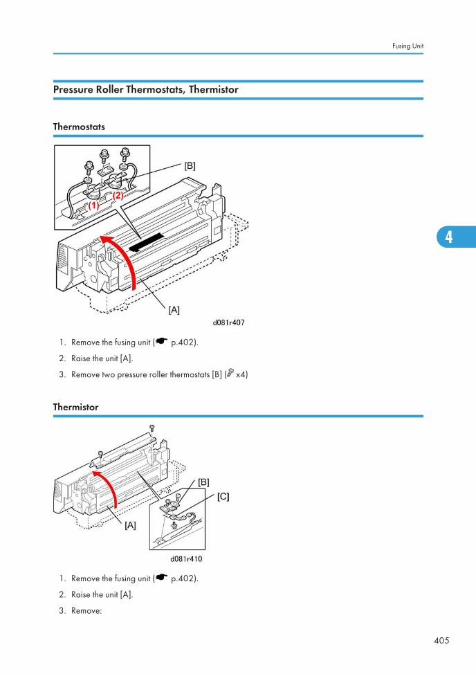
Pressure Roller Thermostats, Thermistor
Thermostats
1. Remove the fusing unit ( p.402).
2. Raise the unit [A].
3. Remove two pressure roller thermostats [B] ( x4)
Thermistor
1. Remove the fusing unit ( p.402).
2. Raise the unit [A].
3. Remove:
Fusing Unit
405
4

[B] Thermistor bracket ( x2)
[C] Pressure roller thermistor ( x1, x1)
Fusing Cleaning Unit
Fusing Belt Strippers
Preparation
• Remove the fusing unit from the machine.
• Allow the unit to cool for at least 10 minutes.
• Raise D2 to a 45° slant.
1. Remove:
[A] Spring
[B] Plate
[C] Spring
[D] Plate
4. Replacement and Adjustments
406
4

2. Remove:
[A] Spring
[B] Spring
3. Remove fusing belt stripper plate [A] with strippers attached.
Fusing Unit
407
4
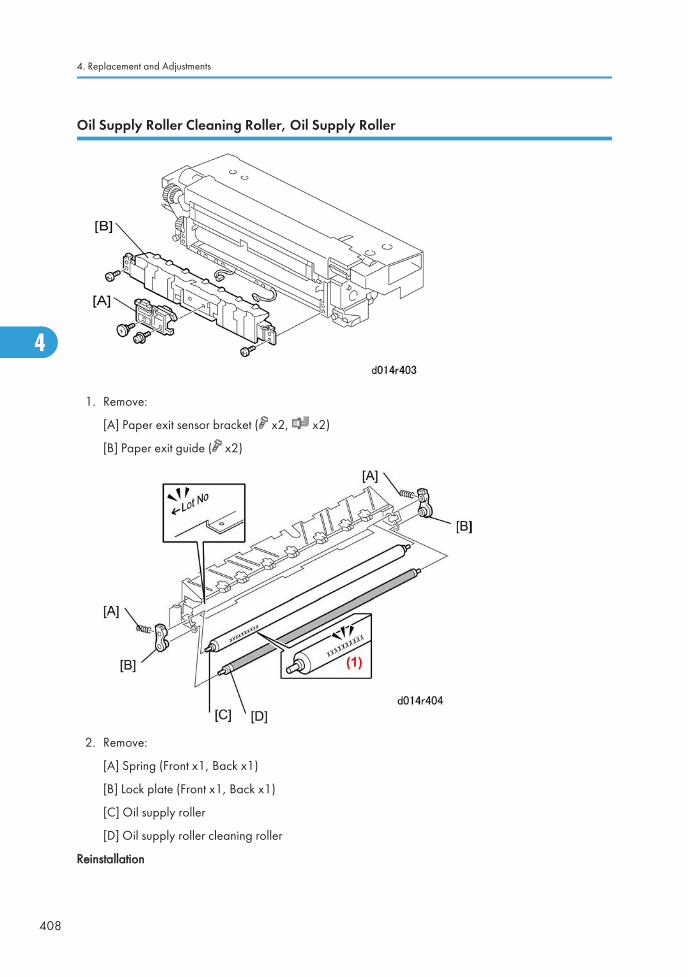
Oil Supply Roller Cleaning Roller, Oil Supply Roller
1. Remove:
[A] Paper exit sensor bracket ( x2, x2)
[B] Paper exit guide ( x2)
2. Remove:
[A] Spring (Front x1, Back x1)
[B] Lock plate (Front x1, Back x1)
[C] Oil supply roller
[D] Oil supply roller cleaning roller
Reinstallation
4. Replacement and Adjustments
408
4
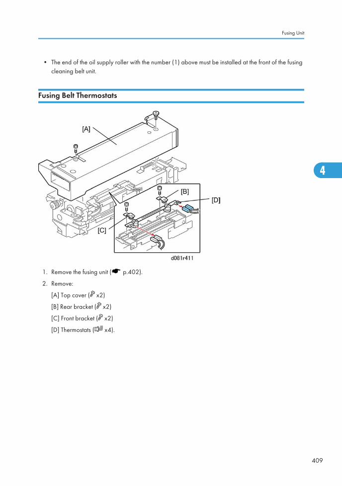
• The end of the oil supply roller with the number (1) above must be installed at the front of the fusingcleaning belt unit.
Fusing Belt Thermostats
1. Remove the fusing unit ( p.402).
2. Remove:
[A] Top cover ( x2)
[B] Rear bracket ( x2)
[C] Front bracket ( x2)
[D] Thermostats ( x4).
Fusing Unit
409
4
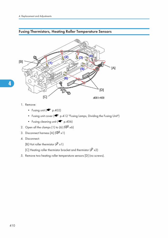
Fusing Thermistors, Heating Roller Temperature Sensors
1. Remove:
• Fusing unit ( p.402)
• Fusing unit cover ( p.412 "Fusing Lamps, Dividing the Fusing Unit")
• Fusing cleaning unit ( p.406)
2. Open all the clamps (1) to (6) ( x6)
3. Disconnect harness [A] ( x1)
4. Disconnect:
[B] Hot roller thermistor ( x1)
[C] Heating roller thermistor bracket and thermistor ( x2)
5. Remove two heating roller temperature sensors [D] (no screws).
4. Replacement and Adjustments
410
4
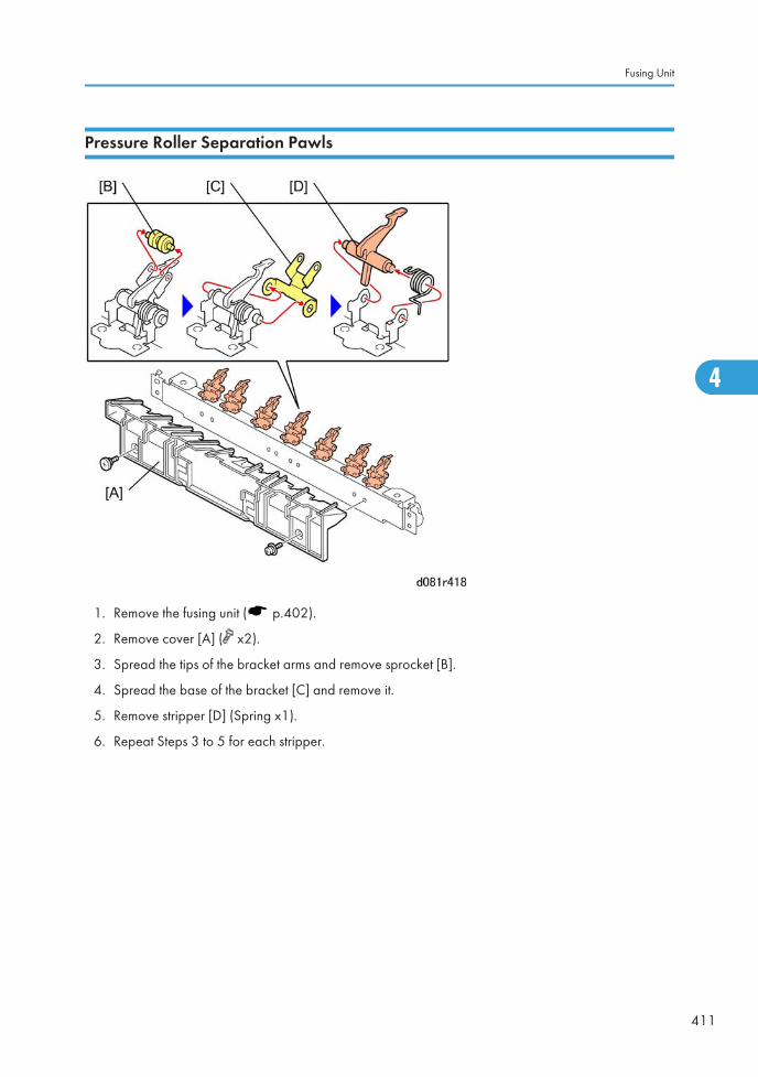
Pressure Roller Separation Pawls
1. Remove the fusing unit ( p.402).
2. Remove cover [A] ( x2).
3. Spread the tips of the bracket arms and remove sprocket [B].
4. Spread the base of the bracket [C] and remove it.
5. Remove stripper [D] (Spring x1).
6. Repeat Steps 3 to 5 for each stripper.
Fusing Unit
411
4
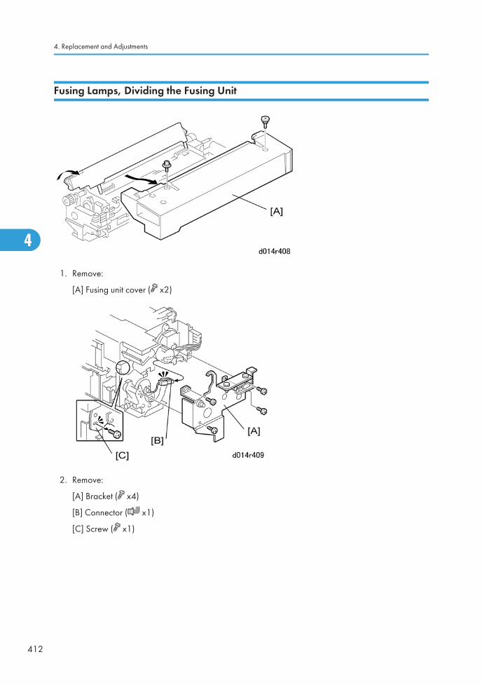
Fusing Lamps, Dividing the Fusing Unit
1. Remove:
[A] Fusing unit cover ( x2)
2. Remove:
[A] Bracket ( x4)
[B] Connector ( x1)
[C] Screw ( x1)
4. Replacement and Adjustments
412
4
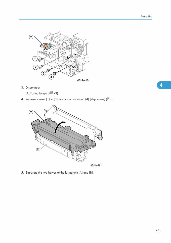
3. Disconnect
[A] Fusing lamps ( x3)
4. Remove screws (1) to (3) (normal screws) and (4) (step screw) ( x3)
5. Separate the two halves of the fusing unit [A] and [B].
Fusing Unit
413
4

6. Remove:
[A] Lock plate ( x1)
[B] Lock plate ( x1)
[C] Bracket ( x4)
[D] Heating roller fusing lamps ( x3)
7. Remove:
[A] Lock plate ( x1)
[B] Connector ( x1)
4. Replacement and Adjustments
414
4
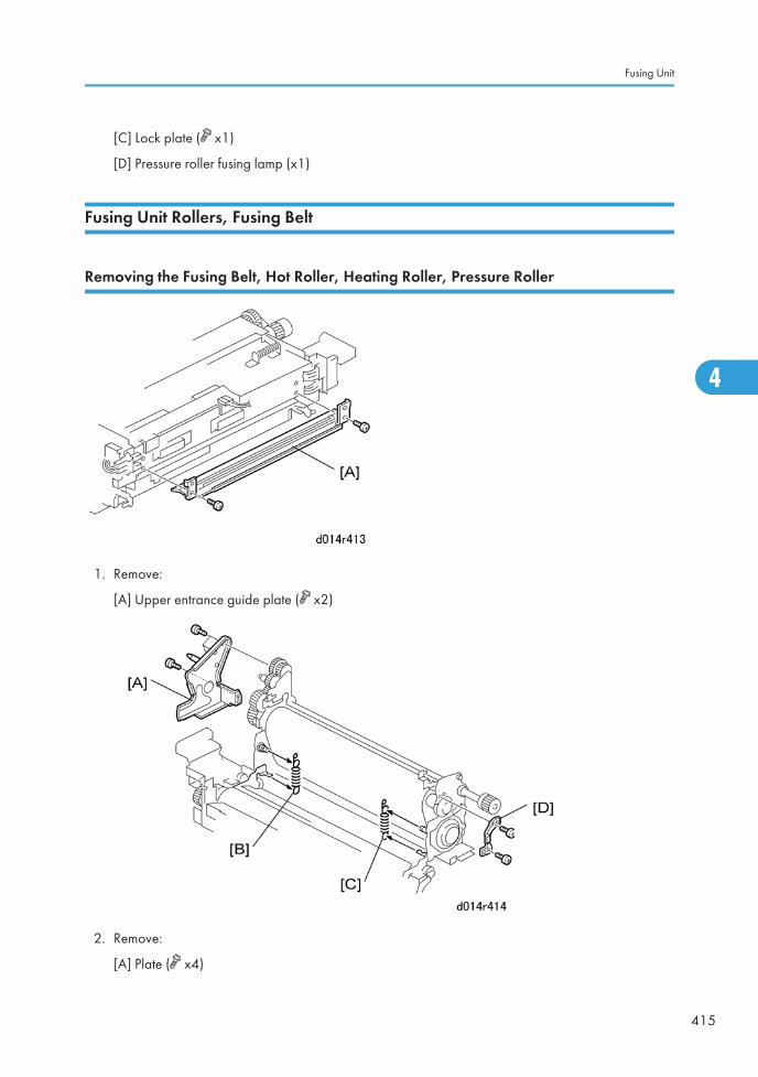
[C] Lock plate ( x1)
[D] Pressure roller fusing lamp (x1)
Fusing Unit Rollers, Fusing Belt
Removing the Fusing Belt, Hot Roller, Heating Roller, Pressure Roller
1. Remove:
[A] Upper entrance guide plate ( x2)
2. Remove:
[A] Plate ( x4)
Fusing Unit
415
4
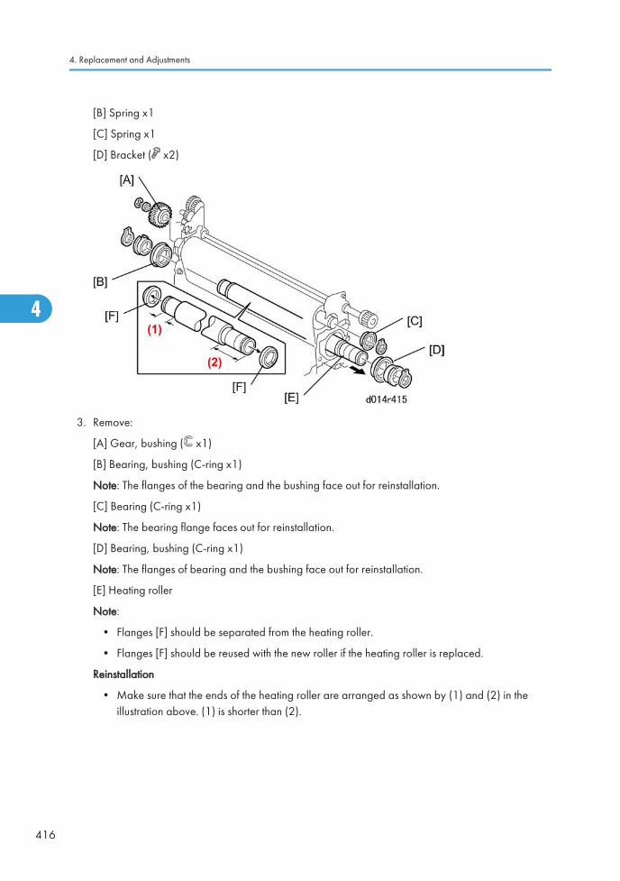
[B] Spring x1
[C] Spring x1
[D] Bracket ( x2)
3. Remove:
[A] Gear, bushing ( x1)
[B] Bearing, bushing (C-ring x1)
Note: The flanges of the bearing and the bushing face out for reinstallation.
[C] Bearing (C-ring x1)
Note: The bearing flange faces out for reinstallation.
[D] Bearing, bushing (C-ring x1)
Note: The flanges of bearing and the bushing face out for reinstallation.
[E] Heating roller
Note:
• Flanges [F] should be separated from the heating roller.
• Flanges [F] should be reused with the new roller if the heating roller is replaced.
Reinstallation
• Make sure that the ends of the heating roller are arranged as shown by (1) and (2) in theillustration above. (1) is shorter than (2).
4. Replacement and Adjustments
416
4
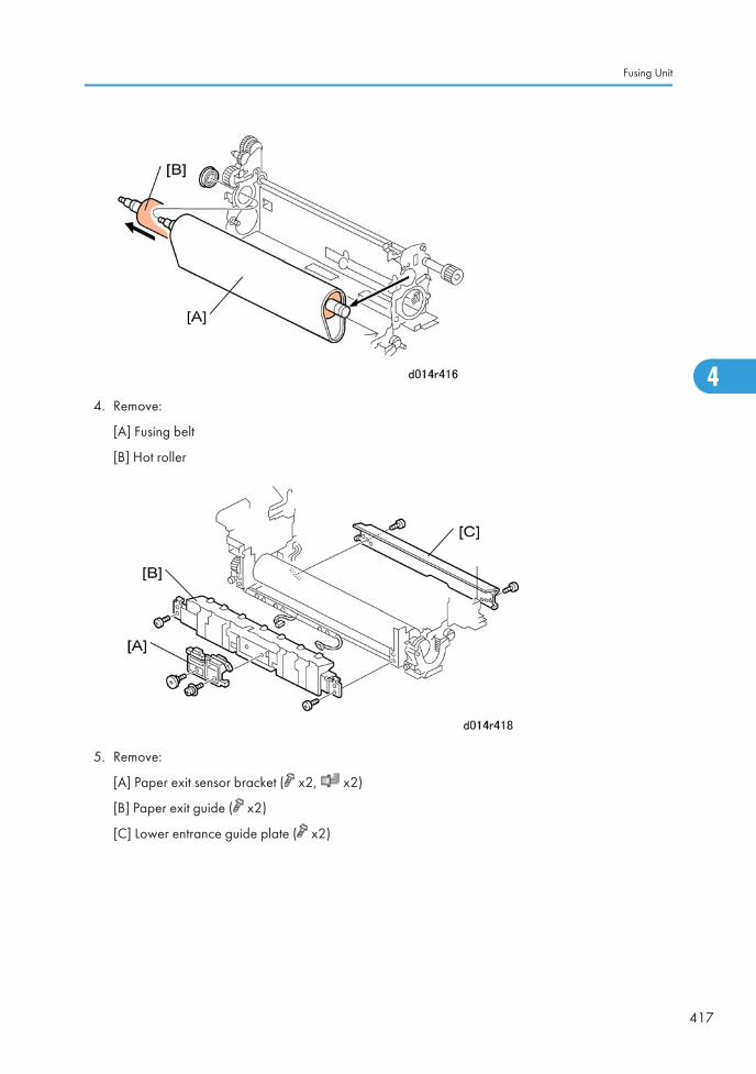
4. Remove:
[A] Fusing belt
[B] Hot roller
5. Remove:
[A] Paper exit sensor bracket ( x2, x2)
[B] Paper exit guide ( x2)
[C] Lower entrance guide plate ( x2)
Fusing Unit
417
4
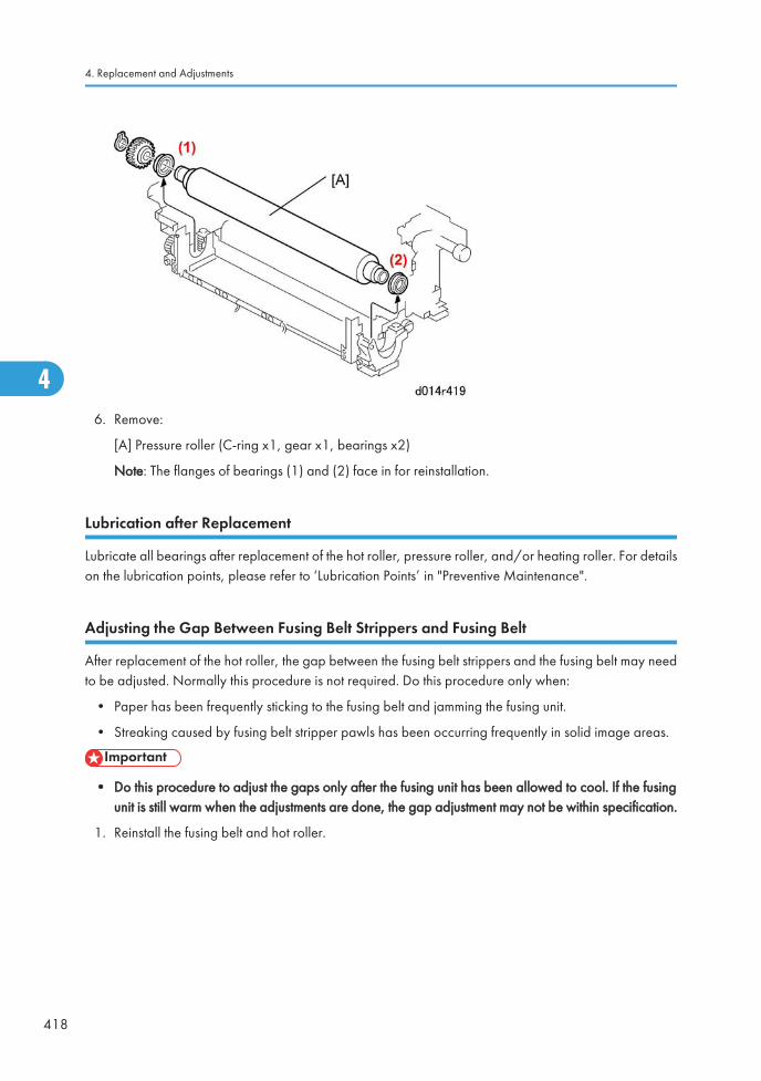
6. Remove:
[A] Pressure roller (C-ring x1, gear x1, bearings x2)
Note: The flanges of bearings (1) and (2) face in for reinstallation.
Lubrication after Replacement
Lubricate all bearings after replacement of the hot roller, pressure roller, and/or heating roller. For detailson the lubrication points, please refer to ‘Lubrication Points’ in "Preventive Maintenance".
Adjusting the Gap Between Fusing Belt Strippers and Fusing Belt
After replacement of the hot roller, the gap between the fusing belt strippers and the fusing belt may needto be adjusted. Normally this procedure is not required. Do this procedure only when:
• Paper has been frequently sticking to the fusing belt and jamming the fusing unit.
• Streaking caused by fusing belt stripper pawls has been occurring frequently in solid image areas.
• Do this procedure to adjust the gaps only after the fusing unit has been allowed to cool. If the fusingunit is still warm when the adjustments are done, the gap adjustment may not be within specification.
1. Reinstall the fusing belt and hot roller.
4. Replacement and Adjustments
418
4
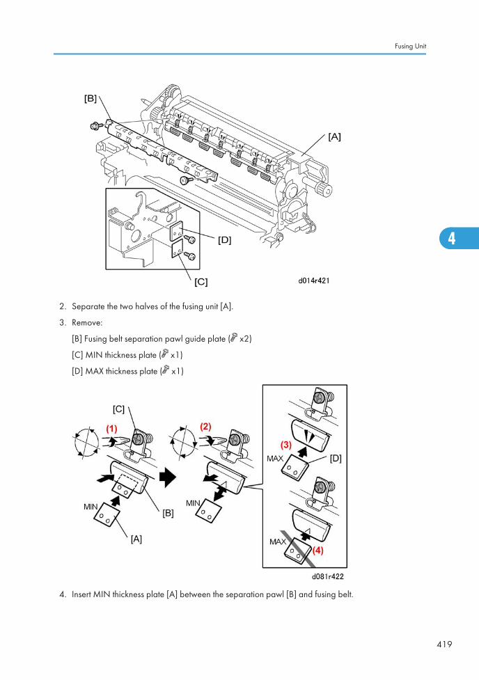
2. Separate the two halves of the fusing unit [A].
3. Remove:
[B] Fusing belt separation pawl guide plate ( x2)
[C] MIN thickness plate ( x1)
[D] MAX thickness plate ( x1)
4. Insert MIN thickness plate [A] between the separation pawl [B] and fusing belt.
Fusing Unit
419
4
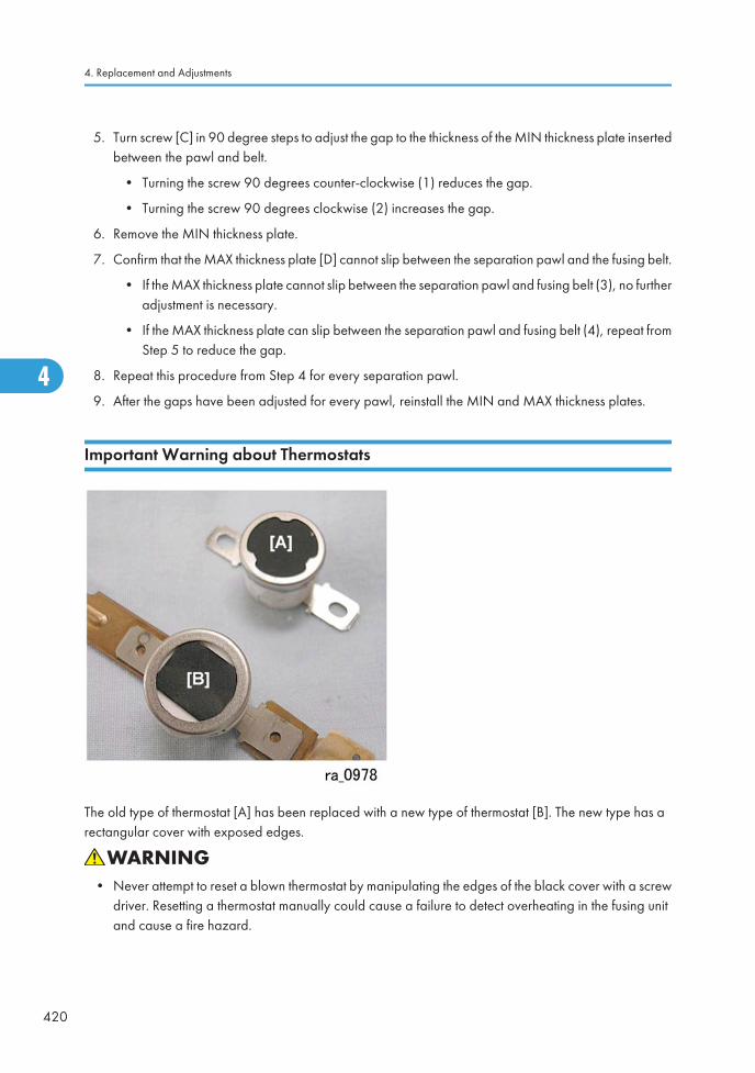
5. Turn screw [C] in 90 degree steps to adjust the gap to the thickness of the MIN thickness plate insertedbetween the pawl and belt.
• Turning the screw 90 degrees counter-clockwise (1) reduces the gap.
• Turning the screw 90 degrees clockwise (2) increases the gap.
6. Remove the MIN thickness plate.
7. Confirm that the MAX thickness plate [D] cannot slip between the separation pawl and the fusing belt.
• If the MAX thickness plate cannot slip between the separation pawl and fusing belt (3), no furtheradjustment is necessary.
• If the MAX thickness plate can slip between the separation pawl and fusing belt (4), repeat fromStep 5 to reduce the gap.
8. Repeat this procedure from Step 4 for every separation pawl.
9. After the gaps have been adjusted for every pawl, reinstall the MIN and MAX thickness plates.
Important Warning about Thermostats
The old type of thermostat [A] has been replaced with a new type of thermostat [B]. The new type has arectangular cover with exposed edges.
• Never attempt to reset a blown thermostat by manipulating the edges of the black cover with a screwdriver. Resetting a thermostat manually could cause a failure to detect overheating in the fusing unitand cause a fire hazard.
4. Replacement and Adjustments
420
4
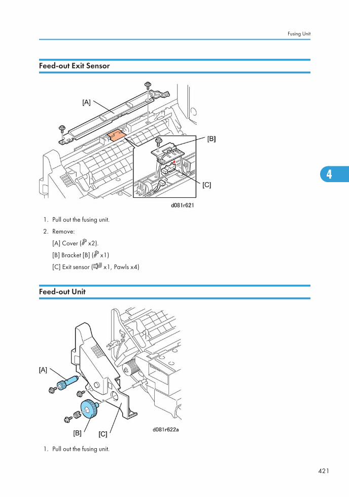
Feed-out Exit Sensor
1. Pull out the fusing unit.
2. Remove:
[A] Cover ( x2).
[B] Bracket [B] ( x1)
[C] Exit sensor ( x1, Pawls x4)
Feed-out Unit
1. Pull out the fusing unit.
Fusing Unit
421
4
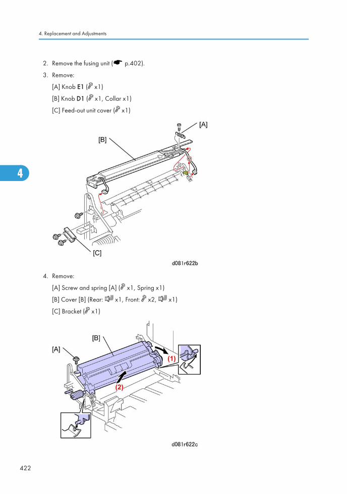
2. Remove the fusing unit ( p.402).
3. Remove:
[A] Knob E1 ( x1)
[B] Knob D1 ( x1, Collar x1)
[C] Feed-out unit cover ( x1)
4. Remove:
[A] Screw and spring [A] ( x1, Spring x1)
[B] Cover [B] (Rear: x1, Front: x2, x1)
[C] Bracket ( x1)
4. Replacement and Adjustments
422
4

5. Remove:
[A] Front screw ( x1)
[B] Feed-out Unit. Rotate the unit to the right (1) then lift it out (2).
Fusing Unit
423
4
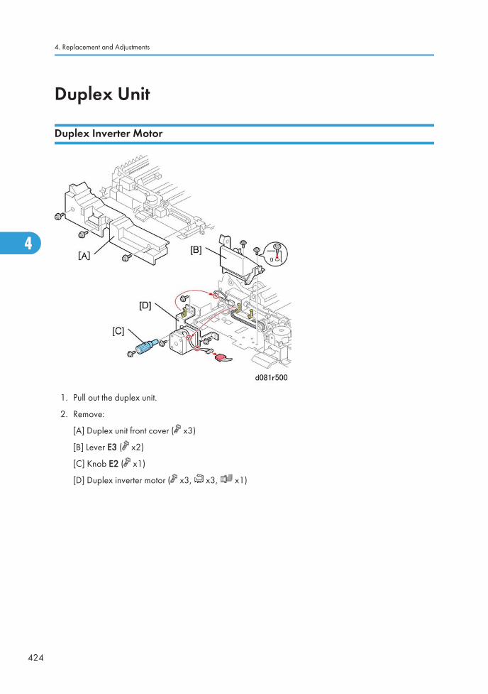
Duplex Unit
Duplex Inverter Motor
1. Pull out the duplex unit.
2. Remove:
[A] Duplex unit front cover ( x3)
[B] Lever E3 ( x2)
[C] Knob E2 ( x1)
[D] Duplex inverter motor ( x3, x3, x1)
4. Replacement and Adjustments
424
4
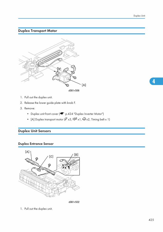
Duplex Transport Motor
1. Pull out the duplex unit.
2. Release the lower guide plate with knob F.
3. Remove:
• Duplex unit front cover ( p.424 "Duplex Inverter Motor")
• [A] Duplex transport motor ( x3, x1, x2, Timing belt x 1)
Duplex Unit Sensors
Duplex Entrance Sensor
1. Pull out the duplex unit.
Duplex Unit
425
4
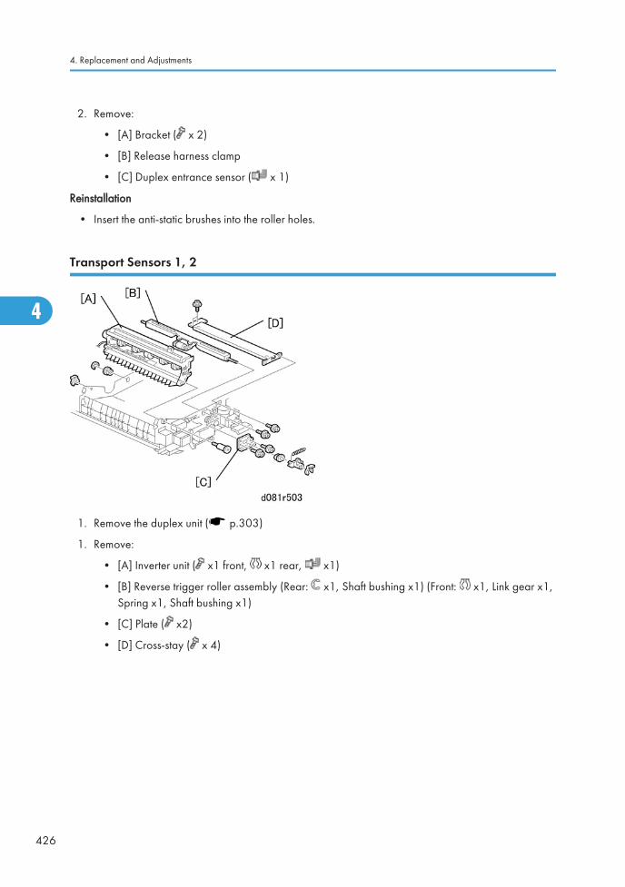
2. Remove:
• [A] Bracket ( x 2)
• [B] Release harness clamp
• [C] Duplex entrance sensor ( x 1)
Reinstallation
• Insert the anti-static brushes into the roller holes.
Transport Sensors 1, 2
1. Remove the duplex unit ( p.303)
1. Remove:
• [A] Inverter unit ( x1 front, x1 rear, x1)
• [B] Reverse trigger roller assembly (Rear: x1, Shaft bushing x1) (Front: x1, Link gear x1,Spring x1, Shaft bushing x1)
• [C] Plate ( x2)
• [D] Cross-stay ( x 4)
4. Replacement and Adjustments
426
4
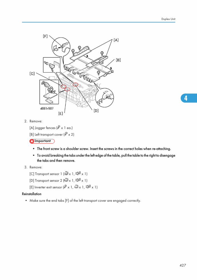
2. Remove:
[A] Jogger fences ( x 1 ea.)
[B] Left transport cover ( x 2)
• The front screw is a shoulder screw. Insert the screws in the correct holes when re-attaching.
• To avoid breaking the tabs under the left edge of the table, pull the table to the right to disengagethe tabs and then remove.
3. Remove:
[C] Transport sensor 1 ( x 1, x 1)
[D] Transport sensor 2 ( x 1, x 1)
[E] Inverter exit sensor ( x 1, x 1, x 1)
Reinstallation
• Make sure the end tabs [F] of the left transport cover are engaged correctly.
Duplex Unit
427
4
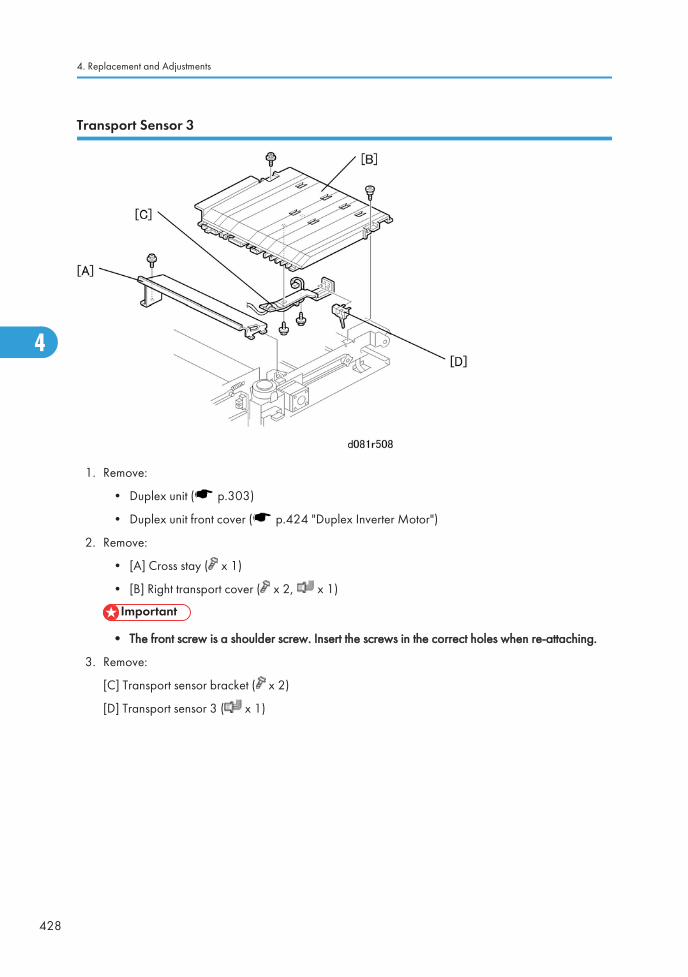
Transport Sensor 3
1. Remove:
• Duplex unit ( p.303)
• Duplex unit front cover ( p.424 "Duplex Inverter Motor")
2. Remove:
• [A] Cross stay ( x 1)
• [B] Right transport cover ( x 2, x 1)
• The front screw is a shoulder screw. Insert the screws in the correct holes when re-attaching.
3. Remove:
[C] Transport sensor bracket ( x 2)
[D] Transport sensor 3 ( x 1)
4. Replacement and Adjustments
428
4
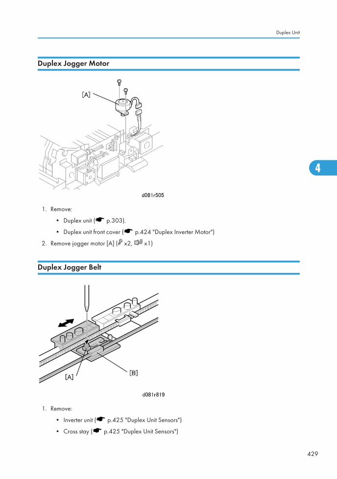
Duplex Jogger Motor
1. Remove:
• Duplex unit ( p.303).
• Duplex unit front cover ( p.424 "Duplex Inverter Motor")
2. Remove jogger motor [A] ( x2, x1)
Duplex Jogger Belt
1. Remove:
• Inverter unit ( p.425 "Duplex Unit Sensors")
• Cross stay ( p.425 "Duplex Unit Sensors")
Duplex Unit
429
4
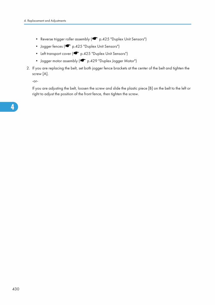
• Reverse trigger roller assembly ( p.425 "Duplex Unit Sensors")
• Jogger fences ( p.425 "Duplex Unit Sensors")
• Left transport cover ( p.425 "Duplex Unit Sensors")
• Jogger motor assembly ( p.429 "Duplex Jogger Motor")
2. If you are replacing the belt, set both jogger fence brackets at the center of the belt and tighten thescrew [A].
-or-
If you are adjusting the belt, loosen the screw and slide the plastic piece [B] on the belt to the left orright to adjust the position of the front fence, then tighten the screw.
4. Replacement and Adjustments
430
4
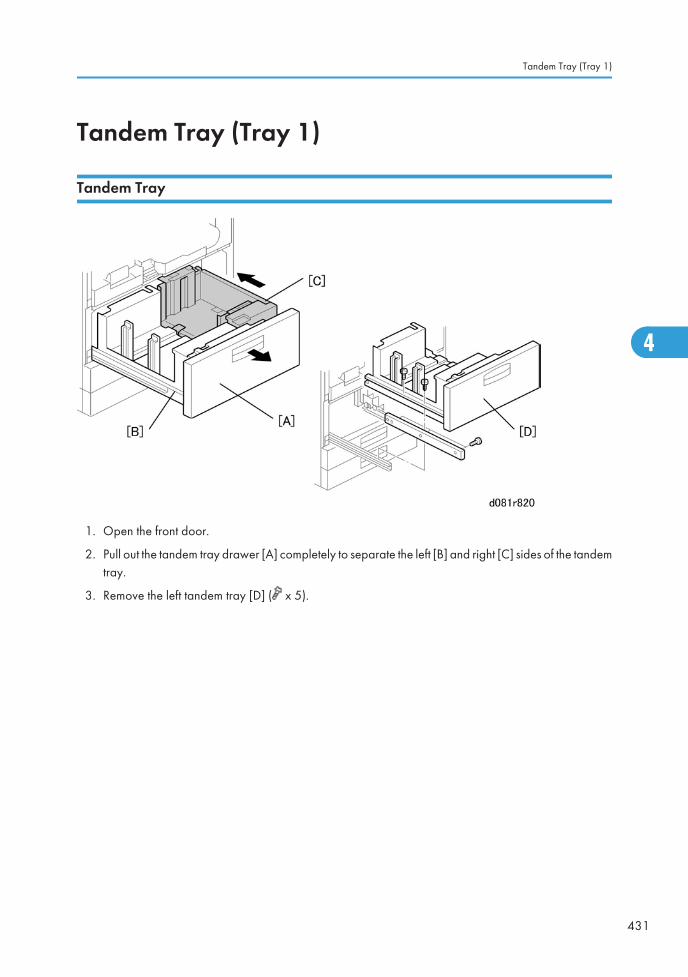
Tandem Tray (Tray 1)
Tandem Tray
1. Open the front door.
2. Pull out the tandem tray drawer [A] completely to separate the left [B] and right [C] sides of the tandemtray.
3. Remove the left tandem tray [D] ( x 5).
Tandem Tray (Tray 1)
431
4
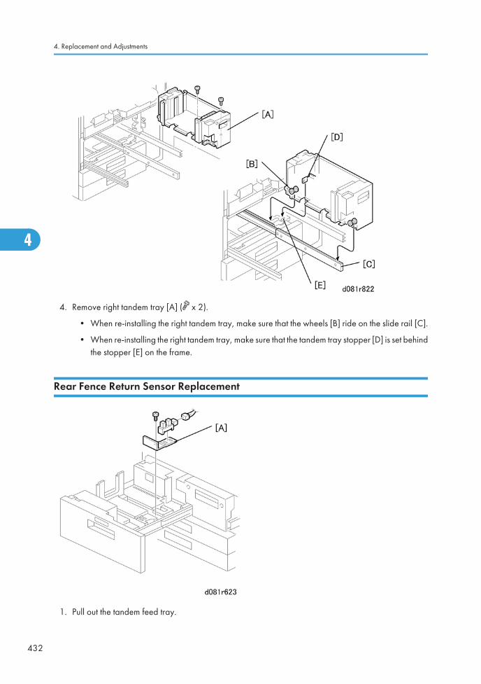
4. Remove right tandem tray [A] ( x 2).
• When re-installing the right tandem tray, make sure that the wheels [B] ride on the slide rail [C].
• When re-installing the right tandem tray, make sure that the tandem tray stopper [D] is set behindthe stopper [E] on the frame.
Rear Fence Return Sensor Replacement
1. Pull out the tandem feed tray.
4. Replacement and Adjustments
432
4

2. Remove return sensor assembly [A] ( x 1, x1).
Rear Fence HP Sensor Replacement
1. Pull out the tandem feed tray.
2. Remove:
[A] Rear bottom plate ( x 1).
[B] Back fence transport gear ( x 1)
[C] Move the back fence to the right.
[D] Rear HP sensor ( x 1)
Tandem Tray (Tray 1)
433
4
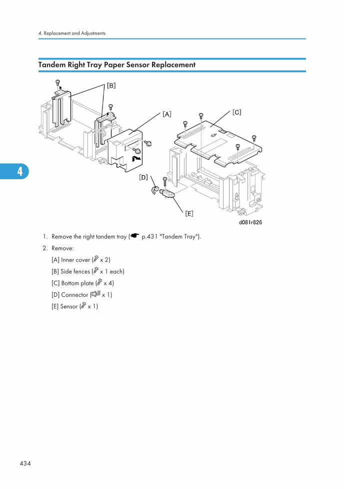
Tandem Right Tray Paper Sensor Replacement
1. Remove the right tandem tray ( p.431 "Tandem Tray").
2. Remove:
[A] Inner cover ( x 2)
[B] Side fences ( x 1 each)
[C] Bottom plate ( x 4)
[D] Connector ( x 1)
[E] Sensor ( x 1)
4. Replacement and Adjustments
434
4
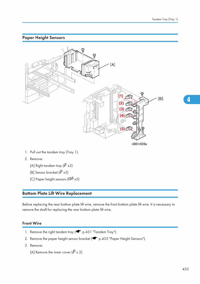
Paper Height Sensors
1. Pull out the tandem tray (Tray 1).
2. Remove:
[A] Right tandem tray ( x2)
[B] Sensor bracket ( x3)
[C] Paper height sensors ( x5)
Bottom Plate Lift Wire Replacement
Before replacing the rear bottom plate lift wire, remove the front bottom plate lift wire. It is necessary toremove the shaft for replacing the rear bottom plate lift wire.
Front Wire
1. Remove the right tandem tray ( p.431 "Tandem Tray").
2. Remove the paper height sensor bracket ( p.435 "Paper Height Sensors").
3. Remove:
[A] Remove the inner cover ( x 2)
Tandem Tray (Tray 1)
435
4
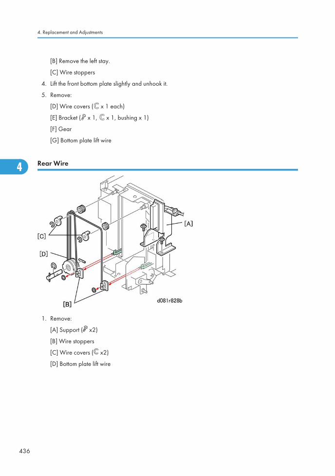
[B] Remove the left stay.
[C] Wire stoppers
4. Lift the front bottom plate slightly and unhook it.
5. Remove:
[D] Wire covers ( x 1 each)
[E] Bracket ( x 1, x 1, bushing x 1)
[F] Gear
[G] Bottom plate lift wire
Rear Wire
1. Remove:
[A] Support ( x2)
[B] Wire stoppers
[C] Wire covers ( x2)
[D] Bottom plate lift wire
4. Replacement and Adjustments
436
4
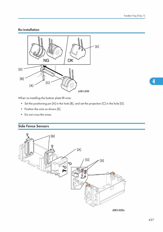
Re-installation
When re-installing the bottom plate lift wire:
• Set the positioning pin [A] in the hole [B], and set the projection [C] in the hole [D].
• Position the wire as shown [E].
• Do not cross the wires.
Side Fence Sensors
Tandem Tray (Tray 1)
437
4
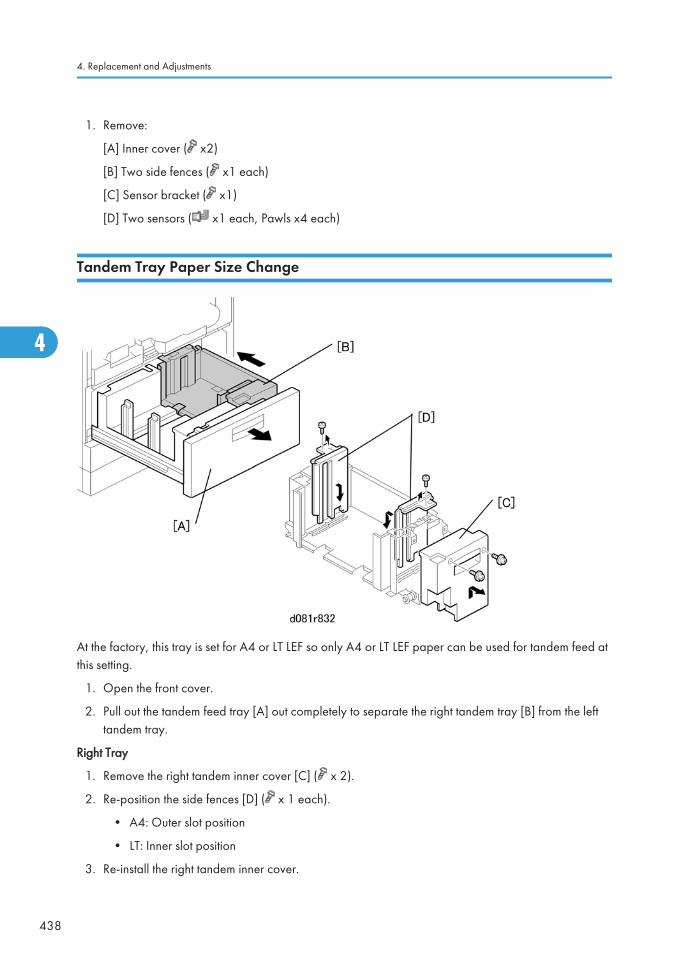
1. Remove:
[A] Inner cover ( x2)
[B] Two side fences ( x1 each)
[C] Sensor bracket ( x1)
[D] Two sensors ( x1 each, Pawls x4 each)
Tandem Tray Paper Size Change
At the factory, this tray is set for A4 or LT LEF so only A4 or LT LEF paper can be used for tandem feed atthis setting.
1. Open the front cover.
2. Pull out the tandem feed tray [A] out completely to separate the right tandem tray [B] from the lefttandem tray.
Right Tray
1. Remove the right tandem inner cover [C] ( x 2).
2. Re-position the side fences [D] ( x 1 each).
• A4: Outer slot position
• LT: Inner slot position
3. Re-install the right tandem inner cover.
4. Replacement and Adjustments
438
4
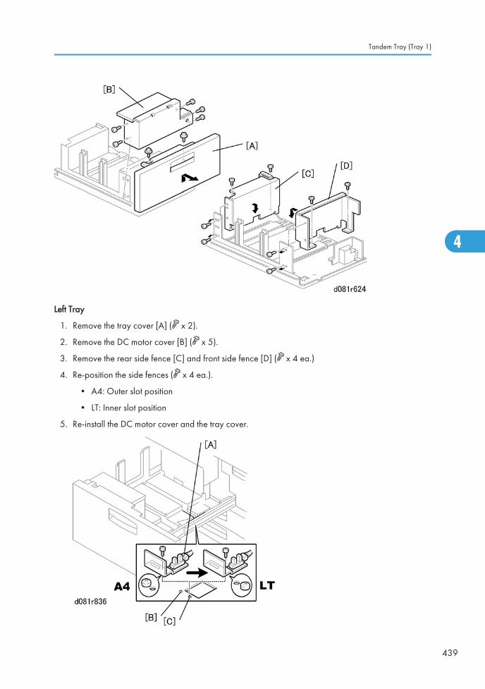
Left Tray
1. Remove the tray cover [A] ( x 2).
2. Remove the DC motor cover [B] ( x 5).
3. Remove the rear side fence [C] and front side fence [D] ( x 4 ea.)
4. Re-position the side fences ( x 4 ea.).
• A4: Outer slot position
• LT: Inner slot position
5. Re-install the DC motor cover and the tray cover.
Tandem Tray (Tray 1)
439
4
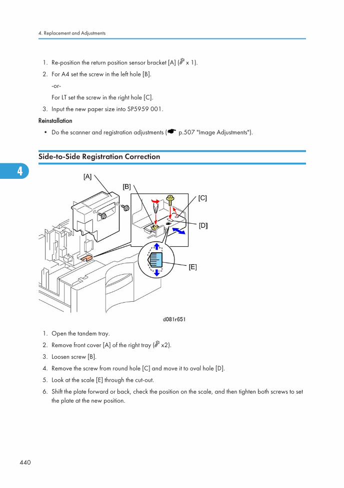
1. Re-position the return position sensor bracket [A] ( x 1).
2. For A4 set the screw in the left hole [B].
-or-
For LT set the screw in the right hole [C].
3. Input the new paper size into SP5959 001.
Reinstallation
• Do the scanner and registration adjustments ( p.507 "Image Adjustments").
Side-to-Side Registration Correction
1. Open the tandem tray.
2. Remove front cover [A] of the right tray ( x2).
3. Loosen screw [B].
4. Remove the screw from round hole [C] and move it to oval hole [D].
5. Look at the scale [E] through the cut-out.
6. Shift the plate forward or back, check the position on the scale, and then tighten both screws to setthe plate at the new position.
4. Replacement and Adjustments
440
4
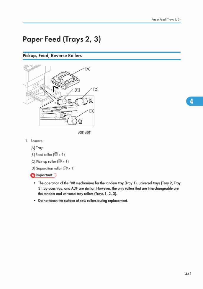
Paper Feed (Trays 2, 3)
Pickup, Feed, Reverse Rollers
1. Remove:
[A] Tray.
[B] Feed roller ( x 1)
[C] Pick-up roller ( x 1)
[D] Separation roller ( x 1)
• The operation of the FRR mechanisms for the tandem tray (Tray 1), universal trays (Tray 2, Tray3), by-pass tray, and ADF are similar. However, the only rollers that are interchangeable arethe tandem and universal tray rollers (Trays 1, 2, 3).
• Do not touch the surface of new rollers during replacement.
Paper Feed (Trays 2, 3)
441
4
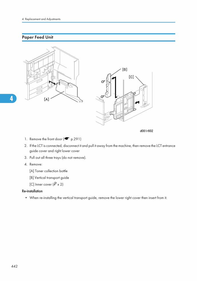
Paper Feed Unit
1. Remove the front door ( p.291)
2. If the LCT is connected, disconnect it and pull it away from the machine, then remove the LCT entranceguide cover and right lower cover
3. Pull out all three trays (do not remove).
4. Remove:
[A] Toner collection bottle
[B] Vertical transport guide
[C] Inner cover ( x 2)
Re-installation
• When re-installing the vertical transport guide, remove the lower right cover then insert from it.
4. Replacement and Adjustments
442
4
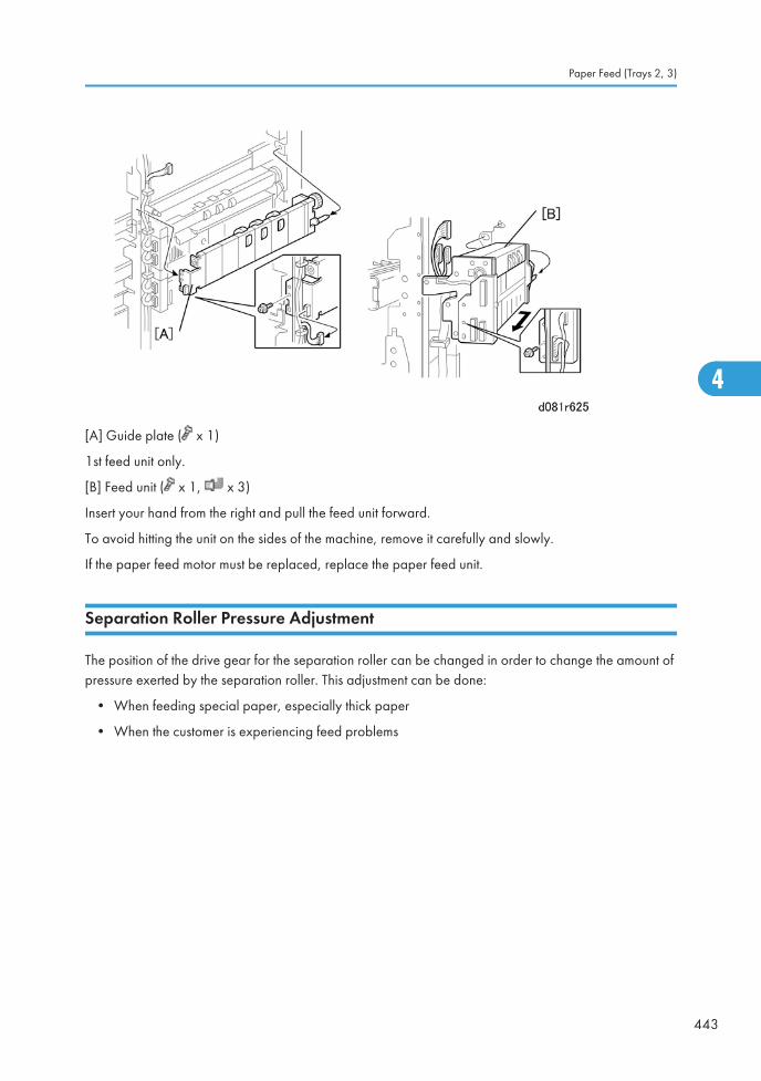
[A] Guide plate ( x 1)
1st feed unit only.
[B] Feed unit ( x 1, x 3)
Insert your hand from the right and pull the feed unit forward.
To avoid hitting the unit on the sides of the machine, remove it carefully and slowly.
If the paper feed motor must be replaced, replace the paper feed unit.
Separation Roller Pressure Adjustment
The position of the drive gear for the separation roller can be changed in order to change the amount ofpressure exerted by the separation roller. This adjustment can be done:
• When feeding special paper, especially thick paper
• When the customer is experiencing feed problems
Paper Feed (Trays 2, 3)
443
4
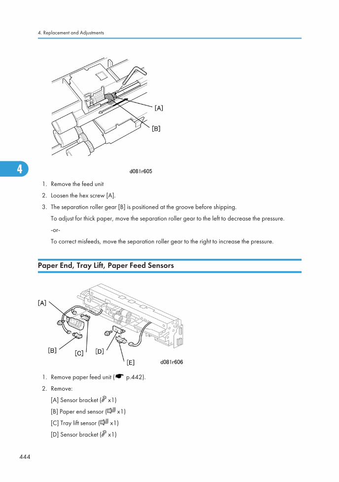
1. Remove the feed unit
2. Loosen the hex screw [A].
3. The separation roller gear [B] is positioned at the groove before shipping.
To adjust for thick paper, move the separation roller gear to the left to decrease the pressure.
-or-
To correct misfeeds, move the separation roller gear to the right to increase the pressure.
Paper End, Tray Lift, Paper Feed Sensors
1. Remove paper feed unit ( p.442).
2. Remove:
[A] Sensor bracket ( x1)
[B] Paper end sensor ( x1)
[C] Tray lift sensor ( x1)
[D] Sensor bracket ( x1)
4. Replacement and Adjustments
444
4
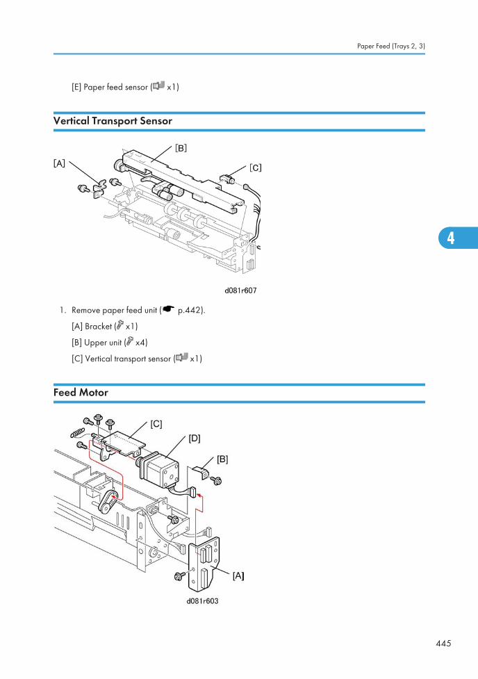
[E] Paper feed sensor ( x1)
Vertical Transport Sensor
1. Remove paper feed unit ( p.442).
[A] Bracket ( x1)
[B] Upper unit ( x4)
[C] Vertical transport sensor ( x1)
Feed Motor
Paper Feed (Trays 2, 3)
445
4
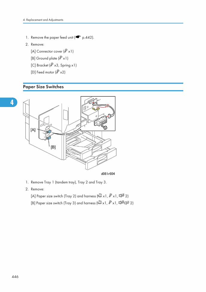
1. Remove the paper feed unit ( p.442).
2. Remove:
[A] Connector cover ( x1)
[B] Ground plate ( x1)
[C] Bracket ( x3, Spring x1)
[D] Feed motor ( x2)
Paper Size Switches
1. Remove Tray 1 (tandem tray), Tray 2 and Tray 3.
2. Remove:
[A] Paper size switch (Tray 2) and harness ( x1, x1, 2)
[B] Paper size switch (Tray 3) and harness ( x1, x1, 2)
4. Replacement and Adjustments
446
4
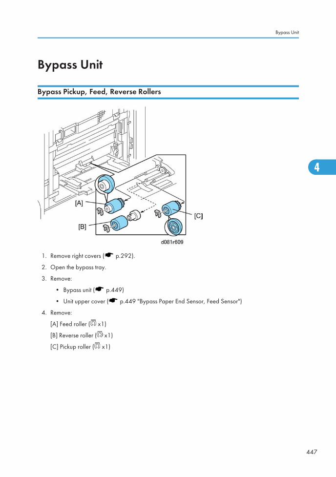
Bypass Unit
Bypass Pickup, Feed, Reverse Rollers
1. Remove right covers ( p.292).
2. Open the bypass tray.
3. Remove:
• Bypass unit ( p.449)
• Unit upper cover ( p.449 "Bypass Paper End Sensor, Feed Sensor")
4. Remove:
[A] Feed roller ( x1)
[B] Reverse roller ( x1)
[C] Pickup roller ( x1)
Bypass Unit
447
4
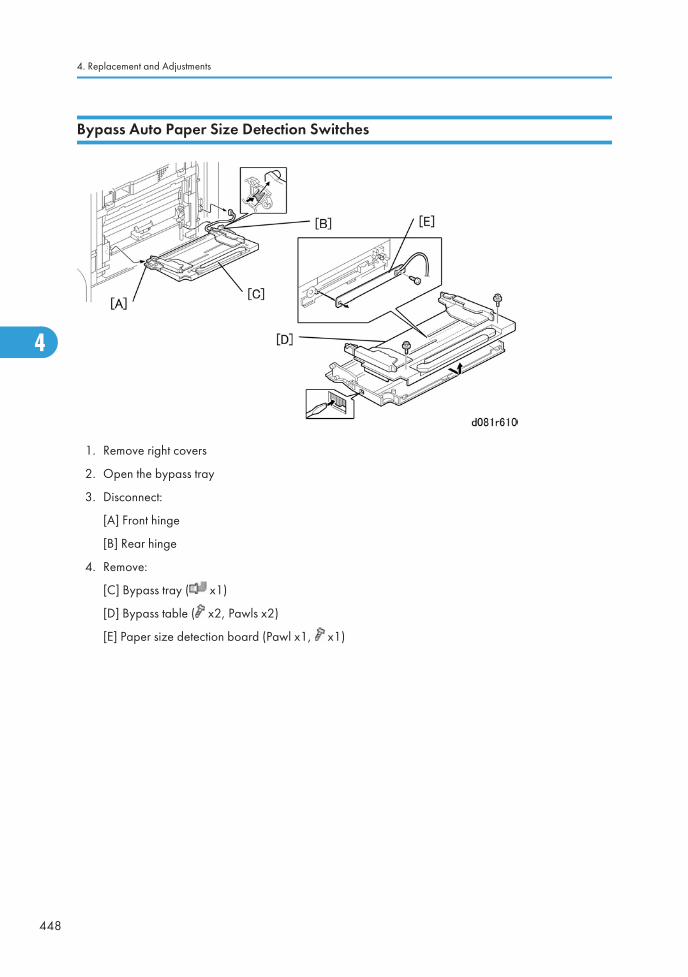
Bypass Auto Paper Size Detection Switches
1. Remove right covers
2. Open the bypass tray
3. Disconnect:
[A] Front hinge
[B] Rear hinge
4. Remove:
[C] Bypass tray ( x1)
[D] Bypass table ( x2, Pawls x2)
[E] Paper size detection board (Pawl x1, x1)
4. Replacement and Adjustments
448
4
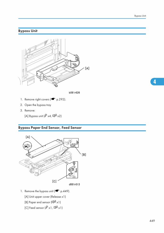
Bypass Unit
1. Remove right covers ( p.292).
2. Open the bypass tray
3. Remove:
[A] Bypass unit ( x4, x2)
Bypass Paper End Sensor, Feed Sensor
1. Remove the bypass unit ( p.449).
[A] Unit upper cover (Release x1)
[B] Paper end sensor ( x1)
[C] Feed sensor ( x1, x1)
Bypass Unit
449
4
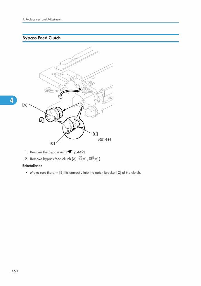
Bypass Feed Clutch
1. Remove the bypass unit ( p.449).
2. Remove bypass feed clutch [A] ( x1, x1)
Reinstallation
• Make sure the arm [B] fits correctly into the notch bracket [C] of the clutch.
4. Replacement and Adjustments
450
4
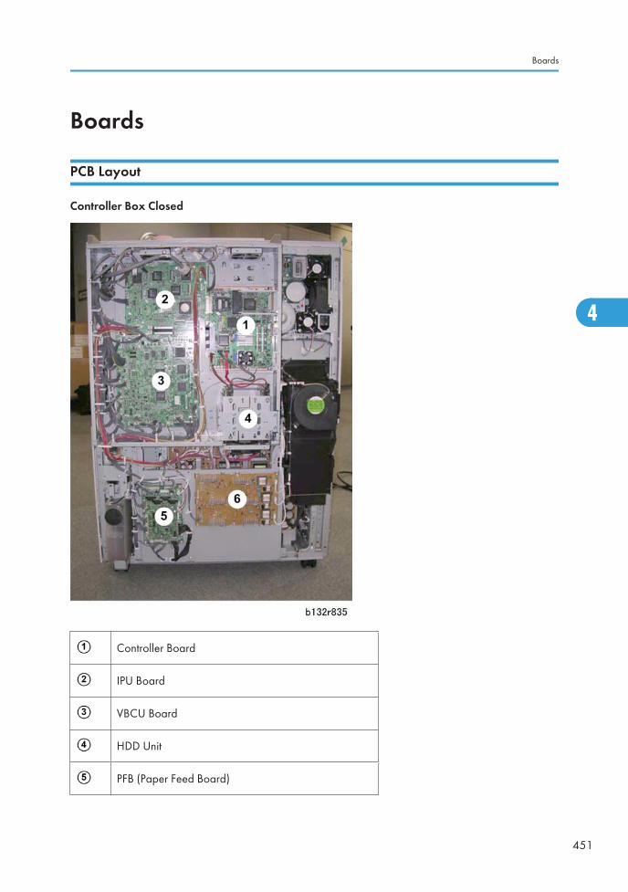
Boards
PCB Layout
Controller Box Closed
Controller Board
IPU Board
VBCU Board
HDD Unit
PFB (Paper Feed Board)
Boards
451
4
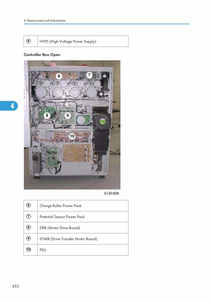
HVPS (High Voltage Power Supply)
Controller Box Open
Charge Roller Power Pack
Potential Sensor Power Pack
DRB (Motor Drive Board)
DTMB (Drum Transfer Motor Board)
PSU
4. Replacement and Adjustments
452
4
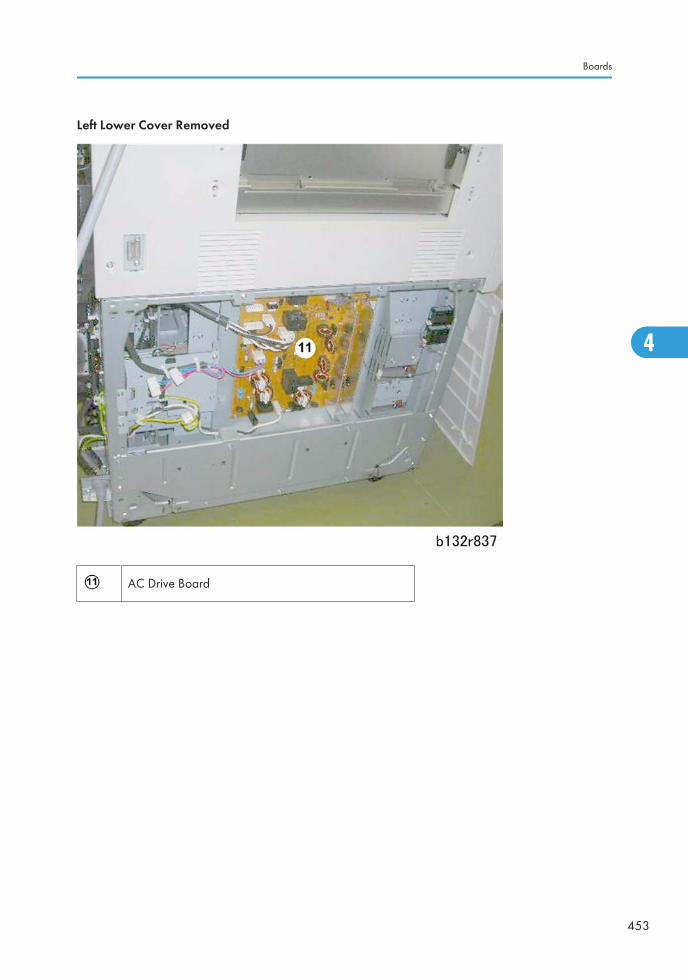
Left Lower Cover Removed
AC Drive Board
Boards
453
4
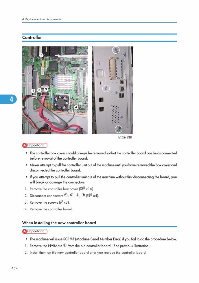
Controller
• The controller box cover should always be removed so that the controller board can be disconnectedbefore removal of the controller board.
• Never attempt to pull the controller unit out of the machine until you have removed the box cover anddisconnected the controller board.
• If you attempt to pull the controller unit out of the machine without first disconnecting the board, youwill break or damage the connectors.
1. Remove the controller box cover ( x16)
2. Disconnect connectors , , , ( x4).
3. Remove the screws ( x3).
4. Remove the controller board.
When installing the new controller board
• The machine will issue SC195 (Machine Serial Number Error) if you fail to do the procedure below.
1. Remove the NVRAMs from the old controller board. (See previous illustration.)
2. Install them on the new controller board after you replace the controller board.
4. Replacement and Adjustments
454
4
3. Replace the NVRAMs if the NVRAM on the old controller board is defective.
• Make sure you print out the SMC reports ("SP Mode Data" and "Logging Data") before youreplace the NVRAMs.
• Keep NVRAMs away from any objects that can cause static electricity. Static electricity candamage NVRAM data.
• Make sure the NVRAMs are correctly installed on the controller board.
• Make sure that the DIP-switch settings on the old controller board are the same for the newcontroller board. Do not change the DIP switches on the controller board in the field.
After installing the controller board
1. For a model in which the HDD encryption unit has been installed, restoring the encryption key isrequired. Refer to "Recovery from a Device Problem" in the installation procedure for the HDDEncryption Unit.
2. Turn the main power switch off/on.
Boards
455
4
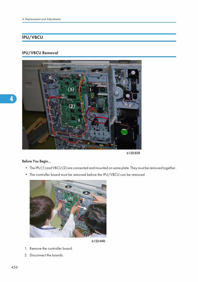
IPU/VBCU
IPU/VBCU Removal
Before You Begin…
• The IPU (1) and VBCU (2) are connected and mounted on same plate. They must be removed together.
• The controller board must be removed before the IPU/VBCU can be removed.
1. Remove the controller board.
2. Disconnect the boards.
4. Replacement and Adjustments
456
4
Ed
Typewritten Text
RTB 118: Before removing a defective VBCU
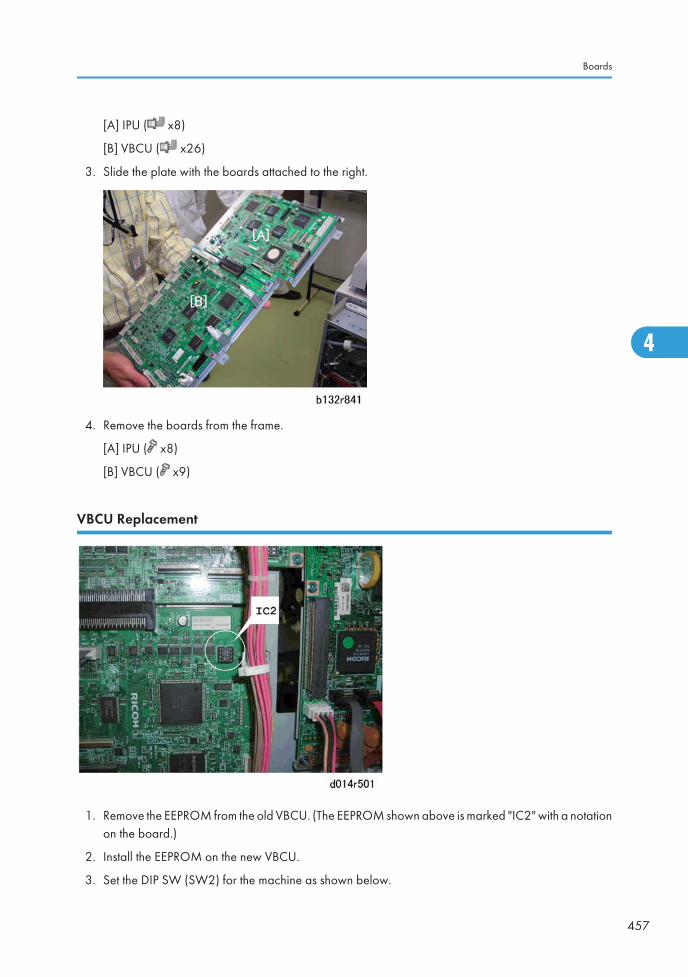
[A] IPU ( x8)
[B] VBCU ( x26)
3. Slide the plate with the boards attached to the right.
4. Remove the boards from the frame.
[A] IPU ( x8)
[B] VBCU ( x9)
VBCU Replacement
1. Remove the EEPROM from the old VBCU. (The EEPROM shown above is marked "IC2" with a notationon the board.)
2. Install the EEPROM on the new VBCU.
3. Set the DIP SW (SW2) for the machine as shown below.
Boards
457
4
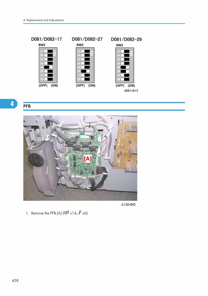
PFB
1. Remove the PFB [A] ( x14, x6).
4. Replacement and Adjustments
458
4
Ed
Typewritten Text
RTB 19 This has now been corrected
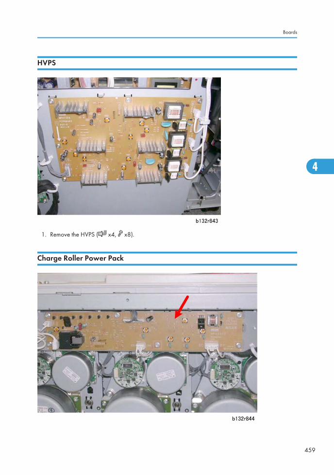
HVPS
1. Remove the HVPS ( x4, x8).
Charge Roller Power Pack
Boards
459
4
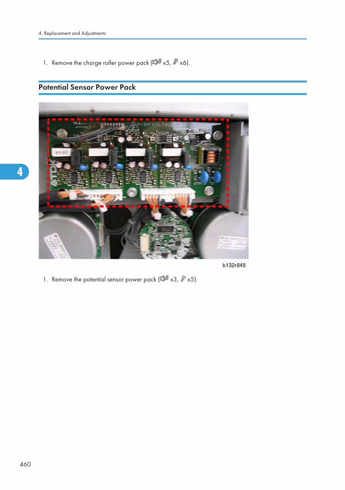
1. Remove the charge roller power pack ( x5, x6).
Potential Sensor Power Pack
1. Remove the potential sensor power pack ( x3, x5).
4. Replacement and Adjustments
460
4
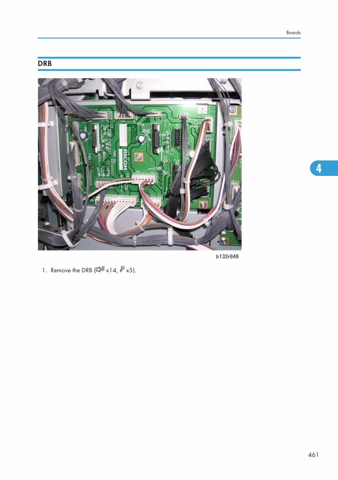
DRB
1. Remove the DRB ( x14, x5).
Boards
461
4
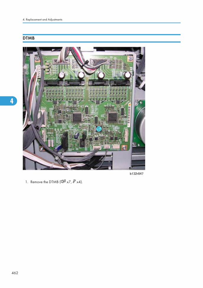
DTMB
1. Remove the DTMB ( x7, x4).
4. Replacement and Adjustments
462
4
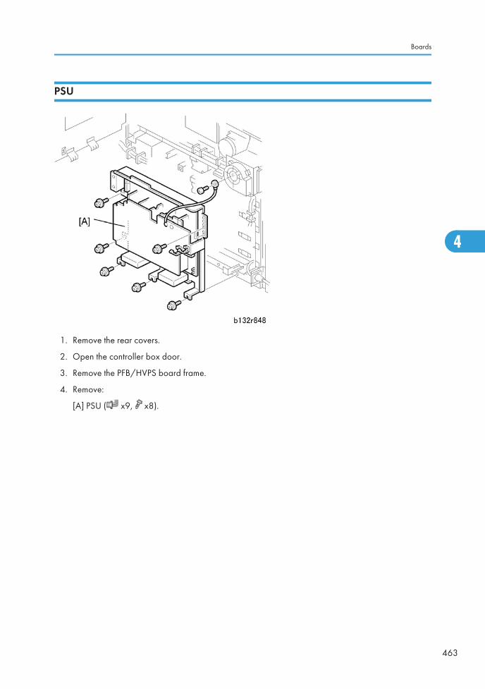
PSU
1. Remove the rear covers.
2. Open the controller box door.
3. Remove the PFB/HVPS board frame.
4. Remove:
[A] PSU ( x9, x8).
Boards
463
4
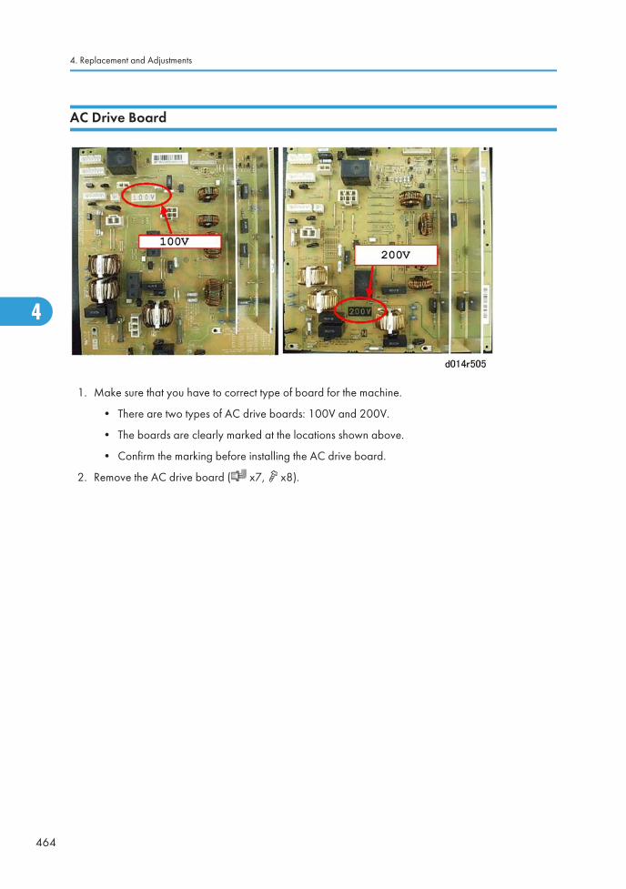
AC Drive Board
1. Make sure that you have to correct type of board for the machine.
• There are two types of AC drive boards: 100V and 200V.
• The boards are clearly marked at the locations shown above.
• Confirm the marking before installing the AC drive board.
2. Remove the AC drive board ( x7, x8).
4. Replacement and Adjustments
464
4
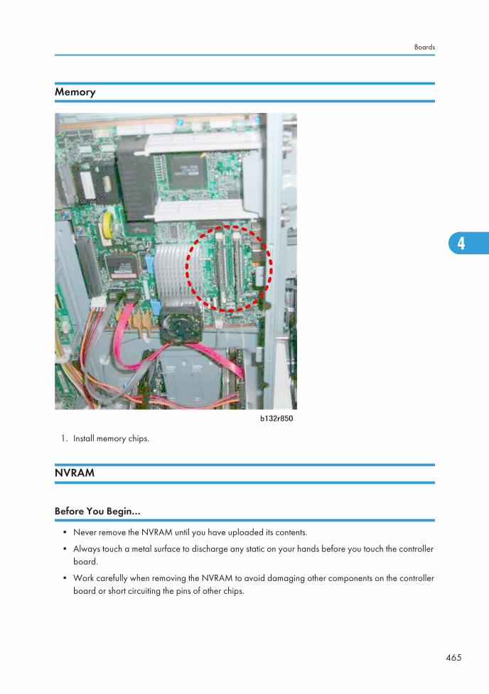
Memory
1. Install memory chips.
NVRAM
Before You Begin…
• Never remove the NVRAM until you have uploaded its contents.
• Always touch a metal surface to discharge any static on your hands before you touch the controllerboard.
• Work carefully when removing the NVRAM to avoid damaging other components on the controllerboard or short circuiting the pins of other chips.
Boards
465
4
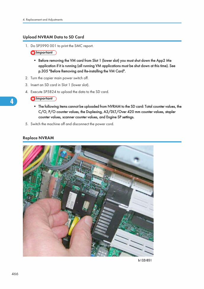
Upload NVRAM Data to SD Card
1. Do SP5990 001 to print the SMC report.
• Before removing the VM card from Slot 1 (lower slot) you must shut down the App2 Meapplication if it is running (all running VM applications must be shut down at this time). Seep.305 "Before Removing and Re-installing the VM Card".
2. Turn the copier main power switch off.
3. Insert an SD card in Slot 1 (lower slot).
4. Execute SP5824 to upload the data to the SD card.
• The following items cannot be uploaded from NVRAM to the SD card: Total counter values, theC/O, P/O counter values, the Duplexing, A3/DLT/Over 420 mm counter values, staplercounter values, scanner counter values, and Engine SP settings.
5. Switch the machine off and disconnect the power cord.
Replace NVRAM
4. Replacement and Adjustments
466
4

1. Remove the old NVRAM.
2. Attach the new NVRAM.
Download NVRAM Data from SD Card
1. Turn the copier main power switch off.
2. Put the SD card with the NVRAM data into Slot 1 (lower slot).
3. Open the front door of the copier.
4. Turn the copier main power switch on.
If the NVRAM is new, SC195 (Machine Serial Number Error) may appear. If this occurs:
• Enter the SP mode and do SP5801 001 to reset the memory to the defaults (All).
• Switch the machine off/on and start from Step 1.
• If SC195 occurs, the serial number must be input. You must contact your technical supervisor.
5. Execute SP5825 to download the data uploaded from the old NVRAM.
6. Switch the machine off and remove the SD card.
7. Switch the machine on, then do SP5990-1 to print another SMC report.
8. Compare this new SMC report with the report you printed in Step 1. If any of the SP settings aredifferent, enter the SP settings of the first report.
9. Execute SP5907 and enter the brand and model name of the machine for Windows Plug & Playcapability.
• If the client is using any VM card applications, such as App2 Me, you must do the procedure tore-start these VM applications. ( p.305 "Before Removing and Re-installing the VM Card")
Boards
467
4
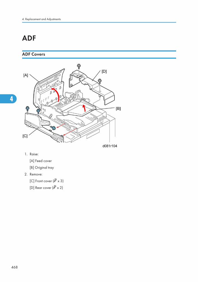
ADF
ADF Covers
1. Raise:
[A] Feed cover
[B] Original tray
2. Remove:
[C] Front cover ( x 3)
[D] Rear cover ( x 2)
4. Replacement and Adjustments
468
4

Feed Unit
1. Open the feed cover [A].
2. Remove the snap fitting [B].
3. Push the feed unit slowly to the left to disengage the shaft [C] on the right, and lift it out.
ADF
469
4
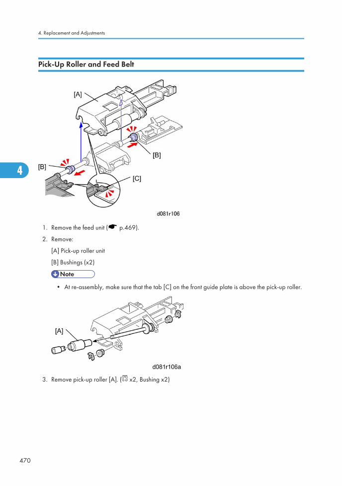
Pick-Up Roller and Feed Belt
1. Remove the feed unit ( p.469).
2. Remove:
[A] Pick-up roller unit
[B] Bushings (x2)
• At re-assembly, make sure that the tab [C] on the front guide plate is above the pick-up roller.
3. Remove pick-up roller [A]. ( x2, Bushing x2)
4. Replacement and Adjustments
470
4
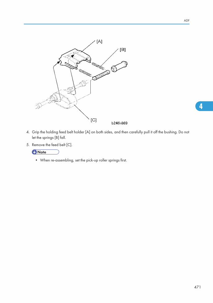
4. Grip the holding feed belt holder [A] on both sides, and then carefully pull it off the bushing. Do notlet the springs [B] fall.
5. Remove the feed belt [C].
• When re-assembling, set the pick-up roller springs first.
ADF
471
4
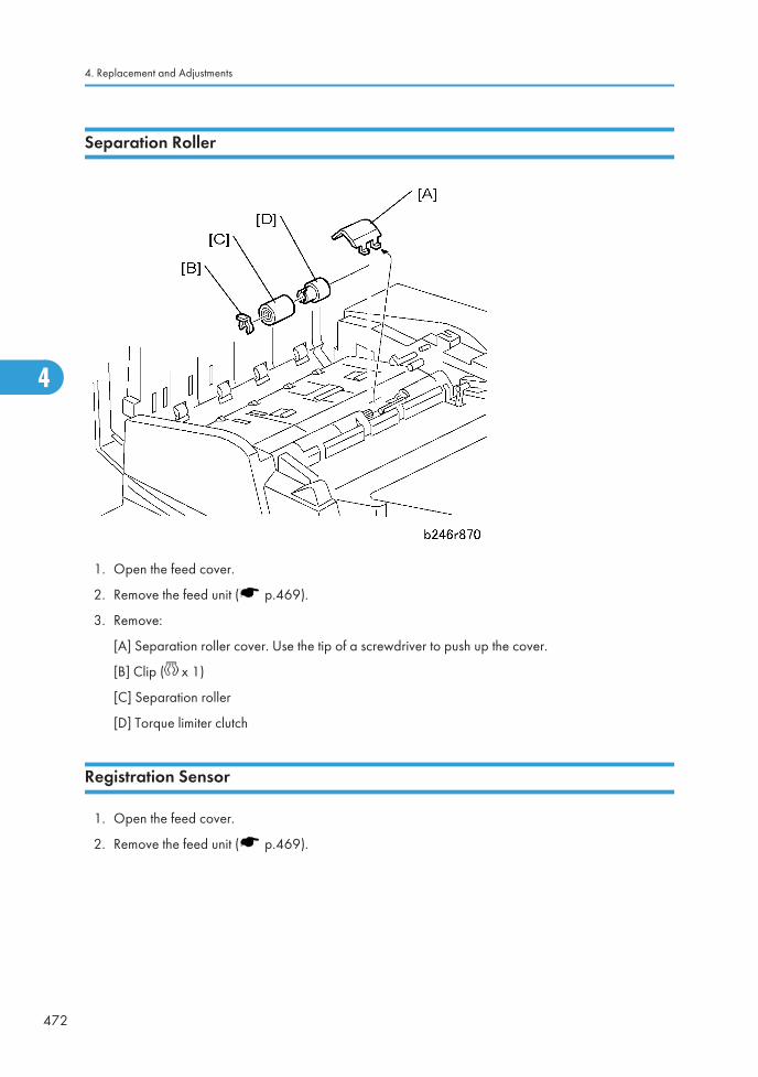
Separation Roller
1. Open the feed cover.
2. Remove the feed unit ( p.469).
3. Remove:
[A] Separation roller cover. Use the tip of a screwdriver to push up the cover.
[B] Clip ( x 1)
[C] Separation roller
[D] Torque limiter clutch
Registration Sensor
1. Open the feed cover.
2. Remove the feed unit ( p.469).
4. Replacement and Adjustments
472
4
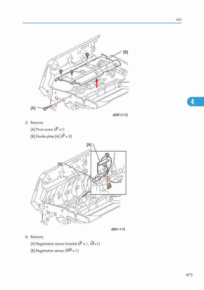
3. Remove:
[A] Pivot screw ( x1)
[B] Guide plate [A] ( x 3)
4. Remove:
[A] Registration sensor bracket ( x 1, x1)
[B] Registration sensor ( x 1)
ADF
473
4
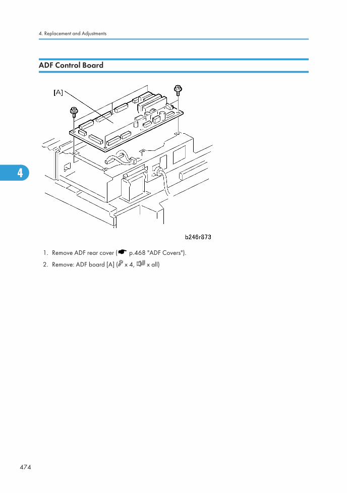
ADF Control Board
1. Remove ADF rear cover ( p.468 "ADF Covers").
2. Remove: ADF board [A] ( x 4, x all)
4. Replacement and Adjustments
474
4
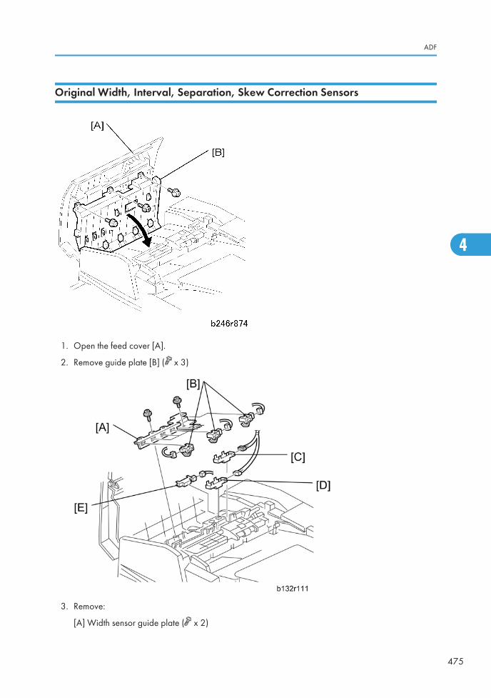
Original Width, Interval, Separation, Skew Correction Sensors
1. Open the feed cover [A].
2. Remove guide plate [B] ( x 3)
3. Remove:
[A] Width sensor guide plate ( x 2)
ADF
475
4
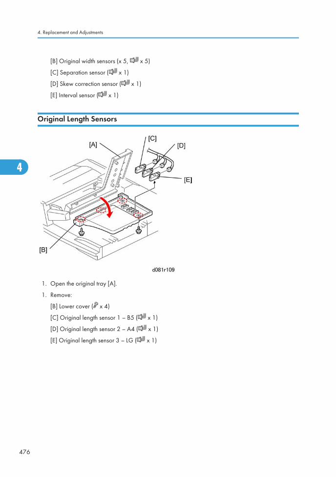
[B] Original width sensors (x 5, x 5)
[C] Separation sensor ( x 1)
[D] Skew correction sensor ( x 1)
[E] Interval sensor ( x 1)
Original Length Sensors
1. Open the original tray [A].
1. Remove:
[B] Lower cover ( x 4)
[C] Original length sensor 1 – B5 ( x 1)
[D] Original length sensor 2 – A4 ( x 1)
[E] Original length sensor 3 – LG ( x 1)
4. Replacement and Adjustments
476
4
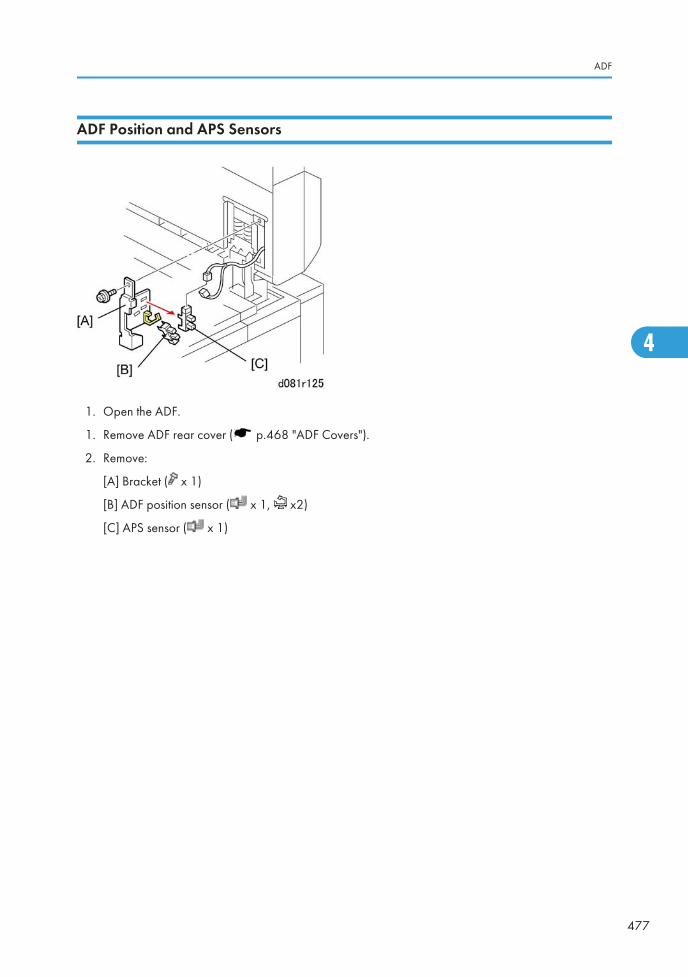
ADF Position and APS Sensors
1. Open the ADF.
1. Remove ADF rear cover ( p.468 "ADF Covers").
2. Remove:
[A] Bracket ( x 1)
[B] ADF position sensor ( x 1, x2)
[C] APS sensor ( x 1)
ADF
477
4
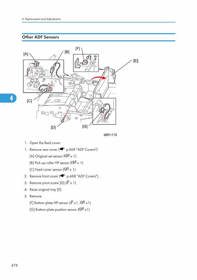
Other ADF Sensors
1. Open the feed cover.
1. Remove rear cover ( p.468 "ADF Covers").
[A] Original set sensor ( x 1)
[B] Pick-up roller HP sensor ( x 1)
[C] Feed cover sensor ( x 1)
2. Remove front cover ( p.468 "ADF Covers").
3. Remove pivot screw [D] ( x 1)
4. Raise original tray [E].
5. Remove:
[F] Bottom plate HP sensor ( x1, x1)
[G] Bottom plate position sensor ( x1)
4. Replacement and Adjustments
478
4
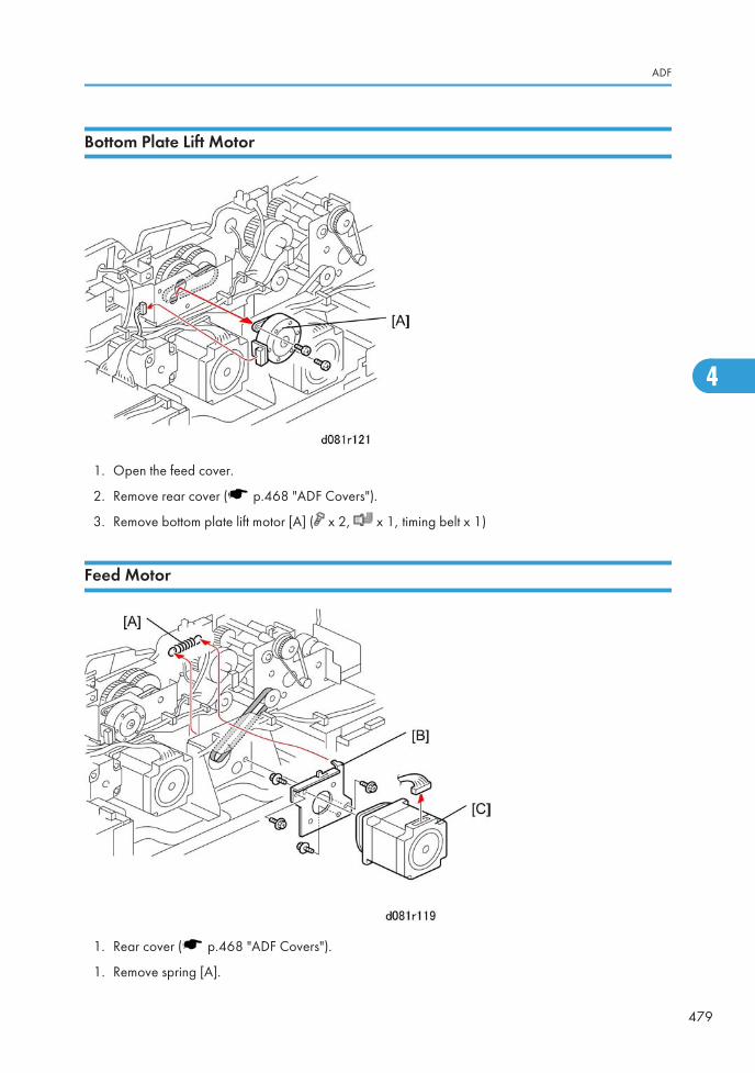
Bottom Plate Lift Motor
1. Open the feed cover.
2. Remove rear cover ( p.468 "ADF Covers").
3. Remove bottom plate lift motor [A] ( x 2, x 1, timing belt x 1)
Feed Motor
1. Rear cover ( p.468 "ADF Covers").
1. Remove spring [A].
ADF
479
4
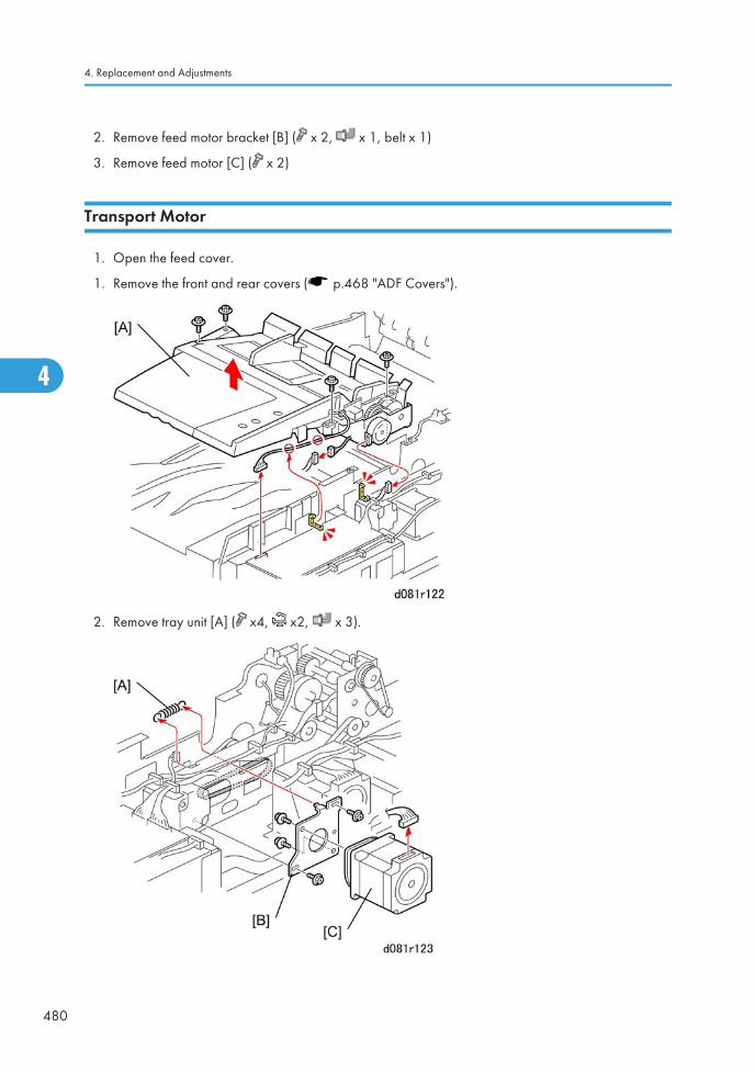
2. Remove feed motor bracket [B] ( x 2, x 1, belt x 1)
3. Remove feed motor [C] ( x 2)
Transport Motor
1. Open the feed cover.
1. Remove the front and rear covers ( p.468 "ADF Covers").
2. Remove tray unit [A] ( x4, x2, x 3).
4. Replacement and Adjustments
480
4
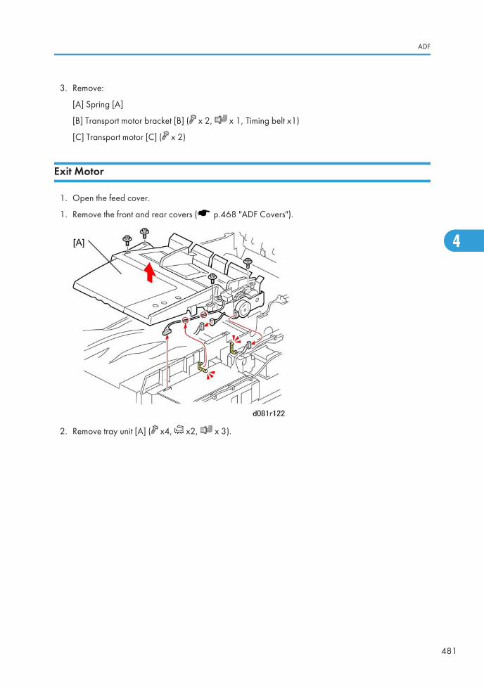
3. Remove:
[A] Spring [A]
[B] Transport motor bracket [B] ( x 2, x 1, Timing belt x1)
[C] Transport motor [C] ( x 2)
Exit Motor
1. Open the feed cover.
1. Remove the front and rear covers ( p.468 "ADF Covers").
2. Remove tray unit [A] ( x4, x2, x 3).
ADF
481
4
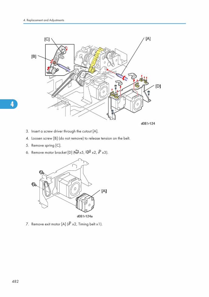
3. Insert a screw driver through the cutout [A].
4. Loosen screw [B] (do not remove) to release tension on the belt.
5. Remove spring [C].
6. Remove motor bracket [D] ( x5, x2, x3).
7. Remove exit motor [A] ( x2, Timing belt x1).
4. Replacement and Adjustments
482
4
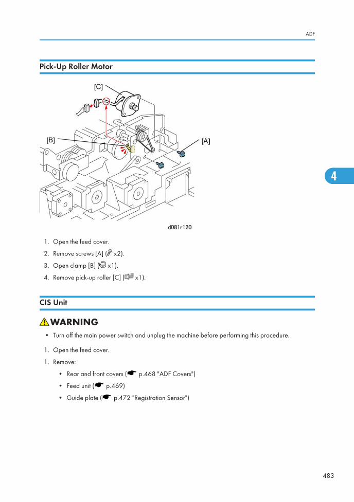
Pick-Up Roller Motor
1. Open the feed cover.
2. Remove screws [A] ( x2).
3. Open clamp [B] ( x1).
4. Remove pick-up roller [C] ( x1).
CIS Unit
• Turn off the main power switch and unplug the machine before performing this procedure.
1. Open the feed cover.
1. Remove:
• Rear and front covers ( p.468 "ADF Covers")
• Feed unit ( p.469)
• Guide plate ( p.472 "Registration Sensor")
ADF
483
4
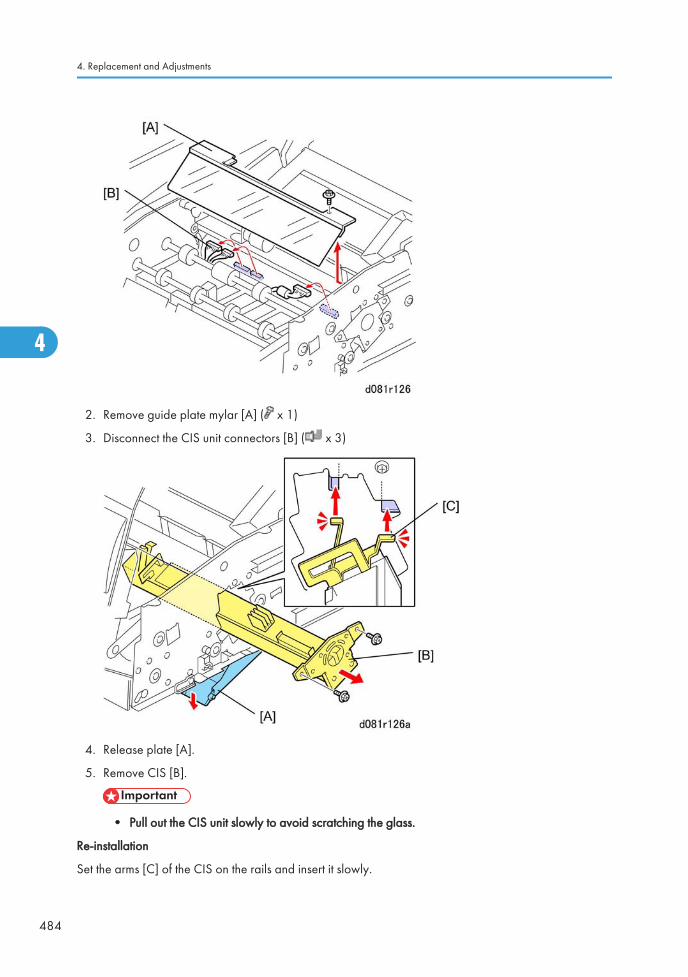
2. Remove guide plate mylar [A] ( x 1)
3. Disconnect the CIS unit connectors [B] ( x 3)
4. Release plate [A].
5. Remove CIS [B].
• Pull out the CIS unit slowly to avoid scratching the glass.
Re-installation
Set the arms [C] of the CIS on the rails and insert it slowly.
4. Replacement and Adjustments
484
4
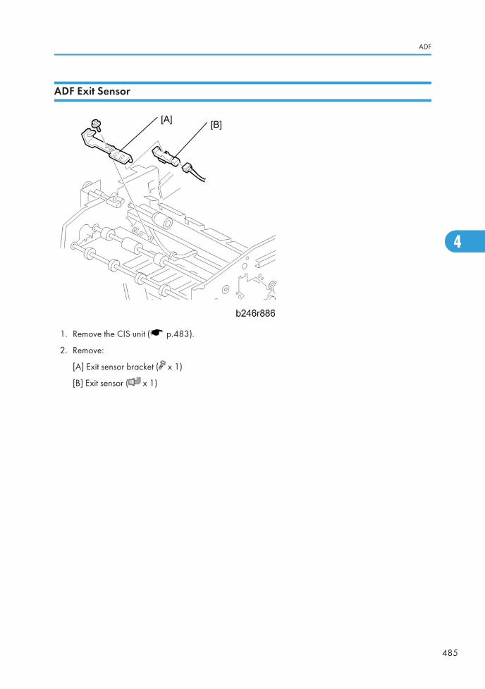
ADF Exit Sensor
1. Remove the CIS unit ( p.483).
2. Remove:
[A] Exit sensor bracket ( x 1)
[B] Exit sensor ( x 1)
ADF
485
4
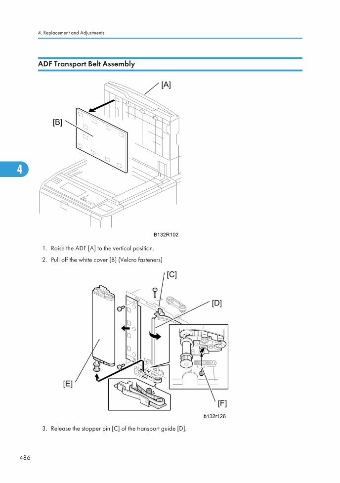
ADF Transport Belt Assembly
1. Raise the ADF [A] to the vertical position.
2. Pull off the white cover [B] (Velcro fasteners)
3. Release the stopper pin [C] of the transport guide [D].
4. Replacement and Adjustments
486
4
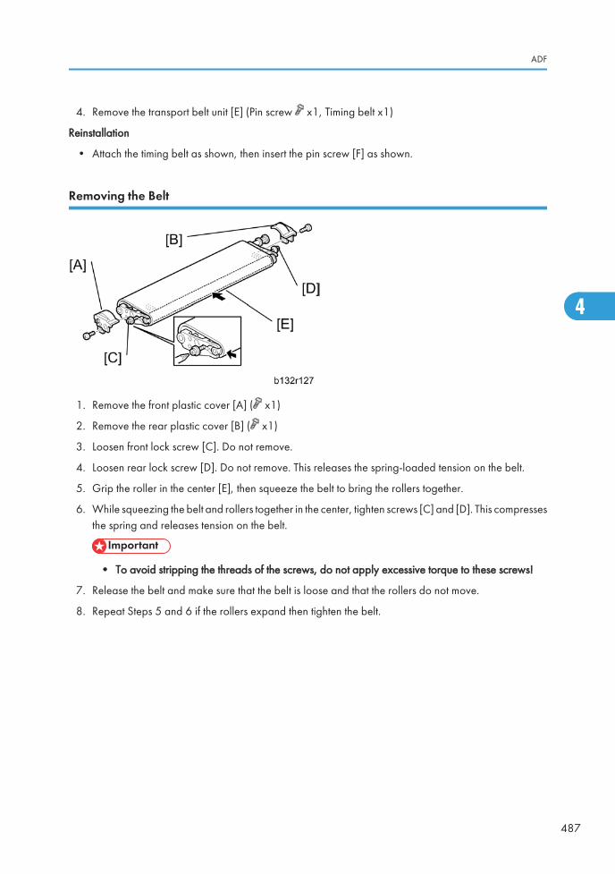
4. Remove the transport belt unit [E] (Pin screw x1, Timing belt x1)
Reinstallation
• Attach the timing belt as shown, then insert the pin screw [F] as shown.
Removing the Belt
1. Remove the front plastic cover [A] ( x1)
2. Remove the rear plastic cover [B] ( x1)
3. Loosen front lock screw [C]. Do not remove.
4. Loosen rear lock screw [D]. Do not remove. This releases the spring-loaded tension on the belt.
5. Grip the roller in the center [E], then squeeze the belt to bring the rollers together.
6. While squeezing the belt and rollers together in the center, tighten screws [C] and [D]. This compressesthe spring and releases tension on the belt.
• To avoid stripping the threads of the screws, do not apply excessive torque to these screws!
7. Release the belt and make sure that the belt is loose and that the rollers do not move.
8. Repeat Steps 5 and 6 if the rollers expand then tighten the belt.
ADF
487
4
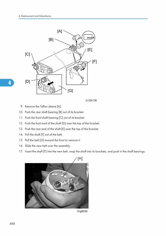
9. Remove the Teflon sleeve [A].
10. Push the rear shaft bearing [B] out of its bracket.
11. Push the front shaft bearing [C] out of its bracket.
12. Push the front end of the shaft [D] over the top of the bracket.
13. Push the rear end of the shaft [E] over the top of the bracket.
14. Pull the shaft [F] out of the belt.
15. Pull the belt [G] toward the front to remove it.
16. Slide the new belt over the assembly.
17. Insert the shaft [F] into the new belt, snap the shaft into its brackets, and push in the shaft bearings.
4. Replacement and Adjustments
488
4
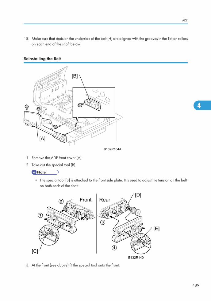
18. Make sure that studs on the underside of the belt [H] are aligned with the grooves in the Teflon rollerson each end of the shaft below.
Reinstalling the Belt
1. Remove the ADF front cover [A]
2. Take out the special tool [B].
• The special tool [B] is attached to the front side plate. It is used to adjust the tension on the belton both ends of the shaft.
3. At the front (see above) fit the special tool onto the front.
ADF
489
4
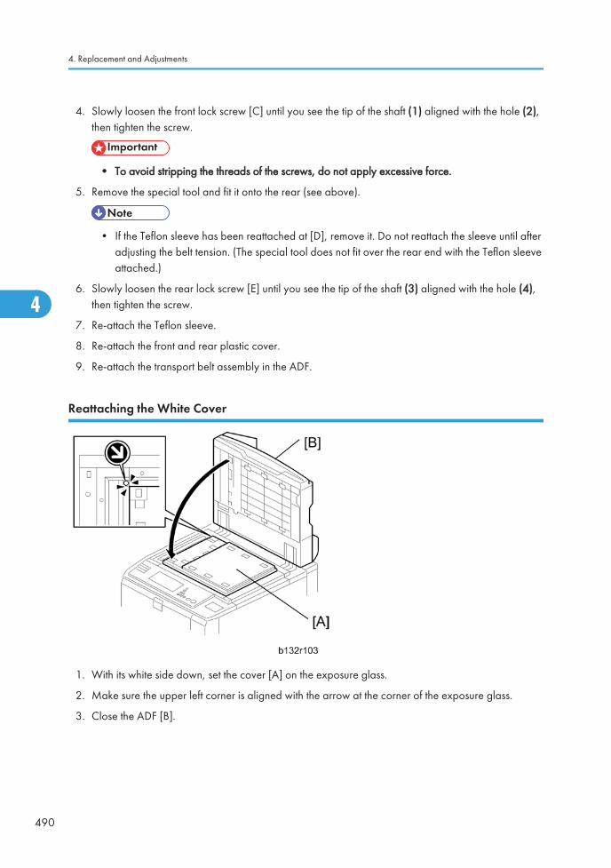
4. Slowly loosen the front lock screw [C] until you see the tip of the shaft (1) aligned with the hole (2),then tighten the screw.
• To avoid stripping the threads of the screws, do not apply excessive force.
5. Remove the special tool and fit it onto the rear (see above).
• If the Teflon sleeve has been reattached at [D], remove it. Do not reattach the sleeve until afteradjusting the belt tension. (The special tool does not fit over the rear end with the Teflon sleeveattached.)
6. Slowly loosen the rear lock screw [E] until you see the tip of the shaft (3) aligned with the hole (4),then tighten the screw.
7. Re-attach the Teflon sleeve.
8. Re-attach the front and rear plastic cover.
9. Re-attach the transport belt assembly in the ADF.
Reattaching the White Cover
1. With its white side down, set the cover [A] on the exposure glass.
2. Make sure the upper left corner is aligned with the arrow at the corner of the exposure glass.
3. Close the ADF [B].
4. Replacement and Adjustments
490
4
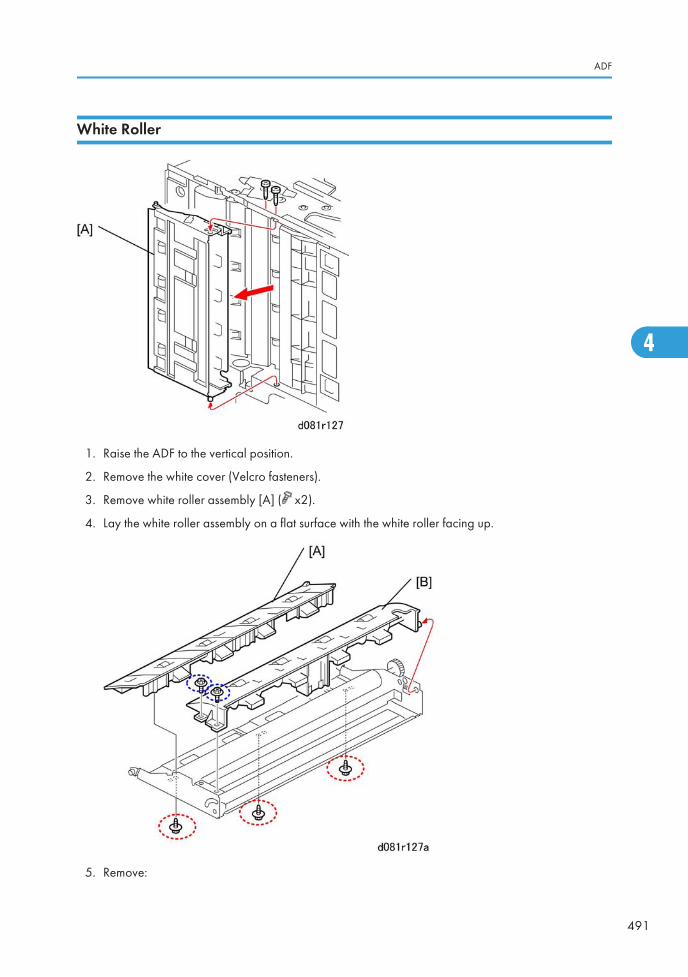
White Roller
1. Raise the ADF to the vertical position.
2. Remove the white cover (Velcro fasteners).
3. Remove white roller assembly [A] ( x2).
4. Lay the white roller assembly on a flat surface with the white roller facing up.
5. Remove:
ADF
491
4

[A] Left plate ( x3)
[B] Right plate ( x2)
6. Remove:
[A] Roller bracket [A] (Springs x2)
[B] Rear ( x1, Gear x1)
[C] Front (Spring x1)
[D] Rear (Spring x1)
[E] Lock piece
[F] White roller
4. Replacement and Adjustments
492
4
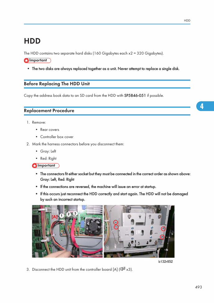
HDDThe HDD contains two separate hard disks (160 Gigabytes each x2 = 320 Gigabytes).
• The two disks are always replaced together as a unit. Never attempt to replace a single disk.
Before Replacing The HDD Unit
Copy the address book data to an SD card from the HDD with SP5846-051 if possible.
Replacement Procedure
1. Remove:
• Rear covers
• Controller box cover
2. Mark the harness connectors before you disconnect them:
• Gray: Left
• Red: Right
• The connectors fit either socket but they must be connected in the correct order as shown above:Gray: Left, Red: Right
• If the connections are reversed, the machine will issue an error at startup.
• If this occurs just reconnect the HDD correctly and start again. The HDD will not be damagedby such an incorrect startup.
3. Disconnect the HDD unit from the controller board [A] ( x3).
HDD
493
4
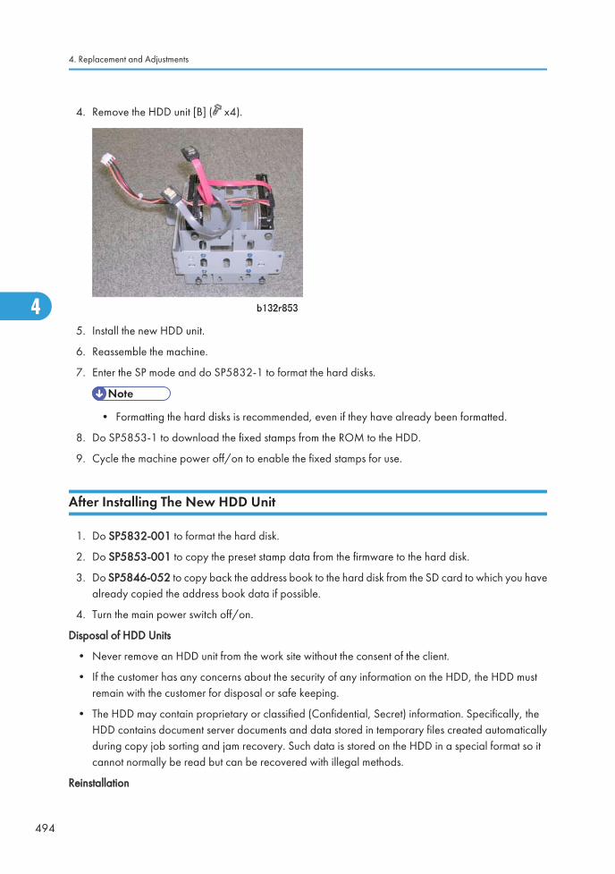
4. Remove the HDD unit [B] ( x4).
5. Install the new HDD unit.
6. Reassemble the machine.
7. Enter the SP mode and do SP5832-1 to format the hard disks.
• Formatting the hard disks is recommended, even if they have already been formatted.
8. Do SP5853-1 to download the fixed stamps from the ROM to the HDD.
9. Cycle the machine power off/on to enable the fixed stamps for use.
After Installing The New HDD Unit
1. Do SP5832-001 to format the hard disk.
2. Do SP5853-001 to copy the preset stamp data from the firmware to the hard disk.
3. Do SP5846-052 to copy back the address book to the hard disk from the SD card to which you havealready copied the address book data if possible.
4. Turn the main power switch off/on.
Disposal of HDD Units
• Never remove an HDD unit from the work site without the consent of the client.
• If the customer has any concerns about the security of any information on the HDD, the HDD mustremain with the customer for disposal or safe keeping.
• The HDD may contain proprietary or classified (Confidential, Secret) information. Specifically, theHDD contains document server documents and data stored in temporary files created automaticallyduring copy job sorting and jam recovery. Such data is stored on the HDD in a special format so itcannot normally be read but can be recovered with illegal methods.
Reinstallation
4. Replacement and Adjustments
494
4

• Explain to the customer that the following information stored on the HDD is lost when the HDD isreplaced: document server documents, fixed stamps, document server address book
• The address book and document server documents (if needed) must be input again.
• If the customer is using the Data Overwrite Security or the Data Encryption feature, these applicationsmust be installed again. For more, see Section "1. Installation".
• If the customer is using the HDD Encryption Unit, the encryption key must be restored after replacingthe HDD unit. For details, see the installation procedure for the HDD Encryption Unit.
HDD
495
4
O'Brien
O'Brien
Ed
Typewritten Text
RTB 30 Delete this part
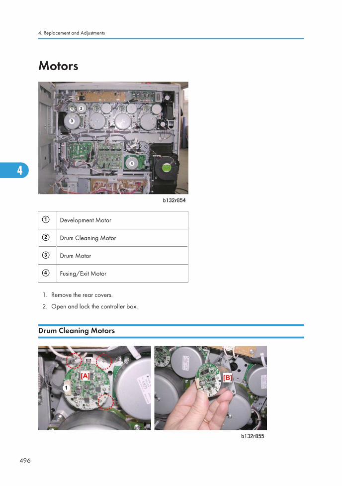
Motors
Development Motor
Drum Cleaning Motor
Drum Motor
Fusing/Exit Motor
1. Remove the rear covers.
2. Open and lock the controller box.
Drum Cleaning Motors
4. Replacement and Adjustments
496
4
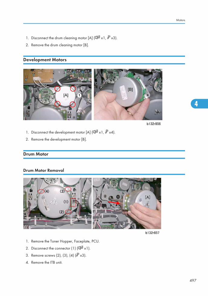
1. Disconnect the drum cleaning motor [A] ( x1, x3).
2. Remove the drum cleaning motor [B].
Development Motors
1. Disconnect the development motor [A] ( x1, x4).
2. Remove the development motor [B].
Drum Motor
Drum Motor Removal
1. Remove the Toner Hopper, Faceplate, PCU.
2. Disconnect the connector (1) ( x1).
3. Remove screws (2), (3), (4) ( x3).
4. Remove the ITB unit.
Motors
497
4
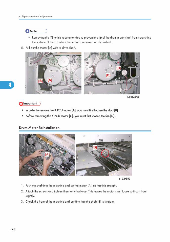
• Removing the ITB unit is recommended to prevent the tip of the drum motor shaft from scratchingthe surface of the ITB when the motor is removed or reinstalled.
5. Pull out the motor [A] with its drive shaft.
• In order to remove the K PCU motor [A], you must first loosen the duct [B].
• Before removing the Y PCU motor [C], you must first loosen the fan [D].
Drum Motor Reinstallation
1. Push the shaft into the machine and set the motor [A], so that it is straight.
2. Attach the screws and tighten them only halfway. This leaves the motor shaft loose so it can floatslightly.
3. Check the front of the machine and confirm that the shaft [B] is straight.
4. Replacement and Adjustments
498
4
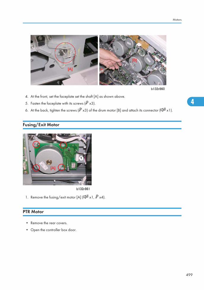
4. At the front, set the faceplate set the shaft [A] as shown above.
5. Fasten the faceplate with its screws ( x3).
6. At the back, tighten the screws ( x3) of the drum motor [B] and attach its connector ( x1).
Fusing/Exit Motor
1. Remove the fusing/exit motor [A] ( x1, x4).
PTR Motor
• Remove the rear covers.
• Open the controller box door.
Motors
499
4
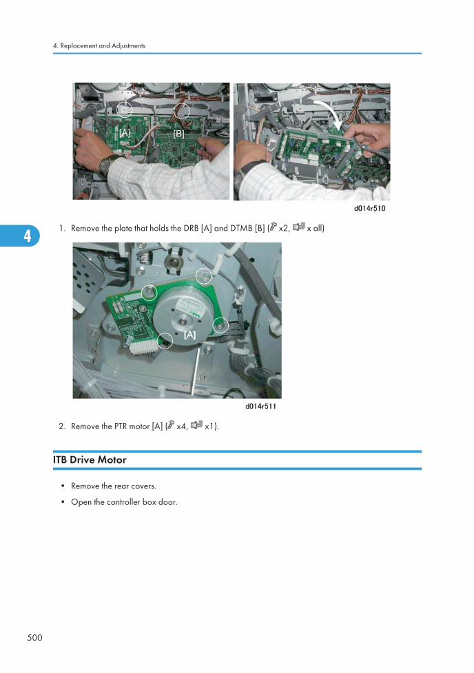
1. Remove the plate that holds the DRB [A] and DTMB [B] ( x2, x all)
2. Remove the PTR motor [A] ( x4, x1).
ITB Drive Motor
• Remove the rear covers.
• Open the controller box door.
4. Replacement and Adjustments
500
4
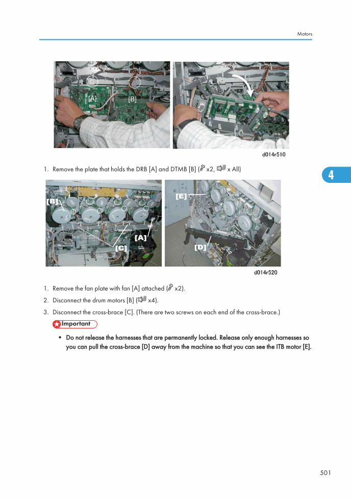
1. Remove the plate that holds the DRB [A] and DTMB [B] ( x2, x All)
1. Remove the fan plate with fan [A] attached ( x2).
2. Disconnect the drum motors [B] ( x4).
3. Disconnect the cross-brace [C]. (There are two screws on each end of the cross-brace.)
• Do not release the harnesses that are permanently locked. Release only enough harnesses soyou can pull the cross-brace [D] away from the machine so that you can see the ITB motor [E].
Motors
501
4
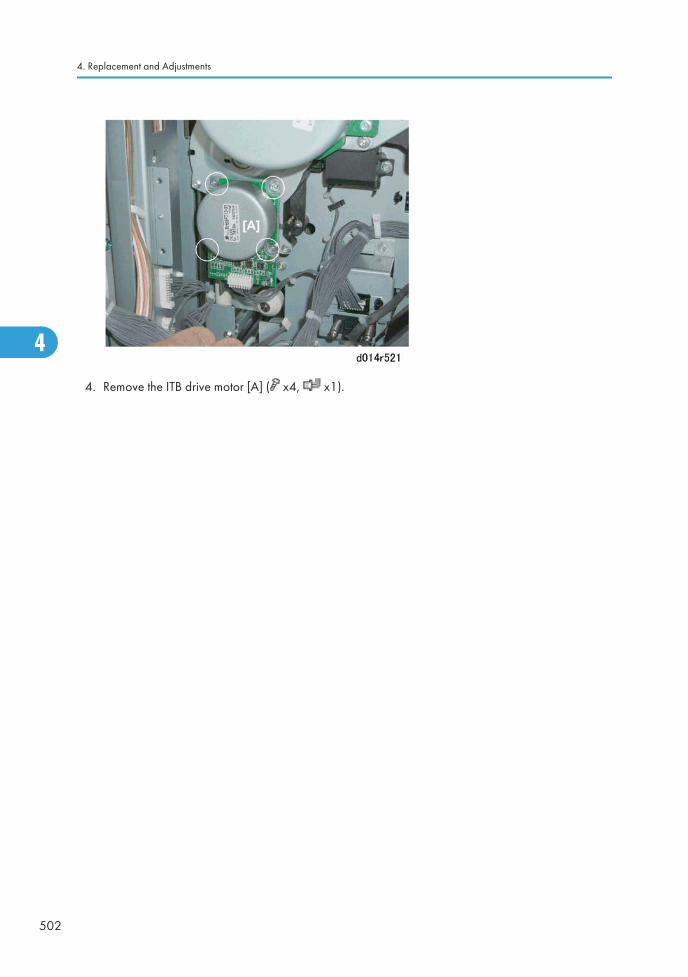
4. Remove the ITB drive motor [A] ( x4, x1).
4. Replacement and Adjustments
502
4
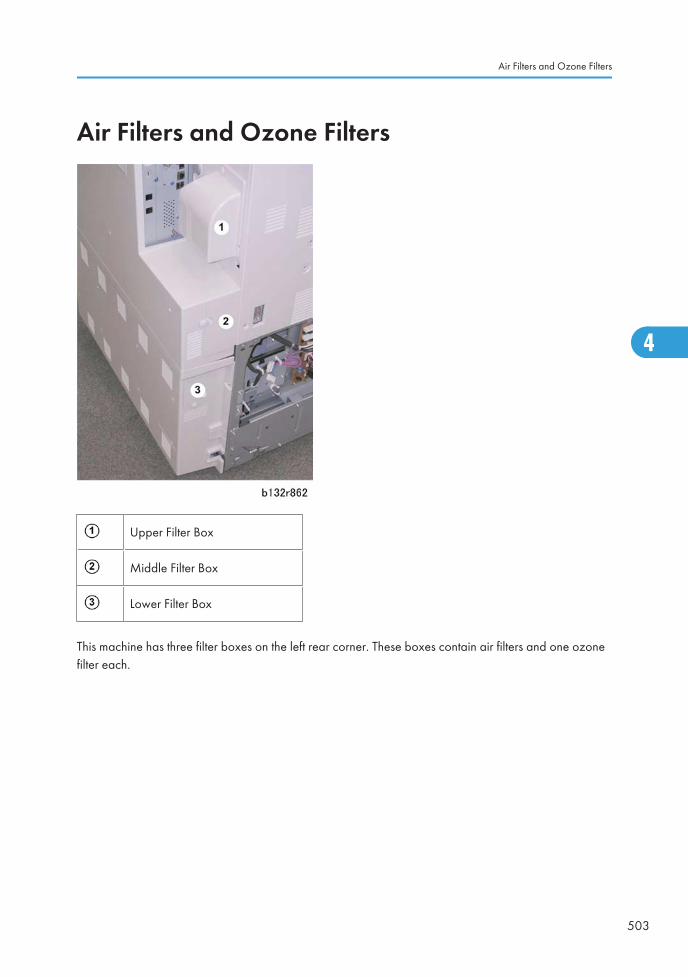
Air Filters and Ozone Filters
Upper Filter Box
Middle Filter Box
Lower Filter Box
This machine has three filter boxes on the left rear corner. These boxes contain air filters and one ozonefilter each.
Air Filters and Ozone Filters
503
4
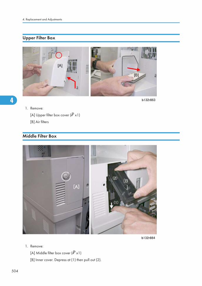
Upper Filter Box
1. Remove:
[A] Upper filter box cover ( x1)
[B] Air filters
Middle Filter Box
1. Remove:
[A] Middle filter box cover ( x1)
[B] Inner cover. Depress at (1) then pull out (2).
4. Replacement and Adjustments
504
4
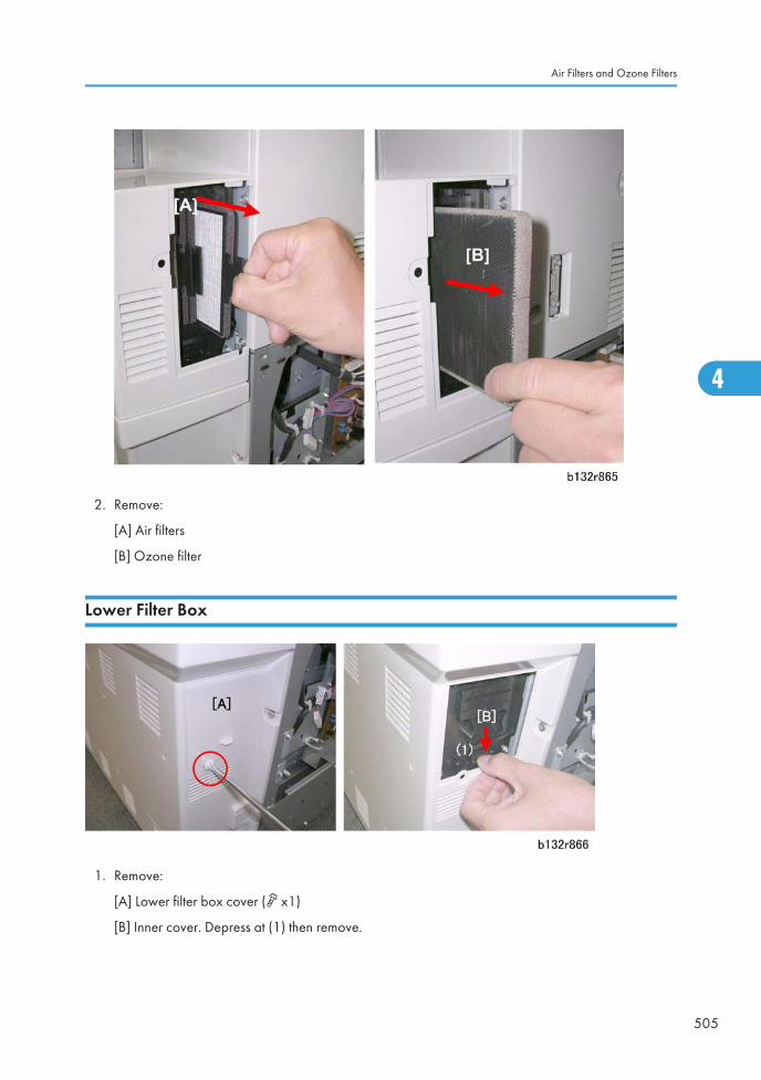
2. Remove:
[A] Air filters
[B] Ozone filter
Lower Filter Box
1. Remove:
[A] Lower filter box cover ( x1)
[B] Inner cover. Depress at (1) then remove.
Air Filters and Ozone Filters
505
4
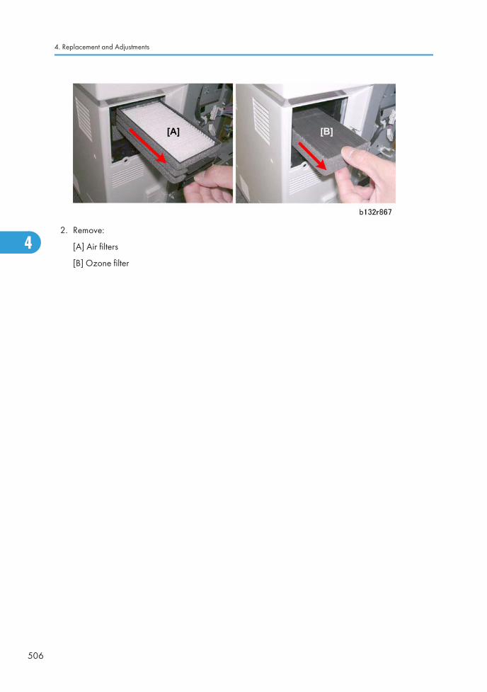
2. Remove:
[A] Air filters
[B] Ozone filter
4. Replacement and Adjustments
506
4
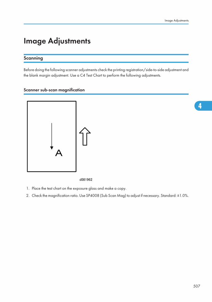
Image Adjustments
Scanning
Before doing the following scanner adjustments check the printing registration/side-to-side adjustment andthe blank margin adjustment. Use a C4 Test Chart to perform the following adjustments.
Scanner sub-scan magnification
1. Place the test chart on the exposure glass and make a copy.
2. Check the magnification ratio. Use SP4008 (Sub Scan Mag) to adjust if necessary. Standard: ±1.0%.
Image Adjustments
507
4
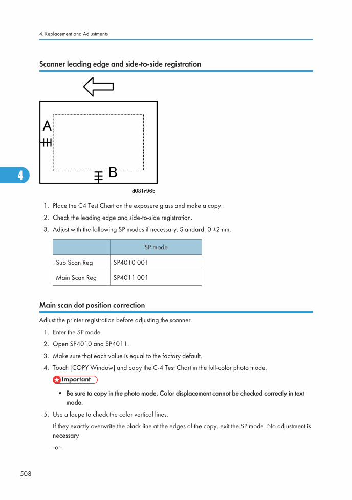
Scanner leading edge and side-to-side registration
1. Place the C4 Test Chart on the exposure glass and make a copy.
2. Check the leading edge and side-to-side registration.
3. Adjust with the following SP modes if necessary. Standard: 0 ±2mm.
SP mode
Sub Scan Reg SP4010 001
Main Scan Reg SP4011 001
Main scan dot position correction
Adjust the printer registration before adjusting the scanner.
1. Enter the SP mode.
2. Open SP4010 and SP4011.
3. Make sure that each value is equal to the factory default.
4. Touch [COPY Window] and copy the C-4 Test Chart in the full-color photo mode.
• Be sure to copy in the photo mode. Color displacement cannot be checked correctly in textmode.
5. Use a loupe to check the color vertical lines.
If they exactly overwrite the black line at the edges of the copy, exit the SP mode. No adjustment isnecessary
-or-
4. Replacement and Adjustments
508
4
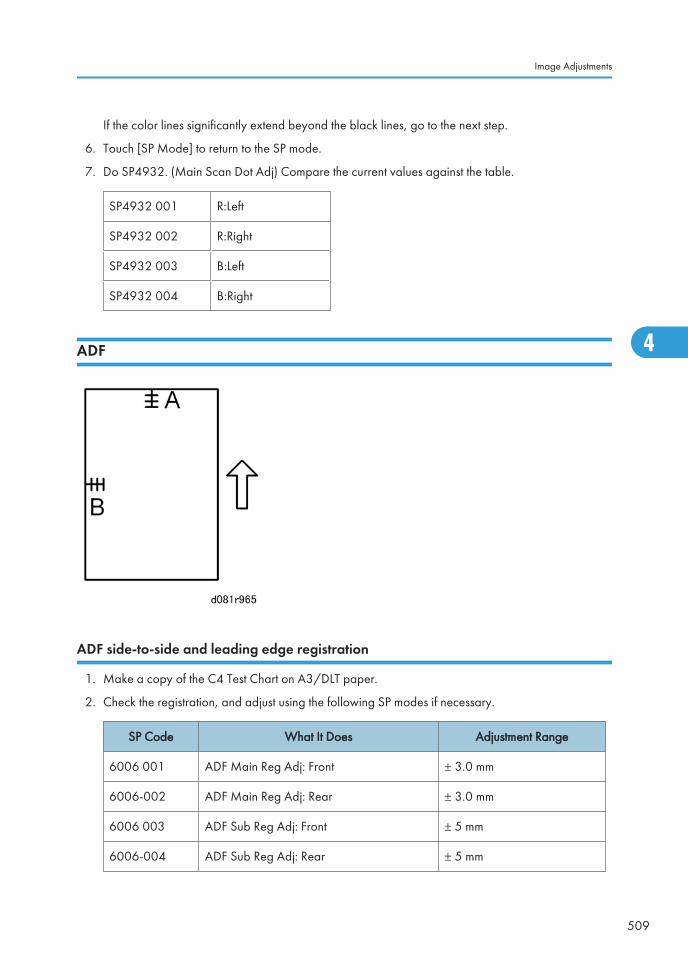
If the color lines significantly extend beyond the black lines, go to the next step.
6. Touch [SP Mode] to return to the SP mode.
7. Do SP4932. (Main Scan Dot Adj) Compare the current values against the table.
SP4932 001 R:Left
SP4932 002 R:Right
SP4932 003 B:Left
SP4932 004 B:Right
ADF
ADF side-to-side and leading edge registration
1. Make a copy of the C4 Test Chart on A3/DLT paper.
2. Check the registration, and adjust using the following SP modes if necessary.
SP Code What It Does Adjustment Range
6006 001 ADF Main Reg Adj: Front ± 3.0 mm
6006-002 ADF Main Reg Adj: Rear ± 3.0 mm
6006 003 ADF Sub Reg Adj: Front ± 5 mm
6006-004 ADF Sub Reg Adj: Rear ± 5 mm
Image Adjustments
509
4
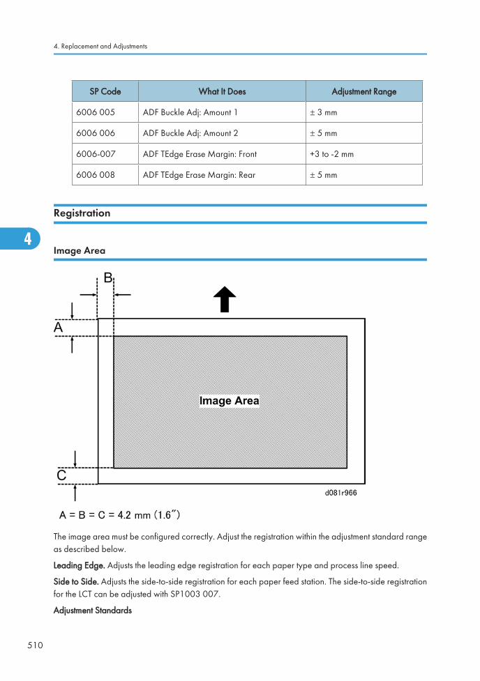
SP Code What It Does Adjustment Range
6006 005 ADF Buckle Adj: Amount 1 ± 3 mm
6006 006 ADF Buckle Adj: Amount 2 ± 5 mm
6006-007 ADF TEdge Erase Margin: Front +3 to -2 mm
6006 008 ADF TEdge Erase Margin: Rear ± 5 mm
Registration
Image Area
The image area must be configured correctly. Adjust the registration within the adjustment standard rangeas described below.
Leading Edge. Adjusts the leading edge registration for each paper type and process line speed.
Side to Side. Adjusts the side-to-side registration for each paper feed station. The side-to-side registrationfor the LCT can be adjusted with SP1003 007.
Adjustment Standards
4. Replacement and Adjustments
510
4
• Leading edge (sub-scan direction): 3 ±0 mm
• Side to side (main-scan direction): 2 ±0 mm
Paper Registration Standard
The registration in both main- and sub-scan directions may fluctuate within the following tolerance.
1st side
• Sub-scan direction:0 ±1.5 mm
• Main-scan direction:0 ±2 mm
2nd side in duplex
• Sub-scan direction:0 ±3 mm
• Main-scan direction:0 ±4 mm
Adjustment Procedure
1. Enter SP mode and open SP2109-2.
2. Select Pattern #10 (Trim Area), and touch [OK].
3. Print several printing patterns and average the measured values of the leading edge and side-to-sideregistration values.
4. Do the leading edge registration adjustment.
• Check the leading edge registration and adjust it with SP1001.
• Select the adjustment conditions (paper type and process line speed).
• Input the value and press the [#] key.
• Check the leading edge adjustment by printing Pattern 10 with SP2109.
5. Do the side to side registration adjustment.
• Check the side-to-side registration and adjust it with SP1003.
• Select the adjustment conditions for the paper feed station.
• Input the value and press the [#] key.
• Check the side-to-side adjustment by printing Pattern 10 with SP2109-2.
Color Registration
Forced MUSIC Adjustment
The line position adjustment optimizes the quality of color prints. You can do forced MUSIC adjustmentwith SP 2111 001 (Force Tnr Pos):
Image Adjustments
511
4
We recommend that you do the forced MUSIC adjustment at the customer location immediately afterinstallation, or after servicing or adjusting any parts or components of the following units:
• Around the drum
• ITB unit (especially after belt replacement)
• Paper Transfer Roller
• Laser unit
Adjustment of Line Speed for Thick Paper
Adjust the line speed of the fusing unit (the speed of the K development motor) when:
• Color shift corrected with the line position adjustment.
• Color registration shifts more at the trailing edge than at the leading edge.
Color Registration Test and Error Adjustment
Before you start this procedure, make sure that the exposure glass is clean. Also, make sure that the ITB isinstalled correctly, especially at the edge.
1. Load A3/DLT paper and select full-color (FC) mode.
2. Start SP2109 002 and select Pattern #1 (1: Grid pattern), and then touch "OK".
3. Push the "Copy Window" button. Then select A3/DLT paper, and push the "Start" button to print thepattern. Make sure that "Full Color Mode" is selected before you push the Start button.
4. Look at the printout. The horizontal and vertical lines must show no color (must be black). In thatcondition, the K, C, M, and Y images are deposited exactly on top of each other.
5. If there is color on the printout, there is a color registration error, and we must correct the problem.To correct the problem, do the MUSIC process with SP2111 001. This takes about 50 seconds.
6. Do step 2 again.
7. If there are color registration errors, then do the procedure described in the Troubleshooting section"Color Registration Error Adjustments"
Skew Adjustment After Laser Unit Replacement
To Print the Trim Pattern:
1. Do SP2109 002 (Test Pattern - Select Pattern) and select pattern 10.
2. Touch [Execute] on the display.
3. Touch [Copy Screen] on the display to switch to the normal copier screen.
4. Select the paper size and color then press the [Start] key to print the pattern.
4. Replacement and Adjustments
512
4
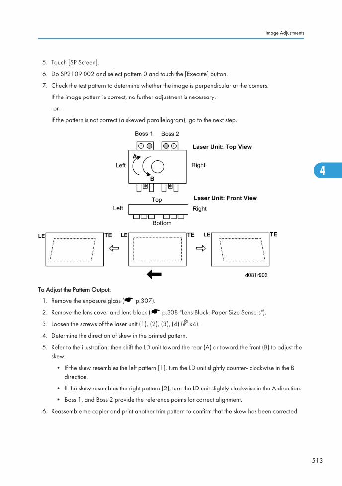
5. Touch [SP Screen].
6. Do SP2109 002 and select pattern 0 and touch the [Execute] button.
7. Check the test pattern to determine whether the image is perpendicular at the corners.
If the image pattern is correct, no further adjustment is necessary.
-or-
If the pattern is not correct (a skewed parallelogram), go to the next step.
To Adjust the Pattern Output:
1. Remove the exposure glass ( p.307).
2. Remove the lens cover and lens block ( p.308 "Lens Block, Paper Size Sensors").
3. Loosen the screws of the laser unit (1), (2), (3), (4) ( x4).
4. Determine the direction of skew in the printed pattern.
5. Refer to the illustration, then shift the LD unit toward the rear (A) or toward the front (B) to adjust theskew.
• If the skew resembles the left pattern [1], turn the LD unit slightly counter- clockwise in the Bdirection.
• If the skew resembles the right pattern [2], turn the LD unit slightly clockwise in the A direction.
• Boss 1, and Boss 2 provide the reference points for correct alignment.
6. Reassemble the copier and print another trim pattern to confirm that the skew has been corrected.
Image Adjustments
513
4
Printer Gamma Correction
ACC adjustment done at installation is usually sufficient to adjust the color balance for optimumperformance.
• Printer gamma correction is required for fine adjustment to meet a customer requirement.
• The printer gamma curve created during ACC can be modified with SP modes.
• The gamma data for highlight, middle, shadow areas, and IDmax can be adjusted. The adjustablerange is from 0 to 30 (31 steps).
Copy Mode
KCMY Color Balance Adjustment
The adjustment uses only "Offset" values.
• Never change "Option" values (default value is 0).
Highlight (Low ID) Levels 2 through 5 in the C4 chart 10-level scale
Middle (Middle ID) Levels 3 through 7 in the C4 chart 10-level scale
Shadow (High ID) Levels 6 through 9 in the C4 chart 10-level scale
ID max Level 10 in the C4 chart 10-level scale (affects the entire image density.)
OffsetThe higher the number in the range associated with the low ID, middle ID, highID, and ID max, the greater the density.
There are four adjustable modes. You can access these with SP4918 (Man Gamma Adj:
• Copy: Photo (Photo Mode)
• Copy: Letter (Text Mode Full Color)
• Copy: Letter (SC) (Text Single Color Mode)
• Copy: Photo (SC) (Photo Mode Single Color)
4. Replacement and Adjustments
514
4

Adjustment Procedure
Copy the C-4 chart in mode that you want to adjust.
1. Enter the SP mode.
2. Touch"Copy SP."
3. Open SP4918.
4. Adjust the offset values until the copy quality conforms to the standard. (Refer the tables below.)
• Never change "Option" value (default value is 0).
• Always adjust the density in order: ID Max> Middle> Shadow> Highlight.
Copy: Photo (Photo Mode Full Color)
Step Item to Adjust Level on the C-4 chart
IDMax
ID max: (K, C, M, and Y)
Adjust the offset value so that the density of level 10 matchesthat of level 10 on the C-4 chart.
M
Middle (Middle ID) (K, C, M, and Y)
Adjust the offset value so that the density of level 6 matches thatof level 6 on the C-4 chart.
Image Adjustments
515
4
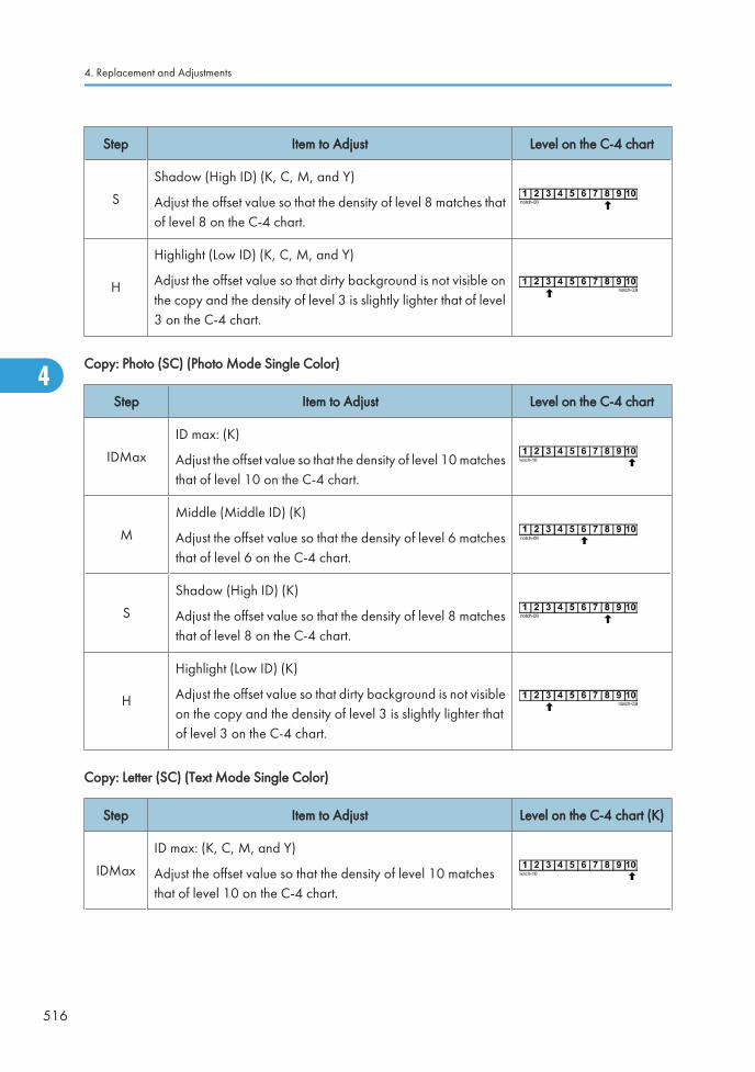
Step Item to Adjust Level on the C-4 chart
S
Shadow (High ID) (K, C, M, and Y)
Adjust the offset value so that the density of level 8 matches thatof level 8 on the C-4 chart.
H
Highlight (Low ID) (K, C, M, and Y)
Adjust the offset value so that dirty background is not visible onthe copy and the density of level 3 is slightly lighter that of level3 on the C-4 chart.
Copy: Photo (SC) (Photo Mode Single Color)
Step Item to Adjust Level on the C-4 chart
IDMax
ID max: (K)
Adjust the offset value so that the density of level 10 matchesthat of level 10 on the C-4 chart.
M
Middle (Middle ID) (K)
Adjust the offset value so that the density of level 6 matchesthat of level 6 on the C-4 chart.
S
Shadow (High ID) (K)
Adjust the offset value so that the density of level 8 matchesthat of level 8 on the C-4 chart.
H
Highlight (Low ID) (K)
Adjust the offset value so that dirty background is not visibleon the copy and the density of level 3 is slightly lighter thatof level 3 on the C-4 chart.
Copy: Letter (SC) (Text Mode Single Color)
Step Item to Adjust Level on the C-4 chart (K)
IDMax
ID max: (K, C, M, and Y)
Adjust the offset value so that the density of level 10 matchesthat of level 10 on the C-4 chart.
4. Replacement and Adjustments
516
4
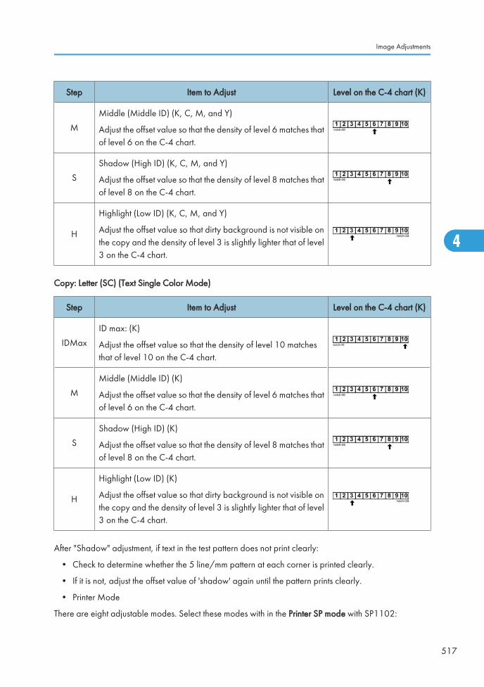
Step Item to Adjust Level on the C-4 chart (K)
M
Middle (Middle ID) (K, C, M, and Y)
Adjust the offset value so that the density of level 6 matches thatof level 6 on the C-4 chart.
S
Shadow (High ID) (K, C, M, and Y)
Adjust the offset value so that the density of level 8 matches thatof level 8 on the C-4 chart.
H
Highlight (Low ID) (K, C, M, and Y)
Adjust the offset value so that dirty background is not visible onthe copy and the density of level 3 is slightly lighter that of level3 on the C-4 chart.
Copy: Letter (SC) (Text Single Color Mode)
Step Item to Adjust Level on the C-4 chart (K)
IDMax
ID max: (K)
Adjust the offset value so that the density of level 10 matchesthat of level 10 on the C-4 chart.
M
Middle (Middle ID) (K)
Adjust the offset value so that the density of level 6 matches thatof level 6 on the C-4 chart.
S
Shadow (High ID) (K)
Adjust the offset value so that the density of level 8 matches thatof level 8 on the C-4 chart.
H
Highlight (Low ID) (K)
Adjust the offset value so that dirty background is not visible onthe copy and the density of level 3 is slightly lighter that of level3 on the C-4 chart.
After "Shadow" adjustment, if text in the test pattern does not print clearly:
• Check to determine whether the 5 line/mm pattern at each corner is printed clearly.
• If it is not, adjust the offset value of 'shadow' again until the pattern prints clearly.
• Printer Mode
There are eight adjustable modes. Select these modes with in the Printer SP mode with SP1102:
Image Adjustments
517
4
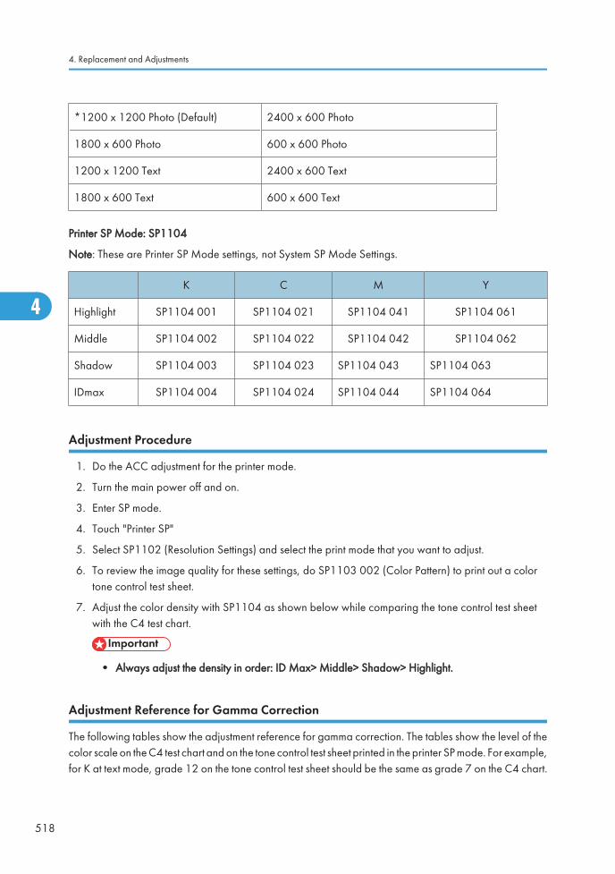
*1200 x 1200 Photo (Default) 2400 x 600 Photo
1800 x 600 Photo 600 x 600 Photo
1200 x 1200 Text 2400 x 600 Text
1800 x 600 Text 600 x 600 Text
Printer SP Mode: SP1104
Note: These are Printer SP Mode settings, not System SP Mode Settings.
K C M Y
Highlight SP1104 001 SP1104 021 SP1104 041 SP1104 061
Middle SP1104 002 SP1104 022 SP1104 042 SP1104 062
Shadow SP1104 003 SP1104 023 SP1104 043 SP1104 063
IDmax SP1104 004 SP1104 024 SP1104 044 SP1104 064
Adjustment Procedure
1. Do the ACC adjustment for the printer mode.
2. Turn the main power off and on.
3. Enter SP mode.
4. Touch "Printer SP"
5. Select SP1102 (Resolution Settings) and select the print mode that you want to adjust.
6. To review the image quality for these settings, do SP1103 002 (Color Pattern) to print out a colortone control test sheet.
7. Adjust the color density with SP1104 as shown below while comparing the tone control test sheetwith the C4 test chart.
• Always adjust the density in order: ID Max> Middle> Shadow> Highlight.
Adjustment Reference for Gamma Correction
The following tables show the adjustment reference for gamma correction. The tables show the level of thecolor scale on the C4 test chart and on the tone control test sheet printed in the printer SP mode. For example,for K at text mode, grade 12 on the tone control test sheet should be the same as grade 7 on the C4 chart.
4. Replacement and Adjustments
518
4
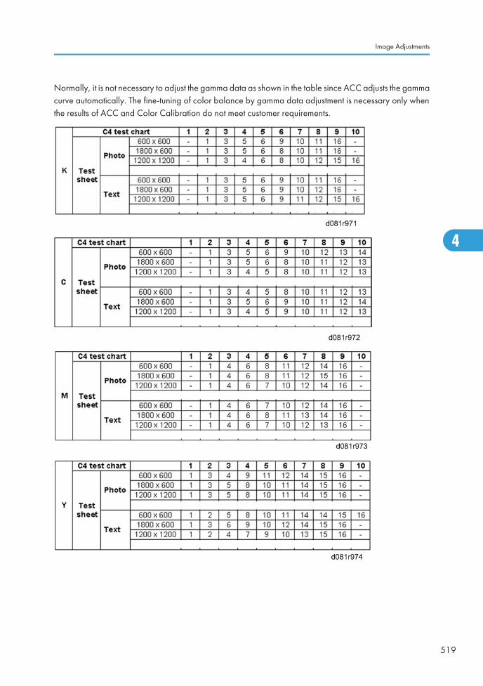
Normally, it is not necessary to adjust the gamma data as shown in the table since ACC adjusts the gammacurve automatically. The fine-tuning of color balance by gamma data adjustment is necessary only whenthe results of ACC and Color Calibration do not meet customer requirements.
Image Adjustments
519
4
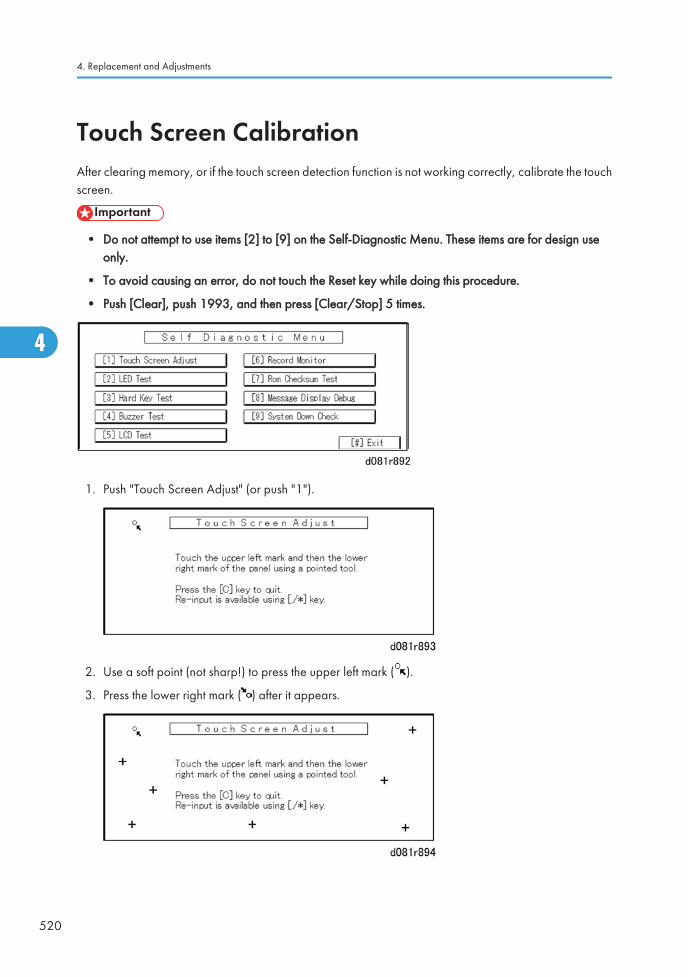
Touch Screen CalibrationAfter clearing memory, or if the touch screen detection function is not working correctly, calibrate the touchscreen.
• Do not attempt to use items [2] to [9] on the Self-Diagnostic Menu. These items are for design useonly.
• To avoid causing an error, do not touch the Reset key while doing this procedure.
• Push [Clear], push 1993, and then press [Clear/Stop] 5 times.
1. Push "Touch Screen Adjust" (or push "1").
2. Use a soft point (not sharp!) to press the upper left mark ( ).
3. Press the lower right mark ( ) after it appears.
4. Replacement and Adjustments
520
4

4. Touch a few random spots on the touch screen to confirm that the marker (+) appears exactly wherethe screen is touched.
5. If the ( mark does not appear where the screen is touched, push [Cancel] and repeat from Step 2.
6. When you are finished, touch [#] OK on the screen (or push [#] on the operation panel).
7. Touch [#] Exit on the screen to close the Self-Diagnostic menu and save the settings.
Touch Screen Calibration
521
4
Firmware Update
Before You Begin...
Always obey these rules when handling and using SD cards:
• Never connect or remove an SD card with the machine on.
• Never turn the power off while the machine is downloading data from an SD card.
• The SD card is a precision item. Use it carefully. Do not keep the card in a location where there is hightemperature, high humidity, or light from the sun.
• Handle SD cards carefully to avoid bending, scratching, or dropping them.
• If a power failure occurs during the firmware update, turn the machine power off/on without removingthe SD card. The firmware update procedure should start again.
Firmware Update Procedure
1. Obtain the System SD card.
2. Disconnect the network cable and other interface cables. This prevents outside interference causedby data transfers to the machine while the software is being uploaded.
3. Turn the main switch off.
4. Remove the SD card slot cover ( x1).
5. Remove the VM card from the lower slot.
• Before removing the VM card from Slot 1 (lower slot) you must shut down the App2 Meapplication (and all other VM card applications) if it is running. See p.305 "Before Removingand Re-installing the VM Card".
6. Insert the SD card into Slot 1 (lower slot).
7. Open the front door of the machine. This prevents generation of electrical noise from motors duringthe update procedure.
8. Switch the machine on.
You will see "Please Wait" then "Preparing to start firmware update."
The first screen appears after about 60 to 90 sec.
4. Replacement and Adjustments
522
4

9. Check the notations to the right.
• "ROM" shows the module number and version of the currently installed software.
• "NEW" shows the module number and version of software on the SD card in Slot 1 (lower slot).
10. Touch item that you want to update. The selected item appears in reverse black and white, and youcan select more than one
11. Touch [Update] or push [#] on the 10-key pad to start the update.
While the Update Is in Progress
• Remain with the machine. Do not leave it unattended.
• Never close the front door during firmware update.
• You will see a progress bar on the screen while the update is in progress.
• For some updates the [Start] key LED may flash RED slowly, while the update is in progress.When it starts to flash RED rapidly, this means the update is nearly finished. When the LED flashesGREEN this means the update is completed.
• Never switch the machine off while the [Start] key is flashing RED.
• If the machine is switched off or accidentally unplugged before the update is finished, do notremove the SD card. Just switch the machine on again. The firmware update should restartautomatically. If the firmware update does not recover, obtain a new System SD card.
The following screen sequence appears after selecting one "OpePanel" selected for update.
Example: System/Copy Update
• The middle bar tells you the name of the item that you are updating.
• The bottom bar shows the progress of the update procedure.
Firmware Update
523
4
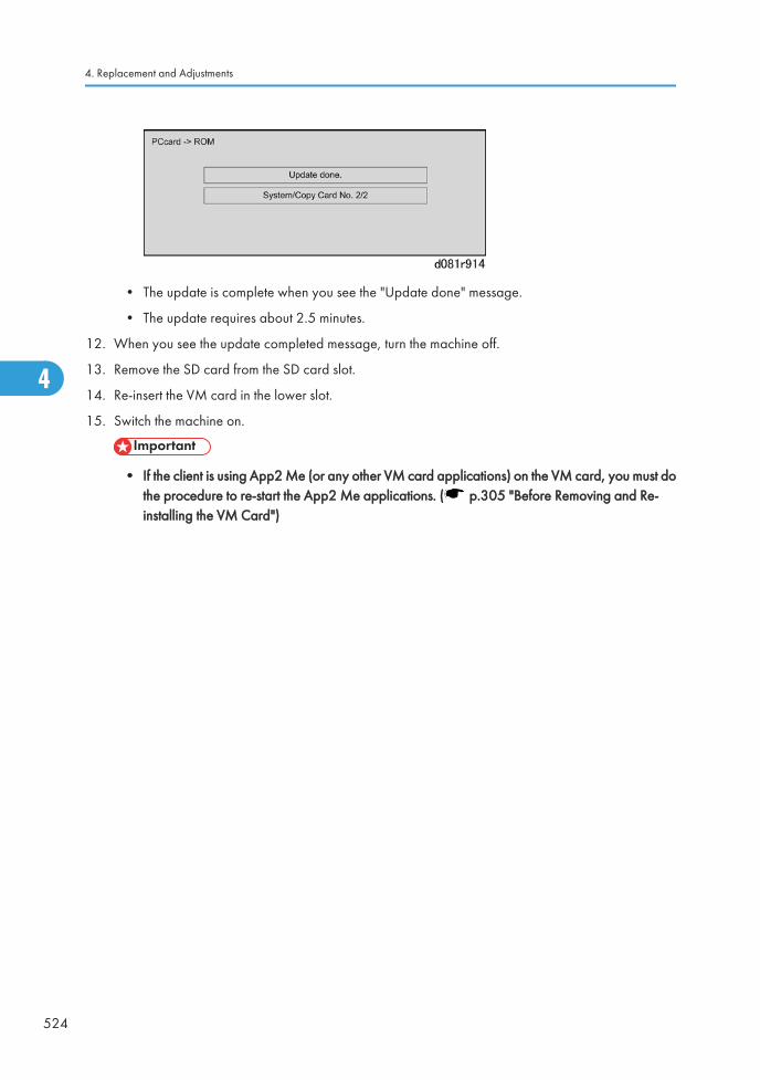
• The update is complete when you see the "Update done" message.
• The update requires about 2.5 minutes.
12. When you see the update completed message, turn the machine off.
13. Remove the SD card from the SD card slot.
14. Re-insert the VM card in the lower slot.
15. Switch the machine on.
• If the client is using App2 Me (or any other VM card applications) on the VM card, you must dothe procedure to re-start the App2 Me applications. ( p.305 "Before Removing and Re-installing the VM Card")
4. Replacement and Adjustments
524
4

5. System Maintenance
Service Program ModeSee "Appendices" for "Service Program Mode" information,
525
5

5. System Maintenance
526
5
6. Troubleshooting
Handling Errors
Program Download
Overview
Here are some important points to keep in mind when downloading software:
• If an error interrupts download processing, the machine cannot operate normally with the programsoftware only partially downloaded.
• When download processing execution starts, “Downloading…” is displayed and when downloadinghas completed successfully, the message is cleared.
• If the download is interrupted when the “Downloading …” message is displayed, the machine doesnot attempt a re-try.
• The program that downloads firmware from an SD card is part of the GW controller software. Ifdownloading this software is interrupted, the program stored in the machine may be corrupted.Because of this, it may not be possible to restart the downloading program. (In addition, if the GWcontroller software cannot be downloaded, other software on other SD cards cannot bedownloaded.) However, it may be possible to restart the program without replacing the board bysetting DIP SW 1 on the controller to ON, and re-starting.
Recovery Methods
When an error occurs during downloading, an error code is displayed on the operation panel.
• If the download procedure can be re-started, re-start the download procedure.
• If the download procedure cannot be downloaded for other than the GW controller, replace theboard where the downloaded program is stored.
• If the download procedure cannot be downloaded for the GW controller, set DIP SW 1 to ON. Powerthe machine off and on to start the downloading program. After downloading has completed, set theDIP SW to OFF then power the machine off and on again.
527
6
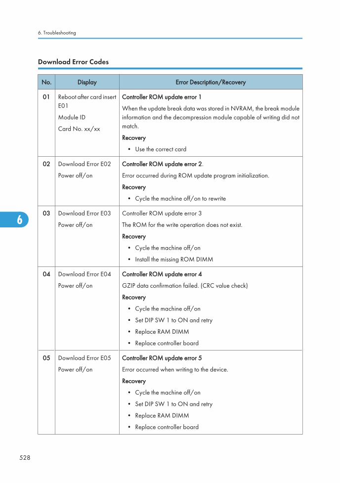
Download Error Codes
No. Display Error Description/Recovery
01 Reboot after card insertE01
Module ID
Card No. xx/xx
Controller ROM update error 1
When the update break data was stored in NVRAM, the break moduleinformation and the decompression module capable of writing did notmatch.
Recovery
• Use the correct card
02 Download Error E02
Power off/on
Controller ROM update error 2.
Error occurred during ROM update program initialization.
Recovery
• Cycle the machine off/on to rewrite
03 Download Error E03
Power off/on
Controller ROM update error 3
The ROM for the write operation does not exist.
Recovery
• Cycle the machine off/on
• Install the missing ROM DIMM
04 Download Error E04
Power off/on
Controller ROM update error 4
GZIP data confirmation failed. (CRC value check)
Recovery
• Cycle the machine off/on
• Set DIP SW 1 to ON and retry
• Replace RAM DIMM
• Replace controller board
05 Download Error E05
Power off/on
Controller ROM update error 5
Error occurred when writing to the device.
Recovery
• Cycle the machine off/on
• Set DIP SW 1 to ON and retry
• Replace RAM DIMM
• Replace controller board
6. Troubleshooting
528
6
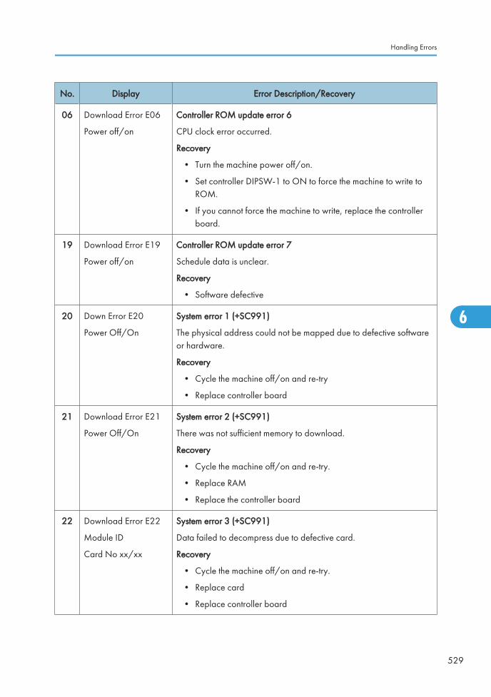
No. Display Error Description/Recovery
06 Download Error E06
Power off/on
Controller ROM update error 6
CPU clock error occurred.
Recovery
• Turn the machine power off/on.
• Set controller DIPSW-1 to ON to force the machine to write toROM.
• If you cannot force the machine to write, replace the controllerboard.
19 Download Error E19
Power off/on
Controller ROM update error 7
Schedule data is unclear.
Recovery
• Software defective
20 Down Error E20
Power Off/On
System error 1 (+SC991)
The physical address could not be mapped due to defective softwareor hardware.
Recovery
• Cycle the machine off/on and re-try
• Replace controller board
21 Download Error E21
Power Off/On
System error 2 (+SC991)
There was not sufficient memory to download.
Recovery
• Cycle the machine off/on and re-try.
• Replace RAM
• Replace the controller board
22 Download Error E22
Module ID
Card No xx/xx
System error 3 (+SC991)
Data failed to decompress due to defective card.
Recovery
• Cycle the machine off/on and re-try.
• Replace card
• Replace controller board
Handling Errors
529
6

No. Display Error Description/Recovery
--- SC991 System error 4
“Selfupdate” did not execute due to defective software.
Recovery
• Cycle the machine off/on and re-try
• Set DIP SW 1 to ON and re-try
• Replace the controller board
23 Download Error E24
Power Off/On
System error 5
Card read/write error occurred or software or card defective.
Recovery
• Cycle the machine off/on and re-try
• Replace the card
• Replace the controller board
30 No Valid Data E30 Download dysfunction 1
Could not download to HDD because HDD is not not installed or HDDis defective.
Recovery
• HDD defective
• HDD harness disconnected, defective
31 Reboot After CardInsert E31
Module ID
Card No. xx/xx
Download dysfunction 2
Download continuity error occurred with more than one card. Thesecond or later card was not compatible.
Recovery
• Set the correct cards in the correct order
32 Reboot After CardInsert E32
Module ID
Card No. xx/xx
Download dysfunction 3
Download interrupted because card wrong card was used, or a powerfailure interrupted the download operation.
Recovery
• Use the correct card
• If power failure caused the failure, remove the card and insertanother.
6. Troubleshooting
530
6
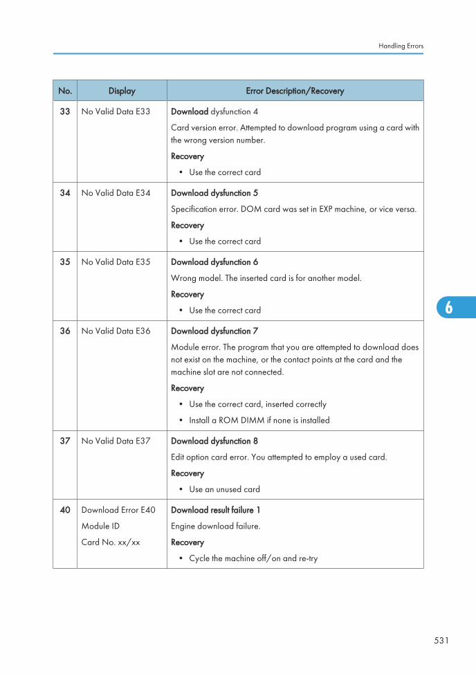
No. Display Error Description/Recovery
33 No Valid Data E33 Download dysfunction 4
Card version error. Attempted to download program using a card withthe wrong version number.
Recovery
• Use the correct card
34 No Valid Data E34 Download dysfunction 5
Specification error. DOM card was set in EXP machine, or vice versa.
Recovery
• Use the correct card
35 No Valid Data E35 Download dysfunction 6
Wrong model. The inserted card is for another model.
Recovery
• Use the correct card
36 No Valid Data E36 Download dysfunction 7
Module error. The program that you are attempted to download doesnot exist on the machine, or the contact points at the card and themachine slot are not connected.
Recovery
• Use the correct card, inserted correctly
• Install a ROM DIMM if none is installed
37 No Valid Data E37 Download dysfunction 8
Edit option card error. You attempted to employ a used card.
Recovery
• Use an unused card
40 Download Error E40
Module ID
Card No. xx/xx
Download result failure 1
Engine download failure.
Recovery
• Cycle the machine off/on and re-try
Handling Errors
531
6
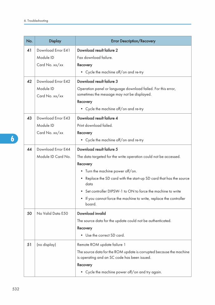
No. Display Error Description/Recovery
41 Download Error E41
Module ID
Card No. xx/xx
Download result failure 2
Fax download failure.
Recovery
• Cycle the machine off/on and re-try
42 Download Error E42
Module ID
Card No. xx/xx
Download result failure 3
Operation panel or language download failed. For this error,sometimes the message may not be displayed.
Recovery
• Cycle the machine off/on and re-try
43 Download Error E43
Module ID
Card No. xx/xx
Download result failure 4
Print download failed.
Recovery
• Cycle the machine off/on and re-try
44 Download Error E44
Module ID Card No.
Download result failure 5
The data targeted for the write operation could not be accessed.
Recovery
• Turn the machine power off/on.
• Replace the SD card with the start-up SD card that has the sourcedata
• Set controller DIPSW-1 to ON to force the machine to write
• If you cannot force the machine to write, replace the controllerboard.
50 No Valid Data E50 Download invalid
The source data for the update could not be authenticated.
Recovery
• Use the correct SD card.
51 (no display) Remote ROM update failure 1
The source data for the ROM update is corrupted because the machineis operating and an SC code has been issued.
Recovery
• Cycle the machine power off/on and try again.
6. Troubleshooting
532
6
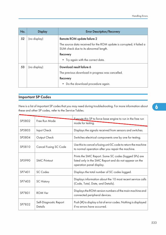
No. Display Error Description/Recovery
52 (no display) Remote ROM update failure 2
The source data received for the ROM update is corrupted; it failed aSUM check due to its abnormal length.
Recovery
• Try again with the correct data.
53 (no display) Download result failure 6
The previous download in progress was cancelled.
Recovery
• Do the download procedure again.
Important SP Codes
Here is a list of important SP codes that you may need during troubleshooting. For more information aboutthese and other SP codes, refer to the Service Tables.
SP5802 Free Run ModeExecute this SP to force base engine to run in the free runmode for testing.
SP5803 Input Check Displays the signals received from sensors and switches.
SP5804 Output Check Switches electrical components one by one for testing.
SP5810 Cancel Fusing SC CodeUse this to cancel a fusing unit SC code to return the machineto normal operation after you repair the machine.
SP5990 SMC PrintoutPrints the SMC Report. Some SC codes (logged SPs) arelisted only in the SMC Report and do not appear on theoperation panel display.
SP7401 SC Codes Displays the total number of SC codes logged.
SP7403 SC HistoryDisplays information about the 10 most recent service calls(Code, Total, Date, and Details).
SP7801 ROM VerDisplays the ROM version numbers of the main machine andconnected peripheral devices.
SP7832Self-Diagnostic ReportDetails
Push [#] to display a list of error codes. Nothing is displayedif no errors have occurred.
Handling Errors
533
6
O'Brien
Ed
Typewritten Text
RTB 22 This SP is not used
Special Procedures
Correcting the Halo Effect
Images printed with the GW controller may show a "halo" effect when printing in 2-bit mode(1800x600dpi) and in 4-bit mode (9600x600dpi).
Problem
• This problem is most visible when text is overlaid onto halftone areas in 2-bit mode or 4-bit mode. Thegreater the difference in image density between text and halftone areas, the more noticeable the haloeffect.
• This problem is also evident when the mode is changed to 2-bit mode. (The default dithering patternfor 2-bit mode is designed to improve gradation, but this can also make the halo effect more visible.)
• This problem is a product limitation for this model, as announced in the SLG (User/Sales/ServiceRemarks #12).
Solution
The following solution is only effective when using the GW controller. There are two ways to reduce thehalo effect:
1. Print out the image using 1-bit mode (600x600dpi) instead, or
2. Change the dither pattern used in 2-bit mode (1800x600dpi).
As mentioned above, the default dither pattern for 2-bit mode is provided to improve gradation.However, there is one more dither pattern (“Low halo effect dither”) that can be selected to reducethe halo effect.
Procedure: To Change the Dither Pattern for 2-Bit Mode
Do the following procedure manually to change the dither pattern used in 2-bit mode to “Low halo effectdither”.
1. Confirm that the Printer/Scanner firmware is Ver1.00.1 (D3765902A) or newer.
2. Execute SP5801-008 (Memory Clear Printer Application).
When you execute this SP, the following will be reset to factory settings:
• The gamma curve adjusted at the last Printer ACC execution.
• All Group SP1000 settings in Printer SP mode, which includes SP1104 (Gamma Adjustment)and SP1106 (Toner Limit).
3. When you see the “Completed. You have to reboot.” message, turn the machine on.
4. Open Printer SP1001-002 (Bit Switch – Bit Switch 2 Settings).
5. Touch the “6” key, and then the [#] key on the operation panel.
The LCD display will change:
6. Troubleshooting
534
6
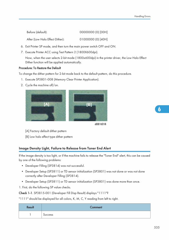
Before (default): 00000000 (0) [00H]
After (Low Halo Effect Dither): 01000000 (0) [40H]
6. Exit Printer SP mode, and then turn the main power switch OFF and ON.
7. Execute Printer ACC using Test Pattern 2 (1800X600dpi).
Now, when the user selects 2-bit mode (1800x600dpi) in the printer driver, the Low Halo EffectDither function will be applied automatically.
Procedure: To Restore the Default
To change the dither pattern for 2-bit mode back to the default pattern, do this procedure.
1. Execute SP5801-008 (Memory Clear Printer Application).
2. Cycle the machine off/on.
[A] Factory default dither pattern
[B] Low halo effect type dither pattern
Image Density Light, Failure to Release from Toner End Alert
If the image density is too light, or if the machine fails to release the "Toner End" alert, this can be causedby one of the following problems:
• Developer Filling (SP3814) was not successful.
• Developer Setup (SP3811) or TD sensor initialization (SP3801) was not done or was not donecorrectly after Developer Filling (SP3814).
• Developer Setup (SP3811) or TD sensor initialization (SP3801) was done more than once.
1. First, do the following SP value checks.
Check 1-1. SP3815-001 (Developer Fill Disp Result) displays "1111"?
"1111" should be displayed for all colors, K, M, C, Y reading from left to right.
Result Comment
1 Success
Handling Errors
535
6
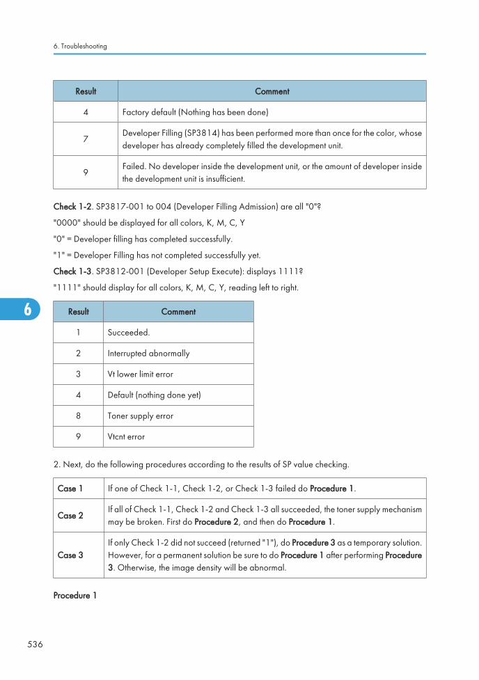
Result Comment
4 Factory default (Nothing has been done)
7Developer Filling (SP3814) has been performed more than once for the color, whosedeveloper has already completely filled the development unit.
9Failed. No developer inside the development unit, or the amount of developer insidethe development unit is insufficient.
Check 1-2. SP3817-001 to 004 (Developer Filling Admission) are all "0"?
"0000" should be displayed for all colors, K, M, C, Y
"0" = Developer filling has completed successfully.
"1" = Developer Filling has not completed successfully yet.
Check 1-3. SP3812-001 (Developer Setup Execute): displays 1111?
"1111" should display for all colors, K, M, C, Y, reading left to right.
Result Comment
1 Succeeded.
2 Interrupted abnormally
3 Vt lower limit error
4 Default (nothing done yet)
8 Toner supply error
9 Vtcnt error
2. Next, do the following procedures according to the results of SP value checking.
Case 1 If one of Check 1-1, Check 1-2, or Check 1-3 failed do Procedure 1.
Case 2If all of Check 1-1, Check 1-2 and Check 1-3 all succeeded, the toner supply mechanismmay be broken. First do Procedure 2, and then do Procedure 1.
Case 3If only Check 1-2 did not succeed (returned "1"), do Procedure 3 as a temporary solution.However, for a permanent solution be sure to do Procedure 1 after performing Procedure3. Otherwise, the image density will be abnormal.
Procedure 1
6. Troubleshooting
536
6
1.Replace the toner cartridge causing the problem (density too light or no "Toner End" release) with a newtoner cartridge.
• After the "Toner End" alert appears for a color, this "Toner End" information is written into the ID chipon the toner cartridge, even though a lot of toner may remain inside the cartridge. This means thatmachine will detect that the toner cartridge is empty.
2. Follow the procedure in the service manual to replace the developer for all colors.
3.After the TD sensor initialization (SP3801-001 to 006) has been completed, check these SP values:
• SP3812-001 = 1111 (Display Result of Developer Setup Execution)
• SP3821-001 = 10101010 (Display Result of Process Control)
Procedure 2
1.Replace the toner cartridge causing the problem (density too light or no "Toner End" release) with a newtoner cartridge.
• After the "Toner End" alert appears for a color, this "Toner End" information is written into the ID chipon the toner cartridge, even though a lot of toner may remain inside the cartridge. This means thatmachine will detect that the toner cartridge is empty.
2.Do SP2251-001 to 004 "Forced Toner Supply for the color (K, M, C, or Y) for the color whose imagedensity is too light.
• To avoid damage to the toner supply mechanism, never perform "Forced Toner Supply for K, M, C,or Y more than three times.
3.Check the image density to see if it is darker.
4.Do SP3820-002 (Manual ProCon).
5.Do SP3821-001 (ProCon OK?) to confirm that SP3820-002 succeeded. YOu should see "10101010"displayed if SP3820-002 executed successfully.
• If SP3820-002 displays any values other than "10101010" (successful execution), the toner supplymechanism may be broken. Replace the toner supply mechanism.
6.If SP3820-002 shows "10101010" (successful execution), perform Steps 2 and 3 of Procedure 1 forthe color causing the problem (light image or failure to release from "Toner End" alert).
Procedure 3
• For this procedure there must be developer in the development unit.
Handling Errors
537
6
1.Replace the toner cartridge causing the problem (density too light or no "Toner End" release) with a newtoner cartridge.
• After the "Toner End" alert appears for a color, this "Toner End" information is written into the ID chipon the toner cartridge, even though a lot of toner may remain inside the cartridge. This means thatmachine will detect that the toner cartridge is empty.
2.Do SP3817-005 (Developer Filling Admission: Clear). This SP forces the settings of SP3817-001 to 004to change from "1" to "0" and forces toner supply from toner cartridges to toner sub hoppers.
3.Do SP2251-001 to 004 (Forced Toner Supply K, M, C, or Y) for the color whose image density is toolight.
• To prevent damaging the toner supply mechanism, never perform "Forced Toner Supply K, M, C, Y"more than three times.
4.Check the image density to see if it is darker.
5.Do SP3820-002 "Manual ProCon".
6.Do SP3821-001 "ProCon OK?" to confirm if SP3820-002 succeeded. You should see "10101010"displayed if SP3820-002 executed successfully.
7.If SP3820-002 shows "10101010" (successful execution), perform the Steps 2 and 3 of Procedure 1for the color causing the problem (light image or failure to release from "Toner End" alert).
SP2181 030 (Alignment Result) Errors
After SP2181 030 executes normally, you should see a "1" replace the "0" (default display). If you seeany number other than a "1", this indicates an error.
Code. Error, Problem, Solution
2 Failure
Problem 1
• Large amount of skew.
• Large amount of K skew.
• Large amount of skew in every color.
Solution
Print a trim pattern with SP2109 002 Pattern #10 (Trim Area).
6. Troubleshooting
538
6
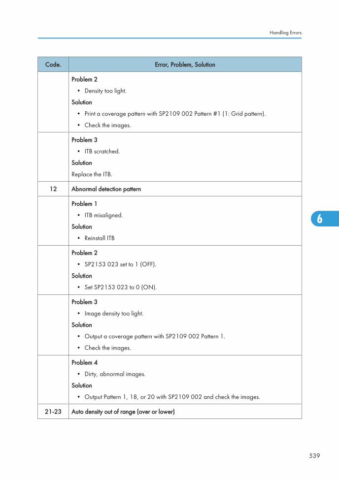
Code. Error, Problem, Solution
Problem 2
• Density too light.
Solution
• Print a coverage pattern with SP2109 002 Pattern #1 (1: Grid pattern).
• Check the images.
Problem 3
• ITB scratched.
Solution
Replace the ITB.
12 Abnormal detection pattern
Problem 1
• ITB misaligned.
Solution
• Reinstall ITB
Problem 2
• SP2153 023 set to 1 (OFF).
Solution
• Set SP2153 023 to 0 (ON).
Problem 3
• Image density too light.
Solution
• Output a coverage pattern with SP2109 002 Pattern 1.
• Check the images.
Problem 4
• Dirty, abnormal images.
Solution
• Output Pattern 1, 18, or 20 with SP2109 002 and check the images.
21-23 Auto density out of range (over or lower)
Handling Errors
539
6
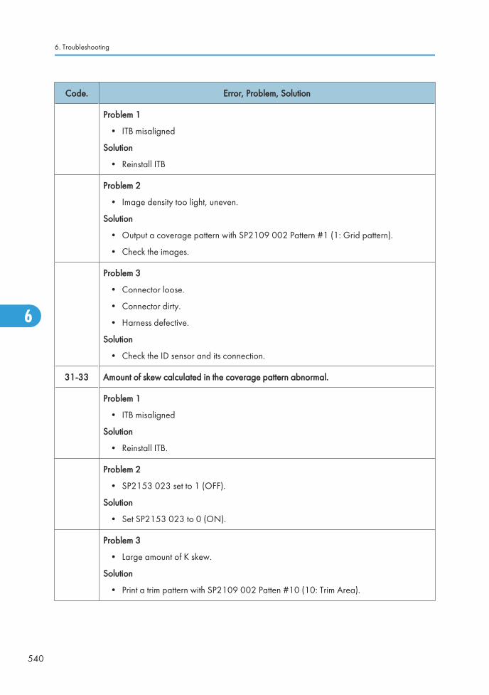
Code. Error, Problem, Solution
Problem 1
• ITB misaligned
Solution
• Reinstall ITB
Problem 2
• Image density too light, uneven.
Solution
• Output a coverage pattern with SP2109 002 Pattern #1 (1: Grid pattern).
• Check the images.
Problem 3
• Connector loose.
• Connector dirty.
• Harness defective.
Solution
• Check the ID sensor and its connection.
31-33 Amount of skew calculated in the coverage pattern abnormal.
Problem 1
• ITB misaligned
Solution
• Reinstall ITB.
Problem 2
• SP2153 023 set to 1 (OFF).
Solution
• Set SP2153 023 to 0 (ON).
Problem 3
• Large amount of K skew.
Solution
• Print a trim pattern with SP2109 002 Patten #10 (10: Trim Area).
6. Troubleshooting
540
6
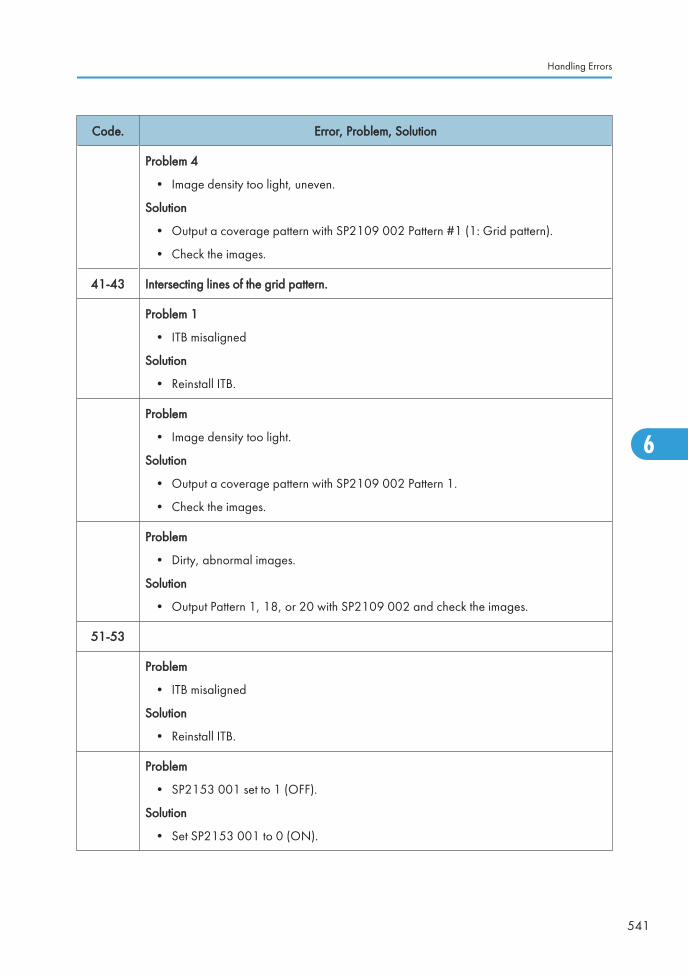
Code. Error, Problem, Solution
Problem 4
• Image density too light, uneven.
Solution
• Output a coverage pattern with SP2109 002 Pattern #1 (1: Grid pattern).
• Check the images.
41-43 Intersecting lines of the grid pattern.
Problem 1
• ITB misaligned
Solution
• Reinstall ITB.
Problem
• Image density too light.
Solution
• Output a coverage pattern with SP2109 002 Pattern 1.
• Check the images.
Problem
• Dirty, abnormal images.
Solution
• Output Pattern 1, 18, or 20 with SP2109 002 and check the images.
51-53
Problem
• ITB misaligned
Solution
• Reinstall ITB.
Problem
• SP2153 001 set to 1 (OFF).
Solution
• Set SP2153 001 to 0 (ON).
Handling Errors
541
6
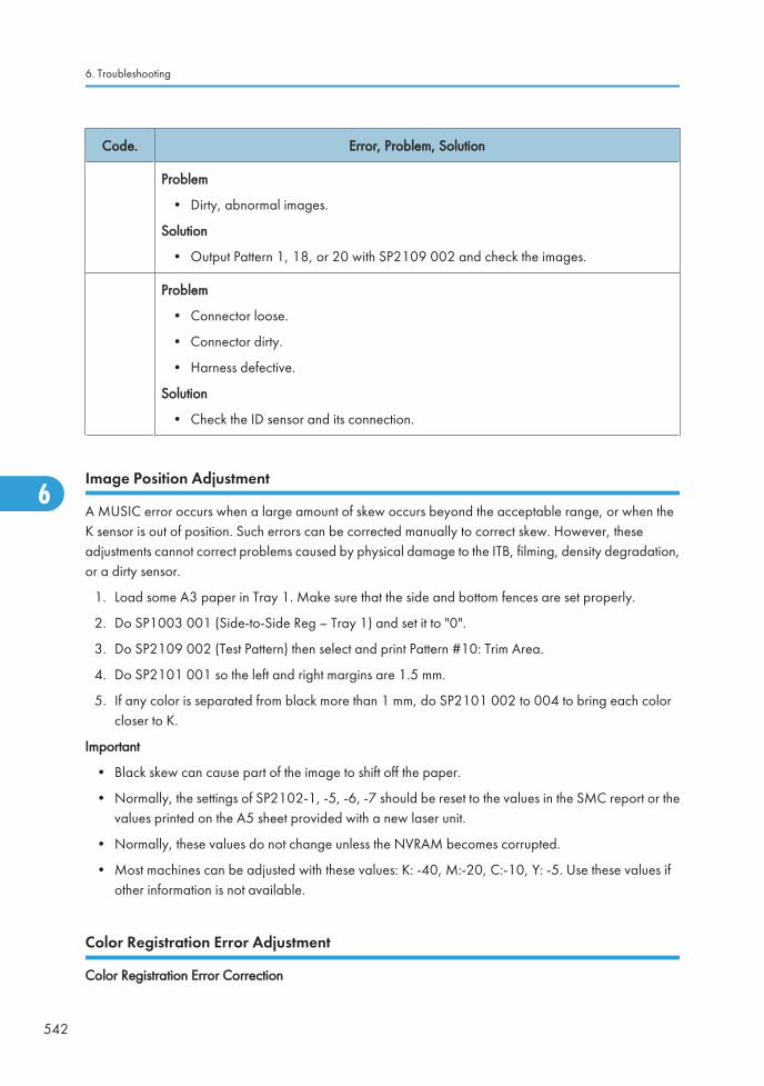
Code. Error, Problem, Solution
Problem
• Dirty, abnormal images.
Solution
• Output Pattern 1, 18, or 20 with SP2109 002 and check the images.
Problem
• Connector loose.
• Connector dirty.
• Harness defective.
Solution
• Check the ID sensor and its connection.
Image Position Adjustment
A MUSIC error occurs when a large amount of skew occurs beyond the acceptable range, or when theK sensor is out of position. Such errors can be corrected manually to correct skew. However, theseadjustments cannot correct problems caused by physical damage to the ITB, filming, density degradation,or a dirty sensor.
1. Load some A3 paper in Tray 1. Make sure that the side and bottom fences are set properly.
2. Do SP1003 001 (Side-to-Side Reg – Tray 1) and set it to "0".
3. Do SP2109 002 (Test Pattern) then select and print Pattern #10: Trim Area.
4. Do SP2101 001 so the left and right margins are 1.5 mm.
5. If any color is separated from black more than 1 mm, do SP2101 002 to 004 to bring each colorcloser to K.
Important
• Black skew can cause part of the image to shift off the paper.
• Normally, the settings of SP2102-1, -5, -6, -7 should be reset to the values in the SMC report or thevalues printed on the A5 sheet provided with a new laser unit.
• Normally, these values do not change unless the NVRAM becomes corrupted.
• Most machines can be adjusted with these values: K: -40, M:-20, C:-10, Y: -5. Use these values ifother information is not available.
Color Registration Error Adjustment
Color Registration Error Correction
6. Troubleshooting
542
6
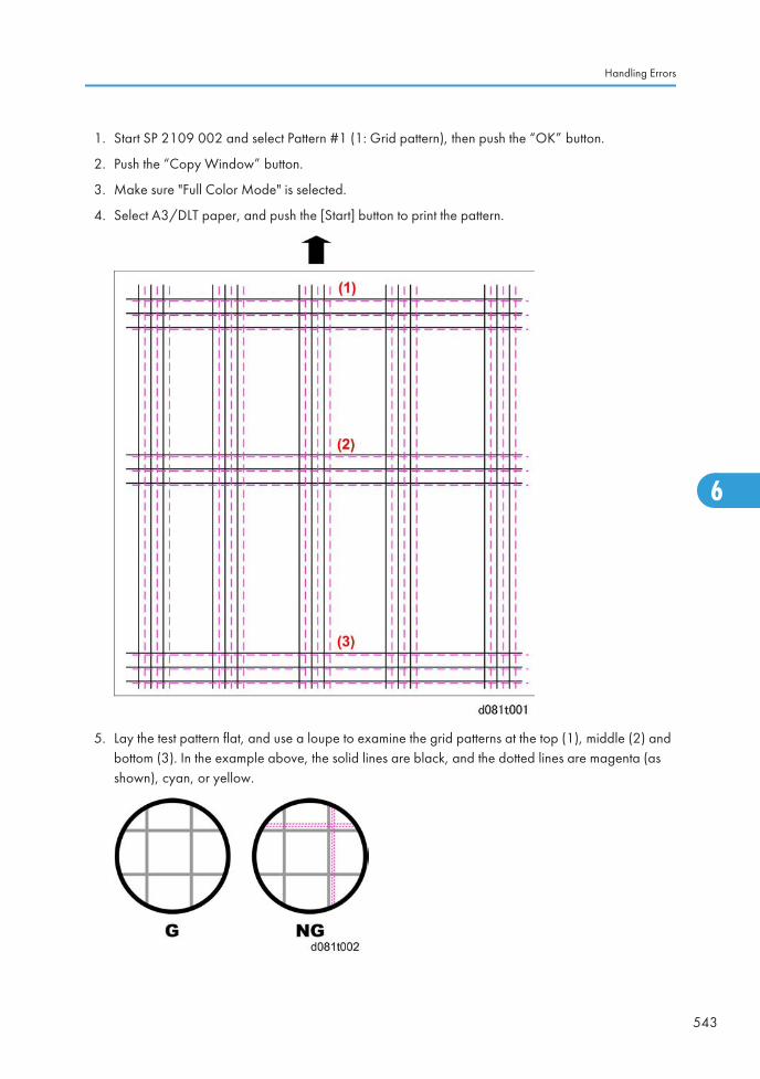
1. Start SP 2109 002 and select Pattern #1 (1: Grid pattern), then push the “OK” button.
2. Push the “Copy Window” button.
3. Make sure "Full Color Mode" is selected.
4. Select A3/DLT paper, and push the [Start] button to print the pattern.
5. Lay the test pattern flat, and use a loupe to examine the grid patterns at the top (1), middle (2) andbottom (3). In the example above, the solid lines are black, and the dotted lines are magenta (asshown), cyan, or yellow.
Handling Errors
543
6
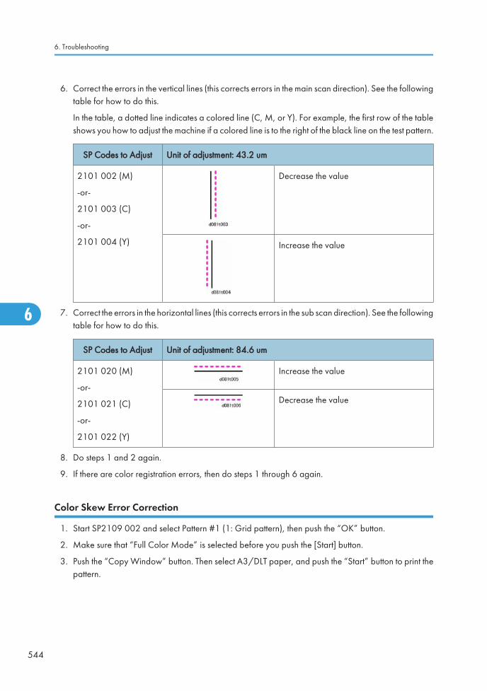
6. Correct the errors in the vertical lines (this corrects errors in the main scan direction). See the followingtable for how to do this.
In the table, a dotted line indicates a colored line (C, M, or Y). For example, the first row of the tableshows you how to adjust the machine if a colored line is to the right of the black line on the test pattern.
SP Codes to Adjust Unit of adjustment: 43.2 um
2101 002 (M)
-or-
2101 003 (C)
-or-
2101 004 (Y)
Decrease the value
Increase the value
7. Correct the errors in the horizontal lines (this corrects errors in the sub scan direction). See the followingtable for how to do this.
SP Codes to Adjust Unit of adjustment: 84.6 um
2101 020 (M)
-or-
2101 021 (C)
-or-
2101 022 (Y)
Increase the value
Decrease the value
8. Do steps 1 and 2 again.
9. If there are color registration errors, then do steps 1 through 6 again.
Color Skew Error Correction
1. Start SP2109 002 and select Pattern #1 (1: Grid pattern), then push the “OK” button.
2. Make sure that “Full Color Mode” is selected before you push the [Start] button.
3. Push the “Copy Window” button. Then select A3/DLT paper, and push the “Start” button to print thepattern.
6. Troubleshooting
544
6
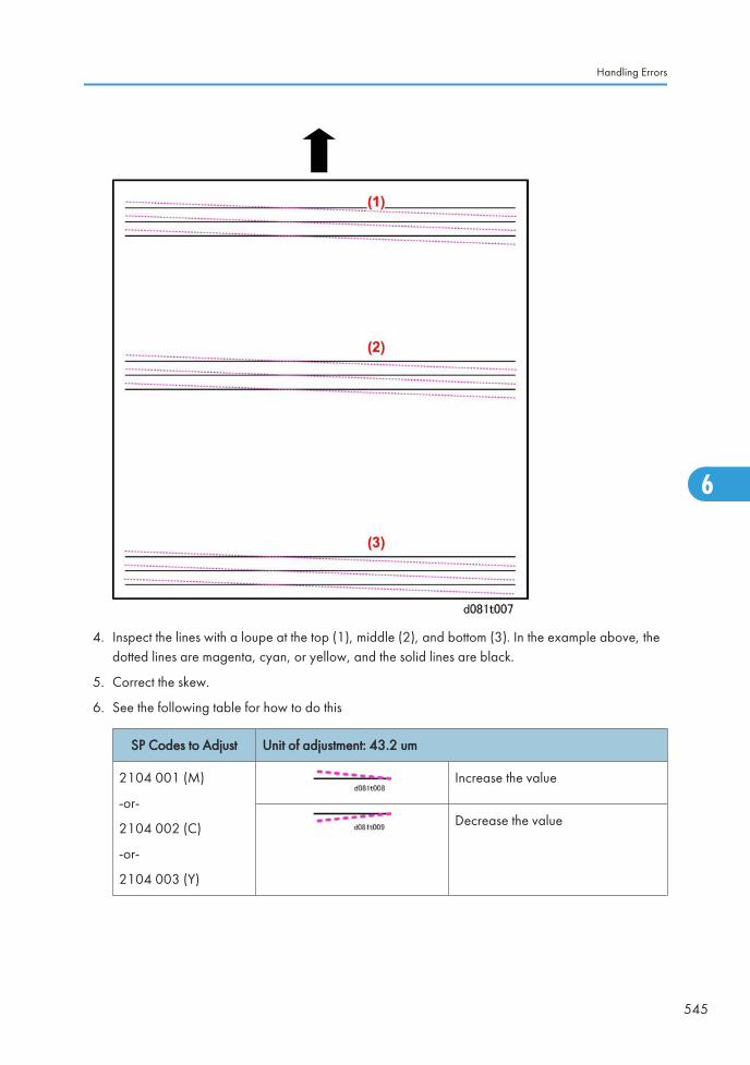
4. Inspect the lines with a loupe at the top (1), middle (2), and bottom (3). In the example above, thedotted lines are magenta, cyan, or yellow, and the solid lines are black.
5. Correct the skew.
6. See the following table for how to do this
SP Codes to Adjust Unit of adjustment: 43.2 um
2104 001 (M)
-or-
2104 002 (C)
-or-
2104 003 (Y)
Increase the value
Decrease the value
Handling Errors
545
6
Overall Check
1. After you do the color registration error and color skew corrections, do a forced MUSIC again, withSP2111 001.
2. Do SP2109 002 and print Pattern #1 (1: Grid pattern) on A3/DLT paper again. Check the skew andcolor registration. If they are still not acceptable, do the forced MUSIC again.
3. Do SP2181-001 (Alignment Result – General) to make sure that the forced MUSIC was donecorrectly.
• If the result is ‘1’, then each color was aligned correctly.
• If "1" is not shown, then please see "SP2181 030 (Alignment Result) Errors" in this section under"Special Procedures"..
Color Registration at the Left and Right Folds of the Test Pattern
Do this procedure after you complete “Color Registration Error Correction” and “Color Skew ErrorCorrection”.
1. Do SP2109 002 and print Pattern #1 (1: Grid pattern) on A3/DLT paper.
2. Make sure that “Full Color Mode” is selected.
3. Push the [Start] button.
6. Troubleshooting
546
6
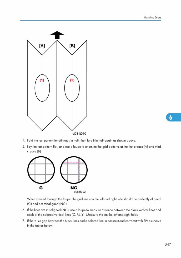
4. Fold the test pattern lengthways in half, then fold it in half again as shown above.
5. Lay the test pattern flat, and use a loupe to examine the grid patterns at the first crease [A] and thirdcrease [B].
When viewed through the loupe, the grid lines on the left and right side should be perfectly aligned(G) and not misaligned (NG).
6. If the lines are misaligned (NG), use a loupe to measure distance between the black vertical lines andeach of the colored vertical lines (C, M, Y). Measure this on the left and right folds:
7. If there is a gap between the black lines and a colored line, measure it and correct it with SPs as shownin the tables below.
Handling Errors
547
6
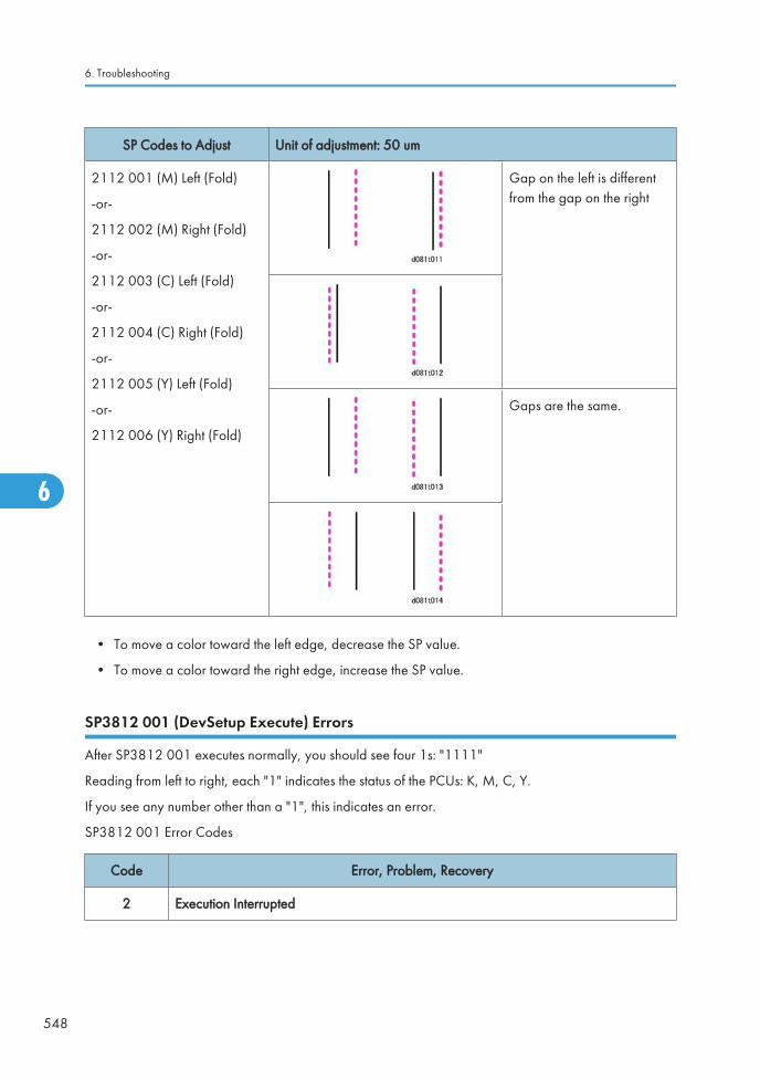
SP Codes to Adjust Unit of adjustment: 50 um
2112 001 (M) Left (Fold)
-or-
2112 002 (M) Right (Fold)
-or-
2112 003 (C) Left (Fold)
-or-
2112 004 (C) Right (Fold)
-or-
2112 005 (Y) Left (Fold)
-or-
2112 006 (Y) Right (Fold)
Gap on the left is differentfrom the gap on the right
Gaps are the same.
• To move a color toward the left edge, decrease the SP value.
• To move a color toward the right edge, increase the SP value.
SP3812 001 (DevSetup Execute) Errors
After SP3812 001 executes normally, you should see four 1s: "1111"
Reading from left to right, each "1" indicates the status of the PCUs: K, M, C, Y.
If you see any number other than a "1", this indicates an error.
SP3812 001 Error Codes
Code Error, Problem, Recovery
2 Execution Interrupted
6. Troubleshooting
548
6
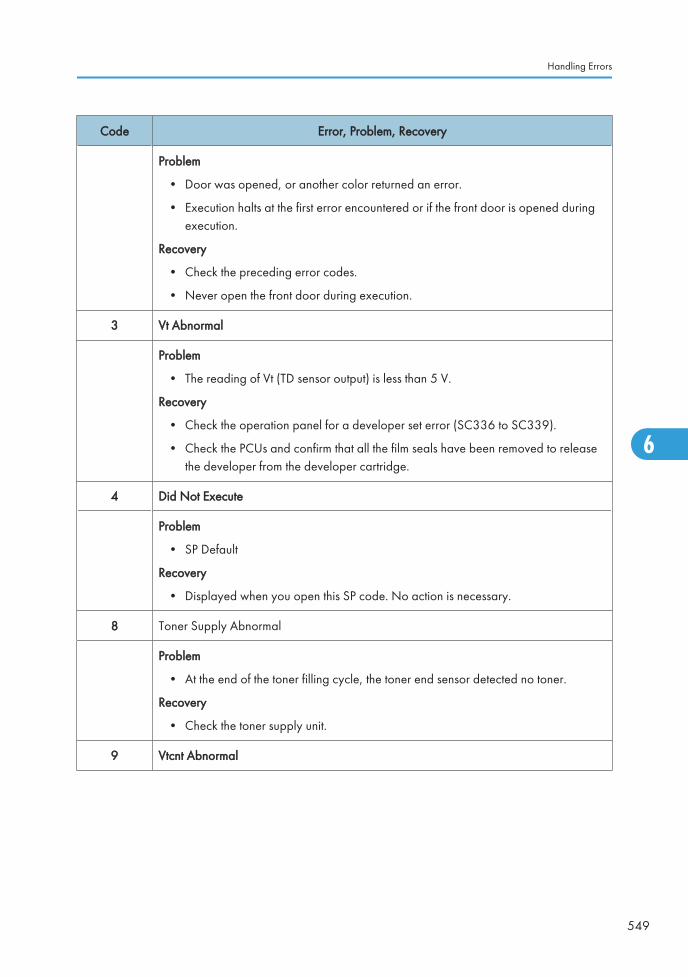
Code Error, Problem, Recovery
Problem
• Door was opened, or another color returned an error.
• Execution halts at the first error encountered or if the front door is opened duringexecution.
Recovery
• Check the preceding error codes.
• Never open the front door during execution.
3 Vt Abnormal
Problem
• The reading of Vt (TD sensor output) is less than 5 V.
Recovery
• Check the operation panel for a developer set error (SC336 to SC339).
• Check the PCUs and confirm that all the film seals have been removed to releasethe developer from the developer cartridge.
4 Did Not Execute
Problem
• SP Default
Recovery
• Displayed when you open this SP code. No action is necessary.
8 Toner Supply Abnormal
Problem
• At the end of the toner filling cycle, the toner end sensor detected no toner.
Recovery
• Check the toner supply unit.
9 Vtcnt Abnormal
Handling Errors
549
6
Code Error, Problem, Recovery
Problem
• Vtref (control reference voltage) could not be adjusted to within 0.2 V of Vt (TDsensor output).
Recovery
• This is a TD sensor adjustment error (SC372 to SC375). Execute SP3801 again forthe PCU that returned the error. If this does not recover operation, check the nextfour points.
• Film seal not removed from a new developer pack
• TD harness sensor disconnected, loose or defective
• TD sensor defective
• Harness between TD sensor and drawer disconnected, defective
Process Control Troubleshooting
Summary of Process Control SC Codes
This is a list of SC codes that may occur during process control. For more, please refer to the process controltables on the following pages.
Pre-Processing Check
SC316 to SC319
Vpp is not within the normal range (Vpp: the AC current applied to the chargeroller to compensate for changes in the ambient temperature and humidity).Insufficient charge causes white spotting and too much charge causes toner tofilm on the surface of the drum. Vpp must be > 2.8 kV.
SC400ID sensor could not be calibrated. An abnormal ID sensor condition is detectedwhen before calibration begins, Vsg < 0.5V or after calibration, Vsg cannot beadjusted to 4.0±0.2V.
SC418 Correct current could not be supplied to the ID sensor.
SC436 to SC439 A problem is detected with a potential sensor during calibration.
Potential Control
SC410 to SC413 The development gamma is out of range (not between 0.3 and 6.0) for a color.
SC414 to SC417Vk is out of range (not within ±150V) for a color. If the development potential isless than Vk, toner is not applied to the drum.
6. Troubleshooting
550
6
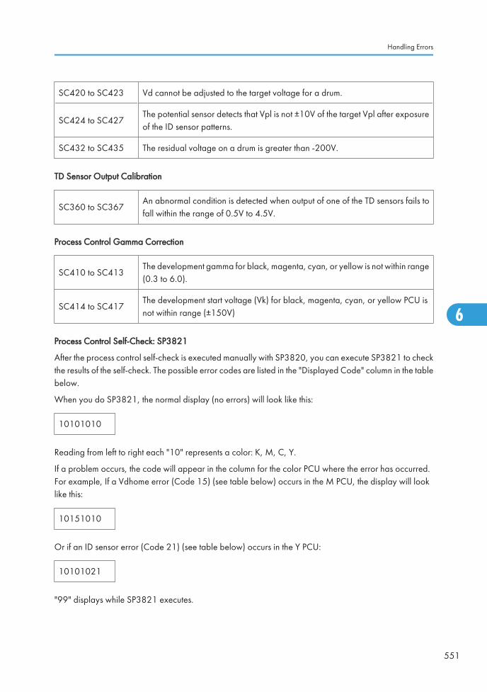
SC420 to SC423 Vd cannot be adjusted to the target voltage for a drum.
SC424 to SC427The potential sensor detects that Vpl is not ±10V of the target Vpl after exposureof the ID sensor patterns.
SC432 to SC435 The residual voltage on a drum is greater than -200V.
TD Sensor Output Calibration
SC360 to SC367An abnormal condition is detected when output of one of the TD sensors fails tofall within the range of 0.5V to 4.5V.
Process Control Gamma Correction
SC410 to SC413The development gamma for black, magenta, cyan, or yellow is not within range(0.3 to 6.0).
SC414 to SC417The development start voltage (Vk) for black, magenta, cyan, or yellow PCU isnot within range (±150V)
Process Control Self-Check: SP3821
After the process control self-check is executed manually with SP3820, you can execute SP3821 to checkthe results of the self-check. The possible error codes are listed in the "Displayed Code" column in the tablebelow.
When you do SP3821, the normal display (no errors) will look like this:
10101010
Reading from left to right each "10" represents a color: K, M, C, Y.
If a problem occurs, the code will appear in the column for the color PCU where the error has occurred.For example, If a Vdhome error (Code 15) (see table below) occurs in the M PCU, the display will looklike this:
10151010
Or if an ID sensor error (Code 21) (see table below) occurs in the Y PCU:
10101021
"99" displays while SP3821 executes.
Handling Errors
551
6
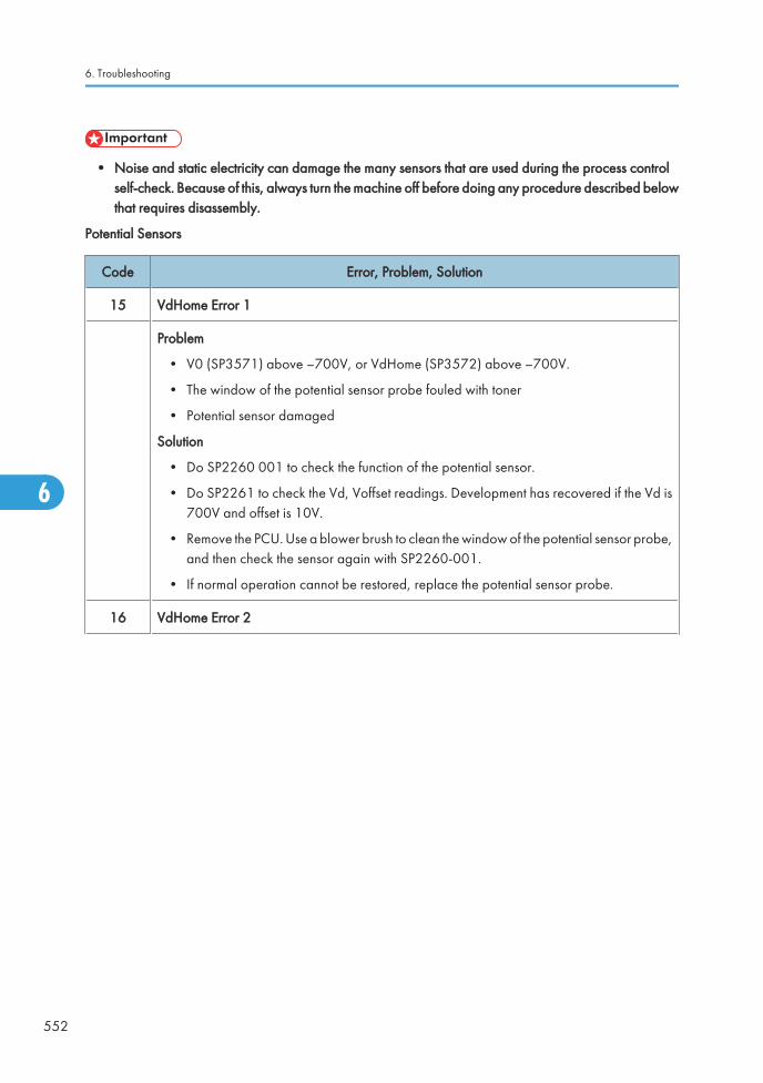
• Noise and static electricity can damage the many sensors that are used during the process controlself-check. Because of this, always turn the machine off before doing any procedure described belowthat requires disassembly.
Potential Sensors
Code Error, Problem, Solution
15 VdHome Error 1
Problem
• V0 (SP3571) above –700V, or VdHome (SP3572) above –700V.
• The window of the potential sensor probe fouled with toner
• Potential sensor damaged
Solution
• Do SP2260 001 to check the function of the potential sensor.
• Do SP2261 to check the Vd, Voffset readings. Development has recovered if the Vd is700V and offset is 10V.
• Remove the PCU. Use a blower brush to clean the window of the potential sensor probe,and then check the sensor again with SP2260-001.
• If normal operation cannot be restored, replace the potential sensor probe.
16 VdHome Error 2
6. Troubleshooting
552
6
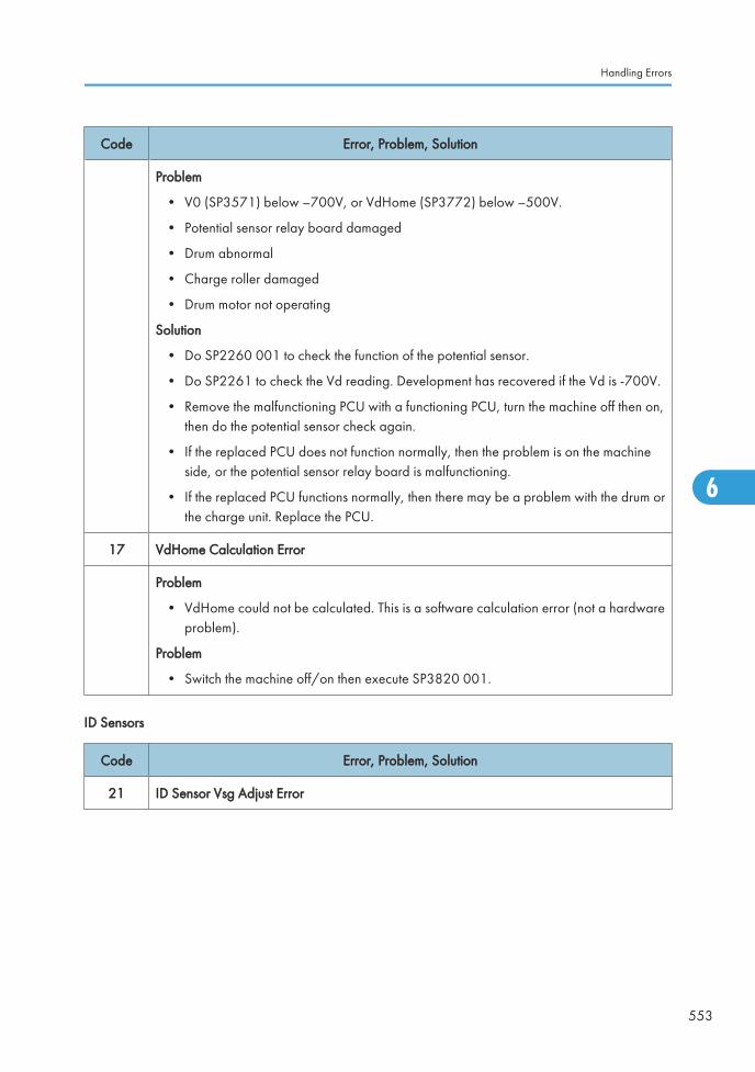
Code Error, Problem, Solution
Problem
• V0 (SP3571) below –700V, or VdHome (SP3772) below –500V.
• Potential sensor relay board damaged
• Drum abnormal
• Charge roller damaged
• Drum motor not operating
Solution
• Do SP2260 001 to check the function of the potential sensor.
• Do SP2261 to check the Vd reading. Development has recovered if the Vd is -700V.
• Remove the malfunctioning PCU with a functioning PCU, turn the machine off then on,then do the potential sensor check again.
• If the replaced PCU does not function normally, then the problem is on the machineside, or the potential sensor relay board is malfunctioning.
• If the replaced PCU functions normally, then there may be a problem with the drum orthe charge unit. Replace the PCU.
17 VdHome Calculation Error
Problem
• VdHome could not be calculated. This is a software calculation error (not a hardwareproblem).
Problem
• Switch the machine off/on then execute SP3820 001.
ID Sensors
Code Error, Problem, Solution
21 ID Sensor Vsg Adjust Error
Handling Errors
553
6

Code Error, Problem, Solution
Problem
• Vsg_reg (SP3121) is out of range (not within 4.0±0.2V).
• ID sensor fouled with dust, toner
• ITB undulating or out of position
Solution
• Remove the ITB unit.
• Make sure the belt is mounted correctly.
• Clean the windows of the ID sensors with alcohol and a clean cloth.
• Be sure to wipe the sensor apertures with a wet cloth. A dry cloth may generate staticwhich can attract dust.
22 ID Sensor LED Current Error
Problem
• LED PWM (SP3131) greater than 3000.
• ID sensor fouled with dust, toner
• ID sensor deteriorated
Solution
• Remove the ITB unit and check the ID sensors.
• Clean the windows of the ID sensors with alcohol and a clean cloth.
• Be sure to wipe the sensor apertures with a wet cloth. A dry cloth may generate staticwhich can attract dust.
• If the apertures are clean, then the LED of an ID sensor may have deteriorated. Replacethe ID sensor plate.
23 ID Sensor Output Error
6. Troubleshooting
554
6
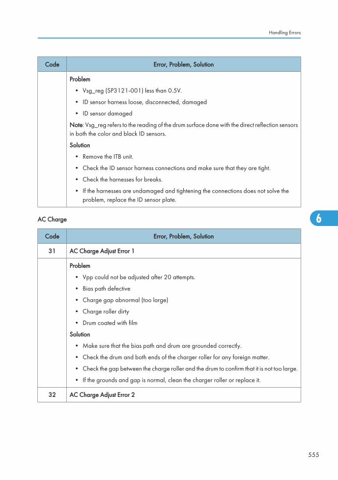
Code Error, Problem, Solution
Problem
• Vsg_reg (SP3121-001) less than 0.5V.
• ID sensor harness loose, disconnected, damaged
• ID sensor damaged
Note: Vsg_reg refers to the reading of the drum surface done with the direct reflection sensorsin both the color and black ID sensors.
Solution
• Remove the ITB unit.
• Check the ID sensor harness connections and make sure that they are tight.
• Check the harnesses for breaks.
• If the harnesses are undamaged and tightening the connections does not solve theproblem, replace the ID sensor plate.
AC Charge
Code Error, Problem, Solution
31 AC Charge Adjust Error 1
Problem
• Vpp could not be adjusted after 20 attempts.
• Bias path defective
• Charge gap abnormal (too large)
• Charge roller dirty
• Drum coated with film
Solution
• Make sure that the bias path and drum are grounded correctly.
• Check the drum and both ends of the charger roller for any foreign matter.
• Check the gap between the charge roller and the drum to confirm that it is not too large.
• If the grounds and gap is normal, clean the charger roller or replace it.
32 AC Charge Adjust Error 2
Handling Errors
555
6
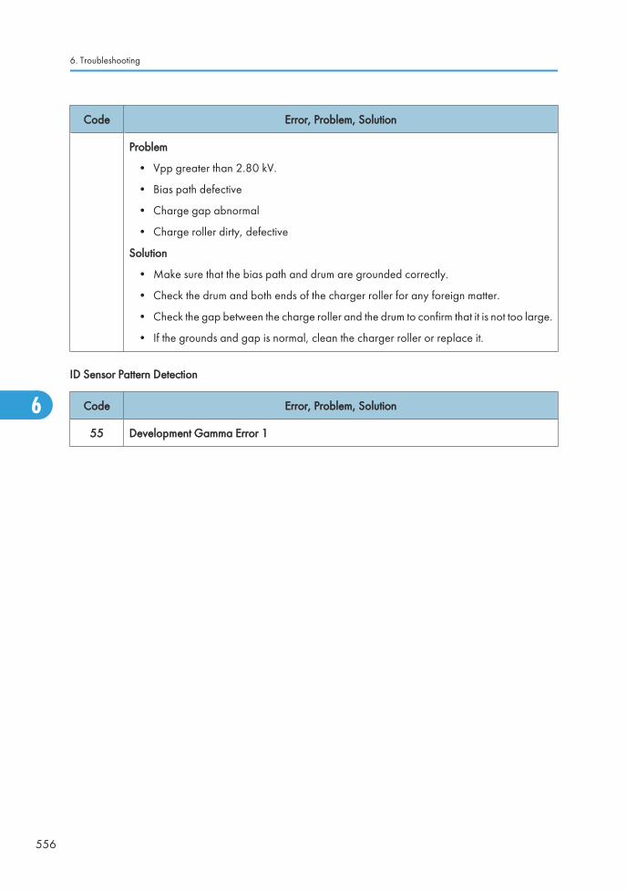
Code Error, Problem, Solution
Problem
• Vpp greater than 2.80 kV.
• Bias path defective
• Charge gap abnormal
• Charge roller dirty, defective
Solution
• Make sure that the bias path and drum are grounded correctly.
• Check the drum and both ends of the charger roller for any foreign matter.
• Check the gap between the charge roller and the drum to confirm that it is not too large.
• If the grounds and gap is normal, clean the charger roller or replace it.
ID Sensor Pattern Detection
Code Error, Problem, Solution
55 Development Gamma Error 1
6. Troubleshooting
556
6
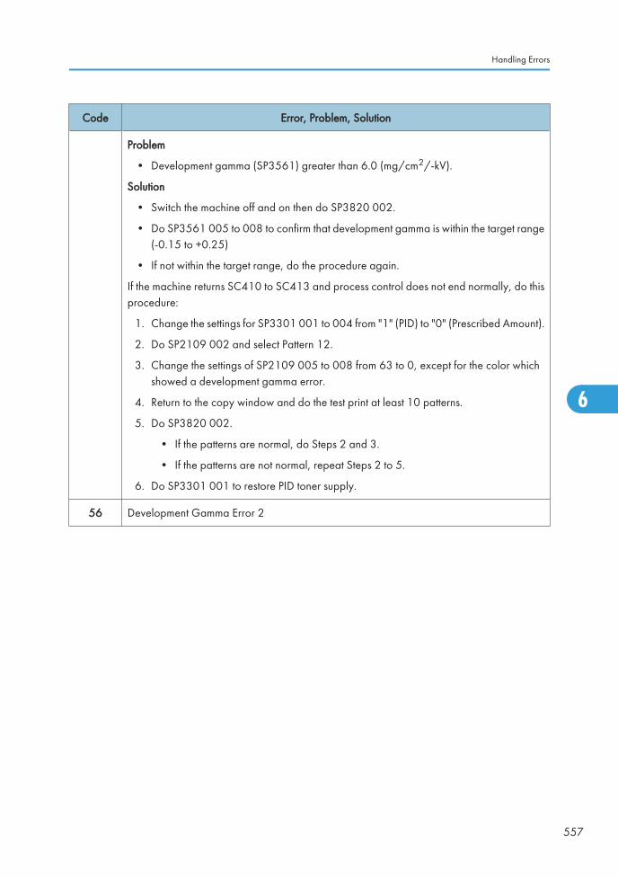
Code Error, Problem, Solution
Problem
• Development gamma (SP3561) greater than 6.0 (mg/cm2/-kV).
Solution
• Switch the machine off and on then do SP3820 002.
• Do SP3561 005 to 008 to confirm that development gamma is within the target range(-0.15 to +0.25)
• If not within the target range, do the procedure again.
If the machine returns SC410 to SC413 and process control does not end normally, do thisprocedure:
1. Change the settings for SP3301 001 to 004 from "1" (PID) to "0" (Prescribed Amount).
2. Do SP2109 002 and select Pattern 12.
3. Change the settings of SP2109 005 to 008 from 63 to 0, except for the color whichshowed a development gamma error.
4. Return to the copy window and do the test print at least 10 patterns.
5. Do SP3820 002.
• If the patterns are normal, do Steps 2 and 3.
• If the patterns are not normal, repeat Steps 2 to 5.
6. Do SP3301 001 to restore PID toner supply.
56 Development Gamma Error 2
Handling Errors
557
6
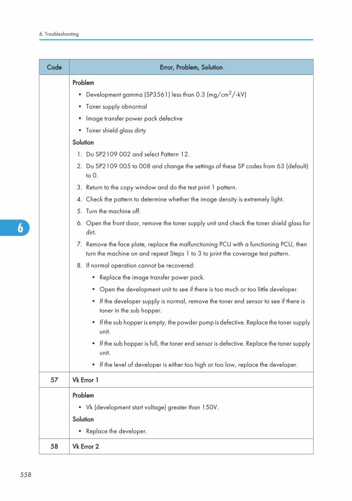
Code Error, Problem, Solution
Problem
• Development gamma (SP3561) less than 0.3 (mg/cm2/-kV)
• Toner supply abnormal
• Image transfer power pack defective
• Toner shield glass dirty
Solution
1. Do SP2109 002 and select Pattern 12.
2. Do SP2109 005 to 008 and change the settings of these SP codes from 63 (default)to 0.
3. Return to the copy window and do the test print 1 pattern.
4. Check the pattern to determine whether the image density is extremely light.
5. Turn the machine off.
6. Open the front door, remove the toner supply unit and check the toner shield glass fordirt.
7. Remove the face plate, replace the malfunctioning PCU with a functioning PCU, thenturn the machine on and repeat Steps 1 to 3 to print the coverage test pattern.
8. If normal operation cannot be recovered:
• Replace the image transfer power pack.
• Open the development unit to see if there is too much or too little developer.
• If the developer supply is normal, remove the toner end sensor to see if there istoner in the sub hopper.
• If the sub hopper is empty, the powder pump is defective. Replace the toner supplyunit.
• If the sub hopper is full, the toner end sensor is defective. Replace the toner supplyunit.
• If the level of developer is either too high or too low, replace the developer.
57 Vk Error 1
Problem
• Vk (development start voltage) greater than 150V.
Solution
• Replace the developer.
58 Vk Error 2
6. Troubleshooting
558
6
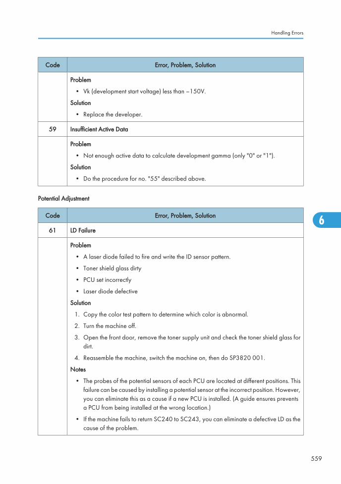
Code Error, Problem, Solution
Problem
• Vk (development start voltage) less than –150V.
Solution
• Replace the developer.
59 Insufficient Active Data
Problem
• Not enough active data to calculate development gamma (only "0" or "1").
Solution
• Do the procedure for no. "55" described above.
Potential Adjustment
Code Error, Problem, Solution
61 LD Failure
Problem
• A laser diode failed to fire and write the ID sensor pattern.
• Toner shield glass dirty
• PCU set incorrectly
• Laser diode defective
Solution
1. Copy the color test pattern to determine which color is abnormal.
2. Turn the machine off.
3. Open the front door, remove the toner supply unit and check the toner shield glass fordirt.
4. Reassemble the machine, switch the machine on, then do SP3820 001.
Notes
• The probes of the potential sensors of each PCU are located at different positions. Thisfailure can be caused by installing a potential sensor at the incorrect position. However,you can eliminate this as a cause if a new PCU is installed. (A guide ensures preventsa PCU from being installed at the wrong location.)
• If the machine fails to return SC240 to SC243, you can eliminate a defective LD as thecause of the problem.
Handling Errors
559
6
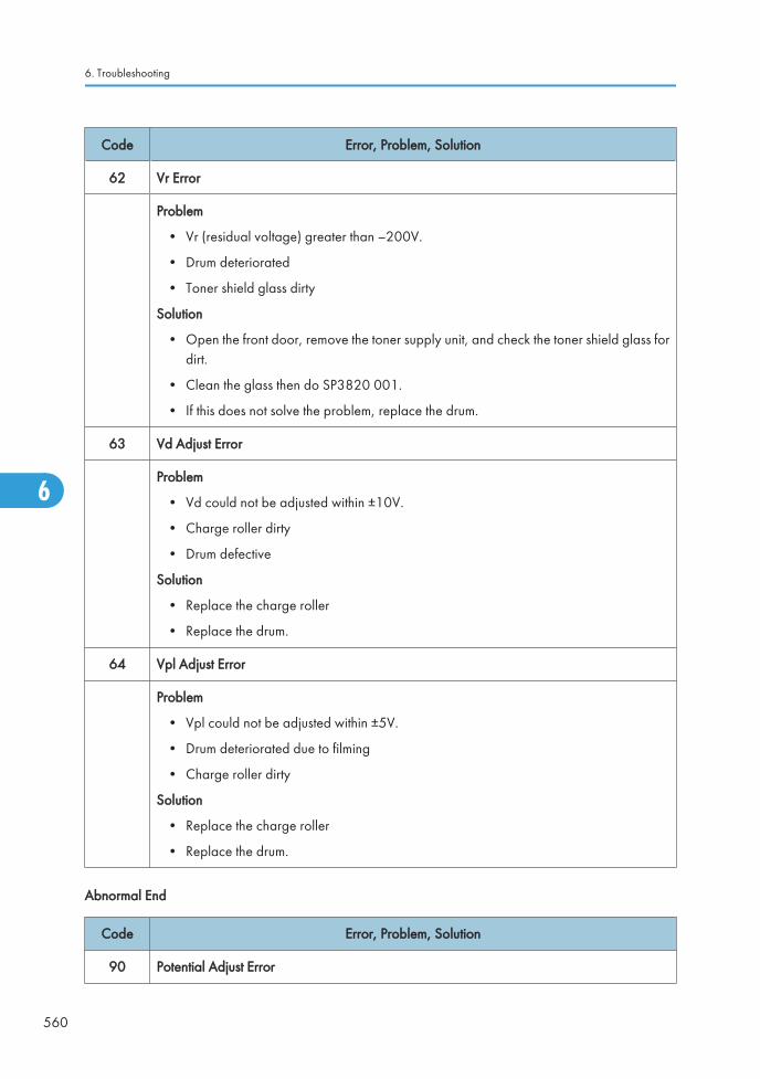
Code Error, Problem, Solution
62 Vr Error
Problem
• Vr (residual voltage) greater than –200V.
• Drum deteriorated
• Toner shield glass dirty
Solution
• Open the front door, remove the toner supply unit, and check the toner shield glass fordirt.
• Clean the glass then do SP3820 001.
• If this does not solve the problem, replace the drum.
63 Vd Adjust Error
Problem
• Vd could not be adjusted within ±10V.
• Charge roller dirty
• Drum defective
Solution
• Replace the charge roller
• Replace the drum.
64 Vpl Adjust Error
Problem
• Vpl could not be adjusted within ±5V.
• Drum deteriorated due to filming
• Charge roller dirty
Solution
• Replace the charge roller
• Replace the drum.
Abnormal End
Code Error, Problem, Solution
90 Potential Adjust Error
6. Troubleshooting
560
6
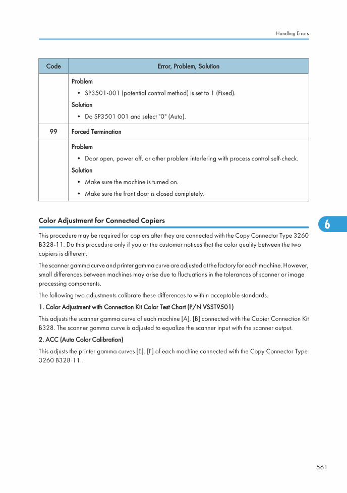
Code Error, Problem, Solution
Problem
• SP3501-001 (potential control method) is set to 1 (Fixed).
Solution
• Do SP3501 001 and select "0" (Auto).
99 Forced Termination
Problem
• Door open, power off, or other problem interfering with process control self-check.
Solution
• Make sure the machine is turned on.
• Make sure the front door is closed completely.
Color Adjustment for Connected Copiers
This procedure may be required for copiers after they are connected with the Copy Connector Type 3260B328-11. Do this procedure only if you or the customer notices that the color quality between the twocopiers is different.
The scanner gamma curve and printer gamma curve are adjusted at the factory for each machine. However,small differences between machines may arise due to fluctuations in the tolerances of scanner or imageprocessing components.
The following two adjustments calibrate these differences to within acceptable standards.
1. Color Adjustment with Connection Kit Color Test Chart (P/N VSST9501)
This adjusts the scanner gamma curve of each machine [A], [B] connected with the Copier Connection KitB328. The scanner gamma curve is adjusted to equalize the scanner input with the scanner output.
2. ACC (Auto Color Calibration)
This adjusts the printer gamma curves [E], [F] of each machine connected with the Copy Connector Type3260 B328-11.
Handling Errors
561
6
Ed
Typewritten Text
RTB 33 This section has been modified
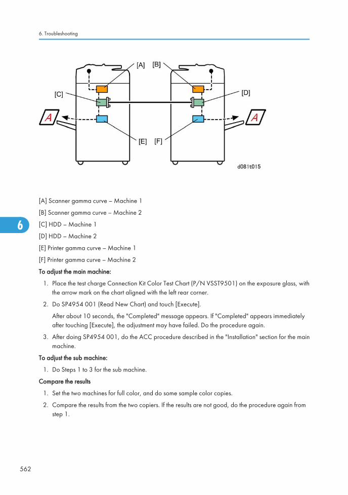
[A] Scanner gamma curve – Machine 1
[B] Scanner gamma curve – Machine 2
[C] HDD – Machine 1
[D] HDD – Machine 2
[E] Printer gamma curve – Machine 1
[F] Printer gamma curve – Machine 2
To adjust the main machine:
1. Place the test charge Connection Kit Color Test Chart (P/N VSST9501) on the exposure glass, withthe arrow mark on the chart aligned with the left rear corner.
2. Do SP4954 001 (Read New Chart) and touch [Execute].
After about 10 seconds, the "Completed" message appears. If "Completed" appears immediatelyafter touching [Execute], the adjustment may have failed. Do the procedure again.
3. After doing SP4954 001, do the ACC procedure described in the "Installation" section for the mainmachine.
To adjust the sub machine:
1. Do Steps 1 to 3 for the sub machine.
Compare the results
1. Set the two machines for full color, and do some sample color copies.
2. Compare the results from the two copiers. If the results are not good, do the procedure again fromstep 1.
6. Troubleshooting
562
6
Ed
Typewritten Text
RTB 33 This section has been modified
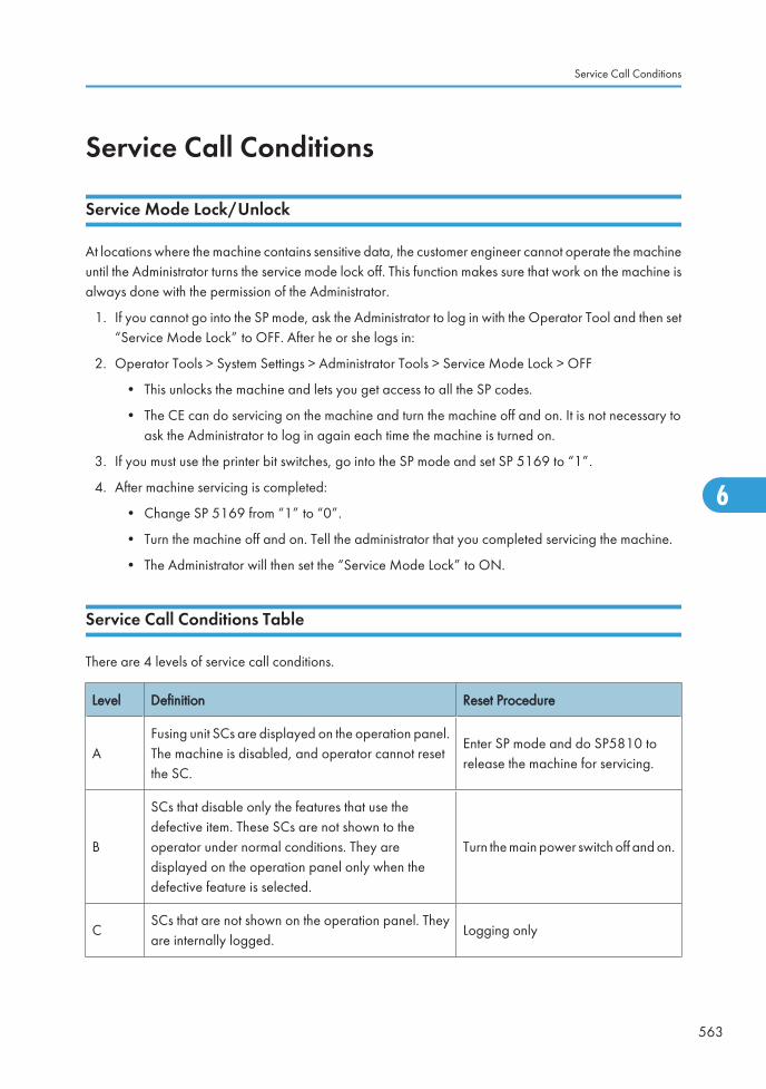
Service Call Conditions
Service Mode Lock/Unlock
At locations where the machine contains sensitive data, the customer engineer cannot operate the machineuntil the Administrator turns the service mode lock off. This function makes sure that work on the machine isalways done with the permission of the Administrator.
1. If you cannot go into the SP mode, ask the Administrator to log in with the Operator Tool and then set“Service Mode Lock” to OFF. After he or she logs in:
2. Operator Tools > System Settings > Administrator Tools > Service Mode Lock > OFF
• This unlocks the machine and lets you get access to all the SP codes.
• The CE can do servicing on the machine and turn the machine off and on. It is not necessary toask the Administrator to log in again each time the machine is turned on.
3. If you must use the printer bit switches, go into the SP mode and set SP 5169 to “1”.
4. After machine servicing is completed:
• Change SP 5169 from “1” to “0”.
• Turn the machine off and on. Tell the administrator that you completed servicing the machine.
• The Administrator will then set the “Service Mode Lock” to ON.
Service Call Conditions Table
There are 4 levels of service call conditions.
Level Definition Reset Procedure
AFusing unit SCs are displayed on the operation panel.The machine is disabled, and operator cannot resetthe SC.
Enter SP mode and do SP5810 torelease the machine for servicing.
B
SCs that disable only the features that use thedefective item. These SCs are not shown to theoperator under normal conditions. They aredisplayed on the operation panel only when thedefective feature is selected.
Turn the main power switch off and on.
CSCs that are not shown on the operation panel. Theyare internally logged.
Logging only
Service Call Conditions
563
6
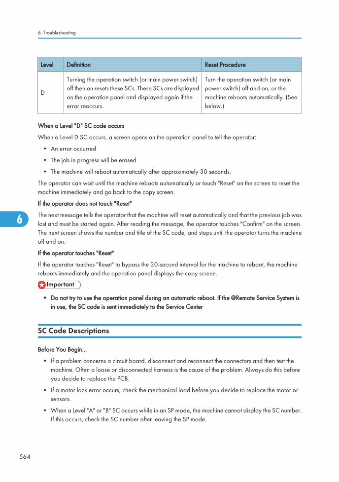
Level Definition Reset Procedure
D
Turning the operation switch (or main power switch)off then on resets these SCs. These SCs are displayedon the operation panel and displayed again if theerror reoccurs.
Turn the operation switch (or mainpower switch) off and on, or themachine reboots automatically. (Seebelow.)
When a Level "D" SC code occurs
When a Level D SC occurs, a screen opens on the operation panel to tell the operator:
• An error occurred
• The job in progress will be erased
• The machine will reboot automatically after approximately 30 seconds.
The operator can wait until the machine reboots automatically or touch "Reset" on the screen to reset themachine immediately and go back to the copy screen.
If the operator does not touch "Reset"
The next message tells the operator that the machine will reset automatically and that the previous job waslost and must be started again. After reading the message, the operator touches "Confirm" on the screen.The next screen shows the number and title of the SC code, and stops until the operator turns the machineoff and on.
If the operator touches "Reset"
If the operator touches "Reset" to bypass the 30-second interval for the machine to reboot, the machinereboots immediately and the operation panel displays the copy screen.
• Do not try to use the operation panel during an automatic reboot. If the @Remote Service System isin use, the SC code is sent immediately to the Service Center
SC Code Descriptions
Before You Begin…
• If a problem concerns a circuit board, disconnect and reconnect the connectors and then test themachine. Often a loose or disconnected harness is the cause of the problem. Always do this beforeyou decide to replace the PCB.
• If a motor lock error occurs, check the mechanical load before you decide to replace the motor orsensors.
• When a Level "A" or "B" SC occurs while in an SP mode, the machine cannot display the SC number.If this occurs, check the SC number after leaving the SP mode.
6. Troubleshooting
564
6

• The machine reboots automatically when the machine issues a Level "D" SC code. This is done forLevel "D" SC codes only.
• Never turn off the main power switch when the power LED is lit or flashing. To avoid damaging thehard disk or memory, press the operation switch to switch the power off, wait for the power LED togo off, and then switch the main power switch off.
The main power LED () lights or flashes while the platen cover or ARDF is open, while the main machineis communicating with a facsimile or the network server, or while the machine is accessing the hard disk ormemory for reading or writing data.
Service Call Conditions
565
6

Service Call TablesSee "Appendices" for "Service Call Tables" information,
6. Troubleshooting
566
6
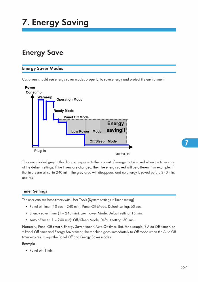
7. Energy Saving
Energy Save
Energy Saver Modes
Customers should use energy saver modes properly, to save energy and protect the environment.
The area shaded grey in this diagram represents the amount of energy that is saved when the timers areat the default settings. If the timers are changed, then the energy saved will be different. For example, ifthe timers are all set to 240 min., the grey area will disappear, and no energy is saved before 240 min.expires.
Timer Settings
The user can set these timers with User Tools (System settings > Timer setting)
• Panel off timer (10 sec – 240 min): Panel Off Mode. Default setting: 60 sec.
• Energy saver timer (1 – 240 min): Low Power Mode. Default setting: 15 min.
• Auto off timer (1 – 240 min): Off/Sleep Mode. Default setting: 30 min.
Normally, Panel Off timer < Energy Saver timer < Auto Off timer. But, for example, if Auto Off timer < or= Panel Off timer and Energy Saver timer, the machine goes immediately to Off mode when the Auto Offtimer expires. It skips the Panel Off and Energy Saver modes.
Example
• Panel off: 1 min.
567
7
• Low power: 15 min.
• Auto Off: 1 min.
• The machine goes to Off mode after 1 minute. Panel Off and Low Power modes are not used.
Return to Stand-by Mode
Low Power Mode
The recovery time depends on the model and the region.
• 45 sec.
Off/Sleep Mode
Recovery time.
• V-C3a: 90 sec.
• V-C3b: 75 sec.
Recommendation
We recommend that the default settings should be kept.
• If the customer requests that these settings should be changed, please explain that their energy costscould increase, and that they should consider the effects on the environment of extra energy use.
• If it is necessary to change the settings, please try to make sure that the Auto Off timer is not too long.Try with a shorter setting first, such as 30 min., then go to a longer one (such as 60 min.) if the customeris not satisfied.
• If the timers are all set to the maximum value, the machine will not begin saving energy until 240minutes has expired after the last job. This means that after the customer has finished using the machinefor the day, energy will be consumed that could otherwise be saved.
• If you change the settings, the energy consumed can be measured using SP8941, as explained below.
Energy Save Effectiveness
SP 8941 (Machine Status) keeps a record of the amount of time that the machine spends in each mode.
• 8941-001: Operating mode
• 8941-002: Standby mode
• 8941-003: Panel off mode
• 8941-004: Low power mode
• 8941-005: Off/sleep mode
7. Energy Saving
568
7
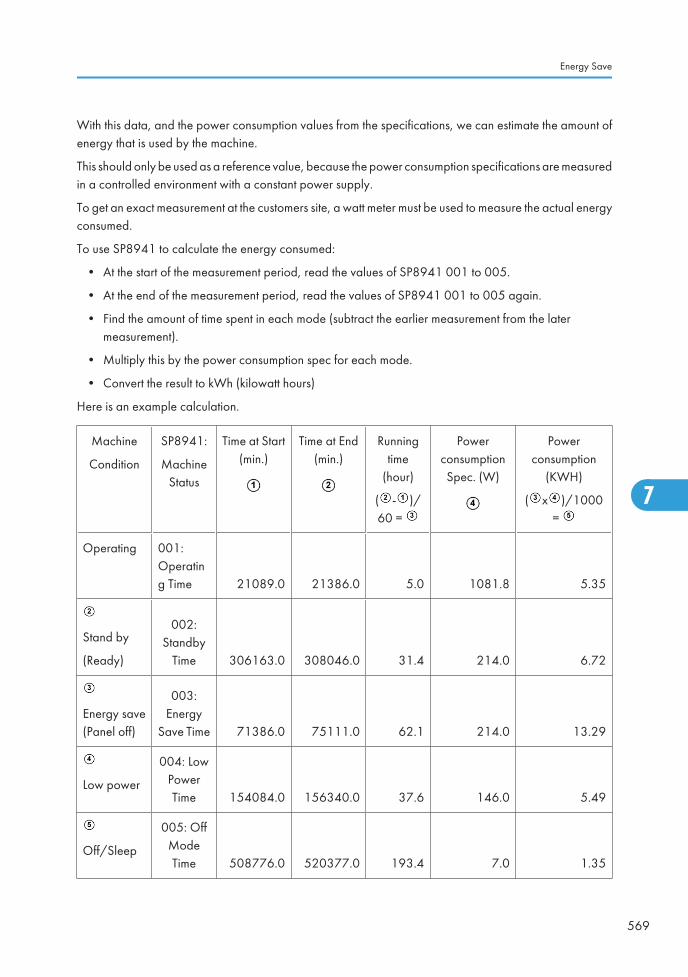
With this data, and the power consumption values from the specifications, we can estimate the amount ofenergy that is used by the machine.
This should only be used as a reference value, because the power consumption specifications are measuredin a controlled environment with a constant power supply.
To get an exact measurement at the customers site, a watt meter must be used to measure the actual energyconsumed.
To use SP8941 to calculate the energy consumed:
• At the start of the measurement period, read the values of SP8941 001 to 005.
• At the end of the measurement period, read the values of SP8941 001 to 005 again.
• Find the amount of time spent in each mode (subtract the earlier measurement from the latermeasurement).
• Multiply this by the power consumption spec for each mode.
• Convert the result to kWh (kilowatt hours)
Here is an example calculation.
Machine
Condition
SP8941:
MachineStatus
Time at Start(min.)
Time at End(min.)
Runningtime
(hour)
( - )/60 =
PowerconsumptionSpec. (W)
Powerconsumption
(KWH)
( x )/1000=
Operating 001:Operating Time 21089.0 21386.0 5.0 1081.8 5.35
Stand by
(Ready)
002:Standby
Time 306163.0 308046.0 31.4 214.0 6.72
Energy save(Panel off)
003:Energy
Save Time 71386.0 75111.0 62.1 214.0 13.29
Low power
004: LowPowerTime 154084.0 156340.0 37.6 146.0 5.49
Off/Sleep
005: OffModeTime 508776.0 520377.0 193.4 7.0 1.35
Energy Save
569
7

Total 32.20
7. Energy Saving
570
7
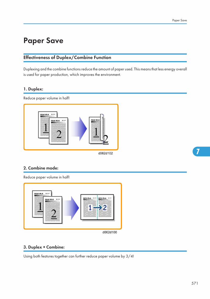
Paper Save
Effectiveness of Duplex/Combine Function
Duplexing and the combine functions reduce the amount of paper used. This means that less energy overallis used for paper production, which improves the environment.
1. Duplex:
Reduce paper volume in half!
2. Combine mode:
Reduce paper volume in half!
3. Duplex + Combine:
Using both features together can further reduce paper volume by 3/4!
Paper Save
571
7
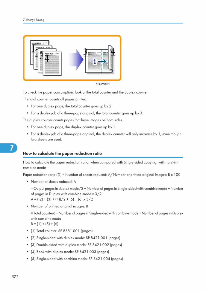
To check the paper consumption, look at the total counter and the duplex counter.
The total counter counts all pages printed.
• For one duplex page, the total counter goes up by 2.
• For a duplex job of a three-page original, the total counter goes up by 3.
The duplex counter counts pages that have images on both sides.
• For one duplex page, the duplex counter goes up by 1.
• For a duplex job of a three-page original, the duplex counter will only increase by 1, even thoughtwo sheets are used.
How to calculate the paper reduction ratio
How to calculate the paper reduction ratio, when compared with Single-sided copying, with no 2-in-1combine mode
Paper reduction ratio (%) = Number of sheets reduced: A/Number of printed original images: B x 100
• Number of sheets reduced: A
= Output pages in duplex mode/2 + Number of pages in Single-sided with combine mode + Numberof pages in Duplex with combine mode x 3/2A = ((2) + (3) + (4))/2 + (5) + (6) x 3/2
• Number of printed original images: B
= Total counter6 + Number of pages in Single-sided with combine mode + Number of pages in Duplexwith combine modeB = (1) + (5) + (6)
• (1) Total counter: SP 8581 001 (pages)
• (2) Single-sided with duplex mode: SP 8421 001 (pages)
• (3) Double-sided with duplex mode: SP 8421 002 (pages)
• (4) Book with duplex mode: SP 8421 003 (pages)
• (5) Single-sided with combine mode: SP 8421 004 (pages)
7. Energy Saving
572
7

• (6) Duplex with combine mode: SP 8421 005 (pages)
Paper Save
573
7

7. Energy Saving
574
7

Model V-C3 Machine Code: D081/082
Appendices
25 December, 2009

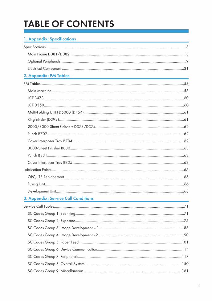
TABLE OF CONTENTS1. Appendix: Specifications
Specifications......................................................................................................................................................3
Main Frame D081/D082............................................................................................................................3
Optional Peripherals......................................................................................................................................9
Electrical Components.................................................................................................................................31
2. Appendix: PM Tables
PM Tables.........................................................................................................................................................53
Main Machine.............................................................................................................................................53
LCT B473......................................................................................................................................................60
LCT D350.....................................................................................................................................................60
Multi-Folding Unit FD5000 (D454)...........................................................................................................61
Ring Binder (D392).....................................................................................................................................61
2000/3000-Sheet Finishers D373/D374..............................................................................................62
Punch B702..................................................................................................................................................62
Cover Interposer Tray B704.......................................................................................................................62
3000-Sheet Finisher B830.........................................................................................................................63
Punch B831..................................................................................................................................................63
Cover Interposer Tray B835.......................................................................................................................63
Lubrication Points..............................................................................................................................................65
OPC, ITB Replacement................................................................................................................................65
Fusing Unit....................................................................................................................................................66
Development Unit........................................................................................................................................68
3. Appendix: Service Call Conditions
Service Call Tables...........................................................................................................................................71
SC Codes Group 1: Scanning....................................................................................................................71
SC Codes Group 2: Exposure....................................................................................................................75
SC Codes Group 3: Image Development – 1 .........................................................................................83
SC Codes Group 4: Image Development - 2 ..........................................................................................90
SC Codes Group 5: Paper Feed..............................................................................................................101
SC Codes Group 6: Device Communication..........................................................................................114
SC Codes Group 7: Peripherals..............................................................................................................117
SC Codes Group 8: Overall System.......................................................................................................150
SC Codes Group 9: Miscellaneous.........................................................................................................161
1
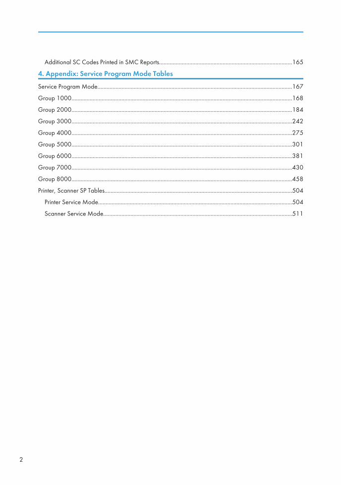
Additional SC Codes Printed in SMC Reports........................................................................................165
4. Appendix: Service Program Mode Tables
Service Program Mode.................................................................................................................................167
Group 1000..................................................................................................................................................168
Group 2000..................................................................................................................................................184
Group 3000..................................................................................................................................................242
Group 4000..................................................................................................................................................275
Group 5000..................................................................................................................................................301
Group 6000..................................................................................................................................................381
Group 7000..................................................................................................................................................430
Group 8000..................................................................................................................................................458
Printer, Scanner SP Tables............................................................................................................................504
Printer Service Mode.................................................................................................................................504
Scanner Service Mode.............................................................................................................................511
2
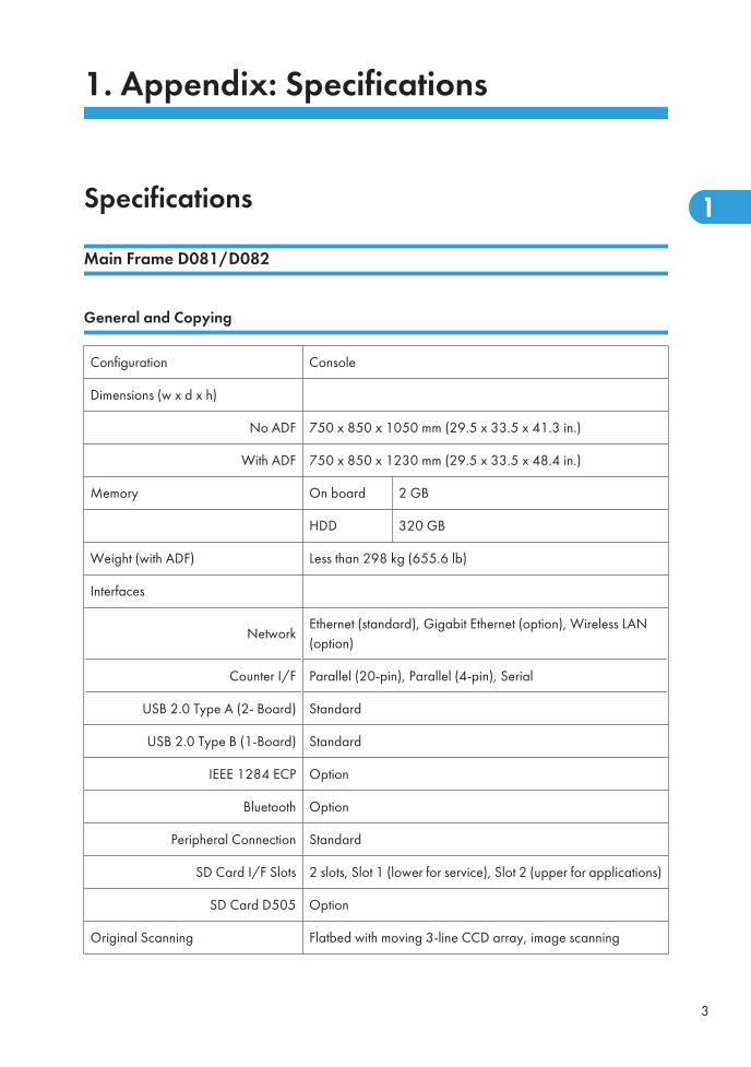
1. Appendix: Specifications
Specifications
Main Frame D081/D082
General and Copying
Configuration Console
Dimensions (w x d x h)
No ADF 750 x 850 x 1050 mm (29.5 x 33.5 x 41.3 in.)
With ADF 750 x 850 x 1230 mm (29.5 x 33.5 x 48.4 in.)
Memory On board 2 GB
HDD 320 GB
Weight (with ADF) Less than 298 kg (655.6 lb)
Interfaces
NetworkEthernet (standard), Gigabit Ethernet (option), Wireless LAN(option)
Counter I/F Parallel (20-pin), Parallel (4-pin), Serial
USB 2.0 Type A (2- Board) Standard
USB 2.0 Type B (1-Board) Standard
IEEE 1284 ECP Option
Bluetooth Option
Peripheral Connection Standard
SD Card I/F Slots 2 slots, Slot 1 (lower for service), Slot 2 (upper for applications)
SD Card D505 Option
Original Scanning Flatbed with moving 3-line CCD array, image scanning
3
1
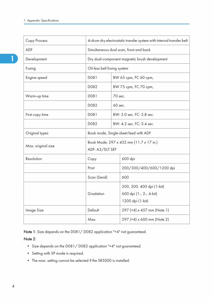
Copy Process 4-drum dry electrostatic transfer system with internal transfer belt
ADF Simultaneous dual scan, front and back
Development Dry dual-component magnetic brush development
Fusing Oil-less belt fusing system
Engine speed D081 BW 65 cpm, FC 60 cpm,
D082 BW 75 cpm, FC 70 cpm,
Warm-up time D081 70 sec.
D082 60 sec.
First copy time D081 BW: 5.0 sec. FC: 5.8 sec.
D082 BW: 4.2 sec. FC: 5.4 sec.
Original types Book mode, Single-sheet feed with ADF
Max. original sizeBook Mode: 297 x 432 mm (11.7 x 17 in.)
ADF: A3/DLT SEF
Resolution Copy 600 dpi
Print 200/300/400/600/1200 dpi
Scan (Send) 600
Gradation
200, 300, 400 dpi (1-bit)
600 dpi (1-, 2-, 4-bit)
1200 dpi (1-bit)
Image Size Default 297 (+4) x 457 mm (Note 1)
Max. 297 (+4) x 600 mm (Note 2)
Note 1: Size depends on the D081/ D082 application "+4" not guaranteed.
Note 2:
• Size depends on the D081/ D082 application "+4" not guaranteed.
• Setting with SP mode is required.
• The max. setting cannot be selected if the SR5000 is installed.
1. Appendix: Specifications
4
1
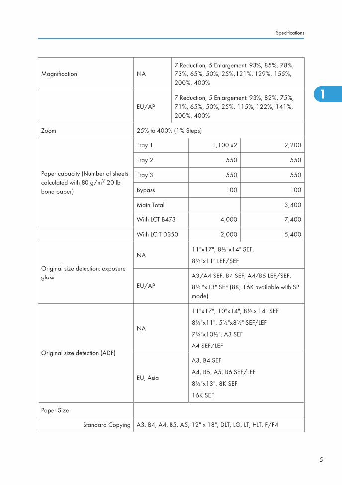
Magnification NA7 Reduction, 5 Enlargement: 93%, 85%, 78%,73%, 65%, 50%, 25%,121%, 129%, 155%,200%, 400%
EU/AP7 Reduction, 5 Enlargement: 93%, 82%, 75%,71%, 65%, 50%, 25%, 115%, 122%, 141%,200%, 400%
Zoom 25% to 400% (1% Steps)
Paper capacity (Number of sheetscalculated with 80 g/m2 20 lbbond paper)
Tray 1 1,100 x2 2,200
Tray 2 550 550
Tray 3 550 550
Bypass 100 100
Main Total 3,400
With LCT B473 4,000 7,400
With LCIT D350 2,000 5,400
Original size detection: exposureglass
NA11"x17", 8½"x14" SEF,
8½"x11" LEF/SEF
EU/AP
A3/A4 SEF, B4 SEF, A4/B5 LEF/SEF,
8½ "x13" SEF (8K, 16K available with SPmode)
Original size detection (ADF)
NA
11"x17", 10"x14", 8½ x 14" SEF
8½"x11", 5½"x8½" SEF/LEF
7¼"x10½", A3 SEF
A4 SEF/LEF
EU, Asia
A3, B4 SEF
A4, B5, A5, B6 SEF/LEF
8½"x13", 8K SEF
16K SEF
Paper Size
Standard Copying A3, B4, A4, B5, A5, 12" x 18", DLT, LG, LT, HLT, F/F4
Specifications
5
1
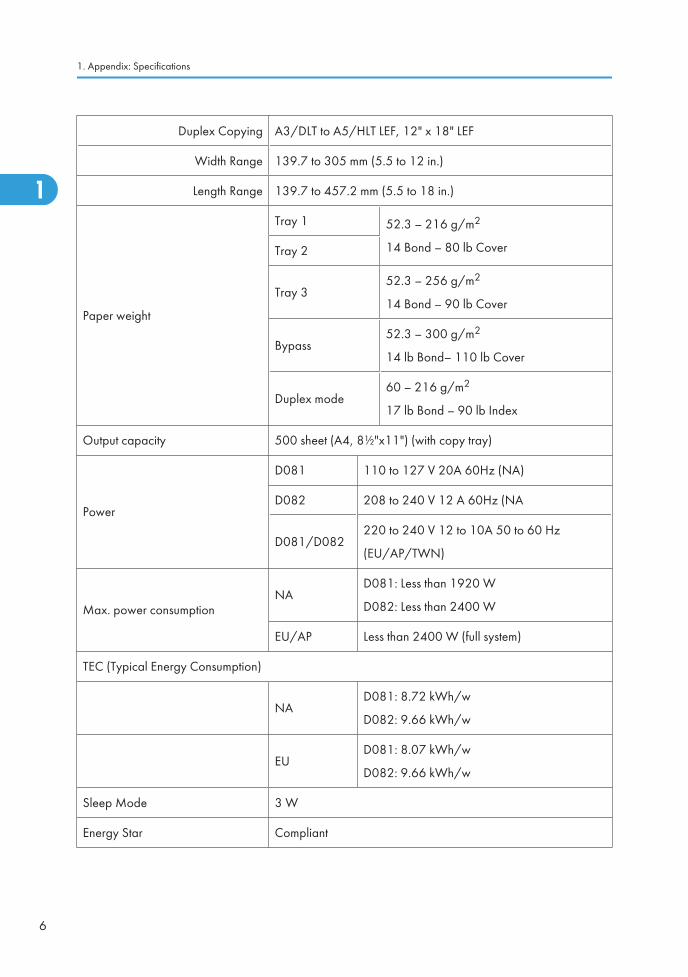
Duplex Copying A3/DLT to A5/HLT LEF, 12" x 18" LEF
Width Range 139.7 to 305 mm (5.5 to 12 in.)
Length Range 139.7 to 457.2 mm (5.5 to 18 in.)
Paper weight
Tray 1 52.3 – 216 g/m2
14 Bond – 80 lb CoverTray 2
Tray 352.3 – 256 g/m2
14 Bond – 90 lb Cover
Bypass52.3 – 300 g/m2
14 lb Bond– 110 lb Cover
Duplex mode60 – 216 g/m2
17 lb Bond – 90 lb Index
Output capacity 500 sheet (A4, 8½"x11") (with copy tray)
Power
D081 110 to 127 V 20A 60Hz (NA)
D082 208 to 240 V 12 A 60Hz (NA
D081/D082220 to 240 V 12 to 10A 50 to 60 Hz
(EU/AP/TWN)
Max. power consumptionNA
D081: Less than 1920 W
D082: Less than 2400 W
EU/AP Less than 2400 W (full system)
TEC (Typical Energy Consumption)
NAD081: 8.72 kWh/w
D082: 9.66 kWh/w
EUD081: 8.07 kWh/w
D082: 9.66 kWh/w
Sleep Mode 3 W
Energy Star Compliant
1. Appendix: Specifications
6
1
Ed
Typewritten Text
RTB 34 Spec was modified
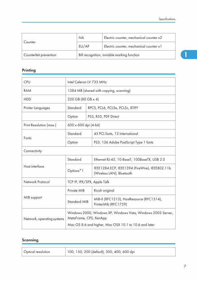
CounterNA Electric counter, mechanical counter x2
EU/AP Electric counter, mechanical counter x1
Counterfeit prevention Bill recognition, invisible marking function
Printing
CPU Intel Celeron LV 733 MHz
RAM 1384 MB (shared with copying, scanning)
HDD 320 GB (80 GB x 4)
Printer Languages Standard RPCS, PCL6, PCL5e, PCL5c, RTIFF
Option PS3, R55, PDF Direct
Print Resolution (max.) 600 x 600 dpi (4-bit)
FontsStandard 45 PCL fonts, 13 International
Option PS3, 136 Adobe PostScript Type 1 fonts
Connectivity
Host interface
Standard Ethernet RJ-45, 10-BaseT, 100BaseTX, USB 2.0
Options*1IEEE1284 ECP, IEEE1394 (FireWire), IEEE802.11b(Wireless LAN), Bluetooth
Network Protocol TCP IP, IPX/SPX, Apple Talk
MIB support
Private MIB Ricoh original
Standard MIBMIB-II (RFC1213), HostResource (RFC1514),PrinterMib (RFC1759)
Network, operating systems
Windows 2000, Windows XP, Windows Vista, Windows 2003 Server,MetaFrame, CPS, XenApp
Mac OS 8.6 and higher, Mac OSX 10.1 to 10.6 and later
Scanning
Optical resolution 100, 150, 200 (default), 300, 400, 600 dpi
Specifications
7
1
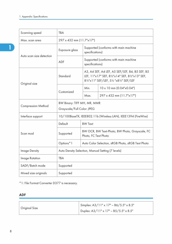
Scanning speed TBA
Max. scan area 297 x 432 mm (11.7"x17")
Auto scan size detection
Exposure glassSupported (conforms with main machinespecifications)
ADFSupported (conforms with main machinespecifications)
Original size
StandardA3, A4 SEF, A4 LEF, A5 SEF/LEF, B4, B5 SEF, B5LEF, 11"x17" SEF, 8½"x14" SEF, 8½"x13" SEF,8½"x11" SEF/LEF, 5½ "x8½" SEF/LEF
CustomizedMin. 10 x 10 mm (0.04"x0.04")
Max. 297 x 432 mm (11.7"x17")
Compression MethodBW Binary: TIFF MH, MR, MMR
Grayscale/Full Color: JPEG
Interface support 10/100BaseTX, IEEE802.11b (Wireless LAN), IEEE1394 (FireWire)
Scan mod
Default BW Text
SupportedBW OCR, BW Text-Photo, BW Photo, Grayscale, FCPhoto, FC Text Photo
Options*1 Auto Color Selection, sRGB Photo, sRGB Text Photo
Image Density Auto Density Selection, Manual Setting (7 levels)
Image Rotation TBA
SADF/Batch mode Supported
Mixed size originals Supported
*1: File Format Converter D377 is necessary.
ADF
Original SizeSimplex: A3/11" x 17" – B6/5.5" x 8.5"
Duplex: A3/11" x 17" – B5/5.5" x 8.5"
1. Appendix: Specifications
8
1

Original WeightSimplex: 40 to 128 g/m2 (11 to 34 lb.)
Duplex: 52 to 128 g/m2 (14 to 34 lb.)
Table Capacity (A4 SEF, LT SEF)250 sheets: 69g/m2
(150 sheets: 80g/m2, 20 lb. Bond)
Original Standard Position Rear left corner
Separation Feed belt and separation roller
Original Transport Roller transport
Original Feed Order From top original
Reproduction Range 100%
Power Source DC 24 V from the main machine
Power Consumption Less than 110 W
Rated Voltage of Output Connector Max. DC 24 V
Permissible voltage fluctuation ±10%
Dimensions (W x D x H) 680 x 560 x 180 mm (26.8" x 22.0" x 7.1")
Weight 18 kg (39.6 lb.)
Optional Peripherals
LCT B473
Installation of the LCT Adapter B699 is required to adjust the height of LCT B473.
Dimensions (w x d x h)Stand-alone 314 x 458 x 659 mm (12.4 x 18 x 25.9 in.)
With LG/B4 Option 462 x 458 x 659 mm (18.2 x 18 x 25.9 in.)
WeightStandalone Less than 20 kg (44 lb)
With LG/B4 Option Less than 27 kg (59.4 lb)
Power Consumption Less than 50 W
Noise Less than 74dB
Specifications
9
1
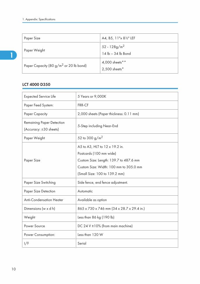
Paper Size A4, B5, 11"x 8½" LEF
Paper Weight52 - 128g/m2
14 lb – 34 lb Bond
Paper Capacity (80 g/m2 or 20 lb bond)4,000 sheets**
2,500 sheets*
LCT 4000 D350
Expected Service Life 5 Years or 9,000K
Paper Feed System: FRR-CF
Paper Capacity 2,000 sheets (Paper thickness: 0.11 mm)
Remaining Paper Detection
(Accuracy: ±30 sheets)5-Step including Near-End
Paper Weight 52 to 300 g/m2
Paper Size
A5 to A3, HLT to 12 x 19.2 in.
Postcards (100 mm wide)
Custom Size: Length: 139.7 to 487.6 mm
Custom Size: Width: 100 mm to 305.0 mm
(Small Size: 100 to 139.2 mm)
Paper Size Switching Side fence, end fence adjustment.
Paper Size Detection Automatic
Anti-Condensation Heater Available as option
Dimensions (w x d h) 865 x 730 x 746 mm (34 x 28.7 x 29.4 in.)
Weight Less than 86 kg (190 lb)
Power Source DC 24 V ±10% (from main machine)
Power Consumption: Less than 120 W
I/F Serial
1. Appendix: Specifications
10
1
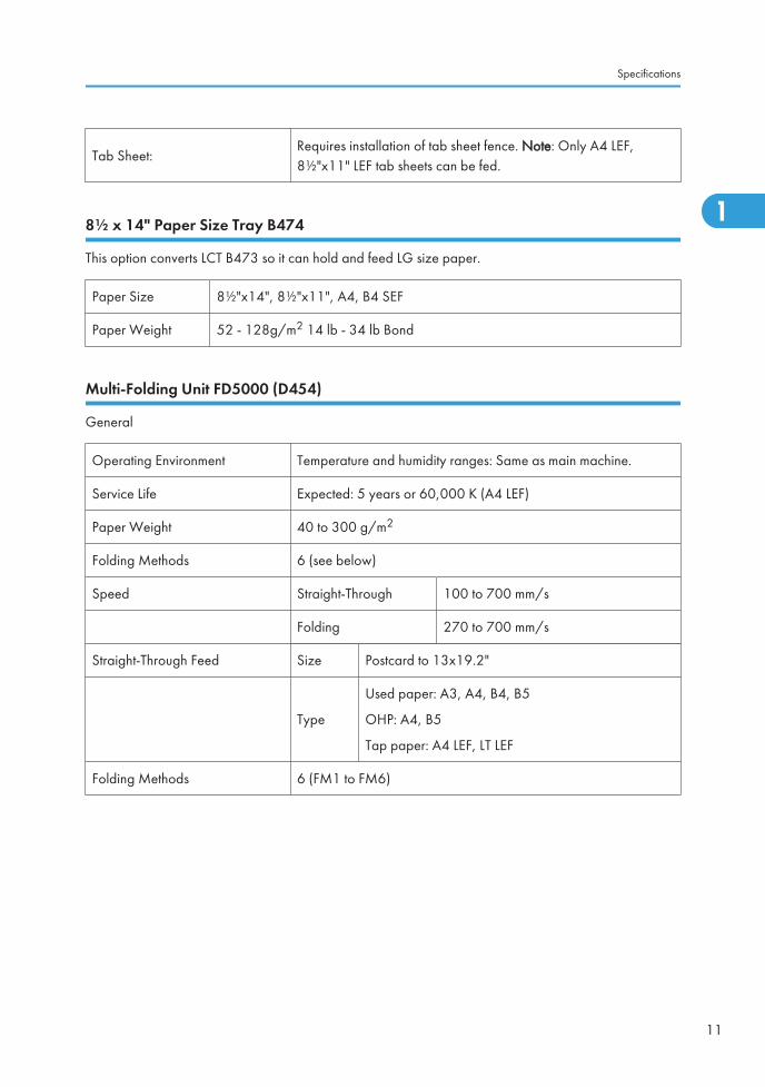
Tab Sheet:Requires installation of tab sheet fence. Note: Only A4 LEF,8½"x11" LEF tab sheets can be fed.
8½ x 14" Paper Size Tray B474
This option converts LCT B473 so it can hold and feed LG size paper.
Paper Size 8½"x14", 8½"x11", A4, B4 SEF
Paper Weight 52 - 128g/m2 14 lb - 34 lb Bond
Multi-Folding Unit FD5000 (D454)
General
Operating Environment Temperature and humidity ranges: Same as main machine.
Service Life Expected: 5 years or 60,000 K (A4 LEF)
Paper Weight 40 to 300 g/m2
Folding Methods 6 (see below)
Speed Straight-Through 100 to 700 mm/s
Folding 270 to 700 mm/s
Straight-Through Feed Size Postcard to 13x19.2"
Type
Used paper: A3, A4, B4, B5
OHP: A4, B5
Tap paper: A4 LEF, LT LEF
Folding Methods 6 (FM1 to FM6)
Specifications
11
1
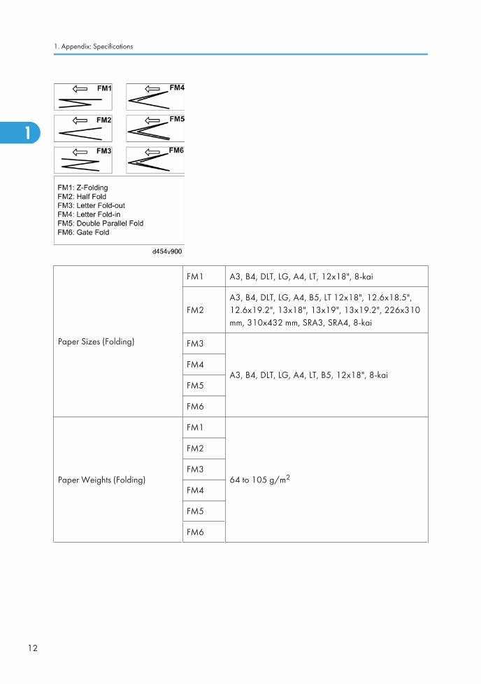
Paper Sizes (Folding)
FM1 A3, B4, DLT, LG, A4, LT, 12x18", 8-kai
FM2A3, B4, DLT, LG, A4, B5, LT 12x18", 12.6x18.5",12.6x19.2", 13x18", 13x19", 13x19.2", 226x310mm, 310x432 mm, SRA3, SRA4, 8-kai
FM3
A3, B4, DLT, LG, A4, LT, B5, 12x18", 8-kaiFM4
FM5
FM6
Paper Weights (Folding)
FM1
64 to 105 g/m2
FM2
FM3
FM4
FM5
FM6
1. Appendix: Specifications
12
1
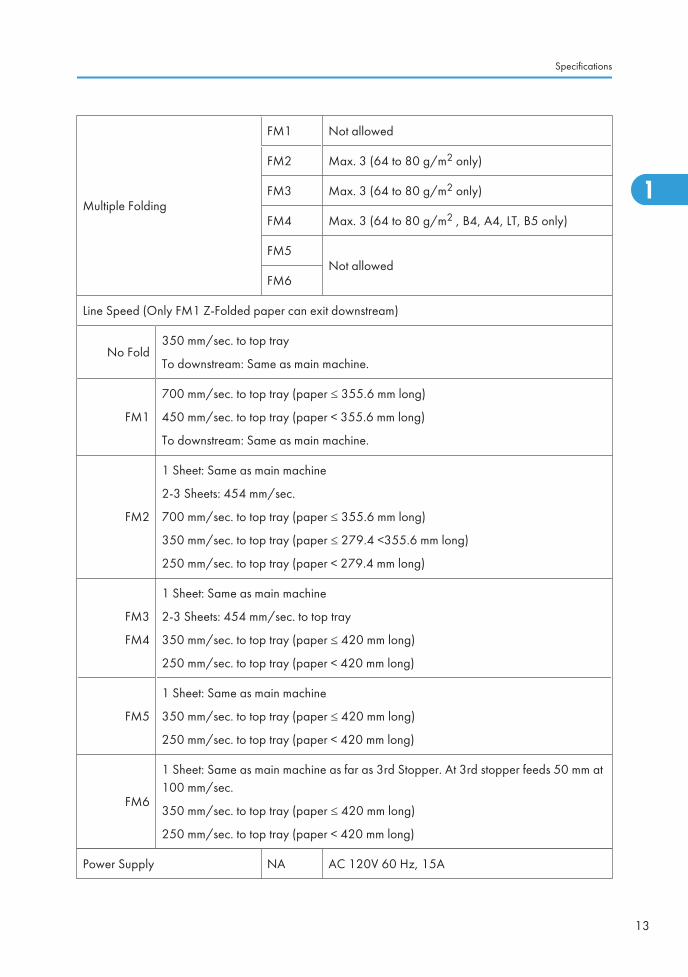
Multiple Folding
FM1 Not allowed
FM2 Max. 3 (64 to 80 g/m2 only)
FM3 Max. 3 (64 to 80 g/m2 only)
FM4 Max. 3 (64 to 80 g/m2 , B4, A4, LT, B5 only)
FM5Not allowed
FM6
Line Speed (Only FM1 Z-Folded paper can exit downstream)
No Fold350 mm/sec. to top tray
To downstream: Same as main machine.
FM1
700 mm/sec. to top tray (paper ≤ 355.6 mm long)
450 mm/sec. to top tray (paper < 355.6 mm long)
To downstream: Same as main machine.
FM2
1 Sheet: Same as main machine
2-3 Sheets: 454 mm/sec.
700 mm/sec. to top tray (paper ≤ 355.6 mm long)
350 mm/sec. to top tray (paper ≤ 279.4 <355.6 mm long)
250 mm/sec. to top tray (paper < 279.4 mm long)
FM3
FM4
1 Sheet: Same as main machine
2-3 Sheets: 454 mm/sec. to top tray
350 mm/sec. to top tray (paper ≤ 420 mm long)
250 mm/sec. to top tray (paper < 420 mm long)
FM5
1 Sheet: Same as main machine
350 mm/sec. to top tray (paper ≤ 420 mm long)
250 mm/sec. to top tray (paper < 420 mm long)
FM6
1 Sheet: Same as main machine as far as 3rd Stopper. At 3rd stopper feeds 50 mm at100 mm/sec.
350 mm/sec. to top tray (paper ≤ 420 mm long)
250 mm/sec. to top tray (paper < 420 mm long)
Power Supply NA AC 120V 60 Hz, 15A
Specifications
13
1
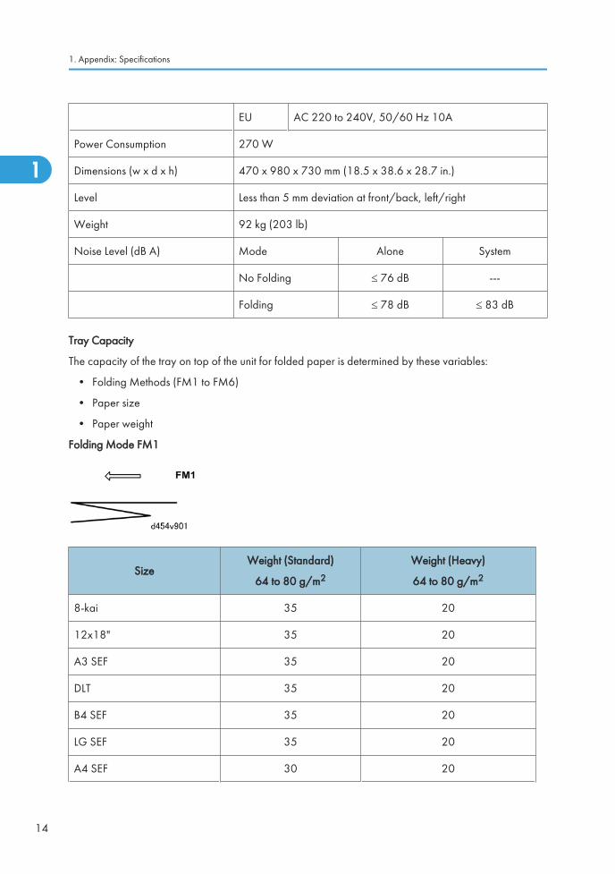
EU AC 220 to 240V, 50/60 Hz 10A
Power Consumption 270 W
Dimensions (w x d x h) 470 x 980 x 730 mm (18.5 x 38.6 x 28.7 in.)
Level Less than 5 mm deviation at front/back, left/right
Weight 92 kg (203 lb)
Noise Level (dB A) Mode Alone System
No Folding ≤ 76 dB ---
Folding ≤ 78 dB ≤ 83 dB
Tray Capacity
The capacity of the tray on top of the unit for folded paper is determined by these variables:
• Folding Methods (FM1 to FM6)
• Paper size
• Paper weight
Folding Mode FM1
SizeWeight (Standard)
64 to 80 g/m2
Weight (Heavy)
64 to 80 g/m2
8-kai 35 20
12x18" 35 20
A3 SEF 35 20
DLT 35 20
B4 SEF 35 20
LG SEF 35 20
A4 SEF 30 20
1. Appendix: Specifications
14
1
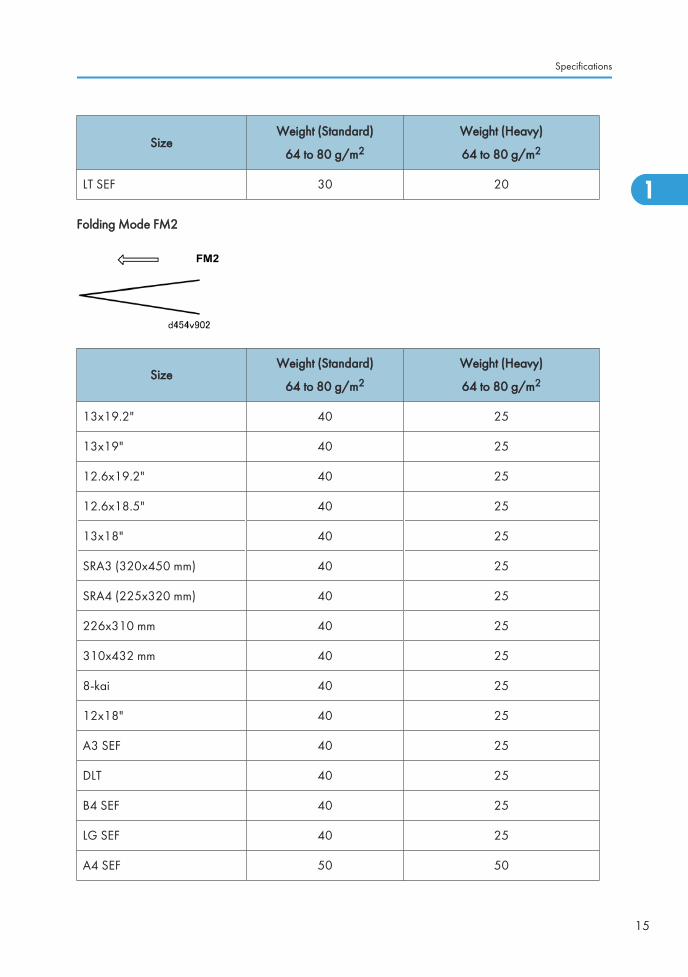
SizeWeight (Standard)
64 to 80 g/m2
Weight (Heavy)
64 to 80 g/m2
LT SEF 30 20
Folding Mode FM2
SizeWeight (Standard)
64 to 80 g/m2
Weight (Heavy)
64 to 80 g/m2
13x19.2" 40 25
13x19" 40 25
12.6x19.2" 40 25
12.6x18.5" 40 25
13x18" 40 25
SRA3 (320x450 mm) 40 25
SRA4 (225x320 mm) 40 25
226x310 mm 40 25
310x432 mm 40 25
8-kai 40 25
12x18" 40 25
A3 SEF 40 25
DLT 40 25
B4 SEF 40 25
LG SEF 40 25
A4 SEF 50 50
Specifications
15
1
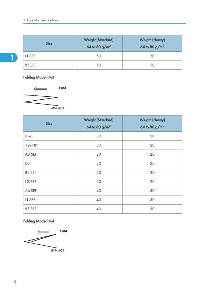
SizeWeight (Standard)
64 to 80 g/m2
Weight (Heavy)
64 to 80 g/m2
LT SEF 50 50
B5 SEF 50 50
Folding Mode FM3
SizeWeight (Standard)
64 to 80 g/m2
Weight (Heavy)
64 to 80 g/m2
8-kai 30 20
12x18" 30 20
A3 SEF 30 20
DLT 30 20
B4 SEF 30 20
LG SEF 30 20
A4 SEF 40 30
LT SEF 40 30
B5 SEF 40 30
Folding Mode FM4
1. Appendix: Specifications
16
1
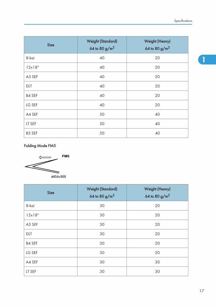
SizeWeight (Standard)
64 to 80 g/m2
Weight (Heavy)
64 to 80 g/m2
8-kai 40 20
12x18" 40 20
A3 SEF 40 20
DLT 40 20
B4 SEF 40 20
LG SEF 40 20
A4 SEF 50 40
LT SEF 50 40
B5 SEF 50 40
Folding Mode FM5
SizeWeight (Standard)
64 to 80 g/m2
Weight (Heavy)
64 to 80 g/m2
8-kai 30 20
12x18" 30 20
A3 SEF 30 20
DLT 30 20
B4 SEF 30 20
LG SEF 30 20
A4 SEF 30 30
LT SEF 30 30
Specifications
17
1
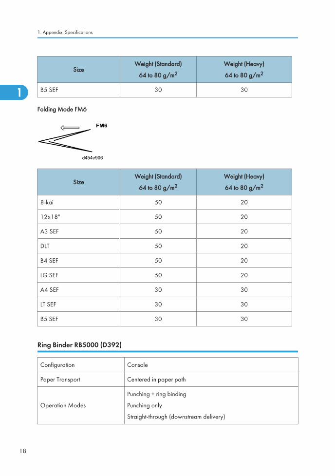
SizeWeight (Standard)
64 to 80 g/m2
Weight (Heavy)
64 to 80 g/m2
B5 SEF 30 30
Folding Mode FM6
SizeWeight (Standard)
64 to 80 g/m2
Weight (Heavy)
64 to 80 g/m2
8-kai 50 20
12x18" 50 20
A3 SEF 50 20
DLT 50 20
B4 SEF 50 20
LG SEF 50 20
A4 SEF 30 30
LT SEF 30 30
B5 SEF 30 30
Ring Binder RB5000 (D392)
Configuration Console
Paper Transport Centered in paper path
Operation Modes
Punching + ring binding
Punching only
Straight-through (downstream delivery)
1. Appendix: Specifications
18
1
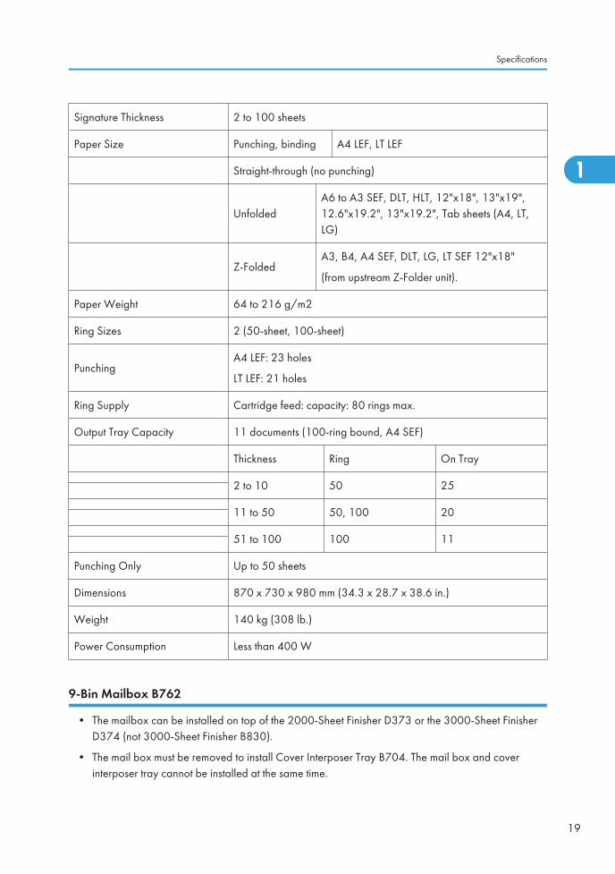
Signature Thickness 2 to 100 sheets
Paper Size Punching, binding A4 LEF, LT LEF
Straight-through (no punching)
UnfoldedA6 to A3 SEF, DLT, HLT, 12"x18", 13"x19",12.6"x19.2", 13"x19.2", Tab sheets (A4, LT,LG)
Z-FoldedA3, B4, A4 SEF, DLT, LG, LT SEF 12"x18"
(from upstream Z-Folder unit).
Paper Weight 64 to 216 g/m2
Ring Sizes 2 (50-sheet, 100-sheet)
PunchingA4 LEF: 23 holes
LT LEF: 21 holes
Ring Supply Cartridge feed: capacity: 80 rings max.
Output Tray Capacity 11 documents (100-ring bound, A4 SEF)
Thickness Ring On Tray
2 to 10 50 25
11 to 50 50, 100 20
51 to 100 100 11
Punching Only Up to 50 sheets
Dimensions 870 x 730 x 980 mm (34.3 x 28.7 x 38.6 in.)
Weight 140 kg (308 lb.)
Power Consumption Less than 400 W
9-Bin Mailbox B762
• The mailbox can be installed on top of the 2000-Sheet Finisher D373 or the 3000-Sheet FinisherD374 (not 3000-Sheet Finisher B830).
• The mail box must be removed to install Cover Interposer Tray B704. The mail box and coverinterposer tray cannot be installed at the same time.
Specifications
19
1
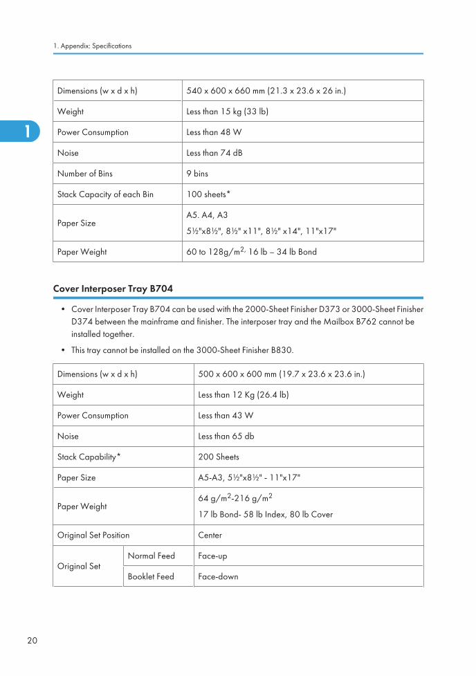
Dimensions (w x d x h) 540 x 600 x 660 mm (21.3 x 23.6 x 26 in.)
Weight Less than 15 kg (33 lb)
Power Consumption Less than 48 W
Noise Less than 74 dB
Number of Bins 9 bins
Stack Capacity of each Bin 100 sheets*
Paper SizeA5. A4, A3
5½"x8½", 8½" x11", 8½" x14", 11"x17"
Paper Weight 60 to 128g/m2, 16 lb – 34 lb Bond
Cover Interposer Tray B704
• Cover Interposer Tray B704 can be used with the 2000-Sheet Finisher D373 or 3000-Sheet FinisherD374 between the mainframe and finisher. The interposer tray and the Mailbox B762 cannot beinstalled together.
• This tray cannot be installed on the 3000-Sheet Finisher B830.
Dimensions (w x d x h) 500 x 600 x 600 mm (19.7 x 23.6 x 23.6 in.)
Weight Less than 12 Kg (26.4 lb)
Power Consumption Less than 43 W
Noise Less than 65 db
Stack Capability* 200 Sheets
Paper Size A5-A3, 5½"x8½" - 11"x17"
Paper Weight64 g/m2-216 g/m2
17 lb Bond- 58 lb Index, 80 lb Cover
Original Set Position Center
Original SetNormal Feed Face-up
Booklet Feed Face-down
1. Appendix: Specifications
20
1
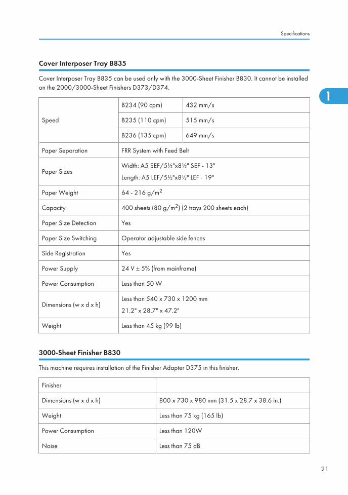
Cover Interposer Tray B835
Cover Interposer Tray B835 can be used only with the 3000-Sheet Finisher B830. It cannot be installedon the 2000/3000-Sheet Finishers D373/D374.
Speed
B234 (90 cpm) 432 mm/s
B235 (110 cpm) 515 mm/s
B236 (135 cpm) 649 mm/s
Paper Separation FRR System with Feed Belt
Paper SizesWidth: A5 SEF/5½"x8½" SEF - 13"
Length: A5 LEF/5½"x8½" LEF - 19"
Paper Weight 64 - 216 g/m2
Capacity 400 sheets (80 g/m2) (2 trays 200 sheets each)
Paper Size Detection Yes
Paper Size Switching Operator adjustable side fences
Side Registration Yes
Power Supply 24 V ± 5% (from mainframe)
Power Consumption Less than 50 W
Dimensions (w x d x h)Less than 540 x 730 x 1200 mm
21.2" x 28.7" x 47.2"
Weight Less than 45 kg (99 lb)
3000-Sheet Finisher B830
This machine requires installation of the Finisher Adapter D375 in this finisher.
Finisher
Dimensions (w x d x h) 800 x 730 x 980 mm (31.5 x 28.7 x 38.6 in.)
Weight Less than 75 kg (165 lb)
Power Consumption Less than 120W
Noise Less than 75 dB
Specifications
21
1
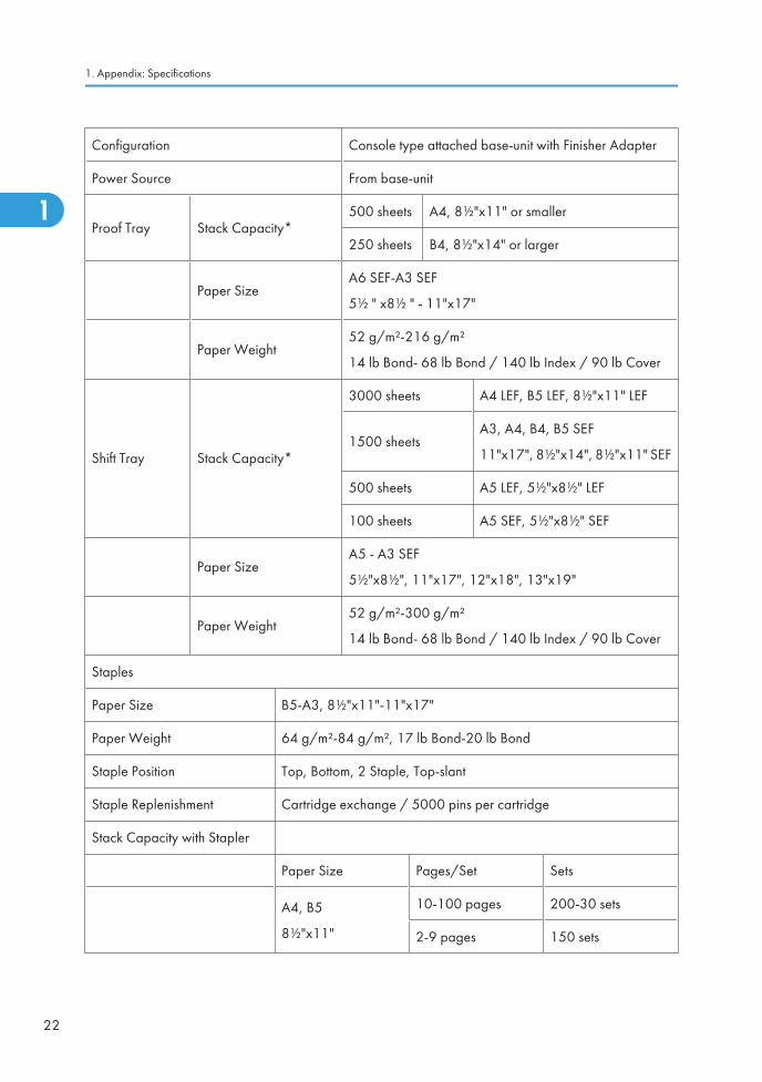
Configuration Console type attached base-unit with Finisher Adapter
Power Source From base-unit
Proof Tray Stack Capacity*500 sheets A4, 8½"x11" or smaller
250 sheets B4, 8½"x14" or larger
Paper SizeA6 SEF-A3 SEF
5½ " x8½ " - 11"x17"
Paper Weight52 g/m²-216 g/m²
14 lb Bond- 68 lb Bond / 140 lb Index / 90 lb Cover
Shift Tray Stack Capacity*
3000 sheets A4 LEF, B5 LEF, 8½"x11" LEF
1500 sheetsA3, A4, B4, B5 SEF
11"x17", 8½"x14", 8½"x11" SEF
500 sheets A5 LEF, 5½"x8½" LEF
100 sheets A5 SEF, 5½"x8½" SEF
Paper SizeA5 - A3 SEF
5½"x8½", 11"x17", 12"x18", 13"x19"
Paper Weight52 g/m²-300 g/m²
14 lb Bond- 68 lb Bond / 140 lb Index / 90 lb Cover
Staples
Paper Size B5-A3, 8½"x11"-11"x17"
Paper Weight 64 g/m²-84 g/m², 17 lb Bond-20 lb Bond
Staple Position Top, Bottom, 2 Staple, Top-slant
Staple Replenishment Cartridge exchange / 5000 pins per cartridge
Stack Capacity with Stapler
Paper Size Pages/Set Sets
A4, B5
8½"x11"
10-100 pages 200-30 sets
2-9 pages 150 sets
1. Appendix: Specifications
22
1
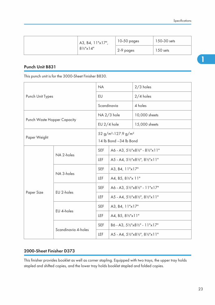
A3, B4, 11"x17",8½"x14"
10-50 pages 150-30 sets
2-9 pages 150 sets
Punch Unit B831
This punch unit is for the 3000-Sheet Finisher B830.
Punch Unit Types
NA 2/3 holes
EU 2/4 holes
Scandinavia 4 holes
Punch Waste Hopper CapacityNA 2/3 hole 10,000 sheets
EU 2/4 hole 15,000 sheets
Paper Weight52 g/m²-127.9 g/m²
14 lb Bond –34 lb Bond
Paper Size
NA 2-holesSEF A6 - A3, 5½"x8½" - 8½"x11"
LEF A5 - A4, 5½"x8½", 8½"x11"
NA 3-holesSEF A3, B4, 11"x17"
LEF A4, B5, 8½"x 11"
EU 2-holesSEF A6 - A3, 5½"x8½" - 11"x17"
LEF A5 - A4, 5½"x8½", 8½"x11"
EU 4-holesSEF A3, B4, 11"x17"
LEF A4, B5, 8½"x11"
Scandinavia 4-holesSEF B6 - A3, 5½"x8½" - 11"x17"
LEF A5 - A4, 5½"x8½", 8½"x11"
2000-Sheet Finisher D373
This finisher provides booklet as well as corner stapling. Equipped with two trays, the upper tray holdsstapled and shifted copies, and the lower tray holds booklet stapled and folded copies.
Specifications
23
1
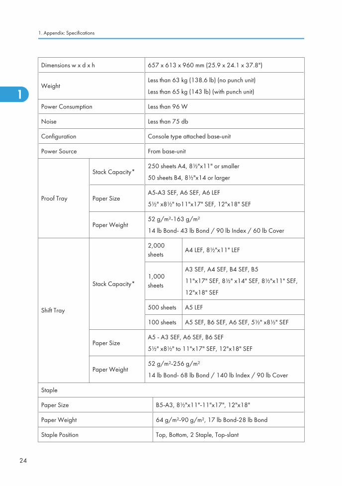
Dimensions w x d x h 657 x 613 x 960 mm (25.9 x 24.1 x 37.8")
WeightLess than 63 kg (138.6 lb) (no punch unit)
Less than 65 kg (143 lb) (with punch unit)
Power Consumption Less than 96 W
Noise Less than 75 db
Configuration Console type attached base-unit
Power Source From base-unit
Proof Tray
Stack Capacity*250 sheets A4, 8½"x11" or smaller
50 sheets B4, 8½"x14 or larger
Paper SizeA5-A3 SEF, A6 SEF, A6 LEF
5½" x8½" to11"x17" SEF, 12"x18" SEF
Paper Weight52 g/m²-163 g/m²
14 lb Bond- 43 lb Bond / 90 lb Index / 60 lb Cover
Shift Tray
Stack Capacity*
2,000sheets
A4 LEF, 8½"x11" LEF
1,000sheets
A3 SEF, A4 SEF, B4 SEF, B5
11"x17" SEF, 8½" x14" SEF, 8½"x11" SEF,
12"x18" SEF
500 sheets A5 LEF
100 sheets A5 SEF, B6 SEF, A6 SEF, 5½" x8½" SEF
Paper SizeA5 - A3 SEF, A6 SEF, B6 SEF
5½" x8½" to 11"x17" SEF, 12"x18" SEF
Paper Weight52 g/m²-256 g/m²
14 lb Bond- 68 lb Bond / 140 lb Index / 90 lb Cover
Staple
Paper Size B5-A3, 8½"x11"-11"x17", 12"x18"
Paper Weight 64 g/m²-90 g/m², 17 lb Bond-28 lb Bond
Staple Position Top, Bottom, 2 Staple, Top-slant
1. Appendix: Specifications
24
1
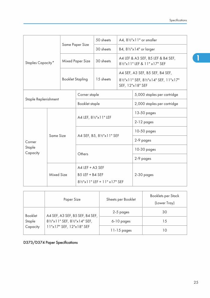
Staples Capacity*
Same Paper Size50 sheets A4, 8½"x11" or smaller
30 sheets B4, 8½"x14" or larger
Mixed Paper Size 30 sheetsA4 LEF & A3 SEF, B5 LEF & B4 SEF,8½"x11" LEF & 11" x17" SEF
Booklet Stapling 15 sheets
A4 SEF, A3 SEF, B5 SEF, B4 SEF,
8½"x11" SEF, 8½"x14" SEF, 11"x17"SEF, 12"x18" SEF
Staple ReplenishmentCorner staple 5,000 staples per cartridge
Booklet staple 2,000 staples per cartridge
CornerStapleCapacity
Same Size
A4 LEF, 8½"x11" LEF13-50 pages
2-12 pages
A4 SEF, B5, 8½"x11" SEF10-50 pages
2-9 pages
Others10-30 pages
2-9 pages
Mixed Size
A4 LEF + A3 SEF
B5 LEF + B4 SEF
8½"x11" LEF + 11" x17" SEF
2-30 pages
Paper Size Sheets per BookletBooklets per Stack
(Lower Tray)
BookletStapleCapacity
A4 SEF, A3 SEF, B5 SEF, B4 SEF,8½"x11" SEF, 8½"x14" SEF,11"x17" SEF, 12"x18" SEF
2-5 pages 30
6-10 pages 15
11-15 pages 10
D373/D374 Paper Specifications
Specifications
25
1
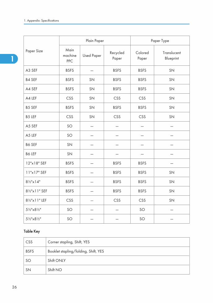
Paper Size
Plain Paper Paper Type
Mainmachine
PPCUsed Paper
RecycledPaper
ColoredPaper
TranslucentBlueprint
A3 SEF BSFS — BSFS BSFS SN
B4 SEF BSFS SN BSFS BSFS SN
A4 SEF BSFS SN BSFS BSFS SN
A4 LEF CSS SN CSS CSS SN
B5 SEF BSFS SN BSFS BSFS SN
B5 LEF CSS SN CSS CSS SN
A5 SEF SO — — — —
A5 LEF SO — — — —
B6 SEF SN — — — —
B6 LEF SN — — — —
12"x18" SEF BSFS — BSFS BSFS —
11"x17" SEF BSFS — BSFS BSFS SN
8½"x14" BSFS — BSFS BSFS SN
8½"x11" SEF BSFS — BSFS BSFS SN
8½"x11" LEF CSS — CSS CSS SN
5½"x8½" SO — — SO —
5½"x8½" SO — — SO —
Table Key
CSS Corner stapling, Shift, YES
BSFS Booklet stapling/folding, Shift, YES
SO Shift ONLY
SN Shift NO
1. Appendix: Specifications
26
1
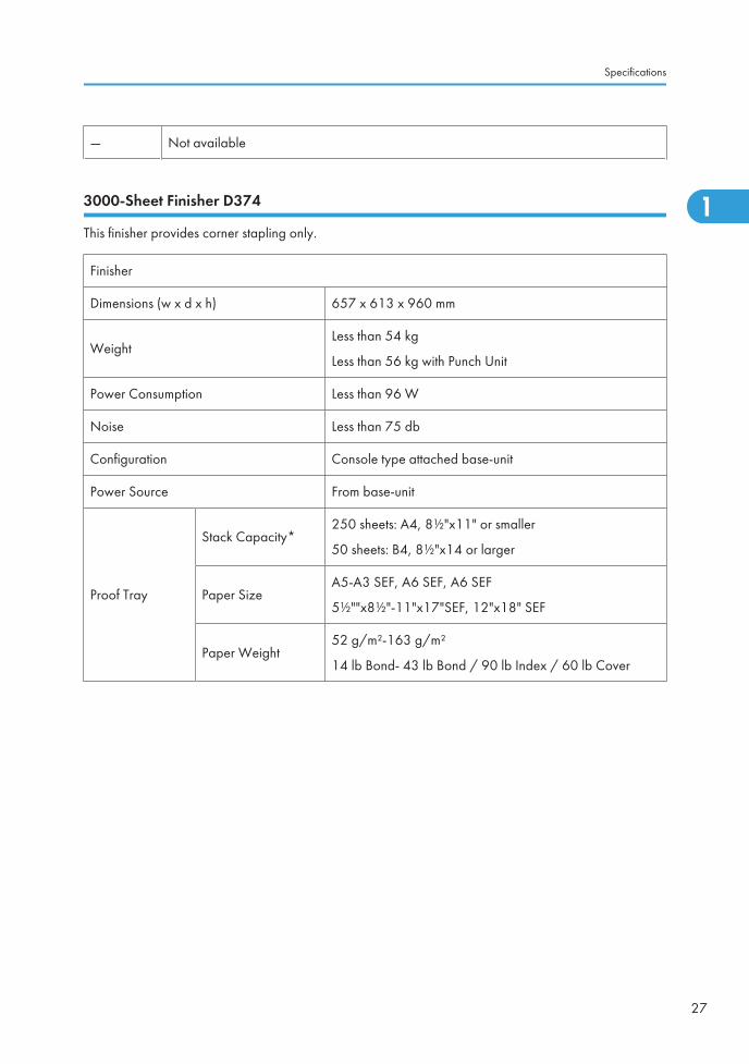
— Not available
3000-Sheet Finisher D374
This finisher provides corner stapling only.
Finisher
Dimensions (w x d x h) 657 x 613 x 960 mm
WeightLess than 54 kg
Less than 56 kg with Punch Unit
Power Consumption Less than 96 W
Noise Less than 75 db
Configuration Console type attached base-unit
Power Source From base-unit
Proof Tray
Stack Capacity*250 sheets: A4, 8½"x11" or smaller
50 sheets: B4, 8½"x14 or larger
Paper SizeA5-A3 SEF, A6 SEF, A6 SEF
5½""x8½"-11"x17"SEF, 12"x18" SEF
Paper Weight52 g/m²-163 g/m²
14 lb Bond- 43 lb Bond / 90 lb Index / 60 lb Cover
Specifications
27
1
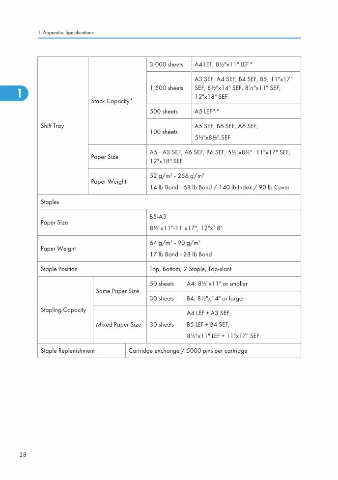
Shift Tray
Stack Capacity*
3,000 sheets A4 LEF, 8½"x11" LEF "
1,500 sheetsA3 SEF, A4 SEF, B4 SEF, B5, 11"x17"SEF, 8½"x14" SEF, 8½"x11" SEF,12"x18" SEF
500 sheets A5 LEF**
100 sheetsA5 SEF, B6 SEF, A6 SEF,
5½"x8½",SEF
Paper SizeA5 - A3 SEF, A6 SEF, B6 SEF, 5½"x8½"- 11"x17" SEF,12"x18" SEF
Paper Weight52 g/m² - 256 g/m²
14 lb Bond - 68 lb Bond / 140 lb Index / 90 lb Cover
Staples
Paper SizeB5-A3
8½"x11"-11"x17", 12"x18"
Paper Weight64 g/m² - 90 g/m²
17 lb Bond - 28 lb Bond
Staple Position Top, Bottom, 2 Staple, Top-slant
Stapling Capacity
Same Paper Size50 sheets A4, 8½"x11" or smaller
30 sheets B4, 8½"x14" or larger
Mixed Paper Size 30 sheets
A4 LEF + A3 SEF,
B5 LEF + B4 SEF,
8½"x11" LEF + 11"x17" SEF
Staple Replenishment Cartridge exchange / 5000 pins per cartridge
1. Appendix: Specifications
28
1
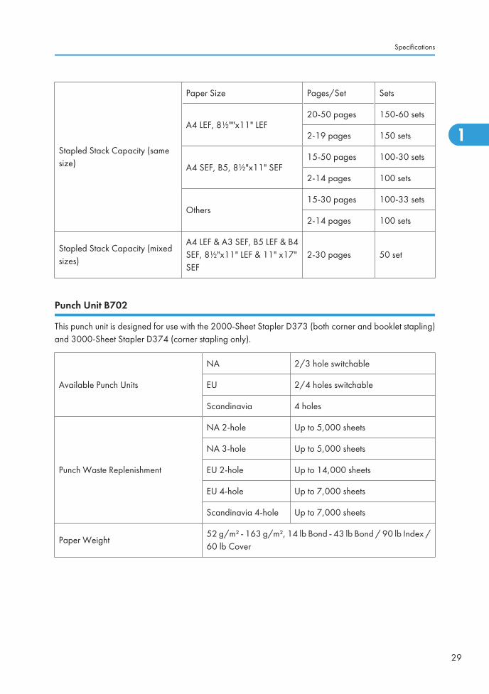
Stapled Stack Capacity (samesize)
Paper Size Pages/Set Sets
A4 LEF, 8½""x11" LEF20-50 pages 150-60 sets
2-19 pages 150 sets
A4 SEF, B5, 8½"x11" SEF15-50 pages 100-30 sets
2-14 pages 100 sets
Others15-30 pages 100-33 sets
2-14 pages 100 sets
Stapled Stack Capacity (mixedsizes)
A4 LEF & A3 SEF, B5 LEF & B4SEF, 8½"x11" LEF & 11" x17"SEF
2-30 pages 50 set
Punch Unit B702
This punch unit is designed for use with the 2000-Sheet Stapler D373 (both corner and booklet stapling)and 3000-Sheet Stapler D374 (corner stapling only).
Available Punch Units
NA 2/3 hole switchable
EU 2/4 holes switchable
Scandinavia 4 holes
Punch Waste Replenishment
NA 2-hole Up to 5,000 sheets
NA 3-hole Up to 5,000 sheets
EU 2-hole Up to 14,000 sheets
EU 4-hole Up to 7,000 sheets
Scandinavia 4-hole Up to 7,000 sheets
Paper Weight52 g/m² - 163 g/m², 14 lb Bond - 43 lb Bond / 90 lb Index /60 lb Cover
Specifications
29
1
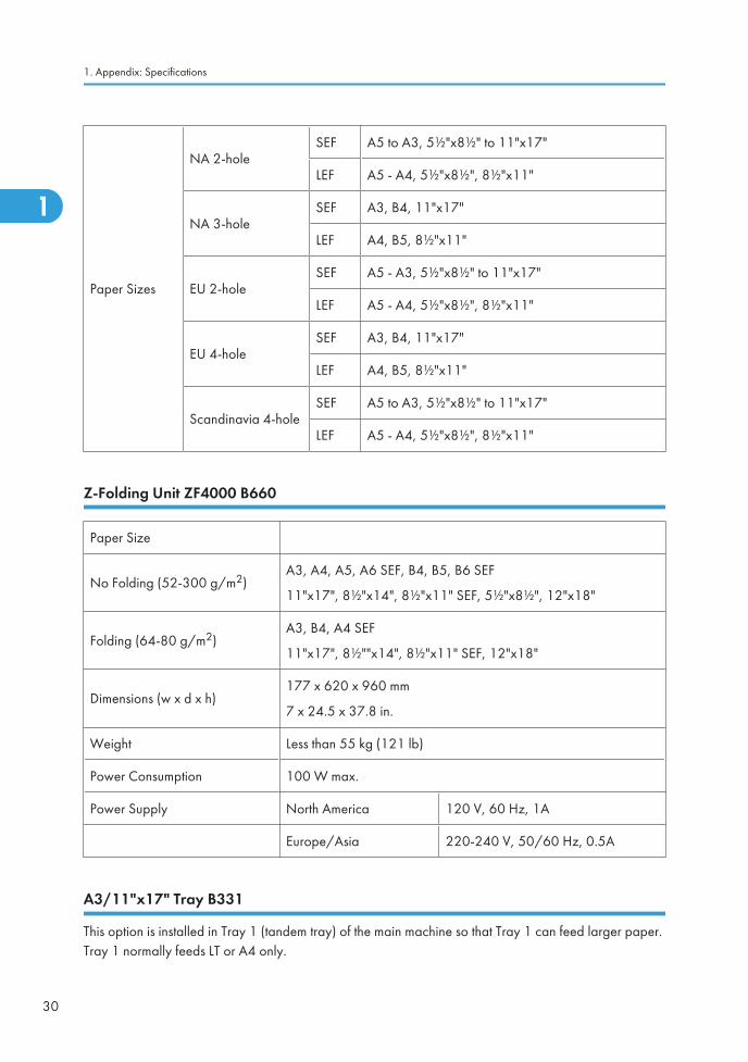
Paper Sizes
NA 2-holeSEF A5 to A3, 5½"x8½" to 11"x17"
LEF A5 - A4, 5½"x8½", 8½"x11"
NA 3-holeSEF A3, B4, 11"x17"
LEF A4, B5, 8½"x11"
EU 2-holeSEF A5 - A3, 5½"x8½" to 11"x17"
LEF A5 - A4, 5½"x8½", 8½"x11"
EU 4-holeSEF A3, B4, 11"x17"
LEF A4, B5, 8½"x11"
Scandinavia 4-holeSEF A5 to A3, 5½"x8½" to 11"x17"
LEF A5 - A4, 5½"x8½", 8½"x11"
Z-Folding Unit ZF4000 B660
Paper Size
No Folding (52-300 g/m2)A3, A4, A5, A6 SEF, B4, B5, B6 SEF
11"x17", 8½"x14", 8½"x11" SEF, 5½"x8½", 12"x18"
Folding (64-80 g/m2)A3, B4, A4 SEF
11"x17", 8½""x14", 8½"x11" SEF, 12"x18"
Dimensions (w x d x h)177 x 620 x 960 mm
7 x 24.5 x 37.8 in.
Weight Less than 55 kg (121 lb)
Power Consumption 100 W max.
Power Supply North America 120 V, 60 Hz, 1A
Europe/Asia 220-240 V, 50/60 Hz, 0.5A
A3/11"x17" Tray B331
This option is installed in Tray 1 (tandem tray) of the main machine so that Tray 1 can feed larger paper.Tray 1 normally feeds LT or A4 only.
1. Appendix: Specifications
30
1
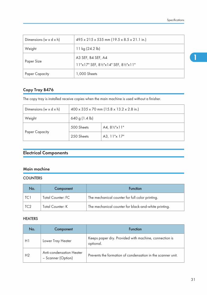
Dimensions (w x d x h) 495 x 215 x 535 mm (19.5 x 8.5 x 21.1 in.)
Weight 11 kg (24.2 lb)
Paper SizeA3 SEF, B4 SEF, A4
11"x17" SEF, 8½"x14" SEF, 8½"x11"
Paper Capacity 1,000 Sheets
Copy Tray B476
The copy tray is installed receive copies when the main machine is used without a finisher.
Dimensions (w x d x h) 400 x 335 x 70 mm (15.8 x 13.2 x 2.8 in.)
Weight 640 g (1.4 lb)
Paper Capacity500 Sheets A4, 8½"x11"
250 Sheets A3, 11"x 17"
Electrical Components
Main machine
COUNTERS
No. Component Function
TC1 Total Counter: FC The mechanical counter for full color printing.
TC2 Total Counter: K The mechanical counter for black-and-white printing.
HEATERS
No. Component Function
H1 Lower Tray HeaterKeeps paper dry. Provided with machine, connection isoptional.
H2Anti-condensation Heater– Scanner (Option)
Prevents the formation of condensation in the scanner unit.
Specifications
31
1
Ed
Typewritten Text
RTB 47 Note added
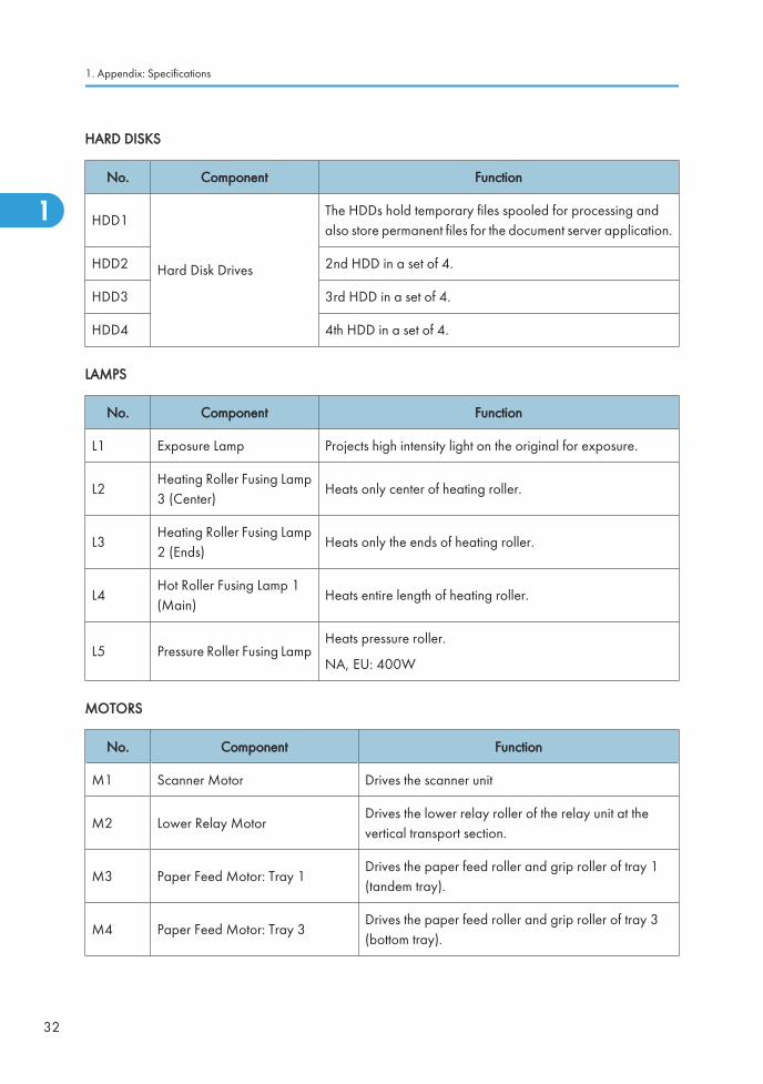
HARD DISKS
No. Component Function
HDD1
Hard Disk Drives
The HDDs hold temporary files spooled for processing andalso store permanent files for the document server application.
HDD2 2nd HDD in a set of 4.
HDD3 3rd HDD in a set of 4.
HDD4 4th HDD in a set of 4.
LAMPS
No. Component Function
L1 Exposure Lamp Projects high intensity light on the original for exposure.
L2Heating Roller Fusing Lamp3 (Center)
Heats only center of heating roller.
L3Heating Roller Fusing Lamp2 (Ends)
Heats only the ends of heating roller.
L4Hot Roller Fusing Lamp 1(Main)
Heats entire length of heating roller.
L5 Pressure Roller Fusing LampHeats pressure roller.
NA, EU: 400W
MOTORS
No. Component Function
M1 Scanner Motor Drives the scanner unit
M2 Lower Relay MotorDrives the lower relay roller of the relay unit at thevertical transport section.
M3 Paper Feed Motor: Tray 1Drives the paper feed roller and grip roller of tray 1(tandem tray).
M4 Paper Feed Motor: Tray 3Drives the paper feed roller and grip roller of tray 3(bottom tray).
1. Appendix: Specifications
32
1
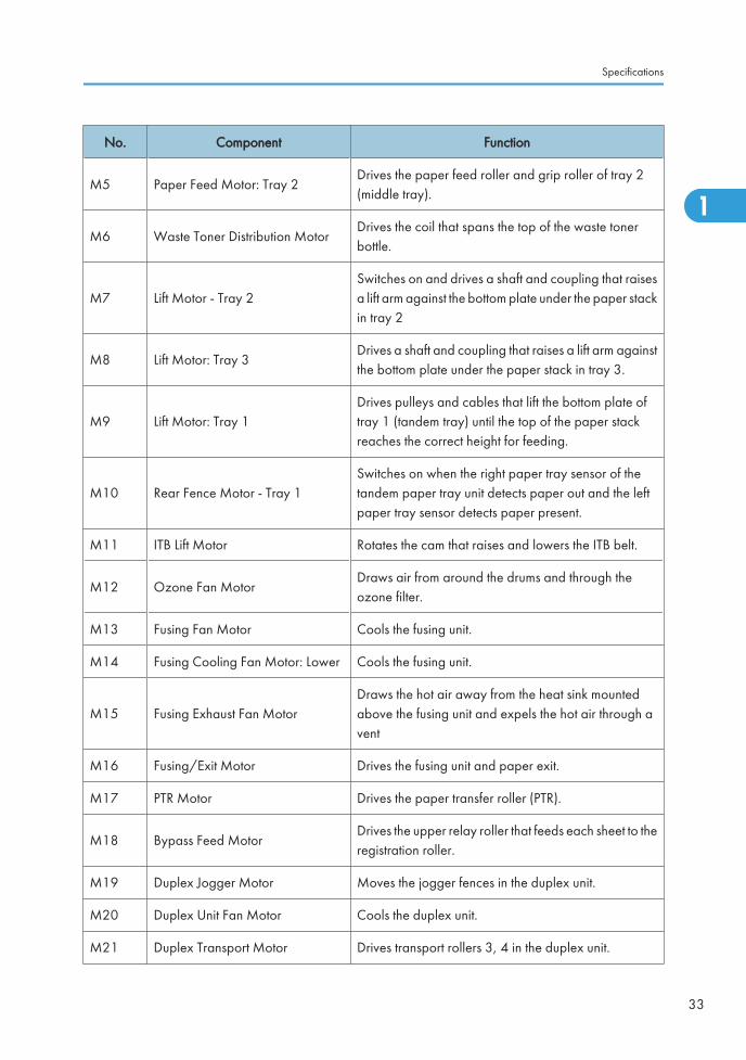
No. Component Function
M5 Paper Feed Motor: Tray 2Drives the paper feed roller and grip roller of tray 2(middle tray).
M6 Waste Toner Distribution MotorDrives the coil that spans the top of the waste tonerbottle.
M7 Lift Motor - Tray 2Switches on and drives a shaft and coupling that raisesa lift arm against the bottom plate under the paper stackin tray 2
M8 Lift Motor: Tray 3Drives a shaft and coupling that raises a lift arm againstthe bottom plate under the paper stack in tray 3.
M9 Lift Motor: Tray 1Drives pulleys and cables that lift the bottom plate oftray 1 (tandem tray) until the top of the paper stackreaches the correct height for feeding.
M10 Rear Fence Motor - Tray 1Switches on when the right paper tray sensor of thetandem paper tray unit detects paper out and the leftpaper tray sensor detects paper present.
M11 ITB Lift Motor Rotates the cam that raises and lowers the ITB belt.
M12 Ozone Fan MotorDraws air from around the drums and through theozone filter.
M13 Fusing Fan Motor Cools the fusing unit.
M14 Fusing Cooling Fan Motor: Lower Cools the fusing unit.
M15 Fusing Exhaust Fan MotorDraws the hot air away from the heat sink mountedabove the fusing unit and expels the hot air through avent
M16 Fusing/Exit Motor Drives the fusing unit and paper exit.
M17 PTR Motor Drives the paper transfer roller (PTR).
M18 Bypass Feed MotorDrives the upper relay roller that feeds each sheet to theregistration roller.
M19 Duplex Jogger Motor Moves the jogger fences in the duplex unit.
M20 Duplex Unit Fan Motor Cools the duplex unit.
M21 Duplex Transport Motor Drives transport rollers 3, 4 in the duplex unit.
Specifications
33
1
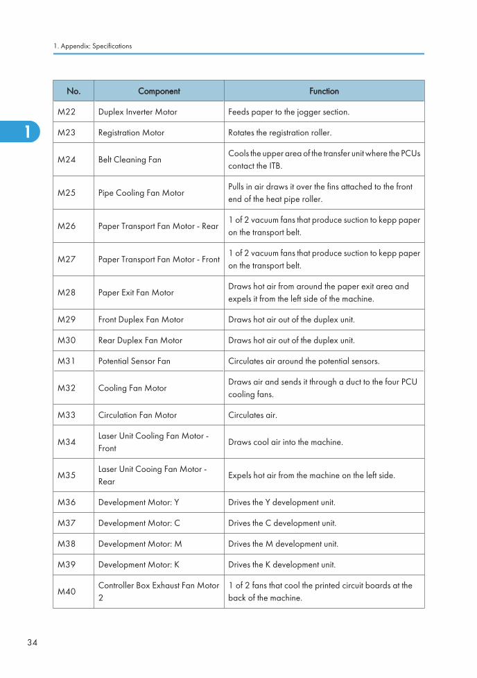
No. Component Function
M22 Duplex Inverter Motor Feeds paper to the jogger section.
M23 Registration Motor Rotates the registration roller.
M24 Belt Cleaning FanCools the upper area of the transfer unit where the PCUscontact the ITB.
M25 Pipe Cooling Fan MotorPulls in air draws it over the fins attached to the frontend of the heat pipe roller.
M26 Paper Transport Fan Motor - Rear1 of 2 vacuum fans that produce suction to kepp paperon the transport belt.
M27 Paper Transport Fan Motor - Front1 of 2 vacuum fans that produce suction to kepp paperon the transport belt.
M28 Paper Exit Fan MotorDraws hot air from around the paper exit area andexpels it from the left side of the machine.
M29 Front Duplex Fan Motor Draws hot air out of the duplex unit.
M30 Rear Duplex Fan Motor Draws hot air out of the duplex unit.
M31 Potential Sensor Fan Circulates air around the potential sensors.
M32 Cooling Fan MotorDraws air and sends it through a duct to the four PCUcooling fans.
M33 Circulation Fan Motor Circulates air.
M34Laser Unit Cooling Fan Motor -Front
Draws cool air into the machine.
M35Laser Unit Cooing Fan Motor -Rear
Expels hot air from the machine on the left side.
M36 Development Motor: Y Drives the Y development unit.
M37 Development Motor: C Drives the C development unit.
M38 Development Motor: M Drives the M development unit.
M39 Development Motor: K Drives the K development unit.
M40Controller Box Exhaust Fan Motor2
1 of 2 fans that cool the printed circuit boards at theback of the machine.
1. Appendix: Specifications
34
1
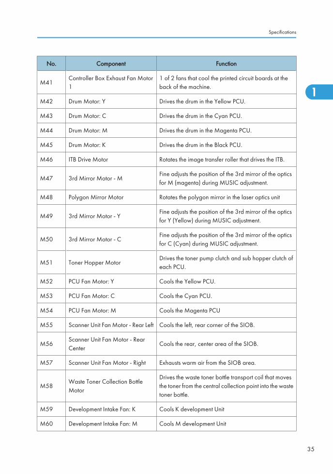
No. Component Function
M41Controller Box Exhaust Fan Motor1
1 of 2 fans that cool the printed circuit boards at theback of the machine.
M42 Drum Motor: Y Drives the drum in the Yellow PCU.
M43 Drum Motor: C Drives the drum in the Cyan PCU.
M44 Drum Motor: M Drives the drum in the Magenta PCU.
M45 Drum Motor: K Drives the drum in the Black PCU.
M46 ITB Drive Motor Rotates the image transfer roller that drives the ITB.
M47 3rd Mirror Motor - MFine adjusts the position of the 3rd mirror of the opticsfor M (magenta) during MUSIC adjustment.
M48 Polygon Mirror Motor Rotates the polygon mirror in the laser optics unit
M49 3rd Mirror Motor - YFine adjusts the position of the 3rd mirror of the opticsfor Y (Yellow) during MUSIC adjustment.
M50 3rd Mirror Motor - CFine adjusts the position of the 3rd mirror of the opticsfor C (Cyan) during MUSIC adjustment.
M51 Toner Hopper MotorDrives the toner pump clutch and sub hopper clutch ofeach PCU.
M52 PCU Fan Motor: Y Cools the Yellow PCU.
M53 PCU Fan Motor: C Cools the Cyan PCU.
M54 PCU Fan Motor: M Cools the Magenta PCU
M55 Scanner Unit Fan Motor - Rear Left Cools the left, rear corner of the SIOB.
M56Scanner Unit Fan Motor - RearCenter
Cools the rear, center area of the SIOB.
M57 Scanner Unit Fan Motor - Right Exhausts warm air from the SIOB area.
M58Waste Toner Collection BottleMotor
Drives the waste toner bottle transport coil that movesthe toner from the central collection point into the wastetoner bottle.
M59 Development Intake Fan: K Cools K development Unit
M60 Development Intake Fan: M Cools M development Unit
Specifications
35
1
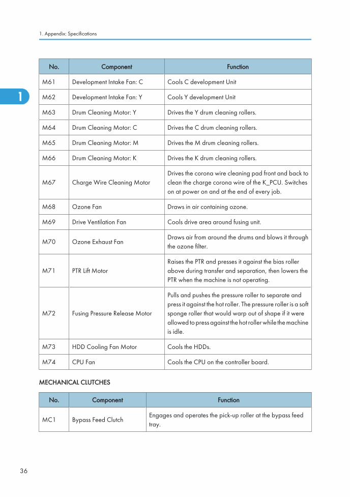
No. Component Function
M61 Development Intake Fan: C Cools C development Unit
M62 Development Intake Fan: Y Cools Y development Unit
M63 Drum Cleaning Motor: Y Drives the Y drum cleaning rollers.
M64 Drum Cleaning Motor: C Drives the C drum cleaning rollers.
M65 Drum Cleaning Motor: M Drives the M drum cleaning rollers.
M66 Drum Cleaning Motor: K Drives the K drum cleaning rollers.
M67 Charge Wire Cleaning MotorDrives the corona wire cleaning pad front and back toclean the charge corona wire of the K_PCU. Switcheson at power on and at the end of every job.
M68 Ozone Fan Draws in air containing ozone.
M69 Drive Ventilation Fan Cools drive area around fusing unit.
M70 Ozone Exhaust FanDraws air from around the drums and blows it throughthe ozone filter.
M71 PTR Lift MotorRaises the PTR and presses it against the bias rollerabove during transfer and separation, then lowers thePTR when the machine is not operating.
M72 Fusing Pressure Release Motor
Pulls and pushes the pressure roller to separate andpress it against the hot roller. The pressure roller is a softsponge roller that would warp out of shape if it wereallowed to press against the hot roller while the machineis idle.
M73 HDD Cooling Fan Motor Cools the HDDs.
M74 CPU Fan Cools the CPU on the controller board.
MECHANICAL CLUTCHES
No. Component Function
MC1 Bypass Feed ClutchEngages and operates the pick-up roller at the bypass feedtray.
1. Appendix: Specifications
36
1
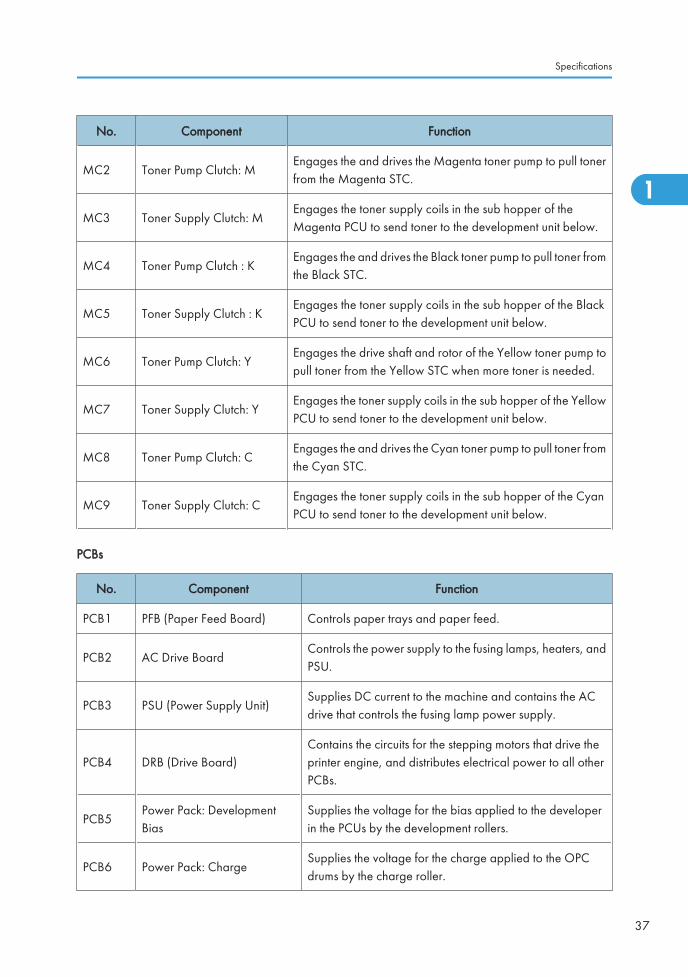
No. Component Function
MC2 Toner Pump Clutch: MEngages the and drives the Magenta toner pump to pull tonerfrom the Magenta STC.
MC3 Toner Supply Clutch: MEngages the toner supply coils in the sub hopper of theMagenta PCU to send toner to the development unit below.
MC4 Toner Pump Clutch : KEngages the and drives the Black toner pump to pull toner fromthe Black STC.
MC5 Toner Supply Clutch : KEngages the toner supply coils in the sub hopper of the BlackPCU to send toner to the development unit below.
MC6 Toner Pump Clutch: YEngages the drive shaft and rotor of the Yellow toner pump topull toner from the Yellow STC when more toner is needed.
MC7 Toner Supply Clutch: YEngages the toner supply coils in the sub hopper of the YellowPCU to send toner to the development unit below.
MC8 Toner Pump Clutch: CEngages the and drives the Cyan toner pump to pull toner fromthe Cyan STC.
MC9 Toner Supply Clutch: CEngages the toner supply coils in the sub hopper of the CyanPCU to send toner to the development unit below.
PCBs
No. Component Function
PCB1 PFB (Paper Feed Board) Controls paper trays and paper feed.
PCB2 AC Drive BoardControls the power supply to the fusing lamps, heaters, andPSU.
PCB3 PSU (Power Supply Unit)Supplies DC current to the machine and contains the ACdrive that controls the fusing lamp power supply.
PCB4 DRB (Drive Board)Contains the circuits for the stepping motors that drive theprinter engine, and distributes electrical power to all otherPCBs.
PCB5Power Pack: DevelopmentBias
Supplies the voltage for the bias applied to the developerin the PCUs by the development rollers.
PCB6 Power Pack: ChargeSupplies the voltage for the charge applied to the OPCdrums by the charge roller.
Specifications
37
1
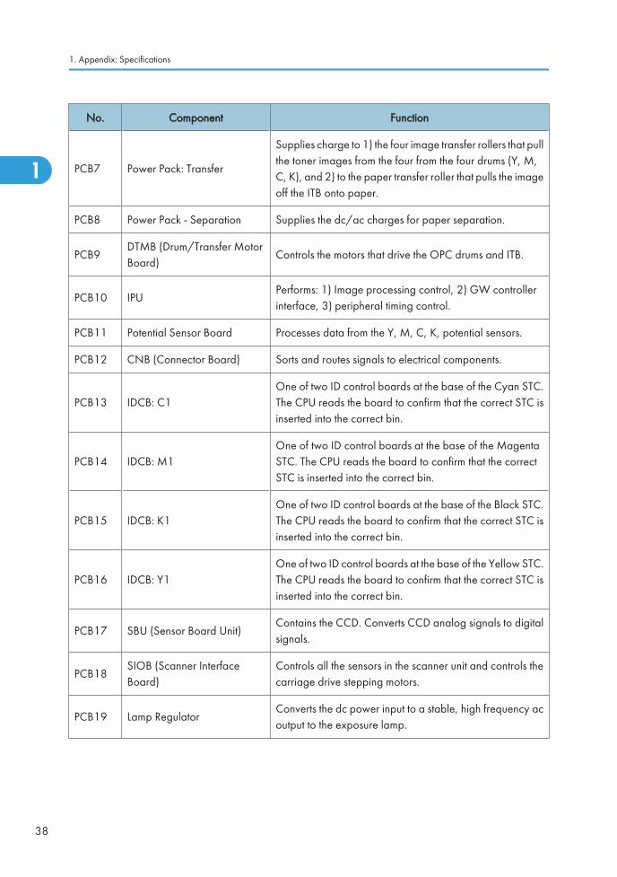
No. Component Function
PCB7 Power Pack: Transfer
Supplies charge to 1) the four image transfer rollers that pullthe toner images from the four from the four drums (Y, M,C, K), and 2) to the paper transfer roller that pulls the imageoff the ITB onto paper.
PCB8 Power Pack - Separation Supplies the dc/ac charges for paper separation.
PCB9DTMB (Drum/Transfer MotorBoard)
Controls the motors that drive the OPC drums and ITB.
PCB10 IPUPerforms: 1) Image processing control, 2) GW controllerinterface, 3) peripheral timing control.
PCB11 Potential Sensor Board Processes data from the Y, M, C, K, potential sensors.
PCB12 CNB (Connector Board) Sorts and routes signals to electrical components.
PCB13 IDCB: C1One of two ID control boards at the base of the Cyan STC.The CPU reads the board to confirm that the correct STC isinserted into the correct bin.
PCB14 IDCB: M1One of two ID control boards at the base of the MagentaSTC. The CPU reads the board to confirm that the correctSTC is inserted into the correct bin.
PCB15 IDCB: K1One of two ID control boards at the base of the Black STC.The CPU reads the board to confirm that the correct STC isinserted into the correct bin.
PCB16 IDCB: Y1One of two ID control boards at the base of the Yellow STC.The CPU reads the board to confirm that the correct STC isinserted into the correct bin.
PCB17 SBU (Sensor Board Unit)Contains the CCD. Converts CCD analog signals to digitalsignals.
PCB18SIOB (Scanner InterfaceBoard)
Controls all the sensors in the scanner unit and controls thecarriage drive stepping motors.
PCB19 Lamp RegulatorConverts the dc power input to a stable, high frequency acoutput to the exposure lamp.
1. Appendix: Specifications
38
1
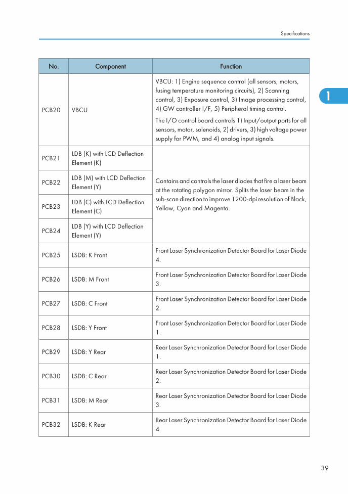
No. Component Function
PCB20 VBCU
VBCU: 1) Engine sequence control (all sensors, motors,fusing temperature monitoring circuits), 2) Scanningcontrol, 3) Exposure control, 3) Image processing control,4) GW controller I/F, 5) Peripheral timing control.
The I/O control board controls 1) Input/output ports for allsensors, motor, solenoids, 2) drivers, 3) high voltage powersupply for PWM, and 4) analog input signals.
PCB21LDB (K) with LCD DeflectionElement (K)
Contains and controls the laser diodes that fire a laser beamat the rotating polygon mirror. Splits the laser beam in thesub-scan direction to improve 1200-dpi resolution of Black,Yellow, Cyan and Magenta.
PCB22LDB (M) with LCD DeflectionElement (Y)
PCB23LDB (C) with LCD DeflectionElement (C)
PCB24LDB (Y) with LCD DeflectionElement (Y)
PCB25 LSDB: K FrontFront Laser Synchronization Detector Board for Laser Diode4.
PCB26 LSDB: M FrontFront Laser Synchronization Detector Board for Laser Diode3.
PCB27 LSDB: C FrontFront Laser Synchronization Detector Board for Laser Diode2.
PCB28 LSDB: Y FrontFront Laser Synchronization Detector Board for Laser Diode1.
PCB29 LSDB: Y RearRear Laser Synchronization Detector Board for Laser Diode1.
PCB30 LSDB: C RearRear Laser Synchronization Detector Board for Laser Diode2.
PCB31 LSDB: M RearRear Laser Synchronization Detector Board for Laser Diode3.
PCB32 LSDB: K RearRear Laser Synchronization Detector Board for Laser Diode4.
Specifications
39
1
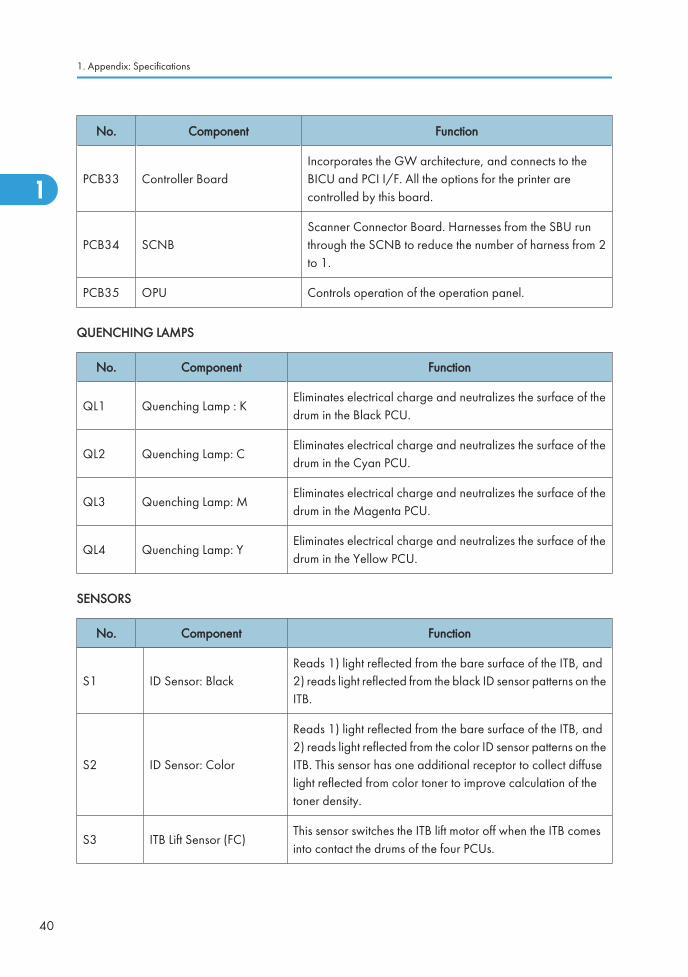
No. Component Function
PCB33 Controller BoardIncorporates the GW architecture, and connects to theBICU and PCI I/F. All the options for the printer arecontrolled by this board.
PCB34 SCNBScanner Connector Board. Harnesses from the SBU runthrough the SCNB to reduce the number of harness from 2to 1.
PCB35 OPU Controls operation of the operation panel.
QUENCHING LAMPS
No. Component Function
QL1 Quenching Lamp : KEliminates electrical charge and neutralizes the surface of thedrum in the Black PCU.
QL2 Quenching Lamp: CEliminates electrical charge and neutralizes the surface of thedrum in the Cyan PCU.
QL3 Quenching Lamp: MEliminates electrical charge and neutralizes the surface of thedrum in the Magenta PCU.
QL4 Quenching Lamp: YEliminates electrical charge and neutralizes the surface of thedrum in the Yellow PCU.
SENSORS
No. Component Function
S1 ID Sensor: BlackReads 1) light reflected from the bare surface of the ITB, and2) reads light reflected from the black ID sensor patterns on theITB.
S2 ID Sensor: Color
Reads 1) light reflected from the bare surface of the ITB, and2) reads light reflected from the color ID sensor patterns on theITB. This sensor has one additional receptor to collect diffuselight reflected from color toner to improve calculation of thetoner density.
S3 ITB Lift Sensor (FC)This sensor switches the ITB lift motor off when the ITB comesinto contact the drums of the four PCUs.
1. Appendix: Specifications
40
1
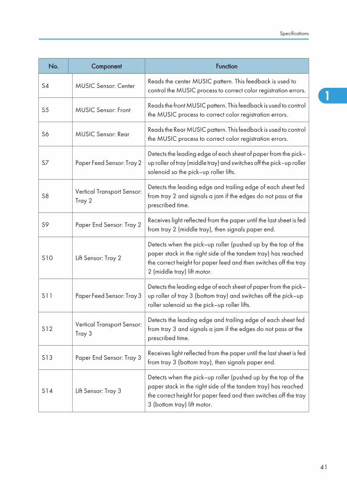
No. Component Function
S4 MUSIC Sensor: CenterReads the center MUSIC pattern. This feedback is used tocontrol the MUSIC process to correct color registration errors.
S5 MUSIC Sensor: FrontReads the front MUSIC pattern. This feedback is used to controlthe MUSIC process to correct color registration errors.
S6 MUSIC Sensor: RearReads the Rear MUSIC pattern. This feedback is used to controlthe MUSIC process to correct color registration errors.
S7 Paper Feed Sensor: Tray 2Detects the leading edge of each sheet of paper from the pick–up roller of tray (middle tray) and switches off the pick–up rollersolenoid so the pick–up roller lifts.
S8Vertical Transport Sensor:Tray 2
Detects the leading edge and trailing edge of each sheet fedfrom tray 2 and signals a jam if the edges do not pass at theprescribed time.
S9 Paper End Sensor: Tray 2Receives light reflected from the paper until the last sheet is fedfrom tray 2 (middle tray), then signals paper end.
S10 Lift Sensor: Tray 2
Detects when the pick–up roller (pushed up by the top of thepaper stack in the right side of the tandem tray) has reachedthe correct height for paper feed and then switches off the tray2 (middle tray) lift motor.
S11 Paper Feed Sensor: Tray 3Detects the leading edge of each sheet of paper from the pick–up roller of tray 3 (bottom tray) and switches off the pick–uproller solenoid so the pick–up roller lifts.
S12Vertical Transport Sensor:Tray 3
Detects the leading edge and trailing edge of each sheet fedfrom tray 3 and signals a jam if the edges do not pass at theprescribed time.
S13 Paper End Sensor: Tray 3Receives light reflected from the paper until the last sheet is fedfrom tray 3 (bottom tray), then signals paper end.
S14 Lift Sensor: Tray 3
Detects when the pick–up roller (pushed up by the top of thepaper stack in the right side of the tandem tray) has reachedthe correct height for paper feed and then switches off the tray3 (bottom tray) lift motor.
Specifications
41
1
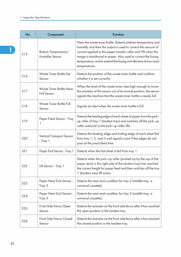
No. Component Function
S15Bottom Temperature/Humidity Sensor
Near the waste toner bottle. Detects ambient temperature andhumidity and then this output is used to control the amount ofcurrent applied to the paper transfer roller and ITB when theimage is transferred to paper. Also used to correct the fusingtemperature, and to extend the fusing unit idle time at low roomtemperatures.
S16Waste Toner Bottle SetSensor
Detects the position of the waste toner bottle and confirmswhether it is set correctly.
S17Waste Toner Bottle Near-Full Sensor
When the level of the waste toner rises high enough to movethe actuator of this sensor out of its normal position, the sensorsignals the machine that the waste toner bottle is nearly full.
S18Waste Toner Bottle FullSensor
Signals an alert when the waste toner bottle is full.
S19Paper Feed Sensor - Tray1
Detects the leading edge of each sheet of paper from the pick–up roller of tray 1 (tandem tray) and switches off the pick–uproller solenoid so the pick–up roller lifts.
S20Vertical Transport Sensor- Tray 1
Detects the leading edge and trailing edge of each sheet fedfrom tray 1, 2, and 3 and signals a jam if the edges do notpass at the prescribed time.
S21 Paper End Sensor - Tray 1 Detects when the last sheet is fed from tray 1.
S22 Lift Sensor - Tray 1
Detects when the pick–up roller (pushed up by the top of thepaper stack in the right side of the tandem tray) has reachedthe correct height for paper feed and then switches off the tray1 (tandem tray) lift motor.
S23Paper Near End Sensor -Tray 2
Detects the near end condition for tray 2 (middle tray, auniversal cassette).
S24Paper Near End Sensor:Tray 3
Detects the near end condition for tray 3 (middle tray, auniversal cassette).
S25Front Side Fence OpenSensor
Detects the actuator on the front side fence after it has reachedthe open position in the tandem tray.
S26Front Side Fence ClosedSensor
Detects the actuator on the front side fence after it has reachedthe closed position in the tandem tray.
1. Appendix: Specifications
42
1
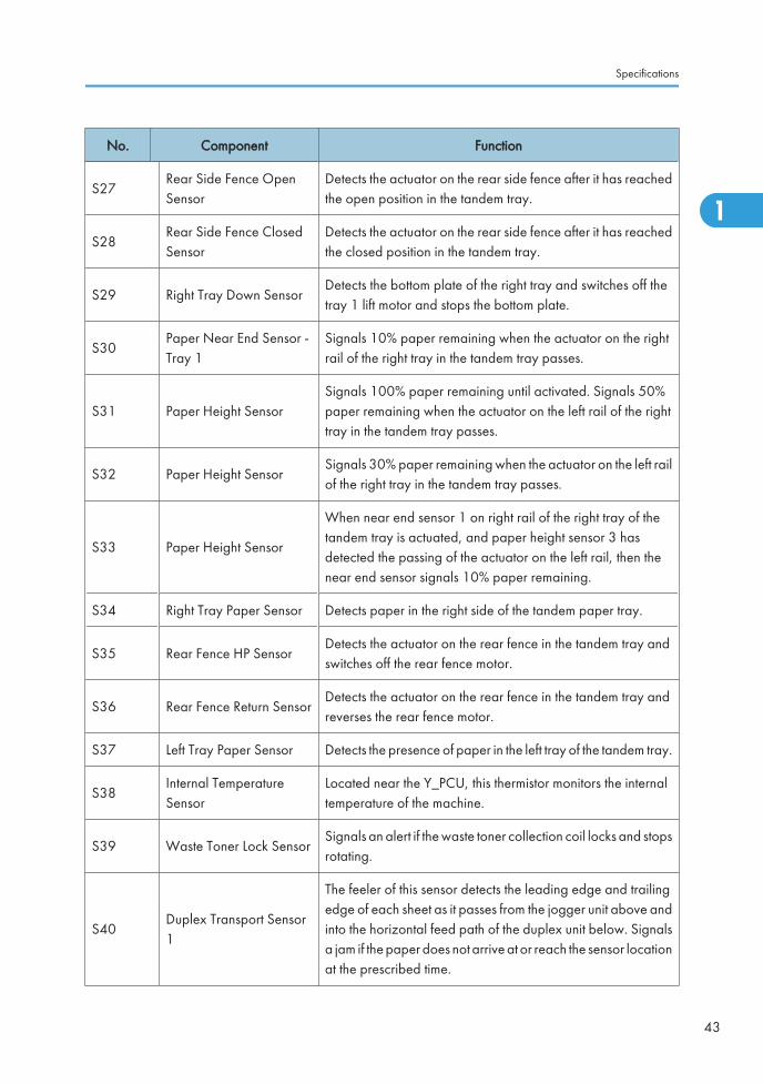
No. Component Function
S27Rear Side Fence OpenSensor
Detects the actuator on the rear side fence after it has reachedthe open position in the tandem tray.
S28Rear Side Fence ClosedSensor
Detects the actuator on the rear side fence after it has reachedthe closed position in the tandem tray.
S29 Right Tray Down SensorDetects the bottom plate of the right tray and switches off thetray 1 lift motor and stops the bottom plate.
S30Paper Near End Sensor -Tray 1
Signals 10% paper remaining when the actuator on the rightrail of the right tray in the tandem tray passes.
S31 Paper Height SensorSignals 100% paper remaining until activated. Signals 50%paper remaining when the actuator on the left rail of the righttray in the tandem tray passes.
S32 Paper Height SensorSignals 30% paper remaining when the actuator on the left railof the right tray in the tandem tray passes.
S33 Paper Height Sensor
When near end sensor 1 on right rail of the right tray of thetandem tray is actuated, and paper height sensor 3 hasdetected the passing of the actuator on the left rail, then thenear end sensor signals 10% paper remaining.
S34 Right Tray Paper Sensor Detects paper in the right side of the tandem paper tray.
S35 Rear Fence HP SensorDetects the actuator on the rear fence in the tandem tray andswitches off the rear fence motor.
S36 Rear Fence Return SensorDetects the actuator on the rear fence in the tandem tray andreverses the rear fence motor.
S37 Left Tray Paper Sensor Detects the presence of paper in the left tray of the tandem tray.
S38Internal TemperatureSensor
Located near the Y_PCU, this thermistor monitors the internaltemperature of the machine.
S39 Waste Toner Lock SensorSignals an alert if the waste toner collection coil locks and stopsrotating.
S40Duplex Transport Sensor1
The feeler of this sensor detects the leading edge and trailingedge of each sheet as it passes from the jogger unit above andinto the horizontal feed path of the duplex unit below. Signalsa jam if the paper does not arrive at or reach the sensor locationat the prescribed time.
Specifications
43
1
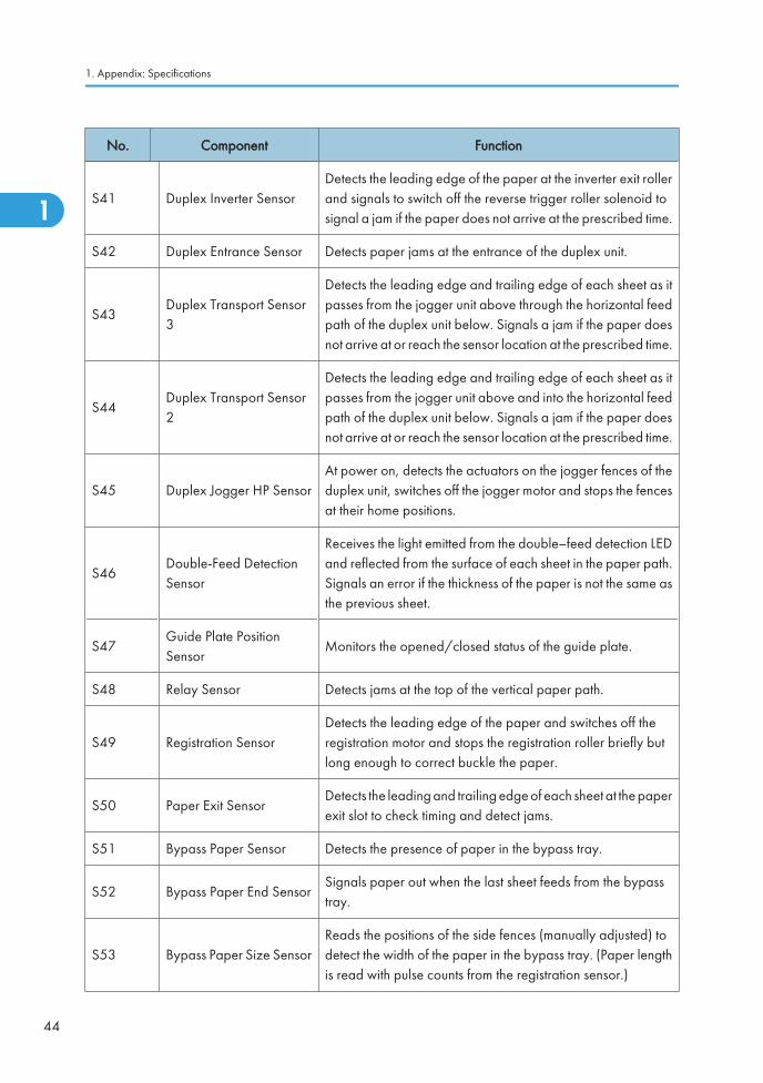
No. Component Function
S41 Duplex Inverter SensorDetects the leading edge of the paper at the inverter exit rollerand signals to switch off the reverse trigger roller solenoid tosignal a jam if the paper does not arrive at the prescribed time.
S42 Duplex Entrance Sensor Detects paper jams at the entrance of the duplex unit.
S43Duplex Transport Sensor3
Detects the leading edge and trailing edge of each sheet as itpasses from the jogger unit above through the horizontal feedpath of the duplex unit below. Signals a jam if the paper doesnot arrive at or reach the sensor location at the prescribed time.
S44Duplex Transport Sensor2
Detects the leading edge and trailing edge of each sheet as itpasses from the jogger unit above and into the horizontal feedpath of the duplex unit below. Signals a jam if the paper doesnot arrive at or reach the sensor location at the prescribed time.
S45 Duplex Jogger HP SensorAt power on, detects the actuators on the jogger fences of theduplex unit, switches off the jogger motor and stops the fencesat their home positions.
S46Double-Feed DetectionSensor
Receives the light emitted from the double–feed detection LEDand reflected from the surface of each sheet in the paper path.Signals an error if the thickness of the paper is not the same asthe previous sheet.
S47Guide Plate PositionSensor
Monitors the opened/closed status of the guide plate.
S48 Relay Sensor Detects jams at the top of the vertical paper path.
S49 Registration SensorDetects the leading edge of the paper and switches off theregistration motor and stops the registration roller briefly butlong enough to correct buckle the paper.
S50 Paper Exit SensorDetects the leading and trailing edge of each sheet at the paperexit slot to check timing and detect jams.
S51 Bypass Paper Sensor Detects the presence of paper in the bypass tray.
S52 Bypass Paper End SensorSignals paper out when the last sheet feeds from the bypasstray.
S53 Bypass Paper Size SensorReads the positions of the side fences (manually adjusted) todetect the width of the paper in the bypass tray. (Paper lengthis read with pulse counts from the registration sensor.)
1. Appendix: Specifications
44
1
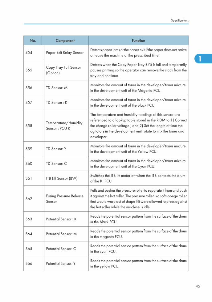
No. Component Function
S54 Paper Exit Relay SensorDetects paper jams at the paper exit if the paper does not arriveor leave the machine at the prescribed time.
S55Copy Tray Full Sensor(Option)
Detects when the Copy Paper Tray B75 is full and temporarilypauses printing so the operator can remove the stack from thetray and continue.
S56 TD Sensor: MMonitors the amount of toner in the developer/toner mixturein the development unit of the Magenta PCU.
S57 TD Sensor : KMonitors the amount of toner in the developer/toner mixturein the development unit of the Black PCU.
S58Temperature/HumiditySensor : PCU K
The temperature and humidity readings of this sensor arereferenced to a lookup table stored in the ROM to 1) Correctthe charge roller voltage , and 2) Set the length of time theagitators in the development unit rotate to mix the toner anddeveloper.
S59 TD Sensor: YMonitors the amount of toner in the developer/toner mixturein the development unit of the Yellow PCU.
S60 TD Sensor: CMonitors the amount of toner in the developer/toner mixturein the development unit of the Cyan PCU.
S61 ITB Lift Sensor (BW)Switches the ITB lift motor off when the ITB contacts the drumof the K_PCU
S62Fusing Pressure ReleaseSensor
Pulls and pushes the pressure roller to separate it from and pushit against the hot roller. The pressure roller is a soft sponge rollerthat would warp out of shape if it were allowed to press againstthe hot roller while the machine is idle.
S63 Potential Sensor : KReads the potential sensor pattern from the surface of the drumin the black PCU.
S64 Potential Sensor: MReads the potential sensor pattern from the surface of the drumin the magenta PCU.
S65 Potential Sensor: CReads the potential sensor pattern from the surface of the drumin the cyan PCU.
S66 Potential Sensor: YReads the potential sensor pattern from the surface of the drumin the yellow PCU.
Specifications
45
1
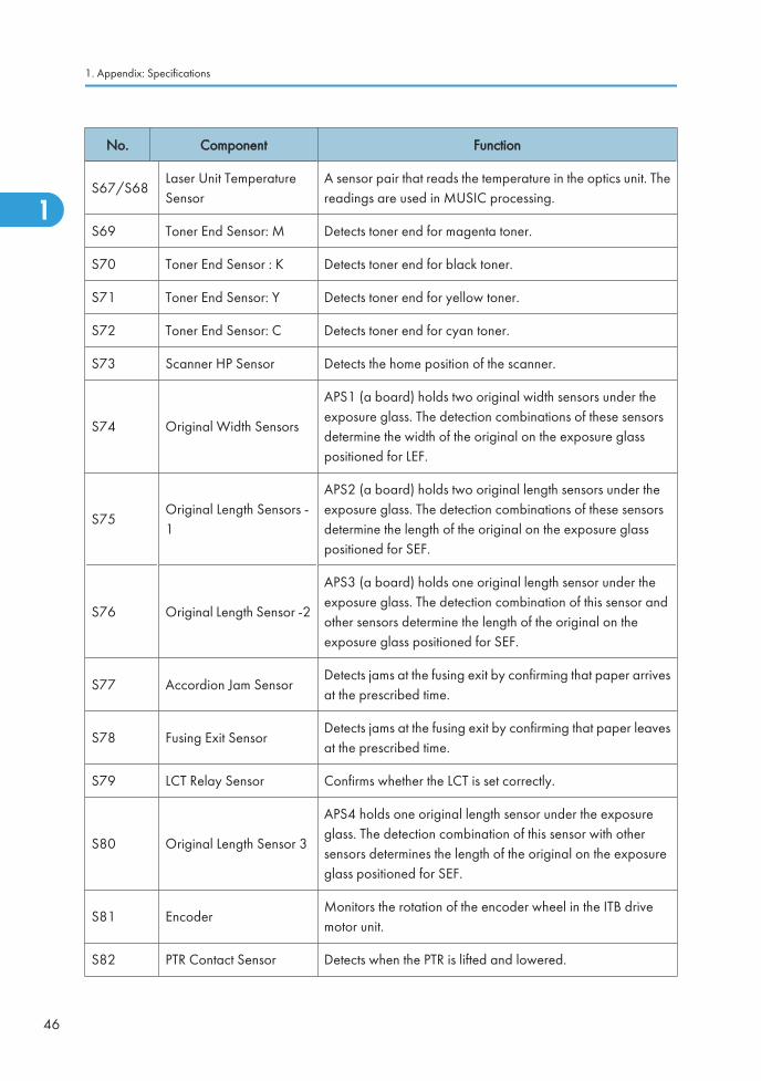
No. Component Function
S67/S68Laser Unit TemperatureSensor
A sensor pair that reads the temperature in the optics unit. Thereadings are used in MUSIC processing.
S69 Toner End Sensor: M Detects toner end for magenta toner.
S70 Toner End Sensor : K Detects toner end for black toner.
S71 Toner End Sensor: Y Detects toner end for yellow toner.
S72 Toner End Sensor: C Detects toner end for cyan toner.
S73 Scanner HP Sensor Detects the home position of the scanner.
S74 Original Width Sensors
APS1 (a board) holds two original width sensors under theexposure glass. The detection combinations of these sensorsdetermine the width of the original on the exposure glasspositioned for LEF.
S75Original Length Sensors -1
APS2 (a board) holds two original length sensors under theexposure glass. The detection combinations of these sensorsdetermine the length of the original on the exposure glasspositioned for SEF.
S76 Original Length Sensor -2
APS3 (a board) holds one original length sensor under theexposure glass. The detection combination of this sensor andother sensors determine the length of the original on theexposure glass positioned for SEF.
S77 Accordion Jam SensorDetects jams at the fusing exit by confirming that paper arrivesat the prescribed time.
S78 Fusing Exit SensorDetects jams at the fusing exit by confirming that paper leavesat the prescribed time.
S79 LCT Relay Sensor Confirms whether the LCT is set correctly.
S80 Original Length Sensor 3
APS4 holds one original length sensor under the exposureglass. The detection combination of this sensor with othersensors determines the length of the original on the exposureglass positioned for SEF.
S81 EncoderMonitors the rotation of the encoder wheel in the ITB drivemotor unit.
S82 PTR Contact Sensor Detects when the PTR is lifted and lowered.
1. Appendix: Specifications
46
1
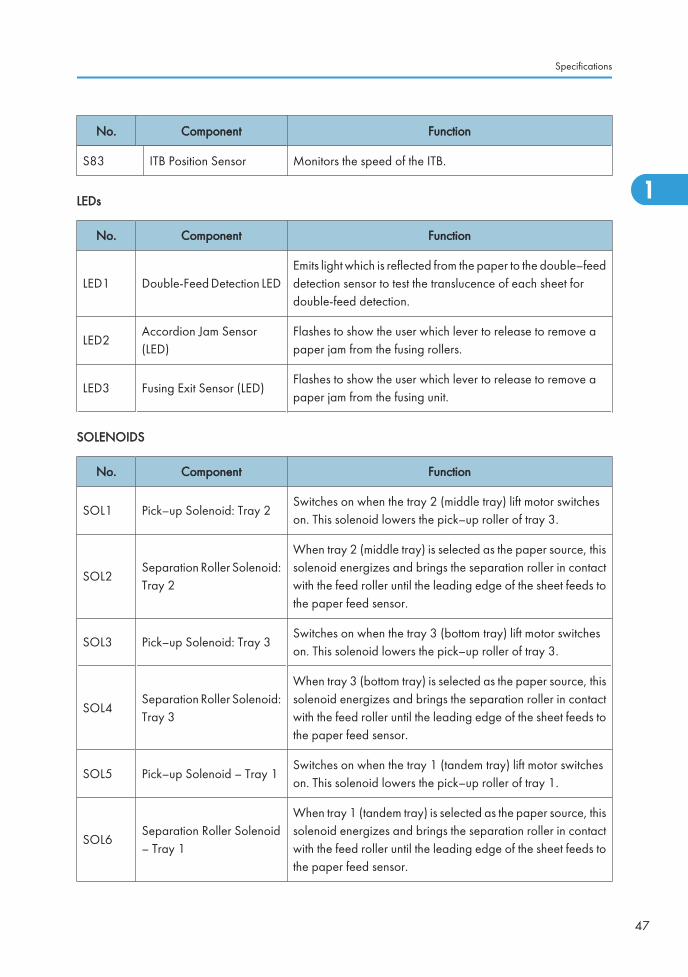
No. Component Function
S83 ITB Position Sensor Monitors the speed of the ITB.
LEDs
No. Component Function
LED1 Double-Feed Detection LEDEmits light which is reflected from the paper to the double–feeddetection sensor to test the translucence of each sheet fordouble-feed detection.
LED2Accordion Jam Sensor(LED)
Flashes to show the user which lever to release to remove apaper jam from the fusing rollers.
LED3 Fusing Exit Sensor (LED)Flashes to show the user which lever to release to remove apaper jam from the fusing unit.
SOLENOIDS
No. Component Function
SOL1 Pick–up Solenoid: Tray 2Switches on when the tray 2 (middle tray) lift motor switcheson. This solenoid lowers the pick–up roller of tray 3.
SOL2Separation Roller Solenoid:Tray 2
When tray 2 (middle tray) is selected as the paper source, thissolenoid energizes and brings the separation roller in contactwith the feed roller until the leading edge of the sheet feeds tothe paper feed sensor.
SOL3 Pick–up Solenoid: Tray 3Switches on when the tray 3 (bottom tray) lift motor switcheson. This solenoid lowers the pick–up roller of tray 3.
SOL4Separation Roller Solenoid:Tray 3
When tray 3 (bottom tray) is selected as the paper source, thissolenoid energizes and brings the separation roller in contactwith the feed roller until the leading edge of the sheet feeds tothe paper feed sensor.
SOL5 Pick–up Solenoid – Tray 1Switches on when the tray 1 (tandem tray) lift motor switcheson. This solenoid lowers the pick–up roller of tray 1.
SOL6Separation Roller Solenoid– Tray 1
When tray 1 (tandem tray) is selected as the paper source, thissolenoid energizes and brings the separation roller in contactwith the feed roller until the leading edge of the sheet feeds tothe paper feed sensor.
Specifications
47
1
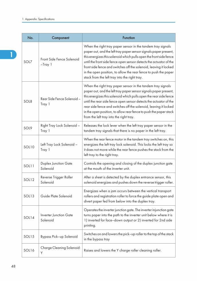
No. Component Function
SOL7Front Side Fence Solenoid–Tray 1
When the right tray paper sensor in the tandem tray signalspaper out, and the left tray paper sensor signals paper present,this energizes this solenoid which pulls open the front side fenceuntil the front side fence open sensor detects the actuator of thefront side fence and switches off the solenoid, leaving it lockedin the open position, to allow the rear fence to push the paperstack from the left tray into the right tray.
SOL8Rear Side Fence Solenoid –Tray 1
When the right tray paper sensor in the tandem tray signalspaper out, and the left tray paper sensor signals paper present,this energizes this solenoid which pulls open the rear side fenceuntil the rear side fence open sensor detects the actuator of therear side fence and switches off the solenoid, leaving it lockedin the open position, to allow rear fence to push the paper stackfrom the left tray into the right tray.
SOL9Right Tray Lock Solenoid –Tray 1
Releases the lock lever when the left tray paper sensor in thetandem tray signals that there is no paper in the left tray.
SOL10Left Tray Lock Solenoid –Tray 1
When the rear fence motor in the tandem tray switches on, thisenergizes the left tray lock solenoid. This locks the left tray soit does not move while the rear fence pushes the stack from theleft tray to the right tray.
SOL11Duplex Junction GateSolenoid
Controls the opening and closing of the duplex junction gateat the mouth of the inverter unit.
SOL12Reverse Trigger RollerSolenoid
After a sheet is detected by the duplex entrance sensor, thissolenoid energizes and pushes down the reverse trigger roller.
SOL13 Guide Plate SolenoidEnergizes when a jam occurs between the vertical transportrollers and registration roller to force the guide plate open anddivert paper fed from below into the duplex tray.
SOL14Inverter Junction GateSolenoid
Operates the inverter junction gate. The inverter injunction gateturns paper into the path to the inverter unit below where it is1) inverted for face–down output or 2) inverted for 2nd sideprinting.
SOL15 Bypass Pick–up SolenoidSwitches on and lowers the pick–up roller to the top of the stackin the bypass tray
SOL16Charge Cleaning Solenoid:Y
Raises and lowers the Y charge roller cleaning roller.
1. Appendix: Specifications
48
1
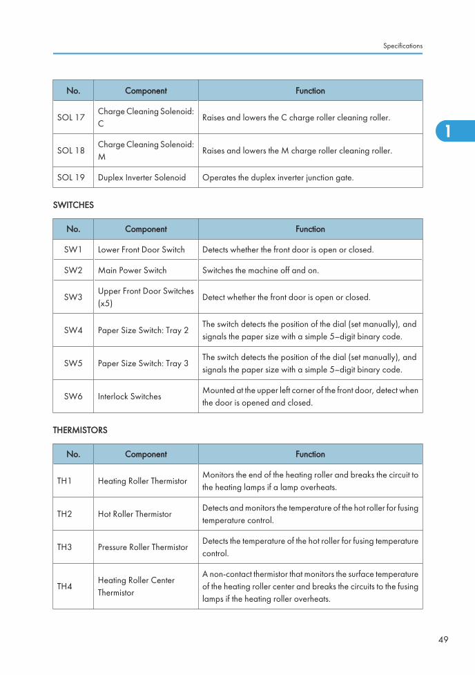
No. Component Function
SOL 17Charge Cleaning Solenoid:C
Raises and lowers the C charge roller cleaning roller.
SOL 18Charge Cleaning Solenoid:M
Raises and lowers the M charge roller cleaning roller.
SOL 19 Duplex Inverter Solenoid Operates the duplex inverter junction gate.
SWITCHES
No. Component Function
SW1 Lower Front Door Switch Detects whether the front door is open or closed.
SW2 Main Power Switch Switches the machine off and on.
SW3Upper Front Door Switches(x5)
Detect whether the front door is open or closed.
SW4 Paper Size Switch: Tray 2The switch detects the position of the dial (set manually), andsignals the paper size with a simple 5–digit binary code.
SW5 Paper Size Switch: Tray 3The switch detects the position of the dial (set manually), andsignals the paper size with a simple 5–digit binary code.
SW6 Interlock SwitchesMounted at the upper left corner of the front door, detect whenthe door is opened and closed.
THERMISTORS
No. Component Function
TH1 Heating Roller ThermistorMonitors the end of the heating roller and breaks the circuit tothe heating lamps if a lamp overheats.
TH2 Hot Roller ThermistorDetects and monitors the temperature of the hot roller for fusingtemperature control.
TH3 Pressure Roller ThermistorDetects the temperature of the hot roller for fusing temperaturecontrol.
TH4Heating Roller CenterThermistor
A non-contact thermistor that monitors the surface temperatureof the heating roller center and breaks the circuits to the fusinglamps if the heating roller overheats.
Specifications
49
1
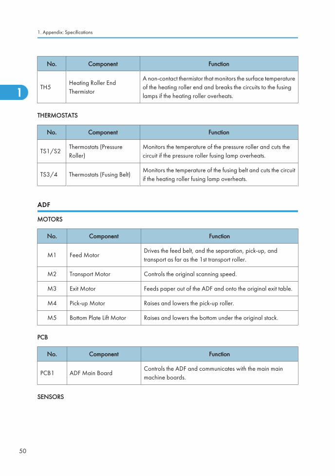
No. Component Function
TH5Heating Roller EndThermistor
A non-contact thermistor that monitors the surface temperatureof the heating roller end and breaks the circuits to the fusinglamps if the heating roller overheats.
THERMOSTATS
No. Component Function
TS1/S2Thermostats (PressureRoller)
Monitors the temperature of the pressure roller and cuts thecircuit if the pressure roller fusing lamp overheats.
TS3/4 Thermostats (Fusing Belt)Monitors the temperature of the fusing belt and cuts the circuitif the heating roller fusing lamp overheats.
ADF
MOTORS
No. Component Function
M1 Feed MotorDrives the feed belt, and the separation, pick-up, andtransport as far as the 1st transport roller.
M2 Transport Motor Controls the original scanning speed.
M3 Exit Motor Feeds paper out of the ADF and onto the original exit table.
M4 Pick-up Motor Raises and lowers the pick-up roller.
M5 Bottom Plate Lift Motor Raises and lowers the bottom under the original stack.
PCB
No. Component Function
PCB1 ADF Main BoardControls the ADF and communicates with the main mainmachine boards.
SENSORS
1. Appendix: Specifications
50
1
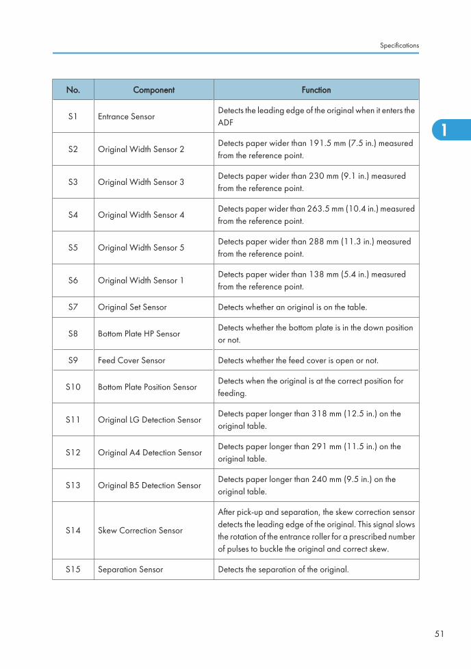
No. Component Function
S1 Entrance SensorDetects the leading edge of the original when it enters theADF
S2 Original Width Sensor 2Detects paper wider than 191.5 mm (7.5 in.) measuredfrom the reference point.
S3 Original Width Sensor 3Detects paper wider than 230 mm (9.1 in.) measuredfrom the reference point.
S4 Original Width Sensor 4Detects paper wider than 263.5 mm (10.4 in.) measuredfrom the reference point.
S5 Original Width Sensor 5Detects paper wider than 288 mm (11.3 in.) measuredfrom the reference point.
S6 Original Width Sensor 1Detects paper wider than 138 mm (5.4 in.) measuredfrom the reference point.
S7 Original Set Sensor Detects whether an original is on the table.
S8 Bottom Plate HP SensorDetects whether the bottom plate is in the down positionor not.
S9 Feed Cover Sensor Detects whether the feed cover is open or not.
S10 Bottom Plate Position SensorDetects when the original is at the correct position forfeeding.
S11 Original LG Detection SensorDetects paper longer than 318 mm (12.5 in.) on theoriginal table.
S12 Original A4 Detection SensorDetects paper longer than 291 mm (11.5 in.) on theoriginal table.
S13 Original B5 Detection SensorDetects paper longer than 240 mm (9.5 in.) on theoriginal table.
S14 Skew Correction Sensor
After pick-up and separation, the skew correction sensordetects the leading edge of the original. This signal slowsthe rotation of the entrance roller for a prescribed numberof pulses to buckle the original and correct skew.
S15 Separation Sensor Detects the separation of the original.
Specifications
51
1
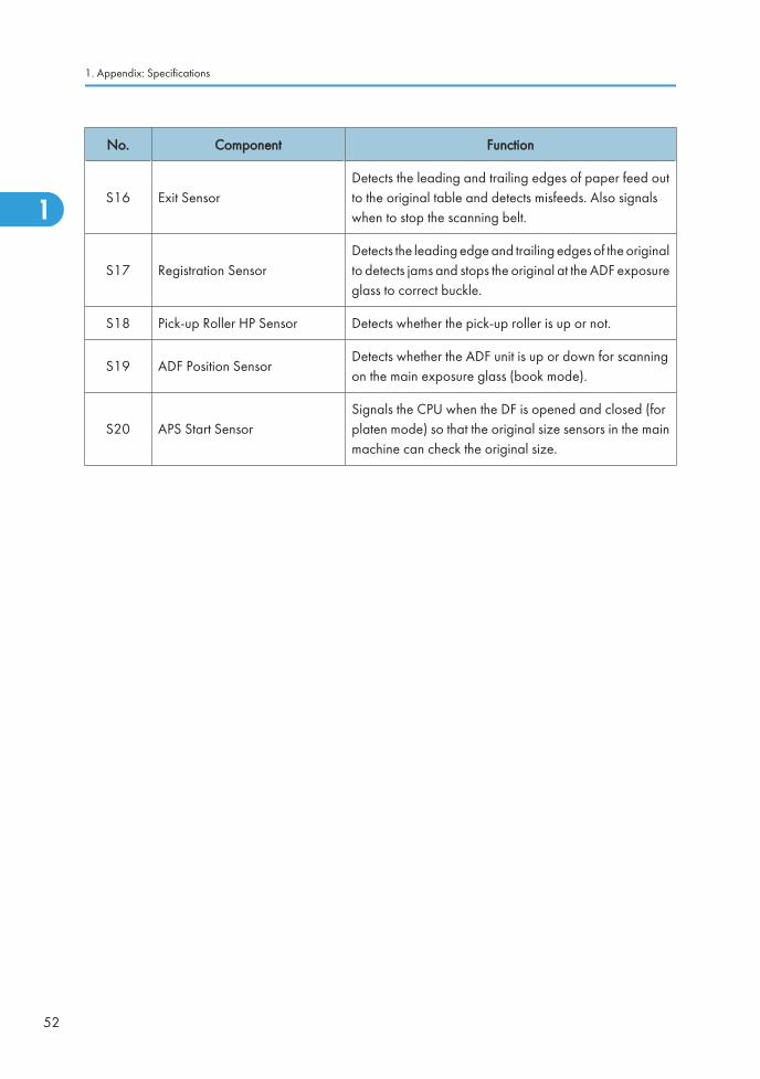
No. Component Function
S16 Exit SensorDetects the leading and trailing edges of paper feed outto the original table and detects misfeeds. Also signalswhen to stop the scanning belt.
S17 Registration SensorDetects the leading edge and trailing edges of the originalto detects jams and stops the original at the ADF exposureglass to correct buckle.
S18 Pick-up Roller HP Sensor Detects whether the pick-up roller is up or not.
S19 ADF Position SensorDetects whether the ADF unit is up or down for scanningon the main exposure glass (book mode).
S20 APS Start SensorSignals the CPU when the DF is opened and closed (forplaten mode) so that the original size sensors in the mainmachine can check the original size.
1. Appendix: Specifications
52
1
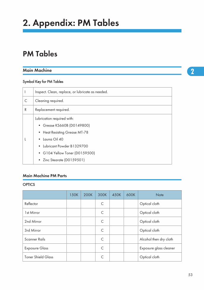
2. Appendix: PM Tables
PM Tables
Main Machine
Symbol Key for PM Tables
I Inspect. Clean, replace, or lubricate as needed.
C Cleaning required.
R Replacement required.
L
Lubrication required with:
• Grease KS660B (D0149800)
• Heat Resisting Grease MT-78
• Launa Oil 40
• Lubricant Powder B1329700
• G104 Yellow Toner (D0159500)
• Zinc Stearate (D0159501)
Main Machine PM Parts
OPTICS
150K 200K 300K 450K 600K Note
Reflector C Optical cloth
1st Mirror C Optical cloth
2nd Mirror C Optical cloth
3rd Mirror C Optical cloth
Scanner Rails C Alcohol then dry cloth
Exposure Glass C Exposure glass cleaner
Toner Shield Glass C Optical cloth
53
2
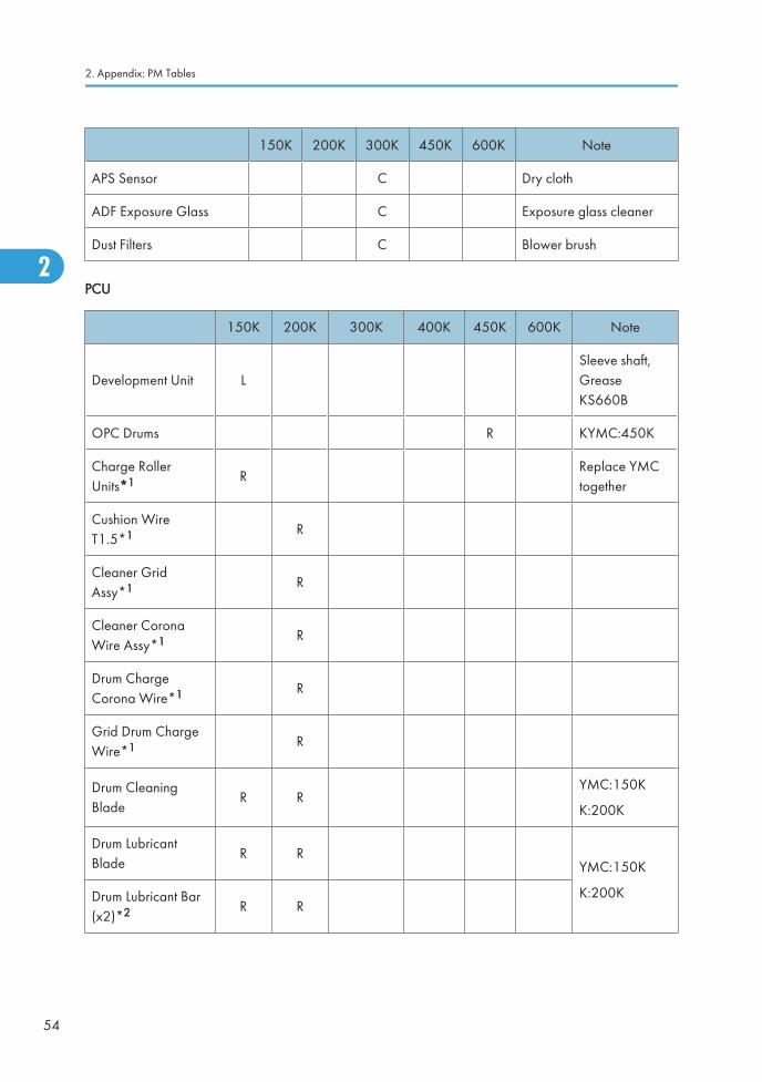
150K 200K 300K 450K 600K Note
APS Sensor C Dry cloth
ADF Exposure Glass C Exposure glass cleaner
Dust Filters C Blower brush
PCU
150K 200K 300K 400K 450K 600K Note
Development Unit LSleeve shaft,GreaseKS660B
OPC Drums R KYMC:450K
Charge RollerUnits*1 R
Replace YMCtogether
Cushion WireT1.5*1 R
Cleaner GridAssy*1 R
Cleaner CoronaWire Assy*1 R
Drum ChargeCorona Wire*1 R
Grid Drum ChargeWire*1 R
Drum CleaningBlade
R RYMC:150K
K:200K
Drum LubricantBlade
R RYMC:150K
K:200KDrum Lubricant Bar(x2)*2 R R
2. Appendix: PM Tables
54
2
Ed
Typewritten Text
RTB 78 Problems if lubricant bar is not replaced at the correct PM interval
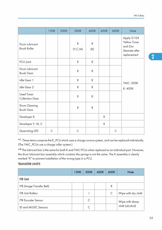
150K 200K 300K 400K 450K 600K Note
Drum LubricantBrush Roller
R
(Y,C,M)
R
(K)
Apply G104Yellow Tonerand ZincStearate afterreplacement
PCU Joint R R
YMC: 300K
K: 400K
Drum LubricantBrush Gear
R R
Idle Gear 1 R R
Idle Gear 2 R R
Used TonerCollection Gear
R R
Drum CleaningBrush Gear
R R
Developer K R
Developer Y, M, C R
Quenching LED C C C
*1: These items comprise the K_PCU which uses a charge corona system, and can be replaced individually.(The YMC_PCUs use a charge roller system.)
*2 The lubricant bar is the same for both K and YMC PCUs when replaced as an individual part. However,the drum lubricant bar assembly which contains the springs is not the same. The K assembly is clearlymarked "K" to prevent installation of the wrong type in a PCU.
TRANSFER UNITS
150K 300K 450K 600K Note
ITB Unit
ITB (Image Transfer Belt) R
ITB Unit Rollers I C Wipe with dry cloth
ITB Encoder Sensor C Wipe with dampcloth (alcohol)ID and MUSIC Sensors C
PM Tables
55
2
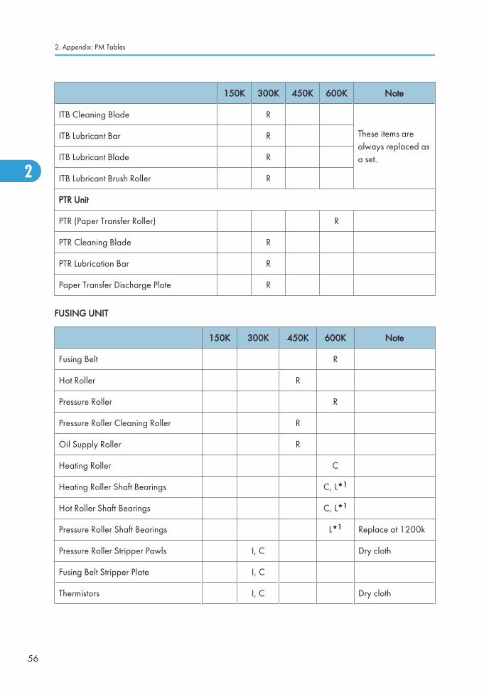
150K 300K 450K 600K Note
ITB Cleaning Blade R
These items arealways replaced asa set.
ITB Lubricant Bar R
ITB Lubricant Blade R
ITB Lubricant Brush Roller R
PTR Unit
PTR (Paper Transfer Roller) R
PTR Cleaning Blade R
PTR Lubrication Bar R
Paper Transfer Discharge Plate R
FUSING UNIT
150K 300K 450K 600K Note
Fusing Belt R
Hot Roller R
Pressure Roller R
Pressure Roller Cleaning Roller R
Oil Supply Roller R
Heating Roller C
Heating Roller Shaft Bearings C, L*1
Hot Roller Shaft Bearings C, L*1
Pressure Roller Shaft Bearings L*1 Replace at 1200k
Pressure Roller Stripper Pawls I, C Dry cloth
Fusing Belt Stripper Plate I, C
Thermistors I, C Dry cloth
2. Appendix: PM Tables
56
2
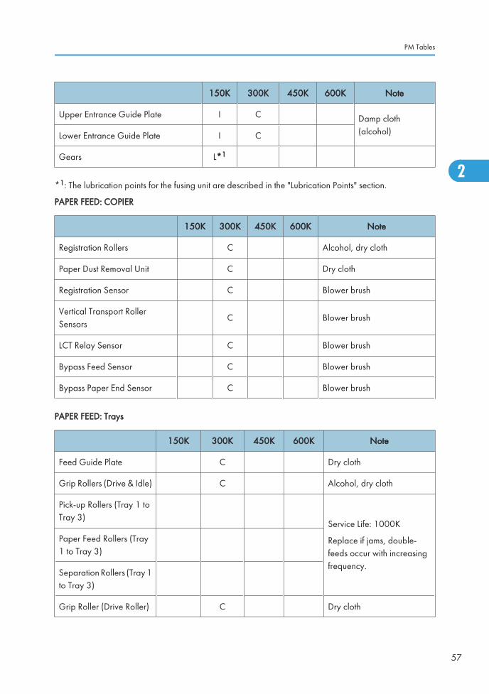
150K 300K 450K 600K Note
Upper Entrance Guide Plate I C Damp cloth(alcohol)Lower Entrance Guide Plate I C
Gears L*1
*1: The lubrication points for the fusing unit are described in the "Lubrication Points" section.
PAPER FEED: COPIER
150K 300K 450K 600K Note
Registration Rollers C Alcohol, dry cloth
Paper Dust Removal Unit C Dry cloth
Registration Sensor C Blower brush
Vertical Transport RollerSensors
C Blower brush
LCT Relay Sensor C Blower brush
Bypass Feed Sensor C Blower brush
Bypass Paper End Sensor C Blower brush
PAPER FEED: Trays
150K 300K 450K 600K Note
Feed Guide Plate C Dry cloth
Grip Rollers (Drive & Idle) C Alcohol, dry cloth
Pick-up Rollers (Tray 1 toTray 3)
Service Life: 1000K
Replace if jams, double-feeds occur with increasingfrequency.
Paper Feed Rollers (Tray1 to Tray 3)
Separation Rollers (Tray 1to Tray 3)
Grip Roller (Drive Roller) C Dry cloth
PM Tables
57
2
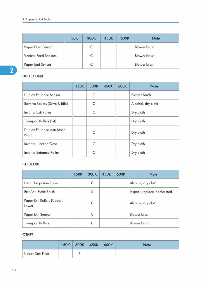
150K 300K 450K 600K Note
Paper Feed Sensor C Blower brush
Vertical Feed Sensors C Blower brush
Paper-End Sensor C Blower brush
DUPLEX UNIT
150K 300K 450K 600K Note
Duplex Entrance Sensor C Blower brush
Reverse Rollers (Drive & Idle) C Alcohol, dry cloth
Inverter Exit Roller C Dry cloth
Transport Rollers (x4) C Dry cloth
Duplex Entrance Anti-StaticBrush
C Dry cloth
Inverter Junction Gate C Dry cloth
Inverter Entrance Roller C Dry cloth
PAPER EXIT
150K 300K 450K 600K Note
Heat Dissipation Roller C Alcohol, dry cloth
Exit Anti-Static Brush C Inspect, replace if deformed.
Paper Exit Rollers (Upper,Lower)
C Alcohol, dry cloth
Paper Exit Sensor C Blower brush
Transport Rollers C Blower brush
OTHER
150K 300K 450K 600K Note
Upper Dust Filter R
2. Appendix: PM Tables
58
2
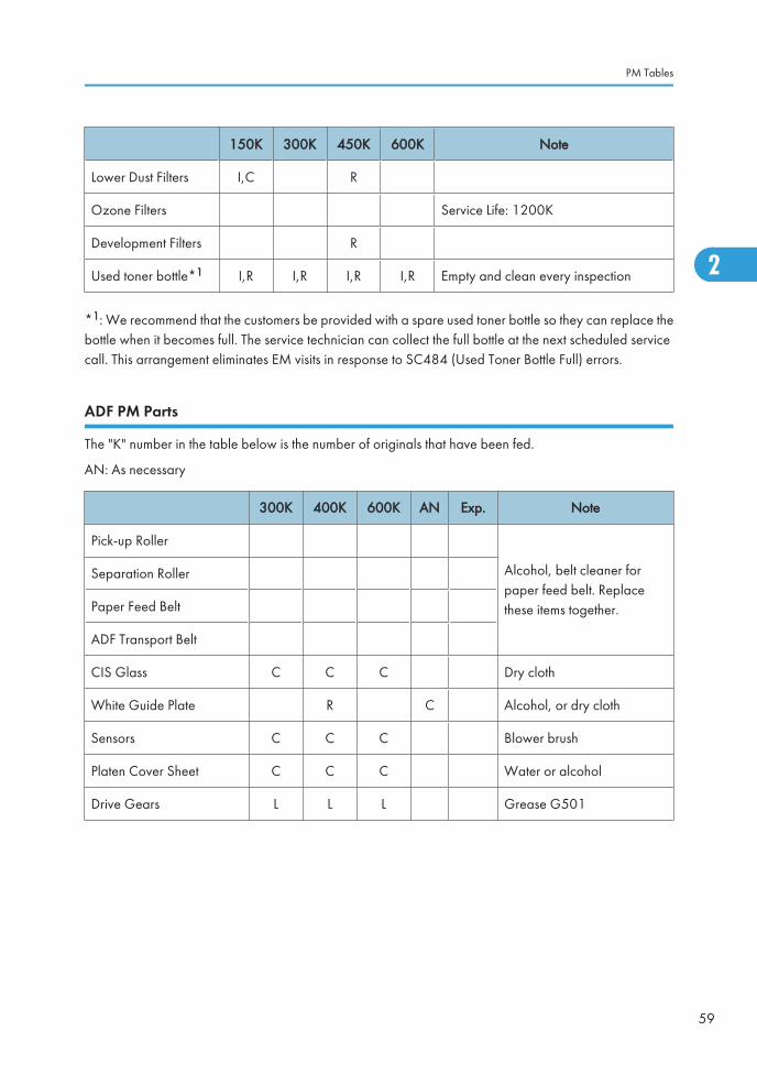
150K 300K 450K 600K Note
Lower Dust Filters I,C R
Ozone Filters Service Life: 1200K
Development Filters R
Used toner bottle*1 I,R I,R I,R I,R Empty and clean every inspection
*1: We recommend that the customers be provided with a spare used toner bottle so they can replace thebottle when it becomes full. The service technician can collect the full bottle at the next scheduled servicecall. This arrangement eliminates EM visits in response to SC484 (Used Toner Bottle Full) errors.
ADF PM Parts
The "K" number in the table below is the number of originals that have been fed.
AN: As necessary
300K 400K 600K AN Exp. Note
Pick-up Roller
Alcohol, belt cleaner forpaper feed belt. Replacethese items together.
Separation Roller
Paper Feed Belt
ADF Transport Belt
CIS Glass C C C Dry cloth
White Guide Plate R C Alcohol, or dry cloth
Sensors C C C Blower brush
Platen Cover Sheet C C C Water or alcohol
Drive Gears L L L Grease G501
PM Tables
59
2
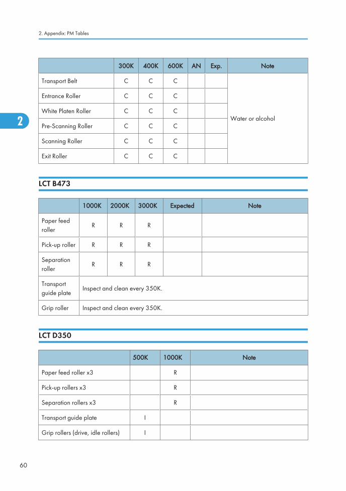
300K 400K 600K AN Exp. Note
Transport Belt C C C
Water or alcohol
Entrance Roller C C C
White Platen Roller C C C
Pre-Scanning Roller C C C
Scanning Roller C C C
Exit Roller C C C
LCT B473
1000K 2000K 3000K Expected Note
Paper feedroller
R R R
Pick-up roller R R R
Separationroller
R R R
Transportguide plate
Inspect and clean every 350K.
Grip roller Inspect and clean every 350K.
LCT D350
500K 1000K Note
Paper feed roller x3 R
Pick-up rollers x3 R
Separation rollers x3 R
Transport guide plate I
Grip rollers (drive, idle rollers) I
2. Appendix: PM Tables
60
2
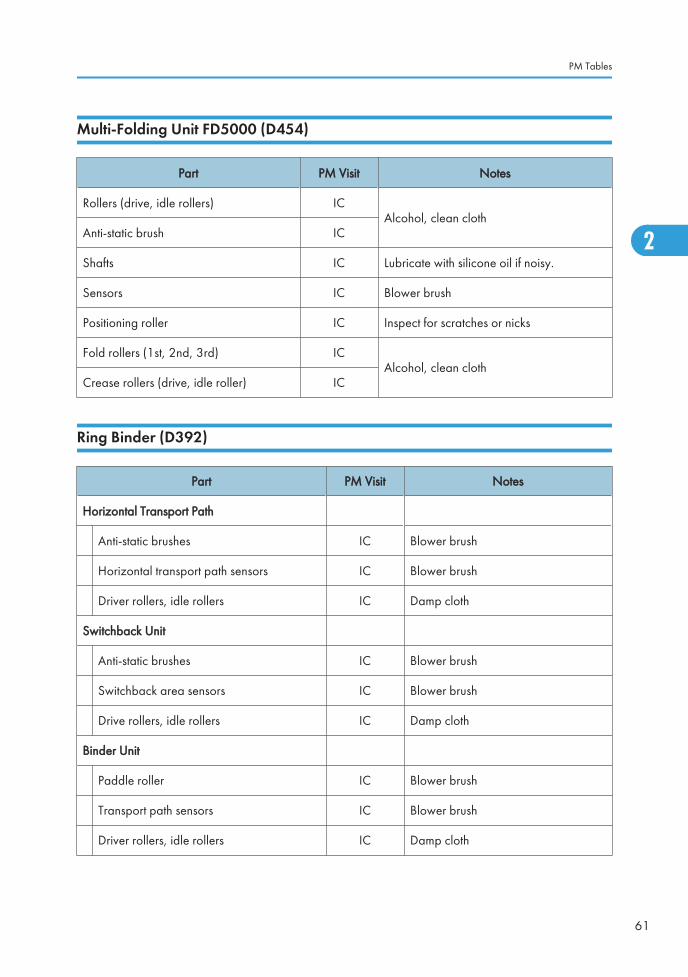
Multi-Folding Unit FD5000 (D454)
Part PM Visit Notes
Rollers (drive, idle rollers) ICAlcohol, clean cloth
Anti-static brush IC
Shafts IC Lubricate with silicone oil if noisy.
Sensors IC Blower brush
Positioning roller IC Inspect for scratches or nicks
Fold rollers (1st, 2nd, 3rd) ICAlcohol, clean cloth
Crease rollers (drive, idle roller) IC
Ring Binder (D392)
Part PM Visit Notes
Horizontal Transport Path
Anti-static brushes IC Blower brush
Horizontal transport path sensors IC Blower brush
Driver rollers, idle rollers IC Damp cloth
Switchback Unit
Anti-static brushes IC Blower brush
Switchback area sensors IC Blower brush
Drive rollers, idle rollers IC Damp cloth
Binder Unit
Paddle roller IC Blower brush
Transport path sensors IC Blower brush
Driver rollers, idle rollers IC Damp cloth
PM Tables
61
2
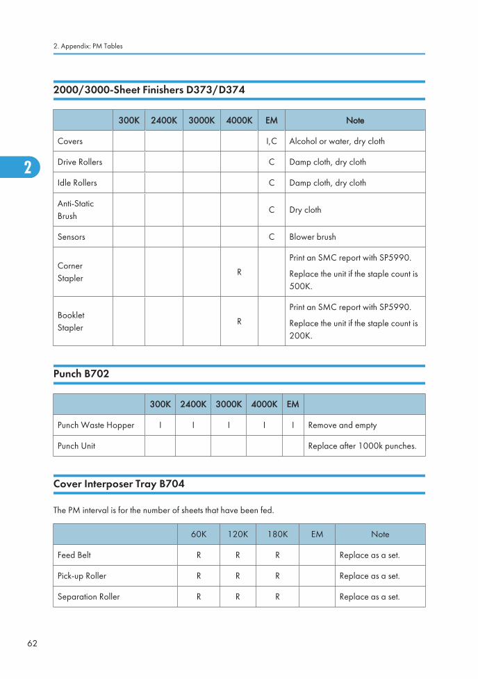
2000/3000-Sheet Finishers D373/D374
300K 2400K 3000K 4000K EM Note
Covers I,C Alcohol or water, dry cloth
Drive Rollers C Damp cloth, dry cloth
Idle Rollers C Damp cloth, dry cloth
Anti-StaticBrush
C Dry cloth
Sensors C Blower brush
CornerStapler
R
Print an SMC report with SP5990.
Replace the unit if the staple count is500K.
BookletStapler
R
Print an SMC report with SP5990.
Replace the unit if the staple count is200K.
Punch B702
300K 2400K 3000K 4000K EM
Punch Waste Hopper I I I I I Remove and empty
Punch Unit Replace after 1000k punches.
Cover Interposer Tray B704
The PM interval is for the number of sheets that have been fed.
60K 120K 180K EM Note
Feed Belt R R R Replace as a set.
Pick-up Roller R R R Replace as a set.
Separation Roller R R R Replace as a set.
2. Appendix: PM Tables
62
2
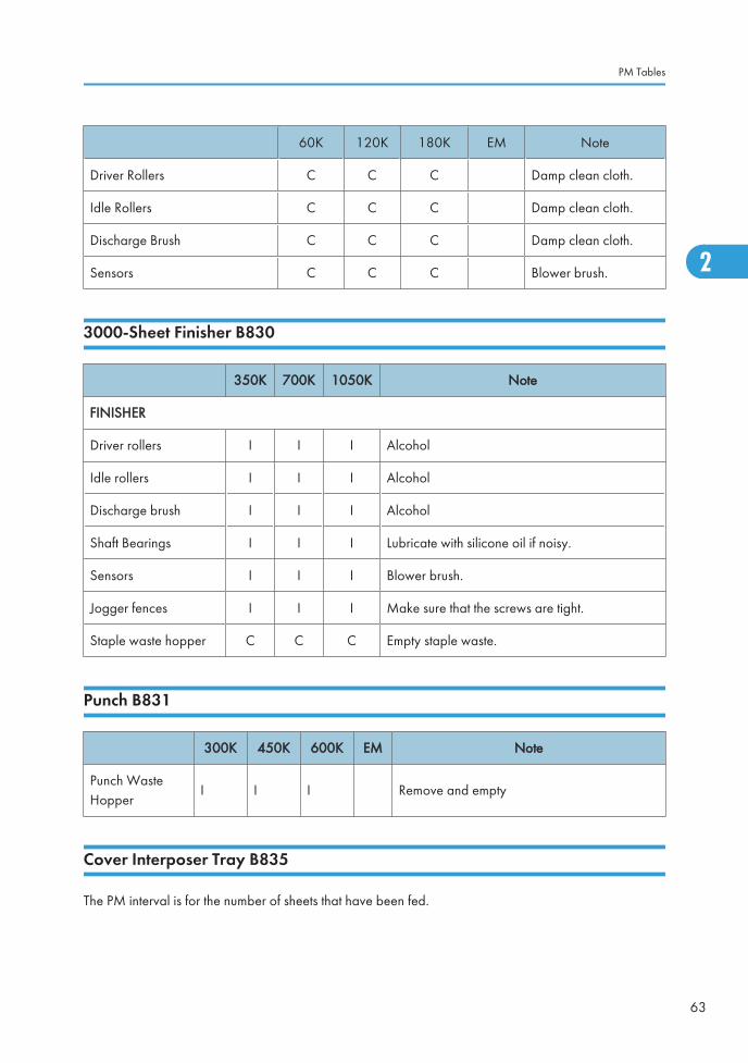
60K 120K 180K EM Note
Driver Rollers C C C Damp clean cloth.
Idle Rollers C C C Damp clean cloth.
Discharge Brush C C C Damp clean cloth.
Sensors C C C Blower brush.
3000-Sheet Finisher B830
350K 700K 1050K Note
FINISHER
Driver rollers I I I Alcohol
Idle rollers I I I Alcohol
Discharge brush I I I Alcohol
Shaft Bearings I I I Lubricate with silicone oil if noisy.
Sensors I I I Blower brush.
Jogger fences I I I Make sure that the screws are tight.
Staple waste hopper C C C Empty staple waste.
Punch B831
300K 450K 600K EM Note
Punch WasteHopper
I I I Remove and empty
Cover Interposer Tray B835
The PM interval is for the number of sheets that have been fed.
PM Tables
63
2
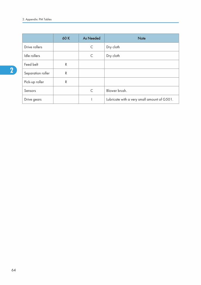
60 K As Needed Note
Drive rollers C Dry cloth
Idle rollers C Dry cloth
Feed belt R
Separation roller R
Pick-up roller R
Sensors C Blower brush.
Drive gears I Lubricate with a very small amount of G501.
2. Appendix: PM Tables
64
2
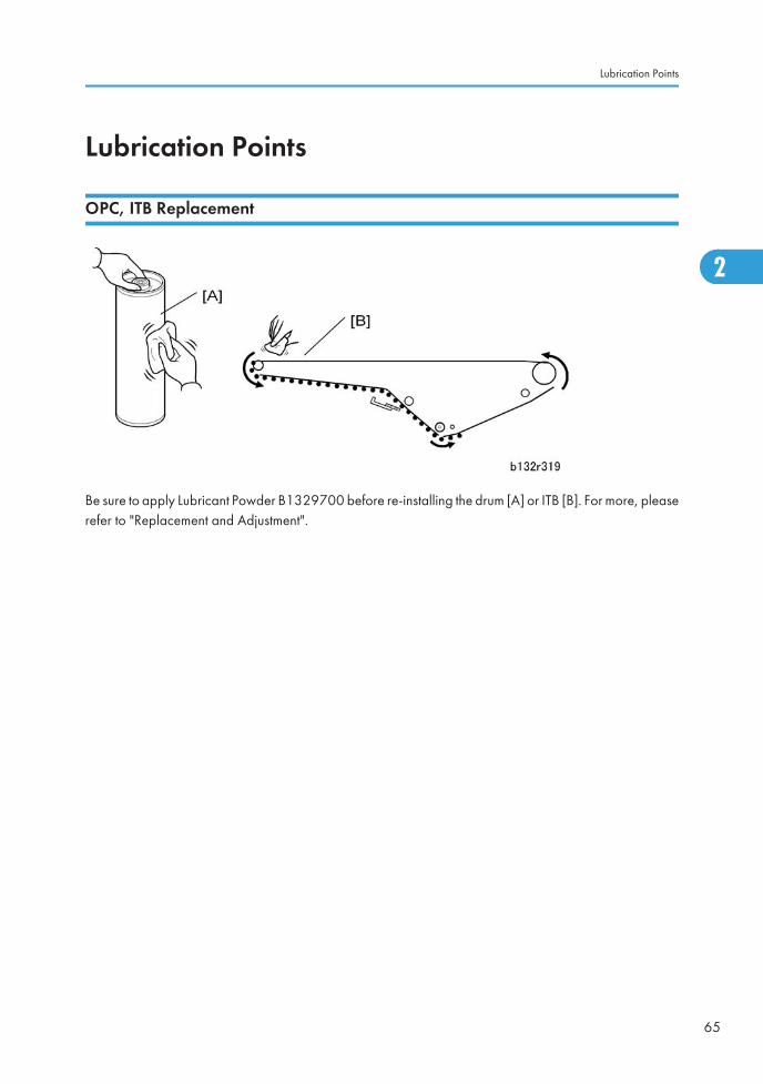
Lubrication Points
OPC, ITB Replacement
Be sure to apply Lubricant Powder B1329700 before re-installing the drum [A] or ITB [B]. For more, pleaserefer to "Replacement and Adjustment".
Lubrication Points
65
2
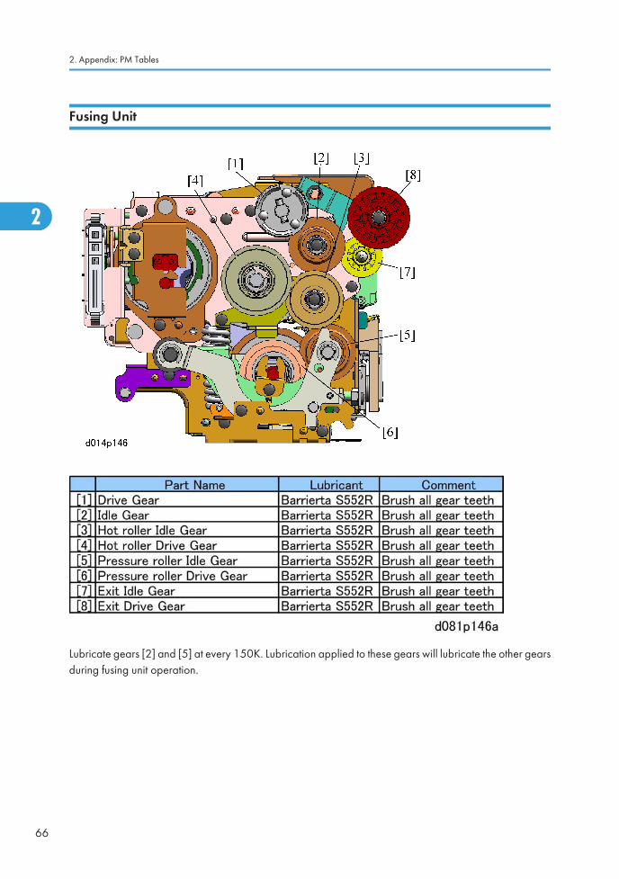
Fusing Unit
Lubricate gears [2] and [5] at every 150K. Lubrication applied to these gears will lubricate the other gearsduring fusing unit operation.
2. Appendix: PM Tables
66
2
Ed
Typewritten Text
See RTB 73 for more details about this lubrication.
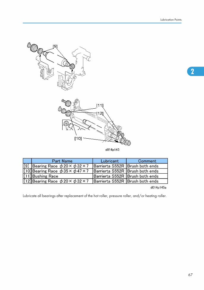
Lubricate all bearings after replacement of the hot roller, pressure roller, and/or heating roller.
Lubrication Points
67
2
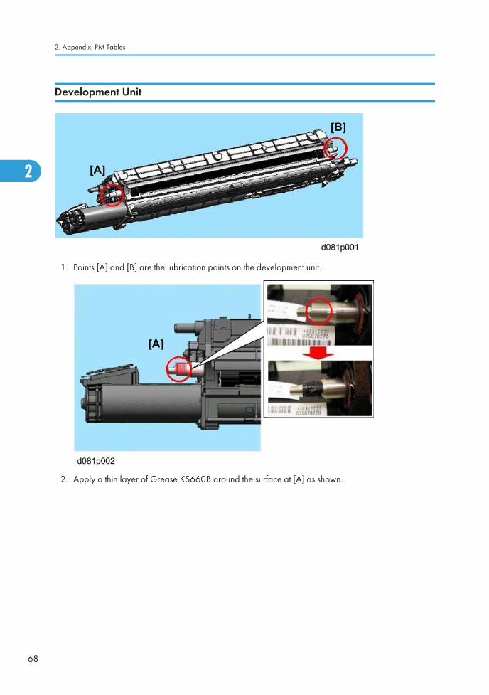
Development Unit
1. Points [A] and [B] are the lubrication points on the development unit.
2. Apply a thin layer of Grease KS660B around the surface at [A] as shown.
2. Appendix: PM Tables
68
2
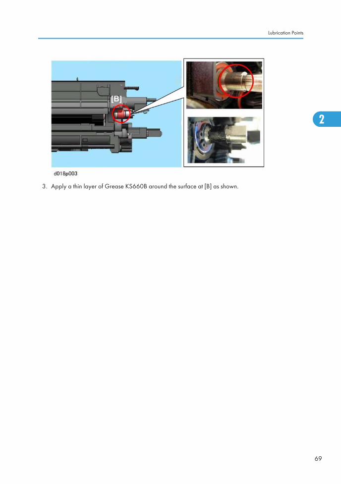
3. Apply a thin layer of Grease KS660B around the surface at [B] as shown.
Lubrication Points
69
2

2. Appendix: PM Tables
70
2
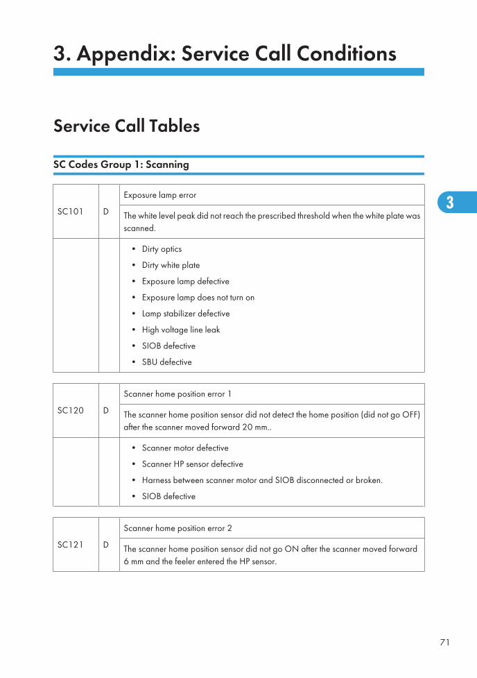
3. Appendix: Service Call Conditions
Service Call Tables
SC Codes Group 1: Scanning
SC101 D
Exposure lamp error
The white level peak did not reach the prescribed threshold when the white plate wasscanned.
• Dirty optics
• Dirty white plate
• Exposure lamp defective
• Exposure lamp does not turn on
• Lamp stabilizer defective
• High voltage line leak
• SIOB defective
• SBU defective
SC120 D
Scanner home position error 1
The scanner home position sensor did not detect the home position (did not go OFF)after the scanner moved forward 20 mm..
• Scanner motor defective
• Scanner HP sensor defective
• Harness between scanner motor and SIOB disconnected or broken.
• SIOB defective
SC121 D
Scanner home position error 2
The scanner home position sensor did not go ON after the scanner moved forward6 mm and the feeler entered the HP sensor.
71
3
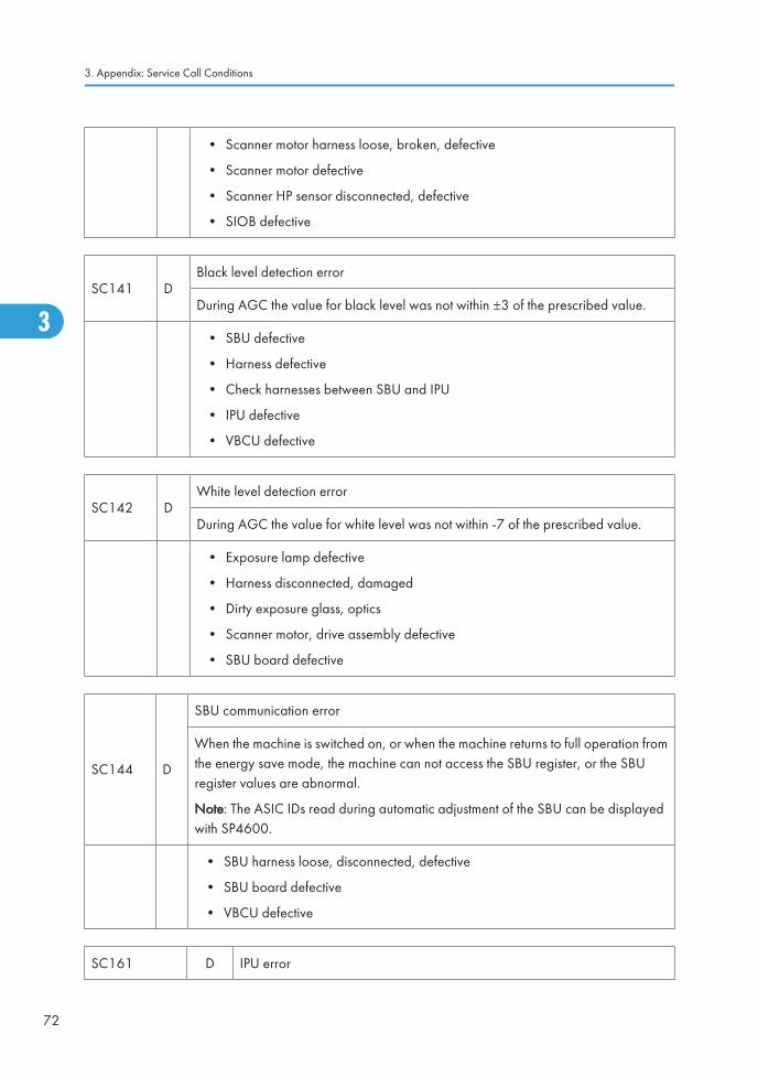
• Scanner motor harness loose, broken, defective
• Scanner motor defective
• Scanner HP sensor disconnected, defective
• SIOB defective
SC141 DBlack level detection error
During AGC the value for black level was not within ±3 of the prescribed value.
• SBU defective
• Harness defective
• Check harnesses between SBU and IPU
• IPU defective
• VBCU defective
SC142 DWhite level detection error
During AGC the value for white level was not within -7 of the prescribed value.
• Exposure lamp defective
• Harness disconnected, damaged
• Dirty exposure glass, optics
• Scanner motor, drive assembly defective
• SBU board defective
SC144 D
SBU communication error
When the machine is switched on, or when the machine returns to full operation fromthe energy save mode, the machine can not access the SBU register, or the SBUregister values are abnormal.
Note: The ASIC IDs read during automatic adjustment of the SBU can be displayedwith SP4600.
• SBU harness loose, disconnected, defective
• SBU board defective
• VBCU defective
SC161 D IPU error
3. Appendix: Service Call Conditions
72
3
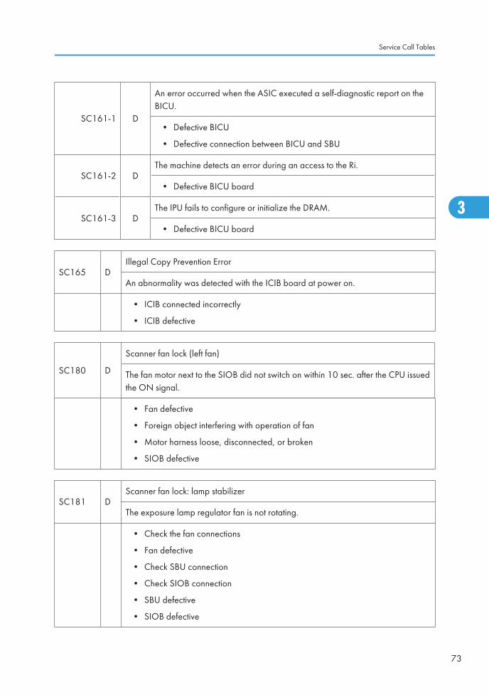
SC161-1 D
An error occurred when the ASIC executed a self-diagnostic report on theBICU.
• Defective BICU
• Defective connection between BICU and SBU
SC161-2 DThe machine detects an error during an access to the Ri.
• Defective BICU board
SC161-3 DThe IPU fails to configure or initialize the DRAM.
• Defective BICU board
SC165 DIllegal Copy Prevention Error
An abnormality was detected with the ICIB board at power on.
• ICIB connected incorrectly
• ICIB defective
SC180 D
Scanner fan lock (left fan)
The fan motor next to the SIOB did not switch on within 10 sec. after the CPU issuedthe ON signal.
• Fan defective
• Foreign object interfering with operation of fan
• Motor harness loose, disconnected, or broken
• SIOB defective
SC181 DScanner fan lock: lamp stabilizer
The exposure lamp regulator fan is not rotating.
• Check the fan connections
• Fan defective
• Check SBU connection
• Check SIOB connection
• SBU defective
• SIOB defective
Service Call Tables
73
3
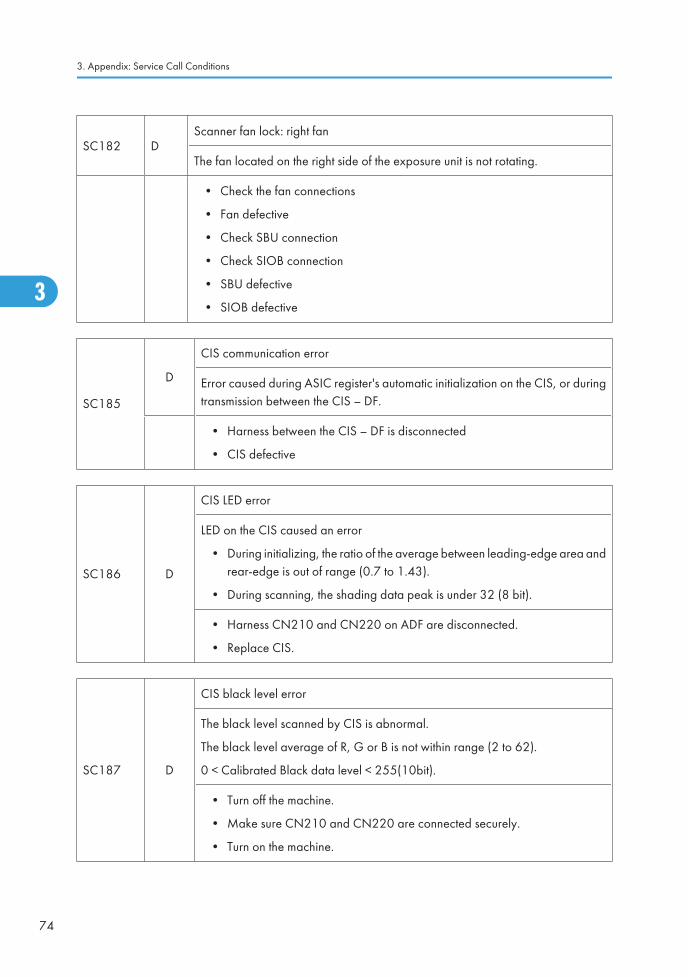
SC182 DScanner fan lock: right fan
The fan located on the right side of the exposure unit is not rotating.
• Check the fan connections
• Fan defective
• Check SBU connection
• Check SIOB connection
• SBU defective
• SIOB defective
SC185
D
CIS communication error
Error caused during ASIC register's automatic initialization on the CIS, or duringtransmission between the CIS – DF.
• Harness between the CIS – DF is disconnected
• CIS defective
SC186 D
CIS LED error
LED on the CIS caused an error
• During initializing, the ratio of the average between leading-edge area andrear-edge is out of range (0.7 to 1.43).
• During scanning, the shading data peak is under 32 (8 bit).
• Harness CN210 and CN220 on ADF are disconnected.
• Replace CIS.
SC187 D
CIS black level error
The black level scanned by CIS is abnormal.
The black level average of R, G or B is not within range (2 to 62).
0 < Calibrated Black data level < 255(10bit).
• Turn off the machine.
• Make sure CN210 and CN220 are connected securely.
• Turn on the machine.
3. Appendix: Service Call Conditions
74
3

SC188 D
CIS white level error
The shading data peak detected from the CIS is abnormal.
• CIS defective
• Make sure CN210 and CN220 are connected firmly.
• Replace the CIS.
SC189 D
CIS gray balance adjustment error
The adjustment error occurs during the test after adjusting the gray balance.
• CIS defective
1. Retry the gray balance adjustment.
2. If the machine does not recover, do the following steps.
• Turn off the machine.
• Make sure CN210 and CN220 are connected firmly.
• Turn on the machine.
3. If the machine does not recover, replace the CIS.
SC195 DMachine serial number error
The number registered for the machine serial number does not match.
• Confirm the correct serial number of the machine in the specifications
• Re-input the serial number.
Important: When SC195 occurs, the serial number must be input. Please contact yourtechnical supervisor.
SC Codes Group 2: Exposure
SC202 D
Polygon motor error: ON timeout
The polygon mirror motor does not reach the targeted operating speed within theprescribed time.
Service Call Tables
75
3
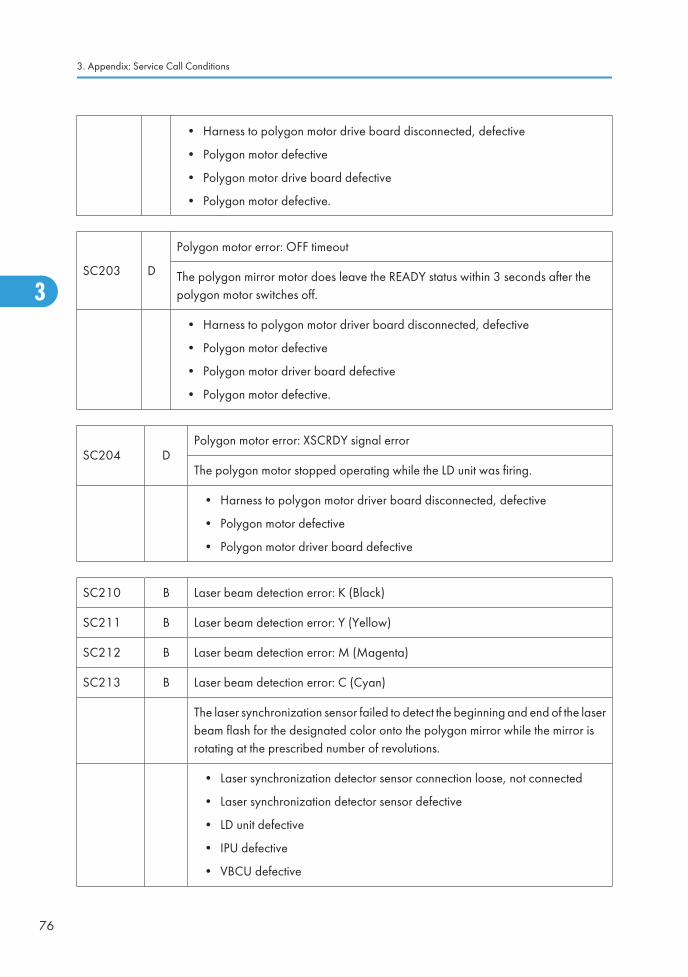
• Harness to polygon motor drive board disconnected, defective
• Polygon motor defective
• Polygon motor drive board defective
• Polygon motor defective.
SC203 D
Polygon motor error: OFF timeout
The polygon mirror motor does leave the READY status within 3 seconds after thepolygon motor switches off.
• Harness to polygon motor driver board disconnected, defective
• Polygon motor defective
• Polygon motor driver board defective
• Polygon motor defective.
SC204 DPolygon motor error: XSCRDY signal error
The polygon motor stopped operating while the LD unit was firing.
• Harness to polygon motor driver board disconnected, defective
• Polygon motor defective
• Polygon motor driver board defective
SC210 B Laser beam detection error: K (Black)
SC211 B Laser beam detection error: Y (Yellow)
SC212 B Laser beam detection error: M (Magenta)
SC213 B Laser beam detection error: C (Cyan)
The laser synchronization sensor failed to detect the beginning and end of the laserbeam flash for the designated color onto the polygon mirror while the mirror isrotating at the prescribed number of revolutions.
• Laser synchronization detector sensor connection loose, not connected
• Laser synchronization detector sensor defective
• LD unit defective
• IPU defective
• VBCU defective
3. Appendix: Service Call Conditions
76
3
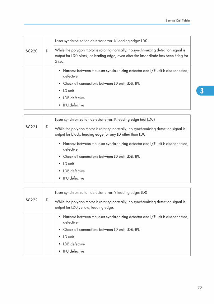
SC220 D
Laser synchronization detector error: K leading edge: LD0
While the polygon motor is rotating normally, no synchronizing detection signal isoutput for LD0 black, or leading edge, even after the laser diode has been firing for2 sec.
• Harness between the laser synchronizing detector and I/F unit is disconnected,defective
• Check all connections between LD unit, LDB, IPU
• LD unit
• LDB defective
• IPU defective
SC221 D
Laser synchronization detector error: K leading edge (not LD0)
While the polygon motor is rotating normally, no synchronizing detection signal isoutput for black, leading edge for any LD other than LD0.
• Harness between the laser synchronizing detector and I/F unit is disconnected,defective
• Check all connections between LD unit, LDB, IPU
• LD unit
• LDB defective
• IPU defective
SC222 D
Laser synchronization detector error: Y leading edge: LD0
While the polygon motor is rotating normally, no synchronizing detection signal isoutput for LD0 yellow, leading edge.
• Harness between the laser synchronizing detector and I/F unit is disconnected,defective
• Check all connections between LD unit, LDB, IPU
• LD unit
• LDB defective
• IPU defective
Service Call Tables
77
3
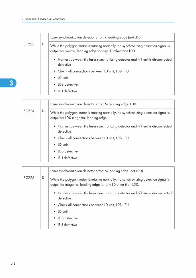
SC223 D
Laser synchronization detector error: Y leading edge (not LD0)
While the polygon motor is rotating normally, no synchronizing detection signal isoutput for yellow, leading edge for any LD other than LD0.
• Harness between the laser synchronizing detector and I/F unit is disconnected,defective
• Check all connections between LD unit, LDB, IPU
• LD unit
• LDB defective
• IPU defective
SC224 D
Laser synchronization detector error: M leading edge: LD0
While the polygon motor is rotating normally, no synchronizing detection signal isoutput for LD0 magenta, leading edge.
• Harness between the laser synchronizing detector and I/F unit is disconnected,defective
• Check all connections between LD unit, LDB, IPU
• LD unit
• LDB defective
• IPU defective
SC225 D
Laser synchronization detector error: M leading edge (not LD0)
While the polygon motor is rotating normally, no synchronizing detection signal isoutput for magenta, leading edge for any LD other than LD0.
• Harness between the laser synchronizing detector and I/F unit is disconnected,defective
• Check all connections between LD unit, LDB, IPU
• LD unit
• LDB defective
• IPU defective
3. Appendix: Service Call Conditions
78
3
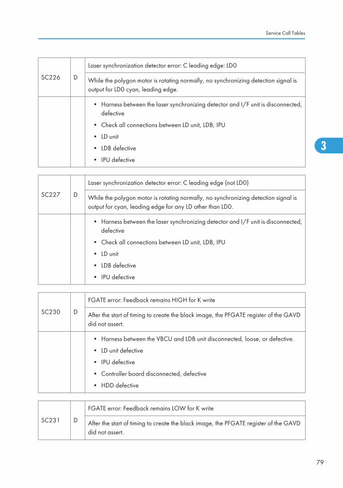
SC226 D
Laser synchronization detector error: C leading edge: LD0
While the polygon motor is rotating normally, no synchronizing detection signal isoutput for LD0 cyan, leading edge.
• Harness between the laser synchronizing detector and I/F unit is disconnected,defective
• Check all connections between LD unit, LDB, IPU
• LD unit
• LDB defective
• IPU defective
SC227 D
Laser synchronization detector error: C leading edge (not LD0)
While the polygon motor is rotating normally, no synchronizing detection signal isoutput for cyan, leading edge for any LD other than LD0.
• Harness between the laser synchronizing detector and I/F unit is disconnected,defective
• Check all connections between LD unit, LDB, IPU
• LD unit
• LDB defective
• IPU defective
SC230 D
FGATE error: Feedback remains HIGH for K write
After the start of timing to create the black image, the PFGATE register of the GAVDdid not assert.
• Harness between the VBCU and LDB unit disconnected, loose, or defective.
• LD unit defective
• IPU defective
• Controller board disconnected, defective
• HDD defective
SC231 D
FGATE error: Feedback remains LOW for K write
After the start of timing to create the black image, the PFGATE register of the GAVDdid not assert.
Service Call Tables
79
3
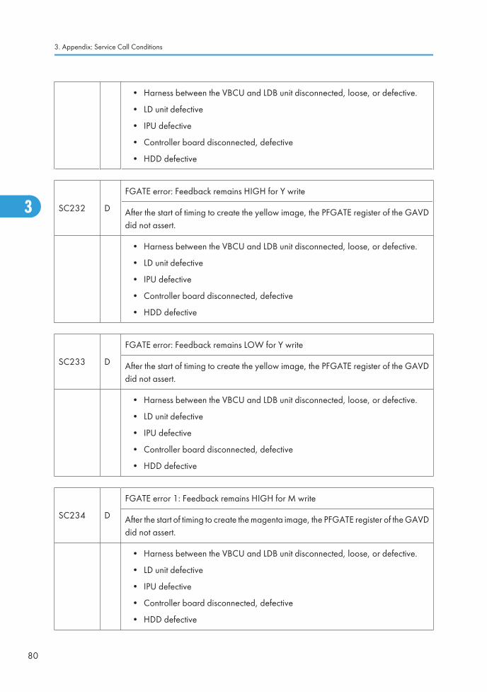
• Harness between the VBCU and LDB unit disconnected, loose, or defective.
• LD unit defective
• IPU defective
• Controller board disconnected, defective
• HDD defective
SC232 D
FGATE error: Feedback remains HIGH for Y write
After the start of timing to create the yellow image, the PFGATE register of the GAVDdid not assert.
• Harness between the VBCU and LDB unit disconnected, loose, or defective.
• LD unit defective
• IPU defective
• Controller board disconnected, defective
• HDD defective
SC233 D
FGATE error: Feedback remains LOW for Y write
After the start of timing to create the yellow image, the PFGATE register of the GAVDdid not assert.
• Harness between the VBCU and LDB unit disconnected, loose, or defective.
• LD unit defective
• IPU defective
• Controller board disconnected, defective
• HDD defective
SC234 D
FGATE error 1: Feedback remains HIGH for M write
After the start of timing to create the magenta image, the PFGATE register of the GAVDdid not assert.
• Harness between the VBCU and LDB unit disconnected, loose, or defective.
• LD unit defective
• IPU defective
• Controller board disconnected, defective
• HDD defective
3. Appendix: Service Call Conditions
80
3
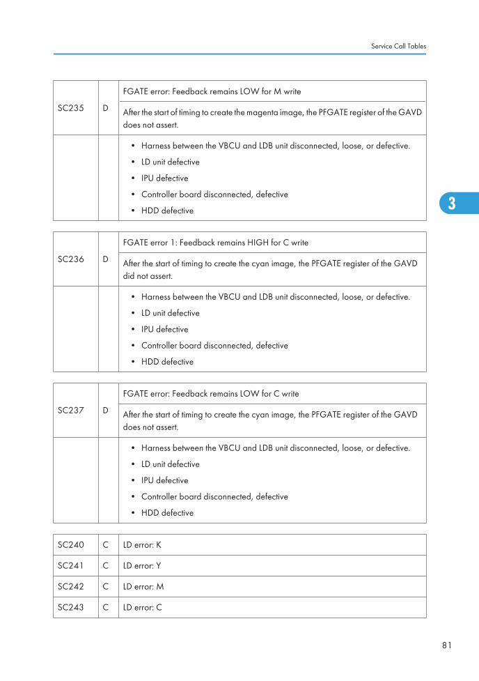
SC235 D
FGATE error: Feedback remains LOW for M write
After the start of timing to create the magenta image, the PFGATE register of the GAVDdoes not assert.
• Harness between the VBCU and LDB unit disconnected, loose, or defective.
• LD unit defective
• IPU defective
• Controller board disconnected, defective
• HDD defective
SC236 D
FGATE error 1: Feedback remains HIGH for C write
After the start of timing to create the cyan image, the PFGATE register of the GAVDdid not assert.
• Harness between the VBCU and LDB unit disconnected, loose, or defective.
• LD unit defective
• IPU defective
• Controller board disconnected, defective
• HDD defective
SC237 D
FGATE error: Feedback remains LOW for C write
After the start of timing to create the cyan image, the PFGATE register of the GAVDdoes not assert.
• Harness between the VBCU and LDB unit disconnected, loose, or defective.
• LD unit defective
• IPU defective
• Controller board disconnected, defective
• HDD defective
SC240 C LD error: K
SC241 C LD error: Y
SC242 C LD error: M
SC243 C LD error: C
Service Call Tables
81
3
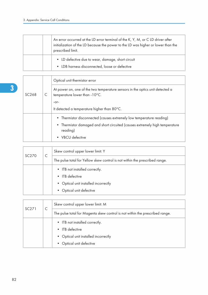
An error occurred at the LD error terminal of the K, Y, M, or C LD driver afterinitialization of the LD because the power to the LD was higher or lower than theprescribed limit.
• LD defective due to wear, damage, short circuit
• LDB harness disconnected, loose or defective
SC268 C
Optical unit thermistor error
At power on, one of the two temperature sensors in the optics unit detected atemperature lower than -10°C.
-or-
It detected a temperature higher than 80°C.
• Thermistor disconnected (causes extremely low temperature reading)
• Thermistor damaged and short circuited (causes extremely high temperaturereading)
• VBCU defective
SC270 CSkew control upper lower limit: Y
The pulse total for Yellow skew control is not within the prescribed range.
• ITB not installed correctly.
• ITB defective
• Optical unit installed incorrectly
• Optical unit defective
SC271 CSkew control upper lower limit: M
The pulse total for Magenta skew control is not within the prescribed range.
• ITB not installed correctly.
• ITB defective
• Optical unit installed incorrectly
• Optical unit defective
3. Appendix: Service Call Conditions
82
3
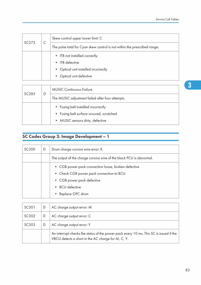
SC272 CSkew control upper lower limit: C
The pulse total for Cyan skew control is not within the prescribed range.
• ITB not installed correctly.
• ITB defective
• Optical unit installed incorrectly
• Optical unit defective
SC285 DMUSIC Continuous Failure
The MUSIC adjustment failed after four attempts.
• Fusing belt installed incorrectly
• Fusing belt surface scoured, scratched
• MUSIC sensors dirty, defective
SC Codes Group 3: Image Development – 1
SC300 D Drum charge corona wire error: K
The output of the charge corona wire of the black PCU is abnormal.
• CGB power pack connection loose, broken defective
• Check CGB power pack connection to BCU
• CGB power pack defective
• BCU defective
• Replace OPC drum
SC301 D AC charge output error: M
SC302 D AC charge output error: C
SC303 D AC charge output error: Y
An interrupt checks the status of the power pack every 10 ms. This SC is issued if theVBCU detects a short in the AC charge for M, C, Y.
Service Call Tables
83
3
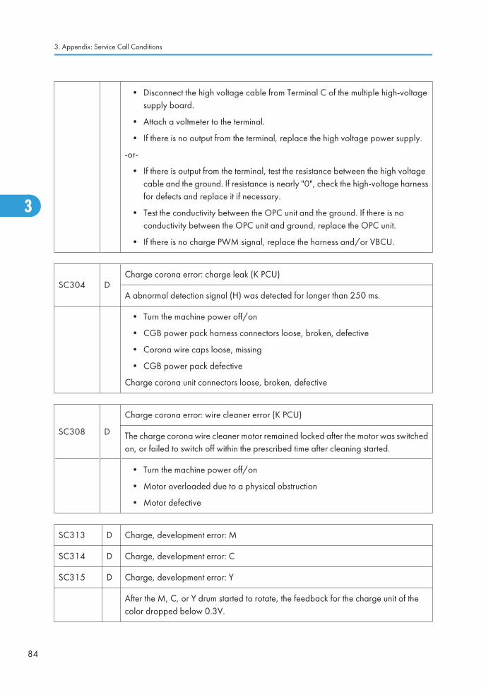
• Disconnect the high voltage cable from Terminal C of the multiple high-voltagesupply board.
• Attach a voltmeter to the terminal.
• If there is no output from the terminal, replace the high voltage power supply.
-or-
• If there is output from the terminal, test the resistance between the high voltagecable and the ground. If resistance is nearly "0", check the high-voltage harnessfor defects and replace it if necessary.
• Test the conductivity between the OPC unit and the ground. If there is noconductivity between the OPC unit and ground, replace the OPC unit.
• If there is no charge PWM signal, replace the harness and/or VBCU.
SC304 DCharge corona error: charge leak (K PCU)
A abnormal detection signal (H) was detected for longer than 250 ms.
• Turn the machine power off/on
• CGB power pack harness connectors loose, broken, defective
• Corona wire caps loose, missing
• CGB power pack defective
Charge corona unit connectors loose, broken, defective
SC308 D
Charge corona error: wire cleaner error (K PCU)
The charge corona wire cleaner motor remained locked after the motor was switchedon, or failed to switch off within the prescribed time after cleaning started.
• Turn the machine power off/on
• Motor overloaded due to a physical obstruction
• Motor defective
SC313 D Charge, development error: M
SC314 D Charge, development error: C
SC315 D Charge, development error: Y
After the M, C, or Y drum started to rotate, the feedback for the charge unit of thecolor dropped below 0.3V.
3. Appendix: Service Call Conditions
84
3
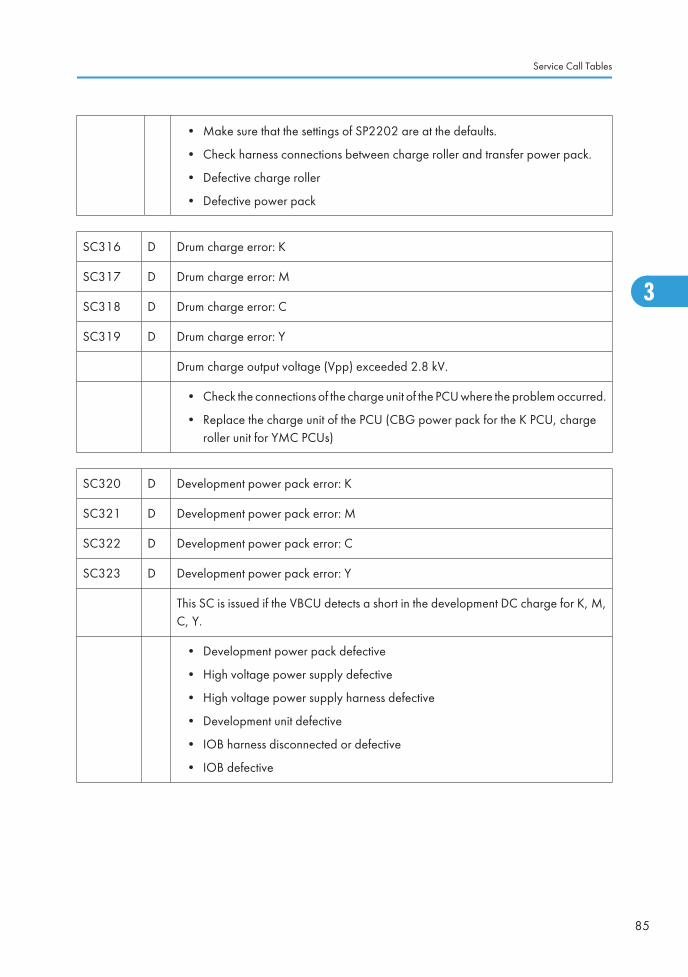
• Make sure that the settings of SP2202 are at the defaults.
• Check harness connections between charge roller and transfer power pack.
• Defective charge roller
• Defective power pack
SC316 D Drum charge error: K
SC317 D Drum charge error: M
SC318 D Drum charge error: C
SC319 D Drum charge error: Y
Drum charge output voltage (Vpp) exceeded 2.8 kV.
• Check the connections of the charge unit of the PCU where the problem occurred.
• Replace the charge unit of the PCU (CBG power pack for the K PCU, chargeroller unit for YMC PCUs)
SC320 D Development power pack error: K
SC321 D Development power pack error: M
SC322 D Development power pack error: C
SC323 D Development power pack error: Y
This SC is issued if the VBCU detects a short in the development DC charge for K, M,C, Y.
• Development power pack defective
• High voltage power supply defective
• High voltage power supply harness defective
• Development unit defective
• IOB harness disconnected or defective
• IOB defective
Service Call Tables
85
3
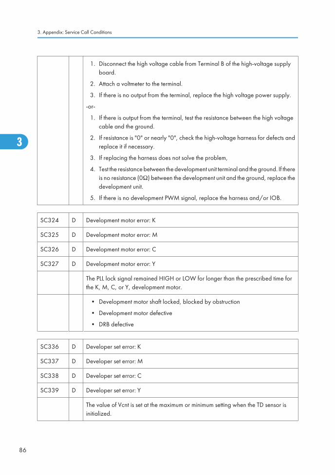
1. Disconnect the high voltage cable from Terminal B of the high-voltage supplyboard.
2. Attach a voltmeter to the terminal.
3. If there is no output from the terminal, replace the high voltage power supply.
-or-
1. If there is output from the terminal, test the resistance between the high voltagecable and the ground.
2. If resistance is "0" or nearly "0", check the high-voltage harness for defects andreplace it if necessary.
3. If replacing the harness does not solve the problem,
4. Test the resistance between the development unit terminal and the ground. If thereis no resistance (0Ω) between the development unit and the ground, replace thedevelopment unit.
5. If there is no development PWM signal, replace the harness and/or IOB.
SC324 D Development motor error: K
SC325 D Development motor error: M
SC326 D Development motor error: C
SC327 D Development motor error: Y
The PLL lock signal remained HIGH or LOW for longer than the prescribed time forthe K, M, C, or Y, development motor.
• Development motor shaft locked, blocked by obstruction
• Development motor defective
• DRB defective
SC336 D Developer set error: K
SC337 D Developer set error: M
SC338 D Developer set error: C
SC339 D Developer set error: Y
The value of Vcnt is set at the maximum or minimum setting when the TD sensor isinitialized.
3. Appendix: Service Call Conditions
86
3
Ed
Typewritten Text
SC324-327 RTB 101
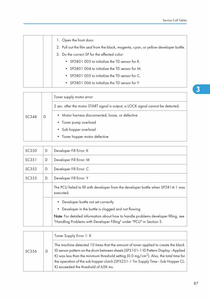
1. Open the front door.
2. Pull out the film seal from the black, magenta, cyan, or yellow developer bottle.
3. Do the correct SP for the affected color:
• SP3801 003 to initialize the TD sensor for K.
• SP3801 004 to initialize the TD sensor for M.
• SP3801 005 to initialize the TD sensor for C.
• SP3801 006 to initialize the TD sensor for Y
SC348 D
Toner supply motor error
2 sec. after the motor START signal is output, a LOCK signal cannot be detected.
• Motor harness disconnected, loose, or defective
• Toner pump overload
• Sub hopper overload
• Toner hopper motor defective
SC350 D Developer Fill Error: K
SC351 D Developer Fill Error: M
SC352 D Developer Fill Error: C
SC353 D Developer Fill Error: Y
The PCU failed to fill with developer from the developer bottle when SP3814-1 wasexecuted.
• Developer bottle not set correctly
• Developer in the bottle is clogged and not flowing
Note: For detailed information about how to handle problems developer filling, see"Handling Problems with Developer Filling" under "PCU" in Section 3.
SC356 D
Toner Supply Error 1: K
The machine detected 10 times that the amount of toner applied to create the blackID sensor pattern on the drum between sheets (SP3101-1 ID Pattern Display - AppliedK) was less than the minimum threshold setting (0.0 mg/cm2). Also, the total time forthe operation of the sub hopper clutch (SP3251-1 Tnr Supply Time - Sub Hopper CL:K) exceeded the threshold of 65K ms.
Service Call Tables
87
3

• Toner end sensor cleaning spring broken, mechanism defective
• Toner end sensor loose, broken, or defective
• Replace toner supply unit
SC357 D
Toner Supply Error 2: M
The machine detected 10 times that the amount of toner applied to create the magentaID sensor pattern on the drum between sheets (SP3101-2 ID Pattern Display - AppliedM) was less than the minimum threshold setting (0.0 mg/cm2). Also, the total time forthe operation of the sub hopper clutch (SP3251-2 Tnr Supply Time - Sub Hopper CL:M) exceeded the threshold of 65K ms.
• Toner end sensor cleaning spring broken, mechanism defective
• Toner end sensor loose, broken, or defective
• Replace toner supply unit
SC358 D
Toner Supply Error 3: C
The machine detected 10 times that the amount of toner applied to create the cyanID sensor pattern on the drum between sheets (SP3101-3 ID Pattern Display - AppliedC) was less than the minimum threshold setting (0.0 mg/cm2). Also, the total time forthe operation of the sub hopper clutch (SP3251-3 Tnr Supply Time - Sub Hopper CL:C) exceeded the threshold of 65K ms.
• Toner end sensor cleaning spring broken, mechanism defective
• Toner end sensor loose, broken, or defective
• Replace toner supply unit
SC359 D
Toner Supply Error 4: Y
The machine detected 10 times that the amount of toner applied to create the yellowID sensor pattern on the drum between sheets (SP3101-4 ID Pattern Display - AppliedY) was less than the minimum threshold setting (0.0 mg/cm2). Also, the total time forthe operation of the sub hopper clutch (SP3251-4 Tnr Supply Time - Sub Hopper CL:Y) exceeded the threshold of 65K ms.
• Toner end sensor cleaning spring broken, mechanism defective
• Toner end sensor loose, broken, or defective
• Replace toner supply unit
3. Appendix: Service Call Conditions
88
3
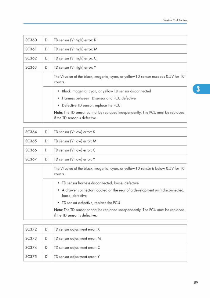
SC360 D TD sensor (Vt high) error: K
SC361 D TD sensor (Vt high) error: M
SC362 D TD sensor (Vt high) error: C
SC363 D TD sensor (Vt high) error: Y
The Vt value of the black, magenta, cyan, or yellow TD sensor exceeds 0.5V for 10counts.
• Black, magenta, cyan, or yellow TD sensor disconnected
• Harness between TD sensor and PCU defective
• Defective TD sensor, replace the PCU
Note: The TD sensor cannot be replaced independently. The PCU must be replacedif the TD sensor is defective.
SC364 D TD sensor (Vt low) error: K
SC365 D TD sensor (Vt low) error: M
SC366 D TD sensor (Vt low) error: C
SC367 D TD sensor (Vt low) error: Y
The Vt value of the black, magenta, cyan, or yellow TD sensor is below 0.5V for 10counts.
• TD sensor harness disconnected, loose, defective
• A drawer connector (located on the rear of a development unit) disconnected,loose, defective
• TD sensor defective, replace the PCU
Note: The TD sensor cannot be replaced independently. The PCU must be replacedif the TD sensor is defective.
SC372 D TD sensor adjustment error: K
SC373 D TD sensor adjustment error: M
SC374 D TD sensor adjustment error: C
SC375 D TD sensor adjustment error: Y
Service Call Tables
89
3
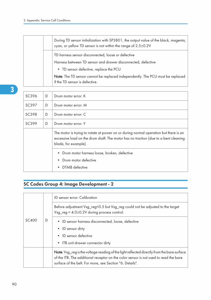
During TD sensor initialization with SP3801, the output value of the black, magenta,cyan, or yellow TD sensor is not within the range of 2.5±0.2V
TD harness sensor disconnected, loose or defective
Harness between TD sensor and drawer disconnected, defective
• TD sensor defective, replace the PCU
Note: The TD sensor cannot be replaced independently. The PCU must be replacedif the TD sensor is defective.
SC396 D Drum motor error: K
SC397 D Drum motor error: M
SC398 D Drum motor error: C
SC399 D Drum motor error: Y
The motor is trying to rotate at power on or during normal operation but there is anexcessive load on the drum shaft. The motor has no traction (due to a bent cleaningblade, for example).
• Drum motor harness loose, broken, defective
• Drum motor defective
• DTMB defective
SC Codes Group 4: Image Development - 2
SC400 D
ID sensor error: Calibration
Before adjustment Vsg_reg<0.5 but Vsg_reg could not be adjusted to the targetVsg_reg = 4.0±0.2V during process control.
• ID sensor harness disconnected, loose, defective
• ID sensor dirty
• ID sensor defective
• ITB unit drawer connector dirty
Note: Vsg_reg is the voltage reading of the light reflected directly from the bare surfaceof the ITB. The additional receptor on the color sensor is not used to read the baresurface of the belt. For more, see Section "6. Details".
3. Appendix: Service Call Conditions
90
3
Ed
Typewritten Text
SC 4xx RTB 25
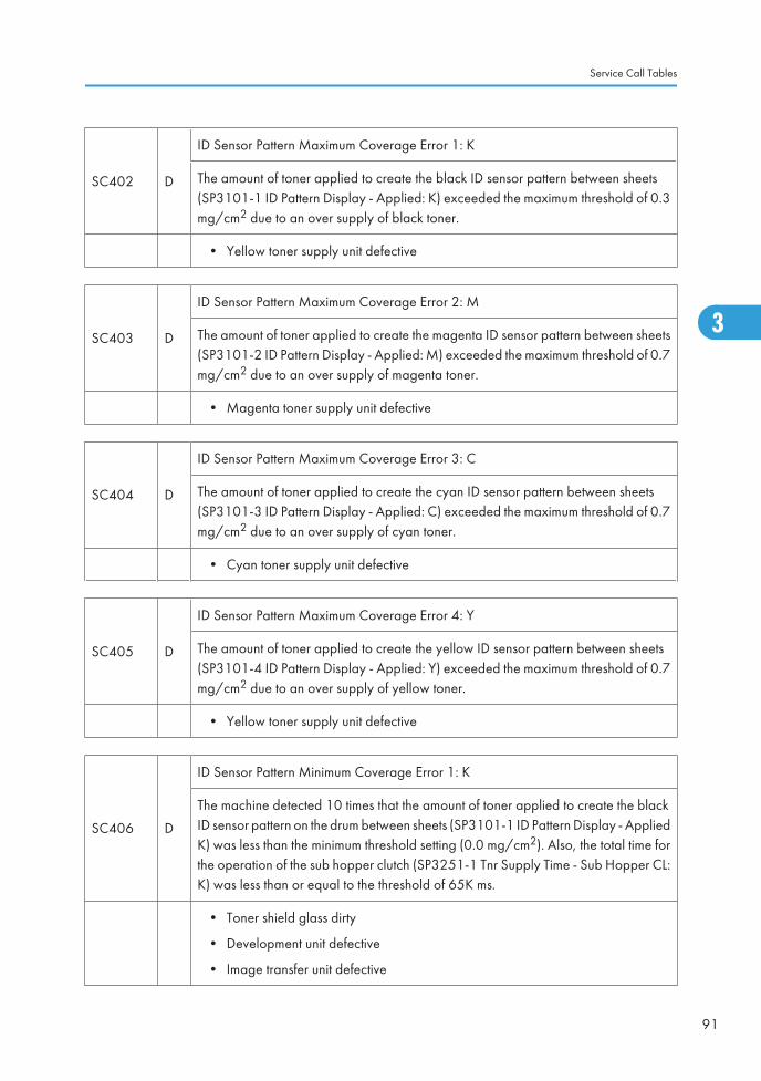
SC402 D
ID Sensor Pattern Maximum Coverage Error 1: K
The amount of toner applied to create the black ID sensor pattern between sheets(SP3101-1 ID Pattern Display - Applied: K) exceeded the maximum threshold of 0.3mg/cm2 due to an over supply of black toner.
• Yellow toner supply unit defective
SC403 D
ID Sensor Pattern Maximum Coverage Error 2: M
The amount of toner applied to create the magenta ID sensor pattern between sheets(SP3101-2 ID Pattern Display - Applied: M) exceeded the maximum threshold of 0.7mg/cm2 due to an over supply of magenta toner.
• Magenta toner supply unit defective
SC404 D
ID Sensor Pattern Maximum Coverage Error 3: C
The amount of toner applied to create the cyan ID sensor pattern between sheets(SP3101-3 ID Pattern Display - Applied: C) exceeded the maximum threshold of 0.7mg/cm2 due to an over supply of cyan toner.
• Cyan toner supply unit defective
SC405 D
ID Sensor Pattern Maximum Coverage Error 4: Y
The amount of toner applied to create the yellow ID sensor pattern between sheets(SP3101-4 ID Pattern Display - Applied: Y) exceeded the maximum threshold of 0.7mg/cm2 due to an over supply of yellow toner.
• Yellow toner supply unit defective
SC406 D
ID Sensor Pattern Minimum Coverage Error 1: K
The machine detected 10 times that the amount of toner applied to create the blackID sensor pattern on the drum between sheets (SP3101-1 ID Pattern Display - AppliedK) was less than the minimum threshold setting (0.0 mg/cm2). Also, the total time forthe operation of the sub hopper clutch (SP3251-1 Tnr Supply Time - Sub Hopper CL:K) was less than or equal to the threshold of 65K ms.
• Toner shield glass dirty
• Development unit defective
• Image transfer unit defective
Service Call Tables
91
3
Ed
Typewritten Text
RTB 58 Correction
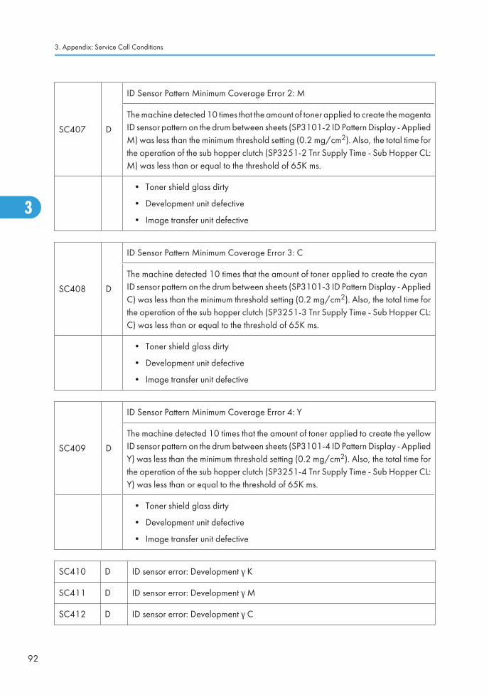
SC407 D
ID Sensor Pattern Minimum Coverage Error 2: M
The machine detected 10 times that the amount of toner applied to create the magentaID sensor pattern on the drum between sheets (SP3101-2 ID Pattern Display - AppliedM) was less than the minimum threshold setting (0.2 mg/cm2). Also, the total time forthe operation of the sub hopper clutch (SP3251-2 Tnr Supply Time - Sub Hopper CL:M) was less than or equal to the threshold of 65K ms.
• Toner shield glass dirty
• Development unit defective
• Image transfer unit defective
SC408 D
ID Sensor Pattern Minimum Coverage Error 3: C
The machine detected 10 times that the amount of toner applied to create the cyanID sensor pattern on the drum between sheets (SP3101-3 ID Pattern Display - AppliedC) was less than the minimum threshold setting (0.2 mg/cm2). Also, the total time forthe operation of the sub hopper clutch (SP3251-3 Tnr Supply Time - Sub Hopper CL:C) was less than or equal to the threshold of 65K ms.
• Toner shield glass dirty
• Development unit defective
• Image transfer unit defective
SC409 D
ID Sensor Pattern Minimum Coverage Error 4: Y
The machine detected 10 times that the amount of toner applied to create the yellowID sensor pattern on the drum between sheets (SP3101-4 ID Pattern Display - AppliedY) was less than the minimum threshold setting (0.2 mg/cm2). Also, the total time forthe operation of the sub hopper clutch (SP3251-4 Tnr Supply Time - Sub Hopper CL:Y) was less than or equal to the threshold of 65K ms.
• Toner shield glass dirty
• Development unit defective
• Image transfer unit defective
SC410 D ID sensor error: Development γ K
SC411 D ID sensor error: Development γ M
SC412 D ID sensor error: Development γ C
3. Appendix: Service Call Conditions
92
3
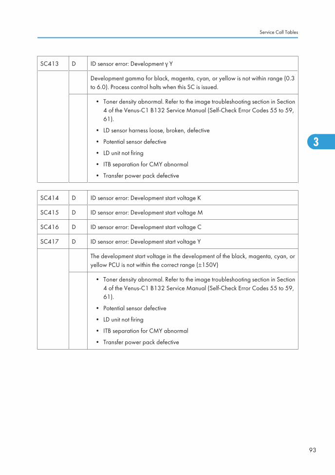
SC413 D ID sensor error: Development γ Y
Development gamma for black, magenta, cyan, or yellow is not within range (0.3to 6.0). Process control halts when this SC is issued.
• Toner density abnormal. Refer to the image troubleshooting section in Section4 of the Venus-C1 B132 Service Manual (Self-Check Error Codes 55 to 59,61).
• LD sensor harness loose, broken, defective
• Potential sensor defective
• LD unit not firing
• ITB separation for CMY abnormal
• Transfer power pack defective
SC414 D ID sensor error: Development start voltage K
SC415 D ID sensor error: Development start voltage M
SC416 D ID sensor error: Development start voltage C
SC417 D ID sensor error: Development start voltage Y
The development start voltage in the development of the black, magenta, cyan, oryellow PCU is not within the correct range (±150V)
• Toner density abnormal. Refer to the image troubleshooting section in Section4 of the Venus-C1 B132 Service Manual (Self-Check Error Codes 55 to 59,61).
• Potential sensor defective
• LD unit not firing
• ITB separation for CMY abnormal
• Transfer power pack defective
Service Call Tables
93
3

SC418 C
LED error during Vsg adjustment
PWM value: Ifsg>3000
This means one or more of the following sensors is not functioning correctly:
• ITB encoder sensor
• ID sensor
• MUSIC sensors
• ID sensor dirty
• ID sensor defective
Note:
• This error can occur as a result of cleaning the sensors with a dry cloth, whichcan cause a static charge to build up on the sensor and attract particles ofpaper dust.
• Always clean these with a clean cloth moistened with alcohol as described inthe PM table.
SC420 C Potential sensor error: Vd Adjustment K
SC421 C Potential sensor error: Vd Adjustment M
SC422 C Potential sensor error: Vd Adjustment C
SC423 C Potential sensor error: Vd Adjustment Y
The development potential of the drum before exposure (Vd) cannot be adjusted towithin ±8 V of the target voltage (-900V).
• Drum potential sensor harness, connector is loose, broken, defective
• Drum potential sensor dirty
• Drum potential sensor defective
• Drum connector, harness loose, broken, defective
• Development power pack defective
• VBCU defective
SC424 C Potential sensor error 5: Vl adjustment K
SC425 C Potential sensor error 6: Vl adjustment M
SC426 C Potential sensor error 7: Vl adjustment C
3. Appendix: Service Call Conditions
94
3
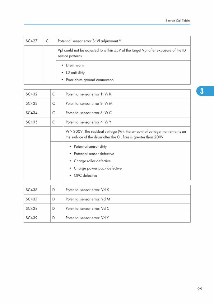
SC427 C Potential sensor error 8: Vl adjustment Y
Vpl could not be adjusted to within ±5V of the target Vpl after exposure of the IDsensor patterns.
• Drum worn
• LD unit dirty
• Poor drum ground connection
SC432 C Potential sensor error 1: Vr K
SC433 C Potential sensor error 2: Vr M
SC434 C Potential sensor error 3: Vr C
SC435 C Potential sensor error 4: Vr Y
Vr > 200V. The residual voltage (Vr), the amount of voltage that remains onthe surface of the drum after the QL fires is greater than 200V.
• Potential sensor dirty
• Potential sensor defective
• Charge roller defective
• Charge power pack defective
• OPC defective
SC436 D Potential sensor error: Vd K
SC437 D Potential sensor error: Vd M
SC438 D Potential sensor error: Vd C
SC439 D Potential sensor error: Vd Y
Service Call Tables
95
3
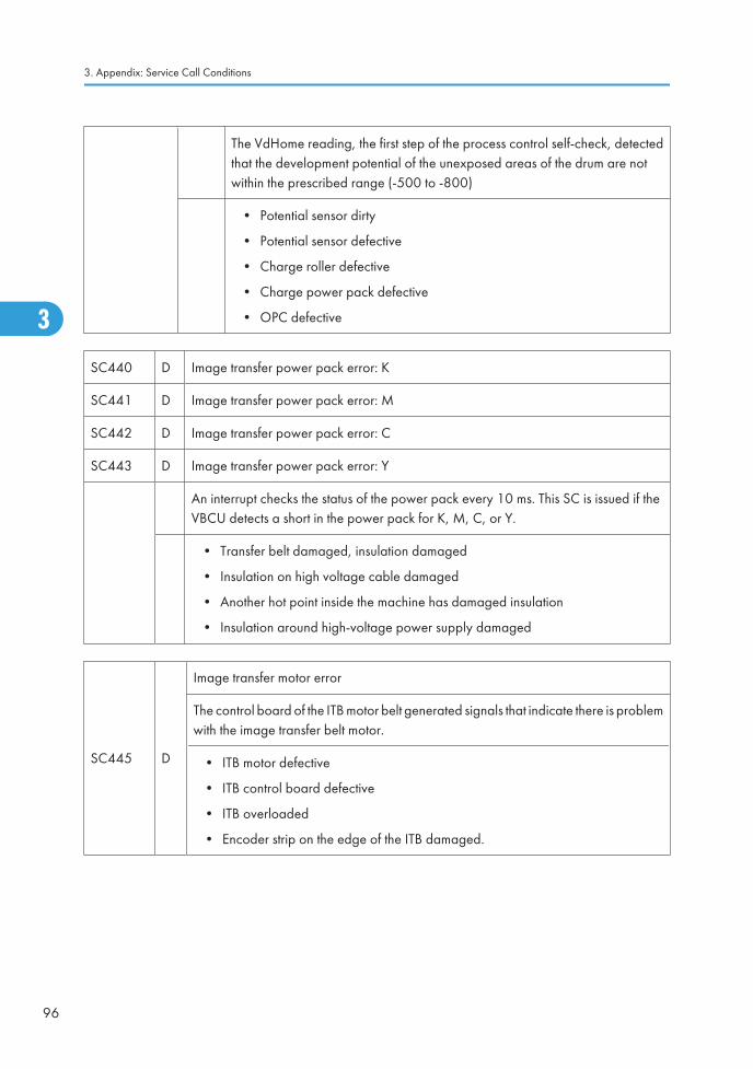
The VdHome reading, the first step of the process control self-check, detectedthat the development potential of the unexposed areas of the drum are notwithin the prescribed range (-500 to -800)
• Potential sensor dirty
• Potential sensor defective
• Charge roller defective
• Charge power pack defective
• OPC defective
SC440 D Image transfer power pack error: K
SC441 D Image transfer power pack error: M
SC442 D Image transfer power pack error: C
SC443 D Image transfer power pack error: Y
An interrupt checks the status of the power pack every 10 ms. This SC is issued if theVBCU detects a short in the power pack for K, M, C, or Y.
• Transfer belt damaged, insulation damaged
• Insulation on high voltage cable damaged
• Another hot point inside the machine has damaged insulation
• Insulation around high-voltage power supply damaged
SC445 D
Image transfer motor error
The control board of the ITB motor belt generated signals that indicate there is problemwith the image transfer belt motor.
• ITB motor defective
• ITB control board defective
• ITB overloaded
• Encoder strip on the edge of the ITB damaged.
3. Appendix: Service Call Conditions
96
3
Ed
Typewritten Text
SC445 RTB 101
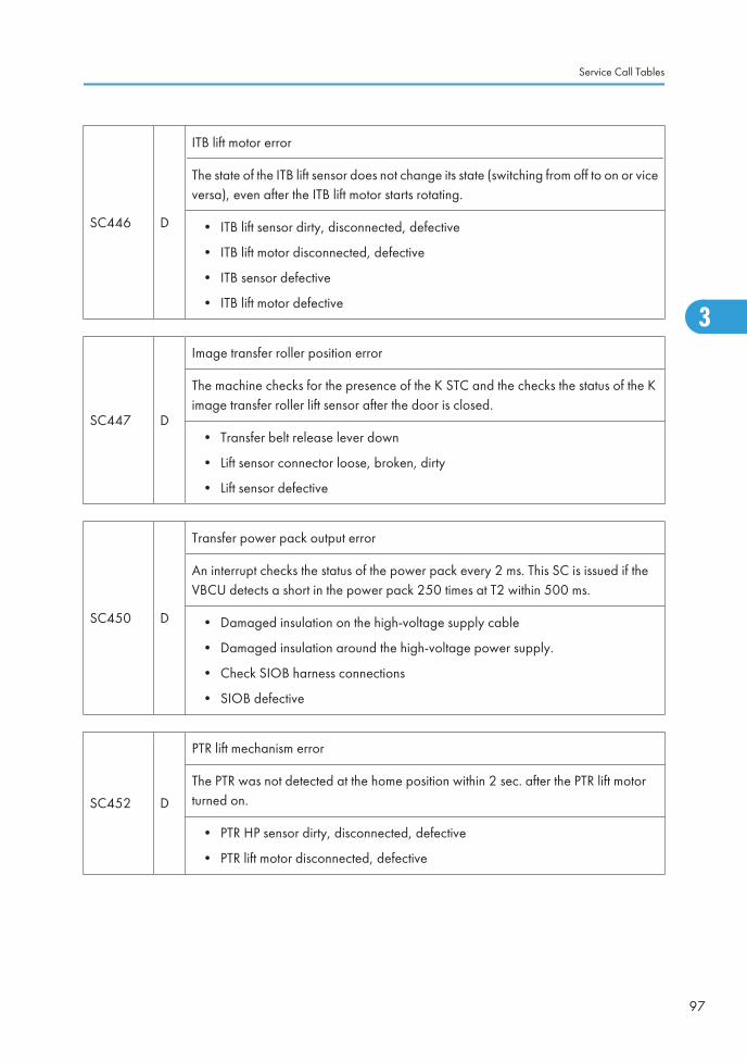
SC446 D
ITB lift motor error
The state of the ITB lift sensor does not change its state (switching from off to on or viceversa), even after the ITB lift motor starts rotating.
• ITB lift sensor dirty, disconnected, defective
• ITB lift motor disconnected, defective
• ITB sensor defective
• ITB lift motor defective
SC447 D
Image transfer roller position error
The machine checks for the presence of the K STC and the checks the status of the Kimage transfer roller lift sensor after the door is closed.
• Transfer belt release lever down
• Lift sensor connector loose, broken, dirty
• Lift sensor defective
SC450 D
Transfer power pack output error
An interrupt checks the status of the power pack every 2 ms. This SC is issued if theVBCU detects a short in the power pack 250 times at T2 within 500 ms.
• Damaged insulation on the high-voltage supply cable
• Damaged insulation around the high-voltage power supply.
• Check SIOB harness connections
• SIOB defective
SC452 D
PTR lift mechanism error
The PTR was not detected at the home position within 2 sec. after the PTR lift motorturned on.
• PTR HP sensor dirty, disconnected, defective
• PTR lift motor disconnected, defective
Service Call Tables
97
3
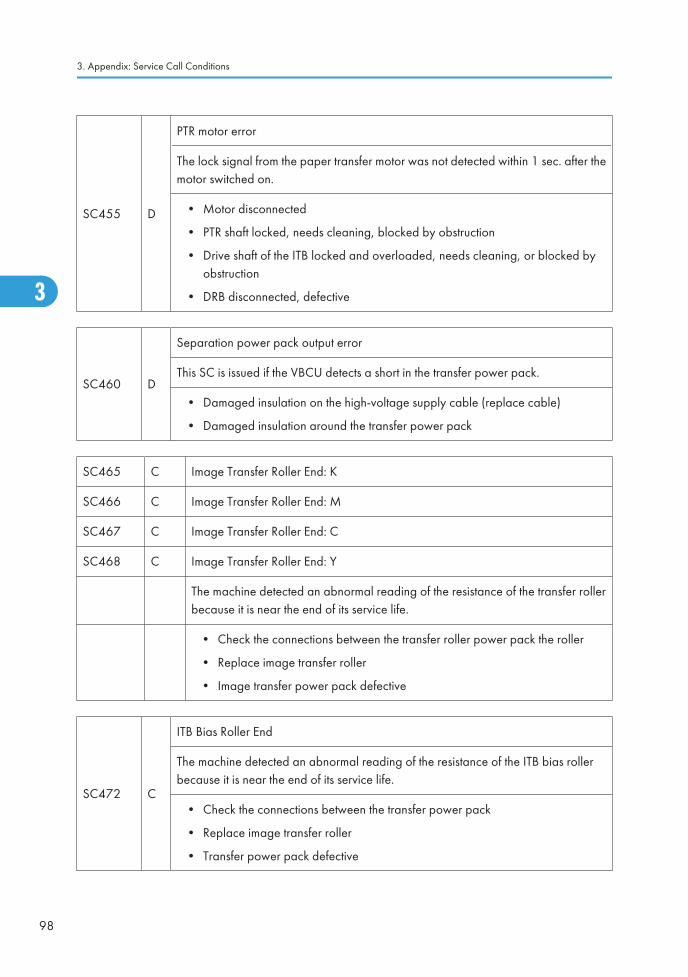
SC455 D
PTR motor error
The lock signal from the paper transfer motor was not detected within 1 sec. after themotor switched on.
• Motor disconnected
• PTR shaft locked, needs cleaning, blocked by obstruction
• Drive shaft of the ITB locked and overloaded, needs cleaning, or blocked byobstruction
• DRB disconnected, defective
SC460 D
Separation power pack output error
This SC is issued if the VBCU detects a short in the transfer power pack.
• Damaged insulation on the high-voltage supply cable (replace cable)
• Damaged insulation around the transfer power pack
SC465 C Image Transfer Roller End: K
SC466 C Image Transfer Roller End: M
SC467 C Image Transfer Roller End: C
SC468 C Image Transfer Roller End: Y
The machine detected an abnormal reading of the resistance of the transfer rollerbecause it is near the end of its service life.
• Check the connections between the transfer roller power pack the roller
• Replace image transfer roller
• Image transfer power pack defective
SC472 C
ITB Bias Roller End
The machine detected an abnormal reading of the resistance of the ITB bias rollerbecause it is near the end of its service life.
• Check the connections between the transfer power pack
• Replace image transfer roller
• Transfer power pack defective
3. Appendix: Service Call Conditions
98
3
Ed
Typewritten Text
SC455 RTB 101
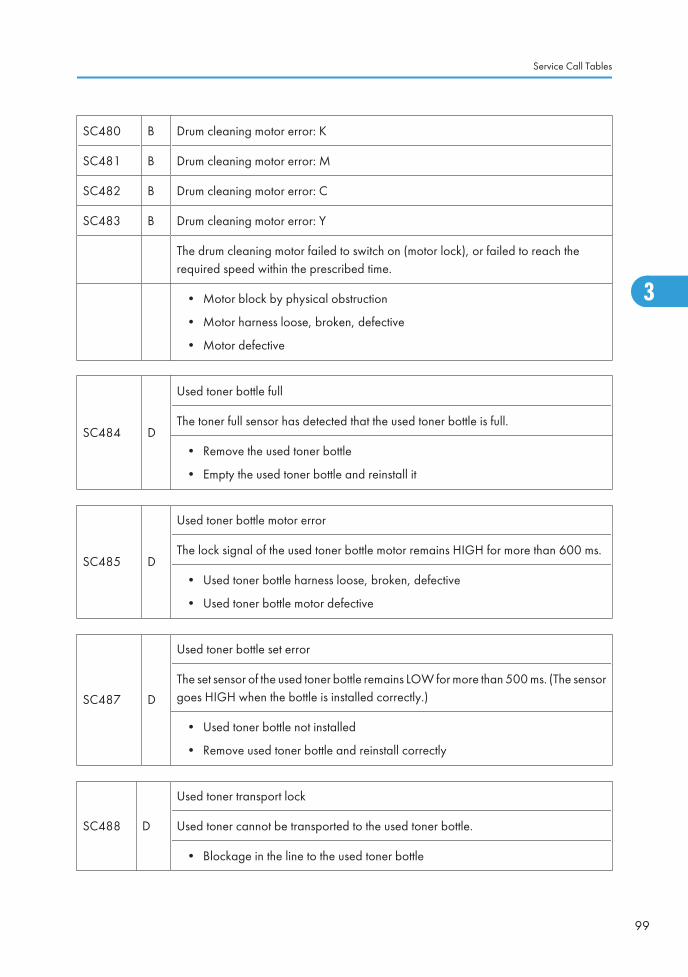
SC480 B Drum cleaning motor error: K
SC481 B Drum cleaning motor error: M
SC482 B Drum cleaning motor error: C
SC483 B Drum cleaning motor error: Y
The drum cleaning motor failed to switch on (motor lock), or failed to reach therequired speed within the prescribed time.
• Motor block by physical obstruction
• Motor harness loose, broken, defective
• Motor defective
SC484 D
Used toner bottle full
The toner full sensor has detected that the used toner bottle is full.
• Remove the used toner bottle
• Empty the used toner bottle and reinstall it
SC485 D
Used toner bottle motor error
The lock signal of the used toner bottle motor remains HIGH for more than 600 ms.
• Used toner bottle harness loose, broken, defective
• Used toner bottle motor defective
SC487 D
Used toner bottle set error
The set sensor of the used toner bottle remains LOW for more than 500 ms. (The sensorgoes HIGH when the bottle is installed correctly.)
• Used toner bottle not installed
• Remove used toner bottle and reinstall correctly
SC488 D
Used toner transport lock
Used toner cannot be transported to the used toner bottle.
• Blockage in the line to the used toner bottle
Service Call Tables
99
3
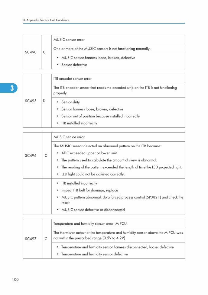
SC490 C
MUSIC sensor error
One or more of the MUSIC sensors is not functioning normally.
• MUSIC sensor harness loose, broken, defective
• Sensor defective
SC495 D
ITB encoder sensor error
The ITB encoder sensor that reads the encoded strip on the ITB is not functioningproperly.
• Sensor dirty
• Sensor harness loose, broken, defective
• Sensor out of position because installed incorrectly
• ITB installed incorrectly
SC496 C
MUSIC sensor error
The MUSIC sensor detected an abnormal pattern on the ITB because:
• ADC exceeded upper or lower limit.
• The pattern used to calculate the amount of skew is abnormal.
• The reading of the pattern exceeded the length of time the LED projected light.
• LED light could not be adjusted correctly.
• ITB installed incorrectly
• Inspect ITB belt for damage, replace
• MUSIC pattern abnormal; do a forced process control (SP3821) and check theresult.
• MUSIC sensor defective or disconnected
SC497 C
Temperature and humidity sensor error: M PCU
The thermistor output of the temperature and humidity sensor above the M PCU wasnot within the prescribed range (0.5V to 4.2V)
• Temperature and humidity sensor harness disconnected, loose, defective
• Temperature and humidity sensor defective
3. Appendix: Service Call Conditions
100
3
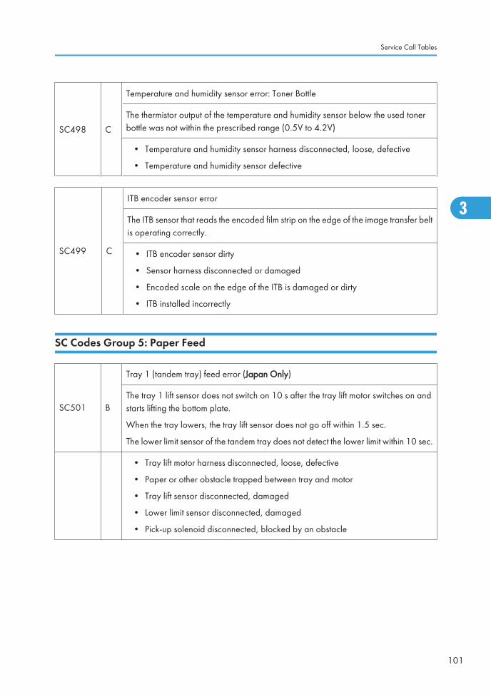
SC498 C
Temperature and humidity sensor error: Toner Bottle
The thermistor output of the temperature and humidity sensor below the used tonerbottle was not within the prescribed range (0.5V to 4.2V)
• Temperature and humidity sensor harness disconnected, loose, defective
• Temperature and humidity sensor defective
SC499 C
ITB encoder sensor error
The ITB sensor that reads the encoded film strip on the edge of the image transfer beltis operating correctly.
• ITB encoder sensor dirty
• Sensor harness disconnected or damaged
• Encoded scale on the edge of the ITB is damaged or dirty
• ITB installed incorrectly
SC Codes Group 5: Paper Feed
SC501 B
Tray 1 (tandem tray) feed error (Japan Only)
The tray 1 lift sensor does not switch on 10 s after the tray lift motor switches on andstarts lifting the bottom plate.
When the tray lowers, the tray lift sensor does not go off within 1.5 sec.
The lower limit sensor of the tandem tray does not detect the lower limit within 10 sec.
• Tray lift motor harness disconnected, loose, defective
• Paper or other obstacle trapped between tray and motor
• Tray lift sensor disconnected, damaged
• Lower limit sensor disconnected, damaged
• Pick-up solenoid disconnected, blocked by an obstacle
Service Call Tables
101
3
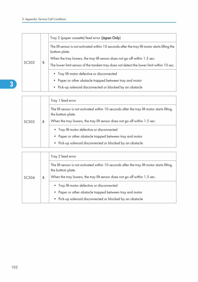
SC502 B
Tray 2 (paper cassette) feed error (Japan Only)
The lift sensor is not activated within 10 seconds after the tray lift motor starts lifting thebottom plate.
When the tray lowers, the tray lift sensor does not go off within 1.5 sec.
The lower limit sensor of the tandem tray does not detect the lower limit within 10 sec.
• Tray lift motor defective or disconnected
• Paper or other obstacle trapped between tray and motor
• Pick-up solenoid disconnected or blocked by an obstacle
SC503 B
Tray 1 feed error
The lift sensor is not activated within 10 seconds after the tray lift motor starts liftingthe bottom plate.
When the tray lowers, the tray lift sensor does not go off within 1.5 sec.
• Tray lift motor defective or disconnected
• Paper or other obstacle trapped between tray and motor
• Pick-up solenoid disconnected or blocked by an obstacle
SC504 B
Tray 2 feed error
The lift sensor is not activated within 10 seconds after the tray lift motor starts liftingthe bottom plate.
When the tray lowers, the tray lift sensor does not go off within 1.5 sec.
• Tray lift motor defective or disconnected
• Paper or other obstacle trapped between tray and motor
• Pick-up solenoid disconnected or blocked by an obstacle
3. Appendix: Service Call Conditions
102
3
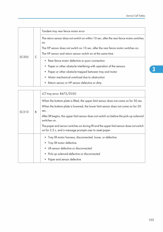
SC505 C
Tandem tray rear fence motor error
The return sensor does not switch on within 10 sec. after the rear fence motor switcheson.
The HP sensor does not switch on 10 sec. after the rear fence motor switches on.
The HP sensor and return sensor switch on at the same time.
• Rear fence motor defective or poor connection
• Paper or other obstacle interfering with operation of the sensors
• Paper or other obstacle trapped between tray and motor
• Motor mechanical overload due to obstruction
• Return sensor or HP sensor defective or dirty
SC510 B
LCT tray error: B473/D350
When the bottom plate is lifted, the upper limit sensor does not come on for 30 sec.
When the bottom plate is lowered, the lower limit sensor does not come on for 30sec.
After lift begins, the upper limit sensor does not switch on before the pick-up solenoidswitches on.
The paper end sensor switches on during lift and the upper limit sensor does not switchon for 2.5 s, and a message prompts user to reset paper.
• Tray lift motor harness, disconnected, loose, or defective
• Tray lift motor defective
• Lift sensor defective or disconnected
• Pick-up solenoid defective or disconnected
• Paper end sensor defective
Service Call Tables
103
3
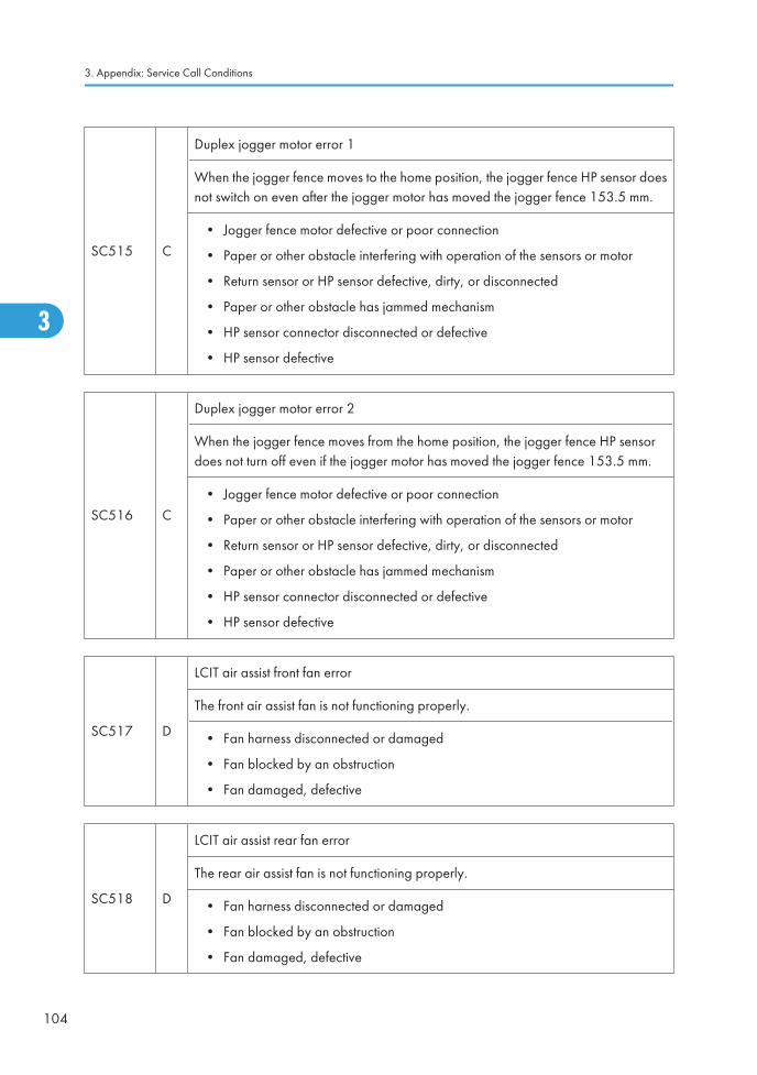
SC515 C
Duplex jogger motor error 1
When the jogger fence moves to the home position, the jogger fence HP sensor doesnot switch on even after the jogger motor has moved the jogger fence 153.5 mm.
• Jogger fence motor defective or poor connection
• Paper or other obstacle interfering with operation of the sensors or motor
• Return sensor or HP sensor defective, dirty, or disconnected
• Paper or other obstacle has jammed mechanism
• HP sensor connector disconnected or defective
• HP sensor defective
SC516 C
Duplex jogger motor error 2
When the jogger fence moves from the home position, the jogger fence HP sensordoes not turn off even if the jogger motor has moved the jogger fence 153.5 mm.
• Jogger fence motor defective or poor connection
• Paper or other obstacle interfering with operation of the sensors or motor
• Return sensor or HP sensor defective, dirty, or disconnected
• Paper or other obstacle has jammed mechanism
• HP sensor connector disconnected or defective
• HP sensor defective
SC517 D
LCIT air assist front fan error
The front air assist fan is not functioning properly.
• Fan harness disconnected or damaged
• Fan blocked by an obstruction
• Fan damaged, defective
SC518 D
LCIT air assist rear fan error
The rear air assist fan is not functioning properly.
• Fan harness disconnected or damaged
• Fan blocked by an obstruction
• Fan damaged, defective
3. Appendix: Service Call Conditions
104
3
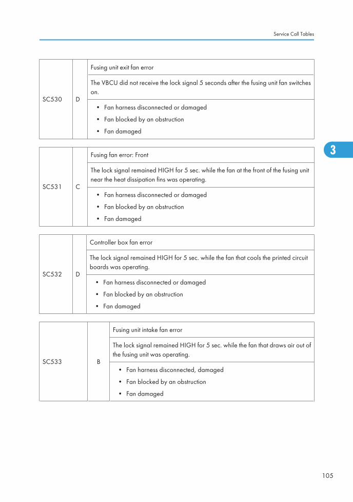
SC530 D
Fusing unit exit fan error
The VBCU did not receive the lock signal 5 seconds after the fusing unit fan switcheson.
• Fan harness disconnected or damaged
• Fan blocked by an obstruction
• Fan damaged
SC531 C
Fusing fan error: Front
The lock signal remained HIGH for 5 sec. while the fan at the front of the fusing unitnear the heat dissipation fins was operating.
• Fan harness disconnected or damaged
• Fan blocked by an obstruction
• Fan damaged
SC532 D
Controller box fan error
The lock signal remained HIGH for 5 sec. while the fan that cools the printed circuitboards was operating.
• Fan harness disconnected or damaged
• Fan blocked by an obstruction
• Fan damaged
SC533 B
Fusing unit intake fan error
The lock signal remained HIGH for 5 sec. while the fan that draws air out ofthe fusing unit was operating.
• Fan harness disconnected, damaged
• Fan blocked by an obstruction
• Fan damaged
Service Call Tables
105
3
Ed
Typewritten Text
SC530 RTB 84: Modified
Ed
Typewritten Text
SC531 RTB 84: Modified
Ed
Typewritten Text
SC533 RTB 84: Modified
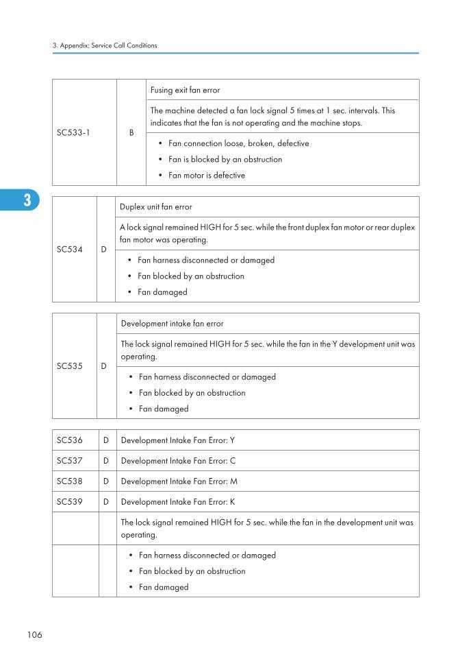
SC533-1 B
Fusing exit fan error
The machine detected a fan lock signal 5 times at 1 sec. intervals. Thisindicates that the fan is not operating and the machine stops.
• Fan connection loose, broken, defective
• Fan is blocked by an obstruction
• Fan motor is defective
SC534 D
Duplex unit fan error
A lock signal remained HIGH for 5 sec. while the front duplex fan motor or rear duplexfan motor was operating.
• Fan harness disconnected or damaged
• Fan blocked by an obstruction
• Fan damaged
SC535 D
Development intake fan error
The lock signal remained HIGH for 5 sec. while the fan in the Y development unit wasoperating.
• Fan harness disconnected or damaged
• Fan blocked by an obstruction
• Fan damaged
SC536 D Development Intake Fan Error: Y
SC537 D Development Intake Fan Error: C
SC538 D Development Intake Fan Error: M
SC539 D Development Intake Fan Error: K
The lock signal remained HIGH for 5 sec. while the fan in the development unit wasoperating.
• Fan harness disconnected or damaged
• Fan blocked by an obstruction
• Fan damaged
3. Appendix: Service Call Conditions
106
3
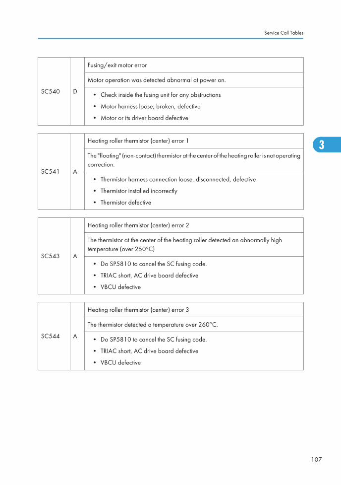
SC540 D
Fusing/exit motor error
Motor operation was detected abnormal at power on.
• Check inside the fusing unit for any obstructions
• Motor harness loose, broken, defective
• Motor or its driver board defective
SC541 A
Heating roller thermistor (center) error 1
The "floating" (non-contact) thermistor at the center of the heating roller is not operatingcorrection.
• Thermistor harness connection loose, disconnected, defective
• Thermistor installed incorrectly
• Thermistor defective
SC543 A
Heating roller thermistor (center) error 2
The thermistor at the center of the heating roller detected an abnormally hightemperature (over 250°C)
• Do SP5810 to cancel the SC fusing code.
• TRIAC short, AC drive board defective
• VBCU defective
SC544 A
Heating roller thermistor (center) error 3
The thermistor detected a temperature over 260°C.
• Do SP5810 to cancel the SC fusing code.
• TRIAC short, AC drive board defective
• VBCU defective
Service Call Tables
107
3
Ed
Typewritten Text
SC542 RTB 119
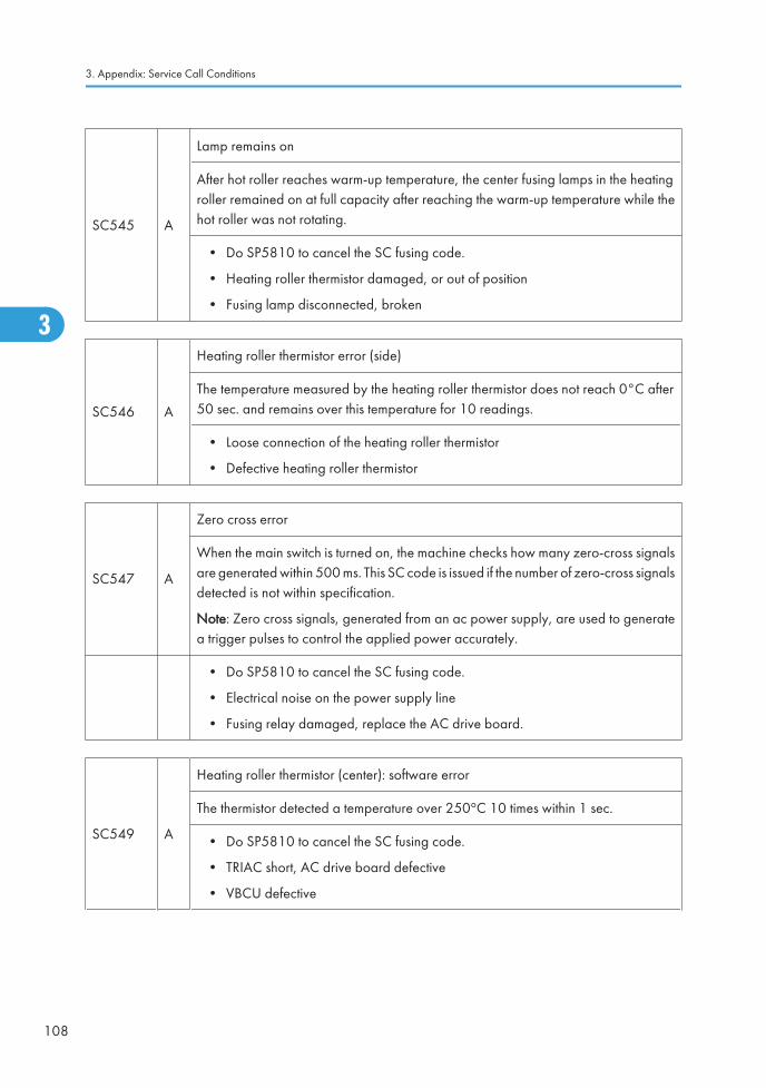
SC545 A
Lamp remains on
After hot roller reaches warm-up temperature, the center fusing lamps in the heatingroller remained on at full capacity after reaching the warm-up temperature while thehot roller was not rotating.
• Do SP5810 to cancel the SC fusing code.
• Heating roller thermistor damaged, or out of position
• Fusing lamp disconnected, broken
SC546 A
Heating roller thermistor error (side)
The temperature measured by the heating roller thermistor does not reach 0°C after50 sec. and remains over this temperature for 10 readings.
• Loose connection of the heating roller thermistor
• Defective heating roller thermistor
SC547 A
Zero cross error
When the main switch is turned on, the machine checks how many zero-cross signalsare generated within 500 ms. This SC code is issued if the number of zero-cross signalsdetected is not within specification.
Note: Zero cross signals, generated from an ac power supply, are used to generatea trigger pulses to control the applied power accurately.
• Do SP5810 to cancel the SC fusing code.
• Electrical noise on the power supply line
• Fusing relay damaged, replace the AC drive board.
SC549 A
Heating roller thermistor (center): software error
The thermistor detected a temperature over 250°C 10 times within 1 sec.
• Do SP5810 to cancel the SC fusing code.
• TRIAC short, AC drive board defective
• VBCU defective
3. Appendix: Service Call Conditions
108
3
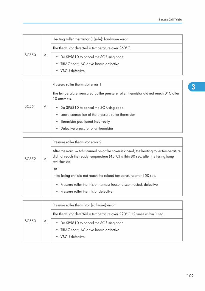
SC550 A
Heating roller thermistor 3 (side): hardware error
The thermistor detected a temperature over 260°C.
• Do SP5810 to cancel the SC fusing code.
• TRIAC short, AC drive board defective
• VBCU defective
SC551 A
Pressure roller thermistor error 1
The temperature measured by the pressure roller thermistor did not reach 0°C after10 attempts.
• Do SP5810 to cancel the SC fusing code.
• Loose connection of the pressure roller thermistor
• Thermistor positioned incorrectly
• Defective pressure roller thermistor
SC552 A
Pressure roller thermistor error 2
After the main switch is turned on or the cover is closed, the heating roller temperaturedid not reach the ready temperature (45°C) within 80 sec. after the fusing lampswitches on.
-or-
If the fusing unit did not reach the reload temperature after 350 sec.
• Pressure roller thermistor harness loose, disconnected, defective
• Pressure roller thermistor defective
SC553 A
Pressure roller thermistor (software) error
The thermistor detected a temperature over 220°C 12 times within 1 sec.
• Do SP5810 to cancel the SC fusing code.
• TRIAC short, AC drive board defective
• VBCU defective
Service Call Tables
109
3

SC554 A
Pressure roller thermistor (hardware) error
The thermistor detected a temperature over 230°C.
• Do SP5810 to cancel the SC fusing code
• TRIAC short, AC drive board defective
• VBCU defective
SC555 A
Pressure roller fusing lamp remains on
After hot roller reaches warm-up temperature, the pressure roller fusing lampremained for 300 sec. while the hot roller is not rotating.
• Do SP5810 to cancel the SC fusing code.
• Thermistor damaged, or out of position
• Fusing lamp disconnected, broken
SC556 A
Heating roller fusing lamp error
After hot roller reaches warmup temperature, the heating roller fusing lamp (ends)remains for 10 sec. while the hot roller is not rotating.
• Thermistor damaged, or out of position
• Fusing lamp disconnected, broken
SC557 A
Zero cross over error
At power on the fusing relay was detected as defective.
• Replace the AC drive board.
SC559 A
Three successive paper jams in fusing unit
This SC only occurs if SP1159 is on, and a jam occurred in the fusing unit for threeconsecutive sheets of paper. With SP1159 set to "1" the machine operation can berestored only by the service technician.
The paper cooling job time sensor detected paper late for 3 counts.
• Remove the paper that is jammed in the fusing unit.
• Make sure that the fusing unit is clean and has no obstacles in the paper feedpath.
3. Appendix: Service Call Conditions
110
3
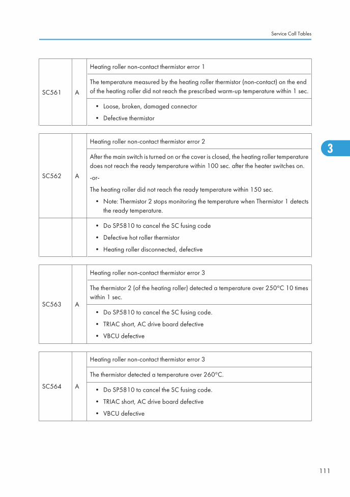
SC561 A
Heating roller non-contact thermistor error 1
The temperature measured by the heating roller thermistor (non-contact) on the endof the heating roller did not reach the prescribed warm-up temperature within 1 sec.
• Loose, broken, damaged connector
• Defective thermistor
SC562 A
Heating roller non-contact thermistor error 2
After the main switch is turned on or the cover is closed, the heating roller temperaturedoes not reach the ready temperature within 100 sec. after the heater switches on.
-or-
The heating roller did not reach the ready temperature within 150 sec.
• Note: Thermistor 2 stops monitoring the temperature when Thermistor 1 detectsthe ready temperature.
• Do SP5810 to cancel the SC fusing code
• Defective hot roller thermistor
• Heating roller disconnected, defective
SC563 A
Heating roller non-contact thermistor error 3
The thermistor 2 (of the heating roller) detected a temperature over 250°C 10 timeswithin 1 sec.
• Do SP5810 to cancel the SC fusing code.
• TRIAC short, AC drive board defective
• VBCU defective
SC564 A
Heating roller non-contact thermistor error 3
The thermistor detected a temperature over 260°C.
• Do SP5810 to cancel the SC fusing code.
• TRIAC short, AC drive board defective
• VBCU defective
Service Call Tables
111
3
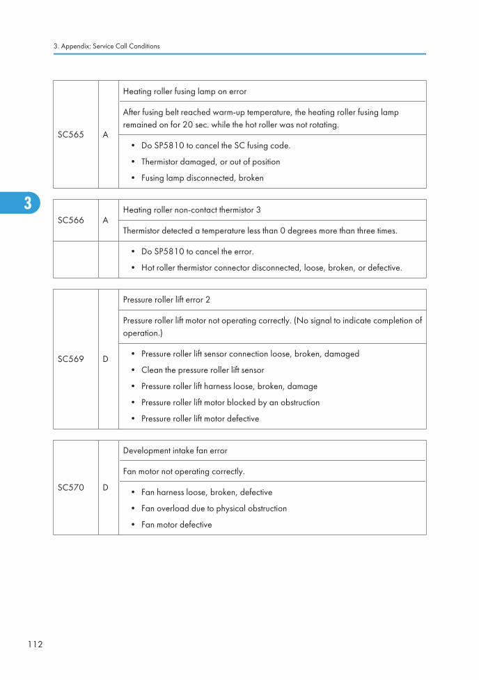
SC565 A
Heating roller fusing lamp on error
After fusing belt reached warm-up temperature, the heating roller fusing lampremained on for 20 sec. while the hot roller was not rotating.
• Do SP5810 to cancel the SC fusing code.
• Thermistor damaged, or out of position
• Fusing lamp disconnected, broken
SC566 AHeating roller non-contact thermistor 3
Thermistor detected a temperature less than 0 degrees more than three times.
• Do SP5810 to cancel the error.
• Hot roller thermistor connector disconnected, loose, broken, or defective.
SC569 D
Pressure roller lift error 2
Pressure roller lift motor not operating correctly. (No signal to indicate completion ofoperation.)
• Pressure roller lift sensor connection loose, broken, damaged
• Clean the pressure roller lift sensor
• Pressure roller lift harness loose, broken, damage
• Pressure roller lift motor blocked by an obstruction
• Pressure roller lift motor defective
SC570 D
Development intake fan error
Fan motor not operating correctly.
• Fan harness loose, broken, defective
• Fan overload due to physical obstruction
• Fan motor defective
3. Appendix: Service Call Conditions
112
3
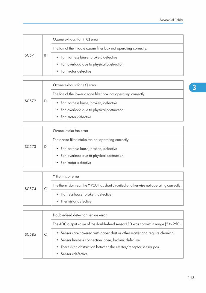
SC571 B
Ozone exhaust fan (FC) error
The fan of the middle ozone filter box not operating correctly.
• Fan harness loose, broken, defective
• Fan overload due to physical obstruction
• Fan motor defective
SC572 D
Ozone exhaust fan (K) error
The fan of the lower ozone filter box not operating correctly.
• Fan harness loose, broken, defective
• Fan overload due to physical obstruction
• Fan motor defective
SC573 D
Ozone intake fan error
The ozone filter intake fan not operating correctly.
• Fan harness loose, broken, defective
• Fan overload due to physical obstruction
• Fan motor defective
SC574 C
Y thermistor error
The thermistor near the Y PCU has short circuited or otherwise not operating correctly.
• Harness loose, broken, defective
• Thermistor defective
SC585 C
Double-feed detection sensor error
The ADC output value of the double-feed sensor LED was not within range (2 to 250).
• Sensors are covered with paper dust or other matter and require cleaning
• Sensor harness connection loose, broken, defective
• There is an obstruction between the emitter/receptor sensor pair.
• Sensors defective
Service Call Tables
113
3
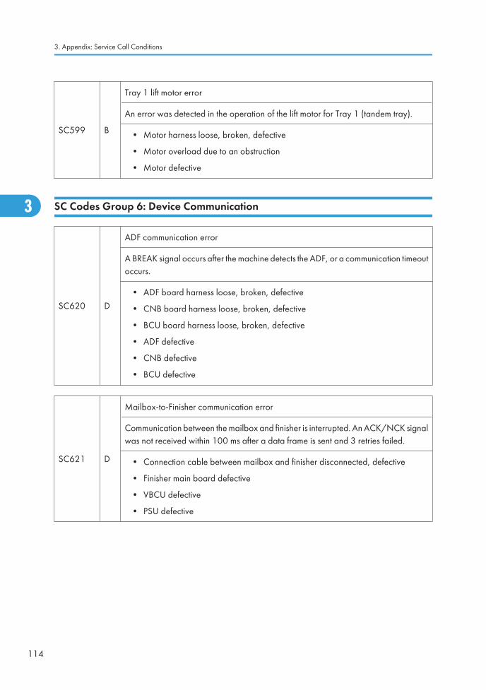
SC599 B
Tray 1 lift motor error
An error was detected in the operation of the lift motor for Tray 1 (tandem tray).
• Motor harness loose, broken, defective
• Motor overload due to an obstruction
• Motor defective
SC Codes Group 6: Device Communication
SC620 D
ADF communication error
A BREAK signal occurs after the machine detects the ADF, or a communication timeoutoccurs.
• ADF board harness loose, broken, defective
• CNB board harness loose, broken, defective
• BCU board harness loose, broken, defective
• ADF defective
• CNB defective
• BCU defective
SC621 D
Mailbox-to-Finisher communication error
Communication between the mailbox and finisher is interrupted. An ACK/NCK signalwas not received within 100 ms after a data frame is sent and 3 retries failed.
• Connection cable between mailbox and finisher disconnected, defective
• Finisher main board defective
• VBCU defective
• PSU defective
3. Appendix: Service Call Conditions
114
3
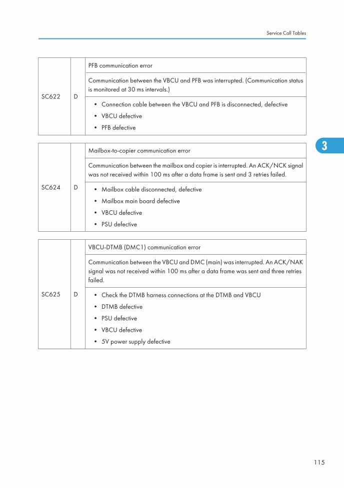
SC622 D
PFB communication error
Communication between the VBCU and PFB was interrupted. (Communication statusis monitored at 30 ms intervals.)
• Connection cable between the VBCU and PFB is disconnected, defective
• VBCU defective
• PFB defective
SC624 D
Mailbox-to-copier communication error
Communication between the mailbox and copier is interrupted. An ACK/NCK signalwas not received within 100 ms after a data frame is sent and 3 retries failed.
• Mailbox cable disconnected, defective
• Mailbox main board defective
• VBCU defective
• PSU defective
SC625 D
VBCU-DTMB (DMC1) communication error
Communication between the VBCU and DMC (main) was interrupted. An ACK/NAKsignal was not received within 100 ms after a data frame was sent and three retriesfailed.
• Check the DTMB harness connections at the DTMB and VBCU
• DTMB defective
• PSU defective
• VBCU defective
• 5V power supply defective
Service Call Tables
115
3
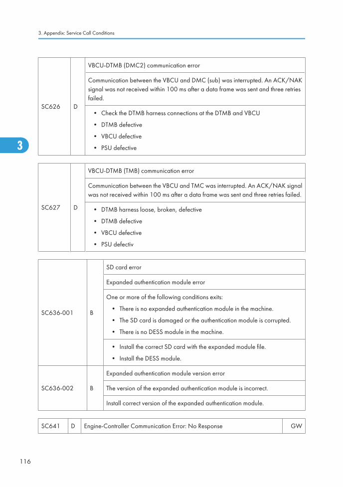
SC626 D
VBCU-DTMB (DMC2) communication error
Communication between the VBCU and DMC (sub) was interrupted. An ACK/NAKsignal was not received within 100 ms after a data frame was sent and three retriesfailed.
• Check the DTMB harness connections at the DTMB and VBCU
• DTMB defective
• VBCU defective
• PSU defective
SC627 D
VBCU-DTMB (TMB) communication error
Communication between the VBCU and TMC was interrupted. An ACK/NAK signalwas not received within 100 ms after a data frame was sent and three retries failed.
• DTMB harness loose, broken, defective
• DTMB defective
• VBCU defective
• PSU defectiv
SC636-001 B
SD card error
Expanded authentication module error
One or more of the following conditions exits:
• There is no expanded authentication module in the machine.
• The SD card is damaged or the authentication module is corrupted.
• There is no DESS module in the machine.
• Install the correct SD card with the expanded module file.
• Install the DESS module.
SC636-002 B
Expanded authentication module version error
The version of the expanded authentication module is incorrect.
Install correct version of the expanded authentication module.
SC641 D Engine-Controller Communication Error: No Response GW
3. Appendix: Service Call Conditions
116
3
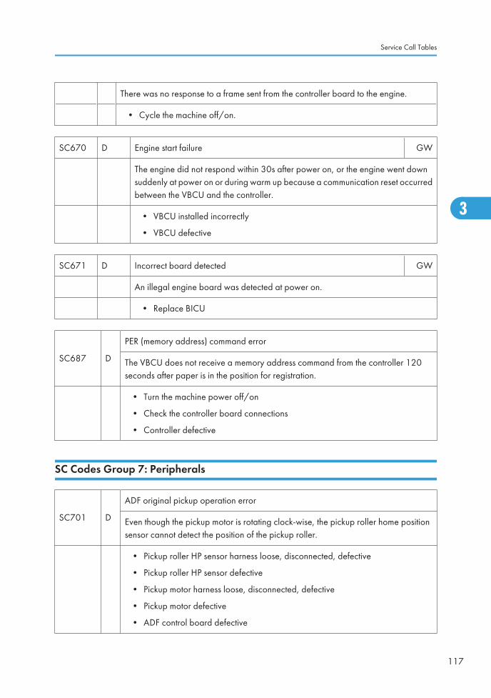
There was no response to a frame sent from the controller board to the engine.
• Cycle the machine off/on.
SC670 D Engine start failure GW
The engine did not respond within 30s after power on, or the engine went downsuddenly at power on or during warm up because a communication reset occurredbetween the VBCU and the controller.
• VBCU installed incorrectly
• VBCU defective
SC671 D Incorrect board detected GW
An illegal engine board was detected at power on.
• Replace BICU
SC687 D
PER (memory address) command error
The VBCU does not receive a memory address command from the controller 120seconds after paper is in the position for registration.
• Turn the machine power off/on
• Check the controller board connections
• Controller defective
SC Codes Group 7: Peripherals
SC701 D
ADF original pickup operation error
Even though the pickup motor is rotating clock-wise, the pickup roller home positionsensor cannot detect the position of the pickup roller.
• Pickup roller HP sensor harness loose, disconnected, defective
• Pickup roller HP sensor defective
• Pickup motor harness loose, disconnected, defective
• Pickup motor defective
• ADF control board defective
Service Call Tables
117
3
Ed
Typewritten Text
SC672 RTB 46
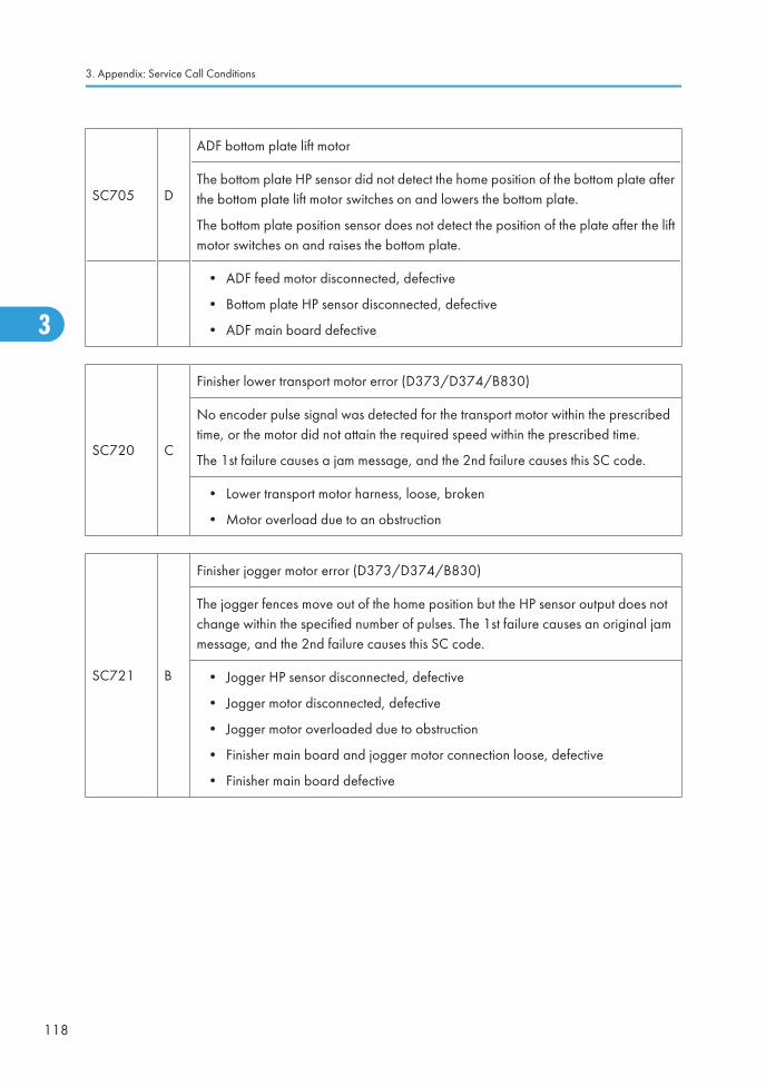
SC705 D
ADF bottom plate lift motor
The bottom plate HP sensor did not detect the home position of the bottom plate afterthe bottom plate lift motor switches on and lowers the bottom plate.
The bottom plate position sensor does not detect the position of the plate after the liftmotor switches on and raises the bottom plate.
• ADF feed motor disconnected, defective
• Bottom plate HP sensor disconnected, defective
• ADF main board defective
SC720 C
Finisher lower transport motor error (D373/D374/B830)
No encoder pulse signal was detected for the transport motor within the prescribedtime, or the motor did not attain the required speed within the prescribed time.
The 1st failure causes a jam message, and the 2nd failure causes this SC code.
• Lower transport motor harness, loose, broken
• Motor overload due to an obstruction
SC721 B
Finisher jogger motor error (D373/D374/B830)
The jogger fences move out of the home position but the HP sensor output does notchange within the specified number of pulses. The 1st failure causes an original jammessage, and the 2nd failure causes this SC code.
• Jogger HP sensor disconnected, defective
• Jogger motor disconnected, defective
• Jogger motor overloaded due to obstruction
• Finisher main board and jogger motor connection loose, defective
• Finisher main board defective
3. Appendix: Service Call Conditions
118
3
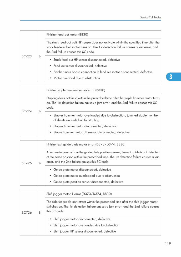
SC723 B
Finisher feed-out motor (B830)
The stack feed-out belt HP sensor does not activate within the specified time after thestack feed-out belt motor turns on. The 1st detection failure causes a jam error, andthe 2nd failure causes this SC code.
• Stack feed-out HP sensor disconnected, defective
• Feed-out motor disconnected, defective
• Finisher main board connection to feed out motor disconnected, defective
• Motor overload due to obstruction
SC724 B
Finisher stapler hammer motor error (B830)
Stapling does not finish within the prescribed time after the staple hammer motor turnson. The 1st detection failure causes a jam error, and the 2nd failure causes this SCcode.
• Stapler hammer motor overloaded due to obstruction, jammed staple, numberof sheets exceeds limit for stapling
• Stapler hammer motor disconnected, defective
• Staple hammer motor HP sensor disconnected, defective
SC725 B
Finisher exit guide plate motor error (D373/D374, B830)
After moving away from the guide plate position sensor, the exit guide is not detectedat the home position within the prescribed time. The 1st detection failure causes a jamerror, and the 2nd failure causes this SC code.
• Guide plate motor disconnected, defective
• Guide plate motor overloaded due to obstruction
• Guide plate position sensor disconnected, defective
SC726 B
Shift jogger motor 1 error (D373/D374, B830)
The side fences do not retract within the prescribed time after the shift jogger motorswitches on. The 1st detection failure causes a jam error, and the 2nd failure causesthis SC code.
• Shift jogger motor disconnected, defective
• Shift jogger motor overloaded due to obstruction
• Shift jogger HP sensor disconnected, defective
Service Call Tables
119
3
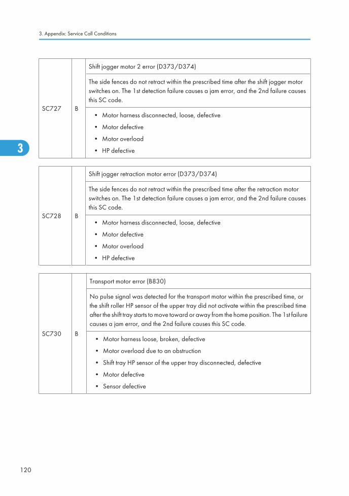
SC727 B
Shift jogger motor 2 error (D373/D374)
The side fences do not retract within the prescribed time after the shift jogger motorswitches on. The 1st detection failure causes a jam error, and the 2nd failure causesthis SC code.
• Motor harness disconnected, loose, defective
• Motor defective
• Motor overload
• HP defective
SC728 B
Shift jogger retraction motor error (D373/D374)
The side fences do not retract within the prescribed time after the retraction motorswitches on. The 1st detection failure causes a jam error, and the 2nd failure causesthis SC code.
• Motor harness disconnected, loose, defective
• Motor defective
• Motor overload
• HP defective
SC730 B
Transport motor error (B830)
No pulse signal was detected for the transport motor within the prescribed time, orthe shift roller HP sensor of the upper tray did not activate within the prescribed timeafter the shift tray starts to move toward or away from the home position. The 1st failurecauses a jam error, and the 2nd failure causes this SC code.
• Motor harness loose, broken, defective
• Motor overload due to an obstruction
• Shift tray HP sensor of the upper tray disconnected, defective
• Motor defective
• Sensor defective
3. Appendix: Service Call Conditions
120
3
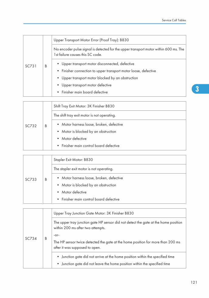
SC731 B
Upper Transport Motor Error (Proof Tray): B830
No encoder pulse signal is detected for the upper transport motor within 600 ms. The1st failure causes this SC code.
• Upper transport motor disconnected, defective
• Finisher connection to upper transport motor loose, defective
• Upper transport motor blocked by an obstruction
• Upper transport motor defective
• Finisher main board defective
SC732 B
Shift Tray Exit Motor: 3K Finisher B830
The shift tray exit motor is not operating.
• Motor harness loose, broken, defective
• Motor is blocked by an obstruction
• Motor defective
• Finisher main control board defective
SC733 B
Stapler Exit Motor: B830
The stapler exit motor is not operating.
• Motor harness loose, broken, defective
• Motor is blocked by an obstruction
• Motor defective
• Finisher main control board defective
SC734 B
Upper Tray Junction Gate Motor: 3K Finisher B830
The upper tray junction gate HP sensor did not detect the gate at the home positionwithin 200 ms after two attempts.
-or-
The HP sensor twice detected the gate at the home position for more than 200 msafter it was supposed to open.
• Junction gate did not arrive at the home position within the specified time
• Junction gate did not leave the home position within the specified time
Service Call Tables
121
3
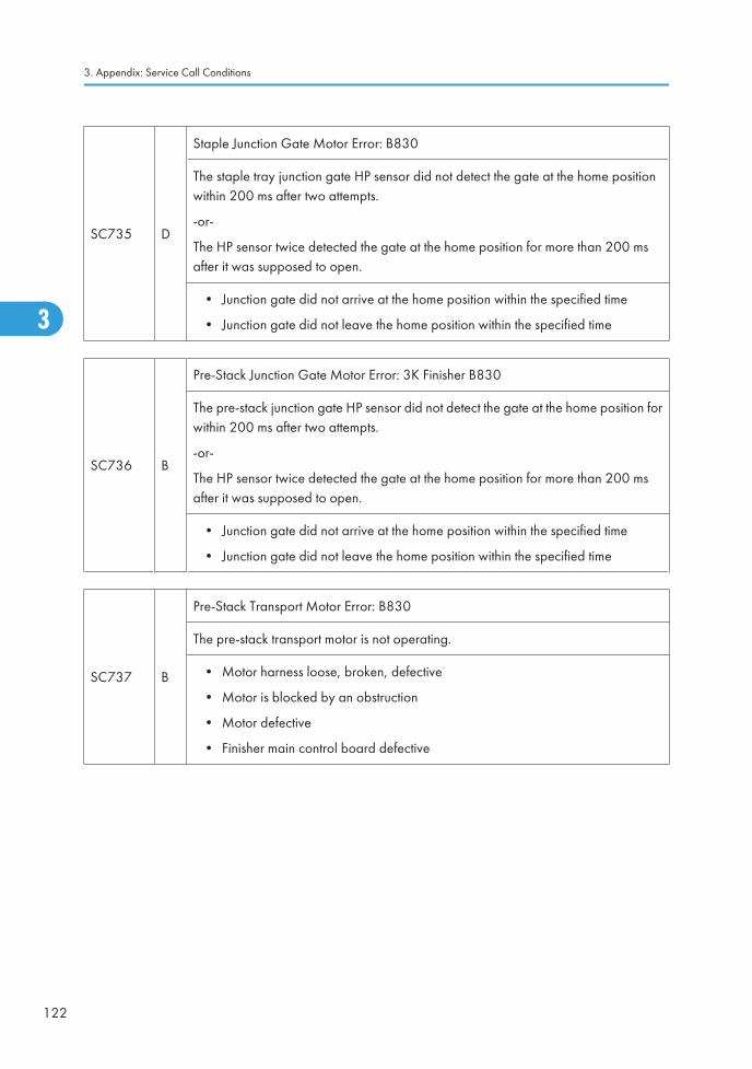
SC735 D
Staple Junction Gate Motor Error: B830
The staple tray junction gate HP sensor did not detect the gate at the home positionwithin 200 ms after two attempts.
-or-
The HP sensor twice detected the gate at the home position for more than 200 msafter it was supposed to open.
• Junction gate did not arrive at the home position within the specified time
• Junction gate did not leave the home position within the specified time
SC736 B
Pre-Stack Junction Gate Motor Error: 3K Finisher B830
The pre-stack junction gate HP sensor did not detect the gate at the home position forwithin 200 ms after two attempts.
-or-
The HP sensor twice detected the gate at the home position for more than 200 msafter it was supposed to open.
• Junction gate did not arrive at the home position within the specified time
• Junction gate did not leave the home position within the specified time
SC737 B
Pre-Stack Transport Motor Error: B830
The pre-stack transport motor is not operating.
• Motor harness loose, broken, defective
• Motor is blocked by an obstruction
• Motor defective
• Finisher main control board defective
3. Appendix: Service Call Conditions
122
3
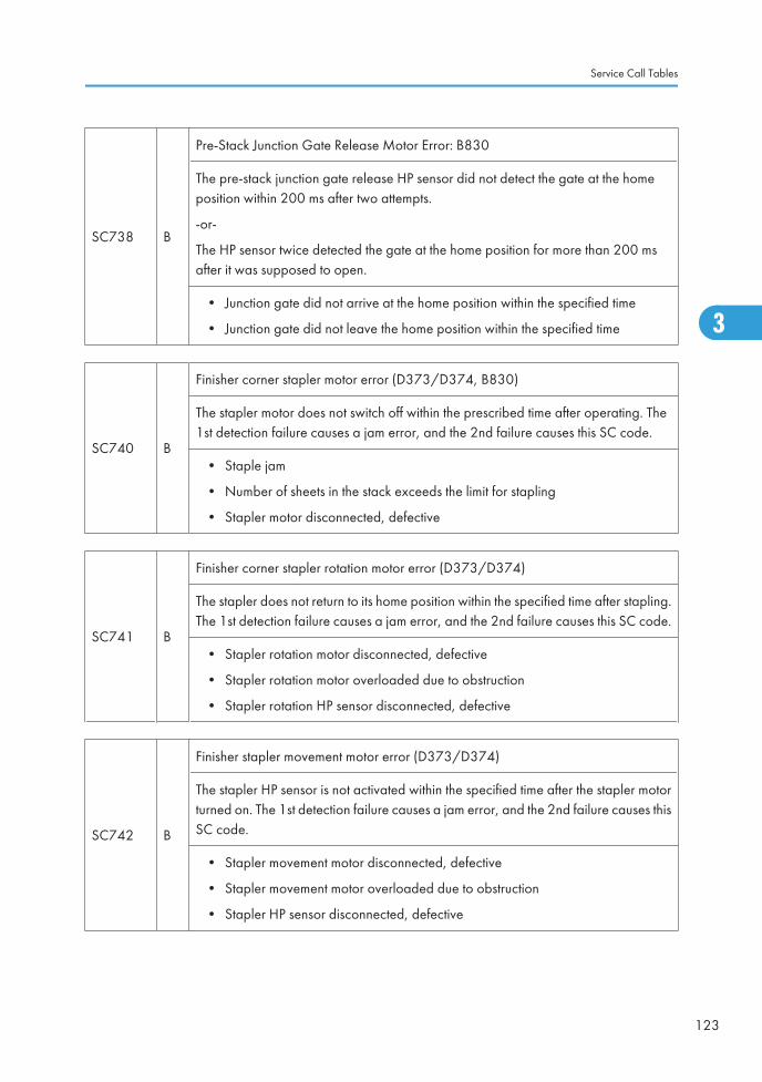
SC738 B
Pre-Stack Junction Gate Release Motor Error: B830
The pre-stack junction gate release HP sensor did not detect the gate at the homeposition within 200 ms after two attempts.
-or-
The HP sensor twice detected the gate at the home position for more than 200 msafter it was supposed to open.
• Junction gate did not arrive at the home position within the specified time
• Junction gate did not leave the home position within the specified time
SC740 B
Finisher corner stapler motor error (D373/D374, B830)
The stapler motor does not switch off within the prescribed time after operating. The1st detection failure causes a jam error, and the 2nd failure causes this SC code.
• Staple jam
• Number of sheets in the stack exceeds the limit for stapling
• Stapler motor disconnected, defective
SC741 B
Finisher corner stapler rotation motor error (D373/D374)
The stapler does not return to its home position within the specified time after stapling.The 1st detection failure causes a jam error, and the 2nd failure causes this SC code.
• Stapler rotation motor disconnected, defective
• Stapler rotation motor overloaded due to obstruction
• Stapler rotation HP sensor disconnected, defective
SC742 B
Finisher stapler movement motor error (D373/D374)
The stapler HP sensor is not activated within the specified time after the stapler motorturned on. The 1st detection failure causes a jam error, and the 2nd failure causes thisSC code.
• Stapler movement motor disconnected, defective
• Stapler movement motor overloaded due to obstruction
• Stapler HP sensor disconnected, defective
Service Call Tables
123
3
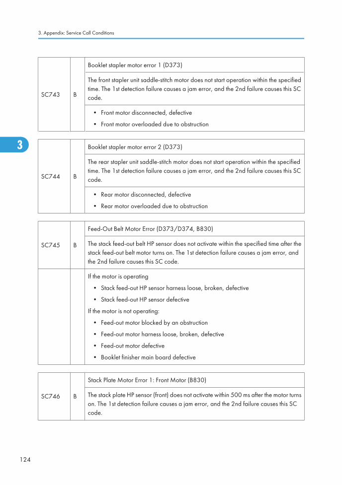
SC743 B
Booklet stapler motor error 1 (D373)
The front stapler unit saddle-stitch motor does not start operation within the specifiedtime. The 1st detection failure causes a jam error, and the 2nd failure causes this SCcode.
• Front motor disconnected, defective
• Front motor overloaded due to obstruction
SC744 B
Booklet stapler motor error 2 (D373)
The rear stapler unit saddle-stitch motor does not start operation within the specifiedtime. The 1st detection failure causes a jam error, and the 2nd failure causes this SCcode.
• Rear motor disconnected, defective
• Rear motor overloaded due to obstruction
SC745 B
Feed-Out Belt Motor Error (D373/D374, B830)
The stack feed-out belt HP sensor does not activate within the specified time after thestack feed-out belt motor turns on. The 1st detection failure causes a jam error, andthe 2nd failure causes this SC code.
If the motor is operating
• Stack feed-out HP sensor harness loose, broken, defective
• Stack feed-out HP sensor defective
If the motor is not operating:
• Feed-out motor blocked by an obstruction
• Feed-out motor harness loose, broken, defective
• Feed-out motor defective
• Booklet finisher main board defective
SC746 B
Stack Plate Motor Error 1: Front Motor (B830)
The stack plate HP sensor (front) does not activate within 500 ms after the motor turnson. The 1st detection failure causes a jam error, and the 2nd failure causes this SCcode.
3. Appendix: Service Call Conditions
124
3
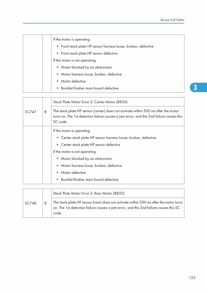
If the motor is operating
• Front stack plate HP sensor harness loose, broken, defective
• Front stack plate HP sensor defective
If the motor is not operating:
• Motor blocked by an obstruction
• Motor harness loose, broken, defective
• Motor defective
• Booklet finisher main board defective
SC747 B
Stack Plate Motor Error 2: Center Motor (B830)
The stack plate HP sensor (center) does not activate within 500 ms after the motorturns on. The 1st detection failure causes a jam error, and the 2nd failure causes thisSC code.
If the motor is operating
• Center stack plate HP sensor harness loose, broken, defective
• Center stack plate HP sensor defective
If the motor is not operating:
• Motor blocked by an obstruction
• Motor harness loose, broken, defective
• Motor defective
• Booklet finisher main board defective
SC748 B
Stack Plate Motor Error 3: Rear Motor (B830)
The stack plate HP sensor (rear) does not activate within 500 ms after the motor turnson. The 1st detection failure causes a jam error, and the 2nd failure causes this SCcode.
Service Call Tables
125
3
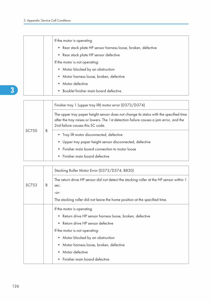
If the motor is operating
• Rear stack plate HP sensor harness loose, broken, defective
• Rear stack plate HP sensor defective
If the motor is not operating:
• Motor blocked by an obstruction
• Motor harness loose, broken, defective
• Motor defective
• Booklet finisher main board defective
SC750 B
Finisher tray 1 (upper tray lift) motor error (D373/D374)
The upper tray paper height sensor does not change its status with the specified timeafter the tray raises or lowers. The 1st detection failure causes a jam error, and the2nd failure causes this SC code.
• Tray lift motor disconnected, defective
• Upper tray paper height sensor disconnected, defective
• Finisher main board connection to motor loose
• Finisher main board defective
SC753 B
Stacking Roller Motor Error (D373/D374, B830)
The return drive HP sensor did not detect the stacking roller at the HP sensor within 1sec.
-or-
The stacking roller did not leave the home position at the specified time.
If the motor is operating
• Return drive HP sensor harness loose, broken, defective
• Return drive HP sensor defective
If the motor is not operating:
• Motor blocked by an obstruction
• Motor harness loose, broken, defective
• Motor defective
• Finisher main board defective
3. Appendix: Service Call Conditions
126
3
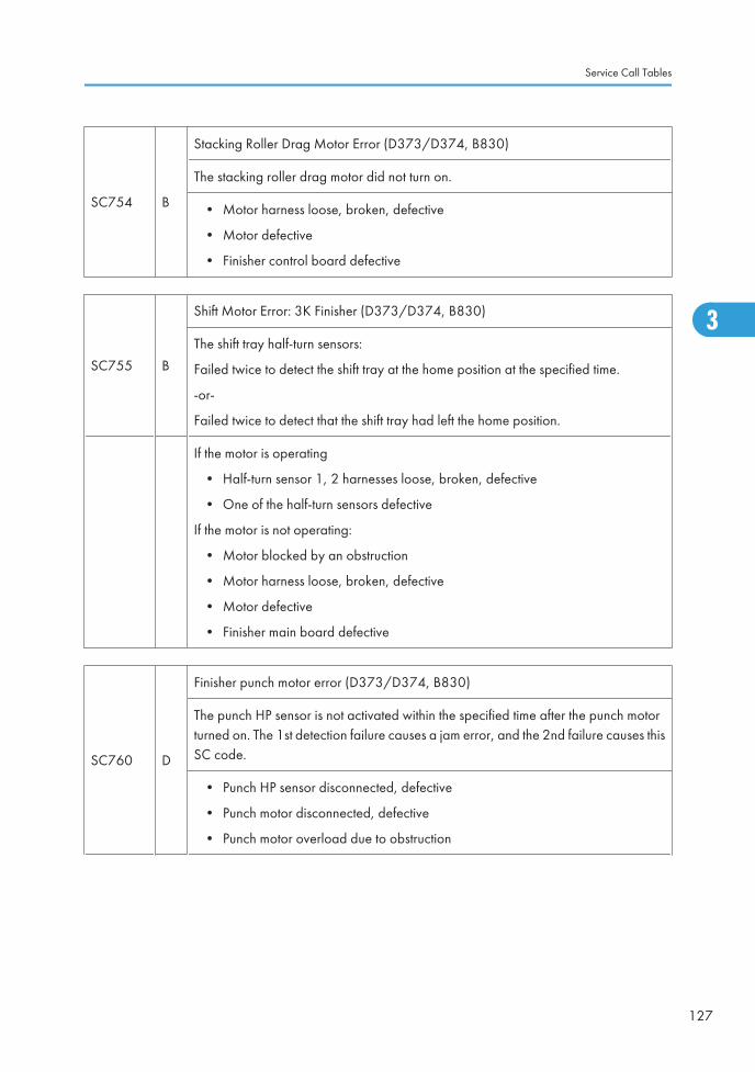
SC754 B
Stacking Roller Drag Motor Error (D373/D374, B830)
The stacking roller drag motor did not turn on.
• Motor harness loose, broken, defective
• Motor defective
• Finisher control board defective
SC755 B
Shift Motor Error: 3K Finisher (D373/D374, B830)
The shift tray half-turn sensors:
Failed twice to detect the shift tray at the home position at the specified time.
-or-
Failed twice to detect that the shift tray had left the home position.
If the motor is operating
• Half-turn sensor 1, 2 harnesses loose, broken, defective
• One of the half-turn sensors defective
If the motor is not operating:
• Motor blocked by an obstruction
• Motor harness loose, broken, defective
• Motor defective
• Finisher main board defective
SC760 D
Finisher punch motor error (D373/D374, B830)
The punch HP sensor is not activated within the specified time after the punch motorturned on. The 1st detection failure causes a jam error, and the 2nd failure causes thisSC code.
• Punch HP sensor disconnected, defective
• Punch motor disconnected, defective
• Punch motor overload due to obstruction
Service Call Tables
127
3
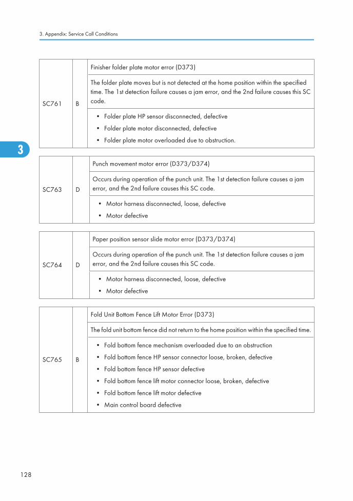
SC761 B
Finisher folder plate motor error (D373)
The folder plate moves but is not detected at the home position within the specifiedtime. The 1st detection failure causes a jam error, and the 2nd failure causes this SCcode.
• Folder plate HP sensor disconnected, defective
• Folder plate motor disconnected, defective
• Folder plate motor overloaded due to obstruction.
SC763 D
Punch movement motor error (D373/D374)
Occurs during operation of the punch unit. The 1st detection failure causes a jamerror, and the 2nd failure causes this SC code.
• Motor harness disconnected, loose, defective
• Motor defective
SC764 D
Paper position sensor slide motor error (D373/D374)
Occurs during operation of the punch unit. The 1st detection failure causes a jamerror, and the 2nd failure causes this SC code.
• Motor harness disconnected, loose, defective
• Motor defective
SC765 B
Fold Unit Bottom Fence Lift Motor Error (D373)
The fold unit bottom fence did not return to the home position within the specified time.
• Fold bottom fence mechanism overloaded due to an obstruction
• Fold bottom fence HP sensor connector loose, broken, defective
• Fold bottom fence HP sensor defective
• Fold bottom fence lift motor connector loose, broken, defective
• Fold bottom fence lift motor defective
• Main control board defective
3. Appendix: Service Call Conditions
128
3
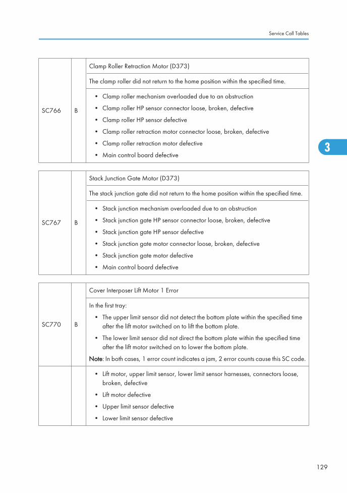
SC766 B
Clamp Roller Retraction Motor (D373)
The clamp roller did not return to the home position within the specified time.
• Clamp roller mechanism overloaded due to an obstruction
• Clamp roller HP sensor connector loose, broken, defective
• Clamp roller HP sensor defective
• Clamp roller retraction motor connector loose, broken, defective
• Clamp roller retraction motor defective
• Main control board defective
SC767 B
Stack Junction Gate Motor (D373)
The stack junction gate did not return to the home position within the specified time.
• Stack junction mechanism overloaded due to an obstruction
• Stack junction gate HP sensor connector loose, broken, defective
• Stack junction gate HP sensor defective
• Stack junction gate motor connector loose, broken, defective
• Stack junction gate motor defective
• Main control board defective
SC770 B
Cover Interposer Lift Motor 1 Error
In the first tray:
• The upper limit sensor did not detect the bottom plate within the specified timeafter the lift motor switched on to lift the bottom plate.
• The lower limit sensor did not direct the bottom plate within the specified timeafter the lift motor switched on to lower the bottom plate.
Note: In both cases, 1 error count indicates a jam, 2 error counts cause this SC code.
• Lift motor, upper limit sensor, lower limit sensor harnesses, connectors loose,broken, defective
• Lift motor defective
• Upper limit sensor defective
• Lower limit sensor defective
Service Call Tables
129
3
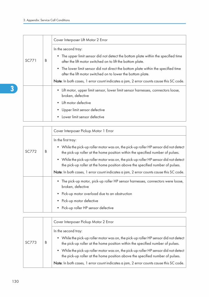
SC771 B
Cover Interposer Lift Motor 2 Error
In the second tray:
• The upper limit sensor did not detect the bottom plate within the specified timeafter the lift motor switched on to lift the bottom plate.
• The lower limit sensor did not direct the bottom plate within the specified timeafter the lift motor switched on to lower the bottom plate.
Note: In both cases, 1 error count indicates a jam, 2 error counts cause this SC code.
• Lift motor, upper limit sensor, lower limit sensor harnesses, connectors loose,broken, defective
• Lift motor defective
• Upper limit sensor defective
• Lower limit sensor defective
SC772 B
Cover Interposer Pickup Motor 1 Error
In the first tray:
• While the pick-up roller motor was on, the pick-up roller HP sensor did not detectthe pick-up roller at the home position within the specified number of pulses.
• While the pick-up roller motor was on, the pick-up roller HP sensor did not detectthe pick-up roller at the home position above the specified number of pulses.
Note: In both cases, 1 error count indicates a jam, 2 error counts cause this SC code.
• The pick-up motor, pick-up roller HP sensor harnesses, connectors were loose,broken, defective
• Pick-up motor overload due to an obstruction
• Pick-up motor defective
• Pick-up roller HP sensor defective
SC773 B
Cover Interposer Pickup Motor 2 Error
In the second tray:
• While the pick-up roller motor was on, the pick-up roller HP sensor did not detectthe pick-up roller at the home position within the specified number of pulses.
• While the pick-up roller motor was on, the pick-up roller HP sensor did not detectthe pick-up roller at the home position above the specified number of pulses.
Note: In both cases, 1 error count indicates a jam, 2 error counts cause this SC code.
3. Appendix: Service Call Conditions
130
3
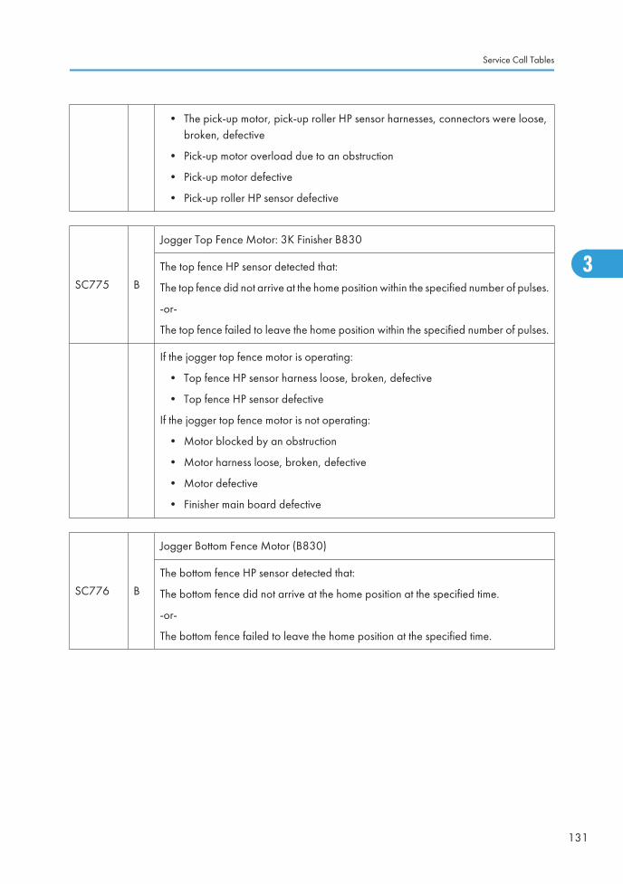
• The pick-up motor, pick-up roller HP sensor harnesses, connectors were loose,broken, defective
• Pick-up motor overload due to an obstruction
• Pick-up motor defective
• Pick-up roller HP sensor defective
SC775 B
Jogger Top Fence Motor: 3K Finisher B830
The top fence HP sensor detected that:
The top fence did not arrive at the home position within the specified number of pulses.
-or-
The top fence failed to leave the home position within the specified number of pulses.
If the jogger top fence motor is operating:
• Top fence HP sensor harness loose, broken, defective
• Top fence HP sensor defective
If the jogger top fence motor is not operating:
• Motor blocked by an obstruction
• Motor harness loose, broken, defective
• Motor defective
• Finisher main board defective
SC776 B
Jogger Bottom Fence Motor (B830)
The bottom fence HP sensor detected that:
The bottom fence did not arrive at the home position at the specified time.
-or-
The bottom fence failed to leave the home position at the specified time.
Service Call Tables
131
3
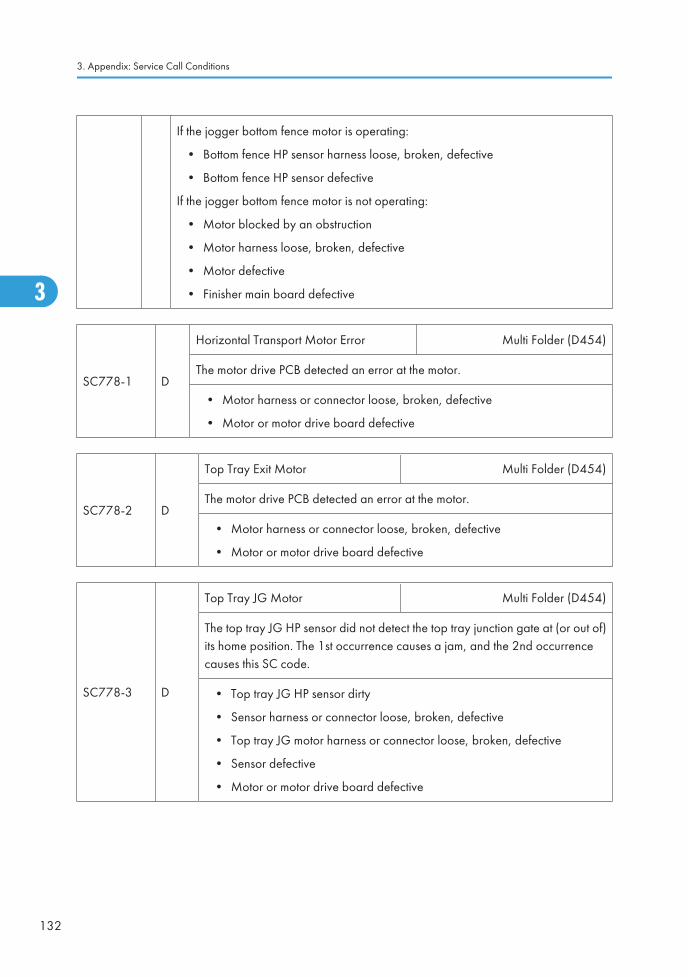
If the jogger bottom fence motor is operating:
• Bottom fence HP sensor harness loose, broken, defective
• Bottom fence HP sensor defective
If the jogger bottom fence motor is not operating:
• Motor blocked by an obstruction
• Motor harness loose, broken, defective
• Motor defective
• Finisher main board defective
SC778-1 D
Horizontal Transport Motor Error Multi Folder (D454)
The motor drive PCB detected an error at the motor.
• Motor harness or connector loose, broken, defective
• Motor or motor drive board defective
SC778-2 D
Top Tray Exit Motor Multi Folder (D454)
The motor drive PCB detected an error at the motor.
• Motor harness or connector loose, broken, defective
• Motor or motor drive board defective
SC778-3 D
Top Tray JG Motor Multi Folder (D454)
The top tray JG HP sensor did not detect the top tray junction gate at (or out of)its home position. The 1st occurrence causes a jam, and the 2nd occurrencecauses this SC code.
• Top tray JG HP sensor dirty
• Sensor harness or connector loose, broken, defective
• Top tray JG motor harness or connector loose, broken, defective
• Sensor defective
• Motor or motor drive board defective
3. Appendix: Service Call Conditions
132
3

SC778-4 D
Entrance JG Motor Multi Folder (D454)
The entrance junction gate HP sensor did not detect the entrance junction gateat (or out of) its home position. The 1st occurrence causes a jam, and the 2ndoccurrence causes this SC code.
• Entrance JG HP sensor dirty
• Sensor harness or connector loose, broken, defective
• Entrance JG motor harness or connector loose, broken, defective
• Sensor defective
• Motor or motor drive board defective
SC779 B
1st Stopper Motor Error Multi Folder (D454)
The 1st stopper HP sensor did not detect the 1st stopper in (or out of) its homeposition within the prescribed time. The 1st occurrence causes a jam, and the 2ndoccurrence causes this SC code.
• 1st stopper HP sensor dirty
• Sensor harness or connector loose, broken, defective
• 1st stopper motor harness or connector loose, broken, defective
• Sensor defective
• Motor or motor drive board defective
SC780 B
Z-Fold Feed Motor Error Japan Only
The feed motor that drives the feed rollers and exit rollers in the Z-fold unit is notoperating. The 1st alert signals a jam, the 2nd alert triggers this SC.
• Motor harness loose, broken, defective
• Motor blocked by an obstruction
• Motor defective
Service Call Tables
133
3
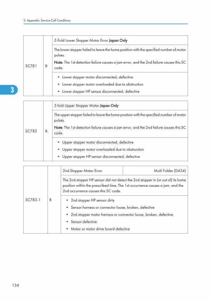
SC781 B
Z-Fold Lower Stopper Motor Error Japan Only
The lower stopper failed to leave the home position with the specified number of motorpulses.
Note: The 1st detection failure causes a jam error, and the 2nd failure causes this SCcode.
• Lower stopper motor disconnected, defective
• Lower stopper motor overloaded due to obstruction
• Lower stopper HP sensor disconnected, defective
SC782 B
Z-fold Upper Stopper Motor Japan Only
The upper stopper failed to leave the home position with the specified number of motorpulses.
Note: The 1st detection failure causes a jam error, and the 2nd failure causes this SCcode.
• Upper stopper motor disconnected, defective
• Upper stopper motor overloaded due to obstruction
• Upper stopper HP sensor disconnected, defective
SC783-1 B
2nd Stopper Motor Error Multi Folder (D454)
The 2nd stopper HP sensor did not detect the 2nd stopper in (or out of) its homeposition within the prescribed time. The 1st occurrence causes a jam, and the2nd occurrence causes this SC code.
• 2nd stopper HP sensor dirty
• Sensor harness or connector loose, broken, defective
• 2nd stopper motor harness or connector loose, broken, defective
• Sensor defective
• Motor or motor drive board defective
3. Appendix: Service Call Conditions
134
3
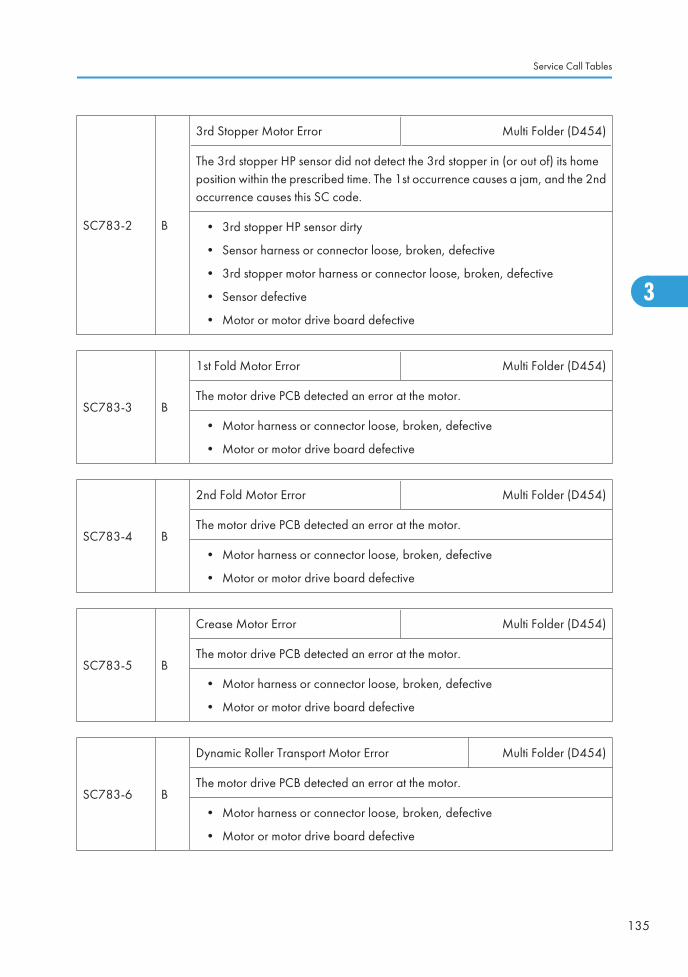
SC783-2 B
3rd Stopper Motor Error Multi Folder (D454)
The 3rd stopper HP sensor did not detect the 3rd stopper in (or out of) its homeposition within the prescribed time. The 1st occurrence causes a jam, and the 2ndoccurrence causes this SC code.
• 3rd stopper HP sensor dirty
• Sensor harness or connector loose, broken, defective
• 3rd stopper motor harness or connector loose, broken, defective
• Sensor defective
• Motor or motor drive board defective
SC783-3 B
1st Fold Motor Error Multi Folder (D454)
The motor drive PCB detected an error at the motor.
• Motor harness or connector loose, broken, defective
• Motor or motor drive board defective
SC783-4 B
2nd Fold Motor Error Multi Folder (D454)
The motor drive PCB detected an error at the motor.
• Motor harness or connector loose, broken, defective
• Motor or motor drive board defective
SC783-5 B
Crease Motor Error Multi Folder (D454)
The motor drive PCB detected an error at the motor.
• Motor harness or connector loose, broken, defective
• Motor or motor drive board defective
SC783-6 B
Dynamic Roller Transport Motor Error Multi Folder (D454)
The motor drive PCB detected an error at the motor.
• Motor harness or connector loose, broken, defective
• Motor or motor drive board defective
Service Call Tables
135
3
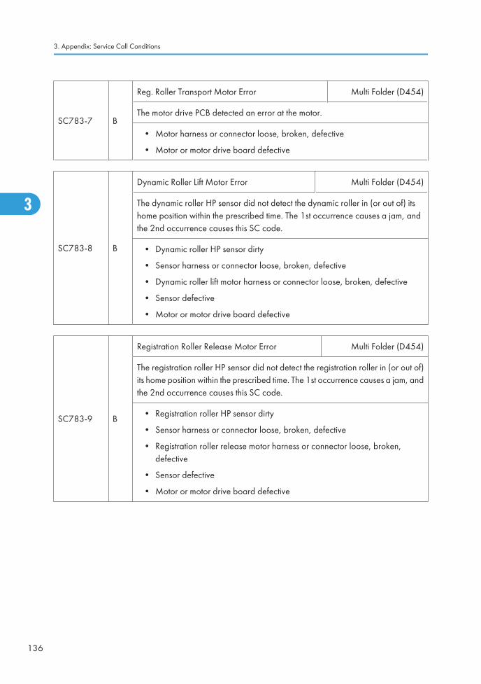
SC783-7 B
Reg. Roller Transport Motor Error Multi Folder (D454)
The motor drive PCB detected an error at the motor.
• Motor harness or connector loose, broken, defective
• Motor or motor drive board defective
SC783-8 B
Dynamic Roller Lift Motor Error Multi Folder (D454)
The dynamic roller HP sensor did not detect the dynamic roller in (or out of) itshome position within the prescribed time. The 1st occurrence causes a jam, andthe 2nd occurrence causes this SC code.
• Dynamic roller HP sensor dirty
• Sensor harness or connector loose, broken, defective
• Dynamic roller lift motor harness or connector loose, broken, defective
• Sensor defective
• Motor or motor drive board defective
SC783-9 B
Registration Roller Release Motor Error Multi Folder (D454)
The registration roller HP sensor did not detect the registration roller in (or out of)its home position within the prescribed time. The 1st occurrence causes a jam, andthe 2nd occurrence causes this SC code.
• Registration roller HP sensor dirty
• Sensor harness or connector loose, broken, defective
• Registration roller release motor harness or connector loose, broken,defective
• Sensor defective
• Motor or motor drive board defective
3. Appendix: Service Call Conditions
136
3
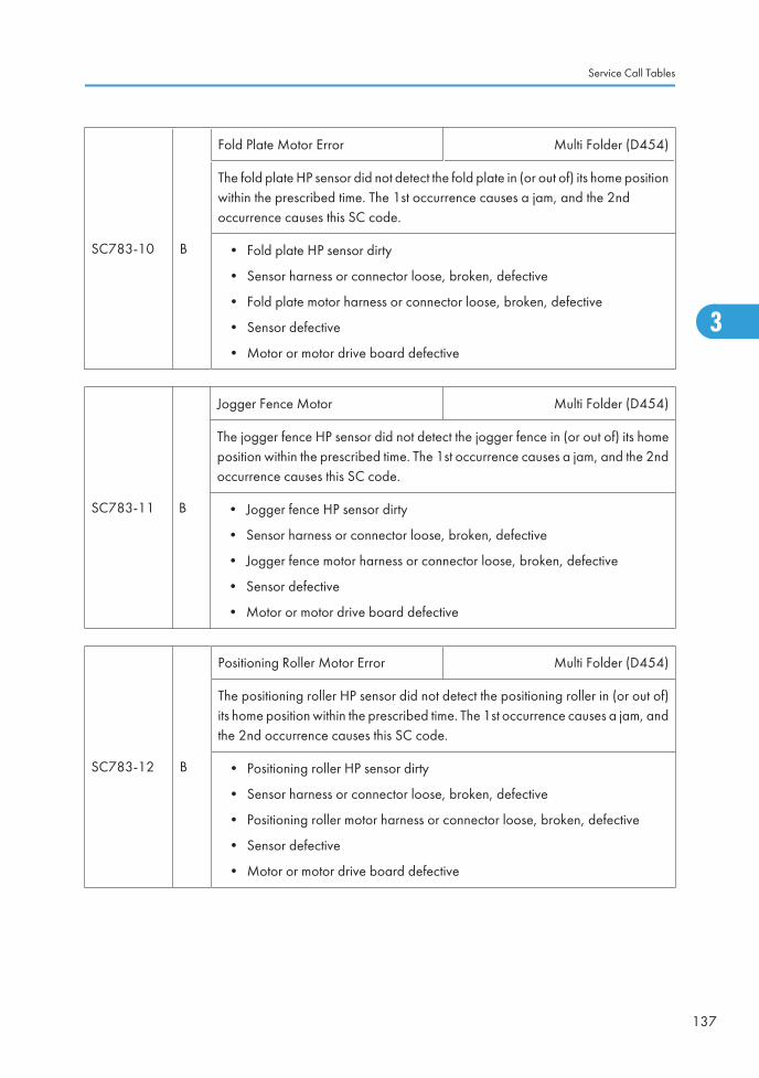
SC783-10 B
Fold Plate Motor Error Multi Folder (D454)
The fold plate HP sensor did not detect the fold plate in (or out of) its home positionwithin the prescribed time. The 1st occurrence causes a jam, and the 2ndoccurrence causes this SC code.
• Fold plate HP sensor dirty
• Sensor harness or connector loose, broken, defective
• Fold plate motor harness or connector loose, broken, defective
• Sensor defective
• Motor or motor drive board defective
SC783-11 B
Jogger Fence Motor Multi Folder (D454)
The jogger fence HP sensor did not detect the jogger fence in (or out of) its homeposition within the prescribed time. The 1st occurrence causes a jam, and the 2ndoccurrence causes this SC code.
• Jogger fence HP sensor dirty
• Sensor harness or connector loose, broken, defective
• Jogger fence motor harness or connector loose, broken, defective
• Sensor defective
• Motor or motor drive board defective
SC783-12 B
Positioning Roller Motor Error Multi Folder (D454)
The positioning roller HP sensor did not detect the positioning roller in (or out of)its home position within the prescribed time. The 1st occurrence causes a jam, andthe 2nd occurrence causes this SC code.
• Positioning roller HP sensor dirty
• Sensor harness or connector loose, broken, defective
• Positioning roller motor harness or connector loose, broken, defective
• Sensor defective
• Motor or motor drive board defective
Service Call Tables
137
3
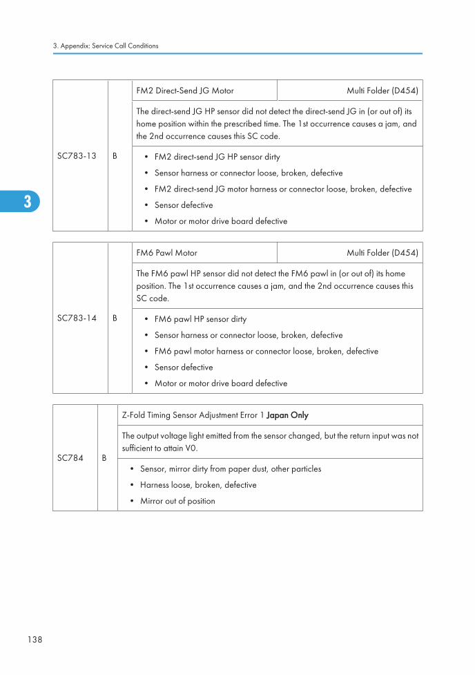
SC783-13 B
FM2 Direct-Send JG Motor Multi Folder (D454)
The direct-send JG HP sensor did not detect the direct-send JG in (or out of) itshome position within the prescribed time. The 1st occurrence causes a jam, andthe 2nd occurrence causes this SC code.
• FM2 direct-send JG HP sensor dirty
• Sensor harness or connector loose, broken, defective
• FM2 direct-send JG motor harness or connector loose, broken, defective
• Sensor defective
• Motor or motor drive board defective
SC783-14 B
FM6 Pawl Motor Multi Folder (D454)
The FM6 pawl HP sensor did not detect the FM6 pawl in (or out of) its homeposition. The 1st occurrence causes a jam, and the 2nd occurrence causes thisSC code.
• FM6 pawl HP sensor dirty
• Sensor harness or connector loose, broken, defective
• FM6 pawl motor harness or connector loose, broken, defective
• Sensor defective
• Motor or motor drive board defective
SC784 B
Z-Fold Timing Sensor Adjustment Error 1 Japan Only
The output voltage light emitted from the sensor changed, but the return input was notsufficient to attain V0.
• Sensor, mirror dirty from paper dust, other particles
• Harness loose, broken, defective
• Mirror out of position
3. Appendix: Service Call Conditions
138
3
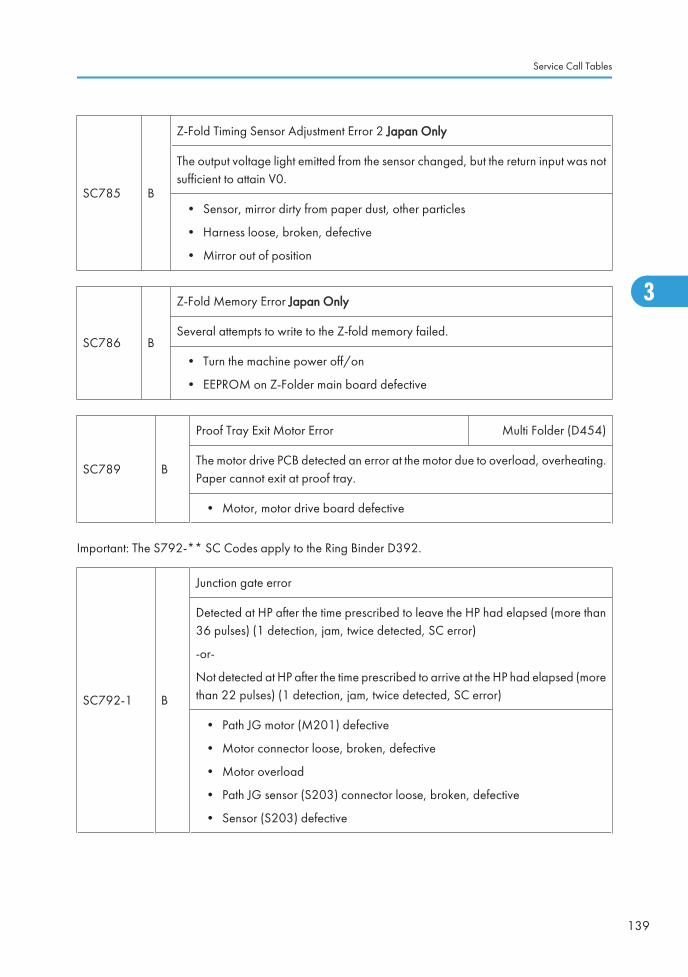
SC785 B
Z-Fold Timing Sensor Adjustment Error 2 Japan Only
The output voltage light emitted from the sensor changed, but the return input was notsufficient to attain V0.
• Sensor, mirror dirty from paper dust, other particles
• Harness loose, broken, defective
• Mirror out of position
SC786 B
Z-Fold Memory Error Japan Only
Several attempts to write to the Z-fold memory failed.
• Turn the machine power off/on
• EEPROM on Z-Folder main board defective
SC789 B
Proof Tray Exit Motor Error Multi Folder (D454)
The motor drive PCB detected an error at the motor due to overload, overheating.Paper cannot exit at proof tray.
• Motor, motor drive board defective
Important: The S792-** SC Codes apply to the Ring Binder D392.
SC792-1 B
Junction gate error
Detected at HP after the time prescribed to leave the HP had elapsed (more than36 pulses) (1 detection, jam, twice detected, SC error)
-or-
Not detected at HP after the time prescribed to arrive at the HP had elapsed (morethan 22 pulses) (1 detection, jam, twice detected, SC error)
• Path JG motor (M201) defective
• Motor connector loose, broken, defective
• Motor overload
• Path JG sensor (S203) connector loose, broken, defective
• Sensor (S203) defective
Service Call Tables
139
3
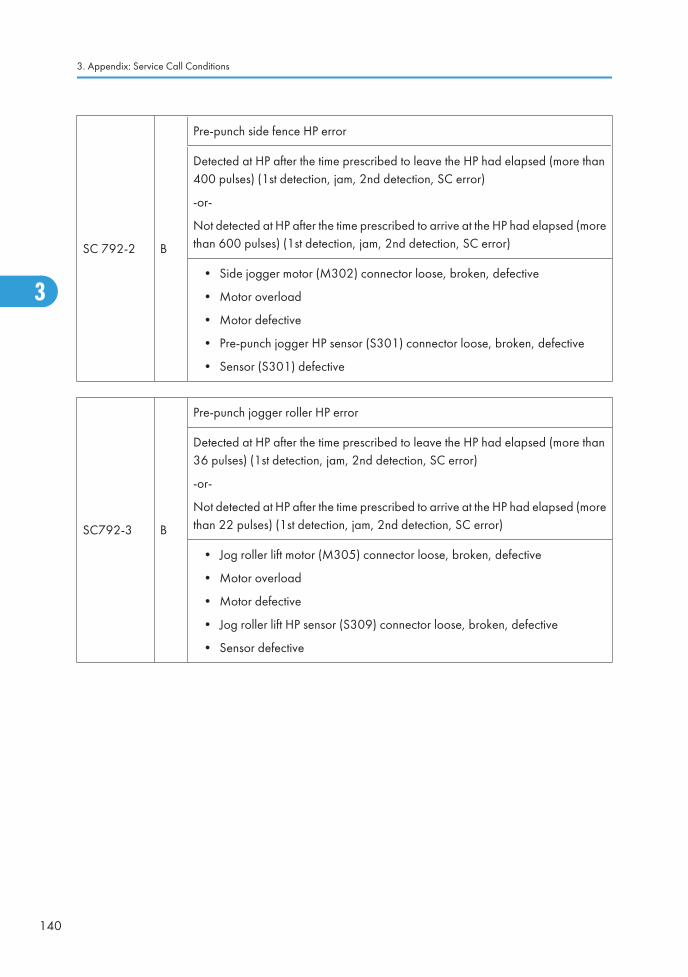
SC 792-2 B
Pre-punch side fence HP error
Detected at HP after the time prescribed to leave the HP had elapsed (more than400 pulses) (1st detection, jam, 2nd detection, SC error)
-or-
Not detected at HP after the time prescribed to arrive at the HP had elapsed (morethan 600 pulses) (1st detection, jam, 2nd detection, SC error)
• Side jogger motor (M302) connector loose, broken, defective
• Motor overload
• Motor defective
• Pre-punch jogger HP sensor (S301) connector loose, broken, defective
• Sensor (S301) defective
SC792-3 B
Pre-punch jogger roller HP error
Detected at HP after the time prescribed to leave the HP had elapsed (more than36 pulses) (1st detection, jam, 2nd detection, SC error)
-or-
Not detected at HP after the time prescribed to arrive at the HP had elapsed (morethan 22 pulses) (1st detection, jam, 2nd detection, SC error)
• Jog roller lift motor (M305) connector loose, broken, defective
• Motor overload
• Motor defective
• Jog roller lift HP sensor (S309) connector loose, broken, defective
• Sensor defective
3. Appendix: Service Call Conditions
140
3
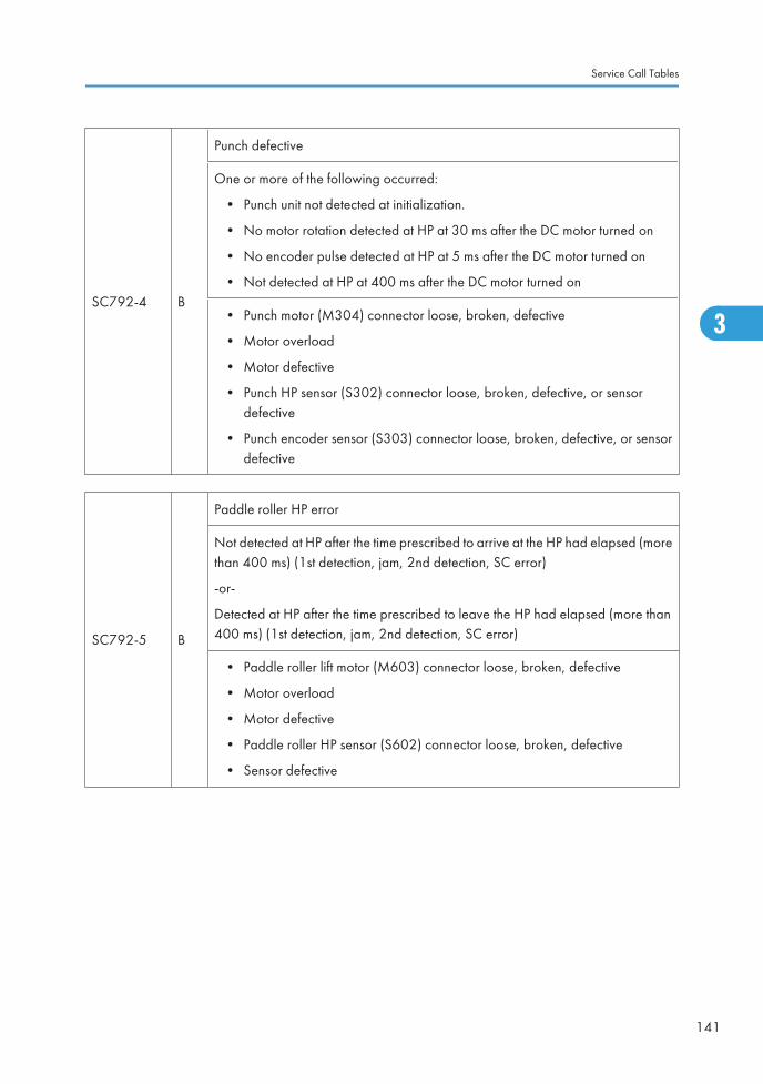
SC792-4 B
Punch defective
One or more of the following occurred:
• Punch unit not detected at initialization.
• No motor rotation detected at HP at 30 ms after the DC motor turned on
• No encoder pulse detected at HP at 5 ms after the DC motor turned on
• Not detected at HP at 400 ms after the DC motor turned on
• Punch motor (M304) connector loose, broken, defective
• Motor overload
• Motor defective
• Punch HP sensor (S302) connector loose, broken, defective, or sensordefective
• Punch encoder sensor (S303) connector loose, broken, defective, or sensordefective
SC792-5 B
Paddle roller HP error
Not detected at HP after the time prescribed to arrive at the HP had elapsed (morethan 400 ms) (1st detection, jam, 2nd detection, SC error)
-or-
Detected at HP after the time prescribed to leave the HP had elapsed (more than400 ms) (1st detection, jam, 2nd detection, SC error)
• Paddle roller lift motor (M603) connector loose, broken, defective
• Motor overload
• Motor defective
• Paddle roller HP sensor (S602) connector loose, broken, defective
• Sensor defective
Service Call Tables
141
3
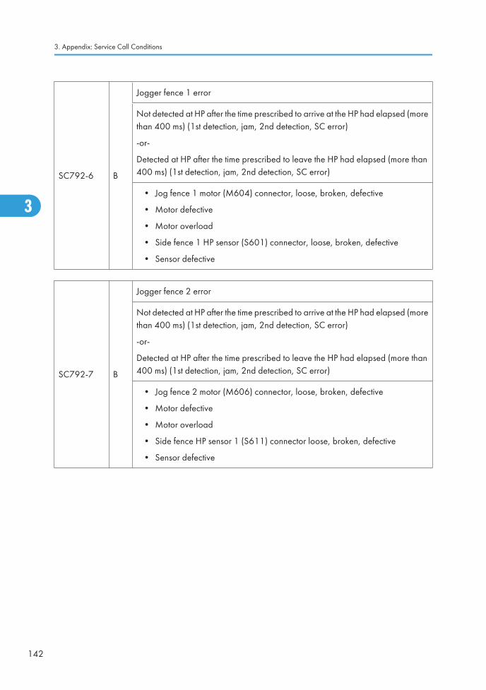
SC792-6 B
Jogger fence 1 error
Not detected at HP after the time prescribed to arrive at the HP had elapsed (morethan 400 ms) (1st detection, jam, 2nd detection, SC error)
-or-
Detected at HP after the time prescribed to leave the HP had elapsed (more than400 ms) (1st detection, jam, 2nd detection, SC error)
• Jog fence 1 motor (M604) connector, loose, broken, defective
• Motor defective
• Motor overload
• Side fence 1 HP sensor (S601) connector, loose, broken, defective
• Sensor defective
SC792-7 B
Jogger fence 2 error
Not detected at HP after the time prescribed to arrive at the HP had elapsed (morethan 400 ms) (1st detection, jam, 2nd detection, SC error)
-or-
Detected at HP after the time prescribed to leave the HP had elapsed (more than400 ms) (1st detection, jam, 2nd detection, SC error)
• Jog fence 2 motor (M606) connector, loose, broken, defective
• Motor defective
• Motor overload
• Side fence HP sensor 1 (S611) connector loose, broken, defective
• Sensor defective
3. Appendix: Service Call Conditions
142
3
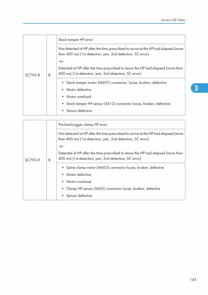
SC792-8 B
Stack tamper HP error
Not detected at HP after the time prescribed to arrive at the HP had elapsed (morethan 400 ms) (1st detection, jam, 2nd detection, SC error)
-or-
Detected at HP after the time prescribed to leave the HP had elapsed (more than400 ms) (1st detection, jam, 2nd detection, SC error)
• Stack tamper motor (M607) connector, loose, broken, defective
• Motor defective
• Motor overload
• Stack tamper HP sensor (S612) connector loose, broken, defective
• Sensor defective
SC792-9 B
Pre-bind jogger clamp HP error
Not detected at HP after the time prescribed to arrive at the HP had elapsed (morethan 400 ms) (1st detection, jam, 2nd detection, SC error)
-or-
Detected at HP after the time prescribed to leave the HP had elapsed (more than400 ms) (1st detection, jam, 2nd detection, SC error)
• Spine clamp motor (M605) connector loose, broken, defective
• Motor defective
• Motor overload
• Clamp HP sensor (S603) connector loose, broken, defective
• Sensor defective
Service Call Tables
143
3
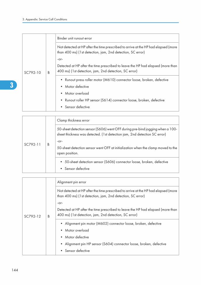
SC792-10 B
Binder unit runout error
Not detected at HP after the time prescribed to arrive at the HP had elapsed (morethan 400 ms) (1st detection, jam, 2nd detection, SC error)
-or-
Detected at HP after the time prescribed to leave the HP had elapsed (more than400 ms) (1st detection, jam, 2nd detection, SC error)
• Runout press roller motor (M610) connector loose, broken, defective
• Motor defective
• Motor overload
• Runout roller HP sensor (S614) connector loose, broken, defective
• Sensor defective
SC792-11 B
Clamp thickness error
50-sheet detection sensor (S606) went OFF during pre-bind jogging when a 100-sheet thickness was detected. (1st detection jam, 2nd detection SC error)
-or-
50-sheet detection sensor went OFF at initialization when the clamp moved to theopen position.
• 50-sheet detection sensor (S606) connector loose, broken, defective
• Sensor defective
SC792-12 B
Alignment pin error
Not detected at HP after the time prescribed to arrive at the HP had elapsed (morethan 400 ms) (1st detection, jam, 2nd detection, SC error)
-or-
Detected at HP after the time prescribed to leave the HP had elapsed (more than400 ms) (1st detection, jam, 2nd detection, SC error)
• Alignment pin motor (M602) connector loose, broken, defective
• Motor overload
• Motor defective
• Alignment pin HP sensor (S604) connector loose, broken, defective
• Sensor defective
3. Appendix: Service Call Conditions
144
3
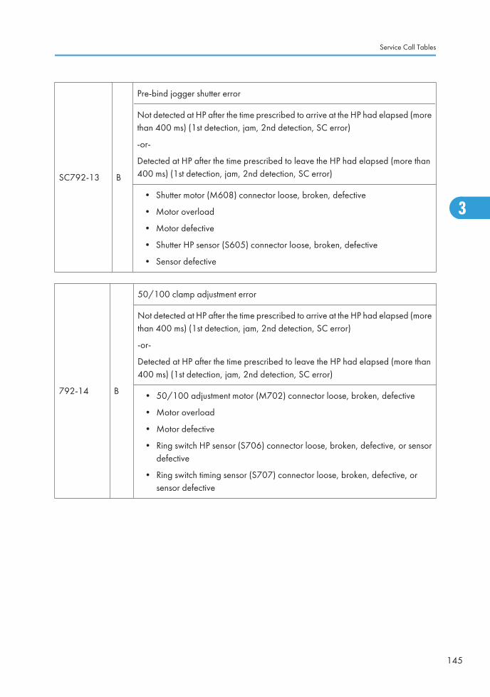
SC792-13 B
Pre-bind jogger shutter error
Not detected at HP after the time prescribed to arrive at the HP had elapsed (morethan 400 ms) (1st detection, jam, 2nd detection, SC error)
-or-
Detected at HP after the time prescribed to leave the HP had elapsed (more than400 ms) (1st detection, jam, 2nd detection, SC error)
• Shutter motor (M608) connector loose, broken, defective
• Motor overload
• Motor defective
• Shutter HP sensor (S605) connector loose, broken, defective
• Sensor defective
792-14 B
50/100 clamp adjustment error
Not detected at HP after the time prescribed to arrive at the HP had elapsed (morethan 400 ms) (1st detection, jam, 2nd detection, SC error)
-or-
Detected at HP after the time prescribed to leave the HP had elapsed (more than400 ms) (1st detection, jam, 2nd detection, SC error)
• 50/100 adjustment motor (M702) connector loose, broken, defective
• Motor overload
• Motor defective
• Ring switch HP sensor (S706) connector loose, broken, defective, or sensordefective
• Ring switch timing sensor (S707) connector loose, broken, defective, orsensor defective
Service Call Tables
145
3
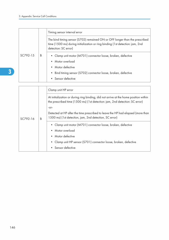
SC792-15 B
Timing sensor interval error
The bind timing sensor (S702) remained ON or OFF longer than the prescribedtime (1500 ms) during initialization or ring binding (1st detection: jam, 2nddetection: SC error)
• Clamp unit motor (M701) connector loose, broken, defective
• Motor overload
• Motor defective
• Bind timing sensor (S702) connector loose, broken, defective
• Sensor defective
SC792-16 B
Clamp unit HP error
At initialization or during ring binding, did not arrive at the home position withinthe prescribed time (1500 ms) (1st detection: jam, 2nd detection: SC error)
-or-
Detected at HP after the time prescribed to leave the HP had elapsed (more than1500 ms) (1st detection, jam, 2nd detection, SC error)
• Clamp unit motor (M701) connector loose, broken, defective
• Motor overload
• Motor defective
• Clamp unit HP sensor (S701) connector loose, broken, defective
• Sensor defective
3. Appendix: Service Call Conditions
146
3
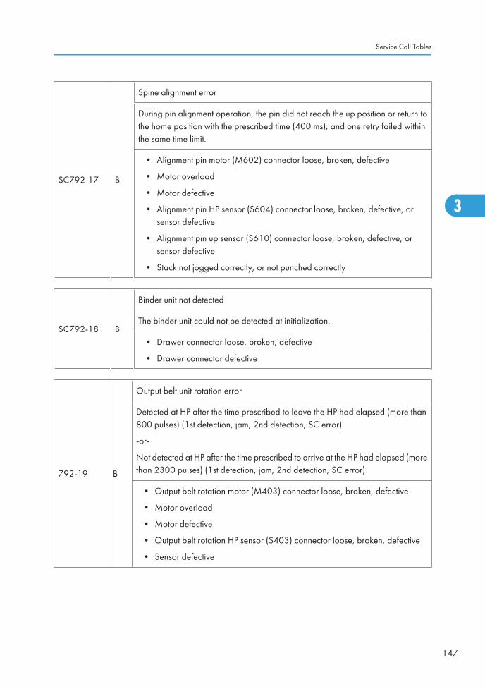
SC792-17 B
Spine alignment error
During pin alignment operation, the pin did not reach the up position or return tothe home position with the prescribed time (400 ms), and one retry failed withinthe same time limit.
• Alignment pin motor (M602) connector loose, broken, defective
• Motor overload
• Motor defective
• Alignment pin HP sensor (S604) connector loose, broken, defective, orsensor defective
• Alignment pin up sensor (S610) connector loose, broken, defective, orsensor defective
• Stack not jogged correctly, or not punched correctly
SC792-18 B
Binder unit not detected
The binder unit could not be detected at initialization.
• Drawer connector loose, broken, defective
• Drawer connector defective
792-19 B
Output belt unit rotation error
Detected at HP after the time prescribed to leave the HP had elapsed (more than800 pulses) (1st detection, jam, 2nd detection, SC error)
-or-
Not detected at HP after the time prescribed to arrive at the HP had elapsed (morethan 2300 pulses) (1st detection, jam, 2nd detection, SC error)
• Output belt rotation motor (M403) connector loose, broken, defective
• Motor overload
• Motor defective
• Output belt rotation HP sensor (S403) connector loose, broken, defective
• Sensor defective
Service Call Tables
147
3
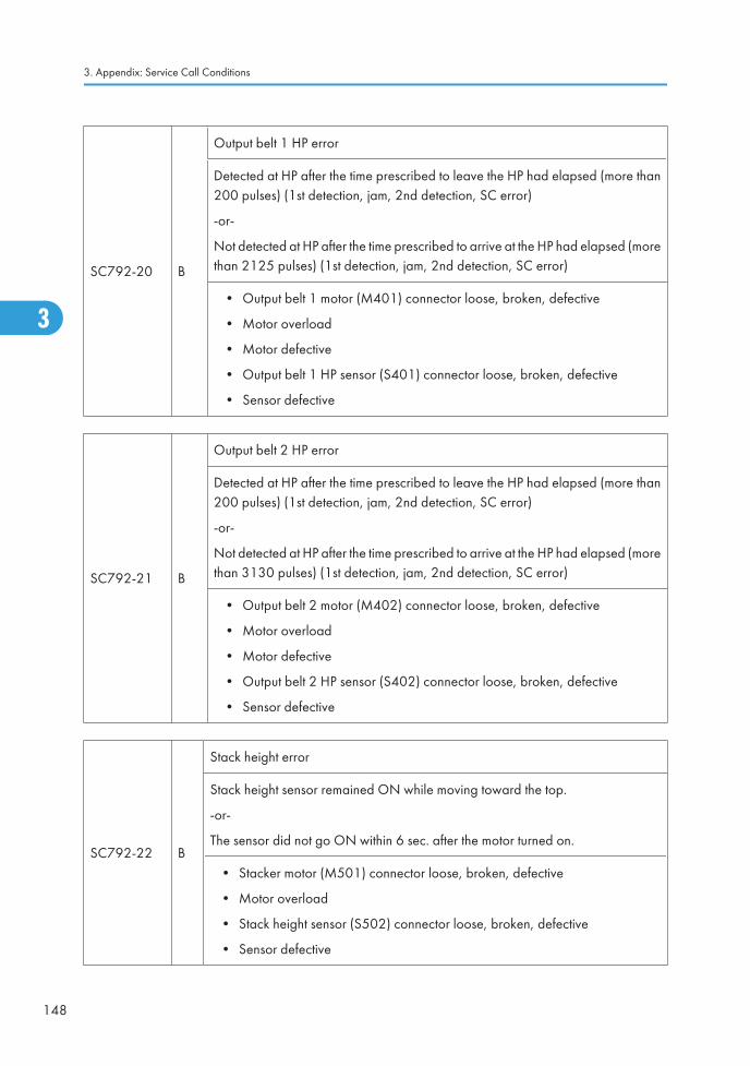
SC792-20 B
Output belt 1 HP error
Detected at HP after the time prescribed to leave the HP had elapsed (more than200 pulses) (1st detection, jam, 2nd detection, SC error)
-or-
Not detected at HP after the time prescribed to arrive at the HP had elapsed (morethan 2125 pulses) (1st detection, jam, 2nd detection, SC error)
• Output belt 1 motor (M401) connector loose, broken, defective
• Motor overload
• Motor defective
• Output belt 1 HP sensor (S401) connector loose, broken, defective
• Sensor defective
SC792-21 B
Output belt 2 HP error
Detected at HP after the time prescribed to leave the HP had elapsed (more than200 pulses) (1st detection, jam, 2nd detection, SC error)
-or-
Not detected at HP after the time prescribed to arrive at the HP had elapsed (morethan 3130 pulses) (1st detection, jam, 2nd detection, SC error)
• Output belt 2 motor (M402) connector loose, broken, defective
• Motor overload
• Motor defective
• Output belt 2 HP sensor (S402) connector loose, broken, defective
• Sensor defective
SC792-22 B
Stack height error
Stack height sensor remained ON while moving toward the top.
-or-
The sensor did not go ON within 6 sec. after the motor turned on.
• Stacker motor (M501) connector loose, broken, defective
• Motor overload
• Stack height sensor (S502) connector loose, broken, defective
• Sensor defective
3. Appendix: Service Call Conditions
148
3
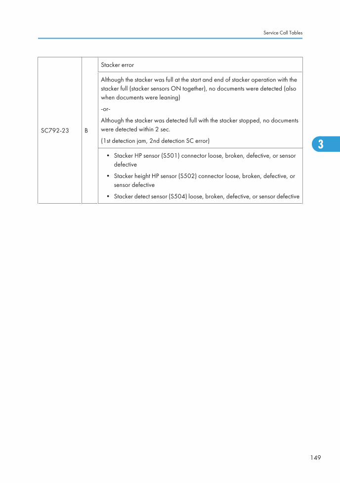
SC792-23 B
Stacker error
Although the stacker was full at the start and end of stacker operation with thestacker full (stacker sensors ON together), no documents were detected (alsowhen documents were leaning)
-or-
Although the stacker was detected full with the stacker stopped, no documentswere detected within 2 sec.
(1st detection jam, 2nd detection SC error)
• Stacker HP sensor (S501) connector loose, broken, defective, or sensordefective
• Stacker height HP sensor (S502) connector loose, broken, defective, orsensor defective
• Stacker detect sensor (S504) loose, broken, defective, or sensor defective
Service Call Tables
149
3
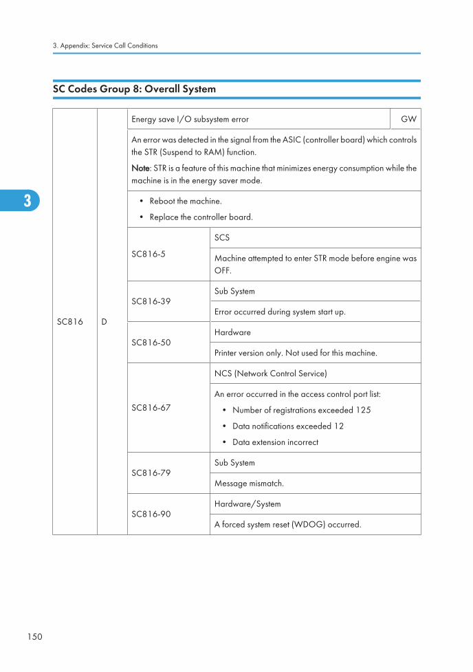
SC Codes Group 8: Overall System
SC816 D
Energy save I/O subsystem error GW
An error was detected in the signal from the ASIC (controller board) which controlsthe STR (Suspend to RAM) function.
Note: STR is a feature of this machine that minimizes energy consumption while themachine is in the energy saver mode.
• Reboot the machine.
• Replace the controller board.
SC816-5
SCS
Machine attempted to enter STR mode before engine wasOFF.
SC816-39Sub System
Error occurred during system start up.
SC816-50Hardware
Printer version only. Not used for this machine.
SC816-67
NCS (Network Control Service)
An error occurred in the access control port list:
• Number of registrations exceeded 125
• Data notifications exceeded 12
• Data extension incorrect
SC816-79Sub System
Message mismatch.
SC816-90Hardware/System
A forced system reset (WDOG) occurred.
3. Appendix: Service Call Conditions
150
3
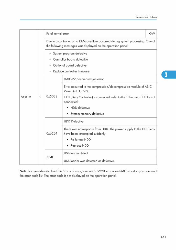
SC819 D
Fatal kernel error GW
Due to a control error, a RAM overflow occurred during system processing. One ofthe following messages was displayed on the operation panel.
• System program defective
• Controller board defective
• Optional board defective
• Replace controller firmware
0x5032
HAIC-P2 decompression error
Error occurred in the compression/decompression module of ASICVeena in HAIC-P2.
If EFI (Fiery Controller) is connected, refer to the EFI manual. If EFI is notconnected:
• HDD defective
• System memory defective
0x6261
HDD Defective
There was no response from HDD. The power supply to the HDD mayhave been interrupted suddenly.
• Re-format HDD.
• Replace HDD
554CUSB loader defect
USB loader was detected as defective.
Note: For more details about this SC code error, execute SP5990 to print an SMC report so you can readthe error code list. The error code is not displayed on the operation panel.
Service Call Tables
151
3
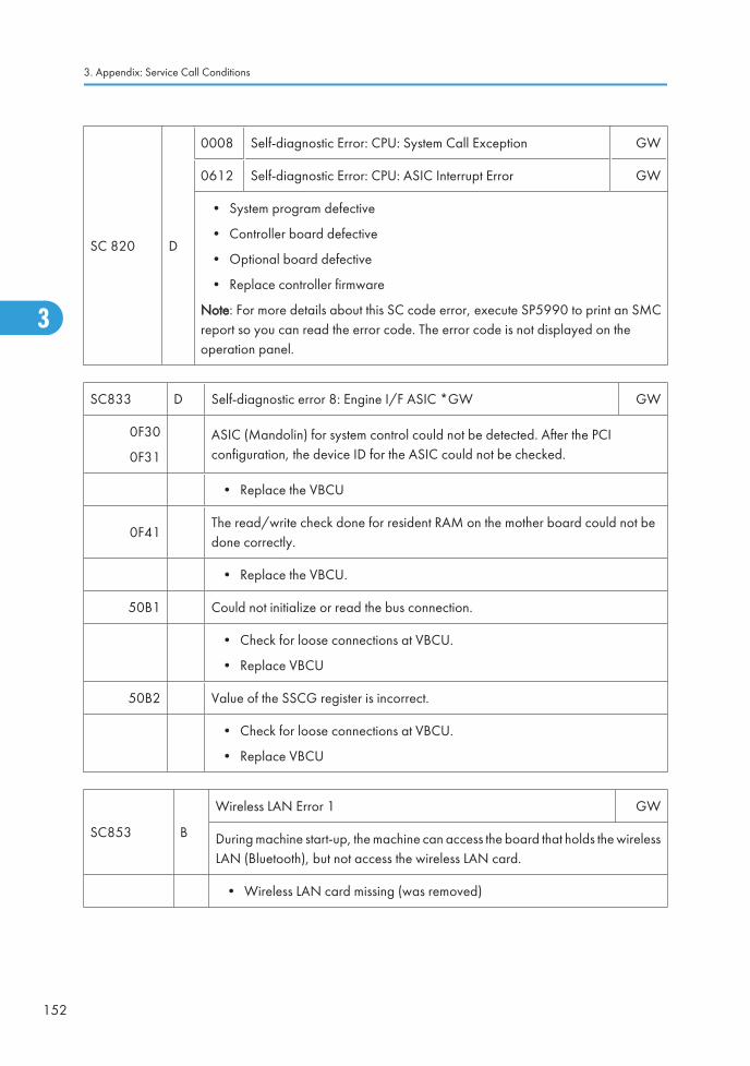
SC 820 D
0008 Self-diagnostic Error: CPU: System Call Exception GW
0612 Self-diagnostic Error: CPU: ASIC Interrupt Error GW
• System program defective
• Controller board defective
• Optional board defective
• Replace controller firmware
Note: For more details about this SC code error, execute SP5990 to print an SMCreport so you can read the error code. The error code is not displayed on theoperation panel.
SC833 D Self-diagnostic error 8: Engine I/F ASIC *GW GW
0F30
0F31
ASIC (Mandolin) for system control could not be detected. After the PCIconfiguration, the device ID for the ASIC could not be checked.
• Replace the VBCU
0F41The read/write check done for resident RAM on the mother board could not bedone correctly.
• Replace the VBCU.
50B1 Could not initialize or read the bus connection.
• Check for loose connections at VBCU.
• Replace VBCU
50B2 Value of the SSCG register is incorrect.
• Check for loose connections at VBCU.
• Replace VBCU
SC853 B
Wireless LAN Error 1 GW
During machine start-up, the machine can access the board that holds the wirelessLAN (Bluetooth), but not access the wireless LAN card.
• Wireless LAN card missing (was removed)
3. Appendix: Service Call Conditions
152
3
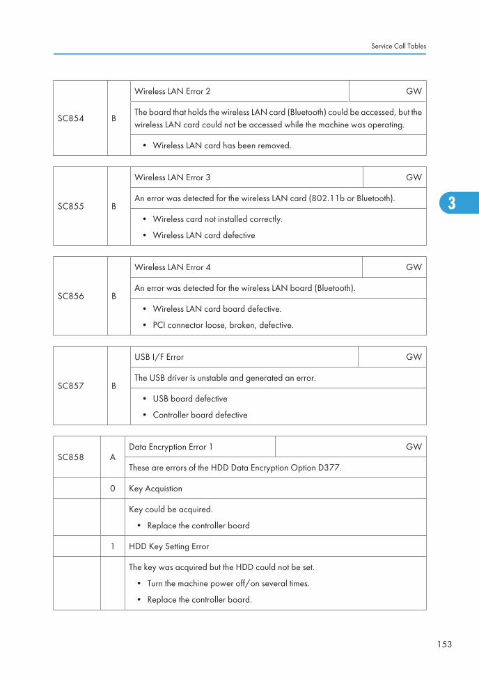
SC854 B
Wireless LAN Error 2 GW
The board that holds the wireless LAN card (Bluetooth) could be accessed, but thewireless LAN card could not be accessed while the machine was operating.
• Wireless LAN card has been removed.
SC855 B
Wireless LAN Error 3 GW
An error was detected for the wireless LAN card (802.11b or Bluetooth).
• Wireless card not installed correctly.
• Wireless LAN card defective
SC856 B
Wireless LAN Error 4 GW
An error was detected for the wireless LAN board (Bluetooth).
• Wireless LAN card board defective.
• PCI connector loose, broken, defective.
SC857 B
USB I/F Error GW
The USB driver is unstable and generated an error.
• USB board defective
• Controller board defective
SC858 AData Encryption Error 1 GW
These are errors of the HDD Data Encryption Option D377.
0 Key Acquistion
Key could be acquired.
• Replace the controller board
1 HDD Key Setting Error
The key was acquired but the HDD could not be set.
• Turn the machine power off/on several times.
• Replace the controller board.
Service Call Tables
153
3
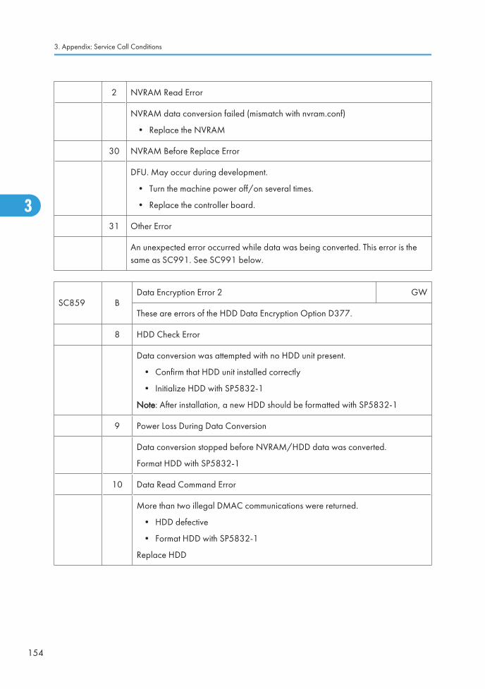
2 NVRAM Read Error
NVRAM data conversion failed (mismatch with nvram.conf)
• Replace the NVRAM
30 NVRAM Before Replace Error
DFU. May occur during development.
• Turn the machine power off/on several times.
• Replace the controller board.
31 Other Error
An unexpected error occurred while data was being converted. This error is thesame as SC991. See SC991 below.
SC859 BData Encryption Error 2 GW
These are errors of the HDD Data Encryption Option D377.
8 HDD Check Error
Data conversion was attempted with no HDD unit present.
• Confirm that HDD unit installed correctly
• Initialize HDD with SP5832-1
Note: After installation, a new HDD should be formatted with SP5832-1
9 Power Loss During Data Conversion
Data conversion stopped before NVRAM/HDD data was converted.
Format HDD with SP5832-1
10 Data Read Command Error
More than two illegal DMAC communications were returned.
• HDD defective
• Format HDD with SP5832-1
Replace HDD
3. Appendix: Service Call Conditions
154
3
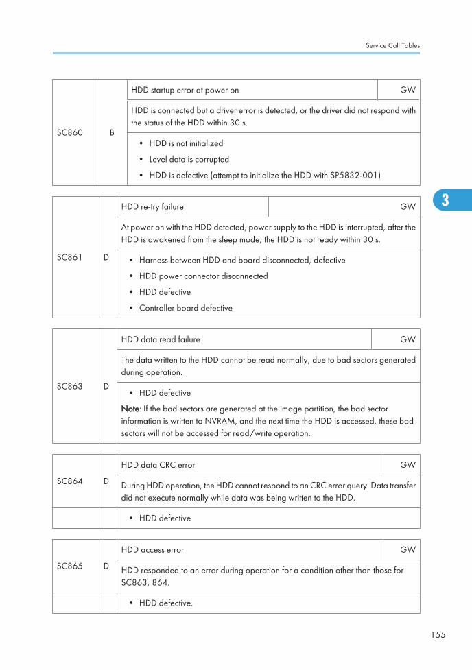
SC860 B
HDD startup error at power on GW
HDD is connected but a driver error is detected, or the driver did not respond withthe status of the HDD within 30 s.
• HDD is not initialized
• Level data is corrupted
• HDD is defective (attempt to initialize the HDD with SP5832-001)
SC861 D
HDD re-try failure GW
At power on with the HDD detected, power supply to the HDD is interrupted, after theHDD is awakened from the sleep mode, the HDD is not ready within 30 s.
• Harness between HDD and board disconnected, defective
• HDD power connector disconnected
• HDD defective
• Controller board defective
SC863 D
HDD data read failure GW
The data written to the HDD cannot be read normally, due to bad sectors generatedduring operation.
• HDD defective
Note: If the bad sectors are generated at the image partition, the bad sectorinformation is written to NVRAM, and the next time the HDD is accessed, these badsectors will not be accessed for read/write operation.
SC864 D
HDD data CRC error GW
During HDD operation, the HDD cannot respond to an CRC error query. Data transferdid not execute normally while data was being written to the HDD.
• HDD defective
SC865 D
HDD access error GW
HDD responded to an error during operation for a condition other than those forSC863, 864.
• HDD defective.
Service Call Tables
155
3
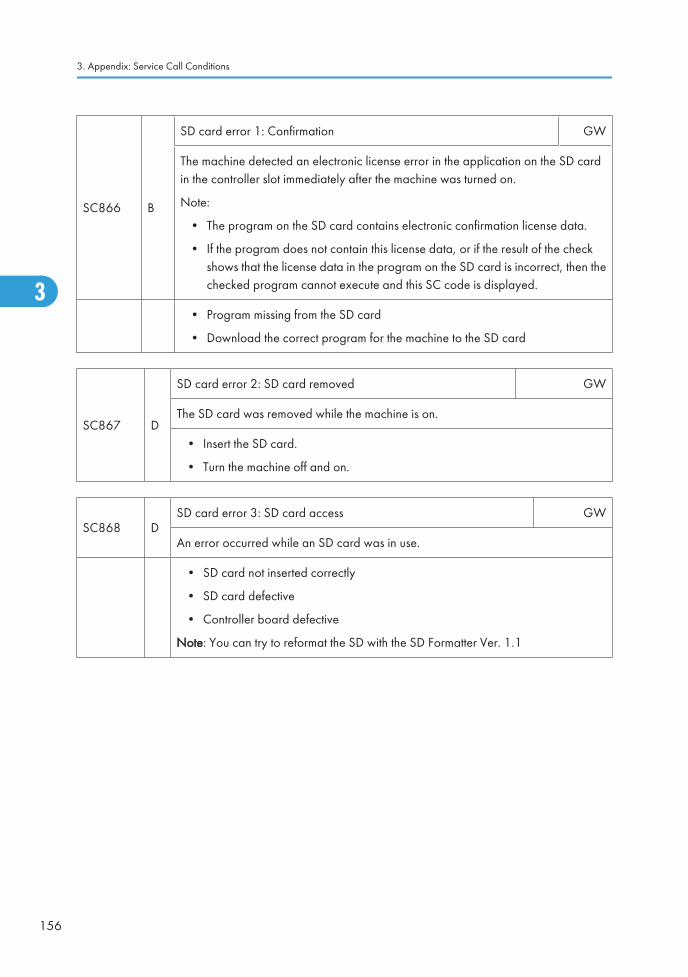
SC866 B
SD card error 1: Confirmation GW
The machine detected an electronic license error in the application on the SD cardin the controller slot immediately after the machine was turned on.
Note:
• The program on the SD card contains electronic confirmation license data.
• If the program does not contain this license data, or if the result of the checkshows that the license data in the program on the SD card is incorrect, then thechecked program cannot execute and this SC code is displayed.
• Program missing from the SD card
• Download the correct program for the machine to the SD card
SC867 D
SD card error 2: SD card removed GW
The SD card was removed while the machine is on.
• Insert the SD card.
• Turn the machine off and on.
SC868 DSD card error 3: SD card access GW
An error occurred while an SD card was in use.
• SD card not inserted correctly
• SD card defective
• Controller board defective
Note: You can try to reformat the SD with the SD Formatter Ver. 1.1
3. Appendix: Service Call Conditions
156
3

SC870 B
Address book data error GW
The address book data cannot be read from the HDD or SD card where it is stored, orthe data read from the media is defective.
• Cycle the machine off/on.
• Software defective.
• Replace controller firmware.
• HDD defective.
More Details
• Do SP5846-50 to reset all address book data.
• Reset the user information with SP5832-6.
• Replace the HDDs.
SC872 B
HDD mail receive data error GW
An HDD error was detected immediately after power on, or the machine detectedthat the HDD was not operating correctly (data read or write) while receivingmail. The HDD may be defective or the machine was accidentally powered offwhile the HDD was being accessed.
• Reformat the mail RX data on the HDD with SP5832-7
• Replace the HDD
SC873 B
HDD mail send data error GW
An error was detected on the HDD immediately after the machine was turnedon, or power was turned of while the machine was using the HDD.
• Do SP5832-007 (Format HDD – Mail TX Data) to initialize the HDD.
• Replace the HDD.
Service Call Tables
157
3
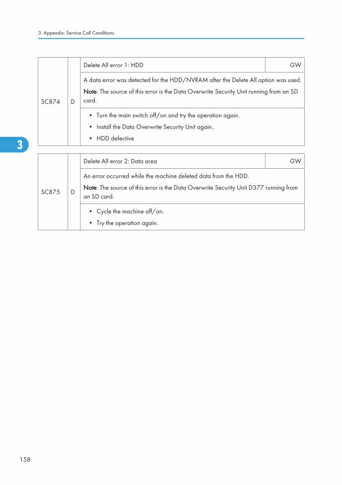
SC874 D
Delete All error 1: HDD GW
A data error was detected for the HDD/NVRAM after the Delete All option was used.
Note: The source of this error is the Data Overwrite Security Unit running from an SDcard.
• Turn the main switch off/on and try the operation again.
• Install the Data Overwrite Security Unit again..
• HDD defective
SC875 D
Delete All error 2: Data area GW
An error occurred while the machine deleted data from the HDD.
Note: The source of this error is the Data Overwrite Security Unit D377 running froman SD card.
• Cycle the machine off/on.
• Try the operation again.
3. Appendix: Service Call Conditions
158
3
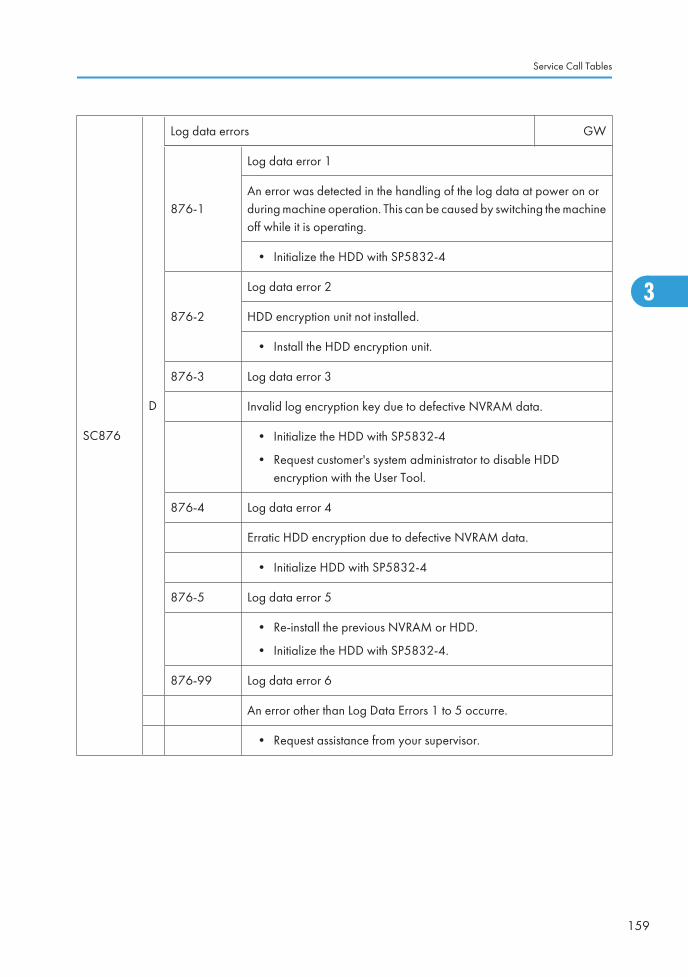
SC876
D
Log data errors GW
876-1
Log data error 1
An error was detected in the handling of the log data at power on orduring machine operation. This can be caused by switching the machineoff while it is operating.
• Initialize the HDD with SP5832-4
876-2
Log data error 2
HDD encryption unit not installed.
• Install the HDD encryption unit.
876-3 Log data error 3
Invalid log encryption key due to defective NVRAM data.
• Initialize the HDD with SP5832-4
• Request customer's system administrator to disable HDDencryption with the User Tool.
876-4 Log data error 4
Erratic HDD encryption due to defective NVRAM data.
• Initialize HDD with SP5832-4
876-5 Log data error 5
• Re-install the previous NVRAM or HDD.
• Initialize the HDD with SP5832-4.
876-99 Log data error 6
An error other than Log Data Errors 1 to 5 occurre.
• Request assistance from your supervisor.
Service Call Tables
159
3
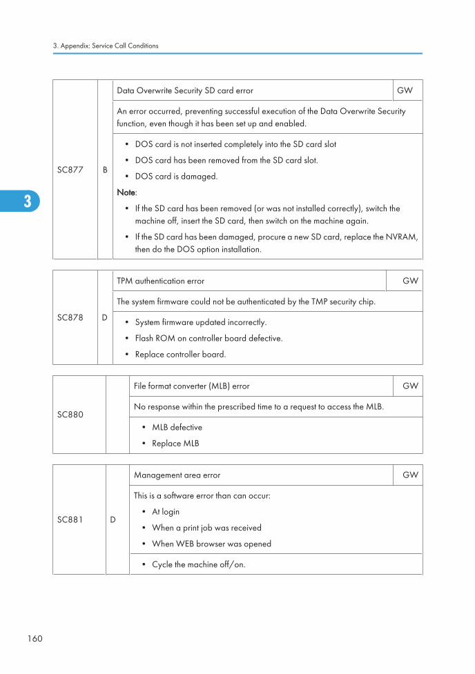
SC877 B
Data Overwrite Security SD card error GW
An error occurred, preventing successful execution of the Data Overwrite Securityfunction, even though it has been set up and enabled.
• DOS card is not inserted completely into the SD card slot
• DOS card has been removed from the SD card slot.
• DOS card is damaged.
Note:
• If the SD card has been removed (or was not installed correctly), switch themachine off, insert the SD card, then switch on the machine again.
• If the SD card has been damaged, procure a new SD card, replace the NVRAM,then do the DOS option installation.
SC878 D
TPM authentication error GW
The system firmware could not be authenticated by the TMP security chip.
• System firmware updated incorrectly.
• Flash ROM on controller board defective.
• Replace controller board.
SC880
File format converter (MLB) error GW
No response within the prescribed time to a request to access the MLB.
• MLB defective
• Replace MLB
SC881 D
Management area error GW
This is a software error than can occur:
• At login
• When a print job was received
• When WEB browser was opened
• Cycle the machine off/on.
3. Appendix: Service Call Conditions
160
3
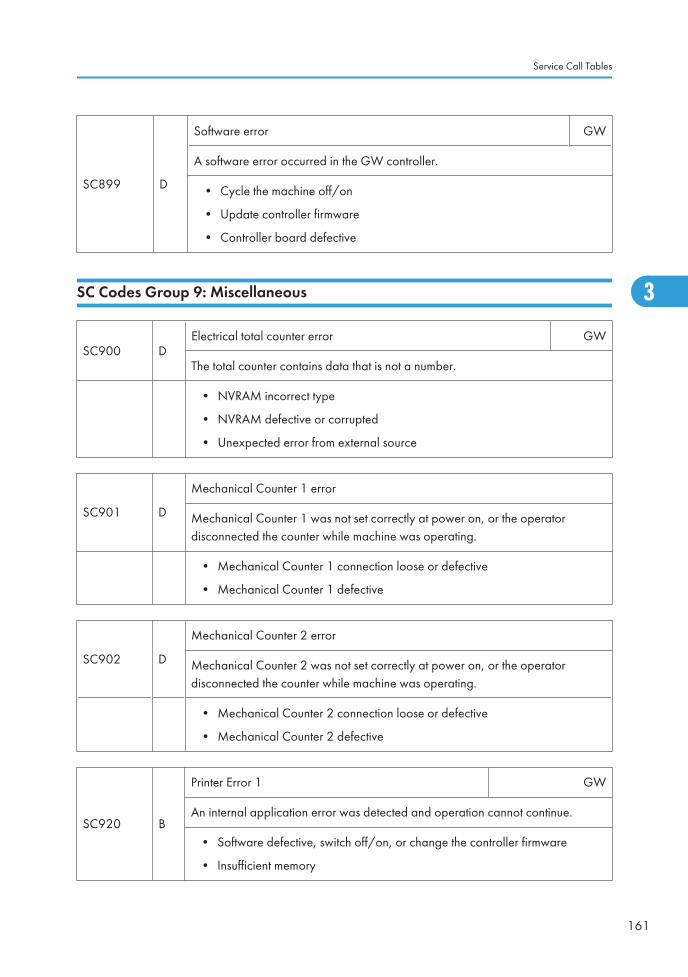
SC899 D
Software error GW
A software error occurred in the GW controller.
• Cycle the machine off/on
• Update controller firmware
• Controller board defective
SC Codes Group 9: Miscellaneous
SC900 DElectrical total counter error GW
The total counter contains data that is not a number.
• NVRAM incorrect type
• NVRAM defective or corrupted
• Unexpected error from external source
SC901 D
Mechanical Counter 1 error
Mechanical Counter 1 was not set correctly at power on, or the operatordisconnected the counter while machine was operating.
• Mechanical Counter 1 connection loose or defective
• Mechanical Counter 1 defective
SC902 D
Mechanical Counter 2 error
Mechanical Counter 2 was not set correctly at power on, or the operatordisconnected the counter while machine was operating.
• Mechanical Counter 2 connection loose or defective
• Mechanical Counter 2 defective
SC920 B
Printer Error 1 GW
An internal application error was detected and operation cannot continue.
• Software defective, switch off/on, or change the controller firmware
• Insufficient memory
Service Call Tables
161
3
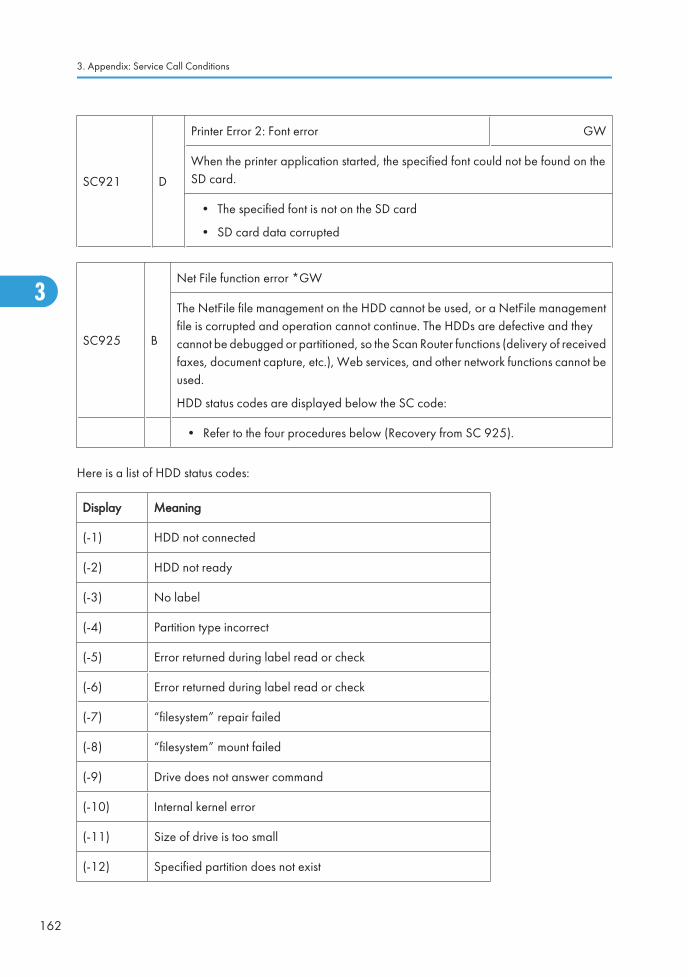
SC921 D
Printer Error 2: Font error GW
When the printer application started, the specified font could not be found on theSD card.
• The specified font is not on the SD card
• SD card data corrupted
SC925 B
Net File function error *GW
The NetFile file management on the HDD cannot be used, or a NetFile managementfile is corrupted and operation cannot continue. The HDDs are defective and theycannot be debugged or partitioned, so the Scan Router functions (delivery of receivedfaxes, document capture, etc.), Web services, and other network functions cannot beused.
HDD status codes are displayed below the SC code:
• Refer to the four procedures below (Recovery from SC 925).
Here is a list of HDD status codes:
Display Meaning
(-1) HDD not connected
(-2) HDD not ready
(-3) No label
(-4) Partition type incorrect
(-5) Error returned during label read or check
(-6) Error returned during label read or check
(-7) “filesystem” repair failed
(-8) “filesystem” mount failed
(-9) Drive does not answer command
(-10) Internal kernel error
(-11) Size of drive is too small
(-12) Specified partition does not exist
3. Appendix: Service Call Conditions
162
3
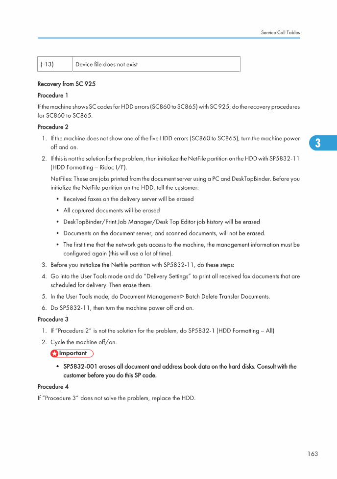
(-13) Device file does not exist
Recovery from SC 925
Procedure 1
If the machine shows SC codes for HDD errors (SC860 to SC865) with SC 925, do the recovery proceduresfor SC860 to SC865.
Procedure 2
1. If the machine does not show one of the five HDD errors (SC860 to SC865), turn the machine poweroff and on.
2. If this is not the solution for the problem, then initialize the NetFile partition on the HDD with SP5832-11(HDD Formatting – Ridoc I/F).
NetFiles: These are jobs printed from the document server using a PC and DeskTopBinder. Before youinitialize the NetFile partition on the HDD, tell the customer:
• Received faxes on the delivery server will be erased
• All captured documents will be erased
• DeskTopBinder/Print Job Manager/Desk Top Editor job history will be erased
• Documents on the document server, and scanned documents, will not be erased.
• The first time that the network gets access to the machine, the management information must beconfigured again (this will use a lot of time).
3. Before you initialize the Netfile partition with SP5832-11, do these steps:
4. Go into the User Tools mode and do “Delivery Settings” to print all received fax documents that arescheduled for delivery. Then erase them.
5. In the User Tools mode, do Document Management> Batch Delete Transfer Documents.
6. Do SP5832-11, then turn the machine power off and on.
Procedure 3
1. If “Procedure 2” is not the solution for the problem, do SP5832-1 (HDD Formatting – All)
2. Cycle the machine off/on.
• SP5832-001 erases all document and address book data on the hard disks. Consult with thecustomer before you do this SP code.
Procedure 4
If “Procedure 3” does not solve the problem, replace the HDD.
Service Call Tables
163
3
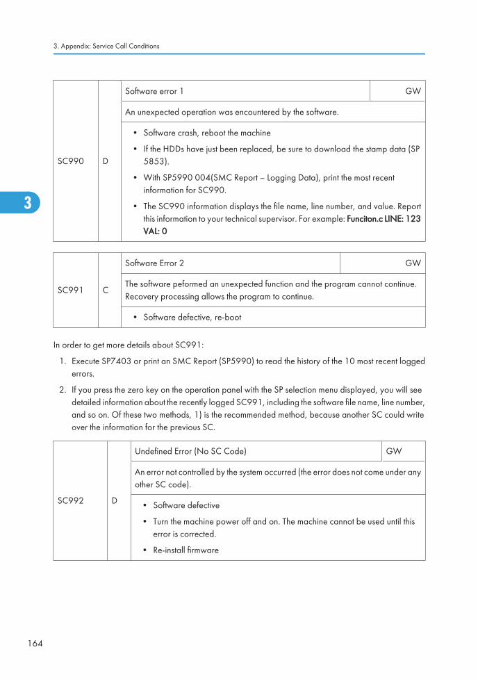
SC990 D
Software error 1 GW
An unexpected operation was encountered by the software.
• Software crash, reboot the machine
• If the HDDs have just been replaced, be sure to download the stamp data (SP5853).
• With SP5990 004(SMC Report – Logging Data), print the most recentinformation for SC990.
• The SC990 information displays the file name, line number, and value. Reportthis information to your technical supervisor. For example: Funciton.c LINE: 123VAL: 0
SC991 C
Software Error 2 GW
The software peformed an unexpected function and the program cannot continue.Recovery processing allows the program to continue.
• Software defective, re-boot
In order to get more details about SC991:
1. Execute SP7403 or print an SMC Report (SP5990) to read the history of the 10 most recent loggederrors.
2. If you press the zero key on the operation panel with the SP selection menu displayed, you will seedetailed information about the recently logged SC991, including the software file name, line number,and so on. Of these two methods, 1) is the recommended method, because another SC could writeover the information for the previous SC.
SC992 D
Undefined Error (No SC Code) GW
An error not controlled by the system occurred (the error does not come under anyother SC code).
• Software defective
• Turn the machine power off and on. The machine cannot be used until thiserror is corrected.
• Re-install firmware
3. Appendix: Service Call Conditions
164
3
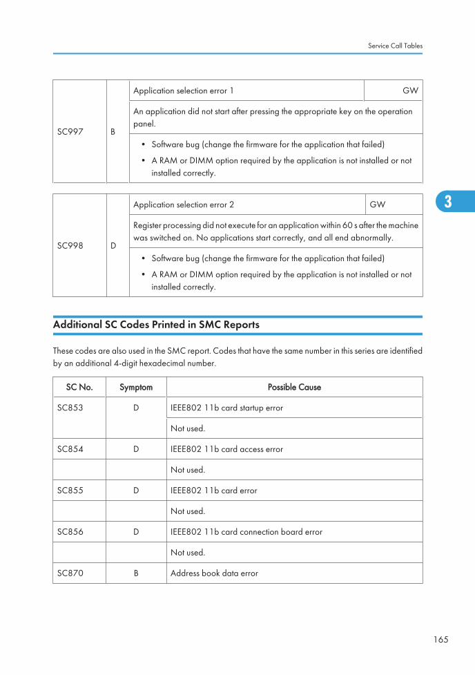
SC997 B
Application selection error 1 GW
An application did not start after pressing the appropriate key on the operationpanel.
• Software bug (change the firmware for the application that failed)
• A RAM or DIMM option required by the application is not installed or notinstalled correctly.
SC998 D
Application selection error 2 GW
Register processing did not execute for an application within 60 s after the machinewas switched on. No applications start correctly, and all end abnormally.
• Software bug (change the firmware for the application that failed)
• A RAM or DIMM option required by the application is not installed or notinstalled correctly.
Additional SC Codes Printed in SMC Reports
These codes are also used in the SMC report. Codes that have the same number in this series are identifiedby an additional 4-digit hexadecimal number.
SC No. Symptom Possible Cause
SC853 D IEEE802 11b card startup error
Not used.
SC854 D IEEE802 11b card access error
Not used.
SC855 D IEEE802 11b card error
Not used.
SC856 D IEEE802 11b card connection board error
Not used.
SC870 B Address book data error
Service Call Tables
165
3
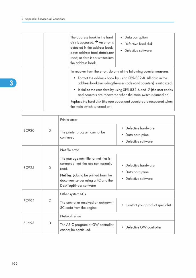
The address book in the harddisk is accessed. An error isdetected in the address bookdata; address book data is notread; or data is not written intothe address book.
• Data corruption
• Defective hard disk
• Defective software
To recover from the error, do any of the following countermeasures:
• Format the address book by using SP5-832-8. All data in theaddress book (including the user codes and counters) is initialized)
• Initialize the user data by using SP5-832-6 and -7 (the user codesand counters are recovered when the main switch is turned on).
Replace the hard disk (the user codes and counters are recovered whenthe main switch is turned on).
SC920 D
Printer error
The printer program cannot becontinued.
• Defective hardware
• Data corruption
• Defective software
SC925 D
Net file error
The management file for net files iscorrupted; net files are not normallyread.
Netfiles: Jobs to be printed from thedocument server using a PC and theDeskTopBinder software
• Defective hardware
• Data corruption
• Defective software
SC992 C
Other system SCs
The controller received an unknownSC code from the engine.
• Contact your product specialist.
SC993 D
Network error
The ASIC program of GW controllercannot be continued.
• Defective GW controller
3. Appendix: Service Call Conditions
166
3
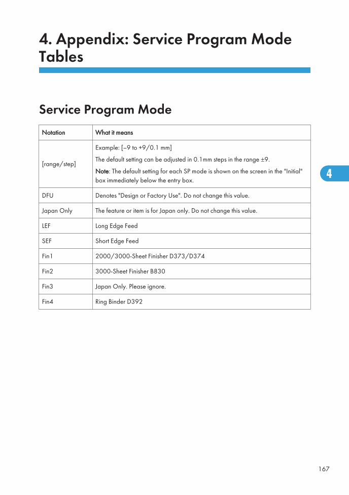
4. Appendix: Service Program ModeTables
Service Program ModeNotation What it means
[range/step]
Example: [–9 to +9/0.1 mm]
The default setting can be adjusted in 0.1mm steps in the range ±9.
Note: The default setting for each SP mode is shown on the screen in the "Initial"box immediately below the entry box.
DFU Denotes "Design or Factory Use". Do not change this value.
Japan Only The feature or item is for Japan only. Do not change this value.
LEF Long Edge Feed
SEF Short Edge Feed
Fin1 2000/3000-Sheet Finisher D373/D374
Fin2 3000-Sheet Finisher B830
Fin3 Japan Only. Please ignore.
Fin4 Ring Binder D392
167
4

Group 10001001
Lead Edge Reg
Adjusts the printing leading edge registration using the trimming area pattern (SP2109-2, PatternNo. 10).
[–9 to +9/ 0.1 mm]
Specification: 3 ±2mm
1002 Fine Adj LEdge (Thick)
Fine adjusts leading edge registration for thick paper (Thick 2, Thick 3).
[–9 to +9/ 0.1 mm]
1 Thick 2 Thick 2: 164 to 249.9 g/m2
2 Thick 3 Thick 3: 250 to 300 g/m2
1003
Side-to-Side Reg
Side-to-Side Registration Adjustment. Adjusts printing side-to-side registration for each feedstation, using the test pattern (SP2109-2, Pattern No. 10). These SP's should be adjusted afterreplacing the laser synchronization detector or the laser optical unit.
1 Tray 1 [–9 to +9/ 0.1 mm]
2 Tray 2
3 Tray 3
4 Tray 4 Japan Only
5 Bypass Tray
6 Dupx Tray
7 LCT LCT1: B473
8 WIDE LCT LCT2: D350
4. Appendix: Service Program Mode Tables
168
4
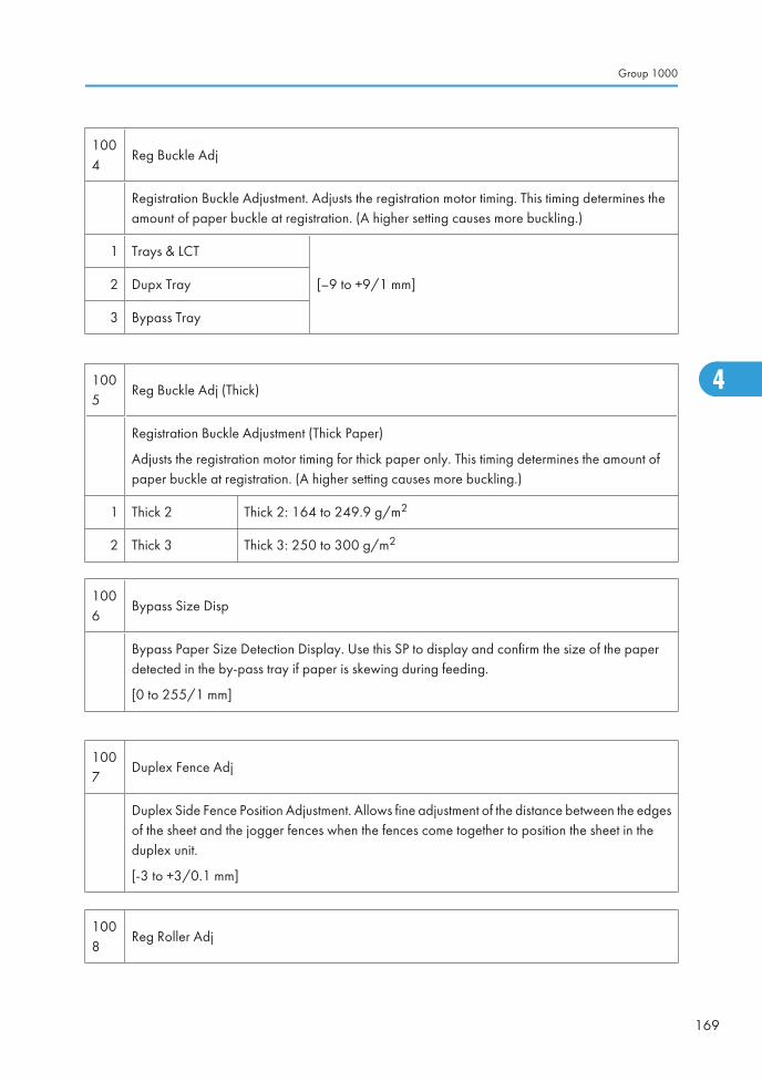
1004
Reg Buckle Adj
Registration Buckle Adjustment. Adjusts the registration motor timing. This timing determines theamount of paper buckle at registration. (A higher setting causes more buckling.)
1 Trays & LCT
[–9 to +9/1 mm]2 Dupx Tray
3 Bypass Tray
1005
Reg Buckle Adj (Thick)
Registration Buckle Adjustment (Thick Paper)
Adjusts the registration motor timing for thick paper only. This timing determines the amount ofpaper buckle at registration. (A higher setting causes more buckling.)
1 Thick 2 Thick 2: 164 to 249.9 g/m2
2 Thick 3 Thick 3: 250 to 300 g/m2
1006
Bypass Size Disp
Bypass Paper Size Detection Display. Use this SP to display and confirm the size of the paperdetected in the by-pass tray if paper is skewing during feeding.
[0 to 255/1 mm]
1007
Duplex Fence Adj
Duplex Side Fence Position Adjustment. Allows fine adjustment of the distance between the edgesof the sheet and the jogger fences when the fences come together to position the sheet in theduplex unit.
[-3 to +3/0.1 mm]
1008
Reg Roller Adj
Group 1000
169
4
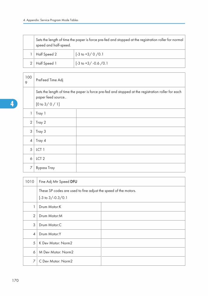
Sets the length of time the paper is force pre-fed and stopped at the registration roller for normalspeed and half-speed.
1 Half Speed 2 [-3 to +3/ 0 /0.1
2 Half Speed 1 [-3 to +3/ -0.6 /0.1
1009
PreFeed Time Adj
Sets the length of time the paper is force pre-fed and stopped at the registration roller for eachpaper feed source..
[0 to 3/ 0 / 1]
1 Tray 1
2 Tray 2
3 Tray 3
4 Tray 4
5 LCT 1
6 LCT 2
7 Bypass Tray
1010 Fine Adj Mtr Speed DFU
These SP codes are used to fine adjust the speed of the motors.
[-3 to 3/-0.3/0.1
1 Drum Motor:K
2 Drum Motor:M
3 Drum Motor:C
4 Drum Motor:Y
5 K Dev Motor: Norm2
6 M Dev Motor: Norm2
7 C Dev Motor: Norm2
4. Appendix: Service Program Mode Tables
170
4
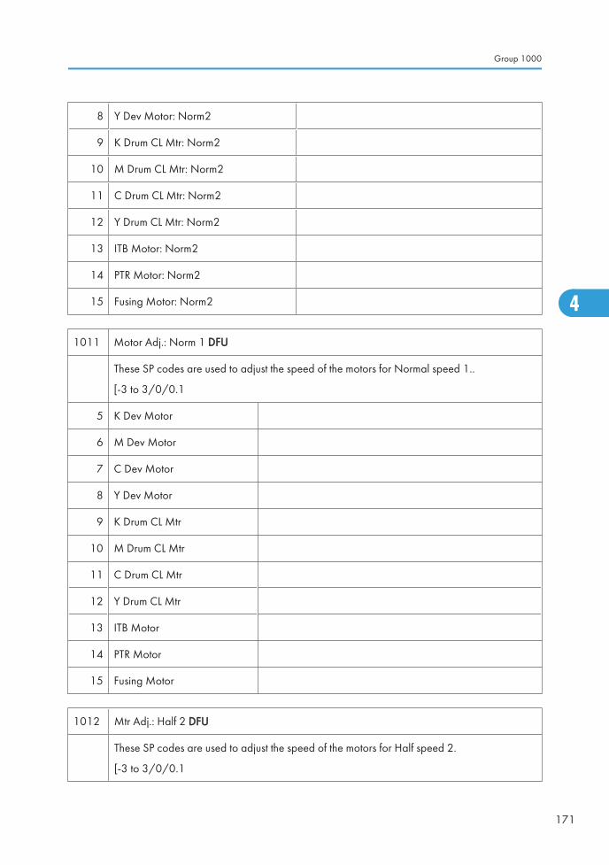
8 Y Dev Motor: Norm2
9 K Drum CL Mtr: Norm2
10 M Drum CL Mtr: Norm2
11 C Drum CL Mtr: Norm2
12 Y Drum CL Mtr: Norm2
13 ITB Motor: Norm2
14 PTR Motor: Norm2
15 Fusing Motor: Norm2
1011 Motor Adj.: Norm 1 DFU
These SP codes are used to adjust the speed of the motors for Normal speed 1..
[-3 to 3/0/0.1
5 K Dev Motor
6 M Dev Motor
7 C Dev Motor
8 Y Dev Motor
9 K Drum CL Mtr
10 M Drum CL Mtr
11 C Drum CL Mtr
12 Y Drum CL Mtr
13 ITB Motor
14 PTR Motor
15 Fusing Motor
1012 Mtr Adj.: Half 2 DFU
These SP codes are used to adjust the speed of the motors for Half speed 2.
[-3 to 3/0/0.1
Group 1000
171
4
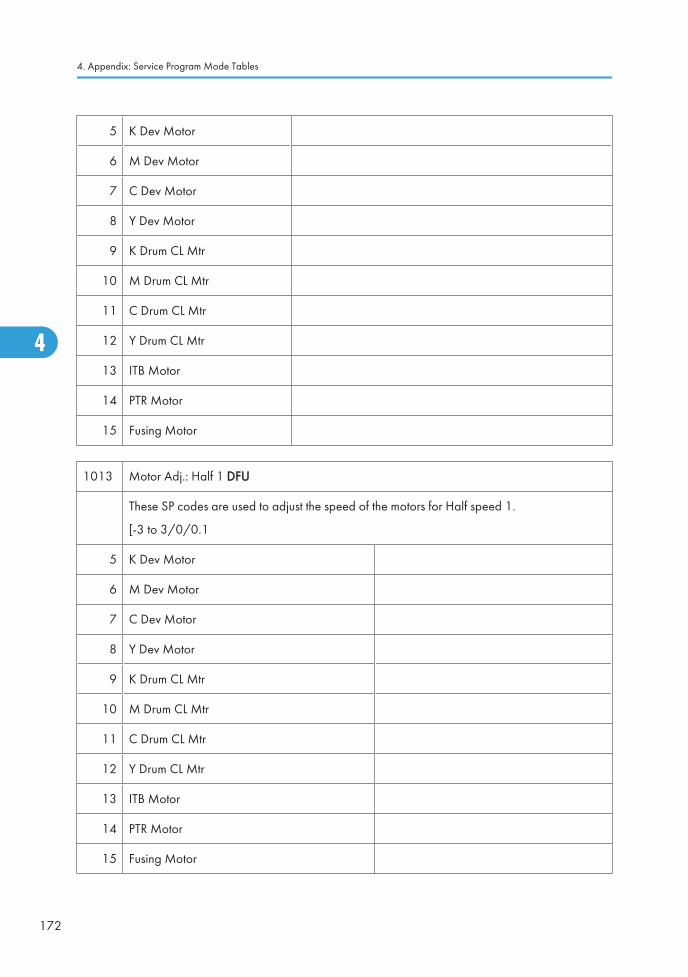
5 K Dev Motor
6 M Dev Motor
7 C Dev Motor
8 Y Dev Motor
9 K Drum CL Mtr
10 M Drum CL Mtr
11 C Drum CL Mtr
12 Y Drum CL Mtr
13 ITB Motor
14 PTR Motor
15 Fusing Motor
1013 Motor Adj.: Half 1 DFU
These SP codes are used to adjust the speed of the motors for Half speed 1.
[-3 to 3/0/0.1
5 K Dev Motor
6 M Dev Motor
7 C Dev Motor
8 Y Dev Motor
9 K Drum CL Mtr
10 M Drum CL Mtr
11 C Drum CL Mtr
12 Y Drum CL Mtr
13 ITB Motor
14 PTR Motor
15 Fusing Motor
4. Appendix: Service Program Mode Tables
172
4
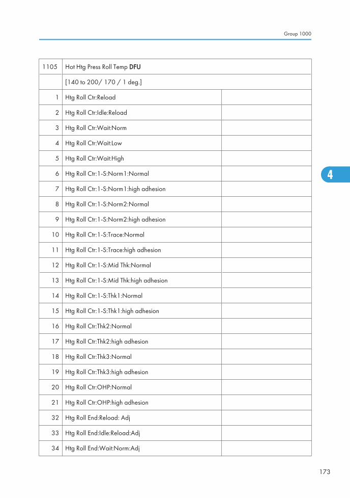
1105 Hot Htg Press Roll Temp DFU
[140 to 200/ 170 / 1 deg.]
1 Htg Roll Ctr:Reload
2 Htg Roll Ctr:Idle:Reload
3 Htg Roll Ctr:Wait:Norm
4 Htg Roll Ctr:Wait:Low
5 Htg Roll Ctr:Wait:High
6 Htg Roll Ctr:1-S:Norm1:Normal
7 Htg Roll Ctr:1-S:Norm1:high adhesion
8 Htg Roll Ctr:1-S:Norm2:Normal
9 Htg Roll Ctr:1-S:Norm2:high adhesion
10 Htg Roll Ctr:1-S:Trace:Normal
11 Htg Roll Ctr:1-S:Trace:high adhesion
12 Htg Roll Ctr:1-S:Mid Thk:Normal
13 Htg Roll Ctr:1-S:Mid Thk:high adhesion
14 Htg Roll Ctr:1-S:Thk1:Normal
15 Htg Roll Ctr:1-S:Thk1:high adhesion
16 Htg Roll Ctr:Thk2:Normal
17 Htg Roll Ctr:Thk2:high adhesion
18 Htg Roll Ctr:Thk3:Normal
19 Htg Roll Ctr:Thk3:high adhesion
20 Htg Roll Ctr:OHP:Normal
21 Htg Roll Ctr:OHP:high adhesion
32 Htg Roll End:Reload: Adj
33 Htg Roll End:Idle:Reload:Adj
34 Htg Roll End:Wait:Norm:Adj
Group 1000
173
4
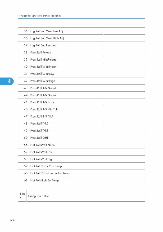
35 Htg Roll End:Wait:Low:Adj
36 Htg Roll End:Wait:High:Adj
37 Htg Roll End:Feed:Adj
38 Press Roll:Reload
39 Press Roll:Idle:Reload
40 Press Roll:Wait:Norm
41 Press Roll:Wait:Low
42 Press Roll:Wait:High
43 Press Roll:1-S:Norm1
44 Press Roll:1-S:Norm2
45 Press Roll:1-S:Trace
46 Press Roll:1-S:Mid Thk
47 Press Roll:1-S:Thk1
48 Press Roll:Thk2
49 Press Roll:Thk3
50 Press Roll:OHP
56 Hot Roll:Wait:Norm
57 Hot Roll:Wait:Low
58 Hot Roll:Wait:High
59 Hot Roll L3:Ctr Corr Temp
60 Hot Roll L3:End correction Temp
61 Hot Roll:High Rot Temp
1106
Fusing Temp Disp
4. Appendix: Service Program Mode Tables
174
4
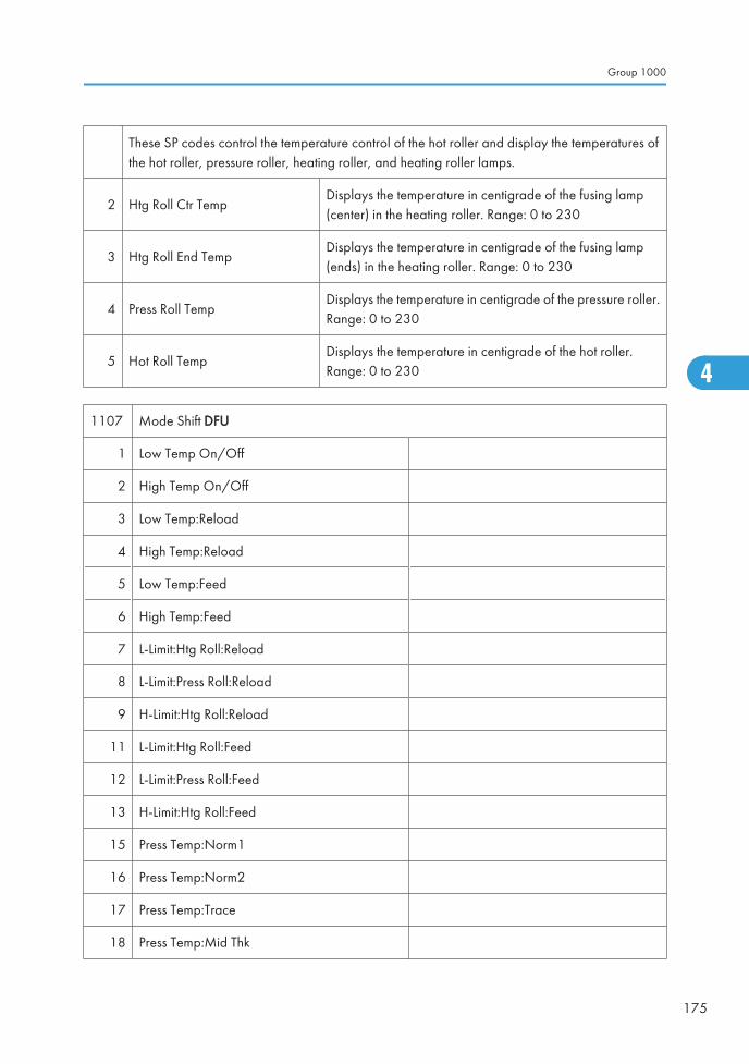
These SP codes control the temperature control of the hot roller and display the temperatures ofthe hot roller, pressure roller, heating roller, and heating roller lamps.
2 Htg Roll Ctr TempDisplays the temperature in centigrade of the fusing lamp(center) in the heating roller. Range: 0 to 230
3 Htg Roll End TempDisplays the temperature in centigrade of the fusing lamp(ends) in the heating roller. Range: 0 to 230
4 Press Roll TempDisplays the temperature in centigrade of the pressure roller.Range: 0 to 230
5 Hot Roll TempDisplays the temperature in centigrade of the hot roller.Range: 0 to 230
1107 Mode Shift DFU
1 Low Temp On/Off
2 High Temp On/Off
3 Low Temp:Reload
4 High Temp:Reload
5 Low Temp:Feed
6 High Temp:Feed
7 L-Limit:Htg Roll:Reload
8 L-Limit:Press Roll:Reload
9 H-Limit:Htg Roll:Reload
11 L-Limit:Htg Roll:Feed
12 L-Limit:Press Roll:Feed
13 H-Limit:Htg Roll:Feed
15 Press Temp:Norm1
16 Press Temp:Norm2
17 Press Temp:Trace
18 Press Temp:Mid Thk
Group 1000
175
4
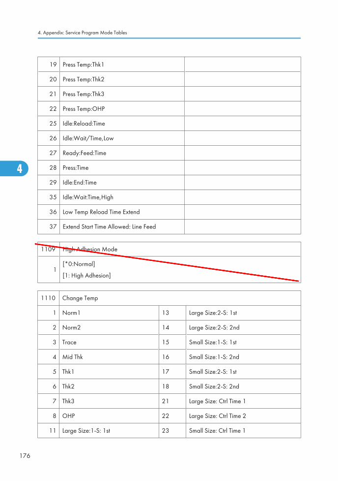
19 Press Temp:Thk1
20 Press Temp:Thk2
21 Press Temp:Thk3
22 Press Temp:OHP
25 Idle:Reload:Time
26 Idle:Wait/Time,Low
27 Ready:Feed:Time
28 Press:Time
29 Idle:End:Time
35 Idle:Wait:Time,High
36 Low Temp Reload Time Extend
37 Extend Start Time Allowed: Line Feed
1109 High Adhesion Mode
1[*0:Normal]
[1: High Adhesion]
1110 Change Temp
1 Norm1 13 Large Size:2-S: 1st
2 Norm2 14 Large Size:2-S: 2nd
3 Trace 15 Small Size:1-S: 1st
4 Mid Thk 16 Small Size:1-S: 2nd
5 Thk1 17 Small Size:2-S: 1st
6 Thk2 18 Small Size:2-S: 2nd
7 Thk3 21 Large Size: Ctrl Time 1
8 OHP 22 Large Size: Ctrl Time 2
11 Large Size:1-S: 1st 23 Small Size: Ctrl Time 1
4. Appendix: Service Program Mode Tables
176
4
Ed O'Brien
Ed
Typewritten Text
SP1109 RTB 56: This SP is not used in this model
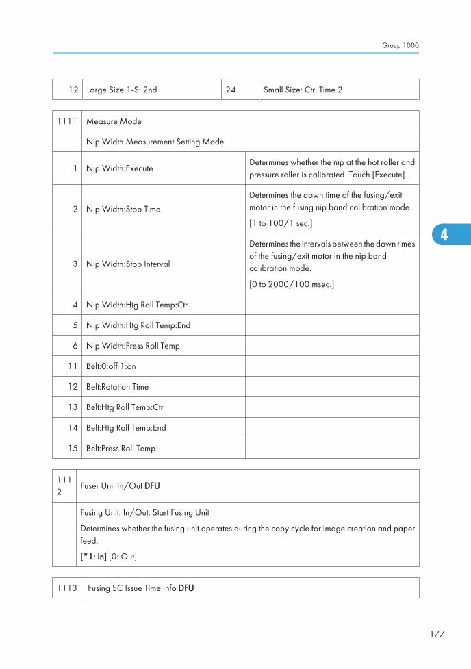
12 Large Size:1-S: 2nd 24 Small Size: Ctrl Time 2
1111 Measure Mode
Nip Width Measurement Setting Mode
1 Nip Width:ExecuteDetermines whether the nip at the hot roller andpressure roller is calibrated. Touch [Execute].
2 Nip Width:Stop Time
Determines the down time of the fusing/exitmotor in the fusing nip band calibration mode.
[1 to 100/1 sec.]
3 Nip Width:Stop Interval
Determines the intervals between the down timesof the fusing/exit motor in the nip bandcalibration mode.
[0 to 2000/100 msec.]
4 Nip Width:Htg Roll Temp:Ctr
5 Nip Width:Htg Roll Temp:End
6 Nip Width:Press Roll Temp
11 Belt:0:off 1:on
12 Belt:Rotation Time
13 Belt:Htg Roll Temp:Ctr
14 Belt:Htg Roll Temp:End
15 Belt:Press Roll Temp
1112
Fuser Unit In/Out DFU
Fusing Unit: In/Out: Start Fusing Unit
Determines whether the fusing unit operates during the copy cycle for image creation and paperfeed.
[*1: In] [0: Out]
1113 Fusing SC Issue Time Info DFU
Group 1000
177
4
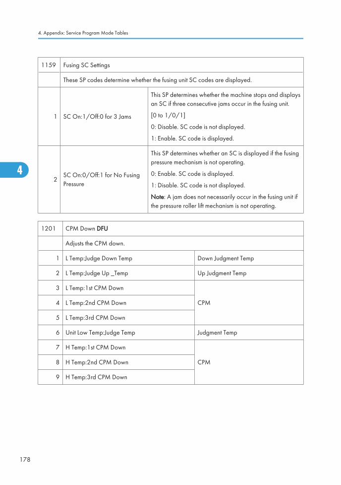
1159 Fusing SC Settings
These SP codes determine whether the fusing unit SC codes are displayed.
1 SC On:1/Off:0 for 3 Jams
This SP determines whether the machine stops and displaysan SC if three consecutive jams occur in the fusing unit.
[0 to 1/0/1]
0: Disable. SC code is not displayed.
1: Enable. SC code is displayed.
2SC On:0/Off:1 for No FusingPressure
This SP determines whether an SC is displayed if the fusingpressure mechanism is not operating.
0: Enable. SC code is displayed.
1: Disable. SC code is not displayed.
Note: A jam does not necessarily occur in the fusing unit ifthe pressure roller lift mechanism is not operating.
1201 CPM Down DFU
Adjusts the CPM down.
1 L Temp:Judge Down Temp Down Judgment Temp
2 L Temp:Judge Up _Temp Up Judgment Temp
3 L Temp:1st CPM Down
CPM4 L Temp:2nd CPM Down
5 L Temp:3rd CPM Down
6 Unit Low Temp:Judge Temp Judgment Temp
7 H Temp:1st CPM Down
CPM8 H Temp:2nd CPM Down
9 H Temp:3rd CPM Down
4. Appendix: Service Program Mode Tables
178
4
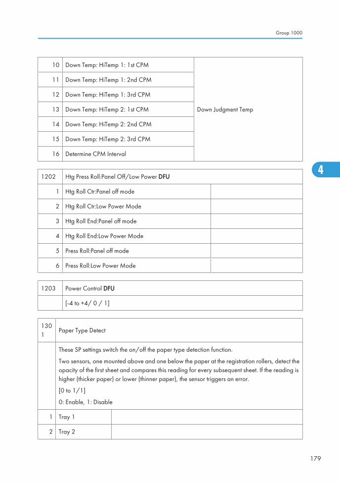
10 Down Temp: HiTemp 1: 1st CPM
Down Judgment Temp
11 Down Temp: HiTemp 1: 2nd CPM
12 Down Temp: HiTemp 1: 3rd CPM
13 Down Temp: HiTemp 2: 1st CPM
14 Down Temp: HiTemp 2: 2nd CPM
15 Down Temp: HiTemp 2: 3rd CPM
16 Determine CPM Interval
1202 Htg Press Roll:Panel Off/Low Power DFU
1 Htg Roll Ctr:Panel off mode
2 Htg Roll Ctr:Low Power Mode
3 Htg Roll End:Panel off mode
4 Htg Roll End:Low Power Mode
5 Press Roll:Panel off mode
6 Press Roll:Low Power Mode
1203 Power Control DFU
[-4 to +4/ 0 / 1]
1301
Paper Type Detect
These SP settings switch the on/off the paper type detection function.
Two sensors, one mounted above and one below the paper at the registration rollers, detect theopacity of the first sheet and compares this reading for every subsequent sheet. If the reading ishigher (thicker paper) or lower (thinner paper), the sensor triggers an error.
[0 to 1/1]
0: Enable, 1: Disable
1 Tray 1
2 Tray 2
Group 1000
179
4
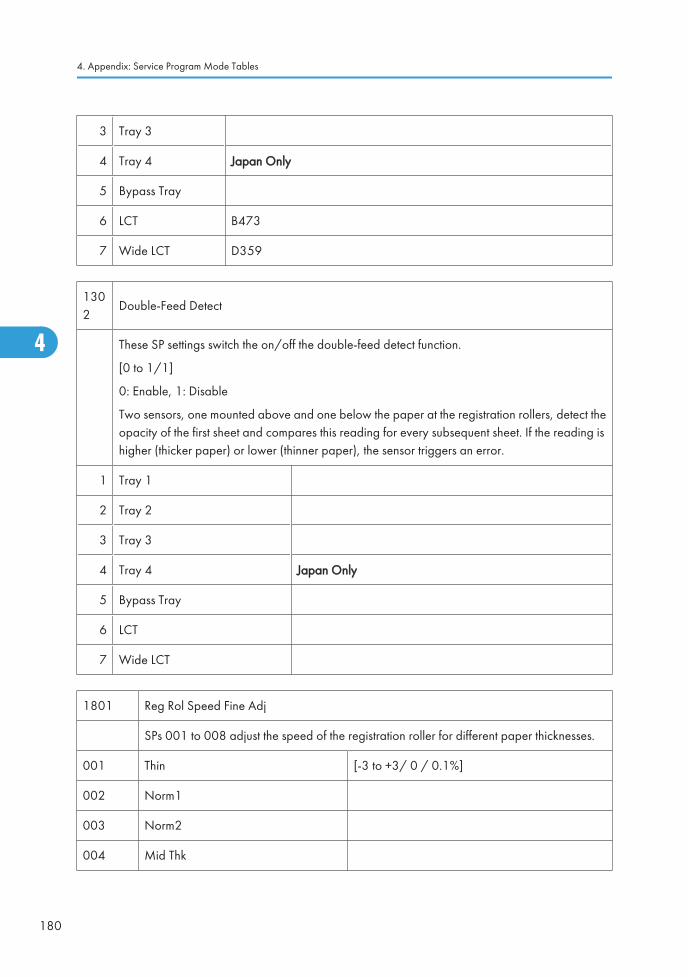
3 Tray 3
4 Tray 4 Japan Only
5 Bypass Tray
6 LCT B473
7 Wide LCT D359
1302
Double-Feed Detect
These SP settings switch the on/off the double-feed detect function.
[0 to 1/1]
0: Enable, 1: Disable
Two sensors, one mounted above and one below the paper at the registration rollers, detect theopacity of the first sheet and compares this reading for every subsequent sheet. If the reading ishigher (thicker paper) or lower (thinner paper), the sensor triggers an error.
1 Tray 1
2 Tray 2
3 Tray 3
4 Tray 4 Japan Only
5 Bypass Tray
6 LCT
7 Wide LCT
1801 Reg Rol Speed Fine Adj
SPs 001 to 008 adjust the speed of the registration roller for different paper thicknesses.
001 Thin [-3 to +3/ 0 / 0.1%]
002 Norm1
003 Norm2
004 Mid Thk
4. Appendix: Service Program Mode Tables
180
4
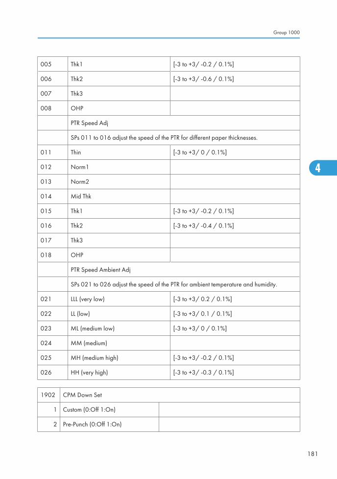
005 Thk1 [-3 to +3/ -0.2 / 0.1%]
006 Thk2 [-3 to +3/ -0.6 / 0.1%]
007 Thk3
008 OHP
PTR Speed Adj
SPs 011 to 016 adjust the speed of the PTR for different paper thicknesses.
011 Thin [-3 to +3/ 0 / 0.1%]
012 Norm1
013 Norm2
014 Mid Thk
015 Thk1 [-3 to +3/ -0.2 / 0.1%]
016 Thk2 [-3 to +3/ -0.4 / 0.1%]
017 Thk3
018 OHP
PTR Speed Ambient Adj
SPs 021 to 026 adjust the speed of the PTR for ambient temperature and humidity.
021 LLL (very low) [-3 to +3/ 0.2 / 0.1%]
022 LL (low) [-3 to +3/ 0.1 / 0.1%]
023 ML (medium low) [-3 to +3/ 0 / 0.1%]
024 MM (medium)
025 MH (medium high) [-3 to +3/ -0.2 / 0.1%]
026 HH (very high) [-3 to +3/ -0.3 / 0.1%]
1902 CPM Down Set
1 Custom (0:Off 1:On)
2 Pre-Punch (0:Off 1:On)
Group 1000
181
4
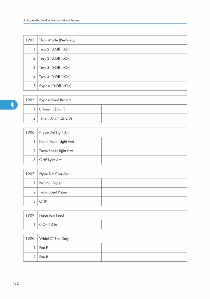
1903 Thick Mode (Re-Pickup)
1 Tray 2 (0:Off 1:On)
2 Tray 2 (0:Off 1:On)
3 Tray 3 (0:Off 1:On)
4 Tray 4 (0:Off 1:On)
5 Bypass (0:Off 1:On)
1905 Bypass Feed Restart
1 0:Timer 1:[Start]
2 Timer: 0:1s 1:2s 2:3s
1906 PType Det Light Amt
1 Norm Paper Light Amt
2 Trans Paper Light Amt
3 OHP Light Amt
1907 Ptype Det Corr Amt
1 Normal Paper
2 Translucent Paper
3 OHP
1909 Force Jam Feed
1 0:Off 1:On
1920 WideLCT Fan Duty
1 Fan F
2 Fan R
4. Appendix: Service Program Mode Tables
182
4
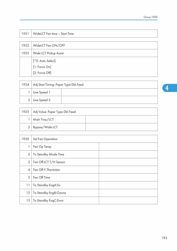
1921 WideLCT Fan time – Start Time
1922 WideLCT Fan ON/OFF
1923 Wide LCT Pickup Assist
[*0: Auto Select]
[1: Force On]
[2: Force Off]
1924 Adj Start Timing: Paper Type Dbl Feed
1 Line Speed 1
2 Line Speed 2
1925 Adj Value: Paper Type Dbl Feed
1 Main Tray/LCT
2 Bypass/Wide LCT
1950 Set Fan Operation
1 Fan Op Temp
2 To Standby Mode Time
3 Fan Off:LCT T/H Sensor
4 Fan Off:Y Thermistor
5 Fan Off Time
11 To Standby EngA:Sn
12 To Standby EngB:Ozone
13 To Standby EngC:Envir
Group 1000
183
4
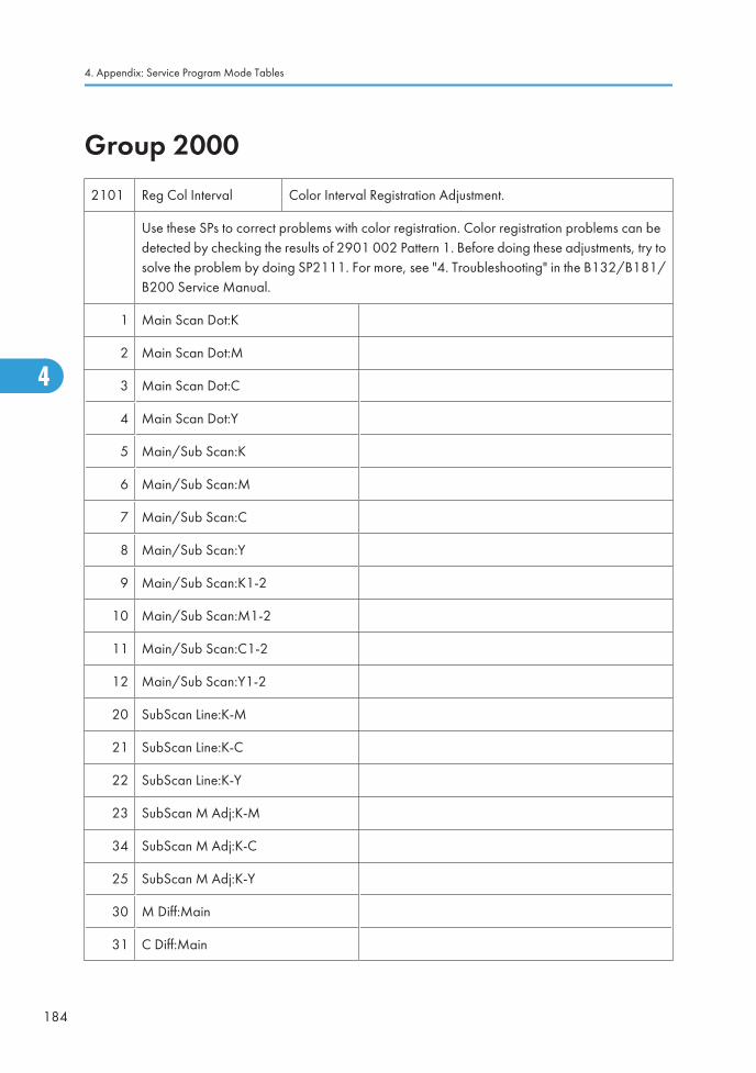
Group 20002101 Reg Col Interval Color Interval Registration Adjustment.
Use these SPs to correct problems with color registration. Color registration problems can bedetected by checking the results of 2901 002 Pattern 1. Before doing these adjustments, try tosolve the problem by doing SP2111. For more, see "4. Troubleshooting" in the B132/B181/B200 Service Manual.
1 Main Scan Dot:K
2 Main Scan Dot:M
3 Main Scan Dot:C
4 Main Scan Dot:Y
5 Main/Sub Scan:K
6 Main/Sub Scan:M
7 Main/Sub Scan:C
8 Main/Sub Scan:Y
9 Main/Sub Scan:K1-2
10 Main/Sub Scan:M1-2
11 Main/Sub Scan:C1-2
12 Main/Sub Scan:Y1-2
20 SubScan Line:K-M
21 SubScan Line:K-C
22 SubScan Line:K-Y
23 SubScan M Adj:K-M
34 SubScan M Adj:K-C
25 SubScan M Adj:K-Y
30 M Diff:Main
31 C Diff:Main
4. Appendix: Service Program Mode Tables
184
4
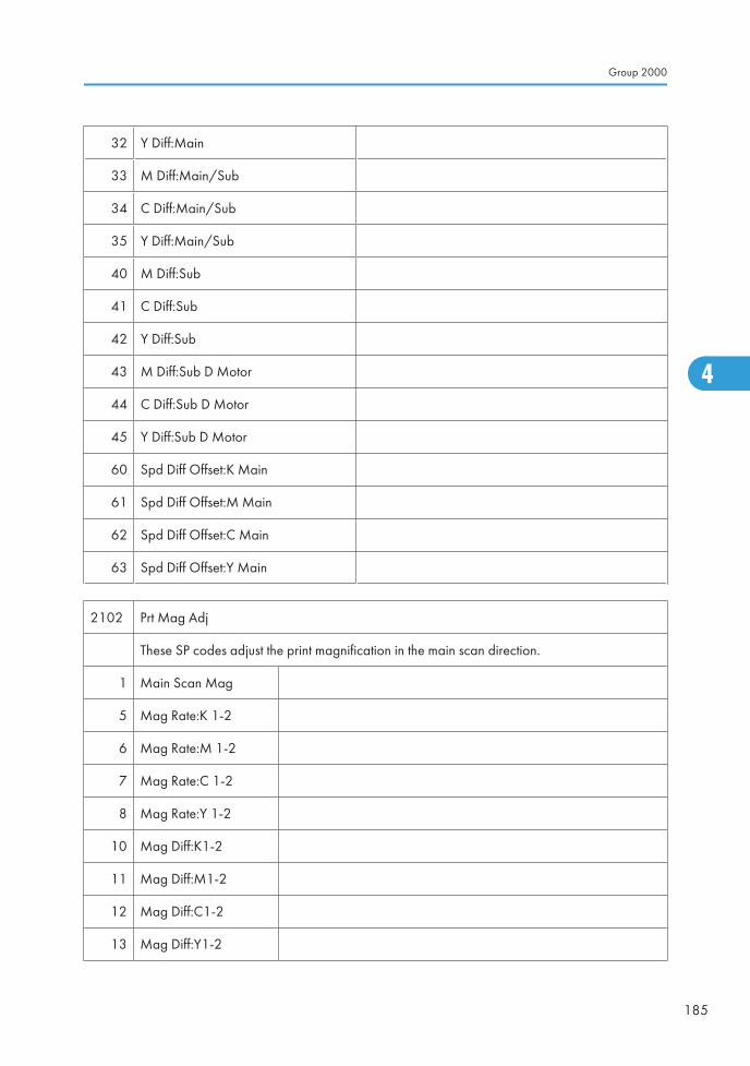
32 Y Diff:Main
33 M Diff:Main/Sub
34 C Diff:Main/Sub
35 Y Diff:Main/Sub
40 M Diff:Sub
41 C Diff:Sub
42 Y Diff:Sub
43 M Diff:Sub D Motor
44 C Diff:Sub D Motor
45 Y Diff:Sub D Motor
60 Spd Diff Offset:K Main
61 Spd Diff Offset:M Main
62 Spd Diff Offset:C Main
63 Spd Diff Offset:Y Main
2102 Prt Mag Adj
These SP codes adjust the print magnification in the main scan direction.
1 Main Scan Mag
5 Mag Rate:K 1-2
6 Mag Rate:M 1-2
7 Mag Rate:C 1-2
8 Mag Rate:Y 1-2
10 Mag Diff:K1-2
11 Mag Diff:M1-2
12 Mag Diff:C1-2
13 Mag Diff:Y1-2
Group 2000
185
4
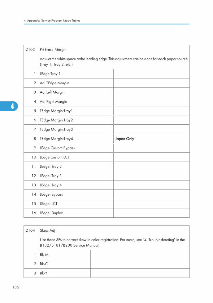
2103 Prt Erase Margin
Adjusts the white space at the leading edge. This adjustment can be done for each paper source(Tray 1, Tray 2, etc.)
1 LEdge:Tray 1
2 Adj TEdge Margin
3 Adj Left Margin
4 Adj Right Margin
5 TEdge Margin:Tray1
6 TEdge Margin:Tray2
7 TEdge Margin:Tray3
8 TEdge Margin:Tray4 Japan Only
9 LEdge Custom:Bypass
10 LEdge Custom:LCT
11 LEdge: Tray 2
12 LEdge: Tray 3
13 LEdge: Tray 4
14 LEdge: Bypass
15 LEdge: LCT
16 LEdge: Duplex
2104 Skew Adj
Use these SPs to correct skew in color registration. For more, see "4. Troubleshooting" in theB132/B181/B200 Service Manual.
1 Bk-M
2 Bk-C
3 Bk-Y
4. Appendix: Service Program Mode Tables
186
4
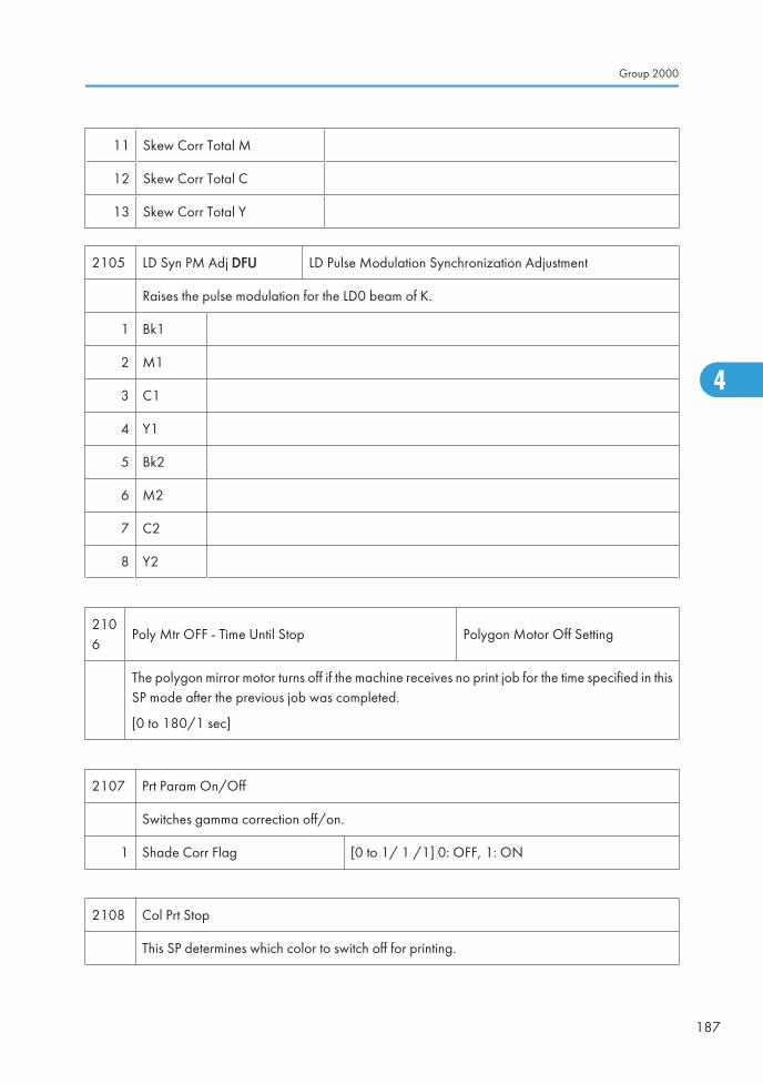
11 Skew Corr Total M
12 Skew Corr Total C
13 Skew Corr Total Y
2105 LD Syn PM Adj DFU LD Pulse Modulation Synchronization Adjustment
Raises the pulse modulation for the LD0 beam of K.
1 Bk1
2 M1
3 C1
4 Y1
5 Bk2
6 M2
7 C2
8 Y2
2106
Poly Mtr OFF - Time Until Stop Polygon Motor Off Setting
The polygon mirror motor turns off if the machine receives no print job for the time specified in thisSP mode after the previous job was completed.
[0 to 180/1 sec]
2107 Prt Param On/Off
Switches gamma correction off/on.
1 Shade Corr Flag [0 to 1/ 1 /1] 0: OFF, 1: ON
2108 Col Prt Stop
This SP determines which color to switch off for printing.
Group 2000
187
4
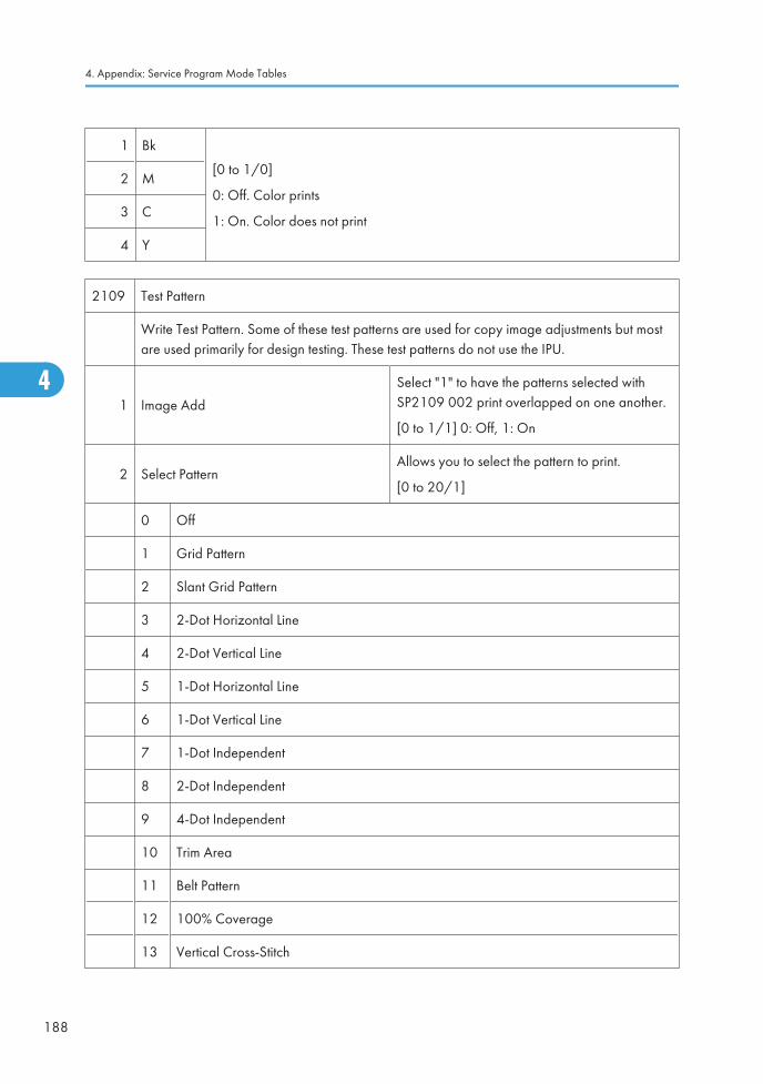
1 Bk
[0 to 1/0]
0: Off. Color prints
1: On. Color does not print
2 M
3 C
4 Y
2109 Test Pattern
Write Test Pattern. Some of these test patterns are used for copy image adjustments but mostare used primarily for design testing. These test patterns do not use the IPU.
1 Image Add
Select "1" to have the patterns selected withSP2109 002 print overlapped on one another.
[0 to 1/1] 0: Off, 1: On
2 Select PatternAllows you to select the pattern to print.
[0 to 20/1]
0 Off
1 Grid Pattern
2 Slant Grid Pattern
3 2-Dot Horizontal Line
4 2-Dot Vertical Line
5 1-Dot Horizontal Line
6 1-Dot Vertical Line
7 1-Dot Independent
8 2-Dot Independent
9 4-Dot Independent
10 Trim Area
11 Belt Pattern
12 100% Coverage
13 Vertical Cross-Stitch
4. Appendix: Service Program Mode Tables
188
4
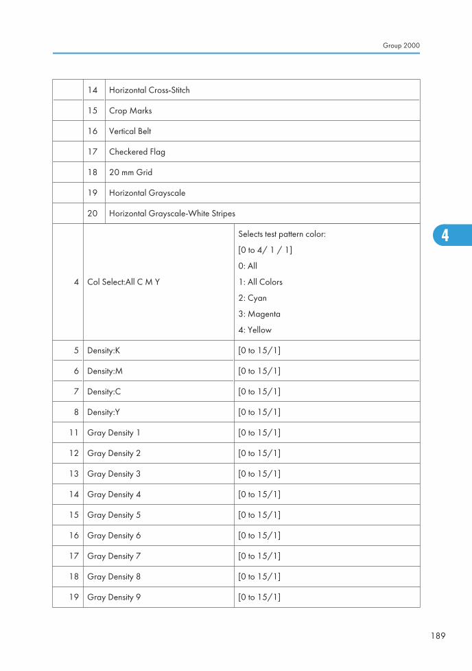
14 Horizontal Cross-Stitch
15 Crop Marks
16 Vertical Belt
17 Checkered Flag
18 20 mm Grid
19 Horizontal Grayscale
20 Horizontal Grayscale-White Stripes
4 Col Select:All C M Y
Selects test pattern color:
[0 to 4/ 1 / 1]
0: All
1: All Colors
2: Cyan
3: Magenta
4: Yellow
5 Density:K [0 to 15/1]
6 Density:M [0 to 15/1]
7 Density:C [0 to 15/1]
8 Density:Y [0 to 15/1]
11 Gray Density 1 [0 to 15/1]
12 Gray Density 2 [0 to 15/1]
13 Gray Density 3 [0 to 15/1]
14 Gray Density 4 [0 to 15/1]
15 Gray Density 5 [0 to 15/1]
16 Gray Density 6 [0 to 15/1]
17 Gray Density 7 [0 to 15/1]
18 Gray Density 8 [0 to 15/1]
19 Gray Density 9 [0 to 15/1]
Group 2000
189
4
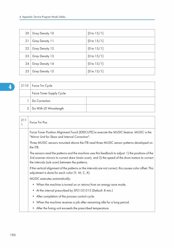
20 Gray Density 10 [0 to 15/1]
21 Gray Density 11 [0 to 15/1]
22 Gray Density 12 [0 to 15/1]
23 Gray Density 13 [0 to 15/1]
24 Gray Density 14 [0 to 15/1]
25 Gray Density 15 [0 to 15/1]
2110 Force Tnr Cycle
Force Toner Supply Cycle.
1 Do Correction
2 Do With LD Wavelength
2111
Force Tnr Pos
Force Toner Position Alignment.Touch [EXECUTE] to execute the MUSIC feature. MUSIC is the"Mirror Unit for Skew and Interval Correction".
Three MUSIC sensors mounted above the ITB read three MUSIC sensor patterns developed onthe ITB.
The sensors read the patterns and the machine uses this feedback to adjust: 1) the positions of the3rd scanner mirrors to correct skew (main scan), and 2) the speed of the drum motors to correctthe intervals (sub scan) between the patterns.
If the vertical alignment of the patterns or the intervals are not correct, this causes color offset. Thisadjustment is done for each color (Y, M, C, K).
MUSIC executes automatically:
• When the machine is turned on or returns from an energy save mode.
• At the interval prescribed by SP2153 015 (Default: 8 min.)
• After completion of the process control cycle.
• When the machine receives a job after remaining idle for a long period.
• After the fusing unit exceeds the prescribed temperature.
4. Appendix: Service Program Mode Tables
190
4
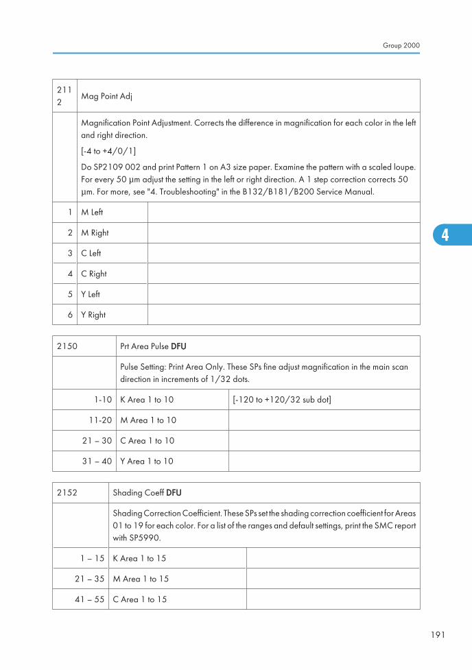
2112
Mag Point Adj
Magnification Point Adjustment. Corrects the difference in magnification for each color in the leftand right direction.
[-4 to +4/0/1]
Do SP2109 002 and print Pattern 1 on A3 size paper. Examine the pattern with a scaled loupe.For every 50 μm adjust the setting in the left or right direction. A 1 step correction corrects 50μm. For more, see "4. Troubleshooting" in the B132/B181/B200 Service Manual.
1 M Left
2 M Right
3 C Left
4 C Right
5 Y Left
6 Y Right
2150 Prt Area Pulse DFU
Pulse Setting: Print Area Only. These SPs fine adjust magnification in the main scandirection in increments of 1/32 dots.
1-10 K Area 1 to 10 [-120 to +120/32 sub dot]
11-20 M Area 1 to 10
21 – 30 C Area 1 to 10
31 – 40 Y Area 1 to 10
2152 Shading Coeff DFU
Shading Correction Coefficient. These SPs set the shading correction coefficient for Areas01 to 19 for each color. For a list of the ranges and default settings, print the SMC reportwith SP5990.
1 – 15 K Area 1 to 15
21 – 35 M Area 1 to 15
41 – 55 C Area 1 to 15
Group 2000
191
4
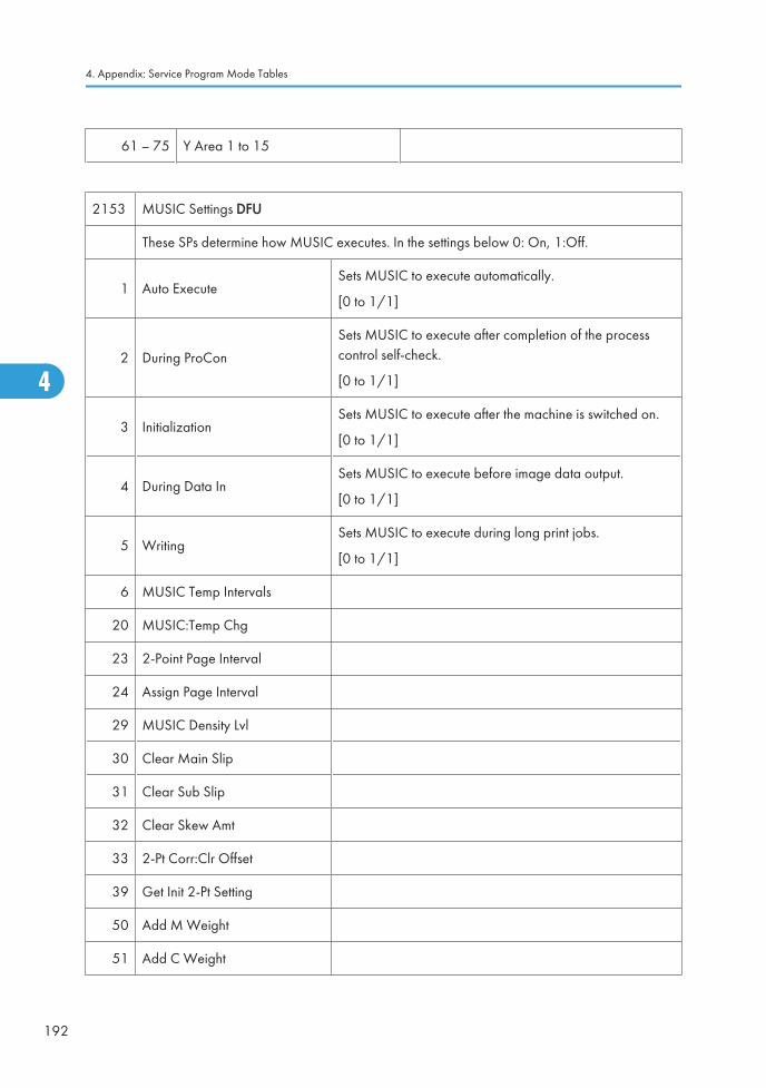
61 – 75 Y Area 1 to 15
2153 MUSIC Settings DFU
These SPs determine how MUSIC executes. In the settings below 0: On, 1:Off.
1 Auto ExecuteSets MUSIC to execute automatically.
[0 to 1/1]
2 During ProCon
Sets MUSIC to execute after completion of the processcontrol self-check.
[0 to 1/1]
3 InitializationSets MUSIC to execute after the machine is switched on.
[0 to 1/1]
4 During Data InSets MUSIC to execute before image data output.
[0 to 1/1]
5 WritingSets MUSIC to execute during long print jobs.
[0 to 1/1]
6 MUSIC Temp Intervals
20 MUSIC:Temp Chg
23 2-Point Page Interval
24 Assign Page Interval
29 MUSIC Density Lvl
30 Clear Main Slip
31 Clear Sub Slip
32 Clear Skew Amt
33 2-Pt Corr:Clr Offset
39 Get Init 2-Pt Setting
50 Add M Weight
51 Add C Weight
4. Appendix: Service Program Mode Tables
192
4
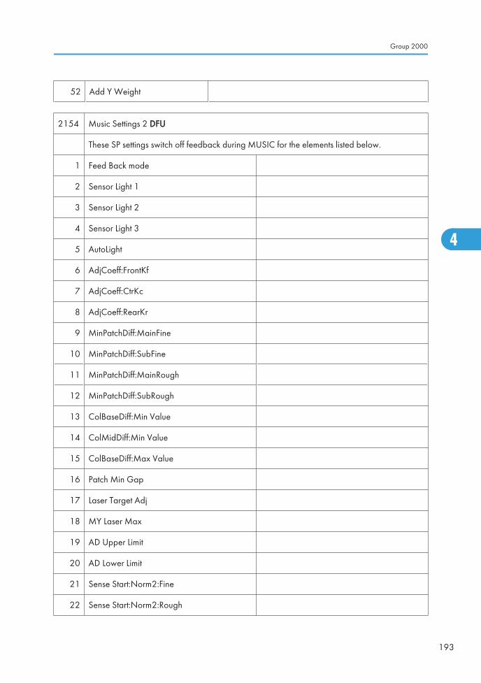
52 Add Y Weight
2154 Music Settings 2 DFU
These SP settings switch off feedback during MUSIC for the elements listed below.
1 Feed Back mode
2 Sensor Light 1
3 Sensor Light 2
4 Sensor Light 3
5 AutoLight
6 AdjCoeff:FrontKf
7 AdjCoeff:CtrKc
8 AdjCoeff:RearKr
9 MinPatchDiff:MainFine
10 MinPatchDiff:SubFine
11 MinPatchDiff:MainRough
12 MinPatchDiff:SubRough
13 ColBaseDiff:Min Value
14 ColMidDiff:Min Value
15 ColBaseDiff:Max Value
16 Patch Min Gap
17 Laser Target Adj
18 MY Laser Max
19 AD Upper Limit
20 AD Lower Limit
21 Sense Start:Norm2:Fine
22 Sense Start:Norm2:Rough
Group 2000
193
4
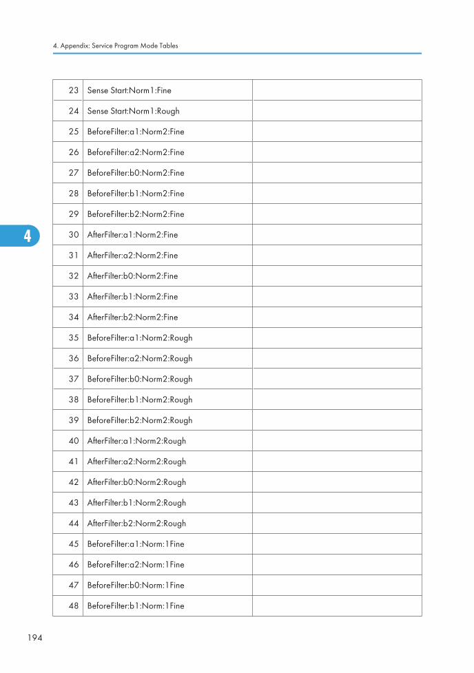
23 Sense Start:Norm1:Fine
24 Sense Start:Norm1:Rough
25 BeforeFilter:a1:Norm2:Fine
26 BeforeFilter:a2:Norm2:Fine
27 BeforeFilter:b0:Norm2:Fine
28 BeforeFilter:b1:Norm2:Fine
29 BeforeFilter:b2:Norm2:Fine
30 AfterFilter:a1:Norm2:Fine
31 AfterFilter:a2:Norm2:Fine
32 AfterFilter:b0:Norm2:Fine
33 AfterFilter:b1:Norm2:Fine
34 AfterFilter:b2:Norm2:Fine
35 BeforeFilter:a1:Norm2:Rough
36 BeforeFilter:a2:Norm2:Rough
37 BeforeFilter:b0:Norm2:Rough
38 BeforeFilter:b1:Norm2:Rough
39 BeforeFilter:b2:Norm2:Rough
40 AfterFilter:a1:Norm2:Rough
41 AfterFilter:a2:Norm2:Rough
42 AfterFilter:b0:Norm2:Rough
43 AfterFilter:b1:Norm2:Rough
44 AfterFilter:b2:Norm2:Rough
45 BeforeFilter:a1:Norm:1Fine
46 BeforeFilter:a2:Norm:1Fine
47 BeforeFilter:b0:Norm:1Fine
48 BeforeFilter:b1:Norm:1Fine
4. Appendix: Service Program Mode Tables
194
4
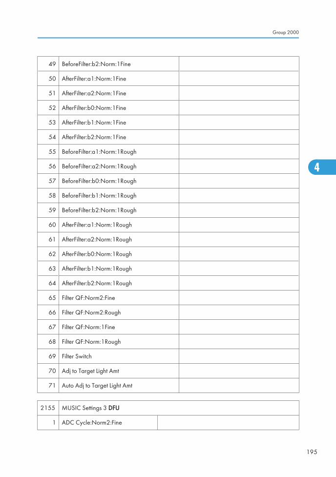
49 BeforeFilter:b2:Norm:1Fine
50 AfterFilter:a1:Norm:1Fine
51 AfterFilter:a2:Norm:1Fine
52 AfterFilter:b0:Norm:1Fine
53 AfterFilter:b1:Norm:1Fine
54 AfterFilter:b2:Norm:1Fine
55 BeforeFilter:a1:Norm:1Rough
56 BeforeFilter:a2:Norm:1Rough
57 BeforeFilter:b0:Norm:1Rough
58 BeforeFilter:b1:Norm:1Rough
59 BeforeFilter:b2:Norm:1Rough
60 AfterFilter:a1:Norm:1Rough
61 AfterFilter:a2:Norm:1Rough
62 AfterFilter:b0:Norm:1Rough
63 AfterFilter:b1:Norm:1Rough
64 AfterFilter:b2:Norm:1Rough
65 Filter QF:Norm2:Fine
66 Filter QF:Norm2:Rough
67 Filter QF:Norm:1Fine
68 Filter QF:Norm:1Rough
69 Filter Switch
70 Adj to Target Light Amt
71 Auto Adj to Target Light Amt
2155 MUSIC Settings 3 DFU
1 ADC Cycle:Norm2:Fine
Group 2000
195
4
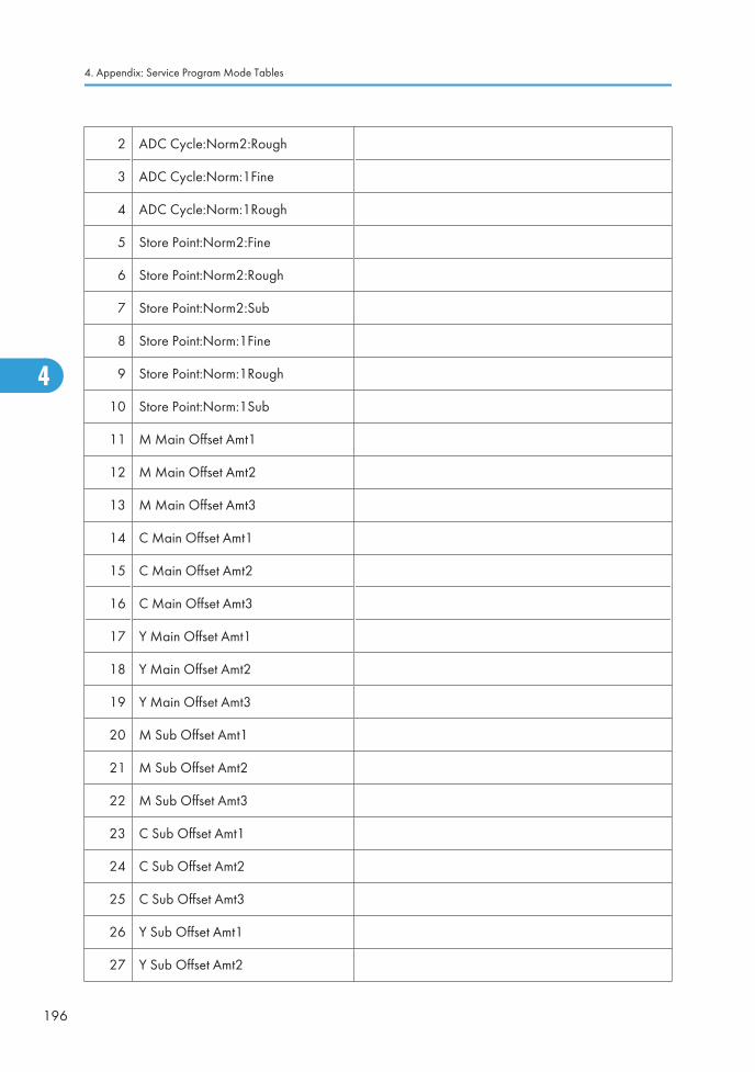
2 ADC Cycle:Norm2:Rough
3 ADC Cycle:Norm:1Fine
4 ADC Cycle:Norm:1Rough
5 Store Point:Norm2:Fine
6 Store Point:Norm2:Rough
7 Store Point:Norm2:Sub
8 Store Point:Norm:1Fine
9 Store Point:Norm:1Rough
10 Store Point:Norm:1Sub
11 M Main Offset Amt1
12 M Main Offset Amt2
13 M Main Offset Amt3
14 C Main Offset Amt1
15 C Main Offset Amt2
16 C Main Offset Amt3
17 Y Main Offset Amt1
18 Y Main Offset Amt2
19 Y Main Offset Amt3
20 M Sub Offset Amt1
21 M Sub Offset Amt2
22 M Sub Offset Amt3
23 C Sub Offset Amt1
24 C Sub Offset Amt2
25 C Sub Offset Amt3
26 Y Sub Offset Amt1
27 Y Sub Offset Amt2
4. Appendix: Service Program Mode Tables
196
4
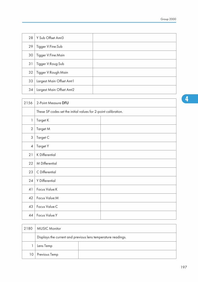
28 Y Sub Offset Amt3
29 Tigger V:Fine:Sub
30 Tigger V:Fine:Main
31 Tigger V:Roug:Sub
32 Tigger V:Rough:Main
33 Largest Main Offset Amt1
34 Largest Main Offset Amt2
2156 2-Point Measure DFU
These SP codes set the initial values for 2-point calibration.
1 Target K
2 Target M
3 Target C
4 Target Y
21 K Differential
22 M Differential
23 C Differential
24 Y Differential
41 Focus Value:K
42 Focus Value:M
43 Focus Value:C
44 Focus Value:Y
2180 MUSIC Monitor
Displays the current and previous lens temperature readings.
1 Lens Temp
10 Previous Temp
Group 2000
197
4
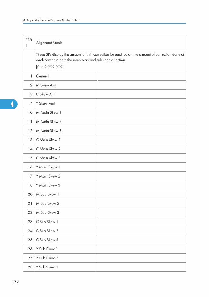
2181
Alignment Result
These SPs display the amount of shift correction for each color, the amount of correction done ateach sensor in both the main scan and sub scan direction.
[0 to 9 999 999]
1 General
2 M Skew Amt
3 C Skew Amt
4 Y Skew Amt
10 M Main Skew 1
11 M Main Skew 2
12 M Main Skew 3
13 C Main Skew 1
14 C Main Skew 2
15 C Main Skew 3
16 Y Main Skew 1
17 Y Main Skew 2
18 Y Main Skew 3
20 M Sub Skew 1
21 M Sub Skew 2
22 M Sub Skew 3
23 C Sub Skew 1
24 C Sub Skew 2
25 C Sub Skew 3
26 Y Sub Skew 1
27 Y Sub Skew 2
28 Y Sub Skew 3
4. Appendix: Service Program Mode Tables
198
4
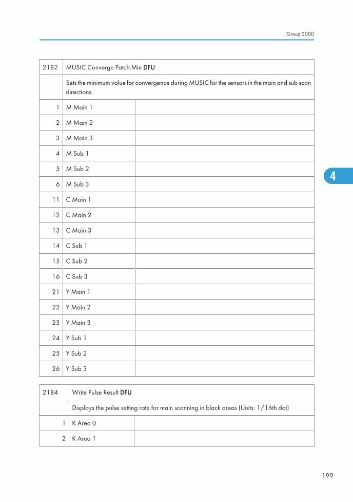
2182 MUSIC Converge Patch:Min DFU
Sets the minimum value for convergence during MUSIC for the sensors in the main and sub scandirections.
1 M Main 1
2 M Main 2
3 M Main 3
4 M Sub 1
5 M Sub 2
6 M Sub 3
11 C Main 1
12 C Main 2
13 C Main 3
14 C Sub 1
15 C Sub 2
16 C Sub 3
21 Y Main 1
22 Y Main 2
23 Y Main 3
24 Y Sub 1
25 Y Sub 2
26 Y Sub 3
2184 Write Pulse Result DFU
Displays the pulse setting rate for main scanning in black areas (Units: 1/16th dot)
1 K Area 0
2 K Area 1
Group 2000
199
4
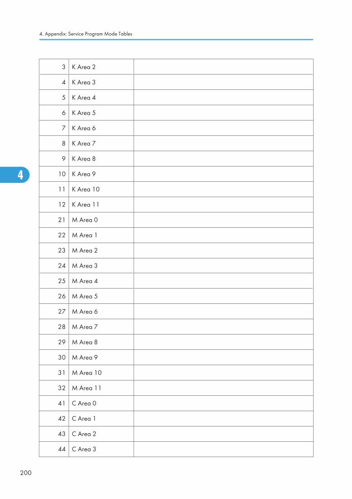
3 K Area 2
4 K Area 3
5 K Area 4
6 K Area 5
7 K Area 6
8 K Area 7
9 K Area 8
10 K Area 9
11 K Area 10
12 K Area 11
21 M Area 0
22 M Area 1
23 M Area 2
24 M Area 3
25 M Area 4
26 M Area 5
27 M Area 6
28 M Area 7
29 M Area 8
30 M Area 9
31 M Area 10
32 M Area 11
41 C Area 0
42 C Area 1
43 C Area 2
44 C Area 3
4. Appendix: Service Program Mode Tables
200
4
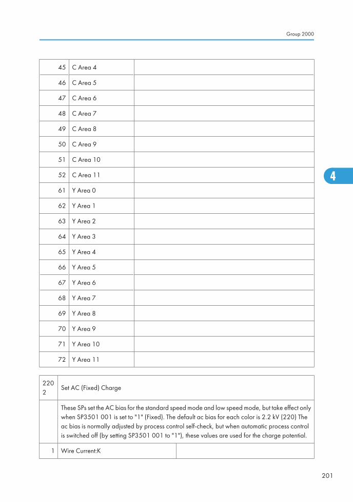
45 C Area 4
46 C Area 5
47 C Area 6
48 C Area 7
49 C Area 8
50 C Area 9
51 C Area 10
52 C Area 11
61 Y Area 0
62 Y Area 1
63 Y Area 2
64 Y Area 3
65 Y Area 4
66 Y Area 5
67 Y Area 6
68 Y Area 7
69 Y Area 8
70 Y Area 9
71 Y Area 10
72 Y Area 11
2202
Set AC (Fixed) Charge
These SPs set the AC bias for the standard speed mode and low speed mode, but take effect onlywhen SP3501 001 is set to "1" (Fixed). The default ac bias for each color is 2.2 kV (220) Theac bias is normally adjusted by process control self-check, but when automatic process controlis switched off (by setting SP3501 001 to "1"), these values are used for the charge potential.
1 Wire Current:K
Group 2000
201
4

2 AC Bias :M
3 AC Bias :C
4 AC Bias :Y
2203 Set Charge Current
Sets and adjusts current for charge applied to the OPC drums.
1 Norm2:LL
6 Norm2:ML
11 Norm2:MM
16 Norm2:MH
21 Norm2:HH
26 Norm1:LL
31 Norm1:ML
36 Norm1:MM
41 Norm1:MH
46 Norm1:HH
51 Half-Speed2:LL
56 Half-Speed2:ML
61 Half-Speed2:MM
66 Half-Speed2:MH
71 Half-Speed2:HH
76 Half-Speed1:LL
81 Half-Speed1:ML
86 Half-Speed1:MM
91 Half-Speed1:MH
96 Half-Speed1:HH
4. Appendix: Service Program Mode Tables
202
4
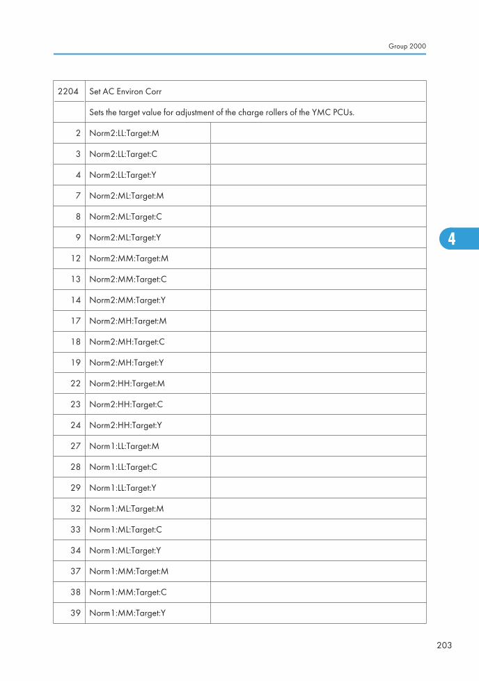
2204 Set AC Environ Corr
Sets the target value for adjustment of the charge rollers of the YMC PCUs.
2 Norm2:LL:Target:M
3 Norm2:LL:Target:C
4 Norm2:LL:Target:Y
7 Norm2:ML:Target:M
8 Norm2:ML:Target:C
9 Norm2:ML:Target:Y
12 Norm2:MM:Target:M
13 Norm2:MM:Target:C
14 Norm2:MM:Target:Y
17 Norm2:MH:Target:M
18 Norm2:MH:Target:C
19 Norm2:MH:Target:Y
22 Norm2:HH:Target:M
23 Norm2:HH:Target:C
24 Norm2:HH:Target:Y
27 Norm1:LL:Target:M
28 Norm1:LL:Target:C
29 Norm1:LL:Target:Y
32 Norm1:ML:Target:M
33 Norm1:ML:Target:C
34 Norm1:ML:Target:Y
37 Norm1:MM:Target:M
38 Norm1:MM:Target:C
39 Norm1:MM:Target:Y
Group 2000
203
4

42 Norm1:MH:Target:M
43 Norm1:MH:Target:C
44 Norm1:MH:Target:Y
47 Norm1:HH:Target:M
48 Norm1:HH:Target:C
49 Norm1:HH:Target:Y
52 Half-Speed2:LL:Target:M
53 Half-Speed2:LL:Target:C
54 Half-Speed2:LL:Target:Y
57 Half-Speed2:ML:Target:M
58 Half-Speed2:ML:Target:C
59 Half-Speed2:ML:Target:Y
62 Half-Speed2:MM:Target:M
63 Half-Speed2:MM:Target:C
64 Half-Speed2:MM:Target:Y
67 Half-Speed2:MH:Target:M
68 Half-Speed2:MH:Target:C
69 Half-Speed2:MH:Target:Y
72 Half-Speed2:HH:Target:M
73 Half-Speed2:HH:Target:C
74 Half-Speed2:HH:Target:Y
77 Half-Speed1:LL:Target:M
78 Half-Speed1:LL:Target:C
79 Half-Speed1:LL:Target:Y
82 Half-Speed1:ML:Target:M
83 Half-Speed1:ML:Target:C
4. Appendix: Service Program Mode Tables
204
4
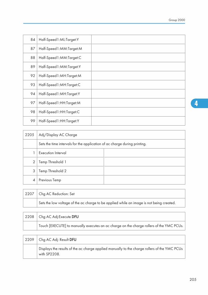
84 Half-Speed1:ML:Target:Y
87 Half-Speed1:MM:Target:M
88 Half-Speed1:MM:Target:C
89 Half-Speed1:MM:Target:Y
92 Half-Speed1:MH:Target:M
93 Half-Speed1:MH:Target:C
94 Half-Speed1:MH:Target:Y
97 Half-Speed1:HH:Target:M
98 Half-Speed1:HH:Target:C
99 Half-Speed1:HH:Target:Y
2205 Adj/Display AC Charge
Sets the time intervals for the application of ac charge during printing.
1 Execution Interval
2 Temp Threshold 1
3 Temp Threshold 2
4 Previous Temp
2207 Chg AC Reduction: Set
Sets the low voltage of the ac charge to be applied while an image is not being created.
2208 Chg AC Adj:Execute DFU
Touch [EXECUTE] to manually executes an ac charge on the charge rollers of the YMC PCUs.
2209 Chg AC Adj: Result DFU
Displays the results of the ac charge applied manually to the charge rollers of the YMC PCUswith SP2208.
Group 2000
205
4
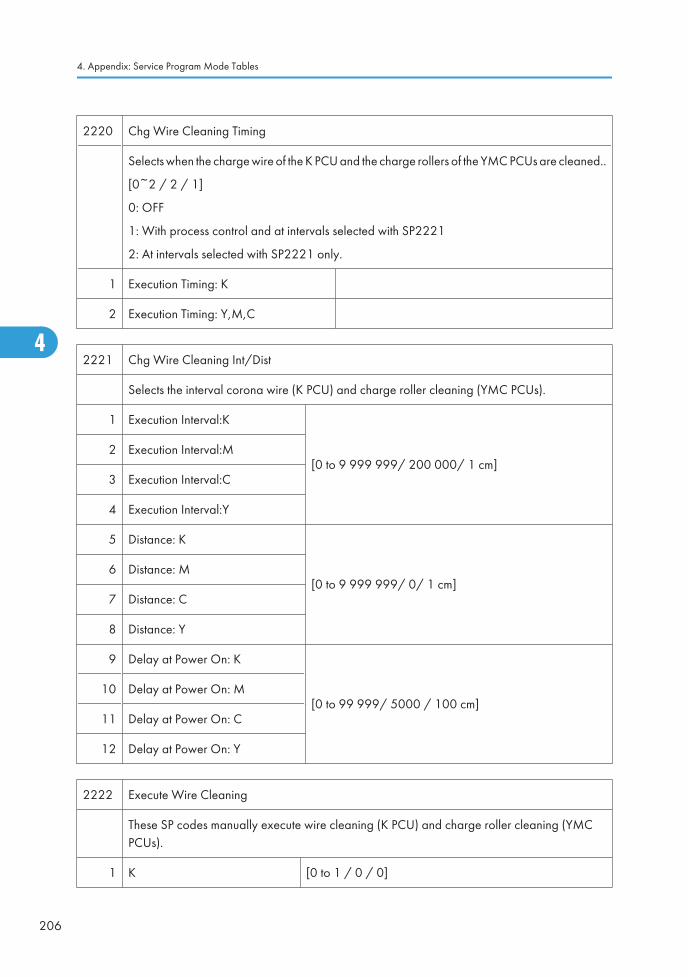
2220 Chg Wire Cleaning Timing
Selects when the charge wire of the K PCU and the charge rollers of the YMC PCUs are cleaned..
[0~2 / 2 / 1]
0: OFF
1: With process control and at intervals selected with SP2221
2: At intervals selected with SP2221 only.
1 Execution Timing: K
2 Execution Timing: Y,M,C
2221 Chg Wire Cleaning Int/Dist
Selects the interval corona wire (K PCU) and charge roller cleaning (YMC PCUs).
1 Execution Interval:K
[0 to 9 999 999/ 200 000/ 1 cm]2 Execution Interval:M
3 Execution Interval:C
4 Execution Interval:Y
5 Distance: K
[0 to 9 999 999/ 0/ 1 cm]6 Distance: M
7 Distance: C
8 Distance: Y
9 Delay at Power On: K
[0 to 99 999/ 5000 / 100 cm]10 Delay at Power On: M
11 Delay at Power On: C
12 Delay at Power On: Y
2222 Execute Wire Cleaning
These SP codes manually execute wire cleaning (K PCU) and charge roller cleaning (YMCPCUs).
1 K [0 to 1 / 0 / 0]
4. Appendix: Service Program Mode Tables
206
4
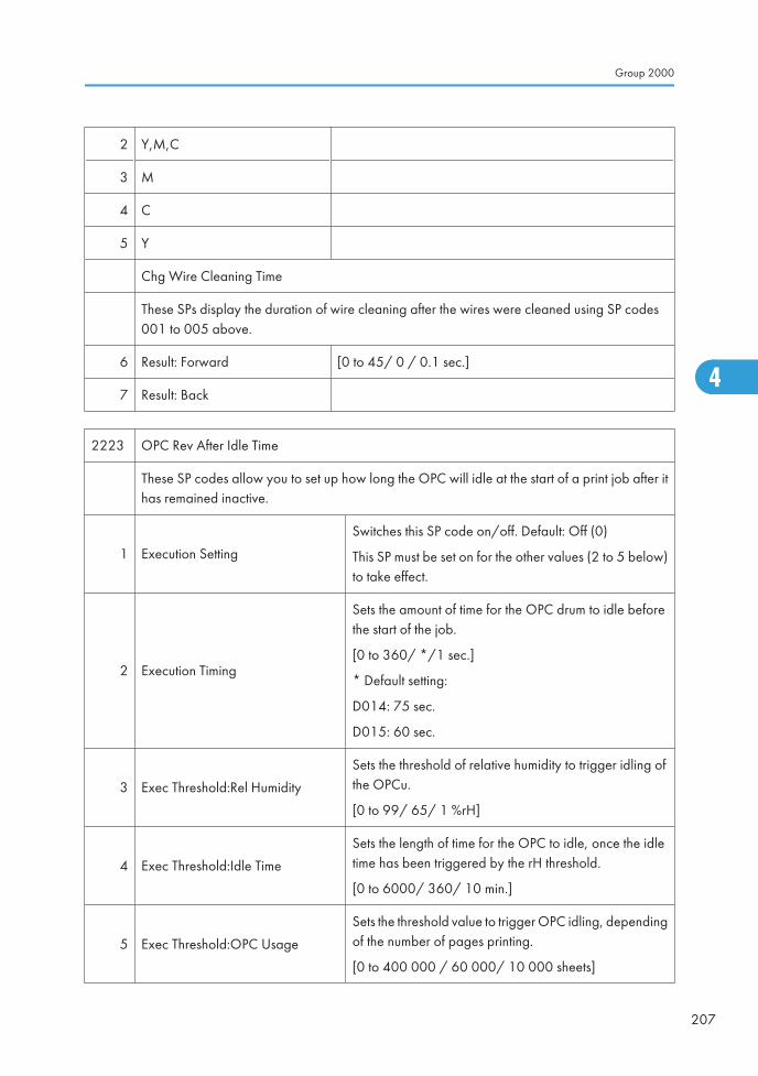
2 Y,M,C
3 M
4 C
5 Y
Chg Wire Cleaning Time
These SPs display the duration of wire cleaning after the wires were cleaned using SP codes001 to 005 above.
6 Result: Forward [0 to 45/ 0 / 0.1 sec.]
7 Result: Back
2223 OPC Rev After Idle Time
These SP codes allow you to set up how long the OPC will idle at the start of a print job after ithas remained inactive.
1 Execution Setting
Switches this SP code on/off. Default: Off (0)
This SP must be set on for the other values (2 to 5 below)to take effect.
2 Execution Timing
Sets the amount of time for the OPC drum to idle beforethe start of the job.
[0 to 360/ */1 sec.]
* Default setting:
D014: 75 sec.
D015: 60 sec.
3 Exec Threshold:Rel Humidity
Sets the threshold of relative humidity to trigger idling ofthe OPCu.
[0 to 99/ 65/ 1 %rH]
4 Exec Threshold:Idle Time
Sets the length of time for the OPC to idle, once the idletime has been triggered by the rH threshold.
[0 to 6000/ 360/ 10 min.]
5 Exec Threshold:OPC Usage
Sets the threshold value to trigger OPC idling, dependingof the number of pages printing.
[0 to 400 000 / 60 000/ 10 000 sheets]
Group 2000
207
4
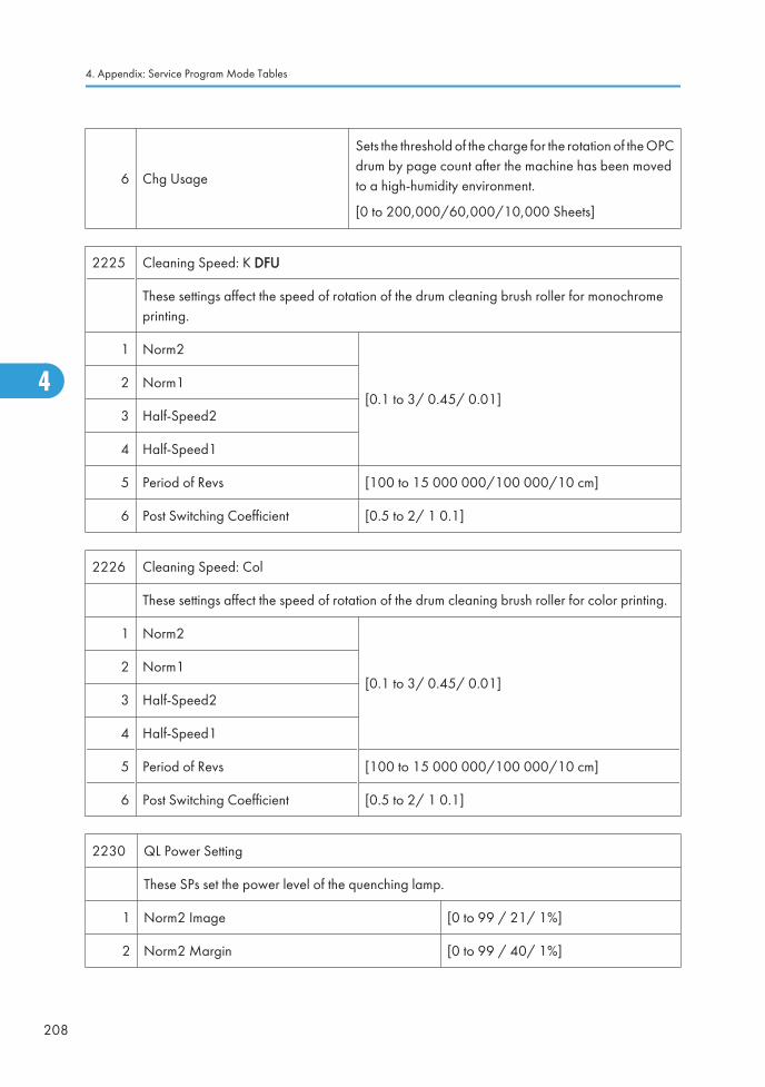
6 Chg Usage
Sets the threshold of the charge for the rotation of the OPCdrum by page count after the machine has been movedto a high-humidity environment.
[0 to 200,000/60,000/10,000 Sheets]
2225 Cleaning Speed: K DFU
These settings affect the speed of rotation of the drum cleaning brush roller for monochromeprinting.
1 Norm2
[0.1 to 3/ 0.45/ 0.01]2 Norm1
3 Half-Speed2
4 Half-Speed1
5 Period of Revs [100 to 15 000 000/100 000/10 cm]
6 Post Switching Coefficient [0.5 to 2/ 1 0.1]
2226 Cleaning Speed: Col
These settings affect the speed of rotation of the drum cleaning brush roller for color printing.
1 Norm2
[0.1 to 3/ 0.45/ 0.01]2 Norm1
3 Half-Speed2
4 Half-Speed1
5 Period of Revs [100 to 15 000 000/100 000/10 cm]
6 Post Switching Coefficient [0.5 to 2/ 1 0.1]
2230 QL Power Setting
These SPs set the power level of the quenching lamp.
1 Norm2 Image [0 to 99 / 21/ 1%]
2 Norm2 Margin [0 to 99 / 40/ 1%]
4. Appendix: Service Program Mode Tables
208
4
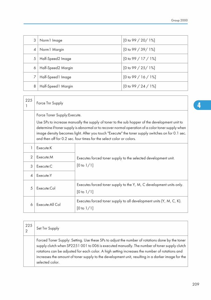
3 Norm1 Image [0 to 99 / 20/ 1%]
4 Norm1 Margin [0 to 99 / 39/ 1%]
5 Half-Speed2 Image [0 to 99 / 17 / 1%]
6 Half-Speed2 Margin [0 to 99 / 25/ 1%]
7 Half-Speed1 Image [0 to 99 / 16 / 1%]
8 Half-Speed1 Margin [0 to 99 / 24 / 1%]
2251
Force Tnr Supply
Force Toner Supply:Execute.
Use SPs to increase manually the supply of toner to the sub hopper of the development unit todetermine if toner supply is abnormal or to recover normal operation of a color toner supply whenimage density becomes light. After you touch "Execute" the toner supply switches on for 0.1 sec.and then off for 0.2 sec. four times for the select color or colors.
1 Execute:K
Executes forced toner supply to the selected development unit.
[0 to 1/1]
2 Execute:M
3 Execute:C
4 Execute:Y
5 Execute:ColExecutes forced toner supply to the Y, M, C development units only.
[0 to 1/1]
6 Execute:All ColExecutes forced toner supply to all development units (Y, M, C, K).
[0 to 1/1]
2252
Set Tnr Supply
Forced Toner Supply: Setting. Use these SPs to adjust the number of rotations done by the tonersupply clutch when SP2251 001 to 006 is executed manually. The number of toner supply clutchrotations can be adjusted for each color. A high setting increases the number of rotations andincreases the amount of toner supply to the development unit, resulting in a darker image for theselected color.
Group 2000
209
4
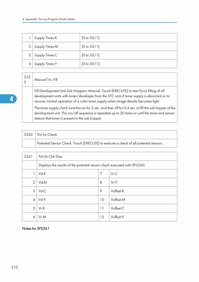
1 Supply Times:K [0 to 30/1]
2 Supply Times:M [0 to 30/1]
3 Supply Times:C [0 to 30/1]
4 Supply Times:Y [0 to 30/1]
2253
Manual Tnr. Fill
Fill Development Unit Sub Hoppers: Manual. Touch [EXECUTE] to start force filling of alldevelopment units with toner/developer from the STC units if toner supply is abnormal or torecover normal operation of a color toner supply when image density becomes light.
The toner supply clutch switches on for 2 sec. and then off for 0.4 sec. to fill the sub hopper of thedevelopment unit. This on/off sequence is repeated up to 20 times or until the toner end sensordetects that toner is present in the sub hopper.
2260 Pot.Sn Check
Potential Sensor Check. Touch [EXECUTE] to execute a check of all potential sensors.
2261 Pot.Sn Chk Disp
Displays the results of the potential sensor check executed with SP2260.
1 Vd:K 7 Vr:C
2 Vd:M 8 Vr:Y
3 Vd:C 9 Voffset:K
4 Vd:Y 10 Voffset:M
5 Vr:K 11 Voffset:C
6 Vr:M 12 Voffset:Y
Notes for SP2261
4. Appendix: Service Program Mode Tables
210
4
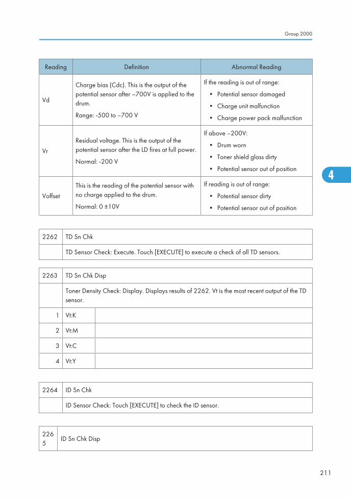
Reading Definition Abnormal Reading
Vd
Charge bias (Cdc). This is the output of thepotential sensor after –700V is applied to thedrum.
Range: -500 to –700 V
If the reading is out of range:
• Potential sensor damaged
• Charge unit malfunction
• Charge power pack malfunction
Vr
Residual voltage. This is the output of thepotential sensor after the LD fires at full power.
Normal: -200 V
If above –200V:
• Drum worn
• Toner shield glass dirty
• Potential sensor out of position
Voffset
This is the reading of the potential sensor withno charge applied to the drum.
Normal: 0 ±10V
If reading is out of range:
• Potential sensor dirty
• Potential sensor out of position
2262 TD Sn Chk
TD Sensor Check: Execute. Touch [EXECUTE] to execute a check of all TD sensors.
2263 TD Sn Chk Disp
Toner Density Check: Display. Displays results of 2262. Vt is the most recent output of the TDsensor.
1 Vt:K
2 Vt:M
3 Vt:C
4 Vt:Y
2264 ID Sn Chk
ID Sensor Check: Touch [EXECUTE] to check the ID sensor.
2265
ID Sn Chk Disp
Group 2000
211
4
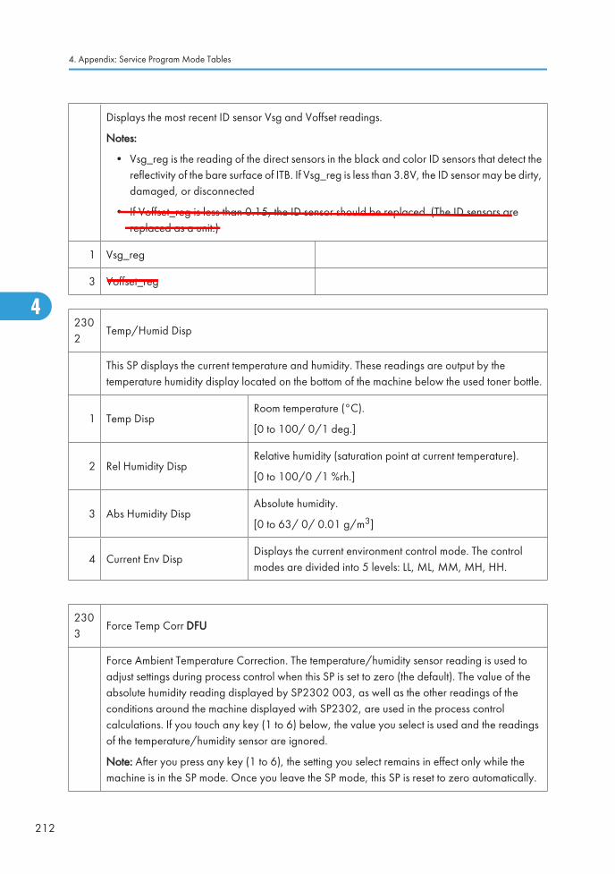
Displays the most recent ID sensor Vsg and Voffset readings.
Notes:
• Vsg_reg is the reading of the direct sensors in the black and color ID sensors that detect thereflectivity of the bare surface of ITB. If Vsg_reg is less than 3.8V, the ID sensor may be dirty,damaged, or disconnected
• If Voffset_reg is less than 0.15, the ID sensor should be replaced. (The ID sensors arereplaced as a unit.)
1 Vsg_reg
3 Voffset_reg
2302
Temp/Humid Disp
This SP displays the current temperature and humidity. These readings are output by thetemperature humidity display located on the bottom of the machine below the used toner bottle.
1 Temp DispRoom temperature (°C).
[0 to 100/ 0/1 deg.]
2 Rel Humidity DispRelative humidity (saturation point at current temperature).
[0 to 100/0 /1 %rh.]
3 Abs Humidity DispAbsolute humidity.
[0 to 63/ 0/ 0.01 g/m3]
4 Current Env DispDisplays the current environment control mode. The controlmodes are divided into 5 levels: LL, ML, MM, MH, HH.
2303
Force Temp Corr DFU
Force Ambient Temperature Correction. The temperature/humidity sensor reading is used toadjust settings during process control when this SP is set to zero (the default). The value of theabsolute humidity reading displayed by SP2302 003, as well as the other readings of theconditions around the machine displayed with SP2302, are used in the process controlcalculations. If you touch any key (1 to 6) below, the value you select is used and the readingsof the temperature/humidity sensor are ignored.
Note: After you press any key (1 to 6), the setting you select remains in effect only while themachine is in the SP mode. Once you leave the SP mode, this SP is reset to zero automatically.
4. Appendix: Service Program Mode Tables
212
4
O'Brien
O'Brien
O'Brien
Ed
Typewritten Text
SP2265-3: Deleted RTB 20
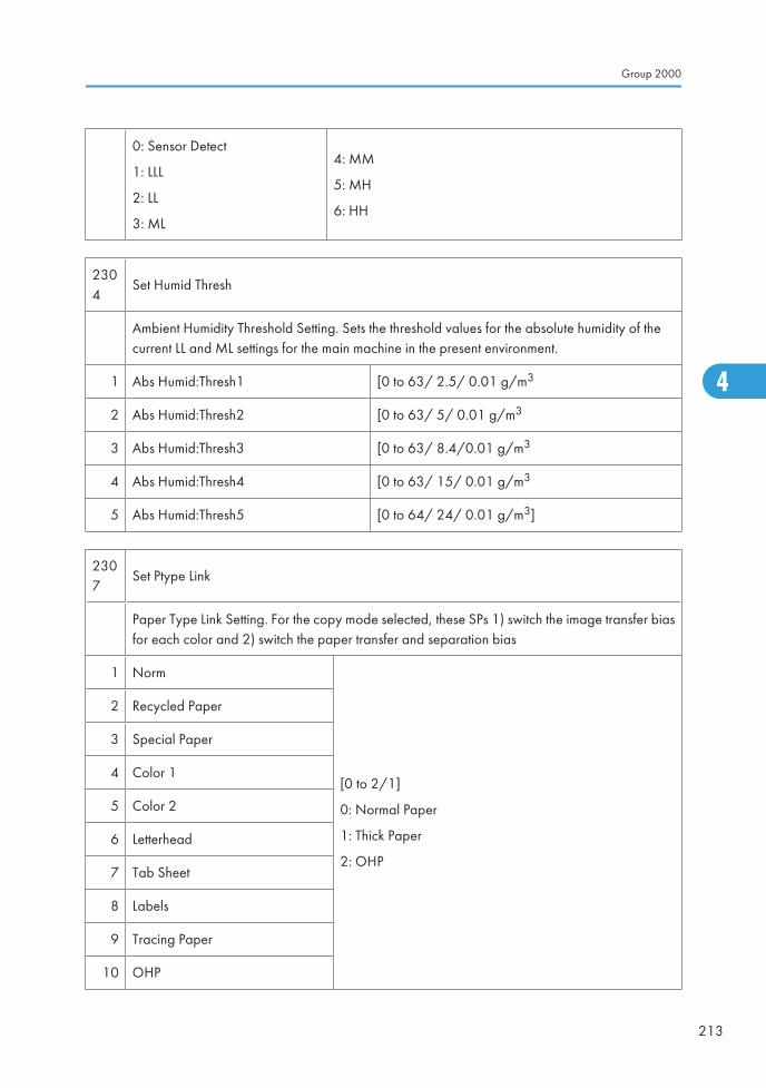
0: Sensor Detect
1: LLL
2: LL
3: ML
4: MM
5: MH
6: HH
2304
Set Humid Thresh
Ambient Humidity Threshold Setting. Sets the threshold values for the absolute humidity of thecurrent LL and ML settings for the main machine in the present environment.
1 Abs Humid:Thresh1 [0 to 63/ 2.5/ 0.01 g/m3
2 Abs Humid:Thresh2 [0 to 63/ 5/ 0.01 g/m3
3 Abs Humid:Thresh3 [0 to 63/ 8.4/0.01 g/m3
4 Abs Humid:Thresh4 [0 to 63/ 15/ 0.01 g/m3
5 Abs Humid:Thresh5 [0 to 64/ 24/ 0.01 g/m3]
2307
Set Ptype Link
Paper Type Link Setting. For the copy mode selected, these SPs 1) switch the image transfer biasfor each color and 2) switch the paper transfer and separation bias
1 Norm
[0 to 2/1]
0: Normal Paper
1: Thick Paper
2: OHP
2 Recycled Paper
3 Special Paper
4 Color 1
5 Color 2
6 Letterhead
7 Tab Sheet
8 Labels
9 Tracing Paper
10 OHP
Group 2000
213
4
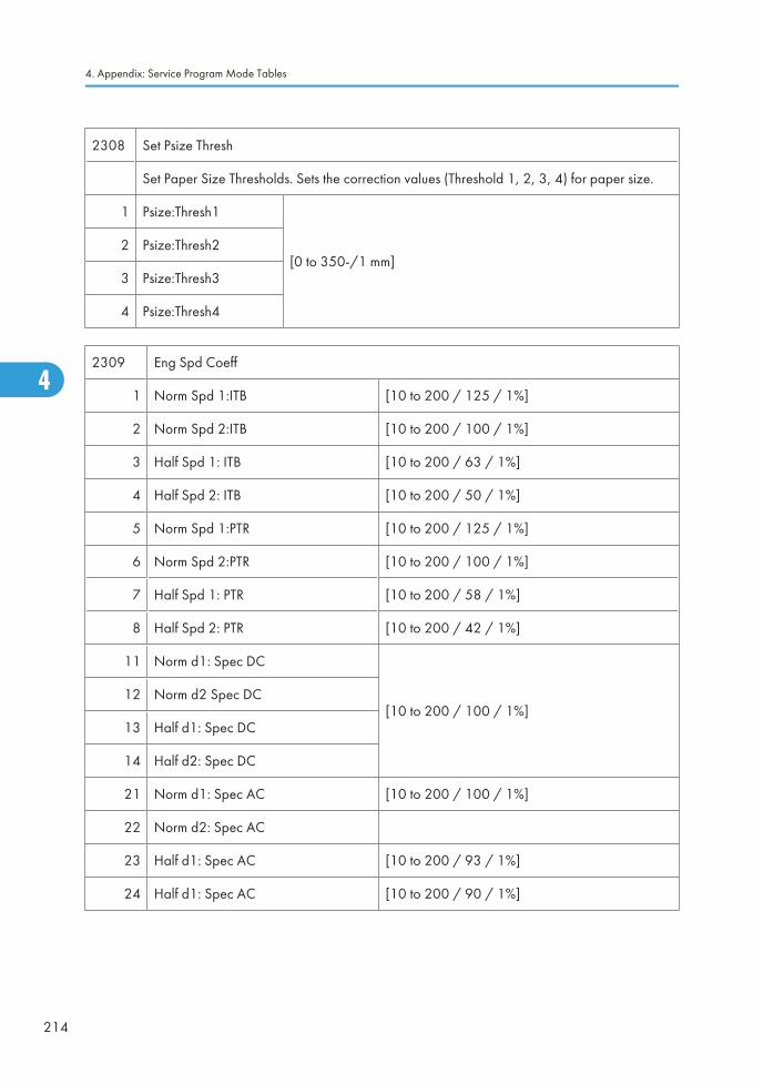
2308 Set Psize Thresh
Set Paper Size Thresholds. Sets the correction values (Threshold 1, 2, 3, 4) for paper size.
1 Psize:Thresh1
[0 to 350-/1 mm]2 Psize:Thresh2
3 Psize:Thresh3
4 Psize:Thresh4
2309 Eng Spd Coeff
1 Norm Spd 1:ITB [10 to 200 / 125 / 1%]
2 Norm Spd 2:ITB [10 to 200 / 100 / 1%]
3 Half Spd 1: ITB [10 to 200 / 63 / 1%]
4 Half Spd 2: ITB [10 to 200 / 50 / 1%]
5 Norm Spd 1:PTR [10 to 200 / 125 / 1%]
6 Norm Spd 2:PTR [10 to 200 / 100 / 1%]
7 Half Spd 1: PTR [10 to 200 / 58 / 1%]
8 Half Spd 2: PTR [10 to 200 / 42 / 1%]
11 Norm d1: Spec DC
[10 to 200 / 100 / 1%]12 Norm d2 Spec DC
13 Half d1: Spec DC
14 Half d2: Spec DC
21 Norm d1: Spec AC [10 to 200 / 100 / 1%]
22 Norm d2: Spec AC
23 Half d1: Spec AC [10 to 200 / 93 / 1%]
24 Half d1: Spec AC [10 to 200 / 90 / 1%]
4. Appendix: Service Program Mode Tables
214
4
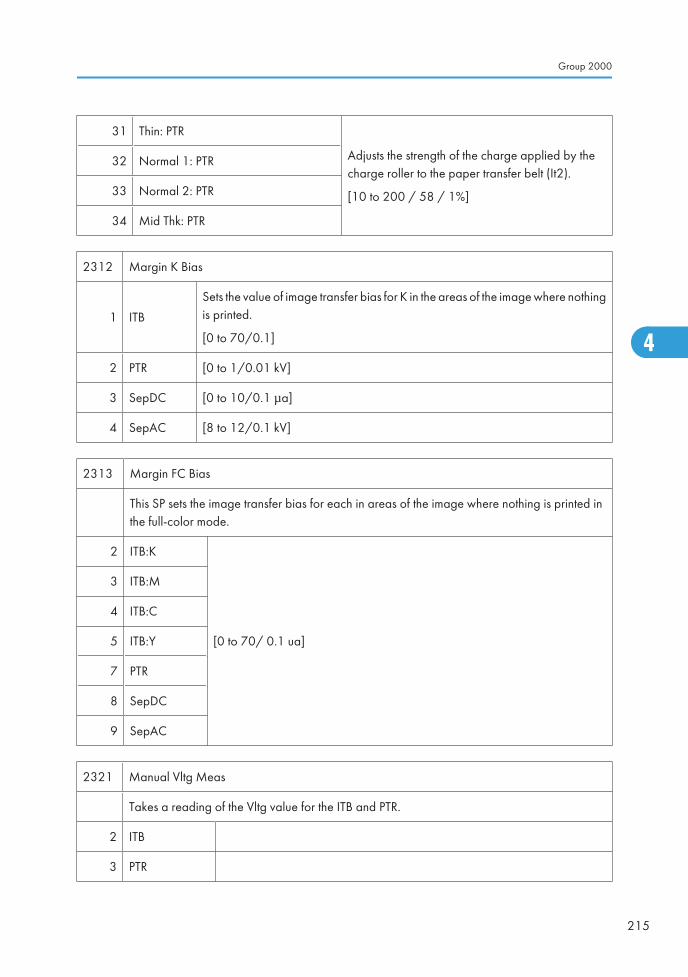
31 Thin: PTR
Adjusts the strength of the charge applied by thecharge roller to the paper transfer belt (It2).
[10 to 200 / 58 / 1%]
32 Normal 1: PTR
33 Normal 2: PTR
34 Mid Thk: PTR
2312 Margin K Bias
1 ITB
Sets the value of image transfer bias for K in the areas of the image where nothingis printed.
[0 to 70/0.1]
2 PTR [0 to 1/0.01 kV]
3 SepDC [0 to 10/0.1 μa]
4 SepAC [8 to 12/0.1 kV]
2313 Margin FC Bias
This SP sets the image transfer bias for each in areas of the image where nothing is printed inthe full-color mode.
2 ITB:K
[0 to 70/ 0.1 ua]
3 ITB:M
4 ITB:C
5 ITB:Y
7 PTR
8 SepDC
9 SepAC
2321 Manual Vltg Meas
Takes a reading of the Vltg value for the ITB and PTR.
2 ITB
3 PTR
Group 2000
215
4
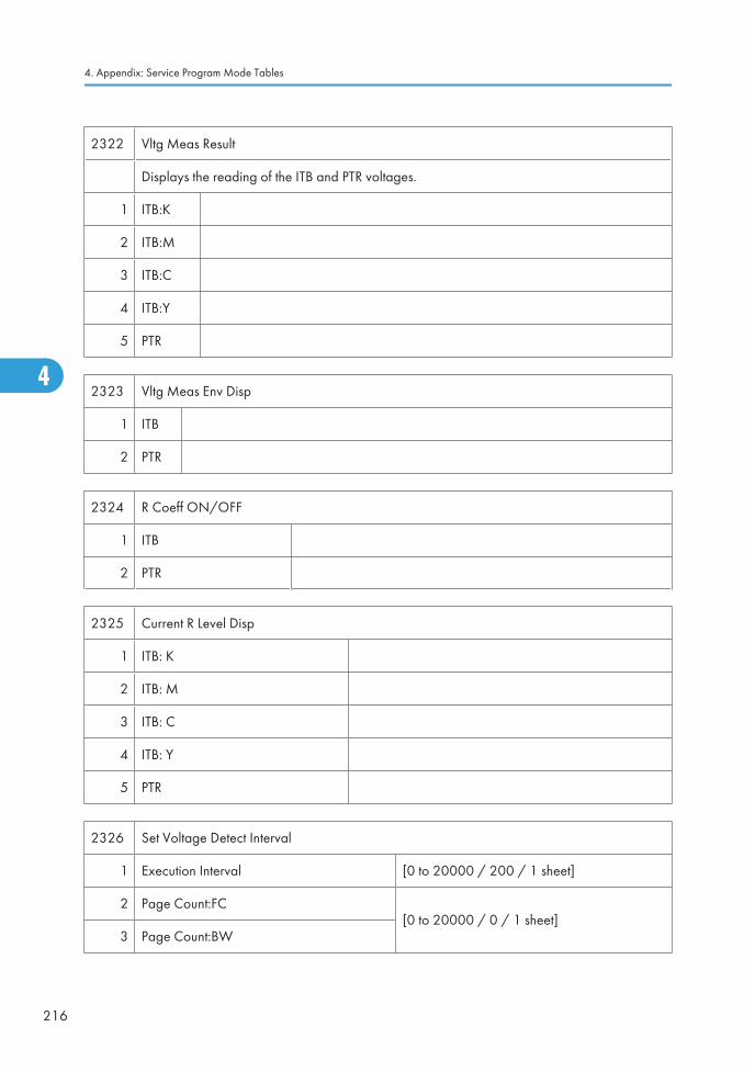
2322 Vltg Meas Result
Displays the reading of the ITB and PTR voltages.
1 ITB:K
2 ITB:M
3 ITB:C
4 ITB:Y
5 PTR
2323 Vltg Meas Env Disp
1 ITB
2 PTR
2324 R Coeff ON/OFF
1 ITB
2 PTR
2325 Current R Level Disp
1 ITB: K
2 ITB: M
3 ITB: C
4 ITB: Y
5 PTR
2326 Set Voltage Detect Interval
1 Execution Interval [0 to 20000 / 200 / 1 sheet]
2 Page Count:FC[0 to 20000 / 0 / 1 sheet]
3 Page Count:BW
4. Appendix: Service Program Mode Tables
216
4
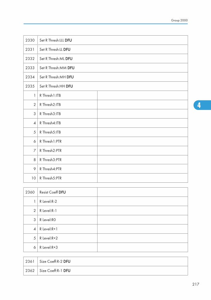
2330 Set R Thresh:LLL DFU
2331 Set R Thresh:LL DFU
2332 Set R Thresh:ML DFU
2333 Set R Thresh:MM DFU
2334 Set R Thresh:MH DFU
2335 Set R Thresh:HH DFU
1 R Thresh1:ITB
2 R Thresh2:ITB
3 R Thresh3:ITB
4 R Thresh4:ITB
5 R Thresh5:ITB
6 R Thresh1:PTR
7 R Thresh2:PTR
8 R Thresh3:PTR
9 R Thresh4:PTR
10 R Thresh5:PTR
2360 Resist Coeff DFU
1 R Level:R-2
2 R Level:R-1
3 R Level:R0
4 R Level:R+1
5 R Level:R+2
6 R Level:R+3
2361 Size Coeff:R-2 DFU
2362 Size Coeff:R-1 DFU
Group 2000
217
4
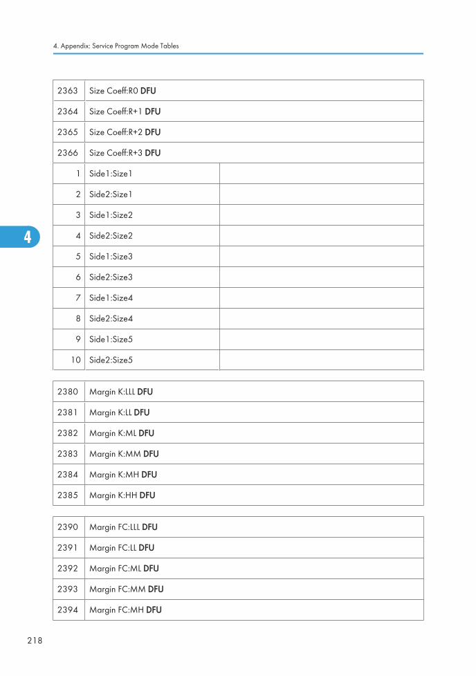
2363 Size Coeff:R0 DFU
2364 Size Coeff:R+1 DFU
2365 Size Coeff:R+2 DFU
2366 Size Coeff:R+3 DFU
1 Side1:Size1
2 Side2:Size1
3 Side1:Size2
4 Side2:Size2
5 Side1:Size3
6 Side2:Size3
7 Side1:Size4
8 Side2:Size4
9 Side1:Size5
10 Side2:Size5
2380 Margin K:LLL DFU
2381 Margin K:LL DFU
2382 Margin K:ML DFU
2383 Margin K:MM DFU
2384 Margin K:MH DFU
2385 Margin K:HH DFU
2390 Margin FC:LLL DFU
2391 Margin FC:LL DFU
2392 Margin FC:ML DFU
2393 Margin FC:MM DFU
2394 Margin FC:MH DFU
4. Appendix: Service Program Mode Tables
218
4
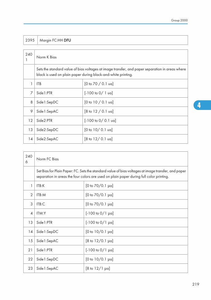
2395 Margin FC:HH DFU
2401
Norm K Bias
Sets the standard value of bias voltages at image transfer, and paper separation in areas whereblack is used on plain paper during black-and-white printing.
1 ITB [0 to 70 / 0.1 ua]
7 Side1:PTR [-100 to 0/ 1 ua]
8 Side1:SepDC [0 to 10 / 0.1 ua]
9 Side1:SepAC [8 to 12 / 0.1 ua]
12 Side2:PTR [-100 to 0/ 0.1 ua]
13 Side2:SepDC [0 to 10/ 0.1 ua]
14 Side2:SepAC [8 to 12/ 0.1 ua]
2406
Norm FC Bias
Set Bias for Plain Paper: FC. Sets the standard value of bias voltages at image transfer, and paperseparation in areas the four colors are used on plain paper during full color printing.
1 ITB:K [0 to 70/0.1 μa]
2 ITB:M [0 to 70/0.1 μa]
3 ITB:C [0 to 70/0.1 μa]
4 ITM:Y [-100 to 0/1 μa]
13 Side1:PTR [-100 to 0/1 μa]
14 Side1:SepDC [0 to 10/0.1 μa]
15 Side1:SepAC [8 to 12/0.1 μa]
21 Side1:PTR [-100 to 0/1 μa]
22 Side1:SepDC [0 to 10/0.1 μa]
23 Side1:SepAC [8 to 12/1 μa]
Group 2000
219
4
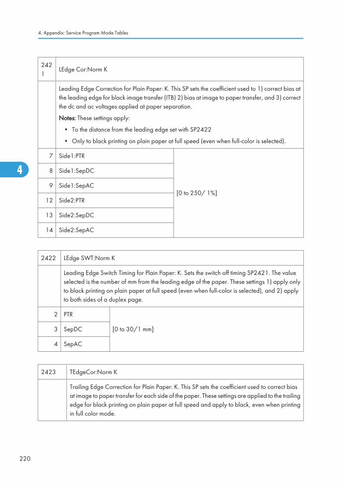
2421
LEdge Cor:Norm K
Leading Edge Correction for Plain Paper: K. This SP sets the coefficient used to 1) correct bias atthe leading edge for black image transfer (ITB) 2) bias at image to paper transfer, and 3) correctthe dc and ac voltages applied at paper separation.
Notes: These settings apply:
• To the distance from the leading edge set with SP2422
• Only to black printing on plain paper at full speed (even when full-color is selected).
7 Side1:PTR
[0 to 250/ 1%]
8 Side1:SepDC
9 Side1:SepAC
12 Side2:PTR
13 Side2:SepDC
14 Side2:SepAC
2422 LEdge SWT:Norm K
Leading Edge Switch Timing for Plain Paper: K. Sets the switch off timing SP2421. The valueselected is the number of mm from the leading edge of the paper. These settings 1) apply onlyto black printing on plain paper at full speed (even when full-color is selected), and 2) applyto both sides of a duplex page.
2 PTR
[0 to 30/1 mm]3 SepDC
4 SepAC
2423 TEdgeCor:Norm K
Trailing Edge Correction for Plain Paper: K. This SP sets the coefficient used to correct biasat image to paper transfer for each side of the paper. These settings are applied to the trailingedge for black printing on plain paper at full speed and apply to black, even when printingin full color mode.
4. Appendix: Service Program Mode Tables
220
4

7 Side1:PTR[0 to 250/1%]
12 Side2:PTR
2424
TEdgeSWT:Norm K (PTR)
Trailing Edge Switch Timing for Plain Paper: K. This setting sets the start timing for application ofSP2423 at the trailing edge of each sheet (Side 1, Side 2). This setting is applied to the trailingedge for black printing on plain paper at full speed and apply to black, even when printing infull color mode.
[-100 to 0/1 mm]
The mm distance is measured away from the trailing edge of the image.
2426
LEdgeCor:Norm FC
Leading Edge Correction for Plain Paper: FC. This SP sets the coefficient used to 1) correct biasat the leading edge for full-color image transfer (ITB) bias at image to paper transfer when usingplain paper, and 3) correct the dc and ac voltages applied at paper separation.
Notes: These settings apply:
• Only the distance from the leading edge set with SP2427.
• Only to full color printing on plain paper at full speed.
7 Side1:PTR
[0 to 250/1%]
8 Side1:SepDC
9 Side1:SepAC
12 Side2:PTR
13 Side2:SepDC
14 Side2:SepAC
2427 LEdgeSWT:Norm FC
Group 2000
221
4
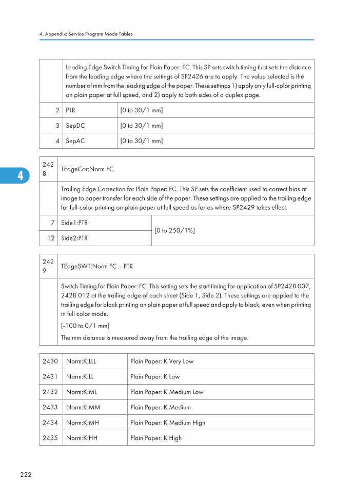
Leading Edge Switch Timing for Plain Paper: FC. This SP sets switch timing that sets the distancefrom the leading edge where the settings of SP2426 are to apply. The value selected is thenumber of mm from the leading edge of the paper. These settings 1) apply only full-color printingon plain paper at full speed, and 2) apply to both sides of a duplex page.
2 PTR [0 to 30/1 mm]
3 SepDC [0 to 30/1 mm]
4 SepAC [0 to 30/1 mm]
2428
TEdgeCor:Norm FC
Trailing Edge Correction for Plain Paper: FC. This SP sets the coefficient used to correct bias atimage to paper transfer for each side of the paper. These settings are applied to the trailing edgefor full-color printing on plain paper at full speed as far as where SP2429 takes effect.
7 Side1:PTR[0 to 250/1%]
12 Side2:PTR
2429
TEdgeSWT:Norm FC – PTR
Switch Timing for Plain Paper: FC. This setting sets the start timing for application of SP2428 007,2428 012 at the trailing edge of each sheet (Side 1, Side 2). These settings are applied to thetrailing edge for black printing on plain paper at full speed and apply to black, even when printingin full color mode.
[-100 to 0/1 mm]
The mm distance is measured away from the trailing edge of the image.
2430 Norm:K:LLL Plain Paper: K Very Low
2431 Norm:K:LL Plain Paper: K Low
2432 Norm:K:ML Plain Paper: K Medium Low
2433 Norm:K:MM Plain Paper: K Medium
2434 Norm:K:MH Plain Paper: K Medium High
2435 Norm:K:HH Plain Paper: K High
4. Appendix: Service Program Mode Tables
222
4
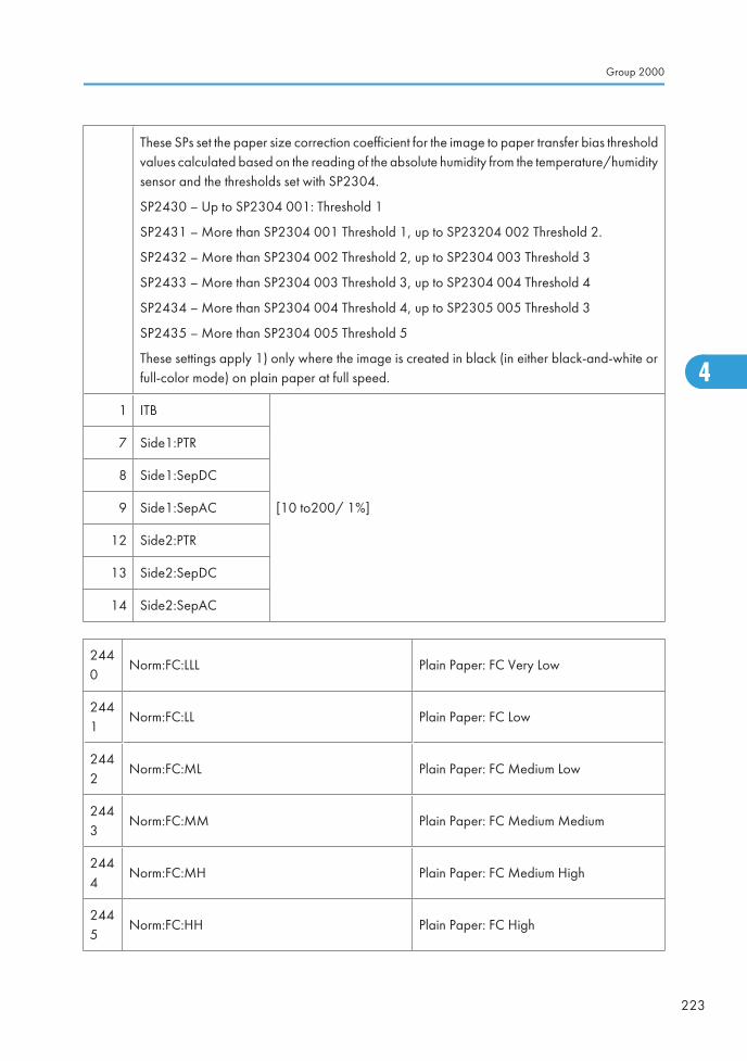
These SPs set the paper size correction coefficient for the image to paper transfer bias thresholdvalues calculated based on the reading of the absolute humidity from the temperature/humiditysensor and the thresholds set with SP2304.
SP2430 – Up to SP2304 001: Threshold 1
SP2431 – More than SP2304 001 Threshold 1, up to SP23204 002 Threshold 2.
SP2432 – More than SP2304 002 Threshold 2, up to SP2304 003 Threshold 3
SP2433 – More than SP2304 003 Threshold 3, up to SP2304 004 Threshold 4
SP2434 – More than SP2304 004 Threshold 4, up to SP2305 005 Threshold 3
SP2435 – More than SP2304 005 Threshold 5
These settings apply 1) only where the image is created in black (in either black-and-white orfull-color mode) on plain paper at full speed.
1 ITB
[10 to200/ 1%]
7 Side1:PTR
8 Side1:SepDC
9 Side1:SepAC
12 Side2:PTR
13 Side2:SepDC
14 Side2:SepAC
2440
Norm:FC:LLL Plain Paper: FC Very Low
2441
Norm:FC:LL Plain Paper: FC Low
2442
Norm:FC:ML Plain Paper: FC Medium Low
2443
Norm:FC:MM Plain Paper: FC Medium Medium
2444
Norm:FC:MH Plain Paper: FC Medium High
2445
Norm:FC:HH Plain Paper: FC High
Group 2000
223
4
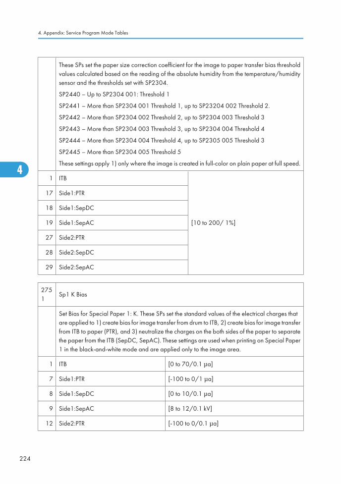
These SPs set the paper size correction coefficient for the image to paper transfer bias thresholdvalues calculated based on the reading of the absolute humidity from the temperature/humiditysensor and the thresholds set with SP2304.
SP2440 – Up to SP2304 001: Threshold 1
SP2441 – More than SP2304 001 Threshold 1, up to SP23204 002 Threshold 2.
SP2442 – More than SP2304 002 Threshold 2, up to SP2304 003 Threshold 3
SP2443 – More than SP2304 003 Threshold 3, up to SP2304 004 Threshold 4
SP2444 – More than SP2304 004 Threshold 4, up to SP2305 005 Threshold 3
SP2445 – More than SP2304 005 Threshold 5
These settings apply 1) only where the image is created in full-color on plain paper at full speed.
1 ITB
[10 to 200/ 1%]
17 Side1:PTR
18 Side1:SepDC
19 Side1:SepAC
27 Side2:PTR
28 Side2:SepDC
29 Side2:SepAC
2751
Sp1 K Bias
Set Bias for Special Paper 1: K. These SPs set the standard values of the electrical charges thatare applied to 1) create bias for image transfer from drum to ITB, 2) create bias for image transferfrom ITB to paper (PTR), and 3) neutralize the charges on the both sides of the paper to separatethe paper from the ITB (SepDC, SepAC). These settings are used when printing on Special Paper1 in the black-and-white mode and are applied only to the image area.
1 ITB [0 to 70/0.1 μa]
7 Side1:PTR [-100 to 0/1 μa]
8 Side1:SepDC [0 to 10/0.1 μa]
9 Side1:SepAC [8 to 12/0.1 kV]
12 Side2:PTR [-100 to 0/0.1 μa]
4. Appendix: Service Program Mode Tables
224
4
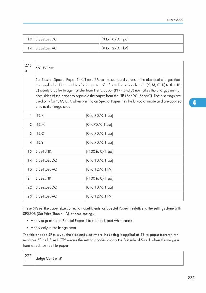
13 Side2:SepDC [0 to 10/0.1 μa]
14 Side2:SepAC [8 to 12/0.1 kV]
2756
Sp1 FC Bias
Set Bias for Special Paper 1: K. These SPs set the standard values of the electrical charges thatare applied to 1) create bias for image transfer from drum of each color (Y, M, C, K) to the ITB,2) create bias for image transfer from ITB to paper (PTR), and 3) neutralize the charges on theboth sides of the paper to separate the paper from the ITB (SepDC, SepAC). These settings areused only for Y, M, C, K when printing on Special Paper 1 in the full-color mode and are appliedonly to the image area.
1 ITB:K [0 to 70/0.1 μa]
2 ITB:M [0 to70/0.1 μa]
3 ITB:C [0 to 70/0.1 μa]
4 ITB:Y [0 to 70/0.1 μa]
13 Side1:PTR [-100 to 0/1 μa]
14 Side1:SepDC [0 to 10/0.1 μa]
15 Side1:SepAC [8 to 12/0.1 kV]
21 Side2:PTR [-100 to 0/1 μa]
22 Side2:SepDC [0 to 10/0.1 μa]
23 Side1:SepAC [8 to 12/0.1 kV]
These SPs set the paper size correction coefficients for Special Paper 1 relative to the settings done withSP2308 (Set Psize Thresh). All of hese settings:
• Apply to printing on Special Paper 1 in the black-and-white mode
• Apply only to the image area
The title of each SP tells you the side and size where the setting is applied at ITB-to-paper transfer, forexample: "Side1:Size1:PTR" means the setting applies to only the first side of Size 1 when the image istransferred from belt to paper.
2771
LEdge Cor:Sp1:K
Group 2000
225
4
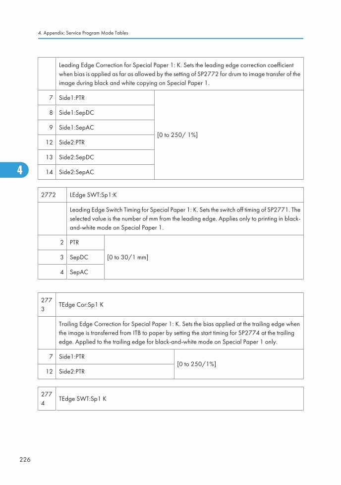
Leading Edge Correction for Special Paper 1: K. Sets the leading edge correction coefficientwhen bias is applied as far as allowed by the setting of SP2772 for drum to image transfer of theimage during black and white copying on Special Paper 1.
7 Side1:PTR
[0 to 250/ 1%]
8 Side1:SepDC
9 Side1:SepAC
12 Side2:PTR
13 Side2:SepDC
14 Side2:SepAC
2772 LEdge SWT:Sp1:K
Leading Edge Switch Timing for Special Paper 1: K. Sets the switch off timing of SP2771. Theselected value is the number of mm from the leading edge. Applies only to printing in black-and-white mode on Special Paper 1.
2 PTR
[0 to 30/1 mm]3 SepDC
4 SepAC
2773
TEdge Cor:Sp1 K
Trailing Edge Correction for Special Paper 1: K. Sets the bias applied at the trailing edge whenthe image is transferred from ITB to paper by setting the start timing for SP2774 at the trailingedge. Applied to the trailing edge for black-and-white mode on Special Paper 1 only.
7 Side1:PTR[0 to 250/1%]
12 Side2:PTR
2774
TEdge SWT:Sp1 K
4. Appendix: Service Program Mode Tables
226
4
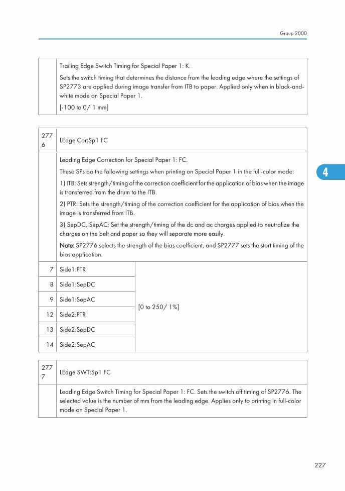
Trailing Edge Switch Timing for Special Paper 1: K.
Sets the switch timing that determines the distance from the leading edge where the settings ofSP2773 are applied during image transfer from ITB to paper. Applied only when in black-and-white mode on Special Paper 1.
[-100 to 0/ 1 mm]
2776
LEdge Cor:Sp1 FC
Leading Edge Correction for Special Paper 1: FC.
These SPs do the following settings when printing on Special Paper 1 in the full-color mode:
1) ITB: Sets strength/timing of the correction coefficient for the application of bias when the imageis transferred from the drum to the ITB.
2) PTR: Sets the strength/timing of the correction coefficient for the application of bias when theimage is transferred from ITB.
3) SepDC, SepAC: Set the strength/timing of the dc and ac charges applied to neutralize thecharges on the belt and paper so they will separate more easily.
Note: SP2776 selects the strength of the bias coefficient, and SP2777 sets the start timing of thebias application.
7 Side1:PTR
[0 to 250/ 1%]
8 Side1:SepDC
9 Side1:SepAC
12 Side2:PTR
13 Side2:SepDC
14 Side2:SepAC
2777
LEdge SWT:Sp1 FC
Leading Edge Switch Timing for Special Paper 1: FC. Sets the switch off timing of SP2776. Theselected value is the number of mm from the leading edge. Applies only to printing in full-colormode on Special Paper 1.
Group 2000
227
4
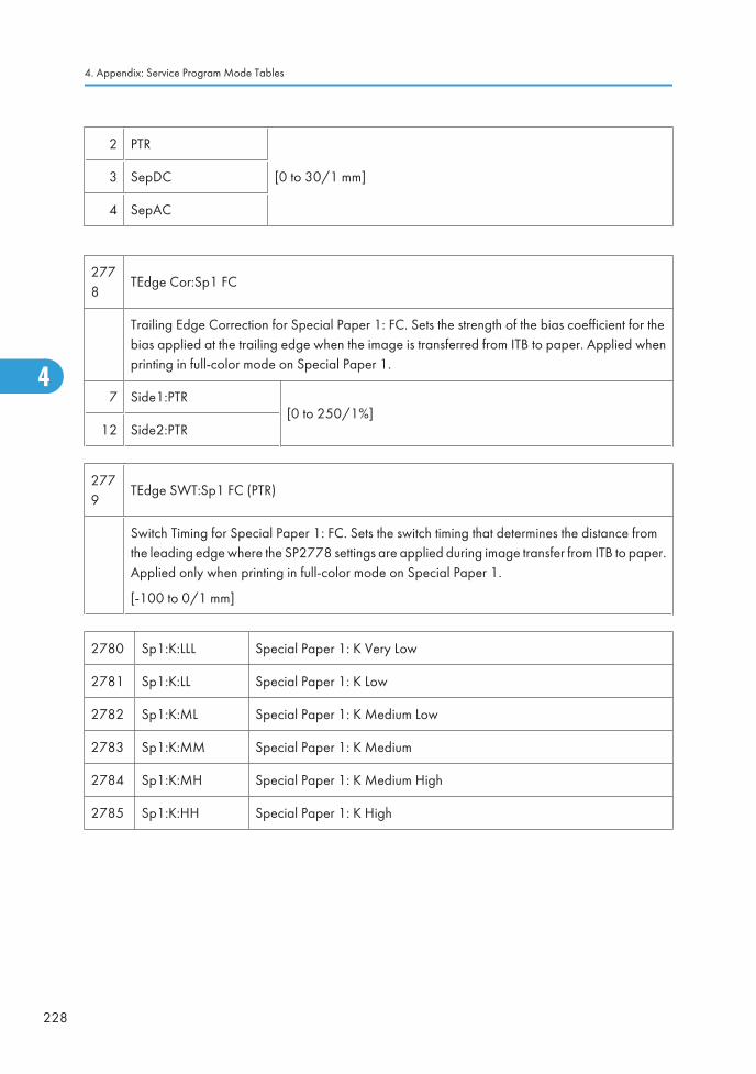
2 PTR
[0 to 30/1 mm]3 SepDC
4 SepAC
2778
TEdge Cor:Sp1 FC
Trailing Edge Correction for Special Paper 1: FC. Sets the strength of the bias coefficient for thebias applied at the trailing edge when the image is transferred from ITB to paper. Applied whenprinting in full-color mode on Special Paper 1.
7 Side1:PTR[0 to 250/1%]
12 Side2:PTR
2779
TEdge SWT:Sp1 FC (PTR)
Switch Timing for Special Paper 1: FC. Sets the switch timing that determines the distance fromthe leading edge where the SP2778 settings are applied during image transfer from ITB to paper.Applied only when printing in full-color mode on Special Paper 1.
[-100 to 0/1 mm]
2780 Sp1:K:LLL Special Paper 1: K Very Low
2781 Sp1:K:LL Special Paper 1: K Low
2782 Sp1:K:ML Special Paper 1: K Medium Low
2783 Sp1:K:MM Special Paper 1: K Medium
2784 Sp1:K:MH Special Paper 1: K Medium High
2785 Sp1:K:HH Special Paper 1: K High
4. Appendix: Service Program Mode Tables
228
4
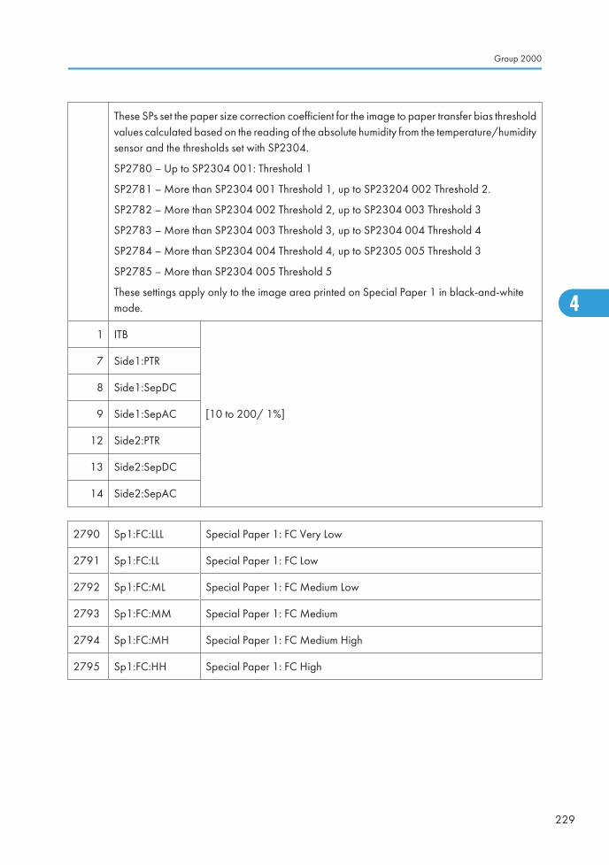
These SPs set the paper size correction coefficient for the image to paper transfer bias thresholdvalues calculated based on the reading of the absolute humidity from the temperature/humiditysensor and the thresholds set with SP2304.
SP2780 – Up to SP2304 001: Threshold 1
SP2781 – More than SP2304 001 Threshold 1, up to SP23204 002 Threshold 2.
SP2782 – More than SP2304 002 Threshold 2, up to SP2304 003 Threshold 3
SP2783 – More than SP2304 003 Threshold 3, up to SP2304 004 Threshold 4
SP2784 – More than SP2304 004 Threshold 4, up to SP2305 005 Threshold 3
SP2785 – More than SP2304 005 Threshold 5
These settings apply only to the image area printed on Special Paper 1 in black-and-whitemode.
1 ITB
[10 to 200/ 1%]
7 Side1:PTR
8 Side1:SepDC
9 Side1:SepAC
12 Side2:PTR
13 Side2:SepDC
14 Side2:SepAC
2790 Sp1:FC:LLL Special Paper 1: FC Very Low
2791 Sp1:FC:LL Special Paper 1: FC Low
2792 Sp1:FC:ML Special Paper 1: FC Medium Low
2793 Sp1:FC:MM Special Paper 1: FC Medium
2794 Sp1:FC:MH Special Paper 1: FC Medium High
2795 Sp1:FC:HH Special Paper 1: FC High
Group 2000
229
4
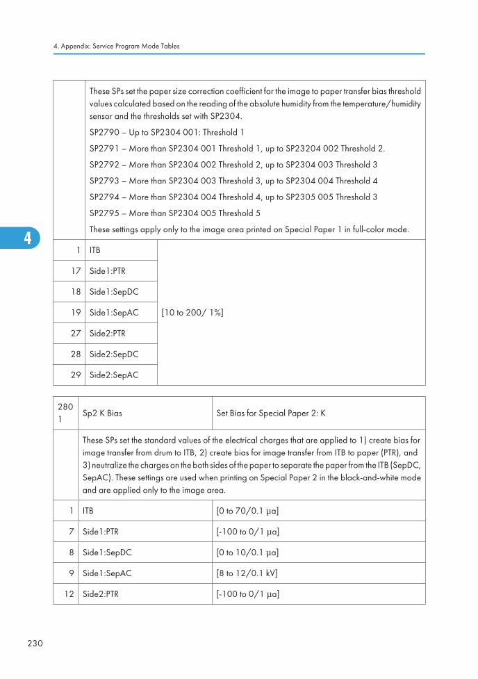
These SPs set the paper size correction coefficient for the image to paper transfer bias thresholdvalues calculated based on the reading of the absolute humidity from the temperature/humiditysensor and the thresholds set with SP2304.
SP2790 – Up to SP2304 001: Threshold 1
SP2791 – More than SP2304 001 Threshold 1, up to SP23204 002 Threshold 2.
SP2792 – More than SP2304 002 Threshold 2, up to SP2304 003 Threshold 3
SP2793 – More than SP2304 003 Threshold 3, up to SP2304 004 Threshold 4
SP2794 – More than SP2304 004 Threshold 4, up to SP2305 005 Threshold 3
SP2795 – More than SP2304 005 Threshold 5
These settings apply only to the image area printed on Special Paper 1 in full-color mode.
1 ITB
[10 to 200/ 1%]
17 Side1:PTR
18 Side1:SepDC
19 Side1:SepAC
27 Side2:PTR
28 Side2:SepDC
29 Side2:SepAC
2801
Sp2 K Bias Set Bias for Special Paper 2: K
These SPs set the standard values of the electrical charges that are applied to 1) create bias forimage transfer from drum to ITB, 2) create bias for image transfer from ITB to paper (PTR), and3) neutralize the charges on the both sides of the paper to separate the paper from the ITB (SepDC,SepAC). These settings are used when printing on Special Paper 2 in the black-and-white modeand are applied only to the image area.
1 ITB [0 to 70/0.1 μa]
7 Side1:PTR [-100 to 0/1 μa]
8 Side1:SepDC [0 to 10/0.1 μa]
9 Side1:SepAC [8 to 12/0.1 kV]
12 Side2:PTR [-100 to 0/1 μa]
4. Appendix: Service Program Mode Tables
230
4
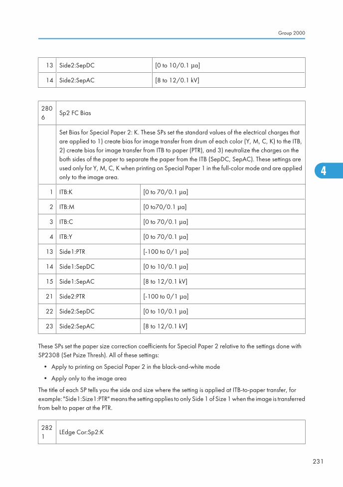
13 Side2:SepDC [0 to 10/0.1 μa]
14 Side2:SepAC [8 to 12/0.1 kV]
2806
Sp2 FC Bias
Set Bias for Special Paper 2: K. These SPs set the standard values of the electrical charges thatare applied to 1) create bias for image transfer from drum of each color (Y, M, C, K) to the ITB,2) create bias for image transfer from ITB to paper (PTR), and 3) neutralize the charges on theboth sides of the paper to separate the paper from the ITB (SepDC, SepAC). These settings areused only for Y, M, C, K when printing on Special Paper 1 in the full-color mode and are appliedonly to the image area.
1 ITB:K [0 to 70/0.1 μa]
2 ITB:M [0 to70/0.1 μa]
3 ITB:C [0 to 70/0.1 μa]
4 ITB:Y [0 to 70/0.1 μa]
13 Side1:PTR [-100 to 0/1 μa]
14 Side1:SepDC [0 to 10/0.1 μa]
15 Side1:SepAC [8 to 12/0.1 kV]
21 Side2:PTR [-100 to 0/1 μa]
22 Side2:SepDC [0 to 10/0.1 μa]
23 Side2:SepAC [8 to 12/0.1 kV]
These SPs set the paper size correction coefficients for Special Paper 2 relative to the settings done withSP2308 (Set Psize Thresh). All of these settings:
• Apply to printing on Special Paper 2 in the black-and-white mode
• Apply only to the image area
The title of each SP tells you the side and size where the setting is applied at ITB-to-paper transfer, forexample: "Side1:Size1:PTR" means the setting applies to only Side 1 of Size 1 when the image is transferredfrom belt to paper at the PTR.
2821
LEdge Cor:Sp2:K
Group 2000
231
4
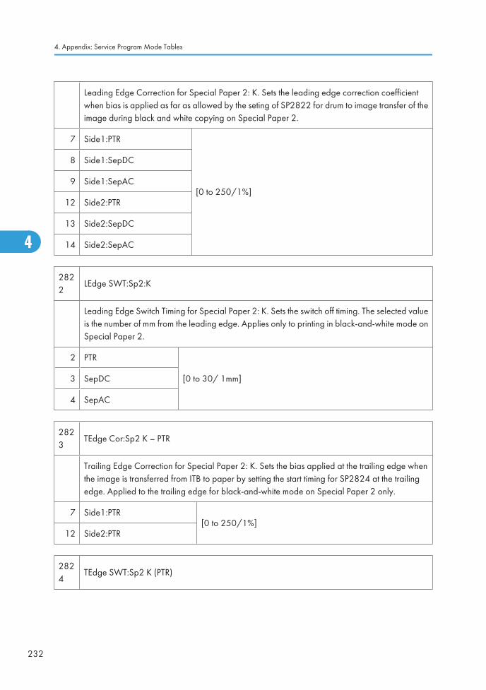
Leading Edge Correction for Special Paper 2: K. Sets the leading edge correction coefficientwhen bias is applied as far as allowed by the seting of SP2822 for drum to image transfer of theimage during black and white copying on Special Paper 2.
7 Side1:PTR
[0 to 250/1%]
8 Side1:SepDC
9 Side1:SepAC
12 Side2:PTR
13 Side2:SepDC
14 Side2:SepAC
2822
LEdge SWT:Sp2:K
Leading Edge Switch Timing for Special Paper 2: K. Sets the switch off timing. The selected valueis the number of mm from the leading edge. Applies only to printing in black-and-white mode onSpecial Paper 2.
2 PTR
[0 to 30/ 1mm]3 SepDC
4 SepAC
2823
TEdge Cor:Sp2 K – PTR
Trailing Edge Correction for Special Paper 2: K. Sets the bias applied at the trailing edge whenthe image is transferred from ITB to paper by setting the start timing for SP2824 at the trailingedge. Applied to the trailing edge for black-and-white mode on Special Paper 2 only.
7 Side1:PTR[0 to 250/1%]
12 Side2:PTR
2824
TEdge SWT:Sp2 K (PTR)
4. Appendix: Service Program Mode Tables
232
4
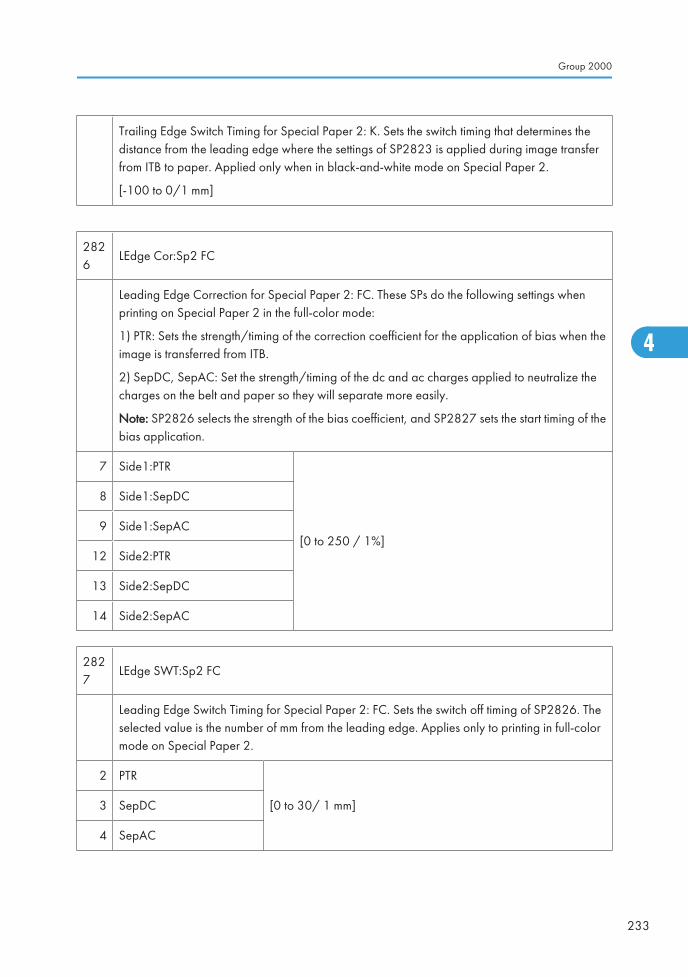
Trailing Edge Switch Timing for Special Paper 2: K. Sets the switch timing that determines thedistance from the leading edge where the settings of SP2823 is applied during image transferfrom ITB to paper. Applied only when in black-and-white mode on Special Paper 2.
[-100 to 0/1 mm]
2826
LEdge Cor:Sp2 FC
Leading Edge Correction for Special Paper 2: FC. These SPs do the following settings whenprinting on Special Paper 2 in the full-color mode:
1) PTR: Sets the strength/timing of the correction coefficient for the application of bias when theimage is transferred from ITB.
2) SepDC, SepAC: Set the strength/timing of the dc and ac charges applied to neutralize thecharges on the belt and paper so they will separate more easily.
Note: SP2826 selects the strength of the bias coefficient, and SP2827 sets the start timing of thebias application.
7 Side1:PTR
[0 to 250 / 1%]
8 Side1:SepDC
9 Side1:SepAC
12 Side2:PTR
13 Side2:SepDC
14 Side2:SepAC
2827
LEdge SWT:Sp2 FC
Leading Edge Switch Timing for Special Paper 2: FC. Sets the switch off timing of SP2826. Theselected value is the number of mm from the leading edge. Applies only to printing in full-colormode on Special Paper 2.
2 PTR
[0 to 30/ 1 mm]3 SepDC
4 SepAC
Group 2000
233
4

2828
TEdge Cor:Sp2 FC
Trailing Edge Correction for Special Paper 2: FC. Sets the strength of the bias coefficient for thebias applied at the trailing edge when the image is transferred from ITB to paper. Applied whenprinting in full-color mode on Special Paper 2.
7 Side1:PTR[0 to 250/1%]
12 Side2:PTR
2829
TEdge SWT:Sp2 FC
Switch Timing for Special Paper 2: FC. Sets the switch timing that determines the distance fromthe leading edge where the SP2828 settings are applied during image transfer from ITB to paper.Applied only when printing in full-color mode on Special Paper 2.
[-100 to 0/1 mm]
2830 Sp2:K:LLL Special Paper 2: K Very Low
2831 Sp2:K:LL Special Paper 2: K Low
2832 Sp2:K:ML Special Paper 2: K Medium Low
2833 Sp2:K:MM Special Paper 2: K Medium
2834 Sp2:K:MH Special Paper 2: K Medium High
2835 Sp2:K:HH Special Paper 2: K High
These SPs set the paper size correction coefficient for the image to paper transfer bias thresholdvalues calculated based on the reading of the absolute humidity from the temperature/humiditysensor and the thresholds set with SP2304 8.
SP2830 – Up to SP2304 001: Threshold 1
SP2831 – More than SP2304 001 Threshold 1, up to SP23204 002 Threshold 2.
SP2832 – More than SP2304 002 Threshold 2, up to SP2304 003 Threshold 3
SP2833 – More than SP2304 003 Threshold 3, up to SP2304 004 Threshold 4
SP2834 – More than SP2304 004 Threshold 4, up to SP2305 005 Threshold 3
SP2835 – More than SP2304 005 Threshold 5
These settings apply only to the image area printed on Special Paper 2 in black-and-whitemode.
4. Appendix: Service Program Mode Tables
234
4
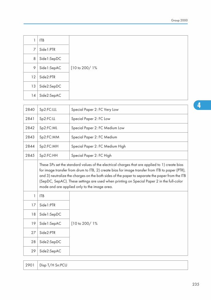
1 ITB
[10 to 200/ 1%
7 Side1:PTR
8 Side1:SepDC
9 Side1:SepAC
12 Side2:PTR
13 Side2:SepDC
14 Side2:SepAC
2840 Sp2:FC:LLL Special Paper 2: FC Very Low
2841 Sp2:FC:LL Special Paper 2: FC Low
2842 Sp2:FC:ML Special Paper 2: FC Medium Low
2843 Sp2:FC:MM Special Paper 2: FC Medium
2844 Sp2:FC:MH Special Paper 2: FC Medium High
2845 Sp2:FC:HH Special Paper 2: FC High
These SPs set the standard values of the electrical charges that are applied to 1) create biasfor image transfer from drum to ITB, 2) create bias for image transfer from ITB to paper (PTR),and 3) neutralize the charges on the both sides of the paper to separate the paper from the ITB(SepDC, SepAC). These settings are used when printing on Special Paper 2 in the full-colormode and are applied only to the image area.
1 ITB
[10 to 200/ 1%
17 Side1:PTR
18 Side1:SepDC
19 Side1:SepAC
27 Side2:PTR
28 Side2:SepDC
29 Side2:SepAC
2901 Disp T/H Sn:PCU
Group 2000
235
4
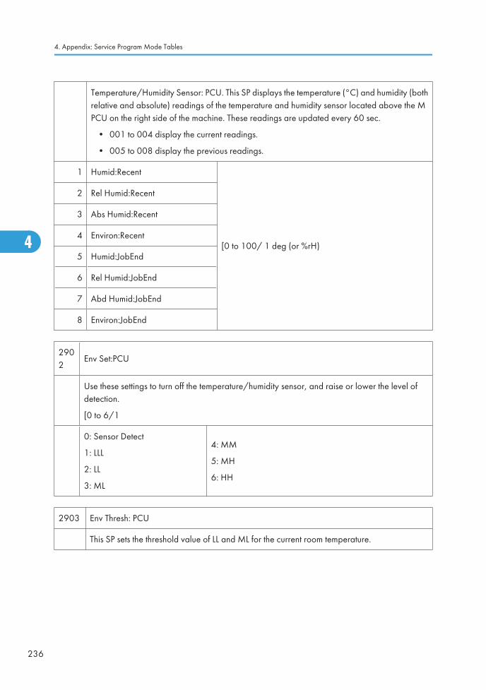
Temperature/Humidity Sensor: PCU. This SP displays the temperature (°C) and humidity (bothrelative and absolute) readings of the temperature and humidity sensor located above the MPCU on the right side of the machine. These readings are updated every 60 sec.
• 001 to 004 display the current readings.
• 005 to 008 display the previous readings.
1 Humid:Recent
[0 to 100/ 1 deg (or %rH)
2 Rel Humid:Recent
3 Abs Humid:Recent
4 Environ:Recent
5 Humid:JobEnd
6 Rel Humid:JobEnd
7 Abd Humid:JobEnd
8 Environ:JobEnd
2902
Env Set:PCU
Use these settings to turn off the temperature/humidity sensor, and raise or lower the level ofdetection.
[0 to 6/1
0: Sensor Detect
1: LLL
2: LL
3: ML
4: MM
5: MH
6: HH
2903 Env Thresh: PCU
This SP sets the threshold value of LL and ML for the current room temperature.
4. Appendix: Service Program Mode Tables
236
4
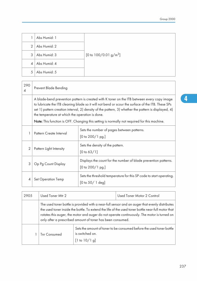
1 Abs Humid: 1
[0 to 100/0.01 g/m3]
2 Abs Humid: 2
3 Abs Humid: 3
4 Abs Humid: 4
5 Abs Humid: 5
2904
Prevent Blade Bending
A blade-bend prevention pattern is created with K toner on the ITB between every copy imageto lubricate the ITB cleaning blade so it will not bend or scour the surface of the ITB. These SPsset 1) pattern creation interval, 2) density of the pattern, 3) whether the pattern is displayed, 4)the temperature at which the operation is done.
Note: This function is OFF. Changing this setting is normally not required for this machine.
1 Pattern Create IntervalSets the number of pages between patterns.
[0 to 200/1 pg.]
2 Pattern Light IntensitySets the density of the pattern.
[0 to 63/1]
3 Op Pg Count DisplayDisplays the count for the number of blade prevention patterns.
[0 to 200/1 pg.]
4 Set Operation TempSets the threshold temperature for this SP code to start operating.
[0 to 50/ 1 deg]
2905 Used Toner Mtr 2 Used Toner Motor 2 Control
The used toner bottle is provided with a near-full sensor and an auger that evenly distributesthe used toner inside the bottle. To extend the life of the used toner bottle near-full motor thatrotates this auger, the motor and auger do not operate continuously. The motor is turned ononly after a prescribed amount of toner has been consumed.
1 Tnr Consumed
Sets the amount of toner to be consumed before the used toner bottleis switched on.
[1 to 10/1 g]
Group 2000
237
4
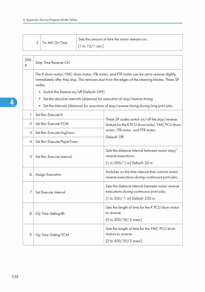
2 Tnr Mtr On TimeSets the amount of time the motor remains on.
[1 to 10/1 sec.]
2906
Stop Time Reverse Ctrl
The K drum motor, YMC drum motor, ITB motor, and PTR motor can be set to reverse slightlyimmediately after they stop. This removes dust from the edges of the cleaning blades. These SPcodes:
• Switch this feature on/off (Default: OFF)
• Set the absolute intervals (distance) for execution of stop/reverse timing
• Set the intervals (distance) for execution of stop/reverse timing during long print jobs.
1 Set Rev Execute:KThese SP codes switch on/off the stop/reversefeature for the K PCU drum motor, YMC PCU drummotor, ITB motor, and PTR motor.
Default: Off
2 Set Rev Execute:YCM
3 Set Rev Execute:ImgTrans
4 Set Rev Execute:PaperTrans
5 Set Rev Execute Interval
Sets the distance interval between motor stop/reverse executions.
[1 to 500/ 1 m] Default: 30 m
6 Assign ExecutionSwitches on the time interval that controls motorreverse executions during continuous print jobs.
7 Set Execute Interval
Sets the distance interval between motor reverseexecutions during continuous print jobs.
[1 to 500/ 1 m] Default: 250 m
8 Op Time Setting:Bk
Sets the length of time for the K PCU drum motorto reverse.
[2 to 500/30/2 msec]
9 Op Time Setting:YCM
Sets the length of time for the YMC PCU drummotors to reverse.
[2 to 500/30/2 msec]
4. Appendix: Service Program Mode Tables
238
4
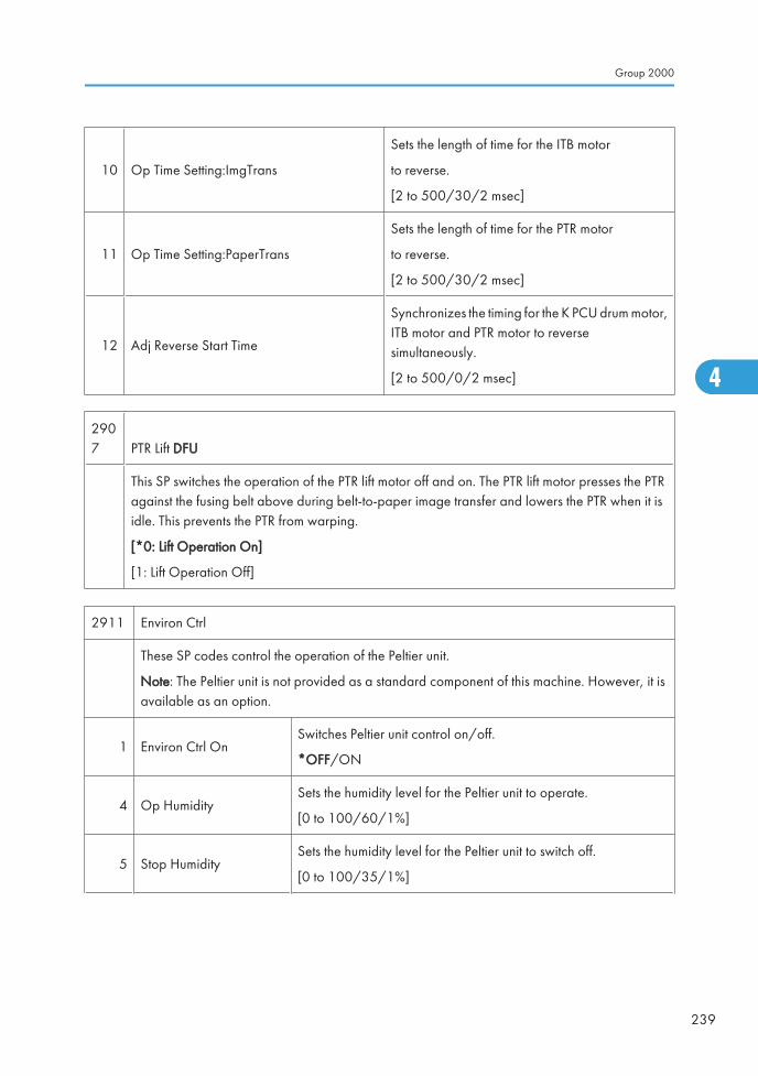
10 Op Time Setting:ImgTrans
Sets the length of time for the ITB motor
to reverse.
[2 to 500/30/2 msec]
11 Op Time Setting:PaperTrans
Sets the length of time for the PTR motor
to reverse.
[2 to 500/30/2 msec]
12 Adj Reverse Start Time
Synchronizes the timing for the K PCU drum motor,ITB motor and PTR motor to reversesimultaneously.
[2 to 500/0/2 msec]
2907 PTR Lift DFU
This SP switches the operation of the PTR lift motor off and on. The PTR lift motor presses the PTRagainst the fusing belt above during belt-to-paper image transfer and lowers the PTR when it isidle. This prevents the PTR from warping.
[*0: Lift Operation On]
[1: Lift Operation Off]
2911 Environ Ctrl
These SP codes control the operation of the Peltier unit.
Note: The Peltier unit is not provided as a standard component of this machine. However, it isavailable as an option.
1 Environ Ctrl OnSwitches Peltier unit control on/off.
*OFF/ON
4 Op HumiditySets the humidity level for the Peltier unit to operate.
[0 to 100/60/1%]
5 Stop HumiditySets the humidity level for the Peltier unit to switch off.
[0 to 100/35/1%]
Group 2000
239
4
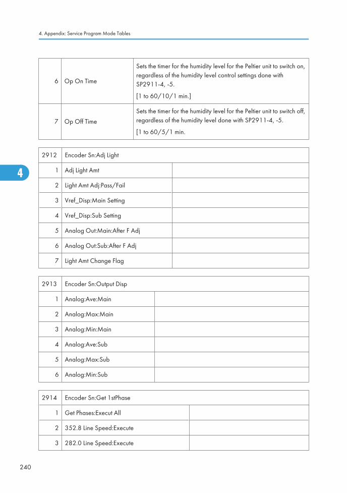
6 Op On Time
Sets the timer for the humidity level for the Peltier unit to switch on,regardless of the humidity level control settings done withSP2911-4, -5.
[1 to 60/10/1 min.]
7 Op Off Time
Sets the timer for the humidity level for the Peltier unit to switch off,regardless of the humidity level done with SP2911-4, -5.
[1 to 60/5/1 min.
2912 Encoder Sn:Adj Light
1 Adj Light Amt
2 Light Amt Adj:Pass/Fail
3 Vref_Disp:Main Setting
4 Vref_Disp:Sub Setting
5 Analog Out:Main:After F Adj
6 Analog Out:Sub:After F Adj
7 Light Amt Change Flag
2913 Encoder Sn:Output Disp
1 Analog:Ave:Main
2 Analog:Max:Main
3 Analog:Min:Main
4 Analog:Ave:Sub
5 Analog:Max:Sub
6 Analog:Min:Sub
2914 Encoder Sn:Get 1stPhase
1 Get Phases:Execut All
2 352.8 Line Speed:Execute
3 282.0 Line Speed:Execute
4. Appendix: Service Program Mode Tables
240
4
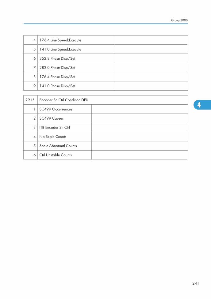
4 176.4 Line Speed:Execute
5 141.0 Line Speed:Execute
6 352.8 Phase Disp/Set
7 282.0 Phase Disp/Set
8 176.4 Phase Disp/Set
9 141.0 Phase Disp/Set
2915 Encoder Sn Ctrl Condition DFU
1 SC499 Occurrences
2 SC499 Causes
3 ITB Encoder Sn Ctrl
4 No Scale Counts
5 Scale Abnormal Counts
6 Ctrl Unstable Counts
Group 2000
241
4
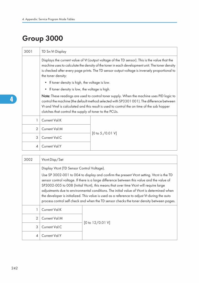
Group 30003001 TD Sn:Vt Display
Displays the current value of Vt (output voltage of the TD sensor). This is the value that themachine uses to calculate the density of the toner in each development unit. The toner densityis checked after every page prints. The TD sensor output voltage is inversely proportional tothe toner density:
• If toner density is high, the voltage is low.
• If toner density is low, the voltage is high.
Note: These readings are used to control toner supply. When the machine uses PID logic tocontrol the machine (the default method selected with SP3301 001). The difference betweenVt and Vtref is calculated and this result is used to control the on time of the sub hopperclutches that control the supply of toner to the PCUs.
1 Current Val:K
[0 to 5./0.01 V]2 Current Val:M
3 Current Val:C
4 Current Val:Y
3002 Vtcnt:Disp/Set
Display Vtcnt (TD Sensor Control Voltage).
Use SP 3002-001 to 004 to display and confirm the present Vtcnt setting. Vtcnt is the TDsensor control voltage. If there is a large difference between this value and the value ofSP3002-005 to 008 (Initial Vtcnt), this means that over time Vtcnt will require largeadjustments due to environmental conditions. The initial value of Vtcnt is determined whenthe developer is initialized. This value is used as a reference to adjust Vt during the autoprocess control self check and when the TD sensor checks the toner density between pages.
1 Current Val:K
[0 to 12/0.01 V]2 Current Val:M
3 Current Val:C
4 Current Val:Y
4. Appendix: Service Program Mode Tables
242
4
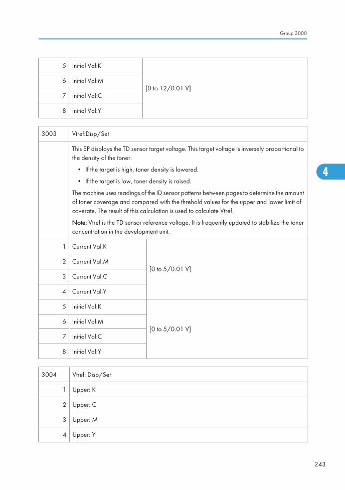
5 Initial Val:K
[0 to 12/0.01 V]6 Initial Val:M
7 Initial Val:C
8 Initial Val:Y
3003 Vtref:Disp/Set
This SP displays the TD sensor target voltage. This target voltage is inversely proportional tothe density of the toner:
• If the target is high, toner density is lowered.
• If the target is low, toner density is raised.
The machine uses readings of the ID sensor patterns between pages to determine the amountof toner coverage and compared with the threhold values for the upper and lower limit ofcoverate. The result of this calculation is used to calculate Vtref.
Note: Vtref is the TD sensor reference voltage. It is frequently updated to stabilize the tonerconcentration in the development unit.
1 Current Val:K
[0 to 5/0.01 V]2 Current Val:M
3 Current Val:C
4 Current Val:Y
5 Initial Val:K
[0 to 5/0.01 V]6 Initial Val:M
7 Initial Val:C
8 Initial Val:Y
3004 Vtref: Disp/Set
1 Upper: K
2 Upper: C
3 Upper: M
4 Upper: Y
Group 3000
243
4
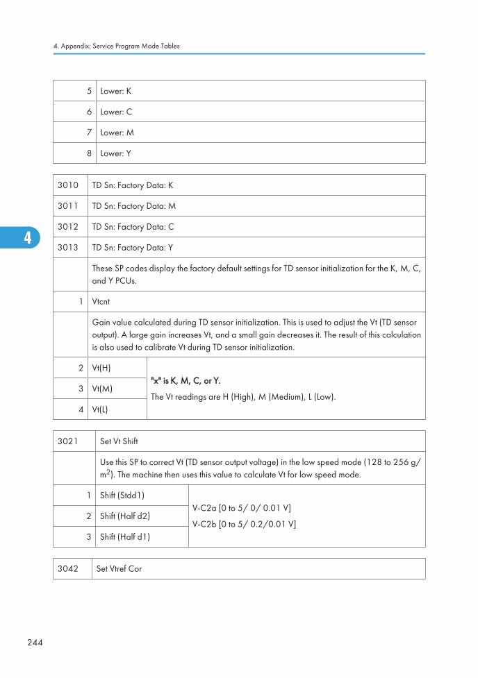
5 Lower: K
6 Lower: C
7 Lower: M
8 Lower: Y
3010 TD Sn: Factory Data: K
3011 TD Sn: Factory Data: M
3012 TD Sn: Factory Data: C
3013 TD Sn: Factory Data: Y
These SP codes display the factory default settings for TD sensor initialization for the K, M, C,and Y PCUs.
1 Vtcnt
Gain value calculated during TD sensor initialization. This is used to adjust the Vt (TD sensoroutput). A large gain increases Vt, and a small gain decreases it. The result of this calculationis also used to calibrate Vt during TD sensor initialization.
2 Vt(H)"x" is K, M, C, or Y.
The Vt readings are H (High), M (Medium), L (Low).3 Vt(M)
4 Vt(L)
3021 Set Vt Shift
Use this SP to correct Vt (TD sensor output voltage) in the low speed mode (128 to 256 g/m2). The machine then uses this value to calculate Vt for low speed mode.
1 Shift (Stdd1)V-C2a [0 to 5/ 0/ 0.01 V]
V-C2b [0 to 5/ 0.2/0.01 V]2 Shift (Half d2)
3 Shift (Half d1)
3042 Set Vtref Cor
4. Appendix: Service Program Mode Tables
244
4

Set Vtref Correction.
Vtref is frequently updated in the toner supply cycle to stabiize the concentration of toner inthe developer. Vtref is corrected between every printed page in the paper path using thecorrection amounts listed below for each color. This is the default setting (0) for SP3042 001.However, you can use this SP to switch this function off.
Vtref (TD sensor reference voltage). It is frequently updated to stabilize the toner concentrationin the development unit.
1 Vtref Corr Mode[0 to 1/1] 0: On, 1: Off
Setting this SP to 1 switches off Vtref correction between pages.
2 Corr Amt(+):K
[0 to 1/0.01 V]
3 Corr Amt(+):M
4 Corr Amt(+):C
5 Corr Amt(+):Y
6 Corr Amt(-):K
7 Corr Amt(-):M
8 Corr Amt(-):C
9 Corr Amt(-):Y
10 Vtref Corr Target:K
[-0.1 to 0.1/0.001 mg/cm2]11 Vtref Corr Target:M
12 Vtref Corr Target:C
13 Vtref Corr Target:Y
14 Corr Thresh:K
[-0.1 to 0.1/0/ mg/cm2]15 Corr Thresh:M
16 Corr Thresh:C
17 Corr Thresh:Y
3044 Img Area
These SP codes display the percentage of coverage on printed pages.
Group 3000
245
4
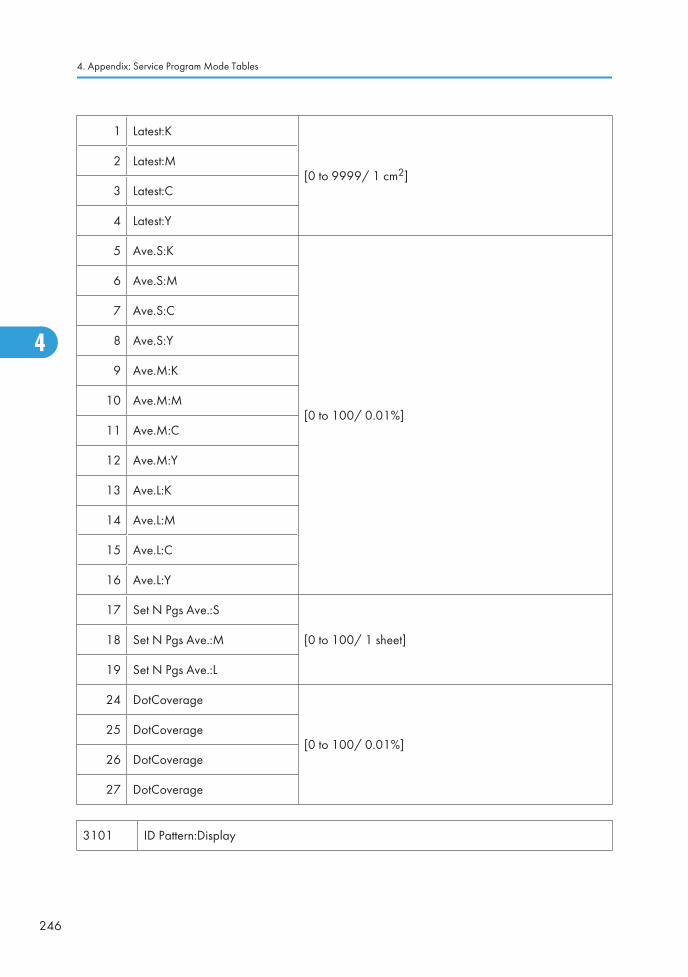
1 Latest:K
[0 to 9999/ 1 cm2]2 Latest:M
3 Latest:C
4 Latest:Y
5 Ave.S:K
[0 to 100/ 0.01%]
6 Ave.S:M
7 Ave.S:C
8 Ave.S:Y
9 Ave.M:K
10 Ave.M:M
11 Ave.M:C
12 Ave.M:Y
13 Ave.L:K
14 Ave.L:M
15 Ave.L:C
16 Ave.L:Y
17 Set N Pgs Ave.:S
[0 to 100/ 1 sheet]18 Set N Pgs Ave.:M
19 Set N Pgs Ave.:L
24 DotCoverage
[0 to 100/ 0.01%]25 DotCoverage
26 DotCoverage
27 DotCoverage
3101 ID Pattern:Display
4. Appendix: Service Program Mode Tables
246
4

ID Sensor Pattern Coverage Display.
Displays the amount toner to be used (coverage) to create the ID sensor patterns betweenpages. The ID sensors cannot accurately detect the patterns if there is too much reflectivityfrom the black toner. This SP changes the solid ID sensor pattern to a hatched pattern.
Note: SP3101-1 to 4 sets detection and update timing for the creation of the ID sensorpatterns.
1 Applied:K
2 Applied:M
3 Applied:C
4 Applied:Y
5 Target Apply:K
6 Target Apply:M
7 Target Apply:C
8 Target Apply:Y
3102 ID Pattern:Int
These SP patterns set the time interval for creation of the ID sensor pattern on the drum.
1 Create Int:K
[0 to 200/10/ 1 page]2 Create Int:M
3 Create Int:C
4 Create Int:Y
5 K Page Cnt
[0 to 200/0/ 1 page]6 M Page Cnt
7 C Page Cnt
8 Y Page Cnt
3111 ID Sn:Voffset DFU
Displays the output voltage of the directly reflected light when the LED of the ID sensor isswitched off.
Group 3000
247
4
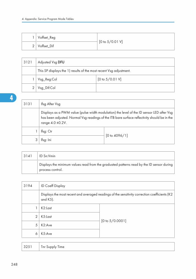
1 Voffset_Reg[0 to 5/0.01 V]
2 Voffset_Dif
3121 Adjusted Vsg DFU
This SP displays the 1) results of the most recent Vsg adjustment.
1 Vsg_Reg:Col [0 to 5/0.01 V]
2 Vsg_Dif:Col
3131 Ifsg After Vsg
Displays as a PWM value (pulse width modulation) the level of the ID sensor LED after Vsghas been adjusted. Normal Vsg readings of the ITB bare surface reflectivity should be in therange 4.0 ±0.2V.
1 lfsg: Ctr[0 to 4096/1]
3 lfsg: Ini
3141 ID Sn:Vmin
Displays the minimum values read from the graduated patterns read by the ID sensor duringprocess control.
3194 ID Coeff Display
Displays the most recent and averaged readings of the sensitivity correction coefficients (K2and K5).
1 K2:Last
[0 to 5/0.0001]2 K5:Last
5 K2:Ave
6 K5:Ave
3251 Tnr Supply Time
4. Appendix: Service Program Mode Tables
248
4
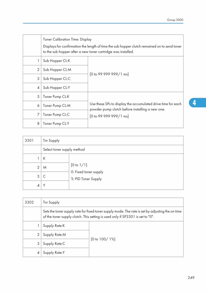
Toner Calibration Time: Display
Displays for confirmation the length of time the sub hopper clutch remained on to send tonerto the sub hopper after a new toner cartridge was installed.
1 Sub Hopper CL:K
[0 to 99 999 999/1 ms]2 Sub Hopper CL:M
3 Sub Hopper CL:C
4 Sub Hopper CL:Y
5 Toner Pump CL:K
Use these SPs to display the accumulated drive time for eachpowder pump clutch before installing a new one.
[0 to 99 999 999/1 ms]
6 Toner Pump CL:M
7 Toner Pump CL:C
8 Toner Pump CL:Y
3301 Tnr Supply
Select toner supply method
1 K
[0 to 1/1]
0: Fixed toner supply
1: PID Toner Supply
2 M
3 C
4 Y
3302 Tnr Supply
Sets the toner supply rate for fixed toner supply mode. The rate is set by adjusting the on timeof the toner supply clutch. This setting is used only if SP3301 is set to "0".
1 Supply Rate:K
[0 to 100/ 1%]2 Supply Rate:M
3 Supply Rate:C
4 Supply Rate:Y
Group 3000
249
4
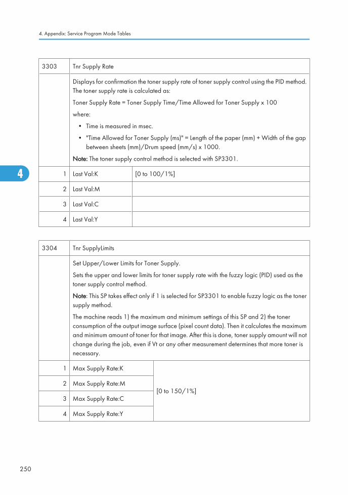
3303 Tnr Supply Rate
Displays for confirmation the toner supply rate of toner supply control using the PID method.The toner supply rate is calculated as:
Toner Supply Rate = Toner Supply Time/Time Allowed for Toner Supply x 100
where:
• Time is measured in msec.
• "Time Allowed for Toner Supply (ms)" = Length of the paper (mm) + Width of the gapbetween sheets (mm)/Drum speed (mm/s) x 1000.
Note: The toner supply control method is selected with SP3301.
1 Last Val:K [0 to 100/1%]
2 Last Val:M
3 Last Val:C
4 Last Val:Y
3304 Tnr SupplyLimits
Set Upper/Lower Limits for Toner Supply.
Sets the upper and lower limits for toner supply rate with the fuzzy logic (PID) used as thetoner supply control method.
Note: This SP takes effect only if 1 is selected for SP3301 to enable fuzzy logic as the tonersupply method.
The machine reads 1) the maximum and minimum settings of this SP and 2) the tonerconsumption of the output image surface (pixel count data). Then it calculates the maximumand minimum amount of toner for that image. After this is done, toner supply amount will notchange during the job, even if Vt or any other measurement determines that more toner isnecessary.
1 Max Supply Rate:K
[0 to 150/1%]2 Max Supply Rate:M
3 Max Supply Rate:C
4 Max Supply Rate:Y
4. Appendix: Service Program Mode Tables
250
4
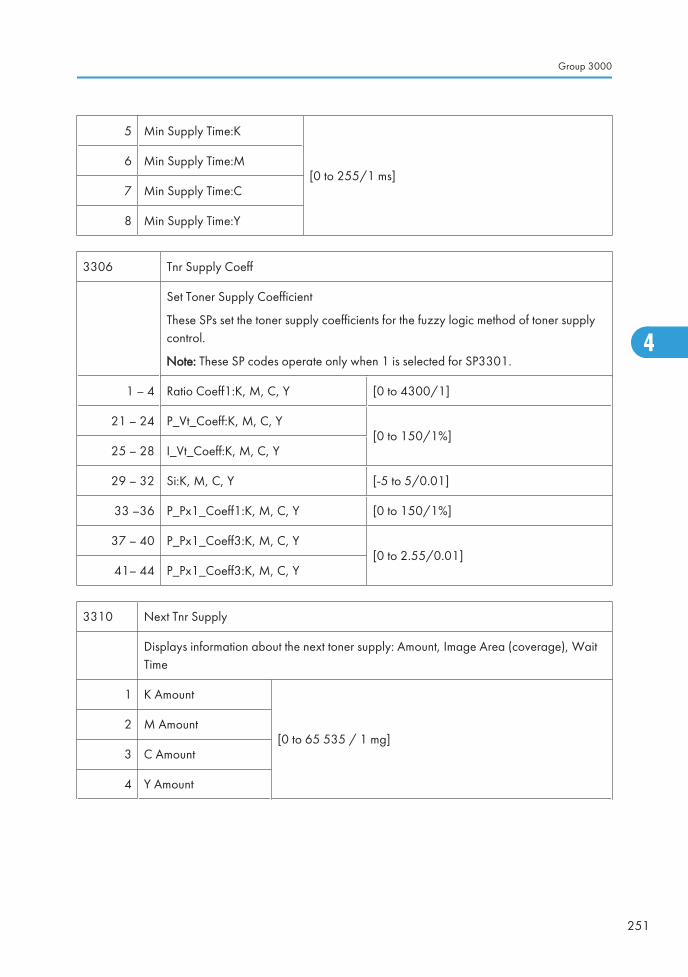
5 Min Supply Time:K
[0 to 255/1 ms]6 Min Supply Time:M
7 Min Supply Time:C
8 Min Supply Time:Y
3306 Tnr Supply Coeff
Set Toner Supply Coefficient
These SPs set the toner supply coefficients for the fuzzy logic method of toner supplycontrol.
Note: These SP codes operate only when 1 is selected for SP3301.
1 – 4 Ratio Coeff1:K, M, C, Y [0 to 4300/1]
21 – 24 P_Vt_Coeff:K, M, C, Y[0 to 150/1%]
25 – 28 I_Vt_Coeff:K, M, C, Y
29 – 32 Si:K, M, C, Y [-5 to 5/0.01]
33 –36 P_Px1_Coeff1:K, M, C, Y [0 to 150/1%]
37 – 40 P_Px1_Coeff3:K, M, C, Y[0 to 2.55/0.01]
41– 44 P_Px1_Coeff3:K, M, C, Y
3310 Next Tnr Supply
Displays information about the next toner supply: Amount, Image Area (coverage), WaitTime
1 K Amount
[0 to 65 535 / 1 mg]2 M Amount
3 C Amount
4 Y Amount
Group 3000
251
4
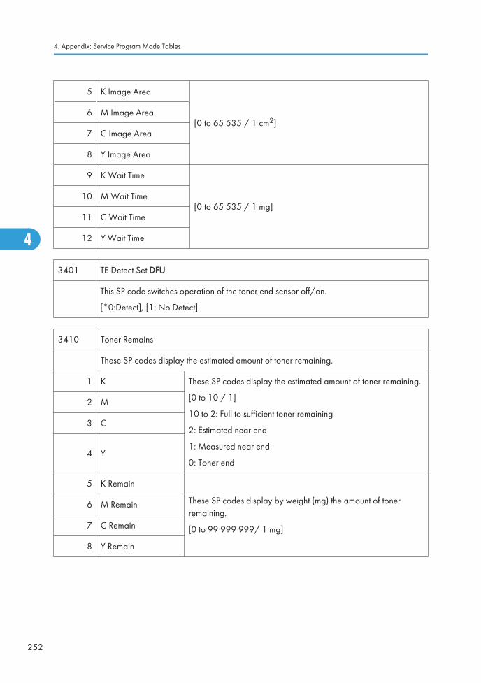
5 K Image Area
[0 to 65 535 / 1 cm2]6 M Image Area
7 C Image Area
8 Y Image Area
9 K Wait Time
[0 to 65 535 / 1 mg]10 M Wait Time
11 C Wait Time
12 Y Wait Time
3401 TE Detect Set DFU
This SP code switches operation of the toner end sensor off/on.
[*0:Detect], [1: No Detect]
3410 Toner Remains
These SP codes display the estimated amount of toner remaining.
1 K These SP codes display the estimated amount of toner remaining.
[0 to 10 / 1]
10 to 2: Full to sufficient toner remaining
2: Estimated near end
1: Measured near end
0: Toner end
2 M
3 C
4 Y
5 K Remain
These SP codes display by weight (mg) the amount of tonerremaining.
[0 to 99 999 999/ 1 mg]
6 M Remain
7 C Remain
8 Y Remain
4. Appendix: Service Program Mode Tables
252
4
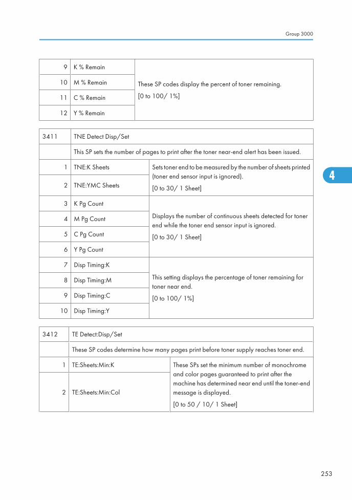
9 K % Remain
These SP codes display the percent of toner remaining.
[0 to 100/ 1%]
10 M % Remain
11 C % Remain
12 Y % Remain
3411 TNE Detect Disp/Set
This SP sets the number of pages to print after the toner near-end alert has been issued.
1 TNE:K Sheets Sets toner end to be measured by the number of sheets printed(toner end sensor input is ignored).
[0 to 30/ 1 Sheet]2 TNE:YMC Sheets
3 K Pg Count
Displays the number of continuous sheets detected for tonerend while the toner end sensor input is ignored.
[0 to 30/ 1 Sheet]
4 M Pg Count
5 C Pg Count
6 Y Pg Count
7 Disp Timing:K
This setting displays the percentage of toner remaining fortoner near end.
[0 to 100/ 1%]
8 Disp Timing:M
9 Disp Timing:C
10 Disp Timing:Y
3412 TE Detect:Disp/Set
These SP codes determine how many pages print before toner supply reaches toner end.
1 TE:Sheets:Min:K These SPs set the minimum number of monochromeand color pages guaranteed to print after themachine has determined near end until the toner-endmessage is displayed.
[0 to 50 / 10/ 1 Sheet]
2 TE:Sheets:Min:Col
Group 3000
253
4
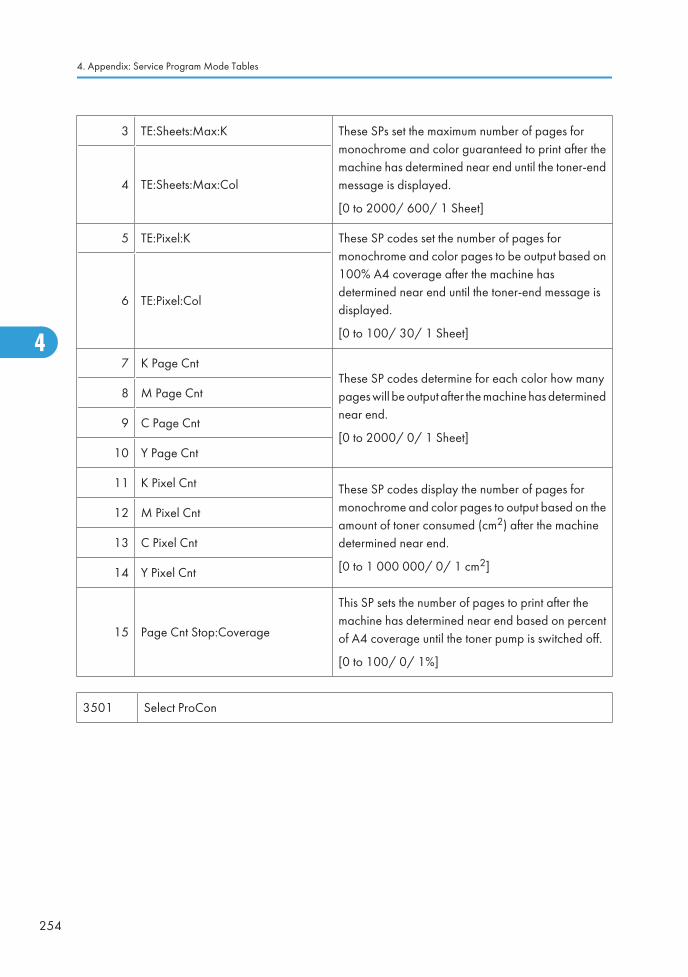
3 TE:Sheets:Max:K These SPs set the maximum number of pages formonochrome and color guaranteed to print after themachine has determined near end until the toner-endmessage is displayed.
[0 to 2000/ 600/ 1 Sheet]
4 TE:Sheets:Max:Col
5 TE:Pixel:K These SP codes set the number of pages formonochrome and color pages to be output based on100% A4 coverage after the machine hasdetermined near end until the toner-end message isdisplayed.
[0 to 100/ 30/ 1 Sheet]
6 TE:Pixel:Col
7 K Page CntThese SP codes determine for each color how manypages will be output after the machine has determinednear end.
[0 to 2000/ 0/ 1 Sheet]
8 M Page Cnt
9 C Page Cnt
10 Y Page Cnt
11 K Pixel Cnt These SP codes display the number of pages formonochrome and color pages to output based on theamount of toner consumed (cm2) after the machinedetermined near end.
[0 to 1 000 000/ 0/ 1 cm2]
12 M Pixel Cnt
13 C Pixel Cnt
14 Y Pixel Cnt
15 Page Cnt Stop:Coverage
This SP sets the number of pages to print after themachine has determined near end based on percentof A4 coverage until the toner pump is switched off.
[0 to 100/ 0/ 1%]
3501 Select ProCon
4. Appendix: Service Program Mode Tables
254
4
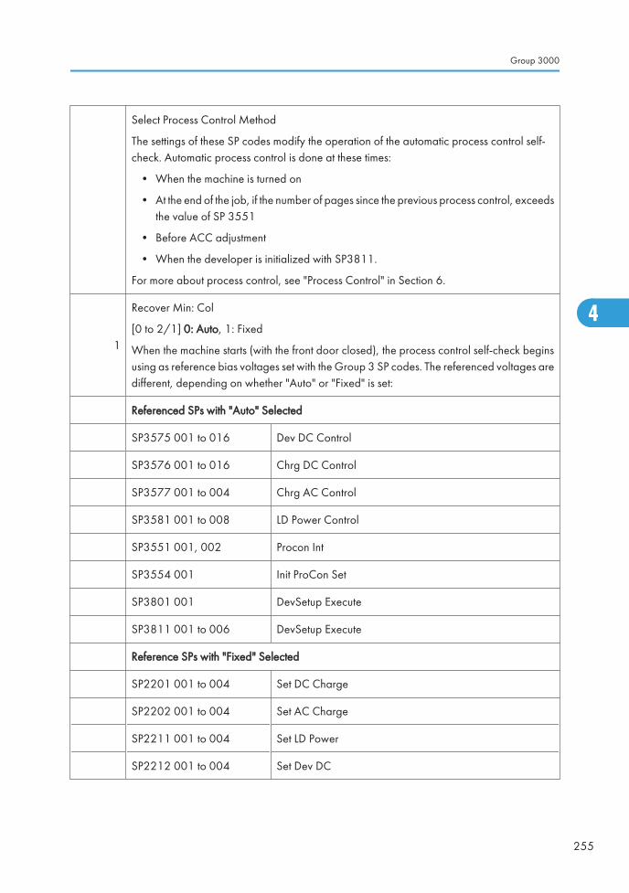
Select Process Control Method
The settings of these SP codes modify the operation of the automatic process control self-check. Automatic process control is done at these times:
• When the machine is turned on
• At the end of the job, if the number of pages since the previous process control, exceedsthe value of SP 3551
• Before ACC adjustment
• When the developer is initialized with SP3811.
For more about process control, see "Process Control" in Section 6.
1
Recover Min: Col
[0 to 2/1] 0: Auto, 1: Fixed
When the machine starts (with the front door closed), the process control self-check beginsusing as reference bias voltages set with the Group 3 SP codes. The referenced voltages aredifferent, depending on whether "Auto" or "Fixed" is set:
Referenced SPs with "Auto" Selected
SP3575 001 to 016 Dev DC Control
SP3576 001 to 016 Chrg DC Control
SP3577 001 to 004 Chrg AC Control
SP3581 001 to 008 LD Power Control
SP3551 001, 002 Procon Int
SP3554 001 Init ProCon Set
SP3801 001 DevSetup Execute
SP3811 001 to 006 DevSetup Execute
Reference SPs with "Fixed" Selected
SP2201 001 to 004 Set DC Charge
SP2202 001 to 004 Set AC Charge
SP2211 001 to 004 Set LD Power
SP2212 001 to 004 Set Dev DC
Group 3000
255
4
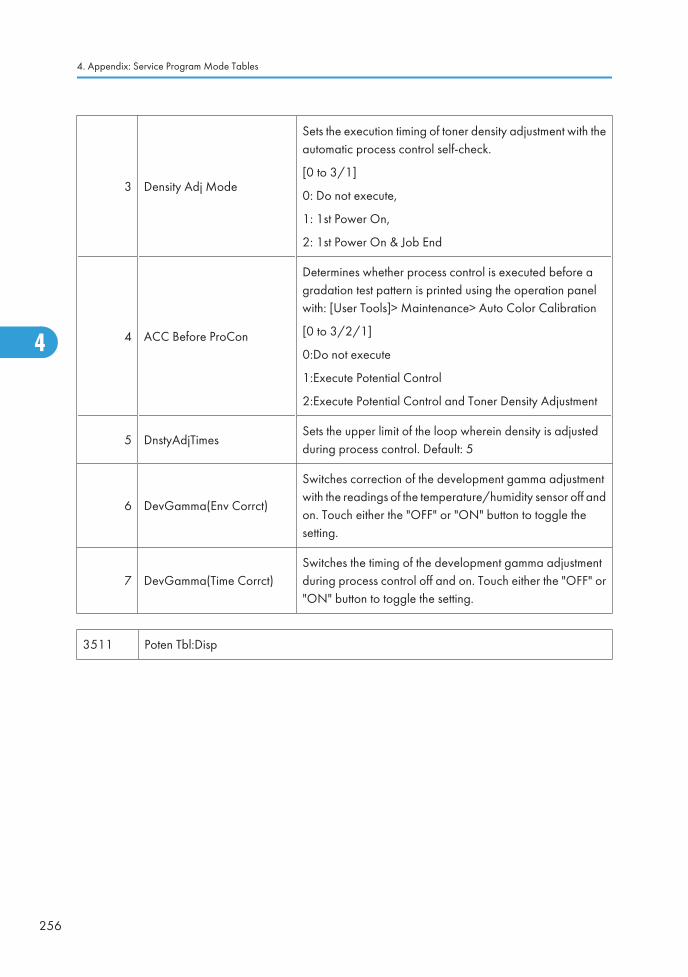
3 Density Adj Mode
Sets the execution timing of toner density adjustment with theautomatic process control self-check.
[0 to 3/1]
0: Do not execute,
1: 1st Power On,
2: 1st Power On & Job End
4 ACC Before ProCon
Determines whether process control is executed before agradation test pattern is printed using the operation panelwith: [User Tools]> Maintenance> Auto Color Calibration
[0 to 3/2/1]
0:Do not execute
1:Execute Potential Control
2:Execute Potential Control and Toner Density Adjustment
5 DnstyAdjTimesSets the upper limit of the loop wherein density is adjustedduring process control. Default: 5
6 DevGamma(Env Corrct)
Switches correction of the development gamma adjustmentwith the readings of the temperature/humidity sensor off andon. Touch either the "OFF" or "ON" button to toggle thesetting.
7 DevGamma(Time Corrct)Switches the timing of the development gamma adjustmentduring process control off and on. Touch either the "OFF" or"ON" button to toggle the setting.
3511 Poten Tbl:Disp
4. Appendix: Service Program Mode Tables
256
4
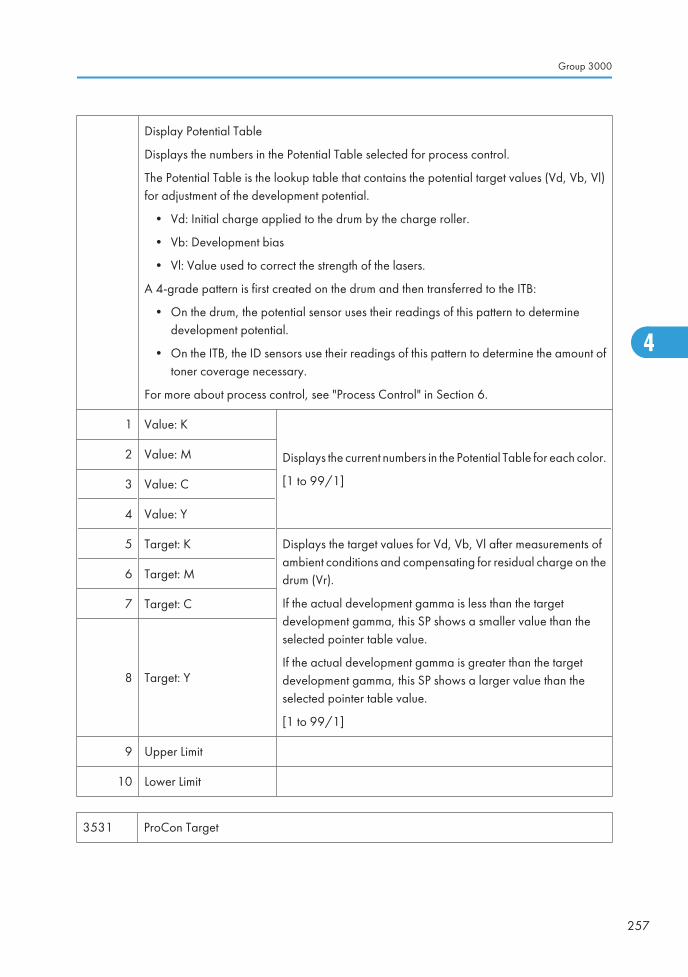
Display Potential Table
Displays the numbers in the Potential Table selected for process control.
The Potential Table is the lookup table that contains the potential target values (Vd, Vb, Vl)for adjustment of the development potential.
• Vd: Initial charge applied to the drum by the charge roller.
• Vb: Development bias
• Vl: Value used to correct the strength of the lasers.
A 4-grade pattern is first created on the drum and then transferred to the ITB:
• On the drum, the potential sensor uses their readings of this pattern to determinedevelopment potential.
• On the ITB, the ID sensors use their readings of this pattern to determine the amount oftoner coverage necessary.
For more about process control, see "Process Control" in Section 6.
1 Value: K
Displays the current numbers in the Potential Table for each color.
[1 to 99/1]
2 Value: M
3 Value: C
4 Value: Y
5 Target: K Displays the target values for Vd, Vb, Vl after measurements ofambient conditions and compensating for residual charge on thedrum (Vr).
If the actual development gamma is less than the targetdevelopment gamma, this SP shows a smaller value than theselected pointer table value.
If the actual development gamma is greater than the targetdevelopment gamma, this SP shows a larger value than theselected pointer table value.
[1 to 99/1]
6 Target: M
7 Target: C
8 Target: Y
9 Upper Limit
10 Lower Limit
3531 ProCon Target
Group 3000
257
4
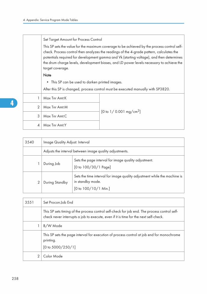
Set Target Amount for Process Control
This SP sets the value for the maximum coverage to be achieved by the process control self-check. Process control then analyzes the readings of the 4-grade pattern, calculates thepotentials required for development gamma and Vk (starting voltage), and then determinesthe drum charge levels, development biases, and LD power levels necessary to achieve thetarget coverage.
Note
• This SP can be used to darken printed images.
After this SP is changed, process control must be executed manually with SP3820.
1 Max Tnr Amt:K
[0 to 1/ 0.001 mg/cm2]2 Max Tnr Amt:M
3 Max Tnr Amt:C
4 Max Tnr Amt:Y
3540 Image Quality Adjust: Interval
Adjusts the interval between image quality adjustments.
1 During JobSets the page interval for image quality adjustment.
[0 to 100/30/1 Page]
2 During Standby
Sets the time interval for image quality adjustment while the machine isin standby mode.
[0 to 100/10/1 Min.]
3551 Set Procon:Job End
This SP sets timing of the process control self-check for job end. The process control self-check never interrupts a job to execute, even if it is time for the next self-check.
1 B/W Mode
This SP sets the page interval for execution of process control at job end for monochromeprinting.
[0 to 5000/250/1]
2 Color Mode
4. Appendix: Service Program Mode Tables
258
4
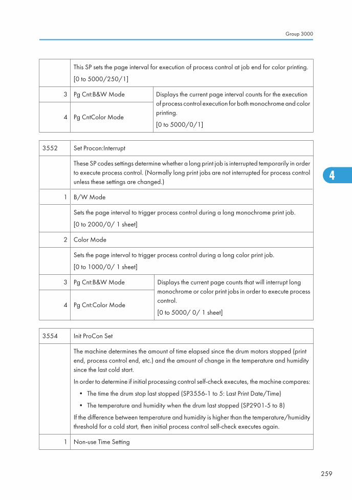
This SP sets the page interval for execution of process control at job end for color printing.
[0 to 5000/250/1]
3 Pg Cnt:B&W Mode Displays the current page interval counts for the executionof process control execution for both monochrome and colorprinting.
[0 to 5000/0/1]4 Pg CntColor Mode
3552 Set Procon:Interrupt
These SP codes settings determine whether a long print job is interrupted temporarily in orderto execute process control. (Normally long print jobs are not interrupted for process controlunless these settings are changed.)
1 B/W Mode
Sets the page interval to trigger process control during a long monochrome print job.
[0 to 2000/0/ 1 sheet]
2 Color Mode
Sets the page interval to trigger process control during a long color print job.
[0 to 1000/0/ 1 sheet]
3 Pg Cnt:B&W Mode Displays the current page counts that will interrupt longmonochrome or color print jobs in order to execute processcontrol.
[0 to 5000/ 0/ 1 sheet]4 Pg Cnt:Color Mode
3554 Init ProCon Set
The machine determines the amount of time elapsed since the drum motors stopped (printend, process control end, etc.) and the amount of change in the temperature and humiditysince the last cold start.
In order to determine if initial processing control self-check executes, the machine compares:
• The time the drum stop last stopped (SP3556-1 to 5: Last Print Date/Time)
• The temperature and humidity when the drum last stopped (SP2901-5 to 8)
If the difference between temperature and humidity is higher than the temperature/humiditythreshold for a cold start, then initial process control self-check executes again.
1 Non-use Time Setting
Group 3000
259
4
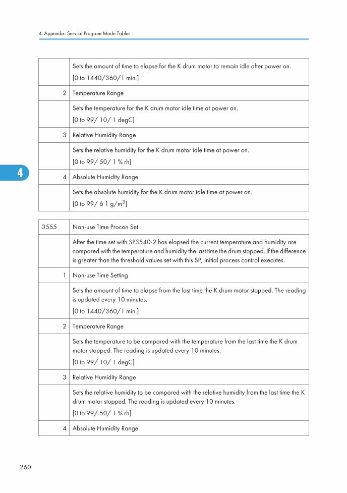
Sets the amount of time to elapse for the K drum motor to remain idle after power on.
[0 to 1440/360/1 min.]
2 Temperature Range
Sets the temperature for the K drum motor idle time at power on.
[0 to 99/ 10/ 1 degC]
3 Relative Humidity Range
Sets the relative humidity for the K drum motor idle time at power on.
[0 to 99/ 50/ 1 % rh]
4 Absolute Humidity Range
Sets the absolute humidity for the K drum motor idle time at power on.
[0 to 99/ 6 1 g/m3]
3555 Non-use Time Procon Set
After the time set with SP3540-2 has elapsed the current temperature and humidity arecompared with the temperature and humidity the last time the drum stopped. If the differenceis greater than the threshold values set with this SP, initial process control executes.
1 Non-use Time Setting
Sets the amount of time to elapse from the last time the K drum motor stopped. The readingis updated every 10 minutes.
[0 to 1440/360/1 min.]
2 Temperature Range
Sets the temperature to be compared with the temperature from the last time the K drummotor stopped. The reading is updated every 10 minutes.
[0 to 99/ 10/ 1 degC]
3 Relative Humidity Range
Sets the relative humidity to be compared with the relative humidity from the last time the Kdrum motor stopped. The reading is updated every 10 minutes.
[0 to 99/ 50/ 1 % rh]
4 Absolute Humidity Range
4. Appendix: Service Program Mode Tables
260
4
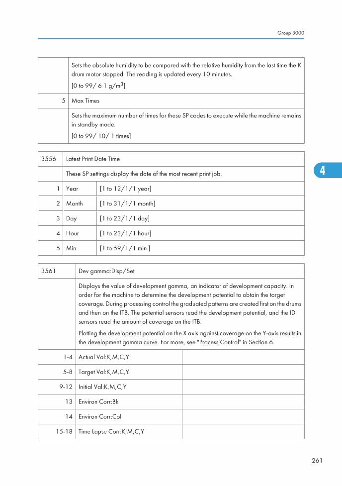
Sets the absolute humidity to be compared with the relative humidity from the last time the Kdrum motor stopped. The reading is updated every 10 minutes.
[0 to 99/ 6 1 g/m3]
5 Max Times
Sets the maximum number of times for these SP codes to execute while the machine remainsin standby mode.
[0 to 99/ 10/ 1 times]
3556 Latest Print Date Time
These SP settings display the date of the most recent print job.
1 Year [1 to 12/1/1 year]
2 Month [1 to 31/1/1 month]
3 Day [1 to 23/1/1 day]
4 Hour [1 to 23/1/1 hour]
5 Min. [1 to 59/1/1 min.]
3561 Dev gamma:Disp/Set
Displays the value of development gamma, an indicator of development capacity. Inorder for the machine to determine the development potential to obtain the targetcoverage. During processing control the graduated patterns are created first on the drumsand then on the ITB. The potential sensors read the development potential, and the IDsensors read the amount of coverage on the ITB.
Plotting the development potential on the X axis against coverage on the Y-axis results inthe development gamma curve. For more, see "Process Control" in Section 6.
1-4 Actual Val:K,M,C,Y
5-8 Target Val:K,M,C,Y
9-12 Initial Val:K,M,C,Y
13 Environ Corr:Bk
14 Environ Corr:Col
15-18 Time Lapse Corr:K,M,C,Y
Group 3000
261
4
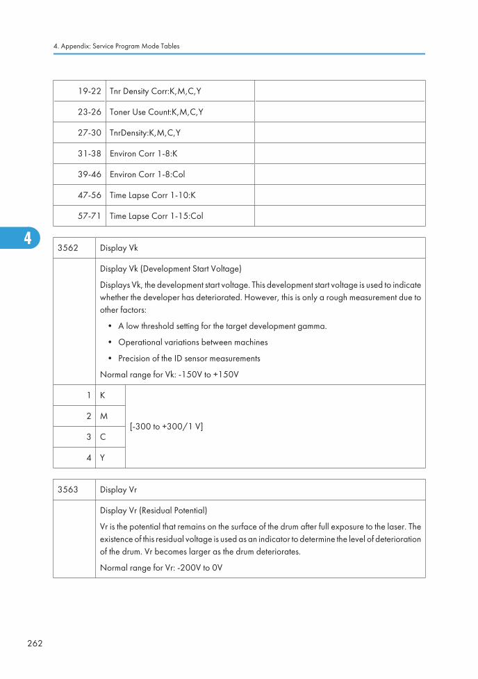
19-22 Tnr Density Corr:K,M,C,Y
23-26 Toner Use Count:K,M,C,Y
27-30 TnrDensity:K,M,C,Y
31-38 Environ Corr 1-8:K
39-46 Environ Corr 1-8:Col
47-56 Time Lapse Corr 1-10:K
57-71 Time Lapse Corr 1-15:Col
3562 Display Vk
Display Vk (Development Start Voltage)
Displays Vk, the development start voltage. This development start voltage is used to indicatewhether the developer has deteriorated. However, this is only a rough measurement due toother factors:
• A low threshold setting for the target development gamma.
• Operational variations between machines
• Precision of the ID sensor measurements
Normal range for Vk: -150V to +150V
1 K
[-300 to +300/1 V]2 M
3 C
4 Y
3563 Display Vr
Display Vr (Residual Potential)
Vr is the potential that remains on the surface of the drum after full exposure to the laser. Theexistence of this residual voltage is used as an indicator to determine the level of deteriorationof the drum. Vr becomes larger as the drum deteriorates.
Normal range for Vr: -200V to 0V
4. Appendix: Service Program Mode Tables
262
4
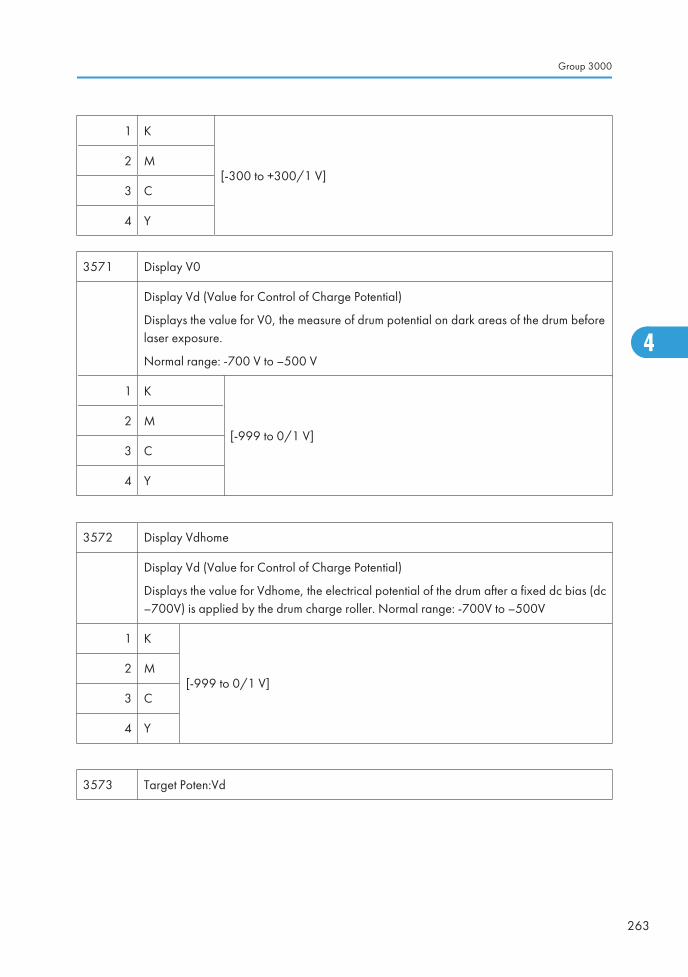
1 K
[-300 to +300/1 V]2 M
3 C
4 Y
3571 Display V0
Display Vd (Value for Control of Charge Potential)
Displays the value for V0, the measure of drum potential on dark areas of the drum beforelaser exposure.
Normal range: -700 V to –500 V
1 K
[-999 to 0/1 V]2 M
3 C
4 Y
3572 Display Vdhome
Display Vd (Value for Control of Charge Potential)
Displays the value for Vdhome, the electrical potential of the drum after a fixed dc bias (dc–700V) is applied by the drum charge roller. Normal range: -700V to –500V
1 K
[-999 to 0/1 V]2 M
3 C
4 Y
3573 Target Poten:Vd
Group 3000
263
4
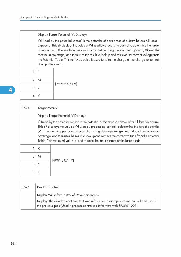
Display Target Potential (VdDisplay)
Vd (read by the potential sensor) is the potential of dark areas of a drum before full laserexposure. This SP displays the value of Vd used by processing control to determine the targetpotential (Vd). The machine performs a calculation using development gamma, Vk and themaximum coverage, and then uses the result to lookup and retrieve the correct voltage fromthe Potential Table. This retrieved value is used to raise the charge of the charge roller thatcharges the drums.
1 K
[-999 to 0/1 V]2 M
3 C
4 Y
3574 Target Poten:Vl
Display Target Potential (VlDisplay)
Vl (read by the potential sensor) is the potential of the exposed areas after full laser exposure.This SP displays the value of Vl used by processing control to determine the target potential(Vl). The machine performs a calculation using development gamma, Vk and the maximumcoverage, and then uses the result to lookup and retrieve the correct voltage from the PotentialTable. This retrieved value is used to raise the input current of the laser diode.
1 K
[-999 to 0/1 V]2 M
3 C
4 Y
3575 Dev DC Control
Display Value for Control of Development DC
Displays the development bias that was referenced during processing control and used inthe previous jobs (Used if process control is set for Auto with SP3501 001.)
4. Appendix: Service Program Mode Tables
264
4
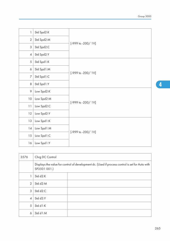
1 Std Spd2:K
[-999 to -200/ 1V]2 Std Spd2:M
3 Std Spd2:C
4 Std Spd2:Y
5 Std Spd1:K
[-999 to -200/ 1V]6 Std Spd1:M
7 Std Spd1:C
8 Std Spd1:Y
9 Low Spd2:K
[-999 to -200/ 1V]10 Low Spd2:M
11 Low Spd2:C
12 Low Spd2:Y
13 Low Spd1:K
[-999 to -200/ 1V]14 Low Spd1:M
15 Low Spd1:C
16 Low Spd1:Y
3576 Chrg DC Control
Displays the value for control of development dc. (Used if process control is set for Auto withSP3501 001.)
1 Std d2:K
2 Std d2:M
3 Std d2:C
4 Std d2:Y
5 Std d1:K
6 Std d1:M
Group 3000
265
4
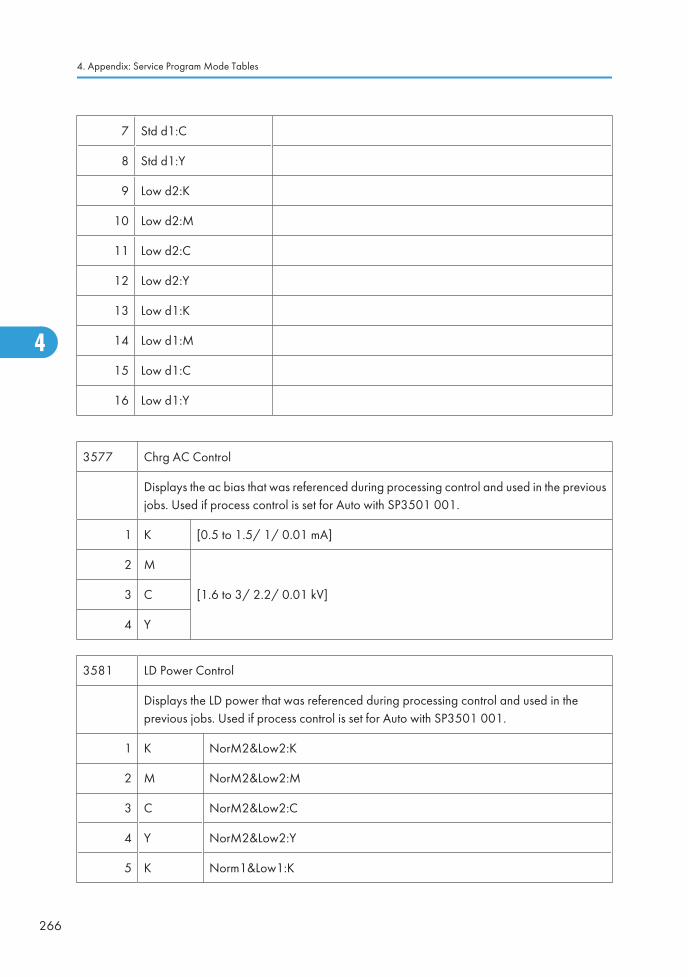
7 Std d1:C
8 Std d1:Y
9 Low d2:K
10 Low d2:M
11 Low d2:C
12 Low d2:Y
13 Low d1:K
14 Low d1:M
15 Low d1:C
16 Low d1:Y
3577 Chrg AC Control
Displays the ac bias that was referenced during processing control and used in the previousjobs. Used if process control is set for Auto with SP3501 001.
1 K [0.5 to 1.5/ 1/ 0.01 mA]
2 M
[1.6 to 3/ 2.2/ 0.01 kV]3 C
4 Y
3581 LD Power Control
Displays the LD power that was referenced during processing control and used in theprevious jobs. Used if process control is set for Auto with SP3501 001.
1 K NorM2&Low2:K
2 M NorM2&Low2:M
3 C NorM2&Low2:C
4 Y NorM2&Low2:Y
5 K Norm1&Low1:K
4. Appendix: Service Program Mode Tables
266
4
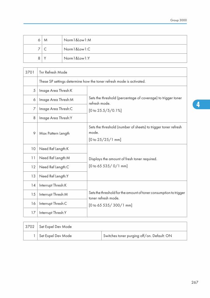
6 M Norm1&Low1:M
7 C Norm1&Low1:C
8 Y Norm1&Low1:Y
3701 Tnr Refresh Mode
These SP settings determine how the toner refresh mode is activated.
5 Image Area Thresh:K
Sets the threshold (percentage of coverage) to trigger tonerrefresh mode.
[0 to 25.5/5/0.1%]
6 Image Area Thresh:M
7 Image Area Thresh:C
8 Image Area Thresh:Y
9 Max Pattern Length
Sets the threshold (number of sheets) to trigger toner refreshmode.
[0 to 25/25/1 mm]
10 Need Ref Length:K
Displays the amount of fresh toner required.
[0 to 65 535/ 0/1 mm]
11 Need Ref Length:M
12 Need Ref Length:C
13 Need Ref Length:Y
14 Interrupt Thresh:K
Sets the threshold for the amount of toner consumption to triggertoner refresh mode.
[0 to 65 535/ 300/1 mm]
15 Interrupt Thresh:M
16 Interrupt Thresh:C
17 Interrupt Thresh:Y
3702 Set Expel Dev Mode
1 Set Expel Dev Mode Switches toner purging off/on. Default: ON
Group 3000
267
4
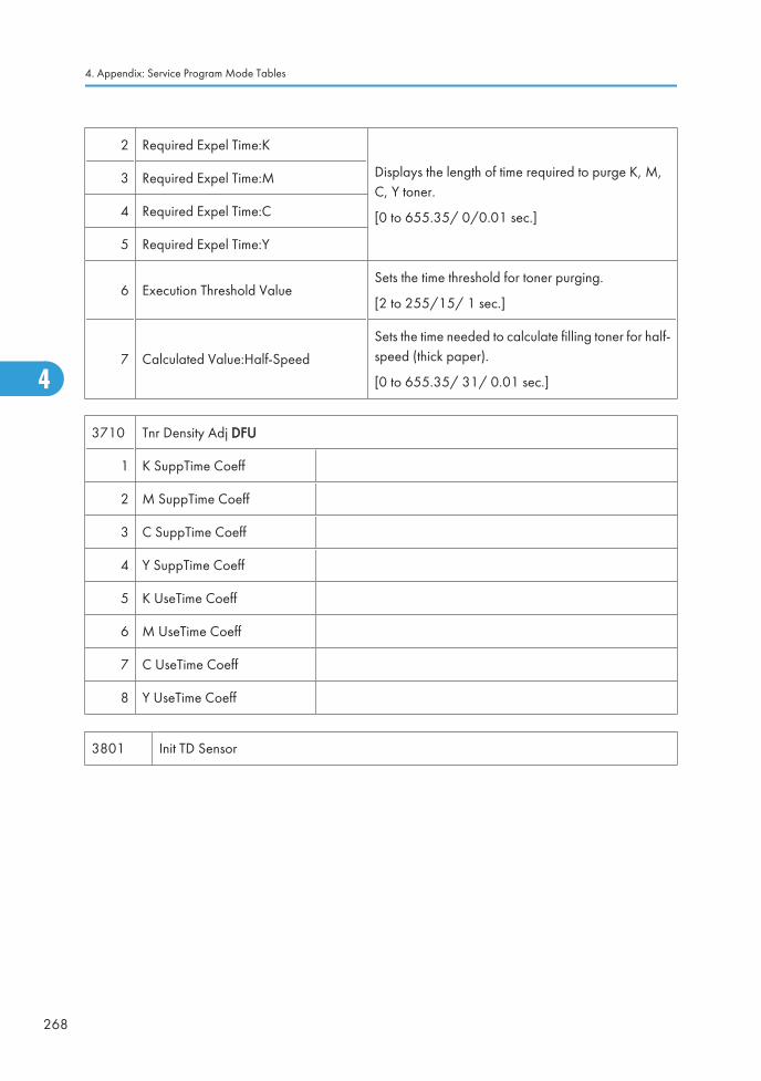
2 Required Expel Time:K
Displays the length of time required to purge K, M,C, Y toner.
[0 to 655.35/ 0/0.01 sec.]
3 Required Expel Time:M
4 Required Expel Time:C
5 Required Expel Time:Y
6 Execution Threshold ValueSets the time threshold for toner purging.
[2 to 255/15/ 1 sec.]
7 Calculated Value:Half-Speed
Sets the time needed to calculate filling toner for half-speed (thick paper).
[0 to 655.35/ 31/ 0.01 sec.]
3710 Tnr Density Adj DFU
1 K SuppTime Coeff
2 M SuppTime Coeff
3 C SuppTime Coeff
4 Y SuppTime Coeff
5 K UseTime Coeff
6 M UseTime Coeff
7 C UseTime Coeff
8 Y UseTime Coeff
3801 Init TD Sensor
4. Appendix: Service Program Mode Tables
268
4
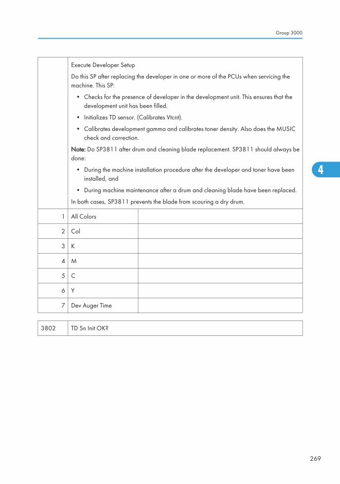
Execute Developer Setup
Do this SP after replacing the developer in one or more of the PCUs when servicing themachine. This SP:
• Checks for the presence of developer in the development unit. This ensures that thedevelopment unit has been filled.
• Initializes TD sensor. (Calibrates Vtcnt).
• Calibrates development gamma and calibrates toner density. Also does the MUSICcheck and correction.
Note: Do SP3811 after drum and cleaning blade replacement. SP3811 should always bedone:
• During the machine installation procedure after the developer and toner have beeninstalled, and
• During machine maintenance after a drum and cleaning blade have been replaced.
In both cases, SP3811 prevents the blade from scouring a dry drum.
1 All Colors
2 Col
3 K
4 M
5 C
6 Y
7 Dev Auger Time
3802 TD Sn Init OK?
Group 3000
269
4
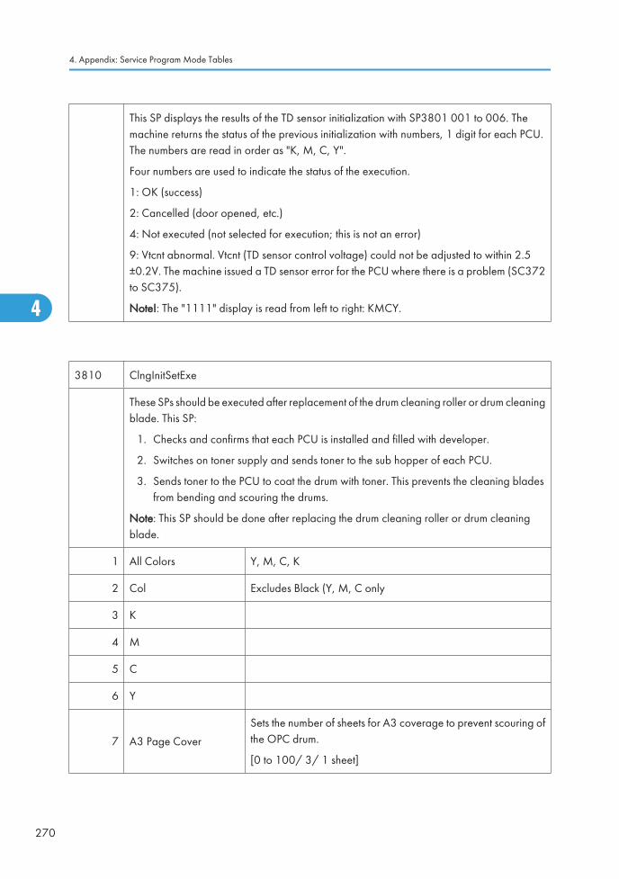
This SP displays the results of the TD sensor initialization with SP3801 001 to 006. Themachine returns the status of the previous initialization with numbers, 1 digit for each PCU.The numbers are read in order as "K, M, C, Y".
Four numbers are used to indicate the status of the execution.
1: OK (success)
2: Cancelled (door opened, etc.)
4: Not executed (not selected for execution; this is not an error)
9: Vtcnt abnormal. Vtcnt (TD sensor control voltage) could not be adjusted to within 2.5±0.2V. The machine issued a TD sensor error for the PCU where there is a problem (SC372to SC375).
Note!: The "1111" display is read from left to right: KMCY.
3810 ClngInitSetExe
These SPs should be executed after replacement of the drum cleaning roller or drum cleaningblade. This SP:
1. Checks and confirms that each PCU is installed and filled with developer.
2. Switches on toner supply and sends toner to the sub hopper of each PCU.
3. Sends toner to the PCU to coat the drum with toner. This prevents the cleaning bladesfrom bending and scouring the drums.
Note: This SP should be done after replacing the drum cleaning roller or drum cleaningblade.
1 All Colors Y, M, C, K
2 Col Excludes Black (Y, M, C only
3 K
4 M
5 C
6 Y
7 A3 Page Cover
Sets the number of sheets for A3 coverage to prevent scouring ofthe OPC drum.
[0 to 100/ 3/ 1 sheet]
4. Appendix: Service Program Mode Tables
270
4
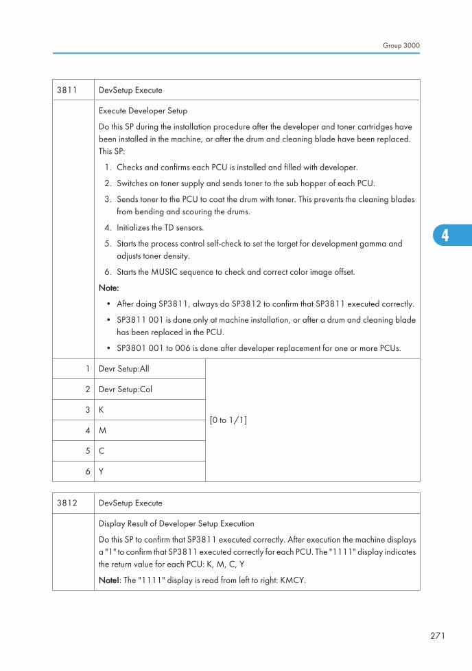
3811 DevSetup Execute
Execute Developer Setup
Do this SP during the installation procedure after the developer and toner cartridges havebeen installed in the machine, or after the drum and cleaning blade have been replaced.This SP:
1. Checks and confirms each PCU is installed and filled with developer.
2. Switches on toner supply and sends toner to the sub hopper of each PCU.
3. Sends toner to the PCU to coat the drum with toner. This prevents the cleaning bladesfrom bending and scouring the drums.
4. Initializes the TD sensors.
5. Starts the process control self-check to set the target for development gamma andadjusts toner density.
6. Starts the MUSIC sequence to check and correct color image offset.
Note:
• After doing SP3811, always do SP3812 to confirm that SP3811 executed correctly.
• SP3811 001 is done only at machine installation, or after a drum and cleaning bladehas been replaced in the PCU.
• SP3801 001 to 006 is done after developer replacement for one or more PCUs.
1 Devr Setup:All
[0 to 1/1]
2 Devr Setup:Col
3 K
4 M
5 C
6 Y
3812 DevSetup Execute
Display Result of Developer Setup Execution
Do this SP to confirm that SP3811 executed correctly. After execution the machine displaysa "1" to confirm that SP3811 executed correctly for each PCU. The "1111" display indicatesthe return value for each PCU: K, M, C, Y
Note!: The "1111" display is read from left to right: KMCY.
Group 3000
271
4
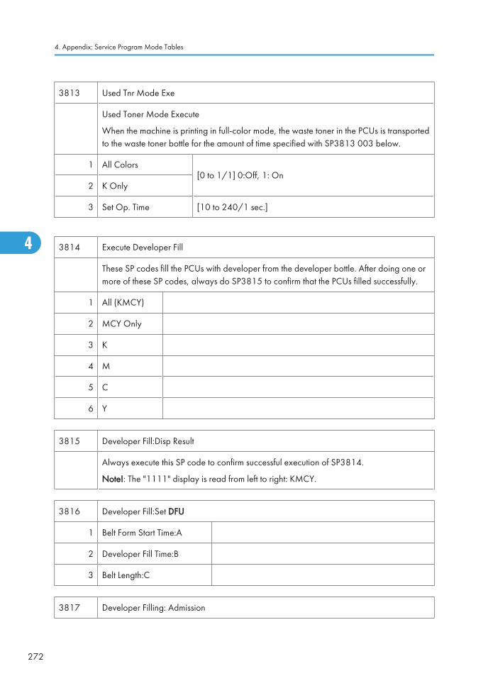
3813 Used Tnr Mode Exe
Used Toner Mode Execute
When the machine is printing in full-color mode, the waste toner in the PCUs is transportedto the waste toner bottle for the amount of time specified with SP3813 003 below.
1 All Colors[0 to 1/1] 0:Off, 1: On
2 K Only
3 Set Op. Time [10 to 240/1 sec.]
3814 Execute Developer Fill
These SP codes fill the PCUs with developer from the developer bottle. After doing one ormore of these SP codes, always do SP3815 to confirm that the PCUs filled successfully.
1 All (KMCY)
2 MCY Only
3 K
4 M
5 C
6 Y
3815 Developer Fill:Disp Result
Always execute this SP code to confirm successful execution of SP3814.
Note!: The "1111" display is read from left to right: KMCY.
3816 Developer Fill:Set DFU
1 Belt Form Start Time:A
2 Developer Fill Time:B
3 Belt Length:C
3817 Developer Filling: Admission
4. Appendix: Service Program Mode Tables
272
4
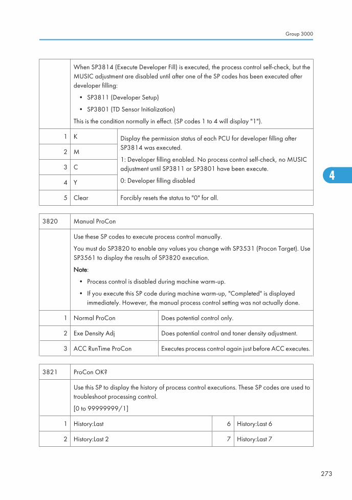
When SP3814 (Execute Developer Fill) is executed, the process control self-check, but theMUSIC adjustment are disabled until after one of the SP codes has been executed afterdeveloper filling:
• SP3811 (Developer Setup)
• SP3801 (TD Sensor Initialization)
This is the condition normally in effect. (SP codes 1 to 4 will display "1").
1 K Display the permission status of each PCU for developer filling afterSP3814 was executed.
1: Developer filling enabled. No process control self-check, no MUSICadjustment until SP3811 or SP3801 have been execute.
0: Developer filling disabled
2 M
3 C
4 Y
5 Clear Forcibly resets the status to "0" for all.
3820 Manual ProCon
Use these SP codes to execute process control manually.
You must do SP3820 to enable any values you change with SP3531 (Procon Target). UseSP3561 to display the results of SP3820 execution.
Note:
• Process control is disabled during machine warm-up.
• If you execute this SP code during machine warm-up, "Completed" is displayedimmediately. However, the manual process control setting was not actually done.
1 Normal ProCon Does potential control only.
2 Exe Density Adj Does potential control and toner density adjustment.
3 ACC RunTime ProCon Executes process control again just before ACC executes.
3821 ProCon OK?
Use this SP to display the history of process control executions. These SP codes are used totroubleshoot processing control.
[0 to 99999999/1]
1 History:Last 6 History:Last 6
2 History:Last 2 7 History:Last 7
Group 3000
273
4
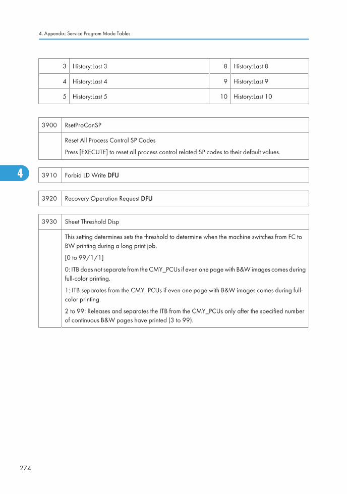
3 History:Last 3 8 History:Last 8
4 History:Last 4 9 History:Last 9
5 History:Last 5 10 History:Last 10
3900 RsetProConSP
Reset All Process Control SP Codes
Press [EXECUTE] to reset all process control related SP codes to their default values.
3910 Forbid LD Write DFU
3920 Recovery Operation Request DFU
3930 Sheet Threshold Disp
This setting determines sets the threshold to determine when the machine switches from FC toBW printing during a long print job.
[0 to 99/1/1]
0: ITB does not separate from the CMY_PCUs if even one page with B&W images comes duringfull-color printing.
1: ITB separates from the CMY_PCUs if even one page with B&W images comes during full-color printing.
2 to 99: Releases and separates the ITB from the CMY_PCUs only after the specified numberof continuous B&W pages have printed (3 to 99).
4. Appendix: Service Program Mode Tables
274
4
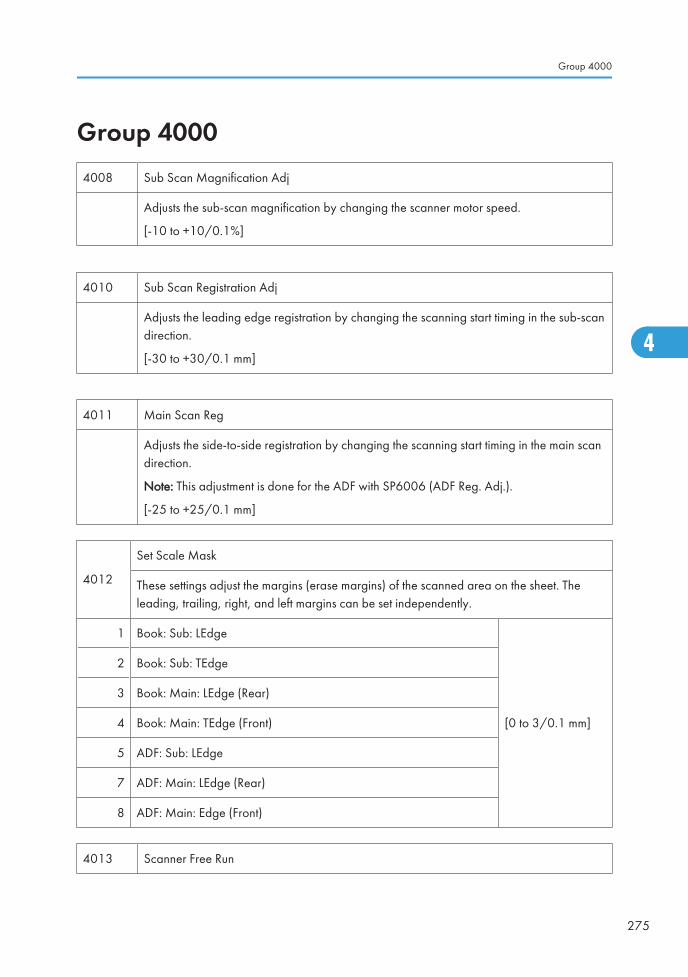
Group 40004008 Sub Scan Magnification Adj
Adjusts the sub-scan magnification by changing the scanner motor speed.
[-10 to +10/0.1%]
4010 Sub Scan Registration Adj
Adjusts the leading edge registration by changing the scanning start timing in the sub-scandirection.
[-30 to +30/0.1 mm]
4011 Main Scan Reg
Adjusts the side-to-side registration by changing the scanning start timing in the main scandirection.
Note: This adjustment is done for the ADF with SP6006 (ADF Reg. Adj.).
[-25 to +25/0.1 mm]
4012
Set Scale Mask
These settings adjust the margins (erase margins) of the scanned area on the sheet. Theleading, trailing, right, and left margins can be set independently.
1 Book: Sub: LEdge
[0 to 3/0.1 mm]
2 Book: Sub: TEdge
3 Book: Main: LEdge (Rear)
4 Book: Main: TEdge (Front)
5 ADF: Sub: LEdge
7 ADF: Main: LEdge (Rear)
8 ADF: Main: Edge (Front)
4013 Scanner Free Run
Group 4000
275
4
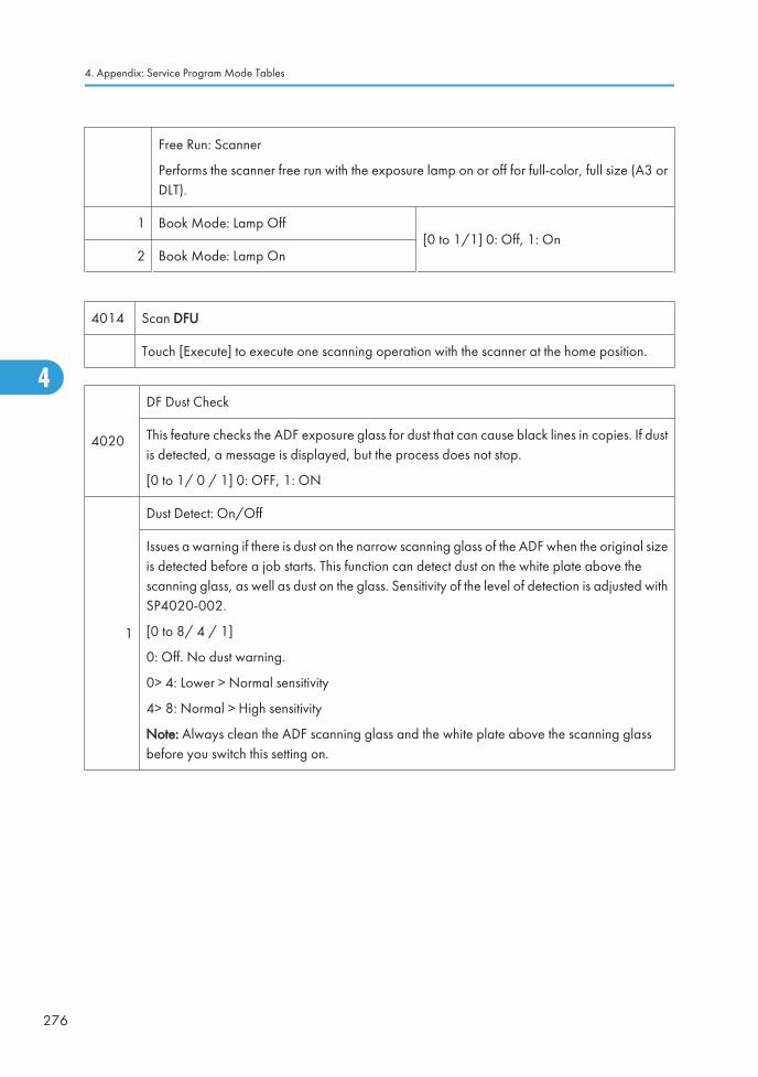
Free Run: Scanner
Performs the scanner free run with the exposure lamp on or off for full-color, full size (A3 orDLT).
1 Book Mode: Lamp Off[0 to 1/1] 0: Off, 1: On
2 Book Mode: Lamp On
4014 Scan DFU
Touch [Execute] to execute one scanning operation with the scanner at the home position.
4020
DF Dust Check
This feature checks the ADF exposure glass for dust that can cause black lines in copies. If dustis detected, a message is displayed, but the process does not stop.
[0 to 1/ 0 / 1] 0: OFF, 1: ON
1
Dust Detect: On/Off
Issues a warning if there is dust on the narrow scanning glass of the ADF when the original sizeis detected before a job starts. This function can detect dust on the white plate above thescanning glass, as well as dust on the glass. Sensitivity of the level of detection is adjusted withSP4020-002.
[0 to 8/ 4 / 1]
0: Off. No dust warning.
0> 4: Lower > Normal sensitivity
4> 8: Normal > High sensitivity
Note: Always clean the ADF scanning glass and the white plate above the scanning glassbefore you switch this setting on.
4. Appendix: Service Program Mode Tables
276
4
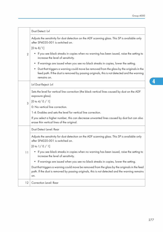
2
Dust Detect: Lvl
Adjusts the sensitivity for dust detection on the ADF scanning glass. This SP is available onlyafter SP4020-001 is switched on.
[0 to 8/1]
• If you see black streaks in copies when no warning has been issued, raise the setting toincrease the level of sensitivity.
• If warnings are issued when you see no black streaks in copies, lower the setting.
• Dust that triggers a warning could move be removed from the glass by the originals in thefeed path. If the dust is removed by passing originals, this is not detected and the warningremains on.
3
Lvl Dust Reject: Lvl
Sets the level for vertical line correction (the black vertical lines caused by dust on the ADFexposure glass).
[0 to 4/ 0 / 1]
0: No vertical line correction.
1-4: Enables and sets the level for vertical line correction.
If you select a higher number, this can decrease unwanted lines caused by dust but can alsoerase thin vertical lines of the original.
11
Dust Detect Level: Rear
Adjusts the sensitivity for dust detection on the ADF scanning glass. This SP is available onlyafter SP4020-001 is switched on.
[0 to 1/ 0 / 1]
• If you see black streaks in copies when no warning has been issued, raise the setting toincrease the level of sensitivity.
• If warnings are issued when you see no black streaks in copies, lower the setting.
Dust that triggers a warning could move be removed from the glass by the originals in the feedpath. If the dust is removed by passing originals, this is not detected and the warning remainson.
12 Correction Level: Rear
Group 4000
277
4
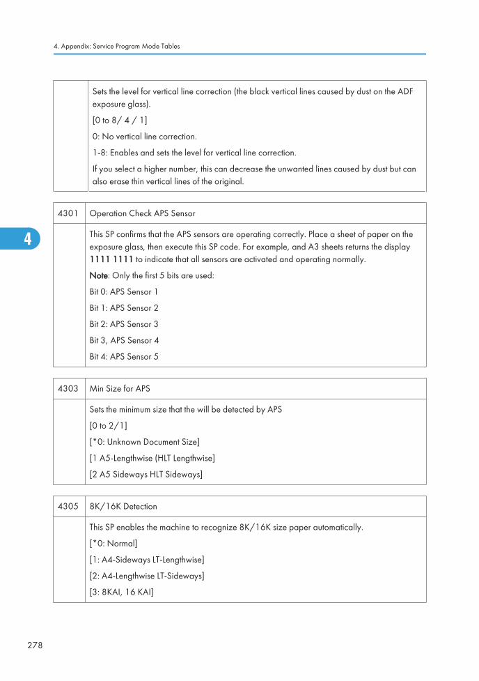
Sets the level for vertical line correction (the black vertical lines caused by dust on the ADFexposure glass).
[0 to 8/ 4 / 1]
0: No vertical line correction.
1-8: Enables and sets the level for vertical line correction.
If you select a higher number, this can decrease the unwanted lines caused by dust but canalso erase thin vertical lines of the original.
4301 Operation Check APS Sensor
This SP confirms that the APS sensors are operating correctly. Place a sheet of paper on theexposure glass, then execute this SP code. For example, and A3 sheets returns the display1111 1111 to indicate that all sensors are activated and operating normally.
Note: Only the first 5 bits are used:
Bit 0: APS Sensor 1
Bit 1: APS Sensor 2
Bit 2: APS Sensor 3
Bit 3, APS Sensor 4
Bit 4: APS Sensor 5
4303 Min Size for APS
Sets the minimum size that the will be detected by APS
[0 to 2/1]
[*0: Unknown Document Size]
[1 A5-Lengthwise (HLT Lengthwise]
[2 A5 Sideways HLT Sideways]
4305 8K/16K Detection
This SP enables the machine to recognize 8K/16K size paper automatically.
[*0: Normal]
[1: A4-Sideways LT-Lengthwise]
[2: A4-Lengthwise LT-Sideways]
[3: 8KAI, 16 KAI]
4. Appendix: Service Program Mode Tables
278
4
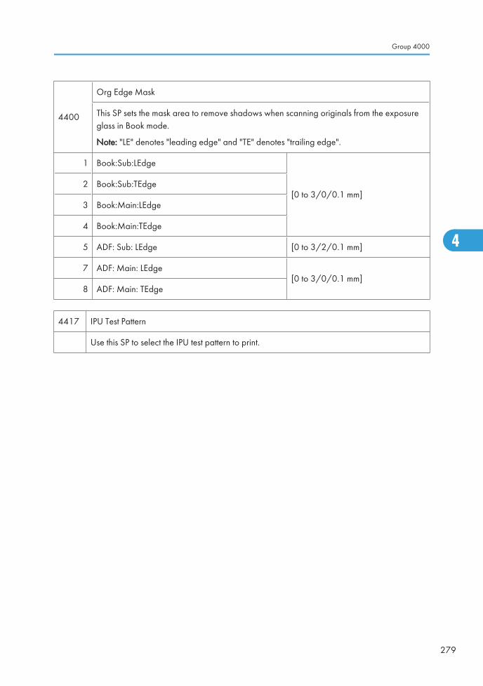
4400
Org Edge Mask
This SP sets the mask area to remove shadows when scanning originals from the exposureglass in Book mode.
Note: "LE" denotes "leading edge" and "TE" denotes "trailing edge".
1 Book:Sub:LEdge
[0 to 3/0/0.1 mm]2 Book:Sub:TEdge
3 Book:Main:LEdge
4 Book:Main:TEdge
5 ADF: Sub: LEdge [0 to 3/2/0.1 mm]
7 ADF: Main: LEdge[0 to 3/0/0.1 mm]
8 ADF: Main: TEdge
4417 IPU Test Pattern
Use this SP to select the IPU test pattern to print.
Group 4000
279
4
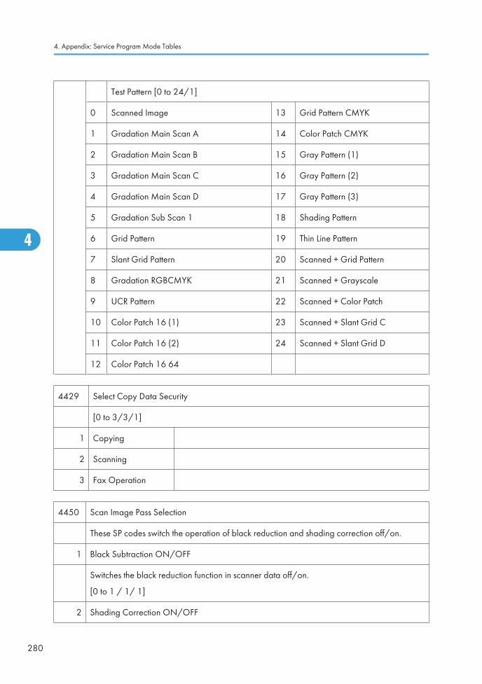
Test Pattern [0 to 24/1]
0 Scanned Image 13 Grid Pattern CMYK
1 Gradation Main Scan A 14 Color Patch CMYK
2 Gradation Main Scan B 15 Gray Pattern (1)
3 Gradation Main Scan C 16 Gray Pattern (2)
4 Gradation Main Scan D 17 Gray Pattern (3)
5 Gradation Sub Scan 1 18 Shading Pattern
6 Grid Pattern 19 Thin Line Pattern
7 Slant Grid Pattern 20 Scanned + Grid Pattern
8 Gradation RGBCMYK 21 Scanned + Grayscale
9 UCR Pattern 22 Scanned + Color Patch
10 Color Patch 16 (1) 23 Scanned + Slant Grid C
11 Color Patch 16 (2) 24 Scanned + Slant Grid D
12 Color Patch 16 64
4429 Select Copy Data Security
[0 to 3/3/1]
1 Copying
2 Scanning
3 Fax Operation
4450 Scan Image Pass Selection
These SP codes switch the operation of black reduction and shading correction off/on.
1 Black Subtraction ON/OFF
Switches the black reduction function in scanner data off/on.
[0 to 1 / 1/ 1]
2 Shading Correction ON/OFF
4. Appendix: Service Program Mode Tables
280
4
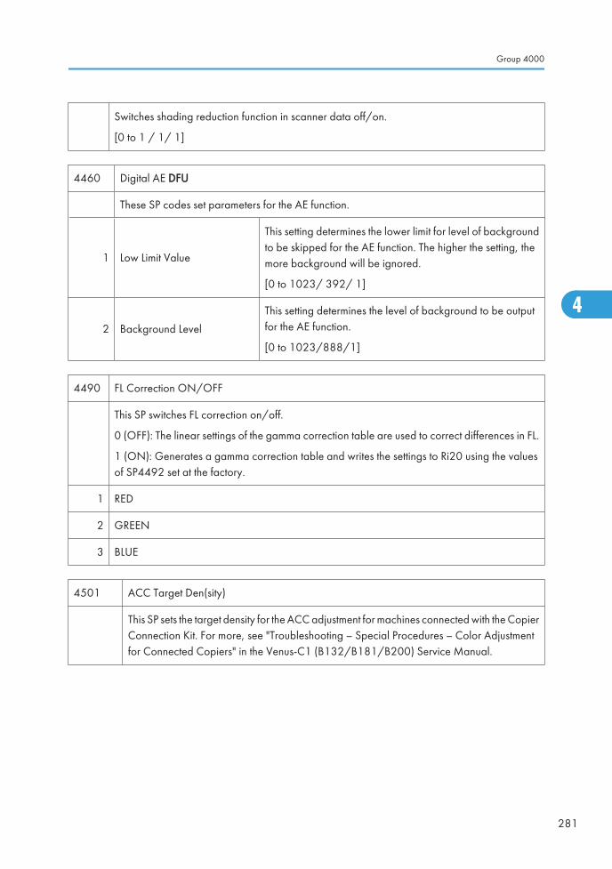
Switches shading reduction function in scanner data off/on.
[0 to 1 / 1/ 1]
4460 Digital AE DFU
These SP codes set parameters for the AE function.
1 Low Limit Value
This setting determines the lower limit for level of backgroundto be skipped for the AE function. The higher the setting, themore background will be ignored.
[0 to 1023/ 392/ 1]
2 Background Level
This setting determines the level of background to be outputfor the AE function.
[0 to 1023/888/1]
4490 FL Correction ON/OFF
This SP switches FL correction on/off.
0 (OFF): The linear settings of the gamma correction table are used to correct differences in FL.
1 (ON): Generates a gamma correction table and writes the settings to Ri20 using the valuesof SP4492 set at the factory.
1 RED
2 GREEN
3 BLUE
4501 ACC Target Den(sity)
This SP sets the target density for the ACC adjustment for machines connected with the CopierConnection Kit. For more, see "Troubleshooting – Special Procedures – Color Adjustmentfor Connected Copiers" in the Venus-C1 (B132/B181/B200) Service Manual.
Group 4000
281
4
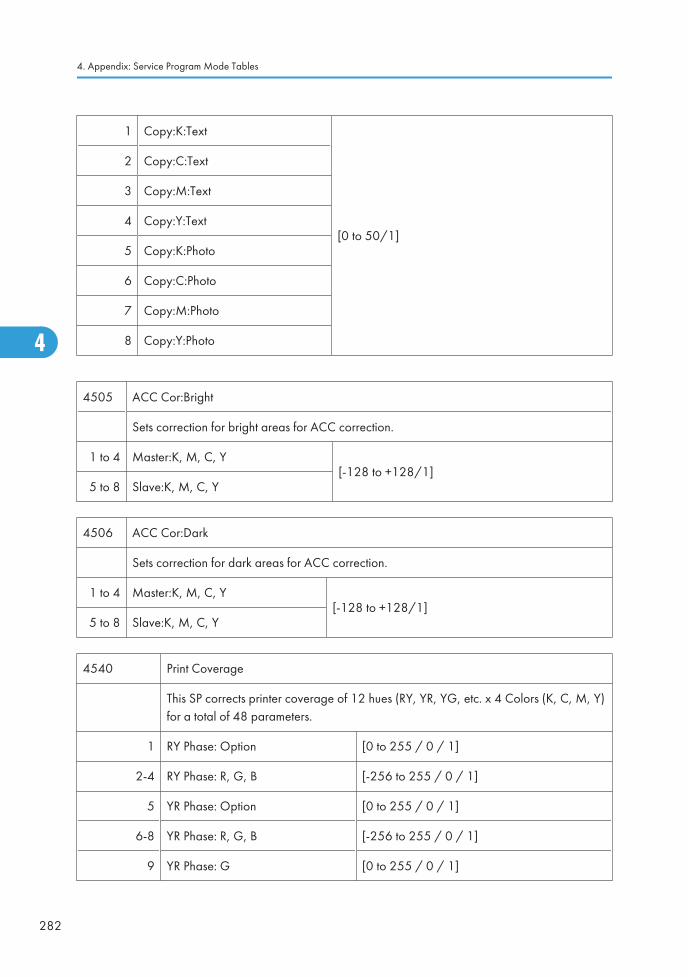
1 Copy:K:Text
[0 to 50/1]
2 Copy:C:Text
3 Copy:M:Text
4 Copy:Y:Text
5 Copy:K:Photo
6 Copy:C:Photo
7 Copy:M:Photo
8 Copy:Y:Photo
4505 ACC Cor:Bright
Sets correction for bright areas for ACC correction.
1 to 4 Master:K, M, C, Y[-128 to +128/1]
5 to 8 Slave:K, M, C, Y
4506 ACC Cor:Dark
Sets correction for dark areas for ACC correction.
1 to 4 Master:K, M, C, Y[-128 to +128/1]
5 to 8 Slave:K, M, C, Y
4540 Print Coverage
This SP corrects printer coverage of 12 hues (RY, YR, YG, etc. x 4 Colors (K, C, M, Y)for a total of 48 parameters.
1 RY Phase: Option [0 to 255 / 0 / 1]
2-4 RY Phase: R, G, B [-256 to 255 / 0 / 1]
5 YR Phase: Option [0 to 255 / 0 / 1]
6-8 YR Phase: R, G, B [-256 to 255 / 0 / 1]
9 YR Phase: G [0 to 255 / 0 / 1]
4. Appendix: Service Program Mode Tables
282
4

10-12 YR Phase: R, G, B [-256 to 255 / 0 / 1]
13 GY Phase: Option [0 to 255 / 0 / 1]
14-16 GY Phase: R, G, B [-256 to 255 / 0 / 1]
17 GC Phase: Option [0 to 255 / 0 / 1]
18-120 GC Phase: R, G, B [-256 to 255 / 0 / 1]
21 CG Phase: Option [0 to 255 / 0 / 1]
22-24 CG Phase: R, G, B [-256 to 255 / 0 / 1]
25 CB Phase: Option [0 to 255 / 0 / 1]
26-28 CB Phase: R, G, B [-256 to 255 / 0 / 1]
29 BC Phase: Option [0 to 255 / 0 / 1]
30-32 BC Phase: R, G, B [-256 to 255 / 0 / 1]
33 BM Phase: Option [0 to 255 / 0 / 1]
34-36 BM Phase: R, G, B [-256 to 255 / 0 / 1]
37 MB Phase: Option [0 to 255 / 0 / 1]
38-40 MB Phase: R, G, B [-256 to 255 / 0 / 1]
41 MR Phase: Option [0 to 255 / 0 / 1]
42-44 MR Phase: R, G, B [-256 to 255 / 0 / 1]
45 RM Phase: Option [0 to 255 / 0 / 1]
46-48 RM Phase: R, G, B [-256 to 255 / 0 / 1]
49 WHITE: Option [0 to 255 / 0 / 1]
50-52 WHITE: R, G, B [-256 to 255 / 0 / 1]
53 BLACK: Option [0 to 255 / 0 / 1]
54-56 BLACK: R, G, B [-256 to 255 / 0 / 1]
4550 Scan Apli:Txt/Print
4551 Scan Apli:Txt
Group 4000
283
4
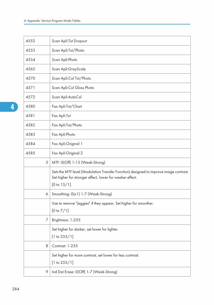
4552 Scan Apli:Txt Dropout
4553 Scan Apli:Txt/Photo
4554 Scan Apli:Photo
4565 Scan Apli:GrayScale
4570 Scan Apli:Col Txt/Photo
4571 Scan Apli:Col Gloss Photo
4572 Scan Apli:AutoCol
4580 Fax Apli:Txt/Chart
4581 Fax Apli:Txt
4582 Fax Apli:Txt/Photo
4583 Fax Apli:Photo
4584 Fax Apli:Original 1
4585 Fax Apli:Original 2
5 MTF: 0(Off) 1-15 (Weak-Strong)
Sets the MTF level (Modulation Transfer Function) designed to improve image contrast.Set higher for stronger effect, lower for weaker effect.
[0 to 15/1]
6 Smoothing: 0(x1) 1-7 (Weak-Strong)
Use to remove "jaggies" if they appear. Set higher for smoother.
[0 to 7/1]
7 Brightness: 1-255
Set higher for darker, set lower for lighter.
[1 to 255/1]
8 Contrast: 1-255
Set higher for more contrast, set lower for less contrast.
[1 to 255/1]
9 Ind Dot Erase: 0(Off) 1-7 (Weak-Strong)
4. Appendix: Service Program Mode Tables
284
4
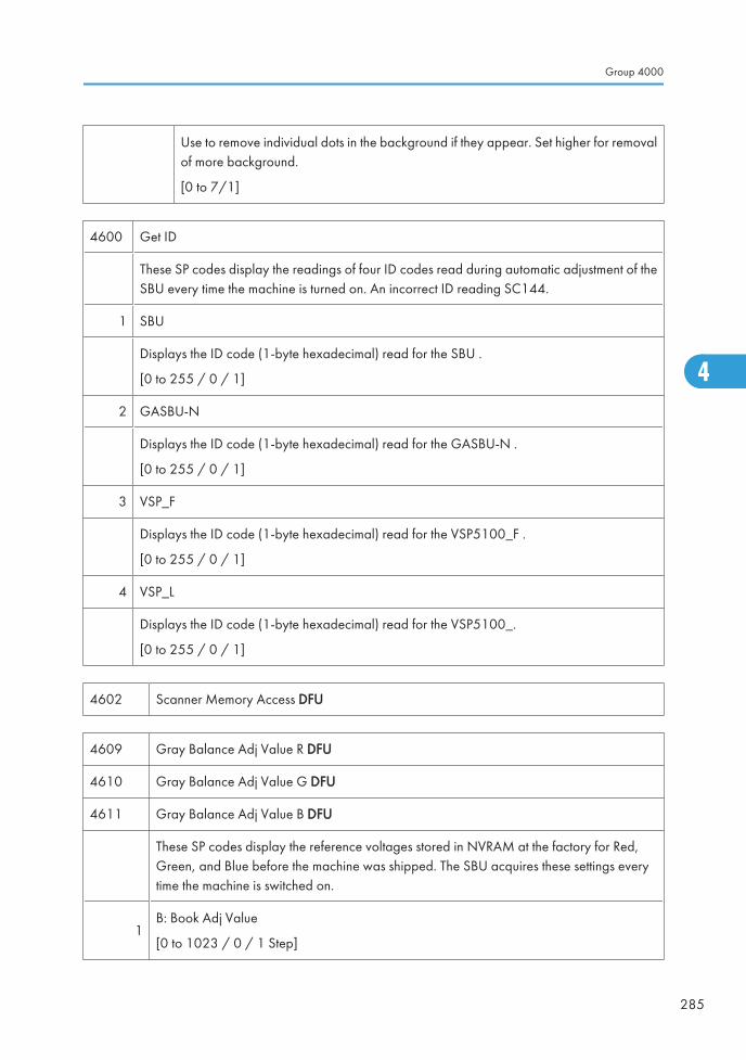
Use to remove individual dots in the background if they appear. Set higher for removalof more background.
[0 to 7/1]
4600 Get ID
These SP codes display the readings of four ID codes read during automatic adjustment of theSBU every time the machine is turned on. An incorrect ID reading SC144.
1 SBU
Displays the ID code (1-byte hexadecimal) read for the SBU .
[0 to 255 / 0 / 1]
2 GASBU-N
Displays the ID code (1-byte hexadecimal) read for the GASBU-N .
[0 to 255 / 0 / 1]
3 VSP_F
Displays the ID code (1-byte hexadecimal) read for the VSP5100_F .
[0 to 255 / 0 / 1]
4 VSP_L
Displays the ID code (1-byte hexadecimal) read for the VSP5100_.
[0 to 255 / 0 / 1]
4602 Scanner Memory Access DFU
4609 Gray Balance Adj Value R DFU
4610 Gray Balance Adj Value G DFU
4611 Gray Balance Adj Value B DFU
These SP codes display the reference voltages stored in NVRAM at the factory for Red,Green, and Blue before the machine was shipped. The SBU acquires these settings everytime the machine is switched on.
1B: Book Adj Value
[0 to 1023 / 0 / 1 Step]
Group 4000
285
4
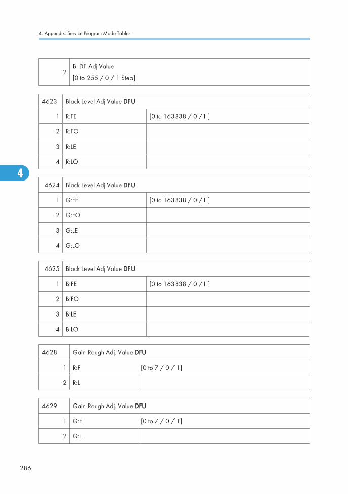
2B: DF Adj Value
[0 to 255 / 0 / 1 Step]
4623 Black Level Adj Value DFU
1 R:FE [0 to 163838 / 0 /1 ]
2 R:FO
3 R:LE
4 R:LO
4624 Black Level Adj Value DFU
1 G:FE [0 to 163838 / 0 /1 ]
2 G:FO
3 G:LE
4 G:LO
4625 Black Level Adj Value DFU
1 B:FE [0 to 163838 / 0 /1 ]
2 B:FO
3 B:LE
4 B:LO
4628 Gain Rough Adj. Value DFU
1 R:F [0 to 7 / 0 / 1]
2 R:L
4629 Gain Rough Adj. Value DFU
1 G:F [0 to 7 / 0 / 1]
2 G:L
4. Appendix: Service Program Mode Tables
286
4
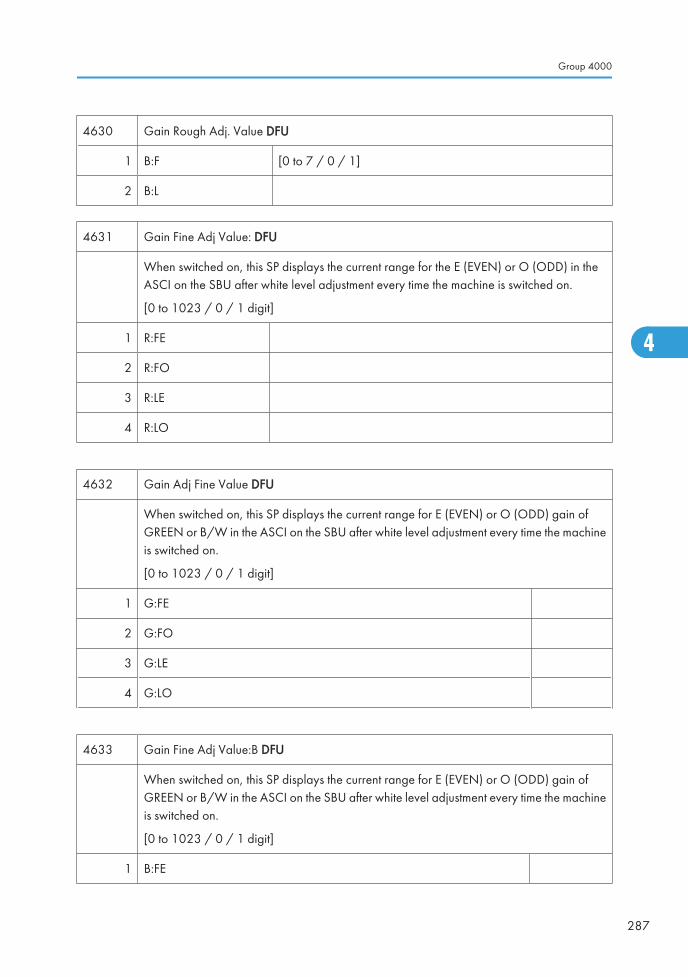
4630 Gain Rough Adj. Value DFU
1 B:F [0 to 7 / 0 / 1]
2 B:L
4631 Gain Fine Adj Value: DFU
When switched on, this SP displays the current range for the E (EVEN) or O (ODD) in theASCI on the SBU after white level adjustment every time the machine is switched on.
[0 to 1023 / 0 / 1 digit]
1 R:FE
2 R:FO
3 R:LE
4 R:LO
4632 Gain Adj Fine Value DFU
When switched on, this SP displays the current range for E (EVEN) or O (ODD) gain ofGREEN or B/W in the ASCI on the SBU after white level adjustment every time the machineis switched on.
[0 to 1023 / 0 / 1 digit]
1 G:FE
2 G:FO
3 G:LE
4 G:LO
4633 Gain Fine Adj Value:B DFU
When switched on, this SP displays the current range for E (EVEN) or O (ODD) gain ofGREEN or B/W in the ASCI on the SBU after white level adjustment every time the machineis switched on.
[0 to 1023 / 0 / 1 digit]
1 B:FE
Group 4000
287
4
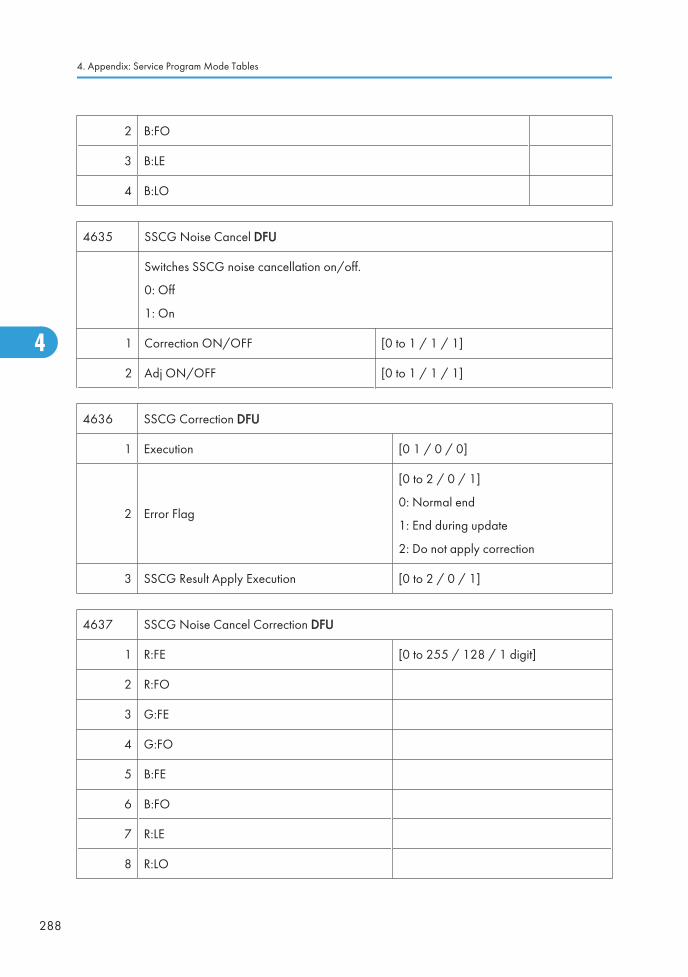
2 B:FO
3 B:LE
4 B:LO
4635 SSCG Noise Cancel DFU
Switches SSCG noise cancellation on/off.
0: Off
1: On
1 Correction ON/OFF [0 to 1 / 1 / 1]
2 Adj ON/OFF [0 to 1 / 1 / 1]
4636 SSCG Correction DFU
1 Execution [0 1 / 0 / 0]
2 Error Flag
[0 to 2 / 0 / 1]
0: Normal end
1: End during update
2: Do not apply correction
3 SSCG Result Apply Execution [0 to 2 / 0 / 1]
4637 SSCG Noise Cancel Correction DFU
1 R:FE [0 to 255 / 128 / 1 digit]
2 R:FO
3 G:FE
4 G:FO
5 B:FE
6 B:FO
7 R:LE
8 R:LO
4. Appendix: Service Program Mode Tables
288
4

9 G:LE
10 G:LO
11 B:LE
12 B:LO
4638 Nose Cancel Correction DFU
1 Previous:R:FE [0 to 255 / 128 / 1 digit]
2 Previous:R:FO
3 Previous:G:FE
4 Previous:G:FO
5 Previous:B:FE
6 Previous:B:FO
7 Previous:R:LE
8 Previous:R:LO
9 Previous:G:LE
10 Previous:G:LO
11 Previous:B:LE
12 Previous:B:LO
4639 Nose Cancel Correction DFU
1 Factory :R:FE [0 to 255 / 128 / 1 digit]
2 Factory :R:FO
3 Factory :G:FE
4 Factory :G:FO
5 Factory :B:FE
6 Factory :B:FO
7 Factory :R:LE
Group 4000
289
4
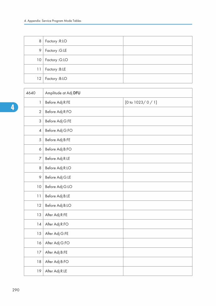
8 Factory :R:LO
9 Factory :G:LE
10 Factory :G:LO
11 Factory :B:LE
12 Factory :B:LO
4640 Amplitude at Adj DFU
1 Before Adj:R:FE [0 to 1023/ 0 / 1]
2 Before Adj:R:FO
3 Before Adj:G:FE
4 Before Adj:G:FO
5 Before Adj:B:FE
6 Before Adj:B:FO
7 Before Adj:R:LE
8 Before Adj:R:LO
9 Before Adj:G:LE
10 Before Adj:G:LO
11 Before Adj:B:LE
12 Before Adj:B:LO
13 After Adj:R:FE
14 After Adj:R:FO
15 After Adj:G:FE
16 After Adj:G:FO
17 After Adj:B:FE
18 After Adj:B:FO
19 After Adj:R:LE
4. Appendix: Service Program Mode Tables
290
4
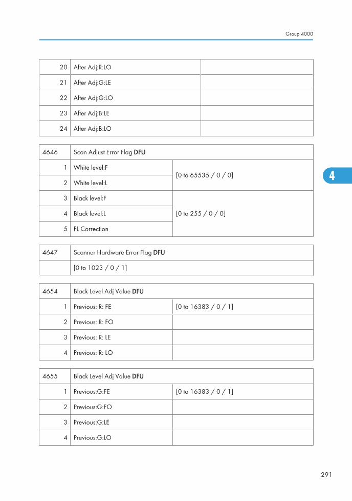
20 After Adj:R:LO
21 After Adj:G:LE
22 After Adj:G:LO
23 After Adj:B:LE
24 After Adj:B:LO
4646 Scan Adjust Error Flag DFU
1 White level:F[0 to 65535 / 0 / 0]
2 White level:L
3 Black level:F
[0 to 255 / 0 / 0]4 Black level:L
5 FL Correction
4647 Scanner Hardware Error Flag DFU
[0 to 1023 / 0 / 1]
4654 Black Level Adj Value DFU
1 Previous: R: FE [0 to 16383 / 0 / 1]
2 Previous: R: FO
3 Previous: R: LE
4 Previous: R: LO
4655 Black Level Adj Value DFU
1 Previous:G:FE [0 to 16383 / 0 / 1]
2 Previous:G:FO
3 Previous:G:LE
4 Previous:G:LO
Group 4000
291
4
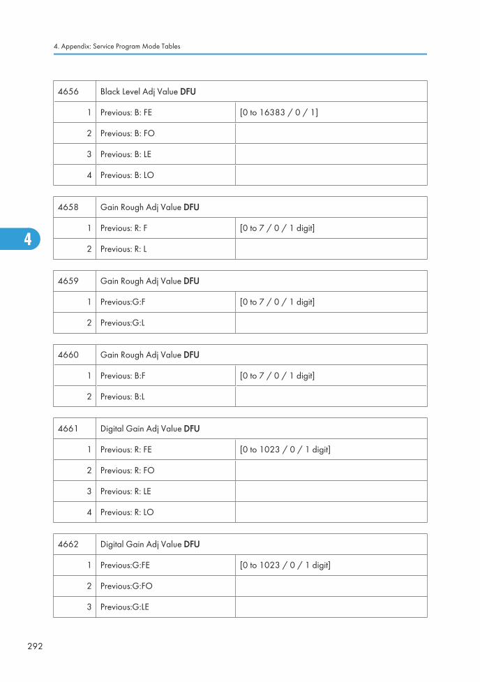
4656 Black Level Adj Value DFU
1 Previous: B: FE [0 to 16383 / 0 / 1]
2 Previous: B: FO
3 Previous: B: LE
4 Previous: B: LO
4658 Gain Rough Adj Value DFU
1 Previous: R: F [0 to 7 / 0 / 1 digit]
2 Previous: R: L
4659 Gain Rough Adj Value DFU
1 Previous:G:F [0 to 7 / 0 / 1 digit]
2 Previous:G:L
4660 Gain Rough Adj Value DFU
1 Previous: B:F [0 to 7 / 0 / 1 digit]
2 Previous: B:L
4661 Digital Gain Adj Value DFU
1 Previous: R: FE [0 to 1023 / 0 / 1 digit]
2 Previous: R: FO
3 Previous: R: LE
4 Previous: R: LO
4662 Digital Gain Adj Value DFU
1 Previous:G:FE [0 to 1023 / 0 / 1 digit]
2 Previous:G:FO
3 Previous:G:LE
4. Appendix: Service Program Mode Tables
292
4
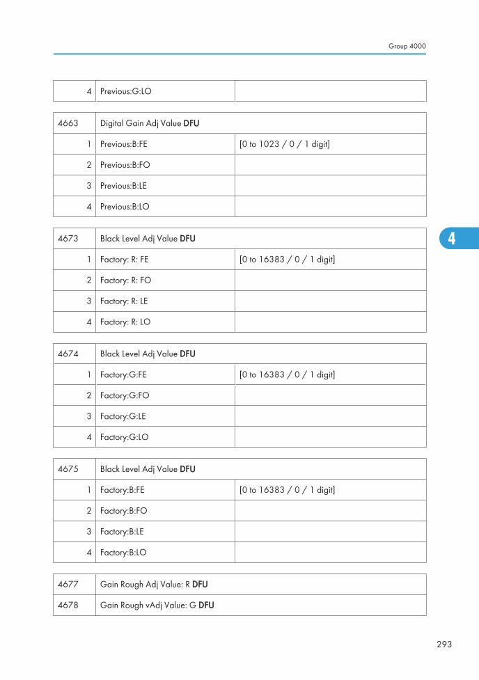
4 Previous:G:LO
4663 Digital Gain Adj Value DFU
1 Previous:B:FE [0 to 1023 / 0 / 1 digit]
2 Previous:B:FO
3 Previous:B:LE
4 Previous:B:LO
4673 Black Level Adj Value DFU
1 Factory: R: FE [0 to 16383 / 0 / 1 digit]
2 Factory: R: FO
3 Factory: R: LE
4 Factory: R: LO
4674 Black Level Adj Value DFU
1 Factory:G:FE [0 to 16383 / 0 / 1 digit]
2 Factory:G:FO
3 Factory:G:LE
4 Factory:G:LO
4675 Black Level Adj Value DFU
1 Factory:B:FE [0 to 16383 / 0 / 1 digit]
2 Factory:B:FO
3 Factory:B:LE
4 Factory:B:LO
4677 Gain Rough Adj Value: R DFU
4678 Gain Rough vAdj Value: G DFU
Group 4000
293
4
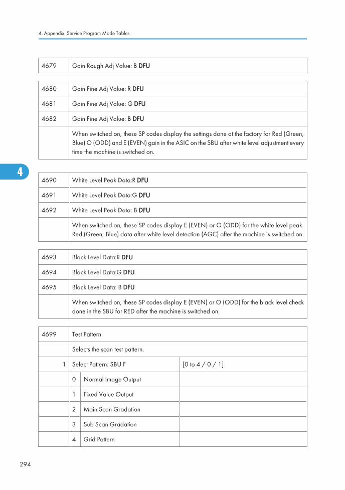
4679 Gain Rough Adj Value: B DFU
4680 Gain Fine Adj Value: R DFU
4681 Gain Fine Adj Value: G DFU
4682 Gain Fine Adj Value: B DFU
When switched on, these SP codes display the settings done at the factory for Red (Green,Blue) O (ODD) and E (EVEN) gain in the ASIC on the SBU after white level adjustment everytime the machine is switched on.
4690 White Level Peak Data:R DFU
4691 White Level Peak Data:G DFU
4692 White Level Peak Data: B DFU
When switched on, these SP codes display E (EVEN) or O (ODD) for the white level peakRed (Green, Blue) data after white level detection (AGC) after the machine is switched on.
4693 Black Level Data:R DFU
4694 Black Level Data:G DFU
4695 Black Level Data: B DFU
When switched on, these SP codes display E (EVEN) or O (ODD) for the black level checkdone in the SBU for RED after the machine is switched on.
4699 Test Pattern
Selects the scan test pattern.
1 Select Pattern: SBU F [0 to 4 / 0 / 1]
0 Normal Image Output
1 Fixed Value Output
2 Main Scan Gradation
3 Sub Scan Gradation
4 Grid Pattern
4. Appendix: Service Program Mode Tables
294
4

2 Output Level: SBU F [0 to 1023/ 512 / 1]
3 Select Pattern: SBU L [0 to 4 / 0 / 1]
0 Normal Image Output
1 Fixed Value Output
2 Main Scan Gradation
3 Sub Scan Gradation
4 Grid Pattern
4 Output Level: SBU L [0 to 1023/ 512 / 1]
4700 CIS ID Display
Reads and displays the CIS hexadecimal ID (Marble Register) when a CIS communicationerror is detected.
4709 GB Chart Level R DFU
4710 GB Chart Level G DFU
4711 GB Chart Level B DFU
4712 GB Adj Value R DFU
4713 GB Adj Value G DFU
4714 GB Adj Value B DFU
4745 Image Level Error Flag DFU
4746 GB Adj Error Flag DFU
4747 CIS Hard Error Flag
Reads and displays CIS hard errors.
[0 to 7 / 0 / 1]
0: Opal register read error flag
1: Marble register rear error flag
2: Marble boot error flag
Group 4000
295
4
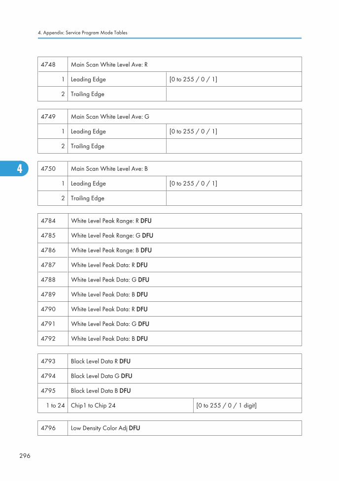
4748 Main Scan White Level Ave: R
1 Leading Edge [0 to 255 / 0 / 1]
2 Trailing Edge
4749 Main Scan White Level Ave: G
1 Leading Edge [0 to 255 / 0 / 1]
2 Trailing Edge
4750 Main Scan White Level Ave: B
1 Leading Edge [0 to 255 / 0 / 1]
2 Trailing Edge
4784 White Level Peak Range: R DFU
4785 White Level Peak Range: G DFU
4786 White Level Peak Range: B DFU
4787 White Level Peak Data: R DFU
4788 White Level Peak Data: G DFU
4789 White Level Peak Data: B DFU
4790 White Level Peak Data: R DFU
4791 White Level Peak Data: G DFU
4792 White Level Peak Data: B DFU
4793 Black Level Data R DFU
4794 Black Level Data G DFU
4795 Black Level Data B DFU
1 to 24 Chip1 to Chip 24 [0 to 255 / 0 / 1 digit]
4796 Low Density Color Adj DFU
4. Appendix: Service Program Mode Tables
296
4
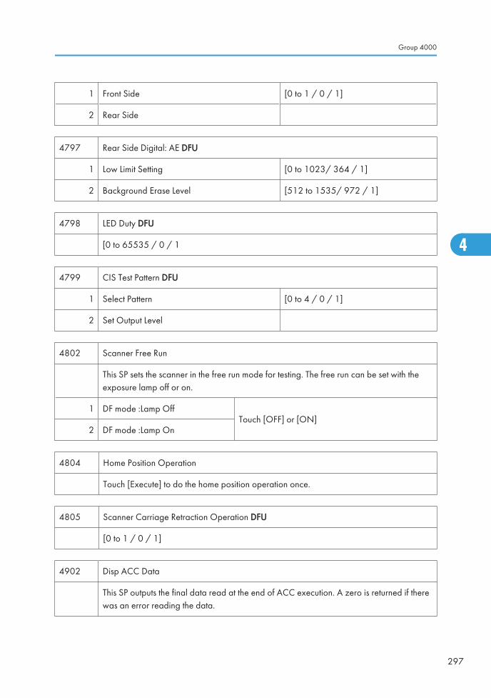
1 Front Side [0 to 1 / 0 / 1]
2 Rear Side
4797 Rear Side Digital: AE DFU
1 Low Limit Setting [0 to 1023/ 364 / 1]
2 Background Erase Level [512 to 1535/ 972 / 1]
4798 LED Duty DFU
[0 to 65535 / 0 / 1
4799 CIS Test Pattern DFU
1 Select Pattern [0 to 4 / 0 / 1]
2 Set Output Level
4802 Scanner Free Run
This SP sets the scanner in the free run mode for testing. The free run can be set with theexposure lamp off or on.
1 DF mode :Lamp OffTouch [OFF] or [ON]
2 DF mode :Lamp On
4804 Home Position Operation
Touch [Execute] to do the home position operation once.
4805 Scanner Carriage Retraction Operation DFU
[0 to 1 / 0 / 1]
4902 Disp ACC Data
This SP outputs the final data read at the end of ACC execution. A zero is returned if therewas an error reading the data.
Group 4000
297
4
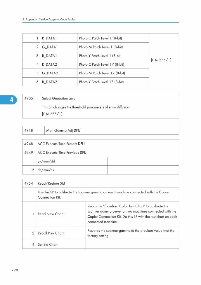
1 R_DATA1 Photo C Patch Level 1 (8-bit)
[0 to 255/1]
2 G_DATA1 Photo M Patch Level 1 (8-bit)
3 B_DATA1 Photo Y Patch Level 1 (8-bit)
4 R_DATA2 Photo C Patch Level 17 (8-bit)
5 G_DATA2 Photo M Patch Level 17 (8-bit)
6 B_DATA2 Photo Y Patch Level 17 (8-bit)
4905 Select Gradation Level
This SP changes the threshold parameters of error diffusion.
[0 to 255/1]
4918 Man Gamma Adj DFU
4948 ACC Execute Time:Present DFU
4949 ACC Execute Time:Previous DFU
1 yy/mm/dd
2 hh/mm/ss
4954 Read/Restore Std
Use this SP to calibrate the scanner gamma on each machine connected with the CopierConnection Kit.
1 Read New Chart
Reads the "Standard Color Test Chart" to calibrate thescanner gamma curve for two machines connected with theCopier Connection Kit. Do this SP with the test chart on eachconnected machine.
2 Recall Prev ChartRestores the scanner gamma to the previous value (not thefactory setting).
4 Set Std Chart
4. Appendix: Service Program Mode Tables
298
4

4958 Read/Restore Std: Rear DFU
1 Read New Chart [0 to 1 / 0 / 1]
2 Recall Prev Chart
4 Set Std Chart
4991 IPU Image Path Selection
Use this SP to use the 10-key pad to enter the number to determine the image path.
IPU [0 to 14/1]
0 DFID input RGB images (upper 8 bits)
1 Synchronous RGB images in DFID
2 Data with shading correction on
3 Data with shading correction off
4 Data before black offset correction
5 Data after black offset correction
6 Shading data
7 Test pattern data (grayscale)
8 RGB image after line interval correction
9 RGB image after dot correction and pre-gamma
10 RGB image after vertiial line correction
11 RGB image after scanner gamma correction
12 RTB image after filtering with MTF
13 RTB image after ADS
14 RGB image after color processing
4993 High Light Correction DFU
1 Sensitivity Selection
2 Range Selection
Group 4000
299
4

4994 Adj Txt/Photo Recognition Level DFU
4996 White Paper Detection Level DFU
4. Appendix: Service Program Mode Tables
300
4
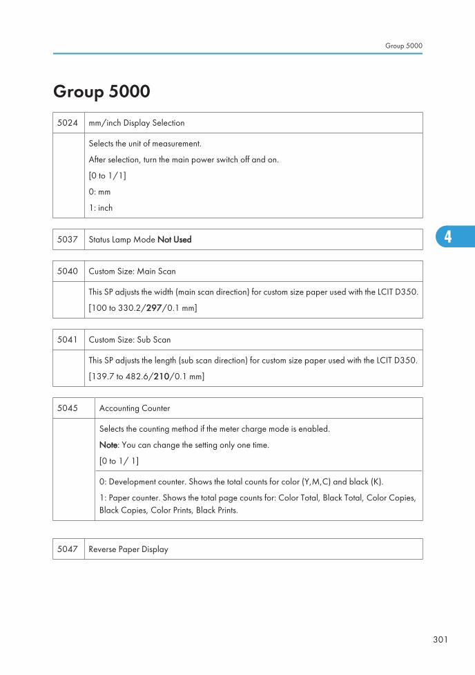
Group 50005024 mm/inch Display Selection
Selects the unit of measurement.
After selection, turn the main power switch off and on.
[0 to 1/1]
0: mm
1: inch
5037 Status Lamp Mode Not Used
5040 Custom Size: Main Scan
This SP adjusts the width (main scan direction) for custom size paper used with the LCIT D350.
[100 to 330.2/297/0.1 mm]
5041 Custom Size: Sub Scan
This SP adjusts the length (sub scan direction) for custom size paper used with the LCIT D350.
[139.7 to 482.6/210/0.1 mm]
5045 Accounting Counter
Selects the counting method if the meter charge mode is enabled.
Note: You can change the setting only one time.
[0 to 1/ 1]
0: Development counter. Shows the total counts for color (Y,M,C) and black (K).
1: Paper counter. Shows the total page counts for: Color Total, Black Total, Color Copies,Black Copies, Color Prints, Black Prints.
5047 Reverse Paper Display
Group 5000
301
4
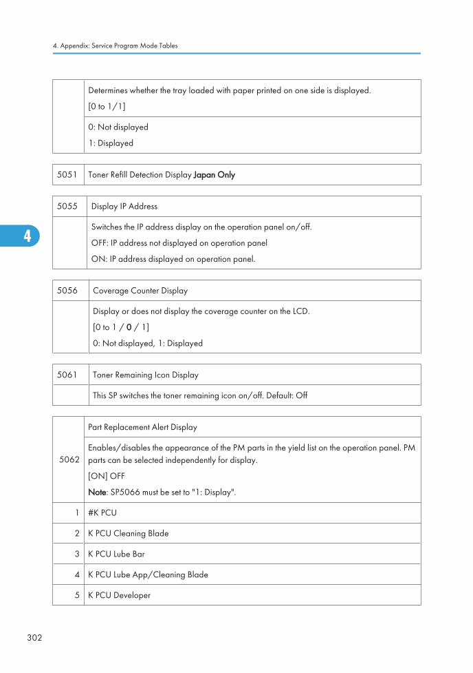
Determines whether the tray loaded with paper printed on one side is displayed.
[0 to 1/1]
0: Not displayed
1: Displayed
5051 Toner Refill Detection Display Japan Only
5055 Display IP Address
Switches the IP address display on the operation panel on/off.
OFF: IP address not displayed on operation panel
ON: IP address displayed on operation panel.
5056 Coverage Counter Display
Display or does not display the coverage counter on the LCD.
[0 to 1 / 0 / 1]
0: Not displayed, 1: Displayed
5061 Toner Remaining Icon Display
This SP switches the toner remaining icon on/off. Default: Off
5062
Part Replacement Alert Display
Enables/disables the appearance of the PM parts in the yield list on the operation panel. PMparts can be selected independently for display.
[ON] OFF
Note: SP5066 must be set to "1: Display".
1 #K PCU
2 K PCU Cleaning Blade
3 K PCU Lube Bar
4 K PCU Lube App/Cleaning Blade
5 K PCU Developer
4. Appendix: Service Program Mode Tables
302
4
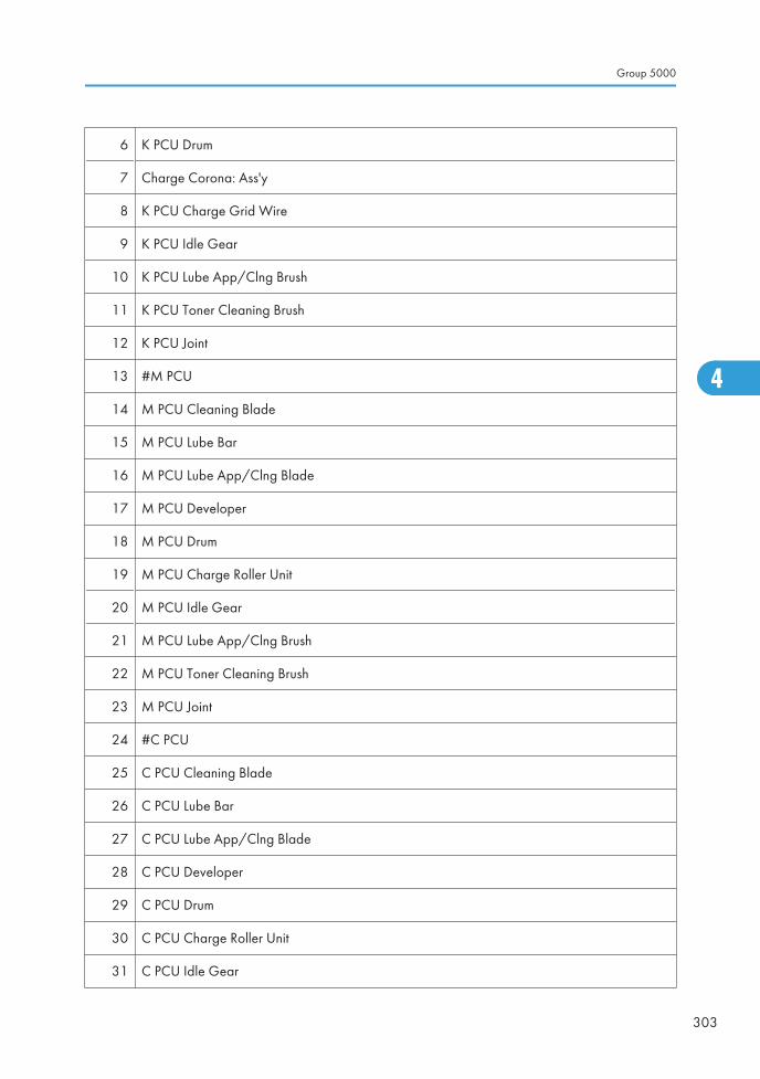
6 K PCU Drum
7 Charge Corona: Ass'y
8 K PCU Charge Grid Wire
9 K PCU Idle Gear
10 K PCU Lube App/Clng Brush
11 K PCU Toner Cleaning Brush
12 K PCU Joint
13 #M PCU
14 M PCU Cleaning Blade
15 M PCU Lube Bar
16 M PCU Lube App/Clng Blade
17 M PCU Developer
18 M PCU Drum
19 M PCU Charge Roller Unit
20 M PCU Idle Gear
21 M PCU Lube App/Clng Brush
22 M PCU Toner Cleaning Brush
23 M PCU Joint
24 #C PCU
25 C PCU Cleaning Blade
26 C PCU Lube Bar
27 C PCU Lube App/Clng Blade
28 C PCU Developer
29 C PCU Drum
30 C PCU Charge Roller Unit
31 C PCU Idle Gear
Group 5000
303
4
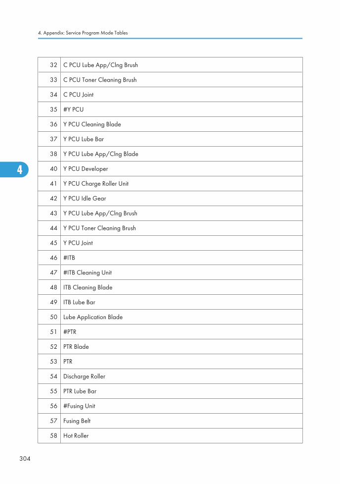
32 C PCU Lube App/Clng Brush
33 C PCU Toner Cleaning Brush
34 C PCU Joint
35 #Y PCU
36 Y PCU Cleaning Blade
37 Y PCU Lube Bar
38 Y PCU Lube App/Clng Blade
40 Y PCU Developer
41 Y PCU Charge Roller Unit
42 Y PCU Idle Gear
43 Y PCU Lube App/Clng Brush
44 Y PCU Toner Cleaning Brush
45 Y PCU Joint
46 #ITB
47 #ITB Cleaning Unit
48 ITB Cleaning Blade
49 ITB Lube Bar
50 Lube Application Blade
51 #PTR
52 PTR Blade
53 PTR
54 Discharge Roller
55 PTR Lube Bar
56 #Fusing Unit
57 Fusing Belt
58 Hot Roller
4. Appendix: Service Program Mode Tables
304
4
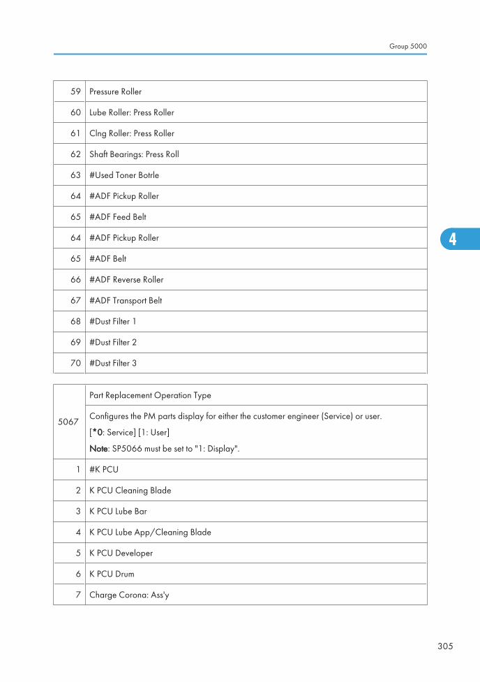
59 Pressure Roller
60 Lube Roller: Press Roller
61 Clng Roller: Press Roller
62 Shaft Bearings: Press Roll
63 #Used Toner Botrle
64 #ADF Pickup Roller
65 #ADF Feed Belt
64 #ADF Pickup Roller
65 #ADF Belt
66 #ADF Reverse Roller
67 #ADF Transport Belt
68 #Dust Filter 1
69 #Dust Filter 2
70 #Dust Filter 3
5067
Part Replacement Operation Type
Configures the PM parts display for either the customer engineer (Service) or user.
[*0: Service] [1: User]
Note: SP5066 must be set to "1: Display".
1 #K PCU
2 K PCU Cleaning Blade
3 K PCU Lube Bar
4 K PCU Lube App/Cleaning Blade
5 K PCU Developer
6 K PCU Drum
7 Charge Corona: Ass'y
Group 5000
305
4
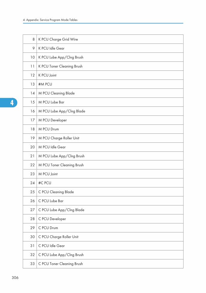
8 K PCU Charge Grid Wire
9 K PCU Idle Gear
10 K PCU Lube App/Clng Brush
11 K PCU Toner Cleaning Brush
12 K PCU Joint
13 #M PCU
14 M PCU Cleaning Blade
15 M PCU Lube Bar
16 M PCU Lube App/Clng Blade
17 M PCU Developer
18 M PCU Drum
19 M PCU Charge Roller Unit
20 M PCU Idle Gear
21 M PCU Lube App/Clng Brush
22 M PCU Toner Cleaning Brush
23 M PCU Joint
24 #C PCU
25 C PCU Cleaning Blade
26 C PCU Lube Bar
27 C PCU Lube App/Clng Blade
28 C PCU Developer
29 C PCU Drum
30 C PCU Charge Roller Unit
31 C PCU Idle Gear
32 C PCU Lube App/Clng Brush
33 C PCU Toner Cleaning Brush
4. Appendix: Service Program Mode Tables
306
4

34 C PCU Joint
35 #Y PCU
36 Y PCU Cleaning Blade
37 Y PCU Lube Bar
38 Y PCU Lube App/Clng Blade
40 Y PCU Developer
41 Y PCU Charge Roller Unit
42 Y PCU Idle Gear
43 Y PCU Lube App/Clng Brush
44 Y PCU Toner Cleaning Brush
45 Y PCU Joint
46 #ITB
47 #ITB Cleaning Unit
48 ITB Cleaning Blade
49 ITB Lube Bar
50 Lube Application Blade
51 #PTR
52 PTR Blade
53 PTR
54 Discharge Roller
55 PTR Lube Bar
56 #Fusing Unit
57 Fusing Belt
58 Hot Roller
59 Pressure Roller
60 Lube Roller: Press Roller
Group 5000
307
4
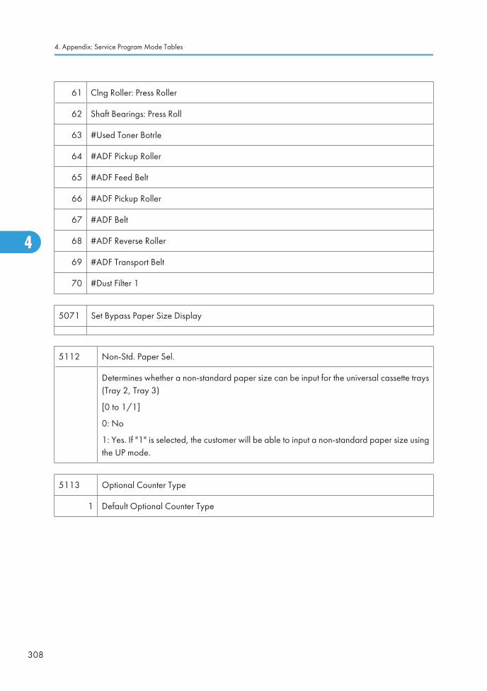
61 Clng Roller: Press Roller
62 Shaft Bearings: Press Roll
63 #Used Toner Botrle
64 #ADF Pickup Roller
65 #ADF Feed Belt
66 #ADF Pickup Roller
67 #ADF Belt
68 #ADF Reverse Roller
69 #ADF Transport Belt
70 #Dust Filter 1
5071 Set Bypass Paper Size Display
5112 Non-Std. Paper Sel.
Determines whether a non-standard paper size can be input for the universal cassette trays(Tray 2, Tray 3)
[0 to 1/1]
0: No
1: Yes. If "1" is selected, the customer will be able to input a non-standard paper size usingthe UP mode.
5113 Optional Counter Type
1 Default Optional Counter Type
4. Appendix: Service Program Mode Tables
308
4
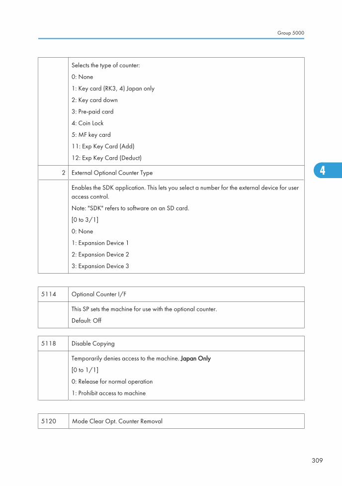
Selects the type of counter:
0: None
1: Key card (RK3, 4) Japan only
2: Key card down
3: Pre-paid card
4: Coin Lock
5: MF key card
11: Exp Key Card (Add)
12: Exp Key Card (Deduct)
2 External Optional Counter Type
Enables the SDK application. This lets you select a number for the external device for useraccess control.
Note: "SDK" refers to software on an SD card.
[0 to 3/1]
0: None
1: Expansion Device 1
2: Expansion Device 2
3: Expansion Device 3
5114 Optional Counter I/F
This SP sets the machine for use with the optional counter.
Default: Off
5118 Disable Copying
Temporarily denies access to the machine. Japan Only
[0 to 1/1]
0: Release for normal operation
1: Prohibit access to machine
5120 Mode Clear Opt. Counter Removal
Group 5000
309
4
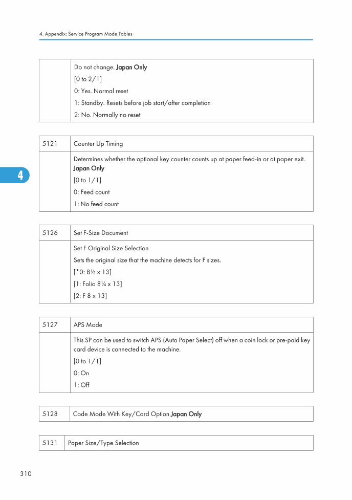
Do not change. Japan Only
[0 to 2/1]
0: Yes. Normal reset
1: Standby. Resets before job start/after completion
2: No. Normally no reset
5121 Counter Up Timing
Determines whether the optional key counter counts up at paper feed-in or at paper exit.Japan Only
[0 to 1/1]
0: Feed count
1: No feed count
5126 Set F-Size Document
Set F Original Size Selection
Sets the original size that the machine detects for F sizes.
[*0: 8½ x 13]
[1: Folio 8¼ x 13]
[2: F 8 x 13]
5127 APS Mode
This SP can be used to switch APS (Auto Paper Select) off when a coin lock or pre-paid keycard device is connected to the machine.
[0 to 1/1]
0: On
1: Off
5128 Code Mode With Key/Card Option Japan Only
5131 Paper Size/Type Selection
4. Appendix: Service Program Mode Tables
310
4
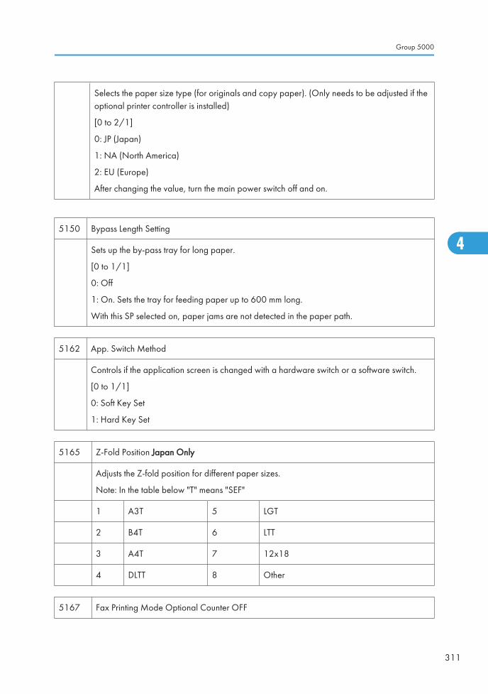
Selects the paper size type (for originals and copy paper). (Only needs to be adjusted if theoptional printer controller is installed)
[0 to 2/1]
0: JP (Japan)
1: NA (North America)
2: EU (Europe)
After changing the value, turn the main power switch off and on.
5150 Bypass Length Setting
Sets up the by-pass tray for long paper.
[0 to 1/1]
0: Off
1: On. Sets the tray for feeding paper up to 600 mm long.
With this SP selected on, paper jams are not detected in the paper path.
5162 App. Switch Method
Controls if the application screen is changed with a hardware switch or a software switch.
[0 to 1/1]
0: Soft Key Set
1: Hard Key Set
5165 Z-Fold Position Japan Only
Adjusts the Z-fold position for different paper sizes.
Note: In the table below "T" means "SEF"
1 A3T 5 LGT
2 B4T 6 LTT
3 A4T 7 12x18
4 DLTT 8 Other
5167 Fax Printing Mode Optional Counter OFF
Group 5000
311
4
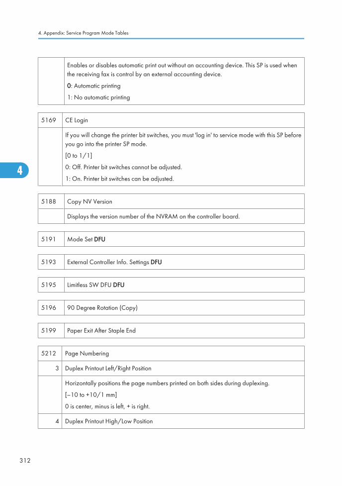
Enables or disables automatic print out without an accounting device. This SP is used whenthe receiving fax is control by an external accounting device.
0: Automatic printing
1: No automatic printing
5169 CE Login
If you will change the printer bit switches, you must 'log in' to service mode with this SP beforeyou go into the printer SP mode.
[0 to 1/1]
0: Off. Printer bit switches cannot be adjusted.
1: On. Printer bit switches can be adjusted.
5188 Copy NV Version
Displays the version number of the NVRAM on the controller board.
5191 Mode Set DFU
5193 External Controller Info. Settings DFU
5195 Limitless SW DFU DFU
5196 90 Degree Rotation (Copy)
5199 Paper Exit After Staple End
5212 Page Numbering
3 Duplex Printout Left/Right Position
Horizontally positions the page numbers printed on both sides during duplexing.
[–10 to +10/1 mm]
0 is center, minus is left, + is right.
4 Duplex Printout High/Low Position
4. Appendix: Service Program Mode Tables
312
4
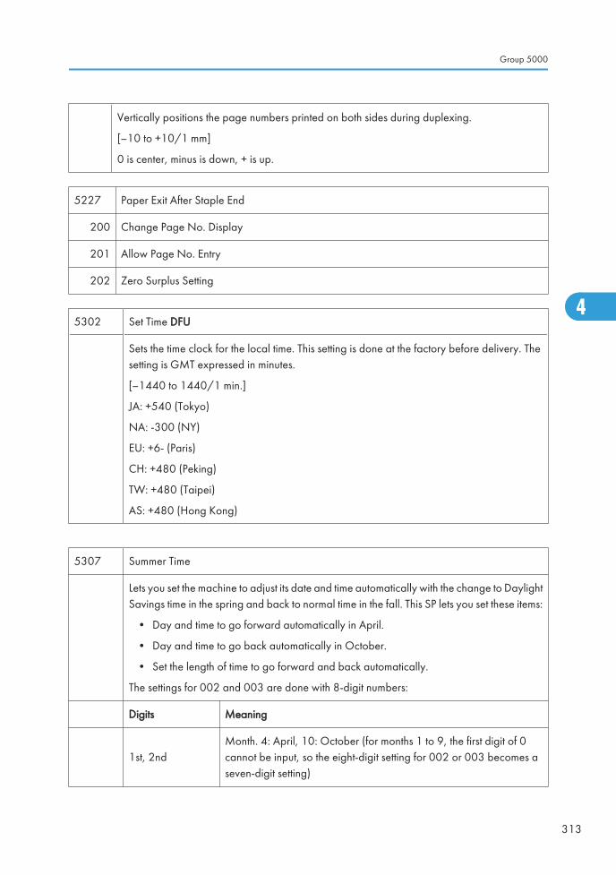
Vertically positions the page numbers printed on both sides during duplexing.
[–10 to +10/1 mm]
0 is center, minus is down, + is up.
5227 Paper Exit After Staple End
200 Change Page No. Display
201 Allow Page No. Entry
202 Zero Surplus Setting
5302 Set Time DFU
Sets the time clock for the local time. This setting is done at the factory before delivery. Thesetting is GMT expressed in minutes.
[–1440 to 1440/1 min.]
JA: +540 (Tokyo)
NA: -300 (NY)
EU: +6- (Paris)
CH: +480 (Peking)
TW: +480 (Taipei)
AS: +480 (Hong Kong)
5307 Summer Time
Lets you set the machine to adjust its date and time automatically with the change to DaylightSavings time in the spring and back to normal time in the fall. This SP lets you set these items:
• Day and time to go forward automatically in April.
• Day and time to go back automatically in October.
• Set the length of time to go forward and back automatically.
The settings for 002 and 003 are done with 8-digit numbers:
Digits Meaning
1st, 2ndMonth. 4: April, 10: October (for months 1 to 9, the first digit of 0cannot be input, so the eight-digit setting for 002 or 003 becomes aseven-digit setting)
Group 5000
313
4
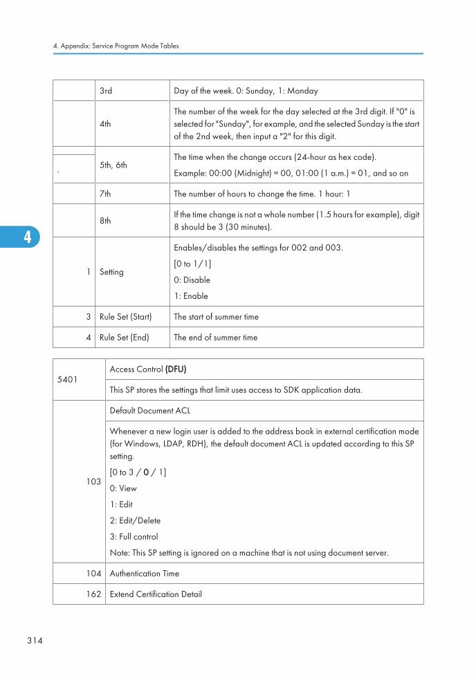
3rd Day of the week. 0: Sunday, 1: Monday
4thThe number of the week for the day selected at the 3rd digit. If "0" isselected for "Sunday", for example, and the selected Sunday is the startof the 2nd week, then input a "2" for this digit.
5th, 6thThe time when the change occurs (24-hour as hex code).
Example: 00:00 (Midnight) = 00, 01:00 (1 a.m.) = 01, and so on.
7th The number of hours to change the time. 1 hour: 1
8thIf the time change is not a whole number (1.5 hours for example), digit8 should be 3 (30 minutes).
1 Setting
Enables/disables the settings for 002 and 003.
[0 to 1/1]
0: Disable
1: Enable
3 Rule Set (Start) The start of summer time
4 Rule Set (End) The end of summer time
5401Access Control (DFU)
This SP stores the settings that limit uses access to SDK application data.
103
Default Document ACL
Whenever a new login user is added to the address book in external certification mode(for Windows, LDAP, RDH), the default document ACL is updated according to this SPsetting.
[0 to 3 / 0 / 1]
0: View
1: Edit
2: Edit/Delete
3: Full control
Note: This SP setting is ignored on a machine that is not using document server.
104 Authentication Time
162 Extend Certification Detail
4. Appendix: Service Program Mode Tables
314
4
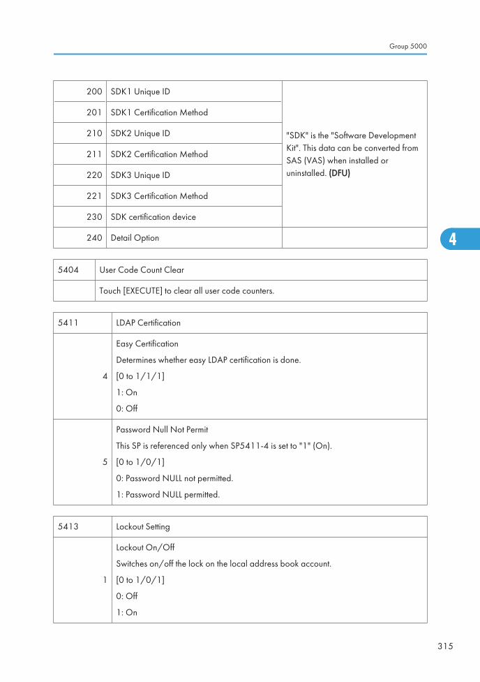
200 SDK1 Unique ID
"SDK" is the "Software DevelopmentKit". This data can be converted fromSAS (VAS) when installed oruninstalled. (DFU)
201 SDK1 Certification Method
210 SDK2 Unique ID
211 SDK2 Certification Method
220 SDK3 Unique ID
221 SDK3 Certification Method
230 SDK certification device
240 Detail Option
5404 User Code Count Clear
Touch [EXECUTE] to clear all user code counters.
5411 LDAP Certification
4
Easy Certification
Determines whether easy LDAP certification is done.
[0 to 1/1/1]
1: On
0: Off
5
Password Null Not Permit
This SP is referenced only when SP5411-4 is set to "1" (On).
[0 to 1/0/1]
0: Password NULL not permitted.
1: Password NULL permitted.
5413 Lockout Setting
1
Lockout On/Off
Switches on/off the lock on the local address book account.
[0 to 1/0/1]
0: Off
1: On
Group 5000
315
4
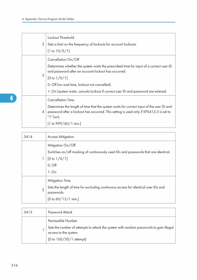
2
Lockout Threshold
Sets a limit on the frequency of lockouts for account lockouts.
[1 to 10/5/1]
3
Cancellation On/Off
Determines whether the system waits the prescribed time for input of a correct user IDand password after an account lockout has occurred.
[0 to 1/0/1]
0: Off (no wait time, lockout not cancelled)
1: On (system waits, cancels lockout if correct user ID and password are entered.
4
Cancellation Time
Determines the length of time that the system waits for correct input of the user ID andpassword after a lockout has occurred. This setting is used only if SP5413-3 is set to"1" (on).
[1 to 999/60/1 min.]
5414 Access Mitigation
1
Mitigation On/Off
Switches on/off masking of continuously used IDs and passwords that are identical.
[0 to 1/0/1]
0: Off
1: On
2
Mitigation Time
Sets the length of time for excluding continuous access for identical user IDs andpasswords.
[0 to 60/15/1 min.]
5415 Password Attack
1
Permissible Number
Sets the number of attempts to attack the system with random passwords to gain illegalaccess to the system.
[0 to 100/30/1 attempt]
4. Appendix: Service Program Mode Tables
316
4
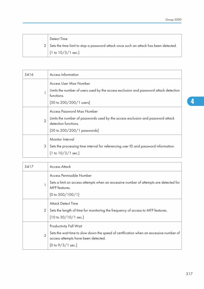
2
Detect Time
Sets the time limit to stop a password attack once such an attack has been detected.
[1 to 10/5/1 sec.]
5416 Access Information
1
Access User Max Number
Limits the number of users used by the access exclusion and password attack detectionfunctions.
[50 to 200/200/1 users]
2
Access Password Max Number
Limits the number of passwords used by the access exclusion and password attackdetection functions.
[50 to 200/200/1 passwords]
3
Monitor Interval
Sets the processing time interval for referencing user ID and password information.
[1 to 10/3/1 sec.]
5417 Access Attack
1
Access Permissible Number
Sets a limit on access attempts when an excessive number of attempts are detected forMFP features.
[0 to 500/100/1]
2
Attack Detect Time
Sets the length of time for monitoring the frequency of access to MFP features.
[10 to 30/10/1 sec.]
3
Productivity Fall Wait
Sets the wait time to slow down the speed of certification when an excessive number ofaccess attempts have been detected.
[0 to 9/3/1 sec.]
Group 5000
317
4
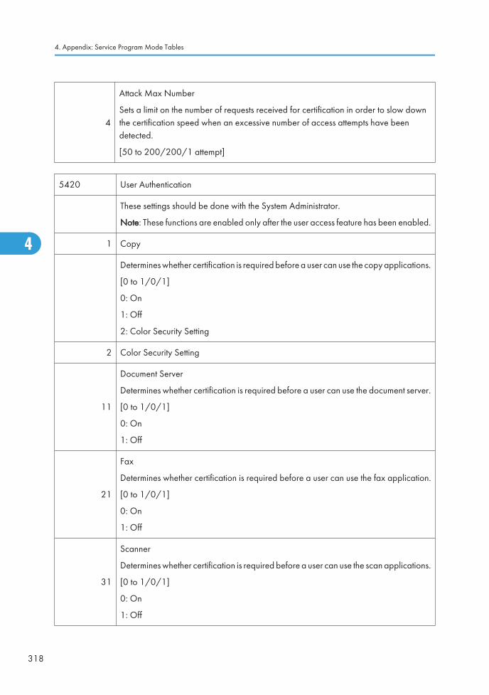
4
Attack Max Number
Sets a limit on the number of requests received for certification in order to slow downthe certification speed when an excessive number of access attempts have beendetected.
[50 to 200/200/1 attempt]
5420 User Authentication
These settings should be done with the System Administrator.
Note: These functions are enabled only after the user access feature has been enabled.
1 Copy
Determines whether certification is required before a user can use the copy applications.
[0 to 1/0/1]
0: On
1: Off
2: Color Security Setting
2 Color Security Setting
11
Document Server
Determines whether certification is required before a user can use the document server.
[0 to 1/0/1]
0: On
1: Off
21
Fax
Determines whether certification is required before a user can use the fax application.
[0 to 1/0/1]
0: On
1: Off
31
Scanner
Determines whether certification is required before a user can use the scan applications.
[0 to 1/0/1]
0: On
1: Off
4. Appendix: Service Program Mode Tables
318
4
Ed
Typewritten Text
RTB 76 Service Manual Revision (SP5420-001,5420-002)
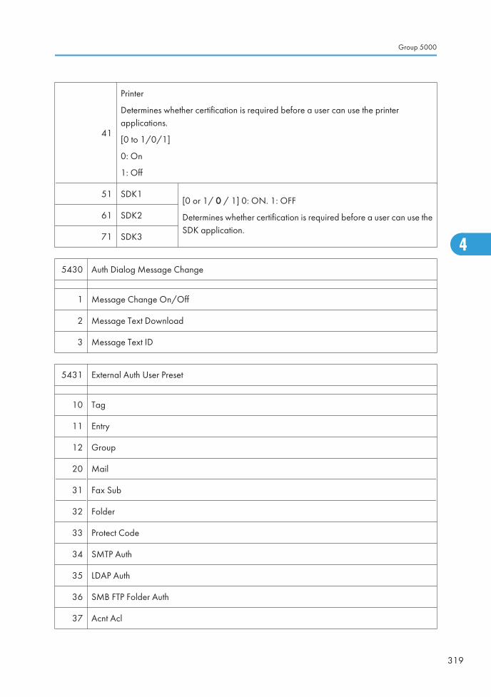
41
Printer
Determines whether certification is required before a user can use the printerapplications.
[0 to 1/0/1]
0: On
1: Off
51 SDK1[0 or 1/ 0 / 1] 0: ON. 1: OFF
Determines whether certification is required before a user can use theSDK application.
61 SDK2
71 SDK3
5430 Auth Dialog Message Change
1 Message Change On/Off
2 Message Text Download
3 Message Text ID
5431 External Auth User Preset
10 Tag
11 Entry
12 Group
20 Mail
31 Fax Sub
32 Folder
33 Protect Code
34 SMTP Auth
35 LDAP Auth
36 SMB FTP Folder Auth
37 Acnt Acl
Group 5000
319
4
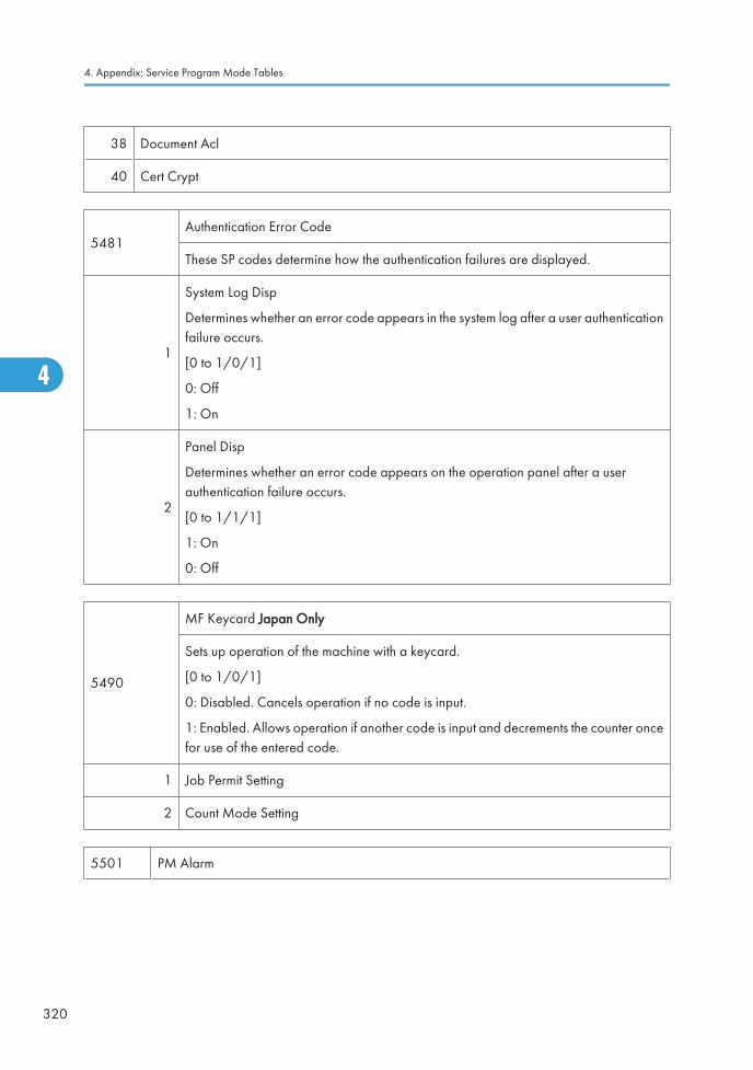
38 Document Acl
40 Cert Crypt
5481Authentication Error Code
These SP codes determine how the authentication failures are displayed.
1
System Log Disp
Determines whether an error code appears in the system log after a user authenticationfailure occurs.
[0 to 1/0/1]
0: Off
1: On
2
Panel Disp
Determines whether an error code appears on the operation panel after a userauthentication failure occurs.
[0 to 1/1/1]
1: On
0: Off
5490
MF Keycard Japan Only
Sets up operation of the machine with a keycard.
[0 to 1/0/1]
0: Disabled. Cancels operation if no code is input.
1: Enabled. Allows operation if another code is input and decrements the counter oncefor use of the entered code.
1 Job Permit Setting
2 Count Mode Setting
5501 PM Alarm
4. Appendix: Service Program Mode Tables
320
4
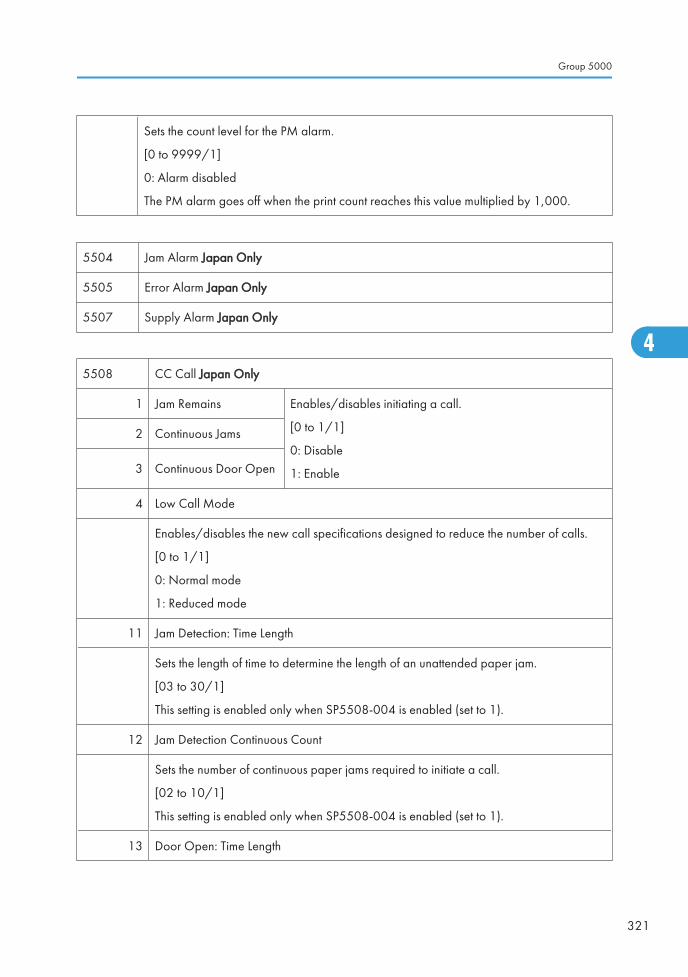
Sets the count level for the PM alarm.
[0 to 9999/1]
0: Alarm disabled
The PM alarm goes off when the print count reaches this value multiplied by 1,000.
5504 Jam Alarm Japan Only
5505 Error Alarm Japan Only
5507 Supply Alarm Japan Only
5508 CC Call Japan Only
1 Jam Remains Enables/disables initiating a call.
[0 to 1/1]
0: Disable
1: Enable
2 Continuous Jams
3 Continuous Door Open
4 Low Call Mode
Enables/disables the new call specifications designed to reduce the number of calls.
[0 to 1/1]
0: Normal mode
1: Reduced mode
11 Jam Detection: Time Length
Sets the length of time to determine the length of an unattended paper jam.
[03 to 30/1]
This setting is enabled only when SP5508-004 is enabled (set to 1).
12 Jam Detection Continuous Count
Sets the number of continuous paper jams required to initiate a call.
[02 to 10/1]
This setting is enabled only when SP5508-004 is enabled (set to 1).
13 Door Open: Time Length
Group 5000
321
4
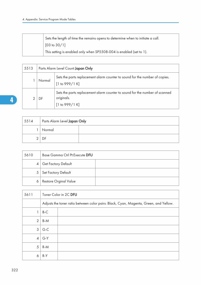
Sets the length of time the remains opens to determine when to initiate a call.
[03 to 30/1]
This setting is enabled only when SP5508-004 is enabled (set to 1).
5513 Parts Alarm Level Count Japan Only
1 NormalSets the parts replacement alarm counter to sound for the number of copies.
[1 to 999/1 K]
2 DF
Sets the parts replacement alarm counter to sound for the number of scannedoriginals.
[1 to 999/1 K]
5514 Parts Alarm Level Japan Only
1 Normal
2 DF
5610 Base Gamma Ctrl Pt:Execute DFU
4 Get Factory Default
5 Set Factory Default
6 Restore Orginal Value
5611 Toner Color in 2C DFU
Adjusts the toner ratio between color pairs: Black, Cyan, Magenta, Green, and Yellow.
1 B-C
2 B-M
3 G-C
4 G-Y
5 R-M
6 R-Y
4. Appendix: Service Program Mode Tables
322
4
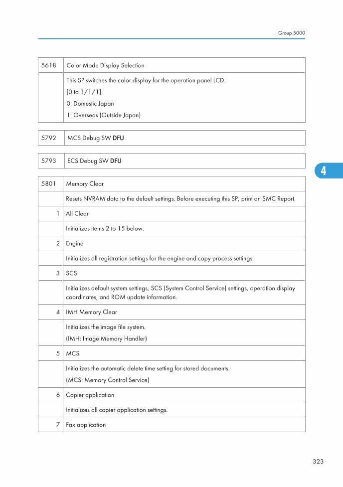
5618 Color Mode Display Selection
This SP switches the color display for the operation panel LCD.
[0 to 1/1/1]
0: Domestic Japan
1: Overseas (Outside Japan)
5792 MCS Debug SW DFU
5793 ECS Debug SW DFU
5801 Memory Clear
Resets NVRAM data to the default settings. Before executing this SP, print an SMC Report.
1 All Clear
Initializes items 2 to 15 below.
2 Engine
Initializes all registration settings for the engine and copy process settings.
3 SCS
Initializes default system settings, SCS (System Control Service) settings, operation displaycoordinates, and ROM update information.
4 IMH Memory Clear
Initializes the image file system.
(IMH: Image Memory Handler)
5 MCS
Initializes the automatic delete time setting for stored documents.
(MCS: Memory Control Service)
6 Copier application
Initializes all copier application settings.
7 Fax application
Group 5000
323
4
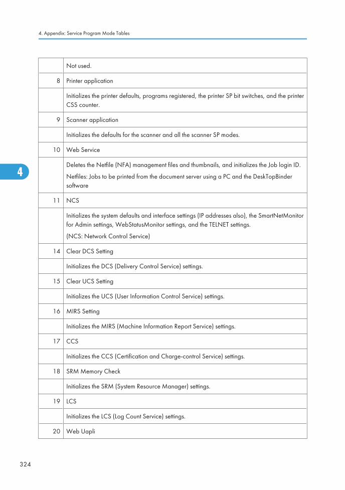
Not used.
8 Printer application
Initializes the printer defaults, programs registered, the printer SP bit switches, and the printerCSS counter.
9 Scanner application
Initializes the defaults for the scanner and all the scanner SP modes.
10 Web Service
Deletes the Netfile (NFA) management files and thumbnails, and initializes the Job login ID.
Netfiles: Jobs to be printed from the document server using a PC and the DeskTopBindersoftware
11 NCS
Initializes the system defaults and interface settings (IP addresses also), the SmartNetMonitorfor Admin settings, WebStatusMonitor settings, and the TELNET settings.
(NCS: Network Control Service)
14 Clear DCS Setting
Initializes the DCS (Delivery Control Service) settings.
15 Clear UCS Setting
Initializes the UCS (User Information Control Service) settings.
16 MIRS Setting
Initializes the MIRS (Machine Information Report Service) settings.
17 CCS
Initializes the CCS (Certification and Charge-control Service) settings.
18 SRM Memory Check
Initializes the SRM (System Resource Manager) settings.
19 LCS
Initializes the LCS (Log Count Service) settings.
20 Web Uapli
4. Appendix: Service Program Mode Tables
324
4
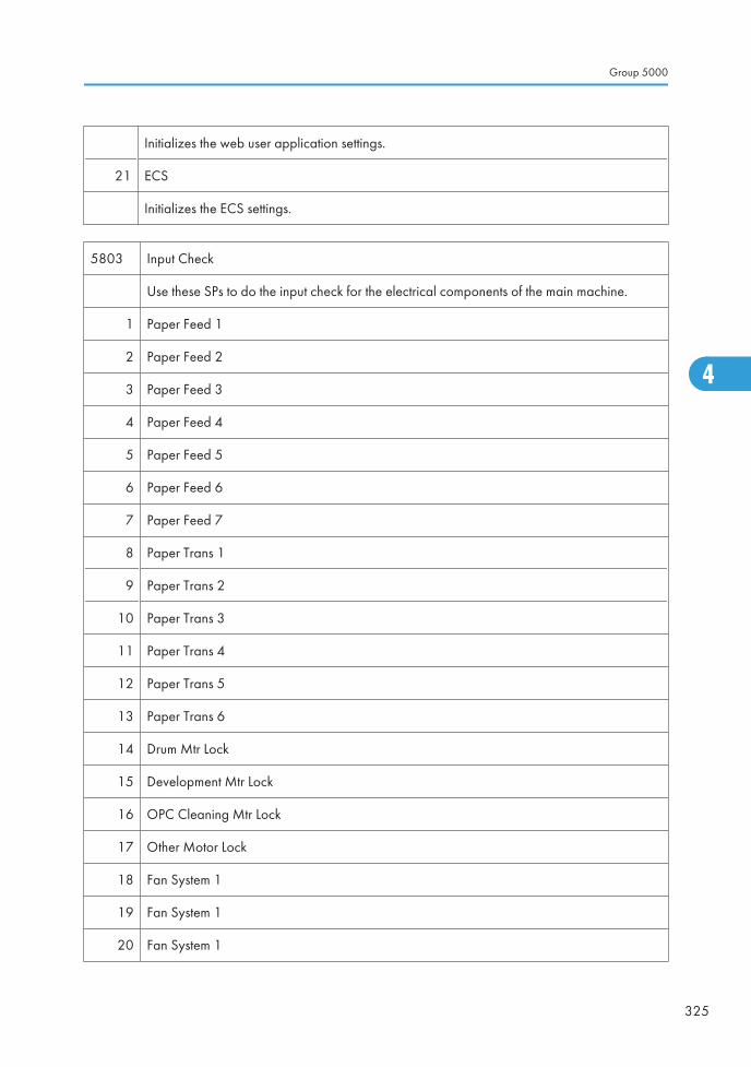
Initializes the web user application settings.
21 ECS
Initializes the ECS settings.
5803 Input Check
Use these SPs to do the input check for the electrical components of the main machine.
1 Paper Feed 1
2 Paper Feed 2
3 Paper Feed 3
4 Paper Feed 4
5 Paper Feed 5
6 Paper Feed 6
7 Paper Feed 7
8 Paper Trans 1
9 Paper Trans 2
10 Paper Trans 3
11 Paper Trans 4
12 Paper Trans 5
13 Paper Trans 6
14 Drum Mtr Lock
15 Development Mtr Lock
16 OPC Cleaning Mtr Lock
17 Other Motor Lock
18 Fan System 1
19 Fan System 1
20 Fan System 1
Group 5000
325
4
Ed
Typewritten Text
RTB 40 New information for SP5803
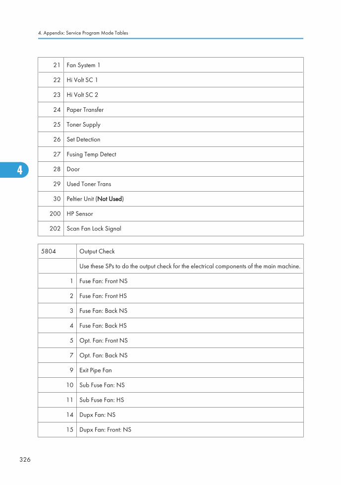
21 Fan System 1
22 Hi Volt SC 1
23 Hi Volt SC 2
24 Paper Transfer
25 Toner Supply
26 Set Detection
27 Fusing Temp Detect
28 Door
29 Used Toner Trans
30 Peltier Unit (Not Used)
200 HP Sensor
202 Scan Fan Lock Signal
5804 Output Check
Use these SPs to do the output check for the electrical components of the main machine.
1 Fuse Fan: Front NS
2 Fuse Fan: Front HS
3 Fuse Fan: Back NS
4 Fuse Fan: Back HS
5 Opt. Fan: Front NS
7 Opt. Fan: Back NS
9 Exit Pipe Fan
10 Sub Fuse Fan: NS
11 Sub Fuse Fan: HS
14 Dupx Fan: NS
15 Dupx Fan: Front: NS
4. Appendix: Service Program Mode Tables
326
4
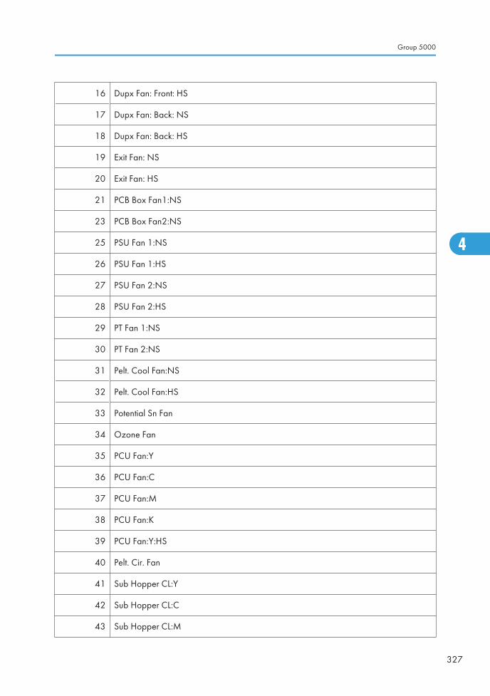
16 Dupx Fan: Front: HS
17 Dupx Fan: Back: NS
18 Dupx Fan: Back: HS
19 Exit Fan: NS
20 Exit Fan: HS
21 PCB Box Fan1:NS
23 PCB Box Fan2:NS
25 PSU Fan 1:NS
26 PSU Fan 1:HS
27 PSU Fan 2:NS
28 PSU Fan 2:HS
29 PT Fan 1:NS
30 PT Fan 2:NS
31 Pelt. Cool Fan:NS
32 Pelt. Cool Fan:HS
33 Potential Sn Fan
34 Ozone Fan
35 PCU Fan:Y
36 PCU Fan:C
37 PCU Fan:M
38 PCU Fan:K
39 PCU Fan:Y:HS
40 Pelt. Cir. Fan
41 Sub Hopper CL:Y
42 Sub Hopper CL:C
43 Sub Hopper CL:M
Group 5000
327
4
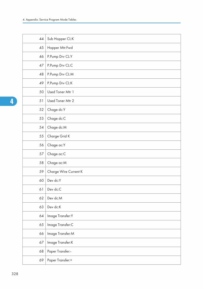
44 Sub Hopper CL:K
45 Hopper Mtr:Fwd
46 P.Pump Drv CL:Y
47 P.Pump Drv CL:C
48 P.Pump Drv CL:M
49 P.Pump Drv CL:K
50 Used Toner Mtr 1
51 Used Toner Mtr 2
52 Chage dc:Y
53 Chage dc:C
54 Chage dc:M
55 Charge Grid K
56 Chage ac:Y
57 Chage ac:C
58 Chage ac:M
59 Charge Wire Current K
60 Dev dc:Y
61 Dev dc:C
62 Dev dc:M
63 Dev dc:K
64 Image Transfer:Y
65 Image Transfer:C
66 Image Transfer:M
67 Image Transfer:K
68 Paper Transfer:-
69 Paper Transfer:+
4. Appendix: Service Program Mode Tables
328
4
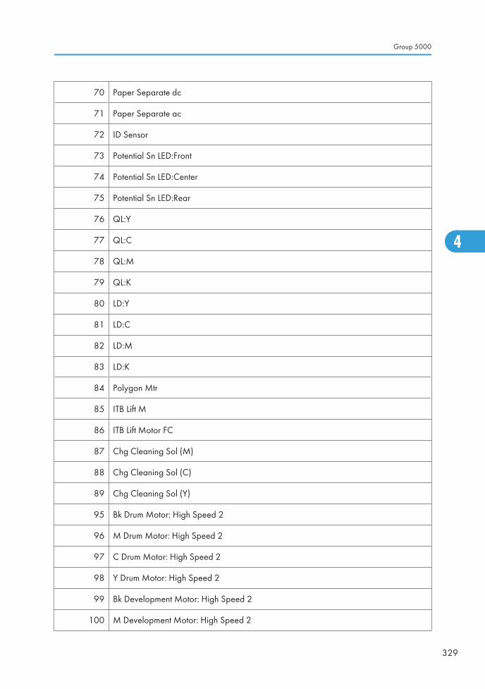
70 Paper Separate dc
71 Paper Separate ac
72 ID Sensor
73 Potential Sn LED:Front
74 Potential Sn LED:Center
75 Potential Sn LED:Rear
76 QL:Y
77 QL:C
78 QL:M
79 QL:K
80 LD:Y
81 LD:C
82 LD:M
83 LD:K
84 Polygon Mtr
85 ITB Lift M
86 ITB Lift Motor FC
87 Chg Cleaning Sol (M)
88 Chg Cleaning Sol (C)
89 Chg Cleaning Sol (Y)
95 Bk Drum Motor: High Speed 2
96 M Drum Motor: High Speed 2
97 C Drum Motor: High Speed 2
98 Y Drum Motor: High Speed 2
99 Bk Development Motor: High Speed 2
100 M Development Motor: High Speed 2
Group 5000
329
4
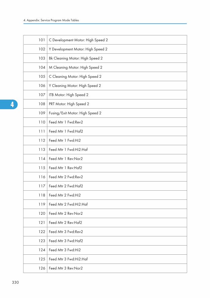
101 C Development Motor: High Speed 2
102 Y Development Motor: High Speed 2
103 Bk Cleaning Motor: High Speed 2
104 M Cleaning Motor: High Speed 2
105 C Cleaning Motor: High Speed 2
106 Y Cleaning Motor: High Speed 2
107 ITB Motor: High Speed 2
108 PRT Motor: High Speed 2
109 Fusing/Exit Motor: High Speed 2
110 Feed Mtr 1 Fwd:Rev2
111 Feed Mtr 1 Fwd:Haf2
112 Feed Mtr 1 Fwd:Hi2
113 Feed Mtr 1 Fwd:Hi2:Haf
114 Feed Mtr 1 Rev:Nor2
115 Feed Mtr 1 Rev:Haf2
116 Feed Mtr 2 Fwd:Rev2
117 Feed Mtr 2 Fwd:Haf2
118 Feed Mtr 2 Fwd:Hi2
119 Feed Mtr 2 Fwd:Hi2:Haf
120 Feed Mtr 2 Rev:Nor2
121 Feed Mtr 2 Rev:Haf2
122 Feed Mtr 3 Fwd:Rev2
123 Feed Mtr 3 Fwd:Haf2
124 Feed Mtr 3 Fwd:Hi2
125 Feed Mtr 3 Fwd:Hi2:Haf
126 Feed Mtr 3 Rev:Nor2
4. Appendix: Service Program Mode Tables
330
4
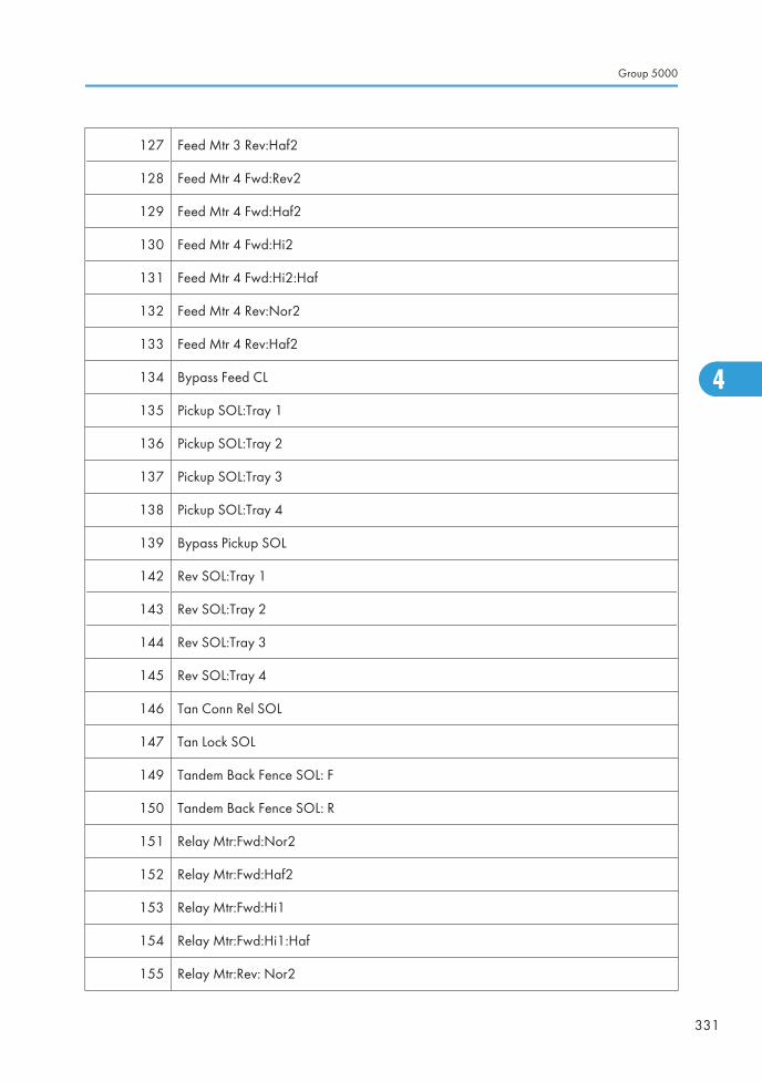
127 Feed Mtr 3 Rev:Haf2
128 Feed Mtr 4 Fwd:Rev2
129 Feed Mtr 4 Fwd:Haf2
130 Feed Mtr 4 Fwd:Hi2
131 Feed Mtr 4 Fwd:Hi2:Haf
132 Feed Mtr 4 Rev:Nor2
133 Feed Mtr 4 Rev:Haf2
134 Bypass Feed CL
135 Pickup SOL:Tray 1
136 Pickup SOL:Tray 2
137 Pickup SOL:Tray 3
138 Pickup SOL:Tray 4
139 Bypass Pickup SOL
142 Rev SOL:Tray 1
143 Rev SOL:Tray 2
144 Rev SOL:Tray 3
145 Rev SOL:Tray 4
146 Tan Conn Rel SOL
147 Tan Lock SOL
149 Tandem Back Fence SOL: F
150 Tandem Back Fence SOL: R
151 Relay Mtr:Fwd:Nor2
152 Relay Mtr:Fwd:Haf2
153 Relay Mtr:Fwd:Hi1
154 Relay Mtr:Fwd:Hi1:Haf
155 Relay Mtr:Rev: Nor2
Group 5000
331
4
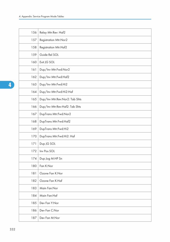
156 Relay Mtr:Rev: Haf2
157 Registration Mtr:Nor2
158 Registration Mtr:Haf2
159 Guide Rel SOL
160 Exit JG SOL
161 Dup/Inv Mtr:Fwd:Nor2
162 Dup/Inv Mtr:Fwd:Haf2
163 Dup/Inv Mtr:Fwd:Hi2
164 Dup/Inv Mtr:Fwd:Hi2:Haf
165 Dup/Inv Mtr:Rev:Nor2: Tab Shts
166 Dup/Inv Mtr:Rev:Haf2: Tab Shts
167 DupTrans Mtr:Fwd:Nor2
168 DupTrans Mtr:Fwd:Haf2
169 DupTrans Mtr:Fwd:Hi2
170 DupTrans Mtr:Fwd:Hi2: Haf
171 Dup JG SOL
172 Inv Pos SOL
174 Dup Jog M:HP Sn
180 Fan K:Nor
181 Ozone Fan K:Nor
182 Ozone Fan K:Haf
183 Main Fan:Nor
184 Main Fan:Haf
185 Dev Fan Y:Nor
186 Dev Fan C:Nor
187 Dev Fan M:Nor
4. Appendix: Service Program Mode Tables
332
4
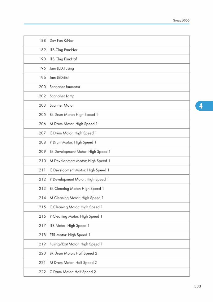
188 Dev Fan K:Nor
189 ITB Clng Fan:Nor
190 ITB Clng Fan:Haf
195 Jam LED:Fusing
196 Jam LED:Exit
200 Scananer fanmotor
202 Scananer Lamp
203 Scanner Motor
205 Bk Drum Motor: High Speed 1
206 M Drum Motor: High Speed 1
207 C Drum Motor: High Speed 1
208 Y Drum Motor: High Speed 1
209 Bk Development Motor: High Speed 1
210 M Development Motor: High Speed 1
211 C Development Motor: High Speed 1
212 Y Development Motor: High Speed 1
213 Bk Cleaning Motor: High Speed 1
214 M Cleaning Motor: High Speed 1
215 C Cleaning Motor: High Speed 1
216 Y Cleaning Motor: High Speed 1
217 ITB Motor: High Speed 1
218 PTR Motor: High Speed 1
219 Fusing/Exit Motor: High Speed 1
220 Bk Drum Motor: Half Speed 2
221 M Drum Motor: Half Speed 2
222 C Drum Motor: Half Speed 2
Group 5000
333
4
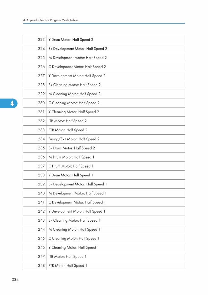
223 Y Drum Motor: Half Speed 2
224 Bk Development Motor: Half Speed 2
225 M Development Motor: Half Speed 2
226 C Development Motor: Half Speed 2
227 Y Development Motor: Half Speed 2
228 Bk Cleaning Motor: Half Speed 2
229 M Cleaning Motor: Half Speed 2
230 C Cleaning Motor: Half Speed 2
231 Y Cleaning Motor: Half Speed 2
232 ITB Motor: Half Speed 2
233 PTR Motor: Half Speed 2
234 Fusing/Exit Motor: Half Speed 2
235 Bk Drum Motor: Half Speed 2
236 M Drum Motor: Half Speed 1
237 C Drum Motor: Half Speed 1
238 Y Drum Motor: Half Speed 1
239 Bk Development Motor: Half Speed 1
240 M Development Motor: Half Speed 1
241 C Development Motor: Half Speed 1
242 Y Development Motor: Half Speed 1
243 Bk Cleaning Motor: Half Speed 1
244 M Cleaning Motor: Half Speed 1
245 C Cleaning Motor: Half Speed 1
246 Y Cleaning Motor: Half Speed 1
247 ITB Motor: Half Speed 1
248 PTR Motor: Half Speed 1
4. Appendix: Service Program Mode Tables
334
4
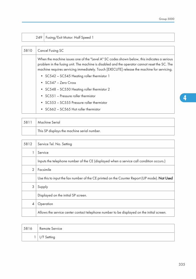
249 Fusing/Exit Motor: Half Speed 1
5810 Cancel Fusing SC
When the machine issues one of the "Level A" SC codes shown below, this indicates a seriousproblem in the fusing unit. The machine is disabled and the operator cannot reset the SC. Themachine requires servicing immediately. Touch [EXECUTE] release the machine for servicing.
• SC542 – SC545 Heating roller thermistor 1
• SC547 – Zero Cross
• SC548 – SC550 Heating roller thermistor 2
• SC551 – Pressure roller thermistor
• SC553 – SC555 Pressure roller thermistor
• SC662 – SC565 Hot roller thermistor
5811 Machine Serial
This SP displays the machine serial number.
5812 Service Tel. No. Setting
1 Service
Inputs the telephone number of the CE (displayed when a service call condition occurs.)
2 Facsimile
Use this to input the fax number of the CE printed on the Counter Report (UP mode). Not Used
3 Supply
Displayed on the initial SP screen.
4 Operation
Allows the service center contact telephone number to be displayed on the initial screen.
5816 Remote Service
1 I/F Setting
Group 5000
335
4
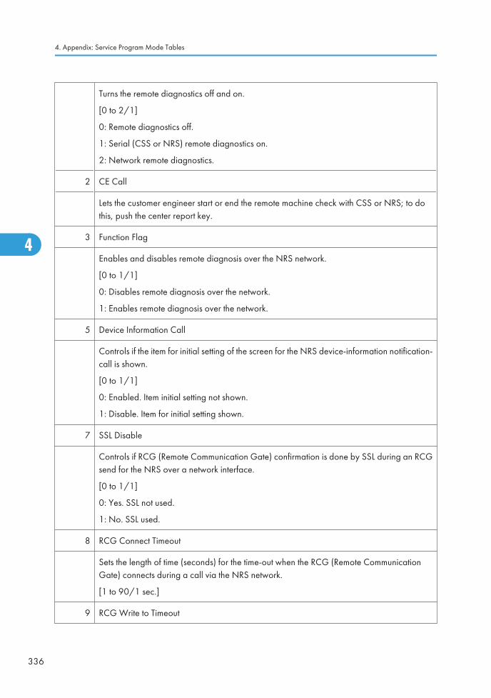
Turns the remote diagnostics off and on.
[0 to 2/1]
0: Remote diagnostics off.
1: Serial (CSS or NRS) remote diagnostics on.
2: Network remote diagnostics.
2 CE Call
Lets the customer engineer start or end the remote machine check with CSS or NRS; to dothis, push the center report key.
3 Function Flag
Enables and disables remote diagnosis over the NRS network.
[0 to 1/1]
0: Disables remote diagnosis over the network.
1: Enables remote diagnosis over the network.
5 Device Information Call
Controls if the item for initial setting of the screen for the NRS device-information notification-call is shown.
[0 to 1/1]
0: Enabled. Item initial setting not shown.
1: Disable. Item for initial setting shown.
7 SSL Disable
Controls if RCG (Remote Communication Gate) confirmation is done by SSL during an RCGsend for the NRS over a network interface.
[0 to 1/1]
0: Yes. SSL not used.
1: No. SSL used.
8 RCG Connect Timeout
Sets the length of time (seconds) for the time-out when the RCG (Remote CommunicationGate) connects during a call via the NRS network.
[1 to 90/1 sec.]
9 RCG Write to Timeout
4. Appendix: Service Program Mode Tables
336
4
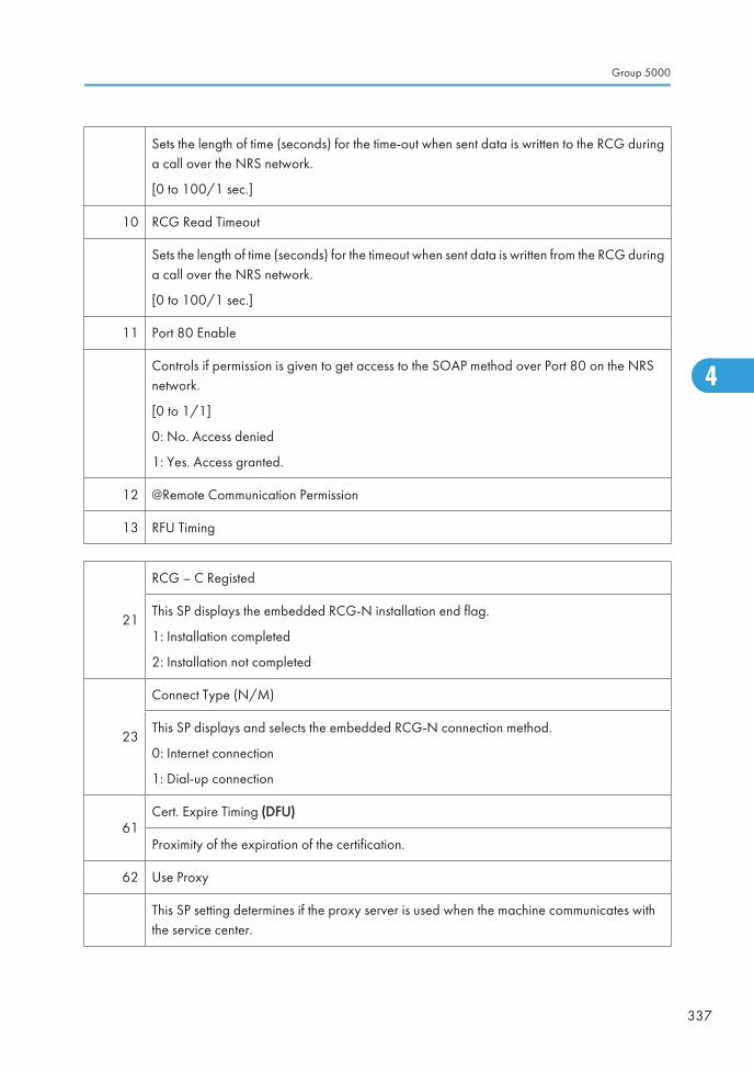
Sets the length of time (seconds) for the time-out when sent data is written to the RCG duringa call over the NRS network.
[0 to 100/1 sec.]
10 RCG Read Timeout
Sets the length of time (seconds) for the timeout when sent data is written from the RCG duringa call over the NRS network.
[0 to 100/1 sec.]
11 Port 80 Enable
Controls if permission is given to get access to the SOAP method over Port 80 on the NRSnetwork.
[0 to 1/1]
0: No. Access denied
1: Yes. Access granted.
12 @Remote Communication Permission
13 RFU Timing
21
RCG – C Registed
This SP displays the embedded RCG-N installation end flag.
1: Installation completed
2: Installation not completed
23
Connect Type (N/M)
This SP displays and selects the embedded RCG-N connection method.
0: Internet connection
1: Dial-up connection
61Cert. Expire Timing (DFU)
Proximity of the expiration of the certification.
62 Use Proxy
This SP setting determines if the proxy server is used when the machine communicates withthe service center.
Group 5000
337
4
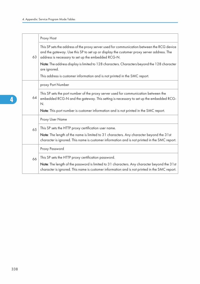
63
Proxy Host
This SP sets the address of the proxy server used for communication between the RCG deviceand the gateway. Use this SP to set up or display the customer proxy server address. Theaddress is necessary to set up the embedded RCG-N.
Note: The address display is limited to 128 characters. Characters beyond the 128 characterare ignored.
This address is customer information and is not printed in the SMC report.
64
proxy Port Number
This SP sets the port number of the proxy server used for communication between theembedded RCG-N and the gateway. This setting is necessary to set up the embedded RCG-N.
Note: This port number is customer information and is not printed in the SMC report.
65
Proxy User Name
This SP sets the HTTP proxy certification user name.
Note: The length of the name is limited to 31 characters. Any character beyond the 31stcharacter is ignored. This name is customer information and is not printed in the SMC report.
66
Proxy Password
This SP sets the HTTP proxy certification password.
Note: The length of the password is limited to 31 characters. Any character beyond the 31stcharacter is ignored. This name is customer information and is not printed in the SMC report.
4. Appendix: Service Program Mode Tables
338
4
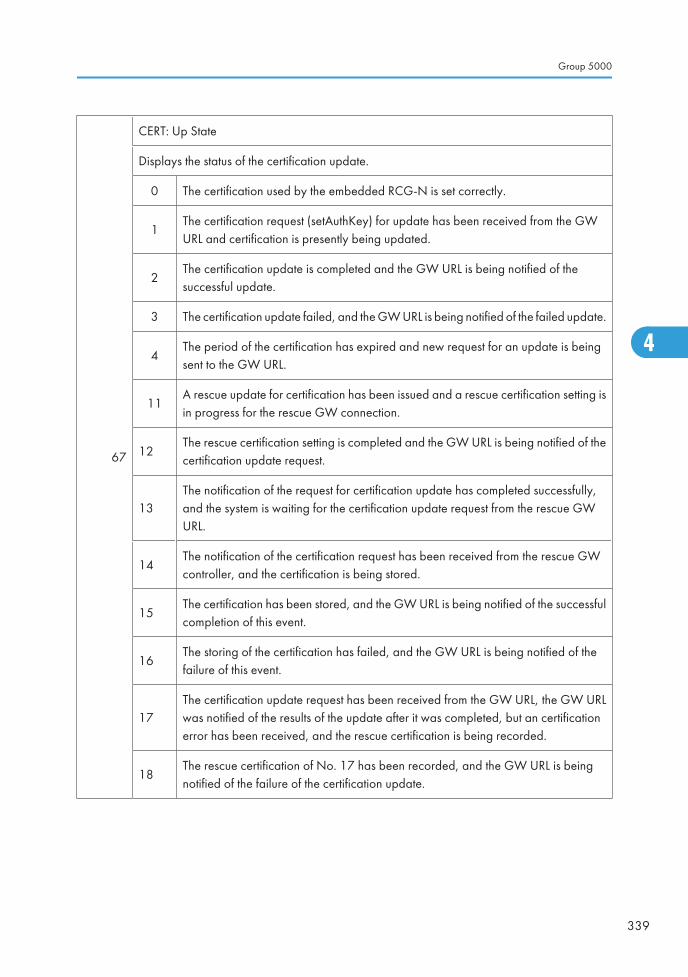
67
CERT: Up State
Displays the status of the certification update.
0 The certification used by the embedded RCG-N is set correctly.
1The certification request (setAuthKey) for update has been received from the GWURL and certification is presently being updated.
2The certification update is completed and the GW URL is being notified of thesuccessful update.
3 The certification update failed, and the GW URL is being notified of the failed update.
4The period of the certification has expired and new request for an update is beingsent to the GW URL.
11A rescue update for certification has been issued and a rescue certification setting isin progress for the rescue GW connection.
12The rescue certification setting is completed and the GW URL is being notified of thecertification update request.
13The notification of the request for certification update has completed successfully,and the system is waiting for the certification update request from the rescue GWURL.
14The notification of the certification request has been received from the rescue GWcontroller, and the certification is being stored.
15The certification has been stored, and the GW URL is being notified of the successfulcompletion of this event.
16The storing of the certification has failed, and the GW URL is being notified of thefailure of this event.
17The certification update request has been received from the GW URL, the GW URLwas notified of the results of the update after it was completed, but an certificationerror has been received, and the rescue certification is being recorded.
18The rescue certification of No. 17 has been recorded, and the GW URL is beingnotified of the failure of the certification update.
Group 5000
339
4
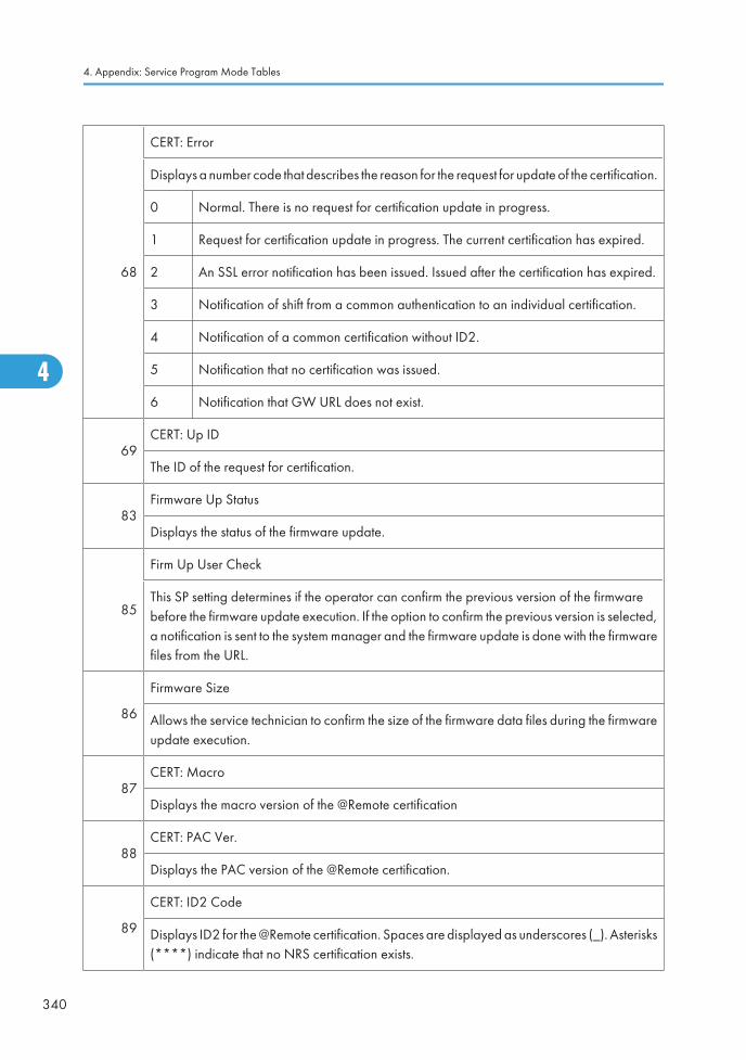
68
CERT: Error
Displays a number code that describes the reason for the request for update of the certification.
0 Normal. There is no request for certification update in progress.
1 Request for certification update in progress. The current certification has expired.
2 An SSL error notification has been issued. Issued after the certification has expired.
3 Notification of shift from a common authentication to an individual certification.
4 Notification of a common certification without ID2.
5 Notification that no certification was issued.
6 Notification that GW URL does not exist.
69CERT: Up ID
The ID of the request for certification.
83Firmware Up Status
Displays the status of the firmware update.
85
Firm Up User Check
This SP setting determines if the operator can confirm the previous version of the firmwarebefore the firmware update execution. If the option to confirm the previous version is selected,a notification is sent to the system manager and the firmware update is done with the firmwarefiles from the URL.
86
Firmware Size
Allows the service technician to confirm the size of the firmware data files during the firmwareupdate execution.
87CERT: Macro
Displays the macro version of the @Remote certification
88CERT: PAC Ver.
Displays the PAC version of the @Remote certification.
89
CERT: ID2 Code
Displays ID2 for the @Remote certification. Spaces are displayed as underscores (_). Asterisks(****) indicate that no NRS certification exists.
4. Appendix: Service Program Mode Tables
340
4
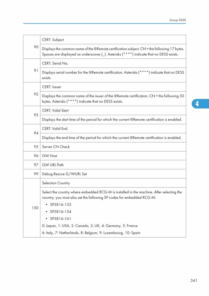
90
CERT: Subject
Displays the common name of the @Remote certification subject. CN = the following 17 bytes.Spaces are displayed as underscores (_). Asterisks (****) indicate that no DESS exists.
91
CERT: Serial No.
Displays serial number for the @Remote certification. Asterisks (****) indicate that no DESSexists.
92
CERT: Issuer
Displays the common name of the issuer of the @Remote certification. CN = the following 30bytes. Asterisks (****) indicate that no DESS exists.
93CERT: Valid Start
Displays the start time of the period for which the current @Remote certification is enabled.
94CERT: Valid End
Displays the end time of the period for which the current @Remote certification is enabled.
95 Server CN Check
96 GW Host
97 GW URL Path
99 Debug Rescue G/WURL Set
150
Selection Country
Select the country where embedded RCG-M is installed in the machine. After selecting thecountry, you must also set the following SP codes for embedded RCG-M:
• SP5816-153
• SP5816-154
• SP5816-161
0: Japan, 1: USA, 2: Canada, 3: UK, 4: Germany, 5: France
6: Italy, 7: Netherlands, 8: Belgium, 9: Luxembourg, 10: Spain
Group 5000
341
4
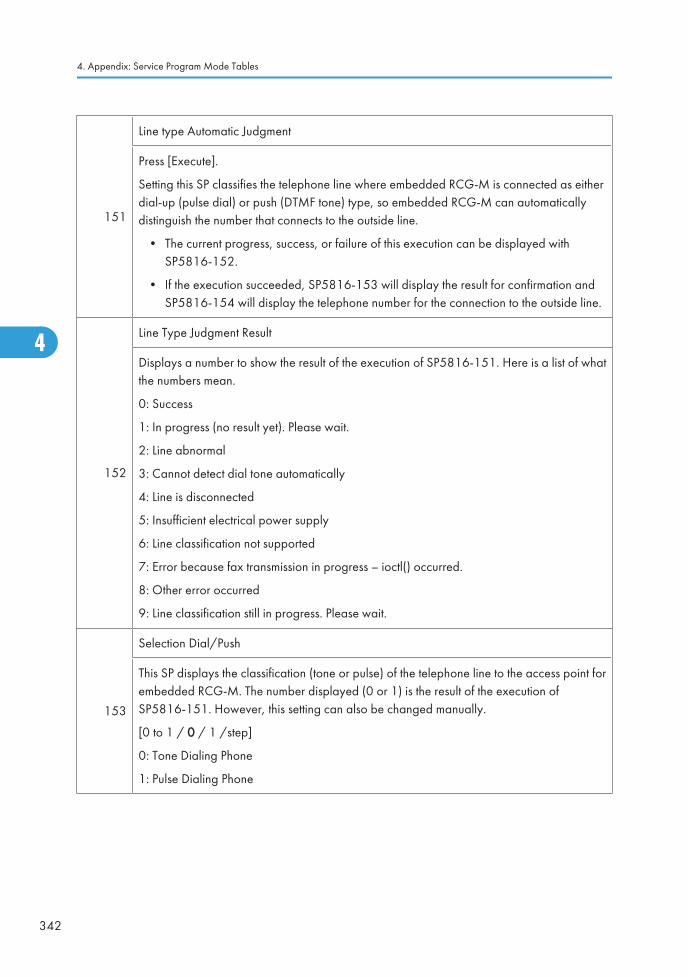
151
Line type Automatic Judgment
Press [Execute].
Setting this SP classifies the telephone line where embedded RCG-M is connected as eitherdial-up (pulse dial) or push (DTMF tone) type, so embedded RCG-M can automaticallydistinguish the number that connects to the outside line.
• The current progress, success, or failure of this execution can be displayed withSP5816-152.
• If the execution succeeded, SP5816-153 will display the result for confirmation andSP5816-154 will display the telephone number for the connection to the outside line.
152
Line Type Judgment Result
Displays a number to show the result of the execution of SP5816-151. Here is a list of whatthe numbers mean.
0: Success
1: In progress (no result yet). Please wait.
2: Line abnormal
3: Cannot detect dial tone automatically
4: Line is disconnected
5: Insufficient electrical power supply
6: Line classification not supported
7: Error because fax transmission in progress – ioctl() occurred.
8: Other error occurred
9: Line classification still in progress. Please wait.
153
Selection Dial/Push
This SP displays the classification (tone or pulse) of the telephone line to the access point forembedded RCG-M. The number displayed (0 or 1) is the result of the execution ofSP5816-151. However, this setting can also be changed manually.
[0 to 1 / 0 / 1 /step]
0: Tone Dialing Phone
1: Pulse Dialing Phone
4. Appendix: Service Program Mode Tables
342
4
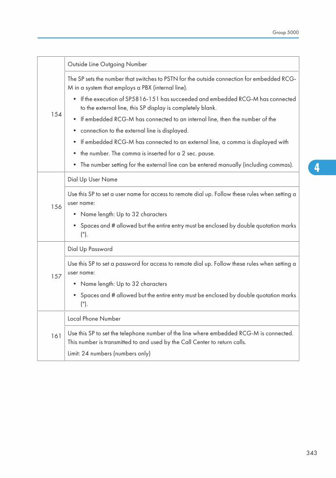
154
Outside Line Outgoing Number
The SP sets the number that switches to PSTN for the outside connection for embedded RCG-M in a system that employs a PBX (internal line).
• If the execution of SP5816-151 has succeeded and embedded RCG-M has connectedto the external line, this SP display is completely blank.
• If embedded RCG-M has connected to an internal line, then the number of the
• connection to the external line is displayed.
• If embedded RCG-M has connected to an external line, a comma is displayed with
• the number. The comma is inserted for a 2 sec. pause.
• The number setting for the external line can be entered manually (including commas).
156
Dial Up User Name
Use this SP to set a user name for access to remote dial up. Follow these rules when setting auser name:
• Name length: Up to 32 characters
• Spaces and # allowed but the entire entry must be enclosed by double quotation marks(").
157
Dial Up Password
Use this SP to set a password for access to remote dial up. Follow these rules when setting auser name:
• Name length: Up to 32 characters
• Spaces and # allowed but the entire entry must be enclosed by double quotation marks(").
161
Local Phone Number
Use this SP to set the telephone number of the line where embedded RCG-M is connected.This number is transmitted to and used by the Call Center to return calls.
Limit: 24 numbers (numbers only)
Group 5000
343
4
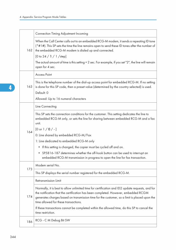
162
Connection Timing Adjustment Incoming
When the Call Center calls out to an embedded RCG-M modem, it sends a repeating ID tone(*#1#). This SP sets the time the line remains open to send these ID tones after the number ofthe embedded RCG-M modem is dialed up and connected.
[0 to 24 / 1 / 1 /step]
The actual amount of time is this setting + 2 sec. For example, if you set "2", the line will remainopen for 4 sec.
163
Access Point
This is the telephone number of the dial-up access point for embedded RCG-M. If no settingis done for this SP code, then a preset value (determined by the country selected) is used.
Default: 0
Allowed: Up to 16 numeral characters
164
Line Connecting
This SP sets the connection conditions for the customer. This setting dedicates the line toembedded RCG-M only, or sets the line for sharing between embedded RCG-M and a faxunit.
[0 or 1 / 0 / - ]
0: Line shared by embedded RCG-M/Fax
1: Line dedicated to embedded RCG-M only
• If this setting is changed, the copier must be cycled off and on.
• SP5816-187 determines whether the off-hook button can be used to interrupt anembedded RCG-M transmission in progress to open the line for fax transaction.
173Modem serial No.
This SP displays the serial number registered for the embedded RCG-M.
174
Retransmission Limit
Normally, it is best to allow unlimited time for certification and ID2 update requests, and forthe notification that the certification has been completed. However, embedded RCGMgenerates charges based on transmission time for the customer, so a limit is placed upon thetime allowed for these transactions.
If these transactions cannot be completed within the allowed time, do this SP to cancel thetime restriction.
186 RCG - C M Debug Bit SW
4. Appendix: Service Program Mode Tables
344
4
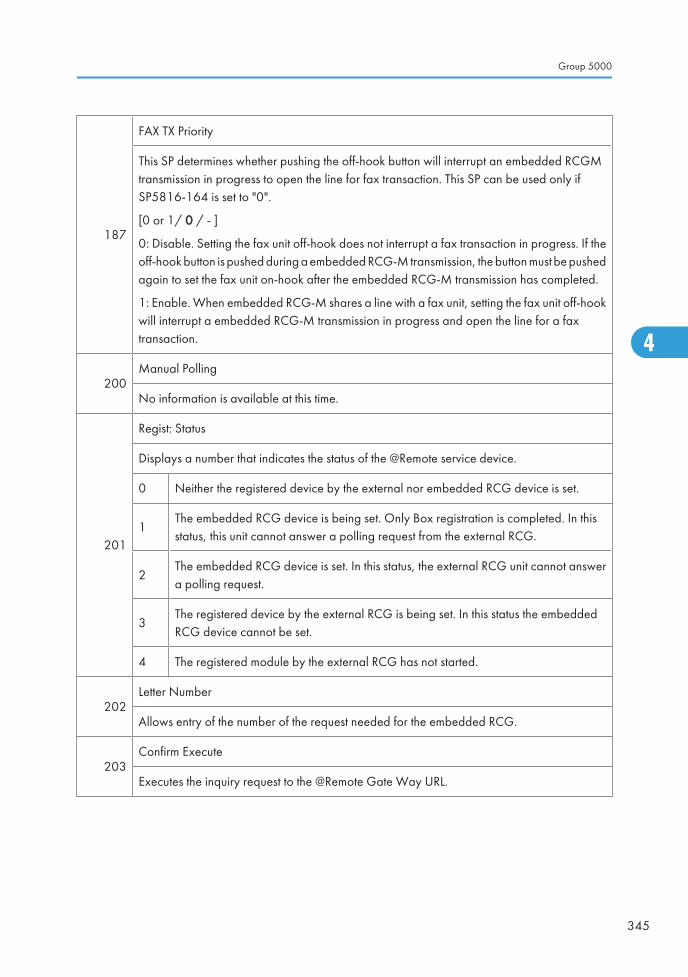
187
FAX TX Priority
This SP determines whether pushing the off-hook button will interrupt an embedded RCGMtransmission in progress to open the line for fax transaction. This SP can be used only ifSP5816-164 is set to "0".
[0 or 1/ 0 / - ]
0: Disable. Setting the fax unit off-hook does not interrupt a fax transaction in progress. If theoff-hook button is pushed during a embedded RCG-M transmission, the button must be pushedagain to set the fax unit on-hook after the embedded RCG-M transmission has completed.
1: Enable. When embedded RCG-M shares a line with a fax unit, setting the fax unit off-hookwill interrupt a embedded RCG-M transmission in progress and open the line for a faxtransaction.
200Manual Polling
No information is available at this time.
201
Regist: Status
Displays a number that indicates the status of the @Remote service device.
0 Neither the registered device by the external nor embedded RCG device is set.
1The embedded RCG device is being set. Only Box registration is completed. In thisstatus, this unit cannot answer a polling request from the external RCG.
2The embedded RCG device is set. In this status, the external RCG unit cannot answera polling request.
3The registered device by the external RCG is being set. In this status the embeddedRCG device cannot be set.
4 The registered module by the external RCG has not started.
202Letter Number
Allows entry of the number of the request needed for the embedded RCG.
203Confirm Execute
Executes the inquiry request to the @Remote Gate Way URL.
Group 5000
345
4
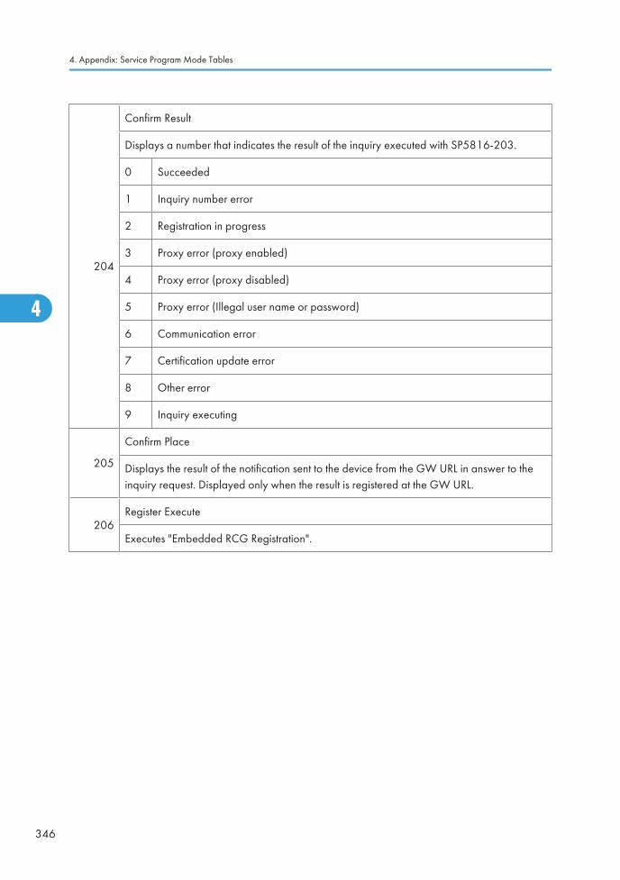
204
Confirm Result
Displays a number that indicates the result of the inquiry executed with SP5816-203.
0 Succeeded
1 Inquiry number error
2 Registration in progress
3 Proxy error (proxy enabled)
4 Proxy error (proxy disabled)
5 Proxy error (Illegal user name or password)
6 Communication error
7 Certification update error
8 Other error
9 Inquiry executing
205
Confirm Place
Displays the result of the notification sent to the device from the GW URL in answer to theinquiry request. Displayed only when the result is registered at the GW URL.
206Register Execute
Executes "Embedded RCG Registration".
4. Appendix: Service Program Mode Tables
346
4
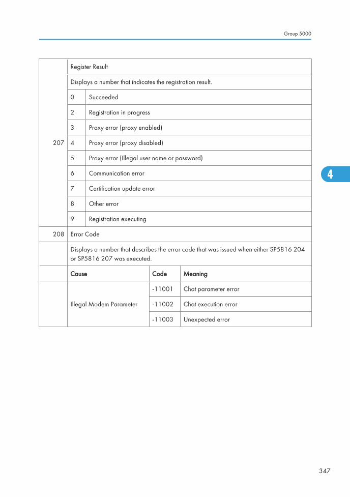
207
Register Result
Displays a number that indicates the registration result.
0 Succeeded
2 Registration in progress
3 Proxy error (proxy enabled)
4 Proxy error (proxy disabled)
5 Proxy error (Illegal user name or password)
6 Communication error
7 Certification update error
8 Other error
9 Registration executing
208 Error Code
Displays a number that describes the error code that was issued when either SP5816 204or SP5816 207 was executed.
Cause Code Meaning
Illegal Modem Parameter
-11001 Chat parameter error
-11002 Chat execution error
-11003 Unexpected error
Group 5000
347
4
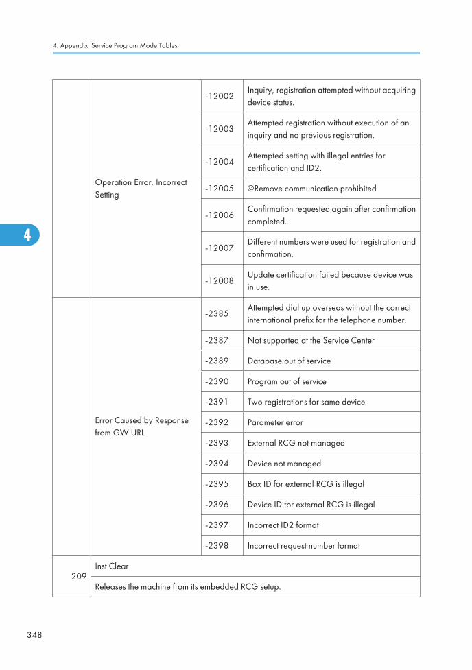
Operation Error, IncorrectSetting
-12002Inquiry, registration attempted without acquiringdevice status.
-12003Attempted registration without execution of aninquiry and no previous registration.
-12004Attempted setting with illegal entries forcertification and ID2.
-12005 @Remove communication prohibited
-12006Confirmation requested again after confirmationcompleted.
-12007Different numbers were used for registration andconfirmation.
-12008Update certification failed because device wasin use.
Error Caused by Responsefrom GW URL
-2385Attempted dial up overseas without the correctinternational prefix for the telephone number.
-2387 Not supported at the Service Center
-2389 Database out of service
-2390 Program out of service
-2391 Two registrations for same device
-2392 Parameter error
-2393 External RCG not managed
-2394 Device not managed
-2395 Box ID for external RCG is illegal
-2396 Device ID for external RCG is illegal
-2397 Incorrect ID2 format
-2398 Incorrect request number format
209Inst Clear
Releases the machine from its embedded RCG setup.
4. Appendix: Service Program Mode Tables
348
4
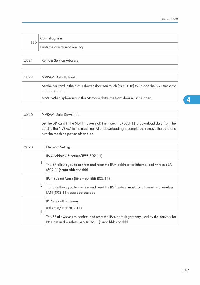
250CommLog Print
Prints the communication log.
5821 Remote Service Address
5824 NVRAM Data Upload
Set the SD card in the Slot 1 (lower slot) then touch [EXECUTE] to upload the NVRAM datato an SD card.
Note: When uploading in this SP mode data, the front door must be open.
5825 NVRAM Data Download
Set the SD card in the Slot 1 (lower slot) then touch [EXECUTE] to download data from thecard to the NVRAM in the machine. After downloading is completed, remove the card andturn the machine power off and on.
5828 Network Setting
1
IPv4 Address (Ethernet/IEEE 802.11)
This SP allows you to confirm and reset the IPv4 address for Ethernet and wireless LAN(802.11): aaa.bbb.ccc.ddd
2
IPv4 Subnet Mask (Ethernet/IEEE 802.11)
This SP allows you to confirm and reset the IPv4 subnet mask for Ethernet and wirelessLAN (802.11): aaa.bbb.ccc.ddd
3
IPv4 default Gateway
(Ethernet/IEEE 802.11)
This SP allows you to confirm and reset the IPv4 default gateway used by the network forEthernet and wireless LAN (802.11): aaa.bbb.ccc.ddd
Group 5000
349
4
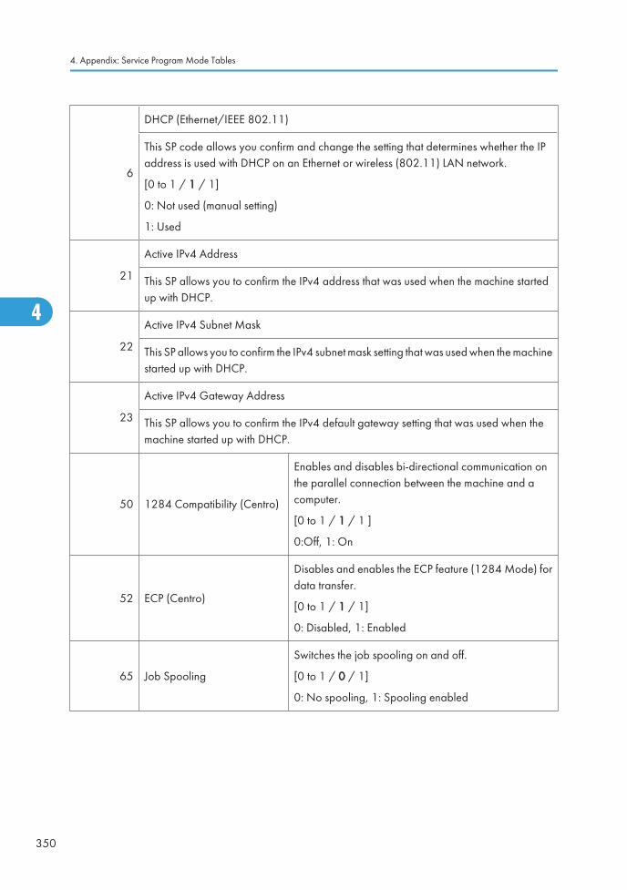
6
DHCP (Ethernet/IEEE 802.11)
This SP code allows you confirm and change the setting that determines whether the IPaddress is used with DHCP on an Ethernet or wireless (802.11) LAN network.
[0 to 1 / 1 / 1]
0: Not used (manual setting)
1: Used
21
Active IPv4 Address
This SP allows you to confirm the IPv4 address that was used when the machine startedup with DHCP.
22
Active IPv4 Subnet Mask
This SP allows you to confirm the IPv4 subnet mask setting that was used when the machinestarted up with DHCP.
23
Active IPv4 Gateway Address
This SP allows you to confirm the IPv4 default gateway setting that was used when themachine started up with DHCP.
50 1284 Compatibility (Centro)
Enables and disables bi-directional communication onthe parallel connection between the machine and acomputer.
[0 to 1 / 1 / 1 ]
0:Off, 1: On
52 ECP (Centro)
Disables and enables the ECP feature (1284 Mode) fordata transfer.
[0 to 1 / 1 / 1]
0: Disabled, 1: Enabled
65 Job Spooling
Switches the job spooling on and off.
[0 to 1 / 0 / 1]
0: No spooling, 1: Spooling enabled
4. Appendix: Service Program Mode Tables
350
4
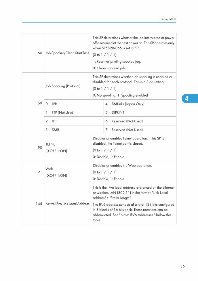
66 Job Spooling Clear: Start Time
This SP determines whether the job interrupted at poweroff is resumed at the next power on. This SP operates onlywhen SP5828-065 is set to "1".
[0 to 1 / 1 / 1]
1: Resumes printing spooled jog.
0: Clears spooled job.
69
Job Spooling (Protocol)
This SP determines whether job spooling is enabled ordisabled for each protocol. This is a 8-bit setting.
[0 to 1 / 1 / 1]
0: No spooling, 1: Spooling enabled
0 LPR 4 BMLinks (Japan Only)
1 FTP (Not Used) 5 DIPRINT
2 IPP 6 Reserved (Not Used)
3 SMB 7 Reserved (Not Used)
90TELNET
(0:OFF 1:ON)
Disables or enables Telnet operation. If this SP isdisabled, the Telnet port is closed.
[0 to 1 / 1 / 1]
0: Disable, 1: Enable
91Web
(0:OFF 1:ON)
Disables or enables the Web operation.
[0 to 1 / 1 / 1]
0: Disable, 1: Enable
145 Active IPv6 Link Local Address
This is the IPv6 local address referenced on the Ethernetor wireless LAN (802.11) in the format: "Link-Localaddress" + "Prefix Length"
The IPv6 address consists of a total 128 bits configuredin 8 blocks of 16 bits each. These notations can beabbreviated. See "Note: IPV6 Addresses " below thistable.
Group 5000
351
4
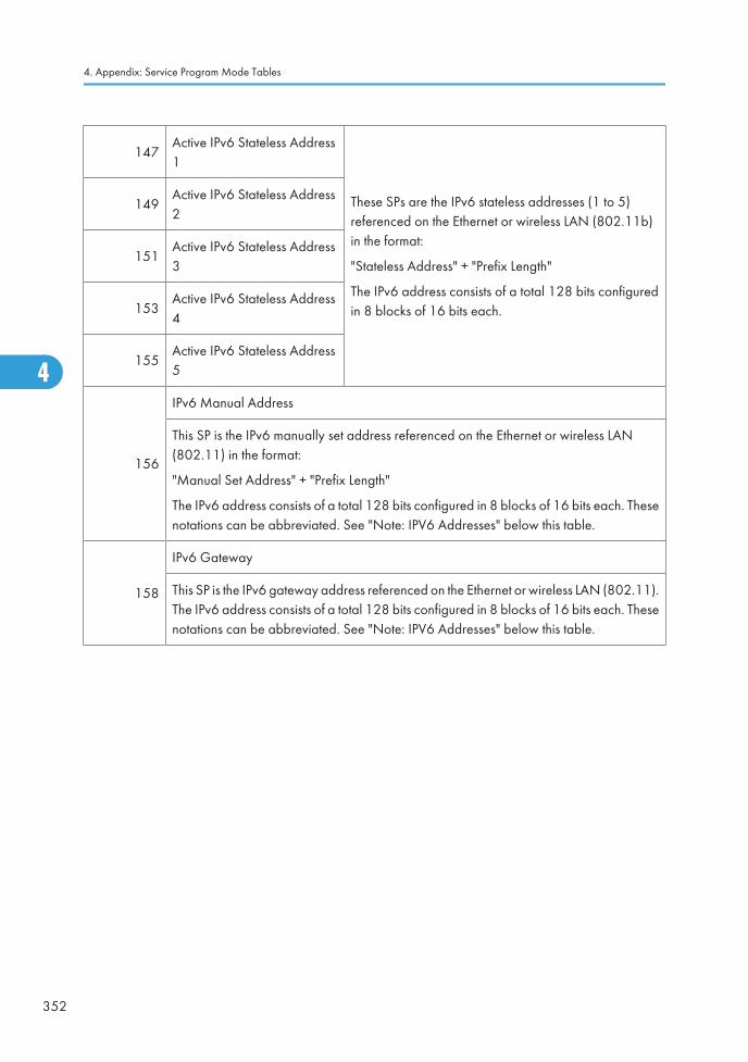
147Active IPv6 Stateless Address1
These SPs are the IPv6 stateless addresses (1 to 5)referenced on the Ethernet or wireless LAN (802.11b)in the format:
"Stateless Address" + "Prefix Length"
The IPv6 address consists of a total 128 bits configuredin 8 blocks of 16 bits each.
149Active IPv6 Stateless Address2
151Active IPv6 Stateless Address3
153Active IPv6 Stateless Address4
155Active IPv6 Stateless Address5
156
IPv6 Manual Address
This SP is the IPv6 manually set address referenced on the Ethernet or wireless LAN(802.11) in the format:
"Manual Set Address" + "Prefix Length"
The IPv6 address consists of a total 128 bits configured in 8 blocks of 16 bits each. Thesenotations can be abbreviated. See "Note: IPV6 Addresses" below this table.
158
IPv6 Gateway
This SP is the IPv6 gateway address referenced on the Ethernet or wireless LAN (802.11).The IPv6 address consists of a total 128 bits configured in 8 blocks of 16 bits each. Thesenotations can be abbreviated. See "Note: IPV6 Addresses" below this table.
4. Appendix: Service Program Mode Tables
352
4
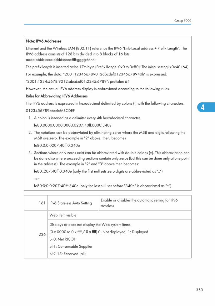
Note: IPV6 Addresses
Ethernet and the Wireless LAN (802.11) reference the IPV6 "Link-Local address + Prefix Length". TheIPV6 address consists of 128 bits divided into 8 blocks of 16 bits:aaaa:bbbb:cccc:dddd:eeee:ffff:gggg:hhhh:
The prefix length is inserted at the 17th byte (Prefix Range: 0x0 to 0x80). The initial setting is 0x40 (64).
For example, the data: "2001123456789012abcdef012345678940h" is expressed:
"2001:1234:5678:9012:abcd:ef01:2345:6789": prefixlen 64
However, the actual IPV6 address display is abbreviated according to the following rules.
Rules for Abbreviating IPV6 Addresses
The IPV6 address is expressed in hexadecimal delimited by colons (:) with the following characters:
0123456789abcdefABCDEF
1. A colon is inserted as a delimiter every 4th hexadecimal character.
fe80:0000:0000:0000:0207:40ff:0000:340e
2. The notations can be abbreviated by eliminating zeros where the MSB and digits following theMSB are zero. The example in "2" above, then, becomes
fe80:0:0:0207:40ff:0:340e
3. Sections where only zeros exist can be abbreviated with double colons (::). This abbreviation canbe done also where succeeding sections contain only zeros (but this can be done only at one pointin the address). The example in "2" and "3" above then becomes:
fe80::207:40ff:0:340e (only the first null sets zero digits are abbreviated as "::")
-or-
fe80:0:0:0:207:40ff::340e (only the last null set before "340e" is abbreviated as "::")
161 IPv6 Stateless Auto SettingEnable or disables the automatic setting for IPv6stateless.
236
Web Item visible
Displays or does not display the Web system items.
[0 x 0000 to 0 x ffff / 0 x ffff] 0: Not displayed, 1: Displayed
bit0: Net RICOH
bit1: Consumable Supplier
bit2-15: Reserved (all)
Group 5000
353
4
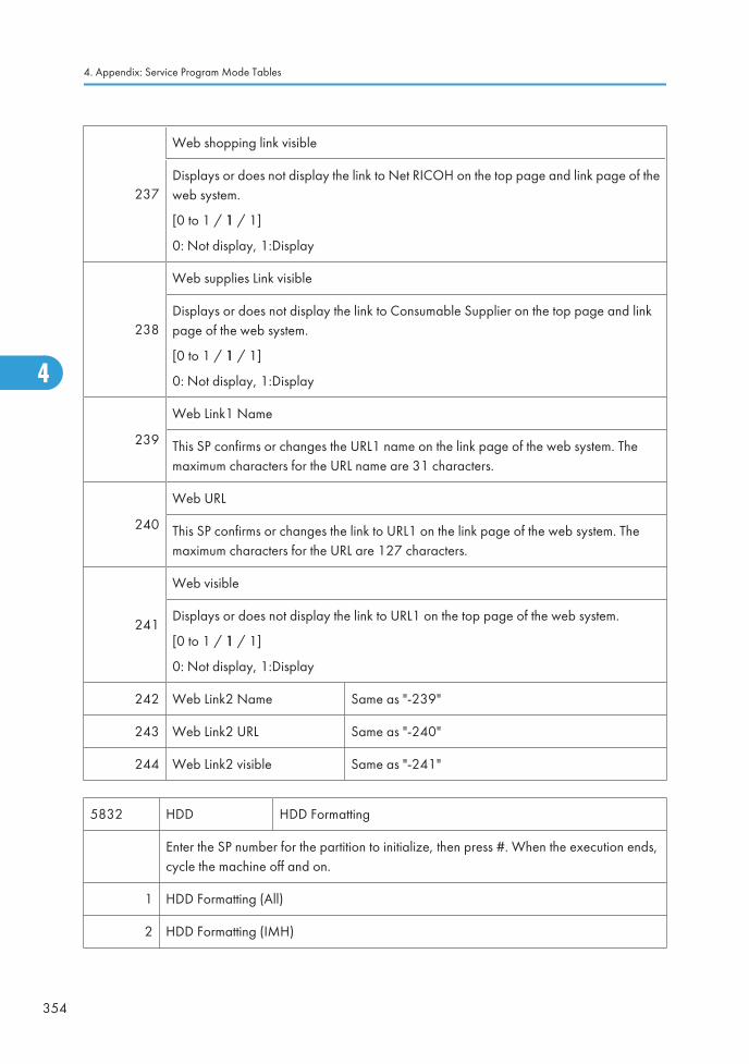
237
Web shopping link visible
Displays or does not display the link to Net RICOH on the top page and link page of theweb system.
[0 to 1 / 1 / 1]
0: Not display, 1:Display
238
Web supplies Link visible
Displays or does not display the link to Consumable Supplier on the top page and linkpage of the web system.
[0 to 1 / 1 / 1]
0: Not display, 1:Display
239
Web Link1 Name
This SP confirms or changes the URL1 name on the link page of the web system. Themaximum characters for the URL name are 31 characters.
240
Web URL
This SP confirms or changes the link to URL1 on the link page of the web system. Themaximum characters for the URL are 127 characters.
241
Web visible
Displays or does not display the link to URL1 on the top page of the web system.
[0 to 1 / 1 / 1]
0: Not display, 1:Display
242 Web Link2 Name Same as "-239"
243 Web Link2 URL Same as "-240"
244 Web Link2 visible Same as "-241"
5832 HDD HDD Formatting
Enter the SP number for the partition to initialize, then press #. When the execution ends,cycle the machine off and on.
1 HDD Formatting (All)
2 HDD Formatting (IMH)
4. Appendix: Service Program Mode Tables
354
4
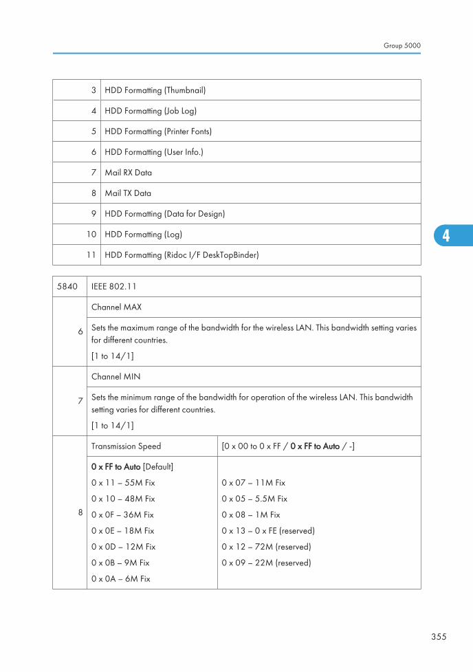
3 HDD Formatting (Thumbnail)
4 HDD Formatting (Job Log)
5 HDD Formatting (Printer Fonts)
6 HDD Formatting (User Info.)
7 Mail RX Data
8 Mail TX Data
9 HDD Formatting (Data for Design)
10 HDD Formatting (Log)
11 HDD Formatting (Ridoc I/F DeskTopBinder)
5840 IEEE 802.11
6
Channel MAX
Sets the maximum range of the bandwidth for the wireless LAN. This bandwidth setting variesfor different countries.
[1 to 14/1]
7
Channel MIN
Sets the minimum range of the bandwidth for operation of the wireless LAN. This bandwidthsetting varies for different countries.
[1 to 14/1]
8
Transmission Speed [0 x 00 to 0 x FF / 0 x FF to Auto / -]
0 x FF to Auto [Default]
0 x 11 – 55M Fix
0 x 10 – 48M Fix
0 x 0F – 36M Fix
0 x 0E – 18M Fix
0 x 0D – 12M Fix
0 x 0B – 9M Fix
0 x 0A – 6M Fix
0 x 07 – 11M Fix
0 x 05 – 5.5M Fix
0 x 08 – 1M Fix
0 x 13 – 0 x FE (reserved)
0 x 12 – 72M (reserved)
0 x 09 – 22M (reserved)
Group 5000
355
4
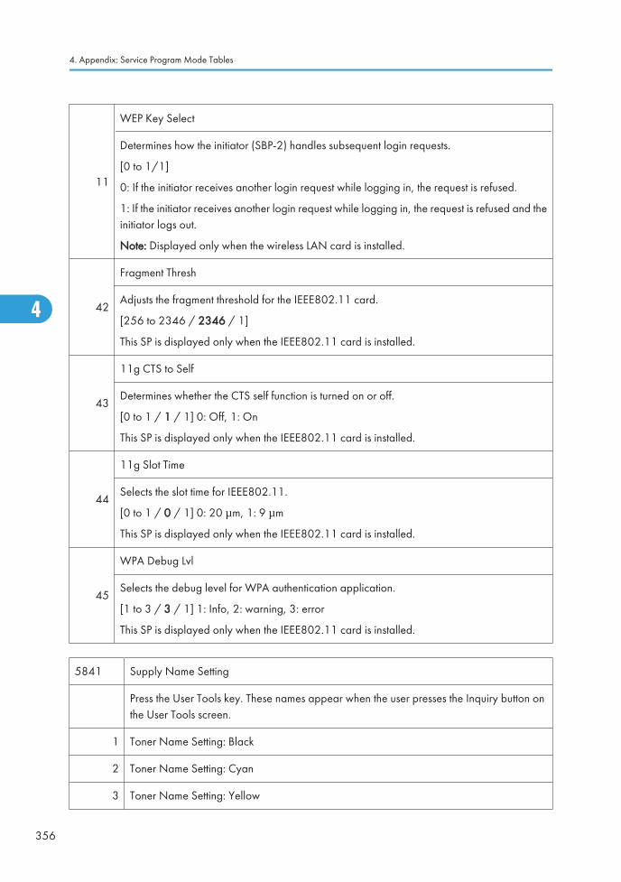
11
WEP Key Select
Determines how the initiator (SBP-2) handles subsequent login requests.
[0 to 1/1]
0: If the initiator receives another login request while logging in, the request is refused.
1: If the initiator receives another login request while logging in, the request is refused and theinitiator logs out.
Note: Displayed only when the wireless LAN card is installed.
42
Fragment Thresh
Adjusts the fragment threshold for the IEEE802.11 card.
[256 to 2346 / 2346 / 1]
This SP is displayed only when the IEEE802.11 card is installed.
43
11g CTS to Self
Determines whether the CTS self function is turned on or off.
[0 to 1 / 1 / 1] 0: Off, 1: On
This SP is displayed only when the IEEE802.11 card is installed.
44
11g Slot Time
Selects the slot time for IEEE802.11.
[0 to 1 / 0 / 1] 0: 20 μm, 1: 9 μm
This SP is displayed only when the IEEE802.11 card is installed.
45
WPA Debug Lvl
Selects the debug level for WPA authentication application.
[1 to 3 / 3 / 1] 1: Info, 2: warning, 3: error
This SP is displayed only when the IEEE802.11 card is installed.
5841 Supply Name Setting
Press the User Tools key. These names appear when the user presses the Inquiry button onthe User Tools screen.
1 Toner Name Setting: Black
2 Toner Name Setting: Cyan
3 Toner Name Setting: Yellow
4. Appendix: Service Program Mode Tables
356
4
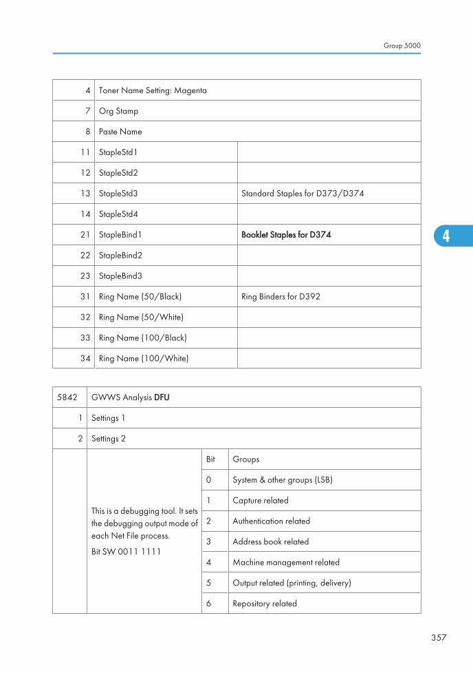
4 Toner Name Setting: Magenta
7 Org Stamp
8 Paste Name
11 StapleStd1
12 StapleStd2
13 StapleStd3 Standard Staples for D373/D374
14 StapleStd4
21 StapleBind1 Booklet Staples for D374
22 StapleBind2
23 StapleBind3
31 Ring Name (50/Black) Ring Binders for D392
32 Ring Name (50/White)
33 Ring Name (100/Black)
34 Ring Name (100/White)
5842 GWWS Analysis DFU
1 Settings 1
2 Settings 2
This is a debugging tool. It setsthe debugging output mode ofeach Net File process.
Bit SW 0011 1111
Bit Groups
0 System & other groups (LSB)
1 Capture related
2 Authentication related
3 Address book related
4 Machine management related
5 Output related (printing, delivery)
6 Repository related
Group 5000
357
4
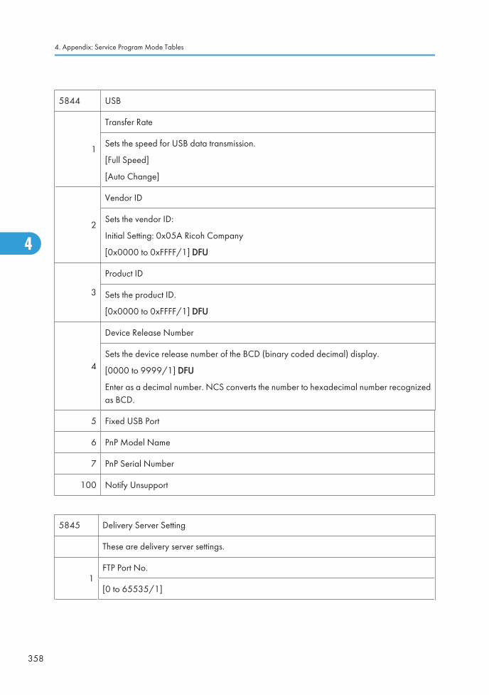
5844 USB
1
Transfer Rate
Sets the speed for USB data transmission.
[Full Speed]
[Auto Change]
2
Vendor ID
Sets the vendor ID:
Initial Setting: 0x05A Ricoh Company
[0x0000 to 0xFFFF/1] DFU
3
Product ID
Sets the product ID.
[0x0000 to 0xFFFF/1] DFU
4
Device Release Number
Sets the device release number of the BCD (binary coded decimal) display.
[0000 to 9999/1] DFU
Enter as a decimal number. NCS converts the number to hexadecimal number recognizedas BCD.
5 Fixed USB Port
6 PnP Model Name
7 PnP Serial Number
100 Notify Unsupport
5845 Delivery Server Setting
These are delivery server settings.
1FTP Port No.
[0 to 65535/1]
4. Appendix: Service Program Mode Tables
358
4
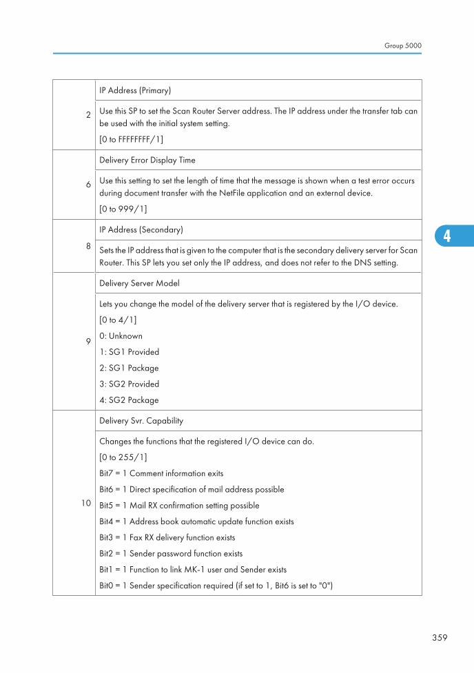
2
IP Address (Primary)
Use this SP to set the Scan Router Server address. The IP address under the transfer tab canbe used with the initial system setting.
[0 to FFFFFFFF/1]
6
Delivery Error Display Time
Use this setting to set the length of time that the message is shown when a test error occursduring document transfer with the NetFile application and an external device.
[0 to 999/1]
8
IP Address (Secondary)
Sets the IP address that is given to the computer that is the secondary delivery server for ScanRouter. This SP lets you set only the IP address, and does not refer to the DNS setting.
9
Delivery Server Model
Lets you change the model of the delivery server that is registered by the I/O device.
[0 to 4/1]
0: Unknown
1: SG1 Provided
2: SG1 Package
3: SG2 Provided
4: SG2 Package
10
Delivery Svr. Capability
Changes the functions that the registered I/O device can do.
[0 to 255/1]
Bit7 = 1 Comment information exits
Bit6 = 1 Direct specification of mail address possible
Bit5 = 1 Mail RX confirmation setting possible
Bit4 = 1 Address book automatic update function exists
Bit3 = 1 Fax RX delivery function exists
Bit2 = 1 Sender password function exists
Bit1 = 1 Function to link MK-1 user and Sender exists
Bit0 = 1 Sender specification required (if set to 1, Bit6 is set to "0")
Group 5000
359
4
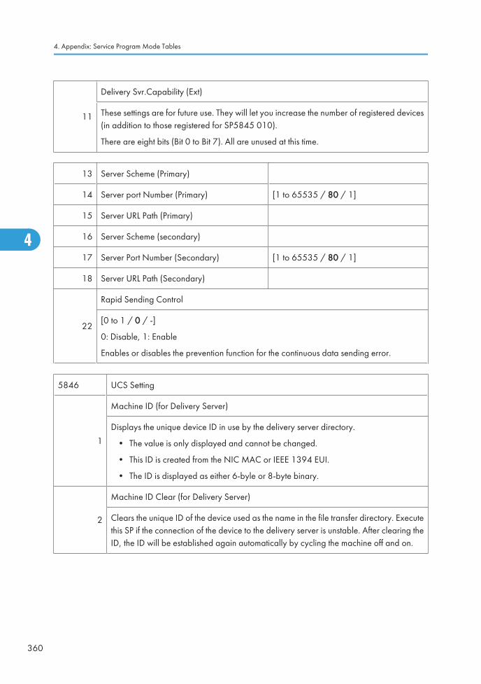
11
Delivery Svr.Capability (Ext)
These settings are for future use. They will let you increase the number of registered devices(in addition to those registered for SP5845 010).
There are eight bits (Bit 0 to Bit 7). All are unused at this time.
13 Server Scheme (Primary)
14 Server port Number (Primary) [1 to 65535 / 80 / 1]
15 Server URL Path (Primary)
16 Server Scheme (secondary)
17 Server Port Number (Secondary) [1 to 65535 / 80 / 1]
18 Server URL Path (Secondary)
22
Rapid Sending Control
[0 to 1 / 0 / -]
0: Disable, 1: Enable
Enables or disables the prevention function for the continuous data sending error.
5846 UCS Setting
1
Machine ID (for Delivery Server)
Displays the unique device ID in use by the delivery server directory.
• The value is only displayed and cannot be changed.
• This ID is created from the NIC MAC or IEEE 1394 EUI.
• The ID is displayed as either 6-byle or 8-byte binary.
2
Machine ID Clear (for Delivery Server)
Clears the unique ID of the device used as the name in the file transfer directory. Executethis SP if the connection of the device to the delivery server is unstable. After clearing theID, the ID will be established again automatically by cycling the machine off and on.
4. Appendix: Service Program Mode Tables
360
4
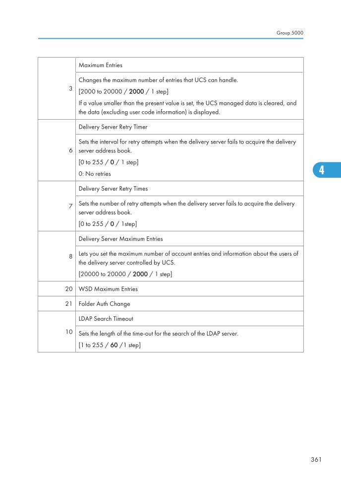
3
Maximum Entries
Changes the maximum number of entries that UCS can handle.
[2000 to 20000 / 2000 / 1 step]
If a value smaller than the present value is set, the UCS managed data is cleared, andthe data (excluding user code information) is displayed.
6
Delivery Server Retry Timer
Sets the interval for retry attempts when the delivery server fails to acquire the deliveryserver address book.
[0 to 255 / 0 / 1 step]
0: No retries
7
Delivery Server Retry Times
Sets the number of retry attempts when the delivery server fails to acquire the deliveryserver address book.
[0 to 255 / 0 / 1step]
8
Delivery Server Maximum Entries
Lets you set the maximum number of account entries and information about the users ofthe delivery server controlled by UCS.
[20000 to 20000 / 2000 / 1 step]
20 WSD Maximum Entries
21 Folder Auth Change
10
LDAP Search Timeout
Sets the length of the time-out for the search of the LDAP server.
[1 to 255 / 60 /1 step]
Group 5000
361
4
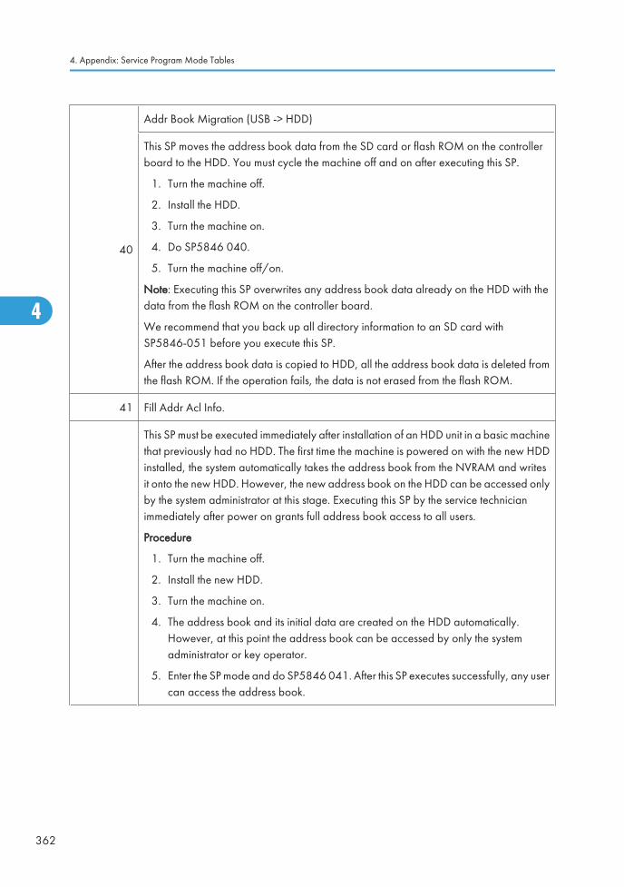
40
Addr Book Migration (USB -> HDD)
This SP moves the address book data from the SD card or flash ROM on the controllerboard to the HDD. You must cycle the machine off and on after executing this SP.
1. Turn the machine off.
2. Install the HDD.
3. Turn the machine on.
4. Do SP5846 040.
5. Turn the machine off/on.
Note: Executing this SP overwrites any address book data already on the HDD with thedata from the flash ROM on the controller board.
We recommend that you back up all directory information to an SD card withSP5846-051 before you execute this SP.
After the address book data is copied to HDD, all the address book data is deleted fromthe flash ROM. If the operation fails, the data is not erased from the flash ROM.
41 Fill Addr Acl Info.
This SP must be executed immediately after installation of an HDD unit in a basic machinethat previously had no HDD. The first time the machine is powered on with the new HDDinstalled, the system automatically takes the address book from the NVRAM and writesit onto the new HDD. However, the new address book on the HDD can be accessed onlyby the system administrator at this stage. Executing this SP by the service technicianimmediately after power on grants full address book access to all users.
Procedure
1. Turn the machine off.
2. Install the new HDD.
3. Turn the machine on.
4. The address book and its initial data are created on the HDD automatically.However, at this point the address book can be accessed by only the systemadministrator or key operator.
5. Enter the SP mode and do SP5846 041. After this SP executes successfully, any usercan access the address book.
4. Appendix: Service Program Mode Tables
362
4

43
Addr Book Media
Displays the slot number where an address book data is in.
[0 to 30 / - /1]
0: Unconfirmed
1: SD Slot 1
2: SD Slot 2
4: USB Flash ROM
20: HDD
30: Nothing
46 Initialize All Settings & Address Book
47
Initialize Local Address Book
Clears all of the address information from the local address book of a machine managedwith UCS.
48
Initialize Delivery Addr Book
Push [Execute] to delete all items (this does not include user codes) in the delivery addressbook that is controlled by UCS.
49
Initialize LDAP Addr Book
Push [Execute] to delete all items (this does not include user codes) in the LDAP addressbook that is controlled by UCS.
50
Initialize All Addr Book
Clears everything (including users codes) in the directory information managed by UCS.However, the accounts and passwords of the system administrators are not deleted.
51
Backup All Addr Book
Copies all directory information to the SD card. Do this SP before replacing the controllerboard or HDD. The operation may not succeed if the controller board or HDD is damaged.
52
Restore All Addr Book
Copies back all directory information from the SD card to the flash ROM or HDD. Uploadthe address book from the old flash ROM or HDD with SP5846-51 before removing it.Do SP5846 52 after installing the new HDD.
Group 5000
363
4
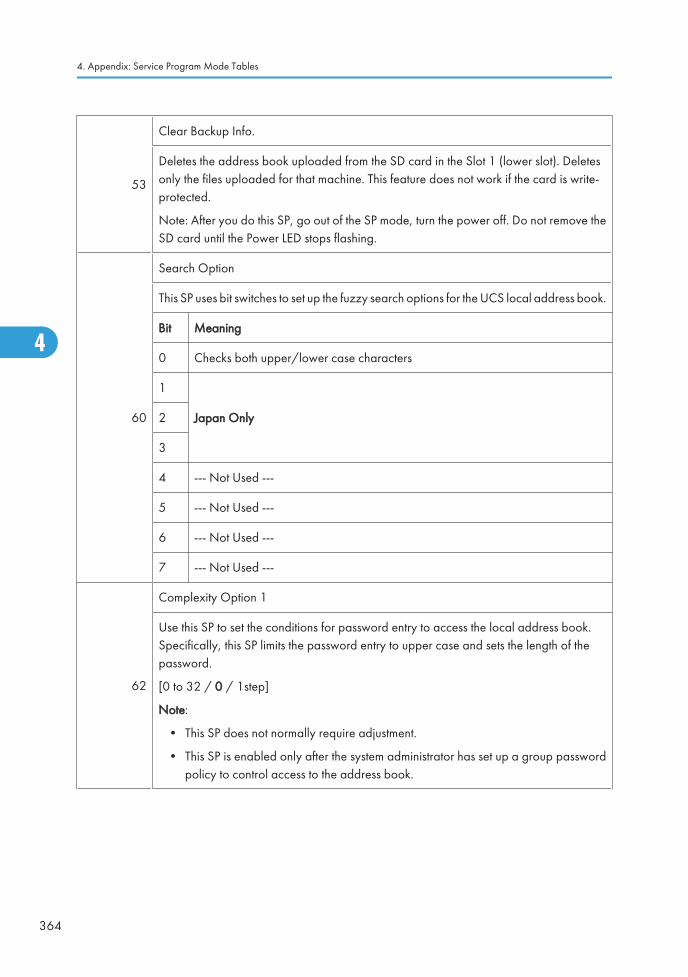
53
Clear Backup Info.
Deletes the address book uploaded from the SD card in the Slot 1 (lower slot). Deletesonly the files uploaded for that machine. This feature does not work if the card is write-protected.
Note: After you do this SP, go out of the SP mode, turn the power off. Do not remove theSD card until the Power LED stops flashing.
60
Search Option
This SP uses bit switches to set up the fuzzy search options for the UCS local address book.
Bit Meaning
0 Checks both upper/lower case characters
1
Japan Only2
3
4 --- Not Used ---
5 --- Not Used ---
6 --- Not Used ---
7 --- Not Used ---
62
Complexity Option 1
Use this SP to set the conditions for password entry to access the local address book.Specifically, this SP limits the password entry to upper case and sets the length of thepassword.
[0 to 32 / 0 / 1step]
Note:
• This SP does not normally require adjustment.
• This SP is enabled only after the system administrator has set up a group passwordpolicy to control access to the address book.
4. Appendix: Service Program Mode Tables
364
4
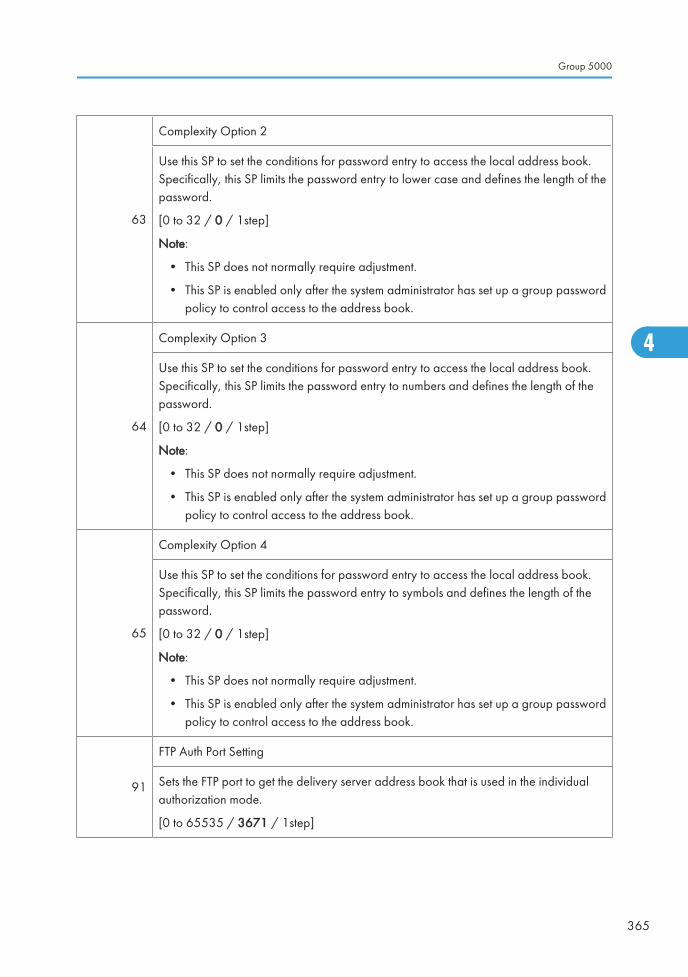
63
Complexity Option 2
Use this SP to set the conditions for password entry to access the local address book.Specifically, this SP limits the password entry to lower case and defines the length of thepassword.
[0 to 32 / 0 / 1step]
Note:
• This SP does not normally require adjustment.
• This SP is enabled only after the system administrator has set up a group passwordpolicy to control access to the address book.
64
Complexity Option 3
Use this SP to set the conditions for password entry to access the local address book.Specifically, this SP limits the password entry to numbers and defines the length of thepassword.
[0 to 32 / 0 / 1step]
Note:
• This SP does not normally require adjustment.
• This SP is enabled only after the system administrator has set up a group passwordpolicy to control access to the address book.
65
Complexity Option 4
Use this SP to set the conditions for password entry to access the local address book.Specifically, this SP limits the password entry to symbols and defines the length of thepassword.
[0 to 32 / 0 / 1step]
Note:
• This SP does not normally require adjustment.
• This SP is enabled only after the system administrator has set up a group passwordpolicy to control access to the address book.
91
FTP Auth Port Setting
Sets the FTP port to get the delivery server address book that is used in the individualauthorization mode.
[0 to 65535 / 3671 / 1step]
Group 5000
365
4
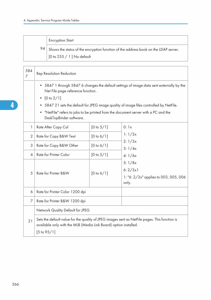
94
Encryption Start
Shows the status of the encryption function of the address book on the LDAP server.
[0 to 255 / 1 ] No default
5847
Rep Resolution Reduction
• 5847 1 through 5847 6 changes the default settings of image data sent externally by theNet File page reference function.
• [0 to 2/1]
• 5847 21 sets the default for JPEG image quality of image files controlled by NetFile.
• "NetFile" refers to jobs to be printed from the document server with a PC and theDeskTopBinder software.
1 Rate After Copy Col [0 to 5/1] 0: 1x
1: 1/2x
2: 1/3x
3: 1/4x
4: 1/6x
5: 1/8x
6: 2/3x1
1: "6: 2/3x" applies to 003, 005, 006only.
2 Rate for Copy B&W Text [0 to 6/1]
3 Rate for Copy B&W Other [0 to 6/1]
4 Rate for Printer Color [0 to 5/1]
5 Rate for Printer B&W [0 to 6/1]
6 Rate for Printer Color 1200 dpi
7 Rate for Printer B&W 1200 dpi
21
Network Quality Default for JPEG
Sets the default value for the quality of JPEG images sent as NetFile pages. This function isavailable only with the MLB (Media Link Board) option installed.
[5 to 95/1]
4. Appendix: Service Program Mode Tables
366
4
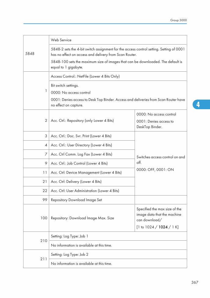
5848
Web Service
5848-2 sets the 4-bit switch assignment for the access control setting. Setting of 0001has no effect on access and delivery from Scan Router.
5848-100 sets the maximum size of images that can be downloaded. The default isequal to 1 gigabyte.
1
Access Control.: NetFile (Lower 4 Bits Only)
Bit switch settings.
0000: No access control
0001: Denies access to Desk Top Binder. Access and deliveries from Scan Router haveno effect on capture.
2 Acc. Ctrl.: Repository (only Lower 4 Bits)
0000: No access control
0001: Denies access toDeskTop Binder.
3 Acc. Ctrl.: Doc. Svr. Print (Lower 4 Bits)
Switches access control on andoff.
0000: OFF, 0001: ON
4 Acc. Ctrl.: User Directory (Lower 4 Bits)
7 Acc. Ctrl Comm. Log Fax (Lower 4 Bits)
9 Acc. Ctrl.: Job Control (Lower 4 Bits)
11 Acc. Ctrl: Device Management (Lower 4 Bits)
21 Acc. Ctrl: Delivery (Lower 4 Bits)
22 Acc. Ctrl: User Administration (Lower 4 Bits)
99 Repository Download Image Set
100 Repository: Download Image Max. Size
Specified the max size of theimage data that the machinecan download/
[1 to 1024 / 1024 / 1 K]
210Setting: Log Type: Job 1
No information is available at this time.
211Setting: Log Type: Job 2
No information is available at this time.
Group 5000
367
4
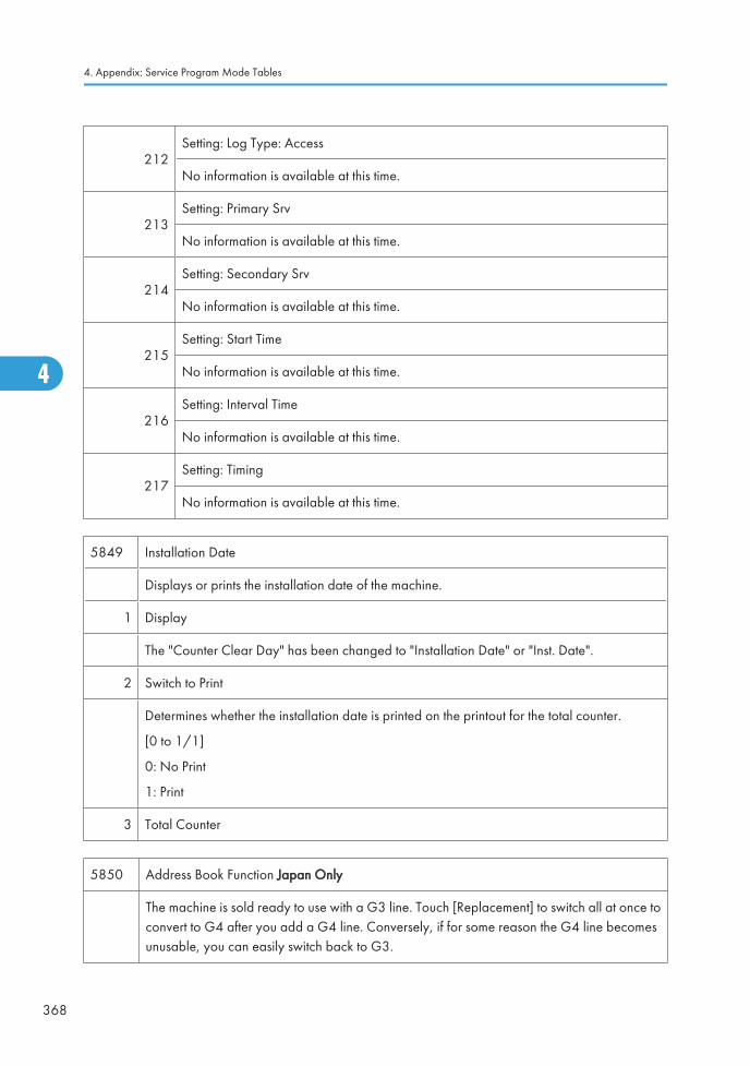
212Setting: Log Type: Access
No information is available at this time.
213Setting: Primary Srv
No information is available at this time.
214Setting: Secondary Srv
No information is available at this time.
215Setting: Start Time
No information is available at this time.
216Setting: Interval Time
No information is available at this time.
217Setting: Timing
No information is available at this time.
5849 Installation Date
Displays or prints the installation date of the machine.
1 Display
The "Counter Clear Day" has been changed to "Installation Date" or "Inst. Date".
2 Switch to Print
Determines whether the installation date is printed on the printout for the total counter.
[0 to 1/1]
0: No Print
1: Print
3 Total Counter
5850 Address Book Function Japan Only
The machine is sold ready to use with a G3 line. Touch [Replacement] to switch all at once toconvert to G4 after you add a G4 line. Conversely, if for some reason the G4 line becomesunusable, you can easily switch back to G3.
4. Appendix: Service Program Mode Tables
368
4
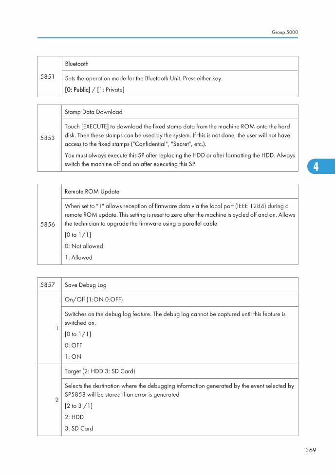
5851
Bluetooth
Sets the operation mode for the Bluetooth Unit. Press either key.
[0: Public] / [1: Private]
5853
Stamp Data Download
Touch [EXECUTE] to download the fixed stamp data from the machine ROM onto the harddisk. Then these stamps can be used by the system. If this is not done, the user will not haveaccess to the fixed stamps ("Confidential", "Secret", etc.).
You must always execute this SP after replacing the HDD or after formatting the HDD. Alwaysswitch the machine off and on after executing this SP.
5856
Remote ROM Update
When set to "1" allows reception of firmware data via the local port (IEEE 1284) during aremote ROM update. This setting is reset to zero after the machine is cycled off and on. Allowsthe technician to upgrade the firmware using a parallel cable
[0 to 1/1]
0: Not allowed
1: Allowed
5857 Save Debug Log
1
On/Off (1:ON 0:OFF)
Switches on the debug log feature. The debug log cannot be captured until this feature isswitched on.
[0 to 1/1]
0: OFF
1: ON
2
Target (2: HDD 3: SD Card)
Selects the destination where the debugging information generated by the event selected bySP5858 will be stored if an error is generated
[2 to 3 /1]
2: HDD
3: SD Card
Group 5000
369
4
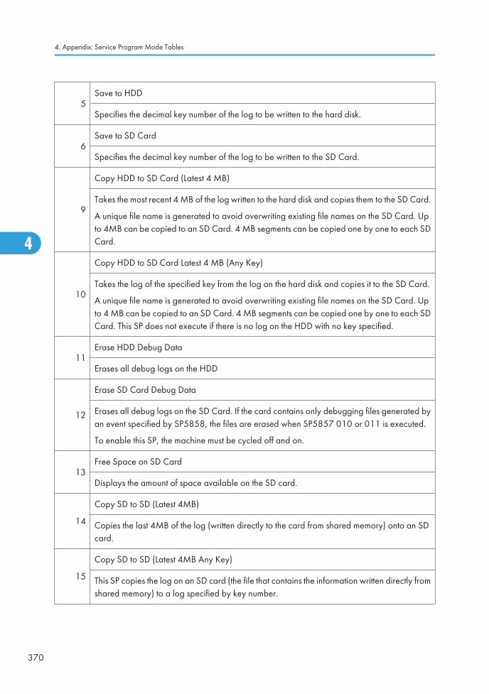
5Save to HDD
Specifies the decimal key number of the log to be written to the hard disk.
6Save to SD Card
Specifies the decimal key number of the log to be written to the SD Card.
9
Copy HDD to SD Card (Latest 4 MB)
Takes the most recent 4 MB of the log written to the hard disk and copies them to the SD Card.
A unique file name is generated to avoid overwriting existing file names on the SD Card. Upto 4MB can be copied to an SD Card. 4 MB segments can be copied one by one to each SDCard.
10
Copy HDD to SD Card Latest 4 MB (Any Key)
Takes the log of the specified key from the log on the hard disk and copies it to the SD Card.
A unique file name is generated to avoid overwriting existing file names on the SD Card. Upto 4 MB can be copied to an SD Card. 4 MB segments can be copied one by one to each SDCard. This SP does not execute if there is no log on the HDD with no key specified.
11Erase HDD Debug Data
Erases all debug logs on the HDD
12
Erase SD Card Debug Data
Erases all debug logs on the SD Card. If the card contains only debugging files generated byan event specified by SP5858, the files are erased when SP5857 010 or 011 is executed.
To enable this SP, the machine must be cycled off and on.
13Free Space on SD Card
Displays the amount of space available on the SD card.
14
Copy SD to SD (Latest 4MB)
Copies the last 4MB of the log (written directly to the card from shared memory) onto an SDcard.
15
Copy SD to SD (Latest 4MB Any Key)
This SP copies the log on an SD card (the file that contains the information written directly fromshared memory) to a log specified by key number.
4. Appendix: Service Program Mode Tables
370
4
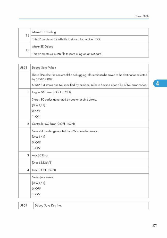
16Make HDD Debug
This SP creates a 32 MB file to store a log on the HDD.
17Make SD Debug
This SP creates a 4 MB file to store a log on an SD card.
5858 Debug Save When
These SPs select the content of the debugging information to be saved to the destination selectedby SP5857 002.
SP5858 3 stores one SC specified by number. Refer to Section 4 for a list of SC error codes.
1 Engine SC Error (0:OFF 1:ON)
Stores SC codes generated by copier engine errors.
[0 to 1/1]
0: OFF
1: ON
2 Controller SC Error (0:OFF 1:ON)
Stores SC codes generated by GW controller errors.
[0 to 1/1]
0: OFF
1: ON
3 Any SC Error
[0 to 65535/1]
4 Jam (0:OFF 1:ON)
Stores jam errors.
[0 to 1/1]
0: OFF
1: ON
5859 Debug Save Key No.
Group 5000
371
4
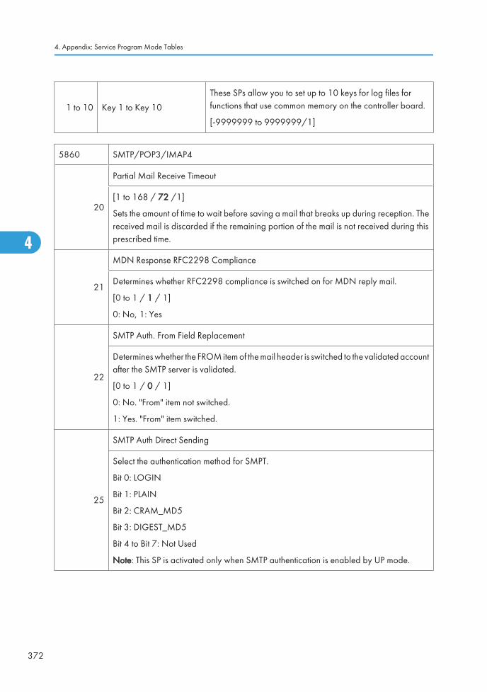
1 to 10 Key 1 to Key 10
These SPs allow you to set up to 10 keys for log files forfunctions that use common memory on the controller board.
[-9999999 to 9999999/1]
5860 SMTP/POP3/IMAP4
20
Partial Mail Receive Timeout
[1 to 168 / 72 /1]
Sets the amount of time to wait before saving a mail that breaks up during reception. Thereceived mail is discarded if the remaining portion of the mail is not received during thisprescribed time.
21
MDN Response RFC2298 Compliance
Determines whether RFC2298 compliance is switched on for MDN reply mail.
[0 to 1 / 1 / 1]
0: No, 1: Yes
22
SMTP Auth. From Field Replacement
Determines whether the FROM item of the mail header is switched to the validated accountafter the SMTP server is validated.
[0 to 1 / 0 / 1]
0: No. "From" item not switched.
1: Yes. "From" item switched.
25
SMTP Auth Direct Sending
Select the authentication method for SMPT.
Bit 0: LOGIN
Bit 1: PLAIN
Bit 2: CRAM_MD5
Bit 3: DIGEST_MD5
Bit 4 to Bit 7: Not Used
Note: This SP is activated only when SMTP authentication is enabled by UP mode.
4. Appendix: Service Program Mode Tables
372
4
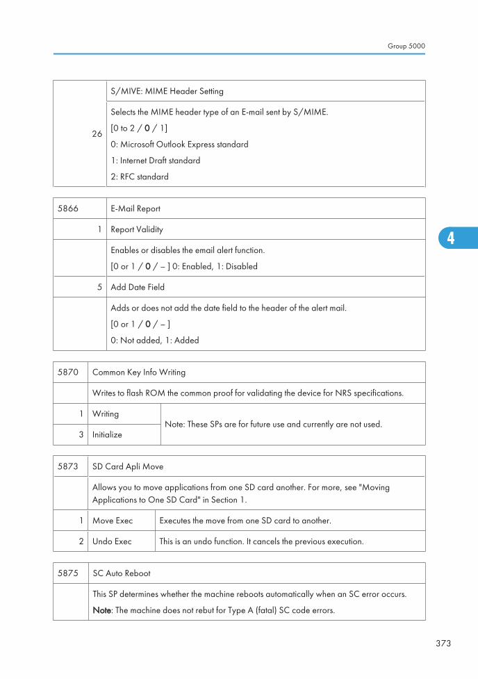
26
S/MIVE: MIME Header Setting
Selects the MIME header type of an E-mail sent by S/MIME.
[0 to 2 / 0 / 1]
0: Microsoft Outlook Express standard
1: Internet Draft standard
2: RFC standard
5866 E-Mail Report
1 Report Validity
Enables or disables the email alert function.
[0 or 1 / 0 / – ] 0: Enabled, 1: Disabled
5 Add Date Field
Adds or does not add the date field to the header of the alert mail.
[0 or 1 / 0 / – ]
0: Not added, 1: Added
5870 Common Key Info Writing
Writes to flash ROM the common proof for validating the device for NRS specifications.
1 WritingNote: These SPs are for future use and currently are not used.
3 Initialize
5873 SD Card Apli Move
Allows you to move applications from one SD card another. For more, see "MovingApplications to One SD Card" in Section 1.
1 Move Exec Executes the move from one SD card to another.
2 Undo Exec This is an undo function. It cancels the previous execution.
5875 SC Auto Reboot
This SP determines whether the machine reboots automatically when an SC error occurs.
Note: The machine does not rebut for Type A (fatal) SC code errors.
Group 5000
373
4
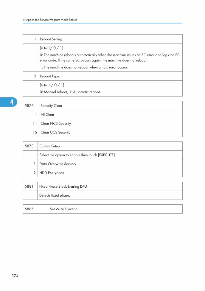
1 Reboot Setting
[0 to 1/ 0 / 1]
0: The machine reboots automatically when the machine issues an SC error and logs the SCerror code. If the same SC occurs again, the machine does not reboot.
1: The machine does not reboot when an SC error occurs.
2 Reboot Type
[0 to 1 / 0 / 1]
0: Manual reboot, 1: Automatic reboot
5876 Security Clear
1 All Clear
11 Clear NCS Security
15 Clear UCS Security
5878 Option Setup
Select the option to enable then touch [EXECUTE].
1 Data Overwrite Security
2 HDD Encryption
5881 Fixed Phase Block Erasing DFU
Detects fixed phase.
5885 Set WIM Function
4. Appendix: Service Program Mode Tables
374
4
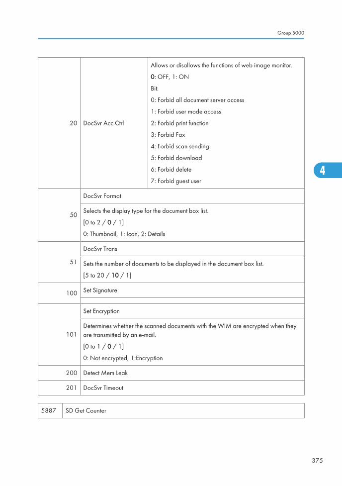
20 DocSvr Acc Ctrl
Allows or disallows the functions of web image monitor.
0: OFF, 1: ON
Bit:
0: Forbid all document server access
1: Forbid user mode access
2: Forbid print function
3: Forbid Fax
4: Forbid scan sending
5: Forbid download
6: Forbid delete
7: Forbid guest user
50
DocSvr Format
Selects the display type for the document box list.
[0 to 2 / 0 / 1]
0: Thumbnail, 1: Icon, 2: Details
51
DocSvr Trans
Sets the number of documents to be displayed in the document box list.
[5 to 20 / 10 / 1]
100 Set Signature
101
Set Encryption
Determines whether the scanned documents with the WIM are encrypted when theyare transmitted by an e-mail.
[0 to 1 / 0 / 1]
0: Not encrypted, 1:Encryption
200 Detect Mem Leak
201 DocSvr Timeout
5887 SD Get Counter
Group 5000
375
4
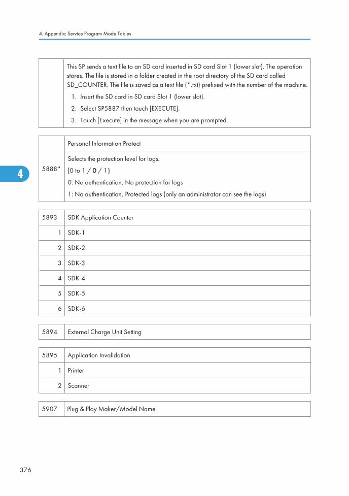
This SP sends a text file to an SD card inserted in SD card Slot 1 (lower slot). The operationstores. The file is stored in a folder created in the root directory of the SD card calledSD_COUNTER. The file is saved as a text file (*.txt) prefixed with the number of the machine.
1. Insert the SD card in SD card Slot 1 (lower slot).
2. Select SP5887 then touch [EXECUTE].
3. Touch [Execute] in the message when you are prompted.
5888*
Personal Information Protect
Selects the protection level for logs.
[0 to 1 / 0 / 1}
0: No authentication, No protection for logs
1: No authentication, Protected logs (only an administrator can see the logs)
5893 SDK Application Counter
1 SDK-1
2 SDK-2
3 SDK-3
4 SDK-4
5 SDK-5
6 SDK-6
5894 External Charge Unit Setting
5895 Application Invalidation
1 Printer
2 Scanner
5907 Plug & Play Maker/Model Name
4. Appendix: Service Program Mode Tables
376
4
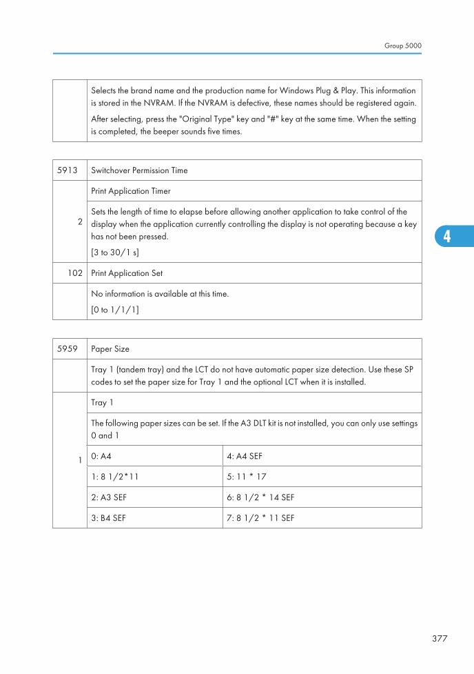
Selects the brand name and the production name for Windows Plug & Play. This informationis stored in the NVRAM. If the NVRAM is defective, these names should be registered again.
After selecting, press the "Original Type" key and "#" key at the same time. When the settingis completed, the beeper sounds five times.
5913 Switchover Permission Time
2
Print Application Timer
Sets the length of time to elapse before allowing another application to take control of thedisplay when the application currently controlling the display is not operating because a keyhas not been pressed.
[3 to 30/1 s]
102 Print Application Set
No information is available at this time.
[0 to 1/1/1]
5959 Paper Size
Tray 1 (tandem tray) and the LCT do not have automatic paper size detection. Use these SPcodes to set the paper size for Tray 1 and the optional LCT when it is installed.
1
Tray 1
The following paper sizes can be set. If the A3 DLT kit is not installed, you can only use settings0 and 1
0: A4 4: A4 SEF
1: 8 1/2*11 5: 11 * 17
2: A3 SEF 6: 8 1/2 * 14 SEF
3: B4 SEF 7: 8 1/2 * 11 SEF
Group 5000
377
4
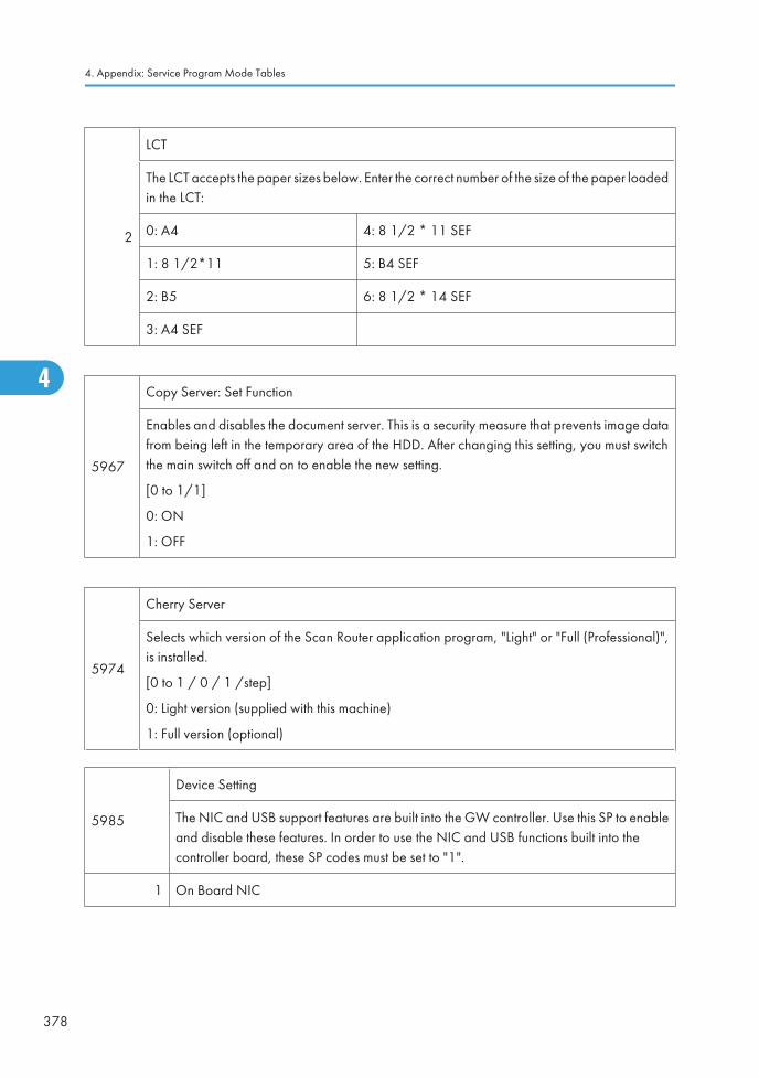
2
LCT
The LCT accepts the paper sizes below. Enter the correct number of the size of the paper loadedin the LCT:
0: A4 4: 8 1/2 * 11 SEF
1: 8 1/2*11 5: B4 SEF
2: B5 6: 8 1/2 * 14 SEF
3: A4 SEF
5967
Copy Server: Set Function
Enables and disables the document server. This is a security measure that prevents image datafrom being left in the temporary area of the HDD. After changing this setting, you must switchthe main switch off and on to enable the new setting.
[0 to 1/1]
0: ON
1: OFF
5974
Cherry Server
Selects which version of the Scan Router application program, "Light" or "Full (Professional)",is installed.
[0 to 1 / 0 / 1 /step]
0: Light version (supplied with this machine)
1: Full version (optional)
5985
Device Setting
The NIC and USB support features are built into the GW controller. Use this SP to enableand disable these features. In order to use the NIC and USB functions built into thecontroller board, these SP codes must be set to "1".
1 On Board NIC
4. Appendix: Service Program Mode Tables
378
4
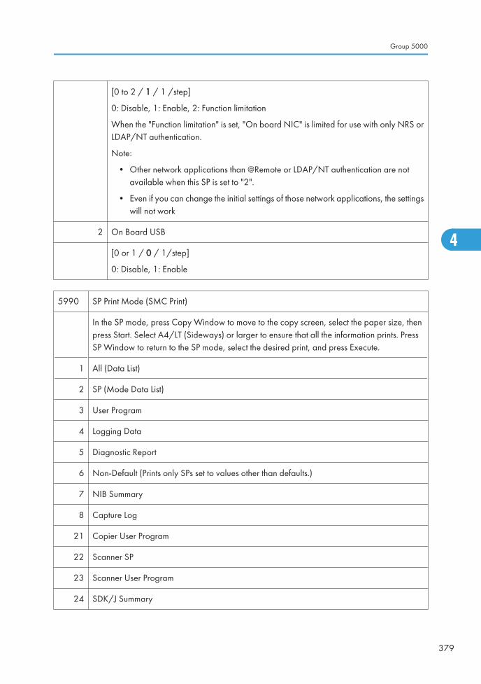
[0 to 2 / 1 / 1 /step]
0: Disable, 1: Enable, 2: Function limitation
When the "Function limitation" is set, "On board NIC" is limited for use with only NRS orLDAP/NT authentication.
Note:
• Other network applications than @Remote or LDAP/NT authentication are notavailable when this SP is set to "2".
• Even if you can change the initial settings of those network applications, the settingswill not work
2 On Board USB
[0 or 1 / 0 / 1/step]
0: Disable, 1: Enable
5990 SP Print Mode (SMC Print)
In the SP mode, press Copy Window to move to the copy screen, select the paper size, thenpress Start. Select A4/LT (Sideways) or larger to ensure that all the information prints. PressSP Window to return to the SP mode, select the desired print, and press Execute.
1 All (Data List)
2 SP (Mode Data List)
3 User Program
4 Logging Data
5 Diagnostic Report
6 Non-Default (Prints only SPs set to values other than defaults.)
7 NIB Summary
8 Capture Log
21 Copier User Program
22 Scanner SP
23 Scanner User Program
24 SDK/J Summary
Group 5000
379
4

25 SDK/J Application Info
4. Appendix: Service Program Mode Tables
380
4
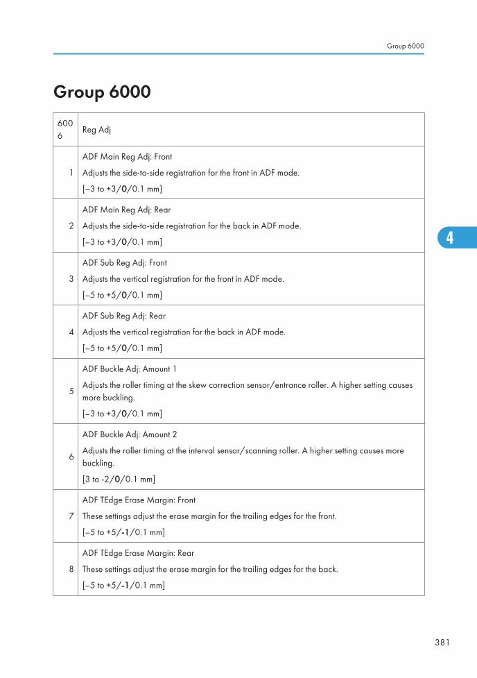
Group 60006006
Reg Adj
1
ADF Main Reg Adj: Front
Adjusts the side-to-side registration for the front in ADF mode.
[–3 to +3/0/0.1 mm]
2
ADF Main Reg Adj: Rear
Adjusts the side-to-side registration for the back in ADF mode.
[–3 to +3/0/0.1 mm]
3
ADF Sub Reg Adj: Front
Adjusts the vertical registration for the front in ADF mode.
[–5 to +5/0/0.1 mm]
4
ADF Sub Reg Adj: Rear
Adjusts the vertical registration for the back in ADF mode.
[–5 to +5/0/0.1 mm]
5
ADF Buckle Adj: Amount 1
Adjusts the roller timing at the skew correction sensor/entrance roller. A higher setting causesmore buckling.
[–3 to +3/0/0.1 mm]
6
ADF Buckle Adj: Amount 2
Adjusts the roller timing at the interval sensor/scanning roller. A higher setting causes morebuckling.
[3 to -2/0/0.1 mm]
7
ADF TEdge Erase Margin: Front
These settings adjust the erase margin for the trailing edges for the front.
[–5 to +5/-1/0.1 mm]
8
ADF TEdge Erase Margin: Rear
These settings adjust the erase margin for the trailing edges for the back.
[–5 to +5/-1/0.1 mm]
Group 6000
381
4
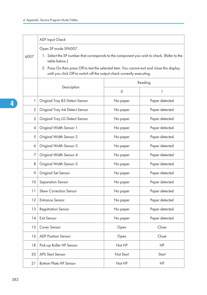
6007
ADF Input Check
Open SP mode SP6007.
1. Select the SP number that corresponds to the component you wish to check. (Refer to thetable below.)
2. Press On then press Off to test the selected item. You cannot exit and close this displayuntil you click Off to switch off the output check currently executing.
DescriptionReading
0 1
1 Original Tray B5 Detect Sensor No paper Paper detected
2 Original Tray A4 Detect Sensor No paper Paper detected
3 Original Tray LG Detect Sensor No paper Paper detected
4 Original Width Sensor 1 No paper Paper detected
5 Original Width Sensor 2 No paper Paper detected
6 Original Width Sensor 3 No paper Paper detected
7 Original Width Sensor 4 No paper Paper detected
8 Original Width Sensor 5 No paper Paper detected
9 Original Set Sensor No paper Paper detected
10 Separation Sensor No paper Paper detected
11 Skew Correction Sensor No paper Paper detected
12 Entrance Sensor No paper Paper detected
13 Registration Sensor No paper Paper detected
14 Exit Sensor No paper Paper detected
15 Cover Sensor Open Close
16 ADF Position Sensor Open Close
18 Pick-up Roller HP Sensor Not HP HP
20 APS Start Sensor Not Start Start
21 Bottom Plate HP Sensor Not HP HP
4. Appendix: Service Program Mode Tables
382
4
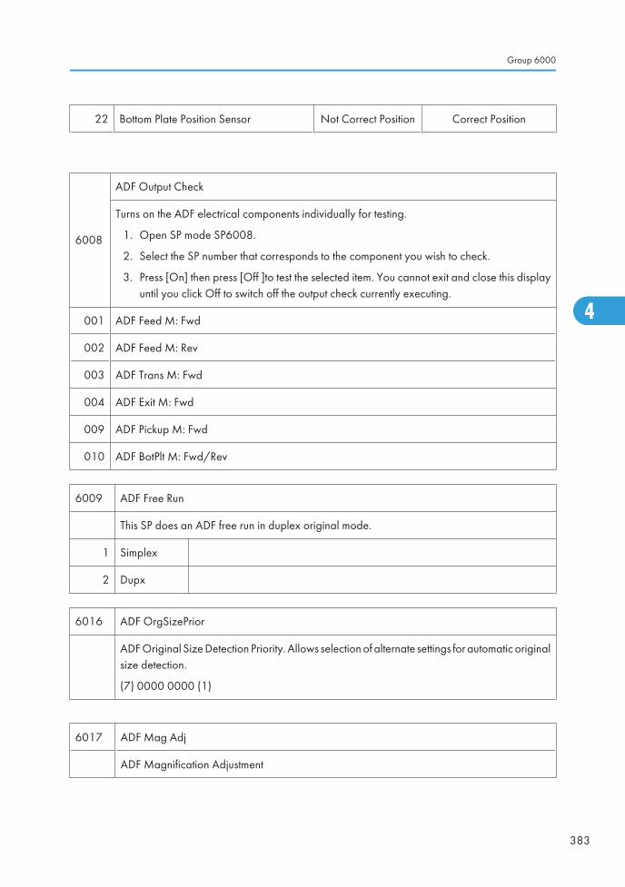
22 Bottom Plate Position Sensor Not Correct Position Correct Position
6008
ADF Output Check
Turns on the ADF electrical components individually for testing.
1. Open SP mode SP6008.
2. Select the SP number that corresponds to the component you wish to check.
3. Press [On] then press [Off ]to test the selected item. You cannot exit and close this displayuntil you click Off to switch off the output check currently executing.
001 ADF Feed M: Fwd
002 ADF Feed M: Rev
003 ADF Trans M: Fwd
004 ADF Exit M: Fwd
009 ADF Pickup M: Fwd
010 ADF BotPlt M: Fwd/Rev
6009 ADF Free Run
This SP does an ADF free run in duplex original mode.
1 Simplex
2 Dupx
6016 ADF OrgSizePrior
ADF Original Size Detection Priority. Allows selection of alternate settings for automatic originalsize detection.
(7) 0000 0000 (1)
6017 ADF Mag Adj
ADF Magnification Adjustment
Group 6000
383
4
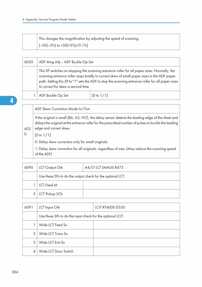
This changes the magnification by adjusting the speed of scanning.
[–50(–5%) to +50(+5%)/0.1%]
6020 ADF Mag Adj – ADF Buckle Op Set
This SP switches on stopping the scanning entrance roller for all paper sizes. Normally, thescanning entrance roller stops briefly to correct skew of small paper sizes in the ADF paperpath. Setting this SP to "1" sets the ADF to stop the scanning entrance roller for all paper sizesto correct for skew a second time.
1 ADF Buckle Op Set [0 to 1/1]
6020
ADF Skew Correction Mode In/Out
If the original is small (B6, A5, HLT), the delay sensor detects the leading edge of the sheet anddelays the original at the entrance roller for the prescribed number of pulses to buckle the leadingedge and correct skew.
[0 to 1/1]
0: Delay skew correction only for small originals
1: Delay skew correction for all originals, regardless of size. (May reduce the scanning speedof the ADF)
6090 LCT Output Chk A4/LT LCT (MAUI) B473
Use these SPs to do the output check for the optional LCT.
1 LCT Feed M
2 LCT Pickup SOL
6091 LCT Input Chk LCIT RT4000 D350
Use these SPs to do the input check for the optional LCIT.
1 Wide LCT Feed Sn
2 Wide LCT Trans Sn
3 Wide LCT Exit Sn
4 Wide LCT Door Switch
4. Appendix: Service Program Mode Tables
384
4
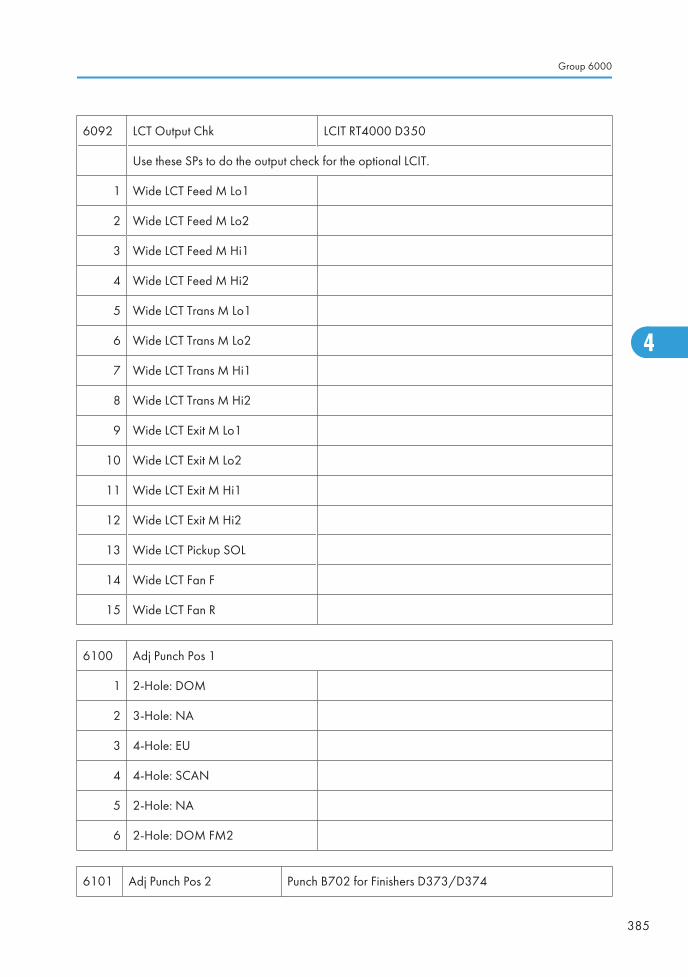
6092 LCT Output Chk LCIT RT4000 D350
Use these SPs to do the output check for the optional LCIT.
1 Wide LCT Feed M Lo1
2 Wide LCT Feed M Lo2
3 Wide LCT Feed M Hi1
4 Wide LCT Feed M Hi2
5 Wide LCT Trans M Lo1
6 Wide LCT Trans M Lo2
7 Wide LCT Trans M Hi1
8 Wide LCT Trans M Hi2
9 Wide LCT Exit M Lo1
10 Wide LCT Exit M Lo2
11 Wide LCT Exit M Hi1
12 Wide LCT Exit M Hi2
13 Wide LCT Pickup SOL
14 Wide LCT Fan F
15 Wide LCT Fan R
6100 Adj Punch Pos 1
1 2-Hole: DOM
2 3-Hole: NA
3 4-Hole: EU
4 4-Hole: SCAN
5 2-Hole: NA
6 2-Hole: DOM FM2
6101 Adj Punch Pos 2 Punch B702 for Finishers D373/D374
Group 6000
385
4

Punch Position Adjustment
Adjusts the punch hole positions in the direction of paper feed.
• NA: North America
• DOM: Japan
• EU: Europe
• SCAN: Scandinavia
1 2-Hole:DOM
[-75 to +75/0.5 mm]
+ Value: Shifts punch unit in the direction of feed.
- Value: Shifts punch unit against direction of feed.
2 3-Hole:NA
3 4-Hole:EU
4 4-Hole:SCAN
5 2-Hole:NA
6102 Punch Hole Reg 1 Punch B702 for Finishers D373/D374
This SP corrects punch hole alignment by correcting the skew of each by adjusting the amountof time the finisher entrance roller remains off while the exit roller of the machine remains on.This buckles the leading edge of the sheet slightly against the finisher entrance roller while itremains off.
4. Appendix: Service Program Mode Tables
386
4
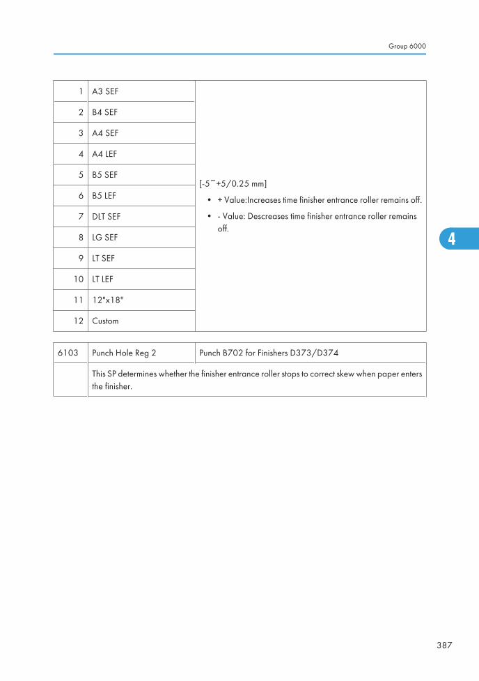
1 A3 SEF
[-5~+5/0.25 mm]
• + Value:Increases time finisher entrance roller remains off.
• - Value: Descreases time finisher entrance roller remainsoff.
2 B4 SEF
3 A4 SEF
4 A4 LEF
5 B5 SEF
6 B5 LEF
7 DLT SEF
8 LG SEF
9 LT SEF
10 LT LEF
11 12"x18"
12 Custom
6103 Punch Hole Reg 2 Punch B702 for Finishers D373/D374
This SP determines whether the finisher entrance roller stops to correct skew when paper entersthe finisher.
Group 6000
387
4
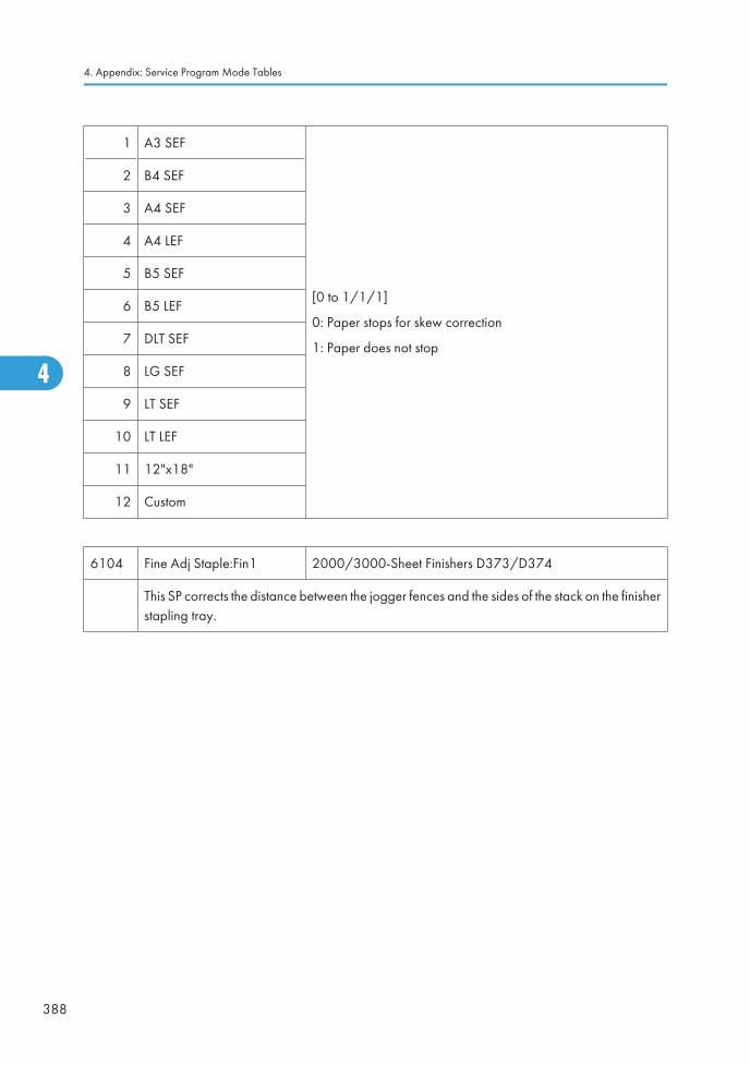
1 A3 SEF
[0 to 1/1/1]
0: Paper stops for skew correction
1: Paper does not stop
2 B4 SEF
3 A4 SEF
4 A4 LEF
5 B5 SEF
6 B5 LEF
7 DLT SEF
8 LG SEF
9 LT SEF
10 LT LEF
11 12"x18"
12 Custom
6104 Fine Adj Staple:Fin1 2000/3000-Sheet Finishers D373/D374
This SP corrects the distance between the jogger fences and the sides of the stack on the finisherstapling tray.
4. Appendix: Service Program Mode Tables
388
4
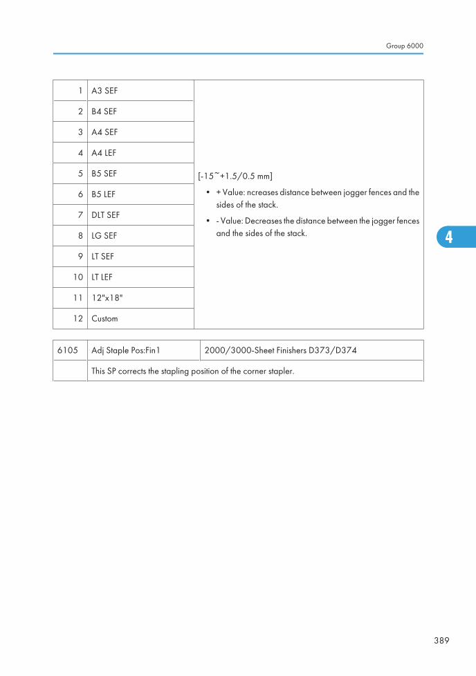
1 A3 SEF
[-15~+1.5/0.5 mm]
• + Value: ncreases distance between jogger fences and thesides of the stack.
• - Value: Decreases the distance between the jogger fencesand the sides of the stack.
2 B4 SEF
3 A4 SEF
4 A4 LEF
5 B5 SEF
6 B5 LEF
7 DLT SEF
8 LG SEF
9 LT SEF
10 LT LEF
11 12"x18"
12 Custom
6105 Adj Staple Pos:Fin1 2000/3000-Sheet Finishers D373/D374
This SP corrects the stapling position of the corner stapler.
Group 6000
389
4
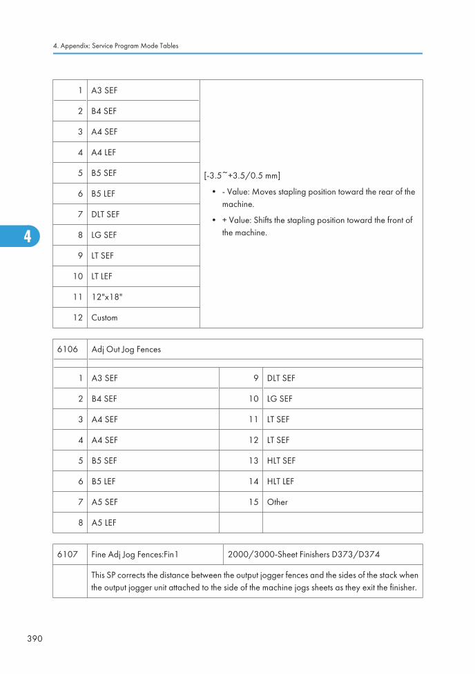
1 A3 SEF
[-3.5~+3.5/0.5 mm]
• - Value: Moves stapling position toward the rear of themachine.
• + Value: Shifts the stapling position toward the front ofthe machine.
2 B4 SEF
3 A4 SEF
4 A4 LEF
5 B5 SEF
6 B5 LEF
7 DLT SEF
8 LG SEF
9 LT SEF
10 LT LEF
11 12"x18"
12 Custom
6106 Adj Out Jog Fences
1 A3 SEF 9 DLT SEF
2 B4 SEF 10 LG SEF
3 A4 SEF 11 LT SEF
4 A4 SEF 12 LT SEF
5 B5 SEF 13 HLT SEF
6 B5 LEF 14 HLT LEF
7 A5 SEF 15 Other
8 A5 LEF
6107 Fine Adj Jog Fences:Fin1 2000/3000-Sheet Finishers D373/D374
This SP corrects the distance between the output jogger fences and the sides of the stack whenthe output jogger unit attached to the side of the machine jogs sheets as they exit the finisher.
4. Appendix: Service Program Mode Tables
390
4
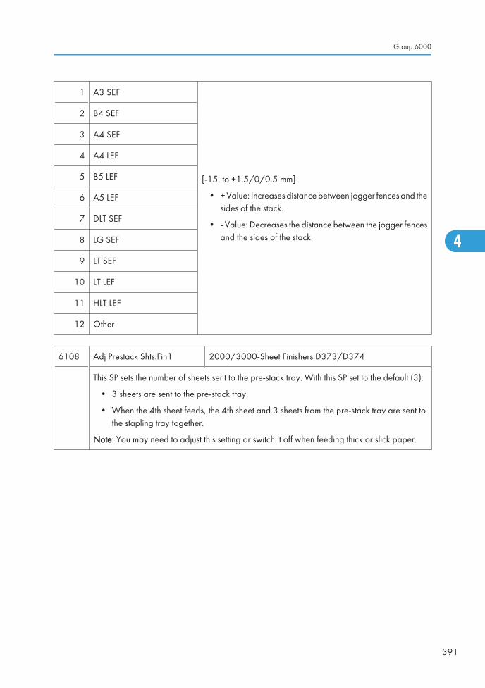
1 A3 SEF
[-15. to +1.5/0/0.5 mm]
• + Value: Increases distance between jogger fences and thesides of the stack.
• - Value: Decreases the distance between the jogger fencesand the sides of the stack.
2 B4 SEF
3 A4 SEF
4 A4 LEF
5 B5 LEF
6 A5 LEF
7 DLT SEF
8 LG SEF
9 LT SEF
10 LT LEF
11 HLT LEF
12 Other
6108 Adj Prestack Shts:Fin1 2000/3000-Sheet Finishers D373/D374
This SP sets the number of sheets sent to the pre-stack tray. With this SP set to the default (3):
• 3 sheets are sent to the pre-stack tray.
• When the 4th sheet feeds, the 4th sheet and 3 sheets from the pre-stack tray are sent tothe stapling tray together.
Note: You may need to adjust this setting or switch it off when feeding thick or slick paper.
Group 6000
391
4
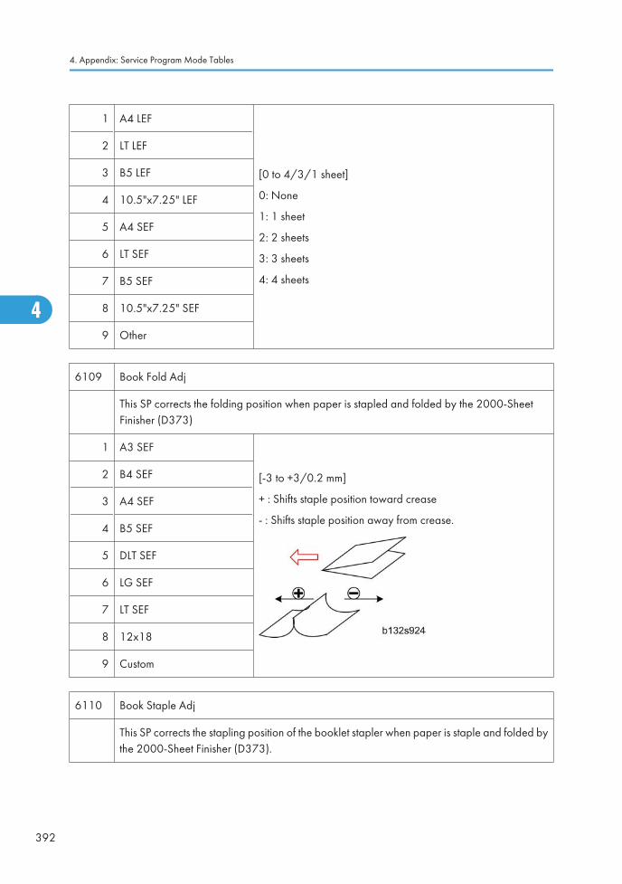
1 A4 LEF
[0 to 4/3/1 sheet]
0: None
1: 1 sheet
2: 2 sheets
3: 3 sheets
4: 4 sheets
2 LT LEF
3 B5 LEF
4 10.5"x7.25" LEF
5 A4 SEF
6 LT SEF
7 B5 SEF
8 10.5"x7.25" SEF
9 Other
6109 Book Fold Adj
This SP corrects the folding position when paper is stapled and folded by the 2000-SheetFinisher (D373)
1 A3 SEF
[-3 to +3/0.2 mm]
+ : Shifts staple position toward crease
- : Shifts staple position away from crease.
2 B4 SEF
3 A4 SEF
4 B5 SEF
5 DLT SEF
6 LG SEF
7 LT SEF
8 12x18
9 Custom
6110 Book Staple Adj
This SP corrects the stapling position of the booklet stapler when paper is staple and folded bythe 2000-Sheet Finisher (D373).
4. Appendix: Service Program Mode Tables
392
4
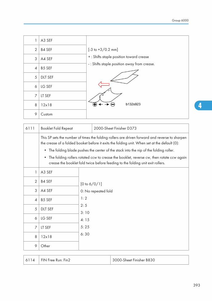
1 A3 SEF
[-3 to +3/0.2 mm]
+ : Shifts staple position toward crease
- : Shifts staple position away from crease.
2 B4 SEF
3 A4 SEF
4 B5 SEF
5 DLT SEF
6 LG SEF
7 LT SEF
8 12x18
9 Custom
6111 Booklet Fold Repeat 2000-Sheet Finisher D373
This SP sets the number of times the folding rollers are driven forward and reverse to sharpenthe crease of a folded booket before it exits the folding unit. When set at the default (0):
• The folding blade pushes the center of the stack into the nip of the folding roller.
• The folding rollers rotated ccw to crease the booklet, reverse cw, then rotate ccw againcrease the booklet fold twice before feeding to the folding unit exit rollers.
1 A3 SEF
[0 to 6/0/1]
0: No repeated fold
1: 2
2: 5
3: 10
4: 15
5: 25
6: 30
2 B4 SEF
3 A4 SEF
4 B5 SEF
5 DLT SEF
6 LG SEF
7 LT SEF
8 12x18
9 Other
6114 FIN Free Run: Fin2 3000-Sheet Finisher B830
Group 6000
393
4
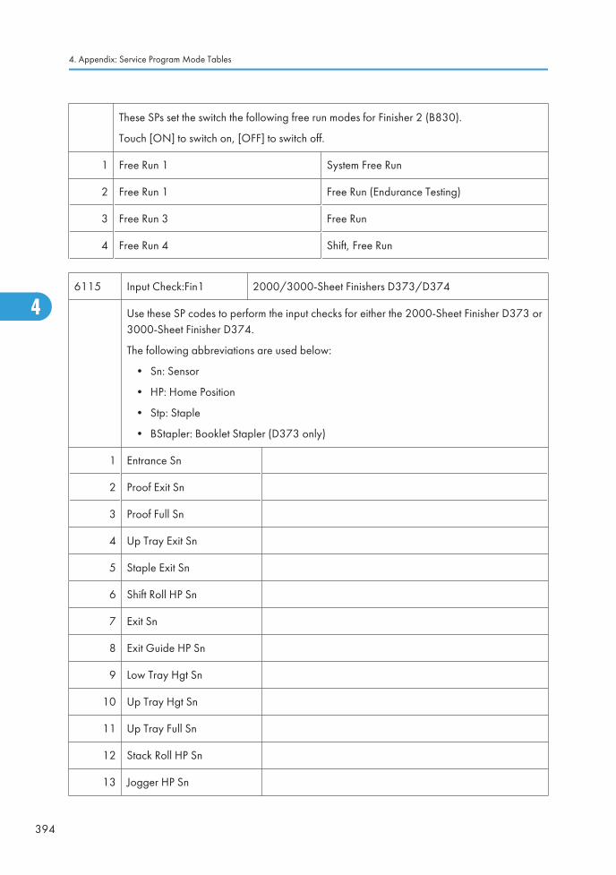
These SPs set the switch the following free run modes for Finisher 2 (B830).
Touch [ON] to switch on, [OFF] to switch off.
1 Free Run 1 System Free Run
2 Free Run 1 Free Run (Endurance Testing)
3 Free Run 3 Free Run
4 Free Run 4 Shift, Free Run
6115 Input Check:Fin1 2000/3000-Sheet Finishers D373/D374
Use these SP codes to perform the input checks for either the 2000-Sheet Finisher D373 or3000-Sheet Finisher D374.
The following abbreviations are used below:
• Sn: Sensor
• HP: Home Position
• Stp: Staple
• BStapler: Booklet Stapler (D373 only)
1 Entrance Sn
2 Proof Exit Sn
3 Proof Full Sn
4 Up Tray Exit Sn
5 Staple Exit Sn
6 Shift Roll HP Sn
7 Exit Sn
8 Exit Guide HP Sn
9 Low Tray Hgt Sn
10 Up Tray Hgt Sn
11 Up Tray Full Sn
12 Stack Roll HP Sn
13 Jogger HP Sn
4. Appendix: Service Program Mode Tables
394
4
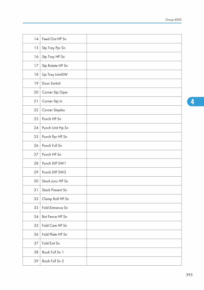
14 Feed Out HP Sn
15 Stp Tray Ppr Sn
16 Stp Tray HP Sn
17 Stp Rotate HP Sn
18 Up Tray LimitSW
19 Door Switch
20 Corner Stp Oper
21 Corner Stp In
22 Corner Staples
23 Punch HP Sn
24 Punch Unit Hp Sn
25 Punch Ppr HP Sn
26 Punch Full Sn
27 Punch HP Sn
28 Punch DIP SW1
29 Punch DIP SW2
30 Stack Junc HP Sn
31 Stack Present Sn
32 Clamp Roll HP Sn
33 Fold Entrance Sn
34 Bot Fence HP Sn
35 Fold Cam HP Sn
36 Fold Plate HP Sn
37 Fold Exit Sn
38 Book Full Sn 1
39 Book Full Sn 2
Group 6000
395
4
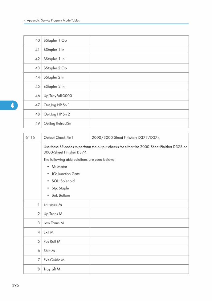
40 BStapler 1 Op
41 BStapler 1 In
42 BStaples 1 In
43 BStapler 2 Op
44 BStapler 2 In
45 BStaples 2 In
46 Up TrayFull:3000
47 Out Jog HP Sn 1
48 Out Jog HP Sn 2
49 OutJog RetractSn
6116 Output Check:Fin1 2000/3000-Sheet Finishers D373/D374
Use these SP codes to perform the output checks for either the 2000-Sheet Finisher D373 or3000-Sheet Finisher D374.
The following abbreviations are used below:
• M: Motor
• JG: Junction Gate
• SOL: Solenoid
• Stp: Staple
• Bot: Bottom
1 Entrance M
2 Up Trans M
3 Low Trans M
4 Exit M
5 Pos Roll M
6 Shift M
7 Exit Guide M
8 Tray Lift M
4. Appendix: Service Program Mode Tables
396
4
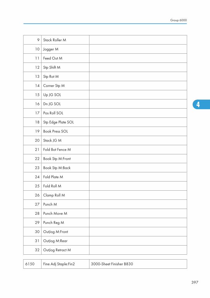
9 Stack Roller M
10 Jogger M
11 Feed Out M
12 Stp Shift M
13 Stp Rot M
14 Corner Stp M
15 Up JG SOL
16 Dn JG SOL
17 Pos Roll SOL
18 Stp Edge Plate SOL
19 Book Press SOL
20 Stack JG M
21 Fold Bot Fence M
22 Book Stp M:Front
23 Book Stp M:Back
24 Fold Plate M
25 Fold Roll M
26 Clamp Roll M
27 Punch M
28 Punch Move M
29 Punch Reg M
30 OutJog M:Front
31 OutJog M:Rear
32 OutJog Retract M
6150 Fine Adj Staple:Fin2 3000-Sheet Finisher B830
Group 6000
397
4
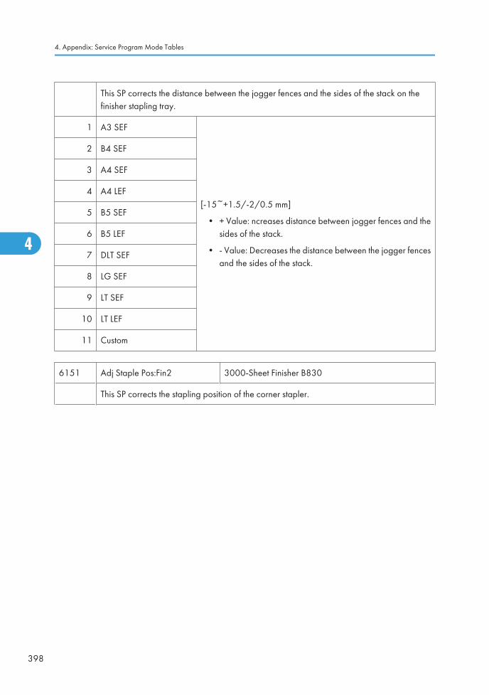
This SP corrects the distance between the jogger fences and the sides of the stack on thefinisher stapling tray.
1 A3 SEF
[-15~+1.5/-2/0.5 mm]
• + Value: ncreases distance between jogger fences and thesides of the stack.
• - Value: Decreases the distance between the jogger fencesand the sides of the stack.
2 B4 SEF
3 A4 SEF
4 A4 LEF
5 B5 SEF
6 B5 LEF
7 DLT SEF
8 LG SEF
9 LT SEF
10 LT LEF
11 Custom
6151 Adj Staple Pos:Fin2 3000-Sheet Finisher B830
This SP corrects the stapling position of the corner stapler.
4. Appendix: Service Program Mode Tables
398
4
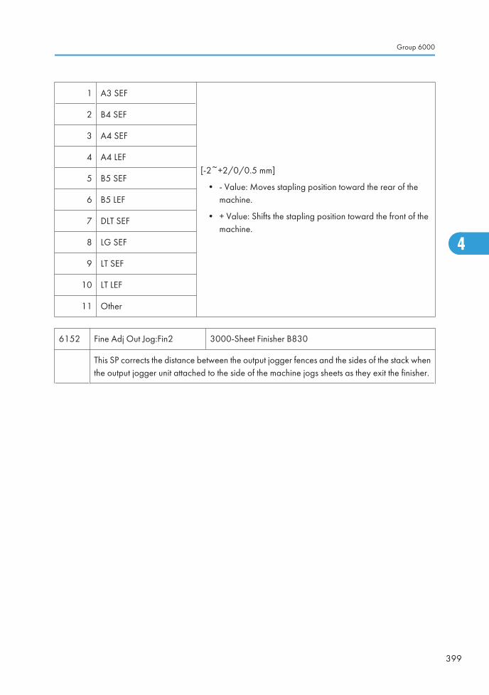
1 A3 SEF
[-2~+2/0/0.5 mm]
• - Value: Moves stapling position toward the rear of themachine.
• + Value: Shifts the stapling position toward the front of themachine.
2 B4 SEF
3 A4 SEF
4 A4 LEF
5 B5 SEF
6 B5 LEF
7 DLT SEF
8 LG SEF
9 LT SEF
10 LT LEF
11 Other
6152 Fine Adj Out Jog:Fin2 3000-Sheet Finisher B830
This SP corrects the distance between the output jogger fences and the sides of the stack whenthe output jogger unit attached to the side of the machine jogs sheets as they exit the finisher.
Group 6000
399
4
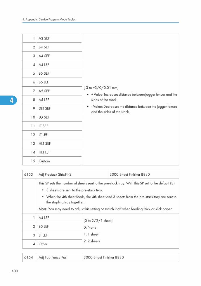
1 A3 SEF
[-3 to +3/0/0.01 mm]
• + Value: Increases distance between jogger fences and thesides of the stack.
• - Value: Decreases the distance between the jogger fencesand the sides of the stack.
2 B4 SEF
3 A4 SEF
4 A4 LEF
5 B5 SEF
6 B5 LEF
7 A5 SEF
8 A5 LEF
9 DLT SEF
10 LG SEF
11 LT SEF
12 LT LEF
13 HLT SEF
14 HLT LEF
15 Custom
6153 Adj Prestack Shts:Fin2 3000-Sheet Finisher B830
This SP sets the number of sheets sent to the pre-stack tray. With this SP set to the default (3):
• 3 sheets are sent to the pre-stack tray.
• When the 4th sheet feeds, the 4th sheet and 3 sheets from the pre-stack tray are sent tothe stapling tray together.
Note: You may need to adjust this setting or switch it off when feeding thick or slick paper.
1 A4 LEF[0 to 2/2/1 sheet]
0: None
1: 1 sheet
2: 2 sheets
2 B5 LEF
3 LT LEF
4 Other
6154 Adj Top Fence Pos 3000-Sheet Finisher B830
4. Appendix: Service Program Mode Tables
400
4
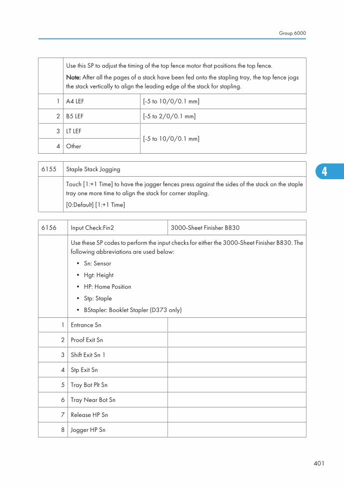
Use this SP to adjust the timing of the top fence motor that positions the top fence.
Note: After all the pages of a stack have been fed onto the stapling tray, the top fence jogsthe stack vertically to align the leading edge of the stack for stapling.
1 A4 LEF [-5 to 10/0/0.1 mm]
2 B5 LEF [-5 to 2/0/0.1 mm]
3 LT LEF[-5 to 10/0/0.1 mm]
4 Other
6155 Staple Stack Jogging
Touch [1:+1 Time] to have the jogger fences press against the sides of the stack on the stapletray one more time to align the stack for corner stapling.
[0:Default] [1:+1 Time]
6156 Input Check:Fin2 3000-Sheet Finisher B830
Use these SP codes to perform the input checks for either the 3000-Sheet Finisher B830. Thefollowing abbreviations are used below:
• Sn: Sensor
• Hgt: Height
• HP: Home Position
• Stp: Staple
• BStapler: Booklet Stapler (D373 only)
1 Entrance Sn
2 Proof Exit Sn
3 Shift Exit Sn 1
4 Stp Exit Sn
5 Tray Bot Plt Sn
6 Tray Near Bot Sn
7 Release HP Sn
8 Jogger HP Sn
Group 6000
401
4
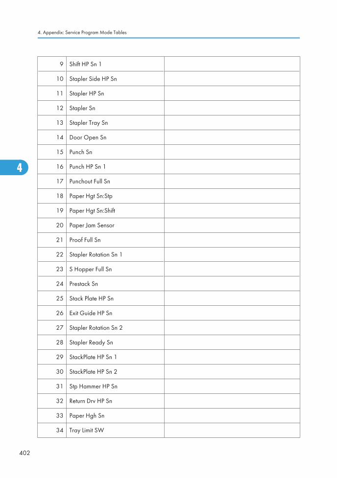
9 Shift HP Sn 1
10 Stapler Side HP Sn
11 Stapler HP Sn
12 Stapler Sn
13 Stapler Tray Sn
14 Door Open Sn
15 Punch Sn
16 Punch HP Sn 1
17 Punchout Full Sn
18 Paper Hgt Sn:Stp
19 Paper Hgt Sn:Shift
20 Paper Jam Sensor
21 Proof Full Sn
22 Stapler Rotation Sn 1
23 S Hopper Full Sn
24 Prestack Sn
25 Stack Plate HP Sn
26 Exit Guide HP Sn
27 Stapler Rotation Sn 2
28 Stapler Ready Sn
29 StackPlate HP Sn 1
30 StackPlate HP Sn 2
31 Stp Hammer HP Sn
32 Return Drv HP Sn
33 Paper Hgh Sn
34 Tray Limit SW
4. Appendix: Service Program Mode Tables
402
4
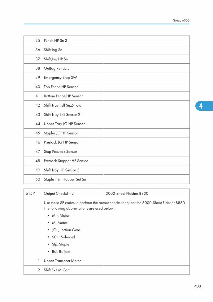
35 Punch HP Sn 2
36 Shift Jog Sn
37 Shift Jog HP Sn
38 OutJog RetractSn
39 Emergency Stop SW
40 Top Fence HP Sensor
41 Bottom Fence HP Sensor
42 Shift Tray Full Sn:Z-Fold
43 Shift Tray Exit Sensor 2
44 Upper Tray JG HP Sensor
45 Stapler JG HP Sensor
46 Prestack JG HP Sensor
47 Stop Prestack Sensor
48 Prestack Stopper HP Sensor
49 Shift Tray HP Sensor 2
50 Staple Trim Hopper Set Sn
6157 Output Check:Fin2 3000-Sheet Finisher B830
Use these SP codes to perform the output checks for either the 3000-Sheet Finisher B830.The following abbreviations are used below:
• Mtr: Motor
• M: Motor
• JG: Junction Gate
• SOL: Solenoid
• Stp: Staple
• Bot: Bottom
1 Upper Transport Motor
2 Shift Exit M:Cont
Group 6000
403
4
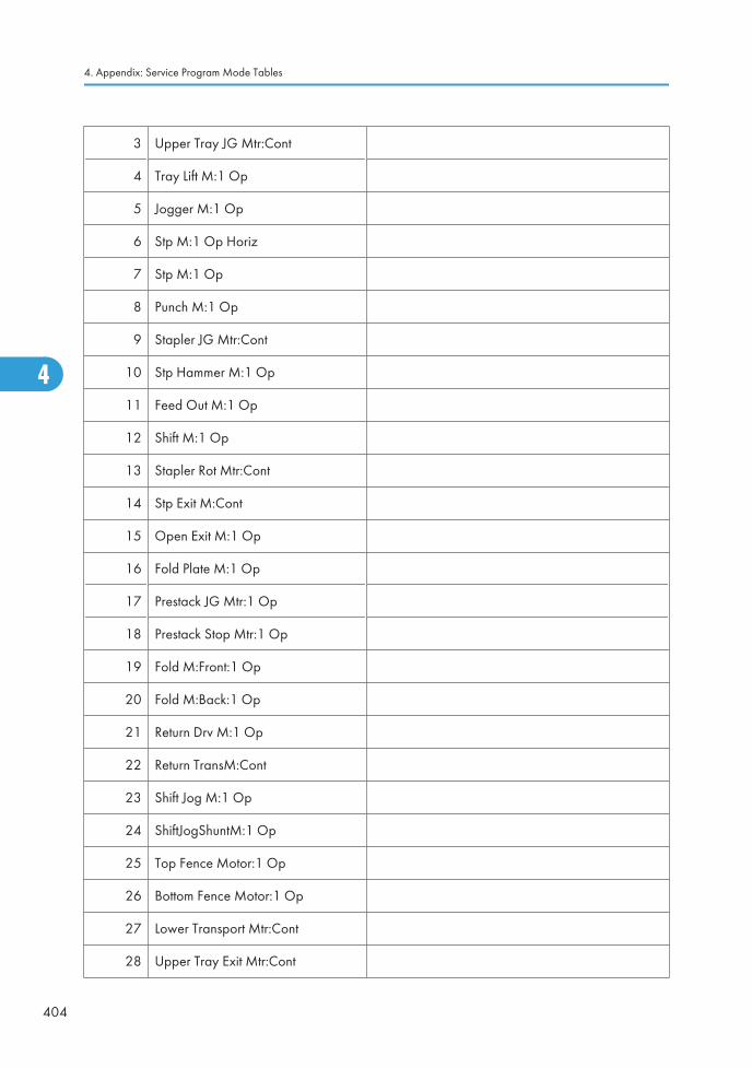
3 Upper Tray JG Mtr:Cont
4 Tray Lift M:1 Op
5 Jogger M:1 Op
6 Stp M:1 Op Horiz
7 Stp M:1 Op
8 Punch M:1 Op
9 Stapler JG Mtr:Cont
10 Stp Hammer M:1 Op
11 Feed Out M:1 Op
12 Shift M:1 Op
13 Stapler Rot Mtr:Cont
14 Stp Exit M:Cont
15 Open Exit M:1 Op
16 Fold Plate M:1 Op
17 Prestack JG Mtr:1 Op
18 Prestack Stop Mtr:1 Op
19 Fold M:Front:1 Op
20 Fold M:Back:1 Op
21 Return Drv M:1 Op
22 Return TransM:Cont
23 Shift Jog M:1 Op
24 ShiftJogShuntM:1 Op
25 Top Fence Motor:1 Op
26 Bottom Fence Motor:1 Op
27 Lower Transport Mtr:Cont
28 Upper Tray Exit Mtr:Cont
4. Appendix: Service Program Mode Tables
404
4
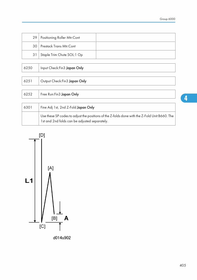
29 Positioning Roller Mtr:Cont
30 Prestack Trans Mtr:Cont
31 Staple Trim Chute SOL:1 Op
6250 Input Check:Fin3 Japan Only
6251 Output Check:Fin3 Japan Only
6252 Free Run:Fin3 Japan Only
6301 Fine Adj 1st, 2nd Z-Fold Japan Only
Use these SP codes to adjust the positions of the Z-folds done with the Z-Fold Unit B660. The1st and 2nd folds can be adjusted separately.
Group 6000
405
4
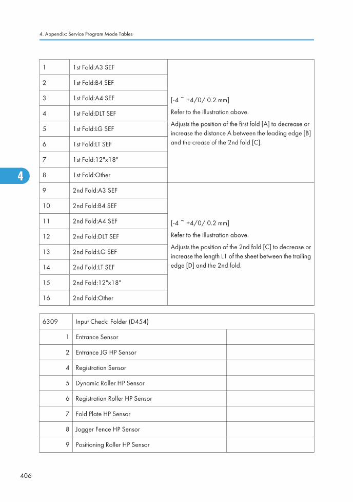
1 1st Fold:A3 SEF
[-4 ~ +4/0/ 0.2 mm]
Refer to the illustration above.
Adjusts the position of the first fold [A] to decrease orincrease the distance A between the leading edge [B]and the crease of the 2nd fold [C].
2 1st Fold:B4 SEF
3 1st Fold:A4 SEF
4 1st Fold:DLT SEF
5 1st Fold:LG SEF
6 1st Fold:LT SEF
7 1st Fold:12"x18"
8 1st Fold:Other
9 2nd Fold:A3 SEF
[-4 ~ +4/0/ 0.2 mm]
Refer to the illustration above.
Adjusts the position of the 2nd fold [C] to decrease orincrease the length L1 of the sheet between the trailingedge [D] and the 2nd fold.
10 2nd Fold:B4 SEF
11 2nd Fold:A4 SEF
12 2nd Fold:DLT SEF
13 2nd Fold:LG SEF
14 2nd Fold:LT SEF
15 2nd Fold:12"x18"
16 2nd Fold:Other
6309 Input Check: Folder (D454)
1 Entrance Sensor
2 Entrance JG HP Sensor
4 Registration Sensor
5 Dynamic Roller HP Sensor
6 Registration Roller HP Sensor
7 Fold Plate HP Sensor
8 Jogger Fence HP Sensor
9 Positioning Roller HP Sensor
4. Appendix: Service Program Mode Tables
406
4
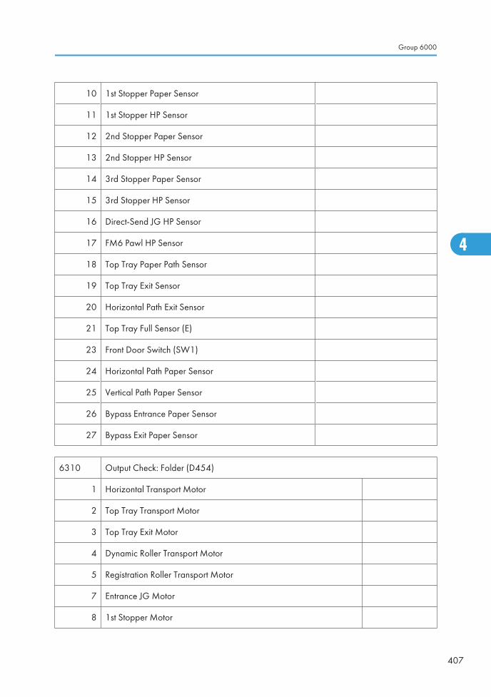
10 1st Stopper Paper Sensor
11 1st Stopper HP Sensor
12 2nd Stopper Paper Sensor
13 2nd Stopper HP Sensor
14 3rd Stopper Paper Sensor
15 3rd Stopper HP Sensor
16 Direct-Send JG HP Sensor
17 FM6 Pawl HP Sensor
18 Top Tray Paper Path Sensor
19 Top Tray Exit Sensor
20 Horizontal Path Exit Sensor
21 Top Tray Full Sensor (E)
23 Front Door Switch (SW1)
24 Horizontal Path Paper Sensor
25 Vertical Path Paper Sensor
26 Bypass Entrance Paper Sensor
27 Bypass Exit Paper Sensor
6310 Output Check: Folder (D454)
1 Horizontal Transport Motor
2 Top Tray Transport Motor
3 Top Tray Exit Motor
4 Dynamic Roller Transport Motor
5 Registration Roller Transport Motor
7 Entrance JG Motor
8 1st Stopper Motor
Group 6000
407
4
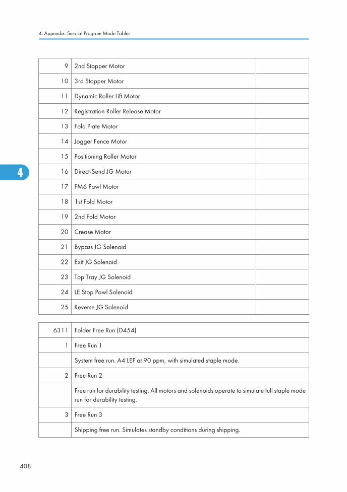
9 2nd Stopper Motor
10 3rd Stopper Motor
11 Dynamic Roller Lift Motor
12 Registration Roller Release Motor
13 Fold Plate Motor
14 Jogger Fence Motor
15 Positioning Roller Motor
16 Direct-Send JG Motor
17 FM6 Pawl Motor
18 1st Fold Motor
19 2nd Fold Motor
20 Crease Motor
21 Bypass JG Solenoid
22 Exit JG Solenoid
23 Top Tray JG Solenoid
24 LE Stop Pawl Solenoid
25 Reverse JG Solenoid
6311 Folder Free Run (D454)
1 Free Run 1
System free run. A4 LEF at 90 ppm, with simulated staple mode.
2 Free Run 2
Free run for durability testing. All motors and solenoids operate to simulate full staple moderun for durability testing.
3 Free Run 3
Shipping free run. Simulates standby conditions during shipping.
4. Appendix: Service Program Mode Tables
408
4
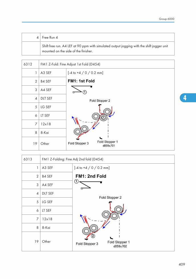
4 Free Run 4
Shift free run. A4 LEF at 90 ppm with simulated output jogging with the shift jogger unitmounted on the side of the finisher.
6312 FM1 Z-Fold: Fine Adjust 1st Fold (D454)
1 A3 SEF [-4 to +4 / 0 / 0.2 mm]
2 B4 SEF
3 A4 SEF
4 DLT SEF
5 LG SEF
6 LT SEF
7 12x18
8 8-Kai
19 Other
6313 FM1 Z-Folding: Fine Adj 2nd fold (D454)
1 A3 SEF [-4 to +4 / 0 / 0.2 mm]
2 B4 SEF
3 A4 SEF
4 DLT SEF
5 LG SEF
6 LT SEF
7 12x18
8 8-Kai
19 Other
Group 6000
409
4
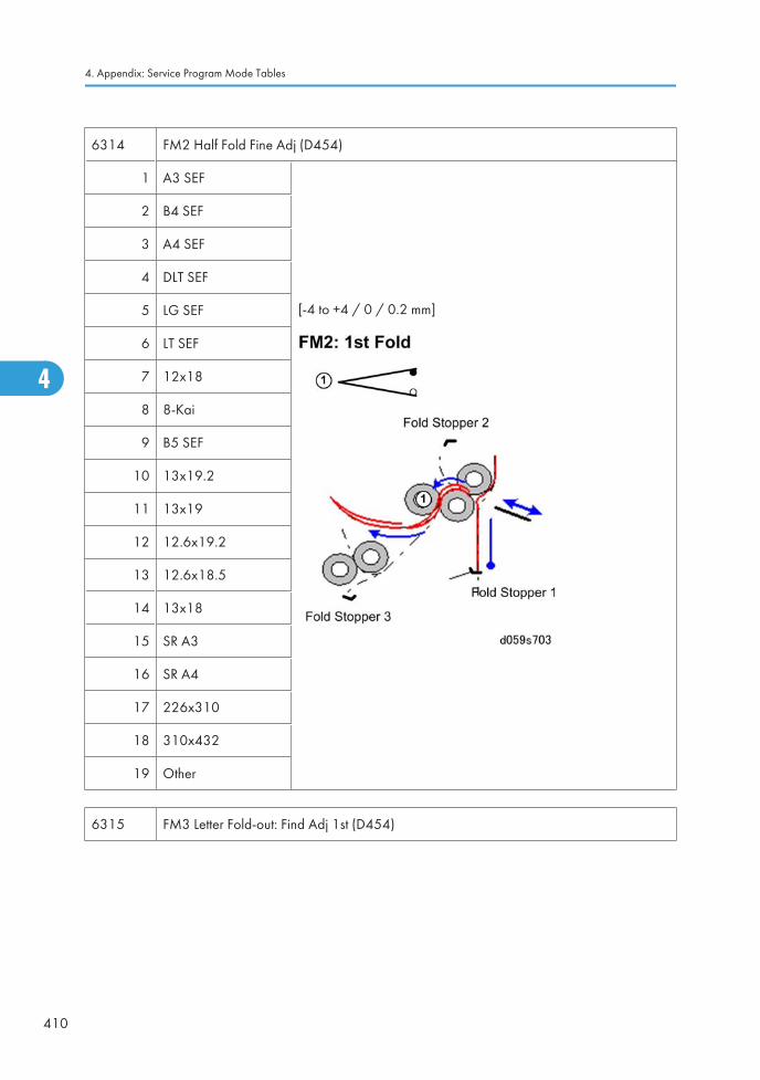
6314 FM2 Half Fold Fine Adj (D454)
1 A3 SEF
[-4 to +4 / 0 / 0.2 mm]
2 B4 SEF
3 A4 SEF
4 DLT SEF
5 LG SEF
6 LT SEF
7 12x18
8 8-Kai
9 B5 SEF
10 13x19.2
11 13x19
12 12.6x19.2
13 12.6x18.5
14 13x18
15 SR A3
16 SR A4
17 226x310
18 310x432
19 Other
6315 FM3 Letter Fold-out: Find Adj 1st (D454)
4. Appendix: Service Program Mode Tables
410
4
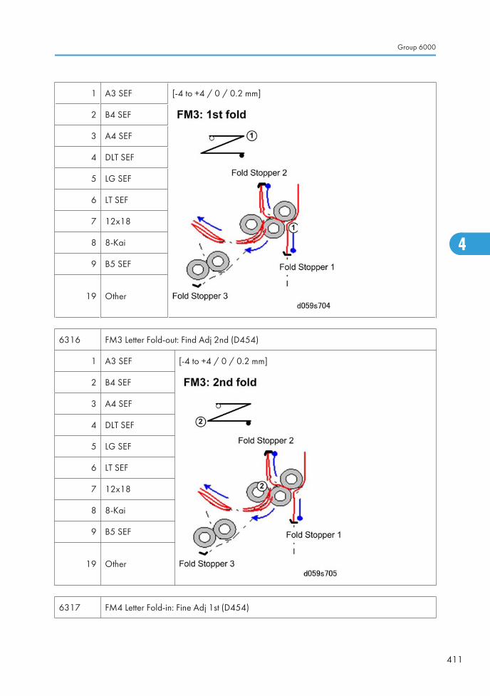
1 A3 SEF [-4 to +4 / 0 / 0.2 mm]
2 B4 SEF
3 A4 SEF
4 DLT SEF
5 LG SEF
6 LT SEF
7 12x18
8 8-Kai
9 B5 SEF
19 Other
6316 FM3 Letter Fold-out: Find Adj 2nd (D454)
1 A3 SEF [-4 to +4 / 0 / 0.2 mm]
2 B4 SEF
3 A4 SEF
4 DLT SEF
5 LG SEF
6 LT SEF
7 12x18
8 8-Kai
9 B5 SEF
19 Other
6317 FM4 Letter Fold-in: Fine Adj 1st (D454)
Group 6000
411
4
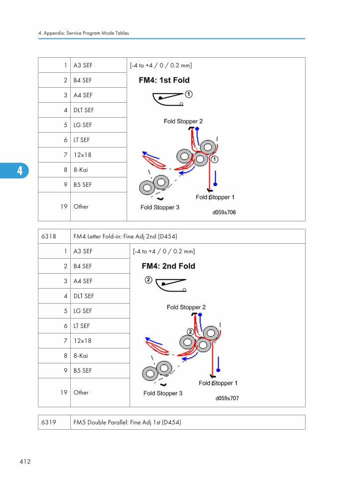
1 A3 SEF [-4 to +4 / 0 / 0.2 mm]
2 B4 SEF
3 A4 SEF
4 DLT SEF
5 LG SEF
6 LT SEF
7 12x18
8 8-Kai
9 B5 SEF
19 Other
6318 FM4 Letter Fold-in: Fine Adj 2nd (D454)
1 A3 SEF [-4 to +4 / 0 / 0.2 mm]
2 B4 SEF
3 A4 SEF
4 DLT SEF
5 LG SEF
6 LT SEF
7 12x18
8 8-Kai
9 B5 SEF
19 Other
6319 FM5 Double Parallel: Fine Adj 1st (D454)
4. Appendix: Service Program Mode Tables
412
4
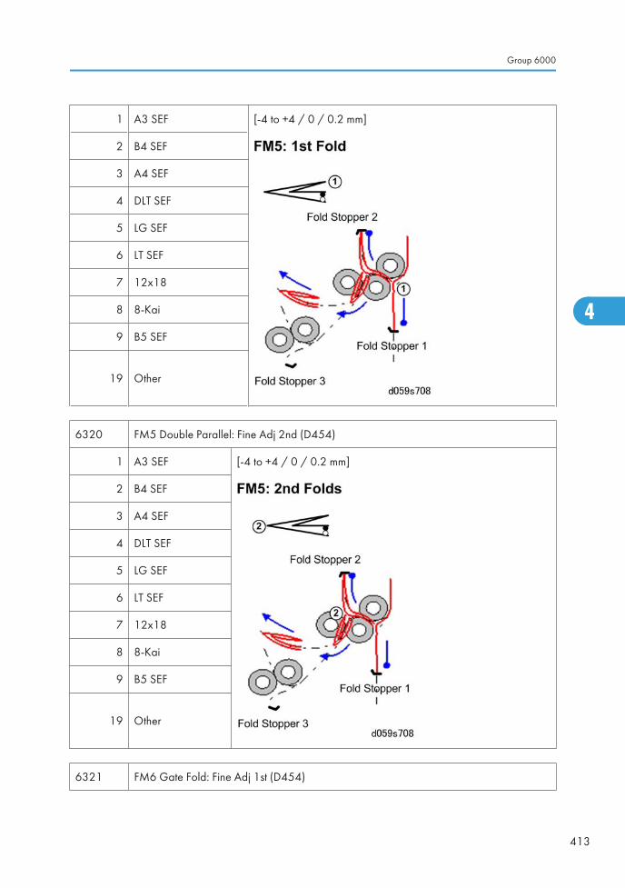
1 A3 SEF [-4 to +4 / 0 / 0.2 mm]
2 B4 SEF
3 A4 SEF
4 DLT SEF
5 LG SEF
6 LT SEF
7 12x18
8 8-Kai
9 B5 SEF
19 Other
6320 FM5 Double Parallel: Fine Adj 2nd (D454)
1 A3 SEF [-4 to +4 / 0 / 0.2 mm]
2 B4 SEF
3 A4 SEF
4 DLT SEF
5 LG SEF
6 LT SEF
7 12x18
8 8-Kai
9 B5 SEF
19 Other
6321 FM6 Gate Fold: Fine Adj 1st (D454)
Group 6000
413
4
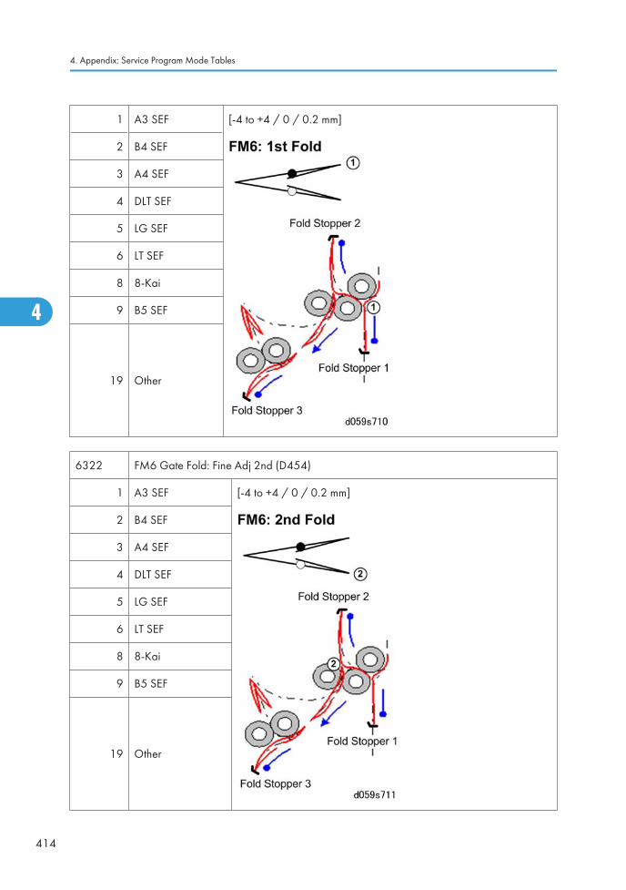
1 A3 SEF [-4 to +4 / 0 / 0.2 mm]
2 B4 SEF
3 A4 SEF
4 DLT SEF
5 LG SEF
6 LT SEF
8 8-Kai
9 B5 SEF
19 Other
6322 FM6 Gate Fold: Fine Adj 2nd (D454)
1 A3 SEF [-4 to +4 / 0 / 0.2 mm]
2 B4 SEF
3 A4 SEF
4 DLT SEF
5 LG SEF
6 LT SEF
8 8-Kai
9 B5 SEF
19 Other
4. Appendix: Service Program Mode Tables
414
4

6323 FM6 Gate Fold: Fine Adj 3rd (D454)
1 A3 SEF [-4 to +4 / 0 / 0.2 mm]
2 B4 SEF
3 A4 SEF
4 DLT SEF
5 LG SEF
6 LT SEF
7 12x18
8 8-Kai
9 B5 SEF
19 Other
6324 Jogger Fence Position Adjust (D454)
1 A3 SEF
[+1 to 1 /0/ 0.5 mm]
2 B4 SEF
3 A4 SEF
4 DLT SEF
5 LG SEF
6 LT SEF
7 12x18
8 8-Kai
9 B5 SEF
19 Other
Group 6000
415
4
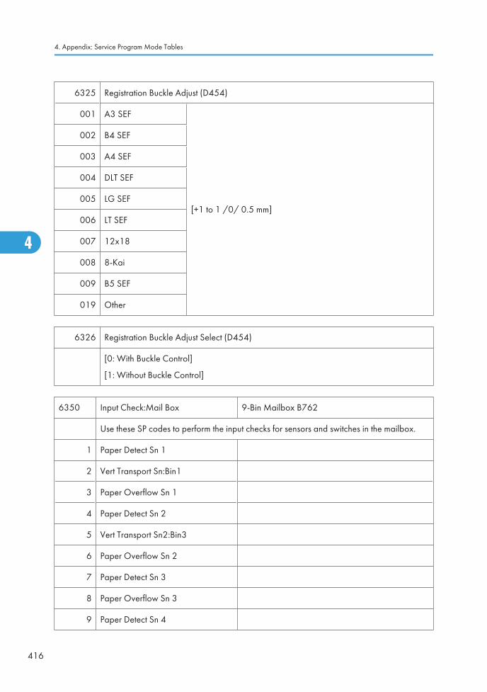
6325 Registration Buckle Adjust (D454)
001 A3 SEF
[+1 to 1 /0/ 0.5 mm]
002 B4 SEF
003 A4 SEF
004 DLT SEF
005 LG SEF
006 LT SEF
007 12x18
008 8-Kai
009 B5 SEF
019 Other
6326 Registration Buckle Adjust Select (D454)
[0: With Buckle Control]
[1: Without Buckle Control]
6350 Input Check:Mail Box 9-Bin Mailbox B762
Use these SP codes to perform the input checks for sensors and switches in the mailbox.
1 Paper Detect Sn 1
2 Vert Transport Sn:Bin1
3 Paper Overflow Sn 1
4 Paper Detect Sn 2
5 Vert Transport Sn2:Bin3
6 Paper Overflow Sn 2
7 Paper Detect Sn 3
8 Paper Overflow Sn 3
9 Paper Detect Sn 4
4. Appendix: Service Program Mode Tables
416
4
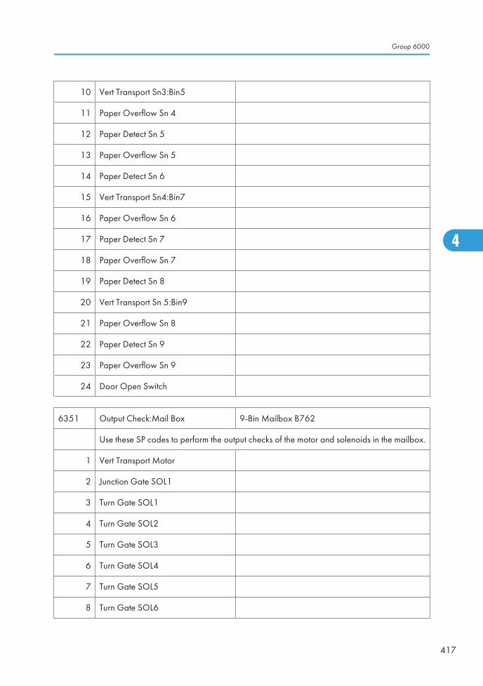
10 Vert Transport Sn3:Bin5
11 Paper Overflow Sn 4
12 Paper Detect Sn 5
13 Paper Overflow Sn 5
14 Paper Detect Sn 6
15 Vert Transport Sn4:Bin7
16 Paper Overflow Sn 6
17 Paper Detect Sn 7
18 Paper Overflow Sn 7
19 Paper Detect Sn 8
20 Vert Transport Sn 5:Bin9
21 Paper Overflow Sn 8
22 Paper Detect Sn 9
23 Paper Overflow Sn 9
24 Door Open Switch
6351 Output Check:Mail Box 9-Bin Mailbox B762
Use these SP codes to perform the output checks of the motor and solenoids in the mailbox.
1 Vert Transport Motor
2 Junction Gate SOL1
3 Turn Gate SOL1
4 Turn Gate SOL2
5 Turn Gate SOL3
6 Turn Gate SOL4
7 Turn Gate SOL5
8 Turn Gate SOL6
Group 6000
417
4
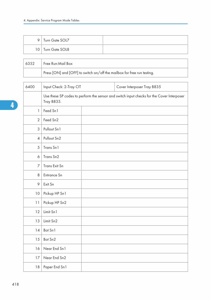
9 Turn Gate SOL7
10 Turn Gate SOL8
6352 Free Run:Mail Box
Press [ON] and [OFF] to switch on/off the mailbox for free run testing.
6400 Input Check: 2-Tray CIT Cover Interposer Tray B835
Use these SP codes to perform the sensor and switch input checks for the Cover InterposerTray B835.
1 Feed Sn1
2 Feed Sn2
3 Pullout Sn1
4 Pullout Sn2
5 Trans Sn1
6 Trans Sn2
7 Trans Exit Sn
8 Entrance Sn
9 Exit Sn
10 Pickup HP Sn1
11 Pickup HP Sn2
12 Limit Sn1
13 Limit Sn2
14 Bot Sn1
15 Bot Sn2
16 Near End Sn1
17 Near End Sn2
18 Paper End Sn1
4. Appendix: Service Program Mode Tables
418
4

19 Paper End Sn2
20 Length Sn1
21 Length Sn2
22 Tray1 Size Sn1
23 Tray1 Size Sn2
24 Tray1 Size Sn3
25 Tray1 Size Sn4
26 Tray1 Size Sn5
27 Tray2 Size Sn1
28 Tray2 Size Sn2
29 Tray2 Size Sn3
30 Tray2 Size Sn4
31 Tray2 Size Sn5
32 Feed Door Sn1
33 Feed Door Sn2
34 Trans Door SW
35 Front Door SW
6401 Output Check:2-Tray CIT Cover Interposer Tray B835
Use these SP codes to perform the output checks for the motors of the Cover Interposer TrayB835.
1 Stop
2 Pickup M1
3 Pickup M2
4 Feed M1
5 Feed M2
Group 6000
419
4
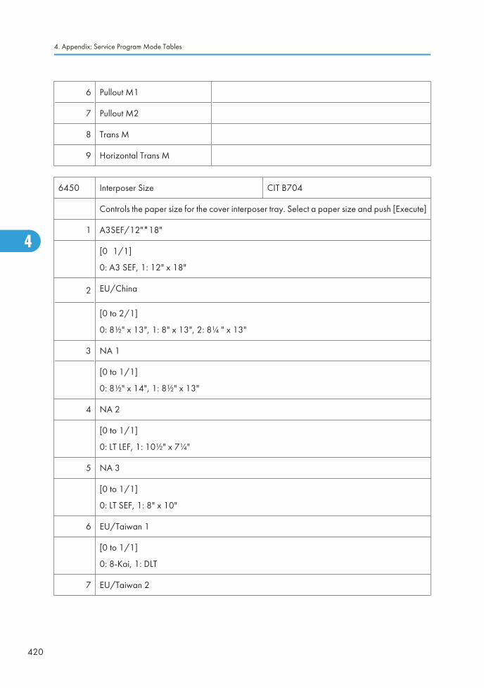
6 Pullout M1
7 Pullout M2
8 Trans M
9 Horizontal Trans M
6450 Interposer Size CIT B704
Controls the paper size for the cover interposer tray. Select a paper size and push [Execute]
1 A3SEF/12"*18"
[0∼1/1]
0: A3 SEF, 1: 12" x 18"
2 EU/China
[0 to 2/1]
0: 8½" x 13", 1: 8" x 13", 2: 8¼ " x 13"
3 NA 1
[0 to 1/1]
0: 8½" x 14", 1: 8½" x 13"
4 NA 2
[0 to 1/1]
0: LT LEF, 1: 10½" x 7¼"
5 NA 3
[0 to 1/1]
0: LT SEF, 1: 8" x 10"
6 EU/Taiwan 1
[0 to 1/1]
0: 8-Kai, 1: DLT
7 EU/Taiwan 2
4. Appendix: Service Program Mode Tables
420
4
[0 to 1/1]
0: 16-Kai SEF, 1: LT
8 EU/Taiwan 3
[0 to 1/1]
0: 16-Kai SEF, 1: LT SEF
6451 Input Check:1-Tray CIT Cover Interposer B704
Use these SP codes to perform the input checks for the sensors of the Cover Interposer TrayB704.
1 Paper Feed Cover Sensor
2 Bottom Plate HP Sensor
3 Paper Near End Sensor
4 Paper Set Sensor
5 Bottom Plate HP Sensor
6 Grip Sensor
7 Guide Plate Set Sensor
8 Exit Sensor
9 Paper Set Sensor
10 Width Sensor 1
11 Width Sensor 2
12 Width Sensor 3
13 Length Sensor 1
14 Length Sensor 2
15 Length Sensor 3
6502 Adj Binding Position 1 Ring Binder D392
1 A4 LEF
Group 6000
421
4
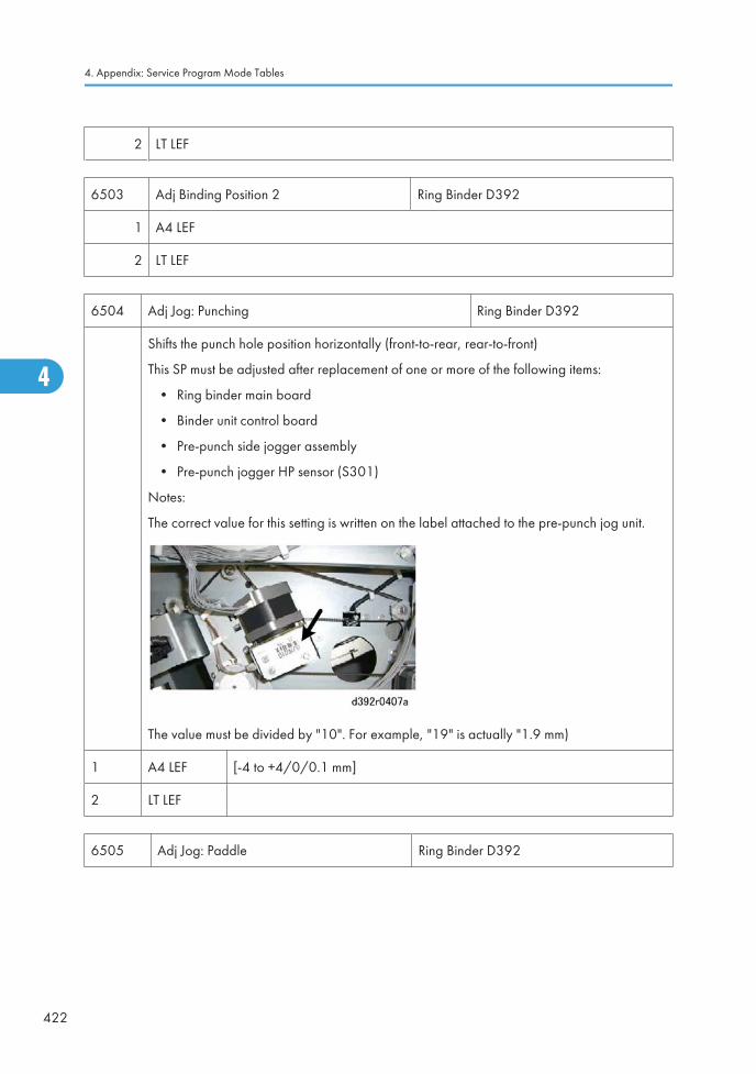
2 LT LEF
6503 Adj Binding Position 2 Ring Binder D392
1 A4 LEF
2 LT LEF
6504 Adj Jog: Punching Ring Binder D392
Shifts the punch hole position horizontally (front-to-rear, rear-to-front)
This SP must be adjusted after replacement of one or more of the following items:
• Ring binder main board
• Binder unit control board
• Pre-punch side jogger assembly
• Pre-punch jogger HP sensor (S301)
Notes:
The correct value for this setting is written on the label attached to the pre-punch jog unit.
The value must be divided by "10". For example, "19" is actually "1.9 mm)
1 A4 LEF [-4 to +4/0/0.1 mm]
2 LT LEF
6505 Adj Jog: Paddle Ring Binder D392
4. Appendix: Service Program Mode Tables
422
4
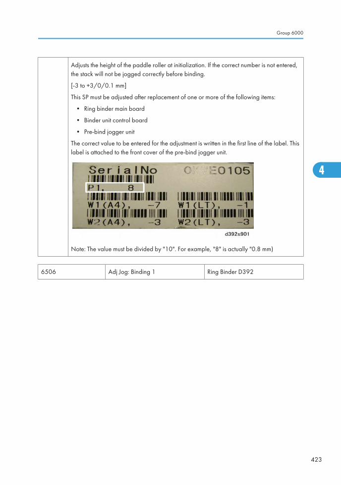
Adjusts the height of the paddle roller at initialization. If the correct number is not entered,the stack will not be jogged correctly before binding.
[-3 to +3/0/0.1 mm]
This SP must be adjusted after replacement of one or more of the following items:
• Ring binder main board
• Binder unit control board
• Pre-bind jogger unit
The correct value to be entered for the adjustment is written in the first line of the label. Thislabel is attached to the front cover of the pre-bind jogger unit.
Note: The value must be divided by "10". For example, "8" is actually "0.8 mm)
6506 Adj Jog: Binding 1 Ring Binder D392
Group 6000
423
4
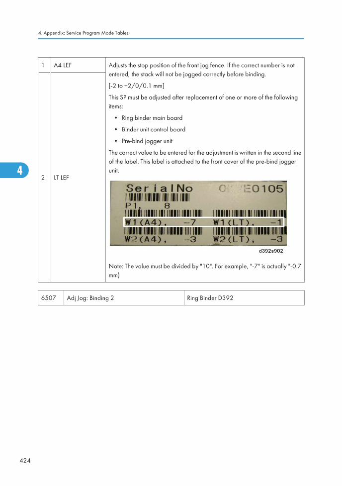
1 A4 LEF Adjusts the stop position of the front jog fence. If the correct number is notentered, the stack will not be jogged correctly before binding.
[-2 to +2/0/0.1 mm]
This SP must be adjusted after replacement of one or more of the followingitems:
• Ring binder main board
• Binder unit control board
• Pre-bind jogger unit
The correct value to be entered for the adjustment is written in the second lineof the label. This label is attached to the front cover of the pre-bind joggerunit.
Note: The value must be divided by "10". For example, "-7" is actually "-0.7mm)
2 LT LEF
6507 Adj Jog: Binding 2 Ring Binder D392
4. Appendix: Service Program Mode Tables
424
4
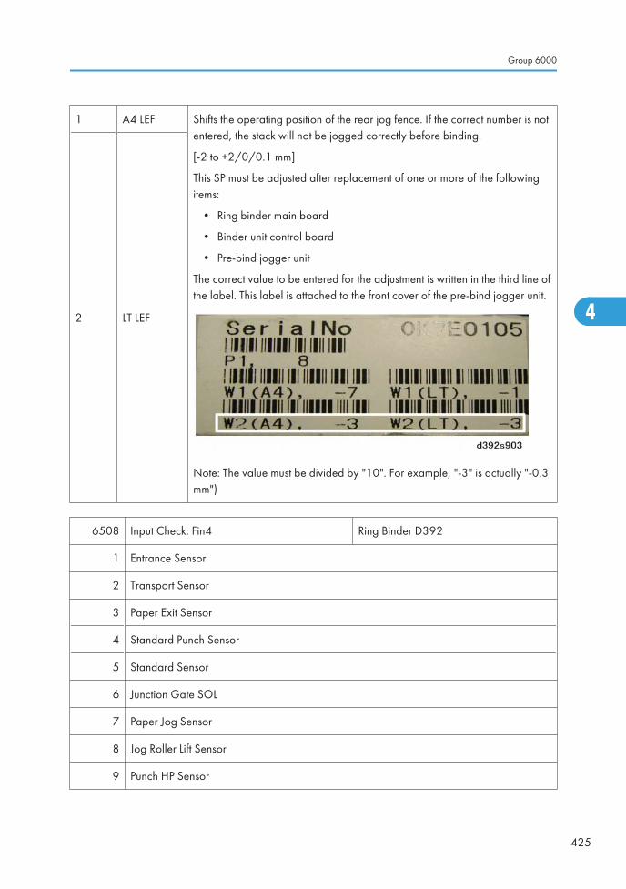
1 A4 LEF Shifts the operating position of the rear jog fence. If the correct number is notentered, the stack will not be jogged correctly before binding.
[-2 to +2/0/0.1 mm]
This SP must be adjusted after replacement of one or more of the followingitems:
• Ring binder main board
• Binder unit control board
• Pre-bind jogger unit
The correct value to be entered for the adjustment is written in the third line ofthe label. This label is attached to the front cover of the pre-bind jogger unit.
Note: The value must be divided by "10". For example, "-3" is actually "-0.3mm")
2 LT LEF
6508 Input Check: Fin4 Ring Binder D392
1 Entrance Sensor
2 Transport Sensor
3 Paper Exit Sensor
4 Standard Punch Sensor
5 Standard Sensor
6 Junction Gate SOL
7 Paper Jog Sensor
8 Jog Roller Lift Sensor
9 Punch HP Sensor
Group 6000
425
4
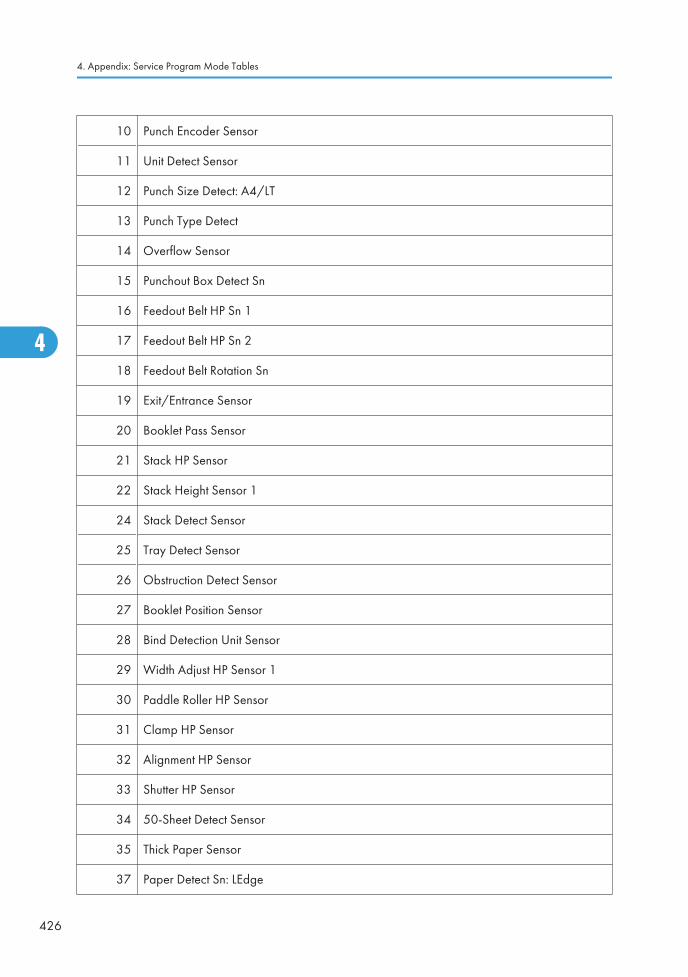
10 Punch Encoder Sensor
11 Unit Detect Sensor
12 Punch Size Detect: A4/LT
13 Punch Type Detect
14 Overflow Sensor
15 Punchout Box Detect Sn
16 Feedout Belt HP Sn 1
17 Feedout Belt HP Sn 2
18 Feedout Belt Rotation Sn
19 Exit/Entrance Sensor
20 Booklet Pass Sensor
21 Stack HP Sensor
22 Stack Height Sensor 1
24 Stack Detect Sensor
25 Tray Detect Sensor
26 Obstruction Detect Sensor
27 Booklet Position Sensor
28 Bind Detection Unit Sensor
29 Width Adjust HP Sensor 1
30 Paddle Roller HP Sensor
31 Clamp HP Sensor
32 Alignment HP Sensor
33 Shutter HP Sensor
34 50-Sheet Detect Sensor
35 Thick Paper Sensor
37 Paper Detect Sn: LEdge
4. Appendix: Service Program Mode Tables
426
4
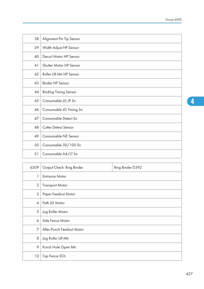
38 Alignment Pin Tip Sensor
39 Width Adjust HP Sensor
40 Decurl Motor HP Sensor
41 Shutter Motor HP Sensor
42 Roller Lift Mtr HP Sensor
43 Binder HP Sensor
44 Binding Timing Sensor
45 Consumable JG JP Sn
46 Consumable JG Timing Sn
47 Consumable Detect Sn
48 Cutter Detect Sensor
49 Consumable NE Sensor
50 Consumable 50/100 Sn
51 Consumable A4/LT Sn
6509 Output Check: Ring Binder Ring Binder D392
1 Entrance Motor
2 Transport Motor
3 Paper Feedout Motor
4 Path JG Motor
5 Jog Roller Motor
6 Side Fence Motor
7 After-Punch Feedout Motor
8 Jog Roller Lift Mtr
9 Punch Hole Open Mtr
10 Top Fence SOL
Group 6000
427
4
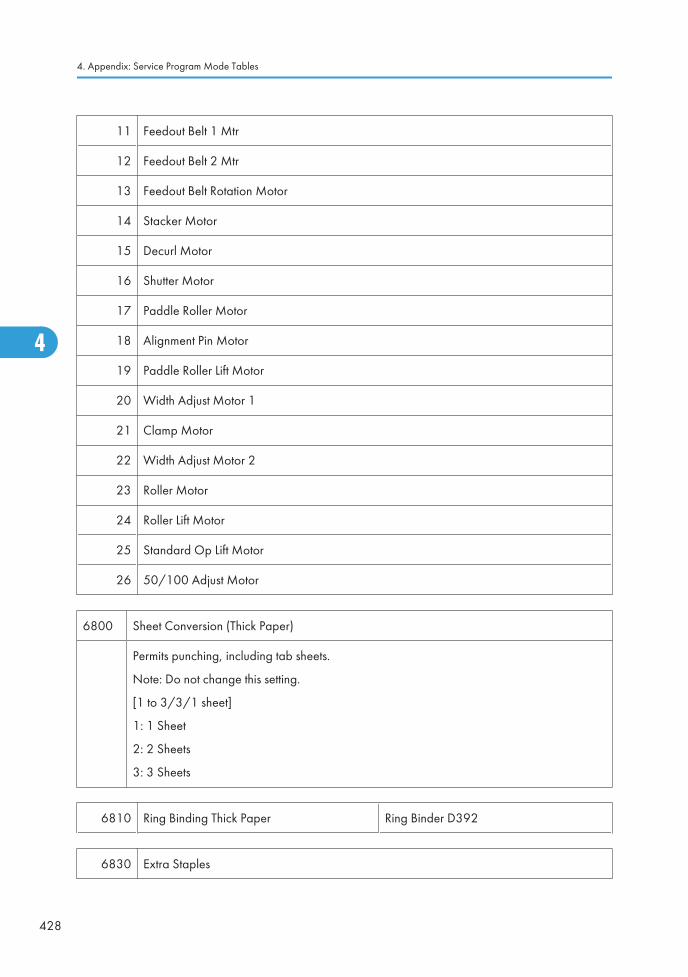
11 Feedout Belt 1 Mtr
12 Feedout Belt 2 Mtr
13 Feedout Belt Rotation Motor
14 Stacker Motor
15 Decurl Motor
16 Shutter Motor
17 Paddle Roller Motor
18 Alignment Pin Motor
19 Paddle Roller Lift Motor
20 Width Adjust Motor 1
21 Clamp Motor
22 Width Adjust Motor 2
23 Roller Motor
24 Roller Lift Motor
25 Standard Op Lift Motor
26 50/100 Adjust Motor
6800 Sheet Conversion (Thick Paper)
Permits punching, including tab sheets.
Note: Do not change this setting.
[1 to 3/3/1 sheet]
1: 1 Sheet
2: 2 Sheets
3: 3 Sheets
6810 Ring Binding Thick Paper Ring Binder D392
6830 Extra Staples
4. Appendix: Service Program Mode Tables
428
4
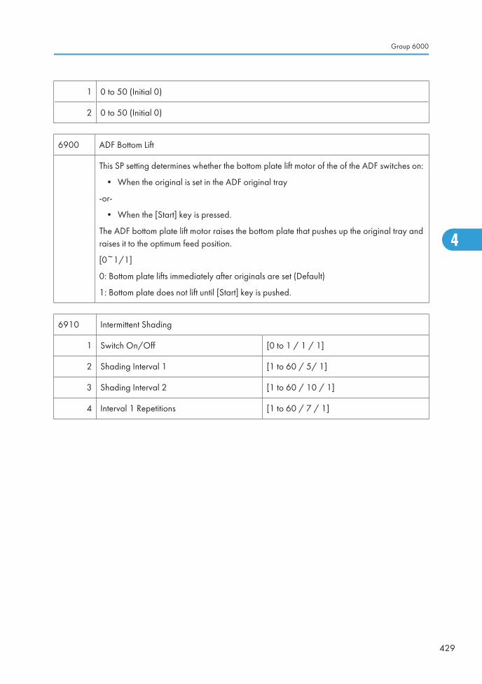
1 0 to 50 (Initial 0)
2 0 to 50 (Initial 0)
6900 ADF Bottom Lift
This SP setting determines whether the bottom plate lift motor of the of the ADF switches on:
• When the original is set in the ADF original tray
-or-
• When the [Start] key is pressed.
The ADF bottom plate lift motor raises the bottom plate that pushes up the original tray andraises it to the optimum feed position.
[0~1/1]
0: Bottom plate lifts immediately after originals are set (Default)
1: Bottom plate does not lift until [Start] key is pushed.
6910 Intermittent Shading
1 Switch On/Off [0 to 1 / 1 / 1]
2 Shading Interval 1 [1 to 60 / 5/ 1]
3 Shading Interval 2 [1 to 60 / 10 / 1]
4 Interval 1 Repetitions [1 to 60 / 7 / 1]
Group 6000
429
4
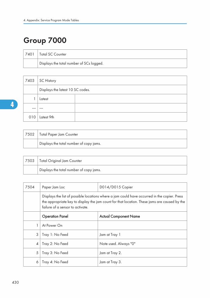
Group 70007401 Total SC Counter
Displays the total number of SCs logged.
7403 SC History
Displays the latest 10 SC codes.
1 Latest
--- ---
010 Latest 9th
7502 Total Paper Jam Counter
Displays the total number of copy jams.
7503 Total Original Jam Counter
Displays the total number of copy jams.
7504 Paper Jam Loc D014/D015 Copier
Displays the list of possible locations where a jam could have occurred in the copier. Pressthe appropriate key to display the jam count for that location. These jams are caused by thefailure of a sensor to activate.
Operation Panel Actual Component Name
1 At Power On
3 Tray 1: No Feed Jam at Tray 1
4 Tray 2: No Feed Note used. Always "0"
5 Tray 3: No Feed Jam at Tray 2.
6 Tray 4: No Feed Jam at Tray 3.
4. Appendix: Service Program Mode Tables
430
4
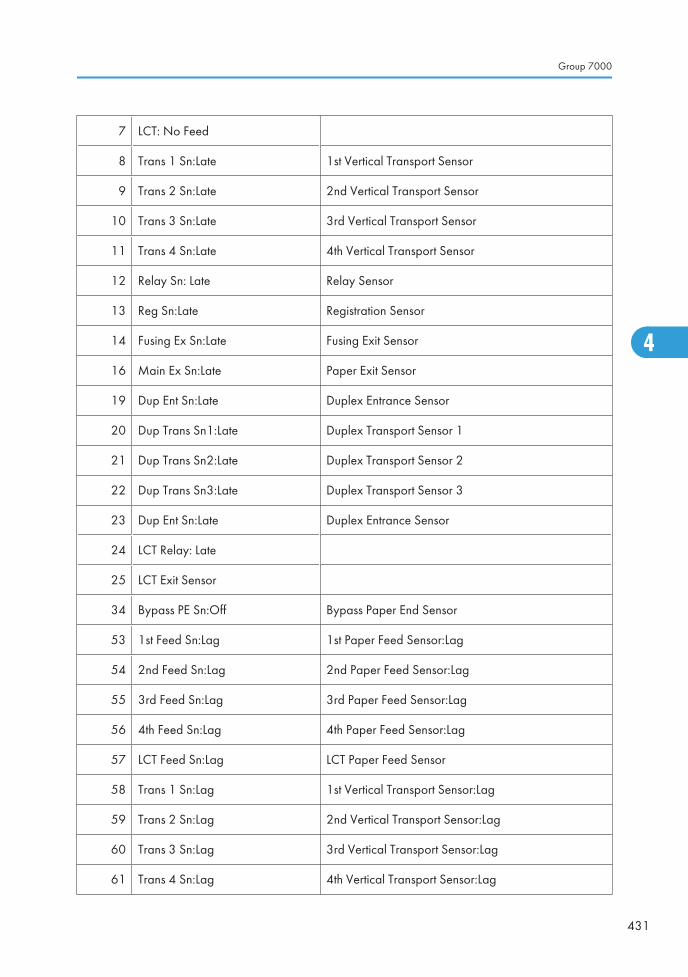
7 LCT: No Feed
8 Trans 1 Sn:Late 1st Vertical Transport Sensor
9 Trans 2 Sn:Late 2nd Vertical Transport Sensor
10 Trans 3 Sn:Late 3rd Vertical Transport Sensor
11 Trans 4 Sn:Late 4th Vertical Transport Sensor
12 Relay Sn: Late Relay Sensor
13 Reg Sn:Late Registration Sensor
14 Fusing Ex Sn:Late Fusing Exit Sensor
16 Main Ex Sn:Late Paper Exit Sensor
19 Dup Ent Sn:Late Duplex Entrance Sensor
20 Dup Trans Sn1:Late Duplex Transport Sensor 1
21 Dup Trans Sn2:Late Duplex Transport Sensor 2
22 Dup Trans Sn3:Late Duplex Transport Sensor 3
23 Dup Ent Sn:Late Duplex Entrance Sensor
24 LCT Relay: Late
25 LCT Exit Sensor
34 Bypass PE Sn:Off Bypass Paper End Sensor
53 1st Feed Sn:Lag 1st Paper Feed Sensor:Lag
54 2nd Feed Sn:Lag 2nd Paper Feed Sensor:Lag
55 3rd Feed Sn:Lag 3rd Paper Feed Sensor:Lag
56 4th Feed Sn:Lag 4th Paper Feed Sensor:Lag
57 LCT Feed Sn:Lag LCT Paper Feed Sensor
58 Trans 1 Sn:Lag 1st Vertical Transport Sensor:Lag
59 Trans 2 Sn:Lag 2nd Vertical Transport Sensor:Lag
60 Trans 3 Sn:Lag 3rd Vertical Transport Sensor:Lag
61 Trans 4 Sn:Lag 4th Vertical Transport Sensor:Lag
Group 7000
431
4
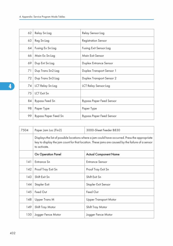
62 Relay Sn:Lag Relay Sensor:Lag
63 Reg Sn:Lag Registration Sensor
64 Fusing Ex Sn:Lag Fusing Exit Sensor:Lag
66 Main Ex Sn:Lag Main Exit Sensor
69 Dup Ent Sn:Lag Duplex Entrance Sensor
71 Dup Trans Sn2:Lag Duplex Transport Sensor 1
72 Dup Trans Sn3:Lag Duplex Transport Sensor 2
74 LCT Relay Sn:Lag LCT Relay Sensor:Lag
75 LCT Exit Sn
84 Bypass Feed Sn Bypass Paper Feed Sensor
98 Paper Type Paper Type
99 Bypass Paper Feed Sn Bypass Paper Feed Sensor
7504 Paper Jam Loc (Fin2) 3000-Sheet Feeder B830
Displays the list of possible locations where a jam could have occurred. Press the appropriatekey to display the jam count for that location. These jams are caused by the failure of a sensorto activate.
On Operation Panel Actual Component Name
141 Entrance Sn Entrance Sensor
142 Proof Tray Exit Sn Proof Tray Exit Sn
143 Shift Exit Sn Shift Exit Sn
144 Stapler Exit Stapler Exit Sensor
145 Feed Out Feed Out
148 Upper Trans M Upper Transport Motor
149 Shift Tray Motor Shift Tray Motor
150 Jogger Fence Motor Jogger Fence Motor
4. Appendix: Service Program Mode Tables
432
4
Ed
Typewritten Text
SP7504-99 RTB 85 RTB 86
Ed
Typewritten Text
-146 added RTB 38
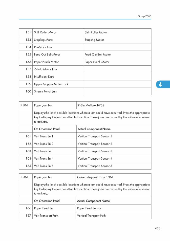
151 Shift Roller Motor Shift Roller Motor
153 Stapling Motor Stapling Motor
154 Pre-Stack Jam
155 Feed Out Belt Motor Feed Out Belt Motor
156 Paper Punch Motor Paper Punch Motor
157 Z-Fold Motor Jam
158 Insufficient Data
159 Upper Stopper Motor Lock
160 Stream Punch Jam
7504 Paper Jam Loc 9-Bin Mailbox B762
Displays the list of possible locations where a jam could have occurred. Press the appropriatekey to display the jam count for that location. These jams are caused by the failure of a sensorto activate.
On Operation Panel Actual Component Name
161 Vert Trans Sn 1 Vertical Transport Sensor 1
162 Vert Trans Sn 2 Vertical Transport Sensor 2
163 Vert Trans Sn 3 Vertical Transport Sensor 3
164 Vert Trans Sn 4 Vertical Transport Sensor 4
165 Vert Trans Sn 5 Vertical Transport Sensor 5
7504 Paper Jam Loc Cover Interposer Tray B704
Displays the list of possible locations where a jam could have occurred. Press the appropriatekey to display the jam count for that location. These jams are caused by the failure of a sensorto activate.
On Operation Panel Actual Component Name
166 Paper Feed Sn Paper Feed Sensor
167 Vert Transport Path Vertical Transport Path
Group 7000
433
4
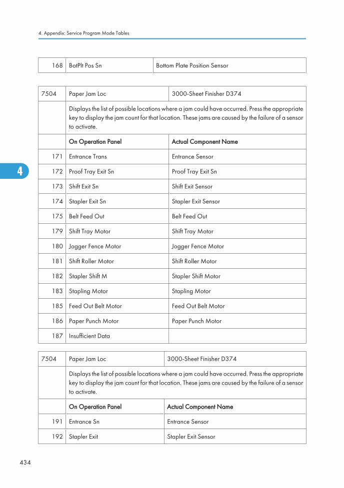
168 BotPlt Pos Sn Bottom Plate Position Sensor
7504 Paper Jam Loc 3000-Sheet Finisher D374
Displays the list of possible locations where a jam could have occurred. Press the appropriatekey to display the jam count for that location. These jams are caused by the failure of a sensorto activate.
On Operation Panel Actual Component Name
171 Entrance Trans Entrance Sensor
172 Proof Tray Exit Sn Proof Tray Exit Sn
173 Shift Exit Sn Shift Exit Sensor
174 Stapler Exit Sn Stapler Exit Sensor
175 Belt Feed Out Belt Feed Out
179 Shift Tray Motor Shift Tray Motor
180 Jogger Fence Motor Jogger Fence Motor
181 Shift Roller Motor Shift Roller Motor
182 Stapler Shift M Stapler Shift Motor
183 Stapling Motor Stapling Motor
185 Feed Out Belt Motor Feed Out Belt Motor
186 Paper Punch Motor Paper Punch Motor
187 Insufficient Data
7504 Paper Jam Loc 3000-Sheet Finisher D374
Displays the list of possible locations where a jam could have occurred. Press the appropriatekey to display the jam count for that location. These jams are caused by the failure of a sensorto activate.
On Operation Panel Actual Component Name
191 Entrance Sn Entrance Sensor
192 Stapler Exit Stapler Exit Sensor
4. Appendix: Service Program Mode Tables
434
4
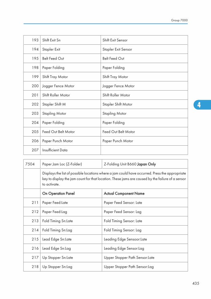
193 Shift Exit Sn Shift Exit Sensor
194 Stapler Exit Stapler Exit Sensor
195 Belt Feed Out Belt Feed Out
198 Paper Folding Paper Folding
199 Shift Tray Motor Shift Tray Motor
200 Jogger Fence Motor Jogger Fence Motor
201 Shift Roller Motor Shift Roller Motor
202 Stapler Shift M Stapler Shift Motor
203 Stapling Motor Stapling Motor
204 Paper Folding Paper Folding
205 Feed Out Belt Motor Feed Out Belt Motor
206 Paper Punch Motor Paper Punch Motor
207 Insufficient Data
7504 Paper Jam Loc (Z-Folder) Z-Folding Unit B660 Japan Only
Displays the list of possible locations where a jam could have occurred. Press the appropriatekey to display the jam count for that location. These jams are caused by the failure of a sensorto activate.
On Operation Panel Actual Component Name
211 Paper Feed:Late Paper Feed Sensor: Late
212 Paper Feed:Lag Paper Feed Sensor: Lag
213 Fold Timing Sn:Late Fold Timing Sensor: Late
214 Fold Timing Sn:Lag Fold Timing Sensor: Lag
215 Lead Edge Sn:Late Leading Edge Sensoor:Late
216 Lead Edge Sn:Lag Leading Edge Sensor:Lag
217 Up Stopper Sn:Late Upper Stopper Path Sensor:Late
218 Up Stopper Sn:Lag Upper Stopper Path Sensor:Lag
Group 7000
435
4
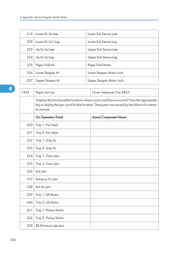
219 Lower Ex Sn:Late Lower Exit Sensor:Late
220 Lower Ex Sn1:Lag Lower Exit Sensor:Lag
223 Up Ex Sn:Late Upper Exit Sensor:Late
224 Up Ex Sn:Lag Upper Exit Sensor:Lag
225 Paper Fold M Paper Fold Motor
226 Lower Stopper M Lower Stopper Motor Lock
227 Upper Stopper M Upper Stopper Motor Lock
7504 Paper Jam Loc Cover Interposer Tray B835
Displays the list of possible locations where a jam could have occurred. Press the appropriatekey to display the jam count for that location. These jams are caused by the failure of a sensorto activate.
On Operation Panel Actual Component Name
230 Tray 1: No Feed
231 Tray 2: No Feed
232 Tray 1: Grip Sn
233 Tray 2: Grip Sn
234 Tray 1: Trans Jam
235 Tray 2: Trans Jam
236 Exit Jam
237 Entrance Sn Jam
238 Exit Sn Jam
239 Tray 1: Lift Motor
240 Tray 2: Lift Motor
241 Tray 1: Pickup Motor
242 Tray 2: Pickup Motor
250 RB Entrance Late Jam
4. Appendix: Service Program Mode Tables
436
4
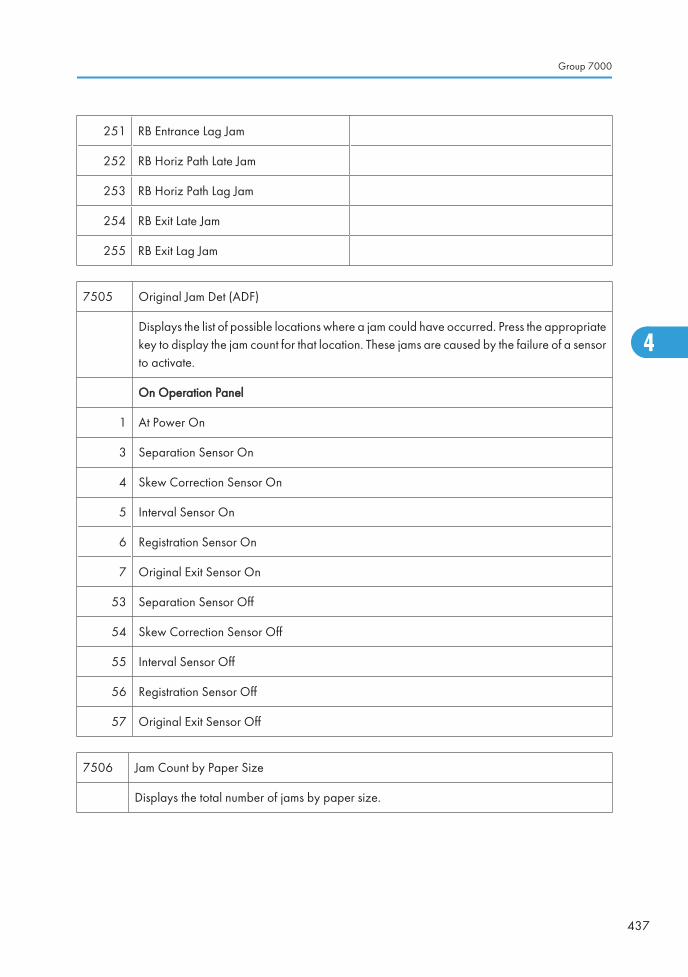
251 RB Entrance Lag Jam
252 RB Horiz Path Late Jam
253 RB Horiz Path Lag Jam
254 RB Exit Late Jam
255 RB Exit Lag Jam
7505 Original Jam Det (ADF)
Displays the list of possible locations where a jam could have occurred. Press the appropriatekey to display the jam count for that location. These jams are caused by the failure of a sensorto activate.
On Operation Panel
1 At Power On
3 Separation Sensor On
4 Skew Correction Sensor On
5 Interval Sensor On
6 Registration Sensor On
7 Original Exit Sensor On
53 Separation Sensor Off
54 Skew Correction Sensor Off
55 Interval Sensor Off
56 Registration Sensor Off
57 Original Exit Sensor Off
7506 Jam Count by Paper Size
Displays the total number of jams by paper size.
Group 7000
437
4
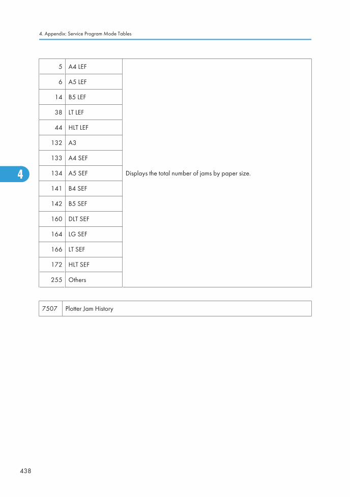
5 A4 LEF
Displays the total number of jams by paper size.
6 A5 LEF
14 B5 LEF
38 LT LEF
44 HLT LEF
132 A3
133 A4 SEF
134 A5 SEF
141 B4 SEF
142 B5 SEF
160 DLT SEF
164 LG SEF
166 LT SEF
172 HLT SEF
255 Others
7507 Plotter Jam History
4. Appendix: Service Program Mode Tables
438
4
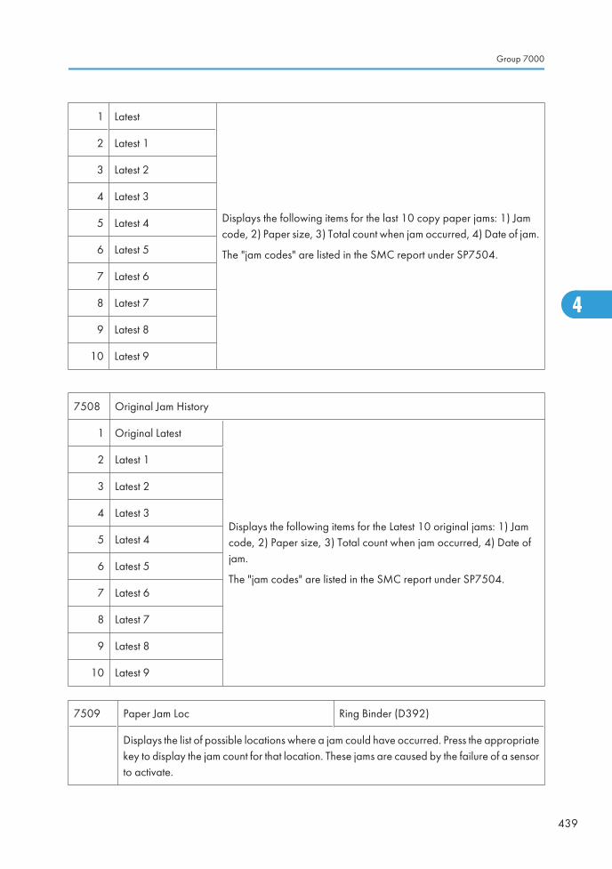
1 Latest
Displays the following items for the last 10 copy paper jams: 1) Jamcode, 2) Paper size, 3) Total count when jam occurred, 4) Date of jam.
The "jam codes" are listed in the SMC report under SP7504.
2 Latest 1
3 Latest 2
4 Latest 3
5 Latest 4
6 Latest 5
7 Latest 6
8 Latest 7
9 Latest 8
10 Latest 9
7508 Original Jam History
1 Original Latest
Displays the following items for the Latest 10 original jams: 1) Jamcode, 2) Paper size, 3) Total count when jam occurred, 4) Date ofjam.
The "jam codes" are listed in the SMC report under SP7504.
2 Latest 1
3 Latest 2
4 Latest 3
5 Latest 4
6 Latest 5
7 Latest 6
8 Latest 7
9 Latest 8
10 Latest 9
7509 Paper Jam Loc Ring Binder (D392)
Displays the list of possible locations where a jam could have occurred. Press the appropriatekey to display the jam count for that location. These jams are caused by the failure of a sensorto activate.
Group 7000
439
4
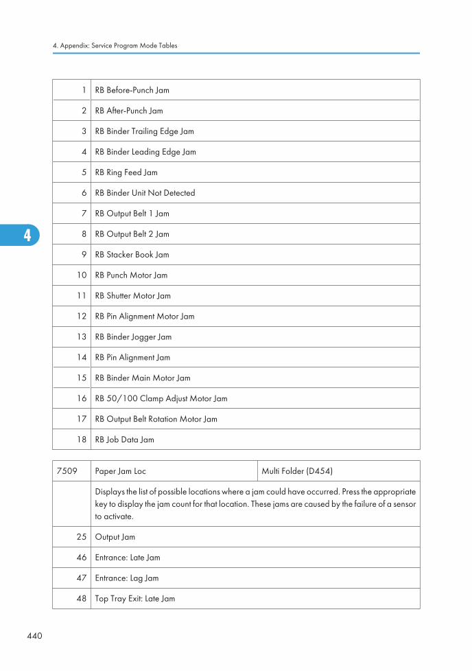
1 RB Before-Punch Jam
2 RB After-Punch Jam
3 RB Binder Trailing Edge Jam
4 RB Binder Leading Edge Jam
5 RB Ring Feed Jam
6 RB Binder Unit Not Detected
7 RB Output Belt 1 Jam
8 RB Output Belt 2 Jam
9 RB Stacker Book Jam
10 RB Punch Motor Jam
11 RB Shutter Motor Jam
12 RB Pin Alignment Motor Jam
13 RB Binder Jogger Jam
14 RB Pin Alignment Jam
15 RB Binder Main Motor Jam
16 RB 50/100 Clamp Adjust Motor Jam
17 RB Output Belt Rotation Motor Jam
18 RB Job Data Jam
7509 Paper Jam Loc Multi Folder (D454)
Displays the list of possible locations where a jam could have occurred. Press the appropriatekey to display the jam count for that location. These jams are caused by the failure of a sensorto activate.
25 Output Jam
46 Entrance: Late Jam
47 Entrance: Lag Jam
48 Top Tray Exit: Late Jam
4. Appendix: Service Program Mode Tables
440
4
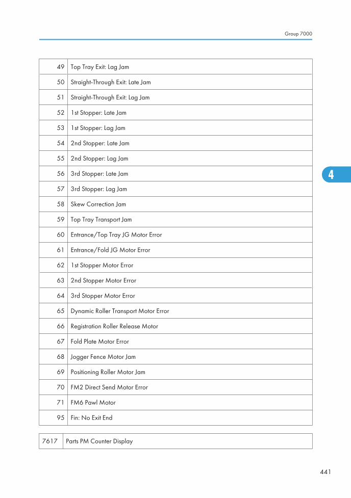
49 Top Tray Exit: Lag Jam
50 Straight-Through Exit: Late Jam
51 Straight-Through Exit: Lag Jam
52 1st Stopper: Late Jam
53 1st Stopper: Lag Jam
54 2nd Stopper: Late Jam
55 2nd Stopper: Lag Jam
56 3rd Stopper: Late Jam
57 3rd Stopper: Lag Jam
58 Skew Correction Jam
59 Top Tray Transport Jam
60 Entrance/Top Tray JG Motor Error
61 Entrance/Fold JG Motor Error
62 1st Stopper Motor Error
63 2nd Stopper Motor Error
64 3rd Stopper Motor Error
65 Dynamic Roller Transport Motor Error
66 Registration Roller Release Motor
67 Fold Plate Motor Error
68 Jogger Fence Motor Jam
69 Positioning Roller Motor Jam
70 FM2 Direct Send Motor Error
71 FM6 Pawl Motor
95 Fin: No Exit End
7617 Parts PM Counter Display
Group 7000
441
4
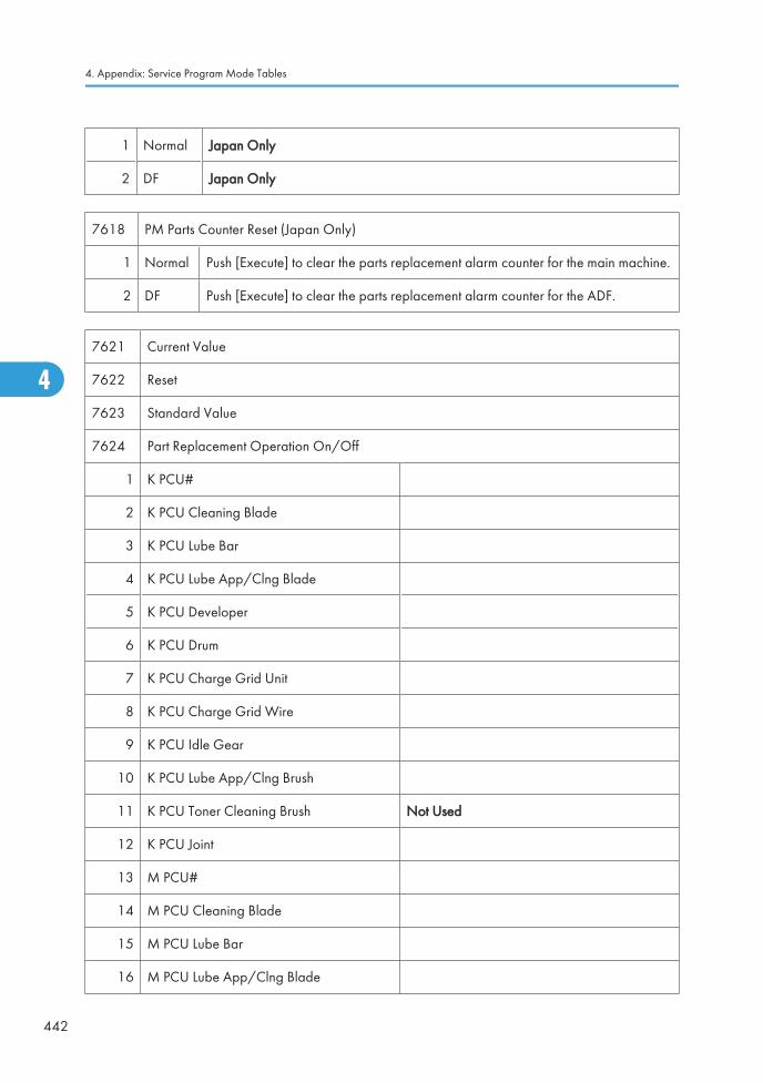
1 Normal Japan Only
2 DF Japan Only
7618 PM Parts Counter Reset (Japan Only)
1 Normal Push [Execute] to clear the parts replacement alarm counter for the main machine.
2 DF Push [Execute] to clear the parts replacement alarm counter for the ADF.
7621 Current Value
7622 Reset
7623 Standard Value
7624 Part Replacement Operation On/Off
1 K PCU#
2 K PCU Cleaning Blade
3 K PCU Lube Bar
4 K PCU Lube App/Clng Blade
5 K PCU Developer
6 K PCU Drum
7 K PCU Charge Grid Unit
8 K PCU Charge Grid Wire
9 K PCU Idle Gear
10 K PCU Lube App/Clng Brush
11 K PCU Toner Cleaning Brush Not Used
12 K PCU Joint
13 M PCU#
14 M PCU Cleaning Blade
15 M PCU Lube Bar
16 M PCU Lube App/Clng Blade
4. Appendix: Service Program Mode Tables
442
4
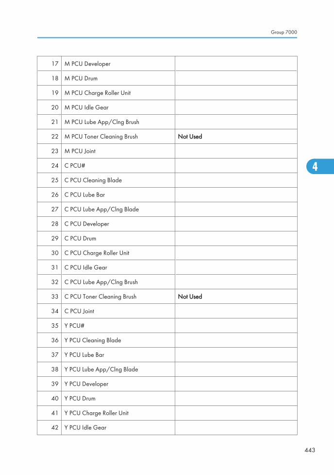
17 M PCU Developer
18 M PCU Drum
19 M PCU Charge Roller Unit
20 M PCU Idle Gear
21 M PCU Lube App/Clng Brush
22 M PCU Toner Cleaning Brush Not Used
23 M PCU Joint
24 C PCU#
25 C PCU Cleaning Blade
26 C PCU Lube Bar
27 C PCU Lube App/Clng Blade
28 C PCU Developer
29 C PCU Drum
30 C PCU Charge Roller Unit
31 C PCU Idle Gear
32 C PCU Lube App/Clng Brush
33 C PCU Toner Cleaning Brush Not Used
34 C PCU Joint
35 Y PCU#
36 Y PCU Cleaning Blade
37 Y PCU Lube Bar
38 Y PCU Lube App/Clng Blade
39 Y PCU Developer
40 Y PCU Drum
41 Y PCU Charge Roller Unit
42 Y PCU Idle Gear
Group 7000
443
4
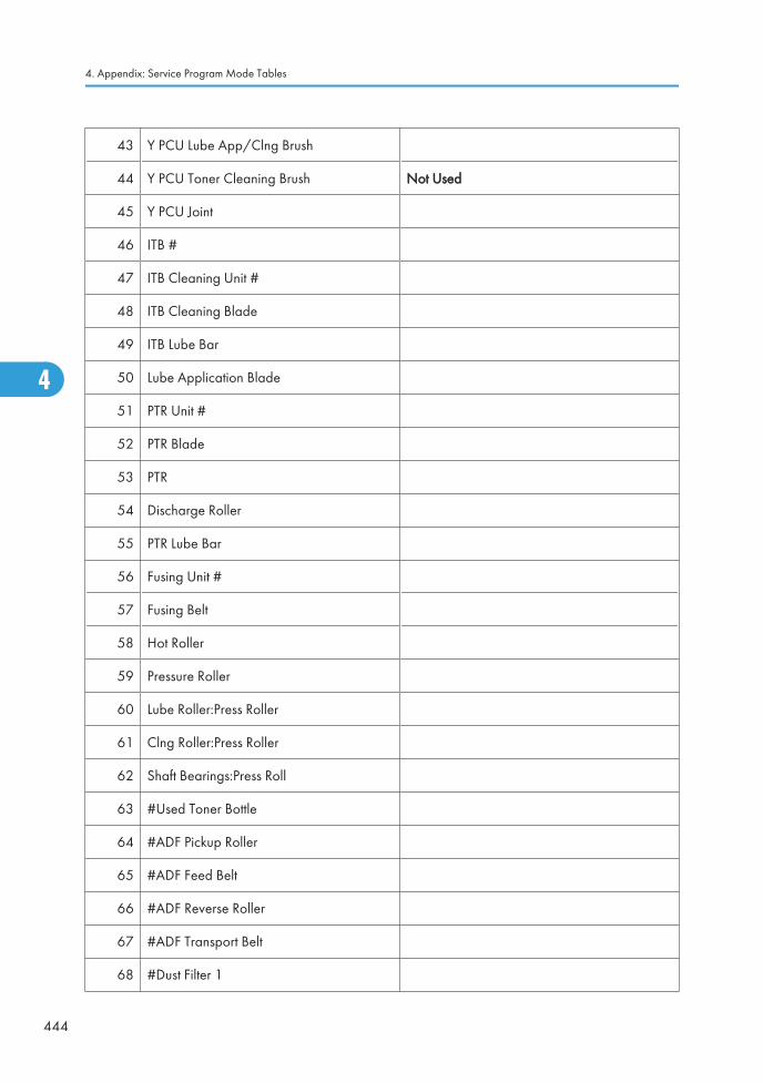
43 Y PCU Lube App/Clng Brush
44 Y PCU Toner Cleaning Brush Not Used
45 Y PCU Joint
46 ITB #
47 ITB Cleaning Unit #
48 ITB Cleaning Blade
49 ITB Lube Bar
50 Lube Application Blade
51 PTR Unit #
52 PTR Blade
53 PTR
54 Discharge Roller
55 PTR Lube Bar
56 Fusing Unit #
57 Fusing Belt
58 Hot Roller
59 Pressure Roller
60 Lube Roller:Press Roller
61 Clng Roller:Press Roller
62 Shaft Bearings:Press Roll
63 #Used Toner Bottle
64 #ADF Pickup Roller
65 #ADF Feed Belt
66 #ADF Reverse Roller
67 #ADF Transport Belt
68 #Dust Filter 1
4. Appendix: Service Program Mode Tables
444
4
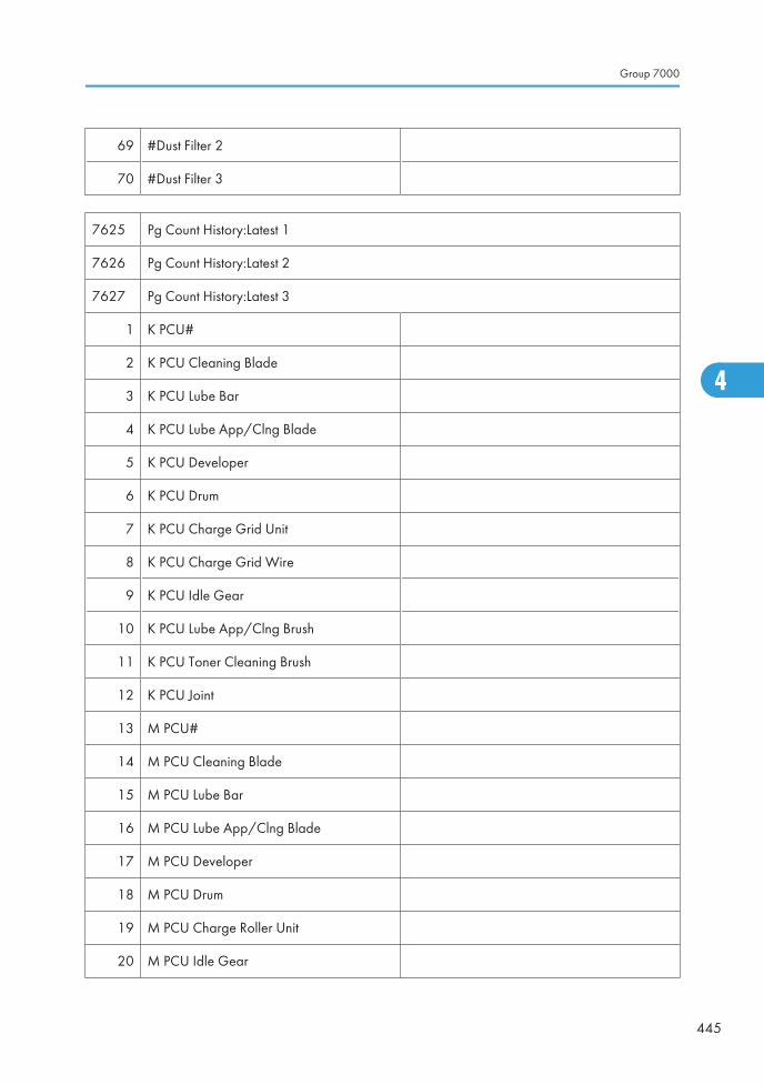
69 #Dust Filter 2
70 #Dust Filter 3
7625 Pg Count History:Latest 1
7626 Pg Count History:Latest 2
7627 Pg Count History:Latest 3
1 K PCU#
2 K PCU Cleaning Blade
3 K PCU Lube Bar
4 K PCU Lube App/Clng Blade
5 K PCU Developer
6 K PCU Drum
7 K PCU Charge Grid Unit
8 K PCU Charge Grid Wire
9 K PCU Idle Gear
10 K PCU Lube App/Clng Brush
11 K PCU Toner Cleaning Brush
12 K PCU Joint
13 M PCU#
14 M PCU Cleaning Blade
15 M PCU Lube Bar
16 M PCU Lube App/Clng Blade
17 M PCU Developer
18 M PCU Drum
19 M PCU Charge Roller Unit
20 M PCU Idle Gear
Group 7000
445
4
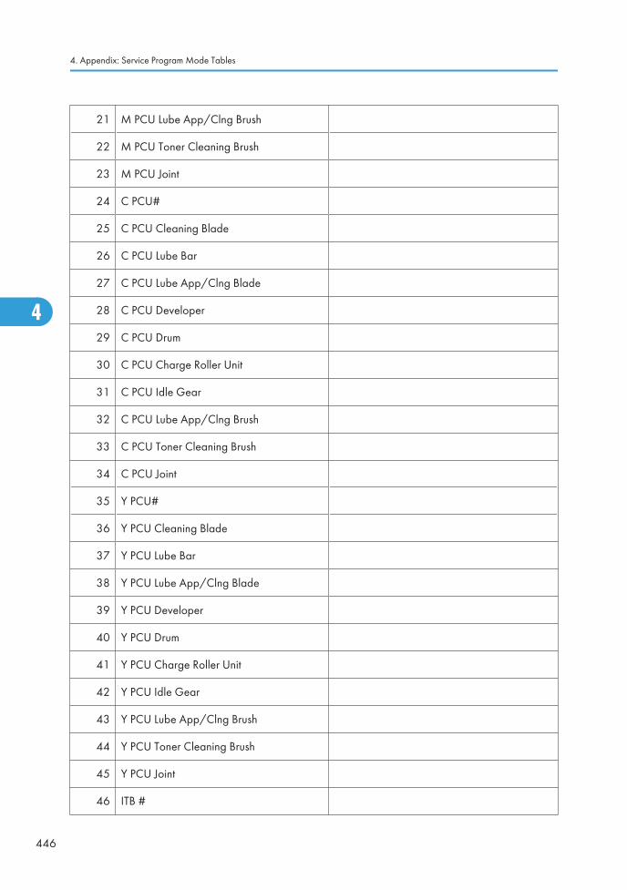
21 M PCU Lube App/Clng Brush
22 M PCU Toner Cleaning Brush
23 M PCU Joint
24 C PCU#
25 C PCU Cleaning Blade
26 C PCU Lube Bar
27 C PCU Lube App/Clng Blade
28 C PCU Developer
29 C PCU Drum
30 C PCU Charge Roller Unit
31 C PCU Idle Gear
32 C PCU Lube App/Clng Brush
33 C PCU Toner Cleaning Brush
34 C PCU Joint
35 Y PCU#
36 Y PCU Cleaning Blade
37 Y PCU Lube Bar
38 Y PCU Lube App/Clng Blade
39 Y PCU Developer
40 Y PCU Drum
41 Y PCU Charge Roller Unit
42 Y PCU Idle Gear
43 Y PCU Lube App/Clng Brush
44 Y PCU Toner Cleaning Brush
45 Y PCU Joint
46 ITB #
4. Appendix: Service Program Mode Tables
446
4
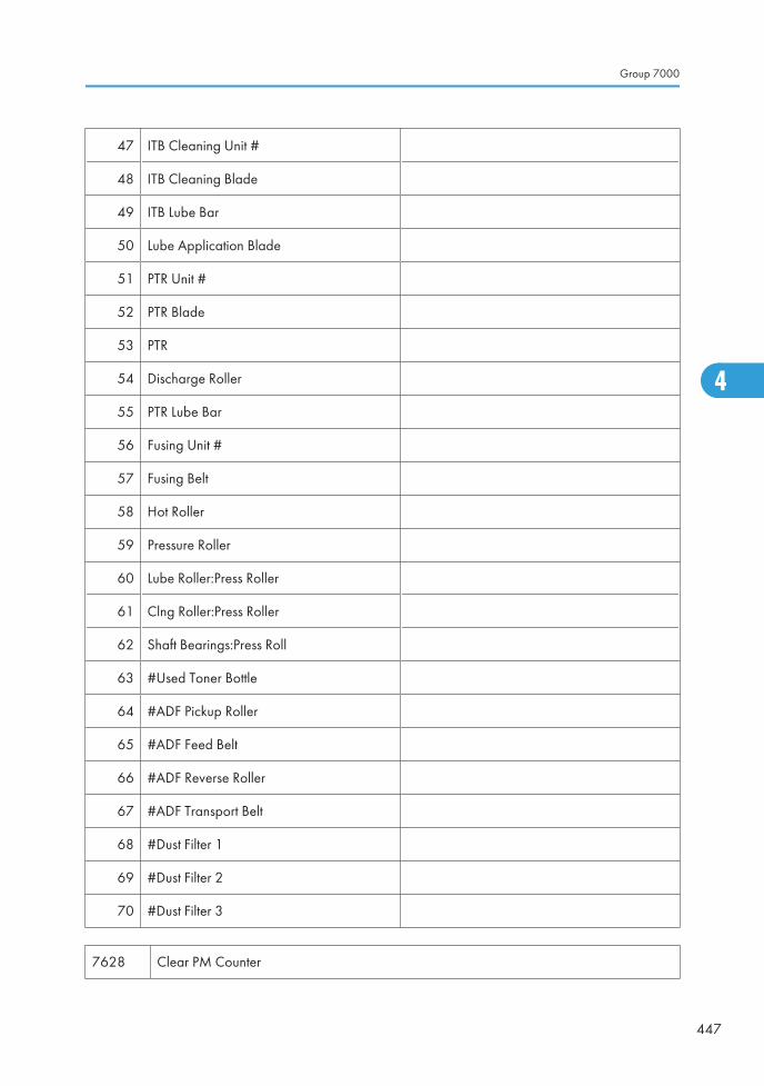
47 ITB Cleaning Unit #
48 ITB Cleaning Blade
49 ITB Lube Bar
50 Lube Application Blade
51 PTR Unit #
52 PTR Blade
53 PTR
54 Discharge Roller
55 PTR Lube Bar
56 Fusing Unit #
57 Fusing Belt
58 Hot Roller
59 Pressure Roller
60 Lube Roller:Press Roller
61 Clng Roller:Press Roller
62 Shaft Bearings:Press Roll
63 #Used Toner Bottle
64 #ADF Pickup Roller
65 #ADF Feed Belt
66 #ADF Reverse Roller
67 #ADF Transport Belt
68 #Dust Filter 1
69 #Dust Filter 2
70 #Dust Filter 3
7628 Clear PM Counter
Group 7000
447
4
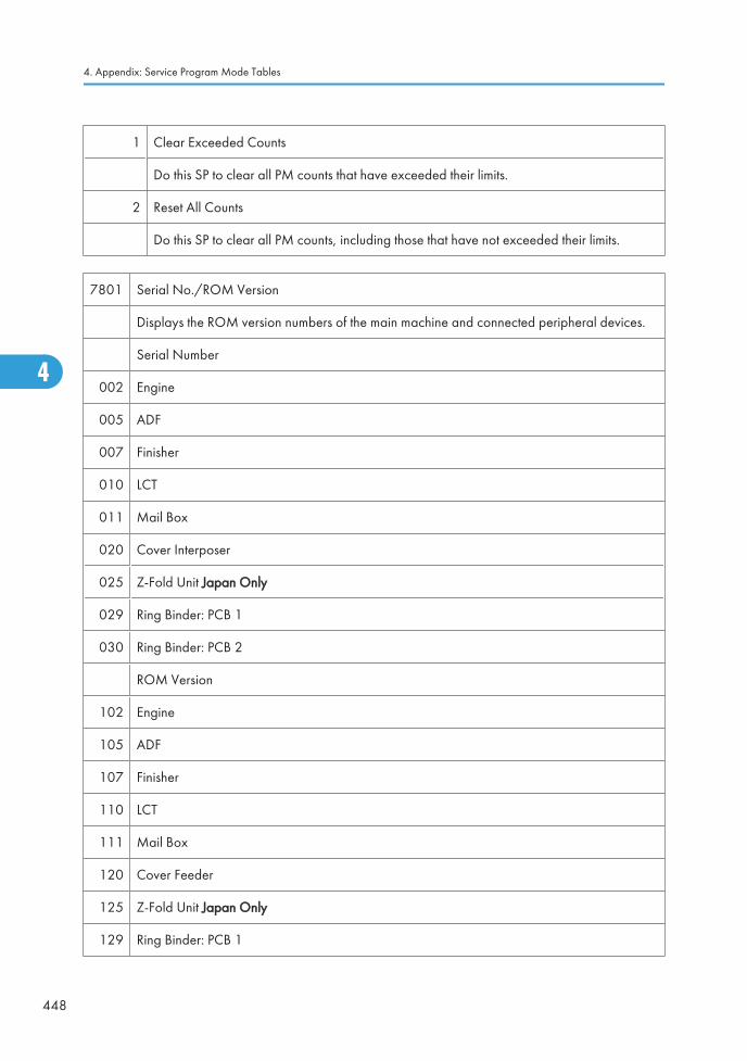
1 Clear Exceeded Counts
Do this SP to clear all PM counts that have exceeded their limits.
2 Reset All Counts
Do this SP to clear all PM counts, including those that have not exceeded their limits.
7801 Serial No./ROM Version
Displays the ROM version numbers of the main machine and connected peripheral devices.
Serial Number
002 Engine
005 ADF
007 Finisher
010 LCT
011 Mail Box
020 Cover Interposer
025 Z-Fold Unit Japan Only
029 Ring Binder: PCB 1
030 Ring Binder: PCB 2
ROM Version
102 Engine
105 ADF
107 Finisher
110 LCT
111 Mail Box
120 Cover Feeder
125 Z-Fold Unit Japan Only
129 Ring Binder: PCB 1
4. Appendix: Service Program Mode Tables
448
4
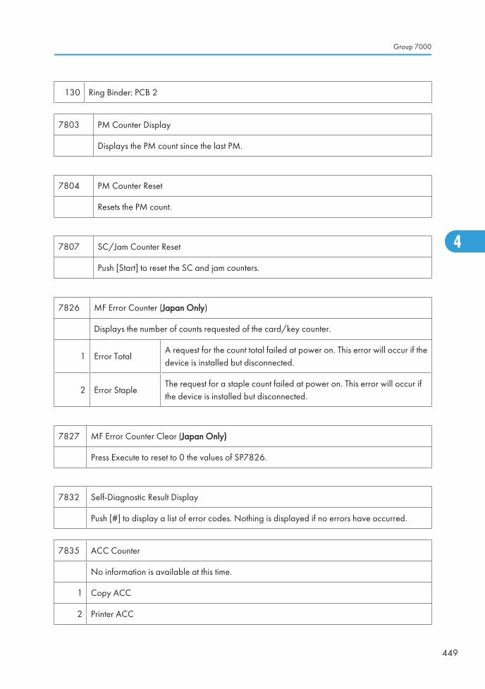
130 Ring Binder: PCB 2
7803 PM Counter Display
Displays the PM count since the last PM.
7804 PM Counter Reset
Resets the PM count.
7807 SC/Jam Counter Reset
Push [Start] to reset the SC and jam counters.
7826 MF Error Counter (Japan Only)
Displays the number of counts requested of the card/key counter.
1 Error TotalA request for the count total failed at power on. This error will occur if thedevice is installed but disconnected.
2 Error StapleThe request for a staple count failed at power on. This error will occur ifthe device is installed but disconnected.
7827 MF Error Counter Clear (Japan Only)
Press Execute to reset to 0 the values of SP7826.
7832 Self-Diagnostic Result Display
Push [#] to display a list of error codes. Nothing is displayed if no errors have occurred.
7835 ACC Counter
No information is available at this time.
1 Copy ACC
2 Printer ACC
Group 7000
449
4
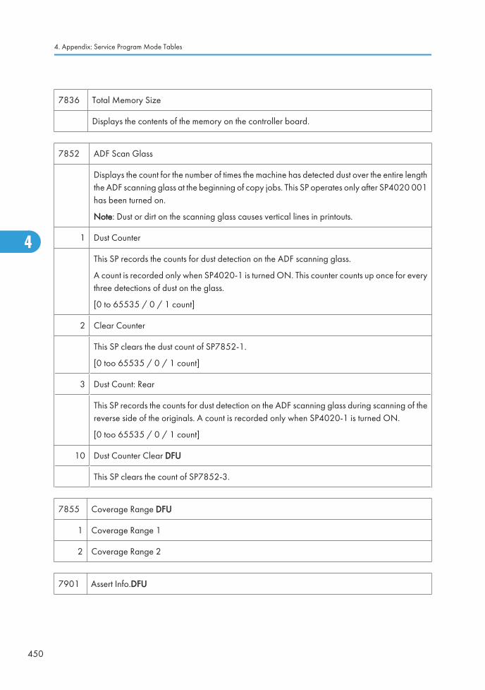
7836 Total Memory Size
Displays the contents of the memory on the controller board.
7852 ADF Scan Glass
Displays the count for the number of times the machine has detected dust over the entire lengththe ADF scanning glass at the beginning of copy jobs. This SP operates only after SP4020 001has been turned on.
Note: Dust or dirt on the scanning glass causes vertical lines in printouts.
1 Dust Counter
This SP records the counts for dust detection on the ADF scanning glass.
A count is recorded only when SP4020-1 is turned ON. This counter counts up once for everythree detections of dust on the glass.
[0 to 65535 / 0 / 1 count]
2 Clear Counter
This SP clears the dust count of SP7852-1.
[0 too 65535 / 0 / 1 count]
3 Dust Count: Rear
This SP records the counts for dust detection on the ADF scanning glass during scanning of thereverse side of the originals. A count is recorded only when SP4020-1 is turned ON.
[0 too 65535 / 0 / 1 count]
10 Dust Counter Clear DFU
This SP clears the count of SP7852-3.
7855 Coverage Range DFU
1 Coverage Range 1
2 Coverage Range 2
7901 Assert Info.DFU
4. Appendix: Service Program Mode Tables
450
4
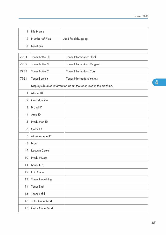
1 File Name
Used for debugging.2 Number of Files
3 Locations
7931 Toner Bottle Bk Toner Information: Black
7932 Toner Bottle M Toner Information: Magenta
7933 Toner Bottle C Toner Information: Cyan
7934 Toner Bottle Y Toner Information: Yellow
Displays detailed information about the toner used in the machine.
1 Model ID
2 Cartridge Ver
3 Brand ID
4 Area ID
5 Production ID
6 Color ID
7 Maintenance ID
8 New
9 Recycle Count
10 Product Date
11 Serial No
12 EDP Code
13 Toner Remaining
14 Toner End
15 Toner Refill
16 Total Count Start
17 Color Count:Start
Group 7000
451
4
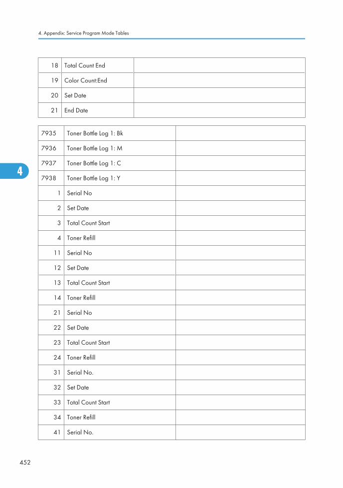
18 Total Count End
19 Color Count:End
20 Set Date
21 End Date
7935 Toner Bottle Log 1: Bk
7936 Toner Bottle Log 1: M
7937 Toner Bottle Log 1: C
7938 Toner Bottle Log 1: Y
1 Serial No
2 Set Date
3 Total Count Start
4 Toner Refill
11 Serial No
12 Set Date
13 Total Count Start
14 Toner Refill
21 Serial No
22 Set Date
23 Total Count Start
24 Toner Refill
31 Serial No.
32 Set Date
33 Total Count Start
34 Toner Refill
41 Serial No.
4. Appendix: Service Program Mode Tables
452
4
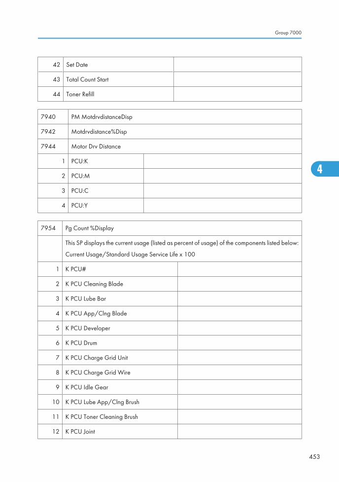
42 Set Date
43 Total Count Start
44 Toner Refill
7940 PM MotdrvdistanceDisp
7942 Motdrvdistance%Disp
7944 Motor Drv Distance
1 PCU:K
2 PCU:M
3 PCU:C
4 PCU:Y
7954 Pg Count %Display
This SP displays the current usage (listed as percent of usage) of the components listed below:
Current Usage/Standard Usage Service Life x 100
1 K PCU#
2 K PCU Cleaning Blade
3 K PCU Lube Bar
4 K PCU App/Clng Blade
5 K PCU Developer
6 K PCU Drum
7 K PCU Charge Grid Unit
8 K PCU Charge Grid Wire
9 K PCU Idle Gear
10 K PCU Lube App/Clng Brush
11 K PCU Toner Cleaning Brush
12 K PCU Joint
Group 7000
453
4
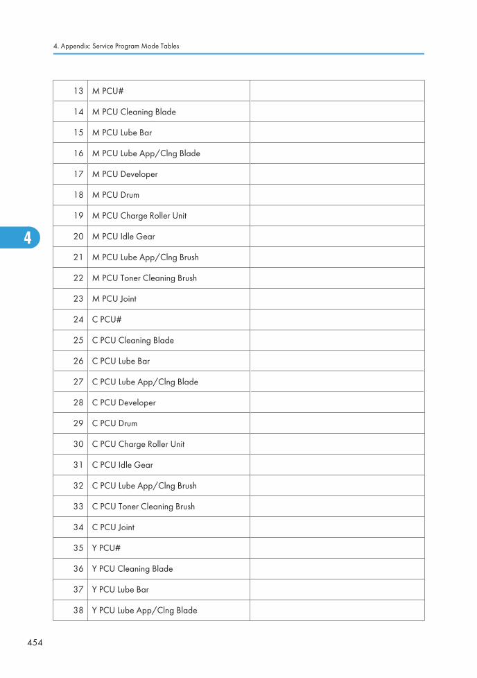
13 M PCU#
14 M PCU Cleaning Blade
15 M PCU Lube Bar
16 M PCU Lube App/Clng Blade
17 M PCU Developer
18 M PCU Drum
19 M PCU Charge Roller Unit
20 M PCU Idle Gear
21 M PCU Lube App/Clng Brush
22 M PCU Toner Cleaning Brush
23 M PCU Joint
24 C PCU#
25 C PCU Cleaning Blade
26 C PCU Lube Bar
27 C PCU Lube App/Clng Blade
28 C PCU Developer
29 C PCU Drum
30 C PCU Charge Roller Unit
31 C PCU Idle Gear
32 C PCU Lube App/Clng Brush
33 C PCU Toner Cleaning Brush
34 C PCU Joint
35 Y PCU#
36 Y PCU Cleaning Blade
37 Y PCU Lube Bar
38 Y PCU Lube App/Clng Blade
4. Appendix: Service Program Mode Tables
454
4
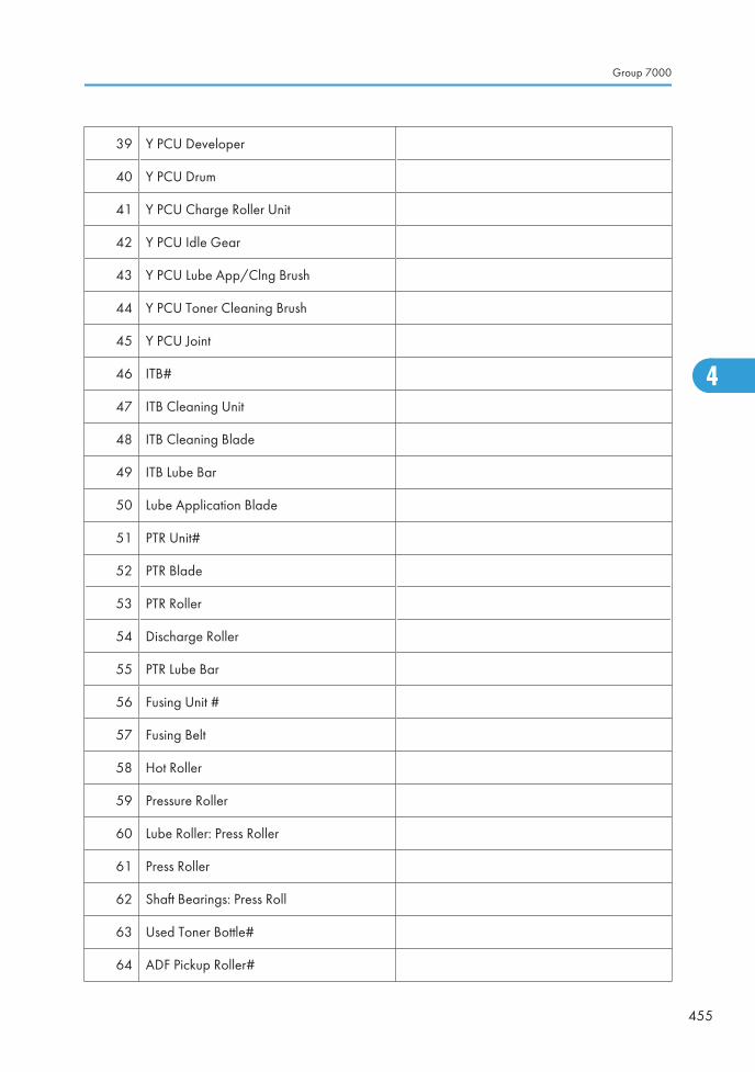
39 Y PCU Developer
40 Y PCU Drum
41 Y PCU Charge Roller Unit
42 Y PCU Idle Gear
43 Y PCU Lube App/Clng Brush
44 Y PCU Toner Cleaning Brush
45 Y PCU Joint
46 ITB#
47 ITB Cleaning Unit
48 ITB Cleaning Blade
49 ITB Lube Bar
50 Lube Application Blade
51 PTR Unit#
52 PTR Blade
53 PTR Roller
54 Discharge Roller
55 PTR Lube Bar
56 Fusing Unit #
57 Fusing Belt
58 Hot Roller
59 Pressure Roller
60 Lube Roller: Press Roller
61 Press Roller
62 Shaft Bearings: Press Roll
63 Used Toner Bottle#
64 ADF Pickup Roller#
Group 7000
455
4
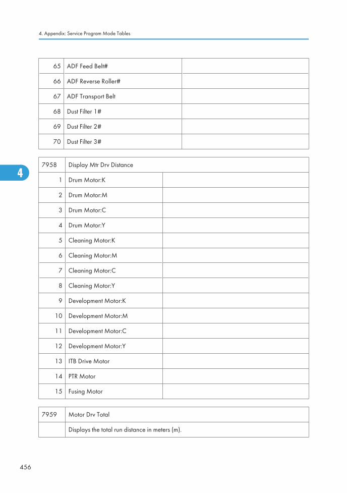
65 ADF Feed Belt#
66 ADF Reverse Roller#
67 ADF Transport Belt
68 Dust Filter 1#
69 Dust Filter 2#
70 Dust Filter 3#
7958 Display Mtr Drv Distance
1 Drum Motor:K
2 Drum Motor:M
3 Drum Motor:C
4 Drum Motor:Y
5 Cleaning Motor:K
6 Cleaning Motor:M
7 Cleaning Motor:C
8 Cleaning Motor:Y
9 Development Motor:K
10 Development Motor:M
11 Development Motor:C
12 Development Motor:Y
13 ITB Drive Motor
14 PTR Motor
15 Fusing Motor
7959 Motor Drv Total
Displays the total run distance in meters (m).
4. Appendix: Service Program Mode Tables
456
4
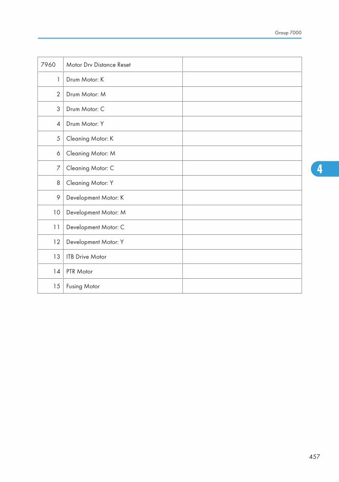
7960 Motor Drv Distance Reset
1 Drum Motor: K
2 Drum Motor: M
3 Drum Motor: C
4 Drum Motor: Y
5 Cleaning Motor: K
6 Cleaning Motor: M
7 Cleaning Motor: C
8 Cleaning Motor: Y
9 Development Motor: K
10 Development Motor: M
11 Development Motor: C
12 Development Motor: Y
13 ITB Drive Motor
14 PTR Motor
15 Fusing Motor
Group 7000
457
4
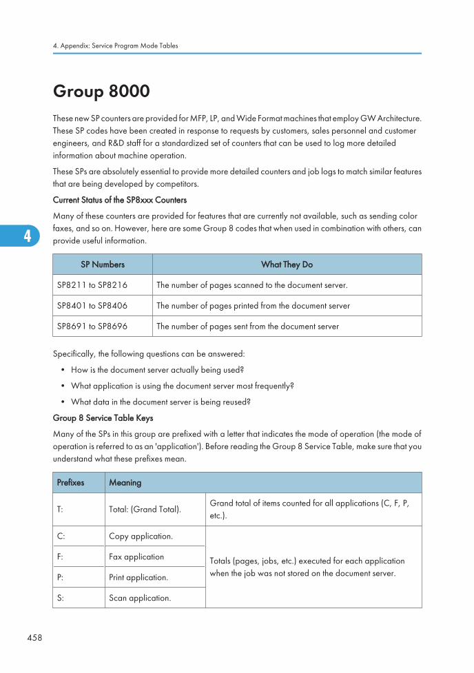
Group 8000These new SP counters are provided for MFP, LP, and Wide Format machines that employ GW Architecture.These SP codes have been created in response to requests by customers, sales personnel and customerengineers, and R&D staff for a standardized set of counters that can be used to log more detailedinformation about machine operation.
These SPs are absolutely essential to provide more detailed counters and job logs to match similar featuresthat are being developed by competitors.
Current Status of the SP8xxx Counters
Many of these counters are provided for features that are currently not available, such as sending colorfaxes, and so on. However, here are some Group 8 codes that when used in combination with others, canprovide useful information.
SP Numbers What They Do
SP8211 to SP8216 The number of pages scanned to the document server.
SP8401 to SP8406 The number of pages printed from the document server
SP8691 to SP8696 The number of pages sent from the document server
Specifically, the following questions can be answered:
• How is the document server actually being used?
• What application is using the document server most frequently?
• What data in the document server is being reused?
Group 8 Service Table Keys
Many of the SPs in this group are prefixed with a letter that indicates the mode of operation (the mode ofoperation is referred to as an 'application'). Before reading the Group 8 Service Table, make sure that youunderstand what these prefixes mean.
Prefixes Meaning
T: Total: (Grand Total).Grand total of items counted for all applications (C, F, P,etc.).
C: Copy application.
Totals (pages, jobs, etc.) executed for each applicationwhen the job was not stored on the document server.
F: Fax application
P: Print application.
S: Scan application.
4. Appendix: Service Program Mode Tables
458
4
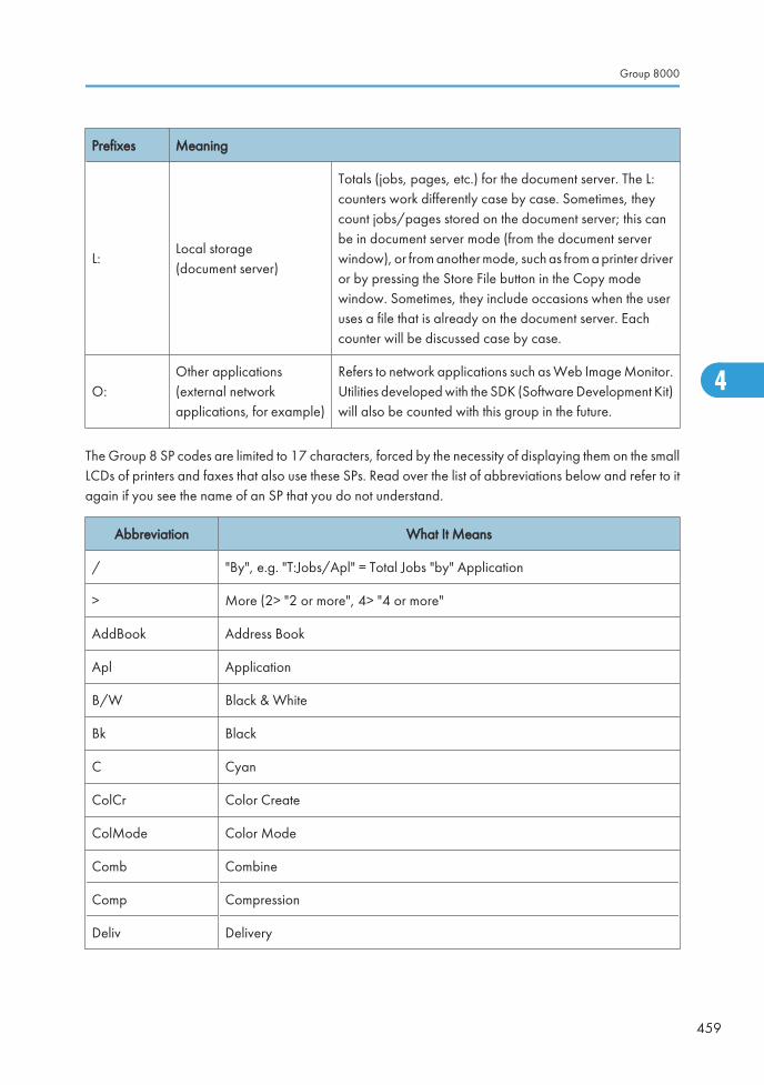
Prefixes Meaning
L:Local storage(document server)
Totals (jobs, pages, etc.) for the document server. The L:counters work differently case by case. Sometimes, theycount jobs/pages stored on the document server; this canbe in document server mode (from the document serverwindow), or from another mode, such as from a printer driveror by pressing the Store File button in the Copy modewindow. Sometimes, they include occasions when the useruses a file that is already on the document server. Eachcounter will be discussed case by case.
O:Other applications(external networkapplications, for example)
Refers to network applications such as Web Image Monitor.Utilities developed with the SDK (Software Development Kit)will also be counted with this group in the future.
The Group 8 SP codes are limited to 17 characters, forced by the necessity of displaying them on the smallLCDs of printers and faxes that also use these SPs. Read over the list of abbreviations below and refer to itagain if you see the name of an SP that you do not understand.
Abbreviation What It Means
/ "By", e.g. "T:Jobs/Apl" = Total Jobs "by" Application
> More (2> "2 or more", 4> "4 or more"
AddBook Address Book
Apl Application
B/W Black & White
Bk Black
C Cyan
ColCr Color Create
ColMode Color Mode
Comb Combine
Comp Compression
Deliv Delivery
Group 8000
459
4
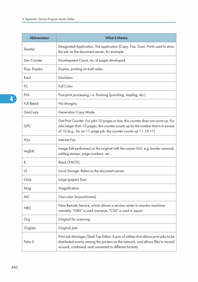
Abbreviation What It Means
DesAplDesignated Application. The application (Copy, Fax, Scan, Print) used to storethe job on the document server, for example.
Dev Counter Development Count, no. of pages developed.
Dup, Duplex Duplex, printing on both sides
Emul Emulation
FC Full Color
FIN Post-print processing, i.e. finishing (punching, stapling, etc.)
Full Bleed No Margins
GenCopy Generation Copy Mode
GPCGet Print Counter. For jobs 10 pages or less, this counter does not count up. Forjobs larger than 10 pages, this counter counts up by the number that is in excessof 10 (e.g., for an 11-page job, the counter counts up 11-10 =1)
IFax Internet Fax
ImgEdtImage Edit performed on the original with the copier GUI, e.g. border removal,adding stamps, page numbers, etc.
K Black (YMCK)
LS Local Storage. Refers to the document server.
LSize Large (paper) Size
Mag Magnification
MC One color (monochrome)
NRSNew Remote Service, which allows a service center to monitor machinesremotely. "NRS" is used overseas, "CSS" is used in Japan.
Org Original for scanning
OrgJam Original Jam
Palm 2Print Job Manager/Desk Top Editor: A pair of utilities that allows print jobs to bedistributed evenly among the printers on the network, and allows files to movedaround, combined, and converted to different formats.
4. Appendix: Service Program Mode Tables
460
4
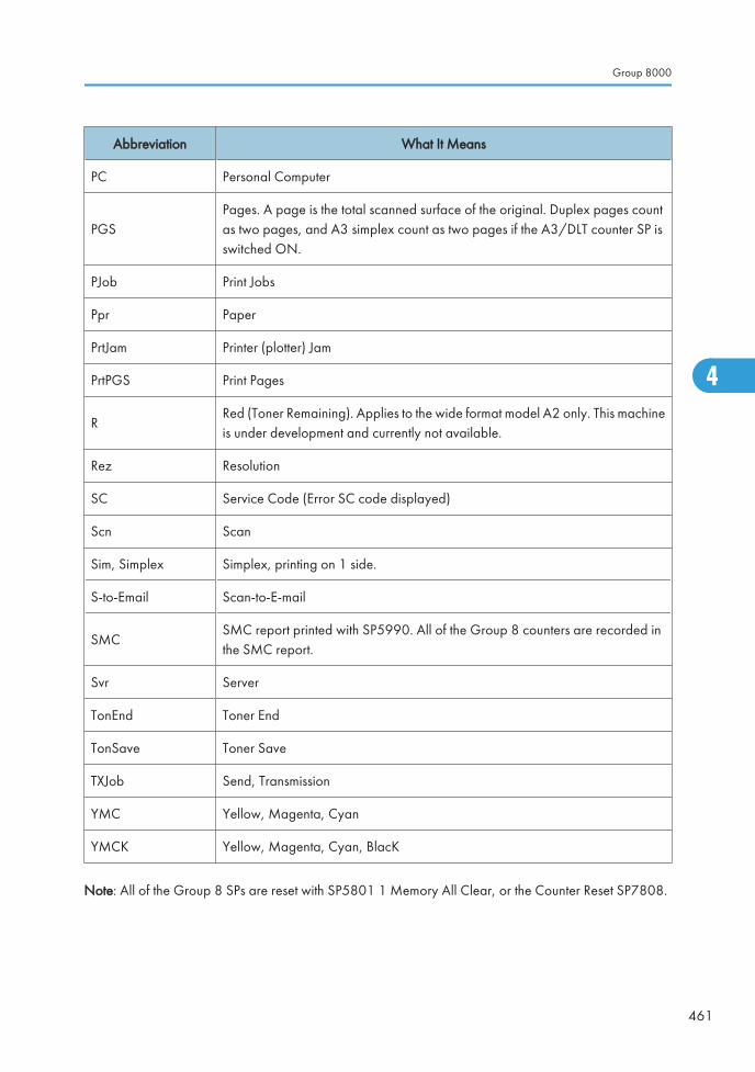
Abbreviation What It Means
PC Personal Computer
PGSPages. A page is the total scanned surface of the original. Duplex pages countas two pages, and A3 simplex count as two pages if the A3/DLT counter SP isswitched ON.
PJob Print Jobs
Ppr Paper
PrtJam Printer (plotter) Jam
PrtPGS Print Pages
RRed (Toner Remaining). Applies to the wide format model A2 only. This machineis under development and currently not available.
Rez Resolution
SC Service Code (Error SC code displayed)
Scn Scan
Sim, Simplex Simplex, printing on 1 side.
S-to-Email Scan-to-E-mail
SMCSMC report printed with SP5990. All of the Group 8 counters are recorded inthe SMC report.
Svr Server
TonEnd Toner End
TonSave Toner Save
TXJob Send, Transmission
YMC Yellow, Magenta, Cyan
YMCK Yellow, Magenta, Cyan, BlacK
Note: All of the Group 8 SPs are reset with SP5801 1 Memory All Clear, or the Counter Reset SP7808.
Group 8000
461
4
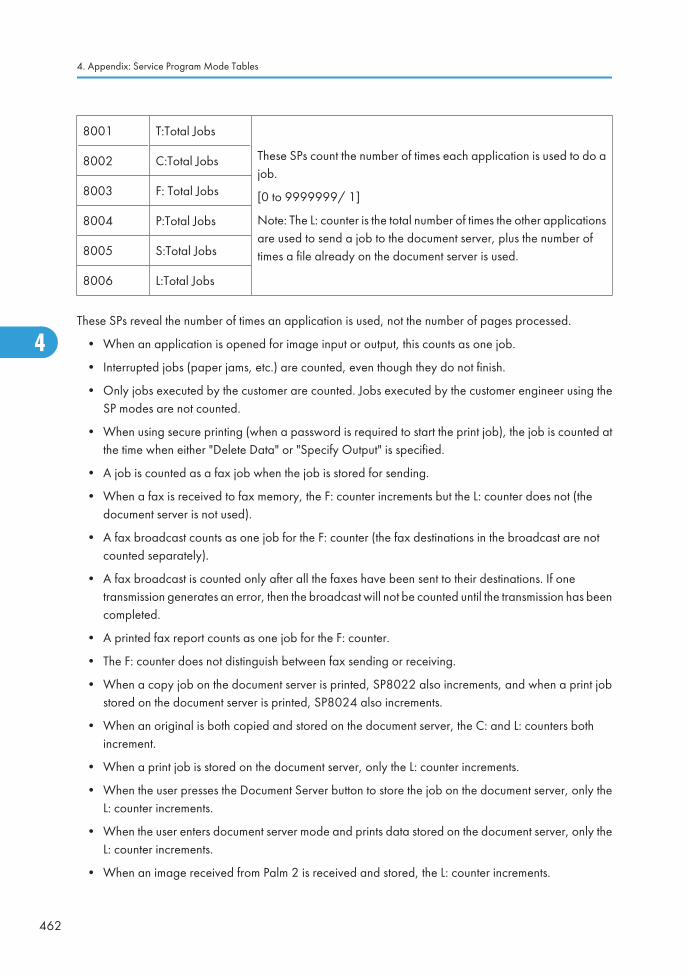
8001 T:Total Jobs
These SPs count the number of times each application is used to do ajob.
[0 to 9999999/ 1]
Note: The L: counter is the total number of times the other applicationsare used to send a job to the document server, plus the number oftimes a file already on the document server is used.
8002 C:Total Jobs
8003 F: Total Jobs
8004 P:Total Jobs
8005 S:Total Jobs
8006 L:Total Jobs
These SPs reveal the number of times an application is used, not the number of pages processed.
• When an application is opened for image input or output, this counts as one job.
• Interrupted jobs (paper jams, etc.) are counted, even though they do not finish.
• Only jobs executed by the customer are counted. Jobs executed by the customer engineer using theSP modes are not counted.
• When using secure printing (when a password is required to start the print job), the job is counted atthe time when either "Delete Data" or "Specify Output" is specified.
• A job is counted as a fax job when the job is stored for sending.
• When a fax is received to fax memory, the F: counter increments but the L: counter does not (thedocument server is not used).
• A fax broadcast counts as one job for the F: counter (the fax destinations in the broadcast are notcounted separately).
• A fax broadcast is counted only after all the faxes have been sent to their destinations. If onetransmission generates an error, then the broadcast will not be counted until the transmission has beencompleted.
• A printed fax report counts as one job for the F: counter.
• The F: counter does not distinguish between fax sending or receiving.
• When a copy job on the document server is printed, SP8022 also increments, and when a print jobstored on the document server is printed, SP8024 also increments.
• When an original is both copied and stored on the document server, the C: and L: counters bothincrement.
• When a print job is stored on the document server, only the L: counter increments.
• When the user presses the Document Server button to store the job on the document server, only theL: counter increments.
• When the user enters document server mode and prints data stored on the document server, only theL: counter increments.
• When an image received from Palm 2 is received and stored, the L: counter increments.
4. Appendix: Service Program Mode Tables
462
4
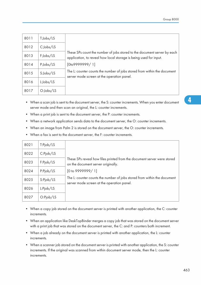
8011 T:Jobs/LS
These SPs count the number of jobs stored to the document server by eachapplication, to reveal how local storage is being used for input.
[0to9999999/ 1]
The L: counter counts the number of jobs stored from within the documentserver mode screen at the operation panel.
8012 C:Jobs/LS
8013 F:Jobs/LS
8014 P:Jobs/LS
8015 S:Jobs/LS
8016 L:Jobs/LS
8017 O:Jobs/LS
• When a scan job is sent to the document server, the S: counter increments. When you enter documentserver mode and then scan an original, the L: counter increments.
• When a print job is sent to the document server, the P: counter increments.
• When a network application sends data to the document server, the O: counter increments.
• When an image from Palm 2 is stored on the document server, the O: counter increments.
• When a fax is sent to the document server, the F: counter increments.
8021 T:Pjob/LS
These SPs reveal how files printed from the document server were storedon the document server originally.
[0 to 9999999/ 1]
The L: counter counts the number of jobs stored from within the documentserver mode screen at the operation panel.
8022 C:Pjob/LS
8023 F:Pjob/LS
8024 P:Pjob/LS
8025 S:Pjob/LS
8026 L:Pjob/LS
8027 O:Pjob/LS
• When a copy job stored on the document server is printed with another application, the C: counterincrements.
• When an application like DeskTopBinder merges a copy job that was stored on the document serverwith a print job that was stored on the document server, the C: and P: counters both increment.
• When a job already on the document server is printed with another application, the L: counterincrements.
• When a scanner job stored on the document server is printed with another application, the S: counterincrements. If the original was scanned from within document server mode, then the L: counterincrements.
Group 8000
463
4
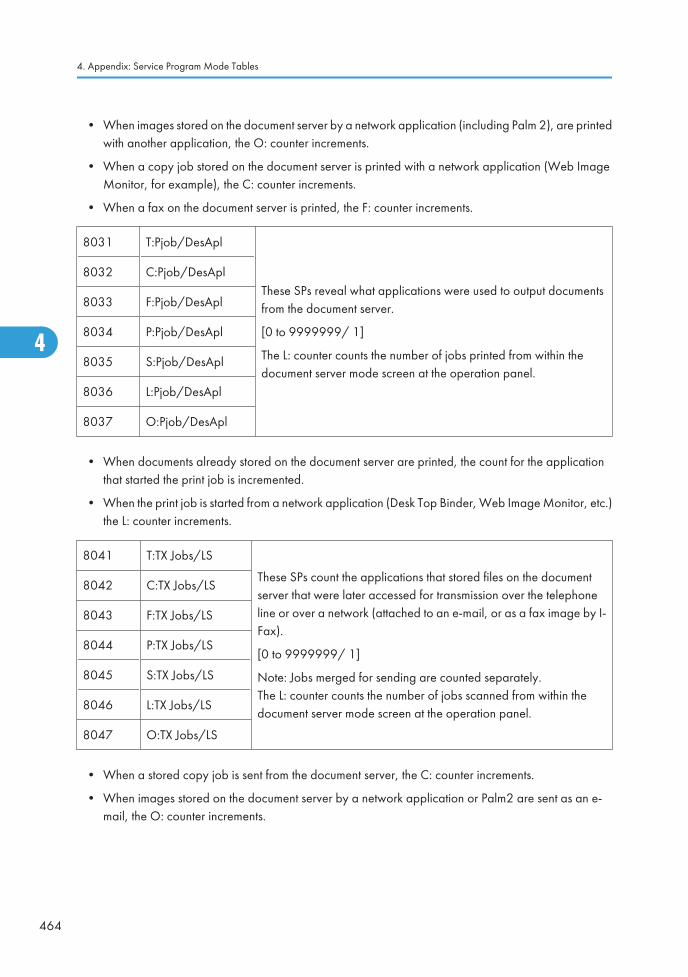
• When images stored on the document server by a network application (including Palm 2), are printedwith another application, the O: counter increments.
• When a copy job stored on the document server is printed with a network application (Web ImageMonitor, for example), the C: counter increments.
• When a fax on the document server is printed, the F: counter increments.
8031 T:Pjob/DesApl
These SPs reveal what applications were used to output documentsfrom the document server.
[0 to 9999999/ 1]
The L: counter counts the number of jobs printed from within thedocument server mode screen at the operation panel.
8032 C:Pjob/DesApl
8033 F:Pjob/DesApl
8034 P:Pjob/DesApl
8035 S:Pjob/DesApl
8036 L:Pjob/DesApl
8037 O:Pjob/DesApl
• When documents already stored on the document server are printed, the count for the applicationthat started the print job is incremented.
• When the print job is started from a network application (Desk Top Binder, Web Image Monitor, etc.)the L: counter increments.
8041 T:TX Jobs/LS
These SPs count the applications that stored files on the documentserver that were later accessed for transmission over the telephoneline or over a network (attached to an e-mail, or as a fax image by I-Fax).
[0 to 9999999/ 1]
Note: Jobs merged for sending are counted separately.The L: counter counts the number of jobs scanned from within thedocument server mode screen at the operation panel.
8042 C:TX Jobs/LS
8043 F:TX Jobs/LS
8044 P:TX Jobs/LS
8045 S:TX Jobs/LS
8046 L:TX Jobs/LS
8047 O:TX Jobs/LS
• When a stored copy job is sent from the document server, the C: counter increments.
• When images stored on the document server by a network application or Palm2 are sent as an e-mail, the O: counter increments.
4. Appendix: Service Program Mode Tables
464
4
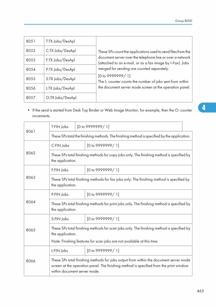
8051 T:TX Jobs/DesApl
These SPs count the applications used to send files from thedocument server over the telephone line or over a network(attached to an e-mail, or as a fax image by I-Fax). Jobsmerged for sending are counted separately.
[0 to 9999999/ 1]The L: counter counts the number of jobs sent from withinthe document server mode screen at the operation panel.
8052 C:TX Jobs/DesApl
8053 F:TX Jobs/DesApl
8054 P:TX Jobs/DesApl
8055 S:TX Jobs/DesApl
8056 L:TX Jobs/DesApl
8057 O:TX Jobs/DesApl
• If the send is started from Desk Top Binder or Web Image Monitor, for example, then the O: counterincrements.
8061T:FIN Jobs [0 to 9999999/ 1]
These SPs total the finishing methods. The finishing method is specified by the application.
8062
C:FIN Jobs [0 to 9999999/ 1]
These SPs total finishing methods for copy jobs only. The finishing method is specified bythe application.
8063
F:FIN Jobs [0 to 9999999/ 1]
These SPs total finishing methods for fax jobs only. The finishing method is specified bythe application.
8064
P:FIN Jobs [0 to 9999999/ 1]
These SPs total finishing methods for print jobs only. The finishing method is specified bythe application.
8065
S:FIN Jobs [0 to 9999999/ 1]
These SPs total finishing methods for scan jobs only. The finishing method is specified bythe application.
Note: Finishing features for scan jobs are not available at this time.
8066
L:FIN Jobs [0 to 9999999/ 1]
These SPs total finishing methods for jobs output from within the document server modescreen at the operation panel. The finishing method is specified from the print windowwithin document server mode.
Group 8000
465
4
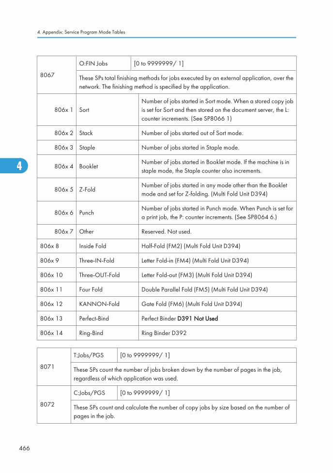
8067
O:FIN Jobs [0 to 9999999/ 1]
These SPs total finishing methods for jobs executed by an external application, over thenetwork. The finishing method is specified by the application.
806x 1 SortNumber of jobs started in Sort mode. When a stored copy jobis set for Sort and then stored on the document server, the L:counter increments. (See SP8066 1)
806x 2 Stack Number of jobs started out of Sort mode.
806x 3 Staple Number of jobs started in Staple mode.
806x 4 BookletNumber of jobs started in Booklet mode. If the machine is instaple mode, the Staple counter also increments.
806x 5 Z-FoldNumber of jobs started in any mode other than the Bookletmode and set for Z-folding. (Multi Fold Unit D394)
806x 6 PunchNumber of jobs started in Punch mode. When Punch is set fora print job, the P: counter increments. (See SP8064 6.)
806x 7 Other Reserved. Not used.
806x 8 Inside Fold Half-Fold (FM2) (Multi Fold Unit D394)
806x 9 Three-IN-Fold Letter Fold-in (FM4) (Multi Fold Unit D394)
806x 10 Three-OUT-Fold Letter Fold-out (FM3) (Multi Fold Unit D394)
806x 11 Four Fold Double Parallel Fold (FM5) (Multi Fold Unit D394)
806x 12 KANNON-Fold Gate Fold (FM6) (Multi Fold Unit D394)
806x 13 Perfect-Bind Perfect Binder D391 Not Used
806x 14 Ring-Bind Ring Binder D392
8071
T:Jobs/PGS [0 to 9999999/ 1]
These SPs count the number of jobs broken down by the number of pages in the job,regardless of which application was used.
8072
C:Jobs/PGS [0 to 9999999/ 1]
These SPs count and calculate the number of copy jobs by size based on the number ofpages in the job.
4. Appendix: Service Program Mode Tables
466
4
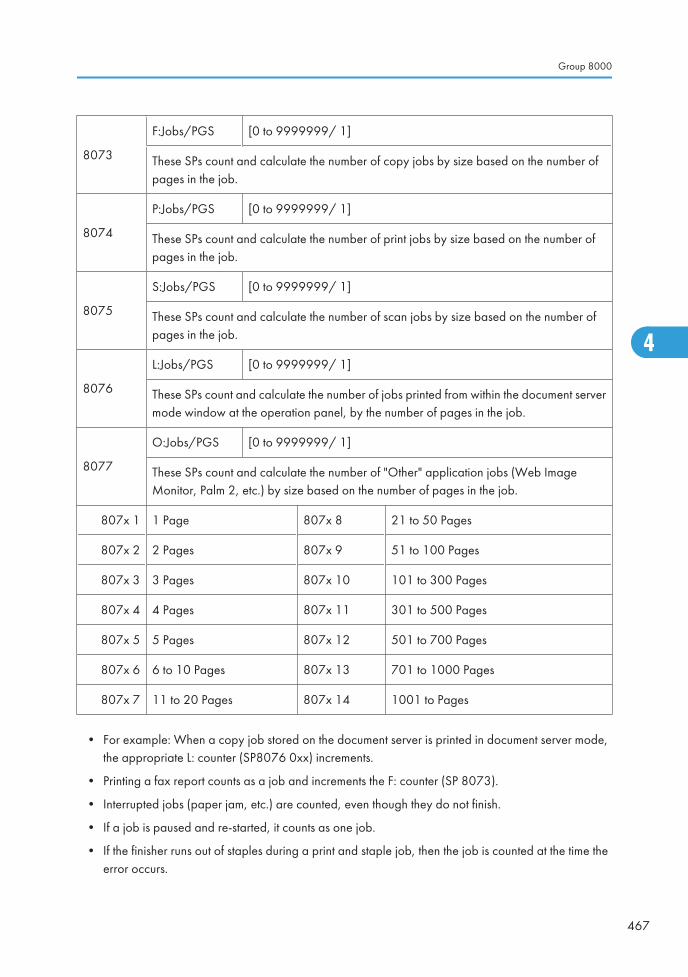
8073
F:Jobs/PGS [0 to 9999999/ 1]
These SPs count and calculate the number of copy jobs by size based on the number ofpages in the job.
8074
P:Jobs/PGS [0 to 9999999/ 1]
These SPs count and calculate the number of print jobs by size based on the number ofpages in the job.
8075
S:Jobs/PGS [0 to 9999999/ 1]
These SPs count and calculate the number of scan jobs by size based on the number ofpages in the job.
8076
L:Jobs/PGS [0 to 9999999/ 1]
These SPs count and calculate the number of jobs printed from within the document servermode window at the operation panel, by the number of pages in the job.
8077
O:Jobs/PGS [0 to 9999999/ 1]
These SPs count and calculate the number of "Other" application jobs (Web ImageMonitor, Palm 2, etc.) by size based on the number of pages in the job.
807x 1 1 Page 807x 8 21 to 50 Pages
807x 2 2 Pages 807x 9 51 to 100 Pages
807x 3 3 Pages 807x 10 101 to 300 Pages
807x 4 4 Pages 807x 11 301 to 500 Pages
807x 5 5 Pages 807x 12 501 to 700 Pages
807x 6 6 to 10 Pages 807x 13 701 to 1000 Pages
807x 7 11 to 20 Pages 807x 14 1001 to Pages
• For example: When a copy job stored on the document server is printed in document server mode,the appropriate L: counter (SP8076 0xx) increments.
• Printing a fax report counts as a job and increments the F: counter (SP 8073).
• Interrupted jobs (paper jam, etc.) are counted, even though they do not finish.
• If a job is paused and re-started, it counts as one job.
• If the finisher runs out of staples during a print and staple job, then the job is counted at the time theerror occurs.
Group 8000
467
4
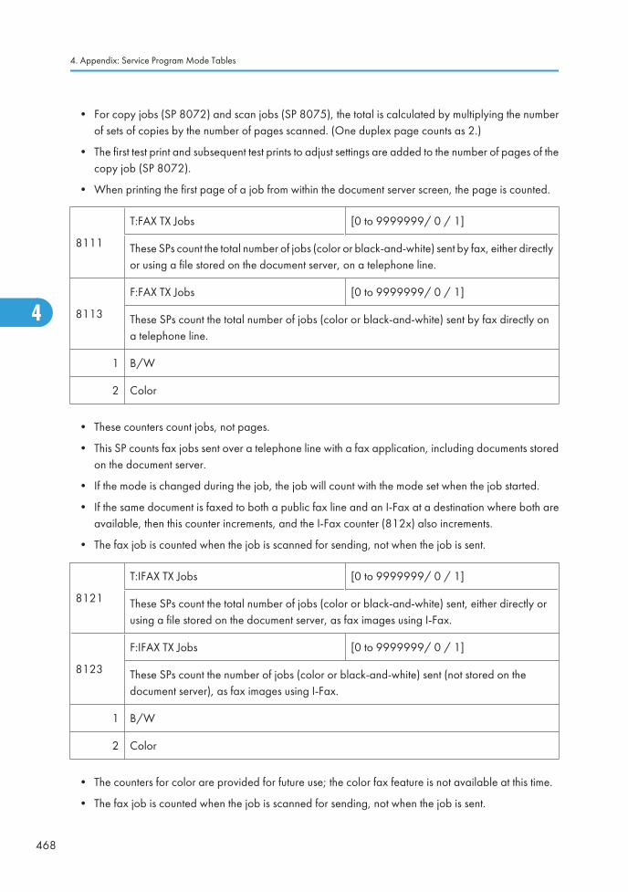
• For copy jobs (SP 8072) and scan jobs (SP 8075), the total is calculated by multiplying the numberof sets of copies by the number of pages scanned. (One duplex page counts as 2.)
• The first test print and subsequent test prints to adjust settings are added to the number of pages of thecopy job (SP 8072).
• When printing the first page of a job from within the document server screen, the page is counted.
8111
T:FAX TX Jobs [0 to 9999999/ 0 / 1]
These SPs count the total number of jobs (color or black-and-white) sent by fax, either directlyor using a file stored on the document server, on a telephone line.
8113
F:FAX TX Jobs [0 to 9999999/ 0 / 1]
These SPs count the total number of jobs (color or black-and-white) sent by fax directly ona telephone line.
1 B/W
2 Color
• These counters count jobs, not pages.
• This SP counts fax jobs sent over a telephone line with a fax application, including documents storedon the document server.
• If the mode is changed during the job, the job will count with the mode set when the job started.
• If the same document is faxed to both a public fax line and an I-Fax at a destination where both areavailable, then this counter increments, and the I-Fax counter (812x) also increments.
• The fax job is counted when the job is scanned for sending, not when the job is sent.
8121
T:IFAX TX Jobs [0 to 9999999/ 0 / 1]
These SPs count the total number of jobs (color or black-and-white) sent, either directly orusing a file stored on the document server, as fax images using I-Fax.
8123
F:IFAX TX Jobs [0 to 9999999/ 0 / 1]
These SPs count the number of jobs (color or black-and-white) sent (not stored on thedocument server), as fax images using I-Fax.
1 B/W
2 Color
• The counters for color are provided for future use; the color fax feature is not available at this time.
• The fax job is counted when the job is scanned for sending, not when the job is sent.
4. Appendix: Service Program Mode Tables
468
4
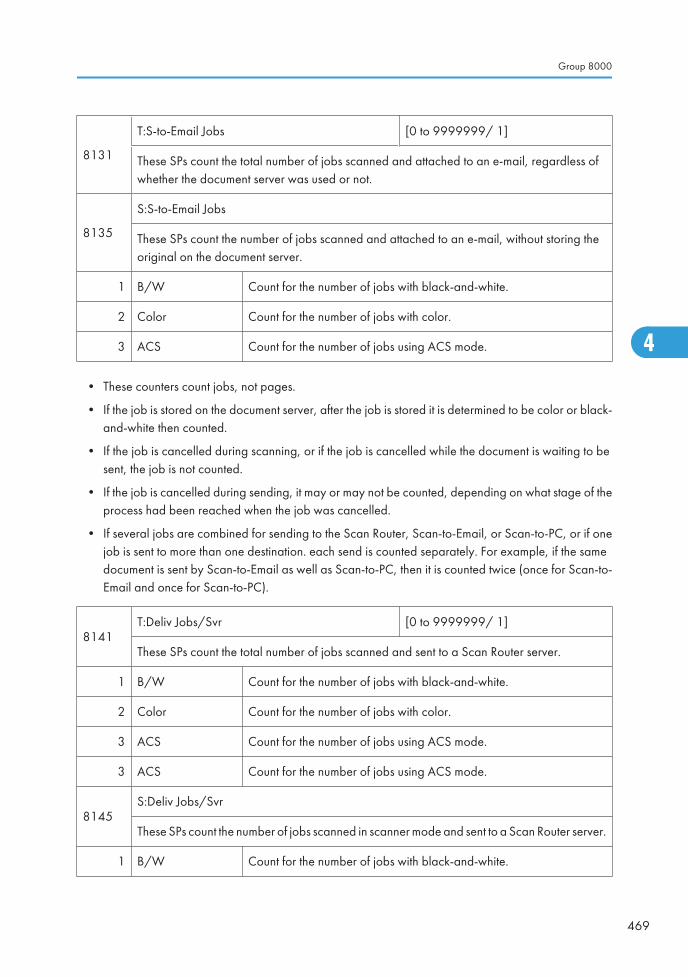
8131
T:S-to-Email Jobs [0 to 9999999/ 1]
These SPs count the total number of jobs scanned and attached to an e-mail, regardless ofwhether the document server was used or not.
8135
S:S-to-Email Jobs
These SPs count the number of jobs scanned and attached to an e-mail, without storing theoriginal on the document server.
1 B/W Count for the number of jobs with black-and-white.
2 Color Count for the number of jobs with color.
3 ACS Count for the number of jobs using ACS mode.
• These counters count jobs, not pages.
• If the job is stored on the document server, after the job is stored it is determined to be color or black-and-white then counted.
• If the job is cancelled during scanning, or if the job is cancelled while the document is waiting to besent, the job is not counted.
• If the job is cancelled during sending, it may or may not be counted, depending on what stage of theprocess had been reached when the job was cancelled.
• If several jobs are combined for sending to the Scan Router, Scan-to-Email, or Scan-to-PC, or if onejob is sent to more than one destination. each send is counted separately. For example, if the samedocument is sent by Scan-to-Email as well as Scan-to-PC, then it is counted twice (once for Scan-to-Email and once for Scan-to-PC).
8141T:Deliv Jobs/Svr [0 to 9999999/ 1]
These SPs count the total number of jobs scanned and sent to a Scan Router server.
1 B/W Count for the number of jobs with black-and-white.
2 Color Count for the number of jobs with color.
3 ACS Count for the number of jobs using ACS mode.
3 ACS Count for the number of jobs using ACS mode.
8145S:Deliv Jobs/Svr
These SPs count the number of jobs scanned in scanner mode and sent to a Scan Router server.
1 B/W Count for the number of jobs with black-and-white.
Group 8000
469
4
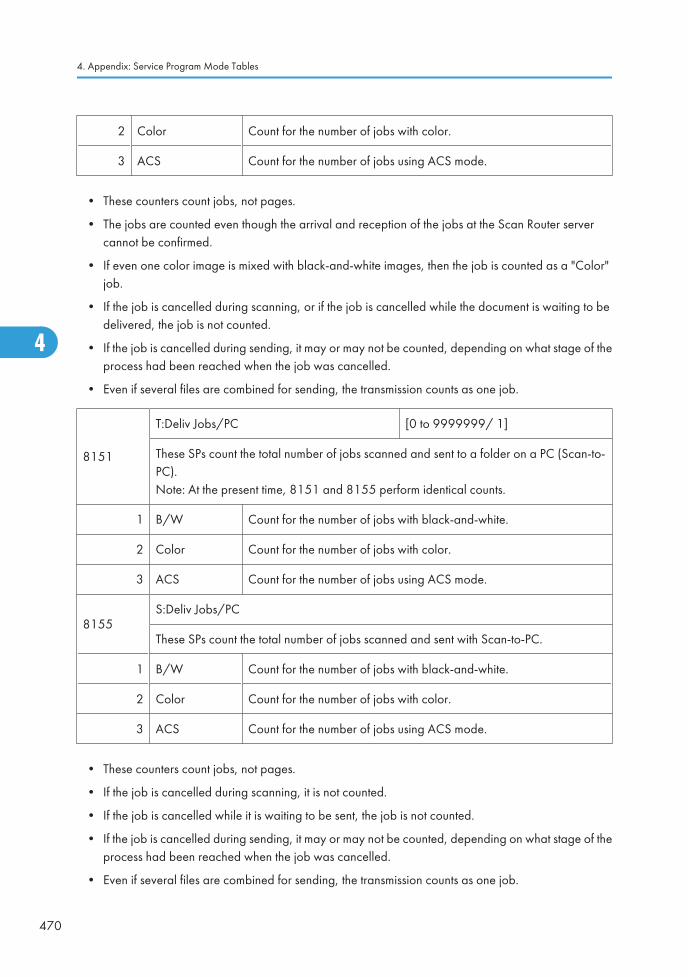
2 Color Count for the number of jobs with color.
3 ACS Count for the number of jobs using ACS mode.
• These counters count jobs, not pages.
• The jobs are counted even though the arrival and reception of the jobs at the Scan Router servercannot be confirmed.
• If even one color image is mixed with black-and-white images, then the job is counted as a "Color"job.
• If the job is cancelled during scanning, or if the job is cancelled while the document is waiting to bedelivered, the job is not counted.
• If the job is cancelled during sending, it may or may not be counted, depending on what stage of theprocess had been reached when the job was cancelled.
• Even if several files are combined for sending, the transmission counts as one job.
8151
T:Deliv Jobs/PC [0 to 9999999/ 1]
These SPs count the total number of jobs scanned and sent to a folder on a PC (Scan-to-PC).Note: At the present time, 8151 and 8155 perform identical counts.
1 B/W Count for the number of jobs with black-and-white.
2 Color Count for the number of jobs with color.
3 ACS Count for the number of jobs using ACS mode.
8155S:Deliv Jobs/PC
These SPs count the total number of jobs scanned and sent with Scan-to-PC.
1 B/W Count for the number of jobs with black-and-white.
2 Color Count for the number of jobs with color.
3 ACS Count for the number of jobs using ACS mode.
• These counters count jobs, not pages.
• If the job is cancelled during scanning, it is not counted.
• If the job is cancelled while it is waiting to be sent, the job is not counted.
• If the job is cancelled during sending, it may or may not be counted, depending on what stage of theprocess had been reached when the job was cancelled.
• Even if several files are combined for sending, the transmission counts as one job.
4. Appendix: Service Program Mode Tables
470
4
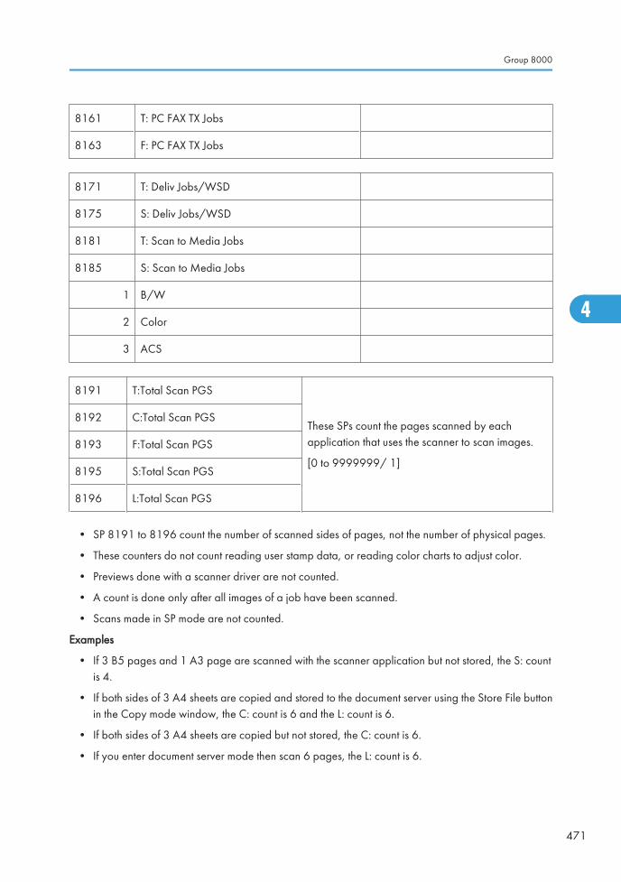
8161 T: PC FAX TX Jobs
8163 F: PC FAX TX Jobs
8171 T: Deliv Jobs/WSD
8175 S: Deliv Jobs/WSD
8181 T: Scan to Media Jobs
8185 S: Scan to Media Jobs
1 B/W
2 Color
3 ACS
8191 T:Total Scan PGS
These SPs count the pages scanned by eachapplication that uses the scanner to scan images.
[0 to 9999999/ 1]
8192 C:Total Scan PGS
8193 F:Total Scan PGS
8195 S:Total Scan PGS
8196 L:Total Scan PGS
• SP 8191 to 8196 count the number of scanned sides of pages, not the number of physical pages.
• These counters do not count reading user stamp data, or reading color charts to adjust color.
• Previews done with a scanner driver are not counted.
• A count is done only after all images of a job have been scanned.
• Scans made in SP mode are not counted.
Examples
• If 3 B5 pages and 1 A3 page are scanned with the scanner application but not stored, the S: countis 4.
• If both sides of 3 A4 sheets are copied and stored to the document server using the Store File buttonin the Copy mode window, the C: count is 6 and the L: count is 6.
• If both sides of 3 A4 sheets are copied but not stored, the C: count is 6.
• If you enter document server mode then scan 6 pages, the L: count is 6.
Group 8000
471
4
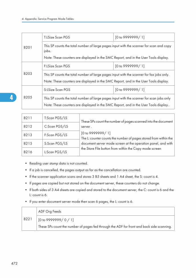
8201
T:LSize Scan PGS [0 to 9999999/ 1]
This SP counts the total number of large pages input with the scanner for scan and copyjobs.
Note: These counters are displayed in the SMC Report, and in the User Tools display.
8203
F:LSize Scan PGS [0 to 9999999/ 1]
This SP counts the total number of large pages input with the scanner for fax jobs only.
Note: These counters are displayed in the SMC Report, and in the User Tools display.
8205
S:LSize Scan PGS [0 to 9999999/ 1]
This SP counts the total number of large pages input with the scanner for scan jobs only
Note: These counters are displayed in the SMC Report, and in the User Tools display..
8211 T:Scan PGS/LSThese SPs count the number of pages scanned into the documentserver .
[0 to 9999999/ 1]The L: counter counts the number of pages stored from within thedocument server mode screen at the operation panel, and withthe Store File button from within the Copy mode screen
8212 C:Scan PGS/LS
8213 F:Scan PGS/LS
8215 S:Scan PGS/LS
8216 L:Scan PGS/LS
• Reading user stamp data is not counted.
• If a job is cancelled, the pages output as far as the cancellation are counted.
• If the scanner application scans and stores 3 B5 sheets and 1 A4 sheet, the S: count is 4.
• If pages are copied but not stored on the document server, these counters do not change.
• If both sides of 3 A4 sheets are copied and stored to the document server, the C: count is 6 and theL: count is 6.
• If you enter document server mode then scan 6 pages, the L: count is 6.
8221
ADF Org Feeds
[0 to 9999999/ 0 / 1]
These SPs count the number of pages fed through the ADF for front and back side scanning.
4. Appendix: Service Program Mode Tables
472
4
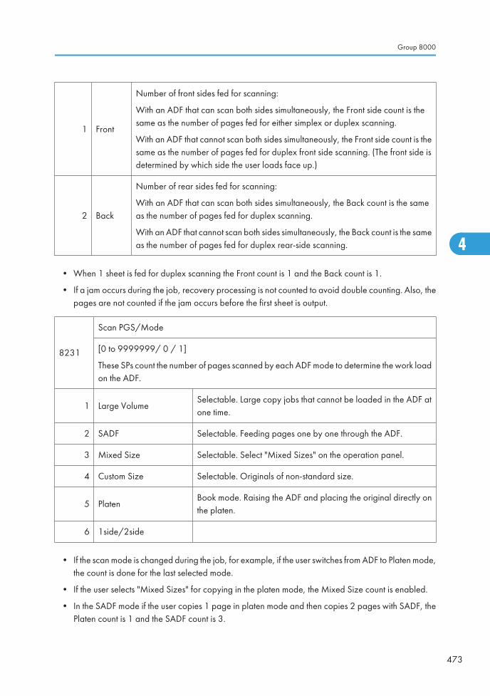
1 Front
Number of front sides fed for scanning:
With an ADF that can scan both sides simultaneously, the Front side count is thesame as the number of pages fed for either simplex or duplex scanning.
With an ADF that cannot scan both sides simultaneously, the Front side count is thesame as the number of pages fed for duplex front side scanning. (The front side isdetermined by which side the user loads face up.)
2 Back
Number of rear sides fed for scanning:
With an ADF that can scan both sides simultaneously, the Back count is the sameas the number of pages fed for duplex scanning.
With an ADF that cannot scan both sides simultaneously, the Back count is the sameas the number of pages fed for duplex rear-side scanning.
• When 1 sheet is fed for duplex scanning the Front count is 1 and the Back count is 1.
• If a jam occurs during the job, recovery processing is not counted to avoid double counting. Also, thepages are not counted if the jam occurs before the first sheet is output.
8231
Scan PGS/Mode
[0 to 9999999/ 0 / 1]
These SPs count the number of pages scanned by each ADF mode to determine the work loadon the ADF.
1 Large VolumeSelectable. Large copy jobs that cannot be loaded in the ADF atone time.
2 SADF Selectable. Feeding pages one by one through the ADF.
3 Mixed Size Selectable. Select "Mixed Sizes" on the operation panel.
4 Custom Size Selectable. Originals of non-standard size.
5 PlatenBook mode. Raising the ADF and placing the original directly onthe platen.
6 1side/2side
• If the scan mode is changed during the job, for example, if the user switches from ADF to Platen mode,the count is done for the last selected mode.
• If the user selects "Mixed Sizes" for copying in the platen mode, the Mixed Size count is enabled.
• In the SADF mode if the user copies 1 page in platen mode and then copies 2 pages with SADF, thePlaten count is 1 and the SADF count is 3.
Group 8000
473
4
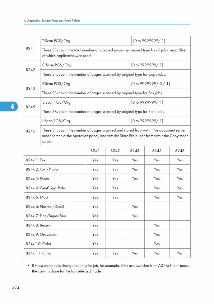
8241
T:Scan PGS/Org [0 to 9999999/ 1]
These SPs count the total number of scanned pages by original type for all jobs, regardlessof which application was used.
8242C:Scan PGS/Org [0 to 9999999/ 1]
These SPs count the number of pages scanned by original type for Copy jobs.
8243F:Scan PGS/Org [0 to 9999999/ 0 / 1]
These SPs count the number of pages scanned by original type for Fax jobs.
8245S:Scan PGS/Org [0 to 9999999/ 1]
These SPs count the number of pages scanned by original type for Scan jobs.
8246
L:Scan PGS/Org [0 to 9999999/ 1]
These SPs count the number of pages scanned and stored from within the document servermode screen at the operation panel, and with the Store File button from within the Copy modescreen
8241 8242 8243 8245 8246
824x 1: Text Yes Yes Yes Yes Yes
824x 2: Text/Photo Yes Yes Yes Yes Yes
824x 3: Photo Yes Yes Yes Yes Yes
824x 4: GenCopy, Pale Yes Yes Yes Yes
824x 5: Map Yes Yes Yes Yes
824x 6: Normal/Detail Yes Yes
824x 7: Fine/Super Fine Yes Yes
824x 8: Binary Yes Yes
824x 9: Grayscale Yes Yes
824x 10: Color Yes Yes
824x 11: Other Yes Yes Yes Yes Yes
• If the scan mode is changed during the job, for example, if the user switches from ADF to Platen mode,the count is done for the last selected mode.
4. Appendix: Service Program Mode Tables
474
4
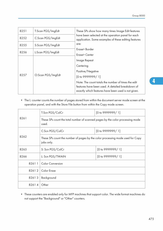
8251 T:Scan PGS/ImgEdt These SPs show how many times Image Edit featureshave been selected at the operation panel for eachapplication. Some examples of these editing featuresare:
Erase> Border
Erase> Center
Image Repeat
Centering
Positive/Negative
[0 to 9999999/ 1]
Note: The count totals the number of times the editfeatures have been used. A detailed breakdown ofexactly which features have been used is not given.
8252 C:Scan PGS/ImgEdt
8255 S:Scan PGS/ImgEdt
8256 L:Scan PGS/ImgEdt
8257 O:Scan PGS/ImgEdt
• The L: counter counts the number of pages stored from within the document server mode screen at theoperation panel, and with the Store File button from within the Copy mode screen.
8261
T:Scn PGS/ColCr [0 to 9999999/ 1]
These SPs count the total number of scanned pages by the color processing modeused.
8262
C:Scn PGS/ColCr [0 to 9999999/ 1]
These SPs count the number of pages by the color processing mode used for Copyjobs only.
8265 S: Scn PGS/ColCr [0 to 9999999/ 1]
8266 L: Scn PGS/TWAIN [0 to 9999999/ 1]
8261 1 Color Conversion
8261 2 Color Erase
8261 3 Background
8261 4 Other
• These counters are enabled only for MFP machines that support color. The wide format machines donot support the "Background" or "Other" counters.
Group 8000
475
4
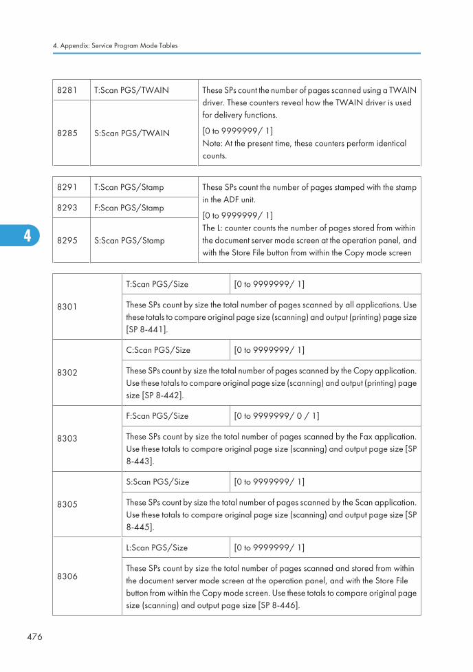
8281 T:Scan PGS/TWAIN These SPs count the number of pages scanned using a TWAINdriver. These counters reveal how the TWAIN driver is usedfor delivery functions.
[0 to 9999999/ 1]Note: At the present time, these counters perform identicalcounts.
8285 S:Scan PGS/TWAIN
8291 T:Scan PGS/Stamp These SPs count the number of pages stamped with the stampin the ADF unit.
[0 to 9999999/ 1]The L: counter counts the number of pages stored from withinthe document server mode screen at the operation panel, andwith the Store File button from within the Copy mode screen
8293 F:Scan PGS/Stamp
8295 S:Scan PGS/Stamp
8301
T:Scan PGS/Size [0 to 9999999/ 1]
These SPs count by size the total number of pages scanned by all applications. Usethese totals to compare original page size (scanning) and output (printing) page size[SP 8-441].
8302
C:Scan PGS/Size [0 to 9999999/ 1]
These SPs count by size the total number of pages scanned by the Copy application.Use these totals to compare original page size (scanning) and output (printing) pagesize [SP 8-442].
8303
F:Scan PGS/Size [0 to 9999999/ 0 / 1]
These SPs count by size the total number of pages scanned by the Fax application.Use these totals to compare original page size (scanning) and output page size [SP8-443].
8305
S:Scan PGS/Size [0 to 9999999/ 1]
These SPs count by size the total number of pages scanned by the Scan application.Use these totals to compare original page size (scanning) and output page size [SP8-445].
8306
L:Scan PGS/Size [0 to 9999999/ 1]
These SPs count by size the total number of pages scanned and stored from withinthe document server mode screen at the operation panel, and with the Store Filebutton from within the Copy mode screen. Use these totals to compare original pagesize (scanning) and output page size [SP 8-446].
4. Appendix: Service Program Mode Tables
476
4
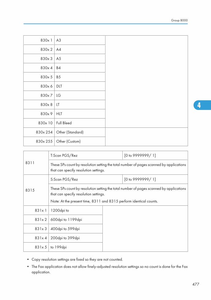
830x 1 A3
830x 2 A4
830x 3 A5
830x 4 B4
830x 5 B5
830x 6 DLT
830x 7 LG
830x 8 LT
830x 9 HLT
830x 10 Full Bleed
830x 254 Other (Standard)
830x 255 Other (Custom)
8311
T:Scan PGS/Rez [0 to 9999999/ 1]
These SPs count by resolution setting the total number of pages scanned by applicationsthat can specify resolution settings.
8315
S:Scan PGS/Rez [0 to 9999999/ 1]
These SPs count by resolution setting the total number of pages scanned by applicationsthat can specify resolution settings.
Note: At the present time, 8311 and 8315 perform identical counts.
831x 1 1200dpi to
831x 2 600dpi to 1199dpi
831x 3 400dpi to 599dpi
831x 4 200dpi to 399dpi
831x 5 to 199dpi
• Copy resolution settings are fixed so they are not counted.
• The Fax application does not allow finely-adjusted resolution settings so no count is done for the Faxapplication.
Group 8000
477
4
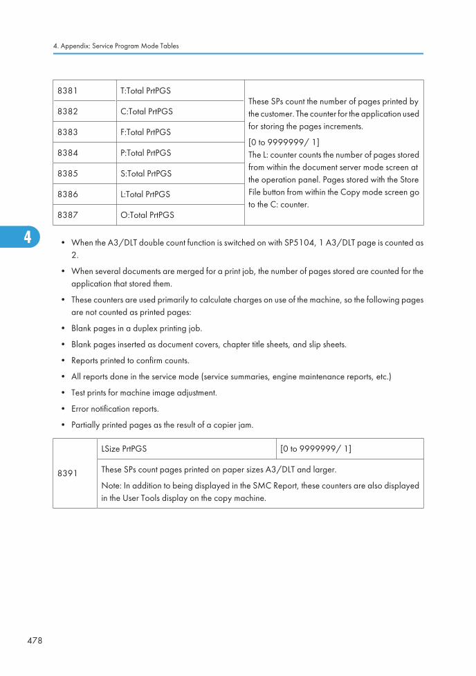
8381 T:Total PrtPGSThese SPs count the number of pages printed bythe customer. The counter for the application usedfor storing the pages increments.
[0 to 9999999/ 1]The L: counter counts the number of pages storedfrom within the document server mode screen atthe operation panel. Pages stored with the StoreFile button from within the Copy mode screen goto the C: counter.
8382 C:Total PrtPGS
8383 F:Total PrtPGS
8384 P:Total PrtPGS
8385 S:Total PrtPGS
8386 L:Total PrtPGS
8387 O:Total PrtPGS
• When the A3/DLT double count function is switched on with SP5104, 1 A3/DLT page is counted as2.
• When several documents are merged for a print job, the number of pages stored are counted for theapplication that stored them.
• These counters are used primarily to calculate charges on use of the machine, so the following pagesare not counted as printed pages:
• Blank pages in a duplex printing job.
• Blank pages inserted as document covers, chapter title sheets, and slip sheets.
• Reports printed to confirm counts.
• All reports done in the service mode (service summaries, engine maintenance reports, etc.)
• Test prints for machine image adjustment.
• Error notification reports.
• Partially printed pages as the result of a copier jam.
8391
LSize PrtPGS [0 to 9999999/ 1]
These SPs count pages printed on paper sizes A3/DLT and larger.
Note: In addition to being displayed in the SMC Report, these counters are also displayedin the User Tools display on the copy machine.
4. Appendix: Service Program Mode Tables
478
4
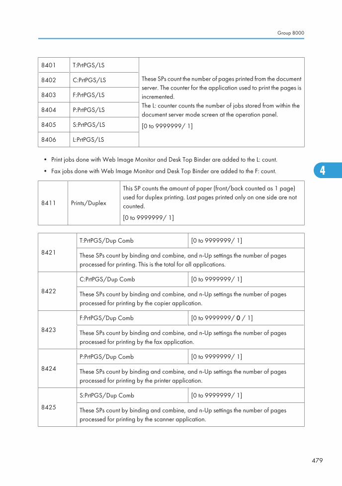
8401 T:PrtPGS/LS
These SPs count the number of pages printed from the documentserver. The counter for the application used to print the pages isincremented.The L: counter counts the number of jobs stored from within thedocument server mode screen at the operation panel.
[0 to 9999999/ 1]
8402 C:PrtPGS/LS
8403 F:PrtPGS/LS
8404 P:PrtPGS/LS
8405 S:PrtPGS/LS
8406 L:PrtPGS/LS
• Print jobs done with Web Image Monitor and Desk Top Binder are added to the L: count.
• Fax jobs done with Web Image Monitor and Desk Top Binder are added to the F: count.
8411 Prints/Duplex
This SP counts the amount of paper (front/back counted as 1 page)used for duplex printing. Last pages printed only on one side are notcounted.
[0 to 9999999/ 1]
8421
T:PrtPGS/Dup Comb [0 to 9999999/ 1]
These SPs count by binding and combine, and n-Up settings the number of pagesprocessed for printing. This is the total for all applications.
8422
C:PrtPGS/Dup Comb [0 to 9999999/ 1]
These SPs count by binding and combine, and n-Up settings the number of pagesprocessed for printing by the copier application.
8423
F:PrtPGS/Dup Comb [0 to 9999999/ 0 / 1]
These SPs count by binding and combine, and n-Up settings the number of pagesprocessed for printing by the fax application.
8424
P:PrtPGS/Dup Comb [0 to 9999999/ 1]
These SPs count by binding and combine, and n-Up settings the number of pagesprocessed for printing by the printer application.
8425
S:PrtPGS/Dup Comb [0 to 9999999/ 1]
These SPs count by binding and combine, and n-Up settings the number of pagesprocessed for printing by the scanner application.
Group 8000
479
4
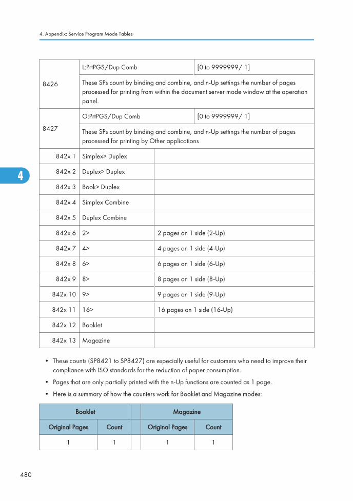
8426
L:PrtPGS/Dup Comb [0 to 9999999/ 1]
These SPs count by binding and combine, and n-Up settings the number of pagesprocessed for printing from within the document server mode window at the operationpanel.
8427
O:PrtPGS/Dup Comb [0 to 9999999/ 1]
These SPs count by binding and combine, and n-Up settings the number of pagesprocessed for printing by Other applications
842x 1 Simplex> Duplex
842x 2 Duplex> Duplex
842x 3 Book> Duplex
842x 4 Simplex Combine
842x 5 Duplex Combine
842x 6 2> 2 pages on 1 side (2-Up)
842x 7 4> 4 pages on 1 side (4-Up)
842x 8 6> 6 pages on 1 side (6-Up)
842x 9 8> 8 pages on 1 side (8-Up)
842x 10 9> 9 pages on 1 side (9-Up)
842x 11 16> 16 pages on 1 side (16-Up)
842x 12 Booklet
842x 13 Magazine
• These counts (SP8421 to SP8427) are especially useful for customers who need to improve theircompliance with ISO standards for the reduction of paper consumption.
• Pages that are only partially printed with the n-Up functions are counted as 1 page.
• Here is a summary of how the counters work for Booklet and Magazine modes:
Booklet Magazine
Original Pages Count Original Pages Count
1 1 1 1
4. Appendix: Service Program Mode Tables
480
4
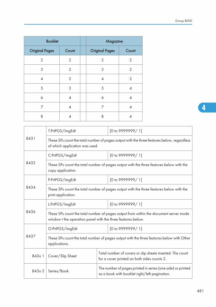
Booklet Magazine
Original Pages Count Original Pages Count
2 2 2 2
3 2 3 2
4 2 4 2
5 3 5 4
6 4 6 4
7 4 7 4
8 4 8 4
8431
T:PrtPGS/ImgEdt [0 to 9999999/ 1]
These SPs count the total number of pages output with the three features below, regardlessof which application was used.
8432
C:PrtPGS/ImgEdt [0 to 9999999/ 1]
These SPs count the total number of pages output with the three features below with thecopy application.
8434
P:PrtPGS/ImgEdt [0 to 9999999/ 1]
These SPs count the total number of pages output with the three features below with theprint application.
8436
L:PrtPGS/ImgEdt [0 to 9999999/ 1]
These SPs count the total number of pages output from within the document server modewindow t the operation panel with the three features below.
8437
O:PrtPGS/ImgEdt [0 to 9999999/ 1]
These SPs count the total number of pages output with the three features below with Otherapplications.
843x 1 Cover/Slip SheetTotal number of covers or slip sheets inserted. The countfor a cover printed on both sides counts 2.
843x 2 Series/BookThe number of pages printed in series (one side) or printedas a book with booklet right/left pagination.
Group 8000
481
4
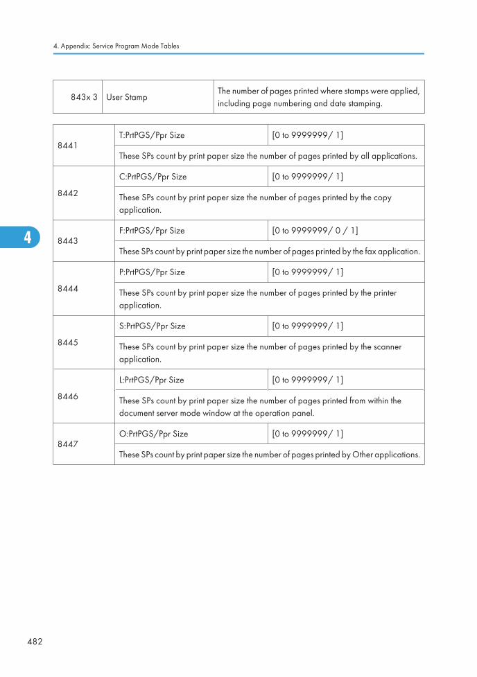
843x 3 User StampThe number of pages printed where stamps were applied,including page numbering and date stamping.
8441T:PrtPGS/Ppr Size [0 to 9999999/ 1]
These SPs count by print paper size the number of pages printed by all applications.
8442
C:PrtPGS/Ppr Size [0 to 9999999/ 1]
These SPs count by print paper size the number of pages printed by the copyapplication.
8443F:PrtPGS/Ppr Size [0 to 9999999/ 0 / 1]
These SPs count by print paper size the number of pages printed by the fax application.
8444
P:PrtPGS/Ppr Size [0 to 9999999/ 1]
These SPs count by print paper size the number of pages printed by the printerapplication.
8445
S:PrtPGS/Ppr Size [0 to 9999999/ 1]
These SPs count by print paper size the number of pages printed by the scannerapplication.
8446
L:PrtPGS/Ppr Size [0 to 9999999/ 1]
These SPs count by print paper size the number of pages printed from within thedocument server mode window at the operation panel.
8447O:PrtPGS/Ppr Size [0 to 9999999/ 1]
These SPs count by print paper size the number of pages printed by Other applications.
4. Appendix: Service Program Mode Tables
482
4
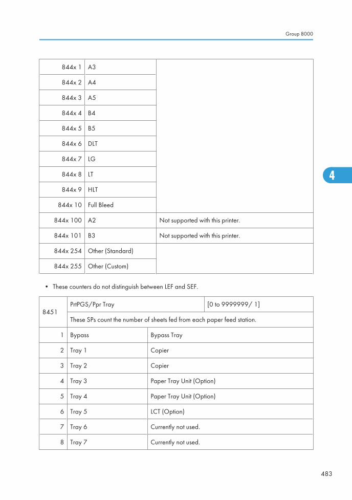
844x 1 A3
844x 2 A4
844x 3 A5
844x 4 B4
844x 5 B5
844x 6 DLT
844x 7 LG
844x 8 LT
844x 9 HLT
844x 10 Full Bleed
844x 100 A2 Not supported with this printer.
844x 101 B3 Not supported with this printer.
844x 254 Other (Standard)
844x 255 Other (Custom)
• These counters do not distinguish between LEF and SEF.
8451PrtPGS/Ppr Tray [0 to 9999999/ 1]
These SPs count the number of sheets fed from each paper feed station.
1 Bypass Bypass Tray
2 Tray 1 Copier
3 Tray 2 Copier
4 Tray 3 Paper Tray Unit (Option)
5 Tray 4 Paper Tray Unit (Option)
6 Tray 5 LCT (Option)
7 Tray 6 Currently not used.
8 Tray 7 Currently not used.
Group 8000
483
4
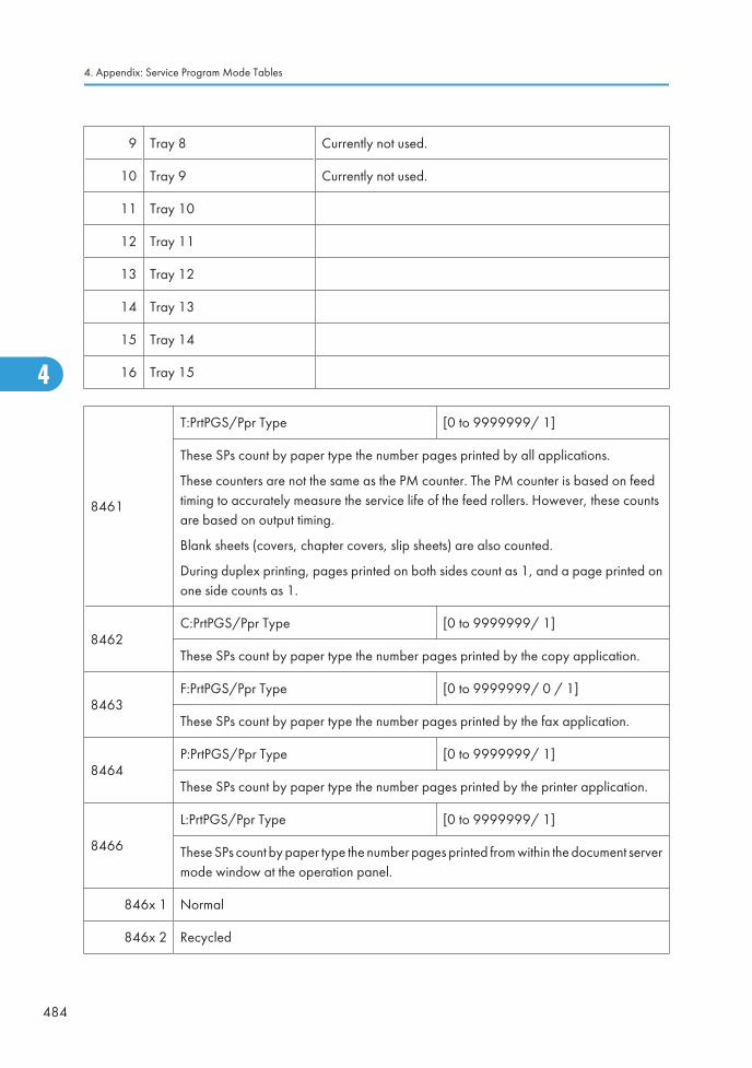
9 Tray 8 Currently not used.
10 Tray 9 Currently not used.
11 Tray 10
12 Tray 11
13 Tray 12
14 Tray 13
15 Tray 14
16 Tray 15
8461
T:PrtPGS/Ppr Type [0 to 9999999/ 1]
These SPs count by paper type the number pages printed by all applications.
These counters are not the same as the PM counter. The PM counter is based on feedtiming to accurately measure the service life of the feed rollers. However, these countsare based on output timing.
Blank sheets (covers, chapter covers, slip sheets) are also counted.
During duplex printing, pages printed on both sides count as 1, and a page printed onone side counts as 1.
8462C:PrtPGS/Ppr Type [0 to 9999999/ 1]
These SPs count by paper type the number pages printed by the copy application.
8463F:PrtPGS/Ppr Type [0 to 9999999/ 0 / 1]
These SPs count by paper type the number pages printed by the fax application.
8464P:PrtPGS/Ppr Type [0 to 9999999/ 1]
These SPs count by paper type the number pages printed by the printer application.
8466
L:PrtPGS/Ppr Type [0 to 9999999/ 1]
These SPs count by paper type the number pages printed from within the document servermode window at the operation panel.
846x 1 Normal
846x 2 Recycled
4. Appendix: Service Program Mode Tables
484
4
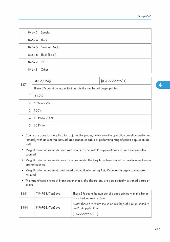
846x 3 Special
846x 4 Thick
846x 5 Normal (Back)
846x 6 Thick (Back)
846x 7 OHP
846x 8 Other
8471PrtPGS/Mag [0 to 9999999/ 1]
These SPs count by magnification rate the number of pages printed.
1 to 49%
2 50% to 99%
3 100%
4 101% to 200%
5 201% to
• Counts are done for magnification adjusted for pages, not only on the operation panel but performedremotely with an external network application capable of performing magnification adjustment aswell.
• Magnification adjustments done with printer drivers with PC applications such as Excel are alsocounted.
• Magnification adjustments done for adjustments after they have been stored on the document serverare not counted.
• Magnification adjustments performed automatically during Auto Reduce/Enlarge copying arecounted.
• The magnification rates of blank cover sheets, slip sheets, etc. are automatically assigned a rate of100%.
8481 T:PrtPGS/TonSave These SPs count the number of pages printed with the TonerSave feature switched on.
Note: These SPs return the same results as this SP is limited tothe Print application.
[0 to 9999999/ 1]
8484 P:PrtPGS/TonSave
Group 8000
485
4
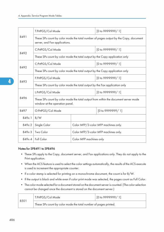
8491
T:PrtPGS/Col Mode [0 to 9999999/ 1]
These SPs count by color mode the total number of pages output by the Copy, documentserver, and Fax applications.
8492C:PrtPGS/Col Mode [0 to 9999999/ 1]
These SPs count by color mode the total output by the Copy application only
8492C:PrtPGS/Col Mode [0 to 9999999/ 1]
These SPs count by color mode the total output by the Copy application only
8493F:PrtPGS/Col Mode [0 to 9999999/ 1]
These SPs count by color mode the total output by the Fax application only
8496
L:PrtPGS/Col Mode [0 to 9999999/ 1]
These SPs count by color mode the total output from within the document server modewindow at the operation panel.
8497 O:PrtPGS/Col Mode [0 to 9999999/ 1]
849x 1 B/W
849x 2 Single Color Color MFP/2-color MFP machines only.
849x 3 Two Color Color MFP/2-color MFP machines only.
849x 4 Full Color Color MFP machines only
Notes for SP8491 to SP8496
• These SPs apply to the Copy, document server, and Fax applications only. They do not apply to thePrint application.
• When the ACS feature is used to select the color settings automatically, the results of the ACS executeis used to increment the appropriate counter.
• If a color stamp is selected for printing on a monochrome document, the count is for B/W.
• If the output is black and white even if color print mode was selected, the pages count as Full Color.
• The color mode selected for a document stored on the document server is counted. (The color selectioncannot be changed once the document is stored on the document server.)
8501T:PrtPGS/Col Mode [0 to 9999999/ 1]
These SPs count by color mode the total number of pages printed.
4. Appendix: Service Program Mode Tables
486
4
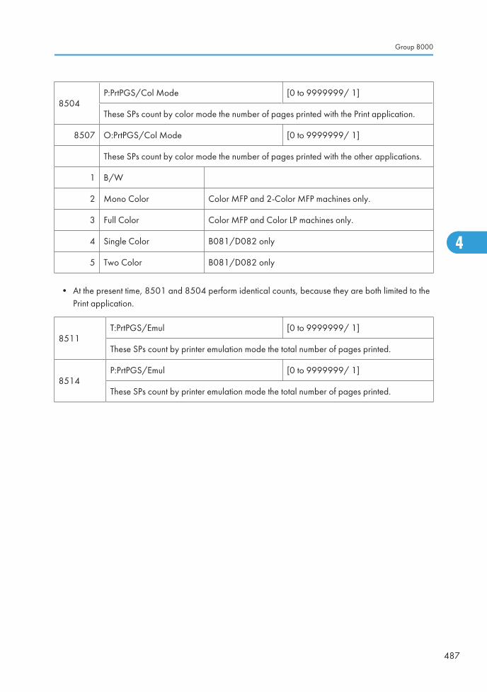
8504P:PrtPGS/Col Mode [0 to 9999999/ 1]
These SPs count by color mode the number of pages printed with the Print application.
8507 O:PrtPGS/Col Mode [0 to 9999999/ 1]
These SPs count by color mode the number of pages printed with the other applications.
1 B/W
2 Mono Color Color MFP and 2-Color MFP machines only.
3 Full Color Color MFP and Color LP machines only.
4 Single Color B081/D082 only
5 Two Color B081/D082 only
• At the present time, 8501 and 8504 perform identical counts, because they are both limited to thePrint application.
8511T:PrtPGS/Emul [0 to 9999999/ 1]
These SPs count by printer emulation mode the total number of pages printed.
8514P:PrtPGS/Emul [0 to 9999999/ 1]
These SPs count by printer emulation mode the total number of pages printed.
Group 8000
487
4
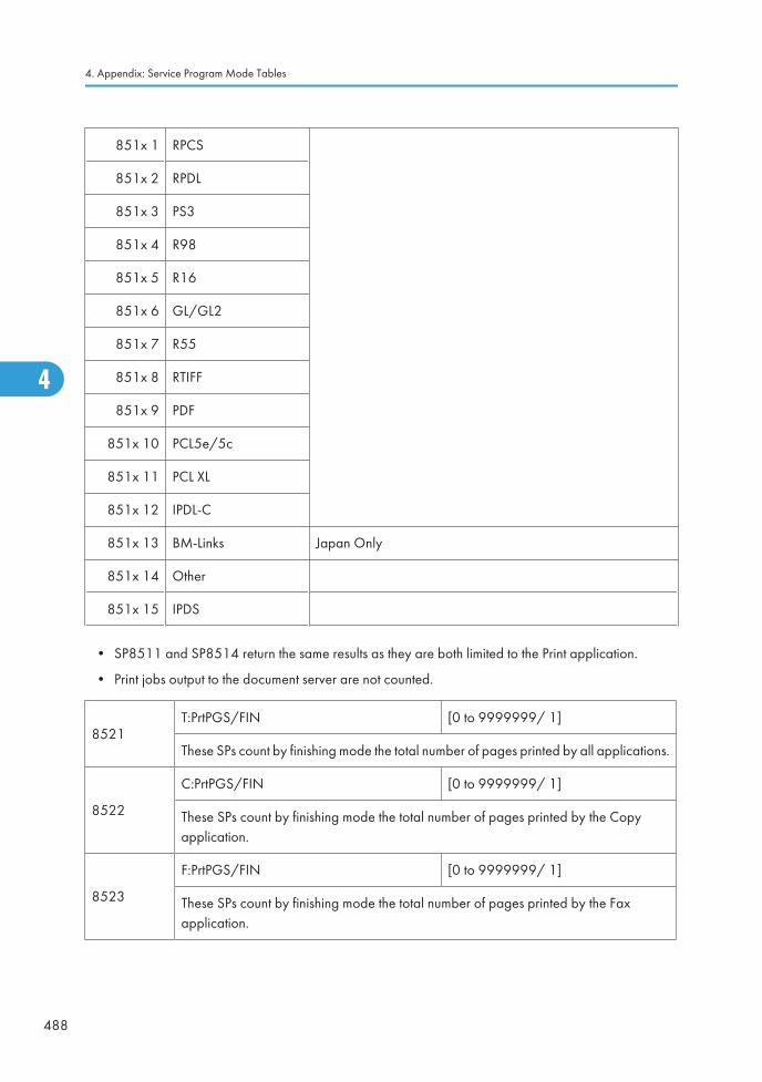
851x 1 RPCS
851x 2 RPDL
851x 3 PS3
851x 4 R98
851x 5 R16
851x 6 GL/GL2
851x 7 R55
851x 8 RTIFF
851x 9 PDF
851x 10 PCL5e/5c
851x 11 PCL XL
851x 12 IPDL-C
851x 13 BM-Links Japan Only
851x 14 Other
851x 15 IPDS
• SP8511 and SP8514 return the same results as they are both limited to the Print application.
• Print jobs output to the document server are not counted.
8521T:PrtPGS/FIN [0 to 9999999/ 1]
These SPs count by finishing mode the total number of pages printed by all applications.
8522
C:PrtPGS/FIN [0 to 9999999/ 1]
These SPs count by finishing mode the total number of pages printed by the Copyapplication.
8523
F:PrtPGS/FIN [0 to 9999999/ 1]
These SPs count by finishing mode the total number of pages printed by the Faxapplication.
4. Appendix: Service Program Mode Tables
488
4
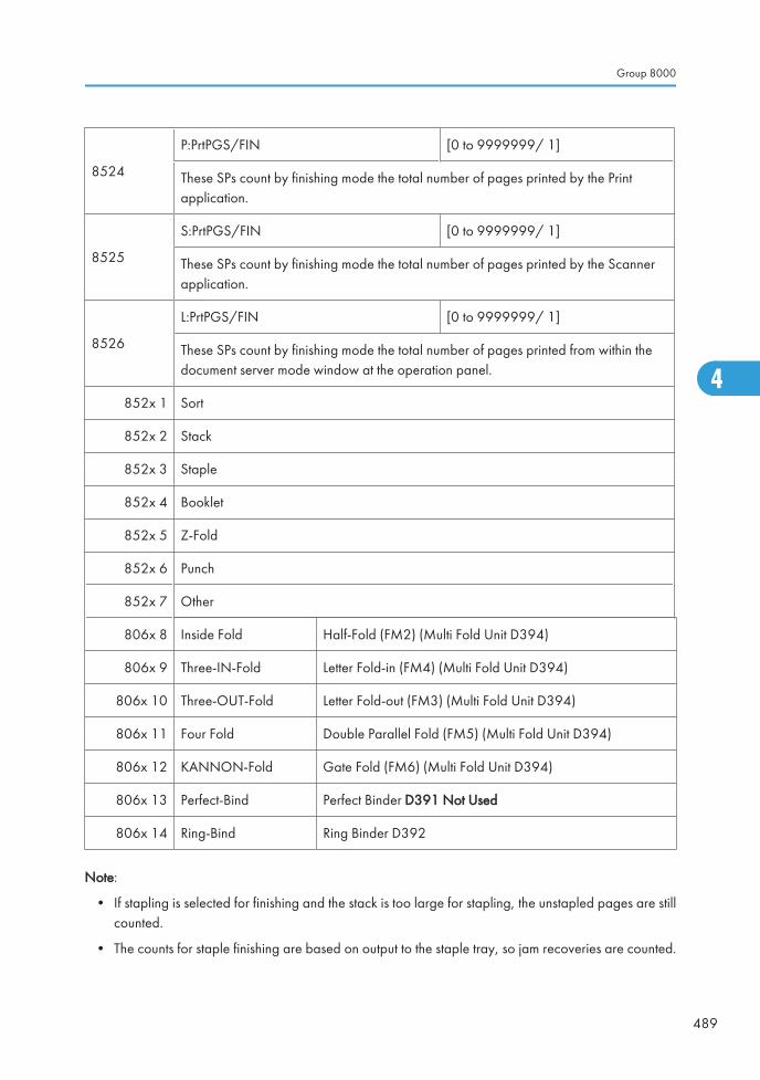
8524
P:PrtPGS/FIN [0 to 9999999/ 1]
These SPs count by finishing mode the total number of pages printed by the Printapplication.
8525
S:PrtPGS/FIN [0 to 9999999/ 1]
These SPs count by finishing mode the total number of pages printed by the Scannerapplication.
8526
L:PrtPGS/FIN [0 to 9999999/ 1]
These SPs count by finishing mode the total number of pages printed from within thedocument server mode window at the operation panel.
852x 1 Sort
852x 2 Stack
852x 3 Staple
852x 4 Booklet
852x 5 Z-Fold
852x 6 Punch
852x 7 Other
806x 8 Inside Fold Half-Fold (FM2) (Multi Fold Unit D394)
806x 9 Three-IN-Fold Letter Fold-in (FM4) (Multi Fold Unit D394)
806x 10 Three-OUT-Fold Letter Fold-out (FM3) (Multi Fold Unit D394)
806x 11 Four Fold Double Parallel Fold (FM5) (Multi Fold Unit D394)
806x 12 KANNON-Fold Gate Fold (FM6) (Multi Fold Unit D394)
806x 13 Perfect-Bind Perfect Binder D391 Not Used
806x 14 Ring-Bind Ring Binder D392
Note:
• If stapling is selected for finishing and the stack is too large for stapling, the unstapled pages are stillcounted.
• The counts for staple finishing are based on output to the staple tray, so jam recoveries are counted.
Group 8000
489
4
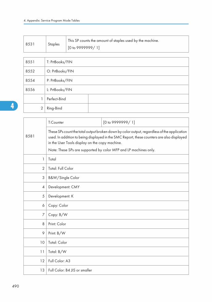
8531 StaplesThis SP counts the amount of staples used by the machine.
[0 to 9999999/ 1]
8551 T: PrtBooks/FIN
8552 O: PrtBooks/FIN
8554 P: PrtBooks/FIN
8556 L: PrtBooks/FIN
1 Perfect-Bind
2 Ring-Bind
8581
T:Counter [0 to 9999999/ 1]
These SPs count the total output broken down by color output, regardless of the applicationused. In addition to being displayed in the SMC Report, these counters are also displayedin the User Tools display on the copy machine.
Note: These SPs are supported by color MFP and LP machines only.
1 Total
2 Total: Full Color
3 B&W/Single Color
4 Development: CMY
5 Development: K
6 Copy: Color
7 Copy: B/W
8 Print: Color
9 Print: B/W
10 Total: Color
11 Total: B/W
12 Full Color: A3
13 Full Color: B4 JIS or smaller
4. Appendix: Service Program Mode Tables
490
4
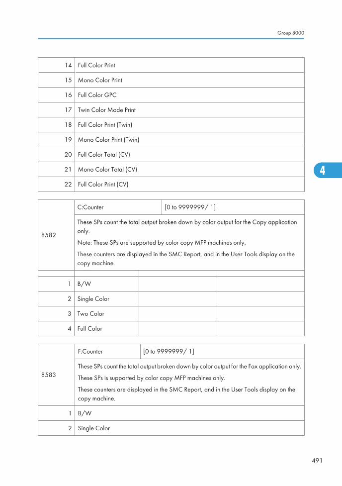
14 Full Color Print
15 Mono Color Print
16 Full Color GPC
17 Twin Color Mode Print
18 Full Color Print (Twin)
19 Mono Color Print (Twin)
20 Full Color Total (CV)
21 Mono Color Total (CV)
22 Full Color Print (CV)
8582
C:Counter [0 to 9999999/ 1]
These SPs count the total output broken down by color output for the Copy applicationonly.
Note: These SPs are supported by color copy MFP machines only.
These counters are displayed in the SMC Report, and in the User Tools display on thecopy machine.
1 B/W
2 Single Color
3 Two Color
4 Full Color
8583
F:Counter [0 to 9999999/ 1]
These SPs count the total output broken down by color output for the Fax application only.
These SPs is supported by color copy MFP machines only.
These counters are displayed in the SMC Report, and in the User Tools display on thecopy machine.
1 B/W
2 Single Color
Group 8000
491
4
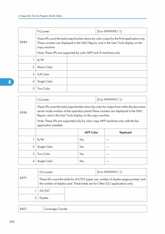
8584
P:Counter [0 to 9999999/ 1]
These SPs count the total output broken down by color output for the Print application only.These counters are displayed in the SMC Report, and in the User Tools display on thecopy machine.
Note: These SPs are supported by color MFP and LP machines only.
1 B/W
2 Mono Color
3 Full Color
4 Single Color
5 Two Color
8586
L:Counter [0 to 9999999/ 1]
These SPs count the total output broken down by color for output from within the documentserver mode window at the operation panel.These counters are displayed in the SMCReport, and in the User Tools display on the copy machine.
Note: These SPs are supported only by color copy MFP machines only with the faxapplication installed.
MFP Color Replaced:
1 B/W Yes ---
2 Single Color Yes ---
3 Two Color Yes ---
4 Single Color Yes ---
8591
O:Counter [0 to 9999999/ 1]
These SPs count the totals for A3/DLT paper use, number of duplex pages printed, andthe number of staples used. These totals are for Other (O:) applications only.
1 A3/DLT
2 Duplex
8601 Coverage Counter
4. Appendix: Service Program Mode Tables
492
4
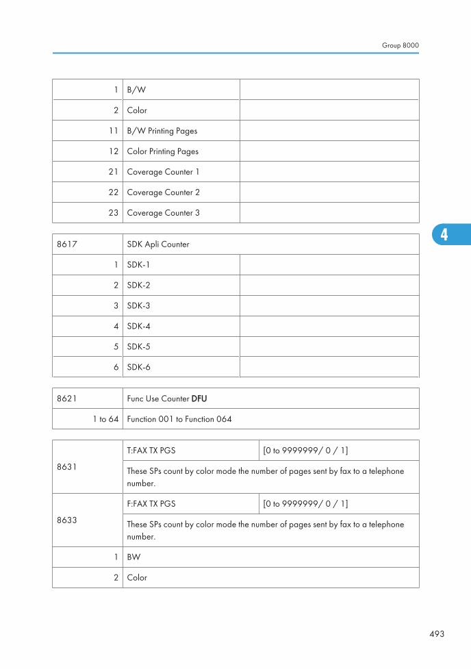
1 B/W
2 Color
11 B/W Printing Pages
12 Color Printing Pages
21 Coverage Counter 1
22 Coverage Counter 2
23 Coverage Counter 3
8617 SDK Apli Counter
1 SDK-1
2 SDK-2
3 SDK-3
4 SDK-4
5 SDK-5
6 SDK-6
8621 Func Use Counter DFU
1 to 64 Function 001 to Function 064
8631
T:FAX TX PGS [0 to 9999999/ 0 / 1]
These SPs count by color mode the number of pages sent by fax to a telephonenumber.
8633
F:FAX TX PGS [0 to 9999999/ 0 / 1]
These SPs count by color mode the number of pages sent by fax to a telephonenumber.
1 BW
2 Color
Group 8000
493
4
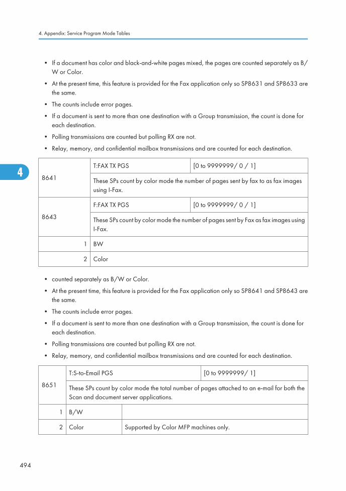
• If a document has color and black-and-white pages mixed, the pages are counted separately as B/W or Color.
• At the present time, this feature is provided for the Fax application only so SP8631 and SP8633 arethe same.
• The counts include error pages.
• If a document is sent to more than one destination with a Group transmission, the count is done foreach destination.
• Polling transmissions are counted but polling RX are not.
• Relay, memory, and confidential mailbox transmissions and are counted for each destination.
8641
T:FAX TX PGS [0 to 9999999/ 0 / 1]
These SPs count by color mode the number of pages sent by fax to as fax imagesusing I-Fax.
8643
F:FAX TX PGS [0 to 9999999/ 0 / 1]
These SPs count by color mode the number of pages sent by Fax as fax images usingI-Fax.
1 BW
2 Color
• counted separately as B/W or Color.
• At the present time, this feature is provided for the Fax application only so SP8641 and SP8643 arethe same.
• The counts include error pages.
• If a document is sent to more than one destination with a Group transmission, the count is done foreach destination.
• Polling transmissions are counted but polling RX are not.
• Relay, memory, and confidential mailbox transmissions and are counted for each destination.
8651
T:S-to-Email PGS [0 to 9999999/ 1]
These SPs count by color mode the total number of pages attached to an e-mail for both theScan and document server applications.
1 B/W
2 Color Supported by Color MFP machines only.
4. Appendix: Service Program Mode Tables
494
4
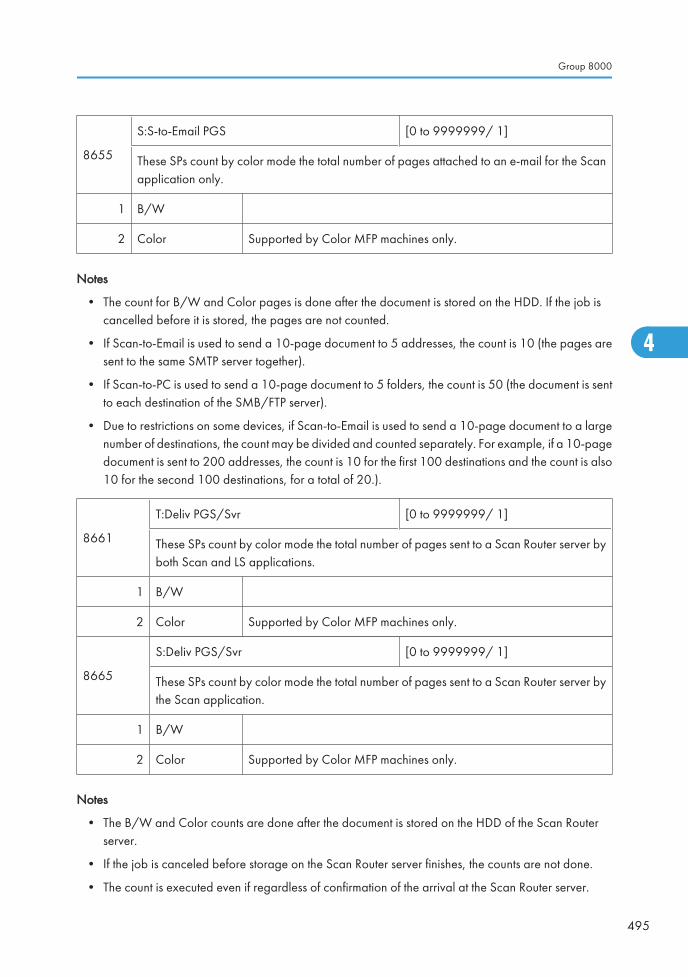
8655
S:S-to-Email PGS [0 to 9999999/ 1]
These SPs count by color mode the total number of pages attached to an e-mail for the Scanapplication only.
1 B/W
2 Color Supported by Color MFP machines only.
Notes
• The count for B/W and Color pages is done after the document is stored on the HDD. If the job iscancelled before it is stored, the pages are not counted.
• If Scan-to-Email is used to send a 10-page document to 5 addresses, the count is 10 (the pages aresent to the same SMTP server together).
• If Scan-to-PC is used to send a 10-page document to 5 folders, the count is 50 (the document is sentto each destination of the SMB/FTP server).
• Due to restrictions on some devices, if Scan-to-Email is used to send a 10-page document to a largenumber of destinations, the count may be divided and counted separately. For example, if a 10-pagedocument is sent to 200 addresses, the count is 10 for the first 100 destinations and the count is also10 for the second 100 destinations, for a total of 20.).
8661
T:Deliv PGS/Svr [0 to 9999999/ 1]
These SPs count by color mode the total number of pages sent to a Scan Router server byboth Scan and LS applications.
1 B/W
2 Color Supported by Color MFP machines only.
8665
S:Deliv PGS/Svr [0 to 9999999/ 1]
These SPs count by color mode the total number of pages sent to a Scan Router server bythe Scan application.
1 B/W
2 Color Supported by Color MFP machines only.
Notes
• The B/W and Color counts are done after the document is stored on the HDD of the Scan Routerserver.
• If the job is canceled before storage on the Scan Router server finishes, the counts are not done.
• The count is executed even if regardless of confirmation of the arrival at the Scan Router server.
Group 8000
495
4
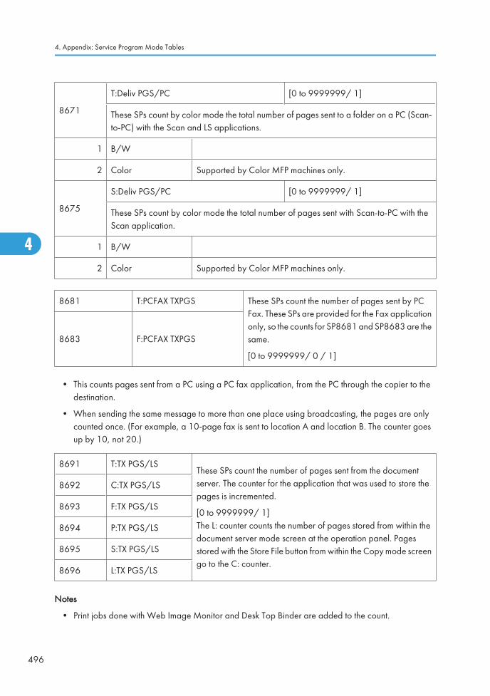
8671
T:Deliv PGS/PC [0 to 9999999/ 1]
These SPs count by color mode the total number of pages sent to a folder on a PC (Scan-to-PC) with the Scan and LS applications.
1 B/W
2 Color Supported by Color MFP machines only.
8675
S:Deliv PGS/PC [0 to 9999999/ 1]
These SPs count by color mode the total number of pages sent with Scan-to-PC with theScan application.
1 B/W
2 Color Supported by Color MFP machines only.
8681 T:PCFAX TXPGS These SPs count the number of pages sent by PCFax. These SPs are provided for the Fax applicationonly, so the counts for SP8681 and SP8683 are thesame.
[0 to 9999999/ 0 / 1]
8683 F:PCFAX TXPGS
• This counts pages sent from a PC using a PC fax application, from the PC through the copier to thedestination.
• When sending the same message to more than one place using broadcasting, the pages are onlycounted once. (For example, a 10-page fax is sent to location A and location B. The counter goesup by 10, not 20.)
8691 T:TX PGS/LSThese SPs count the number of pages sent from the documentserver. The counter for the application that was used to store thepages is incremented.
[0 to 9999999/ 1]The L: counter counts the number of pages stored from within thedocument server mode screen at the operation panel. Pagesstored with the Store File button from within the Copy mode screengo to the C: counter.
8692 C:TX PGS/LS
8693 F:TX PGS/LS
8694 P:TX PGS/LS
8695 S:TX PGS/LS
8696 L:TX PGS/LS
Notes
• Print jobs done with Web Image Monitor and Desk Top Binder are added to the count.
4. Appendix: Service Program Mode Tables
496
4

• If several documents are merged for sending, the number of pages stored are counted for theapplication that stored them
• When several documents are sent by a Fax broadcast, the F: count is done for the number of pagessent to each destination.
8701
TX PGS/Port [0 to 9999999/ 1]
These SPs count the number of pages sent by the physical port used to send them. Forexample, if a 3-page original is sent to 4 destinations via ISDN G4, the count for ISDN(G3, G4) is 12.
1 PSTN-1
2 PSTN-2
3 PSTN-3
4 ISDN (G3,G4)
5 Network
8711
T:Scan PGS/Comp [0 to 9999999/ 1]
These SPs count the number of compressed pages scanned into the document server,counted by the formats slisted below.
1 JPEG/JPEG2000
2 TIFF (Multi/Single)
3 PDF
4 Other
5 PDF/Comp
8715
S:Scan PGS/Comp [0 to 9999999/ 1]
These SPs count the number of compressed pages scanned by the scan application,counted by the formats slisted below.
1 JPEG/JPEG2000
2 TIFF (Multi/Single)
3 PDF
Group 8000
497
4
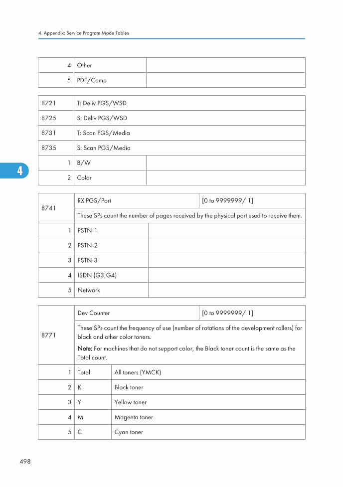
4 Other
5 PDF/Comp
8721 T: Deliv PGS/WSD
8725 S: Deliv PGS/WSD
8731 T: Scan PGS/Media
8735 S: Scan PGS/Media
1 B/W
2 Color
8741RX PGS/Port [0 to 9999999/ 1]
These SPs count the number of pages received by the physical port used to receive them.
1 PSTN-1
2 PSTN-2
3 PSTN-3
4 ISDN (G3,G4)
5 Network
8771
Dev Counter [0 to 9999999/ 1]
These SPs count the frequency of use (number of rotations of the development rollers) forblack and other color toners.
Note: For machines that do not support color, the Black toner count is the same as theTotal count.
1 Total All toners (YMCK)
2 K Black toner
3 Y Yellow toner
4 M Magenta toner
5 C Cyan toner
4. Appendix: Service Program Mode Tables
498
4
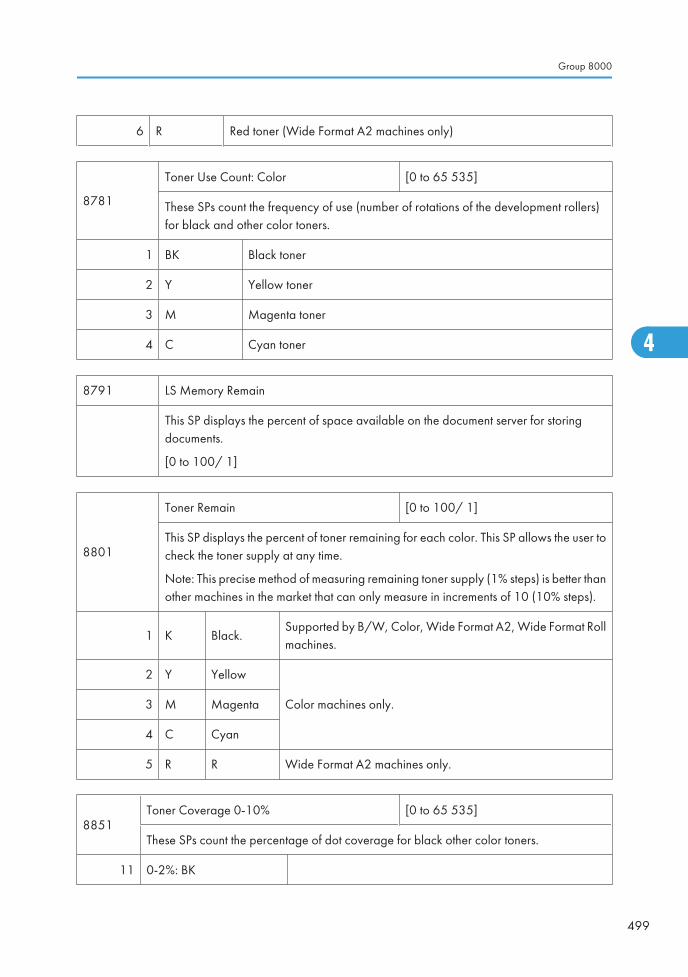
6 R Red toner (Wide Format A2 machines only)
8781
Toner Use Count: Color [0 to 65 535]
These SPs count the frequency of use (number of rotations of the development rollers)for black and other color toners.
1 BK Black toner
2 Y Yellow toner
3 M Magenta toner
4 C Cyan toner
8791 LS Memory Remain
This SP displays the percent of space available on the document server for storingdocuments.
[0 to 100/ 1]
8801
Toner Remain [0 to 100/ 1]
This SP displays the percent of toner remaining for each color. This SP allows the user tocheck the toner supply at any time.
Note: This precise method of measuring remaining toner supply (1% steps) is better thanother machines in the market that can only measure in increments of 10 (10% steps).
1 K Black.Supported by B/W, Color, Wide Format A2, Wide Format Rollmachines.
2 Y Yellow
Color machines only.3 M Magenta
4 C Cyan
5 R R Wide Format A2 machines only.
8851Toner Coverage 0-10% [0 to 65 535]
These SPs count the percentage of dot coverage for black other color toners.
11 0-2%: BK
Group 8000
499
4
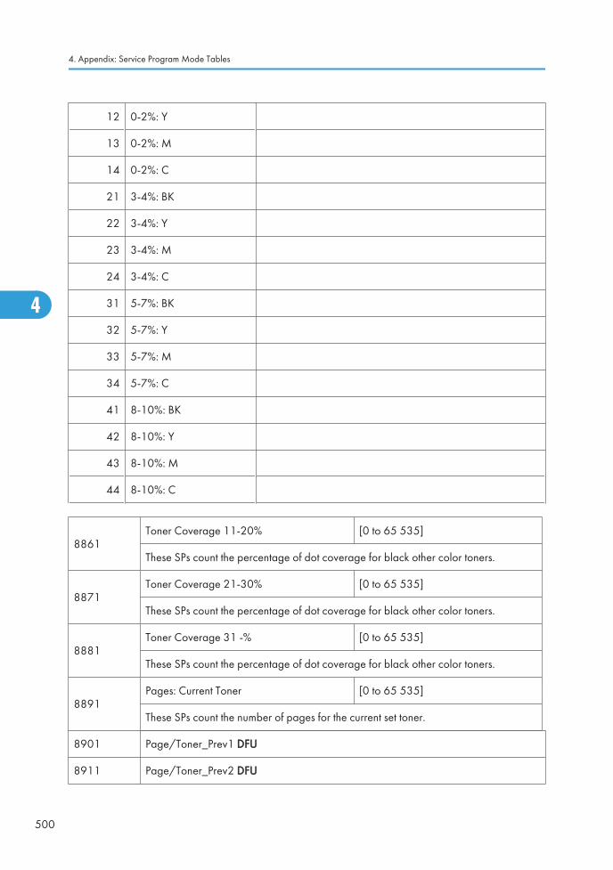
12 0-2%: Y
13 0-2%: M
14 0-2%: C
21 3-4%: BK
22 3-4%: Y
23 3-4%: M
24 3-4%: C
31 5-7%: BK
32 5-7%: Y
33 5-7%: M
34 5-7%: C
41 8-10%: BK
42 8-10%: Y
43 8-10%: M
44 8-10%: C
8861Toner Coverage 11-20% [0 to 65 535]
These SPs count the percentage of dot coverage for black other color toners.
8871Toner Coverage 21-30% [0 to 65 535]
These SPs count the percentage of dot coverage for black other color toners.
8881Toner Coverage 31 -% [0 to 65 535]
These SPs count the percentage of dot coverage for black other color toners.
8891Pages: Current Toner [0 to 65 535]
These SPs count the number of pages for the current set toner.
8901 Page/Toner_Prev1 DFU
8911 Page/Toner_Prev2 DFU
4. Appendix: Service Program Mode Tables
500
4
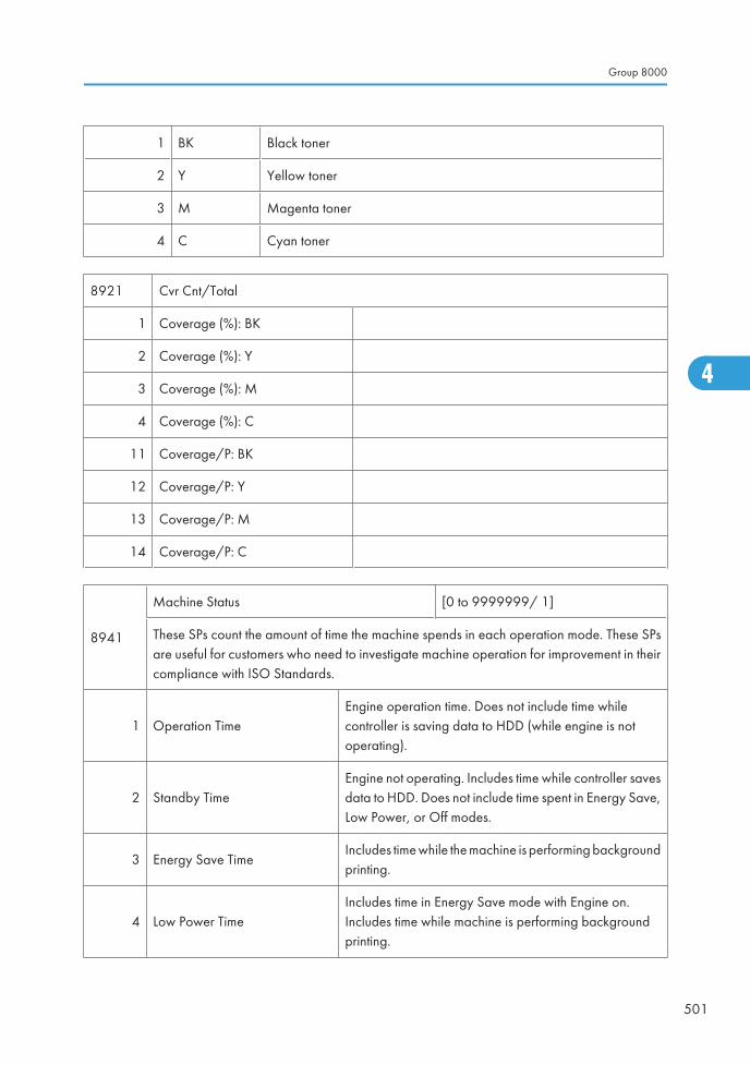
1 BK Black toner
2 Y Yellow toner
3 M Magenta toner
4 C Cyan toner
8921 Cvr Cnt/Total
1 Coverage (%): BK
2 Coverage (%): Y
3 Coverage (%): M
4 Coverage (%): C
11 Coverage/P: BK
12 Coverage/P: Y
13 Coverage/P: M
14 Coverage/P: C
8941
Machine Status [0 to 9999999/ 1]
These SPs count the amount of time the machine spends in each operation mode. These SPsare useful for customers who need to investigate machine operation for improvement in theircompliance with ISO Standards.
1 Operation TimeEngine operation time. Does not include time whilecontroller is saving data to HDD (while engine is notoperating).
2 Standby TimeEngine not operating. Includes time while controller savesdata to HDD. Does not include time spent in Energy Save,Low Power, or Off modes.
3 Energy Save TimeIncludes time while the machine is performing backgroundprinting.
4 Low Power TimeIncludes time in Energy Save mode with Engine on.Includes time while machine is performing backgroundprinting.
Group 8000
501
4
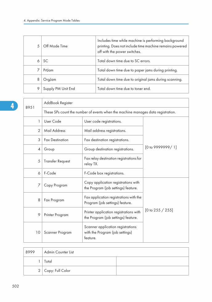
5 Off Mode TimeIncludes time while machine is performing backgroundprinting. Does not include time machine remains poweredoff with the power switches.
6 SC Total down time due to SC errors.
7 PrtJam Total down time due to paper jams during printing.
8 OrgJam Total down time due to original jams during scanning.
9 Supply PM Unit End Total down time due to toner end.
8951AddBook Register
These SPs count the number of events when the machine manages data registration.
1 User Code User code registrations.
[0 to 9999999/ 1]
2 Mail Address Mail address registrations.
3 Fax Destination Fax destination registrations.
4 Group Group destination registrations.
5 Transfer RequestFax relay destination registrations forrelay TX.
6 F-Code F-Code box registrations.
7 Copy ProgramCopy application registrations withthe Program (job settings) feature.
[0 to 255 / 255]
8 Fax ProgramFax application registrations with theProgram (job settings) feature.
9 Printer ProgramPrinter application registrations withthe Program (job settings) feature.
10 Scanner ProgramScanner application registrationswith the Program (job settings)feature.
8999 Admin Counter List
1 Total
2 Copy: Full Color
4. Appendix: Service Program Mode Tables
502
4
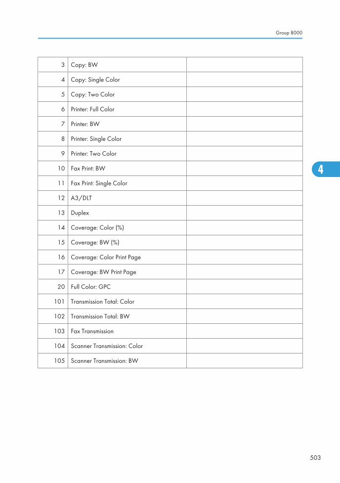
3 Copy: BW
4 Copy: Single Color
5 Copy: Two Color
6 Printer: Full Color
7 Printer: BW
8 Printer: Single Color
9 Printer: Two Color
10 Fax Print: BW
11 Fax Print: Single Color
12 A3/DLT
13 Duplex
14 Coverage: Color (%)
15 Coverage: BW (%)
16 Coverage: Color Print Page
17 Coverage: BW Print Page
20 Full Color: GPC
101 Transmission Total: Color
102 Transmission Total: BW
103 Fax Transmission
104 Scanner Transmission: Color
105 Scanner Transmission: BW
Group 8000
503
4
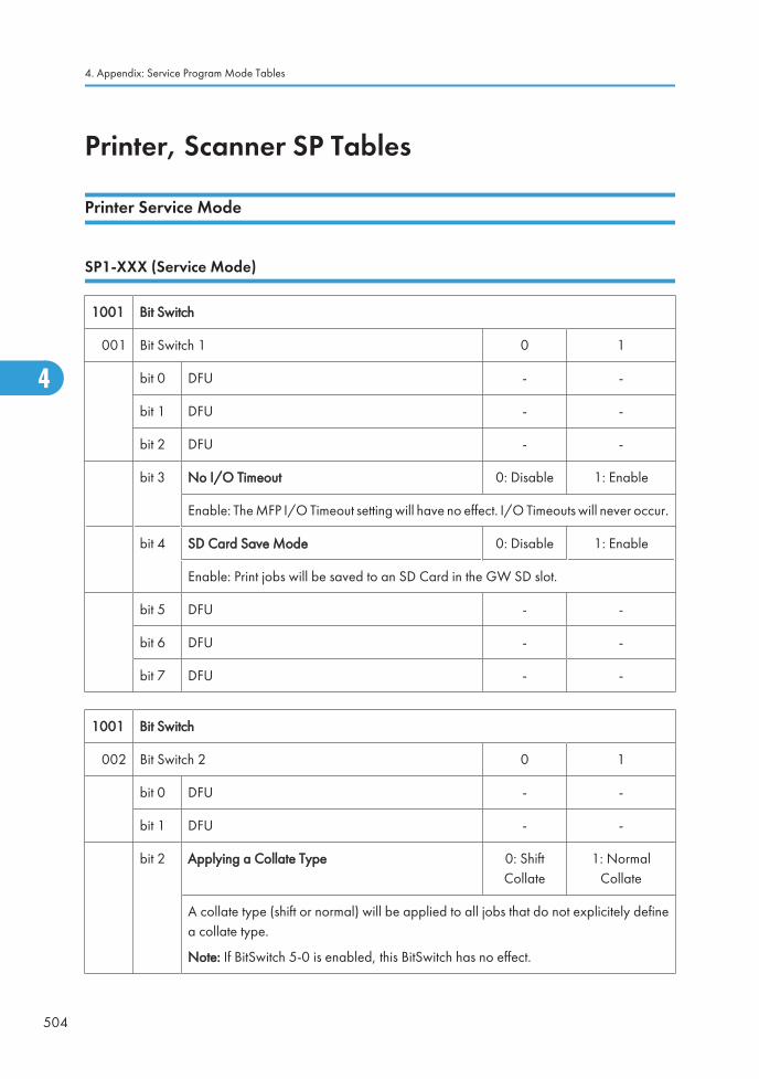
Printer, Scanner SP Tables
Printer Service Mode
SP1-XXX (Service Mode)
1001 Bit Switch
001 Bit Switch 1 0 1
bit 0 DFU - -
bit 1 DFU - -
bit 2 DFU - -
bit 3 No I/O Timeout 0: Disable 1: Enable
Enable: The MFP I/O Timeout setting will have no effect. I/O Timeouts will never occur.
bit 4 SD Card Save Mode 0: Disable 1: Enable
Enable: Print jobs will be saved to an SD Card in the GW SD slot.
bit 5 DFU - -
bit 6 DFU - -
bit 7 DFU - -
1001 Bit Switch
002 Bit Switch 2 0 1
bit 0 DFU - -
bit 1 DFU - -
bit 2 Applying a Collate Type 0: ShiftCollate
1: NormalCollate
A collate type (shift or normal) will be applied to all jobs that do not explicitely definea collate type.
Note: If BitSwitch 5-0 is enabled, this BitSwitch has no effect.
4. Appendix: Service Program Mode Tables
504
4
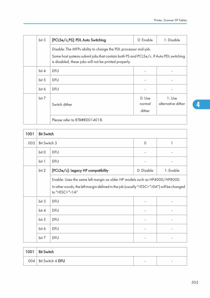
bit 3 [PCL5e/c,PS]: PDL Auto Switching 0: Enable 1: Disable
Disable: The MFPs ability to change the PDL processor mid-job.
Some host systems submit jobs that contain both PS and PCL5e/c. If Auto PDL switchingis disabled, these jobs will not be printed properly.
bit 4 DFU - -
bit 5 DFU - -
bit 6 DFU - -
bit 7
Switch dither
0: Usenormal
dither
1: Usealternative dither
Please refer to RTB#RD014018.
1001 Bit Switch
003 Bit Switch 3 0 1
bit 0 DFU - -
bit 1 DFU - -
bit 2 [PCL5e/c]: Legacy HP compatibility 0: Disable 1: Enable
Enable: Uses the same left margin as older HP models such as HP4000/HP8000.
In other words, the left margin defined in the job (usually "<ESC>*r0A") will be changedto "<ESC>*r1A"
bit 3 DFU - -
bit 4 DFU - -
bit 5 DFU - -
bit 6 DFU - -
bit 7 DFU - -
1001 Bit Switch
004 Bit Switch 4 DFU - -
Printer, Scanner SP Tables
505
4
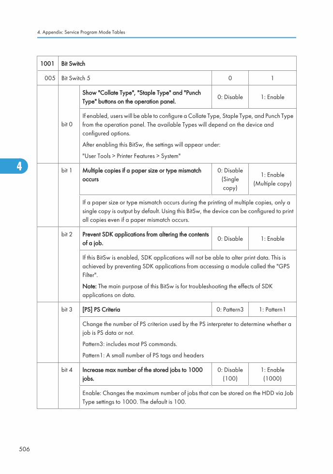
1001 Bit Switch
005 Bit Switch 5 0 1
bit 0
Show "Collate Type", "Staple Type" and "PunchType" buttons on the operation panel.
0: Disable 1: Enable
If enabled, users will be able to configure a Collate Type, Staple Type, and Punch Typefrom the operation panel. The available Types will depend on the device andconfigured options.
After enabling this BitSw, the settings will appear under:
"User Tools > Printer Features > System"
bit 1 Multiple copies if a paper size or type mismatchoccurs
0: Disable(Singlecopy)
1: Enable(Multiple copy)
If a paper size or type mismatch occurs during the printing of multiple copies, only asingle copy is output by default. Using this BitSw, the device can be configured to printall copies even if a paper mismatch occurs.
bit 2 Prevent SDK applications from altering the contentsof a job.
0: Disable 1: Enable
If this BitSw is enabled, SDK applications will not be able to alter print data. This isachieved by preventing SDK applications from accessing a module called the "GPSFilter".
Note: The main purpose of this BitSw is for troubleshooting the effects of SDKapplications on data.
bit 3 [PS] PS Criteria 0: Pattern3 1: Pattern1
Change the number of PS criterion used by the PS interpreter to determine whether ajob is PS data or not.
Pattern3: includes most PS commands.
Pattern1: A small number of PS tags and headers
bit 4 Increase max number of the stored jobs to 1000jobs.
0: Disable(100)
1: Enable(1000)
Enable: Changes the maximum number of jobs that can be stored on the HDD via JobType settings to 1000. The default is 100.
4. Appendix: Service Program Mode Tables
506
4
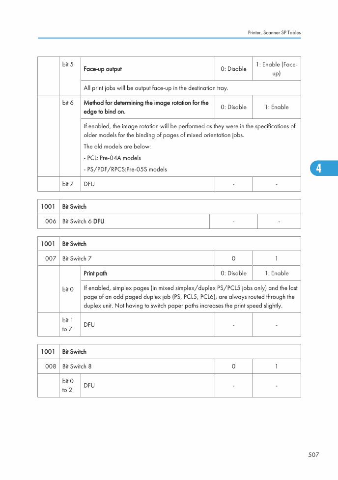
bit 5Face-up output 0: Disable
1: Enable (Face-up)
All print jobs will be output face-up in the destination tray.
bit 6 Method for determining the image rotation for theedge to bind on.
0: Disable 1: Enable
If enabled, the image rotation will be performed as they were in the specifications ofolder models for the binding of pages of mixed orientation jobs.
The old models are below:
- PCL: Pre-04A models
- PS/PDF/RPCS:Pre-05S models
bit 7 DFU - -
1001 Bit Switch
006 Bit Switch 6 DFU - -
1001 Bit Switch
007 Bit Switch 7 0 1
bit 0
Print path 0: Disable 1: Enable
If enabled, simplex pages (in mixed simplex/duplex PS/PCL5 jobs only) and the lastpage of an odd paged duplex job (PS, PCL5, PCL6), are always routed through theduplex unit. Not having to switch paper paths increases the print speed slightly.
bit 1to 7
DFU - -
1001 Bit Switch
008 Bit Switch 8 0 1
bit 0to 2
DFU - -
Printer, Scanner SP Tables
507
4
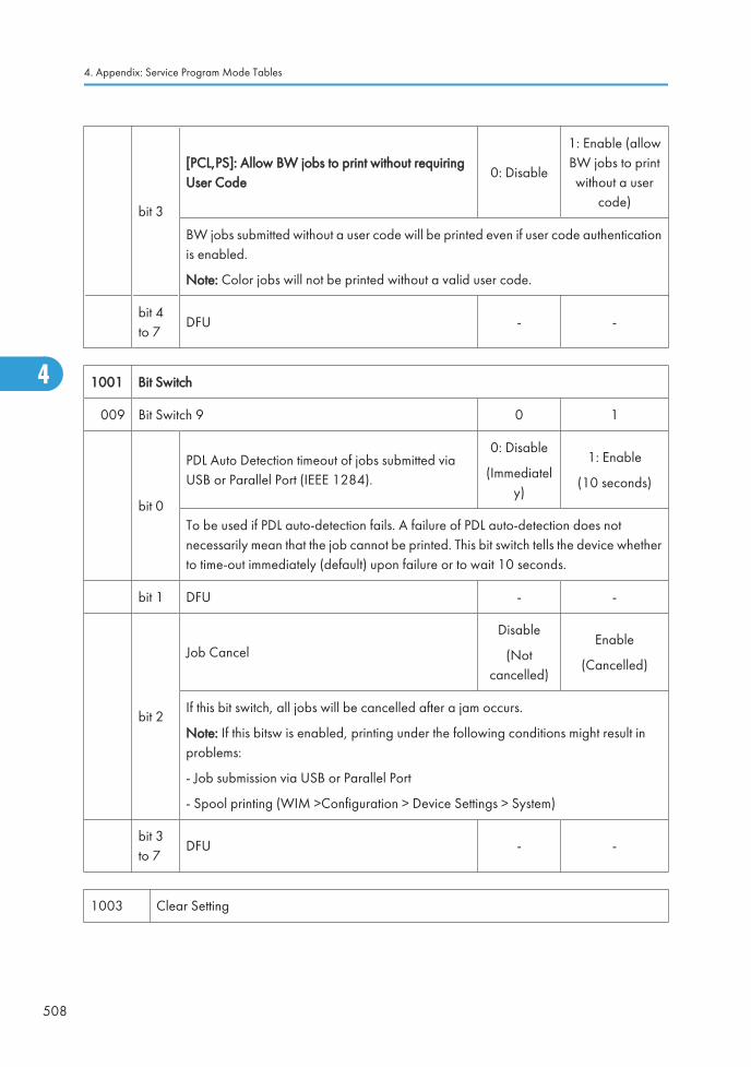
bit 3
[PCL,PS]: Allow BW jobs to print without requiringUser Code
0: Disable
1: Enable (allowBW jobs to printwithout a user
code)
BW jobs submitted without a user code will be printed even if user code authenticationis enabled.
Note: Color jobs will not be printed without a valid user code.
bit 4to 7
DFU - -
1001 Bit Switch
009 Bit Switch 9 0 1
bit 0
PDL Auto Detection timeout of jobs submitted viaUSB or Parallel Port (IEEE 1284).
0: Disable
(Immediately)
1: Enable
(10 seconds)
To be used if PDL auto-detection fails. A failure of PDL auto-detection does notnecessarily mean that the job cannot be printed. This bit switch tells the device whetherto time-out immediately (default) upon failure or to wait 10 seconds.
bit 1 DFU - -
bit 2
Job Cancel
Disable
(Notcancelled)
Enable
(Cancelled)
If this bit switch, all jobs will be cancelled after a jam occurs.
Note: If this bitsw is enabled, printing under the following conditions might result inproblems:
- Job submission via USB or Parallel Port
- Spool printing (WIM >Configuration > Device Settings > System)
bit 3to 7
DFU - -
1003 Clear Setting
4. Appendix: Service Program Mode Tables
508
4
Ed
Typewritten Text
Bit switch 9-4 added RTB 52
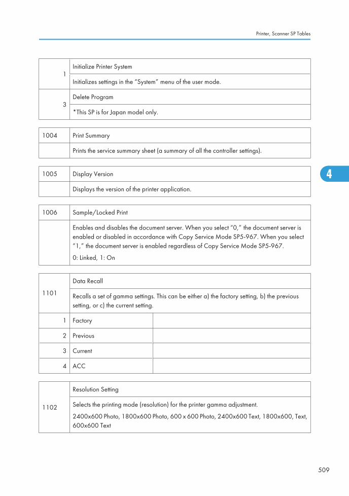
1Initialize Printer System
Initializes settings in the “System” menu of the user mode.
3Delete Program
*This SP is for Japan model only.
1004 Print Summary
Prints the service summary sheet (a summary of all the controller settings).
1005 Display Version
Displays the version of the printer application.
1006 Sample/Locked Print
Enables and disables the document server. When you select “0,” the document server isenabled or disabled in accordance with Copy Service Mode SP5-967. When you select“1,” the document server is enabled regardless of Copy Service Mode SP5-967.
0: Linked, 1: On
1101
Data Recall
Recalls a set of gamma settings. This can be either a) the factory setting, b) the previoussetting, or c) the current setting.
1 Factory
2 Previous
3 Current
4 ACC
1102
Resolution Setting
Selects the printing mode (resolution) for the printer gamma adjustment.
2400x600 Photo, 1800x600 Photo, 600 x 600 Photo, 2400x600 Text, 1800x600, Text,600x600 Text
Printer, Scanner SP Tables
509
4
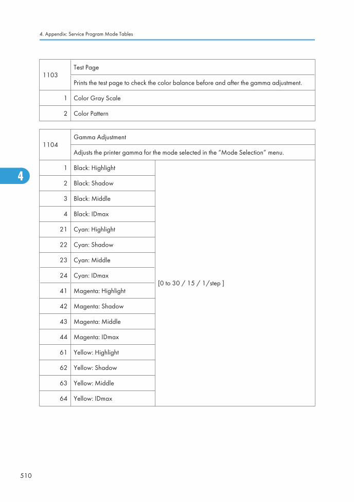
1103Test Page
Prints the test page to check the color balance before and after the gamma adjustment.
1 Color Gray Scale
2 Color Pattern
1104Gamma Adjustment
Adjusts the printer gamma for the mode selected in the “Mode Selection” menu.
1 Black: Highlight
[0 to 30 / 15 / 1/step ]
2 Black: Shadow
3 Black: Middle
4 Black: IDmax
21 Cyan: Highlight
22 Cyan: Shadow
23 Cyan: Middle
24 Cyan: IDmax
41 Magenta: Highlight
42 Magenta: Shadow
43 Magenta: Middle
44 Magenta: IDmax
61 Yellow: Highlight
62 Yellow: Shadow
63 Yellow: Middle
64 Yellow: IDmax
4. Appendix: Service Program Mode Tables
510
4
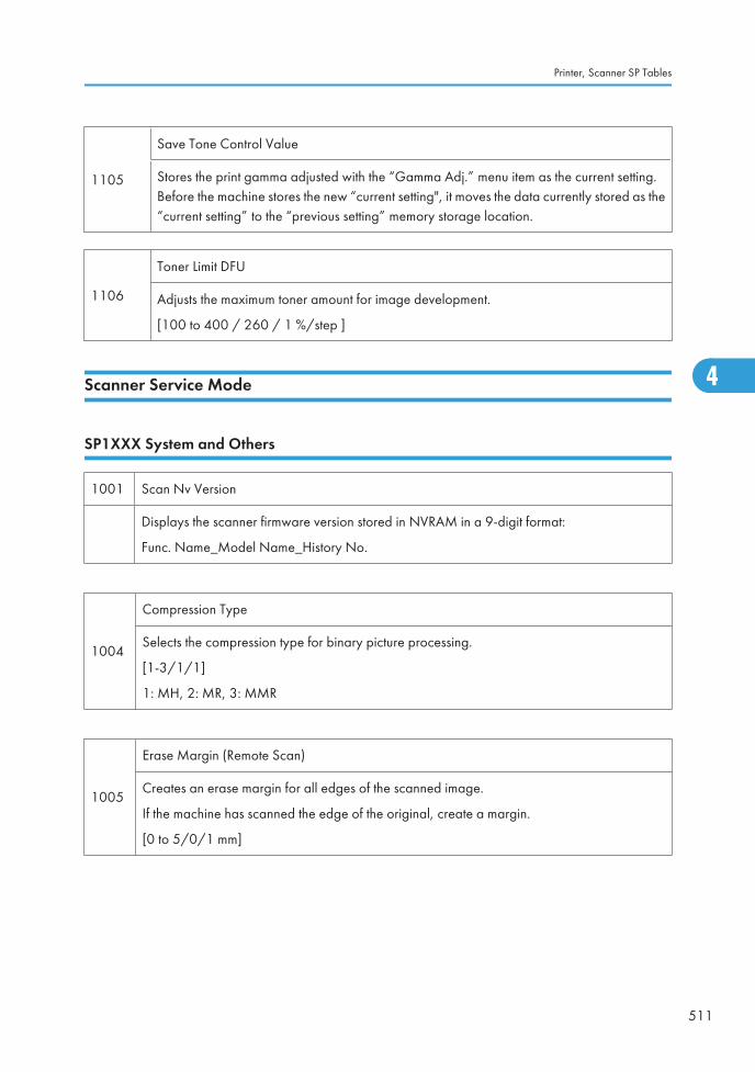
1105
Save Tone Control Value
Stores the print gamma adjusted with the “Gamma Adj.” menu item as the current setting.Before the machine stores the new “current setting", it moves the data currently stored as the“current setting” to the “previous setting” memory storage location.
1106
Toner Limit DFU
Adjusts the maximum toner amount for image development.
[100 to 400 / 260 / 1 %/step ]
Scanner Service Mode
SP1XXX System and Others
1001 Scan Nv Version
Displays the scanner firmware version stored in NVRAM in a 9-digit format:
Func. Name_Model Name_History No.
1004
Compression Type
Selects the compression type for binary picture processing.
[1-3/1/1]
1: MH, 2: MR, 3: MMR
1005
Erase Margin (Remote Scan)
Creates an erase margin for all edges of the scanned image.
If the machine has scanned the edge of the original, create a margin.
[0 to 5/0/1 mm]
Printer, Scanner SP Tables
511
4
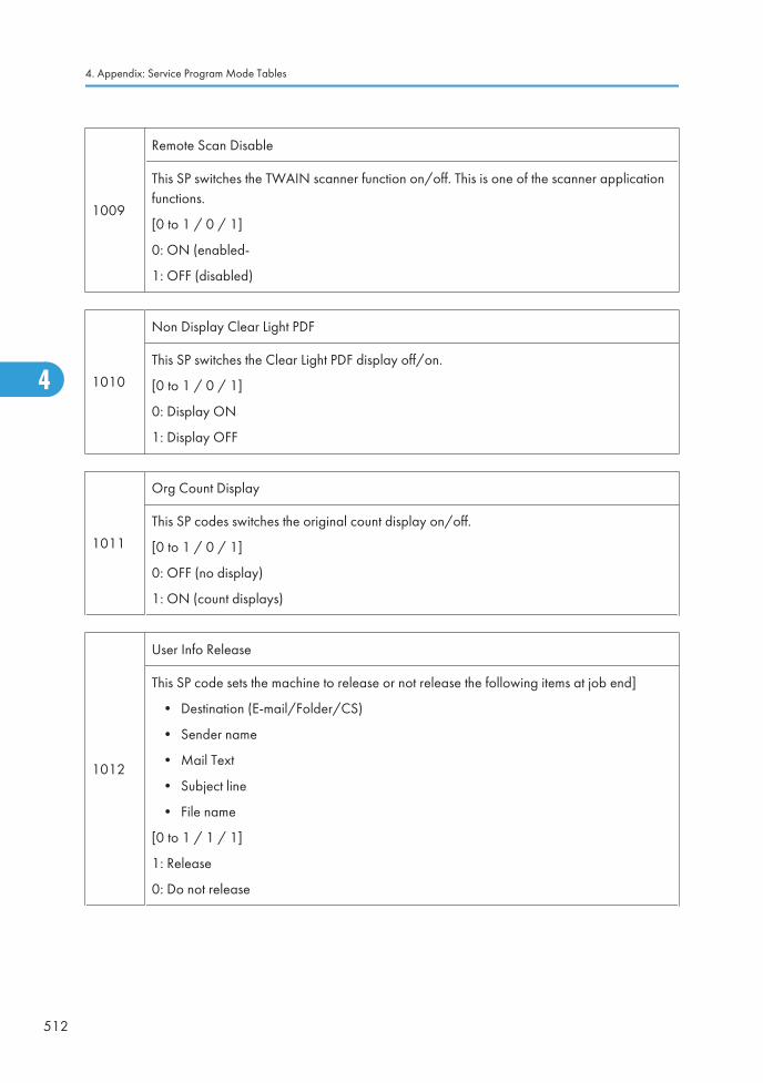
1009
Remote Scan Disable
This SP switches the TWAIN scanner function on/off. This is one of the scanner applicationfunctions.
[0 to 1 / 0 / 1]
0: ON (enabled-
1: OFF (disabled)
1010
Non Display Clear Light PDF
This SP switches the Clear Light PDF display off/on.
[0 to 1 / 0 / 1]
0: Display ON
1: Display OFF
1011
Org Count Display
This SP codes switches the original count display on/off.
[0 to 1 / 0 / 1]
0: OFF (no display)
1: ON (count displays)
1012
User Info Release
This SP code sets the machine to release or not release the following items at job end]
• Destination (E-mail/Folder/CS)
• Sender name
• Mail Text
• Subject line
• File name
[0 to 1 / 1 / 1]
1: Release
0: Do not release
4. Appendix: Service Program Mode Tables
512
4
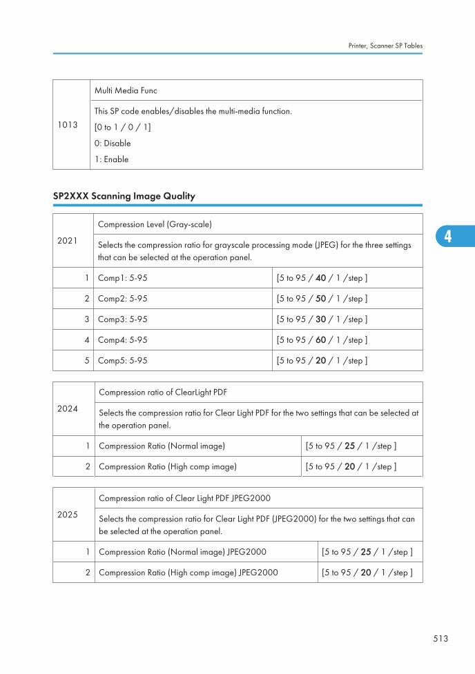
1013
Multi Media Func
This SP code enables/disables the multi-media function.
[0 to 1 / 0 / 1]
0: Disable
1: Enable
SP2XXX Scanning Image Quality
2021
Compression Level (Gray-scale)
Selects the compression ratio for grayscale processing mode (JPEG) for the three settingsthat can be selected at the operation panel.
1 Comp1: 5-95 [5 to 95 / 40 / 1 /step ]
2 Comp2: 5-95 [5 to 95 / 50 / 1 /step ]
3 Comp3: 5-95 [5 to 95 / 30 / 1 /step ]
4 Comp4: 5-95 [5 to 95 / 60 / 1 /step ]
5 Comp5: 5-95 [5 to 95 / 20 / 1 /step ]
2024
Compression ratio of ClearLight PDF
Selects the compression ratio for Clear Light PDF for the two settings that can be selected atthe operation panel.
1 Compression Ratio (Normal image) [5 to 95 / 25 / 1 /step ]
2 Compression Ratio (High comp image) [5 to 95 / 20 / 1 /step ]
2025
Compression ratio of Clear Light PDF JPEG2000
Selects the compression ratio for Clear Light PDF (JPEG2000) for the two settings that canbe selected at the operation panel.
1 Compression Ratio (Normal image) JPEG2000 [5 to 95 / 25 / 1 /step ]
2 Compression Ratio (High comp image) JPEG2000 [5 to 95 / 20 / 1 /step ]
Printer, Scanner SP Tables
513
4

4. Appendix: Service Program Mode Tables
514
4