Expedited Permit Process for PV Systems - Brooks Engineering
Upload
khangminh22Category
view
3download
0
Systems EngineeringHow to model Systems Engineering? Sparx
Systems Enterprise Architect provides aplatform for system engineers, with the SystemsModeling Language (SysML) and model-baseddevelopment, aiding research, design, testing
and management of complex systems.
Enterprise Architect
User Guide Series
Author: Sparx SystemsDate: 2022-06-29
Version: 16.0
CREATED WITH

Table of Contents
Systems Engineering 4Getting Started 15Example Models 22Requirements Models 30Structural Models 38Behavioral Models 45Defense and Commercial Architecture Models 53Verification and Validation 57Simulation and Visualization 61Publications and Documentation 70Collaboration and Teams 72Project Management 74
Systems Engineering 29 June, 2022
Systems Engineering
Systems Engineering is, very broadly, the work ofresearching, designing and managing complex physical orelectronic systems over their lifecycles. It focuses on thewhole system and typically involves a number ofsub-disciplines such as requirements, reliability, logistics,design, testing and maintenance; it considers not only thesystem itself but also processes, optimization and riskmanagement, and requires sophisticated projectmanagement techniques.
In earlier decades a large but localized team might considera very specific set of objects within a very specific andcontrolled environment, to be delivered to a small user baseand maintained by perhaps an, again, localized team ofexperts who each might have responsibility for only a partof the system. Even for such a controlled and structuredscenario, a huge volume of documentation was required todefine the system requirements, the components, theengineering process, the standards applied and compliedwith, and the tests to be run on the system. Keeping thisdocumentation cross-referenced, up to date and integratedwas a major task.
(c) Sparx Systems 2022 Page 4 of 79

Systems Engineering 29 June, 2022
Advancing into computing and basing Systems Engineeringwork on graphical models (Model Based SystemsEngineering) provided huge benefits, allowing engineers tostore and retrieve data from repositories, associate data withdocumentation also held in the repositories, and developboth master structures and variants from templates, all ofwhich reduced the need to recreate and repeat work. Themodel initially represented the organization of thedeveloping system, but grew to reflect the developmentprocess and the factors that supported and directed thatprocess. As computing capabilities grew, and morespecialized and sophisticated applications were madeavailable, it became possible to represent the components ofa system with increasingly varied and detailed modelelements, and with increasingly varied and detailedrelationships between them.
(c) Sparx Systems 2022 Page 5 of 79
Systems Engineering 29 June, 2022
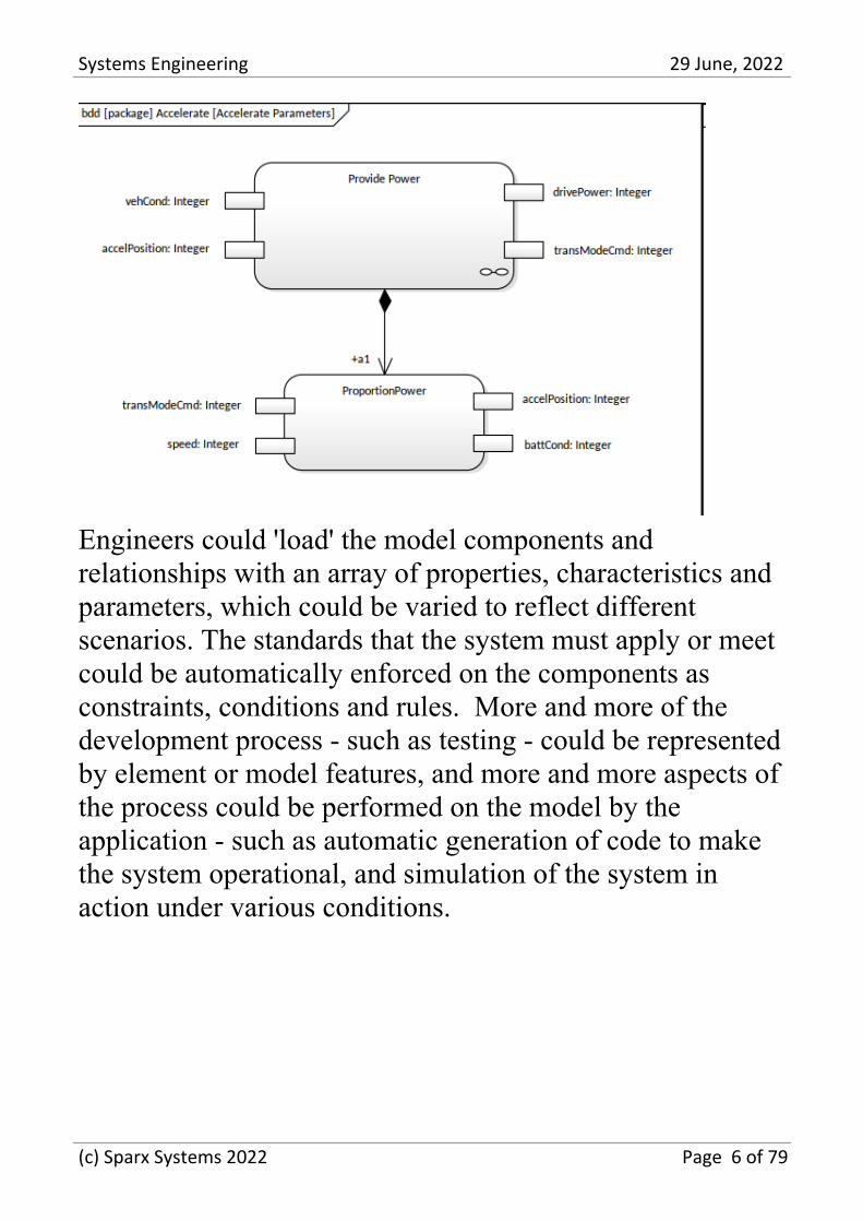
Engineers could 'load' the model components andrelationships with an array of properties, characteristics andparameters, which could be varied to reflect differentscenarios. The standards that the system must apply or meetcould be automatically enforced on the components asconstraints, conditions and rules. More and more of thedevelopment process - such as testing - could be representedby element or model features, and more and more aspects ofthe process could be performed on the model by theapplication - such as automatic generation of code to makethe system operational, and simulation of the system inaction under various conditions.
(c) Sparx Systems 2022 Page 6 of 79
Systems Engineering 29 June, 2022
Currently, the Systems Engineer is likely to be a member ofan interdisciplinary team that has to consider a wide rangeof factors in architecting, designing and modeling a system -a much broader, diverse and inexpert user base, a muchbroader maintenance base, how the system interacts withmany other systems, how the system operates in manydifferent and sometimes extreme environments, the impactthe system has on the global environment - both within itsoperating framework and within its pre-use production andfinal disposal - the socio-economic environment controllingits acceptability and popularity, and how the systemcompares with its increasing range of competitors. To seehow the work of the Systems Engineer has become vastlymore complex one has only to think of a singledevelopment, such as the quantum leap from the relativelyrecent fixed-site landline telephone handset for making
(c) Sparx Systems 2022 Page 7 of 79
Systems Engineering 29 June, 2022
voice calls, to the modern mobile smartphone used as acamera, computer, cinema, music center, navigator, andaudio, visual and text communicator.
Today, large projects and industries are being developedaround systems and products for which the use cases areincreasingly complex. Controlling this complexity growsfurther and further beyond the capacity of the engineer,increasing the level of risk to the product, the end user andthe manufacturer. Examples of systems with dramaticallyincreased risk include the manufacture of passenger air bagsto be fitted to many different brands and types of carmanufactured in different parts of the globe; or therequirements for the development of space probes intendedto travel to the planets of the solar system and beyond.
It is the advances in Systems Engineering tools andmethodologies that have increased this complexity, whilstsimultaneously providing the capability to manage andmitigate the associated risk, and reducing the difficulty andeffort involved in managing and maintaining highlycomplex models.
For additional information, see the Representing Systems
(c) Sparx Systems 2022 Page 8 of 79
Systems Engineering 29 June, 2022
with Models section of the 'SEBoK - Guide to the SystemsEngineering Body of Knowledge' website.
Model-Based Systems Engineering inEnterprise Architect
Enterprise Architect provides a Model Based SystemsEngineering platform that integrates many high-end featuresfor Systems Engineers and model-based development, withthese built-in features.
Feature Description
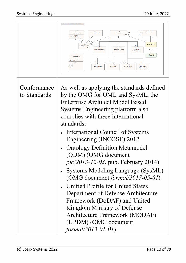
SysML Enterprise Architect is integrated with theSystems Modeling Language (SysML)versions 1.1, 1.2, 1.3, 1.4 and 1.5. Fordetails, see the Systems ModelingLanguage (SysML) Help topic.Enterprise Architect provides a number ofengineering model templates from whichmodels of engineering structures andconcepts can be developed. This is animage of a SysML 1.5 Block Definitiondiagram. It is part of the HSUV Modelthat can be found in the 'SystemsEngineering' section of EnterpriseArchitect's Example Model.
(c) Sparx Systems 2022 Page 9 of 79
Systems Engineering 29 June, 2022
Conformanceto Standards
As well as applying the standards definedby the OMG for UML and SysML, theEnterprise Architect Model BasedSystems Engineering platform alsocomplies with these internationalstandards:
International Council of Systems·
Engineering (INCOSE) 2012Ontology Definition Metamodel·
(ODM) (OMG documentptc/2013-12-03, pub. February 2014)Systems Modeling Language (SysML)·
(OMG document formal/2017-05-01)Unified Profile for United States·
Department of Defense ArchitectureFramework (DoDAF) and UnitedKingdom Ministry of DefenseArchitecture Framework (MODAF)(UPDM) (OMG documentformal/2013-01-01)
(c) Sparx Systems 2022 Page 10 of 79
Systems Engineering 29 June, 2022
ExecutableCodeGeneration
You can quickly generate executablesoftware code from your model elements,using Executable StateMachines. Thecode generated for an ExecutableStateMachine is based on its languageproperty. This might be Java, C, C++, C#or JavaScript. Whichever language it is,Enterprise Architect generates theappropriate code, which is immediatelyready to build and run. There are nomanual interventions necessary beforeyou run it. For more information, see theCode Generation for ExecutableStateMachines Help topic.
Model toCodeTransformations for HDLs
You can not only generate executablesoftware code, but you can generateHardware Description Languages andAda from your model elements, for thechips and circuits in system hardwarecomponents. For more information, seethe StateMachine Modeling for HDLsHelp topic.
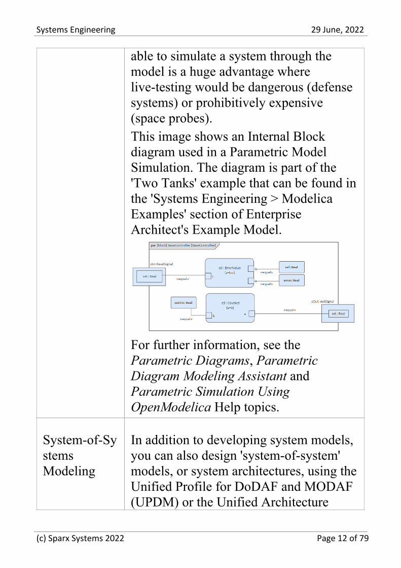
ParametricModelSimulation
Enterprise Architect provides facilities tocreate Parametric diagrams using theParametric Diagram Modeling Assistant,and to perform Parametric ModelSimulation through OpenModelica. Being
(c) Sparx Systems 2022 Page 11 of 79
Systems Engineering 29 June, 2022
able to simulate a system through themodel is a huge advantage wherelive-testing would be dangerous (defensesystems) or prohibitively expensive(space probes).This image shows an Internal Blockdiagram used in a Parametric ModelSimulation. The diagram is part of the'Two Tanks' example that can be found inthe 'Systems Engineering > ModelicaExamples' section of EnterpriseArchitect's Example Model.
For further information, see theParametric Diagrams, ParametricDiagram Modeling Assistant andParametric Simulation UsingOpenModelica Help topics.
System-of-SystemsModeling
In addition to developing system models,you can also design 'system-of-system'models, or system architectures, using theUnified Profile for DoDAF and MODAF(UPDM) or the Unified Architecture
(c) Sparx Systems 2022 Page 12 of 79
Systems Engineering 29 June, 2022
Framework (UAF); these are bothaccessible through the SystemsEngineering Perspective with SysML.
RequirementsManagement
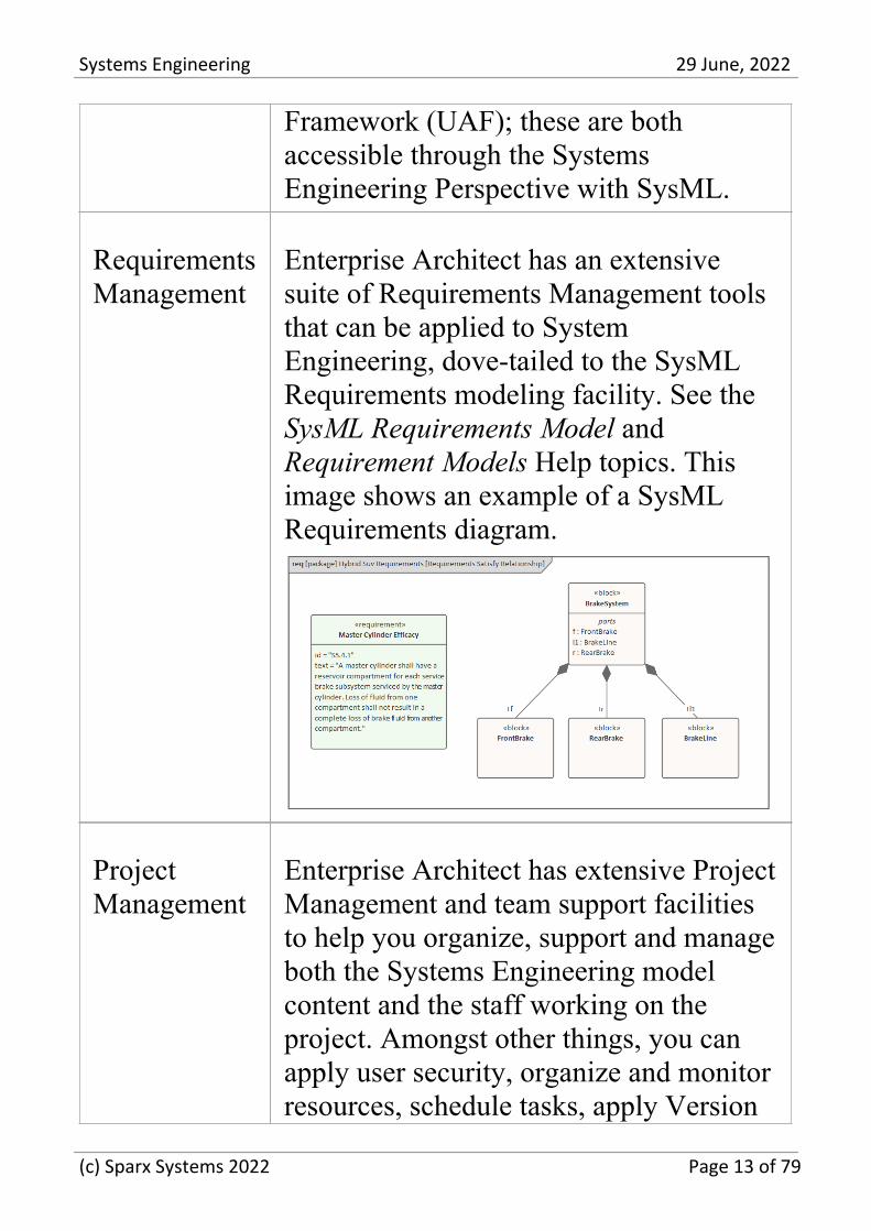
Enterprise Architect has an extensivesuite of Requirements Management toolsthat can be applied to SystemEngineering, dove-tailed to the SysMLRequirements modeling facility. See theSysML Requirements Model andRequirement Models Help topics. Thisimage shows an example of a SysMLRequirements diagram.
ProjectManagement
Enterprise Architect has extensive ProjectManagement and team support facilitiesto help you organize, support and manageboth the Systems Engineering modelcontent and the staff working on theproject. Amongst other things, you canapply user security, organize and monitorresources, schedule tasks, apply Version
(c) Sparx Systems 2022 Page 13 of 79
Systems Engineering 29 June, 2022
Control and enable a range of discussionsfrom simple messaging through informaltopic discussion threads to formalreviews. For more information, see theProject Management and The ModelingTeam Help sections.
(c) Sparx Systems 2022 Page 14 of 79
Systems Engineering 29 June, 2022
Getting Started
Getting started with a new tool is can be quite daunting evenfor experienced engineers, but Enterprise Architect makesthis easy by providing a number of facilities to assist thenewcomer to the tool. Enterprise Architect is a large andmulti-featured application and the breadth of its coveragemight appear overwhelming to a person new to the program,but fortunately a solution to this has been built into thedesign. One of the main tool features is perspectives.
You can use Perspectives to limit the functionality to aspecific domain or language, such as System Engineering,making it easy for a System Engineer or Manager to getstarted. A user still can utilize other functionality that mightbe useful, such as Strategic Modeling, Mind Mapping, CodeEngineering, and more, simply by changing Perspectives, allwithout having to open a different tool. It is worth notingthat Perspectives exist for a wide range of modelingdisciplines that Enterprise Architect supports.
(c) Sparx Systems 2022 Page 15 of 79
Systems Engineering 29 June, 2022
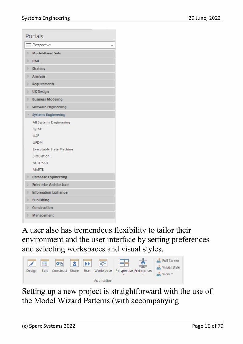
A user also has tremendous flexibility to tailor theirenvironment and the user interface by setting preferencesand selecting workspaces and visual styles.
Setting up a new project is straightforward with the use ofthe Model Wizard Patterns (with accompanying
(c) Sparx Systems 2022 Page 16 of 79
Systems Engineering 29 June, 2022
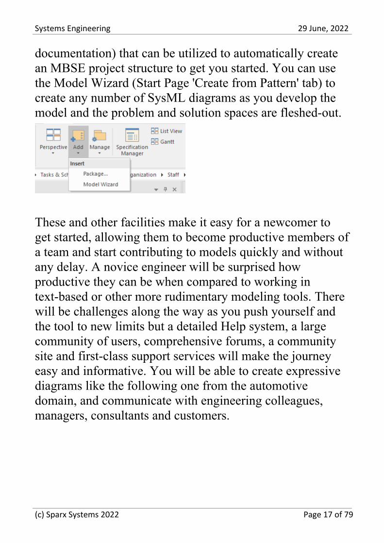
documentation) that can be utilized to automatically createan MBSE project structure to get you started. You can usethe Model Wizard (Start Page 'Create from Pattern' tab) tocreate any number of SysML diagrams as you develop themodel and the problem and solution spaces are fleshed-out.
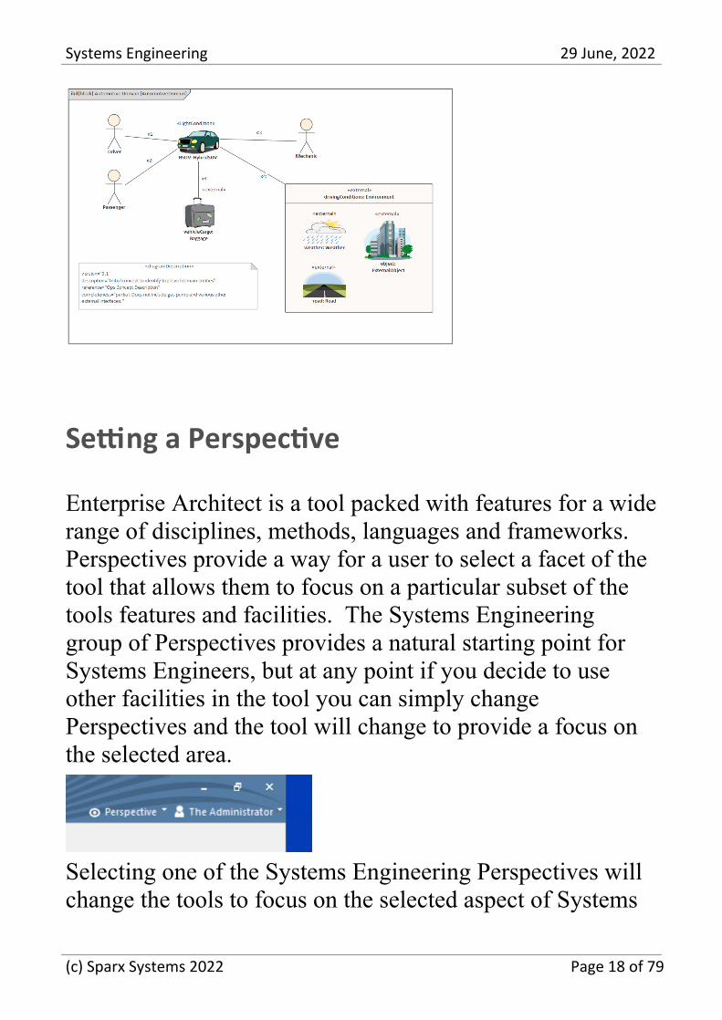
These and other facilities make it easy for a newcomer toget started, allowing them to become productive members ofa team and start contributing to models quickly and withoutany delay. A novice engineer will be surprised howproductive they can be when compared to working intext-based or other more rudimentary modeling tools. Therewill be challenges along the way as you push yourself andthe tool to new limits but a detailed Help system, a largecommunity of users, comprehensive forums, a communitysite and first-class support services will make the journeyeasy and informative. You will be able to create expressivediagrams like the following one from the automotivedomain, and communicate with engineering colleagues,managers, consultants and customers.
(c) Sparx Systems 2022 Page 17 of 79
Systems Engineering 29 June, 2022
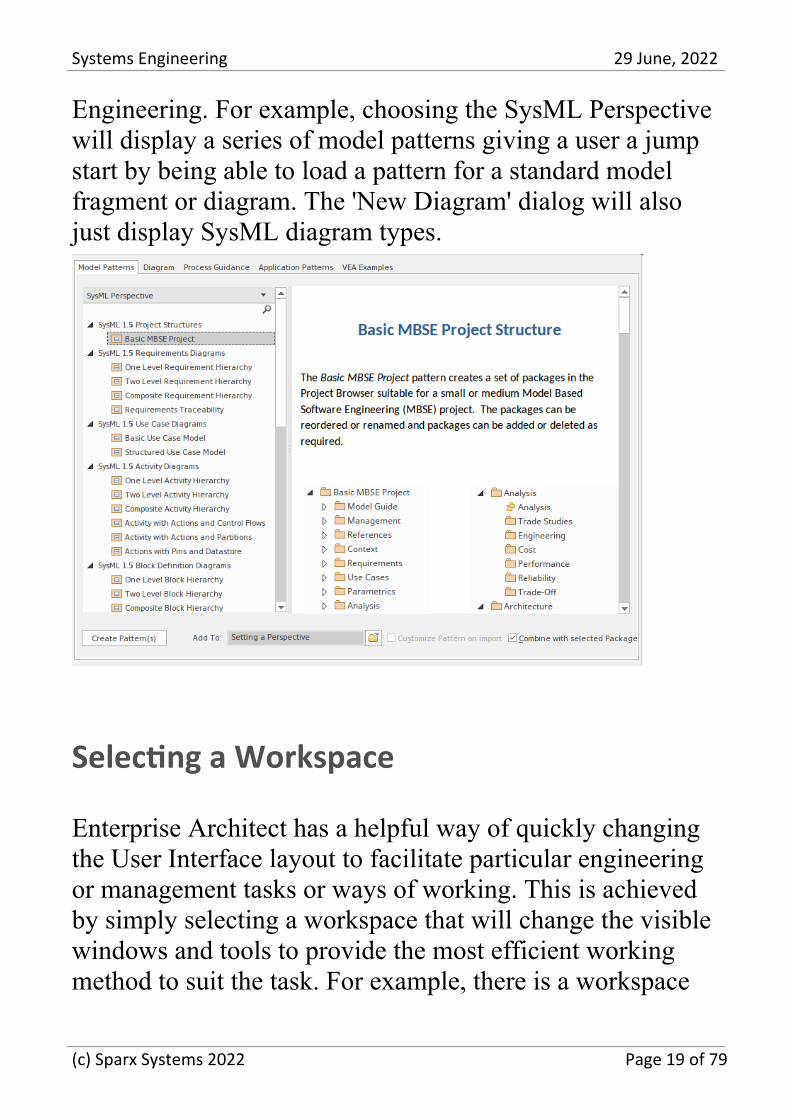
Setting a Perspective
Enterprise Architect is a tool packed with features for a widerange of disciplines, methods, languages and frameworks.Perspectives provide a way for a user to select a facet of thetool that allows them to focus on a particular subset of thetools features and facilities. The Systems Engineeringgroup of Perspectives provides a natural starting point forSystems Engineers, but at any point if you decide to useother facilities in the tool you can simply changePerspectives and the tool will change to provide a focus onthe selected area.
Selecting one of the Systems Engineering Perspectives willchange the tools to focus on the selected aspect of Systems
(c) Sparx Systems 2022 Page 18 of 79
Systems Engineering 29 June, 2022
Engineering. For example, choosing the SysML Perspectivewill display a series of model patterns giving a user a jumpstart by being able to load a pattern for a standard modelfragment or diagram. The 'New Diagram' dialog will alsojust display SysML diagram types.
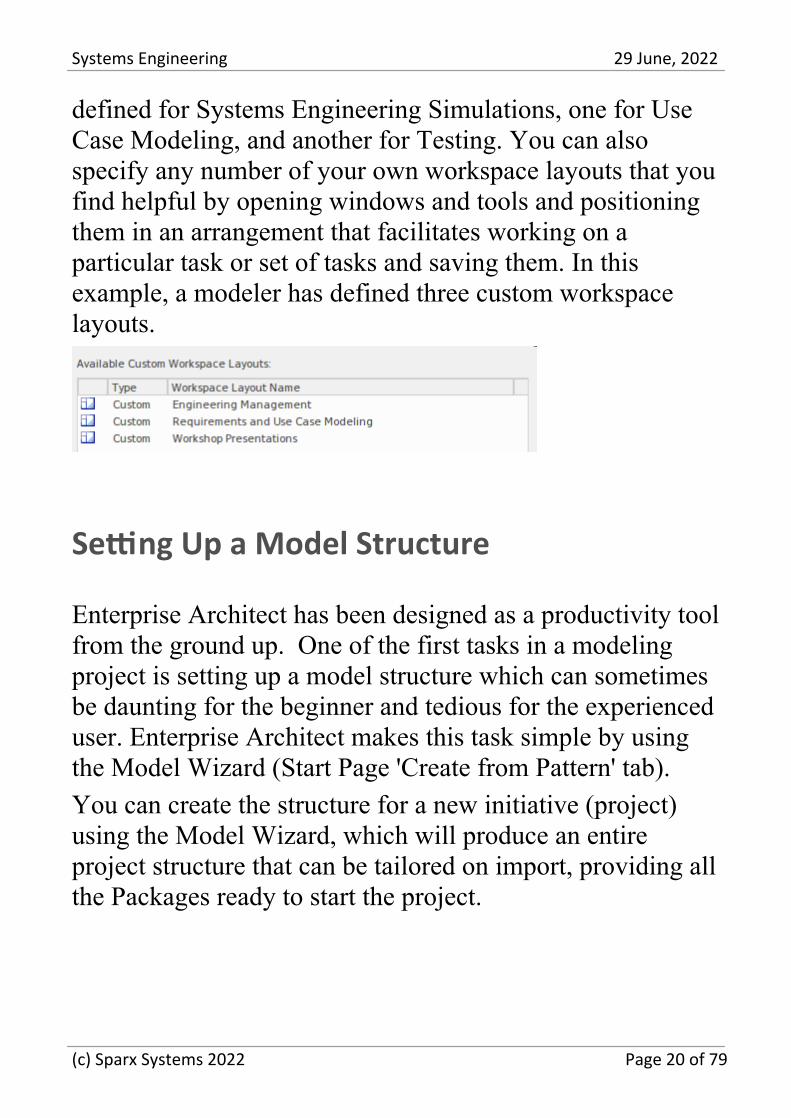
Selecting a Workspace
Enterprise Architect has a helpful way of quickly changingthe User Interface layout to facilitate particular engineeringor management tasks or ways of working. This is achievedby simply selecting a workspace that will change the visiblewindows and tools to provide the most efficient workingmethod to suit the task. For example, there is a workspace
(c) Sparx Systems 2022 Page 19 of 79
Systems Engineering 29 June, 2022
defined for Systems Engineering Simulations, one for UseCase Modeling, and another for Testing. You can alsospecify any number of your own workspace layouts that youfind helpful by opening windows and tools and positioningthem in an arrangement that facilitates working on aparticular task or set of tasks and saving them. In thisexample, a modeler has defined three custom workspacelayouts.
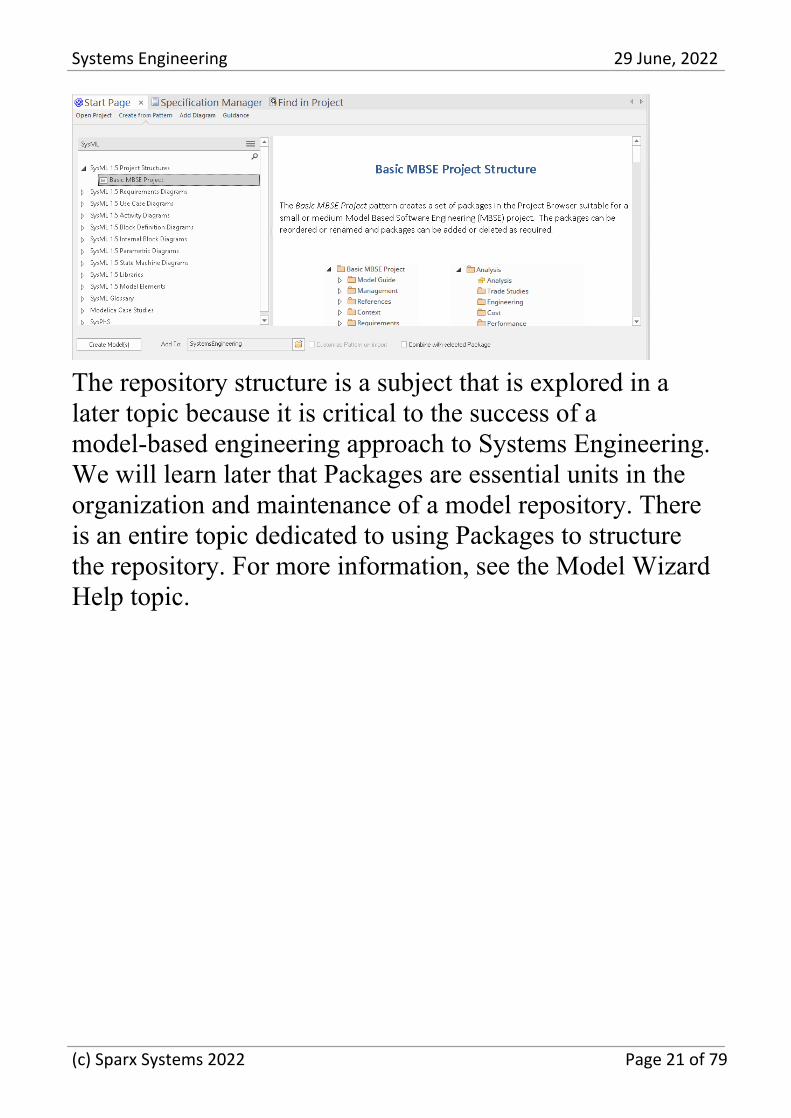
Setting Up a Model Structure
Enterprise Architect has been designed as a productivity toolfrom the ground up. One of the first tasks in a modelingproject is setting up a model structure which can sometimesbe daunting for the beginner and tedious for the experienceduser. Enterprise Architect makes this task simple by usingthe Model Wizard (Start Page 'Create from Pattern' tab).
You can create the structure for a new initiative (project)using the Model Wizard, which will produce an entireproject structure that can be tailored on import, providing allthe Packages ready to start the project.
(c) Sparx Systems 2022 Page 20 of 79
Systems Engineering 29 June, 2022
The repository structure is a subject that is explored in alater topic because it is critical to the success of amodel-based engineering approach to Systems Engineering.We will learn later that Packages are essential units in theorganization and maintenance of a model repository. Thereis an entire topic dedicated to using Packages to structurethe repository. For more information, see the Model WizardHelp topic.
(c) Sparx Systems 2022 Page 21 of 79
Systems Engineering 29 June, 2022
Example Models
Transitioning from a document centric approach to a modelbased systems engineering method can present some hurdlesfor the newcomer. Fortunately Enterprise Architect has richand supportive help available and a series of in-toolfacilities such as patterns that will get you started with thetool and project models. In this topic we present somestraight-forward examples of requirement, structural andbehavioral models and the diagrams that you or yourcolleagues would create in a typical project.
Requirements Models
Requirements models are fundamental to any SystemsEngineering project whether be a greenfield project or achange to an existing system. Requirements are typicallyderived from a number of sources including meetings andworkshops with stakeholders, documents or formal andformal requests from sponsors and other projectstakeholders. There are a three main types of requirementsincluding high level strategic or business requirements, userrequirements and system requirements often referred to asquality attributes of the system.
Requirements models will typically evolve over the lifetimeof the project and adaptive and iterative methods encouragerequirement changes as stakeholders view the partially
(c) Sparx Systems 2022 Page 22 of 79
Systems Engineering 29 June, 2022
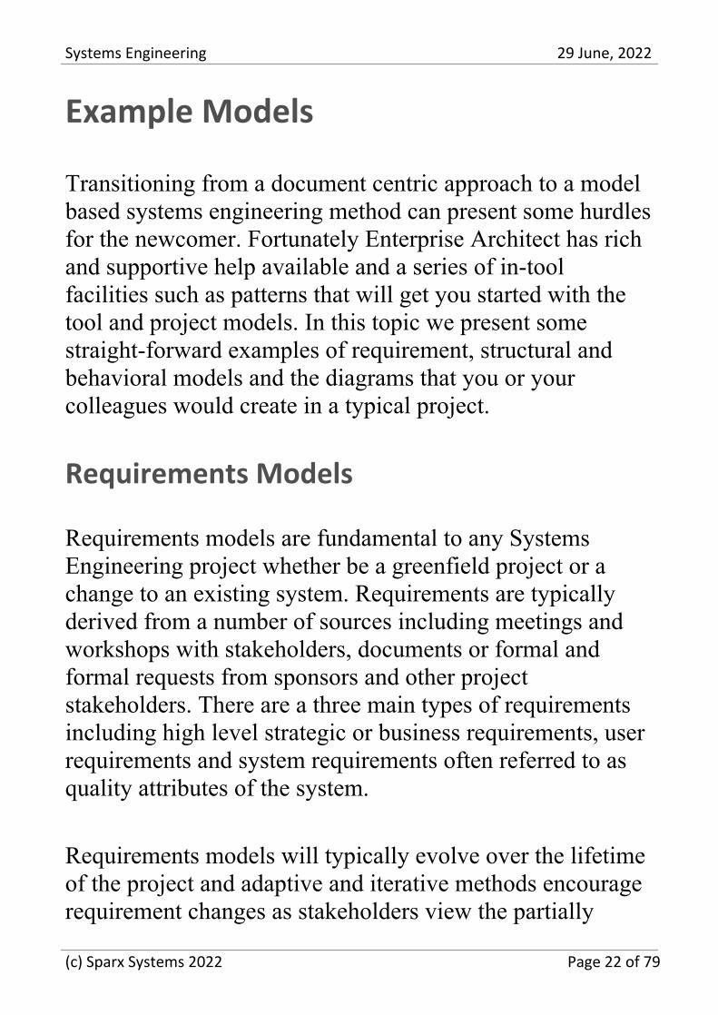
completed product at critical project milestones. Thesechanges can be represented in the tool in a variety of waysincluding using the change management functionalityavailable from the construct ribbon. Alternatively thesechanges can be represented as derivation relationships andvisualized in a requirements diagram.
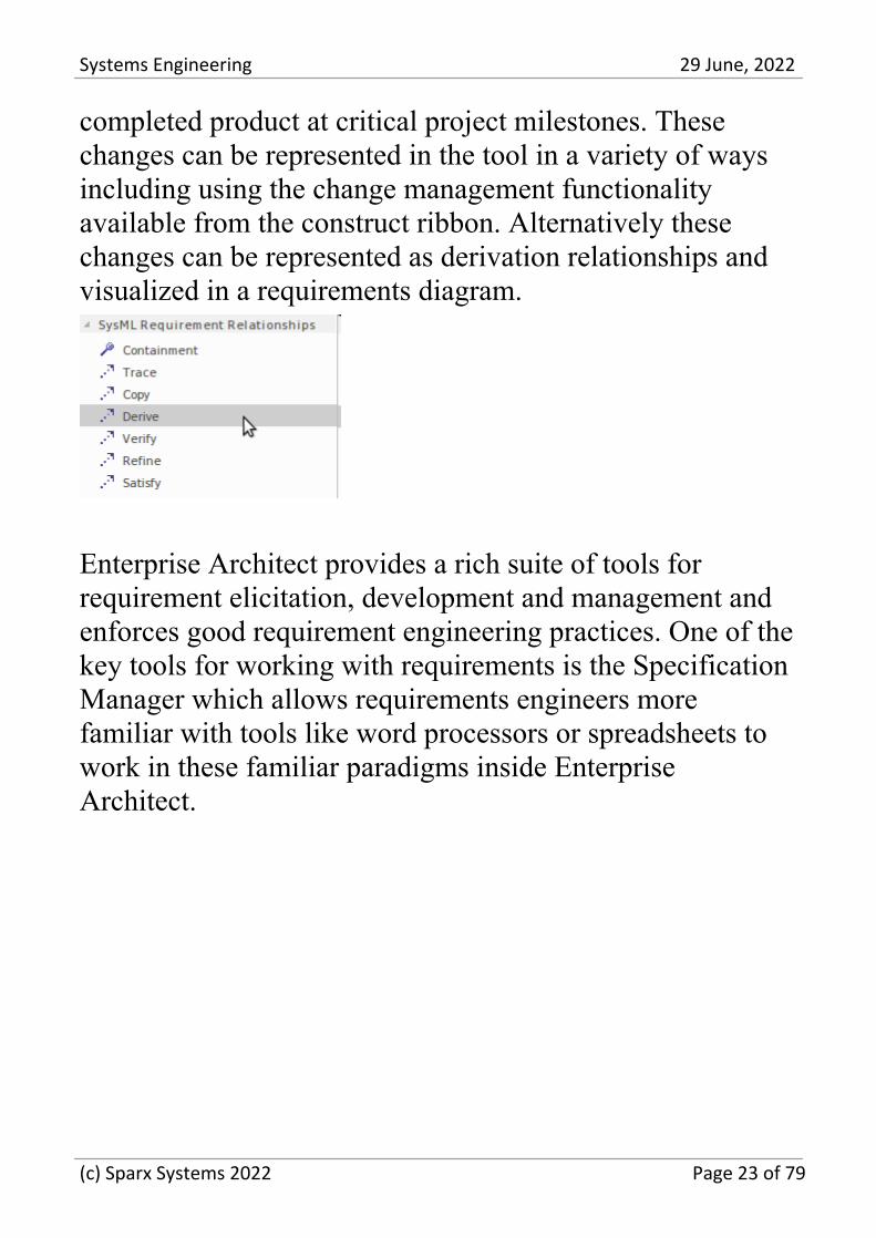
Enterprise Architect provides a rich suite of tools forrequirement elicitation, development and management andenforces good requirement engineering practices. One of thekey tools for working with requirements is the SpecificationManager which allows requirements engineers morefamiliar with tools like word processors or spreadsheets towork in these familiar paradigms inside EnterpriseArchitect.
(c) Sparx Systems 2022 Page 23 of 79
Systems Engineering 29 June, 2022
Behavioral Models
A systems engineer can describe how the structural elementsof a model behave using a series of diagrams collectivelyknown as the Behavioral model. Structural elements exhibitbehavior in a running system, and a number of the structuralelements themselves have behavioral features such asoperations. The system modeling language specificationclassifies the following diagrams as behavior. They are allused to represent different aspects of a system's behavior,
(c) Sparx Systems 2022 Page 24 of 79
Systems Engineering 29 June, 2022
from the Use Case that describes the behavior that isvaluable to a user to a sequence diagram that articulates howelements interact.
Use Case Diagram
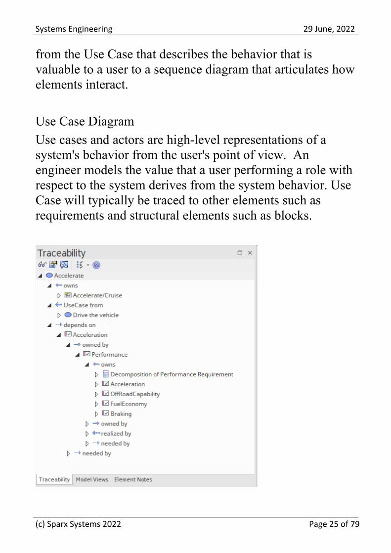
Use cases and actors are high-level representations of asystem's behavior from the user's point of view. Anengineer models the value that a user performing a role withrespect to the system derives from the system behavior. UseCase will typically be traced to other elements such asrequirements and structural elements such as blocks.
(c) Sparx Systems 2022 Page 25 of 79
Systems Engineering 29 June, 2022
Activity Diagram
Activity diagrams are flow-based models that describe asystem's behavior by articulating the flow of items,including information and physical items that act as inputsand outputs to activities and actions as the system performswork.
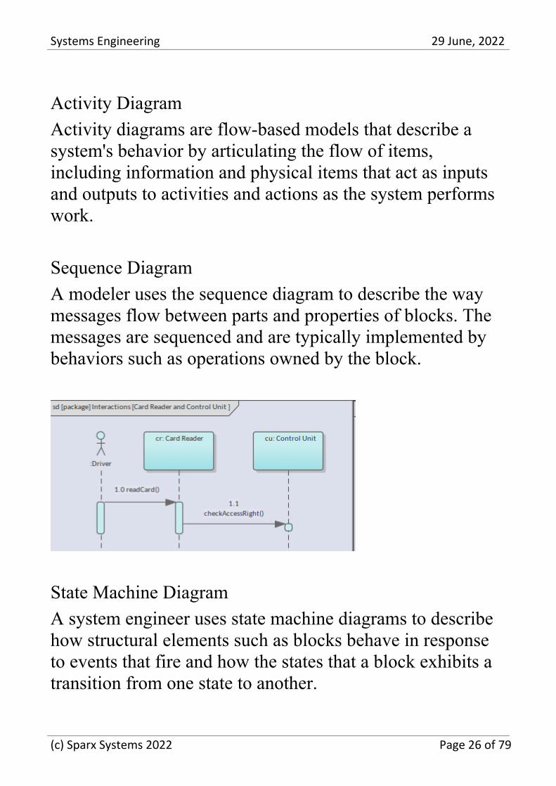
Sequence Diagram
A modeler uses the sequence diagram to describe the waymessages flow between parts and properties of blocks. Themessages are sequenced and are typically implemented bybehaviors such as operations owned by the block.
State Machine Diagram
A system engineer uses state machine diagrams to describehow structural elements such as blocks behave in responseto events that fire and how the states that a block exhibits atransition from one state to another.
(c) Sparx Systems 2022 Page 26 of 79
Systems Engineering 29 June, 2022
Structural Models
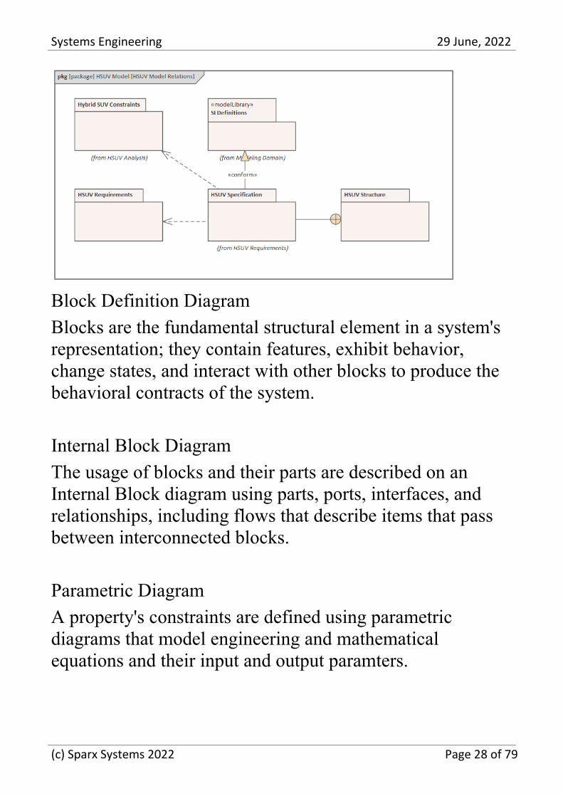
A systems engineer can describe the structure of a systemusing a series of diagrams that together form the structuralmodel. These diagrams and the elements and relationshipsthey contain, define the components of the system that arebought to life by the behavioral models. The systemmodeling language specification classifies the followingdiagrams as structural. They are all used to representdifferent aspects of a system's structure at a logical andphysical level, from the packages that organize the model toparametric diagrams that define equations and their inputand output parameters.
Package Diagram
A complex system needs to be organized to ensure bothhumans and other systems can understand, digest, and locateitems of interest in the model. Packages that appear in theBrowser window can also be placed onto diagrams and arethe primary element used to structure the model.
(c) Sparx Systems 2022 Page 27 of 79
Systems Engineering 29 June, 2022
Block Definition Diagram
Blocks are the fundamental structural element in a system'srepresentation; they contain features, exhibit behavior,change states, and interact with other blocks to produce thebehavioral contracts of the system.
Internal Block Diagram
The usage of blocks and their parts are described on anInternal Block diagram using parts, ports, interfaces, andrelationships, including flows that describe items that passbetween interconnected blocks.
Parametric Diagram
A property's constraints are defined using parametricdiagrams that model engineering and mathematicalequations and their input and output paramters.
(c) Sparx Systems 2022 Page 28 of 79
Systems Engineering 29 June, 2022
Defense and Commercial ArchitectureModels
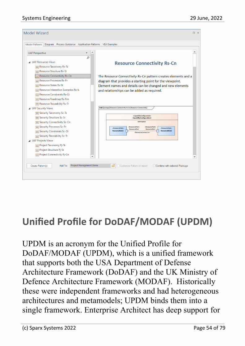
A number of frameworks have been used to model largesystems or systems-of-systems in defense organizations andlarge commercial or industrial organizations. Theseframeworks are based on modeling languages such as theUnified Modeling Language (UML), the Systems ModelingLanguage (SysML), and Service-Oriented Architecturestandards. The frameworks have evolved over severaldecades as defense, and commercial systems and projectshave become larger and more complex. For example,DoDAF and MODAF have been combined to form the basisfor the Unified Profile for DoDAF/MODAF (UPDM), andthis, in turn, has evolved into Unified ArchitectureFramework (UAF). Enterprise Architect has rich support forboth UPDM and UAF, and systems engineers can createrobust, expressive, and compliant defense and commercialmodels that provide views of complex systems or systems ofsystems.
(c) Sparx Systems 2022 Page 29 of 79
Systems Engineering 29 June, 2022
Requirements Models
Requirement Engineering is one of the most importantdisciplines in the system lifecycle. When done well, it willset the foundation for a successful project or program ofwork, ultimately ensuring that engineering teams delivergreat value to the users and other stakeholders. EnterpriseArchitect is a sophisticated and intuitive platform fordeveloping and managing Requirements gleaned frommodeling stakeholder statements, business cases, businessdrivers, and capabilities to define detailed Functional andNon-functional Requirements. The engineer can prioritize,trace, and track requirements and record changes, baseline,version, and record audits of changes. Engineers, managers,consultants, and customers can work together in acollaborative platform with role-based Security,Discussions, a team Library, Model Mail, and a range ofother tools to encourage best practice and productivity,either directly on the local system or through Pro CloudServices.
(c) Sparx Systems 2022 Page 30 of 79
Systems Engineering 29 June, 2022
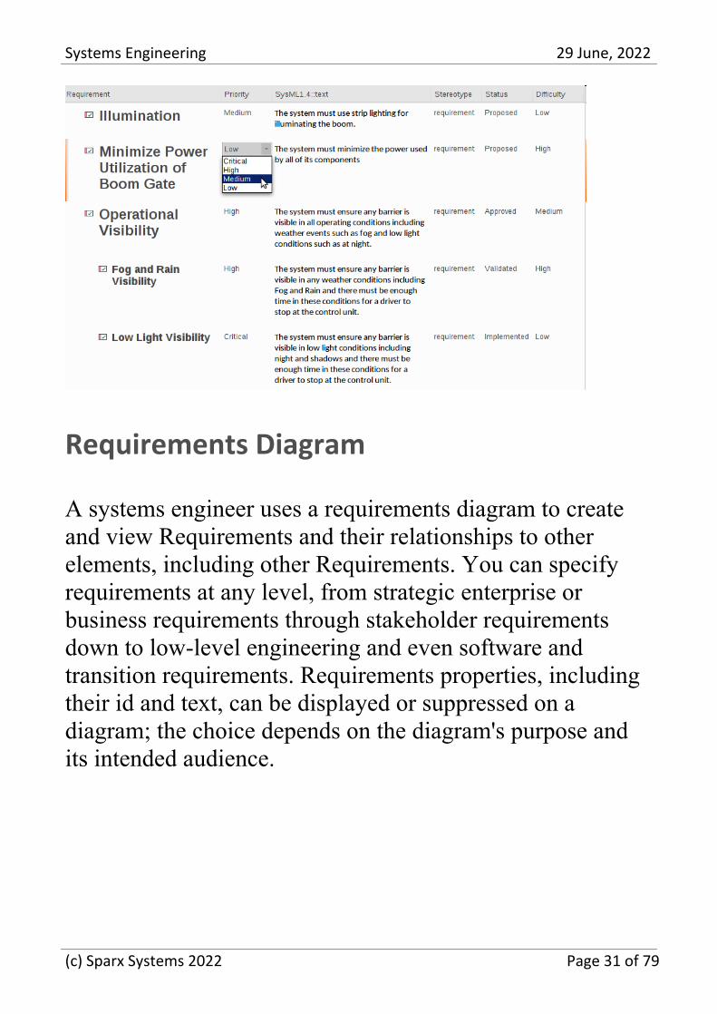
Requirements Diagram
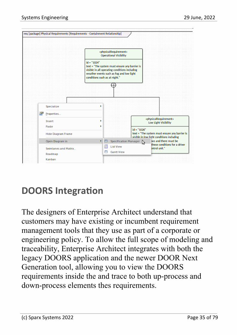
A systems engineer uses a requirements diagram to createand view Requirements and their relationships to otherelements, including other Requirements. You can specifyrequirements at any level, from strategic enterprise orbusiness requirements through stakeholder requirementsdown to low-level engineering and even software andtransition requirements. Requirements properties, includingtheir id and text, can be displayed or suppressed on adiagram; the choice depends on the diagram's purpose andits intended audience.
(c) Sparx Systems 2022 Page 31 of 79
Systems Engineering 29 June, 2022
Requirements Discipline
Requirement development includes all the activities andtasks associated with discovering, evaluating, recording,documenting, and validating the requirements for anengineering project or program of work. Requirements arediscovered, analyzed, specified, and verified, and EnterpriseArchitect has a wide range of tools and features to assist therequirement engineer as they develop requirements. TheSpecification Manager is the centerpiece for requirementdevelopment, allowing the Analyst to enter, view, andmanage requirements in textual form in a spreadsheet ordocument-like view.
(c) Sparx Systems 2022 Page 32 of 79
Systems Engineering 29 June, 2022
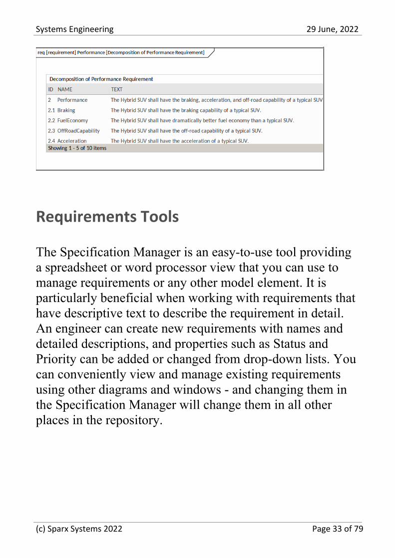
Requirements Tools
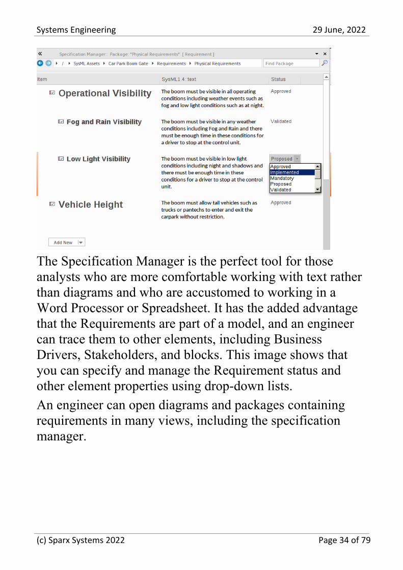
The Specification Manager is an easy-to-use tool providinga spreadsheet or word processor view that you can use tomanage requirements or any other model element. It isparticularly beneficial when working with requirements thathave descriptive text to describe the requirement in detail.An engineer can create new requirements with names anddetailed descriptions, and properties such as Status andPriority can be added or changed from drop-down lists. Youcan conveniently view and manage existing requirementsusing other diagrams and windows - and changing them inthe Specification Manager will change them in all otherplaces in the repository.
(c) Sparx Systems 2022 Page 33 of 79
Systems Engineering 29 June, 2022
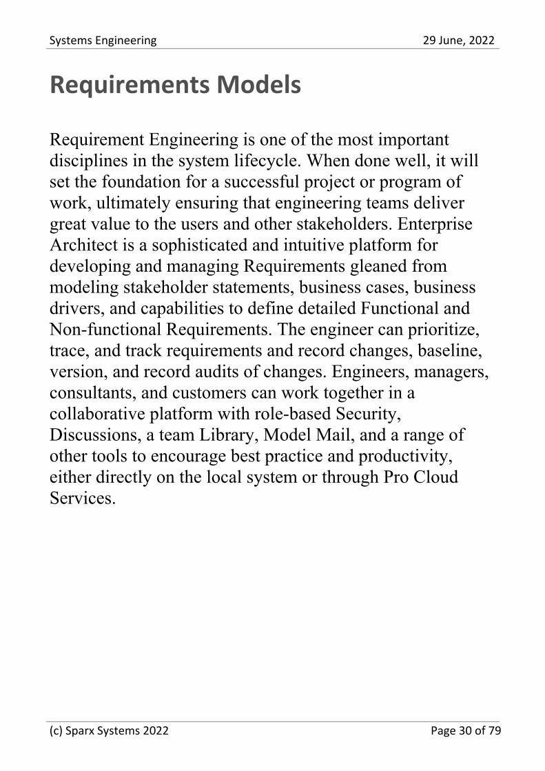
The Specification Manager is the perfect tool for thoseanalysts who are more comfortable working with text ratherthan diagrams and who are accustomed to working in aWord Processor or Spreadsheet. It has the added advantagethat the Requirements are part of a model, and an engineercan trace them to other elements, including BusinessDrivers, Stakeholders, and blocks. This image shows thatyou can specify and manage the Requirement status andother element properties using drop-down lists.
An engineer can open diagrams and packages containingrequirements in many views, including the specificationmanager.
(c) Sparx Systems 2022 Page 34 of 79
Systems Engineering 29 June, 2022
DOORS Integration
The designers of Enterprise Architect understand thatcustomers may have existing or incumbent requirementmanagement tools that they use as part of a corporate orengineering policy. To allow the full scope of modeling andtraceability, Enterprise Architect integrates with both thelegacy DOORS application and the newer DOOR NextGeneration tool, allowing you to view the DOORSrequirements inside the and trace to both up-process anddown-process elements thes requirements.
(c) Sparx Systems 2022 Page 35 of 79
Systems Engineering 29 June, 2022
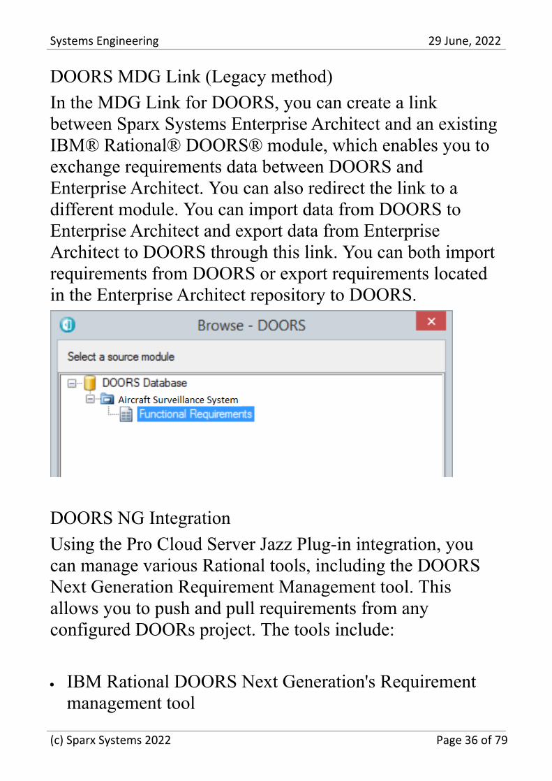
DOORS MDG Link (Legacy method)
In the MDG Link for DOORS, you can create a linkbetween Sparx Systems Enterprise Architect and an existingIBM® Rational® DOORS® module, which enables you toexchange requirements data between DOORS andEnterprise Architect. You can also redirect the link to adifferent module. You can import data from DOORS toEnterprise Architect and export data from EnterpriseArchitect to DOORS through this link. You can both importrequirements from DOORS or export requirements locatedin the Enterprise Architect repository to DOORS.
DOORS NG Integration
Using the Pro Cloud Server Jazz Plug-in integration, youcan manage various Rational tools, including the DOORSNext Generation Requirement Management tool. Thisallows you to push and pull requirements from anyconfigured DOORs project. The tools include:
IBM Rational DOORS Next Generation's Requirement·
management tool
(c) Sparx Systems 2022 Page 36 of 79
Systems Engineering 29 June, 2022
Rational Rhapsody Design Management (DM)·
Rational Team Concert Change and Configuration·
Management (CCM)
Rational Quality Manager (QM).·
(c) Sparx Systems 2022 Page 37 of 79
Systems Engineering 29 June, 2022
Structural Models
The structural models contain the 'nouns' of the system anddefine the structures or components of the system. Packagesare the primary element for structuring a model orrepository and act as containers or namespaces for otherelements and their features, including other packages. Thefundamental element of structure is the Block which cancontain both structural and behavior features and can beused to model any logical or physical aspect of a system.Blocks are typically created and viewed on Block DefinitionDiagrams and also appear on Internal Block diagrams thatyou use to describe the usage of the Block in a particularcontext showing the parts that make up the Block.Parametric diagrams are a specialized type of Internal Blockdiagram used for modeling mathematics and physicsequations.
Structure with Packages
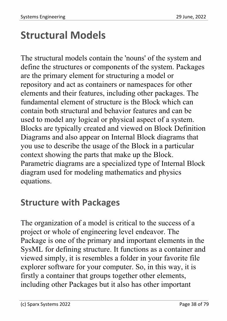
The organization of a model is critical to the success of aproject or whole of engineering level endeavor. ThePackage is one of the primary and important elements in theSysML for defining structure. It functions as a container andviewed simply, it is resembles a folder in your favorite fileexplorer software for your computer. So, in this way, it isfirstly a container that groups together other elements,including other Packages but it also has other important
(c) Sparx Systems 2022 Page 38 of 79
Systems Engineering 29 June, 2022
functions in Enterprise Architect including for versioncontrol, baselining, publications and more.
Packages diagrams can also be used to visualize thestructure of a repository and have the advantage that theycan be included in publications or web views of therepository.
(c) Sparx Systems 2022 Page 39 of 79
Systems Engineering 29 June, 2022
Blocks and Constraints
The SysML has similar grammatical categories found innatural languages, with elements that describe structure andother elements that describe behavior. The SysML describesstructural things (nouns) using a Block. When engineerscreate diagrams, they will often use a mixture of behavior orstructure elements, describing a particular aspect of a system- bringing to light some aspect of the modeled system.
The Block is the fundamental unit of system structure and isused to describe an entire system, a subsystem, acomponent, an item that flows through a system, aconstraint, or entities that reside outside a system. Similar to
(c) Sparx Systems 2022 Page 40 of 79
Systems Engineering 29 June, 2022
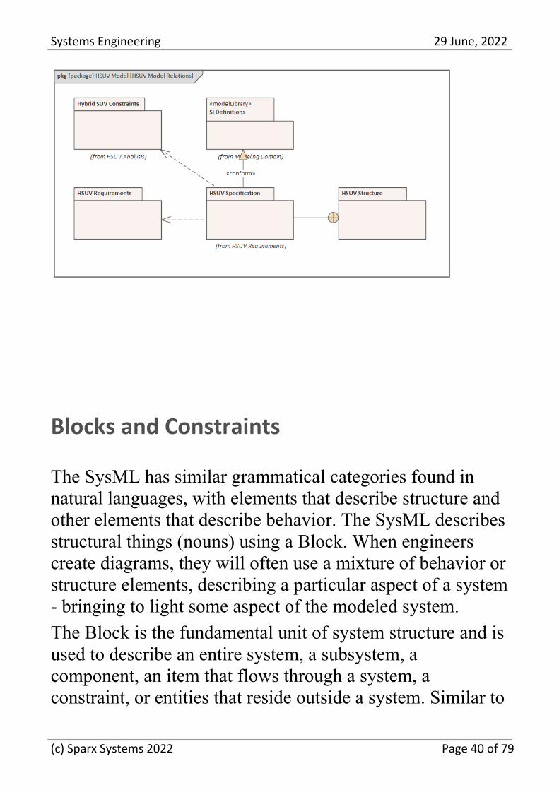
our natural languages, a Block can represent somethingabstract, logical, or physical. This is an important concept,and the SysML writers and readers must be clear about theintention of the representation. For example, in a logicalarchitecture, there are typically Blocks representingconceptual ideas or designs that physical and tangiblecomponents might realize at the time of detailed design andconstruction. A systems architect might define a Blockcalled Collision Detection Subsystem that is an expressionof a logical system component that could at the detaileddesign phase, be in part, realized by a set of radar and lasertransmitters, detectors and cameras.
(c) Sparx Systems 2022 Page 41 of 79
Systems Engineering 29 June, 2022
Parts and Block Usage
Blocks are classifiers and describe the characteristics of aset of elements that represent how the Block is used in acontext. When the Block has attributes (value properties)defined, these are given specific values in the Blockinstances. Effectively, each Block instance has an identityand typically would have different values assigned thatdefine the Block's state. Enterprise Architect allows thesevalues to be specified using a Set Run State option availablefrom the context menu. Block instances are properties orparts. Thus an engineer working in an automotive domaincould define aspects of a vehicle's braking system showingblocks representing a master cylinder's relationship to awheel cylinder defining a multiplicity of 3..4. The engineerwould place instances of these blocks on Internal Blockdiagrams to express how the parts work together to carry outthe behavioral contracts of the system.
The engineer has named each of the wheel cylinder parts(Front Left, Front Right, Back Left, Back Right) as theseneed to be identified with respect to their location in thevehicle, but has decided not to name the master cylinder asno further qualification is required.
(c) Sparx Systems 2022 Page 42 of 79

Systems Engineering 29 June, 2022
Parametrics and Equations
Systems engineering models created in Enterprise Architectprovide a valuable tool for analysis, design, architecture,testing, and visualization. Systems Engineers are chargedwith finding solutions to problems and opportunities andusing models to visualize the system's simplifications underconsideration and the system's operation context orenvironment. This includes predicting how a system willbehave in a given context, balancing competingrequirements and design considerations in the form ofstakeholder negotiations and trade-off analysis. Parametricdiagrams are a powerful tool that can assist the engineer inaddressing these concerns in a model and pre-emptively torepresent how a system is likely to behave.
Constraints can be modeled on a block definition diagramand then Parametric diagrams are used to show how theses
(c) Sparx Systems 2022 Page 43 of 79
Systems Engineering 29 June, 2022
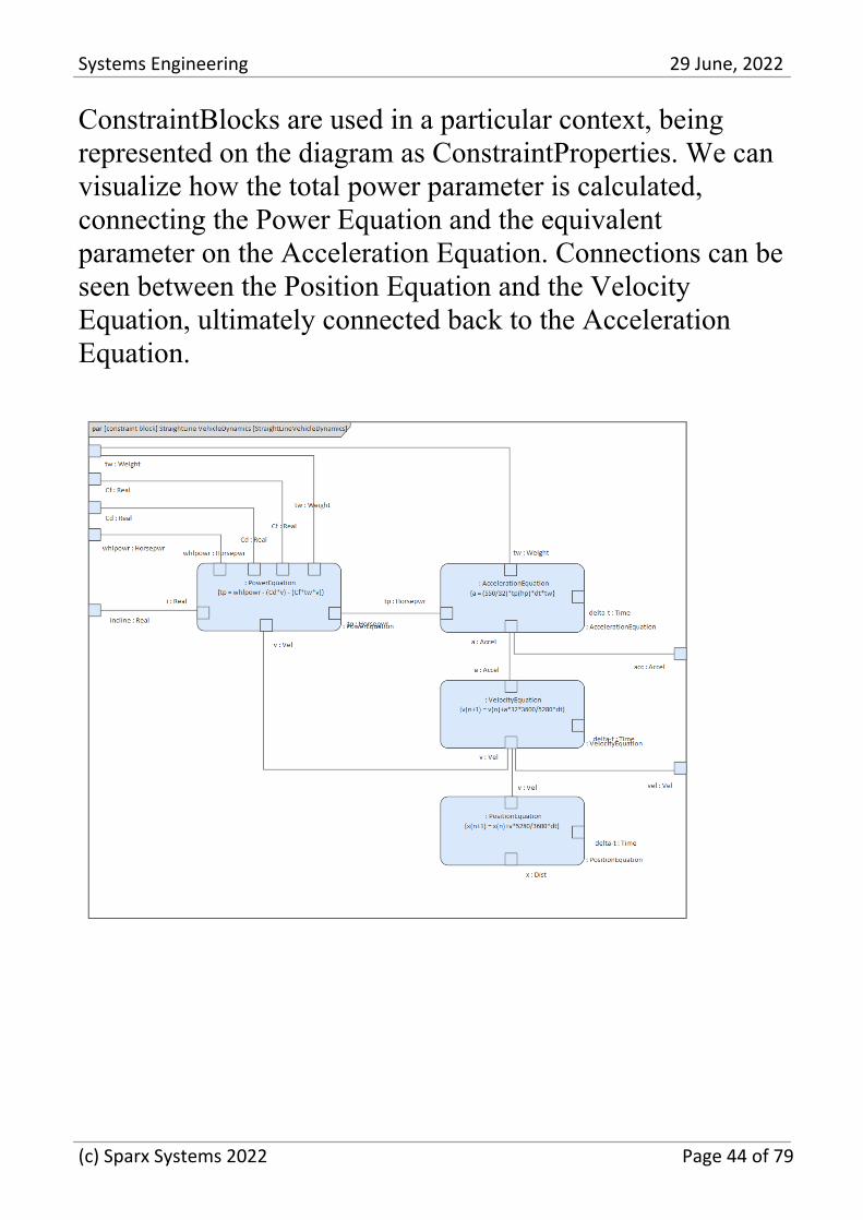
ConstraintBlocks are used in a particular context, beingrepresented on the diagram as ConstraintProperties. We canvisualize how the total power parameter is calculated,connecting the Power Equation and the equivalentparameter on the Acceleration Equation. Connections can beseen between the Position Equation and the VelocityEquation, ultimately connected back to the AccelerationEquation.
(c) Sparx Systems 2022 Page 44 of 79
Systems Engineering 29 June, 2022
Behavioral Models
The behavioral models contain the 'verbs' of the system anddefine how the system behaves from several differentviewpoints.
The Behavior diagrams communicate the behavior of thesystem and demonstrate how the parts of a system worktogether to satisfy behavioral requirements. Behavioralmodels have a range of purposes. The engineer mustunderstand what part of the system's behavior they aremodeling and then choose the appropriate tool feature andlanguage construct to model this behavior. SystemsEngineers use SysML diagrams to model these behavioralcharacteristics.:
Use Case diagrams - used to narrow a system's scope and·
express the users' goals as a value proposition.
Activity diagrams - used to define the ordered set of·
actions that carry the work of the system.
Sequence diagram - used to show how system·
components or parts interact to produce an outcome.
State Machine diagram - used to define the discrete states·
of a system or its parts during its lifetimes.
Enterprise Architect has a range of productivity tools thatthe systems engineer can use while working with behavioralmodels, including the Scenario Builder, State MachineTables, Simulation engine, and many more.
(c) Sparx Systems 2022 Page 45 of 79

Systems Engineering 29 June, 2022
Use Cases and User Goals
The use case model describes the value or goals that users(human and system) derive from interacting with thesystem. A brief description summarizes this value for eachscenario, including the all-important basic (sunny day)scenario.
The Use Case technique is fundamentally straightforwardand was devised to ensure that functional requirements werewritten from the User's perspective. This standpoint helpedto ensure that deployed systems would be fit for purpose andbe accepted by the diverse community of users. There is,however, a vast amount of conflicting literature and anequally large number of styles for defining Use Cases. Thissituation has led to confusion and uncertainty and hastended to attenuate the value that can be derived from this
(c) Sparx Systems 2022 Page 46 of 79
Systems Engineering 29 June, 2022
simple technique.
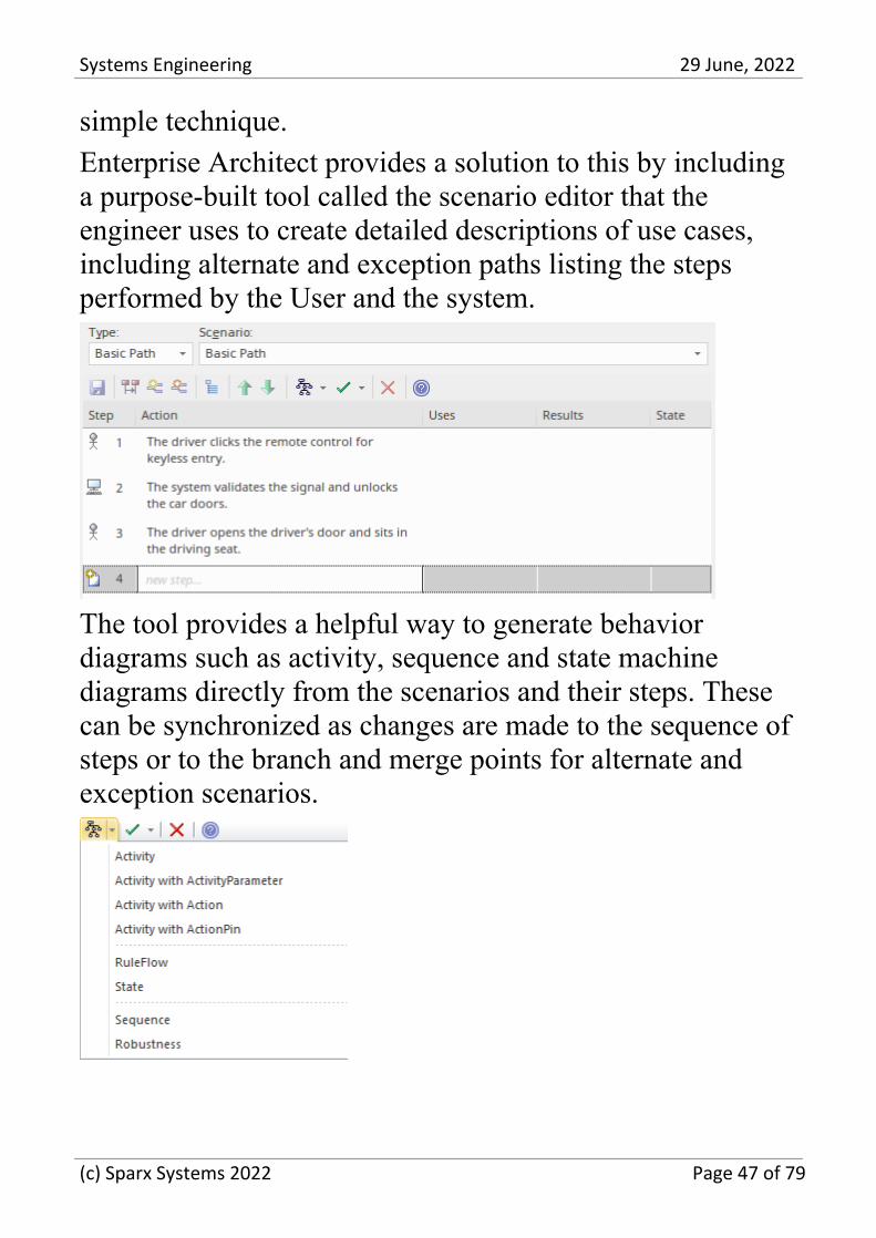
Enterprise Architect provides a solution to this by includinga purpose-built tool called the scenario editor that theengineer uses to create detailed descriptions of use cases,including alternate and exception paths listing the stepsperformed by the User and the system.
The tool provides a helpful way to generate behaviordiagrams such as activity, sequence and state machinediagrams directly from the scenarios and their steps. Thesecan be synchronized as changes are made to the sequence ofsteps or to the branch and merge points for alternate andexception scenarios.
(c) Sparx Systems 2022 Page 47 of 79
Systems Engineering 29 June, 2022
Activities and Behavioral Flows
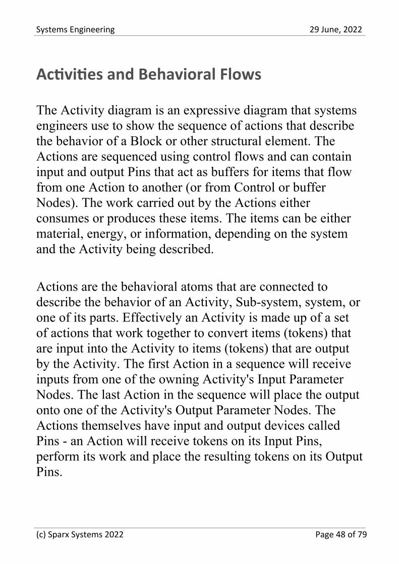
The Activity diagram is an expressive diagram that systemsengineers use to show the sequence of actions that describethe behavior of a Block or other structural element. TheActions are sequenced using control flows and can containinput and output Pins that act as buffers for items that flowfrom one Action to another (or from Control or bufferNodes). The work carried out by the Actions eitherconsumes or produces these items. The items can be eithermaterial, energy, or information, depending on the systemand the Activity being described.
Actions are the behavioral atoms that are connected todescribe the behavior of an Activity, Sub-system, system, orone of its parts. Effectively an Activity is made up of a setof actions that work together to convert items (tokens) thatare input into the Activity to items (tokens) that are outputby the Activity. The first Action in a sequence will receiveinputs from one of the owning Activity's Input ParameterNodes. The last Action in the sequence will place the outputonto one of the Activity's Output Parameter Nodes. TheActions themselves have input and output devices calledPins - an Action will receive tokens on its Input Pins,perform its work and place the resulting tokens on its OutputPins.
(c) Sparx Systems 2022 Page 48 of 79
Systems Engineering 29 June, 2022
Sequences and Object Interactions
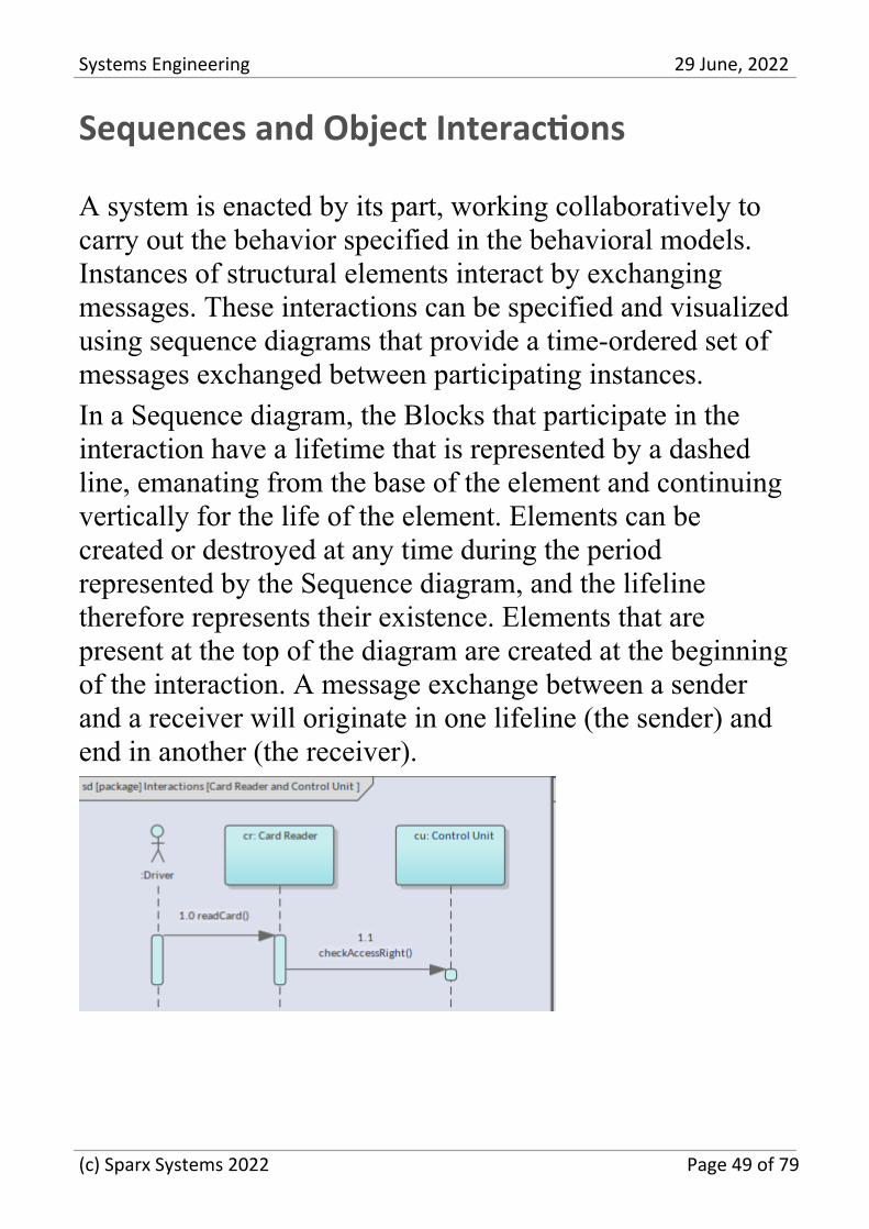
A system is enacted by its part, working collaboratively tocarry out the behavior specified in the behavioral models.Instances of structural elements interact by exchangingmessages. These interactions can be specified and visualizedusing sequence diagrams that provide a time-ordered set ofmessages exchanged between participating instances.
In a Sequence diagram, the Blocks that participate in theinteraction have a lifetime that is represented by a dashedline, emanating from the base of the element and continuingvertically for the life of the element. Elements can becreated or destroyed at any time during the periodrepresented by the Sequence diagram, and the lifelinetherefore represents their existence. Elements that arepresent at the top of the diagram are created at the beginningof the interaction. A message exchange between a senderand a receiver will originate in one lifeline (the sender) andend in another (the receiver).
(c) Sparx Systems 2022 Page 49 of 79
Systems Engineering 29 June, 2022
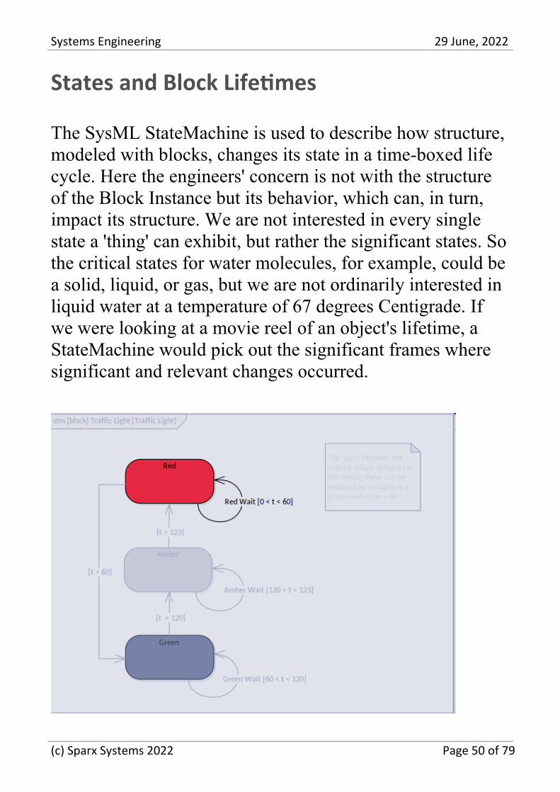
States and Block Lifetimes
The SysML StateMachine is used to describe how structure,modeled with blocks, changes its state in a time-boxed lifecycle. Here the engineers' concern is not with the structureof the Block Instance but its behavior, which can, in turn,impact its structure. We are not interested in every singlestate a 'thing' can exhibit, but rather the significant states. Sothe critical states for water molecules, for example, could bea solid, liquid, or gas, but we are not ordinarily interested inliquid water at a temperature of 67 degrees Centigrade. Ifwe were looking at a movie reel of an object's lifetime, aStateMachine would pick out the significant frames wheresignificant and relevant changes occurred.
(c) Sparx Systems 2022 Page 50 of 79
Systems Engineering 29 June, 2022
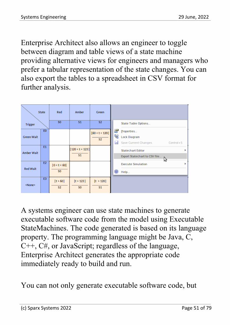
Enterprise Architect also allows an engineer to togglebetween diagram and table views of a state machineproviding alternative views for engineers and managers whoprefer a tabular representation of the state changes. You canalso export the tables to a spreadsheet in CSV format forfurther analysis.
A systems engineer can use state machines to generateexecutable software code from the model using ExecutableStateMachines. The code generated is based on its languageproperty. The programming language might be Java, C,C++, C#, or JavaScript; regardless of the language,Enterprise Architect generates the appropriate codeimmediately ready to build and run.
You can not only generate executable software code, but
(c) Sparx Systems 2022 Page 51 of 79
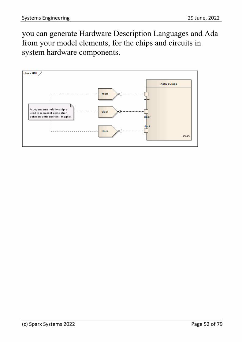
Systems Engineering 29 June, 2022
you can generate Hardware Description Languages and Adafrom your model elements, for the chips and circuits insystem hardware components.
(c) Sparx Systems 2022 Page 52 of 79
Systems Engineering 29 June, 2022
Defense and Commercial ArchitectureModels
Aerospace and military systems have led the way formodel-based system engineering and the use of languagessuch as the Systems Modeling Language (SysML) andframeworks such as the USA Department of DefenseArchitecture Framework (DoDAF) and the UK Ministry ofDefence Architecture Framework (MODAF) and morerecently the Unified Profile for DoDAF/MODAF (UPDM)and the Unified Architecture Framework (UAF).Large-scale commercial organizations have subsequentlyadopted these languages and frameworks to developsystems-of-system projects. Enterprise Architect hasprovided tools for creating language-compliant models andhas rich support for the frameworks, including pre-builtmodel patterns for both the language models andframeworks.
(c) Sparx Systems 2022 Page 53 of 79
Systems Engineering 29 June, 2022
Unified Profile for DoDAF/MODAF (UPDM)
UPDM is an acronym for the Unified Profile forDoDAF/MODAF (UPDM), which is a unified frameworkthat supports both the USA Department of DefenseArchitecture Framework (DoDAF) and the UK Ministry ofDefence Architecture Framework (MODAF). Historicallythese were independent frameworks and had heterogeneousarchitectures and metamodels; UPDM binds them into asingle framework. Enterprise Architect has deep support for
(c) Sparx Systems 2022 Page 54 of 79
Systems Engineering 29 June, 2022
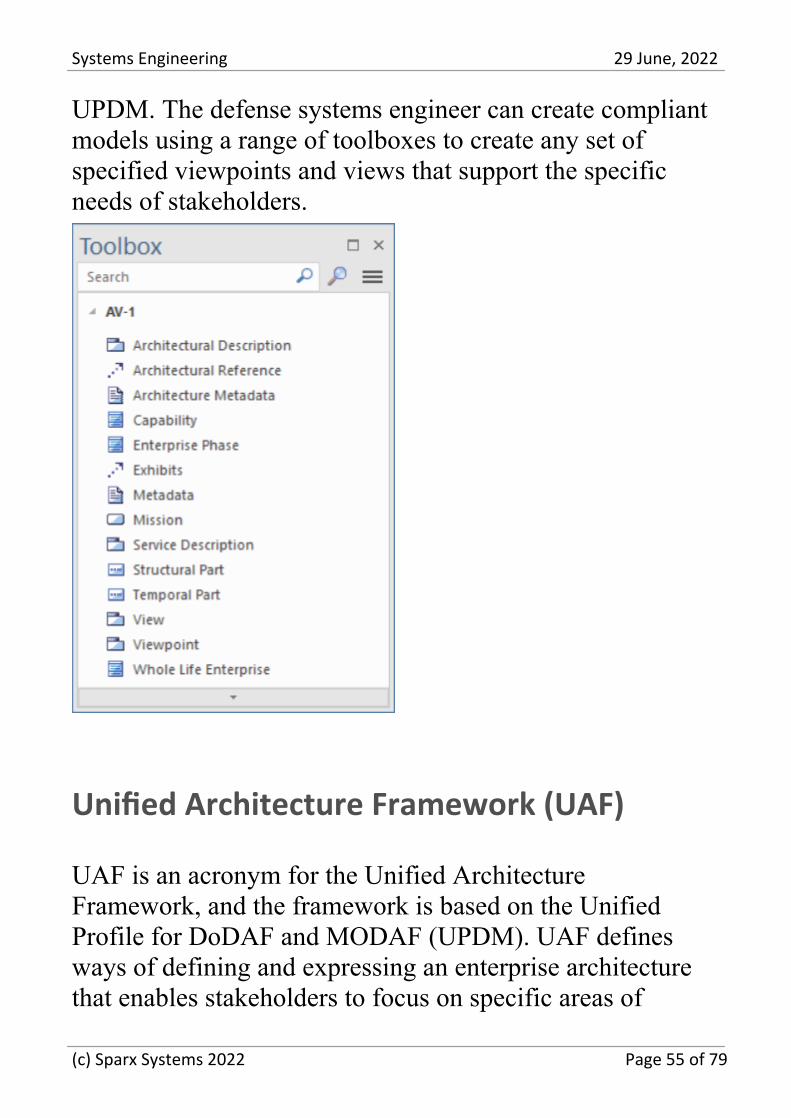
UPDM. The defense systems engineer can create compliantmodels using a range of toolboxes to create any set ofspecified viewpoints and views that support the specificneeds of stakeholders.
Unified Architecture Framework (UAF)
UAF is an acronym for the Unified ArchitectureFramework, and the framework is based on the UnifiedProfile for DoDAF and MODAF (UPDM). UAF definesways of defining and expressing an enterprise architecturethat enables stakeholders to focus on specific areas of
(c) Sparx Systems 2022 Page 55 of 79

Systems Engineering 29 June, 2022
interest while keeping a high-level view of the entiresystem. UAF was designed to meet the needs of allstakeholders and allows the creation of specific business,operational, and systems-of-systems integration models ofcommercial and industrial enterprises as well as the U.S.Department of Defense (DoD), the UK Ministry of Defence(MOD), the North Atlantic Treaty Organization (NATO),and other defense organizations models. EnterpriseArchitect has a full suite of pre-built patterns withaccompanying documentation that can be automaticallyinjected into your models.
(c) Sparx Systems 2022 Page 56 of 79

Systems Engineering 29 June, 2022
Verification and Validation
Enterprise Architect has a full feature set for verificationand validation. Broadly verification is best described as 'hasthe correct system been built' and validation as 'has thesystem been built correctly'. The models that the systemsengineer creates in Enterprise Architect can be used toverify that the correct system is being built using thetraceability features including diagrams the traceabilitywindow and the element matrix.
An engineer can use a requirements diagram to express therelationship between Requirements and test cases effectivelyverifying that the requirements a met by the system.
(c) Sparx Systems 2022 Page 57 of 79
Systems Engineering 29 June, 2022
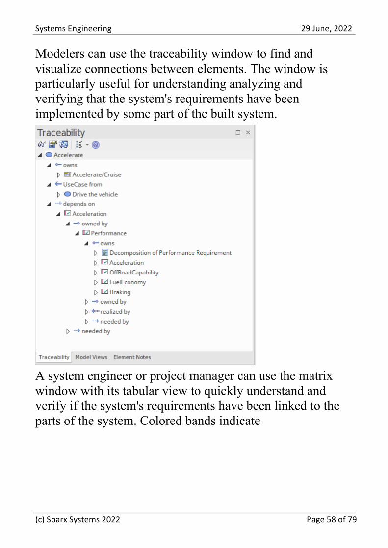
Modelers can use the traceability window to find andvisualize connections between elements. The window isparticularly useful for understanding analyzing andverifying that the system's requirements have beenimplemented by some part of the built system.
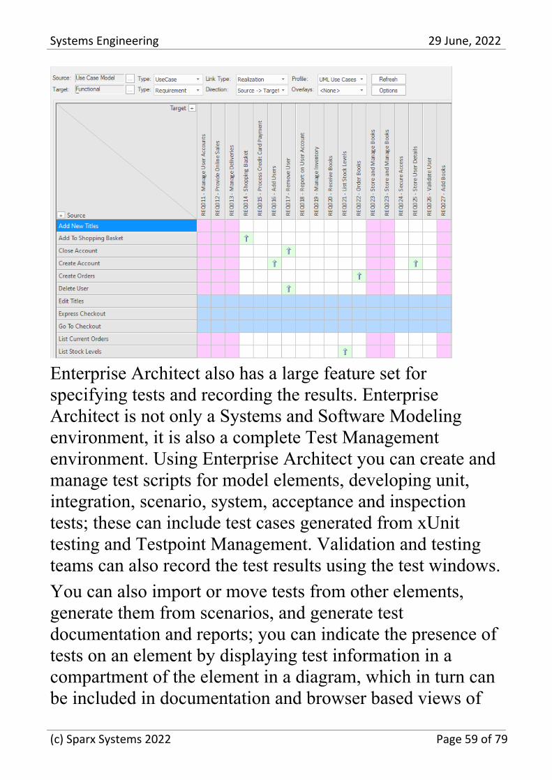
A system engineer or project manager can use the matrixwindow with its tabular view to quickly understand andverify if the system's requirements have been linked to theparts of the system. Colored bands indicate
(c) Sparx Systems 2022 Page 58 of 79
Systems Engineering 29 June, 2022
Enterprise Architect also has a large feature set forspecifying tests and recording the results. EnterpriseArchitect is not only a Systems and Software Modelingenvironment, it is also a complete Test Managementenvironment. Using Enterprise Architect you can create andmanage test scripts for model elements, developing unit,integration, scenario, system, acceptance and inspectiontests; these can include test cases generated from xUnittesting and Testpoint Management. Validation and testingteams can also record the test results using the test windows.
You can also import or move tests from other elements,generate them from scenarios, and generate testdocumentation and reports; you can indicate the presence oftests on an element by displaying test information in acompartment of the element in a diagram, which in turn canbe included in documentation and browser based views of
(c) Sparx Systems 2022 Page 59 of 79

Systems Engineering 29 June, 2022
the elements.
(c) Sparx Systems 2022 Page 60 of 79
Systems Engineering 29 June, 2022
Simulation and Visualization
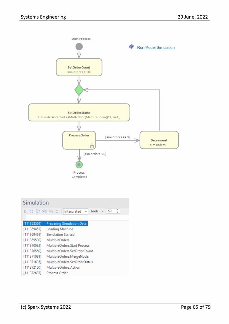
One of the great benefits of creating system models is theability to see the system in motion by running simulations -effectively you to visualize and analyze a system. EnterpriseArchitect provides a suite of tools to simulate the executionand behavior of the processes that your models define. Thetools provide facilities to dynamically simulate a range oftypes of model including SImulation of Activity and StateMachine diagrams, Parametric diagrams, Decision Modelsand more. Executable State Machines provide rich supportfor programming language-specific implementations.OpenModelica and MATLAB Simulink can be used tosupport rapid and robust evaluation of how a SysML modelwill behave in different circumstances.
Dynamic Simulation
Model Simulation brings your behavioral models to life withinstant, real-time behavioral model execution. Coupled withtools to manage triggers, events, guards, effects, breakpointsand Simulation variables, plus the ability to visually trackexecution at run-time, the Simulator is a multi-featuredmeans of 'watching the wheels turn' and verifying thecorrectness of your behavioral models. With Simulation youcan explore and test the dynamic behavior of models. In theCorporate, Unified and Ultimate Editions, you can also useJavaScript as a run-time execution language for evaluating
(c) Sparx Systems 2022 Page 61 of 79
Systems Engineering 29 June, 2022
guards, effects and other scriptable items of behavior.
Extensive support for triggers, trigger sets, nested states,concurrency, dynamic effects and other advancedSimulation capabilities, provides a remarkable environmentin which to build interactive and working models that helpexplore, test and visually trace complex business, softwareand system behavior. With JavaScript enabled, it is alsopossible to create embedded COM objects that will do thework of evaluating guards and executing effects - allowingthe Simulation to be tied into a much larger set of dependentprocesses. For example, a COM object evaluating a guardcondition on a State Transition might query a locallyrunning process, read and use a set of test data, or evenconnect to an SOA web service to obtain some currentinformation.
As Enterprise Architect uses a dynamic, script drivenSimulation mechanism that analyzes and works with UMLconstructs directly, there is no need to generate intermediarycode or compile simulation 'executables' before running aSimulation. This results in a very rapid and dynamicSimulation environment in which changes can be made andtested quickly. It is even possible to update Simulationvariables in real time using the Simulation Console window.This is useful for testing alternative branches and conditions'on the fly', either at a set Simulation break point or whenthe Simulation reaches a point of stability (for example,when the Simulation is 'blocked').
In the Professional Edition of Enterprise Architect, you canmanually walk through Simulations - although no JavaScript
(c) Sparx Systems 2022 Page 62 of 79
Systems Engineering 29 June, 2022
will execute - so all choices are manual decisions. This isuseful for testing the flow of a behavioral model andhighlighting possible choices and processing paths. In theCorporate, Unified and Ultimate Editions it is possible to:
Dynamically execute your behavioral models·
Assess guards and effects written in standard JavaScript·
Define and fire triggers into running Simulations·
Define and use sets of triggers to simulate different event·
sequences
Auto-fire trigger sets to simulate complex event histories·
without user intervention
Update Simulation variables 'on the fly' to change how·
Simulations proceed
Create and call COM objects during a Simulation to·
extend the Simulation's reach and input/outputpossibilities
Inspect Simulation variables at run time·
Set a script 'prologue' for defining variables, constants and·
functions prior to execution
Use multiple Analyzer Scripts with differing 'prologues'·
for running the Simulation under a wide range ofconditions
In the Unified and Ultimate Editions it is also possible tosimulate BPMN models.
Using the Model Simulator, you can simulate the executionof conceptual model designs containing behavior. When youstart a Simulation, the current model Package is analyzed
(c) Sparx Systems 2022 Page 63 of 79
Systems Engineering 29 June, 2022
and a dynamic Simulation process is triggered to execute themodel.
To get up and running with Simulation, the only stepsrequired are:
Build a behavioral diagram (State or Activity for manual·
or dynamic execution, Sequence for manual interactiononly)
Optional: load the 'Simulation Workspace' layout - a fast·
way of bringing up all the frequently used Simulationwindows
Click on the Simulator Play button·
If the diagram contains any external elements (those not inthe same Package as the diagram) you will have to create anImport connector from the diagram's Package to the Packagecontaining the external elements. To do this, drag bothPackages from the Browser window onto a diagram andthen use the Quick Linker arrow to create the connectorbetween them.
(c) Sparx Systems 2022 Page 64 of 79
Systems Engineering 29 June, 2022
(c) Sparx Systems 2022 Page 65 of 79
Systems Engineering 29 June, 2022
Mathematical Simulations
Enterprise Architect provides a wide range of options forintroducing advanced mathematical tools and capabilitiesinto your simulations.
You can bring the power of integrated external tools such asMATLAB into your models through the use of SolverClasses, and can also export your models for execution inother external tools such as MATLAB Simulink, Stateflowand Simscape, or OpenModelica.
Enterprise Architect includes an extensive library ofmathematical functions within the JavaScript engine,providing the benefits of a significantly expandedSimulation capability.
Enterprise Architect also provides a wide range of DynamicCharts; without the need for external tools, you canconfigure these Charts to extract and plot information fromSimulations that have been directly executed insideEnterprise Architect.
Explore the:
Solver classes in Enterprise Architect that call MATLAB·
or Octave to incorporate complex mathematics into yourmodel-based simulations
Extensive internal Math Library based on the popular·
Cephes function library
Integration with the OMG SysPhS standard, enabling you·
to configure your model for export to common tools
Support for exporting models to MATLAB Simulink,·
(c) Sparx Systems 2022 Page 66 of 79
Systems Engineering 29 June, 2022
Simscape and Stateflow; you can create your model inEnterprise Architect and execute it in MATLAB
Extensive support for Modelica; you can create and·
configure your model in Enterprise Architect and executeit in Modelica
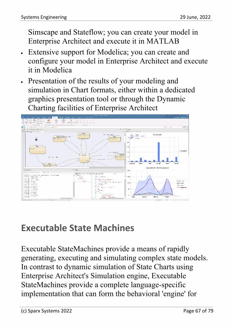
Presentation of the results of your modeling and·
simulation in Chart formats, either within a dedicatedgraphics presentation tool or through the DynamicCharting facilities of Enterprise Architect
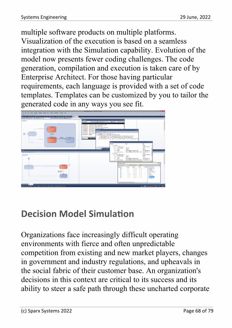
Executable State Machines
Executable StateMachines provide a means of rapidlygenerating, executing and simulating complex state models.In contrast to dynamic simulation of State Charts usingEnterprise Architect's Simulation engine, ExecutableStateMachines provide a complete language-specificimplementation that can form the behavioral 'engine' for
(c) Sparx Systems 2022 Page 67 of 79
Systems Engineering 29 June, 2022
multiple software products on multiple platforms.Visualization of the execution is based on a seamlessintegration with the Simulation capability. Evolution of themodel now presents fewer coding challenges. The codegeneration, compilation and execution is taken care of byEnterprise Architect. For those having particularrequirements, each language is provided with a set of codetemplates. Templates can be customized by you to tailor thegenerated code in any ways you see fit.
Decision Model Simulation
Organizations face increasingly difficult operatingenvironments with fierce and often unpredictablecompetition from existing and new market players, changesin government and industry regulations, and upheavals inthe social fabric of their customer base. An organization'sdecisions in this context are critical to its success and itsability to steer a safe path through these uncharted corporate
(c) Sparx Systems 2022 Page 68 of 79
Systems Engineering 29 June, 2022
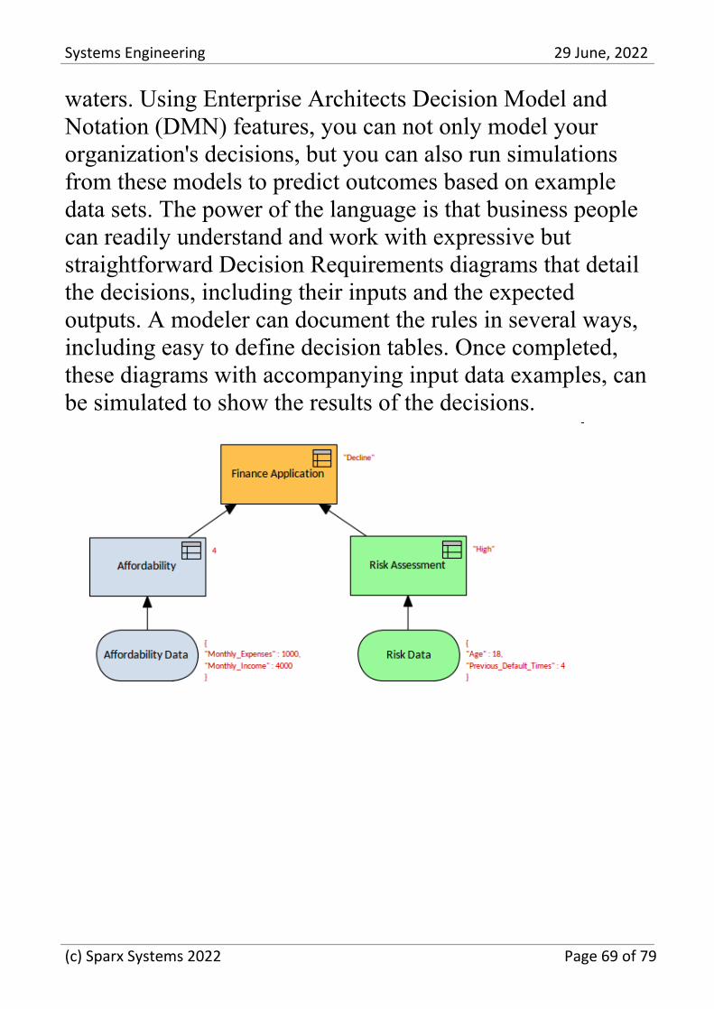
waters. Using Enterprise Architects Decision Model andNotation (DMN) features, you can not only model yourorganization's decisions, but you can also run simulationsfrom these models to predict outcomes based on exampledata sets. The power of the language is that business peoplecan readily understand and work with expressive butstraightforward Decision Requirements diagrams that detailthe decisions, including their inputs and the expectedoutputs. A modeler can document the rules in several ways,including easy to define decision tables. Once completed,these diagrams with accompanying input data examples, canbe simulated to show the results of the decisions.
(c) Sparx Systems 2022 Page 69 of 79
Systems Engineering 29 June, 2022
Publications and Documentation
A systems engineer, manager, or other stakeholders can usethe documentation features to automatically generate a widerange of documentation directly from the models. These canbe document based such as PDF and Docx format orHTML-based. You can use flexible templates to completelytailor the generated documents, including company logos,tables of content, tables of element information, anddiagrams. The success of a systems engineering project and,ultimately the entire engineering practice will depend onhow well you communicate with stakeholders. Manystakeholders will be content to view systems models,including lists, diagrams, and matrices, directly in therepository. Still, others will want or require by contract,electronic, or printed documentation delivered to them. Youcan use the documentation generator to create high-qualitycorporate publications automatically from the repository.This includes a wide range of standard publications such asthe Operation Concept document, Functional Architecture,Requirements Specification, and more. Modelers can alsocreate Ad-hoc reports from tools such as the Glossary andthe Search Window.
(c) Sparx Systems 2022 Page 70 of 79
Systems Engineering 29 June, 2022
(c) Sparx Systems 2022 Page 71 of 79
Systems Engineering 29 June, 2022
Collaboration and Teams
An engineering team is multidisciplinary and consists ofstrategists, managers, system engineers, software engineers,testers and others. The commercial pressures to release aproduct or provide a solution means that teams have to workmore cleverly and cohesively to ensure engineeringoutcomes. Enterprise Architect has been built from theground up as a collaborative platform, not just for engineersbut for all disciplines. It facilitates individuals and teamsworking together and sharing information, models, designs,and solutions with a full range of tools from discussions,reviews, a team library, and chat to Version Control andBaselines.
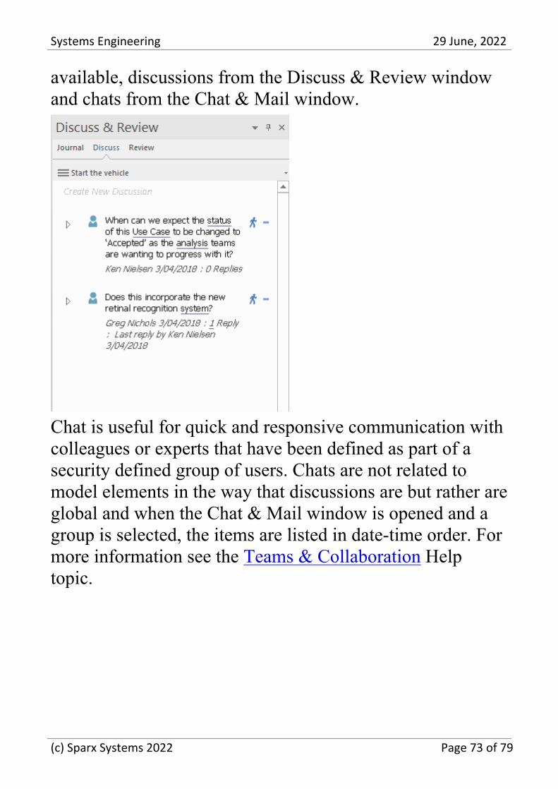
Discussions and Chat
Central to the notion of collaboration is a modeler's abilityto discuss and chat with colleagues or industry andstandards specialists about a problem or solution. EnterpriseArchitect allows engineers, managers, and others to discusselements, diagrams, and connectors. Any modeler can createa post to start a thread or conversation that other modelerscan enter into by replying. The discussions are keptseparately from element and diagram meta-information,allowing you to make rich and constructive commentswithout affecting documentation or reports generated fromthe models. The discussions and chat are two options
(c) Sparx Systems 2022 Page 72 of 79
Systems Engineering 29 June, 2022
available, discussions from the Discuss & Review windowand chats from the Chat & Mail window.
Chat is useful for quick and responsive communication withcolleagues or experts that have been defined as part of asecurity defined group of users. Chats are not related tomodel elements in the way that discussions are but rather areglobal and when the Chat & Mail window is opened and agroup is selected, the items are listed in date-time order. Formore information see the Teams & Collaboration Helptopic.
(c) Sparx Systems 2022 Page 73 of 79
Systems Engineering 29 June, 2022
Project Management
Enterprise Architect has been built from the ground up withthe Project Manager in mind. Systems repositories arevaluable engineering assets and should be managed andmaintained accordingly. Any team can assign themselves asa resource applied to an item performing particular roles,and you can conveniently view these in a built-in GanttChart. Risk can be modeled and managed in variouslocations, and engineers can determine project effort withbuilt-in support for Metrics and Estimation. An Auditfunction allows changes to be tracked at a fine-grained level,and a Library facility and Element Reviews and Discussionsenable users to work collaboratively on models.
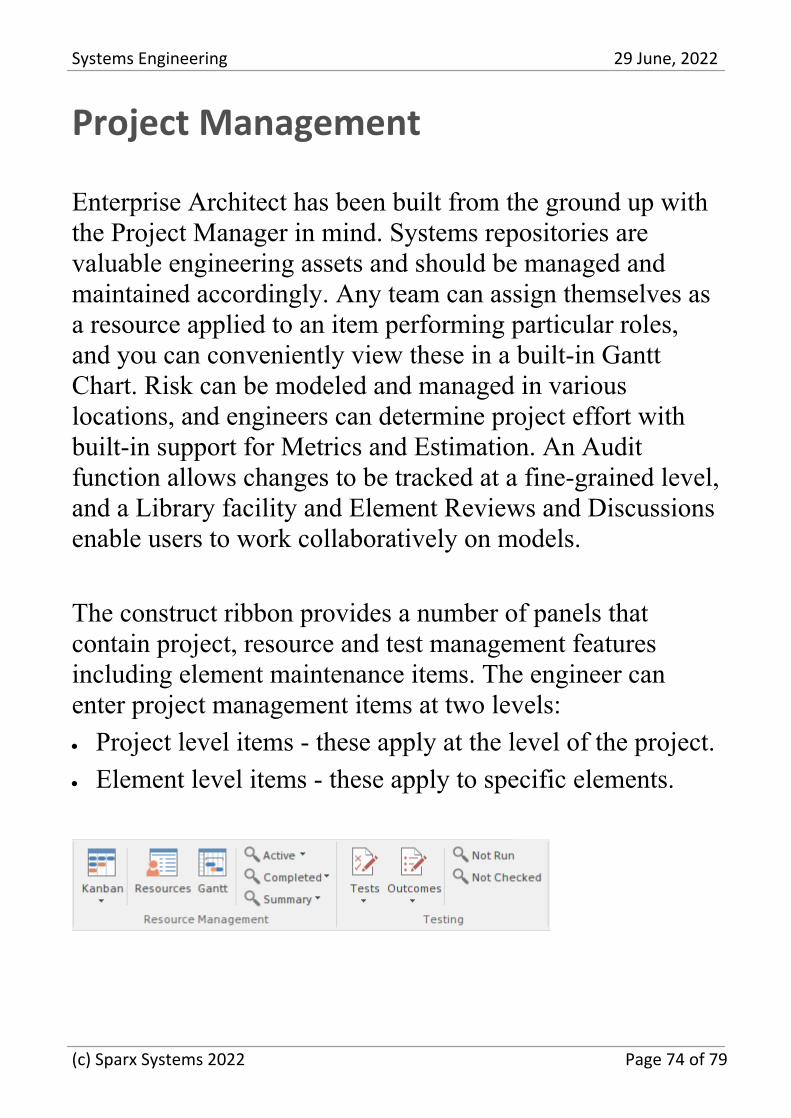
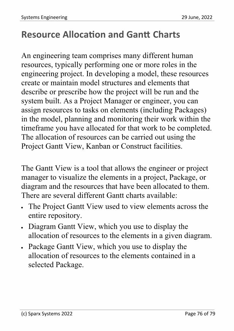
The construct ribbon provides a number of panels thatcontain project, resource and test management featuresincluding element maintenance items. The engineer canenter project management items at two levels:
Project level items - these apply at the level of the project.·
Element level items - these apply to specific elements.·
(c) Sparx Systems 2022 Page 74 of 79
Systems Engineering 29 June, 2022
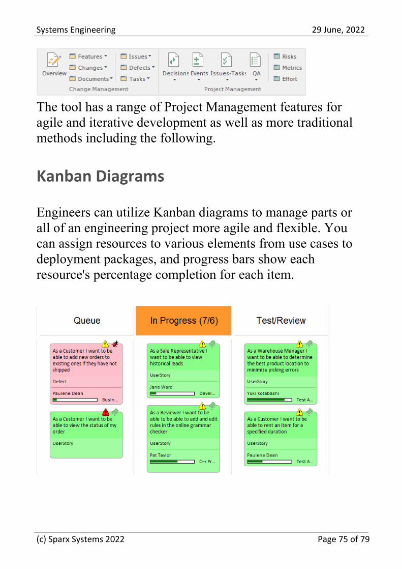
The tool has a range of Project Management features foragile and iterative development as well as more traditionalmethods including the following.
Kanban Diagrams
Engineers can utilize Kanban diagrams to manage parts orall of an engineering project more agile and flexible. Youcan assign resources to various elements from use cases todeployment packages, and progress bars show eachresource's percentage completion for each item.
(c) Sparx Systems 2022 Page 75 of 79
Systems Engineering 29 June, 2022
Resource Allocation and Gantt Charts
An engineering team comprises many different humanresources, typically performing one or more roles in theengineering project. In developing a model, these resourcescreate or maintain model structures and elements thatdescribe or prescribe how the project will be run and thesystem built. As a Project Manager or engineer, you canassign resources to tasks on elements (including Packages)in the model, planning and monitoring their work within thetimeframe you have allocated for that work to be completed.The allocation of resources can be carried out using theProject Gantt View, Kanban or Construct facilities.
The Gantt View is a tool that allows the engineer or projectmanager to visualize the elements in a project, Package, ordiagram and the resources that have been allocated to them.There are several different Gantt charts available:
The Project Gantt View used to view elements across the·
entire repository.
Diagram Gantt View, which you use to display the·
allocation of resources to the elements in a given diagram.
Package Gantt View, which you use to display the·
allocation of resources to the elements contained in aselected Package.
(c) Sparx Systems 2022 Page 76 of 79

Systems Engineering 29 June, 2022
The tool will empower the traditional or agile projectmanager to ensure that a project's resources are allocated torepository content and help ensure high-value outcomes areachieved right from within the repository.
The Gantt View's primary use is to display the allocation ofresources to elements in the repository and to manage thework breakdown structure. Youy can apply a wide range ofviews and filters to tailor the view or make it more relevantto a particular audience. Allocations can be made to anyelements in the repository, from high-level packages to anindividual element such as a Class, Activity, or Change. It isa powerful tool for project managers to visualize how a teamutilization and ultimately deliver high value and highpriority outcomes. Modelers working on a project can viewtheir own work and update their progress on assigned tasks.
While an engineer can make broad changes using the visualduration bars in the Gantt View, it is common practice touse the tool in conjunction with the Resource Allocationwindow where fine details can be entered and adjusted.
(c) Sparx Systems 2022 Page 77 of 79
Systems Engineering 29 June, 2022
Change Management
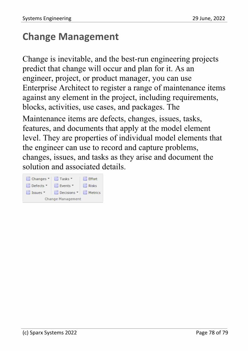
Change is inevitable, and the best-run engineering projectspredict that change will occur and plan for it. As anengineer, project, or product manager, you can useEnterprise Architect to register a range of maintenance itemsagainst any element in the project, including requirements,blocks, activities, use cases, and packages. The
Maintenance items are defects, changes, issues, tasks,features, and documents that apply at the model elementlevel. They are properties of individual model elements thatthe engineer can use to record and capture problems,changes, issues, and tasks as they arise and document thesolution and associated details.
(c) Sparx Systems 2022 Page 78 of 79

Systems Engineering 29 June, 2022
(c) Sparx Systems 2022 Page 79 of 79
Copyright © 2022 FDOKUMEN