Cognitive Systems Engineering Modeling Profile
84
The Cognitive Systems Engineering Modeling Profile (CSEMP): Enabling a Set of Descriptive and Validation Logics to Extend the Unified Modeling Language to Support Cognitive Work and Task Analyses By Jerry A Gordon Submitted in fulfillment of requirements for HFS699, Independent Study Embry Riddle Aeronautical University (ERAU) Human Factors and Systems Department
-
Upload
independent -
Category
Documents
-
view
0 -
download
0
Transcript of Cognitive Systems Engineering Modeling Profile
The Cognitive Systems Engineering Modeling Profile (CSEMP):
Enabling a Set of Descriptive and Validation Logics to
Extend the Unified Modeling Language to Support Cognitive
Work and Task Analyses
By Jerry A Gordon
Submitted in fulfillment of requirements for HFS699,
Independent Study
Embry Riddle Aeronautical University (ERAU) Human Factors
and Systems Department
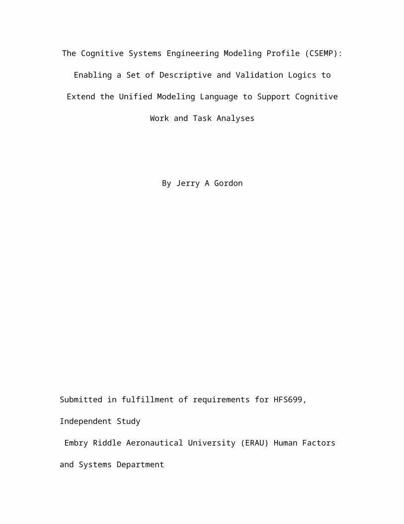
Table of Contents
List of Figures...........................................i
List of Tables...........................................ii
Abstract..................................................1
Introduction..............................................1
Purpose of this Study.....................................6
Method....................................................9
Complex Systems and Cognitive Systems Engineering........10
Unified Modeling Language, Architecture and Profiles.....19
Cognitive Systems Engineering Modeling Profile - Key
Concepts from Cognitive Work Analysis....................28
Conclusions and Recommendations..........................45
References...............................................46
List of Figures
Figure 1. Different Task Analysis Perspectives of Work and the
World, adapted from Hollnagel & Woods, 2005..............13
Figure 2. Components of the Man – Machine Systems viewed as
organizations interacting with their Environment. The Human
i
Machine Interface (HM) becomes the focus in cognitivist
methods..................................................16
Figure 3. Examples of Graphical Symbols used in the UML
descriptions of utility, structure and behavior..........24
Figure 4. Concepts that define an Architectural Framework as
per IEEE 1471............................................26
Figure 5. Hierarchy of meta-models that compose the CSEMP. UML
Package Classes embody the JCS architectural Framework.. .27
Figure 6. Goals Means Decompositions. Adapted from Hollnagel &
Woods, 2006..............................................29
Figure 7. Use Case Diagram Example of an Organization. Used to
Model the top of a Abstraction Decomposition Space.......30
Figure 8. Carrier Flight Control Block Definition Diagram.
This allows us to logically group the elements in our
functional abstraction hierarchy, and add users , or
technology, as they are determined.......................32
Figure 9. Example Package Diagram for the Carrier Flight
Center. It depicts how we are binding concepts such as
“system” to names articulated differently for a CSE view
ii
(developed with the ACWA method) and as used to develop a
manufacturing parts list.................................37
Figure 10. Activity Diagram for Flight Management Procedures.
Used to Evaluate Allocation Strategies...................40
Figure 11. Example of using Parametric Diagram to Capture
Cognitive Loading and Interface Requirements on a Human
Actor Block. Parametric constraint blocks store systems of
equations to use in simulation based analysis............44
List of Tables
Table 1. CSEMP stereotypes defined for block definition
diagrams, and linked objects in other Diagrams...........34
Table 2. Summary of CSEMP Stereotypes and Logics as used In
Activity Diagrams........................................42
Table 3. Parametric Diagram Stereotypes to support Cognitive
Task Analysis. Validation logic is used to verify
completeness.............................................45
iii
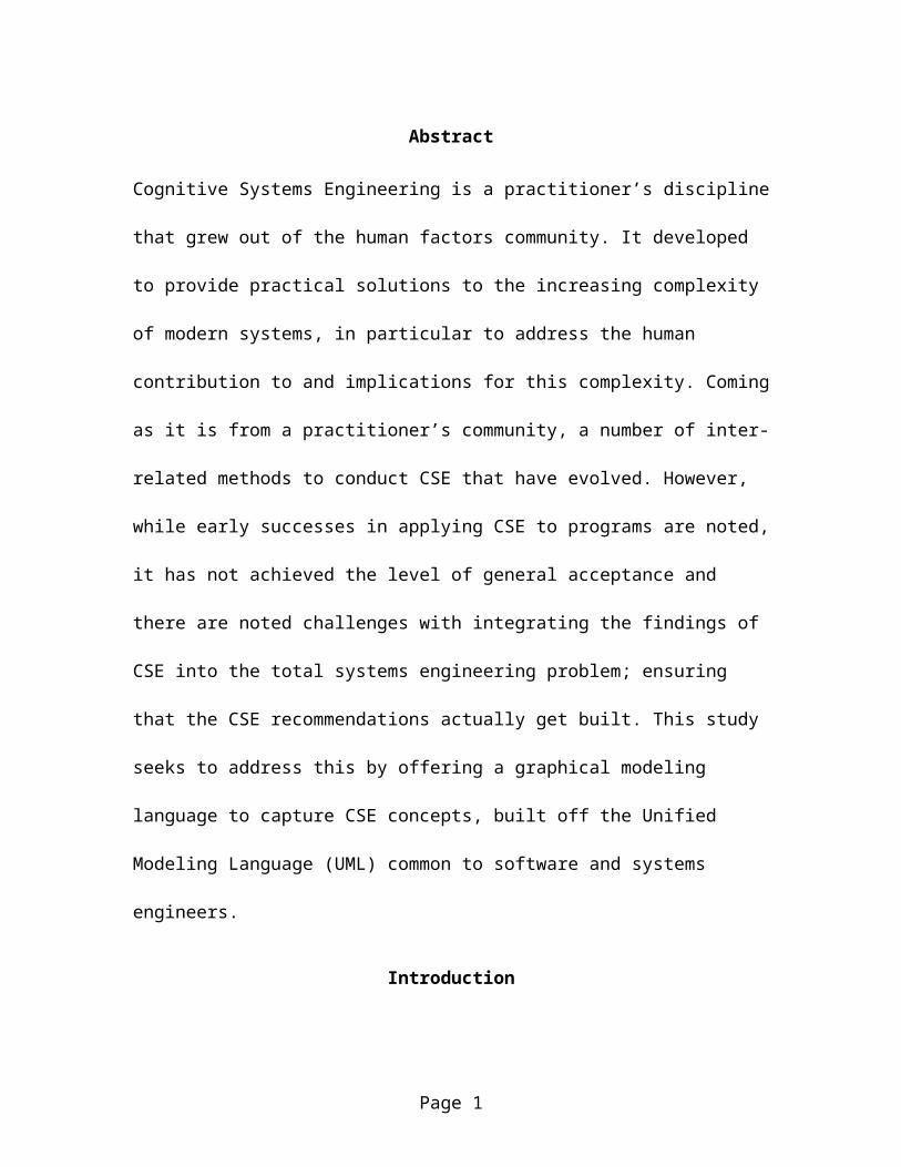
Abstract
Cognitive Systems Engineering is a practitioner’s discipline
that grew out of the human factors community. It developed
to provide practical solutions to the increasing complexity
of modern systems, in particular to address the human
contribution to and implications for this complexity. Coming
as it is from a practitioner’s community, a number of inter-
related methods to conduct CSE that have evolved. However,
while early successes in applying CSE to programs are noted,
it has not achieved the level of general acceptance and
there are noted challenges with integrating the findings of
CSE into the total systems engineering problem; ensuring
that the CSE recommendations actually get built. This study
seeks to address this by offering a graphical modeling
language to capture CSE concepts, built off the Unified
Modeling Language (UML) common to software and systems
engineers.
Introduction
Page 1
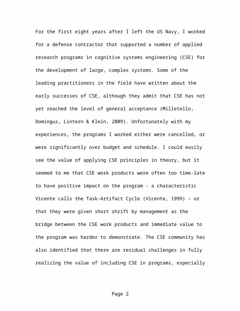
For the first eight years after I left the US Navy, I worked
for a defense contractor that supported a number of applied
research programs in cognitive systems engineering (CSE) for
the development of large, complex systems. Some of the
leading practitioners in the field have written about the
early successes of CSE, although they admit that CSE has not
yet reached the level of general acceptance (Milletello,
Dominguz, Lintern & Klein, 2009). Unfortunately with my
experiences, the programs I worked either were cancelled, or
were significantly over budget and schedule. I could easily
see the value of applying CSE principles in theory, but it
seemed to me that CSE work products were often too time-late
to have positive impact on the program - a characteristic
Vicente calls the Task-Artifact Cycle (Vicente, 1999) – or
that they were given short shrift by management as the
bridge between the CSE work products and immediate value to
the program was harder to demonstrate. The CSE community has
also identified that there are residual challenges in fully
realizing the value of including CSE in programs, especially
Page 2
given that the conduct of CSE analysis and design is so
costly (Milletello et al, 2009).
In addition, it seemed to me that while the leaders in the
human factors/applied psychology field were adept at
achieving success with CSE principals, the tools available
were too immature to enable success by the more median
practitioner, and thus without a leader’s involvement on a
project, it was more difficult to benefit from CSE
application. In my experience, a new technology has to be
applied with some success by the “one standard deviation
below the mean” practitioner in order to be perceived as
generally adding value. Put another way, while having
Gavriel Salvendy on your team is quite likely to contribute
to success, he is expensive and there is only one of him.
CSE and “traditional” engineering (i.e. the fields of
Systems, Software and Hardware Engineering) integration is
complicated by the spectrum of CSE methods, tools and
dictionaries available. Millitello (Milletello et al, 2009)
Page 3
writes that there are a number of related CSE approaches,
each of which comes with their own unique language and
acronyms. Moreover, there are two distinct approaches to
integration of humans into complex work environments, most
traditional Human Factors methods embody the “Cognitivist”
approach, which is the underpinning of concepts such as
“Human Centered Design” The alternative is the “ecological”
approach, which evolved from sociology, and which seeks to
examine work from a holistic perspective, with the humans
and their “artifacts” (technology and information transfer
mechanisms as actually used to provide value to human users)
treated on an equal footing. (Hollnagel & Woods, 2003)
While working on the Virtual Environment Landing Craft Air
Cushion (VELCAC) around 2000, Several colleagues and I
started implementing an “encoding scheme” which modeled the
results of Rasmussen’s goals-operators-methods-selection
(GOMS) style cognitive task analysis (CTA). This scheme
aided the development of software simulation fidelity
requirements for a training simulation (Jonassen, D.
Page 4
Tessmer, M. & Hannum, W., 1999). Revisiting this initial
effort a few years later, we proposed an extension from this
original method, we called the Universal Performance Data
Model – UPDM (Gordon, Burns, & Giebenrath, 2005), which
sought to put performance requirements for system design on
par with human performance requirements, so that designers
could see how they worked together to describe the overall
system operation. The idea was to establish a truly
integrated lingua franca for describing cognitive requirements
in technical engineering terms. It was borne of frustration
experienced (Gordon, Burns, Ricci & Ramsden, 2005) that had
its root in differences between the psychology, technical
and operational perspectives of various stakeholders on a
program we were working.
In particular, we had difficulty in coming up with common
accepted definitions for seemingly simple terms; e.g.
scenario, task and function. Vicente (Vicente, 1999) notes
that the working definitions of “function and task” are
somewhat arbitrary among the Human Factors community. We
Page 5
found that different stakeholders had vastly different
interpretations that brought the biases of their stake to
their understanding of these terms. This made an analysis
from one perspective very difficult to integrate with an
analysis from the different perspective, essentially every
term related to every other term and little meaningful
relationships could be gleaned from the resulting data
“soup”.
Moreover, the project was concerned with a training
analysis for a new weapon system that had not yet been
placed under contract (much less designed or built).
Applying the traditional human factors engineering process
(Sanders & McCormick, 1993) for functional allocation left
us too many unanswered and unanswerable questions (Gordon et
al, 2005). We all agreed that bringing in HF early in the
process was a good idea, but that the methods available to
us to take full advantage of the opportunity were lacking.
Some advancement would be required to realize the potential
of “integrating HF early”. To this end we proposed some
Page 6
extensions to the traditional methods to enable some of our
questions at least to be answered (Gordon, Burns, Sheehan,
Ricci & Pharmer, 2005).
This method was at least satisfactory for correcting the
issues that had plagued us in the earlier project, where now
we could speak of organizations having capabilities,
technology performing functions and humans performing tasks.
“Functional Allocation” in the human factors sense was now
about mapping a manpower concept and a systems concept to a
set of desired capabilities, with task definitions that
would become apparent at the intersections of the two.
Instead of an arbitrarily demarked (Vicente, 1999) hierarchy
of “mission, function, task”, we got the set of attribute
manifolds described in our UPDM “risk tensor” (Gordon, et al,
2005) that could be evaluated to find an optimal
automation/human allocation mix. Subsequent use of this
method illustrated some holes in this simplistic
formulation, but it at least provided a starting point.
Page 7
In reflecting on the problems we encountered, it seemed to
me that the “language” problem was the most significant one
to be addressed. Linguistics science in the early 20th
century held a consensus that the words of a particular
language were reflective of the way its native speakers
actually thought (Putz & Vespoor, 2000). Thus a lack of or
focus on certain related words meant that certain concepts
could not be (or would always be) conceptualized by its
speakers, even if translated into another language, as a
function of their cultural biases embodied in their language
(e.g. the semi-apocryphal 20 Eskimo words for “snow”). This
found its height in the so called “Whorf-Sapir” hypothesis,
(which was not a hypothesis in the strict sense, but a
related collection of loosely stated theories) that had the
above “strong” statement, and a related “weak” statement
that semantics would at least influence the speaker’s
conceptualization of a problem. The Whorfian hypothesis was
largely held in disfavor by the 1980’s. Other theoretical
work in linguistics proposed a “transformational grammar”,
where meaning was common to all languages, and cultural
Page 8
biases simply hampered the interpretation of meaning
(Radford, 1988). However, subsequent research has provided
evidence for the veracity of the weak component (Putz &
Vespoor, 2000).
Thus to address the language problem, it seems a natural
approach to select an agreed upon framework, and extend
concepts as necessary with caveats. Thus, it is possible to
use the word for which stakeholders are accustomed (e.g.
“interface”) and caveat it with adjectives and nouns so that
they can recognize where the usage was meaningful to them
(Human Machine Interface) and where it was not (Class
Interface). CSEMP provides a framework, which can be
extended by or incorporated into other frameworks, for
capturing the goals-means abstractions and cognitive
workspace content inherent in performing cognitive work
analysis.
Purpose of this Study
Page 9
The principal purpose of this study is to create a new way
to support CSE, by evaluating the observations I made in the
last 10 years in applying task analysis methods in concert
with a solid foundation in theory. Applicable research
domains include advances in complexity science, practical
and theoretical application of cognitive work and task
analysis, linguistics, and the practical experiences of CSE
practitioners in applying their methods. The study will
culminate in the definition of a graphical language for
encoding CSE analyses of complex systems, particularly of
socio-technical and/or software intensive systems. This
language should be suitable for capturing the required
concepts, along with validation logic to show when the
models were complete, as well as “legal” in the sense that
information elements were linked with elements in a way that
was logically consistent with those concepts. This CSE
language is called the Cognitive Systems Engineering
Modeling Profile or CSEMP.
Page 10
My hope is by mapping knowledge discovery from CSE methods
to graphical concepts and diagrams familiar to traditional
software/systems engineers, it will facilitate synchronicity
between the problem domain mental models of the psychology
and technical stakeholders. More importantly, as a systems
engineer, I see every program as unique, but I also see that
design resembles doing crossword puzzles. A lot of things I
don’t know at first, but once some words are in place, the
clues and shared letters guide me in finishing the puzzle. I
believe that by capturing the concepts of a complex system
design graphically, it will be become apparent that some
aspects of a notional design are more “defined” or “certain”
than others. Thus the selection of a method to identify and
refine the remaining concepts will become logically
apparent.
In defining the purpose of this study, it will be helpful to
articulate what it is not. First, it is not intended as a
primer on modeling languages; there are plenty of reference
books to define them. It is not intended to evaluate among
Page 11
the alternatives languages, but chooses one for which this
author is most familiar. Most importantly, this study will
not attempt to ensconce any particular practical CSE
approach. While it approaches the data structure from the
holistic, and thus ecological, perspective, it should be
able to represent data as collected from a “cognitivist”
approach with equal facility as from an “ecological”
approach. As an initial logical check on this goal, it
should be able, with simplifications, to represent
information as modeled by a traditional human factors
analysis (in the same way that in fluid mechanics, the
Navier-Stokes equation simplifies down to Bernoulli’s
equation).
While the initial work (Gordon, et al, 2005) posited a
“universalist” approach, with the idea that the model could
simply be extended as far as it needed to encompass the
entire system under study, I have since decided that
completely universal models are probably infeasible. A
search for a universal language has been around since at
Page 12
least Isaac Newton, but all attempts have met with failure.
I think the reasons why are best articulated by combining
the notion that “humans are difficult to pin down” central
to human factors with recent advances in complexity theory.
Attempts at imposing universal languages probably fail for
the same “bounded rationality” problem Wolpert (Braha, Minai
& Bar-Yam, 2006) discusses in trying to deterministically
design large complex systems in waterfall fashion –
incomplete information and non-rational actors. It becomes
apparent that a universal model would be just as expensive,
time consuming, and likely to become obsolete faster than it
could be changed as the method I was attempting to augment.
With uncertain future configurations, it is difficult to
model said configurations, and analysis of possibilities
beyond the control of the designers becomes an intractable
problem. Rather than attempt to model everything, a model
should instead attempt to define an initial set of explicit
analytic boundaries, populate these boundaries with concepts
semantically meaningful to the analysts, and then define
Page 13
strongly typed artifacts as “boundary objects” (Fong, Valerdi,
& Srinivasan, 2007) that can be exchanged at these
boundaries to other stakeholders. Thus, an initial ecology
is defined, with potential flows offered to adjacent
ecologies, which can form “super ecologies” as future
possibilities become more concrete, or the organization
grows in complexity.
Thus it is a principal goal of the CSEMP to identify in
concrete graphical terms “assumptions of scope”. It is in
unmatched assumptions between these system ecologies where
potential miscommunications cause problems in complex system
design (Fong et al, 2007) - Can the system support that
interface? Can it handle data in that range? Can the
operators adapt to the new workload and new nature of the
tasks? What happens to the operators and users culturally?
And what do those cultural shifts mean for the purpose, and
value, of the original system? CSEMP does not seek to answer
these questions; it does however endeavor to see that they
are asked.
Page 14
Most importantly this study is not intended to be
“finished”. My hope is to start a discussion. I know there
are large swaths of the CSE domain space I have left
untouched, and I have only brushed the content of the
modeling languages I have introduced. However, I feel this
profile might at least provide a useful starting point.
Method
In order to develop the CSEMP, I will relay on my experience
in applying model based systems engineering (MBSE) on over a
dozen DOD programs over the last decade, and comparing my
anecdotal observations to characteristics of the languages
described in the reference literature. Secondly, I will
evaluate concepts as articulated in the CSE literature and
look first for atomic semantic equivalencies to SYSML/UML
concepts, and second for complex definitions based on those
atomic definitions. CSE introduces additional stereotype
extensions as descriptive logic with validation logic
routines. The resulting meta-models must serve the intent
Page 15
of CSE methods, while avoiding the pitfalls, articulated
well by Vicente, Woods, Hollnagel and Lintern throughout
their works. The results are presented graphically in
SYSML/UML notation with examples in later sections. Since
the purpose of this language is to manage complexity in
systems, it will aid in discovering what “complexity”
actually means.
Complex Systems and Cognitive Systems Engineering
The human factors methods of cognitive task and work
analysis evolved in response to increased complexity of
systems. The original work done in the 1980’s (Bizantz &
Burns, 2009), coincided with the rise of automation and
computer based manufacturing and other work. It is
interesting that there is not a generally agreed upon
definition for what “complexity” actually means (Vicente,
1999).
Page 16
While there is not a single agreed upon definition, there
are several workable definitions. Suh (Suh, 2001) defines
complexity as the probability of meeting requirements, an
arcane definition that makes the most intuitive sense in the
manufacturing domain from which he developed it. Vicente
defines it in terms of the ability to predict the behavior
of a system; a more mathematical definition that allows for
a lack of stated requirements. Hollnagel and Woods address
it from the perspective of human coping, referencing the
cybernetics “law of requisite variety” – where the number
and range of options to complete the work is at least
equivalent to the number and range of constraints imposed by
the work environment. All of them define complexity in terms
of “information content”; the number of variables that are
present in a system and can impact its behavior; and whether
that behavior achieves desirable ends.
Automation arose to make life easier for humans. While the
potential downsides of technology have been the subject of
authors since “Rossum’s Universal Robots” at the dawn of the
Page 17
20th century, it was generally thought that automation would
make for less work and it certainly has reduced the need for
human muscle (Hollnagel & Woods, 2005). Subsequent to
actually fielding automated systems, however, it was
discovered that the nature of the work had simply changed,
and that automation came with its own challenges, such as
“automation surprises” (Woods, Patterson, & Roth, 1998). Far
from eliminating humans in the work environment, automation
created a whole new set of challenges for designing work
environments for which humans could succeed (Parasuramen &
Wickens, 2008).
Cognitive systems engineering as a sub discipline within
human factors formed out of a collective of related methods
for performing task analyses, in order to better define
human computer interfaces (HCI) for humans operating
computer controlled or automated equipment. Evolving from
“classical” human factors, which in turn evolved from
information theory of Shannon and Weaver (Hollnagel &Woods,
2006), these methods used cognition as a starting point, and
Page 18
then built a model of the world around it. This represents a
hermeneutic or “brain in a jar” perspective, where reality
is experienced through sensors and actors, and the job of the
HCI specialist is to identify and design the right sensors
and actors.
The work detailed in the earlier methods developed by my
colleagues and I (Gordon et al, 2005) was derivative of the
Shannon-Weaver paradigm, and classical human factors. It was
part of an effort to merge the traditional systems
engineering methods of functional analysis, while
considering the cognitive impacts of functional allocation.
It was noted (described in detail in a government report
which is not available for citation) that the human centered
stimulus - response model broke down, practically in our
attempts to describe the goals of the organization we were
studying, and identified empirically in the results
tabulated from the surveys of work activity we submitted as
part of the research. To complete the work at the time we
established a set of conventions for crafting events tied to
Page 19
affective goals rather than acting solely as environmental
stimuli. This method is probably unsatisfactory as well, as
returning to the same data several years later, it was very
difficult to recall or recreate the conditions we used to
establish these conventions. I had a similar experience in
2004 when working on the DDG-1000 program, in developing
discrete event simulation (IMPRINT) operator models based on
the theories of Card, Moran, Newell and Wickens.
Approximately 20% of the cases we studied did not work well
within this stimulus-response based model. I heard this same
20% number during a panel at the 2005 HSI Symposium for a
different Army program using the same modeling tool and
approach.
Fortunately, an alternative philosophy has evolved,
leveraging ideas from sociology; that of an ecological approach
(Hollnagel &Woods, 2006). The ecological approach thinks of
humans and technologies in “Joint Cognitive Systems” (JCS).
These JCS exist with humans and their artifacts interacting
with their environment and identifying, assessing and
Page 20
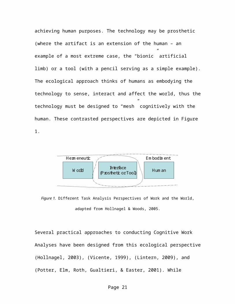
achieving human purposes. The technology may be prosthetic
(where the artifact is an extension of the human – an
example of a most extreme case, the “bionic” artificial
limb) or a tool (with a pencil serving as a simple example).
The ecological approach thinks of humans as embodying the
technology to sense, interact and affect the world, thus the
technology must be designed to “mesh” cognitively with the
human. These contrasted perspectives are depicted in Figure
1.
W orld Interface(Prosthetic or Tool) Hum an
Herm eneutic Em bodim ent
Figure 1. Different Task Analysis Perspectives of Work and the World,
adapted from Hollnagel & Woods, 2005.
Several practical approaches to conducting Cognitive Work
Analyses have been designed from this ecological perspective
(Hollnagel, 2003), (Vicente, 1999), (Lintern, 2009), and
(Potter, Elm, Roth, Gualtieri, & Easter, 2001). While
Page 21
Vicente considers cognitive task analysis (CTA) as a
subspecialty of cognitive work analysis (CWA), I would
consider a CTA as assembling data from the hermeneutic
approach and CWA as assembling data from the embodiment
approach, although Lintern acknowledges that there is no
general agreement on the difference within the CSE
community.
Vicente does point out, however, that the cognitivist
perspective tends to focus on the HMI, since it is here that
the connections between the biological sensors and actuators
and the rest of the world are located. As discussed
previously, this provides for “oversimplification” of the
CTA representation of the “rest of the man-machine” system.
However, I hypothesize that the success realized in applying
cognitivist CTA methods, in such approaches as Human
Centered Design (Vicente, 1999) is due in part to the
relatively closed and fixed nature of the systems for which
it was applied. This is not to say those systems weren’t
challenging, or even apparently complex, but rather the
Page 22
analysts could adopt a set of conventions and
simplifications that could be understood by the various
stakeholders within the timeframe of a tolerable task-
artifact cycle. Additionally, it may have been true that
most of the behaviors present in the rest of the man machine
system had a direct analog on the HMI, and the description
of the HMI from a cognitive perspective was sufficiently
complete to facilitate this understanding.
To support that second hypothesis, I would submit as
evidence the use of Visual Basic and Microsoft Foundation
Classes (MFC) software frameworks, a dominant de facto
standard in the 1990’s and early 2000’s. Code logic was tied
directly to the under the classes that formed the “window”,
which was the basis of the graphical user interface (GUI).
Thus in a very real way, all software developed with those
frameworks proceeded from its GUI. In fact, Martin’s mid
1990’s software engineering method called “Rapid Application
Development” suggested the development of iterative
Page 23
prototype GUIs as the best way to actually discover the user
requirements and domain data structure.
In the abstract, however, there is much more to the complete
man-machine system than the humans and their HMI. Moreover,
especially in socio-technical systems which have emergent
social networks and dominant cultural impacts, there is more
to the human portion than individual thinking. Hollnagel
and Woods call this “distributed cognition”. There is also
more to the Machine aspect than an HMI and the underlying
data. Automation has advanced from the information support
and repetitive motion of its early days (Sheridan &
Parasuramen, 2006) to complex decision and action automation
with “fully automatic control”. We now have robots making
decisions and executing actions, and only then informing
their human monitors (Hollnagel & Woods, 2005). Thus it can
be said that there is a lot to the “man machine” system that
exists in the machine space, for which man has no direct
mechanism to interact.
Page 24
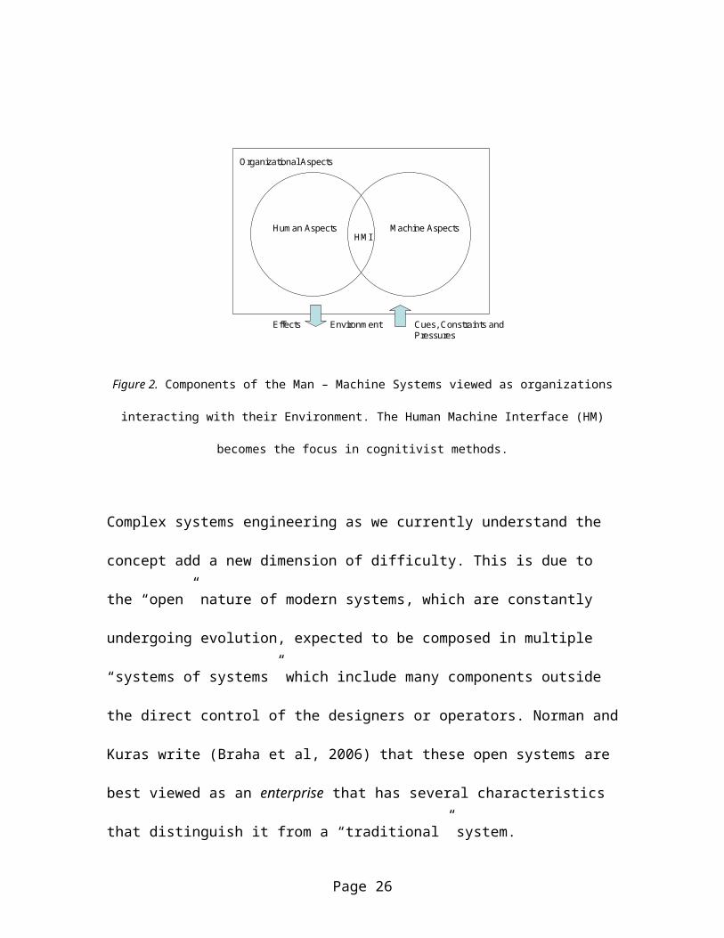
In addition to the human shared cognition and the pure
automation of the machine, there are organizational aspects
which exist above the humans and technology to describe the
system. These organizational aspects include shared culture
and sense of purpose, as well as “institutional knowledge”
that shapes the perceptions of the humans, and defines the
ways in which technology may be applied. Moreover, the
definition of the organization, with formal and informal
networks of command, will determine the rules for
information flow throughout the organization. It is through
these organizational aspects that the cues and responses to
and from the man-machine systems environment are filtered.
This is depicted in Figure 2.
Page 25
HM I
Environm entEffects Cues, Constraints and Pressures
Hum an Aspects M achine Aspects
Organizational Aspects
Figure 2. Components of the Man – Machine Systems viewed as organizations
interacting with their Environment. The Human Machine Interface (HM)
becomes the focus in cognitivist methods.
Complex systems engineering as we currently understand the
concept add a new dimension of difficulty. This is due to
the “open” nature of modern systems, which are constantly
undergoing evolution, expected to be composed in multiple
“systems of systems” which include many components outside
the direct control of the designers or operators. Norman and
Kuras write (Braha et al, 2006) that these open systems are
best viewed as an enterprise that has several characteristics
that distinguish it from a “traditional” system.
Page 26
Each instance of the enterprise is unique
They are continuously evolving with new requirements
They have ambiguous boundaries
New possibilities are constantly evaluated, tried and
implemented
They are self organizing
They include both internally cooperative and
competitive elements
Sheard (Sheard & Mostashari, 2009) adds that the words
“enterprise” and “architecture” have now become semantically
overloaded and inadequate to discuss the implications of
developing complex systems. In addition to restatements of
the above, she adds that complex systems have a fractal
nature, where the structure of low level components cannot
easily be discovered by analysis of macro level structures,
although they do exhibit repeating patterns on ever
increasing scales.
Page 27
In order to address the complexity in CSE, Hollnagel and
Woods introduce the term “Joint Cognitive Systems” JCS. This
concept lies at the heart of all ecological approaches. It
identifies an ecology of humans, both augmented with prostheses
and utilizing tools as artifacts, which have been selected to
provide cognitive affordances, or opportunities to accomplish
work. The result is a socio-technical network of shared and
augmented cognition; defining, evaluating, planning and
executing work towards achieving purpose, the goals of which
are established both internally and externally. The intent
of the JCS concept is to enable focus on the totality of the
work environment as an emergent system, rather than a focus
solely on the human-technology dyad, which in practice tends
to shift engineering emphasis to human-machine interface
(HMI) design.
Complex systems theory as applied to socio-technical systems
has benefited from another concept in sociology, that of the
boundary object. Boundary objects are a concept that is used
to bridge the gap between otherwise isolated ecologies of
Page 28
human society. In the sociological context, this may mean
trade or treaties that govern the relations between
countries or tribes. Fong (Fong et al, 2007) introduces
boundary objects as means to communicate between different
engineering communities of practice (and indeed the very
purpose of this CESMP is to facilitate exchange of that type
of boundary objects). Key concepts from boundary objects are
layering (where one community may add additional comments to
aid in interpretation, equivalent to the view concept
articulated here) and contextualization/de-contextualization (where
senders and receivers encode and decode according to their
own formalisms, and walk away with the correct intended
meaning –analogous in the CSEMP to descriptive logic).
The theoretical basis for the ecological methods lies in the
activity theory of Vygotsky and others, which was developed
as part of Soviet Psychology (Woods & Hollnagel, 2006). They
mandated an anthropocentric frame of reference as being the
only one that matters, i.e. that technology had no meaning
until it was actually used by someone, and that person’s
Page 29
goals assumed primacy. The affordance becomes a property of
elements in the environment, which are acted upon by the
human users and their tools/prosthesis. This theory was
presented in the 1970’s by Gibson as an alternate to the
Shannon-Weaver paradigm (Albrechtsen, H., Andersen, H.,
Bødker, S., & Pejtersen, A., 2001). In the CSEMP, I chose to
represent concepts such as “artifact” and “affordance” as
complex elements, such that users of the model could capture
both the sterile technology as something to build as well as the
emergent technology as rendered meaningful to humans characteristics
of said technology. The affordance propagates as a reference
property back to the human actors after it has been
associated in the UML.
In addition to the Human Factors “ecological” and
“cognitivist” approaches discussed above, there is a third
set of approaches that have been proposed to address the
human element of complex systems. These methods extend the
classical “systems” paradigm, treating “humans” as simply a
third allocation choice, along with hardware and software.
Page 30
Systems based methods were the idea behind the top down
functional analysis (TDFA) approach introduced in Gordon
(Gordon, et al, 2005). Hollnagel, however, warns of the
dangers in anthropomorphizing machines or treating humans
too mechanistically (Woods & Hollnagel, 2006) and my
experience is that it is tempting to fall into this trap if
one is not careful. However, I suggest that looking at the
“systems engineering” problem as one of building an
organization (one that includes hardware and software
“systems” as well as people and culture) that these pitfalls
can be avoided, and that with proper book-keeping of
analysis data, aids in crafting this system cum organization
from either of the two HF perspectives. It was my intention
that the CSEMP provide a means to “keep the books.” Critical
to this is graphical based modeling languages like UML.
Unified Modeling Language, Architecture and Profiles
The Unified Modeling Language or UML was developed in the
late 1990’s by three of the leading names in software
Page 31
development methods: James Rumbaugh, Grady Booch and Ivar
Jacobson (Jacobson, Booch & Rumbaugh, 2000). The three were
hired by IBM to develop a graphical language to help in the
analysis and design of object oriented software, which had
been recently introduced as a means to manage the increasing
complexity of software intensive systems. Since that time,
the UML has been adopted by an advocacy group and standards
body, the Object Management Group (OMG), and undergone
several revisions and extensions.
The purpose of the UML is, as the name implies, to model.
Models are depictions of real world systems that obey some
set of conventions or formalisms (Vicente, 1999). The UML
language, based as it was to support object oriented
computer software languages, preserves several features of
object orientation which are useful constructs for the CSE
purpose. The underlying structure of the UML language is
defined in the Meta Object Facility (MOF), currently in
version 2 (OMG, 2010). The “base class” (the atomic level
convention from which all other UML concepts are derived and
Page 32
extended) is the element. Characteristics of UML that enable
the goals of the CSEMP proposed in this paper include:
Generalization allows concepts to be specified in a
generic, high level sense and to add additional
information (data) or behaviors (functions) which
increase the level of specificity of objects that are
referenced. Some objects can be defined in a “virtual”
or purely abstract sense. In the physical models of UML
“classes” refer to abstract concepts of things and
“objects” refer to specific things or “instances” which
have added values to the defined characteristics of
their class. This paradigm can be extended to other UML
elements as well, such as use cases, which in the virtual
class sense can represent abstract functions of the
functional abstraction hierarchy.
Inheritance – Inheritance is the property whereby an
element that is a specialization (the corollary to
generalization) of another element possesses all of the
Page 33
data and behaviors that describe the general element,
along with new data and behaviors unique to the more
specialized element. However, the values of the data
and behaviors, even the inherited ones, are unique to
the new element.
Polymorphism says that behaviors may be context
dependent. Under different circumstances the behaviors
of an element may be processed differently.
Polymorphism allows for the description of “selections”
in classical CTA analyses, as well as environmental
impact of correspondence driven work domains, where the
environment imposes “dynamic considerations” on the
form of work (Vicente, 1999).
Data Hiding/Encapsulation maintains separation of
concerns in Object Orientation. The use of data hiding
is to encapsulate tightly coupled behaviors and data
within a class or component. Classes and components
then communicate through well defined interfaces, so they
Page 34
may control access to their internal data as the timing
and form of their behaviors. Encapsulation aids in
maintainability of software by reducing the complexity
of the code.
“Paste by reference” means that a particular model or
description can include an element which was introduced
and defined in another model, and rely on the same
instance in both models. In this way, changes to the
item in either model are reflected in the other,
particularly when those changes render the logic of the
other model unusable.
Other important relationships in the UML include:
Aggregation and Composition are represented by solid
and voided lozenges respectively. Aggregation states
that an element is crafted by aggregating two or more
elements that can exist as independent elements (such
as a car aggregated from wheels and doors).
Compositions are elements include subordinate elements
Page 35
that have no independent existence (a paper may
decompose to an introduction and body, but those are
meaningless unless you have the paper first).
Association and Trace are untyped relationships in UML,
meaning that there aren’t detailed rules on legality of
associations. Conventions are adopted by the model
developer as to which relationships are allowed or
required. Associations may be supplied cardinality
constraints that define the multiplicity, optionality
and directionality of a relationship.
Stereotypes are a mechanism included in UML to allow a
common attribute that can extend the vocabulary of UML
for a specific purpose (for example , UML “class” could
be extended to define <library> and <executable> so
that a code file type can quickly be identified, and
sorted, in the model.
Page 36
Packages and Namespaces are used to assemble elements
and diagrams of a similar purpose, subsystem, analysis
space or other highly contextual purpose into a
convenient group for reference. Package names are used
to define a “fully qualified name”. The package defines
a “namespace”, which specifies the context to be used
in interpreting the definition of another work used
within a package. This is especially useful when the
same word (e.g. “interface”, which could be a software
control providing a graphical user interface, a
physical cable, a virtual data-less software class used
to pass messages between memory locations, or a phone
call, depending on the audience and usage).
Translation between one namespace and another is known
as a “binding”.
The UML and tools aiding in UML model development are aided
by the use of descriptive and validation logics. These
logics are possible because the language is “strongly
typed”, i.e. it has precise rules for explaining what
Page 37
concepts are and how they relate. Descriptive Logics
determine what a node is and how it is to be graphically
represented. Validation logics are used to validate that any
model defined in the UML is complete, and possesses only
“legal” relationships (Nantajeewarawat & Wuwonge, 2005). DL
will specify whether a node type can be connected to another
node type, and the nature of the allowable relationships
between the nodes. If an edge does not terminate, or
properly terminate, or if nodes are incomplete, or do not
reference all of the appropriate traces (a function cannot
exist unless a purpose for it existed first), then the model
is not “well formed”. Many UML software tools use validation
logics to discover these “illegal” model elements and will
provide alerts to the user that additional work must be
completed.
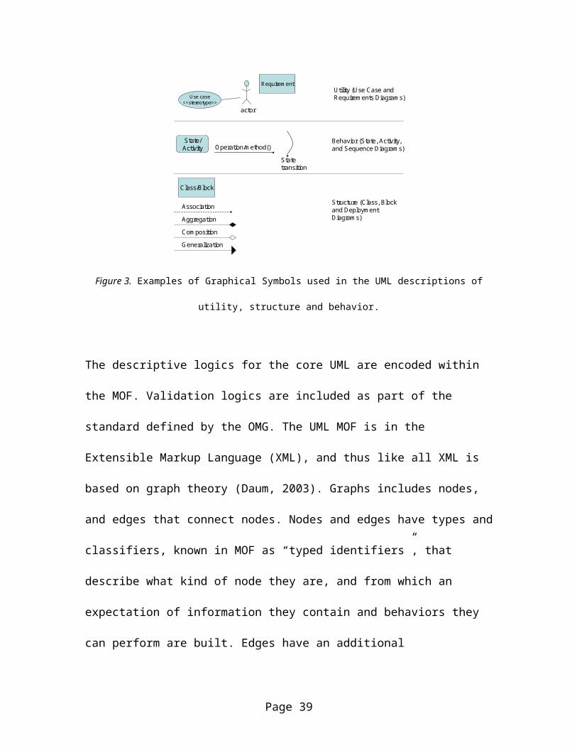
Some representative symbol conventions in the UML are
depicted in Figure 3.
Page 38
Use case<<stereotype>>
Class/Block
State/Activity
Association
actor
Operation/m ethod()Statetransition
AggregationCom positionGeneralization
Utility (Use Case and Requirem ents Diagram s)
Requirem ent
Behavior (State, Activity, and Sequence Diagram s)
Structure (Class, Block and Deploym ent Diagram s)
Figure 3. Examples of Graphical Symbols used in the UML descriptions of
utility, structure and behavior.
The descriptive logics for the core UML are encoded within
the MOF. Validation logics are included as part of the
standard defined by the OMG. The UML MOF is in the
Extensible Markup Language (XML), and thus like all XML is
based on graph theory (Daum, 2003). Graphs includes nodes,
and edges that connect nodes. Nodes and edges have types and
classifiers, known in MOF as “typed identifiers”, that
describe what kind of node they are, and from which an
expectation of information they contain and behaviors they
can perform are built. Edges have an additional
Page 39
characteristic of trajectory, meaning that they must have an
origin and a target node.
Thus, the MOF defines the “meta-language” of the semantics
and syntax for UML. A deep understanding of MOF is not
essential for describing the CSE profile, although this
understanding was necessary to conduct the analysis. UML
itself still maintains its software centric focus, in that
it is optimized for describing software terms, however, it
has been extended to enable descriptions of more general
things, which can be explained in terms of utility,
structure and behavior. The mechanism for extending UML is
the profile, and MOF describes the rules for defining profiles
(just as English grammar provides rules for adding “er” to
turn verbs like “to read” into nouns like “reader”).
An important profile for work related to complex systems
engineering is the Systems Modeling Language - SySML
(Friedenthal, Moore & Reiter, 2008). SYSML utilizes the
behavioral descriptions of sequence, state and use case
Page 40
diagrams in the UML, extends the activity diagrams to create
the equivalent of extended functional flow block diagrams
(another important behavioral description). It includes two
new diagrams, Block diagrams used to describe physical
structure and interfaces, and the requirements diagram,
which is built up from the base element class. SYSML is
useful because it is able to describe full systems,
including hardware, software and operator/users, putting
each on an equal footing. This is an important
characteristic for supporting the ecological perspective of
the cognitive work analysis. The use of graphical
requirements models is powerful, as the lowest level of
Rasmussen’s functional abstraction hierarchy is the physical
implementation, which can now be mapped to requirements,
constraints and specifications, the basic language of the
hardware and software engineers required to actualize the
systems, whether designed by CSE or conventional engineers.
The CSEMP provides an architectural framework for defining
Joint Cognitive System (JCS) architectures. Architecture
Page 41
frameworks are defined by the IEEE 1471 standard for
development of architectures. It defines a particular
stakeholder, who is interested in a subset of information and
normally displays or understands that information as
presented in a certain way, called a view. The stakeholder’s
interest in the view defines the context for interpreting
that subset of model data. Models can be multidimensional
and visually complex, much too complex to be easily read in
their entirety. The concept of a view allows for displaying
only a slice of the model, selecting a subset of available
elements, and depicting it in a particular context. This
context is defined as a viewpoint. This viewpoint exists as
a relationship between the stakeholder and the view (i.e. an
affordance) and is instantiated by the descriptive logic that
define the conventions and content of the model. These
concepts are depicted in Figure 4.
Page 42
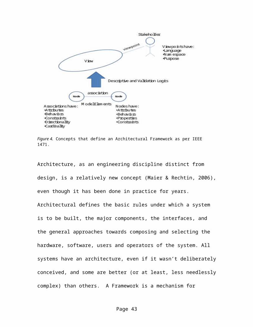
Figure 4. Concepts that define an Architectural Framework as per IEEE 1471.
Architecture, as an engineering discipline distinct from
design, is a relatively new concept (Maier & Rechtin, 2006),
even though it has been done in practice for years.
Architectural defines the basic rules under which a system
is to be built, the major components, the interfaces, and
the general approaches towards composing and selecting the
hardware, software, users and operators of the system. All
systems have an architecture, even if it wasn’t deliberately
conceived, and some are better (or at least, less needlessly
complex) than others. A Framework is a mechanism for
Page 43
describing or solving a number of different problem sets
that share some basic characteristics (e.g. XNA is a
software framework for writing video games).
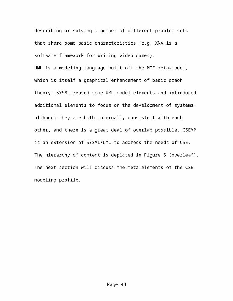
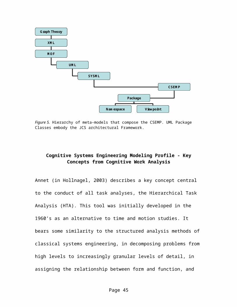
UML is a modeling language built off the MOF meta-model,
which is itself a graphical enhancement of basic graoh
theory. SYSML reused some UML model elements and introduced
additional elements to focus on the development of systems,
although they are both internally consistent with each
other, and there is a great deal of overlap possible. CSEMP
is an extension of SYSML/UML to address the needs of CSE.
The hierarchy of content is depicted in Figure 5 (overleaf).
The next section will discuss the meta-elements of the CSE
modeling profile.
Page 44
Graph Theory
XM L
M OF
UM L
SYSM L
CSEM P
Package
Nam espace View point
Graph Theory
XM L
M OF
UM L
SYSM L
CSEM P
Package
Nam espace View point
Figure 5. Hierarchy of meta-models that compose the CSEMP. UML Package Classes embody the JCS architectural Framework.
Cognitive Systems Engineering Modeling Profile - KeyConcepts from Cognitive Work Analysis
Annet (in Hollnagel, 2003) describes a key concept central
to the conduct of all task analyses, the Hierarchical Task
Analysis (HTA). This tool was initially developed in the
1960’s as an alternative to time and motion studies. It
bears some similarity to the structured analysis methods of
classical systems engineering, in decomposing problems from
high levels to increasingly granular levels of detail, in
assigning the relationship between form and function, and
Page 45
describing functions in terms of inputs, outputs and
processes.
The HTA has undergone a steady evolution, through the work
domain analysis (Vicente, 1999), to the Functional
Abstraction Hierarchy (Hollnagel, 2003) and many variations
in between. Each of them presents an “abstraction-
decomposition” space (Vicente, 1999) that moves from lesser
to greater levels of specificity and concreteness, starting
with abstract wishes and ending with actual systems in
operation providing value. These models start with a
definition of goals (as attributes of the users, and not
having meaning without them) and decomposes to the means to
accomplish these goals. As the models become increasingly
fine grained, they move from statements of purpose, to
described behaviors to design specifications. Hollnagel &
Woods describe this as answering “why, what and how” with
each successive level providing the components which address
one of the previous levels means as its own goal as depicted
in Figure 6.
Page 46
W hy
W hat
How
W hy
W hat
How
Goals -M eans
Next Level of Granularity
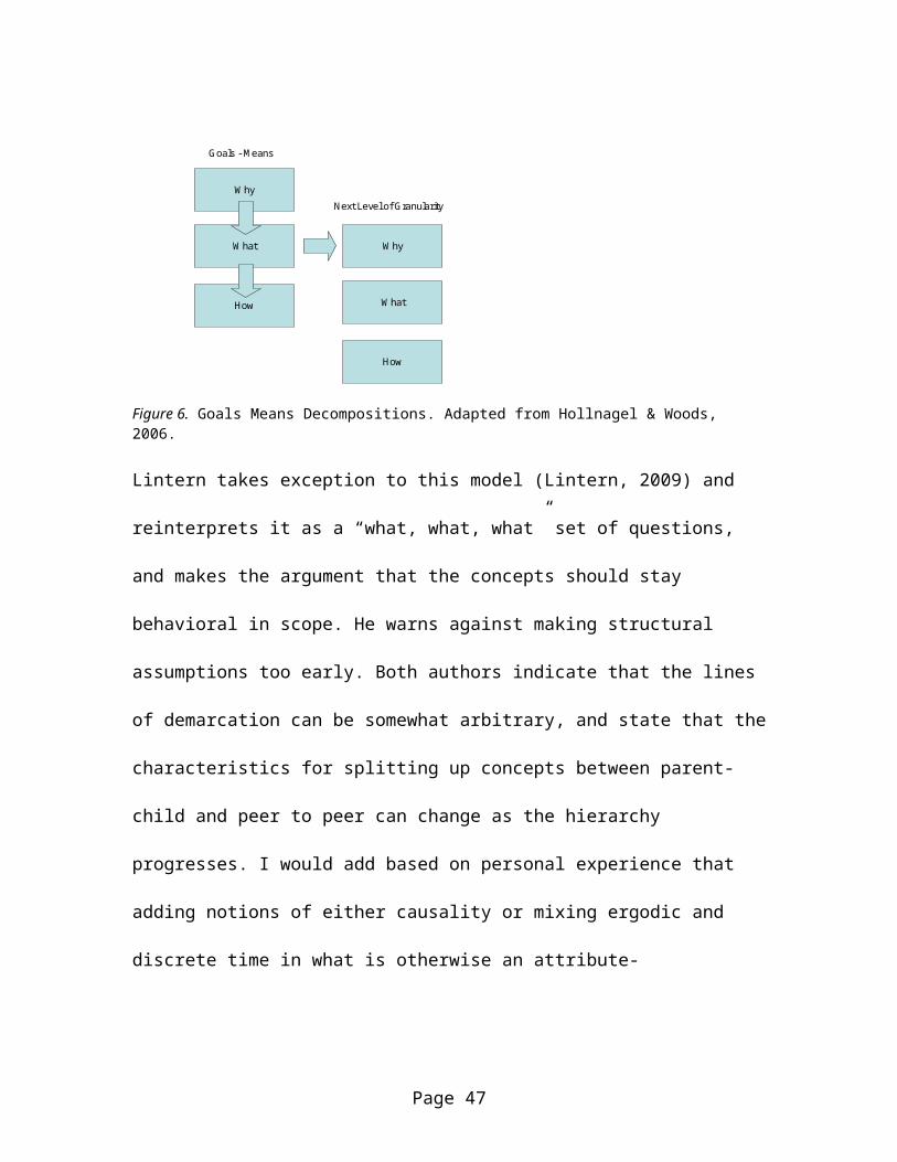
Figure 6. Goals Means Decompositions. Adapted from Hollnagel & Woods, 2006.
Lintern takes exception to this model (Lintern, 2009) and
reinterprets it as a “what, what, what” set of questions,
and makes the argument that the concepts should stay
behavioral in scope. He warns against making structural
assumptions too early. Both authors indicate that the lines
of demarcation can be somewhat arbitrary, and state that the
characteristics for splitting up concepts between parent-
child and peer to peer can change as the hierarchy
progresses. I would add based on personal experience that
adding notions of either causality or mixing ergodic and
discrete time in what is otherwise an attribute-
Page 47
characteristic sorting can complicate future recall, reuse
or interoperability.
CSEMP addresses this by starting with UML use cases, defined
as “functionality of a system in terms of how its users use
that system to achieve their goals” (Friedenthal et al,
2008). Note that “system” here may refer to hardware and
software alone, or it may include humans. However, the UML
notion of “Actor” does represent a human, or other
hardware/software system that is considered external to the
original “system”. To address the apparent discrepancy,
CSEMP utilizes the SYSML “block” concept to establish a set
of analytic hierarchies, decomposing the entire
organization, and identifying sets of hardware and software
as “subjects” within the overall organization, and with
which the actors interact. This is depicted in Figure 7.
Page 48
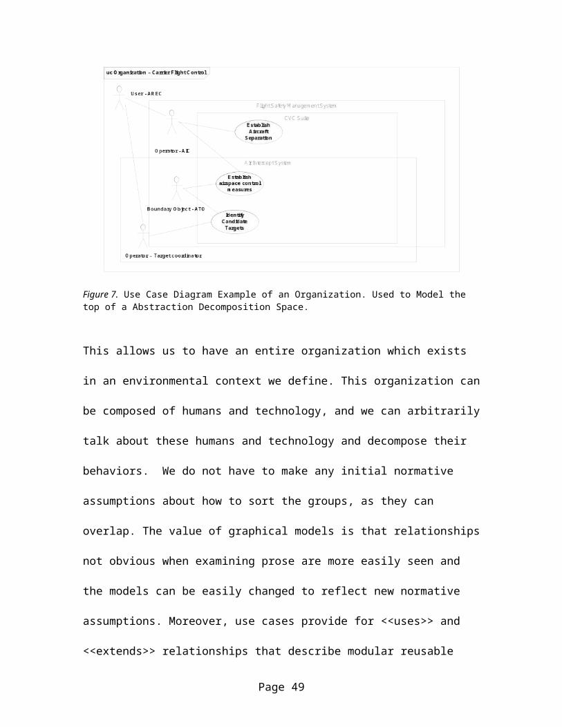
Figure 7. Use Case Diagram Example of an Organization. Used to Model the top of a Abstraction Decomposition Space.
This allows us to have an entire organization which exists
in an environmental context we define. This organization can
be composed of humans and technology, and we can arbitrarily
talk about these humans and technology and decompose their
behaviors. We do not have to make any initial normative
assumptions about how to sort the groups, as they can
overlap. The value of graphical models is that relationships
not obvious when examining prose are more easily seen and
the models can be easily changed to reflect new normative
assumptions. Moreover, use cases provide for <<uses>> and
<<extends>> relationships that describe modular reusable
Page 49
functionality. These relationships can abstract out certain
functions, providing clues to selecting reusable patterns
and frameworks of solutions to address them.
By using the contrast between the aggregation and
decomposition relationships in UML, we can indicate multiple
paths in and out of a particular use case or subject. This
provides a way to track “which things” and “which humans”
are parts of a particular goal as we have stated it. It also
allows us to form the model as a functional abstraction
network, as described by Elm, et al (Hollnagel, 2003), and
it allows us to keep all of the high level definitions
behavioral to address the criticisms of Lintern; the
subject/analytic block mechanism allows us to keep track of
whether we discuss the behavior of a single air intercept
controller, or the behavior of the entire flight control
organization. Aggregations imply “shared” concepts, in this
case, the equipment installed in the CVC suite is shared
between those concerned with flight safety and those
concerned with intercepting targets. Compositions imply
Page 50
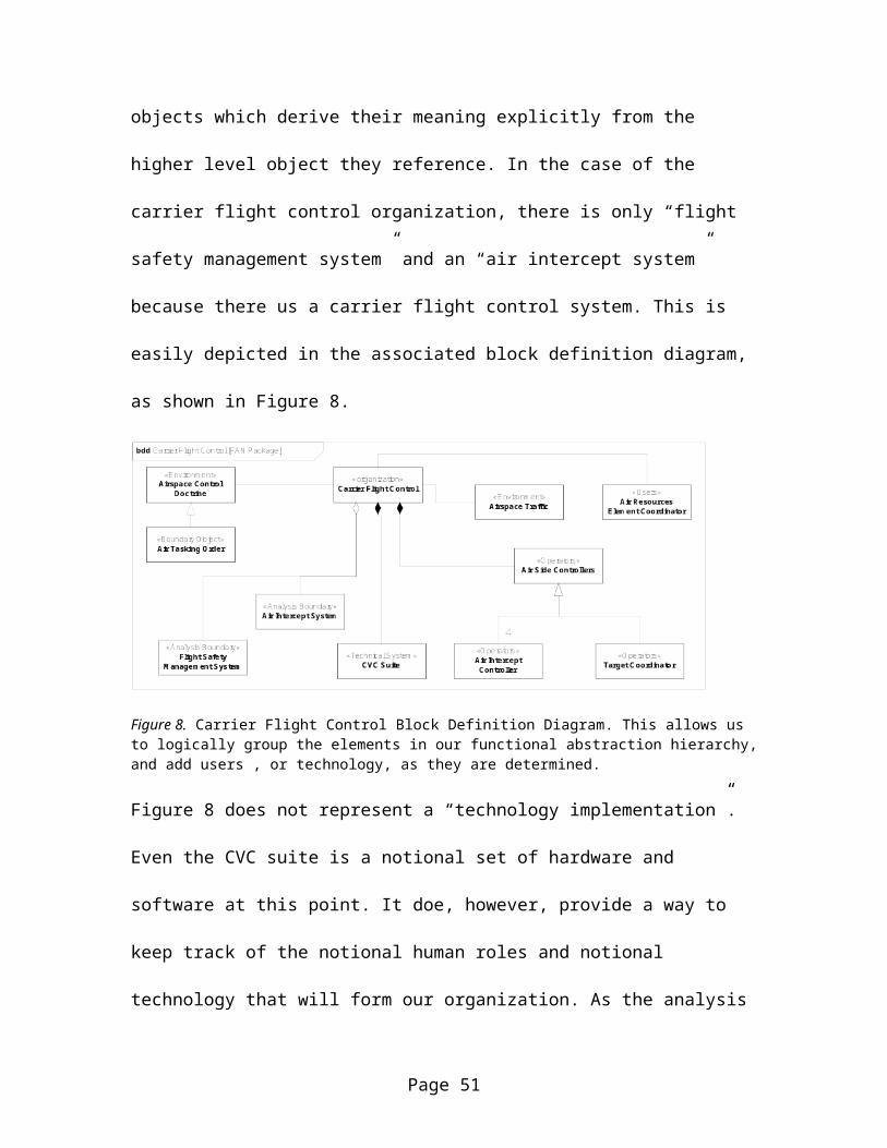
objects which derive their meaning explicitly from the
higher level object they reference. In the case of the
carrier flight control organization, there is only “flight
safety management system” and an “air intercept system”
because there us a carrier flight control system. This is
easily depicted in the associated block definition diagram,
as shown in Figure 8.
Figure 8. Carrier Flight Control Block Definition Diagram. This allows us to logically group the elements in our functional abstraction hierarchy,and add users , or technology, as they are determined.
Figure 8 does not represent a “technology implementation”.
Even the CVC suite is a notional set of hardware and
software at this point. It doe, however, provide a way to
keep track of the notional human roles and notional
technology that will form our organization. As the analysis
Page 51
proceeds, this diagram will change and increase in detail,
however links between the “subjects” in the use case diagram
and the blocks stereotyped here as <<analysis boundaries>>
and <<technical systems>> are maintained by the use of a
“specifies” association in UML, and changes to the block
elements can be seen to impact on the original goals
hierarchy.
Figure 8 is an example SYSML block definition diagram (bdd),
which uses the block element of SYSML as augmented by
stereotypes to support the CSEMP. These stereotypes and
conventions are to maintain consistency with concepts as
used in CSE. The Stereotypes applied to the blocks are
listed (overleaf) in Table 1. In addition to the
stereotypes, blocks may link to other objects. These
linkages are through the refines, allocates, and specifies
relationships in UML. As increasingly lower level elements
(all the way to hardware parts and software classes) are
defined, these linkages provide cues to the engineering/CSE
team when changes may impact the ability to achieve these
Page 52
high level goals as they were originally defined. This
diagram also demonstrates some generalization relationships
to detail actors and boundary objects from their more
abstract “base classes”.
Page 53
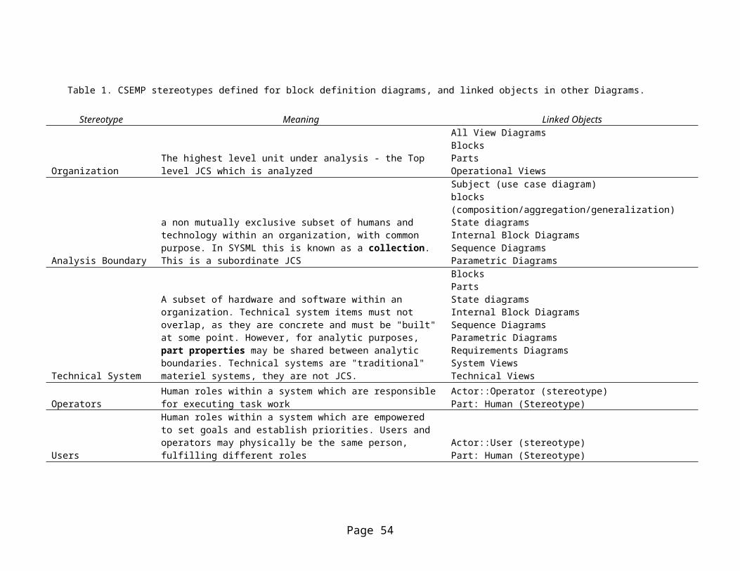
Table 1. CSEMP stereotypes defined for block definition diagrams, and linked objects in other Diagrams.
Stereotype Meaning Linked Objects
OrganizationThe highest level unit under analysis - the Top level JCS which is analyzed
All View DiagramsBlocksPartsOperational Views
Analysis Boundary
a non mutually exclusive subset of humans and technology within an organization, with common purpose. In SYSML this is known as a collection. This is a subordinate JCS
Subject (use case diagram)blocks (composition/aggregation/generalization)State diagramsInternal Block DiagramsSequence DiagramsParametric Diagrams
Technical System
A subset of hardware and software within an organization. Technical system items must not overlap, as they are concrete and must be "built"at some point. However, for analytic purposes, part properties may be shared between analytic boundaries. Technical systems are "traditional" materiel systems, they are not JCS.
BlocksPartsState diagramsInternal Block DiagramsSequence DiagramsParametric DiagramsRequirements DiagramsSystem ViewsTechnical Views
OperatorsHuman roles within a system which are responsiblefor executing task work
Actor::Operator (stereotype)Part: Human (Stereotype)
Users
Human roles within a system which are empowered to set goals and establish priorities. Users and operators may physically be the same person, fulfilling different roles
Actor::User (stereotype)Part: Human (Stereotype)
Page 54
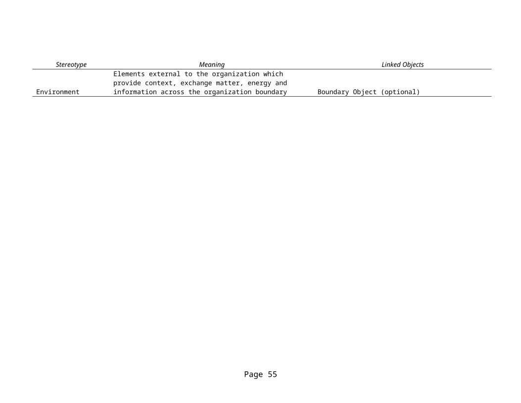
Stereotype Meaning Linked Objects
Environment
Elements external to the organization which provide context, exchange matter, energy and information across the organization boundary Boundary Object (optional)
Page 55
To implement CSE principles, several conventions are
adopted. First, use case diagrams conventionally focus on
the “subject” as technology, with operators external to it
in context. This is at odds with the JCS notion of humans
within the system, or indeed humans extended by technology
as the system. CSEMP addresses this disparity by
establishing two different stereotypes with associated use
case subject boundaries, one to include the humans as part
of an organization, and one to address just the technology.
By SYSML convention, the technology is the “system under
consideration” (Friedenthal, et al, 2008). This allows us to
define when a collection of objects is a JCS, when it is
just technology, and how it overlaps within our overall
understanding.
Another key difference between CSEMP and SYSML convention is
in the assignment of actors. Actors are defined to mean
anything that acts outside of the boundary of the “system
under consideration”. Actors are usually humans, but may
mean external systems. In this case, we are defining actors
Page 56
both within our organization acting on our technological
system, as well as external actors that represent technology
as boundary objects, in this case, an air tasking order
(ATO) which is part of the flight control doctrine, and is
received electronically through the Contingency Theater Air
Planning System (CTAPS). This actor is stereotyped as a
“boundary object” and it is associated with a block, which
may in turn, be associated with the XML document that
details the content of the ATO, along with additional
“bindings” specific to the CFC organization we are now
building as a JCS.
In the UML base specification, the line between the actor
and a use case, or between actors is an association.
Association is a loosely typed specification in the
UML/SYSML standard. In the CSEMP case, it is stereotyped
as <<affordance>>, and the validation logic is extended to
show full traceability to a technology and task to implement
the goal – i.e. this use case must be allocated to technology
parts and human tasks, defined in an activity diagram. If all
Page 57
these conditions are met, it satisfies the definition of
affordance. If they are not, then it is either incomplete,
or unaddressed, or superfluous. Additionally, the technology
parts ultimately defined or selected become “artifacts”,
once they have been linked to activities which decomposed
from use case goals. Artifact become a reference property of the
block, and becomes a useful way to evaluate the top level
structure as it has been refined to ensure those top level
goals and elements have been addressed throughout the model.
Before embarking on the development of the goals means
decomposition, the program manager and chief engineer would
have developed a package diagram. This diagram helps sort
out the various perspectives of the stakeholders, and
establishes namespaces. If, for example, the CSE and the
hardware engineers persisted in different definitions for
“system”, as belied their respective biases, it is possible
to use “fully qualified names” by establishing element
“bindings” within one package and namespace and mapping them
to a different set of bindings in another. On the MMA work
Page 58
(Gordon et al, 2005), we continually had trouble with
“function”, which our prime insisted meant “things an
airplane does”, while we wanted to call functions “what the
squadron did” in order to address the entire organization
within our TDFA framework. We resolved this by using the
Status of Readiness and Training System (SORTS) messages
used by the Navy to report “functional readiness”,
effectively as a boundary object (it was understood by all
stakeholders, even though we were unfamiliar with the
concept at the time), and decomposed our function
description from it, to include mappings to “what an
airplane did”. Examples of the relationship between
packages, namespaces, views and viewpoints are illustrated
in Figure 9.
Page 59
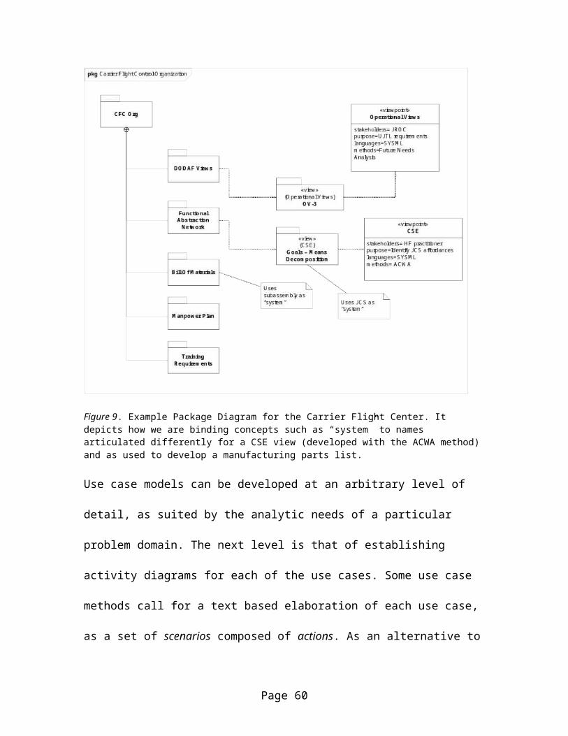
Figure 9. Example Package Diagram for the Carrier Flight Center. It depicts how we are binding concepts such as “system” to names articulated differently for a CSE view (developed with the ACWA method) and as used to develop a manufacturing parts list.
Use case models can be developed at an arbitrary level of
detail, as suited by the analytic needs of a particular
problem domain. The next level is that of establishing
activity diagrams for each of the use cases. Some use case
methods call for a text based elaboration of each use case,
as a set of scenarios composed of actions. As an alternative to
Page 60
the text based method, an activity diagram can be developed
showing the series of actions performed during the use case,
with forks and decision points to show the various branches
that form different scenarios. UML Constraints can be used
to establish starting and ending criteria or state
definitions for the use case. In addition to the basic
activity modeling of UML, the extended activity diagram of
SYSML, which facilitates developed of enhanced functional
flow block diagrams (EFFBD), can describe additional aspects
of the behaviors. EFFBD are semantically equivalent to
Petri-Nets, often used in Human factors research (Jonnasen
et al, 1999).
Vicente (Vicente, 1999) defines tasks as the need to do
something in support of goals. They are performed via
operations, which have inputs and outputs, and actions, which
specify transfer functions for the input to output. This is
semantically equivalent to the “function” of EFFBD, which
describes inputs and outputs, a process and a set of
controls on that process, along with the items passing
Page 61
between processes. The SYSML activity diagram doesn’t
distinguish, although a “traditional” structured analysis
approach would focus on the functions of the technology, and
then define tasks as the human implications of that
functionality (Buede, 2000). In this case, actions in a human
swimlane refer to “functions of the people” (and in a
particular work setting, which is simply the reverse of
looking at the affordance relationship) as opposed to
“functions of the technology”.
In the SYSML case, the activity diagram can include
“swimlanes” which are distributions of functions between
“blocks” which would accomplish them. Swimlanes are the
horizontal lines are linked to blocks and established by the
<<functional allocation>> stereotype between the block and
the action it performs. As we saw previously, these blocks
can be both human and technology. In this way a basic
“functional allocation” is defined. The CSEMP does not
presume to introduce a method to accomplish the allocation,
but merely provide a mechanism to capture it. To provide
Page 62
EFFBD equivalency, SYSML activities, in addition to forks,
unions and decisions, add the following additional features.
Token and Item flow between functions to show how data
moves through the system. Items can be matter, energy
or information. This is equivalent to the processes in
the goals-means decomposition of Elm’s applied
cognitive work analysis (Hollnagel, 2003). Tokens are
control cues, which may be electric signals in hardware
and software, but also represent cues when evaluated by
humans.
<<Continuous>> and <<Discrete>> flows, which
discriminate between item flows which can be parsed,
and those which occur over time. Additional constraints
or parametric models can be added to the flow
specification to describe format and range of these
flows
Ports which can be associated with flow specifications
that describe directionality, modality and content for
flows in and out of objects.
Page 63
Signals used to describe item flows that originate or
terminate outside of the boundary of the subject of the
activity diagram.
An example of an activity diagram from the Carrier Flight
Control case, specifically Establish Flight Management
Procedures Use case, is depicted in Figure 10.
Page 64
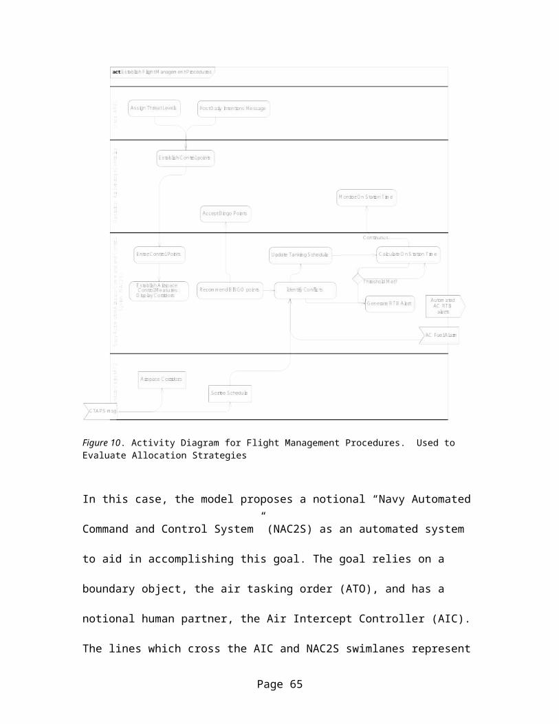
Figure 10. Activity Diagram for Flight Management Procedures. Used to Evaluate Allocation Strategies
In this case, the model proposes a notional “Navy Automated
Command and Control System” (NAC2S) as an automated system
to aid in accomplishing this goal. The goal relies on a
boundary object, the air tasking order (ATO), and has a
notional human partner, the Air Intercept Controller (AIC).
The lines which cross the AIC and NAC2S swimlanes represent
Page 65
items which are passed on the HMI. The descriptive logic can
find these “crossing” item flows and stereotype them as
“HMI”, to be collected later and evaluated within a user
interface design. Additionally, the type, frequency and
modality of the item flow on the HMI can be captured in the
model, as those decisions are made.
Control token flows exchanged on human swimlanes can be
stereotyped as <<environmental cues>> and indicate a
stimulus/response situation that can be evaluated via
classical human factors methods. Additionally, decision
points within the human swimlane can be stereotyped as
<<selections>>, and forks and unions as <<fusions>>, used to
evaluate the cognitive implications as those parts of the
model are continuously refined. Selections passing control
tokens and further amplified with UML guard conditions may
be stereotyped as <<control strategies>> as defined by
Vicente.
Page 66
However, the first cut of the model will likely not have
this level of detail. The initial activity diagram result is
likely to be only a collection of identified actions to
describe the means of the goals established as use cases.
However, as other elements of the overall design are
selected, evaluated or constrained, the model will take
shape, and the functional allocation, cognitive
implications, and interface requirements definition will be
completed. Note that these final elements can be collected
in any order, it is only as the relationships are joined
that they are considered complete, and thus a functionalist,
cognitivist or ecological approach may ultimately yield the
same content, populating the model in vastly different
order. A summary of CSEMP stereotypes used to augment
activity diagrams is listed in Table 2.
Table 2. Summary of CSEMP Stereotypes and Logics as used In Activity Diagrams. Concepts are considered “validated” when the tuples are complete.
Page 67
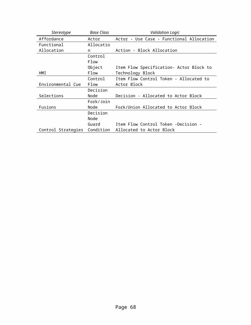
Stereotype Base Class Validation LogicAffordance Actor Actor - Use Case - Functional AllocationFunctional Allocation
Allocation Action - Block Allocation
HMI
Control FlowObject Flow
Item Flow Specification- Actor Block to Technology Block
Environmental CueControl Flow
Item Flow Control Token - Allocated to Actor Block
SelectionsDecision Node Decision - Allocated to Actor Block
FusionsFork/JoinNode Fork/Union Allocated to Actor Block
Control Strategies
Decision Node Guard Condition
Item Flow Control Token -Decision - Allocated to Actor Block
Page 68
SYSML was developed with an eye towards building “executable
architectures”, i.e. enabling engineers to connect their
graphical models directly to simulations such that
verification and trade space analysis could be performed
directly from the model (Friedenthal et al, 2008). A
critical portion of the SYSML specification to support this
goal is the parametric diagram. Parametric diagrams depict
sets of related constraints that define sets of equations.
The equations are provided ports which can be typed and
connected to attribute values of other blocks. Parametric
diagrams have a wide variety of usages, and they can be
associated with blocks, activities or other elements.
Assignment of Technical Performance Measure (TPM) budgets
for system characteristics such as weight or heat balance,
as well as defining systems of equations related to
performance measures such as “braking distance” for a car as
a function of mass, friction, etc. are two common uses from
traditional systems engineering.
Page 69
In the CSE case, parametric constraints provide a useful
place to capture cognitive data relating to human actors
blocks in the system. Activities can be categorized by the
visual, cognitive, auditory and psychomotor loading
contribution as per the human information processor models
of Card, Moran, Newell and Wickens. Each actor required to
execute an action then “connects” to these loading factors,
and a total loading factor for the human can be calculated.
For cases where the analysts are concerned about cognitive
overload, a discrete event simulation can be developed from
the parametric equations and analyzed as a “run time” model.
Similarly, the implications for transferring data from a
technical system into usable information, or the synthesis,
analysis and evaluation of information received from other
human actors can be modeled as “transfer functions” which
capture human factors data required to perform that
transfer: social context constraints, interface modalities,
display phase spaces, supporting knowledge, skills and
abilities, etc. An example is provided in Figure 11.
Page 70
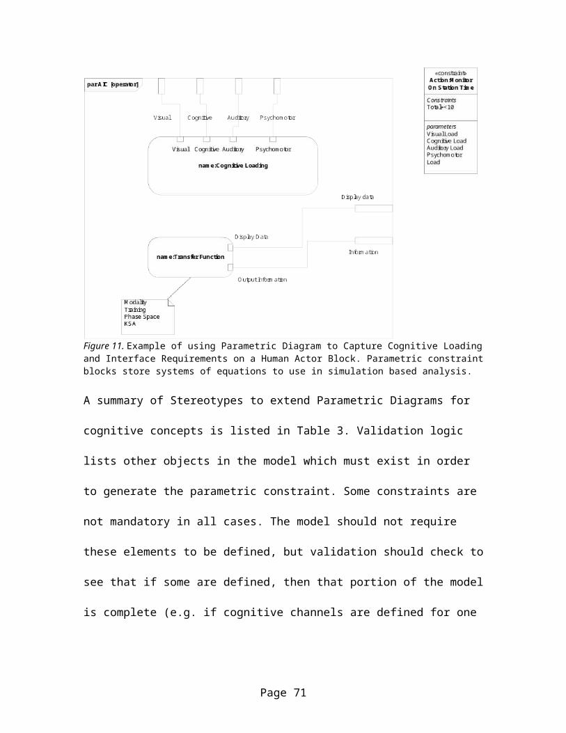
Figure 11. Example of using Parametric Diagram to Capture Cognitive Loadingand Interface Requirements on a Human Actor Block. Parametric constraintblocks store systems of equations to use in simulation based analysis.
A summary of Stereotypes to extend Parametric Diagrams for
cognitive concepts is listed in Table 3. Validation logic
lists other objects in the model which must exist in order
to generate the parametric constraint. Some constraints are
not mandatory in all cases. The model should not require
these elements to be defined, but validation should check to
see that if some are defined, then that portion of the model
is complete (e.g. if cognitive channels are defined for one
Page 71
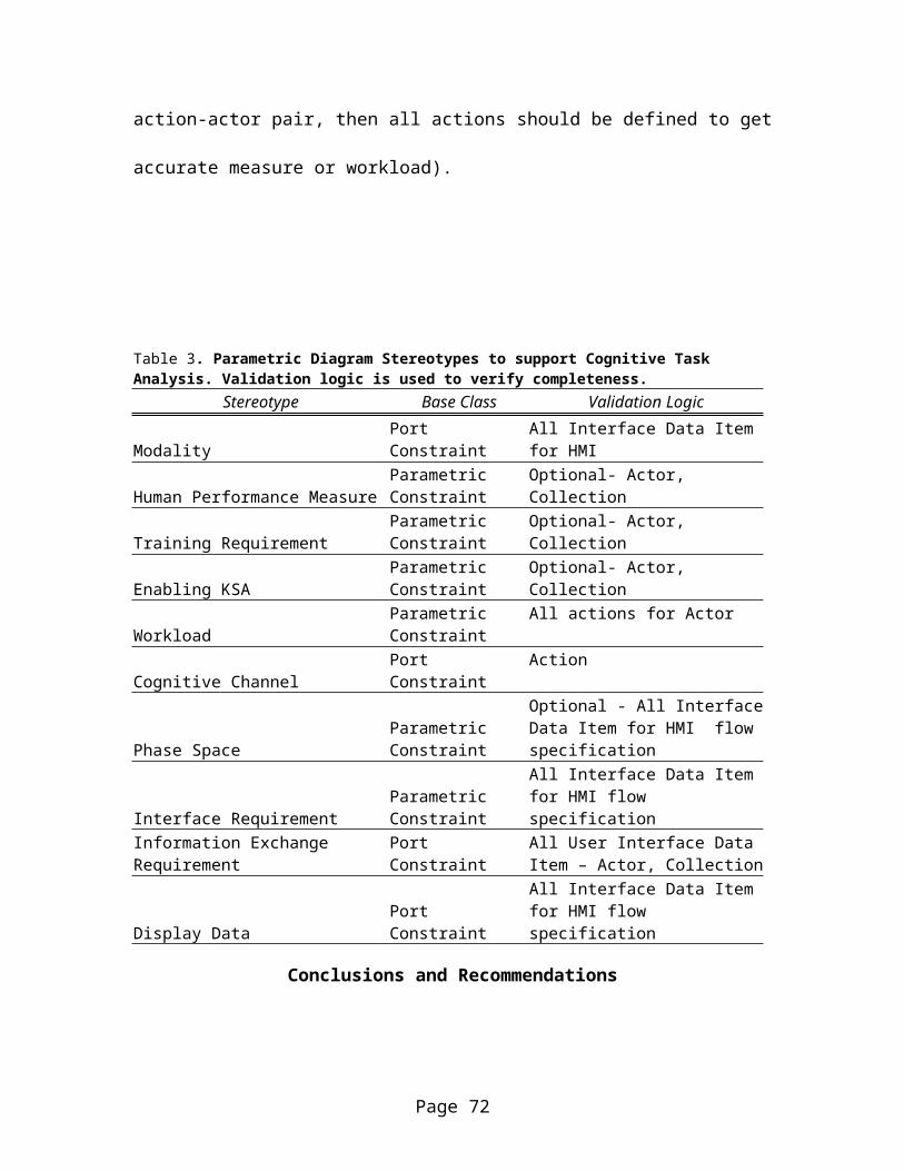
action-actor pair, then all actions should be defined to get
accurate measure or workload).
Table 3. Parametric Diagram Stereotypes to support Cognitive Task Analysis. Validation logic is used to verify completeness.
Stereotype Base Class Validation Logic
ModalityPort Constraint
All Interface Data Item for HMI
Human Performance MeasureParametric Constraint
Optional- Actor, Collection
Training RequirementParametric Constraint
Optional- Actor, Collection
Enabling KSAParametric Constraint
Optional- Actor, Collection
WorkloadParametric Constraint
All actions for Actor
Cognitive ChannelPort Constraint
Action
Phase SpaceParametric Constraint
Optional - All InterfaceData Item for HMI flow specification
Interface RequirementParametric Constraint
All Interface Data Item for HMI flow specification
Information Exchange Requirement
Port Constraint
All User Interface Data Item – Actor, Collection
Display DataPort Constraint
All Interface Data Item for HMI flow specification
Conclusions and Recommendations
Page 72
During the analysis of CSE concepts from the literature, I
found a high degree of textual equivalence to UML and SYSML
concepts, where the stated definitions for two terms were
nearly identical. This provided a good starting point for
developing the CSEMP profile. Additionally, the UML is now
over a decade old, and advances in informatics have
progressed to the point where the language is mature, and
many cases are already addressed. It has become semantically
precise, and many concepts could easily be related by
comparing contextual definitions and examples. The
“namespace” concept is especially powerful, providing a
means to “bind” dictionary meanings between communities of
practice. I found in the literature review good support from
my anecdotal observations that the key challenges in
establishing a working dictionary were those of perspective,
fortunately, the discussions in Vicente, Hollnagel, Lintern
and Woods and Hollnagel were sufficiently complete to
provide a means to construct a meta-perspective that could
accommodate the characteristics of the subordinate
perspectives. I believe that that this study should provide
Page 73
a useful starting point for what I hope is continued
discussion.
References
Albrechtsen, H., Andersen, H., Bødker, S. , & Pejtersen, A.
(2001). Affordances in Activity Theory and Cognitive Systems Engineering.
Riso National Laboratory: Roskilde Denmark. Retrieved 14 Apr
2011, from http://130.226.56.153/rispubl/SYS/syspdf/ris-r-
1287.pdf
Ann M . Bisantz & Catherine M . Burns (eds). (2009).
Applications of Cognitive Work Analysis: CRC Press. Retrieved 19 April
2011, from
http://www.crcnetbase.com.ezproxy.libproxy.db.erau.edu/doi/p
dfplus/10.1201/9781420063059.ch13
Braha, D. , Minai, A. & Bar-Yam, Y. (eds).(2006). Complex
Engineered Systems- Science Meets Technology. MA: Springer Publishing
Page 74
Buede, D. (2000). The Engineering Design of Systems: Models and
Methods. Canada: Wiley and Sons
Daum, B. (2003). Modeling Business Objects with XML Schema. Germany:
Morgan Kaufman.
Douglass, B. (2994). Real Time UML (3rd ed). MA: Addison Wesley
Press
Fong, A./Valerdi, R./Srinivasam, J. (2007). Using a Boundary
Object Framework to Analyze Inter-Organizational Collaboration. Paper
presented at the 17th INCOSE Symposium San Diego,
California. Retrieved 11 Feb 2011, from
http://web.mit.edu/rvalerdi/www/INCOSE_final_Boundary
%20Objects%20(Fong%20Valerdi%20Srinivasan%202007).pdf
Friedenthal, S. Moore, A. & Steiner, R. 2008. A Practical Guide
to SYSML. Amsterdam: Morgan Kaufman Press.
Page 75
Gordon, J., Burns, J, Ricci, K., & Ramsden, C., (2005).
Identifying Training Requirements Early in Systems Acquisition: HSI and the
Navy’s Multi-mission Maritime Aircraft: Proceedings of the 2005 Human
Systems Integration Symposium
Gordon, J. , Burns, J, Sheehan, J., Ricci, K. & Pharmer, J.
(2005).A Framework for Enabling HSI within Systems Engineering: HSI and the
Navy’s Multi-mission Maritime Aircraft: Proceedings of the 2005 Human
Systems Integration Symposium
Gordon, J., Burns, J. & Giebenrath, J. (2005). A Common Data
Representation for HSI: The Universal Performance Data Model: Proceedings
of the 2005 Human Systems Integration Symposium
Hollnagel, E. & Woods, D. (2005). Joint Cognitive Systems,
Foundations of Cognitive Systems Engineering. FL: CRC Press.
Hollnagel, E. (ed). (2003). Handbook of Cognitive Task Design. NJ:
L Erlbaum.
Page 76
Jacobson, Booch& Rumbaugh, (2000). The Unified Software
Development Process. Boston:Addison Wesley
Lintern, G. (2009). The Foundations and Pragmatics of Cognitive Work
Analysis: A Systematic Approach to Developing Large Scale Information Systems.
V 1.0 Retrieved 12 Mar 2011, from
http://www.cognitivesystemsdesign.net/Downloads/Title
%20Contents%20Preface.pdf
Madni, A. (2010_. Integrating Humans with Software and
Systems: Technical Challenges and a Research Agenda. Systems
Engineering, 13(3). 232-245.Wiley Press.
Maier, M. & Rechtin, E. , 2002. The Art of Systems Architecting. Fl:
CRC Press
Militello, L. Dominguez, C. Lintern, G. & Klein, G. 2010.
The Role of Cognitive Systems Engineering in the Systems
Engineering Design Process. Systems Engineering 13(3). 261-273.
Wiley Press.
Page 77
Nantajeewarawat, E. , & Wuwongse, (2005). Knowledge-Based
Inconsistency Detection in UML Models. In Chang (ed).
Handbook of software Engineering and Knowledge Engineering Vol3 (pp177-
202). PA: World Scientific
Parasuraman, R. &Wickens, C. (2008) Humans: Still Vital
After All These Years of Automation. Human Factors 50(3): 511-
520
Potter, S.S. , Elm, W. Roth, E. , Gualtieri, J. , & Easter,
J. 2001. Bridging the Gap Between Cognitive Analysis and Effective Decision
Aiding. Retrieved 12 Mar 2011, from
http://mentalmodels.mitre.org/cog_eng/reference_documents/Br
idging%20the%20Gap--revised2.pdf
Putz, M. & Verspoor, M. 2000. Explorations in Linguistic Relativity.
Google Books,. Retrieved 3 Apr 2011, from
http://books.google.com/books?
id=_QLF02w1qXMC&printsec=frontcover&dq=Explorations+in+lingu
Page 78
istic+relativity&source=bl&ots=DmVaa7rYcL&sig=EcH87lpPF3bOJY
MDQr4bYOhYvzs&hl=en&ei=ZkmmTbHYCoaatwfI6bCFAQ&sa=X&oi=book_r
esult&ct=result&resnum=3&ved=0CC8Q6AEwAg#v=onepage&q&f=false
Radford, A. (1988). Transformational Grammar. England:
Cambridge University Press.
Sanders, M. & McCormick, E. (1993). Human Factors in Engineering
and Design, 7th ed. NY: McGraw Hill
Sheard, S. & Mostashari, A. (2009) Principles of Complex
Systems for Systems Engineering. Systems Engineering 12(4). 295-
311. Wiley Press
Sheridan, T., & Parasuramen, R. (2006). Human –Automation
Interaction. Retrieved 10 Oct 2010, from
http://archlab.gmu.edu/people/rparasur/Documents/Sheridan-
ParasuramanRevHFES06.pdf
Page 79
Suh, N. (2001). Axiomatic Design Advances and Applications. NY:
Oxford University Press.
Vicente, K. 1999. Cognitive Work Analysis: Toward Safe, Productive and
Healthy Computer Based Work. NJ: L Erlbaum.
Woods, Patterson & Roth. (1998). Can we ever escape from data
overload? A cognitive systems diagnosis. Cognitive Systems Engineering
Laboratory Institute for Ergonomics: The Ohio State
University. Retrieved 19 April 2011, from
http://10.1.1.37:6079
Page 80