
Feature Engineering of Software Systems - Index of
175
-
Upload
khangminh22 -
Category
Documents
-
view
3 -
download
0
Transcript of Feature Engineering of Software Systems - Index of

Feature Engineering of Software Systems
by
Carlton Reid Turner
B.A., University of North Carolina, 1986
M.S., University of Colorado, 1995
A thesis submitted to the
Faculty of the Graduate School of the
University of Colorado in partial ful�llment
of the requirements for the degree of
Doctor of Philosophy
Department of Computer Science
1999

This thesis entitled:Feature Engineering of Software Systems
written by Carlton Reid Turnerhas been approved for the Department of Computer Science
Alexander L. Wolf
Ken Anderson
Date
The �nal copy of this thesis has been examined by the signatories, and we �nd thatboth the content and the form meet acceptable presentation standards of scholarly
work in the above mentioned discipline.

iii
Turner, Carlton Reid (Ph.D., Computer Science)
Feature Engineering of Software Systems
Thesis directed by Prof. Alexander L. Wolf
Software users and developers have di�erent perspectives. Users are focused on the
problem domain, where a system's features are the primary concern. Developers are
focused on the solution domain, where a system's life-cycle artifacts are key. This
di�erence leads to di�culties producing successful software systems. At present, there
is little understanding of how to narrow the gulf between the two perspectives.
This dissertation argues for establishing an organizing viewpoint, which we term fea-
ture engineering, to incorporate features into software engineering as �rst class objects.
Features, acting as a bridge between the problem and solution domains, can begin to
narrow the gulf.
This dissertation explores three aspects of features in software engineering. First, it
establishes a framework for understanding software features. In this framework, we
de�ne the concept of feature as separate from feature implementation, its realization
in the developed system. The framework also includes a model of features in software
engineering. This model identi�es relationships between a system's features and the
major development artifacts. The �nal part of the framework is an evaluation of the
potential use of feature information in the various software development activities.
The second and third aspects considered are the roles for features and feature rela-
tionships in con�guration management and testing. In this dissertation, we argue that
con�guration management is pivotal for taking advantage of the various relationships
that features structure. The ability of commercial con�guration management systems

iv
to use information about features is evaluated, and our experiences using a prototype
feature-based con�guration management system are reported. Feature testing is identi-
�ed as a useful extension to traditional testing. Feature tests are used to con�rm that a
feature implementation faithfully produces the desired behavior. Feature tests are also
used to uncover feature relationships and interactions in the solution domain.

v
Acknowledgements
I hereby thank my advisor, Alexander Wolf, for his advice, support and guidance.
Without his e�orts, this dissertation simply would not be. I am grateful for his leading
role fostering my academic, professional, and personal growth.
Dennis Heimbigner and Alfonso Fuggetta provided insights and direction in dealing with
the thorny issues uncovered during this research.
A great many thanks go to the SERL students, my editorial sta�, and my colleagues
at U S WEST Advanced Technologies. My friends at SERL sat through numerous
presentations and were never shy with their opinions, helping shape the ideas supporting
this work.

Contents
Chapter
1 Introduction 1
1.1 Problems Addressed . . . . . . . . . . . . . . . . . . . . . . . . . . . . . 1
1.2 Approaches . . . . . . . . . . . . . . . . . . . . . . . . . . . . . . . . . . 2
1.3 Solutions . . . . . . . . . . . . . . . . . . . . . . . . . . . . . . . . . . . 3
1.4 Scope of this Dissertation . . . . . . . . . . . . . . . . . . . . . . . . . . 4
1.5 Validating the Results . . . . . . . . . . . . . . . . . . . . . . . . . . . . 5
1.6 Research Contributions . . . . . . . . . . . . . . . . . . . . . . . . . . . 6
1.7 Road Map . . . . . . . . . . . . . . . . . . . . . . . . . . . . . . . . . . . 8
2 Background and Related Work 10
2.1 Background and Perspective . . . . . . . . . . . . . . . . . . . . . . . . . 10
2.2 Related Work . . . . . . . . . . . . . . . . . . . . . . . . . . . . . . . . . 14

vii
2.2.1 Domain Analysis and Modeling . . . . . . . . . . . . . . . . . . . 14
2.2.2 Requirements Engineering . . . . . . . . . . . . . . . . . . . . . . 15
2.2.3 Feature Interaction Problem . . . . . . . . . . . . . . . . . . . . . 17
2.2.4 Software Reuse . . . . . . . . . . . . . . . . . . . . . . . . . . . . 19
2.2.5 Software Generation . . . . . . . . . . . . . . . . . . . . . . . . . 19
2.2.6 Product Development . . . . . . . . . . . . . . . . . . . . . . . . 20
2.2.7 Software Architecture . . . . . . . . . . . . . . . . . . . . . . . . 21
2.2.8 Con�guration Management . . . . . . . . . . . . . . . . . . . . . 22
2.2.9 Reverse Engineering . . . . . . . . . . . . . . . . . . . . . . . . . 22
2.2.10 Function Point Analysis . . . . . . . . . . . . . . . . . . . . . . . 23
2.2.11 Summary of Related Work . . . . . . . . . . . . . . . . . . . . . 24
3 A Framework for Feature Engineering 26
3.1 De�ning Feature . . . . . . . . . . . . . . . . . . . . . . . . . . . . . . . 26
3.2 Conceptual Model . . . . . . . . . . . . . . . . . . . . . . . . . . . . . . 29
3.2.1 Features and Software Life-cycle Artifacts . . . . . . . . . . . . . 29
3.2.2 Relationships Among Features . . . . . . . . . . . . . . . . . . . 32
3.2.3 The Instance Level . . . . . . . . . . . . . . . . . . . . . . . . . . 33

viii
3.2.4 The System Core . . . . . . . . . . . . . . . . . . . . . . . . . . . 35
3.3 Features in Software Engineering . . . . . . . . . . . . . . . . . . . . . . 37
3.3.1 Features and Problem-Domain Activities . . . . . . . . . . . . . 37
3.3.2 Features and Solution-Domain Activities . . . . . . . . . . . . . . 41
3.4 Terminology . . . . . . . . . . . . . . . . . . . . . . . . . . . . . . . . . . 49
3.5 Summary . . . . . . . . . . . . . . . . . . . . . . . . . . . . . . . . . . . 50
4 Features and Con�guration Management 51
4.1 Requirements for Feature-Based Con�guration Management . . . . . . . 53
4.1.1 Traditional Con�guration Management . . . . . . . . . . . . . . 54
4.1.2 Feature-Based Con�guration Management . . . . . . . . . . . . . 57
4.2 Feature Support in Con�guration Management Systems . . . . . . . . . 61
4.2.1 Evaluation Framework . . . . . . . . . . . . . . . . . . . . . . . . 62
4.2.2 Evaluation of CM systems . . . . . . . . . . . . . . . . . . . . . . 66
4.2.3 Analysis of the Evaluation . . . . . . . . . . . . . . . . . . . . . . 75
4.3 Summary . . . . . . . . . . . . . . . . . . . . . . . . . . . . . . . . . . . 78
5 Feature-Based Con�guration Management Case Study 79

ix
5.1 A Feature-Based Con�guration Management System . . . . . . . . . . . 80
5.1.1 De�ning Features . . . . . . . . . . . . . . . . . . . . . . . . . . . 80
5.1.2 Feature Relationships . . . . . . . . . . . . . . . . . . . . . . . . 80
5.1.3 Checking Out Features . . . . . . . . . . . . . . . . . . . . . . . . 84
5.1.4 Con�guration Consistency . . . . . . . . . . . . . . . . . . . . . . 88
5.1.5 Building System Con�gurations . . . . . . . . . . . . . . . . . . . 91
5.1.6 Feature Reports . . . . . . . . . . . . . . . . . . . . . . . . . . . 92
5.2 PerlPhone - A Software Telephone . . . . . . . . . . . . . . . . . . . . . 94
5.3 The Vim Editor . . . . . . . . . . . . . . . . . . . . . . . . . . . . . . . . 99
5.4 Conclusion . . . . . . . . . . . . . . . . . . . . . . . . . . . . . . . . . . 103
6 Features and Testing 105
6.1 An Introduction to Testing . . . . . . . . . . . . . . . . . . . . . . . . . 105
6.2 Applying Features to Testing . . . . . . . . . . . . . . . . . . . . . . . . 107
6.2.1 Feature Tests . . . . . . . . . . . . . . . . . . . . . . . . . . . . . 108
6.2.2 Using Feature Tests to Discover Feature Relationships . . . . . . 110
6.3 A Case Study in Feature Testing . . . . . . . . . . . . . . . . . . . . . . 117
6.3.1 Application Analyzed . . . . . . . . . . . . . . . . . . . . . . . . 118

x
6.3.2 Coverage Tool . . . . . . . . . . . . . . . . . . . . . . . . . . . . 120
6.3.3 Analysis Method . . . . . . . . . . . . . . . . . . . . . . . . . . . 122
6.3.4 Results . . . . . . . . . . . . . . . . . . . . . . . . . . . . . . . . 129
6.4 Summary . . . . . . . . . . . . . . . . . . . . . . . . . . . . . . . . . . . 142
7 Conclusion 145
7.1 Summary . . . . . . . . . . . . . . . . . . . . . . . . . . . . . . . . . . . 146
7.2 Contributions of this Work . . . . . . . . . . . . . . . . . . . . . . . . . 147
7.3 Future Work . . . . . . . . . . . . . . . . . . . . . . . . . . . . . . . . . 149
Bibliography 151
Appendix
A Vim Functional Decomposition 158
B Concrete Features Identi�ed in Vim Tests 161

Figures
Figure
2.1 5ESSR Switch Architecture. . . . . . . . . . . . . . . . . . . . . . . . . . 13
3.1 Model of Features within Software Engineering . . . . . . . . . . . . . . 30
3.2 Instances of Entities and Relationships . . . . . . . . . . . . . . . . . . . 34
4.1 Software Engineering Activities . . . . . . . . . . . . . . . . . . . . . . . 52
5.1 IronMan Feature Menu . . . . . . . . . . . . . . . . . . . . . . . . . . . . 81
5.2 Example Feature De�nitions . . . . . . . . . . . . . . . . . . . . . . . . . 81
5.3 Relationships De�ned for PerlPhone . . . . . . . . . . . . . . . . . . . . 82
5.4 Feature Relationships Based on Function Mapping . . . . . . . . . . . . 85
5.5 Feature Relationships Based on Component Mapping . . . . . . . . . . . 88
5.6 Specifying a System Con�guration . . . . . . . . . . . . . . . . . . . . . 89

xii
5.7 Report of Features in the System . . . . . . . . . . . . . . . . . . . . . . 93
5.8 Report of Functions De�ned in a File . . . . . . . . . . . . . . . . . . . . 93
5.9 PerlPhone Components . . . . . . . . . . . . . . . . . . . . . . . . . . . 95
5.10 PerlPhone Feature Relationships . . . . . . . . . . . . . . . . . . . . . . 96
5.11 Vim Feature Relationships . . . . . . . . . . . . . . . . . . . . . . . . . . 102
6.1 Feature Testing Entities . . . . . . . . . . . . . . . . . . . . . . . . . . . 109
6.2 Pairs of Feature Tests . . . . . . . . . . . . . . . . . . . . . . . . . . . . 117
6.3 Histogram of Intersection Size for Pairs of Feature Tests . . . . . . . . . 141

Tables
Table
4.1 Activities in the evaluation framework . . . . . . . . . . . . . . . . . . . 62
4.2 Con�guration Management Systems Case Study Summary . . . . . . . . 67
6.1 Method for discovering feature implementation from feature tests . . . . 111
6.2 Features not included in the Analysis . . . . . . . . . . . . . . . . . . . . 119
6.3 Statistics about Vim 5.3 and Feature Tests . . . . . . . . . . . . . . . . 120
6.4 Features Tests . . . . . . . . . . . . . . . . . . . . . . . . . . . . . . . . . 125
6.5 Abstract Features Tested . . . . . . . . . . . . . . . . . . . . . . . . . . 125
6.6 Feature Test and Shadow Test Scripts for increment-number . . . . . . . 126
6.7 Tools Created to Support Test Analysis . . . . . . . . . . . . . . . . . . 128
6.8 Functions Implementing insert-complete-line . . . . . . . . . . . . . . . . 133
6.9 Functions Not Implementing insert-complete-line . . . . . . . . . . . . . 133

xiv
6.10 Evaluation of Identi�ed Feature Implementations . . . . . . . . . . . . . 134
6.11 Conservative Core De�nition . . . . . . . . . . . . . . . . . . . . . . . . 140
A.1 A Functional Decomposition for Vim 5.3 . . . . . . . . . . . . . . . . . . 158
A.2 A Functional Decomposition for Vim 5.3 (continued) . . . . . . . . . . . 159
A.3 A Functional Decomposition for Vim 5.3 (continued) . . . . . . . . . . . 160
B.1 Features exercised test cases distributed with Vim . . . . . . . . . . . . 161

Chapter 1
Introduction
This dissertation explores, within the context of software engineering, the concept of fea-
ture. Rather than consider a speci�c feature in a speci�c system, it seeks to understand
the essence of features.
1.1 Problems Addressed
A major source of di�culty in developing and delivering successful software is the gulf
that exists between the user and the developer perspectives on the system. The user
perspective is centered in the problem domain. Users interact with the system and
are directly concerned with its functionality. The developer perspective, on the other
hand, is centered in the solution domain. Developers are concerned with the creation
and maintenance of life-cycle artifacts, which do not necessarily have meaning in the
problem domain. Several researchers including Jackson and Tracz [39, 86] note that
developers are often quick to focus on the solution domain at the expense of a proper
analysis of the problem domain. This bias is understandable, since developers work
primarily with solution-domain artifacts. Yet the majority of their tasks, and, in fact,
the justi�cation for the system, are motivated by demands emanating from the problem
domain.

2
A second problem we see is an outgrowth of the popularity of life-cycle development
models [9, 70]. Without a doubt these models have contributed greatly to the under-
standing of software development. Progress in the di�erent phases of software develop-
ment has been facilitated by identifying each phase and articulating its area of concern.
This progress has come at a cost; each phase of software development is the subject
of specialization. As a result, the tools that support these di�erent phases incorporate
a deconstructed view of software development. They embody ideas and concepts that
do not take into account other phases of development. For example, architecture de-
scription languages [55, 72] describe components and connectors, but they share little
common ground with testing, con�guration management, or low-level design and imple-
mentation. Another example of this deconstructed view can be seen in the inadequate
use of requirements speci�cations in downstream life cycle activities [37].
1.2 Approaches
Attempts to solve the �rst problem are frequently focused on the problem domain phases
of the development life cycle. Various domain analysis and requirements engineering
techniques push the user perspective into the solution domain by either working toward
design [48, 45, 50] or through scenarios [43] and use cases [90, 11]. These solutions
help bridge the gulf by helping the developer understand how a system is to be used,
but they do not address such solution domain concerns as con�guration management,
testing, and documentation. Raccoon identi�es this problem as the Complexity Gap [73]
between the problem domain analysis and solution domain tools.
Much work has been done to rectify the second problem. One approach is to embed all
of the development phases into a single development environment. Integrated software
development environments [10, 16, 65] seek to provide glue for the di�erent development

3
activities by using common, enriched platforms supported by shared information [16].
Other approaches tackle the mismatch between the di�erent phases in pairs or triples,
for example between software architecture, con�guration management, and software
deployment [88] and between software architecture and testing [74]. Software process
research [32] seeks to model all the activities needed to transform user requirements
into software. These models are used to support precise data de�nitions, to de�ne task
prerequisites and results, and to guide the work e�ort required to realize the desired
software.
1.3 Solutions
The research supporting this dissertation targets both of these problems. With the gulf
in perspectives, we see that users think of systems in terms of the features provided
by the system. Intuitively, a feature is an identi�able bundle of system functionality
that helps characterize the system from the user perspective. Users request new func-
tionality or report defects in existing functionality in terms of features. Developers are
expected to translate such feature-oriented requests and reports into a plan for operat-
ing on life-cycle artifacts, which ultimately should have the desired e�ect on the features
exhibited by the system. The easier the translation process, the greater the likelihood
of a successful software system.
We seek to develop a solid foundation for understanding features in software systems
and, more importantly, de�ning a set of mechanisms for carrying a feature orientation
from the problem domain into the solution domain. We term this area of study feature
engineering. The major goal behind feature engineering is to promote features as
\�rst-class objects" within the software process. Such promotion holds the promise
of supporting features in a broad range of life-cycle activities, including requirements

4
analysis, design, testing, user documentation, con�guration management, and reverse
engineering. Such support for features addresses the two problems stated above, �rst, by
bringing the user perspective deeper into the solution domain, and second, by providing
a consistent organizing concept that system developers can use across all phases of
software development.
1.4 Scope of this Dissertation
Feature Engineering starts with de�ning the concept of feature in software and in soft-
ware development, which involves essentially all of the phases of the software life cycle.
Further, promoting features to \�rst-class objects" has broad rami�cations. We ad-
dress these rami�cations by de�ning a feature framework that identi�es a rich set of
relationships tying features to life-cycle artifacts.
While the feature framework identi�es potential roles for features in all of the life-
cycle activities, the scope of this work is restricted to an in-depth exploration into
con�guration management and testing. The reason is pragmatic; each activity is fertile
ground with signi�cant research opportunities.
Con�guration management plays a unique role in software development. It is responsi-
ble for archiving and retrieval of development artifacts developed in the other activities.
Since features participate in relationships that span all major artifact types, con�gura-
tion management systems can use these relationships to support development activities.
For example, con�guration management systems should eliminate the need for develop-
ers to remember which �les are required when working on a particular feature.
A number of signi�cant relationships are identi�ed in the feature framework. Perhaps
the most important of these is the mapping from feature to feature implementation.

5
One of the principal goals of the work in the testing area is to uncover this complex
mapping. With the information that we develop in testing, it is possible to determine
which tests should be run in response to a change to a system's features.
In domain analysis and requirements engineering, features have been already identi�ed
as important entities. [22] Other research [45] e�orts hold promise for determining a
feature model with the problem domain. As a result, developing requirements-analysis
techniques to distill a feature set during a requirements e�ort is outside the scope of
this dissertation. We assume that one product of a requirements e�ort includes an
identi�cation of the desired feature set for a system. In Section 7.3 we consider further
research opportunities related to this work.
1.5 Validating the Results
Di�erent approaches are used to validate the results presented in this dissertation. The
initial contribution of the research is the conceptual framework for understanding fea-
tures in software. This model of features was evaluated against two separate software
applications. The �rst was an extensive one-man-year evaluation of the UT100 switch-
ing software developed by Italtel. The evaluation was performed by researchers at
the Dipartimento di Elettronica e Informazione in Milan. Their work shows that the
model of features and feature relationships holds for the artifacts and documentation.
The evaluation also con�rmed that building di�erent system con�gurations based on
speci�cation of feature sets was a goal of the system developers. The lack of feature
relationship information as developed in feature engineering contributes to the inability
to create such targeted con�gurations. In addition to the evaluation of the UT100 de-
velopment, we evaluated the feature model against a medium-sized application, again
con�rming that the model accurately describes the features and relationships present

6
in this system.
In the con�guration management domain, we evaluated the ideas presented in this dis-
sertation by developing a prototype con�guration management system and populating
it with the artifacts and relationships of two separate applications. We were able to
demonstrate that con�guration management at the feature level removes the tedious
burden of assembling artifacts. The con�guration management system was able to en-
sure consistent product speci�cations by evaluating the relationships among features
described in Section 3.2.2.
In the testing realm, we were able to develop meaningful feature tests that were comple-
mentary to the existing test suite. Feature tests proved to be a natural test organization,
because the behavior of each feature was well documented and thus eminently testable.
By instrumenting the application and developing a shadow test for each feature test,
we were able to discover the mapping from feature to feature implementation with a
high degree of reliability. This mapping was then used to populate the feature-based
con�guration management system, supporting the ability to populate workspaces with
the artifacts involved in a feature implementation.
1.6 Research Contributions
This dissertation introduces a body of research, feature engineering, centered around
the features incorporated in a software system. In a broad sense, the contribution of the
research is to expand understanding of software and software development, particularly
the role of features in software engineering.
The initial contribution is the creation of a framework for understanding the nature of
features in software. A �rm understanding of features is the foundation of this research.

7
This understanding is predicated on a solid de�nition of the term feature that makes
clear the distinction between feature and feature implementation.
A second contribution is developing an understanding of the role of features within
the software development activities. At present, features have implicit relationships
within each of the major activities. The feature-engineering framework makes these
relationships explicit. Supporting features extends the traditional activities and bene�ts
system developers. Each of these areas shows potential for interesting research; in this
dissertation, two of them are singled out for further examination.
The third contribution is to extend con�guration management to incorporate features.
To be useful, features and feature relationships need to be identi�ed and managed
during the evolution of the underlying software. The �rst part of this contribution is
to identify how the features should be managed and to identify the bene�ts of doing so
within software development. The second part is developing an evaluation framework
for assessing the capabilities of con�guration management systems. The third part is
an evaluation of existing commercial con�guration management systems to determine
the support these systems provide for feature management.
The fourth contribution is developing and using a prototype feature-based con�gura-
tion management system. This system incorporates the feature as a native construct.
It permits maintaining information about the features in a system as well as feature
relationships. This information is used to create workspaces for feature development
and to relieve the developer from having to remember the appropriate artifact set. As
a result, the developer can check out all the source code �les required for a feature
implementation as well as all of the test cases that test the feature. It also enables
developers to specify desired feature sets for a product; when specifying a feature all its
dependent features get added to the speci�cation.

8
The �fth contribution of this dissertation is an exploration of the role of features in
software testing. Testing is a cornerstone of good software-engineering practice and at
present takes limited advantage of the concept of features. This research de�nes feature
testing and identi�es its utility. By combining program instrumentation with feature
testing, we are able to discover the mapping from feature to feature implementation.
Feature testing also provides insight into feature interactions that take place in the
solution domain.
1.7 Road Map
The rest of dissertation has the following organization:
� Chapter 2 provides perspective and background information. It also relates ourwork with feature engineering to a broad range of research initiatives in softwareengineering.
� Chapter 3 develops a conceptual basis for understanding features in softwaresystems. In this chapter we de�ne the concept of feature and present a model ofsoftware-development activities that illuminates the relationships between fea-tures and other life-cycle artifacts. We also examine the intersection of featureengineering with traditional life-cycle activities.
� Chapter 4 examines the impact of feature engineering on con�guration man-agement. We de�ne feature-based con�guration management and identify itsbene�ts. Then we evaluate several commercial con�guration management sys-tems for feature support.
� Chapter 5 describes the feature-based con�guration management prototypeIronMan. We report on our experiences using this system to manage the de-velopment of a software telephone and to provide access to the source code andtest artifacts for the editor Vim.
� Chapter 6 examines the role of feature in testing. It starts with the de�nitionof and motivation for feature testing. Next, we present a case study of theapplication of feature testing to Vim. We de�ne a method for discovering themapping from feature to feature implementation using feature tests.

9
� Chapter 7 concludes by summarizing the contributions from the dissertation,and describing unexplored issues and unresolved problems that form a numberof interesting opportunities for future research.

Chapter 2
Background and Related Work
2.1 Background and Perspective
What is software?
This dissertation begins with this simple question. As researchers in Computer Science,
we have an intuitive appreciation for software in its various forms. And yet, its sheer
complexity threatens to overwhelm our ability to understand it.
Consider for a moment the software that makes a line of text appear on the screen
and then on the piece of paper before you. Software embedded in an integrated circuit
in the keyboard detects key presses, performs de-bouncing, and generates signals that
encode the pressed keys. A software device driver waits for these signals and informs
the operating system of the key codes. Key codes are provided to the X server running
on the system and are translated into characters. These characters are then passed to a
terminal-emulation program and then to an editor. That merely gets the character on
the screen. Another piece of software mediates between the X server and the video card.
The �le containing the text has to be stored on disk, requiring software to control the
hard disk. This particular disk is physically attached to some other computer across the
network, so software is required to control the physical network devices on both sides as

11
well, and software is required to support �le sharing over the network. Printing this �le
requires a typesetting program and another program to create PostScriptR output for
the printer, and there is software that spools print requests and software that controls
the printer device.
As computer science researchers and practitioners, we are awash in a sea of software.
Every day we use more software with more complexity than we could possibly know,
and we design and develop it.
We know that software exists to deliver desired functionality to some well-de�ned set
of users. These users can be people, software, or hardware. Research in software
engineering has provided methods supporting the disciplined creation of software. Life-
cycle models have identi�ed the discrete activities that contribute to its development.
And yet, fundamental questions remain unanswered. How is the functionality of software
best organized? What is the relationship between the functionality exhibited to the users
and the underlying componentry required to realize it? In this dissertation, we seek to
illuminate these questions and to develop feature engineering as a framework that leads
us toward some of the answers.
Feature engineering begins with the premise that it is natural for users to conceptu-
alize software as providing a set of features. The ANSI/IEEE Standard for Software
Requirements Speci�cations [60] provides four alternative organizational schemes for
requirement speci�cations. All four are focused around the individual functionalities,
or features, that the software is to provide. Much of the research that involves features
in software involves speci�c features in speci�c software. This dissertation starts with
the concept of feature in the abstract and with the belief that a deeper understanding
of \feature" provides an enriched understanding of software.

12
This enriched understanding is embodied in answers to fundamental questions into the
nature of software and software development:
� What is a feature?
� How might system features relate to one another?
� What is the di�erence between a feature and its implementation?
� What is the di�erence between a feature and a use case?
� How can software development be driven by the features in a system?
� What is there to software besides feature implementations?
In this dissertation we answer these questions. With a deeper understanding of features
in general, our goal is to enable better development of real systems. Part of our initial
e�ort to understand features was undertaking an analysis of telecommunications switch-
ing software. This involved reading technical documentation [13], attending courses on
telephony and AIN (Advanced Intelligent Network) networks, interviewing switch ad-
ministrators, and programming features, such as call forwarding, multi-line hunt
groups, and ISDN, into switches in the U S WEST telecommunications network. Be-
cause of our familiarity with this domain and the rich examples of features it provides,
we use switching software as an example throughout this dissertation.
The software in a large, long-lived system such as a class 5 telephone switch is composed
of millions of lines of code, and it includes many di�erent types of components, such as
real-time controllers, databases, and user interfaces. The software must provide a vast
number of complex features to its users, ranging from terminal services, such as ISDN,
call forwarding, and call waiting, to network services, such as call routing, load
monitoring, and billing.1 The software that actually implements the switch must be
1

13
ModuleSwitching
ModuleSwitching
ModuleSwitching
ModuleSwitching
Abstract SwitchingMachine
Application Software
Database Management
Operating System
Bare MachineAdministrative
Module
ModuleCommunication
Figure 2.1: 5ESSR Switch Architecture.
made to exhibit these features, as well as to tolerate changes to the features in a cost-
e�ective manner. Bell Laboratories, for example, developed a design in the solution
domain for its 5ESSR switch software by following a layered architectural style [13].
The layers are depicted in Figure 2.1. The Abstract Switching Machine layer was
intended to provide the foundation upon which the features (called \applications")
themselves would be built. This was supposed to result in a clean separation of concerns,
permitting features to be more easily added and modi�ed. The introduction of AIN into
switch software, and thus into service provider networks, is speci�cally targeted toward
increasing the ability to introduce new features.
Features organize a system's functionality, and therefore there is a broad application
of the concept of feature to a number of areas of software engineering research and
practice. In the rest of this chapter, we identify research e�orts related to features as
de�ned in our feature-engineering framework.
Note that from the perspective of a switch builder, network services are not simply internal im-
plementation functions but are truly system features, since they must be made available to external
organizations, such as telecommunications providers.

14
2.2 Related Work
We conducted a search for the term \feature" in the Software Engineering literature
and found little research examining the concept. For the most part, the use of the term
was incidental to the research issue being addressed. A few research e�orts, such as
Feature Oriented Domain Analysis [45, 50] explicitly use the term \feature," but for the
most part, the term feature refers to a speci�c feature, not the concept of feature. Two
typical examples are in [44, 52].
To date, practically no work addresses supporting features throughout the software life
cycle. Feature engineering aims to counter this oversight and bridge the complexity
gap [73] between the problem domain and the solution domain tools and activities.
In this section, we discuss various research e�orts related to the study of features in
software systems. For the most part, these e�orts employ concepts that overlap with
the feature engineering framework in a speci�c domain, such as software architecture or
con�guration management.
2.2.1 Domain Analysis and Modeling
In domain analysis [71] and modeling, the activity of feature analysis has been de-
�ned to capture a customer's or an end user's understanding of the general capabilities
of systems in an application domain [45, 50]. Domain analysis frequently uses the
notion of features to distinguish basic, core functionality from variant, optional func-
tionality [33]. Although features are generally explicit elements of domain models, in
this work, their connection to other life-cycle artifacts is e�ectively non-existent. The
classi�cation scheme described in [71] is a taxonomy of \primitive functions" and rela-
tionships between them in the problem domain. We �nd signi�cant agreement between

15
domain analysis and the feature engineering framework within the problem domain,
but domain analysis does not address solution-domain concerns. One narrow view of
feature engineering might be as research into the application of domain models to other
software engineering activities. A broader view would characterize such domain models
as a starting point for de�ning a feature set known throughout the software life cycle.
Domain models frequently make a distinction between \core," \optional," and \variant"
functionality. A similar distinction is part of the framework for feature engineering, al-
though we view the distinction between optional and intrinsic to be orthogonal to feature
versus core. In other words, features are not de�ned by whether or not they are optional.
Domain models also begin to establish dependencies and other relationships among fea-
tures. Feature engineering also stresses these important relationships in the problem
domain, but it adds relationships that involve solution domain artifacts. Use cases are
an increasingly popular domain modeling techniques we address in Section 3.3.1.1.
2.2.2 Requirements Engineering
Features are problem space entities, and requirements engineering is the discipline that is
focused on providing a concise, consistent, unambiguous, and complete de�nition of the
problem domain. Years ago, researchers identi�ed features as a natural organization of
the problem space [21, 22]. Feature engineering reemphasizes the need for requirements
analysis e�orts to identify the desired feature set. While there are a few close synonyms
for feature, such as \goal" and \root requirement," surprisingly few approaches in the
research literature concentrate on this organization of a system's functionality.
Several approaches in requirements engineering approach the feature identi�cation re-
quired by feature engineering. Hsia and Gupta [38] have worked on automated tech-

16
niques for grouping requirement speci�cations. Their purpose is to support incremental
delivery of system functionality. The cohesive structures that Hsia and Gupta search to
identify are abstract data types (ADTs). It is clear that ADTs are a solution domain
concept with limited relevance in the problem domain. In addition, this work requires
using a development methodology based on ADTs. The goal of delivering ADT-based
prototypes transcends analysis and forces a particular design choice.
Karlsson and Ryan [46] seek to prioritize requirements using a cost-value evauation of
pairs of requirements. Since the number of requirements pairs grows as the square of the
number of requirements, their approach is suited to high-level requirements identi�ed
in the problem domain. Such requirements are equivalent to system features, support-
ing our claim that feature identi�cation is an integral component of the requirements
engineering e�ort.
Another approach that has potential for �nding features in system requirements is the
requirement clustering described by Palmer and Liang. They de�ne the problem state-
ment as an e�ort to \aggregate a set of N requirements into a set of M requirement
clusters where M � N ." [66] This is a precise statement of the goal of identifying
features. Their motivation, however, is to detect errors and inconsistencies within re-
quirements clusters, and therefore the organizing principle behind their clusters is the
similarity of the requirements within a cluster. Thus, they seek to �nd sets of redundant
requirements to analyze the elements of the set for consistency. For feature engineer-
ing purposes, we instead advocate that the organizing principle of a cluster should be
relevance of the constituent requirements to the desired properties of the feature. The
issues of redundancy and consistency are orthogonal, and so a clustering for that pur-
pose, while important, does not provide the structure required to take advantage of
features throughout software development.

17
Quality Function Deployment [25] is a requirements-and-design process aimed at iden-
tifying customer desires and related technical requirements that is popular among some
businesses and quality experts. While there is overlap with the conceptualization of fea-
tures represented by this work and the feature engineering framework, Quality Function
Deployment is more concerned with the organizational and managerial processes than
with the software development.
2.2.3 Feature Interaction Problem
A large number of researchers have studied the feature interaction problem, which is
concerned with how to identify, prevent, and resolve con icts among a set of features [2,
12, 35, 91, 54, 40, 47]. Keck and Kuehn [47] provide a broad survey of of research in this
area. Even in this literature, the de�nition of feature is not established much beyond
the notion of a service customers are willing to purchase.
The feature interaction literature is primarily focused on telecommunications networks;
for example, see [87, 53]. In this domain, features represent capabilities that are in-
crementally added to a telephony network. Telecommunications networks are massive,
complex, distributed systems that incorporate a variety of hardware and software ele-
ments. These systems have potentially hundreds of di�erent features. The presence of
multiple independent component providers makes the feature interaction problem even
more di�cult. According to Aho and Gri�eth, \Since networks involve multiple com-
ponents, interactions can occur if a service in one network component is either unaware
of or incompatible with features of a service in other components." [2]
Telecommunication networks provide many examples of features, such as call waiting,
call forwarding, and voice mail, but they o�er little exploration into the concept

18
of feature itself. The goal of feature interaction research is to eliminate, detect, and/or
resolve feature interactions. In practice, equipment vendors use a variety of ad hoc
mechanisms to deal with feature interaction. A primary method used by some switch
providers is to prioritize features so events can be applied to features in a known order.
Much of the feature interaction literature concentrates on eliminating feature interac-
tions through formal speci�cations, so this work has strong roots in requirements engi-
neering. In the telecommunications switch applications, features such as call waiting
and voice mail relate to the treatment of incoming calls to a busy subscriber line [6],
and thus exhibit overlapping requirements fragments. The identi�cation of such fea-
ture interactions at the requirements phase can help eliminate unanticipated interac-
tion problems during later phases of the software life cycle. The most common research
approach to this problem is the application of formal veri�cation techniques to system
speci�cations, with the goal of detecting all undesired feature interactions. The critical
part of this activity is system speci�cation|de�ning and applying a speci�cation tech-
nique that captures relevant system properties. Jackson and Zave propose DFC [40],
a virtual architecture for representing features that can be dynamically composed to
form a con�guration suitable to provide a speci�c service. From our point of view,
features can be represented and handled in several di�erent ways. In particular, fea-
tures in DFC are treated as �rst class and are expected to drive the subsequent model
checking activities and the design of the system architecture. This conforms to our idea
of a feature-centric development process; feature engineering, however, extends beyond
architecture into the full span of downstream development activities.

19
2.2.4 Software Reuse
Research in software reuse develops methods to increase development productivity. Re-
search e�orts in this domain seek to develop methods that help developers design, create,
classify, retrieve, and employ software components that support multiple use. Bigger-
sta� and Richter assess the e�ectiveness thus: \while reusability is a strategy of great
promise, it is one whose promise has been largely unful�lled" [8].
The feature engineering framework we develop in Section 3.2 overlaps research into soft-
ware reuse. Ku describes developing reusable core components for AIN networks that
facilitate the rapid introduction of features into telecommunication networks. [51] Pre-
sumably, the mapping from feature to feature implementation is made more tenable by
the presence of the correct set of building blocks in the network. The collection of these
Service Independent Building Blocks (SIBs) extends the system core to include func-
tionality to support the desired feature set. Griss, Favaro, and d'Alessadro [36] describe
extending the FODA methodology to create an explicit feature model of functionality
to facilitate reuse-driven software engineering. Among their views is that the feature
model helps integrate other views of the system. In their Reuse-driven Software Engi-
neering Business method, the FODA feature model \ties all of these models together by
structuring and relating feature sets." The feature engineering framework explores how
this structured information can be leveraged across the software development e�ort.
2.2.5 Software Generation
Automatic software generation is based on an analysis of a domain to uncover reusable
components [7, 78]. The components are grouped into subsets (realms, in the terminol-
ogy of Batory and O'Malley) having the same functional interface. A complete system

20
is created by choosing an appropriate element from each subset. The choice is based on
the \features" exhibited by the elements. Here, the term feature is essentially restricted
to extra-functional characteristics of a component, such as performance and reliabil-
ity. Functionally equivalent systems having di�erent extra-functional characteristics can
then be automatically generated by specifying the desired features|the extra-functional
characteristics. Although this work represents an important aspect of features, it needs
to be extended to encompass the generation of functionally dissimilar systems through
the selection of functional characteristics. Software generation research is generally
restricted to a well-known domain, such as user interfaces or databases, that can be sat-
is�ed by assembling well-understood components. These well-understood components
are, of course, solution domain artifacts.
2.2.6 Product Development
Cusumano and Selby [19] describe the strong orientation of software development to-
ward the use of feature teams and feature-driven architectures at Microsoft Corporation.
While this orientation has more to do with project management than with product life-
cycle artifacts and activities, there is a signi�cant interest in features among many
software development teams. Feature enhancements provide both a competitive tool
and a healthy revenue stream from product upgrades. For requirements, a use-case
based method is used to determine the feature set that should be added to a new prod-
uct. Features that score highly in the usage scenarios are most likely to be incorporated
into the next product version. Microsoft's approach to features concentrates on speci�c
features to be added to existing products. Feature engineering, in contrast, is a general
set of approaches geared toward understanding the concept of feature and making use
of the feature relationships in a disciplined fashion across the solution domain. The ex-
istence of feature-based development and testing rea�rms our belief that understanding

21
the concept of feature is important to understanding software.
2.2.7 Software Architecture
Research in Software Architecture is oriented toward the high-level organization of soft-
ware systems [68]. One research direction is an attempt to categorize organizational
schemes or architectural styles that are common to successful software systems. Feature
engineering can bene�t from this type of software architecture research when architec-
tures are evaluated by their support for identi�cation, modi�cation, and addition of
features to the software system.
It has been previously observed that a simple diagram is not adequate to capture the
essence of a complex system [49]. Philippe Kruchten presents the 4+1 View model [49]
as an attempt to organize and structure �ve concurrent views of a system architecture.
A fundamental di�erence between his approach and that described in this dissertation
is that feature engineering attempts to bridge the gap between the user's perspective
and the developer's perspective. Each of Kruchten's four fundamental views is focused
on the solution space. Feature engineering attempts to provide support for important
problem space-objects in the solution space. Further, features are an organization of
the problem space. It is an unproven, but well-supported, assumption that features are
a natural organization and are therefore potentially more valuable inputs into architec-
tural analysis.
In Section 3.3.2.1 we explore the potential synergies between research in software ar-
chitecture and research in feature engineering.

22
2.2.8 Con�guration Management
Con�guration Management is another active discipline within the software engineering
community that relates to feature engineering. Many of the accepted con�guration
management techniques, such as derived object construction and product versioning,
can be directly applied at the feature level. Change sets [29, 20, 82] are a subject of active
research in the con�guration management discipline that will likely be a useful technique
for encapsulating feature implementations. Mathematical Concept Analysis [80] is used
to tease apart con�guration structures from source code based on the examination
of a concept lattice. The concept lattice is generated by examination of conditional
compilation directives embedded in the source code. The goal of this research is to use
Mathematical Concept Analysis to determine possibly inconsistent regions of source
text.
2.2.9 Reverse Engineering
Program slicing is another area that has potential for feature engineering. The notion
of program slicing began with Weiser in 1979 [89]. Since then several researchers have
modi�ed and expanded the concept of a program slice and have proposed additional
methods for determining such slices. In abstract terms, a program slice is a subset of
a program representation that is interesting based upon some criteria. Traditionally,
the criteria are formulated as all program statements that a�ect the value of a variable
at a particular place in the program text. This formulation of the criterion dictates
a backwards slice be computed from the source statement in question. The notion of
forward slices has also been explored. There are several ways that a program slice can
be calculated, with one common technique relying upon program-dependence graphs.
The slicing described so far is known as static slicing, because it relies only upon the

23
program text. Researchers have also explored dynamic slicing, which takes into account
program execution on a particular input set. In general, dynamic slicing produces
smaller slices, which is a bene�t in the isolation of program faults. Current research
frontiers on program slicing are covered by Tip [85]. Program dicing is a term used
to describe the intersection of multiple slices. Tony Sloane expands the traditional
notions of program slicing by generalizing the slicing criteria [79]. His approach relies
upon marking an abstract syntax representation of the program using tree decoration
capabilities inherent in attribute grammars. One of the advantages of Sloane's approach
is that it can easily be used to produce syntactically complete program slices that could
be executed. The notion of program slicing can be expanded to incorporate feature
engineering. By feature slicing, one could extract a subset of the system that interacts
with a particular feature. This would be of critical importance in maintaining individual
features, for exploring feature interactions, and for constructing feature relationships in
an existing system. Presumably, the intersection feature slices would indicate potential
interactions among feature implementations.
2.2.10 Function Point Analysis
Function point analysis is potentially applicable to feature engineering. The basic notion
is that the functionality of a software project can be objectively estimated, independent
of the implementation. Function point analysis considers �ve system characteristics:
application inputs, application outputs, user inquiries, data �les, and interfaces to other
applications. Each application has a function point rating, which presumably can be
determined relatively objectively once the system speci�cation is created. Supporters
claim that function point analysis is superior to lines-of-code metrics for productivity
analysis. Capers Jones asserts that \[Function Point metrics] have substantially replaced
the older lines-of-code metric for purposes of economic and productivity analysis." [42]

24
Since the introduction of this metric, numerous re�nements have been introduced, and
in 1986, the International Function Point Users Group was formed to enhance the tech-
nique's use. Despite advances in function point analysis, subjective judgments remain
a di�culty. Five early goals were identi�ed for the function point metric:
(1) Relate to external features of the software
(2) Deal with features important to the user base
(3) Be applicable early in the life cycle
(4) Relate to economic productivity
(5) Be independent of source code or language
These goals are well-aligned with but considerably narrower than the feature-engineering
ideas identi�ed in this dissertation. Since the function point metrics are based on visible
aspects of a software system, they are a natural �t with the feature view of a software
system. This technique might be useful for estimating the development e�ort required
to implement a particular feature. It might also be used to evaluate the complexity of
various implementation alternatives during the feature design phase. By applying the
metric to the incremental development required for adding features to a system, the
cost and impact of each feature potentially can be estimated.
2.2.11 Summary of Related Work
We believe that features can serve a more catholic role than the narrow one evidenced by
many of the research e�orts identi�ed in this section. We develop a feature engineering
framework in Chapter 3 and identify its overlap with the major software engineering
activities beginning with Section 3.3. Additional research that is at least tangentially
related to features is threaded through that discussion.

25
Looking at the common concept of feature throughout these initiatives, we conclude that
feature is an important concept for software development. Features play important and
varied roles throughout the software life cycle. While we have identi�ed research that is
related to the features present in systems, to date we have been unable to �nd research
speci�cally aimed at uncovering the essence of features, and discovering their potential
within the software life cycle. Feature engineering addresses this overlooked area of
research.

Chapter 3
A Framework for Feature Engineering
3.1 De�ning Feature
Feature engineering begins with the de�nition of the term \feature." \Feature" as
commonly used has a range of meanings. To date, no single de�nition that captures
what feature means within the context of software engineering. Consider, for example,
the two de�nitions in the IEEE Glossary of Software Engineering Terminology [62]:
� A distinguishing characteristic of a software item, for example,performance, portability, or functionality, and
� A software characteristic speci�ed or implied by requirements doc-umentation.
Chasing these de�nitions of \software feature" through the glossary reveals a set of
vague synonyms for feature, including \characteristic," \trait," and \property," which
provides little insight beyond the notion that a feature is some aspect of the software
that might be mentioned in the requirements speci�cation.
We conclude that, despite being a pervasive concept, feature is not well de�ned. The
de�nitions above do not provide answers to basic questions like \How are features related

27
to system functionality?" and \Do features exist in the problem space or the solution
space?" and \How is a feature related to its realization in the source code?" Little
e�ort has been made, so far, to solidify the concept of a feature. Our conceptual model
seeks to address this problem and, in so doing, provide answers to those basic questions.
We present and evaluate three candidate de�nitions that capture the range of interpre-
tations of the term as commonly used within software engineering research and practice.
On an abstract level, it is clear that a feature represents a cohesive unit of system func-
tionality. Our three informal de�nitions each identify this unit in a di�erent way and
embody the di�erent meanings people associate with the term \feature." Our intent
is to emphasize the di�erences among these interpretations, to indicate how they are
interrelated and to show how they can be reconciled.
(1) Subset of system implementation. The code modules that together im-plement a system exhibit the functionality contributing to features. A featureis a subset of these modules associated with the particular functionality. Thisde�nition emphasizes the realization of a feature in the solution domain.
(2) Aggregate view across life-cycle artifacts. A feature is a �lter that high-lights the parts of all of the life-cycle artifacts related to a speci�c functionalityby explicitly aggregating the relevant artifacts, from requirements fragmentsto code modules, test cases, and documentation. This de�nition emphasizesconnections among di�erent artifacts.
(3) Subset of system requirements. Ideally, the requirements speci�cation cap-tures all the important behavioral characteristics of a system. A feature is agrouping or modularization of individual requirements within that speci�cation.This de�nition emphasizes the origin of a feature in the problem domain.
The �rst of these de�nitions has an inherent weakness; accepting it implies that a
feature does not exist until it is coded into a system. It de�nes what we refer to as
a \feature implementation." There are many possible implementations for the same
feature, and certainly it is possible to consider a feature independently of its realization

28
in a particular system. Telecommunications switches provide a clear example: The
5ESS switch has multiple feature implementations; call-waiting is implemented for
both AIN and non-AIN networks. Service providers are able to o�er the same feature
in either type of network because of duplicate implementations of the same feature.
The second de�nition implies that a feature will change simply because an associated
artifact, such as its documentation, changes. A feature should remain a feature re-
gardless of how it is documented, tested, or implemented. In addition, the groupings
of artifacts made explicit in the second de�nition can be inferred by using the third
de�nition, given an appropriate model of the relationships among life-cycle artifacts
(e.g., PMDB [67]). UML collaborations [11], which hold the promise of maintaining
�ne-grained relationships among development artifacts, are a potential mechanism for
supporting the groupings established by this viewpoint.
Features are a user-centered view of a system's functionality and therefore originate in
the problem domain, not the solution domain. The third de�nition captures this critical
aspect. A feature is a set of individual requirements within a requirements speci�cation
for the system. The membership criterion for this set is a direct relationship to a single,
identi�able functionality.
A feature implementation is a projection of a feature into the solution domain. This
projection often represents a complex mapping onto the development artifacts, even for
small and medium-sized systems. The complexity of this mapping leads to fundamental
di�culties in developing software, including the �rst problem identi�ed in Section 1.1.
We use the third de�nition as a fundamental concept to develop a model of the arti-
facts created within the software-engineering activities. The model is not intended to
be de�nitive of all life-cycle artifacts; rather, it is intended to be suggestive of their re-

29
lationships. The model does, however, provide us with several concrete bene�ts. First,
it incorporates not only the software life-cycle activities but also the major artifacts
associated with software development. It also makes explicit the relationships between
these artifacts. As a result, it is complementary to other life-cycle models [9, 70] which
concentrate more on process than on relationships.
3.2 Conceptual Model
In this section, we present a model of features in software development. The model
allows us to identify and to reason about feature relationships both among features and
between features and other life-cycle artifacts. It also permits us to articulate and to
illustrate the bene�ts derived from making features �rst-class. We claim this model,
while not capturing the essence of every development e�ort, is a contribution of this
research.
3.2.1 Features and Software Life-cycle Artifacts
Figure 3.1 shows an entity-relationship diagram that models the role of features within
a software process. The model derives from the concepts typically used in software
engineering practice and commonly presented (often informally) in the literature. The
entities, depicted as rectangles, correspond to life-cycle artifacts. The relationships,
depicted as diamonds, are directional and have cardinality. Despite being directional,
the relationships are invertible. Again, this is just one possible model, and it is meant
to be illustrative of the concepts we are exploring.
The model de�nes key aspects and properties relevant to our understanding of the role
of features in software development, which are explored further in this dissertation.

30
M
N
Tests
M
NM NM N
1
RequirementsFragment
DesignSpecification
DesignFragment
SubsystemModule
SpecificationRequirements
Implements
Reflects
Documents
Composes
Composes
Composes
Tests
Composes
Composes
Composes
UsesUses
1 N
M N
M
N
1
N
MN
N
1
1N
M
N
N
1
1 NFragment
Documentation
UserDocumentation
FeatureSystemTest Set
SystemTest Case
Test SetUnit
Composes
N
Test CaseUnit
Composes
1
N
Tests
Test SetIntegration
Test CaseIntegration
Depends On
M N
Problem Domain
Solution Domain
Figure 3.1: Model of Features within Software Engineering
There are several observations that can be immediately drawn from the model.
(1) Features as life-cycle entities bridge the problem and solution domains.
(2) Whereas a requirements speci�cation encompasses all expressible system re-quirements, features are a means to modularize logically the requirements.
(3) The documentation of a feature is a user-oriented description of the realization ofthat feature within the solution domain. This contrasts with, and complements,the user-oriented description in the requirements within the problem domain.

31
(4) The distinction between the problem and solution domains helps illuminate thefundamentally di�erent orientations among the various testing activities in thelife cycle. For example, \system tests" are focused on user-visible propertiesand are therefore conceived of, and evaluated, within the problem domain.
(5) The connection between requirements and architectural design is di�cult, if notimpossible, to formalize beyond the notion that designs re ect the requirementsthat drive them. If those drivers are features, then there is hope for a better tiebetween the problem and solution domains.
Two less immediate but no less important points can also be seen in the model. First,
while design artifacts are directly related to features, the relationships between features
and the deeper implementation artifacts are implicit. For example, a developer might
want to obtain all modules associated with a particular feature to make a change in the
implementation of that feature. Satisfying such requests requires some form of reasoning
applied to the relevant artifacts and relationships. Such reasoning is made much more
di�cult because the relationships are implicit. In general, this reasoning would occur
at the instance level, as illustrated in Figure 3.2 and explained below. Section 6.2.2
develops an approach to automate one aspect of such reasoning.
Second, there are two distinct levels at which features interact. In the problem domain,
features interact by sharing requirements or by simply depending on one another for par-
ticular services. Similarly, features can interact in the solution domain through shared
subsystems and modules or through use dependencies. Although similar in nature, these
interactions are quite di�erent in their rami�cations. The absence of an interaction in
the problem domain does not imply the absence of an interaction in the solution do-
main, which gives rise to the implementation-based feature interaction problems [35].
The reverse is also true, but less obvious, since it arises from the duplicate-then-modify
style of code update. Such a style results in a proliferation of similar code fragments
that are falsely independent (so-called self-similar code [15]).

32
3.2.2 Relationships Among Features
We now de�ne seven distinct relationships that can exist among features. These rela-
tionships can have di�erent re ections within the problem and the solution domains.
Figure 3.1 shows only the \Compose" relationship for visual clarity.
Abstract - A feature can be an abstraction of several features. Abstraction is a struc-
turing relationship that re ects di�erent granularities of features. Examples
of abstraction are abundant in the functional decomposition provided in Ap-
pendix A.
Compete - A feature can compete with another feature. For instance, in a telephone
switch call-waiting can compete with voice-mail for control when a line in
use receives another call.
Compose - A feature can be composed of two or more features. Composition is dif-
ferent from abstraction because the constituent features do not re�ne the com-
posing feature.
Con ict - A feature can con ict with another feature such that no consistent product
instantiation can contain both features. In the PerlPhone, example from Sec-
tion 5.2 the features gui and console con ict. This relationship is useful for
determining consistent system con�gurations.
Constrain - A feature can change the behavior or properties of another feature. Con-
straint can occur either in the problem domain or in the solution domain. For
example, the presence of registration in PerlPhone constrains the encryption
feature to use only the encryption schemes recognized by the gatekeeper.
Re�ne - A feature can be a specialization of another feature. The re�ne relationship

33
is the inverse of the abstract relationship. Delete-sentence is a re�nement of
delete, an abstract feature.
Require - A feature can require the presence of another feature. For example, the
feature command-redo might require the existence of a command-undo feature.
The requirements for command-redo would presumably constrain the feature to
be inactive until the command-undo feature has been activated.
These relationships arise at various points in the development cycle. The Abstract,
Compose and Re�ne relationships are introduced in the problem domain. The other
four relationships can arise in either the problem domain or in the solution domain. The
Con ict and Require relationships are important for reasoning about consistent system
con�gurations. The feature-based con�guration management system we describe in
Chapter 5 uses these relationships to enforce consistent system con�gurations.
3.2.3 The Instance Level
If we populate the model of Figure 3.1 and examine it at the instance level, we reveal
additional insights into features. Figure 3.2 depicts this level for the instances of entities
and relationships of a hypothetical system. The �gure is simpli�ed somewhat by consid-
ering only a subset of the entities. The shaded dots represent individual instances of the
entity types named in the columns. The unlabeled ovals within a column represent in-
stances of aggregate entity types, which are de�ned through the Composes relationship
in Figure 3.1. In particular, the ovals represent, from left to right, test sets, features,
design speci�cations, and subsystems. In this example, there are ten requirements frag-
ments and four features depicted in the �gure. Notice that aggregate artifacts are not
necessarily disjoint. The semantics of the arrows are given by the relationships de�ned

34
in Figure 3.1.
SystemTest Case
DesignFragmentFragment
RequirementsModule
Figure 3.2: Instances of Entities and Relationships
The instance diagram provides useful information for evaluating the structure of the
system. For example, we can see that the two features represented by the two topmost
ovals in the second column share a requirement, so that a change to that requirement
potentially a�ects both features. Further, we can see that, despite this shared require-
ment, the feature represented by the top oval is re ected in a single design fragment,
which is in turn implemented in a single module. This implies a signi�cant separation
of concerns that might make it easier to modify the feature. We can also see that the
features represented by the two bottom ovals do not interact at the requirements level
but do in fact interact at the subsystem level. Finally, we can see two subsystems whose
designs are not related to any particular feature. This last observation deserves further
discussion; it is addressed in the next section.
There has been a signi�cant amount of work in developing, maintaining, and even
discovering the data for such representations, but none has involved the use of features
as a central element. We advocate a representation that allows one to ask questions
such as the following:

35
� Which features are a�ected by a requirement change?
� Which modules should a developer check out to change this feature?
� Which features are a�ected by this change to a module?
� Which test cases will exercise this feature?
� Which modules are needed to con�gure the system for these two features?
For instance, di�erent features are able to share requirement speci�cations. A shared re-
quirement from the switch example could be both the call-forwarding and call-screening
features signaling completion with an aural tone. These relationships lead to a deeper
set of questions regarding the role of features in a particular system. Answering them
implies the existence of a number of many-to-many relationships. Researchers have
investigated some of these relationships [24, 75] and proposed some solutions. Since
features are a natural structuring of the requirements speci�cation, organizing such re-
lationships around features holds promise for making such e�orts more valuable across
life-cycle activities. In later chapters, we use this model to structure feature relation-
ships that support con�guration management and testing activities to permit answering
the above questions.
3.2.4 The System Core
If a system's functionality is viewed, as we advocate, as a set of features then it is
natural to ask: \Is a system completely composed of the set of features it provides?"
Systems must also include underlying infrastructure to support their features. The
infrastructure, which we call the core, arises solely in the solution domain due to de-
sign and implementation decisions, and it supports development of features. Users are
generally not concerned with the core, and therefore it is not directly re ected in the
requirements. An obvious core is evident in the instance diagram of Figure 3.2. At the

36
module level, the core is composed of the bottom two subsystems, which have no direct
tie back to any feature at the requirements level, other than their use by subsystems
that do have such a tie.
Chen, Rosenblum, and Vo [14] make a similar observation about the existence of feature
components and core components, but their de�nition is based on test coverage. In
particular, core components are exercised by all test cases, whereas feature components
are those exercised by only a subset of the test cases. We will employ this de�nition of
core in our testing work in Section 6.2. The notion of core is also present in feature-
oriented domain models, although in this context it relates more to the optional property
of some features [45, 50].
The concept of feature helps us understand the concept of software. Speci�cally, the
feature concept is a foil that helps de�ne the concept of core|the core is what remains
of the system in the absence of features. Since we would like maximum exibility both
in modifying features and in selecting the set of features in any speci�c system con-
�guration, this de�nition identi�es something quite signi�cant. In fact, it provides the
conceptual foundation for the role of software architecture in software system develop-
ment. An architecture provides the core functionality of the system within the solution
domain that supports the desired functionality of the system in the problem domain.
An architecture must embody assumptions about the features it is intended to support,
and the degree to which it correctly anticipates the needs of those features will deter-
mine the quality of that architecture. For example, the layers up to and including the
Abstract Switching Machine shown in Figure 2.1 can be considered the core of the sys-
tem and the essence of its architecture. The test of that architecture comes as features
are added and modi�ed. Failure can be identi�ed by the need to re-architect a system
in the face of demand for features that were not speci�cally anticipated.

37
3.3 Features in Software Engineering
This part of the feature-engineering framework addresses the role of feature engineering
in software-development activities, which involves identifying relationships and their use
in software development. The relationships identi�ed earlier in this chapter are critical
for using features to bridge the gap between user and developer perspectives. In addi-
tion, a concentration on features introduces common vocabulary and concepts across the
di�erent development activities, an important step toward countering a deconstructed
view of software development. First we consider the role of features in the activities
that focus on the problem space|requirements engineering and domain analysis. Then
we cover solution space activities.
3.3.1 Features and Problem-Domain Activities
Problem-domain activities are critical to feature engineering. Since features are sets
of system requirements, the processes that analyze the problem domain and specify
system requirements should be responsible for identifying features. The product of this
e�ort should be more than a list of features for the desired system. Domain analysis
and requirements engineering should produce an organization of the desired system
functionality. The organization should shape the concrete features into a hierarchy
using the relationships de�ned in Section 3.2.2.
3.3.1.1 Domain Analysis
Domain analysis is a method for understanding systems and applications in a speci�c
area such as databases, compiler generation, or telecommunications switching. The

38
product of domain analysis is a domain model, which captures the essential entities in
a domain and the relationships among those entities. Research in the area of domain
analysis is focused on the development of better methods for eliciting and represent-
ing domain models. In addition, for stable domains, automated software-generation
techniques are being sought that can exploit the domain models.
Use cases [41, 90] are a domain-analysis method popular within the object-oriented
design and analysis community. Use cases represent a collection of intended uses for a
proposed system. It is an illuminating exercise to identify the di�erences between use
cases and features, as both are groupings of system requirements. Use cases imply a
narrative thread or context. Frequently this is instantiated by one or more scenarios.
Features are functional building blocks in the problem domain independent of a narrative
context; however, they can be used to support one or more use cases. A feature is a
more orthogonal requirements grouping. While use cases may overlap, concrete features
do not. It is possible to associate any kind of requirement with a feature, but use cases
do not naturally have an a�nity for expressing such characteristics as performance
constraints. Also, the links between features and solution domain artifacts are more
direct than with use cases. With use cases, the domain model objects have connections
to the solution domain artifacts only when the solution domain shares the object model
of the problem domain.
In summary, use cases are a more operational technique used to gather and document
understanding of a domain. An analysis of use cases provides a popular mechanism
for developing system requirements, and when the requirements are developed, features
are the natural functional building blocks therein. Whatever the method used to un-
derstand a domain, the domain model must be translated into a set of requirements
for the targeted system. Requirements engineering, considered in the next section, is

39
responsible for developing the requirements speci�cation.
3.3.1.2 Requirements Engineering
Requirements engineering de�nes the properties of the desired system. It includes ac-
tivities related to
\. . . identi�cation and documentation of customer and user needs, cre-ation of a document that describes the external behavior and associatedconstraints that will satisfy those needs, analysis and validation of therequirements document to ensure consistency, completeness, and feasi-bility, and evolution of needs." [37]
Research in requirements engineering is focused primarily on formulating improved no-
tations and analyses, and on developing methods and mechanisms for requirements
elicitation, rationale capture, and traceability. In practice, requirements engineers are
responsible for partitioning, abstraction, and projection [23]. Partitioning amounts to
organizing the functionality of the desired system. Abstraction is used to create hierar-
chical relationships among the problem domain entities. Projection selects salient views
of a system, use cases for example.
Partitioning and abstraction are required to identify the feature set for a system and to
create a functional decomposition. This decomposition should identify the features of
the system, the requirements associated with each feature, and the relationships from
Section 3.2.2.
That requirements engineering is responsible for identifying the feature set for a pro-
posed system is far from revolutionary. The ANSI/IEEE Standard 830-1984 [60] de�nes
four alternative formats for requirements speci�cations, which are organized by distinct
functional properties of the desired system, i.e. features. Years before that standard

40
was created, Davis [22, 21] identi�ed features as an important organizational mechanism
for requirements speci�cations:
\. . . for systems with a large number of internal states, it is easier, andmore natural, to modularize the speci�cation by means of features per-ceived by the customer. [22]"
We conclude that a system's features are a natural means to organize the requirements
speci�cation. Researchers in requirements engineering continue to search for organiza-
tional strategies and methods for requirements speci�cations [75, 43], while in practice
requirements engineering faces di�culties, as identi�ed by Hsia et al.:
\For the most part, the state of the practice is that requirements en-gineering produces one large document, written in a natural language,that few people bother to read." [37]
Feature engineering promises to make the requirements e�ort more useful by carrying
the results to downstream life-cycle activities in a disciplined way. The functional
decomposition identifying the desired feature set for a system is a crucial �rst step.
Looking at the example of telephone switch software, features such as call-waiting and
voice-mail both relate to the treatment of incoming calls to busy subscriber lines [6]
and thus exhibit overlapping requirements fragments. The identi�cation of such fea-
ture interactions at the requirements phase can help eliminate unanticipated interaction
problems during later phases in the software life cycle. In practice, switch developers
often prioritize features to enforce discipled access to telecommunication events such as
a call-setup message when the subscriber line is busy.

41
3.3.2 Features and Solution-Domain Activities
Many of the artifacts and relationships identi�ed in the feature engineering framework
are created and maintained primarily in the solution domain. In this section, we present
a high-level survey of the impact that feature engineering can have on those activities.
The goal of feature engineering is to bridge the gap between the problem and the
solution domain using common entities, features, in the development activities. Our
intention here is to suggest some broad rami�cations of feature engineering, rather than
to attempt a complete coverage of the topic. Detailed examination of the role of feature
engineering in con�guration management and testing will be found in later chapters.
3.3.2.1 Software Architecture and High-level Design
Ideally, a requirements speci�cation is a precise statement of a problem to be solved; it
should structure the problem domain as features to be exhibited by an implementation.
The software architecture, on the other hand, is the blueprint for a solution to a prob-
lem, structuring the solution domain as components and their connectors. Researchers
in software architecture are focusing attention on languages for architectural design,
analysis techniques at the architecture level, and commonly used styles or paradigms
for software architectures [68, 1].
Feature engineering has signi�cant implications for software architecture, such as in
relating the problem-domain structure of features to the solution-domain structure.
Another implication is that, from the perspective of the user, features are the elements
of system con�guration and modi�cation. A high-level design that seeks to highlight
and isolate features is likely better to accommodate user con�guration and modi�cation
requests. Within this context, thus, we see at least two mutually supportive approaches:

42
feature tracing and feature-oriented design methods.
The tracing of requirements to designs has been an area of investigation for many years.
The basic problem is that it is essentially a manual task whose results are di�cult to keep
up to date and prone to errors. One way to mitigate this problem is to raise tracing's
level of granularity from individual requirements fragments to logical groupings of such
fragments|features. We conjecture that tracing at the feature level is more tractable
and, in the end, more useful than traditional methods. Validating this supposition at
the software architecture level is outside the scope of this dissertation and must be left
to future research. In Chapter 5, we present a con�guration management example of
managing feature relationships at a lower level of granularity.
A somewhat di�erent approach to high-level design from traditional functional decom-
position or object-oriented design methods arises from a focus on features. The starting
point for a feature-oriented design method is an analysis of the intended feature set
to gain an understanding of the features, both individually and in combination. Of
particular importance is understanding the requirements-derived dependencies among
the features. If feature prominence is a design goal, then the top-level decomposition of
the architecture should match the decomposition of the requirements speci�cation into
features. At each successive level of architectural decomposition, the goal should con-
tinue to be feature isolation. Points of interaction among features naturally arise from
shared requirements, as well as from the need to satisfy extra-functional requirements
such as performance. The criterion for creating new components should be to capture
explicitly some shared functionality among some subset of features. In this way, the
feature interactions will distill into identi�able components.
In a telephone switch, for example, the call-forwarding, abbreviated-dialing, and
direct-connection features all require the association of directory numbers with a

43
subscriber line [6]. Each Switching Module (see Figure 2.1) includes a special database
to store such information. Thus, the database, as a design element, is driven by a
speci�c and identi�able set of features. Maintaining this relationship is critical to un-
derstanding how to evolve this element without violating constraints imposed by the
system's features.
Combining tracing at the feature level with a design method that leads to modules
representing features and feature interactions should help illuminate the traditionally
obscure relationship between speci�c features and the design elements supporting them.
Moreover, when a request for a feature change is presented to a developer, that feature
can be traced immediately to an associated design element. Any potentially problematic
interactions with other features become visible through their capture in shared modules
representing their interaction.
3.3.2.2 Low-level Design and Implementation
Low-level design and implementation are the activities that realize the modules and
subsystems identi�ed in architectural design. The e�ect that feature engineering has on
them is more likely to be found indirectly through the e�ects on the high-level design and
testing activities and through the contribution of a tool set that makes the relationships
across artifacts visible to the developer.
Nevertheless, a feature orientation exists in software developments. Cusumano and
Selby [19] report that development e�orts for many Microsoft product groups are orga-
nized by the features of the product; small teams of developers are assigned responsibility
for one or more features. Especially complex features are assigned to stronger teams
with more experience. Organizational structure built around features extends to teams

44
with responsibility for testing particular features.
Ossher and Harrison [64] discuss a method of extending existing class hierarchies by
applying \extension hierarchies," which bears some relation to feature engineering at
the implementation level. Goals for their work include reducing modi�cation of existing
code and separating di�erent extensions. Much like change sets in con�guration man-
agement (see below), these extensions can be used as a conceptual mechanism to add
functionality to existing object-oriented systems. Unfortunately, this research describes
extensions only at the granularity of object methods, which seems inappropriate for deal-
ing with complex features such as the call-forwarding feature of a telephone switch.
In addition, the semantic compatibility of combined extensions is not well understood
in this technique, and that is a critical need for feature engineering.
The discussion of the 5ESSR switch has made explicit the relationships between the
features in the system and other life-cycle objects such as requirements and design
components. A primary bene�t gained from concentrating on features as a bridge from
the problem domain to the solution domain is a reduction of the intellectual burden
on developers interacting with the implementation of system features. Developers will
be able to work with a feature implementation without having to recreate the mapping
from problem-domain artifacts to solution-domain artifacts.
3.3.2.3 Testing
Testing is an approach to software veri�cation that involves experimenting with a sys-
tem's behavior to determine whether it meets expectations. In practice, there are three
levels of testing. Unit testing is used to test the behavior of each module in isola-
tion. Integration testing is used to detect defects in the interactions among modules at

45
their interfaces. System testing is focused on testing the complete system as a whole
for compliance with the requirements speci�ed by the users, including the system's in-
tended functionality and performance. System testing is oriented toward the problem
domain, while unit and integration testing are oriented toward the solution domain (see
Figure 3.1).
Feature engineering has an impact on testing activities by permitting a somewhat dif-
ferent organization of test sets than traditionally encountered. In particular, test sets
would be organized around the features they are intended to test. The telephone switch
software, for example, supports a vast number of features that must be tested for every
release. Having requirements for each feature provides a basis for testing each feature in
isolation. Taking all the feature tests together provides the equivalent of a system test
set. This system test set, however, is not speci�cally geared toward detecting errors in
the system core except to the extent that the features use the infrastructure provided
by the core.
Where a feature implementation is con�ned to a single module, tests for that feature
amount to unit tests for the module. Feature implementations frequently involve more
than one module; in such cases, feature tests are a mechanism for evaluating module
integration. The connections between features highlighted by instance diagrams, such
as Figure 3.2, point out sets of features that should be tested in combination. This
approach is useful, for example, in guiding the testing of modi�cations to the database
component of the telephone switch's Switching Module, which is shared by several
features [6]. Such feature-combination tests might detect unwanted feature interactions.
The feature-oriented organization of test sets can also help minimize regression testing
when changes are driven by requests to modify features. When a developer changes the
feature implementation within the system, then only the tests related to that feature

46
(and, possibly, other dependent features) need to be run.
Using feature test executions to create a body of relationships among the development
artifacts is an aspect of feature testing that we explore in depth in Chapter 6.
3.3.2.4 Maintenance
Maintenance is an application of system development activities geared toward the mod-
i�cation of an existing software system. The purpose of these activities is frequently
characterized as corrective, adaptive, or perfective. Corrective and perfective mainte-
nance tasks are motivated by users' needs within the problem domain and are related
to feature engineering. Such maintenance tasks are often identi�ed according to the
a�ected features. Corrective maintenance can be viewed as �xing feature defects, and
perfective maintenance is the result of adding a feature to a system.
There is debate as to whether maintenance is a distinct software development activity.
A common characteristic in maintenance projects is that the original system designers
and developers are no longer involved in the project, which makes having the feature
relationships available to developers even more important as their familiarity with the
system is often incomplete. Understanding the feature set and the mapping from fea-
ture to feature implementation is vitally important for performing maintenance tasks.
Recording these relationships and having a tool set that can operate on them eases
signi�cantly the burden on the maintenance team.

47
3.3.2.5 Con�guration Management
Con�guration management is the discipline of coordinating and managing evolution
during the lifetime of a software system. Traditionally, con�guration management is
concerned with maintaining versions of artifacts, creating derived objects, coordinating
parallel development e�orts, and constructing system con�gurations.
The vocabulary of existing con�guration management systems is oriented toward solution-
domain artifacts, such as �les, modules, and subsystems. Many of the accepted con�g-
uration management techniques, such as version management and derived-object cre-
ation, should be directly applied at the feature level. For example, the developers of
the telephone switch software should be able to populate a workspace through a request
for a speci�c version of all the artifacts associated with a particular feature, such as
call-waiting, by simply identifying the feature, not each of the individual relevant
artifacts. It should also be possible to issue a request to construct a system where that
request can be parameterized by a given set of features. For example, it might be useful
to construct a compact release of the telephone switch software that has basic call-
processing features but omits call-waiting and call-forwarding features. Another
useful capability would be the delineation of parallel workspaces based on features. For
features to become �rst-class, they will have to exist in the models of the systems that
are built. This has the potential for raising the level of abstraction at which developers
work from �les to features.
Realizing this expanded role for con�guration management will require feature imple-
mentations to be encapsulated separately and versioned. Bare �les do not appear to be
the right abstraction for this purpose. Change sets [29, 82], on the other hand, show
promise as a potentially useful storage base. In addition, information about feature
dependencies at both the speci�cation and implementation levels will be needed for

48
specifying consistent system con�gurations. In Chapter 4 we examine in depth the
intersection of feature engineering and con�guration management. In Chapter 5 we
report on the use of a feature-based con�guration management system with a software
telephone system and version 5.3 of the Vim editor.
3.3.2.6 Reverse Engineering
Reverse engineering is the process of discovering the structure and organization of an
existing system from available artifacts. Typically, such artifacts are limited to those
associated with implementation, such as source �les. The activities in reverse engineer-
ing center on the application of various analysis techniques to the artifacts in order to
reveal internal structure, as well as static and dynamic dependencies.
The primary in uence of feature engineering on reverse engineering is to focus the anal-
yses toward discovering connections to features. In essence, this means recreating the
(lost) relationships in Figure 3.2. For example, reverse engineering could be used to
discover feature implementations and feature interactions. Reverse engineering tech-
niques can also be applied to discover dependencies among features and among various
implementation artifacts.
One technique would be to broaden the scope of program slicing, following Sloane and
Holdsworth [79], to create a feature slice through the implementation artifacts. A
feature slice would include all of the fragments that contribute to a feature's implemen-
tation. Working the other way, if a feature test set exists, then observations of test case
executions could reveal the portions of the system involved in implementing the feature.

49
3.4 Terminology
Here we summarize feature-related terms used in this dissertation. The motivation
behind the de�nition of feature is considered in Section 3.1. A feature is a subset of
system requirements that identi�es a cohesive unit of functionality. The functionality
of a system can be considered at di�erent levels of abstraction leading to a hierarchical
organization of functionality in a system. With use cases, functionality is also organized
into a hierarchy of high-level goals, subgoals, and system interaction.
In a feature hierarchy an abstract feature is a set of concrete features that are all
re�nements of the same abstract functionality. In a text editor, delete is an abstract
feature containing such concrete features as delete-character, delete-sentence, and
delete-line. A concrete feature is an atomic feature representing a single speci�c
functionality. For example, delete-word-under-cursor is a concrete feature. Abstrac-
tion is not the only structuring mechanisms for functionality. A composite feature
is a set of concrete features used to create a new feature. In a text editor, a composite
feature might open a new window and load the �le named under the cursor. This is a
composite of two concrete features, window-new and edit-file-under-cursor. The
distinction between a feature and its implementation in a speci�c system is fundamental
to this dissertation. A feature implementation is the realization of a feature in the
system software that produces the functionality de�ned by the feature.
Several additional terms used in this dissertation merit attention. A feature interac-
tion is the in uence two or more features have on one another in either the problem
domain or the solution domain. Feature interactions can be intended or unintended.
Managing feature interactions in telecommunications networks is the subject of con-
siderable research. Research into the \feature interaction problem" is considered in

50
Section 2.2.3. A feature test is a test that exercises or invokes a speci�c feature
implementation in a system. In general, testing a feature requires multiple feature tests
that are organized into a feature test suite. In Section 6.3.3.4 we develop the concept
of a shadow test, which is identical to a speci�c feature test except that it does not
exercise or invoke the targeted feature. In Section 6.2.2.1, shadow tests are used, in
conjunction with program instrumentation, to determine the mapping from feature to
feature implementation.
3.5 Summary
This chapter has described a conceptual basis for understanding features in software de-
velopment. Starting with the word \feature," we evaluated the common understanding
of the term and provided a de�nition that supports reasoning about feature relation-
ships and agrees with common understanding. This de�nition is the basis of a conceptual
model of features which encompasses both problem-domain and solution-domain activi-
ties. Further, the model helps us develop a better understanding of software in general.
It provides a framework for de�ning a system's core in addition to its feature set. Fi-
nally, we apply this model to each of the major life-cycle activities and present ideas
that re ect a better understanding of software. In the next chapters, we employ the
feature framework to extend the disciplines of con�guration management and testing.

Chapter 4
Features and Con�guration Management
Con�guration management systems address software development challenges by sup-
porting orderly evolution of artifacts. They archive important documents and mandate
disciplined access to them; they also record signi�cant events during the development
history.
For the most part con�guration management programs work at a �le level. Since spec-
ifying versions of hundreds or thousands of �les is beyond human scale, a common
approach is to use the latest version of each �le by default, but the latest version of
every �le does not always de�ne the desired set. A more sophisticated approach is to use
a set of rules to determine the correct �le versions. ClearCase [4] and Continuus [18] are
two commercial con�guration management systems that use rule satisfaction to select
versions. Following a set of con�guration rules is more powerful than merely select-
ing the latest version, but crafting an appropriate set of rules is often di�cult because
the evaluation order is important, and the results are not always intuitive. The rules
are applied to individual �les, �lename patterns, or �le attributes; there is no inte-
gration between the version-selection mechanisms and the other facilities provided by
con�guration management systems. System modeling facilities in many con�guration
management systems are nonexistent or rely on �le system structure. There is not much

52
con�guration in con�guration management.
A more useful approach to �le selection is to allow users to declare what features they
would like in a system con�guration and let the con�guration management software
determine the correct �le set. This approach permits the developer to work at a higher
level of abstraction, using features rather than �les.
As described in Chapter 3, features organize end-user functionality, and they participate
in relationships that reach across the entire development life cycle. A simpli�ed depiction
of the life cycle is shown in Figure 4.1.
Test ing
Requi rementsEngineer ing
Archi tectureand Design
ReverseEngineer ing
Documentat ionImplementat ion
Conf igurat ion Management
Figure 4.1: Software Engineering Activities
Con�guration management systems support each of the major activities in the life cycle
by archiving artifacts and providing access to them. Feature relationships can be used to
associate artifacts across di�erent development activities. For instance, when changing
a feature implementation, a relationship between features and test cases can be used
to identify the correct set of tests to be executed. Since con�guration management
systems are responsible for providing access to the artifacts, using such information in
their operations makes these systems a focal point for feature engineering.

53
Managing features means maintaining relationships. Recording and maintaining these
relationships is tedious and error-prone, in short, an excellent candidate for automated
support. Con�guration management at the feature level o�ers a range of potential ben-
e�ts to software developers and managers. Since change requests are frequently stated
in terms of a system's features, developers are required to map features to the artifacts
that specify, implement, test, and document them. By making these relationships ex-
plicit and managing them within the con�guration management discipline, a di�cult
and error-prone responsibility is removed from developers. Making feature relationships
explicit facilitates other desirable capabilities, such as con�guring systems based on a
desired feature set. Another bene�t is the ability to work within view of a system
that �lters out artifacts unrelated to the features of interest. Filtering based on fea-
ture relationships can make interacting with large systems more tractable. Filtering
eliminates the need for a tedious, manual process for identifying the correct set of �les
when adding or modifying a feature. Section 4.1.2 explores in detail requirements for
extending con�guration management to include a system's features.
In the remainder of this chapter, de�ne requirements for con�guration management
based on features. After analyzing traditional con�guration management, we explore
how each of the constituent parts can take advantage of feature information. Then
we evaluate the level of support that con�guration management systems provide these
requirements. Where the systems do not provide native support for features, we describe
how the requirements might be met using the primitives the systems provide.
4.1 Requirements for Feature-Based Con�guration Management
Con�guration management systems have a history of successful acceptance in industry,
as the facilities they provide are clearly bene�cial to software-development projects.

54
These systems, however, ignore the features in the software they control. As the case
studies in Chapter 5 demonstrate, we believe these systems can provide more bene�ts
to developers.
These systems' users typically work at a low level of abstraction, specifying versions of
individual �les to access. Often con�guration management systems use the �le system's
directory structure as an organization mechanism. When �les related to a particular
subsystem are contained in a separate directory tree, a workspace can be populated
with all of the artifacts for that subsystem. We see two problems with this approach.
Some artifacts, requirements, documentation, and system tests for example, are related
to multiple subsystems. In this case, populating workspaces based on directory struc-
ture is not as powerful as using richer relationship information. The second problem is
that features cut across the structural organization represented by the software archi-
tecture. As a result, working on a feature means working on multiple subsystems at the
same time. A �le-speci�cation mechanism based on feature relationships would allow
developers to populate workspaces with the set of �les related to a particular feature.
4.1.1 Traditional Con�guration Management
In this section, we characterize con�guration management systems and the problems
they address. In the next section we extend the discipline to take advantage of feature
information.
A fundamental characterization of the functional areas addressed by con�guration man-
agement systems is provided by Dart [20]. The functional areas identi�ed in that work
overlap, and they range in importance from incidental to fundamental. Therefore, we
coalesce these eight functional areas into four fundamental goals for con�guration man-

55
agement systems to achieve. This reorganization seeks to eliminate the overlap and to
provide a basic set of concerns managed by con�guration management systems. This
smaller set proves more tractable for reasoning about the impact of feature orientation
on software con�guration management, and it is much closer to that identi�ed in the
IEEE's con�guration management standard. [61] The four fundamental SCM concerns
are
Identi�cation - identify and classify a system's artifacts and their relationships
Control/Process - control access to system artifacts and ensure that all changes ad-
here to the desired software process
Construction - determine and build valid product con�gurations
Status - record signi�cant events within a development process and provide information
to track the system's evolution
4.1.1.1 Identi�cation
Con�guration management systems are responsible for identifying and classifying every
signi�cant development artifact that contributes to the creation of a software product.
Identi�cation ensures that each artifact has a unique name and that di�erent versions of
an artifact are distinct. The notion of immutability supports identi�cation; tradition-
ally, every version of an artifact is frozen once it has been archived by the con�guration
management system. Identi�cation includes ascribing properties and attributes to the
artifacts. Artifact classi�cation involves ascribing types and properties to artifacts that
belong to speci�c groups, such as source-code �les. The �nal aspect of identi�cation
involves managing the relationships among the artifacts. These relationships represent

56
an important body of information about the software-development project. Con�gu-
ration management systems provide varying levels of support both in maintaining this
information and using it to support the operations they provide.
4.1.1.2 Control / Process
Orderly change is the foundation of con�guration management. Order is enforced by
the control disciplines enabled by the con�guration system. In a well-managed envi-
ronment, these disciplines underlie the process of creating the software product. For
example, isolating the e�ects of multiple developers making simultaneous changes is a
goal for con�guration management systems, and artifact check-in/check-out is a tradi-
tional mechanism to ensure such orderly change. Con�guration management systems
must provide each development member access to an appropriate set of artifacts in
such a way that other changes can be selectively included or ignored. These systems
must also identify potentially con icting changes to the artifacts. Con�guration man-
agement systems provide control mechanisms that enforce policies established by the
development group. These control mechanisms cover such activities as providing access
to artifacts, updating the repository, and exercising test suites. An example of such a
policy is ensuring that every module passes a suite of tests before being accepted by the
con�guration management system.
4.1.1.3 Construction
Con�guration management systems should also provide support for the automatic con-
struction of a consistent software product, ideally including tracking artifact versions,
tool versions, platform information, and tool invocation options used in the derivation of

57
products. A con�guration management system should ensure that the set of assembled
artifacts is consistent and complete, should reduce the cost of product construction,
and should provide information about the products that are built. Typically, con�gu-
ration management systems are able to invoke tools that transform source objects into
derived objects, and they should run tools that test and analyze development artifacts.
Often, these needs are met by an enhanced make [30] facility that manages user-de�ned
dependencies among artifacts.
4.1.1.4 Status
A con�guration management system is responsible for maintaining information about
the status of product development. Information about artifact history, events such as
version merges, branch creation, product builds, and artifact check-in is vital for e�ective
project management. Project managers, system architects, developers and testers all
require access to reports about various aspects of the system. For complex systems
involving numerous people, such information becomes increasingly crucial to managing
the development successfully.
4.1.2 Feature-Based Con�guration Management
Con�guration management support for feature engineering spans the four fundamental
concerns. This section identi�es the requirements that the feature concept imposes on
traditional con�guration management. Primarily, these requirements are driven by the
need to manage and operate on the relationships described in Section 3.2.2. Features are
directly or indirectly related to every type of development artifact, from requirements
documents to end-user documentation. To leverage features, information provided by

58
these relationships must be available to guide development activities. Extending con-
�guration management to take advantage of these relationships is paramount in this
e�ort.
4.1.2.1 Identi�cation
The �rst step toward feature awareness is expanding artifact types known to con�gura-
tion management systems to include features. Features are composed of collections of
requirements fragments; it is important to provide �ne-grained access to the elements of
requirements documents. Features do not exist in �les, so feature-based con�guration
management requires being able to maintain information about concepts that exist out-
side of �les. In addition, con�guration management systems need to accommodate the
rich set of relationships that features have with other life-cycle artifacts such as design
documents, subsystems and components, test cases, and documentation. Di�erent ver-
sions of a feature implementation should be associated with di�erent life-cycle artifacts
such as test suites and documentation. The con�guration management system should
ensure that the correct set of tests is applied to any version of feature implementation.
These relationships also need to be available during other con�guration management
operations such as product construction and status reporting. Frequently, this task
boils down to using the relationship information to identify a set of �les and then using
that set as an input to other areas such as system con�guration. Open Hypermedia sys-
tems [59, 17, 3] are a promising technology for managing these relationships. As these
systems mature, con�guration management systems might bene�t from using Open
Hypermedia systems to manage these important relationships.
Identi�cation questions that the con�guration management system should be able to
answer include:

59
(1) What are the features that the system provides?
(2) What is the latest version of this feature?
(3) What other features depend on this feature?
(4) What test cases test this feature?
(5) What artifacts implement this version of this feature?
(6) What design elements or architectural components re ect this feature?
4.1.2.2 Control / Process
Access control in many con�guration management systems is managed on a per �le
basis. Users access a set of �les they wish to modify. For software systems composed of
hundreds or thousands of �les, de�ning the right �les to access is a signi�cant challenge.
Features impose a higher-level scheme that can be used to access a set of artifacts within
a software-development project. A feature-based con�guration management system
should allow users to access artifacts based on a particular feature set. A feature is
related to a subset of the �les in the development project. Working on a feature set
means working on exactly the subset de�ned by the relationships. The system should
be capable of providing the complete set of artifacts needed to modify a feature. In
addition, such a system should enable multiple people to work on di�erent features and
should coordinate the changes to the same feature made by di�erent teams at the same
time. Such con icting access needs to be mediated.
Control and process questions that the con�guration management system should be
able to answer include:
(1) What artifacts are needed to make a change to this feature?
(2) Is someone else working on this feature right now?
(3) Can I change this feature without interfering with other current changes?

60
4.1.2.3 Construction
A con�guration management system that supports features must be capable of building
versions of the product based on a set of feature speci�cations, which means that the
system model that describes the product must have knowledge of the system's features
and must be capable of selecting a consistent set of features to incorporate into the
product. It must have information about dependencies between features so that the
resulting product not only includes the speci�ed set of features but also includes all the
features in the closure of the \depends on" relationships of those features. In addition,
the construction primitives that transform crafted artifacts into derived artifacts must
be capable of insuring that the correct feature set is incorporated into the product.
This includes selecting the set of artifacts that contain the feature implementation as
well as invoking the derivation tools with the correct set of parameters. Relationships
among artifacts should be available to the construction of the product. Many software-
development projects require the ability to build di�erent versions of a product with
di�erent feature sets.
Construction questions that the con�guration management system should be able to
answer include:
(1) Is this set of features internally consistent?
(2) Does this set of features comprise a valid product con�guration?
(3) How do I specify the features I want to include for a product build?
(4) What features are included in the latest release?

61
4.1.2.4 Status
Con�guration management systems must incorporate a system's features into the track-
ing and reporting capabilities they provide. Since features are important problem do-
main entities, they can be a useful index of such information as defect reports, modi�-
cation history, lines of code, complexity, number of versions and variants.
Status questions that the con�guration management system should be able to answer
include:
(1) How many modules are used to implement this feature?
(2) What is the change history of this feature?
(3) What features will be a�ected by a change to this component?
(4) How many defects are related to this feature?
(5) How many lines of code are incorporated into this feature?
(6) What test sets are used to test this feature?
In the next section, we consolidate the ideas presented in this section into a framework
for evaluating feature support in an existing con�guration management system. In
Section 4.3 we apply this framework to a number of leading con�guration management
systems.
4.2 Feature Support in Con�guration Management Systems
For large systems with multiple developers, con�guration management is critical and
is one of the few areas within software engineering where commercial systems have an
established record of consistent success. Therefore we have evaluated several commer-
cial con�guration management systems to evaluate their ability to support features in

62
software development. Where these systems do not provide native support for feature-
based activities, we describe how one might create such support from the facilities they
do provide.
4.2.1 Evaluation Framework
This section introduces the criteria used to determine the support that con�guration
management systems can provide for the feature requirements described previously. The
criteria consist of six activities and four levels of support that a system can provide for
carrying out those activities. The activities represent concrete steps that materialize
the requirements described in Section 4.1.2.
Activity Concepts
De�ne a feature within the system Identi�cation
De�ne feature and artifact relationships Identi�cation
Feature check out Identi�cation, Control/Process
Evaluate consistency of a product speci�cation Identi�cation, Construction
Build products with feature speci�cations Identi�cation, Construction
Feature-based reporting Identi�cation, Status
Table 4.1: Activities in the evaluation framework
Table 4.1 summarizes the activities. Identi�cation plays a key role. Managing features
means managing relationships, and these relationships are critical to supporting all of
the feature-based con�guration management activities.
4.2.1.1 Evaluation Activities
The �rst activity is to de�ne the features in the system, which involves giving each
feature a unique identi�cation and gathering the requirement elements related to the

63
particular feature. Ideally, the con�guration management system would enforce consis-
tency between the requirement documents and the feature speci�cations, since features
are composed of requirements fragments. Naturally, feature de�nitions should evolve
with the requirements speci�cation and independently from the solution-domain arti-
facts.
The second activity is to record the relationships among features and between features
and the other development artifacts. These relationships are described in Chapter 3.
Feature-based con�guration management systems must be able to both de�ne and pop-
ulate the appropriate relationships. Populating the relationships means both recording
them and enforcing their consistency as the system evolves. For the relationships to
evolve with the system, each distinct state of the system should have a consistent set of
relationships among the artifacts.
The third activity is feature check out, which involves providing access to the set of
artifacts related to a particular feature. This is the �rst evaluation activity that tests
the integration across con�guration-management operations. This activity requires that
the system de�ne the correct set of artifacts based on feature relationships and provide
access to exactly that set. Feature check out should act as a �lter that provides access
to the artifacts needed to make changes to a feature or a feature implementation. The
desired artifact types could include requirement documents, design documents, source
code, test cases and documentation.
The fourth activity is to evaluate the consistency of a product speci�cation. This in-
volves examining the relationship information to determine whether a speci�ed con�g-
uration is legitimate. Obviously, combining features mutually exclusive should produce
an inconsistent con�guration, but the system should also determine the viability of a
feature speci�cation based on other desired properties such as the release version and

64
the target platform. Exploring the relationship information to build closure over the
appropriate relationships and evaluating the consistency of the selected artifacts are
required.
The �fth activity, constructing a product based on a feature speci�cation, extends the
previous one. Once a speci�cation is deemed consistent, the system must be capable of
building the speci�ed product and insuring that all of the requested features are present
in the chosen implementation artifacts. Satisfying this activity requires supplying con-
trol information for each feature implementation to the tools used in constructing the
product and providing con�guration information for the system.
The sixth activity is producing reports based on a system's features. These reports
would be able to answer questions of the type posed in Section 4.1.2.4.
4.2.1.2 Evaluation Criteria
Outlined below are the four levels of support that a con�guration management system
can achieve for each activity.
Native - Feature semantics are built into the system.
Direct - Feature semantics can be supported by con�guration or interpretation of an
existing system facility or facilities.
Indirect - Feature semantics can be supported by scripts or programs that use the
facilities within the system and that can guarantee the preservation of system
constraints.
Inadequate - Feature semantics must be supported by scripts or programs that can-
not be prevented from violating system constraints or that require duplicating

65
managed information outside of the system.
At the highest level, Native, the system provides support for achieving the activity as
a native concept. For example, native support for the �rst activity would be met if the
system provides a mechanism speci�cally de�ned to permit the de�nition of a system's
features. Con�guration management systems provide native support for archiving ver-
sions of �les but not for versions of features. As a native concept, the system provides
the highest level of integration with other concepts and enforces consistency constraints.
For example, con�guration management systems also generally enforce the constraint
that a speci�c version of a �le is immutable. At the Native level of support, the activity
should be covered in the con�guration management system's documentation.
The next level of support is Direct. Direct support indicates that the system does not
recognize the concept, but system primitives or facilities can be used to achieve the
activity with simple con�guration or interpretation. As an example of direct support,
feature check out can be directly supported using change sets. By encapsulating a
feature's implementation within a change set, the feature can be checked out by the
addition of that change set to a baseline version. Change sets provide no feature seman-
tics, but they can be used, without modi�cation, to achieve the speci�ed activity. This
is Direct support; change sets can simply be interpreted with feature semantics. With
Direct support, there is a lower degree of integration with the other system primitives
than with Native support, but integrity constraints would still be maintained because
system facilities are used directly.
The Indirect and Inadequate levels of support require creating scripts or external pro-
grams that extend the con�guration management system's functionality. If program-
ming is required to achieve the activity, the level of support falls below Direct. With the
third level of support, Indirect, a system has facilities that can be adapted to achieve the

66
speci�c feature needs by additional end-user programming. If the programs do not need
to duplicate information the system maintains and can be made to adhere to system
constraints, this is indirect support. An example would be adapting the �le-archiving
mechanism to store the requirements that comprise a feature in the presence of check-in
triggers. The trigger mechanism can ensure that requirements documents that have not
been processed to extract their features do not get checked into the system. At the level
of Indirect support, there is limited integration between the extended mechanism and
the other system primitives.
The fourth and lowest level of support, Inadequate, exists when the con�guration man-
agement system does not provide su�cient mechanisms to achieve a particular task and
the conditions for Indirect support cannot be met. Con�guration management systems
that rely on user-de�ned Make�les for constructing products provide inadequate sup-
port for checking the consistency of a feature speci�cation. Programming is required
to examine the relationship information to determine the source-code �les involved in a
feature's implementation. This information cannot be guaranteed to be consistent with
the speci�cations expressed in the user-de�ned Make�les.
4.2.2 Evaluation of CM systems
Feature support in leading con�guration management systems has been evaluated ac-
cording to the framework discussed in Section 4.2.1. The results of these evaluations
are summarized in Table 4.2.
Additional evaluations for CCC/Harvest, PCMS, and Process-Centered Software Engi-
neering Environments were performed by researchers at the Dipartimento di Elettronica
e Informazione in Milan, Italy but are not included in this dissertation.

67
Activity ADC Adele ClearCase Continuus
Feature de�nition Direct Direct Indirect Inadequate
De�ne relationships Direct Direct Direct Direct
Feature check out Direct Direct Direct Indirect
Product consistency Indirect Direct Inadequate Inadequate
Product construction Direct Direct Indirect Indirect
Feature reports Indirect Unde�ned Indirect Indirect
Table 4.2: Con�guration Management Systems Case Study Summary
In the following sections, we report the results of the con�guration management system
evaluations, and we draw conclusions about the general level of feature support found
in the systems.
4.2.2.1 Feature Support in ADC
Aide-de-Camp [81, 83] (ADC), is built upon the change-set model [29] of con�guration
management. Change sets do not intrinsically have feature semantics, but they can
be readily employed to achieve some feature activities. ADC also provides a feature
de�nition mechanism other than a �le: database lists. ADC is dependent upon a built-
in shell language, Lakota, which is used for writing scripts that call upon the primitives
provided by the system. Lakota provides an integration mechanism that can be used
to tie together feature-relationship information and other mechanisms provided by the
system.
ADC does not provide native support for any of the activities in the framework; the
concept of feature is not explicitly mentioned within ADC.
ADC provides change sets as a native concept, which can be adapted to support feature
semantics. Change sets are groups of logically related changes that span all the �les in

68
a project. To de�ne a feature within ADC, a change set would include additions to the
requirements documents that describe the feature. Ideally, the change set would en-
capsulate the projection of the feature into every related system artifact. For example,
adding a feature would involve additions to the requirements documents, the imple-
mentation artifacts, the test cases and the user documentation. The change set that
encapsulates the feature would contain all the changes needed for that feature within
the system. The changes to the requirements documents would constitute the feature
de�nition, a direct level of support, since the change-set mechanism can be interpreted
to support feature semantics.
ADC provides the ability to create arbitrary relationship verbs and to assert the rela-
tionships among known artifacts. There are no existing feature relationships, but, by
using the relationship mechanism, all types of relationships that involve features can
be de�ned across features and other life-cycle artifacts. Thus, the level of support for
de�ning relationships types and populating relationships is direct.
The most direct way to accomplish feature check out in ADC would be simply to in-
stantiate a version of the product including the change sets encapsulating the feature.
Again, this solution involves interpreting the change-set mechanism with feature seman-
tics; support for this activity is direct. Encapsulating feature implementations within
change sets exploits the unique facilities provided by ADC. Without this organization,
a script in the Lakota language would enable a feature check-out operation. This script
would gather into a list all the artifacts of interest and then populate a directory with
the artifacts relative to the current version of the system, an indirect level of support.
$ adc-set-value List {adc-relationship-left is ImplementsFeatureA}
$ adc-write-file $List

69
There is no built-in mechanism for examining the consistency of a product speci�cation.
Information about which features are not valid in combinations would be contained in
the relationships among features. Here again, the relationship mechanism would have
to express consistency constraints among the various change sets that encapsulate the
features. Since no speci�c semantics are related to features and since it would require
programming to examine the relationships to evaluate con�guration consistency, the
level of support is indirect.
ADC is the only system we evaluated that automates the process of specifying build
instructions. By scanning the source code, ADC maintains a \calls" relationship among
procedures and a \de�nes" relationship between source �les and procedures. Using these
relationships, the system determines which source �les are needed for each product. By
working with a particular combination of change sets encapsulating features, the system
construction could be generated automatically, provided the implementation language
is supported by an ADC source code scanner. Product construction support is direct.
Finally, all feature-status reports would rely upon the change sets encapsulating features.
Thus the reporting mechanisms that exist for change sets could be employed to provide
reports on the system's features. Scripts would be required to provide such information
as \How many lines of code are required to implement this feature?" and \What test
cases should be run to test this feature?" Support for status reporting is indirect.
4.2.2.2 Feature Support in Adele
Adele [28, 27, 26], uses the composite model [29] of con�guration management. The
system treats con�gurations as objects that can be stored in its repository and upon
which operations can be performed. It provides mechanisms for automatically creating

70
con�gurations based on satisfying constraints expressed in �rst-order logic expressions.
Typically, constraints and properties are expressed in a bottom-up manner where they
are associated with individual �les and components. Con�gurations are built by a top-
down expression of the properties that should be satis�ed. The automatic determination
of con�gurations and the ability to operate on con�gurations is well suited to supporting
feature-based activities.
A feature would take the form of an object within the Adele repository. The feature
object would depend upon a set of requirements documents. Documents can be associ-
ated with objects within the Adele database, providing a direct level of support, since
the association mechanism can be employed to support feature semantics.
Adele appears to provide only a \depends" relationship, which is the basis for the
dependency graph that Adele uses to determine con�gurations. The \depends" relation
su�ces for implementation dependencies such as \this feature is implemented by this
source code �le." Relationships that express di�erent semantics, such as \this test case
tests that feature" would have to be synthesized using the \depends" relation along
with additional type or attribute information. As a result, de�ning an appropriate set
of relationship types is more di�cult in Adele than in systems that permit arbitrary
relations between artifacts. However, since the same result can be accomplished without
resorting to end-user programming, the level of support for de�ning relationship types
and for instantiating the relationships is direct.
Feature check-out in Adele can be accomplished by having Adele create a con�guration
that contains the appropriate feature set and projecting that con�guration object into
the �le system. Adele's ability to determine automatically a con�guration list and
export all of the referenced objects into the �le system provides direct support for
feature check-out.

71
Adele's built-in consistency satisfaction guarantees that a proposed con�guration is
consistent or else it reports an error describing the con ict. One of the advantages
of Adele's strategy is that there is no need to maintain a global set of constraints.
Constraints and properties are propagated from each leaf of a con�guration. Evaluating
the consistency of a feature speci�cation in Adele is directly supported.
When a con�guration in Adele is requested, Adele attempts to select versions of com-
ponents that satisfy the desired properties. If the request results in a consistent con�g-
uration, then the appropriate source �les for constructing the product with the desired
properties will be speci�ed in the con�guration list. Building the product from that
set of artifacts will result in a product that contains the desired features. Support for
product construction is therefore direct.
We were unable to determine the level of support Adele provides for status reporting,
because the Adele documentation does not contain information about built-in reporting
mechanisms. Adele does provide an \exec" command that will execute a set of actions
for each component in a con�guration. Depending upon whether the appropriate re-
porting actions would require programming, support for feature status reports is either
indirect or direct.
4.2.2.3 Feature Support in ClearCase
ClearCase [4, 5] is based on the composite model of con�guration management. The
concept of a software feature is not native to ClearCase. In ClearCase, all objects, called
elements, are stored in the Versioned Object Base (VOB). There is no prede�ned element
of type feature, so one would have to be created as a subtype of the text-�le element type.
To de�ne a feature, some mechanism must extract the feature from the requirements

72
documents. There is clearly no such pre-existing mechanism within ClearCase, so the
level of support for de�ning features is below direct. ClearCase does, however, support a
mechanism to customize checking in documents based on their type, which can be used
to ensure the consistency between a feature de�nition and the underlying requirements
documents; thus, the level of support is indirect.
ClearCase provides three mechanisms for creating relationships between elements: hyper-
links, labels, and attributes. Hyper-links are naturally oriented toward de�ning rela-
tionships, whereas with labels and attributes, relationships would have to be synthesized
by associating unique instances with the related entities. Unfortunately, hyper-links are
limited to applying to element versions, rather than elements themselves. They can be,
however, inherited by default as the versions evolve. Since hyper-links can be attributed,
they su�ce for de�ning any relationship type. Support for de�ning relationship types
and populating them is direct.
Feature checkout can be accomplished by de�ning feature workspaces, or views in
ClearCase parlance. De�ning views is done infrequently. De�ning feature views requires
creating a con�guration speci�cation that can exclude inappropriate elements based on
relationship information. If relationship information is encoded in element artifacts,
then support for feature checkout is direct, because the con�guration-speci�cation in-
terpreter can examine element attributes as shown below:
element -type requirements-doc * /main/{comprises=="feature a"}
element -type test-case * /main/{tests=="feature a"}
element -type source * /main/{implements=="feature a"}
ClearCase uses an extended form of Make [30] for product construction. There is in-
adequate support for product-consistency constraints based on an incorporated set of

73
features. ClearCase does not provide any consistency mechanisms that evaluate the
correctness of product speci�cations in the user-de�ned Make�les. As a result, support
for maintaining consistent product speci�cations is inadequate.
There are no built-in mechanisms for parameterizing product construction based on
feature sets. Such a mechanism would build a list of required source �les by examining
the feature relationships and then creating product versions based on the list. Such a
facility would have to be constructed within ClearCase. Therefore, support for feature-
based product construction is indirect.
Feature-status reports require a general facility for building element sets based on re-
lationship information. Unfortunately, there are few built-in mechanisms for building
such sets. Provided that such reports were requested within the context of a feature
view, the con�guration speci�cation might provide a su�cient mechanism. However,
the reporting mechanisms are based on the VOB rather than on speci�c views. Support
for feature-based reports is indirect.
4.2.2.4 Feature Support in Continuus
Continuus [18] is based on the composite model [29] of con�guration management.
In Continuus, objects are stored in the Continuus object pool, and every object is an
instance of a speci�c type. The Continuus type system can be extended with its typedef
facility.
There is no native concept of feature within Continuus. Features would most readily
be de�ned as a custom type of �le to be stored in the object pool. Continuus does
not provide a customized check-in functionality by type. There is no mechanism to
customize the check-in of a particular type, so feature de�nition requires a script to wrap

74
around the requirement document check in to invoke the object-creation command:
ccm create -type feature CallWaiting
to create the features contained in the requirements speci�cations. Since there is no way
to force users to check in documents using the wrapper program, there is inadequate
support for feature de�nition.
Relationship information in Continuus is created by using the relate command shown
below, which provides su�cient exibility because arbitrary relationships among arbi-
trary objects can be created. As with ClearCase, relationship information could be
synthesized by attaching labels to objects as well, but the relationship method is pre-
ferred as it is less tedious. De�ning relationships and relationship types in Continuus is
directly supported.
ccm relate -n RelationshipName -f FromObject -t ToObject
In Continuus, a feature checkout would be performed by creating a subproject in advance
that speci�es the relevant objects. Unfortunately, the method for creating a subproject
does not permit examining the relationship data during speci�cation interpretation time.
Support for feature checkout is indirect.
Product con�gurations are speci�ed using a Make variant within Continuus. The query
mechanism would be used to build information about the set of objects that should be
included in a particular product con�guration. However, there is no integration between
the query mechanism and the user-created product con�gurations that are embodied
in the Make�les. Support for determining the consistency of a product speci�cation is
inadequate.

75
Product construction is accomplished using Make speci�cations of the underlying prod-
uct composition. There are no mechanisms for parameterizing such speci�cations based
on a desired feature set. Support for feature-based product construction, which would
require building con�gurations based on feature relationships, is indirect.
The show command is used to examine the relationships that exist between versioned
objects. Integration of the results of this command with other actions is supported only
by interactively using a reference to the results in a subsequent command. For example,
no mechanism exists to generate a result from this command to use as input for feature
status reports; as a result, they do not achieve a direct level of support. Building such
a reporting mechanism would have to integrate the relationship and reporting facilities.
Support for feature reports is indirect.
4.2.3 Analysis of the Evaluation
Features are not a familiar concept to the con�guration management systems we studied.
None o�ers a native level of support for any activity in the evaluation framework.
Feature orientation poses challenges to all the systems we evaluated.
The most signi�cant challenge involves the level of integration of the basic facilities the
systems provide. Each system provides some mechanism for describing artifact proper-
ties and for recording relationships among artifacts. The di�culties arise when trying
to use these properties and relationships with the other facilities the systems provide.
For example, there is almost no integration between the relationship information and
the mechanisms for de�ning views and generating reports. In general, leveraging these
relationships requires signi�cant customization and end-user programming. Adele, in
contrast, uses �rst-order logic to express constraints, dependencies, and properties. As

76
a result, Adele is able to build con�gurations dynamically based on a speci�cation of
desired properties.
The most common operation needed to support features in con�guration management
is building a set of artifacts based on feature relationships. The systems vary in the level
of access that they provide to the relationship information. None provides any method
for calculating closure across a particular relationship type. Calculating a closure is
important to select all the needed features for the Require relationship identi�ed in
Section 3.2.2. As a result of this omission, programming is needed to create the desired
set.
In ADC a single command might create the desired set, and a second command could
use that set to provide access to the correct artifacts. For ClearCase, it would require
setting up in advance a project workspace that has a set of �lters to allow access to the
correct set of artifacts. The set of �lters is de�ned by speci�cation rules that do not
provide ready access to artifact relationships.
Of the systems we evaluated, Adele and ADC attempt to automate the construction of
build speci�cations. Adele selects appropriate artifacts during con�guration construc-
tion. ADC uses program scanners to build the relationships needed to create build
speci�cations: \calls-by-name" from function-id to function-name, \includes" from �le-
id to �le-name, and \contains" from �le-id to function-id.
The other systems rely upon user-de�ned Make�les to specify which source �les are
needed for speci�c products. All of these systems automate dependency checking for
�les included in the speci�ed source �les. Overall, Adele's �rst-order logic operations and
ADC's change-set approach are well suited for feature-based con�guration management.
Examining con�guration management and features has identi�ed needs unmet by com-

77
mercial systems. In current practice, features have no direct role within con�guration
management systems, despite change requests frequently being expressed in terms of a
system's features.
Each system provides mechanisms for de�ning types and creating relationships about
the artifacts under control. Maintaining these relationships as the products evolve
proves a greater challenge. The systems provide only primitive integration mechanisms
with external tools that might be used to generate these relationships from underlying
artifacts.
Perhaps the most consistent di�culty, however, is using the relationship data to drive
the other con�guration management activities. For instance, none of the systems had
reporting capabilities that produced reports after examination of the relationship infor-
mation.
Based upon the analysis of these con�guration management systems, we have identi�ed
several mechanisms consistently missing. Their inclusion would signi�cantly improve
the level of support. These are listed below:
� Incorporate features as a native concept,
� Use an artifact set created by an examination of relationship information inproduct construction and workspace population,
� Create arbitrary con�gurations speci�ed by features,
� Support checking the consistency of product con�gurations based upon featurerelationship information, and
� Provide reporting based on arbitrary sets of artifacts.

78
4.3 Summary
This chapter examined the intersection between software features and con�guration
management and explored ideas for supporting feature relationships.
Here we have argued that con�guration management is vital to taking advantage of
feature information in software development. Presently, most con�guration management
systems are unaware of the features present in their systems. Without native support for
features, end-user programming is required to take advantage of the feature relationships
in system development.
There are many problems to a user-programming solution. End-user programs may
violate system constraints that might be enforced with native support. It also might
be necessary to duplicate information outside the con�guration management system,
which leads to the standard problems with maintaining consistency. Additionally, this
type of end-user programming squanders developer resources that are presumably better
deployed developing the desired system. A better solution is to design the con�guration
management system to provide native support for features.
Con�guration management at the feature level promises the ability to manage systems
at a higher level of abstraction than the current �le level. This enables con�guration
management tools to automate tedious and error-prone developer tasks, and it permits
developers to create richer con�guration interactions such as feature check out and
product construction based on a desired feature set. In the next section, we describe
the development of and our experiences with the use of IronMan, a prototype feature-
based con�guration management system.

Chapter 5
Feature-Based Con�guration Management Case Study
None of the con�guration management systems evaluated in Chapter 4 provides native
support of the activities speci�ed by the evaluation criteria. A goal of this research
was to gain experience managing software systems based on features. In the previous
chapter, we sketched strategies for building a feature-based con�guration management
system using several commercial systems. These systems are expensive, and licensing
arrangements typically con�ne their use to speci�c machines. To be able to demonstrate
the system we developed, it was implemented using RCS [84], a commonly-available
version management tool. Our system, IronMan, provides native-level support for the
activities described in the evaluation framework from Section 4.2.1.
In this chapter, we describe the mechanisms that IronMan provides in supporting
feature-based software development. Then we report our experiences using the sys-
tem with two software applications. Section 5.2 recounts our experiences developing
PerlPhone, a software telephone under feature-based con�guration management. Sec-
tion 5.3 describes our exploration and testing of Vim version 5.3 using IronMan to
manage development artifacts based on feature relationships. The �nal section summa-
rizes the results and identi�es the contributions from our experiences with feature-based
con�guration management.

80
5.1 A Feature-Based Con�guration Management System
IronMan is a prototype con�guration management system written in the Perl language.
It uses RCS to manage the storage and retrieval of development artifacts, which is
ultimately done at the �le level. Users, on the other hand, have access to the system
under development at the feature level. This section documents the mechanisms that
IronMan uses to support the feature-related activities identi�ed in Section 4.2.1.
5.1.1 De�ning Features
The �rst activity is de�ning the system's features. IronMan supports features as a native
artifact type using the same mechanisms used for �les and components. Every feature,
like all artifacts in IronMan, has a unique identity and can have arbitrary properties
associated with it.
IronMan's users can access and manipulate the features de�ned in the system using
options on the feature menu, depicted in Figure 5.1. The system stores information
about the features in a textual format, as shown in Figure 5.2. This information about
features is fundamental to all the other activities within IronMan.
5.1.2 Feature Relationships
The second requirement is the ability to de�ne and populate relationships involving
features. Our experience with feature-based con�guration management reinforced the
importance of the relationships between the various artifacts. As a result, we designed
IronMan with the ability to maintain arbitrary one-to-many relationships between ar-
bitrary artifact types. As a result, a relationship can exist from any instance of any

81
Figure 5.1: IronMan Feature Menu
11 => {
Name => 'registration',
ID => 11,
Note => 'Uses the RAS.pm network module',
ConfigFileLine => 'Registration=True',
Desc => 'register and use H.323 gatekeeper'
},
12 => {
Name => 'encryption',
ID => 12,
Note => 'uses IDEA',
ConfigFileLine => 'Encryption=True',
Desc => 'Encrypt voice/data traffic'
},
Figure 5.2: Example Feature De�nitions
artifact type to any number of artifacts of any other type. To keep track of this ex-
ibility, relationships are identi�ed by a three-part name. The �rst part of the name
de�nes the artifact type on the \from" side of the relationship. The second part iden-
ti�es the type of relationship; some examples are \requires," \tests," and \implement-
edby." The third part of the name is the artifact type of the \to" side of the rela-
tionship. An example should clarify this mechanism. An instance of the relationship

82
\feature.implementedby.component" associates with a feature all of the components
participating in its implementation. Figure 5.10, described later in this chapter, shows
the relationships between features and components within the PerlPhone application.
Figure 5.3 shows the set of relationships de�ned for the PerlPhone application.
Figure 5.3: Relationships De�ned for PerlPhone
To support the required feature operations, the system needs not only to be able to
de�ne relationships, it must also be able to operate over them. IronMan can calculate
closure over any relationship that exists between artifacts of the same type. These
relationship manipulation facilities are paramount to IronMan's ability to support the
feature-based activities. The algorithm for determining closure over a relationship is
shown below. Error checking in the example above has been removed for clarity and
brevity.
## RelationshipClosure([Stack of IDs], {SeenSoFar}, "Relationship")
## returns set of artifact in closure of "Relationship"
sub
RelationshipClosure
{

83
my ($stack, $seen, $relation) = @_;
## Base case [StackOfIds] is empty
return sort numerically keys %$seen unless scalar @$stack;
## Recursive case
## -- Look at first item on the stack: id -> id*
## -- mark id as seen, id* to the stack
my $id = pop(@$stack);
$seen->{$id}++;
## Get all the relationships of type $relation
my $rshipref = $relationships->{$relation};
## $string is the relation for the entity we're interested in;
my ($string) = grep /^$id:/, @$rshipref;
if ($string) ## Relationship stored id:id:id:id:...
{ ## artifact from ------^ ^--^--^---artifacts to
my ($me, @others) = split /:/, $string;
my $other;
foreach $other (@others)
{ push(@$stack, $other) unless $seen->{$other};
}
}
return RelationshipClosure($stack, $seen, $relation);
}
The closure algorithm uses recursion to examine the relationships. The �rst parameter
is a list of artifacts remaining to be searched. The second parameter is a reference
to a hash table that tracks artifacts that have been seen. The third parameter is the
relationship over which to calculate the closure. The base case for the recursion occurs
when the �rst parameter is empty. When there are no remaining artifacts to explore,
the algorithm simply returns all the artifacts that have been seen. In the recursive case,
the �rst artifact is taken o� the stack and marked as seen in the hash table. The next
step is to get the appropriate relationship. The hash table \relationships" contains all
information about relationships for the system under development. The appropriate

84
set of relationships is selected by accessing the table using the relationship name, given
by the third parameter, for example \feature.requires.feature." This returns all of the
instances for that relationship, so the next line must select the appropriate one for the
current artifact. The relationships are encoded as strings; in this example the string
\5:10:23:40" would indicate that the feature with the identity 5 requires features 10, 23,
and 40. If there is a relationship from the current artifact to other artifacts, the string
encoding it is split, and unseen artifacts are added to the stack to be examined via the
recursive call at the end of the function.
Inverting relationships is also a common task within IronMan. For instance, in the Vim
example, information to populate the \�le.de�nes.function" relationship is created using
the standard Unix tool cproto. When determining which �le a particular function is
de�ned in, this relationshipmust be inverted. Another example of inverting relationships
is used when a user de-selects a feature from a con�guration, described in more detail
in Section 5.1.4.
5.1.3 Checking Out Features
The third activity is the ability to check out a feature from the repository, which Iron-
Man supports as a native operation. To accomplish a feature check out, IronMan ex-
amines the set of de�ned relationships that describe the mapping between features and
feature implementation. Three relationships, \feature.implementedby.function," \fea-
ture.implementedby.�le," and \feature.implementedby.component," are candidates for
this mapping. The di�erent relationships support di�erent levels of granularity. By
default, IronMan searches for these relationships starting with the smallest granularity
to determine the correct artifact set to use in populating a workspace.

85
IronMan, like most con�guration management systems, works at the �le level when
storing and retrieving artifacts. As a result, to check out a selection of features, a feature
speci�cation must be translated to the set of �les to be retrieved from the repository.
Figures 5.4 and 5.5 show two possible schemas for performing this translation. IronMan
supports both methods.
Features
Functions
Files
delete
deleteLine
insertcomplete
insertcomplete
file
deletemotion
deleterange
deletecharacter
format
formatalignment
formatcomments
formattextblock
insertcomplete
tag
insertcompletekeyword
syntaxhighlighting
JB D F L
C G KH
A E I M
Figure 5.4: Feature Relationships Based on Function Mapping
In Figure 5.4, which is loosely based on the editor Vim, features are related to the set of
functions that implement them, and functions are related to the set of �les that de�ne
them. IronMan uses the \feature.implementedby.function" and \�le.de�nes.function"
relationships to capture this information. The upper set of arrows represents the former
relationship, and the lower set represents the latter. The appropriate set of �les needed

86
to populate a workspace is assembled by the algorithm provided below.
## Foreach feature id, add in the functions and any extra files
my @functions = (); ## New Empty Set
my @extraFiles = (); ## Start with no files
my $fid;
foreach $fid (@featureSelections)
{
my @set = CMLogic::FunctionsImplementingFeature($fid);
@functions = PerlUtils::SetUnion(\@set, \@all);
if ($includeTestFiles)
{
my @set = CMLogic::FilesTestingFeature($fid);
@extraFiles = PerlUtils::SetUnion(\@extraFiles, \@set);
}
if ($includeDocumentationFiles)
{
my @set = CMLogic::FilesDocumentingFeature($fid);
@extraFiles = PerlUtils::SetUnion(\@extraFiles, \@set);
}
}
## Include functions for the core, if desired
if ($includeCoreFunctions)
{
my @core = CMLogic::CoreFunctions();
@functions = PerlUtils::SetUnion(\@core, \@functions);
}
## Add the files together and check them out
my @files = CMLogic::FilesForTheseFunctions(@functions)
@files = PerlUtils::SetUnion(\@files, \@extraFiles);
CMLogic::FeatureCheckout(@files);
This computation runs in the background when a user requests that a feature be checked
out into a workspace. The array @featureSelections contains the set of features that
should be checked out. For each of these features, all the functions that contribute to

87
the feature implementation are checked added to a set of functions, using a set union
operation. If the user requests that test and documentation �les be included in the
workspace, any such �les associated with the feature are added to a �le set. After each
desired feature is so handled, the functions implementing the core are added to the
function set, again by a set union. The function \FilesForTheseFunctions" translates a
set of functions into the set of �les that implement them using the \�le.de�nes.function"
relationship. This set is combined with the documentation and test set, and the result
is checked out into the workspace.
In Figure 5.5, which is loosely based on the features and relationships in PerlPhone,
a di�erent strategy is used to determine the correct �les for a feature check out. Fea-
tures are related to components by the \component.implements.feature" relationship
(depicted by the top set of arrows), and components are related to �les by the \com-
ponent.implementedby.�le" relationship (depicted by the bottom set of arrows). The
algorithm used to check out features based on the component relationships is presented
and discussed in Section 5.2.
To summarize, in checking out a feature selection within IronMan, the user simply
chooses the desired feature set and the relationship information is processed to determine
the appropriate artifacts. Figure 5.6 shows the user interface provided for selecting the
desired features. Check-in is the inverse operation from check-out. There are two
approaches that the system can use to maintain consistency when artifacts are checked
in. When the relationship information is generated with external tools the system
can invoke the tools to regenerate the appropriate information. When information
is maintained manually, the system looks up relationship information associated with
the artifact, and it can prompt the user to update any relationships that might have
changed.

88
Components
Directory
ScriptEngine
ServicesManager
GUI
Audio Sign aling
Database
Network
Features
Tutorial
ScriptingConsole GUI
Voice Mail
Recording Directory
AutoAttendantUses
A E I MFiles
JB D F L
C G KH
Figure 5.5: Feature Relationships Based on Component Mapping
5.1.4 Con�guration Consistency
The fourth requirement is the ability to evaluate the consistency of a product speci�-
cation. IronMan takes advantage of the relationship information to ensure that system
speci�cations are always consistent. As a result, no feature can be added to a product
speci�cation if it con icts with the existing feature set.
Product speci�cations are accomplished by selecting a set of features desired for the
system. IronMan evaluates the feature-to-feature relationships and enforces consistency
in the speci�cation. An example of specifying a feature set is shown in Figure 5.6.

89
Figure 5.6: Specifying a System Con�guration
The example in Figure 5.6 is from the PerlPhone application. Selecting the picture-
Phone feature caused both the T120 and the gui features to be included in the selec-
tion because there is a \feature.requires.feature" relationship speci�ed between picture-
Phone and those two features. A similar relationship holds between callHistory and
eventLogging. So, removing eventLogging from the speci�ed product also removes
callHistory. In addition, to the \feature.requires.feature" relationship, product spec-
i�cation obeys constraints from the \feature.excludes.feature" relationship as well. In
the con�guration shown in Figure 5.6, the feature gui excludes the feature console".
As a result, the console feature cannot be selected unless the gui feature is removed.
Therefore it is not possible to specify an inconsistent system con�guration including

90
both picturePhone and console.
Maintaining product consistency makes use of the ability to calculate closure over the
feature relationships. Each attempted change to the speci�cation is checked in real time
against the relationship information. In the code example below, the user has de-selected
a feature, say T120, from the active con�guration. As a result of removing a feature,
any features that require that feature must also be removed. In the case of PerlPhone
and T120, this means that picturePhone must be removed. Making this determination
requires calculating a closure over the relationship \feature.requiredby.feature." Since
\feature.requiredby.feature" is the inverse relationship of the one actually maintained,
\feature.requires.feature," closure over the inverted relationship is calculated as shown
below.
## Figure out which features were deselected
my @lostFids = PerlUtils::SetDifference(\@featureSelections, \@fids);
print "Getting rid of these fids [@lostFids]\n" if $debug;
## Closure determines all that have to be removed
my @closure = CMLogic::InvertedRelationshipClosure(
\@lostFids,
{},
'feature.requires.feature');
## Now, remove these from the configuration
@featureSelections =
PerlUtils::SetDifference(\@featureSelections, \@closure);
In the code provided above, the user has de-selected a feature using the interface shown
in Figure 5.6. The array @featureSelections always maintains a consistent set of features
for the product speci�cation. A temporary set of features is contained in the array @�ds,
which is created as soon as a user removes a feature from the con�guration. This might
not be a consistent set. The features to be removed are determined by a set di�erence

91
between the consistent set and the temporary set; they are stored in the array @lostFids.
To determine all the features that have to be removed to ensure a consistent set after
a con�guration change, the relationship closure is calculated for each of the de-selected
features. The project associated with this code sample maintains the relationship \fea-
ture.requires.feature" rather than its inverse \feature.requiredby.feature," which could
be used to calculate the closure directly. So, the closure must be calculated by inverting
the existing relationship. Once this is calculated, a consistent set of features is restored
by removing the features in the array @closure from @featureSelections.
Enforcing consistency during system speci�cation proved to be a compelling application
of feature relationships. It relieves the developer of the burden of remembering poten-
tially complex relationships, and it puts some con�guration back into con�guration
management.
5.1.5 Building System Con�gurations
The �fth requirement is the ability to build products based on feature speci�cation,
which relies heavily upon the speci�cation of system con�gurations. IronMan supports
two mechanisms for parameterizing system con�gurations for the included features. The
simplest method is building a con�guration �le based on each of the features in a sys-
tem speci�cation. In the feature information shown in Figure 5.2, any \Con�gFileLine"
entries are added to a con�guration �le that is created for the system. This �rst mech-
anism was used during the development of the PerlPhone application. The code that
supports creating a con�guration �le in the workspace directory is shown below.
my $configString;
my $fid;

92
foreach $fid (@featureSelections)
{
my $string = CMLogic::FeatureProperty($fid, 'ConfigFileLine');
chomp($string);
$configString .= $string . "\n";
}
PerlUtils::WriteFile($configFileName, $workspace, $configString);
In this code, for each feature in the desired con�guration, the property information is
assembled into a �le that gets written into the workspace. A second option works in
a similar manner: If the line \BuildParameter" is part of a feature's properties, then
that line is added to the �le \Build.fx.include" to be included when building the system
components.
The con�guration lines can be added to a Make�le for a particular system, or they can
serve as documentation to the developer. Frequently, as in the case of Vim 5.3, building
the system depends on a con�guration script as well as a Make�le. Accommodating
the wide variety of build mechanisms that exist for di�erent applications is an area of
future work in feature engineering.
5.1.6 Feature Reports
The �nal requirement for feature-based con�guration management is the ability to gen-
erate reports based on the features in the system. IronMan provides reports on all of
the di�erent artifact types known to the system, including components, �les, functions,
and relationships. Figures 5.7 and 5.8 depict some of these reports. IronMan is also
capable of aggregating information about the features in a speci�c con�guration, which
takes advantage of the mechanisms shown above to compute a set of artifacts and then
use that set as input into the status reporting mechanisms.

93
Figure 5.7: Report of Features in the System
Figure 5.8: Report of Functions De�ned in a File

94
IronMan was designed to provide native support for managing systems based on the
features they contain. This section provides detailed information about the mechanisms
that were implemented to provide this support.
In the next sections, we report on our experiences using the system with two di�erent
software applications, PerlPhone|a software telephone, and version 5.3 of the Vim ed-
itor. substantially di�erent software applications. They di�er in size by more than an
order of magnitude, in implementation language, types of artifacts, and granularity of
relationships. These di�erences led to di�erent experiences with feature-based con�g-
uration management. Nonetheless, both applications have interesting feature sets that
provided rich opportunities for con�guration management.
5.2 PerlPhone - A Software Telephone
PerlPhone is a software telephone developed using the Perl language for user interface
and control, and the language C for low-level sound and network-device manipulation.
The application consists of 9 C source �les, containing 1,500 lines of code, and 15 Perl
�les, containing 7,500 lines of code. IronMan was used throughout the development of
PerlPhone. PerlPhone is a prototype system used to explore Internet telephony.
PerlPhone supports more than a dozen features that could optionally be included in
system con�gurations. Several of these features, such as callerId and callWaiting, were
developed to mimic features on standard telephone networks. Other features, such
as picturePhone and encryption, were targeted at taking advantage of the computer
platform that hosted the application, and are shown in Figure 5.6.
PerlPhone's architecture consists of more than a dozen components, four of which make
up the system core; the remaining components are optionally included based on the

95
desired features. The non-core components were added to a system con�guration based
on the desired set of features. The components are shown in Figure 5.9.
Figure 5.9: PerlPhone Components
The �rst step to managing a software development within IronMan is de�ning the
entities and relationships. Since there was a de�ned architecture for PerlPhone, the
relationship set in IronMan included relationships involving components. In contrast,
the Vim application did not have a de�ned architecture, so there are no components
or component relationships in that project. Two important relationships are \compo-
nent.implementedby.�le" and \component.implements.feature."
Figure 5.10 shows the instances of these relationships in the PerlPhone application. The
top row of boxes represents the system's features, and the diamonds are the applica-

96
Features
Components
Files
console
Console
registration
RAS
encryption
CPhoneLib
callHistory
CallHistory
recording
AudioManager
directory
Directory GUIDirectory
fileTransfer
NetManager Datagram
eventLogging
EventLogging
compressionmutecallerIdcallWaitingcallForwardBusyLinevoiceMailsoundEffectspicturePhone
GUI
T120
ControlChannel
gui
UIManager Build
Phone_pm
IceHouse
Directory_pm
Callbacks
CallHistory_pm EventLogging_pm Datagram_pm ControlChannel_pmRAS_pm Callbacks_pm Build_pm PerlUtils_pm v RTTKUtil_pm AudioManager_pm PhoneInterface_h PhoneInterface_c libcphone_a Datagram_c Datagram_h Dsp_c Dsp_h RingBuffer_c RingBuffer_h
Formatter
IceHouse_pm Formatter_pm
Figure 5.10: PerlPhone Feature Relationships
tion's components. The components comprising the system core are the four shaded
diamonds. The lines between the features and the components depict the \compo-
nent.implements.feature" relationship. The circles at the bottom represent the source
code �les for the system. Lines between the components and the �les represent instances
of the \component.implementedby.�le" relationship. Using these two relationships, it is
possible to determine an appropriate set of artifacts for checking out speci�c features.
Part of the IronMan code for doing so is shown below.
## Build the set of components
foreach $feature (@features)
{
my @set = ComponentsImplementingFeature($feature);
@components = PerlUtils::SetUnion(\@components, \@set);
}
my @core = $includeCore ? CoreComponents() : ();
@components = PerlUtils::SetUnion(\@core, \@components);
## Translate into files using ``component.implementby.file''
my %files = ();
my $cid;

97
foreach $cid (@components)
{
my @files = FilesForThisComponent($cid);
my $file;
foreach $file (@files)
{
$files{$file}++;
}
## Checkout the files
my @files = keys %files;
CMLogic::FeatureCheckout(@files);
In this code, checking out a selection of features is accomplished by �nding all the
components that contribute to the desired feature set, thereby creating a component
set, built by combining the components for each individual feature. If desired, the
core components are included in the component set. In the second loop, the �les that
implement each component are assembled by noting their presence in hash table. Then
these �les are checked out into a workspace.
Individual �les are retrieved from the archive using the former relationship for each
component in the component set. This two-level mapping from features to the �les that
actually implement them was devised for two reasons: First, the mapping from feature
to component that implements the feature would be of su�ciently high granularity
that maintaining this relationship manually would not place a signi�cant burden on
system developers. Second, the mapping from component to �les is generally available
from sources such as Make�les and build scripts. Thus the second mapping creates no
additional burden on developers.
Our experience with this strategy led to two conclusions. First, the large granularity of
the feature-to-component mapping caused more �les to be checked out than required
by the feature's implementation. When manually maintaining these relationships, there

98
is a trade o� between the e�ort required and the precision of the mapping to feature
implementation. The second conclusion is that automatic methods to collect structured
information concerning artifacts in the problem are essential. The relationships involv-
ing the components had to be updated whenever the components changed. Keeping
the relationships synchronized with the underlying software was arduous, even for a
relatively small system such as PerlPhone. One way to facilitate maintaining this in-
formation manually is to have the developer specify what changes have been made to
the exiting relationships upon artifact check-in, a signi�cant burden, even when the
relationships re ect a high level of granularity. To the greatest extent possible, relation-
ships should be maintained mechanically rather than through developer diligence. As
a result, a small set of tools to analyze source code and populate the relationships for
IronMan was created.
Aside from the engineering required to develop and maintain the set of relationships,
con�guration management based on feature information proved to be valuable in a
number of aspects. Being able to see the feature set de�ned for a system is helpful.
Information about what components contribute to the implementation of speci�c fea-
tures was also useful. The system developer was not forced to remember what �les were
needed to work on each particular feature. For a small system, �ltering through the �les
was not particularly onerous, but capturing the information and reusing it was clearly
an improvement over recreating it repeatedly.
Another useful activity was specifying system con�gurations. Figure 5.6 shows this
activity for PerlPhone. Having the system process the relationships among features
facilitates understanding how features interact. When a user attempts to add a feature
that would create an inconsistent con�guration, feedback is provided that identi�es
the features in con ict. This immediate feedback is valuable for con�guration under-

99
standing; it relieves developers from having to remember the details of the inter-feature
relationships and eliminates the possibility of inconsistent con�gurations.
Di�erent workspaces were created to support the development of separate features.
Checking out a feature and the core components into a workspace permits running the
version of the system that includes just the features under development. Since IronMan
also generates a con�guration �le for the system, the developer did not have to remember
how to con�gure the system for the particular feature. Once again, recording and reusing
information proved a better approach than continually recreating it.
Overall, feature-based con�guration management of PerlPhone provided attractive ad-
vantages. Our experiences have led to a better understanding of the costs and bene�ts
of managing software con�gurations based on the features in the systems. The costs
are centered around the di�culty in maintaining structured information about a system
under development. The more rapidly the system changes and the larger the system,
the more imperative it becomes to generate such information. Once the information is
available, however, it can be used to advantage in software development projects. The
demonstrated bene�ts of feature-based con�guration management are greater con�gu-
ration understanding, more insight into the relationships between system artifacts, and
less memory burden placed on developers.
5.3 The Vim Editor
The second system that used IronMan is the Vim editor. Here we brie y describe
Vim and its artifacts and then discuss our experiences with feature-based con�guration
management of Vim. Vim was the subject of our feature testing e�ort; more detailed
information about this system is provided in Section 6.3.1. We were not actively mod-

100
ifying the Vim source code for actual development of the application, but we were able
to use the con�guration management system to explore the development artifacts and
feature relationships within the system. Vim is an order of magnitude larger than the
PerlPhone application. The software, documentation, and test cases comprise hundreds
of �les, which are recorded in IronMan. The 1,453 functions linked into the application
are also duly recorded as artifacts, enabling operations such as displaying the functions
de�ned in each source �le. Managing con�gurations of this scale is signi�cantly more
challenging, and the value of having feature information associated with the develop-
ment artifacts is concomitantly greater.
The Vim 5.3 distribution lacks any documentation of the system's software architecture,
and all object �les are linked directly into the single application executable. As a result,
we did not de�ne any components or component relationships in IronMan.
As part of the testing e�ort described in Chapter 6, we decomposed Vim's function-
ality into a hierarchy of features. Vim supports scores of features, which are listed in
Appendix A. All these features are modeled in IronMan. There are few relationships
among the features in Vim. The abstract features in the functional decomposition did
participate in the \feature.abstracts.feature" relationship. The other example, \fea-
ture.composes.feature," indicates that new features are created by a combination of
concrete features. In contrast to the PerlPhone application, Vim is built with the fea-
tures coexisting. As a result, con�guration speci�cation was less interesting with this
application. We envision, however, that the combination of large-scale application with
features that have signi�cant Require and Exclude relationships would make this con-
�guration management function exceptionally compelling.
Relationships between other artifacts include \feature.implementedby.�le," \feature.testedby.�le,"
and \feature.implementedby.function." These relationships supporting feature-based

101
con�guration management with Vim are of smaller granularity than with the PerlPhone
project. Using this �ne-grained information was possible, despite the much larger num-
ber of features and �les, due to better tools to support for extracting the relationships.
A standard tool for extracting function prototypes from C source �les, cproto, was
used to populate the \�le.de�nes.function" relationship. An example of the information
provided by this relationship is shown in Figure 5.8.
Execution of feature tests using an instrumented version of Vim provided informa-
tion about the mapping from feature to feature implementation. This information was
used to populate the \feature.implementedby.function" relationship. With these two
relationships populated, it was possible to perform the feature check out operation.
Figure 5.11 shows these relationships for Vim. Artifacts in this �gure are reduced to a
very small scale, e�ectively points on a line, because of the large number of functions
in the application; as a result, it is not possible to identify speci�c artifacts. There are
three horizontal lines in the �gure representing, from top to bottom, the concrete fea-
tures, functions, and �les in the application. Lines from features to functions depict the
mapping from feature to feature implementation identi�ed from feature testing. The
mappings shown here are for the 21 concrete features that were used in Vim's feature
testing. This �gure shows that features and �ls are di�erent organizational structures
for the system's functions.
Feature check out using these relationships is possible because the relationship informa-
tion is generated from feature test executions rather than being maintained by hand.
Manually maintaining information of this detail on a system the size of Vim is untenable.
Since the information was generated using the tool suite and methods we created, the
incremental cost of the information was minimal; the bene�ts were not. We were able
to checkout workspaces that were populated with the �les that implemented speci�c

102
Features
Functions
Files
aabbr_addabbr_clearabbr_displayarglist_displayarglist_firstarglist_lastarglist_nextarglist_previousautocommandsbackup_autosavebackup_preservebackup_recoverbinary_editingbuffer_changebuffer_displaybuffer_editbuffer_hidebuffer_removebuffer_unhidechange_casedecrement_number filter_textincrement_numbermove_text pattern_based_substitutionreplace_textretabshift_textcopy_textdelete_charsdelete_linebreaksdelete_linesdelete_motiondelete_range delete_text_objectalign_textformat_commentsformat_textblockautoindentcindentlispindentsmartindenttab_handlinginsert_complete_filenameinsert_complete_keywordinsert_complete_lineinsert_complete_macro_definition insert_complete_taginsert_change_indentinsert_characters_from_line_aboveinsert_characters_from_line_belowinsert_digraphsinsert_linebreaksinsert_literal insert_register_contentsinsert_textpaste_textpaste_text_adjust_indentcommand_completioncommand_execute_during_insertcommand_execute_registercommand_execute_filecommand_historycommand_repeat_over_rangecommand_shell_executionoption_displayoption_invertoption_resetoption_setread_modelinecscope_integrationjump_commentjump_file_positionjump_file_under_cursor jump_item_under_cursorjump_jumpjump_line jump_markjump_matched_itemjump_quickfixjump_screenjump_search jump_tagjump_tag_backjump_text_objectwindow_cursor_downwindow_cursor_upline_charactersline_findline_positionline_downbline_upscroll_cursor_relativescroll_downscroll_horizontalscroll_updisplay_ascii_valuedisplay_current_file_namedisplay_cursor_position_in_filedisplay_directorydisplay_filesdisplay_grepdisplay_intro_screendisplay_jump_listdisplay_linedisplay_line_numberdisplay_line_numbersdisplay_linesdisplay_lines_containing_keyworddisplay_macro_definitiondisplay_screendisplay_version_infomark_displayregister_displaytag_displayfile_formatsfile_manipulationgui helpkey_mappingkeyword_lookupleave_abandon_changesleave_exitleave_suspendmark_setmark_set_fileole_integrationperl_integrationpython_integrationqf_firstqf_grepqf_lastqf_load_errorfileqf_makeqf_nextqf_previousexecute_registerrecord_keystrokesregister_append_textregister_fill_with_textregister_paste_contentsright_to_left_editingshell_restrictionresource_file_restrictionsleepsyntax_highlightingtag_display_matchingtag_firsttag_lasttag_nexttag_previoustag_selecttcl_integrationredo_undone_changerestore_lineundo_changeuser_commandsuser_functionsvisual_modewindow_closewindow_decrease_sizewindow_exchangewindow_increase_sizewindow_newwindow_onlywindow_resize window_rotate_downwindow_rotate_upwindow_size_equalwindow_split
cdefg
marks
i
Figure 5.11: Vim Feature Relationships
features. This proved very helpful in searching for feature interaction in the source
code. While we were not actively developing the Vim application, it is easy to imagine
that such workspaces would relieve the developer of having to search through the scores
of �les to change a particular feature. Since IronMan is able to include test cases in
these workspaces, it is possible to change a feature implementation and immediately
execute the feature tests.
Information about the mapping from feature to feature implementation permitted check-
ing out �les contributing to a feature's implementation. Since Vim was not a familiar
application, IronMan's ability to produce feature-based status reports was especially
valuable. We were, for instance, able to examine the functions that implemented par-
ticular features, as well functions that constituted our de�nition of core.

103
5.4 Conclusion
IronMan permitted putting our ideas about the intersection between con�guration man-
agement and features into practice. Our experiences con�rm that con�guration manage-
ment is pivotal to using feature relationships successfully in system development. There
are several speci�c conclusions that we can take from our encounter with feature-based
con�guration management.
Maintaining structured information about a system under development is a signi�cant
challenge, even with smaller applications. We see this as a speci�c instance of a general
problem in software engineering that we refer to as the \mapping problem." Information
about system structure degrades as the underlying system evolves. PerlPhone consists
of only 7,500 lines of Perl code and 1,500 lines of C code, yet manual maintenance
of the information was taxing. We are able to make a distinction between problem-
space information and solution-space information. Making changes to the information
about the features themselves was not overly burdensome. In general, problem-space
information tends to change infrequently. On the other hand, maintaining structured
information about the problem space is an impediment to change. Without tool support
to eliminate the mapping problem, maintaining the relationship information required
to take advantage of features within con�guration management will prove a signi�cant
burden on developers.
Three approaches are commonly used to combat speci�c instances of the mapping prob-
lem. One is to allow the information to degrade and intermittently recreate the infor-
mation by hand. This stop-and-resync method is tedious and virtually guarantees that
the structural information will be out of date most of the time. The second approach is
to use the structured information to generate the underlying system artifacts. Unfortu-

104
nately, domains in which speci�cations are rich enough, for example databases [7] and
compiler generation [34], are the minority. The third approach is to generate the infor-
mation from the underlying system artifacts. This requires developing both methods
and tools to create the information.
When there are automated means to create feature information, feature-based con�gura-
tion management was not an impediment to development; the extensions to traditional
con�guration management proved to be useful and engaging. By making this informa-
tion explicit, it was no longer necessary to �lter the entire set of artifacts to identify the
ones associated with the features of interest. A typical example involves the test cases
for Vim. To determine which test cases applied to a particular feature, one could sim-
ply ask the system to �nd all the artifacts satisfying the \�le.tests.feature" relationship
for that particular feature. When working on a particular feature, the system could
populate the appropriate workspace with the feature tests, saving the developer much
tedious and error-prone work.
Looking forward, there are many opportunities for future work. Clearly, having infor-
mation about speci�c functions but checking out �les reduces the precision of a feature
check out. A strategy for taking advantage of this information would further help iden-
tify the feature implementation for developers.
Parameterizing system construction by a feature set is an engineering challenge due
to the variety of methods used to building systems. A common approach that many
con�guration management systems employ is a custom version of make. Some research
e�orts [56] seek to extend make to support system variation and optional components.
Incorporating this technique could prove fruitful, at the cost of requiring developers to
adopt a non-standard construction tool.

Chapter 6
Features and Testing
The third major area covered in this dissertation is the application of the feature frame-
work to software testing. The goals are to explore the role of features in software
testing, to gain a deeper understanding of the nature of a system core, and to validate
the conjectures in Section 3.3.2.3.
This chapter covers that work and has the following organization: We begin with a
brief introduction to software testing. Then we apply the feature framework to testing,
searching for insight into how understanding a system's features can guide and improve
the testing e�ort. We explore the concept of feature testing and then describe how to
use feature tests to discover information about the underlying software. To validate our
ideas about the role of features in testing, we present a case study applying them to
a real-world application. Finally, the chapter concludes with a summary of the results
from this work and an identi�cation of issues for future research.
6.1 An Introduction to Testing
We start with a brief review of the discipline of software testing, which has the goals of
�nding defects and developing con�dence in the software's quality. Software testing is

106
a fundamental part of software development. Large systems require massive test suites
that can take days to run and to analyze. Good testing is a di�cult task, requiring
signi�cant resource costs in developing and executing test cases and then analyzing
the results. In general, complex systems cannot be certi�ed as \bug-free." Even more
rigorous approaches, like Cleanroom Software Engineering [58], serve to reduce defect
rate rather than produce awless code.
Traditional testing organization includes three levels: unit testing, integration testing,
and system testing. An additional level, acceptance testing, is outside consideration for
our purposes; it is done to demonstrate to the customer that a system meets speci�ed
acceptance criteria.
Unit testing is rooted in the solution domain; unit tests are designed to ensure that
individual functions, methods and classes work correctly. Software developers are fre-
quently responsible for performing unit tests on the code artifacts they create. The
subjects of unit testing are of small granularity and rarely have direct associations with
system requirements but rather with detailed design speci�cations.
Integration testing targets components and subsystems. Its goal is to test the system
architecture and the subsystems that implement it. At the integration testing level, it is
possible to identify some requirements that apply to modules and subsystems, so testing
at this level is guided by both requirements speci�cations and design speci�cations.
System testing is designed to exercise an entire system and test conformance to the
system requirements. For large systems, the complexity of the underlying software
forces the volume of system test cases to be large, which leads to a signi�cant problem:
it is often too expensive to test an entire system exhaustively, especially after making
minor changes or enhancements. For instance, consider modifying the semantics of

107
the interface to a function. That small change can have rami�cations throughout the
system; every location in the source code that relies upon the interface might be broken
by the change. In a loosely-coupled design, the impact should be isolated. Maintaining
information about the semantic interdependence of each function is, in practice, too
costly to be feasible.
Promoting features to �rst-class objects helps address this problem. The next section
describes how information about the features in a system can help guide the testing
e�ort and identify appropriate test cases to run following system modi�cations.
6.2 Applying Features to Testing
In Section 3.3.2.3, we discussed possible rami�cations of feature engineering on testing.
In this section, we fully develop the ideas introduced there. Changes to software systems
can be classi�ed along two broad types. First, there are systemic changes that involve
adding to or modifying the system infrastructure or system architecture. These changes
are generally targeted at the routines that comprise the system core. Examples of such
changes are porting a system to a new platform, changing the mechanisms for accessing
and storing data, and changing the architectural style [68, 77] of the system. These
systemic changes require testing at all the traditional levels. When a systemic change
is con�ned in scope to a single subsystem, then unit and integration testing might be
su�cient, but in the general case there is little hope of and limited utility to bounding
the testing e�ort as a result of systemic changes. Fortunately, systemic changes are
infrequent as a system's architecture is relatively stable.
The second class of changes is much more frequent; these changes involve addition to or
modi�cation of a system's features. A system's users conceptualize its functionality in

108
terms of the features it provides. As a result, change requests are frequently presented
in the same terms; here the feature framework creates compelling synergies. If the
system requirements are modularized in the same form as the modi�cation requests,
then it is natural to associate the change request with the relevant requirements. This
organization demonstrates the bene�ts of having tests targeted at individual features.
Changes to the requirements that constitute a feature can be quickly re ected in tests
that target the changed feature. Such targeted tests, or feature tests, are considered
below.
6.2.1 Feature Tests
Feature testing is a natural extension of the traditional testing model. It suggests a
testing organization complementary to traditional testing e�orts, and this organization
is depicted in Figure 6.1. Each feature test links the requirements to a feature to
the behavior of the feature implementation in the system. A characteristic common
to many features is that their implementations frequently cut across the architectural
decomposition of the system. As a result, the scope of feature tests generally cuts across
the three traditional testing levels. When a feature implementation is con�ned to a single
module, testing that feature corresponds to a unit test at the feature level. For feature
implementations that span multiple modules, feature tests represent integration testing,
which is di�erent from attempts to test module interfaces exhaustively.
Since features are de�ned by a collection of requirements, they are excellent candidates
for direct test subjects, and since many changes are changes to speci�c features, there
is great utility in having feature tests. Part of our work validating Vim's feature tests
revealed that two feature tests were incomplete. The tests that we developed did not
completely cover the features' behavior. The feature tests were easy to extend by adding

109
additional test cases. The existence of feature tests permits checking the full range of
system requirements composed by the individual features. Relationships involved in
feature testing are depicted in Figure 6.1. The feature tests embody knowledge of the
feature requirements to ensure that the feature implementations faithfully adhere to the
desired requirements. Ideally, each identi�ed feature in a system should have associated
feature tests.
SystemImplementat ion
Requi rementsSpeci f icat ion
Figure 6.1: Feature Testing Entities
Evidence of increasing adoption of testing targeted at speci�c system features is pre-
sented by Cusumano and Selby [19]. They report that several application development
teams at Microsoft organize testing e�orts by creating feature teams. Such feature
teams are a project-management re ection of feature testing. In addition, observations
of several testing e�orts show that many individual test cases actually represent feature
tests, which is again con�rmed in the case study we describe in Section 6.3.
The features in a system are ideally organized hierarchically, and a parallel organization

110
of feature tests also makes sense. Abstract features are composed of a set of concrete
features, so abstract features would be tested by thoroughly testing each of the con-
stituent concrete features. By developing feature test suites that mirror the structure
of the functional decomposition identi�ed during the requirements e�ort, it is simple to
determine which feature tests need to be run as a minimal response to feature changes.
It is important to remember that having a test set that completely exercises a feature's
functionality does not ensure that changes to the feature's implementation will not be
deleterious to other aspects of the system or that a feature is implemented correctly. As
in all testing, passing a test suite, even one with 100 percent code coverage, does not
prove a system defect-free.
Additional bene�ts accrue from developing feature tests. The features in a system
usually exhibit signi�cant interactions, and developing tests for feature interactions is
more di�cult than developing tests for features in isolation. Each feature has a range of
behavior, and two features together have a range of behavior that is the product of the
individual behaviors. Having feature tests not only serves to document the expected
behavior of a feature in isolation, but it also serves as a starting point for testing feature
interactions. A feature implementation is a subset of the solution-domain artifacts
outside the core. If this subset is known, coverage criteria can be applied to a feature
test suite to evaluate its e�ectiveness in covering the implementation artifacts.
6.2.2 Using Feature Tests to Discover Feature Relationships
Feature testing is facilitated by a well-understood feature set, which should be a direct
result of the functional decomposition that results from the domain analysis and re-
quirements elicitation. A number of feature relationships, however, exist in the solution

111
domain and thus will not be identi�ed by the requirements e�ort. This section describes
in detail a method to use feature tests to recover one of the most important of these
relationships, the mapping from a feature to its implementation. In the next section,
we consider a method for discovering feature interactions in a system.
6.2.2.1 Identifying Feature Implementation
The primary relationship of interest is the mapping from a feature to the set of ob-
jects that implement it. The mapping is frequently complex, hence di�cult for system
developers to generate and maintain. Chapter 5 demonstrates using the relationship
information within con�guration management activities. Solution domain artifacts that
belong to this mapping can be identi�ed by combining feature testing with source code
instrumentation.
The method to determine feature implementation from feature tests is outlined in Ta-
ble 6.1. Below, we explain the method, step by step.
Step Action
1 Instrument source code
2 De�ne system core
3 Create feature test suite
4 Create shadow tests
5 Execute feature tests and shadow tests
6 Calculate feature implementations
Table 6.1: Method for discovering feature implementation from feature tests
Step one is to instrument the source code and build an instrumented version of the
application. Source code pro�lers and coverage tools are candidates for automatically
generating the instrumentation, which should record each entry into every function
de�ned by the application. This excludes standard system library functions, but it

112
includes library functions de�ned by the application. The point of the instrumentation
is to be able to run the application and then to generate a report of the functions entered
during the execution.
Step two is to identify the routines in the application that comprise the system
core. This involves identifying the infrastructure that supports the application. In
the telecommunications switching domain, core infrastructure would include routines
to convert voice samples between analog and digital, subscriber-database implementa-
tion, time-slot interchange for communication among modules, routing tables, protocol
stacks for communication links, and administrative functions that support the abstract
switching machine described in Section 2.1. For the editing domain evaluated in the
case study, the core consists of routines to read and write to the terminal, in-memory
management of the text in bu�ers, error messaging, command parsing and dispatch, and
�le input and output routines. While there may be mechanical methods to approximate
the contents of the core, truly identifying the core requires making decisions based on an
understanding of the application design and development artifacts. It should be noted
that the determination of core versus non-core necessarily involves judgment. There-
fore, it is not productive to strive for an objectively perfect classi�cation. However, the
better the estimation, the better the results that will be achieved in identifying feature
implementations.
Step three is to de�ne a feature test suite that contains a set of tests that exercise
the feature. Ideally, the tests that comprise this suite are minimal; they should exercise
as little functionality as possible outside of the speci�c feature. In practice this goal
is di�cult to achieve. Part of a test design requires creating output or some other
indication that the test has been executed successfully. For example, in the case study
in Section 6.3, speci�c lines from the edit bu�er are written to a �le that is later

113
compared with \golden output" known to be correct. In the next step, we account for
the extra functionality in the feature test.
Step four is to create a duplicate test, called a shadow test, for each test in the
feature-test suite. The shadow test should be almost identical to the feature test,
except it should not exercise the feature. The notion of shadow tests is novel and will
be explained; in the �nal step the shadow test is used to �lter out extraneous system
functionality.
Test design depends on the features being tested, the properties of the underlying ap-
plication, and the test-execution mechanisms. Di�erent applications require di�erent
testing strategies. Whatever the strategy, all tests involve methods of invoking appli-
cation functionality; the speci�c methods are determined based on the above factors.
For an editor, features are most frequently invoked by key sequences from a user. In
a compiler, features are activated by command-line switches and the characteristics of
the code to be compiled. In a telephone switch, features are activated by electrical sig-
nals on subscriber lines, by input from management terminals, and by input from SS7
signaling links [76]. As these examples demonstrate, the exact execution mechanism
depends on the methods required to activate the system's features.
Shadow tests are created to exercise any functionality incidental to the associated feature
test. For an editor, this means starting the application, loading the same text in the
bu�er, and mimicking the feature test except for the key sequences that invoke the
feature being tested. For a compiler, this means invoking the compiler with any switches
from the feature test that do not invoke the tested feature and using input code identical
to that of the feature test, except where it involves the feature. For a telephone switch,
a shadow test uses the same call setup, switch con�guration, and control signals as the
feature test. For example, a shadow test for the call-waiting feature would include an

114
incoming call to a subscriber line that does not have the feature activated, whereas in
the feature test the call-waiting would be active on the subscriber's line. As a result,
the feature executes in one test and not the other. In the general case, some degree of
design ingenuity will be required to excise the feature from the shadow test. Having
little variation between the two test executions improves the ability of the shadow test
to screen out incidental execution of system functionality. Naturally, this can be a more
di�cult goal to achieve for large, non-deterministic systems, such as telephony switches.
In Section 6.3.3.4 we provide a speci�c example of a shadow test for the Vim editor;
the example demonstrates concretely how a shadow test can exercise extraneous func-
tionality of a feature test without exercising the feature. We also consider the di�culty
involved in creating shadow tests. In Section 6.3.4.2 we evaluate the e�ectiveness of
the shadow tests and consider this method's applicability to other types of software.
Step �ve is to run each test and its companion shadow test using the instrumented
version of the executable. The instrumentation code should be able to keep track of each
function entry during a test execution. Separate execution traces should be captured for
each individual test case and each individual shadow test case. An example is described
below.
Step six is to calculate the feature implementation. Given all of the execution traces,
which we will call coverages, the implementation objects for the feature can readily be
determined. If n represents the number of tests in the feature test suite, and covfeaturei
represents the execution trace for feature test i, and covshadowirepresents the execution
trace for shadow test i and covcore represents the execution trace for exercising all of the
core elements, then the following equation approximates the feature implementation.

115
implementation �n[
i=1
(covfeaturei � (covshadowi[ covcore)) (6.1)
We model the coverages as sets, and simple set algebra is all that is required to un-
cover the feature implementation. The intuition is as follows: The set di�erence of
the artifacts in the feature-test execution trace and the union of the shadow execution
trace with the core artifacts leaves the set of artifacts unique to the feature implemen-
tation. The union of this product over all the test cases in the feature test reveals the
approximation of the feature implementation. This method does not reveal the feature
implementation in isolation. It will not be able to discern the full implementation in the
face of coding practices that put feature implementation in general purpose functions.
Also, the completeness of the de�nition of the functions in the system core will in uence
the method's ability to pinpoint a feature's implementation.
In Section 6.3 we apply this method for discovering the mapping within the Vim
editor and report on its success. In Section 6.4 we explore ideas about enriching the
model to provide additional information about the mapping from feature to feature
implementation.
6.2.2.2 Using Feature Tests to Discover Feature Interactions
Feature interactions are more di�cult to discover than feature implementations. Fre-
quently, feature interactions are subtle and di�cult to isolate. Much of the existing work
has been done in telecommunications, where feature interaction has been identi�ed as
a major concern. In this domain, the complexity of the problem is exacerbated by the
massively distributed nature of the applications. Features must work on di�erent ven-
dors's equipment, as well as work across state and national boundaries. As Cameron and

116
Velthuijsen state, \As the number of features now numbers in the hundreds, detecting
their interactions has become staggeringly complex." [12]
No single method can solve feature-interaction problems. Feature interactions can be
manifest in both the problem and the solution domains. Where feature interactions
exist in the solution domain, testing can play a role in identifying them. Interactions in
the problem domain can be analyzed to determine whether the interaction is inherent
in the problem domain or is a result of design choices made to realize the system. At a
minimum, having a set of tests that exercises each feature makes it easier to design test
suites that exercise features in combination.
After creating a set of feature tests and using it to identify feature-implementation sets
as described above, the non-empty intersections of those sets are prime candidates to
search for feature interaction. The number of pairs of feature implementation sets will
be (n2 � n)=2 where n represents the number of feature-test suites. A visual foray into
discrete algebra demonstrates the intuition behind this equation. There are n2 circles
in the box in Figure 6.2 representing pairs of the n tests. Subtracting out the n hollow
circles, which represent picking the same test twice, leaves n2 � n �lled circles. This is
twice the number of intersections because (1; 2) is indistinguishable from (2; 1), as order
is unimportant.
The number grows quickly, especially considering that examining the intersections takes
manual e�ort. It is, however, much smaller than the number of pairs of individual test
cases; aggregating the test cases by feature reduces the number of intersections dramat-
ically. The better the shadow tests are at isolating feature implementation, the more
insight the intersections provide into feature interactions. We report in Section 6.3.4.3
that the size of these intersections is small relative to the total number of functions in
the system, even with an extremely conservative de�nition of the system core. Another

117
1 b r r r r
2 r b r r r
3 r r b r r
... r r r b r
n r r r r b
1 2 3 ... n
Figure 6.2: Pairs of Feature Tests
element to consider about the degree of manual e�ort required is that this work is out-
side the regular build cycle. This examination would ideally be performed periodically
after changes and new features have accumulated. In the case study described in the
next section, we report on our e�orts to examine this intersection, and we develop a
heuristic that increases the number of empty or trivially small intersections with limited
reduction in e�cacy.
6.3 A Case Study in Feature Testing
To test the ideas developed in the previous section, we instituted a case study of a
medium-sized, real-world application. The general goal of this case study was to evaluate
feature testing and the speci�c goals were to answer the following questions:
� Does the test suite test speci�c features?
� Can the application's feature set be determined from the test suite?
� Does the test suite test feature interactions?
� Can feature implementations be discovered from feature testing?
� Can feature testing help discover feature interactions?

118
To develop our ideas and to gain experience in feature testing, we required a software
application to serve as a subject for testing. Finding an acceptable system for our
purposes proved di�cult. The principal factors guiding our selection of a particular
application are given below:
� Source code availability,
� Suitable platform and implementation language,
� Real-world application,
� Existence of a test suite, and
� Requirements speci�cation or user documentation available.
At a minimum, we required access to the application's source code, and that the ap-
plication have an associated test suite. These two requirements tended to be di�cult
to satisfy jointly. With the exception of compilers, it was surprisingly di�cult to �nd
public-domain applications with signi�cant test suites. We did �nd one application, a
vi-based editor, that met all our requirements. The application, Vim version 5.3, is
described in Section 6.3.1.
6.3.1 Application Analyzed
We used a popular text editor, Vim version 5.3, to study feature testing. Vim met the
requirements for a test application listed above. The application and its source code
are freely available. It has complete user documentation and an existing test suite,
and it has thousands of users across the world. Finally, Vim is written entirely in C,
permitting us to use familiar analysis tools as well as a test-coverage tool we describe
below.

119
Vim has other appealing characteristics. Foremost is that the domain, text editing, is
well understood by the vast majority of researchers, which means that the feature set
provided by the application is easy to understand and assimilate. Vim is also fairly easy
to test, since the user interacts with an edit bu�er, parts of which can easily be written
to output �les to record test results.
A few of the optional features that Vim provides were not included in the version that
we tested. The omitted features are listed in Table 6.2.
Farsi language support
GUI version
Perl integration
Python integration
Right to left editing
TCL integration
Table 6.2: Features not included in the Analysis
Most of these features are obscure and fall outside the mainstream editing functionality.
The GUI version of the program was not included, because graphical user interfaces are
notoriously di�cult to test, often requiring visual inspection to con�rm results. The
omitted features are listed in the functional decomposition; they were not compiled
into the instrumented application. With the exception of GUI, the omitted features
represented less than three percent of the total functions de�ned by the application.
The GUI code was less than eight percent. Since the instrumented application contained
well more than a hundred features, eliminating these few did not materially reduce the
application size. Statistics about Vim 5.3 are provided in Table 6.3.
The 91 KLOCs that make up the application con�rm that this is beyond the scope of a
\toy" application. Even though it is two orders of magnitude smaller than telecommuni-
cations switching systems, it still supports a large number of features, as the functional
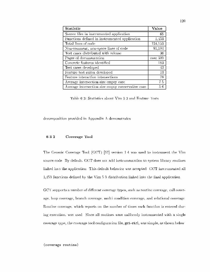
120
Statistic Value
Source �les in instrumented application 65
Functions de�ned in instrumented application 1,453
Total lines of code 124,153
Non-comment, non-space lines of code 91,104
Test cases distributed with release 36
Pages of documentation over 500
Concrete features identi�ed 183
Test cases developed 43
Feature test suites developed 13
Feature interaction intersections 78
Average intersection size empty core 7.5
Average intersection size empty conservative core 5.6
Table 6.3: Statistics about Vim 5.3 and Feature Tests
decomposition provided in Appendix A demonstrates.
6.3.2 Coverage Tool
The Generic Coverage Tool (GCT) [57] version 1.4 was used to instrument the Vim
source code. By default, GCT does not add instrumentation to system library routines
linked into the application. This default behavior was accepted. GCT instrumented all
1,453 functions de�ned by the Vim 5.3 distribution linked into the �nal application.
GCT supports a number of di�erent coverage types, such as routine coverage, call cover-
age, loop coverage, branch coverage, multi-condition coverage, and relational coverage.
Routine coverage, which reports on the number of times each function is entered dur-
ing execution, was used. Since all routines were uniformly instrumented with a single
coverage type, the coverage tool con�guration �le, gct-ctrl, was simple, as shown below.
(coverage routine)

121
(options instrument)
Once the instrumented executable is created, the instrumentation code collects infor-
mation in the �le GCTLOG. By starting with an empty log �le for each execution, it is
possible to determine exactly which functions are entered during an execution. Collect-
ing this information proved to be straightforward. All that was required was to augment
the implicit rule in the test Make�le [30] that caused each test to be run.
.in.out:
-rm -f $(COVERAGELOG)
../vim.instrumented -u vimrc.unix -s dotest.in $*.in
/bin/sh -c "if diff test.out $*.ok;
then
mv -f test.out $*.out;
greport -all GCTLOG | grep -v '[0]$$' > $*.cov;
else
echo $* FAILED >>test.log;
fi"
-rm -f Xdotest
We made three changes to this rule. First, any existing coverage log is deleted, which
ensures that every test execution generates a trace containing the right information.
Second, the instrumented version is executed on the test-case input �le, accomplished
by substituting \vim.instrumented" for \vim." Finally, the contents of the log �le are
extracted using the GCT tool greport and saved in a coverage �le. The -all ag is
used with greport to ensure that an entry count is provided for every function in the
application. The grep command is used to eliminate functions not entered, and the
execution trace is collected in a coverage �le named after the test script.

122
6.3.3 Analysis Method
This section describes the analysis method and tools used to analyze the role of fea-
tures and testing with Vim. Note, that the references to speci�c Vim features use the
feature names established in the functional decomposition. The complete hierarchy of
application functionality is provided in Appendix A.
6.3.3.1 Analyze Test Cases
The �rst step was to evaluate the existing test cases that are part of the Vim 5.3
distribution. The primary point to this analysis was to answer the �rst three questions
listed in Section 6.3. The results are presented below.
Does the test suite test speci�c features? The 36 test cases did indeed test speci�c
application features. Two types of feature testing were discovered, intentional and inci-
dental. Due to the way the scripts were constructed, most of the tests included incidental
tests of features such as jump-search, configuration, and command-shell-execution.
In addition, speci�c test cases were targeted at individual features such as autocommands,
jump-file, and pattern-based-substitution.
Can the application's feature set be determined from the test suite? The
answer is determined primarily by the thoroughness of the test suite. Appendix B
contains the list of features discovered from analyzing Vim's test suite. Less than
one-fourth of the features, 44 out of the 183 that the application provides, could be
discovered from an analysis of the test cases. Clearly a more comprehensive test suite
would have led to the discovery of more application features. In any case, without an
exhaustive list of system features to support test development, it is unlikely that the
test suite would reveal all the features.

123
Does the test suite test feature interactions? Both intentional and incidental
feature-interaction tests were present in the test suite, but were a small minority. Most
of the tests were targeted at a speci�c characteristic of a single feature. The interactions
between the features insert-text-from-file and command-shell-execution was in-
cidentally tested, and the interaction between autocommands and buffer-remove, as
well as the interaction between buffer-hide and tags-processing, were intentionally
tested by the test suite.
6.3.3.2 Vim Functional Decomposition
Once the test suite was analyzed, the documentation was studied to compile a list
of all the documented functionality. The documentation is primarily organized based
on an index of commands, which works well for reference purposes but is di�cult for
understanding the application functionality. IEEE Standard 1003.02-1992 [63], which
speci�es the behavior of the screen oriented vi editor, was also consulted to determine
its character and extent. The editor speci�ed in the standard provides a subset of the
functionality in Vim 5.3. In addition, the functionality is organized by an alphabet-
ical ordering of key sequences that invoke the commands. The standard provides no
meaningful organization of the functionality: for example item 5.35.7.1.15 in the stan-
dard describes the command `Control-W' which deletes a word, and item 5.35.7.1.16 is
`Control-Y' which scrolls backwards line by line.
Once the list of commands was compiled, the underlying functionality that they pro-
vided was put together into a list of approximately 10 pages. This functionality was
organized into a functional decomposition, essentially a hierarchical structure organized
from abstract functionality down to single, concrete features. This functional hierar-
chy is contained in Appendix A. Some of the abstract features such as autocommands,

124
syntax-highlighting, and user-functions are not decomposed in the hierarchy.
While the functional decomposition is a logical and thorough presentation of the appli-
cation's functionality, it is not possible to be completely orthogonal in presenting the
categories and features. Some concrete features re�ne more than one abstract feature.
For example, jumps and marks are two abstract features in Vim, and the concrete fea-
ture jump-mark re�nes both of them. Because some concrete features belong to more
than one abstract feature, it is not possible to organize the functionality into a tree
structure. The point of the decomposition was not to have a perfect, non-overlapping
hierarchy, but to have a document that meaningfully identi�es the majority of system
features. Nonetheless, the decomposition of Vim's functionality was fundamental to our
testing e�orts.
6.3.3.3 Develop Feature Tests for Vim
Once the functional decomposition was complete, it was possible to create a set of
feature tests to explore the ideas presented in Section 3.3.2.3. Roughly 10 percent of
the identi�ed features were tested. Most of the features were concrete features, such
as increment-number, move-text, and jump-mark. Two abstract features, delete and
insert-completion, were included in the feature tests, which are listed in Table 6.4.
Each feature test consists of one or more test cases, and each test case includes an input
�le and an output �le. Upon successful completion of the test, the generated output
should match the output �le associated with the test case.
Feature tests for abstract features consist of the feature tests for their concrete features.
Each of the concrete feature that that comprise the two abstract features that we tested
are listed in Table 6.5.

125
change-case
copy-text
decrement-number
delete
help
increment-number
insert-completion
insert-register-contents
jump-keyword
jump-mark
jump-tag
marks
move-text
Table 6.4: Features Tests
delete insert-completion
delete-character insert-complete-filename
delete-linebreak insert-complete-keyword
delete-line insert-complete-line
delete-motion insert-complete-macro
delete-range insert-complete-tag
Table 6.5: Abstract Features Tested
In the aggregate, the feature tests are composed of 43 individual test scripts and their
associated golden output �les. In addition, each of the 43 feature tests has a shadow
test as speci�ed in Section 6.2.2.1. One of the shadow tests, for the increment-number
feature, is described in detail in the next section.
6.3.3.4 Develop Shadow Tests for Vim
In testing Vim, the general strategy is to load a test script into the application via the
command line, to execute the commands contained in the script, and to write part of
the edit bu�er to a �le. By examining the output of the �le, one can deduce whether

126
the system correctly performed the commands listed in the test script.
In Vim, features are invoked by commands associated with speci�c key sequences. To
test Vim, the shadow test should therefore omit the key sequences that cause the fea-
ture to be executed. The example in Figure 6.6 contains one of the test cases for the
increment-number feature and its associated shadow test. The key sequence `Control-A'
invokes the feature. The shadow test assiduously omits this key sequence.
Test Ctrl-A increment numbers
for hex addition
STARTTEST
/^start-here
:set nrformats=hex
j^A13^A^Al^Al2000^A
:set nrformats=octal,hex
0^A13^A^Al^Al2000^A
:set nrformats=hex,octal
0^A13^A^Al^Al2000^A
:.-2,.wq! test.out
ENDTEST
start-here
0x1 0xFF 0xfade
0x1 0xFF 0xfade
0x1 0xFF 0xfade
Shadow: Ctrl-A increment numbers
for hex addition
STARTTEST
/^start-here
:set nrformats=hex
jlll
:set nrformats=octal,hex
0lll
:set nrformats=hex,octal
0lll
:.-2,.wq! test.out
ENDTEST
start-here
0x1 0xFF 0xfade
0x1 0xFF 0xfade
0x1 0xFF 0xfade
Table 6.6: Feature Test and Shadow Test Scripts for increment-number
In this test, the commands to be executed consist of the text between the \STARTTEST"
and \ENDTEST." For the feature test, the command sequence is described in detail
below.
(1) Search forward for the string \start-here" at the start of a line.
(2) Set the nrformat con�guration option to permit hexadecimal addition.

127
(3) Move the cursor to the next line, increment the number under the cursor, add 13to the number under the cursor, increment the number under the cursor, movethe cursor one character to the right, increment the number under the cursor,move the cursor one character to the right, add 2000 to the number under thecursor, and move the cursor to the next line.
(4) Set the nrformat con�guration option to permit octal and hexadecimal addition.
(5) Move the cursor to column 0, increment the number under the cursor, add 13to the number under the cursor, increment the number under the cursor, movethe cursor one character to the right, increment the number under the cursor,move the cursor one character to the right, add 2000 to the number under thecursor, and move the cursor to the next line.
(6) Set the nrformat con�guration option to permit hexadecimal and octal addition.
(7) Move the cursor to column 0, increment the number under the cursor, add 13to the number under the cursor, increment the number under the cursor, movethe cursor one character to the right, increment the number under the cursor,move the cursor one character to the right, add 2000 to the number under thecursor, and move the cursor to the next line.
(8) Write the range of lines from two above the cursor to the cursor to the �le\test.out" and exit.
The shadow test contains the same sequence of commands but omits the `Control-A'
key sequence that invokes the increment-number feature. The extraneous function-
ality in this test includes the jump-search, configuration, move-character, and
file-manipulation features. The shadow test invokes the same features with the
exception, of course, of the increment-number feature. Recall that the feature test
and the shadow test are both run by the implicit rule of the make�le described earlier.
This rule takes care of comparing test.out with the golden output and capturing the
execution trace into a .cov �le.
This example demonstrates that creating a shadow test for Vim is straightforward. It
takes less thought to create than the feature test itself. Some care does need to be taken,
however, to ensure that the shadow test covers all the incidental functionality and does
not exercise the functionality not in the feature test. Careful observation of the feature

128
test and the shadow test reveals that the numeric arguments to the increment-cursor
feature are not present in the shadow tests. This omission underscores the need to craft
the shadow tests carefully so that as much incidental functionality in the feature test
as possible is masked by the shadow test.
6.3.3.5 Develop Tools to Support Analysis
After developing the feature tests, an instrumented version of Vim was created. All
of the feature tests and feature shadow tests were executed, and their execution traces
were captured, which generated 86 coverage �les, one for each of the feature tests and
shadow tests. Several tools were developed to manipulate the coverage �les in support
of the analysis. Some of the more signi�cant tools are displayed in Table 6.7 and are
discussed below.
cova+b union of two or more coverage sets
cova-b di�erence of two or more coverage sets
cova^b intersection of two or more coverage sets
cov�les extract �le names from a coverage set
covfuncs extract function names from a coverage set
Table 6.7: Tools Created to Support Test Analysis
The raw coverage information captured in .cov �les lists each function entered during
a test execution. The programs cov�les and covfuncs �lter that information and report
the list of �les and functions respectively. The cova*b �les perform basic set operations
on coverage �les. The following script fragment typi�es their use in approximating the
feature implementation for feature 57, increment-number.
echo "Calculating implementation artifacts info for feature 57:"

129
cova+b core.cov ../fs.01.01.cov > a ; cova-b ../fx.01.01.cov a > 1
cova+b core.cov ../fs.01.02.cov > a ; cova-b ../fx.01.02.cov a > 2
cova+b core.cov ../fs.01.03.cov > a ; cova-b ../fx.01.03.cov a > 3
cova+b 1 2 3 > 57.cov ; rm -f 1 2 3 a
This script fragment follows the equation for recreating the mapping between features
and their implementations from Section 6.1. The �rst line reminds the user what is being
calculated. The next three lines calculate the union of the feature-shadow coverage and
the core coverage, and they store the result in a temporary �le \a." Then they store
the set di�erence between the feature coverage and the temporary �le into a numeric
temporary �le. The union of the numeric temporary �les is calculated and stored into
�le \57.cov."
6.3.4 Results
This section reports results of our inquiry into feature testing. The analysis of the
test cases distributed with Vim 5.3 revealed that feature testing is at least an implicit
component of the testing e�ort. A number of the existing test cases were actually
feature tests, and several were even feature-interaction tests, although they were not
always classi�ed as such in the minimal test documentation. These test cases showed
evidence of an organic origin; rather than being designed to cover an entire feature, they
were aimed at testing a speci�c requirement of a feature. For instance, the test cases 2
and 17 were to test the jump-file-under-cursor feature. Jump-file-under-cursor
permits the user to edit a �le named by the text under the cursor. Both of these tests
were aimed at insuring correct behavior of the feature under di�erent conditions. Test
2 was for �lenames embedded in a World Wide Web address, and Test 17 was for a �le
named by a variable's contents. None of the tests was targeted at the basic behavior of
the feature. From these observations, we can conclude that many of the test cases in the

130
suite were developed in response to particular problems. A more disciplined approach,
including feature testing, would improve the thoroughness of Vim's test suite.
6.3.4.1 Feature Testing
Without an explicit enumeration of the features that a system provides, feature testing
is bound to remain implicit and ad hoc. As Section 3.3.1 makes clear, one of the
major contributions of a requirements engineering e�ort is such a decomposition of the
system functionality. In the case of Vim, there is no such requirements document, so
the features were identi�ed through an examination of the documentation. Then they
were organized into a functional hierarchy.
This study revealed that feature testing can be a natural and useful extension to tra-
ditional testing. Feature tests were relatively straightforward to create because their
behaviors were well-documented. Such a test suite, one that ensures that the system's
features work correctly, at least in isolation, is a reasonable and attainable goal for the
testing e�ort. Clearly after making a change to a feature implementation, the devel-
opment e�ort can be improved by having a set of tests that ensure that the behavior
remains correct in isolation.
Having such a suite is an asset for other aspects of the development. We have shown
that it can be used to recover the mapping from feature to feature implementation, it
is useful for ferreting out feature interactions, and it forms a basis for building targeted
and comprehensive test suites.

131
6.3.4.2 Recovering Feature Implementation
Recovering the mapping from feature to feature implementation is a principal goal
for feature testing. In Section 6.2.2.1, we describe a method to achieve this goal.
In this section, we evaluate its e�ectiveness. The evaluation is based on a thorough
analysis of Vim's source code. The method proves reliable in its ability to identify the
desired functions and satisfactory in �ltering out unnecessary ones. We also suggest an
additional technique to improve the method's ability to �lter out extraneous functions.
The method for recovering feature implementation produces a set of functions executed
when a feature is invoked within the target system. Evaluating how well the method
worked with Vim's feature tests requires determining how well the identi�ed set matches
the actual set. Two considerations are crucial for making this determination: First, and
most important, determine whether the identi�ed set contains the functions in the
actual set. If the method fails to identify a signi�cant number of functions in the actual
set, then it fails to identify the mapping meaningfully. Second, determine whether the
method is e�ective in �ltering out functions that do not belong to the actual set. If the
method consistently identi�es hundreds of functions that do not belong in the set, then
it provides little value to the system developers.
To make the required determinations, it was necessary to analyze the source code for
Vim to �nd the actual mapping for each of the features that were tested. We knew
of no alternative to manually examining the entire body of source code, so the actual
feature implementations were compiled manually. This examination involved �nding
each location in the source code where a speci�c feature might be invoked. The func-
tional decomposition and system documentation were helpful in exposing the methods
for invoking features, but the lack of documentation of Vim's system architecture made
the analysis arduous.

132
In Vim, di�erent features are invoked in di�erent places in the source code, and a single
feature can be invoked in more than one. For instance, the change-case feature can
be invoked as an operator, as a normal command, and as an extended command. Thus
there are three places to start the search for its implementation. All three locations
eventually rely on Vim's swapchar function to change the case of individual characters.
As an operator, the implementation of change-case is encapsulated in the function
op tilde, which calls swapchar on its operand. As a normal command change-case
is implemented by n swapchar. The extended commands for the change-case feature
also use the function op tilde to implement the feature. The analysis, repeated for
each feature, identi�ed the set of functions written to implement the speci�c feature.
The functions implementing the insert-complete-line feature are presented, as an
example, in Table 6.8. The determination of which functions in Vim are dedicated to im-
plementing speci�c features was not di�cult, although familiarity with the underlying
programming language and libraries is required. In the few cases where some judg-
ment was necessary, examining the contexts in which the particular function was called
served to disambiguate between feature-speci�c and general purpose. In the case of
insert-complete-line, all of the functions listed in the table except get expansion,
make cyclic, and search for exact line were obviously written to implement the
concrete features re�ning the abstract feature insert-completion. These three func-
tions were called only from the context of other functions implementing the feature.
Documentation internal to the source code consistently con�rmed our intuitions about
which functions provided implementations for speci�c features. Starting from the lo-
cation in the source code where insert-complete-line is invoked and following func-
tion calls permits identifying the set of functions used by the feature implementation.
The majority of the functions that are called by Vim's feature implementations be-

133
add completion
add completion and infercase
free completions
get expansion
ins complete
ins expand pre
make cyclic
search for exact line
Table 6.8: Functions Implementing insert-complete-line
long to the core. A number of others belong to other features; these are considered
in Section 6.3.4.3. A selection of the core functions called by the implementation of
insert-complete-line is provided in Table 6.9. Comparing Tables 6.8 and 6.9 demon-
strates how the feature implementation could be separated from core functionality. For
functions that were not immediately obvious, such as ui breakcheck, examining the
function and its call contexts made the determination clear.
ui breakcheck
STRNCMP
alloc
vim strnsave
vim free
STRCMP
is lower
is upper
is alpha
Table 6.9: Functions Not Implementing insert-complete-line
The complete results of the validation exercise are presented in Table 6.10. The �rst
column lists the 21 concrete features that were tested. Recall that �ve of these features
re�ne the abstract feature delete and �ve re�ne insert-completion, so that the 13
feature tests expand into tests of 21 concrete features. The second column identi�es the
number of functions identi�ed by the feature-testing method. The third column lists the

134
number of functions in the actual feature-implementation set, determined through our
analysis of the underlying source code. The fourth column identi�es the functions that
the method failed to detect. Each of these entries is considered below. The �fth column
is the number of identi�ed functions that should be included in the de�nition of the
system core. The results we present here are predicated on an extremely conservative
de�nition of the system core. A more realistic de�nition of core would permit the method
to �lter out these functions. The �nal column tallies the functions that were neither
part of the feature implementation nor obviously part of the system core. Primarily,
the functions in this column were part of the implementation of features other than the
one being tested.
Feature Identi�ed Actual Missed Core Other
change-case 31 3 0 15 13
copy-text 34 2 0 19 13
decrement-number 28 1 0 15 12
delete-char 40 5 1 20 16
delete-line 23 4 0 11 8
delete-linebreak 49 7 0 30 12
delete-motion 46 9 0 22 15
delete-range 11 3 0 3 5
help 49 5 0 24 20
increment-number 29 1 0 16 12
insert-complete-�lename 21 7 1 15 0
insert-complete-keyword 43 10 1 31 3
insert-complete-line 16 8 1 8 1
insert-complete-macro 21 7 1 15 0
insert-complete-tag 22 5 1 10 8
insert-register-contents 23 6 2 18 1
jump-item-under-cursor 8 2 0 4 2
jump-mark 23 3 0 20 0
jump-tag 31 10 0 17 4
marks 8 4 0 4 0
move-text 26 2 0 16 8
Table 6.10: Evaluation of Identi�ed Feature Implementations
While Table 6.10 shows the method was capable of identifying the functions that belong

135
to the feature implementations, the few cases where functions were not identi�ed by the
method require explanation. All of the features that re�ne insert-completion are par-
tially implemented by the function ins expand pre. This function advances the state of
the input-completion action, if the feature is active. If the feature is not active, then
the function has no e�ect. It is always called within the edit function, so it appears in all
of the shadow tests for insert-completion, and therefore the method fails to detect it.
One strategy for expanding the method to detect this unusual coding idiom would be to
calculate a set di�erence between the shadow test and any functions in a feature's imple-
mentation that are invoked indiscriminantly. Other functions that were not identi�ed
by the method were the result of incomplete feature tests. For the delete-char feature,
an option for vi compatibility controls whether or not the function display dollar is
called. Adding a test case with this option set to the delete-char feature test led to
the inclusion of this function in the identi�ed set. Two functions were missing from
the insert-register-contents implementation, again because the feature tests were
incomplete. Expanding the behavior of the feature tests to include inserting the register
contents without interpretation corrected the omission of stuff escaped; and inserting
the register contents in command mode added the function cmdline paste. When the
shortcomings of the feature tests were �xed, the method identi�ed all the features in the
actual implementation sets except for ins expand pre. While unusual coding practice
can defeat this method, it proved exceptionally e�ective in identifying the functions in
the actual implementation sets.
The other consideration for evaluating the method is its precision in �ltering out func-
tions outside the implementation. The �nal column in Table 6.10 represents the number
of functions that would be erroneously identi�ed if the core were more realistically de-
�ned. Note that from a population of more than 1,400 possible functions, the number
of false positive responses generated by the method is quite small. Two extensions to

136
the method might be used to reduce this number further. First, it would be possible
to �lter the erroneous functions from the feature test coverage �les. Building the �lters
would require manual e�ort, so without process and tool support their accuracy would
degrade as the system evolves. Second, since many of the functions represented in this
column are involved in the implementation of other features, it would be possible to use
the intersection of coverage sets to ag functions that deserve special handling. From
our observations of the feature interactions within Vim, having such information should
prove valuable.
After evaluating the validity of this method, we are prepared to answer another of the
questions posed early in this chapter. Can feature implementations be discovered
from feature testing? This work demonstrated that it is possible to recover the set of
functions implementing a system's features through feature-based testing. We recognize
that the set of functions implementing a feature does not completely capture its imple-
mentation. While this information is helpful, it does not provide an understanding of
everything involved in a feature implementation. Recovering the complete mapping in
the solution domain is a more di�cult problem. Missing information can be classi�ed
into two types: additional information that might be generated, and information that
is based on an understanding of the semantics of the implementation.
For the �rst class of missing information, two additions would help support an under-
standing of the mapping. First, sets are not a rich enough model for the functions
engaged in a feature's implementation. This information could be augmented by re-
lationships between the functions that indicate in what context a function is called.
We see two mechanisms for providing this information: one, enhance the instrumenta-
tion of the executable so that the call stacks are output rather than function entries
in isolation, and, two, synthesize these relationships using program dependence [31, 69]

137
information. The second body of additional information that could be added relates
to the program's data structures. These data structures are manipulated within the
context of the functions that make up the information, and they represent additional
constraints and relationships not captured by the set-of-functions representation. This
context has to be recreated before one fully understands the feature implementation.
Here again, dependence information would be useful.
The second type of missing information is not subject to mechanical reconstitution.
A true understanding of the system resources provided by the system core, the data
structures that support the implementation of the system and its features, and the
constraints between them, is needed to acquire knowledge of the mapping. The intuition
and insight in the designers' and developers' minds is beyond what can be recreated via
a mechanical testing strategy, such as feature testing.
6.3.4.3 Discovering Feature Interaction
Can feature testing help discover feature interactions? Our work with feature
tests leaves little doubt that feature testing does indeed lead to the discovery of feature
interactions. Analysis of the functions identi�ed by the feature tests led to the discov-
ery of a large number of unanticipated interactions. Analysis of the Vim 5.3 source
code indicates that feature interactions are nearly ubiquitous. Certain features such as
undo-redo, autocommands, and right-to-left-editing span disparate sections of the
application code, interacting with many other features, both simple and complex. In
the case of Vim, these features con�rm our assertion that features frequently cut across
system structure.
Consider the relatively simple feature increment-number. This feature performs ad-

138
dition on the number under the cursor in the current bu�er. It is simple and self-
contained; one function, do addsub, implements its functionality. From examining
the code, identi�ed through the feature test, an unanticipated interaction with the
right-to-left-editing feature was found. Evidence of a feature interaction in the
�le ops.c is shown below. To implement the increment-number feature, the editor must
reverse the line when supporting the right-to-left-editing feature.
curwin->w_set_curswant = TRUE;
#ifdef RIGHTLEFT
ptr = ml_get_buf(curbuf, curwin->w_cursor.lnum, TRUE);
RLADDSUBFIX();
#endif
update_screenline();
Working to evaluate the recovery of feature implementation from feature testing revealed
the complexity of the interactions among system features. The example above is a simple
interaction. Below is a more complex interaction between the delete-line and mark
features. The presence of the mark feature imposes constraints on the system that must
be maintained by other feature implementations.
/*
* Now we must be careful adjusting our marks so that we
* don't overlap our mark_adjust() calls.
*
* We adjust the marks within the old text so that they refer
* to the last lines of the file (temporarily), because we know
* no other marks will be set there since these line numbers
* did not exist until we added our new lines.
*
* Then we adjust the marks on lines between the old and new
* text positions (either forwards or backwards).
*
* Finally we adjust the marks we put at the end of the file

139
* back to their final destination at the new text position
*/
last_line = curbuf->b_ml.ml_line_count;
mark_adjust(line1, line2, last_line - line2, 0L);
if (dest >= line2)
{
mark_adjust(line2 + 1, dest, -num_lines, 0L);
curbuf->b_op_start.lnum = dest - num_lines + 1;
curbuf->b_op_end.lnum = dest;
}
else
{
mark_adjust(dest + 1, line1 - 1, num_lines, 0L);
curbuf->b_op_start.lnum = dest + 1;
curbuf->b_op_end.lnum = dest + num_lines;
}
curbuf->b_op_start.col = curbuf->b_op_end.col = 0;
mark_adjust(last_line - num_lines + 1,
last_line,
-(last_line - dest - extra), 0L);
The code to maintain the constraints added by the marks feature doubles the size of
the do move function. Feature interactions add signi�cantly to the complexity of devel-
oping software. The feature interaction is not quite complete. Inside the mark adjust
function, one �nds an interaction with the quick-fix feature:
#ifdef QUICKFIX /* quickfix marks */
qf_mark_adjust(line1, line2, amount, amount_after);
#endif
As a result, the delete-line function has an indirect interaction with the quick-fix
feature. As this example demonstrates, feature interactions are subtle, and they can be
hard to detect upon examination of the system's source code.
We calculated the intersection of the feature coverage sets for each pair of features that
we tested as described in Section 6.2.2.2. Aggregating these cases by feature reduced

140
the number of intersections that had to be examined from 903 to 78. We also took a
conservative approach to de�ning the system core. First, we calculated the intersections
with an empty core. Then we examined the source code and identi�ed a small number of
functions, 21, that de�ned common functionality. With this small handful of functions,
less than 2 percent, we de�ned the core.
File Functions
charset.c vim isblankline
edit.c oneright
�leio.c vim fgets
message.c give warning, emsg, msg
misc1.c changed, changed warning, msgmore
misc2.c alloc check, alloc clear
os unix.c mch isdir, WaitForChar, mch char avail
screen.c update screenline
term.c term bg color
ui.c vim is input buf empty, ui char avail
Table 6.11: Conservative Core De�nition
Table 6.11 lists the �les and functions that were included in the core. These functions
relate mostly to such basic operations as moving the cursor, allocating memory, checking
for input, and producing error messages.
The information in the intersections of the pairs of tests proved valuable for discovering
interactions. A few of the coverage sets evidenced large intersections, leading to the
discovery of a number of feature interactions. A histogram of the number of functions
in each of these intersections is provided in Figure 6.3.
This histogram shows that in general the number of functions in the intersections for
di�erent pairs of features was low, averaging in single digits for both de�nitions of
core. About one in �ve pairs was empty and nearly three out of four pairs had inter-
sections that contained fewer than 10 functions. After examining the functions in the

141
Figure 6.3: Histogram of Intersection Size for Pairs of Feature Tests
intersections, it was possible to identify a number of instances of feature interactions.
Considering the number of core functions identi�ed in Table 6.10, a less conservative
and more accurate de�nition of the system core would result in even signi�cantly more
pairs having empty or trivially small intersections. For the empty core, the 78 intersec-
tions contained 584 functions, including duplication. Excluding duplicates, 112 distinct
functions participated in the intersections.
Since information about the system architecture was not available and we are not the
application's developers, we took a very conservative approach to de�ning the core.
A more informed understanding of the implementation would undoubtedly lead to a
signi�cantly expanded de�nition of the core. Another approach to de�ning the core
would be to examine the functions executed when the application is simply invoked and
then terminated immediately. A large number of functions, nearly a third of the 1,453,

142
were invoked for this simple execution. Of course, one of the major contributions of the
shadow tests was to �lter out exactly this set of functions.
A heuristic that would further reduce the number of intersections and their sizes would
be to include additional functions in the de�nition of the system core used for calculating
the intersections. Functions that do not have side e�ects or do not change system state,
such as predicates, are unlikely to contribute to feature interactions.
In summary, examination of the functions in the non-empty intersections revealed in-
teresting and unanticipated interactions between the features, threaded throughout the
implementation of the application. For example, the insert-complete feature shares
functions with the command-completion and command-file features that examine the
contents of the current directory, and it has additional interactions with the jump-jump,
display-jumplist, and mark features. The functions in the intersections hold promise
for being involved in feature interactions, especially when the system core is fully iden-
ti�ed.
6.4 Summary
To summarize the intersection of the feature-engineering framework and testing, we
examined the three goals established at the beginning of this section. Then, we reported
our �ndings and described future opportunities in the realm of feature testing.
Feature testing adds structure to the testing process. Our analysis of Vim's test cases
shows that the test cases covered a modest subset of the application's functionality.
Creating test suites that follow a feature decomposition of the system is an e�ective
organization of testing e�orts. Creating a suite of tests that can con�rm each feature's
basic behavior is no more di�cult than ad hoc testing. In several weeks, we were able

143
to create a test suite of the same magnitude as the one distributed with the applica-
tion. Creating a feature test for all of the features identi�ed would require an order of
magnitude more e�ort, but that is well within the bounds of reasonable testing e�ort.
Since features are a fundamental element of nearly all software systems, feature testing
should easily generalize to any system with a well-de�ned feature set.
Identifying feature implementations proved e�ective for our work with Vim. We were
able to take the relationship information generated from testing Vim and use it in the
con�guration management study described in Section 5. The synergy a�orded by pop-
ulating a workspace based on this information made sifting through the implementation
artifacts less onerous.
Developing the feature tests was the most di�cult part of the feature testing; how-
ever, it was no more di�cult than developing any thorough set of tests. Instrumenting
the source code and calculating the intersections was a minor, one-time cost. Vim
proved particularly facile to instrument since all of the implementation was in a single
language. For larger systems developed within heterogeneous environments, more en-
gineering e�ort would be required to collect the required information, but such e�orts
are within reasonable expectations. The feature implementations identi�ed through our
method were not minimal but they were, with one exception, complete, showing that
this method is capable of automatically discovering the mapping from feature to feature
implemention.
Discovering feature interactions was the most di�cult of the three goals to achieve.
De�ning the intersections of the feature implementations is certainly feasible and creates
limited technical challenges. It is extremely di�cult to quantify the e�ectiveness of
this approach for discovering feature interactions because the universe of interactions
is unknown. Certainly, examination of the intersections provided fruitful ground for

144
discovering interactions. The brute force approach of combining each feature test suite
would prove daunting on systems with hundreds of de�ned features. In this case a more
selective approach would be required. One strategy would be to use feedback from each
intersection examined to augment the de�nition of the core. Every function examined
could be characterized as \safe" or \risky" based on the impact the function execution
has on the application's state. Safe functions could be added to the de�nition of the core
to reduce the size of the intersections that need to be checked. Regardless, identifying
feature interactions remains a challenge.
In addition to evaluating the e�ectiveness of our testing e�orts, we also identi�ed fruit-
ful areas for additional research. The preceding paragraph makes clear that discovering
feature interactions will require additional methods and testing to demonstrate e�cacy.
We also determined that the set of functions identifying a feature interaction is not as
rich a model as we would like. By enhancing the output of the coverage tool and by com-
bining information from program dependence analysis, more structured and complete
information about feature implementation could be synthesized.

Chapter 7
Conclusion
From the user's perspective, the operations that software performs are characterized
as a set of features, and as an application domain matures, features become a major
competitive tool. New features from other applications are quickly adopted into new
releases. Adding new features to software is not often a simple, cosmetic change. A
feature's implementation can span multiple subsystems and can contribute to unan-
ticipated architectural connections among components. Features are deeply enmeshed
within the software that implements them.
In this dissertation, we have examined the concept of feature. Our goal has been to
expand the understanding of the nature of software itself. As a result of this work, we
are able to provide answers to the questions raised in Chapter 2; the answers provide
a summary of the conclusions that follow from this research. We also enumerate our
contributions to computer science research, and �nally, we look ahead to future research
opportunities opened up by this work.

146
7.1 Summary
In Chapter 2 we posed several questions that seek to understand the essence of soft-
ware. In this section, we summarize the answers developed within the context of this
dissertation work.
What is a feature? It is a unit of functionality at some level of abstraction. As such,
it is a denizen of the problem domain and is described by a set of requirements.
How might system features relate to one another? In Chapter 3, we describe
a rich set of relationships that can exist between features. Where these relationships
hold in the problem domain, the participating features serve to structure the desired
system functionality. Where they exist in the problem domain, they illuminate design
and code choices made to enable an e�cient and well-structured implementation.
What is the di�erence between a feature and a feature implementation? A
feature exists in the problem domain; a feature implementation is its realization in the
solution domain. Requirements analysts identify the features; developers create feature
implementations in software.
What is the di�erence between a feature and a use case? A use case captures
the use of a system to achieve a speci�c goal. Any number of features may be employed
in a use case. Features are the building blocks of a system's functionality; use cases
are the building blocks of the way people use a system. A use case might involve the
user goal of correcting spelling errors in an editor. If there is a spell-checking feature
de�ned for the system, then presumably the use case would take advantage of it. If no
such feature exists, then the use case would involve other means of achieving the goal,
perhaps by using an external program.

147
How can software development be driven by the features in a system? Under-
standing features helps us understand software. Feature engineering helps us understand
how features can be used in software development. It has re ections in all phases of de-
velopment. Identi�cation of the feature set provides a natural structuring of the desired
system functionality. High-level design should result in an architecture that gracefully
hosts unanticipated features. Implementation activities are enhanced by explicit rela-
tionships that relieve developers of tedious and error-prone tasks, like recreating the
mapping from a feature to its implementation. Con�guration management can be done
at a level that more closely resembles the problem domain. Testing can be targeted to
speci�c features, and since the features are composed of requirements, the tests can be
written against known constraints.
What is there to software besides feature implementations? Systems deliver
their functionality to users in quanta of features. Beneath the feature implementation,
there is an infrastructure that represents the realization of a system's architecture. We
can conceive of systems as being comprised of two distinct parts, its feature implemen-
tations and its core.
7.2 Contributions of this Work
A framework for understanding features in software is the �rst contribution of this
research. This understanding starts with de�ning features to be a problem domain
entity. The distinction between feature and feature implementation is also important.
The feature framework presents a model of software development that has been applied
to several software projects and found to �t them well.
Understanding the possibilities for taking advantage of feature information within soft-

148
ware development is the second contribution. These possibilities are predicated on mak-
ing the implicit roles for features explicit. The feature-engineering framework makes use
of these relationships and extends traditional development activities. Each of these ar-
eas of extension has the potential for interesting research. In this dissertation, two are
explored and found to be bene�cial to the development of software.
Extending con�guration management to make use of feature information in a system
is the third contribution. Con�guration management occupies a unique position in
software development because it provides support for each of the other activities. To
be useful within software development, features and the relationships that they struc-
ture require identi�cation and management throughout the evolution of the underlying
software. We identify how features might be managed within software development.
Managing feature relationships poses a signi�cant challenge to con�guration manage-
ment systems. One part of this contribution was to develop a framework for evaluating
the support that con�guration-management systems are able to provide for feature
management. Using this framework, we undertook an evaluation of commercial con-
�guration management systems. This evaluation led to a better understanding of the
con�guration management discipline in general and helped identify poorly-supported
requirements for managing features.
The fourth contribution is building a prototype feature-based con�guration manage-
ment system, IronMan, and using it to support software development. The system was
built to incorporate the feature extensions to provide native support for the activities
identi�ed in the evaluation framework. The experiences using IronMan con�rmed the
value of bringing feature relationships into software development. Signi�cant burdens
are eliminated from developers when this information guides workspace management
and system con�guration.

149
Exploring features in software testing is the �fth contribution of this dissertation. Test-
ing is fundamental to the development of good software. We de�ne feature testing and
outline its use with the testing discipline. As features organize an application's func-
tionality, feature tests are a natural organization for testing. In our research, we also
develop a method to use feature tests to reveal the mapping from features to feature
implementations. Recovering this mapping is important for feature-based con�guration
as well as improving developers' understanding of software structure.
7.3 Future Work
The span of feature engineering is broad, leading to a number of directions for extend-
ing this work. The systems analyzed in this research have �t the feature-engineering
framework; applying the framework to additional systems is warranted. Exploring the
characteristics of di�erent software systems that in uence their suitability for feature
engineering is a logical extension to this work. We de�ne relationships that can be used
to improve the development of software systems. In the problem domain, relationships
are created through the analytical skill of domain analysts and requirements engineers.
In the solution domain, there are opportunities to take advantage of these relationships;
in Section 3.3 we identify many of these. Extending the tools and process within the
software-development activities to re ect these relationships is rich ground for future
work. For instance, in software architecture, there is potential for developing methods
to trace features to the architectural elements that provide them. In addition to the
relationships stemming from the problem domain, additional ones occur in the problem
domain. Much work remains to develop tools and methods for discovering them from
development artifacts. There is also the potential for developing a language for express-
ing these relationships and integrating it with the existing concepts within the di�erent

150
software development activities.
We de�ne a set of relationships that con�guration management systems should maintain.
Our experience with the feature-based con�guration management prototype demon-
strates the value of making this information available for workspace management and
system con�guration. Existing con�guration management systems are weak in using the
identi�cation facilities they provide as input into the other operations. Additional work
is needed to characterize and extend the interaction mechanisms between the di�erent
con�guration management activities. Another useful e�ort would be a thorough ex-
amination program construction techniques to categorize the mechanisms they provide
for including optional features. Con�guration management systems leave program con-
struction to external tools that do not take advantage of feature information, creating
another area for future work.
In software testing, two areas merit additional research. The �rst is to create richer
information from feature testing. Extending the set model of feature implementation
to incorporate a path through code artifacts and incorporating data structures into
the implementation would provide greater insight into feature implementation. We can
identify promising and complementary approaches. Incorporating information from de-
pendence analysis for the software and enriching the program instrumentation would
facilitate generating the desired information. Greater insight promises better identi�-
cation of the feature interactions occurring in the solution domain. These techniques
should help developers attain more value from testing e�orts and improve the quality
of the software they develop.

Bibliography
[1] G.D. Abowd, R. Allen, and D. Garlan. Formalizing Style to Understand Descrip-tions of Software Architecture. ACM Transactions on Software Engineering andMethodology, 4(4):319{364, October 1995.
[2] A.V. Aho and N. Gri�eth. Feature Interaction in the Global Information Infrastruc-ture. In Proceedings of the Third ACM SIGSOFT Symposium on the Foundationsof Software Engineering, pages 2{5. ACM SIGSOFT, October 1995.
[3] K.M. Anderson, R.N. Taylor, and E.J. Whitehead Jr. Chimera: Hypertext for Het-erogeneous Software Environments. In Proceedings of the 1994 ACM Conferenceon Hypertext, pages 94{107, September 1994.
[4] Atria Corporation, Inc., Lexington, Massachusetts. ClearCase Concepts Manual -Unix Edition, March 1995.
[5] Atria Corporation, Inc., Lexington, Massachusetts. ClearCase Reference Manual -Unix Edition, March 1995.
[6] AT&T Network Systems. 5ESS Switch Global Technical Description, September1991. Issue 3.
[7] D. Batory and S O'Malley. The Design and Implementation of Hierarchical SoftwareSystems with Reusable Components. ACM Transactions on Software Engineeringand Methodology, 1(4):355{398, October 1992.
[8] T. Biggersta� and C. Richter. Reusability Framework, Assessment, and Directions.IEEE Computer Society, 1987.
[9] B.W. Boehm. A Spiral Model of Software Development and Enhancement. IEEEComputer, 21(5):61{72, May 1988.
[10] B.W. Boehm, M.H. Penedo, E.D. Stuckle, R.D. Williams, and A.B. Pyster. ASoftware Development Environment for Improving Productivity. IEEE Computer,17(6):30{44, June 1984.
[11] G. Booch, J. Rumbaugh, and I. Jacobson. The Uni�ed Modeling Language UserGuide. Addison-Wesley, Reading, Massachusetts, 2 edition, 1998.

152
[12] E.J. Cameron and H. Velthuijsen. Feature Interactions in TelecommunicationsSystems. IEEE Communications, pages 18{23, August 1993.
[13] D.L. Carney, J.I. Cochrane, L.J. Gitten, E.M. Prell, and R. Staehler. ArchitecturalOverview. AT&T Technical Journal, 64(6):1339{1356, 1985.
[14] Y.-F. Chen, D.S. Rosenblum, and K.-P. Vo. TestTube: A System for Selective Re-gression Testing. In Proceedings of the 16th International Conference on SoftwareEngineering, pages 211{220. IEEE Computer Society, May 1994.
[15] K.W. Church and J.I. Helfman. Dotplot: A Program for Exploring Self-Similarityin Millions of Lines for Text and Code. Journal of Computational and GraphicalStatistics, 2(2):153{174, June 1993.
[16] L.A. Clarke, J.C. Wileden, and A.L. Wolf. Object Management Support forSoftware Development Environments. In Appin Workshop on Persistent ObjectSystems, August 1987.
[17] J. Conklin. Hypertext: An Introduction and Survey. IEEE - Computer, 20(9):17{41, January 1987.
[18] Continuus Software Corporation, Irvine, California. Continuus Task Reference,1994.
[19] M.A. Cusumano and R.W. Selby. Microsoft Secrets. The Free Press, New York,1995.
[20] S. Dart. Concepts in Con�guration Management Systems. In Proceedings of theThird International Workshop on Software Con�guration Management, pages 1{18.ACM SIGSOFT, 1991.
[21] A. Davis and R. Rauscher. Formal Techniques and Automatic Processing to EnsureCorrectness in Requirements Speci�cations. In Proceedings of the 1979 Conferenceon Speci�cations of Reliable Software, pages 15{35. IEEE Computer Society, 1979.
[22] A.M. Davis. The Design of a Family of Application-Oriented Requirements Lan-guages. IEEE - Computer, 15(5):21{28, May 1982.
[23] A.M. Davis. Software Requirements - Objects, Functions, & States. Prentice-Hall,Englewood Cli�s, New Jersey, 1993.
[24] C.G. Davis and C.R. Vick. The Sofware Development System. IEEE Transactionson Software Engineering, SE-3(1):69{84, January 1977.
[25] R.G. Day. Quality Function Deployment. ASQC Quality Press, Milwaukee Wis-consin, 1993.
[26] J. Estublier. A Con�guration Manager: The Adele Data Base of Programs.
[27] J. Estublier. Con�guration Management - The Notion and the Tools.

153
[28] J. Estublier and R. Casallas. The Adele Con�guration Manager. In W. Tichy,editor, Con�guration Management, number 2 in Trends in Software, pages 99{134.Wiley, London, 1994.
[29] P.H. Feiler. Con�guration Management Models in Commercial Environments.Technical Report SEI-91-TR-07, Software Engineering Institute, Pittsburgh, Penn-sylvania, April 1991.
[30] S.I. Feldman. Make - A Program for Maintaining Computer Programs. Software -Practice and Experience, 9(4):255{265, April 1979.
[31] J. Ferrante, K.J. Ottenstein, and J.D. Warren. The Program Dependence Graphand its Use in Optimization. ACM Transactions on Programming Languages andSystems, 9(3):319{349, October 1987.
[32] A. Fuggetta and A.L. Wolf, editors. Software Process. Number 4 in Trends inSoftware. Wiley, London, 1996.
[33] H.V. Gomaa, H.V. Sugumaran, C. Bosch, and I. Tavakoli. A Prototype DomainModeling Environment for Reusable Software Architectures. In Proceedings ofthe Third International Conference on the Software Reuse, pages 74{83. IEEEComputer Society, November 1994.
[34] R.W. Gray, V.P. Heuring, S.P. Levi, A.M. Sloane, and W.M. Waite. Eli: AComplete, Flexible Compiler Construction System. Communications of the ACM,35(2):121{131, February 1992.
[35] N.D. Gri�eth and Y. Lin. Extending Telecommunications Systems: The Feature-Interaction Problem. IEEE Computer, 26(8):14{18, August 1993.
[36] M. Griss, J. Favaro, and M. d'Alessandro. Developing Architecture Through Reuse.1997.
[37] P. Hsia, A.M. Davis, and D.C. Kung. Status Report: Requirements Engineering.IEEE Software, 10(6):75{79, November 1993.
[38] P. Hsia and A. Gupta. Incremental Delivery Using Abstract Data Types andRequirements Clustering. In Proceedings of the Second International Conferenceon Systems Integration, pages 137{150. IEEE Computer Society, June 1992.
[39] M. Jackson. Software Requirements and Speci�cations: A Lexicon of Practice,Principles, and Prejudices. Addison-Wesley, Reading, Massachusetts, 1995.
[40] M. Jackson and P.Zave. Distributed Feature Composition: A Virtual Architecturefor Telecommunications Services. IEEE Transactions on Software Engineering,24(10):831{847, October 1998.
[41] I. Jacobson. Object-Oriented Software Engineering - A Use Case Driven Approach.Addison-Wesley, Reading, Massachusetts, 1992.
[42] C. Jones. Applied Software Measurement: Assuring Productivity and Quality.McGraw-Hill, New York, 2 edition, 1996.

154
[43] H. Kaindl, S. Kramer, and R. Kacsich. A Case Study of Decoposing FunctionalRequirements Using Scenarios. In Third Internation Conference on RequirementsEngineering, pages 82{89. IEEE Computer Society, April 1998.
[44] Y. Kamigaki, T. Nara, S. Machida, A. Hakata, and K. Yamaguchi. 160 Gbit/s ATMswitching system for public network. In Global Telecommunications Conference,1996., pages 1380{1387, November 1996.
[45] K.C. Kang, S.G. Cohen, J.A. Hess, W.E. Novak, and A.S. Peterson. Feature-Oriented Domain Analysis (FODA) Feasibility Study. Technical Report CMU/SEI{90{TR{21, Software Engineering Institute, Pittsburgh, Pennsylvania, 1990.
[46] J. Karlsson and K. Ryan. A Cost-Value Approach for Prioritizing Requirements.IEEE - Software, 14(5):67{74, Sep/Oct 1997.
[47] D.O. Keck and P.J. Kuehn. The Feature and Service Interaction Problem inTelecommunications Software Systems: A Survey. IEEE Transactions on SoftwareEngineering, 24(10):779{796, October 1998.
[48] C. Kop and H.C. Mayr. Conceptual Predesign Bridging the Gap between Require-ments and Conceptual Design. In Third Internation Conference on RequirementsEngineering, pages 90{98. IEEE Computer Society, April 1998.
[49] P. Kruchten. The 4+1 View Model of Architecture. IEEE Software, 12(6):42{50,November 1995.
[50] R.W. Krut. Integrating 001 Tool Support into the Feature-Oriented Domain Anal-ysis Methodology. Technical Report CMU/SEI{93{TR{01, Software EngineeringInstitute, Pittsburgh, Pennsylvania, July 1993.
[51] B.S. Ku. A Reuse-Driven Approach for Rapid Telephone Service Creation.Proceedings of the Third Interanational Conference in Software Reuse, pages 64{72,November 1994.
[52] M.M Larrondo-Petrie, K.R. Nair, and G.K. Raghavan. A domain analysis of Webbrowser architectures, languages and features. In Southcon/96 Conference Record,pages 168{174, 1996.
[53] F.J. Lin, H. Liu, and A. Ghosh. A Methodology fo rFeature Interaction Detection inthe AIN 0.1 Framework. IEEE Transactions on Software Engineering, 24(10):797{817, October 1998.
[54] Y.-J. Lin and M. Jazayeri. Guest Editoral: Introduction to the Special Sectionon Managing Feature Interactions in Telecommunications Software Systems. IEEETransactions on Software Engineering, 24(10):777{778, October 1998.
[55] D.C. Luckham and J. Vera. An Event-based Architecture De�nition Language.IEEE Transactions on Software Engineering, 21(9):717{734, September 1995.
[56] A. Mahler. Variants: Keeping Things Together and Telling Them Apart. InW. Tichy, editor, Con�guration Management, number 2 in Trends in Software,pages 73{97. Wiley, London, 1994.

155
[57] B. Marick. The Craft of Software Testing. Prentice-Hall, Englewood Cli�s,New Jersey, 1995.
[58] H.D. Mills, M. Dyer, and R.C. Linger. Cleanroom Software Engineering. IEEESoftware, 4(5):19{25, September 1987.
[59] J. Nielsen. HyperText & HyperMedia. Academic Press, Inc., Boston, MA, 1990.
[60] Standards Coordinating Committee of the IEEE Computer Society. ANSI/IEEEStd 830-1984. Standard for Software Requirements Speci�cations, 1984.
[61] Standards Coordinating Committee of the IEEE Computer Society. IEEE Std1042-1987. Guide to Software Con�guration Management, 1987.
[62] Standards Coordinating Committee of the IEEE Computer Society. IEEE standardglossary of software engineering terminology . IEEE Std 610.12-1990, December1990.
[63] Standards Coordinating Committee of the IEEE Computer Society. PortableOperating System Interface (POSIXR ) - Part 2 Shell & Utilitites. IEEE/ANSI1003.2-1992 Std for Information Technology, 1992.
[64] H. Ossher andW. Harrison. Combination of Inheritance Hierarchies. In Proceedingsof the Conference on Object-oriented Programming Systems, Languages, andApplications, pages 25{40. Association for Computer Machinery, October 1992.
[65] L.J. Osterweil. Software Environment Research: Directions for the Next Five Years.IEEE Computer, 14(4):35{43, April 1981.
[66] J.D. Palmer and Y. Liang. Indexing and Clustering of Software RequirementsSpeci�cations. Information and Decision Technologies, 18(4):283{299, 1992.
[67] M.H. Penedo and E.D. Stuckle. PMDB|A Project Master Database for SoftwareEngineering Environments. In Proceedings of the 8th International Conference onSoftware Engineering, pages 150{157. IEEE Computer Society, August 1985.
[68] D.E. Perry and A.L. Wolf. Foundations for the Study of Software Architecture.SIGSOFT Software Engineering Notes, 17(4):40{52, October 1992.
[69] A. Podgurski and L.A. Clarke. A Formal Model of Program Dependenciesand its Implications for Software Testing, Debugging, and Maintenance. IEEETransactions on Software Engineering, 16(9):965{979, September 1990.
[70] R.S. Pressman. Software Engineering: A Practitioner's Approach. McGraw-Hill,New York, 3 edition, 1992.
[71] R. Prieto-D��az. Domain Analysis for Reusability. In Eleventh Annual ComputerSoftware and Applications Conference, pages 23{29. IEEE Computer Society, 1987.
[72] R. Prieto-D��az and J.M. Neighbors. Module Interconnection Languages. Journalof Systems and Software, 6(4):307{334, November 1986.

156
[73] L.B.S. Raccoon. The Complexity Gap. SIGSOFT Software Engineering Notes,20(3):37{44, July 1995.
[74] D.J. Richardson and A.L. Wolf. Software Testing at the Architectural Level. InSecond International Software Architecture Workshop, pages 68{71, October 1996.
[75] W.N. Robinson and S. Pawlowski. Surfacing Root Requirements Interactionsfrom Inquiry Cycle Requirements Documents. In Third Internation Conferenceon Requirements Engineering, pages 82{89. IEEE Computer Society, April 1998.
[76] T. Russell. Singaling System 7. McGraw-Hill, New York, 2 edition, 1998.
[77] M. Shaw. Comparing Architectural Design Styles. IEEE Software, 12(6):27{41,November 1995.
[78] M. Sitaraman. Performance Parameterized Reusable Software Components.International Journal of Software Engineering and Knowledge Engineering,2(4):567{587, October 1992.
[79] A.M. Sloane and J. Holdsworth. Beyond Traditional Program Slicing. InProceedings of the 1996 International Symposium on Software Testing and Analysis(ISSTA '96), pages 180{186. ACM SIGSOFT, January 1996.
[80] Gregor Snelting. Reengineering of con�gurations based on mathematical conceptanalysis. ACM Transactions on Software Engineering and Methodology, 5(2):146{89, April 1996.
[81] Software Maintenance & Development Systems, Inc., Concord, Massachusetts.Aide de Camp Con�guration Management System, April 1994.
[82] Software Maintenance & Development Systems, Inc, Concord, Massachusetts.Aide de Camp Product Overview, September 1994.
[83] Software Maintenance & Development Systems, Inc., Concord, Massachusetts.Aide de Camp Product Overview, September 1994.
[84] W.F. Tichy. Design, Implementation, and Evaluation of a Revision Control System.Proceedings of the 6th International Conference on Software Engineering, pages58{67, September 1982.
[85] F. Tip. A Survey of Program Slicing Techniques. Technical Report CS-R9428,Centrum voor Wiskunde Informatica (CWI), Amsterdam, The Netherlands, 1994.
[86] W. Tracz. Confessions of a Used Program Salesman - Institutionalizing SoftwareReuse. Addison-Wesley, Reading, Massachusetts, 1995.
[87] S. Tsang and E.H. Magill. Learning to Detect and Avoid Run-Time Feature In-teractions in Intelligent Networks. IEEE Transactions on Software Engineering,24(10):818{830, October 1998.

157
[88] A. van der Hoek, D.M. Heimbigner, and A.L. Wolf. Software Architecture, Con�g-uration Management, and Con�gurable Distributed Systems: A Menage a Trois.Technical Report CU-CS-849-98, University of Colorado, University of Colorado,Boulder, Colorado, January 1998.
[89] M. Weiser. Program Slicing. In Proceedings of the 5th International Conferenceon Software Engineering, pages 439{449. IEEE Computer Society, March 1981.
[90] M. Fowler with K. Scott. UML Distilled - Applying the Standard Object ModelingLanguage. Object Technology Series. Addison-Wesley, Reading, Massachusetts,1997.
[91] P. Zave. Feature Interactions and Formal Speci�cations in Telecommunications.IEEE Computer, 26(8):20{29, August 1993.

Appendix A
Vim Functional Decomposition
abbreviations
abbr-add
abbr-clear
abbr-display
argument-list
arglist-display
arglist-first
arglist-last
arglist-next
arglist-previous
autocommands
backup
backup-autosave
backup-preserve
backup-recover
binary-editing
buffer
buffer-change
buffer-display
buffer-edit
buffer-hide
buffer-remove
buffer-unhide
command-line
command-completion
command-execute-during-insert
command-execute-register
command-execute-file
command-history
command-repeat-over-range
command-shell-execution
configuration
option-display
option-invert
option-reset
option-set
read-modeline
cscope-integration
cursor-movement
jumps
jump-comment
jump-file-position
jump-file-under-cursor
jump-item-under-cursor
jump-jump
Table A.1: A Functional Decomposition for Vim 5.3

159
cursor-movement (continued)
jump (continued)
jump-line
jump-mark
jump-matched-item
jump-quickfix
jump-screen
jump-search
jump-tag
jump-tag-back
jump-text-object
window-cursor-down
window-cursor-up
move-horizontal
line-characters
line-find
line-position
move-vertical
line-down
line-up
scrolling
scroll-cursor-relative
scroll-down
scroll-horizontal
scroll-up
display-information
abbr-display
arglist-display
buffer-display
display-ascii-value
display-current-file-name
display-cursor-position-in-file
display-directory
display-files
display-grep
display-intro-screen
display-jump-list
display-line
display-line-number
display-line-numbers
display-lines
display-lines-containing-keyword
display-macro-definition
display-screen
display-version-info
mark-display
register-display
option-display
tag-display
edit
change
change-case
decrement-number
filter-text
increment-number
move-text
pattern-based-substitution
replace-text
retab
shift-text
copy-text
delete
delete-chars
delete-linebreaks
delete-lines
delete-motion
delete-range
format
align-text
format-comments
format-textblock
indent
autoindent
cindent
lispindent
smartindent
tab-handling
insert
completion
insert-complete-filename
insert-complete-keyword
insert-complete-line
insert-complete-macro-def
insert-complete-tag
insert-change-indent
insert-characters-line-above
insert-characters-line-below
insert-digraphs
insert-linebreaks
insert-literal
insert-register-contents
insert-text
paste
paste-text
paste-text-adjust-indent
file-formats

160
file-manipulation
gui
help
key-mapping
keyword-lookup
leaving
leave-abandon-changes
leave-exit
leave-suspend
marks
mark-display
mark-set
mark-set-file
jump-mark
ole-integration
perl-integration
python-integration
quickfix
qf-first
qf-grep
qf-last
qf-load-errorfile
qf-make
qf-next
qf-newer
qf-older
qf-previous
registers
execute-register
record-keystrokes
register-append-text
register-display
register-fill-with-text
register-paste-contents
right-to-left-editing
security
shell-restriction
resource-file-restriction
sleep
syntax-highlighting
tags
jump-tag
jump-tag-back
tag-display
tag-display-matching
tag-first
tag-last
tag-next
tag-previous
tag-select
tcl-integration
undo-redo
redo-undone-change
restore-line
undo-change
user-commands
user-functions
visual-mode
windows
window-close
window-cursor-down
window-cursor-up
window-decrease-size
window-exchange
window-increase-size
window-new
window-only
window-resize
window-rotate-down
window-rotate-up
window-size-equal
window-split
composite-features
split-all-args
split-all-buffers
split-edit-tag-file
split-first-arg
split-goto-define-def
split-goto-file
split-goto-identifier-def
split-last-arg
split-tag-jump
split-tag-select
Table A.3: A Functional Decomposition for Vim 5.3 (continued)

161
Appendix B
Concrete Features Identi�ed in Vim Tests
autocommands
buffer-edit
buffer-hide
buffer-remove
buffer-unhide
decrement-number
pattern-based-substitution
delete-linebreaks
delete-motion
align-text
autoindent
cindent
lispindent
smartindent
tab-handling
insert-complete-filename
insert-complete-keyword
insert-complete-tag
insert-text
command-execute-file
command-shell-execution
option-set
read-modeline
jump-file-position
jump-file-under-cursor
jump-item-under-cursor
jump-search
jump-text-object
line-down
file-formats
file-manipulation
leave-abandon-changes
leave-exit
qf-load-errorfile
qf-next
resource-file-restriction
jump-tag
user-commands
user-functions
visual-mode
window-close
window-only
window-split
window-split-all-args
Table B.1: Features exercised test cases distributed with Vim