Guide to the Systems Engineering Body of ... - SEBoK
1005
Guide to the Systems Engineering Body of Knowledge (SEBoK) v1.4 - Full BKCASE June 29, 2015
-
Upload
khangminh22 -
Category
Documents
-
view
0 -
download
0
Transcript of Guide to the Systems Engineering Body of ... - SEBoK

Guide to the Systems Engineering Body of Knowledge (SEBoK)
v1.4
-
Full
BKCASE
June 29, 2015

Contents
Front matter vii
Part 1: SEBoK Introduction 3
Part 2: Foundations of Systems Engineering 57
Part 3: SE and Management 215
Part 4: Applications of Systems Engineering 537
Part 5: Enabling Systems Engineering 709
Part 6: Related Disciplines 813
Part 7: SE Implementation Examples 909


Cover


Letter from the Editor 1
Letter from the EditorA very warm welcome to all SEBoK users, both old and new. The BKCASE Editor in Chief (EIC) has overallresponsibility for the continuing review and update of the SEBoK. Many thanks to the BKCASE Governors and thecurrent members of the Editorial Board for supporting me.I am delighted to be able to talk to you about SEBoK v. 1.4 which continues our commitment to regular review ofthe information referenced in our "Guide to the Systems Engineering Body of Knowledge".This new version features changes to respond to publication of ISO/IEC/IEEE. 15288:2015 Systems and SoftwareEngineering - System Life Cycle Processes and the INCOSE SE Handbook v4.0, 2015. Over the last 12 months theBKCASE Editorial Board has made significant efforts to become more involved in activities within our sponsoringorganizations on key topics such as model based systems engineering (MBSE), systems of systems, systemsengineering leadership, etc. You will begin to see the impact of this in v1.4 of the SEBoK, with further updates in v.1.5, planned for Autumn 2015.
SEBoK v. 1.4SEBoK v.1.4 feels like something of a turning point for the body of knowledge. On one hand we have “closed theloop” on the current cycle of updates to our core Systems Engineering reference sources, while on the other we havetaken the first steps towards a richer relationship with other sources of knowledge and turned our focus onto some ofthe exciting transformations happening within Systems Engineering.A brief summary of the changes in this version are given below, for details of content affected by these updates go toAcknowledgements and Release History.A small but significant change has been made in SEBoK Part 2. This has been renamed from Systems toFoundations of Systems Engineering. This change reflects the focus of part 2 on the wider knowledge sources whichunderpin or enable good SE practice. While this has always been our aim for part 2, the old name was interpreted asan overview of all systems knowledge by some both inside and outside of BKCASE. This confusion led to aconfusion in scope and purpose of some articles and miss understanding of our relationships with the systemsscience community. With this change we have begun to address this miss understanding and provide a firmer basisfor this part of the SEBoK in future.The most significant change to the SEBoK for v1.4 is in Part 3: SE and Management. A number of the technical andproject process articles in SEBoK have been updated to reflect the revisions of ISO/IEC/IEEE 15288 (ISO 2015):• A new “Business or Mission Analysis Process” has been added to the standard. This process defines SE
activities to assist business or enterprise decision makers to define the problem space, identify the stakeholders,develop preliminary operational concepts, and distinguish environmental conditions and constraints that boundthe solution space. This process follows the same approach as the Business or Mission Analysis article which wasalready in SEBoK. This article has been updated to better align with the standard.
• The “Stakeholder Requirement Definition Process” in the standard has been renamed “Stakeholder Needs andRequirements Definition”. The revised process builds on the change above to include more description of how totranslate stakeholder needs and business strategy into requirements. The SEBoK article Stakeholder Needs andRequirements has been updated to better align with the standard; a new article Life Cycle Processes andEnterprise Need has been added to discuss how requirements can be related to business strategy and needs whereappropriate.
• The “Architectural Design Process” in the standard has been replaced with an “Architecture Definition Process” which focuses more on the identification of stakeholder concerns and the higher level system architecture that will address the concerns. A new “Design Definition Process” describes how system architecture translates into realisable system design. Two new SEBoK articles System Architecture and System Design reflect

Letter from the Editor 2
this revision of the standard and replace the previous article on architectural design. The Systems Requirementsarticle has also changed to reflect these updates.
• The Logical Architecture Model Development and Physical Architecture Model Development SEBoK articlesremain, describing the development of a couple commonly used architecture models in more detail as described inother standards, such as ISO/IEC/IEEE 42010, Systems and Software Architecture Description (ISO 2011).
• A new “System Analysis Process” has been added to the standard. This process defines SE activities to allowdevelopers to objectively plan and carry out quantitative assessments of a system or aspects of a system, in orderto select and/or update the most efficient system architecture and to generate derived engineering data. Thisprocess follows the same approach as the System Analysis article which was already in SEBoK. This article hasbeen updated to better align with the standard.
Some of the changes to the standard build on the descriptions of SE which were developed for the SEBoK. This isnot surprising, since many of the same authors were involved in both. The alignment of these views also includes theupdated INCOSE SE Handbook v4.0 (INCOSE 2015), which now fully aligns with the standard. This completes aprocess which has overlapped the creation of the SEBoK. Going forward we plan to expand the scope of knowledgein the SEBoK to cover broader applications of SE within this generic framework of Life Cycle Processes. It is likelythat this will shift the focus of activity from SEBoK Part 3 to SEBoK Part 4: Applications of SE and in particular thetailoring of SE to a range of application types and domains.Some other small changes have been made in Parts 4, 5 and 7 as part of the ongoing review of SEBoK material toreflect new source material.
Future Direction for SEBoKOnce again, many thanks to the "core group of dedicated and knowledgeable contributing authors and reviewers"who make up the BKCASE community. It has been my privilege over the last 12 months to continue working withand grow this community and to expand our relationships with key organizations and groups both within systemsengineering and outside of it.The role of the Editorial Board is to work with this community of interest on an ongoing review of the currentSEBoK content and structure and to develop plans for its maintenance and evolution. Our overall goals in evolvingthe SEBoK remain broadly the same as those outlined in the previous SEBoK updates. I have restated and slightlymodified those goals below:• Improve the ways in which Part 1 (SEBoK Introduction) provides a starting point for different SEBoK users to
find and navigate knowledge relevant to them. This will include consideration of some of the SEBoK Use Caseswhich were not expanded in previous releases, and possible new case studies covering application domains suchas Defense, Health Care or Transport.
• Review Part 2 (Foundations of Systems Engineering) with help from the International Society for the SystemsSciences (ISSS) to better understand the relationships between Systems Science (glossary) and Systems Thinking(glossary) as applied to engineered systems. We hope this will lead to an improved integration of systemsprinciples, concepts, patterns and models into the other systems engineering focused knowledge areas across theSEBoK.
• Look for broader views on the key practices of Part 3 (Systems Engineering and Management) to feed back intothe ongoing co evolution of key standards. In particular make more direct reference to the continuing evolution ofAgile life cycle thinking and bring in more knowledge sources from the model based SE (MBSE) community.
•• Expand our coverage of knowledge on systems engineering application and practices. In particular look for waysto bring in more knowledge on how systems engineering practices such as architecting, life cycle tailoring andmodel based systems engineering are applied in other domains.
• Identify the other groups, both within the systems engineering community and beyond, with interest in the topics of Part 5 (Enabling Systems Engineering) and Part 6 Related Disciplines and form stronger relationships with

Letter from the Editor 3
them.We continue to work towards ensuring that our coverage of existing systems engineering knowledge is complete andto push the boundaries of that knowledge into new approaches and domains. I also want to strengthen further ourlinks to all members of the systems engineering community through things like the SEBoK Sandbox. If you areinterested in any of the activity discussed above or if you have other topics which we should be considering pleasecontact me or the appropriate member of the Editorial Board directly or use one of the available feedbackmechanisms.We have made a good start on gathering review comments and content suggestions from as wide a variety ofindividuals as possible to make the SEBoK a truly community-led product. Thank you to all those who have alreadyjoined this effort and I continue to look forward to working with many of you on future SEBoK releases.Thank you,
BKCASE Governance and Editorial Board
BKCASE Governing BoardThe three SEBoK steward organizations – the International Council on Systems Engineering (INCOSE), the Instituteof Electrical and Electronics Engineers Computer Society (IEEE-CS), and the Systems Engineering Research Center(SERC) provide the funding and resources needed to sustain and evolve the SEBoK and make it available as a freeand open resource to all. The stewards appoint the BKCASE Governing Board to be their primary agents to overseeand guide the SEBoK and its companion BKCASE product, GRCSE.The BKCASE Governing Board includes:•• INCOSE
•• Paul Frenz, William Miller (Governing Board Chair)•• IEEE Computer Society
•• Richard Fairley, Massood Towhidnejad•• SERC
•• Art Pyster, Cihan DagliPast INCOSE governors Kevin Forsberg, David Newbern, David Walden, Courtney Wright, Dave Olwell, and KenNidiffer. The governors would also like to acknowledge John Keppler, IEEE Computer Society, who has beeninstrumental in helping the Governors to work within the IEEE CS structure.The stewards appoint the BKCASE Editor in Chief to manage the SEBoK and GRCSE and oversee the EditorialBoard.

BKCASE Governance and Editorial Board 4
Editorial BoardThe SEBoK Editorial Board is chaired by an Editor in Chief, supported by a group of Associate Editors.
BKCASE Editor in Chief
Richard D. Adcock
Cranfield University (UK)
Responsible for the appointment of SEBoK Editors and for the overall content and coherence of theSEBoK.
Each Editor has his/her area(s) of responsibility, or shared responsibility, highlighted in the table below.
SEBoK Part 1 SEBoK Introduction
Ariela Sofer
George Mason University (USA)
Responsible for Part 1
SEBoK Part 2: Systems
Cihan Dagli
Missouri University of Science & Technology (USA)
Responsible for the Systems Approach Applied to Engineered Systemsknowledge areas
Dov Dori
Massachusetts Institute of Technology (USA) and Technion IsraelInstitute of Technology (Israel)
Responsible for the Representing Systems with Models knowledge area
Duane Hybertson
MITRE (USA)
Jointly responsible for the Systems Fundamentals, Systems Science andSystems Thinking knowledge areas
Janet Singer (USA)
Jointly responsible for the Systems Fundamentals, Systems Science andSystems Thinking knowledge areas
Mike Yearworth
University of Bristol (UK)
Jointly responsible for the Systems Fundamentals, Systems Science and Systems Thinking knowledge areas

BKCASE Governance and Editorial Board 5
SEBoK Part 3: Systems Engineering and Management
Barry Boehm
University of Southern California (USA)
Jointly responsible for the Systems Engineering Management and LifeCycle Models knowledge areas
Kevin Forsberg
OGR Systems
Jointly responsible for the Systems Engineering Management and LifeCycle Models knowledge areas
Gregory Parnell
University of Arkansas (USA)
Responsible for Systems Engineering Management knowledge area.
Garry Roedler
Lockheed Martin (USA)
Responsible for the Concept Definition and System Definition knowledgeareas.
Ricardo Valerdi
University of Arizona (USA)
Responsible for the System Realization knowledge area.
Ken Zemrowski
TASC
Responsible for the Systems Engineering Standards knowledge area.
SEBoK Part 4: Applications of Systems Engineering
Judith Dahmann
MITRE Corporation (USA)
[email protected] [10]
Jointly responsible for Product Systems Engineering and Systems of Systems (SoS)knowledge areas
Rick Hefner
California Institute of Technology (USA)
Responsible for the Service Systems Engineeringknowledge area.
Michael Henshaw
Loughborough University (UK)
[email protected] [11]
Jointly responsible for Product Systems Engineering and Systems of Systems (SoS)knowledge areas
James Martin The Aerospace Corporation
[email protected] [12]
Responsible for the Enterprise Systems Engineeringknowledge area.
SEBoK Part 5: Enabling Systems Engineering
Heidi Davidz
Aerojet Rocketdyne (USA)
[email protected] [13]
Jointly responsible for the Enabling Individuals and Enabling Teamsknowledge area
Emma Sparks
Cranfield University
Jointly responsible for the Enabling Individuals and Enabling Teamsknowledge area
SEBoK Part 6 Related Disciplines
Alice Squires
Washington State University (USA)
[email protected] [14]
Responsible for Part 6
SEBoK Part 7 Systems Engineering Implementation Examples

BKCASE Governance and Editorial Board 6
Brian Sauser
University of North Texas (USA)
[email protected] [15]
Responsible for Part 7: Systems Engineering Implementation Examples,which includes Case Studies and Vignettes
Brian White
CAU>SE (USA)
[email protected] [16]
Responsible for Part 7: Systems Engineering Implementation Examples,which includes Case Studies and Vignettes
Graduate Reference Curriculum for Systems Engineering (GRCSE)
David H. Olwell
Naval Postgraduate School (USA)
Senior Editor for GRCSE.
Editorial Board SupportThe Assistant Editor provide general editorial support across all topics and assist with both content improvement andproduction issues.
BKCASE Assistant Editor
Claus Ballegaard Nielsen
Cranfield University (UK)
[email protected] [17]
Interested in Editing?The Editor in Chief is looking for additional editors to support the evolution of the SEBoK. Editors are responsiblefor maintaining and updating one to two knowledge areas, including recruiting and working with authors, ensuringthe incorporation of community feedback, and maintaining the quality of SEBoK content. We are specificallyinterested in support for the following knowledge areas:•• System Deployment and Use•• Product and Service Life Management•• Enabling Businesses and Enterprises•• Systems Engineering and Software Engineering•• Systems Engineering and Procurement/Acquisition•• Systems Engineering and Specialty EngineeringIf you are interested in being considered for participation on the Editorial Board, please visit the BKCASE websitehttp:/ / www. bkcase. org/ join-us/ or contact the BKCASE Staff directly at [email protected] [18].
SEBoK v. 1.4 released 29 June 2015
SEBoK DiscussionPlease provide your comments and feedback on the SEBoK below. You will need to log in to DISQUS using anexisting account (e.g. Yahoo, Google, Facebook, Twitter, etc.) or create a DISQUS account. Simply type yourcomment in the text field below and DISQUS will guide you through the login or registration steps. Feedback will bearchived and used for future updates to the SEBoK. If you provided a comment that is no longer listed, that commenthas been adjudicated. You can view adjudication for comments submitted prior to SEBoK v. 1.0 at SEBoK Reviewand Adjudication. Later comments are addressed and changes are summarized in the Letter from the Editor andAcknowledgements and Release History.
BKCASE Governance and Editorial Board 7
If you would like to provide edits on this article, recommend new content, or make comments on the SEBoKas a whole, please see the SEBoK Sandbox [19].
ENCODED_CONTENTMTkwMDgPGRpdiBpZD0iZGlzcXVzX3RocmVhZCI+PC9kaXY+CjxzY3JpcHQgdHlwZT0idGV4dC9qYXZhc2NyaXB0Ij4KICAgIC8qICogKiBDT05GSUdVUkFUSU9OIFZBUklBQkxFUzogRURJVCBCRUZPUkUgUEFTVElORyBJTlRPIFlPVVIgV0VCUEFHRSAqICogKi8KICAgIHZhciBkaXNxdXNfc2hvcnRuYW1lID0gJ3NlYm9rd2lraTEwJzsgLy8gcmVxdWlyZWQ6IHJlcGxhY2UgZXhhbXBsZSB3aXRoIHlvdXIgZm9ydW0gc2hvcnRuYW1lCiAgICB2YXIgZGlzcXVzX2lkZW50aWZpZXIgPSAnQktDQVNFIEdvdmVybmFuY2UgYW5kIEVkaXRvcmlhbCBCb2FyZCc7ICAgIHZhciBkaXNxdXNfdXJsID0gJ2h0dHA6Ly9zZWJva3dpa2kub3JnL2RyYWZ0L0JLQ0FTRV9Hb3Zlcm5hbmNlX2FuZF9FZGl0b3JpYWxfQm9hcmQnOwogICAgLyogKiAqIERPTidUIEVESVQgQkVMT1cgVEhJUyBMSU5FICogKiAqLwogICAgKGZ1bmN0aW9uKCkgewogICAgICAgIHZhciBkc3EgPSBkb2N1bWVudC5jcmVhdGVFbGVtZW50KCdzY3JpcHQnKTsgZHNxLnR5cGUgPSAndGV4dC9qYXZhc2NyaXB0JzsgZHNxLmFzeW5jID0gdHJ1ZTsKICAgICAgICBkc3Euc3JjID0gJ2h0dHA6Ly8nICsgZGlzcXVzX3Nob3J0bmFtZSArICcuZGlzcXVzLmNvbS9lbWJlZC5qcyc7CiAgICAgICAgKGRvY3VtZW50LmdldEVsZW1lbnRzQnlUYWdOYW1lKCdoZWFkJylbMF0gfHwgZG9jdW1lbnQuZ2V0RWxlbWVudHNCeVRhZ05hbWUoJ2JvZHknKVswXSkuYXBwZW5kQ2hpbGQoZHNxKTsKICAgIH0pKCk7Cjwvc2NyaXB0Pgo8bm9zY3JpcHQ+UGxlYXNlIGVuYWJsZSBKYXZhU2NyaXB0IHRvIHZpZXcgdGhlIDxhIGhyZWY9Imh0dHA6Ly9kaXNxdXMuY29tLz9yZWZfbm9zY3JpcHQiPmNvbW1lbnRzIHBvd2VyZWQgYnkgRGlzcXVzLjwvYT48L25vc2NyaXB0Pgo8YSBocmVmPSJodHRwOi8vZGlzcXVzLmNvbSIgY2xhc3M9ImRzcS1icmxpbmsiPmJsb2cgY29tbWVudHMgcG93ZXJlZCBieSA8c3BhbiBjbGFzcz0ibG9nby1kaXNxdXMiPkRpc3F1czwvc3Bhbj48L2E+END_ENCODED_CONTENT
References[1] mailto:richard. adcock@incose. org[2] mailto:asofer@gmu. edu[3] mailto:dagli@mst. edu[4] mailto:dori@mit. edu[5] mailto:boehm@usc. edu[6] mailto:gparnell@uark. edu[7] mailto:garry. j. roedler@lmco. com[8] mailto:rvalerdi@email. arizona. edu[9] mailto:kenneth. zemrowski@incose. org[10] mailto:jdahmann@mitre. org[11] mailto:M. J. d. Henshaw@lboro. ac. uk[12] mailto:james. martin@incose. org[13] mailto:heidi. davidz@rocket. com[14] mailto:alice. squires@wsu. edu[15] mailto:brian. sauser@unt. edu[16] mailto:bewhite71@gmail. com[17] mailto:c. nielsen@cranfield. ac. uk[18] mailto:bkcase. incose. ieeecs@gmail. com[19] http:/ / www. sebokwiki. org/ sandbox/
Acknowledgements and Release HistoryThis article describes the contributors to the current version of the SEBoK. For information on contributors to pastversions of the SEBoK, please follow the links under "SEBoK Release History" below. To learn more about theupdates to the SEBoK for v. 1.4, please see the Letter from the Editor.
GovernanceThe SEBoK is shaped by the BKCASE Editorial Board and is overseen by the BKCASE Governing Board. Acomplete list of members for each of these bodies can be found on the BKCASE Governance and Editorial Boardpage.
Acknowledgements and Release History 8
Content and Feature Updates for 1.4This is minor update, including changes related to ISO/IEC/IEEE 15288:2015 standard, updated articles in the areasof System Architecture, Life-Cycle processes, System of Systems, Competencies, Ethics and MBSE, as well as threenew case studies.For more information about this release please refer to Version 1.4.
SEBoK Release HistoryThere have been 13 releases of the SEBoK to date, collected into 4 main releases.• Version 1.0 – The first version intended for broad use.• Version 1.1 - A minor update that made modest content improvements.• Version 1.2 - A minor update, including two new articles and revision of several existing articles.• Version 1.3 - A minor update, including three new case studies, a new use case, updates to several existing
articles, and updates to references.Click on the links above to read more information about each release.
Wiki TeamThe wiki team is responsible for maintenance of the wiki infrastructure as well as technical review of all materialsprior to publication.•• Claus Ballegaard Nielsen, Cranfield University.•• Kimberly Francia, IEEEThe wiki is currently supported by Daniel Robbins of WikiWorks.
SEBoK v. 1.4 released 29 June 2015
SEBoK DiscussionPlease provide your comments and feedback on the SEBoK below. You will need to log in to DISQUS using anexisting account (e.g. Yahoo, Google, Facebook, Twitter, etc.) or create a DISQUS account. Simply type yourcomment in the text field below and DISQUS will guide you through the login or registration steps. Feedback will bearchived and used for future updates to the SEBoK. If you provided a comment that is no longer listed, that commenthas been adjudicated. You can view adjudication for comments submitted prior to SEBoK v. 1.0 at SEBoK Reviewand Adjudication. Later comments are addressed and changes are summarized in the Letter from the Editor andAcknowledgements and Release History.
If you would like to provide edits on this article, recommend new content, or make comments on the SEBoKas a whole, please see the SEBoK Sandbox [19].
ENCODED_CONTENTNDc5ODgPGRpdiBpZD0iZGlzcXVzX3RocmVhZCI+PC9kaXY+CjxzY3JpcHQgdHlwZT0idGV4dC9qYXZhc2NyaXB0Ij4KICAgIC8qICogKiBDT05GSUdVUkFUSU9OIFZBUklBQkxFUzogRURJVCBCRUZPUkUgUEFTVElORyBJTlRPIFlPVVIgV0VCUEFHRSAqICogKi8KICAgIHZhciBkaXNxdXNfc2hvcnRuYW1lID0gJ3NlYm9rd2lraTEwJzsgLy8gcmVxdWlyZWQ6IHJlcGxhY2UgZXhhbXBsZSB3aXRoIHlvdXIgZm9ydW0gc2hvcnRuYW1lCiAgICB2YXIgZGlzcXVzX2lkZW50aWZpZXIgPSAnQWNrbm93bGVkZ2VtZW50cyBhbmQgUmVsZWFzZSBIaXN0b3J5JzsgICAgdmFyIGRpc3F1c191cmwgPSAnaHR0cDovL3NlYm9rd2lraS5vcmcvZHJhZnQvQWNrbm93bGVkZ2VtZW50c19hbmRfUmVsZWFzZV9IaXN0b3J5JzsKICAgIC8qICogKiBET04nVCBFRElUIEJFTE9XIFRISVMgTElORSAqICogKi8KICAgIChmdW5jdGlvbigpIHsKICAgICAgICB2YXIgZHNxID0gZG9jdW1lbnQuY3JlYXRlRWxlbWVudCgnc2NyaXB0Jyk7IGRzcS50eXBlID0gJ3RleHQvamF2YXNjcmlwdCc7IGRzcS5hc3luYyA9IHRydWU7CiAgICAgICAgZHNxLnNyYyA9ICdodHRwOi8vJyArIGRpc3F1c19zaG9ydG5hbWUgKyAnLmRpc3F1cy5jb20vZW1iZWQuanMnOwogICAgICAgIChkb2N1bWVudC5nZXRFbGVtZW50c0J5VGFnTmFtZSgnaGVhZCcpWzBdIHx8IGRvY3VtZW50LmdldEVsZW1lbnRzQnlUYWdOYW1lKCdib2R5JylbMF0pLmFwcGVuZENoaWxkKGRzcSk7CiAgICB9KSgpOwo8L3NjcmlwdD4KPG5vc2NyaXB0PlBsZWFzZSBlbmFibGUgSmF2YVNjcmlwdCB0byB2aWV3IHRoZSA8YSBocmVmPSJodHRwOi8vZGlzcXVzLmNvbS8/cmVmX25vc2NyaXB0Ij5jb21tZW50cyBwb3dlcmVkIGJ5IERpc3F1cy48L2E+PC9ub3NjcmlwdD4KPGEgaHJlZj0iaHR0cDovL2Rpc3F1cy5jb20iIGNsYXNzPSJkc3EtYnJsaW5rIj5ibG9nIGNvbW1lbnRzIHBvd2VyZWQgYnkgPHNwYW4gY2xhc3M9ImxvZ28tZGlzcXVzIj5EaXNxdXM8L3NwYW4+PC9hPg==END_ENCODED_CONTENT

Part 1: SEBoK Introduction


ContentsArticlesPart 1: SEBoK Introduction 1
SEBoK Introduction 1Systems Engineering Overview 6Economic Value of Systems Engineering 11Systems Engineering: Historic and Future Challenges 15Systems Engineering and Other Disciplines 19Scope of the SEBoK 22Structure of the SEBoK 26SEBoK Users and Uses 28Use Case 1: Practicing Systems Engineers 31Use Case 2: Other Engineers 35Use Case 3: Customers of Systems Engineering 39Use Case 4: Educators and Researchers 43Use Case 5: General Managers 46
ReferencesArticle Sources and Contributors 50Image Sources, Licenses and Contributors 51

1
Part 1: SEBoK Introduction
SEBoK IntroductionSystems engineering (SE) is essential to the success of many human endeavors. As systems increase in scale andcomplexity, SE is increasingly recognized worldwide for its importance in their development, deployment,operation, and evolution.The purpose of the Guide to the Systems Engineering Body of Knowledge (SEBoK) is to provide a widely accepted,community-based, and regularly updated baseline of SE knowledge. This baseline will strengthen the mutualunderstanding across the many disciplines involved in developing and operating systems. Shortfalls in such mutualunderstanding are a major source of system failures, which have increasingly severe impacts as systems becomemore global, interactive, and critical.
Key TermsA good first step towards understanding is to define key terms. Four terms will suffice for this introduction: system,engineered system, systems engineering, and systems engineer.Here are baseline definitions of what these terms mean for the purposes of the SEBoK:• A system is "a collection of elements and a collection of inter-relationships amongst the elements such that they
can be viewed as a bounded whole relative to the elements around them". Open systems exist in an environmentdescribed by related systems with which they may interact and conditions to which they may respond. Element isused in its very broadest sense to include anything from simple physical things to complex organisms (includingpeople), environments and technologies, to organizations of people, information or ideas.
• An engineered system is an open system of technical or sociotechnical elements that exhibits emergent propertiesnot exhibited by its individual elements. It is created by and for people; has a purpose, with multiple views;satisfies key stakeholders’ value propositions; has a life cycle and evolution dynamics; has a boundary and anexternal environment; and is part of a system-of-interest hierarchy.
Note: while there are many definitions of the word "system," the SEBoK authors believe that this definitionencompasses most of those which are relevant to SE. Engineered system is a specialization of system which fulfillsthe basic properties of all systems but which is explicitly man-made, contains technology, exists for a purpose and isengineered through a series of managed life cycle activities to make it better able to achieve that purpose. Thisdefinition was developed for the SEBoK in an attempt to position SE as part of the wider world of systems researchand practice without in any way detracting from other more abstract or philosophical uses of systems ideas.• Systems engineering is "an interdisciplinary approach and means to enable the realization of successful
(engineered) systems" (INCOSE 2012). It focuses on holistically and concurrently discovering and understandingstakeholder needs; exploring opportunities; documenting requirements; and synthesizing, verifying, validating,deploying, sustaining and evolving solutions while considering the complete problem, from system conceptexploration through system disposal.
• A systems engineer is "a person who practices systems engineering" as defined above, and whose systemsengineering capabilities and experience include sustained practice, specialization, leadership, or authority over SEactivities. These activities may be conducted by any competent person regardless of job title or professionalaffiliation.

SEBoK Introduction 2
Part 1 ArticlesArticles in Part 1 include:•• Systems Engineering Overview•• Economic Value of Systems Engineering•• Systems Engineering: Historic and Future Challenges•• Systems Engineering and Other Disciplines•• Scope of the SEBoK•• Structure of the SEBoK•• SEBoK Users and Uses
Purpose of the SEBoKThe purpose of the SEBoK is to provide a widely accepted, community-based, and regularly updated baseline of SEknowledge. This baseline will strengthen the mutual understanding across the many disciplines involved indeveloping and operating systems. Shortfalls in such mutual understanding are a major source of system failures,which have increasingly severe impacts as systems become more global, interactive, and critical. Ongoing studies ofsystem cost and schedule failures (Gruhl-Stutzke 2005; Johnson 2006) and safety failures (Leveson 2012) haveshown that the failures have mostly come not from their domain disciplines, but from lack of adequate SE.To provide a foundation for the desired mutual understanding, the SEBoK describes the boundaries, terminology,content, and structure of SE. In so doing, the SEBoK systematically and consistently supports six broad purposes,described in Table 1.
Table 1. SEBoK Purposes. (SEBoK Original)
Purpose Description
1 Inform Practice Inform systems engineers about the boundaries, terminology, and structure of their discipline and point them to usefulinformation needed to practice SE in any application domain.
2 Inform Research Inform researchers about the limitations and gaps in current SE knowledge that should help guide their researchagenda.
3 Inform Interactors Inform performers in interacting disciplines (system implementation, project and enterprise management, otherdisciplines) and other stakeholders of the nature and value of SE.
4 Inform CurriculumDevelopers
Inform organizations defining the content that should be common in undergraduate and graduate programs in SE.
5 Inform Certifiers Inform organizations certifying individuals as qualified to practice systems engineering.
6 Inform SE Staffing Inform organizations and managers deciding which competencies that practicing systems engineers should possess invarious roles ranging from apprentice to expert.
The SEBoK is a guide to the body of SE knowledge, not an attempt to capture that knowledge directly. It providesreferences to more detailed sources of knowledge, all of which are generally available to any interested reader. Noproprietary information is referenced, but not all referenced material is free—for example, some books or standardsmust be purchased from their publishers. The criterion for including a source is simply that the authors believed itoffered the best generally available information on a particular subject.The SEBoK is global in applicability. Although SE is practiced differently from industry to industry and country tocountry, the SEBoK is written to be useful to systems engineers anywhere. The authors were chosen from diverselocales and industries, and have refined the SEBoK to broaden applicability based on extensive global reviews ofseveral drafts.
SEBoK Introduction 3
The SEBoK aims to inform a wide variety of user communities about essential SE concepts and practices, in waysthat can be tailored to different enterprises and activities while retaining greater commonality and consistency thanwould be possible without the SEBoK. Because the world in which SE is being applied is evolving and dynamic, theSEBoK is designed for easy, continuous updating as new sources of knowledge emerge.
Scope and Context of the SEBoKThe SEBoK is one of two complementary products. The other, which uses the content of the SEBoK to define a corebody of knowledge (CorBoK) to be included in graduate SE curricula, is called the Graduate Reference Curriculumfor Systems Engineering (GRCSE™). GRCSE is not a standard, but a reference curriculum to be tailored andextended to meet the objectives of each university’s graduate program. (Pyster and Olwell et al. 2012) Theseproducts are being developed by the Body of Knowledge and Curriculum to Advance Systems Engineering(BKCASE) [1] project.Most of the SEBoK (Parts 2 – 6) focuses on domain-independent information—that which is universal to systemsengineering regardless of the domain in which it is applied. Part 7 includes examples from real projects. Theseillustrate the concepts discussed elsewhere in the SEBoK, while detailing considerations relevant to domains such asaerospace, medicine, and transportation.SE in the context of engineered systems (ES) is the primary scope for the SEBoK, though general systems conceptsare also discussed in Part 2. The SEBoK also covers considerations for the disciplines of software engineering andproject management, which are strongly intertwined with the practice of SE (see Part 6).The context of the SEBoK is elaborated in two agent-activity-artifact diagrams in Part 1.One summarizes the SEBoK’s definition by an international group of volunteer authors; its review by the SEcommunity at large; its life cycle evolution management and support by the two primary international SE-relatedprofessional societies, the Institute of Electrical and Electronic Engineers (IEEE) and the International Council onSystems Engineering (INCOSE); and its use in derivative products and services by the community at large.A second diagram summarizes the interactions among systems engineers, systems developers, and the environmentof an engineered system, across its life cycle of system definition, development, evolution (production, utilization,and support) and retirement. These are elaborated in the discussion of the nature of systems and systems engineeringin Part 2, and in the Life Cycle Models article in Part 3.
SEBoK UsesThe communities involved with SE include its various specialists, engineers from disciplines other than systemsengineering, managers, researchers, and educators. This diversity means that there is no single best way to use theSEBoK. The SEBoK includes use cases that highlight ways that particular communities can draw upon the contentof the SEBoK, identify articles of interest to those communities, and discuss primary users (those who use theSEBoK directly), and secondary users (those who use the SEBoK with assistance from a systems engineer). See thearticle SEBoK Users and Uses.

SEBoK Introduction 4
SEBoK DevelopmentThis is SEBoK v. 1.4 of the SEBoK, released on June 29, 2015. 11 development releases preceded this productionrelease:1.1. Version 0.25 on September 15, 20102.2. Version 0.5 on September 19, 20113.3. Version 0.75 on March 15, 20124.4. Version 1.0 on September 14, 20125.5. Version 1.0.1 on November 30, 20126.6. Version 1.1 on April 26, 20137.7. Version 1.1.1 on June 14, 20138.8. Version 1.1.2 on August 15, 20139.9. Version 1.2 on November 15, 201310.10. Version 1.3 on May 30, 201411.11. Version 1.3.1 on December 5, 201412.12. Version 1.3.2. on April 14, 201513.13. Version 1.4 on June 29, 2015Version 0.25 was released as a PDF document for limited review. A total of 3135 comments were received on thisdocument from 114 reviewers across 17 countries. The author team studied these comments with particular interestin feedback about content and about diversity within the community.In January 2011, the authors agreed to move from a document-based SEBoK to a wiki-based SEBoK, and beginningwith v. 0.5, the SEBOK has been available at www.sebokwiki.org [2]. Making the transition to a wiki provided threebenefits:1.1. easy worldwide access to the SEBoK;2.2. more methods for search and navigation; and3.3. a forum for community feedback alongside content that remains stable between versions.For additional information, see the article on Acknowledgements and Release History.
References
Works CitedGruhl, W. and Stutzke, R. 2005. “Werner Gruhl Analysis of SE Investments and NASA Overruns,” in R. Stutzke,Estimating Software-Intensive Systems. Boston, MA, USA: Addison Wesley, page 290.INCOSE. 2012. Systems Engineering Handbook: A Guide for System Life Cycle Processes and Activities, version3.2.2. San Diego, CA, USA: International Council on Systems Engineering (INCOSE). INCOSE-TP-2003-002-03.2.Johnson, J. 2006. My Life Is Failure: 100 Things You Should Know to Be a Better Project Leader. Boston, MA,USA: Standish Group International.Leveson, N. 2012. Engineering a Safer World: Systems Thinking Applied to Safety. Cambridge, MA, USA: MITPress.Pyster, A., D.H. Olwell, T.L.J. Ferris, N. Hutchison, S. Enck, J.F. Anthony, D. Henry, and A. Squires (eds). 2012.Graduate Reference Curriculum for Systems Engineering (GRCSE™), version 1.0. Hoboken, NJ, USA: TheTrustees of the Stevens Institute of Technology ©2012. Accessed on 17 November 2014 at BKCASE.org http:/ /www. bkcase. org/ grcse-2/ .

SEBoK Introduction 5
Primary ReferencesINCOSE. 2012. Systems Engineering Handbook: A Guide for System Life Cycle Processes and Activities, version3.2.2. San Diego, CA, USA: International Council on Systems Engineering (INCOSE). INCOSE-TP-2003-002-03.2.Pyster, A., D.H. Olwell, T.L.J. Ferris, N. Hutchison, S. Enck, J.F. Anthony, D. Henry, and A. Squires (eds). 2012.Graduate Reference Curriculum for Systems Engineering (GRCSE™), version 1.0. Hoboken, NJ, USA: TheTrustees of the Stevens Institute of Technology ©2012. Accessed on 17 November 2014 at BKCASE.org http:/ /www. bkcase. org/ grcse-2/ .Sage, A. and W. Rouse (eds). 2009. Handbook of Systems Engineering and Management, 2nd ed. Hoboken, NJ,USA: John Wiley and Sons, Inc.
Additional ReferencesBertalanffy, L. von. 1968. General System Theory: Foundations, Development, Applications, Revised ed. New York,NY, USA: Braziller.Blanchard, B. and W. Fabrycky. 2010. Systems Engineering and Analysis, (5th edition). Saddle River, NJ, USA:Prentice Hall.Booher, H. (ed.) 2003. Handbook of Human Systems Integration. Hoboken, NJ, USA: Wiley.Checkland, P. 1999. Systems Thinking, Systems Practice, 2nd ed. Hoboken, NJ, USA: Wiley.Hitchins, D. 2007. Systems Engineering: A 21st Century Methodology. Chichester, England: Wiley.
< Return to Table of Contents | Parent Article | Next Article >SEBoK v. 1.4 released 29 June 2015
SEBoK DiscussionPlease provide your comments and feedback on the SEBoK below. You will need to log in to DISQUS using anexisting account (e.g. Yahoo, Google, Facebook, Twitter, etc.) or create a DISQUS account. Simply type yourcomment in the text field below and DISQUS will guide you through the login or registration steps. Feedback will bearchived and used for future updates to the SEBoK. If you provided a comment that is no longer listed, that commenthas been adjudicated. You can view adjudication for comments submitted prior to SEBoK v. 1.0 at SEBoK Reviewand Adjudication. Later comments are addressed and changes are summarized in the Letter from the Editor andAcknowledgements and Release History.
If you would like to provide edits on this article, recommend new content, or make comments on the SEBoKas a whole, please see the SEBoK Sandbox [3].
ENCODED_CONTENTMTQ4MzcPGRpdiBpZD0iZGlzcXVzX3RocmVhZCI+PC9kaXY+CjxzY3JpcHQgdHlwZT0idGV4dC9qYXZhc2NyaXB0Ij4KICAgIC8qICogKiBDT05GSUdVUkFUSU9OIFZBUklBQkxFUzogRURJVCBCRUZPUkUgUEFTVElORyBJTlRPIFlPVVIgV0VCUEFHRSAqICogKi8KICAgIHZhciBkaXNxdXNfc2hvcnRuYW1lID0gJ3NlYm9rd2lraTEwJzsgLy8gcmVxdWlyZWQ6IHJlcGxhY2UgZXhhbXBsZSB3aXRoIHlvdXIgZm9ydW0gc2hvcnRuYW1lCiAgICB2YXIgZGlzcXVzX2lkZW50aWZpZXIgPSAnU0VCb0sgSW50cm9kdWN0aW9uJzsgICAgdmFyIGRpc3F1c191cmwgPSAnaHR0cDovL3NlYm9rd2lraS5vcmcvZHJhZnQvU0VCb0tfSW50cm9kdWN0aW9uJzsKICAgIC8qICogKiBET04nVCBFRElUIEJFTE9XIFRISVMgTElORSAqICogKi8KICAgIChmdW5jdGlvbigpIHsKICAgICAgICB2YXIgZHNxID0gZG9jdW1lbnQuY3JlYXRlRWxlbWVudCgnc2NyaXB0Jyk7IGRzcS50eXBlID0gJ3RleHQvamF2YXNjcmlwdCc7IGRzcS5hc3luYyA9IHRydWU7CiAgICAgICAgZHNxLnNyYyA9ICdodHRwOi8vJyArIGRpc3F1c19zaG9ydG5hbWUgKyAnLmRpc3F1cy5jb20vZW1iZWQuanMnOwogICAgICAgIChkb2N1bWVudC5nZXRFbGVtZW50c0J5VGFnTmFtZSgnaGVhZCcpWzBdIHx8IGRvY3VtZW50LmdldEVsZW1lbnRzQnlUYWdOYW1lKCdib2R5JylbMF0pLmFwcGVuZENoaWxkKGRzcSk7CiAgICB9KSgpOwo8L3NjcmlwdD4KPG5vc2NyaXB0PlBsZWFzZSBlbmFibGUgSmF2YVNjcmlwdCB0byB2aWV3IHRoZSA8YSBocmVmPSJodHRwOi8vZGlzcXVzLmNvbS8/cmVmX25vc2NyaXB0Ij5jb21tZW50cyBwb3dlcmVkIGJ5IERpc3F1cy48L2E+PC9ub3NjcmlwdD4KPGEgaHJlZj0iaHR0cDovL2Rpc3F1cy5jb20iIGNsYXNzPSJkc3EtYnJsaW5rIj5ibG9nIGNvbW1lbnRzIHBvd2VyZWQgYnkgPHNwYW4gY2xhc3M9ImxvZ28tZGlzcXVzIj5EaXNxdXM8L3NwYW4+PC9hPg==END_ENCODED_CONTENT
References[1] http:/ / www. bkcase. org/[2] http:/ / www. sebokwiki. org/[3] http:/ / www. sebokwiki. org/ sandbox/

Systems Engineering Overview 6
Systems Engineering OverviewSystems engineering (SE) is an interdisciplinary approach and means to enable the realization of successful systems.Successful systems must satisfy the needs of their customers, users and other stakeholders. This article provides anoverview SE as discussed in the SEBoK and the relationship between SE and systems (for additional information onthis, please see Part 2).
Systems EngineeringSE is an interdisciplinary approach and means to enable the realization of successful systems. Successful systemsmust satisfy the needs of its customers, users and other stakeholders. Some key elements of systems engineering arehighlighted in Figure 1 and include:• The principles and concepts that characterize a system, where a system is an interacting combination of system
elements to accomplish a defined objective(s). The system interacts with its environment, which may includeother systems, users, and the natural environment. The system elements that compose the system may includehardware, software, firmware, people, information, techniques, facilities, services, and other support elements.
• A systems engineer is a person or role who supports this interdisciplinary approach. In particular, the systemsengineer often serves to elicit and translate customer needs into specifications that can be realized by the systemdevelopment team.
• In order to help realize successful systems, the systems engineer supports a set of life cycle processes beginningearly in conceptual design and continuing throughout the life cycle of the system through its manufacture,deployment, use and disposal. The systems engineer must analyze, specify, design, and verify the system toensure that its functional, interface, performance, physical, and other quality characteristics, and cost are balancedto meet the needs of the system stakeholders.
• A systems engineer helps ensure the elements of the system fit together to accomplish the objectives of the whole,and ultimately satisfy the needs of the customers and other stakeholders who will acquire and use the system.
Figure 1. Key Elements of Systems Engineering. (SEBoK Original)

Systems Engineering Overview 7
Systems and Systems EngineeringIn the broad community, the term system “system,” may mean an engineered system, a natural system, a socialsystem, or all three. Since the province of SE is engineered systems, most SE literature assumes that this is thecontext. Thus, in an SE discussion, “system architecture” would refer to the architecture of the system beingengineered (e.g., a spacecraft) and not the architecture of a natural system outside its boundary (e.g., the solarsystem).This may produce ambiguities at times: for example, does “management” refer to management of the SE process, ormanagement of the system being engineered? In such cases, the SEBoK tries to avoid misinterpretation byelaborating the alternatives into “system management” or “systems engineering management.”As with many special disciplines, SE uses terms in ways that may be unfamiliar outside the discipline. For example,in systems science and therefore SE, “open” means that a system is able to interact with its environment--as opposedto being "closed” to its environment. But in the broader engineering world we would read “open” to mean“non-proprietary” or “publicly agreed upon.”Some special meanings or terms reflect the historical evolution of SE. “Systems architecting” was introduced in(Rechtin 1991) to embody the idea that better systems resulted from concurrently rather than sequentially addressinga system’s operational concept, requirements, structure, plans, and economics. “Soft SE” was introduced in(Checkland 1981) to express the criticality of human factors in SE. In both cases, the emphases that these termsimply are now accepted as integral to SE.An extensive glossary of terms identifies how terms are used in the SEBoK, and shows how their meanings mayvary in different contexts. As needed, the glossary includes pointers to articles providing more detail.For more about the definition of systems, see the article What is a System? in Part 2. For more on SE see Part 3.
Scope of Systems Engineering within the Systems DomainWhile considering all classes of systems, SE focuses on the domain of the engineered systems (ES). Sociotechnicalsystems are treated as a special form of engineered system. The differences and commonalities in scope of the threeoverall categories of systems — engineered, natural, and social — are depicted in Figure 2 below. (The figure is oneof many possible versions of a Venn diagram where the underlined headings are always "natural systems","engineered systems", and "social systems", while the bullet points listing instances of systems within and acrossthose categories, could change with each new version.)This picture provides a convenient tool for understanding the scope of an engineered system. For example, powergeneration and distribution systems are purely ESs which include software and human operators as well as hardware.Water and power safety legislation comes from the political processes of a legislature, which is a social system. Theresulting water and power safety assurance and safety governance systems are sociotechnical systems whoseparticipants work in both engineered systems and social systems.

Systems Engineering Overview 8
Figure 2. System Boundaries of Engineered Systems, Social Systems, and Natural Systems.(SEBoK Original)
The nature of and relationships between these system domains is discussed in Part 2, which considers the generalnature and purpose of systems and how these ideas are used to ensure a better ES. Part 2 covers:• Systems thinking – a way of understanding complex situations by looking at them as combinations of systems• Systems science – a collection of disciplines that have created useful knowledge by applying systems thinking
and the scientific method to different aspects of the system domains• Systems approach – a way of tackling real-world problems which uses the tools of system science to enable
systems to be engineered and used.One must understand both natural and sociotechnical systems to identify and scope the engineering of systemproblems or opportunities. This scoping largely determines whether engineered systems achieve their goals, withoutadverse impact on other outcomes, when those systems are deployed in the real world.The primary focus of Part 3: Systems Engineering and Management, and Part 4: Applications of SystemsEngineering is on how to create or change an engineered system to fulfill the goals of stakeholders within thesewider system contexts. The knowledge in Part 5: Enabling Systems Engineering and Part 6: Systems Engineeringand Other Disciplines examines the need for SE itself to be integrated and supported within the human activitysystems in which it is performed, and the relationships between SE and other engineering and managementdisciplines.

Systems Engineering Overview 9
Scope of Systems Engineering within the Engineered Systems DomainThe scope of SE does not encompass the entire ES domain. Activities can be part of the SE environment, but otherthan the specific management of the SE function, not considered to be part of SE. Examples include systemconstruction, manufacturing, funding, and general management. This is reflected in the International Council onSystems Engineering (INCOSE) top-level definition of systems engineering as, “an interdisciplinary approach andmeans to enable the realization of successful systems.” (INCOSE 2012) Although SE can enable the realization of asuccessful system, if an activity that is outside the scope of SE, such as manufacturing, is poorly managed andexecuted, SE cannot ensure a successful realization.Again, a convenient way to define the scope of SE within the ES domain is to develop a Venn diagram. Figure 3shows the relationship between SE, system implementation, and project/systems management. Activities, such asanalyzing alternative methods for production, testing, and operations, are part of SE planning and analysis functions.Such activities as production line equipment ordering and installation, and its use in manufacturing, while stillimportant SE environment considerations, stand outside the SE boundary. Note that as defined in Figure 3, systemimplementation engineering also includes the software production aspects of system implementation. Softwareengineering, then, is not considered a subset of SE.
Figure 3. System Boundaries of Systems Engineering, Systems Implementation, and Project/Systems Management.(SEBoK Original)
Traditional definitions of SE have emphasized sequential performance of SE activities, e.g., “documentingrequirements, then proceeding with design synthesis …”. (INCOSE 2012) The SEBoK authors depart from traditionto emphasize the inevitable intertwining of system requirements definition and system design in the followingrevised definition of SE:
Systems Engineering (SE) is an interdisciplinary approach and means to enable the realization of successful systems. It focuses on holistically and concurrently understanding stakeholder needs;

Systems Engineering Overview 10
exploring opportunities; documenting requirements; and synthesizing, verifying, validating, andevolving solutions while considering the complete problem, from system concept exploration throughsystem disposal. (INCOSE 2012, modified)
Part 3: Systems Engineering and Management, elaborates on the definition above to flesh out the scope of SE morefully.
References
Works CitedCheckland, P. 1981. Systems Thinking, Systems Practice. Hoboken, NJ, USA: Wiley.INCOSE. 2012. Systems Engineering Handbook, version 3.2.2. San Diego, CA, USA: International Council onSystems Engineering (INCOSE). INCOSE-TP-2003-002-03.2.Rechtin, E. 1991. Systems Architecting. Upper Saddle River, NJ, USA: Prentice Hall.
Primary ReferencesINCOSE. 2012. Systems Engineering Handbook, version 3.2.2. San Diego, CA, USA: International Council onSystems Engineering (INCOSE). INCOSE-TP-2003-002-03.2.
Additional ReferencesNone.
< Previous Article | Parent Article | Next Article >SEBoK v. 1.4 released 29 June 2015
SEBoK DiscussionPlease provide your comments and feedback on the SEBoK below. You will need to log in to DISQUS using anexisting account (e.g. Yahoo, Google, Facebook, Twitter, etc.) or create a DISQUS account. Simply type yourcomment in the text field below and DISQUS will guide you through the login or registration steps. Feedback will bearchived and used for future updates to the SEBoK. If you provided a comment that is no longer listed, that commenthas been adjudicated. You can view adjudication for comments submitted prior to SEBoK v. 1.0 at SEBoK Reviewand Adjudication. Later comments are addressed and changes are summarized in the Letter from the Editor andAcknowledgements and Release History.
If you would like to provide edits on this article, recommend new content, or make comments on the SEBoKas a whole, please see the SEBoK Sandbox [3].
ENCODED_CONTENTMjc0OTgPGRpdiBpZD0iZGlzcXVzX3RocmVhZCI+PC9kaXY+CjxzY3JpcHQgdHlwZT0idGV4dC9qYXZhc2NyaXB0Ij4KICAgIC8qICogKiBDT05GSUdVUkFUSU9OIFZBUklBQkxFUzogRURJVCBCRUZPUkUgUEFTVElORyBJTlRPIFlPVVIgV0VCUEFHRSAqICogKi8KICAgIHZhciBkaXNxdXNfc2hvcnRuYW1lID0gJ3NlYm9rd2lraTEwJzsgLy8gcmVxdWlyZWQ6IHJlcGxhY2UgZXhhbXBsZSB3aXRoIHlvdXIgZm9ydW0gc2hvcnRuYW1lCiAgICB2YXIgZGlzcXVzX2lkZW50aWZpZXIgPSAnU3lzdGVtcyBFbmdpbmVlcmluZyBPdmVydmlldyc7ICAgIHZhciBkaXNxdXNfdXJsID0gJ2h0dHA6Ly9zZWJva3dpa2kub3JnL2RyYWZ0L1N5c3RlbXNfRW5naW5lZXJpbmdfT3ZlcnZpZXcnOwogICAgLyogKiAqIERPTidUIEVESVQgQkVMT1cgVEhJUyBMSU5FICogKiAqLwogICAgKGZ1bmN0aW9uKCkgewogICAgICAgIHZhciBkc3EgPSBkb2N1bWVudC5jcmVhdGVFbGVtZW50KCdzY3JpcHQnKTsgZHNxLnR5cGUgPSAndGV4dC9qYXZhc2NyaXB0JzsgZHNxLmFzeW5jID0gdHJ1ZTsKICAgICAgICBkc3Euc3JjID0gJ2h0dHA6Ly8nICsgZGlzcXVzX3Nob3J0bmFtZSArICcuZGlzcXVzLmNvbS9lbWJlZC5qcyc7CiAgICAgICAgKGRvY3VtZW50LmdldEVsZW1lbnRzQnlUYWdOYW1lKCdoZWFkJylbMF0gfHwgZG9jdW1lbnQuZ2V0RWxlbWVudHNCeVRhZ05hbWUoJ2JvZHknKVswXSkuYXBwZW5kQ2hpbGQoZHNxKTsKICAgIH0pKCk7Cjwvc2NyaXB0Pgo8bm9zY3JpcHQ+UGxlYXNlIGVuYWJsZSBKYXZhU2NyaXB0IHRvIHZpZXcgdGhlIDxhIGhyZWY9Imh0dHA6Ly9kaXNxdXMuY29tLz9yZWZfbm9zY3JpcHQiPmNvbW1lbnRzIHBvd2VyZWQgYnkgRGlzcXVzLjwvYT48L25vc2NyaXB0Pgo8YSBocmVmPSJodHRwOi8vZGlzcXVzLmNvbSIgY2xhc3M9ImRzcS1icmxpbmsiPmJsb2cgY29tbWVudHMgcG93ZXJlZCBieSA8c3BhbiBjbGFzcz0ibG9nby1kaXNxdXMiPkRpc3F1czwvc3Bhbj48L2E+END_ENCODED_CONTENT

Economic Value of Systems Engineering 11
Economic Value of Systems Engineering
The Increasing Value of Systems EngineeringWith traditional projects, such as railroads, reservoirs, and refrigerators, a systems engineer faced a self-containedsystem that typically had relatively stable requirements, a sound scientific base, and numerous previous precedents.As most modern systems become parts within one or more evolving systems of systems (SoS), the performance ofeffective SE now takes on an ever-higher economic value, as the systems feature a rapidly increasing scale,dynamism, interdependence, human-intensiveness, sources of vulnerability, and novelty.This is corroborated by the Case Studies and Vignettes in Part 7. Shortfalls in SE lead to either cancellation ofalready expensive systems or even more expensive systems in terms of total cost of ownership or loss of human life.Part 7 presents the problems in the United States Federal Aviation Administration (FAA) Advanced AutomationSystem (AAS), United States Federal Bureau of Investigation (FBI) Virtual Case File System, the Hubble SpaceTelescope Case Study, and the Therac-25 medical linear accelerator.On the other hand, the Global Positioning System (GPS), Miniature Seeker Technology Integration Project (MSTI),and Next Generation Medical Infusion Pump Project all demonstrate that investment in thorough SE results in highlycost-effective systems. Figure 1 summarizes the analyses data by Werner Gruhl, which relates investment levels inSE to cost overruns of the United States National Aeronautics and Space Administration (NASA) projects (Stutzke2005). The results indicate that there is a general correlation between the amount invested in SE within a programand cost overruns, demonstrating the critical role of properly allocating SE resources.
Figure 1. Relation of SE Investments to NASA Program Cost Overruns (Stutzke 2005). Released by NASA HDQRT/Gruhl.
Economic Value of Systems Engineering 12
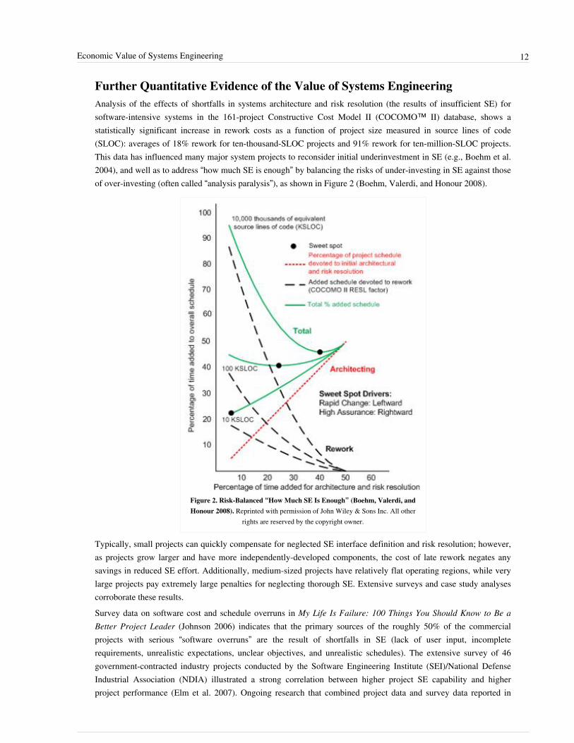
Further Quantitative Evidence of the Value of Systems EngineeringAnalysis of the effects of shortfalls in systems architecture and risk resolution (the results of insufficient SE) forsoftware-intensive systems in the 161-project Constructive Cost Model II (COCOMO™ II) database, shows astatistically significant increase in rework costs as a function of project size measured in source lines of code(SLOC): averages of 18% rework for ten-thousand-SLOC projects and 91% rework for ten-million-SLOC projects.This data has influenced many major system projects to reconsider initial underinvestment in SE (e.g., Boehm et al.2004), and well as to address “how much SE is enough” by balancing the risks of under-investing in SE against thoseof over-investing (often called “analysis paralysis”), as shown in Figure 2 (Boehm, Valerdi, and Honour 2008).
Figure 2. Risk-Balanced “How Much SE Is Enough” (Boehm, Valerdi, andHonour 2008). Reprinted with permission of John Wiley & Sons Inc. All other
rights are reserved by the copyright owner.
Typically, small projects can quickly compensate for neglected SE interface definition and risk resolution; however,as projects grow larger and have more independently-developed components, the cost of late rework negates anysavings in reduced SE effort. Additionally, medium-sized projects have relatively flat operating regions, while verylarge projects pay extremely large penalties for neglecting thorough SE. Extensive surveys and case study analysescorroborate these results.Survey data on software cost and schedule overruns in My Life Is Failure: 100 Things You Should Know to Be a Better Project Leader (Johnson 2006) indicates that the primary sources of the roughly 50% of the commercial projects with serious “software overruns” are the result of shortfalls in SE (lack of user input, incomplete requirements, unrealistic expectations, unclear objectives, and unrealistic schedules). The extensive survey of 46 government-contracted industry projects conducted by the Software Engineering Institute (SEI)/National Defense Industrial Association (NDIA) illustrated a strong correlation between higher project SE capability and higher project performance (Elm et al. 2007). Ongoing research that combined project data and survey data reported in

Economic Value of Systems Engineering 13
“Toward an Understanding of The Value of SE” (Honour 2003) and “Effective Characterization Parameters forMeasuring SE” (Honour 2010) has provided additional evidence as to the economic value of SE and further insightson critical factors the affect SE success.A calibrated model for determining “how much SE is enough”, the Constructive Systems Engineering Cost Model(COSYSMO) has been developed and is discussed in (Valerdi 2008). It estimates the number of person-months thata project needs for SE as a function of system size (i.e., requirements, interfaces, algorithms, and operationalscenarios), modified by 14 factors (i.e., requirements understanding, technology risk, personnel experience, etc.),which dictates the amount of SE effort needed. Other economic considerations of SE include the costs and benefitsof reuse (Wang, Valerdi and Fortune 2010), the management of SE assets across product lines (Fortune and Valerdi2013), the impact of SE on project risk (Madachy and Valerdi 2010), and the role of requirements volatility on SEeffort (Pena and Valerdi 2010).
References
Works CitedBoehm, B., Brown, A.W., Basili, V., and Turner, R. 2004. "Spiral Acquisition of Software-Intensive Systems ofSystems." CrossTalk. May, pp. 4-9.Boehm, B., R. Valerdi, and E.C. Honour. 2008. "The ROI of Systems Engineering: Some Quantitative Results forSoftware-Intensive Systems." Systems Engineering. 11(3): 221-234.Elm, J. P., D.R. Goldenson, K. El Emam, N. Donatelli, and A. Neisa. 2008. A Survey of Systems EngineeringEffectiveness-Initial Results (with Detailed Survey Response Data). Pittsburgh, PA, USA: Software EngineeringInstitute, CMU/SEI-2008-SR-034. December 2008.Fortune, J., and R. Valerdi. 2013. "A Framework for Systems Engineering Reuse." Systems Engineering 16(2).Honour, E.C. 2003. "Toward An Understanding of The Value of Systems Engineering." Proceedings of the FirstAnnual Conference on Systems Integration, March 2003, Hoboken, NJ, USA.Honour, E.C. 2010. "Effective Characterization Parameters for Measuring Systems Engineering." Proceedings of the8th Annual Conference on Systems Engineering Research (CSER). March 17-19, 2010. Hoboken, NJ, USA.Johnson, J. 2006. My Life Is Failure: 100 Things You Should Know to Be a Better Project Leader. Boston, MA,USA: Standish Group International.Madachy, R., and R. Valerdi. 2010. Automating Systems Engineering Risk Assessment. 8th Conference on SystemsEngineering Research, Hoboken, NJ.Pena, M., and R. Valerdi. 2010. "Characterizing the Impact of Requirements Volatility on Systems EngineeringEffort." 25th Forum on COCOMO and Systems/Software Cost Modeling, Los Angeles, CA.Stutzke, R. 2005. Estimating Software-Intensive Systems. Boston, MA, USA: Addison Wesley.Valerdi, R. 2008. The Constructive Systems Engineering Cost Model (COSYSMO): Quantifying the Costs of SystemsEngineering Effort in Complex Systems. Saarbrücken, Germany: VDM Verlag.Wang, G., R. Valerdi, and J. Fortune. 2010. “Reuse in Systems Engineering,” IEEE Systems Journal. 4(3): 376-384.

Economic Value of Systems Engineering 14
Primary ReferencesBoehm, B., R. Valerdi, and E.C. Honour. 2008. "The ROI of Systems Engineering: Some Quantitative Results forSoftware-Intensive Systems." Systems Engineering, 11(3): 221-234.Honour, E.C. 2010. "Effective Characterization Parameters for Measuring Systems Engineering." Proceedings of the8th Annual Conference on Systems Engineering Research (CSER). March 17-19, 2010. Hoboken, NJ, USA.Valerdi, R. 2008. The Constructive Systems Engineering Cost Model (COSYSMO): Quantifying the Costs of SystemsEngineering Effort in Complex Systems. Saarbrücken, Germany: VDM Verlag.
Additional ReferencesHughes, T.P. 2000. Rescuing Prometheus: Four Monumental Projects that Changed the Modern World. New York,NY: Vintage Books.Vanek, F., R. Grzybowski, P. Jackson, and M. Whiting. 2010. "Effectiveness of Systems Engineering Techniques onNew Product Development: Results from Interview Research at Corning Incorporated." Proceedings of the 20thAnnual INCOSE International Symposium. 12-15 July 2010. Chicago, IL.
< Previous Article | Parent Article | Next Article >SEBoK v. 1.4 released 29 June 2015
SEBoK DiscussionPlease provide your comments and feedback on the SEBoK below. You will need to log in to DISQUS using anexisting account (e.g. Yahoo, Google, Facebook, Twitter, etc.) or create a DISQUS account. Simply type yourcomment in the text field below and DISQUS will guide you through the login or registration steps. Feedback will bearchived and used for future updates to the SEBoK. If you provided a comment that is no longer listed, that commenthas been adjudicated. You can view adjudication for comments submitted prior to SEBoK v. 1.0 at SEBoK Reviewand Adjudication. Later comments are addressed and changes are summarized in the Letter from the Editor andAcknowledgements and Release History.
If you would like to provide edits on this article, recommend new content, or make comments on the SEBoKas a whole, please see the SEBoK Sandbox [3].
ENCODED_CONTENTMTIxMzgPGRpdiBpZD0iZGlzcXVzX3RocmVhZCI+PC9kaXY+CjxzY3JpcHQgdHlwZT0idGV4dC9qYXZhc2NyaXB0Ij4KICAgIC8qICogKiBDT05GSUdVUkFUSU9OIFZBUklBQkxFUzogRURJVCBCRUZPUkUgUEFTVElORyBJTlRPIFlPVVIgV0VCUEFHRSAqICogKi8KICAgIHZhciBkaXNxdXNfc2hvcnRuYW1lID0gJ3NlYm9rd2lraTEwJzsgLy8gcmVxdWlyZWQ6IHJlcGxhY2UgZXhhbXBsZSB3aXRoIHlvdXIgZm9ydW0gc2hvcnRuYW1lCiAgICB2YXIgZGlzcXVzX2lkZW50aWZpZXIgPSAnRWNvbm9taWMgVmFsdWUgb2YgU3lzdGVtcyBFbmdpbmVlcmluZyc7ICAgIHZhciBkaXNxdXNfdXJsID0gJ2h0dHA6Ly9zZWJva3dpa2kub3JnL2RyYWZ0L0Vjb25vbWljX1ZhbHVlX29mX1N5c3RlbXNfRW5naW5lZXJpbmcnOwogICAgLyogKiAqIERPTidUIEVESVQgQkVMT1cgVEhJUyBMSU5FICogKiAqLwogICAgKGZ1bmN0aW9uKCkgewogICAgICAgIHZhciBkc3EgPSBkb2N1bWVudC5jcmVhdGVFbGVtZW50KCdzY3JpcHQnKTsgZHNxLnR5cGUgPSAndGV4dC9qYXZhc2NyaXB0JzsgZHNxLmFzeW5jID0gdHJ1ZTsKICAgICAgICBkc3Euc3JjID0gJ2h0dHA6Ly8nICsgZGlzcXVzX3Nob3J0bmFtZSArICcuZGlzcXVzLmNvbS9lbWJlZC5qcyc7CiAgICAgICAgKGRvY3VtZW50LmdldEVsZW1lbnRzQnlUYWdOYW1lKCdoZWFkJylbMF0gfHwgZG9jdW1lbnQuZ2V0RWxlbWVudHNCeVRhZ05hbWUoJ2JvZHknKVswXSkuYXBwZW5kQ2hpbGQoZHNxKTsKICAgIH0pKCk7Cjwvc2NyaXB0Pgo8bm9zY3JpcHQ+UGxlYXNlIGVuYWJsZSBKYXZhU2NyaXB0IHRvIHZpZXcgdGhlIDxhIGhyZWY9Imh0dHA6Ly9kaXNxdXMuY29tLz9yZWZfbm9zY3JpcHQiPmNvbW1lbnRzIHBvd2VyZWQgYnkgRGlzcXVzLjwvYT48L25vc2NyaXB0Pgo8YSBocmVmPSJodHRwOi8vZGlzcXVzLmNvbSIgY2xhc3M9ImRzcS1icmxpbmsiPmJsb2cgY29tbWVudHMgcG93ZXJlZCBieSA8c3BhbiBjbGFzcz0ibG9nby1kaXNxdXMiPkRpc3F1czwvc3Bhbj48L2E+END_ENCODED_CONTENT
Systems Engineering: Historic and Future Challenges 15
Systems Engineering: Historic and FutureChallengesWe can view the evolution of systems engineering (SE) in terms of challenges and responses. Humans have facedincreasingly complex challenges and have had to think systematically and holistically in order to produce successfulresponses to challenges. From these responses, generalists have developed generic principles and practices forreplicating success.
Historical PerspectiveSome of the earliest relevant challenges were in organizing cities. Emerging cities relied on functions such as storinggrain and emergency supplies, defending the stores and the city, supporting transportation and trade, afterlifepreparations, providing a water supply, and accommodating palaces, citadels, and temples. The considerable holisticplanning and organizational skills required to realize these functions were independently developed in the MiddleEast, Egypt, Asia, and Latin America, as described in Lewis Mumford’s The City in History (Mumford 1961).Megacities, and mobile cities for military operations, such as those present in the Roman Empire, emerged next,bringing another wave of challenges and responses. These also spawned generalists and their ideological works, suchas Vitruvius and his Ten Books on Architecture (Vitruvius: Morgan transl. 1960). “Architecture” in Rome meant notjust buildings, but also aqueducts, central heating, surveying, landscaping, and overall planning of cities.The Industrial Revolution brought another wave of challenges and responses. In the nineteenth century, new holisticthinking and planning went into creating and sustaining transportation systems, including canal, railroad, andmetropolitan transit. General treatises, such as The Economic Theory of the Location of Railroads (Wellington1887), appeared in this period. The early twentieth century saw large-scale industrial enterprise engineering, such asthe Ford automotive assembly plants, along with treatises like The Principles of Scientific Management (Taylor1911).The Second World War presented challenges around the complexities of real-time command and control ofextremely large multinational land, sea, and air forces and their associated logistics and intelligence functions. Thepostwar period brought the Cold War and Russian space achievements. The U.S. and its allies responded to thesechallenges by investing heavily in researching and developing principles, methods, processes, and tools for militarydefense systems, complemented by initiatives addressing industrial and other governmental systems. Landmarkresults included the codification of operations research and SE in Introduction to Operations Research (Churchmanet. al 1957), Warfield (1956), and Goode-Machol (1957) and the Rand Corporation approach as seen in Efficiency inGovernment Through Systems Analysis (McKean 1958). In theories of system behavior and SE, we see cybernetics(Weiner 1948), system dynamics (Forrester 1961), general systems theory (Bertalanffy 1968), and mathematicalsystems engineering theory (Wymore 1977).Two further sources of challenge began to emerge in the 1960s, and accelerated in the 1970s through the 1990s: thegrowth of software functionality in systems, and, awareness of the criticality of the human element in complexsystems.While software was responsible for functionality in 8% of military aircraft in 1960, this number had risen to 80% in2000 (Ferguson 2001). One response to this challenge is the appearance of model-based systems engineering(MBSE), which is better suited to managing complexity, including that of software, than traditionaldocument-centric approaches (Friedenthal 2008).Concerning awareness of the human element, the response was a reorientation from traditional SE toward “soft” SE approaches. Traditional hardware-oriented SE featured sequential processes, pre-specified requirements, functional-hierarchy architectures, mathematics-based solutions, and single-step system development. “Soft” SE is

Systems Engineering: Historic and Future Challenges 16
characterized by emergent requirements, concurrent definition of requirements and solutions, combinations oflayered service-oriented and functional-hierarchy architectures, heuristics-based solutions, and evolutionary systemdevelopment. Good examples are societal systems (Warfield 1976), soft systems methodology (Checkland 1981),and systems architecting (Rechtin 1991 and Rechtin-Maier 1997). As with Vitruvius, "architecting" in this sense isnot confined to producing blueprints from requirements, but instead extends to concurrent work on operationalconcepts, requirements, structure, and life cycle planning.
Evolution of Systems Engineering ChallengesFrom 1990 on, rapidly increasing scale, dynamism, and vulnerabilities in the systems being engineered havepresented ever-greater challenges. The Internet offers efficient interoperability of net-centric systems of systems(SoS), but brings new sources of system vulnerability and obsolescence as new Internet services (clouds, socialnetworks, search engines, geolocation services, recommendation services, and electrical grid and industrial controlsystems) proliferate and compete with each other.Meanwhile, challenges come from several ways in which solution approaches have proliferated:•• While domain-specific model-based approaches offer significant benefits, reconciling many different domain
assumptions to get domain-specific systems to interoperate is a challenge.•• The appearance of many competing object-oriented methods posed a problem that was addressed by the
development of the Unified Modeling Language (UML) (Booch-Rumbaugh-Jacobson 1998) and the SystemsModeling Language (SysML) (Friedenthal 2008). However, the wave of UML and SysML tools that followed,along with a number of alternative requirements and architecture representations intended to compensate forshortcomings of UML and SysML, again create dilemmas around interoperability and choice.
•• Areas that have seen a sometimes bewildering growth of alternatives are: enterprise architecture, lean and agileprocesses, iterative and evolutionary processes, and methods for simultaneously achieving high-effectiveness,high-assurance, resilient, adaptive, and life cycle affordable systems.
This trend towards diversity has increased awareness that there is no one-size-fits-all product or process approachthat works best in all situations. In turn, determining which SE approaches work best in which situation, and how tosustain workable complex SoSs containing different solution approaches, emerges as yet another challenge.Similarly, assessing and integrating new technologies with increasing rates of change presents further SE challenges.This is happening in such areas as biotechnology, nanotechnology, and combinations of physical and biologicalentities, mobile networking, social network technology, cooperative autonomous agent technology, massivelyparallel data processing, cloud computing, and data mining technology.Ambitious projects to create smart services, smart hospitals, energy grids, and cities are underway. These promiseimproved system capabilities and quality of life, but carry risks of reliance on immature technologies or oncombinations of technologies with incompatible objectives or assumptions. The advantages of creatingnetwork-centric SoSs to “see first,” “understand first,” and “act first” are highly attractive in a globally competitiveworld, but carry challenges of managing complexes of hundreds of independently-evolving systems over which onlypartial control is possible. SE is increasingly needed but increasingly challenged in the quest to make future systemsscalable, stable, adaptable, and humane.To accommodate this complexity, the SEBoK presents alternative approaches along with current knowledge ofwhere they work best. Being a wiki allows the SEBoK to evolve quickly while maintaining stability betweenversions.

Systems Engineering: Historic and Future Challenges 17
References
Works CitedBertalanffy, L. von. 1968. General System Theory: Foundations, Development, Applications. New York, NY, USA:George Braziller.Booch, G., J. Rumbaugh, and I. Jacobson. 1998. The Unified Modeling Language User Guide. Reading, MA, USA:Addison Wesley.Checkland, P. 1981. Systems Thinking, Systems Practice. Hoboken, NJ, USA: Wiley, 1981.Churchman, C.W., R. Ackoff, and E. Arnoff. 1957. Introduction to Operations Research. New York, NY, USA:Wiley and Sons.Ferguson, J. 2001. "Crouching Dragon, Hidden Software: Software in DoD Weapon Systems." IEEE Software,July/August, p. 105–107.Forrester, J. 1961. Industrial Dynamics. Winnipeg, Manitoba, Canada: Pegasus Communications.Friedenthal, S. 2008. A Practical Guide to SysML: The Systems Modeling Language. Morgan Kaufmann / The OMGPress.Goode, H. and R. Machol. 1957. Systems Engineering: An Introduction to the Design of Large-Scale Systems. NewYork, NY, USA: McGraw-Hill.McKean, R. 1958. Efficiency in Government Through Systems Analysis. New York, NY, USA: John Wiley and Sons.Mumford, L. 1961. The City in History. San Diego, CA, USA: Harcourt Brace Jovanovich.Rechtin, E. 1991. Systems Architecting. Upper Saddle River, NJ, USA: Prentice Hall.Rechtin, E. and M. Maier. 1997. The Art of Systems Architecting. Boca Raton, FL, USA: CRC Press.Taylor, F. 1911. The Principles of Scientific Management. New York, NY, USA and London, UK: Harper &Brothers.Vitruvius, P. (transl. Morgan, M.) 1960. The Ten Books on Architecture. North Chelmsford, MA, USA: CourierDover Publications.Warfield, J. 1956. Systems Engineering. Washington, DC, USA: US Department of Commerce (DoC).Wellington, A. 1887. The Economic Theory of the Location of Railroads. New York, NY, USA: John Wiley andSons.Wiener, N. 1948. Cybernetics or Control and Communication in the Animal and the Machine. New York, NY, USA:John Wiley & Sons Inc.Wymore, A. W. 1977. A Mathematical Theory of Systems Engineering: The Elements. Huntington, NY, USA:Robert E. Krieger.
Primary ReferencesBertalanffy, L. von. 1968. General System Theory: Foundations, Development, Applications. New York, NY, USA:George Braziller.Boehm, B. 2006. "Some Future Trends and Implications for Systems and Software Engineering Processes." SystemsEngineering. Wiley Periodicals, Inc. 9(1), pp 1-19.Checkland, P. 1981. Systems Thinking, Systems Practice. Hoboken, NJ, USA: Wiley, 1981.INCOSE Technical Operations. 2007. Systems Engineering Vision 2020, version 2.03. Seattle, WA: InternationalCouncil on Systems Engineering, Seattle, WA, INCOSE-TP-2004-004-02.

Systems Engineering: Historic and Future Challenges 18
INCOSE. 2012. Systems Engineering Handbook: A Guide for System Life Cycle Processes and Activities, version3.2.2. San Diego, CA, USA: International Council on Systems Engineering (INCOSE). INCOSE-TP-2003-002-03.2.Warfield, J. 1956. Systems Engineering. Washington, DC, USA: US Department of Commerce (DoC). ReportPB111801.Warfield, J. 1976. Societal Systems: Planning, Policy, and Complexity. New York, NY, USA: John Wiley & Sons.Wymore, A. W. 1977. A Mathematical Theory of Systems Engineering: The Elements. Huntington, NY, USA:Robert E. Krieger.
Additional ReferencesHitchins, D. 2007. Systems Engineering: A 21st Century Methodology. Chichester, England: Wiley.McKean, R. 1958. Efficiency in Government Through Systems Analysis. New York, NY, USA: John Wiley and Sons.The MITRE Corporation. 2011. "The Evolution of Systems Engineering." in The MITRE Systems EngineeringGuide. Accessed 8 March 2012 at [1].Sage, A. and W. Rouse (eds). 1999. Handbook of Systems Engineering and Management. Hoboken, NJ, USA: JohnWiley and Sons, Inc.
< Previous Article | Parent Article | Next Article >SEBoK v. 1.4 released 29 June 2015
SEBoK DiscussionPlease provide your comments and feedback on the SEBoK below. You will need to log in to DISQUS using anexisting account (e.g. Yahoo, Google, Facebook, Twitter, etc.) or create a DISQUS account. Simply type yourcomment in the text field below and DISQUS will guide you through the login or registration steps. Feedback will bearchived and used for future updates to the SEBoK. If you provided a comment that is no longer listed, that commenthas been adjudicated. You can view adjudication for comments submitted prior to SEBoK v. 1.0 at SEBoK Reviewand Adjudication. Later comments are addressed and changes are summarized in the Letter from the Editor andAcknowledgements and Release History.
If you would like to provide edits on this article, recommend new content, or make comments on the SEBoKas a whole, please see the SEBoK Sandbox [3].
ENCODED_CONTENTMTc2MDIPGRpdiBpZD0iZGlzcXVzX3RocmVhZCI+PC9kaXY+CjxzY3JpcHQgdHlwZT0idGV4dC9qYXZhc2NyaXB0Ij4KICAgIC8qICogKiBDT05GSUdVUkFUSU9OIFZBUklBQkxFUzogRURJVCBCRUZPUkUgUEFTVElORyBJTlRPIFlPVVIgV0VCUEFHRSAqICogKi8KICAgIHZhciBkaXNxdXNfc2hvcnRuYW1lID0gJ3NlYm9rd2lraTEwJzsgLy8gcmVxdWlyZWQ6IHJlcGxhY2UgZXhhbXBsZSB3aXRoIHlvdXIgZm9ydW0gc2hvcnRuYW1lCiAgICB2YXIgZGlzcXVzX2lkZW50aWZpZXIgPSAnU3lzdGVtcyBFbmdpbmVlcmluZzogSGlzdG9yaWMgYW5kIEZ1dHVyZSBDaGFsbGVuZ2VzJzsgICAgdmFyIGRpc3F1c191cmwgPSAnaHR0cDovL3NlYm9rd2lraS5vcmcvZHJhZnQvU3lzdGVtc19FbmdpbmVlcmluZzpfSGlzdG9yaWNfYW5kX0Z1dHVyZV9DaGFsbGVuZ2VzJzsKICAgIC8qICogKiBET04nVCBFRElUIEJFTE9XIFRISVMgTElORSAqICogKi8KICAgIChmdW5jdGlvbigpIHsKICAgICAgICB2YXIgZHNxID0gZG9jdW1lbnQuY3JlYXRlRWxlbWVudCgnc2NyaXB0Jyk7IGRzcS50eXBlID0gJ3RleHQvamF2YXNjcmlwdCc7IGRzcS5hc3luYyA9IHRydWU7CiAgICAgICAgZHNxLnNyYyA9ICdodHRwOi8vJyArIGRpc3F1c19zaG9ydG5hbWUgKyAnLmRpc3F1cy5jb20vZW1iZWQuanMnOwogICAgICAgIChkb2N1bWVudC5nZXRFbGVtZW50c0J5VGFnTmFtZSgnaGVhZCcpWzBdIHx8IGRvY3VtZW50LmdldEVsZW1lbnRzQnlUYWdOYW1lKCdib2R5JylbMF0pLmFwcGVuZENoaWxkKGRzcSk7CiAgICB9KSgpOwo8L3NjcmlwdD4KPG5vc2NyaXB0PlBsZWFzZSBlbmFibGUgSmF2YVNjcmlwdCB0byB2aWV3IHRoZSA8YSBocmVmPSJodHRwOi8vZGlzcXVzLmNvbS8/cmVmX25vc2NyaXB0Ij5jb21tZW50cyBwb3dlcmVkIGJ5IERpc3F1cy48L2E+PC9ub3NjcmlwdD4KPGEgaHJlZj0iaHR0cDovL2Rpc3F1cy5jb20iIGNsYXNzPSJkc3EtYnJsaW5rIj5ibG9nIGNvbW1lbnRzIHBvd2VyZWQgYnkgPHNwYW4gY2xhc3M9ImxvZ28tZGlzcXVzIj5EaXNxdXM8L3NwYW4+PC9hPg==END_ENCODED_CONTENT
References[1] http:/ / www. mitre. org/ work/ systems_engineering/ guide/ evolution_systems. html

Systems Engineering and Other Disciplines 19
Systems Engineering and Other DisciplinesAs discussed in the Scope of the SEBoK article, there are many touch points and overlaps between systemsengineering (SE) and other disciplines. Systems engineers should have a basic understanding of the nature of theseother disciplines, and often need to understand aspects of another discipline in detail. This article describes thelandscape of disciplines that are intertwined with SE. For a closer view of the individual disciplines, see Part 6.
Engineering Disciplines Other than Systems EngineeringEngineering disciplines are mostly component-oriented and value-neutral in their intellectual content (Boehm andJain 2006). Their underlying laws and equations, such as Ohm’s Law, Hooke’s Law, Newton’s Laws, Maxwell’sequations, the Navier-Stokes equations, Knuth’s compendia of sorting and searching algorithms, and Fitts’s Law ofhuman movement, pertain to performance in a system-of-interest. They do not address how that performancecontributes to the value propositions of stakeholders.In contrast, SE is more holistic than component-oriented, and more stakeholder value-oriented than value-neutral,performance-oriented in its intellectual content. Realizing successful systems requires reasoning with stakeholdersabout the relative value of alternative realizations, and about the organization of components and people into asystem that satisfies the often-conflicting value propositions of stakeholders. Stakeholders who are critical to thesystem’s success include funders, owners, users, operators, maintainers, manufacturers, and safety and pollutionregulators.In some disciplines, the engineer evaluates and integrates design elements into a system that satisfies proxies ofvalue. The wider the scope of the SoI, the broader the set of SE skills the engineer needs.For example, an aeronautical engineer might integrate mechanical, electrical, fluid, combustion-chemical, software,and cockpit design elements into a system that satisfies proxies of value like flight range, payload capacity, fuelconsumption, maneuverability, and cost of production and maintenance. In so doing, the engineer operates partly asa systems engineer. The SoI is the aircraft itself and the engineer applies aircraft-domain expertise.However, the same engineer could participate in the engineering of passenger services, airport configurations,baggage handling, and local surface transportation options. All of these contribute to the value propositions ofsuccess-critical stakeholders. The SoIs are wider, and the engineer needs broader SE knowledge, skills, and abilitiesto operate as a systems engineer. The aircraft-domain expertise remains needed for effective engineering of the widersystems. As discussed in (Guest 1991), most good systems engineers are “T-shaped” people, with both a workingknowledge of wider-system considerations, and a deep expertise in a relevant domain, such as aeronautical,manufacturing, software, or human factors engineering.Engineering disciplines that are intertwined with SE include software engineering (SwE), human factors engineering,and industrial engineering. SwE and SE are not just allied disciplines, they are intimately intertwined (Boehm 1994).Most functionality of commercial and government systems is now implemented in software, and software plays aprominent or dominant role in differentiating competing systems in the marketplace. Software is usually prominentin modern systems architectures and is often the “glue” for integrating complex system components.The scope of SwE includes both software SE and software construction, but does not include hardware SE. Thusneither SwE nor SE is a subset of the other. See Figure 1 in Scope of the SEBoK. For a definition of the relationshipbetween the SEBoK and the Guide to the Software Engineering Body of Knowledge (SWEBOK), which is publishedby the Institute of Electrical and Electronics Engineers (IEEE) (Abran et al. 2004) and is currently under revision,see Systems Engineering and Software Engineering.Human factors engineering, from micro-ergonomics to macro-ergonomics, is intertwined with SE (Booher 2003;Pew and Mavor 2007). See Human Systems Integration in Part 6.

Systems Engineering and Other Disciplines 20
Industrial engineering overlaps significantly with SE in the industrial domain, but also includes manufacturing andother implementation activities outside of SE. See Systems Engineering and Industrial Engineering in Part 6.Finally, to field a successful system, a systems engineer may need to know one or more of the many specialty fieldsin engineering, e.g., security, safety, reliability, availability, and maintainability engineering. Most of these areconsidered professional disciplines in their own right and many have their own bodies of knowledge. Forexplanations of how these disciplines relate to SE, overviews of what most systems engineers need to know aboutthem, and references within their bodies of knowledge, see Systems Engineering and Specialty Engineering in Part 6.
Non-Engineering DisciplinesSE is intimately intertwined with two non-technical disciplines: technical management (TM), and procurement andacquisition (also known as acquisition and procurement). TM often falls within the purview of a systems engineer.Many SE textbooks, competency models, and university programs include material about TM. TM is a specializationof project management (PM). SE and PM have significant common content in TM, but neither is a subset of theother. See Figure 1 in the article Scope of the SEBoK. For a definition of the relationship between the SEBoK andthe Guide to the Project Management Body of Knowledge (PMBOK), which is published by the Project ManagementInstitute (PMI) (PMI 2013), see Systems Engineering and Project Management in Part 6.Procurement and acquisition practitioners draw upon SE to determine the scope and overall requirements of thesystem to be procured or acquired. They then prepare requests for proposals and statements of work, determineevaluation criteria, and design source selection processes. Once a leading source is selected, they decide uponcontracting options that encompass payments, reviews, audits, incentive fees, acceptance criteria, procedures, and thenature of deliverables. Finally, they monitor progress with respect to plans (including those for SE), and negotiateand execute changes and corrective actions. Many of these activities amount to specialty disciplines withinprocurement and acquisition. See the article Related Disciplines in Part 6.
References
Works CitedAbran, A., J. W. Moore, P. Bourque, R. Dupuis, and L. L. Tripp. 2004. Guide to the Software Engineering Body ofKnowledge (SWEBOK), 2004 version. Los Alamitos, CA, USA and Tokyo, Japan: IEEE Computer Society Press.Boehm, B. and A. Jain. 2006. "A Value-Based Theory of Systems Engineering." Proceedings, INCOSE IS 2006.Also available at: http:/ / sunset. usc. edu/ csse/ TECHRPTS/ 2006/ usccse2006-619/ usccse2006-619. pdf.Booher, H. 2003. Handbook of Human-Systems Integration. New York, NY, USA: John Wiley & Sons Inc.Guest, D. 1991. "The hunt is on for the Renaissance Man of computing." The Independent. London, England:September 17, 1991.INCOSE. 2011. Systems Engineering Handbook, version 3.2.1. San Diego, CA, USA: International Council onSystems Engineering (INCOSE). INCOSE-TP-2003-002-03.2.Pew, R. and A. Mavor. 2007. Human-System Integration in the System Development Process. Washington, DC,USA: The National Academies Press.PMI. 2013. A Guide to the Project Management Body of Knowledge (PMBOK® Guide), 5th ed. Newtown Square,PA, USA: Project Management Institute (PMI).

Systems Engineering and Other Disciplines 21
Primary ReferencesAbran, A., J. W. Moore, P. Bourque, R. Dupuis, and L. L. Tripp. 2004. Guide to the Software Engineering Body ofKnowledge (SWEBOK), 2004 version. Los Alamitos, CA, USA and Tokyo, Japan: IEEE Computer Society Press.Booher, H. 2003. Handbook of Human-Systems Integration. New York, NY, USA: John Wiley & Sons Inc.Gallagher, B., M. Phillips, K. Richter, and S. Shrum. 2011. CMMI For Acquisition: Guidelines for Improving theAcquisition of Products and Services, second ed. Upper Saddle River, NJ, USA: Addison Wesley.Paulk, M., C. Weber, B. Curtis, and M. Chrissis. 1995. The Capability Maturity Model: Guidelines for Improving theSoftware Process. Upper Saddle River, NJ, USA: Addison Wesley.Pyster, A. (ed.). 2009. Graduate Software Engineering 2009 (GSwE2009): Curriculum Guidelines for GraduateDegree Programs in Software Engineering. Integrated Software & Systems Engineering Curriculum Project.Hoboken, NJ, USA: Stevens Institute of Technology, September 30, 2009.Pew, R. and A. Mavor. 2007. Human-System Integration in the System Development Process. Washington, DC,USA: The National Academies Press.PMI. 2013. A Guide to the Project Management Body of Knowledge (PMBOK® Guide), 5th ed. Newtown Square,PA, USA: Project Management Institute (PMI).
Additional ReferencesNone.
< Previous Article | Parent Article | Next Article >SEBoK v. 1.4 released 29 June 2015
SEBoK DiscussionPlease provide your comments and feedback on the SEBoK below. You will need to log in to DISQUS using anexisting account (e.g. Yahoo, Google, Facebook, Twitter, etc.) or create a DISQUS account. Simply type yourcomment in the text field below and DISQUS will guide you through the login or registration steps. Feedback will bearchived and used for future updates to the SEBoK. If you provided a comment that is no longer listed, that commenthas been adjudicated. You can view adjudication for comments submitted prior to SEBoK v. 1.0 at SEBoK Reviewand Adjudication. Later comments are addressed and changes are summarized in the Letter from the Editor andAcknowledgements and Release History.
If you would like to provide edits on this article, recommend new content, or make comments on the SEBoKas a whole, please see the SEBoK Sandbox [3].
ENCODED_CONTENTMjA2MTIPGRpdiBpZD0iZGlzcXVzX3RocmVhZCI+PC9kaXY+CjxzY3JpcHQgdHlwZT0idGV4dC9qYXZhc2NyaXB0Ij4KICAgIC8qICogKiBDT05GSUdVUkFUSU9OIFZBUklBQkxFUzogRURJVCBCRUZPUkUgUEFTVElORyBJTlRPIFlPVVIgV0VCUEFHRSAqICogKi8KICAgIHZhciBkaXNxdXNfc2hvcnRuYW1lID0gJ3NlYm9rd2lraTEwJzsgLy8gcmVxdWlyZWQ6IHJlcGxhY2UgZXhhbXBsZSB3aXRoIHlvdXIgZm9ydW0gc2hvcnRuYW1lCiAgICB2YXIgZGlzcXVzX2lkZW50aWZpZXIgPSAnU3lzdGVtcyBFbmdpbmVlcmluZyBhbmQgT3RoZXIgRGlzY2lwbGluZXMnOyAgICB2YXIgZGlzcXVzX3VybCA9ICdodHRwOi8vc2Vib2t3aWtpLm9yZy9kcmFmdC9TeXN0ZW1zX0VuZ2luZWVyaW5nX2FuZF9PdGhlcl9EaXNjaXBsaW5lcyc7CiAgICAvKiAqICogRE9OJ1QgRURJVCBCRUxPVyBUSElTIExJTkUgKiAqICovCiAgICAoZnVuY3Rpb24oKSB7CiAgICAgICAgdmFyIGRzcSA9IGRvY3VtZW50LmNyZWF0ZUVsZW1lbnQoJ3NjcmlwdCcpOyBkc3EudHlwZSA9ICd0ZXh0L2phdmFzY3JpcHQnOyBkc3EuYXN5bmMgPSB0cnVlOwogICAgICAgIGRzcS5zcmMgPSAnaHR0cDovLycgKyBkaXNxdXNfc2hvcnRuYW1lICsgJy5kaXNxdXMuY29tL2VtYmVkLmpzJzsKICAgICAgICAoZG9jdW1lbnQuZ2V0RWxlbWVudHNCeVRhZ05hbWUoJ2hlYWQnKVswXSB8fCBkb2N1bWVudC5nZXRFbGVtZW50c0J5VGFnTmFtZSgnYm9keScpWzBdKS5hcHBlbmRDaGlsZChkc3EpOwogICAgfSkoKTsKPC9zY3JpcHQ+Cjxub3NjcmlwdD5QbGVhc2UgZW5hYmxlIEphdmFTY3JpcHQgdG8gdmlldyB0aGUgPGEgaHJlZj0iaHR0cDovL2Rpc3F1cy5jb20vP3JlZl9ub3NjcmlwdCI+Y29tbWVudHMgcG93ZXJlZCBieSBEaXNxdXMuPC9hPjwvbm9zY3JpcHQ+CjxhIGhyZWY9Imh0dHA6Ly9kaXNxdXMuY29tIiBjbGFzcz0iZHNxLWJybGluayI+YmxvZyBjb21tZW50cyBwb3dlcmVkIGJ5IDxzcGFuIGNsYXNzPSJsb2dvLWRpc3F1cyI+RGlzcXVzPC9zcGFuPjwvYT4=END_ENCODED_CONTENT

Scope of the SEBoK 22
Scope of the SEBoKThe SEBoK is a large compendium of information about systems engineering. It:•• is a guide to the body of SE knowledge which provides references to detailed sources for additional information;
it is not a self-contained knowledge resource•• is domain-independent, with implementation examples to provide domain-specific context• focuses on engineered systems (ES), that is, products, services, enterprises, and systems of systems (SoS), while
treating social and natural systems as relevant and important environmental considerations for ESs (see thediscussion below for more on this as well as look at What is a System? in Part 2)
• recognizes that SE principles can be applied differently to different types of systems (see Part 4)• provides resources for organization support of SE activities (see Part 5)• explores the interaction between SE and other disciplines, highlighting what systems engineers need to know
about these disciplines (see Part 6)Each of these considerations depends upon the definition and scope of SE itself, which is the subject of the nextsection.
Systems Engineering and Engineered Systems Project Life Cycle ContextFigure 1 summarizes the main agents, activities, and artifacts involved in the life cycle of SE, in the context of aproject to create and evolve an ES.
Figure 1. SE and Engineered System Project Life Cycle Context: Related Agents, Activities, and Artifacts. (SEBoK Original)
For each primary project life cycle phase, we see activities being performed by primary agents, changing the state ofthe ES.•• Primary project life cycle phases appear in the leftmost column. They are system definition, system initial
operational capability (IOC) development, and system evolution and retirement.

Scope of the SEBoK 23
•• Primary agents appear in the three inner columns of the top row. They are systems engineers, systems developers,and primary project-external bodies (users, owners, external systems) which constitute the project environment.
•• The ES, which appears in the rightmost column, may be a product, a service, and/or an enterprise.In each row:•• boxes in each inner column show activities being performed by the agent listed in the top row of that column•• the resulting artifacts appears in the rightmost box.Arrows indicate dependencies: an arrow from box A to box B means that the successful outcome of box B dependson the successful outcome of box A. Two-headed arrows indicate a two-way dependencies: an arrow that points bothfrom box A to box B and from box B to box A means that the successful outcome of each box depends on thesuccessful outcome of the other.For example, consider how the inevitable changes that arise during system development and evolution are handled:• One box shows that the system’s users and owners may propose changes.•• The changes must be negotiated with the systems developers, who are shown in a second box.•• The negotiations are mediated by systems engineers, who are shown in a third box in between the first two.•• Since the proposed changes run from left to right and the counter-proposals run from right to left, all three boxes
are connected by two-headed arrows. This reflects the two-way dependencies of the negotiation.An agent-activity-artifact diagram like Figure 1 can be used to capture complex interactions. Taking a more detailedview of the present example demonstrates that:• The system’s users and owners (stakeholders) propose changes to respond to competitive threats or opportunities,
or to adapt to changes imposed by independently evolving external systems, such as Commercial-off-the-ShelfCOTS products, cloud services, or supply chain enablers.
•• Negotiation among these stakeholders and the system developers follows, mediated by the SEs.•• The role of the SEs is to analyze the relative costs and benefits of alternative change proposals, and synthesize
mutually satisfactory solutions.
SEBoK Domain Independent ContextThe SEBoK uses language and concepts that are generally accepted for domain-independent SE. For example, thedomain-independent conceptual foundations of SE are elaborated in Part 2: Foundations of Systems Engineering.However, each of the numerous domains in which SE is practiced — including telecommunications, finance,medicine, and aerospace — has its own specialized vocabulary and key concepts. Accordingly, the SEBoK isdesigned to show how its domain-independent material relates to individual domains, by means of examples that tellstories of how SE is applied in particular domains. (Part 7 ) consists of examples (case studies and vignettes), eachset in a particular domain such as aerospace, medicine, or software, and featuring vocabulary and concepts special tothat domain. There are similar vignettes in some of the Use Cases in Part 1. These examples demonstrate the effectof domain on the application of SE and complement the domain-independent information elsewhere in the SEBoK.They show how a concept works in a given domain and provide a fair opportunity for reviewers to reflect on whetherthere are better ways to capture application-dependent aspects of SE knowledge.The authors recognize that case studies and vignettes add significant value to the SEBoK, and expect many more tobe added as the SEBoK evolves.

Scope of the SEBoK 24
SEBoK Life Cycle ContextFigure 2 summarizes the main agents, activities, and artifacts in the SEBoK life cycle.The SEBoK is one of two complementary products. The other, which uses the content of the SEBoK to define a corebody of knowledge (CorBoK) to be included in graduate SE curricula, is called the Graduate Reference Curriculumfor Systems Engineering (GRCSE) (Pyster et al. 2012). GRCSE is not a standard, but a reference curriculum to betailored and extended to meet the objectives of each university’s graduate program. These products are beingdeveloped by the Body of Knowledge and Curriculum to Advance Systems Engineering (BKCASE) project (seehttp:/ / www. bkcase. org).
Figure 2. SEBoK Life Cycle and Context: Related Agents, Activities, and Artifacts. (SEBoK Original)
The BKCASE project, led by Stevens Institute of Technology and the Naval Postgraduate School, draws upon threeprimary resources. The U.S. Department of Defense (DoD) has provided the funding and a representative, but doeshas not constrain or direct the project’s approach and content. The Systems Engineering Research Center (SERC), aDoD university-affiliated research center operated by Stevens Institute of Technology, supports BKCASEmanagement and infrastructure and is the means by which DoD funding is delivered to the BKCASE project. Theinternational author team of 70 members has been selected for expertise in SE and diversity of national origin(authors have come from 10 different countries in 5 continents), economic sector (government, industry, academia),and SE specialty area. These authors have donated their time to the development of the SEBoK content.The SEBoK content has been developed incrementally. Each of the prototype versions (0.25, 0.5, and 0.75)underwent an open review by all interested parties. Over 200 reviewers submitted thousands of comments, each ofwhich was adjudicated. Upon completion of the initial SEBoK and GRCSE development in late 2012, the Institute ofElectrical and Electronic Engineers Computer Society (IEEE-CS) and the International Council on SystemsEngineering (INCOSE), together with the SERC, are anticipated to become the primary stewards for both theSEBoK and the GRCSE. Interested parties will be able develop, operate, and support derivative products andservices such as courseware, education, certification, and domain-specific versions of the SEBoK and the GRCSE.Copyright Information offers complete information about what others may do with the content of the SEBoK.
Scope of the SEBoK 25
References
Works CitedINCOSE. 2012. Systems Engineering Handbook, version 3.2.2. San Diego, CA, USA: International Council onSystems Engineering (INCOSE). INCOSE-TP-2003-002-03.2.Pyster, A., D.H. Olwell, T.L.J. Ferris, N. Hutchison, S. Enck, J.F. Anthony, D. Henry, and A. Squires (eds). 2012.Graduate Reference Curriculum for Systems Engineering (GRCSE™), version 1.0. Hoboken, NJ, USA: TheTrustees of the Stevens Institute of Technology. Available at: http:/ / www. bkcase. org/ grcse/ .
Primary ReferencesINCOSE. 2012. Systems Engineering Handbook, version 3.2.2. San Diego, CA, USA: International Council onSystems Engineering (INCOSE). INCOSE-TP-2003-002-03.2.Pyster, A., D.H. Olwell, T.L.J. Ferris, N. Hutchison, S. Enck, J.F. Anthony, D. Henry, and A. Squires (eds). 2012.Graduate Reference Curriculum for Systems Engineering (GRCSE™), version 1.0. Hoboken, NJ, USA: TheTrustees of the Stevens Institute of Technology. Available at: http:/ / www. bkcase. org/ grcse/ .
Additional ReferencesSage, A. and W. Rouse (eds). 1999. Handbook of Systems Engineering and Management. Hoboken, NJ, USA: JohnWiley and Sons, Inc.
< Previous Article | Parent Article | Next Article >SEBoK v. 1.4 released 29 June 2015
SEBoK DiscussionPlease provide your comments and feedback on the SEBoK below. You will need to log in to DISQUS using anexisting account (e.g. Yahoo, Google, Facebook, Twitter, etc.) or create a DISQUS account. Simply type yourcomment in the text field below and DISQUS will guide you through the login or registration steps. Feedback will bearchived and used for future updates to the SEBoK. If you provided a comment that is no longer listed, that commenthas been adjudicated. You can view adjudication for comments submitted prior to SEBoK v. 1.0 at SEBoK Reviewand Adjudication. Later comments are addressed and changes are summarized in the Letter from the Editor andAcknowledgements and Release History.
If you would like to provide edits on this article, recommend new content, or make comments on the SEBoKas a whole, please see the SEBoK Sandbox [3].
ENCODED_CONTENTMjA3MDAPGRpdiBpZD0iZGlzcXVzX3RocmVhZCI+PC9kaXY+CjxzY3JpcHQgdHlwZT0idGV4dC9qYXZhc2NyaXB0Ij4KICAgIC8qICogKiBDT05GSUdVUkFUSU9OIFZBUklBQkxFUzogRURJVCBCRUZPUkUgUEFTVElORyBJTlRPIFlPVVIgV0VCUEFHRSAqICogKi8KICAgIHZhciBkaXNxdXNfc2hvcnRuYW1lID0gJ3NlYm9rd2lraTEwJzsgLy8gcmVxdWlyZWQ6IHJlcGxhY2UgZXhhbXBsZSB3aXRoIHlvdXIgZm9ydW0gc2hvcnRuYW1lCiAgICB2YXIgZGlzcXVzX2lkZW50aWZpZXIgPSAnU2NvcGUgb2YgdGhlIFNFQm9LJzsgICAgdmFyIGRpc3F1c191cmwgPSAnaHR0cDovL3NlYm9rd2lraS5vcmcvZHJhZnQvU2NvcGVfb2ZfdGhlX1NFQm9LJzsKICAgIC8qICogKiBET04nVCBFRElUIEJFTE9XIFRISVMgTElORSAqICogKi8KICAgIChmdW5jdGlvbigpIHsKICAgICAgICB2YXIgZHNxID0gZG9jdW1lbnQuY3JlYXRlRWxlbWVudCgnc2NyaXB0Jyk7IGRzcS50eXBlID0gJ3RleHQvamF2YXNjcmlwdCc7IGRzcS5hc3luYyA9IHRydWU7CiAgICAgICAgZHNxLnNyYyA9ICdodHRwOi8vJyArIGRpc3F1c19zaG9ydG5hbWUgKyAnLmRpc3F1cy5jb20vZW1iZWQuanMnOwogICAgICAgIChkb2N1bWVudC5nZXRFbGVtZW50c0J5VGFnTmFtZSgnaGVhZCcpWzBdIHx8IGRvY3VtZW50LmdldEVsZW1lbnRzQnlUYWdOYW1lKCdib2R5JylbMF0pLmFwcGVuZENoaWxkKGRzcSk7CiAgICB9KSgpOwo8L3NjcmlwdD4KPG5vc2NyaXB0PlBsZWFzZSBlbmFibGUgSmF2YVNjcmlwdCB0byB2aWV3IHRoZSA8YSBocmVmPSJodHRwOi8vZGlzcXVzLmNvbS8/cmVmX25vc2NyaXB0Ij5jb21tZW50cyBwb3dlcmVkIGJ5IERpc3F1cy48L2E+PC9ub3NjcmlwdD4KPGEgaHJlZj0iaHR0cDovL2Rpc3F1cy5jb20iIGNsYXNzPSJkc3EtYnJsaW5rIj5ibG9nIGNvbW1lbnRzIHBvd2VyZWQgYnkgPHNwYW4gY2xhc3M9ImxvZ28tZGlzcXVzIj5EaXNxdXM8L3NwYW4+PC9hPg==END_ENCODED_CONTENT

Structure of the SEBoK 26
Structure of the SEBoKThe SEBoK is divided into seven parts, the first six of which focus on domain-independent knowledge, and theseventh part devoted to implementation examples.
Structure
Part 1: SEBoK IntroductionTo help you get the most out of the SEBoK, this part explains the scope, context, and structure of the SEBoK, andthen turns to aspects of systems engineering (SE) itself that matter as you begin to use the SEBoK: SE's economicvalue, history, future, and relationship to other disciplines. An overview of who should use the SEBoK, and for whatpurpose, is followed by detailed use cases. This part concludes with a summary of how the SEBoK has evolved.
Part 2: Foundations of Systems EngineeringStating what systems are, this part covers systems fundamentals and moves on to describe systems science in termsof history and major questions, systems thinking as a set of ideas to be used in SE, and how systems are representedwith models. It concludes by looking at how to take a systems approach to an engineered system (ES), which leadsnaturally into the next two parts, which are concerned with SE management and applications.
Part 3: Systems Engineering and ManagementHow systems are engineered is the subject of this part, which begins with the life cycle models common in SE, thenmoves on to SE management, where planning, measurement, risk, and quality are among the topics. Next is productand service life management, a distinct area of SE management that emphasizes the entire life cycle includingretirement and disposal. An account of SE standards concludes this part. Focused on what many think of as the mainbody of SE, including best practices and common pitfalls, this part constitutes a substantial proportion of theSEBoK. It is anticipated that this part and the following parts will reflect increased emphasis on model-basedsystems engineering (MBSE) practices as these practices continue to evolve and become more mainstream.
Part 4: Applications of Systems EngineeringThis part covers how to apply SE principles as defined in the previous part, focusing on four major categories ofsystems in turn: products, services, enterprises, and systems of systems (SoS).
Part 5: Enabling Systems EngineeringThe subject of this part is how to organize to perform SE activities, at the enterprise, team, or individual level. Therange of considerations extends from value proposition, business purpose, and governance, down to competency,personal development as a systems engineer, and ethics.

Structure of the SEBoK 27
Part 6: Related DisciplinesHow SE is intertwined with software engineering (SwE), project management (PM), industrial engineering,procurement and acquisition, and specialty engineering, is the subject of this part, which describes the varioussystem “–ilities” (like reliability, availability, and maintainability) that SE must balance and integrate.
Part 7: Systems Engineering Implementation ExamplesA set of real-world examples of SE activities forms the natural conclusion of the SEBoK. These come in two forms:case studies, which refer the reader to and summarize published examinations of the successes and challenges of SEprograms, and vignettes, which are brief, self-contained wiki articles. This part is a key place to look within theSEBoK for lessons learned, best practices, and patterns. Many links connect material in the examples to theconceptual, methodological, and other content elsewhere in the SEBoK.
AddendaThe SEBoK contains a Glossary of Terms, which provides authoritatively-referenced definitions of key terms. It alsocontains a list of Primary References, with additional information about each reference. Quicklinks in the left marginprovide additional background information, including a table of contents, a listing of articles by topic [1], and a list ofAcronyms.
Inter-relationshipsAs you navigate the SEBoK, it may be useful to consider the relationships among the elements of the SEBoK andthose found in its external environment. Figures 1 and 2 from the article Scope and Context of the SEBoK expressthose relationships. These figures are an outgrowth of a systems modeling language (SysML) concept map whosedevelopment, application, and iteration were key activities when the SEBoK was being written.
ReferencesNone.
< Previous Article | Parent Article | Next Article >SEBoK v. 1.4 released 29 June 2015
SEBoK DiscussionPlease provide your comments and feedback on the SEBoK below. You will need to log in to DISQUS using anexisting account (e.g. Yahoo, Google, Facebook, Twitter, etc.) or create a DISQUS account. Simply type yourcomment in the text field below and DISQUS will guide you through the login or registration steps. Feedback will bearchived and used for future updates to the SEBoK. If you provided a comment that is no longer listed, that commenthas been adjudicated. You can view adjudication for comments submitted prior to SEBoK v. 1.0 at SEBoK Reviewand Adjudication. Later comments are addressed and changes are summarized in the Letter from the Editor andAcknowledgements and Release History.
If you would like to provide edits on this article, recommend new content, or make comments on the SEBoKas a whole, please see the SEBoK Sandbox [3].
ENCODED_CONTENTODk1MzMPGRpdiBpZD0iZGlzcXVzX3RocmVhZCI+PC9kaXY+CjxzY3JpcHQgdHlwZT0idGV4dC9qYXZhc2NyaXB0Ij4KICAgIC8qICogKiBDT05GSUdVUkFUSU9OIFZBUklBQkxFUzogRURJVCBCRUZPUkUgUEFTVElORyBJTlRPIFlPVVIgV0VCUEFHRSAqICogKi8KICAgIHZhciBkaXNxdXNfc2hvcnRuYW1lID0gJ3NlYm9rd2lraTEwJzsgLy8gcmVxdWlyZWQ6IHJlcGxhY2UgZXhhbXBsZSB3aXRoIHlvdXIgZm9ydW0gc2hvcnRuYW1lCiAgICB2YXIgZGlzcXVzX2lkZW50aWZpZXIgPSAnU3RydWN0dXJlIG9mIHRoZSBTRUJvSyc7ICAgIHZhciBkaXNxdXNfdXJsID0gJ2h0dHA6Ly9zZWJva3dpa2kub3JnL2RyYWZ0L1N0cnVjdHVyZV9vZl90aGVfU0VCb0snOwogICAgLyogKiAqIERPTidUIEVESVQgQkVMT1cgVEhJUyBMSU5FICogKiAqLwogICAgKGZ1bmN0aW9uKCkgewogICAgICAgIHZhciBkc3EgPSBkb2N1bWVudC5jcmVhdGVFbGVtZW50KCdzY3JpcHQnKTsgZHNxLnR5cGUgPSAndGV4dC9qYXZhc2NyaXB0JzsgZHNxLmFzeW5jID0gdHJ1ZTsKICAgICAgICBkc3Euc3JjID0gJ2h0dHA6Ly8nICsgZGlzcXVzX3Nob3J0bmFtZSArICcuZGlzcXVzLmNvbS9lbWJlZC5qcyc7CiAgICAgICAgKGRvY3VtZW50LmdldEVsZW1lbnRzQnlUYWdOYW1lKCdoZWFkJylbMF0gfHwgZG9jdW1lbnQuZ2V0RWxlbWVudHNCeVRhZ05hbWUoJ2JvZHknKVswXSkuYXBwZW5kQ2hpbGQoZHNxKTsKICAgIH0pKCk7Cjwvc2NyaXB0Pgo8bm9zY3JpcHQ+UGxlYXNlIGVuYWJsZSBKYXZhU2NyaXB0IHRvIHZpZXcgdGhlIDxhIGhyZWY9Imh0dHA6Ly9kaXNxdXMuY29tLz9yZWZfbm9zY3JpcHQiPmNvbW1lbnRzIHBvd2VyZWQgYnkgRGlzcXVzLjwvYT48L25vc2NyaXB0Pgo8YSBocmVmPSJodHRwOi8vZGlzcXVzLmNvbSIgY2xhc3M9ImRzcS1icmxpbmsiPmJsb2cgY29tbWVudHMgcG93ZXJlZCBieSA8c3BhbiBjbGFzcz0ibG9nby1kaXNxdXMiPkRpc3F1czwvc3Bhbj48L2E+END_ENCODED_CONTENT

Structure of the SEBoK 28
References[1] http:/ / sebokwiki. org/ 1. 1. 1/ index. php?title=Category:Topic
SEBoK Users and UsesThe users and uses described in this article were identified based on the six SEBoK purposes described in theSEBoK Introduction.Users can either be primary (those who use the SEBoK directly) or secondary (those who use the SEBoK withassistance from a systems engineer). Indicative, but not exhaustive, sets of example uses are shown in Tables 1 and 2below.
New to SEBoK or Systems Engineering?The list of users and use cases below allow someone who has come to the SEBoK with a particular focus to identifyquickly where to focus their reading. If you are completely new to systems engineering or have no clear view of howit is covered in the SEBoK you should use Use Case 0 below to orient yourself and learn the basics before looking atthe other use cases:•• Use Case 0: Systems Engineering Novices
Primary UsersPrimary users are those who use the SEBoK directly, as shown in Table 1. Hyperlinks in the second column link tothe associated use case, where one has been written. The use cases are listed at the end of the topic, and may also beseen here. [1]
Table 1. Primary SEBoK Users and Common Uses. (SEBoK Original)
# Users Uses
1 Practicing Systems Engineersranging from novice through expert
•• Taking on a new SE role in a project; preparing by finding references for study•• Expanding SE expertise and specialization; preparing by finding references for study•• Seeking to understand the principles of SE; seeking the best references to elaborate on those principles•• Reviewing a project or mentoring a new SE performer; seeking to understand what best practices to
look for•• Pursuing professional development through study of SE topics, including new developments in SE
2 Process engineers responsible fordefining or implementing SEprocesses
•• Maintaining a library of SE process assets; seeking to understand which SE process models andstandards are most relevant
•• Tailoring a process for a specific project; seeking to learn how others have tailored processes, or how aspecific application domain affects tailoring
• Measuring the effectiveness of an organization’s SE processes; seeking to learn how others have donethat
•• Defining standards for a professional society or standards organization
3 Faculty Members • Developing a new graduate program in SE, and deciding what core knowledge all its students mustmaster; the user should consult the Graduate Reference Curriculum for Systems Engineering(GRCSE™) in conjunction with the SEBoK
•• Developing a new SE course; seeking to identify course objectives, topics, and reading assignments•• Incorporate SE concepts in courses or curricula focused on engineering disciplines other than SE
4 GRCSE authors •• As members of the GRCSE author team, deciding what knowledge to expect from all SE graduatestudents
• See Graduate Reference Curriculum for Systems Engineering (GRCSE™) (Pyster et al. 2012)

SEBoK Users and Uses 29
5 Certifiers • Defining a company’s in-house SE certification program; seeking to understand what others have done,how such programs are typically structured, and how to select the knowledge that each person seekingcertification should master
•• Defining certification criteria for a professional society or licensure program
6 General Managers, OtherEngineers, developers, testers,researchers
• Mastering basic vocabulary, boundaries, and structure of SE; seeking a few primary references•• Learning what the scope of SE is, relative to the General Manager role• Learning what the role of the systems engineer consists of, relative to others on a project or in an
organization•• Learning to effectively perform a general manager role on an SE integrated product team
7 Customers of Systems Engineering •• Providing resources to and receiving artifacts from systems engineers•• Seeking to better understand what to ask for, how to request it, how much to pay for it, and how to
judge the quality of what is received
8 SE managers •• Evaluating possible changes in team processes and tools proposed by systems engineers on variousteams; seeking independent information with which to evaluate the proposals
•• Hiring systems engineers, and developing competency-based job descriptions
9 SE researchers •• Looking for gaps are in SE knowledge to help guide a research agenda•• Getting familiarize with a research topic; seeking the most important articles about the topic
Secondary UsersSecondary users are those who use the SEBoK with assistance from a systems engineer, as shown in Table 2.
Table 2. Secondary SEBoK Users and Common Usages. (SEBoK Original)
# Users Uses
1 Human resourcedevelopmentprofessionals
•• Supporting the hiring and professional development of systems engineers
2 Non-technical managers •• Augmenting understanding of central concerns with information about relevant SE topics; e.g., a contractingmanager might want to better understand SE deliverables being called out in a contract
3 Attorneys, policy makers •• Defining the impact of SE performance on central concerns; e.g., understanding the liability of a systems engineerfor errors in judgment on a project, or the limitations of SE in guaranteeing the success of a project againstactions of sponsors, managers, or developers
List of Use CasesAt this time not every class of user has a use case developed. To illustrate the major uses, the following use cases areincluded:• Use Case 1: Practicing Systems Engineers. This covers the first set of users from Table 1.• Use Case 2: Other Engineers. This covers the second and sixth sets of users from Table 1.• Use Case 3: Customers of Systems Engineering. This covers the seventh set of users from Table 1.• Use Case 4: Educators and Researchers. This covers the third, fourth, and ninth sets of users from Table 1.• Use Case 5: General Managers. This covers the sixth and eighth sets of users from Table 1.While not exhaustive, the use cases show the utility of the SEBoK in various applications and contexts.

SEBoK Users and Uses 30
ReferencesNone.
< Previous Article | Parent Article | Next Article >SEBoK v. 1.4 released 29 June 2015
SEBoK DiscussionPlease provide your comments and feedback on the SEBoK below. You will need to log in to DISQUS using anexisting account (e.g. Yahoo, Google, Facebook, Twitter, etc.) or create a DISQUS account. Simply type yourcomment in the text field below and DISQUS will guide you through the login or registration steps. Feedback will bearchived and used for future updates to the SEBoK. If you provided a comment that is no longer listed, that commenthas been adjudicated. You can view adjudication for comments submitted prior to SEBoK v. 1.0 at SEBoK Reviewand Adjudication. Later comments are addressed and changes are summarized in the Letter from the Editor andAcknowledgements and Release History.
If you would like to provide edits on this article, recommend new content, or make comments on the SEBoKas a whole, please see the SEBoK Sandbox [3].
ENCODED_CONTENTNDI5MTkPGRpdiBpZD0iZGlzcXVzX3RocmVhZCI+PC9kaXY+CjxzY3JpcHQgdHlwZT0idGV4dC9qYXZhc2NyaXB0Ij4KICAgIC8qICogKiBDT05GSUdVUkFUSU9OIFZBUklBQkxFUzogRURJVCBCRUZPUkUgUEFTVElORyBJTlRPIFlPVVIgV0VCUEFHRSAqICogKi8KICAgIHZhciBkaXNxdXNfc2hvcnRuYW1lID0gJ3NlYm9rd2lraTEwJzsgLy8gcmVxdWlyZWQ6IHJlcGxhY2UgZXhhbXBsZSB3aXRoIHlvdXIgZm9ydW0gc2hvcnRuYW1lCiAgICB2YXIgZGlzcXVzX2lkZW50aWZpZXIgPSAnU0VCb0sgVXNlcnMgYW5kIFVzZXMnOyAgICB2YXIgZGlzcXVzX3VybCA9ICdodHRwOi8vc2Vib2t3aWtpLm9yZy9kcmFmdC9TRUJvS19Vc2Vyc19hbmRfVXNlcyc7CiAgICAvKiAqICogRE9OJ1QgRURJVCBCRUxPVyBUSElTIExJTkUgKiAqICovCiAgICAoZnVuY3Rpb24oKSB7CiAgICAgICAgdmFyIGRzcSA9IGRvY3VtZW50LmNyZWF0ZUVsZW1lbnQoJ3NjcmlwdCcpOyBkc3EudHlwZSA9ICd0ZXh0L2phdmFzY3JpcHQnOyBkc3EuYXN5bmMgPSB0cnVlOwogICAgICAgIGRzcS5zcmMgPSAnaHR0cDovLycgKyBkaXNxdXNfc2hvcnRuYW1lICsgJy5kaXNxdXMuY29tL2VtYmVkLmpzJzsKICAgICAgICAoZG9jdW1lbnQuZ2V0RWxlbWVudHNCeVRhZ05hbWUoJ2hlYWQnKVswXSB8fCBkb2N1bWVudC5nZXRFbGVtZW50c0J5VGFnTmFtZSgnYm9keScpWzBdKS5hcHBlbmRDaGlsZChkc3EpOwogICAgfSkoKTsKPC9zY3JpcHQ+Cjxub3NjcmlwdD5QbGVhc2UgZW5hYmxlIEphdmFTY3JpcHQgdG8gdmlldyB0aGUgPGEgaHJlZj0iaHR0cDovL2Rpc3F1cy5jb20vP3JlZl9ub3NjcmlwdCI+Y29tbWVudHMgcG93ZXJlZCBieSBEaXNxdXMuPC9hPjwvbm9zY3JpcHQ+CjxhIGhyZWY9Imh0dHA6Ly9kaXNxdXMuY29tIiBjbGFzcz0iZHNxLWJybGluayI+YmxvZyBjb21tZW50cyBwb3dlcmVkIGJ5IDxzcGFuIGNsYXNzPSJsb2dvLWRpc3F1cyI+RGlzcXVzPC9zcGFuPjwvYT4=END_ENCODED_CONTENT
References[1] http:/ / sebokwiki. org/ draft/ Case_Studies

Use Case 1: Practicing Systems Engineers 31
Use Case 1: Practicing Systems EngineersBoth for the entry-level systems engineer learning the discipline of systems engineering (SE), and the moreexperienced systems engineer seeking the knowledge required to accomplish a work activity, the SEBoK serves as aprimary information source and a quick, comprehensive reference for SE information.What these system engineers find in the SEBoK includes:•• definitions of terms,•• explanations of basic concepts and principles,•• useful discussions of topics,•• references to articles and textbooks that cover topics in-depth, and•• pointers to additional sources.
How Systems Engineers Use TopicsResearching SE-related subjects, identifying educational resources, and connecting with individuals or organizationswhich offer specialized expertise are all part of the job for the practicing systems engineer. The time available to theSE for these activities can be quite limited. The SEBoK is designed to ease the pressure on the systems engineer inthis situation, in several ways:•• Because its content is based on research, proven practices, and emerging knowledge, the SEBoK makes
high-quality information available to the systems engineer right away.•• Being composed of articles of 2000 words or less in most cases, the SEBoK enables the systems engineer to
quickly get an overview of relevant topics.•• By providing primary references, each topic offers a direct route to more detailed information.•• Even greater detail, breadth, and a sense of what's relevant in the SE literature are available through the additional
references each topic provides.•• Since the SEBoK sources have been reviewed and vetted by a team of experts, the SEBoK helps the systems
engineer avoid less reliable information which can be hard to eliminate within Internet search results.•• The systems engineer who needs to connect with educators and researchers can find relevant names and
institutions in SEBoK topics and references.Systems engineers using the SEBoK may choose one or more of several approaches:• searching on keywords or article names, using the text field, Search [1] button, and Go [2] button at the top right of
each SEBoK page• scanning the Quick Links, Outline (where the table of contents is located), or Navigation indexes that appear at
the left of each SEBoK page, and following links from there to articles that seem likely to be of interest•• searching on keywords using an Internet search engine•• reading through one or more of Parts 1 through 7 in sequenceReading the SEBoK in sequence is especially suitable for the practicing engineer who is new to SE, or is enrolled inan SE-related training course. For this engineer, SE (or some aspect of it) is a subject to be learned comprehensively.This is made easier by navigation links from each article to the previous, next, and parent articles as found in theTable of Contents.For practicing systems engineers, having the SEBoK makes it possible to gain knowledge more quickly and reliablythan they would otherwise. The goal is to spend less time searching for and compiling new information fromdisparate sources and more time getting work done.For a team of practicing engineers, the gap in knowledge between more- and less-experienced engineers can be a major obstacle. The SEBoK serves as a tool for the team to build a framework of agreed-upon definitions and perspectives. The consistency of such a framework enhances communication across the team. New teams, especially,

Use Case 1: Practicing Systems Engineers 32
can benefit from bridging the gap between legacy and more-recently-acquired knowledge. For more information, seeEnabling Teams in Part 5.
How Systems Engineers Use Implementation ExamplesThe SEBoK is written, for the most part, independent of any particular domain of practice. By design, parts 1 though6 focus on the discipline of SE and not the numerous domains where SE can be applied.This lack of domain-specific content is partly offset by Part 7, Systems Engineering Implementation Examples,which consists of case studies and vignettes drawn from a number of domains where SE is applied. Each exampledemonstrates the impact of a particular application domain upon SE activities. Examples are generally most useful tothe systems engineer when they are aligned with the domain in which the he or she is working, but sometimes ideasfrom an example in one domain can be usefully applied to situations in another.
Example: Model-Based Systems Engineering PractitionersFor practitioners of model-based systems engineering (MBSE), the Representing Systems with Models knowledgearea is of central importance within the SEBoK.Academic faculty who use the SEBoK to support curriculum development and assessment can refer to the sameknowledge area to ensure that their curricula accurately cover the languages and/or methodologies such as SystemModeling Language (SysML) and Object-Process Methodology (OPM).SE researchers, too, can adopt an MBSE approach, making their research products more formal and rigorous bybasing them on models.In MBSE, models of systems support system life cycle activities, including requirements engineering, high-levelarchitecture, detailed design, testing, usage, maintenance, and disposal.
Vignette: Systems Engineering for Medical DevicesTara Washington has worked as a engineer for the HealthTech medical device company for seven years. Besidescontinuing to improve her strong software skills, she has shown an aptitude for systems thinking. To betterunderstand the products that her software supports, Tara has taken courses in electrical engineering, mechanicalengineering, and physiology. The coursework has helped her to perform effectively as a software system analyst onthe SE teams of her last two projects.HealthTech’s Research Division proposes a new concept for a highly programmable radiation therapy device thatmonitors the effects of the radiation on various parts of the body and adjusts the parameters of the radiation dosageto maximize its effectiveness, subject to a number of safety constraints. The software-intensiveness of the deviceleads Tara’s project manager to recommend her as the lead systems engineer for the design and development of theproduct.Tara welcomes the opportunity, knowing that she possesses enough domain knowledge to take the lead SE role.Even so, she realizes that she has picked up SE skills mainly by intuition and needs to build them up moresystematically. Tara begins to consult some of HealthTech’s lead systems engineers, and to study the SEBoK.After reading the SEBoK Introduction, Tara feels that she has a solid overview of the SEBoK. Tara finds that thenext topic, Scope and Context of the SEBoK, outlines the key activities that she expects to lead, along with otherswhich will require her to collaborate with systems developers and project and systems management personnel.The same topic identifies those parts of the SEBoK that Tara needs to study in preparation for her lead systemsengineer role:• SE concepts, principles, and modeling approaches in Part 2 (Representing Systems with Models knowledge area
(KA))
Use Case 1: Practicing Systems Engineers 33
• life cycle processes, management, technical practices, in Part 3 (Systems Engineering and Management KA)• approaches for specifying, architecting, verifying and validating the hardware, software, and human factors
aspects of the product, as well as common pitfalls to avoid and risks to manage, also in Systems Engineering andManagement
• guidelines for the systems engineering of products, in Part 4: Applications of Systems Engineering, includingreferences
• SE knowledge, skills, abilities, and attitudes (KSAAs) needed for a project in Part 5: Enabling SystemsEngineering including references
• specialty engineering disciplines that may be key to the project’s success, in Part 6: Related DisciplinesTara's awareness of the deaths caused by the Therac-25 radiation therapy device motivates her to study not only theSafety Engineering topic in Part 6, but all of its key references as well.While reading about SE life cycle process models in Systems Engineering and Management in Part 3, Tara notes thereference to the Next Generation Medical Infusion Pump Case Study in Part 7. This case study strikes Tara as highlyrelevant to her medical-device work, and she observes that it is organized into phases similar to those used atHealthTech. From the case study, Tara gains understanding of how a project such as hers would progress: byconcurrently evaluating technology opportunities, by discovering the needs of various device stakeholders such aspatients, nurses, doctors, hospital administrators, and regulatory agencies, and by working through increasinglydetailed prototypes, specifications, designs, plans, business cases, and product safety analyses.The case study mentions its source: Human-System Integration in the System Development Process [3] (Pew andMavor 2007), published by the U.S. National Research Council. Tara obtains this book. In it, she finds numerousgood practices for human-systems needs analysis, organizational analysis, operations analysis, prototyping, usabilitycriteria formulation, hardware-software-human factors integration, process decision milestone review criteria, andrisk management.As a result of her SEBoK-based study, Tara feels better-qualified to plan, staff, organize, control, and direct the SEportion of the HealthTech radiation therapy device project and to help bring the project to a successful conclusion.
SummaryIn the SEBoK, practicing engineers have an authoritative knowledge resource that can be accessed quickly to gainessential high-level information, and to identify the best references for in-depth study and research into SE topicswhen an individual’s initial level of understanding is not adequate to get the job done.The SEBoK is also a resource for practicing engineers who teach, as well as those taking training courses.
References
Works CitedPew, R. and A. Mavor. 2007. Human-System Integration in the System Development Process: A New Look.Washington, DC, USA: The National Academies Press.

Use Case 1: Practicing Systems Engineers 34
Primary ReferencesNone.
Additional ReferencesNone.
< Previous Article | Parent Article | Next Article >SEBoK v. 1.4 released 29 June 2015
SEBoK DiscussionPlease provide your comments and feedback on the SEBoK below. You will need to log in to DISQUS using anexisting account (e.g. Yahoo, Google, Facebook, Twitter, etc.) or create a DISQUS account. Simply type yourcomment in the text field below and DISQUS will guide you through the login or registration steps. Feedback will bearchived and used for future updates to the SEBoK. If you provided a comment that is no longer listed, that commenthas been adjudicated. You can view adjudication for comments submitted prior to SEBoK v. 1.0 at SEBoK Reviewand Adjudication. Later comments are addressed and changes are summarized in the Letter from the Editor andAcknowledgements and Release History.
If you would like to provide edits on this article, recommend new content, or make comments on the SEBoKas a whole, please see the SEBoK Sandbox [3].
ENCODED_CONTENTMTMzODUPGRpdiBpZD0iZGlzcXVzX3RocmVhZCI+PC9kaXY+CjxzY3JpcHQgdHlwZT0idGV4dC9qYXZhc2NyaXB0Ij4KICAgIC8qICogKiBDT05GSUdVUkFUSU9OIFZBUklBQkxFUzogRURJVCBCRUZPUkUgUEFTVElORyBJTlRPIFlPVVIgV0VCUEFHRSAqICogKi8KICAgIHZhciBkaXNxdXNfc2hvcnRuYW1lID0gJ3NlYm9rd2lraTEwJzsgLy8gcmVxdWlyZWQ6IHJlcGxhY2UgZXhhbXBsZSB3aXRoIHlvdXIgZm9ydW0gc2hvcnRuYW1lCiAgICB2YXIgZGlzcXVzX2lkZW50aWZpZXIgPSAnVXNlIENhc2UgMTogUHJhY3RpY2luZyBTeXN0ZW1zIEVuZ2luZWVycyc7ICAgIHZhciBkaXNxdXNfdXJsID0gJ2h0dHA6Ly9zZWJva3dpa2kub3JnL2RyYWZ0L1VzZV9DYXNlXzE6X1ByYWN0aWNpbmdfU3lzdGVtc19FbmdpbmVlcnMnOwogICAgLyogKiAqIERPTidUIEVESVQgQkVMT1cgVEhJUyBMSU5FICogKiAqLwogICAgKGZ1bmN0aW9uKCkgewogICAgICAgIHZhciBkc3EgPSBkb2N1bWVudC5jcmVhdGVFbGVtZW50KCdzY3JpcHQnKTsgZHNxLnR5cGUgPSAndGV4dC9qYXZhc2NyaXB0JzsgZHNxLmFzeW5jID0gdHJ1ZTsKICAgICAgICBkc3Euc3JjID0gJ2h0dHA6Ly8nICsgZGlzcXVzX3Nob3J0bmFtZSArICcuZGlzcXVzLmNvbS9lbWJlZC5qcyc7CiAgICAgICAgKGRvY3VtZW50LmdldEVsZW1lbnRzQnlUYWdOYW1lKCdoZWFkJylbMF0gfHwgZG9jdW1lbnQuZ2V0RWxlbWVudHNCeVRhZ05hbWUoJ2JvZHknKVswXSkuYXBwZW5kQ2hpbGQoZHNxKTsKICAgIH0pKCk7Cjwvc2NyaXB0Pgo8bm9zY3JpcHQ+UGxlYXNlIGVuYWJsZSBKYXZhU2NyaXB0IHRvIHZpZXcgdGhlIDxhIGhyZWY9Imh0dHA6Ly9kaXNxdXMuY29tLz9yZWZfbm9zY3JpcHQiPmNvbW1lbnRzIHBvd2VyZWQgYnkgRGlzcXVzLjwvYT48L25vc2NyaXB0Pgo8YSBocmVmPSJodHRwOi8vZGlzcXVzLmNvbSIgY2xhc3M9ImRzcS1icmxpbmsiPmJsb2cgY29tbWVudHMgcG93ZXJlZCBieSA8c3BhbiBjbGFzcz0ibG9nby1kaXNxdXMiPkRpc3F1czwvc3Bhbj48L2E+END_ENCODED_CONTENT
References[1] http:/ / www. mediawiki. org/ wiki/ Help:Searching[2] http:/ / meta. wikimedia. org/ wiki/ Help:Go_button[3] http:/ / www. nap. edu/ catalog. php?record_id=11893

Use Case 2: Other Engineers 35
Use Case 2: Other EngineersThe realization of successful complex systems requires experts from many disciplines to work together. This makesthe SEBoK useful to engineers with backgrounds in biomedical, civil, electrical, chemical, civil, materials,mechanical, software, and many other engineering disciplines.Studying the SEBoK enables engineers from disciplines other than systems engineering (SE) to•• see why good systems engineering practice must involve multiple disciplines,•• appreciate a broader view of systems beyond their specialties,•• understand how their contributions fit into the larger systems picture, and•• prepare to solve more difficult and encompassing problems.In many cases, engineers who study systems engineering as a supplement to their area of specialization find theirprofessional value enhanced when they put the new knowledge into practice.
Use of TopicsFor engineers from non-SE backgrounds, each part of the SEBoK contributes something to the experience oflearning about systems engineering.• Part 1 provides an overview both of systems engineering and of the SEBoK itself• Part 2 highlights the areas of systems knowledge most relevant to systems engineering, providing a foundation for
the theory and practice of systems engineering as explained in Parts 3, 4 and 5• Part 3 includes the knowledge areas of Life Cycle Models, System Definition, System Realization, and System
Deployment and Use, all highly important when approaching study of SE from another discipline.• Also in Part 3, Systems Engineering Management includes such relevant topics as risk management,
measurement, configuration management, and quality management.• Part 4 identifies the SE activities for four kinds of engineered systems, namely products, services, enterprises, and
systems of systems (SoS).• The primary references and glossary terms — not just the content — for a given type of system are essential
reading for an engineer developing or modifying a system of that kind.• Part 5, especially Team Capability, explains how systems engineers and other types of engineers fit into the larger
picture of enabling individuals and teams to perform systems engineering activities, and into the larger picture ofsystems engineering organizational strategies.
• Part 6 is key for engineers from non-SE backgrounds.• Within Part 6, Systems Engineering and Project Management should be of interest to almost all readers, while
Systems Engineering and Software Engineering and Systems Engineering and Specialty Engineering arenaturally most essential for engineers in the respective disciplines.
• Part 7 illustrates how systems engineering practices, principles, and concepts are applied in real settings, andcontains much universally-useful insight
Engineers may be tempted to skip over knowledge areas or topics which sound more like management thanengineering stories, for example Systems Engineering Management in Part 3 or Part 5. This temptation should beresisted, because these topics are actually about how SE orchestrates the efforts of multiple disciplines, notmanagement in the administrative sense.Finally, the extensive lists of references throughout the SEBoK provide a basis for further readings.
Use Case 2: Other Engineers 36
Vignette: Software EngineerJose Wilks is an entrepreneurial software engineer who wants to learn more about systems engineering principlesapplied to embedded systems for advanced document identification and verification. He wants to implement bestpractices in developing highly secure systems for real-time image processing and forensic verification of documents.His company provides a rapid, secure and cost-effective solution for verifying the authenticity of identification,travel, and financial documents, with technology that runs on proprietary tablet computers for portable and fixedlocations.Jose is knowledgeable about computer hardware engineering, low-level interfaces between hardware and software,and the related tradeoffs in embedded devices. His company has developed research prototypes, but without thestringent security requirements for actual field usage linked to government identification databases. The fewexperimental units which have been sold have fared well in limited testing, but Jose wants to expand into markets forgovernment agencies, law enforcement departments and the private sector. To make headway into those diversemarkets, he will need to confront abundant new constraints and challenges.Jose begins his study of SE by skimming the SEBoK Introduction and the Scope and Context of the SEBoK to get anoverview of the SEBoK contents. As he reads, he sometimes refers to the Software Engineering Body of Knowledge ((SWEBoK) [1]) (Abran et al. 2004), which Jose already knows from his many years of experience on softwareprojects. In the SEBoK, Jose is looking for nuggets of knowledge and pointers that can help his enterprise expand.Here are his notes:• Part 3: Systems Engineering and Management has concepts that are new to us and that may work. Extra
system-level verification and validation (V&V) gates identified in Life Cycle Models can be incorporated incompany processes, and the references can help with implementation details. There is also material aboutsystem-wide procedures beyond software V&V, and about where to find testing and regulation standards used byvarious government entities. Together with the traditional software testing already in place, these processes couldensure conformity to the regulations and expedite the product's approval for use.
• Though the system concept is proven, the company must still convince potential buyers of the system's financialbenefits while demonstrating that all security criteria are satisfied. To do that, we must understand the needs ofthe stakeholders better. In expressing system requirements and benefits, we need to start using the terminology ofusers, corporate/government purchasers, and regulatory agencies. Stakeholder Needs and Requirements isrelevant here. The company needs to quantify expected return on investment (ROI) for its products.
• System Realization addresses our broader V&V concerns. We need to demonstrate the measures we are taking toboost reliability of system performance. The standard models and measures for system reliability described in theSEBoK are new to us — now staff must develop tests to quantify important attributes. We may want to modelreliability and system adherence to regulations using a form of model-based systems engineering (MBSE). Wecan learn more about this from the references.
• Systems Engineering Management makes it clear that new configuration management (CM) and informationmanagement (IM) procedures need to be adopted for federal database controls and integrity. We can use thereferences in Systems Engineering Standards to learn how to define processes and develop test cases.
• Part 5: Enabling Systems Engineering makes a convincing case that having the right people for a new systemsengineering culture is critical. We should probably hire a systems engineer or two to augment our engineeringdepartment expertise.
• Our application must deal with private data concerns, and Part 7: Systems Engineering Implementation Examples,the FBI Virtual Case File System Case Study could help us avoid pitfalls that have hurt others in similarsituations. We can put this in context based on Security Engineering in Part 6: Related Disciplines, and thenfollow up with further study based on the references.
Now Jose feels that he is better prepared to adapt his processes for new system lifecycles and environments, and thathe can see a clear path through the morass of agencies and regulations. His priorities are to quantify the value

Use Case 2: Other Engineers 37
proposition for his technology innovations, make inroads into new markets, and strengthen his staff for the long-termenterprise.
Vignette: Mechanical EngineerCindy Glass is a mechanical engineer whose experience in the petroleum industry has focused on large-scale oilextraction equipment in the field. Now Cindy is tasked with helping to manage the development of new offshore oilplatforms featuring robotic technology and computer networks. This calls for incorporating SE principles from dayone to cope with the systems considerations, which are broader than anything in Cindy's previous experience.Some of the drilling is to be done with remote-controlled, unmanned underwater vehicles (UUVs). Along withsafety, which was always a major concern, cybersecurity now takes center stage. Hostile state actors, “hacktivists,” orothers could cause havoc if they succeed in taking control of the remote vehicles or other infrastructure.Unfortunately, software system implementation is completely new to Cindy, who realizes that this entails dealingwith many more engineering disciplines and dimensions of system constraints than she previously encountered.Cindy is accustomed to implementing minor design changes in existing equipment, with automation and safetyguidelines already in place. Now she is starting from scratch, with the earliest stages of the platform lifecycle. WhileCindy understands tradeoffs involving mechanical sub-systems like rigs and drilling materials, she now must nowbroaden her system analysis to include new environmental constraints and system security.Cindy consults the SEBoK and discovers that for her effort to understand system design with many "-ilities," SystemRealization is a good starting point and its references should provide the in-depth information she needs.The project lifecycle requires pursuing several major activities concurrently:•• engineering platform sub-components• evaluating technology opportunities• understanding the needs of all stakeholders inside and outside the company•• progressing through increasingly detailed prototypes, working slices of software, system specifications, designs,
plans, business cases, and, security and safety analyses of the platform architecture and its operations.To understand how to manage such a project lifecycle, Cindy turns to Part 3: Systems Engineering and Management.The planning section provides detailed advice for starting out. Cindy expects to conduct her management activitieson a rigorous basis, to consider the interfaces between the engineering specialties, and to produce a project plan thatcalls for a broad set of integrated management and technical plans.Being new to the software development world, Cindy reads The Nature of Software and Key Points a SystemsEngineer Needs to Know about Software Engineering, and consults the SWEBoK [1] for references on softwareengineering. For guidance on managing a software team, she studies Key Points a Systems Engineer Needs to Knowabout Managing a Software Team.These readings show Cindy how closely systems engineering and software engineering are intertwined. For example,they remind her to include security specialists at both the software level and the systems level from the beginning.From her initial plunge into study of the SEBoK, Cindy has gained an appreciation of the wide range of systemconstraints she must account for, and the many engineering disciplines she must work with as a result. She plans toconsult the references in the SEBoK on each unfamiliar subject that she encounters throughout the architecting,design, development and deployment of the new platforms.

Use Case 2: Other Engineers 38
SummaryEngineers from disciplines other than systems engineering benefit from the insights about SE principles that theSEBoK provides. Studying the knowledge areas highlighted in this use case and the sources to which their referencespoint can help such engineers become more interdisciplinary. Ultimately, they can consider broadening their workresponsibilities, rendering them more valuable to their employers and society.
References
Works CitedAbran, A., J. W. Moore, P. Bourque, R. Dupuis, and L. L. Tripp. 2004. SWEBOK: Guide to the SoftwareEngineering Body of Knowledge, 2004 version. Los Alamitos, CA, USA and Tokyo, Japan: IEEE Computer SocietyPress.
Primary ReferencesNone.
Additional ReferencesNone.
< Previous Article | Parent Article | Next Article >SEBoK v. 1.4 released 29 June 2015
SEBoK DiscussionPlease provide your comments and feedback on the SEBoK below. You will need to log in to DISQUS using anexisting account (e.g. Yahoo, Google, Facebook, Twitter, etc.) or create a DISQUS account. Simply type yourcomment in the text field below and DISQUS will guide you through the login or registration steps. Feedback will bearchived and used for future updates to the SEBoK. If you provided a comment that is no longer listed, that commenthas been adjudicated. You can view adjudication for comments submitted prior to SEBoK v. 1.0 at SEBoK Reviewand Adjudication. Later comments are addressed and changes are summarized in the Letter from the Editor andAcknowledgements and Release History.
If you would like to provide edits on this article, recommend new content, or make comments on the SEBoKas a whole, please see the SEBoK Sandbox [3].
ENCODED_CONTENTMTkwNzUPGRpdiBpZD0iZGlzcXVzX3RocmVhZCI+PC9kaXY+CjxzY3JpcHQgdHlwZT0idGV4dC9qYXZhc2NyaXB0Ij4KICAgIC8qICogKiBDT05GSUdVUkFUSU9OIFZBUklBQkxFUzogRURJVCBCRUZPUkUgUEFTVElORyBJTlRPIFlPVVIgV0VCUEFHRSAqICogKi8KICAgIHZhciBkaXNxdXNfc2hvcnRuYW1lID0gJ3NlYm9rd2lraTEwJzsgLy8gcmVxdWlyZWQ6IHJlcGxhY2UgZXhhbXBsZSB3aXRoIHlvdXIgZm9ydW0gc2hvcnRuYW1lCiAgICB2YXIgZGlzcXVzX2lkZW50aWZpZXIgPSAnVXNlIENhc2UgMjogT3RoZXIgRW5naW5lZXJzJzsgICAgdmFyIGRpc3F1c191cmwgPSAnaHR0cDovL3NlYm9rd2lraS5vcmcvZHJhZnQvVXNlX0Nhc2VfMjpfT3RoZXJfRW5naW5lZXJzJzsKICAgIC8qICogKiBET04nVCBFRElUIEJFTE9XIFRISVMgTElORSAqICogKi8KICAgIChmdW5jdGlvbigpIHsKICAgICAgICB2YXIgZHNxID0gZG9jdW1lbnQuY3JlYXRlRWxlbWVudCgnc2NyaXB0Jyk7IGRzcS50eXBlID0gJ3RleHQvamF2YXNjcmlwdCc7IGRzcS5hc3luYyA9IHRydWU7CiAgICAgICAgZHNxLnNyYyA9ICdodHRwOi8vJyArIGRpc3F1c19zaG9ydG5hbWUgKyAnLmRpc3F1cy5jb20vZW1iZWQuanMnOwogICAgICAgIChkb2N1bWVudC5nZXRFbGVtZW50c0J5VGFnTmFtZSgnaGVhZCcpWzBdIHx8IGRvY3VtZW50LmdldEVsZW1lbnRzQnlUYWdOYW1lKCdib2R5JylbMF0pLmFwcGVuZENoaWxkKGRzcSk7CiAgICB9KSgpOwo8L3NjcmlwdD4KPG5vc2NyaXB0PlBsZWFzZSBlbmFibGUgSmF2YVNjcmlwdCB0byB2aWV3IHRoZSA8YSBocmVmPSJodHRwOi8vZGlzcXVzLmNvbS8/cmVmX25vc2NyaXB0Ij5jb21tZW50cyBwb3dlcmVkIGJ5IERpc3F1cy48L2E+PC9ub3NjcmlwdD4KPGEgaHJlZj0iaHR0cDovL2Rpc3F1cy5jb20iIGNsYXNzPSJkc3EtYnJsaW5rIj5ibG9nIGNvbW1lbnRzIHBvd2VyZWQgYnkgPHNwYW4gY2xhc3M9ImxvZ28tZGlzcXVzIj5EaXNxdXM8L3NwYW4+PC9hPg==END_ENCODED_CONTENT
References[1] http:/ / www. computer. org/ portal/ web/ swebok

Use Case 3: Customers of Systems Engineering 39
Use Case 3: Customers of Systems EngineeringCustomers of systems engineering (SE) provide resources to SE organizations and individuals, and receive SEproducts and services in return. They are among the stakeholders for a system-of-interest (SoI). They and otherstakeholders express needs and expectations for results that system engineers provide.Although their main SE activity is helping to define the system, customers must take account of all life cycle aspects.The better they understand the activities that systems engineers perform, the better customers know what to request,how to request it, how much to pay for it, and how to judge the quality and value of the results of systemsengineering. In short, what customers need to grasp is how systems engineers participate in the realization ofengineered systems resulting in products, services, enterprises, and systems of systems (SoS).The SEBoK assists the customers of systems engineering by providing a broad, comprehensive treatment of theconcepts, principles, theory, and practice related to systems in general and SE in particular. Its references informcustomers about books and articles that provide important perspectives on systems and SE.Customers of SE include:•• sponsors of internal SE organizations•• organizations that maintain long-term customer-domain relationships with external SE organizations, and•• organizations that outsource SE functions to general-purpose SE organizations.The two vignettes below show how the SEBoK can assist SE customers. In one, the customer of an internal,corporate SE organization leads the transition to a mobile supply chain management system. In the other, thecustomer of a mixture of customer-domain and other SE organizations presides over the SE of acatastrophe-response sSoS, which entails integration over multiple domains.
Use of TopicsFor customers of SE, most parts of the SEBoK offer immediately relevant knowledge about SE.Part 1:•• explains the relationship between SE, system development, and project management,•• summarizes overall trends in the rate of growth of systems interdependency, complexity, assurance levels, and
pace of change, and of the evolving nature of integrated hardware-software-human systems, and•• provides pointers to other parts of the SEBoK of interest to customers.Part 3:• explains evolving system life cycle models and their elements, indicating which elements are SE-intensive (see
Life Cycle Models),•• provides overall perspectives on customer participation in SE activity,•• identifies customer influence points on SE activity, and• explains how customers can express their concerns in the form of needs, expectations, and requirements (see
System Definition).Part 4:• explains how the SE function varies by class of system product, service, enterprise, and systems of systems
engineering).Part 6:•• explains how SE relates to project management, procurement and acquisition, and specialty engineering for such
customer-intensive specialties as safety, security, maintainability, usability, and affordability.Part 7:

Use Case 3: Customers of Systems Engineering 40
•• provides case studies and vignettes to illustrate how the parts have been used in similar situations, presentingsuccesses to emulate and failures to avoid.
If there is a central theme here, it is that the quality of customer input is critical. That is because the systems engineerevaluates customer input, then uses it in formulating an approach to defining and realizing the system. Part 3addresses this, explaining that the customer should expect the systems engineer to provide:• a well-architected product, service, enterprise, or system of systems that meets customer needs and expectations
(again, this depends on high quality input from stakeholders — see System Definition)• a managed life cycle model from the customer need and requirements to the delivered product, service, enterprise
or system of systems (see Life Cycle Models)• verification that the system-of-interest (SoI) meets the needs and requirements of the stakeholders, and• validation that the final result, when deployed in an operational environment, provides the value added that was
desired are critical to systems engineering (see System Realization and System Deployment and Use).
Implementation ExamplesGood examples provide a basis for deeper understanding. In Part 7, the SEBoK provides summaries of andreferences to full case studies, as well as overviews of events (vignettes). These are linked back to the appropriateareas of the SEBoK and a matrix is provided that shows the primary areas of the SEBoK addressed by each casestudy or vignette. Readers can use the matrix to find case studies and vignettes - and through these, references - thatrelate to their concerns.
Vignette: Mobile Supply Chain ManagementBarbara Bradley is the Director of Supply Chain Management Systems for a large manufacturing company. Hermain area of expertise is transportation logistics. She has led the evolution of a highly successful corporate supplychain management system based on desktop and mainframe technology, more by making incremental strategicchoices than by applying formal SE.Now, many of her suppliers and distributors adopt mobile devices and cloud services and Barbara sees that her owncompany must do the same. The company's status quo approach of incremental, ad hoc choices is clearly inadequatefor a technology transition of this magnitude. Not only that, but the company must evolve to the new mode ofoperation while providing continuity of service to the supply chain stakeholders.Barbara decides that these challenges require formal SE. As a first step, she plans to put together a Next-GenerationSupply Chain Management System integrated product team (IPT). Members of the IPT will include Barbara's supplychain experts, her supply-chain success-critical stakeholders, and the corporate SE organization.Barbara has never used the corporate SE organization before, and wants to better understand an SE organization’soverall capabilities and modes of operation. She turns to the SEBoK for answers to the questions about SE that areon her mind:•• How do we maintain continuity of service while pursuing incremental development?
•• What choices about life cycle models can make this possible?•• What is the role of the customer in defining systems of interest (SoIs)?
•• How do we provide guidance to the customer in expressing needs, concerns, and requirements?•• What is the role of the customer at early decision milestones?
•• How do we ensure that results of our interaction with the customer include well-architected products andthorough development plans, budgets, and schedules?
•• What is the role of the customer in product acceptance, specifically when we verify stakeholder requirements andwhen we validate the final result?

Use Case 3: Customers of Systems Engineering 41
Barbara seeks the answer to one question in Part 4: Applications of Systems Engineering:•• Given that a supply chain management system combines product, service, enterprise, and SoS views, how do we
understand what goes into all those views, and keep the overall picture clear?Barbara's final question is addressed in Part 6: Systems Engineering and Other Disciplines:•• How do we integrate SE and software engineering (SwE)?Once in command of the answers to these questions, Barbara is ready to lead the IPT in analyzing, negotiating, anddefining an approach that is satisfactory to all of the success-critical stakeholders. By having the IPT members readthe portions of the SEBoK that she has found most valuable, Barbara begins to build a shared vision within the IPT.As the IPT defines a Next-Generation Supply Chain Management System and prepares the transition from the oldsystem to the new, the SEBoK is an important tool and resource.
Vignette: Catastrophe-Response System of SystemsAhmed Malik is the Information Systems Division General Manager in his country’s Department of NaturalResources. The country suffers frequent wildfires that destroy crops, forests, villages, and parts of cities, and alsocause problems with emergency care, crime prevention, and the water supply.During a recent catastrophic wildfire, personnel responsible for firefighting, crime prevention, traffic control, watersupply maintenance, emergency care facilities, and other key capabilities found themselves unable to communicatewith each other. As a result, the Minister for Natural Resources has been tasked with improving the country’scatastrophe response capabilities, and has named Ahmed as the SE customer lead for this effort.The Minister suggests that Ahmed organize a workshop to scope the problem and explore candidate solutions to thecommunications problems. Ahmed invites the various actors involved in catastrophe response — medical, insurance,and news media organizations from both public and private sectors. He also invites SE organizations with SoSexperience.Ahmed has strong experience in information SE, but none in the development of SoSs. To come up to speed in hisrole as the SE customer lead, Ahmed turns to the SEBoK Part 3: Systems Engineering and Management. To betterunderstand the challenges of SoS SE, he studies the SoS knowledge area in Part 4, and its references. Ahmed alsoschedules meetings with the leading SoS SE provider organizations, who are eager to tell him about theircapabilities. Overall, Ahmed looks for both guidance and pointers to candidate solution sources in the SEBoK.Thus prepared, Ahmed structures the workshop to address three key challenges:•• mutual understanding of organization roles, responsibilities, and authority•• summary analyses of previous catastrophe response communication gaps and needs•• candidate solution capabilities in communications, data access, geolocation services, public emergency warning
systems, coordinating evacuation procedures, architectural connector approaches for improving interoperability,and sharable models for evaluating alternative solution approaches.
The workshop brings the primary organizations involved in catastrophe responses together with the most capableSoS SE provider organizations. The results of their discussions provide Ahmed and his Minister with sufficientinformation to prepare a phased plan, budget, and schedule for incremental development of improved catastropheresponse capabilities, beginning with simple interoperability aids and analysis of architecture alternatives forperformance, scalability, and feasibility of evolution from the initial simple fixes. The plan is then iterated with thekey stakeholders, and converged to a common-consensus approach for achieving strong, credible earlyimprovements and a way forward to a much more scalable and cost-effective catastrophe-response SoS.This vignette is based on the Regional Area Crisis Response SoS (RACRS) in (Lane and Bohn 2010).

Use Case 3: Customers of Systems Engineering 42
SummaryFor the customers of SE, the SEBoK provides both general and specific knowledge that will help users gainimportant insight in relating to systems engineers. Key to this is learning about life cycles, the definition of SoIs, andhow to provide guidance in expressing needs, concerns, and requirements. Further, customers need to know what toexpect as a result of SE activities in the form of well-architected products, services, enterprises, or systems ofsystems and a managed life cycle. The results of verification of stakeholder requirements and the validation of thefinal result in respect to fulfilling the user needs are vital.
References
Works CitedLane, J. and T. Bohn. 2010. Using SySML to Evolve Systems of Systems. Los Angeles, CA, USA: USC CSSETechnical Report. USC-CSSE-2010-506.
Primary ReferencesINCOSE. 2011. Systems Engineering Handbook, version 3.2.2. San Diego, CA, USA: International Council onSystems Engineering (INCOSE). INCOSE-TP-2003-002-03.2.Jamshidi, M. (ed.) 2009. Systems of Systems Engineering - Principles and Applications. Boca Raton, FL, USA: CRCPress.Sage, A., and Rouse, W. (eds.) 1999. Handbook of Systems Engineering and Management. Hoboken, NJ, USA: JohnWiley and Sons, Inc.U.S. Department of Defense. 2008. Systems Engineering Guide for System of Systems, version 1.0. Arlington, VA:U.S. Department of Defense. Accessed 18 April 2013, available at: http:/ / www. acq. osd. mil/ se/ docs/SE-Guide-for-SoS. pdf.
Additional ReferencesAbran, A. and J.W. Moore (exec. eds); P. Borque and R. Dupuis (eds.). 2004. Guide to the Software EngineeringBody of Knowledge (SWEBOK). Piscataway, NJ, USA: The Institute of Electrical and Electronic Engineers, Inc.(IEEE). Available at: http:/ / www. computer. org/ portal/ web/ swebok
< Previous Article | Parent Article | Next Article >SEBoK v. 1.4 released 29 June 2015
SEBoK DiscussionPlease provide your comments and feedback on the SEBoK below. You will need to log in to DISQUS using anexisting account (e.g. Yahoo, Google, Facebook, Twitter, etc.) or create a DISQUS account. Simply type yourcomment in the text field below and DISQUS will guide you through the login or registration steps. Feedback will bearchived and used for future updates to the SEBoK. If you provided a comment that is no longer listed, that commenthas been adjudicated. You can view adjudication for comments submitted prior to SEBoK v. 1.0 at SEBoK Reviewand Adjudication. Later comments are addressed and changes are summarized in the Letter from the Editor andAcknowledgements and Release History.
If you would like to provide edits on this article, recommend new content, or make comments on the SEBoKas a whole, please see the SEBoK Sandbox [3].
ENCODED_CONTENTMTM2ODYPGRpdiBpZD0iZGlzcXVzX3RocmVhZCI+PC9kaXY+CjxzY3JpcHQgdHlwZT0idGV4dC9qYXZhc2NyaXB0Ij4KICAgIC8qICogKiBDT05GSUdVUkFUSU9OIFZBUklBQkxFUzogRURJVCBCRUZPUkUgUEFTVElORyBJTlRPIFlPVVIgV0VCUEFHRSAqICogKi8KICAgIHZhciBkaXNxdXNfc2hvcnRuYW1lID0gJ3NlYm9rd2lraTEwJzsgLy8gcmVxdWlyZWQ6IHJlcGxhY2UgZXhhbXBsZSB3aXRoIHlvdXIgZm9ydW0gc2hvcnRuYW1lCiAgICB2YXIgZGlzcXVzX2lkZW50aWZpZXIgPSAnVXNlIENhc2UgMzogQ3VzdG9tZXJzIG9mIFN5c3RlbXMgRW5naW5lZXJpbmcnOyAgICB2YXIgZGlzcXVzX3VybCA9ICdodHRwOi8vc2Vib2t3aWtpLm9yZy9kcmFmdC9Vc2VfQ2FzZV8zOl9DdXN0b21lcnNfb2ZfU3lzdGVtc19FbmdpbmVlcmluZyc7CiAgICAvKiAqICogRE9OJ1QgRURJVCBCRUxPVyBUSElTIExJTkUgKiAqICovCiAgICAoZnVuY3Rpb24oKSB7CiAgICAgICAgdmFyIGRzcSA9IGRvY3VtZW50LmNyZWF0ZUVsZW1lbnQoJ3NjcmlwdCcpOyBkc3EudHlwZSA9ICd0ZXh0L2phdmFzY3JpcHQnOyBkc3EuYXN5bmMgPSB0cnVlOwogICAgICAgIGRzcS5zcmMgPSAnaHR0cDovLycgKyBkaXNxdXNfc2hvcnRuYW1lICsgJy5kaXNxdXMuY29tL2VtYmVkLmpzJzsKICAgICAgICAoZG9jdW1lbnQuZ2V0RWxlbWVudHNCeVRhZ05hbWUoJ2hlYWQnKVswXSB8fCBkb2N1bWVudC5nZXRFbGVtZW50c0J5VGFnTmFtZSgnYm9keScpWzBdKS5hcHBlbmRDaGlsZChkc3EpOwogICAgfSkoKTsKPC9zY3JpcHQ+Cjxub3NjcmlwdD5QbGVhc2UgZW5hYmxlIEphdmFTY3JpcHQgdG8gdmlldyB0aGUgPGEgaHJlZj0iaHR0cDovL2Rpc3F1cy5jb20vP3JlZl9ub3NjcmlwdCI+Y29tbWVudHMgcG93ZXJlZCBieSBEaXNxdXMuPC9hPjwvbm9zY3JpcHQ+CjxhIGhyZWY9Imh0dHA6Ly9kaXNxdXMuY29tIiBjbGFzcz0iZHNxLWJybGluayI+YmxvZyBjb21tZW50cyBwb3dlcmVkIGJ5IDxzcGFuIGNsYXNzPSJsb2dvLWRpc3F1cyI+RGlzcXVzPC9zcGFuPjwvYT4=

Use Case 3: Customers of Systems Engineering 43
END_ENCODED_CONTENT
Use Case 4: Educators and ResearchersFor educators or researchers, the SEBoK should be used together with GRCSE (Graduate Reference Curriculum forSystem Engineering). The SEBoK is a guide to the knowledge that constitutes the system engineering domain, whileGRCSE [1] “describes a program for a professional master’s degree focused on developing student ability to performsystems engineering tasks and roles” (Pyster et al. 2012).An educator, for purposes of this use case, is a university faculty member or a professional trainer. Educators use theSEBoK and the GRCSE to develop curricula or courses focused on systems engineering (SE) generally, ondomain-centric systems engineering, or on another engineering discipline that touches on SE. The SEBoK andGRCSE are means to assure accuracy, completeness, and effective assessment at all levels, from lessons throughobjectives.A researcher, for purposes of this use case, is a person actively contributing to the body of SE knowledge.
The Use of TopicsEducators can use SEBOK topics and their primary and additional references as:•• assigned readings for courses,•• supplemental references for student research, and•• content for curriculum development.Educators can also use the concepts, perspectives, and references to develop or refine course objectives and thetechniques for assessing them.Researchers can use SEBoK topics and their primary and additional references to learn about the state of the art inthe subject areas of interest, for summaries of the literature, and to look for opportunities to advance those areas byfurther research.A good course or research topic should reflect multiple perspectives, which the SEBoK provides. As well, catalogingthe wide diversity in accepted practices across SE is an important function of the SEBoK from the researcher'sperspective.For both educators and researchers, the fact that the SEBoK provides both primary and additional references in eachtopic is useful. So is the fact that the SEBoK is a wiki, which allows frequent updates to keep pace with the dynamicevolution of the systems engineering domain. See Acknowledgements and Release History.
Implementation ExamplesGood examples make for good teaching. The Systems Engineering Implementation Examples in the SEBoK consistof relatively in-depth case studies and shorter vignettes, which are linked back to appropriate areas of the SEBoK. Amatrix shows which SEBoK topics are addressed by each case study or vignette.Each case study in the SEBoK is actually a summary of an original case found in the SE literature, and isaccompanied by a reference to the full, published case study. Case study summaries or vignettes from the SEBoKmay be incorporated in curricula.
Use Case 4: Educators and Researchers 44
EducatorUniversity faculty may use the SEBoK and GRCSE to develop:•• a complete SE curriculum,•• a single course in systems engineering, either for use in an SE curriculum, or in a curriculum that belongs to some
other discipline, or•• assessment criteria for curricula or courses.Likewise, professional trainers use the SEBoK to develop training material, or to evaluate or update existing trainingcourses.Both faculty and trainers pursue professional development, in the form of SE study, using the SEBoK.
Vignette: Curriculum and Course DevelopmentA university designates a faculty team to investigate the feasibility of developing a graduate degree in SE.Results of preliminary feasibility analysis (including evaluating the market, competing degree programs, and so on)are encouraging. The faculty team then begins to design the program, by identifying:•• program constituents•• potential objectives, outcomes and entrance requirements, based on review of GRCSE•• one half of the of the curriculum content, based on review of the typical curriculum architecture (GRCSE chapter
5) and the core body of knowledge (CorBoK) (chapter 6) of GRCSE and•• the other half of the curriculum content based on review the SEBoK (Parts 2 through 7) .According to the GRCSE, 50% of the total knowledge conveyed in a graduate program should be based on theCorBoK, to assure a common foundation among programs offered at different institutions. At the same time,restricting the CorBoK to no more than 50% encourages a healthy variety in those programs.Once these steps are complete, the overall architecture and the content and the scope of the curriculum are defined.Now the faculty designs the courses themselves, defining in turn:•• the prerequisites for each course•• the overall course sequencing for the curriculum, based on the course prerequisites•• the objectives and goals for each course and•• the expected outcomes of each course.Finally, the faculty is ready to develop the content for each individual course.Defining course content is done based on topics in the SEBoK that cover the subject of the course.Using primary and additional references as much as the topics themselves, the faculty responsible for course designdefine:•• the scope of the course content•• the course coverage, that is, what within the course content scope is actually taught in the course.Given the scope and coverage, the next and final step is to develop the course material.A professional trainer designing the training material performs the same kinds of activities. To customize the trainingcourse for a specific industry or customers, the trainer may integrate domain-specific content as well.

Use Case 4: Educators and Researchers 45
ResearcherResearchers use SEBoK topics and their primary and additional references to learn about the state of the art in thesubject areas of topics, and to look for opportunities to advance those areas by further research.
Vignette: Software Engineering ResearchWilliam McGregor, a software engineer, wants to learn more about software intensive systems (SIS). Initially,William wants to answer the question: Do the activities and practices used to develop SIS represent specialtreatments of standard activities and practices?William has already reviewed the SWEBoK and its primary references extensively for an answer to his question. Inthe course of his research, William learns about the SEBoK and decides to look there, too.William finds no specific discussion of the SIS within the SEBoK. As he looks through the SEBoK, though, herealizes that there are activities throughout the system development life cycle which can be adapted or customizedfor the development of SIS. Accordingly, William decides to replace his original question with two new ones: (a)what best practices are applied throughout the software development life cycle and (b) how can those practices beadapted to SISs?William now focuses on Part 3 to learn about the system development life cycle, and identify development activitiesand practices that he can customize for software intensive systems.
SummaryEducators use the SEBoK as a framework or a resource which helps them:•• determine what subject matter should be included in a new curriculum•• identify gaps in an existing curriculum and craft plans to address those gaps, and•• design individual courses.The case studies and vignettes in the SEBoK may be used by educators in the classroom.To develop curricula at the program level, educators should use the SEBoK in tandem with the GRCSE.Researchers use the SEBoK to learn about the state of the systems engineering discipline, and to look foropportunities to advance that state by further research.
References
Works CitedBloom, B.S., M.D. Engelhart, E.J. Furst, W.H. Hill, and D.R. Krathwohl. 1956. Taxonomy of Educational Objectivesthe Classification of Educational Goals Handbook I: Cognitive Domain. London, UK: Longman Group Ltd.
Primary ReferencesPyster, A., D.H. Olwell, T.L.J. Ferris, N. Hutchison, S. Enck, J.F. Anthony, D. Henry, and A. Squires (eds). 2012.Graduate Reference Curriculum for Systems Engineering (GRCSE™), version 1.0. Hoboken, NJ, USA: TheTrustees of the Stevens Institute of Technology ©2012. Available at: http:/ / www. bkcase. org/ grcse-2/ .
Use Case 4: Educators and Researchers 46
Additional ReferencesNone.
< Previous Article | Parent Article | Next Article >SEBoK v. 1.4 released 29 June 2015
SEBoK DiscussionPlease provide your comments and feedback on the SEBoK below. You will need to log in to DISQUS using anexisting account (e.g. Yahoo, Google, Facebook, Twitter, etc.) or create a DISQUS account. Simply type yourcomment in the text field below and DISQUS will guide you through the login or registration steps. Feedback will bearchived and used for future updates to the SEBoK. If you provided a comment that is no longer listed, that commenthas been adjudicated. You can view adjudication for comments submitted prior to SEBoK v. 1.0 at SEBoK Reviewand Adjudication. Later comments are addressed and changes are summarized in the Letter from the Editor andAcknowledgements and Release History.
If you would like to provide edits on this article, recommend new content, or make comments on the SEBoKas a whole, please see the SEBoK Sandbox [3].
ENCODED_CONTENTMTgxMDEPGRpdiBpZD0iZGlzcXVzX3RocmVhZCI+PC9kaXY+CjxzY3JpcHQgdHlwZT0idGV4dC9qYXZhc2NyaXB0Ij4KICAgIC8qICogKiBDT05GSUdVUkFUSU9OIFZBUklBQkxFUzogRURJVCBCRUZPUkUgUEFTVElORyBJTlRPIFlPVVIgV0VCUEFHRSAqICogKi8KICAgIHZhciBkaXNxdXNfc2hvcnRuYW1lID0gJ3NlYm9rd2lraTEwJzsgLy8gcmVxdWlyZWQ6IHJlcGxhY2UgZXhhbXBsZSB3aXRoIHlvdXIgZm9ydW0gc2hvcnRuYW1lCiAgICB2YXIgZGlzcXVzX2lkZW50aWZpZXIgPSAnVXNlIENhc2UgNDogRWR1Y2F0b3JzIGFuZCBSZXNlYXJjaGVycyc7ICAgIHZhciBkaXNxdXNfdXJsID0gJ2h0dHA6Ly9zZWJva3dpa2kub3JnL2RyYWZ0L1VzZV9DYXNlXzQ6X0VkdWNhdG9yc19hbmRfUmVzZWFyY2hlcnMnOwogICAgLyogKiAqIERPTidUIEVESVQgQkVMT1cgVEhJUyBMSU5FICogKiAqLwogICAgKGZ1bmN0aW9uKCkgewogICAgICAgIHZhciBkc3EgPSBkb2N1bWVudC5jcmVhdGVFbGVtZW50KCdzY3JpcHQnKTsgZHNxLnR5cGUgPSAndGV4dC9qYXZhc2NyaXB0JzsgZHNxLmFzeW5jID0gdHJ1ZTsKICAgICAgICBkc3Euc3JjID0gJ2h0dHA6Ly8nICsgZGlzcXVzX3Nob3J0bmFtZSArICcuZGlzcXVzLmNvbS9lbWJlZC5qcyc7CiAgICAgICAgKGRvY3VtZW50LmdldEVsZW1lbnRzQnlUYWdOYW1lKCdoZWFkJylbMF0gfHwgZG9jdW1lbnQuZ2V0RWxlbWVudHNCeVRhZ05hbWUoJ2JvZHknKVswXSkuYXBwZW5kQ2hpbGQoZHNxKTsKICAgIH0pKCk7Cjwvc2NyaXB0Pgo8bm9zY3JpcHQ+UGxlYXNlIGVuYWJsZSBKYXZhU2NyaXB0IHRvIHZpZXcgdGhlIDxhIGhyZWY9Imh0dHA6Ly9kaXNxdXMuY29tLz9yZWZfbm9zY3JpcHQiPmNvbW1lbnRzIHBvd2VyZWQgYnkgRGlzcXVzLjwvYT48L25vc2NyaXB0Pgo8YSBocmVmPSJodHRwOi8vZGlzcXVzLmNvbSIgY2xhc3M9ImRzcS1icmxpbmsiPmJsb2cgY29tbWVudHMgcG93ZXJlZCBieSA8c3BhbiBjbGFzcz0ibG9nby1kaXNxdXMiPkRpc3F1czwvc3Bhbj48L2E+END_ENCODED_CONTENT
References[1] http:/ / www. grcse. org
Use Case 5: General ManagersGeneral managers preside over system development projects, system acquisitions, product lines, systems of systems(SoSs), and commercial and government organizations. For general managers, the SEBoK serves as a primaryinformation source and quick, comprehensive reference for systems engineering information.In particular, the SEBoK helps the general manager understand:•• the boundaries and synergies among systems engineering (SE), systems development, project management (PM),
and life cycle support•• how those boundaries and synergies are likely to evolve with increasing use of evolutionary development, lean
and agile methods, and systems that provide purchased services as opposed to salable products•• how to best balance a mix of hardware, software, human factors, domain, and specialty-area systems engineers
and•• how an organization can evolve to take advantage of the trend towards cross-discipline systems engineers.

Use Case 5: General Managers 47
Use of TopicsFor general managers, most parts of the SEBoK offer immediately relevant knowledge about SE.Part 1:•• explains the relationship between SE, system development, and project management•• summarizes overall trends in the nature of systems interdependency, complexity, assurance levels, and pace of
change•• describes the evolving nature of integrated hardware-software-human systems and•• provides pointers to other parts of the SEBoK of interest to general managers.Part 3:• explains evolving system life cycle models and their elements, indicating which elements are SE-intensive (see
Life Cycle Models) and•• provides overall guidance on the management of SE activity.Part 4:• explains how the SE function varies by class of system product, service, enterprise, and systems of systems
engineering).Part 5:•• explains SE governance and competence development.Part 6:•• explains how SE relates to software engineering, project management, industrial engineering, procurement and
acquisition, and specialty engineering for such specialties as safety, security, maintainability, and usability.Part 7:•• provides case studies and vignettes to illustrate how the parts have been used in similar situations in successes to
emulate and failures to avoid.
Vignette: Emerging Nation Satellite SystemTom Lee is General Manager for Telecommunications in a ministry of a large emerging nation. The governmentdoes not have much existing capability for developing capital-intensive infrastructure projects. The governmentdecides to use a major investment in technology as a vehicle to develop national enterprise capabilities.To accomplish this, the minister assigns Tom to lead a project to develop a national satellite system fortelecommunications and earth resources observation. Tom understands that this is a very complex system, anddecides to do some background research. During this research, Tom discovers the SEBoK and decides that is may bea useful resource.Tom first reads:• Part 1 for an overview and pointers to relevant sections of Parts 3 through 6,• portions of Part 3, Part 4, Part 5, and Part 6 to learn about the life cycle, nature, scope, and management aspects of
enterprise SE,• the successful satellite system case studies in Part 7 (Global Positioning System, Miniature Seeker Technology
Integration spacecraft) for approaches to emulate, and• the satellite system case study in Part 7 which describes development and integration problems (Hubble Space
Telescope) for pitfalls to avoid.Tom continues by carefully reading Part 5. He realizes that he must develop simultaneously individuals, teams, and the enterprise. The knowledge areas (KAs) from Part 5 give useful background. For this project, Tom enlists both a proven multi-national satellite SE company and some of his brightest aerospace systems engineers. Tom expects his

Use Case 5: General Managers 48
local systems engineers to learn from the SE company, and he plans to use them as the core group of the nationalsatellite system as it ultimately develops and operates.He realizes that correct problem definition and requirements setting will be critical first steps. He carefully reads theConcept Definition and System Definition KAs. As his team develops the Stakeholder Needs and Requirements andthe System Requirements, he makes sure they follow good practices as listed in the SEBoK. Once architecturaldesigns have been proposed and approved, he requires his team to perform cost-benefit tradeoff analyses ofalternative solutions.Thus prepared, Tom is confident that he can formulate and execute a successful approach.
Vignette: Commercial Safety Equipment CompanyMaria Moreno is General Manager at Safety First Equipment Company, specialists in hardware-intensive safetyequipment. Maria’s background is in electromechanical systems. Safety First is highly successful, but beginning tolose market share to competitors who offer software-intensive capabilities and user amenities.Maria is preparing an initiative to make Safety First into a leading software-intensive safety equipment provider. Shedecides to make the SEBoK a primary resource for gathering concepts and insights for the initiative. She begins byskimming through all of Parts 1 through 6, both to become familiar with the SEBoK itself and to start organizing herthoughts on SE.Now Maria is ready to focus on subjects of prime importance to her task. Here are those subjects, listed with theplaces in the SEBoK where she find information about them.In Systems Engineering and Software Engineering in Part 6:•• the nature of software•• differences between hardware and software architectures and practices and•• key aspects of managing software teams.In the article Human Systems Integration in the Systems Engineering and Specialty Engineering knowledge area,also in Part 6:•• the SE of user amenities.In the Next Generation Medical Infusion Pump Case Study in Part 7:•• the software aspects of safety practices, such as software fault tree analysis and failure modes and effects analysis
and•• overall approaches for concurrent engineering of the hardware, software, and human factors aspects of
safety-critical equipment.In the Medical Radiation Case Study in Part 7:•• hardware-software pitfalls to avoid in safety-critical equipment.Maria chose the last two items from among the case studies in Part 7 because being safety-critical, they containlessons directly applicable to her initiative at Safety First.With this framework of concepts and practical information in place, Maria begins assembling a core team of SafetyFirst systems engineers, complemented by external experts in software and human factors engineering. Maria wantsthe team to begin by developing a shared vision. To that end, she asks them to read the portions of the SEBoK thatshe has found most valuable in assessing the challenges of transitioning Safety First into a leadingsoftware-intensive, user-friendly safety equipment provider.

Use Case 5: General Managers 49
SummaryFor the general manager whose organization includes systems engineers, the relationship between SE, systemsdevelopment, project management, and life cycle support is a central concern. The SEBoK provides insights andguidance about this and other aspects of SE principle and practice, and explains the role of SE in a variety ofmanagement challenge areas and application domains.The SEBoK complements the general management guidance available in sources such as the PMBOK® Guide (PMI2013).
References
Works CitedPMI. 2013. A Guide to the Project Management Body of Knowledge (PMBOK® Guide), 5th ed. Newtown Square,PA, USA: Project Management Institute (PMI).
Primary ReferencesPMI. 2013. A Guide to the Project Management Body of Knowledge (PMBOK® Guide), 5th ed. Newtown Square,PA, USA: Project Management Institute (PMI).
Additional ReferencesAbran, A. and J.W. Moore (exec. eds); P. Borque and R. Dupuis (eds.). 2004. Guide to the Software EngineeringBody of Knowledge (SWEBOK). Piscataway, NJ, USA: The Institute of Electrical and Electronic Engineers, Inc.(IEEE). Available at: http:/ / www. computer. org/ portal/ web/ swebokBooher, H. 2003. Handbook of Human-Systems Integration. New York, NY, USA: John Wiley & Sons Inc.Hooks, I.F. and K. Farry. 2000. Customer Centered Products: Creating Successful Products Through SmartRequirements Management. New York NY, USA: AMACON/American Management Association.Pew, R. and A. Mavor. 2007. Human-System Integration in the System Development Process. Washington, DC,USA: The National Academies Press.
< Previous Article | Parent Article | Next Article(Part 2) >SEBoK v. 1.4 released 29 June 2015
SEBoK DiscussionPlease provide your comments and feedback on the SEBoK below. You will need to log in to DISQUS using anexisting account (e.g. Yahoo, Google, Facebook, Twitter, etc.) or create a DISQUS account. Simply type yourcomment in the text field below and DISQUS will guide you through the login or registration steps. Feedback will bearchived and used for future updates to the SEBoK. If you provided a comment that is no longer listed, that commenthas been adjudicated. You can view adjudication for comments submitted prior to SEBoK v. 1.0 at SEBoK Reviewand Adjudication. Later comments are addressed and changes are summarized in the Letter from the Editor andAcknowledgements and Release History.
If you would like to provide edits on this article, recommend new content, or make comments on the SEBoKas a whole, please see the SEBoK Sandbox [3].
ENCODED_CONTENTNTA4MTcPGRpdiBpZD0iZGlzcXVzX3RocmVhZCI+PC9kaXY+CjxzY3JpcHQgdHlwZT0idGV4dC9qYXZhc2NyaXB0Ij4KICAgIC8qICogKiBDT05GSUdVUkFUSU9OIFZBUklBQkxFUzogRURJVCBCRUZPUkUgUEFTVElORyBJTlRPIFlPVVIgV0VCUEFHRSAqICogKi8KICAgIHZhciBkaXNxdXNfc2hvcnRuYW1lID0gJ3NlYm9rd2lraTEwJzsgLy8gcmVxdWlyZWQ6IHJlcGxhY2UgZXhhbXBsZSB3aXRoIHlvdXIgZm9ydW0gc2hvcnRuYW1lCiAgICB2YXIgZGlzcXVzX2lkZW50aWZpZXIgPSAnVXNlIENhc2UgNTogR2VuZXJhbCBNYW5hZ2Vycyc7ICAgIHZhciBkaXNxdXNfdXJsID0gJ2h0dHA6Ly9zZWJva3dpa2kub3JnL2RyYWZ0L1VzZV9DYXNlXzU6X0dlbmVyYWxfTWFuYWdlcnMnOwogICAgLyogKiAqIERPTidUIEVESVQgQkVMT1cgVEhJUyBMSU5FICogKiAqLwogICAgKGZ1bmN0aW9uKCkgewogICAgICAgIHZhciBkc3EgPSBkb2N1bWVudC5jcmVhdGVFbGVtZW50KCdzY3JpcHQnKTsgZHNxLnR5cGUgPSAndGV4dC9qYXZhc2NyaXB0JzsgZHNxLmFzeW5jID0gdHJ1ZTsKICAgICAgICBkc3Euc3JjID0gJ2h0dHA6Ly8nICsgZGlzcXVzX3Nob3J0bmFtZSArICcuZGlzcXVzLmNvbS9lbWJlZC5qcyc7CiAgICAgICAgKGRvY3VtZW50LmdldEVsZW1lbnRzQnlUYWdOYW1lKCdoZWFkJylbMF0gfHwgZG9jdW1lbnQuZ2V0RWxlbWVudHNCeVRhZ05hbWUoJ2JvZHknKVswXSkuYXBwZW5kQ2hpbGQoZHNxKTsKICAgIH0pKCk7Cjwvc2NyaXB0Pgo8bm9zY3JpcHQ+UGxlYXNlIGVuYWJsZSBKYXZhU2NyaXB0IHRvIHZpZXcgdGhlIDxhIGhyZWY9Imh0dHA6Ly9kaXNxdXMuY29tLz9yZWZfbm9zY3JpcHQiPmNvbW1lbnRzIHBvd2VyZWQgYnkgRGlzcXVzLjwvYT48L25vc2NyaXB0Pgo8YSBocmVmPSJodHRwOi8vZGlzcXVzLmNvbSIgY2xhc3M9ImRzcS1icmxpbmsiPmJsb2cgY29tbWVudHMgcG93ZXJlZCBieSA8c3BhbiBjbGFzcz0ibG9nby1kaXNxdXMiPkRpc3F1czwvc3Bhbj48L2E+END_ENCODED_CONTENT

Article Sources and Contributors 50
Article Sources and ContributorsSEBoK Introduction Source: http://sebokwiki.org/d/index.php?oldid=51001 Contributors: Afaisandier, Apyster, Bkcase, Cnielsen, Dhenry, Dholwell, Gparnell, HP.deKoning, Janthony,Jgercken, Kguillemette, Mhenshaw, Nicole.hutchison, Radcock, Smenck2, Wikiexpert, Zamoses
Systems Engineering Overview Source: http://sebokwiki.org/d/index.php?oldid=50569 Contributors: Apyster, Bkcase, Cnielsen, Dhenry, Dholwell, Smenck2
Economic Value of Systems Engineering Source: http://sebokwiki.org/d/index.php?oldid=50030 Contributors: Apyster, Asofer, Bkcase, Cnielsen, Dhenry, Dholwell, Eleach, Gparnell,Janthony, Mhenshaw, Rvalerdi, Smenck2, Wikiexpert
Systems Engineering: Historic and Future Challenges Source: http://sebokwiki.org/d/index.php?oldid=50033 Contributors: Apyster, Bkcase, Cnielsen, Dhenry, Dholwell, Gparnell, Janthony,Jgercken, Smenck2, Wikiexpert
Systems Engineering and Other Disciplines Source: http://sebokwiki.org/d/index.php?oldid=50042 Contributors: Apyster, Asquires, Bkcase, Cnielsen, Dhenry, Dholwell, Gparnell, Janthony,Jgercken, Kguillemette, Nicole.hutchison, Skmackin, Smenck2, Wikiexpert, Zamoses
Scope of the SEBoK Source: http://sebokwiki.org/d/index.php?oldid=50568 Contributors: Apyster, Bkcase, Cnielsen, Dhenry, Dholwell, Gparnell, Groedler, Janthony, Jgercken, Mhenshaw,Nicole.hutchison, Skmackin, Smenck2, Wikiexpert, Zamoses
Structure of the SEBoK Source: http://sebokwiki.org/d/index.php?oldid=50773 Contributors: Apyster, Bkcase, Dhenry, Dholwell, Gparnell, Janthony, Jgercken, Nicole.hutchison, Sfriedenthal,Skmackin, Smenck2, Wikiexpert, Zamoses
SEBoK Users and Uses Source: http://sebokwiki.org/d/index.php?oldid=50402 Contributors: Apyster, Asquires, Bkcase, Cnielsen, Dhenry, Dholwell, Gparnell, Jgercken, Kguillemette,Nicole.hutchison, Radcock, Skmackin, Smenck2, Wikiexpert, Zamoses
Use Case 1: Practicing Systems Engineers Source: http://sebokwiki.org/d/index.php?oldid=49450 Contributors: Apyster, Bkcase, Dhenry, Dholwell, Gparnell, Janthony, Jgercken, Rmadachy,Smenck2, Wikiexpert
Use Case 2: Other Engineers Source: http://sebokwiki.org/d/index.php?oldid=50552 Contributors: Apyster, Bkcase, Cnielsen, Dhenry, Dholwell, Gparnell, Jgercken, Rmadachy, Smenck2,Wikiexpert
Use Case 3: Customers of Systems Engineering Source: http://sebokwiki.org/d/index.php?oldid=49692 Contributors: Apyster, Bkcase, Dhenry, Dholwell, Gparnell, Jgercken, Rmadachy,Smenck2, Wikiexpert
Use Case 4: Educators and Researchers Source: http://sebokwiki.org/d/index.php?oldid=50052 Contributors: Apyster, Asquires, Bkcase, Cnielsen, Dhenry, Dholwell, Gparnell, Jgercken,Mhenshaw, Rmadachy, Smenck2, Wikiexpert
Use Case 5: General Managers Source: http://sebokwiki.org/d/index.php?oldid=50538 Contributors: Apyster, Asquires, Bkcase, Dhenry, Dholwell, Gparnell, Jgercken, Mhenshaw, Rmadachy,Smenck2, Wikiexpert

Image Sources, Licenses and Contributors 51
Image Sources, Licenses and ContributorsFile:SE_Key_Concepts.jpeg Source: http://sebokwiki.org/d/index.php?title=File:SE_Key_Concepts.jpeg License: unknown Contributors: Bkcase, Smenck2, SmurawskiFile:Scope_SystemBoundaries.png Source: http://sebokwiki.org/d/index.php?title=File:Scope_SystemBoundaries.png License: unknown Contributors: Bkcase, SmurawskiFile:Scope_BoundariesSE_PM_SM.png Source: http://sebokwiki.org/d/index.php?title=File:Scope_BoundariesSE_PM_SM.png License: unknown Contributors: Bkcase, Smenck2,SmurawskiFile:NASA Image Part 1.png Source: http://sebokwiki.org/d/index.php?title=File:NASA_Image_Part_1.png License: unknown Contributors: Smenck2, SmurawskiFile:P1_EconValueSE_RiskBalancedfig2_BB.jpg Source: http://sebokwiki.org/d/index.php?title=File:P1_EconValueSE_RiskBalancedfig2_BB.jpg License: unknown Contributors:Smenck2, SmurawskiFile:P1_Scope_and_Con_SE_and_Eng_Sys_Proj_LF_BB.jpg Source: http://sebokwiki.org/d/index.php?title=File:P1_Scope_and_Con_SE_and_Eng_Sys_Proj_LF_BB.jpg License: unknown Contributors: Smenck2, SmurawskiFile:P1_Scope_and_Con_SEbok_LC_and_Cont_Related_Agents_BB.jpg Source:http://sebokwiki.org/d/index.php?title=File:P1_Scope_and_Con_SEbok_LC_and_Cont_Related_Agents_BB.jpg License: unknown Contributors: Smenck2, Smurawski

Part 2: Systems


ContentsArticlesPart 2: Foundations of Systems Engineering 1
Foundations of Systems Engineering 1Systems Fundamentals 7What is a System? 10Types of Systems 16Groupings of Systems 22Complexity 26Emergence 31Systems Science 36History of Systems Science 38Systems Approaches 45Systems Thinking 51What is Systems Thinking? 54Concepts of Systems Thinking 58Principles of Systems Thinking 64Patterns of Systems Thinking 70Representing Systems with Models 79What is a Model? 81Why Model? 86Types of Models 89System Modeling Concepts 94Integrating Supporting Aspects into System Models 98Modeling Standards 104Systems Approach Applied to Engineered Systems 109Overview of the Systems Approach 112Engineered System Context 118Identifying and Understanding Problems and Opportunities 123Synthesizing Possible Solutions 128Analysis and Selection between Alternative Solutions 133Implementing and Proving a Solution 137Deploying, Using, and Sustaining Systems to Solve Problems 138Stakeholder Responsibility 142Applying the Systems Approach 146

ReferencesArticle Sources and Contributors 152Image Sources, Licenses and Contributors 153

1
Part 2: Foundations of Systems Engineering
Foundations of Systems EngineeringPart 2 of the Guide to the SE Body of Knowledge (SEBoK) is a guide to foundational knowledge which is relevantor useful to systems engineering (SE). This knowledge is included in the SEBoK firstly to help systems engineersbenefit from an understanding of the foundations of their discipline, and to provide them with access to some of thetheories and practices of systems science and other fields of systems practice. Including this wider integrativesystems science context in the SEBoK should also help to make SE knowledge more accessible to a wider audienceoutside of its traditional domains.
Knowledge Areas in Part 2Each part of the SEBoK is divided into knowledge areas (KAs), which are groupings of information with a relatedtheme. Part 2 contains the following KAs:•• Systems Fundamentals•• Systems Science•• Systems Thinking•• Representing Systems with Models•• Systems Approach Applied to Engineered Systems
IntroductionMost systems engineers are practitioners, applying processes and methods that have been developed and evolvedover decades. SE is a pragmatic approach, inherently interdisciplinary, yet specialized. Systems engineers usuallywork within a specific domain, using processes and methods that are tailored to their domain’s unique problems,constraints, risks and opportunities. These processes and methods have evolved to capture domain experts’knowledge regarding the best approach to applying SE the particular domain.Specific domains in which systems approaches are used and adapted include:• Technology products, integrating multiple engineering disciplines• Information-rich systems, e.g. command & control, air traffic management etc.•• Platforms, e.g. aircraft, civil airliners, cars, trains, etc.•• Organizational and enterprise systems, which may be focused on delivering service or capability•• Civil engineering/infrastructure systems, e.g. roads networks, bridges, builds, communications networks, etc.The specific skill-sets for each domain, and the kinds and scales of system it considers, may be quite different.However, there are certain underlying unifying systems principles that can improve the effectiveness of the systemsapproach in any domain. In particular, shared knowledge of systems principles and terminology will enablecommunication and improve system engineers’ ability to integrate complex systems that span traditional domainboundaries (Sillitto 2012). This integrated approach is increasingly needed to solve today’s complex systemchallenges, but as these different communities come together they may find that assumptions underpinning theirworld-views are not shared.To bridge the gap between different domains and communities of practice, it is important to first establish a well-grounded definition of the “intellectual foundations of systems engineering”, as well as a common language to describe the relevant concepts and paradigms. An integrated systems approach for solving complex problems needs

Foundations of Systems Engineering 2
to combine elements of systems theories and systems approaches to practice. This may range from thetechnical-systems focus that has been dominant in systems engineering to the learning-systems focus of socialsystems intervention. An integrated systems approach needs to provide a framework and language that allowdifferent communities, with highly divergent world-views and skill sets, to work together for a common purpose.
The Systems Praxis FrameworkThe term “systems praxis” refers to the entire intellectual and practical endeavor for creating holistic solutions totoday’s complex system challenges. Praxis is defined as “translating an idea into action” (Wordnet 2012) andsuggests that the best holistic approach to a given complex challenge may require integrating appropriate theory andappropriate practice from a wide variety of sources. Systems praxis requires many communities to work together. Towork together we must first communicate; and to communicate, we must first connect.A framework for unifying systems praxis was developed by members of International Council on SystemsEngineering (INCOSE) and International Society for the System Sciences (ISSS) (International Federation forSystems Research (IFSR) 2012)) as the first step towards a “common language for systems praxis”. This SystemsPraxis Framework is included here because it represents current thinking on the foundations and common languageof systems engineering, making the concepts and principles of systems thinking and practice accessible to anyoneapplying a systems approach to engineered system problems. This framework and thinking have been used to helporganize the guide to systems knowledge in the SEBoK.The diagram below shows the flows and interconnections among elements of a “knowledge ecosystem” of systemstheory and practice.
Figure 1. The Systems Praxis Framework, Developed as a Joint Project of INCOSE and ISSS. (© 2012 International Federation forSystems Research) Released under Creative Commons Attribution 3.0 License. Source is available at http:/ / systemspraxis. org/
framework. pdf.
Foundations of Systems Engineering 3
In this framework, the following elements are connected:Systems Thinking is the core integrative element of the framework. It binds the foundations, theories andrepresentations of systems science together with the hard, soft and pragmatic approaches of systems practice. Insystems praxis, as in any practical discipline underpinned by science, there is constant interplay between theories andpractice, with theory informing practice and outcomes from practice informing theory. Systems thinking is theongoing activity of assessing and appreciating the system context, and guiding appropriate adaptation, throughoutthe praxis cycle.Integrative Systems Science has a very wide scope and is grouped into three broad areas:• Foundations, which help to organize knowledge and promote learning and discovery including: meta-theories of
methodology, ontology, epistemology, axiology, praxiology (theory of effective action), teleology, semiotics &semiosis, category theory, etc.
• Theories pertaining to systems are abstracted from domains and specialties, so as to be universally applicable:general system theory, systems pathology, complexity, anticipatory systems, cybernetics, autopoiesis, livingsystems, science of generic design, organization theory, etc.
• Representations and corresponding theories describe, explore, analyze, and make predictions about systems andtheir wider contexts, whether in terms of models, dynamics, networks, cellular automata, life cycles, queues,graphs, rich pictures, narratives, games and dramas, agent-based simulations, etc.
Systems Approaches to Practice aim to act on real world experiences to produce desired outcomes without adverse,unintended consequences; ergo, practice needs to draw on the wide range of knowledge appropriate to thesystem-of-interest and its wider context. No one branch of systems science or practice provides a satisfactoryexplanation for all aspects of a typical system “problematique”; therefore, a more pragmatic approach is needed.Traditional systems approaches are often described to be either hard or soft:• Hard approaches are suited to solving well-defined problems with reliable data and clear goals, using analytical
methods and quantitative techniques. Strongly influenced by “machine” metaphors, they focus on technicalsystems, objective complexity, and optimization to achieve desired combinations of emergent properties. They arebased on “realist” and “functionalist” foundations and worldview.
• Soft approaches are suited to structuring problems involving incomplete data, unclear goals, and open inquiries,using a “learning system” metaphor, focus on communication, intersubjective complexity, interpretations androles, and draw on subjective and “humanist” philosophies with constructivist and interpretivist foundations.
Pragmatic (pluralist or critical) approaches judiciously select an appropriate set of tools and patterns that will givesufficient and appropriate insights to manage the issue at hand, by applying multiple methodologies drawn fromdifferent foundations as appropriate to the situation. Heuristics, boundary critiques, model unfolding, etc, enable theunderstanding of assumptions, contexts, and constraints, including complexity due to different stakeholders’ valuesand valuations. An appropriate mix of “hard”, “soft”, and custom methods draws on both systems anddomain-specific traditions. Systems may be viewed as networks, societies of agents, organisms, ecosystems,rhizomes, discourses, machines, etc.The set of “clouds” that collectively represents systems praxis is part of a wider ecosystem of knowledge, learning,and action. Successful integration with this wider ecosystem is the key to success with real world systems. Systemsscience is augmented by “hard” scientific disciplines, such as physics and neuroscience, and by formal disciplines,such as mathematics, logic and computation. It is both enhanced by, and used in, humanistic disciplines, such aspsychology, culture, and rhetoric, and pragmatic disciplines, such as accounting, design, and law. Systems practicedepends on measured data and specified metrics relevant to the problem situation and domain, the solicitation oflocal values and knowledge, and the pragmatic integration of experience, legacy practices, and discipline knowledge.In summary, Integrative Systems Science allows us to identify, explore, and understand patterns of complexity through contributions from the foundations, theories, and representations of systems science and other disciplines relevant to the “problematique”. Systems Approaches to Practice address complex problems and opportunities

Foundations of Systems Engineering 4
using methods, tools, frameworks, patterns, etc., drawn from the knowledge of integrative systems science, while theobservation of the results of systems practice enhances the body of theory. Systems Thinking binds the two togetherthrough appreciative and reflective practice using systems concepts, principles, patterns, etc.
Scope of Part 2Part 2 of the SEBoK contains a guide to knowledge about systems, which is relevant to a better understanding of SE.It does not try to capture all of this systems knowledge here; rather, it provides an overview of a number of keyaspects of systems theory and practice especially relevant to SE.The organization of knowledge in Part 2 is based around the Praxis Framework discussed above (IFSR 2012). Theneed to develop a clear guide to the underpinning knowledge of SE is one of the motivations behind the praxisframework. It is expected that the coverage of systems knowledge will be significantly increased in future versionsof the SEBoK as this work progresses.The following diagram summarizes the way in which the knowledge in SEBoK Part 2 is organized.
Figure 2. The Relationships between Key Systems Ideas and SE. (SEBoK Original)
The diagram is divided into five sections, each describing how systems knowledge is treated in the SEBoK.1. The Systems Fundamentals Knowledge Area considers the question “What is a System?” It explores the wide
range of system definitions and considers open systems, system types, groupings of systems, complexity, andemergence. All of these ideas are particularly relevant to engineered systems and to the groupings of such systemsassociated with the systems approach applied to engineered systems (i.e. product system, service system,enterprise system and system of systems).
2. The Systems Science Knowledge Area presents some influential movements in systems science, including thechronological development of systems knowledge and underlying theories behind some of the approaches takenin applying systems science to real problems.

Foundations of Systems Engineering 5
3. The Systems Thinking Knowledge Area describes key concepts, principles and patterns shared across systemsresearch and practice.
4. The Representing Systems with Models Knowledge Area considers the key role that abstract models play in boththe development of system theories and the application of systems approaches.
5. The Systems Approach Applied to Engineered Systems Knowledge Area defines a structured approach toproblem/opportunity discovery, exploration, and resolution, that can be applied to all engineered systems. Theapproach is based on systems thinking and utilizes appropriate elements of system approaches andrepresentations. This KA provides principles that map directly to SE practice.
Systems thinking is a fundamental paradigm describing a way of looking at the world. People who think and act in asystems way are essential to the success of both the research and practice of system disciplines. In particular,individuals who have an awareness and/or active involvements in both research and practice of system disciplinesare needed to help integrate these closely related activities.The knowledge presented in this part of the SEBoK has been organized into these areas to facilitate understanding;the intention is to present a rounded picture of research and practice based on system knowledge. These knowledgeareas should be seen together as a “system of ideas” for connecting research, understanding, and practice, based onsystem knowledge which underpins a wide range of scientific, management, and engineering disciplines and appliesto all types of domains.
References
Works CitedIFSR. 2012. The Systems Praxis Framework, developed as a joint project of INCOSE and ISSS. Vienna, Austria:International Federation for Systems Research (IFSR). Source is available at http:/ / systemspraxis. org/ framework.pdf.Sillitto, H G, 2012. "Integrating Systems Science, Systems Thinking, and Systems Engineering: understanding thedifferences and exploiting the synergies", Proceedings of the 22nd INCOSE International Symposium, 9-12 July,2012, Rome, Italy.Wordnet. 2012. “Praxis.” Accessed 4/16/2013 at http:/ / wordnetweb. princeton. edu/ perl/ webwn?s=praxis&sub=Search+ WordNet& o2=& o0=1& o8=1& o1=1& o7=& o5=& o9=& o6=& o3=& o4=& h=
Primary ReferencesBertalanffy, L., von. 1968. General System Theory: Foundations, Development, Applications, rev. ed. New York,NY, USA: Braziller.Checkland, P. B. 1999. Systems Thinking, Systems Practice. Chichester, UK: John Wiley & Sons.
Additional ReferencesBlanchard, B., and Fabrycky, W. 2010. Systems Engineering and Analysis, (5th edition). Saddle River, NJ, USA:Prentice Hall.Lawson, H. 2010. A Journey Through the Systems Landscape. London, UK: College Publications, Kings College,UK.Martin J, Bendz J, Chroust G, Hybertson D, Lawson H, Martin R, Sillitto H, Singer J, Singer M, Takaku T.“Towards a Common Language for Systems Praxis”, proceedings of the 23rd INCOSE International Symposium,Philadelphia, June 2013.MITRE Corporation. 2011. Systems Engineering Guide: Comprehensive Viewpoint.. Accessed 20 November 2014 at MITRE http:/ / www. mitre. org/ work/ systems_engineering/ guide/ enterprise_engineering/

Foundations of Systems Engineering 6
comprehensive_viewpoint/MITRE Corporation. 2011. Systems Engineering Guide: Systems Thinking.. Accessed 20 November 2014 at MITREhttp:/ / www. mitre. org/ work/ systems_engineering/ guide/ enterprise_engineering/ comprehensive_viewpoint/systems_thinking. htmlSenge, P. M. 1990. The Fifth Discipline: The Art & Practice of the Learning Organization. New York, NY:Doubleday Business.
< Previous Article | Parent Article | Next Article >SEBoK v. 1.4 released 29 June 2015
SEBoK DiscussionPlease provide your comments and feedback on the SEBoK below. You will need to log in to DISQUS using anexisting account (e.g. Yahoo, Google, Facebook, Twitter, etc.) or create a DISQUS account. Simply type yourcomment in the text field below and DISQUS will guide you through the login or registration steps. Feedback will bearchived and used for future updates to the SEBoK. If you provided a comment that is no longer listed, that commenthas been adjudicated. You can view adjudication for comments submitted prior to SEBoK v. 1.0 at SEBoK Reviewand Adjudication. Later comments are addressed and changes are summarized in the Letter from the Editor andAcknowledgements and Release History.
If you would like to provide edits on this article, recommend new content, or make comments on the SEBoKas a whole, please see the SEBoK Sandbox [1].
ENCODED_CONTENTNDQwMjEPGRpdiBpZD0iZGlzcXVzX3RocmVhZCI+PC9kaXY+CjxzY3JpcHQgdHlwZT0idGV4dC9qYXZhc2NyaXB0Ij4KICAgIC8qICogKiBDT05GSUdVUkFUSU9OIFZBUklBQkxFUzogRURJVCBCRUZPUkUgUEFTVElORyBJTlRPIFlPVVIgV0VCUEFHRSAqICogKi8KICAgIHZhciBkaXNxdXNfc2hvcnRuYW1lID0gJ3NlYm9rd2lraTEwJzsgLy8gcmVxdWlyZWQ6IHJlcGxhY2UgZXhhbXBsZSB3aXRoIHlvdXIgZm9ydW0gc2hvcnRuYW1lCiAgICB2YXIgZGlzcXVzX2lkZW50aWZpZXIgPSAnRm91bmRhdGlvbnMgb2YgU3lzdGVtcyBFbmdpbmVlcmluZyc7ICAgIHZhciBkaXNxdXNfdXJsID0gJ2h0dHA6Ly9zZWJva3dpa2kub3JnL2RyYWZ0L0ZvdW5kYXRpb25zX29mX1N5c3RlbXNfRW5naW5lZXJpbmcnOwogICAgLyogKiAqIERPTidUIEVESVQgQkVMT1cgVEhJUyBMSU5FICogKiAqLwogICAgKGZ1bmN0aW9uKCkgewogICAgICAgIHZhciBkc3EgPSBkb2N1bWVudC5jcmVhdGVFbGVtZW50KCdzY3JpcHQnKTsgZHNxLnR5cGUgPSAndGV4dC9qYXZhc2NyaXB0JzsgZHNxLmFzeW5jID0gdHJ1ZTsKICAgICAgICBkc3Euc3JjID0gJ2h0dHA6Ly8nICsgZGlzcXVzX3Nob3J0bmFtZSArICcuZGlzcXVzLmNvbS9lbWJlZC5qcyc7CiAgICAgICAgKGRvY3VtZW50LmdldEVsZW1lbnRzQnlUYWdOYW1lKCdoZWFkJylbMF0gfHwgZG9jdW1lbnQuZ2V0RWxlbWVudHNCeVRhZ05hbWUoJ2JvZHknKVswXSkuYXBwZW5kQ2hpbGQoZHNxKTsKICAgIH0pKCk7Cjwvc2NyaXB0Pgo8bm9zY3JpcHQ+UGxlYXNlIGVuYWJsZSBKYXZhU2NyaXB0IHRvIHZpZXcgdGhlIDxhIGhyZWY9Imh0dHA6Ly9kaXNxdXMuY29tLz9yZWZfbm9zY3JpcHQiPmNvbW1lbnRzIHBvd2VyZWQgYnkgRGlzcXVzLjwvYT48L25vc2NyaXB0Pgo8YSBocmVmPSJodHRwOi8vZGlzcXVzLmNvbSIgY2xhc3M9ImRzcS1icmxpbmsiPmJsb2cgY29tbWVudHMgcG93ZXJlZCBieSA8c3BhbiBjbGFzcz0ibG9nby1kaXNxdXMiPkRpc3F1czwvc3Bhbj48L2E+END_ENCODED_CONTENT
References[1] http:/ / www. sebokwiki. org/ sandbox/

Systems Fundamentals 7
Systems FundamentalsThis knowledge area (KA) provides a guide to some of the most important knowledge about a system, which formspart of systems thinking and acts as a foundation for the related worlds of integrative systems science and systemsapproaches to practice.This is part of the wider systems knowledge, which can help to provide a common language and intellectualfoundation and make practical systems concepts, principles, patterns and tools accessible to systems engineering(SE) as discussed in Part 2: Foundations of Systems Engineering.
TopicsEach part of the SEBoK is divided into KAs, which are groupings of information with a related theme. The KAs inturn are divided into topics. This KA contains the following topics:•• What is a System?•• Types of Systems•• Groupings of Systems•• Complexity•• Emergence

Systems Fundamentals 8
IntroductionThe word system is used in many areas of human activity and at many levels. But what do systems researchers andpractitioners mean when they use the word system? Is there some part of that meaning common to all applications?The following diagram summarizes the ways in which this question is explored in this KA.
Figure 1. System Fundamentals and Engineered Systems. (SEBoK Original)
The concepts of open system and closed system are explored. Open systems, described by a set of elements andrelationships, are used to describe many real world phenomena. Closed systems have no interactions with theirenvironment. Two particular aspects of systems, complexity and emergence, are described in this KA. Betweenthem, these two concepts represent many of the challenges which drive the need for systems thinking and anappreciation of systems science in SE.Some systems classifications, characterized by type of element or by purpose, are presented.Within the SEBoK an engineered system is defined as encompassing combinations of technology and people in thecontext of natural, social, business, public or political environments, created, used and sustained for an identifiedpurpose. The application of the Systems Approach Applied to Engineered Systems requires the ability to positionproblems or opportunities in the wider system containing them, to create or change a specific engineeredsystem-of-interest, and to understand and deal with the consequences of these changes in appropriate wider systems.The concept of a system context allows all of the system elements and relationships needed to support this to beidentified.The discussions of engineered system contexts includes the general idea of groups of systems to help deal withsituations in which the elements of an engineered system are themselves independent engineered systems. To helpprovide a focus for the discussions of how SE is applied to real world problems, four engineered system contexts areintroduced in the KA:

Systems Fundamentals 9
1. Product System (glossary) context2. Service System (glossary) context3. Enterprise System (glossary) context4. System of Systems (SoS) (glossary) capability contextThe details of how SE is applied to each of these contexts are described in Part 4: Applications of SystemsEngineering.
References
Works CitedNone.
Primary ReferencesBertalanffy, L., von. 1968. General System Theory: Foundations, Development, Applications, rev. ed. New York,NY, USA: Braziller.Magee, C. L., O.L. de Weck. 2004. "Complex System Classification." Proceedings of the 14th Annual InternationalCouncil on Systems Engineering International Symposium, 20-24 June 2004, Toulouse, France.Rebovich, G., and B.E. White (eds.). 2011. Enterprise Systems Engineering: Advances in the Theory and Practice.Boca Raton, FL, USA: CRC Press.Sheard, S.A. and A. Mostashari. 2009. "Principles of Complex Systems for Systems Engineering". SystemsEngineering, 12(4): 295-311.Tien, J.M. and D. Berg. 2003. "A Case for Service Systems Engineering". Journal of Systems Science and SystemsEngineering, 12(1): 13-38.
Additional ReferencesNone.
< Previous Article | Parent Article | Next Article >SEBoK v. 1.4 released 29 June 2015
SEBoK DiscussionPlease provide your comments and feedback on the SEBoK below. You will need to log in to DISQUS using anexisting account (e.g. Yahoo, Google, Facebook, Twitter, etc.) or create a DISQUS account. Simply type yourcomment in the text field below and DISQUS will guide you through the login or registration steps. Feedback will bearchived and used for future updates to the SEBoK. If you provided a comment that is no longer listed, that commenthas been adjudicated. You can view adjudication for comments submitted prior to SEBoK v. 1.0 at SEBoK Reviewand Adjudication. Later comments are addressed and changes are summarized in the Letter from the Editor andAcknowledgements and Release History.
If you would like to provide edits on this article, recommend new content, or make comments on the SEBoKas a whole, please see the SEBoK Sandbox [1].
ENCODED_CONTENTNzUzMDcPGRpdiBpZD0iZGlzcXVzX3RocmVhZCI+PC9kaXY+CjxzY3JpcHQgdHlwZT0idGV4dC9qYXZhc2NyaXB0Ij4KICAgIC8qICogKiBDT05GSUdVUkFUSU9OIFZBUklBQkxFUzogRURJVCBCRUZPUkUgUEFTVElORyBJTlRPIFlPVVIgV0VCUEFHRSAqICogKi8KICAgIHZhciBkaXNxdXNfc2hvcnRuYW1lID0gJ3NlYm9rd2lraTEwJzsgLy8gcmVxdWlyZWQ6IHJlcGxhY2UgZXhhbXBsZSB3aXRoIHlvdXIgZm9ydW0gc2hvcnRuYW1lCiAgICB2YXIgZGlzcXVzX2lkZW50aWZpZXIgPSAnU3lzdGVtcyBGdW5kYW1lbnRhbHMnOyAgICB2YXIgZGlzcXVzX3VybCA9ICdodHRwOi8vc2Vib2t3aWtpLm9yZy9kcmFmdC9TeXN0ZW1zX0Z1bmRhbWVudGFscyc7CiAgICAvKiAqICogRE9OJ1QgRURJVCBCRUxPVyBUSElTIExJTkUgKiAqICovCiAgICAoZnVuY3Rpb24oKSB7CiAgICAgICAgdmFyIGRzcSA9IGRvY3VtZW50LmNyZWF0ZUVsZW1lbnQoJ3NjcmlwdCcpOyBkc3EudHlwZSA9ICd0ZXh0L2phdmFzY3JpcHQnOyBkc3EuYXN5bmMgPSB0cnVlOwogICAgICAgIGRzcS5zcmMgPSAnaHR0cDovLycgKyBkaXNxdXNfc2hvcnRuYW1lICsgJy5kaXNxdXMuY29tL2VtYmVkLmpzJzsKICAgICAgICAoZG9jdW1lbnQuZ2V0RWxlbWVudHNCeVRhZ05hbWUoJ2hlYWQnKVswXSB8fCBkb2N1bWVudC5nZXRFbGVtZW50c0J5VGFnTmFtZSgnYm9keScpWzBdKS5hcHBlbmRDaGlsZChkc3EpOwogICAgfSkoKTsKPC9zY3JpcHQ+Cjxub3NjcmlwdD5QbGVhc2UgZW5hYmxlIEphdmFTY3JpcHQgdG8gdmlldyB0aGUgPGEgaHJlZj0iaHR0cDovL2Rpc3F1cy5jb20vP3JlZl9ub3NjcmlwdCI+Y29tbWVudHMgcG93ZXJlZCBieSBEaXNxdXMuPC9hPjwvbm9zY3JpcHQ+CjxhIGhyZWY9Imh0dHA6Ly9kaXNxdXMuY29tIiBjbGFzcz0iZHNxLWJybGluayI+YmxvZyBjb21tZW50cyBwb3dlcmVkIGJ5IDxzcGFuIGNsYXNzPSJsb2dvLWRpc3F1cyI+RGlzcXVzPC9zcGFuPjwvYT4=END_ENCODED_CONTENT

What is a System? 10
What is a System?This article forms part of the Systems Fundamentals knowledge area (KA). It provides various perspectives onsystems, including definitions, scope, and context. The basic definitions in this article are further expanded anddiscussed in the articles Types of Systems and What is Systems Thinking?.This article provides a guide to some of the basic concepts of systems developed by systems science and discusseshow these relate to the definitions to be found in systems engineering (SE) literature. The concept of an engineeredsystem is introduced as the system context of most relevance to SE.
A Basic View of SystemsThe most basic ideas of a system whole can be traced back to the thinking of Greek philosophers such as Aristotleand Plato. Many philosophers have considered notions of holism, that ideas, people or things must be considered inrelation to the things around them to be fully understood (M’Pherson 1974).One influential systems science definition of a system comes from general system theory (GST):
"A System is a set of elements in interaction." (Bertalanffy 1968)The elements of a system may be conceptual organizations of ideals in symbolic form or real objects. GST considersabstract systems to contain only conceptual elements and concrete systems to contain at least two elements that arereal objects, e.g. people, information, software and physical artifacts, etc.The interactions between a set of elements allow us to identify a system boundary and defined what membership ofthe system means. For closed systems all aspects of the system exist within this boundary. This idea is useful forabstract systems and for some theoretical system descriptions. Some systems approaches (glossary) make use ofabstract closed systems of ideas to define and organize concepts.The boundary of an open systems (glossary) defines those elements and relationships which can be considered partof the system and those which describe the interactions across the boundary between system elements and elementsin the environment (glossary). Many natural, social and man made things can be best understood by describing themas open systemsThe identification of a system and its boundary is ultimately the choice of the observer. This may be throughobservation and classification of sets of elements as systems, or through a more abstract conceptualisation of one ormore possible boundaries and relationships in a given situation. This underlines the fact that any particularidentification of a system is a human construct used to help make better sense of a set of things and to share thatunderstanding with others if needed.The concept of a network of open systems created, sustained and used to achieve a purpose within one or moreenvironments is a powerful model that can be used to understand many complex real world situations and provide abasis for effective problem solving.

What is a System? 11
Open SystemsOne of the reasons we find the idea of systems useful is that it is possible to identify shared concepts which apply tomany systems, and give use useful insights into them, independently of the kinds of elements they are made up of.Some of the foundational concepts of open systems are discussed below, see Concepts of Systems Thinking for moredetails.The relationships between the various elements of an open system can be understood as a combination of the systemstructure and behavior. The structure of a system describes a set of system elements and the allowable relationshipsbetween them. System behavior refers to the effect produced when an instance of the system interacts with itsenvironment. An allowable configuration of the relationships between elements is referred to as a system state andthe set of allowable configurations as its state space.Laszlo summarizes the open system property of holism (or systemic state) as a property of the system elements andhow they are related in the system structure that leads them to create a cohesive whole (Laszlo 1972). Open systemscan persist when the relationships between the elements reach a balance which remains stable within itsenvironment. Laszlo describes three kinds of system response to environmental disturbance:• Adaptive Self-Regulation - Systems will tend to return to their previous state in response to external stimulus.• Adaptive Self-Organization - Some systems not only return to a previous state, but also reorganize to create new
stable states which are more resistant to change.• Holonic - Systems displaying characteristics one and two will tend to develop increasingly complex (hierarchical)
structures.A system may be made up of a network of system elements and relationships at a single level of detail or scale.However, many systems evolve or are designed as hierarchies of related systems. Thus, it is often true that theelements of a system can themselves be considered as open systems. A “holon” was defined by Koestler assomething which exists simultaneously a whole and as a part (Koestler 1967).The observed behavior of a system in its environment leads to the fundamental property of emergence. Wholeentities exhibit properties which are meaningful only when attributed to the whole, not to its parts… (Checkland1999). At some point, the nature of the relationships between elements within and across boundaries in a hierarchyof systems may lead to behavior which is difficult to understand or predict. This system complexity can only be dealtwith by considering the systems as a collective whole.
Open Systems DomainsBertalanffy (1968) further divided open systems into nine types ranging from static structures and controlmechanisms to socio-cultural systems. Other similar classification systems are discussed in the article Types ofSystems.The following is a simple classification of system elements:•• Natural elements, objects or concepts which exist outside of any practical human control. Examples: the real
number system, the solar system, planetary atmosphere circulation systems.•• Human elements, either abstract human types or social constructs, or concrete individuals or social groups.• Technological elements, man-made artifacts or constructs; including physical hardware,softwareand information.In the SEBoK, three related open system domains are considered:• A natural system is one whose elements are wholly natural.• A social system includes only humans as elements.• An engineering system is a man-made aggregation which may contain physical, informational, human, natural
and social elements; it is normally created for the benefit of people.These three types overlap to cover the full scope of real-world open, concrete systems.

What is a System? 12
Figure 1. System Boundaries of Engineered Systems, Social Systems, and Natural Systems.(SEBoK Original)
Natural systems are real world phenomena to which systems thinking is applied to help better understand what thosesystems do and how they do it. A truly natural system would be one that can be observed and reasoned about, butover which people cannot exercise direct control, such as the solar system.Social systems are purely human in nature, such as legislatures, conservation foundations, and the United NationsSecurity Council. These systems are human artifacts created to help people gain some kind of control over, orprotection from, the natural world.While the above distinctions can be made as an abstract classification, in reality, these are not hard and fastboundaries between these types of systems: e.g., social systems are operated by, developed by, and also containnatural systems and social systems depend on engineered systems to fully realize their purpose and thus will formpart of one or more engineered systems contexts.Engineered systems may be purely technical systems, such as bridges, electric autos, and power generators.Engineered systems which contain technical and either human or natural elements, such as water and powermanagement, safety governance systems, dams and flood control systems, water and power safety assurance systemsare often called sociotechnical systems (glossary). The behavior of such systems is determined both by the nature ofthe engineered elements and by their ability to integrate with or deal with the variability of the natural and socialsystems around them. The ultimate success of any engineered system is thus measured by its ability to contribute tothe success of relevant sociotechnical system contexts.Many of the original ideas upon which GST is based come from the study of systems in the biological and social sciences. Many natural systems and social systems are formed through the inherent cohesion between elements. Once formed, they will tend to stay in this structure, as well as combine and evolve further into more complex stable states to exploit this cohesion in order to sustain themselves in the face of threats or environmental pressures, as well

What is a System? 13
as to produce other behaviors not possible from simpler combinations of elements. Natural and social systems can beunderstood through an understanding of this wholeness and cohesion. They can also be guided towards thedevelopment of behaviors which not only enhance their basic survival, but also fulfill other goals or benefit to themor the systems around them. The Architecture of Complexity (Simon 1962) has shown that systems which evolve viaa series of stable “hierarchical intermediate forms” will be more successful and adapt more quickly to environmentalchange.Some systems are created by people for specific reasons and will need to not only exist and survive, but also achievenecessary outcomes. Engineered systems can be deliberately created to take advantage of system properties such asholism and stability, but must also consider system challenges such as complexity and emergence.There are a number of more detailed system concepts (glossary) which must also be consider, such as static ordynamic, deterministic or non-deterministic, chaotic or homeostatic, complexity and adaptation, feedback andcontrol, and more. Understanding these system concepts and associated principles forms the basis of systemsthinking. An expanded discussion of these concepts is given in the article Concepts of Systems Thinking.
System Definitions –cross SE A DiscussionAuthors of SE literature often take a particular view of the foundational aspects of systems. Fundamental propertiesof a system described in the SE literature include togetherness, structure, behavior, and emergence. These propertiesprovide one perspective on what a system is. We believe that the essence of a system is 'togetherness', the drawingtogether of various parts and the relationships they form in order to produce a new whole… (Boardman and Sauser2008). Hitchins refers to this systems property as cohesion (Hitchins 2009, 59-63).Systems engineers generally refer to their system-of-interest (SoI) as “the system” and their definitions of “a system”tend to characterize technology focused systems with a defined purpose, e.g.• “A system is a value-delivering object” (Dori 2002).• “A system is an array of components designed to accomplish a particular objective according to plan” (Johnson,
Kast, and Rosenzweig 1963).• “A system is defined as a set of concepts and/or elements used to satisfy a need or requirement" (Miles 1973).Thus SE definitions refer to engineered systems, containing combinations of technology and people created toachieve a goal or purpose of value to one or more stakeholders (Hitchins 2009).The International Council on Systems Engineering Handbook (INCOSE) (INCOSE 2012) generalizes this idea of anengineered system as “an interacting combination of elements to accomplish a defined objective. These includehardware, software, firmware, people, information, techniques, facilities, services, and other support elements."However, engineered systems often find that their environment includes natural systems that do not follow thedefinitions of a “system” above in that they have not been defined to satisfy a requirement or come into being tosatisfy a defined objective. These include such systems as the solar system if one’s engineered system is aninterplanetary spacecraft.Hence, while many SE authors talk about systems and systems ideas they are often based on a particular world viewwhich related to engineered systems and is focused on the creation of one or more systems of interest.
System-of-InterestAs can be seen from the discussion above, most attempts to define the term “system” in SE either includeassumptions about the system domain being considered, or are attempts to take a systems science view which riskbecoming too abstract to be of practical use. A clear distinction is needed between defining "the system" to which asystems approach is applied and defining "systems" as an abstract idea which can be used to help understandcomplex situations.and aid in the creation of "the systems"

What is a System? 14
The concept of a system helps make sense of the complexities of the real world. This is done either by creating anabstract system to help explain complex situations, such as the real number system, by creating a standardizedapproach to common problems, such as the Dewey Decimal System, or by agreeing on a model of a new situation toallow further exploration, such as a scientific theory or conceptual system design. People use systems to make senseof complexity in an individual way and then they work together to solve problems.In the systems approach, a number of relevant systems may be considered to fully explore problems and solutionsand a given element may be included in several system views. Thus, it is less important that “the system” can bedefined than it is that combinations of systems can be used to help achieve engineering or management tasks.The idea of a system context is used to define a SoI and to identify the important relationships between it, thesystems it works directly with, and the systems which influence it in some way. This engineered system contextrelates to the systems science ideas of an open, concrete system, although such a system may include abstract systemelements.An engineered system is created and used by people for a purpose and may need to be considered across the wholeof its life, from initial problem formulation through to its final safe removal from use (INCOSE 2012). A systemscontext view can be taken not only as the engineered systems we create to fulfill a purpose, but also the problemsituation in which they sit, the systems which developed, sustained and used them, and the commercial or publicenterprises in which these all sit (Martin 2004).
References
Works CitedBertalanffy, L. von. 1968. General System Theory: Foundations, Development, Applications, rev. ed. New York:Braziller.Boardman, J. and B. Sauser. 2008. Systems Thinking: Coping with 21st Century Problems. Boca Raton, FL, USA:Taylor & Francis.Checkland, P. 1999. Systems Thinking, Systems Practice. New York, NY, USA: Wiley and Sons, Inc.Dori, D. 2002. Object-Process Methodology – A Holistic Systems Paradigm. Verlag, Berlin, Heidelberg, New York:Springer.Hitchins, D. 2009. “What Are the General Principles Applicable to Systems?” INCOSE Insight, 12(4): 59-63.INCOSE. 2012. Systems Engineering Handbook: A Guide for System Life Cycle Processes and Activities, version3.2.2. San Diego, CA, USA: International Council on Systems Engineering (INCOSE),INCOSE-TP-2003-002-03.2.2.Johnson, R.A., F.W. Kast, and J.E. Rosenzweig. 1963. The Theory and Management of Systems. New York, NY,USA: McGraw-Hill Book Company.Koestler, A. 1990. The Ghost in the Machine, 1990 reprint ed. Penguin Group.Laszlo, E., ed. 1972. The Relevance of General Systems Theory: Papers Presented to Ludwig von Bertalanffy on HisSeventieth Birthday. New York, NY, USA: George Brazillier.Martin, J, 2004. "The Seven Samurai of Systems Engineering: Dealing with the Complexity of 7 InterrelatedSystems". Proceedings of the 14th Annual International Council on Systems Engineering International Symposium,20-24 June, 2004, Toulouse, France.Miles, R.F. (ed). 1973. System Concepts. New York, NY, USA: Wiley and Sons, Inc.M’Pherson, P.K. 1974. "A perspective on systems science and systems philosophy". Futures. 6(3):219-39.Simon, H.A. 1962. "The Architecture of Complexity." Proceedings of the American Philosophical Society. 106(6)(Dec. 12, 1962): 467-482.
What is a System? 15
Primary ReferencesBertalanffy, L., von. 1968. General System Theory: Foundations, Development, Applications, rev. ed. New York,NY, USA: Braziller.INCOSE. 2012. Systems Engineering Handbook: A Guide for System Life Cycle Processes and Activities, version3.2.2. San Diego, CA, USA: International Council on Systems Engineering (INCOSE),INCOSE-TP-2003-002-03.2.2.
Additional ReferencesHybertson, Duane. 2009. Model-oriented Systems Engineering Science: A Unifying Framework for Traditional andComplex Systems. Boca Raton, FL, USA: CRC Press.Hubka, Vladimir, and W. E. Eder. 1988. Theory of Technical Systems: A Total Concept Theory for EngineeringDesign. Berlin: Springer-Verlag.
< Previous Article | Parent Article | Next Article >SEBoK v. 1.4 released 29 June 2015
SEBoK DiscussionPlease provide your comments and feedback on the SEBoK below. You will need to log in to DISQUS using anexisting account (e.g. Yahoo, Google, Facebook, Twitter, etc.) or create a DISQUS account. Simply type yourcomment in the text field below and DISQUS will guide you through the login or registration steps. Feedback will bearchived and used for future updates to the SEBoK. If you provided a comment that is no longer listed, that commenthas been adjudicated. You can view adjudication for comments submitted prior to SEBoK v. 1.0 at SEBoK Reviewand Adjudication. Later comments are addressed and changes are summarized in the Letter from the Editor andAcknowledgements and Release History.
If you would like to provide edits on this article, recommend new content, or make comments on the SEBoKas a whole, please see the SEBoK Sandbox [1].
ENCODED_CONTENTOTY1NzQPGRpdiBpZD0iZGlzcXVzX3RocmVhZCI+PC9kaXY+CjxzY3JpcHQgdHlwZT0idGV4dC9qYXZhc2NyaXB0Ij4KICAgIC8qICogKiBDT05GSUdVUkFUSU9OIFZBUklBQkxFUzogRURJVCBCRUZPUkUgUEFTVElORyBJTlRPIFlPVVIgV0VCUEFHRSAqICogKi8KICAgIHZhciBkaXNxdXNfc2hvcnRuYW1lID0gJ3NlYm9rd2lraTEwJzsgLy8gcmVxdWlyZWQ6IHJlcGxhY2UgZXhhbXBsZSB3aXRoIHlvdXIgZm9ydW0gc2hvcnRuYW1lCiAgICB2YXIgZGlzcXVzX2lkZW50aWZpZXIgPSAnV2hhdCBpcyBhIFN5c3RlbT8nOyAgICB2YXIgZGlzcXVzX3VybCA9ICdodHRwOi8vc2Vib2t3aWtpLm9yZy9kcmFmdC9XaGF0X2lzX2FfU3lzdGVtJTNGJzsKICAgIC8qICogKiBET04nVCBFRElUIEJFTE9XIFRISVMgTElORSAqICogKi8KICAgIChmdW5jdGlvbigpIHsKICAgICAgICB2YXIgZHNxID0gZG9jdW1lbnQuY3JlYXRlRWxlbWVudCgnc2NyaXB0Jyk7IGRzcS50eXBlID0gJ3RleHQvamF2YXNjcmlwdCc7IGRzcS5hc3luYyA9IHRydWU7CiAgICAgICAgZHNxLnNyYyA9ICdodHRwOi8vJyArIGRpc3F1c19zaG9ydG5hbWUgKyAnLmRpc3F1cy5jb20vZW1iZWQuanMnOwogICAgICAgIChkb2N1bWVudC5nZXRFbGVtZW50c0J5VGFnTmFtZSgnaGVhZCcpWzBdIHx8IGRvY3VtZW50LmdldEVsZW1lbnRzQnlUYWdOYW1lKCdib2R5JylbMF0pLmFwcGVuZENoaWxkKGRzcSk7CiAgICB9KSgpOwo8L3NjcmlwdD4KPG5vc2NyaXB0PlBsZWFzZSBlbmFibGUgSmF2YVNjcmlwdCB0byB2aWV3IHRoZSA8YSBocmVmPSJodHRwOi8vZGlzcXVzLmNvbS8/cmVmX25vc2NyaXB0Ij5jb21tZW50cyBwb3dlcmVkIGJ5IERpc3F1cy48L2E+PC9ub3NjcmlwdD4KPGEgaHJlZj0iaHR0cDovL2Rpc3F1cy5jb20iIGNsYXNzPSJkc3EtYnJsaW5rIj5ibG9nIGNvbW1lbnRzIHBvd2VyZWQgYnkgPHNwYW4gY2xhc3M9ImxvZ28tZGlzcXVzIj5EaXNxdXM8L3NwYW4+PC9hPg==END_ENCODED_CONTENT
Types of Systems 16
Types of SystemsThis article forms part of the Systems Fundamentals knowledge area (KA). It provides various perspectives onsystem classifications and types of systems, expanded from the definitions presented in What is a System?.The modern world has numerous kinds of systems that influence daily life. Some examples include transportsystems; solar systems; telephone systems; the Dewey Decimal System; weapons systems; ecological systems; spacesystems; etc. Indeed, it seems there is almost no end to the use of the word “system” in today’s society.This article considers the different classification systems which some Systems Science (glossary) authors haveproposed in an attempt to extract some general principles from these multiple occurrences. These classificationschemes look at either the kinds of elements from which the system is composed or its reason for existing.The idea of an engineered system (glossary) is expanded. Four specific types of engineered system context aregenerally recognized in systems engineering: product system, service system, enterprise system and system ofsystems capability.
System ClassificationA taxonomy is "a classification into ordered categories" (Dictionary.com 2011). Taxonomies are useful ways oforganizing large numbers of individual items so their similarities and differences are apparent. No single standardclassification system exists, though several attempts have been made to produce a useful classification taxonomy.Kenneth Boulding (Boulding 1956), one of the founding fathers of general system theory, developed a systemsclassification which has been the starting point for much of the subsequent work. He classifies systems into ninetypes:1.1. Structures (Bridges)2.2. Clock works (Solar system)3.3. Controls (Thermostat)4.4. Open (Biological cells)5.5. Lower organisms (Plants)6.6. Animals (Birds)7.7. Man (Humans)8.8. Social (Families)9.9. Transcendental (God)Bertalanffy (1968) divided systems into nine types, including control mechanisms, socio-cultural systems, opensystems, and static structures. Miller (Miller 1986) offered cells, organization, and society among his eight nestedhierarchical living systems levels, with twenty critical subsystems at each level.Peter Checkland (Checkland 1999, 111) divides systems into five classes: natural systems, designed physicalsystems, designed abstract systems, human activity systems and transcendental systems. The first two classes areself-explanatory.• Designed abstract systems – These systems do not contain any physical artifacts but are designed by humans to
serve some explanatory purpose.• Human activity systems – These systems are observable in the world of innumerable sets of human activities
that are more or less consciously ordered in wholes as a result of some underlying purpose or mission. At oneextreme is a system consisting of a human wielding a hammer. At the other extreme lies international politicalsystems.
• Transcendental systems – These are systems that go beyond the aforementioned four systems classes, and areconsidered to be systems beyond knowledge.

Types of Systems 17
Checkland refers to these five systems as comprising a “systems map of the universe”. Other, similar categorizationsof system types can be found in (Aslaksen 1996), (Blanchard 2005) and (Giachetti 2009).These approaches also highlight some of the subsequent issues with these kinds of classification. Boulding impliesthat physical structures are closed and natural while social ones are open. However, a bridge can only be understoodby considering how it reacts to traffic crossing it, and it must be sustained or repaired over time (Hitchins 2007).Boulding also separates humans from animals, which would not fit into more modern thinking.Magee and de Weck (Magee and de Weck 2004) provide a comprehensive overview of sources on systemclassification such as (Maier and Rechtin 2009), (Paul 1998) and (Wasson 2006). They cover some methods forclassifying natural systems, but their primary emphasis and value to the practice of systems engineer is in theirclassification method for human-designed, or man-made, systems. They examine many possible methods thatinclude: degree of complexity, branch of the economy that produced the system, realm of existence (physical or inthought), boundary, origin, time dependence, system states, human involvement / system control, human wants,ownership and functional type. They conclude by proposing a functional classification method that sorts systems bytheir process (transform, transport, store, exchange, or control), and by the entity that they operate on matter, energy,information and value.
Systems of SystemsSystems can be grouped together to create more complex systems. In some cases it is sufficient to consider thesesystems as systems elements in a higher level system, as part of a system hierarchy.However, there are cases where the groupings of system produce an entity that must be treated differently from anintegrated system. The most common groupings of systems that have characteristics beyond a single integratedsystem are Systems of Systems (SoS) and Federations of Systems (FoS).Maier examined the meaning of System of Systems in detail and used a characterization approach which emphasizesthe independent nature of the system element, rather than “the commonly cited characteristics of systems-of-systems(complexity of the component systems and geographic distribution) which are not the appropriate taxonomicclassifiers” (Maier 1998, 268).Wherever independent systems are combined into groups the interaction between the systems adds a furthercomplexity; specifically, by constraining how the resulting system can be changed or controlled. This dimension ofcomplexity affects the management and control aspects of the systems approach.A more detailed discussion of the different system grouping taxonomies developed by systems science can be foundin Groupings of Systems.
Engineered Systems ClassificationsThe classification approaches discussed above have either been applied to all possible types of systems or havelooked at how man-made systems differ from natural systems. The idea of an Engineered System (glossary) is toprovide a focus on systems containing both technology and social or natural elements, developed for a definedpurpose by an engineering life cycle. Engineered Systems:• are created, used and sustained to achieve a purpose, goal or mission that is of interest to an enterprise, team, or
an individual.•• require a commitment of resources for development and support.• are driven by stakeholders (glossary) with multiple views on the use or creation of the system, or with some other
stake in the system, its properties or existence.• contain engineered hardware, software, people, services, or a combination of these.•• exist within an environment that impacts the characteristics, use, sustainment and creation of the system.Engineered systems typically

Types of Systems 18
•• are defined by their purpose, goal or mission.• have a life cycle (glossary) and evolution dynamics.•• may include human operators (interacting with the systems via processes) as well as other natural components
that must be considered in the design and development of the system.• are part of a system-of-interest hierarchy.Historically,
Economists divide all economic activity into two broad categories, goods and services.Goods-producing industries are agriculture, mining, manufacturing, and construction; each of themcreates some kind of tangible object. Service industries include everything else: banking,communications, wholesale and retail trade, all professional services such as engineering, computersoftware development, and medicine, nonprofit economic activity, all consumer services, and allgovernment services, including defense and administration of justice.... (Encyclopedia Britannica 2011).
A product or service is developed and supported by an individual, team, or enterprise. For example, express packagedelivery is a service offered worldwide by many enterprises, public and private, small and large. These servicesmight use vehicles, communications or software products, or a combination of the three as needed.The nature of engineered systems has changed dramatically over the past several decades from systems dominatedby hardware (mechanical and electrical) to systems dominated by software. In addition, systems that provideservices, without delivering hardware or software, have become common as the need to obtain and use informationhas become greater. Recently, organizations have become sufficiently complex that the techniques that weredemonstrated to work on hardware and software have been applied to the engineering of enterprises.Three specific types of engineered system context are generally recognized in systems engineering: product system,service system and enterprise system.
Products and Product SystemsThe word product (glossary) is defined as "a thing produced by labor or effort; or anything produced" (OxfordEnglish Dictionary). In a commercial sense a product is anything which is acquired, owned and used by an enterprise(hardware, software, information, personnel, an agreement or contract to provide something, etc.).Product systems are systems in which products are developed and delivered to the Acquirer (glossary) for the use ofinternal or external user. For product systems, the ability to provide the necessary capability (glossary) must bedefined in the specifications for the hardware and software or the integrated system that will be provided to theacquiring enterprise.
Services and Service SystemsA service (glossary) can be simply defined as an act of help or assistance, or as any outcome required by one or moreusers which can be defined in terms of outcomes and quality of service without detail to how it is provided (e.g.,transport, communications, protection, data processing, etc.) Services are processes, performances, or experiencesthat one person or organization does for the benefit of another, such as custom tailoring a suit; cooking a dinner toorder; driving a limousine; mounting a legal defense; setting a broken bone; teaching a class; or running a business’sinformation technology infrastructure and applications. In all cases, service involves deployment of knowledge andskills (competencies) that one person or organization has for the benefit of another (Lusch and Vargo 2006), oftendone as a single, customized job. In all cases, service requires substantial input from the customer or client (Sampson2001). For example, how can a steak be customized unless the customer tells the waiter how the customer wants thesteak prepared?A service system (glossary) is one that provides outcomes for a user without necessarily delivering hardware or software products to the service supplier. The hardware and software systems may be owned by a third party who is
Types of Systems 19
not responsible for the service. The use of service systems reduces or eliminates the need for acquirers to obtaincapital equipment and software in order to obtain the capabilities needed to satisfy users.Services have been part of the language of systems engineering (SE) for many years. The use of the term servicesystem in more recent times is often associated with information systems, i.e.,
...unique features that characterize services – namely, services, especially emerging services, areinformation-driven, customer-centric, e-oriented, and productivity-focused. (Tien and Berg 2003, 13)
A more detailed discussion of the system theory associated with service systems can be found in History of SystemsScience.
Enterprises and Enterprise SystemsAn enterprise (glossary) is one or more organizations or individuals sharing a definite mission, goals, and objectivesto offer an output such as a product or service.An enterprise system (glossary) consists of a purposeful combination (network) of interdependent resources (e.g.,people; processes; organizations; supporting technologies; and funding) that interact with 1.) each other (e.g., tocoordinate functions; share information; allocate funding; create workflows; and make decisions), and 2) theirenvironment(s), to achieve business and operational goals through a complex web of interactions distributed acrossgeography and time (Rebovich and White 2011, 4, 10, 34-35).Both product and service systems require an enterprise system to create them and an enterprise to use the productsystem to deliver services either internally to the enterprise or externally to a broader community.According to Maier’s definition, an enterprise would not necessarily be called a system of systems (SoS) since thesystems within the enterprise do not usually meet the criteria of operational and managerial independence. In fact,the whole purpose of an enterprise is to explicitly establish operational dependence between systems that theenterprise owns and/or operates in order to maximize the efficiency and effectiveness of the enterprise as a whole.Therefore, it is more proper to treat an enterprise system and an SoS as different types of things, with differentproperties and characteristics (DeRosa 2005).Enterprise systems are unique, compared to product and service systems, in that they are constantly evolving; theyrarely have detailed configuration controlled requirements; they typically have the goal of providing shareholdervalue and customer satisfaction, which are constantly changing and are difficult to verify; and they exist in a context(or environment) that is ill-defined and constantly changing.The notion of enterprises and enterprise systems permeates Part 5 Enabling Systems Engineering.
System of Systems CapabilityAs discussed above, "system of systems" is a classification used for any system which contains elements which insome way can be considered as independent (Maier 1998). Any of the other three engineered system contextsdescribed above may have some aspects of SoS to be considered across their life cycle. Similarly, capability is aconcept relevant to all system contexts, relating to the real world outcomes which system users can achieve when thesystem is fully deployed in its operational environment.The term System of Systems Capability is used here to describe an engineering context in which a number ofenterprise, service and product systems are brought together dynamically to provide a capability which is beyond thescope of any individual enterprise.Understanding the need for system of systems capability is a way of setting a broader problem context for the engineering of other systems. Both product and service systems may be engineered to both satisfy immediate stakeholder needs and to have the potential to be used for the composition of SoS capabilities. Engineering at the Enterprise level can include an Enterprise Capability Management activity, in which possible SoS problems are explored and used to identify gaps in the enterprise's current product and service portfolio. (See the SEBoK, Part 4

Types of Systems 20
Applications of Systems Engineering)
References
Works CitedAslaksen, E.W. 1996. The Changing Nature of Engineering. New York, NY, USA: McGraw-Hill.Bertalanffy, L. von. 1968. General System Theory. New York, NY, USA: Brazillier.Blanchard, B.S., and W.J. Fabrycky. 2005. Systems Engineering and Analysis, 4th ed. Prentice-Hall InternationalSeries in Industrial and Systems Engineering. Englewood Cliffs, NJ, USA: Prentice-Hall.Boulding, K. 1956 “General Systems Theory: Management Science, 2, 3 (Apr. 1956) pp.197-208; reprinted inGeneral Systems, Yearbook of the Society for General Systems Research, vol. 1, 1956.Checkland, P.B. 1999. Systems Thinking, Systems Practice. Chichester, UK: John Wiley & Sons Ltd.Dictionary.com, s.v. "Taxonomy," Accessed December 3 2014 at Dictionary.com http:/ / dictionary. reference. com/browse/ taxonomy.Encyclopedia Britannica, s.v. "Service Industry," Accessed December 3 2014 at Dictionary.com http:/ / www.britannica. com/ EBchecked/ topic/ 535980/ service-industry.DeRosa, J. K. 2005. “Enterprise Systems Engineering.” Air Force Association, Industry Day, Day 1, 4 August 2005,Danvers, MA.Giachetti, R.E. 2009. Design of Enterprise Systems: Theory, Architectures, and Methods. Boca Raton, FL, USA:CRC Press.Hitchins, D. 2007. Systems Engineering: A 21st Century Systems Methodology. Hoboken, NJ, USA: Wiley.Lusch, R.F. and S. L. Vargo (Eds). 2006. The service-dominant logic of marketing: Dialog, debate, and directions.Armonk, NY: ME Sharpe Inc.Magee, C.L. and O.L. de Weck. 2004. "Complex System Classification". Proceedings of the 14th AnnualInternational Symposium of the International Council on Systems Engineering, 20-24 June, 2004, Toulouse, France.Maier, M. W. 1998. "Architecting Principles for Systems-of-Systems". Systems Engineering, 1(4): 267-84.Maier, M., and E. Rechtin. 2009. The Art of Systems Architecting, 3rd Ed.. Boca Raton, FL, USA: CRC Press.Miller J. G. 1986. "Can Systems Theory Generate Testable Hypothesis?: From Talcott Parsons to Living SystemsTheory?" Systems Research. 3:73-84.Paul, A.S. 1998. "Classifying Systems." Proceedings of The 8th Annual International Council on SystemsEngineering International Symposium, 26-30 July, 1998, Vancouver, BC, Canada.Rebovich, G., and B.E. White (eds.). 2011. Enterprise Systems Engineering: Advances in the Theory and Practice.Boca Raton, FL, USA: CRC Press.Sampson, S.E. 2001. Understanding Service Businesses. New York, NY, USA: John Wiley.Tien, J.M. and D. Berg. 2003. "A Case for Service Systems Engineering." Journal of Systems Science and SystemsEngineering. 12(1): 13-38.Wasson, C.S. 2006. System Analysis, Design and Development. Hoboken, NJ, USA: John Wiley and Sons.
Types of Systems 21
Primary ReferencesCheckland, P. B. 1999. Systems Thinking, Systems Practice. Chichester, UK: John Wiley & Sons.Magee, C. L., O.L. de Weck. 2004. "Complex System Classification." Proceedings of the 14th Annual InternationalCouncil on Systems Engineering International Symposium, 20-24 June 2004, Toulouse, France.Rebovich, G., and B.E. White (eds.). 2011. Enterprise Systems Engineering: Advances in the Theory and Practice.Boca Raton, FL, USA: CRC Press.Tien, J.M. and D. Berg. 2003. "A Case for Service Systems Engineering". Journal of Systems Science and SystemsEngineering. 12(1): 13-38.
Additional ReferencesNone.
< Previous Article | Parent Article | Next Article >SEBoK v. 1.4 released 29 June 2015
SEBoK DiscussionPlease provide your comments and feedback on the SEBoK below. You will need to log in to DISQUS using anexisting account (e.g. Yahoo, Google, Facebook, Twitter, etc.) or create a DISQUS account. Simply type yourcomment in the text field below and DISQUS will guide you through the login or registration steps. Feedback will bearchived and used for future updates to the SEBoK. If you provided a comment that is no longer listed, that commenthas been adjudicated. You can view adjudication for comments submitted prior to SEBoK v. 1.0 at SEBoK Reviewand Adjudication. Later comments are addressed and changes are summarized in the Letter from the Editor andAcknowledgements and Release History.
If you would like to provide edits on this article, recommend new content, or make comments on the SEBoKas a whole, please see the SEBoK Sandbox [1].
ENCODED_CONTENTNDM5MzAPGRpdiBpZD0iZGlzcXVzX3RocmVhZCI+PC9kaXY+CjxzY3JpcHQgdHlwZT0idGV4dC9qYXZhc2NyaXB0Ij4KICAgIC8qICogKiBDT05GSUdVUkFUSU9OIFZBUklBQkxFUzogRURJVCBCRUZPUkUgUEFTVElORyBJTlRPIFlPVVIgV0VCUEFHRSAqICogKi8KICAgIHZhciBkaXNxdXNfc2hvcnRuYW1lID0gJ3NlYm9rd2lraTEwJzsgLy8gcmVxdWlyZWQ6IHJlcGxhY2UgZXhhbXBsZSB3aXRoIHlvdXIgZm9ydW0gc2hvcnRuYW1lCiAgICB2YXIgZGlzcXVzX2lkZW50aWZpZXIgPSAnVHlwZXMgb2YgU3lzdGVtcyc7ICAgIHZhciBkaXNxdXNfdXJsID0gJ2h0dHA6Ly9zZWJva3dpa2kub3JnL2RyYWZ0L1R5cGVzX29mX1N5c3RlbXMnOwogICAgLyogKiAqIERPTidUIEVESVQgQkVMT1cgVEhJUyBMSU5FICogKiAqLwogICAgKGZ1bmN0aW9uKCkgewogICAgICAgIHZhciBkc3EgPSBkb2N1bWVudC5jcmVhdGVFbGVtZW50KCdzY3JpcHQnKTsgZHNxLnR5cGUgPSAndGV4dC9qYXZhc2NyaXB0JzsgZHNxLmFzeW5jID0gdHJ1ZTsKICAgICAgICBkc3Euc3JjID0gJ2h0dHA6Ly8nICsgZGlzcXVzX3Nob3J0bmFtZSArICcuZGlzcXVzLmNvbS9lbWJlZC5qcyc7CiAgICAgICAgKGRvY3VtZW50LmdldEVsZW1lbnRzQnlUYWdOYW1lKCdoZWFkJylbMF0gfHwgZG9jdW1lbnQuZ2V0RWxlbWVudHNCeVRhZ05hbWUoJ2JvZHknKVswXSkuYXBwZW5kQ2hpbGQoZHNxKTsKICAgIH0pKCk7Cjwvc2NyaXB0Pgo8bm9zY3JpcHQ+UGxlYXNlIGVuYWJsZSBKYXZhU2NyaXB0IHRvIHZpZXcgdGhlIDxhIGhyZWY9Imh0dHA6Ly9kaXNxdXMuY29tLz9yZWZfbm9zY3JpcHQiPmNvbW1lbnRzIHBvd2VyZWQgYnkgRGlzcXVzLjwvYT48L25vc2NyaXB0Pgo8YSBocmVmPSJodHRwOi8vZGlzcXVzLmNvbSIgY2xhc3M9ImRzcS1icmxpbmsiPmJsb2cgY29tbWVudHMgcG93ZXJlZCBieSA8c3BhbiBjbGFzcz0ibG9nby1kaXNxdXMiPkRpc3F1czwvc3Bhbj48L2E+END_ENCODED_CONTENT

Groupings of Systems 22
Groupings of SystemsThis article forms part of the Systems Fundamentals knowledge area (KA). It expands on groups of systemclassification introduced in Types of Systems.Systems can be grouped together to create more complex systems. In some cases, considering systems as systemelements in a system hierarchy is sufficient. However, there are cases where the groupings of system produce anentity that must be treated differently from a single integrated system. This article explores the different descriptionsof how and why system groupings might be considered.
System of SystemsThe term “ system of systems” (SoS) is commonly used, but there is no widespread agreement on its exact meaning,or on how it can be distinguished from a conventional system. An extensive history of SoS is provided in“System-of-Systems Engineering Management: A Review of Modern History and a Path Forward” (Gorod &Boardman 2008). This paper provides a historical perspective for systems engineering from Brill (Brill 1998). Theauthors then provide a chronological history for SoS engineering from 1990 to 2008. Their history provides anextensive set of references to all of the significant papers and textbooks on SoS. Gorod and Boardman cite Maier asone of the most influential contributors to the study of SoS.Maier examined the meaning of SoS in detail and used a characterization approach to create a definition (Maier1998, 267-284). His definition has been adopted by many working in the field (AFSAB 2005). Maier provides thisdefinition:
A system-of-systems is an assemblage of components which individually may be regarded as systems, andwhich possess two additional properties:
1.1. Operational Independence of the Components: If the system-of-systems is disassembled into its componentsystems, the component systems must be able to usefully operate independently. That is, the components fulfillcustomer-operator purposes on their own.
2. Managerial Independence of the Components: The component systems not only can operate independently,they do operate independently. The component systems are separately acquired and integrated but maintain acontinuing operational existence independent of the system-of-systems. (Maier 1998, 271)Maier goes on further, saying that “the commonly cited characteristics of systems-of-systems (complexity ofthe component systems and geographic distribution) are not the appropriate taxonomic classifiers” (Maier1998, 268). According to the Defense Acquisition Guide: "A SoS is defined as a set or arrangement of systemsthat results from independent systems integrated into a larger system that delivers unique capabilities" (DAU2010, 4.1.4. System of Systems (SoS) Engineering). For further details on SoS, see the Systems EngineeringGuide for SoS developed by the US Department of Defense (DoD) (DUS(AT) 2008).Four kinds of SoS have been defined (Maier 1998; Dahmann and Baldwin 2008; DUS(AT) 2008; Dahmann,Lane, and Rebovich 2008):1. Virtual. Virtual SoS lack a central management authority and a centrally agreed upon purpose for the
system-of-systems. Large-scale behavior emerges—and may be desirable—but this type of SoS must relyupon relatively invisible mechanisms to maintain it.
2. Collaborative. In collaborative SoS the component systems interact more or less voluntarily to fulfillagreed upon central purposes. The Internet is a collaborative system. The Internet Engineering Task Forceworks out standards but has no power to enforce them. The central players collectively decide how toprovide or deny service, thereby providing some means of enforcing and maintaining standards.
3. Acknowledged. Acknowledged SoS have recognized objectives, a designated manager, and resources for the SoS; however, the constituent systems retain their independent ownership, objectives, funding, and

Groupings of Systems 23
development and sustainment approaches. Changes in the systems are based on collaboration between theSoS and the system.
4. Directed. Directed SoS are those in which the integrated system-of-systems is built and managed to fulfillspecific purposes. It is centrally managed during long-term operation to continue to fulfill those purposes,as well as any new ones the system owners might wish to address. The component systems maintain anability to operate independently, but their normal operational mode is subordinated to the central managedpurpose (DUS(AT) 2008, 4-5; and, Dahmann, Lane, and Rebovich 2008, 4; in reference to (Maier 1998;Dahmann and Baldwin 2008).)
The terms emergence (glossary) and emergent behavior are increasingly being used in SoS contexts,fueled, in part, by the movement to apply systems science and complexity theory to problems oflarge-scale, heterogeneous information technology based systems. In this context, a working definitionof emergent behavior of a system is behavior which is unexpected or cannot be predicted by knowledgeof the system’s constituent parts.One of the leading authors in the area of SoS is Mo Jamshidi, who is the editor of a leading textbook(Jamshidi 2009) and articles such as “System of Systems Engineering – New Challenges for the 21stCentury” (Jamshidi 2008). This article provides numerous references to papers that have examined thedefinition of SoS. The author selects six of the many potential definitions. His lead definition is
Systems of systems exist when there is a presence of a majority of the following five characteristics:operational and managerial independence; geographic distribution; emergent behavior; andevolutionary development. (Jamshidi 2008, 5; adapted from Sage and Cuppan 2001, 326)
Federation of SystemsDifferent from the SoS concept, but related to it in several ways, is the concept called federation of systems (FoS).This concept might apply when there is a very limited amount of centralized control and authority (Sage and Cuppan2001). Each system in an FoS is very strongly in control of its own destiny, but “chooses” to participate in the FoSfor its own good and the good of the “country,” so to speak. It is a coalition of the willing.An FoS is generally characterized by significant autonomy, heterogeneity, and geographic distribution or dispersion(Krygiel 1999). Krygiel (1999) defined a taxonomy of systems showing the relationships among conventionalsystems, SoSs, and FoSs. This taxonomy has three dimensions: autonomy; heterogeneity; and dispersion. An FoSwould have a larger value on each of these three dimensions than a non-federated SoS. An enterprise system, asdescribed in Types of Systems, could be considered to be an FoS if it rates highly on these three dimensions.However, it is possible for an enterprise to have components that are not highly autonomous, that are relativelyhomogenous, and are geographically close together. Therefore, it would be a mistake to say that an enterprise isnecessarily the same as an FoS.Handy (1992) describes a federalist approach called “New Federalism”, which identifies the need for structuring ofloosely coupled organizations to help them adapt to the rapid changes inherent in the Information Age. This leads tothe need for virtual organizations where alliances can be quickly formed to handle the challenges of newly identifiedthreats and a rapidly changing marketplace (Handy 1995). Handy sets out to define a number of federalist politicalprinciples that could be applicable to an FoS. Handy’s principles have been tailored to the domain of systemsengineering and management by Sage and Cuppan (2001).

Groupings of Systems 24
Families of SystemsThe Defense Acquisition University (DAU 2010, 4.1.4. System of Systems (SoS) Engineering) defines families ofsystems as:
A grouping of systems having some common characteristic(s). For example, each system in a family ofsystems may belong to a domain or product line (e.g., a family of missiles, aircraft, or situationawareness systems). In general, a family of systems is not considered to be a system per se because itdoes not necessarily create capability beyond the additive sum of the individual capabilities of itsmember systems. A family of systems lacks the synergy of a SoS. The family of systems does not acquirequalitatively new properties as a result of the grouping. In fact, the member systems may not beconnected into a whole. (DAU 2010)
Very few papers have been written that address families of systems or compare them to systems of systems.James Clark provides a view that a family of systems is equivalent to a product line:
By family, we mean a product-line or domain, wherein some assets are re-used un-modified; someassets are modified, used, and re-used later; and some assets are developed new, used, and re-usedlater. Product-lines are the result. (Clark 2008)
References
Works CitedAFSAB. 2005. Report on Domain Integration. Washington, D.C.: U.S. Air Force Scientific Advisory Board/U.S. AirForce. SAB-TR-05-03.Brill, J. H. 1998. "Systems Engineering – A Retrospective View." Systems Engineering. 1(4): 258-266.Clark, J. 2008. "System of Systems Engineering and Family of Systems Engineering From a Standards, V-Model,and Dual-V Model Perspective." Proceedings of the 18th Annual International Council on Systems EngineeringInternational Symposium, 15-19 June, 2008, Utrecht, The Netherlands.Dahmann, J., and K. Baldwin. 2008. "Understanding the Current State of US Defense Systems of Systems and theImplications for Systems Engineering." Paper presented at IEEE Systems Conference, 7-10 April, Montreal, Canada.Dahmann, J.S., J.A. Lane, and G. Rebovich. 2008. "Systems Engineering for Capabilities." CROSSTALK: TheJournal of Defense Software Engineering. (November 2008): 4-9.DAU. February 19, 2010. Defense acquisition guidebook (DAG). Ft. Belvoir, VA, USA: Defense AcquisitionUniversity (DAU)/U.S. Department of Defense.DUS(AT). 2008. Systems Engineering Guide for Systems of Systems," version 1.0. Washington, DC, USA: DeputyUnder Secretary of Defense for Acquisition and Technology (DUS(AT))/U.S. Department of Defense (DoD).
Gorod, A., B. Sauser, and J. Boardman. 2008. "System-of-Systems Engineering Management: A Review of ModernHistory and a Path Forward". IEEE Systems Journal, 2(4): 484-499.Handy, C. 1995. "How Do You Manage People Whom You Do Not See? Trust and the Virtual Organization."Harvard Business Review.' 73(3) (May-June): 40-50.
Handy, C. 1992. "Balancing Corporate Power: A New Federalist Paper". Harvard Business Review. 70(6)(November/December): 59-72.Jain, P. and Dickerson, C. 2005. "Family-of-Systems Architecture Analysis Technologies." Proceedings of the 15thAnnual International Council on Systems Engineering International Symposium, 10-15, July 2005, Rochester, NY,USA.

Groupings of Systems 25
Jamshidi, M. "Theme of the IEEE SMC 2005" in IEEE SMC 2005 - International Conference on Systems, Man, andCybernetics. Accessed 11 September 2011. Available at: http:/ / ieeesmc2005. unm. edu.Jamshidi, M. (ed.). 2009. Systems of Systems Engineering – Innovations for the 21st Century. Hoboken, NJ, USA:John Wiley and Sons.Jamshidi, M. 2008. "System of Systems Engineering – New Challenges for the 21st Century". IEEE Aerospace andElectronic Systems Magazine. 23(5) (May 2008): 4-19.Krygiel, A.J. 1999. Behind the Wizard's Curtain: An Integration Environment for a System of Systems. Arlington,VA, USA: C4ISR Cooperative Research Program (CCRP).Maier, M.W. 1998. "Architecting Principles for Systems-of-Systems". Systems Engineering, 1(4): 267-84.Sage, A., and C. Cuppan. 2001. "On the Systems Engineering and Management of Systems of Systems andFederations of Systems". Information-Knowledge-Systems Management Journal. 2(4) (December 2001): 325-45.
Primary ReferencesGorod, A., B. Sauser, and J. Boardman. 2008. "System-of-Systems Engineering Management: A Review of ModernHistory and a Path Forward." IEEE Systems Journal. 2(4): 484-499.Jamshidi, M. (ed). 2009. Systems of Systems Engineering – Innovations for the 21st Century. Hoboken, NJ: Wileyand Sons.Jamshidi, M. 2008. "System of Systems Engineering – New Challenges for the 21st Century." IEEE Aerospace andElectronic Systems Magazine. 23(5) (May 2008): 4-19.Maier, M.W. 1998. "Architecting Principles for Systems-of-Systems". Systems Engineering. 1(4): 267-84.Sage, A. and C. Cuppan. 2001. "On the Systems Engineering and Management of Systems of Systems andFederations of Systems." Information-Knowledge-Systems Management Journal. 2(4) (December 2001): 325-45.
Additional ReferencesNone.
< Previous Article | Parent Article | Next Article >SEBoK v. 1.4 released 29 June 2015
SEBoK DiscussionPlease provide your comments and feedback on the SEBoK below. You will need to log in to DISQUS using anexisting account (e.g. Yahoo, Google, Facebook, Twitter, etc.) or create a DISQUS account. Simply type yourcomment in the text field below and DISQUS will guide you through the login or registration steps. Feedback will bearchived and used for future updates to the SEBoK. If you provided a comment that is no longer listed, that commenthas been adjudicated. You can view adjudication for comments submitted prior to SEBoK v. 1.0 at SEBoK Reviewand Adjudication. Later comments are addressed and changes are summarized in the Letter from the Editor andAcknowledgements and Release History.
If you would like to provide edits on this article, recommend new content, or make comments on the SEBoKas a whole, please see the SEBoK Sandbox [1].
ENCODED_CONTENTMTI5MDkPGRpdiBpZD0iZGlzcXVzX3RocmVhZCI+PC9kaXY+CjxzY3JpcHQgdHlwZT0idGV4dC9qYXZhc2NyaXB0Ij4KICAgIC8qICogKiBDT05GSUdVUkFUSU9OIFZBUklBQkxFUzogRURJVCBCRUZPUkUgUEFTVElORyBJTlRPIFlPVVIgV0VCUEFHRSAqICogKi8KICAgIHZhciBkaXNxdXNfc2hvcnRuYW1lID0gJ3NlYm9rd2lraTEwJzsgLy8gcmVxdWlyZWQ6IHJlcGxhY2UgZXhhbXBsZSB3aXRoIHlvdXIgZm9ydW0gc2hvcnRuYW1lCiAgICB2YXIgZGlzcXVzX2lkZW50aWZpZXIgPSAnR3JvdXBpbmdzIG9mIFN5c3RlbXMnOyAgICB2YXIgZGlzcXVzX3VybCA9ICdodHRwOi8vc2Vib2t3aWtpLm9yZy9kcmFmdC9Hcm91cGluZ3Nfb2ZfU3lzdGVtcyc7CiAgICAvKiAqICogRE9OJ1QgRURJVCBCRUxPVyBUSElTIExJTkUgKiAqICovCiAgICAoZnVuY3Rpb24oKSB7CiAgICAgICAgdmFyIGRzcSA9IGRvY3VtZW50LmNyZWF0ZUVsZW1lbnQoJ3NjcmlwdCcpOyBkc3EudHlwZSA9ICd0ZXh0L2phdmFzY3JpcHQnOyBkc3EuYXN5bmMgPSB0cnVlOwogICAgICAgIGRzcS5zcmMgPSAnaHR0cDovLycgKyBkaXNxdXNfc2hvcnRuYW1lICsgJy5kaXNxdXMuY29tL2VtYmVkLmpzJzsKICAgICAgICAoZG9jdW1lbnQuZ2V0RWxlbWVudHNCeVRhZ05hbWUoJ2hlYWQnKVswXSB8fCBkb2N1bWVudC5nZXRFbGVtZW50c0J5VGFnTmFtZSgnYm9keScpWzBdKS5hcHBlbmRDaGlsZChkc3EpOwogICAgfSkoKTsKPC9zY3JpcHQ+Cjxub3NjcmlwdD5QbGVhc2UgZW5hYmxlIEphdmFTY3JpcHQgdG8gdmlldyB0aGUgPGEgaHJlZj0iaHR0cDovL2Rpc3F1cy5jb20vP3JlZl9ub3NjcmlwdCI+Y29tbWVudHMgcG93ZXJlZCBieSBEaXNxdXMuPC9hPjwvbm9zY3JpcHQ+CjxhIGhyZWY9Imh0dHA6Ly9kaXNxdXMuY29tIiBjbGFzcz0iZHNxLWJybGluayI+YmxvZyBjb21tZW50cyBwb3dlcmVkIGJ5IDxzcGFuIGNsYXNzPSJsb2dvLWRpc3F1cyI+RGlzcXVzPC9zcGFuPjwvYT4=END_ENCODED_CONTENT
Complexity 26
ComplexityThis article is part of the Systems Fundamentals knowledge area (KA). It gives the background and an indication ofcurrent thinking on complexity and how it influences systems engineering (SE) practice.Complexity is one of the most important and difficult to define system concepts. Is a system's complexity in the eyeof the beholder, or is there inherent complexity in how systems are organized? Is there a single definitive definitionof complexity and, if so, how can it be assessed and measured? This topic will discuss how these ideas relate to thegeneral definitions of a system given in What is a System?, and in particular to the different engineered systemcontexts. This article is closely related to the emergence topic that follows it.
Origins and Characteristics of ComplexityThis section describes some of the prevailing ideas on complexity. Various authors have used different language toexpress these ideas. While a number of common threads can be seen, some of the ideas take different viewpoints andmay be contradictory in nature.One of the most widely used definitions of complexity is the degree of difficulty in predicting the properties of asystem if the properties of the system's parts are given (generally attributed to Weaver). This, in turn, is related to thenumber of elements and connections between them. Weaver (Weaver 1948) relates complexity to types of elementsand how they interact. He describes simplicity as problems with a finite number of variables and interaction, andidentifies two kinds of complexity:1. Disorganized Complexity is found in a system with many loosely coupled, disorganized and equal elements,
which possesses certain average properties such as temperature or pressure. Such a system can be described by“19th Century” statistical analysis techniques.
2. Organized Complexity can be found in a system with many strongly coupled, organized and different elementswhich possess certain emergent properties and phenomena such as those exhibited by economic, political or socialsystems. Such a system can not be described well by traditional analysis techniques.
Weaver's ideas about this new kind of complex problem are one of the foundational ideas of systems thinking. (Seealso Systems Thinking.)Later authors, such as Flood and Carson (Flood and Carson 1993) and Lawson (Lawson 2010), expand organizedcomplexity to systems which have been organized into a structure intended to be understood and thus amenable toengineering and life cycle management (Braha et al. 2006). They also suggest that disorganized complexity couldresult from a heterogeneous complex system evolving without explicit architectural control during its life(complexity creep).However, "complexity" should not be confused with "complicated". Complexity is a system property related to thekinds of elements and relationships, not simply to their number.Ordered systems have fixed relationships between elements and are not adaptable. Page (Page 2009) cites a watch asan example of something which can be considered an ordered system. Such a system is complicated, with manyelements working together. Its components are based on similar technologies, with clear mapping between form andfunction. If the operating environment changes beyond prescribed limits, or one key component is removed, thewatch will cease to perform its function.In common usage, chaos is a state of disorder or unpredictability characterized by elements which are not interconnected and behave randomly with no adaptation or control. Chaos Theory (Kellert 1993) is applied to certain dynamic systems (e.g., the weather) which, although they have structure and relationships, exhibit unpredictable behavior. These systems may include aspects of randomness but can be described using deterministic models from which their behavior can be described given a set of initial conditions. However, their structure is such that (un-measurably) small perturbations in inputs or environmental conditions may result in unpredictable changes in

Complexity 27
behavior. Such systems are referred to as deterministically chaotic or, simply, chaotic systems. Simulations ofchaotic systems can be created and, with increases in computing power, reasonable predictions of behavior arepossible at least some of the time.On a spectrum of order to complete disorder complexity is somewhere in the middle, with more flexibility andchange than complete order and more stability than complete disorder (Sheard and Mostashari 2009).Complex systems may evolve “to the edge of chaos”, resulting in systems which can appear deterministic but whichexhibit counter intuitive behavior compared to that of more ordered systems. The statistics of chance events in acomplex system are often characterized by a power-law distribution, the “signature of complexity” (Sheard 2005).The power-law distribution is found in a very wide variety of natural and man-made phenomena, and it means thatthe probability of a low probability—large impact event is much higher than a Gaussian distribution would suggest.Such a system may react in a non-linear way to exhibit abrupt phase changes. These phase changes can be eitherreversible or irreversible. This has a major impact on engineered systems in terms of the occurrence, impact andpublic acceptance of risk and failure.Objective complexity is an attribute of complex systems and is a measure of where a system sits on this spectrum. Itis defined as the extent to which future states of the system cannot be predicted with certainty and precision,regardless of our knowledge of current state and history. Subjective complexity is a measure of how easy it is for anobserver to understand a system or predict what it will do next. As such, it is a function of the perspective andcomprehension of each individual. It is important to be prepared to mitigate subjective complexity with consistent,clear communication and strong stakeholder engagement (Sillitto 2009).The literature has evolved to a fairly consistent definition of the characteristics of system elements and relationshipsfor objective systems complexity. The following summary is given by Page (Page 2009):1. Independence: Autonomous system elements which are able to make their own decisions; influenced by
information from other elements and the adaptability algorithms it carries with it (Sheard and Mostashari 2009).2. Interconnectedness: System elements connect via a physical connection, shared data or simply a visual
awareness of where the other elements are and what they are doing, as in the case of the flock of geese or thesquadron of aircraft.
3. Diversity: System elements which are either technologically or functionally different in some way. For example,elements may be carrying different adaptability algorithms.
4. Adaptability: Self-organizing system element which can do what it wants to do to support itself or the entiresystem in response to their environment (Sheard and Mostashari 2009). Adaptability is often achieved by humanelements but can be achieved with software. Pollock and Hodgson (2004) describe how this can be done in avariety of complex system types, including power grids and enterprise systems.
Due to the variability of human behavior as part of a system and the perceptions of people outside the system, theinclusion of people in a system is often a factor in their complexity. People may be viewed as observing systems oras system elements which contribute to the other types of complexity (Axelrod and Cohen 1999). The rational orirrational behavior of individuals in particular situations is a vital factor in respect to complexity (Kline 1995). Someof this complexity can be reduced through education, training and familiarity with a system. Some is irreducible, andmust be managed as part of a problem or solution. Checkland (Checkland 1999) argues that a group of stakeholderswill have its own world views which lead them to form different, but equally valid, understandings of a systemcontext. These differences cannot be explained away or analyzed out, and must be understood and considered in theformulation of problems and the creation of potential solutions.Warfield (Warfield 2006) developed a powerful methodology for addressing complex issues, particularly in the socio-economic field, based on a relevant group of people developing an understanding of the issue in the form of a set of interacting problems - what he called the “problematique”. The complexity is then characterized via several measures, such as the number of significant problems, their interactions and the degree of consensus about the nature of the problems. What becomes clear is that how, why, where and by whom a system is used may all contribute to its

Complexity 28
perceived complexity.Sheard and Mostashari (Sheard and Mostashari 2011) sort the attributes of complexity into causes and effects.Attributes that cause complexity include being non-linear; emergent; chaotic; adaptive; tightly coupled;self-organized; decentralized; open; political (as opposed to scientific); and multi-scale; as well as having manypieces. The effects of those attributes which make a system be perceived as complex include being uncertain;difficult to understand; unpredictable; uncontrollable; unstable; unrepairable; unmaintainable and costly; havingunclear cause and effect; and taking too long to build.
Defining System ComplexitySheard and Mostashari (Sheard and Mostashari 2011) synthesize many of the ideas described above to categorizecomplexity as follows:1. Structural Complexity looks at the system elements and relationships. In particular, structural complexity looks
at how many different ways system elements can be combined. Thus, it is related to the potential for the system toadapt to external needs.
2. Dynamic Complexity considers the complexity which can be observed when systems are used to performparticular tasks in an environment. There is a time element to dynamic complexity. The ways in which systemsinteract in the short term is directly related to system behavior; the longer term effects of using systems in anenvironment is related to system evolution.
3. Socio-political Complexity considers the effect of individuals or groups of people on complexity. People-relatedcomplexity has two aspects. One is related to the perception of a situation as complex or not, due to multiplestakeholder viewpoints within a system context and social or cultural biases which add to the wider influences ona system context. The other involves either the “irrational” behavior of an individual or the swarm behavior ofmany people behaving individually in ways that make sense; however, the emergent behavior is unpredicted andperhaps counterproductive. This latter type is based on the interactions of the people according to their variousinterrelationships and is often graphed using systems dynamics formalisms.
Thus, complexity is a measure of how difficult it is to understand how a system will behave or to predict theconsequences of changing it. It occurs when there is no simple relationship between what an individual element doesand what the system as a whole will do, and when the system includes some element of adaptation or problemsolving to achieve its goals in different situations. It can be affected by objective attributes of a system such as by thenumber, types of and diversity of system elements and relationships, or by the subjective perceptions of systemobservers due to their experience, knowledge, training, or other sociopolitical considerations.This view of complex systems provides insight into the kind of system for which systems thinking and a systemsapproach is essential.
Complexity and Engineered SystemsThe different perspectives on complexity are not independent when considered across a systems context. Bothproblem situations and potential solutions may contain subjective and objective complexity; structural complexity ofa system-of-interest (SoI) may be related to dynamic complexity when the SoI also functions as part of a widersystem in different problem scenarios. People are involved in most system contexts, as system elements and as partof the operating environment. People are also involved with systems throughout the lifetimes of those systems.Sheard and Mostashari (Sheard and Mostashari 2011) show the ways different views of complexity map onto product system, service system and enterprise system contexts, as well as to associated development and sustainment systems and project organizations. Ordered systems occur as system components and are the subject of traditional engineering. It is important to understand the behaviors of such systems when using them in a complex system. One might also need to consider both truly random or chaotic natural or social systems as part of the context of an
Complexity 29
engineered system. The main focus for systems approaches is organized complexity, the ways we choose tostructure system elements to help manage and mitigate both objective and subjective complexity.Sillitto (Sillitto 2009) considers the link between the types of system complexity and system architecture. The abilityto understand, manage and respond to both objective and subjective complexity be they in the problem situation, thesystems we develop or the systems we use to develop and sustain them is a key component of the Systems ApproachApplied to Engineered Systems and hence to the practice of systems engineering.
References
Works CitedAxelrod, R. and M. Cohen. 1999. Harnessing Complexity: Organizational Implications of a Scientific Frontier. NewYork, NY, USA: Simon and Schuster.Braha, D., A. Minai, and Y. Bar-Yam (eds.). 2006. Complex Engineered Systems: Science Meets Technology. NewYork, NY, USA: Springer.Checkland, P. 1999. Systems Thinking, Systems Practice. New York, NY, USA: John Wiley & Sons.Flood, R. L., and E.R. Carson. 1993. Dealing with Complexity: An Introduction to The Theory and Application ofSystems Science", 2nd ed. New York, NY, USA: Plenum Press.Lawson, H. W. 2010. A Journey Through the Systems Landscape. Kings College, UK: College Publications.Kellert, S. 1993. In the Wake of Chaos: Unpredictable Order in Dynamical Systems, Chicago, IL, USA: Universityof Chicago Press. p. 32.Kline, S. 1995. Foundations of Multidisciplinary Thinking. Stanford, CA, USA: Stanford University Press.Page, Scott E. 2009. Understanding Complexity. Chantilly, VA, USA: The Teaching Company.Pollock, J.T. and R. Hodgson. 2004. Adaptive Information. Hoboken, NJ, USA: John Wiley & Sons.Senge, P.M. 1990. The Fifth Discipline: The Art & Practice of The Learning Organization. New York, NY, USA:Doubleday/Currency.Sheard, S.A. 2005. "Practical Applications of Complexity Theory for Systems Engineers". Proceedings of theFifteenth Annual International Council on Systems Engineering. Volume 15 Issue 1.Sheard, S.A. and A. Mostashari. 2009. "Principles of Complex Systems for Systems Engineering." SystemsEngineering, 12(4): 295-311.Sheard, SA. and A. Mostashari. 2011. "Complexity Types: From Science to Systems Engineering." Proceedings ofthe 21st Annual of the International Council on Systems Engineering (INCOSE) International Symposium, 20-23June 2011, Denver, Colorado, USA.Sillitto H.G. 2009. "On Systems Architects and Systems Architecting: Some Thoughts on Explaining The Art andScience of System Architecting." Proceedings of the 19th Annual International Council on Systems Engineering(INCOSE) International Symposium, 20-23 July 2009, Singapore.Warfield, J.N. 2006. An Introduction to Systems Science. London, UK: World Scientific Publishing.Weaver, W. 1948. "Science and Complexity." American Science. 36: 536-544.

Complexity 30
Primary ReferencesFlood, R. L., & E.R. Carson. 1993. Dealing with Complexity: An Introduction to The Theory and Application ofSystems Science, 2nd ed. New York, NY, USA: Plenum Press.Page, Scott E. 2009. Understanding Complexity. Chantilly, VA, USA: The Teaching Company.Sheard, S.A. and A. Mostashari. 2009. "Principles of Complex Systems for Systems Engineering". SystemsEngineering, 12(4): 295-311.
Additional ReferencesAshby, W.R. 1956. An Introduction to Cybernetics. London, UK: Chapman and Hall.Aslaksen, E.W. 2004. "System Thermodynamics: A Model Illustrating Complexity Emerging from Simplicity".Systems Engineering, 7(3). Hoboken, NJ, USA: Wiley.Aslaksen, E.W. 2009. Engineering Complex Systems: Foundations of Design in the Functional Domain. Boca Raton,FL, USA: CRC Press.Aslaksen, E.W. 2011. "Elements of a Systems Engineering Ontology". Proceedings of SETE 2011, Canberra,Australia.Eisner, H. 2005. Managing Complex Systems: Thinking Outside the Box. Hoboken, NJ, USA: John Wiley & Sons.Jackson, S., D. Hitchins, and H. Eisner. 2010. What is the Systems Approach? INCOSE Insight 13(1) (April 2010):41-43.MITRE. 2011. "Systems Engineering Strategies for Uncertainty and Complexity." Systems Engineering Guide.Accessed 9 March 2011 at http:/ / www. mitre. org/ work/ systems_engineering/ guide/ enterprise_engineering/comprehensive_viewpoint/ sys_engineering_strategies_uncertainty_complexity. html.Ryan, A. 2007. "Emergence Is Coupled to Scope, Not Level, Complexity". A condensed version appeared inINCOSE Insight, 11(1) (January 2008): 23-24.
< Previous Article | Parent Article | Next Article >SEBoK v. 1.4 released 29 June 2015
SEBoK DiscussionPlease provide your comments and feedback on the SEBoK below. You will need to log in to DISQUS using anexisting account (e.g. Yahoo, Google, Facebook, Twitter, etc.) or create a DISQUS account. Simply type yourcomment in the text field below and DISQUS will guide you through the login or registration steps. Feedback will bearchived and used for future updates to the SEBoK. If you provided a comment that is no longer listed, that commenthas been adjudicated. You can view adjudication for comments submitted prior to SEBoK v. 1.0 at SEBoK Reviewand Adjudication. Later comments are addressed and changes are summarized in the Letter from the Editor andAcknowledgements and Release History.
If you would like to provide edits on this article, recommend new content, or make comments on the SEBoKas a whole, please see the SEBoK Sandbox [1].
ENCODED_CONTENTMTE4MzQPGRpdiBpZD0iZGlzcXVzX3RocmVhZCI+PC9kaXY+CjxzY3JpcHQgdHlwZT0idGV4dC9qYXZhc2NyaXB0Ij4KICAgIC8qICogKiBDT05GSUdVUkFUSU9OIFZBUklBQkxFUzogRURJVCBCRUZPUkUgUEFTVElORyBJTlRPIFlPVVIgV0VCUEFHRSAqICogKi8KICAgIHZhciBkaXNxdXNfc2hvcnRuYW1lID0gJ3NlYm9rd2lraTEwJzsgLy8gcmVxdWlyZWQ6IHJlcGxhY2UgZXhhbXBsZSB3aXRoIHlvdXIgZm9ydW0gc2hvcnRuYW1lCiAgICB2YXIgZGlzcXVzX2lkZW50aWZpZXIgPSAnQ29tcGxleGl0eSc7ICAgIHZhciBkaXNxdXNfdXJsID0gJ2h0dHA6Ly9zZWJva3dpa2kub3JnL2RyYWZ0L0NvbXBsZXhpdHknOwogICAgLyogKiAqIERPTidUIEVESVQgQkVMT1cgVEhJUyBMSU5FICogKiAqLwogICAgKGZ1bmN0aW9uKCkgewogICAgICAgIHZhciBkc3EgPSBkb2N1bWVudC5jcmVhdGVFbGVtZW50KCdzY3JpcHQnKTsgZHNxLnR5cGUgPSAndGV4dC9qYXZhc2NyaXB0JzsgZHNxLmFzeW5jID0gdHJ1ZTsKICAgICAgICBkc3Euc3JjID0gJ2h0dHA6Ly8nICsgZGlzcXVzX3Nob3J0bmFtZSArICcuZGlzcXVzLmNvbS9lbWJlZC5qcyc7CiAgICAgICAgKGRvY3VtZW50LmdldEVsZW1lbnRzQnlUYWdOYW1lKCdoZWFkJylbMF0gfHwgZG9jdW1lbnQuZ2V0RWxlbWVudHNCeVRhZ05hbWUoJ2JvZHknKVswXSkuYXBwZW5kQ2hpbGQoZHNxKTsKICAgIH0pKCk7Cjwvc2NyaXB0Pgo8bm9zY3JpcHQ+UGxlYXNlIGVuYWJsZSBKYXZhU2NyaXB0IHRvIHZpZXcgdGhlIDxhIGhyZWY9Imh0dHA6Ly9kaXNxdXMuY29tLz9yZWZfbm9zY3JpcHQiPmNvbW1lbnRzIHBvd2VyZWQgYnkgRGlzcXVzLjwvYT48L25vc2NyaXB0Pgo8YSBocmVmPSJodHRwOi8vZGlzcXVzLmNvbSIgY2xhc3M9ImRzcS1icmxpbmsiPmJsb2cgY29tbWVudHMgcG93ZXJlZCBieSA8c3BhbiBjbGFzcz0ibG9nby1kaXNxdXMiPkRpc3F1czwvc3Bhbj48L2E+END_ENCODED_CONTENT

Emergence 31
EmergenceThis topic forms part of the Systems Fundamentals knowledge area (KA). It gives the background to some of theways in which emergence has been described, as well as an indication of current thinking on what it is and how itinfluences systems engineering (SE) practice. It will discuss how these ideas relate to the general definitions ofsystems given in What is a System?; in particular, how they relate to different engineered system contexts. This topicis closely related to the complexity topic that precedes it.Emergence is a consequence of the fundamental system concepts of holism and interaction (Hitchins 2007, 27).System wholes have behaviors and properties arising from the organization of their elements and their relationships,which only become apparent when the system is placed in different environments.Questions that arise from this definition include: What kinds of systems exhibit different kinds of emergence andunder what conditions? Can emergence be predicted, and is it beneficial or detrimental to a system? How do we dealwith emergence in the development and use of engineered systems? Can it be planned for? How?There are many varied and occasionally conflicting views on emergence. This topic presents the prevailing viewsand provides references for others.
Overview of EmergenceAs defined by Checkland, emergence is “the principle that entities exhibit properties which are meaningful onlywhen attributed to the whole, not to its parts.” (Checkland 1999, 314). Emergent system behavior can be viewed as aconsequence of the interactions and relationships between system elements rather than the behavior of individualelements. It emerges from a combination of the behavior and properties of the system elements and the systemsstructure or allowable interactions between the elements, and may be triggered or influenced by a stimulus from thesystems environment.Emergence is common in nature. The pungent gas ammonia results from the chemical combination of two odorlessgases, hydrogen and nitrogen. As individual parts, feathers, beaks, wings, and gullets do not have the ability toovercome gravity. Properly connected in a bird, however, they create the emergent behavior of flight. What we referto as “self-awareness” results from the combined effect of the interconnected and interacting neurons that make upthe brain (Hitchins 2007, 7).Hitchins also notes that technological systems exhibit emergence. We can observe a number of levels of outcomewhich arise from interaction between elements in an engineered system context. At a simple level, some systemoutcomes or attributes have a fairly simple and well defined mapping to their elements; for example, center ofgravity or top speed of a vehicle result from a combination of element properties and how they are combined. Otherbehaviors can be associated with these simple outcomes, but their value emerges in complex and less predictableways across a system. The single lap performance of a vehicle around a track is related to center of gravity andspeed; however, it is also affected by driver skill, external conditions, component ware, etc. Getting the 'best'performance from a vehicle can only be achieved by a combination of good design and feedback from real lapsunder race conditions.There are also outcomes which are less tangible and which come as a surprise to both system developers and users.How does lap time translate into a winning motor racing team? Why is a sports car more desirable to many thanother vehicles with performances that are as good or better?Emergence can always be observed at the highest level of system. However, Hitchins (2007, 7) also points out that tothe extent that the systems elements themselves can be considered as systems, they also exhibit emergence. Page(Page 2009) refers to emergence as a “macro-level property.” Ryan (Ryan 2007) contends that emergence is coupledto scope rather than system hierarchical levels. In Ryan’s terms, scope has to do with spatial dimensions (how systemelements are related to each other) rather than hierarchical levels.

Emergence 32
Abbott (Abbott 2006) does not disagree with the general definition of emergence as discussed above. However, hetakes issue with the notion that emergence operates outside the bounds of classical physics. He says that “suchhigher-level entities…can always be reduced to primitive physical forces.”Bedau and Humphreys (2008) and Francois (2004) provide comprehensive descriptions of the philosophical andscientific background of emergence.
Types of EmergenceA variety of definitions of types of emergence exists. See Emmeche et al. (Emmeche et al. 1997), Chroust (Chroust2003) and O’Connor and Wong (O’Connor and Wong 2006) for specific details of some of the variants. Page (Page2009) describes three types of emergence: "simple", "weak", and "strong".According to Page, simple emergence is generated by the combination of element properties and relationships andoccurs in non-complex or “ordered” systems (see Complexity) (2009). To achieve the emergent property of“controlled flight” we cannot consider only the wings, or the control system, or the propulsion system. All three mustbe considered, as well as the way these three are interconnected-with each other, as well as with all the other parts ofthe aircraft. Page suggests that simple emergence is the only type of emergence that can be predicted. This view ofemergence is also referred to as synergy (Hitchins 2009).Page describes weak emergence as expected emergence which is desired (or at least allowed for) in the systemstructure (2009). However, since weak emergence is a product of a complex system, the actual level of emergencecannot be predicted just from knowledge of the characteristics of the individual system components.The term strong emergence is used to describe unexpected emergence; that is, emergence not observed until thesystem is simulated or tested or, more alarmingly, until the system encounters in operation a situation that was notanticipated during design and development.Strong emergence may be evident in failures or shutdowns. For example, the US-Canada Blackout of 2003 asdescribed by the US-Canada Power System Outage Task Force (US-Canada Power Task Force 2004) was a case ofcascading shutdown that resulted from the design of the system. Even though there was no equipment failure, theshutdown was systemic. As Hitchins points out, this example shows that emergent properties are not alwaysbeneficial (Hitchins 2007, 15).Other authors make a different distinction between the ideas of strong, or unexpected, emergence and unpredictableemergence:• Firstly, there are the unexpected properties that could have been predicted but were not considered in a systems
development: "Properties which are unexpected by the observer because of his incomplete data set, with regard tothe phenomenon at hand" (Francois, C. 2004, 737). According to Jackson et al. (Jackson et al. 2010), a desiredlevel of emergence is usually achieved by iteration. This may occur as a result of evolutionary processes, in whichelement properties and combinations are "selected for", depending on how well they contribute to a systemseffectiveness against environmental pressures or by iteration of design parameters through simulation or build/testcycles. Taking this view, the specific values of weak emergence can be refined and examples of strong emergencecan be considered in subsequent iterations so long as they are amenable to analysis.
• Secondly, there are unexpected properties which cannot be predicted from the properties of the system’scomponents: "Properties which are, in and of themselves, not derivable a priori from the behavior of the parts ofthe system" (Francois, C. 2004, 737). This view of emergence is a familiar one in social or natural sciences, butmore controversial in engineering. We should distinguish between a theoretical and a practical unpredictability(Chroust 2002). The weather forecast is theoretically predictable, but beyond certain limited accuracy practicallyimpossible due to its chaotic nature. The emergence of consciousness in human beings cannot be deduced fromthe physiological properties of the brain. For many, this genuinely unpredictable type of complexity has limitedvalue for engineering. (See Practical Considerations below.)

Emergence 33
A type of system particularly subject to strong emergence is the System of Systems (SoS) (glossary). The reason forthis is that the SoS, by definition, is composed of different systems that were designed to operate independently.When these systems are operated together, the interaction among the parts of the system is likely to result inunexpected emergence. Chaotic or truly unpredictable emergence is likely for this class of systems.
Emergent PropertiesEmergent properties can be defined as follows: “A property of a complex system is said to be ‘emergent’ [in the casewhen], although it arises out of the properties and relations characterizing its simpler constituents, it is neitherpredictable from, nor reducible to, these lower-level characteristics” (Honderich 1995, 224).All systems can have emergent properties which may or may not be predictable or amenable to modeling, asdiscussed above. Much of the literature on complexity includes emergence as a defining characteristic of complexsystems. For example, Boccara (Boccara 2004) states that “The appearance of emergent properties is the single mostdistinguishing feature of complex systems”. In general, the more ordered a systems is, the easier its emergentproperties are to predict. The more complex a system is, the more difficult predicting its emergent propertiesbecomes.Some practitioners use the term “emergence” only when referring to “strong emergence”. These practitioners refer tothe other two forms of emergent behavior as synergy or “system level behavior” (Chroust 2002). Taking this view,we would reserve the term "Emergent Property" for unexpected properties, which can be modeled or refined throughiterations of the systems development.Unforeseen emergence causes nasty shocks. Many believe that the main job of the systems approach is to preventundesired emergence in order to minimize the risk of unexpected and potentially undesirable outcomes. This reviewof emergent properties is often specifically associated with identifying and avoiding system failures (Hitchins 2007).Good SE isn't just focused on avoiding system failure, however. It also involves maximizing opportunity byunderstanding and exploiting emergence in engineered systems to create the required system level characteristicsfrom synergistic interactions between the components, not just from the components themselves (Sillitto 2010).One important group of emergent properties include properties such as agility and resilience. These are criticalsystem properties that are not meaningful except at the whole system level.
Practical ConsiderationsAs mentioned above, one way to manage emergent properties is through iteration. The requirements to iterate thedesign of an engineered system to achieve desired emergence results in a design process are more lengthy than thoseneeded to design an ordered system. Creating an engineered system capable of such iteration may also require amore configurable or modular solution. The result is that complex systems may be more costly and time-consumingto develop than ordered ones, and the cost and time to develop is inherently less predictable.Sillitto (2010) observes that “engineering design domains that exploit emergence have good mathematical models ofthe domain, and rigorously control variability of components and subsystems, and of process, in both design andoperation”. The iterations discussed above can be accelerated by using simulation and modeling, so that not all theiterations need to involve building real systems and operating them in the real environment.The idea of domain models is explored further by Hybertson in the context of general models or patterns learnedover time and captured in a model space (Hybertson 2009). Hybertson states that knowing what emergence willappear from a given design, including side effects, requires hindsight. For a new type of problem that has not beensolved, or a new type of system that has not been built, it is virtually impossible to predict emergent behavior of thesolution or system. Some hindsight, or at least some insight, can be obtained by modeling and iterating a specificsystem design; however, iterating the design within the development of one system yields only limited hindsight andoften does not give a full sense of emergence and side effects.

Emergence 34
True hindsight and understanding comes from building multiple systems of the same type and deploying them, thenobserving their emergent behavior in operation and the side effects of placing them in their environments. If thoseobservations are done systematically, and the emergence and side effects are distilled and captured in relation to thedesign of the systems — including the variations in those designs — and made available to the community, then weare in a position to predict and exploit the emergence.Two factors are discovered in this type of testing environment: what works (that is, what emergent behavior and sideeffects are desirable); and what does not work (that is, what emergent behavior and side effects are undesirable).What works affirms the design. What does not work calls for corrections in the design. This is why multiple systems,especially complex systems, must be built and deployed over time and in different environments; to learn andunderstand the relations among the design, emergent behavior, side effects, and environment.These two types of captured learning correspond respectively to patterns and “antipatterns”, or patterns of failure,both of which are discussed in a broader context in the Principles of Systems Thinking and Patterns of SystemsThinking topics.The use of iterations to refine the values of emergent properties, either across the life of a single system or throughthe development of patterns encapsulating knowledge gained from multiple developments, applies most easily to thediscussion of strong emergence above. In this sense, those properties which can be observed but cannot be related todesign choices are not relevant to a systems approach. However, they can have value when dealing with acombination of engineering and managed problems which occur for system of systems contexts (Sillitto 2010). (SeeSystems Approach Applied to Engineered Systems.)
References
Works CitedAbbott, R. 2006. "Emergence Explained: Getting Epiphenomena to Do Real Work". Complexity. 12(1)(September-October): 13-26.Bedau, M.A. and P. Humphreys, P. (eds.). 2008. "Emergence" In Contemporary Readings in Philosophy andScience. Cambridge, MA, USA: The MIT Press.Boccara, N. 2004. Modeling Complex Systems. New York: Springer-Verlag.Checkland, P. 1999. Systems Thinking, Systems Practice. New York, NY, USA: John Wiley & Sons.Chroust. G. 2002. "Emergent Properties in Software Systems." 10th Interdisciplinary Information ManagementTalks; Hofer, C. and Chroust, G. (eds.). Verlag Trauner Linz, pages 277-289.Chroust, G., C. Hofer, C. Hoyer (eds.). 2005. The Concept of Emergence in Systems Engineering." The 12th FuschlConversation, April 18-23, 2004, Institute for Systems Engineering and Automation, Johannes Kepler UniversityLinz. pp. 49-60.
Emmeche, C., S. Koppe, and F. Stjernfelt. 1997. "Explaining Emergence: Towards an Ontology of Levels." Journalfor General Philosophy of Science. 28: 83-119 (1997). Accessed December 3 2014 at Claus Emmeche http:/ / www.nbi. dk/ ~emmeche/ coPubl/ 97e. EKS/ emerg. html.Francois, C. 2004. International Encyclopedia of Systems and Cybernetics, 2nd edition, 2 volumes. K.G.Saur,Munchen.Hitchins, D. 2007. Systems Engineering: A 21st Century Systems Methodology. Hoboken, NJ, USA: John Wiley &Sons.Honderich. T. 1995. The Oxford Companion to Philosophy. New York: Oxford University Press.Hybertson, D. 2009. Model-Oriented Systems Engineering Science: A Unifying Framework for Traditional andComplex Systems. Auerbach/CRC Press, Boca Raton, FL.

Emergence 35
Jackson, S., D. Hitchins, and H. Eisner. 2010. "What is the Systems Approach?" INCOSE Insight. 13(1) (April2010): 41-43.O’Connor, T. and H. Wong. 2006. "Emergent Properties". Stanford Encyclopedia of Philosophy. Accessed December3 2014 at Stanford Encyclopedia of Philosophy http:/ / plato. stanford. edu/ entries/ properties-emergent/ .Page, S.E. 2009. Understanding Complexity. The Great Courses. Chantilly, VA, USA: The Teaching Company.Ryan, A. 2007. "Emergence is Coupled to Scope, Not Level." Complexity. 13(2) (November-December).Sillitto, H.G. 2010. "Design Principles for Ultra-Large-Scale Systems". Proceedings of the 20th Annual InternationalCouncil on Systems Engineering (INCOSE) International Symposium, July 2010, Chicago, IL, USA, reprinted in“The Singapore Engineer”, April 2011.US-Canada Power System Outage Task Force. 2004. Final Report on the August 14, 2003 Blackout in the UnitedStates and Canada: Causes and Recommendations. April, 2004. Washington-Ottawa. Accessed December 3 2014 atUS Department of Energy http:/ / energy. gov/ oe/ downloads/blackout-2003-final-report-august-14-2003-blackout-united-states-and-canada-causes-and
Primary ReferencesEmmeche, C., S. Koppe, and F. Stjernfelt. 1997. "Explaining Emergence: Towards an Ontology of Levels." Journalfor General Philosophy of Science, 28: 83-119 (1997). http:/ / www. nbi. dk/ ~emmeche/ coPubl/ 97e. EKS/ emerg.html.Hitchins, D. 2007. Systems Engineering: A 21st Century Systems Methodology. Hoboken, NJ, USA: John Wiley &Sons.Page, S. E. 2009. Understanding Complexity. The Great Courses. Chantilly, VA, USA: The Teaching Company.
Additional ReferencesSheard, S.A. and A. Mostashari. 2008. "Principles of Complex Systems for Systems Engineering." SystemsEngineering. 12: 295-311.
< Previous Article | Parent Article | Next Article >SEBoK v. 1.4 released 29 June 2015
SEBoK DiscussionPlease provide your comments and feedback on the SEBoK below. You will need to log in to DISQUS using anexisting account (e.g. Yahoo, Google, Facebook, Twitter, etc.) or create a DISQUS account. Simply type yourcomment in the text field below and DISQUS will guide you through the login or registration steps. Feedback will bearchived and used for future updates to the SEBoK. If you provided a comment that is no longer listed, that commenthas been adjudicated. You can view adjudication for comments submitted prior to SEBoK v. 1.0 at SEBoK Reviewand Adjudication. Later comments are addressed and changes are summarized in the Letter from the Editor andAcknowledgements and Release History.
If you would like to provide edits on this article, recommend new content, or make comments on the SEBoKas a whole, please see the SEBoK Sandbox [1].
ENCODED_CONTENTMTY0MzYPGRpdiBpZD0iZGlzcXVzX3RocmVhZCI+PC9kaXY+CjxzY3JpcHQgdHlwZT0idGV4dC9qYXZhc2NyaXB0Ij4KICAgIC8qICogKiBDT05GSUdVUkFUSU9OIFZBUklBQkxFUzogRURJVCBCRUZPUkUgUEFTVElORyBJTlRPIFlPVVIgV0VCUEFHRSAqICogKi8KICAgIHZhciBkaXNxdXNfc2hvcnRuYW1lID0gJ3NlYm9rd2lraTEwJzsgLy8gcmVxdWlyZWQ6IHJlcGxhY2UgZXhhbXBsZSB3aXRoIHlvdXIgZm9ydW0gc2hvcnRuYW1lCiAgICB2YXIgZGlzcXVzX2lkZW50aWZpZXIgPSAnRW1lcmdlbmNlJzsgICAgdmFyIGRpc3F1c191cmwgPSAnaHR0cDovL3NlYm9rd2lraS5vcmcvZHJhZnQvRW1lcmdlbmNlJzsKICAgIC8qICogKiBET04nVCBFRElUIEJFTE9XIFRISVMgTElORSAqICogKi8KICAgIChmdW5jdGlvbigpIHsKICAgICAgICB2YXIgZHNxID0gZG9jdW1lbnQuY3JlYXRlRWxlbWVudCgnc2NyaXB0Jyk7IGRzcS50eXBlID0gJ3RleHQvamF2YXNjcmlwdCc7IGRzcS5hc3luYyA9IHRydWU7CiAgICAgICAgZHNxLnNyYyA9ICdodHRwOi8vJyArIGRpc3F1c19zaG9ydG5hbWUgKyAnLmRpc3F1cy5jb20vZW1iZWQuanMnOwogICAgICAgIChkb2N1bWVudC5nZXRFbGVtZW50c0J5VGFnTmFtZSgnaGVhZCcpWzBdIHx8IGRvY3VtZW50LmdldEVsZW1lbnRzQnlUYWdOYW1lKCdib2R5JylbMF0pLmFwcGVuZENoaWxkKGRzcSk7CiAgICB9KSgpOwo8L3NjcmlwdD4KPG5vc2NyaXB0PlBsZWFzZSBlbmFibGUgSmF2YVNjcmlwdCB0byB2aWV3IHRoZSA8YSBocmVmPSJodHRwOi8vZGlzcXVzLmNvbS8/cmVmX25vc2NyaXB0Ij5jb21tZW50cyBwb3dlcmVkIGJ5IERpc3F1cy48L2E+PC9ub3NjcmlwdD4KPGEgaHJlZj0iaHR0cDovL2Rpc3F1cy5jb20iIGNsYXNzPSJkc3EtYnJsaW5rIj5ibG9nIGNvbW1lbnRzIHBvd2VyZWQgYnkgPHNwYW4gY2xhc3M9ImxvZ28tZGlzcXVzIj5EaXNxdXM8L3NwYW4+PC9hPg==END_ENCODED_CONTENT

Systems Science 36
Systems ScienceThis knowledge area (KA) provides a guide to some of the major developments in systems science which is aninterdisciplinary field of science that studies the nature of complex systems in nature, society, and engineering.This is part of the wider systems knowledge which can help to provide a common language and intellectualfoundation; and make practical systems concepts, principles, patterns and tools accessible to systems engineering(SE) as discussed in the Introduction to Part 2.
TopicsEach part of the SEBoK is divided into KAs, which are groupings of information with a related theme. The KAs inturn are divided into topics. This KA contains the following topics:•• History of Systems Science•• Systems Approaches
IntroductionThe following diagram summarizes the relationships between Systems Science (glossary) and other sections of theSEBoK
Figure 1. Systems Science in the SEBoK. (SEBoK Original)
Systems science brings together research into all aspects of systems with the goal of identifying, exploring, and understanding patterns of complexity which cross disciplinary fields and areas of application. It seeks to develop interdisciplinary foundations which can form the basis of theories applicable to all types of systems, independent of element type or application; additionally, it could form the foundations of a meta-discipline unifying traditional

Systems Science 37
scientific specialisms.The History of Systems Science article describes some of the important multidisciplinary fields of research of whichsystems science is composed.A second article presents and contrasts the underlying theories behind some of the system approaches taken inapplying systems science to real problems.People who think and act in a systems way are essential to the success of both research and practice. Successfulsystems research will not only apply systems thinking to the topic being researched but should also consider asystems thinking approach to the way the research is planned and conducted. It would also be of benefit to havepeople involved in research who have, at a minimum, an awareness of system practice and ideally are involved inpractical applications of the theories they develop.
References
Works CitedNone.
Primary ReferencesCheckland, P. 1999. Systems Thinking, Systems Practice. New York, NY, USA: John Wiley & Sons.Bertalanffy, L. von. 1968. General System Theory: Foundations, Development, Applications, Revised ed. New York,NY, USA: Braziller.Flood, R.L. 1999. Rethinking the Fifth Discipline: Learning within the Unknowable. London, UK: Routledge.
Additional ReferencesNone.
< Previous Article | Parent Article | Next Article >SEBoK v. 1.4 released 29 June 2015
SEBoK DiscussionPlease provide your comments and feedback on the SEBoK below. You will need to log in to DISQUS using anexisting account (e.g. Yahoo, Google, Facebook, Twitter, etc.) or create a DISQUS account. Simply type yourcomment in the text field below and DISQUS will guide you through the login or registration steps. Feedback will bearchived and used for future updates to the SEBoK. If you provided a comment that is no longer listed, that commenthas been adjudicated. You can view adjudication for comments submitted prior to SEBoK v. 1.0 at SEBoK Reviewand Adjudication. Later comments are addressed and changes are summarized in the Letter from the Editor andAcknowledgements and Release History.
If you would like to provide edits on this article, recommend new content, or make comments on the SEBoKas a whole, please see the SEBoK Sandbox [1].
ENCODED_CONTENTMTk3NTkPGRpdiBpZD0iZGlzcXVzX3RocmVhZCI+PC9kaXY+CjxzY3JpcHQgdHlwZT0idGV4dC9qYXZhc2NyaXB0Ij4KICAgIC8qICogKiBDT05GSUdVUkFUSU9OIFZBUklBQkxFUzogRURJVCBCRUZPUkUgUEFTVElORyBJTlRPIFlPVVIgV0VCUEFHRSAqICogKi8KICAgIHZhciBkaXNxdXNfc2hvcnRuYW1lID0gJ3NlYm9rd2lraTEwJzsgLy8gcmVxdWlyZWQ6IHJlcGxhY2UgZXhhbXBsZSB3aXRoIHlvdXIgZm9ydW0gc2hvcnRuYW1lCiAgICB2YXIgZGlzcXVzX2lkZW50aWZpZXIgPSAnU3lzdGVtcyBTY2llbmNlJzsgICAgdmFyIGRpc3F1c191cmwgPSAnaHR0cDovL3NlYm9rd2lraS5vcmcvZHJhZnQvU3lzdGVtc19TY2llbmNlJzsKICAgIC8qICogKiBET04nVCBFRElUIEJFTE9XIFRISVMgTElORSAqICogKi8KICAgIChmdW5jdGlvbigpIHsKICAgICAgICB2YXIgZHNxID0gZG9jdW1lbnQuY3JlYXRlRWxlbWVudCgnc2NyaXB0Jyk7IGRzcS50eXBlID0gJ3RleHQvamF2YXNjcmlwdCc7IGRzcS5hc3luYyA9IHRydWU7CiAgICAgICAgZHNxLnNyYyA9ICdodHRwOi8vJyArIGRpc3F1c19zaG9ydG5hbWUgKyAnLmRpc3F1cy5jb20vZW1iZWQuanMnOwogICAgICAgIChkb2N1bWVudC5nZXRFbGVtZW50c0J5VGFnTmFtZSgnaGVhZCcpWzBdIHx8IGRvY3VtZW50LmdldEVsZW1lbnRzQnlUYWdOYW1lKCdib2R5JylbMF0pLmFwcGVuZENoaWxkKGRzcSk7CiAgICB9KSgpOwo8L3NjcmlwdD4KPG5vc2NyaXB0PlBsZWFzZSBlbmFibGUgSmF2YVNjcmlwdCB0byB2aWV3IHRoZSA8YSBocmVmPSJodHRwOi8vZGlzcXVzLmNvbS8/cmVmX25vc2NyaXB0Ij5jb21tZW50cyBwb3dlcmVkIGJ5IERpc3F1cy48L2E+PC9ub3NjcmlwdD4KPGEgaHJlZj0iaHR0cDovL2Rpc3F1cy5jb20iIGNsYXNzPSJkc3EtYnJsaW5rIj5ibG9nIGNvbW1lbnRzIHBvd2VyZWQgYnkgPHNwYW4gY2xhc3M9ImxvZ28tZGlzcXVzIj5EaXNxdXM8L3NwYW4+PC9hPg==END_ENCODED_CONTENT
History of Systems Science 38
History of Systems ScienceThis article is part of the Systems Science knowledge area (KA). It describes some of the important multidisciplinaryfields of research comprising systems science in historical context.Systems science, is an integrative discipline which brings together ideas from a wide range of sources which share acommon systems theme. Some fundamental concepts now used in systems science have been present in otherdisciplines for many centuries, while equally fundamental concepts have independently emerged as recently as 40years ago (Flood and Carson 1993).
The “Systems Problem”Questions about the nature of systems, organization, and complexity are not specific to the modern age. AsInternational Council on Systems Engineering (INCOSE) pioneer and former International Society for SystemSciences (ISSS) President John Warfield put it, “Virtually every important concept that backs up the key ideasemergent in systems literature is found in ancient literature and in the centuries that follow.” (Warfield 2006) It wasnot until around the middle of the 20th Century, however, that there was a growing sense of a need for, andpossibility of a scientific approach to problems of organization and complexity in a “science of systems” per se.The explosion of knowledge in the natural and physical sciences during the 18th and 19th centuries had made thecreation of specialist disciplines inevitable: in order for science to advance, there was a need for scientists to becomeexpert in a narrow field of study. The creation of educational structures to pass on this knowledge to the nextgeneration of specialists perpetuated the fragmentation of knowledge (M’Pherson 1973).This increasing specialization of knowledge and education proved to be a strength rather than a weakness forproblems which were suited to the prevailing scientific methods of experimental isolation and analytic reduction.However there were areas of both basic and applied science that were not adequately served by those methods alone.The systems movement has its roots in two such areas of science: the biological-social sciences, and amathematical-managerial base stemming first from cybernetics and operations research, and later fromorganizational theory.Biologist Ludwig von Bertalanffy was one of the first to argue for and develop a broadly applicable scientificresearch approach based on Open System Theory (Bertalanffy 1950). He explained the scientific need for systemsresearch in terms of the limitations of analytical procedures in science.These limitations, often expressed as emergent evolution or "the whole is more than a sum of its parts”, are based onthe idea that an entity can be resolved into and reconstituted from its parts, either material or conceptual:
This is the basic principle of "classical" science, which can be circumscribed in different ways:resolution into isolable causal trains or seeking for "atomic" units in the various fields of science, etc.
He stated that while the progress of "classical" science has shown that these principles, first enunciated by Galileoand Descartes, are highly successful in a wide realm of phenomena, but two conditions are required for theseprinciples to apply:
The first is that interactions between "parts" be non-existent or weak enough to be neglected for certainresearch purposes. Only under this condition, can the parts be "worked out," actually, logically, andmathematically, and then be "put together." The second condition is that the relations describing thebehavior of parts be linear; only then is the condition of summativity given, i.e., an equation describingthe behavior of the total is of the same form as the equations describing the behavior of the parts.
These conditions are not fulfilled in the entities called systems, i.e. consisting of parts "in interaction" and description by nonlinear mathematics. These system entities describe many real world situations: populations, eco systems, organizations and complex man made technologies. The methodological

History of Systems Science 39
problem of systems theory is to provide for problems beyond the analytical-summative ones of classicalscience. (Bertalanffy 1968, 18-19)
Bertalanffy also cited a similar argument by mathematician and co-founder of information theory Warren Weaver ina 1948 American Scientist article on “Science and Complexity”. Weaver had served as Chief of the AppliedMathematics Panel at the U.S. Office of Scientific Research and Development during WWII. Based on thoseexperiences, he proposed an agenda for what he termed a new “science of problems of organized complexity”.Weaver explained how the mathematical methods which had led to great successes of science to date were limited toproblems where appropriate simplifying assumptions could be made. What he termed “problems of simplicity” couldbe adequately addressed by the mathematics of mechanics, while “problems of disorganized complexity” could besuccessfully addressed by the mathematics of statistical mechanics. But with other problems, making the simplifyingassumptions in order to use the methods would not lead to helpful solutions. Weaver placed in this categoryproblems such as, how the genetic constitution of an organism expresses itself in the characteristics of the adult, andto what extent it is safe to rely on the free interplay of market forces if one wants to avoid wide swings fromprosperity to depression. He noted that these were complex problems which involved “analyzing systems which areorganic wholes, with their parts in close interrelation.”
These problems-and a wide range of similar problems in the biological, medical, psychological,economic, and political sciences-are just too complicated to yield to the old nineteenth centurytechniques which were so dramatically successful on two-, three-, or four-variable problems ofsimplicity. These new problems, moreover, cannot be handled with the statistical techniques so effectivein describing average behavior in problems of disorganized complexity [problems with elementsexhibiting random or unpredictable behaviour].
These new critical global problems require science to make a third great advance,An advance that must be even greater than the nineteenth-century conquest of problems of simplicity orthe twentieth-century victory over problems of disorganized complexity. Science must, over the next 50years, learn to deal with these problems of organized complexity [problems for which complexity“emerges” from the coordinated interaction between its parts. (Weaver 1948)
Weaver identified two grounds for optimism in taking on this great challenge: 1.) developments in mathematicalmodeling and digital simulation, and 2.) the success during WWII of the “mixed team” approach of operationsanalysis, where individuals from across disciplines brought their skills and insights together to solve critical,complex problems.The importance of modeling and simulation and the importance of working across disciplinary boundaries have beenthe key recurring themes in development of this “third way” science for systems problems of organized complexity.
The Development of Systems ResearchThe following overview of the evolution of systems science is broadly chronological, but also follows the evolutionof different paradigms in system theory.
Open Systems and General Systems TheoryGeneral system theory (GST) attempts to formulate principles relevant to all open systems (Bertalanffy 1968). GSTis based on the idea that correspondence relationships (homologies) exist between systems from different disciplines.Thus, knowledge about one system should allow us to reason about other systems. Many of the generic systemconcepts come from the investigation of GST.In 1954, Bertalanffy co-founded, along with Kenneth Boulding (economist), Ralph Gerard (physiologist) and 'AnatolRapoport (mathematician), the Society for General System Theory (renamed in 1956 the Society for GeneralSystems Research, and in 1988 the ISSS.

History of Systems Science 40
The initial purpose of the society was "to encourage the development of theoretical systems which are applicable tomore than one of the traditional departments of knowledge ... and promote the unity of science through improvingthe communication among specialists." (Bertalanffy 1968)This group is considered by many to be the founders of System Age Thinking (Flood 1999).
CyberneticsCybernetics was defined by Wiener, Ashby and others as the study and modeling of communication, regulation, andcontrol in systems (Ashby 1956; Wiener 1948). Cybernetics studies the flow of information through a system andhow information is used by the system to control itself through feedback mechanisms. Early work in cybernetics inthe 1940s was applied to electronic and mechanical networks, and was one of the disciplines used in the formation ofearly systems theory. It has since been used as a set of founding principles for all of the significant systemdisciplines.Some of the key concepts of feedback and control from Cybernetics are expanded in the Concepts of SystemsThinking article.
Operations ResearchOperations Research (OR) considers the use of technology by an organization. It is based on the use of mathematicalmodeling and statistical analysis to optimize decisions on the deployment of the resources under an organization'scontrol. An interdisciplinary approach based on scientific methods, OR arose from military planning techniquesdeveloped during World War II.Operations Research and Management Science (ORMS) was formalized in 1950 by Ackoff and Churchmanapplying the ideas and techniques of OR to organizations and organizational decisions (Churchman et. al. 1950).
Systems AnalysisSystems analysis was developed by RAND Corporation in 1948. It borrowed from and extended OR, including usingblack boxes and feedback loops from cybernetics to construct block diagrams and flow graphs. In 1961, the KennedyAdministration decreed that systems analysis techniques should be used throughout the government to provide aquantitative basis for broad decision-making problems, combining OR with cost analysis. (Ryan 2008)
Systems DynamicsSystems dynamics (SD) uses some of the ideas of cybernetics to consider the behavior of systems as a whole in theirenvironment. SD was developed by Jay Forrester in the 1960’s (Forrester 1961). He was interested in modeling thedynamic behavior of systems such as populations in cities, industrial supply chains. See Systems Approaches formore details.SD is also used by Senge (Senge 1990) in his influential book The Fifth Discipline. This book advocates a systemthinking approach to organization and also makes extensive use of SD notions of feedback and control.

History of Systems Science 41
Organizational CyberneticsStafford Beer was one of the first to take a cybernetics approach to organizations (Beer 1959). For Beer thetechniques of ORMS are best applied in the context of an understanding of the whole system. Beer also developed aViable Systems Model (Beer 1979), which encapsulates the effective organization needed for a system to be viable(to survive and adapt in its environment).Work in cybernetics and ORMS consider the mechanism for communication and control in complex systems, andparticularly in organizations and management sciences. They provide useful approaches for dealing with operationaland tactical problems within a system, but do not allow consideration of more strategic organizational problems(Flood 1999).
Hard and Soft Systems ThinkingAction research is an approach, first described by Kurt Lewin, as a reflective process of progressive problem solvingin which reflection on action leads to a deeper understanding of what is going on and to further investigation (Lewin1958).Peter Checkland’s action research program in the 1980‘s led to an Interpretative-based Systemic Theory which seeksto understand organizations by not only observing the actions of people, but also by building understandings of thecultural context, intentions and perceptions of the individuals involved. Checkland, himself starting from a systemsengineering (SE) perspective, successively observed the problems in applying a SE approach to the more fuzzy,ill-defined problems found in the social and political arenas (Checkland 1978). Thus he introduced a distinctionbetween hard systems and soft systems - see also Systems Approaches.Hard systems (glossary) views of the world are characterized by the ability to define purpose, goals, and missionsthat can be addressed via engineering methodologies in an attempt to, in some sense, “optimize” a solution.In hard system approaches the problems may be complex and difficult, but they are known and can be fullyexpressed by the investigator. Such problems can be solved by selecting from the best available solutions (possiblywith some modification or integration to create an optimum solution). In this context, the term "systems" is used todescribe real world things; a solution system is selected, created and then deployed to solve the problem.Soft systems (glossary) views of the world are characterized by complex, problematical, and often mysteriousphenomena for which concrete goals cannot be established and which require learning in order to makeimprovement. Such systems are not limited to the social and political arenas and also exist within and amongstenterprises where complex, often ill-defined patterns of behavior are observed that are limiting the enterprise's abilityto improve.Soft system approaches reject the idea of a single problem and consider problematic situations in which differentpeople will perceive different issues depending upon their own viewpoint and experience. These problematicsituations are not solved, but managed through interventions which seek to reduce "discomfort" among theparticipants. The term system is used to describe systems of ideas, conceptual systems which guide ourunderstanding of the situation, or help in the selection of intervention strategies.These three ideas of “problem vs. problematic situation”,“solution vs. discomfort reduction”, and “the system vs.systems understanding” encapsulate the differences between hard and soft approaches (Flood and Carson 1993).
History of Systems Science 42
Critical Systems ThinkingThe development of a range of hard and soft methods naturally leads to the question of which method to apply inwhat circumstances (Jackson 1989). Critical systems thinking (CST), or critical management science (Jackson1985), attempts to deal with this question.The word critical is used in two ways. Firstly, critical thinking considers the limits of knowledge and investigatesthe limits and assumptions of hard and soft systems, as discussed in the above sections. The second aspect of criticalthinking considers the ethical, political and coercive dimension and the role of system thinking in society, see alsoSystems Approaches.
Service Science and Service Systems EngineeringThe world economies have transitioned over the past few decades from manufacturing economies that provide goods- to service based economies. Harry Katzan defined the newly emerging field of service science: "Service science isdefined as the application of scientific, engineering, and management competencies that a service-providerorganization performs that creates value for the benefit of the client of customer" (Katzan 2008, vii).The disciplines of service science and service engineering have developed to support this expansion and are built onprinciples of systems thinking but applied to the development and delivery of service systems.Service Systems Engineering is described more fully in the Service Systems Engineering KA in Part 4 of theSEBoK.
References
Works CitedAckoff, R.L. 1971. "Towards a System of Systems Concepts". Management Science. 17(11).Ashby, W. R. 1956. Introduction to Cybernetics. London, UK: Methuen.Beer, S. 1959. Cybernetics and Management. London, UK: English Universities; New York: Wiley and Sons.Beer, S. 1979. The Heart of the Enterprise. Chichester, UK: Wiley.Bertalanffy, L. von. 1950. "The Theory of Open Systems in Physics and Biology". Science, New Series, 111(2872)(Jan 13): 23-29Bertalanffy, L. von. 1968. General System Theory: Foundations, Development, Applications, Revised ed. New York,NY, USA: Braziller.Checkland, P. 1978. "The Origins and Nature of “Hard” Systems Thinking." Journal of Applied Systems Analysis,5(2): 99-110.Checkland, P. 1999. Systems Thinking, Systems Practice, New York, NY, USA: John Wiley & Sons.Churchman, C.W. 1968. The Systems Approach. New York, NY, USA: Dell Publishing.Churchman, C.W., R.L. Ackoff. and E.L. Arnoff. 1950. Introduction to Operations Research. New York, NY, USA:Wiley and Sons.Flood, R.L. 1999. Rethinking the Fifth Discipline: Learning within the Unknowable. London, UK: Routledge.Flood, R.L. and E.R. Carson. 1993. Dealing with Complexity: An Introduction to the Theory and Application ofSystems Science, 2nd ed. New York, NY, USA: Plenum Press.Forrester, J. 1961. Industrial Dynamics. Cambridge, MA, USA: MIT Press.Jackson, M. 1985. "Social Systems Theory and Practice: the Need for a Critical Approach." International Journal ofGeneral Systems. 10: 135-151.

History of Systems Science 43
Jackson, M. 1989. "Which Systems Methodology When? Initial Results from a Research Program." In: R Flood, MJackson and P Keys (eds). Systems Prospects: the Next Ten Years of Systems Research. New York, NY, USA:Plenum.Jackson, M. 2003. Systems Thinking: Creating Holisms for Managers. Chichester, UK: Wiley.Katzan, H. 2008. Service Science. Bloomington, IN, USA: iUniverse Books.Lewin, K. 1958. Group Decision and Social Change. New York, NY, USA: Holt, Rinehart and Winston. p. 201.Magee, C. L., O.L. de Weck. 2004. "Complex System Classification." Proceedings of the 14th Annual InternationalCouncil on Systems Engineering International Symposium, 20-24 June 2004, Toulouse, France.M’Pherson, P, K. 1974. "A Perspective on Systems Science and Systems Philosophy." Futures 6(3) (June 1974):219-239.Miller, J.G. 1986. "Can Systems Theory Generate Testable Hypothesis?: From Talcott Parsons to Living SystemsTheory." Systems Research. 3: 73-84.Ryan, A. 2008. “What is a Systems Approach?” Journal of Nonlinear Science.
Senge, P.M. 1990. The fifth discipline: The Art & Practice of the Learning Organization. New York, NY, USA:Doubleday Business.Weaver, W. (1948). “Science and complexity.” American Scientist. 36: 536-544.Wiener, N. 1948. Cybernetics or Control and Communication in the Animal and the Machine. Paris, France:Hermann & Cie Editeurs; Cambridge, MA, USA: The Technology Press; New York, NY, USA: John Wiley & SonsInc.
Primary ReferencesBertalanffy, L. von. 1968. General System Theory: Foundations, Development, Applications, Revised ed. New York,NY, USA: Braziller.Chang, C.M., 2010. Service Systems Management and Engineering: Creating Strategic Differentiation andOperational Excellence. Hoboken, NJ, USA: John Wiley and Sons.Checkland, P. 1999. Systems Thinking, Systems Practice. New York, NY, USA: John Wiley & Sons.Flood, R. L. 1999. Rethinking the Fifth Discipline: Learning within the Unknowable. London, UK: Routledge.Jackson, M. 1985. "Social Systems Theory and Practice: the Need for a Critical Approach." International Journal ofGeneral Systems. 10: 135-151.
Additional ReferencesAckoff, R.L. 1981. Creating the Corporate Future. New York, NY, USA: Wiley and Sons.Blanchard, B.S., and W.J. Fabrycky. 2005. Systems Engineering and Analysis, 4th ed. Prentice-Hall InternationalSeries in Industrial and Systems Engineering. Englewood Cliffs, NJ, USA: Prentice-Hall.Bowler, D.T. 1981. General Systems Thinking: Its Scope and Applicability. Amsterdam: The Netherlands: Elsevier.Boulding, K.E. 1996. The World as a Total System. Beverly Hills, CA, USA: Sage Publications.Hitchins, D. 2007. Systems Engineering: A 21st Century Systems Methodology. Hoboken, NJ, USA: Wiley.Laszlo, E. (ed). 1972. The Relevance of General Systems Theory. New York, NY, USA: George Brazillier.Skyttner, L. 1996. General Systems Theory - An Introduction. Basingstoke, UK: Macmillan Press.Warfield, J.N. 2006. An Introduction to Systems Science. Singapore: World Scientific Publishing Co. Pte Ltd. Chang,C.M., 2010. Service Systems Management and Engineering: Creating Strategic Differentiation and OperationalExcellence. Hoboken, NJ, USA: John Wiley and Sons.

History of Systems Science 44
Lusch, R.F. and S. L. Vargo (Eds). 2006. The service-dominant logic of marketing: Dialog, debate, and directions.Armonk, NY: ME Sharpe Inc.Maglio P., S. Srinivasan, J.T. Kreulen, and J. Spohrer. 2006. “Service Systems, Service Scientists, SSME, andInnovation." Communications of the ACM. 49(7) (July).Popper, K. R. 1979. Objective Knowledge, 2nd edition. Oxford, UK: Oxford University Press.Salvendy, G. and W. Karwowski (eds.). 2010. Introduction to Service Engineering. Hoboken, NJ, USA: John Wileyand Sons.Sampson, S.E. 2001. Understanding Service Businesses. New York, NY, USA: John Wiley.Spohrer, J. and P. P. Maglio. 2008. "The emergence of service science: Toward systematic service innovations toaccelerate co-creation of value." Production and Operations Management 17 (3): 238-246, cited by Spohrer, J. andP. Maglio. 2010. "Service Science: Toward a Smarter Planet." In Introduction to Service Engineering. Ed. GSalvendy and W Karwowski. 3-30. Hoboken, NJ, USA: John Wiley & Sons, Inc.Tien, J.M. and D. Berg. 2003. "A Case for Service Systems Engineering." Journal of Systems Science and SystemsEngineering. 12(1): 13-38.
< Previous Article | Parent Article | Next Article >SEBoK v. 1.4 released 29 June 2015
SEBoK DiscussionPlease provide your comments and feedback on the SEBoK below. You will need to log in to DISQUS using anexisting account (e.g. Yahoo, Google, Facebook, Twitter, etc.) or create a DISQUS account. Simply type yourcomment in the text field below and DISQUS will guide you through the login or registration steps. Feedback will bearchived and used for future updates to the SEBoK. If you provided a comment that is no longer listed, that commenthas been adjudicated. You can view adjudication for comments submitted prior to SEBoK v. 1.0 at SEBoK Reviewand Adjudication. Later comments are addressed and changes are summarized in the Letter from the Editor andAcknowledgements and Release History.
If you would like to provide edits on this article, recommend new content, or make comments on the SEBoKas a whole, please see the SEBoK Sandbox [1].
ENCODED_CONTENTMTc2NjUPGRpdiBpZD0iZGlzcXVzX3RocmVhZCI+PC9kaXY+CjxzY3JpcHQgdHlwZT0idGV4dC9qYXZhc2NyaXB0Ij4KICAgIC8qICogKiBDT05GSUdVUkFUSU9OIFZBUklBQkxFUzogRURJVCBCRUZPUkUgUEFTVElORyBJTlRPIFlPVVIgV0VCUEFHRSAqICogKi8KICAgIHZhciBkaXNxdXNfc2hvcnRuYW1lID0gJ3NlYm9rd2lraTEwJzsgLy8gcmVxdWlyZWQ6IHJlcGxhY2UgZXhhbXBsZSB3aXRoIHlvdXIgZm9ydW0gc2hvcnRuYW1lCiAgICB2YXIgZGlzcXVzX2lkZW50aWZpZXIgPSAnSGlzdG9yeSBvZiBTeXN0ZW1zIFNjaWVuY2UnOyAgICB2YXIgZGlzcXVzX3VybCA9ICdodHRwOi8vc2Vib2t3aWtpLm9yZy9kcmFmdC9IaXN0b3J5X29mX1N5c3RlbXNfU2NpZW5jZSc7CiAgICAvKiAqICogRE9OJ1QgRURJVCBCRUxPVyBUSElTIExJTkUgKiAqICovCiAgICAoZnVuY3Rpb24oKSB7CiAgICAgICAgdmFyIGRzcSA9IGRvY3VtZW50LmNyZWF0ZUVsZW1lbnQoJ3NjcmlwdCcpOyBkc3EudHlwZSA9ICd0ZXh0L2phdmFzY3JpcHQnOyBkc3EuYXN5bmMgPSB0cnVlOwogICAgICAgIGRzcS5zcmMgPSAnaHR0cDovLycgKyBkaXNxdXNfc2hvcnRuYW1lICsgJy5kaXNxdXMuY29tL2VtYmVkLmpzJzsKICAgICAgICAoZG9jdW1lbnQuZ2V0RWxlbWVudHNCeVRhZ05hbWUoJ2hlYWQnKVswXSB8fCBkb2N1bWVudC5nZXRFbGVtZW50c0J5VGFnTmFtZSgnYm9keScpWzBdKS5hcHBlbmRDaGlsZChkc3EpOwogICAgfSkoKTsKPC9zY3JpcHQ+Cjxub3NjcmlwdD5QbGVhc2UgZW5hYmxlIEphdmFTY3JpcHQgdG8gdmlldyB0aGUgPGEgaHJlZj0iaHR0cDovL2Rpc3F1cy5jb20vP3JlZl9ub3NjcmlwdCI+Y29tbWVudHMgcG93ZXJlZCBieSBEaXNxdXMuPC9hPjwvbm9zY3JpcHQ+CjxhIGhyZWY9Imh0dHA6Ly9kaXNxdXMuY29tIiBjbGFzcz0iZHNxLWJybGluayI+YmxvZyBjb21tZW50cyBwb3dlcmVkIGJ5IDxzcGFuIGNsYXNzPSJsb2dvLWRpc3F1cyI+RGlzcXVzPC9zcGFuPjwvYT4=END_ENCODED_CONTENT

Systems Approaches 45
Systems ApproachesThis article is part of the Systems Science knowledge area (KA). It presents issues in the comparison and analysis ofsystems approaches by the systems science community. Some of these ideas contribute to basic theory and methodsthat are used in systems thinking discussed in the Systems Thinking KA.
What is a Systems Approach?In Bertalanffy's introduction to his 1968 book General System Theory (GST), he characterizes a systems approachas:
A certain objective is given; to find ways and means for its realization requires the system specialist (orteam of specialists) to consider alternative solutions and to choose those promising optimization atmaximum efficiency and minimum cost in a tremendously complex network of interactions. (Bertalanffy1968, 4)
He goes on to list as possible elements of a systems approach: “classical” systems theory (differential equations),computerization and simulation, compartment theory, set theory, graph theory, net theory, cybernetics, informationtheory, theory of automata, game theory, decision theory, queuing theory, and models in ordinary language.This description is similar to what Warren Weaver identified as the methods used successfully by “mixed teams”during World War II (WWII) on “problems of organized complexity”. However, some conditions that hadcontributed to success during wartime did not hold after the war, such as a clear focus on well-defined commongoals that motivated participants to work across disciplinary boundaries.By the early 1970’s, there was growing disillusionment with the promise that a systems approach would provide easysolutions for all complex problems. There was particular criticism from some, including pioneers of OperationsResearch and Management Science (ORMS) like Ackoff and Churchman, that reliance on rote mathematicalmethods to identify optimal solutions among fixed alternatives had become just as inflexible and unimaginative anapproach to complex problems as whatever it had replaced. Interest grew in examining and comparing methods andmethodologies to better understand what could help ensure the best thinking and learning in terms of systems insystems approaches to practice.
Issues in Systems ApproachesA systems approach is strongly associated with systems thinking and how it helps to guides systems practice. InWhat is Systems Thinking? the key ideas of considering a system holistically, setting a boundary for a problem/solution of interest, and considering the resulting system-of-interest from outside its boundary are identified(Churchman 1979; Senge 2006).A systems approach can view a system as a “holon” – an entity that is itself a “whole system” that interacts with amosaic of other holons in its wider environment (Hybertson 2009), while also being made up of interacting parts. Wecan use this model recursively – each part of the system may be a system in its own right, and can itself be viewedboth as an entity as seen from outside, and as a set of interacting parts. This model also applies in upwards recursion,so the original “system-of-interest” is an interacting part of one or more wider systems.This means that an important skill in a systems approach is to identify the “natural holons” in the problem situationand solution systems and to make the partitioning of responsibilities match the “natural holons”, so as to minimizethe coupling between parallel activities when applying a solution. This is the “cohesive/loose coupling” heuristic thathas been around for a long time in many design disciplines.Another consequence of the holistic nature of a systems approach is that it considers not only a problem situation and a solution system but also the system created and deployed to apply one to the other. A systems approach must
Systems Approaches 46
consider both the boundary of the system of concern as well as the boundary of the system inquiry (or model). Realsystems are always open, i.e., they interact with their environment or supersystem(s). On the other hand, real modelsare always “closed” due to resource constraints — a fixed boundary of consideration must be set. So there is anongoing negotiation to relate the two in systems practice and the judgment to do so is greatly helped by anappreciation of the difference between them.Thus, a systems approach can be characterized by how it considers problems, solutions and the problem resolutionprocess itself:•• Consider problems holistically, setting problem boundaries though understanding of natural system relationships
and trying to avoid unwanted consequences.• Create solutions based on sound system principles, in particular creating system structures which reduce
organized complexity and unwanted emergent properties.•• Use understanding, judgment and models in both problem understanding and solution creation, while
understanding the limitations of such views and models.
Systems MethodologiesOne topic that has received significant attention in the systems science community is the analysis and comparison ofmethodologies which implement a systems approach. A methodology is a body of tools, procedures, and methodsapplied to a problem situation, ideally derived from a theoretical framework. These describe structured approaches toproblem understanding and/or resolution making use of some of the concepts of systems thinking. Thesemethodologies are generally associated with a particular system paradigm or way of thinking, which has a stronginfluence on the three aspects of a systems approach described above.The most widely used groups of methodologies are as follows, see also History of Systems Science:• Hard System (glossary) methodologies (Checkland 1978) set out to select an efficient means to achieve a
predefined and agreed end.• Soft System (glossary) methodologies (Checkland 1999) are interactive and participatory approaches to assist
groups of diverse participants to alleviate a complex, problematic situation of common interest.• Critical Systems Thinking (glossary) methodologies (Jackson 1985) attempts to provide a framework in which
appropriate hard and soft methods can be applied as appropriate to the situation under investigation.
Systems DynamicsSystems dynamics (SD) uses some of the ideas of cybernetics to consider the behavior of systems as a whole in theirenvironment. SD was developed by Jay Forrester in the 1960’s. He was interested in modeling the dynamic behaviorof systems such as populations in cities, or industrial supply chains.System dynamics, (Forrester 1961), is an approach to understanding the behavior of complex systems over time. Itdeals with internal feedback loops and time delays that affect the behavior of the entire system. The main elementsof SD are:•• The understanding of the dynamic interactions in a problem or solution as a system of feedback loops, modeled
using a Causal Loop Diagram.•• Quantitative modeling of system performance as an accumulation of stocks (any entity or property which varies
over time) and flows (representations of the rate of change of a stock).• The creation of dynamic simulations, exploring how the value of key parameters change over time. A wide range
of software tools are available to support this.These elements help describe how even seemingly simple systems display baffling non-linearity.

Systems Approaches 47
Hard Systems MethodologiesCheckland (Checkland 1975) classifies hard system (glossary) methodologies, which set out to select an efficientmeans to achieve a predefined end, under the following headings:• System Analysis (glossary) - the systematic appraisal of the costs and other implications of meeting a defined
requirement in various ways.• Systems Engineering (glossary) (SE) - the set of activities that together lead to the creation of a complex
man-made entity and/or the procedures and information flows associated with its operation.Operational Research is also considered a hard system approach, closely related to the systems analysis approachdeveloped by the Rand Corporation, in which solutions are known but the best combinations of these solutions mustbe found. There is some debate as to whether system dynamics is a hard approach, which is used to assess theobjective behavior of real situations. Many application of SD have focused on the system, however it can and hasalso be used as part of a soft approach including the modeling of subjective perceptions (Lane 2000).SE allows for the creation of new solution systems, based upon available technologies. This hard view of SE as asolution focused approach applied to large, complex and technology focused solutions, is exemplified by (Jenkins1969; Hall 1962) and early defense and aerospace standards.It should be noted that historically the SE discipline was primarily aimed at developing, modifying or supportinghard systems. More recent developments in SE have incorporated problem focused thinking and agile solutionapproaches. It is this view of SE that is described in the SEBoK.All of these hard approaches can use systems thinking to ensure complete and viable solutions are created and/or aspart of the solution optimization process. These approaches are appropriate to unitary problems, but not when theproblem situation or solution technologies are unclear.
Soft Systems and Problem Structured MethodsProblem Structuring Methods (PSM) are interactive and participatory approaches to assist groups of diverseparticipants to alleviate a complex, problematic situation of common interest. Typically the hardest element of thesituation is framing the issues which constitute the problem (Minger and Resenhead 2004).PSM use systems and systems thinking as an abstract framework for investigation, rather than a structure for creatingsolutions. Systems descriptions are used to understand the current situation and describe an idealized future.Interventions directly in the current organization to move towards the idea recognize that the assumptions and mentalmodels of the participants are an important obstruction to change and that these differing views cannot be dismissed,but instead must form part of the intervention approach.Peter Checkland’s action research program, see Systems Science, in the 1980‘s forms the basis of work byCheckland, Wilson and others in the development of Soft Systems Methodology (glossary) (SSM) (Checkland 1999;Wilson 2001). SSM formalizes the idea of a soft approach using systemic thinking to expose the issues in a problemsituation and guide interventions to reduce them. SSM provides a framework of ideas and models to help guideparticipants through this systemic thinking.Other PSM approaches include interactive planning approach (Ackoff 1981), social systems design (Churchman1968), and strategic assumptions surfacing and testing (Mason and Mitroff 1981).SSM and other soft approaches use systems thinking to ensure problem situations are fully explored and resolved.These approaches are appropriate to pluralist (glossary) problems. Critics of SSM suggest that it does not considerthe process of intervention, and in particular how differences in power between individuals and social groups impactthe effectiveness of interventions.

Systems Approaches 48
Critical Systems Thinking and Multi-MethodologyThe development of a range of hard and soft methods naturally leads to the question of which method to apply inwhat set of circumstances (Jackson 1989). Critical systems thinking (CST) or Critical Management ScienceJackson (Jackson 1985) attempts to deal with this question.The word critical is used in two ways. Firstly, critical thinking considers the limits of knowledge and investigates thelimits and assumptions of hard and soft systems, as discussed in the above sections. From this comes frameworksand meta-methodology that establish when to apply different methods such as total systems intervention (TSI)(Flood and Jackson 1991). Critical or “pluralist” or “pragmatic” , multi-methodology approaches take this aspect ofcritical thinking one stage further to recognize the value of combining techniques from several hard, soft , or custommethods as needed (Mingers and Gill 1997). Many in the systems science community believe that themulti-methodology approach has been accepted as the de facto systems approach and that the challenges now are inrefining tools and methods to support it.Churchman (Churchman, 1979) and others have also considered broader ethics political and social questions relatedto management science, with regards to the relative power and responsibility of the participants in systeminterventions. The second aspect of critical thinking considers the ethical, political, and coercive dimension inJackson's System of Systems Methodologies (SOSM) framework (Jackson 2003) and the role of system thinking insociety.
Selecting Systems MethodologiesJackson proposes a frame for considering which approach should be applied, please see Jackson's Framework [1]. InJackson's framework the following definitions apply to the participants involved in solving the problem:• Unitary (glossary) - A problem situation in which participants "have similar values, beliefs and interests. They
share common purposes and are all involved, in one way or another, in decision-making about how to realize theiragreed objectives." (Jackson 2003, 19)
• Pluralist (glossary) - A problem situation involving participants in which "although their basic interests arecompatible, they do not share the same values and beliefs. Space needs to be made available within which debate,disagreement, even conflict, can take place. If this is done, and all feel they have been involved indecision-making, then accommodations and compromises can be found. Participants will come to agree, at leasttemporarily, on productive ways forward and will act accordingly." (Jackson 2003, 19)
• Coercive (glossary) - A problem situation in which the participants "have few interests in common and, if free toexpress them, would hold conflicting values and beliefs. Compromise is not possible and so no agreed objectivesdirect action. Decisions are taken on the basis of who has most power and various forms of coercion employed toensure adherence to commands." (Jackson 2003, 19)
Jackson's framework suggests that for simple and complex systems with unitary participants, hard and dynamicsystems thinking applies, respectively. For simple and complex systems with pluralist participants, soft systemsthinking applies. For simple and complex systems with coercive participants, emancipatory and postmodernistsystem thinking applies, respectively. These thinking approaches consider all attempts to look for system solutions tobe temporary and ineffective in situations where the power of individuals and groups of people dominate any systemstructures we create. They advocate an approach which encourages diversity, free-thinking and creativity ofindividuals and in the organization's structures. Thus, modern system thinking has the breadth needed to deal with abroad range of complex problems and solutions.These ideas sit at the extreme of system thinking as a tool for challenging assumptions in and stimulating innovativesolutions in problem solving. Jackson (Jackson 2003) identifies the work of some authors who have included theseideas into their systems approach.

Systems Approaches 49
References
Works CitedBertalanffy, L. 1968. General System Theory: Foundations, Development, Applications. New York, NY, USA:George Braziller, Inc.Ackoff, R.L. 1981. Creating the Corporate Future. New York, NY, USA: Wiley and Sons.Checkland, P. 1978. "The Origins and Nature of “Hard” Systems Thinking." Journal of Applied Systems Analysis.5(2): 99-110.Checkland, P. 1999. Systems Thinking, Systems Practice. New York, NY, USA: John Wiley & Sons.Churchman, C.W. 1968. The Systems Approach. New York, NY, USA: Dell Publishing.Churchman, C. West. 1979. The Systems Approach and Its Enemies. New York: Basic Books.Flood, R. and M. Jackson. 1991. Creative Problem Solving: Total Systems Intervention. London, UK: Wiley.Forrester, J. 1961. Industrial Dynamics. Cambridge, MA, USA: MIT Press.Hall, A.D. 1962. A Methodology for Systems Engineering. New York, NY, USA: Van Nostrand Reinhold.Hybertson, D, 2009. Model-oriented Systems Engineering Science: A Unifying Framework for Traditional andComplex Systems. Series in Complex and Enterprise Systems Engineering. Boston, MA, USA: AuerbachPublications.Jackson, M. 1985. "Social Systems Theory and Practice: the Need for a Critical Approach." International Journal ofGeneral Systems. 10: 135-151.Jackson, M. 1989. "Which Systems Methodology When? Initial Results from a Research Program." In: R Flood, MJackson and P Keys (eds). Systems Prospects: the Next Ten Years of Systems Research. New York, NY, USA:Plenum.Jackson, M. 2003. Systems Thinking: Creating Holisms for Managers. Chichester, UK: Wiley.Jenkins, G.M. 1969. "The Systems Approach." In Beishon, J. and G. Peters (eds.), Systems Behavior, 2nd ed. NewYork, NY, USA: Harper and Row.Lane, D. 2000. “Should System Dynamics be Described as a `Hard' or `Deterministic' Systems Approach?” SystemsResearch and Behavioral Science. 17: 3–22 (2000).Mason, R.O. and I.I. Mitroff. 1981. Challenging Strategic Planning Assumptions: Theory, Case and Techniques.New York, NY, USA: Wiley and Sons.Mingers, J. and A. Gill. 1997. Multimethodology: Theory and Practice of Combining Management ScienceMethodologies. Chichester, UK: Wiley.Senge, P.M. 1990, 2006. The Fifth Discipline: The Art and Practice of the Learning Organization. New York,Doubleday/Currency.Wilson, B. 2001. Soft Systems Methodology—Conceptual Model Building and Its Contribution. New York, NY,USA: J.H.Wiley.

Systems Approaches 50
Primary ReferencesCheckland, P. 1999. Systems Thinking, Systems Practice. New York, NY, USA: John Wiley & Sons.Forrester, J. 1961. Industrial Dynamics. Cambridge, MA, USA: MIT Press.Jackson, M. 1985. "Social Systems Theory and Practice: the Need for a Critical Approach." International Journal ofGeneral Systems. 10: 135-151.
Additional ReferencesJackson, M.C. and P. Keys. 1984. "Towards a System of Systems Methodologies." The Journal of the OperationalResearch Society. 35(6) (Jun. 1984): 473-486.Mingers, J. and J. Rosenhead. 2004. "Problem Structuring Methods in Action." European Journal of OperationsResearch. 152(3) (Feb. 2004): 530-554. Sterman, J.D. 2001. "System dynamics modeling: Tools for learning in acomplex world." California Management Review. 43(4): 8–25.
< Previous Article | Parent Article | Next Article >SEBoK v. 1.4 released 29 June 2015
SEBoK DiscussionPlease provide your comments and feedback on the SEBoK below. You will need to log in to DISQUS using anexisting account (e.g. Yahoo, Google, Facebook, Twitter, etc.) or create a DISQUS account. Simply type yourcomment in the text field below and DISQUS will guide you through the login or registration steps. Feedback will bearchived and used for future updates to the SEBoK. If you provided a comment that is no longer listed, that commenthas been adjudicated. You can view adjudication for comments submitted prior to SEBoK v. 1.0 at SEBoK Reviewand Adjudication. Later comments are addressed and changes are summarized in the Letter from the Editor andAcknowledgements and Release History.
If you would like to provide edits on this article, recommend new content, or make comments on the SEBoKas a whole, please see the SEBoK Sandbox [1].
ENCODED_CONTENTMjAxMjQPGRpdiBpZD0iZGlzcXVzX3RocmVhZCI+PC9kaXY+CjxzY3JpcHQgdHlwZT0idGV4dC9qYXZhc2NyaXB0Ij4KICAgIC8qICogKiBDT05GSUdVUkFUSU9OIFZBUklBQkxFUzogRURJVCBCRUZPUkUgUEFTVElORyBJTlRPIFlPVVIgV0VCUEFHRSAqICogKi8KICAgIHZhciBkaXNxdXNfc2hvcnRuYW1lID0gJ3NlYm9rd2lraTEwJzsgLy8gcmVxdWlyZWQ6IHJlcGxhY2UgZXhhbXBsZSB3aXRoIHlvdXIgZm9ydW0gc2hvcnRuYW1lCiAgICB2YXIgZGlzcXVzX2lkZW50aWZpZXIgPSAnU3lzdGVtcyBBcHByb2FjaGVzJzsgICAgdmFyIGRpc3F1c191cmwgPSAnaHR0cDovL3NlYm9rd2lraS5vcmcvZHJhZnQvU3lzdGVtc19BcHByb2FjaGVzJzsKICAgIC8qICogKiBET04nVCBFRElUIEJFTE9XIFRISVMgTElORSAqICogKi8KICAgIChmdW5jdGlvbigpIHsKICAgICAgICB2YXIgZHNxID0gZG9jdW1lbnQuY3JlYXRlRWxlbWVudCgnc2NyaXB0Jyk7IGRzcS50eXBlID0gJ3RleHQvamF2YXNjcmlwdCc7IGRzcS5hc3luYyA9IHRydWU7CiAgICAgICAgZHNxLnNyYyA9ICdodHRwOi8vJyArIGRpc3F1c19zaG9ydG5hbWUgKyAnLmRpc3F1cy5jb20vZW1iZWQuanMnOwogICAgICAgIChkb2N1bWVudC5nZXRFbGVtZW50c0J5VGFnTmFtZSgnaGVhZCcpWzBdIHx8IGRvY3VtZW50LmdldEVsZW1lbnRzQnlUYWdOYW1lKCdib2R5JylbMF0pLmFwcGVuZENoaWxkKGRzcSk7CiAgICB9KSgpOwo8L3NjcmlwdD4KPG5vc2NyaXB0PlBsZWFzZSBlbmFibGUgSmF2YVNjcmlwdCB0byB2aWV3IHRoZSA8YSBocmVmPSJodHRwOi8vZGlzcXVzLmNvbS8/cmVmX25vc2NyaXB0Ij5jb21tZW50cyBwb3dlcmVkIGJ5IERpc3F1cy48L2E+PC9ub3NjcmlwdD4KPGEgaHJlZj0iaHR0cDovL2Rpc3F1cy5jb20iIGNsYXNzPSJkc3EtYnJsaW5rIj5ibG9nIGNvbW1lbnRzIHBvd2VyZWQgYnkgPHNwYW4gY2xhc3M9ImxvZ28tZGlzcXVzIj5EaXNxdXM8L3NwYW4+PC9hPg==END_ENCODED_CONTENT
References[1] http:/ / www. systemswiki. org/ index. php?title=System_of_Systems_Methodologies_(SOSM)

Systems Thinking 51
Systems ThinkingThis knowledge area (KA) provides a guide to knowledge about systems thinking which is the integrating paradigmfor systems science and systems approaches to practice.This is part of the wider systems knowledge which can help to provide a common language and intellectualfoundation; and make practical systems concepts, principles, patterns and tools accessible to systems engineering(SE), as discussed in the Introduction to Part 2.
TopicsEach part of the Guide to the SE Body of Knowledge (SEBoK) is divided into KAs, which are groupings ofinformation with a related theme. The KAs in turn are divided into topics. This KA contains the following topics:•• What is Systems Thinking?•• Concepts of Systems Thinking•• Principles of Systems Thinking•• Patterns of Systems Thinking
IntroductionSystems thinking is concerned with understanding or intervening in problem situations, based on the principles andconcepts of the systems paradigm. This KA offers some basic definitions of systems thinking. The followingdiagram summarizes how the knowledge is presented.
Figure 1. Systems Thinking in the SEBoK. (SEBoK Original)
Systems thinking considers the similarities between systems from different domains in terms of a set of commonsystems concepts, principles and patterns:
Systems Thinking 52
• A principle is a rule of conduct or behavior. To take this further, a principle is a “basic generalization that isaccepted as true and that can be used as a basis for reasoning or conduct” (WordWeb.com).
• A concept is an abstraction, or a general idea inferred or derived from specific instances.Principles depend on concepts in order to state a “truth.” Hence, principles and concepts go hand in hand; principlescannot exist without concepts and concepts are not very useful without principles to help guide the proper way to act(Lawson and Martin 2008).Many sources combine both concepts and the principles based on them. The Concepts of Systems Thinking articlepresents concepts extracted from a variety of theory and practice sources. The Principles of Systems Thinkingarticle, in turn, presents a summary of important principles referring back to the concepts upon which they are basedis also provided.A pattern is an expression of observable similarities found in systems from different domains. Patterns exist in bothnatural and man-made systems and are used in systems science and systems engineering. A summary of the differentclasses of patterns and the use of patterns to support a systems approach is discussed in the final Patterns of SystemsThinking article.The practical application of systems thinking often employs the use of abstract system representations or models.Some mention of models is made in this KA; additionally, a more complete guide provided in Representing Systemswith Models.
References
Works CitedLawson, H., and J.N. Martin. 2008. "On the Use of Concepts and Principles for Improving Systems EngineeringPractice". Proceedings of the 18th Annual International Council on Systems Engineering (INCOSE) InternationalSymposium, 5-19 June 2008, Utrecht, The Netherlands.WordWeb Online. n.d. "Definition:Principle." Accessed Dec 3 2014 At WordWeb Online http:/ / www.wordwebonline. com/ en/ PRINCIPLE
Primary ReferencesBertalanffy, L. von. 1968. General System Theory: Foundations, Development, Applications, Revised ed. New York,NY: Braziller.Checkland, P. 1999. Systems Thinking, Systems Practice, New York, NY, USA: John Wiley & Sons.Churchman, C. W. 1968. The Systems Approach and its Enemies. New York, NY, USA: Dell Publishing.Flood, R. L. 1999. Rethinking the Fifth Discipline: Learning Within The Unknowable. London UK: Routledge.INCOSE. 2012. INCOSE Systems Engineering Handbook: A Guide for System Life Cycle Processes and Activities,version 3.2.2. San Diego, CA, USA: International Council on Systems Engineering (INCOSE),INCOSE-TP-2003-002-03.2.1.

Systems Thinking 53
Additional ReferencesAckoff, R.L. 1971. "Towards a System of Systems Concepts". Management Science. 17(11).Hitchins, D. 2009. "What Are the General Principles Applicable to Systems?" INCOSE Insight. 12(4).Lawson, H. 2010. A Journey Through the Systems Landscape. London, UK: College Publications, Kings College.Ramage, Magnus, and Karen Shipp. 2009. Systems Thinkers. Dordrecht: Springer.Weinberg, Gerald M. 1975. An Introduction to General Systems Thinking. New York: Wiley.
< Previous Article | Parent Article | Next Article >SEBoK v. 1.4 released 29 June 2015
SEBoK DiscussionPlease provide your comments and feedback on the SEBoK below. You will need to log in to DISQUS using anexisting account (e.g. Yahoo, Google, Facebook, Twitter, etc.) or create a DISQUS account. Simply type yourcomment in the text field below and DISQUS will guide you through the login or registration steps. Feedback will bearchived and used for future updates to the SEBoK. If you provided a comment that is no longer listed, that commenthas been adjudicated. You can view adjudication for comments submitted prior to SEBoK v. 1.0 at SEBoK Reviewand Adjudication. Later comments are addressed and changes are summarized in the Letter from the Editor andAcknowledgements and Release History.
If you would like to provide edits on this article, recommend new content, or make comments on the SEBoKas a whole, please see the SEBoK Sandbox [1].
ENCODED_CONTENTMTg4MDcPGRpdiBpZD0iZGlzcXVzX3RocmVhZCI+PC9kaXY+CjxzY3JpcHQgdHlwZT0idGV4dC9qYXZhc2NyaXB0Ij4KICAgIC8qICogKiBDT05GSUdVUkFUSU9OIFZBUklBQkxFUzogRURJVCBCRUZPUkUgUEFTVElORyBJTlRPIFlPVVIgV0VCUEFHRSAqICogKi8KICAgIHZhciBkaXNxdXNfc2hvcnRuYW1lID0gJ3NlYm9rd2lraTEwJzsgLy8gcmVxdWlyZWQ6IHJlcGxhY2UgZXhhbXBsZSB3aXRoIHlvdXIgZm9ydW0gc2hvcnRuYW1lCiAgICB2YXIgZGlzcXVzX2lkZW50aWZpZXIgPSAnU3lzdGVtcyBUaGlua2luZyc7ICAgIHZhciBkaXNxdXNfdXJsID0gJ2h0dHA6Ly9zZWJva3dpa2kub3JnL2RyYWZ0L1N5c3RlbXNfVGhpbmtpbmcnOwogICAgLyogKiAqIERPTidUIEVESVQgQkVMT1cgVEhJUyBMSU5FICogKiAqLwogICAgKGZ1bmN0aW9uKCkgewogICAgICAgIHZhciBkc3EgPSBkb2N1bWVudC5jcmVhdGVFbGVtZW50KCdzY3JpcHQnKTsgZHNxLnR5cGUgPSAndGV4dC9qYXZhc2NyaXB0JzsgZHNxLmFzeW5jID0gdHJ1ZTsKICAgICAgICBkc3Euc3JjID0gJ2h0dHA6Ly8nICsgZGlzcXVzX3Nob3J0bmFtZSArICcuZGlzcXVzLmNvbS9lbWJlZC5qcyc7CiAgICAgICAgKGRvY3VtZW50LmdldEVsZW1lbnRzQnlUYWdOYW1lKCdoZWFkJylbMF0gfHwgZG9jdW1lbnQuZ2V0RWxlbWVudHNCeVRhZ05hbWUoJ2JvZHknKVswXSkuYXBwZW5kQ2hpbGQoZHNxKTsKICAgIH0pKCk7Cjwvc2NyaXB0Pgo8bm9zY3JpcHQ+UGxlYXNlIGVuYWJsZSBKYXZhU2NyaXB0IHRvIHZpZXcgdGhlIDxhIGhyZWY9Imh0dHA6Ly9kaXNxdXMuY29tLz9yZWZfbm9zY3JpcHQiPmNvbW1lbnRzIHBvd2VyZWQgYnkgRGlzcXVzLjwvYT48L25vc2NyaXB0Pgo8YSBocmVmPSJodHRwOi8vZGlzcXVzLmNvbSIgY2xhc3M9ImRzcS1icmxpbmsiPmJsb2cgY29tbWVudHMgcG93ZXJlZCBieSA8c3BhbiBjbGFzcz0ibG9nby1kaXNxdXMiPkRpc3F1czwvc3Bhbj48L2E+END_ENCODED_CONTENT
What is Systems Thinking? 54
What is Systems Thinking?This topic is part of the Systems Thinking knowledge area (KA). The scope of systems thinking is a starting point fordealing with real world situations using a set of related systems concept discussed in Concepts of Systems Thinkingtopic, systems principles discussed in Principles of Systems Thinking topic, and system patterns discussed inPatterns of Systems Thinking topic.
IntroductionThe concepts, principles, and patterns of systems thinking have arisen both from the work of systems scientists andfrom the work of practitioners applying the insights of systems science to real-world problems.Holism has been a dominant theme in systems thinking for nearly a century, in recognition of the need to consider asystem as a whole because of observed phenomena such as emergence. Proponents have included Wertheimer,Smuts, Bertalanffy, Weiss, (Ackoff 1979), (Klir 2001), and (Koestler 1967) among many others.A more detailed discussion of the most important movements in systems theory can be found in History of SystemsScience.
Identifying Systems of InterestWhen humans observe or interact with a system, they allocate boundaries and names to parts of the system. Thisnaming may follow the natural hierarchy of the system, but will also reflect the needs and experience of the observerto associate elements with common attributes of purposes relevant to their own. Thus, a number of systems ofinterest (SoIs) (Flood and Carson 1993) must be identified and they must be both relevant and include a set ofelements which represent a system whole. This way of observing systems wherein the complex system relationshipsare focused around a particular system boundary is called systemic resolution.Systems thinking requires an ongoing process of attention and adaptation to ensure that one has appropriatelyidentified boundaries, dependencies, and relationships. Churchman (Churchman 1968) and others have alsoconsidered broader ethical, political, and social questions related to management science with regards to the relativepower and responsibility of the participants in system interventions. These are seen by critical systems thinkers askey factors to be considered in defining problem system boundaries.A system context can be used to define a SoI and to capture and agree on the important relationships between it, suchas the systems it works directly with and the systems which influence it in some way. When this approach is used tofocus on part of a larger system, a balance of reductionism and holism is applied. This balance sits at the heart of asystems approach. A systems context provides the tool for applying this balance, and is thus an essential part of anysystems approach and hence, of systems engineering (SE) as well. Approaches for describing the context of thedifferent types of engineered systems are discussed in Engineered System Context topic within the SystemsApproach Applied to Engineered Systems KA.

What is Systems Thinking? 55
Thoughts on Systems ThinkingSenge (1990) discusses systems thinking in a number of ways as
a discipline for seeing wholes ... a framework for seeing interrelationships rather than things ... aprocess of discovery and diagnosis ... and as a sensibility for the subtle interconnectedness that givesliving systems their unique character.(Senge 2006, 68-69)
Churchman came to define a systems approach as requiring consideration of a system from the viewpoint of thoseoutside its boundary (Churchman 1979). There are many demonstrations that choosing too narrow a boundary, eitherin terms of scope or timeline, results in the problem of the moment being solved only at the expense of a similar orbigger problem being created somewhere else in space, community, or time (Senge 2006) and (Meadows 1977). Thisis the “shifting the burden” archetype described in Patterns of Systems Thinking topic.Churchman believes that an important component of system knowledge comes from "others" or "enemies" outsidethe system; the systems approach begins when first you see the world through the eyes of another (Churchman1968). In this famous phrase, Churchman suggests that people can step outside a system they are in and mentally tryto consider it through the lenses of other people's values. Churchman (1979) identified four main enemies of thesystems approach namely: politics, morality, religion and aesthetics.To Churchman, the "enemies" of the systems approach provide a powerful way of learning about the systemsapproach, precisely because they enable the rational thinker to step outside the boundary of a system and to look atit. It means that systems thinkers are not necessarily just involved within a system but are essentially involved inreasoning and decisions "outside" of systems rationality.Some additional perspectives on systems thinking definitions are as follows:• “Systems thinking requires the consciousness of the fact that we deal with models of our reality and not with the
reality itself.” (Ossimitz 1997, 1)• “…what is often called “systemic thinking” …is …a bundle of capabilities, and at the heart of it is the ability to
apply our normal thought processes, our common sense, to the circumstances of a given situation.” (Dörner 1996,199)
• “Systems thinking provides a powerful way of taking account of causal connections that are distant in time andspace.” (Stacey 2000, 9)
Chaos and complexity theories have also impacted the development of systems thinking, including the treatment ofsuch concepts as emergence. According to Gharajedaghi:
Systems thinking is the art of simplifying complexity. It is about seeing through chaos, managinginterdependency, and understanding choice. We see the world as increasingly more complex andchaotic because we use inadequate concepts to explain it. When we understand something, we no longersee it as chaotic or complex. (Gharajedaghi 1999, 283)
Kasser considers systems thinking to be one element in a wider system of holistic thinking. Kasser defines holisticthinking as follows: "...the combination of analysis [in the form of elaboration], systems thinking and criticalthinking." (Kasser 2010)

What is Systems Thinking? 56
Systems Thinking and the Guide to the Systems Engineering Body ofKnowledgeFrom these discussions one can see systems thinking as both a set of founding ideas for the development of systemstheories and practices and also as a pervasive way of thinking need by those developing and applying them.The SEBoK is particularly focused on how systems thinking can support a systems approach to engineered systems.In order to examine a SoI in more detail, to understand, use, or change them in some way, practitioners are facedwith an apparent “systems thinking paradox”. One can only truly understand a system by considering all of itspossible relationships and interactions, inside and outside of its boundary and in all possible future situations (of bothsystem creation and life), but this makes it apparently impossible for people to understand a system or to predict allof the consequences of changes to it.If this means that all possible system relationships and environmental conditions must be considered to fullyunderstand the consequences of creating or changing a system, what useful work can be done?In many ways this is the essence of all human endeavors, whether they are technical, managerial, social or political,the so called known knowns and unknown unknowns. The systems approach is a way of tackling real worldproblems and making use of the concepts, principle and patterns of systems thinking to enable systems to beengineered and used.The systems principles of encapsulation and separation of concerns in Principles of Systems Thinking relate to thisissue. Some of the detail of complex situations must be hidden to allow focus on changes to a system element. Theimpact must be considered of any changes that might be made across sufficient related system components to fitwithin the acceptable commercial and social risks that must be considered. Engineering and management disciplinesdeal with this by gathering as much knowledge as necessary to proceed at a risk level acceptable to the requiredneed. The assessment of what is enough and how much risk to take can, to some extent, be codified with rules andregulations, and managed through processes and procedures; however, it is ultimately a combination of the skill andjudgment of the individuals performing the work.
References
Works CitedBertalanffy, L. von. 1968. General System Theory: Foundations, Development, Applications, Revised ed. New York,NY: Braziller.Churchman, C.W. 1968. The Systems Approach. Delacorte Press.Churchman, C.W. 1979. "The Systems Approach and Its Enemies". New York: Basic Books.Checkland, P. 1981. Systems Thinking, Systems Practice. New York, NY, USA: Wiley.Dorner, H., and A. Karpati. 2008. "Mentored innovation in teacher training using two virtual collaborative learningenvironments." In Beyond knowledge: The legacy of competence--meaningful computer-based learningenvironments., eds. J. Zumbach, N. Schwartz, T. Seufert and L. Kester. Vol. VIII. New York, NY: Springer.Flood, R.L. and E.R. Carson. 1993. Dealing with Complexity: An Introduction to the Theory and Application ofSystems Science, 2nd ed. New York, NY, USA: Plenum Press.Gharajedaghi, J. 1999. Systems Thinking: Managing Chaos and Complexity: A platform for designing. 1st ed.Woburn, MA: Butterworth-Heinemann.Jackson, M. 1989. "Which Systems Methodology When? Initial Results from a Research Program." In: R Flood, MJackson and P Keys (eds). Systems Prospects: the Next Ten Years of Systems Research. New York, NY, USA:Plenum.

What is Systems Thinking? 57
Kasser, J. 2010. "Holistic thinking and how it can produce innovative solutions to difficult problems." Paperpresented at 7th Bi-annual European Systems Engineering Conference (EuSEC), 24-27 May 2010, Stockholm,Sweden.Meadows, Donella H. et al. 1977. "Limits to Growth: A Report for the Club of Rome's Project on the Predicament ofMankind." New American Library, paperback, ISBN 0-451-13695-0; Universe Books, hardcover, 1972, ISBN0-87663-222-3 (scarce).Ossimitz, G. "The development of systems thinking skills using system dynamics modeling tools." in UniversitatKlagenfurt [database online]. Klagenfurt, Austria, 1997 [cited November 12 2007]. Available from http:/ / wwwu.uni-klu. ac. at/ gossimit/ sdyn/ gdm_eng. htm.Senge, P.M. 1990, 2006. The Fifth Discipline: The Art and Practice of the Learning Organization. New York, NY,USA: Doubleday Currency.Stacey, R.D., D. Griffin, and P. Shaw. 2000. Complexity and management: Fad or radical challenge to systemsthinking? London, U.K.: Routledge.
Primary ReferencesBertalanffy, L. von. 1968. General System Theory: Foundations, Development, Applications, Revised ed. New York,NY: Braziller.Churchman, C.W.. 1979. "The Systems Approach and its Enemies". New York: Basic Books.Gharajedaghi, J. 1999. Systems Thinking: Managing Chaos and Complexity: A platform for designing. 1st ed.Woburn, MA: Butterworth-Heinemann.Senge, P.M. 1990, 2006. The Fifth Discipline: The Art and Practice of the Learning Organization. New York, NY,USA: Doubleday Currency.
Additional ReferencesJackson, M. 2003. Systems Thinking: Creating Holisms for Managers. Wiley; ChichesterEdson, R. 2008. Systems Thinking. Applied. A Primer. In: ASYST Institute (ed.). Arlington, VA: Analytic Services.Klir, G. 2001. Facets of Systems Science, 2nd ed. New York: Kluwer Academic/Plenum Publishers.Koestler, A. 1967. The Ghost in the Machine. New York, NY: Macmillan. Lawson, H. 2010. A Journey Through theSystems Landscape. London, Kings College, UK.MITRE. 2012. “Systems Engineering Guide.” Accessed September 11, 2012. Available at http:/ / www. mitre. org/work/ systems_engineering/ guide.Rebovich, G., Jr. 2005. "Systems Thinking for the Enterprise (New and Emerging Perspectives)," In Volume 2 ofEnterprise Systems Engineering Theory and Practice. The MITRE Corporation.Senge, P.M., A. Klieiner, C. Roberts, R.B. Ross, and B.J. Smith. 1994. The Fifth Discipline Fieldbook: Strategiesand tools for building a learning organization. New York, NY: Crown Business.
< Previous Article | Parent Article | Next Article >SEBoK v. 1.4 released 29 June 2015
SEBoK DiscussionPlease provide your comments and feedback on the SEBoK below. You will need to log in to DISQUS using an existing account (e.g. Yahoo, Google, Facebook, Twitter, etc.) or create a DISQUS account. Simply type your comment in the text field below and DISQUS will guide you through the login or registration steps. Feedback will be archived and used for future updates to the SEBoK. If you provided a comment that is no longer listed, that comment

What is Systems Thinking? 58
has been adjudicated. You can view adjudication for comments submitted prior to SEBoK v. 1.0 at SEBoK Reviewand Adjudication. Later comments are addressed and changes are summarized in the Letter from the Editor andAcknowledgements and Release History.
If you would like to provide edits on this article, recommend new content, or make comments on the SEBoKas a whole, please see the SEBoK Sandbox [1].
ENCODED_CONTENTNzM5OTcPGRpdiBpZD0iZGlzcXVzX3RocmVhZCI+PC9kaXY+CjxzY3JpcHQgdHlwZT0idGV4dC9qYXZhc2NyaXB0Ij4KICAgIC8qICogKiBDT05GSUdVUkFUSU9OIFZBUklBQkxFUzogRURJVCBCRUZPUkUgUEFTVElORyBJTlRPIFlPVVIgV0VCUEFHRSAqICogKi8KICAgIHZhciBkaXNxdXNfc2hvcnRuYW1lID0gJ3NlYm9rd2lraTEwJzsgLy8gcmVxdWlyZWQ6IHJlcGxhY2UgZXhhbXBsZSB3aXRoIHlvdXIgZm9ydW0gc2hvcnRuYW1lCiAgICB2YXIgZGlzcXVzX2lkZW50aWZpZXIgPSAnV2hhdCBpcyBTeXN0ZW1zIFRoaW5raW5nPyc7ICAgIHZhciBkaXNxdXNfdXJsID0gJ2h0dHA6Ly9zZWJva3dpa2kub3JnL2RyYWZ0L1doYXRfaXNfU3lzdGVtc19UaGlua2luZyUzRic7CiAgICAvKiAqICogRE9OJ1QgRURJVCBCRUxPVyBUSElTIExJTkUgKiAqICovCiAgICAoZnVuY3Rpb24oKSB7CiAgICAgICAgdmFyIGRzcSA9IGRvY3VtZW50LmNyZWF0ZUVsZW1lbnQoJ3NjcmlwdCcpOyBkc3EudHlwZSA9ICd0ZXh0L2phdmFzY3JpcHQnOyBkc3EuYXN5bmMgPSB0cnVlOwogICAgICAgIGRzcS5zcmMgPSAnaHR0cDovLycgKyBkaXNxdXNfc2hvcnRuYW1lICsgJy5kaXNxdXMuY29tL2VtYmVkLmpzJzsKICAgICAgICAoZG9jdW1lbnQuZ2V0RWxlbWVudHNCeVRhZ05hbWUoJ2hlYWQnKVswXSB8fCBkb2N1bWVudC5nZXRFbGVtZW50c0J5VGFnTmFtZSgnYm9keScpWzBdKS5hcHBlbmRDaGlsZChkc3EpOwogICAgfSkoKTsKPC9zY3JpcHQ+Cjxub3NjcmlwdD5QbGVhc2UgZW5hYmxlIEphdmFTY3JpcHQgdG8gdmlldyB0aGUgPGEgaHJlZj0iaHR0cDovL2Rpc3F1cy5jb20vP3JlZl9ub3NjcmlwdCI+Y29tbWVudHMgcG93ZXJlZCBieSBEaXNxdXMuPC9hPjwvbm9zY3JpcHQ+CjxhIGhyZWY9Imh0dHA6Ly9kaXNxdXMuY29tIiBjbGFzcz0iZHNxLWJybGluayI+YmxvZyBjb21tZW50cyBwb3dlcmVkIGJ5IDxzcGFuIGNsYXNzPSJsb2dvLWRpc3F1cyI+RGlzcXVzPC9zcGFuPjwvYT4=END_ENCODED_CONTENT
Concepts of Systems ThinkingThis article forms part of the Systems Thinking knowledge area (KA). It describes systems concepts, knowledge thatcan be used to understand problems and solutions to support systems thinking.The concepts below have been synthesized from a number of sources, which are themselves summaries of conceptsfrom other authors. Ackoff (1971) proposed a system of system concepts as part of general system theory (GST);Skyttner (2001) describes the main GST concepts from a number of systems science authors; Flood and Carlson(1993) give a description of concepts as an overview of systems thinking; Hitchins (2007) relates the concepts tosystems engineering practice; and Lawson (2010) describes a system of system concepts where systems arecategorized according to fundamental concepts, types, topologies, focus, complexity, and roles.
Wholeness and InteractionA system is defined by a set of elements which exhibit sufficient cohesion, or "togetherness", to form a boundedwhole (Hitchins 2007; Boardman and Sauser 2008).According to Hitchins, interaction between elements is the "key" system concept (Hitchins 2009, 60). The focus oninteractions and holism is a push-back against the perceived reductionist focus on parts and provides recognition thatin complex systems, the interactions among parts is at least as important as the parts themselves.An open system is defined by the interactions between system elements within a system boundary and by theinteraction between system elements and other systems within an environment (see What is a System?). Theremaining concepts below apply to open systems.
RegularityRegularity is a uniformity or similarity that exists in multiple entities or at multiple times (Bertalanffy 1968).Regularities make science possible and engineering efficient and effective. Without regularities, we would be forcedto consider every natural and artificial system problem and solution as unique. We would have no scientific laws, nocategories or taxonomies, and each engineering effort would start from a clean slate.Similarities and differences exist in any set or population. Every system problem or solution can be regarded asunique, but no problem/solution is in fact entirely unique. The nomothetic approach assumes regularities amongentities and investigates what the regularities are. The idiographic approach assumes each entity is unique andinvestigates the unique qualities of entities, (Bertalanffy 1975).A very large amount of regularity exists in both natural systems and engineered systems. Patterns of systemsthinking capture and exploit that regularity.

Concepts of Systems Thinking 59
State and BehaviorAny quality or property of a system element is called an attribute. The state of a system is a set of system attributesat a given time. A system event describes any change to the environment of a system, and hence its state:• Static - A single state exists with no events.• Dynamic - Multiple possible stable states exist.• Homeostatic - System is static but its elements are dynamic. The system maintains its state by internal
adjustments.A stable state is one in which a system will remain until another event occurs.State can be monitored using state variables, values of attributes which indicate the system state. The set of possiblevalues of state variables over time is called the "'state space'". State variables are generally continuous, but can bemodeled using a finite state model (or, "state machine").Ackoff (Ackoff 1971) considers "change" to be how a system is affected by events, and system behavior as the effecta system has upon its environment. A system can• react to a request by turning on a light,• respond to darkness by deciding to turn on the light• act to turn on the lights at a fixed time, randomly or with discernible reasoning.A stable system is one which has one or more stable states within an environment for a range of possible events:• Deterministic systems have a one-to-one mapping of state variables to state space, allowing future states to be
predicted from past states.• Non-Deterministic systems have a many-to-many mapping of state variables; future state cannot be reliably
predicted.The relationship between determinism and system complexity, including the idea of chaotic systems, is furtherdiscussed in the Complexity article.
Survival BehaviorSystems often behave in a manner that allows them to sustain themselves in one or more alternative viable states.Many natural or social systems have this goal, either consciously or as a "self organizing" system, arising from theinteraction between elements.Entropy is the tendency of systems to move towards disorder or disorganization. In physics, entropy is used todescribe how organized heat energy is “lost” into the random background energy of the surrounding environment (the2nd Law of Thermodynamics). A similar effect can be seen in engineered systems. What happens to a building orgarden left unused for any time? Entropy can be used as a metaphor for aging, skill fade, obsolescence, misuse,boredom, etc."Negentropy" describes the forces working in a system to hold off entropy. Homeostasis is the biological equivalentof this, describing behavior which maintains a "steady state" or "dynamic equilibrium". Examples in nature includehuman cells, which maintain the same function while replacing their physical content at regular intervals. Again, thiscan be used as a metaphor for the fight against entropy, e.g. training, discipline, maintenance, etc.Hitchins (Hitchins 2007) describes the relationship between the viability of a system and the number of connectionsbetween its elements. Hitchins's concept of connected variety states that stability of a system increases with itsconnectivity (both internally and with its environment). (See variety.)

Concepts of Systems Thinking 60
Goal Seeking BehaviorSome systems have reasons for existence beyond simple survival. Goal seeking is one of the defining characteristicsof engineered systems:• A goal is a specific outcome which a system can achieve in a specified time• An objective is a longer term outcome which can be achieved through a series of goals.• An ideal is an objective which cannot be achieved with any certainty, but for which progress towards the
objective has value.Systems may be single goal seeking (perform set tasks), multi-goal seeking (perform related tasks), or reflective (setgoals to tackle objectives or ideas). There are two types of goal seeking systems:• Purposive (glossary) systems have multiple goals with some shared outcome. Such a system can be used to
provide pre-determined outcomes within an agreed time period. This system may have some freedom to choosehow to achieve the goal. If it has memory it may develop processes describing the behaviors needed for definedgoals. Most machines or software systems are purposive.
• Purposeful (glossary) systems are free to determine the goals needed to achieve an outcome. Such a system can betasked to pursue objectives or ideals over a longer time through a series of goals. Humans and sufficientlycomplex machines are purposeful.
Control BehaviorCybernetics, the science of control, defines two basic control mechanisms:• Negative feedback, maintaining system state against a set objectives or levels.• Positive feedback, forced growth or contraction to new levels.One of the main concerns of cybernetics is the balance between stability and speed of response. A black-box system(glossary) view looks at the whole system. Control can only be achieved by carefully balancing inputs with outputs,which reduces speed of response. A white-box system (glossary) view considers the system elements and theirrelationships; control mechanisms can be imbedded into this structure to provide more responsive control andassociated risks to stability.Another useful control concept is that of a "meta-system", which sits over the system and is responsible forcontrolling its functions, either as a black-box or white-box. In this case, behavior arises from the combination ofsystem and meta-system.Control behavior is a trade between• Specialization, the focus of system behavior to exploit particular features of its environment, and• Flexibility (glossary), the ability of a system to adapt quickly to environmental change.While some system elements may be optimized for either specialization, a temperature sensitive switch, flexibility,or an autonomous human controller, complex systems must strike a balance between the two for best results. This isan example of the concept of dualism, discussed in more detail in Principles of Systems Thinking.Variety describes the number of different ways elements can be controlled, and is dependent on the different ways inwhich they can then be combined. The Law of Requisite Variety states that a control system must have at least asmuch variety as the system it is controlling (Ashby 1956).

Concepts of Systems Thinking 61
FunctionAckoff defines function as outcomes which contribute to goals or objectives. To have a function, a system must beable to provide the outcome in two or more different ways. (This is called equifinality).This view of function and behavior is common in systems science. In this paradigm, all system elements havebehavior of some kind; however, to be capable of functioning in certain ways requires a certain richness ofbehaviors.In most hard systems approaches, a set of functions are described from the problem statement, and then associatedwith one or more alternative element structures (Flood and Carson 1993). This process may be repeated until asystem component (implementable combinations of function and structure) has been defined (Martin 1997). Here,function is defined as either a task or activity that must be performed to achieve a desired outcome or as atransformation of inputs to outputs. This transformation may be:• Synchronous, a regular interaction with a closely related system, or• Asynchronous, an irregular response to a demand from another system that often triggers a set response.The behavior of the resulting system is then assessed as a combination of function and effectiveness. In this casebehavior is seen as an external property of the system as a whole and is often described as analogous to human ororganic behavior (Hitchins 2009).
Hierarchy, Emergence and ComplexitySystem behavior is related to combinations of element behaviors. Most systems exhibit increasing variety; i.e., theyhave behavior resulting from the combination of element behaviors. The term "synergy", or weak emergence, is usedto describe the idea that the whole is greater than the sum of the parts. This is generally true; however, it is alsopossible to get reducing variety, in which the whole function is less than the sum of the parts, (Hitchins 2007).Complexity frequently takes the form of hierarchies (glossary). Hierarchic systems have some common propertiesindependent of their specific content, and they will evolve far more quickly than non-hierarchic systems ofcomparable size (Simon 1996). A natural system hierarchy is a consequence of wholeness, with strongly cohesiveelements grouping together forming structures which reduce complexity and increase robustness (Simons 1962).Encapsulation is the enclosing of one thing within another. It may also be described as the degree to which it isenclosed. System encapsulation encloses system elements and their interactions from the external environment, andusually involves a system boundary that hides the internal from the external; for example, the internal organs of thehuman body can be optimized to work effectively within tightly defined conditions because they are protected fromextremes of environmental change.Socio-technical systems form what are known as control hierarchies, with systems at a higher level having someownership of control over those at lower levels. Hitchins (2009) describes how systems form "preferred patterns"which can be used to the enhanced stability of interacting systems hierarchies.Looking across a hierarchy of systems generally reveals increasing complexity at the higher level, relating to boththe structure of the system and how it is used. The term emergence describes behaviors emerging across a complexsystem hierarchy.

Concepts of Systems Thinking 62
Effectiveness, Adaptation and LearningSystems effectiveness is a measure of the system's ability to perform the functions necessary to achieve goals orobjectives. Ackoff (Ackoff 1971) defines this as the product of the number of combinations of behavior to reach afunction and the efficiency of each combination.Hitchins (2007) describes effectiveness as a combination of performance (how well a function is done in idealconditions), availability (how often the function is there when needed), and survivability (how likely is it that thesystem will be able to use the function fully).System elements and their environment change in a positive, neutral or negative way in individual situations. Anadaptive system is one that is able to change itself or its environment if its effectiveness is insufficient to achieve itscurrent or future objectives. Ackoff (Ackoff 1971) defines four types of adaptation, changing the environment or thesystem in response to internal or external factors.A system may also learn, improving its effectiveness over time, without any change in state or goal.
References
Works CitedAckoff, R.L. 1971. "Towards a System of Systems Concepts". Management Science. 17(11).Ackoff, R. 1979. "The Future of Operational Research is Past." Journal of the Operational Research Society. 30(2):93–104, Pergamon Press.Ashby, W R. 1956. "Chapter 11". Introduction to Cybernetics. London, UK: Wiley.Bertalanffy, L. von. 1968. General System Theory: Foundations, Development, Applications, Revised ed. New York,NY, USA: Braziller.Bertalanffy, L. von. 1975. 'Perspectives on General System Theory. E. Taschdjian, ed. New York: George Braziller.
Boardman, J. and B. Sauser. 2008. Systems Thinking: Coping with 21st Century Problems. Boca Raton, FL, USA:Taylor & Francis.Flood, R.L. and E.R. Carson. 1993. Dealing With Complexity: An Introduction to the Theory and Application ofSystems Science. New York, NY, USA: Plenum Press.Hitchins, D. 2007. Systems Engineering: A 21st Century Systems Methodology. Hoboken, NJ, USA: John Wiley andSons.Hitchins, D. 2009. "What are the General Principles Applicable to Systems?" INCOSE Insight. 12(4): 59-63.Lawson, H. 2010. A Journey Through the Systems Landscape. London, UK: College Publications, Kings College.Martin J. N. 1997. Systems Engineering Guidebook. Boca Raton, FL, USA: CRC Press.Skyttner, L. 2001. General Systems Theory: Ideas and Applications. Singapore: World Scientific Publishing Co. p.53-69.Simon, H.A. 1962. "The Architecture of Complexity." Proceedings of the American Philosophical Society. 106(6)(Dec. 12, 1962): 467-482.Simon, H. 1996. The Sciences of the Artificial, 3rd ed. Cambridge, MA: MIT Press.

Concepts of Systems Thinking 63
Primary ReferencesAckoff, R.L. 1971. "Towards a System of Systems Concept." Management Science. 17(11).Hitchins, D. 2009. "What are the General Principles Applicable to Systems?" INCOSE Insight. 12(4): 59-63.
Additional ReferencesEdson, Robert. 2008. Systems Thinking. Applied. A Primer. Arlington, VA, USA: Applied Systems ThinkingInstitute (ASysT), Analytic Services Inc.Jackson, S., D. Hitchins, and H. Eisner. 2010. "What is the Systems Approach?" INCOSE Insight. 13(1) (April2010): 41-43.Waring, A. 1996. "Chapter 1." Practical Systems Thinking. London, UK: International Thomson Business Press.
< Previous Article | Parent Article | Next Article >SEBoK v. 1.4 released 29 June 2015
SEBoK DiscussionPlease provide your comments and feedback on the SEBoK below. You will need to log in to DISQUS using anexisting account (e.g. Yahoo, Google, Facebook, Twitter, etc.) or create a DISQUS account. Simply type yourcomment in the text field below and DISQUS will guide you through the login or registration steps. Feedback will bearchived and used for future updates to the SEBoK. If you provided a comment that is no longer listed, that commenthas been adjudicated. You can view adjudication for comments submitted prior to SEBoK v. 1.0 at SEBoK Reviewand Adjudication. Later comments are addressed and changes are summarized in the Letter from the Editor andAcknowledgements and Release History.
If you would like to provide edits on this article, recommend new content, or make comments on the SEBoKas a whole, please see the SEBoK Sandbox [1].
ENCODED_CONTENTMTQxOTQPGRpdiBpZD0iZGlzcXVzX3RocmVhZCI+PC9kaXY+CjxzY3JpcHQgdHlwZT0idGV4dC9qYXZhc2NyaXB0Ij4KICAgIC8qICogKiBDT05GSUdVUkFUSU9OIFZBUklBQkxFUzogRURJVCBCRUZPUkUgUEFTVElORyBJTlRPIFlPVVIgV0VCUEFHRSAqICogKi8KICAgIHZhciBkaXNxdXNfc2hvcnRuYW1lID0gJ3NlYm9rd2lraTEwJzsgLy8gcmVxdWlyZWQ6IHJlcGxhY2UgZXhhbXBsZSB3aXRoIHlvdXIgZm9ydW0gc2hvcnRuYW1lCiAgICB2YXIgZGlzcXVzX2lkZW50aWZpZXIgPSAnQ29uY2VwdHMgb2YgU3lzdGVtcyBUaGlua2luZyc7ICAgIHZhciBkaXNxdXNfdXJsID0gJ2h0dHA6Ly9zZWJva3dpa2kub3JnL2RyYWZ0L0NvbmNlcHRzX29mX1N5c3RlbXNfVGhpbmtpbmcnOwogICAgLyogKiAqIERPTidUIEVESVQgQkVMT1cgVEhJUyBMSU5FICogKiAqLwogICAgKGZ1bmN0aW9uKCkgewogICAgICAgIHZhciBkc3EgPSBkb2N1bWVudC5jcmVhdGVFbGVtZW50KCdzY3JpcHQnKTsgZHNxLnR5cGUgPSAndGV4dC9qYXZhc2NyaXB0JzsgZHNxLmFzeW5jID0gdHJ1ZTsKICAgICAgICBkc3Euc3JjID0gJ2h0dHA6Ly8nICsgZGlzcXVzX3Nob3J0bmFtZSArICcuZGlzcXVzLmNvbS9lbWJlZC5qcyc7CiAgICAgICAgKGRvY3VtZW50LmdldEVsZW1lbnRzQnlUYWdOYW1lKCdoZWFkJylbMF0gfHwgZG9jdW1lbnQuZ2V0RWxlbWVudHNCeVRhZ05hbWUoJ2JvZHknKVswXSkuYXBwZW5kQ2hpbGQoZHNxKTsKICAgIH0pKCk7Cjwvc2NyaXB0Pgo8bm9zY3JpcHQ+UGxlYXNlIGVuYWJsZSBKYXZhU2NyaXB0IHRvIHZpZXcgdGhlIDxhIGhyZWY9Imh0dHA6Ly9kaXNxdXMuY29tLz9yZWZfbm9zY3JpcHQiPmNvbW1lbnRzIHBvd2VyZWQgYnkgRGlzcXVzLjwvYT48L25vc2NyaXB0Pgo8YSBocmVmPSJodHRwOi8vZGlzcXVzLmNvbSIgY2xhc3M9ImRzcS1icmxpbmsiPmJsb2cgY29tbWVudHMgcG93ZXJlZCBieSA8c3BhbiBjbGFzcz0ibG9nby1kaXNxdXMiPkRpc3F1czwvc3Bhbj48L2E+END_ENCODED_CONTENT

Principles of Systems Thinking 64
Principles of Systems ThinkingThis topic forms part of the Systems Thinking knowledge area (KA). It identifies systems principles as part of thebasic ideas of systems thinking.Some additional concepts more directly associated with engineered systems are described, and a summary of systemprinciples associated with the concepts already defined is provided. A number of additional “laws” and heuristics arealso discussed.
Systems Principles, Laws, and HeuristicsA principle is a general rule of conduct or behavior (Lawson and Martin 2008). It can also be defined as a basicgeneralization that is accepted as true and that can be used as a basis for reasoning or conduct (WordWeb 2012c).Thus, systems principles can be used as a basis for reasoning about systems thinking or associated conduct (systemsapproaches).
Separation of ConcernsA systems approach is focused on a systems-of-interest (SoI) of an open system. This SoI consists of open,interacting subsystems that as a whole interact with and adapt to other systems in an environment. The systemsapproach also considers the SoI in its environment to be part of a larger, wider, or containing system (Hitchins2009).In the What is Systems Thinking? topic, a “systems thinking paradox” is discussed. How is it possible to take aholistic system view while still being able to focus on changing or creating systems?Separation of concerns describes a balance between considering parts of a system problem or solution while notlosing sight of the whole (Greer 2008). Abstraction is the process of taking away characteristics from something inorder to reduce it to a set of base characteristics (SearchCIO 2012). In attempting to understand complex situations itis easier to focus on bounded problems, whose solutions still remain agnostic to the greater problem (Erl 2012). Thisprocess sounds reductionist, but it can be applied effectively to systems. The key to the success of this approach isensuring that one of the selected problems is the concerns of the system as a whole. Finding balance between usingabstraction to focus on specific concerns while ensuring we continue to consider the whole is at the center of systemsapproaches. A view is a subset of information observed of one or more entities, such as systems. The physical orconceptual point from which a view is observed is the viewpoint, which can be motivated by one or more observerconcerns. Different views of the same target must be both separate, to reflect separation of concerns, and integratedsuch that all views of a given target are consistent and form a coherent whole (Hybertson 2009). Some sample viewsof a system are internal (What does it consist of?); external (What are its properties and behavior as a whole?); static(What are its parts or structures?); and dynamic (interactions).Encapsulation (glossary), which encloses system elements and their interactions from the external environment, isdiscussed in Concepts of Systems Thinking. Encapsulation is associated with modularity, the degree to which asystem's components may be separated and recombined (Griswold 1995). Modularity applies to systems in natural,social, and engineered domains. In engineering, encapsulation is the isolation of a system function within a moduleand provides precise specifications for the module (IEEE Std. 610.12-1990).Dualism is a characteristic of systems in which they exhibit seemingly contradictory characteristics that areimportant for the system (Hybertson 2009). The yin yang concept in Chinese philosophy emphasizes the interactionbetween dual elements and their harmonization, ensuring a constant dynamic balance through a cyclic dominance ofone element and then the other, such as day and night (IEP 2006).

Principles of Systems Thinking 65
From a systems perspective the interaction, harmonization, and balance between system properties is important.Hybertson (Hybertson 2009) defines leverage as the duality between• Power, the extent to which a system solves a specific problem, and• Generality, the extent to which a system solves a whole class of problems.While some systems or elements may be optimized for one extreme of such dualities, a dynamic balance is needed tobe effective in solving complex problems.
Summary of Systems PrinciplesA set of systems principles is given in Table 1 below. The "Names" segment points to concepts underlying theprinciple. (See Concepts of Systems Thinking). Following the table, two additional sets of items related to systemsprinciples are noted and briefly discussed: prerequisite laws for design science, and heuristics and pragmaticprinciples.
Table 1. A Set of Systems Principles. (SEBoK Original)
Name Statement of Principle
Abstraction A focus on essential characteristics is important in problem solving because it allows problem solvers to ignore thenonessential, thus simplifying the problem. (Sci-Tech Encyclopedia 2009; SearchCIO 2012; Pearce 2012)
Boundary A boundary or membrane separates the system from the external world. It serves to concentrate interactions inside the systemwhile allowing exchange with external systems. (Hoagland, Dodson, and Mauck 2001)
Change Change is necessary for growth and adaptation, and should be accepted and planned for as part of the natural order of thingsrather than something to be ignored, avoided, or prohibited (Bertalanffy 1968; Hybertson 2009).
Dualism Recognize dualities and consider how they are, or can be, harmonized in the context of a larger whole (Hybertson 2009)
Encapsulation Hide internal parts and their interactions from the external environment. (Klerer 1993; IEEE 1990)
Equifinality In open systems, the same final state may be reached from different initial conditions and in different ways (Bertalanffy 1968).This principle can be exploited, especially in systems of purposeful agents.
Holism A system should be considered as a single entity, a whole, not just as a set of parts. (Ackoff 1979; Klir 2001)
Interaction The properties, capabilities, and behavior of a system are derived from its parts, from interactions between those parts, and frominteractions with other systems. (Hitchins 2009 p. 60)
Layer Hierarchy The evolution of complex systems is facilitated by their hierarchical structure (including stable intermediate forms) and theunderstanding of complex systems is facilitated by their hierarchical description. (Pattee 1973; Bertalanffy 1968; Simon 1996)
Leverage Achieve maximum leverage (Hybertson 2009). Because of the power versus generality tradeoff, leverage can be achieved by acomplete solution (power) for a narrow class of problems, or by a partial solution for a broad class of problems (generality).
Modularity Unrelated parts of the system should be separated, and related parts of the system should be grouped together. (Griswold 1995;Wikipedia 2012a)
Network The network is a fundamental topology for systems that forms the basis of togetherness, connection, and dynamic interaction ofparts that yield the behavior of complex systems (Lawson 2010; Martin et al. 2004; Sillitto 2010)
Parsimony One should choose the simplest explanation of a phenomenon, the one that requires the fewest assumptions (Cybernetics 2012).This applies not only to choosing a design, but also to operations and requirements.
Regularity Systems science should find and capture regularities in systems, because those regularities promote systems understanding andfacilitate systems practice. (Bertalanffy 1968)
Relations A system is characterized by its relations: the interconnections between the elements. Feedback is a type of relation. The set ofrelations defines the network of the system. (Odum 1994)
Separation ofConcerns
A larger problem is more effectively solved when decomposed into a set of smaller problems or concerns. (Erl 2012; Greer2008)
Similarity/Difference
Both the similarities and differences in systems should be recognized and accepted for what they are. (Bertalanffy 1975 p. 75;Hybertson 2009). Avoid forcing one size fits all, and avoid treating everything as entirely unique.

Principles of Systems Thinking 66
Stability/Change
Things change at different rates, and entities or concepts at the stable end of the spectrum can and should be used to provide aguiding context for rapidly changing entities at the volatile end of the spectrum (Hybertson 2009). The study of complexadaptive systems can give guidance to system behavior and design in changing environments (Holland 1992).
Synthesis Systems can be created by choosing (conceiving, designing, selecting) the right parts, bringing them together to interact in theright way, and in orchestrating those interactions to create requisite properties of the whole, such that it performs with optimumeffectiveness in its operational environment, so solving the problem that prompted its creation” (Hitchins 2008: 120).
View Multiple views, each based on a system aspect or concern, are essential to understand a complex system or problem situation.One critical view is how concern relates to properties of the whole. (Edson 2008; Hybertson 2009)
The principles are not independent. They have synergies and tradeoffs. Lipson (Lipson 2007), for example, arguedthat “scalability of open-ended evolutionary processes depends on their ability to exploit functional modularity,structural regularity and hierarchy.” He proposed a formal model for examining the properties, dependencies, andtradeoffs among these principles. Edson (Edson 2008) related many of the above principles in a structure called theconceptagon, which he modified from the work of Boardman and Sauser (Boardman and Sauser 2008). Edson alsoprovided guidance on how to apply these principles. Not all principles apply to every system or engineering decision.Judgment, experience, and heuristics (see below) provide understanding into which principles apply in a givensituation.Several principles illustrate the relation of view with the dualism and yin yang principle; for example, holism andseparation of concerns. These principles appear to be contradictory but are in fact dual ways of dealing withcomplexity. Holism deals with complexity by focusing on the whole system, while separation of concerns divides aproblem or system into smaller, more manageable elements that focus on particular concerns. They are reconciled bythe fact that both views are needed to understand systems and to engineer systems; focusing on only one or the otherdoes not give sufficient understanding or a good overall solution. This dualism is closely related to the systemsthinking paradox described in What is Systems Thinking?.Rosen (Rosen 1979) discussed “false dualisms” of systems paradigms that are considered incompatible but are in factdifferent aspects or views of reality. In the present context, they are thus reconcilable through yin yangharmonization. Edson (Edson 2008) emphasized viewpoints as an essential principle of systems thinking;specifically, as a way to understand opposing concepts.Derick Hitchins (Hitchins 2003) produced a systems life cycle theory described by a set of seven principles formingan integrated set. This theory describes the creation, manipulation and demise of engineered systems. Theseprinciples consider the factors which contribute to the stability and survival of man made systems in an environment.Stability is associated with the principle of connected variety, in which stability is increased by variety plus thecohesion and adaptability of that variety. Stability is limited by allowable relations, resistance to change, andpatterns of interaction. Hitchins describes how interconnected systems tend toward a cyclic progression, in whichvariety is generated, dominance emerges to suppress variety, dominant modes decay and collapse and survivorsemerge to generate new variety.Guidance on how to apply many of these principles to engineered systems is given in the topic Synthesizing PossibleSolutions, as well as in System Definition and other knowledge areas in Part 3 of the SEBoK.
Prerequisite Laws of Design ScienceJohn Warfield (Warfield 1994) identified a set of laws of generic design science that are related to systemsprinciples. Three of these laws are stated here:1. ‘’Law of Requisite Variety’’: A design situation embodies a variety that must be matched by the specifications.
The variety includes the diversity of stakeholders. This law is an application of the design science of the Ashby(1956) Law of Requisite Variety, which was defined in the context of cybernetics and states that to successfullyregulate a system, the variety of the regulator must be at least as large as the variety of the regulated system.
Principles of Systems Thinking 67
2. ‘’Law of Requisite Parsimony’’: Information must be organized and presented in a way that prevents humaninformation overload. This law derives from Miller’s findings on the limits of human information processingcapacity (Miller 1956). Warfield’s structured dialog method is one possible way to help achieve the requisiteparsimony.
3. ‘’Law of Gradation’’: Any conceptual body of knowledge can be graded in stages or varying degrees ofcomplexity and scale, ranging from simplest to most comprehensive, and the degree of knowledge applied to anydesign situation should match the complexity and scale of the situation. A corollary, called the Law ofDiminishing Returns, states that a body of knowledge should be applied to a design situation to the stage at whichthe point of diminishing returns is reached.
Heuristics and Pragmatic PrinciplesA heuristic is a common sense rule intended to increase the probability of solving some problem (WordWeb 2012b).In the present context it may be regarded as an informal or pragmatic principle. Maier and Rechtin (Maier andRechtin 2000) identified an extensive set of heuristics that are related to systems principles. A few of these heuristicsare stated here.• Relationships among the elements are what give systems their added value. This is related to the ‘’Interaction’’
principle.• Efficiency is inversely proportional to universality. This is related to the ‘’Leverage’’ principle.• The first line of defense against complexity is simplicity of design. This is related to the ‘’Parsimony’’ principle.• In order to understand anything, you must not try to understand everything (attributed to Aristotle). This is related
to the ‘’Abstraction’’ principle.An International Council on Systems Engineering (INCOSE) working group (INCOSE 1993) defined a set of“pragmatic principles” for systems engineering (SE). They are essentially best practice heuristics for engineering asystem. For example:•• Know the problem, the customer, and the consumer•• Identify and assess alternatives so as to converge on a solution•• Maintain the integrity of the systemHitchins defines a set of SE principles which include principles of holism and synthesis as discussed above, as wellas principles describing how systems problems should be resolved that are of particular relevance to a SystemsApproach Applied to Engineered Systems (Hitchins 2009).
References
Works CitedAckoff, R. 1979. "The Future of Operational Research is Past." Journal of the Operational Research Society. 30(2):93–104, Pergamon Press.Ashby, W.R. 1956. "Requisite variety and its implications for the control of complex systems." Cybernetica.1(2):1–17.Bertalanffy, L. von. 1968. General System Theory: Foundations, Development, Applications. Revised ed. New York,NY: Braziller.Bertalanffy, L. von. 1975. Perspectives on General System Theory. E. Taschdjian, ed. New York: George Braziller.Boardman, J. and B. Sauser. 2008. Systems Thinking: Coping with 21st Century Problems. Boca Raton, FL: Taylor& Francis.Cybernetics (Web Dictionary of Cybernetics and Systems). 2012. "Principle of Parsimony or Principle of Simplicity." Accessed December 3 2014 at Web Dictionary of Cybernetics and Systems http:/ / pespmc1. vub. ac.

Principles of Systems Thinking 68
be/ ASC/ PRINCI_SIMPL. htmlEdson, R. 2008. Systems Thinking. Applied. A Primer. Arlington, VA, USA: Applied Systems Thinking (ASysT)Institute, Analytic Services Inc.Erl, T. 2012. "SOA Principles: An Introduction to the Service Orientation Paradigm." Accessed December 3 2014 atArcitura http:/ / www. soaprinciples. com/ p3. phpGreer, D. 2008. "The Art of Separation of Concerns." Accessed December 3 2014 at Aspiring Craftsman http:/ /aspiringcraftsman. com/ tag/ separation-of-concerns/Griswold, W. 1995. "Modularity Principle." Accessed December 3 2014 at William Griswold http:/ / cseweb. ucsd.edu/ users/ wgg/ CSE131B/ Design/ node1. htmlHitchins D. K. 2003. Advanced systems thinking engineering and management. Boston, MA, USA: Artech House.Hitchins, D. 2009. "What are the General Principles Applicable to Systems?" INCOSE Insight. 12(4): 59-63.Hoagland, M., B. Dodson, and J. Mauck. 2001. Exploring the Way Life Works. Burlington, MA, USA: Jones andBartlett Publishers, Inc.Holland, J. 1992. Adaptation in Natural and Artificial Systems: An Introductory Analysis with Applications toBiology, Control, and Artificial Intelligence. Cambridge, MA: MIT Press.Hybertson, D. 2009. Model-Oriented Systems Engineering Science: A Unifying Framework for Traditional andComplex Systems. Boca Raton, FL, USA: Auerbach/CRC Press.IEEE. 1990. IEEE Standard Glossary of Software Engineering Terminology. Geneva, Switzerland: Institute ofElectrical and Electronics Engineers. IEEE Std 610.12-1990.IEP (Internet Encyclopedia of Philosophy). 2006. "Yinyang (Yin-yang)." Accessed December 3 2014 at InternetEncyclopedia of Philosophy http:/ / www. iep. utm. edu/ yinyang/INCOSE 1993. An Identification of Pragmatic Principles - Final Report. SE Principles Working Group, January 21,1993.Klerer, S. “System Management Information Modeling.” IEEE Communications. 31(5)May 1993: 38-44.Klir, G. 2001. Facets of Systems Science, 2nd ed. New York, NY: Kluwer Academic/Plenum Publishers.Lawson, H. 2010. A Journey Through the Systems Landscape. London, UK: College Publications, Kings College,UK.Lawson, H. and J. Martin. 2008. "On the Use of Concepts and Principles for Improving Systems EngineeringPractice." INCOSE International Symposium 2008, 15-19 June 2008, The Netherlands.Lipson, H. 2007. "Principles of modularity, regularity, and hierarchy for scalable systems." Journal of BiologicalPhysics and Chemistry. 7: 125–128.Maier, M. and E. Rechtin. 2000. The Art of Systems Architecting, 2nd ed. Boca Raton, FL: CRC Press.Miller, G. 1956. "The magical number seven, plus or minus two: some limits on our capacity for processinginformation." The Psychological Review. 63: 81–97.Odum, H. 1994. Ecological and General Systems: An Introduction to Systems Ecology (Revised Edition). Boulder,CO: University Press of Colorado.Pattee, H. (ed.) 1973. Hierarchy Theory: The Challenge of Complex Systems. New York, NY: George Braziller.Pearce, J. 2012. "The Abstraction Principle." Posting date unknown. Accessed December 3 2014 at Jon Pearce, SanJose State University http:/ / www. cs. sjsu. edu/ ~pearce/ modules/ lectures/ ood/ principles/ Abstraction. htmRosen, R. 1979. "Old trends and new trends in general systems research." International Journal of General Systems.5(3): 173-184.

Principles of Systems Thinking 69
Sci-Tech Encyclopedia. 2009. "Abstract Data Type." McGraw-Hill Concise Encyclopedia of Science andTechnology, Sixth Edition, The McGraw-Hill Companies, Inc.SearchCIO. 2012. "Abstraction." Accessed December 3 2014 at SearchCIO http:/ / searchcio-midmarket. techtarget.com/ definition/ abstractionSillitto, H. 2010. "Design principles for Ultra-Large-Scale (ULS) Systems." 'Proceedings of INCOSE InternationalSymposium 2010', 12-15 July 2010, Chicago, IL.Simon, H. 1996. The Sciences of the Artificial, 3rd ed. Cambridge, MA: MIT Press.Warfield, J.N. 1994. A Science of Generic Design. Ames, IA: Iowa State University Press.Wikipedia. 2012a. "Modularity." Accessed December 3 2014 at Wikipedia http:/ / en. wikipedia. org/ wiki/ModularityWordWeb. 2012b. "Dualism." Accessed December 3 2014 at WordWeb http:/ / www. wordwebonline. com/ en/DUALISM.WordWeb. 2012c. "Heuristic." Accessed December 3 2014 at WordWeb http:/ / www. wordwebonline. com/ en/HEURISTIC.WordWeb. 2012d. "Principle." Accessed December 3 2014 at WordWeb http:/ / www. wordwebonline. com/ en/PRINCIPLE.
Primary ReferencesBertalanffy, L. von. 1968. General System Theory: Foundations, Development, Applications. Revised ed. New York,NY: Braziller.Hybertson, D. 2009. Model-Oriented Systems Engineering Science: A Unifying Framework for Traditional andComplex Systems. Auerbach/CRC Press, Boca Raton, FL.Klir, G. 2001. Facets of Systems Science, 2nd ed. New York: Kluwer Academic/Plenum Publishers.
Additional ReferencesFrancois, F. (ed.). 2004. International Encyclopedia of Systems and Cybernetics, 2nd ed. Munich, Germany: K. G.Saur Verlag.Meyers, R. (ed.). 2009. Encyclopedia of Complexity and Systems Science. New York, NY: Springer.Midgley, G. (ed.). 2003. Systems Thinking. Thousand Oaks, CA: Sage Publications Ltd.Volk, T., and J.W. Bloom. (2007). "The use of metapatterns for research into complex systems of teaching, learning,and schooling. Part I: Metapatterns in nature and culture." Complicity: An International Journal of Complexity andEducation. 4(1): 25—43.
< Previous Article | Parent Article | Next Article >SEBoK v. 1.4 released 29 June 2015
SEBoK DiscussionPlease provide your comments and feedback on the SEBoK below. You will need to log in to DISQUS using anexisting account (e.g. Yahoo, Google, Facebook, Twitter, etc.) or create a DISQUS account. Simply type yourcomment in the text field below and DISQUS will guide you through the login or registration steps. Feedback will bearchived and used for future updates to the SEBoK. If you provided a comment that is no longer listed, that commenthas been adjudicated. You can view adjudication for comments submitted prior to SEBoK v. 1.0 at SEBoK Reviewand Adjudication. Later comments are addressed and changes are summarized in the Letter from the Editor andAcknowledgements and Release History.
Principles of Systems Thinking 70
If you would like to provide edits on this article, recommend new content, or make comments on the SEBoKas a whole, please see the SEBoK Sandbox [1].
ENCODED_CONTENTMTg5MTEPGRpdiBpZD0iZGlzcXVzX3RocmVhZCI+PC9kaXY+CjxzY3JpcHQgdHlwZT0idGV4dC9qYXZhc2NyaXB0Ij4KICAgIC8qICogKiBDT05GSUdVUkFUSU9OIFZBUklBQkxFUzogRURJVCBCRUZPUkUgUEFTVElORyBJTlRPIFlPVVIgV0VCUEFHRSAqICogKi8KICAgIHZhciBkaXNxdXNfc2hvcnRuYW1lID0gJ3NlYm9rd2lraTEwJzsgLy8gcmVxdWlyZWQ6IHJlcGxhY2UgZXhhbXBsZSB3aXRoIHlvdXIgZm9ydW0gc2hvcnRuYW1lCiAgICB2YXIgZGlzcXVzX2lkZW50aWZpZXIgPSAnUHJpbmNpcGxlcyBvZiBTeXN0ZW1zIFRoaW5raW5nJzsgICAgdmFyIGRpc3F1c191cmwgPSAnaHR0cDovL3NlYm9rd2lraS5vcmcvZHJhZnQvUHJpbmNpcGxlc19vZl9TeXN0ZW1zX1RoaW5raW5nJzsKICAgIC8qICogKiBET04nVCBFRElUIEJFTE9XIFRISVMgTElORSAqICogKi8KICAgIChmdW5jdGlvbigpIHsKICAgICAgICB2YXIgZHNxID0gZG9jdW1lbnQuY3JlYXRlRWxlbWVudCgnc2NyaXB0Jyk7IGRzcS50eXBlID0gJ3RleHQvamF2YXNjcmlwdCc7IGRzcS5hc3luYyA9IHRydWU7CiAgICAgICAgZHNxLnNyYyA9ICdodHRwOi8vJyArIGRpc3F1c19zaG9ydG5hbWUgKyAnLmRpc3F1cy5jb20vZW1iZWQuanMnOwogICAgICAgIChkb2N1bWVudC5nZXRFbGVtZW50c0J5VGFnTmFtZSgnaGVhZCcpWzBdIHx8IGRvY3VtZW50LmdldEVsZW1lbnRzQnlUYWdOYW1lKCdib2R5JylbMF0pLmFwcGVuZENoaWxkKGRzcSk7CiAgICB9KSgpOwo8L3NjcmlwdD4KPG5vc2NyaXB0PlBsZWFzZSBlbmFibGUgSmF2YVNjcmlwdCB0byB2aWV3IHRoZSA8YSBocmVmPSJodHRwOi8vZGlzcXVzLmNvbS8/cmVmX25vc2NyaXB0Ij5jb21tZW50cyBwb3dlcmVkIGJ5IERpc3F1cy48L2E+PC9ub3NjcmlwdD4KPGEgaHJlZj0iaHR0cDovL2Rpc3F1cy5jb20iIGNsYXNzPSJkc3EtYnJsaW5rIj5ibG9nIGNvbW1lbnRzIHBvd2VyZWQgYnkgPHNwYW4gY2xhc3M9ImxvZ28tZGlzcXVzIj5EaXNxdXM8L3NwYW4+PC9hPg==END_ENCODED_CONTENT
Patterns of Systems ThinkingThis topic forms part of the Systems Thinking knowledge area (KA). It identifies systems patterns as part of thebasic ideas of systems thinking. The general idea of patterns and a number of examples are described. A briefconclusion discusses the maturity of systems science from the perspective of principles and patterns.
Systems PatternsThis section first discusses definitions, types, and pervasiveness of patterns. Next, samples of basic patterns in theform of hierarchy and network patterns, metapatterns, and systems engineering (SE) patterns are discussed. Thensamples of patterns of failure (or “antipatterns”) are presented in the form of system archetypes, along withantipatterns in software engineering and other fields. Finally, a brief discussion of patterns as maturity indicators isgiven.
Pattern Definitions and TypesThe most general definition of pattern is that it is an expression of an observed regularity. Patterns exist in bothnatural and artificial systems and are used in both systems science and systems engineering (SE). Theories in scienceare patterns. Building architecture styles are patterns. Engineering uses patterns extensively.Patterns are a representation of similarities in a set or class of problems, solutions, or systems. In addition, somepatterns can also represent uniqueness or differences, e.g., uniqueness pattern or unique identifier, such asautomobile vehicle identification number (VIN), serial number on a consumer product, human fingerprints, DNA.The pattern is that a unique identifier, common to all instances in a class (such as fingerprint), distinguishes betweenall instances in that class.The term pattern has been used primarily in building architecture and urban planning by Alexander (Alexander et al.1977, Alexander 1979) and in software engineering (e.g., Gamma et al. 1995; Buschmann et al. 1996). Theirdefinitions portray a pattern as capturing design ideas as an archetypal and reusable description. A design patternprovides a generalized solution in the form of templates to a commonly occurring real-world problem within a givencontext. A design pattern is not a finished design that can be transformed directly into a specific solution. It is adescription or template for how to solve a problem that can be used in many different specific situations (Gamma etal. 1995; Wikipedia 2012b). Alexander placed significant emphasis on the pattern role of reconciling and resolvingcompeting forces, which is an important application of the yin yang principle.Other examples of general patterns in both natural and engineered systems include: conventional designs inengineering handbooks, complex system models such as evolution and predator-prey models that apply to multipleapplication domains, domain taxonomies, architecture frameworks, standards, templates, architecture styles,reference architectures, product lines, abstract data types, and classes in class hierarchies (Hybertson 2009). Shawand Garlan (Garlan 1996) used the terms pattern and style interchangeably in discussing software architecture.Lehmann and Belady (Lehmann 1985) examined a set of engineered software systems and tracked their change overtime and observed regularities that they captured as evolution laws or patterns.Patterns have been combined with model-based systems engineering (MBSE) to lead to pattern-based systemsengineering (PBSE) (Schindel and Smith 2002, Schindel 2005).

Patterns of Systems Thinking 71
Patterns also exist in systems practice, both science and engineering. At the highest level, Gregory (1966) definedscience and design as behavior patterns:
The scientific method is a pattern of problem-solving behavior employed in finding out the nature ofwhat exists, whereas the design method is a pattern of behavior employed in inventing things of valuewhich do not yet exist.
Regularities exist not only as positive solutions to recurring problems, but also as patterns of failure, i.e., ascommonly attempted solutions that consistently fail to solve recurring problems. In software engineering these arecalled antipatterns, originally coined and defined by Koenig (Koenig 1995): An antipattern is just like a pattern,except that instead of a solution it gives something that looks superficially like a solution but isn’t one. Koenig’srationale was that if one does not know how to solve a problem, it may nevertheless be useful to know about likelyblind alleys. Antipatterns may include patterns of pathologies (i.e., common diseases), common impairment ofnormal functioning, and basic recurring problematic situations. These antipatterns can be used to help identify theroot cause of a problem and eventually lead to solution patterns. The concept was expanded beyond software toinclude project management, organization, and other antipatterns (Brown et al. 1998; AntiPatterns Catalog 2012).Patterns are grouped in the remainder of this section into basic foundational patterns and antipatterns (or patterns offailure).
Basic Foundational PatternsThe basic patterns in this section consist of a set of hierarchy and network patterns, followed by a set of metapatternsand SE patterns.
Hierarchy and Network Patterns
The first group of patterns are representative types of hierarchy patterns distinguished by the one-to-many relationtype (extended from Hybertson 2009, 90), as shown in the table below. These are presented first because hierarchypatterns infuse many of the other patterns discussed in this section.
Table 1. Hierarchy Patterns. (SEBoK Original)
Relation Hierarchy Type or Pattern
Basic: Repeating One-to-Many Relation General: Tree structure
Part of a Whole Composition (or Aggregation) hierarchy
Part of + Dualism: Each element in the hierarchy is a holon, i.e., is both awhole that has parts and a part of a larger whole
Holarchy (composition hierarchy of holons) (Koestler 1967) - helpsrecognize similarities across levels in multi-level systems
Part of + Interchangeability: The parts are clonons, i.e., interchangeable Composition Hierarchy of Clonons (Bloom 2005). Note: Thispattern reflects horizontal similarity.
Part of + Self-Similarity: At each level, the shape or structure of thewhole is repeated in the parts, i.e., the hierarchy is self-similar at allscales.
Fractal. Note: This pattern reflects vertical similarity.
Part of + Connections or Interactions among Parts System composition hierarchy
Control of Many by One Control hierarchy—e.g., a command structure
Subtype or Sub-Class Type or specialization hierarchy; a type of generalization
Instance of Category Categorization (object-class; model-metamodel…) hierarchy; atype of generalization
Network patterns are of two flavors. First, traditional patterns are network topology types, such as bus (commonbackbone), ring, star (central hub), tree, and mesh (multiple routes) (ATIS 2008). Second, the relatively youngscience of networks has been investigating social and other complex patterns, such as percolation, cascades, power

Patterns of Systems Thinking 72
law, scale-free, small worlds, semantic networks, and neural networks (Boccara 2004; Neumann et al. 2006).
Metapatterns
The metapatterns identified and defined in the table below are from (Bloom 2005), (Volk and Bloom 2007), and(Kappraff 1991). They describe a metapattern as convergences exhibited in the similar structures of evolved systemsacross widely separated scales (Volk and Bloom 2007).
Table 2. Metapatterns. (SEBoK Original)
Name Brief Definition Examples
Spheres Shape of maximum volume, minimumsurface, containment
Cell, planet, dome, ecosystem, community
Centers Key components of system stability Prototypes, purpose, causation; Deoxyribonucleic acid (DNA), social insect centers,political constitutions and government, attractors
Tubes Surface transfer, connection, support Networks, lattices, conduits, relations; leaf veins, highways, chains of command
Binaries Plus Minimal and thus efficient system Contrast, duality, reflections, tensions, complementary/symmetrical/reciprocalrelationships; two sexes, two-party politics, bifurcating decision process
Clusters,Clustering
Subset of webs, distributed systems ofparts with mutual attractions
Bird flocks, ungulate herds, children playing, egalitarian social groups
Webs orNetworks
Parts in relationships within systems (canbe centered or clustered, using clonons orholons)
Subsystems of cells, organisms, ecosystems, machines, society
Sheets Transfer surface for matter, energy, orinformation
Films; fish gills, solar collectors
Borders andPores
Protection, openings for controlledexchange
Boundaries, containers, partitions, cell membranes, national borders
Layers Combination of other patterns that buildsup order, structure, and stabilization
Levels of scale, parts and wholes, packing, proportions, tiling
Similarity Figures of the same shape but differentsizes
Similar triangles, infant-adult
Emergence General phenomenon when a new type offunctionality derives from binaries orwebs.
Creation (birth), life from molecules, cognition from neurons
Holarchies Levels of webs, in which successivesystems are parts of larger systems
Biological nesting from biomolecules to ecosystems, human social nesting,engineering designs, computer software
Holons Parts of systems as functionally unique Heart-lungs-liver (holons) of body
Clonons Parts of systems as interchangeable Skin cells (clonons) of the skin; bricks in constructing a house
Arrows Stability or gradient-like change over time Stages, sequence, orientation, stress, growth, meanders, biological homeostasis,growth, self-maintaining social structures
Cycles Recurrent patterns in systems over time Alternating repetition, vortex, spiral, turbulence, helices, rotations; protein degradationand synthesis, life cycles, power cycles of electricity generating plants, feedbackcycles
Breaks Relatively sudden changes in systembehavior
Transformation, change, branching, explosion, cracking, translations; cell division,insect metamorphosis, coming-of-age ceremonies, political elections, bifurcationpoints
Triggers Initiating agents of breaks, both internaland external
Sperm entering egg or precipitating events of war
Gradients Continuum of variation between binarypoles
Chemical waves in cell development, human quantitative and qualitative values

Patterns of Systems Thinking 73
Systems Engineering PatternsSome work has been done on various aspects of explicitly applying patterns to SE. A review article of much of thiswork was written by Bagnulo and Addison (Bagnulo and Addison 2010), covering patterns in general, capabilityengineering, pattern languages, pattern modeling, and other SE-related pattern topics. Cloutier (Cloutier 2005)discussed applying patterns to SE, based on architecture and software design patterns. Haskins (Haskins 2005), andSimpson and Simpson (Simpson and Simpson 2006) discussed the use of SE pattern languages to enhance theadoption and use of SE patterns. Simpsons identified three high-level, global patterns that can be used as a means oforganizing systems patterns:•• Anything can be described as a system.•• The problem system is always separate from the solution system.• Three systems, at a minimum, are always involved in any system activity: the environmental system, the product
system, and the process system.Haskins (Haskins 2008) also proposed the use of patterns as a way to facilitate the extension of SE from traditionaltechnological systems to address social and socio-technical systems. Some patterns have been applied and identifiedin this extended arena, described as patterns of success by Rebovich and DeRosa (Rebovich and DeRosa2012).Stevens (Stevens 2010) also discussed patterns in the engineering of large-scale, complex “mega-systems.”A common SE activity in which patterns are applied is in system design, especially in defining one or more solutionoptions for a system-of-interest. See Synthesizing Possible Solutions for a discussion. The more specific topic ofusing patterns (and antipatterns, as described below) to understand and exploit emergence is discussed in theEmergence topic.
Patterns of Failure: Antipatterns
System Archetypes
The system dynamics community has developed a collection of what are called system archetypes. The concept wasoriginated by Forrester (Forrester 1969), while Senge (Senge 1990) appears to have introduced the system archetypeterm. According to Braun (2002), the archetypes describe common patterns of behavior that help answer thequestion, “Why do we keep seeing the same problems recur over time?” They focus on behavior in organizations andother complex social systems that are repeatedly but unsuccessfully used to solve recurring problems. This is whythey are grouped here under antipatterns, even though the system dynamics community does not refer to thearchetypes as antipatterns. The table below summarizes the archetypes. There is not a fixed set, or even fixed namesfor a given archetype. The table shows alternative names for some archetypes.
Table 3. System Archetypes. (SEBoK Original)
Name (Alternates) Description Reference**
Counterintuitive Behavior Forrester identified three “especially dangerous” counter-intuitive behaviors of social systems,which correspond respectively to three of the archetypes discussed below: (1) Low-LeveragePolicies: Ineffective Actions; (2) High Leverage Policies: Often Wrongly Applied; and (3)Long-Term vs. Short-Term Trade-offs
F1, F2
Low-Leverage Policies:Ineffective Actions (PolicyResistance)
Most intuitive policy changes in a complex system have very little leverage to create change;this is because the change causes reactions in other parts of the system that counteract the newpolicy.
F1, F3, M

Patterns of Systems Thinking 74
High Leverage Policies: OftenWrongly Applied (HighLeverage, Wrong Direction)
A system problem is often correctable with a small change, but this high-leverage solution istypically counter-intuitive in two ways: (1) the leverage point is difficult to find because it isusually far removed in time and place from where the problem appears, and (2) if the leveragepoint is identified, the change is typically made in the wrong direction, thereby intensifying theproblem.
F1, F3, M
Long-Term vs. Short-TermTrade-offs (Fixes that Fail,Shifting the Burden, Addiction)
Short-term solutions are intuitive, but in complex systems there is nearly always a conflict ortradeoff between short-term and long-term goals. Thus, a quick fix produces immediate positiveresults, but its unforeseen and unintended long-term consequences worsen the problem.Furthermore, a repeated quick fix approach makes it harder to change to a more fundamentalsolution approach later.
F1, F3, M, S,B
Drift to Low Performance(Eroding Goals, Collapse ofGoals)
There is a strong tendency for complex system goals to drift downward. A gap between currentstate and goal state creates pressure to lower the goal rather than taking difficult correctiveaction to reach the goal. Over time the continually lowered goals lead to crisis and possiblecollapse of the system.
F1, F3, M, B
Official Addiction – Shiftingthe Burden to the Intervener
The ability of a system to maintain itself deteriorates when an intervener provides help and thesystem then becomes dependent on the intervener
M, S
Limits to Growth (a.k.a. Limitsto Success)
A reinforcing process of accelerating growth (or expansion) will encounter a balancing processas the limit of that system is approached and continuing efforts will produce diminishing returnsas one approaches the limits.
S, B
Balancing Process with Delay Delay in the response of a system to corrective action causes the correcting agent to eitherover-correct or to give up due to no visible progress.
S
Escalation Two systems compete for superiority, with each escalating its competitive actions to get ahead,to the point that both systems are harmed.
B
Success to the Successful Growth leads to decline elsewhere. When two equally capable systems compete for a limitedresource, if one system receives more resources, it is more likely to be successful, which resultsin it’s receiving even more resources, in a reinforcing loop.
S, B
Tragedy of the Commons A shared resource is depleted as each system abuses it for individual gain, ultimately hurting allwho share it.
H, S, B
Growth and Underinvestment In a situation where capacity investments can overcome limits, if such investments are not made,then growth stalls, which then rationalizes further underinvestment.
S, B
Accidental Adversaries Two systems destroy their relationship through escalating retaliations for perceived injuries. B
Attractiveness Principle In situations where a system faces multiple limiting or impeding factors, the tendency is toconsider each factor separately to select which one to address first, rather than a strategy basedon the interdependencies among the factors.
B
** B—(Braun 2002); F1—(Forrester 1969); F2—(Forrester 1995); F3—(Forrester 2009); H—(Hardin 1968);M—(Meadows 1982); S—(Senge 1990).Relations among system archetypes were defined by Goodman and Kleiner (Goodman and Kleiner 1993/1994) andrepublished in Senge et al. (Senge et al. 1994).

Patterns of Systems Thinking 75
Software and Other Antipatterns
Antipatterns have been identified and collected in the software community in areas that include: Architecture,development, project management, user interface, organization, analysis, software design, programming,methodology, and configuration management (AntiPatterns Catalog 2012, Wikibooks 2012). A brief statement ofthree of them follows; the first two are organization and the third is software design.•• Escalation of commitment - Failing to revoke a decision when it proves wrong.•• Moral hazard - Insulating a decision-maker from the consequences of his or her decision.•• Big ball of mud - A system with no recognizable structure,A link between the software community and the system archetypes is represented in a project at the SoftwareEngineering Institute (SEI) (2012), which is exploring the system archetypes in the context of identifying recurringsoftware acquisition problems as “acquisition archetypes.” They refer to both types of archetypes as patterns offailure.Another set of antipatterns in the general systems arena has been compiled by Troncale (Troncale 2010; Troncale2011) in his systems pathologies project. Sample pathology types or patterns include:•• Cyberpathologies - Systems-level malfunctions in feedback architectures.•• Nexopathologies - Systems-level malfunctions in network architectures or dynamics.• Heteropathologies - systems-level malfunctions in hierarchical, modular structure & dynamics.Some treatments of antipatterns, including Senge (Senge 1990) and SEI (SEI 2012), also provide some advice ondealing with or preventing the antipattern.
Patterns and MaturityPatterns may be used as an indicator of the maturity of a domain of inquiry, such as systems science or systemsengineering. In a mature and relatively stable domain, the problems and solutions are generally understood and theirsimilarities are captured in a variety of what are here called patterns. A couple of observations can be made in thisregard on the maturity of systems science in support of systems engineering.In the arenas of physical systems and technical systems, systems science is relatively mature; many system patternsof both natural physical systems and engineered technical systems are reasonably well defined and understood.In the arena of more complex systems, including social systems, systems science is somewhat less mature. Solutionpatterns in that arena are more challenging. A pessimistic view of the possibility of science developing solutions tosocial problems was expressed by Rittel and Webber (Rittel and Webber 1973) in their classic paper on wickedproblems: “The search for scientific bases for confronting problems of social policy is bound to fail, because . . . theyare ‘wicked’ problems, whereas science has developed to deal with ‘tame’ problems.” A more optimistic stancetoward social problems has characterized the system dynamics community. They have been pointing out for over 40years the problems with conventional solutions to social problems, in the form of the system archetypes andassociated feedback loop models. That was an important first step. Nevertheless, they have had difficulty achievingthe second step; producing social patterns that can be applied to solve those problems. The antipatterns characterizeproblems, but the patterns for solving those problems are elusive.Despite the difficulties, however, social systems do exhibit regularities, and social problems are often solved to somedegree. The social sciences and complex systems community have limited sets of patterns, such as common types oforganization structures, common macro-economic models, and even patterns of insurgency and counter-insurgency.The challenge for systems science is to capture those regularities and the salient features of those solutions morebroadly, and make them explicit and available in the form of mature patterns. Then perhaps social problems can besolved on a more regular basis. As systems engineering expands its scope from the traditional emphasis on technicalaspects of systems to the interplay of the social and technical aspects of socio-technical systems, such progress insystems science is becoming even more important to the practice of systems engineering.

Patterns of Systems Thinking 76
References
Works CitedAlexander, C. 1979. The Timeless Way of Building. New York: Oxford University Press.Alexander, C., S. Ishikawa, M. Silverstein, M. Jacobson, I. Fiksdahl-King, and S. Angel. 1977. A Pattern Language:Towns – Buildings – Construction. New York: Oxford University Press.ATIS. 2008. ATIS Telecom Glossary 2007. Washington, D.C.: Alliance for Telecommunications Industry Solutions.Accessed December 3 2014 at ATIS http:/ / www. atis. org/ glossary/ definition. aspx?id=3516.Bagnulo, A. and T. Addison. 2010. State of the Art Report on Patterns in Systems Engineering and CapabilityEngineering. Contract Report 2010-012 by CGI Group for Defence R&D Canada – Valcartier. March 2010.Bloom, J. 2005. "The application of chaos, complexity, and emergent (meta)patterns to research in teachereducation." Proceedings of the 2004 Complexity Science and Educational Research Conference (pp. 155-191), Sep30–Oct 3 • Chaffey’s Locks, Canada. http:/ / www. complexityandeducation. ca.Boccara, N. 2004. Modeling Complex Systems. New York, NY: Springer-Verlag.Braun, T. 2002. "The System Archetypes." Accessed December 3 at http:/ / www. albany. edu/ faculty/ gpr/PAD724/ 724WebArticles/ sys_archetypes. pdfBrown, W., R. Malveau, H. McCormick, and T. Mowbray. 1998. AntiPatterns: Refactoring Software, Architectures,and Projects in Crisis. John Wiley & Sons.Buschmann, F., R. Meunier, H. Rohnert, P. Sommerlad, and M. Stal. 1996. Pattern-Oriented Software Architecture:A System of Patterns. Chichester, U.K.: John Wiley.Cloutier, R. 2005. "Toward the Application of Patterns to Systems Engineering." 'Proceedings of the Conference onSystems Engineering Research (CSER) 2005, March 23-25, Hoboken, NJ, USA.Forrester, J. 1969. Urban Dynamics. Waltham, MA: Pegasus Communications.Forrester, J. 1995. "Counterintuitive Behavior of Social Systems." Technology Review. 73(3), Jan. 1971: 52-68.Forrester, J. 2009. Learning through System Dynamics as Preparation for the 21st Century.Gamma, E., R. Helm, R. Johnson, and J. Vlissides. 1995. Design Patterns: Elements of Reusable Object-OrientedSoftware. Reading, MA: Addison-Wesley.Goodman, G. and A. Kleiner. 1993/1994. “Using the Archetype Family Tree as a Diagnostic Tool.” The SystemsThinker. December 1993/January 1994.Gregory, S. 1966. "Design and the design method," in S. Gregory (ed.). The Design Method. London, Engladh:Butterworth.Hardin, G. 1968. "The Tragedy of the Commons." Science. 162(13 December 1968):1243-1248. DOI:10.1126/science.162.3859.1243.Haskins, C. 2005. "Application of Patterns and Pattern Languages to Systems Engineering." Proceedings of the 15thAnnual INCOSE International Symposium. Rochester, NY, July 10-13, 2005.Haskins, C. 2008. "Using patterns to transition systems engineering from a technological to social context." SystemsEngineering, 11(2), May 2008: 147-155.Hybertson, D. 2009. Model-Oriented Systems Engineering Science: A Unifying Framework for Traditional andComplex Systems. Boca Raton, FL: Auerbach/CRC Press.Kappraff, J. (1991). Connections: The geometric bridge between art and science. New York, NY: McGraw-Hill.Koenig, A. 1995. "Patterns and Antipatterns". Journal of Object-Oriented Programming. 8(1)March/April 1995:46–48.Koestler, A. 1967. The Ghost in the Machine. New York, NY: Macmillan.

Patterns of Systems Thinking 77
Lehmann, M. and L. Belady. 1985. Program Evolution. London, England: Academic Press.Meadows, D. 1982. Whole Earth Models and Systems. The Co-Evolution Quarterly. Summer 1982: 98-108.Odum, H.1994. Ecological and General Systems: An Introduction to Systems Ecology (Revised Edition). Boulder,CO: University Press of Colorado.Rebovich, G. and J. DeRosa 2012. "Patterns of Success in Systems Engineering of IT-Intensive GovernmentSystems." Procedia Computer Science. 8(2012): 303 – 308.Rittel, H. and M. Webber. 1973. "Dilemmas in a general theory of planning." Policy Sciences. 4:155–169.Schindel, W. 2005. "Pattern-based systems engineering: An extension of model-based systems engineering."INCOSE TIES tutorial presented at 2005 INCOSE Symposium, 10-15 July 2005, Rochester, NY.Schindel, W. and V. Smith. 2002. Results of applying a families-of-systems approach to systems engineering ofproduct line families. Technical Report 2002-01-3086. SAE International.SEI 2012. Patterns of Failure: System Archetypes. Accessed December 3 2014 at SEI http:/ / www. sei. cmu. edu/acquisition/ research/ pofsa. cfmSenge, P. 1990. The Fifth Discipline: Discipline: The Art and Practice of the Learning Organization. New York,NY: Currency Doubleday.Senge, P., A. Kleiner, C. Roberts and R. Ross. 1994. The Fifth Discipline Fieldbook: Strategies and Tools forBuilding a Learning Organization. New York, NY: Currency Doubleday.Shaw, M. and D. Garlan. 1996. Software Architecture: Perspectives on an Emerging Discipline. Upper Saddle River,NJ: Prentice Hall.Simpson, J. and M. Simpson. 2006. "Foundational Systems Engineering Patterns for a SE Pattern Language."Proceedings of the 16th Annual INCOSE Symposium, July, 2006, Orlando, FL.
Stevens, R. 2011. Engineering Mega-Systems: The Challenge of Systems Engineering in the Information Age. BocaRaton, FL: Auerbach/Taylor & Francis.Troncale, L. 2010. "Would a Rigorous Knowledge Base in “Systems Pathology” Add to the S.E. Portfolio?"Presented at 2010 LA Mini-Conference, 16 October 2010, Loyola Marymount University, Los Angeles, CA.Troncale, L. 2011. “Would A Rigorous Knowledge Base in Systems Pathology Add Significantly to the SEPortfolio?" Proceedings of the Conference on Systems Engineering Research (CSER), April 14-16, Redondo Beach,CA.Volk, T., and J.W. Bloom. 2007. "The use of metapatterns for research into complex systems of teaching, learning,and schooling. Part I: Metapatterns in nature and culture." Complicity: An International Journal of Complexity andEducation, 4(1): 25—43.Wikibooks. 2012a. "AntiPatterns." http:/ / en. wikibooks. org/ wiki/ Introduction_to_Software_Engineering/Architecture/ Anti-Patterns.Wikipedia. 2012b. "Software design pattern." http:/ / en. wikipedia. org/ wiki/ Software_design_pattern
Patterns of Systems Thinking 78
Primary ReferencesAlexander, C. 1979. The Timeless Way of Building. New York, NY: Oxford University Press.Bertalanffy, L. von. 1968. General System Theory: Foundations, Development, Applications. Revised ed. New York,NY: Braziller.Bloom, J. 2005. "The application of chaos, complexity, and emergent (meta)patterns to research in teachereducation." Proceedings of the 2004 Complexity Science and Educational Research Conference (pp. 155-191), Sep30–Oct 3, Chaffey’s Locks, Canada. http:/ / www. complexityandeducation. ca.Hybertson, D. 2009. Model-Oriented Systems Engineering Science: A Unifying Framework for Traditional andComplex Systems. Auerbach/CRC Press, Boca Raton, FL.
Additional ReferencesPrincipia Cybernetica. 1996. "Cybernetics and Systems Theory." Accessed 21 April 2013. Available at: http:/ /pespmc1. vub. ac. be/ CYBSYSTH. htmlErl, T. 2009. SOA: Design Patterns. Upper Saddle River, NJ: Prentice Hall.Erl, T. 2008. SOA: Principles of Service Design. Upper Saddle River, NJ: Prentice Hall.Francois, F. (ed.). 2004. International Encyclopedia of Systems and Cybernetics, 2nd ed.. Munich, Germany: K. G.Saur Verlag.Meyers, R. (ed.). 2009. Encyclopedia of Complexity and Systems Science. New York, NY: Springer.Midgley, G. (ed.). 2003. Systems Thinking. Thousand Oaks, CA: Sage Publications Ltd.Principia Cybernetica Web. 2013. "Web Dictionary of Cybernetics and Systems." Accessed 21 April 2013. Availableat: http:/ / pespmc1. vub. ac. be/ ASC/ indexASC. html
Previous Article | Parent Article | Next Article >SEBoK v. 1.4 released 29 June 2015
SEBoK DiscussionPlease provide your comments and feedback on the SEBoK below. You will need to log in to DISQUS using anexisting account (e.g. Yahoo, Google, Facebook, Twitter, etc.) or create a DISQUS account. Simply type yourcomment in the text field below and DISQUS will guide you through the login or registration steps. Feedback will bearchived and used for future updates to the SEBoK. If you provided a comment that is no longer listed, that commenthas been adjudicated. You can view adjudication for comments submitted prior to SEBoK v. 1.0 at SEBoK Reviewand Adjudication. Later comments are addressed and changes are summarized in the Letter from the Editor andAcknowledgements and Release History.
If you would like to provide edits on this article, recommend new content, or make comments on the SEBoKas a whole, please see the SEBoK Sandbox [1].
ENCODED_CONTENTMTA0MDQPGRpdiBpZD0iZGlzcXVzX3RocmVhZCI+PC9kaXY+CjxzY3JpcHQgdHlwZT0idGV4dC9qYXZhc2NyaXB0Ij4KICAgIC8qICogKiBDT05GSUdVUkFUSU9OIFZBUklBQkxFUzogRURJVCBCRUZPUkUgUEFTVElORyBJTlRPIFlPVVIgV0VCUEFHRSAqICogKi8KICAgIHZhciBkaXNxdXNfc2hvcnRuYW1lID0gJ3NlYm9rd2lraTEwJzsgLy8gcmVxdWlyZWQ6IHJlcGxhY2UgZXhhbXBsZSB3aXRoIHlvdXIgZm9ydW0gc2hvcnRuYW1lCiAgICB2YXIgZGlzcXVzX2lkZW50aWZpZXIgPSAnUGF0dGVybnMgb2YgU3lzdGVtcyBUaGlua2luZyc7ICAgIHZhciBkaXNxdXNfdXJsID0gJ2h0dHA6Ly9zZWJva3dpa2kub3JnL2RyYWZ0L1BhdHRlcm5zX29mX1N5c3RlbXNfVGhpbmtpbmcnOwogICAgLyogKiAqIERPTidUIEVESVQgQkVMT1cgVEhJUyBMSU5FICogKiAqLwogICAgKGZ1bmN0aW9uKCkgewogICAgICAgIHZhciBkc3EgPSBkb2N1bWVudC5jcmVhdGVFbGVtZW50KCdzY3JpcHQnKTsgZHNxLnR5cGUgPSAndGV4dC9qYXZhc2NyaXB0JzsgZHNxLmFzeW5jID0gdHJ1ZTsKICAgICAgICBkc3Euc3JjID0gJ2h0dHA6Ly8nICsgZGlzcXVzX3Nob3J0bmFtZSArICcuZGlzcXVzLmNvbS9lbWJlZC5qcyc7CiAgICAgICAgKGRvY3VtZW50LmdldEVsZW1lbnRzQnlUYWdOYW1lKCdoZWFkJylbMF0gfHwgZG9jdW1lbnQuZ2V0RWxlbWVudHNCeVRhZ05hbWUoJ2JvZHknKVswXSkuYXBwZW5kQ2hpbGQoZHNxKTsKICAgIH0pKCk7Cjwvc2NyaXB0Pgo8bm9zY3JpcHQ+UGxlYXNlIGVuYWJsZSBKYXZhU2NyaXB0IHRvIHZpZXcgdGhlIDxhIGhyZWY9Imh0dHA6Ly9kaXNxdXMuY29tLz9yZWZfbm9zY3JpcHQiPmNvbW1lbnRzIHBvd2VyZWQgYnkgRGlzcXVzLjwvYT48L25vc2NyaXB0Pgo8YSBocmVmPSJodHRwOi8vZGlzcXVzLmNvbSIgY2xhc3M9ImRzcS1icmxpbmsiPmJsb2cgY29tbWVudHMgcG93ZXJlZCBieSA8c3BhbiBjbGFzcz0ibG9nby1kaXNxdXMiPkRpc3F1czwvc3Bhbj48L2E+END_ENCODED_CONTENT

Representing Systems with Models 79
Representing Systems with ModelsA model is a simplified representation of a system at some particular point in time or space intended to promoteunderstanding of the real system. As an abstraction of a system, it offers insight about one or more of the system'saspects, such as its function, structure, properties, performance, behavior, or cost.
OverviewThe modeling of systems as holistic, value-providing entities has been gaining recognition as a central process ofsystems engineering. The use of modeling and simulation during the early stages of the system design of complexsystems and architectures can:•• document system functions and requirements,•• assess the mission performance,•• estimate costs,•• evaluate tradeoffs, and•• provide insights to improve performance, reduce risk, and manage costs.Modeling and analysis can complement testing and evaluation which occur later in the life cycle. In some systems,modeling and simulation may be the only way to fully evaluate performance (e.g., ballistic missile defense) or toevaluate system performance in severe scenarios (e.g., response to weapons of mass destruction attacks on thehomeland). Furthermore, advanced simulations, e.g. flight simulators and command and control center simulations,can be a cost-effective technique for personnel training in accompaniment with operational system training(INCOSE 2012).Modeling serves to make concepts concrete and formal, enhance quality, productivity, documentation, andinnovation, as well as to reduce the cost and risk of systems development.Modeling occurs at many levels: component, subsystem, system, and systems-of-systems; and throughout the lifecycle of a system. Different types of models may be needed to represent systems in support of the analysis,specification, design, and verification of systems. This knowledge area provides an overview of models used torepresent different aspects of systems.Modeling is a common practice that is shared by most engineering disciplines, including:• electrical engineering, which uses electrical circuit design models•• mechanical engineering, which uses three-dimensional computer-aided design models•• software engineering, which uses software design and architecture models.Each of these disciplines has its own language with its syntax and semantics, serving as a means of communicationamong professionals in that discipline. Analytic models are used to support power, thermal, structural, and embeddedreal-time analysis.Modeling Standards play an important role in defining system modeling concepts that can be represented for aparticular domain of interest and enable the integration of different types of models across domains of interest.

Representing Systems with Models 80
TopicsEach part of the Guide to the Systems Engineering Body of Knowledge (SEBoK) is divided into knowledge areas(KAs), which are groupings of information with a related theme. The KAs in turn are divided into topics. This KAcontains the following topics:•• What is a Model?•• Why Model?•• Types of Models•• System Modeling Concepts•• Modeling Standards•• Integrating Supporting Aspects into System Models
References
Works CitedINCOSE. 2012. Systems Engineering Handbook: A Guide for System Life Cycle Processes and Activities, version3.2.2. San Diego, CA, USA: International Council on Systems Engineering (INCOSE),INCOSE-TP-2003-002-03.2.2.
Primary ReferencesDori, D. 2002. Object-Process Methodology – A Holistic Systems Paradigm. Berlin, Germany: Springer Verlag.Estefan, J. 2008. A Survey of Model-Based Systems Engineering (MBSE) Methodologies, rev, B. Seattle, WA:International Council on Systems Engineering. INCOSE-TD-2007-003-02. Accessed April 13, 2015 at http:/ / www.omgsysml. org/ MBSE_Methodology_Survey_RevB. pdfFriedenthal, S., A. Moore, R. Steiner, and M. Kaufman. 2012. A Practical Guide to SysML: The Systems ModelingLanguage, 2nd Edition. Needham, MA, USA: OMG Press.Guizzardi, G. 2007. On Ontology, Ontologies, Conceptualizations, Modeling Languages, and (Meta)Models.Proceedings of the Databases and Information Systems IV Conference, Amsterdam, Netherlands. AccessedDecember 4 2014 at ACM http:/ / portal. acm. org/ citation. cfm?id=1565425.INCOSE. 2007. Systems Engineering Vision 2020. Seattle, WA, USA: International Council on SystemsEngineering. September 2007. INCOSE-TP-2004-004-02.Wymore, A.W. 1993. Model-Based Systems Engineering. Boca Raton, FL, USA: CRC Press, Inc.
Additional ReferencesHolt, J. and S. Perry. 2008. SysML for systems engineering. Stevenage: Institution of Engineering and Technology.Accessed December 4 2014 at Ebrary http:/ / site. ebrary. com/ id/ 10263845.Grobshtein, Y. and D. Dori. 2011. "Generating SysML Views from an OPM Model: Design and Evaluation."Systems Engineering. 14(3), Sept.West, P., J. Kobza, and S. Goerger. 2011. "Chapter 4, Systems Modeling and Analysis," in Parnell, G.S., P.J.Driscoll, and D.L Henderson (eds). Decision Making for Systems Engineering and Management, 2nd ed. WileySeries in Systems Engineering. Hoboken, NJ: Wiley & Sons Inc.
Representing Systems with Models 81
< Previous Article | Parent Article | Next Article >SEBoK v. 1.4 released 29 June 2015
SEBoK DiscussionPlease provide your comments and feedback on the SEBoK below. You will need to log in to DISQUS using anexisting account (e.g. Yahoo, Google, Facebook, Twitter, etc.) or create a DISQUS account. Simply type yourcomment in the text field below and DISQUS will guide you through the login or registration steps. Feedback will bearchived and used for future updates to the SEBoK. If you provided a comment that is no longer listed, that commenthas been adjudicated. You can view adjudication for comments submitted prior to SEBoK v. 1.0 at SEBoK Reviewand Adjudication. Later comments are addressed and changes are summarized in the Letter from the Editor andAcknowledgements and Release History.
If you would like to provide edits on this article, recommend new content, or make comments on the SEBoKas a whole, please see the SEBoK Sandbox [1].
ENCODED_CONTENTMTc3OTQPGRpdiBpZD0iZGlzcXVzX3RocmVhZCI+PC9kaXY+CjxzY3JpcHQgdHlwZT0idGV4dC9qYXZhc2NyaXB0Ij4KICAgIC8qICogKiBDT05GSUdVUkFUSU9OIFZBUklBQkxFUzogRURJVCBCRUZPUkUgUEFTVElORyBJTlRPIFlPVVIgV0VCUEFHRSAqICogKi8KICAgIHZhciBkaXNxdXNfc2hvcnRuYW1lID0gJ3NlYm9rd2lraTEwJzsgLy8gcmVxdWlyZWQ6IHJlcGxhY2UgZXhhbXBsZSB3aXRoIHlvdXIgZm9ydW0gc2hvcnRuYW1lCiAgICB2YXIgZGlzcXVzX2lkZW50aWZpZXIgPSAnUmVwcmVzZW50aW5nIFN5c3RlbXMgd2l0aCBNb2RlbHMnOyAgICB2YXIgZGlzcXVzX3VybCA9ICdodHRwOi8vc2Vib2t3aWtpLm9yZy9kcmFmdC9SZXByZXNlbnRpbmdfU3lzdGVtc193aXRoX01vZGVscyc7CiAgICAvKiAqICogRE9OJ1QgRURJVCBCRUxPVyBUSElTIExJTkUgKiAqICovCiAgICAoZnVuY3Rpb24oKSB7CiAgICAgICAgdmFyIGRzcSA9IGRvY3VtZW50LmNyZWF0ZUVsZW1lbnQoJ3NjcmlwdCcpOyBkc3EudHlwZSA9ICd0ZXh0L2phdmFzY3JpcHQnOyBkc3EuYXN5bmMgPSB0cnVlOwogICAgICAgIGRzcS5zcmMgPSAnaHR0cDovLycgKyBkaXNxdXNfc2hvcnRuYW1lICsgJy5kaXNxdXMuY29tL2VtYmVkLmpzJzsKICAgICAgICAoZG9jdW1lbnQuZ2V0RWxlbWVudHNCeVRhZ05hbWUoJ2hlYWQnKVswXSB8fCBkb2N1bWVudC5nZXRFbGVtZW50c0J5VGFnTmFtZSgnYm9keScpWzBdKS5hcHBlbmRDaGlsZChkc3EpOwogICAgfSkoKTsKPC9zY3JpcHQ+Cjxub3NjcmlwdD5QbGVhc2UgZW5hYmxlIEphdmFTY3JpcHQgdG8gdmlldyB0aGUgPGEgaHJlZj0iaHR0cDovL2Rpc3F1cy5jb20vP3JlZl9ub3NjcmlwdCI+Y29tbWVudHMgcG93ZXJlZCBieSBEaXNxdXMuPC9hPjwvbm9zY3JpcHQ+CjxhIGhyZWY9Imh0dHA6Ly9kaXNxdXMuY29tIiBjbGFzcz0iZHNxLWJybGluayI+YmxvZyBjb21tZW50cyBwb3dlcmVkIGJ5IDxzcGFuIGNsYXNzPSJsb2dvLWRpc3F1cyI+RGlzcXVzPC9zcGFuPjwvYT4=END_ENCODED_CONTENT
What is a Model?This topic provides foundational concepts, such as definitions of a model and a modeling language, and expressestheir relationships to modeling tools and model-based systems engineering (MBSE).
Definition of a ModelThere are many definitions of the word model. The following definitions refer to a model as a representation ofselected aspects of a domain of interest to the modeler:• a physical, mathematical, or otherwise logical representation of a system, entity, phenomenon, or process (DoD
1998);•• a representation of one or more concepts that may be realized in the physical world (Friedenthal, Moore, and
Steiner 2009);•• a simplified representation of a system at some particular point in time or space intended to promote
understanding of the real system (Bellinger 2004);• an abstraction of a system, aimed at understanding, communicating, explaining, or designing aspects of interest of
that system (Dori 2002); and•• a selective representation of some system whose form and content are chosen based on a specific set of concerns;
the model is related to the system by an explicit or implicit mapping (Object Management Group 2010).In the context of systems engineering, a model that represents a system and its environment is of particularimportance to the system engineer who must specify, design, analyze, and verify systems, as well as shareinformation with other stakeholders. A variety of system models are used to represent different types of systems fordifferent modeling purposes. Some of the purposes for modeling systems are summarized in the topic Why Model?,and a simple taxonomy of the different types of models are described in the topic Types of Models. The modelingstandards topic refers to some of the standard system modeling languages and other modeling standards that supportMBSE.A model can have different forms as indicated in the first definition above, including a physical, mathematical, or logical representation. A physical model can be a mockup that represents an actual system, such as a model airplane.

What is a Model? 82
A mathematical model may represent possible flight trajectories in terms of acceleration, speed, position, andorientation. A logical model may represent logical relationships that describe potential causes of airplane failure,such as how an engine failure can result in a loss of power and cause the airplane to lose altitude, or how the parts ofthe system are interconnected. It is apparent that many different models may be required to represent asystem-of-interest (SoI).
Modeling LanguageA physical model is a concrete representation of an actual system that can be felt and touched. Other models may bemore abstract representations of a system or entity. These models rely on a modeling language to express theirmeaning as explained in “On Ontology, Ontologies, Conceptualizations, Modeling Languages, and (Meta)Models”(Guizzardi 2007).Just as engineering drawings express the 3D structure of mechanical and architectural designs, conceptual modelsare the means by which systems are conceived, architected, designed, and built. The resulting models are thecounterparts of the mechanical design blueprint. The difference, however, is that while blueprints are exactrepresentations of physical artifacts with a precise, agreed-upon syntax and long tradition of serving as a means ofcommunication among professionals, conceptual models are just beginning to make headway toward being acomplete and unambiguous representation of a system under development. The articles in the special section ofCommunications of the Association for Computing Machinery (ACM) (Dori 2003) present the abstract world ofsystems analysis and architecting by means of conceptual modeling, and, how to evaluate, select, and constructmodels.Modeling languages are generally intended to be both human-interpretable and computer-interpretable, and arespecified in terms of both syntax and semantics.The abstract syntax specifies the model constructs and the rules for constructing the model. In the case of a naturallanguage like English, the constructs may include types of words such as verbs, nouns, adjectives, and prepositions,and the rules specify how these words can be used together to form proper sentences. The abstract syntax for amathematical model may specify constructs to define mathematical functions, variables, and their relationship. Theabstract syntax for a logical model may also specify constructs to define logical entities and their relationships. Awell-formed model abides by the rules of construction, just as a well-formed sentence must conform to thegrammatical rules of the natural language.The concrete syntax specifies the symbols used to express the model constructs. The natural language English can beexpressed in text or Morse code. A modeling language may be expressed using graphical symbols and/or textstatements. For example, a functional flow model may be expressed using graphical symbols consisting of acombination of graphical nodes and arcs annotated with text; while a simulation modeling language may beexpressed using a programming language text syntax such as the C programming language.The semantics of a language define the meaning of the constructs. For example, an English word does not haveexplicit meaning until the word is defined. Similarly, a construct that is expressed as a symbol, such as a box orarrow on a flow chart, does not have meaning until it is defined. The language must give meaning to the concept of averb or noun, and must give specific meaning to a specific word that is a verb or noun. The definition can beestablished by providing a natural language definition, or by mapping the construct to a formalism whose meaning isdefined. As an example, a graphical symbol that expresses sin(x) and cos(x) is defined using a well-definedmathematical formalism for the sine and cosine function. If the position of a pendulum is defined in terms of sin(θ)and cos(θ), the meaning of the pendulum position is understood in terms of these formalisms.
What is a Model? 83
Modeling ToolsModels are created by a modeler using modeling tools. For physical models, the modeling tools may include drills,lathes, and hammers. For more abstract models, the modeling tools are typically software programs running on acomputer. These programs provide the ability to express modeling constructs using a particular modeling language.A word processor can be viewed as a tool used to build text descriptions using natural language. In a similar way,modeling tools are used to build models using modeling languages. The tool often provides a tool palette to selectsymbols and a content area to construct the model from the graphical symbols or other concrete syntax. A modelingtool typically checks the model to evaluate whether it conforms to the rules of the language, and enforces such rulesto help the modeler create a well-formed model. This is similar to the way a word processor checks the text to seethat it conforms to the grammar rules for the natural language.Some modeling tools are commercially available products, while others may be created or customized to provideunique modeling solutions. Modeling tools are often used as part of a broader set of engineering tools whichconstitute the systems development environment. There is increased emphasis on tool support for standard modelinglanguages that enable models and modeling information to be interchanged among different tools.
Relationship of Model to Model-Based Systems EngineeringThe International Council of Systems Engineering (INCOSE) INCOSE Systems Engineering Vision 2020 (2007)defines MBSE as “the formalized application of modeling to support system requirements, design, analysis,verification, and validation activities beginning in the conceptual design phase and continuing throughoutdevelopment and later life cycle phases.” In MBSE, the models of the system are primary artifacts of the systemsengineering process, and are managed, controlled, and integrated with other parts of the system technical baseline.This contrasts with the traditional document-centric approach to systems engineering, where text-baseddocumentation and specifications are managed and controlled. Leveraging a model-based approach to systemsengineering is intended to result in significant improvements in system specification and design quality, lower riskand cost of system development by surfacing issues early in the design process, enhanced productivity through reuseof system artifacts, and improved communications among the system development and implementation teams.In addition to creating models, the MBSE approach typically includes methods for model management which aim toensure that models are properly controlled and methods for model validation which aim to ensure that modelsaccurately represent the systems being modeled.The jointly sponsored INCOSE/Object Management Group (OMG) MBSE Wiki [1] provides additional informationon the INCOSE MBSE Initiative including some applications of MBSE and some key topics related to MBSE suchas sections on Methodology and Metrics, and Model Management.The Final Report of the Model Based Engineering (MBE) Subcommittee, which was generated by the the NationalDefense Industrial Association (NDIA) Modeling and Simulation Committee of the Systems Engineering Division,highlights many of the benefits, risks, and challenges of a model-based approach, and includes many references tocase studies of MBE (NDIA 2011).
Brief History of System Modeling Languages and MethodsMany system modeling methods and associated modeling languages have been developed and deployed to supportvarious aspects of system analysis, design, and implementation. Functional modeling languages include the data flowdiagram (DFD) (Yourdon and Constantine 1979), Integration Definition for Functional Modeling (IDEF0) (Menzeland Maier 1998), and enhanced functional flow block diagram (eFFBD). Other behavioral modeling techniquesinclude the classical state transition diagram, statecharts (Harel 1987), and process flow diagrams. Structuralmodeling techniques include data structure diagrams (Jackson 1975), entity relationship diagrams (Chen 1976), andobject modeling techniques (Rumbaugh et al. 1991), which combine object diagrams, DFDs, and statecharts.

What is a Model? 84
Some of the recent system modeling methods and languages evolved from these roots and are highlighted in ASurvey of Model-Based Systems Engineering (MBSE) Methodologies (Estefan 2008). This survey identifies severalcandidate MBSE methodologies and modeling languages that can be applied to support an MBSE approach.Additional modeling methods are available from the MBSE Wiki [1] under the section on Methodology and Metrics[2] . The modeling standards section refers to some of the standard system modeling languages and other modelingstandards that support MBSE.
References
Works CitedBellinger, G. 2004. "Modeling & Simulation: An Introduction," in Mental Model Musings. Available at http:/ / www.systems-thinking. org/ modsim/ modsim. htm.Chen, P. 1976. "The Entity Relationship Model – Toward a Unifying View of Data." ACM Transactions on DataBase Systems 1(1): 9-36.DoD. 1998. "'DoD Modeling and Simulation (M&S) Glossary" in DoD Manual 5000.59-M. Arlington, VA, USA:US Department of Defense. January. P2.13.22. Available at http:/ / www. dtic. mil/ whs/ directives/ corres/ pdf/500059m. pdfDori, D. 2002. Object-Process Methodology: A Holistic System Paradigm. New York, NY, USA: Springer.Dori, D. 2003. "Conceptual Modeling and System Architecting." Communications of the ACM, 46(10), pp. 62-65.[3]Estefan, J. 2008. “A Survey of Model-Based Systems Engineering (MBSE) Methodologies,” rev. B, Seattle, WA,USA: International Council on Systems Engineering. INCOSE-TD-2007-003-02.Friedenthal, S., A. Moore, R. Steiner, and M. Kaufman. 2012. A Practical Guide to SysML: The Systems ModelingLanguage, 2nd Edition. Needham, MA, USA: OMG Press.Guizzardi, G. 2007. "On Ontology, Ontologies, Conceptualizations, Modeling Languages, and (Meta)Models"Proceedings of Seventh International Baltic Conference. Amsterdam, The Netherlands. Available at http:/ / portal.acm. org/ citation. cfm?id=1565425.Harel, D. 1987. "Statecharts: A Visual Formalism for Complex Systems." Science of Computer Programming. 8(3):231–74.Jackson, M.A. 1975. Principles of Program Design. New York, NY, USA: Academic Press.Menzel, C. and R.J. Mayer. 1998. "The IDEF Family of Languages." in P. Bernus, K. Mertins, and G. Schmidt(eds.). Handbook on Architectures for Information Systems. Berlin, Germany: Springer-Verlag. p. 209-241.OMG. 2010. MDA Foundation Model. Needham, MA, USA: Object Management Group. ORMSC/2010-09-06.Rumbaugh, J., M. Blaha, W. Premerlani, F. Eddy, and W. Lorenson. 1990. Object-Oriented Modeling and Design.Upper Saddle River, NJ: Prentice Hall.Press, Y. and L.L. Constantine. 1976. Structured Design: Fundamentals of a Discipline of Computer Program andSystems Design. Upper Saddle River, NJ: Prentice Hall.Yourdon E. and Constantine L.L. 1973. Structured Design: Fundamentals of a Discipline of Computer Program andSystems Design. Prentice-Hall, Inc. Upper Saddle River, NJ, USA. 1st Edition.

What is a Model? 85
Primary ReferencesEstefan, J. 2008. A Survey of Model-Based Systems Engineering (MBSE) Methodologies, Rev. B. San Diego, CA,USA: International Council on Systems Engineering. INCOSE-TD-2007-003-02. Available at http:/ / www. incose.org/ ProductsPubs/ pdf/ techdata/ MTTC/ MBSE_Methodology_Survey_2008-0610_RevB-JAE2. pdf.Guizzardi, G. 2007. "On Ontology, Ontologies, Conceptualizations, Modeling Languages, and (Meta)Models."Proceedings of Seventh International Baltic Conference. Amsterdam, The Netherlands. Available at http:/ / portal.acm. org/ citation. cfm?id=1565425.INCOSE. 2007. Systems Engineering Vision 2020. Seattle, WA, USA: International Council on SystemsEngineering. September 2007. INCOSE-TP-2004-004-02.NDIA. 2011. Final Report of the Model Based Engineering (MBE) Subcommittee. Arlington, VA, USA: NationalDefense Industrial Association. Available at: http:/ / www. ndia. org/ Divisions/ Divisions/ SystemsEngineering/Documents/ Committees/ M_S%20Committee/ Reports/MBE_Final_Report_Document_(2011-04-22)_Marked_Final_Draft. pdf
Additional ReferencesDowns, E., P. Clare, and I. Coe. 1992. Structured Systems Analysis and Design Method: Application and Context.Hertfordshire, UK: Prentice-Hall International.Eisner, H. 1988. Computer-Aided Systems Engineering. Englewood Cliffs, NJ, USA: Prentice Hall.Harel, D. 1987. "Statecharts: A Visual Formalism for Complex Systems." Science of Computer Programming. 8(3):231–74.Kossiakoff, A. and W. Sweet. 2003. "Chapter 14" in Systems Engineering Principles and Practice. New York, NY,USA: Wiley and Sons.OMG. "MBSE Wiki." Object Management Group (OMG). Accessed 11 September 2011. Available at: http:/ / www.omgwiki. org/ MBSE/ doku. php.Oliver, D., T. Kelliber, and J. Keegan. 1997. Engineering Complex Systems with Models and Objects. New York,NY, USA: McGraw-Hill.
< Previous Article | Parent Article | Next Article >SEBoK v. 1.4 released 29 June 2015
SEBoK DiscussionPlease provide your comments and feedback on the SEBoK below. You will need to log in to DISQUS using anexisting account (e.g. Yahoo, Google, Facebook, Twitter, etc.) or create a DISQUS account. Simply type yourcomment in the text field below and DISQUS will guide you through the login or registration steps. Feedback will bearchived and used for future updates to the SEBoK. If you provided a comment that is no longer listed, that commenthas been adjudicated. You can view adjudication for comments submitted prior to SEBoK v. 1.0 at SEBoK Reviewand Adjudication. Later comments are addressed and changes are summarized in the Letter from the Editor andAcknowledgements and Release History.
If you would like to provide edits on this article, recommend new content, or make comments on the SEBoKas a whole, please see the SEBoK Sandbox [1].
ENCODED_CONTENTMzYyNTQPGRpdiBpZD0iZGlzcXVzX3RocmVhZCI+PC9kaXY+CjxzY3JpcHQgdHlwZT0idGV4dC9qYXZhc2NyaXB0Ij4KICAgIC8qICogKiBDT05GSUdVUkFUSU9OIFZBUklBQkxFUzogRURJVCBCRUZPUkUgUEFTVElORyBJTlRPIFlPVVIgV0VCUEFHRSAqICogKi8KICAgIHZhciBkaXNxdXNfc2hvcnRuYW1lID0gJ3NlYm9rd2lraTEwJzsgLy8gcmVxdWlyZWQ6IHJlcGxhY2UgZXhhbXBsZSB3aXRoIHlvdXIgZm9ydW0gc2hvcnRuYW1lCiAgICB2YXIgZGlzcXVzX2lkZW50aWZpZXIgPSAnV2hhdCBpcyBhIE1vZGVsPyc7ICAgIHZhciBkaXNxdXNfdXJsID0gJ2h0dHA6Ly9zZWJva3dpa2kub3JnL2RyYWZ0L1doYXRfaXNfYV9Nb2RlbCUzRic7CiAgICAvKiAqICogRE9OJ1QgRURJVCBCRUxPVyBUSElTIExJTkUgKiAqICovCiAgICAoZnVuY3Rpb24oKSB7CiAgICAgICAgdmFyIGRzcSA9IGRvY3VtZW50LmNyZWF0ZUVsZW1lbnQoJ3NjcmlwdCcpOyBkc3EudHlwZSA9ICd0ZXh0L2phdmFzY3JpcHQnOyBkc3EuYXN5bmMgPSB0cnVlOwogICAgICAgIGRzcS5zcmMgPSAnaHR0cDovLycgKyBkaXNxdXNfc2hvcnRuYW1lICsgJy5kaXNxdXMuY29tL2VtYmVkLmpzJzsKICAgICAgICAoZG9jdW1lbnQuZ2V0RWxlbWVudHNCeVRhZ05hbWUoJ2hlYWQnKVswXSB8fCBkb2N1bWVudC5nZXRFbGVtZW50c0J5VGFnTmFtZSgnYm9keScpWzBdKS5hcHBlbmRDaGlsZChkc3EpOwogICAgfSkoKTsKPC9zY3JpcHQ+Cjxub3NjcmlwdD5QbGVhc2UgZW5hYmxlIEphdmFTY3JpcHQgdG8gdmlldyB0aGUgPGEgaHJlZj0iaHR0cDovL2Rpc3F1cy5jb20vP3JlZl9ub3NjcmlwdCI+Y29tbWVudHMgcG93ZXJlZCBieSBEaXNxdXMuPC9hPjwvbm9zY3JpcHQ+CjxhIGhyZWY9Imh0dHA6Ly9kaXNxdXMuY29tIiBjbGFzcz0iZHNxLWJybGluayI+YmxvZyBjb21tZW50cyBwb3dlcmVkIGJ5IDxzcGFuIGNsYXNzPSJsb2dvLWRpc3F1cyI+RGlzcXVzPC9zcGFuPjwvYT4=END_ENCODED_CONTENT

What is a Model? 86
References[1] http:/ / www. omgwiki. org/ MBSE/ doku. php[2] http:/ / www. omgwiki. org/ MBSE/ doku. php?id=mbse:methodology|[3] http:/ / esml. iem. technion. ac. il/ site/ wp-content/ uploads/ 2011/ 02/ article169. pdf
Why Model?System models can be used for many purposes. This topic highlights some of those purposes, and provides indicatorsof an effective model, in the context of model-based systems engineering (MBSE).
Purpose of a ModelModels are representations that can aid in defining, analyzing, and communicating a set of concepts. System modelsare specifically developed to support analysis, specification, design, verification, and validation of a system, as wellas to communicate certain information. One of the first principles of modeling is to clearly define the purpose of themodel. Some of the purposes that models can serve throughout the system life cycle are• Characterizing an existing system: Many existing systems are poorly documented, and modeling the system can
provide a concise way to capture the existing system design. This information can then be used to facilitatemaintaining the system or to assess the system with the goal of improving it. This is analogous to creating anarchitectural model of an old building with overlays for electrical, plumbing, and structure before proceeding toupgrade it to new standards to withstand earthquakes.
• Mission and system concept formulation and evaluation: Models can be applied early in the system life cycleto synthesize and evaluate alternative mission and system concepts. This includes clearly and unambiguouslydefining the system's mission and the value it is expected to deliver to its beneficiaries. Models can be used toexplore a trade-space by modeling alternative system designs and assessing the impact of critical systemparameters such as weight, speed, accuracy, reliability, and cost on the overall measures of merit. In addition tobounding the system design parameters, models can also be used to validate that the system requirements meetstakeholder needs before proceeding with later life cycle activities such as synthesizing the detailed systemdesign.
• System design synthesis and requirements flowdown: Models can be used to support architecting systemsolutions, as well as flow mission and system requirements down to system components. Different models may berequired to address different aspects of the system design and respond to the broad range of system requirements.This may include models that specify functional, interface, performance, and physical requirements, as well asother non-functional requirements such as reliability, maintainability, safety, and security.
• Support for system integration and verification: Models can be used to support integration of the hardware andsoftware components into a system, as well as to support verification that the system satisfies its requirements.This often involves integrating lower level hardware and software design models with system-level design modelswhich verify that system requirements are satisfied. System integration and verification may also includereplacing selected hardware and design models with actual hardware and software products in order toincrementally verify that system requirements are satisfied. This is referred to as hardware-in-the-loop testing andsoftware-in-the-loop testing. Models can also be used to define the test cases (glossary) and other aspects of thetest program to assist in test planning and execution.
• Support for training: Models can be used to simulate various aspects of the system to help train users to interactwith the system. Users may be operators, maintainers, or other stakeholders. Models may be a basis fordeveloping a simulator (glossary) of the system with varying degrees of fidelity to represent user interaction indifferent usage scenarios.

Why Model? 87
• Knowledge capture and system design evolution: Models can provide an effective means for capturingknowledge about the system and retaining it as part of organizational knowledge. This knowledge, which can bereused and evolved, provides a basis for supporting the evolution of the system, such as changing systemrequirements in the face of emerging, relevant technologies, new applications, and new customers. Models canalso enable the capture of families of products.
Indicators of an Effective ModelWhen modeling is done well, a model’s purposes are clear and well-defined. The value of a model can be assessed interms of how effectively it supports those purposes. The remainder of this section and the topics Types of Models,System Modeling Concepts, and Modeling Standards describe indicators of an effective model (Friedenthal, Moore,and Steiner 2012).
Model ScopeThe model must be scoped to address its intended purpose. In particular, the types of models and associatedmodeling languages selected must support the specific needs to be met. For example, suppose models areconstructed to support an aircraft’s development. A system architecture model may describe the interconnectionamong the airplane parts, a trajectory analysis model may analyze the airplane trajectory, and a fault tree analysismodel may assess potential causes of airplane failure.For each type of model, the appropriate breadth, depth, and fidelity should be determined to address the model’sintended purpose. The model breadth reflects the system requirements coverage in terms of the degree to which themodel must address the functional, interface, performance, and physical requirements, as well as othernon-functional requirements, such as reliability, maintainability, and safety. For an airplane functional model, themodel breadth may be required to address some or all of the functional requirements to power up, takeoff, fly, land,power down, and maintain the aircraft’s environment.The model’s depth indicates the coverage of system decomposition from the system context down to the systemcomponents. For the airplane example, a model’s scope may require it to define the system context, ranging from theaircraft, the control tower, and the physical environment, down to the navigation subsystem and its components, suchas the inertial measurement unit; and, perhaps down to lower-level parts of the inertial measurement unit.The model’s fidelity indicates the level of detail the model must represent for any given part of the model. Forexample, a model that specifies the system interfaces may be fairly abstract and represent only the logicalinformation content, such as aircraft status data; or, it may be much more detailed to support higher fidelityinformation, such as the encoding of a message in terms of bits, bytes, and signal characteristics. Fidelity can alsorefer to the precision of a computational model, such as the time step required for a simulation.
Indicators of Model QualityThe quality of a model should not be confused with the quality of the design that the model represents. For example,one may have a high-quality, computer-aided design model of a chair that accurately represents the design of thechair, yet the design itself may be flawed such that when one sits in the chair, it falls apart. A high quality modelshould provide a representation sufficient to assist the design team in assessing the quality of the design anduncovering design issues.Model quality is often assessed in terms of the adherence of the model to modeling guidelines and the degree towhich the model addresses its intended purpose. Typical examples of modeling guidelines include namingconventions, application of appropriate model annotations, proper use of modeling constructs, and applying modelreuse considerations. Specific guidelines are different for different types of models. For example, the guidelines fordeveloping a geometric model using a computer-aided design tool may include conventions for defining coordinate

Why Model? 88
systems, dimensioning, and tolerances.
Model-based MetricsModels can provide a wealth of information that can be used for both technical and management metrics to assessthe modeling effort, and, in some cases, the overall systems engineering (SE) effort. Different types of modelsprovide different types of information. In general, models provide information that enables one to•• assess progress;•• estimate effort and cost;• assess technical quality and risk; and•• assess model quality.Models can capture metrics similar to those captured in a traditional document-based approach to systemsengineering, but potentially with more precision given the more accurate nature of models compared to documents.Traditional systems engineering metrics are described in Metrics Guidebook for Integrated Systems and ProductDevelopment (Wilbur 2005).A model’s progress can be assessed in terms of the completeness of the modeling effort relative to the defined scopeof the model. Models may also be used to assess progress in terms of the extent to which the requirements have beensatisfied by the design or verified through testing. When augmented with productivity metrics, the model can be usedto estimate the cost of performing the required systems engineering effort to deliver the system.Models can be used to identify critical system parameters and assess technical risks in terms of any uncertainty thatlies in those parameters. The models can also be used to provide additional metrics that are associated with itspurpose. For example, when the model’s purpose is to support mission and system concept formulation andevaluation, then a key metric may be the number of alternative concepts that are explored over a specified period oftime.
References
Works CitedFriedenthal, S., A. Moore, R. Steiner, and M. Kaufman. 2012. A Practical Guide to SysML: The Systems ModelingLanguage, 2nd Edition. Needham, MA, USA: OMG Press.Wilbur, A., G. Towers, T. Sherman, D. Yasukawa, and S. Shreve. 2005. Metrics Guidebook for Integrated Systemsand Product Development. Seattle, WA, USA: International Council on Systems Engineering (INCOSE).INCOSE-TP-1995-002-01.
Primary ReferencesFriedenthal, S., A. Moore, R. Steiner, and M. Kaufman. 2012. A Practical Guide to SysML: The Systems ModelingLanguage, 2nd Edition. Needham, MA, USA: OMG Press.Wilbur, A., G. Towers, T. Sherman, D. Yasukawa, and S. Shreve. 2005. Metrics Guidebook for Integrated Systemsand Product Development. Seattle, WA, USA: International Council on Systems Engineering (INCOSE).INCOSE-TP-1995-002-01. Accessed April 13 at https:/ / www. incose. org/ ProductsPublications/ techpublications/GuideMetrics
Why Model? 89
Additional ReferencesNone.
< Previous Article | Parent Article | Next Article >SEBoK v. 1.4 released 29 June 2015
SEBoK DiscussionPlease provide your comments and feedback on the SEBoK below. You will need to log in to DISQUS using anexisting account (e.g. Yahoo, Google, Facebook, Twitter, etc.) or create a DISQUS account. Simply type yourcomment in the text field below and DISQUS will guide you through the login or registration steps. Feedback will bearchived and used for future updates to the SEBoK. If you provided a comment that is no longer listed, that commenthas been adjudicated. You can view adjudication for comments submitted prior to SEBoK v. 1.0 at SEBoK Reviewand Adjudication. Later comments are addressed and changes are summarized in the Letter from the Editor andAcknowledgements and Release History.
If you would like to provide edits on this article, recommend new content, or make comments on the SEBoKas a whole, please see the SEBoK Sandbox [1].
ENCODED_CONTENTMTU3MDQPGRpdiBpZD0iZGlzcXVzX3RocmVhZCI+PC9kaXY+CjxzY3JpcHQgdHlwZT0idGV4dC9qYXZhc2NyaXB0Ij4KICAgIC8qICogKiBDT05GSUdVUkFUSU9OIFZBUklBQkxFUzogRURJVCBCRUZPUkUgUEFTVElORyBJTlRPIFlPVVIgV0VCUEFHRSAqICogKi8KICAgIHZhciBkaXNxdXNfc2hvcnRuYW1lID0gJ3NlYm9rd2lraTEwJzsgLy8gcmVxdWlyZWQ6IHJlcGxhY2UgZXhhbXBsZSB3aXRoIHlvdXIgZm9ydW0gc2hvcnRuYW1lCiAgICB2YXIgZGlzcXVzX2lkZW50aWZpZXIgPSAnV2h5IE1vZGVsPyc7ICAgIHZhciBkaXNxdXNfdXJsID0gJ2h0dHA6Ly9zZWJva3dpa2kub3JnL2RyYWZ0L1doeV9Nb2RlbCUzRic7CiAgICAvKiAqICogRE9OJ1QgRURJVCBCRUxPVyBUSElTIExJTkUgKiAqICovCiAgICAoZnVuY3Rpb24oKSB7CiAgICAgICAgdmFyIGRzcSA9IGRvY3VtZW50LmNyZWF0ZUVsZW1lbnQoJ3NjcmlwdCcpOyBkc3EudHlwZSA9ICd0ZXh0L2phdmFzY3JpcHQnOyBkc3EuYXN5bmMgPSB0cnVlOwogICAgICAgIGRzcS5zcmMgPSAnaHR0cDovLycgKyBkaXNxdXNfc2hvcnRuYW1lICsgJy5kaXNxdXMuY29tL2VtYmVkLmpzJzsKICAgICAgICAoZG9jdW1lbnQuZ2V0RWxlbWVudHNCeVRhZ05hbWUoJ2hlYWQnKVswXSB8fCBkb2N1bWVudC5nZXRFbGVtZW50c0J5VGFnTmFtZSgnYm9keScpWzBdKS5hcHBlbmRDaGlsZChkc3EpOwogICAgfSkoKTsKPC9zY3JpcHQ+Cjxub3NjcmlwdD5QbGVhc2UgZW5hYmxlIEphdmFTY3JpcHQgdG8gdmlldyB0aGUgPGEgaHJlZj0iaHR0cDovL2Rpc3F1cy5jb20vP3JlZl9ub3NjcmlwdCI+Y29tbWVudHMgcG93ZXJlZCBieSBEaXNxdXMuPC9hPjwvbm9zY3JpcHQ+CjxhIGhyZWY9Imh0dHA6Ly9kaXNxdXMuY29tIiBjbGFzcz0iZHNxLWJybGluayI+YmxvZyBjb21tZW50cyBwb3dlcmVkIGJ5IDxzcGFuIGNsYXNzPSJsb2dvLWRpc3F1cyI+RGlzcXVzPC9zcGFuPjwvYT4=END_ENCODED_CONTENT
Types of ModelsThere are many different types of models (glossary) expressed in a diverse array of modeling languages and toolsets. This article offers a taxonomy of model types and highlights how different models must work together tosupport broader engineering efforts.
Model ClassificationThere are many different types of models and associated modeling languages to address different aspects of a systemand different types of systems. Since different models serve different purposes, a classification of models can beuseful for selecting the right type of model for the intended purpose and scope.
Formal versus Informal ModelsSince a system model is a representation of a system, many different expressions that vary in degrees of formalismcould be considered models. In particular, one could draw a picture of a system and consider it a model. Similarly,one could write a description of a system in text, and refer to that as a model. Both examples are representations of asystem. However, unless there is some agreement on the meaning of the terms, there is a potential lack of precisionand the possibility of ambiguity in the representation.The primary focus of system modeling is to use models supported by a well-defined modeling language. While lessformal representations can be useful, a model must meet certain expectations for it to be considered within the scopeof model-based systems engineering (MBSE). In particular, the initial classification distinguishes between informaland formal models as supported by a modeling language with a defined syntax and the semantics for the relevantdomain of interest.
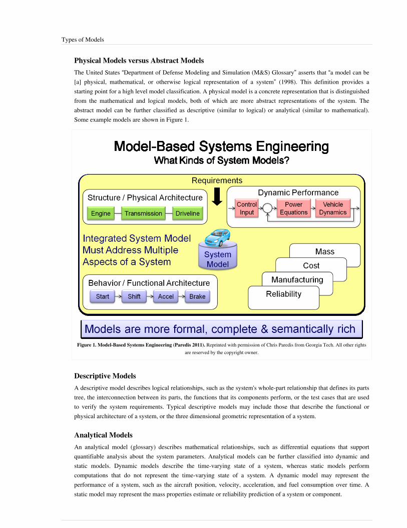
Types of Models 90
Physical Models versus Abstract ModelsThe United States “Department of Defense Modeling and Simulation (M&S) Glossary” asserts that “a model can be[a] physical, mathematical, or otherwise logical representation of a system” (1998). This definition provides astarting point for a high level model classification. A physical model is a concrete representation that is distinguishedfrom the mathematical and logical models, both of which are more abstract representations of the system. Theabstract model can be further classified as descriptive (similar to logical) or analytical (similar to mathematical).Some example models are shown in Figure 1.
Figure 1. Model-Based Systems Engineering (Paredis 2011). Reprinted with permission of Chris Paredis from Georgia Tech. All other rightsare reserved by the copyright owner.
Descriptive ModelsA descriptive model describes logical relationships, such as the system's whole-part relationship that defines its partstree, the interconnection between its parts, the functions that its components perform, or the test cases that are usedto verify the system requirements. Typical descriptive models may include those that describe the functional orphysical architecture of a system, or the three dimensional geometric representation of a system.
Analytical ModelsAn analytical model (glossary) describes mathematical relationships, such as differential equations that supportquantifiable analysis about the system parameters. Analytical models can be further classified into dynamic andstatic models. Dynamic models describe the time-varying state of a system, whereas static models performcomputations that do not represent the time-varying state of a system. A dynamic model may represent theperformance of a system, such as the aircraft position, velocity, acceleration, and fuel consumption over time. Astatic model may represent the mass properties estimate or reliability prediction of a system or component.

Types of Models 91
Hybrid Descriptive and Analytical ModelsA particular model may include descriptive and analytical aspects as described above, but models may favor oneaspect or the other. The logical relationships of a descriptive model can also be analyzed, and inferences can be madeto reason about the system. Nevertheless, logical analysis provides different insights than a quantitative analysis ofsystem parameters.
Domain-specific ModelsBoth descriptive and analytical models can be further classified according to the domain that they represent. Thefollowing classifications are partially derived from the presentation on OWL, Ontologies and SysML Profiles:Knowledge Representation and Modeling (Web Ontology Language (OWL) & Systems Modeling Language(SysML)) (Jenkins 2010):•• properties of the system, such as performance, reliability, mass properties, power, structural, or thermal models;• design and technology implementations, such as electrical, mechanical, and software design models;• subsystems and products, such as communications, fault management, or power distribution models; and•• system applications, such as information systems, automotive systems, aerospace systems, or medical device
models.The model classification, terminology and approach is often adapted to a particular application domain. For example,when modeling organization or business, the behavioral model may be referred to as workflow or process model, andthe performance modeling may refer to the cost and schedule performance associated with the organization orbusiness process.A single model may include multiple domain categories from the above list. For example, a reliability, thermal,and/or power model may be defined for an electrical design of a communications subsystem for an aerospacesystem, such as an aircraft or satellite.
System ModelsSystem models can be hybrid models that are both descriptive and analytical. They often span several modelingdomains that must be integrated to ensure a consistent and cohesive system representation. As such, the systemmodel must provide both general-purpose system constructs and domain-specific constructs that are shared acrossmodeling domains. A system model may comprise multiple views to support planning, requirements, design,analysis, and verification.Wayne Wymore is credited with one of the early efforts to formally define a system model using a mathematicalframework in A Mathematical Theory of Systems Engineering: The Elements (Wymore 1967). Wymore established arigorous mathematical framework for designing systems in a model-based context. A summary of his work can befound in A Survey of Model-Based Systems Engineering (MBSE) Methodologies.
Simulation versus ModelThe term simulation, or more specifically computer simulation, refers to a method for implementing a model overtime (DoD 1998). The computer simulation includes the analytical model which is represented in executable code,the input conditions and other input data, and the computing infrastructure. The computing infrastructure includesthe computational engine needed to execute the model, as well as input and output devices. The great variety ofapproaches to computer simulation is apparent from the choices that the designer of computer simulation must make,which include•• stochastic or deterministic;•• steady-state or dynamic;•• continuous or discrete; and

Types of Models 92
•• local or distributed.Other classifications of a simulation may depend on the type of model that is being simulated. One example is anagent-based simulation that simulates the interaction among autonomous agents to predict complex emergentbehavior (Barry 2009). They are many other types of models that could be used to further classify simulations. Ingeneral, simulations provide a means for analyzing complex dynamic behavior of systems, software, hardware,people, and physical phenomena.Simulations are often integrated with the actual hardware, software, and operators of the system to evaluate howactual components and users of the system perform in a simulated environment. Within the United States defensecommunity, it is common to refer to simulations as live, virtual, or constructive, where live simulation refers to liveoperators operating real systems, virtual simulation refers to live operators operating simulated systems, andconstructive simulations refers to simulated operators operating with simulated systems. The virtual and constructivesimulations may also include actual system hardware and software in the loop as well as stimulus from a realsystems environment.In addition to representing the system and its environment, the simulation must provide efficient computationalmethods for solving the equations. Simulations may be required to operate in real time, particularly if there is anoperator in the loop. Other simulations may be required to operate much faster than real time and perform thousandsof simulation runs to provide statistically valid simulation results. Several computational and other simulationmethods are described in Simulation Modeling and Analysis (Law 2007).
VisualizationComputer simulation results and other analytical results often need to be processed so they can be presented to theusers in a meaningful way. Visualization techniques and tools are used to display the results in various visual forms,such as a simple plot of the state of the system versus time to display a parametric relationship. Another example ofthis occurs when the input and output values from several simulation executions are displayed on a response surfaceshowing the sensitivity of the output to the input. Additional statistical analysis of the results may be performed toprovide probability distributions for selected parameter values. Animation is often used to provide a virtualrepresentation of the system and its dynamic behavior. For example, animation can display an aircraft’sthree-dimensional position and orientation as a function of time, as well as project the aircraft’s path on the surfaceof the Earth as represented by detailed terrain maps.
Integration of ModelsMany different types of models may be developed as artifacts of a MBSE effort. Many other domain-specific modelsare created for component design and analysis. The different descriptive and analytical models must be integrated inorder to fully realize the benefits of a model-based approach. The role of MBSE as the models integrate acrossmultiple domains is a primary theme in the International Council on Systems Engineering (INCOSE) INCOSESystems Engineering Vision 2020 (INCOSE 2007).As an example, system models can be used to specify the components of the system. The descriptive model of thesystem architecture may be used to identify and partition the components of the system and define theirinterconnection or other relationships. Analytical models for performance, physical, and other quality characteristics,such as reliability, may be employed to determine the required values for specific component properties to satisfy thesystem requirements. An executable system model that represents the interaction of the system components may beused to validate that the component requirements can satisfy the system behavioral requirements. The descriptive,analytical, and executable system model each represent different facets of the same system.The component designs must satisfy the component requirements that are specified by the system models. As a result, the component design and analysis models must have some level of integration to ensure that the design
Types of Models 93
model is traceable to the requirements model. The different design disciplines for electrical, mechanical, andsoftware each create their own models representing different facets of the same system. It is evident that the differentmodels must be sufficiently integrated to ensure a cohesive system solution.To support the integration, the models must establish semantic interoperability to ensure that a construct in onemodel has the same meaning as a corresponding construct in another model. This information must also beexchanged between modeling tools.One approach to semantic interoperability is to use model transformations between different models.Transformations are defined which establish correspondence between the concepts in one model and the concepts inanother. In addition to establishing correspondence, the tools must have a means to exchange the model data andshare the transformation information. There are multiple means for exchanging data between tools, including fileexchange, use of application program interfaces (API), and a shared repository.The use of modeling standards for modeling languages, model transformations, and data exchange is an importantenabler of integration across modeling domains.
References
Works CitedBarry, P.S., M.T.K. Koehler, and B.F. Tivnan. 2009. Agent-Directed Simulation for Systems Engineering. McLean,VA: MITRE, March 2009, PR# 09-0267.DoD. 1998. "'DoD Modeling and Simulation (M&S) Glossary" in DoD Manual 5000.59-M. Arlington, VA, USA:US Department of Defense. January 1998.Wymore, A. 1967. A Mathematical Theory of Systems Engineering: The Elements. New York, NY, USA: JohnWiley.Wymore, A. 1993. Model-Based Systems Engineering. Boca Raton, FL, USA: CRC Press.
Primary ReferencesLaw, A. 2007. Simulation Modeling and Analysis, 4th ed. New York, NY, USA: McGraw Hill.Wymore, A. 1993. Model-Based Systems Engineering. Boca Raton, FL, USA: CRC Press.
Additional ReferencesEstefan, J. 2008. Survey of Candidate Model-Based Systems Engineering (MBSE) Methodologies, Revision B.Pasadena, CA, USA: International Council on Systems Engineering (INCOSE), INCOSE-TD-2007-003-02.Hybertson, D. 2009. Model-Oriented Systems Engineering Science: A Unifying Framework for Traditional andComplex Systems. Boca Raton, FL, USA: Auerbach/CRC Press.INCOSE. 2007. Systems Engineering Vision 2020. Seattle, WA, USA: International Council on SystemsEngineering. September 2007. INCOSE-TP-2004-004-02.Rouquette, N. and S. Jenkins. 2010. OWL Ontologies and SysML Profiles: Knowledge Representation and Modeling.Proceedings of the NASA-ESA PDE Workshop, June 2010.

Types of Models 94
< Previous Article | Parent Article | Next Article >SEBoK v. 1.4 released 29 June 2015
SEBoK DiscussionPlease provide your comments and feedback on the SEBoK below. You will need to log in to DISQUS using anexisting account (e.g. Yahoo, Google, Facebook, Twitter, etc.) or create a DISQUS account. Simply type yourcomment in the text field below and DISQUS will guide you through the login or registration steps. Feedback will bearchived and used for future updates to the SEBoK. If you provided a comment that is no longer listed, that commenthas been adjudicated. You can view adjudication for comments submitted prior to SEBoK v. 1.0 at SEBoK Reviewand Adjudication. Later comments are addressed and changes are summarized in the Letter from the Editor andAcknowledgements and Release History.
If you would like to provide edits on this article, recommend new content, or make comments on the SEBoKas a whole, please see the SEBoK Sandbox [1].
ENCODED_CONTENTMTM0NjkPGRpdiBpZD0iZGlzcXVzX3RocmVhZCI+PC9kaXY+CjxzY3JpcHQgdHlwZT0idGV4dC9qYXZhc2NyaXB0Ij4KICAgIC8qICogKiBDT05GSUdVUkFUSU9OIFZBUklBQkxFUzogRURJVCBCRUZPUkUgUEFTVElORyBJTlRPIFlPVVIgV0VCUEFHRSAqICogKi8KICAgIHZhciBkaXNxdXNfc2hvcnRuYW1lID0gJ3NlYm9rd2lraTEwJzsgLy8gcmVxdWlyZWQ6IHJlcGxhY2UgZXhhbXBsZSB3aXRoIHlvdXIgZm9ydW0gc2hvcnRuYW1lCiAgICB2YXIgZGlzcXVzX2lkZW50aWZpZXIgPSAnVHlwZXMgb2YgTW9kZWxzJzsgICAgdmFyIGRpc3F1c191cmwgPSAnaHR0cDovL3NlYm9rd2lraS5vcmcvZHJhZnQvVHlwZXNfb2ZfTW9kZWxzJzsKICAgIC8qICogKiBET04nVCBFRElUIEJFTE9XIFRISVMgTElORSAqICogKi8KICAgIChmdW5jdGlvbigpIHsKICAgICAgICB2YXIgZHNxID0gZG9jdW1lbnQuY3JlYXRlRWxlbWVudCgnc2NyaXB0Jyk7IGRzcS50eXBlID0gJ3RleHQvamF2YXNjcmlwdCc7IGRzcS5hc3luYyA9IHRydWU7CiAgICAgICAgZHNxLnNyYyA9ICdodHRwOi8vJyArIGRpc3F1c19zaG9ydG5hbWUgKyAnLmRpc3F1cy5jb20vZW1iZWQuanMnOwogICAgICAgIChkb2N1bWVudC5nZXRFbGVtZW50c0J5VGFnTmFtZSgnaGVhZCcpWzBdIHx8IGRvY3VtZW50LmdldEVsZW1lbnRzQnlUYWdOYW1lKCdib2R5JylbMF0pLmFwcGVuZENoaWxkKGRzcSk7CiAgICB9KSgpOwo8L3NjcmlwdD4KPG5vc2NyaXB0PlBsZWFzZSBlbmFibGUgSmF2YVNjcmlwdCB0byB2aWV3IHRoZSA8YSBocmVmPSJodHRwOi8vZGlzcXVzLmNvbS8/cmVmX25vc2NyaXB0Ij5jb21tZW50cyBwb3dlcmVkIGJ5IERpc3F1cy48L2E+PC9ub3NjcmlwdD4KPGEgaHJlZj0iaHR0cDovL2Rpc3F1cy5jb20iIGNsYXNzPSJkc3EtYnJsaW5rIj5ibG9nIGNvbW1lbnRzIHBvd2VyZWQgYnkgPHNwYW4gY2xhc3M9ImxvZ28tZGlzcXVzIj5EaXNxdXM8L3NwYW4+PC9hPg==END_ENCODED_CONTENT
System Modeling ConceptsA system model represents aspects of a system and its environment. There are many different types of models, asthere a variety of purposes for which they are built. It is useful to have a common way to talk about the conceptsunderlying the many different types of models (e.g., many modeling techniques enable the understanding of systembehavior, while others enable the understanding of system structure). This article highlights several concepts used formodeling systems.
AbstractionPerhaps the most fundamental concept in systems modeling is abstraction, which concerns hiding unimportantdetails in order to focus on essential characteristics. Systems that are worth modeling have too many details for all ofthem to reasonably be modeled. Apart from the sheer size and structural complexity that a system may possess, asystem may be behaviorally complex as well, with emergent properties, non-deterministic behavior, and otherdifficult-to-characterize properties. Consequently, models must focus on a few vital characteristics in order to becomputationally and intellectually tractable. Modeling techniques address this complexity through various forms ofabstraction. For example, a model may assume that structural characteristics of many individual components of aparticular type are all the same, ignoring the small order differences between individuals in instances that occur inreal life. In that case, those differences are assumed to be unimportant to modeling the structural integrity of thosecomponents. Of course, if that assumption is wrong, then the model could lead to false confidence in that structuralintegrity. There are two key concepts that are applied in regard to modeling different levels of abstraction, which are:view and viewpoint and black-box and white-box modeling, which are described below. Although these twomodeling methods are the most widely recognized, different modeling languages and tools employ other techniquesas well.

System Modeling Concepts 95
View and ViewpointIEEE 1471, a standard for architecture modeling, defines "view" and "viewpoint" as follows:• View (glossary) - A representation of a whole system from the perspective of a related set of concerns.• Viewpoint (glossary) - A specification of the conventions necessary for constructing and using a view; a pattern
or template from which to develop individual views by establishing the purposes and audience for a view and thetechniques for its creation and analysis.
Even though IEEE 1471 is focused on architecture models, the concepts of view and viewpoint are general and couldapply to models for other purposes as well (IEEE 2000). The viewpoint addresses the concerns of the stakeholdersand provides the necessary conventions for constructing a view to address those concerns; therefore, the viewrepresents aspects of the system that address the concerns of the stakeholder. Models can be created to represent thedifferent views of the system. A systems model should be able to represent multiple views of the system to address arange of stakeholder concerns. Standard views may include requirements, functional, structural, and parametricviews, as well as a multitude of discipline-specific views to address system reliability, safety, security, and otherquality characteristics.
Black-Box and White-Box ModelsA very common abstraction technique is to model the system as a black-box, which only exposes the features of thesystem that are visible from an external observer and hides the internal details of the design. This includes externallyvisible behavior and other physical characteristics, such as the system’s mass or weight. A white-box model of asystem, on the other hand, shows the internal structure and displays the behavior of the system. Black-box andwhite-box modeling can be applied to the next level of design decomposition in order to create a black-box andwhite-box model of each system component.
Conceptual ModelA conceptual model is the set of concepts within a system and the relationships among those concepts (e.g., view andviewpoint). A system conceptual model describes, using one diagram type (such as in Object-Process Methodology(OPM)) or several diagram types (such as in Systems Modeling Language (SysML)) the various aspects of thesystem. The conceptual model might include its requirements, behavior, structure, and properties. In addition, asystem conceptual model is accompanied by a set of definitions for each concept. Sometimes, system conceptmodels are defined using an entity relationship diagram, an object-process diagram (OPD), or a Unified ModelingLanguage (UML) class diagram.A preliminary conceptual (or concept) model for systems engineering (Systems Engineering Concept Model) wasdeveloped in support of the integration efforts directed toward the development of the Object Management Group(OMG) SysML and the International Organization for Standardization (ISO) AP233 Data Exchange Standard forSystems Engineering (ISO 2010). The concept model was originally captured in an informal manner; however, themodel and associated concepts were rigorously reviewed by a broad representation of the systems engineeringcommunity, including members from the International Council on Systems Engineering (INCOSE), AP233, andSysML development teams.A fragment from the top level systems engineering concept model is included in Figure 1. This model providesconcepts for requirements, behavior, structure and properties of the system, as well as other concepts common tosystems engineering and project management, such as stakeholder. The concept model is augmented by awell-defined glossary of terms called the semantic dictionary. The concept model and the semantic dictionarycontributed greatly to the requirements for the OMG Systems Modeling Language written in the UML for SystemsEngineering Request for Proposal.

System Modeling Concepts 96
Figure 1. Fragment of the Object Management Group System Concept Model (Oliver 2003, Slide 3). Permission granted byDavid Oliver on behalf of INCOSE MDSD Working Group. All other rights are reserved by the copyright owner.
A concept model is sometimes referred to as a meta-model, domain meta-model, or schema, and can be used tospecify the abstract syntax of a modeling language (refer to the Model Driven Architecture (MDA®) FoundationModel (OMG 2010)). Several other systems engineering concept models have been developed but not standardized.Future standardization efforts should establish a standard systems engineering concept model. The model can thenevolve over time as the systems engineering community continues to formalize and advance the practice of systemsengineering.
References
Works CitedIEEE. 2000. Recommended practice for architectural description for software-intensive systems. New York, NY:Institute of Electrical and Electronics Engineers (IEEE), IEEE 1471-2000.ISO. 2010. OMG System Modeling Language (OMG SysML), version 1.2. Needham, MA, USA: Object ManagementGroup.OMG. 2010. MDA Foundation Model. Needham, MA, USA: Object Management Group. Document numberORMSC/2010-09-06.

System Modeling Concepts 97
Primary ReferencesANSI/IEEE. 2000. Recommended Practice for Architectural Description for Software-Intensive Systems. New York,NY, USA: American National Standards Institute (ANSI)/Institute of Electrical and Electronics Engineers (IEEE),ANSI/IEEE 1471-2000.Dori, D. 2002. Object-Process Methodology – A Holistic Systems Paradigm. New York, NY, USA: Springer-Verlag.Guizzardi, G. 2007. "On Ontology, Ontologies, Conceptualizations, Modeling Languages, and (Meta)Models".Proceeding of the 2007 Conference on Databases and Information Systems IV. Available at http:/ / portal. acm. org/citation. cfm?id=1565425.IEEE. 2000. Recommended practice for architectural description for software-intensive systems. New York, NY:Institute of Electrical and Electronics Engineers (IEEE), IEEE 1471-2000.INCOSE. 2003. Systems Engineering Concept Model. Draft 12 Baseline. Seattle, WA: International Council onSystems Engineering. Available at http:/ / syseng. omg. org/ SE_Conceptual%20Model/ SE_Conceptual_Model.htm.OMG. 2003. UML for Systems Engineering Request for Proposal. Needham, MA: Object Management Group. OMGdocument number ad/2003-3-41. Available at http:/ / www. omg. org/ cgi-bin/ doc?ad/ 2003-3-41.
Additional ReferencesNone
< Previous Article | Parent Article | Next Article >SEBoK v. 1.4 released 29 June 2015
SEBoK DiscussionPlease provide your comments and feedback on the SEBoK below. You will need to log in to DISQUS using anexisting account (e.g. Yahoo, Google, Facebook, Twitter, etc.) or create a DISQUS account. Simply type yourcomment in the text field below and DISQUS will guide you through the login or registration steps. Feedback will bearchived and used for future updates to the SEBoK. If you provided a comment that is no longer listed, that commenthas been adjudicated. You can view adjudication for comments submitted prior to SEBoK v. 1.0 at SEBoK Reviewand Adjudication. Later comments are addressed and changes are summarized in the Letter from the Editor andAcknowledgements and Release History.
If you would like to provide edits on this article, recommend new content, or make comments on the SEBoKas a whole, please see the SEBoK Sandbox [1].
ENCODED_CONTENTMTY3MzgPGRpdiBpZD0iZGlzcXVzX3RocmVhZCI+PC9kaXY+CjxzY3JpcHQgdHlwZT0idGV4dC9qYXZhc2NyaXB0Ij4KICAgIC8qICogKiBDT05GSUdVUkFUSU9OIFZBUklBQkxFUzogRURJVCBCRUZPUkUgUEFTVElORyBJTlRPIFlPVVIgV0VCUEFHRSAqICogKi8KICAgIHZhciBkaXNxdXNfc2hvcnRuYW1lID0gJ3NlYm9rd2lraTEwJzsgLy8gcmVxdWlyZWQ6IHJlcGxhY2UgZXhhbXBsZSB3aXRoIHlvdXIgZm9ydW0gc2hvcnRuYW1lCiAgICB2YXIgZGlzcXVzX2lkZW50aWZpZXIgPSAnU3lzdGVtIE1vZGVsaW5nIENvbmNlcHRzJzsgICAgdmFyIGRpc3F1c191cmwgPSAnaHR0cDovL3NlYm9rd2lraS5vcmcvZHJhZnQvU3lzdGVtX01vZGVsaW5nX0NvbmNlcHRzJzsKICAgIC8qICogKiBET04nVCBFRElUIEJFTE9XIFRISVMgTElORSAqICogKi8KICAgIChmdW5jdGlvbigpIHsKICAgICAgICB2YXIgZHNxID0gZG9jdW1lbnQuY3JlYXRlRWxlbWVudCgnc2NyaXB0Jyk7IGRzcS50eXBlID0gJ3RleHQvamF2YXNjcmlwdCc7IGRzcS5hc3luYyA9IHRydWU7CiAgICAgICAgZHNxLnNyYyA9ICdodHRwOi8vJyArIGRpc3F1c19zaG9ydG5hbWUgKyAnLmRpc3F1cy5jb20vZW1iZWQuanMnOwogICAgICAgIChkb2N1bWVudC5nZXRFbGVtZW50c0J5VGFnTmFtZSgnaGVhZCcpWzBdIHx8IGRvY3VtZW50LmdldEVsZW1lbnRzQnlUYWdOYW1lKCdib2R5JylbMF0pLmFwcGVuZENoaWxkKGRzcSk7CiAgICB9KSgpOwo8L3NjcmlwdD4KPG5vc2NyaXB0PlBsZWFzZSBlbmFibGUgSmF2YVNjcmlwdCB0byB2aWV3IHRoZSA8YSBocmVmPSJodHRwOi8vZGlzcXVzLmNvbS8/cmVmX25vc2NyaXB0Ij5jb21tZW50cyBwb3dlcmVkIGJ5IERpc3F1cy48L2E+PC9ub3NjcmlwdD4KPGEgaHJlZj0iaHR0cDovL2Rpc3F1cy5jb20iIGNsYXNzPSJkc3EtYnJsaW5rIj5ibG9nIGNvbW1lbnRzIHBvd2VyZWQgYnkgPHNwYW4gY2xhc3M9ImxvZ28tZGlzcXVzIj5EaXNxdXM8L3NwYW4+PC9hPg==END_ENCODED_CONTENT

Integrating Supporting Aspects into System Models 98
Integrating Supporting Aspects into SystemModelsThis article discusses the integrated modeling of systems and supporting aspects using Model-Based SystemsEngineering methodologies and frameworks. Supporting aspects of systems engineering include:•• Engineering Management•• Project Management•• Requirements Engineering and Management•• Risk Modeling, Analysis, and Management•• Quality Assurance, Testing, Verification, and Validation•• System Integration and Employment•• Analysis of "-ilities" (e.g., Reliability, Availability, Maintainability, Safety, And Security (RAMSS),
Manufacturability, Extensibility, Robustness, Resilience, Flexibility, and Evolvability)These aspects can pertain to physical facets, as well as to functional, structural, behavioral, social, and environmentalfacets of the core system model. The article focuses on three main aspects:1.1. Project and Engineering Management2.2. Risk Modeling, Analysis, and Management3.3. Requirements Definition and Management
BackgroundThe model-based approach to systems engineering considers the system model as much more than a plaindescription of the system; the model is the central common basis for capturing, representing, and integrating thevarious system aspects listed above. The model is essential to the design and understanding of the system as well asto managing its life cycle and evolution. Modeling languages constitute the basis for standardized, formaldescriptions of systems, just like natural languages form the basis for human communication.As systems progressively become more complex and multidisciplinary, the conceptual modeling of systems needs toevolve and will become more critical for understanding complex design (Dori 2002). In addition to facilitatingcommunication among clients, designers, and developers, conceptual modeling languages also assist in clearlydescribing and documenting various domains, systems, and problems, and define requirements and constraints forthe design and development phases (Wand and Weber 2002). The importance of model-based analysis isdemonstrated by the variety of conceptual modeling methodologies and frameworks, although de facto standards areslow to emerge. While certain disciplines of engineering design, such as structural analysis or circuit design, haveestablished modeling semantics and notation, the conceptual modeling of complex systems and processes has not yetconverged on a unified, consolidated modeling framework (Estefan 2007). The challenge is not only to integratemultiple aspects and support the various phases of the system’s life cycle, but also to capture the multidisciplinarynature of the system, which has led to the creation of various frameworks. Nevertheless, the information systemsanalysis paradigm is currently the most widely used, perhaps due to the need to integrate complex systems viainformation-intensive applications and interactions.

Integrating Supporting Aspects into System Models 99
Integrated Modeling of Systems and ProjectsThis section discusses the integrated modeling of systems and projects and of the project-system relationship (oftencalled Project-Product Integration). The fields of Project Management (glossary) and Systems Engineering (glossary)have been advancing hand-in-hand for the last two decades, due to the understanding that successful projects createsuccessful systems. Many of the main systems engineering resources pay considerable attention to projectmanagement and consider it to be a critical process and enabler of systems engineering (INCOSE 2012; NASA2007; Sage and Rouse 2011). The integration of system-related aspects and concepts into project plans is morecommon than the integration of project-related aspects and concepts into system models. Because the project is ameans to an end, it is the process that is expected to deliver the system. Indeed, project activities are often namedafter or in accord with the deliverables that they are aimed at facilitating (e.g., “console design”, “softwaredevelopment”, “hardware acquisition”, or “vehicle assembly”). Each is a function name, consisting of an object(noun), or the system to be attained, and a process (verb), being the project or part of the project aimed at attainingthe end system.The specific process associated with each of these examples refers to different stages or phases of the project and todifferent maturity levels of the system or sub-system it applies to. Moreover, the mere inclusion of system and partnames in activity names does not truly associate system model artifacts with these activities. Overall, it is not trulypossible to derive the set of activities associated with a particular part or functionality of the system which that willbe delivered by the project. Project-Product integration is not straightforward, as project models and system modelsare traditionally disparate and hardly interface. A model-based approach to project-system integration follows asystem-centric paradigm and focuses on incorporating project-related aspects and concepts into the core systemmodel, as opposed to the project-centric approach described in the previous paragraph. Such aspects and conceptsinclude schedule, budget and resources, deliverables, work-packages, constraints and previous relations. Theintegrated system-project model should provide useful information on the mutual effects of project activities andsystem components and capabilities. Some examples of integrated system-project modeling include the following:•• The set of project activities associated with a particular system component, feature, or capability.•• The set of resources required for performing a task of designing or developing a particular component of the
system.•• The team or subcontractor responsible for delivering each system component.•• The preexisting dependencies between activities of system components deployment.•• The cost associated with each system component, feature, or capability.•• The parts of the system negotiated for each delivery, deployment, build, release, or version.The Work Breakdown Structure (WBS) is designed to support the division of the project scope (work content)amongst the individuals and organizations participating in the project (Golany and Shtub 2001). The WBS istraditionally organization or activity-oriented; however, one of its main cornerstones focuses on the deliverable,which corresponds to the system, sub-system, component, or a capability or feature of one or more of these. Adeliverable-oriented WBS, in which the high-level elements correspond to primary sub-systems, is advocated, as it islikely to allow the WBS to be more product-oriented (Rad 1999). An integrated approach to project planning andsystem modeling (Sharon and Dori 2009) merges the system model with the project’s WBS using Object-ProcessMethodology (OPM) (Dori 2002). The unified OPM model captures both the project activities and the systemcomponents and functionalities.The Design Structure Matrix (DSM) is a common method for enhancing and analyzing the design of products andsystems. DSMs can be component-based, task-based, parameter-based, or team-based (Browning 2001). A DSM foran OPM-based project-product model derives a hybrid DSM of project activities and system building blocks fromthe unified OPM model, accounting for dependencies between project activities and system components, as well asreplacing the two monolithic and separate component-based and task-based DSM views (Sharon, De-Weck, andDori 2012). The underlying OPM model assures model consistency and traceability. The integrated project-product

Integrating Supporting Aspects into System Models 100
OPM model includes both a diagram and an equivalent auto-generated textual description. The DSM derived fromthis model visualizes a dependency loop comprising both system components and project activities.Another model-based approach (Demoly et al. 2010) employs System Modeling Language (SysML) in order tocreate various views that meet the needs of various system stakeholders, such as the project/process manager. Theapproach includes both product-oriented and process-oriented views.
Integrated Modeling of Systems and RequirementsRequirements are statements that describe operational, functional, or design-related aspects of a system.Requirements definition and management is an important SE process, as it both initiates and facilitates the entire SEeffort by defining the expected functions and performance of the engineered system. Several challenges associatedwith requirements include:•• Defining the requirements in a structured, controlled manner.•• Tracing these requirements to system components, aspects, and decisions.•• Testing and verifying compliance of the system with these requirements.The extension of conceptual system models to include requirements has several significant benefits:1.1. Requirements provide the rationale for the system's architecture and design by making and justifying architectural
and design decisions based on specific requirements.2.2. Modeling the internal logic and the hierarchy and dependency relations among requirements enables
identification and elimination of redundant and contradictory requirements.3.3. Responsibility for satisfying specific requirements can often be assigned to teams and persons responsible for
delivering various system components. While the advantages of having good requirements engineering is clear, itis often a challenge to directly trace requirements to specific system artifacts, especially when the requirementsare defined in a holistic, solution-independent manner.
There are several methods to incorporate requirements into system models, including SysML RequirementsEngineering and Object-Process Methodology(OPM)-based Requirements Engineering and Authoring.
SysML-Based Requirements Engineering
The SysML requirements diagram makes it possible to capture the requirements and the relations among them in avisual manner, which is more intuitive than the textual manner in which requirements are traditionally edited andmanaged. The diagram was added to the basic set of UML diagrams that formed the basis for SysML (Friedenthal,Moore, and Steiner 2006), and is not a native UML diagram. Tracing requirements to the system blocks and artifactssatisfying them can be captured in the SysML Block Definition Diagram, which is primarily designated to capturethe relations among types of system elements and components. The < > link between the block and the requirementcaptures the trace.
OPM-Based Requirements Engineering
Object-Process Methodology (OPM) is a methodology and language for conceptual modeling of complex systemsand processes with a bimodal textual and graphical representation (Dori 2002). OPM’s textual representation iscoordinated with the graphical representation; additionally, each visual model construct in the Object-ProcessDiagram (OPD) is described by a formal structured textual statement in Object-Process Language (OPL), which is asubset of natural English. OPM facilitates model-based requirements engineering, authoring, and specification, inthree possible modes:1. OPM can be used to generate conceptual models which initially focus on the requirements level—the problem
domain, rather than the design level or the solution domain, which facilitates automated model-basedrequirements generation (Blekhman and Dori 2011). The requirements model is solution-neutral and it can be thebasis for one or more architectural solutions for achieving the functions specified in the requirements.

Integrating Supporting Aspects into System Models 101
2.2. Utilizing OPM in order to generate requirement-oriented OPDs in a manner similar to the SysML RequirementsDiagram enables an engineer to capture the requirements specification as the skeleton for the system model.User-defined tagged structural relations, such as "is realized by" or is allocated to", provide for associatingrequirements with system model functions (objects and processes that transform them). This approach is similarto the SysML requirements diagram; however, instead of using a unique notation in a separate diagram type, therequirements are seamlessly incorporated into the single system model.
3.3. OPM can be used for the purpose of generating visual system models from formally specified requirements bytracing the textually authored requirements to system model inserts and artifacts (Dori et al. 2004).
Integrating Risk into System ModelsRisk is an expression and a measure of the negative or adverse impact of uncertainty. Risk exists wheneveruncertainty can lead to several results, of which some may be negative (adverse) and some positive. A system facesrisks from other systems or from the environment, and it can also pose risks to other systems or to the environment.Systems are characterized by such attributes, such as: goals, objectives, inputs, outputs, variables, parameters,processes, events, states, subsystems, interfaces, mechanisms, and methods. System vulnerability is the system's totalpotential to be harmed or negatively affected in any one of these attributes. Analogously, system harmfulness is thesystem's total potential to harm others or to generate negative effects, which can be manifested in one or more ofthese attributes (Haimes 2009). Model-based risk analysis (MBRA) enables structured analysis and risk-relatedprocess control. Several model-based risk analysis approaches are available in the literature. MBRA is presentlycommon in the information technology and information security domains more than the systems engineeringdomain; however, some of the methods are generally applicable to complex systems as well. The ISO-IEC-IEEEcollaborative software development and operation lifecycle standard (ISO and IEC 2004) proposes a concurrentapproach to IT Risk Management. This approach consists of six main activities:•• Plan and Implement Risk Management•• Manage the Project Risk Profile•• Perform Risk Analysis•• Perform Risk Monitoring•• Perform Risk Treatment•• Evaluate the Risk Management ProcessThese activities are executed concurrently, affect and provide feedback to each other, and interact with othersoftware life cycle processes, such as the technical management and the design processes (ISO and IEC 2004).The CORAS approach (Fredriksen et al. 2002; den Braber et al. 2006; Lund, Solhaug, and Stølen 2011) is aUML-derivative for IT security risk modeling and assessment. This framework consists mostly of the UML use case(UC) diagram, extended for misuse cases. Additional notation was added to the UC notation in order to capture risksources, effects, and results (e.g., the “bad actor” icon, moneybag for asset-in-risk). A misuse diagram can include,for example, the risk of loss of legal protection of proprietary know-how due to information theft and distribution byan unfaithful employee. The treatment for the risk source of insufficient security policy, which contributes to theabove risk, is illustrated in a separate treatment diagram.A quantitative risk assessment method for component-based systems (Grunske and Joyce 2008) supports componentvulnerability analysis and specification using modular attack trees. In addition, it provides attacker profiling, whichenables supporting econometric approaches to risk response. The methodology utilizes SysML as its underpinninglanguage, and especially the SysML block definition diagram and parametric diagram, in order to capture parametricrelations and constraints as a means to defining risk profiles.System-Theoretic Accident Model and Processes (STAMP) is a method for system and component design for safety(Leveson 2011). STAMP reformulates the safety problem as a control problem as opposed to a reliability problem.STAMP is optimized for safety-oriented systems engineering and design and for hazard avoidance and mitigation,

Integrating Supporting Aspects into System Models 102
specifically in complex socio-technical systems. A model-based adaptation of STAMP was also proposed (Leveson2004) and was implemented in various safety-critical and mission-critical systems, including aircraft collisionavoidance systems (CAS) (Leveson 2004) and ballistic missile defense systems (Pereira, Lee, and Howard 2006).Risk-Oriented Systems Engineering (ROSE) (Mordecai and Dori 2013) is a method based on Object-ProcessMethodology (OPM) for integrating risk into system models. Being system-centric, ROSE is responsible forcapturing risk layers and aspects on top of and in sync with the core system model, while improving and immunizingit against captured risks, as well as for generating system robustness and resilience by design in response to variousrisk-posing scenarios. The risk handling meta-model includes risk mitigation during the design phase and riskresponse during the operational phase.
References
Works CitedBlekhman, A. and D. Dori. 2011. “Model-Based Requirements Authoring - Creating Explicit Specifications withOPM.” In 6th International Conference on Systems Engineering. Herzeliyya, Israel.Browning, T.R. 2001. “Applying the Design Structure Matrix to System Decomposition and Integration Problems: aReview and New Directions.” IEEE Transactions on Engineering Management 48 (3): 292–306.doi:10.1109/17.946528. Accessed December 4 2014 at IEEE http:/ / ieeexplore. ieee. org/ lpdocs/ epic03/ wrapper.htm?arnumber=946528.Demoly, F., D. Monticolo, B. Eynard, L. Rivest, and S. Gomes. 2010. “Multiple Viewpoint Modelling FrameworkEnabling Integrated Product–process Design.” International Journal on Interactive Design and Manufacturing(IJIDeM) 4 (4) (October 12): 269–280. doi:10.1007/s12008-010-0107-3. Accessed December 4 2014 at Springerhttp:/ / link. springer. com/ 10. 1007/ s12008-010-0107-3.Den Braber, F., G. Brændeland, H.E.I. Dahl, I. Engan, I. Hogganvik, M.S. Lund, B. Solhaug, K. Stølen, and F.Vraalsen. 2006. The CORAS Model-based Method for Security Risk Analysis. SINTEF, Oslo. Oslo: SINTEF.Dori, D. 2002. Object-Process Methodology – A Holistic Systems Paradigm. New York, NY, USA: Springer-Verlag.Dori, D., N. Korda, A. Soffer, and S. Cohen. 2004. “SMART: System Model Acquisition from Requirements Text.”Lecture Notes in Computer Science: Business Process Management 3080: 179–194. Accessed December 4 2014 atSpringer http:/ / link. springer. com/ chapter/ 10. 1007/ 978-3-540-25970-1_12.Estefan, J. 2008. A Survey of Model-Based Systems Engineering (MBSE) Methodologies, Rev. B. San Diego, CA,USA: International Council on Systems Engineering. INCOSE-TD-2007-003-02.Friedenthal, S., A. Moore, and R. Steiner. 2006. “OMG Systems Modeling Language (OMG SysML™) Tutorial”(July).Golany, B. and A. Shtub. 2001. “Work Breakdown Structure.” In Salvendy, G. (ed.) 2001. Handbook of IndustrialEngineering, Technology and Operations Management, 3rd ed. Hoboken, NJ, USA: John Wiley & Sons, Inc.1263–1280.Grunske, L. and D. Joyce. 2008. “Quantitative Risk-based Security Prediction for Component-based Systems withExplicitly Modeled Attack Profiles.” Journal of Systems and Software 81 (8): 1327–1345. Haimes, YY. 2009. “Onthe Complex Definition of Risk: A Systems-Based Approach.” Risk Analysis. 29 (12): 1647–1654. AccessedDecember 4 2014 at Wiley http:/ / onlinelibrary. wiley. com/ doi/ 10. 1111/ j. 1539-6924. 2009. 01310. x/ full.ISO/IEC/IEEE. 2004. Systems and software engineering - Life cycle processes - Risk management. Geneva,Switzerland: International Organization for Standardization (ISO)/International Electrotechnical Commission (IEC),ISO/IEC/IEEE 16085:2006.Leveson, N.G. 2004. “Model-based Analysis of Socio-technical Risk.” Cambridge, MA: Massachusetts Institute ofTechnology (MIT) Working Paper Series. ESD-WP-2004-08.

Integrating Supporting Aspects into System Models 103
Leveson, N.G. 2011. Engineering a Safer World: Systems Thinking Applied to Safety. Cambridge, MA: MIT Press.Lund, M.S., B. Solhaug, and K. Stølen. 2011. Model-Driven Risk Analysis: The CORAS Approach. Berlin,Heidelberg: Springer Berlin Heidelberg. doi:10.1007/978-3-642-12323-8. Accessed December 4 2014 at Springerhttp:/ / www. springerlink. com/ index/ 10. 1007/ 978-3-642-12323-8.Mordecai, Y., and D. Dori. 2013. “Model-Based Risk-Oriented Robust Systems Design with Object-ProcessMethodology.” International Journal of Strategic Engineering Asset Management. TBD (CESUN 2012 SpecialIssue).NASA. 2007. NASA Systems Engineering Handbook|Systems Engineering Handbook. Washington, D.C.: NationalAeronautics and Space Administration (NASA), NASA/SP-2007-6105.Pereira, S.J., G. Lee, and J. Howard. 2006. “A System-Theoretic Hazard Analysis Methodology for a Non-advocateSafety Assessment of the Ballistic Missile Defense System”. Vol. 1606. Accessed December 4 2014 at DefenseTechnical Information Center http:/ / oai. dtic. mil/ oai/ oai?verb=getRecord& metadataPrefix=html&identifier=ADA466864.Rad, P.F. 1999. “Advocating a Deliverable-oriented Work Breakdown Structure.” Sage, Andrew P., and William B.Rouse. 2011. Handbook of Systems Engineering and Management. Edited by A.P. Sage and W.B. Rouse. 2nd ed.John Wiley & Sons.Sharon, A., O.L. de-Weck, and D. Dori. 2012. “Improving Project-Product Lifecycle Management withModel-Based Design Structure Matrix : A Joint Project Management and Systems Engineering Approach.” SystemsEngineering: 1–14. doi:10.1002/sys.Sharon, A., and D. Dori. 2009. “A Model-Based Approach for Planning Work Breakdown Structures of ComplexSystems Projects.” In Proc. 14th IFAC Symposium on Information Control Problems in Manufacturing.Wand, Y., and R. Weber. 2002. “Research Commentary: Information Systems and Conceptual Modeling?A ResearchAgenda.” Information Systems Research. 13(4) (December): 363–376. doi:10.1287/isre.13.4.363.69.
Primary ReferencesDori, D. 2002. Object-Process Methodology – A Holistic Systems Paradigm. New York, NY, USA: Springer-Verlag.Estefan, J. 2008. A Survey of Model-Based Systems Engineering (MBSE) Methodologies, Rev. B. San Diego, CA,USA: International Council on Systems Engineering. INCOSE-TD-2007-003-02.Golany, B. and A. Shtub. 2001. “Work Breakdown Structure.” In Salvendy, G. (ed.) 2001. Handbook of IndustrialEngineering, Technology and Operations Management, 3rd ed. Hoboken, NJ, USA: John Wiley & Sons, Inc.1263–1280.INCOSE. 2012. INCOSE Systems Engineering Handbook: A Guide for System Life Cycle Processes and Activities.Version 3.2.2. San Diego, CA, USA: International Council on Systems Engineering (INCOSE),INCOSE-TP-2003-002-03.2.2.NASA. 2007. Systems Engineering Handbook. Washington, D.C.: National Aeronautics and Space Administration(NASA), NASA/SP-2007-6105.

Integrating Supporting Aspects into System Models 104
Additional ReferencesKristiansen, B.G. and K. Stolen. 2002. “The CORAS Framework for a Model-based Risk Management Process.” InLecture Notes In, edited by Stuart Anderson, Massimo Felici, and SandroEditors Bologna, 2434:94–105.Springer-Verlag. doi:10.1007/3-540-45732-1_11.
< Previous Article | Parent Article | Next Article >SEBoK v. 1.4 released 29 June 2015
SEBoK DiscussionPlease provide your comments and feedback on the SEBoK below. You will need to log in to DISQUS using anexisting account (e.g. Yahoo, Google, Facebook, Twitter, etc.) or create a DISQUS account. Simply type yourcomment in the text field below and DISQUS will guide you through the login or registration steps. Feedback will bearchived and used for future updates to the SEBoK. If you provided a comment that is no longer listed, that commenthas been adjudicated. You can view adjudication for comments submitted prior to SEBoK v. 1.0 at SEBoK Reviewand Adjudication. Later comments are addressed and changes are summarized in the Letter from the Editor andAcknowledgements and Release History.
If you would like to provide edits on this article, recommend new content, or make comments on the SEBoKas a whole, please see the SEBoK Sandbox [1].
ENCODED_CONTENTMTAyMDMPGRpdiBpZD0iZGlzcXVzX3RocmVhZCI+PC9kaXY+CjxzY3JpcHQgdHlwZT0idGV4dC9qYXZhc2NyaXB0Ij4KICAgIC8qICogKiBDT05GSUdVUkFUSU9OIFZBUklBQkxFUzogRURJVCBCRUZPUkUgUEFTVElORyBJTlRPIFlPVVIgV0VCUEFHRSAqICogKi8KICAgIHZhciBkaXNxdXNfc2hvcnRuYW1lID0gJ3NlYm9rd2lraTEwJzsgLy8gcmVxdWlyZWQ6IHJlcGxhY2UgZXhhbXBsZSB3aXRoIHlvdXIgZm9ydW0gc2hvcnRuYW1lCiAgICB2YXIgZGlzcXVzX2lkZW50aWZpZXIgPSAnSW50ZWdyYXRpbmcgU3VwcG9ydGluZyBBc3BlY3RzIGludG8gU3lzdGVtIE1vZGVscyc7ICAgIHZhciBkaXNxdXNfdXJsID0gJ2h0dHA6Ly9zZWJva3dpa2kub3JnL2RyYWZ0L0ludGVncmF0aW5nX1N1cHBvcnRpbmdfQXNwZWN0c19pbnRvX1N5c3RlbV9Nb2RlbHMnOwogICAgLyogKiAqIERPTidUIEVESVQgQkVMT1cgVEhJUyBMSU5FICogKiAqLwogICAgKGZ1bmN0aW9uKCkgewogICAgICAgIHZhciBkc3EgPSBkb2N1bWVudC5jcmVhdGVFbGVtZW50KCdzY3JpcHQnKTsgZHNxLnR5cGUgPSAndGV4dC9qYXZhc2NyaXB0JzsgZHNxLmFzeW5jID0gdHJ1ZTsKICAgICAgICBkc3Euc3JjID0gJ2h0dHA6Ly8nICsgZGlzcXVzX3Nob3J0bmFtZSArICcuZGlzcXVzLmNvbS9lbWJlZC5qcyc7CiAgICAgICAgKGRvY3VtZW50LmdldEVsZW1lbnRzQnlUYWdOYW1lKCdoZWFkJylbMF0gfHwgZG9jdW1lbnQuZ2V0RWxlbWVudHNCeVRhZ05hbWUoJ2JvZHknKVswXSkuYXBwZW5kQ2hpbGQoZHNxKTsKICAgIH0pKCk7Cjwvc2NyaXB0Pgo8bm9zY3JpcHQ+UGxlYXNlIGVuYWJsZSBKYXZhU2NyaXB0IHRvIHZpZXcgdGhlIDxhIGhyZWY9Imh0dHA6Ly9kaXNxdXMuY29tLz9yZWZfbm9zY3JpcHQiPmNvbW1lbnRzIHBvd2VyZWQgYnkgRGlzcXVzLjwvYT48L25vc2NyaXB0Pgo8YSBocmVmPSJodHRwOi8vZGlzcXVzLmNvbSIgY2xhc3M9ImRzcS1icmxpbmsiPmJsb2cgY29tbWVudHMgcG93ZXJlZCBieSA8c3BhbiBjbGFzcz0ibG9nby1kaXNxdXMiPkRpc3F1czwvc3Bhbj48L2E+END_ENCODED_CONTENT
Modeling StandardsDifferent types of models are needed to support the analysis, specification, design, and verification of systems. Theevolution of modeling standards enables the broad adoption of Model-Based Systems Engineering (MBSE).
Motivation for Modeling StandardsModeling standards play an important role in defining agreed-upon system modeling concepts that can berepresented for a particular domain of interest and enable the integration of different types of models across domainsof interest. Modeling standards are extremely important to support MBSE, which aims to integrate various systemaspects across various disciplines, products, and technologies.Standards for system modeling languages can enable cross-discipline, cross-project, and cross- organizationcommunication. This communication offers the potential to reduce the training requirements for practitioners whoonly need to learn about a particular system and enables the reuse of system artifacts. Standard modeling languagesalso provide a common foundation for advancing the practice of systems engineering, as do other systemsengineering standards.
Types of Modeling StandardsMany different standards apply to systems modeling. Modeling standards include standards for modeling languages,data exchange between models, and the transformation of one model to another to achieve semantic interoperability.Each type of model can be used to represent different aspects of a system, such as representing the set of systemcomponents and their interconnections and interfaces, or to represent a system to support performance analysis orreliability analysis.

Modeling Standards 105
The following is a partial list of representative modeling standards, which also includes the common acronym, whenapplicable, and a reference as to where additional information can be found on the topic.
Modeling Languages for SystemsDescriptive Models - These standards apply to general descriptive modeling of systems:•• Functional Flow Block Diagram (FFBD) (Oliver, Kelliher, and Keegan 1997)•• Integration Definition for Functional Modeling (IDEF0) (NIST 1993)• Object-Process Methodology (OPM) [[1]] [[2]] (Dori 2002; ISO 19450 PAS - Publicly Available Specification in
progress)•• Systems Modeling Language (SysML)(OMG 2010a)• Unified Profile for United States Department of Defense Architecture Framework (DoDAF) and United Kingdom
Ministry of Defense Architecture Framework (MODAF) (OMG 2011e)•• Web ontology language (OWL) (W3C 2004b)Analytical Models and Simulations - These standards apply to analytical models and simulations:•• Distributed Interactive Simulation (DIS) (IEEE 1998)•• High-Level Architecture (HLA) (IEEE 2010)•• Modelica (Modelica Association 2010)•• Semantics of a Foundational Subset for Executable Unified Modeling Language (UML) Models (FUML) (OMG
2011d)
Data Exchange StandardsThese standards enable the exchange of information between models:•• Application Protocol for Systems Engineering Data Exchange (ISO 10303-233) (AP-233) (ISO 2005)•• Requirements Interchange Format (ReqIF) (OMG 2011c)•• Extensible Mark-Up Language -(XML) Metadata Interchange (XMI) (OMG 2003a)•• Resource Description Framework (RDF) (W3C 2004a)
Model TransformationsThese standards apply to transforming one model to another to support semantic interoperability:•• Query View Transformations (QVT) (OMG 2011b)•• Systems Modeling Language (SysML)-Modelica Transformation (OMG 2010c)•• OPM-to-SysML Transformation (Grobshtein and Dori 2011)
General Modeling StandardsThese standards provide general frameworks for modeling:•• Model-driven architecture (MDA®) (OMG 2003b)• IEEE 1471-2000 - Recommended Practice for Architectural Description of Software-Intensive Systems
(ANSI/IEEE 2000) (ISO/IEC 2007)

Modeling Standards 106
Other Domain-Specific Modeling StandardsSoftware Design Models
These standards apply to modeling application software and/or embedded software design:•• Architecture Analysis and Design Language (AADL) (SAE 2009)•• Modeling and Analysis for Real-Time and Embedded Systems (MARTE) (OMG 2009)•• Unified Modeling Language (UML) (OMG 2010b)Hardware Design Models
These standards apply to modeling hardware design:•• Very-High-Speed Integrated Circuit (VHSIC) Hardware Description Language (VHDL) (IEEE 2008)Business Process Models
These standards apply to modeling business processes:•• Business Process Modeling Notation (BPMN) (OMG 2011a)
References
Works CitedANSI/IEEE. 2000. Recommended Practice for Architectural Description for Software-Intensive Systems. New York,NY: American National Standards Institute (ANSI)/Institute of Electrical and Electronics Engineers (IEEE),ANSI/IEEE 1471-2000.Grobshtein, Y. and D. Dori. 2011. "Generating SysML Views from an OPM Model: Design and Evaluation."Systems Engineering, 14 (3), Sept. 2011.IEEE. 1998. Distributed Interactive Simulation (DIS). Washington, DC: Institute for Electrical and ElectronicEngineers. IEEE 1278.1-1995. Accessed December 4 2014 at IEEE http:/ / standards. ieee. org/ develop/ project/1278. 2. html.IEEE. 2008. VHSIC hardware description language (VHDL). Washington, DC: Institute of Electrical andElectronics Engineers. IEEE Standard 1076-2008. Accessed December 4 2014 at IEEE http:/ / standards. ieee. org/findstds/ standard/ 1076-2008. html.IEEE. 2010. Standard for High Level Architecture. Washington, DC: Institute for Electrical and ElectronicEngineers. IEEE Standard 1516. Accessed December 4 2014 at IEEE http:/ / standards. ieee. org/ develop/ intl/intlstds. htmlISO. 2005. Application Protocol for Systems Engineering Data Exchange. Geneva, Switzerland: InternationalOrganization for Standardization. ISO 10303-233. Accessed December 4 2014 at ISO http:/ / www. iso. org/ iso/iso_catalogue/ catalogue_ics/ catalogue_detail_ics. htm?csnumber=55257.ISO/IEC/IEEE. 2011. Systems and Software Engineering — Architecture Description. Geneva, Switzerland:International Organization for Standardization/International Electrotechnical Commission/Institute of Electrical andElectronics Engineers. December 1, 2011. ISO/IEC/IEEE 42010:2011. Accessed December 4 2014 at ISO http:/ /www. iso. org/ iso/ home/ store/ catalogue_ics/ catalogue_detail_ics. htm?csnumber=50508.Modelica Association. 2010. Modelica® - A Unified Object-Oriented Language for Physical Systems Modeling,Language Specification, Version 3.2. Modelica Association. Accessed December 4 2014 at Modelica https:/ / www.modelica. org/ documents/ ModelicaSpec32. pdf.NIST. 1993. Integration Definition for Functional Modeling (IDEF0). Gaithersburg, MD: National Institute forStandards and Technologies. Accessed December 4 2014 at IDEF http:/ / www. idef. com/ IDEF0. htm.

Modeling Standards 107
Oliver, D., T. Kelliher, and J. Keegan. 1997. Engineering Complex Systems with Models and Objects. New York,NY, USA: McGraw Hill.OMG 2003a. XML Metadata Interchange (XMI), Version 1.1. Needham, MA, USA: Object Management Group.Accessed December 4 2014 at OMG http:/ / www. omg. org/ spec/ XML/ .OMG. 2003b. Model driven architecture (MDA®), Version 1.0.1. Needham, MA, USA: Object Management Group.Accessed December 4 2014 at OMG http:/ / www. omg. org/ mda.OMG. 2009. Modeling and Analysis for Real-Time and Embedded Systems (MARTE), Version 1.0. ObjectManagement Group. Accessed December 4 2014 at OMG http:/ / www. omg. org/ spec/ MARTE/ 1. 0/ .OMG. 2010a. OMG Systems Modeling Language (SysML), Version 1.2. Needham, MA, USA: Object ManagementGroup. Accessed December 4 2014 at SysML forum http:/ / www. sysml. org/ docs/ specs/ OMGSysML-v1.2-10-06-02. pdf.OMG. 2010b. Unified Modeling Language™ (UML), Version 2.. Needham, MA, USA: Object Management Group.Accessed December 4 2014 at OMG http:/ / www. omg. org/ spec/ UML/ .OMG. 2010c. SysML-Modelica Transformation Specification, Beta Version. Needham, MA, USA: ObjectManagement Group. Accessed December 4 2014 at OMG http:/ / www. omg. org/ spec/ SyM/ .OMG. 2011a. Business Process Modeling Notation (BPMN), Version 2.0. Needham, MA, USA: Object ManagementGroup. Accessed December 4 2014 at OMG http:/ / www. omg. org/ spec/ BPMN/ 2. 0/OMG. 2011b. Query View Transformations (QVT), Version 1.1. Needham, MA, USA: Object Management Group.Accessed December 4 2014 at OMG http:/ / www. omg. org/ spec/ QVT/ 1. 1/ .OMG. 2011c. Requirements Interchange Format (ReqIF), Version 1.0.1. Needham, MA, USA: Object ManagementGroup. Accessed December 4 2014 at OMG http:/ / www. omg. org/ spec/ ReqIF/ .OMG. 2011d. Semantics of a Foundational Subset for Executable UML Models (FUML), Version 1.0. Needham,MA, USA: Object Management Group. Accessed December 4 2014 at OMG http:/ / www. omg. org/ spec/ FUML/1. 0/ .OMG. 2011e. Unified Profile for DoDAF and MODAF (UPDM), Version 1.1. Needham, MA, USA: ObjectManagement Group. Accessed December 4 2014 at OMG http:/ / www. omg. org/ spec/ UPDM/ .SAE. 2009. Architecture Analysis & Design Language (AADL). Warrendale, PA, USA: SAE International. AccessedDecember 4 2014 at Society of Automotive Engineers http:/ / standards. sae. org/ as5506a/ .W3C. 2004a. Resource Description Framework (RDF), Version 1.0. World Wide Web Consortium. AccessedDecember 4 2014 at World Wide Web Consortium http:/ / www. w3. org/ RDF/ .W3C. 2004b. Web ontology language. (OWL). World Wide Web Consortium. Accessed December 4 2014 at WorldWide Web Consortium http:/ / www. w3. org/ 2004/ OWL.
Primary ReferencesDori, D. 2002. Object-Process Methodology – A Holistic Systems Paradigm. Berlin, Germany: Heidelberg; NewYork, NY, USA: Springer Verlag.Friedenthal, S., A. Moore, R. Steiner, and M. Kaufman. 2012. A Practical Guide to SysML: The Systems ModelingLanguage, 2nd Edition. Needham, MA, USA: OMG Press.
Additional ReferencesFritzon, P. 2004. Object-oriented modeling and simulation with Modelica 2.1. New York, NY, USA: WileyInterscience and IEEE Press.Bibliowicz, A. and D. Dori. A Graph Grammar-Based Formal Validation of Object-Process Diagrams. Softwareand Systems Modeling, 11, (2) pp. 287-302, 2012.

Modeling Standards 108
Blekhman, A. and D. Dori. "Model-Based Requirements Authoring." INCOSE 2011 – the 6th Internationalconference on System Engineering. March, 2011.Dori, D., R. Feldman, and A. Sturm. From conceptual models to schemata: An object-process-based data warehouseconstruction method." Information Systems. 33: 567–593, 2008.
Osorio, C.A., D. Dori, and J. Sussman. COIM: An Object-Process Based Method for Analyzing Architectures ofComplex, Interconnected, Large-Scale Socio-Technical Systems. Systems Engineering 14(3), 2011.Paredis, C.J.J., Y. Bernard, R.M. Burkhart, H-P. de Koning, S. Friedenthal, P. Fritzson, N.F. Rouquette, W. Schamai.2010. "An overview of the SysML-modelica transformation specification". Proceedings of the 20th AnnualInternational Council on Systems Engineering (INCOSE) International Symposium, 12-15 July 2010, Chicago, IL.Reinhartz-Berger, I. and D. Dori. "OPM vs. UML—Experimenting with Comprehension and Construction of WebApplication Models." Empirical Software Engineering, 10: 57–79, 2005.Weilkiens, T. 2008. Systems Engineering with SysML/UML. Needham, MA, USA: OMG Press.
< Previous Article | Parent Article | Next Article >SEBoK v. 1.4 released 29 June 2015
SEBoK DiscussionPlease provide your comments and feedback on the SEBoK below. You will need to log in to DISQUS using anexisting account (e.g. Yahoo, Google, Facebook, Twitter, etc.) or create a DISQUS account. Simply type yourcomment in the text field below and DISQUS will guide you through the login or registration steps. Feedback will bearchived and used for future updates to the SEBoK. If you provided a comment that is no longer listed, that commenthas been adjudicated. You can view adjudication for comments submitted prior to SEBoK v. 1.0 at SEBoK Reviewand Adjudication. Later comments are addressed and changes are summarized in the Letter from the Editor andAcknowledgements and Release History.
If you would like to provide edits on this article, recommend new content, or make comments on the SEBoKas a whole, please see the SEBoK Sandbox [1].
ENCODED_CONTENTMTc2NjUPGRpdiBpZD0iZGlzcXVzX3RocmVhZCI+PC9kaXY+CjxzY3JpcHQgdHlwZT0idGV4dC9qYXZhc2NyaXB0Ij4KICAgIC8qICogKiBDT05GSUdVUkFUSU9OIFZBUklBQkxFUzogRURJVCBCRUZPUkUgUEFTVElORyBJTlRPIFlPVVIgV0VCUEFHRSAqICogKi8KICAgIHZhciBkaXNxdXNfc2hvcnRuYW1lID0gJ3NlYm9rd2lraTEwJzsgLy8gcmVxdWlyZWQ6IHJlcGxhY2UgZXhhbXBsZSB3aXRoIHlvdXIgZm9ydW0gc2hvcnRuYW1lCiAgICB2YXIgZGlzcXVzX2lkZW50aWZpZXIgPSAnTW9kZWxpbmcgU3RhbmRhcmRzJzsgICAgdmFyIGRpc3F1c191cmwgPSAnaHR0cDovL3NlYm9rd2lraS5vcmcvZHJhZnQvTW9kZWxpbmdfU3RhbmRhcmRzJzsKICAgIC8qICogKiBET04nVCBFRElUIEJFTE9XIFRISVMgTElORSAqICogKi8KICAgIChmdW5jdGlvbigpIHsKICAgICAgICB2YXIgZHNxID0gZG9jdW1lbnQuY3JlYXRlRWxlbWVudCgnc2NyaXB0Jyk7IGRzcS50eXBlID0gJ3RleHQvamF2YXNjcmlwdCc7IGRzcS5hc3luYyA9IHRydWU7CiAgICAgICAgZHNxLnNyYyA9ICdodHRwOi8vJyArIGRpc3F1c19zaG9ydG5hbWUgKyAnLmRpc3F1cy5jb20vZW1iZWQuanMnOwogICAgICAgIChkb2N1bWVudC5nZXRFbGVtZW50c0J5VGFnTmFtZSgnaGVhZCcpWzBdIHx8IGRvY3VtZW50LmdldEVsZW1lbnRzQnlUYWdOYW1lKCdib2R5JylbMF0pLmFwcGVuZENoaWxkKGRzcSk7CiAgICB9KSgpOwo8L3NjcmlwdD4KPG5vc2NyaXB0PlBsZWFzZSBlbmFibGUgSmF2YVNjcmlwdCB0byB2aWV3IHRoZSA8YSBocmVmPSJodHRwOi8vZGlzcXVzLmNvbS8/cmVmX25vc2NyaXB0Ij5jb21tZW50cyBwb3dlcmVkIGJ5IERpc3F1cy48L2E+PC9ub3NjcmlwdD4KPGEgaHJlZj0iaHR0cDovL2Rpc3F1cy5jb20iIGNsYXNzPSJkc3EtYnJsaW5rIj5ibG9nIGNvbW1lbnRzIHBvd2VyZWQgYnkgPHNwYW4gY2xhc3M9ImxvZ28tZGlzcXVzIj5EaXNxdXM8L3NwYW4+PC9hPg==END_ENCODED_CONTENT
References[1] http:/ / www. amazon. com/ gp/ product/ 3540654712/ sr=8-1/ qid=1146053424/ ref=sr_1_1/ 104-2484506-3323967?_encoding=UTF8[2] http:/ / esml. iem. technion. ac. il/ ?page_id=874

Systems Approach Applied to Engineered Systems 109
Systems Approach Applied to EngineeredSystemsThis knowledge area (KA) provides a guide for applying the systems approach as a means of identifying andunderstanding complex problems and opportunities, synthesizing possible alternatives, analyzing and selecting thebest alternative, implementing and approving a solution, as well as deploying, using and sustaining engineeredsystem solutions. The active participation of stakeholders during all the activities of the systems approach is the keyto the success of the systems approach.In an engineered system context, a systems approach is a holistic approach that spans the entire life of the system;however, it is usually applied in the development and operational/support life cycle stages. This knowledge areadefines a systems approach using a common language and intellectual foundation to ensure that practical systemsconcepts, principles, patterns and tools are accessible to perform systems engineering (SE), as is discussed in theintroduction to Part 2: Foundations of Systems Engineering.
TopicsEach part of the Guide to the SE Body of Knowledge (SEBoK) is divided into KAs, which are groupings ofinformation with a related theme. The KAs in turn are divided into topics. This KA contains the following topics:•• Overview of the Systems Approach•• Engineered System Context•• Identifying and Understanding Problems and Opportunities•• Synthesizing Possible Solutions•• Analysis and Selection between Alternative Solutions•• Implementing and Proving a Solution•• Deploying, Using, and Sustaining Systems to Solve Problems•• Stakeholder Responsibility•• Applying the Systems Approach

Systems Approach Applied to Engineered Systems 110
Systems ApproachThis KA describes a high-level framework of activities and principles synthesized from the elements of the systemsapproach, as described earlier in Part 2 of the SEBoK, and is mapped to the articles Concepts of Systems Thinking,Principles of Systems Thinking, and Patterns of Systems Thinking. The concept map in Figure 1 describes how theknowledge is arranged in this KA and the linkage to the KA in Part 3.
Figure 1. Systems Engineering and the Systems Approach. (SEBoK Original)
According to Jackson et al. (Jackson et al. 2010, 41-43), the systems approach to engineered systems is aproblem-solving paradigm. It is a comprehensive problem identification and resolution approach based upon theprinciples, concepts, and tools of systems thinking and systems science, along with the concepts inherent inengineering problem-solving. It incorporates a holistic systems view that covers the larger context of the system,including engineering and operational environments, stakeholders, and the entire life cycle.Successful systems practice should not only apply systems thinking to the system being created, but should alsoutilize systems thinking in consideration of the way in which work is planned and conducted. See Part 5: EnablingSystems Engineering for further discussions on how individuals, teams, businesses and enterprises may be enabled toperform systems engineering.
Systems Approach Applied to Engineered Systems 111
References
Works CitedJackson, S., D. Hitchins, and H. Eisner. 2010. "What is the Systems Approach?". INCOSE Insight. 13(1): 41-43.
Primary ReferencesCheckland, P. 1999. Systems Thinking, Systems Practice. New York, NY, USA: John Wiley & Sons.Hitchins, D. 2009. "What are the General Principles Applicable to Systems?" INCOSE Insight. 12(4).Jackson, S., D. Hitchins, and H. Eisner. 2010. "What is the Systems Approach?" INCOSE Insight. 13(1): 41-43.
Additional ReferencesHitchins, D. 2007. Systems Engineering: A 21st Century Systems Methodology. Hoboken, NJ, USA: John Wiley &Sons.Lawson, H. 2010. A Journey Through the Systems Landscape. London, UK: College Publications, Kings College.Senge, P. M. 1990. The Fifth Discipline: The Art and Practice of the Learning Organization. New York,Doubleday/Currency.
< Previous Article | Parent Article | Next Article >SEBoK v. 1.4 released 29 June 2015
SEBoK DiscussionPlease provide your comments and feedback on the SEBoK below. You will need to log in to DISQUS using anexisting account (e.g. Yahoo, Google, Facebook, Twitter, etc.) or create a DISQUS account. Simply type yourcomment in the text field below and DISQUS will guide you through the login or registration steps. Feedback will bearchived and used for future updates to the SEBoK. If you provided a comment that is no longer listed, that commenthas been adjudicated. You can view adjudication for comments submitted prior to SEBoK v. 1.0 at SEBoK Reviewand Adjudication. Later comments are addressed and changes are summarized in the Letter from the Editor andAcknowledgements and Release History.
If you would like to provide edits on this article, recommend new content, or make comments on the SEBoKas a whole, please see the SEBoK Sandbox [1].
ENCODED_CONTENTMTA2NjAPGRpdiBpZD0iZGlzcXVzX3RocmVhZCI+PC9kaXY+CjxzY3JpcHQgdHlwZT0idGV4dC9qYXZhc2NyaXB0Ij4KICAgIC8qICogKiBDT05GSUdVUkFUSU9OIFZBUklBQkxFUzogRURJVCBCRUZPUkUgUEFTVElORyBJTlRPIFlPVVIgV0VCUEFHRSAqICogKi8KICAgIHZhciBkaXNxdXNfc2hvcnRuYW1lID0gJ3NlYm9rd2lraTEwJzsgLy8gcmVxdWlyZWQ6IHJlcGxhY2UgZXhhbXBsZSB3aXRoIHlvdXIgZm9ydW0gc2hvcnRuYW1lCiAgICB2YXIgZGlzcXVzX2lkZW50aWZpZXIgPSAnU3lzdGVtcyBBcHByb2FjaCBBcHBsaWVkIHRvIEVuZ2luZWVyZWQgU3lzdGVtcyc7ICAgIHZhciBkaXNxdXNfdXJsID0gJ2h0dHA6Ly9zZWJva3dpa2kub3JnL2RyYWZ0L1N5c3RlbXNfQXBwcm9hY2hfQXBwbGllZF90b19FbmdpbmVlcmVkX1N5c3RlbXMnOwogICAgLyogKiAqIERPTidUIEVESVQgQkVMT1cgVEhJUyBMSU5FICogKiAqLwogICAgKGZ1bmN0aW9uKCkgewogICAgICAgIHZhciBkc3EgPSBkb2N1bWVudC5jcmVhdGVFbGVtZW50KCdzY3JpcHQnKTsgZHNxLnR5cGUgPSAndGV4dC9qYXZhc2NyaXB0JzsgZHNxLmFzeW5jID0gdHJ1ZTsKICAgICAgICBkc3Euc3JjID0gJ2h0dHA6Ly8nICsgZGlzcXVzX3Nob3J0bmFtZSArICcuZGlzcXVzLmNvbS9lbWJlZC5qcyc7CiAgICAgICAgKGRvY3VtZW50LmdldEVsZW1lbnRzQnlUYWdOYW1lKCdoZWFkJylbMF0gfHwgZG9jdW1lbnQuZ2V0RWxlbWVudHNCeVRhZ05hbWUoJ2JvZHknKVswXSkuYXBwZW5kQ2hpbGQoZHNxKTsKICAgIH0pKCk7Cjwvc2NyaXB0Pgo8bm9zY3JpcHQ+UGxlYXNlIGVuYWJsZSBKYXZhU2NyaXB0IHRvIHZpZXcgdGhlIDxhIGhyZWY9Imh0dHA6Ly9kaXNxdXMuY29tLz9yZWZfbm9zY3JpcHQiPmNvbW1lbnRzIHBvd2VyZWQgYnkgRGlzcXVzLjwvYT48L25vc2NyaXB0Pgo8YSBocmVmPSJodHRwOi8vZGlzcXVzLmNvbSIgY2xhc3M9ImRzcS1icmxpbmsiPmJsb2cgY29tbWVudHMgcG93ZXJlZCBieSA8c3BhbiBjbGFzcz0ibG9nby1kaXNxdXMiPkRpc3F1czwvc3Bhbj48L2E+END_ENCODED_CONTENT
Overview of the Systems Approach 112
Overview of the Systems ApproachThis knowledge area (KA) considers how a systems approach relates to engineered systems and to systemsengineering (SE). The article Applying the Systems Approach considers the dynamic aspects of how the approach isused and how this relates to elements of SE.
Systems Approach and Systems EngineeringThe term systems approach is used by systems science authors to describe a systems "thinking" approach, as itpertains to issues outside of the boundary of the immediate system-of-interest (Churchman 1979). This systemsapproach is essential when reductionist assumptions (the notion that the whole system has properties derived directlyfrom the properties of their components) no longer apply to the system-of-interest (SoI) and when emergence andcomplexity at multiple levels of a system context necessitate a holistic approach.The systems approach for engineered systems is designed to examine the "whole system, whole lifecycle, and wholestakeholder community" as well as to ensure that the purpose of the system (or systemic intervention) is achievedsustainably without causing any negative unintended consequences. This prevents the engineer from "transferringthe burden" (in systems thinking terms) to some other part of the environment that unable to sustain that burden(Senge 2006). This also deters issues involving sub-optimization that could occur when whole systems are not keptin mind in achieving the purpose of the system (Sillitto 2012).The systems approach (derived from systems thinking) and systems engineering (SE) have developed and matured,for the most part, independently; therefore, the systems science and the systems engineering communities differ intheir views as to what extent SE is based on a systems approach and how well SE uses the concepts, principles,patterns and representations of systems thinking. These two views are discussed in the following sections.
Systems Science ViewAs discussed in the Systems Science article, some parts of the systems movement have been developed as a reactionto the perceived limitations of systems engineering (Checkland 1999).According to Ryan (2008):
Systems engineering has a history quite separate to the systems movement. Its closest historical linkcomes from the application of systems analysis techniques to parts of the systems engineering process . .. The recent popularity of the SoS buzzword in the systems engineering literature has prompted theexpansion of systems engineering techniques to include methods that can cope with evolvingnetworks of semi-autonomous systems. This has led many systems engineers to read more widelyacross the systems literature, and is providing a re-conceptualization of systems engineering as part ofthe systems movement, despite its historical independence. This is reflected in the latest INCOSEhand-book [INCOSE 2011, page 52], which states “the systems engineering perspective is based onsystems thinking”, which “recognizes circular causation, where a variable is both the cause and theeffect of another and recognizes the primacy of interrelationships and non-linear and organicthinking—a way of thinking where the primacy of the whole is acknowledged. (emphases added)
Thus, for many in the systems science community, systems thinking is not naturally embedded in either SEdefinitions or practice.

Overview of the Systems Approach 113
Systems Engineering ViewMany SE authors see a clear link between SE and systems thinking. For example, Hitchins (Hitchins 2007) describesgeneric models for the application of systems thinking to engineered system contexts. He suggests that these couldform the foundation for descriptions and standards for the practices of SE. Hitchins also proposes a set of guidingprinciples which have been the foundations of SE, apparently since its inception (Hitchins 2009):• SE Principle A: The Systems Approach - “SE is applied to a system-of-interest (SoI) in a wider systems context”• SE Principle B: Synthesis - “SE must bring together a collection of parts to create whole system solutions”• SE Principle C: Holism - “Always consider the consequences on the wider system when making decisions about
the system elements”• SE Principle D: Organismic Analogy - “Always consider systems as having dynamic “living” behavior in their
environment”• SE Principle E: Adaptive Optimizing - “Solve problems progressively over time”• SE Principle F: Progressive Entropy Reduction - “Continue to make systems work over time, through
maintenance, sustainment, upgrade activities.”• SE Principle G: Adaptive Satisfying - “A system will succeed only if it makes winners of its success-critical
stakeholders, so the lifecycle of a system must be driven by how well its outputs contribute to stakeholderpurpose”
Hitchins considers principles A-D as pillars of SE that identify key aspects of systems thinking which shouldunderpin the practice of SE. Principles E-G consider the dynamics of SE life cycle thinking, the why, when and howoften of SE.The following sections consider the systems approach to engineered systems against four themes.
1. Whole SystemThe system coupling diagram (Figure 1), describes the scope of a systems approach to engineered systems (Lawson2010).
Figure 1. System Coupling Diagram (Lawson 2010). Reprinted with permission of Harold "Bud" Lawson. All otherrights are reserved by the copyright owner.
• The situation system is the problem or opportunity either unplanned or planned. The situation may be natural,man-made, a combination of both, or a postulated situation used as a basis for deeper understanding and training(e.g. business games or military exercises).
• The respondent system is the system created to respond to the situation. The parallel bars indicate that thissystem interacts with the situation and transforms it to a new situation. Respondent systems have several names,project, program, mission, task force, or in a scientific context, experiment.

Overview of the Systems Approach 114
• System assets are the sustained assets of one or more enterprises to be used in response to situations. Systemassets must be adequately managed throughout the life of a system to ensure that they perform their functionwhen instantiated in a respondent system. Examples include: value-added products or services, facilities,instruments and tools, and abstract systems, such as theories, knowledge, processes and methods.
Martin (Martin 2004) describes seven types of system, or “the seven samurai of systems engineering”, all of which,system developers need to understand to develop successful systems:•• the context system•• the intervention system•• the realization system•• the deployed system•• collaborating systems•• the sustainment system•• competing systemsMartin contends that all seven systems must be explicitly acknowledged and understood when engineering a solutionfor a complex adaptive situation.These views, and others, describe one aspect of the systems approach when applied to engineered systems; inaddition, it is applicable to understanding a problem, it organizes the resolution of that problem, and creates andintegrates any relevant assets and capabilities to enable that solution.
2. Whole LifecycleRing (Ring 1998) provides a powerful framework for the continuing management and periodic upgrade of long-lifeand “immortal” systems. It also accurately represents the “continuous” or very rapid product launch and refreshmentcycle driven by market feedback and constant innovation that is seen in most product and service system consumermarkets.
Figure 2. Ellipse Graphic (Ring 1998). © 1998 IEEE. Reprinted, with permission, from Jack Ring, Engineering Value-Seeking Systems,IEEE-SMC. Conference Proceedings. All other rights are reserved by the copyright owner.
Enterprise systems engineering may be considered in multiple concurrent instances of this model for differentsub-sets of enterprise assets and services, in order to maintain a capability to pursue enterprise goals in a complex

Overview of the Systems Approach 115
and dynamic external environment.The dynamic nature of this cycle and its relationship to Life Cycle thinking is discussed in the article Applying theSystems Approach.
3. Whole ProblemThe article Identifying and Understanding Problems and Opportunities considers the nature of problem situations. Itdiscusses the relationship between hard system and soft system views of problems and how they relate to engineeredsystems. Engineered systems are designed to operate with and add value to a containing social and/or ecologicalsystem. The scope of problems is captured by frameworks, such as Political, Economic, Social, Technological, Legaland Environmental (PESTLE) (Gillespie 2007) or Social, Technical, Economic, Environmental, Political, Legal,Ethical and Demographic (STEEPLED).The idea of a wicked problem (Rittel and Webber 1973) is also discussed. These problems cannot be quantified andsolved in a traditional engineering sense.Sillitto (Sillitto 2010) describes a lifecycle model in which the decision as to what parts of problems can be “solved”and what parts must be “managed” is the first key decision and emphasizes the need for a solution approach thatprovides flexibility in the solution to match the level of uncertainty and change in the problem and stakeholderexpectations. It is now normal to view a problem as one that "changes over time” and to promote the belief that valueis determined by the perceptions of key stakeholders.
Figure 3. Engineered vs Managed Problems (Sillitto 2010). Reproduced with permission of Hillary Sillitto. All other rights are reserved by thecopyright owner.
Thus, a systems approach can be useful when addressing all levels of a problematic situation, from individualtechnologies to the complex socio-technical issues that come about in the area of engineered systems development.

Overview of the Systems Approach 116
4. Multi-DisciplinaryAs discussed by Sillitto (Sillitto 2012), the methods and thinking applied by many practicing systems engineers havebecome optimized to the domains of practice. While systems thinking concepts, patterns and methods are usedwidely, they are not endemic in SE practice. As a result, SE practitioners find it difficult to share systems ideas withothers involved in a systems approach. Part 4: Applications of Systems Engineering describes traditional (productbased) SE (Lawson 2010) and examines this against the SE approaches that are applicable to service, enterprise, andsystem of systems capability. These approaches require more use of problem exploration, a broader solution context,and a purpose driven life cycle thinking.
SE and Systems ApproachFrom the above discussions, there are three ways in which SE could make use of a systems approach:•• in its overall problem solving approach•• in the scope of problem and solution system contexts considered•• in the embedding of systems thinking and systems thinking tools and in all aspects of the conduct of that approachThe current SE standards and guides, as described in Part 3: Systems Engineering and Management, encapsulatemany of the elements of a systems approach. However, they tend to focus primarily on the development of systemsolutions while the wider purpose-driven thinking of a full systems approach (Ring 1998) and the widerconsideration of all relevant systems (Martin 2004) are embedded in the acquisition and operational practices of theirapplication domains.The inclusion of systems thinking in SE competency frameworks (INCOSE 2010) represents a general move towarda desire for more use of systems thinking in SE practice. There is a wide stakeholder desire to acquire the benefits ofa systems approach through the application of SE, particularly in areas where current SE approaches are inadequateor irrelevant. Hence, there is a need for a better articulation of the systems approach and how to apply it tonon-traditional problems.
Synthesis for SEBOKThe systems approach presented in the SEBoK uses the following activities:•• identify and understand the relationships between the potential problems and opportunities in a real world
situation•• gain a thorough understanding of the problem and describe a selected problem or opportunity in the context of its
wider system and its environment•• synthesize viable system solutions to a selected problem or opportunity situation•• analyze and choose between alternative solutions for a given time/cost/quality version of the problem.•• provide evidence that a solution has been correctly implemented and integrated•• deploy, sustain, and apply a solution to help solve the problem (or exploit the opportunity)All of the above are considered within a life cycle (glossary) framework which may need concurrent, recursive(glossary) and iterative applications of some or all of the systems approach.When the systems approach is executed in the real world of an engineered system (glossary), a number ofengineering and management disciplines emerge, including SE. Part 3: Systems Engineering and Management andPart 4: Applications of Systems Engineering contain a detailed guide to SE with references to the principles of thesystems approach, where they are relevant. Part 5: Enabling Systems Engineering provides a guide to therelationships between SE and the organizations and Part 6: Related Disciplines also offers a guide to the relationshipbetween SE and other disciplines.
Overview of the Systems Approach 117
More detailed discussion of how the systems approach relates to these engineering and management disciplines isincluded in the article Applying the Systems Approach within this KA.
References
Works CitedCheckland, P. 1999. Systems Thinking, Systems Practice. New York, NY, USA: John Wiley & Sons.Churchman, C.W. 1979. The Systems Approach and Its Enemies. New York, NY: Basic Books.Gillespie. 2007. Foundations of Economics - Additional chapter on Business Strategy. Oxford University Press.Hitchins, D. 2009. "What are the General Principles Applicable to Systems?". INCOSE Insight. 12(4).Hitchins, D. 2007. Systems Engineering, a 21st Century Systems Methodology. Hoboken, NJ: Wiley.INCOSE. 2010. Systems Engineering Competencies Framework 2010-0205. San Diego, CA, USA: InternationalCouncil on Systems Engineering (INCOSE), INCOSE-TP-2010-003.INCOSE. 2012. INCOSE Systems Engineering Handbook: A Guide for System Life Cycle Processes and Activities,version 3.2.1. San Diego, CA, USA: International Council on Systems Engineering (INCOSE),INCOSE-TP-2003-002-03.2.1.Lawson, H. 2010. A Journey Through the Systems Landscape. London, UK: College Publications, Kings College.Martin, J, 2004. "The Seven Samurai of Systems Engineering: Dealing with the Complexity of 7 InterrelatedSystems." Proceedings of the 14th Annual INCOSE International Symposium, 20-24 June 2004, Toulouse, France.Ring, J., 1998. "A Value Seeking Approach to the Engineering of Systems." Proceedings of the IEEE Conference onSystems, Man, and Cybernetics. p. 2704-2708.Rittel, H. and M. Webber. 1973. "Dilemmas in a General Theory of Planning." Policy Sciences. 4:155–169.Ryan, A. 2008. “What is a Systems Approach?” Journal of Non-linear Science.Senge, P.M. 2006. The Fifth Discipline: The Art and Practice of the Learning Organization, 2nd ed. New York, NY,USA: Doubleday Currency.Sillitto, H. 2010. “Design principles for ultra-large scale systems.” Proceedings of the INCOSE InternationalSymposium, Chicago, July 2010, re-printed in "The Singapore Engineer" July 2011.Sillitto, H.G. 2012: "Integrating Systems Science, Systems Thinking, and Systems Engineering: understanding thedifferences and exploiting the synergies", Proceedings of the INCOSE International Symposium, Rome July 2012.
Primary ReferencesCheckland, P. 1999. Systems Thinking, Systems Practice. New York, NY, USA: John Wiley & Sons.Hitchins, D. 2009. "What are the General Principles Applicable to Systems?" INCOSE Insight. 12(4).Senge, P.M. 2006. The Fifth Discipline: The Art and Practice of the Learning Organization, 2nd ed. New York, NY,USA: Doubleday Currency.
Additional ReferencesBiggs, J.B. 1993. "From Theory to Practice: A Cognitive Systems Approach". Journal of Higher Education &Development. Accessed December 4 2014 Taylor and Francis from http:/ / www. informaworld. com/ smpp/content~db=all~content=a758503083.Boardman, J. and B. Sauser 2008. Systems Thinking: Coping with 21st Century Problems. Boca Raton, FL, USA:CRC Press.

Overview of the Systems Approach 118
Edson, R. 2008. Systems Thinking. Applied. A Primer. Arlington, VA, USA: Applied Systems Thinking (ASysT)Institute, Analytic Services Inc.Ring J. 2004. "Seeing an Enterprise as a System." INCOSE Insight. 6(2): 7-8.
< Previous Article | Parent Article | Next Article >SEBoK v. 1.4 released 29 June 2015
SEBoK DiscussionPlease provide your comments and feedback on the SEBoK below. You will need to log in to DISQUS using anexisting account (e.g. Yahoo, Google, Facebook, Twitter, etc.) or create a DISQUS account. Simply type yourcomment in the text field below and DISQUS will guide you through the login or registration steps. Feedback will bearchived and used for future updates to the SEBoK. If you provided a comment that is no longer listed, that commenthas been adjudicated. You can view adjudication for comments submitted prior to SEBoK v. 1.0 at SEBoK Reviewand Adjudication. Later comments are addressed and changes are summarized in the Letter from the Editor andAcknowledgements and Release History.
If you would like to provide edits on this article, recommend new content, or make comments on the SEBoKas a whole, please see the SEBoK Sandbox [1].
ENCODED_CONTENTMjg3NTAPGRpdiBpZD0iZGlzcXVzX3RocmVhZCI+PC9kaXY+CjxzY3JpcHQgdHlwZT0idGV4dC9qYXZhc2NyaXB0Ij4KICAgIC8qICogKiBDT05GSUdVUkFUSU9OIFZBUklBQkxFUzogRURJVCBCRUZPUkUgUEFTVElORyBJTlRPIFlPVVIgV0VCUEFHRSAqICogKi8KICAgIHZhciBkaXNxdXNfc2hvcnRuYW1lID0gJ3NlYm9rd2lraTEwJzsgLy8gcmVxdWlyZWQ6IHJlcGxhY2UgZXhhbXBsZSB3aXRoIHlvdXIgZm9ydW0gc2hvcnRuYW1lCiAgICB2YXIgZGlzcXVzX2lkZW50aWZpZXIgPSAnT3ZlcnZpZXcgb2YgdGhlIFN5c3RlbXMgQXBwcm9hY2gnOyAgICB2YXIgZGlzcXVzX3VybCA9ICdodHRwOi8vc2Vib2t3aWtpLm9yZy9kcmFmdC9PdmVydmlld19vZl90aGVfU3lzdGVtc19BcHByb2FjaCc7CiAgICAvKiAqICogRE9OJ1QgRURJVCBCRUxPVyBUSElTIExJTkUgKiAqICovCiAgICAoZnVuY3Rpb24oKSB7CiAgICAgICAgdmFyIGRzcSA9IGRvY3VtZW50LmNyZWF0ZUVsZW1lbnQoJ3NjcmlwdCcpOyBkc3EudHlwZSA9ICd0ZXh0L2phdmFzY3JpcHQnOyBkc3EuYXN5bmMgPSB0cnVlOwogICAgICAgIGRzcS5zcmMgPSAnaHR0cDovLycgKyBkaXNxdXNfc2hvcnRuYW1lICsgJy5kaXNxdXMuY29tL2VtYmVkLmpzJzsKICAgICAgICAoZG9jdW1lbnQuZ2V0RWxlbWVudHNCeVRhZ05hbWUoJ2hlYWQnKVswXSB8fCBkb2N1bWVudC5nZXRFbGVtZW50c0J5VGFnTmFtZSgnYm9keScpWzBdKS5hcHBlbmRDaGlsZChkc3EpOwogICAgfSkoKTsKPC9zY3JpcHQ+Cjxub3NjcmlwdD5QbGVhc2UgZW5hYmxlIEphdmFTY3JpcHQgdG8gdmlldyB0aGUgPGEgaHJlZj0iaHR0cDovL2Rpc3F1cy5jb20vP3JlZl9ub3NjcmlwdCI+Y29tbWVudHMgcG93ZXJlZCBieSBEaXNxdXMuPC9hPjwvbm9zY3JpcHQ+CjxhIGhyZWY9Imh0dHA6Ly9kaXNxdXMuY29tIiBjbGFzcz0iZHNxLWJybGluayI+YmxvZyBjb21tZW50cyBwb3dlcmVkIGJ5IDxzcGFuIGNsYXNzPSJsb2dvLWRpc3F1cyI+RGlzcXVzPC9zcGFuPjwvYT4=END_ENCODED_CONTENT
Engineered System ContextThis article is part of the Systems Approach Applied to Engineered Systems knowledge area (KA). It describesknowledge related to the further expansion of the ideas of an engineered system and engineered system context thatwere introduced in the Systems Fundamentals KA.The single most important principle of the systems approach is that it is applied to an engineered system context andnot just to a single system (INCOSE 2012). The systems approach includes models and activities useful for theunderstanding, creation, use, and sustainment of engineered systems to enable the realization of stakeholder needs.Disciplines that use a systems approach (like systems engineering (SE)) consider an engineered system context thatdefines stakeholder needs, and look for the best ways to provide value by applying managed technical activities toone or more selected engineered systems of interest (SoI).Generally, four specific types of engineered system contexts are recognized in SE:•• product system (glossary)•• service system (glossary)•• enterprise system (glossary)•• system of systems (SoS) capabilityOne of the key distinctions between these system contexts pertains to the establishment of how and when the SoIboundary is drawn.

Engineered System Context 119
Engineered System-of-InterestWe use the idea of an engineered system context to define an engineered SoI and to capture and agree on theimportant relationships between it, the systems it works directly with, and any other systems with which it work. Allapplications of a systems approach (and hence of SE) are applied in a system context rather than only to anindividual system.A system context can be constructed around the following set of open system relationships (Flood and Carson 1993):• The Narrower System-of-Interest (NSoI) is the system of direct concern to the observer. The focus of this
system is driven by the scope of authority or control with implicit recognition that this scope may not capture allrelated elements.
• The Wider System-of-Interest (WSoI) describes a logical system boundary containing all of the elements neededto fully understand system behavior. The observer may not have authority over all of the elements in the WSoI,but will be able to establish the relationships between WSoI elements and NSoI elements.
• The WSoI exists in an environment. The immediate environment contains engineered, natural, and/or socialsystems, with which the WSoI (and thus some elements of the NSoI) directly interact with for the purpose ofexchanging material, information, and/or energy to achieve its goals or objective.
• A Wider Environment completes the context and contains systems that have no direct interaction with the SoI,but which might influence decisions related to it during its life cycle.
• "Some Theoretical Considerations of Mathematical Modeling" (Flood 1987) extends this context to include ameta-system (MS) that exists outside of the WSoI and exercises direct control over it.
The choice of the SoI boundary for particular activities depends upon what can be changed and what must remainfixed. The SoI will always include one or more NSoI, but may also include WSoI and a MS if appropriate, such aswhen considering a service or an enterprise system.
Applying the System ContextFor lower-level and less-complex systems, the WSoI can represent levels of a product system hierarchy. An exampleof this would be an engine management unit as part of an engine, or an engine as part of a car. The WSoI in a systemcontext may encapsulate some aspects of SoS ideas for sufficiently complex systems. In these cases, the WSoIrepresents a collection of systems with their own objectives and ownership with which the NSoI must cooperate within working towards a shared goal. An example of this would be a car and a driver contributing to a transportationservice.This view of a SoS context being used as a means to support the engineering of a NSoI product system is one way inwhich a systems approach can be applied. It can also be applied directly to the SoS. Examples of this include aflexible multi-vehicle transportation service or transportation as part of a commercial enterprise. In this case, theNSoI aspect of the context no longer applies. The WSoI will consist of a set of cooperating systems, each of whichmight be changed or replaced to aid in the synthesis of a solution. The context may also need to represent loosecoupling, with some systems moving in or out of the context depending on the need, or late binding with systemsjoining the context only at, or close to the delivery of the service.Thus, a context allows a reductionist view of the SoI that is of direct concern to an observer, as it provides for thesystem relationships and influences that are needed to maintain a holistic (glossary) view of the consequence of anyactions taken.

Engineered System Context 120
Product System ContextThe distinction between a product (glossary) and a product system (glossary) is discussed in the article Types ofSystems.A product system context would be one in which the SoI is the product itself. The wider system context for a productsystem can be a higher level of product hierarchy, a service, or an enterprise system that uses the product directly tohelp provide value to the user. A significant aspect of a product systems context is the clear statement of how theproduct is intended to be used and ensures that this information is given to the acquirer upon delivery. The customerwill be required to accept the system, typically through a formal process, agreeing not to go against the terms of use.If a systems approach is applied to a product context, it is done with the purpose of engineering a narrow systemproduct to be integrated and used in a wider system product hierarchy or to enable the delivery of a wider systemservice directly to a user by an enterprise.This view of the relationship between product and service is specific to product systems engineering. While someengineering of the acquirer's static service system may occur, it is done with a product focus. The definition ofservice system in a service systems engineering context describes a more dynamic view of service systems.
Service System ContextServices are activities that cause a transformation of the state of an entity (people, product, business, and region ornation) by mutually agreed terms between the service provider and the customer (Spohrer 2008). The distinctionbetween service and a service system is discussed in the article Types of Systems.A service system context is one in which the SoI is the service system. This SoI contains all of the technology,infrastructure, people, resources, etc. that are needed to enable the service. The WSoI describes the enterpriseproviding the service as well as its relationship with other services that are impact the success of the enterprise.If a systems approach is applied to a service system, it is done with the purpose of engineering a service system toenable the outcomes required by an enterprise to satisfy its clients. When operating in the service system context, alloptions to provide the service must be considered, providing that they fit within the constraints of the enterprise. Thiswill include interfaces to other services, people, and resources in the enterprise. If an option for providing the servicemakes use of existing products or resources within or outside of the enterprise, it must be ensured that they areavailable for this use and that this does not adversely affect other services. Part of getting the right service mayrequire the negotiation of changes to the wider enterprise context, but this must be by agreement with the relevantauthority.For a service system, and also when considering the service system context, the value is realized only throughservice transactions. The end-user co-creates value at the time of the request to use the service. For example, to makea flight reservation using a smart phone, the service system is composed of many service system entities (the caller,the person called, the smart phone, the access network, the core Internet Protocol (IP) network, the Internet Serviceprovider (ISP), the World Wide Web (WWW), data centers, etc. All these are necessary to enable the service. Whena caller makes a reservation and then books the flight, the value has been created.This definition of a service system, as associated with dynamic Information Technology (IT) services, is discussedfurther in the article Service Systems Engineering.
Engineered System Context 121
Enterprise System ContextThe distinction between an enterprise and an enterprise system is discussed in the article Types of Systems.An enterprise system context is one in which the SoI is the enterprise system. This system contains all of thetechnology, infrastructure, people, resources, etc. needed to enable the service. The WSoI describes the businessenvironment within which the enterprise sits.It is to be noted that an enterprise context is not equivalent to an organization according to this definition. Anenterprise includes not only the organizations that participate in it, but also the people, knowledge, and other assets,such as processes, principles, policies, practices, doctrines, theories, beliefs, facilities, land, and intellectual propertythat compose the enterprise.An enterprise may contain or employ service systems along with product systems. An enterprise might even containsub-enterprises. Enterprise systems are unique when compared to product and service systems in that:•• they are constantly evolving•• they rarely have detailed configuration controlled requirements•• they typically have (constantly changing) goals of providing shareholder value and customer satisfaction•• they exist in a context (or environment) that is ill-defined and constantly changingThe enterprise systems engineer must consider and account for these factors in their processes and methods.Both product and service systems require an enterprise system context to create them and an enterprise to use theproduct system and deliver services, either internally to the enterprise or externally to a broader community. Thus,the three types of engineered system contexts are linked in all instances, regardless of which type of system thedevelopers consider as the object of the development effort that is delivered to the customer.
References
Works CitedFlood, R.L. 1987. "Some Theoretical Considerations of Mathematical Modeling." In Problems of Constancy andChange (proceedings of 31st Conference of the International Society for General Systems Research, Budapest),Volume 1, p. 354 - 360.Flood, R.L. and E.R. Carson. 1993. Dealing with Complexity: An Introduction to the Theory and Application ofSystems Science, 2nd ed. New York, NY, USA: Plenum Press.INCOSE. 2012. Systems Engineering Handbook: A Guide for System Life Cycle Processes and Activities, version3.2.2. San Diego, CA, USA: International Council on Systems Engineering (INCOSE),INCOSE-TP-2003-002-03.2.2.Spohrer, J. 2008. "Service Science, Management, Engineering, and Design (SSMED): An EmergingDiscipline-Outline & References." International Journal of Information Systems in the Service Sector. 1(3) (May).

Engineered System Context 122
Primary ReferencesChang, C.M., 2010. Service Systems Management and Engineering: Creating Strategic Differentiation andOperational Excellence. Hoboken, NJ, USA: John Wiley and Sons.INCOSE. 2012. Systems Engineering Handbook: A Guide for System Life Cycle Processes and Activities, version3.2.2. San Diego, CA, USA: International Council on Systems Engineering (INCOSE),INCOSE-TP-2003-002-03.2.2.Rebovich, G., and B.E. White (eds.). 2011. Enterprise Systems Engineering: Advances in the Theory and Practice.Boca Raton, FL, USA: CRC Press.Rouse, W.B. 2005. "Enterprise as Systems: Essential Challenges and Enterprise Transformation". SystemsEngineering. 8(2): 138-50.Tien, J.M. and D. Berg. 2003. "A Case for Service Systems Engineering". Journal of Systems Science and SystemsEngineering. 12(1): 13-38.
Additional ReferencesANSI/EIA. 2003. Processes for Engineering a System. Philadelphia, PA, USA: American National StandardsInstitute (ANSI)/Electronic Industries Association (EIA). ANSI/EIA 632‐1998.Bernus, P., L. Nemes, and G. Schmidt (eds.). 2003. Handbook on Enterprise Architecture. Heidelberg, Germany:Springer.Chang, C.M., 2010. Service Systems Management and Engineering: Creating Strategic Differentiation andOperational Excellence. Hoboken, NJ, USA: John Wiley and Sons.DeRosa, J. K. 2006. “An Enterprise Systems Engineering Model.” Proceedings of the 16th Annual InternationalCouncil on Systems Engineering, 9-13 July 2006, Orlando, FL, USA.Giachetti, R.E. 2010. Design of Enterprise Systems: Theory, Architecture, and Methods. Boca Raton, FL, USA: CRCPress.Joannou, P. 2007. "Enterprise, Systems, and Software—The Need for Integration." IEEE Computer. 40(5) (May):103-105.Katzan, H. 2008. Service Science. Bloomington, IN, USA: iUniverse Books.Maglio P., S. Srinivasan, J.T. Kreulen, and J. Spohrer. 2006. “Service Systems, Service Scientists, SSME, andInnovation." Communications of the ACM. 49(7) (July).Martin J.N. 1997. Systems Engineering Guidebook. Boca Raton, FL, USA: CRC Press.Rebovich, G., and B.E. White (eds.). 2011. Enterprise Systems Engineering: Advances in the Theory and Practice.Boca Raton, FL, USA: CRC Press.Rouse, W.B. 2009. "Engineering the Enterprise as a System". In Handbook of Systems Engineering andManagement, 2nd ed. A.P. Sage and W.B. Rouse (eds.). New York, NY, USA: Wiley and Sons.Tien, J.M. and D. Berg. 2003. "A Case for Service Systems Engineering". Journal of Systems Science and SystemsEngineering. 12(1): 13-38.Valerdi, R. and D.J. Nightingale. 2011. "An Introduction to the Journal of Enterprise Transformation." Journal ofEnterprise Transformation 1(1):1-6.

Engineered System Context 123
< Previous Article | Parent Article | Next Article >SEBoK v. 1.4 released 29 June 2015
SEBoK DiscussionPlease provide your comments and feedback on the SEBoK below. You will need to log in to DISQUS using anexisting account (e.g. Yahoo, Google, Facebook, Twitter, etc.) or create a DISQUS account. Simply type yourcomment in the text field below and DISQUS will guide you through the login or registration steps. Feedback will bearchived and used for future updates to the SEBoK. If you provided a comment that is no longer listed, that commenthas been adjudicated. You can view adjudication for comments submitted prior to SEBoK v. 1.0 at SEBoK Reviewand Adjudication. Later comments are addressed and changes are summarized in the Letter from the Editor andAcknowledgements and Release History.
If you would like to provide edits on this article, recommend new content, or make comments on the SEBoKas a whole, please see the SEBoK Sandbox [1].
ENCODED_CONTENTMTMyMzgPGRpdiBpZD0iZGlzcXVzX3RocmVhZCI+PC9kaXY+CjxzY3JpcHQgdHlwZT0idGV4dC9qYXZhc2NyaXB0Ij4KICAgIC8qICogKiBDT05GSUdVUkFUSU9OIFZBUklBQkxFUzogRURJVCBCRUZPUkUgUEFTVElORyBJTlRPIFlPVVIgV0VCUEFHRSAqICogKi8KICAgIHZhciBkaXNxdXNfc2hvcnRuYW1lID0gJ3NlYm9rd2lraTEwJzsgLy8gcmVxdWlyZWQ6IHJlcGxhY2UgZXhhbXBsZSB3aXRoIHlvdXIgZm9ydW0gc2hvcnRuYW1lCiAgICB2YXIgZGlzcXVzX2lkZW50aWZpZXIgPSAnRW5naW5lZXJlZCBTeXN0ZW0gQ29udGV4dCc7ICAgIHZhciBkaXNxdXNfdXJsID0gJ2h0dHA6Ly9zZWJva3dpa2kub3JnL2RyYWZ0L0VuZ2luZWVyZWRfU3lzdGVtX0NvbnRleHQnOwogICAgLyogKiAqIERPTidUIEVESVQgQkVMT1cgVEhJUyBMSU5FICogKiAqLwogICAgKGZ1bmN0aW9uKCkgewogICAgICAgIHZhciBkc3EgPSBkb2N1bWVudC5jcmVhdGVFbGVtZW50KCdzY3JpcHQnKTsgZHNxLnR5cGUgPSAndGV4dC9qYXZhc2NyaXB0JzsgZHNxLmFzeW5jID0gdHJ1ZTsKICAgICAgICBkc3Euc3JjID0gJ2h0dHA6Ly8nICsgZGlzcXVzX3Nob3J0bmFtZSArICcuZGlzcXVzLmNvbS9lbWJlZC5qcyc7CiAgICAgICAgKGRvY3VtZW50LmdldEVsZW1lbnRzQnlUYWdOYW1lKCdoZWFkJylbMF0gfHwgZG9jdW1lbnQuZ2V0RWxlbWVudHNCeVRhZ05hbWUoJ2JvZHknKVswXSkuYXBwZW5kQ2hpbGQoZHNxKTsKICAgIH0pKCk7Cjwvc2NyaXB0Pgo8bm9zY3JpcHQ+UGxlYXNlIGVuYWJsZSBKYXZhU2NyaXB0IHRvIHZpZXcgdGhlIDxhIGhyZWY9Imh0dHA6Ly9kaXNxdXMuY29tLz9yZWZfbm9zY3JpcHQiPmNvbW1lbnRzIHBvd2VyZWQgYnkgRGlzcXVzLjwvYT48L25vc2NyaXB0Pgo8YSBocmVmPSJodHRwOi8vZGlzcXVzLmNvbSIgY2xhc3M9ImRzcS1icmxpbmsiPmJsb2cgY29tbWVudHMgcG93ZXJlZCBieSA8c3BhbiBjbGFzcz0ibG9nby1kaXNxdXMiPkRpc3F1czwvc3Bhbj48L2E+END_ENCODED_CONTENT
Identifying and Understanding Problems andOpportunitiesThis topic is part of the Systems Approach Applied to Engineered Systems knowledge area (KA). It describesknowledge related to the identification and exploration of problems or opportunities in detail. The problem situationsdescribed by the activities in this topic may form a starting point for Synthesizing Possible Solutions. Any of theactivities described below may also need to be considered concurrently with other activities in the systems approachat a particular point in the life of a system-of-interest (SoI).The activities described below should be considered in the context of the Overview of the Systems Approach topic atthe start of this KA. The final topic in this knowledge area, Applying the Systems Approach, considers the dynamicaspects of how these activities are used as part of the systems approach and how this relates in detail to elements ofsystems engineering (SE).The phrase "problem or opportunity" used herein recognizes that the "problem" is not always a negative situation andcan also be a positive opportunity to improve a situation.
IntroductionAccording to Jenkins (1969), the first step in the systems approach is “the recognition and formulation of theproblem.” The systems approach described in the Guide to the SE Body of Knowledge (SEBoK) is predominantly ahard system approach. The analysis, synthesis, and proving parts of the approach assume a problem or opportunityhas been identified and agreed upon and that a "new" engineered system (glossary) solution is needed.However, the systems approach does not have to apply to the development and use of a newly designed and builttechnical solution. Abstract or experimental solutions to potential problems might be explored to help achieveagreement on a problem context. Solutions may involve reorganizing existing system of systems (SoS) contexts orthe modification or re-use of existing products and services. The problem and opportunity parts of the approachoverlap with soft system approaches. This is discussed in more detail below.
Identifying and Understanding Problems and Opportunities 124
One thing that must be considered in relation to system complexity is that the opportunity situation may be difficultto fully understand; therefore, system solutions may not solve the problem the first time, but is still useful inincreasing the understanding of both problem issues and what to try next to work toward a solution.Hence, problem exploration and identification is often not a one-time process that specifies the problem, but is usedin combination with solution synthesis and analysis to progress toward a more complete understanding of problemsand solutions over time (see Applying the Systems Approach for a more complete discussion of the dynamics of thisaspect of the approach).
Problem ExplorationSoft system thinking does not look for "the problem", but considers a problematic situation. Forming systems viewsof this situation can help stakeholders better understand each other's viewpoints and provide a starting point fordirected intervention in the current system context. If a full soft systems intervention is undertaken, such as a softsystems methodology (SSM) (Checkland 1999), it will not include formal analysis, synthesis, and proving. However,the SSM method was originally based on hard methodologies, in particular one presented by Jenkins (1969). Itfollows the basic principles of a systems approach: "analyzing" conceptual models of shared understanding,"synthesizing" intervention strategies, and "proving" improvements in the problematic situation.Often, the distinction between hard and soft methods is not as clear cut as the theory might suggest. Checklandhimself has been involved in applications of SSM as part of the development of information system design(Checkland and Holwell 1998). It is now agreed upon by many that while there is a role for a "pure soft system"approach, the service (glossary) and enterprise (glossary) problems now being tackled can only be dealt withsuccessfully by a combination of soft problematic models and hard system solutions. Mingers and White (Mingersand White 2009) give a number of relevant examples of this. In particular they reference "Process and Content: TwoWays of Using SSM" (Checkland and Winters 2006). It is likely in the future that engineered system problems willbe stated, solved, and used as part of a predominately soft intervention, which will place pressure on the speed ofdevelopment needed in the solution space. This is discussed more fully in the topic Life Cycle Models.The critical systems thinking and multi-methodology approaches (Jackson 1985) take this further by advocating a"pick and mix" approach, in which the most appropriate models and techniques are chosen to fit the problem ratherthan following a single methodology (Mingers and Gill 1997). Thus, even if the hard problem identificationapproach described below is used, some use of the soft system techniques (such as rich pictures, root definitions, orconceptual models) should be considered within it.
Problem IdentificationHard system thinking is based on the premise that a problem exists and can be stated by one or more stakeholders inan objective way. This does not mean that hard systems approaches start with a defined problem. Exploring thepotential problem with key stakeholders is still an important part of the approach.According to Blanchard and Fabrycky (Blanchard and Fabrycky 2006, 55-56), defining a problem is sometimes themost important and difficult step. In short, a system cannot be defined unless it is possible to clearly describe what itis supposed to accomplish.According to Edson (Edson 2008, 26-29), there are three kinds of questions that need to be asked to ensure we fullyunderstand a problem situation. First, how difficult or well understood is the problem? The answer to this questionwill help define the tractability of the problem. Problems can be “tame,” “regular,” or “wicked”:•• For tame problems, the solution may be well-defined and obvious.•• Regular problems are those that are encountered on a regular basis. Their solutions may not be obvious, thus
serious attention should be given to every aspect of them.

Identifying and Understanding Problems and Opportunities 125
• Wicked problems (Rittel and Webber 1973) cannot be fully solved, or perhaps even fully defined. Additionally,with wicked problems, it is not possible to understand the full effect of applying systems to the problem.
Next, who or what is impacted? There may be elements of the situation that are causing the problem, elements thatare impacted by the problem, and elements that are just in the loop. Beyond these factors, what is the environmentand what are the external factors that affect the problem? In examining these aspects, the tools and methods ofsystems thinking can be productively applied.Finally, what are the various viewpoints of the problem? Does everyone think it is a problem? Perhaps there areconflicting viewpoints. All these viewpoints need to be defined. Persons affected by the system, who stand to benefitfrom the system, or can be harmed by the system, are called stakeholders. Wasson (Wasson 2006, 42-45) provides acomprehensive list of stakeholder types. The use of soft systems models, as discussed above, can play an importantpart in this. Describing a problem using situation views can be useful when considering these issues, even if a singleproblem perspective is selected for further consideration.Operations research is a hard systems method which concentrates on solving problem situations by deploying knownsolutions. The problem analysis step of a typical approach asks questions about the limitation and cost of the currentsystem to identify efficiency improvements that need to be made (Flood and Carson 1993).Traditional SE methods tend to focus more on describing an abstract model of the problem, which is then used todevelop a solution that will produce the benefits stakeholders expect to see (Jenkins 1969). The expectation is oftenthat a new solution must be created, although this need not be the case. Jenkins suggests that SE is just as applicableto a redesign of existing systems. A clear understanding of stakeholder expectations in this regard should produce abetter understanding of part of the problem. Do stakeholders expect a new solution or modifications to their existingsolutions, or are they genuinely open to solution alternatives which consider the pros and cons of either. Suchexpectations will influence suggestions of solution alternatives, as discussed in the Synthesizing Possible Solutionsarticle.An important factor in defining the desired stakeholder outcomes, benefits, and constraints is the operationalenvironment, or scenario, in which the problem or opportunity exists. Armstrong (Armstrong 2009, 1030) suggeststwo scenarios: the first is the descriptive scenario, or the situation as it exists now, and the second is the normativescenario, or the situation as it may exist sometime in the future.All of these aspects of problem understanding can be related to the concept of a system context.
Problem ContextThe Engineered System Context topic identifies a way by which a complex system situation can be resolved arounda system-of-interest (glossary) (SoI). The initial identification of a "problem context" can be considered as theoutcome of this part of the systems approach.The systems approach should not consider only soft or hard situations. More appropriately, a problem or opportunityshould be explored using aspects of both. In general, the application of the systems approach with a focus onengineered system contexts will lead to hard system contexts in which an identified SoI and required outcome can bedefined.An initial description of the wider SoI and environment serves as the problem or opportunity problem scope. Desiredstakeholder benefits are expressed as outcomes in the wider system and some initial expression of what the SoI isintended for may be identified. Jenkins (1969) defines a problem formulation approach where one:•• states the aim of the SoI•• defines the wider SoI•• defines the objectives of the wider SoI•• defines the objectives of the system•• defines economic, informational, and other conditions.

Identifying and Understanding Problems and Opportunities 126
In a hard system problem context, a description of a logical or ideal system solution may be included. This idealsystem cannot be implemented directly, but describes the properties required of any realizable system solution.To support this problem or opportunity description, a soft context view of the SoI will help ensure wider stakeholderconcerns are considered. If a soft system context has been defined, it may include a conceptual model (Checkland1999) which describes the logical elements of a system that resolve the problem situation and how they are perceivedby different stakeholders. Unlike the hard system view, this does not describe the ideal solution, but provides analternative view on how aspects of any solution would be viewed by potential stakeholders.In problem contexts with a strong coercive dimension, the problem context should include an identification of therelative power and the importance of stakeholders.The problem context should include some boundaries on the cost, time to deployment, time in use, and operationaleffectiveness needed by stakeholders. In general, both the full problem context and an agreed version of the problemto be tackled next are described. (see Applying the Systems Approach).
References
Works CitedArmstrong, Jr., J.E., 2009. "Issue Formulation." In A.P. Sage and W.B. Rouse (eds.). Handbook of SystemsEngineering and Management, 2nd edition. Hoboken, NJ, USA: Wiley.Blanchard, B. and W.J. Fabrycky. 2006. Systems Engineering and Analysis. Upper Saddle River, NJ, USA: PrenticeHall.Checkland, P. 1999. Systems Thinking, Systems Practice. New York, NY, USA: Wiley.Checkland, P. and S. Holwell. 1998. Information, Systems and Information Systems: Making Sense of the Field.Hoboken, NJ, USA: Wiley.Checkland, P. and M. Winter. 2006. "Process and Content: Two Ways of Using SSM". Journal of OperationalResearch Society. 57(12): 1435-1441.Edson, R. 2008. Systems Thinking. Applied. A Primer. Arlington, VA, USA: Applied Systems Thinking (ASysT)Institute, Analytic Services Inc.Flood, R. L. and E.R. Carson 1993. Dealing with Complexity: An Introduction to the Theory and Application ofSystems Science, 2nd ed. New York, NY, USA: Plenum Press.Jackson, M. 1985. "Social Systems Theory and Practice: The Need for A Critical Approach". International Journalof General Systems. 10: 135-151.Jenkins, G.M. 1969. "The Systems Approach." The Journal of Systems Engineering. 1(1).Mingers, J. and A. Gill. 1997. Multimethodology: Theory and Practice of Combining Management ScienceMethodologies. Chichester, UK: Wiley.Mingers, J. and L. White. 2009. A Review of Recent Contributions of Systems Thinking to Operational Research andManagement Science, Working Paper 197. Canterbury, UK: Kent Business School.Rittel, H. and M. Webber. 1973. "Dilemmas in a General Theory of Planning." In Policy Sciences. 4:155–169.Wasson, C.S. 2006. System Analysis, Design, and Development. Hoboken, NJ, USA: Wiley.

Identifying and Understanding Problems and Opportunities 127
Primary ReferencesBlanchard, B. & W.J. Fabrycky. 2006. Systems Engineering and Analysis. Upper Saddle River, NJ, USA: PrenticeHall.Edson, R. 2008. Systems Thinking. Applied. A Primer. Arlington, VA, USA: Applied Systems Thinking (ASysT)Institute, Analytic Services Inc.
Additional ReferencesNone
< Previous Article | Parent Article | Next Article >SEBoK v. 1.4 released 29 June 2015
SEBoK DiscussionPlease provide your comments and feedback on the SEBoK below. You will need to log in to DISQUS using anexisting account (e.g. Yahoo, Google, Facebook, Twitter, etc.) or create a DISQUS account. Simply type yourcomment in the text field below and DISQUS will guide you through the login or registration steps. Feedback will bearchived and used for future updates to the SEBoK. If you provided a comment that is no longer listed, that commenthas been adjudicated. You can view adjudication for comments submitted prior to SEBoK v. 1.0 at SEBoK Reviewand Adjudication. Later comments are addressed and changes are summarized in the Letter from the Editor andAcknowledgements and Release History.
If you would like to provide edits on this article, recommend new content, or make comments on the SEBoKas a whole, please see the SEBoK Sandbox [1].
ENCODED_CONTENTODc0MDkPGRpdiBpZD0iZGlzcXVzX3RocmVhZCI+PC9kaXY+CjxzY3JpcHQgdHlwZT0idGV4dC9qYXZhc2NyaXB0Ij4KICAgIC8qICogKiBDT05GSUdVUkFUSU9OIFZBUklBQkxFUzogRURJVCBCRUZPUkUgUEFTVElORyBJTlRPIFlPVVIgV0VCUEFHRSAqICogKi8KICAgIHZhciBkaXNxdXNfc2hvcnRuYW1lID0gJ3NlYm9rd2lraTEwJzsgLy8gcmVxdWlyZWQ6IHJlcGxhY2UgZXhhbXBsZSB3aXRoIHlvdXIgZm9ydW0gc2hvcnRuYW1lCiAgICB2YXIgZGlzcXVzX2lkZW50aWZpZXIgPSAnSWRlbnRpZnlpbmcgYW5kIFVuZGVyc3RhbmRpbmcgUHJvYmxlbXMgYW5kIE9wcG9ydHVuaXRpZXMnOyAgICB2YXIgZGlzcXVzX3VybCA9ICdodHRwOi8vc2Vib2t3aWtpLm9yZy9kcmFmdC9JZGVudGlmeWluZ19hbmRfVW5kZXJzdGFuZGluZ19Qcm9ibGVtc19hbmRfT3Bwb3J0dW5pdGllcyc7CiAgICAvKiAqICogRE9OJ1QgRURJVCBCRUxPVyBUSElTIExJTkUgKiAqICovCiAgICAoZnVuY3Rpb24oKSB7CiAgICAgICAgdmFyIGRzcSA9IGRvY3VtZW50LmNyZWF0ZUVsZW1lbnQoJ3NjcmlwdCcpOyBkc3EudHlwZSA9ICd0ZXh0L2phdmFzY3JpcHQnOyBkc3EuYXN5bmMgPSB0cnVlOwogICAgICAgIGRzcS5zcmMgPSAnaHR0cDovLycgKyBkaXNxdXNfc2hvcnRuYW1lICsgJy5kaXNxdXMuY29tL2VtYmVkLmpzJzsKICAgICAgICAoZG9jdW1lbnQuZ2V0RWxlbWVudHNCeVRhZ05hbWUoJ2hlYWQnKVswXSB8fCBkb2N1bWVudC5nZXRFbGVtZW50c0J5VGFnTmFtZSgnYm9keScpWzBdKS5hcHBlbmRDaGlsZChkc3EpOwogICAgfSkoKTsKPC9zY3JpcHQ+Cjxub3NjcmlwdD5QbGVhc2UgZW5hYmxlIEphdmFTY3JpcHQgdG8gdmlldyB0aGUgPGEgaHJlZj0iaHR0cDovL2Rpc3F1cy5jb20vP3JlZl9ub3NjcmlwdCI+Y29tbWVudHMgcG93ZXJlZCBieSBEaXNxdXMuPC9hPjwvbm9zY3JpcHQ+CjxhIGhyZWY9Imh0dHA6Ly9kaXNxdXMuY29tIiBjbGFzcz0iZHNxLWJybGluayI+YmxvZyBjb21tZW50cyBwb3dlcmVkIGJ5IDxzcGFuIGNsYXNzPSJsb2dvLWRpc3F1cyI+RGlzcXVzPC9zcGFuPjwvYT4=END_ENCODED_CONTENT

Synthesizing Possible Solutions 128
Synthesizing Possible SolutionsThis topic is part of the Systems Approach Applied to Engineered Systems knowledge area (KA). It describesknowledge related to the synthesis of possible solution options in response to the problem situations described byactivities from Identifying and Understanding Problems and Opportunities topic. The solution options proposed bythe synthesis activities will form the starting point for the Analysis and Selection between Alternative Solutions. Anyof the activities described below may also need to be considered concurrently with other activities in the systemsapproach at a particular point in the life of a system-of-interest (SoI).The activities described below should be considered in the context of the Overview of the Systems Approach topic atthe start of this KA. The final topic in this KA, Applying the Systems Approach, considers the dynamic aspects ofhow these activities are used as part of the systems approach and how this relates in detail to elements of systemsengineering (SE).
Synthesis OverviewSystem synthesis is an activity within the systems approach that is used to describe one or more system solutionsbased upon a problem context for the life cycle of the system to:• Define options for a SoI with the required properties and behavior for an identified problem or opportunity
context.• Provide solution options relevant to the SoI in its intended environment, such that the options can be assessed to
be potentially realizable within a prescribed time limit, cost, and risk described in the problem context.•• Assess the properties and behavior of each candidate solution in its wider system context.The iterative activity of system synthesis develops possible solutions and may make some overall judgmentregarding the feasibility of said solutions. The detailed judgment on whether a solution is suitable for a giveniteration of the systems approach is made using the Analysis and Selection between Alternative Solutions activities.Essential to synthesis is the concept of holism, according to Hitchins (Hitchins 2009), and states that a system mustbe considered as a whole and not simply as a collection of its elements. The holism of any potential solution systemrequires that the behavior of the whole be determined by addressing a system within an intended environment andnot simply the accumulation of the properties of the elements. The latter process is known as reductionism and is theopposite of holism, which Hitchins (Hitchins 2009, 60) describes as the notion that “the properties, capabilities, andbehavior of a system derive from its parts, from interactions between those parts, and from interactions with othersystems.”When the system is considered as a whole, properties called emergent properties often appear (see Emergence).These properties are often difficult to predict from the properties of the elements alone. They must be evaluatedwithin the systems approach to determine the complete set of performance levels of the system. According toJackson (Jackson 2010), these properties can be considered in the design of a system, but to do so, an iterativeapproach is required.In complex systems, individual elements will adapt to the behavior of the other elements and to the system as awhole. The entire collection of elements will behave as an organic whole. Therefore, the entire synthesis activity,particularly in complex systems, must itself be adaptive.Hence, synthesis is often not a one-time process of solution design, but is used in combination with problemunderstanding and solution analysis to progress towards a more complete understanding of problems and solutionsover time (see Applying the Systems Approach topic for a more complete discussion of the dynamics of this aspectof the approach).

Synthesizing Possible Solutions 129
Problem or Opportunity ContextSystem synthesis needs the problem or opportunity that the system is intended to address to have already beenidentified and described and for non-trivial systems, the problem or opportunity needs to be identified andunderstood concurrently with solution synthesis activities.As discussed in Identifying and Understanding Problems and Opportunities, the systems approach should notconsider strictly soft or hard situations. In general, the application of the systems approach, with a focus onengineered system contexts, will lead to hard system contexts in which an identified SoI and required outcome bedefined. Even in these cases, a soft context view of the SoI context will help ensure wider stakeholder concerns areconsidered.The problem context should include some boundaries on the cost, time to deployment, time in use, and operationaleffectiveness needed by stakeholders. In general, the goal is not to synthesize the perfect solution to a problem, butrather to find the best available solution for the agreed version of the problem.
Synthesis ActivitiesThe following activities provide an outline for defining the SoI: grouping of elements, identification of theinteractions among the elements, identification of interfaces between elements, identification of external interfaces tothe SoI boundary and common sub-elements within the SoI boundary.The activities of systems synthesis are built on the idea of a balanced reduction vs. holism approach as discussed inWhat is Systems Thinking? topic. It is necessary to divide system elements and functions to create a description ofthe SoI which is realizable, either through combinations of available elements or through the design and constructionof new elements. However, if the system is simply decomposed into smaller and smaller elements, the holistic natureof systems will make it more and more difficult to predict the function and behavior of the whole. Thus, synthesisprogresses through activities that divide, group, and allocate elements, and then assesses the complete system’sproperties in context relevant to the user need the SoI will fulfill. Hence, synthesis occurs over the entire life cycle ofthe system as the system and its environment change.
Identification of the Boundary of a SystemEstablishing the boundary of a system is essential to synthesis, the determination of the system's interaction with itsenvironment and with other systems, and the extent of the SoI. Buede (Buede 2009, 1102) provides a comprehensivediscussion of the importance of, and methods of, defining the boundary of a system in a SE context.
Identification of the Functions of the SystemThe function of a system at a given level of abstraction is critical to synthesis since the primary goal of the synthesisactivity is to propose realizable system descriptions which can provide a given function. The function of a system isdistinct from its behavior as it describes what the system can be used for or is asked to do in a larger system context.Buede (Buede 2009, 1091-1126) provides a comprehensive description of functional analysis in a SE context.

Synthesizing Possible Solutions 130
Identification of the Elements of a SystemSystem synthesis calls for the identification of the elements of a system. Typical elements of an Engineered SystemContext may be physical, conceptual, or processes. Physical elements may be hardware, software, or humans.Conceptual elements may be ideas, plans, concepts, or hypotheses. Processes may be mental, mental-motor (writing,drawing, etc.), mechanical, or electronic (Blanchard and Fabrycky 2006, 7).In addition to the elements of the system under consideration (i.e., a SoI), ISO 15288 (ISO/IEC/IEEE 15288 2015)also calls for the identification of the enabling systems. These are systems (or services) utilized at various stages inthe life cycle, e.g., development, utilization or support stages, to facilitate the SoI in achieving its objectives.Today's systems often include existing elements. It is rare to find a true "greenfield" system, in which the developerscan specify and implement all new elements from scratch. "Brownfield" systems, wherein legacy elements constrainthe system structure, capabilities, technology choices, and other aspects of implementation, are much more typical(Boehm 2009).
Division of System ElementsSystem synthesis may require elements to be divided into smaller elements. The division of elements into smallerelements allows the systems to be grouped and leads to the SE concept of physical architecture, as described byLevin (Levin 2009, 493-495). Each layer of division leads to another layer of the hierarchical view of a system. AsLevin points out, there are many ways to depict the physical architecture, including the use of wiring diagrams, blockdiagrams, etc. All of these views depend on arranging the elements and dividing them into smaller elements.According to the principle of recursion, these decomposed elements are either terminal elements, or are able to befurther decomposed. The hierarchical view does not imply a top-down analytical approach to defining a system. It issimply a view. In the systems approach, levels of the hierarchy are defined and considered recursively with one levelforming the context for the next.
Grouping of System ElementsSystem synthesis may require that elements be grouped. This leads to the identification of the sub-systems that areessential to the definition of a system. Synthesis determines how a system may be partitioned and how eachsub-system fits and functions within the whole system. The largest group is the SoI, also called the relevant systemby Checkland (Checkland 1999, 166). According to Hitchins, some of the properties of a SoI are as follows: the SoIis open and dynamic, the SoI interacts with other systems, and the SoI contains sub-systems (Hitchins 2009, 61). TheSoI is brought together through the concept of synthesis.
Identification of the Interactions among System ElementsSystem synthesis may require the identification of the interactions among system elements. These interactions leadto the SE process of interface analysis. Integral to this aspect is the principle of interactions. Interactions occur bothwith other system elements as well as with external elements and the environment. In a systems approach, interfaceshave both a technical and managerial importance. Managerial aspects include the contracts between interfacingorganizations. Technical aspects include the properties of the physical and functional interfaces. Browning providesa list of desirable characteristics of both technical and managerial interface characteristics (Browning 2009,1418-1419) .System synthesis will include activities to understand the properties of system elements, the structure of proposedsystem solutions, and the resultant behavior of the composed system. A number of system concepts for describingsystem behavior are discussed in Concepts of Systems Thinking topic. It should be noted that in order to fullyunderstand a system’s behavior, we must consider the full range of environments in which it might be placed and itsallowable state in each. According to Page, in complex systems, the individual elements of the system arecharacterized by properties which enhance the systems as a whole, such as their adaptability (Page 2009).

Synthesizing Possible Solutions 131
Defining the System-of-InterestFlood and Carson provide two ways to identify system boundaries: a bottom-up, or structural approach, whichstarts with significant system elements and builds out, and a top down, or behavioral approach, in which majorsystems needed to fulfill a goal are identified and then the work flows downward (Flood and Carson 1993). Theyidentify a number of rules proposed by Beishon (Beishon 1980) and Jones (Jones 1982) to help in the selection of thebest approach.In either case, the ways in which system elements are refined, grouped, and allocated must be driven towards thesynthesis of a realizable system solution description. A realizable solution must consider elements that are eitheralready available, can be created from existing system elements, or are themselves described as system contextswhich will need to be synthesized at a future point. In the third case, it is one of the outcomes of the Analysis andSelection between Alternative Solutions activities that is used to assess the risk that a given element may not be ableto be synthesized in the required time limit or cost budget.A top down approach might start with a system boundary and an overall description of system functions. Throughthe repeated application of element identification, division, grouping, and allocation of functions, a completedescription of the elements needed for the SoI can be defined. In this case, the choice of system elements andallocation of functions may be guided by pre-defined ways of solving a given problem or by identified systempatterns; both can support as well as insert bias into the synthesis. For example, one might start with the need toprovide energy to a new housing project and propose solution options based around connections to an existing powergrid, local power generators, renewable energy sources, increased energy efficiency, etc.The iterative nature of analysis also reflects the need to change the solution as the life cycle progresses and changesthe system's environment; thereby, possibly changing what a "best" solution is.A bottom up approach starts with major elements and interactions. Again, division, grouping, and identificationallows for the construction of a full system description that is capable of providing all the necessary functions, atwhich point the final SoI boundary can be set. In this case, the choice of system elements and groupings will bedriven by the goal of ensuring that the major system elements can be formed together into a viable system whole. Forexample, there may be a need to replace an existing delivery vehicle and produce solution options that considervehicle ownership/leasing, driver training, petrol, diesel or electric fuel, etc.The systems approach aspect of synthesis leads to SE terms such as “design” and “development.” Wasson describessynthesis from a SE point of view (Wasson 2006, 390-690). White provides a comprehensive discussion of methodsof achieving design synthesis (White 2009, 512-515). The systems approach treats synthesis at the abstract levelwhile the SE process definitions provide the concrete steps.The SoI brings together elements, sub-systems and systems through the concept of synthesis to identify a solutionoption.Synthesis of possible solutions may result in the development of artifacts documenting the synthesis itself andprovide the basis for analysis and selection between alternative solutions. These artifacts are dynamic and willchange as the SoI changes its environment throughout the system life cycle.
Synthesizing Possible Solutions 132
References
Works CitedBeishon, J. 1980. Systems Organisations: the Management of Complexity. Milton Keynes; Open University press.Blanchard, B. and W.J. Fabrcky. 2006. Systems Engineering and Analysis. Upper Saddle River, NJ: Prentice Hall.Boehm, B. 2009. "Applying the Incremental Commitment Model to Brownfield System Development". Proceedingsof the 7th Annual Conference on Systems Engineering Research (CSER), Loughborough, UK.Browning, T.R. 2009. "Using the Design Structure Matrix to Design Program Organizations". In Sage, A.P. andW.B. Rouse (eds.). Handbook of Systems Engineering and Management, 2nd ed. Hoboken, NJ, USA: John Wiley &Sons.Buede, D.M. 2009. "Functional Analysis". In Sage, A.P. and W.B. Rouse (eds.). Handbook of Systems Engineeringand Management, 2nd ed. Hoboken, NJ, USA: John Wiley & Sons.Checkand, P. 1999. Systems Thinking, Systems Practice. New York, NY, USA: John Wiley & Sons.Flood, R.L. and E.R. Carson. 1993. Dealing with Complexity: An Introduction to the Theory and Application ofSystems Science, 2nd ed. New York, NY, USA: Plenum Press.Hitchins, D. 2009. "What are the General Principles Applicable to Systems?" INCOSE Insight. 12(4) (December2009): 59-63.INCOSE. 1998. "INCOSE SE Terms Glossary." INCOSE Concepts and Terms WG (eds.). Seattle, WA, USA:International Council on Systems Engineering.Jackson, S., D. Hitchins, and H. Eisner. 2010. "What is the Systems Approach?". INCOSE Insight. 13(1) (April2010): 41-43.Jones, L. 1982. "Defining System Boundaries in Practice: Some Proposals and Guidelines." Journal of AppliedSystems Analysis, 9: 41-55.Levin, A.H. 2009. "System Architectures". In Sage, A.P. and W.B. Rouse (eds.). Handbook of Systems Engineeringand Management, 2nd ed. Hoboken, NJ, USA: John Wiley & Sons.Page, S.E. 2009. "Understanding Complexity". The Great Courses. Chantilly, VA, USA: The Teaching Company.Wasson, C.S. 2006. System Analysis, Design, and Development. Hoboken, NJ, USA: John Wiley & Sons.White, Jr., K.P. 2009. "Systems Design." In Sage, A.P. and W.B. Rouse (eds.). Handbook of Systems Engineeringand Management, 2nd ed. Hoboken, NJ, USA: John Wiley & Sons.
Primary ReferencesHitchins, D. 2009. "What are the General Principles Applicable to Systems?" INCOSE Insight. 12(4) (December2009): 59-63.ISO/IEC/IEEE. 2015. Systems and software engineering -- System life cycle processes. Geneva, Switzerland:International Organisation for Standardisation/International Electrotechnical Commissions. ISO/IEC/IEEE15288:2015.Jackson, S., D. Hitchins and H. Eisner. 2010. "What is the Systems Approach?" INCOSE Insight. 13(1) (April2010): 41-43.

Synthesizing Possible Solutions 133
Additional ReferencesNone
< Previous Article | Parent Article | Next Article >SEBoK v. 1.4 released 29 June 2015
SEBoK DiscussionPlease provide your comments and feedback on the SEBoK below. You will need to log in to DISQUS using anexisting account (e.g. Yahoo, Google, Facebook, Twitter, etc.) or create a DISQUS account. Simply type yourcomment in the text field below and DISQUS will guide you through the login or registration steps. Feedback will bearchived and used for future updates to the SEBoK. If you provided a comment that is no longer listed, that commenthas been adjudicated. You can view adjudication for comments submitted prior to SEBoK v. 1.0 at SEBoK Reviewand Adjudication. Later comments are addressed and changes are summarized in the Letter from the Editor andAcknowledgements and Release History.
If you would like to provide edits on this article, recommend new content, or make comments on the SEBoKas a whole, please see the SEBoK Sandbox [1].
ENCODED_CONTENTMjc5MTMPGRpdiBpZD0iZGlzcXVzX3RocmVhZCI+PC9kaXY+CjxzY3JpcHQgdHlwZT0idGV4dC9qYXZhc2NyaXB0Ij4KICAgIC8qICogKiBDT05GSUdVUkFUSU9OIFZBUklBQkxFUzogRURJVCBCRUZPUkUgUEFTVElORyBJTlRPIFlPVVIgV0VCUEFHRSAqICogKi8KICAgIHZhciBkaXNxdXNfc2hvcnRuYW1lID0gJ3NlYm9rd2lraTEwJzsgLy8gcmVxdWlyZWQ6IHJlcGxhY2UgZXhhbXBsZSB3aXRoIHlvdXIgZm9ydW0gc2hvcnRuYW1lCiAgICB2YXIgZGlzcXVzX2lkZW50aWZpZXIgPSAnU3ludGhlc2l6aW5nIFBvc3NpYmxlIFNvbHV0aW9ucyc7ICAgIHZhciBkaXNxdXNfdXJsID0gJ2h0dHA6Ly9zZWJva3dpa2kub3JnL2RyYWZ0L1N5bnRoZXNpemluZ19Qb3NzaWJsZV9Tb2x1dGlvbnMnOwogICAgLyogKiAqIERPTidUIEVESVQgQkVMT1cgVEhJUyBMSU5FICogKiAqLwogICAgKGZ1bmN0aW9uKCkgewogICAgICAgIHZhciBkc3EgPSBkb2N1bWVudC5jcmVhdGVFbGVtZW50KCdzY3JpcHQnKTsgZHNxLnR5cGUgPSAndGV4dC9qYXZhc2NyaXB0JzsgZHNxLmFzeW5jID0gdHJ1ZTsKICAgICAgICBkc3Euc3JjID0gJ2h0dHA6Ly8nICsgZGlzcXVzX3Nob3J0bmFtZSArICcuZGlzcXVzLmNvbS9lbWJlZC5qcyc7CiAgICAgICAgKGRvY3VtZW50LmdldEVsZW1lbnRzQnlUYWdOYW1lKCdoZWFkJylbMF0gfHwgZG9jdW1lbnQuZ2V0RWxlbWVudHNCeVRhZ05hbWUoJ2JvZHknKVswXSkuYXBwZW5kQ2hpbGQoZHNxKTsKICAgIH0pKCk7Cjwvc2NyaXB0Pgo8bm9zY3JpcHQ+UGxlYXNlIGVuYWJsZSBKYXZhU2NyaXB0IHRvIHZpZXcgdGhlIDxhIGhyZWY9Imh0dHA6Ly9kaXNxdXMuY29tLz9yZWZfbm9zY3JpcHQiPmNvbW1lbnRzIHBvd2VyZWQgYnkgRGlzcXVzLjwvYT48L25vc2NyaXB0Pgo8YSBocmVmPSJodHRwOi8vZGlzcXVzLmNvbSIgY2xhc3M9ImRzcS1icmxpbmsiPmJsb2cgY29tbWVudHMgcG93ZXJlZCBieSA8c3BhbiBjbGFzcz0ibG9nby1kaXNxdXMiPkRpc3F1czwvc3Bhbj48L2E+END_ENCODED_CONTENT
Analysis and Selection between AlternativeSolutionsThis topic is part of the Systems Approach Applied to Engineered Systems knowledge area (KA). It describesknowledge related to the analysis and selection of a preferred solution from the possible options, which may havebeen proposed by Synthesizing Possible Solutions. Selected solution options may form the starting point forImplementing and Proving a Solution. Any of the activities described below may also need to be consideredconcurrently with other activities in the systems approach at a particular point in the life of a system-of-interest(SoI).The activities described below should be considered in the context of the Overview of the Systems Approach topic atthe start of this KA. The final topic in this KA, Applying the Systems Approach, considers the dynamic aspects ofhow these activities are used as part of the systems approach and how this relates in detail to elements of systemsengineering (SE).
System AnalysisSystem analysis is an activity in the systems approach that evaluates one or more system artifacts created during theactivities involved in Synthesizing Possible Solutions, such as:• Defining assessment criteria based on the required properties and behavior of an identified problem or
opportunity system situation.•• Accessing the properties and behavior of each candidate solution in comparison to the criteria.•• Comparing the assessments of the candidate solutions and identification of any that could resolve the problem or
exploit the opportunities, along with the selection of candidates that should be further explored.
Analysis and Selection between Alternative Solutions 134
As discussed in Synthesizing Possible Solutions topic, the problem context for an engineered system will include alogical or ideal system solution description. It is assumed that the solution that “best” matches the ideal one will bethe most acceptable solution to the stakeholders. Note, as discussed below, the “best” solution should include anunderstanding of cost and risk, as well as effectiveness. The problem context may include a soft system conceptualmodel describing the logical elements of a system to resolve the problem situation and how these are perceived bydifferent stakeholders (Checkland 1999). This soft context view will provide additional criteria for the analysisprocess, which may become the critical issue in selecting between two equally effective solution alternatives.Hence, analysis is often not a one-time process of solution selection; rather, it is used in combination with problemunderstanding and solution synthesis to progress towards a more complete understanding of problems and solutionsover time (see Applying the Systems Approach topic for a more complete discussion of the dynamics of this aspectof the approach).
Effectiveness AnalysisEffectiveness studies use the problem or opportunity system context as a starting point.The effectiveness of a synthesized system solution will include performance criteria associated with both thesystem’s primary and enabling functions. These are derived from the system’s purpose, in order to enable therealization of stakeholder needs in one or more, wider system contexts.For a product system there are a set of generic non-functional qualities that are associated with different types ofsolution patterns or technology, e.g., safety, security, reliability, maintainability, usability, etc. These criteria areoften explicitly stated as parts of the domain knowledge of related technical disciplines in technology domains.For a service system or enterprise system the criteria will be more directly linked to the identified user needs orenterprise goals. Typical qualities for such systems include agility, resilience, flexibility, upgradeability, etc.In addition to assessments of the absolute effectiveness of a given solution system, systems engineers must also beable to combine effectiveness with the limitations of cost and timescales included in the problem context. In general,the role of system analysis is to identify the proposed solutions which can provide some effectiveness within the costand time allocated to any given iteration of the systems approach (see Applying the Systems Approach for details). Ifnone of the solutions can deliver an effectiveness level that justifies the proposed investment, then it is necessary toreturn to the original framing of the problem. If at least one solution is assessed as sufficiently effective, then achoice between solutions can be proposed.
Trade-Off StudiesIn the context of the definition of a system, a trade-off study consists of comparing the characteristics of eachcandidate system element to those of each candidate system architecture, in order to determine the solution thatglobally balances the assessment criteria in the best way. The various characteristics analyzed are gathered in costanalysis, technical risks analysis, and effectiveness analysis (NASA 2007). To accomplish a trade off study there area variety of methods, often supported by tooling. Each class of analysis is the subject of the following topics:•• Assessment criteria are used to classify the various candidate solutions. They are either absolute or relative. For
example, the maximum cost per unit produced is c$, cost reduction shall be x%, effectiveness improvement isy%, and risk mitigation is z%.
• Boundaries identify and limit the characteristics or criteria to be taken into account at the time of analysis (e.g.,the kind of costs to be taken into account, acceptable technical risks, and the type and level of effectiveness).
• Scales are used to quantify the characteristics, properties, and/or criteria and to make comparisons. Theirdefinition requires knowledge of the highest and lowest limits, as well as the type of evolution of thecharacteristic (linear, logarithmic, etc.).

Analysis and Selection between Alternative Solutions 135
• An assessment score is assigned to a characteristic or criterion for each candidate solution. The goal of thetrade-off study is to succeed in quantifying the three variables (and their decomposition in sub-variables) of cost,risk, and effectiveness for each candidate solution. This operation is generally complex and requires the use ofmodels.
• The optimization of the characteristics or properties improves the scoring of interesting solutions.A decision-making process is not an accurate science; ergo, trade-off studies have limits. The following concernsshould be taken into account:• Subjective Criteria – personal bias of the analyst; for example, if the component has to be beautiful, what
constitutes a “beautiful” component?• Uncertain Data – for example, inflation has to be taken into account to estimate the cost of maintenance during
the complete life cycle of a system, how can a systems engineer predict the evolution of inflation over the nextfive years?
• Sensitivity Analysis – A global assessment score that is designated to every candidate solution is not absolute;thus, it is recommended that a robust selection is gathered by performing a sensitivity analysis that considerssmall variations of assessment criteria values (weights). The selection is robust if the variations do not change theorder of scores.
A thorough trade-off study specifies the assumptions, variables, and confidence intervals of the results.
Systems Principles of System AnalysisFrom the discussions above, the following general principles of systems analysis can be defined:•• Systems analysis is an iterative activity consisting of trade studies made between various solution options from
the systems synthesis activity.•• Systems analysis uses assessment criteria based upon a problem or opportunity system description.
• These criteria will be based around an ideal system description that assumes a hard system problem contextcan be defined.
•• The criteria must consider required system behavior and properties of the complete solution in all of thepossible wider system contexts and environments.
•• Trade studies require equal consideration to the primary system and the enabling system working as a singlesytem to address the User need. These trades need to consider system requirements for Key PerformanceParameters (KPPs), systems safety, security, and affordability across the entire life cycle
• This ideal system description may be supported by soft system descriptions from which additional “soft”criteria may be defined (e.g., a stakeholder preference for or against certain kinds of solutions and relevantsocial, political, or cultural conventions to be considered in the likely solution environment, etc.).
•• At a minimum, the assessment criteria should include the constraints on cost and time scales acceptable tostakeholders.
•• Trade studies provide a mechanism for conducting analysis of alternative solutions.• A trade study should consider a “system of assessment criteria”, designating special attention to the limitations
and dependencies between individual criteria.•• Trade studies need to deal with both objective and subjective criteria. Care must be taken to assess the
sensitivity of the overall assessment to particular criteria.
Analysis and Selection between Alternative Solutions 136
References
Works CitedCheckland, P.B. 1999. Systems Thinking, Systems Practice. Chichester, UK: John Wiley & Sons Ltd.NASA. 2007. Systems Engineering Handbook, Revision 1. Washington, DC, USA: National Aeronautics and SpaceAdministration (NASA). NASA/SP-2007-6105.
Primary ReferencesISO/IEC/IEEE. 2015. Systems and software engineering -- System life cycle processes. Geneva, Switzerland:International Organisation for Standardisation / International Electrotechnical Commissions. ISO/IEC/IEEE15288:2015.Jackson, S., D. Hitchins and H. Eisner. 2010. "What is the Systems Approach?" INCOSE Insight. 13(1) (April2010): 41-43.
Additional ReferencesNone.
< Previous Article | Parent Article | Next Article >SEBoK v. 1.4 released 29 June 2015
SEBoK DiscussionPlease provide your comments and feedback on the SEBoK below. You will need to log in to DISQUS using anexisting account (e.g. Yahoo, Google, Facebook, Twitter, etc.) or create a DISQUS account. Simply type yourcomment in the text field below and DISQUS will guide you through the login or registration steps. Feedback will bearchived and used for future updates to the SEBoK. If you provided a comment that is no longer listed, that commenthas been adjudicated. You can view adjudication for comments submitted prior to SEBoK v. 1.0 at SEBoK Reviewand Adjudication. Later comments are addressed and changes are summarized in the Letter from the Editor andAcknowledgements and Release History.
If you would like to provide edits on this article, recommend new content, or make comments on the SEBoKas a whole, please see the SEBoK Sandbox [1].
ENCODED_CONTENTOTc2NzQPGRpdiBpZD0iZGlzcXVzX3RocmVhZCI+PC9kaXY+CjxzY3JpcHQgdHlwZT0idGV4dC9qYXZhc2NyaXB0Ij4KICAgIC8qICogKiBDT05GSUdVUkFUSU9OIFZBUklBQkxFUzogRURJVCBCRUZPUkUgUEFTVElORyBJTlRPIFlPVVIgV0VCUEFHRSAqICogKi8KICAgIHZhciBkaXNxdXNfc2hvcnRuYW1lID0gJ3NlYm9rd2lraTEwJzsgLy8gcmVxdWlyZWQ6IHJlcGxhY2UgZXhhbXBsZSB3aXRoIHlvdXIgZm9ydW0gc2hvcnRuYW1lCiAgICB2YXIgZGlzcXVzX2lkZW50aWZpZXIgPSAnQW5hbHlzaXMgYW5kIFNlbGVjdGlvbiBiZXR3ZWVuIEFsdGVybmF0aXZlIFNvbHV0aW9ucyc7ICAgIHZhciBkaXNxdXNfdXJsID0gJ2h0dHA6Ly9zZWJva3dpa2kub3JnL2RyYWZ0L0FuYWx5c2lzX2FuZF9TZWxlY3Rpb25fYmV0d2Vlbl9BbHRlcm5hdGl2ZV9Tb2x1dGlvbnMnOwogICAgLyogKiAqIERPTidUIEVESVQgQkVMT1cgVEhJUyBMSU5FICogKiAqLwogICAgKGZ1bmN0aW9uKCkgewogICAgICAgIHZhciBkc3EgPSBkb2N1bWVudC5jcmVhdGVFbGVtZW50KCdzY3JpcHQnKTsgZHNxLnR5cGUgPSAndGV4dC9qYXZhc2NyaXB0JzsgZHNxLmFzeW5jID0gdHJ1ZTsKICAgICAgICBkc3Euc3JjID0gJ2h0dHA6Ly8nICsgZGlzcXVzX3Nob3J0bmFtZSArICcuZGlzcXVzLmNvbS9lbWJlZC5qcyc7CiAgICAgICAgKGRvY3VtZW50LmdldEVsZW1lbnRzQnlUYWdOYW1lKCdoZWFkJylbMF0gfHwgZG9jdW1lbnQuZ2V0RWxlbWVudHNCeVRhZ05hbWUoJ2JvZHknKVswXSkuYXBwZW5kQ2hpbGQoZHNxKTsKICAgIH0pKCk7Cjwvc2NyaXB0Pgo8bm9zY3JpcHQ+UGxlYXNlIGVuYWJsZSBKYXZhU2NyaXB0IHRvIHZpZXcgdGhlIDxhIGhyZWY9Imh0dHA6Ly9kaXNxdXMuY29tLz9yZWZfbm9zY3JpcHQiPmNvbW1lbnRzIHBvd2VyZWQgYnkgRGlzcXVzLjwvYT48L25vc2NyaXB0Pgo8YSBocmVmPSJodHRwOi8vZGlzcXVzLmNvbSIgY2xhc3M9ImRzcS1icmxpbmsiPmJsb2cgY29tbWVudHMgcG93ZXJlZCBieSA8c3BhbiBjbGFzcz0ibG9nby1kaXNxdXMiPkRpc3F1czwvc3Bhbj48L2E+END_ENCODED_CONTENT

Implementing and Proving a Solution 137
Implementing and Proving a SolutionThis topic is part of the Systems Approach Applied to Engineered Systems knowledge area (KA). It describesknowledge related to the implementation and proving of a preferred solution that may have been selected byactivities described in the Analysis and Selection between Alternative Solutions topic. The activities that apply to animplemented solution during its operational life are described in Deploying, Using, and Sustaining Systems to SolveProblems topic and how systems fit into commercial and acquisition relationships is discussed in the StakeholderResponsibility topic. Any of the activities described below may also need to be considered concurrently with otheractivities in the systems approach at a particular point in the life of a system-of-interest (SoI).The activities described below should be considered in the context of the Overview of the Systems Approach topic atthe start of this KA. The final topic in this KA, Applying the Systems Approach, considers the dynamic aspects ofhow these activities are used as part of the systems approach and how this relates in detail to elements of systemsengineering (SE).
Proving the System OverviewThis topic covers both the sub-topics of verification and validation.
VerificationVerification is the determination that each element of the system meets the requirements of a documentedspecification (see principle of elements). Verification is performed at each level of the system hierarchy. In thesystems approach this topic pertains to the more abstract level of providing evidence that the system will accomplishwhat it was meant to do. In SE this topic pertains to providing quantitative evidence from tests and other methods forverifying the performance of the system.
ValidationValidation is the determination that the entire system meets the needs of the stakeholders. Validation only occurs atthe top level of the system hierarchy. In the systems approach this topic pertains to the more abstract level of makingsure the system meets the needs of the stakeholders. In SE, this topic pertains to the detailed demonstrations andother methods that are used to promote stakeholder satisfaction.In a SE context, Wasson provides a comprehensive guide to the methods of both system verification and systemvalidation (Wasson 2006, 691-709).
References
Works CitedWasson, C. S. 2006. System Analysis, Design, and Development. Hoboken, NJ, USA: John Wiley & Sons.
Primary ReferencesJackson, S., D. Hitchins and H. Eisner. 2010. "What is the Systems Approach?" INCOSE Insight. 13(1) (April2010): 41-43.
Additional ReferencesMITRE. 2012. "Verification and Validation." Systems Engineering Guide. http:/ / mitre. org/ work/
systems_engineering/ guide/ se_lifecycle_building_blocks/ test_evaluation/ verification_validation. html (accessed

Implementing and Proving a Solution 138
September 11, 2012)Wasson, C. S. 2006. System Analysis, Design, and Development. Hoboken, NJ, USA: John Wiley & Sons.
< Previous Article | Parent Article | Next Article >SEBoK v. 1.4 released 29 June 2015
SEBoK DiscussionPlease provide your comments and feedback on the SEBoK below. You will need to log in to DISQUS using anexisting account (e.g. Yahoo, Google, Facebook, Twitter, etc.) or create a DISQUS account. Simply type yourcomment in the text field below and DISQUS will guide you through the login or registration steps. Feedback will bearchived and used for future updates to the SEBoK. If you provided a comment that is no longer listed, that commenthas been adjudicated. You can view adjudication for comments submitted prior to SEBoK v. 1.0 at SEBoK Reviewand Adjudication. Later comments are addressed and changes are summarized in the Letter from the Editor andAcknowledgements and Release History.
If you would like to provide edits on this article, recommend new content, or make comments on the SEBoKas a whole, please see the SEBoK Sandbox [1].
ENCODED_CONTENTNjM2MTUPGRpdiBpZD0iZGlzcXVzX3RocmVhZCI+PC9kaXY+CjxzY3JpcHQgdHlwZT0idGV4dC9qYXZhc2NyaXB0Ij4KICAgIC8qICogKiBDT05GSUdVUkFUSU9OIFZBUklBQkxFUzogRURJVCBCRUZPUkUgUEFTVElORyBJTlRPIFlPVVIgV0VCUEFHRSAqICogKi8KICAgIHZhciBkaXNxdXNfc2hvcnRuYW1lID0gJ3NlYm9rd2lraTEwJzsgLy8gcmVxdWlyZWQ6IHJlcGxhY2UgZXhhbXBsZSB3aXRoIHlvdXIgZm9ydW0gc2hvcnRuYW1lCiAgICB2YXIgZGlzcXVzX2lkZW50aWZpZXIgPSAnSW1wbGVtZW50aW5nIGFuZCBQcm92aW5nIGEgU29sdXRpb24nOyAgICB2YXIgZGlzcXVzX3VybCA9ICdodHRwOi8vc2Vib2t3aWtpLm9yZy9kcmFmdC9JbXBsZW1lbnRpbmdfYW5kX1Byb3ZpbmdfYV9Tb2x1dGlvbic7CiAgICAvKiAqICogRE9OJ1QgRURJVCBCRUxPVyBUSElTIExJTkUgKiAqICovCiAgICAoZnVuY3Rpb24oKSB7CiAgICAgICAgdmFyIGRzcSA9IGRvY3VtZW50LmNyZWF0ZUVsZW1lbnQoJ3NjcmlwdCcpOyBkc3EudHlwZSA9ICd0ZXh0L2phdmFzY3JpcHQnOyBkc3EuYXN5bmMgPSB0cnVlOwogICAgICAgIGRzcS5zcmMgPSAnaHR0cDovLycgKyBkaXNxdXNfc2hvcnRuYW1lICsgJy5kaXNxdXMuY29tL2VtYmVkLmpzJzsKICAgICAgICAoZG9jdW1lbnQuZ2V0RWxlbWVudHNCeVRhZ05hbWUoJ2hlYWQnKVswXSB8fCBkb2N1bWVudC5nZXRFbGVtZW50c0J5VGFnTmFtZSgnYm9keScpWzBdKS5hcHBlbmRDaGlsZChkc3EpOwogICAgfSkoKTsKPC9zY3JpcHQ+Cjxub3NjcmlwdD5QbGVhc2UgZW5hYmxlIEphdmFTY3JpcHQgdG8gdmlldyB0aGUgPGEgaHJlZj0iaHR0cDovL2Rpc3F1cy5jb20vP3JlZl9ub3NjcmlwdCI+Y29tbWVudHMgcG93ZXJlZCBieSBEaXNxdXMuPC9hPjwvbm9zY3JpcHQ+CjxhIGhyZWY9Imh0dHA6Ly9kaXNxdXMuY29tIiBjbGFzcz0iZHNxLWJybGluayI+YmxvZyBjb21tZW50cyBwb3dlcmVkIGJ5IDxzcGFuIGNsYXNzPSJsb2dvLWRpc3F1cyI+RGlzcXVzPC9zcGFuPjwvYT4=END_ENCODED_CONTENT
Deploying, Using, and Sustaining Systems toSolve ProblemsThis topic is part of the Systems Approach Applied to Engineered Systems knowledge area (KA). It describesknowledge related to the deployment, sustainment, and use of a solution, that may have been developed through theactivities described in the Implementing and Proving a Solution topic. Discussion of how a deployed systems fit intocommercial and acquisition relationships in Stakeholder Responsibility topic. Any of the activities described belowmay also need to be considered concurrently with other activities in the systems approach at a particular point in thelife of a system-of-interest (SoI).The activities described below should be considered in the context of the Overview of the Systems Approach topic atthe start of this KA. The final topic in this KA, Applying the Systems Approach, considers the dynamic aspects ofhow these activities are used as part of the systems approach and how this relates in detail to elements of systemsengineering (SE).
IntroductionPart 3, Systems Engineering and Management, of the Guide to the SE Body of Knowledge (SEBoK) provides twoadditional KAs that address the engineering aspects of these steps of the systems approach. In KA Product andService Life Management and System Deployment and Use, in Part 3 explain the SE aspects of deployment,operation, maintenance, logistics, service life extension, updates, upgrades, disposal and the retirement of systems.A systems approach considers the total system and the total life cycle of the system. This includes all aspects of thesystem and the system throughout its life until the day users depose of the system and the external enterprisescomplete the handling of the disposed system products. Creation of the system is rarely the step that solves thestakeholders’ problems. It is the use of the system solution that solves the problem. So from this perspective thedeployment, use and sustainment of the system are important concepts that must be a part of the systems approach.
Deploying, Using, and Sustaining Systems to Solve Problems 139
Engineered systems are eventually owned by an individual, team, or enterprise. Those who own the system duringdevelopment may not be the ones who own the system when it is in operation. Moreover, the owners may not be theusers; e.g., service systems may be used by the general public but owned by a specific business that is offering theservice. The transition of a system from development to operations is often itself a complex task, involving suchactivities as training those who will operate the system, taking legal actions to complete the transfer, and establishinglogistical arrangements so that the operators can keep the system running once the transition is completed.A complete systems approach must also consider the many enterprises involved in the system from initial conceptionthrough the completion of the disposal process. These enterprises are all stakeholders with requirements , which allhave interfaces that must be considered as part of a total systems approach.There is very little in the literature pertaining to the application of the systems approach to these phases of the lifecycle. However, a basic premise of this KA is that the systems approach pertains to all phases of a system’s lifecycle. Hence, to properly build systems to solve problems or for other uses, it can be inferred that the systemsapproach pertains to the deployment, use, and the sustainment of the systems. Many of the available references inthis topic area are from SE literature rather than from literature associated with the systems approach so the readershould also see Part 3, Systems Engineering and Management, of the SEBoK.
Deployment: The Transition from Development to OperationTransferring custody of the SoI and responsibility for its support from one organization to another occurs duringdeployment and is often called transition (INCOSE 2011). Transition of a product system includes the integration ofthe system into the acquiring organization's infrastructure. Deployment and transition involves the activity of movingthe system from the development to the operational locations, along with the support systems necessary toaccomplish the relocation.Transition includes the initial installation of a system and the determination that it is compatible with the widersystem and does not cause any significant wider system issues. This process of acceptance and release for use variesbetween domains and across businesses and enterprises and can be thought of as an initial assessment of the system’seffectiveness (Hitchins 2007). Generally, transition may be considered as having two parts: 1.) ensuring that the newsystem interoperates with the systems around it and 2.) ensuring the resulting system is safe and possesses othercritical operational properties.It is particularly important to considered emergent properties when a new system is added to the existingorganization's system of systems (SoS) network, as well as the complexity of the organization into which the newsystem is transitioned (see also Complexity). The more complex the receiving organization is the more challengingthe transition will be, and the greater the likelihood of unintended interactions and consequences from the newsystem's insertion. Dealing with the consequences of this complexity starts in transition and continues into operation,maintenance, and disposal.Transition of a service system is often performed in two stages. First, the service system infrastructure is acceptedand released. Second, each realization of the service is accepted and released. There can be significant problemsduring the second stage if the required responsiveness of the service does not leave sufficient time to ensure that theservice meets necessary functional and quality attributes, including interoperability, safety, and security. (SeeService Systems Engineering).Transition and deployment of a system may introduce unique requirements that are not necessary for operation oruse. These requirements can influence the design of the system; therefore, must be considered during the initialrequirements and design stages. The most common examples are related to the need to transport the system orsystem elements, which often limits the size and weight of the system elements.Transition can also require its own enabling systems, each of which can be realized using a systems approach.

Deploying, Using, and Sustaining Systems to Solve Problems 140
Use: OperationUse of the system to help enable delivery of user services is often called “operations” (INCOSE 2011). A system’seffectiveness is normally considered throughout the operational life of a system. For a complex system, emergentbehavior should be considered in three ways:• to identify and plan for emergent properties within the system realization process (See System Realization KA in
Part 3, Systems Engineering and Management)•• to incorporate mechanisms for identifying and handling unexpected emergent properties within the system during
its use•• to provide necessary procedures for dealing with wider system consequences of unexpected emergent properties
in the enterprise (e.g., emergency responses or medical first aid)Operations require their own enabling systems, each of which can be realized using a systems approach.
System Sustainment and MaintenanceSystem sustainment requires maintenance of the system throughout its useful life (INCOSE 2011). In system terms,maintenance implements systems that handle entropy and maintaining the SoI in a viable state. Since an open systemmaintains its existence by continual exchange of energy, information, and materiel with it’s environment, one aspectof its maintenance must be the management of resources in the environment.Hitchins (Hitchins 2007) describes generic approaches to resource management and viability management based onsystems concepts. Resource management identifies the need to consider the acquisition, storage, distribution,conversion, and disposal of resources. Viability management should consider systems to maintain homeostasis and ameans for ensuring resilience to environmental disturbance and adaptability to environmental change.Maintenance will require its own enabling systems, each of which can be realized using a systems approach.Maintenance success is more likely if it is considered as part of the system concept and design well before thesystem enters service.
DisposalA total life cycle systems approach cannot be considered complete without consideration of how disposal of thesystem will be accomplished. The purpose of disposal is to remove a system element from the operationalenvironment with the intent of permanently terminating its use and remove any hazardous or toxic materials or wasteproducts (INCOSE 2011).During disposal the entirety of the open system crosses the boundary from the system side to the environment. Acomplete systems approach must consider how it crosses the boundary and what remains that must be managed byenterprises other than the ones that developed, used or sustained the system. Including disposal in the systemapproach expands the stakeholders, the enterprises and the external systems that must be considered.Disposal requires its own enabling systems, each of which can be realized using a systems approach. Some of thesemay be contained within the system boundaries and others may be external to the system. For the external disposalsystems, the interface where the handover occurs must be considered. As with maintenance, a large part of successfuldisposal requires related issues to have been considered early on in the system’s life cycle.The topic Disposal and Retirement in Part 3, Systems Engineering and Management, of the SEBoK providesinformation on the engineering aspects of system disposal.

Deploying, Using, and Sustaining Systems to Solve Problems 141
References
Works CitedHitchins, D. 2007. Systems Engineering: A 21st Century Systems Methodology. Hoboken, NJ, USA: John Wiley andSons.INCOSE. 2012. INCOSE Systems Engineering Handbook, version 3.2.2. San Diego, CA, USA: International Councilon Systems Engineering. INCOSE-TP-2003-002-03.2.2.
Primary ReferencesINCOSE. 2011. Systems Engineering Handbook, version 3.2.1. San Diego, CA, USA: International Council onSystems Engineering. INCOSE-TP-2003-002-03.2.1.
Additional ReferencesMITRE. 2011. "Transformation Planning and Organizational Change." . Systems Engineering Guide. AccessedDecember 4 2014 at MITRE http:/ / www. mitre. org/ work/ systems_engineering/ guide/ enterprise_engineering/transformation_planning_org_change/ .
< Previous Article | Parent Article | Next Article >SEBoK v. 1.4 released 29 June 2015
SEBoK DiscussionPlease provide your comments and feedback on the SEBoK below. You will need to log in to DISQUS using anexisting account (e.g. Yahoo, Google, Facebook, Twitter, etc.) or create a DISQUS account. Simply type yourcomment in the text field below and DISQUS will guide you through the login or registration steps. Feedback will bearchived and used for future updates to the SEBoK. If you provided a comment that is no longer listed, that commenthas been adjudicated. You can view adjudication for comments submitted prior to SEBoK v. 1.0 at SEBoK Reviewand Adjudication. Later comments are addressed and changes are summarized in the Letter from the Editor andAcknowledgements and Release History.
If you would like to provide edits on this article, recommend new content, or make comments on the SEBoKas a whole, please see the SEBoK Sandbox [1].
ENCODED_CONTENTMjkxNjIPGRpdiBpZD0iZGlzcXVzX3RocmVhZCI+PC9kaXY+CjxzY3JpcHQgdHlwZT0idGV4dC9qYXZhc2NyaXB0Ij4KICAgIC8qICogKiBDT05GSUdVUkFUSU9OIFZBUklBQkxFUzogRURJVCBCRUZPUkUgUEFTVElORyBJTlRPIFlPVVIgV0VCUEFHRSAqICogKi8KICAgIHZhciBkaXNxdXNfc2hvcnRuYW1lID0gJ3NlYm9rd2lraTEwJzsgLy8gcmVxdWlyZWQ6IHJlcGxhY2UgZXhhbXBsZSB3aXRoIHlvdXIgZm9ydW0gc2hvcnRuYW1lCiAgICB2YXIgZGlzcXVzX2lkZW50aWZpZXIgPSAnRGVwbG95aW5nLCBVc2luZywgYW5kIFN1c3RhaW5pbmcgU3lzdGVtcyB0byBTb2x2ZSBQcm9ibGVtcyc7ICAgIHZhciBkaXNxdXNfdXJsID0gJ2h0dHA6Ly9zZWJva3dpa2kub3JnL2RyYWZ0L0RlcGxveWluZyxfVXNpbmcsX2FuZF9TdXN0YWluaW5nX1N5c3RlbXNfdG9fU29sdmVfUHJvYmxlbXMnOwogICAgLyogKiAqIERPTidUIEVESVQgQkVMT1cgVEhJUyBMSU5FICogKiAqLwogICAgKGZ1bmN0aW9uKCkgewogICAgICAgIHZhciBkc3EgPSBkb2N1bWVudC5jcmVhdGVFbGVtZW50KCdzY3JpcHQnKTsgZHNxLnR5cGUgPSAndGV4dC9qYXZhc2NyaXB0JzsgZHNxLmFzeW5jID0gdHJ1ZTsKICAgICAgICBkc3Euc3JjID0gJ2h0dHA6Ly8nICsgZGlzcXVzX3Nob3J0bmFtZSArICcuZGlzcXVzLmNvbS9lbWJlZC5qcyc7CiAgICAgICAgKGRvY3VtZW50LmdldEVsZW1lbnRzQnlUYWdOYW1lKCdoZWFkJylbMF0gfHwgZG9jdW1lbnQuZ2V0RWxlbWVudHNCeVRhZ05hbWUoJ2JvZHknKVswXSkuYXBwZW5kQ2hpbGQoZHNxKTsKICAgIH0pKCk7Cjwvc2NyaXB0Pgo8bm9zY3JpcHQ+UGxlYXNlIGVuYWJsZSBKYXZhU2NyaXB0IHRvIHZpZXcgdGhlIDxhIGhyZWY9Imh0dHA6Ly9kaXNxdXMuY29tLz9yZWZfbm9zY3JpcHQiPmNvbW1lbnRzIHBvd2VyZWQgYnkgRGlzcXVzLjwvYT48L25vc2NyaXB0Pgo8YSBocmVmPSJodHRwOi8vZGlzcXVzLmNvbSIgY2xhc3M9ImRzcS1icmxpbmsiPmJsb2cgY29tbWVudHMgcG93ZXJlZCBieSA8c3BhbiBjbGFzcz0ibG9nby1kaXNxdXMiPkRpc3F1czwvc3Bhbj48L2E+END_ENCODED_CONTENT

Stakeholder Responsibility 142
Stakeholder ResponsibilityThis topic is part of the Systems Approach Applied to Engineered Systems knowledge area (KA). It summarizesvarious aspects of stakeholder responsibility for acquisition and ownership during the system life cycle processescovered by such sources as the International Council on Systems Engineering Handbook (INCOSE 2012). Any ofthe activities described below may also need to be considered concurrently with other activities in the systemsapproach at a particular point in the life of a system-of-interest (SoI).The activities described below should be considered in the context of the Overview of the Systems Approach topic atthe start of this KA. The final topic in this KA, Applying the Systems Approach, considers the dynamic aspects ofhow these activities are used as part of the systems approach and how this relates in detail to elements of systemsengineering (SE).
Products, Services, and EnterprisesMost often, the terms "product" and "service" describe the effects that are exchanged in a customer and supplieragreement. This may be a commercial agreement, one funded publicly by a charity, or provided by a governmentagency. The difference between a product and a service is that a product is an artifact acquired to achieve anoutcome while a service is an outcome supplied directly to a user.The terms “customer” and “user” are often used interchangeably in engineering and management disciplines. TheINCOSE Systems Engineering Handbook (INCOSE 2012) makes the following specific distinctions among thestakeholders associated with a system:• The acquirer is the stakeholder that acquires or procures a product or service from a supplier.• The supplier is an organization or individual that enters into an agreement with the acquirer to supply a product or
service.• The operator is an individual or organization that that uses knowledge, skills and procedures to perform the
functions of the system to provide the product or service.•• The user or customer is the individual or group that benefit from the operation of the system.These terms define the roles stakeholders take; however, they may not always lie within these distinct entities (e.g.sometimes the acquirer may also be the user). This also applies to service systems, as some of the entities may alsooverlap in roles. Parnell et al., (Parnell et al. 2011) offer an alternative list of stakeholders that include decisionauthority, client, owner, user, consumer, and interconnected.Product systems consist of hardware, software, and humans, and they have traditionally been the focus of SE efforts.These systems are delivered to the acquirer and operated to accomplish the goals that led to the requirements for thesystem. These requirements were derived from the need to provide products and services to one or more users as partof an enterprise.The delivery (supplying) of a service is indicative of the direct delivery of an outcome, which is often related to thedelivery of products (e.g., a maintenance, training, or cleaning service). This is not the same as the delivery of aservice system (see the discussion below).In traditional SE, the term “service” or “service system” refers to the wider system context that describes theacquirer's need to deliver user value. In this case, the service system is a fixed system definition that dictates themanner in which the acquiring enterprise will utilize the products to enable the delivery of services to users. Productsystems are designed to be integrated and operated as appropriate to enable this service to be maintained or improvedas required. In this view, a service system is static and contains dedicated products, people, and resources; that is,hierarchies of products are engineered to provide acquirers with the ability to offer predefined services to users orcustomers.
Stakeholder Responsibility 143
More recently, the term "service systems" has been used to describe a system that is engineered in a manner thatallows enterprises to offer services directly to users, bypassing the need to hold all of the necessary products andservices within the enterprise itself. This requires the expansion of the definition of a “supplier” as follows:• A product supplier is an organization or individual that enters into an agreement with an acquirer to supply a
product or related product support services.• A service system supplier is an organization or individual that enters into an agreement with an acquirer to
supply a service system.• A service supplier is an organization or individual that enters into an agreement with a user to supply a service.These service systems tend to be configured dynamically to deal with problems that traditional static service findchallenging to address. This view of a service system employs "late binding" with product systems that are notowned by the enterprise, but are used to enable the service to be offered as closely to given time demands aspossible. This is the definition of a service system used in the Service Systems Engineering topic in Part 4,Applications of Systems Engineering.
Stakeholder NeedsOne of the most critical stakeholder responsibilities is to identify the needs and requirements for the system thatprovides the products or services (INCOSE 2012).These needs and requirements are expressed in agreementsbetween acquirers and suppliers.There are other stakeholders who shape system requirements based on their needs, but who are not necessarilyacquirers or suppliers. The stakeholders and the requirements engineers share the responsibility to identify theirneeds during the requirements process.
Acquirer/Supplier AgreementsLawson (Lawson 2010) provides a perspective on what it means to own systems, trade in system products andservices, and the implications of supply chains in respect to the value added and ownership of the systems, itsproducts and services. INCOSE (INCOSE 2012) defines two life cycle processes related to acquisition and supply.The acquisition process includes activities to identify, select, and reach commercial agreements with a product orservice supplier.In many larger organizations, there is a tradition of system ownership vested in individuals or, in some cases,enterprise entities (groups or teams). Ownership implies the authority and responsibility to create, manage, anddispose of a system-of-interest (SoI), as well as sometimes to operate the SoI.
Product Acquire/SupplyIn some industries, a supplier works directly with an acquirer to help understand the acquirer’s needs and thenengineer one or more products to satisfy these needs. In certain cases, a single supplier will provide the completeworthy product system. In other cases, a supply chain will be formed to deliver product systems with a systemintegrator to ensure they fit together and integrate into the wider context. This is a theoretical view of productsystems engineering in which the context is fixed and the product is designed to fit into it. A good systems engineermay suggest changes to the enterprise as a better way to solve the problem and then modify the product system’srequirements accordingly. However, at some point, an agreed context will be set and a product system developed towork within it.For many commercial products, such as mobile phones, a supplier creates a representative user profile to generatethe requirement and then markets the product to real users once it is realized. In these cases, the other elements of thesystems approach are performed by the acquirer/user and may not follow formal SE processes. It is important that aproduct supplier takes this into account when considering the best manner in which to engineer a system, as

Stakeholder Responsibility 144
additional help or support services may need to be offered with the purchased product. The idea of a supplieroffering support services for users with a type of product purchased elsewhere (e.g., an auto-mechanic servicingdifferent makes of cars) begins to overlap with the service systems context, as discussed in the next topic.For an institutionalized infrastructure in which SoIs are entirely owned by an enterprise or parties thereof, the entireresponsibility of life cycle management, including operation, is often vested with the system owners. These systemsbelong to the system asset portfolio of an enterprise or multiple enterprises and provide the system resources,including the planned systems that are developed during life cycle management.
Service Acquire/SupplyOrganizations providing service systems need not own the individual products and services that they deliver to theirusers and customers. With this viewpoint, the supplied service system includes the means to identify and gain accessto appropriate products or services when needed. The service systems then would then be the bundle of products andservices assembled for the user; for example, assembling software applications and service agreements for a mobilephone already owned by a user. The enterprises providing service systems may, in turn, offer infrastructure servicesto a wide range of different technologies or application domains. This can mean that the transition, operation,maintenance and disposal activities associated with system ownership may not be embedded in the acquiring servicesystem enterprise, and will therefore need to be treated as separate system services. More detail can be found inProduct Systems Engineering, Service Systems Engineering, and Enterprise Systems Engineering, in Part 4,Applications of Systems Engineering in the Guide to the Systems Engineering Body of Knowledge (SEBoK).The service systems engineer helps the service supplier create and sustain the service system that can be used todiscover, integrate, and use specific versions of generic products or services when needed. The realization of servicesystems requires the ability to make use of product systems; however, these product systems are developed andowned outside of the service system. The service system must be able to gain access to a product or service whenneeded, as well as to interface with it effectively. The use of open interface standards, such as standard powersupplies, interface connections (e.g., Universal Serial Bus (USB)), or file formats (e.g., Portable Document Format(PDF)) can help make this easier.
Enterprise EvolutionA useful distinction between product system design and enterprise system design is that “enterprise design does notoccur at a single point in time like the design of most systems. Instead, enterprises evolve over time and areconstantly changing, or are constantly being designed” (Giachetti 2010, xiii).The enterprise developer may also aim to optimize back stage processes (the internal operations) of an organizationor an institution by exploiting advances in technology, particularly information technology (IT) and associatedprocesses. In these cases, the engineered systems are considered to be enterprise systems.Enterprise systems may offer products (goods) and/or services. From an enterprise engineering viewpoint, anenterprise concurrent with its product SE must not only look at the development and delivery of the products but alsolook at the alignment and optimization of the product delivery within the enterprise objectives. Similarly, in serviceSE, the main focus is on an intangible value delivery to the end-customer (externally focused: front stage), in whichinternal and external processes must be synchronized. However, with the rapid advances in information andcommunications technologies (ICT), in many cases the boundaries between internal and external processes are quiteblurred. Current SE research is extending product methods, processes, and tools into the enterprise transformationand service innovation fields to exploit advances in business process methodologies and technologies.Enterprise SE must not only do the engineering of the enterprise itself, but may also be involved in the engineeringof the service systems and products systems that are necessary for the enterprise to achieve its goals.

Stakeholder Responsibility 145
References
Works CitedGiachetti, R.E. 2010. Design of Enterprise Systems: Theory, Architecture, and Methods. Boca Raton, FL, USA: CRCPress.INCOSE. 2012. Systems Engineering Handbook: A Guide for System Life Cycle Processes and Activities, version3.2.2. San Diego, CA, USA: International Council on Systems Engineering (INCOSE),INCOSE-TP-2003-002-03.2.2.Lawson, H. 2010. A Journey Through the Systems Landscape. London, UK: College Publications, Kings College.Parnell, G.S., P.J. Driscoll, and D.L Henderson (eds). 2011. Decision Making for Systems Engineering andManagement, 2nd ed. Wiley Series in Systems Engineering. Hoboken, NJ: Wiley & Sons Inc.
Primary ReferencesINCOSE. 2012. Systems Engineering Handbook: A Guide for System Life Cycle Processes and Activities, version3.2.2. San Diego, CA, USA: International Council on Systems Engineering (INCOSE),INCOSE-TP-2003-002-03.2.2.ISO/IEC/IEEE. 2015.Systems and Software Engineering -- System Life Cycle Processes. Geneva, Switzerland:International Organisation for Standardisation / International Electrotechnical Commissions / Institute of Electricaland Electronics Engineers. ISO/IEC/IEEE 15288:2015.Lawson, H. 2010. A Journey Through the Systems Landscape. London, UK: College Publications, Kings College.
Additional ReferencesCarlock, P.G. and R.E. Fenton. 2001. "System of Systems (SoS) enterprise systems engineering forinformation‐intensive organizations." Systems Engineering. 4(4): 242–261.Rouse, W.B. 2005. "Enterprises as Systems: Essential Challenges and Approaches to Transformation." SystemsEngineering. 8(2): 138-150.
< Previous Article | Parent Article | Next Article >SEBoK v. 1.4 released 29 June 2015
SEBoK DiscussionPlease provide your comments and feedback on the SEBoK below. You will need to log in to DISQUS using anexisting account (e.g. Yahoo, Google, Facebook, Twitter, etc.) or create a DISQUS account. Simply type yourcomment in the text field below and DISQUS will guide you through the login or registration steps. Feedback will bearchived and used for future updates to the SEBoK. If you provided a comment that is no longer listed, that commenthas been adjudicated. You can view adjudication for comments submitted prior to SEBoK v. 1.0 at SEBoK Reviewand Adjudication. Later comments are addressed and changes are summarized in the Letter from the Editor andAcknowledgements and Release History.
If you would like to provide edits on this article, recommend new content, or make comments on the SEBoKas a whole, please see the SEBoK Sandbox [1].
ENCODED_CONTENTMjY3NDUPGRpdiBpZD0iZGlzcXVzX3RocmVhZCI+PC9kaXY+CjxzY3JpcHQgdHlwZT0idGV4dC9qYXZhc2NyaXB0Ij4KICAgIC8qICogKiBDT05GSUdVUkFUSU9OIFZBUklBQkxFUzogRURJVCBCRUZPUkUgUEFTVElORyBJTlRPIFlPVVIgV0VCUEFHRSAqICogKi8KICAgIHZhciBkaXNxdXNfc2hvcnRuYW1lID0gJ3NlYm9rd2lraTEwJzsgLy8gcmVxdWlyZWQ6IHJlcGxhY2UgZXhhbXBsZSB3aXRoIHlvdXIgZm9ydW0gc2hvcnRuYW1lCiAgICB2YXIgZGlzcXVzX2lkZW50aWZpZXIgPSAnU3Rha2Vob2xkZXIgUmVzcG9uc2liaWxpdHknOyAgICB2YXIgZGlzcXVzX3VybCA9ICdodHRwOi8vc2Vib2t3aWtpLm9yZy9kcmFmdC9TdGFrZWhvbGRlcl9SZXNwb25zaWJpbGl0eSc7CiAgICAvKiAqICogRE9OJ1QgRURJVCBCRUxPVyBUSElTIExJTkUgKiAqICovCiAgICAoZnVuY3Rpb24oKSB7CiAgICAgICAgdmFyIGRzcSA9IGRvY3VtZW50LmNyZWF0ZUVsZW1lbnQoJ3NjcmlwdCcpOyBkc3EudHlwZSA9ICd0ZXh0L2phdmFzY3JpcHQnOyBkc3EuYXN5bmMgPSB0cnVlOwogICAgICAgIGRzcS5zcmMgPSAnaHR0cDovLycgKyBkaXNxdXNfc2hvcnRuYW1lICsgJy5kaXNxdXMuY29tL2VtYmVkLmpzJzsKICAgICAgICAoZG9jdW1lbnQuZ2V0RWxlbWVudHNCeVRhZ05hbWUoJ2hlYWQnKVswXSB8fCBkb2N1bWVudC5nZXRFbGVtZW50c0J5VGFnTmFtZSgnYm9keScpWzBdKS5hcHBlbmRDaGlsZChkc3EpOwogICAgfSkoKTsKPC9zY3JpcHQ+Cjxub3NjcmlwdD5QbGVhc2UgZW5hYmxlIEphdmFTY3JpcHQgdG8gdmlldyB0aGUgPGEgaHJlZj0iaHR0cDovL2Rpc3F1cy5jb20vP3JlZl9ub3NjcmlwdCI+Y29tbWVudHMgcG93ZXJlZCBieSBEaXNxdXMuPC9hPjwvbm9zY3JpcHQ+CjxhIGhyZWY9Imh0dHA6Ly9kaXNxdXMuY29tIiBjbGFzcz0iZHNxLWJybGluayI+YmxvZyBjb21tZW50cyBwb3dlcmVkIGJ5IDxzcGFuIGNsYXNzPSJsb2dvLWRpc3F1cyI+RGlzcXVzPC9zcGFuPjwvYT4=END_ENCODED_CONTENT

Applying the Systems Approach 146
Applying the Systems ApproachThe systems approach relates to both the dynamics of problem resolution and stakeholder value over time, as well asto the levels of system relationship, detailed management, and the engineering activities this implies.This article builds on the concepts introduced in Overview of the Systems Approach topic. It is part of the SystemsApproach Applied to Engineered Systems knowledge area (KA), which describes, primarily through five groups ofactivities, the application of an approach based around systems thinking to engineered system contexts throughouttheir lives.
Life CycleEngineered Systems provide outcomes which deliver benefits to stakeholders by helping them achieve something ofvalue in one or more problem situations. Ultimately, a system is successful only if it enables successful outcomes forits stakeholders (Boehm and Jain 2006). In complex real world situations value can best be provided through acontinuing process of adapting the system needs and developing associated solutions in response to changingcircumstances, according to the principle of Progressive Satisfying (Hitchins 2009).A value cycle associating the systems approach to the deliver real world stakeholder benefits is discussed in theOverview of the Systems Approach topic. A greater understanding of the value of an engineered system within itscontext enables agreement on the problem situation and appropriate system interventions to be created, deployed,and used overall, in turn enabling a more effective application of the systems approach. Value is fully realized onlywhen considered within the context of time, cost, funding and other resource issues appropriate to key stakeholders(Ring 1998).
Figure 1. Ellipse Graphic (Ring 1998). © 1998 IEEE. Reprinted, with permission, from Jack Ring, Engineering Value-Seeking Systems,IEEE-SMC. Conference Proceedings. All other rights are reserved by the copyright owner.
The views in Figure 1 apply the idea of Systemic Intervention to the resolution of problem situations in which oneor more engineered system solution might be required. For each turn of the cycle an agreement is made betweenstakeholders and developers that an Engineered System to solve problem X with effectiveness Y in agreedconditions Z has a chance of delivering value A for which we are willing to invest cost B and other resources C.

Applying the Systems Approach 147
It is in the nature of wicked problems that this proposition cannot be a certainty. life cycle approaches to understandand manage the shared risk of tackling such problems are discussed in Life Cycle Models. The idea of SystemicIntervention comes from soft systems thinking (see Systems Approaches).For each of the engineered system problems, the solutions agreed above must be developed such that they areeffective in terms of cost, performance and other properties relevant to the problem domain. A developer mustconsider not only what to do, but when and how much to do to provide real value (Senge 1990). In systemsengineering (SE) and management practices this leads to the two key concepts (INCOSE 2011):• Life Cycles: Stakeholder value and problem resolution described as a set of life cycle stages over which problems
can be explored and resolved, and resources can be managed.• Life Cycle Processes: Systems of activities focused on creation and sharing of knowledge associated with the
systems approach, that can be employed to promote a holistic approach over a life cycle.Life cycle management provides the framework in which to take a systems approach to all aspects of an engineeredsystem context, which includes not only the system product or service but also the systems to create, deploy andsupport it (Martin 2004). The following sections consider how the systems approach should be applied to anidentified problem statement, within the context of the overall value cycle discussed above.
Application Principles
ConcurrencyWithin any application of the systems approach the activities of problem identification, solution synthesis andselection; solution implementation and proving and deployment, sustainment and use should be applied concurrently,reflecting their interrelationships and dependencies.The system value cycle (Ring 1998) can be taken as a generic model of the life of an engineered system within aproblem resolution cycle driven by stakeholder value. For practical reasons it is necessary to break this life downinto a set of finite stages, to allow activities to be organized. We can express the value cycle as six groups ofquestions to cycle around value, problem, and solution questions that are related to the systems approach:1.1. What values do Stakeholders want/need?2.2. What system outcomes could improve this value?3.3. What system can provide these outcomes?4.4. How do we create such a system?5.5. How do we deploy and use the system to achieve the outcomes?6.6. Do these outcomes provide the expected improvement in value?The above questions focus on each iteration of the systems approach to deliver stakeholder goals within an enterprisecontext. Activities 1 and 6 are part of the business cycles of providing stakeholder value within an enterprise,whereas activities 2 through 5 can be mapped directly to product, service, and enterprise engineering life cycles. Adistinction is made here between the normal business of an enterprise and the longer-term strategic activities ofEnterprise Systems Engineering.The following diagram illustrates the concurrent nature of the activities of a systems approach over time.

Applying the Systems Approach 148
Figure 2. Activities of the Systems Approach Applied within a System Life Cycle. (SEBoK Original)
The lines on Figure 2 represent activity in each of the activity areas over a simple (not to scale) life cycle based onthe questions above. Activities may have a primary focus in certain stages, but need to span the whole of life toensure a holistic approach. For example, problem identification has a large input during the Problem Understandingstage, but problems are refined, reviewed, and reassessed over the rest of the life cycle. Similarly, Implement andProving activities are conducted during the transition from Create to Use. This is only possible if proving issues,strategies, and risks are considered in earlier stages. This diagram is a schematic representation of these activitymappings, sometimes called a hump diagram (Kruchten 2003).For the generic systems approach, the following fundamental life cycle principles apply:• A life cycle has groups of stages which cover understanding stakeholder value; exploration of a problem situation
(see System Definition); creation of a system solution (see System Realization); and System Deployment andUse.
• Life cycle processes define a system of engineering and management activities based on the detailed informationneeded to ensure a systems approach across a life cycle (e.g., requirements, architecture, verification, andvalidation).
•• Activities in any of the processes may be employed in all of the stages to allow for appropriate concurrency.• The sequence and control of the life cycle stages and concurrent process activities must be tailored to the problem
situation and commercial environment (Lawson 2010), thus leading to the selection of an appropriate life cyclemodel.
•• Appropriate management activities must be included in the life cycle to ensure consideration of time, cost, andresource drivers.
• In focusing on the creation of a specific system-of-interest (SoI) to provide solutions within the cycle, it isimportant to recognize the need to employ the right balance between reductionism and holism by considering theappropriate system context.

Applying the Systems Approach 149
The ways in which this idea of concurrent process activity across a life cycle has been implemented in SE arediscussed in Systems Engineering and Management.
IterationThe systems approach can be applied in an iterative way to move towards an acceptable solution to a problemsituation within a larger cycle of stakeholder value.The systems approach can be applied to multiple systems within an engineered system context, as discussed below.At each level, the approach may be applied iteratively to cycle between what is needed and versions of the solutionswithin a life cycle model.Hitchins (Hitchins 2009) defines two principle related to iterations:• Adaptive Optimizing — Continual redesign addresses the problem space, detecting and addressing changes in
situation, operational environment, other interacting systems, and other factors; it continually conceives, designs,and implements or reconfigures the whole solution system to perform with optimal effectiveness in thecontemporary operational environment.
• Progressive Entropy Reduction — Continual performance and capability improvement of systems in operationmay be undertaken by customer or user organizations with or without support from industry, as they seek to “getthe best” out of their systems in demanding situations. In terms of knowledge or information, this process involvesprogressively reducing entropy, going from a condition of high entropy (that is, disorder) at the outset to lowentropy (order) at the finish.
In general, these two cycles of iterations can be realized from combinations of three life cycle types (Adcock 2005):•• Sequential: With iteration between the stages to solve detailed issues as they arise, a single application of the
systems approach is sufficient.• Incremental: Successive versions of the sequential approach are necessary for a solution concept. Each increment
adds functionality or effectiveness to the growing solution over time.• Evolutionary: A series of applications of the sequential approach for alternative solutions intended to both provide
stakeholder value and increase problem understanding. Each evolutionary cycle provides an opportunity toexamine how the solution is used so these lessons learned can be incorporated in the next iteration.
These aspects of the systems approach form the basis for life cycle models in Life Cycle Models.
RecursionThe stakeholder value, problem resolution, and system creation aspects of the system value cycle may each requirethe use of a focused systems approach. These might be soft systems to prove a better understanding of a situation,product systems and/or service systems solutions to operational needs, enabling systems to support an aspect of theproduct or service life cycle, or enabling systems used directly by the enterprise system.Each of these systems may be identified as a system-of-interest (SoI)and require the application of the systemsapproach. This application may be sequential (the start of one system approach dependent on the completion ofanother) or parallel (independent approaches which may or may not overlap in time), but will often be recursive innature.Recursion is a technique borrowed from computer science. In computer science recursion occurs when a functioncalls itself repeatedly to logically simplify an algorithm. In a recursive application applied to systems, the systemsapproach for one system-of-interest is nested inside another. Examples include cases where• trades made at one level of the system require trades to be made for system elements;•• the analysis of a system requires analysis of a system element;•• the synthesis of a solution system requires one or more sub-system elements; and•• the verification of a product system requires verification of system elements.

Applying the Systems Approach 150
In each case, the “outer” system approach may continue in parallel with the “inner” to some extent, but depends onkey outcomes for its own progress.As with all recursive processes, at some stage the application of the approach must reach a level at which it can becompleted successfully. This then "rolls up" to allow higher levels to move forward and eventually complete allnested applications successfully.The INCOSE Systems Engineering Handbook (INCOSE 2011) describes a recursive application of SE to levels ofsystem element with each application representing a system project. Martin (1997) describes the recursiveapplication of SE within a product system hierarchy until a component level is reached, at which point procurementof design and build processes can be used to create solution elements.The principle of recursive application and how it relates to life cycle models is described in Life Cycle Models.
Activity MappingThis topic belongs to the Systems Approach Applied to Engineered Systems KA from Part 2 Foundations of SystemsEngineering. Other topics about activities, from the same KA, relate to high level technical processes defined in KAsin Part 3, Systems Engineering and Management, in the following way:• Identifying and Understanding Problems and Opportunities topic relates to the Concept Definition KA.• Synthesizing Possible Solutions and Analysis and Selection between Alternative Solutions topics relate to the
System Definition KA.• Implementing and Proving a Solution topic relates to the System Realization KA.• Deploying, Using, and Sustaining Systems to Solve Problems topic relates to the Product and Service Life
Management KA.Part 3 discusses the principles defined in each of the systems approach activities, and how they help shape thetechnical processes to which they are mapped.
References
Works CitedAdcock, R.D. 2005. "Tailoring Systems Engineering Lifecycle Processes to meet the challenges of Project andProgramme". INCOSE International Symposium 2005. Volume 15. Issue 1.Boehm, B. and A. Jain. 2006. "A value-based theory of Systems Engineering." Presented at the 16th AnnualINCOSE Systems Engineering Conference (Orlando FL).Hitchins, D. 2009. "What are the General Principles Applicable to Systems?" INCOSE Insight. 12(4).INCOSE. 2011. INCOSE Systems Engineering Handbook, version 3.2.1. San Diego, CA, USA: International Councilon Systems Engineering. INCOSE-TP-2003-002-03.2.1.Kruchten, P. 2003. The Rational Unified Process: An Introduction, 3rd edition. Boston, MA: Addison Wesley.Lawson, H. 2010. A Journey Through the Systems Landscape. London, UK: College Publications, Kings College.Martin J.N. 1997. Systems Engineering Guidebook. Boca Raton, FL, USA: CRC Press.Martin, J, 2004. "The Seven Samurai of Systems Engineering: Dealing with the Complexity of 7 InterrelatedSystems." INCOSE 2004 - 14th Annual International Symposium Proceedings.Ring, J. 1998. "A Value Seeking Approach to the Engineering of Systems." Proceedings of the IEEE Conference onSystems, Man, and Cybernetics. p. 2704-2708.Senge, P. 1990. The Fifth Discipline: The Art and Practice of the Learning Organization. New York, NY, USA:Doubleday/Currency.

Applying the Systems Approach 151
Primary ReferencesHitchins, D. 2009. "What are the General Principles Applicable to Systems?" INCOSE Insight. 12(4).Lawson, H. 2010. A Journey Through the Systems Landscape. London, UK: College Publications, Kings College.
Additional ReferencesBlanchard, B. and W.J. Fabrycky 2006. Systems Engineering and Analysis. Upper Saddle River, NJ: Prentice Hall.Checkland, P. 1999. Systems Thinking, Systems Practice. New York, NY, USA: John Wiley & Sons.
< Previous Article | Parent Article | Next Article (Part 3)>SEBoK v. 1.4 released 29 June 2015
SEBoK DiscussionPlease provide your comments and feedback on the SEBoK below. You will need to log in to DISQUS using anexisting account (e.g. Yahoo, Google, Facebook, Twitter, etc.) or create a DISQUS account. Simply type yourcomment in the text field below and DISQUS will guide you through the login or registration steps. Feedback will bearchived and used for future updates to the SEBoK. If you provided a comment that is no longer listed, that commenthas been adjudicated. You can view adjudication for comments submitted prior to SEBoK v. 1.0 at SEBoK Reviewand Adjudication. Later comments are addressed and changes are summarized in the Letter from the Editor andAcknowledgements and Release History.
If you would like to provide edits on this article, recommend new content, or make comments on the SEBoKas a whole, please see the SEBoK Sandbox [1].
ENCODED_CONTENTMTAyNTAPGRpdiBpZD0iZGlzcXVzX3RocmVhZCI+PC9kaXY+CjxzY3JpcHQgdHlwZT0idGV4dC9qYXZhc2NyaXB0Ij4KICAgIC8qICogKiBDT05GSUdVUkFUSU9OIFZBUklBQkxFUzogRURJVCBCRUZPUkUgUEFTVElORyBJTlRPIFlPVVIgV0VCUEFHRSAqICogKi8KICAgIHZhciBkaXNxdXNfc2hvcnRuYW1lID0gJ3NlYm9rd2lraTEwJzsgLy8gcmVxdWlyZWQ6IHJlcGxhY2UgZXhhbXBsZSB3aXRoIHlvdXIgZm9ydW0gc2hvcnRuYW1lCiAgICB2YXIgZGlzcXVzX2lkZW50aWZpZXIgPSAnQXBwbHlpbmcgdGhlIFN5c3RlbXMgQXBwcm9hY2gnOyAgICB2YXIgZGlzcXVzX3VybCA9ICdodHRwOi8vc2Vib2t3aWtpLm9yZy9kcmFmdC9BcHBseWluZ190aGVfU3lzdGVtc19BcHByb2FjaCc7CiAgICAvKiAqICogRE9OJ1QgRURJVCBCRUxPVyBUSElTIExJTkUgKiAqICovCiAgICAoZnVuY3Rpb24oKSB7CiAgICAgICAgdmFyIGRzcSA9IGRvY3VtZW50LmNyZWF0ZUVsZW1lbnQoJ3NjcmlwdCcpOyBkc3EudHlwZSA9ICd0ZXh0L2phdmFzY3JpcHQnOyBkc3EuYXN5bmMgPSB0cnVlOwogICAgICAgIGRzcS5zcmMgPSAnaHR0cDovLycgKyBkaXNxdXNfc2hvcnRuYW1lICsgJy5kaXNxdXMuY29tL2VtYmVkLmpzJzsKICAgICAgICAoZG9jdW1lbnQuZ2V0RWxlbWVudHNCeVRhZ05hbWUoJ2hlYWQnKVswXSB8fCBkb2N1bWVudC5nZXRFbGVtZW50c0J5VGFnTmFtZSgnYm9keScpWzBdKS5hcHBlbmRDaGlsZChkc3EpOwogICAgfSkoKTsKPC9zY3JpcHQ+Cjxub3NjcmlwdD5QbGVhc2UgZW5hYmxlIEphdmFTY3JpcHQgdG8gdmlldyB0aGUgPGEgaHJlZj0iaHR0cDovL2Rpc3F1cy5jb20vP3JlZl9ub3NjcmlwdCI+Y29tbWVudHMgcG93ZXJlZCBieSBEaXNxdXMuPC9hPjwvbm9zY3JpcHQ+CjxhIGhyZWY9Imh0dHA6Ly9kaXNxdXMuY29tIiBjbGFzcz0iZHNxLWJybGluayI+YmxvZyBjb21tZW50cyBwb3dlcmVkIGJ5IDxzcGFuIGNsYXNzPSJsb2dvLWRpc3F1cyI+RGlzcXVzPC9zcGFuPjwvYT4=END_ENCODED_CONTENT

Article Sources and Contributors 152
Article Sources and ContributorsFoundations of Systems Engineering Source: http://sebokwiki.org/d/index.php?oldid=51048 Contributors: Alee, Apyster, Asquires, Bkcase, Cdagli, Cnielsen, Dcarey, Ddori, Dhenry,Dholwell, Eleach, Janthony, Jgercken, Mhenshaw, Radcock, Sjackson, Skmackin, Smenck2, Wikiexpert, Zamoses
Systems Fundamentals Source: http://sebokwiki.org/d/index.php?oldid=50557 Contributors: Apyster, Bkcase, Cnielsen, Dhenry, Janthony, Mhenshaw, Radcock, Smenck2, Wikiexpert,Ymordecai
What is a System? Source: http://sebokwiki.org/d/index.php?oldid=51055 Contributors: Afaisandier, Alee, Apyster, Asquires, Bkcase, Bwells, Ccalvano, Cnielsen, Ddori, Dhenry, Dholwell,Dnewbern, Janthony, Jgercken, Mhenshaw, Radcock, Skmackin, Smenck2, Wikiexpert, Zamoses
Types of Systems Source: http://sebokwiki.org/d/index.php?oldid=50156 Contributors: Apyster, Asquires, Bkcase, Bwells, Ccalvano, Cnielsen, Dhenry, Dholwell, Janthony, Jgercken,Jsnoderly, Radcock, Skmackin, Smenck2, Wikiexpert, Ymordecai, Zamoses
Groupings of Systems Source: http://sebokwiki.org/d/index.php?oldid=50157 Contributors: Apyster, Asquires, Bkcase, Bwells, Ccalvano, Cnielsen, Dhenry, Dholwell, Janthony, Jgercken,Mhenshaw, Radcock, Skmackin, Smenck2, Wikiexpert, Ymordecai, Zamoses
Complexity Source: http://sebokwiki.org/d/index.php?oldid=50161 Contributors: Apyster, Asquires, Bkcase, Cnielsen, Dhenry, Dholwell, Janthony, Jgercken, Jsnoderly, Radcock, Skmackin,Smenck2, Wikiexpert, Ymordecai, Zamoses
Emergence Source: http://sebokwiki.org/d/index.php?oldid=50171 Contributors: Apyster, Bkcase, Cnielsen, Dfairley, Dhenry, Janthony, Jgercken, Mhenshaw, Radcock, Sjackson, Skmackin,Smenck2, Wikiexpert, Ymordecai, Zamoses
Systems Science Source: http://sebokwiki.org/d/index.php?oldid=50566 Contributors: Apyster, Asquires, Bkcase, Blawson, Cnielsen, Dhenry, Dholwell, Dnewbern, Janthony, Jgercken,Mhenshaw, Radcock, Sjackson, Skmackin, Smenck2, Wikiexpert, Zamoses
History of Systems Science Source: http://sebokwiki.org/d/index.php?oldid=50175 Contributors: Apyster, Asquires, Bkcase, Ccalvano, Cnielsen, Dhenry, Dholwell, Dnewbern, Janthony,Jgercken, Mhenshaw, Qwang, Radcock, Sjackson, Skmackin, Smenck2, Wikiexpert, Zamoses
Systems Approaches Source: http://sebokwiki.org/d/index.php?oldid=50341 Contributors: Apyster, Bkcase, Cnielsen, Dhenry, Dholwell, Dnewbern, Janthony, Mhenshaw, Radcock, Smenck2,Wikiexpert
Systems Thinking Source: http://sebokwiki.org/d/index.php?oldid=50563 Contributors: Apyster, Asquires, Bkcase, Blawson, Ccalvano, Cnielsen, Dhenry, Dholwell, Dnewbern, Janthony,Jgercken, Mhenshaw, Radcock, Sjackson, Skmackin, Smenck2, Wikiexpert, Zamoses
What is Systems Thinking? Source: http://sebokwiki.org/d/index.php?oldid=50344 Contributors: Apyster, Asquires, Bkcase, Blawson, Bwells, Ccalvano, Cnielsen, Dhenry, Dnewbern,Janthony, Jgercken, Radcock, Rturner, Sjackson, Smenck2, Wikiexpert
Concepts of Systems Thinking Source: http://sebokwiki.org/d/index.php?oldid=50188 Contributors: Apyster, Asquires, Bkcase, Cnielsen, Dhenry, Dholwell, Janthony, Jgercken, Mhenshaw,Radcock, Sfriedenthal, Sjackson, Skmackin, Smenck2, Wikiexpert, Ymordecai, Zamoses
Principles of Systems Thinking Source: http://sebokwiki.org/d/index.php?oldid=50429 Contributors: Bkcase, Bsauser, Cnielsen, Dhenry, Dholwell, Janthony, Mhenshaw, Radcock, Smenck2,Wikiexpert, Ymordecai
Patterns of Systems Thinking Source: http://sebokwiki.org/d/index.php?oldid=50200 Contributors: Bkcase, Cnielsen, Dhenry, Dnewbern, Janthony, Mhenshaw, Radcock, Smenck2
Representing Systems with Models Source: http://sebokwiki.org/d/index.php?oldid=50542 Contributors: Apyster, Bkcase, Cnielsen, Ddori, Dhenry, Dholwell, Dnewbern, Eleach, Gparnell,Janthony, Jgercken, Radcock, Sfriedenthal, Sjackson, Skmackin, Smenck2, Wikiexpert, Zamoses
What is a Model? Source: http://sebokwiki.org/d/index.php?oldid=50417 Contributors: Alee, Apyster, Bkcase, Cnielsen, Ddori, Dhenry, Gparnell, Janthony, Jgercken, Mhenshaw, Radcock,Sfriedenthal, Skmackin, Smenck2, Wikiexpert, Zamoses
Why Model? Source: http://sebokwiki.org/d/index.php?oldid=50444 Contributors: Alee, Apyster, Bkcase, Cnielsen, Dhenry, Dholwell, Gparnell, Janthony, Jgercken, Radcock, Sfriedenthal,Skmackin, Smenck2, Wikiexpert, Zamoses
Types of Models Source: http://sebokwiki.org/d/index.php?oldid=50425 Contributors: Apyster, Asquires, Bkcase, Cnielsen, Dhenry, Gparnell, Janthony, Jgercken, Mhenshaw, Radcock,Sfriedenthal, Skmackin, Smenck2, Wikiexpert, Zamoses
System Modeling Concepts Source: http://sebokwiki.org/d/index.php?oldid=50266 Contributors: Apyster, Asquires, Bkcase, Cnielsen, Ddori, Dhenry, Dnewbern, Janthony, Jgercken,Mhenshaw, Radcock, Sfriedenthal, Sjackson, Skmackin, Smenck2, Wikiexpert, Zamoses
Integrating Supporting Aspects into System Models Source: http://sebokwiki.org/d/index.php?oldid=50427 Contributors: Bkcase, Cnielsen, Eleach, Smenck2, Ymordecai
Modeling Standards Source: http://sebokwiki.org/d/index.php?oldid=50265 Contributors: Apyster, Bkcase, Cnielsen, Dcarey, Ddori, Dhenry, Dnewbern, Janthony, Jgercken, Mhenshaw,Radcock, Sfriedenthal, Skmackin, Smenck2, Wikiexpert, Zamoses
Systems Approach Applied to Engineered Systems Source: http://sebokwiki.org/d/index.php?oldid=50543 Contributors: Apyster, Bkcase, Blawson, Cnielsen, Dcarey, Dhenry, Dholwell,Dnewbern, Eleach, Gparnell, Janthony, Jgercken, Mhenshaw, Radcock, Sjackson, Skmackin, Smenck2, Wikiexpert, Zamoses
Overview of the Systems Approach Source: http://sebokwiki.org/d/index.php?oldid=50274 Contributors: Apyster, Bkcase, Blawson, Bwells, Cnielsen, Dcarey, Dhenry, Dnewbern, Janthony,Jgercken, Mhenshaw, Radcock, Sfriedenthal, Sjackson, Skmackin, Smenck2, Wikiexpert, Zamoses
Engineered System Context Source: http://sebokwiki.org/d/index.php?oldid=50275 Contributors: Apyster, Asquires, Bkcase, Bwells, Ccalvano, Cnielsen, Dhenry, Dholwell, Dnewbern,Janthony, Jgercken, Mhenshaw, Radcock, Skmackin, Smenck2, Wikiexpert, Zamoses
Identifying and Understanding Problems and Opportunities Source: http://sebokwiki.org/d/index.php?oldid=50277 Contributors: Apyster, Bkcase, Cnielsen, Dhenry, Dholwell, Dnewbern,Janthony, Jgercken, Mhenshaw, Radcock, Rturner, Sjackson, Skmackin, Smenck2, Wikiexpert, Zamoses
Synthesizing Possible Solutions Source: http://sebokwiki.org/d/index.php?oldid=50856 Contributors: Apyster, Bkcase, Cnielsen, Dhenry, Dholwell, Dnewbern, Janthony, Jgercken, Mhenshaw,Radcock, Rturner, Sjackson, Skmackin, Smenck2, Wikiexpert, Zamoses
Analysis and Selection between Alternative Solutions Source: http://sebokwiki.org/d/index.php?oldid=50499 Contributors: Afaisandier, Apyster, Bkcase, Dhenry, Dholwell, Dnewbern,Janthony, Jgercken, Mhenshaw, Radcock, Rturner, Sjackson, Skmackin, Smenck2, Wikiexpert, Zamoses
Implementing and Proving a Solution Source: http://sebokwiki.org/d/index.php?oldid=50281 Contributors: Apyster, Bkcase, Bwells, Cnielsen, Dhenry, Dholwell, Dnewbern, Janthony,Jgercken, Radcock, Sjackson, Skmackin, Smenck2, Wikiexpert, Zamoses
Deploying, Using, and Sustaining Systems to Solve Problems Source: http://sebokwiki.org/d/index.php?oldid=50283 Contributors: Apyster, Bkcase, Bwells, Cnielsen, Dhenry, Dholwell,Dnewbern, Janthony, Jgercken, Mhenshaw, Radcock, Rturner, Sfriedenthal, Sjackson, Skmackin, Smenck2, Wikiexpert, Zamoses
Stakeholder Responsibility Source: http://sebokwiki.org/d/index.php?oldid=50531 Contributors: Apyster, Bkcase, Cnielsen, Dhenry, Dholwell, Eleach, Gparnell, Janthony, Mhenshaw,Radcock, Smenck2, Wikiexpert, Ymordecai
Applying the Systems Approach Source: http://sebokwiki.org/d/index.php?oldid=50565 Contributors: Alee, Apyster, Bkcase, Cnielsen, Dhenry, Dholwell, Gparnell, Hdavidz, Janthony,Jgercken, Mhenshaw, Radcock, Sjackson, Skmackin, Smenck2, Wikiexpert, Zamoses

Image Sources, Licenses and Contributors 153
Image Sources, Licenses and ContributorsFile:IFSR_SPF_August_2013.jpg Source: http://sebokwiki.org/d/index.php?title=File:IFSR_SPF_August_2013.jpg License: unknown Contributors: Smenck2File:IFSR_ISA_July_2012_REV.png Source: http://sebokwiki.org/d/index.php?title=File:IFSR_ISA_July_2012_REV.png License: unknown Contributors: Bkcase, Smenck2File:Fig_1_System_Fundamentals_and_Engineered_Systems_RA.png Source: http://sebokwiki.org/d/index.php?title=File:Fig_1_System_Fundamentals_and_Engineered_Systems_RA.png License: unknown Contributors: Bkcase, SmurawskiFile:Scope_SystemBoundaries.png Source: http://sebokwiki.org/d/index.php?title=File:Scope_SystemBoundaries.png License: unknown Contributors: Bkcase, SmurawskiFile:Fig_1_Systems_Science_and_Systems_Thinking_RA.png Source: http://sebokwiki.org/d/index.php?title=File:Fig_1_Systems_Science_and_Systems_Thinking_RA.png License:unknown Contributors: Bkcase, SmurawskiFile:Fig2_Systems_Thinking_and_Systems_Science_RA.png Source: http://sebokwiki.org/d/index.php?title=File:Fig2_Systems_Thinking_and_Systems_Science_RA.png License: unknown Contributors: Bkcase, Smenck2, SmurawskiFile:Picture1.png Source: http://sebokwiki.org/d/index.php?title=File:Picture1.png License: unknown Contributors: Smenck2, SmurawskiFile:060611_SF_System_Conept_Model-Top_Levelnofig10.png Source: http://sebokwiki.org/d/index.php?title=File:060611_SF_System_Conept_Model-Top_Levelnofig10.png License:unknown Contributors: Smenck2, SmurawskiFile:Fig_1_Systems_Engineering_and_the_Systems_Approach_RA.png Source:http://sebokwiki.org/d/index.php?title=File:Fig_1_Systems_Engineering_and_the_Systems_Approach_RA.png License: unknown Contributors: Bkcase, Smenck2, SmurawskiFile:052311_SJ_System_Coupling_Diagram.png Source: http://sebokwiki.org/d/index.php?title=File:052311_SJ_System_Coupling_Diagram.png License: unknown Contributors: Smenck2,SmurawskiFile:Ellipse Graphic J Ring.png Source: http://sebokwiki.org/d/index.php?title=File:Ellipse_Graphic_J_Ring.png License: unknown Contributors: Bkcase, Smenck2, SmurawskiFile:Fig_3_Complex_Systems_Engineering_Diagram_Sillitto2010.png Source: http://sebokwiki.org/d/index.php?title=File:Fig_3_Complex_Systems_Engineering_Diagram_Sillitto2010.png License: unknown Contributors: Bkcase, SmurawskiFile:Fig_1_SA_Activities_Through_Life_RA.png Source: http://sebokwiki.org/d/index.php?title=File:Fig_1_SA_Activities_Through_Life_RA.png License: unknown Contributors: Bkcase,Cnielsen, Smurawski


Part 3: SE and Management


ContentsArticlesPart 3: SE and Management 1
Systems Engineering and Management 1Introduction to Life Cycle Processes 5Generic Life Cycle Model 8Applying Life Cycle Processes 11Life Cycle Processes and Enterprise Need 18Life Cycle Models 22System Life Cycle Process Drivers and Choices 27System Life Cycle Process Models: Vee 33System Life Cycle Process Models: Iterative 45Integration of Process and Product Models 64Lean Engineering 75Concept Definition 78Business or Mission Analysis 81Stakeholder Needs and Requirements 88System Definition 95System Requirements 101System Architecture 111Logical Architecture Model Development 120Physical Architecture Model Development 129System Design 137System Analysis 142System Realization 149System Implementation 154System Integration 159System Verification 169System Validation 177System Deployment and Use 188System Deployment 190Operation of the System 194System Maintenance 197Logistics 200

ReferencesArticle Sources and Contributors 207Image Sources, Licenses and Contributors 208

1
Part 3: SE and Management
Systems Engineering and ManagementThis part of the SEBoK focuses on the general knowledge of how systems are engineered. It builds upon Part 2:Foundations of Systems Engineering, which discusses the need for a Systems Approach (glossary) applied to one ormore Engineered System (glossary) contexts as a part of managed interventions into complex real world problems.Part 3 provides an overview of the common uses of life cycle models to organize the technical and none technicalaspects of SE and discusses Systems Engineering Management activities. Part 3 also discusses the mostcommonly-used SE technical processes; provides additional references to the common methods, tools, andtechniques used in these processesThe commonly recognized definition of systems engineering (SE) used across the SEBoK (INCOSE 2015) definesSE as an interdisciplinary approach which applies across the complete life cycle of an identified System-of-Interest.The definition states that systems engineering “integrates all the disciplines and speciality groups into a teameffort forming a structured development process that proceeds from concept to production to operation”.Thus, SE is an engineering discipline concerned with all aspects of an engineered systems life, including how weorganize to do the engineering, what is produced by that engineering and how the resulting systems are used andsustained to meet stakeholder needs.Part 3 provides only an overview of how systems are engineered in a generic sense. Part 4 provides more specificinformation as to how the principles discussed in Part 3 are applied differently in consideration of product systems,service systems, enterprise systems, and systems of systems (SoS) contexts. Part 5 explains how people andorganizations may approach utilizing these principles as part of a holistic systems approach. Part 6 containsreferences to other engineering and management disciplines, which work with the SE processes within a systems lifecycle, but do not fall under the umbrella of SE.Systems engineering is transitioning to a model-based approach, model-based systems engineering (MBSE), likemany other engineering disciplines. The aim is to enhance productivity and quality, and to cope with the design ofincreasingly complex systems. Although, models have always been used by systems engineering to createinformation about engineered systems, that information has been translated and managed through document basedartifacts. In a model-based approach, the information about the system is captured in a shared system model, madeup of a set of integrated models appropriate to the life cycle stages. This model is managed and controlledthroughout the system life cycle as noted in Part 2 under Representing Systems with Models. This provides theability to maintain more consistent, precise, and traceable information about the system. The system model providesan authoritative source of information that can be communicated across the development team and otherstakeholders, can be used to generate views of the system relevant to particular stakeholders, and be used to generatedocumentation about the system similar to more traditional systems engineering documentation. The model can alsobe analyzed to assess the integrity of the system specification and design. A model also captures knowledge in a waythat can be more readily reused than traditional document based approaches. In a model-based systems engineeringapproach, the processes referred to in this and other Parts of the SEBoK remain fundamentally the same, but theartifacts produced are model-based. Some examples of MBSE methods are highlighted in A Survey of Model-BasedSystems Engineering (MBSE) Methodologies (Estefan 2008). It is anticipated that as the transition to model-basedpractices occurs, the SEBoK will be updated to reflect the body of current and emerging practice.

Systems Engineering and Management 2
Knowledge Areas in Part 3Each part of the SEBoK is divided into knowledge areas (KAs), which are groupings of information with a relatedtheme. Part 3 contains the following knowledge areas:•• Introduction to Life Cycle Processes•• Life Cycle Models•• Concept Definition•• System Definition•• System Realization•• System Deployment and Use•• Systems Engineering Management•• Product and Service Life Management•• Systems Engineering StandardsSee the article Matrix of Implementation Examples for a mapping of case studies and vignettes included in Part 7 totopics covered in Part 3.
Value of Ontology Concepts for Systems EngineeringOntology is the set of entities presupposed by a theory (Collins English Dictionary 2011). Systems engineering, andsystem development in particular, is based on concepts related to mathematics and proven practices. A SE ontologycan be defined considering the following path.SE provides engineers with an approach based on a set of concepts (i.e., stakeholder, requirement, function, scenario,system element, etc.) and generic processes. Each process is composed of a set of activities and tasks gatheredlogically around a theme or a purpose. A process describes “what to do” using the applied concepts. Theimplementation of the activities and tasks is supported by methods and modeling techniques, which are composedthemselves of elementary tasks; they describe the “how to do” of SE. The activities and tasks of SE aretransformations of generic data using predefined concepts. Those generic data are called entities, classes, or types.Each entity is characterized by specific attributes, and each attribute may have a different value. All along theirexecution, the activities and tasks of processes, methods, and modeling techniques exchange instances of genericentities according to logical relationships. These relationships allow the engineer to link the entities betweenthemselves (traceability) and to follow a logical sequence of the activities and the global progression (engineeringmanagement). Cardinality is associated with every relationship, expressing the minimum and maximum number ofentities that are required in order to make the relationship valid. Additional information on this subject may be foundin Engineering Complex Systems with Models and Objects (Oliver, Kelliher, and Keegan 1997).The set of SE entities and their relationships form an ontology, which is also referred to as an "engineeringmeta-model". Such an approach is used and defined in the ISO 10303 standard (ISO 2007). There are many benefitsto using an ontology. The ontology allows or forces:•• the use of a standardized vocabulary, with carefully chosen names, which helps to avoid the use of synonyms in
the processes, methods, and modeling techniques•• the reconciliation of the vocabulary used in different modeling techniques and methods•• the automatic appearance of the traceability requirements when implemented in databases, SE tools or
workbenches, and the quick identification of the impacts of modifications in the engineering data set•• the continual observation of the consistency and completeness of engineering data; etc.Throughout Part 3, there are discussions of the ontological elements specifically relevant to a given topic.
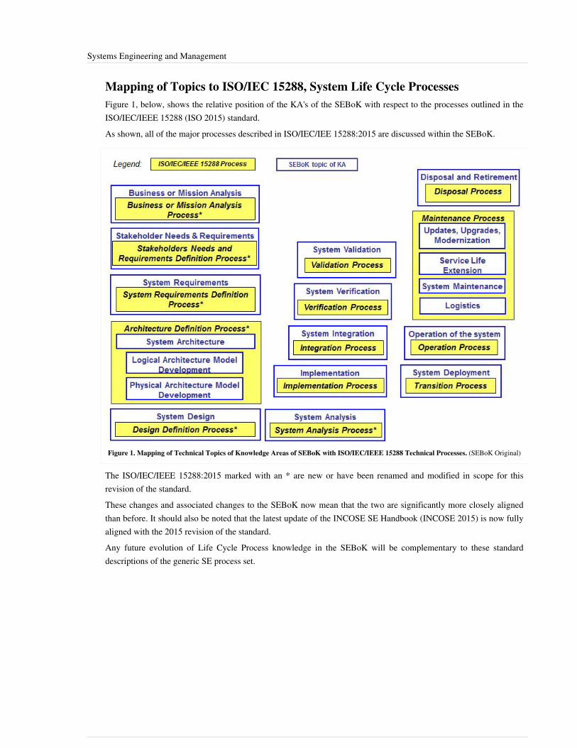
Systems Engineering and Management 3
Mapping of Topics to ISO/IEC 15288, System Life Cycle ProcessesFigure 1, below, shows the relative position of the KA's of the SEBoK with respect to the processes outlined in theISO/IEC/IEEE 15288 (ISO 2015) standard.As shown, all of the major processes described in ISO/IEC/IEE 15288:2015 are discussed within the SEBoK.
Figure 1. Mapping of Technical Topics of Knowledge Areas of SEBoK with ISO/IEC/IEEE 15288 Technical Processes. (SEBoK Original)
The ISO/IEC/IEEE 15288:2015 marked with an * are new or have been renamed and modified in scope for thisrevision of the standard.These changes and associated changes to the SEBoK now mean that the two are significantly more closely alignedthan before. It should also be noted that the latest update of the INCOSE SE Handbook (INCOSE 2015) is now fullyaligned with the 2015 revision of the standard.Any future evolution of Life Cycle Process knowledge in the SEBoK will be complementary to these standarddescriptions of the generic SE process set.
Systems Engineering and Management 4
ReferencesCollins English Dictionary, s.v. "Ontology." 2011.Estefan, J. 2008. A Survey of Model-Based Systems Engineering (MBSE) Methodologies, rev, B. Seattle, WA:International Council on Systems Engineering. INCOSE-TD-2007-003-02. Accessed April 13, 2015 at http:/ / www.omgsysml. org/ MBSE_Methodology_Survey_RevB. pdfINCOSE. 2015. 'Systems Engineering Handbook: A Guide for System Life Cycle Processes and Activities', version4.0. Hoboken, NJ, USA: John Wiley and Sons, Inc, ISBN: 978-1-118-99940-0ISO/IEC/IEEE. 2015. Systems and Software Engineering -- System Life Cycle Processes. Geneva, Switzerland:International Organisation for Standardisation / International Electrotechnical Commissions / Institute for Electricaland Electronics Engineers. ISO/IEC/IEEE 15288:2015.ISO. 2007. Systems Engineering and Design. Geneva, Switzerland: International Organization for Standardization(ISO). ISO 10303-AP233.Oliver, D., T. Kelliher, and J. Keegan. 1997. Engineering Complex Systems with Models and Objects. New York,NY, USA: McGraw-Hill.
Primary ReferencesINCOSE. 2015. Systems Engineering Handbook - A Guide for System Life Cycle Processes and Activities'', version4.0. Hoboken, NJ, USA: John Wiley and Sons, Inc, ISBN: 978-1-118-99940-0ISO/IEC/IEEE. 2015. Systems and Software Engineering -- System Life Cycle Processes. Geneva, Switzerland:International Organisation for Standardisation / International Electrotechnical Commissions. ISO/IEC/IEEE15288:2015.
Additional ReferencesBell Telephone Laboratories. 1982. Engineering and Operations in the Bell System. Murray Hill, NJ: Bell TelephoneLaboratories.Fortescue, P.W., J. Stark, and G. Swinerd. 2003. Spacecraft Systems Engineering. New York, NY, USA: J. Wiley.
< Previous Article | Parent Article | Next Article >SEBoK v. 1.4 released 29 June 2015
SEBoK DiscussionPlease provide your comments and feedback on the SEBoK below. You will need to log in to DISQUS using anexisting account (e.g. Yahoo, Google, Facebook, Twitter, etc.) or create a DISQUS account. Simply type yourcomment in the text field below and DISQUS will guide you through the login or registration steps. Feedback will bearchived and used for future updates to the SEBoK. If you provided a comment that is no longer listed, that commenthas been adjudicated. You can view adjudication for comments submitted prior to SEBoK v. 1.0 at SEBoK Reviewand Adjudication. Later comments are addressed and changes are summarized in the Letter from the Editor andAcknowledgements and Release History.
If you would like to provide edits on this article, recommend new content, or make comments on the SEBoKas a whole, please see the SEBoK Sandbox [1].
ENCODED_CONTENTMTcwODMPGRpdiBpZD0iZGlzcXVzX3RocmVhZCI+PC9kaXY+CjxzY3JpcHQgdHlwZT0idGV4dC9qYXZhc2NyaXB0Ij4KICAgIC8qICogKiBDT05GSUdVUkFUSU9OIFZBUklBQkxFUzogRURJVCBCRUZPUkUgUEFTVElORyBJTlRPIFlPVVIgV0VCUEFHRSAqICogKi8KICAgIHZhciBkaXNxdXNfc2hvcnRuYW1lID0gJ3NlYm9rd2lraTEwJzsgLy8gcmVxdWlyZWQ6IHJlcGxhY2UgZXhhbXBsZSB3aXRoIHlvdXIgZm9ydW0gc2hvcnRuYW1lCiAgICB2YXIgZGlzcXVzX2lkZW50aWZpZXIgPSAnU3lzdGVtcyBFbmdpbmVlcmluZyBhbmQgTWFuYWdlbWVudCc7ICAgIHZhciBkaXNxdXNfdXJsID0gJ2h0dHA6Ly9zZWJva3dpa2kub3JnL2RyYWZ0L1N5c3RlbXNfRW5naW5lZXJpbmdfYW5kX01hbmFnZW1lbnQnOwogICAgLyogKiAqIERPTidUIEVESVQgQkVMT1cgVEhJUyBMSU5FICogKiAqLwogICAgKGZ1bmN0aW9uKCkgewogICAgICAgIHZhciBkc3EgPSBkb2N1bWVudC5jcmVhdGVFbGVtZW50KCdzY3JpcHQnKTsgZHNxLnR5cGUgPSAndGV4dC9qYXZhc2NyaXB0JzsgZHNxLmFzeW5jID0gdHJ1ZTsKICAgICAgICBkc3Euc3JjID0gJ2h0dHA6Ly8nICsgZGlzcXVzX3Nob3J0bmFtZSArICcuZGlzcXVzLmNvbS9lbWJlZC5qcyc7CiAgICAgICAgKGRvY3VtZW50LmdldEVsZW1lbnRzQnlUYWdOYW1lKCdoZWFkJylbMF0gfHwgZG9jdW1lbnQuZ2V0RWxlbWVudHNCeVRhZ05hbWUoJ2JvZHknKVswXSkuYXBwZW5kQ2hpbGQoZHNxKTsKICAgIH0pKCk7Cjwvc2NyaXB0Pgo8bm9zY3JpcHQ+UGxlYXNlIGVuYWJsZSBKYXZhU2NyaXB0IHRvIHZpZXcgdGhlIDxhIGhyZWY9Imh0dHA6Ly9kaXNxdXMuY29tLz9yZWZfbm9zY3JpcHQiPmNvbW1lbnRzIHBvd2VyZWQgYnkgRGlzcXVzLjwvYT48L25vc2NyaXB0Pgo8YSBocmVmPSJodHRwOi8vZGlzcXVzLmNvbSIgY2xhc3M9ImRzcS1icmxpbmsiPmJsb2cgY29tbWVudHMgcG93ZXJlZCBieSA8c3BhbiBjbGFzcz0ibG9nby1kaXNxdXMiPkRpc3F1czwvc3Bhbj48L2E+END_ENCODED_CONTENT

Systems Engineering and Management 5
References[1] http:/ / www. sebokwiki. org/ sandbox/
Introduction to Life Cycle ProcessesIn this Knowledge Area we introduce key principles of life cycle, life cycle model and life cycle processes. Ageneric SE paradigm is described; this forms a starting point for discussions of more detailed life cycle knowledge.
TopicsEach part of the SEBoK is divided into knowledge areas (KAs), which are groupings of information with a relatedtheme. The KAs in turn are divided into topics. This KA contains the following topics:•• Generic Life Cycle Model•• Applying Life Cycle Processes•• Life Cycle Processes and Enterprise NeedSee the article Matrix of Implementation Examples for a mapping of case studies and vignettes included in Part 7 totopics covered in Part 3.
Life Cycle TerminologyThe term Life Cycle (glossary) is one that engineering has borrowed from the natural sciences, it is used to describeboth the changes a single organism goes through over it life and how the lives of multiple organisms interact tosustain or evolve a population. We use it in engineering in the same ways to describe the complete life of an instanceof a System-of-Interest (glossary) (SoI); and the managed combination of multiple such instances to providecapabilities which deliver stakeholder satisfaction.A life cycle model identifies the major stages that a specific SoI goes through, from its inception to its retirement.Life cycle models are generally implemented in development projects, and are strongly aligned with managementplanning and decision making.
Generic Systems Engineering ParadigmFigure 1 identifies the overall goals of any SE effort, which are: the understanding of stakeholder value; the selectionof a specific need to be addressed; the transformation of that need into a system (the product or service that providesfor the need); and the use of that product or service to provide the stakeholder value. This paradigm has beendeveloped according to the principles of the systems approach discussed in Part 2 and is used to establish a basis forthe KAs in Part 3 and Part 4 of the SEBoK.

Introduction to Life Cycle Processes 6
Figure 1. Generic Systems Engineering Paradigm. (SEBoK Original)
On the left side of Figure 1, there are SoI's identified in the formation of a system breakdown structure. SoI 1 isbroken down into its basic elements, which in this case are systems as well (SoI 2 and SoI 3). These two systems arecomposed of system elements that are not refined any further.On the right side of Figure 1, each SoI has a corresponding life cycle model (glossary) which is composed of stagesthat are populated with processes. The function of these processes is to define the work that is to be performed andthe associated artifacts to be produced. In a model-based approach, these artifacts are captured in the system modelthat represent the SoI's. Note that some of the requirements defined to meet the need are distributed in the earlystages of the life cycle for SoI 1, while others are designated to the life cycles of SoI 2 or SoI 3. The decompositionof the system illustrates the fundamental concept of recursion (glossary) as defined in the ISO/IEC/IEEE 15288standard; with the standard being reapplied for each SoI (ISO 2015). It is important to point out that the requirementsmay be allocated to different system elements, which may be integrated in different life cycle stages of any of thethree SoI's; however, together they form a cohesive system. For example, SoI 1 may be a simple vehicle composedof a chassis, motor and controls, SoI 2 an embedded hardware system, and Sol 3 a software intensive interface andcontrol system.When performing SE processes in stages, iteration (glossary) between stages is often required (e.g. in successiverefinement of the definition of the system or in providing an update or upgrade of an existing system). The workperformed in the processes and stages can be performed in a concurrent manner within the life cycle of any of thesystems of interest and also among the multiple life cycles.This paradigm provides a fundamental framework for understanding generic SE (seen in Part 3), as well as for theapplication of SE to the various types of systems described in Part 4.
Introduction to Life Cycle Processes 7
References
Works CitedISO/IEC/IEEE. 2015.Systems and software engineering - system life cycle processes.Geneva, Switzerland:International Organization for Standardization (ISO)/International Electrotechnical Commission (IEC), Institute ofElectrical and Electronics Engineers.ISO/IEC 15288:2015.
Primary ReferencesINCOSE. 2015. 'Systems Engineering Handbook: A Guide for System Life Cycle Processes and Activities', version4.0. Hoboken, NJ, USA: John Wiley and Sons, Inc, ISBN: 978-1-118-99940-0Lawson, H. 2010. A Journey Through the Systems Landscape. London, UK: College Publications.
Additional References
< Previous Article | Parent Article | Next Article >SEBoK v. 1.4 released 29 June 2015
SEBoK DiscussionPlease provide your comments and feedback on the SEBoK below. You will need to log in to DISQUS using anexisting account (e.g. Yahoo, Google, Facebook, Twitter, etc.) or create a DISQUS account. Simply type yourcomment in the text field below and DISQUS will guide you through the login or registration steps. Feedback will bearchived and used for future updates to the SEBoK. If you provided a comment that is no longer listed, that commenthas been adjudicated. You can view adjudication for comments submitted prior to SEBoK v. 1.0 at SEBoK Reviewand Adjudication. Later comments are addressed and changes are summarized in the Letter from the Editor andAcknowledgements and Release History.
If you would like to provide edits on this article, recommend new content, or make comments on the SEBoKas a whole, please see the SEBoK Sandbox [1].
ENCODED_CONTENTMTU4NTEPGRpdiBpZD0iZGlzcXVzX3RocmVhZCI+PC9kaXY+CjxzY3JpcHQgdHlwZT0idGV4dC9qYXZhc2NyaXB0Ij4KICAgIC8qICogKiBDT05GSUdVUkFUSU9OIFZBUklBQkxFUzogRURJVCBCRUZPUkUgUEFTVElORyBJTlRPIFlPVVIgV0VCUEFHRSAqICogKi8KICAgIHZhciBkaXNxdXNfc2hvcnRuYW1lID0gJ3NlYm9rd2lraTEwJzsgLy8gcmVxdWlyZWQ6IHJlcGxhY2UgZXhhbXBsZSB3aXRoIHlvdXIgZm9ydW0gc2hvcnRuYW1lCiAgICB2YXIgZGlzcXVzX2lkZW50aWZpZXIgPSAnSW50cm9kdWN0aW9uIHRvIExpZmUgQ3ljbGUgUHJvY2Vzc2VzJzsgICAgdmFyIGRpc3F1c191cmwgPSAnaHR0cDovL3NlYm9rd2lraS5vcmcvZHJhZnQvSW50cm9kdWN0aW9uX3RvX0xpZmVfQ3ljbGVfUHJvY2Vzc2VzJzsKICAgIC8qICogKiBET04nVCBFRElUIEJFTE9XIFRISVMgTElORSAqICogKi8KICAgIChmdW5jdGlvbigpIHsKICAgICAgICB2YXIgZHNxID0gZG9jdW1lbnQuY3JlYXRlRWxlbWVudCgnc2NyaXB0Jyk7IGRzcS50eXBlID0gJ3RleHQvamF2YXNjcmlwdCc7IGRzcS5hc3luYyA9IHRydWU7CiAgICAgICAgZHNxLnNyYyA9ICdodHRwOi8vJyArIGRpc3F1c19zaG9ydG5hbWUgKyAnLmRpc3F1cy5jb20vZW1iZWQuanMnOwogICAgICAgIChkb2N1bWVudC5nZXRFbGVtZW50c0J5VGFnTmFtZSgnaGVhZCcpWzBdIHx8IGRvY3VtZW50LmdldEVsZW1lbnRzQnlUYWdOYW1lKCdib2R5JylbMF0pLmFwcGVuZENoaWxkKGRzcSk7CiAgICB9KSgpOwo8L3NjcmlwdD4KPG5vc2NyaXB0PlBsZWFzZSBlbmFibGUgSmF2YVNjcmlwdCB0byB2aWV3IHRoZSA8YSBocmVmPSJodHRwOi8vZGlzcXVzLmNvbS8/cmVmX25vc2NyaXB0Ij5jb21tZW50cyBwb3dlcmVkIGJ5IERpc3F1cy48L2E+PC9ub3NjcmlwdD4KPGEgaHJlZj0iaHR0cDovL2Rpc3F1cy5jb20iIGNsYXNzPSJkc3EtYnJsaW5rIj5ibG9nIGNvbW1lbnRzIHBvd2VyZWQgYnkgPHNwYW4gY2xhc3M9ImxvZ28tZGlzcXVzIj5EaXNxdXM8L3NwYW4+PC9hPg==END_ENCODED_CONTENT

Generic Life Cycle Model 8
Generic Life Cycle ModelAs discussed in the generic life cycle paradigm in Introduction to Life Cycle Processes each System-of-Interest(glossary) (SoI) has an associated Life Cycle Model (glossary). The generic life cycle model below applies to asingle SoI. SE must generally be synchronised across a number tailored instances of such life cycle models to fullysatisfy stakeholder needs. More complex life cycle models which address this are described in Life Cycle Models.
A Generic System Life Cycle ModelThere is no single “one-size-fits-all” system life cycle model that can provide specific guidance for all projectsituations. Figure 1, adapted from (Lawson 2010, ISO 2015, and ISO 2010), provides a generic life cycle model thatforms a starting point for the most common versions of pre-specified, evolutionary, sequential, opportunistic, andconcurrent life cycle processes. The model is defined as a set of stages, within which technical and managementactivities are performed. The stages are terminated by decision gates where the key stakeholders decide whether toproceed into the next stage, to remain in the current stage, or to terminate or re-scope related projects.
Figure 1. A Generic Life Cycle Model. (SEBoK Original)
Elaborated definitions of these stages are provided below, in the glossary, and in various other ways in subsequentarticles.The Concept Definition stage begins with a decision by a protagonist (individual or organization) to investresources in a new or improved engineered system. Inception begins with a set of stakeholders agreeing to the needfor change to an engineered system context and exploring whether new or modified SoI can be developed, in whichthe life cycle benefits are worth the investments in the life cycle costs. Activities include: developing the concept ofoperations and business case; determining the key stakeholders and their desired capabilities; negotiating thestakeholder requirements among the key stakeholders and selecting the system’s non-developmental items (NDIs).The System Definition stage begins when the key stakeholders decide that the business needs and stakeholderrequirements are sufficiently well defined to justify committing the resources necessary to define a solution optionsin sufficient detail to answer the life cycle cost question identified in concept definition and provide a basis of systemrealization if appropriate. Activities include developing system architectures; defining and agreeing levels of systemrequirements; developing systems-level life cycle plans and performing system analysis in order to illustrate thecompatibility and feasibility of the resulting system definition. The transition into the system realization stage canlead to either single-pass or multiple-pass development.It should be noted that the concept and system definition activities above describe activities performed by systemsengineers when performing systems engineering. There is a very strong concurrency between proposing a problemsituation or opportunity and describing one or more possible system solutions, as discussed in Systems ApproachApplied to Engineered Systems. Other related definition activities include: prototyping or actual development ofhigh-risk items to show evidence of system feasibility; collaboration with business analysts or performing missioneffectiveness analyses to provide a viable business case for proceeding into realization; and modifications to realizedsystems to improve their production, support or utilization. These activities will generally happen through the systemlife cycle to handle system evolution, especially under multiple-pass development. This is discussed in more detail inthe Life Cycle Models knowledge area.

Generic Life Cycle Model 9
The System Realization stage begins when the key stakeholders decide that the SoI architecture and feasibilityevidence are sufficiently low-risk to justify committing the resources necessary to develop and sustain the initialoperational capability (IOC) or the single-pass development of the full operational capability (FOC). Activitiesinclude: construction of the developmental elements; integration of these with each other and with thenon-developmental item (NDI) elements; verification and validation of the elements and their integration as itproceeds; and preparing for the concurrent production, support, and utilization activities.The System Production, Support, and Utilization (PSU) stages begins when the key stakeholders decide that theSoI life-cycle feasibility and safety are at a sufficiently low-risk level that justifies committing the resourcesnecessary to produce, field, support, and utilize the system over its expected lifetime. The lifetimes of production,support, and utilization are likely to be different. After market support will generally continue after production iscomplete and users will often continue to use unsupported systems.System Production involves the fabrication of instances or versions of a SoI and of associated after market spareparts. It also includes production quality monitoring and improvement; product or service acceptance activities; andcontinuous production process improvement. It may include low-rate initial production (LRIP) to mature theproduction process or to promote the continued preservation of the production capability for future spikes in demand.Systems Support includes various classes of maintenance: corrective (for defects), adaptive (for interoperabilitywith independently evolving co-dependent systems), and perfective (for enhancement of performance, usability, orother key performance parameters). It also includes hot lines and responders for user or emergency support and theprovisioning of needed consumables (gas, water, power, etc.). Its boundaries include some gray areas, such as theboundary between small system enhancements and the development of larger complementary new additions, and theboundary between rework/maintenance of earlier fielded increments in incremental or evolutionary development.Systems Support usually continues after System Production is terminated.System Utilization includes the use of the SoI in its context by operators, administrators, the general public, orsystems above it in the system-of-interest hierarchy. It usually continues after Systems Support is terminated.The System Retirement stage is often executed incrementally as system versions or elements become obsolete orare no longer economical to support and therefore undergo disposal or recycling of their content. Increasinglyaffordable considerations make system re-purposing an attractive alternative.
Applying the Life Cycle ModelFigure 1 shows just the single-step approach for proceeding through the stages of a SoI life cycle. In Life CycleModels knowledge area we discuss examples of real world enterprises and their drivers, both technical andorganizational. These have lead to a number of documented approaches for sequencing the life cycle stages to dealwith some of the issues raised. The Life Cycle Models KA summarizes a number of incremental and evolutionarylife cycle models, including their main strengths and weaknesses and also discusses criteria for choosing the best-fitapproach.In figure 1 we have listed key technical and management activities critical to successful completion of each stage.This is a useful way to illustrate the goals of each stage and gives an indication of how processes align with thesestages. This can be important when considering how to plan for resources, milestones, etc. However, it is importantto observe that the execution of process activities are not compartmentalized to particular life cycle stages (Lawson2010). In Applying Life Cycle Processes we discuss a number of views on the nature of the inter-relationshipsbetween process activities within a life cycle model. In general, the technical and management activities are appliedin accordance with the principles of concurrency, Iteration (glossary) and Recursion (glossary) described in thegeneric life cycle paradigm.

Generic Life Cycle Model 10
References
Works CitedISO/IEC/IEEE. 2015.Systems and software engineering - system life cycle processes.Geneva, Switzerland:International Organization for Standardization (ISO)/International Electrotechnical Commission (IEC), Institute ofElectrical and Electronics Engineers.ISO/IEC 15288:2015.ISO/IEC. 2010. Systems and Software Engineering, Part 1: Guide for Life Cycle Management. Geneva, Switzerland:International Organization for Standardization (ISO)/International Electrotechnical Commission (IEC), ISO/IEC24748-1:2010.Lawson, H. 2010. A Journey Through the Systems Landscape. London, UK: College Publications.
Primary ReferencesForsberg, K., H. Mooz, H. Cotterman. 2005. Visualizing Project Management, 3rd Ed. Hoboken, NJ: J. Wiley &Sons.INCOSE. 2015. 'Systems Engineering Handbook: A Guide for System Life Cycle Processes and Activities', version4.0. Hoboken, NJ, USA: John Wiley and Sons, Inc, ISBN: 978-1-118-99940-0Lawson, H. 2010. A Journey Through the Systems Landscape. London, UK: College Publications.
Additional Referencesnone.
< Previous Article | Parent Article | Next Article >SEBoK v. 1.4 released 29 June 2015
SEBoK DiscussionPlease provide your comments and feedback on the SEBoK below. You will need to log in to DISQUS using anexisting account (e.g. Yahoo, Google, Facebook, Twitter, etc.) or create a DISQUS account. Simply type yourcomment in the text field below and DISQUS will guide you through the login or registration steps. Feedback will bearchived and used for future updates to the SEBoK. If you provided a comment that is no longer listed, that commenthas been adjudicated. You can view adjudication for comments submitted prior to SEBoK v. 1.0 at SEBoK Reviewand Adjudication. Later comments are addressed and changes are summarized in the Letter from the Editor andAcknowledgements and Release History.
If you would like to provide edits on this article, recommend new content, or make comments on the SEBoKas a whole, please see the SEBoK Sandbox [1].
ENCODED_CONTENTMTg3MDYPGRpdiBpZD0iZGlzcXVzX3RocmVhZCI+PC9kaXY+CjxzY3JpcHQgdHlwZT0idGV4dC9qYXZhc2NyaXB0Ij4KICAgIC8qICogKiBDT05GSUdVUkFUSU9OIFZBUklBQkxFUzogRURJVCBCRUZPUkUgUEFTVElORyBJTlRPIFlPVVIgV0VCUEFHRSAqICogKi8KICAgIHZhciBkaXNxdXNfc2hvcnRuYW1lID0gJ3NlYm9rd2lraTEwJzsgLy8gcmVxdWlyZWQ6IHJlcGxhY2UgZXhhbXBsZSB3aXRoIHlvdXIgZm9ydW0gc2hvcnRuYW1lCiAgICB2YXIgZGlzcXVzX2lkZW50aWZpZXIgPSAnR2VuZXJpYyBMaWZlIEN5Y2xlIE1vZGVsJzsgICAgdmFyIGRpc3F1c191cmwgPSAnaHR0cDovL3NlYm9rd2lraS5vcmcvZHJhZnQvR2VuZXJpY19MaWZlX0N5Y2xlX01vZGVsJzsKICAgIC8qICogKiBET04nVCBFRElUIEJFTE9XIFRISVMgTElORSAqICogKi8KICAgIChmdW5jdGlvbigpIHsKICAgICAgICB2YXIgZHNxID0gZG9jdW1lbnQuY3JlYXRlRWxlbWVudCgnc2NyaXB0Jyk7IGRzcS50eXBlID0gJ3RleHQvamF2YXNjcmlwdCc7IGRzcS5hc3luYyA9IHRydWU7CiAgICAgICAgZHNxLnNyYyA9ICdodHRwOi8vJyArIGRpc3F1c19zaG9ydG5hbWUgKyAnLmRpc3F1cy5jb20vZW1iZWQuanMnOwogICAgICAgIChkb2N1bWVudC5nZXRFbGVtZW50c0J5VGFnTmFtZSgnaGVhZCcpWzBdIHx8IGRvY3VtZW50LmdldEVsZW1lbnRzQnlUYWdOYW1lKCdib2R5JylbMF0pLmFwcGVuZENoaWxkKGRzcSk7CiAgICB9KSgpOwo8L3NjcmlwdD4KPG5vc2NyaXB0PlBsZWFzZSBlbmFibGUgSmF2YVNjcmlwdCB0byB2aWV3IHRoZSA8YSBocmVmPSJodHRwOi8vZGlzcXVzLmNvbS8/cmVmX25vc2NyaXB0Ij5jb21tZW50cyBwb3dlcmVkIGJ5IERpc3F1cy48L2E+PC9ub3NjcmlwdD4KPGEgaHJlZj0iaHR0cDovL2Rpc3F1cy5jb20iIGNsYXNzPSJkc3EtYnJsaW5rIj5ibG9nIGNvbW1lbnRzIHBvd2VyZWQgYnkgPHNwYW4gY2xhc3M9ImxvZ28tZGlzcXVzIj5EaXNxdXM8L3NwYW4+PC9hPg==END_ENCODED_CONTENT

Applying Life Cycle Processes 11
Applying Life Cycle ProcessesThe Generic Life Cycle Model describes a set of life cycle stages and their relationships. In defining this wedescribed some of the technical and management activities critical to the success of each stage. While thisassociation of activity to stage is important we must also recognise the through life relationships between theseactivities to ensure we take a Systems Approach (glossary).Systems Engineering technical and management activities are defined in a set of life cycle processes. These grouptogether closely related activities and allow us to describe the relationships between them. In this topic we discuss anumber of views on the nature of the inter-relationships between process activities within a life cycle model.In general, the technical and management activities are applied in accordance with the principles of concurrency,Iteration (glossary) and Recursion (glossary) described in the generic systems engineering paradigm. Theseprinciples overlap to some extent and can be seen as related views of the same fundamental need to ensure we cantake a holistic systems approach, while allowing for some structuring and sequence of our activities. The viewspresented below should be seen as examples of the ways in which different SE authors present these overlappingideas.
Life Cycle Process Terminology
ProcessA process is a series of actions or steps taken in order to achieve a particular end. Processes can be performed byhumans or machines transforming inputs into outputs.In SEBoK processes are interpreted in several ways, including: technical, life cycle, business, or manufacturing flowprocesses. Many of the Part 3 sections are structured along technical processes (e.g. design, verification); however,Life Cycle Models also describes a number of high level program life cycle sequence which call themselvesprocesses (e.g. rational unified process (RUP), etc.).Part 4: Applications of Systems Engineering and Part 5: Enabling Systems Engineering utilize processes that arerelated to services and business enterprise operations.Systems Engineering Life Cycle Process (glossary) define technical and management activities performed across oneor more stages to provide the information needed to make life cycle decisions; and to enable realization, use andsustainment of a System-of-Interest (glossary) (SoI) across its life cycle model as necessary. This relationshipbetween Life Cycle Model (glossary) and process activities can be used to describe how SE is applied to differentsystem contexts.
RequirementA requirement is something that is needed or wanted, but may not be compulsory in all circumstances. Requirementsmay refer to product or process characteristics or constraints. Different understandings of requirements aredependent on process state, level of abstraction, and type (e.g. functional, performance, constraint). An individualrequirement may also have multiple interpretations over time.Requirements exist at multiple levels of enterprise or system with multiple levels abstraction. This ranges from thehighest level of the enterprise capability or customer need to the lowest level of the system design .Thus,requirements need to be defined at the appropriate level of detail for the level of the entity to which it applies. Seethe article Life Cycle Processes and Enterprise Needs for further detail on the transformation of needs andrequirements from the enterprise to the lowest system element across concept definition and system definition.

Applying Life Cycle Processes 12
ArchitectureAn architecture refers to the organizational structure of a system, whereby the system can be defined in differentcontexts. Architecting is the art or practice of designing the structures. See below for further discussions on the useof levels of Logical and Physical architecture models to define related system and system elements; and support therequirements activities.Architectures can apply for a system product, enterprise, or service. For example, Part 3 mostly considers product orservice related architectures that systems engineers create, but enterprise architecture describes the structure of anorganization. Part 5: Enabling Systems Engineering interprets enterprise architecture in a much broader manner thanan IT system used across an organization, which is a specific instance of architecture.Frameworks are closely related to architectures, as they are ways of representing architectures. See the glossary ofterms Architecture Framework for definition and examples.
Other ProcessesA number of other life cycle processes are mentioned below, including System Analysis (glossary), Integration(glossary), Verification (glossary), Validation (glossary), deployment, operation, Maintenance (glossary) andDisposal (glossary) are discussed in detail in the System Realization and System Deployment and Use knowledgeareas.
Life Cycle Process ConcurrencyIn the Generic Life Cycle Model we have listed key activities critical to successful completion of each stage. This isa useful way to illustrate the goals of each stage and gives an indication of how processes align with these stages.This can be important when considering how to plan for resources, milestones, etc. However, it is important toobserve that the execution of process activities are not compartmentalized to particular life cycle stages (Lawson2010).Figure 1 shows a simple illustration of the through life nature of technical and management processes. This figurebuilds directly on the "hump diagram" principles described in Systems Approach Applied to Engineered Systems.

Applying Life Cycle Processes 13
Figure 1: Generic Relationships between life cycle stages and processes (modified from Lawson 2010)
The lines on this diagram represent the amount of activity for each process over the generic life cycle. The peaks (orhumps) of activity represent the periods when a process activity becomes the main focus of a stage. The activitybefore and after these peaks may represent through life issues raised by a process focus, e.g. how will likelymaintenance constraints be represented in the system requirements. These considerations help maintain a moreholistic perspective in each stage; or they can represent forward planning to ensure the resources needed to completefuture activities have been included in estimates and plans, e.g. are all resources need for verification in place oravailable. Ensuring this hump diagram principle is implemented in a way which is achievable, affordable andappropriate to the situation is a critical driver for all life cycle models.

Applying Life Cycle Processes 14
Life Cycle Process IterationThe concept of iteration applies to life cycle stages within a life cycle model, and also applies to processes. Figure 2below gives an example of iteration in the life cycle processes associated with concept and system definition.
Figure 2. Example of Iterations of Processes Related to System Definition (Faisandier 2012). Permission Granted by Sinergy'Com. All otherrights are reserved by the copyright owner.
There is generally a close coupling between the exploration of a problem or opportunity and the definition of one ormore feasible solutions, see Systems Approach to Engineered Systems. Thus the related processes in this examplewill normally be applied in an iterative way. The relationships between these process are further discussed in theSystem Definition KA.Figure 3 below gives an example of the iteration between the other life cycle processes.
Figure 3. System Realization. (SEBoK Original)

Applying Life Cycle Processes 15
The iterations in this example relate to the overlaps in process outcomes shown in Figure 1. They either allowconsideration of cross process issues to influence the system definition, e.g. considering likely integration orverification approaches might make us think about failure modes or add data collection or monitoring elements intothe system. Or they allow risk management and through life planning activities to identify the need for futureactivities.The relationships between these processes are further discussed in system realization and system deployment anduse.
Life Cycle Process RecursionThe comprehensive definition of a SoI is generally achieved using decomposition layers and system elements(glossary). Figure 4 presents a fundamental schema of a system breakdown structure.
Figure 4. Hierarchical Decomposition of a System-of-Interest (Faisandier 2012). Permission Granted by Sinergy'Com. All other rights arereserved by the copyright owner.
In each decomposition layer and for each system, the System Definition processes are applied recursively becausethe notion of "system" is in itself recursive; the notions of SoI, system, and system element are based on the sameconcepts (see Part 2). Figure 5 shows an example of the recursion of life cycle processes.

Applying Life Cycle Processes 16
Figure 5. Recursion of Processes on Layers (Faisandier 2012). Permission Granted by Sinergy'Com. All other rights are reserved by thecopyright owner.
Systems Approach to Solution SynthesisThe sections above give different perspectives on how SE life cycle processes are related and how this shapes theirapplication. Solution synthesis is described in Part 2 as away of taking a systems approach to creating solution.Synthesis is in general a mixture of top down and bottom up approaches as discussed below.
Top-Down Approach: From Problem to SolutionIn a top-down approach, concept definition activities are focused primarily on understanding the problem, theoperational needs/requirements within the problem space, and the conditions that constrain the solution and boundthe solution space. The concept definition activities determine the mission context, Mission Analysis, and the needsto be fulfilled in that context by a new or modified system (i.e. the SoI), and addresses stakeholder needs andrequirements.The System Definition activities consider functional, behavioral, temporal, and physical aspects of one or moresolutions based on the results of concept definition. System Analysis considers the advantages and disadvantages ofthe proposed system solutions both in terms of how they satisfy the needs established in concept definition, as wellas the relative cost, time scales and other development issues. This may require further refinement of the conceptdefinition to ensure all legacy relationships and stakeholders relevant to a particular solution architecture have beenconsidered in the stakeholder requirements.The outcomes of this iteration between Concept Definition and System Definition define a required system solution and its associated problem context, which are used for System Realization, System Deployment and Use, and Product and Service Life Management of one or more solution implementations. In this approach problem

Applying Life Cycle Processes 17
understanding and solution selection activities are completed in the front-end portion of system development anddesign and then maintained and refined as necessary throughout the life cycle of any resulting solution systems.Top-down activities can be sequential, iterative, recursive or evolutionary depending upon the life cycle model.
Bottom-Up Approach: Evolution of the SolutionIn some situations, the concept definition activities determine the need to evolve existing capabilities or add newcapabilities to an existing system. During the concept definition, the alternatives to address the needs are evaluated.Engineers are then led to reconsider the system definition in order to modify or adapt some structural, functional,behavioral, or temporal properties during the product (glossary) or service (glossary) life cycle for a changingcontext (glossary) of use or for the purpose of improving existing solutions.Reverse engineering is often necessary to enable system engineers to (re)characterize the properties of thesystem-of-interest (SoI) or its elements. This is an important step to ensure that system engineers understand the SoIbefore beginning modification. For more information on system definition, see the System Definition article.A bottom-up approach is necessary for analysis purposes, or for (re)using existing elements in the designarchitecture. Changes in the context of use or a need for improvement can prompt this. In contrast, a top-downapproach is generally used to define an initial design solution corresponding to a problem or a set of needs.
Solution SynthesisIn most real problems a combination of bottom-up and top-down approaches provides the right mixture of innovativesolution thinking driven by need and constrained and pragmatic thinking driven by what already exists. This is oftenreferred to as a “middle-out” approach.As well as being the most pragmatic approach, synthesis has the potential to keep the life cycle focused on wholesystem issues, while allow the exploration of the focused levels of detail needed to describe realizable solutions, seeSynthesising System Solutions.
References
Works CitedFaisandier, A. 2012. Systems Architecture and Design. Belberaud, France: Sinergy'Com.Lawson, H. 2010. A Journey Through the Systems Landscape. London, UK: College Publications.
Primary ReferencesINCOSE. 2015. 'Systems Engineering Handbook: A Guide for System Life Cycle Processes and Activities', version4.0. Hoboken, NJ, USA: John Wiley and Sons, Inc, ISBN: 978-1-118-99940-0
Additional ReferencesNone.

Applying Life Cycle Processes 18
< Previous Article | Parent Article | Next Article >SEBoK v. 1.4 released 29 June 2015
SEBoK DiscussionPlease provide your comments and feedback on the SEBoK below. You will need to log in to DISQUS using anexisting account (e.g. Yahoo, Google, Facebook, Twitter, etc.) or create a DISQUS account. Simply type yourcomment in the text field below and DISQUS will guide you through the login or registration steps. Feedback will bearchived and used for future updates to the SEBoK. If you provided a comment that is no longer listed, that commenthas been adjudicated. You can view adjudication for comments submitted prior to SEBoK v. 1.0 at SEBoK Reviewand Adjudication. Later comments are addressed and changes are summarized in the Letter from the Editor andAcknowledgements and Release History.
If you would like to provide edits on this article, recommend new content, or make comments on the SEBoKas a whole, please see the SEBoK Sandbox [1].
ENCODED_CONTENTMTk0MTMPGRpdiBpZD0iZGlzcXVzX3RocmVhZCI+PC9kaXY+CjxzY3JpcHQgdHlwZT0idGV4dC9qYXZhc2NyaXB0Ij4KICAgIC8qICogKiBDT05GSUdVUkFUSU9OIFZBUklBQkxFUzogRURJVCBCRUZPUkUgUEFTVElORyBJTlRPIFlPVVIgV0VCUEFHRSAqICogKi8KICAgIHZhciBkaXNxdXNfc2hvcnRuYW1lID0gJ3NlYm9rd2lraTEwJzsgLy8gcmVxdWlyZWQ6IHJlcGxhY2UgZXhhbXBsZSB3aXRoIHlvdXIgZm9ydW0gc2hvcnRuYW1lCiAgICB2YXIgZGlzcXVzX2lkZW50aWZpZXIgPSAnQXBwbHlpbmcgTGlmZSBDeWNsZSBQcm9jZXNzZXMnOyAgICB2YXIgZGlzcXVzX3VybCA9ICdodHRwOi8vc2Vib2t3aWtpLm9yZy9kcmFmdC9BcHBseWluZ19MaWZlX0N5Y2xlX1Byb2Nlc3Nlcyc7CiAgICAvKiAqICogRE9OJ1QgRURJVCBCRUxPVyBUSElTIExJTkUgKiAqICovCiAgICAoZnVuY3Rpb24oKSB7CiAgICAgICAgdmFyIGRzcSA9IGRvY3VtZW50LmNyZWF0ZUVsZW1lbnQoJ3NjcmlwdCcpOyBkc3EudHlwZSA9ICd0ZXh0L2phdmFzY3JpcHQnOyBkc3EuYXN5bmMgPSB0cnVlOwogICAgICAgIGRzcS5zcmMgPSAnaHR0cDovLycgKyBkaXNxdXNfc2hvcnRuYW1lICsgJy5kaXNxdXMuY29tL2VtYmVkLmpzJzsKICAgICAgICAoZG9jdW1lbnQuZ2V0RWxlbWVudHNCeVRhZ05hbWUoJ2hlYWQnKVswXSB8fCBkb2N1bWVudC5nZXRFbGVtZW50c0J5VGFnTmFtZSgnYm9keScpWzBdKS5hcHBlbmRDaGlsZChkc3EpOwogICAgfSkoKTsKPC9zY3JpcHQ+Cjxub3NjcmlwdD5QbGVhc2UgZW5hYmxlIEphdmFTY3JpcHQgdG8gdmlldyB0aGUgPGEgaHJlZj0iaHR0cDovL2Rpc3F1cy5jb20vP3JlZl9ub3NjcmlwdCI+Y29tbWVudHMgcG93ZXJlZCBieSBEaXNxdXMuPC9hPjwvbm9zY3JpcHQ+CjxhIGhyZWY9Imh0dHA6Ly9kaXNxdXMuY29tIiBjbGFzcz0iZHNxLWJybGluayI+YmxvZyBjb21tZW50cyBwb3dlcmVkIGJ5IDxzcGFuIGNsYXNzPSJsb2dvLWRpc3F1cyI+RGlzcXVzPC9zcGFuPjwvYT4=END_ENCODED_CONTENT
Life Cycle Processes and Enterprise NeedThe Generic Life Cycle Model describes a simple translation from a need to achieve an outcome to a proposal torealize a new or modified engineered system. This then forms the basis for the decision to invest time, money andother resources in the life cycle of that System-of-Interest (glossary) (SoI). A significant proportion of the SEactivities involved in this transformation involve varying levels and types of Requirement (glossary).
Requirements and Life CycleDuring the concept definition stage of a life cycle, as the enterprise identifies new capabilities that are desired, thebusiness or mission analysis develops a high level set of strategies and need (which may be expressed as mission orbusiness requirements) that reflect the problem space perspective. As the solution space is explored and solutionclasses are characterized, stakeholder needs are developed and transformed into stakeholder requirements (from auser perspective). After the solution class has been determined and the specific solution is sought, during the systemdefinition stage of a life cycle, the stakeholder requirements are transformed into system requirements (from asolution perspective). As the system definition recursively defines the lower level detail of the solution, requirementsare defined with lower levels of abstraction. At the highest level, the ideal requirement isimplementation-independent, and therefore not specific to a solution, allowing for a range of possible solutions. Atthe lowest level, requirement statements may become more specific to the selected solution.Concept Definition has further descriptions of business or enterprise and stakeholder needs and requirements. Itdiscusses how the new capability for the business or enterprise is defined as part of the understanding of the problemspace. It also discusses the development of the stakeholder needs and their transformation into requirements from theuser perspective.System Definition has further descriptions of requirements and their types (e.g. system requirement, stakeholderrequirement, derived requirement). It discusses how different process roles/ states, levels, and the nature ofrequirements apply to the understanding of requirements.
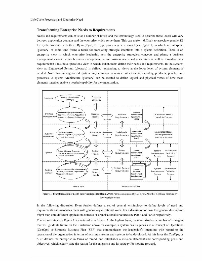
Life Cycle Processes and Enterprise Need 19
Transforming Enterprise Needs to RequirementsNeeds and requirements can exist at a number of levels and the terminology used to describe these levels will varybetween application domains and the enterprise which serve them. This can make it difficult to associate generic SElife cycle processes with them. Ryan (Ryan, 2013) proposes a generic model (see Figure 1) in which an Enterprise(glossary) of some kind forms a focus for translating strategic intentions into a system definition. There is anenterprise view in which enterprise leadership sets the enterprise strategies, concepts and plans; a businessmanagement view in which business management derive business needs and constraints as well as formalize theirrequirements; a business operations view in which stakeholders define their needs and requirements. In the systemsview an Engineered System (glossary) is defined, expanding to views at the lower-level of system elements ifneeded. Note that an engineered system may comprise a number of elements including products, people, andprocesses. A system Architecture (glossary) can be created to define logical and physical views of how theseelements together enable a needed capability for the organization.
Figure 1. Transformation of needs into requirements (Ryan, 2013) Permission granted by M. Ryan. All other rights are reserved bythe copyright owner.
In the following discussion Ryan further defines a set of general terminology to define levels of need andrequirements and associates them with generic organizational roles. For a discussion of how this general descriptionmight map onto different application contexts or organisational structures see Part 4 and Part 5 respectively.The various views in Figure 1 are referred to as layers. At the highest layer, the enterprise has a number of strategiesthat will guide its future. In the illustration above for example, a system has its genesis in a Concept of Operations(ConOps) or Strategic Business Plan (SBP) that communicates the leadership’s intentions with regard to theoperation of the organization in terms of existing systems and systems to be developed. At this layer the ConOps, orSBP, defines the enterprise in terms of ‘brand’ and establishes a mission statement and corresponding goals andobjectives, which clearly state the reason for the enterprise and its strategy for moving forward.
Life Cycle Processes and Enterprise Need 20
The Business or Mission Analysis Process begins with the organization’s mission or vision statement, goals andobjectives communicated by the ConOps or SBP. Business management uses this guidance to define business needs,largely in the form of a life-cycle concepts, which capture the business management’s concepts for acquisition,development, marketing, operations, deployment, support, and retirement. These concepts are then used to definespecific needs for that layer.The business needs contained in the life-cycle concepts are elaborated and formalized into business requirements,which are documented in the Business Requirements Specification (BRS) or Business Requirement Document(BRD). The process by which business needs are transformed into business requirements is called mission analysisor business analysis.Once business management is satisfied their needs and requirements are reasonably complete, they pass them on tothe business operations layer. Here, the Stakeholder Needs and Requirements (SNR) Definition Process uses theConOps or SBP and concepts contained in the life-cycle concepts as guidance. The Requirements Engineer (RE) orBusiness Analyst (BA) leads stakeholders from the business operations layer through a structured process to elicitstakeholder needs—in the form of a refined OpsCon or similar document and other life-cycle concepts (see Figure1). The RE or BA uses a structured process to elicit specific needs, as documented in user stories, use cases,scenarios, system concepts, or operational concepts. For further discussion of the Concept of Operations and theOperational Concept Document, and their interplay, see ANSI/AIAA G-043-2012e, Guide to the Preparation ofOperational Concept Documents.Stakeholder needs are then transformed into a formal set of Stakeholder Requirements, which are documented in theStakeholder Requirement Specification (StRS) or Stakeholder Requirement Document (StRD). That transformationis guided by a well‐defined, repeatable, rigorous, and documented process of requirements analysis. Thisrequirements analysis may involve the use of functional flow diagrams, timeline analysis, N2 Diagrams, designreference missions, modeling and simulations, movies, pictures, states and modes analysis, fault tree analysis, failuremodes and effects analysis, and trade studies. In some cases these requirements analysis methods may make use ofviews created as part of a high level Logical Architecture (glossary).At the system layer, in the System Requirements Definition Process, the requirements in the StRS are thentransformed by the RE or BA into System Requirements, which are documented in the System RequirementSpecification (SyRS) or System Requirement Document (SyRD). As in the previous process, the RE or BAaccomplishes the transformation of needs into requirements using the same requirements analysis methods describedabove to define the requirements. At each layer, the resulting requirements will be documented, agreed-to, baselined,and will be put under configuration management. As above the system requirements analysis may also be linked toappropriate logical and Physical Architecture (glossary), either informally or under shared configuration control.Note that some organizations may prepare individual life-cycle concepts for each of a number of systems that aredeveloped to meet the business needs.Once a set of requirements has been documented, agreed-to, and baselined at one layer they will flow down to thenext layer as shown in Figure 1. At the next layer, the requirements are a result of the transformation process of theneeds at that layer as well a result of the decomposition or derivation of the requirements from the previous layer. Assuch, a number of SyRS or SyRD requirements may be either decomposed from (that is, made explicit by therequirements of) or derived from (that is, implied by the requirements of) the StRS or StRD. The same is true at thesubsystem or system element layer, where a number of the subsystem or system element requirements may be eitherdecomposed or derived from the SyRS or SyRD. In all cases, for each layer shown in Figure 1, the set ofrequirements can be traced back to the requirements at the previous layer from which they were either decomposedor derived. This process continues for the next layer of system elements.How requirements are expressed differs through these layers, and therefore so do the rules for expressing them. As requirements are developed – and solutions designed – down through the layers of abstraction, we expect statements of requirement to become more and more specific. At the highest level, the ideal requirement is not specific to a

Life Cycle Processes and Enterprise Need 21
particular solution, and permits a range of possible solutions. At the lowest level, statements of requirement will beentirely specific to the selected solution. It is important to note that the form of requirements at one layer may not beappropriate for another layer. For example, at the business management layer, there may be a requirement that allproducts are “safe”. While this is a poor system requirement, it is appropriate for the Business Management layer. Atthe next layer, business operations, there will be less ambiguous and more detailed requirements that define safe.These requirements apply across all product lines. At the system layer, more specific safety requirements will bedeveloped for that specific system. These requirements will then be allocated to the system elements at the nextlower layer.
References
Works CitedANSI/AIAA G-043-2012e, Guide to the Preparation of Operational Concept Documents.Dick, J. and J. Chard, “The Systems Engineering Sandwich: Combining Requirements, Models and Design”,INCOSE International Symposium IS2004, July 2004.Hull, E., K. Jackson, J. Dick, Requirements Engineering, Springer, 2010.Ryan, M.J., “An Improved Taxonomy for Major Needs and Requirements Artefacts”, INCOSE InternationalSymposium IS2013, June 2013.
Primary ReferencesHull, E., K. Jackson, J. Dick, Requirements Engineering, Springer, 2010.Ryan, M.J., “An Improved Taxonomy for Major Needs and Requirements Artefacts”, INCOSE InternationalSymposium IS2013, June 2013.
Additional References
< Previous Article | Parent Article | Next Article >SEBoK v. 1.4 released 29 June 2015
SEBoK DiscussionPlease provide your comments and feedback on the SEBoK below. You will need to log in to DISQUS using anexisting account (e.g. Yahoo, Google, Facebook, Twitter, etc.) or create a DISQUS account. Simply type yourcomment in the text field below and DISQUS will guide you through the login or registration steps. Feedback will bearchived and used for future updates to the SEBoK. If you provided a comment that is no longer listed, that commenthas been adjudicated. You can view adjudication for comments submitted prior to SEBoK v. 1.0 at SEBoK Reviewand Adjudication. Later comments are addressed and changes are summarized in the Letter from the Editor andAcknowledgements and Release History.
If you would like to provide edits on this article, recommend new content, or make comments on the SEBoKas a whole, please see the SEBoK Sandbox [1].
ENCODED_CONTENTMjIwMzIPGRpdiBpZD0iZGlzcXVzX3RocmVhZCI+PC9kaXY+CjxzY3JpcHQgdHlwZT0idGV4dC9qYXZhc2NyaXB0Ij4KICAgIC8qICogKiBDT05GSUdVUkFUSU9OIFZBUklBQkxFUzogRURJVCBCRUZPUkUgUEFTVElORyBJTlRPIFlPVVIgV0VCUEFHRSAqICogKi8KICAgIHZhciBkaXNxdXNfc2hvcnRuYW1lID0gJ3NlYm9rd2lraTEwJzsgLy8gcmVxdWlyZWQ6IHJlcGxhY2UgZXhhbXBsZSB3aXRoIHlvdXIgZm9ydW0gc2hvcnRuYW1lCiAgICB2YXIgZGlzcXVzX2lkZW50aWZpZXIgPSAnTGlmZSBDeWNsZSBQcm9jZXNzZXMgYW5kIEVudGVycHJpc2UgTmVlZCc7ICAgIHZhciBkaXNxdXNfdXJsID0gJ2h0dHA6Ly9zZWJva3dpa2kub3JnL2RyYWZ0L0xpZmVfQ3ljbGVfUHJvY2Vzc2VzX2FuZF9FbnRlcnByaXNlX05lZWQnOwogICAgLyogKiAqIERPTidUIEVESVQgQkVMT1cgVEhJUyBMSU5FICogKiAqLwogICAgKGZ1bmN0aW9uKCkgewogICAgICAgIHZhciBkc3EgPSBkb2N1bWVudC5jcmVhdGVFbGVtZW50KCdzY3JpcHQnKTsgZHNxLnR5cGUgPSAndGV4dC9qYXZhc2NyaXB0JzsgZHNxLmFzeW5jID0gdHJ1ZTsKICAgICAgICBkc3Euc3JjID0gJ2h0dHA6Ly8nICsgZGlzcXVzX3Nob3J0bmFtZSArICcuZGlzcXVzLmNvbS9lbWJlZC5qcyc7CiAgICAgICAgKGRvY3VtZW50LmdldEVsZW1lbnRzQnlUYWdOYW1lKCdoZWFkJylbMF0gfHwgZG9jdW1lbnQuZ2V0RWxlbWVudHNCeVRhZ05hbWUoJ2JvZHknKVswXSkuYXBwZW5kQ2hpbGQoZHNxKTsKICAgIH0pKCk7Cjwvc2NyaXB0Pgo8bm9zY3JpcHQ+UGxlYXNlIGVuYWJsZSBKYXZhU2NyaXB0IHRvIHZpZXcgdGhlIDxhIGhyZWY9Imh0dHA6Ly9kaXNxdXMuY29tLz9yZWZfbm9zY3JpcHQiPmNvbW1lbnRzIHBvd2VyZWQgYnkgRGlzcXVzLjwvYT48L25vc2NyaXB0Pgo8YSBocmVmPSJodHRwOi8vZGlzcXVzLmNvbSIgY2xhc3M9ImRzcS1icmxpbmsiPmJsb2cgY29tbWVudHMgcG93ZXJlZCBieSA8c3BhbiBjbGFzcz0ibG9nby1kaXNxdXMiPkRpc3F1czwvc3Bhbj48L2E+END_ENCODED_CONTENT

Life Cycle Models 22
Life Cycle ModelsThe life cycle model is one of the key concepts of systems engineering (SE). A life cycle (glossary) for a system(glossary) generally consists of a series of stages (glossary) regulated by a set of management decisions whichconfirm that the system is mature enough to leave one stage and enter another.
TopicsEach part of the SEBoK is divided into knowledge areas (KAs), which are groupings of information with a relatedtheme. The KAs in turn are divided into topics. This KA contains the following topics:•• System Life Cycle Process Drivers and Choices•• System Life Cycle Process Models: Vee•• System Life Cycle Process Models: Iterative•• Integration of Process and Product Models•• Lean EngineeringSee the article Matrix of Implementation Examples for a mapping of case studies and vignettes included in Part 7 totopics covered in Part 3.
Type of Value Added Products/ServicesThe Generic Life Cycle Model shows just the single-step approach for proceeding through the stages of a system’slife cycle. Adding value (as a product, a service, or both), is a shared purpose among all enterprises, whether publicor private, for profit or non-profit. Value is produced by providing and integrating the elements of a system into aproduct or service according to the system description and transitioning it into productive use. These valueconsiderations will lead to various forms of the generic life cycle management approach in Figure 1. Some examplesare as follows (Lawson 2010):•• A manufacturing enterprise produces nuts, bolts, and lock washer products and then sells their products as value
added elements to be used by other enterprises; in turn, these enterprises integrate these products into their moreencompassing value added system, such as an aircraft or an automobile. Their requirements will generally bepre-specified by the customer or by industry standards.
•• A wholesaling or retailing enterprise offers products to their customers. Its customers (individuals or enterprises)acquire the products and use them as elements in their systems. The enterprise support system will likely evolveopportunistically, as new infrastructure capabilities or demand patterns emerge.
• A commercial service enterprise such as a bank sells a variety of products as services to their customers; forexample, this includes current accounts, savings accounts, loans, and investment management. These services addvalue and are incorporated into customer systems of individuals or enterprises. The service enterprise’s supportsystem will also likely evolve opportunistically, as new infrastructure capabilities or demand patterns emerge.
•• A governmental service enterprise provides citizens with services that vary widely, but may include services suchas health care, highways and roads, pensions, law enforcement, or defense. Where appropriate, these servicesbecome infrastructure elements utilized in larger encompassing systems of interest to individuals and/orenterprises. Major initiatives, such as a next-generation air traffic control system or a metropolitan-area crisismanagement system (hurricane, typhoon, earthquake, tsunami, flood, fire), will be sufficiently complex enough tofollow an evolutionary development and fielding approach. At the element level, there will likely be pre-specifiedsingle-pass life cycles.
•• For aircraft and automotive systems, there would likely be a pre-specified multiple-pass life cycle to capitalize onearly capabilities in the first pass, but architected to add further value-adding capabilities in later passes.

Life Cycle Models 23
• A diversified software development enterprise provides software products that meet stakeholder requirements(needs), thus providing services to product users. It will need to be developed to have capabilities that can betailored to be utilized in different customers’ life-cycle approaches and also with product-line capabilities that canbe quickly and easily applied to similar customer system developments. Its business model may also includeproviding the customer with system life-cycle support and evolution capabilities.
Within these examples, there are systems that remain stable over reasonably long periods of time and those thatchange rapidly. The diversity represented by these examples and their processes illustrate why there is noone-size-fits-all process that can be used to define a specific systems life cycle. Management and leadershipapproaches must consider the type of systems involved, their longevity, and the need for rapid adaptation tounforeseen changes, whether in competition, technology, leadership, or mission priorities. In turn, the managementand leadership approaches impact the type and number of life cycle models that are deployed as well as the processesthat will be used within any particular life cycle.There are several incremental and evolutionary approaches for sequencing the life cycle stages to deal with some ofthe issues raised above. The Life Cycle Models knowledge area summarizes a number of incremental andevolutionary life cycle models, including their main strengths and weaknesses and also discusses criteria forchoosing the best-fit approach.
Categories of Life Cycle ModelThe Generic System Life Cycle Model in Figure 1 does not explicitly fit all situations. A simple, precedential,follow-on system may need only one phase in the definition stage, while a complex system may need more than two.With build-upon (vs. throwaway) prototypes, a good deal of development may occur during the definition stage.System integration, verification, and validation may follow implementation or acquisition of the system elements.With software test-first and daily builds in particular, integration, verification, and validation are interwoven withelement implementation. Additionally, with the upcoming Third Industrial Revolution of three-dimensional printingand digital manufacturing (Whadcock 2012), not only initial development but also initial production may be doneduring the concept stage.Software is a flexible and malleable medium which facilitates iterative analysis, design, construction, verification,and validation to a greater degree than is usually possible for the purely physical components of a system. Eachrepetition of an iterative development model adds material (code) to the growing software base, in which theexpanded code base is tested, reworked as necessary, and demonstrated to satisfy the requirements for the baseline.Software can be electronically bought, sold, delivered, and upgraded anywhere in the world within reach of digitalcommunication, making its logistics significantly different and more cost-effective than hardware. It doesn’t wearout and its fixes change its content and behavior, making regression testing more complex than with hardware fixes.Its discrete nature provides that its testing cannot count on analytic continuity as with hardware. Adding 1 to 32767in a 15-bit register does not produce 32768, but 0 instead, as experienced in serious situations, such as with the useof the Patriot Missile.There are a large number of potential life cycle process models. They fall into three major categories:1.1. primarily pre-specified and sequential processes (e.g. the single-step waterfall model)2.2. primarily evolutionary and concurrent processes (e.g. lean development, the rational unified process, and various
forms of the vee and spiral models)3.3. primarily interpersonal and emergent processes (e.g. agile development, scrum, extreme programming (XP), the
dynamic system development method, and innovation-based processes)The emergence of integrated, interactive hardware-software systems made pre-specified processes potentiallyharmful, as the most effective human-system interfaces tended to emerge with its use, leading to further processvariations, such as soft SE (Warfield 1976, Checkland 1981) and human-system integration processes (Booher 2003,

Life Cycle Models 24
Pew and Mavor 2007). Until recently, process standards and maturity models have tried to cover every eventualityand have included extensive processes for acquisition management, source selection, reviews and audits, qualityassurance, configuration management, and document management, which in many instances would become overlybureaucratic and inefficient. This led to the introduction of more lean (Ohno 1988; Womack et al. 1990; Oppenheim2011) and agile (Beck 1999; Anderson 2010) approaches to concurrent hardware-software-human factors approachessuch as the concurrent vee models (Forsberg 1991; Forsberg 2005) and Incremental Commitment Spiral Model (Pewand Mavor 2007; Boehm and Lane 2007).In the next article on System Life Cycle Process Drivers and Choices, these variations on the theme of life cyclemodels will be identified and presented.
Systems Engineering ResponsibilityRegardless of the life cycle models deployed, the role of the systems engineer encompasses the entire life cycle ofthe system-of-interest. Systems engineers orchestrate the development and evolution of a solution, from definingrequirements through operation and ultimately until system retirement. They assure that domain experts are properlyinvolved, all advantageous opportunities are pursued, and all significant risks are identified and, when possible,mitigated. The systems engineer works closely with the project manager in tailoring the generic life cycle, includingkey decision gates, to meet the needs of their specific project.Systems engineering tasks are usually concentrated at the beginning of the life cycle; however, both commercial andgovernment organizations recognize the need for SE throughout the system’s life cycle. Often this ongoing effort isto modify or change a system, product or service after it enters production or is placed in operation. Consequently,SE is an important part of all life cycle stages. During the production, support, and utilization (PSU) stages, forexample, SE executes performance analysis, interface monitoring, failure analysis, logistics analysis, tracking, andanalysis of proposed changes. All of these activities are essential to ongoing support of the system.All project managers must ensure that the business aspect (cost, schedule, and value) and the technical aspect of theproject cycle remain synchronized. Often, the technical aspect drives the project and it is the systems engineers’responsibility to ensure that the technical solutions that are being considered are consistent with the cost andschedule objectives. This can require working with the users and customers to revise objectives to fit within thebusiness bounds. These issues also drive the need for decision gates to be appropriately spaced throughout theproject cycle. Although the nature of these decision gates will vary by the major categories above, each will involvein-process validation between the developers and the end users. In-process validation asks the question: “Will whatwe are planning or creating satisfy the stakeholders’ needs?” In-process validation begins at the initialization of theproject during user needs discovery and continues through daily activities, formal decision gate reviews, finalproduct or solution delivery, operations, and ultimately to system closeout and disposal.
References
Works CitedAnderson, D. 2010. Kanban. Sequim, WA: Blue Hole Press.Beck, K. 1999. Extreme Programming Explained. Boston, MA: Addison Wesley.Boehm, B. and J. Lane. 2007. “Using the Incremental Commitment Model to Integrate System Acquisition, SystemsEngineering, and Software Engineering.” CrossTalk. October 2007: 4-9.Booher, H. (ed.) 2003. Handbook of Human Systems Integration. Hoboken, NJ, USA: Wiley.Checkland, P. 1999. Systems Thinking, Systems Practice, 2nd ed. Hoboken, NJ, USA: Wiley.Cusumano, M., and D. Yoffie 1998. Competing on Internet Time, New York, NY, USA: The Free Press.
Life Cycle Models 25
Forsberg, K. and H. Mooz. 1991. "The Relationship of System Engineering to the Project Cycle," Proceedings ofNCOSE, October 1991.Forsberg, K., H. Mooz, and H. Cotterman. 2005. Visualizing Project Management, 3rd ed. Hoboken, NJ: J. Wiley &Sons.ISO/IEC/IEEE. 2015.Systems and software engineering - system life cycle processes.Geneva, Switzerland:International Organization for Standardization (ISO)/International Electrotechnical Commission (IEC), Institute ofElectrical and Electronics Engineers.ISO/IEC 15288:2015.Lawson, H. 2010. A Journey Through the Systems Landscape. London, UK: College Publications.Ohno, T. 1988. Toyota Production System. New York, NY: Productivity Press.Oppenheim, B. 2011. Lean for Systems Engineering. Hoboken, NJ: Wiley.Pew, R. and A. Mavor (eds.). 2007. Human-System Integration in The System Development Process: A New Look.Washington, DC, USA: The National Academies Press.Warfield, J. 1976. Systems Engineering. Washington, DC, USA: US Department of Commerce (DoC).Whadcock, I. 2012. “A third industrial revolution.” The Economist. April 21, 2012.Womack, J.P., D.T. Jones, and D. Roos 1990. The Machine That Changed the World: The Story of Lean Production.New York, NY, USA: Rawson Associates.
Primary ReferencesBlanchard, B.S., and W.J. Fabrycky. 2011. Systems Engineering and Analysis, 5th ed. Prentice-Hall Internationalseries in Industrial and Systems Engineering. Englewood Cliffs, NJ, USA: Prentice-Hall.Forsberg, K., H. Mooz, H. Cotterman. 2005. Visualizing Project Management, 3rd Ed. Hoboken, NJ: J. Wiley &Sons.INCOSE. 2012. Systems Engineering Handbook, version 3.2.2. San Diego, CA, USA: International Council onSystems Engineering (INCOSE). INCOSE-TP-2003-002-03.2.2.Lawson, H. 2010. A Journey Through the Systems Landscape. London, UK: College Publications.Pew, R. and A. Mavor (eds.). 2007. Human-System Integration in The System Development Process: A New Look.Washington, DC, USA: The National Academies Press.
Additional ReferencesChrissis, M., M. Konrad, and S. Shrum. 2003. CMMI: Guidelines for Process Integration and Product Improvement.New York, NY, USA: Addison Wesley.Larman , C. and B. Vodde. 2009. Scaling Lean and Agile Development. New York, NY, USA: Addison Wesley.The following three books are not referenced in the SEBoK text, nor are they systems engineering "texts"; however,they contain important systems engineering lessons, and readers of this SEBOK are encouraged to read them.
Kinder, G. 1998. Ship of Gold in the Deep Blue Sea. New York, NY, USA: Grove Press.This is an excellent book that follows an idea from inception to its ultimately successful conclusion. Althoughsystems engineering is not discussed, it is clearly illustrated in the whole process from early project definition toalternate concept development to phased exploration and “thought experiments” to addressing challenges along theway. It also shows the problem of not anticipating critical problems outside the usual project and engineering scope.It took about five years to locate and recover the 24 tons of gold bars and coins from the sunken ship in the2,500-meter-deep sea, but it took ten years to win the legal battle with the lawyers representing insurance companieswho claimed ownership based on 130-year-old policies they issued to the gold owners in 1857.

Life Cycle Models 26
McCullough, D. 1977. The Path Between the Seas: The Creation of the Panama Canal (1870 – 1914).New York, NY, USA: Simon & Schuster.
Although “systems engineering” is not mentioned, this book highlights many systems engineering issues andillustrates the need for SE as a discipline. The book also illustrates the danger of applying a previously successfulconcept (the sea level canal used in Suez a decade earlier) in a similar but different situation. Ferdinand de Lessepsled both the Suez and Panama projects. It illustrates the danger of not having a fact-based project cycle andmeaningful decision gates throughout the project cycle. It also highlights the danger of providing project statuswithout visibility, since after five years into the ten-year project investors were told the project was more than 50percent complete when in fact only 10 percent of the work was complete. The second round of development underStevens in 1904 focused on “moving dirt” rather than digging a canal, a systems engineering concept key to thecompletion of the canal. The Path Between the Seas won the National Book Award for history (1978), the FrancisParkman Prize (1978), the Samuel Eliot Morison Award (1978), and the Cornelius Ryan Award (1977).
Shackleton, Sir E.H. 2008. (Originally published in by William Heinemann, London, 1919). South: TheLast Antarctic Expedition of Shackleton and the Endurance. Guilford, CT, USA: Lyons Press.
This is the amazing story of the last Antarctic expedition of Shackleton and the Endurance in 1914 to 1917. Thesystems engineering lesson is the continuous, daily risk assessment by the captain, expedition leader, and crew asthey lay trapped in the arctic ice for 18 months. All 28 crew members survived.
< Previous Article | Parent Article | Next Article >SEBoK v. 1.4 released 29 June 2015
SEBoK DiscussionPlease provide your comments and feedback on the SEBoK below. You will need to log in to DISQUS using anexisting account (e.g. Yahoo, Google, Facebook, Twitter, etc.) or create a DISQUS account. Simply type yourcomment in the text field below and DISQUS will guide you through the login or registration steps. Feedback will bearchived and used for future updates to the SEBoK. If you provided a comment that is no longer listed, that commenthas been adjudicated. You can view adjudication for comments submitted prior to SEBoK v. 1.0 at SEBoK Reviewand Adjudication. Later comments are addressed and changes are summarized in the Letter from the Editor andAcknowledgements and Release History.
If you would like to provide edits on this article, recommend new content, or make comments on the SEBoKas a whole, please see the SEBoK Sandbox [1].
ENCODED_CONTENTNDMxMDMPGRpdiBpZD0iZGlzcXVzX3RocmVhZCI+PC9kaXY+CjxzY3JpcHQgdHlwZT0idGV4dC9qYXZhc2NyaXB0Ij4KICAgIC8qICogKiBDT05GSUdVUkFUSU9OIFZBUklBQkxFUzogRURJVCBCRUZPUkUgUEFTVElORyBJTlRPIFlPVVIgV0VCUEFHRSAqICogKi8KICAgIHZhciBkaXNxdXNfc2hvcnRuYW1lID0gJ3NlYm9rd2lraTEwJzsgLy8gcmVxdWlyZWQ6IHJlcGxhY2UgZXhhbXBsZSB3aXRoIHlvdXIgZm9ydW0gc2hvcnRuYW1lCiAgICB2YXIgZGlzcXVzX2lkZW50aWZpZXIgPSAnTGlmZSBDeWNsZSBNb2RlbHMnOyAgICB2YXIgZGlzcXVzX3VybCA9ICdodHRwOi8vc2Vib2t3aWtpLm9yZy9kcmFmdC9MaWZlX0N5Y2xlX01vZGVscyc7CiAgICAvKiAqICogRE9OJ1QgRURJVCBCRUxPVyBUSElTIExJTkUgKiAqICovCiAgICAoZnVuY3Rpb24oKSB7CiAgICAgICAgdmFyIGRzcSA9IGRvY3VtZW50LmNyZWF0ZUVsZW1lbnQoJ3NjcmlwdCcpOyBkc3EudHlwZSA9ICd0ZXh0L2phdmFzY3JpcHQnOyBkc3EuYXN5bmMgPSB0cnVlOwogICAgICAgIGRzcS5zcmMgPSAnaHR0cDovLycgKyBkaXNxdXNfc2hvcnRuYW1lICsgJy5kaXNxdXMuY29tL2VtYmVkLmpzJzsKICAgICAgICAoZG9jdW1lbnQuZ2V0RWxlbWVudHNCeVRhZ05hbWUoJ2hlYWQnKVswXSB8fCBkb2N1bWVudC5nZXRFbGVtZW50c0J5VGFnTmFtZSgnYm9keScpWzBdKS5hcHBlbmRDaGlsZChkc3EpOwogICAgfSkoKTsKPC9zY3JpcHQ+Cjxub3NjcmlwdD5QbGVhc2UgZW5hYmxlIEphdmFTY3JpcHQgdG8gdmlldyB0aGUgPGEgaHJlZj0iaHR0cDovL2Rpc3F1cy5jb20vP3JlZl9ub3NjcmlwdCI+Y29tbWVudHMgcG93ZXJlZCBieSBEaXNxdXMuPC9hPjwvbm9zY3JpcHQ+CjxhIGhyZWY9Imh0dHA6Ly9kaXNxdXMuY29tIiBjbGFzcz0iZHNxLWJybGluayI+YmxvZyBjb21tZW50cyBwb3dlcmVkIGJ5IDxzcGFuIGNsYXNzPSJsb2dvLWRpc3F1cyI+RGlzcXVzPC9zcGFuPjwvYT4=END_ENCODED_CONTENT
System Life Cycle Process Drivers and Choices 27
System Life Cycle Process Drivers and ChoicesAs discussed in the Generic Life Cycle Model article, there are many organizational factors that can impact whichlife cycle processes are appropriate for a specific system. In addition, technical factors will also influence the typesof life cycle models appropriate for a given system. For example, system requirements can be predetermined or theycan be changing, depending on the scope and nature of the development for a system. These considerations lead todifferent life cycle model selections. This article discusses different technical factors which can be considered whenselecting a life cycle process model and provides examples, guidance and tools from the literature to support lifecycle model selection. The life cycle model selected can impact all other aspects of system design and development.(See the knowledge areas in Part 3 for a description of how the life cycle can impact systems engineering (SE)processes.)
Fixed-Requirements and Evolutionary Development ProcessesAside from the traditional, pre-specified, sequential, single-step development process, there are several models ofincremental and evolutionary development; however, there is no one-size-fits-all approach that is best for allsituations. For rapid-fielding situations, an easiest-first, prototyping approach may be most appropriate. For enduringsystems, an easiest-first approach may produce an unscalable system, in which the architecture is incapable ofachieving high levels of performance, safety, or security. In general, system evolution now requires much highersustained levels of SE effort, earlier and continuous integration and testing, proactive approaches to address sourcesof system change, greater levels of concurrent engineering, and achievement reviews based on evidence of feasibilityversus plans and system descriptions.Incremental and evolutionary development methods have been in use since the 1960s (and perhaps earlier). Theyallow a project to provide an initial capability followed by successive deliveries to reach the desiredsystem-of-interest (SoI). This practice is particularly valuable in cases in which•• rapid exploration and implementation of part of the system is desired;•• requirements are unclear from the beginning, or are rapidly changing;•• funding is constrained;•• the customer wishes to hold the SoI open to the possibility of inserting new technology when it becomes mature;
and•• experimentation is required to develop successive versions.In iterative development, each cycle of the iteration subsumes the system elements of the previous iteration and addsnew capabilities to the evolving product to create an expanded version of the software. Iterative developmentprocesses can provide a number of advantages, including•• continuous integration, verification, and validation of the evolving product;•• frequent demonstrations of progress;•• early detection of defects;•• early warning of process problems; and•• systematic incorporation of the inevitable rework that occurs in software development.
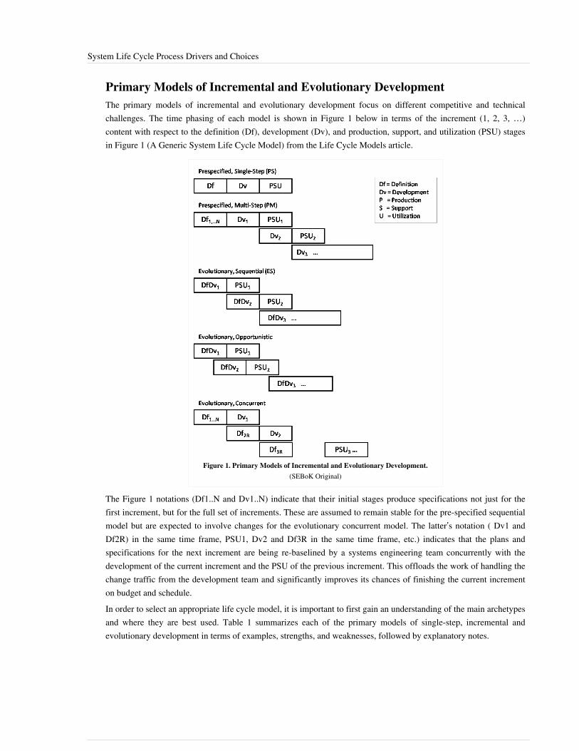
System Life Cycle Process Drivers and Choices 28
Primary Models of Incremental and Evolutionary DevelopmentThe primary models of incremental and evolutionary development focus on different competitive and technicalchallenges. The time phasing of each model is shown in Figure 1 below in terms of the increment (1, 2, 3, …)content with respect to the definition (Df), development (Dv), and production, support, and utilization (PSU) stagesin Figure 1 (A Generic System Life Cycle Model) from the Life Cycle Models article.
Figure 1. Primary Models of Incremental and Evolutionary Development.(SEBoK Original)
The Figure 1 notations (Df1..N and Dv1..N) indicate that their initial stages produce specifications not just for thefirst increment, but for the full set of increments. These are assumed to remain stable for the pre-specified sequentialmodel but are expected to involve changes for the evolutionary concurrent model. The latter’s notation ( Dv1 andDf2R) in the same time frame, PSU1, Dv2 and Df3R in the same time frame, etc.) indicates that the plans andspecifications for the next increment are being re-baselined by a systems engineering team concurrently with thedevelopment of the current increment and the PSU of the previous increment. This offloads the work of handling thechange traffic from the development team and significantly improves its chances of finishing the current incrementon budget and schedule.In order to select an appropriate life cycle model, it is important to first gain an understanding of the main archetypesand where they are best used. Table 1 summarizes each of the primary models of single-step, incremental andevolutionary development in terms of examples, strengths, and weaknesses, followed by explanatory notes.
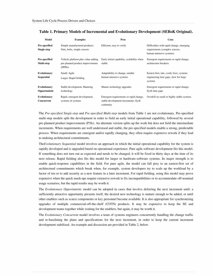
System Life Cycle Process Drivers and Choices 29
Table 1. Primary Models of Incremental and Evolutionary Development (SEBoK Original).
Model Examples Pros Cons
Pre-specifiedSingle-step
Simple manufactured products:Nuts, bolts, simple sensors
Efficient, easy to verify Difficulties with rapid change, emergingrequirements (complex sensors,human-intensive systems)
Pre-specifiedMulti-step
Vehicle platform plus value-addingpre-planned product improvements(PPPIs)
Early initial capability, scalability whenstable
Emergent requirements or rapid change,architecture breakers
EvolutionarySequential
Small: Agile
Larger: Rapid fielding
Adaptability to change, smallerhuman-intensive systems
Easiest-first, late, costly fixes, systemsengineering time gaps, slow for largesystems
EvolutionaryOpportunistic
Stable development, Maturingtechnology
Mature technology upgrades Emergent requirements or rapid change,SysE time gaps
EvolutionaryConcurrent
Rapid, emergent development,systems of systems
Emergent requirements or rapid change,stable development increments, SysEcontinuity
Overkill on small or highly stable systems
The Pre-specified Single-step and Pre-specified Multi-step models from Table 1 are not evolutionary. Pre-specifiedmulti-step models split the development in order to field an early initial operational capability, followed by severalpre-planned product improvements (P3Is). An alternate version splits up the work but does not field the intermediateincrements. When requirements are well understood and stable, the pre-specified models enable a strong, predictableprocess. When requirements are emergent and/or rapidly changing, they often require expensive rework if they leadto undoing architectural commitments.TheEvolutionary Sequential model involves an approach in which the initial operational capability for the system israpidly developed and is upgraded based on operational experience. Pure agile software development fits this model.If something does not turn out as expected and needs to be changed, it will be fixed in thirty days at the time of itsnext release. Rapid fielding also fits this model for larger or hardware-software systems. Its major strength is toenable quick-response capabilities in the field. For pure agile, the model can fall prey to an easiest-first set ofarchitectural commitments which break when, for example, system developers try to scale up the workload by afactor of ten or to add security as a new feature in a later increment. For rapid fielding, using this model may proveexpensive when the quick mash-ups require extensive rework to fix incompatibilities or to accommodate off-nominalusage scenarios, but the rapid results may be worth it.The Evolutionary Opportunistic model can be adopted in cases that involve deferring the next increment until: asufficiently attractive opportunity presents itself, the desired new technology is mature enough to be added, or untilother enablers such as scarce components or key personnel become available. It is also appropriate for synchronizingupgrades of multiple commercial-off-the-shelf (COTS) products. It may be expensive to keep the SE anddevelopment teams together while waiting for the enablers, but again, it may be worth it.The Evolutionary Concurrent model involves a team of systems engineers concurrently handling the change trafficand re-baselining the plans and specifications for the next increment, in order to keep the current incrementdevelopment stabilized. An example and discussion are provided in Table 2, below.
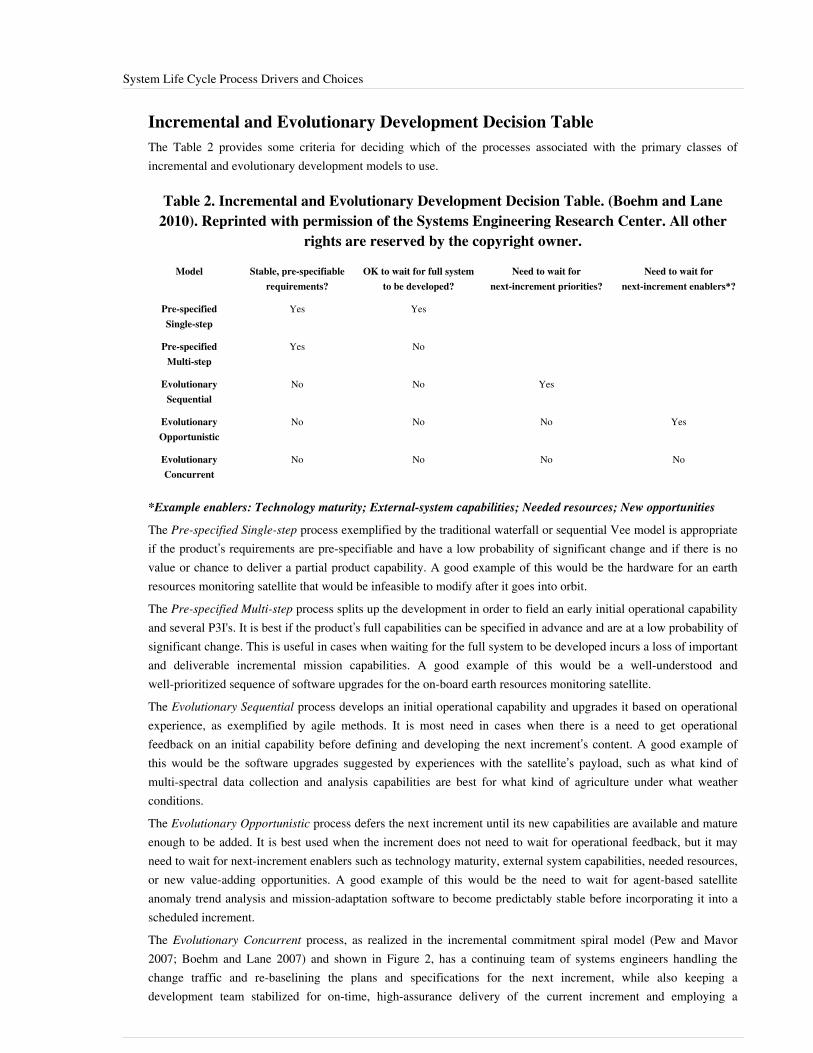
System Life Cycle Process Drivers and Choices 30
Incremental and Evolutionary Development Decision TableThe Table 2 provides some criteria for deciding which of the processes associated with the primary classes ofincremental and evolutionary development models to use.
Table 2. Incremental and Evolutionary Development Decision Table. (Boehm and Lane2010). Reprinted with permission of the Systems Engineering Research Center. All other
rights are reserved by the copyright owner.
Model Stable, pre-specifiablerequirements?
OK to wait for full systemto be developed?
Need to wait fornext-increment priorities?
Need to wait fornext-increment enablers*?
Pre-specifiedSingle-step
Yes Yes
Pre-specifiedMulti-step
Yes No
EvolutionarySequential
No No Yes
EvolutionaryOpportunistic
No No No Yes
EvolutionaryConcurrent
No No No No
*Example enablers: Technology maturity; External-system capabilities; Needed resources; New opportunities
The Pre-specified Single-step process exemplified by the traditional waterfall or sequential Vee model is appropriateif the product’s requirements are pre-specifiable and have a low probability of significant change and if there is novalue or chance to deliver a partial product capability. A good example of this would be the hardware for an earthresources monitoring satellite that would be infeasible to modify after it goes into orbit.The Pre-specified Multi-step process splits up the development in order to field an early initial operational capabilityand several P3I's. It is best if the product’s full capabilities can be specified in advance and are at a low probability ofsignificant change. This is useful in cases when waiting for the full system to be developed incurs a loss of importantand deliverable incremental mission capabilities. A good example of this would be a well-understood andwell-prioritized sequence of software upgrades for the on-board earth resources monitoring satellite.The Evolutionary Sequential process develops an initial operational capability and upgrades it based on operationalexperience, as exemplified by agile methods. It is most need in cases when there is a need to get operationalfeedback on an initial capability before defining and developing the next increment’s content. A good example ofthis would be the software upgrades suggested by experiences with the satellite’s payload, such as what kind ofmulti-spectral data collection and analysis capabilities are best for what kind of agriculture under what weatherconditions.The Evolutionary Opportunistic process defers the next increment until its new capabilities are available and matureenough to be added. It is best used when the increment does not need to wait for operational feedback, but it mayneed to wait for next-increment enablers such as technology maturity, external system capabilities, needed resources,or new value-adding opportunities. A good example of this would be the need to wait for agent-based satelliteanomaly trend analysis and mission-adaptation software to become predictably stable before incorporating it into ascheduled increment.The Evolutionary Concurrent process, as realized in the incremental commitment spiral model (Pew and Mavor 2007; Boehm and Lane 2007) and shown in Figure 2, has a continuing team of systems engineers handling the change traffic and re-baselining the plans and specifications for the next increment, while also keeping a development team stabilized for on-time, high-assurance delivery of the current increment and employing a

System Life Cycle Process Drivers and Choices 31
concurrent verification and validation (V&V) team to perform continuous defect detection to enable even higherassurance levels. A good example of this would be the satellite’s ground-based mission control and data handlingsoftware’s next-increment re-baselining to adapt to new COTS releases and continuing user requests for dataprocessing upgrades.The satellite example illustrates the various ways in which the complex systems of the future, different parts of thesystem, and its software may evolve in a number of ways, once again affirming that there is no one-size-fits-allprocess for software evolution. However, Table 2 can be quite helpful in determining which processes are the bestfits for evolving each part of the system and the three-team model in Figure 2 provides a way for projects to developthe challenging software-intensive systems of the future that will need both adaptability to rapid change and highlevels of assurance.
Figure 2. Evolutionary-Concurrent Rapid Change Handling and High Assurance (Pew and Mavor 2007, Figure 2-6). Reprinted withpermission from the National Academy of Sciences, Courtesy of National Academies Press, Washington, D.C. All other rights are reserved
by the copyright owner.
References
Works CitedBoehm, B. 2006. “Some Future Trends and Implications for Systems and Software Engineering Processes.” SystemsEngineering. 9(1): 1-19.Boehm, B. and J. Lane. 2007. “Using the Incremental Commitment Model to Integrate System Acquisition, SystemsEngineering, and Software Engineering.” CrossTalk. October 2007: 4-9.Boehm, B. and J. Lane. 2010. DoD Systems Engineering and Management Implications for Evolutionary Acquisitionof Major Defense Systems. SERC RT-5 report, March 2010. USC-CSSE-2010-500.Cusumano, M. and D. Yoffee. 1998. Competing on Internet Time: Lessons from Netscape and Its Battle withMicrosoft. New York, NY, USA: Free Press.Pew, R. and A. Mavor (eds.). 2007. Human-System Integration in the System Development Process: A New Look.Washington DC, USA: The National Academies Press.

System Life Cycle Process Drivers and Choices 32
Primary ReferencesPew, R., and A. Mavor (eds.). 2007. Human-System Integration in the System Development Process: A New Look.Washington, DC, USA: The National Academies Press.
Additional ReferencesNone
< Previous Article | Parent Article | Next Article >SEBoK v. 1.4 released 29 June 2015
SEBoK DiscussionPlease provide your comments and feedback on the SEBoK below. You will need to log in to DISQUS using anexisting account (e.g. Yahoo, Google, Facebook, Twitter, etc.) or create a DISQUS account. Simply type yourcomment in the text field below and DISQUS will guide you through the login or registration steps. Feedback will bearchived and used for future updates to the SEBoK. If you provided a comment that is no longer listed, that commenthas been adjudicated. You can view adjudication for comments submitted prior to SEBoK v. 1.0 at SEBoK Reviewand Adjudication. Later comments are addressed and changes are summarized in the Letter from the Editor andAcknowledgements and Release History.
If you would like to provide edits on this article, recommend new content, or make comments on the SEBoKas a whole, please see the SEBoK Sandbox [1].
ENCODED_CONTENTODI5OTUPGRpdiBpZD0iZGlzcXVzX3RocmVhZCI+PC9kaXY+CjxzY3JpcHQgdHlwZT0idGV4dC9qYXZhc2NyaXB0Ij4KICAgIC8qICogKiBDT05GSUdVUkFUSU9OIFZBUklBQkxFUzogRURJVCBCRUZPUkUgUEFTVElORyBJTlRPIFlPVVIgV0VCUEFHRSAqICogKi8KICAgIHZhciBkaXNxdXNfc2hvcnRuYW1lID0gJ3NlYm9rd2lraTEwJzsgLy8gcmVxdWlyZWQ6IHJlcGxhY2UgZXhhbXBsZSB3aXRoIHlvdXIgZm9ydW0gc2hvcnRuYW1lCiAgICB2YXIgZGlzcXVzX2lkZW50aWZpZXIgPSAnU3lzdGVtIExpZmUgQ3ljbGUgUHJvY2VzcyBEcml2ZXJzIGFuZCBDaG9pY2VzJzsgICAgdmFyIGRpc3F1c191cmwgPSAnaHR0cDovL3NlYm9rd2lraS5vcmcvZHJhZnQvU3lzdGVtX0xpZmVfQ3ljbGVfUHJvY2Vzc19Ecml2ZXJzX2FuZF9DaG9pY2VzJzsKICAgIC8qICogKiBET04nVCBFRElUIEJFTE9XIFRISVMgTElORSAqICogKi8KICAgIChmdW5jdGlvbigpIHsKICAgICAgICB2YXIgZHNxID0gZG9jdW1lbnQuY3JlYXRlRWxlbWVudCgnc2NyaXB0Jyk7IGRzcS50eXBlID0gJ3RleHQvamF2YXNjcmlwdCc7IGRzcS5hc3luYyA9IHRydWU7CiAgICAgICAgZHNxLnNyYyA9ICdodHRwOi8vJyArIGRpc3F1c19zaG9ydG5hbWUgKyAnLmRpc3F1cy5jb20vZW1iZWQuanMnOwogICAgICAgIChkb2N1bWVudC5nZXRFbGVtZW50c0J5VGFnTmFtZSgnaGVhZCcpWzBdIHx8IGRvY3VtZW50LmdldEVsZW1lbnRzQnlUYWdOYW1lKCdib2R5JylbMF0pLmFwcGVuZENoaWxkKGRzcSk7CiAgICB9KSgpOwo8L3NjcmlwdD4KPG5vc2NyaXB0PlBsZWFzZSBlbmFibGUgSmF2YVNjcmlwdCB0byB2aWV3IHRoZSA8YSBocmVmPSJodHRwOi8vZGlzcXVzLmNvbS8/cmVmX25vc2NyaXB0Ij5jb21tZW50cyBwb3dlcmVkIGJ5IERpc3F1cy48L2E+PC9ub3NjcmlwdD4KPGEgaHJlZj0iaHR0cDovL2Rpc3F1cy5jb20iIGNsYXNzPSJkc3EtYnJsaW5rIj5ibG9nIGNvbW1lbnRzIHBvd2VyZWQgYnkgPHNwYW4gY2xhc3M9ImxvZ28tZGlzcXVzIj5EaXNxdXM8L3NwYW4+PC9hPg==END_ENCODED_CONTENT

System Life Cycle Process Models: Vee 33
System Life Cycle Process Models: VeeThere are a large number of life cycle process models. As discussed in the System Life Cycle Process Drivers andChoices article, these models fall into three major categories: (1) primarily pre-specified and sequential processes;(2) primarily evolutionary and concurrent processes (e.g., the rational unified process and various forms of the Veeand spiral models); and (3) primarily interpersonal and unconstrained processes (e.g., agile development, Scrum,extreme programming (XP), the dynamic system development method, and innovation-based processes).This article specifically focuses on the Vee Model as the primary example of pre-specified and sequential processes.In this discussion, it is important to note that the Vee model, and variations of the Vee model, all address the samebasic set of systems engineering (SE) activities. The key difference between these models is the way in which theygroup and represent the aforementioned SE activities.General implications of using the Vee model for system design and development are discussed below; for a morespecific understanding of how this life cycle model impacts systems engineering activities, please see the otherknowledge areas (KAs) in Part 3.
A Primarily Pre-specified and Sequential Process Model: The Vee ModelThe sequential version of the Vee Model is shown in Figure 1. Its core involves a sequential progression of plans,specifications, and products that are baselined and put under configuration management. The vertical, two-headedarrow enables projects to perform concurrent opportunity and risk analyses, as well as continuous in-processvalidation. The Vee Model encompasses the first three life cycle stages listed in the "Generic Life Cycle Stages"table of the INCOSE Systems Engineering Handbook: exploratory research, concept, and development (INCOSE2012).
Figure 1. Left Side of the Sequential Vee Model (Forsberg, Mooz, and Cotterman2005). Reprinted with permission of John Wiley & Sons Inc. All other rights are reserved
by the copyright owner.
The Vee Model endorses the INCOSE Systems Engineering Handbook (INCOSE 2012) definition of life cyclestages and their purposes or activities, as shown in Figure 2 below.
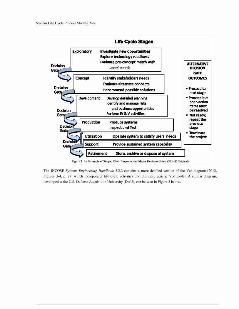
System Life Cycle Process Models: Vee 34
Figure 2. An Example of Stages, Their Purposes and Major Decision Gates. (SEBoK Original)
The INCOSE Systems Engineering Handbook 3.2.2 contains a more detailed version of the Vee diagram (2012,Figures 3-4, p. 27) which incorporates life cycle activities into the more generic Vee model. A similar diagram,developed at the U.S. Defense Acquisition University (DAU), can be seen in Figure 3 below.

System Life Cycle Process Models: Vee 35
Figure 3. The Vee Activity Diagram (Prosnik 2010). Released by the Defense Acquisition University (DAU)/U.S. Department of Defense (DoD).
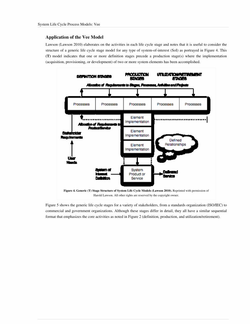
System Life Cycle Process Models: Vee 36
Application of the Vee ModelLawson (Lawson 2010) elaborates on the activities in each life cycle stage and notes that it is useful to consider thestructure of a generic life cycle stage model for any type of system-of-interest (SoI) as portrayed in Figure 4. This(T) model indicates that one or more definition stages precede a production stage(s) where the implementation(acquisition, provisioning, or development) of two or more system elements has been accomplished.
Figure 4. Generic (T) Stage Structure of System Life Cycle Models (Lawson 2010). Reprinted with permission ofHarold Lawson. All other rights are reserved by the copyright owner.
Figure 5 shows the generic life cycle stages for a variety of stakeholders, from a standards organization (ISO/IEC) tocommercial and government organizations. Although these stages differ in detail, they all have a similar sequentialformat that emphasizes the core activities as noted in Figure 2 (definition, production, and utilization/retirement).

System Life Cycle Process Models: Vee 37
Figure 5. Comparisons of Life Cycle Models (Forsberg, Mooz, and Cotterman 2005). Reprinted withpermission of John Wiley & Sons. All other rights are reserved by the copyright owner.
It is important to note that many of the activities throughout the life cycle are iterated. This is an example ofrecursion (glossary) as discussed in the Part 3 Introduction.
Fundamentals of Life Cycle Stages and Program Management PhaseFor this discussion, it is important to note that• The term stage refers to the different states of a system during its life cycle; some stages may overlap in time,
such as the utilization stage and the support stage. The term “stage” is used in ISO/IEC/IEEE 15288.• The term phase refers to the different steps of the program that support and manage the life of the system; the
phases usually do not overlap. The term “phase” is used in many well-established models as an equivalent to theterm “stage.”
Program management employs phases, milestones, and decision gates which are used to assess the evolution of asystem through its various stages. The stages contain the activities performed to achieve goals and serve to controland manage the sequence of stages and the transitions between each stage. For each project, it is essential to defineand publish the terms and related definitions used on respective projects to minimize confusion.A typical program is composed of the following phases:• The pre-study phase, which identifies potential opportunities to address user needs with new solutions that make
business sense.• The feasibility phase consists of studying the feasibility of alternative concepts to reach a second decision gate
before initiating the execution stage. During the feasibility phase, stakeholders' requirements and system requirements are identified, viable solutions are identified and studied, and virtual prototypes (glossary) can be
System Life Cycle Process Models: Vee 38
implemented. During this phase, the decision to move forward is based on•• whether a concept is feasible and is considered able to counter an identified threat or exploit an opportunity;•• whether a concept is sufficiently mature to warrant continued development of a new product or line of
products; and•• whether to approve a proposal generated in response to a request for proposal.
• The execution phase includes activities related to four stages of the system life cycle: development, production,utilization, and support. Typically, there are two decision gates and two milestones associated with executionactivities. The first milestone provides the opportunity for management to review the plans for execution beforegiving the go-ahead. The second milestone provides the opportunity to review progress before the decision ismade to initiate production. The decision gates during execution can be used to determine whether to produce thedeveloped SoI and whether to improve it or retire it.
These program management views apply not only to the SoI, but also to its elements and structure.
Life Cycle StagesVariations of the Vee model deal with the same general stages of a life cycle:• New projects typically begin with an exploratory research phase which generally includes the activities of concept
definition, specifically the topics of business or mission analysis and the understanding of stakeholder needs andrequirements. These mature as the project goes from the exploratory stage to the concept stage to the developmentstage.
• The production phase includes the activities of system definition and system realization, as well as thedevelopment of the system requirements (glossary) and architecture (glossary) through verification andvalidation.
• The utilization phase includes the activities of system deployment and system operation.• The support phase includes the activities of system maintenance, logistics, and product and service life
management, which may include activities such as service life extension or capability updates, upgrades, andmodernization.
• The retirement phase includes the activities of disposal and retirement, though in some models, activities such asservice life extension or capability updates, upgrades, and modernization are grouped into the "retirement" phase.
Additional information on each of these stages can be found in the sections below (see links to additional Part 3articles above for further detail). It is important to note that these life cycle stages, and the activities in each stage,are supported by a set of systems engineering management processes.
Exploratory Research StageUser requirements analysis and agreement is part of the exploratory research stage and is critical to the developmentof successful systems. Without proper understanding of the user needs, any system runs the risk of being built tosolve the wrong problems. The first step in the exploratory research phase is to define the user (and stakeholder)requirements and constraints. A key part of this process is to establish the feasibility of meeting the userrequirements, including technology readiness assessment. As with many SE activities this is often done iteratively,and stakeholder needs and requirements are revisited as new information becomes available.A recent study by the National Research Council (National Research Council 2008) focused on reducing thedevelopment time for US Air Force projects. The report notes that, “simply stated, systems engineering is thetranslation of a user’s needs into a definition of a system and its architecture through an iterative process that resultsin an effective system design.” The iterative involvement with stakeholders is critical to the project success.Except for the first and last decision gates of a project, the gates are performed simultaneously. See Figure 6 below.

System Life Cycle Process Models: Vee 39
Figure 6. Scheduling the Development Phases. (SEBoK Original)
Concept StageDuring the concept stage, alternate concepts are created to determine the best approach to meet stakeholder needs.By envisioning alternatives and creating models, including appropriate prototypes, stakeholder needs will beclarified and the driving issues highlighted. This may lead to an incremental or evolutionary approach to systemdevelopment. Several different concepts may be explored in parallel.
Development StageThe selected concept(s) identified in the concept stage are elaborated in detail down to the lowest level to producethe solution that meets the stakeholder requirements. Throughout this stage, it is vital to continue with userinvolvement through in-process validation (the upward arrow on the Vee models). On hardware, this is done withfrequent program reviews and a customer resident representative(s) (if appropriate). In agile development, thepractice is to have the customer representative integrated into the development team.
Production StageThe production stage is where the SoI is built or manufactured. Product modifications may be required to resolveproduction problems, to reduce production costs, or to enhance product or SoI capabilities. Any of thesemodifications may influence system requirements and may require system re-qualification, re-verification, orre-validation. All such changes require SE assessment before changes are approved.
Utilization StageA significant aspect of product life cycle management is the provisioning of supporting systems which are vital insustaining operation of the product. While the supplied product or service may be seen as the narrowsystem-of-interest (NSOI) for an acquirer, the acquirer also must incorporate the supporting systems into a widersystem-of-interest (WSOI). These supporting systems should be seen as system assets that, when needed, areactivated in response to a situation that has emerged in respect to the operation of the NSOI. The collective name forthe set of supporting systems is the integrated logistics support (ILS) system.
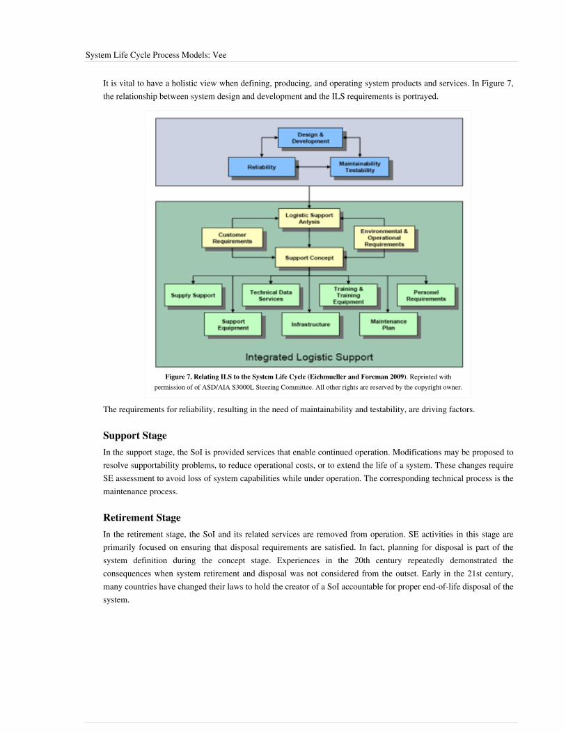
System Life Cycle Process Models: Vee 40
It is vital to have a holistic view when defining, producing, and operating system products and services. In Figure 7,the relationship between system design and development and the ILS requirements is portrayed.
Figure 7. Relating ILS to the System Life Cycle (Eichmueller and Foreman 2009). Reprinted withpermission of of ASD/AIA S3000L Steering Committee. All other rights are reserved by the copyright owner.
The requirements for reliability, resulting in the need of maintainability and testability, are driving factors.
Support StageIn the support stage, the SoI is provided services that enable continued operation. Modifications may be proposed toresolve supportability problems, to reduce operational costs, or to extend the life of a system. These changes requireSE assessment to avoid loss of system capabilities while under operation. The corresponding technical process is themaintenance process.
Retirement StageIn the retirement stage, the SoI and its related services are removed from operation. SE activities in this stage areprimarily focused on ensuring that disposal requirements are satisfied. In fact, planning for disposal is part of thesystem definition during the concept stage. Experiences in the 20th century repeatedly demonstrated theconsequences when system retirement and disposal was not considered from the outset. Early in the 21st century,many countries have changed their laws to hold the creator of a SoI accountable for proper end-of-life disposal of thesystem.

System Life Cycle Process Models: Vee 41
Life Cycle ReviewsTo control the progress of a project, different types of reviews are planned. The most commonly used are listed asfollows, although the names are not universal:• The system requirements review (SRR) is planned to verify and validate the set of system requirements before
starting the detailed design activities.• The preliminary design review (PDR) is planned to verify and validate the set of system requirements, the design
artifacts, and justification elements at the end of the first engineering loop (also known as the "design-to" gate).• The critical design review (CDR) is planned to verify and validate the set of system requirements, the design
artifacts, and justification elements at the end of the last engineering loop (the “build-to” and “code-to” designs arereleased after this review).
• The integration, verification, and validation reviews are planned as the components are assembled into higherlevel subsystems and elements. A sequence of reviews is held to ensure that everything integrates properly andthat there is objective evidence that all requirements have been met. There should also be an in-process validationthat the system, as it is evolving, will meet the stakeholders’ requirements (see Figure 7).
•• The final validation review is carried out at the end of the integration phase.•• Other management related reviews can be planned and conducted in order to control the correct progress of work,
based on the type of system and the associated risks.
Figure 8. Right Side of the Vee Model (Forsberg, Mooz, and Cotterman 2005). Reprintedwith permission of John Wiley & Sons Inc. All other rights are reserved by the copyright
owner.

System Life Cycle Process Models: Vee 42
References
Works CitedEichmueller, P. and B. Foreman. 2010. S3000LTM. Brussels, Belgium: Aerospace and Defence IndustriesAssociation of Europe (ASD)/Aerospace Industries Association (AIA).Faisandier, A. 2012. Systems Architecture and Design. Belberaud, France: Sinergy'Com.Forsberg, K., H. Mooz, and H. Cotterman. 2005. Visualizing Project Management, 3rd ed. New York, NY, USA: J.Wiley & Sons.INCOSE. 2012. Systems Engineering Handbook: A Guide for System Life Cycle Processes and Activities, version3.2.2. San Diego, CA, USA: International Council on Systems Engineering (INCOSE),INCOSE-TP-2003-002-03.2.2.Lawson, H. 2010. A Journey Through the Systems Landscape. London, UK: College Publications, Kings College,UK.
Primary ReferencesBeedle, M., et al. 2009. "The Agile Manifesto: Principles behind the Agile Manifesto". in The Agile Manifesto[database online]. Accessed December 04 2014 at www.agilemanifesto.org/principles.htmlBoehm, B. and R. Turner. 2004. Balancing Agility and Discipline. New York, NY, USA: Addison-Wesley.Fairley, R. 2009. Managing and Leading Software Projects. New York, NY, USA: J. Wiley & Sons.Forsberg, K., H. Mooz, and H. Cotterman. 2005. Visualizing Project Management. 3rd ed. New York, NY, USA: J.Wiley & Sons.INCOSE. 2012. Systems Engineering Handbook: A Guide for System Life Cycle Processes and Activities, version3.2.2. San Diego, CA, USA: International Council on Systems Engineering (INCOSE),INCOSE-TP-2003-002-03.2.2.Lawson, H. 2010. A Journey Through the Systems Landscape. Kings College, UK: College Publications.Pew, R., and A. Mavor (eds.) 2007. Human-System Integration in the System Development Process: A New Look.Washington, DC, USA: The National Academies Press.Royce, W.E. 1998. Software Project Management: A Unified Framework. New York, NY, USA: Addison Wesley.
Additional ReferencesAnderson, D. 2010. Kanban. Sequim, WA, USA: Blue Hole Press.Baldwin, C. and K. Clark. 2000. Design Rules: The Power of Modularity. Cambridge, MA, USA: MIT Press.Beck, K. 1999. Extreme Programming Explained. New York, NY, USA: Addison Wesley.Beedle, M., et al. 2009. "The Agile Manifesto: Principles behind the Agile Manifesto". in The Agile Manifesto[database online]. Accessed 2010. Available at: www.agilemanifesto.org/principles.htmlBiffl, S., A. Aurum, B. Boehm, H. Erdogmus, and P. Gruenbacher (eds.). 2005. Value-Based Software Engineering.New York, NY, USA: Springer.Boehm, B. 1988. “A Spiral Model of Software Development.” IEEE Computer 21(5): 61-72.Boehm, B. 2006. “Some Future Trends and Implications for Systems and Software Engineering Processes.” SystemsEngineering. 9(1): 1-19.Boehm, B., A. Egyed, J. Kwan, D. Port, A. Shah, and R. Madachy. 1998. “Using the WinWin Spiral Model: A CaseStudy.” IEEE Computer. 31(7): 33-44.

System Life Cycle Process Models: Vee 43
Boehm, B., R. Turner, J. Lane, S. Koolmanojwong. 2014 (in press). Embracing the Spiral Model: CreatingSuccessful Systems with the Incremental Commitment Spiral Model. Boston, MA, USA: Addison Wesley.Castellano, D.R. 2004. “Top Five Quality Software Projects.” CrossTalk. 17(7) (July 2004): 4-19. Available at: http:// www. crosstalkonline. org/ storage/ issue-archives/ 2004/ 200407/ 200407-0-Issue. pdfCheckland, P. 1981. Systems Thinking, Systems Practice. New York, NY, USA: Wiley.Crosson, S. and B. Boehm. 2009. “Adjusting Software Life cycle Anchorpoints: Lessons Learned in a System ofSystems Context.” Proceedings of the Systems and Software Technology Conference, 20-23 April 2009, Salt LakeCity, UT, USA.Dingsoyr, T., T. Dyba. and N. Moe (eds.). 2010. "Agile Software Development: Current Research and FutureDirections.” Chapter in B. Boehm, J. Lane, S. Koolmanjwong, and R. Turner, Architected Agile Solutions forSoftware-Reliant Systems. New York, NY, USA: Springer.Dorner, D. 1996. The Logic of Failure. New York, NY, USA: Basic Books.Forsberg, K. 1995. "'If I Could Do That, Then I Could…' System Engineering in a Research and DevelopmentEnvironment.” Proceedings of the Fifth Annual International Council on Systems Engineering (INCOSE)International Symposium. 22-26 July 1995. St. Louis, MO, USA.Forsberg, K. 2010. “Projects Don’t Begin With Requirements.” Proceedings of the IEEE Systems Conference, 5-8April 2010, San Diego, CA, USA.Gilb, T. 2005. Competitive Engineering. Maryland Heights, MO, USA: Elsevier Butterworth Heinemann.Goldratt, E. 1984. The Goal. Great Barrington, MA, USA: North River Press.Hitchins, D. 2007. Systems Engineering: A 21st Century Systems Methodology. New York, NY, USA: Wiley.Holland, J. 1998. Emergence. New York, NY, USA: Perseus Books.ISO/IEC. 2010. Systems and Software Engineering, Part 1: Guide for Life Cycle Management. Geneva, Switzerland:International Organization for Standardization (ISO)/International Electrotechnical Commission (IEC), ISO/IEC24748-1:2010.ISO/IEC/IEEE. 2015. Systems and Software Engineering -- System Life Cycle Processes. Geneva, Switzerland:International Organisation for Standardisation / International Electrotechnical Commissions. ISO/IEC/IEEE15288:2015.ISO/IEC. 2003. Systems Engineering — A Guide for The Application of ISO/IEC 15288 System Life CycleProcesses. Geneva, Switzerland: International Organization for Standardization (ISO)/International ElectrotechnicalCommission (IEC), ISO/IEC 19760:2003 (E).Jarzombek, J. 2003. “Top Five Quality Software Projects.” CrossTalk. 16(7) (July 2003): 4-19. Available at: http:/ /www. crosstalkonline. org/ storage/ issue-archives/ 2003/ 200307/ 200307-0-Issue. pdf.Kruchten, P. 1999. The Rational Unified Process. New York, NY, USA: Addison Wesley.Landis, T. R. 2010. Lockheed Blackbird Family (A-12, YF-12, D-21/M-21 & SR-71). North Branch, MN, USA:Specialty Press.Madachy, R. 2008. Software Process Dynamics. Hoboken, NJ, USA: Wiley.Maranzano, J.F., S.A. Rozsypal, G.H. Zimmerman, G.W. Warnken, P.E. Wirth, D.W. Weiss. 2005. “ArchitectureReviews: Practice and Experience.” IEEE Software. 22(2): 34-43.National Research Council of the National Academies (USA). 2008. Pre-Milestone A and Early-Phase SystemsEngineering. Washington, DC, USA: The National Academies Press.Osterweil, L. 1987. “Software Processes are Software Too.” Proceedings of the SEFM 2011: 9th InternationalConference on Software Engineering. Monterey, CA, USA.

System Life Cycle Process Models: Vee 44
Poppendeick, M. and T. Poppendeick. 2003. Lean Software Development: an Agile Toolkit. New York, NY, USA:Addison Wesley.Rechtin, E. 1991. System Architecting: Creating and Building Complex Systems. Upper Saddle River, NY, USA:Prentice-Hall.Rechtin, E., and M. Maier. 1997. The Art of System Architecting. Boca Raton, FL, USA: CRC Press.Schwaber, K. and M. Beedle. 2002. Agile Software Development with Scrum. Upper Saddle River, NY, USA:Prentice Hall.Spruill, N. 2002. “Top Five Quality Software Projects.” CrossTalk. 15(1) (January 2002): 4-19. Available at: http:/ /www. crosstalkonline. org/ storage/ issue-archives/ 2002/ 200201/ 200201-0-Issue. pdf.Stauder, T. 2005. “Top Five Department of Defense Program Awards.” CrossTalk. 18(9) (September 2005): 4-13.Available at http:/ / www. crosstalkonline. org/ storage/ issue-archives/ 2005/ 200509/ 200509-0-Issue. pdf.Warfield, J. 1976. Societal Systems: Planning, Policy, and Complexity. New York, NY, USA: Wiley.Womack, J. and D. Jones. 1996. Lean Thinking. New York, NY, USA: Simon and Schuster.
< Previous Article | Parent Article | Next Article >SEBoK v. 1.4 released 29 June 2015
SEBoK DiscussionPlease provide your comments and feedback on the SEBoK below. You will need to log in to DISQUS using anexisting account (e.g. Yahoo, Google, Facebook, Twitter, etc.) or create a DISQUS account. Simply type yourcomment in the text field below and DISQUS will guide you through the login or registration steps. Feedback will bearchived and used for future updates to the SEBoK. If you provided a comment that is no longer listed, that commenthas been adjudicated. You can view adjudication for comments submitted prior to SEBoK v. 1.0 at SEBoK Reviewand Adjudication. Later comments are addressed and changes are summarized in the Letter from the Editor andAcknowledgements and Release History.
If you would like to provide edits on this article, recommend new content, or make comments on the SEBoKas a whole, please see the SEBoK Sandbox [1].
ENCODED_CONTENTMTQ3OTUPGRpdiBpZD0iZGlzcXVzX3RocmVhZCI+PC9kaXY+CjxzY3JpcHQgdHlwZT0idGV4dC9qYXZhc2NyaXB0Ij4KICAgIC8qICogKiBDT05GSUdVUkFUSU9OIFZBUklBQkxFUzogRURJVCBCRUZPUkUgUEFTVElORyBJTlRPIFlPVVIgV0VCUEFHRSAqICogKi8KICAgIHZhciBkaXNxdXNfc2hvcnRuYW1lID0gJ3NlYm9rd2lraTEwJzsgLy8gcmVxdWlyZWQ6IHJlcGxhY2UgZXhhbXBsZSB3aXRoIHlvdXIgZm9ydW0gc2hvcnRuYW1lCiAgICB2YXIgZGlzcXVzX2lkZW50aWZpZXIgPSAnU3lzdGVtIExpZmUgQ3ljbGUgUHJvY2VzcyBNb2RlbHM6IFZlZSc7ICAgIHZhciBkaXNxdXNfdXJsID0gJ2h0dHA6Ly9zZWJva3dpa2kub3JnL2RyYWZ0L1N5c3RlbV9MaWZlX0N5Y2xlX1Byb2Nlc3NfTW9kZWxzOl9WZWUnOwogICAgLyogKiAqIERPTidUIEVESVQgQkVMT1cgVEhJUyBMSU5FICogKiAqLwogICAgKGZ1bmN0aW9uKCkgewogICAgICAgIHZhciBkc3EgPSBkb2N1bWVudC5jcmVhdGVFbGVtZW50KCdzY3JpcHQnKTsgZHNxLnR5cGUgPSAndGV4dC9qYXZhc2NyaXB0JzsgZHNxLmFzeW5jID0gdHJ1ZTsKICAgICAgICBkc3Euc3JjID0gJ2h0dHA6Ly8nICsgZGlzcXVzX3Nob3J0bmFtZSArICcuZGlzcXVzLmNvbS9lbWJlZC5qcyc7CiAgICAgICAgKGRvY3VtZW50LmdldEVsZW1lbnRzQnlUYWdOYW1lKCdoZWFkJylbMF0gfHwgZG9jdW1lbnQuZ2V0RWxlbWVudHNCeVRhZ05hbWUoJ2JvZHknKVswXSkuYXBwZW5kQ2hpbGQoZHNxKTsKICAgIH0pKCk7Cjwvc2NyaXB0Pgo8bm9zY3JpcHQ+UGxlYXNlIGVuYWJsZSBKYXZhU2NyaXB0IHRvIHZpZXcgdGhlIDxhIGhyZWY9Imh0dHA6Ly9kaXNxdXMuY29tLz9yZWZfbm9zY3JpcHQiPmNvbW1lbnRzIHBvd2VyZWQgYnkgRGlzcXVzLjwvYT48L25vc2NyaXB0Pgo8YSBocmVmPSJodHRwOi8vZGlzcXVzLmNvbSIgY2xhc3M9ImRzcS1icmxpbmsiPmJsb2cgY29tbWVudHMgcG93ZXJlZCBieSA8c3BhbiBjbGFzcz0ibG9nby1kaXNxdXMiPkRpc3F1czwvc3Bhbj48L2E+END_ENCODED_CONTENT

System Life Cycle Process Models: Iterative 45
System Life Cycle Process Models: IterativeThere are a large number of life cycle process models. As discussed in the System Life Cycle Process Drivers andChoices article, these models fall into three major categories: (1) primarily pre-specified and sequential processes;(2) primarily evolutionary and concurrent processes (e.g., the rational unified process and various forms of the Veeand spiral models); and (3) primarily interpersonal and unconstrained processes (e.g., agile development, Scrum,extreme programming (XP), dynamic system development methods, and innovation-based processes).This article discusses incremental and evolutionary development models (the second and third categories listedabove) beyond variants of the Vee model. While there are a number of different models describing the projectenvironment, the spiral model and the Vee Model have become the dominant approaches to visualizing thedevelopment process. Both the Vee and the spiral are useful models that emphasize different aspects of a system lifecycle.General implications of using iterative models for system design and development are discussed below. For a morespecific understanding of how this life cycle model impacts systems engineering activities, please see the otherknowledge areas (KAs) in Part 3. This article is focused on the use of iterative life cycle process models in systemsengineering; however, because iterative process models are commonly used in software development, many of theexamples below come from software projects. (See Systems Engineering and Software Engineering in Part 6 formore information on life cycle implications in software engineering.)
Incremental and Evolutionary Development
Overview of the Incremental ApproachIncremental and iterative development (IID) methods have been in use since the 1960s (and perhaps earlier). Theyallow a project to provide an initial capability followed by successive deliveries to reach the desiredsystem-of-interest (SoI).The IID approach, shown in Figure 1, is used when•• rapid exploration and implementation of part of the system is desired;•• the requirements are unclear from the beginning;•• funding is constrained;•• the customer wishes to hold the SoI open to the possibility of inserting new technology at a later time; and/or• experimentation is required to develop successive prototype (glossary) versions.The attributes that distinguish IID from the single-pass, plan-driven approach are velocity and adaptability.

System Life Cycle Process Models: Iterative 46
Figure 1. Incremental Development with Multiple Deliveries (Forsberg, Mooz, and Cotterman 2005). Reprinted with permission ofJohn Wiley & Sons Inc. All other rights are reserved by the copyright owner.
Incremental development may also be “plan-driven” in nature if the requirements are known early on in the lifecycle. The development of the functionality is performed incrementally to allow for insertion of the latest technologyor for potential changes in needs or requirements. IID also imposes constraints. The example shown in Figure 2 usesthe increments to develop high-risk subsystems (or components) early, but the system cannot function until allincrements are complete.
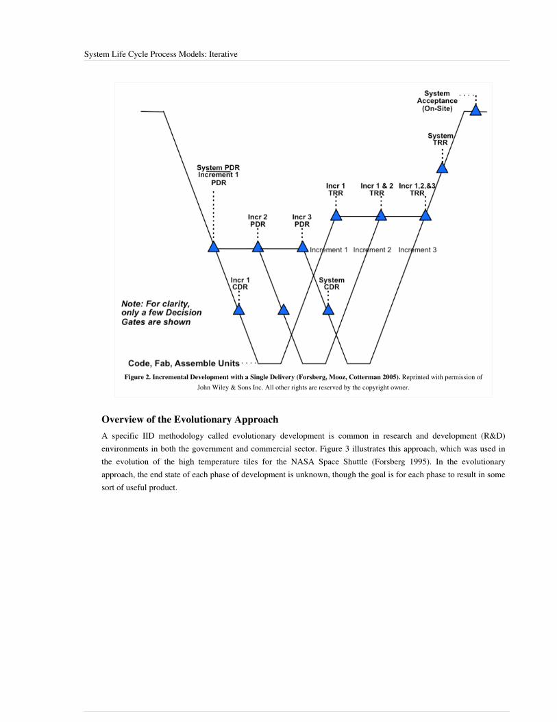
System Life Cycle Process Models: Iterative 47
Figure 2. Incremental Development with a Single Delivery (Forsberg, Mooz, Cotterman 2005). Reprinted with permission ofJohn Wiley & Sons Inc. All other rights are reserved by the copyright owner.
Overview of the Evolutionary ApproachA specific IID methodology called evolutionary development is common in research and development (R&D)environments in both the government and commercial sector. Figure 3 illustrates this approach, which was used inthe evolution of the high temperature tiles for the NASA Space Shuttle (Forsberg 1995). In the evolutionaryapproach, the end state of each phase of development is unknown, though the goal is for each phase to result in somesort of useful product.

System Life Cycle Process Models: Iterative 48
Figure 3. Evolutionary Generic Model (Forsberg, Mooz, Cotterman 2005). Reprinted with permission of John Wiley & Sons, Inc. All other rightsare reserved by the copyright owner.
The real world development environment is complex and difficult to map because many different project cycles aresimultaneously underway. Figure 4 shows the applied research era for the development of the space shuttle Orbiterand illustrates multi-levels of simultaneous development, trade-studies, and ultimately, implementation.

System Life Cycle Process Models: Iterative 49
Figure 4. Evolution of Components and Orbiter Subsystems (including space shuttle tiles) During Creation of a Large"Single-Pass" Project (Forsberg 1995). Reprinted with permission of Kevin Forsberg. All other rights are reserved by the copyright
owner.
Iterative Software Development Process ModelsSoftware is a flexible and malleable medium which facilitates iterative analysis, design, construction, verification,and validation to a greater degree than is usually possible for the purely physical components of a system. Eachrepetition of an iterative development model adds material (code) to the growing software base; the expanded codebase is tested, reworked as necessary, and demonstrated to satisfy the requirements for the baseline.Process models for software development support iterative development on cycles of various lengths. Table 1 liststhree iterative software development models which are presented in more detail below, as well as the aspects ofsoftware development that are emphasized by those models.

System Life Cycle Process Models: Iterative 50
Table 1. Primary Emphases of Three Iterative Software Development Models.
Iterative Model Emphasis
Incremental-build Iterative implementation-verification-validations-demonstration cycles
Spiral Iterative risk-based analysis of alternative approaches and evaluation of outcomes
Agile Iterative evolution of requirements and code
Please note that the information below is focused specifically on the utilization of different life cycle models forsoftware systems. In order to better understand the interactions between software engineering (SwE) and systemsengineering (SE), please see the Systems Engineering and Software Engineering KA in Part 6.
Overview of Iterative-Development Process ModelsDeveloping and modifying software involves creative processes that are subject to many external and changeableforces. Long experience has shown that it is impossible to “get it right” the first time, and that iterative developmentprocesses are preferable to linear, sequential development process models, such as the well-known Waterfall model.In iterative development, each cycle of the iteration subsumes the software of the previous iteration and adds newcapabilities to the evolving product to create an expanded version of the software. Iterative development processesprovide the following advantages:•• Continuous integration, verification, and validation of the evolving product;•• Frequent demonstrations of progress;•• Early detection of defects;•• Early warning of process problems;•• Systematic incorporation of the inevitable rework that occurs in software development; and•• Early delivery of subset capabilities (if desired).Iterative development takes many forms in SwE, including the following:•• An incremental-build process, which is used to produce periodic (typically weekly) builds of increasing product
capabilities;•• Agile development, which is used to closely involve a prototypical customer in an iterative process that may
repeat on a daily basis; and•• The spiral model, which is used to confront and mitigate risk factors encountered in developing the successive
versions of a product.
The Incremental-Build ModelThe incremental-build model is a build-test-demonstrated model of iterative cycles in which frequent demonstrationsof progress, verification, and validation of work-to-date are emphasized. The model is based on stable requirementsand a software architectural specification. Each build adds new capabilities to the incrementally growing product.The process ends when the final version is verified, validated, demonstrated, and accepted by the customer.Table 2 lists some partitioning criteria for incremental development into incremental build units of (typically) onecalendar week each. The increments and the number of developers available to work on the project determine thenumber of features that can be included in each incremental build. This, in turn, determines the overall schedule.

System Life Cycle Process Models: Iterative 51
Table 2. Some partitioning criteria for incremental builds (Fairley 2009). Reprinted withpermission of the IEEE Computer Society and John Wiley & Sons Inc. All other rights are
reserved by the copyright owner.
Kind of System Partitioning Criteria
Application package Priority of features
Safety-critical systems Safety features first; prioritized others follow
User-intensive systems User interface first; prioritized others follow
System software Kernel first; prioritized utilities follow
Figure 5 illustrates the details of the build-verify-validate-demonstrate cycles in the incremental build process. Eachbuild includes detailed design, coding, integration, review, and testing done by the developers. In cases where codeis to be reused without modification, some or all of an incremental build may consist of review, integration, andtesting of the base code augmented with the reused code. It is important to note that development of an incrementmay result in reworking previous components developed for integration to fix defects.
Figure 5. Incremental Build-Verify-Validate-Demonstrate Cycles (Fairley 2009). Reprinted with permission of the IEEEComputer Society and John Wiley & Sons Inc. All other rights are reserved by the copyright owner.
Incremental verification, validation, and demonstration, as illustrated in Figure 5, overcome two of the majorproblems of a waterfall approach by•• exposing problems early so they can be corrected as they occur; and•• incorporating minor in-scope changes to requirements that occur as a result of incremental demonstrations in
subsequent builds.Figure 5 also illustrates that it may be possible to overlap successive builds of the product. It may be possible, forexample, to start a detailed design of the next version while the present version is being validated.Three factors determine the degree of overlap that can be achieved:

System Life Cycle Process Models: Iterative 52
1.1. Availability of personnel;2.2. Adequate progress on the previous version; and3.3. The risk of significant rework on the next overlapped build because of changes to the previous in-progress build.The incremental build process generally works well with small teams, but can be scaled up for larger projects.A significant advantage of an incremental build process is that features built first are verified, validated, anddemonstrated most frequently because subsequent builds incorporate the features of the earlier iterations. In buildingthe software to control a nuclear reactor, for example, the emergency shutdown software could be built first, as itwould then be verified and validated in conjunction with the features of each successive build.In summary, the incremental build model, like all iterative models, provides the advantages of continuous integrationand validation of the evolving product, frequent demonstrations of progress, early warning of problems, earlydelivery of subset capabilities, and systematic incorporation of the inevitable rework that occurs in softwaredevelopment.
The Role of Prototyping in Software DevelopmentIn SwE, a prototype is a mock-up of the desired functionality of some part of the system. This is in contrast tophysical systems, where a prototype is usually the first fully functional version of a system (Fairley 2009, 74).In the past, incorporating prototype software into production systems has created many problems. Prototyping is auseful technique that should be employed as appropriate; however, prototyping is not a process model for softwaredevelopment. When building a software prototype, the knowledge gained through the development of the prototypeis beneficial to the program; however, the prototype code may not be used in the deliverable version of the system.In many cases, it is more efficient and more effective to build the production code from scratch using the knowledgegained by prototyping than to re-engineer the existing code.
Life Cycle Sustainment of SoftwareSoftware, like all systems, requires sustainment efforts to enhance capabilities, adapt to new environments, andcorrect defects. The primary distinction for software is that sustainment efforts change the software; unlike physicalentities, software components do not have to be replaced because of physical wear and tear. Changing the softwarerequires re-verification and re-validation, which may involve extensive regression testing to determine that thechange has the desired effect and has not altered other aspects of functionality or behavior.
Retirement of SoftwareUseful software is rarely retired; however, software that is useful often experiences many upgrades during itslifetime. A later version may bear little resemblance to the initial release. In some cases, software that ran in a formeroperational environment is executed on hardware emulators that provide a virtual machine on newer hardware. Inother cases, a major enhancement may replace and rename an older version of the software, but the enhanced versionprovides all of the capabilities of the previous software in a compatible manner. Sometimes, however, a newerversion of software may fail to provide compatibility with the older version, which necessitates other changes to asystem.
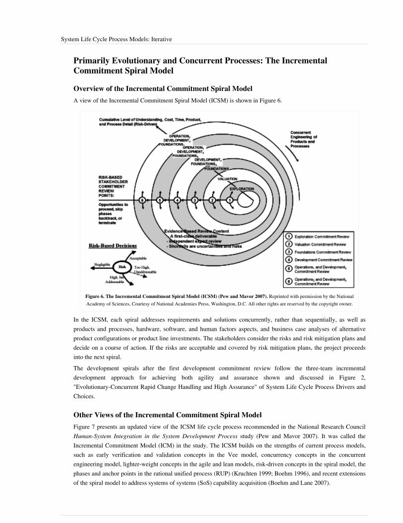
System Life Cycle Process Models: Iterative 53
Primarily Evolutionary and Concurrent Processes: The IncrementalCommitment Spiral Model
Overview of the Incremental Commitment Spiral ModelA view of the Incremental Commitment Spiral Model (ICSM) is shown in Figure 6.
Figure 6. The Incremental Commitment Spiral Model (ICSM) (Pew and Mavor 2007). Reprinted with permission by the NationalAcademy of Sciences, Courtesy of National Academies Press, Washington, D.C. All other rights are reserved by the copyright owner.
In the ICSM, each spiral addresses requirements and solutions concurrently, rather than sequentially, as well asproducts and processes, hardware, software, and human factors aspects, and business case analyses of alternativeproduct configurations or product line investments. The stakeholders consider the risks and risk mitigation plans anddecide on a course of action. If the risks are acceptable and covered by risk mitigation plans, the project proceedsinto the next spiral.The development spirals after the first development commitment review follow the three-team incrementaldevelopment approach for achieving both agility and assurance shown and discussed in Figure 2,"Evolutionary-Concurrent Rapid Change Handling and High Assurance" of System Life Cycle Process Drivers andChoices.
Other Views of the Incremental Commitment Spiral ModelFigure 7 presents an updated view of the ICSM life cycle process recommended in the National Research CouncilHuman-System Integration in the System Development Process study (Pew and Mavor 2007). It was called theIncremental Commitment Model (ICM) in the study. The ICSM builds on the strengths of current process models,such as early verification and validation concepts in the Vee model, concurrency concepts in the concurrentengineering model, lighter-weight concepts in the agile and lean models, risk-driven concepts in the spiral model, thephases and anchor points in the rational unified process (RUP) (Kruchten 1999; Boehm 1996), and recent extensionsof the spiral model to address systems of systems (SoS) capability acquisition (Boehm and Lane 2007).

System Life Cycle Process Models: Iterative 54
Figure 7. Phased View of the Generic Incremental Commitment Spiral Model Process (Pew and Mavor 2007). Reprintedwith permission by the National Academy of Sciences, Courtesy of National Academies Press, Washington, D.C. All other rights
are reserved by the copyright owner.
The top row of activities in Figure 7 indicates that a number of system aspects are being concurrently engineered atan increasing level of understanding, definition, and development. The most significant of these aspects are shown inFigure 8, an extension of a similar “hump diagram” view of concurrently engineered software activities developed aspart of the RUP (Kruchten 1999).

System Life Cycle Process Models: Iterative 55
Figure 8. ICSM Activity Categories and Level of Effort (Pew and Mavor 2007).Reprinted with permission by the National Academy of Sciences, Courtesy of National
Academies Press, Washington, D.C. All other rights are reserved by the copyright owner.
As with the RUP version, the magnitude and shape of the levels of effort will be risk-driven and likely to vary fromproject to project. Figure 8 indicates that a great deal of concurrent activity occurs within and across the variousICSM phases, all of which need to be "synchronized and stabilized," a best-practice phrase taken from MicrosoftSecrets (Cusumano and Selby 1996) to keep the project under control.The review processes and use of independent experts are based on the highly successful AT&T Architecture ReviewBoard procedures described in “Architecture Reviews: Practice and Experience” (Maranzano et al. 2005). Figure 9shows the content of the feasibility evidence description. Showing feasibility of the concurrently-developed elementshelps synchronize and stabilize the concurrent activities.
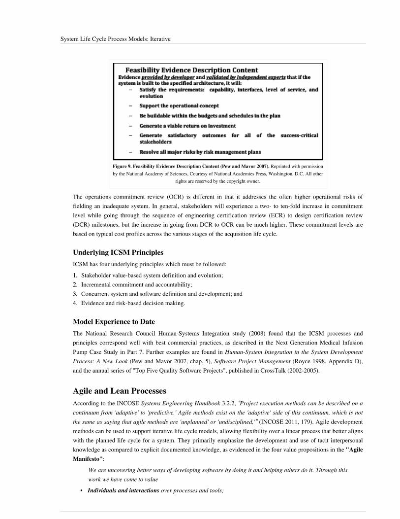
System Life Cycle Process Models: Iterative 56
Figure 9. Feasibility Evidence Description Content (Pew and Mavor 2007). Reprinted with permissionby the National Academy of Sciences, Courtesy of National Academies Press, Washington, D.C. All other
rights are reserved by the copyright owner.
The operations commitment review (OCR) is different in that it addresses the often higher operational risks offielding an inadequate system. In general, stakeholders will experience a two- to ten-fold increase in commitmentlevel while going through the sequence of engineering certification review (ECR) to design certification review(DCR) milestones, but the increase in going from DCR to OCR can be much higher. These commitment levels arebased on typical cost profiles across the various stages of the acquisition life cycle.
Underlying ICSM PrinciplesICSM has four underlying principles which must be followed:1.1. Stakeholder value-based system definition and evolution;2.2. Incremental commitment and accountability;3.3. Concurrent system and software definition and development; and4.4. Evidence and risk-based decision making.
Model Experience to DateThe National Research Council Human-Systems Integration study (2008) found that the ICSM processes andprinciples correspond well with best commercial practices, as described in the Next Generation Medical InfusionPump Case Study in Part 7. Further examples are found in Human-System Integration in the System DevelopmentProcess: A New Look (Pew and Mavor 2007, chap. 5), Software Project Management (Royce 1998, Appendix D),and the annual series of "Top Five Quality Software Projects", published in CrossTalk (2002-2005).
Agile and Lean ProcessesAccording to the INCOSE Systems Engineering Handbook 3.2.2, “Project execution methods can be described on acontinuum from 'adaptive' to 'predictive.' Agile methods exist on the 'adaptive' side of this continuum, which is notthe same as saying that agile methods are 'unplanned' or 'undisciplined,'” (INCOSE 2011, 179). Agile developmentmethods can be used to support iterative life cycle models, allowing flexibility over a linear process that better alignswith the planned life cycle for a system. They primarily emphasize the development and use of tacit interpersonalknowledge as compared to explicit documented knowledge, as evidenced in the four value propositions in the "AgileManifesto":
We are uncovering better ways of developing software by doing it and helping others do it. Through thiswork we have come to value
• Individuals and interactions over processes and tools;
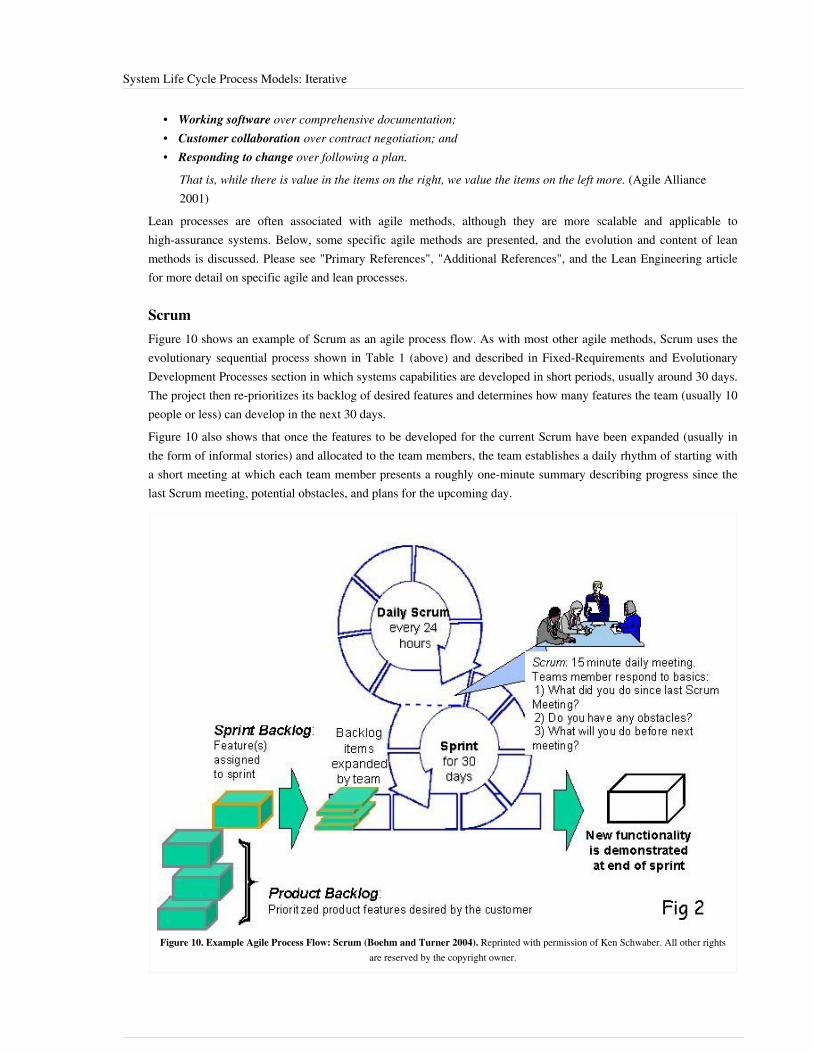
System Life Cycle Process Models: Iterative 57
• Working software over comprehensive documentation;• Customer collaboration over contract negotiation; and• Responding to change over following a plan.
That is, while there is value in the items on the right, we value the items on the left more. (Agile Alliance2001)
Lean processes are often associated with agile methods, although they are more scalable and applicable tohigh-assurance systems. Below, some specific agile methods are presented, and the evolution and content of leanmethods is discussed. Please see "Primary References", "Additional References", and the Lean Engineering articlefor more detail on specific agile and lean processes.
ScrumFigure 10 shows an example of Scrum as an agile process flow. As with most other agile methods, Scrum uses theevolutionary sequential process shown in Table 1 (above) and described in Fixed-Requirements and EvolutionaryDevelopment Processes section in which systems capabilities are developed in short periods, usually around 30 days.The project then re-prioritizes its backlog of desired features and determines how many features the team (usually 10people or less) can develop in the next 30 days.Figure 10 also shows that once the features to be developed for the current Scrum have been expanded (usually inthe form of informal stories) and allocated to the team members, the team establishes a daily rhythm of starting witha short meeting at which each team member presents a roughly one-minute summary describing progress since thelast Scrum meeting, potential obstacles, and plans for the upcoming day.
Figure 10. Example Agile Process Flow: Scrum (Boehm and Turner 2004). Reprinted with permission of Ken Schwaber. All other rightsare reserved by the copyright owner.

System Life Cycle Process Models: Iterative 58
Architected Agile Methods
Over the last decade, several organizations have been able to scale up agile methods by using two layers often-person Scrum teams. This involves, among other things, having each Scrum team’s daily meeting followed up bya daily meeting of the Scrum team leaders discussing up-front investments in evolving system architecture (Boehmet al. 2010). Figure 11 shows an example of the Architected Agile approach.
Figure 11. Example of Architected Agile Process (Boehm 2009). Reprinted with permission of Barry Boehm on behalf of USC-CSSE. All otherrights are reserved by the copyright owner.
Agile Practices and PrinciplesAs seen with the Scrum and architected agile methods, "generally-shared" principles are not necessarily "uniformlyfollowed". However, there are some general practices and principles shared by most agile methods:•• The project team understands, respects, works, and behaves within a defined SE process;•• The project is executed as fast as possible with minimum down time or staff diversion during the project and the
critical path is managed;•• All key players are physically or electronically collocated, and "notebooks" are considered team property
available to all.• Baseline management and change control are achieved by formal, oral agreements based on “make a
promise—keep a promise” discipline. Participants hold each other accountable.•• Opportunity exploration and risk reduction are accomplished by expert consultation and rapid model verification
coupled with close customer collaboration; software development is done in a rapid development environmentwhile hardware is developed in a multi-disciplined model shop; and
• A culture of constructive confrontation pervades the project organization. The team takes ownership for success;it is never “someone else’s responsibility.”
Agile development principles (adapted for SE) are as follows (adapted from Principles behind the Agile Manifesto(Beedle et al. 2009)):1.1. First, satisfy the customer through early and continuous delivery of valuable software (and other system
elements).2. Welcome changing requirements, even late in development; agile processes harness change for the customer’s
competitive advantage.3.3. Deliver working software (and other system elements) frequently, from a couple of weeks to a couple of months,
with a preference to the shorter timescale.
System Life Cycle Process Models: Iterative 59
4.4. Business personnel and developers must work together daily throughout the project.5.5. Build projects around motivated individuals; give them the environment, support their needs, and trust them to
get the job done.6.6. The most efficient and effective method of conveying information is face-to-face conversation.7.7. Working software (and other system elements) is the primary measure of progress.8.8. Agile processes promote sustainable development; the sponsors, developers, and users should be able to maintain
a constant pace indefinitely.9.9. Continuous attention to technical excellence and good design enhances agility.10. Simplicity—the art of maximizing the amount of work not done—is essential.11.11. The best architectures, requirements, and designs emerge from self-organizing teams.A team should reflect on how to become more effective at regular intervals and then tune and adjust its behavioraccordingly. This self-reflection is a critical aspect for projects that implement agile processes.
Lean Systems Engineering and Development
Origins
As the manufacturing of consumer products such as automobiles became more diversified, traditional pre-plannedmass-production approaches had increasing problems with quality and adaptability. Lean manufacturing systemssuch as the Toyota Production System (TPS) (Ohno 1988) were much better suited to accommodate diversity, toimprove quality, and to support just-in-time manufacturing that could rapidly adapt to changing demand patternswithout having to carry large, expensive inventories.Much of this transformation was stimulated by the work of W. Edwards Deming, whose Total Quality Management(TQM) approach shifted responsibility for quality and productivity from planners and inspectors to the productionworkers who were closer to the real processes (Deming 1982). Deming's approach involved everyone in themanufacturing organization in seeking continuous process improvement, or "Kaizen".Some of the TQM techniques, such as statistical process control and repeatability, were more suited to repetitivemanufacturing processes than to knowledge work such as systems engineering (SE) and software engineering (SwE).Others, such as early error elimination, waste elimination, workflow stabilization, and Kaizen, were equallyapplicable to knowledge work. Led by Watts Humphrey, TQM became the focus for the Software CapabilityMaturity Model (Humphrey 1987; Paulk et al. 1994) and the CMM-Integrated or CMMI, which extended its scope toinclude systems engineering (Chrissis et al. 2003). One significant change was the redefinition of Maturity Level 2from "Repeatable" to "Managed".The Massachusetts Institute of Technology (MIT) conducted studies of the TPS, which produced a similar approachthat was called the "Lean Production System" (Krafcik 1988; Womack et al. 1990). Subsequent development of"lean thinking" and related work at MIT led to the Air Force-sponsored Lean Aerospace Initiative (now called theLean Advancement Initiative), which applied lean thinking to SE (Murman 2003, Womack-Jones 2003).Concurrently, lean ideas were used to strengthen the scalability and dependability aspects of agile methods forsoftware (Poppendieck 2003; Larman-Vodde 2009). The Kanban flow-oriented approach has been successfullyapplied to software development (Anderson 2010).

System Life Cycle Process Models: Iterative 60
Principles
Each of these efforts has developed a similar but different set of Lean principles. For systems engineering, thecurrent best source is Lean for Systems Engineering, the product of several years’ work by the INCOSE Lean SEworking group (Oppenheim 2011). It is organized into six principles, each of which is elaborated into a set of leanenabler and sub-enabler patterns for satisfying the principle:1. Value. Guide the project by determining the value propositions of the customers and other key stakeholders.
Keep them involved and manage changes in their value propositions.2. Map the Value Stream (Plan the Program). This includes thorough requirements specification, the concurrent
exploration of trade spaces among the value propositions, COTS evaluation, and technology maturity assessment,resulting in a full project plan and set of requirements.
3. Flow. Focus on careful attention to the project’s critical path activities to avoid expensive work stoppages,including coordination with external suppliers.
4. Pull. Pull the next tasks to be done based on prioritized needs and dependencies. If a need for the task can’t befound, reject it as waste.
5. Perfection. Apply continuous process improvement to approach perfection. Drive defects out early to get thesystem Right The First #Time, vs. fixing them during inspection and test. Find and fix root causes rather thansymptoms.
6. Respect for People. Flow down responsibility, authority, and accountability to all personnel. Nurture a learningenvironment. Treat people as the organization’s most valued assets. (Oppenheim 2011)
These lean SE principles are highly similar to the four underlying incremental commitment spiral model principles.• Principle 1: Stakeholder value-based system definition and evolution, addresses the lean SE principles of
value, value stream mapping, and respect for people (developers are success-critical stakeholders in the ICSM).• Principle 2: Incremental commitment and accountability, partly addresses the pull principle, and also
addresses respect for people (who are accountable for their commitments).• Principle 3: Concurrent system and software definition and development, partly addresses both value stream
mapping and flow.• Principle 4: Evidence and risk-based decision making, uses evidence of achievability as its measure of
success. Overall, the ICSM principles are somewhat light on continuous process improvement, and the lean SEprinciples are somewhat insensitive to requirements emergence in advocating a full pre-specified project plan andset of requirements.
See Lean Engineering for more information.
References
Works CitedAgile Alliance. 2001. “Manifesto for Agile Software Development.” http:/ / agilemanifesto. org/ .Anderson, D. 2010. Kanban, Sequim, WA: Blue Hole Press.Boehm, B. 1996. "Anchoring the Software Process." IEEE Software 13(4): 73-82.Boehm, B. and J. Lane. 2007. “Using the Incremental Commitment Model to Integrate System Acquisition, SystemsEngineering, and Software Engineering.” CrossTalk. 20(10) (October 2007): 4-9.Boehm, B., J. Lane, S. Koolmanjwong, and R. Turner. 2010. “Architected Agile Solutions for Software-ReliantSystems,” in Dingsoyr, T., T. Dyba., and N. Moe (eds.), Agile Software Development: Current Research and FutureDirections. New York, NY, USA: Springer.Boehm, B. and R. Turner. 2004. Balancing Agility and Discipline. New York, NY, USA: Addison-Wesley.

System Life Cycle Process Models: Iterative 61
Castellano, D.R. 2004. “Top Five Quality Software Projects.” CrossTalk. 17(7) (July 2004): 4-19. Available at: http:// www. crosstalkonline. org/ storage/ issue-archives/ 2004/ 200407/ 200407-0-Issue. pdfChrissis, M., M. Konrad, and S. Shrum. 2003. CMMI: Guidelines for Process Integration and Product Improvement.New York, NY, USA, Addison Wesley.Deming, W.E. 1982. Out of the Crisis. Cambridge, MA, USA: MIT.Fairley, R. 2009. Managing and Leading Software Projects. New York, NY, USA: John Wiley & Sons.Forsberg, K. 1995. "If I Could Do That, Then I Could…’ System Engineering in a Research and DevelopmentEnvironment." Proceedings of the Fifth International Council on Systems Engineering (INCOSE) InternationalSymposium. 22-26 July 1995. St Louis, MO, USA.Forsberg, K., H. Mooz, and H. Cotterman. 2005. Visualizing Project Management, 3rd ed. New York, NY, USA:John Wiley & Sons.Humphrey, W., 1987. “Characterizing the Software Process: A Maturity Framework.” Pittsburgh, PA, USA: CMUSoftware Engineering Institute. CMU/SEI-87-TR-11.Jarzombek, J. 2003. “Top Five Quality Software Projects.” CrossTalk. 16(7) (July 2003): 4-19. Available at: http:/ /www. crosstalkonline. org/ storage/ issue-archives/ 2003/ 200307/ 200307-0-Issue. pdf.Krafcik, J. 1988. "Triumph of the lean production system". Sloan Management Review. 30(1): 41–52.Kruchten, P. 1999. The Rational Unified Process. New York, NY, USA: Addison Wesley.Larman , C. and B. Vodde. 2009. Scaling Lean and Agile Development. New York, NY, USA: Addison Wesley.Maranzano, J.F., S.A. Rozsypal, G.H. Zimmerman, G.W. Warnken, P.E. Wirth, D.M. Weiss. 2005. “ArchitectureReviews: Practice and Experience.” IEEE Software. 22(2): 34-43.Murman, E. 2003. Lean Systems Engineering I, II, Lecture Notes, MIT Course 16.885J, Fall. Cambridge, MA, USA:MIT.Oppenheim, B. 2011. Lean for Systems Engineering. Hoboken, NJ: Wiley.Paulk, M., C. Weber, B. Curtis, and M. Chrissis. 1994. The Capability Maturity Model: Guidelines for Improving theSoftware Process. Reading, MA, USA: Addison Wesley.Pew, R. and A. Mavor (eds.). 2007. Human-System Integration in The System Development Process: A New Look.Washington, DC, USA: The National Academies Press.Poppendieck, M. and T. Poppendieck. 2003. Lean Software Development: An Agile Toolkit for SoftwareDevelopment Managers. New York, NY, USA: Addison Wesley.Spruill, N. 2002. “Top Five Quality Software Projects.” CrossTalk. 15(1) (January 2002): 4-19. Available at: http:/ /www. crosstalkonline. org/ storage/ issue-archives/ 2002/ 200201/ 200201-0-Issue. pdf.Stauder, T. “Top Five Department of Defense Program Awards.” CrossTalk. 18(9) (September 2005): 4-13.Available at http:/ / www. crosstalkonline. org/ storage/ issue-archives/ 2005/ 200509/ 200509-0-Issue. pdf.Womack, J., D. Jones, and D Roos. 1990. The Machine That Changed the World: The Story of Lean Production.New York, NY, USA: Rawson Associates.Womack, J. and D. Jones. 2003. Lean Thinking. New York, NY, USA: The Free Press.

System Life Cycle Process Models: Iterative 62
Primary ReferencesBeedle, M., et al. 2009. "The Agile Manifesto: Principles behind the Agile Manifesto". in The Agile Manifesto[database online]. Accessed 2010. Available at: www.agilemanifesto.org/principles.htmlBoehm, B. and R. Turner. 2004. Balancing Agility and Discipline. New York, NY, USA: Addison-Wesley.Fairley, R. 2009. Managing and Leading Software Projects. New York, NY, USA: J. Wiley & Sons.Forsberg, K., H. Mooz, and H. Cotterman. 2005. Visualizing Project Management, 3rd ed. New York, NY, USA: J.Wiley & Sons.INCOSE. 2012. Systems Engineering Handbook: A Guide for System Life Cycle Processes and Activities. Version3.2.2. San Diego, CA, USA: International Council on Systems Engineering (INCOSE),INCOSE-TP-2003-002-03.2.2.Lawson, H. 2010. A Journey Through the Systems Landscape. Kings College, UK: College Publications.Pew, R., and A. Mavor (eds.). 2007. Human-System Integration in the System Development Process: A New Look.Washington, DC, USA: The National Academies Press.Royce, W.E. 1998. Software Project Management: A Unified Framework. New York, NY, USA: Addison Wesley.
Additional ReferencesAnderson, D. 2010. Kanban. Sequim, WA, USA: Blue Hole Press.Baldwin, C. and K. Clark. 2000. Design Rules: The Power of Modularity. Cambridge, MA, USA: MIT Press.Beck, K. 1999. Extreme Programming Explained. New York, NY, USA: Addison Wesley.Beedle, M., et al. 2009. "The Agile Manifesto: Principles behind the Agile Manifesto" in The Agile Manifesto[database online]. Accessed 2010. Available at: www.agilemanifesto.org/principles.htmlBiffl, S., A. Aurum, B. Boehm, H. Erdogmus, and P. Gruenbacher (eds.). 2005. Value-Based Software Engineering.New York, NY, USA: Springer.Boehm, B. 1988. “A Spiral Model of Software Development.” IEEE Computer. 21(5): 61-72.Boehm, B. 2006. “Some Future Trends and Implications for Systems and Software Engineering Processes.” SystemsEngineering. 9(1): 1-19.Boehm, B., A. Egyed, J. Kwan, D. Port, A. Shah, and R. Madachy. 1998. “Using the WinWin Spiral Model: A CaseStudy.” IEEE Computer. 31(7): 33-44.Boehm, B., J. Lane, S. Koolmanojwong, and R. Turner. 2013 (in press). Embracing the Spiral Model: CreatingSuccessful Systems with the Incremental Commitment Spiral Model. New York, NY, USA: Addison Wesley.Castellano, D.R. 2004. “Top Five Quality Software Projects.” CrossTalk. 17(7) (July 2004): 4-19. Available at: http:// www. crosstalkonline. org/ storage/ issue-archives/ 2004/ 200407/ 200407-0-Issue. pdfCheckland, P. 1981. Systems Thinking, Systems Practice. New York, NY, USA: Wiley.Crosson, S. and B. Boehm. 2009. “Adjusting Software Life Cycle Anchorpoints: Lessons Learned in a System ofSystems Context.” Proceedings of the Systems and Software Technology Conference, 20-23 April 2009, Salt LakeCity, UT, USA.Dingsoyr, T., T. Dyba. and N. Moe (eds.). 2010. "Agile Software Development: Current Research and FutureDirections.” Chapter in B. Boehm, J. Lane, S. Koolmanjwong, and R. Turner, Architected Agile Solutions forSoftware-Reliant Systems. New York, NY, USA: Springer.Dorner, D. 1996. The Logic of Failure. New York, NY, USA: Basic Books.Faisandier, A. 2012. Systems Architecture and Design. Belberaud, France: Sinergy'Com.

System Life Cycle Process Models: Iterative 63
Forsberg, K. 1995. "'If I Could Do That, Then I Could…' System Engineering in a Research and DevelopmentEnvironment.” Proceedings of the Fifth Annual International Council on Systems Engineering (INCOSE)International Symposium. 22-26 July 1995. St. Louis, MO, USA.Forsberg, K. 2010. “Projects Don’t Begin With Requirements.” Proceedings of the IEEE Systems Conference. 5-8April 2010. San Diego, CA, USA.Gilb, T. 2005. Competitive Engineering. Maryland Heights, MO, USA: Elsevier Butterworth Heinemann.Goldratt, E. 1984. The Goal. Great Barrington, MA, USA: North River Press.Hitchins, D. 2007. Systems Engineering: A 21st Century Systems Methodology. New York, NY, USA: Wiley.Holland, J. 1998. Emergence. New York, NY, USA: Perseus Books.ISO/IEC. 2010. Systems and Software Engineering, Part 1: Guide for Life Cycle Management. Geneva, Switzerland:International Organization for Standardization (ISO)/International Electrotechnical Commission (IEC), ISO/IEC24748-1:2010.ISO/IEC/IEEE. 2015. Systems and Software Engineering -- System Life Cycle Processes. Geneva, Switzerland:International Organisation for Standardisation / International Electrotechnical Commissions. ISO/IEC/IEEE15288:2015.ISO/IEC. 2003. Systems Engineering — A Guide for The Application of ISO/IEC 15288 System Life CycleProcesses. Geneva, Switzerland: International Organization for Standardization (ISO)/International ElectrotechnicalCommission (IEC), ISO/IEC 19760:2003 (E).Jarzombek, J. 2003. “Top Five Quality Software Projects.” CrossTalk. 16(7) (July 2003): 4-19. Available at: http:/ /www. crosstalkonline. org/ storage/ issue-archives/ 2003/ 200307/ 200307-0-Issue. pdf.Kruchten, P. 1999. The Rational Unified Process. New York, NY, USA: Addison Wesley.Landis, T. R. 2010. Lockheed Blackbird Family (A-12, YF-12, D-21/M-21 & SR-71). North Branch, MN, USA:Specialty Press.Madachy, R. 2008. Software Process Dynamics. New York, NY, USA: Wiley.Maranzano, J., et al. 2005. “Architecture Reviews: Practice and Experience.” IEEE Software. 22(2): 34-43.National Research Council of the National Academies (USA). 2008. Pre-Milestone A and Early-Phase SystemsEngineering. Washington, DC, USA: The National Academies Press.Osterweil, L. 1987. “Software Processes are Software Too.” Proceedings of the SEFM 2011: 9th InternationalConference on Software Engineering. Monterey, CA, USA.Poppendeick, M. and T. Poppendeick. 2003. Lean Software Development: an Agile Toolkit. New York, NY, USA:Addison Wesley.Rechtin, E. 1991. System Architecting: Creating and Building Complex Systems. Upper Saddle River, NY, USA:Prentice-Hall.Rechtin, E., and M. Maier. 1997. The Art of System Architecting. Boca Raton, FL, USA: CRC Press.Schwaber, K. and M. Beedle. 2002. Agile Software Development with Scrum. Upper Saddle River, NY, USA:Prentice Hall.Spruill, N. 2002. “Top Five Quality Software Projects.” CrossTalk. 15(1) (January 2002): 4-19. Available at: http:/ /www. crosstalkonline. org/ storage/ issue-archives/ 2002/ 200201/ 200201-0-Issue. pdf.Stauder, T. 2005. “Top Five Department of Defense Program Awards.” CrossTalk. 18(9) (September 2005): 4-13.Available at http:/ / www. crosstalkonline. org/ storage/ issue-archives/ 2005/ 200509/ 200509-0-Issue. pdf.Warfield, J. 1976. Societal Systems: Planning, Policy, and Complexity. New York, NY, USA: Wiley.Womack, J. and D. Jones. 1996. Lean Thinking. New York, NY, USA: Simon and Schuster.

System Life Cycle Process Models: Iterative 64
< Previous Article | Parent Article | Next Article >SEBoK v. 1.4 released 29 June 2015
SEBoK DiscussionPlease provide your comments and feedback on the SEBoK below. You will need to log in to DISQUS using anexisting account (e.g. Yahoo, Google, Facebook, Twitter, etc.) or create a DISQUS account. Simply type yourcomment in the text field below and DISQUS will guide you through the login or registration steps. Feedback will bearchived and used for future updates to the SEBoK. If you provided a comment that is no longer listed, that commenthas been adjudicated. You can view adjudication for comments submitted prior to SEBoK v. 1.0 at SEBoK Reviewand Adjudication. Later comments are addressed and changes are summarized in the Letter from the Editor andAcknowledgements and Release History.
If you would like to provide edits on this article, recommend new content, or make comments on the SEBoKas a whole, please see the SEBoK Sandbox [1].
ENCODED_CONTENTMTkyODQPGRpdiBpZD0iZGlzcXVzX3RocmVhZCI+PC9kaXY+CjxzY3JpcHQgdHlwZT0idGV4dC9qYXZhc2NyaXB0Ij4KICAgIC8qICogKiBDT05GSUdVUkFUSU9OIFZBUklBQkxFUzogRURJVCBCRUZPUkUgUEFTVElORyBJTlRPIFlPVVIgV0VCUEFHRSAqICogKi8KICAgIHZhciBkaXNxdXNfc2hvcnRuYW1lID0gJ3NlYm9rd2lraTEwJzsgLy8gcmVxdWlyZWQ6IHJlcGxhY2UgZXhhbXBsZSB3aXRoIHlvdXIgZm9ydW0gc2hvcnRuYW1lCiAgICB2YXIgZGlzcXVzX2lkZW50aWZpZXIgPSAnU3lzdGVtIExpZmUgQ3ljbGUgUHJvY2VzcyBNb2RlbHM6IEl0ZXJhdGl2ZSc7ICAgIHZhciBkaXNxdXNfdXJsID0gJ2h0dHA6Ly9zZWJva3dpa2kub3JnL2RyYWZ0L1N5c3RlbV9MaWZlX0N5Y2xlX1Byb2Nlc3NfTW9kZWxzOl9JdGVyYXRpdmUnOwogICAgLyogKiAqIERPTidUIEVESVQgQkVMT1cgVEhJUyBMSU5FICogKiAqLwogICAgKGZ1bmN0aW9uKCkgewogICAgICAgIHZhciBkc3EgPSBkb2N1bWVudC5jcmVhdGVFbGVtZW50KCdzY3JpcHQnKTsgZHNxLnR5cGUgPSAndGV4dC9qYXZhc2NyaXB0JzsgZHNxLmFzeW5jID0gdHJ1ZTsKICAgICAgICBkc3Euc3JjID0gJ2h0dHA6Ly8nICsgZGlzcXVzX3Nob3J0bmFtZSArICcuZGlzcXVzLmNvbS9lbWJlZC5qcyc7CiAgICAgICAgKGRvY3VtZW50LmdldEVsZW1lbnRzQnlUYWdOYW1lKCdoZWFkJylbMF0gfHwgZG9jdW1lbnQuZ2V0RWxlbWVudHNCeVRhZ05hbWUoJ2JvZHknKVswXSkuYXBwZW5kQ2hpbGQoZHNxKTsKICAgIH0pKCk7Cjwvc2NyaXB0Pgo8bm9zY3JpcHQ+UGxlYXNlIGVuYWJsZSBKYXZhU2NyaXB0IHRvIHZpZXcgdGhlIDxhIGhyZWY9Imh0dHA6Ly9kaXNxdXMuY29tLz9yZWZfbm9zY3JpcHQiPmNvbW1lbnRzIHBvd2VyZWQgYnkgRGlzcXVzLjwvYT48L25vc2NyaXB0Pgo8YSBocmVmPSJodHRwOi8vZGlzcXVzLmNvbSIgY2xhc3M9ImRzcS1icmxpbmsiPmJsb2cgY29tbWVudHMgcG93ZXJlZCBieSA8c3BhbiBjbGFzcz0ibG9nby1kaXNxdXMiPkRpc3F1czwvc3Bhbj48L2E+END_ENCODED_CONTENT
Integration of Process and Product ModelsWhen performing systems engineering activities, it is important to consider the mutual relationship betweenprocesses and the desired system. The type of system (see Types of Systems) being produced will affect the neededprocesses, as indicated in system life cycle process drivers and choices. This may cause the tailoring (glossary) ofdefined processes as described in application of systems engineering standards.
Process and Product ModelsFigure 1 of life cycle models introduced the perspective of viewing stage work products provided by processexecution as versions of a system-of-interest (SoI) at various life stages. The fundamental changes that take placeduring the life cycle of any man-made system include definition, production, and utilization. Building upon these, itis useful to consider the structure of a generic process and product life cycle stage model as portrayed in Figure 1below.

Integration of Process and Product Models 65
Figure 1. Generic (T) Stage Structure of System Life Cycle (Lawson 2010). Reprinted with permission of Harold "Bud"Lawson. All other rights are reserved by the copyright owner.
The (T) model indicates that a definition stage precedes a production stage where the implementation (acquisition,provisioning, or development) of two or more system elements has been accomplished. The system elements areintegrated according to defined relationships into the SoI. Thus, both the process and product aspects are portrayed.The implementation and integration processes are followed in providing the primary stage results—namely, inassembled system product or service instances. However, as noted in life cycle models, the definition of the SoIwhen provided in a development stage can also be the result of first versions of the system. For example, a prototype(glossary), which may be viewed as a form of production or pre-production stage. Following the production stage isa utilization stage. Further relevant stages can include support and retirement. Note that this model also displays theimportant distinction between definition versus implementation and integration.According to ISO/IEC/IEEE 15288 (2015), this structure is generic for any type of man-made SoI to undergo lifecycle management. The production stage thus becomes the focal point of the (T) model at which system elements areimplemented and integrated into system product or service instances based upon the definitions. For defined physicalsystems, this is the point at which product instances are manufactured and assembled (singularly or mass-produced).For non-physical systems, the implementation and integration processes are used in service preparation(establishment) prior to being instantiated to provide a service. For software systems, this is the point at which buildsthat combine software elements into versions, releases, or some other form of managed software product areproduced.Using recursive decomposition, the implementation of each system element can involve the invocation of thestandard again at the next lowest level, thus treating the system element as a SoI in its own right. A new life cyclestructure is then utilized for the lower level SoIs.This is illustrated in the Dual Vee model (Figures 2a and 2b). The Dual Vee model is a three-dimensional systemdevelopment model that integrates product and process in the creation of the system and component architectures. Itemphasizes•• concurrent opportunity and risk management;

Integration of Process and Product Models 66
• user in-process validation (glossary);• integration (glossary), verification (glossary), and validation (glossary) planning; and• verification (glossary) problem resolution.When decomposition terminates according to the practical need and risk-benefit analysis, system elements are thenimplemented (acquired, provisioned, or developed) according to the type of element involved.
Figure 2a. The Dual Vee Model (2a) (Forsberg, Mooz, Cotterman 2005). Reprinted with permission of John Wiley & Sons Inc. Allother rights are reserved by the copyright owner.

Integration of Process and Product Models 67
Figure 2b. The Dual Vee Model (2b) (Forsberg, Mooz, Cotterman 2005). Reprinted with permission of John Wiley & Sons Inc. Allother rights are reserved by the copyright owner.
A practical aspect that can very well affect the process and product aspect is the decision to use off-the-shelfelements in commercial-off-the-shelf (COTS) form. In this case, further decomposition of the element is notnecessary. The use of COTS elements (and their internally created neighbor or non-development item (NDI)) hasbecome widespread, and they have proven their value. However, developers must make sure that the COTS productis appropriate for their environment.A known flaw which occurs infrequently in normal use of the product in its intended environment may be benignand easily dealt with. In a new situation, it could have dramatic adverse consequences, such as those that occurred onthe USS Yorktown Cruiser in 1998 (Wired News Contributors 1998). The customer mandated that Windows NT beused as the primary operating system for the ship. A divide by zero fault caused the operating system to fail, and theship was dead in the water. It had to be towed back to port on three occasions.Spiral models concurrently engineer not only process and product models, but also property and success models.Figure 3 shows how these models provide checks and balances, both at milestone reviews and as individual modelchoices are made. Methods and tools supporting this concurrent engineering are provided in “When Models Collide:Lessons from Software System Analysis” (Boehm and Port 1999), “Avoiding the Software Model-Clash Spiderweb”(Boehm, Port, and Al-Said 2000), and “Detecting Model Clashes During Software Systems Development” (Al-Said2003).
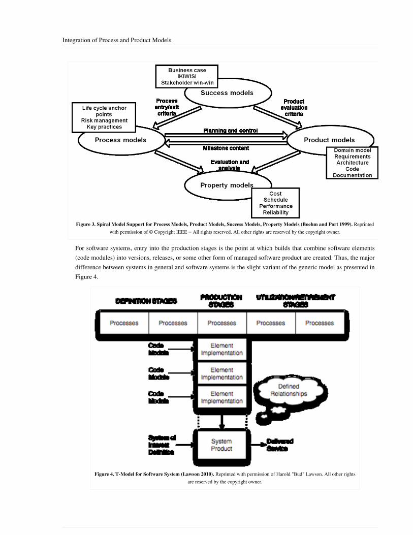
Integration of Process and Product Models 68
Figure 3. Spiral Model Support for Process Models, Product Models, Success Models, Property Models (Boehm and Port 1999). Reprintedwith permission of © Copyright IEEE – All rights reserved. All other rights are reserved by the copyright owner.
For software systems, entry into the production stages is the point at which builds that combine software elements(code modules) into versions, releases, or some other form of managed software product are created. Thus, the majordifference between systems in general and software systems is the slight variant of the generic model as presented inFigure 4.
Figure 4. T-Model for Software System (Lawson 2010). Reprinted with permission of Harold "Bud" Lawson. All other rightsare reserved by the copyright owner.

Integration of Process and Product Models 69
Stage Execution OrderA sequential execution of life cycle stages is the most straightforward. As presented in System Life Cycle ProcessModels: Vee and System Life Cycle Process Models: Iterative, variants of the Vee model and the spiral modelprovide non-sequential models when practical considerations require a non-linear execution of life cycle stages.Building upon these two models, it is important to note that various types of complex systems require that the stagesof the life cycle model be revisited as insight (knowledge) is gained, as well as when stakeholder requirementschange. The iterations may involve necessary changes in the processes and in the product or service system. Thus,within the context of the (T) stage model, various orderings of stage execution - reflecting forms of non-sequentialstage ordering - can be conveniently described, as portrayed in Figure 5.
Figure 5. Iteration Through Life Cycle Stages (Lawson 2010). Reprinted with permission of Harold "Bud" Lawson. Allother rights are reserved by the copyright owner.
Each pattern of stage execution involves iteration of the previous stages, perhaps with altered requirements for theprocesses or the system. The heavy lines in Figure 5 denote the demarcation of the revisited end points. Three areiterative forms, for which several variants can be extracted:1. Iterative development is quite frequently deployed in order to assess stakeholder requirements, analyze the
requirements, and develop a viable architectural design. Thus, it is typical that the concept stage may be revisitedduring the development stage. For systems where products are based upon physical structures (electronics,mechanics, chemicals, and so on), iteration after production has begun can involve significant costs and scheduledelays. It is, therefore, important to get it "right" before going to production. The early stages are thus used tobuild confidence (verify and validate) that the solution works properly and will meet the needs of thestakeholders. Naturally, such an approach could be used for software and human activity systems as well;however, due to their soft nature, it can be useful to go further by experimenting and evaluating variousconfigurations of the system.
Integration of Process and Product Models 70
2. Iterative development and implementation involves producing (defining, implementing, and integrating)various versions of the system, evaluating how well they meet stakeholder requirements, perhaps in the context ofchanging requirements, and then revisiting the concept and/or development stages. Such iterations are typicalwithin software system development, where the cost of production is not as significant as for defined physicalsystems. A variant of this approach is the spiral model, where successive iterations fill in more detail (Boehm andMay 1998). The use of this approach requires careful attention to issues related to baseline and configurationmanagement. In this approach, significant verification (testing) should be performed on software systems in orderto build confidence that the system delivered will meet stakeholder requirements.
3. Incremental or progressive acquisition involves releasing systems in the form of products and/or services to theconsumers. This approach is appropriate when structural and capability (functions) changes are anticipated in acontrolled manner after deployment. The use of this approach can be due to not knowing all of the requirements atthe beginning, which leads to progressive acquisition/deployment, or due to a decision to handle the complexityof the system and its utilization in increments—namely, incremental acquisition. These approaches are vital forcomplex systems in which software is a significant system element. Each increment involves revisiting thedefinition and production stages. The utilization of these approaches must be based upon well-defined, agreedrelationships between the supplying and acquiring enterprises. In fact, the iteration associated with each resultingproduct and/or service instance may well be viewed as a joint project, with actor roles being provided by bothenterprises.
In all of the approaches it is wise to use modeling and simulation techniques and related tools to assist inunderstanding the effect of changes made in the complex systems being life cycle managed. These techniques aretypically deployed in the earlier stages; however, they can be used in gaining insight into the potential problems andopportunities associated with the latter stages of utilization and maintenance (for example, in understanding therequired logistics and help-desk aspects).
Allocating and Meeting Requirements - Integration of Process and ProductModelsRegardless of the order in which life cycle stages are executed, stakeholder requirements for the system, includingchanged requirements in each iteration, must be allocated into appropriate activities of the processes used in projectsfor various stages as well as to the properties of the elements of the product system or service system and theirdefined relationships. This distribution was illustrated in the fourth variant of Lawson’s T-model as presented inSystem Life Cycle Process Models: Iterative and System Life Cycle Process Models: Vee.Ideally, the project management team should implement proven processes that will integrate the technical processmodels with the project management product models to manage any of the processes discussed earlier, includingincremental and evolutionary development. The processes shown are the project management flow, starting with thebeginning of the development phase (Forsberg, Mooz, and Cotterman 2005, 201).

Integration of Process and Product Models 71
Figure 6a. New Product Planning Process – Getting Started (Forsberg, Mooz, and Cotterman 2005). Reprinted with permission ofJohn Wiley & Sons Inc. All other rights are reserved by the copyright owner.

Integration of Process and Product Models 72
Figure 6b. New Product Planning Process Solving the Problem (Forsberg, Mooz, and Cotterman 2005). Reprinted withpermission of John Wiley & Sons Inc. All other rights are reserved by the copyright owner.

Integration of Process and Product Models 73
Figure 6c. New Product Planning Process – Getting Commitment (Forsberg, Mooz, and Cotterman 2005). Reprinted withpermission of John Wiley & Sons Inc. All other rights are reserved by the copyright owner.
References
Works CitedBoehm, B. and W. May. 1988. "A Spiral Model of Software Development and Enhancement." IEEE Computer21(5): 61-72.Boehm, B. and D. Port. 1999. "When Models Collide: Lessons From Software System Analysis." IT Professional1(1): 49-56.Boehm, B., J. Lane, S. Koolmanojwong, and R. Turner (forthcoming). Embracing the Spiral Model: CreatingSuccessful Systems with the Incremental Commitment Spiral Model. New York, NY, USA: Addison Wesley.Forsberg, K., H. Mooz, and H. Cotterman. 2005. Visualizing Project Management. 3rd ed. New York, NY, USA: J.Wiley & Sons.ISO/IEC/IEEE. 2015.Systems and Software Engineering-- System Life Cycle Processes. Geneva, Switzerland:International Organisation for Standardisation / International Electrotechnical Commissions.ISO/IEC/IEEE15288:2015Lawson, H. 2010. A Journey Through the Systems Landscape. London, UK: College Publications.Wired News Contributors. 2011. “Sunk by Windows NT,” Wired News, last modified July 24, 1998. Accessed onSeptember 11, 2011. Available at http:/ / www. wired. com/ science/ discoveries/ news/ 1998/ 07/ 13987.

Integration of Process and Product Models 74
Primary ReferencesBoehm, B. and W. May. 1988. “A Spiral Model of Software Development and Enhancement.” IEEE Computer.21(5): 61-72.Forsberg, K., H. Mooz, and H. Cotterman. 2005. Visualizing Project Management, 3rd ed. New York, NY, USA:John Wiley & Sons.Lawson, H. 2010. A Journey Through the Systems Landscape. London, UK: College Publications.
Additional ReferencesAl-Said, M. 2003. "Detecting Model Clashes During Software Systems Development." PhD Diss. Department ofComputer Science, University of Southern California, December 2003.Boehm, B., J. Lane, S. Koolmanojwong, and R. Turner. (forthcoming). Embracing the Spiral Model: CreatingSuccessful Systems with the Incremental Commitment Spiral Model. New York, NY, USA: Addison Wesley.Boehm, B. and D. Port. 1999. "Escaping the Software Tar Pit: Model Clashes and How to Avoid Them." ACMSoftware Engineering Notes. (January, 1999): p. 36-48.Boehm, B. and D. Port. 1999. "When Models Collide: Lessons From Software System Analysis." IT Professional.1(1): 49-56.Boehm, B., D. Port, and M. Al-Said. 2000. "Avoiding the Software Model-Clash Spiderweb." IEEE Computer.33(11): 120-122.Lawson, H. and M. Persson. 2010. “Portraying Aspects of System Life Cycle Models.” Proceedings of the EuropeanSystems Engineering Conference (EuSEC). 23-26 May 2010. Stockholm, Sweden.
< Previous Article | Parent Article | Next Article >SEBoK v. 1.4 released 29 June 2015
SEBoK DiscussionPlease provide your comments and feedback on the SEBoK below. You will need to log in to DISQUS using anexisting account (e.g. Yahoo, Google, Facebook, Twitter, etc.) or create a DISQUS account. Simply type yourcomment in the text field below and DISQUS will guide you through the login or registration steps. Feedback will bearchived and used for future updates to the SEBoK. If you provided a comment that is no longer listed, that commenthas been adjudicated. You can view adjudication for comments submitted prior to SEBoK v. 1.0 at SEBoK Reviewand Adjudication. Later comments are addressed and changes are summarized in the Letter from the Editor andAcknowledgements and Release History.
If you would like to provide edits on this article, recommend new content, or make comments on the SEBoKas a whole, please see the SEBoK Sandbox [1].
ENCODED_CONTENTMTY0MDAPGRpdiBpZD0iZGlzcXVzX3RocmVhZCI+PC9kaXY+CjxzY3JpcHQgdHlwZT0idGV4dC9qYXZhc2NyaXB0Ij4KICAgIC8qICogKiBDT05GSUdVUkFUSU9OIFZBUklBQkxFUzogRURJVCBCRUZPUkUgUEFTVElORyBJTlRPIFlPVVIgV0VCUEFHRSAqICogKi8KICAgIHZhciBkaXNxdXNfc2hvcnRuYW1lID0gJ3NlYm9rd2lraTEwJzsgLy8gcmVxdWlyZWQ6IHJlcGxhY2UgZXhhbXBsZSB3aXRoIHlvdXIgZm9ydW0gc2hvcnRuYW1lCiAgICB2YXIgZGlzcXVzX2lkZW50aWZpZXIgPSAnSW50ZWdyYXRpb24gb2YgUHJvY2VzcyBhbmQgUHJvZHVjdCBNb2RlbHMnOyAgICB2YXIgZGlzcXVzX3VybCA9ICdodHRwOi8vc2Vib2t3aWtpLm9yZy9kcmFmdC9JbnRlZ3JhdGlvbl9vZl9Qcm9jZXNzX2FuZF9Qcm9kdWN0X01vZGVscyc7CiAgICAvKiAqICogRE9OJ1QgRURJVCBCRUxPVyBUSElTIExJTkUgKiAqICovCiAgICAoZnVuY3Rpb24oKSB7CiAgICAgICAgdmFyIGRzcSA9IGRvY3VtZW50LmNyZWF0ZUVsZW1lbnQoJ3NjcmlwdCcpOyBkc3EudHlwZSA9ICd0ZXh0L2phdmFzY3JpcHQnOyBkc3EuYXN5bmMgPSB0cnVlOwogICAgICAgIGRzcS5zcmMgPSAnaHR0cDovLycgKyBkaXNxdXNfc2hvcnRuYW1lICsgJy5kaXNxdXMuY29tL2VtYmVkLmpzJzsKICAgICAgICAoZG9jdW1lbnQuZ2V0RWxlbWVudHNCeVRhZ05hbWUoJ2hlYWQnKVswXSB8fCBkb2N1bWVudC5nZXRFbGVtZW50c0J5VGFnTmFtZSgnYm9keScpWzBdKS5hcHBlbmRDaGlsZChkc3EpOwogICAgfSkoKTsKPC9zY3JpcHQ+Cjxub3NjcmlwdD5QbGVhc2UgZW5hYmxlIEphdmFTY3JpcHQgdG8gdmlldyB0aGUgPGEgaHJlZj0iaHR0cDovL2Rpc3F1cy5jb20vP3JlZl9ub3NjcmlwdCI+Y29tbWVudHMgcG93ZXJlZCBieSBEaXNxdXMuPC9hPjwvbm9zY3JpcHQ+CjxhIGhyZWY9Imh0dHA6Ly9kaXNxdXMuY29tIiBjbGFzcz0iZHNxLWJybGluayI+YmxvZyBjb21tZW50cyBwb3dlcmVkIGJ5IDxzcGFuIGNsYXNzPSJsb2dvLWRpc3F1cyI+RGlzcXVzPC9zcGFuPjwvYT4=END_ENCODED_CONTENT

Lean Engineering 75
Lean EngineeringLean Systems Engineering (LSE) is the application of lean thinking (Womack 2003) to systems engineering (SE)and related aspects of enterprise and project management. LSE is an approach that is applicable throughout thesystem life cycle. The goal of LSE is to deliver the best life-cycle value for technically complex systems withminimal waste. Lean engineering is relevant to all of the traditional SE technical processes (see concept definition,system definition, system realization, system deployment and use, etc.). Lean engineering also interacts with andutilizes many of the specialty engineering disciplines discussed in Part 6.
Lean Systems EngineeringSE is an established, sound practice, but not always delivered effectively. Most programs are burdened with someform of waste such as: poor coordination, unstable requirements, quality problems, delays, rework, or managementfrustration. Recent U.S. Government Accountability Office (GAO), National Aeronautics and Space Association(NASA), and Massachusetts Institute of Technology (MIT) studies of government programs document major budgetand schedule overruns and a significant amount of waste in government programs - some reaching seventy percent ofcharged time. This waste represents a productivity reserve in programs and major opportunities to improve programefficiency.LSE is the application of lean thinking to systems engineering and related aspects of enterprise and projectmanagement. SE is focused on the discipline that enables development of complex technical systems. Lean thinkingis a holistic paradigm that focuses on delivering maximum value to the customer and minimizing wasteful practices.It has been successfully applied in manufacturing, aircraft depots, administration, supply chain management,healthcare, and product development, which includes engineering. LSE is the area of synergy between lean thinkingand SE, which aims to deliver the best life-cycle value for technically complex systems with minimal waste. LSEdoes not mean less SE. It means more and better SE with higher responsibility, authority, and accountability (RAA),leading to better, waste-free workflow with increased mission assurance. Under the LSE philosophy, missionassurance is non-negotiable and any task which is legitimately required for success must be included; however, itshould be well-planned and executed with minimal waste.
Lean PrinciplesOppenheim (2011) describes the six lean principles for product development (PD) as follows:1. Capture the value defined by the customer. One cannot over-emphasize the importance of capturing task or
program value (requirements, CONOPS, etc.) with precision, clarity, and completeness before resourceexpenditures ramp up to avoid unnecessary rework.
2. Map the value stream (plan the program) and eliminate waste. Map all end-to-end linked tasks,control/decision nodes, and the interconnecting information flows necessary to realize customer value. During themapping process, eliminate all non-value added activities, and enable the remaining activities to flow (withoutrework, backflow or stopping). The term information flow refers to the packets of information (knowledge)created by different tasks and flowing to other tasks for subsequent value adding, such as: design, analysis, test,review, decision, or integration. Each task adds value if it increases the level of useful information and reducesrisk in the context of delivering customer value.
3. Flow the work through planned and streamlined value - adding steps and processes, without stopping or idle time, unplanned rework, or backflow. To optimize flow, one should plan for maximum concurrency of tasks, up to near capacity of an enterprise. Legitimate engineering iterations are frequently needed in PD, but they tend to be time consuming and expensive if they extend across disciplines. Lean PD encourages efficient methodology of fail early - fail often through rapid architecting and discovery techniques during early design

Lean Engineering 76
phases. Lean flow also makes every effort to use techniques that prevent lengthy iterations, such as designfrontloading, trade space explorations, set designs, modular designs, legacy knowledge, and large margins. Wheredetailed cross-functional iterations are indeed necessary, lean flow optimizes iteration loops for overall value.
4. Let customers pull value. In PD, the pull principle has two important meanings: (1) the inclusion of any task in aprogram must be justified by a specific need from an internal or external customer and coordinated with them,and (2) the task should be completed when the customer needs the output. Excessively early completion leads to“shelf life obsolescence” including possible loss of human memory or changed requirements and late completionleads to schedule slips. This is the reason that every task owner or engineer needs to be in close communicationwith their internal customers to fully understand their needs and expectations and to coordinate their work.
5. Pursue perfection of all processes. Global competition requires continuous improvements of processes andproducts. Yet, no organization can afford to spend resources improving everything all the time. Systems engineersmust make a distinction between processes and process outputs. Perfecting and refining the work output in a giventask must be bounded by the overall value proposition (system or mission success, program budget and schedule)which define when an output is "good enough". In contrast, engineering and other processes must be continuouslyimproved for competitive reasons.
6. Respect for people. A lean enterprise is an organization that recognizes that its people are the most importantresource. In a lean enterprise, people are not afraid to identify problems and imperfections honestly and openly inreal time, brainstorm about root causes and corrective actions without fear, or plan effective solutions together byconsensus to prevent a problem from occurring again.
Lean Enablers for SystemsIn 2009, the International Council on Systems Engineering's (INCOSE's) Lean SE Working Group (LSE WG)released an online product entitled Lean Enablers for Systems Engineering (LEfSE). It is a collection of practices andrecommendations formulated as “dos” and “don’ts” of SE, based on lean thinking. The practices cover a largespectrum of SE and other relevant enterprise management practices, with a general focus on improving the programvalue and stakeholder satisfaction and reduce waste, delays, cost overruns, and frustrations. LEfSE are groupedunder the six lean principles outlined above. The LEfSE are not intended to become a mandatory practice but shouldbe used as a checklist of good practices. LEfSE do not replace the traditional SE; instead, they amend it with leanthinking.LEfSE were developed by fourteen experienced INCOSE practitioners, some recognized leaders in lean and SE fromindustry, academia, and governments (such as the U.S., United Kingdom, and Israel), with cooperation from the160-member international LSE WG. They collected best practices from the many companies, added collective tacitknowledge, wisdom, and experience of the LSE WG members, and inserted best practices from lean research andliterature. The product has been evaluated by surveys and comparisons with the recent programmaticrecommendations by GAO and NASA.Oppenheim (2011) includes a comprehensive explanation of the enablers, as well as the history of LSE, thedevelopment process of LEfSE, industrial examples, and other material. Oppeneheim, Murman, and Secor (2011)provide a scholarly article about LEfSE. A short summary was also published by Oppenheim in 2009.

Lean Engineering 77
References
Works CitedLean Systems Engineering Working Group. 2009. "Lean Enablers for Systems Engineering." Accessed 1 March2012 at http:/ / cse. lmu. edu/ Assets/ Colleges+ Schools/ CSE/ Lean+ Enablers+ for+ SE+ Version+ 1. 01. pdf.Lean Systems Engineering Working Group. 2009. "Quick Reference Guide Lean Enablers for Systems Engineering."Accessed 1 March 2012 at http:/ / cse. lmu. edu/ Assets/ Colleges+ Schools/ CSE/ Mechanical+ Engr/ LEfSE+Quick+ Reference+ Guide+ (8+ pages$!2c+ pdf). pdf.Oppenheim, B.W. 2009. "Process Replication: Lean Enablers for Systems Engineering." CrossTalk, The Journal ofDefense Software Engineering. July/August 2009.Oppenheim, B.W. 2011. Lean for Systems Engineering, with Lean Enablers for Systems Engineering. Hoboken, NJ,USA: Wiley.Oppenheim, B.W., E.M. Murman, and D. Secor. 2011. "Lean Enablers for Systems Engineering." Journal of SystemsEngineering. 1(14).Womack, J.P. 2003. Lean Thinking. Columbus, OH, USA: Free Press.
Primary ReferencesLean Systems Engineering Working Group. 2009. "Lean Enablers for Systems Engineering." Accessed 1 March2012 at http:/ / cse. lmu. edu/ Assets/ Colleges+ Schools/ CSE/ Lean+ Enablers+ for+ SE+ Version+ 1. 01. pdf.Oppenheim, B., E. Murman, and D. Sekor. 2010. "Lean Enablers for Systems Engineering." Systems Engineering.14(1). Accessed on September 14, 2011. Available at http:/ / cse. lmu. edu/ Assets/ Lean+ Enablers. pdf.
Additional ReferencesLean Enterprise Institute. 2009. "Principles of Lean." Accessed 1 March 2012 at http:/ / www. lean. org/ WhatsLean/Principles. cfm.
< Previous Article | Parent Article | Next Article >SEBoK v. 1.4 released 29 June 2015
SEBoK DiscussionPlease provide your comments and feedback on the SEBoK below. You will need to log in to DISQUS using anexisting account (e.g. Yahoo, Google, Facebook, Twitter, etc.) or create a DISQUS account. Simply type yourcomment in the text field below and DISQUS will guide you through the login or registration steps. Feedback will bearchived and used for future updates to the SEBoK. If you provided a comment that is no longer listed, that commenthas been adjudicated. You can view adjudication for comments submitted prior to SEBoK v. 1.0 at SEBoK Reviewand Adjudication. Later comments are addressed and changes are summarized in the Letter from the Editor andAcknowledgements and Release History.
If you would like to provide edits on this article, recommend new content, or make comments on the SEBoKas a whole, please see the SEBoK Sandbox [1].
ENCODED_CONTENTMTUwMjgPGRpdiBpZD0iZGlzcXVzX3RocmVhZCI+PC9kaXY+CjxzY3JpcHQgdHlwZT0idGV4dC9qYXZhc2NyaXB0Ij4KICAgIC8qICogKiBDT05GSUdVUkFUSU9OIFZBUklBQkxFUzogRURJVCBCRUZPUkUgUEFTVElORyBJTlRPIFlPVVIgV0VCUEFHRSAqICogKi8KICAgIHZhciBkaXNxdXNfc2hvcnRuYW1lID0gJ3NlYm9rd2lraTEwJzsgLy8gcmVxdWlyZWQ6IHJlcGxhY2UgZXhhbXBsZSB3aXRoIHlvdXIgZm9ydW0gc2hvcnRuYW1lCiAgICB2YXIgZGlzcXVzX2lkZW50aWZpZXIgPSAnTGVhbiBFbmdpbmVlcmluZyc7ICAgIHZhciBkaXNxdXNfdXJsID0gJ2h0dHA6Ly9zZWJva3dpa2kub3JnL2RyYWZ0L0xlYW5fRW5naW5lZXJpbmcnOwogICAgLyogKiAqIERPTidUIEVESVQgQkVMT1cgVEhJUyBMSU5FICogKiAqLwogICAgKGZ1bmN0aW9uKCkgewogICAgICAgIHZhciBkc3EgPSBkb2N1bWVudC5jcmVhdGVFbGVtZW50KCdzY3JpcHQnKTsgZHNxLnR5cGUgPSAndGV4dC9qYXZhc2NyaXB0JzsgZHNxLmFzeW5jID0gdHJ1ZTsKICAgICAgICBkc3Euc3JjID0gJ2h0dHA6Ly8nICsgZGlzcXVzX3Nob3J0bmFtZSArICcuZGlzcXVzLmNvbS9lbWJlZC5qcyc7CiAgICAgICAgKGRvY3VtZW50LmdldEVsZW1lbnRzQnlUYWdOYW1lKCdoZWFkJylbMF0gfHwgZG9jdW1lbnQuZ2V0RWxlbWVudHNCeVRhZ05hbWUoJ2JvZHknKVswXSkuYXBwZW5kQ2hpbGQoZHNxKTsKICAgIH0pKCk7Cjwvc2NyaXB0Pgo8bm9zY3JpcHQ+UGxlYXNlIGVuYWJsZSBKYXZhU2NyaXB0IHRvIHZpZXcgdGhlIDxhIGhyZWY9Imh0dHA6Ly9kaXNxdXMuY29tLz9yZWZfbm9zY3JpcHQiPmNvbW1lbnRzIHBvd2VyZWQgYnkgRGlzcXVzLjwvYT48L25vc2NyaXB0Pgo8YSBocmVmPSJodHRwOi8vZGlzcXVzLmNvbSIgY2xhc3M9ImRzcS1icmxpbmsiPmJsb2cgY29tbWVudHMgcG93ZXJlZCBieSA8c3BhbiBjbGFzcz0ibG9nby1kaXNxdXMiPkRpc3F1czwvc3Bhbj48L2E+END_ENCODED_CONTENT

Concept Definition 78
Concept DefinitionConcept Definition (glossary)Concept Definition is the set of systems engineering (SE) activities in which theproblem space and the needs and requirements of the business or enterprise and stakeholders are closely examined.The activities are grouped and described as generic processes which include Mission Analysis and StakeholderNeeds and Requirements. Concept Definition begins before any formal definition of the system-of-interest (SoI) isdeveloped.Mission Analysis focuses on the needs and requirements of business or enterprise — that is, on defining the problemor opportunity that exists (in what is often called the problem space or problem situation), as well as understandingthe constraints on and boundaries of the selected system when it is fielded (in what is often called the solutionspace). The Stakeholder Needs and Requirements process explores and defines the operational aspects of a potentialsolution for the stakeholders from their point of view, independent of any specific solution. In these two ConceptDefinition activities, business or enterprise decision makers and other stakeholders describe what a solution shouldaccomplish and why it is needed. Both why and what need to be answered before consideration is given to how theproblem will be addressed (i.e., what type of solution will be implemented) and how the solution will be defined anddeveloped.If a new or modified system is needed then System Definition activities are performed to assess the system. See LifeCycle Processes and Enterprise Need for further detail on the transformation of needs and requirements from thebusiness or enterprise and stakeholder levels of abstraction addressed in Concept Definition to the system and systemelement level of abstraction addressed in System Definition.The specific activities and sequence of Concept Definition activities and their involvement with the life cycleactivities of any system, and in particular the close integration with System Definition activities, will be dependentupon the type of life cycle model being utilized. See Applying Life Cycle Processes for further discussion of theconcurrent, iterative and recursive nature of these relationships.
TopicsEach part of the SEBoK is divided into knowledge areas (KAs), which are groupings of information with a relatedtheme. The KAs in turn are divided into topics. This KA contains the following topics:•• Business or Mission Analysis•• Stakeholder Needs and RequirementsSee the article Matrix of Implementation Examples for a mapping of case studies and vignettes included in Part 7 aswell as topics covered in Part 3.
Concept Definition ActivitiesThere are two primary activities discussed under concept definition: Mission Analysis and the definition ofStakeholder Needs and Requirements:1. Mission Analysis begins an iteration of the life cycle of a potential SoI that could solve a problem or realize an
opportunity for developing a new product, service, or enterprise. These activities assist business or enterprisedecision makers to define the problem space, identify the stakeholders, develop preliminary operational concepts,and distinguish environmental conditions and constraints that bound the solution space. In other words, missionanalysis takes the enterprise capability gap or opportunity and defines the problem/opportunity in a manner thatprovides a common understanding encapsulated in what are referred to as “business or mission needs”. Businessor mission needs are then used to produce a clear, concise, and verifiable set of business requirements.

Concept Definition 79
2. The Stakeholder Needs and Requirements activity works with stakeholders across the life cycle to elicit andcapture a set of needs, expectations, goals, or objectives for a desired solution to the problem or opportunity,referred to as "stakeholder needs". The stakeholder needs are used to produce a clear, concise, and verifiable setof stakeholder requirements. Stakeholder needs and requirements identify and define the needs and requirementsof the stakeholders in a manner that enables the characterization of the solution alternatives.
Mission Analysis takes the business and stakeholders' needs and requirements and carries the analysis down fromproblem space to solution space, including concept, mission, and boundary or context so that a solution concept (atthe black-box level) can be selected from the alternatives. Figure 1 in the Mission Analysis topic depicts thisinteraction. The products and artifacts produced during Concept Definition are then used in System Definition.The different aspects of how systems thinking is applicable to concept definition are discussed in SEBoK Part 2. Inparticular, the use of a combination of hard system and soft system approaches depending on the type of problem orclass of solution is discussed in Identifying and Understanding Problems and Opportunities and the contrast betweentop-down and bottom up approaches in Synthesizing Possible Solutions.
Drivers of Solution on Problem Definition: Push Versus PullProblem definition and solution design depend on each other. Solutions should be developed to respondappropriately to well-defined problems. Problem definitions should be constrained to what is feasible in the solutionspace. System Analysis activities are used to provide the link between problems and solutions.There are two paradigms that drive the ways in which concept definition is done: push and pull. The pull paradigm isbased on providing a solution to an identified problem or gap, such as a missing mission capability for defense orinfrastructure. The push paradigm is based on creating a solution to address a perceived opportunity, such as theemergence of an anticipated product or service that is attractive to some portion of the population (i.e. whether acurrent market exists or not). This can have an effect on other life cycle processes, such as in verification andvalidation, or alpha/beta testing as done in some commercial domains.As systems generally integrate existing and new system elements in a mixture of push and pull, it is often best tocombine a bottom-up approach with a top-down approach to take into account legacy elements, as well as to identifythe services and capabilities that must be provided in order to define applicable interface requirements andconstraints. This is discussed in Applying Life Cycle Processes.
References
Works CitedNone.
Primary ReferencesANSI/EIA. 1998. Processes for Engineering a System. Philadelphia, PA, USA: American National StandardsInstitute (ANSI)/Electronic Industries Association (EIA), ANSI/EIA 632-1998.INCOSE. 2015. 'Systems Engineering Handbook: A Guide for System Life Cycle Processes and Activities', version4.0. Hoboken, NJ, USA: John Wiley and Sons, Inc, ISBN: 978-1-118-99940-0ISO/IEC/IEEE. 2015. Systems and Software Engineering - System Life Cycle Processes. Geneva, Switzerland:International Organization for Standardization (ISO)/International Electrotechnical Commission (IEC), Institute ofElectrical and Electronics Engineers. ISO/IEC/IEEE 15288:2015.ISO/IEC/IEEE. 2011. Systems and Software Engineering - Requirements Engineering. Geneva, Switzerland:International Organization for Standardization (ISO)/International Electrotechnical Commission/ Institute ofElectrical and Electronics Engineers (IEEE), (IEC), ISO/IEC/IEEE 29148.

Concept Definition 80
Additional ReferencesHitchins, D. 2007. Systems Engineering: A 21st Century Systems Methodology. Hoboken, NJ, USA: John Wiley &Sons.ISO/IEC. 2003. Systems Engineering – A Guide for The Application of ISO/IEC 15288 System Life Cycle Processes.Geneva, Switzerland: International Organization for Standardization (ISO)/International ElectrotechnicalCommission (IEC), ISO/IEC 19760:2003 (E). http:/ / www. hitchins. net/ EmergenceEtc. pdf.ISO/IEC. 2007. Systems Engineering – Application and Management of The Systems Engineering Process. Geneva,Switzerland: International Organization for Standards (ISO)/International Electrotechnical Commission (IEC),ISO/IEC 26702:2007.Jackson, S., D. Hitchins, and H. Eisner. 2010. "What is the Systems Approach?" INCOSE Insight. (April 2010):41-43.NASA. 2007. Systems Engineering Handbook. Washington, D.C., USA: National Aeronautics and SpaceAdministration (NASA). NASA/SP-2007-6105.
< Previous Article | Parent Article | Next Article >SEBoK v. 1.4 released 29 June 2015
SEBoK DiscussionPlease provide your comments and feedback on the SEBoK below. You will need to log in to DISQUS using anexisting account (e.g. Yahoo, Google, Facebook, Twitter, etc.) or create a DISQUS account. Simply type yourcomment in the text field below and DISQUS will guide you through the login or registration steps. Feedback will bearchived and used for future updates to the SEBoK. If you provided a comment that is no longer listed, that commenthas been adjudicated. You can view adjudication for comments submitted prior to SEBoK v. 1.0 at SEBoK Reviewand Adjudication. Later comments are addressed and changes are summarized in the Letter from the Editor andAcknowledgements and Release History.
If you would like to provide edits on this article, recommend new content, or make comments on the SEBoKas a whole, please see the SEBoK Sandbox [1].
ENCODED_CONTENTMjQyNDcPGRpdiBpZD0iZGlzcXVzX3RocmVhZCI+PC9kaXY+CjxzY3JpcHQgdHlwZT0idGV4dC9qYXZhc2NyaXB0Ij4KICAgIC8qICogKiBDT05GSUdVUkFUSU9OIFZBUklBQkxFUzogRURJVCBCRUZPUkUgUEFTVElORyBJTlRPIFlPVVIgV0VCUEFHRSAqICogKi8KICAgIHZhciBkaXNxdXNfc2hvcnRuYW1lID0gJ3NlYm9rd2lraTEwJzsgLy8gcmVxdWlyZWQ6IHJlcGxhY2UgZXhhbXBsZSB3aXRoIHlvdXIgZm9ydW0gc2hvcnRuYW1lCiAgICB2YXIgZGlzcXVzX2lkZW50aWZpZXIgPSAnQ29uY2VwdCBEZWZpbml0aW9uJzsgICAgdmFyIGRpc3F1c191cmwgPSAnaHR0cDovL3NlYm9rd2lraS5vcmcvZHJhZnQvQ29uY2VwdF9EZWZpbml0aW9uJzsKICAgIC8qICogKiBET04nVCBFRElUIEJFTE9XIFRISVMgTElORSAqICogKi8KICAgIChmdW5jdGlvbigpIHsKICAgICAgICB2YXIgZHNxID0gZG9jdW1lbnQuY3JlYXRlRWxlbWVudCgnc2NyaXB0Jyk7IGRzcS50eXBlID0gJ3RleHQvamF2YXNjcmlwdCc7IGRzcS5hc3luYyA9IHRydWU7CiAgICAgICAgZHNxLnNyYyA9ICdodHRwOi8vJyArIGRpc3F1c19zaG9ydG5hbWUgKyAnLmRpc3F1cy5jb20vZW1iZWQuanMnOwogICAgICAgIChkb2N1bWVudC5nZXRFbGVtZW50c0J5VGFnTmFtZSgnaGVhZCcpWzBdIHx8IGRvY3VtZW50LmdldEVsZW1lbnRzQnlUYWdOYW1lKCdib2R5JylbMF0pLmFwcGVuZENoaWxkKGRzcSk7CiAgICB9KSgpOwo8L3NjcmlwdD4KPG5vc2NyaXB0PlBsZWFzZSBlbmFibGUgSmF2YVNjcmlwdCB0byB2aWV3IHRoZSA8YSBocmVmPSJodHRwOi8vZGlzcXVzLmNvbS8/cmVmX25vc2NyaXB0Ij5jb21tZW50cyBwb3dlcmVkIGJ5IERpc3F1cy48L2E+PC9ub3NjcmlwdD4KPGEgaHJlZj0iaHR0cDovL2Rpc3F1cy5jb20iIGNsYXNzPSJkc3EtYnJsaW5rIj5ibG9nIGNvbW1lbnRzIHBvd2VyZWQgYnkgPHNwYW4gY2xhc3M9ImxvZ28tZGlzcXVzIj5EaXNxdXM8L3NwYW4+PC9hPg==END_ENCODED_CONTENT

Business or Mission Analysis 81
Business or Mission AnalysisThe starting point of engineering any system-of-interest (SoI) is understanding the socio-economic and technologicalcontext in which potential problems or opportunities reside. Then, the enterprise strategic goals and stakeholderneeds, expectations, and requirements represent the problem or the opportunity from the viewpoint of business orenterprise decision makers while also taking into account the views of users, acquirers, and customers.Mission Analysis (MA) is part of the larger set of Concept Definition (glossary) activities - the set of systemsengineering activities in which the problem space and the needs of the business or enterprise and stakeholders areclosely examined; this occurs before any formal definition of the (SoI) is developed, but may need to be revisitedthrough the life cycle. In fact, the activities of Concept Definition determine whether the enterprise strategic goalsand business needs will be addressed by a new system, a change to an existing system, a service, an operationalchange or some other solution. The MA activity focuses on the identification of the primary purpose(s) of thesolution (its "mission"), while Stakeholder Needs and Requirements activity explores what capabilities stakeholdersdesire in accomplishing the mission and may include some detail on the performance of certain aspects of thesolution. MA is often performed iteratively with the Stakeholder Needs and Requirements activity to betterunderstand the problem (or opportunity) space, as well as the solution space.
Purpose and DefinitionThe purpose of MA is to understand a mission/market problem or opportunity, analyze the solution space, andinitiate the life cycle of a potential solution that could address the problem or take advantage of an opportunity. MAis a type of strategic or operations analysis related to needs, capability gaps, or opportunities and solutions that canbe applied to any organization that evolves its strategy for its business objectives.MA, in some domains called market analysis or business analysis, is the identification, characterization, andassessment of an operational problem or opportunity within an enterprise. The definition of a mission or businessfunction in a problem space frames the solution, both in terms of the direct application to the mission or businessfunction, and in terms of the context for the resulting solution.MA is used to define needed (or desired) operational actions, not hardware/software functions; that is, it is focusedon defining the problem space, not the solution space. MA begins with the business vision and Concept ofOperations (ConOps) (IEEE. 1998), and other organization strategic goals and objectives including the mission (orbusiness function). The primary products of MA are Business or Mission Needs, which are supported by preliminarylife-cycle concepts—including a preliminary acquisition concept, a preliminary operational concept (OpsCon), apreliminary deployment concept, a preliminary support concept, and a preliminary retirement concept. Business orMission Needs are then elaborated and formalized into Business or Mission Requirements. The preliminaryoperational concept includes the operational scenarios for the mission and the context in which the solution willexist.MA may include mathematical analysis, modeling, simulation, visualization, and other analytical tools tocharacterize the intended mission and determine how to best achieve the needs/objectives. MA evaluates alternativeapproaches to determine which best supports the stakeholder needs (among both materiel and non-materiel solutionalternatives, also known as product solutions and service/operational solutions). Thus, MA defines the problem spaceand analyzes the solution space alternatives using quality attribute constraints driven by the enterprise objectives.
Business or Mission Analysis 82
Principles and Concepts
Mission Analysis and Concept of OperationsMA and the terms ConOps and OpsCon are broadly used in U.S. and UK defense and aerospace organizations toanalyze and define how a system is intended to operate, as well as how the major operations or operational scenariosare intended to be performed. They take into account the strategic, operational, and tactical aspects of the identifiedscenarios. ANSI/AIAA G-043A-2012 (ANSI 2012) identifies that the terms ‘concept of operations’ and ‘operationalconcept’ are often used interchangeably but notes that an important distinction exists because each has a separatepurpose and is used to meet different ends. The ConOps is at an organisational level, prepared by enterprisemanagement and refined by business management:
The ConOps, at the organization level, addresses the leadership's intended way of operating theorganization. It may refer to the use of one or more systems (as black boxes) to forward theorganization's goals and objectives. The ConOps document describes the organization's assumptions orintent in regard to an overall operation or series of operations within the business in regards to thesystem to be developed, existing systems, and possible future systems. This document is frequentlyembodied in long-range strategic plans and annual operational plans. The ConOps document serves asa basis for the organization to direct the overall characteristics of future business and systems.(ISO/IEC 2011)
The ConOps informs the OpsCon, which is drafted by business management in the Mission Analysis activity andrefined by stakeholders in the Stakeholder Needs and Requirements activity:
A system OpsCon document describes what the system will do (not how it will do it) and why (rationale).An OpsCon is a user-oriented document that describes system characteristics of the to-be-deliveredsystem from the user's viewpoint. The OpsCon document is used to communicate overall quantitativeand qualitative system characteristics to the acquirer, user, supplier and other organizational elements.(ISO/IEC 2011)
It should be noted that the OpsCon has an operational focus and should be supported by the development of otherconcepts, including a deployment concept, a support concept, and a retirement concept.In order to determine appropriate technical solutions for evolving enterprise capabilities, systems engineering (SE)leaders interact with enterprise leaders and operations analysts to understand•• the enterprise ConOps and future mission, business, and operational (MBO) objectives;•• the characterization of the operational concept and objectives (i.e., constraints, mission or operational scenarios,
tasks, resources, risks, assumptions, and related missions or operations); and•• how specific missions or operations are currently conducted and what gaps exist in those areas.They then conceptually explore and select from alternative candidate solutions. This interaction ensures a fullunderstanding of both the problem space and the solution space. The alternative candidate solutions can include awide range of approaches to address the need, as well as variants for an approach to optimize specific characteristics(e.g., using a different distribution of satellite orbit parameters to maximize coverage or events while minimizing thenumber of satellites). Analysis, modeling and simulation, and trade studies are employed to select alternativeapproaches (NDIA 2010).The notions of mission analysis, ConOps and OpsCon are also used in industrial sectors, such as aviationadministrations and aeronautic transportation, health care systems, and space with adapted definitions and/or terms,such as operational concepts, usage concepts and/or technological concepts. For example, “mission analysis” is theterm used to describe the mathematical analysis of satellite orbits performed to determine how best to achieve theobjectives of a space mission (ESA 2008).

Business or Mission Analysis 83
In commercial sectors, MA is often primarily performed as market analysis. Wikipedia defines market analysis as aprocess that:
. . . studies the attractiveness and the dynamics of a special market within a special industry. It is part ofthe industry analysis and this in turn of the global environmental analysis. Through all these analyses,the chances, strengths, weaknesses, and risks of a company can be identified. Finally, with the help of aStrengths, Weaknesses, Opportunities, and Threats (SWOT) analysis, adequate business strategies of acompany will be defined. The market analysis is also known as a documented investigation of a marketthat is used to inform a firm's planning activities, particularly around decisions of inventory, purchase,work force expansion/contraction, facility expansion, purchases of capital equipment, promotionalactivities, and many other aspects of a company. (Wikipedia Contributors, 2012)
Anywhere these notions are used, it is evident that they are based on fundamental concepts, such as the operationalmode (or state of the system), scenario (of actions), the enterprise level ConOps and the system level operationalconcepts, functions, etc. For more explanations about the ConOps and operational concept, refer to Systems andSoftware Engineering - Requirements Engineering (ISO/IEC 2011); useful information can be found in Annex A,"System Operational Concept", and Annex B, "Concept of Operations" (ISO/IEC 2011).
Mission Analysis as Part of Enterprise Strategy DevelopmentPeriodically, most enterprises re-evaluate their strategy with respect to their mission, vision, and positioning toaccomplish their goals. Figure 1 shows the interactions of the enterprise strategy development and the conceptdefinition, including the MA and Stakeholder Needs and Requirements activities that are involved in an iterativemanner to fully develop the strategy and define future capabilities and solutions.
Figure 1. Enterprise Strategy and Concept Development (Roedler 2012). Used with permission of Garry Roedler. All other rightsare reserved by the copyright owner.

Business or Mission Analysis 84
As the enterprise evolves the strategy, it is essential to conduct the supporting MA or strategic analysis for eachelement of the enterprise to determine readiness to achieve future objectives. This analysis examines the current stateto identify any problems or opportunities related to the objective achievement and aids the enterprise in fullyunderstanding and defining the problem space. The analysis examines the external environment and interfaces insearch of impacts and trends, as well as the internal enterprise to gauge its capabilities and value stream gaps.Additionally, a strengths, weaknesses, opportunities, and threats (SWOT) analysis may be performed. As theproblem space is defined, the stakeholder needs are defined and transformed into stakeholder requirements thatdefine the solutions needed. These requirements include those that address customer and mission needs, the futurestate of core processes and capabilities of the enterprise, and the enablers to support performance of those processesand capabilities. Finally, MA is engaged again to examine the solution space. Candidate solutions that span thepotential solution space are identified, from simple operational changes to various system developments ormodifications. Various techniques are applied to analyze the candidates, understand their feasibility and value, andselect the best alternative.
Process Approach
Activities of the ProcessIt is necessary to perform the following major activities and tasks during the MA process:1.1. Review and understand the enterprise mission, vision, and ConOps.2.2. Identify and define any gaps and opportunities related to future evolution of the strategy:
1.1. Examine the current state to identify any problems or opportunities related to the objective achievement,including any deficiencies of the existing system.
2. Analyze the context of the actual political, economic, social, technological, environmental, and legal(PESTAL) factors, while studying sensitive factors such as cost and effectiveness, security and safetyimprovement, performance improvement or lack of existing systems, market opportunities, regulation changes,users' dissatisfaction, etc. External, internal, and SWOT analysis should be included as well. For thetechnological considerations, an appropriate architecture framework representation, such as the U.S.Department of Defense Architecture Framework (DoDAF) operations view (DoD 2010), the ZachmanFramework (Rows1 and 2) (Zachman 2008), and The Open Group Architecture Framework (TOGAF)Architecture Development Method (ADM) (The Open Group 2010) Phases A and B should be included withinthe concept definition when performing mission analysis and stakeholders needs and requirements.
3.3. Define the mission, business, and/or operational problem or opportunity, as well as its context, and any keyparameters, without focusing on a solution.
3.3. Examine and evaluate the solution space.1.1. Identify the main stakeholders (customers, users, administrations, regulations, etc.).2.2. Identify high level operational modes or states, or potential use cases.3.3. Identify candidate solutions that span the potential solution space, from simple operational changes to various
system developments or modifications. Identify existing systems, products, and services that may address theneed for operational or functional modifications. Deduce what potential expected services may be needed. TheSoI is a potential and not yet existing product, service or enterprise. Additionally, the solution could be anoperational change or a change to an existing product or service.
4.4. Perform appropriate modeling, simulation, and analytical techniques to understand the feasibility and value of thealternative candidate solutions. Model or simulate operational scenarios from these services and use cases, andenrich them through reviews with stakeholders and subject matter experts.
5.5. Define basic operational concept or market strategy, and/or business models.

Business or Mission Analysis 85
1.1. From previous modeled operational scenarios and operational modes, deduce and express the usage ofoperational concepts, or technical concepts.
2.2. Collect and enrich needs, expectations, scenarios, and constraints.3.3. Validate the mission of any potential SoI in the context of any proposed market strategy or business model.
6.6. Evaluate the set of alternatives and select the best alternative.1.1. Perform a trade study of the alternatives to discriminate between the alternatives.
7.7. Provide feedback on feasibility, market factors, and alternatives for use in completion of the enterprise strategyand further actions.
8.8. Define preliminary deployment concept, preliminary support concept, and preliminary retirement concept.
Mission Analysis ArtifactsThis process may create several artifacts, such as•• recommendations for revisions to the enterprise ConOps;•• preliminary operational concept document or inputs;•• mission analysis and definition reports (perhaps with recommendations for revisions of the mission);•• a set of business needs•• preliminary life-cycle concepts (preliminary operational concept, preliminary deployment concept, preliminary
support concept, and preliminary retirement concept• system analysis artifacts (e.g., use case diagrams, context diagrams, sequence/activity diagrams, functional flow
block diagrams);•• trade study results (alternatives analysis);•• market study/analysis reports; and•• a set of business (or mission) requirements (often captured in a business requirement specification).
Methods and Modeling TechniquesMA uses several techniques, such as•• use case analysis;•• operational analysis;•• functional analysis;•• technical documentation review;•• trade studies;•• modeling;•• simulation;•• prototyping;•• workshops, interviews, and questionnaires;•• market competitive assessments;•• benchmarking; and•• organizational analysis techniques (e.g., strengths, weaknesses, opportunities, threats (SWOT analysis), and
product portfolios).

Business or Mission Analysis 86
Practical ConsiderationsMajor pitfalls encountered with mission analysis and marketing analysis are presented in Table 1.
Table 1. Major Pitfalls for Mission Analysis. (SEBoK Original)
Pitfall Description
Wrong level ofsystem addressed
When delineating the boundaries of the SoI and defining the mission and purpose of the system at the very beginning ofsystems engineering, a classic mistake is to place the system-of-interest at the wrong level of abstraction. The level of
abstraction can be too high or too low (sitting respectively in the upper-system or in a sub-system). This is the consequence ofthe principle stating that a system is always included in a larger system and of confusing the purpose and the mission of the SoI.
Operationalmodes or
scenarios missing
In commercial products or systems, the lack or insufficient description of operational modes and scenarios (how the SoI will beused, in which situations, etc.) is often encountered.
Proven practices with mission analysis and marketing analysis are presented in Table 2.
Table 2. Mission Analysis Proven Practices. (SEBoK Original)
Practice Description
Models of operationalscenarios
Using modeling techniques as indicated in sections above for operational scenarios in any kind of SoI (includingcommercial systems).
Models of the context Consider the context of use as a system and force oneself to use modeling techniques for main aspects of the context(functional, behavioral, physical, etc.).
References
Works CitedANSI/AIAA G-043-2012e, Guide to the Preparation of Operational Concept Documents.DoD. 2010. DoD Architecture Framework, version 2.02. Arlington, VA: U.S. Department of Defense. AccessedAugust 29, 2012. Available at: http:/ / dodcio. defense. gov/ Portals/ 0/ Documents/ DODAF/ DoDAF_v2-02_web.pdf.ESA. 2008. Mission Analysis: Towards a European Harmonization. Paris, France: European Space Agency.Accessed August 29, 2012. Available at: http:/ / www. esa. int/ esapub/ bulletin/ bulletin134/bul134b_schoenmaekers. pdf.IEEE. 1998. Guide for Information Technology – System Definition – Concept of Operations (ConOps) Document.Piscataway, NJ, USA: Institute of Electrical and Electronics Engineers, IEEE 1362:1998.ISO/IEC/IEEE. 2011. Systems and Software Engineering - Life CYcle Processes - Requirements Engineering.Geneva, Switzerland: International Organization for Standardization (ISO)/International ElectrotechnicalCommission/ Institute of Electrical and Electronics Engineers (IEEE), ISO/IEC/IEEE 29148:2011.NDIA. 2010. “Mission Analysis Committee Charter”. Website of the National Defense Industrial Association,Systems Engineering Division, Mission Analysis Committee. Accessed August 29, 2012. Available at: http:/ / www.ndia. org/ Divisions/ Divisions/ SystemsEngineering/ Documents/ Committees/Mission%20Analysis%20Committee/ Mission%20Analysis%20Committee%20Charter. pdf.The Open Group. 2011. TOGAF, version 9.1. Hogeweg, The Netherlands: Van Haren Publishing. Accessed August29, 2012. Available at: https:/ / www2. opengroup. org/ ogsys/ jsp/ publications/ PublicationDetails.jsp?catalogno=g116.

Business or Mission Analysis 87
Wikipedia contributors, "Market analysis," Wikipedia, The Free Encyclopedia, http:/ / en. wikipedia. org/ w/ index.php?title=Market_analysis& oldid=508583878 (accessed August 29, 2012).Zachman, J. 2008. "John Zachman's Concise Definition of The Zachman Framework™." Zachman InternationalEnterprise Architecture. Accessed August 29, 2012. Available at: http:/ / www. zachman. com/about-the-zachman-framework.
Primary ReferencesISO/IEC/IEEE. 2015. Systems and Software Engineering -- System Life Cycle Processes. Geneva, Switzerland:International Organisation for Standardisation / International Electrotechnical Commissions / Institute of Electricaland Electronics Engineers. ISO/IEC/IEEE 15288:2015.ISO/IEC/IEEE. 2011. Systems and Software Engineering - Requirements Engineering. Geneva, Switzerland:International Organization for Standardization (ISO)/International Electrotechnical Commission/ Institute ofElectrical and Electronics Engineers (IEEE), (IEC), ISO/IEC/IEEE 29148.INCOSE. 2015. 'Systems Engineering Handbook: A Guide for System Life Cycle Processes and Activities', version4.0. Hoboken, NJ, USA: John Wiley and Sons, Inc, ISBN: 978-1-118-99940-0Lamsweerde, A. van. 2009. Requirements Engineering: From System Goals to UML Models to SoftwareSpecifications. New York, NY, USA: Wiley.
Additional ReferencesCenter for Quality Management. 1993. "Special Issue on Kano's Methods for Understanding Customer DefinedQuality." Center for Quality Management Journal. 2(4) (Fall 1993).Faisandier, A. 2012. Systems Opportunities and Requirements. Belberaud, France: Sinergy'Com.Freeman, R. "Chapter 27: Achieving Strategic Aims: Moving Toward a Process Based Military Enterprise," inHandbook of Military Industrial Engineering. A.B. Badiru and M.U. Thomas (eds). Boca Raton, FL, USA: Taylor &Francis Group, CRC Press.IEEE. 1998. Guide for Information Technology – System Definition – Concept of Operations (ConOps) Document.Piscataway, NJ, USA: Institute of Electrical and Electronics Engineers, IEEE 1362:1998.Hull, M.E.C., K. Jackson, A.J.J. Dick. 2010. Systems Engineering. 3rd ed. London, UK: Springer.Kaplan, R.S. and D.P. Norton. 2008. “Developing the Strategy: Vision, Value Gaps, and Analysis,” BalancedScorecard Report. Cambridge, MA, USA: Harvard Business School Publishing, Jan-Feb 2008.Kano, N. 1984. "Attractive Quality and Must-Be Quality." Quality JSQC. 14(2) (October 1984).Kohda, T., M. Wada, and K. Inoue. 1994. "A Simple Method for Phased Mission Analysis." Reliability Engineering& System Safety. 45(3): 299-309.Marca, D. A. and C. L. McGowan. 1987. "SADT: Structured analysis and design techniques." Software Engineering.New York, NY: McGraw-Hill.MITRE. 2011. "Concept Development." Systems Engineering Guide. Accessed 9 March 2012 at http:/ / www. mitre.org/ work/ systems_engineering/ guide/ se_lifecycle_building_blocks/ concept_development/ [1].MITRE. 2011. "Requirements Engineering." Systems Engineering Guide. Accessed 9 March 2012 at http:/ / www.mitre. org/ work/ systems_engineering/ guide/ se_lifecycle_building_blocks/ requirements_engineering/ [2].MITRE. 2011. "Stakeholder Assessment and Management." Systems Engineering Guide. Accessed 9 March 2012 athttp:/ / www. mitre. org/ work/ systems_engineering/ guide/ enterprise_engineering/transformation_planning_org_change/ stakeholder_assessment_management. html/ [3].Shupp, J.K. 2003. “The Mission Analysis Discipline: Bringing focus to the fuzziness about Attaining GoodArchitectures.” Proceedings of INCOSE 13th International Symposium, July 2003.

Business or Mission Analysis 88
< Previous Article | Parent Article | Next Article >SEBoK v. 1.4 released 29 June 2015
SEBoK DiscussionPlease provide your comments and feedback on the SEBoK below. You will need to log in to DISQUS using anexisting account (e.g. Yahoo, Google, Facebook, Twitter, etc.) or create a DISQUS account. Simply type yourcomment in the text field below and DISQUS will guide you through the login or registration steps. Feedback will bearchived and used for future updates to the SEBoK. If you provided a comment that is no longer listed, that commenthas been adjudicated. You can view adjudication for comments submitted prior to SEBoK v. 1.0 at SEBoK Reviewand Adjudication. Later comments are addressed and changes are summarized in the Letter from the Editor andAcknowledgements and Release History.
If you would like to provide edits on this article, recommend new content, or make comments on the SEBoKas a whole, please see the SEBoK Sandbox [1].
ENCODED_CONTENTMTU4NTEPGRpdiBpZD0iZGlzcXVzX3RocmVhZCI+PC9kaXY+CjxzY3JpcHQgdHlwZT0idGV4dC9qYXZhc2NyaXB0Ij4KICAgIC8qICogKiBDT05GSUdVUkFUSU9OIFZBUklBQkxFUzogRURJVCBCRUZPUkUgUEFTVElORyBJTlRPIFlPVVIgV0VCUEFHRSAqICogKi8KICAgIHZhciBkaXNxdXNfc2hvcnRuYW1lID0gJ3NlYm9rd2lraTEwJzsgLy8gcmVxdWlyZWQ6IHJlcGxhY2UgZXhhbXBsZSB3aXRoIHlvdXIgZm9ydW0gc2hvcnRuYW1lCiAgICB2YXIgZGlzcXVzX2lkZW50aWZpZXIgPSAnQnVzaW5lc3Mgb3IgTWlzc2lvbiBBbmFseXNpcyc7ICAgIHZhciBkaXNxdXNfdXJsID0gJ2h0dHA6Ly9zZWJva3dpa2kub3JnL2RyYWZ0L0J1c2luZXNzX29yX01pc3Npb25fQW5hbHlzaXMnOwogICAgLyogKiAqIERPTidUIEVESVQgQkVMT1cgVEhJUyBMSU5FICogKiAqLwogICAgKGZ1bmN0aW9uKCkgewogICAgICAgIHZhciBkc3EgPSBkb2N1bWVudC5jcmVhdGVFbGVtZW50KCdzY3JpcHQnKTsgZHNxLnR5cGUgPSAndGV4dC9qYXZhc2NyaXB0JzsgZHNxLmFzeW5jID0gdHJ1ZTsKICAgICAgICBkc3Euc3JjID0gJ2h0dHA6Ly8nICsgZGlzcXVzX3Nob3J0bmFtZSArICcuZGlzcXVzLmNvbS9lbWJlZC5qcyc7CiAgICAgICAgKGRvY3VtZW50LmdldEVsZW1lbnRzQnlUYWdOYW1lKCdoZWFkJylbMF0gfHwgZG9jdW1lbnQuZ2V0RWxlbWVudHNCeVRhZ05hbWUoJ2JvZHknKVswXSkuYXBwZW5kQ2hpbGQoZHNxKTsKICAgIH0pKCk7Cjwvc2NyaXB0Pgo8bm9zY3JpcHQ+UGxlYXNlIGVuYWJsZSBKYXZhU2NyaXB0IHRvIHZpZXcgdGhlIDxhIGhyZWY9Imh0dHA6Ly9kaXNxdXMuY29tLz9yZWZfbm9zY3JpcHQiPmNvbW1lbnRzIHBvd2VyZWQgYnkgRGlzcXVzLjwvYT48L25vc2NyaXB0Pgo8YSBocmVmPSJodHRwOi8vZGlzcXVzLmNvbSIgY2xhc3M9ImRzcS1icmxpbmsiPmJsb2cgY29tbWVudHMgcG93ZXJlZCBieSA8c3BhbiBjbGFzcz0ibG9nby1kaXNxdXMiPkRpc3F1czwvc3Bhbj48L2E+END_ENCODED_CONTENT
References[1] http:/ / www. mitre. org/ work/ systems_engineering/ guide/ se_lifecycle_building_blocks/ concept_development/[2] http:/ / www. mitre. org/ work/ systems_engineering/ guide/ se_lifecycle_building_blocks/ requirements_engineering/[3] http:/ / www. mitre. org/ work/ systems_engineering/ guide/ enterprise_engineering/ transformation_planning_org_change/
stakeholder_assessment_management. html/
Stakeholder Needs and RequirementsStakeholder needs and requirements represent the views of those at the business or enterprise operations level—thatis, of users, acquirers, customers, and other stakeholders as they relate to the problem (or opportunity), as a set ofrequirements for a solution that can provide the services needed by the stakeholders in a defined environment. Usingenterprise-level life cycle concepts (see Business or Mission Analysis for details) as guidance, stakeholders are ledthrough a structured process to elicit stakeholder needs (in the form of a refined set of system-level life-cycleconcepts). Stakeholder needs are transformed into a defined set of Stakeholder Requirements, which may bedocumented in the form of a model, a document containing textual requirement statements or both.Stakeholder requirements play major roles in systems engineering, as they:• Form the basis of system requirements activities.• Form the basis of system validation and stakeholder acceptance .• Act as a reference for integration and verification activities.•• Serve as means of communication between the technical staff, management, finance department, and the
stakeholder community.This topic describes the definition of stakeholder needs and requirements which involves the activities necessary to elicit and prioritize the needs of the stakeholder(s), and transform those needs into a set of defined stakeholder requirements. Defining the problem or the issue to be solved, identifying the opportunity for developing a new solution, or improving a system-of-interest (SoI) must begin prior to starting the activities necessary to define stakeholder needs and requirements. This means that an initial context of use of the new or modified mission, operation, or capability has already been characterized (see Business or Mission Analysis). System requirements are

Stakeholder Needs and Requirements 89
considered in detail during system definition. None of the above can be considered complete until consistencybetween the two has been achieved, as demonstrated by traceability, for which a number of iterations may be needed.
Purpose and DefinitionThe purpose of the Stakeholder Needs and Requirements definition activities are to elicit a set of clear and conciseneeds related to a new or changed mission for an enterprise (see mission analysis (MA) for information relevant toidentifying and defining the mission or operation), and to transform these stakeholder needs into verifiablestakeholder requirements.Stakeholders may well begin with desires, and expectations that may contain vague, ambiguous statements that aredifficult to use for SE activities. Care must be taken to ensure that those desires and expectations are coalesced into aset of clear and concise need statements that are useful as a start point for system definition. These need statementswill then need to be further clarified and translated into more engineering-oriented language in a set of stakeholderrequirements to enable proper architecture definition and requirement activities. As an example, a need or anexpectation such as, to easily manoeuvre a car in order to park, will be transformed in a set of stakeholderrequirements to a statement such as, increase the driviability of the car, decrease the effort for handling, assist thepiloting, protect the coachwork against shocks or scratch, etc.To allow a clear description of the activities of stakeholder needs and requirements to be described a generic view ofthe business teams and roles involved in a typical enterprise has been used below, this includes teams such abusiness management and business operations; and roles including requirements engineer and business analyst. Foran overview of these roles and how they enable both stakeholder and business requirements across the layers of atypical enterprise see Life Cycle Processes and Enterprise Need.
Principles and Concepts
Identifying StakeholdersStakeholders of a SoI may vary throughout the life cycle. Thus, in order to get a complete set of needs andsubsequent requirements, it is important to consider all stages of the life cycle model when identifying thestakeholders or classes of stakeholders.Every system has its own stages of life, which typically include stages such as concept, development, production,operations, sustainment, and retirement (for more information, please see Life Cycle Models). For each stage, a listof all stakeholders having an interest in the future system must be identified. The goal is to get every stakeholder’spoint of view for every stage of the system life in order to consolidate a complete set of stakeholder needs that can beprioritized and transformed into the set of stakeholder requirements as exhaustively as possible. Examples ofstakeholders are provided in Table 1.
Table 1. Stakeholder Identification Based on Life Cycle Stages. (SEBoK Original)
Life Cycle Stage Example of Related Stakeholders
Engineering Acquirer, panel of potential users, marketing division, research and development department, standardization body,suppliers, verification and validation team, production system, regulator/certification authorities, etc.
Development Acquirer, suppliers (technical domains for components realization), design engineers, integration team, etc.
Transfer for Productionor for Use
Quality control, production system, operators, etc.
Logistics andMaintenance
Supply chain, support services, trainers, etc.
Operation Normal users, unexpected users, etc.

Stakeholder Needs and Requirements 90
Disposal Operators, certifying body, etc.
Identifying Stakeholder NeedsOnce business management is satisfied that their needs and requirements are reasonably complete, they pass them onto the business operations team. Here, the Stakeholder Needs and Requirements (SNR) Definition Process uses theConOps, or Strategic Business Plan (SBP), and the life-cycle concepts as guidance. The requirements engineer (RE)or business analyst (BA) leads stakeholders from the business operations layer through a structured process to elicitstakeholder needs—in the form of a refined OpsCon (or similar document) and other life-cycle concepts. The RE orBA may use a fully or partially structured process to elicit specific needs, as described in models such as user stories,use cases, scenarios, system concepts, and operational concepts.
Identifying Stakeholder RequirementsStakeholder needs are transformed into a formal set of stakeholder requirements, which are captured as models ordocumented as textual requirements in and output typically called a Stakeholder Requirement Specification (StRS),Stakeholder Requirement Document (StRD) or similar. That transformation should be guided by a well‐defined,repeatable, rigorous, and documented process of requirements analysis. This requirements analysis may involve theuse of functional flow diagrams, timeline analysis, N2 Diagrams, design reference missions, modeling andsimulations, movies, pictures, states and modes analysis, fault tree analysis, failure modes and effects analysis, andtrade studies.
Collecting Stakeholder Needs and RequirementsThere are many ways to collect stakeholder needs and requirements. It is recommended that several techniques ormethods be considered during elicitation activities to better accommodate the diverse set of sources, including:•• Structured brainstorming workshops•• Interviews and questionnaires•• Technical, operational, and/or strategy documentation review•• Simulations and visualizations•• Prototyping•• Modeling• Feedback from verification and validation processes,• Review of the outcomes from the system analysis process (ISO/IEC 2015)• Quality function deployment (QFD) - can be used during the needs analysis and is a technique for deploying the
"voice of the customer”. It provides a fast way to translate customer needs into requirements. (Hauser andClausing 1988)
•• Use case diagrams (OMG 2010)•• Activity diagrams (OMG 2010)•• Functional flow block diagrams (Oliver, Kelliher, and Keegan 1997)
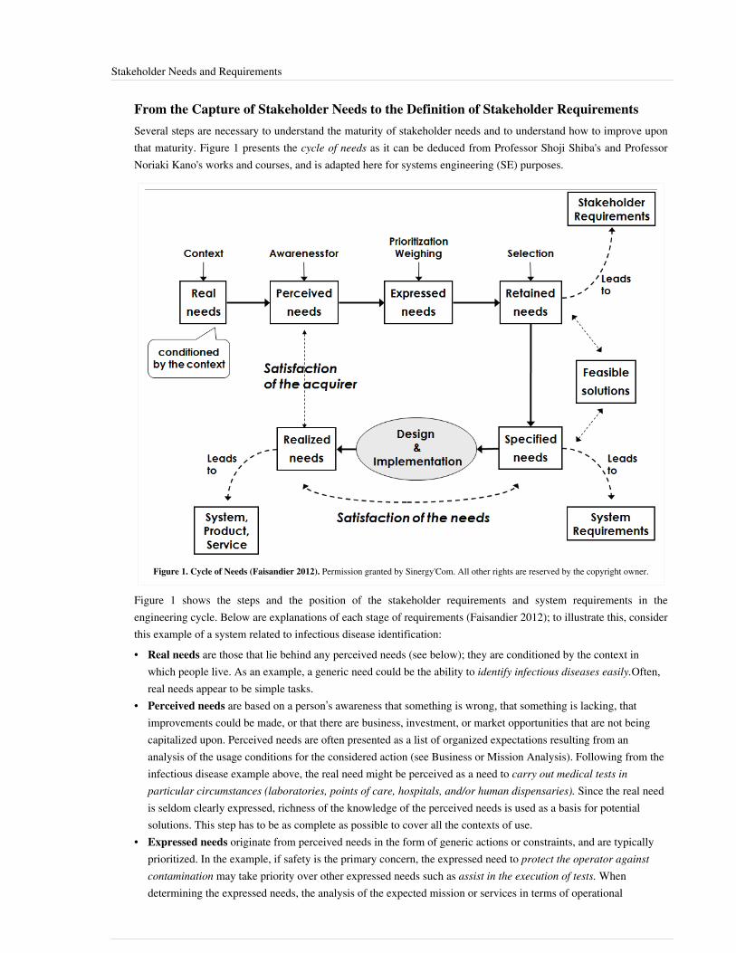
Stakeholder Needs and Requirements 91
From the Capture of Stakeholder Needs to the Definition of Stakeholder RequirementsSeveral steps are necessary to understand the maturity of stakeholder needs and to understand how to improve uponthat maturity. Figure 1 presents the cycle of needs as it can be deduced from Professor Shoji Shiba's and ProfessorNoriaki Kano's works and courses, and is adapted here for systems engineering (SE) purposes.
Figure 1. Cycle of Needs (Faisandier 2012). Permission granted by Sinergy'Com. All other rights are reserved by the copyright owner.
Figure 1 shows the steps and the position of the stakeholder requirements and system requirements in theengineering cycle. Below are explanations of each stage of requirements (Faisandier 2012); to illustrate this, considerthis example of a system related to infectious disease identification:• Real needs are those that lie behind any perceived needs (see below); they are conditioned by the context in
which people live. As an example, a generic need could be the ability to identify infectious diseases easily.Often,real needs appear to be simple tasks.
• Perceived needs are based on a person’s awareness that something is wrong, that something is lacking, thatimprovements could be made, or that there are business, investment, or market opportunities that are not beingcapitalized upon. Perceived needs are often presented as a list of organized expectations resulting from ananalysis of the usage conditions for the considered action (see Business or Mission Analysis). Following from theinfectious disease example above, the real need might be perceived as a need to carry out medical tests inparticular circumstances (laboratories, points of care, hospitals, and/or human dispensaries). Since the real needis seldom clearly expressed, richness of the knowledge of the perceived needs is used as a basis for potentialsolutions. This step has to be as complete as possible to cover all the contexts of use.
• Expressed needs originate from perceived needs in the form of generic actions or constraints, and are typically prioritized. In the example, if safety is the primary concern, the expressed need to protect the operator against contamination may take priority over other expressed needs such as assist in the execution of tests. When determining the expressed needs, the analysis of the expected mission or services in terms of operational
Stakeholder Needs and Requirements 92
scenarios takes place.• Retained needs are selected from the expressed needs. The selection process uses the prioritization of expressed
needs to achieve a solution or to make attaining solutions feasible. The retained needs allow the consideration ofpotential solutions for a SoI. These retained stakeholder intentions do not serve as stakeholder requirements,since they often lack definition, analysis, and possibly consistency and feasibility. Using the concept of operationsto aid the understanding of the stakeholder intentions at the organizational level and the system operationalconcept from the system perspective, requirements engineering leads stakeholders from those initial intentions tostructured and more formal stakeholder requirement statements, ISO/IEC/IEEE 29148 Systems and softwareengineering - Requirements engineering (ISO 2011). Characteristics of good requirements can be found in (ISO2011). Exploration of potential solutions must start from this step. The various solutions suggested at this step arenot yet products, but describe means of satisfying the stakeholder requirements. Each potential solution imposesconstraints on the potential future SoI.
• Specified needs, are the translation of the stakeholder needs to represent the views of the supplier, keeping inmind the potential, preferred, and feasible solutions. Specified needs are translated into system requirements.Consistent practice has shown this process requires iterative and recursive steps in parallel with other life cycleprocesses through the system design hierarchy (ISO 2011).
• Realized needs are the product, service, or enterprise realized, taking into account every specified need (andhence, the retained needs).
Each class of needs listed above aligns with an area of the SE process. For example, the development of specifiedneeds requirements is discussed in the System Requirements topic. For more information on how requirements areused in the systems engineering process, please see the System Definition knowledge area (KA).
Classification of Stakeholder RequirementsSeveral classifications of stakeholder requirements are possible, e.g. ISO/IEC 29148, section 9.4.2.3 (ISO 2011)provides a useful set of elements for classification. Examples of classification of stakeholder requirements include:service or functional, operational, interface, environmental, human factors, logistical, maintenance, design,production, verification requirements, validation, deployment, training, certification, retirement, regulatory,environmental, reliability, availability, maintainability, design, usability, quality, safety, and security requirements.Stakeholders will also be faced with a number of constraints, including: enterprise, business, project, design,realization, and process constraints.
Process Approach
Activities of the ProcessMajor activities and tasks performed during this process include the following:•• Identify the stakeholders or classes of stakeholders across the life cycle.•• Elicit, capture, or consolidate the stakeholder needs, expectations, and objectives as well as any constraints
coming from the mission and business analysis processes.•• Refine the OpsCon and other life-cycle concepts (acquisition concept, deployment concept, support concept, and
retirement concept).•• Prioritize the stakeholder needs.•• Transform the prioritized and retained stakeholder needs into stakeholder requirements.• Verify the quality of each stakeholder requirement and of the set of stakeholder requirements using the
characteristics of good requirements identified in the System Requirements article.• Validate the content and the relevance of each stakeholder requirement with corresponding stakeholder
representatives providing rationale (glossary) for the existence of the requirement.

Stakeholder Needs and Requirements 93
• Identify potential risks (or threats and hazards) that could be generated by the stakeholder requirements (forfurther information, see Risk Management).
•• Synthesize, record, and manage the stakeholder requirements and potential associated risks.
Artifacts, Methods and Modeling TechniquesThis process may create several artifacts, such as:•• Recommendations to refine the Business Requirement Specification (if necessary)•• Refined life-cycle concepts (OpsCon, acquisition concept, deployment concept, support concept, and retirement
concept)•• Stakeholder requirements (in the form of a model or a document containing textual requirements, such as the
Stakeholder Requirement Specification)•• Stakeholder interview reports•• Stakeholder requirements database•• Stakeholder requirements justification documents (for traceability purposes)•• Input for draft verification and validation plansThe content, format, layout and ownership of these artifacts will vary depending on who is creating them and inwhich domains they will be used. Between these artifacts and the outputs of the process, activities should cover theinformation identified in the first part of this article.
Practical ConsiderationsMajor pitfalls encountered with stakeholder requirements are presented in Table 3.
Table 3. Major Pitfalls for Stakeholder Requirements. (SEBoK Original)
Pitfall Description
Operator Role Not Considered Sometimes engineers do not take into account the humans acting as operators inside a system or those who usethe system and are outside of the system. As a consequence, elements are forgotten (e.g. roles of operators).
Exchanges with ExternalObjects Forgotten
The exhaustiveness of requirements can be an issue; in particular, the interfaces with external objects of thecontext of the system can be forgotten (exchanges of matter, energy, information).
Physical Connections withExternal Objects Forgotten
Within the interface issue, physical connections of the system-of-interest with external objects can be forgotten(technological constraints).
Forgotten Stakeholders Stakeholders can be forgotten, as everyone thinks of direct users, customers, and suppliers; however, one mayfail to consider those who do not want the system to exist and malevolent persons.
Proven practices with stakeholder requirements are presented in Table 4.
Table 4. Stakeholder Requirements Proven Practices. (SEBoK Original)
Practice Description
Involve Stakeholders Involve the stakeholders early in the stakeholder requirements development process.
Presence of Rationale Capture the rationale for each stakeholder requirement.
Analyze Sources beforeStarting
Complete stakeholder requirements as much as possible before starting the definition of the system requirements.
Modeling Techniques Use modeling techniques as indicated in sections above.
RequirementsManagement Tool
Consider using a requirements management tool. This tool should have the capability to trace linkages between thestakeholder requirements and the system requirements and to record the source of each stakeholder requirement.
Stakeholder Needs and Requirements 94
References
Works CitedFaisandier, A. 2012. Systems Architecture and Design. Belberaud, France: Sinergy'Com.Hauser, J. and D. Clausing. 1988. "The House of Quality." Harvard Business Review. (May - June 1988).OMG. 2010. OMG Systems Modeling Language specification, version 1.2. Needham, MA: Object ManagementGroup. July 2010.Oliver, D., T. Kelliher, and J. Keegan. 1997. Engineering complex systems with models and objects. New York, NY,USA: McGraw-Hill.ISO/IEC/IEEE. 2011. Systems and software engineering - Requirements engineering. Geneva, Switzerland:International Organization for Standardization (ISO)/International Electrotechnical Commission/ Institute ofElectrical and Electronics Engineers (IEEE), (IEC), ISO/IEC/IEEE 29148.ISO/IEC/IEEE. 2015. Systems and Software Engineering -- System Life Cycle Processes. Geneva, Switzerland:International Organisation for Standardisation / International Electrotechnical Commissions / Institute of Electricaland Electronics Engineers. ISO/IEC/IEEE 15288:2015.
Primary ReferencesISO/IEC/IEEE. 2011. Systems and software engineering - Requirements engineering. Geneva, Switzerland:International Organization for Standardization (ISO)/International Electrotechnical Commission/ Institute ofElectrical and Electronics Engineers (IEEE), (IEC), ISO/IEC/IEEE 29148.ISO/IEC/IEEE. 2015. Systems and Software Engineering -- System Life Cycle Processes. Geneva, Switzerland:International Organisation for Standardisation / International Electrotechnical Commissions / Institute of Electricaland Electronics Engineers. ISO/IEC/IEEE 15288:2015.ISO/IEC/IEEE. 2011. Systems and Software Engineering - Architecture Description. Geneva, Switzerland:International Organization for Standardization (ISO)/International Electrotechnical Commission (IEC)/Institute ofElectrical and Electronics Engineers (IEEE), ISO/IEC/IEEE 42010.
Additional ReferencesBuede, D.M. 2009. The engineering design of systems: Models and methods. 2nd ed. Hoboken, NJ, USA: JohnWiley & Sons Inc.MITRE. 2011. "Requirements Engineering." Systems Engineering Guide. Accessed 9 March 2012 at http:/ / www.mitre. org/ work/ systems_engineering/ guide/ se_lifecycle_building_blocks/ requirements_engineering/ .MITRE. 2011. "Stakeholder Assessment and Management." Systems Engineering Guide. Accessed 9 March 2012 athttp:/ / www. mitre. org/ work/ systems_engineering/ guide/ enterprise_engineering/transformation_planning_org_change/ stakeholder_assessment_management. html.
< Previous Article | Parent Article | Next Article >SEBoK v. 1.4 released 29 June 2015
SEBoK DiscussionPlease provide your comments and feedback on the SEBoK below. You will need to log in to DISQUS using an existing account (e.g. Yahoo, Google, Facebook, Twitter, etc.) or create a DISQUS account. Simply type your comment in the text field below and DISQUS will guide you through the login or registration steps. Feedback will be archived and used for future updates to the SEBoK. If you provided a comment that is no longer listed, that comment

Stakeholder Needs and Requirements 95
has been adjudicated. You can view adjudication for comments submitted prior to SEBoK v. 1.0 at SEBoK Reviewand Adjudication. Later comments are addressed and changes are summarized in the Letter from the Editor andAcknowledgements and Release History.
If you would like to provide edits on this article, recommend new content, or make comments on the SEBoKas a whole, please see the SEBoK Sandbox [1].
ENCODED_CONTENTODA1NjgPGRpdiBpZD0iZGlzcXVzX3RocmVhZCI+PC9kaXY+CjxzY3JpcHQgdHlwZT0idGV4dC9qYXZhc2NyaXB0Ij4KICAgIC8qICogKiBDT05GSUdVUkFUSU9OIFZBUklBQkxFUzogRURJVCBCRUZPUkUgUEFTVElORyBJTlRPIFlPVVIgV0VCUEFHRSAqICogKi8KICAgIHZhciBkaXNxdXNfc2hvcnRuYW1lID0gJ3NlYm9rd2lraTEwJzsgLy8gcmVxdWlyZWQ6IHJlcGxhY2UgZXhhbXBsZSB3aXRoIHlvdXIgZm9ydW0gc2hvcnRuYW1lCiAgICB2YXIgZGlzcXVzX2lkZW50aWZpZXIgPSAnU3Rha2Vob2xkZXIgTmVlZHMgYW5kIFJlcXVpcmVtZW50cyc7ICAgIHZhciBkaXNxdXNfdXJsID0gJ2h0dHA6Ly9zZWJva3dpa2kub3JnL2RyYWZ0L1N0YWtlaG9sZGVyX05lZWRzX2FuZF9SZXF1aXJlbWVudHMnOwogICAgLyogKiAqIERPTidUIEVESVQgQkVMT1cgVEhJUyBMSU5FICogKiAqLwogICAgKGZ1bmN0aW9uKCkgewogICAgICAgIHZhciBkc3EgPSBkb2N1bWVudC5jcmVhdGVFbGVtZW50KCdzY3JpcHQnKTsgZHNxLnR5cGUgPSAndGV4dC9qYXZhc2NyaXB0JzsgZHNxLmFzeW5jID0gdHJ1ZTsKICAgICAgICBkc3Euc3JjID0gJ2h0dHA6Ly8nICsgZGlzcXVzX3Nob3J0bmFtZSArICcuZGlzcXVzLmNvbS9lbWJlZC5qcyc7CiAgICAgICAgKGRvY3VtZW50LmdldEVsZW1lbnRzQnlUYWdOYW1lKCdoZWFkJylbMF0gfHwgZG9jdW1lbnQuZ2V0RWxlbWVudHNCeVRhZ05hbWUoJ2JvZHknKVswXSkuYXBwZW5kQ2hpbGQoZHNxKTsKICAgIH0pKCk7Cjwvc2NyaXB0Pgo8bm9zY3JpcHQ+UGxlYXNlIGVuYWJsZSBKYXZhU2NyaXB0IHRvIHZpZXcgdGhlIDxhIGhyZWY9Imh0dHA6Ly9kaXNxdXMuY29tLz9yZWZfbm9zY3JpcHQiPmNvbW1lbnRzIHBvd2VyZWQgYnkgRGlzcXVzLjwvYT48L25vc2NyaXB0Pgo8YSBocmVmPSJodHRwOi8vZGlzcXVzLmNvbSIgY2xhc3M9ImRzcS1icmxpbmsiPmJsb2cgY29tbWVudHMgcG93ZXJlZCBieSA8c3BhbiBjbGFzcz0ibG9nby1kaXNxdXMiPkRpc3F1czwvc3Bhbj48L2E+END_ENCODED_CONTENT
System DefinitionSystem definition activities are conducted to create and describe in detail a system-of-interest (SoI) to satisfy anidentified need. The activities are grouped and described as generic processes. which consist of system requirementsdefinition, system architecture definition, system design definition and system analysis. The architecture definitionof the system may include the development of related logical architecture models and physical architecture models.During and/or at the end of any iteration, gap analysis is performed to ensure that all system requirements have beenmapped to the architecture and design.System definition activities build on the artifacts and decisions from concept definition, primarily the articulation ofthe mission of the (SoI), the needs and requirements of stakeholders, and preliminary operational concepts. See LifeCycle Processes and Enterprise Need for further detail on the transformation of needs and requirements from thebusiness or enterprise and stakeholder levels of abstraction addressed in concept definition to the system and systemelement level of abstraction addressed in system definition.The products of system definition activities (system requirements, architecture and design) are inputs to systemrealization.The specific activities and sequence of system definition activities and their involvement with the life cycle activitiesof any system, and in particular the close integration with concept definition and system realization activities, will bedependent upon the type of life cycle model being utilized. See Applying Life Cycle Processes for further discussionof the concurrent, iterative and recursive nature of these relationships.
TopicsEach part of the SEBoK is divided into knowledge areas (KAs), which are groupings of information with a relatedtheme. The KAs in turn are divided into topics. This KA contains the following topics:•• System Requirements•• System Architecture•• Logical Architecture Model Development•• Physical Architecture Model Development•• System Design•• System AnalysisSee the article Matrix of Implementation Examples for a mapping of case studies and vignettes included in Part 7 totopics covered in Part 3.

System Definition 96
System Views and System ElementsAn Engineered System (glossary) solution to a defined concept includes a set of engineering elements,characteristics, and properties. These elements are grouped in two ways:•• Needs and requirements views•• Architecture and design viewsArchitecture views include the identification of the boundary and interfaces of a system-of-interest (SoI), which maythen be further refined as a collection of system elements and their relationships.
Needs and Requirements ViewsRequirements provide an overall view of the purpose and mission which the system as a whole is intended to satisfy,as well as a technology-independent view of that the system solutions(s) should do. They are conventionallyorganized into two types:• Business or mission requirements and Stakeholder requirements are defined and discussed in the Concept
Definition KA.• System requirements, which describe the functions which the system as a whole should fulfill in order to satisfy
the stakeholder requirements and are expressed in an appropriate set of views, and non-functional requirementsexpressing the levels of safety, security, reliability, etc., which are called for. These collectively form the basis forverification later in the life cycle.
System requirements and stakeholder requirements are closely related. Neither can be considered complete untilconsistency between the two has been achieved, as demonstrated by traceability, for which a number of iterationsmay be needed.The process activities that are used to identify, engineer and manage system requirements are described further in theSystem Requirements article in the KA.
Architecture and Design ViewsA given engineered system is one solution that could address/answer a problem or an opportunity (representedthrough requirements views); the solution may be more or less complex. A complex solution cannot becomprehended with a single view or model, because of the characteristics or properties of the problem/solution (seesystem complexity). The characteristics are structured as types or entities; types are related to each other. Aninstantiation of the set of types can be understood as THE architecture of the system. The majority of interpretationsof system architecture are based on the fairly intangible notion of structure. Therefore, the system architecture anddesign is formally represented with sets of types or entities such as functions, interfaces, resource flow items,information elements, physical elements, nodes, links, etc. These entities may possess attributes/characteristics suchas dimensions, environmental resilience, availability, reliability, learnability, execution efficiency, etc. The entitiesare interrelated by the means of relationships and are generally grouped into sets to represent views/models of thesystem architecture and design.Viewpoints and views are sometimes specified in architecture frameworks. Views are usually generated frommodels. Many systems engineering practices use logical and physical views for modeling the system architecture anddesign.• The logical view of the architecture supports the logical operation of the system all along its life cycle, and may
include functional, behavioral, and temporal views/models. Operational scenarios refine the mission into acollection of functions and dynamic structures that describe how the mission is performed (behavior).
• The physical view of the architecture is a set of system elements performing the functions of the system. Those system elements can be either material or immaterial (e.g., equipment made of hardware, software and/or human
System Definition 97
roles).The boundary of the system architecture depends on what engineers include within the scope of the SoI and outsideof it. This decision marks the transition from the characterization of the problem context to the beginnings ofsolution definition.Facing the potential number of system elements that constitute the physical architecture, sets of system elements canbe grouped to form systems. The decomposition of the SoI (highest level) may include the decomposition of severallayers of systems (intermediate levels of systems) until technological system elements (lowest level) are defined.Any layer of the decomposition may include systems and non-decomposable technological system elements. Therelationship between each layer is recursive; as a system element is also an engineered system it can be characterizedin its turn using the previous views in its own context.The logical and physical representations of the system architecture are mapped onto each other. The interactionsbetween system elements are defined by interfaces whose complexity strongly depends on the way the systemarchitecture and design is defined. The relationships between the outputs of concept definition and the systemsolution, as well as the range of other views of a system that are available to describe a more complete set ofcharacteristics between the system elements are discussed further in the Logical Architecture Model Developmentand Physical Architecture Model Development sections of system definition.
System Synthesis and DecompositionSystem definition is managed through methodical synthesis of the SoI into systems and system elements. Solutionsynthesis may be top down or bottom up, as discussed in Synthesizing Possible Solutions. However it is done, as thesystem architecture definition advances, a decomposition of systems and system elements emerges, this forms asystem breakdown structure (SBS). For project management purposes, every system of the SBS may be included in abuilding block, a notion introduced in (ANSI/EIA 1998), also called system blocks.Stakeholder requirements and system requirements exist at all layers of the SBS. In ISO/IEC/IEEE 29148 Systemsand software engineering - Requirements Engineering (ISO 2011), these layers are known as levels of abstraction.Along with systematically introducing layers of systems, the architecture and design process manages thetransformation of the system requirements through levels of abstraction. Figure 1 illustrates this approach.

System Definition 98
Figure 1. Top-down Development of Architecture and Design, and Requirements (Faisandier 2012). Permission granted bySinergy'Com. All other rights are reserved by the copyright owner.
As shown in Figure 1•• The white ovals represent requirements at decreasing levels of abstraction, and the arrows represent the
transformation of those requirements through the levels using the architecture and design process. Stakeholderexpressions of needs, expectations, and constraints are transformed into stakeholder requirements.
•• The next transformation crosses the boundary between the problem and solution areas by converting stakeholderrequirements into system requirements, reflecting the bounded solution space.
•• At the SoI level, the system architecture is developed which serves to identify systems and system elements andestablishes how they operate together to address the SoI requirements.
This approach is applied recursively for each level of abstraction/decomposition recognizing that the same genericprocesses are applied at multiple levels of abstraction. At any level of this decomposition one or more solutionoptions may be presented as system architectures. The process by which the solution which best fits the systemrequirements, associated stakeholder needs and wider life cycle concerns is selected and justified is discussed in theSystem Analysis process.Figure 2 below portrays the engineering that occurs in each system block. As necessary, system elements are definedthrough sets of system element requirements, which become inputs to other system blocks (level n+1). The approachis then recursively applied using the system definition processes.

System Definition 99
Figure 2. Recursive Instantiation of Definition Processes (Faisandier 2012). Permission granted by Sinergy'Com. All other rights are reserved bythe copyright owner.
At the n+1 level, the systems or system elements may also collect other stakeholder requirements that are directlypertinent to this level of architecture and design. Processes within each system are generic, but unique in localpurpose, scope and context.See Applying Life Cycle Processes for a discussion of the iterative and recursive application of system requirementsand architecture processes, and Life Cycle Processes and Enterprise Need for further detail on the transformation ofneeds and requirements to system and system element levels of abstraction.The different aspects of how systems thinking is applicable to system definition are discussed in SEBoK Part 2. Inparticular, see discussion of the recursive nature of systems and engineered system contexts in Engineered SystemContext; the contrast between top-down and bottom up approaches in Synthesizing Possible Solutions and the role ofsolution architecture options and selection in Analysis and Selection between Alternative Solutions.
References
Works CitedANSI/EIA. 1998. Processes for Engineering a System. Philadelphia, PA, USA: American National StandardsInstitute (ANSI)/Electronic Industries Association (EIA), ANSI/EIA-632-1998.Faisandier, A. 2012. Systems Architecture and Design. Belberaud, France: Sinergy'Com.ISO/IEC/IEEE. 2011. Systems and software engineering - Requirements Engineering. Geneva, Switzerland:International Organization for Standardization (ISO)/International Electrotechnical Commission/ Institute ofElectrical and Electronics Engineers (IEEE), (IEC), ISO/IEC/IEEE 29148.ISO/IEC/IEEE. 2011. Systems and software engineering - Architecture description. Geneva, Switzerland:International Organization for Standardization (ISO)/International Electrotechnical Commission (IEC)/Institute ofElectrical and Electronics Engineers (IEEE), ISO/IEC/IEEE 42010.

System Definition 100
Primary ReferencesANSI/EIA. 1998. Processes for Engineering a System. Philadelphia, PA, USA: American National StandardsInstitute (ANSI)/Electronic Industries Association (EIA), ANSI/EIA 632-1998.Blanchard, B.S., and W.J. Fabrycky. 2005. Systems Engineering and Analysis. 4th ed. Prentice-Hall InternationalSeries in Industrial and Systems Engineering. Englewood Cliffs, NJ, USA: Prentice-Hall.INCOSE. 2015. 'Systems Engineering Handbook: A Guide for System Life Cycle Processes and Activities', version4.0. Hoboken, NJ, USA: John Wiley and Sons, Inc, ISBN: 978-1-118-99940-0ISO/IEC. 2007. Systems Engineering – Application and Management of The Systems Engineering Process. Geneva,Switzerland: International Organization for Standards (ISO)/International Electrotechnical Commission (IEC),ISO/IEC 26702:2007.ISO/IEC/IEEE. 2015. Systems and Software Engineering - System Life Cycle Processes. Geneva, Switzerland:International Organization for Standardization (ISO)/International Electrotechnical Commission (IEC) / Institute ofElectrical and Electronics Engineers. ISO/IEC/IEEE 15288:2015.ISO/IEC/IEEE. 2011. Systems and Software Engineering - Requirements Engineering. Geneva, Switzerland:International Organization for Standardization (ISO)/International Electrotechnical Commission/ Institute ofElectrical and Electronics Engineers (IEEE), (IEC), ISO/IEC/IEEE 29148.ISO/IEC/IEEE. 2011. Systems and Software Engineering - Architecture Description. Geneva, Switzerland:International Organization for Standardization (ISO)/International Electrotechnical Commission (IEC)/Institute ofElectrical and Electronics Engineers (IEEE), ISO/IEC/IEEE 42010.Martin, J.N. 1997. Systems Engineering Guidebook: A process for developing systems and products, 1st ed. BocaRaton, FL, USA: CRC Press.NASA. 2007. Systems Engineering Handbook. Washington, D.C.: National Aeronautics and Space Administration(NASA), NASA/SP-2007-6105.
Additional ReferencesBaldwin, C.Y. and K.B. Clark. 2000. Design Rules. Cambridge, Mass: MIT Press.Buede, D.M. 2009. The Engineering Design of Systems: Models and Methods. 2nd ed. Hoboken, NJ, USA: JohnWiley & Sons Inc.Faisandier, A. 2012. Systems Architecture and Design. Belberaud, France: Sinergy'Com.Hatley, D.J., and I.A. Pirbhai. 1987. Strategies for Real-Time System Specification. New York, NY: Dorset HousePub.MOD. 2010. MOD Architecture Framework, Version 1.2.004. UK Ministry of Defence. Available at: http:/ / www.mod. uk/ DefenceInternet/ AboutDefence/ WhatWeDo/ InformationManagement/ MODAF/ .
< Previous Article | Parent Article | Next Article >SEBoK v. 1.4 released 29 June 2015
SEBoK DiscussionPlease provide your comments and feedback on the SEBoK below. You will need to log in to DISQUS using an existing account (e.g. Yahoo, Google, Facebook, Twitter, etc.) or create a DISQUS account. Simply type your comment in the text field below and DISQUS will guide you through the login or registration steps. Feedback will be archived and used for future updates to the SEBoK. If you provided a comment that is no longer listed, that comment has been adjudicated. You can view adjudication for comments submitted prior to SEBoK v. 1.0 at SEBoK Review and Adjudication. Later comments are addressed and changes are summarized in the Letter from the Editor and

System Definition 101
Acknowledgements and Release History.
If you would like to provide edits on this article, recommend new content, or make comments on the SEBoKas a whole, please see the SEBoK Sandbox [1].
ENCODED_CONTENTNjQ1NTEPGRpdiBpZD0iZGlzcXVzX3RocmVhZCI+PC9kaXY+CjxzY3JpcHQgdHlwZT0idGV4dC9qYXZhc2NyaXB0Ij4KICAgIC8qICogKiBDT05GSUdVUkFUSU9OIFZBUklBQkxFUzogRURJVCBCRUZPUkUgUEFTVElORyBJTlRPIFlPVVIgV0VCUEFHRSAqICogKi8KICAgIHZhciBkaXNxdXNfc2hvcnRuYW1lID0gJ3NlYm9rd2lraTEwJzsgLy8gcmVxdWlyZWQ6IHJlcGxhY2UgZXhhbXBsZSB3aXRoIHlvdXIgZm9ydW0gc2hvcnRuYW1lCiAgICB2YXIgZGlzcXVzX2lkZW50aWZpZXIgPSAnU3lzdGVtIERlZmluaXRpb24nOyAgICB2YXIgZGlzcXVzX3VybCA9ICdodHRwOi8vc2Vib2t3aWtpLm9yZy9kcmFmdC9TeXN0ZW1fRGVmaW5pdGlvbic7CiAgICAvKiAqICogRE9OJ1QgRURJVCBCRUxPVyBUSElTIExJTkUgKiAqICovCiAgICAoZnVuY3Rpb24oKSB7CiAgICAgICAgdmFyIGRzcSA9IGRvY3VtZW50LmNyZWF0ZUVsZW1lbnQoJ3NjcmlwdCcpOyBkc3EudHlwZSA9ICd0ZXh0L2phdmFzY3JpcHQnOyBkc3EuYXN5bmMgPSB0cnVlOwogICAgICAgIGRzcS5zcmMgPSAnaHR0cDovLycgKyBkaXNxdXNfc2hvcnRuYW1lICsgJy5kaXNxdXMuY29tL2VtYmVkLmpzJzsKICAgICAgICAoZG9jdW1lbnQuZ2V0RWxlbWVudHNCeVRhZ05hbWUoJ2hlYWQnKVswXSB8fCBkb2N1bWVudC5nZXRFbGVtZW50c0J5VGFnTmFtZSgnYm9keScpWzBdKS5hcHBlbmRDaGlsZChkc3EpOwogICAgfSkoKTsKPC9zY3JpcHQ+Cjxub3NjcmlwdD5QbGVhc2UgZW5hYmxlIEphdmFTY3JpcHQgdG8gdmlldyB0aGUgPGEgaHJlZj0iaHR0cDovL2Rpc3F1cy5jb20vP3JlZl9ub3NjcmlwdCI+Y29tbWVudHMgcG93ZXJlZCBieSBEaXNxdXMuPC9hPjwvbm9zY3JpcHQ+CjxhIGhyZWY9Imh0dHA6Ly9kaXNxdXMuY29tIiBjbGFzcz0iZHNxLWJybGluayI+YmxvZyBjb21tZW50cyBwb3dlcmVkIGJ5IDxzcGFuIGNsYXNzPSJsb2dvLWRpc3F1cyI+RGlzcXVzPC9zcGFuPjwvYT4=END_ENCODED_CONTENT
System RequirementsSystem requirements are all of the requirements at the system level that describe the functions which the system as awhole should fulfill to satisfy the stakeholder needs and requirements, and is expressed in an appropriatecombination of textual statements, views, and non-functional requirements; the latter expressing the levels of safety,security, reliability, etc., that will be necessary.System requirements play major roles in systems engineering, as they:• Form the basis of system architecture and design activities.• Form the basis of system Integration (glossary) and verification activities.• Act as reference for validation and stakeholder acceptance.•• Provide a means of communication between the various technical staff that interact throughout the project.Elicitation of stakeholder requirements starts in Concept Definition, and will be initially developed though interviewand mission analysis. System requirements are considered in detail during System Definition. Neither can beconsidered complete until consistency between the two has been achieved, as demonstrated by traceability, for whicha number of iterations may be needed.
Definition and Purpose of RequirementsA requirement is a statement that identifies a product or processes operational, functional, or design characteristic orconstraint, which is unambiguous, testable, or measurable and necessary for product or process acceptability (ISO2007).To avoid confusion in the multitude of terms pertaining to requirements, consider the following classifications:• Process Role or State: The role the requirement plays in the definition process; for instance, its position in the
system block (e.g. translated, derived, satisfied) or its state of agreement (e.g. proposed, approved, cancelled).• Level of Abstraction: The level within the definition process that the requirement stands; for instance,
stakeholder requirement, system requirement, system element requirement.• Type of Requirement: The nature of the requirement itself; for instance, functional, performance, constraint, etc.Any single requirement may simultaneously be in a particular state, at a particular level abstraction, and of aparticular type. For additional explanations about differences between the types of requirements, refer to (Martin1997, Chapter 2).

System Requirements 102
Principles Governing System Requirements
Relationship to Stakeholder Requirements and Logical ArchitectureA set of stakeholder requirements are clarified and translated from statements of need into engineering-orientedlanguage in order to enable proper architecture definition, design, and verification activities that are needed as thebasis for system requirements analysis.The system requirements are based around identification and synthesis of the functions required of any solutionsystem associated with performance and other quality measures and provide the basis for the assessment of candidatesolutions and verification of the completed system. The system requirements are expressed in technical language thatis useful for architecture and design: unambiguous, consistent, coherent, exhaustive, and verifiable. Of course, closecoordination with the stakeholders is necessary to ensure the translation is accurate and traceability is maintained.This results in a set of system functions and requirements specifying measurable characteristics which can form thebasis for system realization.The Logical Architecture (glossary) defines system boundary and functions, from which more detailed systemrequirements can be derived. The starting point for this process may be to identify functional requirements from thestakeholder requirements and to use this to start the architectural definition, or to begin with a high level functionalarchitecture view and use this as the basis for structuring system requirements. The exact approach taken will oftendepend on whether the system is an evolution of an already understood product or service, or a new andunprecedented solution (see Synthesizing Possible Solutions). However, when the process is initiated it is importantthat the stakeholder requirements, system requirements, and logical architecture are all complete, consistent witheach other, and assessed together at the appropriate points in the systems Life Cycle Model (glossary).
Traceability and the Assignment of System Requirements during Architecture and Design
Requirements traceability provides the ability to track information from the origin of the stakeholder requirements,to the top level of requirements and other system definition elements at all levels of the system hierarchy (seeApplying Life Cycle Processes). Traceability is also used to provide an understanding as to the extent of a change asan input when impact analyses is performed in cases of proposed engineering improvements or requests for change.During architecture definition and design, the assignment of requirements from one level to lower levels in thesystem hierarchy can be accomplished using several methods, as appropriate - see Table 1.
Table 1. Assessment Types for a System Requirement. (SEBoK Original)
Assignment Typefor a SystemRequirement
Description
Direct Assignment The system requirement from the higher level is directly assigned to a system or a system element for a lower level (e.g. thecolor used to paint visible parts of the product).
IndirectAssignment
(SimplyDecomposed)
The system requirement is distributed across several systems or system elements and the sum of a more complex calculationfor distribution is equal to the requirement of higher level (e.g. a mass requirement, power distribution, reliability allocation,
etc.) with sufficient margin or tolerance. A documented and configuration-managed "assignment budget" for eachassignment must be maintained.
IndirectAssignment
(Modeled andDecomposed)
The system requirement is distributed to several systems or system elements using an analysis or mathematical modelingtechnique. The resulting design parameters are assigned to the appropriate systems or system elements (with appropriate
margin). For example, in the case of a radar detection requirement that is being analyzed, these lower-level parameters foroutput power, beam size, frequencies, etc. will be assigned to the appropriate hardware and software elements. Again, the
analysis (or model) must be documented and configuration-managed.
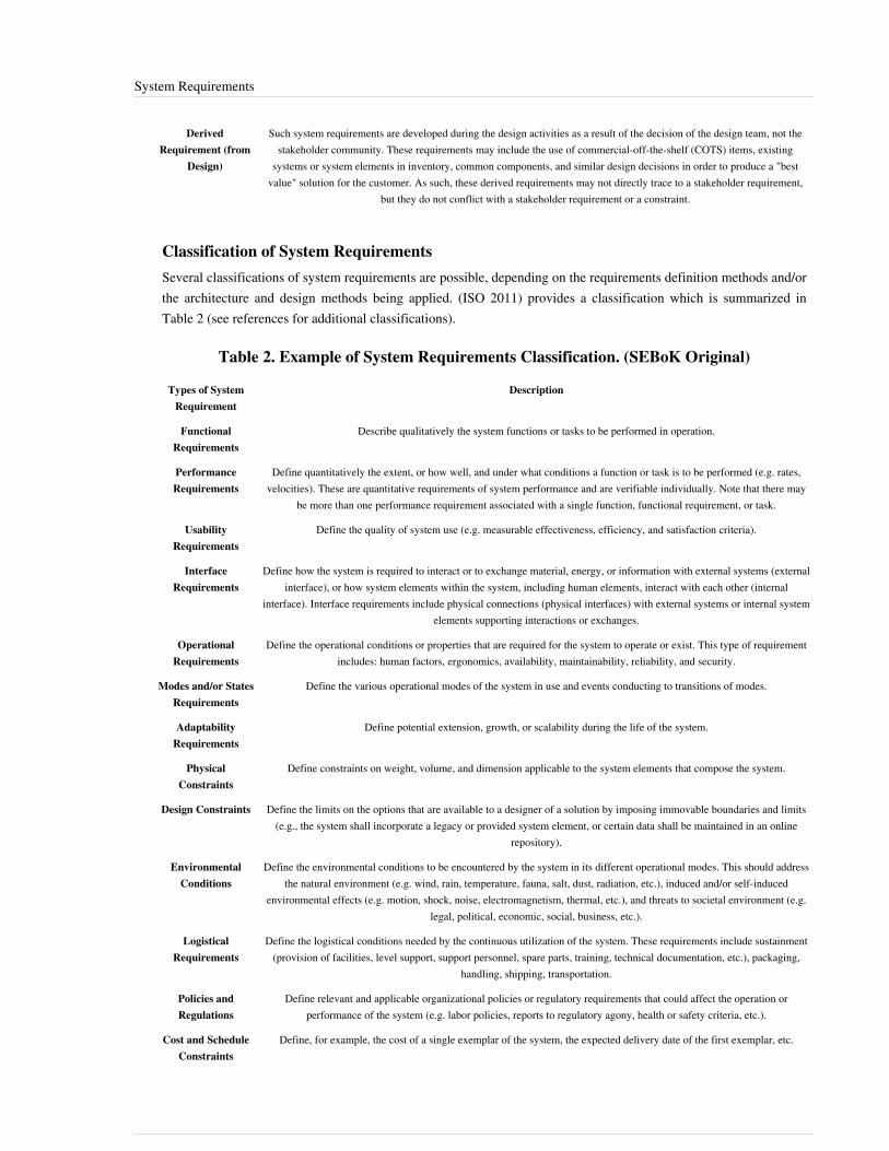
System Requirements 103
DerivedRequirement (from
Design)
Such system requirements are developed during the design activities as a result of the decision of the design team, not thestakeholder community. These requirements may include the use of commercial-off-the-shelf (COTS) items, existing
systems or system elements in inventory, common components, and similar design decisions in order to produce a "bestvalue" solution for the customer. As such, these derived requirements may not directly trace to a stakeholder requirement,
but they do not conflict with a stakeholder requirement or a constraint.
Classification of System RequirementsSeveral classifications of system requirements are possible, depending on the requirements definition methods and/orthe architecture and design methods being applied. (ISO 2011) provides a classification which is summarized inTable 2 (see references for additional classifications).
Table 2. Example of System Requirements Classification. (SEBoK Original)
Types of SystemRequirement
Description
FunctionalRequirements
Describe qualitatively the system functions or tasks to be performed in operation.
PerformanceRequirements
Define quantitatively the extent, or how well, and under what conditions a function or task is to be performed (e.g. rates,velocities). These are quantitative requirements of system performance and are verifiable individually. Note that there may
be more than one performance requirement associated with a single function, functional requirement, or task.
UsabilityRequirements
Define the quality of system use (e.g. measurable effectiveness, efficiency, and satisfaction criteria).
InterfaceRequirements
Define how the system is required to interact or to exchange material, energy, or information with external systems (externalinterface), or how system elements within the system, including human elements, interact with each other (internal
interface). Interface requirements include physical connections (physical interfaces) with external systems or internal systemelements supporting interactions or exchanges.
OperationalRequirements
Define the operational conditions or properties that are required for the system to operate or exist. This type of requirementincludes: human factors, ergonomics, availability, maintainability, reliability, and security.
Modes and/or StatesRequirements
Define the various operational modes of the system in use and events conducting to transitions of modes.
AdaptabilityRequirements
Define potential extension, growth, or scalability during the life of the system.
PhysicalConstraints
Define constraints on weight, volume, and dimension applicable to the system elements that compose the system.
Design Constraints Define the limits on the options that are available to a designer of a solution by imposing immovable boundaries and limits(e.g., the system shall incorporate a legacy or provided system element, or certain data shall be maintained in an online
repository).
EnvironmentalConditions
Define the environmental conditions to be encountered by the system in its different operational modes. This should addressthe natural environment (e.g. wind, rain, temperature, fauna, salt, dust, radiation, etc.), induced and/or self-induced
environmental effects (e.g. motion, shock, noise, electromagnetism, thermal, etc.), and threats to societal environment (e.g.legal, political, economic, social, business, etc.).
LogisticalRequirements
Define the logistical conditions needed by the continuous utilization of the system. These requirements include sustainment(provision of facilities, level support, support personnel, spare parts, training, technical documentation, etc.), packaging,
handling, shipping, transportation.
Policies andRegulations
Define relevant and applicable organizational policies or regulatory requirements that could affect the operation orperformance of the system (e.g. labor policies, reports to regulatory agony, health or safety criteria, etc.).
Cost and ScheduleConstraints
Define, for example, the cost of a single exemplar of the system, the expected delivery date of the first exemplar, etc.

System Requirements 104
Requirements ManagementRequirements management is performed to ensure alignment of the system and system element requirements withother representations, analysis, and artifacts of the system. It includes providing an understanding of therequirements, obtaining commitment, managing changes, maintaining bi-directional traceability among therequirements and with the rest of the system definition, and alignment with project resources and schedule.There are many tools available to provide a supporting infrastructure for requirements management; the best choiceis the one that matches the processes of the project or enterprise. Requirements management is also closely tied toconfiguration management for baseline management and control. When the requirements have been defined,documented, and approved, they need to be put under baseline management and control. The baseline allows theproject to analyze and understand the impact (technical, cost, and schedule) of ongoing proposed changes.
Process Approach
Purpose and Principle of the ApproachThe purpose of the system requirements analysis process is to transform the stakeholder, user-oriented view ofdesired services and properties into a technical view of the product that meets the operational needs of the user. Thisprocess builds a representation of the system that will meet stakeholder requirements and that, as far as constraintspermit, does not imply any specific implementation. It results in measurable system requirements that specify, fromthe supplier’s perspective, what performance and non-performance characteristics it must possess in order to satisfystakeholders' requirements (ISO 2015).
Activities of the ProcessMajor activities and tasks during this process include:1. Analyzing the stakeholder requirements to check completeness of expected services and operational scenarios,
conditions, operational modes, and constraints.2. Defining the system requirements and their rationale.3.3. Classifying the system requirements using suggested classifications (see examples above).4.4. Incorporating the derived requirements (coming from architecture and design) into the system requirements
baseline.5.5. Establishing the upward traceability with the stakeholder needs and requirements.6.6. Establishing bi-directional traceability between requirements at adjacent levels of the system hierarchy.7.7. Verifying the quality and completeness of each system requirement and the consistency of the set of system
requirements.8.8. Validating the content and relevance of each system requirement against the set of stakeholder requirements.9. Identifying potential risks (or threats and hazards) that could be generated by the system requirements.10.10. Synthesizing, recording, and managing the system requirements and potential associated risks.11.11. Upon approval of the requirements, establishing control baselines along with the other system definition
elements in conjunction with established configuration management practices.
Checking Correctness of System RequirementsSystem requirements should be checked to gauge whether they are well expressed and appropriate. There are anumber of characteristics that can be used to check system requirements, such as standard peer review techniquesand comparison of each requirement against the set of requirements characteristics, which are listed in Table 2 andTable 3 of the "Presentation and Quality of Requirements" section (below). Requirements can be further validatedusing the requirements elicitation and rationale capture described in the section "Methods and Modeling Techniques"(below).
System Requirements 105
Methods and Modeling Techniques
Requirements Elicitation and Prototyping
Requirements elicitation requires user involvement and can be effective in gaining stakeholder involvement andbuy-in. Quality Function Deployment (QFD) and prototyping are two common techniques that can be applied andare defined in this section. In addition, interviews, focus groups, and Delphi techniques are often applied to elicitrequirements.QFD is a powerful technique to elicit requirements and compare design characteristics against user needs (Hauserand Clausing 1988). The inputs to the QFD application are user needs and operational concepts, so it is essential thatthe users participate. Users from across the life cycle should be included to ensure that all aspects of user needs areaccounted for and prioritized.Early prototyping can help the users and developers interactively identify functional and operational requirements aswell as user interface constraints. This enables realistic user interaction, discovery, and feedback, as well as somesensitivity analysis. This improves the users' understanding of the requirements and increases the probability ofsatisfying their actual needs.
Capturing Requirements Rationale
One powerful and cost-effective technique to translate stakeholder requirements to system requirements is to capturethe rationale for each requirement. Requirements rationale is merely a statement as to why the requirement exists,any assumptions made, the results of related design studies, or any other related supporting information. Thissupports further requirements analysis and decomposition. The rationale can be captured directly in a requirementsdatabase (Hull, Jackson, and Dick 2010).Some of the benefits of this approach include:• Reducing the total number of requirements - The process aids in identifying duplicates. Reducing
requirements count will reduce project cost and risk.•• Early exposure of bad assumptions• Removes design implementation - Many poorly written stakeholder requirements are design requirements in
disguise, in that the customer is intentionally or unintentionally specifying a candidate implementation.• Improves communication with the stakeholder community - By capturing the requirements rationale for all
stakeholder requirements, the line of communication between the users and the designers is greatly improved.(Adapted from Chapter 8 of (Hooks and Farry 2000)).
Modeling Techniques
Modeling techniques that can be used when requirements must be detailed or refined, or in cases in which theyaddress topics not considered during the stakeholder requirements definition and mission analysis, include:•• State-charts models (ISO 2011, Section 8.4)•• Scenarios modeling (ISO 2011, Section 6.2.3.1)•• Simulations, prototyping (ISO 2011, Section 6.3.3.2)•• Quality Function Deployment (INCOSE 2011, p. 83)•• Systems Modeling Language (SysML) sequence diagrams, activity diagrams, use cases, state machine diagrams,
requirements diagrams (OMG 2010)•• Functional Flow Block Diagram for operational scenarios (Oliver, Kelliher, and Keegan 1997)

System Requirements 106
Presentation and Quality of Requirements
Generally, requirements are provided in a textual form. Guidelines exist for writing good requirements; they includerecommendations about the syntax of requirements statements, wording (exclusions, representation of concepts,etc.), and characteristics (specific, measurable, achievable, feasible, testable, etc.). Refer to (INCOSE 2011, Section4.2.2.2) and (ISO 2011).There are several characteristics of both requirements and sets of requirements that are used to aid their developmentand to verify the implementation of requirements into the solution. Table 3 provides a list and descriptions of thecharacteristics for individual requirements and Table 4 provides a list and descriptions of characteristics for a set ofrequirements, as adapted from (ISO 2011, Sections 5.2.5 and 5.2.6).
Table 3. Characteristics of Individual Requirements. (SEBoK Original)
Characteristic Description
Necessary The requirement defines an essential capability, characteristic, constraint, and/or quality factor. If it is not included in the set ofrequirements, a deficiency in capability or characteristic will exist, which cannot be fulfilled by implementing other requirements
Appropriate The specific intent and amount of detail of the requirement is appropriate to the level of the entity to which it refers (level ofabstraction). This includes avoiding unnecessary constraints on the architecture or design to help ensure implementation
independence to the extent possible
Unambiguous The requirement is stated in such a way so that it can be interpreted in only one way.
Complete The requirement sufficiently describes the necessary capability, characteristic, constraint, or quality factor to meet the entity needwithout needing other information to understand the requirement
Singular The requirement should state a single capability, characteristic, constraint, or quality factor.
Feasible The requirement can be realized within entity constraints (e.g., cost, schedule, technical, legal, regulatory) with acceptable risk
Verifiable The requirement is structured and worded such that its realization can be proven (verified) to the customer’s satisfaction at the levelthe requirements exists.
Correct The requirement must be an accurate representation of the entity need from which it was transformed.
Conforming The individual requirements should conform to an approved standard template and style for writing requirements, when applicable.
Note: Traceability is considered by some sources as a characteristic (ISO 2011). However, a recent viewpoint is thatTraceability is actually an attribute of a requirement; that is, something that is appended to the requirement, not anintrinsic characteristic of a requirement (INCOSE 2011). The traceability characteristic or attribute is defined as: Therequirement is upwards traceable to specific documented stakeholder statement(s) of need, higher tier requirement,or another source (e.g., a trade or design study). The requirement is also downwards traceable to the specificrequirements in the lower tier requirements specifications or other system definition artifacts. That is, all parent-childrelationships for the requirement are identified in tracing such that the requirement traces to its source andimplementation.

System Requirements 107
Table 4. Characteristics of a Set of Requirements. (SEBoK Original)
Characteristic Description
Complete The requirement set stands alone such that it sufficiently describes the necessary capabilities, characteristics, constraints, and/orquality factors to meet the entity needs without needing other information. In addition, the set does not contain any to be
defined (TBD), to be specified (TBS), or to be resolved (TBR) clauses.
Consistent The set of requirements contains individual requirements that are unique, do not conflict with or overlap with otherrequirements in the set, and the units and measurement systems they use are homogeneous. The language used within the set of
requirements is consistent, i.e., the same word is used throughout the set to mean the same thing.
Feasible The requirement set can be realized within entity constraints (e.g., cost, schedule, technical, legal, regulatory) with acceptablerisk. (Note: Feasible includes the concept of "affordable".)
Comprehensible The set of requirements must be written such that it is clear as to what is expected by the entity and its relation to the system ofwhich it is a part.
Able to bevalidated
It must be able to be proven the requirement set will lead to the achievement of the entity needs within the constraints (such ascost, schedule, technical, legal and regulatory compliance).
Requirements in Tables
Requirements may be provided in a table, especially when specifying a set of parameters for the system or a systemelement. It is good practice to make standard table templates available. For tables, the following conventions apply:•• Invoke each requirements table in the requirements set that clearly points to the table.•• Identify each table with a unique title and table number.• Include the word “requirements” in the table title.•• Identify the purpose of the table in the text immediately preceding it and include an explanation of how to read
and use the table, including context and units.•• For independent-dependent variable situations, organize the table in a way that best accommodates the use of the
information.•• Each cell should contain, at most, a single requirement.
Requirements in Flow Charts
Flow charts often contain requirements in a graphical form. These requirements may include logic that must beincorporated into the system, operational requirements, process or procedural requirements, or other situations thatare best defined graphically by a sequence of interrelated steps. For flow charts, the following conventions apply:•• Invoke flow charts in the requirements set that clearly points to the flow chart.•• Identify each flow chart with a unique title and figure number.• Include the word “requirements” in the title of the flow chart.•• Clearly indicate and explain unique symbols that represent requirements in the flow chart.
Requirements in Drawings
Drawings also provide a graphical means to define requirements. The type of requirement defined in a drawingdepends on the type of drawing. The following conventions apply:•• Drawings are used when they can aid in the description of the following:
•• Spatial Requirements•• Interface Requirements•• Layout Requirements
•• Invoke drawings in the requirements set that clearly point to the drawing.

System Requirements 108
ArtifactsThis process may create several artifacts, such as:•• System Requirements Document•• System Requirements Justification Document (for traceability purpose)•• System Requirements Database, including traceability, analysis, rationale, decisions, and attributes, where
appropriate.•• System External Interface Requirements Document (this document describes the interfaces of the system with
external elements of its context of use; the interface requirements can be integrated or not to the systemrequirements document.
The content, format, layout and ownership of these artifacts will vary depending on who is creating them as well asin which domain they will be utilized. Between them and the outputs of the process, activities should cover theinformation identified in the first part of this article.
Practical Considerations about System RequirementsThere are several pitfalls that will inhibit the generation and management of an optimal set of system requirements,as discussed in Table 5.
Table 5. Major Pitfalls with Definition of System Requirements. (SEBoK Original)
Pitfall Description
Insufficient Analysis ofStakeholder Requirements
If the receivers of the stakeholder requirements do not perform a sufficient critical analysis of them, theconsequence could be difficulties translating them into system requirements and the obligation to come back to the
stakeholders, losing time.
Insufficient Analysis ofOperational Modes and
Scenarios
The operational modes and operational scenarios are not sufficiently analyzed or defined by the person in charge ofwriting the system requirements. Those elements allow the structuring of the system and its use early in the
engineering process and help the designer to remember functions and interfaces.
Incomplete Set of SystemRequirements
If the system requirements are not sufficiently precise and complete, there is a great risk that the design will nothave the expected level of quality and that the verification and validation of the system will be delayed.
Lack of Verification Method Delaying the capture of verification methods and events for each system requirement; identification of theverification approach for each requirement often provides additional insight as to the correctness and necessity of
the requirement itself.
Missing traceability Incorrect or missing traceability of each requirement, both to an upper-level "parent" requirement as well asallocation to an inappropriate system or system element.
The proven practices in Table 6 have repeatedly been shown to reduce project risk and cost, foster customersatisfaction, and produce successful system development.

System Requirements 109
Table 6. Proven Practices for System Requirements. (SEBoK Original)
Practice Description
InvolveStakeholders
Involve the stakeholders as early as possible in the system requirements development process.
Presence ofRationale
Capture the rationale for each system requirement.
Always Completebefore Starting
Check that stakeholder requirements are complete as much as possible before starting the definition of the systemrequirements.
Peer Reviews Organize peer reviews of system requirements with applicable subject matter experts.
ModelingTechniques
Use modeling techniques as indicated in sections above.
RequirementsManagement Tool
Consider using a requirements management tool, especially for more complex projects. This tool should have the capabilityto trace linkages between system requirements to display relationships. A requirements management tool is intended to
facilitate and support the systematic managing of system requirements throughout the project life cycle.
Measures forRequirementEngineering
Use typical measures for requirement engineering; for further information, refer to the Systems Engineering LeadingIndicators Guide (Roedler et al. 2010). Both process and product measures should be used for requirements engineering. To
get the desired insight to facilitate risk-managed requirements engineering, it may be necessary to use more than onemeasure based on the information needs (risks, objectives, issues) for the requirements. Useful measures include:
•• Requirements Volatility•• Requirements Trends•• Requirements Verification Progress (plan vs. actual)•• Requirements Validation Progress (plan vs. actual)•• TBD and TBR Closure Per Plan•• Peer Review Defects
References
Works CitedHauser, J. and D. Clausing. 1988. "The House of Quality." Harvard Business Review. (May - June 1988).Hooks, I.F. and K.A. Farry. 2000. Customer-centered products: Creating successful products through smartrequirements management. New York, NY, USA: American Management Association.Hull, M.E.C., K. Jackson, A.J.J. Dick. 2010. Systems Engineering, 3rd ed. London, UK: Springer.INCOSE. 2011. Systems Engineering Handbook: A Guide for System Life Cycle Processes and Activities, version3.2.1. San Diego, CA, USA: International Council on Systems Engineering (INCOSE),INCOSE-TP-2003-002-03.2.1.ISO/IEC. 2007. Systems and Software Engineering -- Recommended Practice for Architectural Description ofSoftware-Intensive Systems. Geneva, Switzerland: International Organization for Standards (ISO)/InternationalElectrotechnical Commission (IEC), ISO/IEC 42010:2007.ISO/IEC/IEEE. 2011. Systems and Software Engineering - Requirements Engineering. Geneva, Switzerland:International Organization for Standardization (ISO)/International Electrotechnical Commission/ Institute ofElectrical and Electronics Engineers (IEEE), (IEC), ISO/IEC/IEEE 29148.ISO/IEC/IEEE. 2015.Systems and Software Engineering - System Life Cycle Processes.Geneva, Switzerland:International Organization for Standardization (ISO)/International Electrotechnical Commission (IEC), Institute ofElectrical and Electronics Engineers. ISO/IEC/IEEE 15288:2015.Martin, J.N. 1997. Systems Engineering Guidebook: A Process for Developing Systems and Products, 1st ed. BocaRaton, FL, USA: CRC Press.

System Requirements 110
Oliver, D., T. Kelliher, and J. Keegan. 1997. Engineering complex systems with models and objects. New York, NY,USA: McGraw-Hill.OMG. 2010. OMG Systems Modeling Language specification, version 1.2. Needham, MA: Object ManagementGroup. July 2010.
Primary ReferencesISO/IEC/IEEE. 2011. Systems and Software Engineering - Requirements Engineering. Geneva, Switzerland:International Organization for Standardization (ISO)/International Electrotechnical Commission/ Institute ofElectrical and Electronics Engineers (IEEE), (IEC), ISO/IEC/IEEE 29148.ISO/IEC/IEEE. 2015.Systems and Software Engineering - System Life Cycle Processes.Geneva, Switzerland:International Organization for Standardization (ISO)/International Electrotechnical Commission (IEC), Institute ofElectrical and Electronics Engineers.ISO/IEC/IEEE 15288:2015.INCOSE. 2015. 'Systems Engineering Handbook: A Guide for System Life Cycle Processes and Activities', version4.0. Hoboken, NJ, USA: John Wiley and Sons, Inc, ISBN: 978-1-118-99940-0Lamsweerde, A. van. 2009. Requirements Engineering: From System Goals to UML Models to SoftwareSpecifications. New York, NY, USA: Wiley.
Additional ReferencesFaisandier, A. 2012. Systems Opportunities and Requirements. Belberaud, France: Sinergy'Com.Hooks, I.F. and K.A. Farry. 2000. Customer-Centered Products: Creating Successful Products through SmartRequirements Management. New York, NY, USA: American Management Association.Hull, M.E.C., K. Jackson, A.J.J. Dick. 2010. Systems Engineering, 3rd ed. London, UK: Springer.Roedler, G., D. Rhodes, C. Jones, and H. Schimmoller. 2010. Systems Engineering Leading Indicators Guide,version 2.0. San Diego, CA, USA: International Council on Systems Engineering (INCOSE),INCOSE-TP-2005-001-03.SEI. 2007. "Requirements Management Process Area" and "Requirements Development Process Area." inCapability Maturity Model Integrated (CMMI) for Development, version 1.2. Pittsburgh, PA, USA: SoftwareEngineering Institute (SEI)/Carnegie Mellon University (CMU).
< Previous Article | Parent Article | Next Article >SEBoK v. 1.4 released 29 June 2015
SEBoK DiscussionPlease provide your comments and feedback on the SEBoK below. You will need to log in to DISQUS using anexisting account (e.g. Yahoo, Google, Facebook, Twitter, etc.) or create a DISQUS account. Simply type yourcomment in the text field below and DISQUS will guide you through the login or registration steps. Feedback will bearchived and used for future updates to the SEBoK. If you provided a comment that is no longer listed, that commenthas been adjudicated. You can view adjudication for comments submitted prior to SEBoK v. 1.0 at SEBoK Reviewand Adjudication. Later comments are addressed and changes are summarized in the Letter from the Editor andAcknowledgements and Release History.
If you would like to provide edits on this article, recommend new content, or make comments on the SEBoKas a whole, please see the SEBoK Sandbox [1].
ENCODED_CONTENTMjYzNTkPGRpdiBpZD0iZGlzcXVzX3RocmVhZCI+PC9kaXY+CjxzY3JpcHQgdHlwZT0idGV4dC9qYXZhc2NyaXB0Ij4KICAgIC8qICogKiBDT05GSUdVUkFUSU9OIFZBUklBQkxFUzogRURJVCBCRUZPUkUgUEFTVElORyBJTlRPIFlPVVIgV0VCUEFHRSAqICogKi8KICAgIHZhciBkaXNxdXNfc2hvcnRuYW1lID0gJ3NlYm9rd2lraTEwJzsgLy8gcmVxdWlyZWQ6IHJlcGxhY2UgZXhhbXBsZSB3aXRoIHlvdXIgZm9ydW0gc2hvcnRuYW1lCiAgICB2YXIgZGlzcXVzX2lkZW50aWZpZXIgPSAnU3lzdGVtIFJlcXVpcmVtZW50cyc7ICAgIHZhciBkaXNxdXNfdXJsID0gJ2h0dHA6Ly9zZWJva3dpa2kub3JnL2RyYWZ0L1N5c3RlbV9SZXF1aXJlbWVudHMnOwogICAgLyogKiAqIERPTidUIEVESVQgQkVMT1cgVEhJUyBMSU5FICogKiAqLwogICAgKGZ1bmN0aW9uKCkgewogICAgICAgIHZhciBkc3EgPSBkb2N1bWVudC5jcmVhdGVFbGVtZW50KCdzY3JpcHQnKTsgZHNxLnR5cGUgPSAndGV4dC9qYXZhc2NyaXB0JzsgZHNxLmFzeW5jID0gdHJ1ZTsKICAgICAgICBkc3Euc3JjID0gJ2h0dHA6Ly8nICsgZGlzcXVzX3Nob3J0bmFtZSArICcuZGlzcXVzLmNvbS9lbWJlZC5qcyc7CiAgICAgICAgKGRvY3VtZW50LmdldEVsZW1lbnRzQnlUYWdOYW1lKCdoZWFkJylbMF0gfHwgZG9jdW1lbnQuZ2V0RWxlbWVudHNCeVRhZ05hbWUoJ2JvZHknKVswXSkuYXBwZW5kQ2hpbGQoZHNxKTsKICAgIH0pKCk7Cjwvc2NyaXB0Pgo8bm9zY3JpcHQ+UGxlYXNlIGVuYWJsZSBKYXZhU2NyaXB0IHRvIHZpZXcgdGhlIDxhIGhyZWY9Imh0dHA6Ly9kaXNxdXMuY29tLz9yZWZfbm9zY3JpcHQiPmNvbW1lbnRzIHBvd2VyZWQgYnkgRGlzcXVzLjwvYT48L25vc2NyaXB0Pgo8YSBocmVmPSJodHRwOi8vZGlzcXVzLmNvbSIgY2xhc3M9ImRzcS1icmxpbmsiPmJsb2cgY29tbWVudHMgcG93ZXJlZCBieSA8c3BhbiBjbGFzcz0ibG9nby1kaXNxdXMiPkRpc3F1czwvc3Bhbj48L2E+
System Requirements 111
END_ENCODED_CONTENT
System ArchitectureThe purpose of system architecture activities is to define a comprehensive solution based on principles, concepts,and properties logically related and consistent with each other. The solution architecture has features, properties, andcharacteristics satisfying, as far as possible, the problem or opportunity expressed by a set of system requirements(traceable to mission/business and stakeholder requirements) and life cycle concepts (e.g., operational, support) andare implementable through technologies (e.g., mechanics, electronics, hydraulics, software, services, procedures,human activity).System Architecture is abstract, conceptualization-oriented, global, and focused to achieve the mission and life cycleconcepts of the system. It also focuses on high‐level structure in systems and system elements. It addresses thearchitectural principles, concepts, properties, and characteristics of the system-of-interest. It may also be applied tomore than one system, in some cases forming the common structure, pattern, and set of requirements for classes orfamilies of similar or related systems.
General Concepts and Principles
Notion of StructureThe SEBoK considers systems engineering to cover all aspects of the creation of a system, including systemarchitecture.The majority of interpretations of system architecture are based on the fairly intangible notion of structure (i.e.relationships between elements). Some authors limit the types of structure considered to be architectural; forexample, restricting themselves to functional and physical structure. Recent practice has extended consideration toinclude behavioral, temporal and other dimensions of structure.ISO/IEC/IEEE 42010 Systems and software engineering - Architecture description (ISO 2011) provides a usefuldescription of the architecture considering the stakeholder concerns, architecture viewpoints, architecture views,architecture models, architecture descriptions, and architecting throughout the life cycle.A discussion of the features of systems architectures can be found in (Maier and Rechtin 2009).An attempt to develop and apply a systematic approach to characterizing architecture belief systems in systemsengineering has been described by the INCOSE UK Architecture Working Group (Wilkinson et al.2010, Wilkinson2010).
Architecture Description of the SystemAn architecture framework contains standardized viewpoints, view templates, meta-models, model templates, etc.that facilitate the development of the views of a system architecture (see Architecture Framework (glossary) forexamples). ISO/IEC/IEEE 42010 (ISO 2011) specifies the normative features of architecture frameworks,viewpoints, and views as they pertain to architecture description. A viewpoint addresses a particular stakeholderconcern (or set of closely related concerns). The viewpoint specifies the kinds of model to be used in developing thesystem architecture to address that concern (or set of concerns), the ways in which the models should be generated,and how the models are related and used to compose a view.Logical and physical models (or views) are often used for representing fundamental aspects of the systemarchitecture. Other complementary viewpoints and views are necessarily used to represent how the systemarchitecture addresses stakeholder concerns, for example, cost models, process models, rule models, ontological
System Architecture 112
models, belief models, project models, capability models, data models, etc.
Classification of Principles and HeuristicsEngineers and architects use a mixture of mathematical principles and heuristics (heuristics are lessons learnedthrough experience, but not mathematically proven). When an issue is identified and defined through systemrequirements, principles and heuristics may or may not be able to address it. Principles and heuristics that are used insystem views/models can be classified according to the domains in which those system views/models are used, asfollows:1. Static domain relates to physical structure or organization of the SoI broken down into systems and system
elements. It deals with partitioning systems, system elements, and physical interfaces.2. Dynamic domain relates to logical architecture models; in particular, to the representation of the behavior of the
system. It includes a description of functions (i.e. transformations of input flows into output flows) andinteractions between functions of the system and between those of the external objects or systems. It takes intoaccount reactions to events that launch or stop the execution of functions of the system. It also deals with theeffectiveness (i.e. performances, operational conditions) of the system.
3. Temporal domain relates to temporal invariance levels of the execution of functions of the system. This meansthat every function is executed according to cyclic or synchronous characteristics. It includes decisional levelsthat are asynchronous characteristics of the behavior of some functions.
4. Environmental domain relates to enablers (production, logistics support, etc.), but also to the survivability of thesystem in reaction to natural hazards or threats and to the integrity of the system in reaction to internal potentialhazards. This includes, for example, climatic, mechanical, electromagnetic, and biological aspects.
More detailed classification of heuristics can be found in (Maier and Rechtin 2009).
Transition from System Requirements to Logical and Physical Architecture ModelsThe aim of the approach is to progress from system requirements (representing the problem from a supplier/designerpoint of view, as independent of technology as possible) through an intermediate model of logical architecture, toallocate the elements of the logical architecture model to system elements of candidate physical architecture models.(System requirements and logical architecture models share many characteristics, as they are both organized onfunctional lines, independently of the implementation. Some authors (Stevens et al 1998) go so far as to conflate thetwo, which simplifies the handling of multiple simultaneous views. Whether this approach is adopted depends on thespecific practices of the development organization and where contractual boundaries are drawn.)Design decisions and technological solutions are selected according to performance criteria and non-functional requirements, such as operational conditions and life cycle constraints (e.g., environmental conditions, maintenance constraints, realization constraints, etc.), as illustrated in Figure 1. Creating intermediate models, such as logical architecture models, facilitates the validation of functional, behavioral, and temporal properties of the system against the system requirements that have no major technological influence impacts during the life of the system, the physical interfaces, or the technological layer without completely questioning the logical functioning of the system.
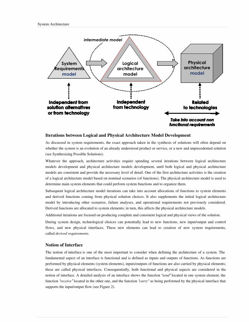
System Architecture 113
Iterations between Logical and Physical Architecture Model DevelopmentAs discussed in system requirements, the exact approach taken in the synthesis of solutions will often depend onwhether the system is an evolution of an already understood product or service, or a new and unprecedented solution(see Synthesizing Possible Solutions).Whatever the approach, architecture activities require spending several iterations between logical architecturemodels development and physical architecture models development, until both logical and physical architecturemodels are consistent and provide the necessary level of detail. One of the first architecture activities is the creationof a logical architecture model based on nominal scenarios (of functions). The physical architecture model is used todetermine main system elements that could perform system functions and to organize them.Subsequent logical architecture model iterations can take into account allocations of functions to system elementsand derived functions coming from physical solution choices. It also supplements the initial logical architecturemodel by introducing other scenarios, failure analyses, and operational requirements not previously considered.Derived functions are allocated to system elements; in turn, this affects the physical architecture models.Additional iterations are focused on producing complete and consistent logical and physical views of the solution.During system design, technological choices can potentially lead to new functions, new input/output and controlflows, and new physical interfaces. These new elements can lead to creation of new system requirements,called derived requirements.
Notion of InterfaceThe notion of interface is one of the most important to consider when defining the architecture of a system. Thefundamental aspect of an interface is functional and is defined as inputs and outputs of functions. As functions areperformed by physical elements (system elements), inputs/outputs of functions are also carried by physical elements;these are called physical interfaces. Consequentially, both functional and physical aspects are considered in thenotion of interface. A detailed analysis of an interface shows the function “send” located in one system element, thefunction “receive” located in the other one, and the function “carry" as being performed by the physical interface thatsupports the input/output flow (see Figure 2).

System Architecture 114
In the context of complex exchanges between system elements, particularly in software-intensive systems, a protocolis seen as a physical interface that carries exchanges of data. However, the input/output flows can include manyother exchanges than data, such as energy.
Emergent PropertiesThe overarching architecture of a system may have design properties or operational effects that emerge from thearrangement and interaction between system elements, but which may not be properties of any individual element orintended for the system as a whole.The elements of an engineered system interact among themselves and can create desirable or undesirablephenomena, such as inhibition, interference, resonance, or the reinforcement of any property. The definition of thesystem includes an analysis of interactions between system elements in order to prevent undesirable properties andreinforce desirable ones.A property which emerges from a system can have various origins, from a single system element to the interactionsamong several elements (Thome, B. 1993). The term emergent properties is used by some authors to identify anyproperty which emerges from a system, while other may refer to this as synergy and reserve emergent property forexplaining unexpected properties or properties not considered fully during system development, but have emergedduring operation. The system concept of emergence is discussed in SEBoK Part 2 (see Emergence).
Broad Categories of Properties Description and Examples
Local Property The property is located in a single system element – e.g. the capacity of a container is the capacity of thesystem.
Accumulative System Property The property is located in several system elements and is obtained through the simple summation of elementalproperties – e.g. the weight of the system results from the sum of the weights of its system elements.
Emergent Property Modified byArchitecture and/orInteractions.
The property exists in several system elements and is modified by their interactions – e.g. the reliability/safetyof a system results from the reliability/safety of each system element and the way they are organized.Architectural steps are often critical to meeting system requirements.
Emergent Property Created byInteractions
The property does not exist in system elements and results only from their interactions – e.g. electromechanicalinterfaces, electromagnetism, static electricity, etc.
Controlled Emergent Property Property controlled or inhibited before going outside the system – e.g.: unbalance removed by the addition of aload; vibration deadened by a damper.
Physical architecture design will include the identification of likely synergies and emergent properties and the inclusion of derived functions, components, arrangements, and/or environmental constraints in the logical or physical architectures models to avoid, mitigate or restrain them within acceptable limits. Corresponding derived requirements should be added to the system requirements baseline when they impact the system-of-interest(SoI). This may be achieved through the knowledge and experience of the systems engineer or through the application of system patterns. However, it is generally not possible to predict, avoid, or control all emergent properties during

System Architecture 115
the architecture development. Fully dealing with the consequences of emergence can only be done via iterationbetween system definition, system realization and system deployment and use (Hitchins, 2008)The notion of emergence is applied during architecture and design to highlight necessary derived functions;additionally, internal emergence is often linked to the notion of complexity. This is the case with complex adaptivesystems (CAS), in which the individual elements act independently, but behave jointly according to commonconstraints and goals (Flood and Carson 1993). Examples of CAS include: the global macroeconomic networkwithin a country or group of countries, stock market, complex web of cross border holding companies,manufacturing businesses, geopolitical organizations, etc. (Holland, J. 1999 and 2006).
Reuse of System ElementsSystems engineers frequently utilize existing system elements. This reuse constraint has to be identified as a systemrequirement and carefully taken into account during architecture and design. One can distinguish three general casesinvolving system element reuse, as shown in Table 2.
Re-use Case Actions and Comments
Case 1:The requirements of the system element areup-to-date and it will be re-used with no modification
required.
•• The system architecture to be defined will have to adapt to the boundaries,interfaces, functions, effectiveness, and behavior of the re-used system element.
•• If the system element is not adapted, it is probable that costs, complexity, and riskswill increase.
Case 2:The requirements of the system element areup-to-date and it will be re-used with possible
modifications.
•• The system architecture to be defined is flexible enough to accommodate theboundaries, interfaces, functions, effectiveness, and behavior of the re-used system
element.•• The design of the reused system element, including its test reports and other
documentation, will be evaluated and potentially redesigned.
Case 3:The requirements are not up-to-date or do notexist.
•• It is necessary to reverse engineer the system element to identify its boundaries,interfaces, functions, performances, and behavior.
•• This is a difficult activity, since the extant documentation for the re-used systemelement is likely unavailable or insufficient.
•• Reverse engineering is expensive in terms of both time and money, and brings withit increased risk.
There is a common idea that reuse is free; however, if not approached correctly, reuse may introduce risks that canbe significant for the project (costs, deadlines, complexity).
Process Approach
PurposeThe purpose of the System Architecture process is to generate system architecture alternatives, to select one or morealternative(s) that frame stakeholder concerns and meet system requirements, and to express this in a set ofconsistent views. (ISO 2015).It should be noted that the architecture activities below overlap with both system definition and concept definitionactivities. In particular that key aspects of the operational and business context, and hence certain stakeholder needs,strongly influence the approach taken to architecture development and description. Also, the architecture activitieswill drive the selection of, and fit within, whatever approach to solution synthesis has been selected.
System Architecture 116
Activities of the processMajor activities and tasks performed during this process include the following:
1. Initialize the definition of the system architecture
•• Build an understanding of the environment/context of use for which a system is needed in order to establishinsight into the stakeholder concerns. To do this, analyze relevant market, industry, stakeholder, enterprise,business, operations, mission, legal and other information that help to understand the perspectives that couldguide the definition of the system architecture views and models.
•• Capture stakeholder concerns (i.e., expectations or constraints) that span system life cycle stages. The concernsare often related to critical characteristics to the system that relate to the stages; they should be translated into orincorporated to system requirements.
•• Tag system requirements that deal with operational conditions (e.g., safety, security, dependability, humanfactors, interfaces, environmental conditions) and life cycle constraints (e.g., maintenance, disposal, deployment)that would influence the definition of the architecture elements.
•• Establish an architecture roadmap and strategy that should include methods, modeling techniques, tools, need forany enabling systems, products, or services, process requirements (e.g., measurement approach and methods),evaluation process (e.g., reviews and criteria).
•• Plan enabling products or services acquisition (need, requirements, procurement).
2. Define necessary architecture viewpoints
•• Based on the identified stakeholder concerns, identify relevant architecture viewpoints and architectureframeworks that may support the development of models and views.
3. Develop candidate architectures models and views
• Using relevant modeling techniques and tools, and in conjunction with the Stakeholder Needs and Requirementsprocess and the System Requirements process, determine the system-of-interest context including boundary withelements of the external environment. This task includes the identification of relationships, interfaces orconnections, exchanges and interactions of the system-of-interest with external elements. This task enables todefine or understand the expected operational scenarios and/or system behaviors within its context of use.
• Define architectural entities (e.g., functions, input/output flows, system elements, physical interfaces, architecturalcharacteristics, information/data elements, containers, nodes, links, communication resources, etc.), which addressthe different types of system requirements (e.g., functional requirements, interface requirements, environmentalrequirements, operational conditions – dependability, human factors, etc., constraints – physical dimensions,production, maintenance, disposal).
•• Relate architectural entities to concepts, properties, characteristics, behaviors, functions, and/or constraints thatare relevant to decisions of the system-of-interest architecture. This gives rise to architectural characteristics (e.g.,generality, modularity, operability, efficiency, simplicity).
• Select, adapt, or develop models of the candidate architectures of the system, such as logical and physical models(see Logical Architecture Model Development and Physical Architecture Model Development). It issometimes neither necessary nor sufficient to use logical and physical models. The models to be used are thosethat best address key stakeholder concerns.
•• From the models of the candidate architectures, compose views that are relevant to the stakeholder concerns andcritical or important requirements.
•• Define derived system requirements induced by necessary instances of architectural entities (e.g., functions,interfaces) and by structural dispositions (e.g., constraints, operational conditions). Use the system requirementsdefinition process to define and formalize them.

System Architecture 117
•• Check models and views consistency and resolve any identified issues. ISO/IEC/IEEE 42010, 2011 maybe usedfor this.
• Verify and validate the models by execution or simulation, if modeling techniques and tools permit. Wherepossible, use design tools to check feasibility and validity; and/or implement partial mock‐ups, or use executablearchitecture prototypes or simulators.
4. Relate system architecture to system design
• Define the system elements that reflect the architectural characteristics (when the architecture is intended to bedesign‐agnostic, these system elements may be notional until the design evolves). To do this, partition, align, andallocate architectural characteristics and system requirements to system elements. Establish guiding principles forthe system design and evolution. Sometimes, a “reference architecture” is created using these notional systemelements as a means to convey architectural intent and to check for design feasibility.
•• Define interfaces for those that are necessary for the level of detail and understanding of the architecture. Thisincludes the internal interfaces between the system elements and the external interfaces with other systems.
• Determine the design properties applicable to system elements in order to satisfy the architectural characteristics.•• For each system element that composes the system, develop requirements corresponding to allocation, alignment,
and partitioning of design properties and system requirements to system elements. To do this, use the stakeholderneeds and requirements definition process and the system requirements definition process.
5. Assess architecture candidates and select one
• Assess the candidate architectures using the architecture evaluation criteria. This is done through application ofthe System Analysis, Measurement, and Risk Management processes.
• Select the preferred architecture(s). This is done through application of the Decision Management process.
6. Manage the selected architecture
•• Establish and maintain the rationale for all selections among alternatives and decision for the architecture,architecture framework(s), viewpoints, kinds of models, and models of the architecture.
•• Manage the maintenance and evolution of the architecture description, including the models, and views. Thisincludes concordance, completeness, and changes due to environment or context changes, technological,implementation, and operational experiences. Allocation and traceability matrices are used to analyze impactsonto the architecture. The present process is performed at any time evolutions of the system occur.
•• Establish a means for the governance of the architecture. Governance includes the roles, responsibilities,authorities, and other control functions.
•• Coordinate reviews of the architecture to achieve stakeholder agreement. The stakeholder requirements andsystem requirements can serve as references.
Artifacts, Methods and Modeling TechniquesThis process may create several artifacts, such as system architecture description documents and system justificationdocuments (traceability matrices and architectural choices).The content, format, layout, and ownership of these artifacts may vary depending on the person creating them andthe domains in which they are being used. The outputs of the process activities should cover the informationidentified in the first part of this article.
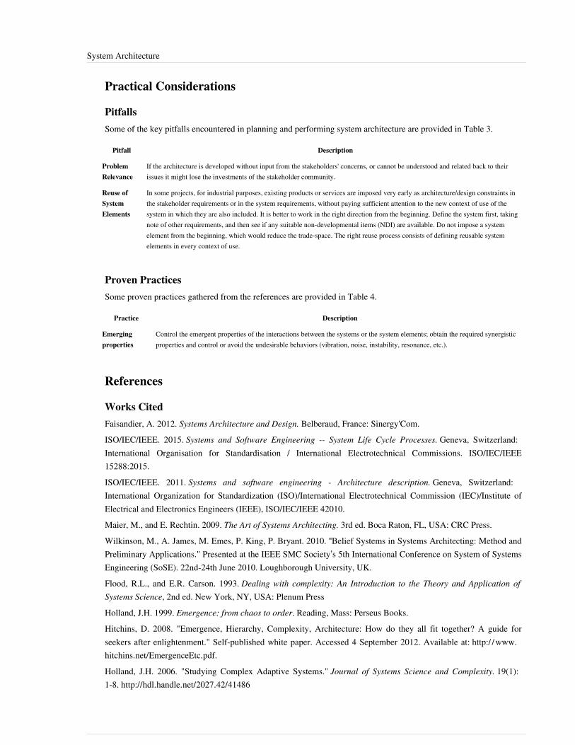
System Architecture 118
Practical Considerations
PitfallsSome of the key pitfalls encountered in planning and performing system architecture are provided in Table 3.
Pitfall Description
ProblemRelevance
If the architecture is developed without input from the stakeholders' concerns, or cannot be understood and related back to theirissues it might lose the investments of the stakeholder community.
Reuse ofSystemElements
In some projects, for industrial purposes, existing products or services are imposed very early as architecture/design constraints inthe stakeholder requirements or in the system requirements, without paying sufficient attention to the new context of use of thesystem in which they are also included. It is better to work in the right direction from the beginning. Define the system first, takingnote of other requirements, and then see if any suitable non-developmental items (NDI) are available. Do not impose a systemelement from the beginning, which would reduce the trade-space. The right reuse process consists of defining reusable systemelements in every context of use.
Proven PracticesSome proven practices gathered from the references are provided in Table 4.
Practice Description
Emergingproperties
Control the emergent properties of the interactions between the systems or the system elements; obtain the required synergisticproperties and control or avoid the undesirable behaviors (vibration, noise, instability, resonance, etc.).
References
Works CitedFaisandier, A. 2012. Systems Architecture and Design. Belberaud, France: Sinergy'Com.ISO/IEC/IEEE. 2015. Systems and Software Engineering -- System Life Cycle Processes. Geneva, Switzerland:International Organisation for Standardisation / International Electrotechnical Commissions. ISO/IEC/IEEE15288:2015.ISO/IEC/IEEE. 2011. Systems and software engineering - Architecture description. Geneva, Switzerland:International Organization for Standardization (ISO)/International Electrotechnical Commission (IEC)/Institute ofElectrical and Electronics Engineers (IEEE), ISO/IEC/IEEE 42010.Maier, M., and E. Rechtin. 2009. The Art of Systems Architecting. 3rd ed. Boca Raton, FL, USA: CRC Press.Wilkinson, M., A. James, M. Emes, P. King, P. Bryant. 2010. “Belief Systems in Systems Architecting: Method andPreliminary Applications." Presented at the IEEE SMC Society’s 5th International Conference on System of SystemsEngineering (SoSE). 22nd-24th June 2010. Loughborough University, UK.Flood, R.L., and E.R. Carson. 1993. Dealing with complexity: An Introduction to the Theory and Application ofSystems Science, 2nd ed. New York, NY, USA: Plenum PressHolland, J.H. 1999. Emergence: from chaos to order. Reading, Mass: Perseus Books.Hitchins, D. 2008. "Emergence, Hierarchy, Complexity, Architecture: How do they all fit together? A guide forseekers after enlightenment." Self-published white paper. Accessed 4 September 2012. Available at: http:/ / www.hitchins. net/ EmergenceEtc. pdf.Holland, J.H. 2006. "Studying Complex Adaptive Systems." Journal of Systems Science and Complexity. 19(1):1-8. http:/ / hdl. handle. net/ 2027. 42/ 41486

System Architecture 119
Thome, B. 1993. Systems Engineering, Principles & Practice of Computer-Based Systems Engineering. New York,NY, USA: Wiley.
Primary ReferencesANSI/IEEE. 2000. Recommended Practice for Architectural Description for Software-Intensive Systems. New York,NY, USA: American National Standards Institute (ANSI)/Institute of Electrical and Electronics Engineers (IEEE),ANSI/IEEE 1471-2000.INCOSE. 2015. 'Systems Engineering Handbook: A Guide for System Life Cycle Processes and Activities', version4.0. Hoboken, NJ, USA: John Wiley and Sons, Inc, ISBN: 978-1-118-99940-0ISO/IEC/IEEE. 2015. Systems and Software Engineering - System Life Cycle Processes.Geneva, Switzerland:International Organization for Standardization (ISO)/International Electrotechnical Commission (IEC) / Institute ofElectrical and Electronics Engineers. ISO/IEC/IEEE 15288:2015.Faisandier, A. 2012. Systems Architecture and Design.Belberaud, France: Sinergy'Com.Blanchard, B.S., and W.J. Fabrycky. 2005. Systems Engineering and Analysis.4th ed. Prentice-Hall InternationalSeries in Industrial and Systems Engineering. Englewood Cliffs, NJ, USA: Prentice-Hall.ISO/IEC. 2007. Systems Engineering – Application and Management of The Systems Engineering Process. Geneva,Switzerland: International Organization for Standards (ISO)/International Electrotechnical Commission(IEC), ISO/IEC 26702:2007.ISO/IEC/IEEE. 2011. Systems and Software Engineering - Architecture Description. Geneva, Switzerland:International Organization for Standardization (ISO)/International Electrotechnical Commission (IEC)/Institute ofElectrical and Electronics Engineers (IEEE), ISO/IEC/IEEE 42010.Martin, J.N. 1997. Systems Engineering Guidebook: A process for developing systems and products,1st ed. BocaRaton, FL, USA: CRC Press.NASA. 2007. Systems Engineering Handbook.Washington, D.C.: National Aeronautics and Space Administration(NASA), NASA/SP-2007-6105.
Additional ReferencesCheckland, P. B. 1999. Systems Thinking, Systems Practice. Chichester, UK: John Wiley & Sons Ltd.OMG. 2010. OMG Systems Modeling Language specification, version 1.2, July 2010. http:/ / www. omg. org/technology/ documents/ spec_catalog. htm.Wilkinson, M.K. 2010. “Z8: Systems Architecture”, in Z-guide series. INCOSE UK, available from INCOSE UKat: http:/ / www. incoseonline. org. uk/ Program_Files/ Publications/ zGuides. aspx?CatID=Publications.
< Previous Article | Parent Article | Next Article >SEBoK v. 1.4 released 29 June 2015
SEBoK DiscussionPlease provide your comments and feedback on the SEBoK below. You will need to log in to DISQUS using anexisting account (e.g. Yahoo, Google, Facebook, Twitter, etc.) or create a DISQUS account. Simply type yourcomment in the text field below and DISQUS will guide you through the login or registration steps. Feedback will bearchived and used for future updates to the SEBoK. If you provided a comment that is no longer listed, that commenthas been adjudicated. You can view adjudication for comments submitted prior to SEBoK v. 1.0 at SEBoK Reviewand Adjudication. Later comments are addressed and changes are summarized in the Letter from the Editor andAcknowledgements and Release History.

System Architecture 120
If you would like to provide edits on this article, recommend new content, or make comments on the SEBoKas a whole, please see the SEBoK Sandbox [1].
ENCODED_CONTENTMjE5NTEPGRpdiBpZD0iZGlzcXVzX3RocmVhZCI+PC9kaXY+CjxzY3JpcHQgdHlwZT0idGV4dC9qYXZhc2NyaXB0Ij4KICAgIC8qICogKiBDT05GSUdVUkFUSU9OIFZBUklBQkxFUzogRURJVCBCRUZPUkUgUEFTVElORyBJTlRPIFlPVVIgV0VCUEFHRSAqICogKi8KICAgIHZhciBkaXNxdXNfc2hvcnRuYW1lID0gJ3NlYm9rd2lraTEwJzsgLy8gcmVxdWlyZWQ6IHJlcGxhY2UgZXhhbXBsZSB3aXRoIHlvdXIgZm9ydW0gc2hvcnRuYW1lCiAgICB2YXIgZGlzcXVzX2lkZW50aWZpZXIgPSAnU3lzdGVtIEFyY2hpdGVjdHVyZSc7ICAgIHZhciBkaXNxdXNfdXJsID0gJ2h0dHA6Ly9zZWJva3dpa2kub3JnL2RyYWZ0L1N5c3RlbV9BcmNoaXRlY3R1cmUnOwogICAgLyogKiAqIERPTidUIEVESVQgQkVMT1cgVEhJUyBMSU5FICogKiAqLwogICAgKGZ1bmN0aW9uKCkgewogICAgICAgIHZhciBkc3EgPSBkb2N1bWVudC5jcmVhdGVFbGVtZW50KCdzY3JpcHQnKTsgZHNxLnR5cGUgPSAndGV4dC9qYXZhc2NyaXB0JzsgZHNxLmFzeW5jID0gdHJ1ZTsKICAgICAgICBkc3Euc3JjID0gJ2h0dHA6Ly8nICsgZGlzcXVzX3Nob3J0bmFtZSArICcuZGlzcXVzLmNvbS9lbWJlZC5qcyc7CiAgICAgICAgKGRvY3VtZW50LmdldEVsZW1lbnRzQnlUYWdOYW1lKCdoZWFkJylbMF0gfHwgZG9jdW1lbnQuZ2V0RWxlbWVudHNCeVRhZ05hbWUoJ2JvZHknKVswXSkuYXBwZW5kQ2hpbGQoZHNxKTsKICAgIH0pKCk7Cjwvc2NyaXB0Pgo8bm9zY3JpcHQ+UGxlYXNlIGVuYWJsZSBKYXZhU2NyaXB0IHRvIHZpZXcgdGhlIDxhIGhyZWY9Imh0dHA6Ly9kaXNxdXMuY29tLz9yZWZfbm9zY3JpcHQiPmNvbW1lbnRzIHBvd2VyZWQgYnkgRGlzcXVzLjwvYT48L25vc2NyaXB0Pgo8YSBocmVmPSJodHRwOi8vZGlzcXVzLmNvbSIgY2xhc3M9ImRzcS1icmxpbmsiPmJsb2cgY29tbWVudHMgcG93ZXJlZCBieSA8c3BhbiBjbGFzcz0ibG9nby1kaXNxdXMiPkRpc3F1czwvc3Bhbj48L2E+END_ENCODED_CONTENT
Logical Architecture Model DevelopmentLogical Architecture Model Development may be used as a task of the activity "Develop candidate architecturesmodels and views", or a sub-process of the System Architecture Definition process (see System Architecture). Itspurpose is to elaborate models and views of the functionality and behavior of the future engineered system as itshould operate, while in service. The logical architecture model of a engineered system of interest (SoI) is composedof a set of related technical concepts and principles that support the logical operation of the system. It may include afunctional architecture view, a behavioral architecture view, and a temporal architecture view. Other additionalviews are suggested in architecture frameworks, depending on the domain.Note: The term Logical Architecture is a contraction of the expression Logical View of the System Architecture.
Concepts and Principles
Functional Architecture ModelA functional architecture model is a set of functions and their sub-functions that defines the transformationsperformed by the system to complete its mission.Function and Input-Output Flow - In the context of System Architecture, functions and input-output flows arearchitecture entities. A function is an action that transforms inputs and generates outputs, involving data, materials,and/or energies. These inputs and outputs are the flow items exchanged between functions. The generalmathematical notation of a function is y = ƒ( x ,t), in which y and x are vectors that may be represented graphicallyand t = time.In order to define the complete set of functions of the system, one must identify all the functions necessitated by thesystem and its derived requirements, as well as the corresponding inputs and outputs of those functions. Generallyspeaking, there are two kinds of functions:1. Functions that are directly deduced from functional and interface requirements. These functions express the
expected services of a system necessary to meet its system requirements.2. Functions that are derived and issued from the alternative solutions of physical architecture model and are
dependent upon the result of the design; additionally, they rely upon on technology choice to implement thelogical architecture model elements.
Functional Hierarchy/Decomposition of Functions - At the highest level of a hierarchy (Figure 1), it is possible torepresent a system as a unique, central function (defined as the system's mission) that in many ways is similar to a"black box" ("F0" in plan A-0 in Figure 1). In order to understand, in detail, what the system does, this"head-of-hierarchy" (F0) is broken down into sub-functions (F1, F2, F3, F4) grouped to form a sub-level of thehierarchy (plan A0), and so on. Functions of the last level of a functional hierarchy can be called leaf-functions (F21,F22, F23, F24 in plan A2). Hierarchies (or breakdowns) decompose a complex or global function into a set offunctions for which physical solutions are known, feasible, or possible to imagine.This view of functional hierarchy represents a static view of functions which would be populated at different levels over a number of iteration, depending upon the synthesis approach used. In general, it is not created by a single top-down decomposition. A static functional hierarchy on its own does not represent how effectively the flows of

Logical Architecture Model Development 121
inputs and outputs are exchanged, and may need to be viewed alongside the other models below.
Figure 1. Decomposition of Functions (Faisandier 2012). Permission granted by Sinergy'Com. All other rights are reserved by the copyright owner.
Behavioral Architecture ModelA behavioral architecture model is an arrangement of functions and their sub-functions as well as interfaces (inputsand outputs) that defines the execution sequencing, conditions for control or data-flow, and performance levelnecessary to satisfy the system requirements ISO/IEC/IEEE 26702 (ISO 2007). A behavioral architecture model canbe described as a set of inter-related scenarios of functions and/or operational modes.Control (Trigger) - A control flow is an element that activates a function as a condition of its execution. The stateof this element, or the condition it represents, activates or deactivates the function (or elements thereof). A controlflow can be a signal or an event, such as a switch being moved to the on position, an alarm, a trigger, a temperaturevariation, or the push of a key on a keyboard.Scenario (of Functions) - A scenario of functions is a chain of functions that are performed as a sequence andsynchronized by a set of control flows to work to achieve a global transformation of inputs into outputs, as seen inthe figures below. A scenario of functions expresses the dynamic of an upper level function. A behavioralarchitecture is developed by considering both scenarios for each level of the functional hierarchy and for each levelof the system hierarchy. When representing scenarios of functions and behavioral architecture models, it isappropriate to use diagrams as modeling techniques, such as functional flow block diagrams (FFBD) (Oliver,Kelliher, and Keegan 1997) or activity diagrams, developed with SysML (OMG 2010). Figures 2 and 3 provideexamples of these diagrams.

Logical Architecture Model Development 122
Figure 2. Illustration of a Scenario (eFFBD). (SEBoK Original)
Figure 3. Illustration of a Scenario (Activity Diagram). (SEBoK Original)
Operational Mode - A scenario of functions can be viewed by abstracting the transformation of inputs into outputsof each function and focusing on the active or non-active state of the function and its controls. This view is called ascenario of modes, which is a chain of modes performed as a sequence of transitions between the various modes ofthe system. The transition from one mode to another is triggered by the arrival of a control flow (event/trigger). Anaction (function) can be generated within a transition between two modes following the arrival of an event or atrigger, as demonstrated in Figure 4 below.
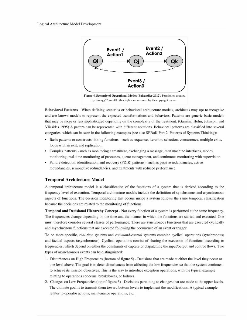
Logical Architecture Model Development 123
Figure 4. Scenario of Operational Modes (Faisandier 2012). Permission grantedby Sinergy'Com. All other rights are reserved by the copyright owner.
Behavioral Patterns - When defining scenarios or behavioral architecture models, architects may opt to recognizeand use known models to represent the expected transformations and behaviors. Patterns are generic basic modelsthat may be more or less sophisticated depending on the complexity of the treatment. (Gamma, Helm, Johnson, andVlissides 1995) A pattern can be represented with different notations. Behavioral patterns are classified into severalcategories, which can be seen in the following examples (see also SEBoK Part 2: Patterns of Systems Thinking):•• Basic patterns or constructs linking functions - such as sequence, iteration, selection, concurrence, multiple exits,
loops with an exit, and replication.•• Complex patterns - such as monitoring a treatment, exchanging a message, man machine interfaces, modes
monitoring, real-time monitoring of processes, queue management, and continuous monitoring with supervision.•• Failure detection, identification, and recovery (FDIR) patterns - such as passive redundancies, active
redundancies, semi-active redundancies, and treatments with reduced performance.
Temporal Architecture ModelA temporal architecture model is a classification of the functions of a system that is derived according to thefrequency level of execution. Temporal architecture models include the definition of synchronous and asynchronousaspects of functions. The decision monitoring that occurs inside a system follows the same temporal classificationbecause the decisions are related to the monitoring of functions.Temporal and Decisional Hierarchy Concept - Not every function of a system is performed at the same frequency.The frequencies change depending on the time and the manner in which the functions are started and executed. Onemust therefore consider several classes of performance. There are synchronous functions that are executed cyclicallyand asynchronous functions that are executed following the occurrence of an event or trigger.To be more specific, real-time systems and command-control systems combine cyclical operations (synchronous)and factual aspects (asynchronous). Cyclical operations consist of sharing the execution of functions according tofrequencies, which depend on either the constraints of capture or dispatching the input/output and control flows. Twotypes of asynchronous events can be distinguished:1. Disturbances on High Frequencies (bottom of figure 5) - Decisions that are made at either the level they occur or
one level above. The goal is to deter disturbances from affecting the low frequencies so that the system continuesto achieve its mission objectives. This is the way to introduce exception operations, with the typical examplerelating to operations concerns, breakdowns, or failures.
2.2. Changes on Low Frequencies (top of figure 5) - Decisions pertaining to changes that are made at the upper levels.The ultimate goal is to transmit them toward bottom levels to implement the modifications. A typical examplerelates to operator actions, maintenance operations, etc.

Logical Architecture Model Development 124
Figure 5. Temporal and Decision Hierarchy Levels (Faisandier 2012). Permission granted by Sinergy'Com. All otherrights are reserved by the copyright owner.
Process Approach
PurposeThe purpose of the Logical Architecture Model Development is to define, select, and synthesize a system’s logicalarchitecture model to provide a framework against which to verify that a future system will satisfy its systemrequirements in all operational scenarios, within which trade-offs between system requirements can be explored indeveloping such systems.Generic inputs to the process include system requirements, generic architecture patterns that architects identify anduse to answer requirements, outcomes from system analysis processes, and feedback from system verification andvalidation processes. Depending on the Life Cycle Model that is chosen, there will be iterations through which theseinputs and outputs, and the relationships between them evolve and change throughout the process (see also ApplyingLife Cycle Processes).Generic outputs from the process are either a single logical architecture model or a set of candidate logicalarchitecture models together with the selected independent logical architecture model and a rationale for itsselection. They include, at minimum, views and models. These involve functional, behavioral and temporal views; atraceability matrix between logical architecture model elements and system requirements.
Logical Architecture Model Development 125
Activities of the ProcessMajor activities and tasks performed during this process include the following:•• Identify and analyze functional and behavioral elements:
• Identify functions, input-output flows, operational modes, transition of modes, and operational scenarios fromsystem requirements by analyzing the functional, interface, and operational requirements.
•• Define necessary inputs and controls (energy, material, and data flows) to each function and outputs that resultin the deduction of the necessary functions to use, transform, move, and generate the input-output flows.
•• Assign system requirements to functional and behavioral elements:•• Formally characterize functions expressions and their attributes through the assignment of performance,
effectiveness, and constraints requirements. In particular, study the temporal aspects from requirements toassign duration, response time, and frequency to functions.
•• Formally characterize the input, output, and control flows expressions and their attributes through assignmentof interface, effectiveness, operational, temporal and constraints requirements.
•• Establish traceability between system requirements and these functional and behavioral elements.•• Define candidate logical architecture models For each candidate:
•• Analyze operational modes as stated in the system requirements (if any) and/or use previously definedelements to model sequences of operational modes and the transition of modes. Eventually decompose themodes into sub-modes and then establish for each operational mode one or several scenarios of functionsrecognizing and/or using relevant generic behavioral patterns.
•• Integrate these scenarios of functions in order to get a behavioral architecture model of the system (a completepicture of the dynamic behavior).
•• Decompose previously defined logical elements as necessary to look towards implementation.•• Assign and incorporate temporal constraints to previously defined logical elements, such as the period of time,
duration, frequency, response-time, timeout, stop conditions, etc.•• Define several levels of execution frequency for functions that correspond to levels of decision, in order to
monitor system operations, prioritize processing on this time basis, and share out functions among thoseexecution frequency levels to get a temporal architecture model.
•• Perform functional failure modes and effects analysis and update the logical architecture elements asnecessary.
•• Execute the models with simulators (when possible) and tune these models to obtain the expectedcharacteristics.
•• Synthesize the selected independent logical architecture model:• Select the logical architecture by assessing the candidate logical architecture models against assessment criteria
(related to system requirements) and compare them, using the system analysis process to perform assessmentsand decision management process for the selection (see the System Analysis and Decision Managementtopics). This selected logical architecture model is called independent logical architecture model because, asmuch as possible, it is independent of implementation decisions.
•• Identify and define derived logical architecture model elements created for the necessity of design andcorresponding with the derived system requirements. Assign these requirements to the appropriate system(current studied system or external systems).
•• Verify and validate the selected logical architecture models (using as executable models as possible), makecorrections as necessary, and establish traceability between system requirements and logical architecture modelelements.
•• Feedback logical architecture model development and system requirements. This activity is performed after thephysical architecture model development process:
Logical Architecture Model Development 126
• Model the allocated logical architecture to systems and system elements, if such a representation is possible,and add any functional, behavioral, and temporal elements as needed to synchronize functions and treatments.
•• Define or consolidate derived logical and physical elements induced by the selected logical and physicalarchitecture models. Define the corresponding derived requirements and allocate them to appropriate logicaland physical architectures elements. Incorporate these derived requirements into the requirements baselines ofimpacted systems.
Artifacts, Methods and Modeling TechniquesLogical architecture descriptions use modeling techniques that are grouped under the following types of models.Several methods have been developed to support these types of models (some are executable models):• Functional Models – These include models such as the structured analysis design technique (SADT/IDEF0),
system analysis & real time (SA-RT), enhanced Functional Flow Block Diagrams (eFFBD), and the functionanalysis system technique (FAST).
•• Semantic Models- These include models such as entities-relationships diagrams, class diagrams, and data flowdiagrams.
• Dynamic Models – These include such models as state-transition diagrams, state-charts, eFFBDs, state machinediagrams (SysML), activity diagrams (SysML) (OMG. 2010), and petri nets.
Depending on the type of domain (e.g. defense, enterprise), architecture frameworks provide descriptions that canhelp to represent additional aspects/views of architectures - see the section 'Enterprise Architecture Frameworks &Methodologies' in Enterprise Systems Engineering Key Concepts. See also practical means for using generaltemplates related to ISO/IEC/IEEE 42010 (ISO 2011).
Practical ConsiderationsAs stated above, the purpose of the logical architecture model is to provide a description of what a system must beable to do to satisfy the stated need. This should help to ensure that the needs and/or concerns of all stakeholders areaddressed by any solution, and that innovative solutions, as well as those based on current solution technologies, canbe considered. In practice it is human nature for problem stakeholders to push their own agendas and for solutionarchitects or designers to offer their familiar solutions. If a logical architecture model is not properly enforced withthe chosen life cycle, it is easy for both problem and solution stakeholders to ignore it and revert to their own biases(see Part 5 Enabling Systems Engineering). This is exacerbated if the logical architecture model becomes an end inits own right or disconnected from the main lifecycle activities. This can occur either through the use of abstractlanguage or notations, levels of detail, time taken, or an overly complex final architecture that does not match thepurpose for which it was created. If the language, scope, and timeliness of the architecture are not matched to theproblem stakeholder or solution providers, it is easier for them to overlook it. Key pitfalls and good practices whichcan help to avoid problems related to logical architecture model are described in the next two sections.
PitfallsSome of the key pitfalls encountered in developing logical architecture are provided in Table 1.

Logical Architecture Model Development 127
Table 1. Pitfalls with Logical Architecture Development. (SEBoK Original)
Pitfall Description
Problem Relevance The logical architecture model should relate back to the operational scenarios produced by mission analysis.
Inputs for ArchitectureModel
The major input for architecture definition activity involves the set of system requirements and the instances inwhich they do not address the right level of architecture. The consequence is that the architect allows therequirements to fall to the side and invents a solution with what he or she understands through the input.
Decomposition Too Deep A common mistake made by many beginners in architecture consists of decomposing the functions too deeply orhaving too many functions and input/output flows in scenarios or in the functional architecture model of the current
system block.
Not Considering Inputsand Outputs Together with
Functions
A common mistake is to consider only the actions supported by functions and decomposing them, while forgettingthe inputs and the outputs or considering them too late. Inputs and outputs are integral parts of a function.
Considering StaticDecomposition of Functions
Only
Static function decomposition is the smallest functional architecture model task and answers the basic question,"How is this done?" The purpose of the static decomposition is to facilitate the management or navigation throughthe list of functions. The static decomposition should be established only when scenarios have been created and the
logical architecture is close to complete.
Mixing Governance,Management, and
Operation
Governance (strategic monitoring), management (tactical monitoring), and basic operations are often mixed incomplex systems. Logical architecture model should deal with behavioral architecture model as well as with
temporal architecture model.
Proven PracticesSome proven practices gathered from the references are provided in Table 2.
Table 2. Proven Practices with Logical Architecture Development. (SEBoK Original)
Practice Description
Constitute Scenariosof Functions
Before constituting a decomposition tree of functions, one must model the behavior of the system, establish scenarios offunctions, and decompose functions as scenarios of sub-functions.
Analysis andSynthesis Cycles
When facing a system that contains a large number of functions, one should attempt to synthesize functions into higherabstraction levels of functions with the assistance of criteria. Do not perform analysis only; instead, conduct small cycles of
analysis (decomposition) and synthesis. The technique of using scenarios includes this design practice.
Alternate Functionaland Behavioral
Views
A function (action verb; e.g. "to move") and its state of execution/operational mode (e.g. "moving") are two similar andcomplimentary views. Utilize this to consider a behavioral view of the system that allows for the transition from one
operational mode to another.
The Order to Createa Scenario Of
Functions
When creating a scenario of functions, it is more efficient to first establish the (control) flow of functions, then to add inputand output flows, and finally to add triggers or signals for synchronization.

Logical Architecture Model Development 128
References
Works CitedGamma, E., R. Helm, R. Johnson, and J. Vlissides. 1995. Design Patterns: Elements of Reusable Object-OrientedSoftware. Boston, MA, USA: Addison-Wesley.Faisandier, A. 2012. Systems Architecture and Design. Belberaud, France: Sinergy'Com.ISO/IEC. 2007.Systems Engineering – Application and Management of the Systems Engineering Process.Geneva,Switzerland: International Organization for Standards (ISO)/International Electronical Commission (IEC), ISO/IEC26702:2007.ISO/IEC/IEEE. 2011. Systems and software engineering - Architecture description. Geneva, Switzerland:International Organization for Standardization (ISO)/International Electrotechnical Commission (IEC)/Institute ofElectrical and Electronics Engineers (IEEE), ISO/IEC/IEEE 42010.Oliver, D., T. Kelliher, and J. Keegan. 1997. Engineering complex systems with models and objects. New York, NY,USA: McGraw-Hill.OMG. 2010. OMG Systems Modeling Language specification, version 1.2, July 2010. http:/ / www. omg. org/technology/ documents/ spec_catalog. htm.
Primary ReferencesANSI/IEEE. 2000. Recommended practice for architectural description for software-intensive systems. New York,NY: American National Standards Institute (ANSI)/Institute of Electrical and Electronics Engineers (IEEE),ANSI/IEEE 1471-2000.INCOSE. 2015. Systems Engineering Handbook - A Guide for System Life Cycle Processes and Activities'', version4.0. Hoboken, NJ, USA: John Wiley and Sons, Inc, ISBN: 978-1-118-99940-0ISO/IEC. 2007. Systems Engineering – Application and Management of the Systems Engineering Process. Geneva,Switzerland: International Organization for Standards (ISO)/International Electronical Commission (IEC), ISO/IEC26702:2007.ISO/IEC/IEEE. 2015. Systems and Software Engineering -- System Life Cycle Processes. Geneva, Switzerland:International Organisation for Standardisation / International Electrotechnical Commissions / Institute of Electricaland Electronics Engineers. ISO/IEC/IEEE 15288:2015.ISO/IEC/IEEE. 2011. Systems and Software Engineering - Architecture Description. Geneva, Switzerland:International Organization for Standardization (ISO)/International Electrotechnical Commission (IEC)/Institute ofElectrical and Electronics Engineers (IEEE), ISO/IEC/IEEE 42010.Maier, M. and E. Rechtin. 2009. The Art of Systems Architecting, 3rd ed. Boca Raton, FL, USA: CRC Press.
Additional ReferencesAlexander, C., S. Ishikawa, M. Silverstein, M. Jacobson, I. Fiksdahl-King, and S. Angel. 1977. A Pattern Language:Towns, Buildings, Construction. New York, NY, USA: Oxford University Press.Buede, D.M. 2009. The engineering design of systems: Models and methods. 2nd ed. Hoboken, NJ, USA: JohnWiley & Sons Inc.Oliver, D., T. Kelliher, and J. Keegan. 1997. Engineering Complex Systems with Models and Objects. New York,NY, USA: McGraw-Hill.The Open Group. 2011. TOGAF, version 9.1. Hogeweg, The Netherlands: Van Haren Publishing. Accessed August29, 2012. Available at: https:/ / www2. opengroup. org/ ogsys/ jsp/ publications/ PublicationDetails.jsp?catalogno=g116.

Logical Architecture Model Development 129
Zachman, J. 2008. "John Zachman's Concise Definition of The Zachman Framework™." Zachman InternationalEnterprise Architecture. Accessed August 29, 2012. Available at: http:/ / www. zachman. com/about-the-zachman-framework.
< Previous Article | Parent Article | Next Article >SEBoK v. 1.4 released 29 June 2015
SEBoK DiscussionPlease provide your comments and feedback on the SEBoK below. You will need to log in to DISQUS using anexisting account (e.g. Yahoo, Google, Facebook, Twitter, etc.) or create a DISQUS account. Simply type yourcomment in the text field below and DISQUS will guide you through the login or registration steps. Feedback will bearchived and used for future updates to the SEBoK. If you provided a comment that is no longer listed, that commenthas been adjudicated. You can view adjudication for comments submitted prior to SEBoK v. 1.0 at SEBoK Reviewand Adjudication. Later comments are addressed and changes are summarized in the Letter from the Editor andAcknowledgements and Release History.
If you would like to provide edits on this article, recommend new content, or make comments on the SEBoKas a whole, please see the SEBoK Sandbox [1].
ENCODED_CONTENTMTA2OTkPGRpdiBpZD0iZGlzcXVzX3RocmVhZCI+PC9kaXY+CjxzY3JpcHQgdHlwZT0idGV4dC9qYXZhc2NyaXB0Ij4KICAgIC8qICogKiBDT05GSUdVUkFUSU9OIFZBUklBQkxFUzogRURJVCBCRUZPUkUgUEFTVElORyBJTlRPIFlPVVIgV0VCUEFHRSAqICogKi8KICAgIHZhciBkaXNxdXNfc2hvcnRuYW1lID0gJ3NlYm9rd2lraTEwJzsgLy8gcmVxdWlyZWQ6IHJlcGxhY2UgZXhhbXBsZSB3aXRoIHlvdXIgZm9ydW0gc2hvcnRuYW1lCiAgICB2YXIgZGlzcXVzX2lkZW50aWZpZXIgPSAnTG9naWNhbCBBcmNoaXRlY3R1cmUgTW9kZWwgRGV2ZWxvcG1lbnQnOyAgICB2YXIgZGlzcXVzX3VybCA9ICdodHRwOi8vc2Vib2t3aWtpLm9yZy9kcmFmdC9Mb2dpY2FsX0FyY2hpdGVjdHVyZV9Nb2RlbF9EZXZlbG9wbWVudCc7CiAgICAvKiAqICogRE9OJ1QgRURJVCBCRUxPVyBUSElTIExJTkUgKiAqICovCiAgICAoZnVuY3Rpb24oKSB7CiAgICAgICAgdmFyIGRzcSA9IGRvY3VtZW50LmNyZWF0ZUVsZW1lbnQoJ3NjcmlwdCcpOyBkc3EudHlwZSA9ICd0ZXh0L2phdmFzY3JpcHQnOyBkc3EuYXN5bmMgPSB0cnVlOwogICAgICAgIGRzcS5zcmMgPSAnaHR0cDovLycgKyBkaXNxdXNfc2hvcnRuYW1lICsgJy5kaXNxdXMuY29tL2VtYmVkLmpzJzsKICAgICAgICAoZG9jdW1lbnQuZ2V0RWxlbWVudHNCeVRhZ05hbWUoJ2hlYWQnKVswXSB8fCBkb2N1bWVudC5nZXRFbGVtZW50c0J5VGFnTmFtZSgnYm9keScpWzBdKS5hcHBlbmRDaGlsZChkc3EpOwogICAgfSkoKTsKPC9zY3JpcHQ+Cjxub3NjcmlwdD5QbGVhc2UgZW5hYmxlIEphdmFTY3JpcHQgdG8gdmlldyB0aGUgPGEgaHJlZj0iaHR0cDovL2Rpc3F1cy5jb20vP3JlZl9ub3NjcmlwdCI+Y29tbWVudHMgcG93ZXJlZCBieSBEaXNxdXMuPC9hPjwvbm9zY3JpcHQ+CjxhIGhyZWY9Imh0dHA6Ly9kaXNxdXMuY29tIiBjbGFzcz0iZHNxLWJybGluayI+YmxvZyBjb21tZW50cyBwb3dlcmVkIGJ5IDxzcGFuIGNsYXNzPSJsb2dvLWRpc3F1cyI+RGlzcXVzPC9zcGFuPjwvYT4=END_ENCODED_CONTENT
Physical Architecture Model DevelopmentPhysical Architecture Model Development may be used as a task of the activity "Develop candidate architecturesmodels and views", or a sub-process of the System Architecture Definition process (see System Architecturearticle).Its purpose is to elaborate models and views of a physical, concrete solution that accommodates the logicalarchitecture model and satisfies and trades-off system requirements. Once a logical architecture model is defined (seeLogical Architecture Model Development), concrete physical elements have to be identified that can supportfunctional, behavioral, and temporal features as well as the expected properties of the system deduced fromnon-functional system requirements (e.g. constraint of replacement of obsolescence, and/or continued productsupport).A physical architecture model is an arrangement of physical elements, (system elements and physical interfaces) thatprovides the solution for a product, service, or enterprise. It is intended to satisfy logical architecture elements andsystem requirements ISO/IEC/IEEE 26702 (ISO 2007). It is implementable through technological system elements.System requirements are allocated to both the logical and physical architectures. The resulting system architecture isassessed with system analysis and when completed becomes the basis for system realization.In some cases, particularly when multiple systems are to be defined to a common physical architecture model, one ofthe drivers for the physical architecture model may be interface standards; these physical interfaces may well be oneof the most important concerns for these systems. It is quite possible that such interface standards are mandated at ahigh level in the system requirements. On the other hand, it is equally possible for standards to be derived duringphysical architecture model development and these can be critical enablers for desirable engineering outcomes, suchas: families of systems, technology insertion, interoperability and “open systems”. For example, today’s video, hi-fi,and computer systems have all benefited from adoption of interface standards. Other examples exist in most fields ofengineering from nuts and bolts, plumbing, electrical installations, rail gauges, TCP/IP, IT systems and software tomodular defense and space systems.

Physical Architecture Model Development 130
Note: The term Physical Architecture is a contraction of the expression Physical View of the System Architecture.
Concepts and Principles
System Element, Physical Interface, and Physical Architecture ModelA system element is a discrete part of a system that can be implemented to fulfill design properties. A systemelement can be hardware, software, data, humans, processes (e.g., processes that provide a service to users),procedures (e.g., operator instructions), facilities, materials, and naturally occurring entities (e.g., water, organisms,and minerals), or any combination of these ISO/IEC/IEEE 15288 (ISO 2015). A physical interface binds two systemelements together; this is similar to a link or a connector. Table 1 provides some examples of system elements andphysical interfaces.
Table 1. Types of System Elements and Physical Interfaces. (SEBoK Original)
Element Product System Service System Enterprise System
SystemElement
•• Hardware Parts (mechanics, electronics,electrical, plastic, chemical, etc.)
•• Operator Roles•• Software Pieces
•• Processes, Data Bases,Procedures, etc.
•• Operator Roles•• Software Applications
•• Corporate, Direction, Division, Department,Project, Technical Team, Leader, etc.
•• IT Components
PhysicalInterface
* Hardware Parts, Protocols, Procedures, etc. * Protocols, Documents, etc. * Protocols, Procedures, Documents, etc.
A complex system composed of thousands of physical and/or intangible parts may be structured in several layers ofsystems and system elements. The number of elements in a level of the structure of one system is limited to only afew, in order to facilitate managing the system definition; a common guideline is five plus or minus two elements(see illustration in Figure 1).
Figure 1. Layers of Systems and System Elements (Faisandier 2012). Permission granted by Sinergy'Com. All other rights are reservedby the copyright owner.

Physical Architecture Model Development 131
A physical architecture model is built from systems, system elements, and all necessary physical interfaces betweenthese elements, as well as from external elements (neighboring or enabling systems and/or system elements in theconsidered layer and concerned elements in the context of the global system-of-interest) - see illustration in Figure 2.
Figure 2. Physical Architecture Model Representation (Faisandier 2012). Permission granted by Sinergy'Com. All other rights are reserved by thecopyright owner.
Design PropertyA design property is a property that is obtained during system architecture and created through the assignment ofnon-functional requirements, estimates, analyses, calculations, simulations of a specific aspect, or through thedefinition of an existing element associated with a system element, a physical interface, and/or a physicalarchitecture. If the defined element complies with a requirement, the design property will relate to (or may equal) therequirement. Otherwise, one has to identify any discrepancy that could modify the requirement or design property,and detect any deviations.Stakeholders have concerns that correspond to the expected behavior of a system within operational, environmental,and/or physical constraints as well as to more general life cycle constraints. Stakeholder requirements and systemrequirements express these concerns as expected capabilities from the system (e.g., usability, interoperability,security, expandability, environment suitability, etc.). Architects and/or designers identify these capabilities fromrequirements and deduce corresponding quantitative or qualitative design properties to properly equip their physicalarchitecture model (e.g., reliability, availability, maintainability, modularity, robustness, operability, climaticenvironment resistance, dimensions limits, etc.). For further discussion on how some of these properties may beincluded in architecture and design, please see the article Systems Engineering and Specialty Engineering in theRelated Disciplines knowledge area (KA).
Allocation of Logical Elements to Physical Elements and PartitioningDeveloping a candidate physical architecture model for a system consists of first identifying the system elements thatcan perform functions of the logical architecture model as well as identifying the interfaces capable of carrying outthe input-output flows and control flows. When identifying potential elements, a systems engineer needs to allocatedesign properties within the logical architecture; these properties are deduced from the system requirements.Partitioning and allocation are activities to decompose, gather, or separate functions in order to facilitate theidentification of feasible system elements that support these functions. Either they exist and can be reused orre-purposed, or they can be developed and technically implemented.

Physical Architecture Model Development 132
Partitioning and allocation use criteria to find potential affinities between functions. Systems engineers use systemrequirements and/or design properties as criteria to assess and select candidate system elements and partitions offunctions, such as similar transformations within the same technology, similar levels of efficiency, exchange of thesame type of input-output flows (information, energy, and materials), centralized or distributed controls, executionwith close frequency level, dependability conditions, environment resistance level, and other enterprise constraints.A concurrent engineering approach is necessary when several different sets of technologies, knowledge, and skillsare necessary to establish a candidate physical architecture model. This is particularly true during the partition andallocation of functions to various system elements, in which the systems engineer must account for compatibilityissues and emergent properties. (see SEBoK Part 2: Synthesizing Possible Solutions for a discussion of possibleapproaches)
Developing Candidate Physical Architecture ModelsThe goal of physical architecture model development activities is to provide the best possible physical architecturemodel made of suitable systems, technological system elements, and physical interfaces (i.e., the architecture thatanswers, at best, all system requirements, depending on agreed limits or margins of each requirement). The best wayto do this is to produce several candidate physical architecture models, assess and compare them, and then select themost suitable one.A candidate physical architecture model is elaborated according to affinity criteria in order to build a set of systemelements (i.e., separate, gather, connect, and disconnect the network of system elements and their physicalinterfaces). These criteria are the same as those used for partitioning and allocating functions to system elements.The physical architecture model development may be focused in different ways, for example, it may address:•• Reduction in the number of physical interfaces•• System elements that can be tested separately•• Compatible technology•• Measures of the proximity of elements in space•• Ease of handling (weight, volume, and transportation facilities)•• Optimization of resources shared between elements•• Modularity (i.e. elements have low interdependence)•• Resilience (i.e. elements which are highly reliable, maintainable or replaceable)
Evaluating and Selecting the Preferred CandidateViable physical architecture models enable all required functions or capabilities specified in the logical architecturemodel to be realized. Architecture and design activity includes evaluation to obtain a balance among designproperties, costs, risks, etc. Generally, the physical architecture model of a system is determined more strongly bynon-functional requirements (e.g., performance, safety, security, environmental conditions, constraints, etc.) than byfunctions. There may be many (physical) ways to establish functions but fewer ways of satisfying non-functionalrequirements. The preferred physical architecture model represents the selection of system elements, their physicalrelationships, and interfaces. Typically this physical architecture will still leave further systems engineering to beundertaken to achieve a fully optimized system after any remaining trade-offs are made and algorithms andparameters of the system are finalized.Certain analyses (efficiency, dependability, cost, risks, etc.) are required to get sufficient data that characterize theglobal behavior and structure of the candidate architectures in regard to system requirements; this is often broadlyreferred to as system analysis. Other analyses and assessments require knowledge and skills from the differentinvolved technologies and specialities (mechanics, electronics, software, thermodynamics, electro-magneticcompatibility, safety, security etc.). They are performed through corresponding specialist analysis of the system.

Physical Architecture Model Development 133
Legacy Systems and Systems of SystemsFew systems come into existence or operate without interacting with others in a system context. These interactionsmay be with other operational systems, or maintenance and support systems, which in turn may be legacy (already inuse) or future legacy (under development and likely to operate with the system of interest in the future).The best chosen approach will be dependent on the strength of interactions between the System-of-Interest (glossary)(SoI) and its wider context. While these interactions are small, they may be accounted for by defining a set of staticexternal interface requirements (for example technical standards) with which the system must comply, by includingthese as constraints in the system requirements and ensuring compliance through design assurance.Where the interactions are more intense, for example where continuous information is to be exchanged with othersystems, these will have to be recognized as part of a system of systems context and will instead be considered aspart of an enterprise systems engineering approach.Another important consideration may be the sharing of technology or system elements between the SoI and othersystems, often as part of a family of systems (many examples occur in automotive and aerospace industries) or there-use of system elements from existing legacy. Here a degree of top-down or middle-out design work will benecessary to ensure the system of interest embodies the required system elements, while conforming as far aspossible to the stakeholder and system requirements, with any compromises being understood and managed.If a System-of-Interest is intended to be used in one or more service systems or system of systems configurations thiswill affect its physical architecture model. One of the features of these SoS is the late binding of component systemsin use. Such component systems must be architected with open or configurable interfaces, must have clearly definedfunctions packaged in such a way as to be relevant to the SoS using them, and must include some method by whichthey can be identified and included in the SoS when needed.Both service systems and SoS will be defined by a high level physical architecture model, which will be utilized todefine the relevant SoS relationships, interfaces, and constraints that should be included in Concept Definition. Theresults will be embedded in the stakeholder and system requirements and handled through interface agreements andacross-project communication during development, realization, and use.See SEBoK Part 4 Applications of Systems Engineering for more information on special considerations forarchitecting SoS.
Process Approach
PurposeThe purpose of the Physical Architecture Model Development is to define, select, and synthesize a system physicalarchitecture model which can support the logical architecture model. A physical architecture model will havespecific properties to address stakeholder concerns or environmental issues and to satisfy system requirements.Because of the evolution of the context of use or technological possibilities, the physical architecture which iscomposed of system elements is supposed to evolve along the life cycle of the system in order for it to continue toperform its mission within the limits of its required effectiveness. Depending on whether or not evolution impactslogical architecture model elements, allocations to system elements may change. A physical architecture model isequipped with specific design properties (glossary) to continuously challenge the evolution.Generic inputs include the selected logical architecture model, system requirements, generic patterns and propertiesthat architects identify and utilize to answer requirements, outcomes from system analysis, and feedback fromsystem verification and system validation.Generic outputs are the selected physical architecture model, allocation matrix of functional elements to physicalelements, traceability matrix with system requirements, stakeholder requirements of each system and system elementcomposing the physical architecture model, and rejected solutions.

Physical Architecture Model Development 134
Activities of the ProcessMajor activities and tasks to be performed during this process include the following:•• Partition and allocate functional elements to system elements:
•• Search for system elements or technologies able to perform functions and physical interfaces to carryinput-output and control flows. Ensure system elements exist or can be engineered. Assess each potentialsystem element using criteria deduced from design properties (themselves deduced from non-functional systemrequirements).
•• Partition functional elements (functions, scenarios, input-outputs, triggers, etc.) using the given criteria andallocate partitioned sets to system elements (using the same criteria).
•• When it is impossible to identify a system element that corresponds to a partitioned functional set, decomposethe function until the identification of implementable system elements is possible.
•• Check the compatibility of technologies and the compatibility of interfaces between selected system elements.•• Constitute candidate physical architecture models.
•• Because partitioned sets of functions can be numerous, there are generally too many system elements. Fordefining controllable architectures, system elements have to be grouped into higher-level system elementsknown as system element groups, often called sub-systems in industry.
•• Constitute several different system element groups corresponding to different combinations of elementarysystem elements. One set of system element groups plus one or several non-decomposable system elementsform a candidate physical architecture model of the considered system.
•• Represent (using patterns) the physical architecture model of each system element group connecting its systemelements with physical Interfaces that carry input-output flows and triggers. Add physical interfaces as needed;in particular, add interfaces with external elements to the system element group.
•• Represent the synthesized physical architecture of the considered system built from system element groups,non-decomposable system, and physical interfaces inherited from the physical architecture model of systemelement groups.
•• Enhance the physical architecture model with design properties such as modularity, evolution capability,adaptability to different environments, robustness, scalability, resistance to environmental conditions, etc.
•• If possible, use executable architecture prototypes (e.g., hardware-software (HW-SW)-in-the-loop prototypes)for identifying potential deficiencies and correct the architecture as needed.
•• Assess physical architecture model candidates and select the most suitable one:• Use the system analysis process to perform assessments (see the System Analysis topic).• Use the Decision Management process to support the trades and selection of the preferred alternative (see the
Decision Management topic).•• Synthesize the selected physical architecture model:
•• Formalize physical elements and properties. Verify that system requirements are satisfied and that the solutionis realistic.
•• Identify the derived physical and functional elements created for the necessity of architecture and design andthe corresponding system requirements.
•• Establish traceability between system requirements and physical elements as well as allocate matrices betweenfunctional and physical elements.

Physical Architecture Model Development 135
Artifacts, Methods and Modeling TechniquesPhysical architecture descriptions use modeling techniques to create and represent physical architectures. Somecommon physical models include structural blocks, mass, layout and other models. Modeling techniques may be:•• Physical block diagrams (PBD)•• SysML block definition diagrams (BDD)•• Internal block diagrams (IBD) (OMG 2010)•• Executable architecture prototyping•• Etc.Depending on the type of domain for which it is to be used (defense, enterprise, etc.), architecture frameworks mayprovide descriptions that can help to trade-off candidate architectures. Please see section 'Enterprise ArchitectureFrameworks & Methodologies' in Enterprise Systems Engineering Key Concepts.
Practical ConsiderationsKey pitfalls and good practices related to physical architecture development are described in the next two sections.
PitfallsSome of the key pitfalls encountered in performing physical architecture model development are provided in Table3.
Table 3. Pitfalls with Physical Architecture Development. (SEBoK Original)
Pitfall Description
Too Many Levels ina Single SystemBlock
The current system block includes too many levels of decomposition. The right practice is that the physical architecturemodel of a system block is composed of one single level of systems and/or system elements.
No LogicalArchitecture Model
The developers perform a direct passage from system requirements to physical architecture model without establishing alogical architecture model; this is a common wrong practice that mainly takes place when dealing with repeating systems andproducts because the functions are already known. The issue is that a function is always associated with input-output flowsdefined in a specific domain set. If the domain set changes, the performance of the function can become invalid.
Direct Allocationon Technologies
At a high level of abstraction of multidisciplinary systems, directly allocating the functions onto technologies of the lowestlevel of abstraction, such as hardware or software, does not reflect a system comprehension. The right practice is to considercriteria to decompose the architecture into the appropriate number of levels, alternating logical and physical before reachingthe technology level ( the last level of the system).
Proven PracticesSome proven practices gathered from the references are provided in Table 4.

Physical Architecture Model Development 136
Table 4. Proven Practices with Physical Architecture Development. (SEBoK Original)
Practice Description
Modularity Restrict the number of interactions between the system elements and consider the modularity principle (maximum of consistencyinside the system element, minimum of physical interfaces with outside) as the right way for architecting systems.
Focus onInterfaces
Focusing on interfaces rather than on system elements is another key element of a successful architecture and design for abstractlevels of systems.
References
Works CitedISO/IEC. 2007. Systems Engineering – Application and Management of The Systems Engineering Process. Geneva,Switzerland: International Organization for Standards (ISO)/International Electrotechnical Commission (IEC),ISO/IEC 26702:2007.ISO/IEC/IEEE. 2015. Systems and Software Engineering -- System Life Cycle Processes. Geneva, Switzerland:International Organisation for Standardisation / International Electrotechnical Commissions / Institute of Electricaland Electronics Engineers. ISO/IEC/IEEE 15288:2015.OMG. 2010. OMG Systems Modeling Language specification, version 1.2, July 2010. http:/ / www. omg. org/technology/ documents/ spec_catalog. htm.Faisandier, A. 2012. Systems Architecture and Design. Belberaud, France: Sinergy'Com.
Primary ReferencesANSI/IEEE. 2000. Recommended practice for architectural description for software-intensive systems. New York,NY: American National Standards Institute (ANSI)/Institute of Electrical and Electronics Engineers (IEEE),ANSI/IEEE 1471-2000.INCOSE. 2015. Systems Engineering Handbook - A Guide for System Life Cycle Processes and Activities'', version4.0. Hoboken, NJ, USA: John Wiley and Sons, Inc, ISBN: 978-1-118-99940-0ISO/IEC/IEEE. 2015. Systems and Software Engineering -- System Life Cycle Processes. Geneva, Switzerland:International Organisation for Standardisation / International Electrotechnical Commissions / Institute of Electricaland Electronics Engineers. ISO/IEC/IEEE 15288:2015.ISO/IEC/IEEE. 2011. Systems and Software Engineering - Architecture Description. Geneva, Switzerland:International Organization for Standardization (ISO)/International Electrotechnical Commission (IEC)/Institute ofElectrical and Electronics Engineers (IEEE), ISO/IEC/IEEE 42010.
Additional ReferencesMaier, M., and E. Rechtin. 2009. The Art of Systems Architecting, 3rd ed. Boca Raton, FL, USA: CRC Press.Holland, J.H. 2006. "Studying Complex Adaptive Systems." Journal of Systems Science and Complexity.19(1):1-8. http:/ / hdl. handle. net/ 2027. 42/ 41486Thome, B. 1993. Systems Engineering, Principles & Practice of Computer-Based Systems Engineering. New York,NY, USA: Wiley.The Open Group. 2011. TOGAF, version 9.1. Hogeweg, The Netherlands: Van Haren Publishing. Accessed August29, 2012. Available at: https:/ / www2. opengroup. org/ ogsys/ jsp/ publications/ PublicationDetails.jsp?catalogno=g116.

Physical Architecture Model Development 137
Zachman, J. 2008. "John Zachman's Concise Definition of The Zachman Framework™." Zachman InternationalEnterprise Architecture. Accessed August 29, 2012. Available at: http:/ / www. zachman. com/about-the-zachman-framework.
< Previous Article | Parent Article | Next Article >SEBoK v. 1.4 released 29 June 2015
SEBoK DiscussionPlease provide your comments and feedback on the SEBoK below. You will need to log in to DISQUS using anexisting account (e.g. Yahoo, Google, Facebook, Twitter, etc.) or create a DISQUS account. Simply type yourcomment in the text field below and DISQUS will guide you through the login or registration steps. Feedback will bearchived and used for future updates to the SEBoK. If you provided a comment that is no longer listed, that commenthas been adjudicated. You can view adjudication for comments submitted prior to SEBoK v. 1.0 at SEBoK Reviewand Adjudication. Later comments are addressed and changes are summarized in the Letter from the Editor andAcknowledgements and Release History.
If you would like to provide edits on this article, recommend new content, or make comments on the SEBoKas a whole, please see the SEBoK Sandbox [1].
ENCODED_CONTENTNDI3MTAPGRpdiBpZD0iZGlzcXVzX3RocmVhZCI+PC9kaXY+CjxzY3JpcHQgdHlwZT0idGV4dC9qYXZhc2NyaXB0Ij4KICAgIC8qICogKiBDT05GSUdVUkFUSU9OIFZBUklBQkxFUzogRURJVCBCRUZPUkUgUEFTVElORyBJTlRPIFlPVVIgV0VCUEFHRSAqICogKi8KICAgIHZhciBkaXNxdXNfc2hvcnRuYW1lID0gJ3NlYm9rd2lraTEwJzsgLy8gcmVxdWlyZWQ6IHJlcGxhY2UgZXhhbXBsZSB3aXRoIHlvdXIgZm9ydW0gc2hvcnRuYW1lCiAgICB2YXIgZGlzcXVzX2lkZW50aWZpZXIgPSAnUGh5c2ljYWwgQXJjaGl0ZWN0dXJlIE1vZGVsIERldmVsb3BtZW50JzsgICAgdmFyIGRpc3F1c191cmwgPSAnaHR0cDovL3NlYm9rd2lraS5vcmcvZHJhZnQvUGh5c2ljYWxfQXJjaGl0ZWN0dXJlX01vZGVsX0RldmVsb3BtZW50JzsKICAgIC8qICogKiBET04nVCBFRElUIEJFTE9XIFRISVMgTElORSAqICogKi8KICAgIChmdW5jdGlvbigpIHsKICAgICAgICB2YXIgZHNxID0gZG9jdW1lbnQuY3JlYXRlRWxlbWVudCgnc2NyaXB0Jyk7IGRzcS50eXBlID0gJ3RleHQvamF2YXNjcmlwdCc7IGRzcS5hc3luYyA9IHRydWU7CiAgICAgICAgZHNxLnNyYyA9ICdodHRwOi8vJyArIGRpc3F1c19zaG9ydG5hbWUgKyAnLmRpc3F1cy5jb20vZW1iZWQuanMnOwogICAgICAgIChkb2N1bWVudC5nZXRFbGVtZW50c0J5VGFnTmFtZSgnaGVhZCcpWzBdIHx8IGRvY3VtZW50LmdldEVsZW1lbnRzQnlUYWdOYW1lKCdib2R5JylbMF0pLmFwcGVuZENoaWxkKGRzcSk7CiAgICB9KSgpOwo8L3NjcmlwdD4KPG5vc2NyaXB0PlBsZWFzZSBlbmFibGUgSmF2YVNjcmlwdCB0byB2aWV3IHRoZSA8YSBocmVmPSJodHRwOi8vZGlzcXVzLmNvbS8/cmVmX25vc2NyaXB0Ij5jb21tZW50cyBwb3dlcmVkIGJ5IERpc3F1cy48L2E+PC9ub3NjcmlwdD4KPGEgaHJlZj0iaHR0cDovL2Rpc3F1cy5jb20iIGNsYXNzPSJkc3EtYnJsaW5rIj5ibG9nIGNvbW1lbnRzIHBvd2VyZWQgYnkgPHNwYW4gY2xhc3M9ImxvZ28tZGlzcXVzIj5EaXNxdXM8L3NwYW4+PC9hPg==END_ENCODED_CONTENT
System DesignThe purpose of the System Design is to supplement the system architecture providing information and data usefuland necessary for implementation of the system elements. Design definition is the process of developing, expressing,documenting, and communicating the realization of the architecture of the system through a complete set of designcharacteristics described in a form suitable for implementation.
Concepts and principles
Design NotionIn industrial practices, the term design is often used to mean both Architecture (glossary) and Design (glossary). Inthe recent past, professionals used the term design when they dealt with simpler technological products - ones that donot include several different and interconnected technological components such as hardware, software, operators,services, etc. In the development of new multi-technology products and services, professionals have recognized theusefulness of the notion of system in dealing with complexity (glossary) (interconnections level, multi-techno,emergence, etc.).It was due to complexity that structuring the elements that comprise a system became necessary. This structureexplains the functional, behavioral, temporal, physical, and other aspects of a system as described in SystemArchitecture. Practitioners found the term structure inadequate to describe all of these aspects of a system. Theterms architecture and architectural design have been used for approximately 30 years, especially in softwareintensive systems and other domains, such as the space industry. The set of different types and interrelated structurescan be understood as the architecture of the system.The trend today is to consider system architecture and system design as different and separate sets of activities, butconcurrent and strongly intertwined.

System Design 138
System design includes activities to conceive a set of system elements that answers a specific, intended purpose,using principles and concepts; it includes assessments and decisions to select system elements that compose thesystem, fit the architecture of the system, and comply with traded-off system requirements. It is the complete set ofdetailed models, properties, and/or characteristics described into a form suitable for implementation.
Design characteristics and design enablersEvery technological domain or discipline owns its peculiar laws, rules, theories, and enablers concerningtransformational, structural, behavioral, and temporal properties of its composing parts of materials, energy, orinformation. These specific parts and/or their compositions are described with typical design characteristics andenablers. These allow achieving the implementation of every system element through various transformations andexchanges required by design characteristics (e.g., operability level, reliability rate, speed, safeguard level) that havebeen assigned during the system architecture definition process.The design definition provides the description of the design characteristics and design enablers necessary forimplementation. Design characteristics include dimensions, shapes, materials, and data processing structures. Designenablers include formal expressions or equations, drawings, diagrams, tables of metrics with their values andmargins, patterns, algorithms, and heuristics.•• Examples of generic design characteristics in mechanics of solids: shape, geometrical pattern, dimension, volume,
surface, curves, resistance to forces, distribution of forces, weight, velocity of motion, temporal persistence•• Examples of generic design characteristics in software: distribution of processing, data structures, data
persistence, procedural abstraction, data abstraction, control abstraction, encapsulation, creational patterns (e.g.,builder, factory, prototype, singleton), and structural patterns (e.g., adapter, bridge, composite, decorator, proxy)
Relation with System ArchitectureSystem design is intended to be the link between the system architecture (at whatever point this milestone is definedin the specific application of the systems engineering process) and the implementation of technological systemelements that compose the physical architecture model of the system.Design definition is driven by specified requirements, the system architecture, and more detailed analysis ofperformance and feasibility. It addresses the implementation technologies and their assimilation. Design provides the“how” or “implement‐to” level of the definition.Design concerns every system element composed of implementation technologies, such as for example mechanics,electronics, software, chemistry, human operations and services for which specific engineering processes are needed.System design provides feedback to the parent system architecture to consolidate or confirm the allocation andpartitioning of architectural characteristics and design properties to system elements.
Design DescriptorA design descriptor is the set of generic design characteristics and of their possible values. If similar, but not exactsystem elements exist, it is possible to analyze these in order to identify their basic characteristics. Variations of thepossible values of each characteristic determine potential candidate system elements.
Holistic DesignHolistic design is an approach that considers the system being designed as an interconnected whole, which is alsopart of something larger. Holistic concepts can be applied to the system as a whole along with the system in itscontext (e.g., the enterprise or mission in which the system participates), as well as the design of mechanical devices,the layout of spaces, and so forth. This approach often incorporates concerns about the environment, consideringhow the design will impact the environment and attempting to reduce environmental impact. Holistic design is about

System Design 139
more than merely trying to meet the system requirements.
Process Approach
PurposeThe purpose of the System Design process is to provide sufficient detailed data and information about the systemand its system elements to enable the implementation consistent with architectural entities as defined in models andviews of the system architecture. ISO/IEC/IEEE 15288 (ISO 2015)Generic inputs include architecture description of the parent system, system element requirements.Generic outputs are the description of the design characteristics and design enablers necessary for implementation.
Activities of the ProcessMajor activities and tasks to be performed during this process include the following:
1. Initialize design definition
•• Plan for technology management for the whole system. Identify the technologies (mechanics, electricity,electronics, software, biology, operators, etc.) that would compose and implement the system elements and theirphysical interfaces.
•• Determine which technologies and system elements have a risk to become obsolete, or evolve during theoperation stage of the system. Plan for their potential replacement.
•• Identify types of design characteristics or properties for each technology of each system element.•• Periodically assess design characteristics and adjust as the system evolves.•• Document the design definition strategy, including the need for and requirements of any enabling systems,
products, or services to perform the design.
2. Establish design characteristics and design enablers related to each system element
•• Perform or consolidate or detail system requirements allocation to system elements for all requirements andsystem elements not fully addressed in the System Architecture process (normally, every system requirementwould have been transformed into architectural entities and architectural characteristics within the SystemArchitecture process, which are then allocated to system elements through direct assignment or somepartitioning).
•• Define the design characteristics relating to the architectural characteristics and check that they areimplementable. Use design enablers, such as models (physical and analytical), design heuristics, etc. If the designcharacteristics are not feasible, then assess other design alternatives or implementation option, or perform tradesof other system elements definition.
•• Define the interfaces that were not defined by the System Architecture process or that need to be refined as thedesign details evolve. This includes both internal interfaces between the system elements and the externalinterfaces with other systems.
•• Record the design characteristics of each system element within the applicable artifacts (they depend on thedesign methods and techniques used).
•• Provide rationale about selection of major implementation options and enablers.
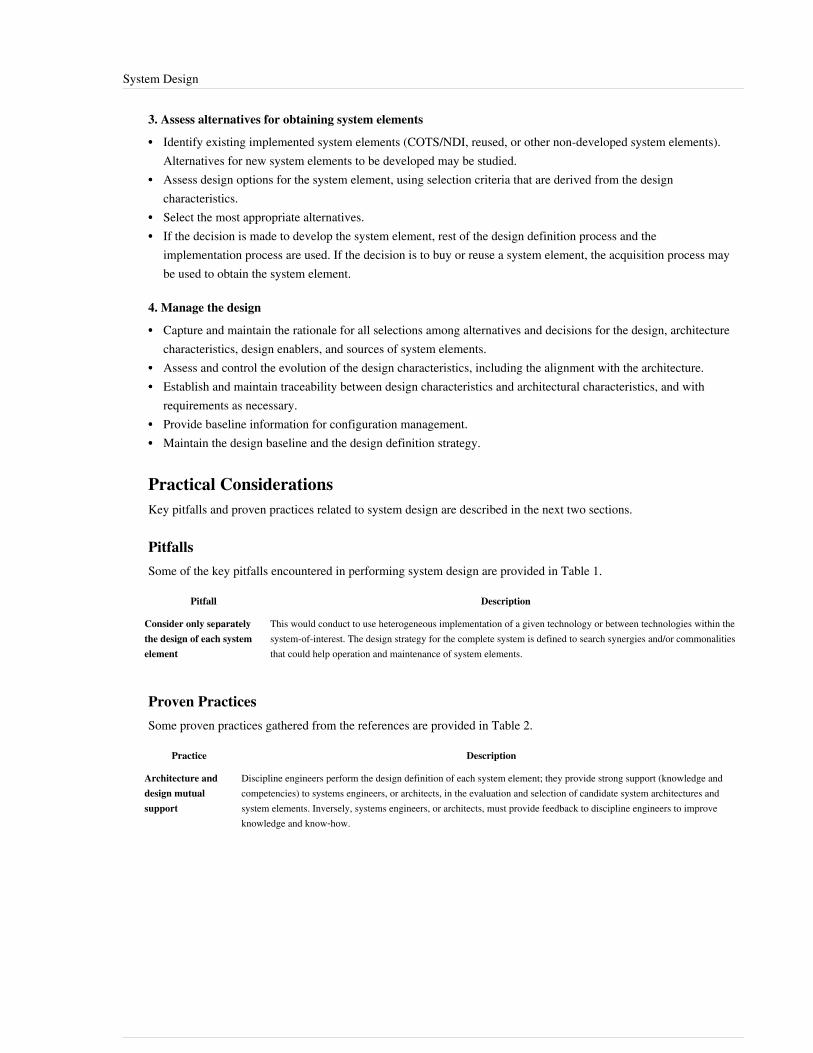
System Design 140
3. Assess alternatives for obtaining system elements
•• Identify existing implemented system elements (COTS/NDI, reused, or other non-developed system elements).Alternatives for new system elements to be developed may be studied.
•• Assess design options for the system element, using selection criteria that are derived from the designcharacteristics.
•• Select the most appropriate alternatives.•• If the decision is made to develop the system element, rest of the design definition process and the
implementation process are used. If the decision is to buy or reuse a system element, the acquisition process maybe used to obtain the system element.
4. Manage the design
•• Capture and maintain the rationale for all selections among alternatives and decisions for the design, architecturecharacteristics, design enablers, and sources of system elements.
•• Assess and control the evolution of the design characteristics, including the alignment with the architecture.•• Establish and maintain traceability between design characteristics and architectural characteristics, and with
requirements as necessary.•• Provide baseline information for configuration management.•• Maintain the design baseline and the design definition strategy.
Practical ConsiderationsKey pitfalls and proven practices related to system design are described in the next two sections.
PitfallsSome of the key pitfalls encountered in performing system design are provided in Table 1.
Pitfall Description
Consider only separatelythe design of each systemelement
This would conduct to use heterogeneous implementation of a given technology or between technologies within thesystem-of-interest. The design strategy for the complete system is defined to search synergies and/or commonalitiesthat could help operation and maintenance of system elements.
Proven PracticesSome proven practices gathered from the references are provided in Table 2.
Practice Description
Architecture anddesign mutualsupport
Discipline engineers perform the design definition of each system element; they provide strong support (knowledge andcompetencies) to systems engineers, or architects, in the evaluation and selection of candidate system architectures andsystem elements. Inversely, systems engineers, or architects, must provide feedback to discipline engineers to improveknowledge and know‐how.

System Design 141
References
Works CitedINCOSE. 2015. INCOSE Systems Engineering Handbook,Version 4. San Diego, CA, USA: International Council onSystems Engineering (INCOSE), INCOSE-TP-2003-002-03.2.2.ISO/IEC/IEEE. 2015. Systems and Software Engineering - System Life Cycle Processes.Geneva, Switzerland:International Organization for Standardization (ISO)/International Electrotechnical Commission (IEC) / Institute ofElectrical and Electronics Engineers. ISO/IEC/IEEE 15288:2015.Faisandier, A. 2012. Systems Architecture and Design. Belberaud, France: Sinergy'Com.
Primary ReferencesISO/IEC/IEEE. 2015. Systems and Software Engineering - System Life Cycle Processes.Geneva, Switzerland:International Organization for Standardization (ISO)/International Electrotechnical Commission (IEC) / Institute ofElectrical and Electronics Engineers. ISO/IEC/IEEE 15288:2015.Faisandier, A. 2012. Systems Architecture and Design. Belberaud, France: Sinergy'Com.
Additional ReferencesBaldwin, C.Y. and K.B. Clark. 2000. Design Rules. Cambridge, Mass: MIT Press.Buede, D.M. 2009. The Engineering Design of Systems: Models and Methods. 2nd ed. Hoboken, NJ, USA: JohnWiley & Sons Inc.DoD. 2010. DOD Architecture Framework.Version 2.02. Arlington, VA, USA: US Department of Defense.Available at: http:/ / cio-nii. defense. gov/ sites/ dodaf20/
< Previous Article | Parent Article | Next Article >SEBoK v. 1.4 released 29 June 2015
SEBoK DiscussionPlease provide your comments and feedback on the SEBoK below. You will need to log in to DISQUS using anexisting account (e.g. Yahoo, Google, Facebook, Twitter, etc.) or create a DISQUS account. Simply type yourcomment in the text field below and DISQUS will guide you through the login or registration steps. Feedback will bearchived and used for future updates to the SEBoK. If you provided a comment that is no longer listed, that commenthas been adjudicated. You can view adjudication for comments submitted prior to SEBoK v. 1.0 at SEBoK Reviewand Adjudication. Later comments are addressed and changes are summarized in the Letter from the Editor andAcknowledgements and Release History.
If you would like to provide edits on this article, recommend new content, or make comments on the SEBoKas a whole, please see the SEBoK Sandbox [1].
ENCODED_CONTENTMTA0MDcPGRpdiBpZD0iZGlzcXVzX3RocmVhZCI+PC9kaXY+CjxzY3JpcHQgdHlwZT0idGV4dC9qYXZhc2NyaXB0Ij4KICAgIC8qICogKiBDT05GSUdVUkFUSU9OIFZBUklBQkxFUzogRURJVCBCRUZPUkUgUEFTVElORyBJTlRPIFlPVVIgV0VCUEFHRSAqICogKi8KICAgIHZhciBkaXNxdXNfc2hvcnRuYW1lID0gJ3NlYm9rd2lraTEwJzsgLy8gcmVxdWlyZWQ6IHJlcGxhY2UgZXhhbXBsZSB3aXRoIHlvdXIgZm9ydW0gc2hvcnRuYW1lCiAgICB2YXIgZGlzcXVzX2lkZW50aWZpZXIgPSAnU3lzdGVtIERlc2lnbic7ICAgIHZhciBkaXNxdXNfdXJsID0gJ2h0dHA6Ly9zZWJva3dpa2kub3JnL2RyYWZ0L1N5c3RlbV9EZXNpZ24nOwogICAgLyogKiAqIERPTidUIEVESVQgQkVMT1cgVEhJUyBMSU5FICogKiAqLwogICAgKGZ1bmN0aW9uKCkgewogICAgICAgIHZhciBkc3EgPSBkb2N1bWVudC5jcmVhdGVFbGVtZW50KCdzY3JpcHQnKTsgZHNxLnR5cGUgPSAndGV4dC9qYXZhc2NyaXB0JzsgZHNxLmFzeW5jID0gdHJ1ZTsKICAgICAgICBkc3Euc3JjID0gJ2h0dHA6Ly8nICsgZGlzcXVzX3Nob3J0bmFtZSArICcuZGlzcXVzLmNvbS9lbWJlZC5qcyc7CiAgICAgICAgKGRvY3VtZW50LmdldEVsZW1lbnRzQnlUYWdOYW1lKCdoZWFkJylbMF0gfHwgZG9jdW1lbnQuZ2V0RWxlbWVudHNCeVRhZ05hbWUoJ2JvZHknKVswXSkuYXBwZW5kQ2hpbGQoZHNxKTsKICAgIH0pKCk7Cjwvc2NyaXB0Pgo8bm9zY3JpcHQ+UGxlYXNlIGVuYWJsZSBKYXZhU2NyaXB0IHRvIHZpZXcgdGhlIDxhIGhyZWY9Imh0dHA6Ly9kaXNxdXMuY29tLz9yZWZfbm9zY3JpcHQiPmNvbW1lbnRzIHBvd2VyZWQgYnkgRGlzcXVzLjwvYT48L25vc2NyaXB0Pgo8YSBocmVmPSJodHRwOi8vZGlzcXVzLmNvbSIgY2xhc3M9ImRzcS1icmxpbmsiPmJsb2cgY29tbWVudHMgcG93ZXJlZCBieSA8c3BhbiBjbGFzcz0ibG9nby1kaXNxdXMiPkRpc3F1czwvc3Bhbj48L2E+END_ENCODED_CONTENT

System Analysis 142
System AnalysisSystem analysis allows developers to objectively carry out quantitative assessments of systems in order to selectand/or update the most efficient system architecture and to generate derived engineering data. During engineering,assessments should be performed every time technical choices or decisions are made to determine compliance withsystem requirements.System analysis provides a rigorous approach to technical decision-making. It is used to perform trade-off studies,and includes modeling and simulation, cost analysis, technical risks analysis, and effectiveness analysis.
Principles Governing System AnalysisOne of the major tasks of a systems engineer is to evaluate the engineering data and artifacts created during thesystems engineering (SE) process. The evaluations are at the center of system analysis, providing means andtechniques• to define assessment criteria based on system requirements;• to assess design properties of each candidate solution in comparison to these criteria;•• to score globally the candidate solutions and to justify the scores; and•• to decide on the appropriate solution(s).The Analysis and Selection between Alternative Solutions article in the Systems Approach Applied to EngineeredSystems knowledge area (KA) of Part 2 describes activities related to selecting between possible system solutions toan identified problem or opportunity. The following general principles of systems analysis are defined:•• Systems analysis is based on assessment criteria based upon a problem or opportunity system description.
• These criteria will be based around an ideal system description, which assumes a hard system problem contextcan be defined.
•• Criteria must consider required system behavior and properties of the complete solution, in all possible widersystem contexts and environments.
• These must consider non-functional issues such as system safety, security, etc. (Please see SystemsEngineering and Specialty Engineering for additional discussion on incorporating non-functional elements.)
• This "ideal" system description may be supported by soft system descriptions, from which additional “soft”criteria may be defined. For example, a stakeholder preference for or against certain kinds of solutions,relevant social, political or cultural conventions to be considered, etc.
•• The assessment criteria should include, at a minimum, the constraints on cost and time scales acceptable tostakeholders.
•• Trade studies provide a mechanism for conducting analysis of alternative solutions.•• A trade study should consider a set of assessment criteria, with appropriate awareness of the limitations and
dependencies between individual criteria.•• Trade studies need to deal with both objective and subjective criteria. Care must be taken to assess the
sensitivity of the overall assessment to particular criteria.

System Analysis 143
Trade-off studiesIn the context of the definition of a system, a trade-off study consists of comparing the characteristics of each systemelement and of each candidate system architecture to determine the solution that best globally balances theassessment criteria. The various characteristics analyzed are gathered in cost analysis, technical risks analysis, andeffectiveness analysis (NASA 2007).Guidance on the conduct of trade studies for all types of system context are characterized in the above principles anddescribed in more details in the Analysis and Selection between Alternative Solutions topic. Of particular interest toSE analysis are technical effectiveness, cost, and technical risk analysis.
Effectiveness AnalysisThe effectiveness of an engineered system solution includes several essential characteristics that are generallygathered in the following list of analyses, including (but not limited to): performance, usability, dependability,manufacturing, maintenance or support, environment, etc. These analyses highlight candidate solutions undervarious aspects.It is essential to establish a classification that limits the number of analyses to the really significant aspects, such askey performance parameters. The main difficulties of effectiveness analysis are to sort and select the right set ofeffectiveness aspects; for example, if the product is made for a single use, maintainability will not be a relevantcriterion.
Cost AnalysisA cost analysis considers the full life cycle costs. A cost baseline can be adapted according to the project and thesystem. The global life cycle cost (LCC), or total ownership cost (TOC), may include examplar labor and non-laborcost items such as those indicated in Table 1.
Table 1. Types of Costs. (SEBoK Original)
Type of Cost Description and Examples
Development Engineering, development tools (equipment and software), project management, test-benches, mock-ups and prototypes,training, etc.
Product manufacturingor service realization
Raw materials and supplying, spare parts and stock assets, necessary resources to operation (water, electricity power,etc.), risks and nuances, evacuation, treatment and storage of waste or rejections produced, expenses of structure (taxes,management, purchase, documentation, quality, cleaning, regulation, controls, etc.), packing and storage, documentationrequired.
Sales and after-sales Expenses of structure (subsidiaries, stores, workshops, distribution, information acquisition, etc.), complaints andguarantees, etc.
Customer utilization Taxes, installation (customer), resources necessary to the operation of the product (water, fuel, lubricants, etc.), financialrisks and nuisances, etc.
Supply chain Transportation and delivery
Maintenance Field services, preventive maintenance, regulation controls, spare parts and stocks, cost of guarantee, etc.
Disposal Collection, dismantling, transportation, treatment, waste recycling, etc.
Methods for determining cost are described in the Planning topic.

System Analysis 144
Technical Risks AnalysisEvery risk analysis concerning every domain is based on three factors:1.1. Analysis of potential threats or undesired events and their probability of occurrence.2.2. Analysis of the consequences of these threats or undesired events and their classification on a scale of gravity.3.3. Mitigation to reduce the probabilities of threats and/or the levels of harmful effect to acceptable values.The technical risks appear when the system cannot satisfy the system requirements any longer. The causes reside inthe requirements and/or in the solution itself. They are expressed in the form of insufficient effectiveness and canhave multiple causes: incorrect assessment of the technological capabilities; over-estimation of the technical maturityof a system element; failure of parts; breakdowns; breakage, obsolescence of equipment, parts, or software,weakness from the supplier (non-compliant parts, delay for supply, etc.), human factors (insufficient training, wrongtunings, error handling, unsuited procedures, malice), etc.Technical risks are not to be confused with project risks, even if the method to manage them is the same. Althoughtechnical risks may lead to project risks, technical risks address the system itself, not the process for its development.(See Risk Management for more details.)
Process Approach
Purpose and Principles of the ApproachThe system analysis process is used to: (1) provide a rigorous basis for technical decision making, resolution ofrequirement conflicts, and assessment of alternative physical solutions (system elements and physical architectures);(2) determine progress in satisfying system requirements and derived requirements; (3) support risk management;and (4) ensure that decisions are made only after evaluating the cost, schedule, performance, and risk effects on theengineering or re-engineering of a system (ANSI/EIA 1998). This process is also called the decision analysis processby NASA (2007, 1-360) and is used to help evaluate technical issues, alternatives, and their uncertainties to supportdecision-making. (See Decision Management for more details.)System analysis supports other system definition processes:• Stakeholder requirements definition and system requirements definition processes use system analysis to solve
issues relating to conflicts among the set of requirements; in particular, those related to costs, technical risks, andeffectiveness (performances, operational conditions, and constraints). System requirements subject to high risks,or those which would require different architectures, are discussed.
• The Logical Architecture Model Development and Physical Architecture Model Development processes use it toassess characteristics or design properties of candidate logical and physical architectures, providing arguments forselecting the most efficient one in terms of costs, technical risks, and effectiveness (e.g., performances,dependability, human factors, etc.).
Like any system definition process, the system analysis process is iterative. Each operation is carried out severaltimes; each step improves the precision of analysis.
Activities of the ProcessMajor activities and tasks performed within this process include•• Planning the trade-off studies:
•• Determine the number of candidate solutions to analyze, the methods and procedures to be used, the expectedresults (examples of objects to be selected: behavioral architecture/scenario, physical architecture, systemelement, etc.), and the justification items.
•• Schedule the analyses according to the availability of models, engineering data (system requirements, designproperties), skilled personnel, and procedures.

System Analysis 145
•• Define the selection criteria model:•• Select the assessment criteria from non-functional requirements (performances, operational conditions,
constraints, etc.), and/or from design properties.•• Sort and order the assessment criteria.•• Establish a scale of comparison for each assessment criterion, and weigh every assessment criterion according
to its level of relative importance with the others.•• Identify candidate solutions, related models, and data.•• Assess candidate solutions using previously defined methods or procedures:
•• Carry out costs analysis, technical risks analysis, and effectiveness analysis placing every candidate solutionon every assessment criterion comparison scale.
•• Score every candidate solution as an assessment score.• Provide results to the calling process: assessment criteria, comparison scales, solutions’ scores, assessment
selection, and possibly recommendations and related arguments.
Artifacts and Ontology ElementsThis process may create several artifacts, such as•• A selection criteria model (list, scales, weighing)•• Costs, risks, and effectiveness analysis reports•• Justification reportsThis process handles the ontology elements of Table 2 within system analysis.
Table 2. Main Ontology Elements as Handled within System Analysis. (SEBoK Original)
AssessmentCriterion
In the context of system analysis, an assessment criterion is a characteristic used to assess or compare system elements, physicalinterfaces, physical architectures, functional architectures/scenarios, or any engineering elements that can be compared.
Identifier; name; description; relative weight; scalar weight
AssessmentSelection
In the context of system analysis, an assessment selection is a technical management element based on an assessment score thatjustifies the selection of a system element, a physical interface, a physical architecture, or a functional architecture/scenario.
AssessmentScore
In the context of system analysis, an assessment score is obtained assessing a system element, a physical interface, a physicalarchitecture, a functional architecture/scenario using a set of assessment criteria.
Identifier; name; description; value
Cost In the context of systems engineering, a cost is an amount expressed in a given currency related to the value of a system element,a physical interface, and a physical architecture.
Identifier; name; description; amount; type (development, production, utilization, maintenance, disposal); confidence interval;period of reference; estimation technique
Risk An event having a probability of occurrence and consequences related to the system mission or on other characteristics. (Usedfor technical risk in engineering.). A risk is the combination of vulnerability a danger or threat.
Identifier; name description; status

System Analysis 146
Checking Correctness of System AnalysisThe main items to be checked within system analysis in order to get validated arguments are•• Relevance of the models and data in the context of use of the system,•• Relevance of assessment criteria related to the context of use of the system,•• Reproducibility of simulation results and of calculations,•• Precision level of comparisons' scales,•• Confidence of estimates, and•• Sensitivity of solutions' scores related to assessment criteria weights.See Ring, Eisner, and Maier (2010) for additional perspective.
Methods and Modeling Techniques• General usage of models: Various types of models can be used in the context of system analysis:
• Physical models are scale models allowing simulation of physical phenomena. They are specific to eachdiscipline; associated tools include mock-ups, vibration tables, test benches, prototypes, decompressionchamber, wind tunnels, etc.
• Representation models are mainly used to simulate the behavior of a system. For example, enhancedfunctional flow block diagrams (eFFBDs), statecharts, state machine diagrams (based in systems modelinglanguage (SysML)), etc.
• Analytical models are mainly used to establish values of estimates. We can consider the deterministic modelsand probabilistic models (also known as stochastic models) to be analytical in nature. Analytical models useequations or diagrams to approach the real operation of the system. They can be very simple (addition) toincredibly complicated (probabilistic distribution with several variables).
• Use right models depending on the project progress•• At the beginning of the project, first studies use simple tools, allowing rough approximations which have the
advantage of not requiring too much time and effort. These approximations are often sufficient to eliminateunrealistic or outgoing candidate solutions.
•• Progressively with the progress of the project it is necessary to improve precision of data to compare thecandidate solutions still competing. The work is more complicated if the level of innovation is high.
•• A systems engineer alone cannot model a complex system; he has to be supported by skilled people fromdifferent disciplines involved.
• Specialist expertise: When the values of assessment criteria cannot be given in an objective or precise way, orbecause the subjective aspect is dominating, we can ask specialists for expertise. The estimates proceed in foursteps:
1.1. Select interviewees to collect the opinion of qualified people for the considered field.2.2. Draft a questionnaire; a precise questionnaire allows an easy analysis, but a questionnaire that is too closed risks
the neglection of significant points.3.3. Interview a limited number of specialists with the questionnaire, including an in-depth discussion to get precise
opinions.4.4. Analyze the data with several different people and compare their impressions until an agreement on a
classification of assessment criteria and/or candidate solutions is reached.Often used analytical models in the context of system analysis are summarized in Table 3.
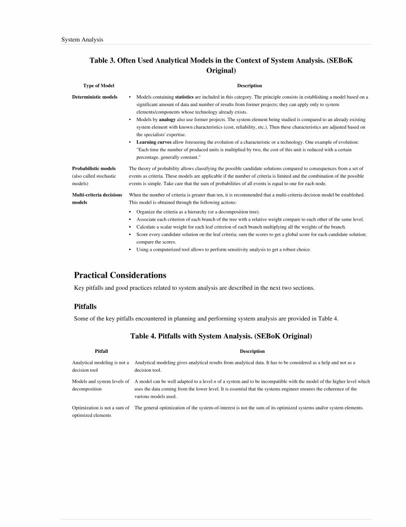
System Analysis 147
Table 3. Often Used Analytical Models in the Context of System Analysis. (SEBoKOriginal)
Type of Model Description
Deterministic models • Models containing statistics are included in this category. The principle consists in establishing a model based on asignificant amount of data and number of results from former projects; they can apply only to systemelements/components whose technology already exists.
• Models by analogy also use former projects. The system element being studied is compared to an already existingsystem element with known characteristics (cost, reliability, etc.). Then these characteristics are adjusted based onthe specialists' expertise.
• Learning curves allow foreseeing the evolution of a characteristic or a technology. One example of evolution:"Each time the number of produced units is multiplied by two, the cost of this unit is reduced with a certainpercentage, generally constant."
Probabilistic models(also called stochasticmodels)
The theory of probability allows classifying the possible candidate solutions compared to consequences from a set ofevents as criteria. These models are applicable if the number of criteria is limited and the combination of the possibleevents is simple. Take care that the sum of probabilities of all events is equal to one for each node.
Multi-criteria decisionsmodels
When the number of criteria is greater than ten, it is recommended that a multi-criteria decision model be established.This model is obtained through the following actions:
•• Organize the criteria as a hierarchy (or a decomposition tree).•• Associate each criterion of each branch of the tree with a relative weight compare to each other of the same level.•• Calculate a scalar weight for each leaf criterion of each branch multiplying all the weights of the branch.•• Score every candidate solution on the leaf criteria; sum the scores to get a global score for each candidate solution;
compare the scores.•• Using a computerized tool allows to perform sensitivity analysis to get a robust choice.
Practical ConsiderationsKey pitfalls and good practices related to system analysis are described in the next two sections.
PitfallsSome of the key pitfalls encountered in planning and performing system analysis are provided in Table 4.
Table 4. Pitfalls with System Analysis. (SEBoK Original)
Pitfall Description
Analytical modeling is not adecision tool
Analytical modeling gives analytical results from analytical data. It has to be considered as a help and not as adecision tool.
Models and system levels ofdecomposition
A model can be well adapted to a level n of a system and to be incompatible with the model of the higher level whichuses the data coming from the lower level. It is essential that the systems engineer ensures the coherence of thevarious models used.
Optimization is not a sum ofoptimized elements
The general optimization of the system-of-interest is not the sum of its optimized systems and/or system elements.
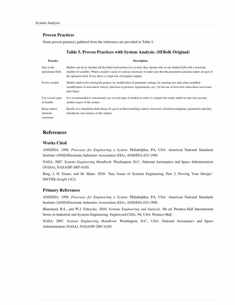
System Analysis 148
Proven PracticesSome proven practices gathered from the references are provided in Table 5.
Table 5. Proven Practices with System Analysis. (SEBoK Original)
Practice Description
Stay in theoperational field
Models can never simulate all the behavior/reactions of a system: they operate only in one limited field with a restrictednumber of variables. When a model is used, it is always necessary to make sure that the parameters and data inputs are part ofthe operation field. If not, there is a high risk of irregular outputs.
Evolve models Models shall evolve during the project: by modification of parameter settings, by entering new data when modified(modification of assessment criteria, functions to perform, requirements, etc.), by the use of new tools when those used reachtheir limits.
Use several typesof models
It is recommended to concurrently use several types of models in order to compare the results and/or to take into accountanother aspect of the system.
Keep contextelementsconsistent
Results of a simulation shall always be given in their modeling context: tool used, selected assumptions, parameters and dataintroduced, and variance of the outputs.
References
Works CitedANSI/EIA. 1998. Processes for Engineering a System. Philadelphia, PA, USA: American National StandardsInstitute (ANSI)/Electronic Industries Association (EIA), ANSI/EIA-632-1998.NASA. 2007. Systems Engineering Handbook. Washington, D.C.: National Aeronautics and Space Administration(NASA), NASA/SP-2007-6105.Ring, J, H. Eisner, and M. Maier. 2010. "Key Issues of Systems Engineering, Part 3: Proving Your Design."INCOSE Insight 13(2).
Primary ReferencesANSI/EIA. 1998. Processes for Engineering a System. Philadelphia, PA, USA: American National StandardsInstitute (ANSI)/Electronic Industries Association (EIA), ANSI/EIA 632-1998.Blanchard, B.S., and W.J. Fabrycky. 2010. Systems Engineering and Analysis, 5th ed. Prentice-Hall InternationalSeries in Industrial and Systems Engineering. Englewood Cliffs, NJ, USA: Prentice-Hall.NASA. 2007. Systems Engineering Handbook. Washington, D.C., USA: National Aeronautics and SpaceAdministration (NASA), NASA/SP-2007-6105.

System Analysis 149
Additional ReferencesRing, J, H. Eisner, and M. Maier. 2010. "Key Issues of Systems Engineering, Part 3: Proving Your Design."INCOSE Insight. 13(2).
< Previous Article | Parent Article | Next Article >SEBoK v. 1.4 released 29 June 2015
SEBoK DiscussionPlease provide your comments and feedback on the SEBoK below. You will need to log in to DISQUS using anexisting account (e.g. Yahoo, Google, Facebook, Twitter, etc.) or create a DISQUS account. Simply type yourcomment in the text field below and DISQUS will guide you through the login or registration steps. Feedback will bearchived and used for future updates to the SEBoK. If you provided a comment that is no longer listed, that commenthas been adjudicated. You can view adjudication for comments submitted prior to SEBoK v. 1.0 at SEBoK Reviewand Adjudication. Later comments are addressed and changes are summarized in the Letter from the Editor andAcknowledgements and Release History.
If you would like to provide edits on this article, recommend new content, or make comments on the SEBoKas a whole, please see the SEBoK Sandbox [1].
ENCODED_CONTENTMTA0MDcPGRpdiBpZD0iZGlzcXVzX3RocmVhZCI+PC9kaXY+CjxzY3JpcHQgdHlwZT0idGV4dC9qYXZhc2NyaXB0Ij4KICAgIC8qICogKiBDT05GSUdVUkFUSU9OIFZBUklBQkxFUzogRURJVCBCRUZPUkUgUEFTVElORyBJTlRPIFlPVVIgV0VCUEFHRSAqICogKi8KICAgIHZhciBkaXNxdXNfc2hvcnRuYW1lID0gJ3NlYm9rd2lraTEwJzsgLy8gcmVxdWlyZWQ6IHJlcGxhY2UgZXhhbXBsZSB3aXRoIHlvdXIgZm9ydW0gc2hvcnRuYW1lCiAgICB2YXIgZGlzcXVzX2lkZW50aWZpZXIgPSAnU3lzdGVtIEFuYWx5c2lzJzsgICAgdmFyIGRpc3F1c191cmwgPSAnaHR0cDovL3NlYm9rd2lraS5vcmcvZHJhZnQvU3lzdGVtX0FuYWx5c2lzJzsKICAgIC8qICogKiBET04nVCBFRElUIEJFTE9XIFRISVMgTElORSAqICogKi8KICAgIChmdW5jdGlvbigpIHsKICAgICAgICB2YXIgZHNxID0gZG9jdW1lbnQuY3JlYXRlRWxlbWVudCgnc2NyaXB0Jyk7IGRzcS50eXBlID0gJ3RleHQvamF2YXNjcmlwdCc7IGRzcS5hc3luYyA9IHRydWU7CiAgICAgICAgZHNxLnNyYyA9ICdodHRwOi8vJyArIGRpc3F1c19zaG9ydG5hbWUgKyAnLmRpc3F1cy5jb20vZW1iZWQuanMnOwogICAgICAgIChkb2N1bWVudC5nZXRFbGVtZW50c0J5VGFnTmFtZSgnaGVhZCcpWzBdIHx8IGRvY3VtZW50LmdldEVsZW1lbnRzQnlUYWdOYW1lKCdib2R5JylbMF0pLmFwcGVuZENoaWxkKGRzcSk7CiAgICB9KSgpOwo8L3NjcmlwdD4KPG5vc2NyaXB0PlBsZWFzZSBlbmFibGUgSmF2YVNjcmlwdCB0byB2aWV3IHRoZSA8YSBocmVmPSJodHRwOi8vZGlzcXVzLmNvbS8/cmVmX25vc2NyaXB0Ij5jb21tZW50cyBwb3dlcmVkIGJ5IERpc3F1cy48L2E+PC9ub3NjcmlwdD4KPGEgaHJlZj0iaHR0cDovL2Rpc3F1cy5jb20iIGNsYXNzPSJkc3EtYnJsaW5rIj5ibG9nIGNvbW1lbnRzIHBvd2VyZWQgYnkgPHNwYW4gY2xhc3M9ImxvZ28tZGlzcXVzIj5EaXNxdXM8L3NwYW4+PC9hPg==END_ENCODED_CONTENT
System RealizationSystem realization activities are conducted to create and test versions of a system as specified by system definition.The activities are grouped and described as generic processes that are performed iteratively and/or concurrentlydepending on the selected Life Cycle Model (glossary). These activities include those required to build a system(system implementation), integrate disparate system elements (system integration), and ensure that the system meetsboth the needs of stakeholders (system validation) and aligns with the system requirements and architecture (systemverification).These activities are not sequential, but are performed concurrently, iteratively and recursively depending on theselected life cycle model. Figure 1 (see "Overview", below), also shows how these processes fit within the context ofSystem Definition (glossary) and System Deployment and Use KAs. See also Applying Life Cycle Processes forfurther discussion of the relationships between process and life cycle model.
TopicsEach part of the SEBoK is divided into KAs, which are groupings of information with a related theme. The KAs inturn are divided into topics. This KA contains the following topics:•• System Implementation•• System Integration•• System Verification•• System ValidationSee the article Matrix of Implementation Examples for a mapping of case studies and vignettes included in Part 7 totopics covered in Part 3.

System Realization 150
OverviewEssentially, the outputs of system definition are used during system implementation to create system elements andduring system integration to provide plans and criteria for combining these elements. The requirements are used toverify and validate system elements, systems, and the overall system-of-interest (SoI). These activities providefeedback into the system design, particularly when problems or challenges are identified.Finally, when the system is considered, verified, and validated, it will then become an input to system deploymentand use. It is important to understand that there is overlap in these activities; they do not have to occur in sequence asdemonstrated in Figure 1. Every life cycle model includes realization activities, principally, verification andvalidation activities. The way these activities are performed is dependent upon the life cycle model in use. (Foradditional information on life cycles, see the Life Cycle Models KA.)
Figure 1. System Realization. (SEBoK Original)
The realization processes are performed to ensure that the system will be ready for transition and has the appropriatestructure and behavior to enable the desired operation and functionality throughout the system’s life span. Both DAUand NASA include transition in realization, in addition to implementation, integration, verification, and validation(Prosnik 2010; NASA December 2007, 1-360).
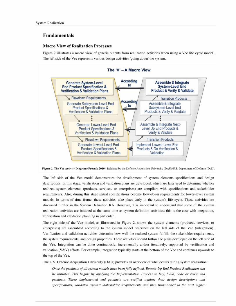
System Realization 151
Fundamentals
Macro View of Realization ProcessesFigure 2 illustrates a macro view of generic outputs from realization activities when using a Vee life cycle model.The left side of the Vee represents various design activities 'going down' the system.
Figure 2. The Vee Activity Diagram (Prosnik 2010). Released by the Defense Acquisition University (DAU)/U.S. Department of Defense (DoD).
The left side of the Vee model demonstrates the development of system elements specifications and designdescriptions. In this stage, verification and validation plans are developed, which are later used to determine whetherrealized system elements (products, services, or enterprises) are compliant with specifications and stakeholderrequirements. Also, during this stage initial specifications become flow-down requirements for lower-level systemmodels. In terms of time frame, these activities take place early in the system’s life cycle. These activities arediscussed further in the System Definition KA. However, it is important to understand that some of the systemrealization activities are initiated at the same time as system definition activities; this is the case with integration,verification and validation planning in particular.The right side of the Vee model, as illustrated in Figure 2, shows the system elements (products, services, orenterprises) are assembled according to the system model described on the left side of the Vee (integration).Verification and validation activities determine how well the realized system fulfills the stakeholder requirements,the system requirements, and design properties. These activities should follow the plans developed on the left side ofthe Vee. Integration can be done continuously, incrementally and/or iteratively, supported by verification andvalidation (V&V) efforts. For example, integration typically starts at the bottom of the Vee and continues upwards tothe top of the Vee.The U.S. Defense Acquisition University (DAU) provides an overview of what occurs during system realization:
Once the products of all system models have been fully defined, Bottom-Up End Product Realization can be initiated. This begins by applying the Implementation Process to buy, build, code or reuse end products. These implemented end products are verified against their design descriptions and specifications, validated against Stakeholder Requirements and then transitioned to the next higher
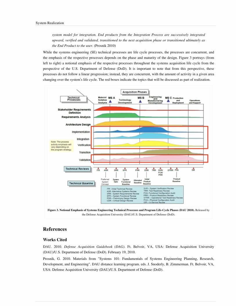
System Realization 152
system model for integration. End products from the Integration Process are successively integratedupward, verified and validated, transitioned to the next acquisition phase or transitioned ultimately asthe End Product to the user. (Prosnik 2010)
While the systems engineering (SE) technical processes are life cycle processes, the processes are concurrent, andthe emphasis of the respective processes depends on the phase and maturity of the design. Figure 3 portrays (fromleft to right) a notional emphasis of the respective processes throughout the systems acquisition life cycle from theperspective of the U.S. Department of Defense (DoD). It is important to note that from this perspective, theseprocesses do not follow a linear progression; instead, they are concurrent, with the amount of activity in a given areachanging over the system’s life cycle. The red boxes indicate the topics that will be discussed as part of realization.
Figure 3. Notional Emphasis of Systems Engineering Technical Processes and Program Life-Cycle Phases (DAU 2010). Released bythe Defense Acquisition University (DAU)/U.S. Department of Defense (DoD).
References
Works CitedDAU. 2010. Defense Acquisition Guidebook (DAG). Ft. Belvoir, VA, USA: Defense Acquisition University(DAU)/U.S. Department of Defense (DoD). February 19, 2010.Prosnik, G. 2010. Materials from "Systems 101: Fundamentals of Systems Engineering Planning, Research,Development, and Engineering". DAU distance learning program. eds. J. Snoderly, B. Zimmerman. Ft. Belvoir, VA,USA: Defense Acquisition University (DAU)/U.S. Department of Defense (DoD).

System Realization 153
Primary ReferencesINCOSE. 2011. INCOSE Systems Engineering Handbook: A Guide for System Life Cycle Processes and Activities.Version 3.2.1. San Diego, CA, USA: International Council on Systems Engineering (INCOSE),INCOSE-TP-2003-002-03.2.1.ISO/IEC/IEEE. 2015.Systems and Software Engineering - System Life Cycle Processes.Geneva, Switzerland:International Organization for Standardization (ISO)/International Electrotechnical Commission (IEC), Institute ofElectrical and Electronics Engineers.ISO/IEC/IEEE 15288:2015.Martin, J.N. 1997. Systems Engineering Guidebook: A process for developing systems and products, 1st ed. BocaRaton, FL, USA: CRC Press.NASA. 2007. Systems Engineering Handbook. Washington, D.C.: National Aeronautics and Space Administration(NASA), NASA/SP-2007-6105.
Additional ReferencesDAU. 2010. Defense Acquisition Guidebook (DAG). Ft. Belvoir, VA, USA: Defense Acquisition University(DAU)/U.S. Department of Defense (DoD). February 19, 2010.DAU. Your Acquisition Policy and Discretionary Best Practices Guide. In Defense Acquisition University(DAU)/U.S. Department of Defense (DoD) [database online]. Ft Belvoir, VA, USA. Available at: https:/ / dag. dau.mil/ Pages/ Default. aspx (accessed 2010).ECSS. 2009. Systems Engineering General Requirements. Noordwijk, Netherlands: Requirements and StandardsDivision, European Cooperation for Space Standardization (ECSS), 6 March 2009. ECSS-E-ST-10C.IEEE. 2012. "Standard for System and Software Verification and Validation". Institute of Electrical and ElectronicsEngineers. IEEE-1012.
< Previous Article | Parent Article | Next Article >SEBoK v. 1.4 released 29 June 2015
SEBoK DiscussionPlease provide your comments and feedback on the SEBoK below. You will need to log in to DISQUS using anexisting account (e.g. Yahoo, Google, Facebook, Twitter, etc.) or create a DISQUS account. Simply type yourcomment in the text field below and DISQUS will guide you through the login or registration steps. Feedback will bearchived and used for future updates to the SEBoK. If you provided a comment that is no longer listed, that commenthas been adjudicated. You can view adjudication for comments submitted prior to SEBoK v. 1.0 at SEBoK Reviewand Adjudication. Later comments are addressed and changes are summarized in the Letter from the Editor andAcknowledgements and Release History.
If you would like to provide edits on this article, recommend new content, or make comments on the SEBoKas a whole, please see the SEBoK Sandbox [1].
ENCODED_CONTENTNjU5ODkPGRpdiBpZD0iZGlzcXVzX3RocmVhZCI+PC9kaXY+CjxzY3JpcHQgdHlwZT0idGV4dC9qYXZhc2NyaXB0Ij4KICAgIC8qICogKiBDT05GSUdVUkFUSU9OIFZBUklBQkxFUzogRURJVCBCRUZPUkUgUEFTVElORyBJTlRPIFlPVVIgV0VCUEFHRSAqICogKi8KICAgIHZhciBkaXNxdXNfc2hvcnRuYW1lID0gJ3NlYm9rd2lraTEwJzsgLy8gcmVxdWlyZWQ6IHJlcGxhY2UgZXhhbXBsZSB3aXRoIHlvdXIgZm9ydW0gc2hvcnRuYW1lCiAgICB2YXIgZGlzcXVzX2lkZW50aWZpZXIgPSAnU3lzdGVtIFJlYWxpemF0aW9uJzsgICAgdmFyIGRpc3F1c191cmwgPSAnaHR0cDovL3NlYm9rd2lraS5vcmcvZHJhZnQvU3lzdGVtX1JlYWxpemF0aW9uJzsKICAgIC8qICogKiBET04nVCBFRElUIEJFTE9XIFRISVMgTElORSAqICogKi8KICAgIChmdW5jdGlvbigpIHsKICAgICAgICB2YXIgZHNxID0gZG9jdW1lbnQuY3JlYXRlRWxlbWVudCgnc2NyaXB0Jyk7IGRzcS50eXBlID0gJ3RleHQvamF2YXNjcmlwdCc7IGRzcS5hc3luYyA9IHRydWU7CiAgICAgICAgZHNxLnNyYyA9ICdodHRwOi8vJyArIGRpc3F1c19zaG9ydG5hbWUgKyAnLmRpc3F1cy5jb20vZW1iZWQuanMnOwogICAgICAgIChkb2N1bWVudC5nZXRFbGVtZW50c0J5VGFnTmFtZSgnaGVhZCcpWzBdIHx8IGRvY3VtZW50LmdldEVsZW1lbnRzQnlUYWdOYW1lKCdib2R5JylbMF0pLmFwcGVuZENoaWxkKGRzcSk7CiAgICB9KSgpOwo8L3NjcmlwdD4KPG5vc2NyaXB0PlBsZWFzZSBlbmFibGUgSmF2YVNjcmlwdCB0byB2aWV3IHRoZSA8YSBocmVmPSJodHRwOi8vZGlzcXVzLmNvbS8/cmVmX25vc2NyaXB0Ij5jb21tZW50cyBwb3dlcmVkIGJ5IERpc3F1cy48L2E+PC9ub3NjcmlwdD4KPGEgaHJlZj0iaHR0cDovL2Rpc3F1cy5jb20iIGNsYXNzPSJkc3EtYnJsaW5rIj5ibG9nIGNvbW1lbnRzIHBvd2VyZWQgYnkgPHNwYW4gY2xhc3M9ImxvZ28tZGlzcXVzIj5EaXNxdXM8L3NwYW4+PC9hPg==END_ENCODED_CONTENT

System Implementation 154
System ImplementationSystem Implementation uses the structure created during architectural design and the results of system analysis toconstruct system elements that meet the stakeholder requirements and system requirements developed in the earlylife cycle phases. These system elements are then integrated to form intermediate aggregates and finally the completesystem-of-interest (SoI). See System Integration.
Definition and PurposeImplementation is the process that actually yields the lowest-level system elements in the system hierarchy (systembreakdown structure). System elements are made, bought, or reused. Production involves the hardware fabricationprocesses of forming, removing, joining, and finishing, the software realization processes of coding and testing, orthe operational procedures development processes for operators' roles. If implementation involves a productionprocess, a manufacturing system which uses the established technical and management processes may be required.The purpose of the implementation process is to design and create (or fabricate) a system element conforming to thatelement’s design properties and/or requirements. The element is constructed employing appropriate technologies andindustry practices. This process bridges the system definition processes and the integration process. Figure 1 portrayshow the outputs of system definition relate to system implementation, which produces the implemented (system)elements required to produce aggregates and the SoI.
Figure 1. Simplification of How the Outputs of System Definition Relate to System Implementation, which Produces the System ElementsRequired to Produce Systems and Subsystems. (SEBoK Original)
Process Approach
Purpose and Principle of the ApproachDuring the implementation process, engineers apply the design properties and/or requirements allocated to a systemelement to design and produce a detailed description. They then fabricate, code, or build each individual elementusing specified materials, processes, physical or logical arrangements, standards, technologies, and/or informationflows outlined in detailed descriptions (drawings or other design documentation). A system element will be verifiedagainst the detailed description of properties and validated against its requirements.If subsequent verification and validation (V&V) actions or configuration audits reveal discrepancies, recursiveinteractions occur, which includes predecessor activities or processes, as required, to mitigate those discrepanciesand to modify, repair, or correct the system element in question. Figure 2 provides the context for theimplementation process from the perspective of the U.S. Defense Acquisition University (DAU).

System Implementation 155
Figure 2. Context Diagram for the Implementation Process (DAU 2010). Released by the Defense Acquisition University (DAU)/U.S.Department of Defense (DoD).
Such figures provide a useful overview of the systems engineering (SE) community’s perspectives on what isrequired for implementation and what the general results of implementation may be. These are further supported bythe discussion of implementation inputs, outputs, and activities found in the National Aeronautics and SpaceAssociation's (NASA's) Systems Engineering Handbook (NASA 2007). It is important to understand that these viewsare process-oriented. While this is a useful model, examining implementation only in terms of process can belimiting.Depending on the technologies and systems chosen when a decision is made to produce a system element, theimplementation process outcomes may generate constraints to be applied on the architecture of the higher-levelsystem; those constraints are normally identified as derived system requirements and added to the set of systemrequirements applicable to this higher-level system. The architectural design has to take those constraints intoaccount.If the decision is made to purchase or reuse an existing system element, it has to be identified as a constraint orsystem requirement applicable to the architecture of the higher-level system. Conversely, the implementation processmay involve some adaptation or adjustments to the system requirement in order to be integrated into a higher-levelsystem or aggregate.Implementation also involves packaging, handling, and storage, depending on the concerned technologies and whereor when the system requirement needs to be integrated into a higher-level aggregate. Developing the supportingdocumentation for a system requirement, such as the manuals for operation, maintenance, and/or installation, is alsoa part of the implementation process; these artifacts are utilized in the system deployment and use phase. The systemelement requirements and the associated verification and validation criteria are inputs to this process; these inputscome from the architectural design process detailed outputs.Execution of the implementation process is governed by both industrial and government standards and the terms ofall applicable agreements. This may include conditions for packaging and storage, as well as preparation for useactivities, such as operator training. In addition, packaging, handling, storage, and transportation (PHS&T)considerations will constrain the implementation activities. For more information, refer to the discussion of PHS&Tin the System Deployment and Use article. The developing or integrating organization will likely haveenterprise-level safety practices and guidelines that must also be considered.

System Implementation 156
Activities of the ProcessThe following major activities and tasks are performed during this process:• Define the implementation strategy - Implementation process activities begin with detailed design and include
developing an implementation strategy that defines fabrication and coding procedures, tools and equipment to beused, implementation tolerances, and the means and criteria for auditing configuration of resulting elements to thedetailed design documentation. In the case of repeated system element implementations (such as for massmanufacturing or replacement elements), the implementation strategy is defined and refined to achieve consistentand repeatable element production; it is retained in the project decision database for future use. Theimplementation strategy contains the arrangements for packing, storing, and supplying the implemented element.
• Realize the system element - Realize or adapt and produce the concerned system element using theimplementation strategy items as defined above. Realization or adaptation is conducted with regard to standardsthat govern applicable safety, security, privacy, and environmental guidelines or legislation and the practices ofthe relevant implementation technology. This requires the fabrication of hardware elements, development ofsoftware elements, definition of training capabilities, drafting of training documentation, and the training of initialoperators and maintainers.
• Provide evidence of compliance - Record evidence that the system element meets its requirements and theassociated verification and validation criteria as well as the legislation policy. This requires the conduction of peerreviews and unit testing, as well as inspection of operation and maintenance manuals. Acquire measuredproperties that characterize the implemented element (weight, capacities, effectiveness, level of performance,reliability, availability, etc.).
• Package, store, and supply the implemented element - This should be defined in the implementation strategy.
Artifacts and Ontology ElementsThis process may create several artifacts such as•• an implemented system•• implementation tools•• implementation procedures•• an implementation plan or strategy•• verification reports•• issue, anomaly, or trouble reports•• change requests (about design)This process handles the ontology elements shown in Table 1 below.
Table 1. Main Ontology Elements as Handled within System Element Implementation.(SEBoK Original)
Element Definition
Attributes (examples)
ImplementedElement
An implemented element is a system element that has been implemented. In the case of hardware it is marked with a part/serialnumber.
Identifier, name, description, type (hardware, software application, software piece, mechanical part, electric art, electroniccomponent, operator role, procedure, protocol, manual, etc.)

System Implementation 157
MeasuredProperty
A measured property is a characteristic of the implemented element established after its implementation. The measured propertiescharacterize the implemented system element when it is completely realized, verified, and validated. If the implemented elementcomplies with a design property, the measured property should equal the design property. Otherwise one has to identify thedifference or non-conformance which treatment could conclude to modify the design property and possibly the relatedrequirements, or to modify (correct, repair) the implemented element, or to identify a deviation.
Identifier, name, description, type (effectiveness, availability, reliability, maintainability, weight, capacity, etc.), value, unit, etc.
The main relationships between ontology elements are presented in Figure 3.
Figure 3. Implementation Elements Relationships with Other EngineeringElements. (SEBoK Original)
Methods, Techniques, and ToolsThere are many software tools available in the implementation and integration phases. The most basic method wouldbe the use of N-squared diagrams as discussed in Jeff Grady’s book System Integration (Grady 1994).
Checking and Correctness of ImplementationProper implementation checking and correctness should include testing to determine if the implemented element(i.e., piece of software, hardware, or other product) works in its intended use. Testing could include mockups andbreadboards, as well as modeling and simulation of a prototype or completed pieces of a system. Once this iscompleted successfully, the next process would be system integration.
System Implementation 158
References
Works CitedDAU. February 19, 2010. Defense acquisition guidebook (DAG). Ft. Belvoir, VA, USA: Defense AcquisitionUniversity (DAU)/U.S. Department of Defense.Grady, J.O. 1994. System integration. Boca Raton, FL, USA: CRC Press, Inc.NASA. 2007. Systems Engineering Handbook. Washington, D.C.: National Aeronautics and Space Administration(NASA), NASA/SP-2007-6105.
Primary ReferencesDAU. 2010. Defense Acquisition Guidebook (DAG). Ft. Belvoir, VA, USA: Defense Acquisition University(DAU)/U.S. Department of Defense (DoD). February 19, 2010.Grady, J.O. 1994. System Integration. Boca Raton, FL, USA: CRC Press, Inc.ISO/IEC/IEEE. 2015. Systems and Software Engineering - System Life Cycle Processes. Geneva, Switzerland:International Organization for Standardization (ISO)/International Electrotechnical Commission (IEC), Institute ofElectrical and Electronics Engineers. ISO/IEC/IEEE 15288:2015.NASA. 2007. Systems Engineering Handbook. Washington, D.C.: National Aeronautics and Space Administration(NASA), NASA/SP-2007-6105.
Additional ReferencesFaisandier, A. 2012. Systems Architecture and Design. Belberaud, France: Sinergy'Com.
< Previous Article | Parent Article | Next Article >SEBoK v. 1.4 released 29 June 2015
SEBoK DiscussionPlease provide your comments and feedback on the SEBoK below. You will need to log in to DISQUS using anexisting account (e.g. Yahoo, Google, Facebook, Twitter, etc.) or create a DISQUS account. Simply type yourcomment in the text field below and DISQUS will guide you through the login or registration steps. Feedback will bearchived and used for future updates to the SEBoK. If you provided a comment that is no longer listed, that commenthas been adjudicated. You can view adjudication for comments submitted prior to SEBoK v. 1.0 at SEBoK Reviewand Adjudication. Later comments are addressed and changes are summarized in the Letter from the Editor andAcknowledgements and Release History.
If you would like to provide edits on this article, recommend new content, or make comments on the SEBoKas a whole, please see the SEBoK Sandbox [1].
ENCODED_CONTENTNDA0NzMPGRpdiBpZD0iZGlzcXVzX3RocmVhZCI+PC9kaXY+CjxzY3JpcHQgdHlwZT0idGV4dC9qYXZhc2NyaXB0Ij4KICAgIC8qICogKiBDT05GSUdVUkFUSU9OIFZBUklBQkxFUzogRURJVCBCRUZPUkUgUEFTVElORyBJTlRPIFlPVVIgV0VCUEFHRSAqICogKi8KICAgIHZhciBkaXNxdXNfc2hvcnRuYW1lID0gJ3NlYm9rd2lraTEwJzsgLy8gcmVxdWlyZWQ6IHJlcGxhY2UgZXhhbXBsZSB3aXRoIHlvdXIgZm9ydW0gc2hvcnRuYW1lCiAgICB2YXIgZGlzcXVzX2lkZW50aWZpZXIgPSAnU3lzdGVtIEltcGxlbWVudGF0aW9uJzsgICAgdmFyIGRpc3F1c191cmwgPSAnaHR0cDovL3NlYm9rd2lraS5vcmcvZHJhZnQvU3lzdGVtX0ltcGxlbWVudGF0aW9uJzsKICAgIC8qICogKiBET04nVCBFRElUIEJFTE9XIFRISVMgTElORSAqICogKi8KICAgIChmdW5jdGlvbigpIHsKICAgICAgICB2YXIgZHNxID0gZG9jdW1lbnQuY3JlYXRlRWxlbWVudCgnc2NyaXB0Jyk7IGRzcS50eXBlID0gJ3RleHQvamF2YXNjcmlwdCc7IGRzcS5hc3luYyA9IHRydWU7CiAgICAgICAgZHNxLnNyYyA9ICdodHRwOi8vJyArIGRpc3F1c19zaG9ydG5hbWUgKyAnLmRpc3F1cy5jb20vZW1iZWQuanMnOwogICAgICAgIChkb2N1bWVudC5nZXRFbGVtZW50c0J5VGFnTmFtZSgnaGVhZCcpWzBdIHx8IGRvY3VtZW50LmdldEVsZW1lbnRzQnlUYWdOYW1lKCdib2R5JylbMF0pLmFwcGVuZENoaWxkKGRzcSk7CiAgICB9KSgpOwo8L3NjcmlwdD4KPG5vc2NyaXB0PlBsZWFzZSBlbmFibGUgSmF2YVNjcmlwdCB0byB2aWV3IHRoZSA8YSBocmVmPSJodHRwOi8vZGlzcXVzLmNvbS8/cmVmX25vc2NyaXB0Ij5jb21tZW50cyBwb3dlcmVkIGJ5IERpc3F1cy48L2E+PC9ub3NjcmlwdD4KPGEgaHJlZj0iaHR0cDovL2Rpc3F1cy5jb20iIGNsYXNzPSJkc3EtYnJsaW5rIj5ibG9nIGNvbW1lbnRzIHBvd2VyZWQgYnkgPHNwYW4gY2xhc3M9ImxvZ28tZGlzcXVzIj5EaXNxdXM8L3NwYW4+PC9hPg==END_ENCODED_CONTENT

System Integration 159
System IntegrationSystem integration consists of taking delivery of the implemented system elements which compose thesystem-of-interest (SoI), assembling these implemented elements together, and performing the verification andvalidation actions (V&V actions) in the course of the assembly. The ultimate goal of system integration is to ensurethat the individual system elements function properly as a whole and satisfy the design properties or characteristicsof the system. System integration is one part of the realization effort and relates only to developmental items.Integration should not to be confused with the assembly of end products on a production line. To perform theproduction, the assembly line uses a different order from that used by integration.
Definition and PurposeSystem integration consists of a process that “iteratively combines implemented system elements to form complete orpartial system configurations in order to build a product or service. It is used recursively for successive levels of thesystem hierarchy.” (ISO/IEC 15288 2015, 68). The process is extended to any kind of product system, servicesystem, and enterprise system. The purpose of system integration is to prepare the SoI for final validation andtransition either for use or for production. Integration consists of progressively assembling aggregates ofimplemented elements that compose the SoI as architected during design, and to check correctness of static anddynamic aspects of interfaces between the implemented elements.The U.S. Defense Acquisition University (DAU) provides the following context for integration: The integrationprocess will be used . . . for the incorporation of the final system into its operational environment to ensure that thesystem is integrated properly into all defined external interfaces. The interface management process is particularlyimportant for the success of the integration process, and iteration between the two processes will occur (DAU 2010).The purpose of system integration can be summarized as below:•• Completely assemble the implemented elements to make sure that the they are compatible with each other.•• Demonstrate that the aggregates of implemented elements perform the expected functions and meet measures of
performance/effectiveness.• Detect defects/faults related to design and assembly activities by submitting the aggregates to focused V&V
actions.Note: In the systems engineering literature, sometimes the term integration is used in a larger context than in thepresent topic. In this larger sense, it concerns the technical effort to simultaneously design and develop the systemand the processes for developing the system through concurrent consideration of all life cycle stages, needs, andcompetences. This approach requires the "integration" of numerous skills, activities, or processes.

System Integration 160
Principles
Boundary of Integration ActivityIntegration can be understood as the whole bottom-up branch of the Vee Model, including the tasks of assembly andthe appropriate verification tasks. See Figure 1 below:
Figure 1. Limits of Integration Activities. (SEBoK Original)
The assembly activity joins together, and physically links, the implemented elements. Each implemented element isindividually verified and validated prior to entering integration. Integration then adds the verification activity to theassembly activity, excluding the final validation.The final validation performs operational tests that authorize the transition for use or the transition for production.Remember that system integration only endeavors to obtain pre-production prototypes of the concerned product,service, or enterprise. If the product, service, or enterprise is delivered as a unique exemplar, the final validationactivity serves as acceptance for delivery and transfer for use. If the prototype has to be produced in severalexemplars, the final validation serves as acceptance to launch their production. The definition of the optimizedoperations of assembly which will be carried out on a production line relates to the manufacturing process and not tothe integration process.Integration activity can sometimes reveal issues or anomalies that require modifications of the design of the system.Modifying the design is not part of the integration process but concerns only the design process. Integration onlydeals with the assembly of the implemented elements and verification of the system against its properties asdesigned. During assembly, it is possible to carry out tasks of finishing touches which require simultaneous use ofseveral implemented elements (e.g., paint the whole after assembly, calibrate a biochemical component, etc.). Thesetasks must be planned in the context of integration and are not carried out on separate implemented elements and donot include modifications related to design.

System Integration 161
Aggregation of Implemented ElementsThe integration is used to systematically assemble a higher-level system from lower-level ones (implemented systemelements) that have been implemented. Integration often begins with analysis and simulations (e.g., various types ofprototypes) and progresses through increasingly more realistic systems and system elements until the final product,service, or enterprise is achieved.System integration is based on the notion of an aggregate - a subset of the system made up of several implementedelements (implemented system elements and physical interfaces) on which a set of V&V actions is applied. Eachaggregate is characterized by a configuration which specifies the implemented elements to be physically assembledand their configuration status.To perform V&V actions, a V&V configuration that includes the aggregate plus V&V tools is constituted. The V&Vtools are enabling products and can be simulators (simulated implemented elements), stubs or caps, activators(launchers, drivers), harness, measuring devices, etc.
Integration by Level of SystemAccording to the Vee Model, system definition (top-down branch) is done by successive levels of decomposition;each level corresponds to the physical architecture of systems and system elements. The integration (bottom-upbranch) takes the opposite approach of composition (i.e., a level by level approach). On a given level, integration isdone on the basis of the physical architecture defined during system definition.
Integration StrategyThe integration of implemented elements is generally performed according to a predefined strategy. The definition ofthe integration strategy is based on the architecture of the system and relies on the way the architecture of the systemhas been designed. The strategy is described in an integration plan that defines the minimum configuration ofexpected aggregates, the order of assembly of these aggregates in order to support efficient subsequent verificationand validation actions (e.g., inspections and/or testing), techniques to check or evaluate interfaces, and necessarycapabilities in the integration environment to support combinations of aggregates. The integration strategy is thuselaborated starting from the selected verification and validation strategy. See the System Verification and SystemValidation topics.To define an integration strategy, there are several possible integration approaches/techniques that may be usedindividually or in combination. The selection of integration techniques depends on several factors; in particular, thetype of system element, delivery time, order of delivery, risks, constraints, etc. Each integration technique hasstrengths and weaknesses which should be considered in the context of the SoI. Some integration techniques aresummarized in Table 1 below.
Table 1. Integration Techniques. (SEBoK Original)
IntegrationTechnique
Description
Global Integration Also known as big-bang integration; all the delivered implemented elements are assembled in only one step.
•• This technique is simple and does not require simulating the implemented elements not being available at that time.•• Difficult to detect and localize faults; interface faults are detected late.•• Should be reserved for simple systems, with few interactions and few implemented elements without technological
risks.
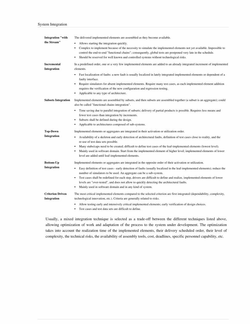
System Integration 162
Integration "withthe Stream"
The delivered implemented elements are assembled as they become available.
•• Allows starting the integration quickly.•• Complex to implement because of the necessity to simulate the implemented elements not yet available. Impossible to
control the end-to-end "functional chains"; consequently, global tests are postponed very late in the schedule.•• Should be reserved for well known and controlled systems without technological risks.
IncrementalIntegration
In a predefined order, one or a very few implemented elements are added to an already integrated increment of implementedelements.
•• Fast localization of faults: a new fault is usually localized in lately integrated implemented elements or dependent of afaulty interface.
•• Require simulators for absent implemented elements. Require many test cases, as each implemented element additionrequires the verification of the new configuration and regression testing.
•• Applicable to any type of architecture.
Subsets Integration Implemented elements are assembled by subsets, and then subsets are assembled together (a subset is an aggregate); couldalso be called "functional chains integration".
•• Time saving due to parallel integration of subsets; delivery of partial products is possible. Requires less means andfewer test cases than integration by increments.
•• Subsets shall be defined during the design.•• Applicable to architectures composed of sub-systems.
Top-DownIntegration
Implemented elements or aggregates are integrated in their activation or utilization order.
•• Availability of a skeleton and early detection of architectural faults, definition of test cases close to reality, and there-use of test data sets possible.
•• Many stubs/caps need to be created; difficult to define test cases of the leaf-implemented elements (lowest level).•• Mainly used in software domain. Start from the implemented element of higher level; implemented elements of lower
level are added until leaf-implemented elements.
Bottom-UpIntegration
Implemented elements or aggregates are integrated in the opposite order of their activation or utilization.
•• Easy definition of test cases - early detection of faults (usually localized in the leaf-implemented elements); reduce thenumber of simulators to be used. An aggregate can be a sub-system.
•• Test cases shall be redefined for each step, drivers are difficult to define and realize, implemented elements of lowerlevels are "over-tested", and does not allow to quickly detecting the architectural faults.
•• Mainly used in software domain and in any kind of system.
Criterion DrivenIntegration
The most critical implemented elements compared to the selected criterion are first integrated (dependability, complexity,technological innovation, etc.). Criteria are generally related to risks.
•• Allow testing early and intensively critical implemented elements; early verification of design choices.•• Test cases and test data sets are difficult to define.
Usually, a mixed integration technique is selected as a trade-off between the different techniques listed above,allowing optimization of work and adaptation of the process to the system under development. The optimizationtakes into account the realization time of the implemented elements, their delivery scheduled order, their level ofcomplexity, the technical risks, the availability of assembly tools, cost, deadlines, specific personnel capability, etc.

System Integration 163
Process Approach
Activities of the ProcessMajor activities and tasks performed during this process include• Establishing the integration plan (this activity is carried out concurrently to the design activity of the system)
that defines:•• The optimized integration strategy: order of aggregates assembly using appropriate integration techniques.• The V&V actions to be processed for the purpose of integration.•• The configurations of the aggregates to be assembled and verified.• The integration means and verification means (dedicated enabling products) that may include assembly
procedures, assembly tools (harness, specific tools), V&V tools (simulators, stubs/caps, launchers, testbenches, devices for measuring, etc.), and V&V procedures.
• Obtain the integration means and verification means as defined in the integration plan; the acquisition of themeans can be done through various ways such as procurement, development, reuse, and sub-contracting; usuallythe acquisition of the complete set of means is a mix of these methods.
• Take delivery of each implemented element:•• Unpack and reassemble the implemented element with its accessories.•• Check the delivered configuration, conformance of implemented elements, compatibility of interfaces, and
ensure the presence of mandatory documentation.• Assemble the implemented elements into aggregates:
• Gather the implemented elements to be assembled, the integration means (assembly tools, assemblyprocedures), and the verification means (V&V tools and procedures).
•• Connect the implemented elements on each other to constitute aggregates in the order prescribed by theintegration plan and in assembly procedures using assembly tools.
• Add or connect the V&V tools to the aggregates as predefined.•• Carry out eventual operations of welding, gluing, drilling, tapping, adjusting, tuning, painting, parametering,
etc.• Verify each aggregate:
•• Check the aggregate is correctly assembled according to established procedures.•• Perform the verification process that uses verification and validation procedures and check that the aggregate
shows the right design properties/specified requirements.•• Record integration results/reports and potential issue reports, change requests, etc.
Artifacts and Ontology ElementsThis process may create several artifacts such as•• an integrated system•• assembly tools•• assembly procedures•• integration plans•• integration reports•• issue/anomaly/trouble reports•• change requests (about design)This process utilizes the ontology elements discussed in Table 2.

System Integration 164
Table 2. Main Ontology Elements as Handled within System Integration. (SEBoK Original)
Element Definition
Attributes
Aggregate An aggregate is a subset of the system made up of several system elements or systems on which a set of verification actions isapplied.
Identifier, name, description
AssemblyProcedure
An assembly procedure groups a set of elementary assembly actions to build an aggregate of implemented system elements.
Identifier, name, description, duration, unit of time
Assembly Tool An assembly tool is a physical tool used to connect, assemble, or link several implemented system elements to build aggregates(specific tool, harness, etc.).
Identifier, name, description
Risk An event having a probability of occurrence and a gravity degree on its consequence onto the system mission or on othercharacteristics (used for technical risk in engineering). A risk is the combination of vulnerability and of a danger or a threat.
Identifier, name, description, status
Rationale An argument that provides the justification for the selection of an engineering element.
Identifier, name, description (rational, reasons for defining an aggregate, assembly procedure, assembly tool)
Note: verification and validation ontology elements are described in the System Verification and System Validationtopics.The main relationships between ontology elements are presented in Figure 2.

System Integration 165
Figure 2. Integration Elements Relationships with Other Engineering Elements. (SEBoK Original)
Checking and Correctness of IntegrationThe main items to be checked during the integration process include the following:•• The integration plan respects its template.•• The expected assembly order (integration strategy) is realistic.•• No system element and physical interface set out in the system design document is forgotten.•• Every interface and interaction between implemented elements is verified.•• Assembly procedures and assembly tools are available and validated prior to beginning the assembly.• V&V procedures and tools are available and validated prior to beginning the verification.•• Integration reports are recorded.
Methods and TechniquesSeveral different approaches are summarized above in the section Integration Strategy [1] (above) that may be usedfor integration, yet other approaches exist. In particular, important integration strategies for intensive softwaresystems include: vertical integration, horizontal integration, and star integration.
Coupling Matrix and N-squared Diagram
One of the most basic methods to define the aggregates and the order of integration would be the use of N-Squareddiagrams (Grady 1994, 190).In the integration context, the coupling matrices are useful for optimizing the aggregate definition and verification ofinterfaces:

System Integration 166
•• The integration strategy is defined and optimized by reorganizing the coupling matrix in order to group theimplemented elements in aggregates, thus minimizing the number of interfaces to be verified between aggregates(see Figure 3).
Figure 3. Initial Arrangement of Aggregates on the Left; Final Arrangement After Reorganization on the Right. (SEBoK Original)
•• When verifying the interactions between aggregates, the matrix is an aid tool for fault detection. If by adding animplemented element to an aggregate an error is detected, the fault can be either related to the implementedelement, to the aggregate, or to the interfaces. If the fault is related to the aggregate, it can relate to anyimplemented element or any interface between the implemented elements internal to the aggregate.
Application to Product Systems, Service Systems, and Enterprise SystemsAs the nature of implemented system elements and physical interfaces is different for these types of systems, theaggregates, the assembly tools, and the V&V tools are different. Some integration techniques are more appropriate tospecific types of systems. Table 3 below provides some examples.
Table 3. Different Integration Elements for Product, Service, and Enterprise Systems.(SEBoK Original)
Element Product System Service System Enterprise System
System Element Hardware Parts (mechanics,electronics, electrical, plastic,chemical, etc.)
Operator Roles
Software Pieces
Processes, data bases, procedures, etc.
Operator Roles
Software Applications
Corporate, direction, division,department, project, technical team,leader, etc.
IT components
Physical Interface Hardware parts, protocols,procedures, etc.
Protocols, documents, etc. Protocols, procedures, documents, etc.
Assembly Tools Harness, mechanical tools, specifictools
Software Linker
Documentation, learning course, etc. Documentation, learning, moving ofoffice
Verification Tools Test bench, simulator, launchers,stub/cap
Activity/scenario models, simulator,human roles rehearsal, computer, etc.
Skilled Experts
Activity/scenario models, simulator,human roles rehearsal
Validation Tools Operational environment Operational environment Operational environment

System Integration 167
RecommendedIntegration Techniques
Top down integration technique
Bottom Up Integration technique
Subsets integration technique(functional chains)
Global integration technique
Incremental integration
Practical ConsiderationsKey pitfalls and good practices related to system integration are described in the next two sections.
PitfallsSome of the key pitfalls encountered in planning and performing SE Measurement are provided in Table 4.
Table 4. Major Pitfalls with System Integration. (SEBoK Original)
Pitfall Description
What is expectedhas delay
The experience shows that the implemented elements always do not arrive in the expected order and the tests never proceedor result as foreseen; therefore, the integration strategy should allow a great flexibility.
Big-bang notappropriate
The "big-bang" integration technique is not appropriate for a fast detection of faults. It is thus preferable to verify theinterfaces progressively all along the integration.
Integration plan toolate
The preparation of the integration activities is planned too late in the project schedule, typically when first implementedelements are delivered.
Good PracticesSome good practices, gathered from the references are provided in Table 5.
Table 5. Proven Practices with System Integration. (SEBoK Original)
Practice Description
Start earlierdevelopment ofmeans
The development of assembly tools and verification and validation tools can be as long as the system itself. It should bestarted as early as possible as soon as the preliminary design is nearly frozen.
Integration meansseen as enablingsystems
The development of integration means (assembly tools, verification, and validation tools) can be seen as enabling systems,using system definition and system realization processes as described in this SEBoK, and managed as projects. Theseprojects can be led by the project of the corresponding system-of-interest, but assigned to specific system blocks, or can besubcontracted as separate projects.
Use coupling matrix A good practice consists in gradually integrating aggregates in order to detect faults more easily. The use of the couplingmatrix applies for all strategies and especially for the bottom up integration strategy.
Flexible integrationplan and schedule
The integration process of complex systems cannot be easily foreseeable and its progress control difficult to observe. Thisis why it is recommended to plan integration with specific margins, using flexible techniques, and integrating sets bysimilar technologies.
Integration anddesign teams
The integration responsible should be part of the design team.
System Integration 168
References
Works CitedDAU. February 19, 2010. Defense Acquisition Guidebook (DAG). Ft. Belvoir, VA, USA: Defense AcquisitionUniversity (DAU)/U.S. Department of Defense (DoD).Faisandier, A. 2012. Systems Architecture and Design. Belberaud, France: Sinergy'Com.ISO/IEC/IEEE. 2015.Systems and Software Engineering - System Life Cycle Processes.Geneva, Switzerland:International Organization for Standardization (ISO)/International Electrotechnical Commission (IEC), Institute ofElectrical and Electronics Engineers.ISO/IEC/IEEE 15288:2015.
Primary ReferencesINCOSE. 2010. Systems Engineering Handbook: A Guide for Systems Life Cycle Processes and Activities. Version3.2. San Diego, CA, USA: International Council on Systems Engineering (INCOSE), INCOSE-TP-2003-002-03.2.NASA. 2007. Systems Engineering Handbook. Washington, D.C.: National Aeronautics and Space Administration(NASA), NASA/SP-2007-6105.
Additional ReferencesBuede, D.M. 2009. The Engineering Design of Systems: Models and Methods. 2nd ed. Hoboken, NJ, USA: JohnWiley & Sons Inc.DAU. 2010. Defense Acquisition Guidebook (DAG). Ft. Belvoir, VA, USA: Defense Acquisition University(DAU)/U.S. Department of Defense. February 19, 2010.Gold-Bernstein, B. and W.A. Ruh. 2004. Enterprise integration: The essential guide to integration solutions.Boston, MA, USA: Addison Wesley Professional.Grady, J.O. 1994. System integration. Boca Raton, FL, USA: CRC Press, Inc.Hitchins, D. 2009. "What are the General Principles Applicable to Systems?" INCOSE Insight 12(4):59-63.Jackson, S. 2010. Architecting Resilient Systems: Accident Avoidance and Survival and Recovery from Disruptions.Hoboken, NJ, USA: John Wiley & Sons.Reason, J. 1997. Managing the Risks of Organizational Accidents. Aldershot, UK: Ashgate Publishing Limited.
< Previous Article | Parent Article | Next Article >SEBoK v. 1.4 released 29 June 2015
SEBoK DiscussionPlease provide your comments and feedback on the SEBoK below. You will need to log in to DISQUS using anexisting account (e.g. Yahoo, Google, Facebook, Twitter, etc.) or create a DISQUS account. Simply type yourcomment in the text field below and DISQUS will guide you through the login or registration steps. Feedback will bearchived and used for future updates to the SEBoK. If you provided a comment that is no longer listed, that commenthas been adjudicated. You can view adjudication for comments submitted prior to SEBoK v. 1.0 at SEBoK Reviewand Adjudication. Later comments are addressed and changes are summarized in the Letter from the Editor andAcknowledgements and Release History.
If you would like to provide edits on this article, recommend new content, or make comments on the SEBoKas a whole, please see the SEBoK Sandbox [1].
ENCODED_CONTENTMTExNDUPGRpdiBpZD0iZGlzcXVzX3RocmVhZCI+PC9kaXY+CjxzY3JpcHQgdHlwZT0idGV4dC9qYXZhc2NyaXB0Ij4KICAgIC8qICogKiBDT05GSUdVUkFUSU9OIFZBUklBQkxFUzogRURJVCBCRUZPUkUgUEFTVElORyBJTlRPIFlPVVIgV0VCUEFHRSAqICogKi8KICAgIHZhciBkaXNxdXNfc2hvcnRuYW1lID0gJ3NlYm9rd2lraTEwJzsgLy8gcmVxdWlyZWQ6IHJlcGxhY2UgZXhhbXBsZSB3aXRoIHlvdXIgZm9ydW0gc2hvcnRuYW1lCiAgICB2YXIgZGlzcXVzX2lkZW50aWZpZXIgPSAnU3lzdGVtIEludGVncmF0aW9uJzsgICAgdmFyIGRpc3F1c191cmwgPSAnaHR0cDovL3NlYm9rd2lraS5vcmcvZHJhZnQvU3lzdGVtX0ludGVncmF0aW9uJzsKICAgIC8qICogKiBET04nVCBFRElUIEJFTE9XIFRISVMgTElORSAqICogKi8KICAgIChmdW5jdGlvbigpIHsKICAgICAgICB2YXIgZHNxID0gZG9jdW1lbnQuY3JlYXRlRWxlbWVudCgnc2NyaXB0Jyk7IGRzcS50eXBlID0gJ3RleHQvamF2YXNjcmlwdCc7IGRzcS5hc3luYyA9IHRydWU7CiAgICAgICAgZHNxLnNyYyA9ICdodHRwOi8vJyArIGRpc3F1c19zaG9ydG5hbWUgKyAnLmRpc3F1cy5jb20vZW1iZWQuanMnOwogICAgICAgIChkb2N1bWVudC5nZXRFbGVtZW50c0J5VGFnTmFtZSgnaGVhZCcpWzBdIHx8IGRvY3VtZW50LmdldEVsZW1lbnRzQnlUYWdOYW1lKCdib2R5JylbMF0pLmFwcGVuZENoaWxkKGRzcSk7CiAgICB9KSgpOwo8L3NjcmlwdD4KPG5vc2NyaXB0PlBsZWFzZSBlbmFibGUgSmF2YVNjcmlwdCB0byB2aWV3IHRoZSA8YSBocmVmPSJodHRwOi8vZGlzcXVzLmNvbS8/cmVmX25vc2NyaXB0Ij5jb21tZW50cyBwb3dlcmVkIGJ5IERpc3F1cy48L2E+PC9ub3NjcmlwdD4KPGEgaHJlZj0iaHR0cDovL2Rpc3F1cy5jb20iIGNsYXNzPSJkc3EtYnJsaW5rIj5ibG9nIGNvbW1lbnRzIHBvd2VyZWQgYnkgPHNwYW4gY2xhc3M9ImxvZ28tZGlzcXVzIj5EaXNxdXM8L3NwYW4+PC9hPg==

System Integration 169
END_ENCODED_CONTENT
References[1] http:/ / sebokwiki. org/ 1. 0. 1/ index. php?title=System_Integration#Integration_Strategy
System VerificationSystem Verification is a set of actions used to check the correctness of any element, such as a system element, asystem, a document, a service, a task, a requirement, etc. These types of actions are planned and carried outthroughout the life cycle of the system. Verification is a generic term that needs to be instantiated within the contextit occurs. As a process, verification is a transverse activity to every life cycle stage of the system. In particular,during the development cycle of the system, the verification process is performed in parallel with the systemdefinition and system realization processes and applies to any activity and any product resulting from the activity.The activities of every life cycle process and those of the verification process can work together. For example, theintegration process frequently uses the verification process. It is important to remember that verification, whileseparate from validation, is intended to be performed in conjunction with validation.
Definition and PurposeVerification is the confirmation, through the provision of objective evidence, that specified requirements have beenfulfilled. With a note added in ISO/IEC/IEEE 15288, the scope of verification includes a set of activities thatcompares a system or system element against the requirements, architecture and design characteristics, and otherproperties to be verified (ISO/IEC/IEEE 2015). This may include, but is not limited to, specified requirements,design description, and the system itself.The purpose of verification, as a generic action, is to identify the faults/defects introduced at the time of anytransformation of inputs into outputs. Verification is used to provide information and evidence that thetransformation was made according to the selected and appropriate methods, techniques, standards, or rules.Verification is based on tangible evidence; i.e., it is based on information whose veracity can be demonstrated byfactual results obtained from techniques such as inspection, measurement, testing, analysis, calculation, etc. Thus,the process of verifying a system (product, service, enterprise, or system of systems (SoS)) consists of comparing therealized characteristics or properties of the product, service, or enterprise against its expected design properties.
Principles and Concepts
Concept of Verification Action
Why Verify?
In the context of human realization, any human thought is susceptible to error. This is also the case with anyengineering activity. Studies in human reliability have shown that people trained to perform a specific operationmake around 1-3 errors per hour in best case scenarios. In any activity, or resulting outcome of an activity, the searchfor potential errors should not be neglected, regardless of whether or not one thinks they will happen or that theyshould not happen; the consequences of errors can cause extremely significant failures or threats.A verification action is defined, and then performed, as shown in Figure 1.

System Verification 170
Figure 1. Definition and Usage of a Verification Action. (SEBoK Original)
The definition of a verification action applied to an engineering element includes the following:•• Identification of the element on which the verification action will be performed•• Identification of the reference to define the expected result of the verification action (see examples of reference in
Table 1)The performance of a verification action includes the following:•• Obtaining a result by performing the verification action onto the submitted element•• Comparing the obtained result with the expected result•• Deducing the degree of correctness of the element
What to Verify?
Any engineering element can be verified using a specific reference for comparison: stakeholder requirement, systemrequirement, function, system element, document, etc. Examples are provided in Table 1.
Table 1. Examples of Verified Items. (SEBoK Original)
Items Explanation for Verification
Document To verify a document is to check the application of drafting rules.
StakeholderRequirement andSystem Requirement
To verify a stakeholder requirement or a system requirement is to check the application of syntactic and grammaticalrules, and characteristics defined in the stakeholder requirements definition process, and the system requirementsdefinition process such as; necessity, implementation free, unambiguous, consistent, complete, singular, feasible,traceable, and verifiable.
Design To verify the design of a system is to check its logical and physical architecture elements against the characteristics ofthe outcomes of the design processes.
System To verify a system (product, service, or enterprise) is to check its realized characteristics or properties against itsexpected design characteristics.
Aggregate To verify an aggregate for integration is to check in particular every interface and interaction between implementedelements.
Verification Procedure To verify a verification procedure is to check the application of a predefined template and drafting rules.

System Verification 171
Verification versus ValidationThe term verification is often associated with the term validation and understood as a single concept of V&V.Validation is used to ensure that one is working the right problem, whereas verification is used to ensure that one hassolved the problem right (Martin 1997). From an actual and etymological meaning, the term verification comes fromthe Latin verus, which means truth, and facere, which means to make/perform. Thus, verification means to provethat something is true or correct (a property, a characteristic, etc.). The term validation comes from the Latin valere,which means to become strong, and has the same etymological root as the word value. Thus, validation means toprove that something has the right features to produce the expected effects. (Adapted from "Verification andValidation in plain English" (Lake INCOSE 1999).)The main differences between the verification process and the validation process concern the references used tocheck the correctness of an element, and the acceptability of the effective correctness.•• Within verification, comparison between the expected result and the obtained result is generally binary, whereas
within validation, the result of the comparison may require a judgment of value regarding whether or not to acceptthe obtained result compared to a threshold or limit.
•• Verification relates more to one element, whereas validation relates more to a set of elements and considers thisset as a whole.
•• Validation presupposes that verification actions have already been performed.•• The techniques used to define and perform the verification actions and those for validation actions are very
similar.
Integration, Verification, and Validation of the SystemThere is sometimes a misconception that verification occurs after integration and before validation. In most cases, itis more appropriate to begin verification activities during development or implementation and to continue them intodeployment and use.Once the system elements have been realized, they’re integrated to form the complete system. Integration consists ofassembling and performing verification actions as stated in the integration process. A final validation activitygenerally occurs when the system is integrated, but a certain number of validation actions are also performed parallelto the system integration in order to reduce the number of verification actions and validation actions whilecontrolling the risks that could be generated if some checks are excluded. Integration, verification, and validation areintimately processed together due to the necessity of optimizing the strategy of verification and validation, as well asthe strategy of integration.
Process Approach
Purpose and Principle of the ApproachThe purpose of the verification process is to confirm that the system fulfills the specified design requirements. Thisprocess provides the information required to effect the remedial actions that correct non-conformances in the realizedsystem or the processes that act on it - see ISO/IEC/IEEE 15288 (ISO/IEC/IEEE 2015).Each system element and the complete system itself should be compared against its own design references (specifiedrequirements). As stated by Dennis Buede, verification is the matching of [configuration items], components,sub-systems, and the system to corresponding requirements to ensure that each has been built right (Buede 2009).This means that the verification process is instantiated as many times as necessary during the global development ofthe system. Because of the generic nature of a process, the verification process can be applied to any engineeringelement that has conducted to the definition and realization of the system elements and the system itself.

System Verification 172
Facing the huge number of potential verification actions that may be generated by the normal approach, it isnecessary to optimize the verification strategy. This strategy is based on the balance between what must be verifiedand constraints, such as time, cost, and feasibility of testing, which naturally limit the number of verification actionsand the risks one accepts when excluding some verification actions.Several approaches exist that may be used for defining the verification process. The International Council onSystems Engineering (INCOSE) dictates that two main steps are necessary for verification: planning and performingverification actions (INCOSE 2012). NASA has a slightly more detailed approach that includes five main steps:prepare verification, perform verification, analyze outcomes, produce a report, and capture work products (NASADecember 2007, 1-360, p. 102). Any approach may be used, provided that it is appropriate to the scope of thesystem, the constraints of the project, includes the activities of the process listed below in some way, and isappropriately coordinated with other activities.Generic inputs are baseline references of the submitted element. If the element is a system, inputs are the logicaland physical architecture elements as described in a system design document, the design description of internalinterfaces to the system and interfaces requirements external to the system, and by extension, the systemrequirements.Generic outputs define the verification plan that includes verification strategy, selected verification actions,verification procedures, verification tools, the verified element or system, verification reports, issue/trouble reports,and change requests on design.
Activities of the ProcessTo establish the verification strategy drafted in a verification plan (this activity is carried out concurrently to systemdefinition activities), the following steps are necessary:•• Identify verification scope by listing as many characteristics or properties as possible that should be checked. The
number of verification actions can be extremely high.•• Identify constraints according to their origin (technical feasibility, management constraints as cost, time,
availability of verification means or qualified personnel, and contractual constraints that are critical to themission) that limit potential verification actions.
•• Define appropriate verification techniques to be applied, such as inspection, analysis, simulation, peer-review,testing, etc., based on the best step of the project to perform every verification action according to the givenconstraints.
•• Consider a tradeoff of what should be verified (scope) taking into account all constraints or limits and deducewhat can be verified; the selection of verification actions would be made according to the type of system,objectives of the project, acceptable risks, and constraints.
•• Optimize the verification strategy by defining the most appropriate verification technique for every verificationaction while defining necessary verification means (tools, test-benches, personnel, location, and facilities)according to the selected verification technique.
•• Schedule the execution of verification actions in the project steps or milestones and define the configuration ofelements submitted to verification actions (this mainly involves testing on physical elements).
Performing verification actions includes the following tasks:•• Detail each verification action; in particular, note the expected results, the verification techniques to be applied,
and the corresponding means required (equipment, resources, and qualified personnel).•• Acquire verification means used during system definition steps (qualified personnel, modeling tools, mocks-up,
simulators, and facilities), and then those used during the integration step (qualified personnel, verification tools,measuring equipment, facilities, verification procedures, etc.).
•• Carry out verification procedures at the right time, in the expected environment, with the expected means, tools,and techniques.

System Verification 173
•• Capture and record the results obtained when performing verification actions using verification procedures andmeans.
The obtained results must be analyzed and compared to the expected results so that the status may be recorded aseither compliant or non-compliant. Systems engineering (SE) practitioners will likely need to generate verificationreports, as well as potential issue/trouble reports, and change requests on design as necessary.Controlling the process includes the following tasks:•• Update the verification plan according to the progress of the project; in particular, planned verification actions can
be redefined because of unexpected events.•• Coordinate verification activities with the project manager: review the schedule and the acquisition of means,
personnel, and resources. Coordinate with designers for issues/trouble/non-conformance reports and with theconfiguration manager for versions of the physical elements, design baselines, etc.
Artifacts and Ontology ElementsThis process may create several artifacts such as:•• verification plans (contain the verification strategy)•• verification matrices (contain the verification action, submitted element, applied technique, step of execution,
system block concerned, expected result, obtained result, etc.)•• verification procedures (describe verification actions to be performed, verification tools needed, the verification
configuration, resources and personnel needed, the schedule, etc.)•• verification reports•• verification tools•• verified elements•• issue / non-conformance / trouble reports•• change requests to the designThis process utilizes the ontology elements displayed in Table 2 below.
Table 2. Main Ontology Elements as Handled within Verification. (SEBoK Original)
Element Definition
Attributes (examples)
Verification Action A verification action describes what must be verified (the element as reference), on which element, the expected result, theverification technique to apply, on which level of decomposition.
Identifier, name, description
VerificationProcedure
A verification procedure groups a set of verification actions performed together (as a scenario of tests) in a gin verificationconfiguration.
Identifier, name, description, duration, unit of time
Verification Tool A verification tool is a device or physical tool used to perform verification procedures (test bench, simulator, cap/stub,launcher, etc.).
Identifier, name, description
VerificationConfiguration
A verification configuration groups all physical elements (aggregates and verification tools) necessary to perform averification procedure.
Identifier, name, description
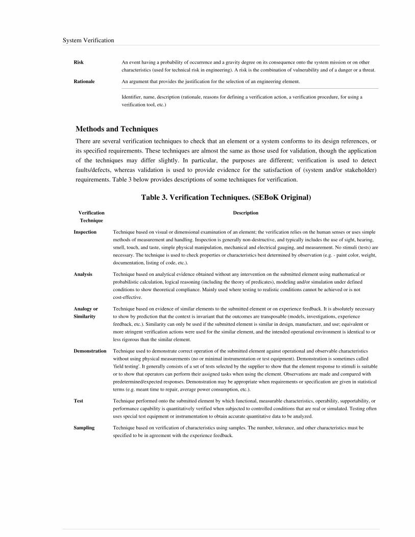
System Verification 174
Risk An event having a probability of occurrence and a gravity degree on its consequence onto the system mission or on othercharacteristics (used for technical risk in engineering). A risk is the combination of vulnerability and of a danger or a threat.
Rationale An argument that provides the justification for the selection of an engineering element.
Identifier, name, description (rationale, reasons for defining a verification action, a verification procedure, for using averification tool, etc.)
Methods and TechniquesThere are several verification techniques to check that an element or a system conforms to its design references, orits specified requirements. These techniques are almost the same as those used for validation, though the applicationof the techniques may differ slightly. In particular, the purposes are different; verification is used to detectfaults/defects, whereas validation is used to provide evidence for the satisfaction of (system and/or stakeholder)requirements. Table 3 below provides descriptions of some techniques for verification.
Table 3. Verification Techniques. (SEBoK Original)
VerificationTechnique
Description
Inspection Technique based on visual or dimensional examination of an element; the verification relies on the human senses or uses simplemethods of measurement and handling. Inspection is generally non-destructive, and typically includes the use of sight, hearing,smell, touch, and taste, simple physical manipulation, mechanical and electrical gauging, and measurement. No stimuli (tests) arenecessary. The technique is used to check properties or characteristics best determined by observation (e.g. - paint color, weight,documentation, listing of code, etc.).
Analysis Technique based on analytical evidence obtained without any intervention on the submitted element using mathematical orprobabilistic calculation, logical reasoning (including the theory of predicates), modeling and/or simulation under definedconditions to show theoretical compliance. Mainly used where testing to realistic conditions cannot be achieved or is notcost-effective.
Analogy orSimilarity
Technique based on evidence of similar elements to the submitted element or on experience feedback. It is absolutely necessaryto show by prediction that the context is invariant that the outcomes are transposable (models, investigations, experiencefeedback, etc.). Similarity can only be used if the submitted element is similar in design, manufacture, and use; equivalent ormore stringent verification actions were used for the similar element, and the intended operational environment is identical to orless rigorous than the similar element.
Demonstration Technique used to demonstrate correct operation of the submitted element against operational and observable characteristicswithout using physical measurements (no or minimal instrumentation or test equipment). Demonstration is sometimes called'field testing'. It generally consists of a set of tests selected by the supplier to show that the element response to stimuli is suitableor to show that operators can perform their assigned tasks when using the element. Observations are made and compared withpredetermined/expected responses. Demonstration may be appropriate when requirements or specification are given in statisticalterms (e.g. meant time to repair, average power consumption, etc.).
Test Technique performed onto the submitted element by which functional, measurable characteristics, operability, supportability, orperformance capability is quantitatively verified when subjected to controlled conditions that are real or simulated. Testing oftenuses special test equipment or instrumentation to obtain accurate quantitative data to be analyzed.
Sampling Technique based on verification of characteristics using samples. The number, tolerance, and other characteristics must bespecified to be in agreement with the experience feedback.

System Verification 175
Practical ConsiderationsKey pitfalls and good practices related to this topic are described in the next two sections.
PitfallsSome of the key pitfalls encountered in planning and performing System Verification are provided in Table 4.
Table 4. Major Pitfalls with System Verification (SEBoK Original)
Pitfall Description
Confusion betweenverification andvalidation
Confusion between verification and validation causes developers to take the wrong reference/baseline to defineverification and validation actions and/or to address the wrong level of granularity (detail level for verification, globallevel for validation).
No verification strategy One overlooks verification actions because it is impossible to check every characteristic or property of all systemelements and of the system in any combination of operational conditions and scenarios. A strategy (justified selection ofverification actions against risks) has to be established.
Save or spend time Skip verification activity to save time.
Use only testing Use only testing as a verification technique. Testing requires checking products and services only when they areimplemented. Consider other techniques earlier during design; analysis and inspections are cost effective and allowdiscovering early potential errors, faults, or failures.
Stop verifications whenfunding is diminished
Stopping the performance of verification actions when budget and/or time are consumed. Prefer using criteria such ascoverage rates to end verification activity.
Proven PracticesSome proven practices gathered from the references are provided in Table 5.
Table 5. Proven Practices with System Verification. (SEBoK Original)
Practice Description
Start verificationsearly in thedevelopment
The more the characteristics of an element are verified early in the project, the more the corrections are easy to do and lessthe error will have consequences on schedule and costs.
Define criteriaending verifications
Carrying out verification actions without limits generates a risk of drift for costs and deadlines. Modifying and verifying in anon-stop cycle until a get a perfect system is the best way to never supply the system. Thus, it is necessary to set limits ofcost, time, and a maximum number of modification loops back for each verification action type, ending criteria (percentagesof success, error count detected, coverage rate obtained, etc.).
Involve designresponsible withverification
Include the verification responsible in the designer team or include some designer onto the verification team.
System Verification 176
References
Works CitedBuede, D.M. 2009. The Engineering Design of Systems: Models and Methods. 2nd ed. Hoboken, NJ, USA: JohnWiley & Sons Inc.INCOSE. 2012. INCOSE Systems Engineering Handbook, version 3.2.2. San Diego, CA, USA: International Councilon Systems Engineering (INCOSE), INCOSE-TP-2003-002-03.2.2.ISO/IEC/IEEE. 2015.Systems and Software Engineering - System Life Cycle Processes.Geneva, Switzerland:International Organization for Standardization (ISO)/International Electrotechnical Commission (IEC), Institute ofElectrical and Electronics Engineers. ISO/IEC/IEEE 15288:2015.Lake, J. 1999. "V & V in Plain English." International Council on Systems Engineering (NCOSE) 9th AnnualInternational Symposium, Brighton, UK, 6-10 June 1999.NASA. 2007. Systems Engineering Handbook. Washington, DC, USA: National Aeronautics and SpaceAdministration (NASA), December 2007. NASA/SP-2007-6105.
Primary ReferencesINCOSE. 2012. INCOSE Systems Engineering Handbook: A Guide for System Life Cycle Processes and Activities,version 3.2.2. San Diego, CA, USA: International Council on Systems Engineering (INCOSE),INCOSE-TP-2003-002-03.2.2.ISO/IEC/IEEE. 2015. Systems and Software Engineering - System Life Cycle Processes. Geneva, Switzerland:International Organization for Standardization (ISO)/International Electrotechnical Commission (IEC)/ Institute ofElectrical and Electronics Engineers. ISO/IEC/IEEE 15288:2015.NASA. 2007. Systems Engineering Handbook. Washington, D.C.: National Aeronautics and Space Administration(NASA), December 2007. NASA/SP-2007-6105.
Additional ReferencesBuede, D.M. 2009. The Engineering Design of Systems: Models and Methods, 2nd ed. Hoboken, NJ, USA: JohnWiley & Sons Inc.DAU. 2010. Defense Acquisition Guidebook (DAG). Ft. Belvoir, VA, USA: Defense Acquisition University(DAU)/U.S. Department of Defense (DoD). February 19, 2010.ECSS. 2009. Systems Engineering General Requirements. Noordwijk, Netherlands: Requirements and StandardsDivision, European Cooperation for Space Standardization (ECSS), 6 March 2009. ECSS-E-ST-10C.MITRE. 2011. "Verification and Validation." in Systems Engineering Guide. Accessed 11 March 2012 at [[1]].SAE International. 1996. Certification Considerations for Highly-Integrated or Complex Aircraft Systems.Warrendale, PA, USA: SAE International, ARP475.SEI. 2007. "Measurement and Analysis Process Area" in Capability Maturity Model Integrated (CMMI) forDevelopment, version 1.2. Pittsburgh, PA, USA: Software Engineering Institute (SEI)/Carnegie Mellon University(CMU).

System Verification 177
< Previous Article | Parent Article | Next Article >SEBoK v. 1.4 released 29 June 2015
SEBoK DiscussionPlease provide your comments and feedback on the SEBoK below. You will need to log in to DISQUS using anexisting account (e.g. Yahoo, Google, Facebook, Twitter, etc.) or create a DISQUS account. Simply type yourcomment in the text field below and DISQUS will guide you through the login or registration steps. Feedback will bearchived and used for future updates to the SEBoK. If you provided a comment that is no longer listed, that commenthas been adjudicated. You can view adjudication for comments submitted prior to SEBoK v. 1.0 at SEBoK Reviewand Adjudication. Later comments are addressed and changes are summarized in the Letter from the Editor andAcknowledgements and Release History.
If you would like to provide edits on this article, recommend new content, or make comments on the SEBoKas a whole, please see the SEBoK Sandbox [1].
ENCODED_CONTENTMTM0OTUPGRpdiBpZD0iZGlzcXVzX3RocmVhZCI+PC9kaXY+CjxzY3JpcHQgdHlwZT0idGV4dC9qYXZhc2NyaXB0Ij4KICAgIC8qICogKiBDT05GSUdVUkFUSU9OIFZBUklBQkxFUzogRURJVCBCRUZPUkUgUEFTVElORyBJTlRPIFlPVVIgV0VCUEFHRSAqICogKi8KICAgIHZhciBkaXNxdXNfc2hvcnRuYW1lID0gJ3NlYm9rd2lraTEwJzsgLy8gcmVxdWlyZWQ6IHJlcGxhY2UgZXhhbXBsZSB3aXRoIHlvdXIgZm9ydW0gc2hvcnRuYW1lCiAgICB2YXIgZGlzcXVzX2lkZW50aWZpZXIgPSAnU3lzdGVtIFZlcmlmaWNhdGlvbic7ICAgIHZhciBkaXNxdXNfdXJsID0gJ2h0dHA6Ly9zZWJva3dpa2kub3JnL2RyYWZ0L1N5c3RlbV9WZXJpZmljYXRpb24nOwogICAgLyogKiAqIERPTidUIEVESVQgQkVMT1cgVEhJUyBMSU5FICogKiAqLwogICAgKGZ1bmN0aW9uKCkgewogICAgICAgIHZhciBkc3EgPSBkb2N1bWVudC5jcmVhdGVFbGVtZW50KCdzY3JpcHQnKTsgZHNxLnR5cGUgPSAndGV4dC9qYXZhc2NyaXB0JzsgZHNxLmFzeW5jID0gdHJ1ZTsKICAgICAgICBkc3Euc3JjID0gJ2h0dHA6Ly8nICsgZGlzcXVzX3Nob3J0bmFtZSArICcuZGlzcXVzLmNvbS9lbWJlZC5qcyc7CiAgICAgICAgKGRvY3VtZW50LmdldEVsZW1lbnRzQnlUYWdOYW1lKCdoZWFkJylbMF0gfHwgZG9jdW1lbnQuZ2V0RWxlbWVudHNCeVRhZ05hbWUoJ2JvZHknKVswXSkuYXBwZW5kQ2hpbGQoZHNxKTsKICAgIH0pKCk7Cjwvc2NyaXB0Pgo8bm9zY3JpcHQ+UGxlYXNlIGVuYWJsZSBKYXZhU2NyaXB0IHRvIHZpZXcgdGhlIDxhIGhyZWY9Imh0dHA6Ly9kaXNxdXMuY29tLz9yZWZfbm9zY3JpcHQiPmNvbW1lbnRzIHBvd2VyZWQgYnkgRGlzcXVzLjwvYT48L25vc2NyaXB0Pgo8YSBocmVmPSJodHRwOi8vZGlzcXVzLmNvbSIgY2xhc3M9ImRzcS1icmxpbmsiPmJsb2cgY29tbWVudHMgcG93ZXJlZCBieSA8c3BhbiBjbGFzcz0ibG9nby1kaXNxdXMiPkRpc3F1czwvc3Bhbj48L2E+END_ENCODED_CONTENT
References[1] http:/ / mitre. org/ work/ systems_engineering/ guide/ se_lifecycle_building_blocks/ test_evaluation/ verification_validation. html
System ValidationSystem Validation is a set of actions used to check the compliance of any element (a system element, a system, adocument, a service, a task, a system requirement, etc.) with its purpose and functions. These actions are planned andcarried out throughout the life cycle of the system. Validation is a generic term that needs to be instantiated withinthe context it occurs. When understood as a process, validation is a transverse activity to every life cycle stage of thesystem. In particular, during the development cycle of the system, the validation process is performed in parallelwith the system definition and system realization processes and applies to any activity and product resulting fromthis activity. The validation process is not limited to a phase at the end of system development, but generally occursat the end of a set of life cycle tasks or activities, and always at the end of each milestone of a development project.It may be performed on an iterative basis on every produced engineering element during development and may beginwith the validation of the expressed stakeholder requirements. When the validation process is applied to the systemwhen completely integrated, it is often called final validation. It is important to remember that while systemvalidation is separate from verification, the activities are complementary and intended to be performed inconjunction.
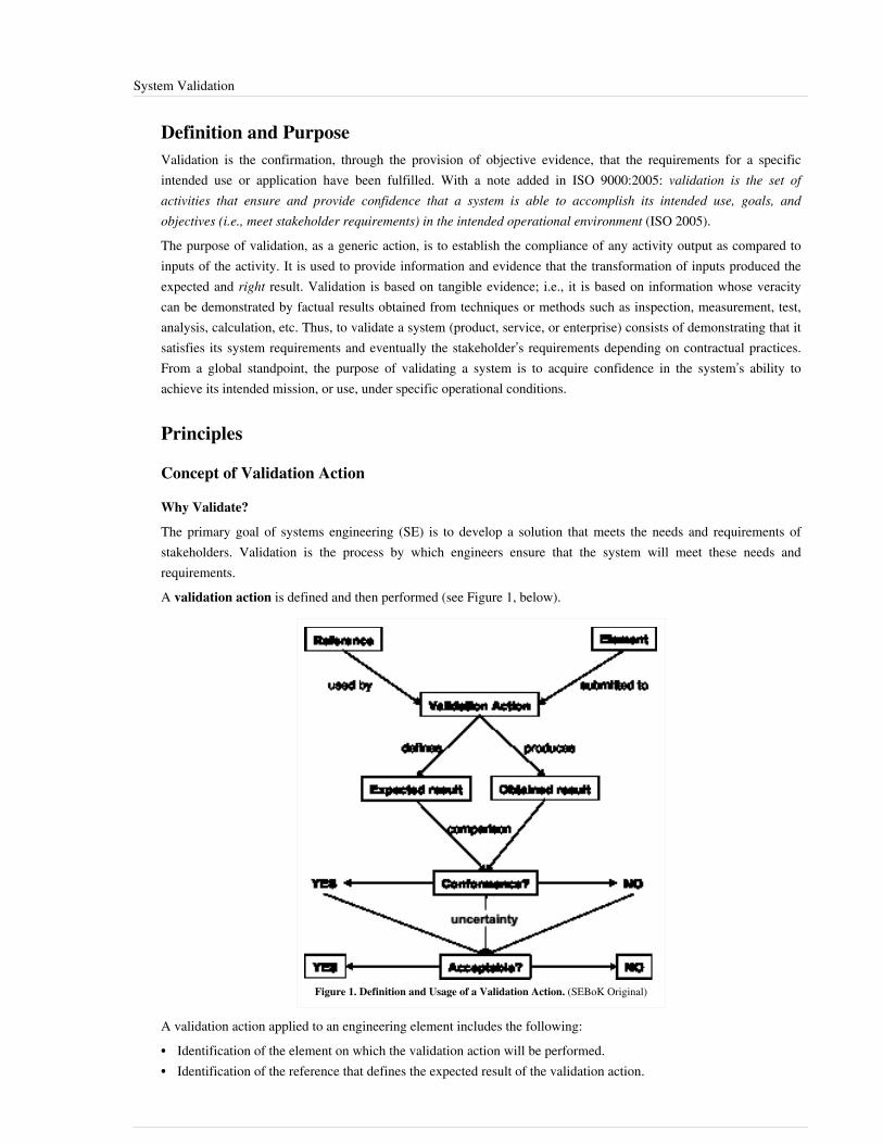
System Validation 178
Definition and PurposeValidation is the confirmation, through the provision of objective evidence, that the requirements for a specificintended use or application have been fulfilled. With a note added in ISO 9000:2005: validation is the set ofactivities that ensure and provide confidence that a system is able to accomplish its intended use, goals, andobjectives (i.e., meet stakeholder requirements) in the intended operational environment (ISO 2005).The purpose of validation, as a generic action, is to establish the compliance of any activity output as compared toinputs of the activity. It is used to provide information and evidence that the transformation of inputs produced theexpected and right result. Validation is based on tangible evidence; i.e., it is based on information whose veracitycan be demonstrated by factual results obtained from techniques or methods such as inspection, measurement, test,analysis, calculation, etc. Thus, to validate a system (product, service, or enterprise) consists of demonstrating that itsatisfies its system requirements and eventually the stakeholder’s requirements depending on contractual practices.From a global standpoint, the purpose of validating a system is to acquire confidence in the system’s ability toachieve its intended mission, or use, under specific operational conditions.
Principles
Concept of Validation Action
Why Validate?
The primary goal of systems engineering (SE) is to develop a solution that meets the needs and requirements ofstakeholders. Validation is the process by which engineers ensure that the system will meet these needs andrequirements.A validation action is defined and then performed (see Figure 1, below).
Figure 1. Definition and Usage of a Validation Action. (SEBoK Original)
A validation action applied to an engineering element includes the following:•• Identification of the element on which the validation action will be performed.•• Identification of the reference that defines the expected result of the validation action.
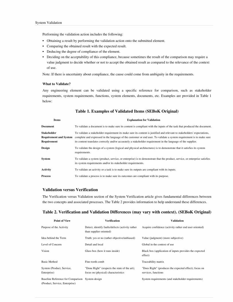
System Validation 179
Performing the validation action includes the following:•• Obtaining a result by performing the validation action onto the submitted element.•• Comparing the obtained result with the expected result.•• Deducing the degree of compliance of the element.•• Deciding on the acceptability of this compliance, because sometimes the result of the comparison may require a
value judgment to decide whether or not to accept the obtained result as compared to the relevance of the contextof use.
Note: If there is uncertainty about compliance, the cause could come from ambiguity in the requirements.
What to Validate?
Any engineering element can be validated using a specific reference for comparison, such as stakeholderrequirements, system requirements, functions, system elements, documents, etc. Examples are provided in Table 1below:
Table 1. Examples of Validated Items (SEBoK Original)
Items Explanation for Validation
Document To validate a document is to make sure its content is compliant with the inputs of the task that produced the document.
StakeholderRequirement and SystemRequirement
To validate a stakeholder requirement its make sure its content is justified and relevant to stakeholders' expectations,complete and expressed in the language of the customer or end user. To validate a system requirement is to make sureits content translates correctly and/or accurately a stakeholder requirement in the language of the supplier.
Design To validate the design of a system (logical and physical architectures) is to demonstrate that it satisfies its systemrequirements.
System To validate a system (product, service, or enterprise) is to demonstrate that the product, service, or enterprise satisfiesits system requirements and/or its stakeholder requirements.
Activity To validate an activity or a task is to make sure its outputs are compliant with its inputs.
Process To validate a process is to make sure its outcomes are compliant with its purpose.
Validation versus VerificationThe Verification versus Validation section of the System Verification article gives fundamental differences betweenthe two concepts and associated processes. The Table 2 provides information to help understand these differences.
Table 2. Verification and Validation Differences (may vary with context). (SEBoK Original)
Point of View Verification Validation
Purpose of the Activity Detect, identify faults/defects (activity ratherthan supplier oriented)
Acquire confidence (activity rather end user oriented)
Idea behind the Term Truth: yes or no (rather objective/unbiased) Value (judgment) (more subjective)
Level of Concern Detail and local Global in the context of use
Vision Glass box (how it runs inside) Black box (application of inputs provides the expectedeffect)
Basic Method Fine-tooth comb Traceability matrix
System (Product, Service,Enterprise)
"Done Right" (respects the state of the art);focus on (physical) characteristics
"Does Right" (produces the expected effect); focus onservices, functions
Baseline Reference for Comparison(Product, Service, Enterprise)
System design System requirements (and stakeholder requirements)

System Validation 180
Order of Performance First Second
Organization of Activity Verification actions are defined and/orperformed by development/designer team
Validation actions are defined and/or performed by expertsand external members to development/designer team
Validation, Final Validation, and Operational ValidationSystem validation concerns the global system seen as a whole and is based on the totality of requirements (systemrequirements, stakeholders requirements, etc.), but it is obtained gradually throughout the development stage in threenon-exclusive ways:•• accumulating the results of verification actions and validation actions provided by the application of
corresponding processes to every engineering element;•• performing final validation actions to the complete, integrated system in an industrial environment (as close as
possible to the operational environment); and•• performing operational validation actions on the complete system in its operational environment (context of use).
Verification and Validation Level per LevelIt is impossible to carry out only a single global validation on a complete, integrated complex system. The sources offaults/defects could be important and it would be impossible to determine the causes of non-conformance manifestedduring this global check. Generally, the system-of-interest (SoI) has been decomposed during design in a set oflayers of systems. Thus, every system and system element is verified, validated, and possibly corrected before beingintegrated into the parent system of the higher level, as shown in Figure 2.
Figure 2. Verification and Validation Level Per Level. (SEBoK Original)
As necessary, systems and system elements are partially integrated in subsets in order to limit the number ofproperties to be verified within a single step. For each level, it is necessary to perform a set of final validation actionsto ensure that features stated at preceding levels are not damaged. Moreover, a compliant result obtained in a givenenvironment can turn into a non-compliant result if the environment changes. Thus, as long as the system is not

System Validation 181
completely integrated and/or doesn't operate in the real operational environment, no result should be regarded asdefinitive.
Verification Actions and Validation Actions Inside and Transverse to LevelsInside each level of system decomposition, verification actions and validation actions are performed during systemdefinition and system realization. This is represented in Figure 3 for the upper levels, and in Figure 4 for the lowerlevels. Stakeholder requirements definition and operational validation make the link between the two levels of thesystem decomposition.
Figure 3. Verification and Validation Actions in Upper Levels of System Decomposition. (SEBoKOriginal)
Operational validation of system element requirements and products makes the link between the two lower levels ofthe decomposition. See Figure 4 below.

System Validation 182
Figure 4. Verification and Validation Actions in Lower Levels of System Decomposition. (SEBoKOriginal)
Note: The last level of system decomposition is dedicated to the realization of system elements and the vocabularyand number of activities may be different from what is seen in Figure 4.
Verification and Validation StrategyThe difference between verification and validation is especially useful for elaborating on the integration strategy, theverification strategy, and the validation strategy. In fact, the efficiency of system realization is gained by optimizingthe three strategies together to form what is often called the verification and validation strategy. This optimizationconsists of defining and performing the minimum number of verification and validation actions but detecting themaximum number of errors/faults/defects and achieving the maximum level of confidence in the system. Theoptimization takes into account the risks potentially generated if some verification actions or validation actions areexcluded.
Process Approach
Purpose and Principles of the ApproachThe purpose of the validation process is to provide objective evidence that the services provided by a system in usecomply with stakeholder requirements and achieve its intended use in its intended operational environment(ISO/IEC/IEEE 15288 2015). The validation process performs a comparative assessment and confirms that thestakeholder requirements are correctly defined. Where variance is identified, it is recorded to guide future correctiveactions. System validation is ratified by stakeholders (ISO/IEC/IEEE 15288 2015).
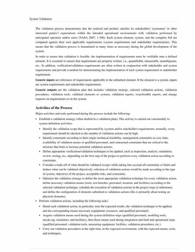
System Validation 183
The validation process demonstrates that the realized end product satisfies its stakeholders' (customers' or otherinterested parties') expectations within the intended operational environments with validation performed byanticipated operators and/or users (NASA 2007, 1-360). Each system element, system, and the complete SoI arecompared against their own applicable requirements (system requirements and stakeholder requirements). Thismeans that the validation process is instantiated as many times as necessary during the global development of thesystem.In order to ensure that validation is feasible, the implementation of requirements must be verifiable onto a definedelement. It is essential to ensure that requirements are properly written, i.e., quantifiable, measurable, unambiguous,etc.. In addition, verification/validation requirements are often written in conjunction with stakeholder and systemrequirements and provide a method for demonstrating the implementation of each system requirement or stakeholderrequirement.Generic inputs are references of requirements applicable to the submitted element. If the element is a system, inputsare system requirements and stakeholder requirements.Generic outputs are the validation plan that includes validation strategy, selected validation actions, validationprocedures, validation tools, validated elements or systems, validation reports, issue/trouble reports, and changerequests on requirements or on the system.
Activities of the ProcessMajor activities and tasks performed during this process include the following:•• Establish a validation strategy (often drafted in a validation plan). This activity is carried out concurrently to
system definition activities:•• Identify the validation scope that is represented by (system and/or stakeholder) requirements; normally, every
requirement should be checked as the number of validation actions can be high.•• Identify constraints according to their origin (technical feasibility, management constraints as cost, time,
availability of validation means or qualified personnel, and contractual constraints that are critical to themission) that limit or increase potential validation actions.
•• Define appropriate verification/validation techniques to be applied, such as inspection, analysis, simulation,review, testing, etc., depending on the best step of the project to perform every validation action according toconstraints.
•• Consider a trade-off of what should be validated (scope) while taking into account all constraints or limits anddeduce what can be validated objectively; selection of validation actions would be made according to the typeof system, objectives of the project, acceptable risks, and constraints.
•• Optimize the validation strategy to define the most appropriate validation technique for every validation action,define necessary validation means (tools, test-benches, personnel, location, and facilities) according to theselected validation technique, schedule the execution of validation actions in the project steps or milestones,and define the configuration of elements submitted to validation actions (this is primarily about testing onphysical elements).
•• Perform validation actions, including the following tasks:•• Detail each validation action, in particular, note the expected results, the validation technique to be applied,
and the corresponding means necessary (equipment, resources, and qualified personnel).•• Acquire validation means used during the system definition steps (qualified personnel, modeling tools,
mocks-up, simulators, and facilities), then those means used during integration and final and operational steps(qualified personnel, validation tools, measuring equipment, facilities, validation procedures, etc.).
•• Carry out validation procedures at the right time, in the expected environment, with the expected means, tools,and techniques.

System Validation 184
•• Capture and record results obtained when performing validation actions using validation procedures andmeans.
•• Analyze the obtained results and compare them to the expected results. Decide if they comply acceptably. Recordwhether the decision and status are compliant or not, and generate validation reports and potential issue/troublereports, as well as change requests on (system or stakeholder) requirements as necessary.
•• Control the process using following tasks:•• Update the validation plan according to the progress of the project; in particular, planned validation actions can
be redefined because of unexpected events.•• Coordinate validation activities with the project manager regarding the schedule, acquisition of means,
personnel, and resources. Coordinate with the designers for issue/trouble/non-conformance reports. Coordinatewith the configuration manager for versions of physical elements, design baselines, etc.
Artifacts and Ontology ElementsThis process may create several artifacts, such as:•• a validation plan (contains the validation strategy)•• a validation matrix (contains for each validation action, submitted element, applied technique, step of execution,
system block concerned, expected result, obtained result, etc.)•• validation procedures (describe the validation actions to be performed, the validation tools needed, the validation
configuration, resources, personnel, schedule, etc.)•• validation reports•• validation tools•• the validated element•• issue, non-conformance, and trouble reports•• change requests on requirements, products, services, and enterprisesThis process utilizes the ontology elements of Table 3.
Table 3. Main Ontology Elements as Handled within Validation. (SEBoK Original)
Element Definition
Attributes (examples)
Validation Action A validation action describes what must be validated (the element as reference), on which element, the expected result, theverification technique to apply, on which level of decomposition.
Identifier, name, description
ValidationProcedure
A validation procedure groups a set of validation actions performed together (as a scenario of tests) in a given validationconfiguration.
Identifier, name, description, duration, unit of time
Validation Tool A validation tool is a device or physical tool used to perform validation procedures (test bench, simulator, cap/stub,launcher, etc.).
Identifier, name, description
ValidationConfiguration
A validation configuration groups the physical elements necessary to perform a validation procedure.
Identifier, name, description

System Validation 185
Risk An event having a probability of occurrence and a gravity degree on its consequence onto the system mission or on othercharacteristics (used for technical risk engineering).
Identifier, name, description, status
Rationale An argument that provides the justification for the selection of an engineering element.
Identifier, name, description (rationale, reasons for defining a validation action, a validation procedure, for using avalidation tool, etc.)
Methods and TechniquesThe validation techniques are the same as those used for verification, but their purposes are different; verification isused to detect faults/defects, whereas validation is used to prove the satisfaction of (system and/or stakeholder)requirements.The validation traceability matrix is introduced in the stakeholder requirements definition topic. It may also beextended and used to record data, such as a validation actions list, selected validation techniques to validateimplementation of every engineering element (in particular stakeholder and system requirements), expected results,and obtained results when validation actions have been performed. The use of such a matrix enables the developmentteam to ensure that selected stakeholder and system requirements have been checked, or to evaluate the percentage ofvalidation actions completed.
Practical ConsiderationsKey pitfalls and good practices related to system validation are described in the next two sections.
PitfallsSome of the key pitfalls encountered in planning and performing system validation are provided in Table 4.
Table 4. Major Pitfalls with System Validation. (SEBoK Original)
Pitfall Description
Start validation at theend of the project
A common mistake is to wait until the system has been entirely integrated and tested (design is qualified) to perform anysort of validation. Validation should occur as early as possible in the [product] life cycle (Martin 1997).
Use only testing Use only testing as a validation technique. Testing requires checking products and services only when they areimplemented. Consider other techniques earlier during design; analysis and inspections are cost effective and allowdiscovering early potential errors, faults, or failures.
Stop validation whenfunding is diminished
Stop the performance of validation actions when budget and/or time are consumed. Prefer using criteria such as coveragerates to end validation activity.
Proven PracticesSome good practices gathered from the references are provided in Table 5.

System Validation 186
Table 5. Proven Practices with System Validation. (SEBoK Original)
Practice Description
Start ValidationPlan Early
It is recommended to start the drafting of the validation plan as soon as the first requirements applicable to the system are known.If the writer of the requirements immediately puts the question to know how to validate whether the future system will answer therequirements, it is possible to:
•• detect the unverifiable requirements•• anticipate, estimate cost, and start the design of validation means (as needed) such as test-benches, simulators•• avoid cost overruns and schedule slippages
VerifiableRequirements
According to Buede, a requirement is verifiable if a "finite, cost-effective process has been defined to check that the requirementhas been attained." (Buede 2009) Generally, this means that each requirement should be quantitative, measurable, unambiguous,understandable, and testable. It is generally much easier and more cost-effective to ensure that requirements meet these criteriawhile they are being written. Requirement adjustments made after implementation and/or integration are generally much morecostly and may have wide-reaching redesign implications. There are several resources which provide guidance on creatingappropriate requirements - see the system definition knowledge area, stakeholder requirements, and system requirements topicsfor additional information.
DocumentValidationActions
It is important to document both the validation actions performed and the results obtained. This provides accountability regardingthe extent to which system, system elements, subsystems fulfill system requirements and stakeholders' requirements. These datacan be used to investigate why the system, system elements, subsystems do not match the requirements and to detect potentialfaults/defects. When requirements are met, these data may be reported to organization parties. For example, in a safety criticalsystem, it may be necessary to report the results of safety demonstration to a certification organization. Validation results may bereported to the acquirer for contractual aspects or to internal company for business purpose.
Involve Userswith Validation
Validation will often involve going back directly to the users to have them perform some sort of acceptance test under their ownlocal conditions.
Involve Often the end users and other relevant stakeholders are involved in the validation process.
The following are elements that should be considered when practicing any of the activities discussed as a part ofsystem realization:•• Confusing verification and validation is a common issue. Validation demonstrates that the product, service, and/or
enterprise as provided, fulfills its intended use, whereas verification addresses whether a local work productproperly reflects its specified requirements. Validation actions use the same techniques as the verification actions(e.g., test, analysis, inspection, demonstration, or simulation).
•• State who the witnesses will be (for the purpose of collecting the evidence of success), what general steps will befollowed, and what special resources are needed, such as instrumentation, special test equipment or facilities,simulators, specific data gathering, or rigorous analysis of demonstration results.
•• Identify the test facility, test equipment, any unique resource needs and environmental conditions, requiredqualifications and test personnel, general steps that will be followed, specific data to be collected, criteria forrepeatability of collected data, and methods for analyzing the results.
System Validation 187
References
Works CitedBuede, D. M. 2009. The engineering design of systems: Models and methods. 2nd ed. Hoboken, NJ: John Wiley &Sons Inc.INCOSE. 2012. INCOSE Systems Engineering Handbook, version 3.2.2. San Diego, CA, USA: International Councilon Systems Engineering (INCOSE), INCOSE-TP-2003-002-03.2.2.ISO/IEC/IEEE. 2015.Systems and Software Engineering - System Life Cycle Processes.Geneva, Switzerland:International Organization for Standardization (ISO)/International Electrotechnical Commission (IEC), Institute ofElectrical and Electronics Engineers. ISO/IEC/IEEE 15288:2015.NASA. 2007. Systems Engineering Handbook. Washington, D.C.: National Aeronautics and Space Administration(NASA), NASA/SP-2007-6105, December 2007.
Primary ReferencesINCOSE. 2012. Systems Engineering Handbook, version 3.2.2. San Diego, CA, USA: International Council onSystems Engineering (INCOSE), INCOSE-TP-2003-002-03.2.2.ISO/IEC/IEEE. 2015.Systems and software engineering - system life cycle processes.Geneva, Switzerland:International Organization for Standardization (ISO)/International Electrotechnical Commission (IEC), Institute ofElectrical and Electronics Engineers. ISO/IEC 15288:2015.NASA. 2007. Systems Engineering Handbook. Washington, D.C.: National Aeronautics and Space Administration(NASA), NASA/SP-2007-6105, December 2007.
Additional ReferencesBuede, D.M. 2009. The engineering design of systems: Models and methods. 2nd ed. Hoboken, NJ: John Wiley &Sons Inc.DAU. February 19, 2010. Defense Acquisition Guidebook (DAG). Ft. Belvoir, VA, USA: Defense AcquisitionUniversity (DAU)/U.S. Department of Defense.ECSS. 2009. Systems engineering general requirements. Noordwijk, Netherlands: Requirements and StandardsDivision, European Cooperation for Space Standardization (ECSS), ECSS-E-ST-10C. 6 March 2009.MITRE. 2011. "Verification and Validation." Systems Engineering Guide. Accessed 11 March 2012 at [[1]].SAE International. 1996. Certification considerations for highly-integrated or complex aircraft systems. Warrendale,PA, USA: SAE International, ARP475SEI. 2007. Capability maturity model integrated (CMMI) for development, version 1.2, measurement and analysisprocess area. Pittsburg, PA, USA: Software Engineering Institute (SEI)/Carnegie Mellon University (CMU).
< Previous Article | Parent Article | Next Article >SEBoK v. 1.4 released 29 June 2015
SEBoK DiscussionPlease provide your comments and feedback on the SEBoK below. You will need to log in to DISQUS using an existing account (e.g. Yahoo, Google, Facebook, Twitter, etc.) or create a DISQUS account. Simply type your comment in the text field below and DISQUS will guide you through the login or registration steps. Feedback will be archived and used for future updates to the SEBoK. If you provided a comment that is no longer listed, that comment has been adjudicated. You can view adjudication for comments submitted prior to SEBoK v. 1.0 at SEBoK Review

System Validation 188
and Adjudication. Later comments are addressed and changes are summarized in the Letter from the Editor andAcknowledgements and Release History.
If you would like to provide edits on this article, recommend new content, or make comments on the SEBoKas a whole, please see the SEBoK Sandbox [1].
ENCODED_CONTENTMTIzOTkPGRpdiBpZD0iZGlzcXVzX3RocmVhZCI+PC9kaXY+CjxzY3JpcHQgdHlwZT0idGV4dC9qYXZhc2NyaXB0Ij4KICAgIC8qICogKiBDT05GSUdVUkFUSU9OIFZBUklBQkxFUzogRURJVCBCRUZPUkUgUEFTVElORyBJTlRPIFlPVVIgV0VCUEFHRSAqICogKi8KICAgIHZhciBkaXNxdXNfc2hvcnRuYW1lID0gJ3NlYm9rd2lraTEwJzsgLy8gcmVxdWlyZWQ6IHJlcGxhY2UgZXhhbXBsZSB3aXRoIHlvdXIgZm9ydW0gc2hvcnRuYW1lCiAgICB2YXIgZGlzcXVzX2lkZW50aWZpZXIgPSAnU3lzdGVtIFZhbGlkYXRpb24nOyAgICB2YXIgZGlzcXVzX3VybCA9ICdodHRwOi8vc2Vib2t3aWtpLm9yZy9kcmFmdC9TeXN0ZW1fVmFsaWRhdGlvbic7CiAgICAvKiAqICogRE9OJ1QgRURJVCBCRUxPVyBUSElTIExJTkUgKiAqICovCiAgICAoZnVuY3Rpb24oKSB7CiAgICAgICAgdmFyIGRzcSA9IGRvY3VtZW50LmNyZWF0ZUVsZW1lbnQoJ3NjcmlwdCcpOyBkc3EudHlwZSA9ICd0ZXh0L2phdmFzY3JpcHQnOyBkc3EuYXN5bmMgPSB0cnVlOwogICAgICAgIGRzcS5zcmMgPSAnaHR0cDovLycgKyBkaXNxdXNfc2hvcnRuYW1lICsgJy5kaXNxdXMuY29tL2VtYmVkLmpzJzsKICAgICAgICAoZG9jdW1lbnQuZ2V0RWxlbWVudHNCeVRhZ05hbWUoJ2hlYWQnKVswXSB8fCBkb2N1bWVudC5nZXRFbGVtZW50c0J5VGFnTmFtZSgnYm9keScpWzBdKS5hcHBlbmRDaGlsZChkc3EpOwogICAgfSkoKTsKPC9zY3JpcHQ+Cjxub3NjcmlwdD5QbGVhc2UgZW5hYmxlIEphdmFTY3JpcHQgdG8gdmlldyB0aGUgPGEgaHJlZj0iaHR0cDovL2Rpc3F1cy5jb20vP3JlZl9ub3NjcmlwdCI+Y29tbWVudHMgcG93ZXJlZCBieSBEaXNxdXMuPC9hPjwvbm9zY3JpcHQ+CjxhIGhyZWY9Imh0dHA6Ly9kaXNxdXMuY29tIiBjbGFzcz0iZHNxLWJybGluayI+YmxvZyBjb21tZW50cyBwb3dlcmVkIGJ5IDxzcGFuIGNsYXNzPSJsb2dvLWRpc3F1cyI+RGlzcXVzPC9zcGFuPjwvYT4=END_ENCODED_CONTENT
System Deployment and UseSystem deployment and use are critical systems engineering (SE) activities that ensure that the developed system isoperationally acceptable and that the responsibility for the effective, efficient, and safe operations of the system istransferred to the owner. Considerations for deployment and use must be included throughout the system life cycle.
TopicsEach part of the SEBoK is divided into knowledge areas (KAs), which are groupings of information with a relatedtheme. The KAs in turn are divided into topics. This KA contains the following topics:•• System Deployment•• Operation of the System•• System Maintenance•• LogisticsSee the article Matrix of Implementation Examples for a mapping of case studies and vignettes included in Part 7 totopics covered in Part 3.
OverviewSystem deployment involves the transition of the capability to the ultimate end-user, as well as transition of supportand maintenance responsibilities to the post-deployment support organization or organizations. It may include aperiod of reliability demonstration tests and the phasing out of legacy systems that the developed system replaces.System use includes a continual assessment of the operational effectiveness of the deployed system or service,identification of mission threat and operational risk, and performance of the actions required to maintain operationaleffectiveness or evolve the capability to meet changing needs. Evolution of the operational system may occur withsmaller maintenance actions or, if the changes cross an agreed-to threshold (complexity, risk, cost, etc.), may requirea formal development project with deliberate planning and SE activities resulting in an enhanced system. As theoperational phase is generally the longest in the system life cycle, activities that may occur during operation areallocated between two knowledge areas (KAs): System Deployment and Use and Product and Service LifeManagement.The Product and Service Life Management knowledge area (KA) specifically deals with SE activities required forsystem evolution and end of system life including service life extension (SLE), capability updates, upgrades, andmodernization during system operation, and system disposal and retirement. In contrast, the System Deployment andUse KA specifically deals with activities required to ensure that system operation can continue as expected. Planningfor system deployment and use should begin early in the SE process to ensure successful transition into operationaluse.

System Deployment and Use 189
System Deployment and Use FundamentalsSystem deployment and use includes the processes used to plan for and manage the transition of new or evolvedsystems and capabilities into operational use and the transition of support responsibilities to the eventualmaintenance or support organization. The use stage normally represents the longest period of a system life cycle and,hence, generally accounts for the largest portion of the life cycle cost. These activities need to be properly managedin order to evaluate the actual system performance, effectiveness, and cost in its intended environment and within itsspecified utilization over its life cycle. Included in use fundamentals are the aspects of continuation of personneltraining and certification.As part of deployment/transition activities special conditions that may apply during the eventual decommissioning ordisposal of the system are identified and accommodated in life cycle plans and system architectures and designs (Seethe System Definition KA for additional information). SE leadership ensures the developed system meets specifiedrequirements, that it be used in the intended environment, and that when the system is transitioned into operation, itachieves the users’ defined mission capabilities and can be maintained throughout the intended life cycle.SE ensures that plans and clear criteria for transition into operation are developed and agreed to by relevantstakeholders and that planning is completed for system maintenance and support after the system is deployed. Theseplans should generally include reasonable accommodation for planned and potential evolution of the system and itseventual removal from operational use (for additional information on evolution and retirement, please see theProduct and Service Life Management KA).
ReferencesNone.
< Previous Article | Parent Article | Next Article >SEBoK v. 1.4 released 29 June 2015
SEBoK DiscussionPlease provide your comments and feedback on the SEBoK below. You will need to log in to DISQUS using anexisting account (e.g. Yahoo, Google, Facebook, Twitter, etc.) or create a DISQUS account. Simply type yourcomment in the text field below and DISQUS will guide you through the login or registration steps. Feedback will bearchived and used for future updates to the SEBoK. If you provided a comment that is no longer listed, that commenthas been adjudicated. You can view adjudication for comments submitted prior to SEBoK v. 1.0 at SEBoK Reviewand Adjudication. Later comments are addressed and changes are summarized in the Letter from the Editor andAcknowledgements and Release History.
If you would like to provide edits on this article, recommend new content, or make comments on the SEBoKas a whole, please see the SEBoK Sandbox [1].
ENCODED_CONTENTODQzOTcPGRpdiBpZD0iZGlzcXVzX3RocmVhZCI+PC9kaXY+CjxzY3JpcHQgdHlwZT0idGV4dC9qYXZhc2NyaXB0Ij4KICAgIC8qICogKiBDT05GSUdVUkFUSU9OIFZBUklBQkxFUzogRURJVCBCRUZPUkUgUEFTVElORyBJTlRPIFlPVVIgV0VCUEFHRSAqICogKi8KICAgIHZhciBkaXNxdXNfc2hvcnRuYW1lID0gJ3NlYm9rd2lraTEwJzsgLy8gcmVxdWlyZWQ6IHJlcGxhY2UgZXhhbXBsZSB3aXRoIHlvdXIgZm9ydW0gc2hvcnRuYW1lCiAgICB2YXIgZGlzcXVzX2lkZW50aWZpZXIgPSAnU3lzdGVtIERlcGxveW1lbnQgYW5kIFVzZSc7ICAgIHZhciBkaXNxdXNfdXJsID0gJ2h0dHA6Ly9zZWJva3dpa2kub3JnL2RyYWZ0L1N5c3RlbV9EZXBsb3ltZW50X2FuZF9Vc2UnOwogICAgLyogKiAqIERPTidUIEVESVQgQkVMT1cgVEhJUyBMSU5FICogKiAqLwogICAgKGZ1bmN0aW9uKCkgewogICAgICAgIHZhciBkc3EgPSBkb2N1bWVudC5jcmVhdGVFbGVtZW50KCdzY3JpcHQnKTsgZHNxLnR5cGUgPSAndGV4dC9qYXZhc2NyaXB0JzsgZHNxLmFzeW5jID0gdHJ1ZTsKICAgICAgICBkc3Euc3JjID0gJ2h0dHA6Ly8nICsgZGlzcXVzX3Nob3J0bmFtZSArICcuZGlzcXVzLmNvbS9lbWJlZC5qcyc7CiAgICAgICAgKGRvY3VtZW50LmdldEVsZW1lbnRzQnlUYWdOYW1lKCdoZWFkJylbMF0gfHwgZG9jdW1lbnQuZ2V0RWxlbWVudHNCeVRhZ05hbWUoJ2JvZHknKVswXSkuYXBwZW5kQ2hpbGQoZHNxKTsKICAgIH0pKCk7Cjwvc2NyaXB0Pgo8bm9zY3JpcHQ+UGxlYXNlIGVuYWJsZSBKYXZhU2NyaXB0IHRvIHZpZXcgdGhlIDxhIGhyZWY9Imh0dHA6Ly9kaXNxdXMuY29tLz9yZWZfbm9zY3JpcHQiPmNvbW1lbnRzIHBvd2VyZWQgYnkgRGlzcXVzLjwvYT48L25vc2NyaXB0Pgo8YSBocmVmPSJodHRwOi8vZGlzcXVzLmNvbSIgY2xhc3M9ImRzcS1icmxpbmsiPmJsb2cgY29tbWVudHMgcG93ZXJlZCBieSA8c3BhbiBjbGFzcz0ibG9nby1kaXNxdXMiPkRpc3F1czwvc3Bhbj48L2E+END_ENCODED_CONTENT

System Deployment 190
System DeploymentAs part of system deployment, on-site installation, check-out, integration, and testing must be carried out to ensurethat the system is fit to be deployed into the field and/or put into an operational context. Transfer is the process thatbridges the gap between qualification and use; it deals explicitly with the handoff from development to logistics,operations, maintenance, and support.
Definition & PurposeThere are many different approaches to transition, or deployment, and many different views on what is includedwithin transition. The SEBoK uses the ISO/IEC/IEEE 15288 definition of transition, as seen below (ISO/IEC/IEEE15288 2015):
[The transition] process installs a verified system, together with relevant enabling systems, e.g.,operating system, support system, operator training system, user training system, as defined inagreements. This process is used at each level in the system structure and in each stage to complete thecriteria established for exiting the stage.
Thinking in a linear fashion, the system is transitioned into operation and then would be used and maintained in theoperational environment. However, there are other views on transition. For example, the NASA Systems EngineeringHandbook states that transition can include delivery for end-use as well as delivery of components for integration(NASA 2007). Using this view, transition is the mechanism for moving system components from implementationactivities into integration activities. The NASA discussion of transition also implies that transition can includesustainment activities:
The act of delivery or moving of a product from the location where the product has been implemented orintegrated, as well as verified and validated, to a customer.
Many systems are deployed using an iterative or evolutionary approach where operationally useful capabilities aredeveloped and deployed incrementally. While these operationally useful capabilities are fully deployed andtransitioned into operational use, transition of logistics, maintenance, and support may occur incrementally or bedelayed until after the full system capability is delivered.
Process ApproachesJust as there are multiple views on the definition of transition and deployment, there are also several ways to dividethe activities required for transition. For example, the NASA Systems Engineering Handbook definition of transitionstates: This act can include packaging, handling, storing, moving, transporting, installing, and sustainment activities(2007). However, the SEBoK includes the topic of sustainment as separate from transition; this is instead coveredunder the maintenance and logistics topics. The International Council on Systems Engineering (INCOSE) views thetransition process as two-step: planning and performance. Though there are several processes for deployment andtransition, most generally include the following activities:• Develop a Deployment/Transition Strategy - Planning for transition activities would ideally begin early in the
SE life cycle, though it is possible to conduct these activities concurrently with realization activities. Planningshould generally include some consideration of the common lower-level activities of installation, checkout,integration, and testing. Such activities are crucial to demonstrate that the system and the interfaces with theoperational environment can function as intended and meet the contractual system specifications. For theseactivities to be effectively managed and efficiently implemented, the criteria, responsibility, and procedures forcarrying out these activities should be clearly established and agreed upon during the planning phase.
• Develop Plans for Transitioning Systems - or system capabilities into operational use and support. Transition plans for the system or incremental system capabilities should be consistent with the overall transition strategy

System Deployment 191
and agreed to by relevant stakeholders. Planning for transition will often include establishing a strategy forsupport, which may include organic support infrastructures, contractor logistics support, or other sources (Bernardet al. 2005, 1-49). It can also include defining the levels of support to be established. The strategy is importantbecause it drives most of the other transition planning activities, as well as product design considerations.Transition plans should include considerations for coordination with the following activities:• Installation - Installation generally refers to the activities required to physically instate the system; this will
likely include connecting interfaces to other systems such as electrical, computer, or security systems, and mayinclude software interfaces as well. Installation planning should generally document the complexity of thesystem, the range of environmental conditions expected in the operational environment, any interfacespecifications, and human factors requirements such as safety. When real-world conditions require changes inthe installation requirements, these should be documented and discussed with the relevant stakeholders.
• Integration - Though system integration activities will generally be performed prior to installation, there maybe additional steps for integrating the system into its operational setting. Additionally, if the system is beingdelivered incrementally, there will likely be integration steps associated with the transition (for moreinformation on integration, please see the System Realization knowledge area (KA)).
• Verification and Validation (V&V) - At this stage, V&V for physical, electrical, and mechanical checks maybe performed in order to verify that the system has been appropriately installed. Acceptance tests conductedafter delivery may become part of this process (for additional information on V&V, please see the SystemRealization KA). There are several types of acceptance tests which may be used:
• On-site Acceptance Test (OSAT) - This test includes any field acceptance testing and is performed only afterthe system has successfully been situated in the operational environment. It may consist of functional tests todemonstrate that the system is functioning and performing properly.• Field Acceptance Test - This test includes flight and sea acceptance tests; it is performed, if applicable, only
after the system has successfully passed the OSAT. The purpose of field testing is to demonstrate that thesystem meets the performance specifications called for in the system specifications in the actual operatingenvironment.
• Operational Test and Evaluation (OT&E) - An OT&E consists of a test series designed to estimate theoperational effectiveness of the system.
• Evaluate the readiness of the system to transition into operations - This is based upon the transition criteriaidentified in the transition plan. These criteria should support an objective evaluation of the system’sreadiness for transition. The integration, verification, and validation activities associated with transition maybe used to gauge whether the system meets transition criteria.
• Analyze the results of transition activities throughout and any necessary actions - As a result of analysis,additional transition activities and actions may be required. The analysis may also identify areas forimprovement in future transition activities.
Some common issues that require additional considerations and SE activities are the utilization or replacement oflegacy systems. It is also common for an organization to continue testing into the early operational phase. Thefollowing activities support these circumstances:• System Run-in - After the successful completion of the various acceptance tests, the system(s) will be handed
over to the user or designated post-deployment support organization. The tested system(s) may have to be verifiedfor a stated period (called the system run-in, normally for one to two years) for the adequacy of reliability andmaintainability (R&M) and integrated logistics support (ILS) deliverables. R&M are vital system operationalcharacteristics having a dominant impact upon the operational effectiveness, the economy of in-servicemaintenance support, and the life cycle cost (LCC).
• Phasing-In/Phasing-Out - The need for phasing-in will usually be identified during the system definition, when it is clear that the new system entails the replacement of an existing system(s) (for additional information, please

System Deployment 192
see the System Definition KA). These activities should help to minimize disruption to operations and, at the sametime, minimize the adverse effect on operational readiness. It is also important that the phasing-in of a new systemand the phasing-out of an existing system occur in parallel with the systems activities of the system run-in tomaximize resource utilization. Other aspects of phasing-in/phasing-out to be considered include:•• Proper planning for the phasing out of an existing system (if necessary).•• For multi-user or complex systems, phase-by-phase introduction of the system according to levels of
command, formation hierarchy, etc.•• Minimum disruption to the current operations of the users.•• Establishment of a feedback system from users on problems encountered in operation, etc.•• Disposal process including handling of hazardous items, cost of disposal, approval etc.
Applicable Methods & ToolsA system may have to undergo reliability demonstration testing (RDT) to ensure that it meets its contractual R&Mguarantees. RDT is conducted under actual field conditions, especially for large systems purchased in small quantity.During RDT, the system is operated in the field within stated test duration and all field data are systematicallyrecorded. At the end of the test period, analysis of the RDT data is performed. Data analysis should facilitatedetermination of system reliability. One possible output of this analysis is shown in Figure 1 below.
Figure 1. Notional Reliability Analysis. (SEBoK Original)
References
Works CitedBernard, S., B. Gallagher, R. Bate, H. Wilson. 2005. CMMI® Acquisition Module (CMMI-AM), version 1.1.Pittsburg, PA, USA: Software Engineering Institute (SEI)/Carnegie Mellon University (CMU).CMU/SEI-2005-TR-011.ISO/IEC/IEEE. 2015.Systems and Software Engineering - System Life Cycle Processes.Geneva, Switzerland:International Organization for Standardization (ISO)/International Electrotechnical Commission (IEC), Institute ofElectrical and Electronics Engineers.ISO/IEC/IEEE 15288:2015.

System Deployment 193
NASA. 2007. Systems Engineering Handbook. Washington, D.C.: National Aeronautics and Space Administration(NASA), NASA/SP-2007-6105.
Primary ReferencesINCOSE. 2011. INCOSE Systems Engineering Handbook: A Guide for System Life Cycle Processes and Activities.Version 3.2.1. San Diego, CA, USA: International Council on Systems Engineering (INCOSE),INCOSE-TP-2003-002-03.2.1.ISO/IEC/IEEE. 2015. Systems and Software Engineering - System Life Cycle Processes. Geneva, Switzerland:International Organization for Standardization (ISO)/International Electrotechnical Commission (IEC), Institute ofElectrical and Electronics Engineers. ISO/IEC/IEEE 15288:2015.NASA. 2007. Systems Engineering Handbook. Washington, D.C.: National Aeronautics and Space Administration(NASA), NASA/SP-2007-6105.
Additional ReferencesNone.
< Previous Article | Parent Article | Next Article >SEBoK v. 1.4 released 29 June 2015
SEBoK DiscussionPlease provide your comments and feedback on the SEBoK below. You will need to log in to DISQUS using anexisting account (e.g. Yahoo, Google, Facebook, Twitter, etc.) or create a DISQUS account. Simply type yourcomment in the text field below and DISQUS will guide you through the login or registration steps. Feedback will bearchived and used for future updates to the SEBoK. If you provided a comment that is no longer listed, that commenthas been adjudicated. You can view adjudication for comments submitted prior to SEBoK v. 1.0 at SEBoK Reviewand Adjudication. Later comments are addressed and changes are summarized in the Letter from the Editor andAcknowledgements and Release History.
If you would like to provide edits on this article, recommend new content, or make comments on the SEBoKas a whole, please see the SEBoK Sandbox [1].
ENCODED_CONTENTMTcwMzkPGRpdiBpZD0iZGlzcXVzX3RocmVhZCI+PC9kaXY+CjxzY3JpcHQgdHlwZT0idGV4dC9qYXZhc2NyaXB0Ij4KICAgIC8qICogKiBDT05GSUdVUkFUSU9OIFZBUklBQkxFUzogRURJVCBCRUZPUkUgUEFTVElORyBJTlRPIFlPVVIgV0VCUEFHRSAqICogKi8KICAgIHZhciBkaXNxdXNfc2hvcnRuYW1lID0gJ3NlYm9rd2lraTEwJzsgLy8gcmVxdWlyZWQ6IHJlcGxhY2UgZXhhbXBsZSB3aXRoIHlvdXIgZm9ydW0gc2hvcnRuYW1lCiAgICB2YXIgZGlzcXVzX2lkZW50aWZpZXIgPSAnU3lzdGVtIERlcGxveW1lbnQnOyAgICB2YXIgZGlzcXVzX3VybCA9ICdodHRwOi8vc2Vib2t3aWtpLm9yZy9kcmFmdC9TeXN0ZW1fRGVwbG95bWVudCc7CiAgICAvKiAqICogRE9OJ1QgRURJVCBCRUxPVyBUSElTIExJTkUgKiAqICovCiAgICAoZnVuY3Rpb24oKSB7CiAgICAgICAgdmFyIGRzcSA9IGRvY3VtZW50LmNyZWF0ZUVsZW1lbnQoJ3NjcmlwdCcpOyBkc3EudHlwZSA9ICd0ZXh0L2phdmFzY3JpcHQnOyBkc3EuYXN5bmMgPSB0cnVlOwogICAgICAgIGRzcS5zcmMgPSAnaHR0cDovLycgKyBkaXNxdXNfc2hvcnRuYW1lICsgJy5kaXNxdXMuY29tL2VtYmVkLmpzJzsKICAgICAgICAoZG9jdW1lbnQuZ2V0RWxlbWVudHNCeVRhZ05hbWUoJ2hlYWQnKVswXSB8fCBkb2N1bWVudC5nZXRFbGVtZW50c0J5VGFnTmFtZSgnYm9keScpWzBdKS5hcHBlbmRDaGlsZChkc3EpOwogICAgfSkoKTsKPC9zY3JpcHQ+Cjxub3NjcmlwdD5QbGVhc2UgZW5hYmxlIEphdmFTY3JpcHQgdG8gdmlldyB0aGUgPGEgaHJlZj0iaHR0cDovL2Rpc3F1cy5jb20vP3JlZl9ub3NjcmlwdCI+Y29tbWVudHMgcG93ZXJlZCBieSBEaXNxdXMuPC9hPjwvbm9zY3JpcHQ+CjxhIGhyZWY9Imh0dHA6Ly9kaXNxdXMuY29tIiBjbGFzcz0iZHNxLWJybGluayI+YmxvZyBjb21tZW50cyBwb3dlcmVkIGJ5IDxzcGFuIGNsYXNzPSJsb2dvLWRpc3F1cyI+RGlzcXVzPC9zcGFuPjwvYT4=END_ENCODED_CONTENT
Operation of the System 194
Operation of the SystemThe role of systems engineering (SE) during the operation of a system consists of ensuring that the system maintainskey mission and business functions and is operationally effective. The systems engineer is one of the stakeholderswho ensures that maintenance actions and other major changes are performed according to the long-term vision ofthe system. Both the maintenance actions and any implemented changes must meet the evolving needs of owningand operating stakeholders consistent with the documented and approved architecture. SE considerations will alsoinclude the eventual decommissioning or disposal of the system so that the disposal occurs according todisposal/retirement plans. Those plans must take into account and be compliant with relevant laws and regulations(for additional information on disposal or retirement, please see the Product and Service Life Managementknowledge area (KA)). When the system-of-interest (SoI) replaces an existing or legacy system, it may be necessaryto manage the migration between systems such that stakeholders do not experience a breakdown in services(INCOSE 2012).
Definition & PurposeThis process assigns personnel to operate the system and monitors the services and operator‐system performance. Inorder to sustain services, it identifies and analyzes operational problems in relation to agreements, stakeholderrequirements, and organizational constraints (ISO/IEC/IEEE 2015).The concept of operations (ConOps) establishes the foundation for initial design specifications according to thelong-term vision. It is also possible that pre-planned program improvements (P3I) had been generated based onexpected evolving requirements. Throughout the systems life cycle the operation of the system requires the systemsengineer to be an active participant in reviews, change management and integrated master schedule activities toensure the system operations continue to meet the evolving needs of stakeholders, and are consistent with thearchitecture through the eventual decommissioning or disposal of the system. In the event of decommissioning, asystems engineer must ensure disposal/retirement plans are compliant with relevant laws and regulations (foradditional information on disposal or retirement, see the Product and Service Life Management KA).Two additional areas are of interest to the systems engineer during system operation require special attention. First, itmay be determined that a system is at the end of its life cycle, but the cost of replacing the system with a completelynew design is too expensive. In this case, there will be intense engineering activities for service life extensionprogram (SLEP). The SLEP solution will take into account obsolescence issues, diminishing manufacturing sourcesand material shortages (DMSMS), and changes in ConOps. Secondly, in the event that a new SoI is designed andproduced as a complete replacement for an existing or legacy system, it will be necessary to manage the migrationbetween systems such that stakeholders do not experience a breakdown in services (INCOSE 2012).
Process ApproachesDuring the operational phase, SE activities ensure the system maintains certain operational attributes and usefulnessthroughout its expected life span. Maintaining operational effectiveness consists of evaluating certain operationallyrelevant attributes and trends, taking actions to prevent degradation of performance, evolving the system to meetchanging mission or business needs (see the Product and Service Life Management KA), and eventuallydecommissioning the system and disposing of its components. During operation, data would be collected to evaluatethe system and determine if changes should be made. It is important to include the process for data collection duringoperations when considering design and ConOps. In some cases, data may be collected by sensors and reportedautonomously. In other cases, operators will identify and report on performance during operations. The systemsengineer needs to understand how all data will be collected and presented for further analysis. The systems engineerwill be involved in analysis of this data in several areas, including the following:

Operation of the System 195
•• Updating training and development of new training as required for operational and support personnel. Training isgenerally developed early with system design and production and executed during integration and operations.Determination of training updates or changes will be based on evaluation of the operational and supportpersonnel.
•• Evaluation of operational effectiveness. Early in the planning phases of a new system or capability, measures ofoperational effectiveness are established based on mission and business goals. These measures are importantduring system operation. These attributes are unique for each system and represent characteristics describing theusefulness of the system as defined and agreed to by system stakeholders. Systems engineers monitor and analyzethese measurements and recommend actions.
•• Failure reporting and corrective actions (FRACA) activities will involve the collection and analysis of data duringoperations. FRACA data will provide trends involving failures that may require design or component changes.Some failures may also result in safety issues requiring operational modifications until the offending elementsunder analysis can be corrected. If components or systems must be returned to maintenance facilities forcorrective repairs, there will be operational and business impacts due to increased unavailability and unplannedtransportation cost.
Applicable Methods & ToolsOperations manuals generally provide operators the steps and activities required to run the system.
Training and Certification
Adequate training must be provided for the operators who are required to operate the system. There are manyobjectives of training:• Provide initial training for all operators in order to equip them with the skill and knowledge to operate the system.
Ideally, this process will begin prior to system transition and will facilitate delivery of the system. It is importantto define the certification standards and required training materials up front (for more information on materialsupply, please see Logistics).
•• Provide continuation training to ensure currency of knowledge.•• Monitor the qualification/certification of the operators to ensure that all personnel operating the system meet the
minimum skill requirements and that their currency remains valid.•• Monitor and evaluate the job performance to determine the adequacy of the training program.
Practical ConsiderationsThe operation process sustains system services by assigning trained personnel to operate the system, as well as bymonitoring operator-system performance and monitoring the system performance. In order to sustain services, theoperation process identifies and analyzes operational problems in relation to agreements, stakeholder requirements,and organizational constraints. When the system replaces an existing system, it may be necessary to manage themigration between systems such that persistent stakeholders do not experience a breakdown in services.Results of a successful implementation of the operation process include•• an operation strategy is defined and refined along the way•• services that meet stakeholder requirements are delivered•• approved, corrective action requests are satisfactorily completed•• stakeholder satisfaction is maintainedOutputs of the operation process include•• operational strategy, including staffing and sustainment of enabling systems and materials•• system performance reports (statistics, usage data, and operational cost data)

Operation of the System 196
•• system trouble/anomaly reports with recommendations for appropriate action•• operational availability constraints to influence future design and specification of similar systems or reused
system elementsActivities of the operation process include•• provide operator training to sustain a pool of operators•• track system performance and account for operational availability•• perform operational analysis•• manage operational support logistics•• document system status and actions taken•• report malfunctions and recommendations for improvement
References
Works CitedINCOSE. 2012. INCOSE Systems Engineering Handbook: A Guide for System Life Cycle Processes and Activities,version 3.2.2. San Diego, CA, USA: International Council on Systems Engineering (INCOSE),INCOSE-TP-2003-002-03.2.2.ISO/IEC/IEEE. 2015. Systems and Software Engineering -- System Life Cycle Processes. Geneva, Switzerland:International Organisation for Standardisation / International Electrotechnical Commissions / Institute of Electricaland Electronics Engineers. ISO/IEC/IEEE 15288:2015.
Primary ReferencesBlanchard, B.S. and W.J. Fabrycky. 2011. Systems Engineering and Analysis, 5th Edition. Englewood Cliffs, NJ,USA:Prentice Hall.Institute of Engineers Singapore. 2009. Systems Engineering Body of Knowledge. Provisional version 2.0. Singapore:Institute of Engineers Singapore.INCOSE. 2012. INCOSE Systems Engineering Handbook: A Guide for System Life Cycle Processes and Activities,version 3.2.2. San Diego, CA, USA: International Council on Systems Engineering (INCOSE),INCOSE-TP-2003-002-03.2.2.ISO/IEC/IEEE. 2015. Systems and Software Engineering -- System Life Cycle Processes. Geneva, Switzerland:International Organisation for Standardisation / International Electrotechnical Commissions / Institute of Electricaland Electronics Engineers. ISO/IEC/IEEE 15288:2015.
Additional ReferencesNone.
< Previous Article | Parent Article | Next Article >SEBoK v. 1.4 released 29 June 2015
SEBoK DiscussionPlease provide your comments and feedback on the SEBoK below. You will need to log in to DISQUS using an existing account (e.g. Yahoo, Google, Facebook, Twitter, etc.) or create a DISQUS account. Simply type your comment in the text field below and DISQUS will guide you through the login or registration steps. Feedback will be archived and used for future updates to the SEBoK. If you provided a comment that is no longer listed, that comment has been adjudicated. You can view adjudication for comments submitted prior to SEBoK v. 1.0 at SEBoK Review

Operation of the System 197
and Adjudication. Later comments are addressed and changes are summarized in the Letter from the Editor andAcknowledgements and Release History.
If you would like to provide edits on this article, recommend new content, or make comments on the SEBoKas a whole, please see the SEBoK Sandbox [1].
ENCODED_CONTENTODI5OTUPGRpdiBpZD0iZGlzcXVzX3RocmVhZCI+PC9kaXY+CjxzY3JpcHQgdHlwZT0idGV4dC9qYXZhc2NyaXB0Ij4KICAgIC8qICogKiBDT05GSUdVUkFUSU9OIFZBUklBQkxFUzogRURJVCBCRUZPUkUgUEFTVElORyBJTlRPIFlPVVIgV0VCUEFHRSAqICogKi8KICAgIHZhciBkaXNxdXNfc2hvcnRuYW1lID0gJ3NlYm9rd2lraTEwJzsgLy8gcmVxdWlyZWQ6IHJlcGxhY2UgZXhhbXBsZSB3aXRoIHlvdXIgZm9ydW0gc2hvcnRuYW1lCiAgICB2YXIgZGlzcXVzX2lkZW50aWZpZXIgPSAnT3BlcmF0aW9uIG9mIHRoZSBTeXN0ZW0nOyAgICB2YXIgZGlzcXVzX3VybCA9ICdodHRwOi8vc2Vib2t3aWtpLm9yZy9kcmFmdC9PcGVyYXRpb25fb2ZfdGhlX1N5c3RlbSc7CiAgICAvKiAqICogRE9OJ1QgRURJVCBCRUxPVyBUSElTIExJTkUgKiAqICovCiAgICAoZnVuY3Rpb24oKSB7CiAgICAgICAgdmFyIGRzcSA9IGRvY3VtZW50LmNyZWF0ZUVsZW1lbnQoJ3NjcmlwdCcpOyBkc3EudHlwZSA9ICd0ZXh0L2phdmFzY3JpcHQnOyBkc3EuYXN5bmMgPSB0cnVlOwogICAgICAgIGRzcS5zcmMgPSAnaHR0cDovLycgKyBkaXNxdXNfc2hvcnRuYW1lICsgJy5kaXNxdXMuY29tL2VtYmVkLmpzJzsKICAgICAgICAoZG9jdW1lbnQuZ2V0RWxlbWVudHNCeVRhZ05hbWUoJ2hlYWQnKVswXSB8fCBkb2N1bWVudC5nZXRFbGVtZW50c0J5VGFnTmFtZSgnYm9keScpWzBdKS5hcHBlbmRDaGlsZChkc3EpOwogICAgfSkoKTsKPC9zY3JpcHQ+Cjxub3NjcmlwdD5QbGVhc2UgZW5hYmxlIEphdmFTY3JpcHQgdG8gdmlldyB0aGUgPGEgaHJlZj0iaHR0cDovL2Rpc3F1cy5jb20vP3JlZl9ub3NjcmlwdCI+Y29tbWVudHMgcG93ZXJlZCBieSBEaXNxdXMuPC9hPjwvbm9zY3JpcHQ+CjxhIGhyZWY9Imh0dHA6Ly9kaXNxdXMuY29tIiBjbGFzcz0iZHNxLWJybGluayI+YmxvZyBjb21tZW50cyBwb3dlcmVkIGJ5IDxzcGFuIGNsYXNzPSJsb2dvLWRpc3F1cyI+RGlzcXVzPC9zcGFuPjwvYT4=END_ENCODED_CONTENT
System MaintenanceSystem Maintenance planning begins early in the acquisition process with development of a maintenance concept.Maintenance planning is conducted to evolve and establish requirements and tasks to be accomplished for achieving,restoring, and maintaining operational capability for the life of the system. For a system to be sustained throughoutits system life cycle, the maintenance process has to be executed concurrently with the operations process(ISO/IEC/IEEE 15288 2015, Clause 6.4.9).
OverviewThe initial requirements for maintenance have to be defined during the stakeholder needs and requirement definitionprocess (Clause 6.4.1) (ISO/IEC/IEEE 15288 2015) and continue to evolve during the development and operation ofthe system. Considerations include:• Maximizing system availability to meet the operational requirements. This has to take into account the
designed-in reliability and maintainability of the system and resources available.• Preserving system operating potential through proper planning of system scheduled maintenance. This requires a
reliability-centered maintenance strategy that incorporates preventive maintenance in order to preempt failures,thereby extending the mean time between corrective maintenance, as well as enhancing the availability of thesystem.
•• Segmentation of maintenance activities for potential outsourcing of non-critical activities to approvedmaintenance subcontractors as to optimize scarce technical manpower resources and maintenance/repairturn-around times.
•• Harnessing IT technology for maintenance management. This involves rigorous and systematic capturing andtracking of operating and maintenance activities to facilitate analysis and planning.
Maintenance management is concerned with the development and review of maintenance plans, as well as securingand coordinating resources, such as budget, service parts provisioning, and management of supporting tasks (e.g.,contract administration, engineering support, and quality assurance). Maintenance planning relies on level of repairanalysis (LORA) as a function of the system acquisition process. Initial planning addresses actions and supportnecessary to ensure a minimum life cycle cost (LCC).

System Maintenance 198
Process ApproachesThe purpose of the maintenance process is to sustain the capability of a system to provide a service. This processmonitors the system’s capability to deliver services, records problems for analysis, takes corrective, adaptive,perfective, and preventive actions, and confirms restored capability. As a result of the successful implementation ofthe maintenance process•• a maintenance strategy is developed•• maintenance constraints are provided as inputs to requirements•• replacement system elements are made available•• services meeting stakeholder requirements are sustained•• the need for corrective design changes is reported•• failure and lifetime data is recordedThe project should implement the following activities and tasks in accordance with applicable organization policiesand procedures with respect to the maintenance process:•• scheduled servicing, such as daily inspection/checks, servicing, and cleaning•• unscheduled servicing (carrying out fault detection and isolation to the faulty replaceable unit and replacement of
the failed unit)•• re-configuration of the system for different roles or functions•• scheduled servicing (higher level scheduled servicing but below depot level)•• unscheduled servicing (carrying out more complicated fault isolation to the faulty replaceable unit and
replacement of the failed unit)•• minor modifications•• minor damage repairs•• major scheduled servicing (e.g., overhaul and corrosion treatment)•• major repairs (beyond normal removal and replacement tasks)The maintenance plan specifies the scheduled servicing tasks and intervals (preventive maintenance) and theunscheduled servicing tasks (adaptive or corrective maintenance). Tasks in the maintenance plan are allocated to thevarious maintenance agencies. A maintenance allocation chart is developed to tag the maintenance tasks to theappropriate maintenance agencies. These include: in-service or in-house work centers, approved contractors,affiliated maintenance or repair facilities, original equipment manufacturer (OEMs), etc. The maintenance plan alsoestablishes the requirements for the support resources.Related activities such as resource planning, budgeting, performance monitoring, upgrades, longer termsupportability, and sustenance also need to be managed. These activities are being planned, managed, and executedover a longer time horizon and they concern the well being of the system over the entire life cycle.Proper maintenance of the system (including maintenance-free system designs) relies very much on the availabilityof support resources, such as support and test equipment (STE), technical data and documentation, personnel, spares,and facilities. These have to be factored in during the acquisition agreement process.
Training and CertificationAdequate training must be provided for the technical personnel maintaining the system. While initial training mayhave been provided during the deployment phase, additional personnel may need to be trained to cope with theincreased number of systems being fielded, as well as to cater to staff turnover. Timely updates to training materialsand trained personnel may be required as part of system upgrades and evolution. It is important to define thecertification standards and contract for the training materials as part of the supply agreement.
System Maintenance 199
Practical ConsiderationsThe organization responsible for maintaining the system should have clear thresholds established to determinewhether a change requested by end users, changes to correct latent defects, or changes required to fulfill the evolvingmission are within the scope of a maintenance change or require a more formal project to step through the entiresystems engineering life-cycle. Evaluation criteria to make such a decision could include cost, schedule, risk, orcriticality characteristics.
References
Works CitedISO/IEC/IEEE. 2015.Systems and Software Engineering - System Life Cycle Processes.Geneva, Switzerland:International Organization for Standardization (ISO)/International Electrotechnical Commission (IEC), Institute ofElectrical and Electronics Engineers.ISO/IEC/IEEE 15288:2015.
Primary ReferencesBlanchard, B.S. and W.J. Fabrycky. 2011. Systems Engineering and Analysis, 5th Edition. Upper Saddle River, NJ,USA: Prentice Hall.DAU. 2010. Defense Acquisition Guidebook (DAG). Ft. Belvoir, VA, USA: Defense Acquisition University(DAU)/U.S. Department of Defense. February 19, 2010.INCOSE. 2012. INCOSE Systems Engineering Handbook: A Guide for System Life Cycle Processes and Activities.Version 3.2.2. San Diego, CA, USA: International Council on Systems Engineering (INCOSE),INCOSE-TP-2003-002-03.2.2.Institute of Engineers Singapore. 2009. Systems Engineering Body of Knowledge, Provisional version 2.0. Singapore:Institute of Engineers Singapore.IISO/IEC/IEEE. 2015.Systems and Software Engineering - System Life Cycle Processes.Geneva, Switzerland:International Organization for Standardization (ISO)/International Electrotechnical Commission (IEC), Institute ofElectrical and Electronics Engineers.ISO/IEC/IEEE 15288:2015.
Additional ReferencesNone.
< Previous Article | Parent Article | Next Article >SEBoK v. 1.4 released 29 June 2015
SEBoK DiscussionPlease provide your comments and feedback on the SEBoK below. You will need to log in to DISQUS using anexisting account (e.g. Yahoo, Google, Facebook, Twitter, etc.) or create a DISQUS account. Simply type yourcomment in the text field below and DISQUS will guide you through the login or registration steps. Feedback will bearchived and used for future updates to the SEBoK. If you provided a comment that is no longer listed, that commenthas been adjudicated. You can view adjudication for comments submitted prior to SEBoK v. 1.0 at SEBoK Reviewand Adjudication. Later comments are addressed and changes are summarized in the Letter from the Editor andAcknowledgements and Release History.
If you would like to provide edits on this article, recommend new content, or make comments on the SEBoKas a whole, please see the SEBoK Sandbox [1].

System Maintenance 200
ENCODED_CONTENTMTcwNDMPGRpdiBpZD0iZGlzcXVzX3RocmVhZCI+PC9kaXY+CjxzY3JpcHQgdHlwZT0idGV4dC9qYXZhc2NyaXB0Ij4KICAgIC8qICogKiBDT05GSUdVUkFUSU9OIFZBUklBQkxFUzogRURJVCBCRUZPUkUgUEFTVElORyBJTlRPIFlPVVIgV0VCUEFHRSAqICogKi8KICAgIHZhciBkaXNxdXNfc2hvcnRuYW1lID0gJ3NlYm9rd2lraTEwJzsgLy8gcmVxdWlyZWQ6IHJlcGxhY2UgZXhhbXBsZSB3aXRoIHlvdXIgZm9ydW0gc2hvcnRuYW1lCiAgICB2YXIgZGlzcXVzX2lkZW50aWZpZXIgPSAnU3lzdGVtIE1haW50ZW5hbmNlJzsgICAgdmFyIGRpc3F1c191cmwgPSAnaHR0cDovL3NlYm9rd2lraS5vcmcvZHJhZnQvU3lzdGVtX01haW50ZW5hbmNlJzsKICAgIC8qICogKiBET04nVCBFRElUIEJFTE9XIFRISVMgTElORSAqICogKi8KICAgIChmdW5jdGlvbigpIHsKICAgICAgICB2YXIgZHNxID0gZG9jdW1lbnQuY3JlYXRlRWxlbWVudCgnc2NyaXB0Jyk7IGRzcS50eXBlID0gJ3RleHQvamF2YXNjcmlwdCc7IGRzcS5hc3luYyA9IHRydWU7CiAgICAgICAgZHNxLnNyYyA9ICdodHRwOi8vJyArIGRpc3F1c19zaG9ydG5hbWUgKyAnLmRpc3F1cy5jb20vZW1iZWQuanMnOwogICAgICAgIChkb2N1bWVudC5nZXRFbGVtZW50c0J5VGFnTmFtZSgnaGVhZCcpWzBdIHx8IGRvY3VtZW50LmdldEVsZW1lbnRzQnlUYWdOYW1lKCdib2R5JylbMF0pLmFwcGVuZENoaWxkKGRzcSk7CiAgICB9KSgpOwo8L3NjcmlwdD4KPG5vc2NyaXB0PlBsZWFzZSBlbmFibGUgSmF2YVNjcmlwdCB0byB2aWV3IHRoZSA8YSBocmVmPSJodHRwOi8vZGlzcXVzLmNvbS8/cmVmX25vc2NyaXB0Ij5jb21tZW50cyBwb3dlcmVkIGJ5IERpc3F1cy48L2E+PC9ub3NjcmlwdD4KPGEgaHJlZj0iaHR0cDovL2Rpc3F1cy5jb20iIGNsYXNzPSJkc3EtYnJsaW5rIj5ibG9nIGNvbW1lbnRzIHBvd2VyZWQgYnkgPHNwYW4gY2xhc3M9ImxvZ28tZGlzcXVzIj5EaXNxdXM8L3NwYW4+PC9hPg==END_ENCODED_CONTENT
LogisticsThere are several definitions for logistics within systems engineering (SE) and the definition used will determinewhat activities are considered part of logistics. The SEBoK defines logistics as the science of planning andimplementing the acquisition and use of the resources necessary to sustain the operation of a system.
OverviewThe ability to sustain the operation of a system is determined by the inherent supportability of the system (a functionof design) and the processes used to sustain the functions and capabilities of the system in the context of the enduser. Figure 1, below, shows a Defense Acquisition University (DAU) model of the SE aspects for consideration inlogistics and logistics planning (DAU 2010).
Figure 1. Affordable System Operational Effectiveness (DAU Guidebook 2010). Released by Defense Acquisition University (DAU)/U.S.Department of Defense (DoD).

Logistics 201
Sustainment PlanningThe focus of sustainment planning is to influence the inherent supportability of the system and to plan thesustainment capabilities and processes that will be used to sustain system operations.
Influence Inherent Supportability (Operational Suitability)Sustainment influence requires an understanding of the concept of operations (ConOps), system missions, missionprofiles, and system capabilities to understand the rationale behind functional and performance priorities.Understanding the rationale paves the way for decisions about necessary tradeoffs between system performance,availability, and life cycle cost (LCC), with impact on the cost effectiveness of system operation, maintenance, andlogistics support. There is no single list of sustainment considerations or specific way of grouping them as they arehighly inter-related. They range from: compatibility, interoperability, transportability, reliability, maintainability,manpower, human factors, safety, natural environment effects (including occupational health, habitability, seeEnvironmental Engineering); diagnostics & prognostics (including real-time maintenance data collection), andcorrosion protection & mitigation. The following are key design considerations:• Architecture Considerations - The focus on openness, modularity, scalability, and upgradeability is critical to
implementing an incremental acquisition strategy. In addition, the architecture attributes that expand systemflexibility and affordability can pay dividends later when obsolescence and end-of-life issues are resolved througha concerted technology refreshment strategy. Trade-offs are often required relative to the extent each attribute isused.
• Reliability Considerations: - Reliability is critical because it contributes to a system's effectiveness as well as itssuitability in terms of logistics burden and the cost to fix failures. For each system, there is a level of basicreliability that must be achieved for the system to be considered useful. Reliability is also one of the most criticalelements in determining the logistics infrastructure and footprint. Consequently, system reliability should be aprimary focus during design (along with system technical performance, functions, and capabilities). The primaryobjective is to achieve the necessary probability of operational success and minimize the risk of failure withindefined availability, cost, schedule, weight, power, and volume constraints. While performing such analyses,trade-offs should be conducted and dependencies should be explored with system maintainability and integratedwith the supportability analysis that addresses support event frequency (i.e. reliability), event duration, and eventcost. Such a focus will play a significant role in minimizing the necessary logistics footprint, while maximizingsystem availability.
• Maintainability Considerations - The design emphasis on maintainability is to reduce the maintenance burdenand supply chain by reducing the time, personnel, tools, test equipment, training, facilities and cost to maintainthe system. Maintainability engineering includes the activities, methods, and practices used to design minimalsystem maintenance requirements (designing out unnecessary and inefficient processes) and associated costs forpreventive and corrective maintenance as well as servicing or calibration activities. Maintainability should be adesigned-in capability and not an add-on option because good maintenance procedures cannot overcome poorsystem and equipment maintainability design. The primary objective is to reduce the time it takes for a properlytrained maintainer to detect and isolate the failure (coverage and efficiency) and affect repair. Intrinsic factorscontributing to maintainability are• Modularity - Packaging of components such that they can be repaired via remove and replace action vs.
on-board repair. Care should be taken not to over modularize and trade-offs to evaluate replacement,transportation, and repair costs should be accomplished to determine the most cost effective approach.
• Interoperability - The compatibility of components with standard interface protocols to facilitate rapid repairand enhancement/upgrade through black box technology using common interfaces. Physical interfaces shouldbe designed so that mating between components can only happen correctly.

Logistics 202
• Physical accessibility - The designed-in structural assurance that components which require more frequentmonitoring, checkout, and maintenance can be easily accessed. This is especially important in low observableplatforms. Maintenance points should be directly visible and accessible to maintainers, including access forcorrosion inspection and mitigation.
• Designs that require minimum preventative maintenance including corrosion prevention and mitigation.Emphasis should be on balancing the maintenance requirement over the life cycle with minimal user workload.
• Embedded training and testing when it is determined to be the optimal solution from a total ownership cost(TOC) and materiel availability perspective.
• Human Systems Integration (HSI) to optimize total system performance and minimize life-cycle costs bydesigning systems and incorporating technologies that (a) require minimal manpower, (b) provide effectivetraining, (c) can be operated and maintained by users, (d) are suitable (habitable and safe with minimalenvironmental and occupational health hazards), and (e) are survivable (for both the user and the equipment).
• Support Considerations - Support features cannot be easily added-on after the design is established.Consequently, supportability should be a high priority early in the program's planning and integral to the systemdesign and development process. Support features cut across reliability, maintainability, and the supply chain tofacilitate detection, isolation, and timely repair/replacement of system anomalies. These include features forservicing and other activities necessary for operation and support including resources that contribute to the overallsupport of the system. Typical supportability features include diagnostics, prognostics (see CBM+ Guidebook),calibration requirements, many HSI issues (e.g. training, safety, HFE, occupational health, etc.), skill levels,documentation, maintenance data collection, compatibility, interoperability, transportability, handling (e.g.,lift/hard/tie down points, etc.), packing requirements, facility requirements, accessibility, and other factors thatcontribute to an optimum environment for sustaining an operational system.
Planning Sustainment ProcessesProcess efficiency reflects how well the system can be produced, operated, serviced (including fueling) andmaintained. It reflects the degree to which the logistics processes (including the supply chain), infrastructure, andfootprint have been balanced to provide an agile, deployable, and operationally effective system.Achieving process efficiency requires early and continuing emphasis on the various logistics support processes alongwith the design considerations. The continued emphasis is important because processes present opportunities forimproving operational effectiveness even after the design-in window has passed via lean-six sigma, supply chainoptimization, or other continuous process improvement (CPI) techniques.
Sustainment Analysis (Product Support Package)The product support package documents the output of supportability analysis and includes details related to thefollowing twelve elements (links below are to excerpts from (NATO RTO 2001):•• Product/information technology (IT) system/medical system support management (integrated life cycle
sustainment planning)•• product/IT system/medical system support strategies•• life cycle sustainment planning•• requirements management• total ownership costs (TOC)/life cycle costs (LCC) planning & management• Integration and management of product support activities•• configuration management• production & distribution•• energy, environmental, safety and health (EESH) management• policies & guidance
Logistics 203
•• risk management• Design Interface [1]
•• reliability•• maintainability•• supportability•• affordability•• configuration management•• safety requirements•• environmental and hazardous materials (HAZMAT) requirements• human systems integration (HSI)•• calibration•• anti-tamper•• habitability•• disposal•• legal requirements
•• Sustainment Engineering•• failure reporting, analysis, and corrective action system (FRACAS)•• value engineering•• diminishing manufacturing sources and material shortages (DMSMS)
• Supply Support (materiel planning) [2]
• Maintenance Planning [3]
•• reliability centered maintenance (RCM)•• maintenance concepts•• levels of maintenance (level of repair analysis)•• condition-based maintenance• prognostics & health management
• Support Equipment [4]
• Technical Data [5]
• Manpower & Personnel [6]
• Training & Training Support [7]
• Facilities & Infrastructure [8]
• Packaging, Handling, Storage, & Transportation [9]
• Computer Resources [10]

Logistics 204
Sustainment ImplementationOnce the system becomes operational, the results of sustainment planning efforts need to be implemented. SEsupports the execution of the twelve integrated product support elements of a sustainment program that strives toensure the system meets operational performance requirements in the most cost-effective manner over its totalremaining life cycle, as illustrated in Figure 2.
Figure 2. Sustainment Implementation Illustration (DAU Guidebook 2012). Released by Defense Acquisition University (DAU)/U.S.Department of Defense (DoD).
Once a system is put into use, SE is often required to correct problems that degrade continued use, and/or to add newcapabilities to improve product performance in the current or a new environment. In the context of integratedproduct support, these SE activities correspond to the integrated product support (IPS) element SustainingEngineering. Changes made to fielded systems to correct problems or increase performance should include anynecessary adjustments to the IPS elements, and should consider the interrelationships and integration of the elementsto maintain the effectiveness of system’s support strategy.The degree of change required to the product support elements varies with the severity of the problem. Minorproblems may require a simple adjustment to a maintenance procedure, a change of supplier, a training coursemodification or a change to a technical manual. In contrast, problems that require system or component redesign mayrequire engineering change proposals and approvals, IPS element trade studies, business case analysis, and updatesto the product support strategy. The focus is to correct problems that degrade continued use, regardless of the degreeof severity.Evolutionary systems provide a strategy for acquisition of mature technology; the system delivers capabilitiesincrementally, planning for future capability enhancements. For these systems a system of systems (SoS) perspectiveis required to synchronize the primary and sustainment systems.

Logistics 205
For more information refer to: An Enterprise Framework for Operationally Effective System of Systems Design(Bobinis and Herald 2012.).
References
Works CitedBobinis, J. and T. Herald. 2012. “An Enterprise Framework for Operationally Effective System of Systems Design.”Journal of Enterprise Architecture. 8(2), May 2012. Available at: https://www.mendling.com/publications/JEA12-2.pdf.DAU. 2010. Defense Acquisition Guidebook (DAG). Ft. Belvoir, VA, USA: Defense Acquisition University(DAU)/U.S. Department of Defense (DoD). February 19, 2010.NATO RTO. 2001. Logistics Test and Evaluation in Flight Test. Flight Test Techniques Series – Volume 20.Quebec, Canada: North Atlantic Treaty Organization (NATO) Research and Technology Organization (RTO).RTO-AG-300 Vol. 20, AC/323(SCI-010)TP/38. Table of contents available at: http:/ / ftp. rta. nato. int/ public/ /PubFullText/ RTO/ AG/ RTO-AG-300-V20/ / / AG-300-V20-$$TOC. pdf
Primary ReferencesBlanchard, B.S. 1998. Logistics Engineering and Management. Upper Saddle River, NJ, USA: Prentice Hall.Blanchard, B. and W. Fabrycky. 2011. Systems Engineering and Analysis, 5th Ed. Englewood Cliffs, NJ, USA:Prentice-Hall.Bobinis, J. and T. Herald. 2012. “An Enterprise Framework for Operationally Effective System of Systems Design.”Journal of Enterprise Architecture. 8(2), May 2012. Available at: https://www.mendling.com/publications/JEA12-2.pdf.Daganzo, C. 2005. Logistics Systems Analysis, 4th Edition. New York, NY, USA: Springer.Fabrycky, W.J. and B.S. Blanchard. 1991. Life-Cycle Cost and Economic Analysis. Upper Saddle River, NJ, USA:Prentice-Hall.Ghiani, G., G. Laporte, and R. Musmanno. 2004. Introduction to Logistics Systems Planning and Control. Hoboken,NJ, USA: Wiley-Interscience.Jones, J.V. 1995. Integrated Logistics Support Handbook. New York, NY, USA: McGraw Hill.
Additional ReferencesBarros, L.L. 1998. "The Optimization of Repair Decision Using Life-Cycle Cost Parameters." IMA Journal ofManagement Mathematics. 9(4): 403.Berkowitz, D., J.N. Gupta, J.T. Simpson, and J.B. McWilliams. 2005. Defining and ImplementingPerformance-Based Logistics in Government. Washington, DC, USA: Defense Technical Information Center.Accessed 6 Sept 2011. Available at: http:/ / handle. dtic. mil/ 100. 2/ ADP018510.Gajpal, P.P., L.S. Ganesh, and C. Rajendran. 1994. "Criticality Analysis of Spare Parts Using the Analytic HierarchyProcess." International Journal of Production Economics. 35(1-3): 293-297.MITRE. 2011. "Integrated Logistics Support." Systems Engineering Guide. Accessed 11 March 2012 at [[11]].Murthy, D.N.P. and W.R. Blischke. 2000. "Strategic Warranty Management: A Life-Cycle Approach." EngineeringManagement. 47(1): 40-54.Northrop Grumman Corporation. 2000. Logistics Systems Engineering. Accessed 6 Sept 2011. Available at: http:/ /www. northropgrumman. com/ Capabilities/ NavigationSystemsLogisticsSystemsEngineering/ Documents/nsd_logistics. pdf.

Logistics 206
Solomon, R., P.A. Sandborn, and M.G. Pecht. 2000. "Electronic Part Life Cycle Concepts and ObsolescenceForecasting." IEEE Transactions on Components and Packaging Technologies. 23(4): 707-717.Spengler, T. and M. Schroter. 2003. "Strategic Management of Spare Parts in Closed-Loop Supply Chains: A SystemDynamics Approach." Interfaces. p. 7-17.
< Previous Article | Parent Article | Next Article >SEBoK v. 1.4 released 29 June 2015
SEBoK DiscussionPlease provide your comments and feedback on the SEBoK below. You will need to log in to DISQUS using anexisting account (e.g. Yahoo, Google, Facebook, Twitter, etc.) or create a DISQUS account. Simply type yourcomment in the text field below and DISQUS will guide you through the login or registration steps. Feedback will bearchived and used for future updates to the SEBoK. If you provided a comment that is no longer listed, that commenthas been adjudicated. You can view adjudication for comments submitted prior to SEBoK v. 1.0 at SEBoK Reviewand Adjudication. Later comments are addressed and changes are summarized in the Letter from the Editor andAcknowledgements and Release History.
If you would like to provide edits on this article, recommend new content, or make comments on the SEBoKas a whole, please see the SEBoK Sandbox [1].
ENCODED_CONTENTMTE3MjcPGRpdiBpZD0iZGlzcXVzX3RocmVhZCI+PC9kaXY+CjxzY3JpcHQgdHlwZT0idGV4dC9qYXZhc2NyaXB0Ij4KICAgIC8qICogKiBDT05GSUdVUkFUSU9OIFZBUklBQkxFUzogRURJVCBCRUZPUkUgUEFTVElORyBJTlRPIFlPVVIgV0VCUEFHRSAqICogKi8KICAgIHZhciBkaXNxdXNfc2hvcnRuYW1lID0gJ3NlYm9rd2lraTEwJzsgLy8gcmVxdWlyZWQ6IHJlcGxhY2UgZXhhbXBsZSB3aXRoIHlvdXIgZm9ydW0gc2hvcnRuYW1lCiAgICB2YXIgZGlzcXVzX2lkZW50aWZpZXIgPSAnTG9naXN0aWNzJzsgICAgdmFyIGRpc3F1c191cmwgPSAnaHR0cDovL3NlYm9rd2lraS5vcmcvZHJhZnQvTG9naXN0aWNzJzsKICAgIC8qICogKiBET04nVCBFRElUIEJFTE9XIFRISVMgTElORSAqICogKi8KICAgIChmdW5jdGlvbigpIHsKICAgICAgICB2YXIgZHNxID0gZG9jdW1lbnQuY3JlYXRlRWxlbWVudCgnc2NyaXB0Jyk7IGRzcS50eXBlID0gJ3RleHQvamF2YXNjcmlwdCc7IGRzcS5hc3luYyA9IHRydWU7CiAgICAgICAgZHNxLnNyYyA9ICdodHRwOi8vJyArIGRpc3F1c19zaG9ydG5hbWUgKyAnLmRpc3F1cy5jb20vZW1iZWQuanMnOwogICAgICAgIChkb2N1bWVudC5nZXRFbGVtZW50c0J5VGFnTmFtZSgnaGVhZCcpWzBdIHx8IGRvY3VtZW50LmdldEVsZW1lbnRzQnlUYWdOYW1lKCdib2R5JylbMF0pLmFwcGVuZENoaWxkKGRzcSk7CiAgICB9KSgpOwo8L3NjcmlwdD4KPG5vc2NyaXB0PlBsZWFzZSBlbmFibGUgSmF2YVNjcmlwdCB0byB2aWV3IHRoZSA8YSBocmVmPSJodHRwOi8vZGlzcXVzLmNvbS8/cmVmX25vc2NyaXB0Ij5jb21tZW50cyBwb3dlcmVkIGJ5IERpc3F1cy48L2E+PC9ub3NjcmlwdD4KPGEgaHJlZj0iaHR0cDovL2Rpc3F1cy5jb20iIGNsYXNzPSJkc3EtYnJsaW5rIj5ibG9nIGNvbW1lbnRzIHBvd2VyZWQgYnkgPHNwYW4gY2xhc3M9ImxvZ28tZGlzcXVzIj5EaXNxdXM8L3NwYW4+PC9hPg==END_ENCODED_CONTENT
References[1] http:/ / ftp. rta. nato. int/ public/ PubFullText/ RTO/ AG/ RTO-AG-300-V20/ AG-300-V20-12. pdf[2] http:/ / ftp. rta. nato. int/ public/ PubFullText/ RTO/ AG/ RTO-AG-300-V20/ AG-300-V20-06. pdf[3] http:/ / ftp. rta. nato. int/ public/ PubFullText/ RTO/ AG/ RTO-AG-300-V20/ AG-300-V20-03. pdf[4] http:/ / ftp. rta. nato. int/ public/ PubFullText/ RTO/ AG/ RTO-AG-300-V20/ AG-300-V20-05. pdf[5] http:/ / ftp. rta. nato. int/ public/ PubFullText/ RTO/ AG/ RTO-AG-300-V20/ AG-300-V20-07. pdf[6] http:/ / ftp. rta. nato. int/ public/ PubFullText/ RTO/ AG/ RTO-AG-300-V20/ AG-300-V20-04. pdf[7] http:/ / ftp. rta. nato. int/ public/ PubFullText/ RTO/ AG/ RTO-AG-300-V20/ AG-300-V20-08. pdf[8] http:/ / www. decisionlens. com/ docs/ WP_Strategic_Facilities_and_Infrastructure_Planning. pdf[9] http:/ / ftp. rta. nato. int/ public/ PubFullText/ RTO/ AG/ RTO-AG-300-V20/ AG-300-V20-11. pdf[10] http:/ / ftp. rta. nato. int/ public/ PubFullText/ RTO/ AG/ RTO-AG-300-V20/ AG-300-V20-09. pdf[11] http:/ / www. mitre. org/ work/ systems_engineering/ guide/ acquisition_systems_engineering/ integrated_logistics_support/

Article Sources and Contributors 207
Article Sources and ContributorsSystems Engineering and Management Source: http://sebokwiki.org/d/index.php?oldid=51386 Contributors: Afaisandier, Apyster, Bkcase, Blawson, Cnielsen, Dcarey, Dfairley, Dhenry,Dholwell, Dnewbern, Groedler, Janthony, Jgercken, Mhenshaw, Radcock, Rmadachy, Sfriedenthal, Skmackin, Smenck2, Wikiexpert, Zamoses
Introduction to Life Cycle Processes Source: http://sebokwiki.org/d/index.php?oldid=51396 Contributors: Bkcase, Radcock, Sfriedenthal
Generic Life Cycle Model Source: http://sebokwiki.org/d/index.php?oldid=51400 Contributors: Apyster, Bkcase, Dhenry, Dholwell, Dnewbern, Janthony, Jgercken, Kforsberg, Mhenshaw,Radcock, Rturner, Skmackin, Wikiexpert, Zamoses
Applying Life Cycle Processes Source: http://sebokwiki.org/d/index.php?oldid=51414 Contributors: Bkcase, Radcock
Life Cycle Processes and Enterprise Need Source: http://sebokwiki.org/d/index.php?oldid=51412 Contributors: Bkcase, Radcock
Life Cycle Models Source: http://sebokwiki.org/d/index.php?oldid=50745 Contributors: Afaisandier, Apyster, Asquires, Bkcase, Dcarey, Dhenry, Dholwell, Dnewbern, Janthony, Jgercken,Kforsberg, Mhenshaw, Radcock, Skmackin, Smenck2, Wikiexpert, Zamoses
System Life Cycle Process Drivers and Choices Source: http://sebokwiki.org/d/index.php?oldid=50754 Contributors: Apyster, Bkcase, Cnielsen, Dcarey, Dhenry, Dholwell, Dnewbern,Janthony, Jgercken, Kforsberg, Mhenshaw, Radcock, Skmackin, Smenck2, Wikiexpert, Zamoses
System Life Cycle Process Models: Vee Source: http://sebokwiki.org/d/index.php?oldid=50507 Contributors: Apyster, Bkcase, Cnielsen, Dfairley, Dhenry, Dholwell, Janthony, Jgercken,Kforsberg, Mhenshaw, Rmadachy, Skmackin, Smenck2, Wikiexpert, Ymordecai, Zamoses
System Life Cycle Process Models: Iterative Source: http://sebokwiki.org/d/index.php?oldid=50530 Contributors: Apyster, Asquires, Bkcase, Dhenry, Dholwell, Jgercken, Kforsberg,Mhenshaw, Smenck2, Wikiexpert, Ymordecai
Integration of Process and Product Models Source: http://sebokwiki.org/d/index.php?oldid=50751 Contributors: Apyster, Bkcase, Blawson, Dhenry, Dholwell, Jgercken, Kforsberg,Mhenshaw, Skmackin, Smenck2, Wikiexpert, Ymordecai, Zamoses
Lean Engineering Source: http://sebokwiki.org/d/index.php?oldid=50750 Contributors: Bkcase, Dhenry, Dholwell, Dnewbern, Smenck2, Wikiexpert
Concept Definition Source: http://sebokwiki.org/d/index.php?oldid=51431 Contributors: Bkcase, Dhenry, Dholwell, Eleach, Groedler, Mhenshaw, Radcock, Smenck2, Wikiexpert, Ymordecai
Business or Mission Analysis Source: http://sebokwiki.org/d/index.php?oldid=51422 Contributors: Afaisandier, Asquires, Bkcase, Dhenry, Dholwell, Groedler, Janthony, Jgercken, Mhenshaw,Radcock, Rturner, Sjackson, Skmackin, Smenck2, Wikiexpert, Ymordecai, Zamoses
Stakeholder Needs and Requirements Source: http://sebokwiki.org/d/index.php?oldid=51430 Contributors: Afaisandier, Apyster, Bkcase, Dhenry, Dholwell, Eleach, Groedler, Janthony,Mhenshaw, Radcock, Smenck2, Wikiexpert, Ymordecai
System Definition Source: http://sebokwiki.org/d/index.php?oldid=51433 Contributors: Afaisandier, Apyster, Bkcase, Dhenry, Dholwell, Eleach, Groedler, Jgercken, Mhenshaw, Radcock,Skmackin, Smenck2, Wikiexpert, Ymordecai, Zamoses
System Requirements Source: http://sebokwiki.org/d/index.php?oldid=51435 Contributors: Afaisandier, Apyster, Asofer, Asquires, Bkcase, Cjones, Dhenry, Dholwell, Eleach, Groedler,Jgercken, Radcock, Rturner, Skmackin, Smenck2, Wikiexpert, Ymordecai, Zamoses
System Architecture Source: http://sebokwiki.org/d/index.php?oldid=51376 Contributors: Afaisandier, Bkcase, Radcock
Logical Architecture Model Development Source: http://sebokwiki.org/d/index.php?oldid=51436 Contributors: Afaisandier, Apyster, Asquires, Bkcase, Dhenry, Dholwell, Dnewbern, Eleach,Groedler, Jgercken, Mhenshaw, Radcock, Skmackin, Smenck2, Wikiexpert, Zamoses
Physical Architecture Model Development Source: http://sebokwiki.org/d/index.php?oldid=51363 Contributors: Afaisandier, Apyster, Bkcase, Dhenry, Dnewbern, Eleach, Mhenshaw,Radcock, Smenck2, Wikiexpert
System Design Source: http://sebokwiki.org/d/index.php?oldid=51377 Contributors: Afaisandier, Bkcase, Radcock
System Analysis Source: http://sebokwiki.org/d/index.php?oldid=51388 Contributors: Afaisandier, Asquires, Bkcase, Dhenry, Dholwell, Jgercken, Mhenshaw, Radcock, Rmadachy, Skmackin,Smenck2, Wikiexpert, Ymordecai, Zamoses
System Realization Source: http://sebokwiki.org/d/index.php?oldid=50766 Contributors: Afaisandier, Apyster, Bkcase, Dhenry, Dholwell, Eleach, Jgercken, Jsnoderly, Mhenshaw, Radcock,Skmackin, Smenck2, Wikiexpert, Ymordecai, Zamoses
System Implementation Source: http://sebokwiki.org/d/index.php?oldid=50508 Contributors: Afaisandier, Apyster, Bkcase, Dhenry, Dholwell, Dnewbern, Jgercken, Jsnoderly, Mhenshaw,Skmackin, Smenck2, Wikiexpert, Zamoses
System Integration Source: http://sebokwiki.org/d/index.php?oldid=50857 Contributors: Afaisandier, Bkcase, Dhenry, Dholwell, Dnewbern, Janthony, Jgercken, Jsnoderly, Mhenshaw,Sjackson, Skmackin, Smenck2, Wikiexpert, Zamoses
System Verification Source: http://sebokwiki.org/d/index.php?oldid=50858 Contributors: Afaisandier, Apyster, Bkcase, Dhenry, Dholwell, Dnewbern, Jgercken, Jsnoderly, Kguillemette,Mhenshaw, Skmackin, Smenck2, Wikiexpert, Zamoses
System Validation Source: http://sebokwiki.org/d/index.php?oldid=50600 Contributors: Afaisandier, Apyster, Bkcase, Dhenry, Dholwell, Dnewbern, Mhenshaw, Smenck2, Wikiexpert
System Deployment and Use Source: http://sebokwiki.org/d/index.php?oldid=48433 Contributors: Bkcase, Dhenry, Dholwell, Dnewbern, Groedler, Jgercken, Jsnoderly, Sjackson, Skmackin,Wikiexpert, Zamoses
System Deployment Source: http://sebokwiki.org/d/index.php?oldid=50603 Contributors: Apyster, Bgallagher, Bkcase, Dhenry, Dholwell, Dnewbern, Jgercken, Mhenshaw, Sjackson,Skmackin, Smenck2, Wikiexpert, Zamoses
Operation of the System Source: http://sebokwiki.org/d/index.php?oldid=50605 Contributors: Apyster, Bgallagher, Bkcase, Dhenry, Dholwell, Dnewbern, Jgercken, Ldecardenas, Mhenshaw,Sjackson, Skmackin, Wikiexpert, Zamoses
System Maintenance Source: http://sebokwiki.org/d/index.php?oldid=50859 Contributors: Bgallagher, Bkcase, Ddorgan, Dhenry, Dholwell, Dnewbern, Jgercken, Sjackson, Skmackin,Wikiexpert, Zamoses
Logistics Source: http://sebokwiki.org/d/index.php?oldid=48199 Contributors: Bkcase, Dhenry, Dholwell, Dnewbern, Groedler, Jgercken, Jsnoderly, Mhenshaw, Sjackson, Skmackin, Smenck2,Wikiexpert, Zamoses

Image Sources, Licenses and Contributors 208
Image Sources, Licenses and ContributorsFile:Mapping_of_tech_topics_SEBoK_with_ISO_IEC_15288techPro_060612.jpg Source:http://sebokwiki.org/d/index.php?title=File:Mapping_of_tech_topics_SEBoK_with_ISO_IEC_15288techPro_060612.jpg License: unknown Contributors: Smenck2, SmurawskiFile:062211_BL_Paradigm.png Source: http://sebokwiki.org/d/index.php?title=File:062211_BL_Paradigm.png License: unknown Contributors: Bkcase, Smenck2, SmurawskiFile:Fig_1_A_generic_life_cycle_KF.png Source: http://sebokwiki.org/d/index.php?title=File:Fig_1_A_generic_life_cycle_KF.png License: unknown Contributors: BkcaseFile:SE Hump diagram.PNG Source: http://sebokwiki.org/d/index.php?title=File:SE_Hump_diagram.PNG License: unknown Contributors: -File:Ex_Itera_of_processes_related_to_Sys_Def_AF_052312.png Source: http://sebokwiki.org/d/index.php?title=File:Ex_Itera_of_processes_related_to_Sys_Def_AF_052312.png License:unknown Contributors: Smenck2, SmurawskiFile:JS_Figure_1.png Source: http://sebokwiki.org/d/index.php?title=File:JS_Figure_1.png License: unknown Contributors: Smenck2, SmurawskiFile:Hierarchical_decomposition_of_a_system-of-interest_060612.jpg Source: http://sebokwiki.org/d/index.php?title=File:Hierarchical_decomposition_of_a_system-of-interest_060612.jpg License: unknown Contributors: Smenck2, SmurawskiFile:Recursion_of_processes_on_layers_060612.jpg Source: http://sebokwiki.org/d/index.php?title=File:Recursion_of_processes_on_layers_060612.jpg License: unknown Contributors:Smenck2, SmurawskiFile:Needs-to-requirements-ryan.PNG Source: http://sebokwiki.org/d/index.php?title=File:Needs-to-requirements-ryan.PNG License: unknown Contributors: -File:Fig 1 Primary models of incremental and evolutionary development KF.png Source:http://sebokwiki.org/d/index.php?title=File:Fig_1_Primary_models_of_incremental_and_evolutionary_development_KF.png License: unknown Contributors: Bkcase, Smenck2, SmurawskiFile:KF_EvolutionaryConcurrentChange.png Source: http://sebokwiki.org/d/index.php?title=File:KF_EvolutionaryConcurrentChange.png License: unknown Contributors: Smenck2,SmurawskiFile:KF_VeeModel_Left.png Source: http://sebokwiki.org/d/index.php?title=File:KF_VeeModel_Left.png License: unknown Contributors: Smenck2, SmurawskiFile:Fig_2_Life_Cycle_Stages_Vee_KF.png Source: http://sebokwiki.org/d/index.php?title=File:Fig_2_Life_Cycle_Stages_Vee_KF.png License: unknown Contributors: BkcaseFile:JS_Figure_2.png Source: http://sebokwiki.org/d/index.php?title=File:JS_Figure_2.png License: unknown Contributors: Smenck2, SmurawskiFile:KF_GenericStageStructure.png Source: http://sebokwiki.org/d/index.php?title=File:KF_GenericStageStructure.png License: unknown Contributors: Smenck2, SmurawskiFile:Comparisons_of_life_cycle_models.PNG Source: http://sebokwiki.org/d/index.php?title=File:Comparisons_of_life_cycle_models.PNG License: unknown Contributors: Janthony,SmurawskiFile:KF_SchedulingDevelopment.png Source: http://sebokwiki.org/d/index.php?title=File:KF_SchedulingDevelopment.png License: unknown Contributors: Smenck2, SmurawskiFile:KF_ILSSystemLifeCycle.png Source: http://sebokwiki.org/d/index.php?title=File:KF_ILSSystemLifeCycle.png License: unknown Contributors: Smenck2, SmurawskiFile:KF_VeeModel_Right.png Source: http://sebokwiki.org/d/index.php?title=File:KF_VeeModel_Right.png License: unknown Contributors: Smenck2, SmurawskiFile:KF_IncrementalDevelopment_Multiple.png Source: http://sebokwiki.org/d/index.php?title=File:KF_IncrementalDevelopment_Multiple.png License: unknown Contributors: Smenck2,SmurawskiFile:Incremental_Development_with_a_single_delivery.PNG Source: http://sebokwiki.org/d/index.php?title=File:Incremental_Development_with_a_single_delivery.PNG License: unknown Contributors: Janthony, SmurawskiFile:Evolutionary_Generic_Model.PNG Source: http://sebokwiki.org/d/index.php?title=File:Evolutionary_Generic_Model.PNG License: unknown Contributors: Janthony, SmurawskiFile:KF_EvolutionComponents_Orbiter.png Source: http://sebokwiki.org/d/index.php?title=File:KF_EvolutionComponents_Orbiter.png License: unknown Contributors: Smenck2,SmurawskiFile:KF_IncrementalBuildCycles.png Source: http://sebokwiki.org/d/index.php?title=File:KF_IncrementalBuildCycles.png License: unknown Contributors: Smenck2, SmurawskiFile:KF_IncrementalCommitmentSpiral.png Source: http://sebokwiki.org/d/index.php?title=File:KF_IncrementalCommitmentSpiral.png License: unknown Contributors: Smenck2,SmurawskiFile:KF_Phase_GenericIncremental.png Source: http://sebokwiki.org/d/index.php?title=File:KF_Phase_GenericIncremental.png License: unknown Contributors: Smenck2, SmurawskiFile:KF_ICSMActivityCategories.png Source: http://sebokwiki.org/d/index.php?title=File:KF_ICSMActivityCategories.png License: unknown Contributors: Smenck2, SmurawskiFile:KF_FeasibilityEvidenceDescription.png Source: http://sebokwiki.org/d/index.php?title=File:KF_FeasibilityEvidenceDescription.png License: unknown Contributors: Smenck2,SmurawskiFile:Tale_of_Two_Implementations_Schwaber.jpg Source: http://sebokwiki.org/d/index.php?title=File:Tale_of_Two_Implementations_Schwaber.jpg License: unknown Contributors:Smenck2, SmurawskiFile:Example_of_Architected_Agile_Process_Replacement_070912.png Source:http://sebokwiki.org/d/index.php?title=File:Example_of_Architected_Agile_Process_Replacement_070912.png License: unknown Contributors: Smenck2, SmurawskiFile:Generic_(T)_Stage_Structure_of_System_Life_Cycle_Models_(Lawson_2010,_Figure_6-2).png Source:http://sebokwiki.org/d/index.php?title=File:Generic_(T)_Stage_Structure_of_System_Life_Cycle_Models_(Lawson_2010,_Figure_6-2).png License: unknown Contributors: Smenck2,SmurawskiFile:@@BKCASE_Wiki_Section_2.5_Fig_2a_PDF_110820.png Source: http://sebokwiki.org/d/index.php?title=File:@@BKCASE_Wiki_Section_2.5_Fig_2a_PDF_110820.png License:unknown Contributors: Smenck2, SmurawskiFile:@@BKCASE_Wiki_Section_2.5_Fig_2b_PDF_110820.png Source: http://sebokwiki.org/d/index.php?title=File:@@BKCASE_Wiki_Section_2.5_Fig_2b_PDF_110820.png License:unknown Contributors: Smenck2, SmurawskiFile:Figure_3._Spiral_Model_support_for_Process_Models,_Product_Models....png Source:http://sebokwiki.org/d/index.php?title=File:Figure_3._Spiral_Model_support_for_Process_Models,_Product_Models....png License: unknown Contributors: Smenck2, SmurawskiFile:T-Model_for_Software_System_(Lawson_2010,_Figure_6-3).png Source: http://sebokwiki.org/d/index.php?title=File:T-Model_for_Software_System_(Lawson_2010,_Figure_6-3).png License: unknown Contributors: Smenck2, SmurawskiFile:Iteration_through_Life_Cycle_Stages_(Lawson_2010,_Figure_6-4).png Source:http://sebokwiki.org/d/index.php?title=File:Iteration_through_Life_Cycle_Stages_(Lawson_2010,_Figure_6-4).png License: unknown Contributors: Smenck2, SmurawskiFile:@@BKCASE_Sect_2.5_Fig_6A.png Source: http://sebokwiki.org/d/index.php?title=File:@@BKCASE_Sect_2.5_Fig_6A.png License: unknown Contributors: Smenck2, SmurawskiFile:@@BKCASE_Sect_2.5_Fig_6B.png Source: http://sebokwiki.org/d/index.php?title=File:@@BKCASE_Sect_2.5_Fig_6B.png License: unknown Contributors: Smenck2, SmurawskiFile:QQBKCASE_Sect_2.5_Fig_6C.png Source: http://sebokwiki.org/d/index.php?title=File:QQBKCASE_Sect_2.5_Fig_6C.png License: unknown Contributors: Smenck2, SmurawskiFile:Enterprise_Strategy_and_Concept_Development.PNG Source: http://sebokwiki.org/d/index.php?title=File:Enterprise_Strategy_and_Concept_Development.PNG License: unknown Contributors: Smenck2, SmurawskiFile:SEBoKv05_KA-SystDef_Cycle_of_needs.png Source: http://sebokwiki.org/d/index.php?title=File:SEBoKv05_KA-SystDef_Cycle_of_needs.png License: unknown Contributors:Smenck2, SmurawskiFile:SEBoKv05_KA-SystDef_Top-down_development_of_design_and_requirements.png Source:http://sebokwiki.org/d/index.php?title=File:SEBoKv05_KA-SystDef_Top-down_development_of_design_and_requirements.png License: unknown Contributors: Smenck2, SmurawskiFile:Recursive_Instantiation_of_Def_Process_AF_071112.png Source: http://sebokwiki.org/d/index.php?title=File:Recursive_Instantiation_of_Def_Process_AF_071112.png License:unknown Contributors: Smenck2, SmurawskiFile:SEBoKv075_KA-SystDef_Progressive_Approach_for_Designing.png Source:http://sebokwiki.org/d/index.php?title=File:SEBoKv075_KA-SystDef_Progressive_Approach_for_Designing.png License: unknown Contributors: Smenck2, SmurawskiFile:SEBoKv075_KA-SystDef_Complete_Interface_Representation.png Source:http://sebokwiki.org/d/index.php?title=File:SEBoKv075_KA-SystDef_Complete_Interface_Representation.png License: unknown Contributors: Smenck2, SmurawskiFile:Decomposition_of_Functions_AF_071112(2).png Source: http://sebokwiki.org/d/index.php?title=File:Decomposition_of_Functions_AF_071112(2).png License: unknown Contributors:Smenck2, Smurawski

Image Sources, Licenses and Contributors 209
File:Illustration_of_a_scenario_(eFFBD)_AF_071112.png Source: http://sebokwiki.org/d/index.php?title=File:Illustration_of_a_scenario_(eFFBD)_AF_071112.png License: unknown Contributors: Smenck2, SmurawskiFile:Illustration_of_a_scenario_Activity_Diagram_AF_071112.png Source: http://sebokwiki.org/d/index.php?title=File:Illustration_of_a_scenario_Activity_Diagram_AF_071112.png License: unknown Contributors: Smenck2, SmurawskiFile:SEBoKv075_KA-SystDef_Scenario_of_Operational_Modes.png Source: http://sebokwiki.org/d/index.php?title=File:SEBoKv075_KA-SystDef_Scenario_of_Operational_Modes.png License: unknown Contributors: Smenck2, SmurawskiFile:SEBoKv05 KA-SystDef Temporal and decision hierarchy levels.png Source:http://sebokwiki.org/d/index.php?title=File:SEBoKv05_KA-SystDef_Temporal_and_decision_hierarchy_levels.png License: unknown Contributors: Smenck2, SmurawskiFile:SEBoKv075_KA-SystDef_Limited_nb_in_decomposition.png Source: http://sebokwiki.org/d/index.php?title=File:SEBoKv075_KA-SystDef_Limited_nb_in_decomposition.png License: unknown Contributors: Smenck2, SmurawskiFile:SEBoKv075_KA-SystDef_Encapsulation.png Source: http://sebokwiki.org/d/index.php?title=File:SEBoKv075_KA-SystDef_Encapsulation.png License: unknown Contributors:Smenck2, SmurawskiFile:JS_Figure_3.png Source: http://sebokwiki.org/d/index.php?title=File:JS_Figure_3.png License: unknown Contributors: Smenck2, SmurawskiFile:SEBoKv05_KA-SystRealiz_how_outputs_of_Definition_relate_to_Implementation.png Source:http://sebokwiki.org/d/index.php?title=File:SEBoKv05_KA-SystRealiz_how_outputs_of_Definition_relate_to_Implementation.png License: unknown Contributors: Smenck2, SmurawskiFile:JS_Figure_5.png Source: http://sebokwiki.org/d/index.php?title=File:JS_Figure_5.png License: unknown Contributors: Smenck2, SmurawskiFile:SEBoKv05_KA-SystRealiz_Implementation_relationships.png Source: http://sebokwiki.org/d/index.php?title=File:SEBoKv05_KA-SystRealiz_Implementation_relationships.png License: unknown Contributors: Smenck2, SmurawskiFile:Limits_of_integration_activities.png Source: http://sebokwiki.org/d/index.php?title=File:Limits_of_integration_activities.png License: unknown Contributors: Smenck2, SmurawskiFile:SEBoKv05_KA-SystRealiz_Integration_relationships.png Source: http://sebokwiki.org/d/index.php?title=File:SEBoKv05_KA-SystRealiz_Integration_relationships.png License:unknown Contributors: Smenck2, SmurawskiFile:JS_Figure_9.png Source: http://sebokwiki.org/d/index.php?title=File:JS_Figure_9.png License: unknown Contributors: Smenck2, SmurawskiFile:Definition_and_usage_of_a_Verification_Action.png Source: http://sebokwiki.org/d/index.php?title=File:Definition_and_usage_of_a_Verification_Action.png License: unknown Contributors: Smenck2, SmurawskiFile:Definition_and_usage_of_a_Validation_Action.png Source: http://sebokwiki.org/d/index.php?title=File:Definition_and_usage_of_a_Validation_Action.png License: unknown Contributors: Smenck2, SmurawskiFile:Verification_and_Validation_level_per_level.png Source: http://sebokwiki.org/d/index.php?title=File:Verification_and_Validation_level_per_level.png License: unknown Contributors:Smenck2, SmurawskiFile:SEBoKv05_KA-SystRealiz_V&V_Actions_upper_levels.png Source: http://sebokwiki.org/d/index.php?title=File:SEBoKv05_KA-SystRealiz_V&V_Actions_upper_levels.png License:unknown Contributors: Smenck2, SmurawskiFile:SEBoKv05_KA-SystRealiz_V&V_Actions_lower_levels.png Source: http://sebokwiki.org/d/index.php?title=File:SEBoKv05_KA-SystRealiz_V&V_Actions_lower_levels.png License:unknown Contributors: Smenck2, SmurawskiFile:052611_SJ_notional_reliability_analysis.png Source: http://sebokwiki.org/d/index.php?title=File:052611_SJ_notional_reliability_analysis.png License: unknown Contributors: Smenck2,SmurawskiFile:Affordable_Sys_Ops_Effect_DAU_GB_Roedler.jpg Source: http://sebokwiki.org/d/index.php?title=File:Affordable_Sys_Ops_Effect_DAU_GB_Roedler.jpg License: unknown Contributors: Smenck2, SmurawskiFile:Sustainment_Implementation_Illustration_Logistics_Roedler.jpg Source: http://sebokwiki.org/d/index.php?title=File:Sustainment_Implementation_Illustration_Logistics_Roedler.jpg License: unknown Contributors: Smenck2, Smurawski

1
Part 3: SE and Management
Systems Engineering ManagementThis knowledge area is about managing the resources and assets allocated to perform systems engineering, often inthe context of a project or a service, but sometimes in the context of a less well-defined activity. Systems engineeringmanagement is distinguished from general project management by its focus on the technical or engineering aspectsof a project. SEM also encompasses exploratory research and development (R&D) activities at the enterprise level incommercial or government operations.
TopicsEach part of the SEBoK is composed of knowledge areas (KAs). Each KA groups topics together around a themerelated to the overall subject of the part. This KA contains the following topics:•• Planning•• Assessment and Control•• Risk Management•• Measurement•• Decision Management•• Configuration Management•• Information Management•• Quality ManagementSee the article Matrix of Implementation Examples for a mapping of case studies and vignettes included in Part 7 totopics covered in Part 3.
DiscussionImplementing systems engineering (SE) requires the coordination of technical and managerial endeavors. Successwith the technical is not possible in the absence of the managerial. Management provides the planning,organizational structure, collaborative environment, and program controls to ensure that stakeholder needs are met.The Venn diagram below provides some context for thinking about SEM. It shows that some functions are managedwithin the SE function, while others are managed in collaboration with the management of systems implementationand with overall project and systems management.

Systems Engineering Management 2
Figure 1. Systems Engineering Management Boundaries. (SEBoK Original)
There is no one-size-fits-all way to define the details of where SEM functions are performed. An in-company SEorganization does not run its own accounting system, but relies on the corporate management organization for thisaspect of SEM. A company performing only SE does include the accounting functions as part of SEM. In all cases,the managers of the SE function must be actively involved in the management of all the activities within the SEsystem boundary, including working out what collaborative arrangements best fit their situation. They must alsoremain aware of management events in their environment outside the system boundary that may affect their ability toperform. Part 6 of the SEBoK includes relevant knowledge areas for collaborative management, including SystemsEngineering and Software Engineering, Systems Engineering and Project Management, Systems Engineering andIndustrial Engineering, Systems Engineering and Procurement/Acquisition, and Systems Engineering and SpecialtyEngineering.
Systems Engineering Management 3
References
Works CitedNone.
Primary ReferencesBlanchard, B.S. 2004. Systems Engineering Management, 3rd ed. New York, NY, USA: John Wiley & Sons Inc.Sage, A.P. and W. Rouse. 2009. Handbook of Systems Engineering and Management, 2nd Ed. Hoboken, NJ, USA:John Wiley and Sons.
Additional ReferencesNone.
< Previous Article | Parent Article | Next Article >SEBoK v. 1.4 released 29 June 2015
SEBoK DiscussionPlease provide your comments and feedback on the SEBoK below. You will need to log in to DISQUS using anexisting account (e.g. Yahoo, Google, Facebook, Twitter, etc.) or create a DISQUS account. Simply type yourcomment in the text field below and DISQUS will guide you through the login or registration steps. Feedback will bearchived and used for future updates to the SEBoK. If you provided a comment that is no longer listed, that commenthas been adjudicated. You can view adjudication for comments submitted prior to SEBoK v. 1.0 at SEBoK Reviewand Adjudication. Later comments are addressed and changes are summarized in the Letter from the Editor andAcknowledgements and Release History.
If you would like to provide edits on this article, recommend new content, or make comments on the SEBoKas a whole, please see the SEBoK Sandbox [1].
ENCODED_CONTENTNzI0MzUPGRpdiBpZD0iZGlzcXVzX3RocmVhZCI+PC9kaXY+CjxzY3JpcHQgdHlwZT0idGV4dC9qYXZhc2NyaXB0Ij4KICAgIC8qICogKiBDT05GSUdVUkFUSU9OIFZBUklBQkxFUzogRURJVCBCRUZPUkUgUEFTVElORyBJTlRPIFlPVVIgV0VCUEFHRSAqICogKi8KICAgIHZhciBkaXNxdXNfc2hvcnRuYW1lID0gJ3NlYm9rd2lraTEwJzsgLy8gcmVxdWlyZWQ6IHJlcGxhY2UgZXhhbXBsZSB3aXRoIHlvdXIgZm9ydW0gc2hvcnRuYW1lCiAgICB2YXIgZGlzcXVzX2lkZW50aWZpZXIgPSAnU3lzdGVtcyBFbmdpbmVlcmluZyBNYW5hZ2VtZW50JzsgICAgdmFyIGRpc3F1c191cmwgPSAnaHR0cDovL3NlYm9rd2lraS5vcmcvZHJhZnQvU3lzdGVtc19FbmdpbmVlcmluZ19NYW5hZ2VtZW50JzsKICAgIC8qICogKiBET04nVCBFRElUIEJFTE9XIFRISVMgTElORSAqICogKi8KICAgIChmdW5jdGlvbigpIHsKICAgICAgICB2YXIgZHNxID0gZG9jdW1lbnQuY3JlYXRlRWxlbWVudCgnc2NyaXB0Jyk7IGRzcS50eXBlID0gJ3RleHQvamF2YXNjcmlwdCc7IGRzcS5hc3luYyA9IHRydWU7CiAgICAgICAgZHNxLnNyYyA9ICdodHRwOi8vJyArIGRpc3F1c19zaG9ydG5hbWUgKyAnLmRpc3F1cy5jb20vZW1iZWQuanMnOwogICAgICAgIChkb2N1bWVudC5nZXRFbGVtZW50c0J5VGFnTmFtZSgnaGVhZCcpWzBdIHx8IGRvY3VtZW50LmdldEVsZW1lbnRzQnlUYWdOYW1lKCdib2R5JylbMF0pLmFwcGVuZENoaWxkKGRzcSk7CiAgICB9KSgpOwo8L3NjcmlwdD4KPG5vc2NyaXB0PlBsZWFzZSBlbmFibGUgSmF2YVNjcmlwdCB0byB2aWV3IHRoZSA8YSBocmVmPSJodHRwOi8vZGlzcXVzLmNvbS8/cmVmX25vc2NyaXB0Ij5jb21tZW50cyBwb3dlcmVkIGJ5IERpc3F1cy48L2E+PC9ub3NjcmlwdD4KPGEgaHJlZj0iaHR0cDovL2Rpc3F1cy5jb20iIGNsYXNzPSJkc3EtYnJsaW5rIj5ibG9nIGNvbW1lbnRzIHBvd2VyZWQgYnkgPHNwYW4gY2xhc3M9ImxvZ28tZGlzcXVzIj5EaXNxdXM8L3NwYW4+PC9hPg==END_ENCODED_CONTENT
References[1] http:/ / www. sebokwiki. org/ sandbox/
Planning 4
PlanningPlanning is an important aspect of systems engineering management (SEM). Systems engineering (SE) planning isperformed concurrently and collaboratively with project planning. It involves developing and integrating technicalplans to achieve the technical project objectives within the resource constraints and risk thresholds. The planninginvolves the success-critical stakeholders to ensure that necessary tasks are defined with the right timing in the lifecycle in order to manage acceptable risks levels, meet schedules, and avoid costly omissions.
SE Planning Process OverviewSE planning provides the following elements:• Definition of the project from a technical perspective.•• Definition or tailoring of engineering processes, practices, methods, and supporting enabling environments to be
used to develop products or services, as well as plans for transition and implementation of the products orservices, as required by agreements.
•• Definition of the technical organizational, personnel, and team functions and responsibilities, as well as alldisciplines required during the project life cycle.
• Definition of the appropriate life cycle model or approach for the products or services.• Definition and timing of technical reviews, product or service assessments, and control mechanisms across the
life cycle, including the success criteria such as cost, schedule, and technical performance at identified projectmilestones.
•• Estimation of technical cost and schedule based on the effort needed to meet the requirements; this estimationbecomes input to project cost and schedule planning.
•• Determination of critical technologies, as well as the associated risks and actions needed to manage and transitionthese technologies.
•• Identification of linkages to other project management efforts.•• Documentation of and commitment to the technical planning.
ScopeSE planning begins with analyzing the scope of technical work to be performed and gaining an understanding theconstraints, risks, and objectives that define and bound the solution space for the product or service. The planningincludes estimating the size of the work products, establishing a schedule (or integrating the technical tasks into theproject schedule), identification of risks, and negotiating commitments. Iteration of these planning tasks may benecessary to establish a balanced plan with respect to cost, schedule, technical performance, and quality. Theplanning continues to evolve with each successive life cycle phase of the project (NASA 2007, 1-360; SEI 1995, 12).SE planning addresses all programmatic and technical elements of the project to ensure a comprehensive andintegrated plan for all of the project's technical aspects and should account for the full scope of technical activities,including system development and definition, risk management, quality management, configuration management,measurement, information management, production, verification and testing, integration, validation, and deployment.SE planning integrates all SE functions to ensure that plans, requirements, operational concepts, and architectures areconsistent and feasible.The scope of planning can vary from planning a specific task to developing a major technical plan. The integratedplanning effort will determine what level of planning and accompanying documentation is appropriate for theproject.
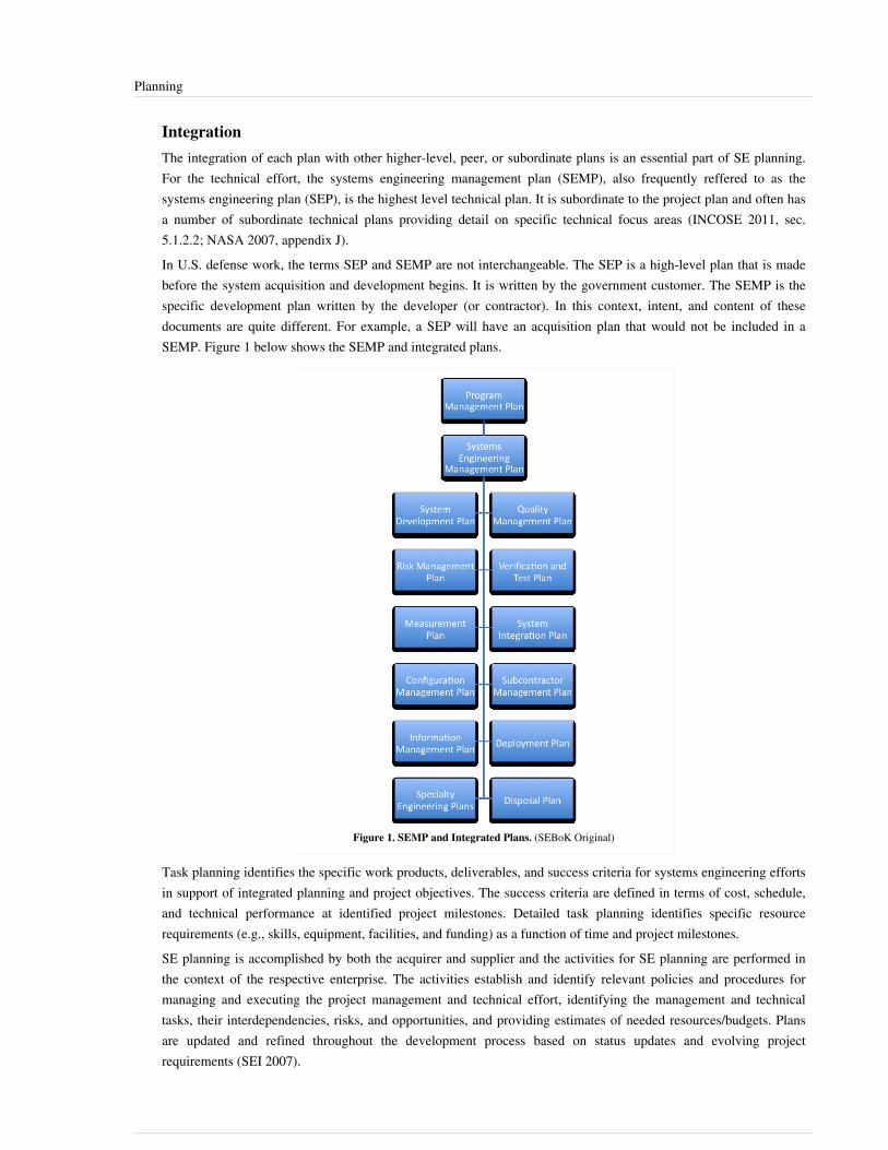
Planning 5
IntegrationThe integration of each plan with other higher-level, peer, or subordinate plans is an essential part of SE planning.For the technical effort, the systems engineering management plan (SEMP), also frequently reffered to as thesystems engineering plan (SEP), is the highest level technical plan. It is subordinate to the project plan and often hasa number of subordinate technical plans providing detail on specific technical focus areas (INCOSE 2011, sec.5.1.2.2; NASA 2007, appendix J).In U.S. defense work, the terms SEP and SEMP are not interchangeable. The SEP is a high-level plan that is madebefore the system acquisition and development begins. It is written by the government customer. The SEMP is thespecific development plan written by the developer (or contractor). In this context, intent, and content of thesedocuments are quite different. For example, a SEP will have an acquisition plan that would not be included in aSEMP. Figure 1 below shows the SEMP and integrated plans.
Figure 1. SEMP and Integrated Plans. (SEBoK Original)
Task planning identifies the specific work products, deliverables, and success criteria for systems engineering effortsin support of integrated planning and project objectives. The success criteria are defined in terms of cost, schedule,and technical performance at identified project milestones. Detailed task planning identifies specific resourcerequirements (e.g., skills, equipment, facilities, and funding) as a function of time and project milestones.SE planning is accomplished by both the acquirer and supplier and the activities for SE planning are performed inthe context of the respective enterprise. The activities establish and identify relevant policies and procedures formanaging and executing the project management and technical effort, identifying the management and technicaltasks, their interdependencies, risks, and opportunities, and providing estimates of needed resources/budgets. Plansare updated and refined throughout the development process based on status updates and evolving projectrequirements (SEI 2007).

Planning 6
Linkages to Other Systems Engineering Management TopicsThe project planning process is closely coupled with the measurement, assessment and control, decisionmanagement, and risk management processes.The measurement process provides inputs for estimation models. Estimates and other products from planning areused in decision management. SE assessment and control processes use planning results for setting milestones andassessing progress. Risk management uses the planning cost models, schedule estimates, and uncertaintydistributions to support quantitative risk analysis (as desired).Additionally, planning needs to use the outputs from assessment and control as well as risk management to ensurecorrective actions have been accounted for in planning future activities. The planning may need to be updated basedon results from technical reviews (from assessment and control) addressing issues pertaining to: measurement,problems that were identified during the performance of risk management activities, or decisions made as a result ofthe decision management activities (INCOSE 2010, sec. 6.1).
Practical Considerations
PitfallsSome of the key pitfalls encountered in planning and performing SE planning are listed in Table 1.
Table 1. Major Pitfalls with Planning. (SEBoK Original)
Name Description
Incomplete andRushed Planning
Inadequate SE planning causes significant adverse impacts on all other engineering activities. Although one may be tempted tosave time by rushing the planning, inadequate planning can create additional costs and interfere with the schedule due toplanning omissions, lack of detail, lack of integration of efforts, infeasible cost and schedules, etc.
Inexperienced Staff Lack of highly experienced engineering staff members, especially in similar projects, will likely result in inadequate planning.Less experienced engineers are often assigned significant roles in the SE planning; however, they may not have theappropriate judgment to lay out realistic and achievable plans. It is essential to assign the SE planning tasks to those with agood amount of relevant experience.
Good PracticesSome good practices gathered from the references are in Table 2.
Table 2. Proven Practices with Planning. (SEBoK Original)
Name Description
Use MultipleDisciplines
Get technical resources from all disciplines involved in the planning process.
Early ConflictResolution
Resolve schedule and resource conflicts early.
Task Independence Tasks should be as independent as possible.
DefineInterdependencies
Define task interdependencies, using dependency networks or other approaches.
Risk Management Integrate risk management with the SE planning to identify areas that require special attention and/or trades.
ManagementReserve
The amount of management reserve should be based on the risk associated with the plan.
Use Historical Data Use historical data for estimates and adjust for differences in the project.
Planning 7
Consider LeadTimes
Identify lead times and ensure that you account for them in the planning (e.g., the development of analytical tools).
Update Plans Prepare to update plans as additional information becomes available or changes are needed.
Use IPDTs An integrated product development team (IPDT) (or integrated product team (IPT)) is often useful to ensure adequatecommunication across the necessary disciplines, timely integration of all design considerations, as well as integration, testing,and consideration of the full range of risks that need to be addressed. Although there are some issues that need to be managedwith them, IPDTs tend to break down the communication and knowledge stovepipes that often exist.
Additional good practices can be found in the Systems Engineering Guidebook for Intelligent TransportationSystems (ITS), NASA Systems Engineering Handbook, the INCOSE Systems Engineering Handbook, and Systems andSoftware Engineering - Life Cycle Processes - Project Management (Caltrans and USDOT 2005, 278; NASADecember 2007, 1-360, sec. 6.1; INCOSE 2011, sec. 5.1; ISO/IEC/IEEE 2009, Clause 6.1).
References
Works CitedCaltrans and USDOT. 2005. Systems Engineering Guidebook for Intelligent Transportation Systems (ITS), version1.1. Sacramento, CA, USA: California Department of Transportation (Caltrans) Division of Reserach &Innovation/U.S. Department of Transportation (USDOT), SEG for ITS 1.1.DAU. 2010. Defense Acquisition Guidebook (DAG). Ft. Belvoir, VA, USA: Defense Acquisition University(DAU)/U.S. Department of Defense, February 19.INCOSE. 2012. INCOSE Systems Engineering Handbook: A Guide for System Life Cycle Processes and Activities.Version 3.2.2. San Diego, CA, USA: International Council on Systems Engineering (INCOSE),INCOSE-TP-2003-002-03.2.2.ISO/IEC/IEEE. 2009. Systems and Software Engineering - Life Cycle Processes - Project Management. Geneva,Switzerland: International Organization for Standardization (ISO)/International Electrotechnical Commission(IEC)/Institute of Electrical and Electronics Engineers (IEEE), ISO/IEC/IEEE 16326:2009(E).NASA. 2007. NASA Systems Engineering Handbook. Washington, D.C.: National Aeronautics and SpaceAdministration (NASA), NASA/SP-2007-6105.SEI. 1995. A systems engineering capability maturity model. Version 1.1. Pittsburgh, PA, USA: SoftwareEngineering Institute (SEI)/Carnegie-Mellon University (CMU), CMU/SEI-95-MM-003.
Primary ReferencesCaltrans and USDOT. 2005. Systems Engineering Guidebook for Intelligent Transportation Systems (ITS), version1.1. Sacramento, CA, USA: California Department of Transportation (Caltrans) Division of Reserach &Innovation/U.S. Department of Transportation (USDOT), SEG for ITS 1.1.DAU. 2010. Defense Acquisition Guidebook (DAG). Ft. Belvoir, VA, USA: Defense Acquisition University(DAU)/U.S. Department of Defense.INCOSE. 2012. INCOSE Systems Engineering Handbook: A Guide for System Life Cycle Processes and Activities.Version 3.2.2. San Diego, CA, USA: International Council on Systems Engineering (INCOSE),INCOSE-TP-2003-002-03.2.2.ISO/IEC/IEEE. 2015. Systems and Software Engineering -- System Life Cycle Processes. Geneva, Switzerland:International Organisation for Standardisation / International Electrotechnical Commissions / Institute of Electricaland Electronics Engineers. ISO/IEC/IEEE 15288:2015.

Planning 8
ISO/IEC/IEEE. 2009. Systems and Software Engineering - Life Cycle Processes - Project Management. Geneva,Switzerland: International Organization for Standardization (ISO)/International Electrotechnical Commission(IEC)/Institute of Electrical and Electronics Engineers (IEEE), ISO/IEC/IEEE 16326:2009(E).NASA. 2007. NASA Systems Engineering Handbook. Washington, D.C., USA: National Aeronautics and SpaceAdministration (NASA), NASA/SP-2007-6105.SEI. 1995. A Systems Engineering Capability Maturity Model, version 1.1. Pittsburgh, PA, USA: SoftwareEngineering Institute (SEI)/Carnegie-Mellon University (CMU), CMU/SEI-95-MM-003.SEI. 2007. Capability Maturity Model Integrated (CMMI) for Development, version 1.2, measurement and analysisprocess area. Pittsburgh, PA, USA: Software Engineering Institute (SEI)/Carnegie Mellon University (CMU).
Additional ReferencesBoehm, B., C. Abts, A.W. Brown, S. Chulani, B.K. Clark, E. Horowitz, R. Madachy, D.J. Reifer, B. Steece. 2000.Software Cost Estimation with COCOMO II. Englewood Cliffs, NJ, USA: Prentice HallDeMarco, T. and T. Lister. 2003. Waltzing with Bears; Managing Risks on Software Projects. New York, NY, USA:Dorset House.ISO/IEC/IEEE. 2009. Systems and Software Engineering - Life Cycle Processes - Project Management. Geneva,Switzerland: International Organization for Standardization (ISO)/International Electrotechnical Commission(IEC)/Institute of Electrical and Electronics Engineers (IEEE), ISO/IEC/IEEE 16326:2009(E).Valerdi, R. 2008. The Constructive Systems Engineering Cost Model (COSYSMO): Quantifying the Costs of SystemsEngineering Effort in Complex Systems. Saarbrücken,Germany: VDM Verlag Dr. Muller
< Previous Article | Parent Article | Next Article >SEBoK v. 1.4 released 29 June 2015
SEBoK DiscussionPlease provide your comments and feedback on the SEBoK below. You will need to log in to DISQUS using anexisting account (e.g. Yahoo, Google, Facebook, Twitter, etc.) or create a DISQUS account. Simply type yourcomment in the text field below and DISQUS will guide you through the login or registration steps. Feedback will bearchived and used for future updates to the SEBoK. If you provided a comment that is no longer listed, that commenthas been adjudicated. You can view adjudication for comments submitted prior to SEBoK v. 1.0 at SEBoK Reviewand Adjudication. Later comments are addressed and changes are summarized in the Letter from the Editor andAcknowledgements and Release History.
If you would like to provide edits on this article, recommend new content, or make comments on the SEBoKas a whole, please see the SEBoK Sandbox [1].
ENCODED_CONTENTOTM3NDgPGRpdiBpZD0iZGlzcXVzX3RocmVhZCI+PC9kaXY+CjxzY3JpcHQgdHlwZT0idGV4dC9qYXZhc2NyaXB0Ij4KICAgIC8qICogKiBDT05GSUdVUkFUSU9OIFZBUklBQkxFUzogRURJVCBCRUZPUkUgUEFTVElORyBJTlRPIFlPVVIgV0VCUEFHRSAqICogKi8KICAgIHZhciBkaXNxdXNfc2hvcnRuYW1lID0gJ3NlYm9rd2lraTEwJzsgLy8gcmVxdWlyZWQ6IHJlcGxhY2UgZXhhbXBsZSB3aXRoIHlvdXIgZm9ydW0gc2hvcnRuYW1lCiAgICB2YXIgZGlzcXVzX2lkZW50aWZpZXIgPSAnUGxhbm5pbmcnOyAgICB2YXIgZGlzcXVzX3VybCA9ICdodHRwOi8vc2Vib2t3aWtpLm9yZy9kcmFmdC9QbGFubmluZyc7CiAgICAvKiAqICogRE9OJ1QgRURJVCBCRUxPVyBUSElTIExJTkUgKiAqICovCiAgICAoZnVuY3Rpb24oKSB7CiAgICAgICAgdmFyIGRzcSA9IGRvY3VtZW50LmNyZWF0ZUVsZW1lbnQoJ3NjcmlwdCcpOyBkc3EudHlwZSA9ICd0ZXh0L2phdmFzY3JpcHQnOyBkc3EuYXN5bmMgPSB0cnVlOwogICAgICAgIGRzcS5zcmMgPSAnaHR0cDovLycgKyBkaXNxdXNfc2hvcnRuYW1lICsgJy5kaXNxdXMuY29tL2VtYmVkLmpzJzsKICAgICAgICAoZG9jdW1lbnQuZ2V0RWxlbWVudHNCeVRhZ05hbWUoJ2hlYWQnKVswXSB8fCBkb2N1bWVudC5nZXRFbGVtZW50c0J5VGFnTmFtZSgnYm9keScpWzBdKS5hcHBlbmRDaGlsZChkc3EpOwogICAgfSkoKTsKPC9zY3JpcHQ+Cjxub3NjcmlwdD5QbGVhc2UgZW5hYmxlIEphdmFTY3JpcHQgdG8gdmlldyB0aGUgPGEgaHJlZj0iaHR0cDovL2Rpc3F1cy5jb20vP3JlZl9ub3NjcmlwdCI+Y29tbWVudHMgcG93ZXJlZCBieSBEaXNxdXMuPC9hPjwvbm9zY3JpcHQ+CjxhIGhyZWY9Imh0dHA6Ly9kaXNxdXMuY29tIiBjbGFzcz0iZHNxLWJybGluayI+YmxvZyBjb21tZW50cyBwb3dlcmVkIGJ5IDxzcGFuIGNsYXNzPSJsb2dvLWRpc3F1cyI+RGlzcXVzPC9zcGFuPjwvYT4=END_ENCODED_CONTENT

Assessment and Control 9
Assessment and ControlThe purpose of systems engineering assessment and control (SEAC) is to provide adequate visibility into theproject’s actual technical progress and risks with respect to the technical plans (i.e., systems engineeringmanagement plan (SEMP) or systems engineering plan (SEP) and subordinate plans). The visibility allows theproject team to take timely preventive action when disruptive trends are recognized or corrective action whenperformance deviates beyond established thresholds or expected values. SEAC includes preparing for andconducting reviews and audits to monitor performance. The results of the reviews and measurement analyses areused to identify and record findings/discrepancies and may lead to causal analysis and corrective/preventive actionplans. Action plans are implemented, tracked, and monitored to closure. (NASA 2007, Section 6.7; SEG-ITS, 2009,Section 3.9.3, 3.9.10; INCOSE, 2010, Clause 6.2; SEI, 2007)
Systems Engineering Assessment and Control Process OverviewThe SEAC process involves determining and initiating the appropriate handling strategies and actions for findingsand/or discrepancies that are uncovered in the enterprise, infrastructure, or life cycle activities associated with theproject. Analysis of the causes of the findings/discrepancies aids in the determination of appropriate handlingstrategies. Implementation of approved preventive, corrective, or improvement actions ensures satisfactorycompletion of the project within planned technical, schedule, and cost objectives. Potential action plans for findingsand/or discrepancies are reviewed in the context of the overall set of actions and priorities in order to optimize thebenefits to the project and/or organization. Interrelated items are analyzed together to obtain a consistent andcost-effective resolution.The SEAC process includes the following steps:•• monitor and review technical performance and resource use against plans•• monitor technical risk, escalate significant risks to the project risk register and seek project funding to execute risk
mitigation plans•• hold technical reviews and report outcomes at the project reviews•• analyze issues and determine appropriate actions•• manage actions to closure•• hold a post-delivery assessment (also known as a post-project review) to capture knowledge associated with the
project (this may be a separate technical assessment or it may be conducted as part of the project assessment andcontrol process).
The following activities are normally conducted as part of a project assessment and control process:•• authorization, release and closure of work•• monitor project performance and resource usage against plan•• monitor project risk and authorize expenditure of project funds to execute risk mitigation plans•• hold project reviews•• analyze issues and determine appropriate actions•• manage actions to closure•• hold a post-delivery assessment (also known as a post-project review) to capture knowledge associated with the
projectExamples of major technical reviews used in SEAC are shown in Table 1 from DAU (2010).

Assessment and Control 10
Table 1. Major Technical Review Examples (DAU 2012). Released by Defense AcquisitionUniversity (DAU)/U.S. Department of Defense (DoD).
Name Description
Alternative SystemsReview
A multi-disciplined review to ensure the resulting set of requirements agrees with the customers' needs and expectations.
Critical DesignReview (CDR)
A multi-disciplined review establishing the initial product baseline to ensure that the system under review has a reasonableexpectation of satisfying the requirements of the capability development document within the currently allocated budget andschedule.
FunctionalConfiguration Audit
Formal examination of the as tested characteristics of a configuration item (hardware and software) with the objective ofverifying that actual performance complies with design and interface requirements in the functional baseline.
In-Service Review A multi-disciplined product and process assessment that is performed to ensure that the system under review is operationallyemployed with well-understood and managed risk.
Initial TechnicalReview
A multi-disciplined review that supports a program's initial program objective memorandum submission.
Integrated BaselineReview
A joint assessment conducted by the government program manager and the contractor to establish the performancemeasurement baseline.
Operational TestReadiness Review
A multi-disciplined product and process assessment to ensure that the system can proceed into initial operational test andevaluation with a high probability of success, and also that the system is effective and suitable for service introduction.
ProductionReadiness Review(PRR)
The examination of a program to determine if the design is ready for production and if the prime contractor and majorsubcontractors have accomplished adequate production planning without incurring unacceptable risks that will breachthresholds of schedule, performance, cost, or other established criteria.
PhysicalConfiguration Audit
An examination of the actual configuration of an item being produced around the time of the full-rate production decision.
Preliminary DesignReview (PDR)
A technical assessment establishing the physically allocated baseline to ensure that the system under review has a reasonableexpectation of being judged operationally effective and suitable.
System FunctionalReview (SFR)
A multi-disciplined review to ensure that the system's functional baseline is established and has a reasonable expectation ofsatisfying the requirements of the initial capabilities document or draft capability development document within the currentlyallocated budget and schedule.
SystemRequirementsReview (SRR)
A multi-disciplined review to ensure that the system under review can proceed into initial systems development and that allsystem requirements and performance requirements derived from the initial capabilities document or draft capabilitydevelopment document are defined and testable, as well as being consistent with cost, schedule, risk, technology readiness,and other system constraints.
System VerificationReview (SVR)
A multi-disciplined product and process assessment to ensure the system under review can proceed into low-rate initialproduction and full-rate production within cost (program budget), schedule (program schedule), risk, and other systemconstraints.
TechnologyReadinessAssessment
A systematic, metrics-based process that assesses the maturity of critical technology elements, such as sustainment drivers.
Test ReadinessReview (TRR)
A multi-disciplined review designed to ensure that the subsystem or system under review is ready to proceed into formaltesting.
Linkages to Other Systems Engineering Management TopicsThe SE assessment and control process is closely coupled with the measurement, planning, decision management,and risk management processes. The measurement process provides indicators for comparing actuals to plans.planning provides estimates and milestones that constitute plans for monitoring as well as the project plan, whichuses measurements to monitor progress. Decision management uses the results of project monitoring as decisioncriteria for making control decisions.

Assessment and Control 11
Practical ConsiderationsKey pitfalls and good practices related to SEAC are described in the next two sections.
PitfallsSome of the key pitfalls encountered in planning and performing SE assessment and control are shown in Table 2.
Table 2. Major Pitfalls with Assessment and Control. (SEBoK Original)
Name Description
No Measurement Since the assessment and control activities are highly dependent on insightful measurement information, it is usually ineffectiveto proceed independently from the measurement efforts - what you get is what you measure.
"Something inTime" Culture
Some things are easier to measure than others - for instance, delivery to cost and schedule. Don't focus on these and neglectharder things to measure like quality of the system, Avoid a "something in time" culture where meeting the schedule takespriority over everything else, but what is delivered is not fit for purpose, which results in the need to rework the project.
No Teeth Make sure that the technical review gates have "teeth". Sometimes the project manager is given authority (or can appeal tosomeone with authority) to over-ride a gate decision and allow work to proceed, even when the gate has exposed significantissues with the technical quality of the system or associated work products. This is a major risk if the organization is stronglyschedule-driven; it can't afford the time to do it right, but somehow it finds the time to do it again (rework).
Too EarlyBaselining
Don't baseline requirements or designs too early. Often there is strong pressure to baseline system requirements and designsbefore they are fully understood or agreed, in order to start subsystem or component development. This just guarantees highlevels of rework.
Good PracticesSome good practices gathered from the references are shown in Table 3.
Table 3. Proven Practices with Assessment and Control. (SEBoK Original)
Name Description
Independence Provide independent (from customer) assessment and recommendations on resources, schedule, technical status, and riskbased on experience and trend analysis.
Peer Reviews Use peer reviews to ensure the quality of a products work before they are submitted for gate review.
Accept Uncertainty Communicate uncertainties in requirements or designs and accept that uncertainty is a normal part of developing asystem.
Risk Mitigation Plans Do not penalize a project at gate review if they admit uncertainty in requirements - ask for their risk mitigation plan tomanage the uncertainty.
Just In-Time Baselining Baseline requirements and designs only when you need to - when other work is committed based on the stability of therequirement or design. If work has to start and the requirement or design is still uncertain, consider how you can buildrobustness into the system to handle the uncertainty with minimum rework.
Communication Document and communicate status findings and recommendations to stakeholders.
Full Visibility Ensure that action items and action-item status, as well as other key status items, are visible to all project participants.
Leverage Previous RootCause Analysis
When performing root cause analysis, take into account the root cause and resolution data documented in previous relatedfindings/discrepancies.
ConcurrentManagement
Plan and perform assessment and control concurrently with the activities for Measurement and Risk Management.
Lessons Learned andPost-Mortems
Hold post-delivery assessments or post-project reviews to capture knowledge associated with the project – e.g., toaugment and improve estimation models, lessons learned databases, gate review checklists, etc.
Assessment and Control 12
Additional good practices can be found in INCOSE (2010, Clause 6.2), SEG-ITS (2009, Sections 3.9.3 and 3.9.10),INCOSE (2010, Section 5.2.1.5), and NASA (2007, Section 6.7).
References
Works CitedCaltrans and USDOT. 2005. Systems Engineering Guidebook for Intelligent Transportation Systems (ITS), version1.1. Sacramento, CA, USA: California Department of Transportation (Caltrans) Division of Reserach &Innovation/U.S. Department of Transportation (USDOT), SEG for ITS 1.1.DAU. 2010. Defense Acquisition Guidebook (DAG). Ft. Belvoir, VA, USA: Defense Acquisition University(DAU)/U.S. Department of Defense (DoD). February 19, 2010.INCOSE. 2012. Systems Engineering Handbook: A Guide for System Life Cycle Processes and Activities. Version3.2.2. San Diego, CA, USA: International Council on Systems Engineering (INCOSE),INCOSE-TP-2003-002-03.2.2.NASA. 2007. Systems Engineering Handbook. Washington, DC, USA: National Aeronautics and SpaceAdministration (NASA), December 2007. NASA/SP-2007-6105.SEI. 2007. "Measurement and Analysis Process Area," in Capability Maturity Model Integrated (CMMI) forDevelopment, version 1.2. Pittsburgh, PA, USA: Software Engineering Institute (SEI)/Carnegie Mellon University(CMU).
Primary ReferencesCaltrans and USDOT. 2005. [[Systems Engineering Guidebook for Intelligent Transportation Systems (ITS)],]version 1.1. Sacramento, CA, USA: California Department of Transportation (Caltrans) Division of Reserach &Innovation/U.S. Department of Transportation (USDOT), SEG for ITS 1.1.DAU. 2010. Defense Acquisition Guidebook (DAG). Ft. Belvoir, VA, USA: Defense Acquisition University(DAU)/U.S. Department of Defense (DoD). February 19, 2010.INCOSE. 2012. Systems Engineering Handbook: A Guide for System Life Cycle Processes and Activities. Version3.2.2. San Diego, CA, USA: International Council on Systems Engineering (INCOSE),INCOSE-TP-2003-002-03.2.2.NASA. 2007. Systems Engineering Handbook. Washington, DC, USA: National Aeronautics and SpaceAdministration (NASA), December 2007. NASA/SP-2007-6105SEI. 2007. "Measurement and Analysis Process Area," in Capability Maturity Model Integrated (CMMI) forDevelopment, version 1.2. Pittsburgh, PA, USA: Software Engineering Institute (SEI)/Carnegie Mellon University(CMU).

Assessment and Control 13
Additional ReferencesISO/IEC/IEEE. 2009. ISO/IEC/IEEE 16326|Systems and Software Engineering - Life Cycle Processes - ProjectManagement. Geneva, Switzerland: International Organization for Standardization (ISO)/InternationalElectrotechnical Commission (IEC)/Institute of Electrical and Electronics Engineers (IEEE), ISO/IEC/IEEE16326:2009(E).
< Previous Article | Parent Article | Next Article >SEBoK v. 1.4 released 29 June 2015
SEBoK DiscussionPlease provide your comments and feedback on the SEBoK below. You will need to log in to DISQUS using anexisting account (e.g. Yahoo, Google, Facebook, Twitter, etc.) or create a DISQUS account. Simply type yourcomment in the text field below and DISQUS will guide you through the login or registration steps. Feedback will bearchived and used for future updates to the SEBoK. If you provided a comment that is no longer listed, that commenthas been adjudicated. You can view adjudication for comments submitted prior to SEBoK v. 1.0 at SEBoK Reviewand Adjudication. Later comments are addressed and changes are summarized in the Letter from the Editor andAcknowledgements and Release History.
If you would like to provide edits on this article, recommend new content, or make comments on the SEBoKas a whole, please see the SEBoK Sandbox [1].
ENCODED_CONTENTNjEyMTcPGRpdiBpZD0iZGlzcXVzX3RocmVhZCI+PC9kaXY+CjxzY3JpcHQgdHlwZT0idGV4dC9qYXZhc2NyaXB0Ij4KICAgIC8qICogKiBDT05GSUdVUkFUSU9OIFZBUklBQkxFUzogRURJVCBCRUZPUkUgUEFTVElORyBJTlRPIFlPVVIgV0VCUEFHRSAqICogKi8KICAgIHZhciBkaXNxdXNfc2hvcnRuYW1lID0gJ3NlYm9rd2lraTEwJzsgLy8gcmVxdWlyZWQ6IHJlcGxhY2UgZXhhbXBsZSB3aXRoIHlvdXIgZm9ydW0gc2hvcnRuYW1lCiAgICB2YXIgZGlzcXVzX2lkZW50aWZpZXIgPSAnQXNzZXNzbWVudCBhbmQgQ29udHJvbCc7ICAgIHZhciBkaXNxdXNfdXJsID0gJ2h0dHA6Ly9zZWJva3dpa2kub3JnL2RyYWZ0L0Fzc2Vzc21lbnRfYW5kX0NvbnRyb2wnOwogICAgLyogKiAqIERPTidUIEVESVQgQkVMT1cgVEhJUyBMSU5FICogKiAqLwogICAgKGZ1bmN0aW9uKCkgewogICAgICAgIHZhciBkc3EgPSBkb2N1bWVudC5jcmVhdGVFbGVtZW50KCdzY3JpcHQnKTsgZHNxLnR5cGUgPSAndGV4dC9qYXZhc2NyaXB0JzsgZHNxLmFzeW5jID0gdHJ1ZTsKICAgICAgICBkc3Euc3JjID0gJ2h0dHA6Ly8nICsgZGlzcXVzX3Nob3J0bmFtZSArICcuZGlzcXVzLmNvbS9lbWJlZC5qcyc7CiAgICAgICAgKGRvY3VtZW50LmdldEVsZW1lbnRzQnlUYWdOYW1lKCdoZWFkJylbMF0gfHwgZG9jdW1lbnQuZ2V0RWxlbWVudHNCeVRhZ05hbWUoJ2JvZHknKVswXSkuYXBwZW5kQ2hpbGQoZHNxKTsKICAgIH0pKCk7Cjwvc2NyaXB0Pgo8bm9zY3JpcHQ+UGxlYXNlIGVuYWJsZSBKYXZhU2NyaXB0IHRvIHZpZXcgdGhlIDxhIGhyZWY9Imh0dHA6Ly9kaXNxdXMuY29tLz9yZWZfbm9zY3JpcHQiPmNvbW1lbnRzIHBvd2VyZWQgYnkgRGlzcXVzLjwvYT48L25vc2NyaXB0Pgo8YSBocmVmPSJodHRwOi8vZGlzcXVzLmNvbSIgY2xhc3M9ImRzcS1icmxpbmsiPmJsb2cgY29tbWVudHMgcG93ZXJlZCBieSA8c3BhbiBjbGFzcz0ibG9nby1kaXNxdXMiPkRpc3F1czwvc3Bhbj48L2E+END_ENCODED_CONTENT
Risk ManagementThe purpose of risk management is to reduce potential risks to an acceptable level before they occur, throughout thelife of the product or project. Risk management is a continuous, forward-looking process that is applied to anticipateand avert risks that may adversely impact the project, and can be considered both a project management and asystems engineering process. A balance must be achieved on each project in terms of overall risk managementownership, implementation, and day-to-day responsibility between these two top-level processes.For the SEBoK, risk management falls under the umbrella of Systems Engineering Management, though the widerbody of risk literature is explored below.
Risk Management Process OverviewRisk is a measure of the potential inability to achieve overall program objectives within defined cost, schedule, andtechnical constraints. It has the following two components (DAU 2003a):1.1. the probability (or likelihood) of failing to achieve a particular outcome2.2. the consequences (or impact) of failing to achieve that outcomeIn the domain of catastrophic risk analysis, risk has three components: (1) threat, (2) vulnerability, and (3)consequence (Willis et al. 2005).Risk management involves defining a risk management strategy, identifying and analyzing risks, handling selectedrisks, and monitoring the progress in reducing risks to an acceptable level (SEI 2010; DoD 2006; DAU 2003a; DAU2003b; PMI 2013) (Opportunity and opportunity management is briefly discussed in below).The SE risk management process includes the following activities:
Risk Management 14
•• risk planning•• risk identification•• risk analysis•• risk handling•• risk monitoringISO/IEC/IEEE 16085 provides a detailed set of risk management activities and tasks which can be utilized in a riskmanagement process aligned with ISO 31000:2009, Risk management — Principles and Guidelines, and ISO Guide73:2009,Risk management — Vocabulary. ISO 9001:2008 standard provides risk-based preventive action requirements insubclause 8.5.3.The Risk Management Process section of the INCOSE Systems Engineering Handbook: A Guide for Systems LifeCycle Processes and Activities, 4th Edition, provides a comprehensive overview of risk management which isintended to be consistent with the Risk Management Process section of ISO 15288.
Risk PlanningRisk planning establishes and maintains a strategy for identifying, analyzing, handling, and monitoring risks withinthe project. The strategy, both the process and its implementation, is documented in a risk management plan (RMP).The risk management process and its implementation should be tailored to each project, updated as appropriatethroughout the life of the project and the RMP should be transmitted in an appropriate means to the project team andkey stakeholders.As necessary the risk management strategy includes the risk management process of all supply chain suppliers anddescribes how risks from all suppliers will be raised to the next level(s) for incorporation in the project risk process.The context of the Risk Management process should include a description of stakeholders’ perspectives, riskcategories, and a description (perhaps by reference) of the technical and managerial objectives, assumptions andconstraints. The risk categories include the relevant technical areas of the system and facilitate identification of risksacross the life cycle of the system. As noted in ISO 31000 the aim of this step is to generate a comprehensive list ofrisks based on those events that might create, enhance, prevent, degrade, accelerate or delay the achievement ofobjectives.The RMP should contain key risk management information; Conrow (2003) identifies the following as keycomponents of RMP:•• a project summary•• project acquisition and contracting strategies•• key definitions•• a list of key documents•• process steps•• inputs, tools and techniques, and outputs per process step•• linkages between risk management and other project processes•• key ground rules and assumptions•• risk categories•• seller and buyer roles and responsibilities•• organizational and personnel roles and responsibilitiesGenerally, the level of detail in a RMP is risk-driven, with simple plans for low risk projects and detailed plans forhigh risk projects.

Risk Management 15
Risk IdentificationRisk identification is the process of examining the project products, processes, and requirements to identify anddocument candidate risks. Risk identification should be performed continuously at the individual-level as well asthrough formerly structured events at both regular intervals and following major program changes (e.g., projectinitiation, re-baselining, change in acquisition phase, etc.).Conrow (2009) states that systems engineers should use one or more top-level approaches (e.g., work breakdownstructure (WBS), key processes evaluation, key requirements evaluation, etc.) and one or more lower-levelapproaches (e.g., affinity, brainstorming, checklists and taxonomies, examining critical path activities, expertjudgment, Ishikawa diagrams, etc.) in risk identification. For example, lower-level checklists and taxonomies existfor software risk identification (Conrow and Shishido 1997, 83-89, p. 84; Boehm 1989, 115-125, Carr et al. 1993, p.A-2) and operational risk identification (Gallagher et al. 2005, p. 4), and have been used on a wide variety ofprograms. The top and lower-level approaches are essential but there is no single accepted method — all approachesshould be examined and used as appropriate.Candidate risk documentation should include the following items where possible, as identified by Conrow (2003p.198):•• risk title•• structured risk description•• applicable risk categories•• potential root causes•• relevant historical information•• responsible individual and managerIt is important to use structured risk descriptions such as an if-then-because format: if (an event occurs--trigger), then(an outcome or affect occurs), because (of the following reasons, or root cause). Another useful construct is acondition (that exists) that leads to a potential consequence (outcome) (Gluch 1994). These approaches help theanalyst to better think through the potential nature of the risk.Risk analysis and risk handling activities should only be performed on approved risks to ensure the best use of scarceresources and maintain focus on the correct risks.
Risk AnalysisRisk analysis is the process of systematically evaluating each identified, approved risk to estimate the probability ofoccurrence (likelihood) and consequence of occurrence (impact), and then converting the results to a correspondingrisk level or rating.There is no best analysis approach for a given risk category. Risk scales and a corresponding matrix, simulations,and probabilistic risk assessments are often used for technical risks, while decision trees, simulations and payoffmatrices are used for cost risk; and simulations are used for schedule risk. Risk analysis approaches are sometimesgrouped into qualitative and quantitative methods. A structured, repeatable methodology should be used in order toincrease analysis accuracy and reduce uncertainty over time.The most common qualitative method (typically) uses ordinal probability and consequence scales coupled with a riskmatrix (also known as a risk cube or mapping matrix) to convert the resulting values to a risk level. Here, one ormore probability of occurrence scales, coupled with three consequences of occurrence scales (cost, performance,schedule) are typically used. Mathematical operations should not be performed on ordinal scale values to preventerroneous results (Conrow 2003, p. 187-364).Once the risk level for each risk is determined, the risks need to be prioritized. Prioritization is typically performedby risk level (e.g., low, medium, high), risk score (the pair of max (probability), max (consequence) values), andother considerations such as time-frame, frequency of occurrence, and interrelationship with other risks (Conrow

Risk Management 16
2003, pp. 187-364). An additional prioritization technique is to convert results into an estimated cost, performance,and schedule value (e.g., probability budget consequence). However, the result is only a point estimate and not adistribution of risk.Widely used quantitative methods include decision trees and the associated expected monetary value analysis(Clemen and Reilly 2001), modeling and simulation (Law 2007; Mun 2010; Vose 2000), payoff matrices (Kerzner2009, p. 747-751), probabilistic risk assessments (Kumamoto and Henley 1996; NASA 2002), and other techniques.Risk prioritization can directly result from the quantitative methods employed. For quantitative approaches, care isneeded in developing the model structure, since the results will only be as good as the accuracy of the structure,coupled with the characteristics of probability estimates or distributions used to model the risks (Law 2007; Evans,Hastings, and Peacock 2000).If multiple risk facets exist for a given item (e.g., cost risk, schedule risk, and technical risk) the different resultsshould be integrated into a cohesive three-dimensional picture of risk. Sensitivity analyses can be applied to bothqualitative and quantitative approaches in an attempt to understand how potential variability will affect results.Particular emphasis should be paid to compound risks (e.g., highly coupled technical risks with inadequate fixedbudgets and schedules).
Risk HandlingRisk handling is the process that identifies and selects options and implements the desired option to reduce a risk toan acceptable level, given program constraints (budget, other resources) and objectives (DAU 2003a, 20-23, 70-78).For a given system-of-interest (SoI), risk handling is primarily performed at two levels. At the system level, theoverall ensemble of system risks is initially determined and prioritized and second-level draft risk element plans(REP's) are prepared for handling the risks. For more complex systems, it is important that the REP's at the higherSoI level are kept consistent with the system RMPs at the lower SoI level, and that the top-level RMP preservescontinuing risk traceability across the SoI.The risk handling strategy selected is the combination of the most desirable risk handling option coupled with asuitable implementation approach for that option (Conrow 2003). Risk handling options include assumption,avoidance, control (mitigation), and transfer. All four options should be evaluated and the best one chosen for eachrisk. An appropriate implementation approach is then chosen for that option. Hybrid strategies can be developed thatinclude more than one risk handling option, but with a single implementation approach. Additional risk handlingstrategies can also be developed for a given risk and either implemented in parallel with the primary strategy or bemade a contingent that is implemented if a particular trigger event occurs during the execution of the primarystrategy. Often, this choice is difficult because of uncertainties in the risk probabilities and impacts. In such cases,buying information to reduce risk uncertainty via prototypes, benchmarking, surveying, modeling, etc. will clarifyrisk handling decisions (Boehm 1981).
Risk Handling Plans
A risk handling plan (RHP - a REP at the system level), should be developed and implemented for all high andmedium risks and selected low risks as warranted.As identified by Conrow (2003, 365-387), each RHP should include:•• a risk owner and management contacts•• selected option•• implementation approach•• estimated probability and consequence of occurrence levels at the start and conclusion of each activity•• specific measurable exit criteria for each activity•• appropriate metrics•• resources needed to implement the RHP

Risk Management 17
Metrics included in each RHP should provide an objective means of determining whether the risk handling strategyis on track and whether it needs to be updated. On larger projects these can include earned value, variation inschedule and technical performance measures (TPMs), and changes in risk level vs. time.The activities present in each RHP should be integrated into the project’s integrated master schedule or equivalent;otherwise there will be ineffective risk monitoring and control.
Risk MonitoringRisk monitoring is used to evaluate the effectiveness of risk handling activities against established metrics andprovide feedback to the other risk management process steps. Risk monitoring results may also provide a basis toupdate RHPs, develop additional risk handling options and approaches, and re-analyze risks. In some cases,monitoring results may also be used to identify new risks, revise an existing risk with a new facet, or revise someaspects of risk planning (DAU 2003a, p. 20). Some risk monitoring approaches that can be applied include earnedvalue, program metrics, TPMs, schedule analysis, and variations in risk level. Risk monitoring approaches should beupdated and evaluated at the same time and WBS level; otherwise, the results may be inconsistent.
Opportunity and Opportunity ManagementIn principle, opportunity management is the duality to risk management, with two components: (1) probability ofachieving an improved outcome and (2) impact of achieving the outcome. Thus, both should be addressed in riskmanagement planning and execution. In practice, however, a positive opportunity exposure will not match a negativerisk exposure in utility space, since the positive utility magnitude of improving an expected outcome is considerablyless than the negative utility magnitude of failing to meet an expected outcome (Canada 1971; Kahneman-Tversky1979). Further, since many opportunity-management initiatives have failed to anticipate serious side effects, allcandidate opportunities should be thoroughly evaluated for potential risks to prevent unintended consequences fromoccurring.In addition, opportunities provide potential benefits for the system or project. Each of the opportunities pursued haveassociated risks that detract from the expected benefit. This includes the risks associated with not pursuing anopportunity, as well as the risk of not achieving the effects of the opportunity.
Linkages to Other Systems Engineering Management TopicsThe measurement process provides indicators for risk analysis. Project planning involves the identification of riskand planning for stakeholder involvement. Project assessment and control monitors project risks. Decisionmanagement evaluates alternatives for selection and handling of identified and analyzed risks.
Practical ConsiderationsKey pitfalls and good practices related to systems engineering risk management are described in the next twosections.
PitfallsSome of the key pitfalls encountered in performing risk management are below in Table 1.

Risk Management 18
Table 1. Risk Management Pitfalls. (SEBoK Original)
Name Description
ProcessOver-Reliance
•• Over-reliance on the process side of risk management without sufficient attention to human and organizational behavioralconsiderations.
Lack ofContinuity
• Failure to implement risk management as a continuous process. Risk management will be ineffective if it’s done just tosatisfy project reviews or other discrete criteria. (Charette, Dwinnell, and McGarry 2004, 18-24 and Scheinin 2008).
Tool andTechniqueOver-Reliance
•• Over-reliance on tools and techniques, with insufficient thought and resources expended on how the process will beimplemented and run on a day-to-day basis.
Lack of Vigilance •• A comprehensive risk identification will generally not capture all risks; some risks will always escape detection, whichreinforces the need for risk identification to be performed continuously.
AutomaticMitigationSelection
• Automatically select the risk handling mitigation option, rather than evaluating all four options in an unbiased fashion andchoosing the “best” option.
Sea of Green • Tracking progress of the risk handling plan, while the plan itself may not adequately include steps to reduce the risk to anacceptable level. Progress indicators may appear “green” (acceptable) associated with the risk handling plan: budgeting,staffing, organizing, data gathering, model preparation, etc. However, the risk itself may be largely unaffected if thehandling strategy and the resulting plan is poorly developed, does not address potential root cause(s), and does notincorporate actions that will effectively resolve the risk.
Band-Aid RiskHandling
•• Handling risks (e.g., interoperability problems with changes in external systems) by patching each instance, rather thanaddressing the root cause(s) and reducing the likelihood of future instances.
Good PracticesSome good practices, gathered from the references are below in Table 2.
Table 2. Risk Management Good Practices. (SEBoK Original)
Name Description
Top Down andBottom Up
• Risk management should be both “top down” and “bottom up” in order to be effective. The project manager or deputy needto own the process at the top level. But risk management principles should be considered and used by all project personnel.
Early Planning •• Include the planning process step in the risk management process. Failure to adequately perform risk planning early in theproject phase, contributes to ineffective risk management.
Risk AnalysisLimitations
•• Understand the limitations of risk analysis tools and techniques. Risk analysis results should be challenged becauseconsiderable input uncertainty and/or potential errors may exist.
Robust RiskHandlingStrategy
• The risk handling strategy should attempt to reduce both the probability and consequence of occurrence terms. It is alsoimperative that the resources needed to properly implement the chosen strategy be available in a timely manner, else the riskhandling strategy, and the entire risk management process, will be viewed as a “paper tiger.”
Structured RiskMonitoring
•• Risk monitoring should be a structured approach to compare actual vs. anticipated cost, performance, schedule, and riskoutcomes associated with implementing the RHP. When ad-hoc or unstructured approaches are used, or when risk level vs.time is the only metric tracked, the resulting risk monitoring usefulness can be greatly reduced.
Update RiskDatabase
•• The risk management database (registry) should be updated throughout the course of the program, striking a balancebetween excessive resources required and insufficient updates performed. Database updates should occur at both a tailored,regular interval and following major program changes.
Risk Management 19
References
Works CitedBoehm, B. 1981. Software Engineering Economics. Upper Saddle River, NJ, USA: Prentice Hall.Boehm, B. 1989. Software Risk Management. Los Alamitos, CA; Tokyo, Japan: IEEE Computer Society Press:115-125.Canada, J.R. 1971. Intermediate Economic Analysis for Management and Engineering. Upper Saddle River, NJ,USA: Prentice Hall.Carr, M., S. Konda, I. Monarch, F. Ulrich, and C. Walker. 1993. Taxonomy-based risk identification. Pittsburgh, PA,USA: Software Engineering Institute (SEI)/Carnegie-Mellon University (CMU), CMU/SEI-93-TR-6.Charette, R., L. Dwinnell, and J. McGarry. 2004. "Understanding the roots of process performance failure."CROSSTALK: The Journal of Defense Software Engineering (August 2004): 18-24.Clemen, R., and T. Reilly. 2001. Making hard decisions. Boston, MA, USA: Duxbury.Conrow, E. 2003. Effective Risk Management: Some Keys to Success, 2nd ed. Reston, VA, USA: American Instituteof Aeronautics and Astronautics (AIAA).Conrow, E. 2008. "Risk analysis for space systems." Paper presented at Space Systems Engineering and RiskManagement Symposium, 27-29 February, 2008, Los Angeles, CA, USA.Conrow, E. and P. Shishido. 1997. "Implementing risk management on software intensive projects." IEEE Software.14(3) (May/June 1997): 83-9.DAU. 2003a. Risk Management Guide for DoD Acquisition: Fifth Edition, version 2. Ft. Belvoir, VA, USA: DefenseAcquisition University (DAU) Press.DAU. 2003b. U.S. Department of Defense extension to: A guide to the project management body of knowledge(PMBOK(R) guide), first edition. Version 1. 1st ed. Ft. Belvoir, VA, USA: Defense Acquisition University (DAU)Press.DoD. 2006. Risk Management Guide for DoD Acquisition, 6th edition, version 1. Washington, DC, USA: Office ofthe Under Secretary of Defense (Acquisition, Technology & Logistics)/Department of Defense.Evans, M., N. Hastings, and B. Peacock. 2000. Statistical Distributions, 3rd ed. New York, NY, USA:Wiley-Interscience.Gallagher, B., P. Case, R. Creel, S. Kushner, and R. Williams. 2005. A taxonomy of operational risk. Pittsburgh, PA,USA: Software Engineering Institute (SEI)/Carnegie-Mellon University (CMU), CMU/SEI-2005-TN-036.Gluch, P. 1994. A Construct for Describing Software Development Risks. Pittsburgh, PA, USA: SoftwareEngineering Institute (SEI)/Carnegie-Mellon University (CMU), CMU/SEI-94-TR-14.ISO/IEC/IEEE. 2015. Systems and Software Engineering -- System Life Cycle Processes. Geneva, Switzerland:International Organisation for Standardisation / International Electrotechnical Commissions / Institute of Electricaland Electronics Engineers. ISO/IEC/IEEE 15288:2015.Kerzner, H. 2009. Project Management: A Systems Approach to Planning, Scheduling, and Controlling. 10th ed.Hoboken, NJ, USA: John Wiley & Sons.Kahneman, D., and A. Tversky. 1979. "Prospect theory: An analysis of decision under risk." Econometrica. 47(2)(Mar., 1979): 263-292.Kumamoto, H. and E. Henley. 1996. Probabilistic Risk Assessment and Management for Engineers and Scientists,2nd ed. Piscataway, NJ, USA: Institute of Electrical and Electronics Engineers (IEEE) Press.Law, A. 2007. Simulation Modeling and Analysis, 4th ed. New York, NY, USA: McGraw Hill.Mun, J. 2010. Modeling Risk, 2nd ed. Hoboken, NJ, USA: John Wiley & Sons.
Risk Management 20
NASA. 2002. Probabilistic Risk Assessment Procedures Guide for NASA Managers and Practitioners, version 1.1.Washington, DC, USA: Office of Safety and Mission Assurance/National Aeronautics and Space Administration(NASA).PMI. 2013. A Guide to the Project Management Body of Knowledge (PMBOK® Guide), 5th ed. Newtown Square,PA, USA: Project Management Institute (PMI).Scheinin, W. 2008. "Start Early and Often: The Need for Persistent Risk Management in the Early AcquisitionPhases." Paper presented at Space Systems Engineering and Risk Management Symposium, 27-29 February 2008,Los Angeles, CA, USA.SEI. 2010. Capability Maturity Model Integrated (CMMI) for Development, version 1.3. Pittsburgh, PA, USA:Software Engineering Institute (SEI)/Carnegie Mellon University (CMU).Vose, D. 2000. Quantitative Risk Analysis, 2nd ed. New York, NY, USA: John Wiley & Sons.Willis, H.H., A.R. Morral, T.K. Kelly, and J.J. Medby. 2005. Estimating Terrorism Risk. Santa Monica, CA, USA:The RAND Corporation, MG-388.
Primary ReferencesBoehm, B. 1981. Software Engineering Economics. Upper Saddle River, NJ, USA:Prentice Hall.Boehm, B. 1989. Software Risk Management. Los Alamitos, CA; Tokyo, Japan: IEEE Computer Society Press, p.115-125.Conrow, E.H. 2003. Effective Risk Management: Some Keys to Success, 2nd ed. Reston, VA, USA: AmericanInstitute of Aeronautics and Astronautics (AIAA).DoD. 2006. Risk Management Guide for DoD Acquisition, 6th ed., version 1. Washington, D. C., USA: Office of theUnder Secretary of Defense (Acquisition, Technology & Logistics)/Department of Defense (DoD).SEI. 2010. Capability Maturity Model Integrated (CMMI) for Development, version 1.3. Pittsburgh, PA, USA:Software Engineering Institute (SEI)/Carnegie Mellon University (CMU).
Additional ReferencesCanada, J.R. 1971. Intermediate Economic Analysis for Management and Engineering. Upper Saddle River, NJ,USA: Prentice Hall.Carr, M., S. Konda, I. Monarch, F. Ulrich, and C. Walker. 1993. Taxonomy-based risk identification. Pittsburgh, PA,USA: Software Engineering Institute (SEI)/Carnegie-Mellon University (CMU), CMU/SEI-93-TR-6.Charette, R. 1990. Application Strategies for Risk Management. New York, NY, USA: McGraw-Hill.Charette, R. 1989. Software Engineering Risk Analysis and Management. New York, NY, USA: McGraw-Hill(MultiScience Press).Charette, R., L. Dwinnell, and J. McGarry. 2004. "Understanding the roots of process performance failure."CROSSTALK: The Journal of Defense Software Engineering (August 2004): 18-24.Clemen, R., and T. Reilly. 2001. Making hard decisions. Boston, MA, USA: Duxbury.Conrow, E. 2010. "Space program schedule change probability distributions." Paper presented at American Instituteof Aeronautics and Astronautics (AIAA) Space 2010, 1 September 2010, Anaheim, CA, USA.Conrow, E. 2009. "Tailoring risk management to increase effectiveness on your project." Presentation to the ProjectManagement Institute, Los Angeles Chapter, 16 April, 2009, Los Angeles, CA.Conrow, E. 2008. "Risk analysis for space systems." Paper presented at Space Systems Engineering and RiskManagement Symposium, 27-29 February, 2008, Los Angeles, CA, USA.

Risk Management 21
Conrow, E. and P. Shishido. 1997. "Implementing risk management on software intensive projects." IEEE Software.14(3) (May/June 1997): 83-9.DAU. 2003a. Risk Management Guide for DoD Acquisition: Fifth Edition. Version 2. Ft. Belvoir, VA, USA:Defense Acquisition University (DAU) Press.DAU. 2003b. U.S. Department of Defense extension to: A guide to the project management body of knowledge(PMBOK(R) guide), 1st ed. Ft. Belvoir, VA, USA: Defense Acquisition University (DAU) Press.Dorofee, A., J. Walker, C. Alberts, R. Higuera, R. Murphy, and R. Williams (eds). 1996. Continuous RiskManagement Guidebook. Pittsburgh, PA, USA: Software Engineering Institute (SEI)/Carnegie-Mellon University(CMU).Evans, M., N. Hastings, and B. Peacock. 2000. Statistical Distributions, 3rd ed. New York, NY, USA:Wiley-Interscience.Gallagher, B., P. Case, R. Creel, S. Kushner, and R. Williams. 2005. A taxonomy of operational risk. Pittsburgh, PA,USA: Software Engineering Institute (SEI)/Carnegie-Mellon University (CMU), CMU/SEI-2005-TN-036.Gluch, P. 1994. A Construct for Describing Software Development Risks. Pittsburgh, PA, USA: SoftwareEngineering Institute (SEI)/Carnegie-Mellon University (CMU), CMU/SEI-94-TR-14.Haimes, Y.Y. 2009. Risk Modeling, Assessment, and Management. Hoboken, NJ,USA: John Wiley & Sons, Inc.Hall, E. 1998. Managing Risk: Methods for Software Systems Development. New York, NY, USA: Addison WesleyProfessional.INCOSE. 2015. Systems Engineering Handbook: A Guide for System Life Cycle Processes and Activities, version 4.San Diego, CA, USA: International Council on Systems Engineering (INCOSE), INCOSE-TP-2014-001-04.ISO. 2009. Risk Management—Principles and Guidelines. Geneva, Switzerland: International Organization forStandardization (ISO), ISO 31000:2009.ISO/IEC. 2009. Risk Management—Risk Assessment Techniques. Geneva, Switzerland: International Organizationfor Standardization (ISO)/International Electrotechnical Commission (IEC), ISO/IEC 31010:2009.ISO/IEC/IEEE. 2006. Systems and Software Engineering - Risk Management. Geneva, Switzerland: InternationalOrganization for Standardization (ISO)/International Electrotechnical Commission (IEC)/Institute of Electrical andElectronics Engineers (IEEE). ISO/IEC/IEEE 16085.ISO. 2003. Space Systems - Risk Management. Geneva, Switzerland: International Organization for Standardization(ISO), ISO 17666:2003.Jones, C. 1994. Assessment and Control of Software Risks. Upper Saddle River, NJ, USA: Prentice-Hall.Kahneman, D. and A. Tversky. 1979. "Prospect theory: An analysis of decision under risk." Econometrica. 47(2)(Mar., 1979): 263-292.Kerzner, H. 2009. Project Management: A Systems Approach to Planning, Scheduling, and Controlling, 10th ed.Hoboken, NJ: John Wiley & Sons.Kumamoto, H., and E. Henley. 1996. Probabilistic Risk Assessment and Management for Engineers and Scientists,2nd ed. Piscataway, NJ, USA: Institute of Electrical and Electronics Engineers (IEEE) Press.Law, A. 2007. Simulation Modeling and Analysis, 4th ed. New York, NY, USA: McGraw Hill.MITRE. 2012. Systems Engineering Guide to Risk Management. Available online: http:/ / www. mitre. org/ work/systems_engineering/ guide/ acquisition_systems_engineering/ risk_management/ . Accessed on July 7, 2012. Pagelast updated on May 8, 2012.Mun, J. 2010. Modeling Risk, 2nd ed. Hoboken, NJ, USA: John Wiley & Sons.NASA. 2002. Probabilistic Risk Assessment Procedures Guide for NASA Managers and Practitioners, version 1.1. Washington, DC, USA: Office of Safety and Mission Assurance/National Aeronautics and Space Administration
Risk Management 22
(NASA).PMI. 2013. A Guide to the Project Management Body of Knowledge (PMBOK® Guide), 5th ed. Newtown Square,PA, USA: Project Management Institute (PMI).Scheinin, W. 2008. "Start Early and Often: The Need for Persistent Risk Management in the Early AcquisitionPhases." Paper presented at Space Systems Engineering and Risk Management Symposium, 27-29 February 2008,Los Angeles, CA, USA.USAF. 2005. SMC systems engineering primer & handbook: Concepts, processes, and techniques, 3rd ed. LosAngeles, CA, USA: Space & Missile Systems Center/U.S. Air Force (USAF).Vose, D. 2000. Quantitative Risk Analysis. 2nd ed. New York, NY, USA: John Wiley & Sons.Willis, H.H., A.R. Morral, T.K. Kelly, and J.J. Medby. 2005. Estimating Terrorism Risk. Santa Monica, CA, USA:The RAND Corporation, MG-388.
< Previous Article | Parent Article | Next Article >SEBoK v. 1.4 released 29 June 2015
SEBoK DiscussionPlease provide your comments and feedback on the SEBoK below. You will need to log in to DISQUS using anexisting account (e.g. Yahoo, Google, Facebook, Twitter, etc.) or create a DISQUS account. Simply type yourcomment in the text field below and DISQUS will guide you through the login or registration steps. Feedback will bearchived and used for future updates to the SEBoK. If you provided a comment that is no longer listed, that commenthas been adjudicated. You can view adjudication for comments submitted prior to SEBoK v. 1.0 at SEBoK Reviewand Adjudication. Later comments are addressed and changes are summarized in the Letter from the Editor andAcknowledgements and Release History.
If you would like to provide edits on this article, recommend new content, or make comments on the SEBoKas a whole, please see the SEBoK Sandbox [1].
ENCODED_CONTENTMTI0MzAPGRpdiBpZD0iZGlzcXVzX3RocmVhZCI+PC9kaXY+CjxzY3JpcHQgdHlwZT0idGV4dC9qYXZhc2NyaXB0Ij4KICAgIC8qICogKiBDT05GSUdVUkFUSU9OIFZBUklBQkxFUzogRURJVCBCRUZPUkUgUEFTVElORyBJTlRPIFlPVVIgV0VCUEFHRSAqICogKi8KICAgIHZhciBkaXNxdXNfc2hvcnRuYW1lID0gJ3NlYm9rd2lraTEwJzsgLy8gcmVxdWlyZWQ6IHJlcGxhY2UgZXhhbXBsZSB3aXRoIHlvdXIgZm9ydW0gc2hvcnRuYW1lCiAgICB2YXIgZGlzcXVzX2lkZW50aWZpZXIgPSAnUmlzayBNYW5hZ2VtZW50JzsgICAgdmFyIGRpc3F1c191cmwgPSAnaHR0cDovL3NlYm9rd2lraS5vcmcvZHJhZnQvUmlza19NYW5hZ2VtZW50JzsKICAgIC8qICogKiBET04nVCBFRElUIEJFTE9XIFRISVMgTElORSAqICogKi8KICAgIChmdW5jdGlvbigpIHsKICAgICAgICB2YXIgZHNxID0gZG9jdW1lbnQuY3JlYXRlRWxlbWVudCgnc2NyaXB0Jyk7IGRzcS50eXBlID0gJ3RleHQvamF2YXNjcmlwdCc7IGRzcS5hc3luYyA9IHRydWU7CiAgICAgICAgZHNxLnNyYyA9ICdodHRwOi8vJyArIGRpc3F1c19zaG9ydG5hbWUgKyAnLmRpc3F1cy5jb20vZW1iZWQuanMnOwogICAgICAgIChkb2N1bWVudC5nZXRFbGVtZW50c0J5VGFnTmFtZSgnaGVhZCcpWzBdIHx8IGRvY3VtZW50LmdldEVsZW1lbnRzQnlUYWdOYW1lKCdib2R5JylbMF0pLmFwcGVuZENoaWxkKGRzcSk7CiAgICB9KSgpOwo8L3NjcmlwdD4KPG5vc2NyaXB0PlBsZWFzZSBlbmFibGUgSmF2YVNjcmlwdCB0byB2aWV3IHRoZSA8YSBocmVmPSJodHRwOi8vZGlzcXVzLmNvbS8/cmVmX25vc2NyaXB0Ij5jb21tZW50cyBwb3dlcmVkIGJ5IERpc3F1cy48L2E+PC9ub3NjcmlwdD4KPGEgaHJlZj0iaHR0cDovL2Rpc3F1cy5jb20iIGNsYXNzPSJkc3EtYnJsaW5rIj5ibG9nIGNvbW1lbnRzIHBvd2VyZWQgYnkgPHNwYW4gY2xhc3M9ImxvZ28tZGlzcXVzIj5EaXNxdXM8L3NwYW4+PC9hPg==END_ENCODED_CONTENT

Measurement 23
MeasurementMeasurement and the accompanying analysis are fundamental elements of systems engineering (SE) and technicalmanagement. SE measurement provides information relating to the products developed, services provided, andprocesses implemented to support effective management of the processes and to objectively evaluate product orservice quality. Measurement supports realistic planning, provides insight into actual performance, and facilitatesassessment of suitable actions (Roedler and Jones 2005, 1-65; Frenz et al. 2010).Appropriate measures and indicators are essential inputs to tradeoff analyses to balance cost, schedule, and technicalobjectives. Periodic analysis of the relationships between measurement results and review of the requirements andattributes of the system provides insights that help to identify issues early, when they can be resolved with lessimpact. Historical data, together with project or organizational context information, forms the basis for the predictivemodels and methods that should be used.
Fundamental ConceptsThe discussion of measurement in this article is based on some fundamental concepts. Roedler et al. (2005, 1-65)states three key SE measurement concepts that are paraphrased here:1. SE measurement is a consistent but flexible process that is tailored to the unique information needs and
characteristics of a particular project or organization and revised as information needs change.2. Decision makers must understand what is being measured. Key decision-makers must be able to connect
what is being measured to what they need to know and what decisions they need to make as part of a closed-loop,feedback control process (Frenz et al. 2010).
3.3. Measurement must be used to be effective.
Measurement Process OverviewThe measurement process as presented here consists of four activities from Practical Software and SystemsMeasurement (PSM) (2011) and described in (ISO/IEC/IEEE 15939; McGarry et al. 2002):1.1. establish and sustain commitment2.2. plan measurement3.3. perform measurement4.4. evaluate measurementThis approach has been the basis for establishing a common process across the software and systems engineeringcommunities. This measurement approach has been adopted by the Capability Maturity Model Integration (CMMI)measurement and analysis process area (SEI 2006, 10), as well as by international systems and software engineeringstandards (ISO/IEC/IEEE 15939; ISO/IEC/IEEE 15288, 1). The International Council on Systems Engineering(INCOSE) Measurement Working Group has also adopted this measurement approach for several of theirmeasurement assets, such as the INCOSE SE Measurement Primer (Frenz et al. 2010) and Technical MeasurementGuide (Roedler and Jones 2005). This approach has provided a consistent treatment of measurement that allows theengineering community to communicate more effectively about measurement. The process is illustrated in Figure 1from Roedler and Jones (2005) and McGarry et al. (2002).

Measurement 24
Figure 1. Four Key Measurement Process Activities (PSM 2011). Reprinted with permission of Practical Software and SystemsMeasurement (PSM [1]). All other rights are reserved by the copyright owner.
Establish and Sustain CommitmentThis activity focuses on establishing the resources, training, and tools to implement a measurement process andensure that there is a management commitment to use the information that is produced. Refer to PSM (August 18,2011) and SPC (2011) for additional detail.
Plan MeasurementThis activity focuses on defining measures that provide insight into project or organization information needs. Thisincludes identifying what the decision-makers need to know and when they need to know it, relaying theseinformation needs to those entities in a manner that can be measured, and identifying, prioritizing, selecting, andspecifying measures based on project and organization processes (Jones 2003, 15-19). This activity also identifiesthe reporting format, forums, and target audience for the information provided by the measures.Here are a few widely used approaches to identify the information needs and derive associated measures, where eachcan be focused on identifying measures that are needed for SE management:• The PSM approach, which uses a set of information categories, measurable concepts, and candidate measures to
aid the user in determining relevant information needs and the characteristics of those needs on which to focus(PSM August 18, 2011).
•• The (GQM) approach, which identifies explicit measurement goals. Each goal is decomposed into severalquestions that help in the selection of measures that address the question and provide insight into the goalachievement (Park, Goethert, and Florac 1996).

Measurement 25
• Software Productivity Center’s (SPC's) 8-step Metrics Program, which also includes stating the goals and definingmeasures needed to gain insight for achieving the goals (SPC 2011).
The following are good sources for candidate measures that address information needs and measurableconcepts/questions:•• PSM Web Site (PSM 2011)•• PSM Guide, Version 4.0, Chapters 3 and 5 (PSM 2000)•• SE Leading Indicators Guide, Version 2.0, Section 3 (Roedler et al. 2010)•• Technical Measurement Guide, Version 1.0, Section 10 (Roedler and Jones 2005, 1-65)•• Safety Measurement (PSM White Paper), Version 3.0, Section 3.4 (Murdoch 2006, 60)•• Security Measurement (PSM White Paper), Version 3.0, Section 7 (Murdoch 2006, 67)•• Measuring Systems Interoperability, Section 5 and Appendix C (Kasunic and Anderson 2004)•• Measurement for Process Improvement (PSM Technical Report), version 1.0, Appendix E (Statz 2005)The INCOSE SE Measurement Primer (Frenz et al. 2010) provides a list of attributes of a good measure withdefinitions for each attribute; these attributes include relevance, completeness, timeliness, simplicity, costeffectiveness, repeatability, and accuracy. Evaluating candidate measures against these attributes can help assure theselection of more effective measures.The details of each measure need to be unambiguously defined and documented. Templates for the specification ofmeasures and indicators are available on the PSM website (2011) and in Goethert and Siviy (2004).
Perform MeasurementThis activity focuses on the collection and preparation of measurement data, measurement analysis, and thepresentation of the results to inform decision makers. The preparation of the measurement data includes verification,normalization, and aggregation of the data, as applicable. Analysis includes estimation, feasibility analysis of plans,and performance analysis of actual data against plans.The quality of the measurement results is dependent on the collection and preparation of valid, accurate, andunbiased data. Data verification, validation, preparation, and analysis techniques are discussed in PSM (2011) andSEI (2010). Per TL 9000, Quality Management System Guidance, The analysis step should integrate quantitativemeasurement results and other qualitative project information, in order to provide managers the feedback neededfor effective decision making (QuEST Forum 2012, 5-10). This provides richer information that gives the users thebroader picture and puts the information in the appropriate context.There is a significant body of guidance available on good ways to present quantitative information. Edward Tuftehas several books focused on the visualization of information, including The Visual Display of QuantitativeInformation (Tufte 2001).Other resources that contain further information pertaining to understanding and using measurement results include•• PSM (2011)•• ISO/IEC/IEEE 15939, clauses 4.3.3 and 4.3.4•• Roedler and Jones (2005), sections 6.4, 7.2, and 7.3
Evaluate MeasurementThis activity involves the analysis of information that explains the periodic evaluation and improvement of themeasurement process and specific measures. One objective is to ensure that the measures continue to align with thebusiness goals and information needs, as well as provide useful insight. This activity should also evaluate the SEmeasurement activities, resources, and infrastructure to make sure it supports the needs of the project andorganization. Refer to PSM (2011) and Practical Software Measurement: Objective Information for Decision Makers(McGarry et al. 2002) for additional detail.

Measurement 26
Systems Engineering Leading IndicatorsLeading indicators are aimed at providing predictive insight that pertains to an information need. A SE leadingindicator is a measure for evaluating the effectiveness of a how a specific activity is applied on a project in a mannerthat provides information about impacts that are likely to affect the system performance objectives (Roedler et al.2010). Leading indicators may be individual measures or collections of measures and associated analysis thatprovide future systems engineering performance insight throughout the life cycle of the system; they support theeffective management of systems engineering by providing visibility into expected project performance and potentialfuture states (Roedler et al. 2010).As shown in Figure 2, a leading indicator is composed of characteristics, a condition, and a predicted behavior. Thecharacteristics and conditions are analyzed on a periodic or as-needed basis to predict behavior within a givenconfidence level and within an accepted time range into the future. More information is also provided by Roedler etal. (2010).
Figure 2. Composition of a Leading Indicator (Roedler et al. 2010). Reprinted with permission of the International Council onSystems Engineering (INCOSE [2]) and Practical Software and Systems Measurement (PSM [1]). All other rights are reserved by the
copyright owner.
Technical MeasurementTechnical measurement is the set of measurement activities used to provide information about progress in thedefinition and development of the technical solution, ongoing assessment of the associated risks and issues, and thelikelihood of meeting the critical objectives of the acquirer. This insight helps an engineer make better decisionsthroughout the life cycle of a system and increase the probability of delivering a technical solution that meets boththe specified requirements and the mission needs. The insight is also used in trade-off decisions when performance isnot within the thresholds or goals.

Measurement 27
Technical measurement includes measures of effectiveness (MOEs), measures of performance (MOPs), andtechnical performance measures (TPMs) (Roedler and Jones 2005, 1-65). The relationships between these types oftechnical measures are shown in Figure 3 and explained in the reference for Figure 3. Using the measurementprocess described above, technical measurement can be planned early in the life cycle and then performedthroughout the life cycle with increasing levels of fidelity as the technical solution is developed, facilitatingpredictive insight and preventive or corrective actions. More information about technical measurement can be foundin the NASA Systems Engineering Handbook, System Analysis, Design, Development: Concepts, Principles, andPractices, and the Systems Engineering Leading Indicators Guide (NASA December 2007, 1-360, Section 6.7.2.2;Wasson 2006, Chapter 34; Roedler and Jones 2005).
Figure 3. Relationship of the Technical Measures (Roedler et al 2010). Reprinted with permission of the International Council onSystems Engineering (INCOSE [1]) and Practical Software and Systems Measurement (PSM [1]). All other rights are reserved by the
copyright owner.
Service MeasurementThe same measurement activities can be applied for service measurement; however, the context and measures will bedifferent. Service providers have a need to balance efficiency and effectiveness, which may be opposing objectives.Good service measures are outcome-based, focus on elements important to the customer (e.g., service availability,reliability, performance, etc.), and provide timely, forward-looking information.For services, the terms critical success factors (CSF) and key performance indicators (KPI) are used often whendiscussing measurement. CSFs are the key elements of the service or service infrastructure that are most important toachieve the business objectives. KPIs are specific values or characteristics measured to assess achievement of thoseobjectives.

Measurement 28
More information about service measurement can be found in the Service Design and Continual ServiceImprovement volumes of BMP (2010, 1). More information on service SE can be found in the Service SystemsEngineering article.
Linkages to Other Systems Engineering Management TopicsSE measurement has linkages to other SEM topics. The following are a few key linkages adapted from Roedler andJones (2005):• Planning – SE measurement provides the historical data and supports the estimation for, and feasibility analysis
of, the plans for realistic planning.• Assessment and Control – SE measurement provides the objective information needed to perform the assessment
and determination of appropriate control actions. The use of leading indicators allows for early assessment andcontrol actions that identify risks and/or provide insight to allow early treatment of risks to minimize potentialimpacts.
• Risk Management – SE risk management identifies the information needs that can impact project andorganizational performance. SE measurement data helps to quantify risks and subsequently provides informationabout whether risks have been successfully managed.
• Decision Management – SE Measurement results inform decision making by providing objective insight.
Practical ConsiderationsKey pitfalls and good practices related to SE measurement are described in the next two sections.
PitfallsSome of the key pitfalls encountered in planning and performing SE Measurement are provided in Table 1.
Table 1. Measurement Pitfalls. (SEBoK Original)
Name Description
Golden Measures •• Looking for the one measure or small set of measures that applies to all projects.•• No one-size-fits-all measure or measurement set exists.•• Each project has unique information needs (e.g., objectives, risks, and issues).•• The one exception is that, in some cases with consistent product lines, processes, and information needs, a small core
set of measures may be defined for use across an organization.
Single-PassPerspective
•• Viewing measurement as a single-pass activity.•• To be effective, measurement needs to be performed continuously, including the periodic identification and
prioritization of information needs and associated measures.
Unknown InformationNeed
•• Performing measurement activities without the understanding of why the measures are needed and what informationthey provide.
•• This can lead to wasted effort.
Inappropriate Usage •• Using measurement inappropriately, such as measuring the performance of individuals or makinng interpretationswithout context information.
•• This can lead to bias in the results or incorrect interpretations.

Measurement 29
Good PracticesSome good practices, gathered from the references are provided in Table 2.
Table 2. Measurement Good Practices. (SEBoK Original)
Name Description
Periodic Review •• Regularly review each measure collected.
Action Driven •• Measurement by itself does not control or improve process performance.•• Measurement results should be provided to decision makers for appropriate action.
Integration intoProject Processes
•• SE Measurement should be integrated into the project as part of the ongoing project business rhythm.•• Data should be collected as processes are performed, not recreated as an afterthought.
Timely Information •• Information should be obtained early enough to allow necessary action to control or treat risks, adjust tactics andstrategies, etc.
•• When such actions are not successful, measurement results need to help decision-makers determine contingency actionsor correct problems.
Relevance toDecision Makers
•• Successful measurement requires the communication of meaningful information to the decision-makers.•• Results should be presented in the decision-makers preferred format.•• Allows accurate and expeditious interpretation of the results.
Data Availability •• Decisions can rarely wait for a complete or perfect set of data, so measurement information often needs to be derived fromanalysis of the best available data, complemented by real-time events and qualitative insight (including experience).
Historical Data •• Use historical data as the basis of plans, measure what is planned versus what is achieved, archive actual achieved results,and use archived data as a historical basis for the next planning effort.
Information Model •• The information model defined in ISO/IEC/IEEE (2007) provides a means to link the entities that are measured to theassociated measures and to the identified information need, and also describes how the measures are converted intoindicators that provide insight to decision-makers.
Additional information can be found in the Systems Engineering Measurement Primer, Section 4.2 (Frenz et al.2010), and INCOSE Systems Engineering Handbook, Section 5.7.1.5 (2012).
References
Works CitedFrenz, P., G. Roedler, D.J. Gantzer, P. Baxter. 2010. Systems Engineering Measurement Primer: A BasicIntroduction to Measurement Concepts and Use for Systems Engineering. Version 2.0. San Diego, CA: InternationalCouncil on System Engineering (INCOSE). INCOSE‐TP‐2010‐005‐02. Accessed April 13, 2015 at http:/ / www.incose. org/ ProductsPublications/ techpublications/ PrimerMeasurementINCOSE. 2012. Systems Engineering Handbook: A Guide for System Life Cycle Processes and Activities, version3.2.2. San Diego, CA, USA: International Council on Systems Engineering (INCOSE),INCOSE-TP-2003-002-03.2.2.ISO/IEC/IEEE. 2007. Systems and software engineering - Measurement process. Geneva, Switzerland: InternationalOrganization for Standardization (ISO)/International Electrotechnical Commission (IEC), ISO/IEC/IEEE15939:2007.ISO/IEC/IEEE. 2015. Systems and Software Engineering -- System Life Cycle Processes. Geneva, Switzerland:International Organisation for Standardisation / International Electrotechnical Commissions / Institute of Electricaland Electronics Engineers. ISO/IEC/IEEE 15288:2015.Kasunic, M. and W. Anderson. 2004. Measuring Systems Interoperability: Challenges and Opportunities.Pittsburgh, PA, USA: Software Engineering Institute (SEI)/Carnegie Mellon University (CMU).

Measurement 30
McGarry, J., D. Card, C. Jones, B. Layman, E. Clark, J.Dean, F. Hall. 2002. Practical Software Measurement:Objective Information for Decision Makers. Boston, MA, USA: Addison-Wesley.NASA. 2007. Systems Engineering Handbook. Washington, DC, USA: National Aeronautics and SpaceAdministration (NASA), December 2007. NASA/SP-2007-6105.Park, R.E., W.B. Goethert, and W.A. Florac. 1996. Goal-Driven Software Measurement – A Guidebook. Pittsburgh,PA, USA: Software Engineering Institute (SEI)/Carnegie Mellon University (CMU), CMU/SEI-96-BH-002.PSM. 2011. "Practical Software and Systems Measurement." Accessed August 18, 2011. Available at: http:/ / www.psmsc. com/ .PSM. 2000. Practical Software and Systems Measurement (PSM) Guide, version 4.0c. Practical Software andSystem Measurement Support Center. Available at: http:/ / www. psmsc. com/ PSMGuide. asp.PSM Safety & Security TWG. 2006. Safety Measurement, version 3.0. Practical Software and SystemsMeasurement. Available at: http:/ / www. psmsc. com/ Downloads/ TechnologyPapers/ SafetyWhitePaper_v3. 0.pdf.PSM Safety & Security TWG. 2006. Security Measurement, version 3.0. Practical Software and SystemsMeasurement. Available at: http:/ / www. psmsc. com/ Downloads/ TechnologyPapers/ SecurityWhitePaper_v3. 0.pdf.QuEST Forum. 2012. Quality Management System (QMS) Measurements Handbook, Release 5.0. Plano, TX, USA:Quest Forum.Roedler, G., D. Rhodes, C. Jones, and H. Schimmoller. 2010. Systems Engineering Leading Indicators Guide,version 2.0. San Diego, CA, USA: International Council on Systems Engineering (INCOSE),INCOSE-TP-2005-001-03.Roedler, G. and C. Jones. 2005. Technical Measurement Guide, version 1.0. San Diego, CA, USA: InternationalCouncil on Systems Engineering (INCOSE), INCOSE-TP-2003-020-01.SEI. 2010. "Measurement and Analysis Process Area" in Capability Maturity Model Integrated (CMMI) forDevelopment, version 1.3. Pittsburgh, PA, USA: Software Engineering Institute (SEI)/Carnegie Mellon University(CMU).Software Productivity Center, Inc. 2011. Software Productivity Center web site. August 20, 2011. Available at: http:// www. spc. ca/Statz, J. et al. 2005. Measurement for Process Improvement, version 1.0. York, UK: Practical Software and SystemsMeasurement (PSM).Tufte, E. 2006. The Visual Display of Quantitative Information. Cheshire, CT, USA: Graphics Press.Wasson, C. 2005. System Analysis, Design, Development: Concepts, Principles, and Practices. Hoboken, NJ, USA:John Wiley and Sons.
Primary ReferencesFrenz, P., G. Roedler, D.J. Gantzer, P. Baxter. 2010. Systems Engineering Measurement Primer: A BasicIntroduction to Measurement Concepts and Use for Systems Engineering. Version 2.0. San Diego, CA: InternationalCouncil on System Engineering (INCOSE). INCOSE‐TP‐2010‐005‐02. Accessed April 13, 2015 at http:/ / www.incose. org/ ProductsPublications/ techpublications/ PrimerMeasurementISO/IEC/IEEE. 2007. Systems and Software Engineering - Measurement Process. Geneva, Switzerland:International Organization for Standardization (ISO)/International Electrotechnical Commission (IEC),ISO/IEC/IEEE 15939:2007.PSM. 2000. Practical Software and Systems Measurement (PSM) Guide, version 4.0c. Practical Software andSystem Measurement Support Center. Available at: http:/ / www. psmsc. com.

Measurement 31
Roedler, G., D. Rhodes, C. Jones, and H. Schimmoller. 2010. Systems Engineering Leading Indicators Guide,version 2.0. San Diego, CA: International Council on Systems Engineering (INCOSE), INCOSE-TP-2005-001-03.Roedler, G. and C.Jones. 2005. Technical Measurement Guide, version 1.0. San Diego, CA: International Council onSystems Engineering (INCOSE), INCOSE-TP-2003-020-01.
Additional ReferencesKasunic, M. and W. Anderson. 2004. Measuring Systems Interoperability: Challenges and Opportunities.Pittsburgh, PA, USA: Software Engineering Institute (SEI)/Carnegie Mellon University (CMU).McGarry, J. et al. 2002. Practical Software Measurement: Objective Information for Decision Makers. Boston, MA,USA: Addison-WesleyNASA. 2007. NASA Systems Engineering Handbook. Washington, DC, USA: National Aeronautics and SpaceAdministration (NASA), December 2007. NASA/SP-2007-6105.Park, Goethert, and Florac. 1996. Goal-Driven Software Measurement – A Guidebook. Pittsburgh, PA, USA:Software Engineering Institute (SEI)/Carnegie Mellon University (CMU), CMU/SEI-96-BH-002.PSM. 2011. "Practical Software and Systems Measurement." Accessed August 18, 2011. Available at: http:/ / www.psmsc. com/ .PSM Safety & Security TWG. 2006. Safety Measurement, version 3.0. Practical Software and SystemsMeasurement. Available at: http:/ / www. psmsc. com/ Downloads/ TechnologyPapers/ SafetyWhitePaper_v3. 0.pdf.PSM Safety & Security TWG. 2006. Security Measurement, version 3.0. Practical Software and SystemsMeasurement. Available at: http:/ / www. psmsc. com/ Downloads/ TechnologyPapers/ SecurityWhitePaper_v3. 0.pdf.SEI. 2010. "Measurement and Analysis Process Area" in Capability Maturity Model Integrated (CMMI) forDevelopment, version 1.3. Pittsburgh, PA, USA: Software Engineering Institute (SEI)/Carnegie Mellon University(CMU).Software Productivity Center, Inc. 2011. Software Productivity Center web site. August 20, 2011. Available at: http:// www. spc. ca/Statz, J. 2005. Measurement for Process Improvement, version 1.0. York, UK: Practical Software and SystemsMeasurement (PSM).Tufte, E. 2006. The Visual Display of Quantitative Information. Cheshire, CT, USA: Graphics Press.Wasson, C. 2005. System Analysis, Design, Development: Concepts, Principles, and Practices. Hoboken, NJ, USA:John Wiley and Sons.
< Previous Article | Parent Article | Next Article >SEBoK v. 1.4 released 29 June 2015
SEBoK DiscussionPlease provide your comments and feedback on the SEBoK below. You will need to log in to DISQUS using anexisting account (e.g. Yahoo, Google, Facebook, Twitter, etc.) or create a DISQUS account. Simply type yourcomment in the text field below and DISQUS will guide you through the login or registration steps. Feedback will bearchived and used for future updates to the SEBoK. If you provided a comment that is no longer listed, that commenthas been adjudicated. You can view adjudication for comments submitted prior to SEBoK v. 1.0 at SEBoK Reviewand Adjudication. Later comments are addressed and changes are summarized in the Letter from the Editor andAcknowledgements and Release History.

Measurement 32
If you would like to provide edits on this article, recommend new content, or make comments on the SEBoKas a whole, please see the SEBoK Sandbox [1].
ENCODED_CONTENTMTc1NjkPGRpdiBpZD0iZGlzcXVzX3RocmVhZCI+PC9kaXY+CjxzY3JpcHQgdHlwZT0idGV4dC9qYXZhc2NyaXB0Ij4KICAgIC8qICogKiBDT05GSUdVUkFUSU9OIFZBUklBQkxFUzogRURJVCBCRUZPUkUgUEFTVElORyBJTlRPIFlPVVIgV0VCUEFHRSAqICogKi8KICAgIHZhciBkaXNxdXNfc2hvcnRuYW1lID0gJ3NlYm9rd2lraTEwJzsgLy8gcmVxdWlyZWQ6IHJlcGxhY2UgZXhhbXBsZSB3aXRoIHlvdXIgZm9ydW0gc2hvcnRuYW1lCiAgICB2YXIgZGlzcXVzX2lkZW50aWZpZXIgPSAnTWVhc3VyZW1lbnQnOyAgICB2YXIgZGlzcXVzX3VybCA9ICdodHRwOi8vc2Vib2t3aWtpLm9yZy9kcmFmdC9NZWFzdXJlbWVudCc7CiAgICAvKiAqICogRE9OJ1QgRURJVCBCRUxPVyBUSElTIExJTkUgKiAqICovCiAgICAoZnVuY3Rpb24oKSB7CiAgICAgICAgdmFyIGRzcSA9IGRvY3VtZW50LmNyZWF0ZUVsZW1lbnQoJ3NjcmlwdCcpOyBkc3EudHlwZSA9ICd0ZXh0L2phdmFzY3JpcHQnOyBkc3EuYXN5bmMgPSB0cnVlOwogICAgICAgIGRzcS5zcmMgPSAnaHR0cDovLycgKyBkaXNxdXNfc2hvcnRuYW1lICsgJy5kaXNxdXMuY29tL2VtYmVkLmpzJzsKICAgICAgICAoZG9jdW1lbnQuZ2V0RWxlbWVudHNCeVRhZ05hbWUoJ2hlYWQnKVswXSB8fCBkb2N1bWVudC5nZXRFbGVtZW50c0J5VGFnTmFtZSgnYm9keScpWzBdKS5hcHBlbmRDaGlsZChkc3EpOwogICAgfSkoKTsKPC9zY3JpcHQ+Cjxub3NjcmlwdD5QbGVhc2UgZW5hYmxlIEphdmFTY3JpcHQgdG8gdmlldyB0aGUgPGEgaHJlZj0iaHR0cDovL2Rpc3F1cy5jb20vP3JlZl9ub3NjcmlwdCI+Y29tbWVudHMgcG93ZXJlZCBieSBEaXNxdXMuPC9hPjwvbm9zY3JpcHQ+CjxhIGhyZWY9Imh0dHA6Ly9kaXNxdXMuY29tIiBjbGFzcz0iZHNxLWJybGluayI+YmxvZyBjb21tZW50cyBwb3dlcmVkIGJ5IDxzcGFuIGNsYXNzPSJsb2dvLWRpc3F1cyI+RGlzcXVzPC9zcGFuPjwvYT4=END_ENCODED_CONTENT
References[1] http:/ / www. psmsc. com[2] http:/ / www. incose. com
Decision ManagementMany systems engineering decisions are difficult because they include numerous stakeholders, multiple competingobjectives, substantial uncertainty, and significant consequences. In these cases, good decision making requires aformal decision management process. The purpose of the decision management process is:
“…to provide a structured, analytical framework for objectively identifying, characterizing andevaluating a set of alternatives for a decision at any point in the life cycle and select the most beneficialcourse of action.”(ISO/IEC/IEEE 15288)
Decision situations (opportunities) are commonly encountered throughout a system’s lifecycle. The decisionmanagement method most commonly employed by systems engineers is the trade study. Trade studies aim to define,measure, and assess shareholder and stakeholder value to facilitate the decision maker’s search for an alternative thatrepresents the best balance of competing objectives. By providing techniques for decomposing a trade decision intological segments and then synthesizing the parts into a coherent whole, a decision management process allows thedecision maker to work within human cognitive limits without oversimplifying the problem. Furthermore, bydecomposing the overall decision problem, experts can provide assessments of alternatives in their area of expertise.
Decision Management ProcessThe decision analysis process is depicted in Figure 1 below. The decision management process is based on severalbest practices, including:•• Utilizing sound mathematical technique of decision analysis for trade studies. Parnell (2009) provided a list of
decision analysis concepts and techniques.•• Developing one master decision model, followed by its refinement, update, and use, as required for trade studies
throughout the system life cycle.•• Using Value-Focused Thinking (Keeney 1992) to create better alternatives.•• Identifying uncertainty and assessing risks for each decision.

Decision Management 33
Figure 1. Decision Management Process (INCOSE DAWG 2013). Permission granted by MatthewCilli who prepared image for the INCOSE Decision Analysis Working Group (DAWG). All other
rights are reserved by the copyright owner.
The center of the diagram shows the five trade space objectives (listed clockwise): Performance, Growth Potential,Schedule, Development & Procurement Costs, and Sustainment Costs . The ten blue arrows represent the decisionmanagement process activities and the white text within the green ring represents SE process elements. Interactionsare represented by the small, dotted green or blue arrows. The decision analysis process is an iterative process. Ahypothetical UAV decision problem is used to illustrate each of the activities in the following sections.
Framing and Tailoring the DecisionTo ensure the decision team fully understands the decision context, the analyst should describe the system baseline,boundaries and interfaces. The decision context includes: the system definition, the life cycle stage, decisionmilestones, a list of decision makers and stakeholders, and available resources. The best practice is to identify adecision problem statement that defines the decision in terms of the system life cycle.
Developing Objectives and MeasuresDefining how an important decision will be made is difficult. As Keeney (2002) puts it:
Most important decisions involve multiple objectives, and usually with multiple-objective decisions, youcan't have it all. You will have to accept less achievement in terms of some objectives in order to achievemore on other objectives. But how much less would you accept to achieve how much more?
The first step is to develop objectives and measures using interviews and focus groups with subject matter experts(SMEs) and stakeholders. For systems engineering trade-off analyses, stakeholder value often includes competingobjectives of performance, development schedule, unit cost, support costs, and growth potential. For corporate

Decision Management 34
decisions, shareholder value would also be added to this list. For performance, a functional decomposition can helpgenerate a thorough set of potential objectives. Test this initial list of fundamental objectives by checking that eachfundamental objective is essential and controllable and that the set of objectives is complete, non-redundant, concise,specific, and understandable (Edwards et al. 2007). Figure 2 provides an example of an objectives hierarchy.
Figure 2. Fundamental Objectives Hierarchy (INCOSE DAWG 2013). Permission granted by Matthew Cilli who prepared image for the INCOSEDecision Analysis Working Group (DAWG). All other rights are reserved by the copyright owner.
For each objective, a measure must be defined to assess the value of each alternative for that objective. A measure(attribute, criterion, and metric) must be unambiguous, comprehensive, direct, operational, and understandable(Keeney & Gregory 2005). A defining feature of multi-objective decision analysis is the transformation frommeasure space to value space. This transformation is performed by a value function which shows returns to scale onthe measure range. When creating a value function, the walk-away point on the measure scale (x-axis) must beascertained and mapped to a 0 value on the value scale (y-axis). A walk-away point is the measure score whereregardless of how well an alternative performs in other measures, the decision maker will walk away from thealternative. He or she does this through working with the user, finding the measure score beyond, at which point analternative provides no additional value, and labeling it "stretch goal" (ideal) and then mapping it to 100 (or 1 and10) on the value scale (y-axis). Figure 3 provides the most common value curve shapes. The rationale for the shapeof the value functions should be documented for traceability and defensibility (Parnell et al. 2011).

Decision Management 35
Figure 3. Value Function Examples (INCOSE DAWG 2013). Permission granted by Matthew Cilli who prepared image for the INCOSE DecisionAnalysis Working Group (DAWG). All other rights are reserved by the copyright owner.
The mathematics of multiple objective decision analysis (MODA) requires that the weights depend on importance ofthe measure and the range of the measure (walk away to stretch goal). A useful tool for determining priorityweighting is the swing weight matrix (Parnell et al. 2011). For each measure, consider its importance throughdetermining whether the measure corresponds to a defining, critical, or enabling function and consider the gapbetween the current capability and the desired capability; finally, put the name of the measure in the appropriate cellof the matrix (Figure 4). The highest priority weighting is placed in the upper-left corner and assigned anunnormalized weight of 100. The unnormalized weights are monotonically decreasing to the right and down thematrix. Swing weights are then assessed by comparing them to the most important value measure or another assessedmeasure. The swing weights are normalized to sum to one for the additive value model used to calculate value in asubsequent section.
Figure 4. Swing Weight Matrix (INCOSE DAWG 2013). Permission granted by Gregory Parnell who prepared image for the INCOSE DecisionAnalysis Working Group (DAWG). All other rights are reserved by the copyright owner.
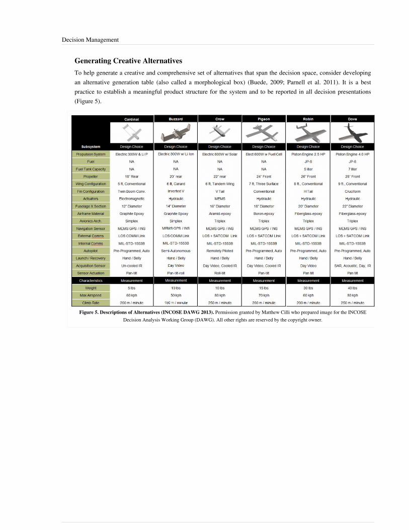
Decision Management 36
Generating Creative AlternativesTo help generate a creative and comprehensive set of alternatives that span the decision space, consider developingan alternative generation table (also called a morphological box) (Buede, 2009; Parnell et al. 2011). It is a bestpractice to establish a meaningful product structure for the system and to be reported in all decision presentations(Figure 5).
Figure 5. Descriptions of Alternatives (INCOSE DAWG 2013). Permission granted by Matthew Cilli who prepared image for the INCOSEDecision Analysis Working Group (DAWG). All other rights are reserved by the copyright owner.

Decision Management 37
Assessing Alternatives via Deterministic AnalysisWith objectives and measures established and alternatives having been defined, the decision team should engageSMEs, equipped with operational data, test data, simulations, models, and expert knowledge. Scores are bestcaptured on scoring sheets for each alternative/measure combination which document the source and rationale.Figure 6 provides a summary of the scores.
Figure 6. Alternative Scores (INCOSE DAWG 2013). Permission granted by Richard Swanson who prepared image for the INCOSE DecisionAnalysis Working Group (DAWG). All other rights are reserved by the copyright owner.
Note that in addition to identified alternatives, the score matrix includes a row for the ideal alternative. The ideal is atool for value-focused thinking, which will be covered later.

Decision Management 38
Synthesizing ResultsNext, one can transform the scores into a value table, by using the value functions developed previously. A colorheat map can be useful to visualize value tradeoffs between alternatives and identify where alternatives needimprovement (Figure 7).
Figure 7. Value Scorecard with Heat Map (INCOSE DAWG 2013). Permission granted by Richard Swanson who prepared image for the INCOSEDecision Analysis Working Group (DAWG). All other rights are reserved by the copyright owner.
The additive value model uses the following equation to calculate each alternative’s value:
where

Decision Management 39
The value component chart (Figure 8) shows the total value and the weighted value measure contribution of eachalternative (Parnell et al. 2011).
Figure 8. Value Component Graph (INCOSE DAWG 2013). Permission granted by Richard Swanson who prepared image for the INCOSEDecision Analysis Working Group (DAWG). All other rights are reserved by the copyright owner.
The heart of a decision management process for system engineering trade off analysis is the ability to assess alldimensions of shareholder and stakeholder value. The stakeholder value scatter plot in Figure 9 shows fivedimensions: unit cost, performance, development risk, growth potential, and operation and support costs for allalternatives.
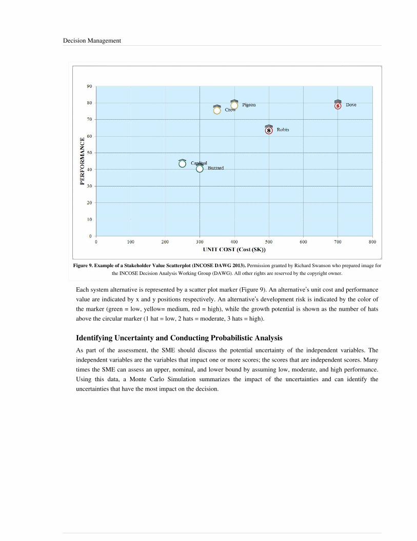
Decision Management 40
Figure 9. Example of a Stakeholder Value Scatterplot (INCOSE DAWG 2013). Permission granted by Richard Swanson who prepared image forthe INCOSE Decision Analysis Working Group (DAWG). All other rights are reserved by the copyright owner.
Each system alternative is represented by a scatter plot marker (Figure 9). An alternative’s unit cost and performancevalue are indicated by x and y positions respectively. An alternative’s development risk is indicated by the color ofthe marker (green = low, yellow= medium, red = high), while the growth potential is shown as the number of hatsabove the circular marker (1 hat = low, 2 hats = moderate, 3 hats = high).
Identifying Uncertainty and Conducting Probabilistic AnalysisAs part of the assessment, the SME should discuss the potential uncertainty of the independent variables. Theindependent variables are the variables that impact one or more scores; the scores that are independent scores. Manytimes the SME can assess an upper, nominal, and lower bound by assuming low, moderate, and high performance.Using this data, a Monte Carlo Simulation summarizes the impact of the uncertainties and can identify theuncertainties that have the most impact on the decision.

Decision Management 41
Accessing Impact of Uncertainty - Analyzing Risk and SensitivityDecision analysis uses many forms of sensitivity analysis including line diagrams, tornado diagrams, waterfalldiagrams and several uncertainty analyses including Monte Carlo Simulation, decision trees, and influence diagrams(Parnell et al. 2013). A line diagram is used to show the sensitivity to the swing weight judgment (Parnell et al.2011). Figure 10 shows the results of a Monte Carlo Simulation of performance value.
Figure 10. Uncertainty on Performance Value from Monte Carlo Simulation (INCOSE DAWG 2013). Permission granted by MatthewCilli who prepared image for the INCOSE Decision Analysis Working Group (DAWG). All other rights are reserved by the copyright owner.
Improving AlternativesMining the data generated for the alternatives will likely reveal opportunities to modify some design choices to claimuntapped value and/or reduce risk. Taking advantage of initial findings to generate new and creative alternativesstarts the process of transforming the decision process from "alternative-focused thinking" to "value-focusedthinking" (Keeney 1993).
Communicating TradeoffsThis is the point in the process where the decision analysis team identifies key observations about tradeoffs and theimportant uncertainties and risks.

Decision Management 42
Presenting Recommendations and Implementing Action PlanIt is often helpful to describe the recommendation(s) in the form of a clearly-worded, actionable task-list in order toincrease the likelihood of the decision implementation. Reports are important for historical traceability and futuredecisions. Take the time and effort to create a comprehensive, high-quality report detailing study findings andsupporting rationale. Consider static paper reports augmented with dynamic hyper-linked e-reports.
References
Works CitedBuede, D.M. 2009. The engineering design of systems: Models and methods. 2nd ed. Hoboken, NJ: John Wiley &Sons Inc.Edwards, W., R.F. Miles Jr., and D. Von Winterfeldt. 2007. Advances In Decision Analysis: From Foundations toApplications. New York, NY: Cambridge University Press.ISO/IEC/IEEE. 2015. Systems and Software Engineering -- System Life Cycle Processes. Geneva, Switzerland:International Organisation for Standardisation / International Electrotechnical Commissions / Institute of Electricaland Electronics Engineers. ISO/IEC/IEEE 15288:2015.Keeney, R.L. and H. Raiffa H. 1976. Decisions with Multiple Objectives - Preferences and Value Tradeoffs. NewYork, NY: Wiley.Keeney, R.L. 1992. Value-Focused Thinking: A Path to Creative Decision-Making. Cambridge, MA: HarvardUniversity Press.Keeney, R.L. 1993. "Creativity in MS/OR: Value-focused thinking—Creativity directed toward decision making."Interfaces, 23(3), p.62–67.Parnell, G.S. 2009. "Decision Analysis in One Chart," Decision Line, Newsletter of the Decision Sciences Institute.May 2009.Parnell, G.S., P.J. Driscoll, and D.L Henderson (eds). 2011. Decision Making for Systems Engineering andManagement, 2nd ed. Wiley Series in Systems Engineering. Hoboken, NJ: Wiley & Sons Inc.Parnell, G.S., T. Bresnick, S. Tani, and E. Johnson. 2013. Handbook of Decision Analysis. Hoboken, NJ: Wiley &Sons.
Primary ReferencesBuede, D.M. 2004. "On Trade Studies." Proceedings of the 14th Annual International Council on SystemsEngineering International Symposium, 20-24 June, 2004, Toulouse, France.Keeney, R.L. 2004. "Making Better Decision Makers." Decision Analysis, 1(4), pp.193–204.Keeney, R.L. & R.S. Gregory. 2005. "Selecting Attributes to Measure the Achievement of Objectives". OperationsResearch, 53(1), pp.1–11.Kirkwood, C.W. 1996. Strategic Decision Making: Multiobjective Decision Analysis with Spreadsheets. Belmont,California: Duxbury Press.
Decision Management 43
Additional ReferencesBuede, D.M. and R.W. Choisser. 1992. "Providing an Analytic Structure for Key System Design Choices." Journalof Multi-Criteria Decision Analysis, 1(1), pp.17–27.Felix, A. 2004. "Standard Approach to Trade Studies." Proceedings of the International Council on SystemsEngineering (INCOSE) Mid-Atlantic Regional Conference, November 2-4 2004, Arlington, VA.Felix, A. 2005. "How the Pro-Active Program (Project) Manager Uses a Systems Engineer’s Trade Study as aManagement Tool, and not just a Decision Making Process." Proceedings of the International Council on SystemsEngineering (INCOSE) International Symposium, July 10-15, 2005, Rochester, NY.Miller, G.A. 1956. "The Magical Number Seven, Plus or Minus Two: Some Limits on Our Capacity for ProcessingInformation." Psychological Review, 63(2), p.81.Ross, A.M. and D.E. Hastings. 2005. "Tradespace Exploration Paradigm." Proceedings of the International Councilon Systems Engineering (INCOSE) International Symposium, July 10-15, 2005, Rochester, NY.Sproles, N. 2002. "Formulating Measures of Effectiveness." Systems Engineering", 5(4), p. 253-263.
Silletto, H. 2005. "Some Really Useful Principles: A new look at the scope and boundaries of systems engineering."Proceedings of the International Council on Systems Engineering (INCOSE) International Symposium, July 10-15,2005, Rochester, NY.Ullman, D.G. and B.P. Spiegel. 2006. "Trade Studies with Uncertain Information." Proceedings of the InternationalCouncil on Systems Engineering (INCOSE) International Symposium, July 9-13, 2006, Orlando, FL.
< Previous Article | Parent Article | Next Article >SEBoK v. 1.4 released 29 June 2015
SEBoK DiscussionPlease provide your comments and feedback on the SEBoK below. You will need to log in to DISQUS using anexisting account (e.g. Yahoo, Google, Facebook, Twitter, etc.) or create a DISQUS account. Simply type yourcomment in the text field below and DISQUS will guide you through the login or registration steps. Feedback will bearchived and used for future updates to the SEBoK. If you provided a comment that is no longer listed, that commenthas been adjudicated. You can view adjudication for comments submitted prior to SEBoK v. 1.0 at SEBoK Reviewand Adjudication. Later comments are addressed and changes are summarized in the Letter from the Editor andAcknowledgements and Release History.
If you would like to provide edits on this article, recommend new content, or make comments on the SEBoKas a whole, please see the SEBoK Sandbox [1].
ENCODED_CONTENTNjYxNjEPGRpdiBpZD0iZGlzcXVzX3RocmVhZCI+PC9kaXY+CjxzY3JpcHQgdHlwZT0idGV4dC9qYXZhc2NyaXB0Ij4KICAgIC8qICogKiBDT05GSUdVUkFUSU9OIFZBUklBQkxFUzogRURJVCBCRUZPUkUgUEFTVElORyBJTlRPIFlPVVIgV0VCUEFHRSAqICogKi8KICAgIHZhciBkaXNxdXNfc2hvcnRuYW1lID0gJ3NlYm9rd2lraTEwJzsgLy8gcmVxdWlyZWQ6IHJlcGxhY2UgZXhhbXBsZSB3aXRoIHlvdXIgZm9ydW0gc2hvcnRuYW1lCiAgICB2YXIgZGlzcXVzX2lkZW50aWZpZXIgPSAnRGVjaXNpb24gTWFuYWdlbWVudCc7ICAgIHZhciBkaXNxdXNfdXJsID0gJ2h0dHA6Ly9zZWJva3dpa2kub3JnL2RyYWZ0L0RlY2lzaW9uX01hbmFnZW1lbnQnOwogICAgLyogKiAqIERPTidUIEVESVQgQkVMT1cgVEhJUyBMSU5FICogKiAqLwogICAgKGZ1bmN0aW9uKCkgewogICAgICAgIHZhciBkc3EgPSBkb2N1bWVudC5jcmVhdGVFbGVtZW50KCdzY3JpcHQnKTsgZHNxLnR5cGUgPSAndGV4dC9qYXZhc2NyaXB0JzsgZHNxLmFzeW5jID0gdHJ1ZTsKICAgICAgICBkc3Euc3JjID0gJ2h0dHA6Ly8nICsgZGlzcXVzX3Nob3J0bmFtZSArICcuZGlzcXVzLmNvbS9lbWJlZC5qcyc7CiAgICAgICAgKGRvY3VtZW50LmdldEVsZW1lbnRzQnlUYWdOYW1lKCdoZWFkJylbMF0gfHwgZG9jdW1lbnQuZ2V0RWxlbWVudHNCeVRhZ05hbWUoJ2JvZHknKVswXSkuYXBwZW5kQ2hpbGQoZHNxKTsKICAgIH0pKCk7Cjwvc2NyaXB0Pgo8bm9zY3JpcHQ+UGxlYXNlIGVuYWJsZSBKYXZhU2NyaXB0IHRvIHZpZXcgdGhlIDxhIGhyZWY9Imh0dHA6Ly9kaXNxdXMuY29tLz9yZWZfbm9zY3JpcHQiPmNvbW1lbnRzIHBvd2VyZWQgYnkgRGlzcXVzLjwvYT48L25vc2NyaXB0Pgo8YSBocmVmPSJodHRwOi8vZGlzcXVzLmNvbSIgY2xhc3M9ImRzcS1icmxpbmsiPmJsb2cgY29tbWVudHMgcG93ZXJlZCBieSA8c3BhbiBjbGFzcz0ibG9nby1kaXNxdXMiPkRpc3F1czwvc3Bhbj48L2E+END_ENCODED_CONTENT
Configuration Management 44
Configuration ManagementThe purpose of configuration management (CM) is to establish and maintain the integrity of all the identified outputsof a project or process and make them available to concerned parties (ISO/IEC/IEEE 2015). Since unmanagedchanges to system artifacts (such as those associated with plans, requirements, design, software, hardware, testing,and documentation) can lead to problems that persist throughout the system life cycle. One primary objective of CMis to manage and control the change to such artifacts.
Configuration Management Process OverviewCM is the discipline of identifying and formalizing the functional and physical characteristics of a configuration itemat discrete points in the product evolution for the purpose of maintaining the integrity of the product system andcontrolling changes to the baseline. The baseline for a project contains all of the technical requirements and relatedcost and schedule requirements that are sufficiently mature to be accepted and placed under change control by theproject manager. The project baseline consists of two parts: the technical baseline and the business baseline. Thesystems engineer is responsible for managing the technical baseline and ensuring that it is consistent with the costsand schedules in the business baseline. Typically, the project control office manages the business baseline.The ANSI/GEIA EIA-649-A standard presents CM from the viewpoint that configuration management practices areemployed because they make good business sense rather than because requirements are imposed by an externalcustomer (ANSI/GEIA 2005). The standard discusses CM principles and practices from an enterprise view; it doesnot prescribe which CM activities individual organizations or teams within the enterprise should perform. Eachenterprise assigns responsibilities in accordance with its own management policy. See also the ImplementationGuide for Configuration Management, which supports and provides further information on this standard(ANSI/GEIA October 2005).Effective CM depends on the establishment, maintenance, and implementation of an effective process. The CMprocess should include, but are not limited to, the following activities:•• identification and involvement of relevant stakeholders•• setting of CM goals and expected outcomes•• identification and description of CM tasks•• assignment of responsibility and authority for performing the CM process tasks•• establishment of procedures for monitoring and control of the CM process•• measurement and assessment of the CM process effectivenessAs a minimum the CM process should incorporate and detail the following tasks (SEI 2010):•• identifying the configuration of selected work products that compose the baselines at given points in time•• controlling changes to configuration items•• building or providing specifications to build work products from the configuration management system•• maintaining the integrity of baselines•• providing accurate status and current configuration data to developers, end users, and customersFigure 1 below shows the primary functions of systems CM.
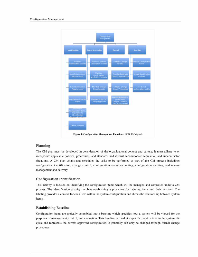
Configuration Management 45
Figure 1. Configuration Management Functions. (SEBoK Original)
PlanningThe CM plan must be developed in consideration of the organizational context and culture; it must adhere to orincorporate applicable policies, procedures, and standards and it must accommodate acquisition and subcontractorsituations. A CM plan details and schedules the tasks to be performed as part of the CM process including:configuration identification, change control, configuration status accounting, configuration auditing, and releasemanagement and delivery.
Configuration IdentificationThis activity is focused on identifying the configuration items which will be managed and controlled under a CMprocess. The identification activity involves establishing a procedure for labeling items and their versions. Thelabeling provides a context for each item within the system configuration and shows the relationship between systemitems.
Establishing BaselineConfiguration items are typically assembled into a baseline which specifies how a system will be viewed for thepurposes of management, control, and evaluation. This baseline is fixed at a specific point in time in the system lifecycle and represents the current approved configuration. It generally can only be changed through formal changeprocedures.

Configuration Management 46
Change ControlA disciplined change control process is critical for systems engineering. A generalized change control process inresponse to an engineering change proposal (ECP) is shown in Figure 2 below, which is adapted from SystemsEngineering and Analysis (Blanchard and Fabrycky 1999).
Figure 2. Configuration Change Control Process. (SEBoK Original)
Configuration AuditingAudits are independent evaluations of the current status of configuration items and determine conformance of theconfiguration activities to the CM process. Adherence to applicable CM plans, regulations, and standards, istypically assessed during audits.
Constraints and GuidanceConstraints affecting and guiding the CM process come from a number of sources. Policies, procedures, andstandards set forth at corporate or other organizational levels might influence or constrain the design andimplementation of the CM process. Also, the contract with an acquirer or supplier may contain provisions affectingthe CM process. The system life cycle process adopted and the tools, methods, and other processes used in systemdevelopment can affect the CM process (Abran 2004). There are a variety of sources for guidance on thedevelopment of a CM process. These include the ISO standards on system life cycle processes (ISO/IEC/IEEE15288 2015) and configuration management guidelines (ISO 10007 2003), as well as the Guide to The SoftwareEngineering Body of Knowledge (SWEBOK) (Abran 2004), and the CMMI for Development (SEI 2010).

Configuration Management 47
Organizational IssuesSuccessful CM planning, management, and implementation requires an understanding of the organizational contextfor on the design and implementation of the CM process and why constraints are placed upon it. To plan a CMprocess for a project, it is necessary to understand the organizational context and the relationships among theorganizational elements. CM interacts with other organizational elements, which may be structured in a number ofways. Although the responsibility for performing certain CM tasks might be assigned to other parts of theorganization, the overall responsibility for CM often rests with a distinct organizational element or designatedindividual (Abran 2004).
MeasurementIn order to carry out certain CM functions, such as status accounting and auditing, as well as to monitor and assessthe effectiveness of CM processes, it is necessary to measure and collect data related to CM activities and systemartifacts. CM libraries and automated report tools provide convenient access and facilitation of data collection.Examples of metrics include the size of documentation artifacts, number of change requests, mean time to change toa configuration item, and rework costs.
ToolsCM employs a variety of tools to support the process, for example:•• library management•• tracking and change management•• version management•• release managementThe INCOSE Tools Database Working Group (INCOSE TDWG 2010) maintains an extensive list of tools includingconfiguration management.
Linkages to Other Systems Engineering Management TopicsConfiguration management is involved in the management and control of artifacts produced and modifiedthroughout the system life cycle in all areas of system definition, system realization, system deployment and use, andproduct and service life management. This includes CM application to the artifacts of all the other managementprocesses (plans, analyses, reports, statuses, etc.).
Practical ConsiderationsKey pitfalls and good practices related to systems engineering CM are described in the next two sections.
PitfallsSome of the key pitfalls encountered in planning and performing CM are in Table 1.
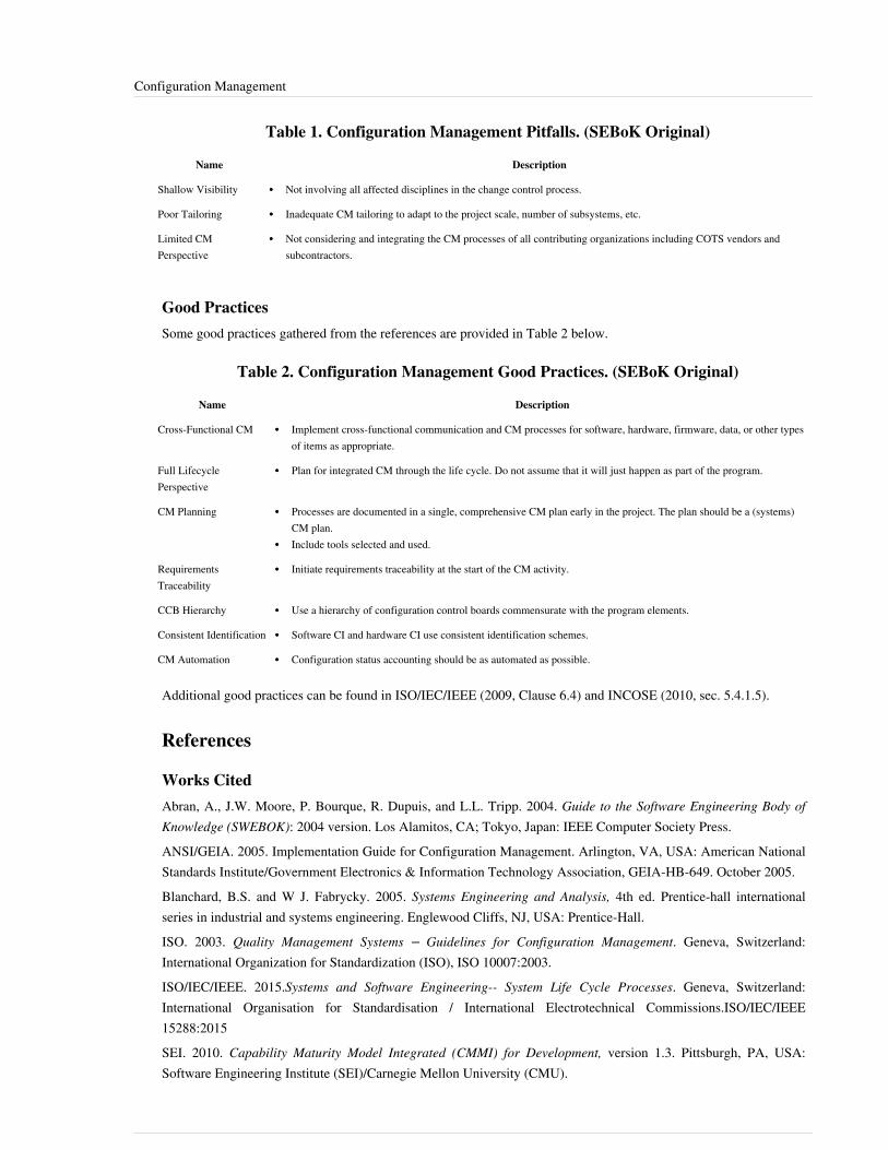
Configuration Management 48
Table 1. Configuration Management Pitfalls. (SEBoK Original)
Name Description
Shallow Visibility •• Not involving all affected disciplines in the change control process.
Poor Tailoring •• Inadequate CM tailoring to adapt to the project scale, number of subsystems, etc.
Limited CMPerspective
•• Not considering and integrating the CM processes of all contributing organizations including COTS vendors andsubcontractors.
Good PracticesSome good practices gathered from the references are provided in Table 2 below.
Table 2. Configuration Management Good Practices. (SEBoK Original)
Name Description
Cross-Functional CM •• Implement cross-functional communication and CM processes for software, hardware, firmware, data, or other typesof items as appropriate.
Full LifecyclePerspective
•• Plan for integrated CM through the life cycle. Do not assume that it will just happen as part of the program.
CM Planning •• Processes are documented in a single, comprehensive CM plan early in the project. The plan should be a (systems)CM plan.
•• Include tools selected and used.
RequirementsTraceability
•• Initiate requirements traceability at the start of the CM activity.
CCB Hierarchy •• Use a hierarchy of configuration control boards commensurate with the program elements.
Consistent Identification •• Software CI and hardware CI use consistent identification schemes.
CM Automation •• Configuration status accounting should be as automated as possible.
Additional good practices can be found in ISO/IEC/IEEE (2009, Clause 6.4) and INCOSE (2010, sec. 5.4.1.5).
References
Works CitedAbran, A., J.W. Moore, P. Bourque, R. Dupuis, and L.L. Tripp. 2004. Guide to the Software Engineering Body ofKnowledge (SWEBOK): 2004 version. Los Alamitos, CA; Tokyo, Japan: IEEE Computer Society Press.ANSI/GEIA. 2005. Implementation Guide for Configuration Management. Arlington, VA, USA: American NationalStandards Institute/Government Electronics & Information Technology Association, GEIA-HB-649. October 2005.Blanchard, B.S. and W J. Fabrycky. 2005. Systems Engineering and Analysis, 4th ed. Prentice-hall internationalseries in industrial and systems engineering. Englewood Cliffs, NJ, USA: Prentice-Hall.ISO. 2003. Quality Management Systems – Guidelines for Configuration Management. Geneva, Switzerland:International Organization for Standardization (ISO), ISO 10007:2003.ISO/IEC/IEEE. 2015.Systems and Software Engineering-- System Life Cycle Processes. Geneva, Switzerland:International Organisation for Standardisation / International Electrotechnical Commissions.ISO/IEC/IEEE15288:2015SEI. 2010. Capability Maturity Model Integrated (CMMI) for Development, version 1.3. Pittsburgh, PA, USA:Software Engineering Institute (SEI)/Carnegie Mellon University (CMU).

Configuration Management 49
Primary ReferencesAbran, A., J.W. Moore, P. Bourque, R. Dupuis, and L.L. Tripp. 2004. Guide to the Software Engineering Body ofKnowledge (SWEBOK): 2004 version. Los Alamitos, CA; Tokyo, Japan: IEEE Computer Society Press.ANSI/GEIA. 2005. Implementation Guide for Configuration Management. Arlington, VA, USA: American NationalStandards Institute/Government Electronics & Information Technology Association, GEIA-HB-649. October 2005.GEIA. 2004. GEIA Consensus Standard for Data Management. Arlington, VA, USA: Government Electronics &Information Technology Association, GEIA-859.ISO. 2003. Quality Management Systems – Guidelines for Configuration Management. Geneva, Switzerland:International Organization for Standardization (ISO), ISO 10007:2003.ISO/IEC/IEEE. 2015.Systems and Software Engineering-- System Life Cycle Processes. Geneva, Switzerland:International Organisation for Standardisation / International Electrotechnical Commissions.ISO/IEC/IEEE15288:2015SEI. 2010. Capability Maturity Model Integrated (CMMI) for Development, version 1.3. Pittsburgh, PA, USA:Software Engineering Institute (SEI)/Carnegie Mellon University (CMU).
Additional ReferencesINCOSE Tools database working group (TDWG). in International Council on Systems Engineering (INCOSE)[database online]. San Diego, CA, USA, 2010. Accessed April 13, 2015 Available at: http:/ / www. incose. org/docs/ default-source/ wgcharters/ tools-database. pdfINCOSE. 2008. "INCOSE measurement tools survey." in International Council on Systems Engineering (INCOSE)[database online]. San Diego, CA, USA, 2008ISO/IEC/IEEE. 2009. Systems and Software Engineering - Life Cycle Processes - Project Management. Geneva,Switzerland: International Organization for Standardization (ISO)/International Electrotechnical Commission(IEC)/Institute of Electrical and Electronics Engineers (IEEE), ISO/IEC/IEEE 16326:2009(E).
< Previous Article | Parent Article | Next Article >SEBoK v. 1.4 released 29 June 2015
SEBoK DiscussionPlease provide your comments and feedback on the SEBoK below. You will need to log in to DISQUS using anexisting account (e.g. Yahoo, Google, Facebook, Twitter, etc.) or create a DISQUS account. Simply type yourcomment in the text field below and DISQUS will guide you through the login or registration steps. Feedback will bearchived and used for future updates to the SEBoK. If you provided a comment that is no longer listed, that commenthas been adjudicated. You can view adjudication for comments submitted prior to SEBoK v. 1.0 at SEBoK Reviewand Adjudication. Later comments are addressed and changes are summarized in the Letter from the Editor andAcknowledgements and Release History.
If you would like to provide edits on this article, recommend new content, or make comments on the SEBoKas a whole, please see the SEBoK Sandbox [1].
ENCODED_CONTENTMTU5NjEPGRpdiBpZD0iZGlzcXVzX3RocmVhZCI+PC9kaXY+CjxzY3JpcHQgdHlwZT0idGV4dC9qYXZhc2NyaXB0Ij4KICAgIC8qICogKiBDT05GSUdVUkFUSU9OIFZBUklBQkxFUzogRURJVCBCRUZPUkUgUEFTVElORyBJTlRPIFlPVVIgV0VCUEFHRSAqICogKi8KICAgIHZhciBkaXNxdXNfc2hvcnRuYW1lID0gJ3NlYm9rd2lraTEwJzsgLy8gcmVxdWlyZWQ6IHJlcGxhY2UgZXhhbXBsZSB3aXRoIHlvdXIgZm9ydW0gc2hvcnRuYW1lCiAgICB2YXIgZGlzcXVzX2lkZW50aWZpZXIgPSAnQ29uZmlndXJhdGlvbiBNYW5hZ2VtZW50JzsgICAgdmFyIGRpc3F1c191cmwgPSAnaHR0cDovL3NlYm9rd2lraS5vcmcvZHJhZnQvQ29uZmlndXJhdGlvbl9NYW5hZ2VtZW50JzsKICAgIC8qICogKiBET04nVCBFRElUIEJFTE9XIFRISVMgTElORSAqICogKi8KICAgIChmdW5jdGlvbigpIHsKICAgICAgICB2YXIgZHNxID0gZG9jdW1lbnQuY3JlYXRlRWxlbWVudCgnc2NyaXB0Jyk7IGRzcS50eXBlID0gJ3RleHQvamF2YXNjcmlwdCc7IGRzcS5hc3luYyA9IHRydWU7CiAgICAgICAgZHNxLnNyYyA9ICdodHRwOi8vJyArIGRpc3F1c19zaG9ydG5hbWUgKyAnLmRpc3F1cy5jb20vZW1iZWQuanMnOwogICAgICAgIChkb2N1bWVudC5nZXRFbGVtZW50c0J5VGFnTmFtZSgnaGVhZCcpWzBdIHx8IGRvY3VtZW50LmdldEVsZW1lbnRzQnlUYWdOYW1lKCdib2R5JylbMF0pLmFwcGVuZENoaWxkKGRzcSk7CiAgICB9KSgpOwo8L3NjcmlwdD4KPG5vc2NyaXB0PlBsZWFzZSBlbmFibGUgSmF2YVNjcmlwdCB0byB2aWV3IHRoZSA8YSBocmVmPSJodHRwOi8vZGlzcXVzLmNvbS8/cmVmX25vc2NyaXB0Ij5jb21tZW50cyBwb3dlcmVkIGJ5IERpc3F1cy48L2E+PC9ub3NjcmlwdD4KPGEgaHJlZj0iaHR0cDovL2Rpc3F1cy5jb20iIGNsYXNzPSJkc3EtYnJsaW5rIj5ibG9nIGNvbW1lbnRzIHBvd2VyZWQgYnkgPHNwYW4gY2xhc3M9ImxvZ28tZGlzcXVzIj5EaXNxdXM8L3NwYW4+PC9hPg==END_ENCODED_CONTENT

Information Management 50
Information ManagementThe information management (IM) process is a set of activities associated with the collection and management ofinformation from one or more sources and the distribution of that information to one or more audiences. Information,in its most restricted technical sense, is an ordered sequence of symbols that record or transmit a message. The keyidea is that information is a collection of facts that is organized in such a way that they have additional value beyondthe value of the facts themselves. The systems engineer is both the generator and recipient of information products;thus, the systems engineer has a vital stake in the success of the development and use of the IM process and IMsystems.
OverviewInformation can exist in many forms in an organization; some information is related to a specific systemdevelopment program and some is held at an enterprise level and made available to programs as required. It may beheld in electronic format or in physical form (for instance, paper drawings or documents, microfiche or otherphotographic records).The IM process includes a set of interrelated activities associated with information systems, system of systems(SoS), architectures, services, nested hardware/platforms, and people. Fundamentally, this process is a set ofactivities that are concerned with improvements in a variety of human problem-solving endeavors. This includes thedesign, development, and use of technologically-based systems and processes that enhance the efficiency andeffectiveness of information and associated knowledge in a variety of strategic/business, tactical, and operationalsituations.Management refers to the organization of and control over process activities associated with the structure,processing, and delivery of information. For example, the organizational structure must have management processescapable of managing this information throughout the information life cycle regardless of source or format (e.g., data,paper documents, electronic documents, audio, video, etc.) for delivery through multiple channels that may includecell phones and web interfaces.A computer-based IM system is an organized combination of people, hardware, software, communication networks,and the data resources that collect, transform, and disseminate information in an organization. From the perspectiveof the systems engineer, the IM process is a cycle of inter-related information activities to be planned for, designed,and coordinated. Numerous life cycle development process models exist. Figure 1 below is a high level processmodel that emphasizes the role of systems engineering (SE) in IM.

Information Management 51
Figure 1. Life Cycle Information Management Process Development Model.(SEBoK Original)
The SE function in the development of an IM system is concerned with several rate-limiting architecture and designvariables, (e.g., information sharing, quality, security, efficiency, compliance, etc.) that should be consideredup-front in the life cycle development process. Each of these variables can be subdivided into architecture and designconsiderations for the information system-of-interest (SoI). For example, quality can be viewed in terms of datavalidity, consistency, and comprehensiveness. Figure 2 provides an overview of information managementconsiderations.

Information Management 52
Figure 2. Information Management Architecture and Design Considerations. (SEBoK Original)
The effective and efficient employment of IM systems should solve business needs. These needs can center onseveral business objectives, such as efficiency, effectiveness, competitiveness, or profitability. From a businessenterprise perspective, the systems engineer may be involved in several activities that support the development of IMsystems, such as strategic planning, analyses of technology/business trends, development of applications,understanding operational disciplines, resource control techniques, and assessment of organization structures.The IM process ensures that necessary information is created, stored, retained, protected, managed, and made easilyavailable to those with a need and who are permitted access. It also ensures that information is disposed of when it isno longer relevant.
The Information Management ProcessTo quote from ISO/IEC/IEEE 15288 (2015):
The purpose of the Information Management Process is to generate, obtain, confirm, transform, retain,retrieve, disseminate and dispose of information, to designated stakeholders..Information management plans, executes, and controls the provision of information to designatedstakeholders that is unambiguous, complete, verifiable, consistent, modifiable, traceable, andpresentable.
The first step in the IM process is to plan IM. The output of this step is the IM strategy or plan. The second step is toperform IM. The outputs of this step are the creation, population and maintenance of one or more informationrepositories, together with the creation and dissemination of information management reports.

Information Management 53
Plan Information ManagementIssues that should be considered when creating the IM strategy/plan include:•• Scope
•• What information has to be managed?•• How long will the information need to be retained?•• Is a system data dictionary is required to be able to "tag" information for ease of search and retrieval?•• Will the media that will be used for the information to be managed be physical, electronic, or both?•• Have a work in progress (WIP) and formally released information already been considered when establishing
data repositories?•• Constraints
•• What level of configuration control that has to be applied to the information?•• Are there any regulatory requirements relating to the management of information for this project; this could
include export control requirements?•• Are there any customer requirements or agreements relating to the management of project information?•• Are there any industry standards relating to the management of project information?•• Are there any organization/enterprise directives, procedures, or standards relating to the management of project
information?•• Are there any project directives, procedures, or standards relating to the management of project information?
•• Control/Security•• Who is allowed access to the information? This could include people working on the project, other members of
the organization/enterprise, customers, partners, suppliers and regulatory authorities.•• Are there requirements to protect the information from unauthorized access? This could include intellectual
property (IP) rights that have to be respected - for instance if information from suppliers is to be stored andthere is the possibility of a supplier gaining access to information belonging to a competitor who is also asupplier for the project.
•• What data repository or repositories are to be used?•• Has the volume of information to be stored been considered when selecting repositories?•• Has speed of access and search been considered when selecting repositories?
•• If electronic information is to be stored, what file formats are allowed?•• Have requirements been defined to ensure that the information being stored is valid?•• Have requirements been defined to ensure that information is disposed of correctly when it is no longer
required to be stored, or when it is no longer valid? For instance, has a review period been defined for eachpiece of information?
•• Life Cycle• If electronic information is to be stored for a long time, how will it be "future-proofed" – for instance, are
neutral file formats available, or will copies of the software that created or used the information be retained?• Have disaster recovery requirements been considered – e.g., if a server holding electronic information is
destroyed, are there back-up copies of the information? Are the back-up copies regularly accessed to show thatinformation recovery is flawless?
•• Is there a formal requirement to archive designated information for compliance with legal (includingregulatory), audit, and information retention requirements? If so, has an archive and archiving method beendefined?
•• Some information may not be required to be stored (e.g., the results files for analyses when the informationoccupies a large volume and can be regenerated by the analysis tool and the input file). However, if the cost tore-generate the information is high, consider doing a cost/benefit analysis for storage versus regeneration.
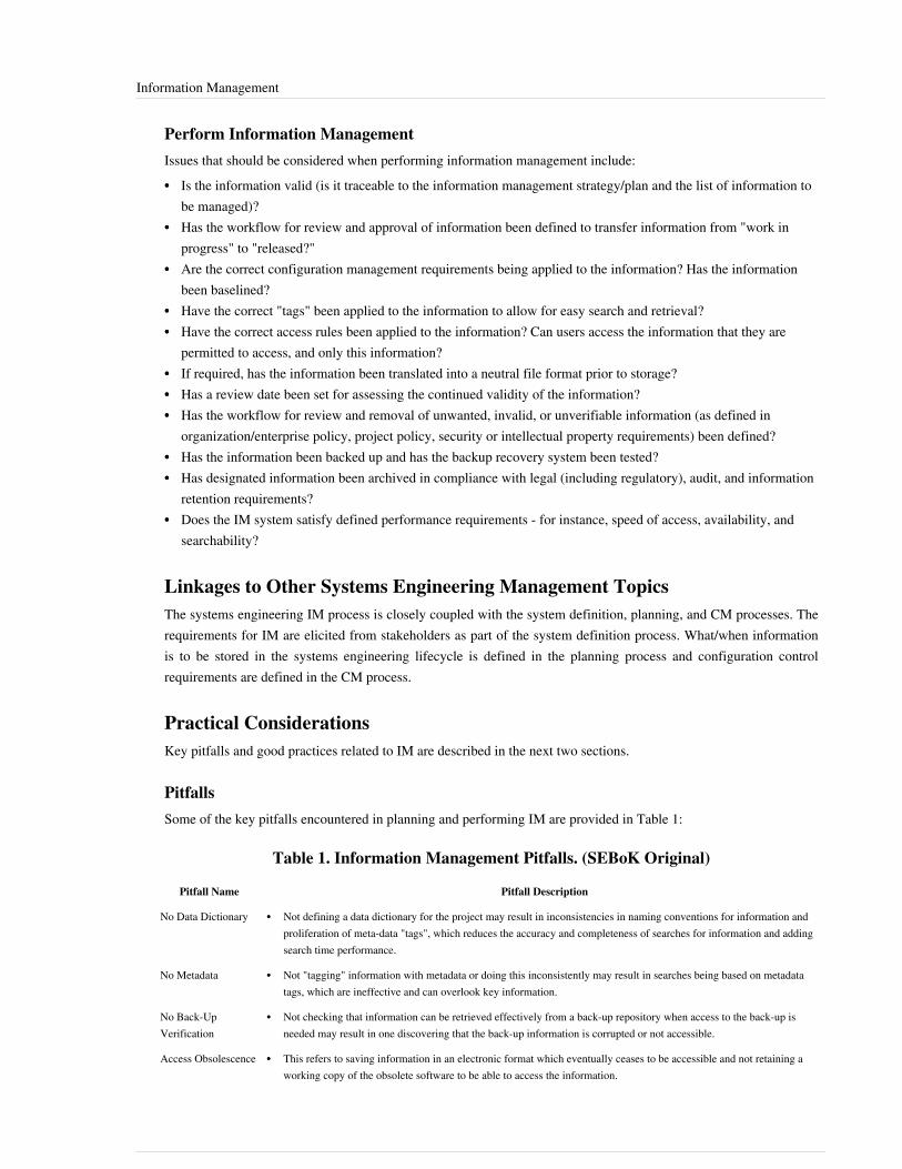
Information Management 54
Perform Information ManagementIssues that should be considered when performing information management include:•• Is the information valid (is it traceable to the information management strategy/plan and the list of information to
be managed)?•• Has the workflow for review and approval of information been defined to transfer information from "work in
progress" to "released?"•• Are the correct configuration management requirements being applied to the information? Has the information
been baselined?•• Have the correct "tags" been applied to the information to allow for easy search and retrieval?•• Have the correct access rules been applied to the information? Can users access the information that they are
permitted to access, and only this information?•• If required, has the information been translated into a neutral file format prior to storage?•• Has a review date been set for assessing the continued validity of the information?•• Has the workflow for review and removal of unwanted, invalid, or unverifiable information (as defined in
organization/enterprise policy, project policy, security or intellectual property requirements) been defined?•• Has the information been backed up and has the backup recovery system been tested?•• Has designated information been archived in compliance with legal (including regulatory), audit, and information
retention requirements?•• Does the IM system satisfy defined performance requirements - for instance, speed of access, availability, and
searchability?
Linkages to Other Systems Engineering Management TopicsThe systems engineering IM process is closely coupled with the system definition, planning, and CM processes. Therequirements for IM are elicited from stakeholders as part of the system definition process. What/when informationis to be stored in the systems engineering lifecycle is defined in the planning process and configuration controlrequirements are defined in the CM process.
Practical ConsiderationsKey pitfalls and good practices related to IM are described in the next two sections.
PitfallsSome of the key pitfalls encountered in planning and performing IM are provided in Table 1:
Table 1. Information Management Pitfalls. (SEBoK Original)
Pitfall Name Pitfall Description
No Data Dictionary •• Not defining a data dictionary for the project may result in inconsistencies in naming conventions for information andproliferation of meta-data "tags", which reduces the accuracy and completeness of searches for information and addingsearch time performance.
No Metadata •• Not "tagging" information with metadata or doing this inconsistently may result in searches being based on metadatatags, which are ineffective and can overlook key information.
No Back-UpVerification
•• Not checking that information can be retrieved effectively from a back-up repository when access to the back-up isneeded may result in one discovering that the back-up information is corrupted or not accessible.
Access Obsolescence •• This refers to saving information in an electronic format which eventually ceases to be accessible and not retaining aworking copy of the obsolete software to be able to access the information.

Information Management 55
InadequateLong-Term Retention
•• This refers to the error of archiving information on an electronic medium that does not have the required durability to bereadable through the required retention life of the information and not regularly accessing and re-archiving theinformation.
Inadequate ValidityMaintenance
•• Not checking the continued validity of information results in outdated or incorrect information being retained and used.
Good PracticesSome good practices gathered from the references are provided in Table 2:
Table 2. Information Management Good Practices. (SEBoK Original)
Good Practice Name Good Practice Description
Guidance •• The DAMA Guide to the Data Management Body of Knowledge provides an excellent, detailed overview of IM at boththe project and enterprise level.
Information as anAsset
•• Recognize that information is a strategic asset for the organization and needs to be managed and protected.
Information StorageCapacity
•• Plan for the organization's information repository storage capacity to need to double every 12 to 18 months.
Effective InformationAccess
•• Information that sits in a repository adds no value. It only adds value when it is used. So the right people need to be ableto access the right information easily and quickly.
Data Modeling •• Invest time and effort in designing data models that are consistent with the underlying structure and information needsof the organization.
Quality Management •• The cost impact of using poor quality information can be enormous. Be rigorous about managing the quality ofinformation.
InformationRepository Design
•• The impact of managing information poorly can also be enormous (e.g., violating intellectual property or export controlrules).
•• Make sure that these requirements are captured and implemented in the information repository, and that all users of therepository are aware of the rules that they need to follow and the penalties for infringement.
References
Works CitedISO/IEC/IEEE. 2008. Systems and Software Engineering - System Life Cycle Processes. Geneva, Switzerland:International Organisation for Standardisation/International Electrotechnical Commissions. ISO/IEC/IEEE15288:2008.Mosley, M. (ed.). 2009. The DAMA Guide to the Data Management Body of Knowledge (DAMA-DMBOK Guide).Bradley Beach, NJ, USA: Technics Publications.
Primary ReferencesINCOSE. 2012. Systems Engineering Handbook: A Guide for System Life Cycle Processes and Activities, version3.2.1. San Diego, CA, USA: International Council on Systems Engineering (INCOSE),INCOSE-TP-2003-002-03.2.2.ISO/IEC/IEEE. 2015. Systems and Software Engineering -- System Life Cycle Processes. Geneva, Switzerland:International Organisation for Standardisation / International Electrotechnical Commissions. ISO/IEC/IEEE15288:2015.

Information Management 56
Mosley, M. (ed.). 2009. The DAMA Guide to the Data Management Body of Knowledge (DAMA-DMBOK Guide).Bradley Beach, NJ, USA: Technics Publications.Redman, T. 2008. Data Driven: Profiting from Your Most Important Business Asset. Cambridge, MA, USA: HarvardBusiness Press.
Additional ReferencesNone.
< Previous Article | Parent Article | Next Article >SEBoK v. 1.4 released 29 June 2015
SEBoK DiscussionPlease provide your comments and feedback on the SEBoK below. You will need to log in to DISQUS using anexisting account (e.g. Yahoo, Google, Facebook, Twitter, etc.) or create a DISQUS account. Simply type yourcomment in the text field below and DISQUS will guide you through the login or registration steps. Feedback will bearchived and used for future updates to the SEBoK. If you provided a comment that is no longer listed, that commenthas been adjudicated. You can view adjudication for comments submitted prior to SEBoK v. 1.0 at SEBoK Reviewand Adjudication. Later comments are addressed and changes are summarized in the Letter from the Editor andAcknowledgements and Release History.
If you would like to provide edits on this article, recommend new content, or make comments on the SEBoKas a whole, please see the SEBoK Sandbox [1].
ENCODED_CONTENTMTMyMTcPGRpdiBpZD0iZGlzcXVzX3RocmVhZCI+PC9kaXY+CjxzY3JpcHQgdHlwZT0idGV4dC9qYXZhc2NyaXB0Ij4KICAgIC8qICogKiBDT05GSUdVUkFUSU9OIFZBUklBQkxFUzogRURJVCBCRUZPUkUgUEFTVElORyBJTlRPIFlPVVIgV0VCUEFHRSAqICogKi8KICAgIHZhciBkaXNxdXNfc2hvcnRuYW1lID0gJ3NlYm9rd2lraTEwJzsgLy8gcmVxdWlyZWQ6IHJlcGxhY2UgZXhhbXBsZSB3aXRoIHlvdXIgZm9ydW0gc2hvcnRuYW1lCiAgICB2YXIgZGlzcXVzX2lkZW50aWZpZXIgPSAnSW5mb3JtYXRpb24gTWFuYWdlbWVudCc7ICAgIHZhciBkaXNxdXNfdXJsID0gJ2h0dHA6Ly9zZWJva3dpa2kub3JnL2RyYWZ0L0luZm9ybWF0aW9uX01hbmFnZW1lbnQnOwogICAgLyogKiAqIERPTidUIEVESVQgQkVMT1cgVEhJUyBMSU5FICogKiAqLwogICAgKGZ1bmN0aW9uKCkgewogICAgICAgIHZhciBkc3EgPSBkb2N1bWVudC5jcmVhdGVFbGVtZW50KCdzY3JpcHQnKTsgZHNxLnR5cGUgPSAndGV4dC9qYXZhc2NyaXB0JzsgZHNxLmFzeW5jID0gdHJ1ZTsKICAgICAgICBkc3Euc3JjID0gJ2h0dHA6Ly8nICsgZGlzcXVzX3Nob3J0bmFtZSArICcuZGlzcXVzLmNvbS9lbWJlZC5qcyc7CiAgICAgICAgKGRvY3VtZW50LmdldEVsZW1lbnRzQnlUYWdOYW1lKCdoZWFkJylbMF0gfHwgZG9jdW1lbnQuZ2V0RWxlbWVudHNCeVRhZ05hbWUoJ2JvZHknKVswXSkuYXBwZW5kQ2hpbGQoZHNxKTsKICAgIH0pKCk7Cjwvc2NyaXB0Pgo8bm9zY3JpcHQ+UGxlYXNlIGVuYWJsZSBKYXZhU2NyaXB0IHRvIHZpZXcgdGhlIDxhIGhyZWY9Imh0dHA6Ly9kaXNxdXMuY29tLz9yZWZfbm9zY3JpcHQiPmNvbW1lbnRzIHBvd2VyZWQgYnkgRGlzcXVzLjwvYT48L25vc2NyaXB0Pgo8YSBocmVmPSJodHRwOi8vZGlzcXVzLmNvbSIgY2xhc3M9ImRzcS1icmxpbmsiPmJsb2cgY29tbWVudHMgcG93ZXJlZCBieSA8c3BhbiBjbGFzcz0ibG9nby1kaXNxdXMiPkRpc3F1czwvc3Bhbj48L2E+END_ENCODED_CONTENT

Quality Management 57
Quality ManagementWhether a systems engineer delivers a product, a service, or an enterprise, the deliverable should meet the needs ofthe customer and be fit for use. Such a deliverable is said to be of high quality. The process to assure high quality iscalled quality management.
OverviewOver the past 80 years, a quality movement has emerged to enable organizations to produce high quality deliverables.This movement has gone though four stages:1. Acceptance Sampling was developed to apply statistical tests to assist in the decision of whether or not to accept
a lot of material based on a random sample of its content.2. Statistical Process Control (SPC) was developed to determine if production processes were stable. Instead of
necessarily measuring products, processes are measured instead. Processes that departed from a state of statisticalcontrol were far more likely to develop low quality deliverables.
3. Design for Quality focused on designing processes that were robust against causes of variation, reducing thelikelihood that a process would go out of control, and accordingly reducing the monitoring requirements.
4. Six sigma methods are applied the tools and power of statistical thinking to improve other aspects of theorganization.
DefinitionsThe American Society for Quality [1] provides the following definitions:• Acceptance Sampling involves the inspection of a sample to decide whether to accept the entire lot. There are two
types of sampling:•• In attributes sampling, the presence or absence of a characteristic is noted in each of the units inspected.•• In variables sampling, the numerical magnitude of a characteristic is measured and recorded for each inspected
unit. This involves reference to a continuous scale of some kind.• SPC is the application of statistical techniques to control a process. It is often used interchangeably with the term
“statistical quality control.”• Quality is a subjective term for which each person or sector has its own definition. In technical usage, quality can
have two meanings:•• The characteristics of a product or service that bear on its ability to satisfy stated or implied needs.• A product or service free of deficiencies. According to Joseph Juran, quality means “fitness for use.”
According to Philip Crosby, it means "conformance to requirements."• Six Sigma is a method that provides organizations with tools to improve the capability of their business processes.
This increase in performance and decrease in process variation leads to defect reduction and improvement inprofits, employee morale, and quality of products or services. Six Sigma quality is a term generally used toindicate a process is well controlled (±6 s from the centerline in a control chart).
Quality AttributesQuality attributes, also known as quality factors, quality characteristics, or non-functional requirements, are a set of system functional and non-functional requirements that are used to evaluate the system performance. There are a large number of system quality attributes identified in the literature (e.g. MSDN 2010, Barbacci et al. 1995). Depending on the type of the system being considered, some of these attributes are more prominent than others. Ideally, a system would be optimized for all the quality attributes that are important to the stakeholders, but this is an

Quality Management 58
impossible task. Therefore, it is important to conduct a trade off analysis to identify the relationship between theattributes and establish whether a change in one attributes would positively or negatively affect any other attributes.An example of such trade off is shown in Table 1 below. (See SEBoK discussion on specialty engineering foradditional information on quality attributes.)
Table 1. Attribute Trade Off. (SEBoK Original)
Flexibility Maintainability Reliability
Flexibility + -
Maintainability + +
Reliability - +
Finding the right set of quality attributes is the first step in quality control and management. In order to achieve highquality, quality has to be measured, monitored, managed, and improved on. Therefore, in order to increase theoverall system quality, it is necessary to•• identify and prioritize the quality attributes•• identify the metrics that can be used for these attributes•• measure and monitor the attributes•• validate the measurements•• analyze the result of those measurements•• establish processes and procedures that result in improved system quality, based on the analysis.
Quality Attributes for ProductsQuality attributes for a product focuses on the conformance to the specifications for the product; frequently these aremanufacturing specifications. Examples include physical characteristics (length, weight, finish, capacity, etc.) beinginside a given tolerance range. The physical characteristics can be related to the function of the product or toaesthetic qualities.A single product may have a vector of quality attributes of high dimension as wells as an associated region in whichthe vector is expected to be. Often the quality is summarized by saying the item is "in compliance" (if the vector is inthe acceptable region) or "defective" (if the vector is outside the acceptable region).
Quality Attributes for ServicesQuality of services plays a major role in the customer satisfaction, which is the measurement of the overall systemquality. Services can be divided into two major categories: primary and secondary. The city public transportationsystem, the U.S. postal service, or the medical services provided by a hospital are all examples of primary services.Services that provide help to a customer are secondary services, which are typically referred to as a customer service.Identifying the appropriate quality attributes is critical in the quality management of services. Some examples ofservice quality attributes include: affordability, availability, dependability, efficiency, predictability, reliability,responsiveness, safety, security, usability, etc. Again, depending on the type of the service, some of these attributesare more prominent than the others.For example, in the case of services that are provided by the hospital, one may be more interested in the availability,reliability, and responsiveness than potentially the security (typically hospitals are assumed to be safe) and theaffordability (typically insurance covers the majority of the cost). Of course, if the patient does not have a goodinsurance coverage, then the importance of affordability will increase (de Knoning, 2006).

Quality Management 59
Quality Attributes for EnterprisesAn enterprise typically refers to a large complex set of interconnected entities that includes people, technologies,processes, financial, and physical elements. Clearly, a typical enterprise has a number of internal and externalstakeholders, and as a result there are a large number of quality attributes that will define its quality. Identifying theright set of attributes is typically more challenging in such a complex system. An example of an enterprise is the airtraffic management system that is mainly responsible for the safe and efficient operation of the civil aviation within acountry or collection of countries. There are a large number of stakeholders that are concerned about the overallquality of the system, some example of these stakeholders and some of the primary quality attributes that they areconcerned with are identified in Table 2.
Table 2. Enterprise Stakeholders and their Quality Attributes. (SEBoK Original)
Stakeholders Primary Quality Attributes
Passengers Ssfety, affordability, and reliability
Airlines adaptability, efficiency, and profitability
Air Traffic Controller safety, reliability, and usability
Hardware & Software Developers reliability, fault tolerance, and maintainability
Government/Regulatory Agency safety, reliability, affordability, etc.
Measuring Quality AttributesQuality cannot be achieved if it cannot be measured. The Measurement System Analysis (MSA) (Wheeler andLynday 1989) is a set of measuring instruments that provide an adequate capability for a team to conduct appropriatemeasurements in order to monitor and control quality. The MSA is a collection of• Tools - measuring instruments, calibration, etc.• Processes - testing and measuring methods, set of specifications, etc.• Procedures - policies and procedures and methodologies that are defined by the company and/or regulatory
agency• People - personnel (managers, testers, analysis, etc.) who are involved in the measurement activities• Environment - both environmental setting and physical setting that best simulate the operational environment
and/or the best setting to get the most accurate measurementsOnce the quality attributes are identified and prioritized, then the MSA supports the monitor and control of overallsystem quality.Additional details about measurement are presented in the measurement article.

Quality Management 60
Quality Management Strategies
Acceptance SamplingIn acceptance sampling many examples of a product are presented for delivery. The consumer samples from the lotand each member of the sample is then categorized as either acceptable or unacceptable based on an attribute(attribute sampling) or measured against one or more metrics (variable sampling). Based on the measurements, aninference is made as to whether the lot meets the customer requirements.There are four possible outcomes of the sampling of a lot, as shown in Table 3.
Table 3. Truth Table - Outcomes of Acceptance Sampling. (SEBoK Original)
Lot Meets Requirement Lot Fails Requirement
Sample Passes Test No error Consumer risk
Sample Fails Test Producer risk No error
A sample acceptance plan balances the risk of error between the producer and consumer. Detailed ANSI/ISO/ASQstandards describe how this allocation is performed (ANSI/ISO/ASQ A3534-2-1993: Statistics—Vocabulary andSymbols—Statistical Quality Control).
Statistical Process ControlSPC is a method that was invented by Walter A. Shewhart (1931) that adopts statistical thinking to monitor andcontrol the behaviors and performances of a process. It involves using statistical analysis techniques as tools inappropriate ways, such as providing an estimate of the variation in the performance of a process, investigating thecauses of this variation, and offering the engineer the means to recognize from the data when the process is notperforming as it should (Mary et al. 2006, 441). In this context, performance is measured by how well the process isperformed.The theory of quality management emphasizes managing processes by fact and maintaining systematicimprovement. All product developments are a series of interconnected processes that have variation in their results.Understanding variation with SPC technology can help the process executors understand the facts of their processesand find the improvement opportunities from a systematic view.Control charts are common tools in SPC. The control chart is also called the Shewhart 3-sigma chart. It consists of 3limit lines: the center line, which is the mean of statistical samples, and the upper and lower control limit lines,which are calculated using the mean and standard deviation of statistical samples. The observed data points or theirstatistical values are drawn in the chart with time or other sequence orders. Upper and lower control limits indicatethe thresholds at which the process output will be considered as unlikely. There are two sources of process variation.One is common cause variation, which is due to inherent interaction among process components. Another isassignable cause, which is due to events that are not part of the normal process. SPC stresses bringing a process intoa state of statistical control, where only common cause variation exists, and keeping it in control. A control chart isused to distinguish between variation in a process resulting from common causes and assignable causes.If the process is in control, and if standard assumptions are met, points will demonstrate a normal distribution aroundthe control limit. Any points outside the either of the limits, or in systematic patterns imply a new source of variationwould be introduced. A new variation means increased quality cost. Additional types of control charts exist,including: cumulative sum charts that detect small, persistent step change model departures and moving averagecharts, which use different possible weighting schemes to detect persistent changes (Hawkins and Olwell 1996).
Quality Management 61
Design for QualityVariation in the inputs to a process usually results in variation in the outputs. Processes can be designed, however, tobe robust against variation in the inputs. Response surface experimental design and analysis is the statisticaltechnique that is used to assist in determining the sensitivity of the process to variations in the input. Such anapproach was pioneered by Taguchi.
Six SigmaSix sigma methodology (Pyzdek and Keller, 2009) is a set of tools to improve the quality of business processes; inparticular, to improve performance and reduce variation. Six sigma methods were pioneered by Motorola and cameinto wide acceptance after they were championed by General Electric.Problems resulting in variation are addressed by six sigma projects, which follow a five-stage process:1. Define the problem, the stakeholders, and the goals.2. Measure key aspects and collect relevant data.3. Analyze the data to determine cause-effect relationships.4. Improve the current process or design a new process.5. Control the future state or verify the design.These steps are known as DMAIC for existing processes and DMADV for new processes. A variant of six sigma iscalled lean six sigma wherein the emphasis is on improving or maintaining quality while driving out waste.
StandardsPrimary standards for quality management are maintained by ISO, principally the IS0 9000 series [2]. The ISOstandards provide requirements for the quality management systems of a wide range of enterprises, withoutspecifying how the standards are to be met and also have world-wide acceptance. The key requirement is that thesystem must be audited.In the United States, the Malcolm Baldridge National Quality Award presents up to three awards in six categories:manufacturing, service company, small business, education, health care, and nonprofit. The Baldridge Criteria [3]
have become de facto standards for assessing the quality performance of organizations.
References
Works CitedBarbacci, M., M.H. Klein, T.A. Longstaff, and C.B. Weinstock. 1995. Quality Attributes. Pittsburg, PA, USA:Software Engineering Institute/Carnegie Melon University. CMU/SEI-95-TR-021.Chrissis, M.B., M. Konrad, and S. Shrum. 2006. CMMI for Development: Guidelines for Process Integration andProduct Improvement, 2nd ed. Boston, MA, USA: Addison Wesley.Evans, J. and W. Lindsay. 2010. Managing for Quality and Performance Excellence. Florence, KY, USA: CengageSouthwestern.Juran, J.M. 1992. Juran on Quality by Design: The New Steps for Planning Quality into Goods and Services. NewYork, NY, USA: The Free Press.Koning, H. de, J.P.S. Verver, J. van den Heuvel, S. Bisgaard, R.J.M.M. Does. 2006. "Lean Six Sigma in Healthcare."Journal for Healthcare Quality. 28(2) pp 4-11.MSDN. 2010. "Chapter 16: Quality Attributes," in Microsoft Application Architecture Guide, 2nd Edition. MicrosoftSoftware Developer Network, Microsoft Corporation. Accessed August 31, 2012. Available online at http:/ / msdn.microsoft. com/ en-us/ library/ ff650706.

Quality Management 62
Moen, R.D., T.W. Nolan, and L.P. Provost. 1991. Quality Improvement through Planned Experimentation. NewYork, NY, USA: McGraw-Hill.Pyzdek, T. and P.A. Keller. 2009. The Six Sigma Handbook, 3rd ed. New York, NY: McGraw-Hill.Shewhart, W.A. 1931. Economic Control of Manufactured Product. New York, NY, USA: Van Nostrand.Wheeler, D.J. and R.W. Lyday. 1989. Evaluating the Measurement Process, 2nd ed. Knoxville, TN, USA: SPCPress.
Primary ReferencesChrissis, M.B, M. Konrad, S. Shrum. 2011. CMMI for Development: Guidelines for Process Integration and ProductImprovement, 3rd ed. Boston, MA, USA: Addison-Wesley Professional.Evans, J. and W. Lindsay. 2010. Managing for Quality and Performance Excellence. Florence, KY, USA: CengageSouthwestern.Juran, J.M. 1992. Juran on Quality by Design: The New Steps for Planning Quality into Goods and Services. NewYork, NY, USA: The Free Press.Moen, R.D., T.W. Nolan, and L.P. Provost. 1991. Quality Improvement through Planned Experimentation. NewYork, NY, USA: McGraw-Hill.Pyzdek, T. and P.A. Keller. 2009. The Six Sigma Handbook, 3rd ed. New York, NY: McGraw-Hill.Wheeler, D.J. and R.W. Lyday. 1989. Evaluating the Measurement Process, 2nd ed. Knoxville, TN, USA: SPCPress.
Additional ReferencesHawkins, D. and D.H. Olwell. 1996. Cumulative Sum Charts and Charting for Quality Improvement. New York,NY, USA: Springer.
< Previous Article | Parent Article | Next Article >SEBoK v. 1.4 released 29 June 2015
SEBoK DiscussionPlease provide your comments and feedback on the SEBoK below. You will need to log in to DISQUS using anexisting account (e.g. Yahoo, Google, Facebook, Twitter, etc.) or create a DISQUS account. Simply type yourcomment in the text field below and DISQUS will guide you through the login or registration steps. Feedback will bearchived and used for future updates to the SEBoK. If you provided a comment that is no longer listed, that commenthas been adjudicated. You can view adjudication for comments submitted prior to SEBoK v. 1.0 at SEBoK Reviewand Adjudication. Later comments are addressed and changes are summarized in the Letter from the Editor andAcknowledgements and Release History.
If you would like to provide edits on this article, recommend new content, or make comments on the SEBoKas a whole, please see the SEBoK Sandbox [1].
ENCODED_CONTENTMjA2MTcPGRpdiBpZD0iZGlzcXVzX3RocmVhZCI+PC9kaXY+CjxzY3JpcHQgdHlwZT0idGV4dC9qYXZhc2NyaXB0Ij4KICAgIC8qICogKiBDT05GSUdVUkFUSU9OIFZBUklBQkxFUzogRURJVCBCRUZPUkUgUEFTVElORyBJTlRPIFlPVVIgV0VCUEFHRSAqICogKi8KICAgIHZhciBkaXNxdXNfc2hvcnRuYW1lID0gJ3NlYm9rd2lraTEwJzsgLy8gcmVxdWlyZWQ6IHJlcGxhY2UgZXhhbXBsZSB3aXRoIHlvdXIgZm9ydW0gc2hvcnRuYW1lCiAgICB2YXIgZGlzcXVzX2lkZW50aWZpZXIgPSAnUXVhbGl0eSBNYW5hZ2VtZW50JzsgICAgdmFyIGRpc3F1c191cmwgPSAnaHR0cDovL3NlYm9rd2lraS5vcmcvZHJhZnQvUXVhbGl0eV9NYW5hZ2VtZW50JzsKICAgIC8qICogKiBET04nVCBFRElUIEJFTE9XIFRISVMgTElORSAqICogKi8KICAgIChmdW5jdGlvbigpIHsKICAgICAgICB2YXIgZHNxID0gZG9jdW1lbnQuY3JlYXRlRWxlbWVudCgnc2NyaXB0Jyk7IGRzcS50eXBlID0gJ3RleHQvamF2YXNjcmlwdCc7IGRzcS5hc3luYyA9IHRydWU7CiAgICAgICAgZHNxLnNyYyA9ICdodHRwOi8vJyArIGRpc3F1c19zaG9ydG5hbWUgKyAnLmRpc3F1cy5jb20vZW1iZWQuanMnOwogICAgICAgIChkb2N1bWVudC5nZXRFbGVtZW50c0J5VGFnTmFtZSgnaGVhZCcpWzBdIHx8IGRvY3VtZW50LmdldEVsZW1lbnRzQnlUYWdOYW1lKCdib2R5JylbMF0pLmFwcGVuZENoaWxkKGRzcSk7CiAgICB9KSgpOwo8L3NjcmlwdD4KPG5vc2NyaXB0PlBsZWFzZSBlbmFibGUgSmF2YVNjcmlwdCB0byB2aWV3IHRoZSA8YSBocmVmPSJodHRwOi8vZGlzcXVzLmNvbS8/cmVmX25vc2NyaXB0Ij5jb21tZW50cyBwb3dlcmVkIGJ5IERpc3F1cy48L2E+PC9ub3NjcmlwdD4KPGEgaHJlZj0iaHR0cDovL2Rpc3F1cy5jb20iIGNsYXNzPSJkc3EtYnJsaW5rIj5ibG9nIGNvbW1lbnRzIHBvd2VyZWQgYnkgPHNwYW4gY2xhc3M9ImxvZ28tZGlzcXVzIj5EaXNxdXM8L3NwYW4+PC9hPg==END_ENCODED_CONTENT

Quality Management 63
References[1] http:/ / asq. org/ glossary/ index. html[2] http:/ / www. iso. org/ iso/ iso_catalogue/ management_and_leadership_standards/ quality_management. htm[3] http:/ / www. nist. gov/ baldrige/ publications/ criteria. cfm
Product and Service Life ManagementProduct and service life management deals with the overall life cycle planning and support of a system. The life of aproduct or service spans a considerably longer period of time than the time required to design and develop thesystem. Systems engineers need to understand and apply the principles of life management throughout the life cycleof the system. (See Life Cycle Models for a general discussion of life cycles.) Specifically, this knowledge area (KA)focuses on changes to a system after deployment, including extension, modernization, disposal, and retirement.
TopicsEach part of the SEBoK is divided into knowledge areas (KAs), which are groupings of information with a relatedtheme. The KAs in turn are divided into topics. This KA contains the following topics:•• Service Life Extension•• Capability Updates, Upgrades, and Modernization•• Disposal and RetirementSee the article Matrix of Implementation Examples for a mapping of case studies and vignettes included in Part 7 totopics covered in Part 3.
OverviewProduct and service life management is also referred to as system sustainment. Sustainment involves thesupportability of operational systems from the initial procurement to disposal. Sustainment is a key task for systemsengineering that influences product and service performance and support costs for the entire life of the program.Sustainment activities include: design for maintainability, application of built-in test, diagnostics, prognostics andother condition-based maintenance techniques, implementation of logistics footprint reduction strategies,identification of technology insertion opportunities, identification of operations and support cost reductionopportunities, and monitoring of key support metrics. Life cycle sustainment plans should be created for large,complex systems (DAU 2010). Product and service life management applies to both commercial systems (e.g.energy generation and distribution systems, information management systems, the Internet, and health industries)and government systems (e.g. defense systems, transportation systems, water-handling systems, and governmentservices).It is critical that the planning for system life management occur during the requirements phase of systemdevelopment. (See System Requirements and System Definition). The requirements phase includes the analysis oflife cycle cost alternatives, as well as gaining the understanding of how the system will be sustained and modifiedonce it is operational.The body of knowledge associated with product and service life management includes the following areas:1. Service Life Extension - Systems engineers need to understand the principles of service life extension, the
challenges that occur during system modifications, and issues involved with the disposal and retirement after asystem has reached the end of its useful life.
2. Modernization and Upgrades - Managing service life extension uses the engineering change management process with an understanding of the design life constraints of the system. Modernizing existing legacy systems requires

Product and Service Life Management 64
special attention and understanding of the legacy requirements and the importance of having a complete inventoryof all the system interfaces and technical drawings.
3. Disposal and Retirement - Disposal and retirement of a product after reaching its useful life requires attention toenvironmental concerns, special handling of hazardous waste, and concurrent operation of a replacement systemas the existing system is being retired.
Principles and StandardsThe principles of product and service life management apply to different types of systems and domains. The type ofsystem (commercial or government) should be used to select the correct body of knowledge and best practices thatexist in different domains. For example, U.S. military systems would rely on sustainment references and bestpractices from the Department of Defense (DoD) (e.g., military services, Defense Acquisition University (DUA),etc.) and military standardization bodies (e.g., the American Institute of Aeronautics and Astronautics (AIAA), theSociety of Automotive Engineers (SAE), the Society of Logistics Engineers (SOLE), the Open GeospatialConsortium (OGC), etc.).Commercial aviation, power distribution, transportation, water-handling systems, the Internet, and health industrieswould rely on system life management references and best practices from a combination of government agencies,local municipalities, and commercial standardization bodies and associations (e.g., in the U.S.- the Department ofTransportation (DOT), State of Michigan, International Organization for Standardization (ISO), Institute ofElectrical and Electronics Engineers (IEEE), International Council on Systems Engineering (INCOSE), etc.).Some standardization bodies have developed system life management practices that bridge both military andcommercial systems (e.g., INCOSE, SOLE, ISO, IEEE, etc.). There are multiple commercial associations involvedwith defining engineering policies, best practices, and requirements for commercial product and service lifemanagement. Each commercial association has a specific focus for the market or domain area where the product isused. Examples of such commercial associations in the U.S. include: American Society of Hospital Engineering(ASHE); Association of Computing Machinery (ACM); American Society of Mechanical Engineers (ASME);American Society for Testing & Materials (ASTM) International; National Association of Home Builders (NAHB);and Internet Society (ISOC), including Internet Engineering Task Force (IETF), and SAE.In addition, there are several specific resources which provide useful information on product and service lifemanagement:• The INCOSE Systems Engineering Handbook, version 3.2.2, identifies several relevant points regarding product
and service life management (2011).• The Systems Engineering Guidebook for Intelligent Transportation Systems (ITS), version 1.1, provides guidance
on product changes and system retirement (Caltrans and USDOT 2005).• Systems Engineering and Analysis emphasizes design for supportability and provides a framework for product
and service supportability and planning for system retirement (Blanchard and Fabrycky 2006).• Modernizing Legacy Systems identifies strategies for product and service modernization (Seacord, Plakosh, and
Lewis 2003).• "Logistics and Materiel Readiness" (http:/ / www. acq. osd. mil/ log/ [1]) provides online policies, procedures, and
planning references for product service life extension, modernization, and retirement (OUSD(AT&L) 2011).• A Multidisciplinary Framework for Resilience to Disasters and Disruptions provides insight into architecting a
system for extended service life (Jackson 2007).

Product and Service Life Management 65
Good PracticesMajor pitfalls associated with systems engineering (SE) after the deployment of products and services can beavoided if the systems engineer:•• Recognizes that the systems engineering process does not stop when the product or service becomes operational.•• Understands that certain life management functions and organizations, especially in the post-delivery phase of the
life cycle, are part of the systems engineering process.•• Identifies that modifications need to comply with the system requirements.•• Considers that the users must be able to continue the maintenance activities drawn up during the system
requirement phase after an upgrade or modification to the system is made.•• Accounts for changing user requirements over the system life cycle.•• Adapts the support concepts, drawn up during development, throughout the life cycle.•• Applies engineering change management to the total system.Not addressing these areas of concern early in development and throughout the product or service’s life cycle canhave dire consequences.
References
Works CitedBlanchard, B.S. and W.J. Fabrycky. 2011. Systems Engineering and Analysis, 5th ed. Prentice-Hall Internationalseries in Industrial and Systems Engineering. Englewood Cliffs, NJ, USA: Prentice-Hall.Caltrans and USDOT. 2005. Systems Engineering Guidebook for Intelligent Transportation Systems (ITS), version1.1. Sacramento, CA, USA: California Department of Transportation (Caltrans) Division of Reserach &Innovation/U.S. Department of Transportation (USDOT), SEG for ITS 1.1.DAU. 2010. “Acquisition Community Connection (ACC): Where the DoD AT&L workforce meets to shareknowledge.” Ft. Belvoir, VA, USA: Defense Acquisition University (DAU)/US Department of Defense (DoD).https:/ / acc. dau. mil.INCOSE. 2012. Systems Engineering Handbook: A Guide for System Life Cycle Processes and Activities, version3.2.2. San Diego, CA, USA: International Council on Systems Engineering (INCOSE),INCOSE-TP-2003-002-03.2.2.Jackson. 2007. “A Multidisciplinary Framework for Resilience to Disasters and Disruptions.” Journal of IntegratedDesign and Process Science. 11(2).OUSD(AT&L). 2011. “Logistics and Materiel Readiness On-line policies, procedures, and planning references.”Arlington, VA, USA: Office of the Under Secretary of Defense for Aquisition, Transportation and Logistics(OUSD(AT&L). http:/ / www. acq. osd. mil/ log/ http:/ / www. acq. osd. mil/ log/ .Seacord, R.C., D. Plakosh, and G.A. Lewis. 2003. Modernizing Legacy Systems: Software Technologies,Engineering Processes, and Business Practices. Boston, MA, USA: Pearson Education.
Product and Service Life Management 66
Primary ReferencesBlanchard, B.S. and W.J. Fabrycky. 2011. Systems Engineering and Analysis, 5th ed. Prentice-Hall Internationalseries in Industrial and Systems Engineering. Englewood Cliffs, NJ, USA: Prentice-Hall.Caltrans and USDOT. 2005. Systems Engineering Guidebook for Intelligent Transportation Systems (ITS), ver 1.1.Sacramento, CA, USA: California Department of Transportation (Caltrans) Division of Research and Innovation andU.S. Department of Transportation (USDOT), SEG for ITS 1.1.INCOSE. 2012. Systems Engineering Handbook: A Guide for System Life Cycle Processes and Activities, version3.2.2. San Diego, CA, USA: International Council on Systems Engineering (INCOSE),INCOSE-TP-2003-002-03.2.2.Jackson, S. 2007. “A Multidisciplinary Framework for Resilience to Disasters and Disruptions.” Journal ofIntegrated Design and Process Science. 11(2).OUSD(AT&L). 2011. “Logistics and Materiel Readiness On-line policies, procedures, and planning references.”Arlington, VA, USA: Office of the Under Secretary of Defense for Aquisition, Transportation and Logistics(OUSD(AT&L). http:/ / www. acq. osd. mil/ log/ .Seacord, R.C., D. Plakosh, and G.A. Lewis. 2003. Modernizing Legacy Systems: Software Technologies,Engineering Processes, and Business Practices. Boston, MA, USA: Pearson Education.
Additional ReferencesBlanchard, B.S. 2010. Logistics engineering and management, 5th ed. Englewood Cliffs, NJ, USA: Prentice Hall:341-342.Braunstein, A. 2007. “Balancing Hardware End-of-Life Costs and Responsibilities.” Westport, CT, USA: ExpertureGroup, ETS 07-12-18.Brown, M., R. Weyers, and M. Sprinkel. 2006. “Service Life Extension of Virginia Bridge Decks afforded byEpoxy-Coated Reinforcement.” Journal of ASTM International (JAI). 3(2): 13.DLA. 2010. “Defense logistics agency disposition services.” In Defense Logistics Agency (DLA)/U.S. Departmentof Defense [database online]. Battle Creek, MI, USA, accessed June 19 2010: 5. Available at: http:/ / www. dtc. dla.mil.EPA. 2010. “Wastes In U.S. Environmental Protection Agency (EPA)." Washington, D.C. Available at: http:/ /www. epa. gov/ epawaste/ index. htm.Finlayson, B. and B. Herdlick. 2008. Systems Engineering of Deployed Systems. Baltimore, MD, USA: JohnsHopkins University: 28.FSA. 2010. “Template for 'System Retirement Plan' and 'System Disposal Plan'.” In Federal Student Aid (FSA)/U.S.Department of Eduation (DoEd). Washington, DC, USA. Accessed August 5, 2010. Available at: http:/ /federalstudentaid. ed. gov/ business/ lcm. html.Gehring, G., D. Lindemuth, and W.T. Young. 2004. “Break Reduction/Life extension Program for CAST andDuctile Iron Water Mains.” Paper presented at NO-DIG 2004, Conference of the North American Society forTrenchless Technology (NASTT), March 22-24, New Orleans, LA, USA.Hovinga, M.N., and G.J. Nakoneczny. 2000. “Standard Recommendations for Pressure Part Inspection during aBoiler Life Extension Program.” Paper presented at ICOLM (International Conference on Life Management and LifeExtension of Power Plant), May, Xi’an, P.R. China.IEC. 2007. Obsolescence Management - Application Guide, ed 1.0. Geneva, Switzerland: InternationalElectrotechnical Commission, IEC 62302.ISO/IEC/IEEE. 2015. Systems and Software Engineering -- System Life Cycle Processes. Geneva, Switzerland: International Organisation for Standardisation / International Electrotechnical Commissions / Institute of Electrical

Product and Service Life Management 67
and Electronics Engineers. ISO/IEC/IEEE 15288:2015.Ihii, K., C.F. Eubanks, and P. Di Marco. 1994. “Design for Product Retirement and Material Life-Cycle.” Materials& Design. 15(4): 225-33.INCOSE UK Chapter. 2010. Applying Systems Engineering to In-Service Systems: Supplementary Guidance to theINCOSE Systems Engineering Handbook, version 3.2, issue 1.0. Foresgate, UK: International Council on SystemsEngineering (INCOSE) UK Chapter: 10, 13, 23.Institute of Engineers Singapore. 2009. Systems Engineering Body of Knowledge, provisional, version 2.0.Singapore.Jackson, S. 1997. Systems Engineering for Commercial Aircraft. Surrey, UK: Ashgate Publishing, Ltd.Koopman, P. 1999. “Life Cycle Considerations.” Pittsburgh, PA, USA:Carnegie Mellon. Accessed August 5, 2010.Available at: http:/ / www. ece. cmu. edu/ ~koopman/ des_s99/ life_cycle/ index. html.L3 Communications. 2010. “Service Life Extension Program (SLEP).” Newport News, VA, USA: L3Communications, Flight International Aviation LLC.Livingston, H. 2010. “GEB1: Diminishing Manufacturing Sources and Material Shortages (DMSMS) ManagementPractices.” McClellan, CA, USA: Defense MicroElectronics Activity (DMEA)/U.S. Department of Defense (DoD).Minneapolis-St. Paul Chapter of SOLE. 2003. "Systems Engineering in Systems Deployment and Retirement,presented to INCOSE." Minneapolis-St. Paul, MN, USA: International Society of Logistics (SOLE), Minneapolis-St.Paul Chapter.NAS. 2006. National Airspace System (NAS) System Engineering Manual, version 3.1 (volumes 1-3). Washington,D.C.: Air Traffic Organization (ATO)/U.S. Federal Aviation Administration (FAA), NAS SEM 3.1.NASA. 2007. Systems Engineering Handbook. Washington, DC, USA: National Aeronautics and SpaceAdministration (NASA), NASA/SP-2007-6105, December 2007.Nguyen, L. 2006. “Adapting the Vee Model to Accomplish Systems Engineering on Change Projects.” Paperpresented at 9th Annual National Defense Industrial Association (NDIA) Systems Engineering Conference, SanDiego, CA, USA.Office of Natural Gas and Oil Technology. 1999. Reservoir LIFE Extension Program: Encouraging Production ofRemaining Oil and Gas. Washington, DC, USA: U.S. Department of Engery (DoE).Paks Nuclear Power Plant. 2010. “Paks Nuclear Power Plant: Service Life Extension.” In Paks Nuclear Power Plant,Ltd.. Hungary, accessed August 5, 2010. Available at: http:/ / paksnuclearpowerplant. com/ service-life-extension.Ryen, E. 2008. Overview of the Systems Engineering Process. Bismarck, ND, USA: North Dakota Department ofTranspofration (NDDOT).SAE International. 2010. “Standards: Commercial Vehicle--Maintenance and Aftermarket.” Warrendale, PA, USA:Society of Automotive Engineers (SAE) International.SAE International. 2010. “Standards: Maintenance and Aftermarket.” Warrendale, PA, USA: Society of AutomotiveEngineers (SAE) International.Sukamto, S. 2003. “Plant Aging and Life Extension Program at Arun LNG Plant Lhokseumawe, North Aceh,Indonesia.” Paper presented at 22nd Annual World Gas Conference, June 1-5, Tokyo, Japan.

Product and Service Life Management 68
< Previous Article | Parent Article | Next Article >SEBoK v. 1.4 released 29 June 2015
SEBoK DiscussionPlease provide your comments and feedback on the SEBoK below. You will need to log in to DISQUS using anexisting account (e.g. Yahoo, Google, Facebook, Twitter, etc.) or create a DISQUS account. Simply type yourcomment in the text field below and DISQUS will guide you through the login or registration steps. Feedback will bearchived and used for future updates to the SEBoK. If you provided a comment that is no longer listed, that commenthas been adjudicated. You can view adjudication for comments submitted prior to SEBoK v. 1.0 at SEBoK Reviewand Adjudication. Later comments are addressed and changes are summarized in the Letter from the Editor andAcknowledgements and Release History.
If you would like to provide edits on this article, recommend new content, or make comments on the SEBoKas a whole, please see the SEBoK Sandbox [1].
ENCODED_CONTENTNzAzMDkPGRpdiBpZD0iZGlzcXVzX3RocmVhZCI+PC9kaXY+CjxzY3JpcHQgdHlwZT0idGV4dC9qYXZhc2NyaXB0Ij4KICAgIC8qICogKiBDT05GSUdVUkFUSU9OIFZBUklBQkxFUzogRURJVCBCRUZPUkUgUEFTVElORyBJTlRPIFlPVVIgV0VCUEFHRSAqICogKi8KICAgIHZhciBkaXNxdXNfc2hvcnRuYW1lID0gJ3NlYm9rd2lraTEwJzsgLy8gcmVxdWlyZWQ6IHJlcGxhY2UgZXhhbXBsZSB3aXRoIHlvdXIgZm9ydW0gc2hvcnRuYW1lCiAgICB2YXIgZGlzcXVzX2lkZW50aWZpZXIgPSAnUHJvZHVjdCBhbmQgU2VydmljZSBMaWZlIE1hbmFnZW1lbnQnOyAgICB2YXIgZGlzcXVzX3VybCA9ICdodHRwOi8vc2Vib2t3aWtpLm9yZy9kcmFmdC9Qcm9kdWN0X2FuZF9TZXJ2aWNlX0xpZmVfTWFuYWdlbWVudCc7CiAgICAvKiAqICogRE9OJ1QgRURJVCBCRUxPVyBUSElTIExJTkUgKiAqICovCiAgICAoZnVuY3Rpb24oKSB7CiAgICAgICAgdmFyIGRzcSA9IGRvY3VtZW50LmNyZWF0ZUVsZW1lbnQoJ3NjcmlwdCcpOyBkc3EudHlwZSA9ICd0ZXh0L2phdmFzY3JpcHQnOyBkc3EuYXN5bmMgPSB0cnVlOwogICAgICAgIGRzcS5zcmMgPSAnaHR0cDovLycgKyBkaXNxdXNfc2hvcnRuYW1lICsgJy5kaXNxdXMuY29tL2VtYmVkLmpzJzsKICAgICAgICAoZG9jdW1lbnQuZ2V0RWxlbWVudHNCeVRhZ05hbWUoJ2hlYWQnKVswXSB8fCBkb2N1bWVudC5nZXRFbGVtZW50c0J5VGFnTmFtZSgnYm9keScpWzBdKS5hcHBlbmRDaGlsZChkc3EpOwogICAgfSkoKTsKPC9zY3JpcHQ+Cjxub3NjcmlwdD5QbGVhc2UgZW5hYmxlIEphdmFTY3JpcHQgdG8gdmlldyB0aGUgPGEgaHJlZj0iaHR0cDovL2Rpc3F1cy5jb20vP3JlZl9ub3NjcmlwdCI+Y29tbWVudHMgcG93ZXJlZCBieSBEaXNxdXMuPC9hPjwvbm9zY3JpcHQ+CjxhIGhyZWY9Imh0dHA6Ly9kaXNxdXMuY29tIiBjbGFzcz0iZHNxLWJybGluayI+YmxvZyBjb21tZW50cyBwb3dlcmVkIGJ5IDxzcGFuIGNsYXNzPSJsb2dvLWRpc3F1cyI+RGlzcXVzPC9zcGFuPjwvYT4=END_ENCODED_CONTENT
References[1] http:/ / www. acq. osd. mil/ log/
Service Life ExtensionProduct and service life extension involves continued use of a product and/or service beyond its original design life.Product and service life extension involves assessing the risks and the life cycle cost (LCC) of continuing the use ofthe product or service versus the cost of a replacement system.Service life extension (SLE) emphasizes reliability upgrades and component replacement or rebuilding of the systemto delay the system’s entry into wear-out status due to issues such as expensive sustainment, reliability, safety, and/orperformance requirements that can no longer be met. The goal is typically to return the system to as new a conditionas possible while remaining consistent with the economic constraints of the program.SLE is regarded as an environmentally friendly way to relieve rampant waste by prolonging the useful life of retiringproducts and preventing them from being discarded too early when they still have unused value. However,challenged by fast-changing technology and physical deterioration, a major concern in planning a product SLE isconsidering to what degree a product or service is fit to have its life extended.

Service Life Extension 69
Topic OverviewSLE is typically required in the following circumstances:•• The system no longer meets the system performance or reliability requirements.•• The cost of operation and maintenance exceeds the cost of SLE, or the available budgets.•• Parts are no longer available for repair and maintenance.•• Operation of the system violates rules or regulations, such as environmental or safety regulations.•• Parts of the system are about to reach their operations life limits, which will result in the issue listed above
occurring.It is best if systems engineers use a pro-active approach that predicts ahead, so that SLE can be accomplished beforethe system fails to meet its requirements and before the operations and support costs rise above acceptable limits.Key factors that must be considered by the systems engineer during service life extension include•• current life cycle costs of the system•• design life and expected remaining useful life of the system•• software maintenance•• configuration management•• warranty policy•• availability of parts, subsystems, and manufacturing sources•• availability of system documentation to support life extensionSystem design life is a major consideration for SLE. System design life parameters are established early on duringthe system design phase and include key assumptions involving safety limits and material life. Safety limits and theproperties of material aging are critical to defining system life extension. Jackson emphasizes the importance ofarchitecting for system resiliency in increases system life. He also points out that a system can be architected towithstand internal and external disruptions (2007, 91-108). Systems that age through use, such as aircraft, bridges,and nuclear power plants, require periodic inspection to ascertain the degree of aging and fatigue. The results ofinspections determine the need for actions to extend the product life (Elliot, Chen, and Swanekamp 1998, sec. 6.5).Software maintenance is a critical aspect of SLE. The legacy system may include multiple computer resources thathave been in operation for a period of many years and have functions that are essential and must not be disruptedduring the upgrade or integration process. Typically, legacy systems include a computer resource or applicationsoftware program that continues to be used because the cost of replacing or redesigning it is prohibitive. TheSoftware Engineering Institute (SEI) has addressed the need for SLE of software products and services and providesuseful guidance in the on-line library for Software Product Lines (SEI 2010, 1). (See Systems Engineering andSoftware Engineering for additional discussion of software engineering (SwE) factors to consider.)Systems engineers have found that service life can be extended through the proper selection of materials. Forexample, transportation system elements such as highway bridges and rail systems are being designed for extendedservice life by using special epoxy-coated steel (Brown, Weyers, and Spinkel 2006, 13). Diminishing manufacturingsources and diminishing suppliers need to be addressed early on in the SLE process. Livingston (2010) inDiminishing Manufacturing Sources and Material Shortages (DMSMS) Management Practices provides a methodfor addressing product life extension when the sources of supply are an issue. He addresses the product life cyclemodel and describes a variety of methods that can be applied during system design to minimize the impact of futurecomponent obsolescence issues.During product and service life extension, it is often necessary to revisit and challenge the assumptions behind anyprevious life cycle cost analysis (and constituent analyses) to evaluate their continued validity and/or applicabilityearly in the process.

Service Life Extension 70
Application to Product SystemsProduct life extension requires an analysis of the LCC associated with continued use of the existing product versusthe cost of a replacement product. In the INCOSE Systems Engineering Handbook, Chapter 3.3 points out that thesupport stage includes service life extension (2012). Chapter 7 provides a framework to determine if a product’s lifeshould be extended (INCOSE 2012). In Systems Engineering and Analysis, Chapter 17 provides a LCCmethodology and emphasizes the analysis of different alternatives before making a decision on product life extension(Blanchard and Fabrycky 2011).For military systems, service life extension is considered a subset of modification or modernization. Military systemsuse well-developed and detailed guidance for SLE programs (SLEP). The Office of the Under Secretary of Defensefor Acquisition, Technology, and Logistics (OSD AT&L) provides an online reference for policies, procedures,planning guidance, and whitepapers for military product service life extension (DAU 2011). Continuous militarysystem modernization is a process by which state-of-the-art technologies are inserted continuously into weaponsystems to increase reliability, lower sustainment costs, and increase the war fighting capability of a military systemto meet evolving customer requirements throughout an indefinite service life.Aircraft service life can be extended by reducing the dynamic loads which lead to structural fatigue. The BoeingB-52 military aircraft and the Boeing 737 commercial aircraft are prime examples of system life extension. The B-52was first fielded in 1955 and the Boeing 737 has been fielded since 1967; both aircraft are still in use today.For nuclear reactors, system safety is the most important precondition for service life extension. System safety mustbe maintained while extending the service life (Paks 2010). Built-in tests, automated fault reporting and prognostics,analysis of failure modes, and the detection of early signs of wear and aging may be applied to predict the time whenmaintenance actions will be required to extend the service life of the product. (For additional discussion, see SafetyEngineering.)
Application to Service SystemsFor systems that provide services to a larger consumer base, SLE involves continued delivery of the service withoutdisrupting consumer use. This involves capital investment and financial planning, as well as a phased deployment ofchanges. Examples of these concepts can be seen in transportation systems, water treatment facilities, energygeneration and delivery systems, and the health care industry. As new technologies are introduced, service deliverycan be improved while reducing LCC's. Service systems have to continuously assess delivery costs based upon theuse of newer technologies.Water handling systems provide a good example of a service system that undergoes life extension. Water handlingsystems have been in existence since early civilization. Since water handling systems are in use as long as a site isoccupied (e.g., the Roman aqueducts) and upgrades are required as the population expands, such systems are a goodexample of "systems that live forever." For example, there are still U.S. water systems that use a few wooden pipessince there has been no reason to replace them. Water system life extension must deal with the issue of water qualityand the capacity for future users (Mays 2000). Water quality requirements can be further understood from theAWWA Manuals of Water Supply Practices (AWWA 2010).
Application to EnterprisesSLE of a large enterprise, such as the National Astronautics and Space Administration's (NASA) national spacetransportation system, involves SLE on the elements of the enterprise, such as the space vehicle (shuttle), groundprocessing systems for launch operations and mission control, and space-based communication systems that supportspace vehicle tracking and status monitoring. SLE of an enterprise requires a holistic look across the entireenterprise. A balanced approach is required to address the cost of operating older system components versus the costrequired to implement service life improvements.

Service Life Extension 71
Large enterprise systems, such as oil and natural gas reservoirs, which span broad geographical areas, can useadvanced technology to increase their service life. The economic extraction of oil and natural gas resources frompreviously established reservoirs can extend their system life. One such life extension method is to pump specialliquids or gases into the reservoir to push the remaining oil or natural gas to the surface for extraction (Office ofNatural Gas & Oil Technology 1999).
Other TopicsCommercial product developers have been required to retain information for extended periods of time after the lastoperational product or unit leaves active service (for up to twenty years). Regulatory requirements should beconsidered when extending service life (INCOSE 2012).
Practical ConsiderationsThe cost associated with life extension is one of the main inputs in the decision to extend service life of a product ora service. The cost of SLE must be compared to the cost of developing and deploying a new system, as well as thefunctional utility the user will obtain from each of the alternatives. It is often the case that the funding required forSLE of large complex systems is spread over several fiscal planning cycles and is therefore subject to changes inattitude by the elected officials that appropriate the funding.The challenges with upgrading a system while it is still being used, which is often the case with SLE, must beunderstood and planned to avoid serious disruptions to the services the systems provide.Any SLE must also consider the obsolescence of the systems parts, (e.g., software, amount of system redesign that isrequired to eliminate the obsolete parts, etc.).
References
Works CitedAWWA. 2010. “AWWA Manuals of Water Supply Practices.” In American Water Works Association (AWWA).Denver, CO.Accessed August 5, 2010. Available at: http:/ / www. awwa. org/ Resources/ standards.cfm?ItemNumber=47829& navItemNumber=47834.Blanchard, B.S. and W.J. Fabrycky. 2011. Systems Engineering and Analysis, 5th ed. Prentice-Hall Internationalseries in Industrial and Systems Engineering. Englewood Cliffs, NJ, USA: Prentice-Hall.Brown, M., R. Weyers, and M. Sprinkel. 2006. “Service Life Extension of Virginia Bridge Decks afforded byEpoxy-Coated Reinforcement.” Journal of ASTM International (JAI), 3(2): 13.DAU. 2010. “Acquisition community connection (ACC): Where the DoD AT&L workforce meets to shareknowledge.” In Defense Acquisition University (DAU)/US Department of Defense (DoD). Ft. Belvoir, VA, USA,accessed August 5, 2010. https:/ / acc. dau. mil/ .Elliot, T., K. Chen, and R.C. Swanekamp. 1998. "Section 6.5" in Standard Handbook of Powerplant Engineering.New York, NY, USA: McGraw Hill.INCOSE. 2012. Systems Engineering Handbook: A Guide for System Life Cycle Processes and Activities, version3.2.2. San Diego, CA, USA: International Council on Systems Engineering (INCOSE),INCOSE-TP-2003-002-03.2.2.Jackson. 2007. “A Multidisciplinary Framework for Resilience to Disasters and Disruptions.” Journal of IntegratedDesign and Process Science. 11(2).Livingston, H. 2010. “GEB1: Diminishing Manufacturing Sources and Material Shortages (DMSMS) ManagementPractices.” McClellan, CA: Defense MicroElectronics Activity (DMEA)/U.S. Department of Defense (DoD).

Service Life Extension 72
Mays, L. (ed). 2000. "Chapter 3" in Water Distribution Systems Handbook. New York, NY, USA: McGraw-HillBook Company.Office of Natural Gas and Oil Technology. 1999. Reservoir LIFE Extension Program: Encouraging Production ofRemaining Oil and Gas. Washington, DC, USA: U.S. Department of Engery (DoE).Paks Nuclear Power Plant. 2010. “Paks Nuclear Power Plant: Service Life Extension.” In Paks Nuclear Power Plant,Ltd.. Hungary, accessed August 5, 2010. Available at: http:/ / paksnuclearpowerplant. com/ service-life-extension.SEI. 2010. “Software Engineering Institute.” In Software Engineering Institute (SEI)/Carnegie-Mellon University(CMU). Pittsburgh, PA, accessed August 5, 2010. http:/ / www. sei. cmu. edu.
Primary ReferencesBlanchard, B.S., and W.J. Fabrycky. 2011. Systems Engineering and Analysis, 5th ed. Prentice-Hall Internationalseries in Industrial and Systems Engineering. Englewood Cliffs, NJ, USA: Prentice-Hall.Caltrans and USDOT. 2005. Systems Engineering Guidebook for Intelligent Transportation Systems (ITS), ver 1.1.Sacramento, CA, USA: California Department of Transportation (Caltrans) Division of Research and Innovation andU.S. Department of Transportation (USDOT), SEG for ITS 1.1.INCOSE. 2012. Systems Engineering Handbook: A Guide for System Life Cycle Processes and Activities, version3.2.2. San Diego, CA, USA: International Council on Systems Engineering (INCOSE),INCOSE-TP-2003-002-03.2.2.Jackson. 2007. “A Multidisciplinary Framework for Resilience to Disasters and Disruptions.” Journal of IntegratedDesign and Process Science. 11(2).OUSD(AT&L). 2011. “Logistics and Materiel Readiness On-line policies, procedures, and planning references.”Arlington, VA, USA: Office of the Under Secretary of Defense for Aquisition, Transportation and Logistics(OUSD(AT&L). http:/ / www. acq. osd. mil/ log/ .Seacord, R.C., D. Plakosh, and G.A. Lewis. 2003. Modernizing Legacy Systems: Software Technologies,Engineering Processes, and Business Practices. Boston, MA, USA: Pearson Education.
Additional ReferencesAWWA. 2010. “AWWA Manuals of Water Supply Practices.” In American Water Works Association (AWWA).Denver, CO. Accessed August 5, 2010. Available at: http:/ / www. awwa. org/ Resources/ standards.cfm?ItemNumber=47829& navItemNumber=47834.Blanchard, B.S. 2010. Logistics engineering and management, 5th ed. Englewood Cliffs, NJ, USA: Prentice Hall,341-342.Braunstein, A. 2007. “Balancing Hardware End-of-Life Costs and Responsibilities.” Westport, CT, USA: ExpertureGroup, ETS 07-12-18.Brown, M., R. Weyers, and M. Sprinkel. 2006. “Service Life Extension of Virginia Bridge Decks afforded byEpoxy-Coated Reinforcement.” Journal of ASTM International (JAI), 3(2): 13.Caltrans and USDOT. 2005. Systems engineering guidebook for ITS, version 1.1. Sacramento, CA, USA: CaliforniaDepartment of Transportation (Caltrans) Division of Research & Innovation/U.S. Department of Transportation(USDOT), SEG for ITS 1.1: 278, 101-103, 107.Casetta, E. 2001. Transportation Systems Engineering: Theory and methods. New York, NY, USA: KluwerPublishers Academic, Springer.DAU. 2010. “Acquisition community connection (ACC): Where the DoD AT&L workforce meets to shareknowledge.” In Defense Acquisition University (DAU)/US Department of Defense (DoD). Ft. Belvoir, VA, USA,accessed August 5, 2010. https:/ / acc. dau. mil/ .

Service Life Extension 73
DLA. 2010. “Defense logistics agency disposition services.” In Defense Logistics Agency (DLA)/U.S. Departmentof Defense [database online]. Battle Creek, MI, USA, accessed June 19 2010: 5. Available at: http:/ / www. dtc. dla.mil.Elliot, T., K. Chen, and R.C. Swanekamp. 1998. "Section 6.5" in Standard Handbook of Powerplant Engineering.New York, NY, USA: McGraw Hill.FAA. 2006. "Section 4.1" in “Systems Engineering Manual.” Washington, DC, USA: US Federal AviationAdministration (FAA).FCC. 2009. “Radio and Television Broadcast Rules.” Washington, DC, USA: US Federal CommunicationsCommission (FCC), 47 CFR Part 73, FCC Rule 09-19: 11299-11318.Finlayson, B. and B. Herdlick. 2008. Systems Engineering of Deployed Systems. Baltimore, MD, USA: JohnsHopkins University: 28.Gehring, G., D. Lindemuth, and W.T. Young. 2004. “Break Reduction/Life extension Program for CAST andDuctile Iron Water Mains.” Paper presented at NO-DIG 2004, Conference of the North American Society forTrenchless Technology (NASTT), March 22-24, New Orleans, LA, USA.Hovinga, M.N. and G.J. Nakoneczny. 2000. “Standard Recommendations for Pressure Part Inspection during aBoiler Life Extension Program.” Paper presented at ICOLM (International Conference on Life Management and LifeExtension of Power Plant), May, Xi’an, P.R. China.IEC. 2007. Obsolescence Management - Application Guide, ed 1.0. Geneva, Switzerland: InternationalElectrotechnical Commission, IEC 62302.IEEE. 2010. IEEE Standard Framework for Reliability Prediction of Hardware. New York, NY, USA: Institute ofElectrical and Electronics Engineers (IEEE), IEEE STD 1413.IEEE. 1998. IEEE Standard Reliability Program for the Development and Production of Electronic Systems andEquipment. New York, NY, USA: Institute of Electrical and Electronics Engineers (IEEE), IEEE STD 1332.IEEE. 2008. IEEE Recommended practice on Software Reliability. New York: Institute of Electrical and ElectronicsEngineers (IEEE), IEEE STD 1633.IEEE 2005. IEEE Standard for Software Configuration Management Plans. New York, NY, USA: Institute ofElectrical and Electronics Engineers (IEEE), IEEE STD 828.IEEE. 2010. IEEE Standard Framework for Reliability Prediction of Hardware. New York, NY, USA: Institute ofElectrical and Electronics Engineers (IEEE), IEEE STD 1413.ISO/IEC/IEEE. 2015. Systems and Software Engineering -- System Life Cycle Processes. Geneva, Switzerland:International Organisation for Standardisation / International Electrotechnical Commissions / Institute of Electricaland Electronics Engineers. ISO/IEC/IEEE 15288:2015.Ihii, K., C.F. Eubanks, and P. Di Marco. 1994. “Design for Product Retirement and Material Life-Cycle.” Materials& Design. 15(4): 225-33.INCOSE UK Chapter. 2010. Applying Systems Engineering to In-Service Systems: Supplementary Guidance to theINCOSE Systems Engineering Handbook, version 3.2, issue 1.0. Foresgate, UK: International Council on SystemsEngineering (INCOSE) UK Chapter: 10, 13, 23.Institute of Engineers Singapore. 2009. “Systems Engineering Body of Knowledge, provisional,” version 2.0.Singapore.ISO/IEC. 2003. “Industrial Automation Systems Integration-Integration of Life-Cycle Data for Process Plantsincluding Oil, Gas Production Factilies.” Geneva, Switzerland: International Organization for Standardization(ISO)/International Electro technical Commission (IEC).ISO/IEC. 1997. “Systems Engineering for Commercial Aircraft.” Surrey, UK: Ashgate Publishing Ltd.

Service Life Extension 74
Koopman, P. 1999. “Life Cycle Considerations.” In Carnegie-Mellon University (CMU). Pittsburgh, PA, USA,accessed August 5, 2010. Available at: http:/ / www. ece. cmu. edu/ ~koopman/ des_s99/ life_cycle/ index. html.L3 Communications. 2010. “Service Life Extension Program (SLEP).” Newport News, VA, USA: L3Communications, Flight International Aviation LLC.Livingston, H. 2010. “GEB1: Diminishing Manufacturing Sources and Material Shortages (DMSMS) ManagementPractices.” McClellan, CA: Defense MicroElectronics Activity (DMEA)/U.S. Department of Defense (DoD).Mays, L. (ed). 2000. "Chapter 3" in Water Distribution Systems Handbook. New York, NY, USA: McGraw-HillBook Company.MDIT. 2008. System Maintenance Guidebook (SMG), version 1.1: A companion to the systems engineeringmethdology (SEM) of the state unified information technology environment (SUITE). MI, USA: MichiganDepartment of Information Technology (MDIT), DOE G 200: 38.NAS. 2006. National Airspace System (NAS) System Engineering Manual, version 3.1 (volumes 1-3). Washington,D.C.: Air Traffic Organization (ATO)/U.S. Federal Aviation Administration (FAA), NAS SEM 3.1.NASA. 2007. Systems Engineering Handbook. Washington, DC, USA: National Aeronautics and SpaceAdministration (NASA), NASA/SP-2007-6105, December 2007.Office of Natural Gas and Oil Technology. 1999. Reservoir LIFE Extension Program: Encouraging Production ofRemaining Oil and Gas. Washington, DC, USA: U.S. Department of Engery (DoE).Paks Nuclear Power Plant. 2010. “Paks Nuclear Power Plant: Service Life Extension.” In Paks Nuclear Power Plant,Ltd.. Hungary, accessed August 5, 2010. Available at: http:/ / paksnuclearpowerplant. com/ service-life-extension.Reason, J. 1997. Managing the Risks of Organizational Accident. Aldershot, UK: Ashgate.Ryen, E. 2008. Overview of the Systems Engineering Process. Bismarck, ND, USA: North Dakota Department ofTranspofration (NDDOT).SAE International. 2010. “Standards: Automotive--Maintenance and Aftermarket.” Warrendale, PA: Society ofAutomotive Engineers (SAE) International.Schafer, D.L. 2003. “Keeping Pace With Technology Advances When Funding Resources Are Diminished.” Paperpresented at Auto Test Con. IEEE Systems Readiness Technology Conference, Anaheim, CA, USA: 584.SEI. 2010. “Software Engineering Institute.” In Software Engineering Institute (SEI)/Carnegie-Mellon University(CMU). Pittsburgh, PA, accessed August 5, 2010. http:/ / www. sei. cmu. edu.SOLE. 2009. “Applications Divisons.” In The International Society of Logistics (SOLE). Hyattsville, MD, USA,accessed August 5, 2010. http:/ / www. sole. org/ appdiv. asp.Sukamto, S. 2003. “Plant Aging and Life Extension Program at Arun LNG Plant Lhokseumawe, North Aceh,Indonesia.” Paper presented at 22nd Annual World Gas Conference, June 1-5, Tokyo, Japan.
< Previous Article | Parent Article | Next Article >SEBoK v. 1.4 released 29 June 2015
SEBoK DiscussionPlease provide your comments and feedback on the SEBoK below. You will need to log in to DISQUS using anexisting account (e.g. Yahoo, Google, Facebook, Twitter, etc.) or create a DISQUS account. Simply type yourcomment in the text field below and DISQUS will guide you through the login or registration steps. Feedback will bearchived and used for future updates to the SEBoK. If you provided a comment that is no longer listed, that commenthas been adjudicated. You can view adjudication for comments submitted prior to SEBoK v. 1.0 at SEBoK Reviewand Adjudication. Later comments are addressed and changes are summarized in the Letter from the Editor andAcknowledgements and Release History.
Service Life Extension 75
If you would like to provide edits on this article, recommend new content, or make comments on the SEBoKas a whole, please see the SEBoK Sandbox [1].
ENCODED_CONTENTMTMxOTMPGRpdiBpZD0iZGlzcXVzX3RocmVhZCI+PC9kaXY+CjxzY3JpcHQgdHlwZT0idGV4dC9qYXZhc2NyaXB0Ij4KICAgIC8qICogKiBDT05GSUdVUkFUSU9OIFZBUklBQkxFUzogRURJVCBCRUZPUkUgUEFTVElORyBJTlRPIFlPVVIgV0VCUEFHRSAqICogKi8KICAgIHZhciBkaXNxdXNfc2hvcnRuYW1lID0gJ3NlYm9rd2lraTEwJzsgLy8gcmVxdWlyZWQ6IHJlcGxhY2UgZXhhbXBsZSB3aXRoIHlvdXIgZm9ydW0gc2hvcnRuYW1lCiAgICB2YXIgZGlzcXVzX2lkZW50aWZpZXIgPSAnU2VydmljZSBMaWZlIEV4dGVuc2lvbic7ICAgIHZhciBkaXNxdXNfdXJsID0gJ2h0dHA6Ly9zZWJva3dpa2kub3JnL2RyYWZ0L1NlcnZpY2VfTGlmZV9FeHRlbnNpb24nOwogICAgLyogKiAqIERPTidUIEVESVQgQkVMT1cgVEhJUyBMSU5FICogKiAqLwogICAgKGZ1bmN0aW9uKCkgewogICAgICAgIHZhciBkc3EgPSBkb2N1bWVudC5jcmVhdGVFbGVtZW50KCdzY3JpcHQnKTsgZHNxLnR5cGUgPSAndGV4dC9qYXZhc2NyaXB0JzsgZHNxLmFzeW5jID0gdHJ1ZTsKICAgICAgICBkc3Euc3JjID0gJ2h0dHA6Ly8nICsgZGlzcXVzX3Nob3J0bmFtZSArICcuZGlzcXVzLmNvbS9lbWJlZC5qcyc7CiAgICAgICAgKGRvY3VtZW50LmdldEVsZW1lbnRzQnlUYWdOYW1lKCdoZWFkJylbMF0gfHwgZG9jdW1lbnQuZ2V0RWxlbWVudHNCeVRhZ05hbWUoJ2JvZHknKVswXSkuYXBwZW5kQ2hpbGQoZHNxKTsKICAgIH0pKCk7Cjwvc2NyaXB0Pgo8bm9zY3JpcHQ+UGxlYXNlIGVuYWJsZSBKYXZhU2NyaXB0IHRvIHZpZXcgdGhlIDxhIGhyZWY9Imh0dHA6Ly9kaXNxdXMuY29tLz9yZWZfbm9zY3JpcHQiPmNvbW1lbnRzIHBvd2VyZWQgYnkgRGlzcXVzLjwvYT48L25vc2NyaXB0Pgo8YSBocmVmPSJodHRwOi8vZGlzcXVzLmNvbSIgY2xhc3M9ImRzcS1icmxpbmsiPmJsb2cgY29tbWVudHMgcG93ZXJlZCBieSA8c3BhbiBjbGFzcz0ibG9nby1kaXNxdXMiPkRpc3F1czwvc3Bhbj48L2E+END_ENCODED_CONTENT
Capability Updates, Upgrades, andModernizationModernization and upgrades involve changing the product or service to include new functions and interfaces,improve system performance, and/or improve system supportability. The logistic support of a product or servicereaches a point in its life where system modernization is required to resolve supportability problems and to reduceoperational costs. The INCOSE Systems Engineering Handbook (INCOSE 2012) and Systems Engineering andAnalysis (Blanchard and Fabrycky 2005) both stress the importance of using life cycle costs (LCC) whendetermining if a product or service should be modernized. Systems can be modernized in the field or returned to adepot or factory for modification.Design for system modernization and upgrade is an important part of the system engineering process and should beconsidered as part of the early requirements and design activities. Engineering change proposals (ECPs) are used toinitiate updates and modifications to the original system. Product and service upgrades can include new technologyinsertion, removing old equipment, or adding new equipment. Form, fit, function, and interface (F3I) is an importantprinciple for upgrades where backward compatibility is a requirement.
Topic OverviewProduct and service modernization involves the same systems engineering (SE) processes and principles that areemployed during the upfront design, development, integration, and testing. The primary differences between productand service modernization are the various constraints imposed by the existing system architecture, design, andcomponents. Modernizing a legacy system requires a detailed understanding of the product or service prior tomaking any changes. The constraints and the existence of design and test artifacts make it necessary for the systemsengineers performing modernization to tailor the traditional development processes to fit the situation.Product and service modernization occurs for many reasons, including the following:1.1. The system or one of its subsystems is experiencing reduced performance, safety, or reliability.2. A customer or other stakeholder desires a new capability for the system.3.3. Some system components may be experiencing obsolescence, including the lack of spare parts.4.4. New uses for the system require modification to add capabilities not built into the originally deployed system.The first three reasons above are discussed in more detail in Applying Systems Engineering to In-Service Systems:Supplementary Guidance to the INCOSE Systems Engineering Handbook. (INCOSE UK Chapter 2010).The UK chapter of the INCOSE developed Applying Systems Engineering to In-Service Systems: SupplementaryGuidance to the INCOSE Systems Engineering Handbook. (INCOSE UK Chapter 2010) This guidance documentapplies to any system for which multiple systems are produced. These systems may be buildings, transmissionnetworks, aircraft, automobiles or military vehicles, trains, naval vessels, and mass transit systems.Government and military products provide a comprehensive body of knowledge for system modernization andupdates. Key references have been developed by the defense industry and can be particular to their needs.
Capability Updates, Upgrades, and Modernization 76
Key factors and questions that must be considered by the systems engineer when making modifications and upgradesto a product or service include•• type of system (space, air, ground, maritime, and safety critical)•• missions and scenarios of expected operational usage•• policy and legal requirements that are imposed by certain agencies or business markets•• product or service LCC's•• electromagnetic spectrum usage expected, including change in RF emissions•• system original equipment manufacturer (OEM) and key suppliers, and availability of parts and subsystems•• understanding and documenting the functions, interfaces, and performance requirements, including environmental
testing and validation•• system integration challenges posed by the prevalence of system-of-systems solutions and corresponding
interoperability issues between legacy, modified, and new systems•• amount of regression testing to be performed on the existing softwareKey processes and procedures that should be considered during product and service modernization include•• legislative policy adherence review and certification•• safety critical review•• engineering change management and configuration control•• analysis of alternatives•• warranty and product return process implementation•• availability of manufacturing and supplier sources and products
Application to Product SystemsProduct modernization involves understanding and managing a list of product deficiencies, prioritizing changerequests, and handling customer issues associated with product usage. The INCOSE Systems Engineering Handbookemphasizes the use of Failure Modes, Effects, and Criticality Analysis (FMECA) to understand the root causes ofproduct failures and provide the basis for making any product changes.Product modernization uses the engineering change management principle of change control boards to review andimplement product changes and improvements. The U.S. Office of the Under Secretary of Defense for Acquisition,Technology, and Logistics (OUSD AT&L) provides an online reference for product modernization and the use of anECP to document planned product or service modernization efforts.Product modernization and upgrades require the use of system documentation. A key part of the product changeprocess is to change the supporting system documentation functions, interfaces, modes, performance requirements,and limitations. Both INCOSE (2012) and Blanchard and Fabrycky (2005) stress the importance of understandingthe intended usage of the product or service documented in the form of a concept of operations.If system documentation is not available, reverse engineering is required to capture the proper “as is configuration”of the system and to gain understanding of system behavior prior to making any changes. Seacord, Plakosh, andLewis's Modernizing Legacy Systems (2003), explains the importance of documenting the existing architecture of asystem, including documenting the software architecture prior to making any changes. Chapter 5 of Seacord,Plakosh, and Lewis provides a framework for understanding and documenting a legacy system (2003). The authorspoint out that the product or service software will undergo a transformation during modernization and upgrades.Chapter 5 introduces a horseshoe model that includes functional transformation, code transformation, andarchitecture transformation (Seacord, Plakosh, and Lewis 2005).During system verification and validation (after product change), it is important to perform regression testing on theportions of the system that were not modified to confirm that upgrades did not impact the existing functions andbehaviors of the system. The degree and amount of regression testing depends on the type of change made to the

Capability Updates, Upgrades, and Modernization 77
system and whether the upgrade includes any changes to those functions or interfaces involved with system safety.INCOSE (2012) recommends the use of a requirements verification traceability matrix to assist the systems engineerduring regression testing.It is important to consider changes to the system support environment. Change may require modification or additionsto the system test equipment and other support elements such as packaging and transportation.Some commercial products contain components and subsystems where modernization activities cannot beperformed. An example of these types of commercial systems can be seen in looking at consumer electronics, suchas radios and computer components. The purchase price of these commercial systems is low enough that upgradesare not economical and are considered cost prohibitive.
Application to Service SystemsService system modernization may require regulatory changes to allow the use of new technologies and newmaterials. Service system modernization requires backward compatibility to previous provided service capabilityduring the period of change. Service system modernization also generally spans large geographical areas, requiring aphase-based change and implementation strategy. Transportation systems, such as highways, provide service tomany different types of consumers and span large geographical areas. Modernization of transportation systems oftenrequires reverse engineering prior to making changes to understand how traffic monitoring devices such as metering,cameras, and toll tags interface with the rest of the system. The California Department of Transportation's (CDOT's)Systems Engineering Guidebook for Intelligent Transportation Systems (ITS) (2005) adds reverse engineering to theprocess steps for system upgrade. In addition, this reference points out the need to maintain system integrity anddefines integrity to include the accurate documentation of the system's functional, performance, and physicalrequirements in the form of requirements, design, and support specifications.Software modernization is discussed in the Guide to the Software Engineering Body of Knowledge (SWEBOK)(Abran, 2004).
Application to EnterprisesEnterprise system modernization must consider the location of the modification and the conditions under which thework will be performed. The largest challenge is implementing the changes while the system remains operational. Inthese cases, disruption of ongoing operations is a serious risk. For some systems, the transition between the old andnew configuration is particularly important and must be carefully planned.Enterprise system modernization may require coordination of changes across international boundaries. Enterprisemodifications normally occur at a lower level of the system hierarchy. Change in requirements at the system levelwould normally constitute a new system or a new model of a system.The INCOSE UK Chapter Supplementary Guidance (2010) discusses the change to the architecture of the system. Incases where a component is added or changed, this change will constitute a change to the architecture. As anexample, the global positioning system (GPS) is an enterprise system implemented by the United States military butused by both commercial and government consumers worldwide. Modernization may involve changes to only acertain segment of the enterprise, such as the ground user segment to reduce size, weight, and power. Modernizationmay only occur in certain geographical areas of operation. For example, the air transportation system consists ofmultiple countries and governing bodies dispersed over the entire world. Changes can occur locally or can requirecoordination and integration world-wide.
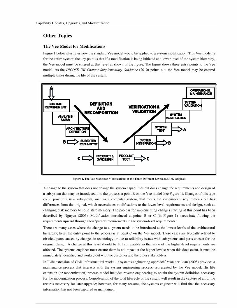
Capability Updates, Upgrades, and Modernization 78
Other Topics
The Vee Model for ModificationsFigure 1 below illustrates how the standard Vee model would be applied to a system modification. This Vee model isfor the entire system; the key point is that if a modification is being initiated at a lower level of the system hierarchy,the Vee model must be entered at that level as shown in the figure. The figure shows three entry points to the Veemodel. As the INCOSE UK Chapter Supplementary Guidance (2010) points out, the Vee model may be enteredmultiple times during the life of the system.
Figure 1. The Vee Model for Modifications at the Three Different Levels. (SEBoK Original)
A change to the system that does not change the system capabilities but does change the requirements and design ofa subsystem that may be introduced into the process at point B on the Vee model (see Figure 1). Changes of this typecould provide a new subsystem, such as a computer system, that meets the system-level requirements but hasdifferences from the original, which necessitates modifications to the lower-level requirements and design, such aschanging disk memory to solid state memory. The process for implementing changes starting at this point has beendescribed by Nguyen (2006). Modification introduced at points B or C (in Figure 1) necessitate flowing therequirements upward through their “parent” requirements to the system-level requirements.There are many cases where the change to a system needs to be introduced at the lowest levels of the architecturalhierarchy; here, the entry point to the process is at point C on the Vee model. These cases are typically related toobsolete parts caused by changes in technology or due to reliability issues with subsystems and parts chosen for theoriginal design. A change at this level should be F3I compatible so that none of the higher-level requirements areaffected. The systems engineer must ensure there is no impact at the higher levels; when this does occur, it must beimmediately identified and worked out with the customer and the other stakeholders.In “Life extension of Civil Infrastructural works - a systems engineering approach” vsan der Laan (2008) provides amaintenance process that interacts with the system engineering process, represented by the Vee model. His lifeextension (or modernization) process model includes reverse engineering to obtain the system definition necessaryfor the modernization process. Consideration of the total lifecycle of the system will result in the capture of all of therecords necessary for later upgrade; however, for many reasons, the systems engineer will find that the necessaryinformation has not been captured or maintained.

Capability Updates, Upgrades, and Modernization 79
Practical ConsiderationsAs pointed out by the INCOSE UK Chapter Supplementary Guidance (2010) there may be multiple modifications toa system in its lifetime. Often these modifications occur concurrently. This situation requires special attention andthere are two methods for managing it. The first is called the “block” method. This means that a group of systems arein the process of being modified simultaneously and will be deployed together as a group at a specific time. Thismethod is meant to ensure that at the end state, all the modifications have been coordinated and integrated so thereare no conflicts and no non-compliance issues with the system-level requirements. The second method is calledcontinuous integration and is meant to occur concurrently with the block method. Information management systemsprovide an example of a commercial system where multiple changes can occur concurrently. The informationmanagement system hardware and network modernization will cause the system software to undergo changes.Software release management is used to coordinate the proper timing for the distribution of system software changesto end-users (Michigan Department of Information Technology, 2008).
Application of Commercial-Off-the-Shelf ComponentsCurrently, a prominent consideration is the use of commercial-off-the-shelf (COTS) components. The application ofCOTS subsystems, components, and technologies to system life management provides a combination of advantagesand risks. The first advantage is the inherent technological advancements that come with COTS components. COTScomponents continue to evolve toward a higher degree of functional integration. They provide increasedfunctionality, while shrinking in physical size. The other advantage to using COTS components is that they typicallyhave a lower cost.The risks associated with using COTS during system life management involve component obsolescence and changesto system interfaces. Commercial market forces drive some components to obsolescence within two years or less.Application of COTS requires careful consideration to form factor and interface (physical and electrical).
References
Works CitedAbran, A. and J.W. Moore (exec. eds); P. Borque and R. Dupuis (eds.). 2004. SWEBOK: Guide to the SoftwareEngineering Body of Knowledge. Piscataway, NJ, USA: The Institute of Electrical and Electronic Engineers, Inc.(IEEE). Available at: http:/ / www. computer. org/ portal/ web/ swebokBlanchard, B.S. and W.J. Fabrycky. 2011. Systems Engineering and Analysis, 5th ed. Prentice-Hall Internationalseries in Industrial and Systems Engineering. Englewood Cliffs, NJ, USA: Prentice-Hall.Caltrans and USDOT. 2005. Systems Engineering Guidebook for Intelligent Transportation Systems (ITS), ver 1.1.Sacramento, CA, USA: California Department of Transportation (Caltrans) Division of Research and Innovation andU.S. Department of Transportation (USDOT), SEG for ITS 1.1.INCOSE. 2012. Systems Engineering Handbook: A Guide for System Life Cycle Processes and Activities, version3.2.2. San Diego, CA, USA: International Council on Systems Engineering (INCOSE),INCOSE-TP-2003-002-03.2.2.INCOSE UK Chapter. 2010. Applying Systems Engineering to In-Service Systems: Supplementary Guidance to theINCOSE Systems Engineering Handbook, version 3.2, issue 1.0. Foresgate, UK: International Council on SystemsEngineering (INCOSE) UK Chapter: 10, 13, 23.MDIT. 2008. System Maintenance Guidebook (SMG), version 1.1: A companion to the systems engineeringmethdology (SEM) of the state unified information technology environment (SUITE). MI, USA: MichiganDepartment of Information Technology (MDIT), DOE G 200: 38.

Capability Updates, Upgrades, and Modernization 80
Nguyen, L. 2006. “Adapting the Vee Model to Accomplish Systems Engineering on Change Projects.” Paperpresented at 9th Annual National Defense Industrial Association (NDIA) Systems Engineering Conference, SanDiego, CA, USA.OUSD(AT&L). 2012. “On-line policies, procedures, and planning references.” Office of the Under Secretary ofDefense for Acquisition, Transportation and Logistics, US Department of Defense (DoD). Accessed on August 30,2012. Available at: http:/ / www. acq. osd. mil/ log/Seacord, R.C., D. Plakosh, and G.A. Lewis. 2003. Modernizing Legacy Systems: Software Technologies,Engineering Processes, and Business Practices. Boston, MA, USA: Pearson Education.van der Laan, J. 2008. “Life extension of Civil Infrastructural works - a systems engineering approach.” Proceedingsof the 18th annual International Symposium of the International Council on Systems Engineering, Utrecht, theNetherlands.
Primary ReferencesBlanchard, B.S. and W.J. Fabrycky. 2011. Systems Engineering and Analysis, 5th ed. Prentice-Hall Internationalseries in Industrial and Systems Engineering. Englewood Cliffs, NJ, USA: Prentice-Hall.Caltrans and USDOT. 2005. Systems Engineering Guidebook for Intelligent Transportation Systems (ITS), ver 1.1.Sacramento, CA, USA: California Department of Transportation (Caltrans) Division of Research and Innovation andU.S. Department of Transportation (USDOT), SEG for ITS 1.1.INCOSE. 2012. Systems Engineering Handbook: A Guide for System Life Cycle Processes and Activities, version3.2.2. San Diego, CA, USA: International Council on Systems Engineering (INCOSE),INCOSE-TP-2003-002-03.2.2.Jackson. 2007. “A Multidisciplinary Framework for Resilience to Disasters and Disruptions.” Journal of IntegratedDesign and Process Science. 11(2).OUSD(AT&L). 2011. “Logistics and Materiel Readiness On-line policies, procedures, and planning references.”Arlington, VA, USA: Office of the Under Secretary of Defense for Aquisition, Transportation and Logistics(OUSD(AT&L). http:/ / www. acq. osd. mil/ log/ .Seacord, R.C., D. Plakosh, and G.A. Lewis. 2003. Modernizing Legacy Systems: Software Technologies,Engineering Processes, and Business Practices. Boston, MA, USA: Pearson Education.
Additional ReferencesAbran, A. and J.W. Moore (exec. eds); P. Borque and R. Dupuis (eds.). 2004. SWEBOK: Guide to the SoftwareEngineering Body of Knowledge. Piscataway, NJ, USA: The Institute of Electrical and Electronic Engineers, Inc.(IEEE). Available at: http:/ / www. computer. org/ portal/ web/ swebokBraunstein, A. 2007. “Balancing Hardware End-of-Life Costs and Responsibilities.” Westport, CT, USA: ExpertureGroup, ETS 07-12-18.Casetta, E. 2001. Transportation Systems Engineering: Theory and methods. New York, NY, USA: KluwerPublishers Academic, Springer.DAU. 2010. “Acquisition community connection (ACC): Where the DoD AT&L workforce meets to shareknowledge.” In Defense Acquisition University (DAU)/US Department of Defense (DoD). Ft. Belvoir, VA, USA,accessed August 5, 2010. https:/ / acc. dau. mil/ .Elliot, T., K. Chen, and R.C. Swanekamp. 1998. "Section 6.5" in Standard Handbook of Powerplant Engineering.New York, NY, USA: McGraw Hill.FAA. 2006. "Section 4.1" in “Systems Engineering Manual.” Washington, DC, USA: US Federal AviationAdministration (FAA).

Capability Updates, Upgrades, and Modernization 81
FCC. 2009. “Radio and Television Broadcast Rules.” Washington, DC, USA: US Federal CommunicationsCommission (FCC), 47 CFR Part 73, FCC Rule 09-19: 11299-11318.Finlayson, B. and B. Herdlick. 2008. Systems Engineering of Deployed Systems. Baltimore, MD, USA: JohnsHopkins University: 28.IEC. 2007. Obsolescence Management - Application Guide, ed 1.0. Geneva, Switzerland: InternationalElectrotechnical Commission, IEC 62302.IEEE. 2010. IEEE Standard Framework for Reliability Prediction of Hardware. New York, NY, USA: Institute ofElectrical and Electronics Engineers (IEEE), IEEE 1413.IEEE. 1998. IEEE Standard Reliability Program for the Development and Production of Electronic Systems andEquipment. New York, NY, USA: Institute of Electrical and Electronics Engineers (IEEE), IEEE 1332.IEEE. 2008. IEEE Recommended practice on Software Reliability. New York: Institute of Electrical and ElectronicsEngineers (IEEE), IEEE 1633.IEEE. 2005. IEEE Standard for Software Configuration Management Plans. New York, NY, USA: Institute ofElectrical and Electronics Engineers (IEEE), IEEE 828.INCOSE. 2010. “In-service systems working group.” San Diego, CA, USA: International Council on SystemsEngineering (INCOSE).INCOSE UK Chapter. 2010. Applying Systems Engineering to In-Service Systems: Supplementary Guidance to theINCOSE Systems Engineering Handbook, version 3.2, issue 1.0. Foresgate, UK: International Council on SystemsEngineering (INCOSE) UK Chapter: 10, 13, 23.Institute of Engineers Singapore. 2009. “Systems Engineering Body of Knowledge, provisional,” version 2.0.Singapore.ISO/IEC. 2003. “Industrial Automation Systems Integration-Integration of Life-Cycle Data for Process Plantsincluding Oil, Gas Production Factilies.” Geneva, Switzerland: International Organization for Standardization(ISO)/International Electro technical Commission (IEC).Jackson, S. 2007. “A Multidisciplinary Framework for Resilience to Disasters and Disruptions.” Journal of Designand Process Science. 11(2): 91-108, 110.Jackson, S. 1997. Systems Engineering for Commercial Aircraft. Surrey, UK: Ashgate Publishing, Ltd.Koopman, P. 1999. “Life Cycle Considerations.” In Carnegie-Mellon University (CMU). Pittsburgh, PA, USA,accessed August 5, 2010. Available at: http:/ / www. ece. cmu. edu/ ~koopman/ des_s99/ life_cycle/ index. html.Livingston, H. 2010. “GEB1: Diminishing Manufacturing Sources and Material Shortages (DMSMS) ManagementPractices.” McClellan, CA: Defense MicroElectronics Activity (DMEA)/U.S. Department of Defense (DoD).Mays, L. (ed). 2000. "Chapter 3" in Water Distribution Systems Handbook. New York, NY, USA: McGraw-HillBook Company.MDIT. 2008. System Maintenance Guidebook (SMG), version 1.1: A companion to the systems engineeringmethdology (SEM) of the state unified information technology environment (SUITE). MI, USA: MichiganDepartment of Information Technology (MDIT), DOE G 200: 38.NAS. 2006. National Airspace System (NAS) System Engineering Manual, version 3.1 (volumes 1-3). Washington,D.C.: Air Traffic Organization (ATO)/U.S. Federal Aviation Administration (FAA), NAS SEM 3.1.NASA. 2007. Systems Engineering Handbook. Washington, DC, USA: National Aeronautics and SpaceAdministration (NASA), NASA/SP-2007-6105, December 2007.Nguyen, L. 2006. “Adapting the Vee Model to Accomplish Systems Engineering on Change Projects.” Paperpresented at 9th Annual National Defense Industrial Association (NDIA) Systems Engineering Conference, SanDiego, CA, USA.
Capability Updates, Upgrades, and Modernization 82
Reason, J. 1997. Managing the Risks of Organizational Accident. Aldershot, UK: Ashgate.Ryen, E. 2008. Overview of the Systems Engineering Process. Bismarck, ND, USA: North Dakota Department ofTranspofration (NDDOT).SAE International. 2010. “Standards: Automotive--Maintenance and Aftermarket.” Warrendale, PA: Society ofAutomotive Engineers (SAE) International.Schafer, D.L. 2003. “Keeping Pace With Technology Advances When Funding Resources Are Diminished.” Paperpresented at Auto Test Con. IEEE Systems Readiness Technology Conference, Anaheim, CA, USA: 584.SEI. 2010. “Software Engineering Institute.” In Software Engineering Institute (SEI)/Carnegie-Mellon University(CMU). Pittsburgh, PA, accessed August 5, 2010. http:/ / www. sei. cmu. edu.SOLE. 2009. “Applications Divisons.” In The International Society of Logistics (SOLE). Hyattsville, MD, USA,accessed August 5, 2010. http:/ / www. sole. org/ appdiv. asp.
< Previous Article | Parent Article | Next Article >SEBoK v. 1.4 released 29 June 2015
SEBoK DiscussionPlease provide your comments and feedback on the SEBoK below. You will need to log in to DISQUS using anexisting account (e.g. Yahoo, Google, Facebook, Twitter, etc.) or create a DISQUS account. Simply type yourcomment in the text field below and DISQUS will guide you through the login or registration steps. Feedback will bearchived and used for future updates to the SEBoK. If you provided a comment that is no longer listed, that commenthas been adjudicated. You can view adjudication for comments submitted prior to SEBoK v. 1.0 at SEBoK Reviewand Adjudication. Later comments are addressed and changes are summarized in the Letter from the Editor andAcknowledgements and Release History.
If you would like to provide edits on this article, recommend new content, or make comments on the SEBoKas a whole, please see the SEBoK Sandbox [1].
ENCODED_CONTENTMTk2NDIPGRpdiBpZD0iZGlzcXVzX3RocmVhZCI+PC9kaXY+CjxzY3JpcHQgdHlwZT0idGV4dC9qYXZhc2NyaXB0Ij4KICAgIC8qICogKiBDT05GSUdVUkFUSU9OIFZBUklBQkxFUzogRURJVCBCRUZPUkUgUEFTVElORyBJTlRPIFlPVVIgV0VCUEFHRSAqICogKi8KICAgIHZhciBkaXNxdXNfc2hvcnRuYW1lID0gJ3NlYm9rd2lraTEwJzsgLy8gcmVxdWlyZWQ6IHJlcGxhY2UgZXhhbXBsZSB3aXRoIHlvdXIgZm9ydW0gc2hvcnRuYW1lCiAgICB2YXIgZGlzcXVzX2lkZW50aWZpZXIgPSAnQ2FwYWJpbGl0eSBVcGRhdGVzLCBVcGdyYWRlcywgYW5kIE1vZGVybml6YXRpb24nOyAgICB2YXIgZGlzcXVzX3VybCA9ICdodHRwOi8vc2Vib2t3aWtpLm9yZy9kcmFmdC9DYXBhYmlsaXR5X1VwZGF0ZXMsX1VwZ3JhZGVzLF9hbmRfTW9kZXJuaXphdGlvbic7CiAgICAvKiAqICogRE9OJ1QgRURJVCBCRUxPVyBUSElTIExJTkUgKiAqICovCiAgICAoZnVuY3Rpb24oKSB7CiAgICAgICAgdmFyIGRzcSA9IGRvY3VtZW50LmNyZWF0ZUVsZW1lbnQoJ3NjcmlwdCcpOyBkc3EudHlwZSA9ICd0ZXh0L2phdmFzY3JpcHQnOyBkc3EuYXN5bmMgPSB0cnVlOwogICAgICAgIGRzcS5zcmMgPSAnaHR0cDovLycgKyBkaXNxdXNfc2hvcnRuYW1lICsgJy5kaXNxdXMuY29tL2VtYmVkLmpzJzsKICAgICAgICAoZG9jdW1lbnQuZ2V0RWxlbWVudHNCeVRhZ05hbWUoJ2hlYWQnKVswXSB8fCBkb2N1bWVudC5nZXRFbGVtZW50c0J5VGFnTmFtZSgnYm9keScpWzBdKS5hcHBlbmRDaGlsZChkc3EpOwogICAgfSkoKTsKPC9zY3JpcHQ+Cjxub3NjcmlwdD5QbGVhc2UgZW5hYmxlIEphdmFTY3JpcHQgdG8gdmlldyB0aGUgPGEgaHJlZj0iaHR0cDovL2Rpc3F1cy5jb20vP3JlZl9ub3NjcmlwdCI+Y29tbWVudHMgcG93ZXJlZCBieSBEaXNxdXMuPC9hPjwvbm9zY3JpcHQ+CjxhIGhyZWY9Imh0dHA6Ly9kaXNxdXMuY29tIiBjbGFzcz0iZHNxLWJybGluayI+YmxvZyBjb21tZW50cyBwb3dlcmVkIGJ5IDxzcGFuIGNsYXNzPSJsb2dvLWRpc3F1cyI+RGlzcXVzPC9zcGFuPjwvYT4=END_ENCODED_CONTENT

Disposal and Retirement 83
Disposal and RetirementProduct or service disposal and retirement is an important part of system life management. At some point, anydeployed system will become one of the following: uneconomical to maintain; obsolete; or unrepairable. Acomprehensive systems engineering process includes an anticipated equipment phase-out period and takes disposalinto account in the design and life cycle cost assessment. (See other knowledge areas in Part 3 for discussion on lifecycle metrics and assessment.)A public focus on sustaining a clean environment encourages contemporary systems engineering (SE) design toconsider recycling, reuse, and responsible disposal techniques. (See Environmental Engineering for additionaldiscussion.)
Topic OverviewAccording to the INCOSE Systems Engineering Handbook (2012), “The purpose of the disposal process is to removea system element from the operation environment with the intent of permanently terminating its use; and to deal withany hazardous or toxic materials or waste products in accordance with the applicable guidance, policy, regulation,and statutes." In addition to technological and economical factors, the system-of-interest (SoI) must be compatible,acceptable, and ultimately address the design of a system for the environment in terms of ecological, political, andsocial considerations.Ecological considerations associated with system disposal or retirement are of prime importance. The mostconcerning problems associated with waste management include•• Air Pollution and Control,•• Water Pollution and Control,•• Noise Pollution and Control,•• Radiation, and•• Solid Waste.In the US, the Environmental Protection Agency (EPA) and the Occupational Safety and Health Administration(OSHA) govern disposal and retirement of commercial systems. Similar organizations perform this function in othercountries. OSHA addresses hazardous materials under the 1910-119A List of Highly Hazardous Chemicals, Toxics,and Reactives (OSHA 2010). System disposal and retirement spans both commercial and government developedproducts and services. While both the commercial and government sectors have common goals, methods differduring the disposition of materials associated with military systems.US DoD Directive 4160.21-M, Defense Material Disposition Manual (1997) outlines the requirements of the FederalProperty Management Regulation (FPMR) and other laws and regulations as appropriate regarding the disposition ofexcess, surplus, and foreign excess personal property (FEPP). Military system disposal activities must be compliantwith EPA and OSHA requirements.
Application to Product SystemsProduct system retirement may include system disposal activities or preservation activities (e.g., mothballing) ifthere is a chance the system may be called upon for use at a later time.Systems Engineering and Analysis has several chapters that discuss the topics of design for goals such as “greenengineering,” reliability, maintainability, logistics, supportability, producibility, disposability, and sustainability.Chapter 16 provides a succinct discussion of green engineering considerations and ecology-based manufacturing.Chapter 17 discusses life cycle costing and the inclusion of system disposal and retirement costs (Blanchard andFabrycky 2011).

Disposal and Retirement 84
Some disposal of a system's components occurs during the system’s operational life. This happens when thecomponents fail and are replaced. As a result, the tasks and resources needed to remove them from the system needto be planned well before a demand for disposal exists.Transportation of failed items, handling equipment, special training requirements for personnel, facilities, technicalprocedures, technical documentation updates, hazardous material (HAZMAT) remediation, all associated costs, andreclamation or salvage value for precious metals and recyclable components are important considerations duringsystem planning. Phase-out and disposal planning addresses when disposal should take place, the economicfeasibility of the disposal methods used, and what the effects on the inventory and support infrastructure, safety,environmental requirements, and impact to the environment will be (Blanchard 2010).Disposal is the least efficient and least desirable alternative for the processing of waste material (Finlayson andHerdlick 2008).The EPA collects information regarding the generation, management and final disposition of hazardous wastesregulated under the Resource Conservation and Recovery Act of 1976 (RCRA). EPA waste management regulationsare codified at 40 C.F.R. parts 239-282. Regulations regarding management of hazardous wastes begin at 40 C.F.R.part 260. Most states have enacted laws and promulgated regulations that are at least as stringent as federalregulations.Due to the extensive tracking of the life of hazardous waste, the overall process has become known as the"cradle-to-grave system". Stringent bookkeeping and reporting requirements have been levied on generators,transporters, and operators of treatment, storage, and disposal facilities that handle hazardous waste.Unfortunately, disposability has a lower priority compared to other activities associated with product development.This is due to the fact that typically, the disposal process is viewed as an external activity to the entity that is incustody of the system at the time. Reasons behind this view include:•• There is no direct revenue associated with the disposal process and the majority of the cost associated with the
disposal process is initially hidden.•• Typically, someone outside of SE performs the disposal activities. For example, neither a car manufacturer nor
the car's first buyer may be concerned about a car's disposal since the car will usually be sold before disposal.The European Union’s Registration, Evaluation, Authorization, and Restriction of Chemicals (REACH) regulationrequires manufacturers and importers of chemicals and products to register and disclose substances in products whenspecific thresholds and criteria are met (European Parliament 2007). The European Chemicals Agency (ECHA)manages REACH processes. Numerous substances will be added to the list of substances already restricted underEuropean legislation; a new regulation emerged when the Restriction on Hazardous Substances (RoHS) in electricaland electronic equipment was adopted in 2003.Requirements for substance use and availability are changing across the globe. Identifying the use of materials in thesupply chain that may face restriction is an important part of system life management. System disposal andretirement requires upfront planning and the development of a disposal plan to manage the activities. An importantconsideration during system retirement is the proper planning required to update the facilities needed to support thesystem during retirement, as explained in the California Department of Transportation Systems EngineeringGuidebook (2005).Disposal needs to take into account environmental and personal risks associated with the decommissioning of asystem and all hazardous materials need to be accounted for. The decommissioning of a nuclear power plant is aprime example of hazardous material control and exemplifies the need for properly handling and transportingresidual materials resulting from the retirement of certain systems.The US Defense Logistics Agency (DLA) is the lead military agency responsible for providing guidance forworldwide reuse, recycling, and disposal of military products. A critical responsibility of the military services anddefense agencies is demilitarization prior to disposal.

Disposal and Retirement 85
Application to Service SystemsAn important consideration during service system retirement or disposal is the proper continuation of services for theconsumers of the system. As an existing service system is decommissioned, a plan should be adopted to bring newsystems online that operate in parallel of the existing system so that service interruption is kept to a minimum. Thisparallel operation needs to be carefully scheduled and can occur over a significant period of time.Examples of parallel operation include phasing-in new Air Traffic Control (ATC) systems (FAA 2006), themigration from analog television to new digital television modulation (FCC 2009), the transition to Internet protocolversion 6 (IPv6), maintaining water handling systems, and maintaining large commercial transportation systems,such as rail and shipping vessels.The Systems Engineering Guidebook for Intelligent Transportation Systems (ITS) provides planning guidance for theretirement and replacement of large transportation systems. Chapter 4.7 identifies several factors which can shortenthe useful life of a transportation system and lead to early retirement, such as the lack of proper documentation, thelack of effective configuration management processes, and the lack of an adequate operations and maintenancebudget (Caltrans, and USDOT 2005).
Application to EnterprisesThe disposal and retirement of large enterprise systems requires a phased approach, with capital planning beingimplemented in stages. As in the case of service systems, an enterprise system's disposal and retirement requireparallel operation of the replacement system along with the existing (older) system to prevent loss of functionalityfor the user.
Other TopicsSee the OSHA standard (1996) and EPA (2010) website for references that provide listings of hazardous materials.See the DLA Disposal Services website [1] for disposal services sites and additional information on hazardousmaterials.
Practical ConsiderationsA prime objective of systems engineering is to design a product or service such that its components can be recycledafter the system has been retired. The recycling process should not cause any detrimental effects to the environment.One of the latest movements in the industry is green engineering. According to the EPA, green engineering is thedesign, commercialization, and use of processes and products that are technically and economically feasible whileminimizing•• the generation of pollutants at the source; and•• the risks to human health and the environment.See Environmental Engineering for additional information.

Disposal and Retirement 86
References
Works CitedBlanchard, B. S. 2010. Logistics Engineering and Management, 5th ed. Englewood Cliffs, NJ: Prentice Hall,341-342.Blanchard, B.S. and W.J. Fabrycky. 2011. Systems Engineering and Analysis, 5th ed. Prentice-Hall Internationalseries in Industrial and Systems Engineering. Englewood Cliffs, NJ, USA: Prentice-Hall.Caltrans and USDOT. 2005. Systems Engineering Guidebook for Intelligent Transportation Systems (ITS), ver 1.1.Sacramento, CA, USA: California Department of Transportation (Caltrans) Division of Research and Innovation andU.S. Department of Transportation (USDOT), SEG for ITS 1.1.DoD. 1997. Defense Materiel Disposition Manual. Arlington, VA, USA: US Department of Defense, DoD 4160.21-M.DLA. 2010. “Defense logistics agency disposition services.” In Defense Logistics Agency (DLA)/U.S. Departmentof Defense [database online]. Battle Creek, MI, USA, accessed June 19 2010: 5. Available at: http:/ / www. dtc. dla.mil.ECHA. 2010. “European Chemicals Agency (ECHA).” In European Chemicals Agency (ECHA). Helsinki, Finland.Available at: http:/ / echa. europa. edu/ home_en. asp.EPA. 2010. “Wastes In U.S. Environmental Protection Agency (EPA)." Washington, D.C. Available at: http:/ /www. epa. gov/ epawaste/ index. htm.European Parliament. 2007. Regulation (EC) no 1907/2006 of the european parliament and of the council of 18december 2006 concerning the registration, evaluation, authorisation and restriction of chemicals (REACH),establishing a european chemicals agency, amending directive 1999/45/EC and repealing council regulation (EEC)no 793/93 and commission regulation (EC) no 1488/94 as well as council directive 76/769/EEC and commissiondirectives 91/155/EEC, 93/67/EEC, 93/105/EC and 2000/21/EC. Official Journal of the European Union 29 (5):136/3,136/280.FAA. 2006. "Section 4.1" in “Systems Engineering Manual.” Washington, DC, USA: US Federal AviationAdministration (FAA).FCC. 2009. “Radio and Television Broadcast Rules.” Washington, DC, USA: US Federal CommunicationsCommission (FCC), 47 CFR Part 73, FCC Rule 09-19: 11299-11318.Finlayson, B. and B. Herdlick. 2008. Systems Engineering of Deployed Systems. Baltimore, MD, USA: JohnsHopkins University: 28.OSHA. 1996. “Hazardous Materials: Appendix A: List of Highly Hazardous Chemicals, Toxics and Reactives.”Washington, DC, USA: Occupational Safety and Health Administration (OSHA)/U.S. Department of Labor (DoL),1910.119(a).Resource Conservation and Recovery Act of 1976, 42 U.S.C. §6901 et seq. (1976)
Primary ReferencesBlanchard, B.S. and W.J. Fabrycky. 2011. Systems Engineering and Analysis, 5th ed. Prentice-Hall Internationalseries in Industrial and Systems Engineering. Englewood Cliffs, NJ, USA: Prentice-Hall.Caltrans and USDOT. 2005. Systems Engineering Guidebook for Intelligent Transportation Systems (ITS), ver 1.1.Sacramento, CA, USA: California Department of Transportation (Caltrans) Division of Research and Innovation andU.S. Department of Transportation (USDOT), SEG for ITS 1.1.INCOSE. 2012. Systems Engineering Handbook: A Guide for System Life Cycle Processes and Activities, version 3.2.2. San Diego, CA, USA: International Council on Systems Engineering (INCOSE),

Disposal and Retirement 87
INCOSE-TP-2003-002-03.2.2.Jackson, S. 2007. “A Multidisciplinary Framework for Resilience to Disasters and Disruptions.” Journal ofIntegrated Design and Process Science. 11(2).OUSD(AT&L). 2011. “Logistics and Materiel Readiness On-line policies, procedures, and planning references.”Arlington, VA, USA: Office of the Under Secretary of Defense for Aquisition, Transportation and Logistics(OUSD(AT&L). http:/ / www. acq. osd. mil/ log/ .Seacord, R.C., D. Plakosh, and G.A. Lewis. 2003. Modernizing Legacy Systems: Software Technologies,Engineering Processes, and Business Practices. Boston, MA, USA: Pearson Education.
Additional ReferencesBlanchard, B. S. 2010. Logistics Engineering and Management, 5th ed. Englewood Cliffs, NJ: Prentice Hall,341-342.Casetta, E. 2001. Transportation Systems Engineering: Theory and methods. New York, NY, USA: KluwerPublishers Academic, Springer.DAU. 2010. “Acquisition community connection (ACC): Where the DoD AT&L workforce meets to shareknowledge.” In Defense Acquisition University (DAU)/US Department of Defense (DoD). Ft. Belvoir, VA, USA,accessed August 5, 2010. https:/ / acc. dau. mil/ .DLA. 2010. “Defense logistics agency disposition services.” In Defense Logistics Agency (DLA)/U.S. Departmentof Defense [database online]. Battle Creek, MI, USA, accessed June 19 2010: 5. Available at: http:/ / www. dtc. dla.mil.ECHA. 2010. “European Chemicals Agency (ECHA).” In European Chemicals Agency (ECHA). Helsinki, Finland.Available at: http:/ / echa. europa. edu/ home_en. asp.Elliot, T., K. Chen, and R.C. Swanekamp. 1998. "Section 6.5" in Standard Handbook of Powerplant Engineering.New York, NY, USA: McGraw Hill.EPA. 2010. “Wastes In U.S. Environmental Protection Agency (EPA)." Washington, D.C. Available at: http:/ /www. epa. gov/ epawaste/ index. htm.European Parliament. 2007. Regulation (EC) no 1907/2006 of the european parliament and of the council of 18december 2006 concerning the registration, evaluation, authorisation and restriction of chemicals (REACH),establishing a european chemicals agency, amending directive 1999/45/EC and repealing council regulation (EEC)no 793/93 and commission regulation (EC) no 1488/94 as well as council directive 76/769/EEC and commissiondirectives 91/155/EEC, 93/67/EEC, 93/105/EC and 2000/21/EC. Official Journal of the European Union 29 (5):136/3,136/280.FAA. 2006. "Section 4.1" in “Systems Engineering Manual.” Washington, DC, USA: US Federal AviationAdministration (FAA).FCC. 2009. “Radio and Television Broadcast Rules.” Washington, DC, USA: US Federal CommunicationsCommission (FCC), 47 CFR Part 73, FCC Rule 09-19: 11299-11318.Finlayson, B. and B. Herdlick. 2008. Systems Engineering of Deployed Systems. Baltimore, MD, USA: JohnsHopkins University: 28.FSA. 2010. “Template for 'System Retirement Plan' and 'System Disposal Plan'.” In Federal Student Aid (FSA)/U.S.Department of Eduation (DoEd). Washington, DC, USA. Accessed August 5, 2010. Available at: http:/ /federalstudentaid. ed. gov/ business/ lcm. html.IEEE 2005. IEEE Standard for Software Configuration Management Plans. New York, NY, USA: Institute ofElectrical and Electronics Engineers (IEEE), IEEE 828.

Disposal and Retirement 88
Ihii, K., C.F. Eubanks, and P. Di Marco. 1994. “Design for Product Retirement and Material Life-Cycle.” Materials& Design. 15(4): 225-33.INCOSE. 2010. “In-service systems working group.” San Diego, CA, USA: International Council on SystemsEngineering (INCOSE).INCOSE UK Chapter. 2010. Applying Systems Engineering to In-Service Systems: Supplementary Guidance to theINCOSE Systems Engineering Handbook, version 3.2, issue 1.0. Foresgate, UK: International Council on SystemsEngineering (INCOSE) UK Chapter: 10, 13, 23.Institute of Engineers Singapore. 2009. “Systems Engineering Body of Knowledge, provisional,” version 2.0.Singapore: Institute of Engineers Singapore.Mays, L. (ed). 2000. "Chapter 3" in Water Distribution Systems Handbook. New York, NY, USA: McGraw-HillBook Company.MDIT. 2008. System Maintenance Guidebook (SMG), version 1.1: A companion to the systems engineeringmethdology (SEM) of the state unified information technology environment (SUITE). MI, USA: MichiganDepartment of Information Technology (MDIT), DOE G 200: 38.Minneapolis-St. Paul Chapter of SOLE. 2003. "Systems Engineering in Systems Deployment and Retirement,presented to INCOSE." Minneapolis-St. Paul, MN, USA: International Society of Logistics (SOLE), Minneapolis-St.Paul Chapter.NAS. 2006. National Airspace System (NAS) System Engineering Manual, version 3.1 (volumes 1-3). Washington,D.C.: Air Traffic Organization (ATO)/U.S. Federal Aviation Administration (FAA), NAS SEM 3.1.NASA. 2007. Systems Engineering Handbook. Washington, DC, USA: National Aeronautics and SpaceAdministration (NASA), NASA/SP-2007-6105, December 2007.OSHA. 1996. “Hazardous Materials: Appendix A: List of Highly Hazardous Chemicals, Toxics and Reactives.”Washington, DC, USA: Occupational Safety and Health Administration (OSHA)/U.S. Department of Labor (DoL),1910.119(a).Ryen, E. 2008. Overview of the Systems Engineering Process. Bismarck, ND, USA: North Dakota Department ofTranspofration (NDDOT).SAE International. 2010. “Standards: Automotive--Maintenance and Aftermarket.” Warrendale, PA: Society ofAutomotive Engineers (SAE) International.Schafer, D.L. 2003. “Keeping Pace With Technology Advances When Funding Resources Are Diminished.” Paperpresented at Auto Test Con. IEEE Systems Readiness Technology Conference, Anaheim, CA, USA: 584.SOLE. 2009. “Applications Divisons.” In The International Society of Logistics (SOLE). Hyattsville, MD, USA,accessed August 5, 2010. http:/ / www. sole. org/ appdiv. asp.
< Previous Article | Parent Article | Next Article >SEBoK v. 1.4 released 29 June 2015
SEBoK DiscussionPlease provide your comments and feedback on the SEBoK below. You will need to log in to DISQUS using anexisting account (e.g. Yahoo, Google, Facebook, Twitter, etc.) or create a DISQUS account. Simply type yourcomment in the text field below and DISQUS will guide you through the login or registration steps. Feedback will bearchived and used for future updates to the SEBoK. If you provided a comment that is no longer listed, that commenthas been adjudicated. You can view adjudication for comments submitted prior to SEBoK v. 1.0 at SEBoK Reviewand Adjudication. Later comments are addressed and changes are summarized in the Letter from the Editor andAcknowledgements and Release History.

Disposal and Retirement 89
If you would like to provide edits on this article, recommend new content, or make comments on the SEBoKas a whole, please see the SEBoK Sandbox [1].
ENCODED_CONTENTMTI0MzAPGRpdiBpZD0iZGlzcXVzX3RocmVhZCI+PC9kaXY+CjxzY3JpcHQgdHlwZT0idGV4dC9qYXZhc2NyaXB0Ij4KICAgIC8qICogKiBDT05GSUdVUkFUSU9OIFZBUklBQkxFUzogRURJVCBCRUZPUkUgUEFTVElORyBJTlRPIFlPVVIgV0VCUEFHRSAqICogKi8KICAgIHZhciBkaXNxdXNfc2hvcnRuYW1lID0gJ3NlYm9rd2lraTEwJzsgLy8gcmVxdWlyZWQ6IHJlcGxhY2UgZXhhbXBsZSB3aXRoIHlvdXIgZm9ydW0gc2hvcnRuYW1lCiAgICB2YXIgZGlzcXVzX2lkZW50aWZpZXIgPSAnRGlzcG9zYWwgYW5kIFJldGlyZW1lbnQnOyAgICB2YXIgZGlzcXVzX3VybCA9ICdodHRwOi8vc2Vib2t3aWtpLm9yZy9kcmFmdC9EaXNwb3NhbF9hbmRfUmV0aXJlbWVudCc7CiAgICAvKiAqICogRE9OJ1QgRURJVCBCRUxPVyBUSElTIExJTkUgKiAqICovCiAgICAoZnVuY3Rpb24oKSB7CiAgICAgICAgdmFyIGRzcSA9IGRvY3VtZW50LmNyZWF0ZUVsZW1lbnQoJ3NjcmlwdCcpOyBkc3EudHlwZSA9ICd0ZXh0L2phdmFzY3JpcHQnOyBkc3EuYXN5bmMgPSB0cnVlOwogICAgICAgIGRzcS5zcmMgPSAnaHR0cDovLycgKyBkaXNxdXNfc2hvcnRuYW1lICsgJy5kaXNxdXMuY29tL2VtYmVkLmpzJzsKICAgICAgICAoZG9jdW1lbnQuZ2V0RWxlbWVudHNCeVRhZ05hbWUoJ2hlYWQnKVswXSB8fCBkb2N1bWVudC5nZXRFbGVtZW50c0J5VGFnTmFtZSgnYm9keScpWzBdKS5hcHBlbmRDaGlsZChkc3EpOwogICAgfSkoKTsKPC9zY3JpcHQ+Cjxub3NjcmlwdD5QbGVhc2UgZW5hYmxlIEphdmFTY3JpcHQgdG8gdmlldyB0aGUgPGEgaHJlZj0iaHR0cDovL2Rpc3F1cy5jb20vP3JlZl9ub3NjcmlwdCI+Y29tbWVudHMgcG93ZXJlZCBieSBEaXNxdXMuPC9hPjwvbm9zY3JpcHQ+CjxhIGhyZWY9Imh0dHA6Ly9kaXNxdXMuY29tIiBjbGFzcz0iZHNxLWJybGluayI+YmxvZyBjb21tZW50cyBwb3dlcmVkIGJ5IDxzcGFuIGNsYXNzPSJsb2dvLWRpc3F1cyI+RGlzcXVzPC9zcGFuPjwvYT4=END_ENCODED_CONTENT
References[1] http:/ / www. dtc. dla. mil
Systems Engineering StandardsThis knowledge area (KA) focuses on the standards and technical protocols that are relevant to systems engineering.It looks at the types of standards, some of the key standards, and the alignment efforts to achieve a consistent set ofstandards. It then compares some of the standards, and surveys the application of the standards. Note that many ofthese standards have been used as references throughout Part 3.
TopicsEach part of the SEBoK is divided into KA's, which are groupings of information with a related theme. The KA's inturn are divided into topics. This KA contains the following topics:•• Relevant Standards•• Alignment and Comparison of the Standards•• Application of Systems Engineering StandardsSee the article Matrix of Implementation Examples for a mapping of case studies and vignettes included in Part 7 totopics covered in Part 3.
ReferencesNone.
< Previous Article | Parent Article | Next Article >SEBoK v. 1.4 released 29 June 2015
SEBoK DiscussionPlease provide your comments and feedback on the SEBoK below. You will need to log in to DISQUS using anexisting account (e.g. Yahoo, Google, Facebook, Twitter, etc.) or create a DISQUS account. Simply type yourcomment in the text field below and DISQUS will guide you through the login or registration steps. Feedback will bearchived and used for future updates to the SEBoK. If you provided a comment that is no longer listed, that commenthas been adjudicated. You can view adjudication for comments submitted prior to SEBoK v. 1.0 at SEBoK Reviewand Adjudication. Later comments are addressed and changes are summarized in the Letter from the Editor andAcknowledgements and Release History.
If you would like to provide edits on this article, recommend new content, or make comments on the SEBoKas a whole, please see the SEBoK Sandbox [1].
ENCODED_CONTENTMTY3MjQPGRpdiBpZD0iZGlzcXVzX3RocmVhZCI+PC9kaXY+CjxzY3JpcHQgdHlwZT0idGV4dC9qYXZhc2NyaXB0Ij4KICAgIC8qICogKiBDT05GSUdVUkFUSU9OIFZBUklBQkxFUzogRURJVCBCRUZPUkUgUEFTVElORyBJTlRPIFlPVVIgV0VCUEFHRSAqICogKi8KICAgIHZhciBkaXNxdXNfc2hvcnRuYW1lID0gJ3NlYm9rd2lraTEwJzsgLy8gcmVxdWlyZWQ6IHJlcGxhY2UgZXhhbXBsZSB3aXRoIHlvdXIgZm9ydW0gc2hvcnRuYW1lCiAgICB2YXIgZGlzcXVzX2lkZW50aWZpZXIgPSAnU3lzdGVtcyBFbmdpbmVlcmluZyBTdGFuZGFyZHMnOyAgICB2YXIgZGlzcXVzX3VybCA9ICdodHRwOi8vc2Vib2t3aWtpLm9yZy9kcmFmdC9TeXN0ZW1zX0VuZ2luZWVyaW5nX1N0YW5kYXJkcyc7CiAgICAvKiAqICogRE9OJ1QgRURJVCBCRUxPVyBUSElTIExJTkUgKiAqICovCiAgICAoZnVuY3Rpb24oKSB7CiAgICAgICAgdmFyIGRzcSA9IGRvY3VtZW50LmNyZWF0ZUVsZW1lbnQoJ3NjcmlwdCcpOyBkc3EudHlwZSA9ICd0ZXh0L2phdmFzY3JpcHQnOyBkc3EuYXN5bmMgPSB0cnVlOwogICAgICAgIGRzcS5zcmMgPSAnaHR0cDovLycgKyBkaXNxdXNfc2hvcnRuYW1lICsgJy5kaXNxdXMuY29tL2VtYmVkLmpzJzsKICAgICAgICAoZG9jdW1lbnQuZ2V0RWxlbWVudHNCeVRhZ05hbWUoJ2hlYWQnKVswXSB8fCBkb2N1bWVudC5nZXRFbGVtZW50c0J5VGFnTmFtZSgnYm9keScpWzBdKS5hcHBlbmRDaGlsZChkc3EpOwogICAgfSkoKTsKPC9zY3JpcHQ+Cjxub3NjcmlwdD5QbGVhc2UgZW5hYmxlIEphdmFTY3JpcHQgdG8gdmlldyB0aGUgPGEgaHJlZj0iaHR0cDovL2Rpc3F1cy5jb20vP3JlZl9ub3NjcmlwdCI+Y29tbWVudHMgcG93ZXJlZCBieSBEaXNxdXMuPC9hPjwvbm9zY3JpcHQ+CjxhIGhyZWY9Imh0dHA6Ly9kaXNxdXMuY29tIiBjbGFzcz0iZHNxLWJybGluayI+YmxvZyBjb21tZW50cyBwb3dlcmVkIGJ5IDxzcGFuIGNsYXNzPSJsb2dvLWRpc3F1cyI+RGlzcXVzPC9zcGFuPjwvYT4=END_ENCODED_CONTENT

Relevant Standards 90
Relevant StandardsThere are a multitude of standards across a number of standards development organizations (SDOs) that are relatedto systems engineering and systems domains. This topic examines the types of standards and provides a summary ofthe relevant standards for systems engineering (SE).
Standards Taxonomies and Types of StandardsThere are many types of standards that focus on different aspects of SE. Thus, it can be helpful to have a taxonomythat classifies the types of standards and the objective of each type. Table 1 provides the types of the currentstandards and a description of the types. Refer to the Modeling Standards for a list of relevant system modelingstandards.
Table 1. Types of Systems Engineering Standards. (SEBoK Original)
Standard Type Description of Type
Concepts and Terminology •• Defines the terminology and describes the concepts of a specific domain.
Process •• Elaborates a specific process, giving normative requirements for the essential elements of the process. It maygive guidance to the requirements.
Requirements •• Describes the requirements for something.•• Most often used for actions, activities, or practices and not objects (see specifications).
Procedure (Practice, Activity) •• A specific procedure. Instructions or requirements on how to do something.•• Could be a description of best practices.•• Sometimes guidance and sometimes normative.
Guidance •• Usually an interpretation and guidance of a published standard.
Management System •• Requirements for management.
Specification •• Specifies the form, attributes, or properties of a subject artifact.•• Usually an object and usually normative.
Reference Model •• A reference model or collection of specifications of which a reference model is composed.
Process Reference Model(PRM)
•• A collection of processes necessary and sufficient to achieve a nominated business outcome.
Process Assessment Model(PAM)
•• Requirements and guidance for assessing attributes of nominated processes or attributes of a nominatedcollection of processes.
Guide to Body of Knowledge(BOK)
•• Collects and describes the current body of knowledge in a domain, or guidance to the body of knowledge.
Systems Engineering Related Standards
Summary of Systems Engineering Related StandardsTable 2 contains a summary of SE related standards. This table does not include all SE related standards, as there aremany are focused on a specific domain, sector, or user group (e.g., it does not include standards from a specificgovernment agenda). The table does include standards that are considered to be widely applicable systemsengineering and systems life cycle management system life cycle processes, such as ISO/IEC/IEEE 15288 (2015).Where available, there is a link to the official abstract for the standard.

Relevant Standards 91
Table 2. Summary of Systems Engineering Standards. (SEBoK Original)
Document ID Document Title Organization
ISO/IEC/IEEE 15288 [1] Systems and Software Engineering - System Life Cycle Processes ISO/IEC/IEEE
ISO/IEC/IEEE 24765 [2] Systems and Software Engineering - Systems and Software Engineering Vocabulary ISO/IEC/IEEE
ISO/IEC/IEEE 42010 [3] Systems and Software Engineering - Architecture Description ISO/IEC/IEEE
ISO/IEC 26702 [4] / IEEE 1220[5]
Management of the Systems Engineering Process ISO/IEC/IEEE
ISO/IEC/IEEE 29148 [6] Systems and Software Engineering - Requirements Engineering ISO/IEC/IEEE
ISO/IEC/IEEE 16085 [7] Systems and Software Engineering - Risk Management ISO/IEC/IEEE
ISO/IEC/IEEE 15939 [8] Systems and Software Engineering - Measurement Process ISO/IEC/IEEE
ISO/IEC/IEEE 16326 [9] Systems and Software Engineering - Project Management ISO/IEC/IEEE
prEN9277 [10] Programme management - Guide for the management of Systems Engineering CEN
EIA 632 [11] Engineering of a System TechAmerica
ISO 9001:2008 [12] Quality Management Systems - Requirements ISO TC 176
EIA-649-B [13] National Consensus Standard for Configuration Management TechAmerica
ISO/IEC/IEEE TR 24748-1 [14] Systems and Software Engineering - Guide to Life Cycle Management ISO/IEC/IEEE
ISO/IEC/IEEE TR 24748-2 [15] Systems and Software Engineering - Guide To The Application of ISO/IEC 15288:2008 ISO/IEC/IEEE
ISO/IEC/IEEE CD 24748-4[16]
Systems and Software Engineering - Application and management of the systemsengineering process
ISO/IEC/IEEE
ISO/IEC DTR 16337 [17] Systems Engineering Handbook (INCOSE) ISO/IEC/INCOSE
ISO/IEC/IEEE 15289:2011 [18] Systems and Software Engineering - Content of Life-Cycle Information Products(Documentation)
ISO/IEC/IEEE
ISO/IEC/IEEE 15026-1:2010[19]
Systems and Software Engineering - System and Software Assurance – Part 1: ConceptsAnd Vocabulary
ISO/IEC/IEEE
ISO/IEC/IEEE 15026-2:2011[20]
Systems and Software Engineering - System and Software Assurance – Part 2: AssuranceCase
ISO/IEC/IEEE
ISO/IEC/IEEE 15026-3:2011[21]
Systems and Software Engineering - System and Software Assurance – Part 3: IntegrityLevels
ISO/IEC/IEEE
ISO/IEC/IEEE 15026-4:2012[22]
Systems and Software Engineering - System And Software Assurance – Part 4: Assurancein the Life Cycle
ISO/IEC/IEEE JTC1
ISO/IEC TR 90005:2008 [23] Guidelines for the Application of ISO 9001 to Systems Life Cycle Processes ISO/IEC JTC 1
ISO 10303-233:2012 [24] Systems Engineering Data Interchange Standard ISO TC 184
ECSS-E-ST-10C [25] Systems Engineering General Requirements ECSS
ECSS-E-ST-10-02 [26] Space Engineering - Verification {Note - standard is canceled} ECSS
ECSS-E-ST-10-06 [27] Space Engineering - Technical Requirements Specification ECSS
ECSS-E-ST-10-24 [28] Space Engineering - Interface Control ECSS
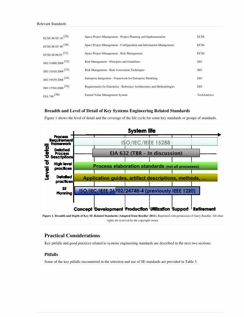
Relevant Standards 92
ECSS-M-ST-10 [29] Space Project Management - Project Planning and Implementation ECSS
ECSS-M-ST-40 [30] Space Project Management - Configuration and Information Management ECSS
ECSS-M-00-03 [31] Space Project Management - Risk Management ECSS
ISO 31000:2009 [32] Risk Management - Principles and Guidelines ISO
ISO 31010:2009 [33] Risk Management - Risk Assessment Techniques ISO
ISO 19439:2006 [34] Enterprise Integration - Framework for Enterprise Modeling ISO
ISO 15704:2000 [35] Requirements for Enterprise - Reference Architectures and Methodologies ISO
EIA 748 [36] Earned Value Management System TechAmerica
Breadth and Level of Detail of Key Systems Engineering Related StandardsFigure 1 shows the level of detail and the coverage of the life cycle for some key standards or groups of standards.
Figure 1. Breadth and Depth of Key SE Related Standards (Adapted from Roedler 2011). Reprinted with permission of Garry Roedler. All otherrights are reserved by the copyright owner.
Practical ConsiderationsKey pitfalls and good practices related to systems engineering standards are described in the next two sections.
PitfallsSome of the key pitfalls encountered in the selection and use of SE standards are provided in Table 3.
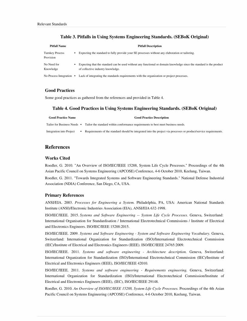
Relevant Standards 93
Table 3. Pitfalls in Using Systems Engineering Standards. (SEBoK Original)
Pitfall Name Pitfall Description
Turnkey ProcessProvision
•• Expecting the standard to fully provide your SE processes without any elaboration or tailoring.
No Need forKnowledge
•• Expecting that the standard can be used without any functional or domain knowledge since the standard is the productof collective industry knowledge.
No Process Integration •• Lack of integrating the standards requirements with the organization or project processes.
Good PracticesSome good practices as gathered from the references and provided in Table 4.
Table 4. Good Practices in Using Systems Engineering Standards. (SEBoK Original)
Good Practice Name Good Practice Description
Tailor for Business Needs •• Tailor the standard within conformance requirements to best meet business needs.
Integration into Project •• Requirements of the standard should be integrated into the project via processes or product/service requirements.
References
Works CitedRoedler, G. 2010. "An Overview of ISO/IEC/IEEE 15288, System Life Cycle Processes." Proceedings of the 4thAsian Pacific Council on Systems Engineering (APCOSE) Conference, 4-6 October 2010, Keelung, Taiwan.Roedler, G. 2011. "Towards Integrated Systems and Software Engineering Standards." National Defense IndustrialAssociation (NDIA) Conference, San Diego, CA, USA.
Primary ReferencesANSI/EIA. 2003. Processes for Engineering a System. Philadelphia, PA, USA: American National StandardsInstitute (ANSI)/Electronic Industries Association (EIA), ANSI/EIA 632-1998.ISO/IEC/IEEE. 2015. Systems and Software Engineering -- System Life Cycle Processes. Geneva, Switzerland:International Organisation for Standardisation / International Electrotechnical Commissions / Institute of Electricaland Electronics Engineers. ISO/IEC/IEEE 15288:2015.ISO/IEC/IEEE. 2009. Systems and Software Engineering - System and Software Engineering Vocabulary. Geneva,Switzerland: International Organization for Standardization (ISO)/International Electrotechnical Commission(IEC)/Institute of Electrical and Electronics Engineers (IEEE). ISO/IEC/IEEE 24765:2009.ISO/IEC/IEEE. 2011. Systems and software engineering - Architecture description. Geneva, Switzerland:International Organization for Standardization (ISO)/International Electrotechnical Commission (IEC)/Institute ofElectrical and Electronics Engineers (IEEE), ISO/IEC/IEEE 42010.ISO/IEC/IEEE. 2011. Systems and software engineering - Requirements engineering. Geneva, Switzerland:International Organization for Standardization (ISO)/International Electrotechnical Commission/Institute ofElectrical and Electronics Engineers (IEEE), (IEC), ISO/IEC/IEEE 29148.Roedler, G. 2010. An Overview of ISO/IEC/IEEE 15288, System Life Cycle Processes. Proceedings of the 4th AsianPacific Council on Systems Engineering (APCOSE) Conference, 4-6 October 2010, Keelung, Taiwan.

Relevant Standards 94
Additional ReferencesISO. 2003. Space Systems - Risk Management. Geneva, Switzerland: International Organization for Standardization(ISO), ISO 17666:2003.ISO. 2009. Risk Management - Principles and Guidelines. Geneva, Switzerland: International Organization forStandardization (ISO), ISO 31000:2009.ISO/IEC. 2009. Risk Management - Risk Assessment Techniques. Geneva, Switzerland: International Organizationfor Standardization (ISO)/International Electrotechnical Commission (IEC), ISO/IEC 31010:2009.ISO/IEC/IEEE. 2006. Systems and Software Engineering - Risk Management. Geneva, Switzerland: InternationalOrganization for Standardization (ISO)/International Electrotechnical Commission (IEC)/Institute of Electrical andElectronics Engineers (IEEE), ISO/IEC/IEEE 16085.ISO/IEC/IEEE. 2007. Systems and Software Engineering - Measurement Process. Geneva, Switzerland:International Organization for Standardization (ISO)/International Electrotechnical Commission (IEC)/Institute ofElectrical and Electronics Engineers (IEEE), ISO/IEC/IEEE 15939.ISO/IEC/IEEE. 2009. Systems and Software Engineering - Project Management. Geneva, Switzerland: InternationalOrganization for Standardization (ISO)/International Electrotechnical Commission (IEC)/Institute of Electrical andElectronics Engineers (IEEE). ISO/IEC/IEEE 16326.ISO/IEC/IEEE. 2009. Systems and Software Engineering - System and Software Assurance, Part 1: Concepts anddefinitions. Geneva, Switzerland: International Organization for Standardization (ISO)/International ElectrotechnicalCommission (IEC)/Institute of Electrical and Electronics Engineers (IEEE). ISO/IEC/IEEE 15026-1.ISO/IEC/IEEE. 2010. Systems and Software Engineering - System and Software Assurance, Part 2: Assurance case.Geneva, Switzerland: International Organization for Standardization (ISO)/International ElectrotechnicalCommission (IEC)/Institute of Electrical and Electronics Engineers (IEEE). ISO/IEC/IEEE 15026-2.ISO/IEC/IEEE. 2011. Systems and Software Engineering - Content of Life-Cycle Information Products(documentation). Geneva, Switzerland: International Organization for Standardization (ISO)/InternationalElectrotechnical Commission (IEC)/Institute of Electrical and Electronics Engineers (IEEE). ISO/IEC/IEEE 15289.ISO/IEC/IEEE. 2011. Systems and Software Engineering - System and Software Assurance, Part 3: Integrity Levels.Geneva, Switzerland: International Organization for Standardization (ISO)/International ElectrotechnicalCommission (IEC)/Institute of Electrical and Electronics Engineers (IEEE). ISO/IEC/IEEE 15026-3.
< Previous Article | Parent Article | Next Article >SEBoK v. 1.4 released 29 June 2015
SEBoK DiscussionPlease provide your comments and feedback on the SEBoK below. You will need to log in to DISQUS using anexisting account (e.g. Yahoo, Google, Facebook, Twitter, etc.) or create a DISQUS account. Simply type yourcomment in the text field below and DISQUS will guide you through the login or registration steps. Feedback will bearchived and used for future updates to the SEBoK. If you provided a comment that is no longer listed, that commenthas been adjudicated. You can view adjudication for comments submitted prior to SEBoK v. 1.0 at SEBoK Reviewand Adjudication. Later comments are addressed and changes are summarized in the Letter from the Editor andAcknowledgements and Release History.
If you would like to provide edits on this article, recommend new content, or make comments on the SEBoKas a whole, please see the SEBoK Sandbox [1].
ENCODED_CONTENTMzYyNjEPGRpdiBpZD0iZGlzcXVzX3RocmVhZCI+PC9kaXY+CjxzY3JpcHQgdHlwZT0idGV4dC9qYXZhc2NyaXB0Ij4KICAgIC8qICogKiBDT05GSUdVUkFUSU9OIFZBUklBQkxFUzogRURJVCBCRUZPUkUgUEFTVElORyBJTlRPIFlPVVIgV0VCUEFHRSAqICogKi8KICAgIHZhciBkaXNxdXNfc2hvcnRuYW1lID0gJ3NlYm9rd2lraTEwJzsgLy8gcmVxdWlyZWQ6IHJlcGxhY2UgZXhhbXBsZSB3aXRoIHlvdXIgZm9ydW0gc2hvcnRuYW1lCiAgICB2YXIgZGlzcXVzX2lkZW50aWZpZXIgPSAnUmVsZXZhbnQgU3RhbmRhcmRzJzsgICAgdmFyIGRpc3F1c191cmwgPSAnaHR0cDovL3NlYm9rd2lraS5vcmcvZHJhZnQvUmVsZXZhbnRfU3RhbmRhcmRzJzsKICAgIC8qICogKiBET04nVCBFRElUIEJFTE9XIFRISVMgTElORSAqICogKi8KICAgIChmdW5jdGlvbigpIHsKICAgICAgICB2YXIgZHNxID0gZG9jdW1lbnQuY3JlYXRlRWxlbWVudCgnc2NyaXB0Jyk7IGRzcS50eXBlID0gJ3RleHQvamF2YXNjcmlwdCc7IGRzcS5hc3luYyA9IHRydWU7CiAgICAgICAgZHNxLnNyYyA9ICdodHRwOi8vJyArIGRpc3F1c19zaG9ydG5hbWUgKyAnLmRpc3F1cy5jb20vZW1iZWQuanMnOwogICAgICAgIChkb2N1bWVudC5nZXRFbGVtZW50c0J5VGFnTmFtZSgnaGVhZCcpWzBdIHx8IGRvY3VtZW50LmdldEVsZW1lbnRzQnlUYWdOYW1lKCdib2R5JylbMF0pLmFwcGVuZENoaWxkKGRzcSk7CiAgICB9KSgpOwo8L3NjcmlwdD4KPG5vc2NyaXB0PlBsZWFzZSBlbmFibGUgSmF2YVNjcmlwdCB0byB2aWV3IHRoZSA8YSBocmVmPSJodHRwOi8vZGlzcXVzLmNvbS8/cmVmX25vc2NyaXB0Ij5jb21tZW50cyBwb3dlcmVkIGJ5IERpc3F1cy48L2E+PC9ub3NjcmlwdD4KPGEgaHJlZj0iaHR0cDovL2Rpc3F1cy5jb20iIGNsYXNzPSJkc3EtYnJsaW5rIj5ibG9nIGNvbW1lbnRzIHBvd2VyZWQgYnkgPHNwYW4gY2xhc3M9ImxvZ28tZGlzcXVzIj5EaXNxdXM8L3NwYW4+PC9hPg==

Relevant Standards 95
END_ENCODED_CONTENT
References[1] http:/ / www. iso. org/ iso/ iso_catalogue/ catalogue_tc/ catalogue_detail. htm?csnumber=43564[2] http:/ / www. iso. org/ iso/ iso_catalogue/ catalogue_tc/ catalogue_detail. htm?csnumber=50518[3] http:/ / www. iso. org/ iso/ home/ store/ catalogue_ics/ catalogue_detail_ics. htm?csnumber=50508[4] http:/ / www. iso. org/ iso/ iso_catalogue/ catalogue_tc/ catalogue_detail. htm?csnumber=43693[5] http:/ / standards. ieee. org/ findstds/ standard/ 1220-2005. html[6] http:/ / www. iso. org/ iso/ iso_catalogue/ catalogue_tc/ catalogue_detail. htm?csnumber=45171[7] http:/ / www. iso. org/ iso/ iso_catalogue/ catalogue_tc/ catalogue_detail. htm?csnumber=40723[8] http:/ / www. iso. org/ iso/ iso_catalogue/ catalogue_tc/ catalogue_detail. htm?csnumber=44344[9] http:/ / www. iso. org/ iso/ iso_catalogue/ catalogue_tc/ catalogue_detail. htm?csnumber=41977[10] http:/ / infostore. saiglobal. com/ store/ details. aspx?ProductID=1615031[11] http:/ / www. techstreet. com/ products/ 1145585[12] http:/ / www. iso. org/ iso/ catalogue_detail?csnumber=46486[13] http:/ / www. techstreet. com/ products/ 1800866[14] http:/ / www. iso. org/ iso/ iso_catalogue/ catalogue_tc/ catalogue_detail. htm?csnumber=50502[15] http:/ / www. iso. org/ iso/ iso_catalogue/ catalogue_ics/ catalogue_detail_ics. htm?csnumber=54994[16] http:/ / www. iso. org/ iso/ iso_catalogue/ catalogue_ics/ catalogue_detail_ics. htm?csnumber=56887[17] http:/ / www. iso. org/ iso/ home/ store/ catalogue_tc/ catalogue_detail. htm?csnumber=56186[18] http:/ / www. iso. org/ iso/ home/ store/ catalogue_tc/ catalogue_detail. htm?csnumber=54388[19] http:/ / www. iso. org/ iso/ iso_catalogue/ catalogue_tc/ catalogue_detail. htm?csnumber=50520[20] http:/ / www. iso. org/ iso/ catalogue_detail. htm?csnumber=52926[21] http:/ / www. iso. org/ iso/ iso_catalogue/ catalogue_tc/ catalogue_detail. htm?csnumber=57107[22] http:/ / www. iso. org/ iso/ iso_catalogue/ catalogue_tc/ catalogue_detail. htm?csnumber=59927[23] http:/ / www. iso. org/ iso/ catalogue_detail?csnumber=41553[24] http:/ / www. iso. org/ iso/ home/ store/ catalogue_tc/ catalogue_detail. htm?csnumber=55257[25] http:/ / www. inpe. br/ twiki/ pub/ Main/ GerenciamentoProjetosEspaciais/ ECSS-E-ST-10C(6March2009). pdf[26] http:/ / www. everyspec. com/ ESA/ ECSS-E-10-02A_14991/[27] http:/ / www. inpe. br/ twiki/ pub/ Main/ GerenciamentoProjetosEspaciais/ ECSS-E-ST-10-06C6March2009. pdf[28] https:/ / www. google. com/ url?sa=t& rct=j& q=& esrc=s& source=web& cd=1& ved=0CCsQFjAA& url=http%3A%2F%2Fwww. ecss.
nl%2Fforums%2Fecss%2Fdispatch.cgi%2Fhome%2FshowFile%2F100807%2Fd20130924080101%2FNo%2FECSS-E-ST-10-24C_DIR1(24September2013). doc&ei=Ji5cUrt0woLbBZ2qgOgN& usg=AFQjCNHNB_u3X71aMcFAeiiN2PAZuxGGmQ& bvm=bv. 53899372,d. b2I
[29] http:/ / www. everyspec. com/ ESA/ ECSS-M-ST-10C_REV-1_47763/[30] http:/ / www. ecss. nl/ forums/ ecss/ dispatch. cgi/ standards/ showFile/ 100665/ d20080802121136/ No/ ECSS-M-ST-80C(31July2008). doc[31] http:/ / www. everyspec. com/ ESA/ ecss-m-00-03a_2569/[32] http:/ / www. iso. org/ iso/ catalogue_detail?csnumber=43170[33] http:/ / www. iso. org/ iso/ catalogue_detail?csnumber=51073[34] http:/ / www. iso. org/ iso/ iso_catalogue/ catalogue_tc/ catalogue_detail. htm?csnumber=33833[35] http:/ / www. iso. org/ iso/ catalogue_detail. htm?csnumber=28777[36] http:/ / www. techstreet. com/ products/ 1854970

Alignment and Comparison of the Standards 96
Alignment and Comparison of the StandardsOver the past decade, a number of the standards development organizations (SDOs) and other industry associationshave been working collaboratively to align the systems engineering (SE) and software engineering (SwE) standards.The objective is to have a set of standards that can easily be used concurrently within both engineering disciplines,due to the disparity that often lies within their use of common terminology and concepts.
ProblemThere has been a lack of integration both within and across SDOs. This has led to SE and SwE standards that usedifferent terminology, process sets, process structures, levels of prescription, and audiences. These differences havebeen both between systems and software, and to some extent, within each. The problem has been exacerbated, inwhole or part, by competing standards (Roedler 2010).
CauseThe cause of this problem includes several factors, as follows (Roedler 2010):• culture - “we’re different”, “not invented here” , etc.•• organizational - different teams, committees, etc.•• competition - many SDO's• domains - focused, narrow view often doesn’t look beyond the domain for commonality
ImpactThe impact of this problem includes the following (Roedler 2010):•• Less effective or efficient processes that are not focused on leveraging commonalities. This causes redundancy
and has resulted in incompatibilities and inconsistencies between the standards making it difficult to concurrentlyuse them together.
•• Less effective solutions that are not focused on a common approach to solve a problem or need.•• Obstacle for communicating (at all levels), working in integrated teams, and leveraging resources.•• Stove-piping due to the incompatibilities, inconsistencies, and lack of leveraging commonalities.
Objective of AlignmentThe objective is to make the standards more usable together by achieving the following (Roedler 2010):•• common vocabulary•• single, integrated process set•• single process structure•• jointly planned level of prescription•• suitable across the audiences•• accounts for considerations in a wide range of domains and applications
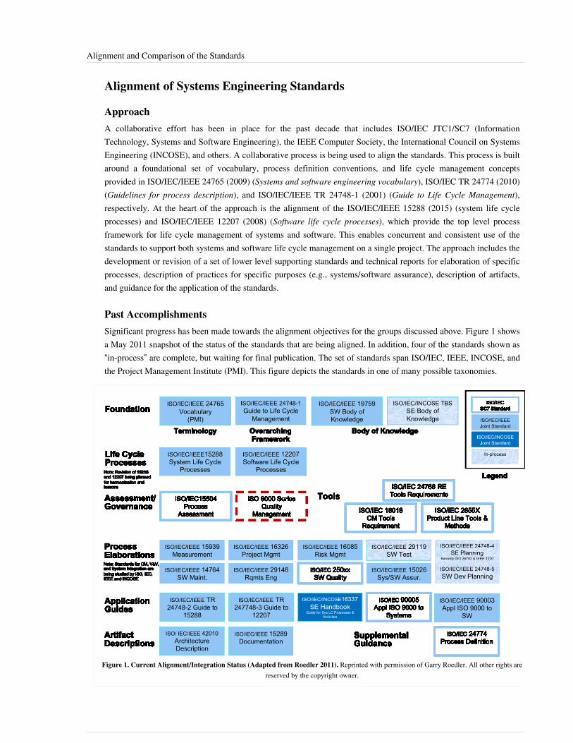
Alignment and Comparison of the Standards 97
Alignment of Systems Engineering Standards
ApproachA collaborative effort has been in place for the past decade that includes ISO/IEC JTC1/SC7 (InformationTechnology, Systems and Software Engineering), the IEEE Computer Society, the International Council on SystemsEngineering (INCOSE), and others. A collaborative process is being used to align the standards. This process is builtaround a foundational set of vocabulary, process definition conventions, and life cycle management conceptsprovided in ISO/IEC/IEEE 24765 (2009) (Systems and software engineering vocabulary), ISO/IEC TR 24774 (2010)(Guidelines for process description), and ISO/IEC/IEEE TR 24748-1 (2001) (Guide to Life Cycle Management),respectively. At the heart of the approach is the alignment of the ISO/IEC/IEEE 15288 (2015) (system life cycleprocesses) and ISO/IEC/IEEE 12207 (2008) (Software life cycle processes), which provide the top level processframework for life cycle management of systems and software. This enables concurrent and consistent use of thestandards to support both systems and software life cycle management on a single project. The approach includes thedevelopment or revision of a set of lower level supporting standards and technical reports for elaboration of specificprocesses, description of practices for specific purposes (e.g., systems/software assurance), description of artifacts,and guidance for the application of the standards.
Past AccomplishmentsSignificant progress has been made towards the alignment objectives for the groups discussed above. Figure 1 showsa May 2011 snapshot of the status of the standards that are being aligned. In addition, four of the standards shown as“in-process” are complete, but waiting for final publication. The set of standards span ISO/IEC, IEEE, INCOSE, andthe Project Management Institute (PMI). This figure depicts the standards in one of many possible taxonomies.
Figure 1. Current Alignment/Integration Status (Adapted from Roedler 2011). Reprinted with permission of Garry Roedler. All other rights arereserved by the copyright owner.

Alignment and Comparison of the Standards 98
Current EffortsA Life Cycle Process Harmonization Advisory Group has been evaluating the current standards for systems andsoftware engineering. The objective of the group is to provide a set of recommendations for further harmonization ofthe industry standards. Specifically, its charter includes:•• Performing an architectural analysis and recommend a framework for an integrated set of process standards in
software and IT systems domains.•• Making recommendations regarding the future content, structure, and relationships of ISO/IEC 12207 (2008),
ISO/IEC 15288 (2015) and their guides, as well as other related SC7 documents.To support the development of the recommendations, process modeling of ISO/IEC/IEEE 15288 (2015) andISO/IEC/IEEE 12207 (2008) has been performed and analyzed for consistency, completeness/gaps, andopportunities. In addition, analysis from other working groups, technical liaisons, and users of the standards has beencollected. The output of this effort will be a harmonization strategy, set of recommendations for specific standards,and timing/sequencing recommendations (Roedler 2011).Additionally, as the industry continues to consider harmonization needs of these standards, the collaboration hasgrown to include the work of the organizations and projects shown in Figure 2. These organizations are workingtowards the goal of completing a complementary and supplementary set of systems engineering resources that usethe same terminology, principles, concepts, practices, and processes and can be used concurrently without issues.
Figure 2. Growing Industry Collaboration. (SEBoK Original)

Alignment and Comparison of the Standards 99
Comparison of Systems Engineering StandardsSee Figure 1 located in the Relevant Standards article to see the breadth and level of detail for many of the SErelated standards. Since EIA 632 (2003) (Engineering of a System) is currently in revision, a comparison ofISO/IEC/IEEE 15288 (2015) (System life cycle processes) and EIA 632 will be deferred until the revision iscomplete.Figure 3 shows a comparison of the 3-part technical reports that provide life cycle management guidance. Part 1 isfocused on the provision of common terminology and concepts that apply to both systems and software. Part 2provides guidance that directly supports ISO/IEC/IEEE 15288 (2015) that is specific to systems. And Part 3 providesguidance that directly supports ISO/IEC/IEEE 12207 (2008) that is specific to software (Roedler 2010).
Figure 3. Standards Alignment Results as of May 2011 (Roedler 2011). Reprinted with permission of Garry Roedler. All other rightsare reserved by the copyright owner.
Alignment and Comparison of the Standards 100
Practical ConsiderationsKey pitfalls and good practices related to systems engineering standards are described in the Relevant Standardsarticle.There are also instances in which standards groups for program management, safety, or other disciplines createstandards on topics addressed within systems engineering but use different terminology, culture, etc. One suchexample is risk management, which has been dealt with by many professional societies from a number ofperspectives.Systems engineers must also be aware of the standards that govern the specialty disciplines that support systemsengineering, as discussed in Part 6.
References
Works CitedANSI/EIA. 2003. Processes for Engineering a System. Philadelphia, PA, USA: American National StandardsInstitute (ANSI)/Electronic Industries Association (EIA). ANSI/EIA 632‐1998.ISO/IEC/IEEE. 2015. Systems and Software Engineering -- System Life Cycle Processes. Geneva, Switzerland:International Organisation for Standardisation / International Electrotechnical Commissions / Institute of Electricaland Electronics Engineers. ISO/IEC/IEEE 15288:2015.ISO/IEC. 2010. Systems and software engineering -- Life cycle management -- Guidelines for process description.Geneva, Switzerland: International Organisation for Standardisation/International Electrotechnical Commissions.ISO/IEC TR 24774:2010.ISO/IEC/IEEE. 2009. Systems and Software Engineering - System and Software Engineering Vocabulary (SEVocab).Geneva, Switzerland: International Organization for Standardization (ISO)/International ElectrotechnicalCommission (IEC)/ Institute of Electrical and Electronics Engineers (IEEE). ISO/IEC/IEEE 24765:2009.ISO/IEC/IEEE. 2011. "Part 1: Guide for life cycle management," in Systems and software engineering--life cyclemanagement.. Geneva, Switzerland: International Organization for Standardization (ISO)/InternationalElectrotechnical Commission (IEC)/ Institute of Electrical and Electronics Engineers (IEEE). ISO/IEC/IEEE TR24748-1:2010.ISO/IEEE. 2008. Systems and Software Engineering — Software Life Cycle Processes. Geneva, Switzerland:International Organization for Standards (ISO)/Institute of Electrical & Electronics Engineers (IEEE) ComputerSociety, ISO/IEEE 12207:2008(E).Roedler, G. 2010. An Overview of ISO/IEC/IEEE 15288, System Life Cycle Processes. Asian Pacific Council onSystems Engineering (APCOSE) Conference.Roedler, G. 2011. "Towards Integrated Systems and Software Engineering Standards." National Defense IndustrialAssociation (NDIA) Conference, San Diego, CA, USA.

Alignment and Comparison of the Standards 101
Primary ReferencesRoedler, G. 2010. "An Overview of ISO/IEC/IEEE 15288, System Life Cycle Processes." Asian Pacific Council onSystems Engineering (APCOSE) Conference.
Additional ReferencesISO. 2003. Space Systems - Risk Management. Geneva, Switzerland: International Organization for Standardization(ISO), ISO 17666:2003.ISO. 2009. Risk Management—Principles and Guidelines. Geneva, Switzerland: International Organization forStandardization (ISO), ISO 31000:2009.ISO/IEC. 2009. Risk Management—Risk Assessment Techniques]]. Geneva, Switzerland: International Organizationfor Standardization (ISO)/International Electrotechnical Commission (IEC), ISO/IEC 31010:2009.ISO/IEC/IEEE. 2006. Systems and Software Engineering - Risk Management. Geneva, Switzerland: InternationalOrganization for Standardization (ISO)/International Electrotechnical Commission (IEC)/Institute of Electrical andElectronics Engineers (IEEE), ISO/IEC/IEEE 16085.ISO/IEC/IEEE. 2007. Systems and Software Engineering - Measurement Process. Geneva, Switzerland:International Organization for Standardization (ISO)/International Electrotechnical Commission (IEC)/Institute ofElectrical and Electronics Engineers (IEEE), ISO/IEC/IEEE 15939.ISO/IEC/IEEE. 2009. Systems and Software Engineering - Project Management]]. Geneva, Switzerland:International Organization for Standardization (ISO)/International Electrotechnical Commission (IEC)/Institute ofElectrical and Electronics Engineers (IEEE). ISO/IEC/IEEE 16326.ISO/IEC/IEEE. 2009. Systems and Software Engineering - System and Software Assurance, Part 1: Concepts anddefinitions. Geneva, Switzerland: International Organization for Standardization (ISO)/International ElectrotechnicalCommission (IEC)/Institute of Electrical and Electronics Engineers (IEEE). ISO/IEC/IEEE 15026-1.ISO/IEC/IEEE. 2009. Systems and Software Engineering - System and Software Engineering Vocabulary (SEVocab).Geneva, Switzerland: International Organization for Standardization (ISO)/International ElectrotechnicalCommission (IEC)/ Institute of Electrical and Electronics Engineers (IEEE). ISO/IEC/IEEE 24765:2009.ISO/IEC/IEEE. 2010. Systems and Software Engineering - System and Software Assurance, Part 2: Assurance case.Geneva, Switzerland: International Organization for Standardization (ISO)/International ElectrotechnicalCommission (IEC)/Institute of Electrical and Electronics Engineers (IEEE). ISO/IEC/IEEE 15026-2.ISO/IEC/IEEE. 2011. Systems and Software Engineering - Content of Life-Cycle Information Products(documentation). Geneva, Switzerland: International Organization for Standardization (ISO)/InternationalElectrotechnical Commission (IEC)/Institute of Electrical and Electronics Engineers (IEEE). ISO/IEC/IEEE 15289.ISO/IEC/IEEE. 2011. Systems and Software Engineering - System and Software Assurance, Part 3: Integrity Levels.Geneva, Switzerland: International Organization for Standardization (ISO)/International ElectrotechnicalCommission (IEC)/Institute of Electrical and Electronics Engineers (IEEE). ISO/IEC/IEEE 15026-3.
< Previous Article | Parent Article | Next Article >SEBoK v. 1.4 released 29 June 2015
SEBoK DiscussionPlease provide your comments and feedback on the SEBoK below. You will need to log in to DISQUS using an existing account (e.g. Yahoo, Google, Facebook, Twitter, etc.) or create a DISQUS account. Simply type your comment in the text field below and DISQUS will guide you through the login or registration steps. Feedback will be archived and used for future updates to the SEBoK. If you provided a comment that is no longer listed, that comment

Alignment and Comparison of the Standards 102
has been adjudicated. You can view adjudication for comments submitted prior to SEBoK v. 1.0 at SEBoK Reviewand Adjudication. Later comments are addressed and changes are summarized in the Letter from the Editor andAcknowledgements and Release History.
If you would like to provide edits on this article, recommend new content, or make comments on the SEBoKas a whole, please see the SEBoK Sandbox [1].
ENCODED_CONTENTMjQ4NDIPGRpdiBpZD0iZGlzcXVzX3RocmVhZCI+PC9kaXY+CjxzY3JpcHQgdHlwZT0idGV4dC9qYXZhc2NyaXB0Ij4KICAgIC8qICogKiBDT05GSUdVUkFUSU9OIFZBUklBQkxFUzogRURJVCBCRUZPUkUgUEFTVElORyBJTlRPIFlPVVIgV0VCUEFHRSAqICogKi8KICAgIHZhciBkaXNxdXNfc2hvcnRuYW1lID0gJ3NlYm9rd2lraTEwJzsgLy8gcmVxdWlyZWQ6IHJlcGxhY2UgZXhhbXBsZSB3aXRoIHlvdXIgZm9ydW0gc2hvcnRuYW1lCiAgICB2YXIgZGlzcXVzX2lkZW50aWZpZXIgPSAnQWxpZ25tZW50IGFuZCBDb21wYXJpc29uIG9mIHRoZSBTdGFuZGFyZHMnOyAgICB2YXIgZGlzcXVzX3VybCA9ICdodHRwOi8vc2Vib2t3aWtpLm9yZy9kcmFmdC9BbGlnbm1lbnRfYW5kX0NvbXBhcmlzb25fb2ZfdGhlX1N0YW5kYXJkcyc7CiAgICAvKiAqICogRE9OJ1QgRURJVCBCRUxPVyBUSElTIExJTkUgKiAqICovCiAgICAoZnVuY3Rpb24oKSB7CiAgICAgICAgdmFyIGRzcSA9IGRvY3VtZW50LmNyZWF0ZUVsZW1lbnQoJ3NjcmlwdCcpOyBkc3EudHlwZSA9ICd0ZXh0L2phdmFzY3JpcHQnOyBkc3EuYXN5bmMgPSB0cnVlOwogICAgICAgIGRzcS5zcmMgPSAnaHR0cDovLycgKyBkaXNxdXNfc2hvcnRuYW1lICsgJy5kaXNxdXMuY29tL2VtYmVkLmpzJzsKICAgICAgICAoZG9jdW1lbnQuZ2V0RWxlbWVudHNCeVRhZ05hbWUoJ2hlYWQnKVswXSB8fCBkb2N1bWVudC5nZXRFbGVtZW50c0J5VGFnTmFtZSgnYm9keScpWzBdKS5hcHBlbmRDaGlsZChkc3EpOwogICAgfSkoKTsKPC9zY3JpcHQ+Cjxub3NjcmlwdD5QbGVhc2UgZW5hYmxlIEphdmFTY3JpcHQgdG8gdmlldyB0aGUgPGEgaHJlZj0iaHR0cDovL2Rpc3F1cy5jb20vP3JlZl9ub3NjcmlwdCI+Y29tbWVudHMgcG93ZXJlZCBieSBEaXNxdXMuPC9hPjwvbm9zY3JpcHQ+CjxhIGhyZWY9Imh0dHA6Ly9kaXNxdXMuY29tIiBjbGFzcz0iZHNxLWJybGluayI+YmxvZyBjb21tZW50cyBwb3dlcmVkIGJ5IDxzcGFuIGNsYXNzPSJsb2dvLWRpc3F1cyI+RGlzcXVzPC9zcGFuPjwvYT4=END_ENCODED_CONTENT
SEBoK IntroductionSystems engineering (SE) is essential to the success of many human endeavors. As systems increase in scale andcomplexity, SE is increasingly recognized worldwide for its importance in their development, deployment,operation, and evolution.The purpose of the Guide to the Systems Engineering Body of Knowledge (SEBoK) is to provide a widely accepted,community-based, and regularly updated baseline of SE knowledge. This baseline will strengthen the mutualunderstanding across the many disciplines involved in developing and operating systems. Shortfalls in such mutualunderstanding are a major source of system failures, which have increasingly severe impacts as systems becomemore global, interactive, and critical.
Key TermsA good first step towards understanding is to define key terms. Four terms will suffice for this introduction: system,engineered system, systems engineering, and systems engineer.Here are baseline definitions of what these terms mean for the purposes of the SEBoK:• A system is "a collection of elements and a collection of inter-relationships amongst the elements such that they
can be viewed as a bounded whole relative to the elements around them". Open systems exist in an environmentdescribed by related systems with which they may interact and conditions to which they may respond. Element isused in its very broadest sense to include anything from simple physical things to complex organisms (includingpeople), environments and technologies, to organizations of people, information or ideas.
• An engineered system is an open system of technical or sociotechnical elements that exhibits emergent propertiesnot exhibited by its individual elements. It is created by and for people; has a purpose, with multiple views;satisfies key stakeholders’ value propositions; has a life cycle and evolution dynamics; has a boundary and anexternal environment; and is part of a system-of-interest hierarchy.
Note: while there are many definitions of the word "system," the SEBoK authors believe that this definitionencompasses most of those which are relevant to SE. Engineered system is a specialization of system which fulfillsthe basic properties of all systems but which is explicitly man-made, contains technology, exists for a purpose and isengineered through a series of managed life cycle activities to make it better able to achieve that purpose. Thisdefinition was developed for the SEBoK in an attempt to position SE as part of the wider world of systems researchand practice without in any way detracting from other more abstract or philosophical uses of systems ideas.• Systems engineering is "an interdisciplinary approach and means to enable the realization of successful
(engineered) systems" (INCOSE 2012). It focuses on holistically and concurrently discovering and understandingstakeholder needs; exploring opportunities; documenting requirements; and synthesizing, verifying, validating,deploying, sustaining and evolving solutions while considering the complete problem, from system conceptexploration through system disposal.

SEBoK Introduction 103
• A systems engineer is "a person who practices systems engineering" as defined above, and whose systemsengineering capabilities and experience include sustained practice, specialization, leadership, or authority over SEactivities. These activities may be conducted by any competent person regardless of job title or professionalaffiliation.
Part 1 ArticlesArticles in Part 1 include:•• Systems Engineering Overview•• Economic Value of Systems Engineering•• Systems Engineering: Historic and Future Challenges•• Systems Engineering and Other Disciplines•• Scope of the SEBoK•• Structure of the SEBoK•• SEBoK Users and Uses
Purpose of the SEBoKThe purpose of the SEBoK is to provide a widely accepted, community-based, and regularly updated baseline of SEknowledge. This baseline will strengthen the mutual understanding across the many disciplines involved indeveloping and operating systems. Shortfalls in such mutual understanding are a major source of system failures,which have increasingly severe impacts as systems become more global, interactive, and critical. Ongoing studies ofsystem cost and schedule failures (Gruhl-Stutzke 2005; Johnson 2006) and safety failures (Leveson 2012) haveshown that the failures have mostly come not from their domain disciplines, but from lack of adequate SE.To provide a foundation for the desired mutual understanding, the SEBoK describes the boundaries, terminology,content, and structure of SE. In so doing, the SEBoK systematically and consistently supports six broad purposes,described in Table 1.
Table 1. SEBoK Purposes. (SEBoK Original)
Purpose Description
1 Inform Practice Inform systems engineers about the boundaries, terminology, and structure of their discipline and point them to usefulinformation needed to practice SE in any application domain.
2 Inform Research Inform researchers about the limitations and gaps in current SE knowledge that should help guide their researchagenda.
3 Inform Interactors Inform performers in interacting disciplines (system implementation, project and enterprise management, otherdisciplines) and other stakeholders of the nature and value of SE.
4 Inform CurriculumDevelopers
Inform organizations defining the content that should be common in undergraduate and graduate programs in SE.
5 Inform Certifiers Inform organizations certifying individuals as qualified to practice systems engineering.
6 Inform SE Staffing Inform organizations and managers deciding which competencies that practicing systems engineers should possess invarious roles ranging from apprentice to expert.
The SEBoK is a guide to the body of SE knowledge, not an attempt to capture that knowledge directly. It providesreferences to more detailed sources of knowledge, all of which are generally available to any interested reader. Noproprietary information is referenced, but not all referenced material is free—for example, some books or standardsmust be purchased from their publishers. The criterion for including a source is simply that the authors believed itoffered the best generally available information on a particular subject.

SEBoK Introduction 104
The SEBoK is global in applicability. Although SE is practiced differently from industry to industry and country tocountry, the SEBoK is written to be useful to systems engineers anywhere. The authors were chosen from diverselocales and industries, and have refined the SEBoK to broaden applicability based on extensive global reviews ofseveral drafts.The SEBoK aims to inform a wide variety of user communities about essential SE concepts and practices, in waysthat can be tailored to different enterprises and activities while retaining greater commonality and consistency thanwould be possible without the SEBoK. Because the world in which SE is being applied is evolving and dynamic, theSEBoK is designed for easy, continuous updating as new sources of knowledge emerge.
Scope and Context of the SEBoKThe SEBoK is one of two complementary products. The other, which uses the content of the SEBoK to define a corebody of knowledge (CorBoK) to be included in graduate SE curricula, is called the Graduate Reference Curriculumfor Systems Engineering (GRCSE™). GRCSE is not a standard, but a reference curriculum to be tailored andextended to meet the objectives of each university’s graduate program. (Pyster and Olwell et al. 2012) Theseproducts are being developed by the Body of Knowledge and Curriculum to Advance Systems Engineering(BKCASE) [1] project.Most of the SEBoK (Parts 2 – 6) focuses on domain-independent information—that which is universal to systemsengineering regardless of the domain in which it is applied. Part 7 includes examples from real projects. Theseillustrate the concepts discussed elsewhere in the SEBoK, while detailing considerations relevant to domains such asaerospace, medicine, and transportation.SE in the context of engineered systems (ES) is the primary scope for the SEBoK, though general systems conceptsare also discussed in Part 2. The SEBoK also covers considerations for the disciplines of software engineering andproject management, which are strongly intertwined with the practice of SE (see Part 6).The context of the SEBoK is elaborated in two agent-activity-artifact diagrams in Part 1.One summarizes the SEBoK’s definition by an international group of volunteer authors; its review by the SEcommunity at large; its life cycle evolution management and support by the two primary international SE-relatedprofessional societies, the Institute of Electrical and Electronic Engineers (IEEE) and the International Council onSystems Engineering (INCOSE); and its use in derivative products and services by the community at large.A second diagram summarizes the interactions among systems engineers, systems developers, and the environmentof an engineered system, across its life cycle of system definition, development, evolution (production, utilization,and support) and retirement. These are elaborated in the discussion of the nature of systems and systems engineeringin Part 2, and in the Life Cycle Models article in Part 3.
SEBoK UsesThe communities involved with SE include its various specialists, engineers from disciplines other than systemsengineering, managers, researchers, and educators. This diversity means that there is no single best way to use theSEBoK. The SEBoK includes use cases that highlight ways that particular communities can draw upon the contentof the SEBoK, identify articles of interest to those communities, and discuss primary users (those who use theSEBoK directly), and secondary users (those who use the SEBoK with assistance from a systems engineer). See thearticle SEBoK Users and Uses.
SEBoK Introduction 105
SEBoK DevelopmentThis is SEBoK v. 1.4 of the SEBoK, released on June 29, 2015. 11 development releases preceded this productionrelease:1.1. Version 0.25 on September 15, 20102.2. Version 0.5 on September 19, 20113.3. Version 0.75 on March 15, 20124.4. Version 1.0 on September 14, 20125.5. Version 1.0.1 on November 30, 20126.6. Version 1.1 on April 26, 20137.7. Version 1.1.1 on June 14, 20138.8. Version 1.1.2 on August 15, 20139.9. Version 1.2 on November 15, 201310.10. Version 1.3 on May 30, 201411.11. Version 1.3.1 on December 5, 201412.12. Version 1.3.2. on April 14, 201513.13. Version 1.4 on June 29, 2015Version 0.25 was released as a PDF document for limited review. A total of 3135 comments were received on thisdocument from 114 reviewers across 17 countries. The author team studied these comments with particular interestin feedback about content and about diversity within the community.In January 2011, the authors agreed to move from a document-based SEBoK to a wiki-based SEBoK, and beginningwith v. 0.5, the SEBOK has been available at www.sebokwiki.org [2]. Making the transition to a wiki provided threebenefits:1.1. easy worldwide access to the SEBoK;2.2. more methods for search and navigation; and3.3. a forum for community feedback alongside content that remains stable between versions.For additional information, see the article on Acknowledgements and Release History.
References
Works CitedGruhl, W. and Stutzke, R. 2005. “Werner Gruhl Analysis of SE Investments and NASA Overruns,” in R. Stutzke,Estimating Software-Intensive Systems. Boston, MA, USA: Addison Wesley, page 290.INCOSE. 2012. Systems Engineering Handbook: A Guide for System Life Cycle Processes and Activities, version3.2.2. San Diego, CA, USA: International Council on Systems Engineering (INCOSE). INCOSE-TP-2003-002-03.2.Johnson, J. 2006. My Life Is Failure: 100 Things You Should Know to Be a Better Project Leader. Boston, MA,USA: Standish Group International.Leveson, N. 2012. Engineering a Safer World: Systems Thinking Applied to Safety. Cambridge, MA, USA: MITPress.Pyster, A., D.H. Olwell, T.L.J. Ferris, N. Hutchison, S. Enck, J.F. Anthony, D. Henry, and A. Squires (eds). 2012.Graduate Reference Curriculum for Systems Engineering (GRCSE™), version 1.0. Hoboken, NJ, USA: TheTrustees of the Stevens Institute of Technology ©2012. Accessed on 17 November 2014 at BKCASE.org http:/ /www. bkcase. org/ grcse-2/ .

SEBoK Introduction 106
Primary ReferencesINCOSE. 2012. Systems Engineering Handbook: A Guide for System Life Cycle Processes and Activities, version3.2.2. San Diego, CA, USA: International Council on Systems Engineering (INCOSE). INCOSE-TP-2003-002-03.2.Pyster, A., D.H. Olwell, T.L.J. Ferris, N. Hutchison, S. Enck, J.F. Anthony, D. Henry, and A. Squires (eds). 2012.Graduate Reference Curriculum for Systems Engineering (GRCSE™), version 1.0. Hoboken, NJ, USA: TheTrustees of the Stevens Institute of Technology ©2012. Accessed on 17 November 2014 at BKCASE.org http:/ /www. bkcase. org/ grcse-2/ .Sage, A. and W. Rouse (eds). 2009. Handbook of Systems Engineering and Management, 2nd ed. Hoboken, NJ,USA: John Wiley and Sons, Inc.
Additional ReferencesBertalanffy, L. von. 1968. General System Theory: Foundations, Development, Applications, Revised ed. New York,NY, USA: Braziller.Blanchard, B. and W. Fabrycky. 2010. Systems Engineering and Analysis, (5th edition). Saddle River, NJ, USA:Prentice Hall.Booher, H. (ed.) 2003. Handbook of Human Systems Integration. Hoboken, NJ, USA: Wiley.Checkland, P. 1999. Systems Thinking, Systems Practice, 2nd ed. Hoboken, NJ, USA: Wiley.Hitchins, D. 2007. Systems Engineering: A 21st Century Methodology. Chichester, England: Wiley.
< Return to Table of Contents | Parent Article | Next Article >SEBoK v. 1.4 released 29 June 2015
SEBoK DiscussionPlease provide your comments and feedback on the SEBoK below. You will need to log in to DISQUS using anexisting account (e.g. Yahoo, Google, Facebook, Twitter, etc.) or create a DISQUS account. Simply type yourcomment in the text field below and DISQUS will guide you through the login or registration steps. Feedback will bearchived and used for future updates to the SEBoK. If you provided a comment that is no longer listed, that commenthas been adjudicated. You can view adjudication for comments submitted prior to SEBoK v. 1.0 at SEBoK Reviewand Adjudication. Later comments are addressed and changes are summarized in the Letter from the Editor andAcknowledgements and Release History.
If you would like to provide edits on this article, recommend new content, or make comments on the SEBoKas a whole, please see the SEBoK Sandbox [1].
ENCODED_CONTENTNzc0NTgPGRpdiBpZD0iZGlzcXVzX3RocmVhZCI+PC9kaXY+CjxzY3JpcHQgdHlwZT0idGV4dC9qYXZhc2NyaXB0Ij4KICAgIC8qICogKiBDT05GSUdVUkFUSU9OIFZBUklBQkxFUzogRURJVCBCRUZPUkUgUEFTVElORyBJTlRPIFlPVVIgV0VCUEFHRSAqICogKi8KICAgIHZhciBkaXNxdXNfc2hvcnRuYW1lID0gJ3NlYm9rd2lraTEwJzsgLy8gcmVxdWlyZWQ6IHJlcGxhY2UgZXhhbXBsZSB3aXRoIHlvdXIgZm9ydW0gc2hvcnRuYW1lCiAgICB2YXIgZGlzcXVzX2lkZW50aWZpZXIgPSAnU0VCb0sgSW50cm9kdWN0aW9uJzsgICAgdmFyIGRpc3F1c191cmwgPSAnaHR0cDovL3NlYm9rd2lraS5vcmcvZHJhZnQvU0VCb0tfSW50cm9kdWN0aW9uJzsKICAgIC8qICogKiBET04nVCBFRElUIEJFTE9XIFRISVMgTElORSAqICogKi8KICAgIChmdW5jdGlvbigpIHsKICAgICAgICB2YXIgZHNxID0gZG9jdW1lbnQuY3JlYXRlRWxlbWVudCgnc2NyaXB0Jyk7IGRzcS50eXBlID0gJ3RleHQvamF2YXNjcmlwdCc7IGRzcS5hc3luYyA9IHRydWU7CiAgICAgICAgZHNxLnNyYyA9ICdodHRwOi8vJyArIGRpc3F1c19zaG9ydG5hbWUgKyAnLmRpc3F1cy5jb20vZW1iZWQuanMnOwogICAgICAgIChkb2N1bWVudC5nZXRFbGVtZW50c0J5VGFnTmFtZSgnaGVhZCcpWzBdIHx8IGRvY3VtZW50LmdldEVsZW1lbnRzQnlUYWdOYW1lKCdib2R5JylbMF0pLmFwcGVuZENoaWxkKGRzcSk7CiAgICB9KSgpOwo8L3NjcmlwdD4KPG5vc2NyaXB0PlBsZWFzZSBlbmFibGUgSmF2YVNjcmlwdCB0byB2aWV3IHRoZSA8YSBocmVmPSJodHRwOi8vZGlzcXVzLmNvbS8/cmVmX25vc2NyaXB0Ij5jb21tZW50cyBwb3dlcmVkIGJ5IERpc3F1cy48L2E+PC9ub3NjcmlwdD4KPGEgaHJlZj0iaHR0cDovL2Rpc3F1cy5jb20iIGNsYXNzPSJkc3EtYnJsaW5rIj5ibG9nIGNvbW1lbnRzIHBvd2VyZWQgYnkgPHNwYW4gY2xhc3M9ImxvZ28tZGlzcXVzIj5EaXNxdXM8L3NwYW4+PC9hPg==END_ENCODED_CONTENT
References[1] http:/ / www. bkcase. org/[2] http:/ / www. sebokwiki. org/

Article Sources and Contributors 107
Article Sources and ContributorsSystems Engineering Management Source: http://sebokwiki.org/d/index.php?oldid=48434 Contributors: Bkcase, Dhenry, Dholwell, Gparnell, Groedler, Jgercken, Mhenshaw, Rmadachy,Skmackin, Smenck2, Wikiexpert, Zamoses
Planning Source: http://sebokwiki.org/d/index.php?oldid=50511 Contributors: Apyster, Bkcase, Bwells, Dhenry, Dholwell, Dnewbern, Groedler, Janthony, Jgercken, Mhenshaw, Rmadachy,Skmackin, Smenck2, Wikiexpert, Zamoses
Assessment and Control Source: http://sebokwiki.org/d/index.php?oldid=48202 Contributors: Apickard, Apyster, Bkcase, Dhenry, Dholwell, Dnewbern, Groedler, Jgercken, Mhenshaw,Rmadachy, Rturner, Skmackin, Smenck2, Wikiexpert, Zamoses
Risk Management Source: http://sebokwiki.org/d/index.php?oldid=50607 Contributors: Apyster, Asquires, Bkcase, Dhenry, Dholwell, Dnewbern, Econrow, Groedler, Jgercken, Kguillemette,Mhenshaw, Rmadachy, Rturner, Skmackin, Smenck2, Wikiexpert, Zamoses
Measurement Source: http://sebokwiki.org/d/index.php?oldid=50877 Contributors: Apyster, Bkcase, Cjones, Dhenry, Dholwell, Dnewbern, Groedler, Jgercken, Mhenshaw, Rcarson,Rmadachy, Skmackin, Smenck2, Wikiexpert, Zamoses
Decision Management Source: http://sebokwiki.org/d/index.php?oldid=50860 Contributors: Asquires, Bkcase, Dhenry, Dholwell, Dnewbern, Eleach, Gparnell, Groedler, Jgercken, Mhenshaw,Rmadachy, Skmackin, Smenck2, Wikiexpert, Zamoses
Configuration Management Source: http://sebokwiki.org/d/index.php?oldid=50609 Contributors: Apyster, Bkcase, Dhenry, Dholwell, Dnewbern, Groedler, Jgercken, Jsnoderly, Mhenshaw,Rmadachy, Skmackin, Smenck2, Wikiexpert, Zamoses
Information Management Source: http://sebokwiki.org/d/index.php?oldid=50861 Contributors: Apickard, Bkcase, Dhenry, Dholwell, Dnewbern, Groedler, Jgercken, Mhenshaw, Rmadachy,Skmackin, Smenck2, Wikiexpert, Zamoses
Quality Management Source: http://sebokwiki.org/d/index.php?oldid=48223 Contributors: Bkcase, Dfairley, Dhenry, Dholwell, Dnewbern, Groedler, Jgercken, Mhenshaw, Mtowhid, Qwang,Skmackin, Smenck2, Wikiexpert, Zamoses
Product and Service Life Management Source: http://sebokwiki.org/d/index.php?oldid=50513 Contributors: Apyster, Bkcase, Bstiffler, Dhenry, Dholwell, Dnewbern, Jgercken, Mhenshaw,Skmackin, Wikiexpert, Zamoses
Service Life Extension Source: http://sebokwiki.org/d/index.php?oldid=50514 Contributors: Asquires, Bkcase, Bstiffler, Bwells, Dhenry, Dholwell, Dnewbern, Jgercken, Mhenshaw,Skmackin, Wikiexpert, Zamoses
Capability Updates, Upgrades, and Modernization Source: http://sebokwiki.org/d/index.php?oldid=51003 Contributors: Asquires, Bkcase, Bstiffler, Bwells, Dhenry, Dholwell, Dnewbern,Jgercken, Mhenshaw, Skmackin, Smenck2, Wikiexpert, Zamoses
Disposal and Retirement Source: http://sebokwiki.org/d/index.php?oldid=51004 Contributors: Asquires, Bkcase, Bstiffler, Bwells, Dhenry, Dholwell, Jgercken, Mhenshaw, Skmackin,Wikiexpert, Ymordecai, Zamoses
Systems Engineering Standards Source: http://sebokwiki.org/d/index.php?oldid=51005 Contributors: Bkcase, Ccalvano, Dhenry, Dholwell, Dnewbern, Groedler, Jgercken, Mhenshaw,Skmackin, Wikiexpert, Zamoses
Relevant Standards Source: http://sebokwiki.org/d/index.php?oldid=51006 Contributors: Bkcase, Ccalvano, Dhenry, Dholwell, Dnewbern, Groedler, Janthony, Jgercken, Kguillemette,Kzemrowski, Mhenshaw, Sfriedenthal, Skmackin, Smenck2, Wikiexpert, Zamoses
Alignment and Comparison of the Standards Source: http://sebokwiki.org/d/index.php?oldid=51007 Contributors: Apyster, Bkcase, Dhenry, Dholwell, Dnewbern, Groedler, Hdavidz,Janthony, Jgercken, Mhenshaw, Skmackin, Smenck2, Wikiexpert, Zamoses
SEBoK Introduction Source: http://sebokwiki.org/d/index.php?oldid=51001 Contributors: Afaisandier, Apyster, Bkcase, Cnielsen, Dhenry, Dholwell, Gparnell, HP.deKoning, Janthony,Jgercken, Kguillemette, Mhenshaw, Nicole.hutchison, Radcock, Smenck2, Wikiexpert, Zamoses

Image Sources, Licenses and Contributors 108
Image Sources, Licenses and ContributorsFile:Scope_BoundariesSE_PM_SM.png Source: http://sebokwiki.org/d/index.php?title=File:Scope_BoundariesSE_PM_SM.png License: unknown Contributors: Bkcase, Smenck2,SmurawskiFile:semp_and_integrated_plans.png Source: http://sebokwiki.org/d/index.php?title=File:Semp_and_integrated_plans.png License: unknown Contributors: Smenck2, SmurawskiFile:Measurement_Process_Model-Figure_1.png Source: http://sebokwiki.org/d/index.php?title=File:Measurement_Process_Model-Figure_1.png License: unknown Contributors: Smenck2,SmurawskiFile:Composition_of_Leading_Indicator-Figure_2.png Source: http://sebokwiki.org/d/index.php?title=File:Composition_of_Leading_Indicator-Figure_2.png License: unknown Contributors: Smenck2, SmurawskiFile:Technical_Measures_Relationship-Figure_3.png Source: http://sebokwiki.org/d/index.php?title=File:Technical_Measures_Relationship-Figure_3.png License: unknown Contributors:Smenck2, SmurawskiFile:Decision_Mgt_Process_DM.png Source: http://sebokwiki.org/d/index.php?title=File:Decision_Mgt_Process_DM.png License: unknown Contributors: Smenck2File:Fund_Obj_Hierarchy_DM.png Source: http://sebokwiki.org/d/index.php?title=File:Fund_Obj_Hierarchy_DM.png License: unknown Contributors: Smenck2File:Value_Function_Example_DM.png Source: http://sebokwiki.org/d/index.php?title=File:Value_Function_Example_DM.png License: unknown Contributors: Smenck2File:Swing_Weight_Matrix_DM.png Source: http://sebokwiki.org/d/index.php?title=File:Swing_Weight_Matrix_DM.png License: unknown Contributors: Smenck2File:Descript_of_Alt_DM.png Source: http://sebokwiki.org/d/index.php?title=File:Descript_of_Alt_DM.png License: unknown Contributors: Smenck2File:ALT_Scores_DM.png Source: http://sebokwiki.org/d/index.php?title=File:ALT_Scores_DM.png License: unknown Contributors: Smenck2File:Value_Scorecard_w_Heat_Map_DM.png Source: http://sebokwiki.org/d/index.php?title=File:Value_Scorecard_w_Heat_Map_DM.png License: unknown Contributors: Smenck2File:Eq_1.jpg Source: http://sebokwiki.org/d/index.php?title=File:Eq_1.jpg License: unknown Contributors: Smenck2File:Eq_2.jpg Source: http://sebokwiki.org/d/index.php?title=File:Eq_2.jpg License: unknown Contributors: Smenck2File:Value_Comp_Graph_DM.png Source: http://sebokwiki.org/d/index.php?title=File:Value_Comp_Graph_DM.png License: unknown Contributors: Smenck2File:Ex_Stakeholder_Value_Scat_DM.png Source: http://sebokwiki.org/d/index.php?title=File:Ex_Stakeholder_Value_Scat_DM.png License: unknown Contributors: Smenck2File:Uncertainty_on_Perf_Value_from_Monte_DM.png Source: http://sebokwiki.org/d/index.php?title=File:Uncertainty_on_Perf_Value_from_Monte_DM.png License: unknown Contributors: Smenck2File:Cm_functions.png Source: http://sebokwiki.org/d/index.php?title=File:Cm_functions.png License: unknown Contributors: Bkcase, Smenck2, SmurawskiFile:Cm_change_control_process.png Source: http://sebokwiki.org/d/index.php?title=File:Cm_change_control_process.png License: unknown Contributors: Bkcase, Smenck2, SmurawskiFile:InfoMgtProcess_Fig1.png Source: http://sebokwiki.org/d/index.php?title=File:InfoMgtProcess_Fig1.png License: unknown Contributors: Smenck2, SmurawskiFile:ArchitectureDesignConsid_Fig2.png Source: http://sebokwiki.org/d/index.php?title=File:ArchitectureDesignConsid_Fig2.png License: unknown Contributors: Smenck2, SmurawskiFile:052411_BSBW_The_Vee_Model.png Source: http://sebokwiki.org/d/index.php?title=File:052411_BSBW_The_Vee_Model.png License: unknown Contributors: Smenck2, SmurawskiFile:Breadth_and_Depth_of_Key_SE_Related_Standards.PNG Source: http://sebokwiki.org/d/index.php?title=File:Breadth_and_Depth_of_Key_SE_Related_Standards.PNG License:unknown Contributors: Bkcase, Janthony, SmurawskiFile:Standards_Alignment_Results_as_of_May_2011.PNG Source: http://sebokwiki.org/d/index.php?title=File:Standards_Alignment_Results_as_of_May_2011.PNG License: unknown Contributors: Bkcase, Janthony, SmurawskiFile:Fig_3_Growing_Industry_Collaboration_GR.png Source: http://sebokwiki.org/d/index.php?title=File:Fig_3_Growing_Industry_Collaboration_GR.png License: unknown Contributors:Bkcase, SmurawskiFile:Standards_Alignment_Results_as_of_May_2011a.PNG Source: http://sebokwiki.org/d/index.php?title=File:Standards_Alignment_Results_as_of_May_2011a.PNG License: unknown Contributors: Janthony, Smurawski


Part 4: Applications of SystemsEngineering


ContentsArticlesPart 4: Applications of Systems Engineering 1
Applications of Systems Engineering 1Product Systems Engineering 7Product Systems Engineering Background 15Product as a System Fundamentals 23Business Activities Related to Product Systems Engineering 31Product Systems Engineering Key Aspects 36Product Systems Engineering Special Activities 48Service Systems Engineering 55Service Systems Background 60Fundamentals of Services 67Properties of Services 74Scope of Service Systems Engineering 79Value of Service Systems Engineering 84Service Systems Engineering Stages 90Enterprise Systems Engineering 96Enterprise Systems Engineering Background 103The Enterprise as a System 112Related Business Activities 120Enterprise Systems Engineering Key Concepts 128Enterprise Systems Engineering Process Activities 134Enterprise Capability Management 144Systems of Systems (SoS) 150Architecting Approaches for Systems of Systems 155Socio-Technical Features of Systems of Systems 162Capability Engineering 165
ReferencesArticle Sources and Contributors 167Image Sources, Licenses and Contributors 168

1
Part 4: Applications of Systems Engineering
Applications of Systems EngineeringThis part of the SEBoK focuses on the application of systems engineering to the creation and life cycle managementof various types of systems. In particular, the part covers product systems, service systems, enterprise systems, andsystem of systems (SoS).
Knowledge Areas in Part 4Each part of the SEBoK is divided into knowledge areas (KAs), which are groupings of information with a relatedtheme. Part 4 contains the following KAs:•• Product Systems Engineering•• Service Systems Engineering•• Enterprise Systems Engineering•• Systems of Systems (SoS)
Systems Engineering Application ParadigmsPart 3, Systems Engineering and Management, introduces a paradigm that identifies the general goal of all systemsengineering efforts; that is the transformation of the specific stakeholder need into a system product or service thatprovides for the need. Given this framework, the various knowledge areas of Part 3 provide deeper insight into howto accomplish activities related to the systems engineering life cycle.The following paradigms provide a look into the primary similarities and differences of the various applications ofsystems engineering presented in Part 4. The similarity is that all systems presented in Part 4 are developed toprovide for the capabilities needed in an operational environment and these capability needs take form of activities.The supply of the systems and the nature of the operational environment differentiate the applications of systemsengineering.

Applications of Systems Engineering 2
Product System ProvisioningThe paradigm in Figure 1 illustrates the main result of traditional systems engineering (TSE), that is, the supply ofproducts and services that fulfill the capability needs as activities in an operational environment. In TSE, theoperational environment is often described by some form of the concept of operations (ConOps), which can includeuse cases of the activities of the system in operation.
Figure 1. Product / Service Provisioning. (SEBoK Original)
It is important to take into account the binding of the products and services to the activities. As implied by the figure,the operational environmental needs are met by directly binding products and/or services to the needs of one or moreof the activities of the operational environment. In a manner consistent with ISO/IEC 15288, the products andservices are composed of systems in which hardware, software, and human elements are supplied. Thus, a mixture ofphysical products (often including software) and services, such as logistics, help-desk functions, etc., may beprovided. The supply of products and services can be a result of a direct acquisition or the result of acquiringproducts or services that have been provided for a marketplace. Note that the provisioning of products and serviceswhen humans are involved, like in a hospital, may even be classified as sociotechnical systems.

Applications of Systems Engineering 3
Service System ProvisioningThe paradigm in Figure 2 illustrates the provision of service systems. The growth of this model has been stimulatedto a large extent due to the widespread availability of IT services, such as service oriented architectures (SOAs),software as a system (SaS), and cloud computing.
Figure 2. Service System Provisioning. (SEBoK Original)
A primary difference between service systems engineering (SSE) and TSE is the dynamic binding of products andservices, potentially from multiple providers, in order to provide a desired service. Thus, the service is dynamicallycomposed from a given service request. In the background, there are a variety of hardware, software, and evenhuman elements that provide the elements of a service. In contrast to an operational environment that is sustained,the service requested may be viewed as a temporary environment established to provide the service and it disappearsafter the service has been provided.
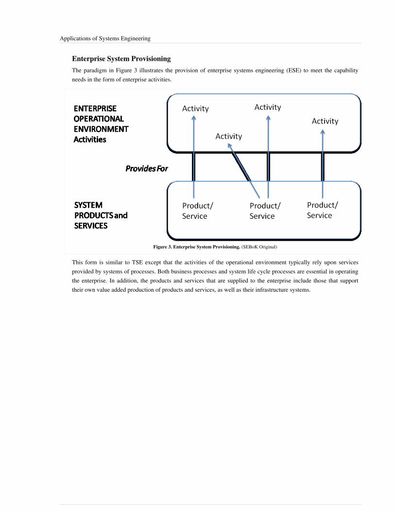
Applications of Systems Engineering 4
Enterprise System ProvisioningThe paradigm in Figure 3 illustrates the provision of enterprise systems engineering (ESE) to meet the capabilityneeds in the form of enterprise activities.
Figure 3. Enterprise System Provisioning. (SEBoK Original)
This form is similar to TSE except that the activities of the operational environment typically rely upon servicesprovided by systems of processes. Both business processes and system life cycle processes are essential in operatingthe enterprise. In addition, the products and services that are supplied to the enterprise include those that supporttheir own value added production of products and services, as well as their infrastructure systems.
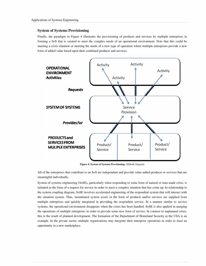
Applications of Systems Engineering 5
System of Systems ProvisioningFinally, the paradigm in Figure 4 illustrates the provisioning of products and services by multiple enterprises informing a SoS that is created to meet the complex needs of an operational environment. Note that this could bemeeting a crisis situation or meeting the needs of a new type of operation where multiple enterprises provide a newform of added value based upon their combined products and services.
Figure 4. System of Systems Provisioning. (SEBoK Original)
All of the enterprises that contribute to an SoS are independent and provide value-added products or services that aremeaningful individually.System of systems engineering (SoSE), particularly when responding to some form of natural or man made crisis, isinitiated in the form of a request for service in order to meet a complex situation that has come up. In relationship tothe system coupling diagram, SoSE involves accelerated engineering of the respondent system that will interact withthe situation system. Thus, instantiated system assets in the form of products and/or services are supplied frommultiple enterprises and quickly integrated in providing the respondent service. In a manner similar to servicesystems, the operational environment disappears when the crises has been handled. SoSE is also applied in mergingthe operations of multiple enterprises in order to provide some new form of service. In contrast to unplanned crises,this is the result of planned development. The formation of the Department of Homeland Security in the USA is anexample. In the private sector, multiple organizations may integrate their enterprise operations in order to meet anopportunity in a new marketplace.

Applications of Systems Engineering 6
References
Works CitedISO/IEC/IEEE. 2015. Systems and Software Engineering -- System Life Cycle Processes. Geneva, Switzerland:International Organisation for Standardisation / International Electrotechnical Commissions. ISO/IEC/IEEE15288:2015.
Primary ReferencesISO/IEC/IEEE. 2015. Systems and Software Engineering -- System Life Cycle Processes. Geneva, Switzerland:International Organisation for Standardisation / International Electrotechnical Commissions. ISO/IEC/IEEE15288:2015.
Additional ReferencesNone.
< Previous Article | Parent Article | Next Article >SEBoK v. 1.4 released 29 June 2015
SEBoK DiscussionPlease provide your comments and feedback on the SEBoK below. You will need to log in to DISQUS using anexisting account (e.g. Yahoo, Google, Facebook, Twitter, etc.) or create a DISQUS account. Simply type yourcomment in the text field below and DISQUS will guide you through the login or registration steps. Feedback will bearchived and used for future updates to the SEBoK. If you provided a comment that is no longer listed, that commenthas been adjudicated. You can view adjudication for comments submitted prior to SEBoK v. 1.0 at SEBoK Reviewand Adjudication. Later comments are addressed and changes are summarized in the Letter from the Editor andAcknowledgements and Release History.
If you would like to provide edits on this article, recommend new content, or make comments on the SEBoKas a whole, please see the SEBoK Sandbox [1].
ENCODED_CONTENTOTYyMjcPGRpdiBpZD0iZGlzcXVzX3RocmVhZCI+PC9kaXY+CjxzY3JpcHQgdHlwZT0idGV4dC9qYXZhc2NyaXB0Ij4KICAgIC8qICogKiBDT05GSUdVUkFUSU9OIFZBUklBQkxFUzogRURJVCBCRUZPUkUgUEFTVElORyBJTlRPIFlPVVIgV0VCUEFHRSAqICogKi8KICAgIHZhciBkaXNxdXNfc2hvcnRuYW1lID0gJ3NlYm9rd2lraTEwJzsgLy8gcmVxdWlyZWQ6IHJlcGxhY2UgZXhhbXBsZSB3aXRoIHlvdXIgZm9ydW0gc2hvcnRuYW1lCiAgICB2YXIgZGlzcXVzX2lkZW50aWZpZXIgPSAnQXBwbGljYXRpb25zIG9mIFN5c3RlbXMgRW5naW5lZXJpbmcnOyAgICB2YXIgZGlzcXVzX3VybCA9ICdodHRwOi8vc2Vib2t3aWtpLm9yZy9kcmFmdC9BcHBsaWNhdGlvbnNfb2ZfU3lzdGVtc19FbmdpbmVlcmluZyc7CiAgICAvKiAqICogRE9OJ1QgRURJVCBCRUxPVyBUSElTIExJTkUgKiAqICovCiAgICAoZnVuY3Rpb24oKSB7CiAgICAgICAgdmFyIGRzcSA9IGRvY3VtZW50LmNyZWF0ZUVsZW1lbnQoJ3NjcmlwdCcpOyBkc3EudHlwZSA9ICd0ZXh0L2phdmFzY3JpcHQnOyBkc3EuYXN5bmMgPSB0cnVlOwogICAgICAgIGRzcS5zcmMgPSAnaHR0cDovLycgKyBkaXNxdXNfc2hvcnRuYW1lICsgJy5kaXNxdXMuY29tL2VtYmVkLmpzJzsKICAgICAgICAoZG9jdW1lbnQuZ2V0RWxlbWVudHNCeVRhZ05hbWUoJ2hlYWQnKVswXSB8fCBkb2N1bWVudC5nZXRFbGVtZW50c0J5VGFnTmFtZSgnYm9keScpWzBdKS5hcHBlbmRDaGlsZChkc3EpOwogICAgfSkoKTsKPC9zY3JpcHQ+Cjxub3NjcmlwdD5QbGVhc2UgZW5hYmxlIEphdmFTY3JpcHQgdG8gdmlldyB0aGUgPGEgaHJlZj0iaHR0cDovL2Rpc3F1cy5jb20vP3JlZl9ub3NjcmlwdCI+Y29tbWVudHMgcG93ZXJlZCBieSBEaXNxdXMuPC9hPjwvbm9zY3JpcHQ+CjxhIGhyZWY9Imh0dHA6Ly9kaXNxdXMuY29tIiBjbGFzcz0iZHNxLWJybGluayI+YmxvZyBjb21tZW50cyBwb3dlcmVkIGJ5IDxzcGFuIGNsYXNzPSJsb2dvLWRpc3F1cyI+RGlzcXVzPC9zcGFuPjwvYT4=END_ENCODED_CONTENT
References[1] http:/ / www. sebokwiki. org/ sandbox/

Product Systems Engineering 7
Product Systems EngineeringProduct systems engineering (PSE) is at the core of the new product development process (NPDP) that is needed tosuccessfully develop and deploy products into different market segments. A market can be consumer based (e.g.,private enterprises or general consumers) or it can be public (not-for-profit). Public markets address the strategicneeds of a country or region, such as military, healthcare, educational, transportation, and energy needs. NPDP hastwo significantly overlapping and integrated activities:1. Systems engineering: This includes concept generation, engineering design/development, and deployment2. Market development: This includes market research, market analysis, product acceptance and market growth
(diffusion), and rate of adoptionNPDP also includes manufacturability/producibility, logistics and distribution, product quality, product disposal,conformance to standards, stakeholder’s value added, and meeting customer’s expectations. The internal enterprisecompetence and capabilities such as customer support, sales & marketing, maintenance and repair, personneltraining, etc., must also be taken into account.
TopicsEach part of the SEBoK is divided into knowledge areas (KAs), which are groupings of information with a relatedtheme. The KAs in turn are divided into topics. This KA contains the following topics:•• Product Systems Engineering Background•• Product as a System Fundamentals•• Business Activities Related to Product Systems Engineering•• Product Systems Engineering Key Aspects•• Product Systems Engineering Special ActivitiesThe Product Systems Engineering Background article discusses product types and the need for a product to bealigned with the business objectives of the enterprise. It also discusses the relationships between PSE and productdevelopment and technology development.Various types of connections between product elements, and the concept of enabling systems are introduced in theProduct as a System Fundamentals article. It also discusses product architecture, modeling, analysis, and integrationwith various specialty engineering areas.Product launching and product offerings have close linkages to different business processes. The major linkages areto business development, marketing, product lines, quality management, project management, operationsmanagement, supply chain management, etc. These and other topics are described in the Business Activities Relatedto Product Systems Engineering article.Products emerge when they are realized based upon a system definition. Realizing the system results in instances ofthe system that are either delivered as products to a specific acquirer (based upon an agreement) or are offereddirectly to buyers and users. Key Aspects of PSE are discussed in the Product Systems Engineering Key Aspectsarticle which discusses aspects such as acquired vs. offered products, product lifecycle and adoption rates, integratedproduct teams (IPTs) and integrated product development teams (IPDTs), product architectures, requirements andstandards, etc.The last article, Product Systems Engineering Special Activities, covers some of the special activities carried out byPSE during the different stages from concept through product deployment.

Product Systems Engineering 8
Key Terms and Concepts
ProductA product is an artifact that is created by some person or by some process such as a manufacturing process, softwaresource code compilation and integration, building construction, creative writing process, or data processing.In general, a business product is defined as a thing produced by labor or effort, or the result of an act or a process. Itstems from the verb produce, from the Latin prōdūce(re) (to) lead or bring forth. Since 1575, the word product hasreferred to anything produced, and since 1695, the word product has referred to a thing or things produced.In economics and commerce, products belong to a broader category of goods. The economic meaning of the wordproduct was first used by political economist Adam Smith. In marketing, a product is anything that can be offered toa market that might satisfy a want or a need. In retail industries, products are called merchandise. In manufacturing,products are purchased as raw materials and sold as finished goods. Commodities are usually raw materials, such asmetals and agricultural products, but a commodity can also be anything widely available in the open market. Inproject management, products are the formal definitions of the project deliverables that make up or contribute todelivering the objectives of the project. In insurance, the policies are considered products offered for sale by theinsurance company that created the contract.
Product SystemA product system is the combination of end products and the enabling products for those end products. This conceptof a product system is illustrated in Figure 1. In the ANSI/EIA 632-2003 standard, just the term system is used, butthe scope of the standard is clearly restricted to product systems.
Figure 1. Product System Components (ANSI/EIA 632). Excerpts from "Processes for Engineering aSystem" (EIA-632), Copyright © (1999) TechAmerica. All Rights Reserved. Reprinted by Permission. All
other rights are reserved by the copyright owner.
The end product can also be considered as a system with its own elements or subsystems, each of which has its ownenabling products as illustrated in Figure 2. The product development process usually focuses only on theengineering of the end product. PSE is essential when the enabling products are by themselves complex or their

Product Systems Engineering 9
relationship to the end product is complex. Otherwise, the use of a traditional product development process issufficient.
Figure 2. End Products and Enabling Products (ANSI/EIA 632). Excerpts from "Processes for Engineering a System" (EIA-632),Copyright © (1999) TechAmerica. All Rights Reserved. Reprinted by Permission. All other rights are reserved by the copyright owner.
Product Realization SystemThere is a related system that enables the realization of the product system, which is the product realization system.It consists of all the resources to be applied in causing the Intervention System [i.e., the product system, in this case]to be fully conceived, developed, produced, tested, and deployed (Martin 2004). Lawson (2010) refers to this as arespondent system in the system coupling diagram. The intervention system is the system that is to be realized (orconceived and brought into being) in order to address some perceived problem in the context as shown in Figure 3.

Product Systems Engineering 10
Figure 3. Realization System That Creates the Intervention to Solve a Problem (Martin 2004). Reprinted with Permission ofAerospace. All other rights are reserved by the copyright owner.
The realization system can be a service system (as described in knowledge area Service Systems Engineering) or anenterprise system (as described in the knowledge are Enterprise Systems Engineering). When the realization systemis a service system, then the service could partially realize the system by just designing the product system withoutdeveloping or creating it. This design service system can pass the design to a manufacturing service system that turnsthe design into a physical artifact. Usually an enterprise is established to orchestrate the disparate services into acohesive whole that is efficiently and effectively performed to achieve the strategic goals of that enterprise.The product realization system utilizes a product realization process as described in (Magrab et al 2010) or a productdevelopment process as described in (Wheelwright and Clark 1992).
Product Sustainment SystemWhen the realization system delivers the product system into its intended environment, the product often needs a setof services to keep that product operational. This other system, when needed, is called the product sustainmentsystem. It consists of various enabling products and operational services. The sustainment system in relation to therealization system and the deployed product system is illustrated in Figure 4. Notice that the realization may need todevelop or modify the sustainment for the particular intervention (product) system under development.

Product Systems Engineering 11
Figure 4. Product Sustainment System in Support of the Deployed Product System (Martin 2004). Reprinted with Permission ofAerospace. All other rights are reserved by the copyright owner.
Product Systems Engineering, Service Systems Engineering and EnterpriseSystems EngineeringPSE is in line with Traditional Systems Engineering (TSE) as captured in most textbooks on the subject, such asWasson (2006), Sage and Rouse (2009), and Blanchard and Fabrycky (2011). However, they do not cover the fullbreadth of PSE since they tend to focus on hardware and software products only. Other kinds of products to beengineered include personnel, facilities, data, materials, processes, techniques, procedures, and media (Martin 1997;Lawson 2010). Further discussions on the distinctions between the various kinds of products is provided in theProduct Systems Engineering Background article. Product system domains could be data-intensive (e.g.transportation system), facilities-intensive (e.g. chemical processing plant), hardware-intensive (e.g. defensesystems), or technique-intensive (e.g. search and rescue system). Most product systems are a composite of severaldifferent kinds of products that must be fully integrated to realize the complete value added potential for the differentstakeholders.When compared to Service Systems Engineering (SSE) and Enterprise Systems Engineering (ESE), PSE has someunique considerations:•• Often a product is part of a product line where both the product line and the products that make up that product
line must be engineered simultaneously.•• Products are often composed of parts and sub-assemblies produced by several suppliers. This entails the need to
work closely with the supply chain to ensure a successful product offering.•• Large complex products often require a lengthy and complicated series of steps for assembly, integration and test.
During integration, many of the key assumptions made during the initial product design could be challenged.

Product Systems Engineering 12
•• Products will usually require certification as to their safety or other factors like energy conservation andenvironmental compatibility. Electronic products often require certification to ensure electromagneticcompatibility and limited electronic emissions into the radio frequency spectrum. Transportation products requirecertification for safe operations.
•• Products often have a complicated distribution network since they are not always developed where the end usermay require it. There could be depots, warehouses, multi-modal transportation, wholesalers, dealers, and retailstores as part of this distribution network. This introduces challenges in delivery, maintenance and support of theproduct.
•• Products must be engineered along with the realization system and the sustainment system. Sometimes it isnecessary to make tradeoffs between the features and functions of the product system, the realization system andthe sustainment system.
These considerations and others will be addressed in the articles under this knowledge area. One of theresponsibilities of ESE is to manage these various considerations across multiple product lines across the enterprisewhile maximizing profits and customer satisfaction. SSE is often dependent on the products resulting from the PSE.A service will often be based on a product infrastructure that includes elements like data processing, hardware,software, data storage, data entry devices, display devices, service delivery facilities and techniques, service desktechnicians, maintenance personnel, service offering catalogs and printed materials. Each of these products in theservice infrastructure may need to be separately engineered using its own PSE lifecycle.
Creating ValueAn enterprise that creates products must also create value in the eyes of the customer; a value that exceeds the cost ofthat product. This applies to both private and public enterprises operated for profit or not-for-profit. The creation anddelivery of products may be the result of an acquisition agreement or an offering directly to buyers or users. Toremain competitive, enterprises also need to understand the effects of the global economy, trends in industry,technology development needs, effects of new technology breakthroughs, market segments creation and theirexpectations, and most importantly, ever evolving customer expectations.Ring (1998) defines a system value cycle with three levels that a systems approach must consider to deliver realworld benefit:1.1. stakeholder value2.2. customer need3.3. system solutionValue will be fully realized only when it is considered within the context of time, cost, and other resourcesappropriate to key stakeholders.
Aligning product characteristics with associated operational activitiesThe user of a product views the product as an asset that can be utilized in one's own systems of interest (Lawson2010). Thus, in supplying the product, the expected form of operation becomes a driving factor in determining thecharacteristics of the product. In several contexts, in particular for military related products, the desired operationalactivities are termed concept of operations (ConOps) and in the case of commercial enterprises the intended use ofthe system is described through some form of Market Service Description of the product. The intended use of theproduct is market/customer driven and so the product characteristics must be aligned with the operational intent.

Product Systems Engineering 13
Architectures as basis for value assessmentArchitectures can be used by enterprises to shift product development from individual products to an underlyingproduct line architecture that incorporates the flexibility required by the enterprise to rapidly tailor new technologiesand features to specific customer requirements (Phillips 2001). In determining the architecture of the product system,various alternative designs may arise. Each of the architecture alternatives is to be evaluated with respect to its valuecontribution to end users and other stakeholders.
Role of evaluation criteria in selection between product alternativesIn assessing the product system value, one must consider the measures that are to be used to determine the goodnessof the product alternatives (alternative architectures and technologies) with respect to producibility, quality,efficiency, performance, cost, schedule and most importantly the coverage provided in meeting the customer’srequirement or market opportunity.
Role of tradeoffs in maximizing valueThe evaluation of alternatives must include the tradeoffs between conflicting properties. For example, in striving forsuperior quality and efficiency, tradeoffs must be made with respect to schedule and cost. See article onMeasurement in Part 3. Tradeoffs are made during different stages of the development process: at the product orsystem level, at the subsystem and architecture definition level, and at the technology level (Blanchard and Fabrycky2011).There are a variety of methods for performing tradeoff analysis such as: utility theory, analytic hierarchical process,the Pugh selection method, multi-objective decision, multi-attribute utility analysis, and multi-variate analysis. Forsoftware, the Software Engineering Institute (SEI) provides 'The Architecture Tradeoff Analysis Method (ATAM)'(Kazman et al., 2000) for evaluating software architectures relative to quality attribute goals. ATAM evaluationsexpose architectural risks that potentially inhibit the achievement of an organization's business goals. The ATAM notonly reveals how well an architecture satisfies particular quality goals, but also provides insight into how thosequality goals interact with each other and how they trade off against each other.
Expanding role of software in creation of product valueSoftware has an increasing role in providing the desired functionality in many products. The embedding of softwarein many types of products (such as transportation vehicles, home appliance, and production equipment) accounts foran ever increasing portion of the product functionality. The current trend is the development of a network of systemsthat incorporate sensing and activating functions. The use of various software products in providing service isdescribed in the Service Systems Engineering knowledge area.
References
Works CitedANSI/EIA. 2003. Processes for Engineering a System. Philadelphia, PA, USA: American National StandardsInstitute (ANSI)/Electronic Industries Association (EIA). ANSI/EIA 632‐2003.Blanchard, B.S., and W.J. Fabrycky. 2011. Systems Engineering and Analysis, 5th ed. Prentice Hall InternationalSeries in Industrial and Systems Engineering. Englewood Cliffs, NJ, USA: Prentice Hall.ISO/IEC/IEEE. 2011. Systems and software engineering - Architecture description. Geneva, Switzerland:International Organization for Standardization (ISO)/International Electrotechnical Commission (IEC)/Institute ofElectrical and Electronics Engineers (IEEE), ISO/IEC/IEEE 42010.

Product Systems Engineering 14
Kazman, R., M. Klein, and P. Clements. 2000. ATAM: Method for Architecture Evaluation. Pittsburgh, PA, USA:Software Engineering Institute (SEI)/Carnegie Mellon University (CMU). CMU/SEI-2000-TR-004,ESC-TR-2000-004.Lawson, H. 2010. A Journey Through the Systems Landscape. London, UK: College Publications.Magrab, E., S. Gupta, P. McCluskey, and P. Sandborn. 2010. Integrated Product and Process Design andDevelopment - The Product Realization Process. Boca Raton, FL, USA: CRC Press.Martin, J.N. 1997. Systems Engineering Guidebook: A process for developing systems and products, 1st ed. BocaRaton, FL, USA: CRC Press.Martin, J. 2004. "The Seven Samurai of Systems Engineering: Dealing with the Complexity of 7 InterrelatedSystems." Proceedings of the International Council on Systems Engineering (INCOSE) International Symposium,2004, Toulouse, France.Phillips, F. 2001. Market-oriented Technology Management - Innovating for Profit in Entrepreneurial Times. Berlin,Germany: Springer-Verlag.Pugh, S. 1990. Total Design: Integrated Methods for Successful Product Engineering. Upper Saddle River, NJ,USA: Prentice Hall.Ring, J. 1998. "A Value Seeking Approach to the Engineering of Systems." Proceedings of the IEEE Conference onSystems, Man, and Cybernetics, 1998, San Diego, CA, USA. p. 2704-2708.Sage, A., and W. Rouse. (eds.) 1999. Handbook of Systems Engineering and Management. Hoboken, NJ, USA: JohnWiley and Sons, Inc.Wasson, C.S. 2006. System Analysis, Design, and Development. New York, NY, USA: John Wiley & Sons.Wheelwright, S., and K. Clark. 1992. Managing New Product and Process Development: Text and Cases.Columbus, OH, USA: Free Press.
Primary ReferencesANSI/EIA. 2003. Processes for Engineering a System. Philadelphia, PA, USA: American National StandardsInstitute (ANSI)/Electronic Industries Association (EIA). ANSI/EIA 632‐2003.Blanchard, B.S., and W.J. Fabrycky. 2011. Systems Engineering and Analysis, 5th ed. Prentice Hall InternationalSeries in Industrial and Systems Engineering. Englewood Cliffs, NJ, USA: Prentice Hall.Magrab, E., S. Gupta, P. McCluskey, and P. Sandborn. 2010. Integrated Product and Process Design andDevelopment - The Product Realization Process. Boca Raton, FL, USA: CRC Press.Martin, J. 2004. "The Seven Samurai of Systems Engineering: Dealing with the Complexity of 7 InterrelatedSystems." Proceedings of the International Council on Systems Engineering (INCOSE) International Symposium,2004, Toulouse, France.Wasson, C.S. 2006. System Analysis, Design, and Development. New York, NY, USA: John Wiley & Sons.

Product Systems Engineering 15
Additional ReferencesNone.
< Previous Article | Parent Article | Next Article >SEBoK v. 1.4 released 29 June 2015
SEBoK DiscussionPlease provide your comments and feedback on the SEBoK below. You will need to log in to DISQUS using anexisting account (e.g. Yahoo, Google, Facebook, Twitter, etc.) or create a DISQUS account. Simply type yourcomment in the text field below and DISQUS will guide you through the login or registration steps. Feedback will bearchived and used for future updates to the SEBoK. If you provided a comment that is no longer listed, that commenthas been adjudicated. You can view adjudication for comments submitted prior to SEBoK v. 1.0 at SEBoK Reviewand Adjudication. Later comments are addressed and changes are summarized in the Letter from the Editor andAcknowledgements and Release History.
If you would like to provide edits on this article, recommend new content, or make comments on the SEBoKas a whole, please see the SEBoK Sandbox [1].
ENCODED_CONTENTNjc0NDAPGRpdiBpZD0iZGlzcXVzX3RocmVhZCI+PC9kaXY+CjxzY3JpcHQgdHlwZT0idGV4dC9qYXZhc2NyaXB0Ij4KICAgIC8qICogKiBDT05GSUdVUkFUSU9OIFZBUklBQkxFUzogRURJVCBCRUZPUkUgUEFTVElORyBJTlRPIFlPVVIgV0VCUEFHRSAqICogKi8KICAgIHZhciBkaXNxdXNfc2hvcnRuYW1lID0gJ3NlYm9rd2lraTEwJzsgLy8gcmVxdWlyZWQ6IHJlcGxhY2UgZXhhbXBsZSB3aXRoIHlvdXIgZm9ydW0gc2hvcnRuYW1lCiAgICB2YXIgZGlzcXVzX2lkZW50aWZpZXIgPSAnUHJvZHVjdCBTeXN0ZW1zIEVuZ2luZWVyaW5nJzsgICAgdmFyIGRpc3F1c191cmwgPSAnaHR0cDovL3NlYm9rd2lraS5vcmcvZHJhZnQvUHJvZHVjdF9TeXN0ZW1zX0VuZ2luZWVyaW5nJzsKICAgIC8qICogKiBET04nVCBFRElUIEJFTE9XIFRISVMgTElORSAqICogKi8KICAgIChmdW5jdGlvbigpIHsKICAgICAgICB2YXIgZHNxID0gZG9jdW1lbnQuY3JlYXRlRWxlbWVudCgnc2NyaXB0Jyk7IGRzcS50eXBlID0gJ3RleHQvamF2YXNjcmlwdCc7IGRzcS5hc3luYyA9IHRydWU7CiAgICAgICAgZHNxLnNyYyA9ICdodHRwOi8vJyArIGRpc3F1c19zaG9ydG5hbWUgKyAnLmRpc3F1cy5jb20vZW1iZWQuanMnOwogICAgICAgIChkb2N1bWVudC5nZXRFbGVtZW50c0J5VGFnTmFtZSgnaGVhZCcpWzBdIHx8IGRvY3VtZW50LmdldEVsZW1lbnRzQnlUYWdOYW1lKCdib2R5JylbMF0pLmFwcGVuZENoaWxkKGRzcSk7CiAgICB9KSgpOwo8L3NjcmlwdD4KPG5vc2NyaXB0PlBsZWFzZSBlbmFibGUgSmF2YVNjcmlwdCB0byB2aWV3IHRoZSA8YSBocmVmPSJodHRwOi8vZGlzcXVzLmNvbS8/cmVmX25vc2NyaXB0Ij5jb21tZW50cyBwb3dlcmVkIGJ5IERpc3F1cy48L2E+PC9ub3NjcmlwdD4KPGEgaHJlZj0iaHR0cDovL2Rpc3F1cy5jb20iIGNsYXNzPSJkc3EtYnJsaW5rIj5ibG9nIGNvbW1lbnRzIHBvd2VyZWQgYnkgPHNwYW4gY2xhc3M9ImxvZ28tZGlzcXVzIj5EaXNxdXM8L3NwYW4+PC9hPg==END_ENCODED_CONTENT
Product Systems Engineering Background
Product TypesA system is by definition composed of elements that interact. The system itself usually is an element of a largersystem, and you can often also view each element as a system on its own.A system element consists of one or more products. Products need to be produced or acquired. Some can be acquiredor procured as-is, without need for fabrication or modification. Others need to be engineered, and in some casessystems-engineered (Martin 1997). Basic product types are depicted in the figure below.Types of products are not limited to hardware or software. Many other types of products perform functions necessaryto meet stakeholder needs. Some are only relevant to certain industries or domains, such as structures for civilengineering, or ships for shipping or the naval domain. Systems engineers must remember not to allocate therequired behavior for a system to hardware and software elements alone.While we may associate the idea of a product with concrete objects like computer chip, phones, aircraft, or evencommand, control and communications centers, an organization or a process can also be a product. Sometimes aproduct is not complex enough to justify performing Product SE, and only needs product design engineering.Enterprise SE and Service SE should determine whether a product needs Product SE.
Product TaxonomyFor any system being developed, the systems engineers must decide what are the right elements to be included. Thisis not self-evident, because basic product types are not necessarily mutually exclusive. For example, some wouldconsider that facilities contain hardware and people. Others would consider facilities to be separate from hardwareand people. Some would include material as part of hardware, while others would not. Creating a taxonomy ofproduct types can help the systems engineer think clearly and thoroughly about what components to include.

Product Systems Engineering Background 16
Business Objectives and ProductsWhen it develops and launches a new product, an enterprise must align that product with its business goals, internalcapabilities, and competition. It must align the end product with the systems expected to realize and sustain it.The new product concept must be based on analysis that, besides product potential, also explores the ability of theenterprise to exploit that potential, including factors like organizational culture, focus, goals, and processes. Presentand future markets and technology must be analyzed. So must several dimensions of competition: competitors’offerings and their plans, for entry into new markets and for product expansion including new functionality, features,or services. These, and the ability of the enterprise to react to them, must also be monitored for the enterprise toremain competitive in the long term.Accelerating economic globalization since the 1970s has forced enterprises to respond to global needs, not just localor regional ones. Enterprises in the resulting hyper-competitive business environment must analyze their financialgoals, their market positions, and the business segments in which they participate, in order to understand whatproducts are required.This is true for completely new products, and also for product enhancements, penetration of new markets, andgrowth within existing markets.
Relationship between Product Systems Engineering and Product DevelopmentProduct development is the process of bringing a new product to market. Product SE (PSE) considers the completeproduct system–that is the product in the context of all its enabling elements. PSE takes a full life cycle perspective,“from cradle to grave” or “dust to dust.”Technology-based product development may be thought of as coming from two sources. One, where innovationenhances existing technology, is aimed at relatively short-term market windows. The other involves long-termresearch to identify the technology developments required to realize the concept. These may be technologies whoseavailability is not foreseen in the near future, meaning that substantial investment and long lead times may berequired before the proof of concept, initial operational capabilities (IOCs) or prototyping stages are reached, letalone the commitment to realize the actual product offering. Some authors claim that the systems engineeringprocess and the new product development (NPD) process for this second source are one and the same.It is from the second source that strategic initiatives (long-term applied research) realize new products in areas likemilitary aircraft or bioengineering. When research resolves fundamental questions on matters of science ornational/regional interest technology breakthroughs occur.This article concentrates on the first source of technology-based product development, that is, the one driven byever-evolving market needs to enhance existing technology.
Product Development PatternsWhen existing or near-future technology innovations are exploited to generate new product ideas, productdevelopment may follow any one of following scenarios (Phillips 2001):•• Product development may use well-established technologies to help the enterprise improve the efficiency of
current operations.•• Product development may use well-established technologies to help the enterprise into new kind of operations.•• Product development may use leading edge technologies to improve the efficiency of current operations.•• Product development may use leading edge technologies to help the enterprise into new kinds of operations.The product itself may simply be a modification of an existing product or its presentation, it may possess new or different characteristics that offer additional benefits to the customer, and/or it may be entirely new and satisfy a newly-defined customer want or market niche (http:/ / www. businessdictionary. com/ definition/
Product Systems Engineering Background 17
product-development. html [1]).Existing realization or sustainment systems may not be adequate to develop a given product. For example, it mightbe necessary to change development practices, use different testing methods or facilities, or upgrade manufacturingequipment and procedures. There might need to be improved customer support procedures and newly trained supportpersonnel, upgraded maintenance facilities and tools, or modified spare parts delivery techniques.
Market PressuresThe product development process must be dynamic, adaptive, and competitive on cost, time-to-market, performance,and quality on a global scale. This is because in the global economy continuous technology innovation andconstantly evolving markets and customer needs demand a rapid response.Products themselves are often multidisciplinary in nature; product development must have close participation, notonly from the different specialty engineering fields (mechanical, electrical, industrial, materials, and so on), but alsofrom the finance field to analyze the total cost of development (including production), marketing and sales tounderstand market behavior and acceptance, manufacturers and distributors, and legal and public relations experts.All this has mandated enterprises to assess how they create their products and services. The result has been an effortto streamline the development process. One example of this is seen by the deployment of integrated product teams(IPTs) sometimes known as integrated product development teams (IPDTs).
Product Systems EngineeringProduct systems engineering strives for the efficient use of company resources in order to achieve businessobjectives and deliver a quality product. Product systems engineering activities range from concept to analysis todesign and determine how conceptual and physical factors can be altered to manufacture the most cost-effective,environmentally friendly product that satisfies customer requirements. Engineering the product system requires aninterdisciplinary approach that includes an analysis of the product and its related elements such as manufacturing,maintenance, support, logistics, phase-out, and disposal; these are all activities which belong to either the realizationsystem or the sustainment system. The proper application of systems engineering and analysis ensures the timely andbalanced use of human, financial, technological assets, and technology investments to minimize problems,harmonize overall results, and maximize customer satisfaction and company profits.Products are as diverse as the customers that acquire them and there are no universally accepted methods, processes,and technologies (MPTs) for end-to-end analysis of products and their supporting subsystems. Every product needsto adapt existing MPTs based on prior experiences and best practices, such as Toyota (Hitchens 2007), MITRE(Trudeau 2010), and NASA (NASA SELDP 2011). Product systems engineering helps develop the end-to-endanalysis of products and sub-systems by performing the following tasks:•• determining the overall scope of needs for the product system;•• defining product and system requirements;•• considering all interactions between the different elements of the product system;•• organizing and integrating engineering disciplines; and•• establishing a disciplined approach that includes review, evaluation and feedback, and ensures orderly and
efficient progress.Constantly evolving needs and requirements, along with constant technology innovations, may render a committedproduct development obsolete even before deployment. This has led to debate among systems engineeringprofessionals on the need for the systems engineering process to become more rapidly adaptable. Platform-basedsolutions to resolve some of these challenges (infrastructure as a service, platform as a service, and software as aservice) are being studied and proposed (MITRE 2010; Boehm 2010).

Product Systems Engineering Background 18
Integrated Product Development ProcessThe integrated product development process (IPDP) starts with understanding market needs and developing astrategy that creates products that satisfy or exceed customer expectations, respond to evolving customer demands,adapt to changing business environments, and incorporate systems thinking to generate novel ideas and co-createvalue with extensive stakeholders’ participation. IPDP is a continuously evolving process that strives to realizeproducts whose cost, performance, features, and time-to-market help increase company profitability and marketshare. Magrab, et al. (2010) discussed the IPDP in terms of four different stages; Figure 1 provides a snapshot of anIPDP and the main tasks carried out at each stage.
Stage I: Product Identification
During the product identification stage, the enterprise aims to identify an enterprise-wide strategy that flows down toindividual product strategies resulting in a good business investment for the company. During this stage addressablemarkets for the product are identified in addition to geographical coverage of the product. The developments throughthis stage result in demonstration of strong customer need, determination of potential markets and geographic scope,the fitness of enterprise core capabilities to the product strategy, business profitability (return on investment, profit &loss), etc.During this stage an integrated product team (IPT) first develops the IPDP for the project, usually by tailoring acorporate IPDP standard. The IPT assesses required technology innovation, feasibility of existing technologies,estimated time and cost of technology development, and the risks associated with markets, finances and technologiesrisk, etc. This stage also takes into account inputs from the continuous improvement (CI) process to develop newfeatures, enhancements in existing products to address new market needs or customer demands.
Stage II: Concept Development
The main goal of the Concept Development stage is to generate feasible concepts designs for the potential productand develop MPTs that will satisfy the product’s performance goals of economic viability and customer satisfaction.These concept designs must ensure that the company’s core competencies can satisfy the requirements to produce theproducts while keeping into account the market viability, manufacturability, and technical feasibility through anextensive analysis of alternative process.During this stage SE supports the IPT in identifying different operational scenarios and modes of operation,functional requirements of the products, technology risks and performance risks, and the main components of theproducts and required interfaces among them, etc. This stage involves a highly interactive and iterative exchange ofconcepts among several IPTs and depending on complexity of the products, a Systems Engineering Integration Teammay be required to ensure analysis of all the possible solutions. During this stage inputs from the CI process helpsanalyze new technologies/processes including upgrades to existing technologies, and create products that results inenhanced customer experiences.
Stage III: Design and Manufacturing
During the design and manufacturing stage the actual product is realized and manufactured. This stage starts withcreating engineering drawings for the product, product configuration items specs, "design for X" (DFX),manufacturing design plans, production plans and schedules, test production run to ensure that product meetscustomer requirements and quality criteria, and a plan for full production, logistics and distribution.During this stage the product design & manufacturing engineering team works closely with operations managers to create MPTs to manage the technical effort for the product from an end-to-end perspective. Some of the SE activities during this stage include product integration, verification and validation plans; modeling, simulation, test & evaluation of the product system under critical scenarios; launch readiness plans including end-user test plans, operational readiness, etc. During this stage MPTs are developed and documented for proper handling of defective

Product Systems Engineering Background 19
parts, processes, or functionalities. The CI process inputs include product and process performance enhancementsand sustained life-cycle operations support.
Stage IV: Product Launch
During the product launch stage the product is delivered to its potential markets. During production and deployment,MPTs are developed to ensure that the product meets its quality goals, satisfies customer requirements, and realizesthe business plan goals. This requires provisions for customer care, logistics, maintenance, training etc., and a CIprocess to monitor product and product system technical performance and product quality. The CI process is realizedthrough extensive data collection using customer satisfaction surveys and remotely or manually observing,recording, and analyzing process performance metrics, technical performance measure, quality metrics, etc.
Figure 1. Integrated Product Development Process. (SEBoK Original)
Relationship between Product Systems Engineering and TechnologyDevelopmentAs technological advancement accelerates, product life cycles become shorter, especially for high technologyproducts. As a result, enterprises risk having outdated or obsolete products that have lost pace with markets trends,technology trends, or customer expectations.Product systems engineering should bring awareness of technology changes and trends to the analysis of newproduct ideas or innovations. This affects the time and cost inputs into the technical feasibility analysis of theproduct. The result should include a road map of required technology developments, which is then used to create theoverall road map for the new product offering.In these cases, new product ideas impose requirements on new technology developments.

Product Systems Engineering Background 20
On the other hand, when technology developments or breakthroughs drive product innovation or the generation ofnew markets, the technology developments may also generate requirements on product features and functionalities.Factors which dictate decisions about introducing products include the technology readiness levels (TRL), theintegration readiness levels (IRL), the manufacturing readiness levels (MRL), the system readiness levels (SRL), andthe operational readiness of the enterprise to launch the product system. See the "Readiness Levels" section in theProduct Systems Engineering Special Activities article.Understanding the entities (i.e., components or elements) that compose the product is not a trivial task for systemsengineers. It is not unusual for a new product to require developments in several technologies, including newmaterials, electronic components, software, maintenance and repair procedures, processes, or organizationalstructures. All of these developments must be factored into the IPDP for the successful deployment and proper use ofthe product.
Figure 2. Basic Product Types that Constitute a Product System (Martin 1997). This material is reproduced with permission ofJohn Wiley & Sons, Inc. All other rights are reserved by the copyright owner.
Product Type ExamplesExamples of each product type are shown below (Martin 1997).
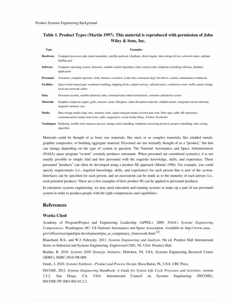
Product Systems Engineering Background 21
Table 1. Product Types (Martin 1997). This material is reproduced with permission of JohnWiley & Sons, Inc.
Type Examples
Hardware Computer processor unit, radar transmitter, satellite payload, telephone, diesel engine, data storage device, network router, airplanelanding gear
Software Computer operating system, firmware, satellite control algorithm, robot control code, telephone switching software, databaseapplication
Personnel Astronaut, computer operator, clerk, business executive, Laika (the cosmonaut dog), bus driver, cashier, maintenance technician
Facilities Space rocket launch pad, warehouse building, shipping docks, airport runway, railroad tracks, conference room, traffic tunnel, bridge,local area network cables
Data Personnel records, satellite telemetry data, command and control instructions, customer satisfaction scores
Materials Graphite composite, paper, gold, concrete, stone, fiberglass, radar absorption material, cladded metals, integrated circuit substrate,magnetic memory core
Media Data storage media (tape, disc, memory card), signal transport media (twisted pair wire, fiber optic cable, RF spectrum),communications media (television, radio, magazines), social media (blogs, Twitter, Facebook)
Techniques Soldering, trouble trick response process, change notice handling, telephone answering protocol, project scheduling, data sortingalgorithm
Materials could be thought of as basic raw materials, like steel, or as complex materials, like cladded metals,graphite composites, or building aggregate material. Personnel are not normally thought of as a “product,” but thatcan change depending on the type of system in question. The National Aeronautics and Space Administration(NASA) space program “system” certainly produces astronauts. When personnel are considered system(s), it is notusually possible to simply find and hire personnel with the requisite knowledge, skills, and experience. Thesepersonnel “products” can often be developed using a product SE approach (Martin 1996). For example, you couldspecify requirements (i.e., required knowledge, skills, and experience) for each person that is part of the system.Interfaces can be specified for each person, and an assessment can be made as to the maturity of each person (i.e.,each potential product). These are a few examples of how product SE can be applied to personnel products.In enterprise systems engineering, we may need education and training systems to make up a part of our personnelsystem in order to produce people with the right competencies and capabilities.
References
Works CitedAcademy of Program/Project and Engineering Leadership (APPEL). 2009. NASA's Systems EngineeringCompetencies. Washington, DC: US National Aeronautics and Space Association. Available at: http:/ / www. nasa.gov/ offices/ oce/ appel/ pm-development/ pm_se_competency_framework. html [2].Blanchard, B.S., and W.J. Fabrycky. 2011. Systems Engineering and Analysis, 5th ed. Prentice Hall InternationalSeries in Industrial and Systems Engineering. Englewood Cliffs, NJ, USA: Prentice Hall.Boehm, B. 2010. Systems 2020 Strategic Initiative. Hoboken, NJ, USA: Systems Engineering Research Center(SERC), SERC-2010-TR-009.Grady, J. 2010. Systems Synthesis - Product and Process Design. Boca Raton, FL, USA: CRC Press.INCOSE. 2012. Systems Engineering Handbook: A Guide for System Life Cycle Processes and Activities, version3.2.2. San Diego, CA, USA: International Council on Systems Engineering (INCOSE),INCOSE-TP-2003-002-03.2.2.

Product Systems Engineering Background 22
Magrab, E., S. Gupta, P. McCluskey, and P. Sandborn. 2010. Integrated Product and Process Design andDevelopment - The Product Realization Process. Boca Raton, FL, USA: CRC Press.Martin, J.N. 1997. Systems Engineering Guidebook: A process for developing systems and products, 1st ed. BocaRaton, FL, USA: CRC Press.MITRE. 2010. Platform as a Service: A 2010 Marketplace Analysis, Cloud Computing Series. Bedford, MA, USA:Systems Engineering at MITRE.Morse, L., and D. Babcock. 2007. Managing Engineering and Technology, 4th ed. Upper Saddle River, NJ, USA:Prentice Hall.Phillips, F. 2001. Market Oriented Technology Management: Innovating for Profit in Entrepreneurial Times. NewYork, NY, USA: Springer.Trudeau, P.N. 2010. Designing and Enhancing a Systems Engineering Training and Development Program.Bedford, MA, USA: The MITRE Corporation.Wasson, C.S. 2006. System Analysis, Design, and Development. New York, NY, USA: John Wiley & Sons.
Primary ReferencesGrady, J. 2010. Systems Synthesis - Product and Process Design. Boca Raton, FL, USA: CRC Press.Magrab, E., S. Gupta, P. McCluskey, and P. Sandborn. 2010. Integrated Product and Process Design andDevelopment - The Product Realization Process. Boca Raton, FL, USA: CRC Press.Martin, J.N. 1997. Systems Engineering Guidebook: A process for developing systems and product, 1st ed. BocaRaton, FL, USA: CRC Press.
Additional ReferencesAcademy of Program/Project and Engineering Leadership (APPEL). 2009. NASA's Systems EngineeringCompetencies. Washington, DC: US National Aeronautics and Space Association. Available at: http:/ / www. nasa.gov/ offices/ oce/ appel/ pm-development/ pm_se_competency_framework. html [2].Blanchard, B.S., and W.J. Fabrycky. 2011. Systems Engineering and Analysis, 5th ed. Prentice Hall InternationalSeries in Industrial and Systems Engineering. Englewood Cliffs, NJ, USA: Prentice Hall.Boehm, B. 2010. Systems 2020 Strategic Initiative. Hoboken, NJ, USA: Systems Engineering Research Center(SERC), SERC-2010-TR-009.INCOSE. 2012. Systems Engineering Handbook: A Guide for System Life Cycle Processes and Activities, version3.2.2. San Diego, CA, USA: International Council on Systems Engineering (INCOSE),INCOSE-TP-2003-002-03.2.2.MITRE. 2010. Platform as a Service: A 2010 Marketplace Analysis, Cloud Computing Series. Bedford, MA, USA:Systems Engineering at MITRE.Morse, L., and D. Babcock. 2007. Managing Engineering and Technology, 4th ed. Upper Saddle River, NJ, USA:Prentice Hall.Phillips, F. 2001. Market Oriented Technology Management: Innovating for Profit in Entrepreneurial Times. NewYork, NY, USA: Springer.Trudeau, P.N. 2010. Designing and Enhancing a Systems Engineering Training and Development Program.Bedford, MA, USA: The MITRE Corporation.Wasson, C.S. 2006. System Analysis, Design, and Development. New York, NY, USA: John Wiley & Sons.
Product Systems Engineering Background 23
< Previous Article | Parent Article | Next Article >SEBoK v. 1.4 released 29 June 2015
SEBoK DiscussionPlease provide your comments and feedback on the SEBoK below. You will need to log in to DISQUS using anexisting account (e.g. Yahoo, Google, Facebook, Twitter, etc.) or create a DISQUS account. Simply type yourcomment in the text field below and DISQUS will guide you through the login or registration steps. Feedback will bearchived and used for future updates to the SEBoK. If you provided a comment that is no longer listed, that commenthas been adjudicated. You can view adjudication for comments submitted prior to SEBoK v. 1.0 at SEBoK Reviewand Adjudication. Later comments are addressed and changes are summarized in the Letter from the Editor andAcknowledgements and Release History.
If you would like to provide edits on this article, recommend new content, or make comments on the SEBoKas a whole, please see the SEBoK Sandbox [1].
ENCODED_CONTENTMjQ3MjcPGRpdiBpZD0iZGlzcXVzX3RocmVhZCI+PC9kaXY+CjxzY3JpcHQgdHlwZT0idGV4dC9qYXZhc2NyaXB0Ij4KICAgIC8qICogKiBDT05GSUdVUkFUSU9OIFZBUklBQkxFUzogRURJVCBCRUZPUkUgUEFTVElORyBJTlRPIFlPVVIgV0VCUEFHRSAqICogKi8KICAgIHZhciBkaXNxdXNfc2hvcnRuYW1lID0gJ3NlYm9rd2lraTEwJzsgLy8gcmVxdWlyZWQ6IHJlcGxhY2UgZXhhbXBsZSB3aXRoIHlvdXIgZm9ydW0gc2hvcnRuYW1lCiAgICB2YXIgZGlzcXVzX2lkZW50aWZpZXIgPSAnUHJvZHVjdCBTeXN0ZW1zIEVuZ2luZWVyaW5nIEJhY2tncm91bmQnOyAgICB2YXIgZGlzcXVzX3VybCA9ICdodHRwOi8vc2Vib2t3aWtpLm9yZy9kcmFmdC9Qcm9kdWN0X1N5c3RlbXNfRW5naW5lZXJpbmdfQmFja2dyb3VuZCc7CiAgICAvKiAqICogRE9OJ1QgRURJVCBCRUxPVyBUSElTIExJTkUgKiAqICovCiAgICAoZnVuY3Rpb24oKSB7CiAgICAgICAgdmFyIGRzcSA9IGRvY3VtZW50LmNyZWF0ZUVsZW1lbnQoJ3NjcmlwdCcpOyBkc3EudHlwZSA9ICd0ZXh0L2phdmFzY3JpcHQnOyBkc3EuYXN5bmMgPSB0cnVlOwogICAgICAgIGRzcS5zcmMgPSAnaHR0cDovLycgKyBkaXNxdXNfc2hvcnRuYW1lICsgJy5kaXNxdXMuY29tL2VtYmVkLmpzJzsKICAgICAgICAoZG9jdW1lbnQuZ2V0RWxlbWVudHNCeVRhZ05hbWUoJ2hlYWQnKVswXSB8fCBkb2N1bWVudC5nZXRFbGVtZW50c0J5VGFnTmFtZSgnYm9keScpWzBdKS5hcHBlbmRDaGlsZChkc3EpOwogICAgfSkoKTsKPC9zY3JpcHQ+Cjxub3NjcmlwdD5QbGVhc2UgZW5hYmxlIEphdmFTY3JpcHQgdG8gdmlldyB0aGUgPGEgaHJlZj0iaHR0cDovL2Rpc3F1cy5jb20vP3JlZl9ub3NjcmlwdCI+Y29tbWVudHMgcG93ZXJlZCBieSBEaXNxdXMuPC9hPjwvbm9zY3JpcHQ+CjxhIGhyZWY9Imh0dHA6Ly9kaXNxdXMuY29tIiBjbGFzcz0iZHNxLWJybGluayI+YmxvZyBjb21tZW50cyBwb3dlcmVkIGJ5IDxzcGFuIGNsYXNzPSJsb2dvLWRpc3F1cyI+RGlzcXVzPC9zcGFuPjwvYT4=END_ENCODED_CONTENT
References[1] http:/ / www. businessdictionary. com/ definition/ product-development. html[2] http:/ / www. nasa. gov/ offices/ oce/ appel/ pm-development/ pm_se_competency_framework. html
Product as a System FundamentalsThis article introduces fundamental concepts of product systems.
Product Elements and ConnectionsProduct systems consist of product elements and two kinds of connections: connections among elements, andconnections between elements and things in the system environment. That portion of the environment that can beinfluenced by the system or that can influence the system is called the “context.”Connections between elements contain interactions and relationships (Hybertson 2009). A connection is more than amere interface.Interactions occur across interfaces between the elements inside or outside the system, and can be defined asexchanges of data, materials, forces, or energy. Connections with an interactive nature can be represented in variousengineering artifacts: schematic block diagrams, data flow diagrams, free body diagrams, interface control diagrams,port specifications, energy transfer diagrams, and so on. Product systems engineering (PSE) usually definesinteractions in an interface control document, interface design document, interface requirements document, or theequivalent.Connections also encompass relationships between elements. These relationships can be spatial, motion-related,temporal, or social.Spatial relationships:•• one element is underneath another• two elements are x units apart•• one element is inside another

Product as a System Fundamentals 24
Motion-related relationships:• the relative velocity of two elements is v units• the relative acceleration between two elements is a units
Temporal relationships:•• one element exists before another•• two elements must exist at the same time• two elements must be separated in time by t units
Social relationships:•• a human element feels a particular way about a system•• a human element owns another (non-human) element•• a human element understands the operation of a system in a particular wayRelationships that are not about time can still change over time. For example, an element that is inside anotherelement during one mode of operation can be outside of it during a different mode of operation. Therefore, oneshould not assume that non-temporal relationships are necessarily static in time.Relationships can be represented in engineering artifacts, including the timing diagram, timeline diagram, missionreference profile, capability road map, and project schedule chart.Social relationships include the implicit or explicit social obligations or expectations between the roles that humanelements play in a system. These roles may be assigned different authorities, responsibilities, and accountabilities.See the discussion on organization behavior in the article Team Dynamics. Organizational behavior theories andhuman factors may need to be considered when engineering such a product system.There can also be social relationships between the humans and the non-human elements of the system. This mayinvolve how the human “feels” about things in the system or perhaps even the system as a whole. Humans inside oroutside the system-of-interest may have different degrees of “understanding” with respect to how the systemoperates, its limitations and capabilities, and the best way to operate it safely and effectively. The “ownership”relationship can be important in determining things like who can operate or change some configuration or mode ofthe system.There are many such social relationships in a product system that are often ignored or misunderstood whenperforming PSE. Social relationships can affect the overall performance or behavior of a product system to the pointof determining its success or failure.

Product as a System Fundamentals 25
Core Product and its Enabling Products & Operational ServicesA variety of systems (themselves being products or services) enable the development, delivery, operation andeventual disposal of a product, as shown in Figure 1. The concept of enabling systems is defined in the ISO/IEC15288 standard (2015).
Figure 1. Example of Enabling Systems (Lawson 2010). Reprinted with permission of Harold "Bud" Lawson. All other rights arereserved by the copyright owner.
In the figure, the system-of-interest (SoI) goes into operation as a delivered product or offered service in theutilization stage while maintenance and logistics are provided (by a product sustainment system) simultaneously inthe support stage. These two stages are commonly executed in parallel, and they offer opportunities to observe anyneed for changes in the properties of the product or service or how it is operated and supported. Making changesiterates the life cycle and results in new or improved products or features.The delivered product and its enabling systems collectively form a wider system-of-interest (WSOI). The projectdesign enabling system is an enterprise based system asset that establishes the strategy and means of organizing theprojects to be executed along the life cycle. In many larger organizations, this type of enabling system isinstitutionalized and can be based upon recommendations of the Project Management Institute (PMI).Product systems should be viewed as enabling service systems. That is, once deployed, a product system provides aservice that contributes to an enterprise’s operations. To the acquirer, the SoI provides operational services to users.This is true at several levels:•• Hardware and software products are used to enable the provisioning of service systems,•• Enterprises incorporate products as system assets and use them to enable operations, and•• Provided products are integrated into the system of systems.

Product as a System Fundamentals 26
Product Architecture, Modeling, and AnalysisIEEE standard 1471-2000 defines architecture as "the fundamental organization of a system embodied in itscomponents, their relationships to each other, and to the environment, and the principles guiding its design andevolution" (IEEE 2000). Similarly, ISO/IEC 42010-2011 defines architecture as "fundamental concepts or propertiesof a system in its environment embodied in its elements, relationships, and in the principles of its design andevolution" (ISO/IEC 2011).A product's purpose (stakeholder’s need) is realized by a product system (the SoI). Because product systems arecomposed of different entities (components, assemblies, subsystems, information, facilities, processes, organizations,people, etc.) that together produce the results unachievable by any of the entities alone, architecting the product isbased on a whole systems approach. To architect with a whole systems approach means to define, document, design,develop, manufacture, distribute, maintain, improve, and to certify proper implementation of the product’s objectivesin terms of the functional (the "what"), the behavioral (the use, or intended operations), the logical (interaction andrelationships between entities) and the physical constructs (Wasson 2006; Maier 2009; Blanchard and Fabrycky2011).The system architect starts at the highest level of abstraction, concentrating on needs, functions, systemscharacteristics and constraints (concerns) before identifying components, assemblies, or subsystems. This is thesystems view, and it is used to represent the stakeholder’s market service description or the concept of operations(understanding of the opportunity/problem space).Next to be documented, as needs become better understood, are architectural descriptions at different levels ofabstraction, representing various stakeholders interests. These are the architecture models. They define the possiblesolution spaces for the product purpose in the form of detailed system, operational, behavioral, and physicalrequirements of the product system.Different modeling techniques are then used to analyze different types of requirements. For operational scenariosand different modes of operation, there are hierarchical decomposition and allocation, architectural block diagrams(ABD), functional block diagrams (FBD), functional flow block diagrams (FFBD), and use case diagrams. Forinteractions and relationships among hardware and/or software components there are sequence diagrams, activitydiagrams, state diagrams, and data flow diagrams. See (Maier 2009) Chapter 8 for an introduction to models andmodeling.Analysis of the solution space makes it possible to produce detailed technical specs, engineering drawings,blueprints, software architectures, information flows, and so on, that describe the entities in the product system. Anentity’s requirements bound its attributes and characteristics, levels of performance, operational capabilities, anddesign constraints. During design and integration, entity characteristics can be traced back to requirements(requirements traceability being a key aspect of SE). Verification and validation plans created during therequirements phase are the basis of testing certification that the product does what it was intended to do.Overall, what occurs is the transformation of a set of requirements into products and processes that satisfy thestakeholder's need. The architecture is represented by a set of models that communicate an integrated view of theproduct's intent and purpose, and the interactions and interfaces required among all the different participatingentities. The product's purpose is articulated in terms of business objectives (market, cost, functionality,performance, and time to deliver). The set of models includes sufficient variety to convey information appropriatelyto the stakeholders, designers/developers, specialty engineering, operations, manufacturers, management, andmarketing and sales personnel.Different architecture frameworks have been developed to guide product teams in defining the product architecturefor commercial and for public enterprises. In general, an architecture framework describes a "view," meaning a"collection of models that represent the whole system from the perspective of a set of related stakeholder concerns."Prime examples of architecture frameworks are the Zachman framework (Zachman 1992), The Open Group
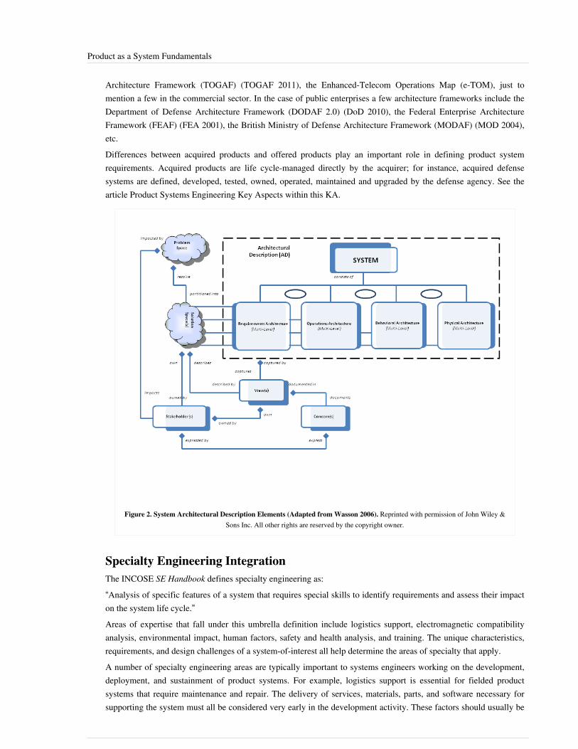
Product as a System Fundamentals 27
Architecture Framework (TOGAF) (TOGAF 2011), the Enhanced-Telecom Operations Map (e-TOM), just tomention a few in the commercial sector. In the case of public enterprises a few architecture frameworks include theDepartment of Defense Architecture Framework (DODAF 2.0) (DoD 2010), the Federal Enterprise ArchitectureFramework (FEAF) (FEA 2001), the British Ministry of Defense Architecture Framework (MODAF) (MOD 2004),etc.Differences between acquired products and offered products play an important role in defining product systemrequirements. Acquired products are life cycle-managed directly by the acquirer; for instance, acquired defensesystems are defined, developed, tested, owned, operated, maintained and upgraded by the defense agency. See thearticle Product Systems Engineering Key Aspects within this KA.
Figure 2. System Architectural Description Elements (Adapted from Wasson 2006). Reprinted with permission of John Wiley &Sons Inc. All other rights are reserved by the copyright owner.
Specialty Engineering IntegrationThe INCOSE SE Handbook defines specialty engineering as:“Analysis of specific features of a system that requires special skills to identify requirements and assess their impacton the system life cycle.”Areas of expertise that fall under this umbrella definition include logistics support, electromagnetic compatibilityanalysis, environmental impact, human factors, safety and health analysis, and training. The unique characteristics,requirements, and design challenges of a system-of-interest all help determine the areas of specialty that apply.A number of specialty engineering areas are typically important to systems engineers working on the development,deployment, and sustainment of product systems. For example, logistics support is essential for fielded productsystems that require maintenance and repair. The delivery of services, materials, parts, and software necessary forsupporting the system must all be considered very early in the development activity. These factors should usually be

Product as a System Fundamentals 28
considered before the system requirements and concept definition are complete. To integrate these specialtydisciplines sufficiently early on, the systems engineer needs to know what specialties relate to the system underdevelopment, how they relate to the systems engineering process, and how to integrate them into the life cycleprocess.For product systems with significant hardware content and that operate in challenging environments, the followingspecialty engineering areas must usually be considered:•• manufacturability,•• reliability and maintainability,•• certification (essential where human safety is an issue),•• logistics support,•• electromagnetic compatibility (if they radiate),•• environmental impact,•• human factors,•• safety and health, and•• training.The relationship of these specialty areas to the systems engineering process must be understood and considered. Thekey aspects of the relationship are:•• when the specialty needs to be considered,•• what essential data or information it provides,•• the consequences of not including the specialty in the systems engineering process, and•• how the systems engineers should interact with the specialty engineers.Grady (2006) provides an overview, with references, for many of the specialty engineering disciplines, includingreliability engineering; parts, materials, and process engineering (PMP); maintainability engineering, availability,producibility engineering, design to cost/life cycle cost (DTC/LCC), human factors engineering, corrosionprevention and control (CPC), system safety engineering, electromagnetic compatibility (EMC) engineering, systemsecurity engineering, mass properties engineering, and environmental impact engineering.Eisner (2008) lists specialty engineering as one of the “thirty elements” of systems engineering. “Specialtyengineering refers to a set of engineering topics that have to be explored on some, but not all, systems engineeringefforts. In other words, some systems involve these special disciplines and some do not. Examples of specialtyengineering areas include electromagnetic compatibility and interference, safety, physical security, computersecurity, communications security, demand forecasting, object-oriented design, and value engineering.” Some ofwhat we consider specialty engineering in the present article, Eisner includes among his “thirty elements” of systemsengineering, but not as part of the specialty engineering element.There is no standard list of specialty engineering disciplines. What is considered specialty engineering variesaccording to the community to which the systems engineering belongs, and sometimes to the preferences of thecustomer.
Product as a System Fundamentals 29
References
Works CitedANSI/IEEE. 2000. Recommended practice for architectural description for software-intensive systems. New York,NY, USA: American National Standards Institute (ANSI)/Institute of Electrical and Electronics Engineers (IEEE),ANSI/IEEE 1471-2000.Blanchard, B.S., and W.J. Fabrycky. 2011. Systems Engineering and Analysis, 5th ed. Prentice Hall InternationalSeries in Industrial and Systems Engineering. Englewood Cliffs, NJ, USA: Prentice Hall.Eisner, H. 2008. "Chapter 7. Essentials of Project and Systems Engineering Management," in The Thirty Elements ofSystems Engineering, 3rd ed. New York, NY, USA: John Wiley & Sons.Grady, J. 2006. "Chapter 3.7. System Requirements Analysis," in Specialty Engineering Requirements Analysis.New York, NY, USA: Academic Press.Grady, J. 2006. System Requirements Analysis. New York, NY, USA: Academic Press.Grady, J. 2010. Systems Synthesis - Product and Process Design. Boca Raton, FL, USA: CRC Press.Hybertson, D. 2009. Model-oriented Systems Engineering Science: A Unifying Framework for Traditional andComplex Systems. Boston, MA, USA: Auerbach Publications.INCOSE. 2012. Systems Engineering Handbook: A Guide for System Life Cycle Processes and Activities, version3.2.2. San Diego, CA, USA: International Council on Systems Engineering (INCOSE),INCOSE-TP-2003-002-03.2.2.ISO/IEC/IEEE. 2015.Systems and software engineering - system life cycle processes.Geneva, Switzerland:International Organization for Standardization (ISO)/International Electrotechnical Commission (IEC), Institute ofElectrical and Electronics Engineers.ISO/IEC 15288:2015.ISO/IEC/IEEE. 2011. Systems and software engineering - Architecture description. Geneva, Switzerland:International Organization for Standardization (ISO)/International Electrotechnical Commission (IEC)/Institute ofElectrical and Electronics Engineers (IEEE), ISO/IEC/IEEE 42010.Lawson, H. 2010. A Journey Through the Systems Landscape. London, UK: College Publications.Maier, M., and E. Rechtin. 2009. The Art of Systems Architecting, 3rd ed. Boca Raton, FL, USA: CRC Press.MOD. 2004. Ministry of Defence Architecture Framework (MODAF), version 2. London, UK: UK Ministry ofDefence.The Open Group. 2011. TOGAF, version 9.1. Hogeweg, The Netherlands: Van Haren Publishing. Accessed August29, 2012. Available at: https:/ / www2. opengroup. org/ ogsys/ jsp/ publications/ PublicationDetails.jsp?catalogno=g116.Wasson, C.S. 2006. System Analysis, Design, and Development. Hoboken, NJ, USA: John Wiley & Sons.Zachman, J.A. 1992. "Extending and Formalizing the Framework for Information Systems Architecture." IBMSystems Journal. 31 (3): 590-616.

Product as a System Fundamentals 30
Primary ReferencesEisner, H. 2008. "Chapter 7. Essentials of Project and Systems Engineering Management," in The Thirty Elements ofSystems Engineering, 3rd ed. New York, NY, USA: John Wiley & Sons.Lawson, H. 2010. A Journey Through the Systems Landscape. London, UK: College Publications.Wasson, C.S. 2006. System Analysis, Design, and Development. Hoboken, NJ, USA: John Wiley & Sons.
Additional ReferencesANSI/IEEE. 2000. Recommended practice for architectural description for software-intensive systems. New York,NY, USA: American National Standards Institute (ANSI)/Institute of Electrical and Electronics Engineers (IEEE),ANSI/IEEE 1471-2000.Blanchard, B.S., and W.J. Fabrycky. 2011. Systems Engineering and Analysis, 5th ed. Prentice Hall InternationalSeries in Industrial and Systems Engineering. Englewood Cliffs, NJ, USA: Prentice Hall.Grady, J. 2006. "Chapter 3.7. System Requirements Analysis," in Specialty Engineering Requirements Analysis.New York, NY, USA: Academic Press.Grady, J. 2006. System Requirements Analysis. New York, NY: Academic Press.Grady, J. 2010. Systems Synthesis- Product and Process Design. Boca Raton, FL, USA: CRC Press.Hybertson, D. 2009. Model-oriented Systems Engineering Science: A Unifying Framework for Traditional andComplex Systems. Boston, MA, USA: Auerbach Publications.INCOSE. 2012. Systems Engineering Handbook: A Guide for System Life Cycle Processes and Activities, version3.2.2. San Diego, CA, USA: International Council on Systems Engineering (INCOSE),INCOSE-TP-2003-002-03.2.2.ISO/IEC. 2008. Systems and Software Engineering -- System Life Cycle Processes. Geneva, Switzerland:International Organisation for Standardisation / International Electrotechnical Commissions. ISO/IEC/IEEE15288:2008.ISO/IEC/IEEE. 2011. Systems and software engineering - Architecture description. Geneva, Switzerland:International Organization for Standardization (ISO)/International Electrotechnical Commission (IEC)/Institute ofElectrical and Electronics Engineers (IEEE), ISO/IEC/IEEE 42010.Maier, M., and E. Rechtin. 2009. The Art of Systems Architecting, 3rd ed. Boca Raton, FL, USA: CRC Press.Zachman, J. 2008. "John Zachman's Concise Definition of The Zachman Framework™." Zachman InternationalEnterprise Architecture. Accessed August 29, 2012. Available at: http:/ / www. zachman. com/about-the-zachman-framework.
< Previous Article | Parent Article | Next Article >SEBoK v. 1.4 released 29 June 2015
SEBoK DiscussionPlease provide your comments and feedback on the SEBoK below. You will need to log in to DISQUS using anexisting account (e.g. Yahoo, Google, Facebook, Twitter, etc.) or create a DISQUS account. Simply type yourcomment in the text field below and DISQUS will guide you through the login or registration steps. Feedback will bearchived and used for future updates to the SEBoK. If you provided a comment that is no longer listed, that commenthas been adjudicated. You can view adjudication for comments submitted prior to SEBoK v. 1.0 at SEBoK Reviewand Adjudication. Later comments are addressed and changes are summarized in the Letter from the Editor andAcknowledgements and Release History.
Product as a System Fundamentals 31
If you would like to provide edits on this article, recommend new content, or make comments on the SEBoKas a whole, please see the SEBoK Sandbox [1].
ENCODED_CONTENTMTY5NzcPGRpdiBpZD0iZGlzcXVzX3RocmVhZCI+PC9kaXY+CjxzY3JpcHQgdHlwZT0idGV4dC9qYXZhc2NyaXB0Ij4KICAgIC8qICogKiBDT05GSUdVUkFUSU9OIFZBUklBQkxFUzogRURJVCBCRUZPUkUgUEFTVElORyBJTlRPIFlPVVIgV0VCUEFHRSAqICogKi8KICAgIHZhciBkaXNxdXNfc2hvcnRuYW1lID0gJ3NlYm9rd2lraTEwJzsgLy8gcmVxdWlyZWQ6IHJlcGxhY2UgZXhhbXBsZSB3aXRoIHlvdXIgZm9ydW0gc2hvcnRuYW1lCiAgICB2YXIgZGlzcXVzX2lkZW50aWZpZXIgPSAnUHJvZHVjdCBhcyBhIFN5c3RlbSBGdW5kYW1lbnRhbHMnOyAgICB2YXIgZGlzcXVzX3VybCA9ICdodHRwOi8vc2Vib2t3aWtpLm9yZy9kcmFmdC9Qcm9kdWN0X2FzX2FfU3lzdGVtX0Z1bmRhbWVudGFscyc7CiAgICAvKiAqICogRE9OJ1QgRURJVCBCRUxPVyBUSElTIExJTkUgKiAqICovCiAgICAoZnVuY3Rpb24oKSB7CiAgICAgICAgdmFyIGRzcSA9IGRvY3VtZW50LmNyZWF0ZUVsZW1lbnQoJ3NjcmlwdCcpOyBkc3EudHlwZSA9ICd0ZXh0L2phdmFzY3JpcHQnOyBkc3EuYXN5bmMgPSB0cnVlOwogICAgICAgIGRzcS5zcmMgPSAnaHR0cDovLycgKyBkaXNxdXNfc2hvcnRuYW1lICsgJy5kaXNxdXMuY29tL2VtYmVkLmpzJzsKICAgICAgICAoZG9jdW1lbnQuZ2V0RWxlbWVudHNCeVRhZ05hbWUoJ2hlYWQnKVswXSB8fCBkb2N1bWVudC5nZXRFbGVtZW50c0J5VGFnTmFtZSgnYm9keScpWzBdKS5hcHBlbmRDaGlsZChkc3EpOwogICAgfSkoKTsKPC9zY3JpcHQ+Cjxub3NjcmlwdD5QbGVhc2UgZW5hYmxlIEphdmFTY3JpcHQgdG8gdmlldyB0aGUgPGEgaHJlZj0iaHR0cDovL2Rpc3F1cy5jb20vP3JlZl9ub3NjcmlwdCI+Y29tbWVudHMgcG93ZXJlZCBieSBEaXNxdXMuPC9hPjwvbm9zY3JpcHQ+CjxhIGhyZWY9Imh0dHA6Ly9kaXNxdXMuY29tIiBjbGFzcz0iZHNxLWJybGluayI+YmxvZyBjb21tZW50cyBwb3dlcmVkIGJ5IDxzcGFuIGNsYXNzPSJsb2dvLWRpc3F1cyI+RGlzcXVzPC9zcGFuPjwvYT4=END_ENCODED_CONTENT
Business Activities Related to Product SystemsEngineeringThis topic discusses the interfaces between product systems engineering and other 'back office' and managementactivities that take place in an enterprise.
Marketing, Product Life Cycle Management, & Quality ManagementProduct systems engineering (PSE) includes critical and robust interfaces with related business activities, such asmarketing, product life cycle management (PLM), and quality. Traditionally, PLM has been a critical stage in theintegrated product development process (IPDP) and continues to be an important tool for life cycle managementafter product deployment. PLM provides an important component of the PSE end-to-end view. The other componentis the “breadth” component that captures everything relevant to the system at each life cycle stage. Recently, thefocus has started to shift from the idea of managing just the life of the product, to an expanded view that includes themanagement of product-lines (families) or product platforms themselves. This provides an increase in sustainability,flexibility, reduced development times, and important reductions in costs as new or enhanced products are notlaunched from scratch every time.PSE also includes interfaces with the marketing function; in particular, PSE works closely with the business andmarket development organizations to elicit product needs and intended operations in target markets to define productroll-out and possible phases of product introduction. Analysis of the market is critical during the entire product lifecycle from conception through retirement with the understanding that each life cycle phase requires very differentmarketing approaches. During concept development, marketing has to help determine the potential market, theaddressable market segments, define products, and product/innovations requirements for those markets. During theproduct introduction stage, marketing has to create demand and prompt early customers to try the product. Duringthe growth and maturity phases, marketing has to drive public awareness, develop the brand, and differentiate theproduct and its features and feature releases to compete with new market entrants. During saturation, marketing musthelp manage diminishing volumes and revenues as focus shifts from top line (increased market share) to bottom line(increased production and distribution efficiencies) considerations. See the article on Systems Engineering andProcurement/Acquisition.The links between PSE and quality are just as critical. The relationships between PSE and quality also reflect the broad view which includes the product and opportunity, but also the company’s internal goals, processes, and capabilities. Quality schemes which focus on a tangible product have been extensively used historically. More recent approaches that acknowledge and match PSE's holistic view have come into use. Issued during 1988, ISO 9000 is a family of standards which focuses on processes and the organization instead of the product itself. In addition, it calls out specific requirements for the design of products and services. ISO 9001 has served as a “platform” for many other schemes which are tailored to specific domains. A collaborative effort of the International Aerospace Quality Group, AS9100 contains all of the base requirements of ISO 9100 and expands further requirements which are critical and specific to the aviation, space, and defense industries. Similarly QS-16949 is a technical standard based on ISO 9001 but expanded to meet specific requirements in the worldwide automotive industry. PSE should play an important role

Business Activities Related to Product Systems Engineering 32
in the design and implementation of any quality management system. See the article on Quality Management.Capability Maturity Model Integrated (CMMI) for Development is a process improvement approach whose goal is tohelp organizations improve their performance. CMMI can be used to guide process improvement across a project, adivision, or an entire organization. Although initially used in software engineering and organizational development,CMMI use is spreading to other domains since it provides organizations with the essential elements for effectiveprocess improvement. According to the Carnegie Mellon Software Engineering Institute, CMMI describe "anevolutionary improvement path from ad hoc, immature processes to disciplined, mature processes with improvedquality and effectiveness." (SEI 2010).
Project Management & Business DevelopmentThe end-to-end view mandated by PSE requires strong relationships with project management and businessdevelopment activities. The ‘concurrent’ thinking encouraged by PSE necessarily requires multiple projects to moveforward in parallel, but with a high level of coordination. In this sense, PSE and project management (see SystemsEngineering and Project Management) are two heavily intertwined disciplines which have been shown to generatesynergy and added value for the stakeholders.The systems engineering management plan (SEMP) is the key document covering the activities, milestones,organization, and resource requirements necessary to ensure the system-of-interest accomplishes its intended goalsand mission. A key objective of the SEMP, which is usually developed during the conceptual design phase, is toprovide the structure, policies, and procedures to foster the optimum management of projects and activities neededfor system development and implementation (Blanchard and Fabrycky 2011).An effective and agile PSE function can make important contributions to business development for an enterprise orcompany. The primary goal of business development activities is to identify new types of business/product/serviceswhich are believed to address existing or potential needs and gaps (new markets), to attract new customers toexisting offerings, and to break into existing markets. PSE’s end-to-end view of the life cycle can support marketdevelopment by intelligence gathering, feedback on market acceptance or rejection, strategic analysis, andproposition development and campaign development. Finally, PSE should encourage the consideration of severalfactors within the new product development which may enhance market development. For example, inwell-established companies, business development can often include setting up strategic alliances with other,third-party companies. In these instances, the companies may leverage each others expertise and/or intellectualproperty to improve the probability for identifying, researching, and bringing to market new businesses and newproducts. See (Sørensen 2012).
Supply Chain Management & Distribution Channel ManagementPSE provides the following information to the supply chain management function in an enterprise:•• product specifications (including intended uses of the product),•• product acceptance criteria (for accepting delivery of the product from the supplier),• product testing and qualification plans and procedures, including which ones are responsibility of the supplier and
which ones are responsibility of the acquirer,•• interface specifications associated with each product,•• supplier certification criteria (including a list of pre-certified suppliers), and•• feedback on quality of products delivered by suppliers.Supply chain management will, as necessary, manage the identification and certification of qualified suppliers withthe concurrence of, and coordination with, systems engineering and product engineers.PSE provides the following information to the distribution channel management function in the enterprise:•• product specifications (including intended uses of the product),
Business Activities Related to Product Systems Engineering 33
•• product user manuals (including installation and maintenance documentation),•• product packaging (for safe delivery of product and for display in retail channels),•• product qualification data (to prove that product meets its design requirements),•• product certification data (to prove product is certified for safe and secure operation),•• user support instructions, and•• operator certification criteria.Distribution channel management will, as necessary, manage the identification and certification of qualifieddistributors with the concurrence of, and coordination with, systems engineering and product engineers.
Capability Management & Operations ManagementCapability is defined in various ways, but each definition is consistent with the notion of "the ability to do somethinguseful." Products and services are acquired by end users to enable and improve their operational capability to letthem do something useful, whether in a military context (e.g., weapon systems improve the capability to conducteffective military operations), or a social context (e.g., a car may improve the ability to satisfy the transport needs ofa family). Users acquire products (e.g., military equipment, cars, “productized” service offerings from airlines andtaxi companies, etc.) to contribute to satisfying their capability needs.Capability management involves identifying and quantifying capabilities (existing, new, or modified) that will beneeded to meet enterprise goals, as well as selecting a coherent set of product and services across all components ofCapability (glossary) that will be integrated to provide the needed capabilities. So normally, requirements for"product systems" are derived from capability management. Capability management is likely to include trade-offprocesses to make the best use of existing products or low-risk evolutions of them, and conversely identifying whena capability need can only be satisfactorily met by a new-generation product, or even a new type of productaltogether. In some cases, new offered products or disruptive technologies (e.g., jet engine, nuclear weapons, andinternet) create opportunities for new or improved capabilities, in which case capability management focuses onensuring that all needed components of capability are put in place to exploit the opportunity provided by the newproduct or technology. See Capability Engineering.Operations management uses an integrated set of product systems to deliver value to the enterprise and itsstakeholders. Operations management involves bringing new product systems into operation, normally whilemaintaining business continuity, so transition plans and relevant metrics are critical; next, operations managementaddresses some of the following: working up to full operational efficiency across all components of capability,coping with incidents, contingency plans to deal with major disruptions, adjusting the system to cope with new waysof working and to deliver new services to meet new enterprise requirements and accommodate new product systemsentering service, and eventually planning transitions out of service or major in-service upgrades. PSE supportsoperations management by defining all dependencies for successful operation on other systems and services, and byproviding ongoing engineering support for spares and repairs, obsolescence management, and system upgrades.Systems engineering in the in-service phase has been analyzed (Elliott et al. 2008) and is best viewed as the samebasic systems engineering process conducted at a much higher tempo (Kemp and Linton, 2008) and requiringdetailed understanding of constraints imposed by the current environment and usage. Configuration management andconfiguration status accounting during operation is very important for high value and high integrity systems toensure that any changes are designed to fit the "as-is" system, which may be significantly different from the"as-originally intended" specification and design.

Business Activities Related to Product Systems Engineering 34
Product Engineering, Assembly, Integration, & TestProduct engineering typically results in an engineering model that is used as the “blueprint” for assembling,integrating, and testing (AIT) a product system. These AIT activities may be performed on prototype versions, aswell as final production versions to be delivered to end users. There is significant experience in domain specificindustries in performing AIT for complex products. Unfortunately, very little is written in the general literature.Wasson (2006) and de Jong (2008) cover some of these aspects. See also System Integration and SystemVerification.For software products, the collection of code modules are integrated via some form of integration program (typicallycalled “make”). The integrated modules are then subjected to tests to exercise the various potential paths through thesoftware. Since software can be easily changed, it is common to use some form of regression testing based upon testsuites in order to verify software correctness. Another common means of testing is by fault injection as described byVoas and McGraw (1998).
Manufacturing, Test, & CertificationSystems engineers usually work with manufacturing indirectly through the electrical and mechanical design teams.There are times in the development cycle when a direct interface and working relationship between systemsengineering and manufacturing is appropriate and can improve the probability of program and system success. Earlyin the program the system concept must be examined to determine if it is manufacturable. The requirements and theconcept design should be reviewed with the manufacturing engineers to obtain an assessment of the risks associatedwith the production of the system. If substantial risks are identified, then actions that improve the manufacturingcapabilities of the organization, modify the design, and perhaps change the requirements may be needed to reducethe identified risks to acceptable levels. Manufacturing prototypes or proof of manufacture (POM) units may benecessary to reduce the risk and to demonstrate readiness to proceed with the design and the system development.Similarly, the systems engineers must establish that the system will be testable early in the product developmentphase. The requirements should be mapped to verification methods of inspection, analysis, demonstration, and testbefore they are released to the design team. All requirements mapped to test must be examined to determine the testmethods and the risk associated with accomplishing the necessary tests as part of the product qualification,acceptance, and release process. Where risks are identified, the systems engineers must work with the test engineersto develop the necessary test capabilities.
Product Delivery & Product SupportMost products live much longer in the usage phase than in the development phase. The costs associated with productsupport are usually greater than the cost of developing the product. These two facts make it very important for theproduct systems engineer to consider the product delivery and support as part of the earliest activities duringdevelopment. The design of the product dictates the maintenance and support that will be required. The systemsrequirements are the first means of influencing the design to achieve the desired product support. If maintenance,reliability, and support requirements have not been defined by the customer, then the systems engineer must definethese to achieve the support methods and costs that the customer, users, and the organization responsible for supportwill find financially acceptable.
Business Activities Related to Product Systems Engineering 35
References
Works Citedde Jong, I. 2008. Integration and Test Strategies for Complex Manufacturing Machines: Integration and TestingCombined in a Single Planning and Optimization Framework. Saarbrücken, Germany: Verlag.Elliott, B. et al. INCOSE UK Chapter Working Group on Applying Systems Engineering to In-Service Systems,Final Report. Somerset, UK: INCOSE UK Chapter Working Group. 2008. Accessed November 11, 2014 at INCOSEUK http:/ / www. incoseonline. org. uk/ Documents/ Groups/ InServiceSystems/ is_tr_001_final_report_final_1_0.pdf.Kemp, D., and R. Linton. 2008. "Service Engineering." Proceedings of the 18th Annual International Symposium ofthe International Council on Systems Engineering, June 15-19, 2008, Utrecht, The Netherlands.CMMI Product Team. CMMI for Development Version 1.3 (CMU/SEI-2010-TR-033). 2010. Pittsburgh, PA:Software Engineering Institute, Carnegie Mellon University. Accessed on 10 Nov 2014 at Software EngineeringInstitute Library http:/ / resources. sei. cmu. edu/ library/ asset-view. cfm?AssetID=9661Sørensen, H.E. 2012. Business Development: a market-oriented perspective. Hoboken, NJ, USA: John Wiley &Sons.Voas, J.M., and G. McGraw. 1998. Software Fault Injection. Hoboken, NJ, USA: John Wiley & Sons.Wasson, C.S. 2006. System Analysis, Design, and Development. Hoboken, NJ, USA: John Wiley & Sons.
Primary Referencesde Jong, I. 2008. Integration and Test Strategies for Complex Manufacturing Machines: Integration and TestingCombined in a Single Planning and Optimization Framework. Saarbrücken, Germany: Verlag.Voas, J.M., and G. McGraw. 1998. Software Fault Injection. Hoboken, NJ, USA: John Wiley & Sons.Wasson, C.S. 2006. System Analysis, Design, and Development. Hoboken, NJ, USA: John Wiley & Sons.
Additional ReferencesPhillips, F.Y. 2001. Market-Oriented Technology Management: Innovating for Profit in Entrepreneurial Times, 1sted. New York, NY, USA: Springer.
< Previous Article | Parent Article | Next Article >SEBoK v. 1.4 released 29 June 2015
SEBoK DiscussionPlease provide your comments and feedback on the SEBoK below. You will need to log in to DISQUS using anexisting account (e.g. Yahoo, Google, Facebook, Twitter, etc.) or create a DISQUS account. Simply type yourcomment in the text field below and DISQUS will guide you through the login or registration steps. Feedback will bearchived and used for future updates to the SEBoK. If you provided a comment that is no longer listed, that commenthas been adjudicated. You can view adjudication for comments submitted prior to SEBoK v. 1.0 at SEBoK Reviewand Adjudication. Later comments are addressed and changes are summarized in the Letter from the Editor andAcknowledgements and Release History.
If you would like to provide edits on this article, recommend new content, or make comments on the SEBoKas a whole, please see the SEBoK Sandbox [1].
ENCODED_CONTENTMTA2OTUPGRpdiBpZD0iZGlzcXVzX3RocmVhZCI+PC9kaXY+CjxzY3JpcHQgdHlwZT0idGV4dC9qYXZhc2NyaXB0Ij4KICAgIC8qICogKiBDT05GSUdVUkFUSU9OIFZBUklBQkxFUzogRURJVCBCRUZPUkUgUEFTVElORyBJTlRPIFlPVVIgV0VCUEFHRSAqICogKi8KICAgIHZhciBkaXNxdXNfc2hvcnRuYW1lID0gJ3NlYm9rd2lraTEwJzsgLy8gcmVxdWlyZWQ6IHJlcGxhY2UgZXhhbXBsZSB3aXRoIHlvdXIgZm9ydW0gc2hvcnRuYW1lCiAgICB2YXIgZGlzcXVzX2lkZW50aWZpZXIgPSAnQnVzaW5lc3MgQWN0aXZpdGllcyBSZWxhdGVkIHRvIFByb2R1Y3QgU3lzdGVtcyBFbmdpbmVlcmluZyc7ICAgIHZhciBkaXNxdXNfdXJsID0gJ2h0dHA6Ly9zZWJva3dpa2kub3JnL2RyYWZ0L0J1c2luZXNzX0FjdGl2aXRpZXNfUmVsYXRlZF90b19Qcm9kdWN0X1N5c3RlbXNfRW5naW5lZXJpbmcnOwogICAgLyogKiAqIERPTidUIEVESVQgQkVMT1cgVEhJUyBMSU5FICogKiAqLwogICAgKGZ1bmN0aW9uKCkgewogICAgICAgIHZhciBkc3EgPSBkb2N1bWVudC5jcmVhdGVFbGVtZW50KCdzY3JpcHQnKTsgZHNxLnR5cGUgPSAndGV4dC9qYXZhc2NyaXB0JzsgZHNxLmFzeW5jID0gdHJ1ZTsKICAgICAgICBkc3Euc3JjID0gJ2h0dHA6Ly8nICsgZGlzcXVzX3Nob3J0bmFtZSArICcuZGlzcXVzLmNvbS9lbWJlZC5qcyc7CiAgICAgICAgKGRvY3VtZW50LmdldEVsZW1lbnRzQnlUYWdOYW1lKCdoZWFkJylbMF0gfHwgZG9jdW1lbnQuZ2V0RWxlbWVudHNCeVRhZ05hbWUoJ2JvZHknKVswXSkuYXBwZW5kQ2hpbGQoZHNxKTsKICAgIH0pKCk7Cjwvc2NyaXB0Pgo8bm9zY3JpcHQ+UGxlYXNlIGVuYWJsZSBKYXZhU2NyaXB0IHRvIHZpZXcgdGhlIDxhIGhyZWY9Imh0dHA6Ly9kaXNxdXMuY29tLz9yZWZfbm9zY3JpcHQiPmNvbW1lbnRzIHBvd2VyZWQgYnkgRGlzcXVzLjwvYT48L25vc2NyaXB0Pgo8YSBocmVmPSJodHRwOi8vZGlzcXVzLmNvbSIgY2xhc3M9ImRzcS1icmxpbmsiPmJsb2cgY29tbWVudHMgcG93ZXJlZCBieSA8c3BhbiBjbGFzcz0ibG9nby1kaXNxdXMiPkRpc3F1czwvc3Bhbj48L2E+
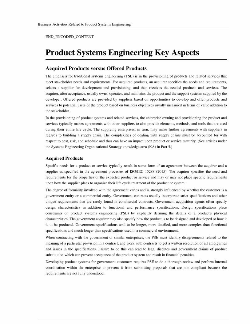
Business Activities Related to Product Systems Engineering 36
END_ENCODED_CONTENT
Product Systems Engineering Key Aspects
Acquired Products versus Offered ProductsThe emphasis for traditional systems engineering (TSE) is in the provisioning of products and related services thatmeet stakeholder needs and requirements. For acquired products, an acquirer specifies the needs and requirements,selects a supplier for development and provisioning, and then receives the needed products and services. Theacquirer, after acceptance, usually owns, operates, and maintains the product and the support systems supplied by thedeveloper. Offered products are provided by suppliers based on opportunities to develop and offer products andservices to potential users of the product based on business objectives usually measured in terms of value addition tothe stakeholder.In the provisioning of product systems and related services, the enterprise owning and provisioning the product andservices typically makes agreements with other suppliers to also provide elements, methods, and tools that are usedduring their entire life cycle. The supplying enterprises, in turn, may make further agreements with suppliers inregards to building a supply chain. The complexities of dealing with supply chains must be accounted for withrespect to cost, risk, and schedule and thus can have an impact upon product or service maturity. (See articles underthe Systems Engineering Organizational Strategy knowledge area (KA) in Part 5.)
Acquired ProductsSpecific needs for a product or service typically result in some form of an agreement between the acquirer and asupplier as specified in the agreement processes of ISO/IEC 15288 (2015). The acquirer specifies the need andrequirements for the properties of the expected product or service and may or may not place specific requirementsupon how the supplier plans to organize their life cycle treatment of the product or system.The degree of formality involved with the agreement varies and is strongly influenced by whether the customer is agovernment entity or a commercial entity. Government contracts usually incorporate strict specifications and otherunique requirements that are rarely found in commercial contracts. Government acquisition agents often specifydesign characteristics in addition to functional and performance specifications. Design specifications placeconstraints on product systems engineering (PSE) by explicitly defining the details of a product's physicalcharacteristics. The government acquirer may also specify how the product is to be designed and developed or how itis to be produced. Government specifications tend to be longer, more detailed, and more complex than functionalspecifications and much longer than specifications used in a commercial environment.When contracting with the government or similar enterprises, the PSE must identify disagreements related to themeaning of a particular provision in a contract, and work with contracts to get a written resolution of all ambiguitiesand issues in the specifications. Failure to do this can lead to legal disputes and government claims of productsubstitution which can prevent acceptance of the product system and result in financial penalties.Developing product systems for government customers requires PSE to do a thorough review and perform internalcoordination within the enterprise to prevent it from submitting proposals that are non-compliant because therequirements are not fully understood.
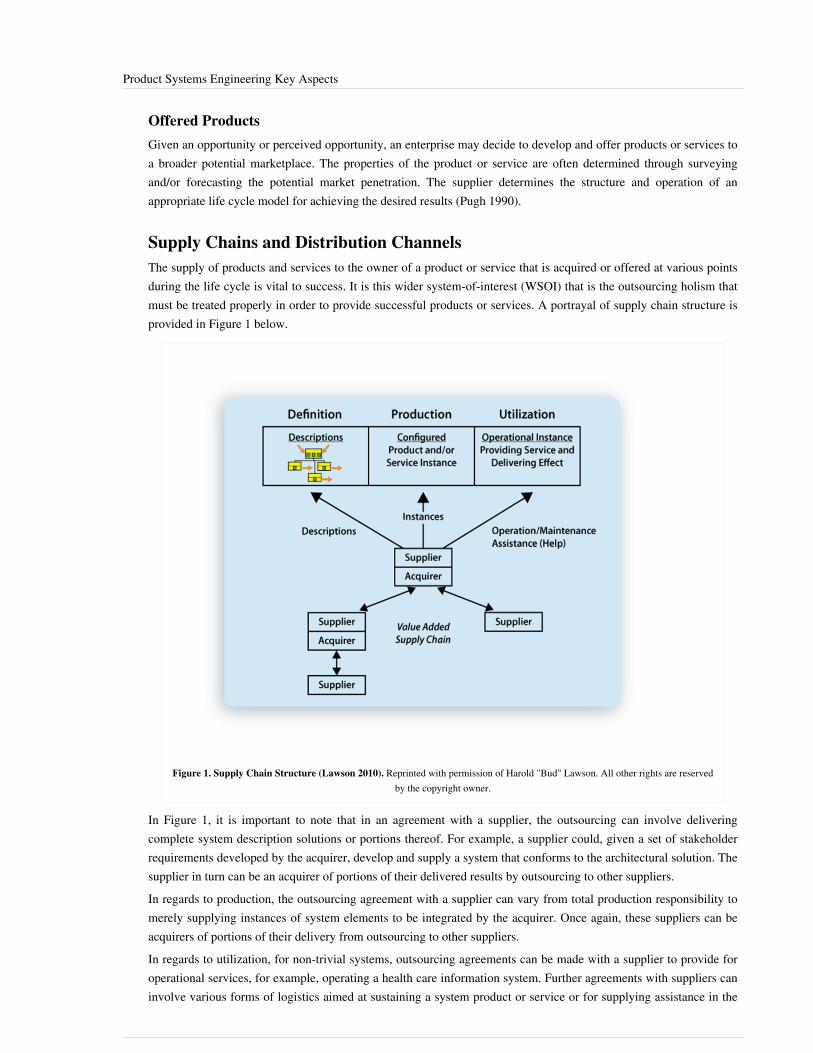
Product Systems Engineering Key Aspects 37
Offered ProductsGiven an opportunity or perceived opportunity, an enterprise may decide to develop and offer products or services toa broader potential marketplace. The properties of the product or service are often determined through surveyingand/or forecasting the potential market penetration. The supplier determines the structure and operation of anappropriate life cycle model for achieving the desired results (Pugh 1990).
Supply Chains and Distribution ChannelsThe supply of products and services to the owner of a product or service that is acquired or offered at various pointsduring the life cycle is vital to success. It is this wider system-of-interest (WSOI) that is the outsourcing holism thatmust be treated properly in order to provide successful products or services. A portrayal of supply chain structure isprovided in Figure 1 below.
Figure 1. Supply Chain Structure (Lawson 2010). Reprinted with permission of Harold "Bud" Lawson. All other rights are reservedby the copyright owner.
In Figure 1, it is important to note that in an agreement with a supplier, the outsourcing can involve deliveringcomplete system description solutions or portions thereof. For example, a supplier could, given a set of stakeholderrequirements developed by the acquirer, develop and supply a system that conforms to the architectural solution. Thesupplier in turn can be an acquirer of portions of their delivered results by outsourcing to other suppliers.In regards to production, the outsourcing agreement with a supplier can vary from total production responsibility tomerely supplying instances of system elements to be integrated by the acquirer. Once again, these suppliers can beacquirers of portions of their delivery from outsourcing to other suppliers.In regards to utilization, for non-trivial systems, outsourcing agreements can be made with a supplier to provide foroperational services, for example, operating a health care information system. Further agreements with suppliers caninvolve various forms of logistics aimed at sustaining a system product or service or for supplying assistance in the
Product Systems Engineering Key Aspects 38
form of help desks. Once again, suppliers that agree to provide services related to utilization can be acquirers of theservices of other suppliers.Important to all supply chains is the concept that supplying parties contribute some form of added value to the lifecycle of a system-of-interest. The proper management of a supply chain system asset is a vital part of the operationsof an enterprise. In fact, the supply chain itself is an enterprise system-of-interest that is composed of acquirers andsuppliers as system elements. There is definitely a structure tied together by agreement relationships. Further, theoperation of the supply chain results in an emergent behavior. The supply chain system becomes a vitalinfrastructure asset in the system portfolios of enterprises and forms the basis for extended enterprises.Similar to a supply chain, the distribution channels for a product system can be a complex web of relationshipsbetween the product supplier and various distributors, for example, package delivery companies, warehouses, servicedepots, wholesale outlets, retail sales establishments, operator training and certification organizations, and so on. Thenature of the distribution channels could have a significant impact on the architecture or design of a product system.PSE may need to include special features in the product design to accommodate for the needs of distribution channelelements, for example, heavy load tie down or lifting brackets, protective shipping packages, retail marketingdisplays, product brochures, installation manuals, operator certification packages, training materials, and so on.Sometimes it may be necessary to create special versions (or instances) of the product for the training of operatorsand users for certifying safe or secure operations, for environmental testing and qualification, for productdemonstration and user testing, for patent application, for load testing and scalability demonstrations, and forinterface fit checking and mass balance certification, to name some examples.
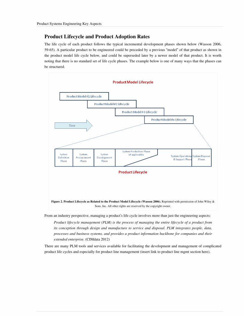
Product Systems Engineering Key Aspects 39
Product Lifecycle and Product Adoption RatesThe life cycle of each product follows the typical incremental development phases shown below (Wasson 2006,59-65). A particular product to be engineered could be preceded by a previous “model” of that product as shown inthe product model life cycle below, and could be superseded later by a newer model of that product. It is worthnoting that there is no standard set of life cycle phases. The example below is one of many ways that the phases canbe structured.
Figure 2. Product Lifecycle as Related to the Product Model Lifecycle (Wasson 2006). Reprinted with permission of John Wiley &Sons, Inc. All other rights are reserved by the copyright owner.
From an industry perspective, managing a product’s life cycle involves more than just the engineering aspects:Product lifecycle management (PLM) is the process of managing the entire lifecycle of a product fromits conception through design and manufacture to service and disposal. PLM integrates people, data,processes and business systems, and provides a product information backbone for companies and theirextended enterprise. (CIMdata 2012)
There are many PLM tools and services available for facilitating the development and management of complicatedproduct life cycles and especially for product line management (insert link to product line mgmt section here).

Product Systems Engineering Key Aspects 40
Figure 3. Product Lifecycle from an Industry Perspective. (Source: http:/ / commons. wikimedia. org/ wiki/File:Product%E2%80%99s_lifecycle. jpg#filelinks Accessed February 6, 2012. NIST Programs of the Manufacturing Engineering
Laboratory, Released by US Federal Government, Public Domain)
The product and product model life cycles are driven by the product adoption rate, illustrated below, that iscommonly experienced by most engineered products (Rogers 2003). As products reach market saturation (i.e., on thedown slope of the curve below) then there would typically be a new, upgraded version of the product ready fordelivery to the marketplace. PSE serves a critical role in determining the best timing for delivery of this new versionand the set of features and functions that would be of the greatest value at that time.

Product Systems Engineering Key Aspects 41
Figure 4. Rogers Innovation Adoption Curve. (Source: http:/ / en. wikipedia. org/ wiki/ File:Diffusionofideas. PNG AccessedFebruary 6, 2012, Released by Tungsten, Public Domain)
Integrated Product Teams and Integrated Product DevelopmentProduct systems as discussed throughout this KA mandate the participation of different disciplines for their successduring their entire lifecycle from concept to product disposal or retirement. Rapid technology innovations andmarket pressures in the mid '90s demanded development process (mostly input-output serial) to shorten theirdevelopment time and development cost, and to improve product quality to remain competitive. For commercialenterprises, the typical development times of 18-24 months to deploy new products into markets of the '90s have inmany cases been reduced to 6-12 months and even 3-6 months for the highly competitive leading edge informationtechnology products.An initial response to these pressures was concurrent engineering. Concurrent engineering is “... a systematicapproach to the integrated, concurrent design of products and their related processes, including manufacturing andsupport to cause developers, from the outset to consider all elements of the product lifecycle from conceptionthrough disposal, including quality, cost, schedule and end user requirements." This definition has evolved into theintegrated product development (IPD) as more descriptive of this concurrency to describe the continuous integrationof the entire product team, including engineering, manufacturing, test, and support through the life cycle. Later, asthe importance of the process was recognized, the terminology was modified to integrated product and processdevelopment or IPPD (INCOSE 2012).The INCOSE Systems Engineering Handbook v. 3.2.2 provides a good description of the IPT and IPDT process; thedifferent types of IPDT; the steps in organizing and running an IPDT; good examples of IPDT, particularly foracquired systems; and a good discussion on IPDT pitfalls to avoid. (INCOSE 2012)
Product Systems Engineering Key Aspects 42
IPD/IPPD helps plan, capture, execute, and evaluate programs to help design, test, build, deliver, and supportproducts that satisfy diverse stakeholder requirements. IPD/IPPD outlines the necessary infrastructure needed todeploy, maintain, evaluate and continuously improve processes and tools by aligning people (IPTs) and processes torealize product goals (customer satisfaction). The implementation of Integrated Product Development Processes(IPDP) requires an integrated approach for program planning and generally includes the following: BusinessStrategy, Program Management and Control, Project Planning, Product Requirements and ArchitectureDevelopment, Product Design and Development, Production and Deployment, Product Verification and Validation,and Operations and Maintenance Support.At each development stage, there is a decision gate that helps decide if the IPDP is feasible to enter the next stage ofproduct development. IPD utilizes multi-functional IPTs to optimize the individual product and processes to meetoverall cost and performance objectives. IPTs are a cross-functional group of people typically includingrepresentatives of all the relevant stakeholders in the project, who are brought together for delivering an integratedproduct to an external or internal customer using relevant IPDP. The main function of the IPTs is to ensure thebusiness, technical and economical integrity and overall success of the product that is delivered to its eventualcustomer. IPTs carry out tailored IPDPs and follow relevant SE processes to deliver products that satisfy customerneeds, overcomes external constraints, and adheres to the overall program strategy.In the case of commercial enterprises, product development is tightly coupled with business strategies (short andlong term), stakeholder value added measured in terms of return on investments (ROI), market presence/coverage,and other strategies as defined by the business objectives. Thus, product integration teams include strategic planners,business managers, financial managers, market managers, quality assurance managers, customer representatives, andend-users, as well as other disciplines required for acquired products. Phillips (2001), Annachino (2003), and Morse(2007) provide good discussions on this topic.
Role of Architectures, Requirements, and StandardsThe architectural properties of a product system are influenced by the concerns of the various stakeholders asindicated in the ISO/IEC 42010 standard (ISO/IEC 2011). The stakeholders have various views that they expressbased on their specific perspective. These views are vital in establishing requirements and are inputs to thoseresponsible for defining the functions, structures, and relationships needed to achieve the desired product or service.A number of stakeholders have been identified in the discussions of product systems. It would be possible to identifya set of important stakeholders based on the life cycle thinking provided by the ISO/IEC 15288 standard (2015), forexample, one such set could consist of owners, conceivers, developers, producers, users, and maintainers asdiscussed by Lawson (2010). As mentioned earlier, these stakeholders should cooperate at all stages of the life cyclein specifying requirements, verifying that the requirements are met, and validating that the products producedprovide needed capabilities.In addition to the two standards that have been identified, there are a variety of standards related to specialty aspectsof products, such as safety and security, as well as standards that are applicable for project management and lifecycle considerations, such as requirements and quality management.

Product Systems Engineering Key Aspects 43
Role of Modeling, Simulation, Prototyping, and ExperimentationModeling, simulation, prototyping, and experimentation are techniques that have the purpose of improvingstakeholder knowledge and shared understanding about aspects of the system to de-risk system development andoperation before heavy commitment of time and funds. Examples of this are found below:• Understanding future needs: “Warfighting experiments are the heart of the Army's warfighting requirements
determination process. Progressive and iterative mixes of high fidelity constructive, virtual, and live simulationsusing real soldiers and units in relevant, tactically competitive scenarios provide Army leaders with futureoperational capability insights" (US Army 2012),
•• Simulation is used to predict and optimize aspects of system performance for which there are good mathematicalor logical models before committing the final physical design, and also to verify and validate the system design inscenarios where physical testing is too difficult, dangerous, or expensive, for example, checking the performanceenvelope of military systems in a wide range of engagement scenarios where test firing thousands of rounds to getstatistically valid data is clearly unaffordable, ensuring that the safety features in a nuclear power station willoperate correctly in a wide range of stressing scenarios, etc.,
•• Prototyping (physical and virtual) is used in a wide variety of ways to check out aspects of system performance,usability, utility, and to validate models and simulations as part of the iterative process of converging on a finaldesign,
• In a manufacturing context, the first units produced are often “prototypes” intended to make sure the productionprocess is working properly before committing to high rate production, and are often not shipped to end users, butused for intensive testing to qualify the design, and
•• Simulation is also used extensively for training and marketing purposes. For training, an accurate model of thehuman machine interface and representation of the operational context allows operators to do most of theirtraining without putting operational hours on the real system enabling them to learn emergency procedures forcombat and accident scenarios in a safe and repeatable environment; for example, airline and military pilots nowtrain mainly on simulators. System simulators of various levels of fidelity are used to familiarize customers andend users with the potential characteristics and benefits of the system, available options and trade-offs, andintegration issues early in the development and acquisition process.
All of these methods use a variety of physical and mathematical representations of the system and its environment somodeling is an enabler for simulation, prototyping, and experimentation.
Increasing Role of Software in Product FunctionalityAn important trend in commercial products is the increasing importance of software in an increasingly wide range ofproducts. Everything from phones, cameras, cars, test gear, and medical equipment now has essential functionalityimplemented in software. Software has had an increasing role in providing the desired functionality in manyproducts. The embedding of software in many types of products accounts for increasing portions of productfunctionality. In tangible products such as cars, software helps improve functionality and usability (cruise control,climate control, etc.). In intangible products such as insurance, software helps in improving operational efficiency,data accessibility, etc.The movement toward the internet of “things” where sensing and activating functions are incorporated is nowstarting to permeate. The use of various software products in proving service is also described in the Service SystemsEngineering article.Recent advancements in IT and software have assisted in their increased use in PSE. Although software developmentis already a very complex field, the role of software in the development and functionality of products is growinglarger each day.

Product Systems Engineering Key Aspects 44
There is a need to broaden the horizons of software engineers to think of problem solving not only in software terms,but also using the systems thinking approach. For this purpose, software engineers need to be able to think criticallyabout the problem and also the possible solutions to the problem or opportunity and its implication for businessobjectives.
Product Integration and Interface ControlIntegration is "the set of activities that bring together smaller units of a system into larger units" (Eisner 2008).Products may consist of several systems, subsystems, assemblies, parts, etc., which have to work together as a wholeto deliver the offered product’s functionalities at specified performance levels in the intended operationsenvironment. Product integration entails not only the working together of hardware and software components, butalso the organization, processes, people, facilities, and the resources for the manufacturing, distribution,maintenance, customer support, sales channels, etc. Grady (2010) groups the above information into threefundamental integration components: functional organization, product integration, and process integration.PSE plays an important role to ensure well defined interfaces, interactions, relationships, information exchange, andprocesses requirements between product components. These requirements are baseline, documented, traced, verified,and validated for the end-to-end Product integration and to maintain and ensure product offering integrity during itslife cycle. The systems engineering hierarchical decomposition level allows requirement definition and allocations atdifferent levels of abstraction to define the building blocks of the product architecture; these building blocks areassigned to integrated product development teams (IPDTs) for detailed design and development. The IPDTs or thesystems engineering integration team (SEIT) must interact with all involved players to generate appropriatearchitectural block specifications at the lower tier of development for a product’s architectural configuration andconfiguration tracking. As the building blocks are put together, interface requirements, information exchange, andinteraction and relationships among entities are verified against the baseline. Once a configuration item has beenbuilt and tested against the baseline, test and verification at higher levels are conducted to obtain the final productconfiguration; the final product configuration can only be changed by a formal approval from a configuration controlboard (CCB). Note: the acronym CCB is often used to mean the change control board that, in addition toconfiguration control, makes decisions of any aspect of a project or an enterprise.Interface agreements, specifications, and interface designs are usually documented through the interface controldocuments (ICD) and the interface design descriptions (IDD); in some instances, depending on the complexity of theproduct and the type of internal and/or external interfaces, an interface control working group (ICWG) is created toanalyze and baseline changes to an interface for further recommendation to the CCB.A configuration item (CI) may be hardware (HWCI), software (SWCI), firmware, subsystems, assemblies,non-development items, commercial off-the-shelf (COTS) items, acquirer furnished equipment, and/or processes.Please see Wasson (2006), Grady (2006), and INCOSE SE Handbook v. 3.2.2 for a more detailed description ofconfiguration and interface control.A product may experience hundreds of changes during its life cycle due to new product releases/enhancements,repair/replacement of parts, upgrades/updates in operating systems, computer infrastructure, software modules,organizational changes, changes in processes and/or methods and procedures, etc. Thus, strong mechanisms forbookkeeping and activity control need to be in place to identify, control, audit, account and trace interfaces,interactions, and relationships between entities that are required to maintain product configuration status (Eisner2008). The product configuration and CI’s are then controlled through the configuration management process.

Product Systems Engineering Key Aspects 45
Configuration Management and Risk ManagementConfiguration management (CM) deals with the identification, control, auditing, status accounting, and traceabilityaspects of the product, and broadly covers the book-keeping and control activities of the systems engineering process(Eisner 2001). Any product configuration changes to the baseline (configuration item, operational baseline,functional baseline, behavior baseline) or product baseline are submitted to a configuration control board (CCB)through an engineering change request (ECR) and/or a configuration change request (CCR). The CCB then analyzesthe request to understand CI impacts and the feasibility (time and cost) of authorization or rejection of changerequest(s). The lack of proper control and tracking of CI and product baselines may result in a loss of features,functionality, data, interfaces, etc., leading to backtracking and CI version losses which may affect the offeredproduct. All approved changes will have to be baselined, documented, and tested for backward compatibility and toensure compliance with the integrated product functionality. Thus, successful implementation and life cyclemanagement of the product mandates a highly disciplined CM process that maintains proper control over the productand its components. Please see the INCOSE Systems Engineering Handbook v. 3.2.2 (2012) for a detaileddescription of the CM Process.Risk management deals with the identification, assessment, and prioritization of technical, cost, schedule, andprogrammatic risks in any system. Almost all engineered systems are designed, constructed, and operated undersome level of risks and uncertainty while achieving multiple, and often conflicting, objectives. As greatercomplexities and new technologies are introduced in modern systems, the potential of risks have significantlyincreased. Thus, the overall managerial decision-making process should involve an extensive cost-benefit analysis ofall identified, qualified, and evaluated risks (Haimes 2008). Risk management involves the coordinated and mostcost-effective application of resources to minimize, monitor, and control the probability and/or impact of allidentified risks within the systems engineering process. The risk management process requires the involvement ofseveral disciplines and encompasses empirical, quantitative, and normative judgmental aspects of decision-making.Furthermore, risk assessment and management should be integrated and incorporated within the broader holisticapproach so technology management can help align the risk management requirements to the overall systemsengineering requirements. Thus, the inclusion of a well defined risk management plan that deals with the analysis ofrisks, within the systems engineering master plan is vital for the long term and sustained success of any system(Blanchard and Fabrycky 2011).
References
Works CitedAnnachino, M. 2003. New Product Development: From Initial Idea to Product Management. Amsterdam,Netherlands: Elsevier.Blanchard, B.S., and W.J. Fabrycky. 2011. Systems Engineering and Analysis, 5th ed. Prentice Hall InternationalSeries in Industrial and Systems Engineering. Englewood Cliffs, NJ, USA: Prentice Hall.Eisner, H. 2008. Essentials of Project and Systems Engineering Management, 3rd ed. New York, NY, USA: JohnWiley & Sons.Grady, J. 2006. System Requirements Analysis. New York, NY, USA: Academic Press.Haimes, Y. 2008. Risk Modeling, Assessment, and Management, 3rd ed. New York, NY, USA: John Wiley & Sons.INCOSE. 2012. Systems Engineering Handbook: A Guide for System Life Cycle Processes and Activities, version3.2.2. San Diego, CA, USA: International Council on Systems Engineering (INCOSE),INCOSE-TP-2003-002-03.2.2.ISO/IEC/IEEE. 2015.Systems and software engineering - system life cycle processes.Geneva, Switzerland: International Organization for Standardization (ISO)/International Electrotechnical Commission (IEC), Institute of
Product Systems Engineering Key Aspects 46
Electrical and Electronics Engineers.ISO/IEC 15288:2015.ISO/IEC/IEEE. 2011. Systems and software engineering - Architecture description. Geneva, Switzerland:International Organization for Standardization (ISO)/International Electrotechnical Commission (IEC)/Institute ofElectrical and Electronics Engineers (IEEE), ISO/IEC/IEEE 42010.Kass, R. 2006. "The logic of warfighting experiments." DOD Command and Control Research Program (CCRP).August 2006. Accessed 23 April 2013 at http:/ / www. dodccrp. org/ files/ Kass_Logic. pdf.Lawson, H. 2010. A Journey Through the Systems Landscape. London, UK: College Publications.Morse, L., and D. Babcock. 2007. Managing Engineering and Technology. International Series in Industrial andSystems Engineering. Upper Saddle River, NJ, USA: Prentice Hall.Phillips, F. 2001. Market Oriented Technology Management: Innovating for Profit in Entrepreneurial Times. NewYork, NY, USA: Springer.Pugh, S. 1990. Total Design: Integrated Methods for Successful Product Engineering. Englewood Cliffs, NJ, USA:Prentice Hall.Reinertsen, D. 1997. Managing the Design Factory: A Product Developers Tool Kit. New York, NY, USA: Simon &Schuster Ltd.Rogers, E.M. 2003. Diffusion of Innovations, 5th ed. New York, NY, USA: Free Press.Smith, P., and D. Reinertsen. 1997. Developing products in half the time – new rules, new tools, 2nd ed. Hoboken,NJ, USA: John Wiley & Sons.US Army. 2012. "Chapter 2, section A.4" in Army Science and Technology Master Plan. Accessed January 12, 2012.Available at: http:/ / www. fas. org/ man/ dod-101/ army/ docs/ astmp/ c2/ P2A4. htm.Wasson, C.S. 2006. System Analysis, Design, and Development. Hoboken, NJ, USA: John Wiley & Sons.
Primary ReferencesBlanchard, B.S., and W.J. Fabrycky. 2011. Systems Engineering and Analysis, 5th ed. Prentice Hall InternationalSeries in Industrial and Systems Engineering. Englewood Cliffs, NJ, USA: Prentice Hall.Eisner, H. 2008. Essentials of Project and Systems Engineering Management, 3rd ed. New York, NY, USA: JohnWiley & Sons.Wasson, C.S. 2006. System Analysis, Design, and Development. Hoboken, NJ, USA: John Wiley & Sons.
Additional ReferencesAnnachino, M. 2003. New Product Development: From Initial Idea to Product Management. Amsterdam,Netherlands: Elsevier.Haimes, Y. 2008. Risk Modeling, Assessment, and Management, 3rd ed. New York, NY, USA: John Wiley & Sons.Kass, R. 2006. "The logic of warfighting experiments." DOD Command and Control Research Program (CCRP).August 2006. Accessed 23 April 2013 at http:/ / www. dodccrp. org/ files/ Kass_Logic. pdf.Lawson, H. 2010. A Journey Through the Systems Landscape. London, UK: College Publications.Morse, L., and D. Babcock. 2007. Managing Engineering and Technology. International Series in Industrial andSystems Engineering. Upper Saddle River, NJ, USA: Prentice Hall.Phillips, F. 2001. Market Oriented Technology Management: Innovating for Profit in Entrepreneurial Times. NewYork, NY, USA: Springer.Pugh, S. 1990. Total Design: Integrated Methods for Successful Product Engineering. Englewood Cliffs, NJ, USA:Prentice Hall.

Product Systems Engineering Key Aspects 47
Reinertsen, D. 1997. Managing the Design Factory: A Product Developers Tool Kit. New York, NY, USA: Simon &Schuster Ltd.Rogers, E.M. 2003. Diffusion of innovations, 5th ed. New York, NY: Free Press.Smith, P., and D. Reinertsen. 1997. Developing products in half the time – new rules, new tools, 2nd ed. Hoboken,NJ, USA: John Wiley & Sons.US Army. 2012. "Chapter 2, section A.4" in Army Science and Technology Master Plan. Accessed January 12, 2012.Available at: http:/ / www. fas. org/ man/ dod-101/ army/ docs/ astmp/ c2/ P2A4. htm.
< Previous Article | Parent Article | Next Article >SEBoK v. 1.4 released 29 June 2015
SEBoK DiscussionPlease provide your comments and feedback on the SEBoK below. You will need to log in to DISQUS using anexisting account (e.g. Yahoo, Google, Facebook, Twitter, etc.) or create a DISQUS account. Simply type yourcomment in the text field below and DISQUS will guide you through the login or registration steps. Feedback will bearchived and used for future updates to the SEBoK. If you provided a comment that is no longer listed, that commenthas been adjudicated. You can view adjudication for comments submitted prior to SEBoK v. 1.0 at SEBoK Reviewand Adjudication. Later comments are addressed and changes are summarized in the Letter from the Editor andAcknowledgements and Release History.
If you would like to provide edits on this article, recommend new content, or make comments on the SEBoKas a whole, please see the SEBoK Sandbox [1].
ENCODED_CONTENTNDE1MDAPGRpdiBpZD0iZGlzcXVzX3RocmVhZCI+PC9kaXY+CjxzY3JpcHQgdHlwZT0idGV4dC9qYXZhc2NyaXB0Ij4KICAgIC8qICogKiBDT05GSUdVUkFUSU9OIFZBUklBQkxFUzogRURJVCBCRUZPUkUgUEFTVElORyBJTlRPIFlPVVIgV0VCUEFHRSAqICogKi8KICAgIHZhciBkaXNxdXNfc2hvcnRuYW1lID0gJ3NlYm9rd2lraTEwJzsgLy8gcmVxdWlyZWQ6IHJlcGxhY2UgZXhhbXBsZSB3aXRoIHlvdXIgZm9ydW0gc2hvcnRuYW1lCiAgICB2YXIgZGlzcXVzX2lkZW50aWZpZXIgPSAnUHJvZHVjdCBTeXN0ZW1zIEVuZ2luZWVyaW5nIEtleSBBc3BlY3RzJzsgICAgdmFyIGRpc3F1c191cmwgPSAnaHR0cDovL3NlYm9rd2lraS5vcmcvZHJhZnQvUHJvZHVjdF9TeXN0ZW1zX0VuZ2luZWVyaW5nX0tleV9Bc3BlY3RzJzsKICAgIC8qICogKiBET04nVCBFRElUIEJFTE9XIFRISVMgTElORSAqICogKi8KICAgIChmdW5jdGlvbigpIHsKICAgICAgICB2YXIgZHNxID0gZG9jdW1lbnQuY3JlYXRlRWxlbWVudCgnc2NyaXB0Jyk7IGRzcS50eXBlID0gJ3RleHQvamF2YXNjcmlwdCc7IGRzcS5hc3luYyA9IHRydWU7CiAgICAgICAgZHNxLnNyYyA9ICdodHRwOi8vJyArIGRpc3F1c19zaG9ydG5hbWUgKyAnLmRpc3F1cy5jb20vZW1iZWQuanMnOwogICAgICAgIChkb2N1bWVudC5nZXRFbGVtZW50c0J5VGFnTmFtZSgnaGVhZCcpWzBdIHx8IGRvY3VtZW50LmdldEVsZW1lbnRzQnlUYWdOYW1lKCdib2R5JylbMF0pLmFwcGVuZENoaWxkKGRzcSk7CiAgICB9KSgpOwo8L3NjcmlwdD4KPG5vc2NyaXB0PlBsZWFzZSBlbmFibGUgSmF2YVNjcmlwdCB0byB2aWV3IHRoZSA8YSBocmVmPSJodHRwOi8vZGlzcXVzLmNvbS8/cmVmX25vc2NyaXB0Ij5jb21tZW50cyBwb3dlcmVkIGJ5IERpc3F1cy48L2E+PC9ub3NjcmlwdD4KPGEgaHJlZj0iaHR0cDovL2Rpc3F1cy5jb20iIGNsYXNzPSJkc3EtYnJsaW5rIj5ibG9nIGNvbW1lbnRzIHBvd2VyZWQgYnkgPHNwYW4gY2xhc3M9ImxvZ28tZGlzcXVzIj5EaXNxdXM8L3NwYW4+PC9hPg==END_ENCODED_CONTENT

Product Systems Engineering Special Activities 48
Product Systems Engineering Special ActivitiesProduct systems engineering has activities that are unique to products. This article discusses many of them.
Readiness Level AssessmentsAs a new system is developed, it is essential to verify and validate that the developed system is mature enough to bereleased as an operational product or service. Technology readiness assessments (TRA) are established tools used toqualify technology development and help make investment decisions within complex development programs in orderto deploy systems or elements of technology to an end user in a timely fashion.This notion of maturity was formalized by the US National Aeronautics and Space Administration (NASA)(Mankins 1995) and later modified for use by the Department of Defense (DoD), the Air Force Research Laboratory(AFRL), and the US Department of Energy (DoE), as well as a growing number of non-governmental organizations.Technology readiness levels (TRL) are a metric developed to summarize the degree of maturity of a technology. Theoriginal NASA TRL scale has nine different levels from the basic principles observed and reported (TRL 1) toactual systems "flight proven" through successful mission operations (TRL 9). The TRL scale utilized by the DoD isportrayed in Table 1.
Table 1. Technology Readiness Levels for Assessing Critical Technologies (Mankins 1995).Released by the Advanced Concept Office, Office of Space Access and Technology, NASA.
Technology
Readiness
Level
+ 1. Basicprinciplesobservedandreported.
+ 2.Technologyconceptand/orapplicationformulated.
+ 3. Ananalyticalandexperimentalcriticalfunctionand/orcharacteristicproof ofconcept.
+ 4.Componentvalidation inlaboratoryenvironment.
+ 5.Componentvalidation inrelevantenvironment.
+ 6. Prototypedemonstrationin a relevantenvironment.
+ 7. Prototypedemonstrationin anoperationalenvironment.
+ 8. Systemqualifiedthrough testanddemonstration.
+ 9. Systemproventhroughsuccessfulmissionoperations.
Actualapplicationof thetechnologyin its finalform andundermissionconditions,such asthoseencounteredinoperationaltest andevaluation.
The utilization of TRLs has an impact on the structure and operation of life cycles as described in Part 3; they allowbetter management and control of risks inherent with technology, as well as better control of costs and the scheduleof program development. However, TRLs do not provide an assessment of the programmatic influence on a TRL,technology criticality and priority, software aging and readiness context, as pointed out by Smith (2005). WhileTRLs have proven to be useful in evaluating a technology’s performance, as demonstrated in the laboratory or in atest environment, they do not inform one whether or not the technology product can actually be produced in anaffordable manner. The concept of manufacturing readiness levels (MRL) has been incorporated to expand the TRLidea so that it can incorporate producibility concerns. The MRL approach addresses questions such as the level oftechnology reproducibility, the cost of production, and technology manufacturing production environment early inthe development phase (GAO 2003, DoD 2011).

Product Systems Engineering Special Activities 49
Figure 1. Technology Readiness Levels and Their Relationship to System Acquisition Milestones (Morgan 2008). Released by theManufacturing Technology Division of the United States Air Force.
Readiness levels are an active research area within academia and government agencies in regards to the integrationof technology components into complex systems (integration readiness levels (IRLs)) to address interface maturityamong existing and maturing technology developments. TRLs apply to the critical enabling technologies, which areusually embodied at the subsystem, assembly level, or system component level. Systems readiness levels (SRL) areused when going from individual technologies to the whole system. The SRL model is a function of the individualTRLs in a system and their subsequent integration points with other technologies, the IRL (Sauser 2006).Another maturity aspect is related to the provisioning of products that are readily available and referred to ascommercial off-the-shelf (COTS). Such products, be they hardware, software, or a mixture of both, have hopefullyachieved the degree of maturity so that those acquiring them can rely upon their operational properties and that thedocumentation of the COTS products is sufficient to provide the proper guidance in their use.The PSE should realize that the TRL assessment for COTS changes dramatically if the operational environment orother requirements are imposed that exceed the design limits of the COTS product (e.g., operations at very high orvery cold temperatures, high shock, or vibration levels).

Product Systems Engineering Special Activities 50
Product CertificationProduct certifications are both domain and product specific, and typically relate to human safety and health, the needto meet a specific government regulation, or are required by underwriters for insurance purposes. Certifications areperformed by a third party (independent of the developer) who provides a guarantee of the quality, safety, andreliability of the product to the customer or user.The INCOSE SE Handbook defines product certification as "the process of certifying that a certain product haspassed performance or quality assurance tests or qualification requirements stipulated in regulations such as abuilding code or nationally accredited test standards, or that it complies with a set of regulations governing quality orminimum performance requirements." (INCOSE 2012)The INCOSE SE Handbook also defines four methods for verification: inspection, analysis, demonstration, andtesting (INCOSE 2012). In addition, it defines certification as a fifth verification method, which is defined asverification against legal or industrial standards by an outside authority without direction to that authority as to howthe requirements are to be verified. For example, electronic devices require a CE certification in Europe, and a ULcertification in the US and Canada (INCOSE 2012).The best known certification is the airworthiness certification, which relates to the safety of flight for aircraft. In theUS, the test for this certification is performed by the Federal Aviation Administration (FAA). Governmentcertifications are also common in the medical systems field where the Federal Drug Administration (FDA) is theprimary certification agency. Some certifications are based on standards defined by technical societies, such as theAmerican Society of Mechanical Engineers (ASME). The combination of the technical standards and a certificationallows product developers to perform certifications that meet government standards without having the governmentdirectly involved in the process.There are equivalent government organizations in other countries and for other regulated areas, such ascommunications, building safety, nuclear systems, transportation systems to include ships, trains and automobiles,environmental impact, and energy use. Systems engineers must be aware of the certifications that are required for thedomain and product being developed. Certification agencies must be involved early in the development effort toensure the necessary certifications are included in the system requirements, the system development plan, and thefunding provided to accomplish the development. When system changes and upgrades are necessary, the systemsengineers must determine if product re-certification is necessary and include it in the plans and funding for thesystem upgrade.
Enabling Product CertificationsThere may be other certifications for enabling products that must be considered and appreciated by PSE, such as anoperator certification of airplane pilots to ensure flight safety, and certification of nuclear plant operators to ensureprevention or mitigation of nuclear radiation effects. An example of this is shown in the certification program by theNorth American Electric Reliability Corporation (NERC):
In support of NERC’s mission, the System Operator Certification Program’s mission is to ensure thatemployers have a workforce of system operators that meet minimum qualifications. These minimumqualifications are set through internationally recognized processes and procedures for agencies thatcertify persons. The Certification Program promotes excellence in the area of system operatorperformance and encourages system operators to be inquisitive and informed. (NERC 2012)
Production qualification testing (PQT) is another type of certification which DAU (2005) describes as:A technical test completed prior to the full-rate production (FRP) decision to ensure the effectiveness ofthe manufacturing process, equipment, and procedures. This testing also serves the purpose ofproviding data for the independent evaluation required for materiel release so that the evaluator canaddress the adequacy of the materiel with respect to the stated requirements. These tests are conducted

Product Systems Engineering Special Activities 51
on a number of samples taken at random from the first production lot, and are repeated if the process ordesign is changed significantly and when a second or alternative source is brought online.
Security certification and accreditation (C&A) is often required for the deployment of computing and networkingequipment in a classified environment. Facility certification may be required to ensure that a building housing theequipment can provide the proper environment for safe and efficient operation of the equipment. High-altitudeelectromagnetic pulse (HEMP) certification may be required to ensure that a building and its equipment canwithstand the effects of HEMP from nuclear weapons. A similar type of certification to HEMP is TEMPEST testingto ensure that sensitive electronic emissions are not allowed to leave high security facilities. TEMPEST is a codename referring to investigations and studies of compromising emission, and is not an acronym.
Technology Planning and InsertionTechnology planning can be an enterprise function or a program function. Technology planning as an enterprisefunction typically occurs on an annual basis to determine the funding necessary for independent research anddevelopment in the coming year. Technology planning as a program function occurs early in the program and oftencontinues throughout the life of the system. The design of the product system is highly dependent on the availabilityof technologies that have acceptable risks and that meet the customer's cost, schedule, and performancerequirements. These critical technologies will only be available when necessary if the systems engineers performconcept designs, technology assessments, and trade studies that define the critical technologies and the capabilitiesnecessary before the system development activities that will use the critical technologies begin.The MITRE Systems Engineering Guide (MITRE 2011) provides the following definition for technology planning:
Technology Planning is the process of planning the technical evolution of a program or system toachieve its future vision or end-state. Technology planning may include desired customer outcomes,technology forecasting and schedule projections, technology maturation requirements and planning,and technology insertion points. The goal is a defined technical end-state enabled by technologyinsertion over time.
Systems engineers who participate in technical planning must understand the future vision and system requirements,and relate these to the current and expected future technologies that can be applied to the system design duringcurrent development stages, as well as for potential future upgrades to the system. To do this, systems engineersmust acquire and maintain knowledge of the existing and developing technology in their design domain. The systemsengineer will also provide the essential connection between the system user and research communities to providealignment between the technology developers and the system designers.Technology planning and insertion usually requires that the systems engineer perform technology readinessassessments that rate the maturity levels and the risks associated with the planned technologies. Immature, riskytechnologies require risk reduction activities that include prototyping and product development and test activitiesthat provide quantification of the capabilities and risks. The risk reduction activities provide the data necessary toassess and update the design to reduce its risk.
Product Road Mapping and Release PlanningProduct road maps provide an outline that shows when products are scheduled for release and include an overview ofthe product's primary and secondary features. Both internal and external product road maps should be created. Theform of the road map will depend on the development methodology being used. Waterfall, iterative, and spiraldevelopment models result in different road maps and release plans. The systems engineer must be an integralmember of the team that creates road maps. Requirements should be mapped onto each of the planned releases. Testplans must be adapted to the development model and the release plans.

Product Systems Engineering Special Activities 52
Product road maps should be aligned with the technology road maps that are applicable to the product. Technologymaturity should be accomplished before the technologies are included in the product development plans and the roadmap for the product release that includes those technologies.Product road maps are essential for software intensive systems that have many releases of software and capabilityupgrades. The identification of the requirements, the test plans, and the features provided for each release are anessential driver of the product development process. Clear definition of these items can make the difference betweendelivering the capabilities the customer is looking for and will support, or a product that fails to meet the needs of thecustomer and is abandoned.
Intellectual Property ManagementSystems engineers must also manage intellectual property as part of their job. Existing systems engineering literaturerarely covers this topic. However, there are many textbooks and management related literature that provideadditional information, such as “Intellectual Property Rights for Engineers” (Irish 2005). Intellectual property may beconsidered as intangible output of the rational thought process that has some intellectual or informational value andis normally protected via using copyrights, patents, and/or trade secrets (Irish 2005). Listed below are some of themore important intellectual property types with brief explanations:•• Proprietary Information: Any information which gives a company (or enterprise) an advantage over its
competitors is usually proprietary.•• Patents: A patent is the principle mechanism for protecting rights for an invention or discovery. In exchange for a
full disclosure of how to practice it, the issuing government will grant the right to exclude others from practicingthe invention for a limited amount of time, usually 15 to 20 years (in the US, a patent usually lasts for 17 yearsfrom the date of issue).
• Design Patents: In some countries, these are referred to by the more appropriate term design registrations or someother name. They protect rights in ornamental designs, provided the designs are new and inventive, i.e.,non-obvious at the time they are made. In the US, the maximum length of a design patent is 14 years.
•• Trademarks: A trademark identifies the source of origin for goods in commerce, and is not stronger than theactual use to which it has been put to and the diligence with which it has been protected from infringement,encroachment, or dilution. Under some circumstances, a trademark may be registered with governmentalagencies. Among a company's most valuable assets is the corporate name, which also is the company's primarytrademark.
• Copyrights: A claim of copyright protects such works as writings, musical compositions, and works of art frombeing copied by others, i.e., from plagiarism. A notice of claim of copyright must be made in the mannerprescribed by law at the time of a protected work’s first publication.
Parts, Materials, and Process ManagementThe consequences of mission failure or an inability to deploy the system on time due to parts, materials, and process(PM&P) issues needs to be clearly understood by the systems engineer since these elements are fundamental to theoverall mission reliability and program success. PM&P management is especially important in harsh environments(like outer space and underwater) and in situations where system failure can have catastrophic impacts on publicsafety (like nuclear power, bridges and tunnels, and chemical processing plants).Generally, original equipment manufacturers (OEMs) engaged in the design and fabrication of electronic systemshave a documented policy that deals with PM&P, sometimes in the form of a PM&P Management Manual. Theelements of a PM&P control program include things such as• PM&P requirements that apply to a system;•• the generation number of a program or project approved parts list (PAPL);
Product Systems Engineering Special Activities 53
• the appointment of a PM&P control board (PMPCB);•• the development of a part stress derating policy and a part parameter derating policy for end of life use; and•• a definition of the minimum qualifications, quality controls, and screening requirements for parts.PM&P management guidance is provided by MIL-HDBK-512 (DoD 2001) and ANSI/AIAA R-100 (2001), whichidentify the overall management process elements of a PM&P program. Additional issues to be addressed by PM&Pinclude the following: hazardous materials, rare earth elements, conflict materials, and counterfeit materials.
References
Works CitedANSI/AIAA. 2001. Recommended Practice for Parts Management. Philadelphia, PA, USA: American NationalStandards Institute (ANSI)/American Institute of Aeronautics and Astronautics (AIAA), ANSI/AIAA R-100A-2001.DAU. 2005. Glossary of Defense Acquisition Acronyms & Terms, 12th ed. Ft. Belvoir, VA, USA: DefenseAcquisition University (DAU)/US Department of Defense (DoD). Available at: http:/ / www. dau. mil/ pubscats/PubsCats/ 13th_Edition_Glossary. pdf.DoD. 2000. Department of Defense Directive (DoD-D) 5000.01: The Defense Acquisition System. Arlington, VA,USA: US Department of Defense, Acquisition, Technology, and Logistics (AT&L). Available at: http:/ / www. dtic.mil/ whs/ directives/ corres/ pdf/ 500001p. pdf.DoD. 2001. Department of Defense Handbook: Parts Management. Arlington, VA, USA: Department of Defense(DoD). MIL-HDBK-512A.DoD. 2011 Department of Defense Technology Readiness Assessment (TRA) Guidance, Assistant Secretary ofDefense for Research and Engineering (ASD(R&E)), May 2011.FAA. 2011. Airworthiness Certificates Overview. Washington, DC, USA: Federal Aviation Administration (FAA).Available at: http:/ / www. faa. gov/ aircraft/ air_cert/ airworthiness_certification/ aw_overview/ .GAO. 2003. Defense acquisitions: Assessments of Major Weapon Programs, GAO-03-476, US GovernmentAccountability Office, May 2003.INCOSE. 2012. Systems Engineering Handbook: A Guide for System Life Cycle Processes and Activities, version3.2.2. San Diego, CA, USA: International Council on Systems Engineering (INCOSE),INCOSE-TP-2003-002-03.2.2.Irish, V. 2005. Intellectual Property Rights for Engineers, 2nd ed. Herts, UK: Institution of Engineering andTechnology (IET).Mankins, J. 1995. Technology Readiness Levels—A White Paper. Washington, DC, USA: Advanced ConceptsOffice, Office of Space Access and Technology, National Aeronautics and Space Administration (NASA).MITRE. 2011. "Systems Engineering Guide." Accessed September 11, 2012. Available at: http:/ / www. mitre. org/work/ systems_engineering/ guide/ .Morgan, J 2007. Manufacturing Readiness Levels (MRLs) and Manufacturing Readiness Assessments (MRAs).ADA510027 Air Force Research Lab Wright-patterson Afb Oh Manufacturing Technology Directorate. September2007. Accessed 06 November 2014 at Defense Technical Information Center http:/ / www. dtic. mil/ get-tr-doc/pdf?AD=ADA510027NERC. 2012. "North American Electric Reliability Corporation (NERC)." Accessed September 11, 2012. Availableat: http:/ / www. nerc. com.Sauser, B., D. Verma, J. Ramirez-Marquez, and R. Gove. 2006. From TRL to SRL: The Concept of System ReadinessLevels. Proceedings of the Conference on Systems Engineering Research (CSER), April 7-8, 2006, Los Angeles,CA, USA.
Product Systems Engineering Special Activities 54
Smith, J. 2005. An Alternative to Technology Readiness Levels for Non-Developmental Item (NDI) Software.Proceedings of the 38th Hawaii International Conference on Systems Sciences, January 3-6, 2005, Island of Hawaii,USA.
Primary ReferencesMankins, J. 1995. Technology Readiness Levels—A White Paper. Washington, DC, USA: Advanced ConceptsOffice, Office of Space Access and Technology, National Aeronautics and Space Administration (NASA).MITRE. "Systems Engineering Guide." Available at http:/ / www. mitre. org/ work/ systems_engineering/ guide/Sauser, B., D. Verma, J. Ramirez-Marquez, and R. Gove. 2006. From TRL to SRL: The Concept of System ReadinessLevels. Proceedings of the Conference on Systems Engineering Research (CSER), Los Angeles, CA, April 7-8,2006.
Additional ReferencesANSI/AIAA. 2001. Recommended Practice for Parts Management. Philadelphia, PA, USA: American NationalStandards Institute (ANSI)/American Institute of Aeronautics and Astronautics (AIAA), ANSI/AIAA R-100A-2001.DoD. 2000. Department of Defense Directive (DoD-D) 5000.01: The Defense Acquisition System. Arlington, VA,USA: US Department of Defense, Acquisition, Technology, and Logistics (AT&L). Available at: http:/ / www. dtic.mil/ whs/ directives/ corres/ pdf/ 500001p. pdf.DoD. 2001. Department of Defense Handbook: Parts Management. Arlington, VA, USA: Department of Defense(DoD). MIL-HDBK-512A.FAA. 2011. "Airworthiness Certificates Overview." Washington, DC, USA: Federal Aviation Administration(FAA). Available at: http:/ / www. faa. gov/ aircraft/ air_cert/ airworthiness_certification/ aw_overview/ .Irish, V. 2005. Intellectual Property Rights for Engineers, 2nd ed. Herts, UK: Institution of Engineering andTechnology (IET).Smith, J. 2005. An Alternative to Technology Readiness Levels for Non-Developmental Item (NDI) Software.Proceedings of the 38th Hawaii International Conference on Systems Sciences, January 3-6, 2005, Island of Hawaii,USA.
< Previous Article | Parent Article | Next Article >SEBoK v. 1.4 released 29 June 2015
SEBoK DiscussionPlease provide your comments and feedback on the SEBoK below. You will need to log in to DISQUS using anexisting account (e.g. Yahoo, Google, Facebook, Twitter, etc.) or create a DISQUS account. Simply type yourcomment in the text field below and DISQUS will guide you through the login or registration steps. Feedback will bearchived and used for future updates to the SEBoK. If you provided a comment that is no longer listed, that commenthas been adjudicated. You can view adjudication for comments submitted prior to SEBoK v. 1.0 at SEBoK Reviewand Adjudication. Later comments are addressed and changes are summarized in the Letter from the Editor andAcknowledgements and Release History.
If you would like to provide edits on this article, recommend new content, or make comments on the SEBoKas a whole, please see the SEBoK Sandbox [1].
ENCODED_CONTENTNzA4NzAPGRpdiBpZD0iZGlzcXVzX3RocmVhZCI+PC9kaXY+CjxzY3JpcHQgdHlwZT0idGV4dC9qYXZhc2NyaXB0Ij4KICAgIC8qICogKiBDT05GSUdVUkFUSU9OIFZBUklBQkxFUzogRURJVCBCRUZPUkUgUEFTVElORyBJTlRPIFlPVVIgV0VCUEFHRSAqICogKi8KICAgIHZhciBkaXNxdXNfc2hvcnRuYW1lID0gJ3NlYm9rd2lraTEwJzsgLy8gcmVxdWlyZWQ6IHJlcGxhY2UgZXhhbXBsZSB3aXRoIHlvdXIgZm9ydW0gc2hvcnRuYW1lCiAgICB2YXIgZGlzcXVzX2lkZW50aWZpZXIgPSAnUHJvZHVjdCBTeXN0ZW1zIEVuZ2luZWVyaW5nIFNwZWNpYWwgQWN0aXZpdGllcyc7ICAgIHZhciBkaXNxdXNfdXJsID0gJ2h0dHA6Ly9zZWJva3dpa2kub3JnL2RyYWZ0L1Byb2R1Y3RfU3lzdGVtc19FbmdpbmVlcmluZ19TcGVjaWFsX0FjdGl2aXRpZXMnOwogICAgLyogKiAqIERPTidUIEVESVQgQkVMT1cgVEhJUyBMSU5FICogKiAqLwogICAgKGZ1bmN0aW9uKCkgewogICAgICAgIHZhciBkc3EgPSBkb2N1bWVudC5jcmVhdGVFbGVtZW50KCdzY3JpcHQnKTsgZHNxLnR5cGUgPSAndGV4dC9qYXZhc2NyaXB0JzsgZHNxLmFzeW5jID0gdHJ1ZTsKICAgICAgICBkc3Euc3JjID0gJ2h0dHA6Ly8nICsgZGlzcXVzX3Nob3J0bmFtZSArICcuZGlzcXVzLmNvbS9lbWJlZC5qcyc7CiAgICAgICAgKGRvY3VtZW50LmdldEVsZW1lbnRzQnlUYWdOYW1lKCdoZWFkJylbMF0gfHwgZG9jdW1lbnQuZ2V0RWxlbWVudHNCeVRhZ05hbWUoJ2JvZHknKVswXSkuYXBwZW5kQ2hpbGQoZHNxKTsKICAgIH0pKCk7Cjwvc2NyaXB0Pgo8bm9zY3JpcHQ+UGxlYXNlIGVuYWJsZSBKYXZhU2NyaXB0IHRvIHZpZXcgdGhlIDxhIGhyZWY9Imh0dHA6Ly9kaXNxdXMuY29tLz9yZWZfbm9zY3JpcHQiPmNvbW1lbnRzIHBvd2VyZWQgYnkgRGlzcXVzLjwvYT48L25vc2NyaXB0Pgo8YSBocmVmPSJodHRwOi8vZGlzcXVzLmNvbSIgY2xhc3M9ImRzcS1icmxpbmsiPmJsb2cgY29tbWVudHMgcG93ZXJlZCBieSA8c3BhbiBjbGFzcz0ibG9nby1kaXNxdXMiPkRpc3F1czwvc3Bhbj48L2E+END_ENCODED_CONTENT

Service Systems Engineering 55
Service Systems EngineeringThe growth of services in the ever-evolving global economy has brought much needed attention to service scienceand service systems engineering (SSE). Research focuses on developing formal methodologies to understandenterprise-end-user (customer) interactions from both socio-economic and technological perspectives, and to enablevalue co-creation and productivity improvements. Service systems require trans-disciplinary collaborations betweensociety, science, enterprises, and engineering. Service transactions are customized and personalized to meet aparticular customer need. This requires a disciplined and systemic approach among stakeholders and resources toemphasize end-user satisfaction in the design and delivery of the service (Hipel et al. 2007; Tien and Berg 2003;Vargo and Akaka 2009; Maglio and Spohrer 2008; Maglio et al. 2010).
TopicsEach part of the SEBoK is divided into knowledge areas (KAs), which are groupings of information with a relatedtheme. The KAs in turn are divided into topics. This KA contains the following topics:•• Service Systems Background•• Fundamentals of Services•• Properties of Services•• Scope of Service Systems Engineering•• Value of Service Systems Engineering•• Service Systems Engineering Stages
IntroductionNew Service Development (NSD) has usually been a proprietary process closely guarded by product businesses andservice businesses for their competitive advantage. Traditional systems engineering practices have been primarilyapplied in aerospace and defense sectors while SSE practices have been applied by information and communicationstechnologies (ICT) service providers (Booz, Allen, and Hamilton 1982; Johnson et al. 2000; Eppinger 2001;Freeman 2004; Whitten and Bentley 2007; AT&T SRP 2008; Lin and Hsieh 2011).These early efforts were, and in some instances remain, very important for product and service businesses. However,the growth and ubiquity of the World Wide Web, advances in computer science and ICT, and business processmanagement through “social networking,” support the realization of closely interrelated service systems. Productbusiness (manufacturing, agriculture, etc.) and service business distinctions are going away (Spohrer 2011).These services, or service innovations, must take into account social aspects, governance processes, businessprocesses, operational processes, as well as design and development processes. The customer, service provider,product provider, and intermediaries need to collaborate toward the optimization of customer experiences andcustomer provided value (through co-creation). The interrelations among different stakeholders and resources requirethat methodologies, processes, and tools be dynamically tailored and delivered for either foreseen or newlydiscovered services to rapidly adapt to changing enterprise and end-user environments.Even in the case of static, predetermined, interaction rules, the major problems faced in the definition, design, andimplementation of services have been in understanding the integration needs among different systems, systementities, stakeholders, and in defining the information flows required for the governance, operations, administration,management and provisioning (OAM&P) of the service. (Maier 1998; Jamshidi 2008; Pineda 2010; Luzeaux andRuault 2013). Thus, the 21st century technology-intensive services are “information-driven, customer centric,e-oriented, and productivity-focused" as discussed by Chesbrough (2011), Chang (2010), Tien and Berg (2003), andHipel et al. (2007). A detailed discussion of these characteristics is given in the Value of Service SystemsEngineering article within this KA.

Service Systems Engineering 56
Service Systems Engineering Knowledge Area TopicsThis knowledge area (KA) describes best practices in SSE during the service design process and outlines currentresearch on methods, processes, and tools. It does not attempt to describe the initial efforts and research in servicescience that were proposed and introduced by International Business Machines (IBM) (Maglio and Spohrer 2008),but it does recognize their leadership in championing these concepts in undergraduate and graduate curricula.The rest of the KA is organized in the following way:The Service Systems Background article presents some background on the transition from a manufacturing economytoward the service economy brought by the World Wide Web through co-creation of end-user value. It describeshow this transformation is impacting industries, such as healthcare, agriculture, manufacturing, transportation,supply chain, environmental, etc. The article also describes the scope of the SSE discipline's contributions to meetingthe needs of the service sector companies in strategic differentiation and operational excellence (Chang 2010) bypointing out some differences between product-oriented systems engineering and SSE.The Fundamentals of Services and Properties of Services articles take the reader through a general discussion ofservices and current attempts to classify different types of services, in particular, attention is paid to the properties ofservice systems for the service sector, such us transportation, environmental and energy services, consulting services,healthcare, etc.The Scope of Service Systems Engineering and Value of Service Systems Engineering articles cover the value ofSSE, defining (or using when available) service architecture frameworks, and the stages of the service developmentprocess from concept to life cycle management.The Service Systems Engineering Stages article summarizes the major SSE process activities that need to be carriedout during the service design process and the needed output (work products) in each of the service design processstages.
Service Innovation and Value-Co-creationService innovation has several dimensions. Service innovation can come about through the creation of a serviceconcept which is sufficiently different that it is not merely an improved service, but in reality is a new serviceconcept. To maintain the rigor and value of innovation, it is necessary to distinguish between an improved service,which may generate some additional value, and a truly new and innovative service concept, which may generate agreat deal of value. Dr. Noriaki Kano, a renowned quality management guru, has suggested that every serviceconcept has its inherent attributes and we should strive to continuously improve upon these; but this is not innovation(Kano 1996).To be innovative, the change in a value proposition cannot be incremental, but it must be enough to significantlyimpact customer and competitor behavior (e.g., new market creation). Value innovation involves a shift inperspective of customer needs that requires a rethinking of what service value proposition is delivered (Kano 1996).Innovation can also come through a significant change in the way or the reason the customer is engaged orconnected. In a service value chain the customer may well change from being just a receiver of service value tobecoming a co-creator, or an active participant in the design and delivery, i.e., service transaction of service value. Atthe retail level, when a customer designs the time, route, and price selection for a plane ticket purchased online, he isco-creating the service. Value innovation involves a shift in perspective of customer needs that requires a rethinkingof how a service value proposition is delivered (Bettencourt 2010).Finally, service innovation can come through significant changes in the way the enterprise is organized to create aservice value proposition from concept through delivery. A considerable improvement in the enterprise structureand/or governance can be seen as innovation. Value innovation involves a shift in perspective of customer needs thatrequires a rethinking of how an enterprise organizes to support a service value proposition.

Service Systems Engineering 57
Continuous improvement can be reasonably planned and predicted while innovation and breakthroughs cannot. Themost effective way to obtain innovation and breakthroughs is to encourage the culture, environment, and atmospherethat are conducive to innovation and breakthroughs. Innovative co-creation requires the integration of people, ideas,and technology for the purpose of creating value for themselves, their customers, companies, and society.The lone inventor sees a problem and must work to create the solutions to all dimensions of the problem. Co-creatorssee the problem and realize that there may already be several creators, each already having a piece of the solution.Co-creation embraces the value of things “not invented here” because of the velocity they can bring to ideation andtime to market. This service innovation process is facilitated by modern mass (and at the same time, personal)communication technology evident in social networking platforms.
Towards a Discipline of Service Systems EngineeringMindful of the evolution taking place in the global economy and the world markets, it would be futile to attemptcovering all the major advances and the boundless possibilities in the services sector for the rest of the century. Theservices sector covers wide areas of application studied in many different fields (e.g., business science, socialscience, cognitive science, political science, etc.). The field of service systems, a trans-disciplinary analysis andstudy of services, was only introduced 10 to 15 years ago. As a consequence, much of the existing literature onservices and service-innovation is scattered. The main objective of this KA is to document the systems engineeringprocesses, methodologies, and existing tools as applied to the service design process, and to introduce critical SSEchallenges and research areas.
References
Works CitedAT&T SRP. 2008. Technical Approach to Service Delivery. General Services Administration, AT&T BridgeContract No. GS00Q09NSD0003. Accessed on June 1, 2011. Available at: http:/ / www. corp. att. com/ gov/contracts/ fts_bridge/ technical/ 07_vol_I_section_1. pdf.Bettencourt, L. 2010. Service Innovation: How to Go from Customer Needs to Breakthrough Services. New York,McGraw-Hill Professional. July 2010.Booz, Allen, and Hamilton. 1982. New Products Management for the 1980s. New York, NY, USA: Booz, Allen, andHamilton Inc.Chang, C.M. 2010. Service Systems Management and Engineering: Creating Strategic Differentiation andOperational Excellence. New York, NY, USA: John Wiley & Sons, Inc.Chesbrough, H. 2011. Open Services Innovation: Rethinking Your Business to Grow and Compete in a New Era. SanFrancisco, CA, USA: Jossey-Bass.Eppinger, S. 2001. "Innovation at the Speed of Information" Harvard Business Review. 79 (1): 149-158.Freeman, R.L. 2004. Telecommunication Systems Engineering, 4th ed. New York, NY, USA: John Wiley & Sons.Hipel, K.W., M.M. Jamshidi, J.M. Tien, and C.C. White. 2007. "The Future of Systems, Man, and Cybernetics:Application Domains and research Methods. IEEE Transactions on Systems, Man, and Cybernetics - Part C:Applications and Reviews. 37 (5): 726-743.Jamshidi M, System of Systems Engineering: Innovations for the Twenty-First Century. New York, NY, USA: JohnWiley & Sons. November 2008.Johnson, S.P., L.J. Menor, A.V. Roth, and R.B. Chase. 2000. "A critical evaluation of the new service developmentprocess: integrating service innovation and service design," in Fitzsimmons, J.A., and M.J. Fitzsimmons (eds.). NewService Development - Creating Memorable Experiences. Thousand Oaks, CA, USA: Sage Publications. p. 1-32.

Service Systems Engineering 58
Kano, N. 1996. Guide to TQM in Service Industry. Tokyo, Japan: Asian Productivity Organization.Lin, F.R., and P.S Hsieh. 2011. A SAT View on New Service Development." Service Science. 3 (2): 141-157.Luzeaux, D. and Ruault. J,. System of Systems. New York, NY, USA: John Wiley & Sons. March 2013.Maglio, P., C. Kieliszewski, and J. Spohrer. 2010. Handbook of Service Science, 1st ed. New York, NY, USA:Springer Science + Business Media.Maglio, P., and J. Spohrer. 2008. "Fundamentals of Service Science." Journal of the Academy of Marketing Science.36 (1): 18-20.Maier, M.W., 1998. "Architecting Principles for System of Systems." Systems Engineering. 1 (4): 267-284.Pineda, R. 2010. "Understanding Complex Systems of Systems Engineering." Presented at Fourth GeneralAssembly, Cartagena Network of Engineering, September 21-24, 2010, Metz, France.Spohrer, J.C. 2011. "Service Science: Progress & Directions." Presented at International Joint Conference on ServiceScience, May 25-27, 2011, Taipei, Taiwan.Tien, J.M., and D. Berg. 2003. "A Case for Service Systems Engineering." Journal of Systems Science and SystemsEngineering. 12 (1): 13-38.Vargo, S.L., and R.F. Lusch. 2004. "The Four Service Marketing Myths – Remnants of a Goods-BasedManufacturing Model." Journal of Service Research. 6 (4): 324-335.Vargo, S.L., and M.A. Akaka. 2009. "Service-Dominant Logic as a Foundation for Service Science: Clarifications."Service Science. 1 (1): 32-41.Whitten, J., and L. Bentley. 2007. Systems Analysis and Design Methods. New York, NY, USA: McGraw-HillHigher Education.
Primary ReferencesMaglio, P., C. Kieliszewski, and J. Spohrer. 2010. Handbook of Service Science, 1st ed. New York, NY, USA:Springer Science + Business Media.Tien, J.M., and D. Berg. 2003. "A Case for Service Systems Engineering." Journal of Systems Science and SystemsEngineering. 12 (1): 13-38.Vargo, S.L., and R.F. Lusch. 2004. "The Four Service Marketing Myths – Remnants of a Goods-BasedManufacturing Model." Journal of Service Research. 6 (4): 324-335.
Additional ReferencesAT&T SRP. 2008. Technical Approach to Service Delivery. General Services Administration, AT&T BridgeContract No. GS00Q09NSD0003. Accessed on June 1, 2011. Available at: http:/ / www. corp. att. com/ gov/contracts/ fts_bridge/ technical/ 07_vol_I_section_1. pdf.Booz, Allen, and Hamilton. 1982. New Products Management for the 1980s. New York, NY, USA: Booz, Allen, andHamilton Inc.Chang, C.M. 2010. Service Systems Management and Engineering: Creating Strategic Differentiation andOperational Excellence. New York, NY, USA: John Wiley & Sons, Inc.Eppinger, S. 2001. "Innovation at the Speed of Information." Harvard Business Review. 79 (1): 149-158.Freeman, R.L. 2004. Telecommunication Systems Engineering, 4th ed. New York, NY, USA: John Wiley & Sons.Hipel, K.W., M.M. Jamshidi, J.M. Tien, and C.C. White. 2007. "The Future of Systems, Man, and Cybernetics:Application Domains and research Methods." IEEE Transactions on Systems, Man, and Cybernetics - Part C:Applications and Reviews. 37 (5): 726-743.

Service Systems Engineering 59
Johnson, S.P., L.J Menor, A.V. Roth, and R.B. Chase. 2000. "A critical evaluation of the new service developmentprocess: integrating service innovation and service design," in Fitzsimmons, J.A., and M.J. Fitzsimmons (eds.). NewService Development - Creating Memorable Experiences. Thousand Oaks, CA, USA: Sage Publications. p. 1-32.Kano, N. 1996. Guide to TQM in Service Industry. Tokyo, Japan: Asian Productivity Organization.Lin, F.R., and P.S Hsieh. 2011. A SAT View on New Service Development." Service Science. 3 (2): 141-157.Luzeaux, D. and Ruault, J. 2013. Systems of Systems, Wiley.Maier, M.W. 1998. "Architecting Principles for System of Systems." Systems Engineering. 1 (4): 267-284.Maglio, P., and J. Spohrer. 2008. "Fundamentals of Service Science." Journal of the Academy of Marketing Science.36 (1): 18-20.Pineda, R. 2010. "Understanding Complex Systems of Systems Engineering." Presented at Fourth GeneralAssembly, Cartagena Network of Engineering, September 21-24, 2010, Metz, France.Spohrer, J.C. 2011. "Service Science: Progress & Directions." Presented at International Joint Conference on ServiceScience, May 25-27, 2011, Taipei, Taiwan.Vargo, S.L., and M.A. Akaka. 2009. "Service-Dominant Logic as a Foundation for Service Science: Clarifications."Service Science. 1 (1): 32-41.Whitten, J., and L. Bentley. 2007. Systems Analysis and Design Methods. New York, NY, USA: McGraw-HillHigher Education.
< Previous Article | Parent Article | Next Article >SEBoK v. 1.4 released 29 June 2015
SEBoK DiscussionPlease provide your comments and feedback on the SEBoK below. You will need to log in to DISQUS using anexisting account (e.g. Yahoo, Google, Facebook, Twitter, etc.) or create a DISQUS account. Simply type yourcomment in the text field below and DISQUS will guide you through the login or registration steps. Feedback will bearchived and used for future updates to the SEBoK. If you provided a comment that is no longer listed, that commenthas been adjudicated. You can view adjudication for comments submitted prior to SEBoK v. 1.0 at SEBoK Reviewand Adjudication. Later comments are addressed and changes are summarized in the Letter from the Editor andAcknowledgements and Release History.
If you would like to provide edits on this article, recommend new content, or make comments on the SEBoKas a whole, please see the SEBoK Sandbox [1].
ENCODED_CONTENTMTY3MjkPGRpdiBpZD0iZGlzcXVzX3RocmVhZCI+PC9kaXY+CjxzY3JpcHQgdHlwZT0idGV4dC9qYXZhc2NyaXB0Ij4KICAgIC8qICogKiBDT05GSUdVUkFUSU9OIFZBUklBQkxFUzogRURJVCBCRUZPUkUgUEFTVElORyBJTlRPIFlPVVIgV0VCUEFHRSAqICogKi8KICAgIHZhciBkaXNxdXNfc2hvcnRuYW1lID0gJ3NlYm9rd2lraTEwJzsgLy8gcmVxdWlyZWQ6IHJlcGxhY2UgZXhhbXBsZSB3aXRoIHlvdXIgZm9ydW0gc2hvcnRuYW1lCiAgICB2YXIgZGlzcXVzX2lkZW50aWZpZXIgPSAnU2VydmljZSBTeXN0ZW1zIEVuZ2luZWVyaW5nJzsgICAgdmFyIGRpc3F1c191cmwgPSAnaHR0cDovL3NlYm9rd2lraS5vcmcvZHJhZnQvU2VydmljZV9TeXN0ZW1zX0VuZ2luZWVyaW5nJzsKICAgIC8qICogKiBET04nVCBFRElUIEJFTE9XIFRISVMgTElORSAqICogKi8KICAgIChmdW5jdGlvbigpIHsKICAgICAgICB2YXIgZHNxID0gZG9jdW1lbnQuY3JlYXRlRWxlbWVudCgnc2NyaXB0Jyk7IGRzcS50eXBlID0gJ3RleHQvamF2YXNjcmlwdCc7IGRzcS5hc3luYyA9IHRydWU7CiAgICAgICAgZHNxLnNyYyA9ICdodHRwOi8vJyArIGRpc3F1c19zaG9ydG5hbWUgKyAnLmRpc3F1cy5jb20vZW1iZWQuanMnOwogICAgICAgIChkb2N1bWVudC5nZXRFbGVtZW50c0J5VGFnTmFtZSgnaGVhZCcpWzBdIHx8IGRvY3VtZW50LmdldEVsZW1lbnRzQnlUYWdOYW1lKCdib2R5JylbMF0pLmFwcGVuZENoaWxkKGRzcSk7CiAgICB9KSgpOwo8L3NjcmlwdD4KPG5vc2NyaXB0PlBsZWFzZSBlbmFibGUgSmF2YVNjcmlwdCB0byB2aWV3IHRoZSA8YSBocmVmPSJodHRwOi8vZGlzcXVzLmNvbS8/cmVmX25vc2NyaXB0Ij5jb21tZW50cyBwb3dlcmVkIGJ5IERpc3F1cy48L2E+PC9ub3NjcmlwdD4KPGEgaHJlZj0iaHR0cDovL2Rpc3F1cy5jb20iIGNsYXNzPSJkc3EtYnJsaW5rIj5ibG9nIGNvbW1lbnRzIHBvd2VyZWQgYnkgPHNwYW4gY2xhc3M9ImxvZ28tZGlzcXVzIj5EaXNxdXM8L3NwYW4+PC9hPg==END_ENCODED_CONTENT

Service Systems Background 60
Service Systems BackgroundEconomies are pre-disposed to follow a developmental progression that moves them from heavy proportionalreliance on agriculture and mining toward the development of manufacturing, and finally toward more service-basedeconomic activity. As reported by the Organization for Economic Co-Operation and Development (OECD) in its“Science, Technology, and Industry (STI) Forum on The Service Economy":
The reason that we see a services economy today, and gather to talk about it and recognize itsimportance is because technology has allowed service industries to gain the operational leverage thatmanufacturing achieved 100 years ago. In addition to banks, health systems, telephone andtelecommunications networks, and distribution and retailing firms are further examples of sectors thathave been able to benefit from economies of scale. As a result, we are now living in a world whereglobal-scale service companies exist for the first time, whereas we have seen global manufacturingcompanies for 50 years or more. (OECD 2000, 8)
Evolution Toward Service-Based EconomiesThe typical industry example given of this progression toward services is the company International BusinessMachines (IBM). Even though IBM still produces hardware, they view their business as overwhelminglyservice-oriented wherein hardware plays only an incidental role in their business solutions services; the fastest line ofbusiness growth within IBM has been the business-to-business (B2B) services: information technology (IT); forexample, data centers and call centers; business process outsourcing/re-engineering; systems integration; andorganizational change.Business to government (B2G) is forecasted to have the fastest growth in the years to come (Spohrer 2011). ForIBM, this trend started in 1989 with the launch of business recovery services; it accelerated with the acquisition ofPrice-Waterhouse Coopers Consultants in 2002 and culminated with the 2005 sale of the laptop (ThinkPad)manufacturing, their last major hardware operation.IBM exemplifies the services trend which has accelerated in the last 25-30 years and as of 2006, the servicesproduced by private industry accounted for 67.8% of U.S. gross domestic product (GDP). The top sub-sectorsincluded real estate, financial, healthcare, education, legal, banking, insurance, and investment. Production of goodsaccounted for 19.8% of GDP. The top product sub-sectors included manufacturing, construction, oil and gas, mining,and agriculture (Moran 2006).Beginning in the mid-1990s, the concept of a product-service system (PSS) started to evolve. PSSs have beenadopted by businesses interested in using the model to bring not only added value to their existing offerings, butcapital-intensive, environmentally favorable products to market (Mont and Tukker 2006).There are some definitional issues in any discussion of PSS, including the fact that services can sometimes beconsidered as products, and services invariably need physical products to support their provisioning or delivery(2006). A PSS is comprised of tangibles and intangibles (activities) in combination to fulfill specific customerrequirements, or ideally, to allow applications to be co-created flexibly by linking loosely coupled agents, typicallyover a network (Domingue et al. 2009). Research has shown that manufacturing firms are more amenable toproducing "results" rather than solely products as specific artifacts and that end users are more amenable toconsuming such results (Cook 2004; Wild et al. 2007).The popularity of wikis, blogs, and social networking tools is strong evidence that "Enterprise 2.0" is already wellunder way; Andrew McAfee describes Enterprise 2.0 as "the use of emergent social software platforms withincompanies, or between companies and their partners or customers" (McAfee 2009). However, the integrated accessto people, media, services, and things, provided by the Future Internet, will enable new styles of societal andeconomic interactions at unprecedented scales, flexibility, and quality. These applications will exploit the wisdom of
Service Systems Background 61
crowds and allow for mass collaboration and value co-creation.The future internet will provide location independent, interoperable, scalable, secure, and efficient access to acoordinated set of services (Tselentis et al. 2009), but such a broad vision demands a sound and well-definedapproach for management and governance.Current application service providers like Amazon, Facebook, Twitter, eBay, and Google must mediate between thebusiness challenges enabled by network and IT convergence and customers (enterprise or consumer) demanding newand more value-adding services enabled by social networks (TMFORUM 2008). The differences between IT andcommunications technologies are disappearing; internally-focused processes (back-stage processes) for operationsoptimization are now being strongly tied to the customer facing (front-stage) processes for value co-creation anddelivery. In this scenario, the enterprise’s internal organization and employees are embedded in the service valuechain to benefit customers and stakeholders. In the service-dominant logic (S-DL) for marketing (Vargo and Lusch2004), service is the application (through deeds, processes, and performances) of specialized operant resources(knowledge and skills) for the benefit of another entity or the entity itself. The emphasis is on the process of doingsomething for, and with, another entity in order to create value; a service system is thus a system of interacting andinterdependent parts (people, technologies, and organizations) that is externally oriented to achieve and maintain asustainable competitive advantage (IFM 2008; Maglio and Spohrer 2008).The future internet is expected to be more agile, scalable, secure, and reliable, demanding rapidly emergingapplications/services with different requirements and implications for the Future Internet design that pose asignificant set of problems and challenges, in particular, “the fragmentation of knowledge and the isolation of thespecialist as well as the need to find new approaches to problems created by earlier 'solution of problems,'” (Skyttner2006). The service systems engineering discipline may inform the discussion and offer potential multidisciplinaryenvironments and trans-disciplinary solutions.The internet has been successfully deployed for several decades due to its high flexibility in running over differentkinds of physical media and in supporting different high-layer protocols and applications, including traditional filetransfer, email, and client-server-based Web applications, among others.
Business Dependence on Service SystemsMost people and enterprises are heavily dependent on service interactions, including entertainment, communications,retail, education, healthcare, etc., brought about by emerging services, such as video on demand, web conferencing,time-shift services, place-shift and device-shift services, enterprise applications (e.g., enterprise resource planning(ERP), customer relationship management (CRM), manufacturing resource management (MRM), softwareconfiguration management (SCM), etc.), software as a service (SaaS), platform as a service (PaaS), cloud services,peer-to-peer (P2P) services, etc. A common denominator in the set of services mentioned is that applications areoffered as services by the interaction of service system entities and thus they are service based applications (SBA).Thus, “A service based application is obtained by composing various service system entities to satisfy the desiredfunctionality” (Andrikopoulos et al. 2010). SBAs are heavily dependent on web services development, such as Webservices 2.0 (WS). Software systems engineering (SwSE) plays a very important role in a business dependent on aservice system. However, another important role is played by human interfaces, organizational development andtechnology development; for instance, governance (rules & regulations) and technology research and developmentare required for future services in healthcare services, intelligent transportation services, environmental services,energy services, etc. to address societal challenges of the 21st century (sustainability, energy, etc.) as presented by(Vest 2010) if we were to face those challenges as an ecosystem.

Service Systems Background 62
Service System ExampleIn an intelligent transport system-emergency transportation operation (ITS-ETO), the service goal is to provide safeevacuation, prompt medical care, and improved emergency management service. Typically, a traveler can requestservice through an emergency call or automated crash report feature, or a public safety officer on location canrequest service based on customer features and access rights.The ITS-ETO service system utilizes advances in communication and information systems (technology andinformation enabler) to access essential, real-time data about conditions on routes throughout the affected area andcoordinate operational and logistical strategies in cooperation within all service entities (organization processes). In acritical emergency situation, when patient conditions are continuously changing, ITS can help identify theappropriate response and get the correct equipment (infrastructure enabler), such as a helicopter and emergencypersonnel (people enabler), to and from the scene quickly and safely.Efficient and reliable voice, data, and video communications (application enabler) further provide agencies with theability to share information related to the status of the emergency, the operational conditions of the transportationfacilities, and the location of emergency response resources to help communicate and coordinate operations andresources in real time. Advances in logistical and decision-making tools can enable commanders and dispatchers toimplement strategies as conditions change (decision making).It is also critical to receive information on the environmental conditions (storm, hazardous materials, multi-vehiclecrashes, etc.) and/or road closures when coordinating evacuations. The availability of real-time data abouttransportation conditions, coupled with decision-making tools, enables more effective responses and coordination ofresources during emergencies. ITS-ETO also enhances the ability of transportation agencies to coordinate responseswith other stakeholders/entities.As a result, increased data accuracy, timeliness, and automation leads to better use of resources, and reuse ofexchanges, resulting in time and cost savings. Enhanced response and management leads to greater situationalawareness and more effective reactions with the ability to identify and utilize the appropriate equipment, resulting ina more efficient response at the right time (output) (US DOT 2011). Figure 1 below lists the possible stakeholders ina service system.

Service Systems Background 63
Figure 1. Service System Context Diagram. (SEBoK Original)
As seen in the above example, the service activities are knowledge-intensive; well defined linkages (including accessrights) and relationships among different entities give rise to the needed service systems interactions for the servicesystem to be successful. As the world becomes more widely interconnected, and people become better educated, theservices networks created by the interaction of the service systems will be accessible from anywhere, at any time, byanyone with the proper access rights.Knowledge agents are then humans creating new linkages of information to create new knowledge which “can laterbe embedded in other people, technology, shared information, and organizations." Thus, people can be considered asindividual service systems with “finite life cycles, identities (with associated histories and expectations), legal rightsand authority to perform certain functions, perform multitasking as a way to increase individual productivity outputin a finite time, and engage in division-of-labor with others to increase collective productive output in finite time”through service transactions enabled by their access rights (Spohrer and Kwan 2008).

Service Systems Background 64
References
Works CitedAndrikopoulos, V., A. Bucchiarone, E. Di Nitto, R. Kazhamiakin, S. Lane, V. Mazza, and I. Richardson. 2010."Chapter 8: Service Engineering," in Service Research Challenges and Solutions for the Future Internet S-Cube –Towards Engineering, Managing and Adapting Service-Based Systems, edited by M. Papazoglou, K. Pohl, M.Parkin, and A. Metzger. Berlin Heidelberg, Germany: Springer-Verlag. p. 271-337.Cook, M. 2004. "Understanding The Potential Opportunities Provided by Service-Orientated Concepts to ImproveResource Productivity," in Design and Manufacture for Sustainable Development 2004, edited by T. Bhamra and B.Hon. Bury St. Edmonds, Suffolk, UK: Professional Engineering Publishing Limited. p. 123-134.Domingue, J., D. Fensel, J. Davies, R. González-Cabero, and C. Pedrinaci. 2009. "The Service Web: a Web ofBillions of Services," in Towards the Future Internet - A European Research Perspective, edited by G. Tselentis, J.Domingue, A. Galis, A. Gavras, D. Hausheer, S. Krco, V. Lotz, and T. Zehariadis. Amsterdam, The Netherlands:IOS Press.IFM. 2008. Succeeding through Service Innovation: A service perspective for education, research, business andgovernment. University of Cambridge Institute for Manufacturing (IfM) and International Business MachinesCorporation (IBM) report. Cambridge Service Science, Management and Engineering Symposium, July 14-15, 2007,Cambridge, UK.Maglio P., and J. Spohrer 2008. "Fundamentals of Service Science." Journal of the Academy of Marketing Science.36 (1): 18-20. DOI: 10.1007/s11747-007-0058-9.Maglio, P., Weske, M., Yang, J. and Fantinato, Marcelo. 2010. 8th International Conference on Service OrientedComputing (ICSOC 2010). Lecture Notes in Computer Science. Vol. 6470. Springer-Verlag, San Francisco,California. December 2010.McAfee, A. 2009. Enterprise 2.0: New Collaborative Tools for Your Organization's Toughest Challenges. Boston,MA, USA: Harvard Business School Press.Mont, O., and A. Tukker. 2006. "Product-Service Systems." Journal of Cleaner Production. 14 (17): 1451-1454.Moran, M. 2006. Servicizing Solar Panels. Industry Course Report. Lund University International Master’sProgramme in Environmental Studies and Sustainability Science Department (LUMES), Lund University, Sweden.Organization for Economic Co-operation and Development (OECD). 2000. The Service Economy. ScienceTechnology Industry (STI) Business and Industry Policy Forum Series. Paris, France: OECD. Available: http:/ /www. oecd. org/ dataoecd/ 10/ 33/ 2090561. pdf.Skyttner, L. 2006. General Systems Theory: Perspectives, Problems, Practice, 2nd ed. Singapore: World ScientificPublishing Company.Spohrer, J., and S.K. Kwan. 2009. "Service Science, Management, Engineering, and Design (SSMED): AnEmerging Discipline - Outline & References." International Journal of Information Systems in the Service Sector. 1(3): 1-31.Spohrer, J.C. 2011. "Service Science: Progress & Directions." Presented at the International Joint Conference onService Science, May 25-27, 2011, Taipei, Taiwan.TM Forum. 2008. Service Delivery Framework (SDF) Overview, Release 2.0. Morristown, NJ: TeleManagementForum. Technical Report 139.Tselentis, G., J. Domingue, A. Galis, A. Gavras, D. Hausheer, S. Krco, V. Lotz, and T. Zahariadis (eds.). 2009.Towards the Future Internet - A European Research Perspective. Amsterdam, The Netherlands: IOS Press.US DOT. 2011. "Emergency Transportation Operations." Research and Innovative Technology Administration.Accessed June 23, 2011. Last updated June 16, 2011. Available: http:/ / www. its. dot. gov/ eto/ index. htm.

Service Systems Background 65
Vargo, S.L., and R.F. Lusch. 2004. "The Four Service Marketing Myths – Remnants of a Goods-BasedManufacturing Model." Journal of Service Research. 6 (4): 324-335.Vest, C.M., 2013. "Educating Engineers for 2020 and Beyond" .The Bridge. Washington DC, National Academy ofEngineering.Wild, P.J., J. Jupp, W. Kerley, C. Eckert, and P.J. Clarkson. 2007. "Towards A Framework for Profiling of Productsand Services." Presented at 5th International Conference on Manufacturing Research (ICMR), September 11-13,2007, Leicester, UK.
Primary ReferencesIFM. 2008. Succeeding through Service Innovation: A service perspective for education, research, business andgovernment. University of Cambridge Institute for Manufacturing (IfM) and International Business MachinesCorporation (IBM) report. Cambridge Service Science, Management and Engineering Symposium, July 14-15, 2007,Cambridge, UK.Organization for Economic Co-operation and Development (OECD). 2000. The Service Economy. ScienceTechnology Industry (STI) Business and Industry Policy Forum Series. Paris, France: OECD. Available: http:/ /www. oecd. org/ dataoecd/ 10/ 33/ 2090561. pdf.Vargo, S.L., and R.F. Lusch. 2004. "The Four Service Marketing Myths – Remnants of a Goods-BasedManufacturing Model." Journal of Service Research. 6 (4): 324-335.
Additional ReferencesAndrikopoulos, V., A. Bucchiarone, E. Di Nitto, R. Kazhamiakin, S. Lane, V. Mazza, and I. Richardson. 2010."Chapter 8: Service Engineering," in Service Research Challenges and Solutions for the Future Internet S-Cube –Towards Engineering, Managing and Adapting Service-Based Systems, edited by M. Papazoglou, K. Pohl, M.Parkin, and A. Metzger. Berlin Heidelberg, Germany: Springer-Verlag. p. 271-337.Cook, M. 2004. "Understanding The Potential Opportunities Provided by Service-Orientated Concepts to ImproveResource Productivity," in Design and Manufacture for Sustainable Development 2004, edited by T. Bhamra and B.Hon. Bury St. Edmonds, Suffolk, UK: Professional Engineering Publishing Limited. p. 123-134.Domingue, J., D. Fensel, J. Davies, R. González-Cabero, and C. Pedrinaci. 2009. "The Service Web: a Web ofBillions of Services," in Towards the Future Internet - A European Research Perspective, edited by G. Tselentis, J.Domingue, A. Galis, A. Gavras, D. Hausheer, S. Krco, V. Lotz, and T. Zehariadis. Amsterdam, The Netherlands:IOS Press.Maglio P., and J. Spohrer 2008. "Fundamentals of Service Science." Journal of the Academy of Marketing Science.36 (1): 18-20. DOI: 10.1007/s11747-007-0058-9.McAfee, A. 2009. Enterprise 2.0: New Collaborative Tools for Your Organization's Toughest Challenges. Boston,MA, USA: Harvard Business School Press.Mont, O., and A. Tukker. 2006. "Product-Service Systems." Journal of Cleaner Production. 14 (17): 1451-1454.Moran, M. 2006. Servicizing Solar Panels. Industry Course Report. Lund University International Master’sProgramme in Environmental Studies and Sustainability Science Department (LUMES), Lund University, Sweden.Skyttner, L. 2006. General Systems Theory: Perspectives, Problems, Practice, 2nd ed. Singapore: World ScientificPublishing Company.Spohrer, J., and S.K. Kwan. 2009. "Service Science, Management, Engineering, and Design (SSMED): AnEmerging Discipline - Outline & References." International Journal of Information Systems in the Service Sector. 1(3): 1-31.

Service Systems Background 66
Spohrer, J.C. 2011. "Service Science: Progress & Directions." Presented at the International Joint Conference onService Science, May 25-27, 2011, Taipei, Taiwan.TM Forum. 2008. Service Delivery Framework (SDF) Overview, Release 2.0. Morristown, NJ: TeleManagementForum. Technical Report 139.Tselentis, G., J. Domingue, A. Galis, A. Gavras, D. Hausheer, S. Krco, V. Lotz, and T. Zahariadis (eds.). 2009.Towards the Future Internet - A European Research Perspective. Amsterdam, The Netherlands: IOS Press.US DOT. 2011. "Emergency Transportation Operations." Research and Innovative Technology Administration.Accessed June 23, 2011. Last updated June 16, 2011. Available: http:/ / www. its. dot. gov/ eto/ index. htm.Wild, P.J., J. Jupp, W. Kerley, C. Eckert, and P.J. Clarkson. 2007. "Towards A Framework for Profiling of Productsand Services." Presented at 5th International Conference on Manufacturing Research (ICMR), September 11-13,2007, Leicester, UK.
< Previous Article | Parent Article | Next Article >SEBoK v. 1.4 released 29 June 2015
SEBoK DiscussionPlease provide your comments and feedback on the SEBoK below. You will need to log in to DISQUS using anexisting account (e.g. Yahoo, Google, Facebook, Twitter, etc.) or create a DISQUS account. Simply type yourcomment in the text field below and DISQUS will guide you through the login or registration steps. Feedback will bearchived and used for future updates to the SEBoK. If you provided a comment that is no longer listed, that commenthas been adjudicated. You can view adjudication for comments submitted prior to SEBoK v. 1.0 at SEBoK Reviewand Adjudication. Later comments are addressed and changes are summarized in the Letter from the Editor andAcknowledgements and Release History.
If you would like to provide edits on this article, recommend new content, or make comments on the SEBoKas a whole, please see the SEBoK Sandbox [1].
ENCODED_CONTENTODE3ODgPGRpdiBpZD0iZGlzcXVzX3RocmVhZCI+PC9kaXY+CjxzY3JpcHQgdHlwZT0idGV4dC9qYXZhc2NyaXB0Ij4KICAgIC8qICogKiBDT05GSUdVUkFUSU9OIFZBUklBQkxFUzogRURJVCBCRUZPUkUgUEFTVElORyBJTlRPIFlPVVIgV0VCUEFHRSAqICogKi8KICAgIHZhciBkaXNxdXNfc2hvcnRuYW1lID0gJ3NlYm9rd2lraTEwJzsgLy8gcmVxdWlyZWQ6IHJlcGxhY2UgZXhhbXBsZSB3aXRoIHlvdXIgZm9ydW0gc2hvcnRuYW1lCiAgICB2YXIgZGlzcXVzX2lkZW50aWZpZXIgPSAnU2VydmljZSBTeXN0ZW1zIEJhY2tncm91bmQnOyAgICB2YXIgZGlzcXVzX3VybCA9ICdodHRwOi8vc2Vib2t3aWtpLm9yZy9kcmFmdC9TZXJ2aWNlX1N5c3RlbXNfQmFja2dyb3VuZCc7CiAgICAvKiAqICogRE9OJ1QgRURJVCBCRUxPVyBUSElTIExJTkUgKiAqICovCiAgICAoZnVuY3Rpb24oKSB7CiAgICAgICAgdmFyIGRzcSA9IGRvY3VtZW50LmNyZWF0ZUVsZW1lbnQoJ3NjcmlwdCcpOyBkc3EudHlwZSA9ICd0ZXh0L2phdmFzY3JpcHQnOyBkc3EuYXN5bmMgPSB0cnVlOwogICAgICAgIGRzcS5zcmMgPSAnaHR0cDovLycgKyBkaXNxdXNfc2hvcnRuYW1lICsgJy5kaXNxdXMuY29tL2VtYmVkLmpzJzsKICAgICAgICAoZG9jdW1lbnQuZ2V0RWxlbWVudHNCeVRhZ05hbWUoJ2hlYWQnKVswXSB8fCBkb2N1bWVudC5nZXRFbGVtZW50c0J5VGFnTmFtZSgnYm9keScpWzBdKS5hcHBlbmRDaGlsZChkc3EpOwogICAgfSkoKTsKPC9zY3JpcHQ+Cjxub3NjcmlwdD5QbGVhc2UgZW5hYmxlIEphdmFTY3JpcHQgdG8gdmlldyB0aGUgPGEgaHJlZj0iaHR0cDovL2Rpc3F1cy5jb20vP3JlZl9ub3NjcmlwdCI+Y29tbWVudHMgcG93ZXJlZCBieSBEaXNxdXMuPC9hPjwvbm9zY3JpcHQ+CjxhIGhyZWY9Imh0dHA6Ly9kaXNxdXMuY29tIiBjbGFzcz0iZHNxLWJybGluayI+YmxvZyBjb21tZW50cyBwb3dlcmVkIGJ5IDxzcGFuIGNsYXNzPSJsb2dvLWRpc3F1cyI+RGlzcXVzPC9zcGFuPjwvYT4=END_ENCODED_CONTENT

Fundamentals of Services 67
Fundamentals of ServicesServices are activities that cause a transformation of the state of an entity (a person, product, business, region, ornation) by mutually agreed terms between the service provider and the customer. Individual services are relativelysimple, although they may require customization and significant back-stage support (e.g., database, knowledgemanagement, analysis, forecasting, etc.) to assure quality and timely delivery. Product services are also relativelystraightforward as product specifications, performance standards, quality control, installation guidelines, andmaintenance procedures require good communication and understanding between providers and users. Businessservices can be rather complex; some may involve intensive negotiations, work process alignment, quality assurance,team collaboration, and service coproduction. Moreover, Chang (2010) states that: “Regional and National servicesare even more complex, as they may affect policy, custom regulations, export permits, local business practices,logistics, distribution, and other such issues" (see also Complexity).
Service SystemsThe service and/or set of services developed and accessible to the customer (individual consumer or enterprise) areenabled by a service system. Service system stakeholders may interact to create a particular service value chain to bedelivered with a specific objective (Spohrer and Maglio 2010). Service system entities dynamically configure fourtypes of resources: people, technology/environment infrastructure, organizations(glossary)/institutions, and sharedinformation/symbolic knowledge. Service systems can be either formal or informal in nature. In the case of formalservice systems, the interactions are contracted through service level agreements (SLA). Informal service systemscan promise to reconfigure resources without a written contractual agreement; in the case of the emergencytransports operations example discussed in the Service Systems Background article, there is no formal contractualagreement (i.e., SLA) between the user requesting the service and the agency providing the service other than a“promise” for a quick and efficient response. SLAs are written contracts between and among service system entities,as well as the legal system for enforcing the contracts. The study of informal service systems contains the study ofrelationships (communications, interactions, and promises) between service systems and social systems, culturalnorms and beliefs, as well as political systems that can maintain those relationships (Spohrer and Kwan 2008). Theresources are either physical or non-physical and have rights or no rights. See Figure 1 below:

Fundamentals of Services 68
Figure 1. Service System Resources (Spohrer 2011). Reprinted with permission of Dr. James C. Spohrer. Allother rights are reserved by the copyright owner.
Service Value ChainSLAs and policies specify the conditions under which services system entities reconfigure access rights to resourcesby mutually agreed value propositions. Current management frameworks typically focus on single service systementity interfaces. They neither use SLAs for managing the implementation and delivery of services nor do theyrecognize/support the fact that many services may be composed of lower-level services, involve third-partyproviders, and rely on possibly complex relationships and processes among participating businesses, informationcommunications, and technologies (CoreGRID 2007). While SLAs are mapped to the respective customerrequirements, policies are provider-specific means to express constraints and rules for their internal operations.These rules may be independent of any particular customer (Theilmann 2009).In service systems practice, we describe the service value chain in terms of links among the entities connected viathe Network Centric operations of service systems. For instance, value could then be created and delivered in termsof e-services, such as business-to-business (B2B), business to consumer (B2C), business to government (B2G),government-to-business (G2B), government-to-government (G2G), government-to-consumer (G2C), etc. Theemerging service in this case interacts or “co-produces” with their customer via the World Wide Web as compared tothe physical environment in which the traditional, or brick and mortar, service enterprises interact with theircustomers.The services sector requires information as input, involves the customer at the production/delivery stage, andemploys mostly qualitative measures to assess its performance, i.e., technology-intensive services are“information-driven, customer centric, e-oriented, and productivity-focused" (Tien and Berg 2003; Hipel et al. 2007;Chesbrough 2011). Chang (2010) defines these features in this manner:• Information Driven: The creation, management, and sharing of information is crucial to the design, production,
and delivery of services.• Customer Centric: Customers are generally the co-producer of the services, as in the case of self-service.
Customers require a certain degree of self-adaptation or customization and customers must be satisfied with therendered services.
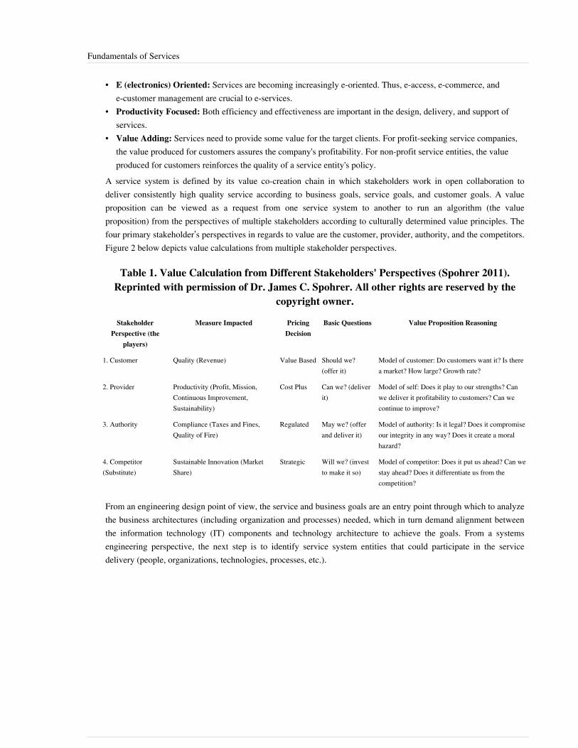
Fundamentals of Services 69
• E (electronics) Oriented: Services are becoming increasingly e-oriented. Thus, e-access, e-commerce, ande-customer management are crucial to e-services.
• Productivity Focused: Both efficiency and effectiveness are important in the design, delivery, and support ofservices.
• Value Adding: Services need to provide some value for the target clients. For profit-seeking service companies,the value produced for customers assures the company's profitability. For non-profit service entities, the valueproduced for customers reinforces the quality of a service entity's policy.
A service system is defined by its value co-creation chain in which stakeholders work in open collaboration todeliver consistently high quality service according to business goals, service goals, and customer goals. A valueproposition can be viewed as a request from one service system to another to run an algorithm (the valueproposition) from the perspectives of multiple stakeholders according to culturally determined value principles. Thefour primary stakeholder’s perspectives in regards to value are the customer, provider, authority, and the competitors.Figure 2 below depicts value calculations from multiple stakeholder perspectives.
Table 1. Value Calculation from Different Stakeholders' Perspectives (Spohrer 2011).Reprinted with permission of Dr. James C. Spohrer. All other rights are reserved by the
copyright owner.
StakeholderPerspective (the
players)
Measure Impacted PricingDecision
Basic Questions Value Proposition Reasoning
1. Customer Quality (Revenue) Value Based Should we?(offer it)
Model of customer: Do customers want it? Is therea market? How large? Growth rate?
2. Provider Productivity (Profit, Mission,Continuous Improvement,Sustainability)
Cost Plus Can we? (deliverit)
Model of self: Does it play to our strengths? Canwe deliver it profitability to customers? Can wecontinue to improve?
3. Authority Compliance (Taxes and Fines,Quality of Fire)
Regulated May we? (offerand deliver it)
Model of authority: Is it legal? Does it compromiseour integrity in any way? Does it create a moralhazard?
4. Competitor(Substitute)
Sustainable Innovation (MarketShare)
Strategic Will we? (investto make it so)
Model of competitor: Does it put us ahead? Can westay ahead? Does it differentiate us from thecompetition?
From an engineering design point of view, the service and business goals are an entry point through which to analyzethe business architectures (including organization and processes) needed, which in turn demand alignment betweenthe information technology (IT) components and technology architecture to achieve the goals. From a systemsengineering perspective, the next step is to identify service system entities that could participate in the servicedelivery (people, organizations, technologies, processes, etc.).

Fundamentals of Services 70
Service System EntitiesSpath and Fahnrich (2007) defined a service meta-model comprised of nine types of entities:1. Customers: customer features, customer attitudes, and customer preferences;2. Goals: business goals, service goals, customer goals, and enterprise culture goals;3. Inputs: physical, human beings, information, knowledge, currency, and constraints;4. Outputs: physical, human beings, information, knowledge, currency, and waste;5. Processes: service provision, service operations, service support, customer relationships, planning and control,
and call center management;6. Human Enablers: service providers, support providers, management, and owner organization (enterprise);7. Physical Enablers: owner organization (physical), buildings, equipment, furnishings, and location;8. Informatics Enablers: information, knowledge, procedures and processes, decision support, and skill
acquisition; and9. Environment: political factors, economic factors, social factors, technological factors, environmental factors,
legal factors (PESTEL), and physical factors.Thus, a service or service offering is created by the relationships among service system entities (includinginformation flows) through business processes into strategic capabilities that consistently provide superior value tothe customer. If we were to represent the service as a network diagram (as in Figure 3 below), then the entitiesrepresent the nodes and the links represent the relationships between nodes.
Figure 2. Service Systems Network Diagram. (SEBoK Original)
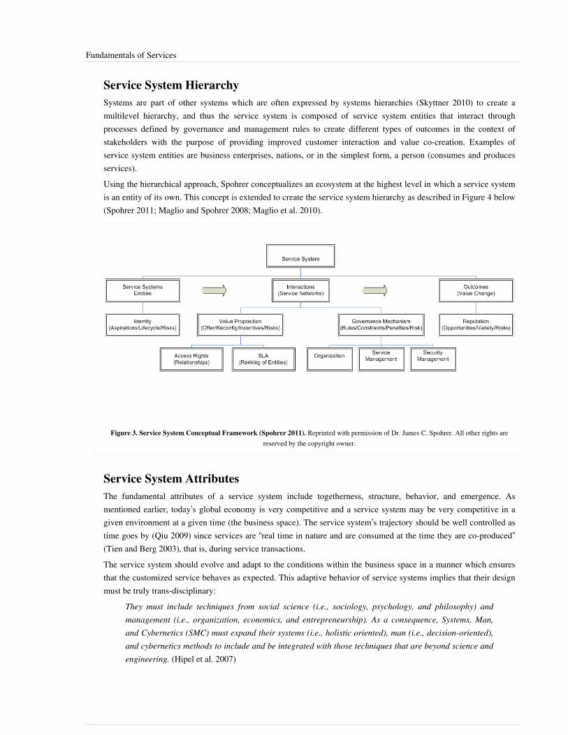
Fundamentals of Services 71
Service System HierarchySystems are part of other systems which are often expressed by systems hierarchies (Skyttner 2010) to create amultilevel hierarchy, and thus the service system is composed of service system entities that interact throughprocesses defined by governance and management rules to create different types of outcomes in the context ofstakeholders with the purpose of providing improved customer interaction and value co-creation. Examples ofservice system entities are business enterprises, nations, or in the simplest form, a person (consumes and producesservices).Using the hierarchical approach, Spohrer conceptualizes an ecosystem at the highest level in which a service systemis an entity of its own. This concept is extended to create the service system hierarchy as described in Figure 4 below(Spohrer 2011; Maglio and Spohrer 2008; Maglio et al. 2010).
Figure 3. Service System Conceptual Framework (Spohrer 2011). Reprinted with permission of Dr. James C. Spohrer. All other rights arereserved by the copyright owner.
Service System AttributesThe fundamental attributes of a service system include togetherness, structure, behavior, and emergence. Asmentioned earlier, today’s global economy is very competitive and a service system may be very competitive in agiven environment at a given time (the business space). The service system’s trajectory should be well controlled astime goes by (Qiu 2009) since services are “real time in nature and are consumed at the time they are co-produced”(Tien and Berg 2003), that is, during service transactions.The service system should evolve and adapt to the conditions within the business space in a manner which ensuresthat the customized service behaves as expected. This adaptive behavior of service systems implies that their designmust be truly trans-disciplinary:
They must include techniques from social science (i.e., sociology, psychology, and philosophy) andmanagement (i.e., organization, economics, and entrepreneurship). As a consequence, Systems, Man,and Cybernetics (SMC) must expand their systems (i.e., holistic oriented), man (i.e., decision-oriented),and cybernetics methods to include and be integrated with those techniques that are beyond science andengineering. (Hipel et al. 2007)

Fundamentals of Services 72
References
Works CitedChang, C.M. 2010. Service Systems Management and Engineering: Creating Strategic Differentiation andOperational Excellence. Hoboken, NJ, USA: John Wiley & Sons, Inc.Chesbrough, H. 2011. Open Services Innovation: Rethinking Your Business to Grow and Compete in a New Era. SanFrancisco, CA, USA: Jossey-Bass.CoreGRID. 2007. Using SLA for Resource Management and Scheduling - A Survey. Technical Report 0096. Jülich& Dortmund, Germany: European Research Network on Foundations, Software Infrastructures and Applications forLarge Scale Distributed, GRID and Peer-to-Peer Technologies, Institute on Resource Management and Scheduling.Accessed June 4, 2011. Available: http:/ / www. coregrid. net/ mambo/ images/ stories/ TechnicalReports/ tr-0096.pdf.Hipel, K.W., M.M. Jamshidi, J.M. Tien, and C.C. White. 2007. "The Future of Systems, Man, and Cybernetics:Application Domains and Research Methods." IEEE Transactions on Systems, Man, and Cybernetics - Part C:Applications and Reviews. 37 (5): 726-743.Maglio, P., C. Kieliszewski, and J. Spohrer. 2010. Handbook of Service Science. New York, NY, USA: SpringerScience and Business Media.Maglio, P., and J. Spohrer. 2008. "Fundamentals of Service Science." Journal of the Academy of Marketing Science.36 (1): 18-20.Qiu, R. 2009. "Computational Thinking of Service Systems: Dynamics and Adaptiveness Modeling." ServiceScience. 1 (1): 42-55.Skyttner, L. 2006. General Systems Theory: Perspectives, Problems, Practice, 2nd ed. Singapore: World ScientificPublishing Company.Spath, D., and K.P. Fähnrich (eds.). 2007. Advances in Services Innovations. Berlin & Heidelberg, Germany:Springer-Verlag.Spohrer, J., and S.K. Kwan. 2009. "Service Science, Management, Engineering, and Design (SSMED): AnEmerging Discipline - Outline & References." International Journal of Information Systems in the Service Sector, 1(3): 1-31.Spohrer, J., and P.P Maglio. 2010. "Chapter 1: Service Science: Toward a Smarter Planet," in Introduction to ServiceEngineering, edited by G. Salvendy and W. Karwowski. Hoboken, NJ: John Wiley & Sons.Spohrer, J.C. 2011. "Service Science: Progress & Directions." Presented at International Joint Conference on ServiceScience, May 25-27, 2011, Taipei, Taiwan.Theilmann, W., and L. Baresi. 2009. "Multi-level SLAs for Harmonized Management in the Future Internet," inTowards the Future Internet - A European Research Perspective, edited by G. Tselentis, J. Domingue, A. Galis, A.Gavras, D. Hausheer, S. Krco, V. Lotz, and T. Zehariadis. Amsterdam, The Netherlands: IOS Press.Tien, J.M., and D. Berg. 2003. "A Case for Service Systems Engineering." Journal of Systems Science and SystemsEngineering. 12 (1): 13-38.Vargo, S.L., and M.A. Akaka. 2009. "Service-Dominant Logic as a Foundation for Service Science: Clarifications."Service Science. 1 (1): 32-41.

Fundamentals of Services 73
Primary ReferencesChang, C.M. 2010. Service Systems Management and Engineering: Creating Strategic Differentiation andOperational Excellence. Hoboken, NJ, USA: John Wiley & Sons, Inc.Hipel, K.W., M.M. Jamshidi, J.M. Tien, and C.C. White. 2007. "The Future of Systems, Man, and Cybernetics:Application Domains and Research Methods." IEEE Transactions on Systems, Man, and Cybernetics - Part C:Applications and Reviews. 37 (5): 726-743.Spath, D., and K.P. Fähnrich (eds.). 2007. Advances in Services Innovations. Berlin & Heidelberg, Germany:Springer-Verlag.Spohrer, J.C. 2011. "Service Science: Progress & Directions." Presented at International Joint Conference on ServiceScience, May 25-27, 2011, Taipei, Taiwan.
Additional ReferencesChesbrough, H. 2011. Open Services Innovation: Rethinking Your Business to Grow and Compete in a New Era. SanFrancisco, CA, USA: Jossey-Bass.CoreGRID. 2007. Using SLA for Resource Management and Scheduling - A Survey. Technical Report 0096. Jülich& Dortmund, Germany: European Research Network on Foundations, Software Infrastructures and Applications forLarge Scale Distributed, GRID and Peer-to-Peer Technologies, Institute on Resource Management and Scheduling.Accessed June 4, 2011. Available: http:/ / www. coregrid. net/ mambo/ images/ stories/ TechnicalReports/ tr-0096.pdf.Maglio, P., C. Kieliszewski, and J. Spohrer. 2010. Handbook of Service Science. New York, NY, USA: SpringerScience and Business Media.Maglio, P., and J. Spohrer. 2008. "Fundamentals of Service Science." Journal of the Academy of Marketing Science.36 (1): 18-20.Qiu, R. 2009. "Computational Thinking of Service Systems: Dynamics and Adaptiveness Modeling." ServiceScience. 1 (1): 42-55.Skyttner, L. 2006. General Systems Theory: Perspectives, Problems, Practice, 2nd ed. Singapore: World ScientificPublishing Company.Spohrer, J., and S.K. Kwan. 2009. "Service Science, Management, Engineering, and Design (SSMED): AnEmerging Discipline - Outline & References." International Journal of Information Systems in the Service Sector, 1(3): 1-31.Spohrer, J., and P.P Maglio. 2010. "Chapter 1: Service Science: Toward a Smarter Planet," in Introduction to ServiceEngineering, edited by G. Salvendy and W. Karwowski. Hoboken, NJ: John Wiley & Sons.Theilmann, W., and L. Baresi. 2009. "Multi-level SLAs for Harmonized Management in the Future Internet," inTowards the Future Internet - A European Research Perspective, edited by G. Tselentis, J. Domingue, A. Galis, A.Gavras, D. Hausheer, S. Krco, V. Lotz, and T. Zehariadis. Amsterdam, The Netherlands: IOS Press.Tien, J.M., and D. Berg. 2003. "A Case for Service Systems Engineering." Journal of Systems Science and SystemsEngineering. 12 (1): 13-38.Vargo, S.L., and M.A. Akaka. 2009. "Service-Dominant Logic as a Foundation for Service Science: Clarifications."Service Science. 1 (1): 32-41.
Fundamentals of Services 74
< Previous Article | Parent Article | Next Article >SEBoK v. 1.4 released 29 June 2015
SEBoK DiscussionPlease provide your comments and feedback on the SEBoK below. You will need to log in to DISQUS using anexisting account (e.g. Yahoo, Google, Facebook, Twitter, etc.) or create a DISQUS account. Simply type yourcomment in the text field below and DISQUS will guide you through the login or registration steps. Feedback will bearchived and used for future updates to the SEBoK. If you provided a comment that is no longer listed, that commenthas been adjudicated. You can view adjudication for comments submitted prior to SEBoK v. 1.0 at SEBoK Reviewand Adjudication. Later comments are addressed and changes are summarized in the Letter from the Editor andAcknowledgements and Release History.
If you would like to provide edits on this article, recommend new content, or make comments on the SEBoKas a whole, please see the SEBoK Sandbox [1].
ENCODED_CONTENTNzk2MTAPGRpdiBpZD0iZGlzcXVzX3RocmVhZCI+PC9kaXY+CjxzY3JpcHQgdHlwZT0idGV4dC9qYXZhc2NyaXB0Ij4KICAgIC8qICogKiBDT05GSUdVUkFUSU9OIFZBUklBQkxFUzogRURJVCBCRUZPUkUgUEFTVElORyBJTlRPIFlPVVIgV0VCUEFHRSAqICogKi8KICAgIHZhciBkaXNxdXNfc2hvcnRuYW1lID0gJ3NlYm9rd2lraTEwJzsgLy8gcmVxdWlyZWQ6IHJlcGxhY2UgZXhhbXBsZSB3aXRoIHlvdXIgZm9ydW0gc2hvcnRuYW1lCiAgICB2YXIgZGlzcXVzX2lkZW50aWZpZXIgPSAnRnVuZGFtZW50YWxzIG9mIFNlcnZpY2VzJzsgICAgdmFyIGRpc3F1c191cmwgPSAnaHR0cDovL3NlYm9rd2lraS5vcmcvZHJhZnQvRnVuZGFtZW50YWxzX29mX1NlcnZpY2VzJzsKICAgIC8qICogKiBET04nVCBFRElUIEJFTE9XIFRISVMgTElORSAqICogKi8KICAgIChmdW5jdGlvbigpIHsKICAgICAgICB2YXIgZHNxID0gZG9jdW1lbnQuY3JlYXRlRWxlbWVudCgnc2NyaXB0Jyk7IGRzcS50eXBlID0gJ3RleHQvamF2YXNjcmlwdCc7IGRzcS5hc3luYyA9IHRydWU7CiAgICAgICAgZHNxLnNyYyA9ICdodHRwOi8vJyArIGRpc3F1c19zaG9ydG5hbWUgKyAnLmRpc3F1cy5jb20vZW1iZWQuanMnOwogICAgICAgIChkb2N1bWVudC5nZXRFbGVtZW50c0J5VGFnTmFtZSgnaGVhZCcpWzBdIHx8IGRvY3VtZW50LmdldEVsZW1lbnRzQnlUYWdOYW1lKCdib2R5JylbMF0pLmFwcGVuZENoaWxkKGRzcSk7CiAgICB9KSgpOwo8L3NjcmlwdD4KPG5vc2NyaXB0PlBsZWFzZSBlbmFibGUgSmF2YVNjcmlwdCB0byB2aWV3IHRoZSA8YSBocmVmPSJodHRwOi8vZGlzcXVzLmNvbS8/cmVmX25vc2NyaXB0Ij5jb21tZW50cyBwb3dlcmVkIGJ5IERpc3F1cy48L2E+PC9ub3NjcmlwdD4KPGEgaHJlZj0iaHR0cDovL2Rpc3F1cy5jb20iIGNsYXNzPSJkc3EtYnJsaW5rIj5ibG9nIGNvbW1lbnRzIHBvd2VyZWQgYnkgPHNwYW4gY2xhc3M9ImxvZ28tZGlzcXVzIj5EaXNxdXM8L3NwYW4+PC9hPg==END_ENCODED_CONTENT
Properties of ServicesA service is realized by the service system through the relationships of service system entities that interact (or relate)in a particular way to deliver the specific service via a service level agreement (SLA). Current managementframeworks typically only focus on the interfaces of single service system entities. Meanwhile, SLAs are mapped tothe respective customer requirements. These policies are provider-specific means to express constraints and rules fortheir internal operations. These rules may be independent of any particular customer (Theilmann 2009).Services not only involve the interaction between the service provider and the consumer to produce value, but haveother attributes, like an intangible quality of service (e.g., an ambulance service's availability and response time to anemergency request). The demand for a service may have varying loads dependent on the time of day, day of week,season, or other unexpected needs (e.g., natural disasters, product promotion campaigns, etc.). In the US for instance,travel services have peak demands during Christmas week; Mother’s day is usually the highest volume handling dayfor a telecommunications provider and tax services peak during extended periods (January through mid-April).Services cannot be inventoried; they are rendered at the time they are requested.Additionally, for a business enterprise, delivering the service at the minimum cost while maximizing its profits maybe the service objective. In contrast, for a non-profit organization the objective may be to maximize customersatisfaction while optimizing the resources required to render the service (e.g., during a natural disaster). Thus, thedesign and operations of service systems “is all about finding the appropriate balance between the resources devotedto the systems and the demands placed on the system so that the quality of service to the customer is as good aspossible” (Daskin 2010).
Service Level AgreementA SLA is a set of technical (functional) and non-technical (non-functional) parameters agreed among customers andservice providers. SLAs can and do contain administrative level (non-functional) business related parameters, suchas SLA duration, service availability for the SLA duration, consequences for variations, failure reporting, priorities,and provisions for modifications to the SLA. However, for service level management, the service level (technical)parameters need to be defined, monitored, and assessed; these parameters may include such things as throughput;

Properties of Services 75
quality; availability; security; performance; reliability, for example, mean time between failure (MTBF), maximumdowntime, and time-to-repair; and resource allocation.An SLA represents the negotiated service level requirements (SLR) of the customer and should establish valid andreliable service performance measures since it is usually the basis for effective service level management (SLM).The goal of SLM is to ensure that service providers meet and maintain the prescribed quality of service (QoS).However, care should be taken since in some domains the term QoS refers only to resource reservation controlmechanisms rather than the achieved service quality (e.g., internet protocol (IP) networks). Some terms used to meanthe “achieved service quality” include quality of experience (QoE), user-perceived performance, and degree ofsatisfaction of the user; these other terms are more generally used across service domains.Non-functional properties fall into two basic categories: business properties, such as price and method of payment,and environmental properties, such as time and location. Business and environmental properties are classified as“context properties” by Youakim Badr (Badr et al. 2008). QoS properties are characteristics such as availability,resilience, security, reliability, scalability, agreement duration, response times, repair times, usability, etc. Thereforeservices evaluation measures are customer oriented and include not only traditional performance metrics(productivity, quality, etc.), but also require a comprehensive analysis of the service system from an end-to-endperspective. Service evaluation typically includes customer demand-supply to ensure economic viability across thelifecycle of the service system. Furthermore, the service delivery is evaluated using the key technical performancemetrics listed above, adding also Service Process Measures (provisioning time, time-to-restore/repair, etc.) andTechnical Performance Measures (end-to-end response times, latency, throughput, etc.). Finally, the service system’sSLAs are then the composition of these categories evaluated on a systemic level to ensure consistency, equity, andsustainability of the service to assure that the desired/contracted SLA for customer satisfaction, value co-creation,and high system robustness are realized. (Spohrer 2011; Tien and Berg 2003; Theilmann and Baresi, 2009)
Service Key Performance IndicatorsService key performance indicators (KPI) are defined and agreed to in the SLA; the service KPIs are decomposedinto service process measures (SPM) and technical performance measures (TPM) during the analysis stage of theservice systems engineering (SSE) process. In the design process, the KPIs and TPM are allocated to service systementities and their components, as well as to the business processes and their components so as to ensure compliancewith SLAs. The allocated measures generate derived requirements (SLR) for the system entities and theirrelationships, as well as for the service entities' components and the data and information flows required in theservice systems to monitor, measure, and assess end-to-end SLA. These allocations ensure that the appropriateperformance indicators apply to each of the links in the service value chain.TPMs are typically categorized by the number of defective parts in a manufacturing service, data transmissionlatency and data throughput in an end-to-end application service, IP QoS expressed by latency, jitter delay, andthroughput; SPMs are typically categorized by service provisioning time, end-to-end response times to a servicerequest (a combination of data and objective feedback), and quality of experience (QoE verified by objectivefeedback). Together, the KPI (TPM combined with SPM) and perception measures make up the service levelmanagement function. A quality assurance system's (QAS) continuous service improvement (CSI), processes, andprocess quality management and improvement (PQMI) should be planned, designed, deployed, and managed for thecapability to continuously improve the service system and to monitor compliance with SLAs (e.g., PQMI, capabilitymaturity model integration (CMMI) (SEI 2007), International Organization for Standardization (ISO) Standards9001 (ISO/IEC 2008), Telecom Quality Management System Standards (TL 9000) (QuEST Forum 2012),Information Technology Infrastructure Library (ITIL) v. 3 (OGC 2009), etc.).As discussed earlier, QoS needs to correlate customer perceived quality (subjective measures) with objective SPM and TPM measures. There are several techniques available to help monitor, measure, and assess TPM’s, but most are a variation on the theme of culling information from TPM’s using, for example, perceptual speech quality measure
Properties of Services 76
(PSQM) and perceptual evaluation of video quality (PEVQ) and enhancing or verifying this information withcustomer or end-user perception of service by extending mean opinion score (MOS) techniques/customer opinionmodels (Ray 1984). Telecommunication systems engineering (TCSE) played an important role in findingmethodologies for correlation between perception and objective measures for the services of the twentieth century;SSE should continue to encourage multidisciplinary participation to equally find methodologies, processes, and toolsto correlate perceived service quality with TPM and with SPM for the services of the twenty-first century (Freeman2004).Subjective (qualitative) service quality is the customer’s perceived conformity of the service with the expectedobjective. Word-of-mouth, personal needs, and past experiences create customer expectations regarding the service.The customers' perception of the service must be captured via surveys and interviews. The customers' perception ofthe service is then compared with their expectations for the service; this process captures the perceived servicequality. Care should be taken to understand that subjective measures appear to measure customer attitudes, andattitudes may be the result of several encounters with the service, as well as numerous encounters with similarservices.In summary, the SLA documents the SLRs and establishes reliable and valid service performance measures,technical parameters, and the agreed performance levels for the technical parameters. The technical parameters arethen monitored and continuously compared against both objective and subjective data culled from multiple internaland external sources (service level management). The goal is not to report the level of service in a given period, butto develop and implement a dynamic system capable of predicting and driving service level improvement over time(i.e., continual service improvement (CSI)).
Evolution of ServicesThe second, third, and fourth decades of the twenty-first century will almost certainly see similar, and probablyaccelerated, technology development as seen in the prior three decades. Mass collaboration will become anestablished mode of operation. The beginnings of mass collaboration have manifested in developments such as valueco-creation where loosely entangled actors or entities come together to create value in unprecedented ways, but waysthat meet mutual and broader market requirements. Further developments in the technology, use, and acceptance ofsocial media will continue to fuel the acceleration of these developments.The next decades will see the grounding of concepts, such as crowdsourcing, coined by Jeff Howe in a June 2006Wired magazine article; open innovation, promoted by Henry Chesbrough, a professor and executive director at theCenter for Open Innovation at Berkeley; and mass collaboration and open source innovation supported by Enterprise2.0 tools, as conceived by Wikinomics consultant Don Tapscott.Roberto Saracco, a telecommunications expert specializing in analyzing economical impacts of technologyevolution, argues that: “Communications will be the invisible fabric connecting us and the world whenever andwherever we happen to be in a completely seamless way, connecting us so transparently, cheaply, and effortlesslythat very seldom will we think about it.” The ubiquity and invisibility of these communications will greatly facilitatethe creation and destruction of ad hoc collectives (groups of entities that share or are motivated by at least onecommon issue or interest, or work together on a specific project(s) to achieve a common objective). This enterprisemay engender the concept of the hive mind (the collective intelligence of many), which will be an intelligent versionof real-life super organisms, such as ant or bee nests (Hölldobler and Wilson 2009).These models will most certainly give rise to issues of property rights and liabilities; access rights for both theprovider and the customer can be owned outright, contracted/leased, shared, or have privileged access (Spohrer2011). For now, we are on the cusp of a management revolution that is likely to be as profound and unsettling as theone that gave birth to the modern industrial age. Driven by the emergence of powerful new collaborativetechnologies, this transformation will radically reshape the nature of work, the boundaries of the enterprise, and theresponsibilities of business leaders (McAfee 2009).

Properties of Services 77
The service-providing industry in the US is divided into thirteen sectors (Chang 2010):1.1. professional and business services,2.2. healthcare and social assistance,3.3. state and local government,4.4. leisure and hospitality,5.5. other services,6.6. educational services,7.7. retail trade,8.8. financial activities,9.9. transportation and warehousing,10.10. wholesale trade,11.11. information,12.12. federal government, and13.13. utilities.Spohrer (2011) goes beyond the service sectors to propose three types of service systems:1. Systems that focus on flow of things: transportation and supply chains, water and waste recycling, food and
products, energy and electric Grid, information/ICT & cloud;2. Systems that focus on Human Activities and Development: buildings and construction, retail and hospitality /
media and entertainment industries, banking and finance / business consulting industries, healthcare and familylife systems, education and work life / jobs and entrepreneurship; and
3. Systems that focus on Governing: cities, states, and nations.Categorizing types and sectors of services is an important beginning because it can lead to a better understanding ofthe emerging rules and relationships in service value chains. This approach can further enhance the value co-creationcapabilities of innovative service concepts that contribute to our quality of life. The classification also helps inidentifying different objectives and constraints for the design and operations of the service system. Some examplesinclude strategic policies under limited budget: education, strategic with readiness for quick response; nationaldefense; business enterprise, maximizing profit while minimizing cost; etc.In addition, this classification is being used to determine the overlap and synergies required among different sciencedisciplines to enable trans-disciplinary collaboration and educational programs.
References
Works CitedBadr, Y., A. Abraham, F. Biennier, and C. Grosan. 2008. "Enhancing Web Service Selection by User Preferences ofNon-Functional Features." Presented at 4th International Conference on Next Generation Web Services Practices,October 20-22, 2008, Seoul, South Korea.Chang, C.M. 2010. Service Systems Management and Engineering: Creating Strategic Differentiation andOperational Excellence. New York, NY, USA: John Wiley & Sons, Inc.Daskin, M.S. 2010. Service Science. New York, NY, USA: John Wiley & Sons.Freeman, R.L. 2004. Telecommunication Systems Engineering, 4th ed. New York, NY, USA: John Wiley & Sons.Hölldobler, B., and E.O. Wilson. 2009. The Super-organism: The Beauty, Elegance, and Strangeness of InsectSocieties. New York, NY, USA: W.W. Norton & Company.ISO. 2008, ISO 9001:2008, Quality management systems -- Requirements. Geneva, Switzerland: InternationalOrganisation for Standardisation.

Properties of Services 78
McAfee, A. 2009. Enterprise 2.0: New Collaborative Tools for Your Organization's Toughest Challenges. Boston,MA, USA: Harvard Business School Press.OGC (Office of Government Commerce). 2009. ITIL Lifecycle Publication Suite Books. London, UK: TheStationery Office.QuEST Forum. 2012. Quality Management System (QMS) Measurements Handbook, Release 5.0. Plano, TX, USA:Quest Forum.Ray, R.F. (ed). 1984. Engineering and Operations in Bell System, 2nd ed. Florham Park, NJ, USA: AT&T Bell Labs.SEI. 2007. Capability Maturity Model Integrated (CMMI) for Development, version 1.2. Pittsburgh, PA, USA:Software Engineering Institute (SEI)/Carnegie Mellon University (CMU).Spohrer, J.C. 2011. "Service Science: Progress & Directions." Presented at the International Joint Conference onService Science, 25-27 May 2011, Taipei, Taiwan.Theilmann, W., and L. Baresi. 2009. "Multi-level SLAs for Harmonized Management in the Future Internet," inTowards the Future Internet - A European Research Perspective, edited by G. Tselentis, J. Domingue, A. Galis, A.Gavras, D. Hausheer, S. Krco, V. Lotz, and T. Zehariadis. Amsterdam, The Netherlands: IOS Press.Tien, J.M., and D. Berg. 2003. "A Case for Service Systems Engineering." Journal of Systems Science and SystemsEngineering. 12 (1): 13-38.
Primary ReferencesChang, C.M. 2010. Service Systems Management and Engineering: Creating Strategic Differentiation andOperational Excellence. New York, NY, USA: John Wiley & Sons, Inc.Theilmann, W., and L. Baresi. 2009. "Multi-level SLAs for Harmonized Management in the Future Internet," inTowards the Future Internet - A European Research Perspective, edited by G. Tselentis, J. Domingue, A. Galis, A.Gavras, D. Hausheer, S. Krco, V. Lotz, and T. Zehariadis. Amsterdam, The Netherlands: IOS Press.
Additional ReferencesNone.
< Previous Article | Parent Article | Next Article >SEBoK v. 1.4 released 29 June 2015
SEBoK DiscussionPlease provide your comments and feedback on the SEBoK below. You will need to log in to DISQUS using anexisting account (e.g. Yahoo, Google, Facebook, Twitter, etc.) or create a DISQUS account. Simply type yourcomment in the text field below and DISQUS will guide you through the login or registration steps. Feedback will bearchived and used for future updates to the SEBoK. If you provided a comment that is no longer listed, that commenthas been adjudicated. You can view adjudication for comments submitted prior to SEBoK v. 1.0 at SEBoK Reviewand Adjudication. Later comments are addressed and changes are summarized in the Letter from the Editor andAcknowledgements and Release History.
If you would like to provide edits on this article, recommend new content, or make comments on the SEBoKas a whole, please see the SEBoK Sandbox [1].
ENCODED_CONTENTMTc1MTQPGRpdiBpZD0iZGlzcXVzX3RocmVhZCI+PC9kaXY+CjxzY3JpcHQgdHlwZT0idGV4dC9qYXZhc2NyaXB0Ij4KICAgIC8qICogKiBDT05GSUdVUkFUSU9OIFZBUklBQkxFUzogRURJVCBCRUZPUkUgUEFTVElORyBJTlRPIFlPVVIgV0VCUEFHRSAqICogKi8KICAgIHZhciBkaXNxdXNfc2hvcnRuYW1lID0gJ3NlYm9rd2lraTEwJzsgLy8gcmVxdWlyZWQ6IHJlcGxhY2UgZXhhbXBsZSB3aXRoIHlvdXIgZm9ydW0gc2hvcnRuYW1lCiAgICB2YXIgZGlzcXVzX2lkZW50aWZpZXIgPSAnUHJvcGVydGllcyBvZiBTZXJ2aWNlcyc7ICAgIHZhciBkaXNxdXNfdXJsID0gJ2h0dHA6Ly9zZWJva3dpa2kub3JnL2RyYWZ0L1Byb3BlcnRpZXNfb2ZfU2VydmljZXMnOwogICAgLyogKiAqIERPTidUIEVESVQgQkVMT1cgVEhJUyBMSU5FICogKiAqLwogICAgKGZ1bmN0aW9uKCkgewogICAgICAgIHZhciBkc3EgPSBkb2N1bWVudC5jcmVhdGVFbGVtZW50KCdzY3JpcHQnKTsgZHNxLnR5cGUgPSAndGV4dC9qYXZhc2NyaXB0JzsgZHNxLmFzeW5jID0gdHJ1ZTsKICAgICAgICBkc3Euc3JjID0gJ2h0dHA6Ly8nICsgZGlzcXVzX3Nob3J0bmFtZSArICcuZGlzcXVzLmNvbS9lbWJlZC5qcyc7CiAgICAgICAgKGRvY3VtZW50LmdldEVsZW1lbnRzQnlUYWdOYW1lKCdoZWFkJylbMF0gfHwgZG9jdW1lbnQuZ2V0RWxlbWVudHNCeVRhZ05hbWUoJ2JvZHknKVswXSkuYXBwZW5kQ2hpbGQoZHNxKTsKICAgIH0pKCk7Cjwvc2NyaXB0Pgo8bm9zY3JpcHQ+UGxlYXNlIGVuYWJsZSBKYXZhU2NyaXB0IHRvIHZpZXcgdGhlIDxhIGhyZWY9Imh0dHA6Ly9kaXNxdXMuY29tLz9yZWZfbm9zY3JpcHQiPmNvbW1lbnRzIHBvd2VyZWQgYnkgRGlzcXVzLjwvYT48L25vc2NyaXB0Pgo8YSBocmVmPSJodHRwOi8vZGlzcXVzLmNvbSIgY2xhc3M9ImRzcS1icmxpbmsiPmJsb2cgY29tbWVudHMgcG93ZXJlZCBieSA8c3BhbiBjbGFzcz0ibG9nby1kaXNxdXMiPkRpc3F1czwvc3Bhbj48L2E+END_ENCODED_CONTENT

Scope of Service Systems Engineering 79
Scope of Service Systems EngineeringService systems engineering (SSE) involves all aspects of the enterprise. This topic discusses different aspects of thescope of SSE, from organizational strategy, to interoperability, to the life cycle of services, and then to their design.
SSE and the EnterpriseEnterprises plan, develop, and manage the enhancements of their infrastructure, products, and services, includingmarketing strategies for product and service offerings. These plans propose new products or service offerings basedon new, unexplored, or unforeseen customer needs with clearly differentiated value propositions. Service strategiesare the internal business processes required to design, operate, and deliver services. The mission of service strategiesis to develop the capacity to achieve and maintain a strategic advantage (OGC 2009).Taking the systems engineering (SE) approach to service systems, or (SSE), is imperative for the service-oriented,customer-centric holistic view to select and combine service system entities. The SSE approach can then define anddiscover relationships among service system entities to plan, design, adapt, or self-adapt to co-create value. The SSEapproach should identify linkages, relationships, constraints, challenges/problems, new technologies, interoperabilitystandards, interface agreements, or process development requirements among service entities required for theplanned service or for potential future services (Lefever 2005).SSE mandates participation not only from engineering, business operations, and customers, but also from variousdifferent domains, such as management science, behavioral science, social science, systems science, networkscience, computer science, decision informatics, etc.Hipel et al. (2007) have presented a table for service science in terms of the domains and methods, including notonly service systems, but also infrastructure and transportation systems, environmental and energy systems, anddefense and space systems. The collaboration domains in Figure 1 below are a first approximation to thecollaboration required from different disciplines for the SSE paradigm.
Table 1. Service Systems Engineering Domain Collaboration. (Hipel et al. 2007) Reprintedwith permission of © Copyright IEEE - All rights reserved.
SEE Collaboration Domains
SSE Management •• Management Science•• Business Process Management•• Cognitive Science•• Decision Science
Service Realization Process (SRP) •• All engineering fields•• Business Operations•• Infrastructure Operations•• Social Science•• Computer Science•• Management Science•• Behavioral Science•• Network Science•• Computational Science•• Systems Science•• Decision Science
Methodologies, Processes, and Tools (MPT) •• Natural Science•• Business Science (BPMN)•• Mathematical•• All engineering fields

Scope of Service Systems Engineering 80
Major challenges faced by SSE include the dynamic nature of service systems evolving and adapting to constantlychanging operations and/or business environments, and the need to overcome silos of knowledge. Interoperability ofservice system entities through interface agreements must be at the forefront of the SSE design process for theharmonization of operations, administration, maintenance, and provisioning procedures of the individual servicesystem entities (Pineda 2010).In addition, service systems require open collaboration among all stakeholders, but recent research on mental modelsof multidisciplinary teams shows integration and collaboration into cohesive teams has proven to be a majorchallenge (Carpenter et al. 2010) (See also Team Dynamics). Thus, the emphasis on multidisciplinary (e.g.,scientific, engineering, management, and social) education and training programs required to foster systems thinkinghelps bridge the gaps created by these silos of knowledge.In the SSE approach, the social, governance, business, service, operations, and management activities are linkedtogether through the service life cycle; service systems are by themselves a type of system of systems (SoS) wheretraditional systems engineering (TSE) practices need to be extended to include service systems entities' relationships(e.g., interface agreements among people, organizations, processes, and technologies) through information flows,technical interoperability, governance, and access rights within a system of systems.
Interoperability of ServicesInteroperability among the different service system entities becomes highly relevant in SSE since the constituententities are designed according to stakeholder needs; the entity is usually managed and operated to satisfy its ownobjectives independently of other system entities. The objectives of individual service system entities may notnecessarily converge with the overall objectives of the service system. Thus, the need to include the following in thedefinition of a service system: analysis and design of the service system, governance frameworks to align politicalobjectives, service strategies, business objectives, information and communications technologies (ICT) objectives,technology objectives and end-to-end operations, administration and maintenance procedures, and allocation of theseprocedures to individual entities (Luzeaux and Ruault 2010).The previous discussion relates to a new service system development. There may be instances where a service isplanned for delivery in phases of deployment (transition/deployment phase), or as presented earlier, if there isalready a service system defined and deployed, then it's possible that the new request is for a service basedapplication (SBA), in which case, the process is more focused on the adaptations needed to deploy the newapplication. For SBA, instances of advances in computer engineering, computer science, and software developmentalready permit the adaptation and creation of SBA in a run-time environment for the discovery, development, andpublishing of applications (Maglio et al. 2010).The service design process (SDP) for new services is triggered by the market concept of the intended service andconsiders the stakeholder(s), service value chain(s), target market(s), target customer(s), proposed SLA, demandforecast, pricing strategy, and customer access privileges, which together comprise the service strategy. The SDPprocess then adapts the TSE as a life cycle approach (concept/definition, design/development, deployment/transition,operations, life cycle management/utilization/CSI, and retirement) as discussed in Life Cycle Models. A moredetailed list of the SSE process activities is described in Value of Service Systems Engineering and Service SystemsEngineering Stages.

Scope of Service Systems Engineering 81
Service Lifecycle StagesThe SDP stages and notation are depicted in Table 2 below; due to the complexity of service systems (see alsoComplexity) the documents generated are becoming more model-based electronic documents than written bindersdepending on the methodologies and tools used.
Table 2. Service Realization Process: Life Cycle Stages. (SEBoK Original)<html>
Life Cycle Changes Purpose Decision Gates
Service Strategy/Concept New Service identification Elicit enterprise needsExplore service concepts
Identify service system entitiesPropose viable HL black box solutions
Output: Service Description
Decision Options- Go, No-GO
- Continue thisstage
- Go to precedingstage
- Hold projectactivity
- Terminateproject- Test
- Deploy
Feasibility Phase
HL Analysis
ServiceDesign/Development
Service Requirement Analysis andEngineering
Refine service system requirementsOutput: Service Requirement Document
Create solution descriptionIdentify Interfaces among entities
Output: Preliminary DesignDevelop service system detailed architecture and specs
Output: Service Specification DocumentVerify and Validate system requirements
Output: service JV & V Plans
Service Development
Service Integration, Verification,and Validation
Service Transition/Deployment Service Insertion PlansDeploy service system
Manage deployment activitiesInspect and test (verify)
Output: Service Operation Plans, Operations TechnicalPlans, Operational Readiness Plans
Service Operations and / Continuous Service Improvement Operate a reliable service system to satisfy customer needsMonitor, Measure, & Assess
Provide sustained system capabilityTroubleshoot potential issues
Store, archive, or dispose of the service system
</html>All the life cycle stages are included for completeness, but very often during the concept analysis phase it may bedetermined that not all of the stages are needed. In these cases, a recommendation should be made regarding whichstages are specifically required for the realization of the service in question.
Service Design ManagementAnother important role of SSE is the management of the service design process. SSE utilizes TSE practices tomanage the resource and asset allocation to perform the activities required to realize the service through the valuechain for both the customer and the service provider. The main focus of the service design process management is toprovide for the planning, organizational structure, collaboration environment, and program controls to ensure thatstakeholder's needs are met from an end-to-end customer perspective.The service design process management process aligns business objectives and business operational plans withend-to-end service objectives, including customer management plans, service management and operations plans, andoperations technical plans. The main SSE management activities are•• planning;

Scope of Service Systems Engineering 82
•• assessment and control;•• decision management;•• risk management;•• configuration management; and•• information management.SSE plays a critical role in describing the needs of the intended service in terms of the service's day-to-dayoperations, including customer care center requirements, interface among service system entities, such as:manufacturing plant, smart grid, hospital, network infrastructure provider(s), content provider(s) and serviceprovider(s), service based application provider(s), applications providers, and the customer management process forthe service.Current research in computer engineering and software systems engineering is looking at the development ofrun-time platforms to allow real time or near real time customer service discovery and publishing (Spark 2009). Theservice-centric systems engineering (SeCSE) consortium has a well-defined service design process that is beingapplied to SBA. In this approach, there are design time and run-time sub-processes for the composition,provisioning, orchestration, and testing for service publishing (Lefever 2005). There is particular interest from theresearch community to include human-computer interactions (HCI) and behavioral science to address current socialnetworking services (Facebook, Twitter, Linkedin, Google+, etc.) used to share unverified information via audio,messaging, video, chats, etc.This research is gaining relevance because of the thin line between the customer (consumer, enterprise) and contentproviders in regards to security, privacy, information authentication, and possible misuse of the user-generatedcontent. Even as the research progresses, these networking services are examples of business models organizingcommunities of interest for innovation. Hsu says, “If we understand this networking, then we may be able to seethrough the business strategies and systems design laws that optimize connected value co-creation” (2009).
References
Works CitedCarpenter, S., H. Delugach, L. Etzkorn, J. Fortune, D. Utley, and S. Virani. 2010. "The Effect of Shared MentalModels on Team Performance." Presented at Industrial Engineering Research Conference, Institute of IndustrialEngineers, 2010, Cancun, Mexico.Hipel, K.W., M.M. Jamshidi, J.M. Tien, and C.C. White. 2007. "The Future of Systems, Man, and Cybernetics:Application Domains and research Methods." IEEE Transactions on Systems, Man, and Cybernetics-Part C:Applications and Reviews. 37 (5): 726-743.Hsu, C. 2009. "Service Science and Network Science." Service Science, 1 (2): i-ii.Lefever, B. 2005. SeSCE Methodology. Rome, Italy: SeCSE Service Centric Systems Engineering. SeCSE511680.Available: http:/ / www. secse-project. eu/ wp-content/ uploads/ 2007/ 08/ a5_d4-secse-methodology-v1_3. pdf.Luzeaux, D., and J.R. Ruault (eds.). 2010. Systems of Systems. New York, NY, USA: John Wiley & Sons.Maglio, P., M. Weske, J. Yang, and M. Fantinato (eds.). 2010. Proceedings of the 8th International Conference onService Oriented Computing: ICSOC 2010. Berlin & Heidelberg, Germany: Springer-Verlag.OGC (Office of Government Commerce). 2009. ITIL Lifecycle Publication Suite Books. London, UK: TheStationery Office.Pineda, R. 2010. "Understanding Complex Systems of Systems Engineering." Presented at Fourth General AssemblyCartagena Network of Engineering, 2010, Metz, France.Spark, D. 2009. "Real-Time Search and Discovery of the Social Web." Spark Media Solutions Report. Accessed September 2, 2011. Available: http:/ / www. sparkminute. com/ 2009/ 12/ 07/

Scope of Service Systems Engineering 83
free-report-real-time-search-and-discovery-of-the-social-web/ .
Primary ReferencesLefever, B. 2005. SeSCE Methodology. Rome, Italy: SeCSE Service Centric Systems Engineering. SeCSE511680.Available: http:/ / www. secse-project. eu/ wp-content/ uploads/ 2007/ 08/ a5_d4-secse-methodology-v1_3. pdf.Luzeaux, D., and J.R. Ruault (eds.). 2010. Systems of Systems. New York, NY, USA: John Wiley & Sons.
Additional ReferencesNone.
< Previous Article | Parent Article | Next Article >SEBoK v. 1.4 released 29 June 2015
SEBoK DiscussionPlease provide your comments and feedback on the SEBoK below. You will need to log in to DISQUS using anexisting account (e.g. Yahoo, Google, Facebook, Twitter, etc.) or create a DISQUS account. Simply type yourcomment in the text field below and DISQUS will guide you through the login or registration steps. Feedback will bearchived and used for future updates to the SEBoK. If you provided a comment that is no longer listed, that commenthas been adjudicated. You can view adjudication for comments submitted prior to SEBoK v. 1.0 at SEBoK Reviewand Adjudication. Later comments are addressed and changes are summarized in the Letter from the Editor andAcknowledgements and Release History.
If you would like to provide edits on this article, recommend new content, or make comments on the SEBoKas a whole, please see the SEBoK Sandbox [1].
ENCODED_CONTENTOTc4NTYPGRpdiBpZD0iZGlzcXVzX3RocmVhZCI+PC9kaXY+CjxzY3JpcHQgdHlwZT0idGV4dC9qYXZhc2NyaXB0Ij4KICAgIC8qICogKiBDT05GSUdVUkFUSU9OIFZBUklBQkxFUzogRURJVCBCRUZPUkUgUEFTVElORyBJTlRPIFlPVVIgV0VCUEFHRSAqICogKi8KICAgIHZhciBkaXNxdXNfc2hvcnRuYW1lID0gJ3NlYm9rd2lraTEwJzsgLy8gcmVxdWlyZWQ6IHJlcGxhY2UgZXhhbXBsZSB3aXRoIHlvdXIgZm9ydW0gc2hvcnRuYW1lCiAgICB2YXIgZGlzcXVzX2lkZW50aWZpZXIgPSAnU2NvcGUgb2YgU2VydmljZSBTeXN0ZW1zIEVuZ2luZWVyaW5nJzsgICAgdmFyIGRpc3F1c191cmwgPSAnaHR0cDovL3NlYm9rd2lraS5vcmcvZHJhZnQvU2NvcGVfb2ZfU2VydmljZV9TeXN0ZW1zX0VuZ2luZWVyaW5nJzsKICAgIC8qICogKiBET04nVCBFRElUIEJFTE9XIFRISVMgTElORSAqICogKi8KICAgIChmdW5jdGlvbigpIHsKICAgICAgICB2YXIgZHNxID0gZG9jdW1lbnQuY3JlYXRlRWxlbWVudCgnc2NyaXB0Jyk7IGRzcS50eXBlID0gJ3RleHQvamF2YXNjcmlwdCc7IGRzcS5hc3luYyA9IHRydWU7CiAgICAgICAgZHNxLnNyYyA9ICdodHRwOi8vJyArIGRpc3F1c19zaG9ydG5hbWUgKyAnLmRpc3F1cy5jb20vZW1iZWQuanMnOwogICAgICAgIChkb2N1bWVudC5nZXRFbGVtZW50c0J5VGFnTmFtZSgnaGVhZCcpWzBdIHx8IGRvY3VtZW50LmdldEVsZW1lbnRzQnlUYWdOYW1lKCdib2R5JylbMF0pLmFwcGVuZENoaWxkKGRzcSk7CiAgICB9KSgpOwo8L3NjcmlwdD4KPG5vc2NyaXB0PlBsZWFzZSBlbmFibGUgSmF2YVNjcmlwdCB0byB2aWV3IHRoZSA8YSBocmVmPSJodHRwOi8vZGlzcXVzLmNvbS8/cmVmX25vc2NyaXB0Ij5jb21tZW50cyBwb3dlcmVkIGJ5IERpc3F1cy48L2E+PC9ub3NjcmlwdD4KPGEgaHJlZj0iaHR0cDovL2Rpc3F1cy5jb20iIGNsYXNzPSJkc3EtYnJsaW5rIj5ibG9nIGNvbW1lbnRzIHBvd2VyZWQgYnkgPHNwYW4gY2xhc3M9ImxvZ28tZGlzcXVzIj5EaXNxdXM8L3NwYW4+PC9hPg==END_ENCODED_CONTENT

Value of Service Systems Engineering 84
Value of Service Systems EngineeringService systems engineering (SSE) is a multidisciplinary approach to manage and design value (glossary)co-creation of a service system. It extends the holistic view of a system (glossary) to a customer-centric, end-to-endview of service system design. Service systems engineers must play the role of an integrator by considering theinterface requirements for the interoperability of service system entities, not only for technical integration, but alsofor the processes and organization required for optimal customer experience during service operations.Service systems engineering uses disciplined approaches to minimize risk by coordinating/orchestrating socialaspects, governance (glossary) (including security), environmental, human behavior, business, customer care, servicemanagement, operations, and technology development processes. Therefore, systems engineers must have a goodunderstanding of cross disciplinary issues to manage, communicate, plan, and organize service systems developmentand delivery of service. Service systems engineering also brings a customer focus to promote service excellence andto facilitate service innovation through the use of emerging technologies to propose creation of new service systemsand value co-creation.The service design process includes the definition of methods, processes, and procedures necessary to monitor andtrack service requirements verification (glossary) and validation, in particular as they relate to the operations,administration, maintenance, and provisioning procedures of the whole service system and its entities. Theseprocedures ensure that failures by any entity are detected and do not propagate and disturb the operations of theservice (Luzeaux and Ruault 2010).Research on service systems needs to fuse business process management, service innovation, and social networks forthe modeling of service system value chain (Carroll et al. 2010). The systems engineering approach helps to betterunderstand and manage conflict, thereby helping both private and public organizations optimize their strategicdecision making. The use of a systemic approach reduces rework, overall time to market, and total cost ofdevelopment.
Service SE Knowledge & SkillsThe world’s economies continue to move toward the creation and delivery of more innovative services. To bestprepare tomorrow’s leaders, new disciplines are needed that include and ingrain different skills and create theknowledge to support such global services. “In this evolving world, a new kind of engineer is needed, one who canthink broadly across disciplines and consider the human dimensions that are at the heart of every design challenge”(Grasso and Martinelli 2007).Service systems engineers fit the T-shaped Model (glossary) of professionals (Maglio and Spohrer 2008) who musthave a deeply developed specialty area, as well as a broad set of skills and capabilities (See the Enabling Individualsarticle). Chang (2010) lists the following twelve service system management and engineering (SSME) skills:1.1. Management of Service Systems. These skills include scheduling, budgeting and management of information
systems/technologies, and leadership;2. Operations of Service Systems. Engineers should be proficient in process evaluation and improvement, Quality
(glossary) improvement, customer relationships, and Uncertainty (glossary) management;3. Service Processes. These skills include performance measurements, flow charting, work task breakdown;4.4. Business Management. Business skills include project costing, business planning, and change management;5.5. Analytical Skills. These skills include problem solving, economic decision analysis, risk analysis, cost estimating,
probability and statistics;6.6. Interpersonal Skills. Increasingly, service systems engineers are expected to excel in professional responsibility,
verbal skills, technical writing, facilitating, and team building;

Value of Service Systems Engineering 85
7.7. Knowledge Management. Service systems engineers should be familiar with definition, strategies, successfactors, hurdles, and best practices in industry;
8.8. Creativity and Innovation in Services. These skills include creative thinking methods, success factors, valuechain, best practices, and future of innovation;
9.9. Financial and Cost Analysis and Management. Additional business skills include activity-based costing, costestimation under uncertainty, T-account, financial statements, ratio analysis, balanced scoreboards, and capitalformation;
10.10. Marketing Management. Market forecast, market segmentation, marketing mix- service, price, communicationsand distribution- are important marketing tools;
11. Ethics and Integrity. Service Systems Engineers must be held to high ethical standards. These include practicingethics in workplace and clear guidelines for making tough ethical decisions, corporate ethics programs,affirmation action, and workforce diversity, as well as global issues related to ethics. (See Ethical Behavior); and
12.12. Global Orientation. Increasingly, engineers must be aware of emerging business trends and challenges withregards to globalization drivers, global opportunities, and global leadership qualities.
Service Architecture, Modeling & ViewsSuccessful deployment of service value chains is highly dependent on the alignment of the service with the overallenterprise service strategy, customer expectations, and customer’s service experience. The importance ofservice-oriented customer-centric design has been recognized for several years by traditional service providers(telecommunications, information technology (IT), business reengineering, web services, etc.) through the creationof process-driven architecture frameworks.Architecture frameworks are important for creating a holistic system view. They promote a common understandingof the major building blocks and their interrelation in systems of systems or complex systems of systems (see alsoComplexity). An architecture (glossary) is a model of the the system created to describe the entities, the interactionsand interoperability among entities, as well as the expected behavior, utilization, and properties of the end-to-endsystem. The architectures become the main tool to guide stakeholders, developers, third-party providers, operationsmanagers, service managers, and users in the understanding of the end-to-end service system, as well as to enablegovernance at the service management and the service development levels.These architecture frameworks have been defined through standards bodies and/or by private enterprises thatrecognize their advantage—standard processes that integrate the business-strategic processes and operations with theinformation technology and technology infrastructure (See Systems Engineering Standards). Most architectureframeworks model different scopes and levels of detail of business strategies, product and service offerings, businessoperations, and organizational aspects. Unfortunately, there are currently no frameworks that cover all the aspects(views) required to model the service systems. Some frameworks focus on business strategies, others in businessprocess management, others in business operations, still others in aligning IT strategy or technology strategy tobusiness strategy. Thus, a combination of architecture frameworks is required to create the enterprise service systemmodel. For instance, an enterprise may use an enterprise business architecture (EBA) model covering strategic goalsand objectives, business organization, and business services and processes where driven by market evolution,technology evolution, and customer demands. However, a reference framework would be needed to model the ITstrategy (e.g., Information Technology Infrastructure Library (ITIL) v. 3 (OGC 2009)) and the organizations andprocesses needed to deliver, maintain, and manage the IT services according to the business strategy.
Value of Service Systems Engineering 86
Service Architecture FrameworksPrime examples of Service Architecture Frameworks are listed below.Standards:•• Zachmann Framework (Zachman 2003)•• Business Process Modeling (BPM) (Hantry et al. 2010)•• The Open Group Architecture Framework (TOGAF) (TOGAF 2009)•• Enhanced-Telecomm Operations Map (eTOM) by the TeleManagemnt Forum (eTOM 2009)•• Service Oriented Architecture (SOA) (Erl 2008)•• National Institute of Standards and Technology (NIST) Smart Grid Reference Model (NIST 2010)•• Web services business process execution language (WS-BPEL) (OASIS 2007)•• Department of Defense Architecture Framework (DoDAF) (DoD 2010)•• Others.Proprietary Enterprise Architecture Frameworks:•• Hewlett - Packard IT Service Management Reference Model (HP ITSMRM 2000)•• International Business Machines Systems Management Solutions Life Cycle, IBM Rational Software.•• Microsoft Operations FrameworkThis list represents only a sample of the existing service architecture frameworks.One great example of architecture frameworks applications for service systems, the “High Level Reference Modelfor the Smart Grid,” developed by NIST in 2010 under the “Energy Independence and Security Act of 2007” (EISA),is presented below:
EISA designated the development of a Smart Grid as a national policy goal, specifying that aninteroperability framework should be “flexible, uniform and technology neutral. The law also instructedthat the framework should accommodate “traditional, centralized generation and distribution resources”while also facilitating incorporation of new, innovative Smart Grid technologies, such as distributedrenewable energy resources and energy storage. (NIST 2010)
The NIST reference model was developed as “a tool for identifying the standards and protocols needed to ensureinteroperability and cyber security, and defining and developing architectures for systems and subsystems within thesmart grid." Figure 1 illustrates this model and the strategic (organizational), informational (business operations, datastructures, and information exchanges required among system entities), and technical needs of the smart grid (datastructures, entities specifications, interoperability requirements, etc.).

Value of Service Systems Engineering 87
Figure 1. The Grid-Wide Architecture Council’s Eight-Layered Stack (NIST and US Dept. of Commerce 2010). Released.
The NIST reference model uses this architecture framework to identify existing standards, identify new standardsrequired for interoperability among interconnected networks, and to enable innovations where smart gridcomponents (energy sources, bulk generation, storage, distribution, transmission, metering, cyber infrastructure,markets, service providers, customers, etc.) are supported by a broad range of interoperable options by well-definedinterfaces useful across industries, including security. Emerging/innovative service development with massivelyscaled, well-managed, and secured networks will enable a dynamic market driven ecosystem representing neweconomic growth (NIST 2010).This architecture framework is being used today by different standards organizations, such as the Smart GridInteroperability Panel (SGIP), and several smart grid working groups. For details on priorities, working programs,and working group charters, see “High Level Reference Model for the Smart Grid” (NIST 2010).For service systems, the application of any of these frameworks requires modifications/adaptations to create dynamicframeworks aware of environmental changes due to competitor’s offerings, market demands, and customerco-creation. Most frameworks are static in nature; this requires business operations to manage changes throughpre-defined (pre-programmed) processes for service configuration (glossary) and change control. Dynamicframeworks would allow real-time, or near real-time, analysis of impacts of newly discovered service on businessprocesses, organizations, and revenue for run-time environment deployment.Automatic service configuration and change control are being incorporated into the management process via serviceoriented architecture (SOA) for service automation (Gu et al. 2010) and service oriented computing (Maglio et al.2010). In particular, progress has been made over the last ten years on the standards for adaptation, orchestration andcreation of web services (WS) for service based applications (SBA). A good summary of existing life cycleapproaches for adaptable and evolvable SBA is presented in (Papazoglou et al. 2010). Some examples of this are•• web services development life cycle (SDLC);

Value of Service Systems Engineering 88
•• rational unified process (RUP) for SOA;•• service oriented modeling and architecture (SOMA); and•• service oriented analysis and design/decision Modeling (SOAD).Further research is required to understand the architectural implications of dynamic service configuration, includingresearch on human behavior, social aspects, governance processes, business processes, and implications of dynamicservice level agreements (SLA) for an enterprise service system. New ways are needed to include adaptationrequirements for new technologies that will exchange information with the service system entities and may havetheir own specifications. These technologies include robots, sensors, renewable energy, nanotechnologies, threedimensional printers, and implantable medical devices.
References
Works CitedCarroll, N., E. Whelan, and I. Richardson. 2010. "Applying Social Network Analysis to Discover Service Innovationwithin Agile Service Networks." Service Science. 2 (4): 225-244.Chang, C.M. 2010. Service Systems Management and Engineering: Creating Strategic Differentiation andOperational Excellence. New York, NY, USA: John Wiley & Sons, Inc.DoD. 2010. DoD Architecture Framework (DoDAF), version 2.0. Arlington, VA, USA: US Department of Defense(DoD).Erl, T. 2008. SOA Principles of Service Design. Boston, MA, USA: Prentice Hall, Pearson Education.eTOM. 2009. "Business Process Framework." Morristown, NJ: TeleManagement Forum. Accessed May 30, 2011 athttp:/ / www. tmforum. org/ BusinessProcessFramework/ 1647/ home. html.Grasso, D., and D. Martinelli. 2007. "Section B: Holistic Engineering." The Chronicle Review, The Chronicles ofHigher Education. Vol. 53, Issue 28. Page 8B. March 2007.Gu. Q., Cuadrado, F., Lago, P. and Duenãs, J.C. 2010. "Architecture views illustrating the service automation aspectof SOA". Service research challenges and solutions for the future internet. 339-372.Hantry, F., M.P. Papazoglou, W. van den Heuvel, R. Haque, E. Whelan, N. Carroll, D. Karastoyanova, F. Leymann,C. Nikolaou, W. Lamersdorf, and M. Hacid. 2010. "Business Process Management," in Service Research Challengesand Solutions for the Future Internet S-Cube – Towards Engineering, Managing and Adapting Service-BasedSystems, edited by M. Papazoglou, K. Pohl, M. Parkin, and A. Metzger. Berlin and Heidelberg, Germany:Springer-Verlag. 27-54.HP ITSMRM. 2000. "HP IT Service Management Reference Model. Technical White Paper." Palo Alto, California,USA: Hewlett – Packard Company. Accessed September 2, 2011. Available: ftp:/ / ftp. hp. com/ pub/ services/ itsm/info/ itsm_rmwp. pdf.Luzeaux, D., and J.R. Ruault (eds.). 2010. Systems of Systems. New York, NY, USA: John Wiley & Sons.Maglio, P., and J. Spohrer. 2008. "Fundamentals of Service Science." Journal of the Academy of Marketing Science.36 (1): 18-20.National Institute of Standard and Technology (NIST). 2010. NIST Framework and Roadmap for Smart GridInteroperability Standards Release 1.0. Gaithersburg, MD, USA: Office of the National Coordinator for Smart GridInteroperability, US Department of Commerce. Accessed September 2, 2011. Available: http:/ / www. nist. gov/smartgrid/ upload/ FinalSGDoc2010019-corr010411-2. pdf.OASIS. 2007. "Web Services Business Process Execution Language Version 2.0." Organization for Advancement ofStructured Information Standards (OASIS) Standard. Accessed September 2, 2011. Available: http:/ / docs.oasis-open. org/ webcgm/ v2. 0/ OS/ webcgm-v2. 0. pdf.

Value of Service Systems Engineering 89
OGC (Office of Government Commerce). 2009. ITIL Lifecycle Publication Suite Books. London, UK: TheStationery Office.Papazoglou, M., K. Pohl, M. Parkin, and A. Metzger. 1998. "Service Research Challenges and Solutions for theFuture Internet," in Service Research Challenges and Solutions for the Future Internet S-Cube – TowardsEngineering, Managing and Adapting Service-Based Systems. Berlin and Heidelberg, Germany: Springer-Verlag.TOGAF. 2009. "The Open Group Architecture Framework," version 9. The Open Architecture Group. AccessedSeptember 2, 2011. Available: http:/ / www. opengroup. org/ togaf.Zachman, J. 2003. "The Zachman Framework for Enterprise Architecture: Primer for Enterprise Engineering andManufacturing." Accessed September 2, 2011. Available: http:/ / www. zachmanframeworkassociates. com/ index.php/ ebook.
Primary ReferencesChang, C.M. 2010. Service Systems Management and Engineering: Creating Strategic Differentiation andOperational Excellence. New York, NY, USA: John Wiley & Sons, Inc.Erl, T. 2008. SOA Principles of Service Design. Boston, MA, USA: Prentice Hall, Pearson Education.Hantry, F., M.P. Papazoglou, W. van den Heuvel, R. Haque, E. Whelan, N. Carroll, D. Karastoyanova, F. Leymann,C. Nikolaou, W. Lamersdorf, and M. Hacid. 2010. "Business Process Management," in Service Research Challengesand Solutions for the Future Internet S-Cube – Towards Engineering, Managing and Adapting Service-BasedSystems, edited by M. Papazoglou, K. Pohl, M. Parkin, and A. Metzger. Berlin and Heidelberg, Germany:Springer-Verlag. p. 27-54.National Institute of Standard and Technology (NIST). 2010. NIST Framework and Roadmap for Smart GridInteroperability Standards Release 1.0. Gaithersburg, MD, USA: Office of the National Coordinator for Smart GridInteroperability, US Department of Commerce. Accessed September 2, 2011. Available: http:/ / www. nist. gov/smartgrid/ upload/ FinalSGDoc2010019-corr010411-2. pdf.
Additional ReferencesNone.
< Previous Article | Parent Article | Next Article >SEBoK v. 1.4 released 29 June 2015
SEBoK DiscussionPlease provide your comments and feedback on the SEBoK below. You will need to log in to DISQUS using anexisting account (e.g. Yahoo, Google, Facebook, Twitter, etc.) or create a DISQUS account. Simply type yourcomment in the text field below and DISQUS will guide you through the login or registration steps. Feedback will bearchived and used for future updates to the SEBoK. If you provided a comment that is no longer listed, that commenthas been adjudicated. You can view adjudication for comments submitted prior to SEBoK v. 1.0 at SEBoK Reviewand Adjudication. Later comments are addressed and changes are summarized in the Letter from the Editor andAcknowledgements and Release History.
If you would like to provide edits on this article, recommend new content, or make comments on the SEBoKas a whole, please see the SEBoK Sandbox [1].
ENCODED_CONTENTMTIwNjkPGRpdiBpZD0iZGlzcXVzX3RocmVhZCI+PC9kaXY+CjxzY3JpcHQgdHlwZT0idGV4dC9qYXZhc2NyaXB0Ij4KICAgIC8qICogKiBDT05GSUdVUkFUSU9OIFZBUklBQkxFUzogRURJVCBCRUZPUkUgUEFTVElORyBJTlRPIFlPVVIgV0VCUEFHRSAqICogKi8KICAgIHZhciBkaXNxdXNfc2hvcnRuYW1lID0gJ3NlYm9rd2lraTEwJzsgLy8gcmVxdWlyZWQ6IHJlcGxhY2UgZXhhbXBsZSB3aXRoIHlvdXIgZm9ydW0gc2hvcnRuYW1lCiAgICB2YXIgZGlzcXVzX2lkZW50aWZpZXIgPSAnVmFsdWUgb2YgU2VydmljZSBTeXN0ZW1zIEVuZ2luZWVyaW5nJzsgICAgdmFyIGRpc3F1c191cmwgPSAnaHR0cDovL3NlYm9rd2lraS5vcmcvZHJhZnQvVmFsdWVfb2ZfU2VydmljZV9TeXN0ZW1zX0VuZ2luZWVyaW5nJzsKICAgIC8qICogKiBET04nVCBFRElUIEJFTE9XIFRISVMgTElORSAqICogKi8KICAgIChmdW5jdGlvbigpIHsKICAgICAgICB2YXIgZHNxID0gZG9jdW1lbnQuY3JlYXRlRWxlbWVudCgnc2NyaXB0Jyk7IGRzcS50eXBlID0gJ3RleHQvamF2YXNjcmlwdCc7IGRzcS5hc3luYyA9IHRydWU7CiAgICAgICAgZHNxLnNyYyA9ICdodHRwOi8vJyArIGRpc3F1c19zaG9ydG5hbWUgKyAnLmRpc3F1cy5jb20vZW1iZWQuanMnOwogICAgICAgIChkb2N1bWVudC5nZXRFbGVtZW50c0J5VGFnTmFtZSgnaGVhZCcpWzBdIHx8IGRvY3VtZW50LmdldEVsZW1lbnRzQnlUYWdOYW1lKCdib2R5JylbMF0pLmFwcGVuZENoaWxkKGRzcSk7CiAgICB9KSgpOwo8L3NjcmlwdD4KPG5vc2NyaXB0PlBsZWFzZSBlbmFibGUgSmF2YVNjcmlwdCB0byB2aWV3IHRoZSA8YSBocmVmPSJodHRwOi8vZGlzcXVzLmNvbS8/cmVmX25vc2NyaXB0Ij5jb21tZW50cyBwb3dlcmVkIGJ5IERpc3F1cy48L2E+PC9ub3NjcmlwdD4KPGEgaHJlZj0iaHR0cDovL2Rpc3F1cy5jb20iIGNsYXNzPSJkc3EtYnJsaW5rIj5ibG9nIGNvbW1lbnRzIHBvd2VyZWQgYnkgPHNwYW4gY2xhc3M9ImxvZ28tZGlzcXVzIj5EaXNxdXM8L3NwYW4+PC9hPg==END_ENCODED_CONTENT
Service Systems Engineering Stages 90
Service Systems Engineering StagesThis article describes the stages of the service systems development process (SSDP) and expected outputs for eachstage; for a closer alignment with the traditional systems engineering (TSE) process, the concept and feasibilityphases have been combined into a single service strategy/concept as discussed in the SEBoK Systems Engineeringand Management article. All of the stages of the SSDP take a similar iterative approach to fully understand theenterprise (glossary) capabilities, enterprise process impact, information technology (IT), and technology impactsand customer (glossary) expectations. Lin and Hsieh (2011) provide a good summary on New service Developmentprocesses. The Information Technology Infrastructure Library (ITIL) stage names have been purposely added to theSSDP to show the needed alignment between IT and technology. The reader should keep in mind that even thoughIT is crucial to the overall end-to-end system, service technology development needs must be taken intoconsideration in all the stages of SSDP.
Service Strategy/ConceptA service strategy/concept is the entry into the SSDP. The concept may be generated by an end-user (enterprisecustomer or consumer), a business manager, an engineering organization, new web service designers, newtechnology developments, and/or information technology trends. The service concept is the highest level of theservice idea and it usually addresses what service is being proposed to what markets and to whom within thesemarkets.A high-level feasibility assessment of the concept is then carried out by the integrated service development team(ISDT) to assess the needs/impacts on enterprise process capabilities, operational capabilities, and/or new technologydevelopments (access, infrastructure, operations support systems (OSS), service support systems (SSS), and businesssupport systems (BSS). It should also consider any impacts on service governance, social, cultural, and humanbehaviors. The feasibility assessment also gives a plus or minus 30% estimate on the time to develop and the cost ofdevelopment, which are entry points into the business case to evaluate whether the service is viable to develop and tomarket given the constraints and estimates. At this time, a decision (decision gate) determines if the service is to bedeveloped.If the business case is viable, then a detailed business description of the service is developed. This includes functionsand features to be included, phases of development, markets to be addressed, customers within the markets to betargeted, and customer experiences expected from the service (i.e., defining the non-functional requirements of theservice, such as the quality of service (QoS), availability, reliability, and security considerations and offerings withinthe service). This description allows detailed studies of expected human-computer interactions, social networking,technology requirements, and operations requirements. Governance and organizational process requirements shouldalso be included to generate the “service description” as the main output from this stage.Service systems engineering (SSE) takes an important role in understanding and eliciting the enterprise serviceconcepts. Clearly, understood end-to-end business processes required for the intended service are fundamental to itssuccessful development, deployment, and customer satisfaction. SSE works with business process management(BPM), social science, and cognitive science to elicit intended service operations, including target audiences,pre-sale, sale, and post-sale customer care processes.

Service Systems Engineering Stages 91
Requirements Analysis and EngineeringA service requirements document is created that describes the service functions, the service entities, the intendedinteraction among entities, and the customer-facing and internal-facing functions/processes that are required tosupport the service. This description should conceptually include intended service level agreements (SLAs) and theobligations of the service provider process should there be any degree of non-compliance during service operation.In addition to the TSE activities described earlier, the SSE requirements analysis and engineering process mustdevelop a customer-centric view of the service to analyze SLA, QoS, value co-creation, monitoring, and assessmentrequirements to comply with the expected/planned SLA. This analysis will determine whether dynamic changes ofthe service are required during service operation to correct faults, reconfigure, administer, or to adapt/self-adapt forpossible performance degradations.Beyond the traditional service life cycle management (LCM) processes, the requirements must also be developed forservice level management (SLM) processes and systems. These are needed to monitor, measure, and assess keyperformance indicators (KPIs), technical performance measures (TPMs), and service performance measures (SPMs)according to the SLA.The SSE requirements analysis addresses the support systems for the governance, business, service, operations, andsupport processes to derive requirements for technologies, information systems, processes, and enterpriseorganizations. Interface requirements, information flows, and data requirements are also within the scope ofrequirements analysis. The main output is the service requirements document (SRD).SSE plays a critical role in describing the services needs for day-to-day operations. These include customer carecenters requirements and interfaces between network infrastructure provider(s), content provider(s), serviceprovider(s), service based application provider(s), and the customer management process for the service. All of theseare described in detail in the service operations plans (SOPs) and the operations technical plans (OTPs).
Systems Design/DevelopmentThe SRD, SOP, and OTP have enough detail regarding the service functions, operations, interfaces, and informationflows required among the different service system entities to analyze, identify, and recommend end-to-endapplicable architecture frameworks; to carry out trade-off analyses for the alternatives among service system entities;and to describe and allocate relationships (interactions) among entities at all levels of the service architecture.Detailed requirements are worked at lower levels to generate specifications for entity developers including datastructures, data flow diagrams, and allocated performance requirements.ITIL v. 3 (OGC 2007) recommends inclusion of the following service design processes:•• service catalog management,•• service level management,• capacity management,•• availability management,•• service continuity management,•• security management, and•• supplier/provider management.

Service Systems Engineering Stages 92
Service Integration, Verification & ValidationSSE defines integration and interface requirements for the seamless operation of the service. In this regard, thesystem engineer takes an integrator role to ensure proper data generation and flow through all the different systemscomposing the service offered. The goal is to ensure customers (consumer or internal) are getting the informationrequired to carry out the tasks required in the business, operations, service, and customer processes. The serviceintegration, verification, and validation plans need to include end-to-end verification and validation procedures forany new development or adaptations required for planned dynamic configuration/re-configuration of previouslytested service systems. (See also System Verification and System Validation.)The systems engineer creates these plans using a number of different perspectives. These include:•• end-to-end service (service validation test plans),•• customer care (operational readiness test plans),•• service provider (network validation test plans),•• service system entities interoperability/interface test plans,•• content provider (content validation test plans), and•• application (user acceptance test plans).
Service Transition/DeploymentService systems may change very rapidly and new enhancements, new features, or new applications can be added asincremental developments, new developments, or adaptation to service offerings. Service systems engineers reviewnew requirements to assess the feasibility of the changes to the service system entities, technologies, processes, andorganizations, as well as their impacts on the service offerings. The service transition/deployment stage takes inputfrom service development to plan for service insertion, technology insertion, processes adaptations, andimplementation with minimal impact to existing services. During this stage, special care is taken with integration,verification, and validation test plans and regression testing to ensure new developments work flawlessly withexisting services.ITIL v. 3 (OGC 2007) recommends the following processes in the transition/deployment stage:•• transition planning and support,•• change management,•• service asset and configuration management,•• release and deployment management,•• service validation and testing,•• evaluation, and•• knowledge management.
Service Operations/Continuous Service Improvement (CSI)Service operation manages the day-to-day activities of all aspects of the end-to-end service delivery to the customer.It manages the operations, administration, maintenance, and provisioning of the service, technology, andinfrastructure required to deliver the contracted service to the customer within the specified service levels. The mainservice operations processes in ITIL v. 3 are•• event management,•• incident management,•• problem management,•• request fulfillment, and•• access management.

Service Systems Engineering Stages 93
A continuous service improvement (CSI) plan for the implementation of technologies and tools for the continuousimprovement of the service, monitoring, measuring, and analyzing process and service metrics is essential.
Service Systems Engineering Tools & TechnologiesTools and technologies from a broad spectrum of fields are extensively used during the different stages of SSE. Notonly are they used for the development of the hardware, software, information systems and technology components,but also for the modelling, definition, and design of the organization, processes, and data structures of the servicesystem (See also Representing Systems with Models). These tools and technologies include modelling, simulation,development, test bed, and social environmental aspects of the intended or to be designed service. The tools fall intothree main domains:1.1. business process management (BPM),2.2. service design process, and3.3. service design management.Business process management (BPM) generally deals with process management scenarios to coordinate people andsystems, including sequential workflow, straight through processing, case management, content life cyclemanagement, collaborative process work, and value chain participation. Systems engineers work with servicemanagers to align the business architectures with the technology and IT architecture. The business process modelingnotation (BPMN) is a graphic notation standard that is implemented to describe a process’s realization within anygiven workflow. This notation is linked with web services business process execution language (WS-BPEL), aformat used to perform an automated business process by implementing web services technology. For an extensivereview of existing BPM tools and BPM suites, please see Hantry et al. (2010), Carroll et al. (2010), Andrikoupolouset al. (2010), Lin and Hsieh (2011), and Ward-Dutton (2010).Service design process: Architecture frameworks (AF) and enterprise architectures (EAs) are standards that helpsplit complex systems (see also Complexity) into an interrelated, structured form. They describe the differentcharacteristics of the products and services. Systems engineering modeling tools, such as the unified modelinglanguage (UML) (OMG 2010a) and system modeling language (SysML) (OMG 2010b), help develop the AF andEA and greatly impact the continued evolution and successful implementation of complex projects. Service orientedarchitecture (SOA) and systems and software engineering architecture (ISO/IEC/IEEE 2011) are standards that applyarchitecture principles for specialized applications. Successful implementation of the architecture tools helps identifycritical interfaces and improves understanding of the allocations between components and functions.Mode-based systems engineering (MBSE), model driven architectures (MDA), and model oriented systemsengineering (MOSES) are examples of commonly used tools for logical (functional), behavioral (operational), andphysical design of the IT. UML, UML 2.0, and SysML are extensively used to describe operational scenarios, modesof operations, use cases, and entity relationships. For an extensive review of MBSE, MDA, and MOSES, please seeFriedenthal (1998), Estefan (2008), Pezuela (2005), Andrikopoulos et al. (2010), and Hybertson (2010).In addition, trade-off and engineering analyses use different optimization methodologies. Since services exhibit asignificant level of randomness, statistical analysis, demand forecasting, multi-objective optimization, queuingtheory, and stochastic optimization methodologies are tools used to model and simulate the service system behavior.These methodologies support decision making in areas as diverse as resource allocation, number of facilities,facilities' geographical locations, fleet routing and optimization, service systems reliability and prognosis, andnetwork optimization. A good overview of these methodologies can be found in Daskin (2010).During the service design process (SDP), planning for the implementation of technologies and tools for the continuous improvement of the service is performed. These tools support monitoring, measuring, and analyzing process and service performance metrics. The Deming cycle (plan, do, check, and act (PDCA) is widely used as the foundation for quality improvements across the service. Lean manufacturing, six sigma, swim lanes, balanced scoreboard, benchmarking, and gap analysis methodologies are commonly used for service evaluation and

Service Systems Engineering Stages 94
continuous improvement.Service design management: There are standards for implementing and managing systems engineering processes(IEEE 1220 (1998)) that help coordinate and synchronize all the service systems engineering processes leading toimproved organizational collaboration and improved service delivery (see also Systems Engineering Standards).Standards have been developed in software engineering for product evaluation (ISO/IEC 14598 (1998)) and productquality (ISO/IEC 9126 series (2003a, 2003b, & 2004)), as well as information security management (ISO 27001(2005)) and evaluation series (ISO 15408 (2008a, 2008b, & 2009)). The ITIL v. 3 describes best practices for ITservice management, which can be extended to include service systems.
References
Works CitedAdams, S., A. Cartlidge, A. Hanna, S. Rance, J. Sowerby, and J. Windebank. 2009. ITIL V3 Foundation Handbook.London, England, UK: The Stationary Office.Andrikopoulos, V., A. Bucchiarone, E. Di Nitto, R. Kazhamiakin, S. Lane, V. Mazza, and I. Richardson. 2010."Chapter 8: Service Engineering," in Service Research Challenges and Solutions for the Future Internet S-Cube –Towards Engineering, Managing and Adapting Service-Based Systems, edited by M. Papazoglou, K. Pohl, M.Parkin, and A. Metzger. Berlin and Heidelberg, Germany: Springer-Verlag. p. 271-337.Carroll, N., E. Whelan, and I. Richardson. 2010. "Applying Social Network Analysis to Discover Service Innovationwithin Agile Service Networks." Service Science. 2 (4): 225-244.Daskin, M.S. 2010. Service Science. New York, NY, USA: John Wiley & Sons.Estefan, J. 2008. A Survey of Model-Based Systems Engineering (MBSE) Methodologies, rev B. Seattle, WA, USA:International Council on Systems Engineering. INCOSE-TD-2007-003-02.Friedenthal, S. 1998. "Object Oriented System Engineering: Process Integration for 2000 and beyond." Presented atSystem Engineering & Software Symposium, Lockheed Martin Corporation, 1998, New Orleans, LA.Hantry, F., M.P. Papazoglou, W. van den Heuvel, R. Haque, E. Whelan, N. Carroll, D. Karastoyanova, F. Leymann,C. Nikolaou, W. Lamersdorf, and M. Hacid. 2010. "Business Process Management," in Service Research Challengesand Solutions for the Future Internet S-Cube – Towards Engineering, Managing and Adapting Service-BasedSystems, edited by M. Papazoglou, K. Pohl, M. Parkin, and A. Metzger. Berlin and Heidelberg, Germany:Springer-Verlag. p. 27-54.Hybertson, D.W. 2009. Model-Oriented Systems Engineering Science: A Unifying Framework for Traditional andComplex Systems. Boston, MA, USA: Auerbach Publications.IEEE. 1998. IEEE 1220-1998, IEEE Standard for Application and Management of the Systems Engineering Process.Washington, DC, USA: Institute of Electrical and Electronics Engineers.ISO/IEC. 1998. ISO/IEC 14598-5:1998, Information technology — Part 5: Process for evaluators. Geneva,Switzerland: International Organization for Standardization / International Electrotechnical Commission.ISO/IEC. 2003a. ISO/IEC TR 9126-2:2003, Software engineering — Product quality — Part 2: External metrics.Geneva, Switzerland: International Organization for Standardization / International Electrotechnical Commission.ISO/IEC. 2003b. ISO/IEC TR 9126-3:2003, Software engineering — Product quality — Part 3: Internal metrics.Geneva, Switzerland: International Organization for Standardization / International Electrotechnical Commission.ISO/IEC. 2004. ISO/IEC TR 9126-4:2004, Software engineering — Product quality — Part 4: Quality in usemetrics. Geneva, Switzerland: International Organization for Standardization / International ElectrotechnicalCommission.

Service Systems Engineering Stages 95
ISO/IEC. 2005. ISO/IEC 27001:2005, Information technology — Security techniques — Information securitymanagement systems — Requirements. Geneva, Switzerland: International Organization for Standardization /International Electrotechnical Commission.ISO/IEC. 2008a. ISO/IEC 15408-2:2008, Information technology — Security techniques — Evaluation criteria forIT security — Part 2: Security functional components. Geneva, Switzerland: International Organization forStandardization / International Electrotechnical Commission.ISO/IEC. 2008b. ISO/IEC 15408-3:2008, Information technology — Security techniques — Evaluation criteria forIT security — Part 3: Security assurance components. Geneva, Switzerland: International Organization forStandardization / International Electrotechnical Commission.ISO/IEC. 2009. ISO/IEC 15408-1:2009, Information technology — Security techniques — Evaluation criteria for ITsecurity — Part 1: Introduction and general model. Geneva, Switzerland: International Organization forStandardization / International Electrotechnical Commission.
ISO/IEC/IEEE. 2011. ISO/IEC/IEEE 42010:2011, Systems and software engineering — Architecture description.Geneva, Switzerland: International Organization for Standardization / International Electrotechnical Commission.Lefever, B. 2005. "SeSCE Methodology." Rome, Italy: SeCSE Service Centric Systems Engineering. SeCSE511680.Available: http:/ / www. secse-project. eu/ wp-content/ uploads/ 2007/ 08/ a5_d4-secse-methodology-v1_3. pdf.Lin, F., and P. Hsieh. 2011. "A SAT View on New Service Development." Service Science. 3 (2): 141-157.OGC (Office of Government Commerce). 2007. ITIL Lifecycle Publication Suite Books. London, England, UK: TheStationery Office.OMG. 2010a. Unified Modeling Language™ (UML), version 2. Needham, MA, USA: Object Management Group.Available: http:/ / www. omg. org/ spec/ UML/ .OMG. 2010b. OMG Systems Modeling Language (SysML), version 1.2. Needham, MA, USA: Object ManagementGroup. Available: http:/ / www. sysml. org/ docs/ specs/ OMGSysML-v1. 2-10-06-02. pdf.Pezuela, C. 2005. "Collection of Existing Service Centric Prototypes." Report A5.D1. Brussels, Belgium: EuropeanUnion, Information Society Technology. Accessed September 5, 2011. Available: http:/ / www. secse-project. eu/wp-content/ uploads/ 2007/ 08/ a5d1-collection-of-existing-service-centric-prototypes. pdf.Ward-Dutton, N. 2010. "BPM Technology: Vendor Capability Comparison." MWD Premium Advisory Report.Horsham, West Sussex, UK: Macehiter Ward-Dutton (MWD) Limited. MWD Advisors. Accessed September 5,2011. Available: http:/ / www. mwdadvisors. com/ library/ detail. php?id=380.
Primary ReferencesEstefan, J. 2008. A Survey of Model-Based Systems Engineering (MBSE) Methodologies, rev B. Seattle, WA, USA:International Council on Systems Engineering. INCOSE-TD-2007-003-02.Hybertson, D.W. 2009. Model-Oriented Systems Engineering Science: A Unifying Framework for Traditional andComplex Systems. Boston, MA, USA: Auerbach Publications.Lefever, B. 2005. "SeSCE Methodology." Rome, Italy: SeCSE Service Centric Systems Engineering. SeCSE511680.Available: http:/ / www. secse-project. eu/ wp-content/ uploads/ 2007/ 08/ a5_d4-secse-methodology-v1_3. pdf.OGC (Office of Government Commerce). 2007. ITIL Lifecycle Publication Suite Books. London, England, UK: TheStationery Office.

Service Systems Engineering Stages 96
Additional ReferencesNone.
< Previous Article | Parent Article | Next Article >SEBoK v. 1.4 released 29 June 2015
SEBoK DiscussionPlease provide your comments and feedback on the SEBoK below. You will need to log in to DISQUS using anexisting account (e.g. Yahoo, Google, Facebook, Twitter, etc.) or create a DISQUS account. Simply type yourcomment in the text field below and DISQUS will guide you through the login or registration steps. Feedback will bearchived and used for future updates to the SEBoK. If you provided a comment that is no longer listed, that commenthas been adjudicated. You can view adjudication for comments submitted prior to SEBoK v. 1.0 at SEBoK Reviewand Adjudication. Later comments are addressed and changes are summarized in the Letter from the Editor andAcknowledgements and Release History.
If you would like to provide edits on this article, recommend new content, or make comments on the SEBoKas a whole, please see the SEBoK Sandbox [1].
ENCODED_CONTENTNjQwODIPGRpdiBpZD0iZGlzcXVzX3RocmVhZCI+PC9kaXY+CjxzY3JpcHQgdHlwZT0idGV4dC9qYXZhc2NyaXB0Ij4KICAgIC8qICogKiBDT05GSUdVUkFUSU9OIFZBUklBQkxFUzogRURJVCBCRUZPUkUgUEFTVElORyBJTlRPIFlPVVIgV0VCUEFHRSAqICogKi8KICAgIHZhciBkaXNxdXNfc2hvcnRuYW1lID0gJ3NlYm9rd2lraTEwJzsgLy8gcmVxdWlyZWQ6IHJlcGxhY2UgZXhhbXBsZSB3aXRoIHlvdXIgZm9ydW0gc2hvcnRuYW1lCiAgICB2YXIgZGlzcXVzX2lkZW50aWZpZXIgPSAnU2VydmljZSBTeXN0ZW1zIEVuZ2luZWVyaW5nIFN0YWdlcyc7ICAgIHZhciBkaXNxdXNfdXJsID0gJ2h0dHA6Ly9zZWJva3dpa2kub3JnL2RyYWZ0L1NlcnZpY2VfU3lzdGVtc19FbmdpbmVlcmluZ19TdGFnZXMnOwogICAgLyogKiAqIERPTidUIEVESVQgQkVMT1cgVEhJUyBMSU5FICogKiAqLwogICAgKGZ1bmN0aW9uKCkgewogICAgICAgIHZhciBkc3EgPSBkb2N1bWVudC5jcmVhdGVFbGVtZW50KCdzY3JpcHQnKTsgZHNxLnR5cGUgPSAndGV4dC9qYXZhc2NyaXB0JzsgZHNxLmFzeW5jID0gdHJ1ZTsKICAgICAgICBkc3Euc3JjID0gJ2h0dHA6Ly8nICsgZGlzcXVzX3Nob3J0bmFtZSArICcuZGlzcXVzLmNvbS9lbWJlZC5qcyc7CiAgICAgICAgKGRvY3VtZW50LmdldEVsZW1lbnRzQnlUYWdOYW1lKCdoZWFkJylbMF0gfHwgZG9jdW1lbnQuZ2V0RWxlbWVudHNCeVRhZ05hbWUoJ2JvZHknKVswXSkuYXBwZW5kQ2hpbGQoZHNxKTsKICAgIH0pKCk7Cjwvc2NyaXB0Pgo8bm9zY3JpcHQ+UGxlYXNlIGVuYWJsZSBKYXZhU2NyaXB0IHRvIHZpZXcgdGhlIDxhIGhyZWY9Imh0dHA6Ly9kaXNxdXMuY29tLz9yZWZfbm9zY3JpcHQiPmNvbW1lbnRzIHBvd2VyZWQgYnkgRGlzcXVzLjwvYT48L25vc2NyaXB0Pgo8YSBocmVmPSJodHRwOi8vZGlzcXVzLmNvbSIgY2xhc3M9ImRzcS1icmxpbmsiPmJsb2cgY29tbWVudHMgcG93ZXJlZCBieSA8c3BhbiBjbGFzcz0ibG9nby1kaXNxdXMiPkRpc3F1czwvc3Bhbj48L2E+END_ENCODED_CONTENT
Enterprise Systems EngineeringEnterprise systems engineering (ESE) is the application of systems engineering principles, concepts, and methods tothe planning, design, improvement, and operation of an enterprise.
TopicsEach part of the SEBoK is divided into knowledge areas (KAs), which are groupings of information with a relatedtheme. The KAs in turn are divided into topics. This KA contains the following topics:•• Enterprise Systems Engineering Background•• The Enterprise as a System•• Related Business Activities•• Enterprise Systems Engineering Key Concepts•• Enterprise Systems Engineering Process Activities•• Enterprise Capability Management
IntroductionThis knowledge area provides an introduction to systems engineering (SE) at the enterprise level in contrast to“traditional” SE (TSE) (sometimes called “conventional” or “classical” SE) performed in a development project or to“product” engineering (often called product development in the SE literature).The concept of enterprise was instrumental in the great expansion of world trade in the 17th century (see note 1) andagain during the Industrial Revolution of the 18th and 19th centuries. The world may be at the cusp of another globalrevolution enabled by the information age and the technologies and cultures of the Internet (see note 2). Thediscipline of SE now has the unique opportunity of providing the tools and methods for the next round of enterprisetransformations.

Enterprise Systems Engineering 97
Note 1. “The Dutch East India Company… was a chartered company established in 1602, when theStates-General of the Netherlands granted it a 21-year monopoly to carry out colonial activities in Asia. It wasthe first multinational corporation in the world and the first company to issue stock. It was also arguably theworld's first mega-corporation, possessing quasi-governmental powers, including the ability to wage war,negotiate treaties, coin money, and establish colonies.” (emphasis added, National Library of the Netherlands2010)
Note 2. This new revolution is being enabled by cheap and easily usable technology, global availability ofinformation and knowledge, and increased mobility and adaptability of human capital. The enterprise level ofanalysis is only feasible now because organizations can work together to form enterprises in a much morefluid manner.
ESE is an emerging discipline that focuses on frameworks, tools, and problem-solving approaches for dealing withthe inherent complexities of the enterprise. Furthermore, ESE addresses more than just solving problems; it alsodeals with the exploitation of opportunities for better ways to achieve the enterprise goals. A good overalldescription of ESE is provided by in the book by Rebovich and White (2011).
Key Terms
EnterpriseAn enterprise consists of a purposeful combination (e.g., a network) of interdependent resources (e.g., people,processes, organizations, supporting technologies, and funding) that interact with•• each other to coordinate functions, share information, allocate funding, create workflows, and make decisions,
etc.; and• their environment(s) to achieve business and operational goals through a complex web of interactions distributed
across geography and time (Rebovich and White 2011, 4-35).The term enterprise has been defined as follows:
(1) One or more organizations sharing a definite mission, goals, and objectives to offer an output suchas a product or service. (ISO 2000);(2) An organization (or cross organizational entity) supporting a defined business scope and missionthat includes interdependent resources (people, organizations and technologies) that must coordinatetheir functions and share information in support of a common mission (or set of related missions). (CIOCouncil 1999);(3) The term enterprise can be defined in one of two ways. The first is when the entity being consideredis tightly bounded and directed by a single executive function. The second is when organizationalboundaries are less well defined and where there may be multiple owners in terms of direction of theresources being employed. The common factor is that both entities exist to achieve specified outcomes.(MOD 2004); and(4) A complex, (adaptive) socio-technical system that comprises interdependent resources of people,processes, information, and technology that must interact with each other and their environment insupport of a common mission. (Giachetti 2010)
An enterprise must do two things: (1) develop things within the enterprise to serve as either external offerings or asinternal mechanisms to enable achievement of enterprise operations, and (2) transform the enterprise itself so that itcan most effectively and efficiently perform its operations and survive in its competitive and constrainedenvironment.

Enterprise Systems Engineering 98
Enterprise vs OrganizationIt is worth noting that an enterprise is not equivalent to an "organization” according to the definition above. This is afrequent misuse of the term enterprise. The figure below shows that an enterprise includes not only the organizationsthat participate in it, but also people, knowledge, and other assets such as processes, principles, policies, practices,doctrine, theories, beliefs, facilities, land, intellectual property, and so on.Some enterprises are organizations, but not all enterprises are organizations. Likewise, not all organizations areenterprises. Some enterprises have no readily identifiable "organizations" in them. Some enterprises areself-organizing (i.e., not organized by mandate) in that the sentient beings in the enterprise will find for themselvessome way in which they can interact to produce greater results than can be done by the individuals alone.Self-organizing enterprises are often more flexible and agile than if they were organized from above (Dyer andEricksen 2009; Stacey 2006).
One type of enterprise architecture that supports agility is a non-hierarchical organization without asingle point of control. Individuals function autonomously, constantly interacting with each other todefine the vision and aims, maintain a common understanding of requirements and monitor the workthat needs to be done. Roles and responsibilities are not predetermined but rather emerge fromindividuals’ self-organizing activities and are constantly in flux. Similarly, projects are generatedeverywhere in the enterprise, sometimes even from outside affiliates. Key decisions are madecollaboratively, on the spot, and on the fly. Because of this, knowledge, power, and intelligence arespread through the enterprise, making it uniquely capable of quickly recovering and adapting to the lossof any key enterprise component. (http:/ / en. wikipedia. org/ wiki/ Business_agility)
In spite of this lack of "organization" in some enterprises, SE can still contribute much in the engineering of theenterprise, as described in the articles below. However, SE must be prepared to apply some non-traditionalapproaches in doing so. Hence the need for embracing the new discipline called enterprise systems engineering(ESE).Giachetti (2010) distinguishes between enterprise and organization by saying that an organization is a view of theenterprise. The organization view defines the structure and relationships of the organizational units, people, andother actors in an enterprise. Using this definition, we would say that all enterprises have some type of organization,whether formal, informal, hierarchical or self-organizing network.
Extended EnterpriseSometimes it is prudent to consider a broader scope than merely the "boundaries" of the organizations involved in anenterprise. In some cases, it is necessary (and wise) to consider the "extended enterprise" in modeling, assessment,and decision making. This could include upstream suppliers, downstream consumers, and end user organizations,and perhaps even "sidestream" partners and key stakeholders. The extended enterprise can be defined as:
Wider organization representing all associated entities - customers, employees, suppliers, distributors,etc. - who directly or indirectly, formally or informally, collaborate in the design, development,production, and delivery of a product (or service) to the end user. (http:/ / www. businessdictionary.com)
Enterprise Systems EngineeringEnterprise systems engineering (ESE), for the purpose of this article, is defined as the application of SE principles, concepts, and methods to the planning, design, improvement, and operation of an enterprise (see note 3). To enable more efficient and effective enterprise transformation, the enterprise needs to be looked at “as a system,” rather than merely as a collection of functions connected solely by information systems and shared facilities (Rouse 2009). While a systems perspective is required for dealing with the enterprise, this is rarely the task or responsibility of

Enterprise Systems Engineering 99
people who call themselves systems engineers.Note 3. This form of systems engineering (i.e., ESE) includes (1) those traditional principles, concepts, andmethods that work well in an enterprise environment, plus (2) an evolving set of newer ideas, precepts, andinitiatives derived from complexity theory and the behavior of complex systems (such as those observed innature and human languages).
Creating ValueThe primary purpose of an enterprise is to create value for society, other stakeholders, and for the organizations thatparticipate in that enterprise. This is illustrated in Figure 1 that shows all the key elements that contribute to thisvalue creation process.There are three types of organizations of interest: businesses, projects, and teams (see note 4). A typical businessparticipates in multiple enterprises through its portfolio of projects. Large SE projects can be enterprises in their ownright, with participation by many different businesses, and may be organized as a number of sub-projects.
Note 4. The use of the word “business” is not intended to mean only for-profit commercial ventures. As usedhere, it also includes government agencies and not-for-profit organizations, as well as commercial ventures.Business is the activity of providing goods and services involving financial, commercial, and industrialaspects.
Figure 1. Organizations Manage Resources to Create Enterprise Value. (SEBoK Original)
Resource OptimizationA key choice for businesses that conduct SE is to what extent, if at all, they seek to optimize their use of resources(people, knowledge, assets) across teams, projects, and business units. Optimization of resources is not the goal initself, but rather a means to achieve the goal of maximizing value for the enterprise and its stakeholders. At oneextreme, in a product-oriented organization, projects may be responsible for hiring, training, and firing their ownstaff, as well as managing all assets required for their delivery of products or services. (The term "product-orientedorganization" is not meant in the sense of product-oriented SE, but rather in the sense of this being one of the basicconstructs available when formulating organizational strategy.)
Enterprise Systems Engineering 100
At the other extreme, in a functional organization, the projects delegate almost all their work to functional groups. Inbetween these two extremes is a matrix organization that is used to give functional specialists a “home” betweenproject assignments. A full discussion of organizational approaches and situations along with their applicability inenabling SE for the organization is provided in the article called Systems Engineering Organizational Strategy.The optimization debate can be handled as described in the book called "Enterprise Architecture as Strategy" (Ross,Weill, and Robertson 2006). In other words, an enterprise can choose (or not) to unify its operations and can choose(or not) to unify its information base. There are different strategies the enterprise might adopt to achieve and sustainvalue creation (and how ESE helps an enterprise to choose). This is further addressed in the section on EnterpriseArchitecture Formulation & Assessment in the article called Enterprise Capability Management.
Enabling Systems Engineering in the OrganizationSE skills, techniques, and resources are relevant to many enterprise functions, and a well-founded SE capability canmake a substantial contribution at the enterprise level, as well as at the project level. The article called SystemsEngineering Organizational Strategy discusses enabling SE in the organization, while the article called EnablingBusinesses and Enterprises focuses on the cross-organizational functions at the business and enterprise levels. Thecompetence of individuals is discussed in the article called Enabling Individuals.
Kinds of Knowledge Used by the EnterpriseKnowledge is a key resource for ESE. There are generally two kinds of knowledge: explicit and tacit. Explicitknowledge can be written down or incorporated in computer codes. Much of the relevant knowledge, however, is“tacit knowledge” that only exists within the heads of people and in the context of relationships that people form witheach other (e.g., team, project, and business level knowledge). The ability of an organization to create value iscritically dependent on the people it employs, on what they know, how they work together, and how well they areorganized and motivated to contribute to the organization’s purpose.
Projects, Programs & BusinessesThe term “program” is used in various ways in different domains. In some domains a team can be called a program(e.g., a customer support team is their customer relationship "program"). In others, an entire business is called aprogram (e.g., a wireless communications business unit program), and in others the whole enterprise is called aprogram (e.g., the Joint Strike Fighter program and the Apollo Space program). And in many cases, the terms projectand program are used interchangeably with no discernible distinction in their meaning or scope. Typically, but notalways, there are program managers who have profit and loss (P&L) responsibility and are the ultimate programdecision makers. A program manager may have a portfolio of items (services, products, facilities, intellectualproperty, etc.) that are usually provided, implemented, or acquired through projects.The Office of Government Commerce provides a useful distinction between programs and projects:
The ultimate goal of a Programme is to realise outcomes and benefits of strategic relevance. To achievethis a programme is designed as a temporary flexible organisation structure created to coordinate,direct and oversee the implementation of a set of related projects and activities in order to deliveroutcomes and benefits related to the organisation’s strategic objectives...
A programme is likely to have a life that spans several years. A Project is usually of shorter duration (afew months perhaps) and will be focussed on the creation of a set of deliverables within agreed cost,time and quality parameters. (OGC 2010)

Enterprise Systems Engineering 101
Practical ConsiderationsWhen it comes to performing SE at the enterprise level, there are several good practices to keep in mind (Rebovichand White 2011):• Set enterprise fitness as the key measure of system success. Leverage game theory and ecology, along with the
practices of satisfying and governing the commons.•• Deal with uncertainty and conflict in the enterprise through adaptation: variety, selection, exploration, and
experimentation.• Leverage the practice of layered architectures with loose couplers and the theory of order and chaos in networks.Enterprise governance involves shaping the political, operational, economic, and technical (POET) landscape. Oneshould not try to control the enterprise like one would in a TSE effort at the project level.
References
Works CitedBusinessDictionary.com, "Extended Enterprise." Accessed September 12, 2012. Available: http:/ / www.businessdictionary. com/ definition/ extended-enterprise. html.CIO Council. 1999. Federal Enterprise Architecture Framework (FEAF). Washington, DC, USA: Chief InformationOfficer (CIO) Council.Dyer, L., and J. Ericksen. 2009. "Complexity-based Agile Enterprises: Putting Self-Organizing Emergence to Work,"in The Sage Handbook of Human Resource Management, edited by A. Wilkinson et al. London, UK: Sage. p.436–457.Giachetti, R.E. 2010. Design of Enterprise Systems: Theory, Architecture, and Methods. Boca Raton, FL, USA: CRCPress, Taylor and Francis Group.ISO. 2000. ISO 15704:2000, Industrial Automation Systems -- Requirements for Enterprise-Reference Architecturesand Methodologies. Geneva, Switzerland: International Organization for Standardization (ISO).MOD. 2004. Ministry of Defence Architecture Framework (MODAF), version 2. London, UK: UK Ministry ofDefence.National Library of the the Netherlands. 2010. "Dossier VOC (1602-1799)." Accessed September 12, 2012.Available: http:/ / www. kb. nl/ dossiers/ voc/ voc. html (in Dutch).OGC (Office of Government Commerce). 2010. Guidelines for Managing Programmes: Understanding programmesand programme management. London, UK: The Stationery Office.Rebovich, G., and B.E. White (eds.). 2011. Enterprise Systems Engineering: Advances in the Theory and Practice.Boca Raton, FL, USA: CRC Press, Taylor & Francis Group, Auerbach.Ross, J.W., P. Weill, and D. Robertson. 2006. Enterprise Architecture As Strategy: Creating a Foundation forBusiness Execution. Boston, MA, USA: Harvard Business Review Press.Rouse, W.B. 2009. "Engineering the Enterprise as a System," in Handbook of Systems Engineering andManagement, 2nd ed., edited by A.P. Sage and W. B. Rouse. New York, NY, USA: Wiley and Sons, Inc.Stacey, R. 2006. "The Science of Complexity: An Alternative Perspective for Strategic Change Processes," inComplexity and Organization: Readings and Conversations, edited by R. MacIntosh et al. London, UK: Routledge.p. 74–100.Wikipedia contributors, "Business agility," Wikipedia, The Free Encyclopedia. Accessed November 28, 2012.Available: http:/ / en. wikipedia. org/ w/ index. php?title=Business_agility& oldid=503858042.

Enterprise Systems Engineering 102
Primary ReferencesBernus, P., L. Nemes, and G. Schmidt (eds.). 2003. Handbook on Enterprise Architecture. Berlin and Heidelberg,Germany: Springer-Verlag.Rebovich, G., and B.E. White (eds.). 2011. Enterprise Systems Engineering: Advances in the Theory and Practice.Boca Raton, FL, USA: CRC Press, Taylor & Francis Group, Auerbach.Rouse, W.B. 2005. "Enterprise as Systems: Essential Challenges and Enterprise Transformation." SystemsEngineering, the Journal of the International Council on Systems Engineering (INCOSE). 8 (2): 138-50.Rouse, W.B. 2009. "Engineering the Enterprise as a System," in Handbook of Systems Engineering andManagement, 2nd ed., edited by A.P. Sage and W.B. Rouse. New York, NY, USA: Wiley and Sons, Inc.Valerdi, R. and D.J. Nightingale. 2011. "An Introduction to the Journal of Enterprise Transformation." Journal ofEnterprise Transformation. 1 (1): 1-6.
Additional ReferencesDrucker, P.F. 1994. "The theory of business." Harvard Business Review. 72 (5): 95-104.Fox, M., J.F. Chionglo, and F.G. Fadel. 1993. "A common sense model of the enterprise." Presented at the 3rdIndustrial Engineering Research Conference, 1993, Norcross, GA, USA.Joannou, P. 2007. "Enterprise, systems, and software—the need for integration." Computer. 40 (5): 103-105.Journal of Enterprise Architecture. Available: http:/ / www. globalaea. org/ ?page=JEAOverview.MITRE. 2012. "Enterprise Engineering," in Systems Engineering Guide, MITRE Corporation. Accessed 8 July 2012.Available: http:/ / www. mitre. org/ work/ systems_engineering/ guide/ enterprise_engineering/ .Nightingale, D., and J. Srinivasan. 2011. Beyond the Lean Revolution: Achieving Successful and SustainableEnterprise Transformation. New York, NY, USA: AMACOM Press.Nightingale, D., and R. Valerdi (eds). Journal of Enterprise Transformation. London, UK: Taylor & Francis.Available: http:/ / www. tandf. co. uk/ journals/ UJET.Saenz, O.A. 2005. "Framework for Enterprise Systems Engineering," in FIU Electronic Theses and Dissertations.Miami, FL, USA: Florida International University. Accessed September 12, 2012. Available: http:/ /digitalcommons. fiu. edu/ cgi/ viewcontent. cgi?article=1055& context=etd.
< Previous Article | Parent Article | Next Article >SEBoK v. 1.4 released 29 June 2015
SEBoK DiscussionPlease provide your comments and feedback on the SEBoK below. You will need to log in to DISQUS using anexisting account (e.g. Yahoo, Google, Facebook, Twitter, etc.) or create a DISQUS account. Simply type yourcomment in the text field below and DISQUS will guide you through the login or registration steps. Feedback will bearchived and used for future updates to the SEBoK. If you provided a comment that is no longer listed, that commenthas been adjudicated. You can view adjudication for comments submitted prior to SEBoK v. 1.0 at SEBoK Reviewand Adjudication. Later comments are addressed and changes are summarized in the Letter from the Editor andAcknowledgements and Release History.
If you would like to provide edits on this article, recommend new content, or make comments on the SEBoKas a whole, please see the SEBoK Sandbox [1].
ENCODED_CONTENTMTI3ODgPGRpdiBpZD0iZGlzcXVzX3RocmVhZCI+PC9kaXY+CjxzY3JpcHQgdHlwZT0idGV4dC9qYXZhc2NyaXB0Ij4KICAgIC8qICogKiBDT05GSUdVUkFUSU9OIFZBUklBQkxFUzogRURJVCBCRUZPUkUgUEFTVElORyBJTlRPIFlPVVIgV0VCUEFHRSAqICogKi8KICAgIHZhciBkaXNxdXNfc2hvcnRuYW1lID0gJ3NlYm9rd2lraTEwJzsgLy8gcmVxdWlyZWQ6IHJlcGxhY2UgZXhhbXBsZSB3aXRoIHlvdXIgZm9ydW0gc2hvcnRuYW1lCiAgICB2YXIgZGlzcXVzX2lkZW50aWZpZXIgPSAnRW50ZXJwcmlzZSBTeXN0ZW1zIEVuZ2luZWVyaW5nJzsgICAgdmFyIGRpc3F1c191cmwgPSAnaHR0cDovL3NlYm9rd2lraS5vcmcvZHJhZnQvRW50ZXJwcmlzZV9TeXN0ZW1zX0VuZ2luZWVyaW5nJzsKICAgIC8qICogKiBET04nVCBFRElUIEJFTE9XIFRISVMgTElORSAqICogKi8KICAgIChmdW5jdGlvbigpIHsKICAgICAgICB2YXIgZHNxID0gZG9jdW1lbnQuY3JlYXRlRWxlbWVudCgnc2NyaXB0Jyk7IGRzcS50eXBlID0gJ3RleHQvamF2YXNjcmlwdCc7IGRzcS5hc3luYyA9IHRydWU7CiAgICAgICAgZHNxLnNyYyA9ICdodHRwOi8vJyArIGRpc3F1c19zaG9ydG5hbWUgKyAnLmRpc3F1cy5jb20vZW1iZWQuanMnOwogICAgICAgIChkb2N1bWVudC5nZXRFbGVtZW50c0J5VGFnTmFtZSgnaGVhZCcpWzBdIHx8IGRvY3VtZW50LmdldEVsZW1lbnRzQnlUYWdOYW1lKCdib2R5JylbMF0pLmFwcGVuZENoaWxkKGRzcSk7CiAgICB9KSgpOwo8L3NjcmlwdD4KPG5vc2NyaXB0PlBsZWFzZSBlbmFibGUgSmF2YVNjcmlwdCB0byB2aWV3IHRoZSA8YSBocmVmPSJodHRwOi8vZGlzcXVzLmNvbS8/cmVmX25vc2NyaXB0Ij5jb21tZW50cyBwb3dlcmVkIGJ5IERpc3F1cy48L2E+PC9ub3NjcmlwdD4KPGEgaHJlZj0iaHR0cDovL2Rpc3F1cy5jb20iIGNsYXNzPSJkc3EtYnJsaW5rIj5ibG9nIGNvbW1lbnRzIHBvd2VyZWQgYnkgPHNwYW4gY2xhc3M9ImxvZ28tZGlzcXVzIj5EaXNxdXM8L3NwYW4+PC9hPg==END_ENCODED_CONTENT

Enterprise Systems Engineering Background 103
Enterprise Systems Engineering BackgroundThis article provides a common context for the succeeding topics in the knowledge area.
Capabilities in the EnterpriseThe enterprise acquires or develops systems or individual elements of a system. The enterprise can also create,supply, use, and operate systems or system elements. Since there could possibly be several organizations involved inthis enterprise venture, each organization could be responsible for particular systems or perhaps for certain kinds ofelements. Each organization brings their own organizational capability with them and the unique combination ofthese organizations leads to the overall operational capability of the whole enterprise. These concepts are illustratedbelow.
Figure 1. Individual Competence Leads to Organizational, System & Operational Capability. (SEBoK Original)
Organizational capabilities are addressed in the article on Systems Engineering Organizational Strategy, andindividual competencies are addressed in the article on Enabling Individuals as they relate to the principles, theories,and practices of organizational behavior.
Organizational Capabilities and CompetenciesThe word "capability" is used in systems engineering (SE) in the sense of “the ability to do something useful under aparticular set of conditions.” This article discusses three different kinds of capabilities: organizational capability,system capability, and operational capability. It uses the word “competence” to refer to the ability of people relativeto the SE task. Individual competence, (sometimes called "competency"), contributes to, but is not the soledeterminant of, organizational capability. This competence is translated to organizational capabilities through thework practices that are adopted by the organizations. New systems (with new or enhanced system capabilities) aredeveloped to enhance enterprise operational capability in response to stakeholder’s concerns about a problemsituation.Enterprise stakeholders are the ultimate arbiters of value (glossary) for the system to be delivered. Organizational, system, and operational capabilities cannot be designed, improved, and implemented independently. The key to understanding the dependencies between capabilities is through architecture modeling and analysis as part of the

Enterprise Systems Engineering Background 104
activities described in the article called Enterprise Capability Management. “Capability engineering” is an emergingdiscipline that could enhance the effectiveness of enterprise systems engineering (ESE), which is further discussed inthe article on Systems of Systems (SoS).
Organizational DesignThe competencies of individuals are important to the overall organizational capability as discussed in the article onEnabling Individuals. The organizational capability is also a function of how the people, teams, projects, andbusinesses are organized. The organizational design should specify the roles, authorities, responsibilities, andaccountabilities (RARA) of the organizational units to ensure the most efficient and effective operations.Effectiveness of enterprise operations is certainly driven by management principles, concepts, and approaches, but itis also largely driven by its leadership principles, concepts, and approaches. These factors are discussed in the articleon Systems Engineering Organizational Strategy that discusses how to organize for effective performance of SE.Organizational structure is tightly tied to creating value for the enterprise’s various stakeholders. Since the enterpriseis made up of various elements including people, processes, technologies, and assets, the organizational structure ofthe people and the allocation of responsibilities for executing portions of the value stream is a “design decision” forthe enterprise and hence is a key element of properly performing ESE. Organizational design is increasinglyinfluenced by the portfolio of products and services and the degree of coupling between them. This organizationaldesign will be based on organizational design patterns and their tradeoffs, as discussed in the article on SystemsEngineering Organizational Strategy. Browning (2009) discusses one approach for modeling and analysis of anorganization.
Operational Capabilities & Operational ServicesAs you can see in this figure, operational capabilities provide operational services that are enabled by systemcapabilities. These system capabilities are inherent in the system that is conceived, developed, created and/oroperated by an enterprise. ESE concentrates its efforts on maximizing operational value for various stakeholders,some of whom may be interested in the improvement of some problem situation.ESE, however, addresses more than just solving problems; it also deals with the exploitation of opportunities forbetter ways to achieve the enterprise goals. This opportunity might involve lowering of operating costs, increasingmarket share, decreasing deployment risk, reducing time to market, and any number of other enterprise goals. Theimportance of addressing opportunity potentials should not be underestimated in the execution of ESE practices.This article focuses on the operational capabilities of an enterprise and the contribution of these capabilities tooperational value (as perceived by the stakeholders). Notice that the organization or enterprise can deal with eitherthe system as a whole or with only one (or a few) of its elements. These elements are not necessarily hard items, likehardware and software, but can also include “soft” items, like people, processes, principles, policies, practices,organizations, doctrine, theories, beliefs, and so on.
Services vs. Products vs. EnterprisesA service system is a collection of items (or entities) that perform the operations, administration, management andprovisioning (OAM&P) of resources that together provide the opportunities to co-create value (glossary) by both theservice provider and the service consumer.A collection of services is not necessarily a service system. In fact, this collection of services is often merely aproduct system that is one of the resources being OAM&P'ed by the service system. A product system can becomposed of hardware, software, personnel (see note 1), facilities, data, materials, techniques, and even services.Each of these product system elements can be "engineered."

Enterprise Systems Engineering Background 105
Note 1. Even personnel are engineered in the sense that their roles and responsibilities are specified preciselyand trade-offs are made about which functions are performed by these people versus by hardware or software.People are "produced" in the sense that untrained people are trained to perform their allocated systemfunctions, unknowledgeable people are educated to find or create the information they need to do theirassigned task, and uninformed people are taught how to get access to the data they need, and how to extractrelevant information from that data.
It is important to understand the difference between the services "enabled" by a service system versus the servicesthat are the elements of a service system entity. See the Service Systems Engineering article for more informationabout services and how they are engineered.Likewise, a collection of services is not necessarily an enterprise system. An enterprise may be composed of servicesystems, along with product systems, as well as policies, procedures, properties, knowledge, financial capital,intellectual capital, and so on. An enterprise might even contain sub-enterprises. Enterprise SE must do theengineering not only across the enterprise itself, but may also get involved in the engineering of the service systemsand products systems that the enterprise depends on in order to achieve its goals.
Enterprise ComponentsThe above depictions of enterprise-related things do not show the components of an enterprise. The components ofan enterprise when it is viewed as a “system” are different than the components of a product or service system (whichis the focus of most literature on systems engineering). The figure below shows the typical kinds of components(shown here as “domains”) in an enterprise (Troux 2010) that could be utilized in achieving the desired enterpriseoperational capability as shown in Figure 1. It is this operational capability that drives ultimate value for theenterprise’s customers and other stakeholders. Further discussion on enterprise components is provided by Reese(2010) and Lawson (2010, chap. 8).

Enterprise Systems Engineering Background 106
Figure 2. Categories of Enterprise Components (Troux Technologies, 2010). Reprinted with permission of Copyright © 2010 TrouxTechnologies. All other rights are reserved by the copyright owner.
The application/software and infrastructure/hardware domains (shown above) are likely the most familiar to systemsengineers. The application/software domain contains things like the deployed software itself plus applications,modules, servers, patches, functions, and messages. The infrastructure/hardware domain contains things like thehardware itself plus networks and different kinds of hardware like computing hardware, cabinets, and networkdevices. There might different subtypes of computing hardware like computers, servers, desktops, laptops, andmainframes.This particular "semantic model" had its origins in the area of information technology (IT) management but has beensuccessfully expanded beyond the IT domain (Martin 2003 and 2005). You can see from this elaboration of thesedomains that an enterprise architecture "schema" can be quite extensive in the kinds of things it can model. The lesstechnical domains would be things like policy, market, strategy, transition, financial, knowledge and skill, andanalysis. In a typical enterprise architecture schema like this there could be over a hundred types of modeling objectsgrouped into these domains.Various tools used in modeling the enterprise are described at http:/ / www. enterprise-architecture. info/ EA_Tools.htm (IEAD 2011). The TOGAF metamodel (http:/ / pubs. opengroup. org/ architecture/ togaf9-doc/ arch/ chap34.html) used in The Open Group Architecture Framework (TOGAF) is another useful depiction of the variousmodeling entities involved in modeling the enterprise (TOGAF 2009).

Enterprise Systems Engineering Background 107
Scope of Enterprise SEComputer and communications technologies make it easier to integrate activities across the enterprise, but this doesnot necessarily make the enterprise more effective and efficient. To enable this to happen, one needs to look at thewhole enterprise as a system, rather than as a collection of functions connected solely by information systems andshared facilities.
Essential ChallengesEnterprises face strategic challenges that are essential to address in order to ensure that the enterprise will succeed(Rouse 2009):• Growth: Increasing impact, perhaps in saturated/declining “markets”,• Value: Enhancing relationships of processes to benefits and costs,• Focus: Pursuing opportunities and avoiding diversions,• Change: Competing creatively while maintaining continuity,• Future: Investing in inherently unpredictable outcomes,• Knowledge: Transforming information to insights to programs, and• Time: Carefully allocating the organization’s scarcest resource.To address these challenges, one recognizes that the central source of value in the enterprise is in its people.“Understanding and supporting the interests of an enterprise’s diverse stakeholders — and finding the ‘sweet spot’among the many competing interests — is a central aspect of discerning the work of the enterprise as a system andcreating mechanisms to enhance this work” (Rouse 2009).
Enterprise TransformationEnterprises are constantly transforming, whether at the individual level (wherein individuals alter their workpractices) or at the enterprise level (large-scale planned strategic changes) (Srinivasan 2010). These changes are aresponse on the part of the enterprise to evolving opportunities and emerging threats. It is not merely a matter ofdoing work better, but doing different work, which is often a more important result. Value is created through theexecution of business processes. However, not all processes necessarily contribute to overall value (Rouse 2005,138-150). It is important to focus on process and how they contribute to the overall value stream.After gaining a good understanding of business processes, the next main concern is how best to deploy and managethe enterprise’s human, financial, and physical assets. The key challenge in transforming an enterprise is, in the midstof all this change, continuing to satisfice key stakeholders (see note 2).
Note 2. “Satisfice” means to decide on and pursue a course of action satisfying the minimum requirements toachieve a goal. For the enterprise as a whole, it is often impossible to completely satisfy all stakeholders giventheir competing and conflicting concerns and interests. Therefore, the concept of “satisficing” is a veryimportant element in the execution of ESE practices. It has less stringent criteria than the concept of"satisfaction," which is commonly used in product/service systems engineering.
Systems engineers have to respond to an increased recognition of the ‘connectedness’ of products and systems,brought about by a number of trends, for example: the capability of (mainly digital) technology, working acrossmultiple systems, to transform businesses and operational systems; the need to create systems in families to increaseproduct diversity and reuse technology, in order to reduce development and operating costs; and the need to buildsystems which can be brought together flexibly in operations, even if such co-operation was not foreseen at the timeof development.There has also been an increase in collaborative systems development activities, often spanning national boundaries. This has proceeded alongside a growth in the development of what might be called meta-systems, that is systems comprising parts which would previously have been considered as complex in their own right a generation ago, now

Enterprise Systems Engineering Background 108
conceived of and developed as a whole, and thus requiring fresh approaches, of the adaption of old ones.Tackling these issues requires an approach that transcends the technical and process domain. ESE needs to addressintegration at the organizational and value chain level.
Transformation ContextEnterprise transformation occurs in the external context of the economy and markets as shown in the figure below(Rouse 2009). The “market” for the enterprise can be thought of as the context in which the enterprise operates. Ofcourse, in the public sector, the enterprise’s “market” is commonly known as its “constituency.”
Figure 3. Context for Enterprise Transformation (Rouse 2009). Reprinted with permission of John Wiley & Sons Inc. All other rightsare reserved by the copyright owner.
The term “intraprise” is used here to denote the many systems internal to the enterprise. This includes "informationsystems such as... ERP [enterprise resource planning] systems, as well as social and cultural systems. Morespecifically, work assignments are pursued via work processes and yield work products, incurring costs" (Rouse2009). The social and cultural aspects of an enterprise are addressed further in the article called Enabling Businessesand Enterprises.
Modeling the EnterpriseModels of the enterprise can serve as the basis for understanding the enterprise in its context of markets andeconomies. The figure below shows the various drivers (or inputs) of an enterprise and its potential outcomes (oroutputs) (Rouse 2009). Enterprise architecture can be a key enabler for modeling and can serve as a basis fortransformation (Vernadat 1996; Bernus, Laszlo, and Schmidt 2003; Nightingale and Rhodes 2004). Enterprisearchitecture can be used to provide a model to understand how the parts of the enterprise fit together (or do not)(Giachetti 2010) (See also Representing Systems with Models). For a good review of the subject see Lillehagen andKrogstie (2008).
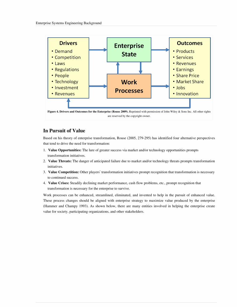
Enterprise Systems Engineering Background 109
Figure 4. Drivers and Outcomes for the Enterprise (Rouse 2009). Reprinted with permission of John Wiley & Sons Inc. All other rightsare reserved by the copyright owner.
In Pursuit of ValueBased on his theory of enterprise transformation, Rouse (2005, 279-295) has identified four alternative perspectivesthat tend to drive the need for transformation:1. Value Opportunities: The lure of greater success via market and/or technology opportunities prompts
transformation initiatives.2. Value Threats: The danger of anticipated failure due to market and/or technology threats prompts transformation
initiatives.3. Value Competition: Other players’ transformation initiatives prompt recognition that transformation is necessary
to continued success.4. Value Crises: Steadily declining market performance, cash flow problems, etc., prompt recognition that
transformation is necessary for the enterprise to survive.Work processes can be enhanced, streamlined, eliminated, and invented to help in the pursuit of enhanced value.These process changes should be aligned with enterprise strategy to maximize value produced by the enterprise(Hammer and Champy 1993). As shown below, there are many entities involved in helping the enterprise createvalue for society, participating organizations, and other stakeholders.

Enterprise Systems Engineering Background 110
Figure 5. Organizations Manage Resources to Create Enterprise Value. (SEBoK Original)
References
Works CitedBrowning, T.R. 2009. "Using the Design Structure Matrix to Design Program Organizations," in Handbook ofSystems Engineering and Management, 2nd ed., edited by A.P. Sage and W.B. Rouse. New York, NY: Wiley andSons, Inc.Giachetti, R.E. 2010. Design of Enterprise Systems: Theory, Architecture, and Methods. Boca Raton, FL, USA: CRCPress, Taylor & Francis Group.Hammer, M., and J. Champy. 1993. Reengineering the Corporation: A Manifesto for Business Revolution. NewYork, NY: Harper Business, HarperCollins Publishers.IEAD. 2011. "Enterprise Architecture Tools." Institute for Enterprise Architecture Developments. AccessedSeptember 12, 2012. Available: http:/ / www. enterprise-architecture. info/ EA_Tools. htm.Lawson, H. 2010. A Journey Through the Systems Landscape. Kings College, UK: College Publications.Lillehagen, F., and J. Krogstie. 2008. "Chapter 4: State of the Art of Enterprise Modelling," in Active KnowledgeManagement of Enterprises. New York, NY, USA: Springer.Martin, J.N. 2003. "On the Use of Knowledge Modeling Tools and Techniques to Characterize the NOAAObserving System Architecture." Presented at 13th Annual International Council on Systems Engineering (INCOSE)International Symposium, 2003, Arlington, VA, USA.Martin, J.N. 2005. "Using an Enterprise Architecture to Assess the Societal Benefits of Earth Science Research."Presented at 15th Annual International Council on Systems Engineering (INCOSE) International Symposium, 2005,Rochester, NY, USA.Miller, J., and S. Page. 2007. Complex Adaptive Systems: An Introduction to Computational Models of Social Life.Princeton, NJ, USA: Princeton University Press.Reese, R.J. 2010. Troux Enterprise Architecture Solutions. Birmingham, UK: Packt Publishing Ltd.

Enterprise Systems Engineering Background 111
Rouse, W.B. 2005. "Enterprise as Systems: Essential Challenges and Enterprise Transformation." SystemsEngineering, the Journal of the International Council on Systems Engineering (INCOSE). 8 (2): 138-150.Rouse, W.B. 2009. "Engineering the Enterprise as a System," in Handbook of Systems Engineering andManagement, 2nd ed., edited by A.P. Sage and W.B. Rouse. New York, NY: Wiley and Sons, Inc.Srinivasan, J. 2010. "Towards a Theory Sensitive Approach to Planning Enterprise Transformation." Presented at 5thEuropean Institute for Advanced Studies in Management (EIASM) Workshop on Organizational Change andDevelopment, September 23-24, 2010, Vienna, Austria.TOGAF 2009. "The Open Group Architecture Framework," version 9. The Open Architecture Group. AccessedSeptember 2, 2011. Available: http:/ / www. opengroup. org/ togaf.Troux. 2010. Metamodeling and modeling with Troux Semantics, version 9. Austin, TX, USA: Troux Technologies.White, B.E. 2009. "Complex Adaptive Systems Engineering (CASE)." Presented at IEEE Systems Conference,March 23-26, 2009, Vancouver, Canada.
Primary ReferencesGiachetti, R.E. 2010. Design of Enterprise Systems: Theory, Architecture, and Methods. Boca Raton, FL, USA: CRCPress, Taylor & Francis Group.Rouse, W.B. 2009. "Engineering the Enterprise as a System," in Handbook of Systems Engineering andManagement, 2nd ed., edited by A.P. Sage and W.B. Rouse. New York, NY: Wiley and Sons, Inc.Srinivasan, J. 2010. "Towards a Theory Sensitive Approach to Planning Enterprise Transformation." Presented at 5thEuropean Institute for Advanced Studies in Management (EIASM) Workshop on Organizational Change andDevelopment, September 23-24, 2010, Vienna, Austria.White, B.E. 2009. "Complex Adaptive Systems Engineering (CASE)." Presented at IEEE Systems Conference,March 23-26, 2009, Vancouver, Canada.
Additional ReferencesMcCarter, B.G., and B.E. White. 2009. "Emergence of SoS, sociocognitive aspects," in Systems of systemsengineering: Principles and applications, edited by M. Jamshidi. Boca Raton, FL, USA: CRC Press, Taylor &Francis Group. p. 71-105.Rouse, W.B. 2008. "Health Care as a Complex Adaptive System: Implications for design and management." TheBridge, National Academy of Engineering. 38 (1): 17-25.Sage, A.P. 2000. "Transdisciplinarity Perspectives in Systems Engineering and Management," in Transdiciplinarity:Recreating Integrated Knowledge, edited by M.A. Somerville and D. Rappaport. Oxford, UK: EOLSS Publishers. p.158-169.von Bertalanffy, L. 1968. General System Theory: Foundations, Development, Applications, revised ed. New York,NY, USA: Braziller.Weinberg, G., and D. Weinberg. 1988. General Principles of Systems Design. New York, NY, USA: Dorset HousePublishing Company. White, B.E. 2007. "On Interpreting Scale (or View) and Emergence in Complex SystemsEngineering." Presented at 1st Annual IEEE Systems Conference, April 9-12, 2007, Honolulu, HI, USA.

Enterprise Systems Engineering Background 112
< Previous Article | Parent Article | Next Article >SEBoK v. 1.4 released 29 June 2015
SEBoK DiscussionPlease provide your comments and feedback on the SEBoK below. You will need to log in to DISQUS using anexisting account (e.g. Yahoo, Google, Facebook, Twitter, etc.) or create a DISQUS account. Simply type yourcomment in the text field below and DISQUS will guide you through the login or registration steps. Feedback will bearchived and used for future updates to the SEBoK. If you provided a comment that is no longer listed, that commenthas been adjudicated. You can view adjudication for comments submitted prior to SEBoK v. 1.0 at SEBoK Reviewand Adjudication. Later comments are addressed and changes are summarized in the Letter from the Editor andAcknowledgements and Release History.
If you would like to provide edits on this article, recommend new content, or make comments on the SEBoKas a whole, please see the SEBoK Sandbox [1].
ENCODED_CONTENTNDc1NjgPGRpdiBpZD0iZGlzcXVzX3RocmVhZCI+PC9kaXY+CjxzY3JpcHQgdHlwZT0idGV4dC9qYXZhc2NyaXB0Ij4KICAgIC8qICogKiBDT05GSUdVUkFUSU9OIFZBUklBQkxFUzogRURJVCBCRUZPUkUgUEFTVElORyBJTlRPIFlPVVIgV0VCUEFHRSAqICogKi8KICAgIHZhciBkaXNxdXNfc2hvcnRuYW1lID0gJ3NlYm9rd2lraTEwJzsgLy8gcmVxdWlyZWQ6IHJlcGxhY2UgZXhhbXBsZSB3aXRoIHlvdXIgZm9ydW0gc2hvcnRuYW1lCiAgICB2YXIgZGlzcXVzX2lkZW50aWZpZXIgPSAnRW50ZXJwcmlzZSBTeXN0ZW1zIEVuZ2luZWVyaW5nIEJhY2tncm91bmQnOyAgICB2YXIgZGlzcXVzX3VybCA9ICdodHRwOi8vc2Vib2t3aWtpLm9yZy9kcmFmdC9FbnRlcnByaXNlX1N5c3RlbXNfRW5naW5lZXJpbmdfQmFja2dyb3VuZCc7CiAgICAvKiAqICogRE9OJ1QgRURJVCBCRUxPVyBUSElTIExJTkUgKiAqICovCiAgICAoZnVuY3Rpb24oKSB7CiAgICAgICAgdmFyIGRzcSA9IGRvY3VtZW50LmNyZWF0ZUVsZW1lbnQoJ3NjcmlwdCcpOyBkc3EudHlwZSA9ICd0ZXh0L2phdmFzY3JpcHQnOyBkc3EuYXN5bmMgPSB0cnVlOwogICAgICAgIGRzcS5zcmMgPSAnaHR0cDovLycgKyBkaXNxdXNfc2hvcnRuYW1lICsgJy5kaXNxdXMuY29tL2VtYmVkLmpzJzsKICAgICAgICAoZG9jdW1lbnQuZ2V0RWxlbWVudHNCeVRhZ05hbWUoJ2hlYWQnKVswXSB8fCBkb2N1bWVudC5nZXRFbGVtZW50c0J5VGFnTmFtZSgnYm9keScpWzBdKS5hcHBlbmRDaGlsZChkc3EpOwogICAgfSkoKTsKPC9zY3JpcHQ+Cjxub3NjcmlwdD5QbGVhc2UgZW5hYmxlIEphdmFTY3JpcHQgdG8gdmlldyB0aGUgPGEgaHJlZj0iaHR0cDovL2Rpc3F1cy5jb20vP3JlZl9ub3NjcmlwdCI+Y29tbWVudHMgcG93ZXJlZCBieSBEaXNxdXMuPC9hPjwvbm9zY3JpcHQ+CjxhIGhyZWY9Imh0dHA6Ly9kaXNxdXMuY29tIiBjbGFzcz0iZHNxLWJybGluayI+YmxvZyBjb21tZW50cyBwb3dlcmVkIGJ5IDxzcGFuIGNsYXNzPSJsb2dvLWRpc3F1cyI+RGlzcXVzPC9zcGFuPjwvYT4=END_ENCODED_CONTENT
The Enterprise as a SystemTo enable more efficient and effective enterprise (glossary) transformation, the enterprise needs to be looked at “as asystem,” rather than as a collection of functions connected solely by information systems and shared facilities (Rouse2005 and 2009; Lawson 2010). What distinguishes the design (glossary) of enterprise systems from product systemsis the inclusion of people as a component (glossary) of the system, not merely as a user/operator of the system.
The term 'enterprise system' has taken on a narrow meaning of only the information system anorganization uses. Research and project experience has taught us that to design a good enterprisesystem, we need to adopt a much broader understanding of enterprise systems. The greater view ofenterprise systems is inclusive of the processes the system supports, the people who work in the system,and the information [and knowledge] content of the system. (Giachetti 2010)
It is worth noting that the concept of "service" systems also includes people in the system. The thoughts above do nottake this into account, primarily since their perspectives come mainly from a product system experience. Thepractice of service systems engineering is relatively new and is an emerging discipline. For more information on this,see the articles on Service Systems Engineering.
Creating ValueThe primary purpose of an enterprise is to create value for society, other stakeholders, and for the organizations thatparticipate in that enterprise. This is illustrated in Figure 1 that shows all the key elements that contribute to thisvalue creation process. These elements in the enterprise can be treated as a "system" and the processes, methods, andtools ESE can be applied.There are three types of organizations of interest: businesses, projects, and teams (see note 1). A typical businessparticipates in multiple enterprises through its portfolio of projects. Large SE projects can be enterprises in their ownright, with participation by many different businesses, and may be organized as a number of sub-projects.
Note 1. The use of the word “business” is not intended to mean only for-profit commercial ventures. As used here, it also includes government agencies and not-for-profit organizations, as well as commercial ventures.

The Enterprise as a System 113
Business is the activity of providing goods and services involving financial, commercial, and industrialaspects.
Figure 1. Organizations Manage Resources to Create Enterprise Value. (SEBoK Original)
Resource OptimizationA key choice for businesses that conduct SE is to what extent, if at all, they seek to optimize their use of resources(people, knowledge, assets) across teams, projects, and business units. Optimization of resources is not the goal initself, but rather a means to achieve the goal of maximizing value for the enterprise and its stakeholders. At oneextreme, in a product-oriented organization, projects may be responsible for hiring, training, and firing their ownstaff, as well as managing all assets required for their delivery of products or services. (The term "product-orientedorganization" is not meant in the sense of product-oriented SE, but rather in the sense of this being one of the basicconstructs available when formulating organizational strategy.)At the other extreme, in a functional organization, the projects delegate almost all their work to functional groups. Inbetween these two extremes is a matrix organization that is used to give functional specialists a “home” betweenproject assignments. A full discussion of organizational approaches and situations along with their applicability inenabling SE for the organization is provided in the article called Systems Engineering Organizational Strategy.The optimization debate can be handled as described in the book called "Enterprise Architecture as Strategy" (Ross,Weill, and Robertson 2006). In other words, an enterprise can choose (or not) to unify its operations and can choose(or not) to unify its information base. There are different strategies the enterprise might adopt to achieve and sustainvalue creation (and how ESE helps an enterprise to choose). This is further addressed in the section on EnterpriseArchitecture Formulation & Assessment in the article called Enterprise Capability Management.
Enabling Systems Engineering in the OrganizationSE skills, techniques, and resources are relevant to many enterprise functions, and a well-founded SE capability canmake a substantial contribution at the enterprise level, as well as at the project level. The article called SystemsEngineering Organizational Strategy discusses enabling SE in the organization, while the article called EnablingBusinesses and Enterprises focuses on the cross-organizational functions at the business and enterprise levels. Thecompetence of individuals is discussed in the article called Enabling Individuals.

The Enterprise as a System 114
Kinds of Knowledge Used by the EnterpriseKnowledge is a key resource for ESE. There are generally two kinds of knowledge: explicit and tacit. Explicitknowledge can be written down or incorporated in computer codes. Much of the relevant knowledge, however, is“tacit knowledge” that only exists within the heads of people and in the context of relationships that people form witheach other (e.g., team, project, and business level knowledge). The ability of an organization to create value iscritically dependent on the people it employs, on what they know, how they work together, and how well they areorganized and motivated to contribute to the organization’s purpose.
Projects, Programs, and BusinessesThe term “program” is used in various ways in different domains. In some domains a team can be called a program(e.g., a customer support team is their customer relationship "program"). In others, an entire business is called aprogram (e.g., a wireless communications business unit program), and in others the whole enterprise is called aprogram (e.g., the Joint Strike Fighter program and the Apollo Space program). And in many cases, the terms projectand program are used interchangeably with no discernible distinction in their meaning or scope. Typically, but notalways, there are program managers who have profit and loss (P&L) responsibility and are the ultimate programdecision makers. A program manager may have a portfolio of items (services, products, facilities, intellectualproperty, etc.) that are usually provided, implemented, or acquired through projects.The Office of Government Commerce provides a useful distinction between programs and projects:
The ultimate goal of a Programme is to realise outcomes and benefits of strategic relevance. To achievethis a programme is designed as a temporary flexible organisation structure created to coordinate,direct and oversee the implementation of a set of related projects and activities in order to deliveroutcomes and benefits related to the organisation’s strategic objectives...
A programme is likely to have a life that spans several years. A Project is usually of shorter duration (afew months perhaps) and will be focussed on the creation of a set of deliverables within agreed cost,time and quality parameters. (OGC 2010)
Enabling the EnterpriseESE, by virtue of its inherent trans-disciplinarity (Sage 2000, 158-169) in dealing with problems that are large inscale and scope, can better enable the enterprise to become more effective and efficient. The complex nature of manyenterprise problems and situations usually goes beyond the abilities of standard tools and techniques provided tobusiness school graduates (See also Complexity). ESE can augment the standard business management methodsusing the tools and methods from the SE discipline to more robustly analyze and evaluate the enterprise as a holisticsystem. A more general viewpoint, or “view,” for dealing with the enterprise consisting of scale, granularity, mindset,and time frame is provided by White (2007) and by McCarter and White (2009, 71-105).ESE can provide the enablers to address the concerns of enterprise executives as shown in Table 1 (Rouse 2009).The methods for dealing with, and the special characteristics of, complex adaptive systems must be properlyconsidered when adapting traditional systems engineering (TSE) practices for use at the enterprise level—many ofwhich come out of the systems science and systems thinking domains (von Bertalanffy 1968; Weinberg andWeinberg 1988; Miller and Page 2007; Rouse 2008, 17-25). For an approach to complex adaptive systems (CAS)engineering, refer to White (2009, 1-16) and to McCarter and White (2009, 71-105).

The Enterprise as a System 115
Table 1. Executive Concerns and SE Enablers (Rouse 2009). Reprinted with permission ofJohn Wiley & Sons Inc. All other rights are reserved by the copyright owner.
Executive Concerns SE Enablers
Identifying ends, means, and scope and candidate changes System complexity analysis to compare "as is" and "to be" enterprises
Evaluating changes in terms of process behaviors and performance Organizational simulation of process flows and relationships
Assessing economics in terms of investments, operating costs, andreturns
Economic modeling in terms of cash flows, volatility, and options
Defining the new enterprise in terms of processes and theirintegration
Enterprise architecting in terms of workflow, processes, and levels ofmaturity
Designing a strategy to change the culture for selected changes Organizational and cultural change via leadership, vision, strategy, andincentives
Developing transformation action plans in terms of what, when,and who
Implementation planning in terms of tasks, schedule, people, andinformation
Enterprise EngineeringAnother distinction is that “enterprise design does not occur at a single point in time like the design of most systems.Instead, enterprises evolve over time and are constantly changing, or are constantly being designed” (Giachetti 2010)[emphasis in original]. Giachetti calls this new discipline “enterprise engineering.” We consider the enterpriseengineering set of practices to be equivalent to what we call enterprise systems engineering (ESE) in this article.
The body of knowledge for enterprise engineering is evolving under such titles as enterpriseengineering, business engineering, and enterprise architecture . . . . Many systems and softwareengineering principles are applicable to enterprise engineering, but enterprise engineering’s uniquecomplexities require additional principles…. Enterprise engineering’s intent is to deliver a targetedlevel of enterprise performance in terms of shareholder value or customer satisfaction . . . . Enterpriseengineering methods include modeling; simulation; total quality management; change management;and bottleneck, cost, workflow, and value-added analysis. (Joannou 2007)
Supersystem Constructs
System of Systems (SoS)The phrase "system of systems” (SoS) is commonly used, but there is no widespread agreement on its exact meaning,nor on how it can be distinguished from a conventional system. A system is generally understood to be a collectionof elements that interact in such a manner that it exhibits behavior that the elements themselves cannot exhibit. Eachelement (or component) of the system can be regarded as a system in its own right. Therefore, the phrase “system ofsystems” can technically be used for any system and, as such, would be a superfluous term. However, the meaning ofthis phrase has been examined in detail by (Maier 1998, 267-284), and his definition has been adopted by somepeople (AFSAB 2005). Maier provides this definition:
A SoS is an assemblage of components which individually may be regarded as systems, and whichpossess two additional properties:
• Operational Independence of the Components: If the system-of-systems is disassembled into its componentsystems the component systems must be able to usefully operate independently. That is, the components fulfillcustomer-operator purposes on their own; and
• Managerial Independence of the Components: The component systems not only can operate independently, they do operate independently. The component systems are separately acquired and integrated but maintain a

The Enterprise as a System 116
continuing operational existence independent of the system-of-systems. (Maier 1998, 267-284)Maier goes on further saying that “the commonly cited characteristics of systems-of-systems (complexity of thecomponent systems and geographic distribution) are not the appropriate taxonomic classifiers” (Maier 1998,267-284). Four kinds of SoS have been defined (Dahmann, Lane, and Rebovich 2008).For further details on SoS, see the Systems Engineering Guide for SoS developed by the US Department of Defense(DoD) (DUS(AT) 2008). Also, see the Systems of Systems (SoS) knowledge area.
Federation of Systems (FoS)Different from the SoS concept, but related to it in several ways, is the concept called “federation of systems” (FoS).This concept might apply when there is a very limited amount of centralized control and authority (Sage and Cuppan2001, 325-345; Sage and Rouse 2009). Each system in an FoS is very strongly in control of its own destiny, but“chooses” to participate in the FoS for its own good and the good of the “country,” so to speak. It is a coalition of thewilling. An FoS is generally characterized by significant autonomy, heterogeneity, and geographic distribution ordispersion (Krygiel 1999). Krygiel defined a taxonomy of systems showing the relationships among conventionalsystems, SoSs, and FOSs.This taxonomy has three dimensions: autonomy, heterogeneity, and dispersion. A FoS would have a larger value oneach of these three dimensions than a non-federated SoS. An “Enterprise System,” as described above, could beconsidered to be an FoS if it rates highly on these three dimensions. However, it is possible for an enterprise to havecomponents that are not highly autonomous, that are relatively homogeneous, and are geographically close together.Therefore, it would be incorrect to say that an enterprise is necessarily the same as an FoS.Dove points out that in order for a large enterprise to survive in the twenty-first century, it must be more agile androbust (Dove 1999 and 2001). Handy (1992, 59-67) describes a federalist approach called “New Federalism” whichidentifies the need for structuring of loosely coupled organizations to help them adapt to the rapid changes inherentin the Information Age. This leads to the need for virtual organizations where alliances can be quickly formed tohandle the challenges of newly identified threats and a rapidly changing marketplace (Handy 1995, 2-8). Handy setsout to define a number of federalist political principles that could be applicable to an FoS. Handy’s principles havebeen tailored to the domain of systems engineering (SE) and management by Sage and Cuppan (2001, 325-345):•• Subsidiarity,•• Interdependence,•• Uniform and standardized way of doing business,•• Separation of powers,•• Dual citizenship, and•• Scales of SE.
Scales of SEAccording to Maier’s definition, not every enterprise would be called a SoS since the systems within the enterprisedo not usually meet the criteria of operational and managerial independence. In fact, one of the key purposes of anenterprise is to explicitly establish operational dependence between systems that the enterprise owns and/or operatesin order to maximize the efficiency and effectiveness of the enterprise as a whole. Therefore, it is more proper totreat an enterprise system and an SoS as different types of things, with different properties and characteristics. Thisdistinction is illustrated in the figure below, where three corresponding categories of SE are shown (DeRosa 2005;Swarz et al. 2006).It is true that an enterprise can be treated as a system itself and is comprised of many systems within the enterprise,but this discussion will reserve the term SoS to those systems that meet the criteria of operational and managerialindependence. This distinction was also used within the MITRE Corporation in their ESE Office (Rebovich andWhite 2011).

The Enterprise as a System 117
Figure 2. Different Groupings and Patterns Revealed at Different Scales (DeRosa 2005). Reprinted with permission of © 2011. The MITRECorporation. All Rights Reserved. All other rights are reserved by the copyright owner.
Relationships between Enterprise and SoSAn enterprise may require a particular operational capability that is brought into being by connecting together achain of systems that together achieve that capability. Any one of these systems in the chain cannot by itself providethis capability. The desired capability is the emergent property of this chain of systems. This chain of systems issometimes called an SoS. However, the enterprise that requires this capability rarely has direct control over all thesystems necessary to provide this full capability. This situation is illustrated in the figure below (Martin 2010).
Figure 3. Relationships Between an Enterprise and SoSs (Martin 2010). Reprinted with permission of The Aerospace Corporation. Allother rights are reserved by the copyright owner.
Enterprise E1 (in the example above) has full control over SoS2, but not full control over SoS1. TSE can be appliedto the individual systems (S1, S2, …, S53) shown within each enterprise, but needs to be augmented with additionalactivities to handle SoS and enterprise kinds of issues.

The Enterprise as a System 118
There is a general issue regarding dealing with enterprises in this situation: there are at least two enterprises relatedto any particular SoS. First, there is the enterprise of builders/developers comprising projects and programs, whichhave to be organized appropriately and adopt special types of architectural principles. Second, there is the enterpriseof users (those who use the products and service provided by the first enterprise), which has to exercise its own sortof agility. How the first enterprise designs systems to allow the second to operate is the core issue.
References
Works CitedAFSAB. 2005. Report on System-of-Systems Engineering for Air Force Capability Development. Washington, DC:US Air Force Scientific Advisory Board (AFSAB), US Air Force. SAB-TR-05-04.Dahmann, J.S., J.A. Lane, and G. Rebovich. 2008. "Systems Engineering for Capabilities." CROSSTALK: TheJournal of Defense Software Engineering. 21 (11): 4–9.DeRosa, J.K. 2005. "Enterprise Systems Engineering." Presented at Air Force Association, Industry Day, Day 1,August 4, 2005, Danvers, MA, USA.Dove, R. 2001. Response Ability: The Language, Structure, and Culture of the Agile Organization. New York, NY,USA: John Wiley & Sons.Dove, R. 1999. "Knowledge Management, Response Ability, and the Agile Enterprise," in Paradigm ShiftInternational [database online]. Accessed September 6, 2011. Available: http:/ / www. parshift. com/ docs/KmRaAeX. htm.DUS(AT). 2008. Systems Engineering Guide for Systems of Systems, version 1.0. Washington, DC, USA: DeputyUnder Secretary of Defense for Acquisition and Technology (DUS(AT)) / US Department of Defense (DoD).Accessed September 6, 2011. Available: http:/ / www. acq. osd. mil/ se/ docs/ SE-Guide-for-SoS. pdf.Giachetti, R.E. 2010. Design of Enterprise Systems: Theory, Architecture, and Methods. Boca Raton, FL, USA: CRCPress, Taylor and Francis Group.Handy, C. 1995. "Trust and the Virtual Organization." Harvard Business Review. 73 (3): 2-8.Handy, C. 1992. "Balancing Corporate Power: A New Federalist Paper." Harvard Business Review. 70 (6): 59-67.Joannou, P. 2007. "Enterprise, Systems, and Software—The Need for Integration." Computer. 40 (5): 103-105.Krygiel, A.J. 1999. Behind the Wizard's Curtain: An Integration Environment for a System of Systems. Arlington,VA, USA: C4ISR Cooperative Research Program (CCRP).Lawson, H. 2010. A Journey Through the Systems Landscape. Kings College, UK: College Publications.Maier, M.W. 1998. "Architecting Principles for Systems-of-Systems." Systems Engineering, the Journal of theInternational Council on Systems Engineering (INCOSE). 1 (4): 267-84.
Martin, J.N. 2010. "An Enterprise Systems Engineering Framework." Presented at 20th Anniversary InternationalCouncil on Systems Engineering (INCOSE) International Symposium, July 12-15, 2010, Chicago, IL, USA.McCarter, B.G., and B.E. White. 2009. "Emergence of SoS, sociocognitive aspects," in Systems of systemsengineering: Principles and applications, edited by M. Jamshidi. Boca Raton, FL, USA: CRC Press, Taylor &Francis Group. p. 71-105.OGC (Office of Government Commerce). 2010. Guidelines for Managing Programmes: Understanding programmesand programme management. London, UK: The Stationery Office.Ross, J.W., P. Weill, and D. Robertson. 2006. Enterprise Architecture As Strategy: Creating a Foundation forBusiness Execution. Boston, MA, USA: Harvard Business Review Press.

The Enterprise as a System 119
Rouse, W.B. 2009. "Engineering the Enterprise as a System," in Handbook of systems engineering and management,2nd ed., edited by A.P. Sage and W.B. Rouse. New York, NY, USA: Wiley and Sons, Inc.Rouse, W.B. 2008. "Health Care as a Complex Adaptive System: Implications for design and management." TheBridge, National Academy of Engineering. 38 (1): 17-25.Rouse, W.B. 2005. "Enterprise as Systems: Essential Challenges and Enterprise Transformation." SystemsEngineering. 8 (2): 138-50.Sage, A.P. 2000. "Transdisciplinarity Perspectives in Systems Engineering and Management." in Transdiciplinarity:Recreating Integrated Knowledge, edited by M.A. Somerville and D. Rappaport. Oxford, UK: EOLSS Publishers. p.158-169.Sage, A., and C. Cuppan. 2001. "On the Systems Engineering and Management of Systems of Systems andFederations of Systems." Information-Knowledge-Systems Management Journal. 2 (4): 325-345.Sage, A.P., and W.B. Rouse (eds). 2009. Handbook of System Engineering and Management, 2nd ed. New York,NY, USA: John Wiley & Sons.Swarz, R.S., J.K. DeRosa, and G. Rebovich. 2006. "An Enterprise Systems Engineering Model." Proceedings of theINCOSE International Symposium, July 9-13, 2006, Orlando, FL, USA.von Bertalanffy, L. 1968. General System Theory: Foundations, Development, Applications, revised ed. New York,NY, USA: Braziller.Weinberg, G., and D. Weinberg. 1988. General Principles of Systems Design. New York, NY: Dorset HousePublishing Company.White, B.E. 2007. "On Interpreting Scale (or View) and Emergence in Complex Systems Engineering." Presented at1st Annual IEEE Systems Conference, 9-12 April, 2007, Honolulu, HI, USA.
Primary ReferencesGiachetti, R.E. 2010. Design of Enterprise Systems: Theory, Architecture, and Methods. Boca Raton, FL, USA: CRCPress, Taylor and Francis Group.Joannou, P. 2007. "Enterprise, Systems, and Software—The Need for Integration." Computer. 40 (5): 103-105.Rouse, W.B. 2009. "Engineering the Enterprise as a System," in Handbook of systems engineering and management,2nd ed., edited by A.P. Sage and W.B. Rouse. New York, NY, USA: Wiley and Sons, Inc.Rouse, W.B. 2005. "Enterprise as Systems: Essential Challenges and Enterprise Transformation." SystemsEngineering. 8 (2): 138-50.
Additional ReferencesArnold, S., and H. Lawson. 2004. "Viewing Systems From a Business Management Perspective." SystemsEngineering. 7 (3): 229.Beimans, F.P.M., M.M. Lankhorst, W.B. Teeuw, and R.G. van de Wetering. 2001. "Dealing with the Complexity ofBusiness Systems Architecting." Systems Engineering. 4 (2): 118-33.Nightingale, D., and D. Rhodes. 2004. "Enterprise systems architecting: Emerging art and science within engineeringsystems." Presented at Engineering Systems Symposium, Massachusetts Institute of Technology (MIT), 29-31March, 2004, Boston, MA, USA.Rebovich, G. 2006. "Systems Thinking for the Enterprise: New & Emerging Perspectives." Presented at IEEE/SMCInternational Conference on System of Systems Engineering, April 2006, Los Angeles, CA, USA.Rechtin, E. 1999. Systems Architecting of Organizations: Why Eagles can't Swim. Boca Raton, FL, USA: CRCPress, Taylor and Francis Group.

The Enterprise as a System 120
Ring, J. 2004. "Intelligent Enterprises." INCOSE INSIGHT. 6 (2).Ring, J. 2004. "Seeing an Enterprise as a System." INCOSE INSIGHT. 6(2).Valerdi, R., D. Nightingale, and C. Blackburn. 2009. "Enterprises as Systems: Context, Boundaries, and PracticalImplications." Information-Knowledge-Systems Management Journal. 7 (4): 377-399.
< Previous Article | Parent Article | Next Article >SEBoK v. 1.4 released 29 June 2015
SEBoK DiscussionPlease provide your comments and feedback on the SEBoK below. You will need to log in to DISQUS using anexisting account (e.g. Yahoo, Google, Facebook, Twitter, etc.) or create a DISQUS account. Simply type yourcomment in the text field below and DISQUS will guide you through the login or registration steps. Feedback will bearchived and used for future updates to the SEBoK. If you provided a comment that is no longer listed, that commenthas been adjudicated. You can view adjudication for comments submitted prior to SEBoK v. 1.0 at SEBoK Reviewand Adjudication. Later comments are addressed and changes are summarized in the Letter from the Editor andAcknowledgements and Release History.
If you would like to provide edits on this article, recommend new content, or make comments on the SEBoKas a whole, please see the SEBoK Sandbox [1].
ENCODED_CONTENTODQ3MTkPGRpdiBpZD0iZGlzcXVzX3RocmVhZCI+PC9kaXY+CjxzY3JpcHQgdHlwZT0idGV4dC9qYXZhc2NyaXB0Ij4KICAgIC8qICogKiBDT05GSUdVUkFUSU9OIFZBUklBQkxFUzogRURJVCBCRUZPUkUgUEFTVElORyBJTlRPIFlPVVIgV0VCUEFHRSAqICogKi8KICAgIHZhciBkaXNxdXNfc2hvcnRuYW1lID0gJ3NlYm9rd2lraTEwJzsgLy8gcmVxdWlyZWQ6IHJlcGxhY2UgZXhhbXBsZSB3aXRoIHlvdXIgZm9ydW0gc2hvcnRuYW1lCiAgICB2YXIgZGlzcXVzX2lkZW50aWZpZXIgPSAnVGhlIEVudGVycHJpc2UgYXMgYSBTeXN0ZW0nOyAgICB2YXIgZGlzcXVzX3VybCA9ICdodHRwOi8vc2Vib2t3aWtpLm9yZy9kcmFmdC9UaGVfRW50ZXJwcmlzZV9hc19hX1N5c3RlbSc7CiAgICAvKiAqICogRE9OJ1QgRURJVCBCRUxPVyBUSElTIExJTkUgKiAqICovCiAgICAoZnVuY3Rpb24oKSB7CiAgICAgICAgdmFyIGRzcSA9IGRvY3VtZW50LmNyZWF0ZUVsZW1lbnQoJ3NjcmlwdCcpOyBkc3EudHlwZSA9ICd0ZXh0L2phdmFzY3JpcHQnOyBkc3EuYXN5bmMgPSB0cnVlOwogICAgICAgIGRzcS5zcmMgPSAnaHR0cDovLycgKyBkaXNxdXNfc2hvcnRuYW1lICsgJy5kaXNxdXMuY29tL2VtYmVkLmpzJzsKICAgICAgICAoZG9jdW1lbnQuZ2V0RWxlbWVudHNCeVRhZ05hbWUoJ2hlYWQnKVswXSB8fCBkb2N1bWVudC5nZXRFbGVtZW50c0J5VGFnTmFtZSgnYm9keScpWzBdKS5hcHBlbmRDaGlsZChkc3EpOwogICAgfSkoKTsKPC9zY3JpcHQ+Cjxub3NjcmlwdD5QbGVhc2UgZW5hYmxlIEphdmFTY3JpcHQgdG8gdmlldyB0aGUgPGEgaHJlZj0iaHR0cDovL2Rpc3F1cy5jb20vP3JlZl9ub3NjcmlwdCI+Y29tbWVudHMgcG93ZXJlZCBieSBEaXNxdXMuPC9hPjwvbm9zY3JpcHQ+CjxhIGhyZWY9Imh0dHA6Ly9kaXNxdXMuY29tIiBjbGFzcz0iZHNxLWJybGluayI+YmxvZyBjb21tZW50cyBwb3dlcmVkIGJ5IDxzcGFuIGNsYXNzPSJsb2dvLWRpc3F1cyI+RGlzcXVzPC9zcGFuPjwvYT4=END_ENCODED_CONTENT
Related Business ActivitiesThe following business (glossary) management activities can be supported by enterprise systems engineering (ESE)activities:•• mission and strategic planning,•• business processes and information Management,•• performance management,•• portfolio management,•• resource allocation and budgeting, and•• program and project management.
IntroductionThe figure below shows how these business activities relate to each other as well as the relative scope of ESE andproduct systems engineering (PSE) (Martin 2010 and 2011). PSE is mainly involved at the project level andcollaborates with project management activities, and gets somewhat involved in program management and theresource allocation and budgeting activities. On the other hand, ESE is heavily involved in the higher level activitiesfrom the program management level and up. Both ESE and PSE have key roles to play in the enterprise.

Related Business Activities 121
Figure 1. Related Business Activities (Martin 2010). Reprinted with permission of The Aerospace Corporation. All other rights are reserved by thecopyright owner.
Shown in this manner, these business activities can be considered to be separate processes with a clear precedence interms of which process drives other processes. TSE uses “requirements” to specify the essential features andfunctions of a system. An enterprise, on the other hand, typically uses goals and objectives to specify thefundamental characteristics of desired enterprise operational capabilities. The enterprise objectives and strategies areused in portfolio management to discriminate between options and to select the appropriate balanced portfolio ofsystems and other enterprise resources.The first three activities listed above are covered in Enabling Businesses and Enterprises. The other businessmanagement activities are described in more detail below in regards to how they relate to ESE.
Business Management CyclesPDCA stands for "plan-do-check-act" and is a commonly used iterative management process as seen in the figurebelow. It is also known as the Deming circle or the Shewhart cycle after its two key proponents (Deming 1986;Shewhart 1939). ESE should use the PDCA cycle as one of its fundamental tenets. For example, after ESE developsthe enterprise transformation plan, execution of the planned improvements are monitored (i.e., “checked” in thePDCA cycle) to ensure they achieve the targeted performance levels. If not, then action needs to be taken (i.e., “act”in the PDCA cycle) to correct the situation and re-planning may be required. ESE can also use the PDCA cycle in itssupport of the 'business as usual' efforts, such as the annual budgeting and business development planning activities.

Related Business Activities 122
Figure 2. PDCA Cycle. (Source: http:/ / en. wikipedia. org/ wiki/PDCA. Accessed July 2010. Diagram by Karn G. Bulsuk (http:/ /
blog. bulsuk. com). Used through a CC BY 3.0 license (http:/ /creativecommons. org/ licenses/ by/ 3. 0/ ).
It is also worth mentioning the utility of using Boyd's OODA loop (observe, orient, decide, and act) to augmentPDCA. This could be accomplished by first using the OODA loop (http:/ / en. wikipedia. org/ wiki/ OODA_loop),which is continuous in situation awareness, and then followed by using the PDCA approach, which is discrete,having goals, resources, usually time limits, etc. (Lawson 2010).
Portfolio ManagementProgram and project managers direct their activities as they relate to the systems under their control. Enterprisemanagement, on the other hand, is involved in directing the portfolio of items that are necessary to achieving theenterprise goals and objectives. This can be accomplished by using portfolio management:
Project Portfolio Management (PPM) is the centralized management of processes, methods, andtechnologies used by project managers and project management offices (PMOs) to analyze andcollectively manage a group of current or proposed projects based on numerous key characteristics. Theobjectives of PPM are to determine the optimal resource mix for delivery and to schedule activities tobest achieve an organization’s operational and financial goals―while honoring constraints imposed bycustomers, strategic objectives, or external real-world factors. (http:/ / en. wikipedia. org/ wiki/Project_portfolio_management)
The enterprise may not actually own these portfolio items. They could rent or lease these items, or they could havepermission to use them through licensing or assignment. The enterprise may only need part of a system (e.g., onebank of switching circuits in a system) or may need an entire system of systems (SoS) (e.g., switching systems,distribution systems, billing systems, provisioning systems, etc.). Notice that the portfolio items are not just thoseitems related to the systems that systems engineering (SE) deals with. These could also include platforms (like shipsand oil drilling derricks), facilities (like warehouses and airports), land and rights of way (like railroad propertyeasements and municipal covenants), and intellectual property (like patents and trademarks).The investment community has been using portfolio management for a long time to manage a set of investments tomaximize return for a given level of acceptable risk. These techniques have also been applied to a portfolio of“projects” within the enterprise (Kaplan 2009). However, it should be noted that an enterprise is not merely aportfolio of projects. The enterprise portfolio consists of whatever systems, organizations, facilities, intellectualproperty, and other resources that are needed to help the enterprise achieve its goals and objectives.Portfolio management in the context of ESE is well addressed in the following article: http:/ / www. mitre. org/work/ systems_engineering/ guide/ enterprise_engineering/ enterprise_planning_management/portfolio_management. html (MITRE 2010).

Related Business Activities 123
Resource Allocation and BudgetingThe resource allocation and budgeting (RA&B) activity is driven by the portfolio management definition of theoptimal set of portfolio elements. Capability gaps are mapped to the elements of the portfolio, and resources areassigned to programs (or other organizational elements) based on the criticality of these gaps. Resources come in theform of people and facilities, policies and practices, money and energy, and platforms and infrastructure. Allocationof resources could also involve the distribution or assignment of corporate assets, like communication bandwidth,manufacturing floor space, computing power, intellectual property licenses, and so on. Resource allocation andbudgeting is typically done on an annual basis, but more agile enterprises will make this a more continuous process.Some of the resource allocation decisions deal with base operational organizations that are not project related.It is sometimes the case that RA&B is part of portfolio management (PfM). But as can be seen in Figure 1, it issometimes useful and practical to separate these two activities. PfM usually recommends changes to the enterpriseportfolio, but RA&B takes these PfM considerations into mind along with inputs from the business process andinformation management and the performance management activities. Furthermore, PfM is usually an annual orbiannual activity whereas RA&B is often done more frequently. RA&B may need to execute ad hoc whenperturbations happen, such as funding cuts, schedule slips, performance targets missed, strategic goals changed, andso on.
Program and Project ManagementWithin the enterprise, TSE is typically applied inside a project to engineer a single system (or perhaps a smallnumber of related systems). If there is a SoS or a large, complex individual system to be engineered, then this mightbe handled at the program level, but is sometimes handled at the project level, depending on the size and complexityof the system-of-interest (See also Complexity).There are commonly three basic types of projects in an enterprise. A development project takes a conceptual notionof a system and turns this into a realizable design. A production project takes the realizable design for a system andturns this into physical copies (or instantiations). An operations “project” directly operates each system or supportsthe operation by others. (Base operations are sometimes called "line organizations" and are not typically calledprojects per se, but should nonetheless be considered as key elements to be considered when adjusting the enterpriseportfolio.) The operations project can also be involved in maintaining the system or supporting maintenance byothers. A program can have all three types of projects active simultaneously for the same system, as in this example:•• Project A is developing System X version 3.•• Project B is operating and maintaining System X version 2.•• Project C is maintaining System X version 1 in a warehouse as a backup in case of emergencies.Project management uses TSE as a tool to ensure a well-structured project and to help identify and mitigate cost,schedule, and technical risks involved with system development and implementation. The project level is where theTSE process is most often employed (Martin 1997; ISO/IEC/IEEE 2015; Wasson 2006; INCOSE 2010; Blanchardand Fabrycky 2010).The Office of Government Commerce provides a useful distinction between programs and projects:
The ultimate goal of a Programme is to realise outcomes and benefits of strategic relevance. To achievethis, a programme is designed as a temporary flexible organisation structure created to coordinate,direct and oversee the implementation of a set of related projects and activities in order to deliveroutcomes and benefits related to the organisation’s strategic objectives...
A programme is likely to have a life that spans several years. A Project is usually of shorter duration (afew months perhaps) and will be focussed on the creation of a set of deliverables within agreed cost,time and quality parameters. (OGC 2010)
Related Business Activities 124
Enterprise GovernanceESE is also concerned with the way in which organizations and embedded management and technical functions worktogether to achieve success at the enterprise level. Governance frameworks provide the essential additional structureand controls needed to both ‘steer a steady ship’ (during business as usual) and to ‘plot a course to a new place’(during business transformation).Such frameworks can be designed by recognizing that there are enduring management concerns that need to beaddressed and by applying the principle of economy. For example, a particular concern for most organizations islinking the control of projects to business drivers and objectives. This leads to a requirement for a governance bodyto both approve the initiation of projects, and to regularly review their progress, continuing relevance, and ifnecessary, mutual coherence in the light of developments inside and outside the enterprise.This might be achieved by delegating some or all of the roles; depending on circumstances, the enterprise might bedriven towards top-down or a more collective, peer-to-peer approach—or even a combination of the two for differentfunctions. Governance bodies and management roles can be engineered in this way against a common set ofmanagement concerns. Governance may also include the maintenance of common technical standards and theirpromulgation and use throughout relevant projects. See Bryant (2012) for more information on governance.
Multi-Level EnterprisesAn enterprise does not always have full control over the ESE processes. In some cases, an enterprise may have nodirect control over the resources necessary to make programs and projects successful. For example, the InternetEngineering Task Force (IETF) is responsible for the “smooth operation of the Internet,” yet it controls none of therequisite resources.
The Internet Engineering Task Force (IETF) is a large open international community of networkdesigners, operators, vendors, and researchers concerned with the evolution of the Internet architectureand the smooth operation of the Internet. … The actual technical work of the IETF is done in itsworking groups, which are organized by topic into several areas (e.g., routing, transport, security, etc.).Much of the work is handled via mailing lists. The IETF holds meetings three times per year. (IETF2010a)
The IETF has “influence” over these resources even though it does not have direct control: "The IETF is unusual inthat it exists as a collection of happenings, but is not a corporation and has no board of directors, no members, and nodues" (IETF 2010b).The ESE processes might be allocated between a “parent” enterprise and “children” enterprises, as shown in thefigure below (Martin 2010). The parent enterprise, in this case, has no resources. These resources are owned by thesubordinate child enterprises. Therefore, the parent enterprise does not implement the processes of resourceallocation and budgeting, program management, and project management.The parent enterprise may have an explicit contract with the subordinate enterprises, or, as in some cases, there ismerely a “working relationship” without the benefit of legal obligations. The parent enterprise will expectperformance feedback from the lower level to ensure that it can meet its own objectives. Where the feedbackindicates a deviation from the plan, the objectives can be adjusted or the portfolio is modified to compensate.

Related Business Activities 125
Figure 3. Parent and Child Enterprise Relationships (Martin 2010). Reprinted with permission of The Aerospace Corporation.All other rights are reserved by the copyright owner.
Enterprises X, Y, and Z in the situation shown above will cooperate with each other to the extent that they honor thedirection and guidance from the parent enterprise. These enterprises may not even be aware of each other, and, inthis case, would be unwittingly cooperating with each other. The situation becomes more complex if each enterprisehas its own set of strategic goals and objectives as shown in the figure below.
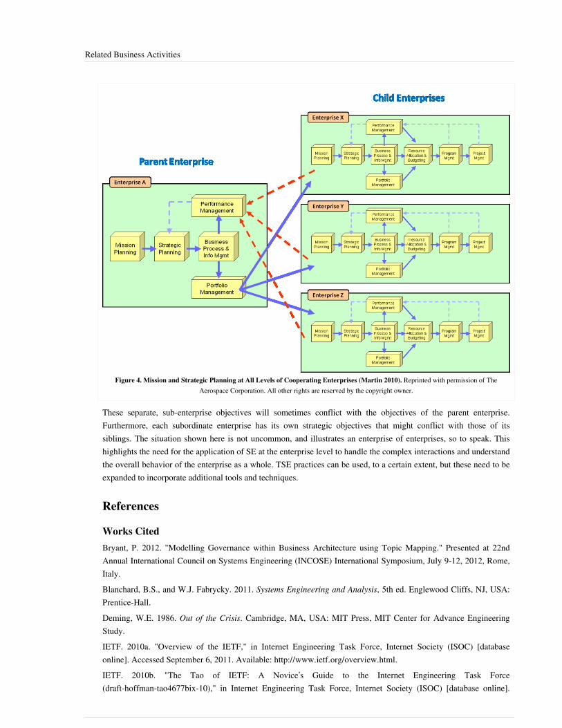
Related Business Activities 126
Figure 4. Mission and Strategic Planning at All Levels of Cooperating Enterprises (Martin 2010). Reprinted with permission of TheAerospace Corporation. All other rights are reserved by the copyright owner.
These separate, sub-enterprise objectives will sometimes conflict with the objectives of the parent enterprise.Furthermore, each subordinate enterprise has its own strategic objectives that might conflict with those of itssiblings. The situation shown here is not uncommon, and illustrates an enterprise of enterprises, so to speak. Thishighlights the need for the application of SE at the enterprise level to handle the complex interactions and understandthe overall behavior of the enterprise as a whole. TSE practices can be used, to a certain extent, but these need to beexpanded to incorporate additional tools and techniques.
References
Works CitedBryant, P. 2012. "Modelling Governance within Business Architecture using Topic Mapping." Presented at 22ndAnnual International Council on Systems Engineering (INCOSE) International Symposium, July 9-12, 2012, Rome,Italy.Blanchard, B.S., and W.J. Fabrycky. 2011. Systems Engineering and Analysis, 5th ed. Englewood Cliffs, NJ, USA:Prentice-Hall.Deming, W.E. 1986. Out of the Crisis. Cambridge, MA, USA: MIT Press, MIT Center for Advance EngineeringStudy.IETF. 2010a. "Overview of the IETF," in Internet Engineering Task Force, Internet Society (ISOC) [databaseonline]. Accessed September 6, 2011. Available: http:/ / www. ietf. org/ overview. html.IETF. 2010b. "The Tao of IETF: A Novice’s Guide to the Internet Engineering Task Force (draft-hoffman-tao4677bix-10)," in Internet Engineering Task Force, Internet Society (ISOC) [database online].
Related Business Activities 127
Accessed September 6, 2011. Available: http:/ / www. ietf. org/ tao. html#intro.INCOSE. 2012. Systems Engineering Handbook, version 3.2.2. San Diego, CA, USA: International Council onSystems Engineering (INCOSE). INCOSE-TP-2003-002-03.2.2.ISO/IEC/IEEE 2015. Systems and Software Engineering -- System Life Cycle Processes. Geneva, Switzerland:International Organisation for Standardisation / International Electrotechnical Commissions. ISO/IEC/IEEE15288:2015.Kaplan, J. 2009. Strategic IT portfolio management: Governing enterprise transformation. Waltham, Massachusetts,USA: Pittiglio, Rabin, Todd & McGrath, Inc. (PRTM).Lawson, H. 2010. A Journey Through the Systems Landscape. Kings College, UK: College Publications.Martin, J.N. 2011. "Transforming the Enterprise Using a Systems Approach." Presented at 21st AnniversaryInternational Council on Systems Engineering (INCOSE) International Symposium, June 20-23, 2011, Denver, CO,USA.Martin, J.N. 2010. "An Enterprise Systems Engineering Framework." Presented at 20th Anniversary InternationalCouncil on Systems Engineering (INCOSE) International Symposium, July 12-15, 2010, Chicago, IL, USA.Martin, J.N. 1997. Systems Engineering Guidebook: A Process for Developing Systems and Products, 1st ed. BocaRaton, FL, USA: CRC Press.MITRE. 2012. "Enterprise Engineering," in Systems Engineering Guide. Bedford, MA, USA: MITRE Corporation.Accessed July 8, 2012. Available: http:/ / www. mitre. org/ work/ systems_engineering/ guide/enterprise_engineering/ .OGC (Office of Government Commerce). 2010. Guidelines for Managing Programmes: Understanding programmesand programme management. London, UK: The Stationery Office.Shewhart, W.A. 1939. Statistical Method from the Viewpoint of Quality Control. New York, NY, USA: DoverPublications.Wasson, C.S. 2006. System Analysis, Design and Development. Hoboken, NJ, USA: John Wiley and Sons Ltd.
Primary ReferencesMartin, J.N. 2011. "Transforming the Enterprise Using a Systems Approach." Presented at 21st AnniversaryInternational Council on Systems Engineering (INCOSE) International Symposium, June 20-23, 2011, Denver, CO,USA.Martin, J.N. 2010. "An Enterprise Systems Engineering Framework." Presented at 20th Anniversary InternationalCouncil on Systems Engineering (INCOSE) International Symposium, July 12-15, 2010, Chicago, IL, USA.
Additional ReferencesArnold, S., and H. Lawson. 2004. "Viewing Systems from a Business Management Perspective." SystemsEngineering. 7 (3): 229.Beimans, F.P.M., M.M. Lankhorst, W.B. Teeuw, and R.G. van de Wetering. 2001. "Dealing with the Complexity ofBusiness Systems Architecting." Systems Engineering. 4 (2): 118-133.Drucker, P.F. 1994. "The Theory of Business." Harvard Business Review. 72 (5): 95-104.Haeckel, S.H. 2003. "Leading on demand businesses–Executives as architects." IBM Systems Journal. 42 (3):405-13.Kaplan, R., and D. Norton. 1996. The balanced scorecard: Translating strategy into action. Cambridge, MA, USA:Harvard Business School Press.

Related Business Activities 128
Lissack, M.R. 2000. "Complexity Metaphors and the Management of a Knowledge Based Enterprise: AnExploration of Discovery." PhD Dissertation in Business Administration. Henley-on-Thames, UK: HenleyManagement College, University of Reading.Rechtin, E. 1999. Systems Architecting of Organizations: Why Eagles Can't Swim. Boca Raton, FL, USA: CRCPress, Taylor and Francis Group.
< Previous Article | Parent Article | Next Article >SEBoK v. 1.4 released 29 June 2015
SEBoK DiscussionPlease provide your comments and feedback on the SEBoK below. You will need to log in to DISQUS using anexisting account (e.g. Yahoo, Google, Facebook, Twitter, etc.) or create a DISQUS account. Simply type yourcomment in the text field below and DISQUS will guide you through the login or registration steps. Feedback will bearchived and used for future updates to the SEBoK. If you provided a comment that is no longer listed, that commenthas been adjudicated. You can view adjudication for comments submitted prior to SEBoK v. 1.0 at SEBoK Reviewand Adjudication. Later comments are addressed and changes are summarized in the Letter from the Editor andAcknowledgements and Release History.
If you would like to provide edits on this article, recommend new content, or make comments on the SEBoKas a whole, please see the SEBoK Sandbox [1].
ENCODED_CONTENTNjExMTEPGRpdiBpZD0iZGlzcXVzX3RocmVhZCI+PC9kaXY+CjxzY3JpcHQgdHlwZT0idGV4dC9qYXZhc2NyaXB0Ij4KICAgIC8qICogKiBDT05GSUdVUkFUSU9OIFZBUklBQkxFUzogRURJVCBCRUZPUkUgUEFTVElORyBJTlRPIFlPVVIgV0VCUEFHRSAqICogKi8KICAgIHZhciBkaXNxdXNfc2hvcnRuYW1lID0gJ3NlYm9rd2lraTEwJzsgLy8gcmVxdWlyZWQ6IHJlcGxhY2UgZXhhbXBsZSB3aXRoIHlvdXIgZm9ydW0gc2hvcnRuYW1lCiAgICB2YXIgZGlzcXVzX2lkZW50aWZpZXIgPSAnUmVsYXRlZCBCdXNpbmVzcyBBY3Rpdml0aWVzJzsgICAgdmFyIGRpc3F1c191cmwgPSAnaHR0cDovL3NlYm9rd2lraS5vcmcvZHJhZnQvUmVsYXRlZF9CdXNpbmVzc19BY3Rpdml0aWVzJzsKICAgIC8qICogKiBET04nVCBFRElUIEJFTE9XIFRISVMgTElORSAqICogKi8KICAgIChmdW5jdGlvbigpIHsKICAgICAgICB2YXIgZHNxID0gZG9jdW1lbnQuY3JlYXRlRWxlbWVudCgnc2NyaXB0Jyk7IGRzcS50eXBlID0gJ3RleHQvamF2YXNjcmlwdCc7IGRzcS5hc3luYyA9IHRydWU7CiAgICAgICAgZHNxLnNyYyA9ICdodHRwOi8vJyArIGRpc3F1c19zaG9ydG5hbWUgKyAnLmRpc3F1cy5jb20vZW1iZWQuanMnOwogICAgICAgIChkb2N1bWVudC5nZXRFbGVtZW50c0J5VGFnTmFtZSgnaGVhZCcpWzBdIHx8IGRvY3VtZW50LmdldEVsZW1lbnRzQnlUYWdOYW1lKCdib2R5JylbMF0pLmFwcGVuZENoaWxkKGRzcSk7CiAgICB9KSgpOwo8L3NjcmlwdD4KPG5vc2NyaXB0PlBsZWFzZSBlbmFibGUgSmF2YVNjcmlwdCB0byB2aWV3IHRoZSA8YSBocmVmPSJodHRwOi8vZGlzcXVzLmNvbS8/cmVmX25vc2NyaXB0Ij5jb21tZW50cyBwb3dlcmVkIGJ5IERpc3F1cy48L2E+PC9ub3NjcmlwdD4KPGEgaHJlZj0iaHR0cDovL2Rpc3F1cy5jb20iIGNsYXNzPSJkc3EtYnJsaW5rIj5ibG9nIGNvbW1lbnRzIHBvd2VyZWQgYnkgPHNwYW4gY2xhc3M9ImxvZ28tZGlzcXVzIj5EaXNxdXM8L3NwYW4+PC9hPg==END_ENCODED_CONTENT
Enterprise Systems Engineering Key ConceptsThe purpose of traditional systems engineering (TSE) is to bring together a diversity of discipline experts to addressa wide range of problems inherent in the development of a large, complex (glossary) “single” system (glossary)(Blanchard and Fabrycky 2010; Hall 1989; Sage and Rouse 2009). Enterprise systems engineering (ESE) expandsbeyond this traditional basis to “consider the full range of SE services increasingly needed in a modern organizationwhere information-intensive systems are becoming central elements of the organization’s business strategy” (Carlockand Fenton 2001, 242-261). The traditional role of systems engineering (SE) is heavily involved in systemacquisition and implementation, especially in the context of government acquisition of very large, complex militaryand civil systems (e.g., F22 fighter jet and air traffic control systems).ESE encompasses this traditional role in system acquisition, but also incorporates enterprise strategic planning andenterprise investment analysis (along with others as described below). These two additional roles for SE at theenterprise level are “shared with the organization’s senior line management, and tend to be more entrepreneurial,business-driven, and economic in nature in comparison to the more technical nature of classical systems engineering”(Carlock and Fenton 2001, 242-261).

Enterprise Systems Engineering Key Concepts 129
Closing the GapESE practices have undergone significant development recently.
Today the watchword is enterprise systems engineering, reflecting a growing recognition that an'enterprise' may comprise many organizations from different parts of government, from the private andpublic sectors, and, in some cases, from other nations. (MITRE 2004)
Rebovich (2006) says there are “new and emerging modes of thought that are increasingly being recognized asessential to successful systems engineering in enterprises.” For example, in addition to the TSE process areas,MITRE has included the following process areas in their ESE process (DeRosa 2005) to close the gap between ESEand PSE:•• strategic technical planning,•• enterprise architecture,•• capabilities-based planning analysis,•• technology planning, and•• enterprise analysis and assessment.These ESE processes are shown in the context of the entire enterprise in the figure below (DeRosa 2006). The ESEprocesses are shown in the middle with business processes on the left and TSE processes on the right. These businessprocesses are described in the article called Related Business Activities. The TSE processes are well documented inmany sources, especially in the ISO/IEC/IEEE 15288 standard (2015).
Figure 1. Enterprise SE Process Areas in the Context of the Entire Enterprise (DeRosa 2006). Reprinted with permission of © 2011. TheMITRE Corporation. All Rights Reserved. All other rights are reserved by the copyright owner.
SE is viewed by many organizations and depicted in many process definitions as bounded by the beginning and endof a system development project. In MITRE, this restricted definition was referred to as TSE. Many have taken awider view seeking to apply SE to the “whole system” and “whole life cycle.” For example, Hitchins (1993) sets out aholistic, whole-life, wider system view of SE centered on operational purpose. Elliott and Deasley (2007) discuss thedifferences between development phase SE and in-service SE.In contrast to TSE, the ESE discipline is more like a “regimen” (Kuras and White 2005) that is responsible for identifying “outcome spaces,” shaping the development environment, coupling development to operations, and rewarding results rather than perceived promises (DeRosa 2005). ESE must continually characterize the operational environmental and the results of enterprise or SoS interventions to stimulate further actions within and among various systems in the enterprise portfolio. Outcome spaces are characterized by a set of desired capabilities that help

Enterprise Systems Engineering Key Concepts 130
meet enterprise objectives, as opposed to definitive “user requirements” based on near-term needs. Enterprisecapabilities must be robust enough to handle unknown threats and situations in the future. A detailed description ofprevious MITRE views on ESE can be found in a work by Rebovich and White (2011).
Role of Requirements in ESETSE typically translates user needs into system requirements that drive the design of the system elements. Thesystem requirements must be “frozen” long enough for the system components to be designed, developed, tested,built, and delivered to the end users (which can sometimes take years, and in the case of very large, complicatedsystems like spacecraft and fighter jets, more than a decade).ESE, on the other hand, must account for the fact that the enterprise must be driven not by requirements (that rarelycan even be defined, let alone made stable), but instead by continually changing organizational visions, goals,governance priorities, evolving technologies, and user expectations. An enterprise consists of people, processes, andtechnology where the people act as “agents” of the enterprise:
Ackoff has characterized an enterprise as a 'purposeful system' composed of agents who choose boththeir goals and the means for accomplishing those goals. The variety of people, organizations, and theirstrategies is what creates the inherent complexity and non-determinism in an enterprise. ESE mustaccount for the concerns, interests and objectives of these agents. (Swarz, DeRosa, and Rebovich 2006)(See also Complexity)
Whereas TSE focuses on output-based methodologies (e.g., functional analysis and object-oriented analysis), ESE isobligated to emphasize outcomes (e.g., business analysis and mission needs analysis), especially those related to theenterprise goals and key mission needs.
Enterprise Entities and RelationshipsAn enterprise “system” has different entities and relationships than you might find in a product/service system (seenote 1). These can be usefully grouped into two categories: asset items and conceptual items. An example of an assetis hardware and software. Examples of conceptual items are things like analysis, financial elements, markets,policies, process, and strategy.
Note 1. An “enterprise system” should not be confused with the enterprise “perceived as a system.” Anenterprise system is a product (or service) system used across the enterprise, such as payroll, financialaccounting, or enterprise resource planning applications, and consolidated data center, data warehouse, andother such facilities and equipment used across one or more organizations.
Products and services are sometimes treated as “assets” as shown in the figure below (Troux 2010). Thiscategorization of enterprise items comes from the semantic model (i.e., metamodel) used in the Troux Architectmodeling tool for characterization and analysis of an enterprise architecture. Other enterprise entities of interest arethings like information, knowledge, skills, finances, policies, process, strategy, markets, and resources, but these arecategorized as "concept" items (in this particular schema). Further details on how to use this metamodel's entities andrelationships are provided by Reese (2010).

Enterprise Systems Engineering Key Concepts 131
Table 1. Asset Domain and Concept Domain Categories for Enterprise Entities. (Troux2010) Reprinted with permission of Copyright © 2010 Troux Technologies. All other rights
are reserved by the copyright owner.
Asset Domains Concept Domains
Application and Software Domain Data Domain Document DomainInfrastructure and Hardware Domain IT Product Domain IT ServiceDomain Location Domain Organization Domain Product and ServiceDomain Services Portfolio Management Domain
Analysis Domain Financial Domain General Domain InformationDomain IT Architecture Domain Knowledge and Skill Domain MarketDomain Policy Domain Process Domain Resource Domain StrategyDomain Timeline Domain Transition Domain
The application/software and infrastructure/hardware domains are likely the most familiar to systems engineers (asillustrated in the figure below). The application/software domain contains things like the deployed software itself,plus applications, modules, servers, patches, functions, and messages. The infrastructure/hardware domain containsthings like the hardware itself, plus networks and different kinds of hardware like computing hardware, cabinets, andnetwork devices. There might be different subtypes of computing hardware like computers, servers, desktops,laptops, and mainframes. You can see from this elaboration of these domains that an enterprise architecture"schema" can be quite extensive in the kinds of things it can model.
Figure 2. Example of Enterprise Entities & Relationships (Troux 2010). Reprinted with permission of Copyright © 2010 Troux Technologies. Allother rights are reserved by the copyright owner.
The less technical domains would be things like policy, market, strategy, transition, financial, knowledge and skill,and analysis. In a typical enterprise architecture schema like this, there could be over a hundred types of modelingobjects grouped into these domains. The examples give above are from the Troux Semantics metamodel used in theTroux Architect modeling tool for enterprise architecture activities. Other enterprise modeling tools have similarmetamodels (sometimes called “schemas”). See Reese (2010) for more details on how to use the metamodel shown inthe figure above.

Enterprise Systems Engineering Key Concepts 132
Enterprise Architecture Frameworks & MethodologiesEnterprise architecture frameworks are collections of standardized viewpoints, views, and models that can be usedwhen developing architectural descriptions of the enterprise. These architecture descriptions can be informal, basedon simple graphics and tables, or informal, based on more rigorous modeling tools and methods. ISO/IEC 42010(2011) specifies how to create architecture descriptions.These frameworks relate to descriptive models of an enterprise, with conventions agreed in particular communities.There are various frameworks and methodologies available that assist in the development of an enterprisearchitecture.Urbaczewski and Mrdalj (2006) provide an overview and comparison of five prominent architectural frameworks,including:•• the Zachman Framework for Enterprise Architecture (Zachman 1992),•• the Department of Defense Architecture Framework (DoDAF) (DoD 2010),•• the Federal Enterprise Architecture Framework (FEAF) (FEA 2001),•• the Treasury Enterprise Architecture Framework (TEAF) (US Treasury 2000),•• and The Open Group Architectural Framework (TOGAF) (TOGAF 2009).
References
Works CitedBlanchard, B.S., and W.J. Fabrycky. 2011. Systems Engineering and Analysis, 5th ed. Englewood Cliffs, NJ, USA:Prentice-Hall.Carlock, P., and R. Fenton. 2001. "System of Systems (SoS) Enterprise Systems Engineering forInformation-Intensive Organizations." Systems Engineering. 4 (4): 242-261.CIO Council. 1999. Federal Enterprise Architecture Framework (FEAF), version 1.1. Washington, DC, USA:Federal Chief Information Officers Council.DeRosa, J.K. 2005. "Enterprise Systems Engineering." Presented at Air Force Association, Industry Day, Day 1,August 4, 2005, Danvers, MA, USA.DoD. 2010. DoD Architecture Framework (DoDAF), version 2.0. Washington, DC: U.S. Department of Defense(DoD).Elliott, C., and P. Deasley. 2007. Creating Systems that Work--Principles of Engineering Systems for the 21stCentury. London, England, UK: Royal Academy of Engineering.FEA. 2001. "Federal Enterprise Architecture – Practical Guide, version 1.0, February 2001." Available: https:/ /secure. cio. noaa. gov/ hpcc/ docita/ files/ a_practical_guide_to_federal_enterprise_architecture. pdf.Friedman, G., and A.P. Sage. 2004. "Case Studies of Systems Engineering and Management in SystemsAcquisition." Systems Engineering. 7 (1): 84-96.Hall, A.D. 1989. Metasystems Methodology: A New Synthesis and Unification, 1st ed. Oxford, UK: Pergamon Press.Hitchins, D. 1993. Putting Systems to Work. New York, NY, USA: John Wiley & Sons.ISO/IEC/IEEE. 2015.Systems and Software Engineering - System Life Cycle Processes.Geneva, Switzerland:International Organization for Standardization (ISO)/International Electrotechnical Commission (IEC), Institute ofElectrical and Electronics Engineers. ISO/IEC/IEEE 15288:2015.Kuras, M.L., and B.E. White. 2005. "Engineering Enterprises Using Complex-Systems Engineering." Annotatedpresentation at 15th Annual International Council on Systems Engineering (INCOSE) International Symposium, July10-15, 2005, Rochester, NY, USA.

Enterprise Systems Engineering Key Concepts 133
MITRE. 2004. MITRE 2004 Annual Report". McLean, VA, USA: MITRE Corporation.
Rebovich, G. 2006. "Systems Thinking for the Enterprise: New & Emerging Perspectives." Presented at IEEE/SMCInternational Conference on System of Systems Engineering, April 2006, Los Angeles, CA, USA.Rebovich, G., and B.E. White (eds.). 2011. Enterprise Systems Engineering: Advances in the Theory and Practice.Boca Raton, FL, USA: CRC Press, Taylor and Francis Group.Reese, R.J. 2010. Troux Enterprise Architecture Solutions. Birmingham, UK: Packt Publishing Ltd.Sage, A.P., and W.B. Rouse (eds). 2009. Handbook of System Engineering and Management, 2nd ed. New York,NY, USA: John Wiley & Sons.Swarz, R.S., J.K. DeRosa, and G. Rebovich. 2006. "An Enterprise Systems Engineering Model." Proceedings of the16th Annual International Council on Systems Engineering (INCOSE) International Symposium, July 9-13, 2006,Orlando, FL, USA.TOGAF. 2009. "The Open Group Architecture Framework," version 9. Accessed September 7, 2011. Available:http:/ / www. opengroup. org/ togaf/ .Troux. 2010. Metamodeling and modeling with Troux Semantics, version 9. Austin, TX, USA: Troux Technologies.Urbaczewski, L., and S. Mrdalj. 2006. "A Comparison of Enterprise Architecture Frameworks." Issues inInformation Systems. 7 (2): 18-26.US Treasury. 2000. Treasury Enterprise Architecture Framework, version 1. Washington, DC, USA: USDepartment of the Treasury Chief Information Officer Council.Zachman, J.A. 1992. "Extending and Formalizing the Framework for Information Systems Architecture." IBMSystems Journal. 31 (3): 590-616.Zachman, J.A. 1987. "A Framework for Information Systems Architectures." IBM Systems Journal. 26 (3): 276-92.
Primary ReferencesKuras, M.L., and B.E. White. 2005. "Engineering Enterprises Using Complex-Systems Engineering." Annotatedpresentation at 15th Annual International Council on Systems Engineering (INCOSE) International Symposium, July10-15, 2005, Rochester, NY, USA.Rebovich, G., and B.E. White (eds.). 2011. Enterprise Systems Engineering: Advances in the Theory and Practice.Boca Raton, FL, USA: CRC Press, Taylor and Francis Group.Swarz, R.S., J.K. DeRosa, and G. Rebovich. 2006. "An Enterprise Systems Engineering Model." Proceedings of the16th Annual International Council on Systems Engineering (INCOSE) International Symposium, July 9-13, 2006,Orlando, FL, USA.
Additional ReferencesJournal of Enterprise Architecture. Available: http:/ / www. globalaea. org/ ?page=JEAOverview.Minoli, D. 2008. Enterprise Architecture A to Z: Frameworks, Business Process Modeling, SOA, and InfrastructureTechnology. Boca Raton, FL, USA: CRC Press, Taylor and Francis Group, An Auerbach Book.TRAK. 2011. "TRAK Enterprise Architecture Framework." Accessed September 7, 2011. Available: http:/ / trak.sourceforge. net/ index. html.Vernadat, F.B. 1996. Enterprise Modelling and Integration - Principles and Applications. London, UK: Chapmanand Hall.
Enterprise Systems Engineering Key Concepts 134
< Previous Article | Parent Article | Next Article >SEBoK v. 1.4 released 29 June 2015
SEBoK DiscussionPlease provide your comments and feedback on the SEBoK below. You will need to log in to DISQUS using anexisting account (e.g. Yahoo, Google, Facebook, Twitter, etc.) or create a DISQUS account. Simply type yourcomment in the text field below and DISQUS will guide you through the login or registration steps. Feedback will bearchived and used for future updates to the SEBoK. If you provided a comment that is no longer listed, that commenthas been adjudicated. You can view adjudication for comments submitted prior to SEBoK v. 1.0 at SEBoK Reviewand Adjudication. Later comments are addressed and changes are summarized in the Letter from the Editor andAcknowledgements and Release History.
If you would like to provide edits on this article, recommend new content, or make comments on the SEBoKas a whole, please see the SEBoK Sandbox [1].
ENCODED_CONTENTMjA3NDAPGRpdiBpZD0iZGlzcXVzX3RocmVhZCI+PC9kaXY+CjxzY3JpcHQgdHlwZT0idGV4dC9qYXZhc2NyaXB0Ij4KICAgIC8qICogKiBDT05GSUdVUkFUSU9OIFZBUklBQkxFUzogRURJVCBCRUZPUkUgUEFTVElORyBJTlRPIFlPVVIgV0VCUEFHRSAqICogKi8KICAgIHZhciBkaXNxdXNfc2hvcnRuYW1lID0gJ3NlYm9rd2lraTEwJzsgLy8gcmVxdWlyZWQ6IHJlcGxhY2UgZXhhbXBsZSB3aXRoIHlvdXIgZm9ydW0gc2hvcnRuYW1lCiAgICB2YXIgZGlzcXVzX2lkZW50aWZpZXIgPSAnRW50ZXJwcmlzZSBTeXN0ZW1zIEVuZ2luZWVyaW5nIEtleSBDb25jZXB0cyc7ICAgIHZhciBkaXNxdXNfdXJsID0gJ2h0dHA6Ly9zZWJva3dpa2kub3JnL2RyYWZ0L0VudGVycHJpc2VfU3lzdGVtc19FbmdpbmVlcmluZ19LZXlfQ29uY2VwdHMnOwogICAgLyogKiAqIERPTidUIEVESVQgQkVMT1cgVEhJUyBMSU5FICogKiAqLwogICAgKGZ1bmN0aW9uKCkgewogICAgICAgIHZhciBkc3EgPSBkb2N1bWVudC5jcmVhdGVFbGVtZW50KCdzY3JpcHQnKTsgZHNxLnR5cGUgPSAndGV4dC9qYXZhc2NyaXB0JzsgZHNxLmFzeW5jID0gdHJ1ZTsKICAgICAgICBkc3Euc3JjID0gJ2h0dHA6Ly8nICsgZGlzcXVzX3Nob3J0bmFtZSArICcuZGlzcXVzLmNvbS9lbWJlZC5qcyc7CiAgICAgICAgKGRvY3VtZW50LmdldEVsZW1lbnRzQnlUYWdOYW1lKCdoZWFkJylbMF0gfHwgZG9jdW1lbnQuZ2V0RWxlbWVudHNCeVRhZ05hbWUoJ2JvZHknKVswXSkuYXBwZW5kQ2hpbGQoZHNxKTsKICAgIH0pKCk7Cjwvc2NyaXB0Pgo8bm9zY3JpcHQ+UGxlYXNlIGVuYWJsZSBKYXZhU2NyaXB0IHRvIHZpZXcgdGhlIDxhIGhyZWY9Imh0dHA6Ly9kaXNxdXMuY29tLz9yZWZfbm9zY3JpcHQiPmNvbW1lbnRzIHBvd2VyZWQgYnkgRGlzcXVzLjwvYT48L25vc2NyaXB0Pgo8YSBocmVmPSJodHRwOi8vZGlzcXVzLmNvbSIgY2xhc3M9ImRzcS1icmxpbmsiPmJsb2cgY29tbWVudHMgcG93ZXJlZCBieSA8c3BhbiBjbGFzcz0ibG9nby1kaXNxdXMiPkRpc3F1czwvc3Bhbj48L2E+END_ENCODED_CONTENT
Enterprise Systems Engineering ProcessActivitiesThe application of the key concepts of Enterprise Systems Engineering requires processes. These processes span andcan transform the enterprise.
Systems Engineering Role in Transforming the Enterprise
Enabling Systematic Enterprise ChangeThe systems engineering (SE) process as applied to the enterprise as a whole could be used as the “means forproducing change in the enterprise … [where the] … Seven Levels of change in an organization [are defined] aseffectiveness, efficiency, improving, cutting, copying, differentiating and achieving the impossible” (McCaughin andDeRosa 2006). The essential nature of enterprise systems engineering (ESE) is that it “determines the balancebetween complexity and order and in turn the balance between effectiveness and efficiency. When viewed as thefundamental mechanism for change, it goes beyond efficiency and drives adaptation of the enterprise” (McCaughinand DeRosa 2006). McCaughin and DeRosa (2006) provide a reasonably good definition for an enterprise thatcaptures this notion of balance:
Enterprise: People, processes and technology interacting with other people, processes and technology,serving some combination of their own objectives, those of their individual organizations and those ofthe enterprise as a whole.

Enterprise Systems Engineering Process Activities 135
Balancing Effectiveness versus EfficiencyAckoff tells us that:
Data, information, knowledge and understanding enable us to increase efficiency, not effectiveness. Thevalue of the objective pursued is not relevant in determining efficiency, but it is relevant in determiningeffectiveness. Effectiveness is evaluated efficiency. It is efficiency multiplied by value. Intelligence is theability to increase efficiency; wisdom is the ability to increase effectiveness.
The difference between efficiency and effectiveness is reflected in the difference between developmentand growth. Growth does not require an increase in value; development does. Therefore, developmentrequires an increase in wisdom as well as understanding, knowledge and information. ((Ackoff 1989,3-9), emphasis added)
ESE has a key role to play in establishing the right balance between effectiveness and efficiency in enterpriseoperations and management. Value stream analysis is one technique, among others, that can help ESE determinewhere inefficiencies exist or ineffective results are being achieved.
Value Stream AnalysisValue stream analysis is one way of treating the enterprise as a system. It provides insights regarding where in thesequence of enterprise activities value is added as it moves towards the final delivery to customer or user (Rother andShook 1999). It relates each step to the costs entailed in that step in terms of resource consumption (i.e., money,time, energy, and materials). In addition to direct costs, there may also be indirect costs due to overhead factors orinfrastructure elements. This activity commonly involves drawing a flowchart of the value stream for the enterpriseas illustrated in the figure below.
Figure 1. Value Stream Example. (Source: http:/ / en. wikipedia. org/ wiki/ Value_stream_mapping Accessed September 6, 2010. US EPALean and Environment Toolkit, Public Domain.)
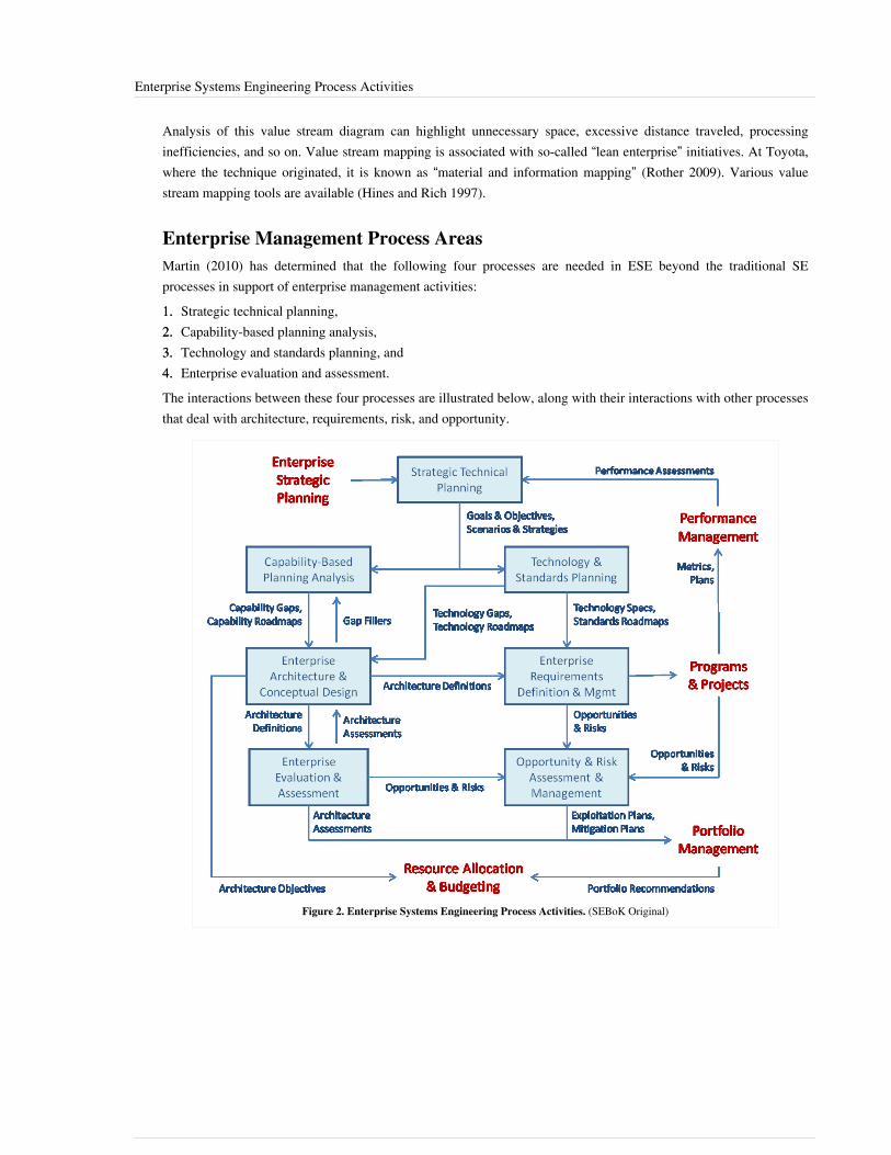
Enterprise Systems Engineering Process Activities 136
Analysis of this value stream diagram can highlight unnecessary space, excessive distance traveled, processinginefficiencies, and so on. Value stream mapping is associated with so-called “lean enterprise” initiatives. At Toyota,where the technique originated, it is known as “material and information mapping” (Rother 2009). Various valuestream mapping tools are available (Hines and Rich 1997).
Enterprise Management Process AreasMartin (2010) has determined that the following four processes are needed in ESE beyond the traditional SEprocesses in support of enterprise management activities:1.1. Strategic technical planning,2.2. Capability-based planning analysis,3.3. Technology and standards planning, and4.4. Enterprise evaluation and assessment.The interactions between these four processes are illustrated below, along with their interactions with other processesthat deal with architecture, requirements, risk, and opportunity.
Figure 2. Enterprise Systems Engineering Process Activities. (SEBoK Original)

Enterprise Systems Engineering Process Activities 137
Strategic Technical PlanningThe purpose of strategic technical planning (STP) is to establish the overall technical strategy for the enterprise. Itcreates the balance between the adoption of standards (see also Systems Engineering Standards) and the use of newtechnologies, along with consideration of the people aspects driven by the relevant trans-disciplinary technicalprinciples and practices from psychology, sociology, organizational change management, etc.This process uses the roadmaps developed during technology and standards planning (TSP). It then maps thesetechnologies and standards against the capabilities roadmap to determine potential alignment and synergy.Furthermore, lack of alignment and synergy is identified as a risk to avoid or an opportunity to pursue in thetechnical strategy. The technical strategy is defined in terms of implementation guidance for the programs andprojects.One reason that STP and TSP are separate processes is that they are often done by different groups in the enterpriseand they involve different skill sets. TSP is often done by the technology and science groups. TSP is done closer to(if not in) the chief architect and budget planning groups. Sometimes the great technology proposed by TSP justdoesn’t line up with the capabilities needed in the requisite time frame. STP does this balancing between technologypush and capability pull.
Capability-Based Planning AnalysisThe purpose of Capability-based Planning Analysis is to translate the enterprise vision and goals into a set of currentand future capabilities that helps achieve those goals. Current missions are analyzed to determine their suitability insupporting the enterprise goals. Potential future missions are examined to determine how they can help achieve thevision. Current and projected capabilities are assessed to identify capability gaps that prevent the vision and technicalstrategy from being achieved. These capability gaps are then used to assess program, project, and systemopportunities that should be pursued by the enterprise. This is defined in terms of success criteria of what theenterprise is desired to achieve.There are different types of capabilities, as shown in the figure below. It is common practice to describe capabilitiesin the form of capability hierarchies and capability roadmaps. Technology roadmaps (discussed below underTechnology Planning) are usually related to the system capabilities while business capability roadmaps (BCRMs) arerelated to the operational capabilities of the enterprise as a whole (ref: Business-Capability Mapping: Staying Aheadof the Joneses, http:/ / msdn. microsoft. com/ en-us/ library/ bb402954. aspx). The BCRM development is usuallydone as part of enterprise strategic planning, which is one level higher than, and a key driver for, the strategictechnical planning activity described above.In some domains there may be competency roadmaps dealing with the organizational capabilities, with perhaps thedesired competency levels of individuals mapped out in terms of the jobs or roles used in the enterprise or perhaps interms of the knowledge and skills required for certain activities. (For more information on systems engineeringcompetency, see the Enabling Individuals article.)

Enterprise Systems Engineering Process Activities 138
Figure 3. Organizational, System & Operational Capabilities. (SEBoK Original)
Technology and Standards PlanningThe purpose of Technology Planning is to characterize technology trends in the commercial marketplace and theresearch community. This activity covers not just trend identification and analysis, but also technology developmentand transition of technology into programs and projects. It identifies current, and predicts future, technologyreadiness levels for the key technologies of interest. Using this information, it defines technology roadmaps. Thisactivity helps establish the technical strategy and implementation guidance in the strategic technical plan. Thebusiness capabilities roadmap (BCRM) from the strategic planning activity is used to identify which technologiescan contribute to achieved targeted levels of performance improvements.The purpose of Standards Planning is to assess technical standards to determine how they inhibit or enhance theincorporation of new technologies into systems development projects. The future of key standards is forecast todetermine where they are headed and the alignment of these new standards with the life cycles for the systems in theenterprise’s current and projected future portfolios. The needs for new or updated standards are defined and resourcesare identified that can address these needs. Standardization activities that can support development of new or updatedstandards are identified (See also Systems Engineering Standards).
Enterprise Evaluation and AssessmentThe purpose of enterprise evaluation and assessment (EE&A) is to determine if the enterprise is heading in the rightdirection. It does this by measuring progress towards realizing the enterprise vision. This process helps to “shape theenvironment” and to select among the program, project, and system opportunities. This is the primary means bywhich the technical dimensions of the enterprise are integrated into the business decisions.This process establishes a measurement program as the means for collecting data for use in the evaluation andassessment of the enterprise. These measures help determine whether the strategy and its implementation areworking as intended. Measures are projected into the future as the basis for determining discrepancies between whatis observed and what had been predicted to occur. This process helps to identify risks and opportunities, diagnoseproblems, and prescribe appropriate actions. Sensitivity analysis is performed to determine the degree of robustnessand agility of the enterprise.

Enterprise Systems Engineering Process Activities 139
Roberts states that EE&A must go beyond traditional system evaluation and assessment practices (Roberts 2006). Hesays that this process area:
must de-emphasize the utility of comparing detailed metrics against specific individual requirementvalues, whether the metrics are derived from measurement, simulation or estimation… [it] must insteadlook for break points where capabilities are either significantly enhanced or totally disabled.
Key characteristics of this activity are the following:•• Multi-scale analysis,•• Early and continuous operational involvement,•• Lightweight command and control (C2) capability representations,•• Developmental versions available for assessment,•• Minimal infrastructure,• Flexible modeling and simulation (M&S), operator-in-the-loop (OITL), and hardware-in-the-loop (HWIL)
capabilities, and•• In-line, continuous performance monitoring and selective forensics. (Roberts 2006)
Enterprise architecture (EA) can be used as a primary tool in support of evaluation and assessment. EA can beused to provide a model to understand how the parts of the enterprise fit together (or do not) (Giachetti 2010).The structure and contents of the EA should be driven by the key business decisions (or, as shown in thesix-step process presented by Martin (2005), the architecture should be driven by the “business questions” tobe addressed by the architecture).The evaluation and assessment success measures can be put into the EA models and views directly andmapped to the elements that are being measured. An example of this can be seen in the US NationalOceanographic and Atmospheric Agency (NOAA) EA shown by Martin (2003a and 2003b). The measures areshown, in this example, as success factors, key performance indicators, and information needs in the businessstrategy layer of the architecture.EA can be viewed as either the set of artifacts developed as “views” of the enterprise, or as a set of activitiesthat create, use, and maintain these artifacts. The literature uses these terms in both senses and it is not alwaysclear in each case which sense is intended.
Enterprise Portfolio Considerations
Opportunity Assessment and ManagementThe management activities dealing with opportunities (as opposed to just risk) are included in ESE. According toWhite (2006), the “greatest enterprise risk may be in not pursuing enterprise opportunities.” Hillson believes there is:
a systemic weakness in risk management as undertaken on most projects. The standard risk process islimited to dealing only with uncertainties that might have negative impact (threats). This means that riskmanagement as currently practiced is failing to address around half of the potential uncertainties—theones with positive impact (opportunities). (Hillson 2004)
White claims that “in systems engineering at an enterprise scale the focus should be on opportunity, and thatenterprise risk should be viewed more as something that threatens the pursuit of enterprise opportunities” (White2006). The figure below (Rebovich and White 2011, chapter 5) shows the relative importance of opportunity and riskat the different scales of an individual system, a system of systems (SoS), and an enterprise. The implication is that,at the enterprise level, there should be more focus on opportunity management than on risk management.

Enterprise Systems Engineering Process Activities 140
Figure 4. Risk & Opportunity at the Enterprise Scale versus the Systems Scale (White 2006). MITRE Approved for Public Release;Distribution Unlimited. Unique Tracking #05-1262.
Enterprise Architecture and RequirementsEA goes above and beyond the technical components of product systems to include additional items such as strategicgoals and objectives, operators and users, organizations and other stakeholders, funding sources and methods,policies and practices, processes and procedures, facilities and platforms, infrastructure, and real estate. EA can beused to provide a model to understand how the parts of the enterprise fit together (or don’t) (Giachetti 2010). The EAis not strictly the province of the chief information officer (CIO), and is not only concerned with informationtechnology. Likewise, enterprise requirements need to focus on the cross-cutting measures necessary to ensureoverall enterprise success. Some of these enterprise requirements will apply to product systems, but they may alsoapply to business processes, inter-organizational commitments, hiring practices, investment directions, and so on(Bernus, Nemes, and Schmidt 2003).Architecture descriptions following the guidelines of an architecture framework have been used to standardize theviews and models used in architecting efforts (Zachman 1987 and 1992; Spewak 1992). Architecture descriptionshave also been developed using a business-question based approach (Martin 2003b; Martin 2006). The standard onArchitecture Description Practices (ISO/IEC 42010) (ISO/IEC 2011) has expanded its scope to include requirementson architecture frameworks.Government agencies have been increasingly turning to SE to solve some of their agency-level (i.e., enterprise)problems. This has sometimes led to the use of an architecture-based investment process, especially for informationtechnology procurements. This approach imposes a requirement for linking business strategies to the development ofEAs. The Federal Enterprise Architecture Framework (FEAF) (CIO Council 1999) and the DoD ArchitectureFramework (DoDAF) (DoD 2010) were developed to support such an architecture-based investment process. Therehave been several other architecture frameworks also developed for this purpose (ISO 2000; ISO/IEC 1998; NATO2004; TOGAF 2009; MOD 2010; TRAK 2010).
Enterprise Systems Engineering Process Activities 141
ESE Process ElementsAs a result of the synthesis outlined above, the ESE process elements to be used at the enterprise scale are asfollows:1.1. Strategic Technical Planning,2.2. Capability-Based Planning Analysis,3.3. Technology and Standards Planning,4.4. Enterprise Evaluation and Assessment,5.5. Opportunity and Risk Assessment and Management,6.6. Enterprise Architecture and Conceptual Design,7.7. Enterprise Requirements Definition and Management,8.8. Program and Project Detailed Design and Implementation,9.9. Program Integration and Interfaces,10.10. Program Validation and Verification,11.11. Portfolio and Program Deployment and Post Deployment, and12.12. Portfolio and Program Life Cycle Support.The first seven of these elements were described in some detail above. The others are more self-evident and are notdiscussed in this article.
References
Works CitedAckoff, R.L. 1989. "From Data to Wisdom." Journal of Applied Systems Analysis. 16 (1): 3-9.Bernus, P., L. Nemes, and G. Schmidt (eds.). 2003. Handbook on Enterprise Architecture. Berlin and Heidelberg,Germany: Springer-Verlag.CIO Council. 1999. Federal Enterprise Architecture Framework (FEAF), Version 1.1. Washington, DC, USA:Federal Chief Information Officers Council.DoD. 2010. DoD architecture framework (DoDAF), version 2.0. Washington, DC: US Department of Defense(DoD).Giachetti, R.E. 2010. Design of Enterprise Systems: Theory, Architecture, and Methods. Boca Raton, FL, USA: CRCPress, Taylor & Francis Group.Hillson, D. 2004. Effective Opportunity Management for Projects: Exploiting Positive Risk. Petersfield, Hampshire,UK; New York, NY, USA: Rick Doctor & Partners; Marcel Dekker, Inc.Hines, P., and N. Rich. 1997. "The Seven Value Stream Mapping Tools." International Journal of Operations &Production Management. 1 (17): 46-64.ISO. 2000. ISO 15704:2000, Industrial Automation Systems — Requirements for Enterprise-Reference Architecturesand Methodologies. Geneva, Switzerland: International Organization for Standardization (ISO).ISO/IEC/IEEE. 2011. Systems and software engineering - Architecture description. Geneva, Switzerland:International Organization for Standardization (ISO)/International Electrotechnical Commission (IEC)/Institute ofElectrical and Electronics Engineers (IEEE), ISO/IEC/IEEE 42010.ISO/IEC. 1998. ISO/IEC 10746:1998, Information Technology — Open Distributed Processing — ReferenceModel: Architecture. Geneva, Switzerland: International Organization for Standardization (ISO)/InternationalElectrotechnical Commission (IEC).Martin, J.N. 2010. "An Enterprise Systems Engineering Framework." Presented at 20th Anniversary InternationalCouncil on Systems Engineering (INCOSE) International Symposium, July 12-15, 2010, Chicago, IL, USA.

Enterprise Systems Engineering Process Activities 142
Martin, J.N. 2006. "An Enterprise Architecture Process Incorporating Knowledge Modeling Methods." PhDdissertation. Fairfax, VA, USA: George Mason University.Martin, J.N. 2005. "Using an Enterprise Architecture to Assess the Societal Benefits of Earth Science Research."Presented at 15th Annual International Council on Systems Engineering (INCOSE) International Symposium, 2005,Rochester, NY, USA.Martin, J.N. 2003a. "An Integrated Tool Suite for the NOAA Observing System Architecture." Presented at 13thAnnual International Council on Systems Engineering (INCOSE) International Symposium, 2003, Arlington, VA,USA.Martin, J.N. 2003b. "On the Use of Knowledge Modeling Tools and Techniques to Characterize the NOAAObserving System Architecture." Presented at 13th Annual International Council on Systems Engineering (INCOSE)International Symposium, 2003, Arlington, VA, USA.McCaughin, K., and J.K. DeRosa. 2006. "Process in Enterprise Systems Engineering." Presented at 16th AnnualInternational Council on Systems Engineering (INCOSE) International Symposium, July 9-13, 2006, Orlando, FL,USA.MOD. 2010. Ministry of Defence Architecture Framework (MODAF), version 1.2.004. London, England, UK: UKMinistry of Defence. Accessed September 8, 2011. Available: http:/ / www. mod. uk/ NR/ rdonlyres/04B5FB3F-8BBC-4A39-96D8-AFA05E500E4A/ 0/ 20100602MODAFDownload12004. pdf.NATO. 2010. NATO Architecture Framework (NAF), version 3.1. Brussels, Belgium: North Atlantic TreatyOrganization.Rebovich, G., and B.E. White (eds.). 2011. Enterprise Systems Engineering: Advances in the Theory and Practice.Boca Raton, FL, USA: CRC Press, Taylor & Francis Group, Auerbach.Roberts, J.L. 2006. "Enterprise Analysis and Assessment." Presented at 16th Annual International Council onSystems Engineering (INCOSE) International Symposium, July 9-13, 2006, Orlando, FL, USA.Rother, M. 2009. Toyota Kata: Managing People for Improvement, Adaptiveness, and Superior Results. New York,NY, USA: McGraw-Hill.Rother, M., and J. Shook. 1999. Learning to See: Value-Stream Mapping to Create Value and Eliminate MUDA.Cambridge, MA, USA: Lean Enterprise Institute.Spewak, S.H. 1992. Enterprise Architecture Planning: Developing a Blueprint for Data, Applications andTechnology. New York, NY, USA: Wiley and Sons, Inc.TOGAF. 2009. "The Open Group Architecture Framework," version 9. Accessed September 2, 2011. Available:http:/ / www. opengroup. org/ togaf.TRAK. 2011. "TRAK Enterprise Architecture Framework." Accessed September 7, 2011. Available: http:/ / trak.sourceforge. net/ index. html.White, B.E. 2006. "Enterprise Opportunity and Risk." Presented at 16th Annual International Council on SystemsEngineering (INCOSE) International Symposium, July 9-13, 2010, Orlando, FL, USA.Zachman, J.A. 1992. "Extending and Formalizing the Framework for Information Systems Architecture." IBMSystems Journal. 31 (3): 590-616.Zachman, J.A. 1987. "A Framework for Information Systems Architectures." IBM Systems Journal. 26 (3): 276-292.

Enterprise Systems Engineering Process Activities 143
Primary ReferencesGiachetti, R.E. 2010. Design of Enterprise Systems: Theory, Architecture, and Methods. Boca Raton, FL, USA: CRCPress, Taylor & Francis Group.Martin, J.N. 2010. "An Enterprise Systems Engineering Framework." Presented at 20th Anniversary InternationalCouncil on Systems Engineering (INCOSE) International Symposium, July 12-15, 2010, Chicago, IL, USA.Rebovich, G., and B.E. White (eds.). 2011. Enterprise Systems Engineering: Advances in the Theory and Practice.Boca Raton, FL, USA: CRC Press, Taylor & Francis Group, Auerbach.
Additional ReferencesDeRosa, J.K. 2005. "Enterprise Systems Engineering." Presented at Air Force Association, Industry Day, Day 1,August 4, 2005, Danvers, MA, USA.Holt, J., and S. Perry. 2010. Modelling enterprise architectures. Stevenage, England, UK: Institution of Engineeringand Technology (IET).Kaplan, R., and D. Norton. 1996. The Balanced Scorecard: Translating Strategy into Action. Cambridge, MA, USA:Harvard Business School Press.McGovern, J., S. Ambler, M. Stevens, J. Linn, V. Sharan, and E. Jo. 2004. A Practical Guide to EnterpriseArchitecture. New York, NY, USA: Prentice Hall.Swarz, R.S., J.K. DeRosa, and G. Rebovich. 2006. "An Enterprise Systems Engineering Model." INCOSESymposium Proceedings, July 9-13, 2006, Orlando, FL, USA.
< Previous Article | Parent Article | Next Article >SEBoK v. 1.4 released 29 June 2015
SEBoK DiscussionPlease provide your comments and feedback on the SEBoK below. You will need to log in to DISQUS using anexisting account (e.g. Yahoo, Google, Facebook, Twitter, etc.) or create a DISQUS account. Simply type yourcomment in the text field below and DISQUS will guide you through the login or registration steps. Feedback will bearchived and used for future updates to the SEBoK. If you provided a comment that is no longer listed, that commenthas been adjudicated. You can view adjudication for comments submitted prior to SEBoK v. 1.0 at SEBoK Reviewand Adjudication. Later comments are addressed and changes are summarized in the Letter from the Editor andAcknowledgements and Release History.
If you would like to provide edits on this article, recommend new content, or make comments on the SEBoKas a whole, please see the SEBoK Sandbox [1].
ENCODED_CONTENTNTU1OTkPGRpdiBpZD0iZGlzcXVzX3RocmVhZCI+PC9kaXY+CjxzY3JpcHQgdHlwZT0idGV4dC9qYXZhc2NyaXB0Ij4KICAgIC8qICogKiBDT05GSUdVUkFUSU9OIFZBUklBQkxFUzogRURJVCBCRUZPUkUgUEFTVElORyBJTlRPIFlPVVIgV0VCUEFHRSAqICogKi8KICAgIHZhciBkaXNxdXNfc2hvcnRuYW1lID0gJ3NlYm9rd2lraTEwJzsgLy8gcmVxdWlyZWQ6IHJlcGxhY2UgZXhhbXBsZSB3aXRoIHlvdXIgZm9ydW0gc2hvcnRuYW1lCiAgICB2YXIgZGlzcXVzX2lkZW50aWZpZXIgPSAnRW50ZXJwcmlzZSBTeXN0ZW1zIEVuZ2luZWVyaW5nIFByb2Nlc3MgQWN0aXZpdGllcyc7ICAgIHZhciBkaXNxdXNfdXJsID0gJ2h0dHA6Ly9zZWJva3dpa2kub3JnL2RyYWZ0L0VudGVycHJpc2VfU3lzdGVtc19FbmdpbmVlcmluZ19Qcm9jZXNzX0FjdGl2aXRpZXMnOwogICAgLyogKiAqIERPTidUIEVESVQgQkVMT1cgVEhJUyBMSU5FICogKiAqLwogICAgKGZ1bmN0aW9uKCkgewogICAgICAgIHZhciBkc3EgPSBkb2N1bWVudC5jcmVhdGVFbGVtZW50KCdzY3JpcHQnKTsgZHNxLnR5cGUgPSAndGV4dC9qYXZhc2NyaXB0JzsgZHNxLmFzeW5jID0gdHJ1ZTsKICAgICAgICBkc3Euc3JjID0gJ2h0dHA6Ly8nICsgZGlzcXVzX3Nob3J0bmFtZSArICcuZGlzcXVzLmNvbS9lbWJlZC5qcyc7CiAgICAgICAgKGRvY3VtZW50LmdldEVsZW1lbnRzQnlUYWdOYW1lKCdoZWFkJylbMF0gfHwgZG9jdW1lbnQuZ2V0RWxlbWVudHNCeVRhZ05hbWUoJ2JvZHknKVswXSkuYXBwZW5kQ2hpbGQoZHNxKTsKICAgIH0pKCk7Cjwvc2NyaXB0Pgo8bm9zY3JpcHQ+UGxlYXNlIGVuYWJsZSBKYXZhU2NyaXB0IHRvIHZpZXcgdGhlIDxhIGhyZWY9Imh0dHA6Ly9kaXNxdXMuY29tLz9yZWZfbm9zY3JpcHQiPmNvbW1lbnRzIHBvd2VyZWQgYnkgRGlzcXVzLjwvYT48L25vc2NyaXB0Pgo8YSBocmVmPSJodHRwOi8vZGlzcXVzLmNvbSIgY2xhc3M9ImRzcS1icmxpbmsiPmJsb2cgY29tbWVudHMgcG93ZXJlZCBieSA8c3BhbiBjbGFzcz0ibG9nby1kaXNxdXMiPkRpc3F1czwvc3Bhbj48L2E+END_ENCODED_CONTENT
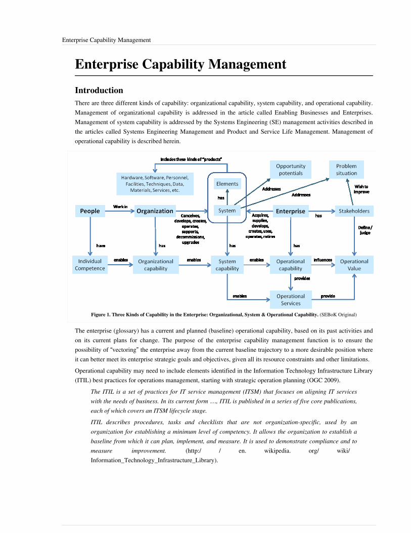
Enterprise Capability Management 144
Enterprise Capability Management
IntroductionThere are three different kinds of capability: organizational capability, system capability, and operational capability.Management of organizational capability is addressed in the article called Enabling Businesses and Enterprises.Management of system capability is addressed by the Systems Engineering (SE) management activities described inthe articles called Systems Engineering Management and Product and Service Life Management. Management ofoperational capability is described herein.
Figure 1. Three Kinds of Capability in the Enterprise: Organizational, System & Operational Capability. (SEBoK Original)
The enterprise (glossary) has a current and planned (baseline) operational capability, based on its past activities andon its current plans for change. The purpose of the enterprise capability management function is to ensure thepossibility of “vectoring” the enterprise away from the current baseline trajectory to a more desirable position whereit can better meet its enterprise strategic goals and objectives, given all its resource constraints and other limitations.Operational capability may need to include elements identified in the Information Technology Infrastructure Library(ITIL) best practices for operations management, starting with strategic operation planning (OGC 2009).
The ITIL is a set of practices for IT service management (ITSM) that focuses on aligning IT serviceswith the needs of business. In its current form …, ITIL is published in a series of five core publications,each of which covers an ITSM lifecycle stage.
ITIL describes procedures, tasks and checklists that are not organization-specific, used by anorganization for establishing a minimum level of competency. It allows the organization to establish abaseline from which it can plan, implement, and measure. It is used to demonstrate compliance and tomeasure improvement. (http:/ / en. wikipedia. org/ wiki/Information_Technology_Infrastructure_Library).
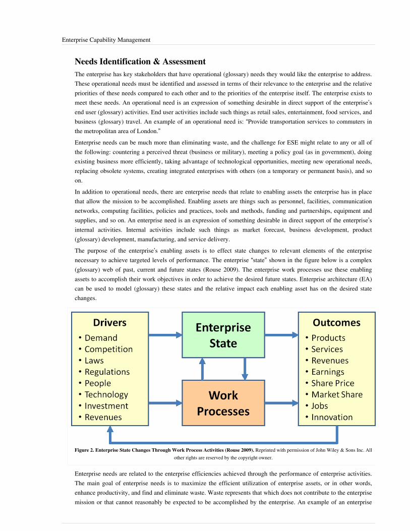
Enterprise Capability Management 145
Needs Identification & AssessmentThe enterprise has key stakeholders that have operational (glossary) needs they would like the enterprise to address.These operational needs must be identified and assessed in terms of their relevance to the enterprise and the relativepriorities of these needs compared to each other and to the priorities of the enterprise itself. The enterprise exists tomeet these needs. An operational need is an expression of something desirable in direct support of the enterprise’send user (glossary) activities. End user activities include such things as retail sales, entertainment, food services, andbusiness (glossary) travel. An example of an operational need is: “Provide transportation services to commuters inthe metropolitan area of London.”Enterprise needs can be much more than eliminating waste, and the challenge for ESE might relate to any or all ofthe following: countering a perceived threat (business or military), meeting a policy goal (as in government), doingexisting business more efficiently, taking advantage of technological opportunities, meeting new operational needs,replacing obsolete systems, creating integrated enterprises with others (on a temporary or permanent basis), and soon.In addition to operational needs, there are enterprise needs that relate to enabling assets the enterprise has in placethat allow the mission to be accomplished. Enabling assets are things such as personnel, facilities, communicationnetworks, computing facilities, policies and practices, tools and methods, funding and partnerships, equipment andsupplies, and so on. An enterprise need is an expression of something desirable in direct support of the enterprise’sinternal activities. Internal activities include such things as market forecast, business development, product(glossary) development, manufacturing, and service delivery.The purpose of the enterprise’s enabling assets is to effect state changes to relevant elements of the enterprisenecessary to achieve targeted levels of performance. The enterprise “state” shown in the figure below is a complex(glossary) web of past, current and future states (Rouse 2009). The enterprise work processes use these enablingassets to accomplish their work objectives in order to achieve the desired future states. Enterprise architecture (EA)can be used to model (glossary) these states and the relative impact each enabling asset has on the desired statechanges.
Figure 2. Enterprise State Changes Through Work Process Activities (Rouse 2009). Reprinted with permission of John Wiley & Sons Inc. Allother rights are reserved by the copyright owner.
Enterprise needs are related to the enterprise efficiencies achieved through the performance of enterprise activities. The main goal of enterprise needs is to maximize the efficient utilization of enterprise assets, or in other words, enhance productivity, and find and eliminate waste. Waste represents that which does not contribute to the enterprise mission or that cannot reasonably be expected to be accomplished by the enterprise. An example of an enterprise

Enterprise Capability Management 146
need is: “Decrease power required for operation of enterprise data centers.” (Power is a limited asset that consumesscarce enterprise funds that could be used for delivery of other more valuable services to its customers.)
Capability Identification & AssessmentThe capabilities of an enterprise should exist for the sole purpose of meeting mission and enterprise needs. Hence,there will be both mission and enterprise capabilities to identify and assess how well they meet these needs. Anexample of an operational capability is: “Transport 150,000 passengers per hour among 27 nodes in the network.” Asupporting enterprise capability might be: “Process 200,000 tickets per hour during peak loading.” There is a baselinecapability due to capability development up to that point in time, plus any additional capability planned for thefuture. The desired levels of capability (based on needs assessment) are compared to the baseline capability todetermine the capability gaps for the enterprise. This activity will also determine points of excess capability.The gaps should be filled and the excesses should be eliminated. The projected gaps and excesses are sometimesmapped into several future timeframes to get a better understanding of the relative timing and intensity of changethat might be required. It is typical to use time “buckets” like near-term, mid-term, and far-term, which, for somelong-lasting capabilities, might correspond to five, ten, and twenty years out respectively. Of course, forfast-changing capabilities (like consumer products) these timeframes would necessarily be shorter in duration, forexample, one, two and three years out.
Enterprise Architecture Formulation & AssessmentEnterprise architecture analysis can be used to determine how best to fill these capability gaps and minimize theexcess capabilities (or “capacities”). Usually a baseline architecture is characterized for the purpose of understandingwhat one currently has and where the enterprise is headed under the current business plans. The needs and gaps areused to determine where in the architecture elements need to be added, dropped, or changed. Each modificationrepresents a potential benefit to various stakeholders, along with associated costs and risks for introducing thatmodification. Enterprise architecture can be used to provide a model to understand how the parts of the enterprise fittogether (or do not) (Giachetti 2010).The enterprise architecture effort supports the entire capability management activity with enterprise-wide views ofstrategy, priorities, plans, resources, activities, locations, facilities, products, services, and so on (ISO/IEC/IEEE15288 (ISO/IEC/IEEE 2015) and architectural design process: ISO/IEC 42010 (ISO/IEC 2011) and ISO 15704 (ISO2000)).
Opportunity Identification & AssessmentThe enterprise architecture is used to help identify opportunities for improvement. Usually these opportunitiesrequire the investment of time, money, facilities, personnel, and so on. There might also be opportunities for“divestment,” which could involve selling of assets, reducing capacity, canceling projects, and so on. Eachopportunity can be assessed on its own merits, but usually these opportunities have dependencies and interfaces withother opportunities, with the current activities and operations of the enterprise, and with the enterprise's partners.Therefore, the opportunities may need to be assessed as a “portfolio,” or, at least, as sets of related opportunities.Typically, a business case assessment is required for each opportunity or set of opportunities.
Enterprise Capability Management 147
Enterprise Portfolio ManagementIf the set of opportunities is large or has complicated relationships, it may be necessary to employ portfoliomanagement techniques. The portfolio elements could be bids, projects, products, services, technologies, intellectualproperty, etc., or any combination of these items. Examples of an enterprise portfolio captured in an architecturemodeling tool can be found in Martin (2005), Martin et al. (2004), and Martin (2003). See Kaplan's work (2009) formore information on portfolio management, and ISO/IEC (2008) for information on projects portfolio managementprocess.
Enterprise Improvement Planning & ExecutionThe results of the opportunity assessment are compiled and laid out in an enterprise plan that considers all relevantfactors, including system capabilities, organizational capabilities, funding constraints, legal commitments andobligations, partner arrangements, intellectual property ownership, personnel development and retention, and so on.The plan usually goes out to some long horizon, typically more than a decade, depending on the nature of theenterprise’s business environment, technology volatility, market intensity, and so on. The enterprise plan needs to bein alignment with the enterprise’s strategic goals and objectives and with leadership priorities.The planned improvements are implemented across the enterprise and in parts of the extended enterprise (glossary)where appropriate, such as suppliers in the supply chain, distributors in the distribution chain, financiers in theinvestment arena, and so on. The planned changes should have associated performance targets and these metricsshould be monitored to ensure that progress is being made against the plan and that the intended improvements arebeing implemented. As necessary, the plan is adjusted to account for unforeseen circumstances and outcomes.Performance management of enterprise personnel is a key element of the improvement efforts.
Enterprise Capability Change ManagementIn an operational context (glossary) (particularly in defense) the term “capability management” is associated withdeveloping and maintaining all aspects of the ability to conduct certain types of missions in a given threat (glossary)environment. In an industrial context, capability refers to the ability to manage certain classes of product and servicethrough those parts of their life cycle that are relevant to the business. Changes to enterprise capability should becarefully managed to ensure that current operations are not adversely affected (where possible) and that the longterm viability of the enterprise is maintained. The following seven lenses can be used to facilitate changemanagement: strategic objectives, stakeholders, processes, performance metrics, current state alignment, resources,and maturity assessment (Nightingale and Srinivasan 2011).Capability management is becoming more often recognized as a key component of the business management toolsuite:
Capability management aims to balance economy in meeting current operational requirements, with thesustainable use of current capabilities, and the development of future capabilities, to meet the sometimescompeting strategic and current operational objectives of an enterprise. Accordingly, effectivecapability management assists organizations to better understand, and effectively integrate, re-align andapply the total enterprise ability or capacity to achieve strategic and current operational objectives; anddevelops and provides innovative solutions that focus on the holistic management of the defined array ofinterlinking functions and activities in the enterprise's strategic and current operational contexts.(Saxena 2009, 1)
There is a widespread perception that capability management is only relevant to defense and aerospace domains.However, it is becoming more widely recognized as key to commercial and civil government efforts.

Enterprise Capability Management 148
References
Works CitedGiachetti, R.E. 2010. Design of Enterprise Systems: Theory, Architecture, and Methods. Boca Raton, FL, USA: CRCPress, Taylor & Francis Group.ISO. 2000. ISO 15704:2000, Industrial Automation Systems — Requirements for Enterprise — ReferenceArchitectures and Methodologies. Geneva, Switzerland: International Organization for Standardization (ISO).ISO/IEC/IEEE. 2011. Systems and software engineering - Architecture description. Geneva, Switzerland:International Organization for Standardization (ISO)/International Electrotechnical Commission (IEC)/Institute ofElectrical and Electronics Engineers (IEEE), ISO/IEC/IEEE 42010.ISO/IEC/IEEE. 2015.Systems and software engineering - system life cycle processes.Geneva, Switzerland:International Organization for Standardization (ISO)/International Electrotechnical Commission (IEC), Institute ofElectrical and Electronics Engineers.ISO/IEC 15288:2015.Kaplan, J. 2009. Strategic IT Portfolio Management: Governing Enterprise Transformation. Waltham, MA, USA:Pittiglio, Rabin, Todd & McGrath, Inc. (PRTM).Martin, J.N. 2005. "Using an Enterprise Architecture to Assess the Societal Benefits of Earth Science Research."Presented at 15th Annual International Council on Systems Engineering (INCOSE) International Symposium, 2005,Rochester, NY, USA.Martin, J.N. 2003. "On the Use of Knowledge Modeling Tools and Techniques to Characterize the NOAAObserving System Architecture." Presented at 13th Annual International Council on Systems Engineering (INCOSE)International Symposium, 2003, Arlington, VA, USA.Martin, J.N., J. Conklin, J. Evans, C. Robinson, L. Doggrell, and J. Diehl. 2004. "The Capability IntegrationFramework: A New Way of doing Enterprise Architecture." Presented at 14th Annual International Council onSystems Engineering (INCOSE) International Symposium, June 20-24, 2004, Toulouse, France.Nightingale, D., and J. Srinivasan. 2011. Beyond the Lean Revolution: Achieving Successful and SustainableEnterprise Transformation. New York, NY, USA: AMACOM Press.OGC (Office of Government Commerce). 2009. ITIL Lifecycle Publication Suite Books. London, UK: TheStationery Office.Rouse, W.B. 2009. "Engineering the Enterprise as a System," in Handbook of Systems Engineering andManagement, 2nd ed., edited by A.P. Sage and W.B. Rouse. New York, NY, USA: Wiley and Sons, Inc.Saxena, M.S. 2009. Capability Management: Monitoring & Improving Capabilities. New Dehli: Global IndiaPublications Pvt Ltd.Wikipedia contributors. "Information Technology Infrastructure Library." Wikipedia, The Free Encyclopedia.Accessed November 28, 2012. Available at: http:/ / en. wikipedia. org/ wiki/Information_Technology_Infrastructure_Library.
Enterprise Capability Management 149
Primary ReferencesKaplan, J. 2009. Strategic IT Portfolio Management: Governing Enterprise Transformation. Waltham, MA, USA:Pittiglio, Rabin, Todd & McGrath, Inc. (PRTM).Nightingale, D., and J. Srinivasan. 2011. Beyond the Lean Revolution: Achieving Successful and SustainableEnterprise Transformation. New York, NY, USA: AMACOM Press.Rouse, W.B. 2009. "Engineering the Enterprise as a System," in Handbook of Systems Engineering andManagement, 2nd ed., edited by A.P. Sage and W.B. Rouse. New York, NY, USA: Wiley and Sons, Inc.
Additional ReferencesDahmann, J.S., J.A. Lane, and G. Rebovich. 2008. "Systems Engineering for Capabilities." CROSSTALK: TheJournal of Defense Software Engineering 21 (11): 4-9.Hillson, D. 2004. Effective Opportunity Management for Projects: Exploiting Positive Risk. Petersfield, Hampshire,UK; New York, NY: Rick Doctor & Partners; Marcel Dekker, Inc.Lillehagen, F., J. Kostie, S. Inella, H.G. Solheim, and D. Karlsen. 2003. "From enterprise modeling to enterprisevisual scenes." Presented at International Society for Pharmaceutical Engineering (ISPE) Conference on ConcurrentEngineering (CE), July 26-30, 2003, Madeira Island, Portugal.McGovern, J., S. Ambler, M. Stevens, J. Linn, V. Sharan, and E. Jo. 2004. A Practical Guide to EnterpriseArchitecture. New York, NY: Prentice Hall.Rechtin, E. 1999. Systems Architecting of Organizations: Why Eagles Can't Swim. Boca Raton, FL, USA: CRCPress, Taylor and Francis Group.Roberts, J.L. 2006. "Enterprise Analysis and Assessment." Presented at 16th Annual International Council onSystems Engineering (INCOSE) International Symposium, July 9-13, 2006, Orlando, FL, USA.
< Previous Article | Parent Article | Next Article >SEBoK v. 1.4 released 29 June 2015
SEBoK DiscussionPlease provide your comments and feedback on the SEBoK below. You will need to log in to DISQUS using anexisting account (e.g. Yahoo, Google, Facebook, Twitter, etc.) or create a DISQUS account. Simply type yourcomment in the text field below and DISQUS will guide you through the login or registration steps. Feedback will bearchived and used for future updates to the SEBoK. If you provided a comment that is no longer listed, that commenthas been adjudicated. You can view adjudication for comments submitted prior to SEBoK v. 1.0 at SEBoK Reviewand Adjudication. Later comments are addressed and changes are summarized in the Letter from the Editor andAcknowledgements and Release History.
If you would like to provide edits on this article, recommend new content, or make comments on the SEBoKas a whole, please see the SEBoK Sandbox [1].
ENCODED_CONTENTODY3ODUPGRpdiBpZD0iZGlzcXVzX3RocmVhZCI+PC9kaXY+CjxzY3JpcHQgdHlwZT0idGV4dC9qYXZhc2NyaXB0Ij4KICAgIC8qICogKiBDT05GSUdVUkFUSU9OIFZBUklBQkxFUzogRURJVCBCRUZPUkUgUEFTVElORyBJTlRPIFlPVVIgV0VCUEFHRSAqICogKi8KICAgIHZhciBkaXNxdXNfc2hvcnRuYW1lID0gJ3NlYm9rd2lraTEwJzsgLy8gcmVxdWlyZWQ6IHJlcGxhY2UgZXhhbXBsZSB3aXRoIHlvdXIgZm9ydW0gc2hvcnRuYW1lCiAgICB2YXIgZGlzcXVzX2lkZW50aWZpZXIgPSAnRW50ZXJwcmlzZSBDYXBhYmlsaXR5IE1hbmFnZW1lbnQnOyAgICB2YXIgZGlzcXVzX3VybCA9ICdodHRwOi8vc2Vib2t3aWtpLm9yZy9kcmFmdC9FbnRlcnByaXNlX0NhcGFiaWxpdHlfTWFuYWdlbWVudCc7CiAgICAvKiAqICogRE9OJ1QgRURJVCBCRUxPVyBUSElTIExJTkUgKiAqICovCiAgICAoZnVuY3Rpb24oKSB7CiAgICAgICAgdmFyIGRzcSA9IGRvY3VtZW50LmNyZWF0ZUVsZW1lbnQoJ3NjcmlwdCcpOyBkc3EudHlwZSA9ICd0ZXh0L2phdmFzY3JpcHQnOyBkc3EuYXN5bmMgPSB0cnVlOwogICAgICAgIGRzcS5zcmMgPSAnaHR0cDovLycgKyBkaXNxdXNfc2hvcnRuYW1lICsgJy5kaXNxdXMuY29tL2VtYmVkLmpzJzsKICAgICAgICAoZG9jdW1lbnQuZ2V0RWxlbWVudHNCeVRhZ05hbWUoJ2hlYWQnKVswXSB8fCBkb2N1bWVudC5nZXRFbGVtZW50c0J5VGFnTmFtZSgnYm9keScpWzBdKS5hcHBlbmRDaGlsZChkc3EpOwogICAgfSkoKTsKPC9zY3JpcHQ+Cjxub3NjcmlwdD5QbGVhc2UgZW5hYmxlIEphdmFTY3JpcHQgdG8gdmlldyB0aGUgPGEgaHJlZj0iaHR0cDovL2Rpc3F1cy5jb20vP3JlZl9ub3NjcmlwdCI+Y29tbWVudHMgcG93ZXJlZCBieSBEaXNxdXMuPC9hPjwvbm9zY3JpcHQ+CjxhIGhyZWY9Imh0dHA6Ly9kaXNxdXMuY29tIiBjbGFzcz0iZHNxLWJybGluayI+YmxvZyBjb21tZW50cyBwb3dlcmVkIGJ5IDxzcGFuIGNsYXNzPSJsb2dvLWRpc3F1cyI+RGlzcXVzPC9zcGFuPjwvYT4=END_ENCODED_CONTENT
Systems of Systems (SoS) 150
Systems of Systems (SoS)System of systems engineering (SoSE) is not a new discipline; however, this is an opportunity for the systemsengineering community to define the complex systems of the twenty-first century (Jamshidi 2009). While systemsengineering is a fairly established field, SoSE represents a challenge for the present systems engineers on a globallevel. In general, SoSE requires considerations beyond those usually associated with engineering to includesocio-technical and sometimes socio-economic phenomena.
TopicsEach part of the SEBoK is divided into knowledge areas (KAs), which are groupings of information with a relatedtheme. The KAs in turn are divided into topics. This KA contains the following topics:•• Architecting Approaches for Systems of Systems•• Socio-Technical Features of Systems of Systems•• Capability Engineering
Definition and Characteristics of Systems of SystemsThere are several definitions of system(s) of systems (SoS), some of which are dependent on the particularity of anapplication area. Maier (1998) postulated five key characteristics of SoS: operational independence of componentsystems, managerial independence of component systems, geographical distribution, emergent behavior, andevolutionary development processes, and identified operational independence and managerial independence as thetwo principal distinguishing characteristics for applying the term 'systems-of-systems.' A system that does notexhibit these two characteristics is not considered a system-of-systems regardless of the complexity or geographicdistribution of its components. Jamshidi has reviewed several potential definitions of SoS; although not all areuniversally accepted by the community, the following has received substantial attention:
A SoS is an integration of a finite number of constituent systems which are independent and operatable,and which are networked together for a period of time to achieve a certain higher goal. (Jamshidi 2009)
It should be noted that according to this definition, formation of a SoS is not necessarily a permanent phenomenon,but rather a matter of necessity for integrating and networking systems in a coordinated way for specific goals suchas robustness, cost, efficiency, etc.DeLaurentis and Crossley (2005) have added to the five SoS characteristics above for SoS Engineering to include:inter-disciplinarity, heterogeneity of the systems involved, and networks of systems.
Types of SoSIn today’s interconnected world, SoS occur in a broad range of circumstances. In those situations where the SoS isrecognized and treated as a system in its right, an SoS can be described as one of four types (Maier 1998; Dahmannand Baldwin 2008):• Directed - The SoS is created and managed to fulfill specific purposes and the constituent systems are
subordinated to the SoS. The component systems maintain an ability to operate independently; however, theirnormal operational mode is subordinated to the central managed purpose;
• Acknowledged - The SoS has recognized objectives, a designated manager, and resources for the SoS; however,the constituent systems retain their independent ownership, objectives, funding, and development and sustainmentapproaches. Changes in the systems are based on cooperative agreements between the SoS and the system;
• Collaborative - The component systems interact more or less voluntarily to fulfill agreed upon central purposes. The central players collectively decide how to provide or deny service, thereby providing some means of

Systems of Systems (SoS) 151
enforcing and maintaining standards; and• Virtual - The SoS lacks a central management authority and a centrally agreed upon purpose for the SoS.
Large-scale behavior emerges—and may be desirable—but this type of SoS must rely on relatively invisiblemechanisms to maintain it.
This taxonomy is based on the degree of independence of constituents and it offers a framework for understandingSoS based on the origin of the SoS objectives and the relationships among the stakeholders for both the SoS and itsconstituent systems. In most actual cases, an SoS will reflect a combination of SoS types. Other taxonomies mayfocus on nature/type of components, their heterogeneity, etc.A set of systems may interact in an SoS manner, but may not be recognized as an SoS. Kemp (2013) has describedsuch ad hoc SoS as ‘accidental’. These are not engineered as SoS although the individual systems will be engineeredand engineering may need to be applied to resource particular issues among systems. Further, in most actual cases,an SoS will reflect a combination of SoS types.
EmergenceEmergence is key to SoS, since in effect multiple, independent systems are brought together in an SoS explicitly tocreate new capability based on the interaction among the constituent systems.Emergent behavior can be viewed as a consequence of the interactions and relationships between system elementsrather than the behavior of individual elements. It emerges from a combination of the behavior and properties of thesystem elements and the systems structure or allowable interactions between the elements, and may be triggered orinfluenced by a stimulus from the systems environment. One of the consequences of emergence of significantconcern to all applications of SE is emergent behavior which is unexpected or cannot be predicted by knowledge ofthe system’s constituent parts. These are often referred to as Emergent Property (glossary). See the Emergence articlefor more details.As discussed in the US Department of Defense Systems Engineering Guide for Systems of Systems (DoD 2008) “forthe purposes of a SoS, unexpected means unintentional, not purposely or consciously designed-in, not known inadvance, or surprising to the developers and users of the SoS. In a SoS context, not predictable by knowledge of itsconstituent parts means the impossibility or impracticability (in time and resources) of subjecting all possible logicalthreads across the myriad functions, capabilities, and data of the systems to a comprehensive SE process."
Application Domains and the Difference between System of SystemsEngineering and Systems EngineeringApplication of SoSE is broad and is expanding into almost all walks of life. Originally addressed in the militaryenvironment, SoSE application is now much broader and still expanding. The early work in the defense sector hasprovided the initial basis for SoSE, including its intellectual foundation, technical approaches, and practicalexperience. Now, SoSE concepts and principles apply across other governmental, civil and commercial domains.Some examples include:• Transportation - air traffic management, the European rail network, integrated ground transportation, cargo
transport, highway management, and space systems,• Energy - smart grid, smart houses, and integrated production/consumption,• Health Care - regional facilities management, emergency services, and personal health management,• Natural Resource Management - global environment, regional water resources, forestry, and recreational
resources,• Disaster Response - responses to disaster events including forest fires, floods, and terrorist attacks,• Consumer Products - integrated entertainment and household product integration,• Business- banking and finance, and

Systems of Systems (SoS) 152
• Media - film, radio, and television.Observations regarding differences between individual or constituent systems and SoS are listed in Table 1. Thesedifferences are not as black and white as the table might suggest. In each case, the degree of difference varies inpractice and with complexity of current systems and system development environments - many of the SoScharacterizations may apply to systems in certain circumstances.
Table 1. Differences Between Systems and Systems of Systems as They Apply to SystemsEngineering. (SEBoK Original), adapted from Dahmann and Baldwin (2008) and Neaga et
al. (2009)
Systems Engineering Systems of Systems Engineering
Management and Oversight
System Physical engineering Socio-technical management and engineering
Stakeholder Involvement Clear set of stakeholders Multiple levels of stakeholders with mixed and possibly competing interests
Governance Aligned management andfunding
Added levels of complexity due to management and funding for both SoS and systems;SoS does not have control over all constituent systems
Operational Focus (Goals)
Operational Focus Designed and developed tomeet common objectives
Called upon to meet new SoS objectives using systems whose objectives may or maynot align with the SoS objectives
Implementation
Acquisition/Development Aligned to establishedacquisition and developmentprocesses
Cross multiple system lifecycles across asynchronous acquisition and developmentefforts, involving legacy systems, developmental systems, and technology insertion
Process Well-established Learning and Adaptation
Test and Evaluation Test and evaluation of thesystem is possible
Testing is more challenging due to systems' asynchronous life cycles and given thecomplexity of all the parts
Engineering and Design Considerations
Boundaries and Interfaces Focuses on boundaries andinterfaces
Focus on identifying systems contributing to SoS objectives and enabling flow of data,control and functionality across the SoS while balancing needs of the systems OR focuson interactions between systems. Difficult to define system-of-interest
Performance andBehavior
Performance of the system tomeet performance objectives
Performance across the SoS that satisfies SoS use capability needs while balancingneeds of the systems
Metrics Well defined (e.g., INCOSEhandbook)
Difficult to define, agree, and quantify

Systems of Systems (SoS) 153
References
Works CitedDahmann, J., and K. Baldwin. 2008. "Understanding the Current State of US Defense Systems of Systems and theImplications for Systems Engineering." Presented at IEEE Systems Conference, April 7-10, 2008, Montreal, Canada.DeLaurentis, D., and W. Crossley. "A Taxonomy-Based Perspective for System of Systems Design Methods." Paper925, presented at IEEE Conference on Systems, Man, and Cybernetics, October 10-12, 2005, Waikoba, HI, USA.DoD. 2008. Systems Engineering Guide for Systems of Systems. Arlington, VA: US Department of Defense,Director, Systems and Software Engineering, Deputy Under Secretary of Defense (Acquisition and Technology),Office of the Under Secretary of Defense (Acquisition, Technology and Logistics). Accessed November 12, 2013.Available: http:/ / www. acq. osd. mil/ se/ docs/ SE-Guide-for-SoS. pdf.Kemp, D., et. al.. 2013. Steampunk System of Systems Engineering: A case study of successful System of Systemsengineering in 19th century Britain." Presented at INCOSE International Symposium, June 24–27, 2013,Philadelphia, PA.Neaga, E.I., M.J.d. Henshaw, and Y. Yue. 2009. "The influence of the concept of capability-based management onthe development of the systems engineering discipline." Proceedings of the 7th Annual Conference on SystemsEngineering Research, April 20-23, 2009, Loughborough University, Loughborough, England, UK.Maier, M.W. 1998. "Architecting Principles for Systems-of-Systems." Systems Engineering. 1 (4): 267-284.
Primary ReferencesDahmann, J., and K. Baldwin. 2008. "Understanding the Current State of US Defense Systems of Systems and theImplications for Systems Engineering." Presented at IEEE Systems Conference, April 7-10, 2008, Montreal, Canada.Jamshidi, M. (ed). 2009a. Systems of Systems Engineering – Innovations for the 21st Century. Hoboken, NJ, USA:Wiley.Jamshidi, M. (ed). 2009b. Systems of Systems Engineering - Principles and Applications. Boca Raton, FL, USA:CRC Press.Maier, M.W. 1998. "Architecting Principles for Systems-of-Systems." Systems Engineering. 1 (4): 267-284.DoD. 2008. Systems Engineering Guide for Systems of Systems, version 1.0. Washington, DC, USA: US Departmentof Defense (DoD). Available: http:/ / www. acq. osd. mil/ se/ docs/ SE-Guide-for-SoS. pdf.
Additional ReferencesBarot, V., S. Henson, M. Henshaw, C. Siemieniuch, M. Sinclair, S.L. Lim, M. Jamshidi, and D. DeLaurentis. 2012.Trans-Atlantic Research and Education Agenda in Systems of Systems (T-AREA-SoS) SOA Report. Longborough,England, UK: Longborough University. Ref. TAREA-RE-WP2-R-LU-7.Boardman, J., and B. Sauser. 2006. "System of Systems - the Meaning of Of." IEEE Conference on Systems ofSystems Engineering, April 24-26, 2006, Los Angeles, CA.Carlock, P., and J.A. Lane. 2006. System of Systems Enterprise Systems Engineering, the Enterprise ArchitectureManagement Framework, and System of Systems Cost Estimation. Los Angeles, CA, USA: Center for Systems andSoftware Engineering (CSSE), University of Southern California (USC). USC-CSE-2006-618.Checkland, P.B. 1999. Systems Thinking, Systems Practice. Chichester, UK: John Wiley & Sons Ltd.Dahmann, J., Rebovich, G., Lane, J., Lowry, R. & Baldwin, K. 2011. "An Implementer's View of SystemsEngineering for Systems of Systems." IEEE Systems Conference, April 4-7, 2011, Montreal, Canada. p. 212-217.Keating C.B., J.J. Padilla, and K. Adams. 2008. "System of systems engineering requirements: Challenges andguidelines". EMJ - Engineering Management Journal. 20 (4): 24-31.

Systems of Systems (SoS) 154
Luzeaux, D., and J.R. Ruault. 2010. Systems of Systems. London, UK: ISTE.Poza, A.S., S. Kovacic, and C. Keating. 2008. "System of Systems Engineering: An Emerging Multidiscipline".International Journal of System of Systems Engineering. 1 (1/2).Rebovich Jr., G. 2009. "Chapter 6: Enterprise System of Systems," in Systems of Systems Engineering - Principlesand Applications. Boca Raton, FL, USA: CRC Press.Ring J. 2002. "Toward an ontology of systems engineering." INSIGHT. 5 (1): 19-22.
< Previous Article | Parent Article | Next Article >SEBoK v. 1.4 released 29 June 2015
SEBoK DiscussionPlease provide your comments and feedback on the SEBoK below. You will need to log in to DISQUS using anexisting account (e.g. Yahoo, Google, Facebook, Twitter, etc.) or create a DISQUS account. Simply type yourcomment in the text field below and DISQUS will guide you through the login or registration steps. Feedback will bearchived and used for future updates to the SEBoK. If you provided a comment that is no longer listed, that commenthas been adjudicated. You can view adjudication for comments submitted prior to SEBoK v. 1.0 at SEBoK Reviewand Adjudication. Later comments are addressed and changes are summarized in the Letter from the Editor andAcknowledgements and Release History.
If you would like to provide edits on this article, recommend new content, or make comments on the SEBoKas a whole, please see the SEBoK Sandbox [1].
ENCODED_CONTENTMTgxNDAPGRpdiBpZD0iZGlzcXVzX3RocmVhZCI+PC9kaXY+CjxzY3JpcHQgdHlwZT0idGV4dC9qYXZhc2NyaXB0Ij4KICAgIC8qICogKiBDT05GSUdVUkFUSU9OIFZBUklBQkxFUzogRURJVCBCRUZPUkUgUEFTVElORyBJTlRPIFlPVVIgV0VCUEFHRSAqICogKi8KICAgIHZhciBkaXNxdXNfc2hvcnRuYW1lID0gJ3NlYm9rd2lraTEwJzsgLy8gcmVxdWlyZWQ6IHJlcGxhY2UgZXhhbXBsZSB3aXRoIHlvdXIgZm9ydW0gc2hvcnRuYW1lCiAgICB2YXIgZGlzcXVzX2lkZW50aWZpZXIgPSAnU3lzdGVtcyBvZiBTeXN0ZW1zIChTb1MpJzsgICAgdmFyIGRpc3F1c191cmwgPSAnaHR0cDovL3NlYm9rd2lraS5vcmcvZHJhZnQvU3lzdGVtc19vZl9TeXN0ZW1zXyhTb1MpJzsKICAgIC8qICogKiBET04nVCBFRElUIEJFTE9XIFRISVMgTElORSAqICogKi8KICAgIChmdW5jdGlvbigpIHsKICAgICAgICB2YXIgZHNxID0gZG9jdW1lbnQuY3JlYXRlRWxlbWVudCgnc2NyaXB0Jyk7IGRzcS50eXBlID0gJ3RleHQvamF2YXNjcmlwdCc7IGRzcS5hc3luYyA9IHRydWU7CiAgICAgICAgZHNxLnNyYyA9ICdodHRwOi8vJyArIGRpc3F1c19zaG9ydG5hbWUgKyAnLmRpc3F1cy5jb20vZW1iZWQuanMnOwogICAgICAgIChkb2N1bWVudC5nZXRFbGVtZW50c0J5VGFnTmFtZSgnaGVhZCcpWzBdIHx8IGRvY3VtZW50LmdldEVsZW1lbnRzQnlUYWdOYW1lKCdib2R5JylbMF0pLmFwcGVuZENoaWxkKGRzcSk7CiAgICB9KSgpOwo8L3NjcmlwdD4KPG5vc2NyaXB0PlBsZWFzZSBlbmFibGUgSmF2YVNjcmlwdCB0byB2aWV3IHRoZSA8YSBocmVmPSJodHRwOi8vZGlzcXVzLmNvbS8/cmVmX25vc2NyaXB0Ij5jb21tZW50cyBwb3dlcmVkIGJ5IERpc3F1cy48L2E+PC9ub3NjcmlwdD4KPGEgaHJlZj0iaHR0cDovL2Rpc3F1cy5jb20iIGNsYXNzPSJkc3EtYnJsaW5rIj5ibG9nIGNvbW1lbnRzIHBvd2VyZWQgYnkgPHNwYW4gY2xhc3M9ImxvZ28tZGlzcXVzIj5EaXNxdXM8L3NwYW4+PC9hPg==END_ENCODED_CONTENT

Architecting Approaches for Systems of Systems 155
Architecting Approaches for Systems of SystemsA key part of systems engineering (SE) for system of systems (SoS) is the composition of systems to meet SoSneeds. This may include simply interfacing systems and leveraging their existing functionality or it may requirechanging the systems functionality, performance or interfaces. These changes occur incrementally, as a SoS evolvesover time to meet changing SoS objectives. System of Systems Engineering (SoSE) supports these changes bydeveloping and evolving a technical framework that acts as an overlay to the systems of which the SoS is composed.This framework provides the architecture for the SoS. The SoS architecture defines how the systems work togetherto meet SoS objectives and considers the details of the individual systems and their impact the SoS performance orfunctionality.
The Role of System of Systems ArchitectingAn architecture is the structure of components, their relationships, and the principles and guidelines governing theirdesign evolution over time (IEEE 610.12-1990).In a SoS, the architecture is the technical framework for the systems comprising the SoS which designates how thesystems will be employed by the users in an operational setting (sometimes called the concept of operations(CONOPs or CONOPs), the internal and external relationships and dependencies among the constituent systems andtheir functions and, finally, the end-to-end functionality and data flow as well as communications among thesystems.Because SoS largely comprise extant independent systems, these place constraints on the SoS architecture and mayrequire that migration to a SoS architecture be incremental. Developing a SoS architecture requires consideration oftechnical feasibility for the constituent systems as well as the needs of the SoS itself. Architecture data for theconstituent systems can also be important data for architecting the SoS.Maier (1998) provides a conceptual discussion on the impact of SoS characteristics on SoS architecting.Additionally, the US DoD SE Guide for SoS (2008) describes practical considerations in developing and evolving aSoS architecture as a core element of SoSE.
Challenges in Architecting SoSIn the case of a new system development, the systems engineer can begin with a fresh, unencumbered approach toarchitecture. However, in a SoS, the systems contributing to the SoS objectives are typically in place when the SoS isestablished and the SoS engineer needs to consider the current state and plans of the individual systems as importantfactors in developing an architecture for the SoS. This, along with the fact that constituent systems may be complexsystems in their own right, leads to a set of challenges to architecting SoS.First, as noted above, the managerial and operational independence of constituent systems can pose major challengesfor the SoS architecture. Because systems are likely to continue to face new functional requirements and the need fortechnology upgrades independent of the SoS, there is an advantage to a SoS architecture, which is loosely coupled;that is, it has limited impact on the individual systems, allowing for changes in functionality and technology in somesystems without impact on others or on the SoS objectives. Dagli and Kilicay-Ergin (2009) have suggested that SoSarchitecting should be considered to be an evolutionary process.Secondly, the independence of the constituent systems also means that these systems are typically not designed tooptimize SoS objectives. In the area of trust for example, a system may severely constrain access to services toprovide a level of security and a SoS may depend on free exchange of those services. (Rebovich 2009) hasarticulated this difficulty as a fundamental problem of SoS:
Architecting Approaches for Systems of Systems 156
From the single-system community's perspective, its part of the SoS capability represents additionalobligations, constraints and complexities. Rarely is participation in an (sic) SoS seen as a net gain fromthe viewpoint of single-system stakeholders.
Finally, as introduced in the article Emergence, there are risks associated with unexpected or unintended behaviorresulting from combining systems that have individually complex behavior. These become serious in cases whichsafety, for example, is threatened through unintended interactions among the functions provided by multipleconstituent systems in a SoS.Finally, the development and implementation of a SoS architecture may be significantly constrained by a reluctanceto make changes or invest in the constituent systems, which could be very mature (e.g. in sustainment) or currentlyproductively supporting other uses. In this case, approaches such as gateways and wrapping may be used toincorporate these systems into the SoS without making significant changes in the other systems.
Architecture AnalysisLarge-scale systems integration has grown in importance and correspondingly, there has been a growing interest inSoS concepts and strategies. The performance and functioning of groups of heterogeneous systems has become thefocus of various applications including military, security, aerospace, distributed energy, healthcare, and disastermanagement systems (Lopez 2006; Wojcik and Hoffman 2006). There is an increasing interest in exploiting synergybetween these independent systems to achieve the desired overall system performance (Azarnoush et al. 2006).Modeling and simulation is conducted to analyze architecture effectiveness and to verify architectural features. In theliterature, researchers have addressed the issues of coordination and interoperability in a SoS (Abel and Sukkarieh2006; Sahin et al. 2007). In order to study SoS characteristics and parameters, one needs to have realistic simulationframeworks properly designed for system of systems architecture. There are some attempts to develop simulationframeworks for multi-agent systems using Discrete Event Simulation (DEVS) tools (Zeigler et al. 2000a). In theseresearch efforts, the major focus is given to DEVS architecture with JAVA. In (Mittall 2000), DEVS state machineapproach is introduced. Finally, DEVS Modeling Language (DEVSML) is developed by using XML based JAVA inorder to simulate systems in a net-centric way with relative ease. Sahin et al. (2007) have recently introduced adiscrete event XML based SoS simulation framework based on DEVS and JAVA.
The Open Approach to SoS EngineeringAs noted above, one of the key challenges with SoS architecting is that the constituent systems of a SoS may nothave been designed, developed and employed with regard to their role in the SoS, which constrains SoS architectureoptions. The degree to the architecture which overlays these constituent systems and supports the SoS end-to-endcapabilities can be based on open standards; the SoS may be able to benefit from open architecture for futureevolution.The critical challenge of moving from SoS, as a concept to the engineering of SoS, is the significant technological,human, and organizational differences in consideration system of systems engineering and management approaches(Wells and Sage 2008). A potential approach to engineering a SoS can be the open systems approach to SoSE (Azani2009). The following open systems principles are listed by Azani (2009):• Open interface principle - Open systems have permeable boundaries that allow them to exchange mass, energy,
and information with other systems;• Synergism principle – The notion that designates that the co-operative interaction between constituent systems
has a greater effect in their combined efforts than the sum of their individual parts. Essentially, this is what givesrise to emergence;
• Self-government principle - This implies that the SoS maintains and develops its internal order withoutinterference from external sources. This could be through cybernetic control, homeostasis, or self-organization;
Architecting Approaches for Systems of Systems 157
• Emergence principle - In this case, this refers to the occurrence of novel and coherent structures, patterns, andproperties during the self-organization of the SoS;
• Conservation principle – This principle states that energy and mass (material) are conserved within the SoS;• Reconfiguration principle – This refers to the SoS reconfiguring and adapting itself to sustain itself against
changes in its environment;• Symbiosis principle - The systems within the SoS have a symbiotic relationship to each other; more
transparently, the successful development and sustainment of a SoS depends on symbiotic collaboration betweenthe stakeholders of the systems of which it is comprised; and
• Modularity principle - This holds that each level and each system is to some extent independent of others. InSoS design, the development of independent modular systems that interoperate with each other throughstandardized interfaces enables greater flexibility to promote better evolution of the SoS.
Azani (2009) elaborates on the open systems development strategies and principles utilized by biotic SoS, discussesthe implications of engineering of man-made SoS, and introduces an integrated SoS development methodology forthe engineering and development of an adaptable, sustainable, and interoperable SoS based on open systemsprinciples and strategies.Hitchens (2003, 107), on the other hand, discusses the principles of open systems rather differently in terms of theirsystems life cycles, as the seven principles that he addresses are system reactions, system cohesion, systemadaptation, connected variety, limited variety, preferred patterns, and cyclic progression. This description takes asystems dynamics approach to show how open systems evolve; the description is applicable to natural andman-made systems.The enablers of openness include open standards and open specifications, which draw from consensus amongst acommunity of interest, and are published by, and freely available within, that community. An open specificationmust ensure that its detail-level is allows for it to be implementable by independent parties. Compliance with openstandards is intended to ensure consistent results (Henshaw, et. al., 2011). This parallels the notion of open systemsarchitecture, which is an open specification of the architecture of a system or system of systems for the purpose ofacquiring specified capabilities. As a general feature of good design (for a system or system of systems), an opensystem architecture should allow for the quick and easy improvement and updating of the system capabilities, byadding or changing components. However, Henshaw et. al. (2011) also denote that open architecture represents acommercial challenge (rather than a technical one) and that establishing open architecture approaches to acquisitioncan be challenging, due to issues involving protection of intellectual property (IP) and commercial advantage.
Networks and Network AnalysisBecause networks are such a common component of SoS, they warrant specific attention. In SoS that are based on anunderlying network, communications and information exchange typically constitute a SoS in its own right. Thisenabling SoS requires architecting like any other SoS, which will be addressed in this section. In the case of anenabling network SoS, the ‘user’, the end-to-end functionality of the larger SoS and enabling network SoS is drivenby these user needs. The relationship between SoSE concepts and network enablement, as well as the concepts ofnetworks and network analysis that extend beyond information sharing, have been explored extensively by thedefense community (Dickerson and Mavris 2009). For instance, during the U.S. Navy’s work on command, control,communications, computers, intelligence, surveillance, and reconnaissance (C4ISR) as part of a SoS (Owens 1996),the term network included organizational aspects of command and control (C2) structure as well as communications.Differences in the architecting of an enabling network SoS derive from the fact that these SoS are typically built on commercial technologies and architectures, which are changing rapidly in today’s dynamic technological environment. In addition, these enabling networks are often shared among SoS and hence may further constrain the overall SoS architecture. For example, many SoS (for cost and convenience) expect to operate over the internet, and therefore must consider characteristics of the internet in the expectations for performance and security provided by

Architecting Approaches for Systems of Systems 158
use of a shared enabling infrastructure.Enabling network SoS architecting is particularly well-served by the initial analysis that explores sensitivitiesthrough modeling, simulation, analysis, and/or laboratory experimentation and identifies scalability issues ordivergent behavior (e.g., concerning requirements or usage assumptions, assumed network bandwidth, or others),beyond which performance starts to break down. This type of analysis provides a basis for network architecturedecisions.In directed SoS, because of the top-down control, there is the option for creating a specialized network for theparticular SoS. In the other types of SoS, if the constituents are already supported by some type of a network then theoverall SoS networking approach typically needs to accommodate these since the constituent systems are likely toneed to continue to use their current approach to support their original users.
InteroperabilityInteroperability within a SoS implies that each system can communicate and interact (control) with any other systemregardless of their hardware and software characteristics or nature. This implies that each constituent member (andpotential new members) of a SoS should be able to communicate with others without compatibility issues in theoperating systems, communication hardware, and so on. For this purpose, a SoS needs a common language the SoS’ssystems can speak. Challenges here are to work towards a common language for exchange of information and dataamong systems of a SoS. Examples of such system are XML (eXtensible Markup Language), as one potentialcandidate (Jamshidi, 2009a).However, interoperability must be achieved at many levels and not just at the data/network level. There are a numberof frameworks that describe the levels of interoperability. From military applications, the NCOIC (Network CentricOperations Industry Consortium) Interoperability Framework (NCOIC 2008) covers three broad levels ofinteroperability, subdivided into further layers as indicated below:•• Network Transport:
•• Physical Interoperability and•• Connectivity and Network Interoperability;
•• Information Services:•• Data/Object Model Interoperability,•• Semantic/Information Interoperability, and•• Knowledge/Awareness of Actions Interoperability; and
•• People, Processes and Applications:•• Aligned Procedures,•• Aligned Operations,•• Harmonized Strategy/Doctrine, and•• Political or Business Objectives.
This spectrum of interoperability layers requires appropriate coherence at each layer consistent with the SoS sharedgoals.There exist interoperability frameworks in other fields of activity. An example is the European InteroperabilityFramework (European Commission 2004), which focuses on enabling business (particularly e-business)interoperability and has four levels within a political context:•• Legal Interoperability,•• Organizational Interoperability,•• Semantic Interoperability, and•• Technical Interoperability.

Architecting Approaches for Systems of Systems 159
The interoperability between the component systems of a SoS is a fundamental design consideration for SoS thatmay be managed through the application of standards.
StandardsStandards of system of systems engineering is perhaps the greatest challenge facing SoSE community. The reasonfor this assertion is that in SoSE, many areas of systems engineering have yet to fully address other challenges ofSoSE. It is a challenging to establish standards for SoS when the architecture, network centricity, control, modeling,simulation, etc. for SoS are yet to mature. Johnson (2009) has surveyed the literature on standards and specifies thatcurrently, with exception of IT service, standards for SoSE is an area of that needs the consideration of organizationslike NIST and ISO. This is perhaps the reason that there are currently no standards specifically written for SoS orSoSE products, processes, management, or other endeavors (Johnson 2009); however, there are many standards thataddress aspects of SoS management (such as ISO 20000 IT service management and the draft ISO 55000 AssetManagement) and Interoperability.Much of the current work in SoS is being done in engineering and acquisition; in the area of engineering the conceptof a universally agreed-upon set of guidelines for interoperability is important. These guidelines provide four levelsof standardization: compatibility, interchangeability, commonality, and reference (Johnson 2009), which are relevantto the SoS environment through the creation of compatibility, similarity, measurement, and symbol and ontologicalstandardization. As the various disciplines that are relevant to SoS mature, standards will be required to ensure thatthese four levels of the SoS standardization are met (Jamshidi 2009b).Interoperability is a key area for standardization. One effort to provide a semantic and syntactic interoperabilitystandard, Levels of Information System Interoperability, was developed by the US DoD C4ISR organization (DoD1998). Overall, open standards are viewed as an effective way to reduce the risks associated with lack ofinteroperability in SoS. An open standard is a standard that is consensus-based amongst a community of interest andis published by and freely available within that community of interest (Henshaw et. al 2011). This has beenemphasized in the software domain; for instance (Hall 2007), the suggested that the DoD adopt open IT standardsand to influence these appropriately through participation in standards developing organizations and/or standardssetting organizations in the area of information and communications technologies.
References
Works CitedAbel, A., and S. Sukkarieh. 2006. "The Coordination of Multiple Autonomous Systems using Information TheoreticPolitical Science Voting Models." Proceedings of the IEEE International Conference on System of SystemsEngineering, April 24-26, 2006, Los Angeles, CA, USA.Azani, C. 2009. A Multi-criteria Decision Model for Migrating Legacy System Architectures into Open Systems andSystems-of-Systems Architectures. Washington, DC, USA: Defense Acquisition University.Azarnoush, H., B. Horan, P. Sridhar, A.M. Madni, and M. Jamshidi. 2006. "Towards optimization of a real-worldrobotic-sensor system of systems". Proceedings of the World Automation Congress (WAC), July 24-26, 2006,Budapest, Hungary.Cloutier, R.M., J. DiMario, and H.W. Polzer. 2009. "Net-Centricity and System of Systems," in Systems of SystemsEngineering - Principles and Applications, edited by M. Jamshidi. Boca Raton, FL, USA: CRC Press.Dagli, C.H., and N. Kilicay-Ergin. 2009. "System of Systems Architecting," in Systems of Systems Engineering -Principles and Applications, edited by M. Jamshidi. Boca Raton, FL, USA: CRC Press.Dickerson, C.E., and D. Mavris. (2009) Architecture and Principles of Systems Engineering. New York, NY, USA:CRC Press, Auerbach Publications.
Architecting Approaches for Systems of Systems 160
DoD. 1998. Levels of Information System Interoperability. Washington, DC, USA: C4IST Interoperability WorkingGroup, US Department of Defense.Hall, J. 2007. "Openness – An Important Principle For The Stewardship of DoD IT Standards." DSPO Journal, 4-7.Available: http:/ / www. dsp. dla. mil/ app_uil/ content/ newsletters/ journal/ DSPJ-01-07. pdf.Henshaw, M. (ed.). 2011. Assessment of open architectures within defence procurement issue 1: systems of systemsapproach community forum working group 1 - open systems and architectures. London, UK: SoSA CommunityForum Working Group 1 (Crown owned copyright). Available: https:/ / dspace. lboro. ac. uk/ 2134/ 8828.Hitchins, D.K. 2003. Advanced Systems Thinking, Engineering and Management. Norwood, MA, USA: ArtechHouse, Inc.IEEE. 1990. IEEE 610.12-1990, Standard Glossary of Software Engineering Terminology. Washington, DC, USA:Institute of Electrical & Electronics Engineers (IEEE).Jamshidi, M. (ed.) 2009. Systems of Systems Engineering - Principles and Applications. Boca Raton, FL, USA: CRCPress.Johnson M. 2009. "System of Systems Standards," in System of Systems Engineering - Innovations for the 21stCentury. Hoboken, NJ, USA: Wiley.Lopez D. 2006. "Lessons Learned From the Front Lines of the Aerospace." Proceedings of the IEEE InternationalConference on System of Systems Engineering, April 24-26, 2006, Los Angeles, CA, US.Mittal, S. 2000. "DEVS Unified Process for Integrated Development and Testing of Service Oriented Architectures."PhD Dissertation. Tucson, AZ, USA: University of Arizona.NCOIC. 2008. "NCOIC Interoperability Framework (NIF(R))." Available: http:/ / www. ncoic. org/ technology/technical-products/ frameworks/ 10-technology/ 33-tech-prod-framework-nif.Owens, W.A. 1996. The Emerging U.S. System-of-Systems. Washington, DC, USA: The National DefenseUniversity, Institute of National Security Studies.Rebovich Jr., G. 2009. "Chapter 6: Enterprise System of Systems," in Systems of Systems Engineering - Principlesand Applications. Boca Raton, FL, USA: CRC Press. p. 169.Sahin, F., M. Jamshidi, and P. Sridhar. 2007. "A Discrete Event XML based Simulation Framework for System ofSystems Architectures." Proceedings of the IEEE International Conference on System of Systems, April 16-18,2007, San Antonio, TX, USA.US Department of Defense. 2008. Systems Engineering Guide for Systems of Systems, version 1.0. Washington, DC,USA: US Department of Defense.Wells, G.D., and A.P. Sage. 2008. "Engineering of a System of Systems," in Systems of Systems Engineering -Principles and Applications. Boca Raton, FL, USA: CRC Press.Wojcik, L.A., and K.C. Hoffman. 2006. "Systems of Systems Engineering in the Enterprise Context: A UnifyingFramework for Dynamics." Proceedings of the IEEE International Conference on System of Systems Engineering,April 24-26, 2006, Los Angeles, CA, USA.Zachmann, J. 1987. "A framework for information systems architecture." IBM Systems Journal. 26 (3).Zeigler, B.P., T.G. Kim, and H. Praehofer. 2000. Theory of Modeling and Simulation. New York, NY, USA:Academic Press.

Architecting Approaches for Systems of Systems 161
Primary ReferencesChen, D., G. Doumeingts, F. Vernadat. 2008. "Architectures for Enterprise Integration and Interoperability: Past,Present and Future." Comput.Ind. 59 (7):647-659.Maier, M.W. 1998. "Architecting Principles for Systems-of-Systems." Systems Engineering. 1 (4): 267-284.
Additional ReferencesDickerson, C.E., S.M. Soules, M.R. Sabins, and P.H. Charles. 2004. Using Architectures for Research, Development,and Acquisition. Washington, DC, USA: Office of the Assistant Secretary of The Navy (Research Development AndAcquisition). ADA427961. Available: http:/ / handle. dtic. mil/ 100. 2/ ADA427961.European Commission. 2010. "Annex to the Communication from the Commission to the European Parliament, theCouncil, the European Economic and Social Committee and the Committee of Region," in Towards interoperabilityfor European public services. Available: http:/ / ec. eupora. eu/ isa/ strategy/ doc/ annex_ii_eif_en. pdfGiachetti, R.E. 2010. Design of Enterprise Systems, Theory, Architecture, and Methods. Boca Raton, FL, USA: CRCPress.Rhodes, D.H., A.M. Ross, and D.J. Nightingale. 2010. "Architecting the System of Systems Enterprise: EnablingConstructs and Methods from the Field of Engineering Systems." IEEE International Systems Conference, March23-26, 2009, Vancouver, Canada.MITRE. 2012. "Architectures Federation," in Systems Engineering Guide. Bedford, MA, USA: MITRE Corporation.Accessed September 11, 2012. Available: http:/ / www. mitre. org/ work/ systems_engineering/ guide/enterprise_engineering/ engineering_info_intensive_enterprises/ architectures_federation. html.Mittal, S. 2000. "Extending DoDAF to Allow DEVS-Based Modeling and Simulation." Journal of Defense Modelingand Simulation (JDMS). 3 (2).Valerdi R., E. Axelband, T. Baehren, B. Boehm, and D. Dorenbos. 2008. "A research agenda for systems of systemsarchitecting." International Journal of System of Systems Engineering. 1 (1-2): 171-188.Zeigler, B.P., D. Fulton, P. Hammonds, and J. Nutaro. 2000. "Framework for M&S–Based System Development andTesting in a Net-Centric Environment." ITEA Journal of Test and Evaluation. 26 (3): 21-34.
< Previous Article | Parent Article | Next Article >SEBoK v. 1.4 released 29 June 2015
SEBoK DiscussionPlease provide your comments and feedback on the SEBoK below. You will need to log in to DISQUS using anexisting account (e.g. Yahoo, Google, Facebook, Twitter, etc.) or create a DISQUS account. Simply type yourcomment in the text field below and DISQUS will guide you through the login or registration steps. Feedback will bearchived and used for future updates to the SEBoK. If you provided a comment that is no longer listed, that commenthas been adjudicated. You can view adjudication for comments submitted prior to SEBoK v. 1.0 at SEBoK Reviewand Adjudication. Later comments are addressed and changes are summarized in the Letter from the Editor andAcknowledgements and Release History.
If you would like to provide edits on this article, recommend new content, or make comments on the SEBoKas a whole, please see the SEBoK Sandbox [1].
ENCODED_CONTENTODA1NDQPGRpdiBpZD0iZGlzcXVzX3RocmVhZCI+PC9kaXY+CjxzY3JpcHQgdHlwZT0idGV4dC9qYXZhc2NyaXB0Ij4KICAgIC8qICogKiBDT05GSUdVUkFUSU9OIFZBUklBQkxFUzogRURJVCBCRUZPUkUgUEFTVElORyBJTlRPIFlPVVIgV0VCUEFHRSAqICogKi8KICAgIHZhciBkaXNxdXNfc2hvcnRuYW1lID0gJ3NlYm9rd2lraTEwJzsgLy8gcmVxdWlyZWQ6IHJlcGxhY2UgZXhhbXBsZSB3aXRoIHlvdXIgZm9ydW0gc2hvcnRuYW1lCiAgICB2YXIgZGlzcXVzX2lkZW50aWZpZXIgPSAnQXJjaGl0ZWN0aW5nIEFwcHJvYWNoZXMgZm9yIFN5c3RlbXMgb2YgU3lzdGVtcyc7ICAgIHZhciBkaXNxdXNfdXJsID0gJ2h0dHA6Ly9zZWJva3dpa2kub3JnL2RyYWZ0L0FyY2hpdGVjdGluZ19BcHByb2FjaGVzX2Zvcl9TeXN0ZW1zX29mX1N5c3RlbXMnOwogICAgLyogKiAqIERPTidUIEVESVQgQkVMT1cgVEhJUyBMSU5FICogKiAqLwogICAgKGZ1bmN0aW9uKCkgewogICAgICAgIHZhciBkc3EgPSBkb2N1bWVudC5jcmVhdGVFbGVtZW50KCdzY3JpcHQnKTsgZHNxLnR5cGUgPSAndGV4dC9qYXZhc2NyaXB0JzsgZHNxLmFzeW5jID0gdHJ1ZTsKICAgICAgICBkc3Euc3JjID0gJ2h0dHA6Ly8nICsgZGlzcXVzX3Nob3J0bmFtZSArICcuZGlzcXVzLmNvbS9lbWJlZC5qcyc7CiAgICAgICAgKGRvY3VtZW50LmdldEVsZW1lbnRzQnlUYWdOYW1lKCdoZWFkJylbMF0gfHwgZG9jdW1lbnQuZ2V0RWxlbWVudHNCeVRhZ05hbWUoJ2JvZHknKVswXSkuYXBwZW5kQ2hpbGQoZHNxKTsKICAgIH0pKCk7Cjwvc2NyaXB0Pgo8bm9zY3JpcHQ+UGxlYXNlIGVuYWJsZSBKYXZhU2NyaXB0IHRvIHZpZXcgdGhlIDxhIGhyZWY9Imh0dHA6Ly9kaXNxdXMuY29tLz9yZWZfbm9zY3JpcHQiPmNvbW1lbnRzIHBvd2VyZWQgYnkgRGlzcXVzLjwvYT48L25vc2NyaXB0Pgo8YSBocmVmPSJodHRwOi8vZGlzcXVzLmNvbSIgY2xhc3M9ImRzcS1icmxpbmsiPmJsb2cgY29tbWVudHMgcG93ZXJlZCBieSA8c3BhbiBjbGFzcz0ibG9nby1kaXNxdXMiPkRpc3F1czwvc3Bhbj48L2E+END_ENCODED_CONTENT

Socio-Technical Features of Systems of Systems 162
Socio-Technical Features of Systems of SystemsMost systems of systems (SoS) are socio-technical systems that are composed of a number of interdependentresources, such as, people, processes, information, and technology that must interact with each other and theirenvironment in support of a common mission (glossary) (See also Enterprise Systems Engineering).
Socio-Technical Aspects of Systems of Systems EngineeringEngineering a systems of systems often entails more than simply integrating physical systems but also incorporatesintegration of the people and processes associated with the constituent systems. In most SoS cases, each constituentsystem has its own users and stakeholders with their own operating processes, objectives, motivations andconstraints as well as its own technical development processes, funding mechanisms, and lifecycle approaches. Thisaffects systems engineering for SoS in several ways.First, this means that the SoS systems engineer needs to consider the operating processes of the constituent systemsand how these will affect the systems of systems. This includes considering changes in the operations of systems tomeet the needs of the SoS and how these will affect the constituent systems which often continue to support theiroriginal users concurrently with the SoS. In effect in many SoS, SoSE includes engineering operational and socialprocesses as well as the technical systems. Examples of emerging ‘soft’ issues that are critical to the design andoperation of systems of systems include issues involving autonomy, authority, responsibility and ethics, impact ofculture and cultural attributes on multinational and multicultural team performance, system of systems ethics,governance, and regulation, and shared/distributed situational awareness (Hubbard et al. 2010).Second, this means that the SoS systems engineering needs to consider the development processes of the systemsincluding their current state of development (e.g. in development, fielded, evolving) and how this affects their abilityto change to meet SoS needs. This can place constraints on the architecture for the SoS as is discussed in the nextsection. It also can introduce complexity into SoS development since it is often the case that different constituentsystems may be on different development schedules making it difficult to synchronize changes across the systems inan SoS. This can lead to challenges in SoS verification, validation and testing (REF) as well as in maintainingoperational capability in the face of asynchronous changes in systems where there are interdependencies among thesystems. This can be further complicated when the life cycle approaches of the constituent systems differ (Boehmand Turner, 2004).Finally, as noted above, many SoS are in effect socio-technical systems. Socio-technical systems are composed of anumber of interdependent resources, such as, people, processes, information, and technology that must interact witheach other and their environment in support of a common mission. Increasingly, (INCOSE Vision 2025) systemsengineering views this class of system as offering an opportunity for a broadened contribution of systemsengineering approaches. Since a socio-technical systems are comprised of multiple, independent systems whichtogether provide a new capability, they can be viewed from an SoS perspective. These socio-technical systems aresometimes referred to as enterprise systems (Rhodes et al. 2009). The relationship between SoS and Enterprise SEapproaches to socio-technical systems is an active topic of discussion.

Socio-Technical Features of Systems of Systems 163
Dealing with Socio-Technical Issues in an SoSMany of the issues associated with ‘soft’ or organizational aspects of an SoS often exhibit many of the characteristicsof so-called wicked problem (Rittel and Webber 1973), including:•• problems are extremely complex and not bounded or stable,•• they do not have uniquely correct solutions, but rather solutions that are either better or worse than others, and
they also do not have a definitive formulation,•• SoS requirements are often volatile with changing constraints and moving targets,•• stakeholders have different views, and•• understanding the whole context is challenging but critical.These issues relate to both hard (mechanical, electronic, and software) and soft (people, organizations, andregulatory) systems considerations. Research must include mixed methods and approaches (Conklin 2005) thatinclude both quantitative and qualitative techniques, which makes this a very challenging area intellectually.
References
Works CitedBernus, P., L. Nemes, and G. Schmidt. 2003. Handbook on Enterprise Architecture. Heidelberg, Germany:Springer-Verlag.Castka, P.B. 2001. "Factors Affecting the Successful Implementation of High Performance Teams." TeamPerformance Management. 7 (7/8): 123-134.Chena, D., G. Doumeingtsb, F. Vernadatc. 2008. "Architectures for enterprise integration and interoperability: Past,present and future." Computers in Industry. 59 (7): 647-659.Curtis, B., W.E. Hefley, and S.A. Miller. 2009. People Capability Maturity Model (P-CMM), version 2.0, 2nd ed.Pittsburgh, PA, USA: Software Engineering Institute, Carnegie Mellon University. Available: http:/ / repository.cmu. edu/ cgi/ viewcontent. cgi?article=1048& context=sei.Conklin, J. 2005. Dialogue Mapping: Building Shared Understanding of Wicked Problems, 1st ed. Chichester, WestSussex, England, UK: John Wiley & Sons, Ltd.Hubbard, E-M., C.E. Siemieniuch, M.A. Sinclair, and A. Hodgson. 2010. "Working towards a Holisticorganisational Systems Model." Presented at 5th Int. Conf. Systems of Systems Engineering (SoSE), June 22-24,2010, Loughborough, UK.Rittel, H.W.J., and M.M. Webber. 1973. "Dilemmas in a General Theory of Planning." Amsterdam, TheNetherlands: Elsevier Scientific Publishing Company, Inc. p. 155–169, in Developments in Design Methodology,edited by N. Cross, 1984. Chichester, West Sussex, England, UK: John Wiley & Sons, Ltd. p. 135–144.Tannenbaum, S.I., E. Salas, and J.A. Cannon-Bowers. 1996. "Promoting Team Effectiveness," in Handbook of WorkGroup Psychology, edited by M.A. West. Chichester, West Sussex, England, UK: John Wiley & Sons, Ltd.Vernadat, F.B. 1996. Enterprise Modeling and Integration: Principles and Applications. London, England, UK:Chapman and Hall Publishers.

Socio-Technical Features of Systems of Systems 164
Primary ReferencesCheckland, P.B. 1981. Systems Thinking, Systems Practice. Chichester, West Sussex, England, UK: John Wiley &Sons, Ltd.Hubbard, E-M., C.E. Siemieniuch, M.A. Sinclair, and A. Hodgson. 2010. "Working towards a HolisticOrganisational Systems Model." Presented at 5th Int. Conf. Systems of Systems Engineering (SoSE), 22-24 June,2010, Loughborough, UK.Rittel, H.W.J., and Webber, M.M. 1973. "Dilemmas in a General Theory of Planning," in Policy Sciences 4.Amsterdam, The Netherlands: Elsevier Scientific Publishing Company, Inc. p. 155–169. In Cross, N. 1984. Ed.Developments in Design Methodology. Chichester, West Sussex, England, UK: John Wiley & Sons, Ltd. p. 135–144.
Additional ReferencesBruesburg, A., and G. Fletcher. 2009. The Human View Handbook for MODAF, draft version 2, second issue.Bristol, England, UK: Systems Engineering & Assessment Ltd. Available: http:/ / www. hfidtc. com/ research/process/ reports/ phase-2/ hv-handbook-issue2-draft. pdf.IFIP-IFAC Task Force. 1999. "The Generalised Enterprise Reference Architecture and Methodology," V1.6.3.Available: http:/ / www. cit. gu. edu. au/ ~bernus/ taskforce/ geram/ versions/ geram1-6-3/ v1. 6. 3. html.ISO. 1998. ISO 14258:1998, Industrial automation systems — Concepts and rules for enterprise models. Geneva,Switzerland: International Organization for Standardization.ISO. 2006. ISO 19439:2006, Enterprise integration — Framework for enterprise modelling. Geneva, Switzerland:International Organization for Standardization.ISO. 2007. ISO 19440:2007, Enterprise integration — Constructs for enterprise modelling. Geneva, Switzerland:International Organization for Standardization.Miller, F.P., A.F. Vandome, and J. McBrewster. 2009. Enterprise Modelling. Mauritius: Alphascript Publishing,VDM Verlag Dr. Müller GmbH & Co. KG.
< Previous Article | Parent Article | Next Article >SEBoK v. 1.4 released 29 June 2015
SEBoK DiscussionPlease provide your comments and feedback on the SEBoK below. You will need to log in to DISQUS using anexisting account (e.g. Yahoo, Google, Facebook, Twitter, etc.) or create a DISQUS account. Simply type yourcomment in the text field below and DISQUS will guide you through the login or registration steps. Feedback will bearchived and used for future updates to the SEBoK. If you provided a comment that is no longer listed, that commenthas been adjudicated. You can view adjudication for comments submitted prior to SEBoK v. 1.0 at SEBoK Reviewand Adjudication. Later comments are addressed and changes are summarized in the Letter from the Editor andAcknowledgements and Release History.
If you would like to provide edits on this article, recommend new content, or make comments on the SEBoKas a whole, please see the SEBoK Sandbox [1].
ENCODED_CONTENTNTc0ODMPGRpdiBpZD0iZGlzcXVzX3RocmVhZCI+PC9kaXY+CjxzY3JpcHQgdHlwZT0idGV4dC9qYXZhc2NyaXB0Ij4KICAgIC8qICogKiBDT05GSUdVUkFUSU9OIFZBUklBQkxFUzogRURJVCBCRUZPUkUgUEFTVElORyBJTlRPIFlPVVIgV0VCUEFHRSAqICogKi8KICAgIHZhciBkaXNxdXNfc2hvcnRuYW1lID0gJ3NlYm9rd2lraTEwJzsgLy8gcmVxdWlyZWQ6IHJlcGxhY2UgZXhhbXBsZSB3aXRoIHlvdXIgZm9ydW0gc2hvcnRuYW1lCiAgICB2YXIgZGlzcXVzX2lkZW50aWZpZXIgPSAnU29jaW8tVGVjaG5pY2FsIEZlYXR1cmVzIG9mIFN5c3RlbXMgb2YgU3lzdGVtcyc7ICAgIHZhciBkaXNxdXNfdXJsID0gJ2h0dHA6Ly9zZWJva3dpa2kub3JnL2RyYWZ0L1NvY2lvLVRlY2huaWNhbF9GZWF0dXJlc19vZl9TeXN0ZW1zX29mX1N5c3RlbXMnOwogICAgLyogKiAqIERPTidUIEVESVQgQkVMT1cgVEhJUyBMSU5FICogKiAqLwogICAgKGZ1bmN0aW9uKCkgewogICAgICAgIHZhciBkc3EgPSBkb2N1bWVudC5jcmVhdGVFbGVtZW50KCdzY3JpcHQnKTsgZHNxLnR5cGUgPSAndGV4dC9qYXZhc2NyaXB0JzsgZHNxLmFzeW5jID0gdHJ1ZTsKICAgICAgICBkc3Euc3JjID0gJ2h0dHA6Ly8nICsgZGlzcXVzX3Nob3J0bmFtZSArICcuZGlzcXVzLmNvbS9lbWJlZC5qcyc7CiAgICAgICAgKGRvY3VtZW50LmdldEVsZW1lbnRzQnlUYWdOYW1lKCdoZWFkJylbMF0gfHwgZG9jdW1lbnQuZ2V0RWxlbWVudHNCeVRhZ05hbWUoJ2JvZHknKVswXSkuYXBwZW5kQ2hpbGQoZHNxKTsKICAgIH0pKCk7Cjwvc2NyaXB0Pgo8bm9zY3JpcHQ+UGxlYXNlIGVuYWJsZSBKYXZhU2NyaXB0IHRvIHZpZXcgdGhlIDxhIGhyZWY9Imh0dHA6Ly9kaXNxdXMuY29tLz9yZWZfbm9zY3JpcHQiPmNvbW1lbnRzIHBvd2VyZWQgYnkgRGlzcXVzLjwvYT48L25vc2NyaXB0Pgo8YSBocmVmPSJodHRwOi8vZGlzcXVzLmNvbSIgY2xhc3M9ImRzcS1icmxpbmsiPmJsb2cgY29tbWVudHMgcG93ZXJlZCBieSA8c3BhbiBjbGFzcz0ibG9nby1kaXNxdXMiPkRpc3F1czwvc3Bhbj48L2E+END_ENCODED_CONTENT

Capability Engineering 165
Capability Engineering
Capability Engineering PerspectivesThe term capability is widely used across many industrial sectors and has begun to take on various specific meaningsacross, and even within, those sectors. Terms such as capability-based acquisition, capability engineering andmanagement, life capability management, capability sponsor, etc. are now ubiquitous in defense and elsewhere.Henshaw et al. (2011) have identified at least eight worldviews of capability and capability engineering andconcluded that the task of capability engineering is not consistently defined across the different communities.Whilst most practitioners recognize that there is a strong relationship between capability and system of systems(SoS), there is no agreed position; however, there are two beliefs that are widely accepted among the differentcommunities, including:•• a capability comprises a range of systems, processes, people, information and organizations. (i.e. a system at
levels three through five in Hitchin's (2003) five layer model, such as a Carrier-Strike capability) and•• the capability is an emergent property of SoS (i.e. the capability of Carrier-Strike to engage targets within 300
miles of the sea.)
Services View of SoSEAs it has been discussed throughout the Systems of Systems (SoS) knowledge area, a ‘system of systems’ is typicallyapproached from the viewpoint of bringing together multiple systems to provide broader capability. As is discussedin Architecting Approaches for Systems of Systems, the networking of the constituent systems in a SoS is often akey part of an SoS. In some circumstances, the entire content of a SoS is information and the SoS brings togethermultiple information systems to support the information needs of a broader community. These ‘informationtechnology (IT)-based’ SoSs have the same set of characteristics of other SoSs and face many of the samechallenges. Currently, IT has adopted a ‘services’ view of this type of SoS and increasingly applies a InternationalOrganization for Standaradization (ISO) 20000 series (Information technology -- Service management) orInformation Technology Infrastructure Library (ITIL) v. 3 (OGC 2009) based approach to the design andmanagement of information-based SoS. A service perspective simplifies SoSE as it:•• is a more natural way for users to interact with and understand a SoS,•• allows designers to design specific services to meet defined performance and effectiveness targets, and•• enables specific service levels to be tested and monitored through life.Although it has not been proven to be universally applicable, the services view works well in both IT andtransportation SoS.
References
Works CitedErl, T. 2008. SOA Principles of Service Design. Boston, MA, USA: Prentice Hall Pearson Education.Hitchins, D.K. 2003. Advanced Systems Thinking, Engineering and Management. Norwood, MA, USA: ArtechHouse, Inc.OGC (Office of Government Commerce). 2009. ITIL Lifecycle Publication Suite Books. London, UK: TheStationery Office.

Capability Engineering 166
Primary ReferencesHenshaw, M., D. Kemp, P. Lister, A. Daw, A. Harding, A. Farncombe, and M. Touchin. 2011. "CapabilityEngineering - An Analysis of Perspectives." Presented at International Council on Systems Engineering (INCOSE)21st International Symposium, June 20-23, 2011, Denver, CO, USA.
Additional ReferencesDavies, J.K. 2011. Survey of Background Literature for Capability Engineering. INCOSE UK Capability WorkingGroup Report.
< Previous Article | Parent Article | Next Article (Part 5) >SEBoK v. 1.4 released 29 June 2015
SEBoK DiscussionPlease provide your comments and feedback on the SEBoK below. You will need to log in to DISQUS using anexisting account (e.g. Yahoo, Google, Facebook, Twitter, etc.) or create a DISQUS account. Simply type yourcomment in the text field below and DISQUS will guide you through the login or registration steps. Feedback will bearchived and used for future updates to the SEBoK. If you provided a comment that is no longer listed, that commenthas been adjudicated. You can view adjudication for comments submitted prior to SEBoK v. 1.0 at SEBoK Reviewand Adjudication. Later comments are addressed and changes are summarized in the Letter from the Editor andAcknowledgements and Release History.
If you would like to provide edits on this article, recommend new content, or make comments on the SEBoKas a whole, please see the SEBoK Sandbox [1].
ENCODED_CONTENTMTI5NTQPGRpdiBpZD0iZGlzcXVzX3RocmVhZCI+PC9kaXY+CjxzY3JpcHQgdHlwZT0idGV4dC9qYXZhc2NyaXB0Ij4KICAgIC8qICogKiBDT05GSUdVUkFUSU9OIFZBUklBQkxFUzogRURJVCBCRUZPUkUgUEFTVElORyBJTlRPIFlPVVIgV0VCUEFHRSAqICogKi8KICAgIHZhciBkaXNxdXNfc2hvcnRuYW1lID0gJ3NlYm9rd2lraTEwJzsgLy8gcmVxdWlyZWQ6IHJlcGxhY2UgZXhhbXBsZSB3aXRoIHlvdXIgZm9ydW0gc2hvcnRuYW1lCiAgICB2YXIgZGlzcXVzX2lkZW50aWZpZXIgPSAnQ2FwYWJpbGl0eSBFbmdpbmVlcmluZyc7ICAgIHZhciBkaXNxdXNfdXJsID0gJ2h0dHA6Ly9zZWJva3dpa2kub3JnL2RyYWZ0L0NhcGFiaWxpdHlfRW5naW5lZXJpbmcnOwogICAgLyogKiAqIERPTidUIEVESVQgQkVMT1cgVEhJUyBMSU5FICogKiAqLwogICAgKGZ1bmN0aW9uKCkgewogICAgICAgIHZhciBkc3EgPSBkb2N1bWVudC5jcmVhdGVFbGVtZW50KCdzY3JpcHQnKTsgZHNxLnR5cGUgPSAndGV4dC9qYXZhc2NyaXB0JzsgZHNxLmFzeW5jID0gdHJ1ZTsKICAgICAgICBkc3Euc3JjID0gJ2h0dHA6Ly8nICsgZGlzcXVzX3Nob3J0bmFtZSArICcuZGlzcXVzLmNvbS9lbWJlZC5qcyc7CiAgICAgICAgKGRvY3VtZW50LmdldEVsZW1lbnRzQnlUYWdOYW1lKCdoZWFkJylbMF0gfHwgZG9jdW1lbnQuZ2V0RWxlbWVudHNCeVRhZ05hbWUoJ2JvZHknKVswXSkuYXBwZW5kQ2hpbGQoZHNxKTsKICAgIH0pKCk7Cjwvc2NyaXB0Pgo8bm9zY3JpcHQ+UGxlYXNlIGVuYWJsZSBKYXZhU2NyaXB0IHRvIHZpZXcgdGhlIDxhIGhyZWY9Imh0dHA6Ly9kaXNxdXMuY29tLz9yZWZfbm9zY3JpcHQiPmNvbW1lbnRzIHBvd2VyZWQgYnkgRGlzcXVzLjwvYT48L25vc2NyaXB0Pgo8YSBocmVmPSJodHRwOi8vZGlzcXVzLmNvbSIgY2xhc3M9ImRzcS1icmxpbmsiPmJsb2cgY29tbWVudHMgcG93ZXJlZCBieSA8c3BhbiBjbGFzcz0ibG9nby1kaXNxdXMiPkRpc3F1czwvc3Bhbj48L2E+END_ENCODED_CONTENT

Article Sources and Contributors 167
Article Sources and ContributorsApplications of Systems Engineering Source: http://sebokwiki.org/d/index.php?oldid=50526 Contributors: Bkcase, Blawson, Dcarey, Dhenry, Dholwell, Janthony, Jgercken, Kguillemette,Mhenshaw, Smenck2, Wikiexpert, Zamoses
Product Systems Engineering Source: http://sebokwiki.org/d/index.php?oldid=49892 Contributors: Bkcase, Blawson, Dcarey, Dhenry, Dholwell, Janthony, Jgercken, Kguillemette, Mhenshaw,Rlpineda, Skmackin, Smenck2, Wikiexpert, Zamoses
Product Systems Engineering Background Source: http://sebokwiki.org/d/index.php?oldid=49895 Contributors: Bkcase, Dhenry, Dholwell, Janthony, Jgercken, Kguillemette, Mhenshaw,Rlpineda, Smenck2, Wikiexpert
Product as a System Fundamentals Source: http://sebokwiki.org/d/index.php?oldid=50503 Contributors: Bkcase, Dhenry, Dholwell, Janthony, Jgercken, Kguillemette, Mhenshaw, Rlpineda,Smenck2, Wikiexpert
Business Activities Related to Product Systems Engineering Source: http://sebokwiki.org/d/index.php?oldid=50034 Contributors: Bkcase, Cnielsen, Dhenry, Dholwell, Janthony, Jgercken,Kguillemette, Rlpineda, Wikiexpert
Product Systems Engineering Key Aspects Source: http://sebokwiki.org/d/index.php?oldid=50504 Contributors: Bkcase, Dhenry, Dholwell, Janthony, Jgercken, Kguillemette, Mhenshaw,Rlpineda, Smenck2, Wikiexpert
Product Systems Engineering Special Activities Source: http://sebokwiki.org/d/index.php?oldid=50002 Contributors: Bkcase, Cnielsen, Dhenry, Dholwell, Janthony, Jgercken, Kguillemette,Mhenshaw, Rlpineda, Smenck2, Wikiexpert
Service Systems Engineering Source: http://sebokwiki.org/d/index.php?oldid=50036 Contributors: Apyster, Bkcase, Blawson, Cnielsen, Dhenry, Dholwell, Janthony, Jgercken, Jmartin,Kguillemette, Mhenshaw, Rlpineda, Rturner, Smenck2, Wikiexpert, Zamoses
Service Systems Background Source: http://sebokwiki.org/d/index.php?oldid=50037 Contributors: Bkcase, Blawson, Cnielsen, Dhenry, Dholwell, Janthony, Jgercken, Kguillemette,Mhenshaw, Rlpineda, Smenck2, Wikiexpert, Zamoses
Fundamentals of Services Source: http://sebokwiki.org/d/index.php?oldid=49933 Contributors: Bkcase, Blawson, Dhenry, Dholwell, Janthony, Jgercken, Kguillemette, Mhenshaw, Rlpineda,Smenck2, Wikiexpert, Zamoses
Properties of Services Source: http://sebokwiki.org/d/index.php?oldid=49938 Contributors: Asquires, Bkcase, Blawson, Bwells, Dhenry, Dholwell, Janthony, Jgercken, Kguillemette, Rlpineda,Smenck2, Wikiexpert, Zamoses
Scope of Service Systems Engineering Source: http://sebokwiki.org/d/index.php?oldid=49939 Contributors: Bkcase, Blawson, Dhenry, Dholwell, Janthony, Jgercken, Kguillemette,Mhenshaw, Rlpineda, Smenck2, Wikiexpert, Zamoses
Value of Service Systems Engineering Source: http://sebokwiki.org/d/index.php?oldid=50040 Contributors: Bkcase, Blawson, Cnielsen, Dhenry, Dholwell, Janthony, Jgercken, Kguillemette,Mhenshaw, Rlpineda, Rturner, Smenck2, Wikiexpert, Zamoses
Service Systems Engineering Stages Source: http://sebokwiki.org/d/index.php?oldid=50449 Contributors: Asquires, Bkcase, Blawson, Cnielsen, Dhenry, Dholwell, Janthony, Jgercken,Kguillemette, Rlpineda, Rturner, Smenck2, Wikiexpert, Zamoses
Enterprise Systems Engineering Source: http://sebokwiki.org/d/index.php?oldid=50152 Contributors: Apyster, Bkcase, Blawson, Dfairley, Dhenry, Dholwell, Janthony, Jgercken, Jmartin,Kguillemette, Mhenshaw, Skmackin, Smenck2, Wikiexpert, Zamoses
Enterprise Systems Engineering Background Source: http://sebokwiki.org/d/index.php?oldid=49968 Contributors: Afaisandier, Bkcase, Blawson, Dfairley, Dhenry, Dholwell, Janthony,Jgercken, Jmartin, Kguillemette, Mhenshaw, Skmackin, Smenck2, Wikiexpert
The Enterprise as a System Source: http://sebokwiki.org/d/index.php?oldid=50140 Contributors: Bkcase, Blawson, Dhenry, Dholwell, Janthony, Jdahmann, Jgercken, Jmartin, Kguillemette,Mhenshaw, Skmackin, Smenck2, Wikiexpert, Zamoses
Related Business Activities Source: http://sebokwiki.org/d/index.php?oldid=50640 Contributors: Apyster, Bkcase, Blawson, Dfairley, Dhenry, Dholwell, Janthony, Jgercken, Jmartin,Kguillemette, Mhenshaw, Skmackin, Smenck2, Wikiexpert, Zamoses
Enterprise Systems Engineering Key Concepts Source: http://sebokwiki.org/d/index.php?oldid=50599 Contributors: Afaisandier, Bkcase, Blawson, Dhenry, Dholwell, Janthony, Jgercken,Jmartin, Kguillemette, Mhenshaw, Skmackin, Smenck2, Wikiexpert, Zamoses
Enterprise Systems Engineering Process Activities Source: http://sebokwiki.org/d/index.php?oldid=50180 Contributors: Afaisandier, Asquires, Bkcase, Blawson, Dhenry, Dholwell, Janthony,Jgercken, Jmartin, Kguillemette, Mhenshaw, Skmackin, Smenck2, Wikiexpert, Zamoses
Enterprise Capability Management Source: http://sebokwiki.org/d/index.php?oldid=50505 Contributors: Afaisandier, Asquires, Bkcase, Blawson, Dhenry, Janthony, Jgercken, Jmartin,Kguillemette, Mhenshaw, Skmackin, Smenck2, Wikiexpert, Zamoses
Systems of Systems (SoS) Source: http://sebokwiki.org/d/index.php?oldid=51079 Contributors: Apyster, Bkcase, Blawson, Cwright, Dhenry, Dholwell, Dnewbern, Henshaw, Janthony,Jdahmann, Jgercken, Kguillemette, Mhenshaw, Radcock, Skmackin, Smenck2, Wikiexpert, Zamoses
Architecting Approaches for Systems of Systems Source: http://sebokwiki.org/d/index.php?oldid=50241 Contributors: Apyster, Bkcase, Blawson, Cwright, Dhenry, Dholwell, Dnewbern,Janthony, Jdahmann, Jgercken, Kguillemette, Skmackin, Wikiexpert, Zamoses
Socio-Technical Features of Systems of Systems Source: http://sebokwiki.org/d/index.php?oldid=51083 Contributors: Afaisandier, Bkcase, Blawson, Cwright, Dhenry, Dholwell, Dnewbern,Hdavidz, Janthony, Jdahmann, Jgercken, Kguillemette, Mhenshaw, Radcock, Skmackin, Wikiexpert, Zamoses
Capability Engineering Source: http://sebokwiki.org/d/index.php?oldid=50244 Contributors: Apyster, Bkcase, Blawson, Cwright, Dhenry, Dholwell, Dnewbern, Janthony, Jdahmann,Jgercken, Kguillemette, Skmackin, Wikiexpert, Zamoses

Image Sources, Licenses and Contributors 168
Image Sources, Licenses and ContributorsFile:062611_BL_Product_Services_Provisioning_Paradigm.png Source: http://sebokwiki.org/d/index.php?title=File:062611_BL_Product_Services_Provisioning_Paradigm.png License:unknown Contributors: Smenck2, SmurawskiFile:062611_BL_Service_Systems_Paradigm.png Source: http://sebokwiki.org/d/index.php?title=File:062611_BL_Service_Systems_Paradigm.png License: unknown Contributors:Smenck2, SmurawskiFile:062611_BL_Engineering_of_an_Enterprise_Paradigm.png Source: http://sebokwiki.org/d/index.php?title=File:062611_BL_Engineering_of_an_Enterprise_Paradigm.png License:unknown Contributors: Smenck2, SmurawskiFile:062611_BL_Systems_of_Systems_Paradigm.png Source: http://sebokwiki.org/d/index.php?title=File:062611_BL_Systems_of_Systems_Paradigm.png License: unknown Contributors:Smenck2, SmurawskiFile:PSE_Intro_Fig1.png Source: http://sebokwiki.org/d/index.php?title=File:PSE_Intro_Fig1.png License: unknown Contributors: Smenck2, SmurawskiFile:PSE_Intro_Fig2.png Source: http://sebokwiki.org/d/index.php?title=File:PSE_Intro_Fig2.png License: unknown Contributors: Smenck2, SmurawskiFile:PSE_Intro_Fig3.png Source: http://sebokwiki.org/d/index.php?title=File:PSE_Intro_Fig3.png License: unknown Contributors: Smenck2, SmurawskiFile:PSE_Intro_Fig4.png Source: http://sebokwiki.org/d/index.php?title=File:PSE_Intro_Fig4.png License: unknown Contributors: Smenck2, SmurawskiFile:IPDP PSE Background Figure 1.png Source: http://sebokwiki.org/d/index.php?title=File:IPDP_PSE_Background_Figure_1.png License: unknown Contributors: Smenck2, SmurawskiFile:PSE_PSEB_Fig2.png Source: http://sebokwiki.org/d/index.php?title=File:PSE_PSEB_Fig2.png License: unknown Contributors: Smenck2, SmurawskiFile:PSE_PAAS_Fig1.png Source: http://sebokwiki.org/d/index.php?title=File:PSE_PAAS_Fig1.png License: unknown Contributors: Smenck2, SmurawskiFile:PSE_PAAS_Fig2.png Source: http://sebokwiki.org/d/index.php?title=File:PSE_PAAS_Fig2.png License: unknown Contributors: Smenck2, SmurawskiFile:PSE_PSEKA_Fig1.png Source: http://sebokwiki.org/d/index.php?title=File:PSE_PSEKA_Fig1.png License: unknown Contributors: Smenck2, SmurawskiFile:PSE_PSEKA_Fig2.png Source: http://sebokwiki.org/d/index.php?title=File:PSE_PSEKA_Fig2.png License: unknown Contributors: Smenck2, SmurawskiFile:PSE_PSEKA_Fig3.png Source: http://sebokwiki.org/d/index.php?title=File:PSE_PSEKA_Fig3.png License: unknown Contributors: Smenck2, SmurawskiFile:PSE_PSEKA_Fig4.png Source: http://sebokwiki.org/d/index.php?title=File:PSE_PSEKA_Fig4.png License: unknown Contributors: Smenck2, SmurawskiFile:PSE_PSESA_Fig1.png Source: http://sebokwiki.org/d/index.php?title=File:PSE_PSESA_Fig1.png License: unknown Contributors: Smenck2, SmurawskiFile:SSE_SSB_Fig1.png Source: http://sebokwiki.org/d/index.php?title=File:SSE_SSB_Fig1.png License: unknown Contributors: Smenck2, SmurawskiFile:SSE_FOS_Fig1_no_white_space.png Source: http://sebokwiki.org/d/index.php?title=File:SSE_FOS_Fig1_no_white_space.png License: unknown Contributors: Smenck2File:SSE_FOS_Fig3.png Source: http://sebokwiki.org/d/index.php?title=File:SSE_FOS_Fig3.png License: unknown Contributors: Smenck2, SmurawskiFile:SSE_FOS_Fig4.PNG Source: http://sebokwiki.org/d/index.php?title=File:SSE_FOS_Fig4.PNG License: unknown Contributors: Smenck2, SmurawskiFile:SSE_VoSSE_Fig1v2.png Source: http://sebokwiki.org/d/index.php?title=File:SSE_VoSSE_Fig1v2.png License: unknown Contributors: Smenck2, SmurawskiFile:ESE-F01.png Source: http://sebokwiki.org/d/index.php?title=File:ESE-F01.png License: unknown Contributors: Smenck2, SmurawskiFile:ESE-F02.png Source: http://sebokwiki.org/d/index.php?title=File:ESE-F02.png License: unknown Contributors: Smenck2, SmurawskiFile:ESE-F03.png Source: http://sebokwiki.org/d/index.php?title=File:ESE-F03.png License: unknown Contributors: Smenck2, SmurawskiFile:ESE-F04.png Source: http://sebokwiki.org/d/index.php?title=File:ESE-F04.png License: unknown Contributors: Smenck2, SmurawskiFile:ESE-F05.png Source: http://sebokwiki.org/d/index.php?title=File:ESE-F05.png License: unknown Contributors: Smenck2, SmurawskiFile:ESE-F07.png Source: http://sebokwiki.org/d/index.php?title=File:ESE-F07.png License: unknown Contributors: Smenck2, SmurawskiFile:ESE-F08.png Source: http://sebokwiki.org/d/index.php?title=File:ESE-F08.png License: unknown Contributors: Smenck2, SmurawskiFile:ESE-F09.png Source: http://sebokwiki.org/d/index.php?title=File:ESE-F09.png License: unknown Contributors: Smenck2, SmurawskiFile:ESE-F10.png Source: http://sebokwiki.org/d/index.php?title=File:ESE-F10.png License: unknown Contributors: Smenck2, SmurawskiFile:ESE-F11.png Source: http://sebokwiki.org/d/index.php?title=File:ESE-F11.png License: unknown Contributors: Smenck2, SmurawskiFile:ESE-F12.png Source: http://sebokwiki.org/d/index.php?title=File:ESE-F12.png License: unknown Contributors: Smenck2, SmurawskiFile:ESE-F13.png Source: http://sebokwiki.org/d/index.php?title=File:ESE-F13.png License: unknown Contributors: Smenck2, SmurawskiFile:ESE-F15.png Source: http://sebokwiki.org/d/index.php?title=File:ESE-F15.png License: unknown Contributors: Smenck2, SmurawskiFile:ESE-F06.png Source: http://sebokwiki.org/d/index.php?title=File:ESE-F06.png License: unknown Contributors: Smenck2, SmurawskiFile:ESE-F30_Process_Breakdown.png Source: http://sebokwiki.org/d/index.php?title=File:ESE-F30_Process_Breakdown.png License: unknown Contributors: Smenck2, SmurawskiFile:ESE-F21.png Source: http://sebokwiki.org/d/index.php?title=File:ESE-F21.png License: unknown Contributors: Smenck2, SmurawskiFile:ESE-F22.png Source: http://sebokwiki.org/d/index.php?title=File:ESE-F22.png License: unknown Contributors: Smenck2, Smurawski


Part 5: Enabling SystemsEngineering

ContentsArticlesPart 5: Enabling Systems Engineering 1
Enabling Systems Engineering 1Enabling Businesses and Enterprises 4Systems Engineering Organizational Strategy 6Determining Needed Systems Engineering Capabilities in Businesses and Enterprises 15Organizing Business and Enterprises to Perform Systems Engineering 24Assessing Systems Engineering Performance of Business and Enterprises 31Developing Systems Engineering Capabilities within Businesses and Enterprises 38Culture 46Enabling Teams 53Team Capability 55Team Dynamics 63Technical Leadership in Systems Engineering 66Enabling Individuals 73Roles and Competencies 75Assessing Individuals 85Developing Individuals 89Ethical Behavior 95
ReferencesArticle Sources and Contributors 99Image Sources, Licenses and Contributors 100

1
Part 5: Enabling Systems Engineering
Enabling Systems EngineeringThis part of the SEBoK is a guide to knowledge about how an enterprise prepares and positions itself to effectivelyperform the systems engineering (SE) activities described elsewhere in the SEBoK.SE activities—how to develop requirements, select an appropriate life cycle model, and architect a system ofsystems, and so on—are covered elsewhere, especially in Part 3, Systems Engineering and Management. Anorganization that desires to do these things effectively must work through questions like whether to allow a projectmanager to select the systems engineers he or she employs, and, if so, what competencies the project manager mightseek in those systems engineers. These are the kinds of questions that Part 5 explores.The discussion defines three levels of organization: enterprise or business, team, and individual. To adapt anexample to a more complex organizational structure, simply decompose enterprises into sub-enterprises and teamsinto sub-teams, as needed. For more about the different types of enterprises, see Types of Systems in Part 2.
Knowledge Areas in Part 5Each part of the SEBoK is composed of knowledge areas (KA). Each KA groups topics around a theme related to theoverall subject of the part.The KAs in Part 5 explore how to enable an organization to perform SE:•• Enabling Businesses and Enterprises•• Enabling Teams•• Enabling Individuals
Common PracticesThere are as many different ways to enable SE performance as there are organizations, and every organization'sapproach is detailed and unique. Nevertheless, common practices, methods, and considerations do exist. Part 5 usesthem as a framework to structure the relevant knowledge.SE activities that support business needs and deliver value are enabled by many factors, including• Culture (see Culture),• SE competencies (see Determining Needed Systems Engineering Capabilities in Businesses and Enterprises) and
how the organization grows and deploys its workforce to acquire them, and• SE tooling and infrastructure (see Systems Engineering and Management in Part 3).

Enabling Systems Engineering 2
Enterprises and BusinessesThe fact that Part 5 uses two terms, “Enterprise” and “Business,” to name a single level of organization, indicates thatthe two are closely related. In many contexts it is not necessary to make any distinction between them: an enterprisemay be a traditional business, and a business can be seen as a special type of enterprise. For the sake of brevity, theterm “business” is used to mean “business or enterprise” throughout most of Part 5.Traditional businesses usually have a legal structure and a relatively centralized control structure. Such a businessmay be a corporation, or a unit of a company or government agency, that creates a product line or offers services.On the other hand, an enterprise can be structured in a way that excludes description as a business. This happenswhen the enterprise crosses traditional business boundaries, lacks a centralized legal authority, and has relativelyloose governance. One example is the healthcare system in the US which encompasses hospitals, insurancecompanies, medical equipment manufacturers, pharmaceutical companies, and government regulators. Another is theset of companies that form the supply chain for a manufacturer, such as the thousands of companies whose parts andservices Apple uses to create, distribute, and support the iPhone.Significant actions that enable SE are often conducted by traditional businesses rather than by less tightly-structuredenterprises. Even so, organizational context affects how the business approaches SE and therefore how it enables SEperformance. A business that sells to the general commercial marketplace typically has far fewer constraints on itsSE practices than one which performs contract work for a government agency. A business that creates systems withvery demanding characteristics, such as aircraft, typically has a much more rigorous and planned approach to SEthan one which creates less demanding systems, such as an app for a smartphone.Traditional businesses are intended to be permanent, and typically offer a portfolio (glossary) of products andservices, introduce new ones, retire old ones, and otherwise seek to grow the value of the business. Sometimes asingle product or service has such value and longevity that it spawns a business or enterprise just for its creation,maintenance, and support. The Eurofighter Typhoon aircraft, for example, was developed by a consortium of threecorporations that formed a holding company specifically to provide support and upgrade services throughout thein-service life of the aircraft.For more on the distinction between businesses and enterprises and the value of systems engineering of enterprises tothem, see Enterprise Systems Engineering in Part 4. Systems of Systems (SoS), also in Part 4, contrasts the tightercontrol over SE that is usual for businesses with the looser control that is usual for enterprises lacking a traditionalbusiness structure. Groupings of Systems in Part 2, discusses the Directed SoS, to which the traditional business maybe equivalent.
TeamsTeams operate within the context of the businesses in which they reside. This context determines how the team isenabled to perform SE.For example, a business may grant a team wide autonomy on key technical decisions, which are made either bysystems engineers on the team or in consultation with team systems engineers. On the other hand, the same businesscould instead create a generic set of SE processes that all teams are to tailor and use, constraining the team to adhereto established business policies, practices, and culture. The business could even require that the team gain approvalfor its tailored SE process from a higher level technical authority.Teams are usually formed for a limited duration to accomplish a specific purpose, such as creating a new system orupgrading an existing service or product. Once the purpose has been fulfilled, the team responsible for that effort isusually disbanded and the individuals associated with the effort are assigned to new tasks. Exceptions do happen,however. For example, a team of systems engineers tasked with assisting troubled programs throughout acorporation could persist indefinitely.
Enabling Systems Engineering 3
References
Works CitedNone.
Primary ReferencesNone.
Additional ReferencesNone.
< Previous Article | Parent Article | Next Article >SEBoK v. 1.4 released 29 June 2015
SEBoK DiscussionPlease provide your comments and feedback on the SEBoK below. You will need to log in to DISQUS using anexisting account (e.g. Yahoo, Google, Facebook, Twitter, etc.) or create a DISQUS account. Simply type yourcomment in the text field below and DISQUS will guide you through the login or registration steps. Feedback will bearchived and used for future updates to the SEBoK. If you provided a comment that is no longer listed, that commenthas been adjudicated. You can view adjudication for comments submitted prior to SEBoK v. 1.0 at SEBoK Reviewand Adjudication. Later comments are addressed and changes are summarized in the Letter from the Editor andAcknowledgements and Release History.
If you would like to provide edits on this article, recommend new content, or make comments on the SEBoKas a whole, please see the SEBoK Sandbox [1].
ENCODED_CONTENTNTIyNjAPGRpdiBpZD0iZGlzcXVzX3RocmVhZCI+PC9kaXY+CjxzY3JpcHQgdHlwZT0idGV4dC9qYXZhc2NyaXB0Ij4KICAgIC8qICogKiBDT05GSUdVUkFUSU9OIFZBUklBQkxFUzogRURJVCBCRUZPUkUgUEFTVElORyBJTlRPIFlPVVIgV0VCUEFHRSAqICogKi8KICAgIHZhciBkaXNxdXNfc2hvcnRuYW1lID0gJ3NlYm9rd2lraTEwJzsgLy8gcmVxdWlyZWQ6IHJlcGxhY2UgZXhhbXBsZSB3aXRoIHlvdXIgZm9ydW0gc2hvcnRuYW1lCiAgICB2YXIgZGlzcXVzX2lkZW50aWZpZXIgPSAnRW5hYmxpbmcgU3lzdGVtcyBFbmdpbmVlcmluZyc7ICAgIHZhciBkaXNxdXNfdXJsID0gJ2h0dHA6Ly9zZWJva3dpa2kub3JnL2RyYWZ0L0VuYWJsaW5nX1N5c3RlbXNfRW5naW5lZXJpbmcnOwogICAgLyogKiAqIERPTidUIEVESVQgQkVMT1cgVEhJUyBMSU5FICogKiAqLwogICAgKGZ1bmN0aW9uKCkgewogICAgICAgIHZhciBkc3EgPSBkb2N1bWVudC5jcmVhdGVFbGVtZW50KCdzY3JpcHQnKTsgZHNxLnR5cGUgPSAndGV4dC9qYXZhc2NyaXB0JzsgZHNxLmFzeW5jID0gdHJ1ZTsKICAgICAgICBkc3Euc3JjID0gJ2h0dHA6Ly8nICsgZGlzcXVzX3Nob3J0bmFtZSArICcuZGlzcXVzLmNvbS9lbWJlZC5qcyc7CiAgICAgICAgKGRvY3VtZW50LmdldEVsZW1lbnRzQnlUYWdOYW1lKCdoZWFkJylbMF0gfHwgZG9jdW1lbnQuZ2V0RWxlbWVudHNCeVRhZ05hbWUoJ2JvZHknKVswXSkuYXBwZW5kQ2hpbGQoZHNxKTsKICAgIH0pKCk7Cjwvc2NyaXB0Pgo8bm9zY3JpcHQ+UGxlYXNlIGVuYWJsZSBKYXZhU2NyaXB0IHRvIHZpZXcgdGhlIDxhIGhyZWY9Imh0dHA6Ly9kaXNxdXMuY29tLz9yZWZfbm9zY3JpcHQiPmNvbW1lbnRzIHBvd2VyZWQgYnkgRGlzcXVzLjwvYT48L25vc2NyaXB0Pgo8YSBocmVmPSJodHRwOi8vZGlzcXVzLmNvbSIgY2xhc3M9ImRzcS1icmxpbmsiPmJsb2cgY29tbWVudHMgcG93ZXJlZCBieSA8c3BhbiBjbGFzcz0ibG9nby1kaXNxdXMiPkRpc3F1czwvc3Bhbj48L2E+END_ENCODED_CONTENT
References[1] http:/ / www. sebokwiki. org/ sandbox/

Enabling Businesses and Enterprises 4
Enabling Businesses and EnterprisesPart 5 on Enabling Systems Engineering explores how systems engineering (SE) is enabled at three levels of anorganization: the business or enterprise (hereafter usually just called "business" --- See Enabling SystemsEngineering for more on this), the team, and individuals.The Enabling Businesses and Enterprises Knowledge Area describes the knowledge needed to enable SE at thetop level of the organization. Part 3, Systems Engineering and Management, describes how to perform SE once it hasbeen enabled using the techniques described in Part 5. Moreover, a business is itself a system and can benefit frombeing viewed that way. (See Enterprise Systems Engineering in Part 4.)
TopicsEach part of the SEBoK is divided into knowledge areas (KAs), which are groupings of information with a relatedtheme. The KAs in turn are divided into topics. This KA contains the following topics:•• Systems Engineering Organizational Strategy•• Determining Needed Systems Engineering Capabilities in Businesses and Enterprises•• Organizing Business and Enterprises to Perform Systems Engineering•• Assessing Systems Engineering Performance of Business and Enterprises•• Developing Systems Engineering Capabilities within Businesses and Enterprises•• Culture
Relationship Among Topics• Systems Engineering Organizational Strategy describes how SE delivers value to the business, who makes
decisions about SE in the business, how are those decisions made, how resources are allocated, and how thesoundness and performance of those decisions are monitored.
• Determining Needed Systems Engineering Capabilities in Businesses and Enterprises describes how a businessdecides what specific SE capabilities are needed; e.g., a business that creates cutting edge products would likelyrequire very strong architecting capabilities, including modeling tools. A business that has a global developmentteam would likely need a very robust collaboration toolset.
• Organizing Business and Enterprises to Perform Systems Engineering describes various organizational models;e.g., which SE functions should be centralized, which should be distributed, how much SE every engineer shouldknow.
• Assessing Systems Engineering Performance of Business and Enterprises describes how a business understandshow well it is doing with respect to the SE actually being performed using the techniques described in SystemsEngineering and Management.
• Developing Systems Engineering Capabilities within Businesses and Enterprises describes how SE talent thatdelivers the desired SE capabilities is grown and acquired
• Finally, Culture describes how the culture of a business affects SE; e.g., a risk-averse business will likely useplan-driven SE processes; an entrepreneurial fast-pace business will likely use agile SE processes (See Life CycleModels).
To some extent, these topics have the character of a "plan-do-check-act" cycle, where the "do" part of the cycle isperforming SE using the techniques described in Part 3, Systems Engineering and Management(Deming Part 3). Forexample, if assessing the business' SE performance shows shortfalls, then additional SE capabilities may need to bedeveloped, the organization may need to be adjusted, processes may need to be improved, etc., all working withinthe existing cultural norms. If those norms prevent the business from successfully performing SE, thentransformational efforts to change the culture may be needed as well.
Enabling Businesses and Enterprises 5
References
Works CitedDeming, W.E. 1994. The New Economics. Cambridge, MA, USA: Massachusetts Institute of Technology, Centre forAdvanced Educational Services.
Primary ReferencesEisner, H. 2008. Essentials of Project and Systems Engineering Management, 3rd ed. Hoboken, NJ, USA: JohnWiley and Sons.Elliott, C. et al. 2007. Creating Systems That Work – Principles of Engineering Systems for The 21st Century.London, UK: Royal Academy of Engineering. Accessed September 2, 2011. Available at http:/ / www. raeng. org.uk/ education/ vps/ pdf/ RAE_Systems_Report. pdf.Hofstede, G. 1984. Culture’s Consequences: International Differences in Work-Related Values. London, UK: Sage.Lawson, H. 2010. A Journey Through the Systems Landscape. London, UK: College Publications, Kings College,UK.Morgan, J. and J. Liker. 2006. The Toyota Product Development System: Integrating People, Process andTechnology. New York, NY, USA: Productivity Press.Rouse, W. 2006. Enterprise Transformation: Understanding and Enabling Fundamental Change. Hoboken, NJ,USA: John Wiley and Sons.Senge, P. M. 2006. The Fifth Discipline: The Art and Practice of the Learning Organization, 2nd ed. New York,NY, USA: Currency Doubleday.Shenhar, A.J. and D. Dvir. 2007. Reinventing Project Management: The Diamond Approach to Successful Growthand Innovation. Boston, MA, USA: Harvard Business School Publishing.
Additional ReferencesINCOSE. 2012. Systems Engineering Handbook: A Guide for System Life Cycle Processes and Activities, version3.2.2. San Diego, CA, USA: International Council on Systems Engineering (INCOSE),INCOSE-TP-2003-002-03.2.2.ISO/IEC/IEEE. 2015. Systems and Software Engineering -- System Life Cycle Processes. Geneva, Switzerland:International Organisation for Standardisation / International Electrotechnical Commissions. ISO/IEC/IEEE15288:2015.
< Previous Article | Parent Article | Next Article >SEBoK v. 1.4 released 29 June 2015
SEBoK DiscussionPlease provide your comments and feedback on the SEBoK below. You will need to log in to DISQUS using anexisting account (e.g. Yahoo, Google, Facebook, Twitter, etc.) or create a DISQUS account. Simply type yourcomment in the text field below and DISQUS will guide you through the login or registration steps. Feedback will bearchived and used for future updates to the SEBoK. If you provided a comment that is no longer listed, that commenthas been adjudicated. You can view adjudication for comments submitted prior to SEBoK v. 1.0 at SEBoK Reviewand Adjudication. Later comments are addressed and changes are summarized in the Letter from the Editor andAcknowledgements and Release History.
Enabling Businesses and Enterprises 6
If you would like to provide edits on this article, recommend new content, or make comments on the SEBoKas a whole, please see the SEBoK Sandbox [1].
ENCODED_CONTENTMzExMDgPGRpdiBpZD0iZGlzcXVzX3RocmVhZCI+PC9kaXY+CjxzY3JpcHQgdHlwZT0idGV4dC9qYXZhc2NyaXB0Ij4KICAgIC8qICogKiBDT05GSUdVUkFUSU9OIFZBUklBQkxFUzogRURJVCBCRUZPUkUgUEFTVElORyBJTlRPIFlPVVIgV0VCUEFHRSAqICogKi8KICAgIHZhciBkaXNxdXNfc2hvcnRuYW1lID0gJ3NlYm9rd2lraTEwJzsgLy8gcmVxdWlyZWQ6IHJlcGxhY2UgZXhhbXBsZSB3aXRoIHlvdXIgZm9ydW0gc2hvcnRuYW1lCiAgICB2YXIgZGlzcXVzX2lkZW50aWZpZXIgPSAnRW5hYmxpbmcgQnVzaW5lc3NlcyBhbmQgRW50ZXJwcmlzZXMnOyAgICB2YXIgZGlzcXVzX3VybCA9ICdodHRwOi8vc2Vib2t3aWtpLm9yZy9kcmFmdC9FbmFibGluZ19CdXNpbmVzc2VzX2FuZF9FbnRlcnByaXNlcyc7CiAgICAvKiAqICogRE9OJ1QgRURJVCBCRUxPVyBUSElTIExJTkUgKiAqICovCiAgICAoZnVuY3Rpb24oKSB7CiAgICAgICAgdmFyIGRzcSA9IGRvY3VtZW50LmNyZWF0ZUVsZW1lbnQoJ3NjcmlwdCcpOyBkc3EudHlwZSA9ICd0ZXh0L2phdmFzY3JpcHQnOyBkc3EuYXN5bmMgPSB0cnVlOwogICAgICAgIGRzcS5zcmMgPSAnaHR0cDovLycgKyBkaXNxdXNfc2hvcnRuYW1lICsgJy5kaXNxdXMuY29tL2VtYmVkLmpzJzsKICAgICAgICAoZG9jdW1lbnQuZ2V0RWxlbWVudHNCeVRhZ05hbWUoJ2hlYWQnKVswXSB8fCBkb2N1bWVudC5nZXRFbGVtZW50c0J5VGFnTmFtZSgnYm9keScpWzBdKS5hcHBlbmRDaGlsZChkc3EpOwogICAgfSkoKTsKPC9zY3JpcHQ+Cjxub3NjcmlwdD5QbGVhc2UgZW5hYmxlIEphdmFTY3JpcHQgdG8gdmlldyB0aGUgPGEgaHJlZj0iaHR0cDovL2Rpc3F1cy5jb20vP3JlZl9ub3NjcmlwdCI+Y29tbWVudHMgcG93ZXJlZCBieSBEaXNxdXMuPC9hPjwvbm9zY3JpcHQ+CjxhIGhyZWY9Imh0dHA6Ly9kaXNxdXMuY29tIiBjbGFzcz0iZHNxLWJybGluayI+YmxvZyBjb21tZW50cyBwb3dlcmVkIGJ5IDxzcGFuIGNsYXNzPSJsb2dvLWRpc3F1cyI+RGlzcXVzPC9zcGFuPjwvYT4=END_ENCODED_CONTENT
Systems Engineering Organizational StrategyVirtually every significant business (glossary) or enterprise (glossary) that creates products (glossary) or services(glossary) benefits from performing a wide variety of systems engineering (SE) activities to increase the value(glossary) that those products and services deliver to its owners, customers, employees, regulators, and otherstakeholders. (See Stakeholder Needs and Requirements.)A business is a specific type of enterprise, usually a legal entity with a management structure that allows forrelatively tight control of its components...including how it enables SE. The term business is often used in this articlein lieu of enterprise because specific actions to enable SE are typically done by businesses. This is discussed furtherin the parent article Enabling Systems Engineering. The strategy for organizing to conduct SE activities is importantto their effectiveness. For example, every enterprise has a purpose, context, and scope determined by some of itsstakeholders and modified over time to increase the value the enterprise offers to them.Some enterprises are for-profit businesses. Others are not-for-profit businesses that work for the public good. Stillothers are non-traditional businesses, but more loosely structured entities without legal structure, such as a nationalhealthcare system. Some enterprises are located at a single site, while some others are far-flung global "empires".Some work in highly regulated industries such as medical equipment, while others work with little governmentoversight and can follow a much wider range of business practices. All of these variations shape the strategy forperforming SE.
Primary ConsiderationsSE organizational strategy is driven by the goals of the business and the resources and constraints available toachieve those goals. SE strategy in particular is influenced by several considerations:•• The purpose of the business•• The value the business offers its stakeholders; e.g., profits, public safety, entertainment, or convenience•• The characteristics of the system which the SE activities support; e.g., the size, complexity, primary design
factors, major components, required products, critical specialties, or areas of life cycle•• The phases of the life cycle in which the SE activities are being performed; e.g., development, deployment,
operations, or maintenance of a product or service•• The scale of the business, the systems and services of interest; e.g., is it a single site company or a global venture?
Is the business creating a relatively modest product for internal use, such as a new Web application to trackemployee training, or a new hybrid automobile complete with concerns for engineering, manufacturing, servicing,and distribution?
•• The culture of the business in which the SE activities are performed; e.g., is the business risk-averse? Do peoplenormally collaborate or work in isolated organizations?
•• The business structure and how well the current structure aligns with what is needed to create new products andservices; e.g., does the structure of the business align with the architecture of its major products and services?
•• The degree of change or transformation that the business is undertaking in its operation, products, and marketsRouse (2006) offers a thorough look at enterprise strategy, especially as it relates to delivering value to the enterprisein various phases of the life cycle, beginning with research and development through operations. Rouse provides a

Systems Engineering Organizational Strategy 7
number of techniques to determine and improve the value offered to enterprises using SE methods, especially usefulwhen an enterprise is undergoing significant transformation rather than conducting "business as usual"; e.g., theenterprise could be trying to•• do current business better (drive down costs or improve quality of its current products and services);•• cope with a disruption in the market, a competitive threat, or changing customer expectations and ways of doing
business;•• reposition itself in its value chain (move from being a part supplier to a subassembly supplier); or•• launch a new generation product or enter a new market.Eisner (2008) provides a thorough look at different SE organizational approaches.
Systems Engineering Strategy ElementsBased on the primary considerations, the SE strategy generally addresses the following:• How SE activities provide value to the business (See Economic Value of Systems Engineering)• How SE activities are allocated among the various business entities (See Organizing Business and Enterprises to
Perform Systems Engineering)• What competencies are expected from the parts of the business in order to perform these SE activities (See
Deciding on Desired Systems Engineering Capabilities within Businesses and Enterprises)• How parts of the business gain and improve competencies (See Developing Systems Engineering Capabilities
within Businesses and Enterprises)• Who performs SE activities within each part of the business (See Team Capability)• How people who perform SE activities interact with others in the business ((See Part 6: Related Disciplines)• How SE activities enable the business to address transformation (See Enterprise Systems Engineering).Depending on the business' approach to SE, there may not be a single coherent SE strategy common across thebusiness. Different business units may have their own SE strategies, or development of a strategy may be delegatedto individual projects. The SE strategy may not even be explicitly documented or may only be found in multipledocuments across the business. Some businesses publish guidebooks and policies that describe their organizationalstrategy. These are usually proprietary unless the business is a government or quasi-government agency. Two publicdocuments are NASA (2007) and MITRE (2012). The latter has a number of short articles on different topicsincluding an article on Stakeholder Assessment and Management and another on Formulation of OrganizationalTransformation Strategies.
Product and Service Development ModelsThere are three basic product and service development models that most businesses employ:1.1. Market-driven commercial2.2. Product-line3.3. ContractThe biggest differences between the three business models are where requirements risks lie and how user needs andusage are fed into the design and delivery process. SE support to the business varies in each case.Market-driven commercial products and services are sold to many customers and are typically developed byorganizations at their own risk. The requirements come from marketing based on understanding the market, relevantregulation and legislation, and good ideas from within the organization (Pugh 1991, Smith and Reinertsen 1997).Sillitto (1999) contends that market-driven commercial product development is a form of systems engineering withadapted techniques for requirements elicitation and validation.Product-line products and services are variants of the same product and service, usually customized for each customer. Extra investment is required to create the underlying product platform. Architecting such a platform in a

Systems Engineering Organizational Strategy 8
way that supports cost-effective customization is usually more complex both technically and organizationally thanmarket-driven commercial products and services.Systems engineers typically play a central role in establishing the platform architecture, understanding theimplications of platform choices on manufacturing and service, etc. There are a number of examples of goodpractices in product line; e.g., automobile models from virtually all major manufacturers such as Toyota, GeneralMotors, and Hyundai; Boeing and Airbus aircraft such as the B-737 family and the Airbus 320 family; and Nokiaand Motorola cellphones. The Software Engineering Institute has done extensive research on product lines forsoftware systems and has developed a framework for constructing and analyzing them (Northrop et.al. 2007). For areference on product line principles and methods, see Simpson (et al. 2006).Contract products and services often demand tailor-made system/service solutions which are typically specified bya single customer to whom the solution is provided. The supplier responds with proposed solutions. This style ofdevelopment is common in defense, space, transport, energy, and civil infrastructure. Customers that acquire manysystems often have a specific procurement organization with precise rules and controls on the acquisition process,and mandated technical and process standards. The supplier typically has much less flexibility in SE process, tools,and practices in this model than the other two.Any single business or enterprise is likely to apply some combination of these three models with varying importancegiven to one or more of them.
Organizations That Use and Provide SEThere are five basic types of organizations that use SE or provide SE services:1.1. A business with multiple project teams2.2. A project that spans multiple businesses3.3. An SE team within either of the above4.4. A business with a single project team5.5. An SE service supplier that offers a specific SE capability or service (tools, training, lifecycle process) to multiple
clients, either as an external consultancy or as an internal SE function.The kind of business determines the scope and diversity of SE across the organization. This is shown in abstractform in Figure 1, which illustrates the fundamental form of an extended enterprise. This also shows howorganizational structure tends to match system structure.

Systems Engineering Organizational Strategy 9
Figure 1. Organization Coupling Diagram. (SEBoK Original (Adapted from Lawson 2010))
The problem owners are the people, communities, or organizations involved in and affected by the problemsituation. They may be seeking to defend a country, to improve transportation links in a community, or to deal withan environmental challenge. The respondent system might be a new fighter aircraft, a new or improvedtransportation infrastructure, or a new low-emission electricity generation systems (respectively). The organizationsresponsible for the respondent systems would be the Air Force, transport operator or regulator, or electricity supplycompany. The prime role of these organizations would be to operate the systems of interest to deliver value to theproblem owners. They might reasonably be expected to manage the entire system lifecycle.This same concept is expanded in Figure 2.
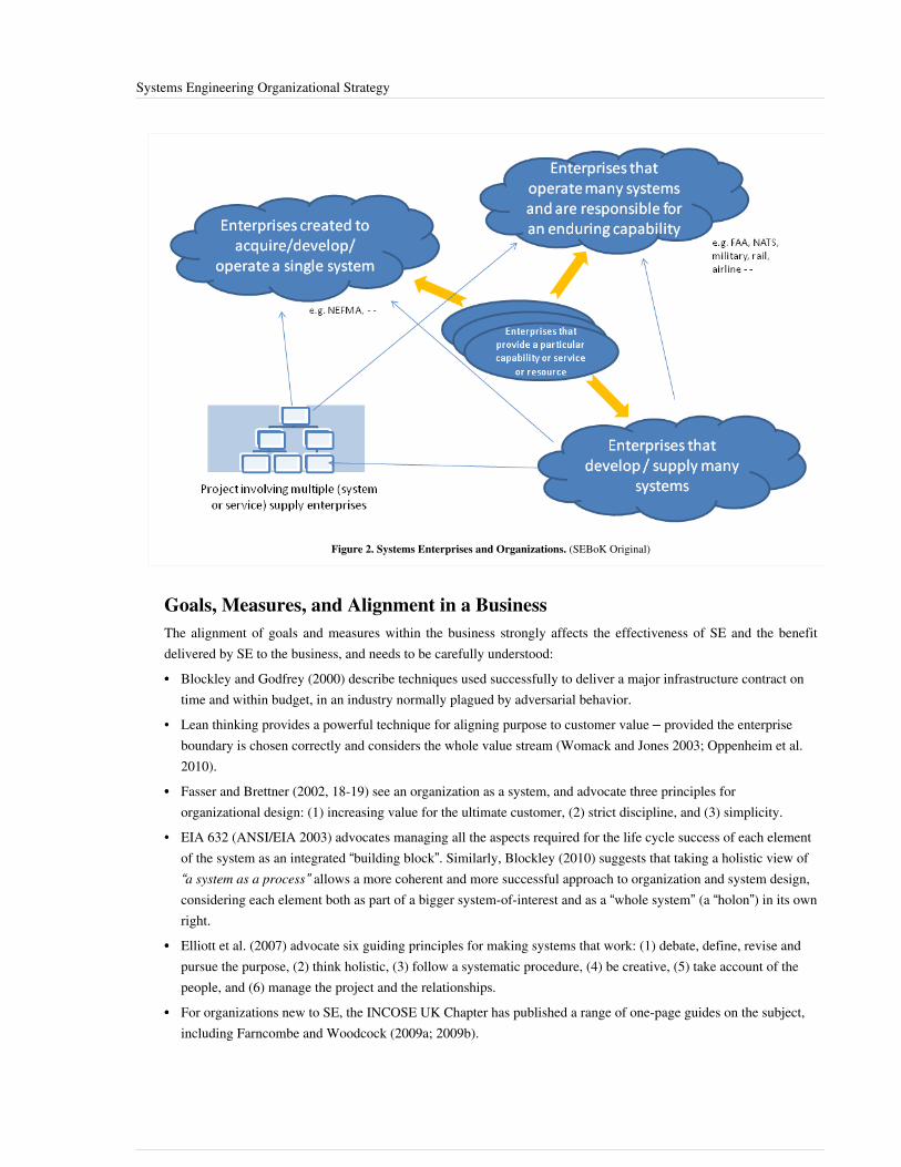
Systems Engineering Organizational Strategy 10
Figure 2. Systems Enterprises and Organizations. (SEBoK Original)
Goals, Measures, and Alignment in a BusinessThe alignment of goals and measures within the business strongly affects the effectiveness of SE and the benefitdelivered by SE to the business, and needs to be carefully understood:•• Blockley and Godfrey (2000) describe techniques used successfully to deliver a major infrastructure contract on
time and within budget, in an industry normally plagued by adversarial behavior.• Lean thinking provides a powerful technique for aligning purpose to customer value – provided the enterprise
boundary is chosen correctly and considers the whole value stream (Womack and Jones 2003; Oppenheim et al.2010).
•• Fasser and Brettner (2002, 18-19) see an organization as a system, and advocate three principles fororganizational design: (1) increasing value for the ultimate customer, (2) strict discipline, and (3) simplicity.
• EIA 632 (ANSI/EIA 2003) advocates managing all the aspects required for the life cycle success of each elementof the system as an integrated “building block”. Similarly, Blockley (2010) suggests that taking a holistic view of“a system as a process” allows a more coherent and more successful approach to organization and system design,considering each element both as part of a bigger system-of-interest and as a “whole system” (a “holon”) in its ownright.
•• Elliott et al. (2007) advocate six guiding principles for making systems that work: (1) debate, define, revise andpursue the purpose, (2) think holistic, (3) follow a systematic procedure, (4) be creative, (5) take account of thepeople, and (6) manage the project and the relationships.
•• For organizations new to SE, the INCOSE UK Chapter has published a range of one-page guides on the subject,including Farncombe and Woodcock (2009a; 2009b).

Systems Engineering Organizational Strategy 11
GovernanceSE governance is the process and practice through which a business puts in place the decision rights that enable SEto deliver as much business value as possible. Those rights may be codified in policy, implemented through thebusiness structure, enforced through tools, and understood through measures of compliance and effectiveness.SE governance in large businesses is often explicit and codified in policy. In small businesses, it is often tacit andsimply understood in how the business works. One of the key implementation steps when a business defines its SEstrategy is to establish its SE governance model, which should be tailored to the particular context in which thebusiness operates and delivers value. Of course, in practice, this is often incremental and uneven, and subject to wideswings based on the current state of the business and the people occupying key management positions.The term governance for development organizations was first popularized in reference to how InformationTechnology (IT) is overseen in businesses and enterprises (Weill and Ross 2006; Cantor and Sanders 2007). Therecognition in the 1990s and the last decade that IT is a fundamental driver of performance and value for mostcorporations and government agencies led to the transformation of the Chief Information Officer (CIO) into a keysenior manager.Explicit governance of IT became important to enabling an enterprise to respond to new technology opportunities,emerging markets, new threats, and rapid delivery of new products and services. The term "governance" is nowwidely used to describe how SE is woven into an enterprise. Governance becomes especially challenging forcomplex projects in which there are high levels of uncertainty (Cantor 2006) or for system of systems projects inwhich responsibility for major decisions may be distributed over multiple organizations within an enterprise in whichthere is no single individual who is "in control" (see Systems of Systems (SoS)). Morgan and Liker (2006) describethe governance model for Toyota, which is one of the largest companies in the world.SE governance establishes the framework and responsibility for managing issues such as design authority, fundingand approvals, project initiation and termination, as well as the legal and regulatory framework in which the systemwill be developed and will operate. Governance includes the rationale and rules for why and how the enterprisepolicies, processes, methods and tools are tailored to the context. SE governance may also specify product andprocess measures, documentation standards, and technical reviews and audits.The ways in which a team organizes to conduct SE activities either conform to policies established at the level aboveor are captured in that team’s own governance policies, processes, and practices. These policies cover theorganizational context and goals, the responsibilities for governance, process, practices and product at the level ofinterest, and the freedom delegated to and governance and reporting obligations imposed on lower organizationallevels. It is good practice to capture the assignment of people and their roles and responsibilities in the form of theResponsible, Accountable, Consult, Inform (RACI) matrix (PMI 2013) or something similar. Responsibility in largeorganizations can easily become diffused. Sommerville et. al. (2009, 515-529) discuss the relationship betweeninformation and responsibility, and describe methods to analyze and model responsibility in complex organizations.Small organizations tend to have relatively informal governance documentation and processes, while largerorganizations tend towards more structure and rigor in their governance approach. Government organizationsresponsible for developing or acquiring large complex systems, such as the US Department of Defense or the USFederal Aviation Administration, usually develop policies that describe governance of their SE activities and SEorganizations. See DoD (2012) for the Department of Defense SE policies.Government contracting typically brings additional regulation and oversight, driving a group to greater rigor,documentation, and specific practices in their SE governance. Development of systems or operating services thataffect public safety or security is subject to constraints similar to those seen in government contracting. Think of thecreation of medical devices or the operation of emergency response systems, air traffic management, or the nuclearindustry. (See Jackson (2010) for example).

Systems Engineering Organizational Strategy 12
Governance models vary widely. For example, Linux, the greatest success of the open source community, has agovernance model that is dramatically different than those of traditional businesses. Smith (2009) offers a cogentexplanation of how decisions are made on what goes into the Linux kernel. All of the decision rights are completelytransparent, posted on the Linux website, and have proven remarkably effective as they have evolved. The classicpaper The Cathedral and The Bazaar by Eric Raymond (2000) provides great insight into the evolution of Linuxgovernance and how Linus Torvalds responded to changing context and circumstances to keep Linux so successfulin the marketplace with a governance model that was radically novel for its time.The project management literature also contributes to the understanding of SE governance (see Systems Engineeringand Project Management). For example, Shenhar and Dvir (2007) offer the "diamond model" for projectmanagement, which identifies four dimensions that should guide how development projects are managed: novelty,technology, complexity, and pace. Application of this model to SE governance would influence the available lifecycle models for development projects and how those models are applied.There are numerous examples of projects that went well or badly based in large part on the governance practiced byboth the acquirer and the supplier organizations. Part 7 of the SEBoK has several examples, notably the SingaporeWater Management Vignette (went well) and FAA Advanced Automation System (AAS) Vignette (went not sowell).
References
Works CitedANSI/EIA. 2003. Processes for Engineering a System. Philadelphia, PA, USA: American National StandardsInstitute (ANSI)/Electronic Industries Association (EIA). ANSI/EIA 632‐1998.Blockley, D. 2010. "The Importance of Being Process." Journal of Civil Engineering and Environmental Systems.27(3).Blockley, D. and Godfrey, P. 2000. Doing It Differently – Systems for Rethinking Construction. London, UK:Thomas Telford, Ltd.Cantor, M. 2006. "Estimation Variance and Governance." In IBM developerWorks. Abstract [1] accessed on April24, 2013.Cantor, M. and J.D. Sanders. 2007. "Operational IT Governance." In IBM developerWorks. Accessed on September15, 2011. Available at http:/ / www. ibm. com/ developerworks/ rational/ library/ may07/ cantor_sanders/ .DoD. 2012. "Systems Engineering Policy". Accessed on August 4, 2012. Available at http:/ / www. acq. osd. mil/ se/pg/ index. html.Eisner, H. 2008. "Essentials of Project and Systems Engineering Management", 3rd ed. Hoboken, NJ, USA: JohnWiley & Sons.Elliott, C. et al. 2007. Creating Systems That Work – Principles of Engineering Systems for The 21st Century.London, UK: Royal Academy of Engineering. Accessed September 2, 2011. Available at http:/ / www. raeng. org.uk/ education/ vps/ pdf/ RAE_Systems_Report. pdf.Fasser, Y. and D. Brettner. 2002. Management for Quality in High-Technology Enterprises. Hoboken, NJ, USA:John Wiley & Sons-Interscience.Farncombe, A. and H. Woodcock. 2009a. "Enabling Systems Engineering". Z-2 Guide, Issue 2.0. Somerset, UK:INCOSE UK Chapter. March, 2009. Accessed September 2, 2011. Available at http:/ / www. incoseonline. org. uk/Documents/ zGuides/ Z2_Enabling_SE. pdf.Farncombe, A. and H. Woodcock. 2009b. "Why Invest in Systems Engineering". Z-3 Guide, Issue 3.0. Somerset, UK: INCOSE UK Chapter. March 2009. Accessed September 2, 2011. Available at http:/ / www. incoseonline. org.

Systems Engineering Organizational Strategy 13
uk/ Documents/ zGuides/ Z3_Why_invest_in_SE. pdf.Jackson, S. 2010. Architecting Resilient Systems: Accident Avoidance and Survival and Recovery from Disruptions.Hoboken, NJ, USA: John Wiley & Sons.Lawson, H. 2010. "A Journey Through the Systems Landscape". London, UK: College Publications, Kings College,UK.MITRE. 2012. "Systems Engineering Guidebook". Accessed on August 4, 2012. Available at http:/ / www. mitre.org/ work/ systems_engineering/ guide/ index. html.Morgan, J. and J. Liker. 2006. The Toyota Product Development System: Integrating People, Process andTechnology. New York, NY, USA: Productivity Press.NASA. 2007. "NASA Systems Engineering Handbook". Accessed on April 24, 2013. Available at http:/ / www. acq.osd. mil/ se/ docs/ NASA-SP-2007-6105-Rev-1-Final-31Dec2007. pdf. Washington, DC, USA: NASA.Northrop, L., P. Clements, et. al. 2007. A Framework for Software Product Line Practice, Version 5.0. With F.Bachmann, J. Bergey, G. Chastek, S. Cohen, P. Donohoe, L. Jones, R. Krut, R. Little, J. McGregor, and L. O'Brien.Pittsburgh, PA, USA: Software Engineering Institute.Oppenheim, B., E.M. Murman, D.A. Secor. 2010. Lean Enablers for Systems Engineering. Systems Engineering.14(1): 29-55.PMI. 2013. A Guide to the Project Management Body of Knowledge (PMBOK® Guide), 5th ed. Newtown Square,PA, USA: Project Management Institute (PMI).Raymond, E.S. 2000. The Cathedral and The Bazaar, version 3.0. Accessed on April 24, 2013. Available at http:/ /www. catb. org/ esr/ writings/ homesteading/ cathedral-bazaar/ cathedral-bazaar. ps.Rouse, W. 2006. "Enterprise Transformation: Understanding and Enabling Fundamental Change." Hoboken, NJ,USA: John Wiley & Sons.Shenhar, A.J. and D. Dvir. 2007. Reinventing Project Management: The Diamond Approach to Successful Growthand Innovation. Boston, MA, USA: Harvard Business School Publishing.Sillitto, H. 1999. “Simple Simon Met A System”. Proceedings of the 9th Annual International Council on SystemsEngineering (INCOSE) International Symposium, 6-10 June, 1999, Brighton, UK.Simpson, T.W., Z. Siddique, R.J. Jiao (eds.). 2006. Product Platform and Product Family Design: Methods andApplications. New York, NY, USA: Springer Science & Business Media, Inc.Smith, J.T. 2009. "2.4 Kernel: How are Decisions Made on What Goes into The Kernel?" Available at http:/ / www.linux. com/ feature/ 8090.Smith, P.G. and D.G. Reinertsen. 1997. Developing Products in Half the Time. New York, NY, USA: Wiley andSons.Sommerville, I., R. Lock, T. Storer, and J.E. Dobson. 2009. "Deriving Information Requirements fromResponsibility Models." Paper presented at 21st International Conference on Advanced Information SystemsEngineering, Amsterdam, Netherlands.Weill, P. and J.W. Ross. 2004. IT Governance: How Top Performers Manage IT Decision Rights for SuperiorResults. Boston, MA, USA: Harvard Business School Publishing.Pugh, S. 1991. Total Design: Integrated Methodsfor Successful Product Engineering. New York, NY, USA: Addison-Wesley.Womack, J. and D. Jones. 2003. Lean Thinking: Banish Waste and Create Wealth in Your Corporation, RevisedEdition. New York, NY, USA: Simon & Schuster.
Systems Engineering Organizational Strategy 14
Primary ReferencesBlockley, D. and Godfrey, P. 2000. Doing It Differently – Systems for Rethinking Construction. London, UK:Thomas Telford, Ltd.Cantor, M. and J.D. Sanders. 2007. "Operational IT Governance." In IBM developerWorks. Accessed on September15, 2011. Available at http:/ / www. ibm. com/ developerworks/ rational/ library/ may07/ cantor_sanders/ .Eisner, H. 2008. Essentials of Project and Systems Engineering Management, 3rd ed. Hoboken, NJ, USA: JohnWiley & Sons.Elliott, C., et al. 2007. Creating Systems That Work – Principles of Engineering Systems for The 21st Century.London, UK: Royal Academy of Engineering. Accessed September 2, 2011. Available at http:/ / www. raeng. org.uk/ education/ vps/ pdf/ RAE_Systems_Report. pdf.Lawson, H. 2010. A Journey Through the Systems Landscape. London, UK: College Publications, Kings College,UK.Morgan, J. and J. Liker. 2006. The Toyota Product Development System: Integrating People, Process andTechnology. New York, NY, USA: Productivity Press.Northrop, L., P. Clements, et al. 2007. A Framework for Software Product Line Practice, version 5.0. With F.Bachmann, J. Bergey, G. Chastek, S. Cohen, P. Donohoe, L. Jones, R. Krut, R. Little, J. McGregor, and L. O'Brien.Pittsburgh, PA, USA: Software Engineering Institute. Accessed on April 25, 2013. Available at http:/ / www. sei.cmu. edu/ productlines/ frame_report/ index. html.Rouse, W. 2006. Enterprise Transformation: Understanding and Enabling Fundamental Change. Hoboken, NJ,USA: John Wiley & Sons.Shenhar, A.J. and D. Dvir. 2007. Reinventing Project Management: The Diamond Approach to Successful Growthand Innovation. Boston, MA, USA: Harvard Business School Publishing.
Additional ReferencesChastek, D., P. Donohoe, and J.D. Mcgregor. 2009. Formulation of a Production Strategy for a Software ProductLine. Pittsburgh, PA, USA: Software Engineering Institute, CMU/SEI-2009-TN-025. Accessed on September 14,2011. Available at http:/ / www. sei. cmu. edu/ reports/ 09tn025. pdf.Sillitto, Mazzella, and Fromenteau. 2001. "The development of Product Lines in THALES: methods, examples,lessons learnt," Paper presented at the INCOSE UK Spring Conference.
< Previous Article | Parent Article | Next Article >SEBoK v. 1.4 released 29 June 2015
SEBoK DiscussionPlease provide your comments and feedback on the SEBoK below. You will need to log in to DISQUS using anexisting account (e.g. Yahoo, Google, Facebook, Twitter, etc.) or create a DISQUS account. Simply type yourcomment in the text field below and DISQUS will guide you through the login or registration steps. Feedback will bearchived and used for future updates to the SEBoK. If you provided a comment that is no longer listed, that commenthas been adjudicated. You can view adjudication for comments submitted prior to SEBoK v. 1.0 at SEBoK Reviewand Adjudication. Later comments are addressed and changes are summarized in the Letter from the Editor andAcknowledgements and Release History.
If you would like to provide edits on this article, recommend new content, or make comments on the SEBoKas a whole, please see the SEBoK Sandbox [1].

Systems Engineering Organizational Strategy 15
ENCODED_CONTENTMjA2MDIPGRpdiBpZD0iZGlzcXVzX3RocmVhZCI+PC9kaXY+CjxzY3JpcHQgdHlwZT0idGV4dC9qYXZhc2NyaXB0Ij4KICAgIC8qICogKiBDT05GSUdVUkFUSU9OIFZBUklBQkxFUzogRURJVCBCRUZPUkUgUEFTVElORyBJTlRPIFlPVVIgV0VCUEFHRSAqICogKi8KICAgIHZhciBkaXNxdXNfc2hvcnRuYW1lID0gJ3NlYm9rd2lraTEwJzsgLy8gcmVxdWlyZWQ6IHJlcGxhY2UgZXhhbXBsZSB3aXRoIHlvdXIgZm9ydW0gc2hvcnRuYW1lCiAgICB2YXIgZGlzcXVzX2lkZW50aWZpZXIgPSAnU3lzdGVtcyBFbmdpbmVlcmluZyBPcmdhbml6YXRpb25hbCBTdHJhdGVneSc7ICAgIHZhciBkaXNxdXNfdXJsID0gJ2h0dHA6Ly9zZWJva3dpa2kub3JnL2RyYWZ0L1N5c3RlbXNfRW5naW5lZXJpbmdfT3JnYW5pemF0aW9uYWxfU3RyYXRlZ3knOwogICAgLyogKiAqIERPTidUIEVESVQgQkVMT1cgVEhJUyBMSU5FICogKiAqLwogICAgKGZ1bmN0aW9uKCkgewogICAgICAgIHZhciBkc3EgPSBkb2N1bWVudC5jcmVhdGVFbGVtZW50KCdzY3JpcHQnKTsgZHNxLnR5cGUgPSAndGV4dC9qYXZhc2NyaXB0JzsgZHNxLmFzeW5jID0gdHJ1ZTsKICAgICAgICBkc3Euc3JjID0gJ2h0dHA6Ly8nICsgZGlzcXVzX3Nob3J0bmFtZSArICcuZGlzcXVzLmNvbS9lbWJlZC5qcyc7CiAgICAgICAgKGRvY3VtZW50LmdldEVsZW1lbnRzQnlUYWdOYW1lKCdoZWFkJylbMF0gfHwgZG9jdW1lbnQuZ2V0RWxlbWVudHNCeVRhZ05hbWUoJ2JvZHknKVswXSkuYXBwZW5kQ2hpbGQoZHNxKTsKICAgIH0pKCk7Cjwvc2NyaXB0Pgo8bm9zY3JpcHQ+UGxlYXNlIGVuYWJsZSBKYXZhU2NyaXB0IHRvIHZpZXcgdGhlIDxhIGhyZWY9Imh0dHA6Ly9kaXNxdXMuY29tLz9yZWZfbm9zY3JpcHQiPmNvbW1lbnRzIHBvd2VyZWQgYnkgRGlzcXVzLjwvYT48L25vc2NyaXB0Pgo8YSBocmVmPSJodHRwOi8vZGlzcXVzLmNvbSIgY2xhc3M9ImRzcS1icmxpbmsiPmJsb2cgY29tbWVudHMgcG93ZXJlZCBieSA8c3BhbiBjbGFzcz0ibG9nby1kaXNxdXMiPkRpc3F1czwvc3Bhbj48L2E+END_ENCODED_CONTENT
References[1] http:/ / www. ibm. com/ developerworks/ library/ ?sort_by=& show_abstract=true& show_all=& search_flag=& contentarea_by=All+
Zones& search_by=Estimation+ Variance+ and+ Governance& product_by=-1& topic_by=-1& industry_by=-1& type_by=All+ Types&ibm-search=Search
Determining Needed Systems EngineeringCapabilities in Businesses and EnterprisesEnabling a business or enterprise to perform systems engineering (SE) well requires deciding which specific SEcapabilities the business or enterprise needs in order to be successful. (In the rest of this article business or enterpriseis usually abbreviated to just "business", because a business is a specific type of enterprise that has sufficientlystrong central authority and motivation to take steps to enable SE). SE capabilities should support the SystemsEngineering Organizational Strategy and reflect the nature of the business, its products and services, variousstakeholders, business leadership focus, etc.This topic, which is part of the Enabling Businesses and Enterprises knowledge area (KA) of Part 5, summarizes thefactors used to decide which SE capabilities a business needs; e.g., the interactions between SE and other functionalareas in the business, and consideration of social dynamics and leadership at the team and business levels. Neededcapabilities may be decided and developed centrally by a business, or within teams and individuals, or through somecombination of the two. Determination of team SE capability is discussed in the article Team Capability, andindividual SE competencies are discussed in the article Roles and Competencies.
Relationship of this Topic to Enterprise Systems EngineeringEnterprise Systems Engineering and Capability Engineering techniques can be used to establish needed SEcapabilities. At a high level of abstraction, the following are basic steps that could be used to decide the desired SEcapabilities within the business:1.1. understand the context;2.2. determine the required SE roles;3.3. determine the competencies and capabilities needed for each of the SE roles;4.4. assess the ability and availability of the needed SE organizations, teams, and individuals;5.5. make adjustments to the required SE roles based on the actual ability and availability; and6.6. organize the SE function to facilitate communication, coordination, and performance.See the article Organizing Business and Enterprises to Perform Systems Engineering for additional information.More information on context and required SE roles is provided below.

Determining Needed Systems Engineering Capabilities in Businesses and Enterprises 16
Contextual DriversThe following discussion illustrates some of the contextual factors that influence the definition of the SE capabilityneeded by a business.
Where the SE Activities are Performed in the Value ChainThe SE approach adopted by the business should depend on what role the organization plays. Ring (2002) defines avalue cycle, and where the business sits in that cycle is a key influence of SE capability need.• Problem owner: focus on identifying and scoping the system problem (defining system-of-interest
(SoI)(glossary))and understanding the nature of the appropriate respondent system using Enterprise SystemsEngineering and Capability Engineering approaches.
• System operator: focus on establishing all the necessary components of capability (glossary) to deliver therequired services, as well as on integrating new system assets into the system operation as they become available(see Service Systems Engineering). The definition of the components of capability varies by organization - e.g.,•• The US Department of Defense defines the components of capability as DOTMLPF: doctrine, organization,
training, materiel, logistics, people, and facilities.•• The UK Ministry of Defense defines the components of capability as TEPIDOIL; i.e., training, equipment,
people, information, doctrine, organization, infrastructure, and logistics.•• Other domains and organizations define the components of capability with similar, equivalent breakdowns
which are either explicit or implicit.• Prime contractor or primary commercial developer: focus on understanding customer needs and trading
alternative solution approaches, then establishing a system team and supply chain to develop, deliver, support,and in some cases, operate the system solution. This may require enterprise SE (see Enterprise SystemsEngineering) as well as "traditional" product SE (see Product Systems Engineering).
• Subsystem/component developer: focus on understanding the critical customer and system integrator issues forthe subsystem or component of interest, define the component or subsystem boundary, and integrate criticaltechnologies. This may exploit re-usable elements and can be sold in identical or modified forms to severalcustomers. (In Part 4 of the SEBoK, see Systems of Systems, Enterprise Systems Engineering, and ProductSystems Engineering for more information and references to the literature.)
• Specialist service provider: focus on specific process capabilities and competences which are typically sold on atime and materials or work package basis to other businesses.
Where the Enterprise Operates in the LifecycleThe SE capabilities required by the business will depend on the system life cycle (glossary) phase(s) in which itoperates (see Life Cycle Models in Part 3).• Concept definition phase: requires the SE capability to identify a “problem situation,” define the context and
potential concept of operations for a solution system, assess the feasibility of a range of possible solutions inbroad terms, and refine the definition to allow the development of system requirements for the solution (seeConcept Definition in Part 3).
• System Definition phase: requires the SE capability to influence concept studies (ensure feasible and understoodby the development team), establish the trade space that remains at the end of the concept study, perform thesystem definition activities, including architecture design, and create a detailed definition of the system elements.
• System realization phase: requires the SE capability to configure the manufacturing and logistics systems for thesystem assets, and manufacture system assets (see System Realization in Part 3).
• System deployment and use: requires the SE capability to maintain business continuity during the transition to operation, bring the system into service, support system, monitor system performance, and respond to emerging needs (see System Deployment and Use. Elliott et al. (2008) describe the different emphases that should be placed

Determining Needed Systems Engineering Capabilities in Businesses and Enterprises 17
in SE during the "in-service" phase. This phase particularly requires the business to be able to perform SE at anappropriate operational tempo.
• Retirement phase: requires the SE capability for ensuring the safe retirement of systems and keeping them in astate ready for re-activation (“mothballed”), safe disposal of the system assets.
Nature of Responsibility to End Users and SocietyDepending on the business model and the contracting environment, the business may find that its responsibility toend users is• explicit, or spelled out by clear requirements and prescriptive legislation; or• implicit; i.e., a legal or ethical obligation to ensure “fitness for purpose” which may be enforced by commercial
frameworks, national or international standards, and specific product liability legislation.Typically, businesses whose business model is contract driven focus on satisfying explicit requirements, whereasmarket-driven businesses have to be more aware of implicit responsibilities.
Nature of Responsibility to CustomersThe business may contract with its customers to deliver any of the following:• an outcome: The intended benefits the system is expected to provide, requires enterprise systems engineering;• an output: Deliver or operate the system or part of it against agreed acceptance criteria; requires product systems
engineering;• an activity: Perform a specified set of tasks, requires service systems engineering; and• a resource: Provide a specified resource; requires focus on individual competencies - see Enabling Individuals.
Scale of SystemsThe business or enterprise may need very different SE approaches depending on the scale of the system at which thebusiness operates. The following categories are based on Hitchins’ five layered system model (Hitchins 2005):• Level 1: Subsystem and technical artifacts – focus on product systems engineering and on technology
integration.• Level 2: Project systems – focus on product systems engineering with cross-discipline and human integration.• Level 3: Business systems – focus on enterprise systems engineering , service systems engineering to implement
them, and on service management (Chang 2010) and continuous improvement (SEI 2010b); see also QualityManagement) for the day to day running of the business.
• Level 4: Industry systems – If there is a conscious effort to treat an entire industry as a system, the focus will beon Enterprise Systems Engineering, and on the long-term economic and environmental sustainability of theoverall industry.
• Level 5: Societal systems – Enterprise systems engineering is used to analyze and attempt to optimize societalsystems (see Singapore Water Management Vignette in Part 7).
Sillitto (2011) has proposed extending this model to cover sustainability issues by adding two additional layers, the“ecosystem” and the “geosystem”.

Determining Needed Systems Engineering Capabilities in Businesses and Enterprises 18
Complexity of Systems Integration Tasks and Stupples’ levelsCreating Systems That Work – Principles of Engineering Systems for The 21st century identifies three “kinds” of SE,originally proposed by Stupples (2006), that have to do with the level of cross-disciplinary integration involved(Elliot et al. 2007)1. Within a discipline (e.g., software, hardware, optics, or mechanics), the SE focus is on taking a systems view of
the architecture and implementation to manage complexity and scale within a single engineering discipline.2. In multiple disciplines (e.g., software, hardware, optics, and mechanics), the SE focus is on holistic integration of
multiple technologies and skills to achieve a balanced system solution.3.3. In socio-technical systems integration, the SE focus is on getting people and the non-human parts of the system
working synergistically.Sillitto (2011) proposed extending this model properly to cover sustainability issues by adding one additional level,“Environmental Integration”. He describes this level and show how the Stupples’ levels relate to other dimensionsused to categorize systems and professional engineering skills.
Criticality of System and Certification RequirementsThe level of rigor in the SE approach adopted by the business will depend on the criticality of various classes ofrequirement. (See Systems Engineering and Specialty Engineering.)•• Safety and security requirements often demand specific auditable processes and proof of staff competence.•• Ethical and environmental requirements may require an audit of the whole supply and value chain.• Extremely demanding combinations of performance requirements will require more design iteration and more
critical control of component characteristics; e.g., see Quality Management and Management for Quality inHigh-Technology Enterprises (Fasser and Brettner 2010).
The Nature of a Contract or AgreementThe nature of the contractual relationship between a business and its customers and end users will influence the styleof SE.•• Fixed price, cost plus, or other contracting models influence the mix of focus on performance and cost control and
how the business is incentivized to handle risk and opportunity.•• In mandated work share arrangements, the architecture of the product system may be compromised or constrained
by the architecture of a viable business system; this is often the case in multi-national projects and high profilegovernment procurements (Maier and Rechtin 2009, 361-373).
• In self-funded approaches, the priorities will be requirements elicitation approaches designed to discover thelatent needs of consumers and business customers, as well as development approaches designed to achieve rapidtime to market with a competitive offering, or to have a competitive offering of sufficient maturity available at themost critical time during a customer’s selection process.
• In single phase or whole-life approaches, the business may be able to optimize trade-offs across the development,implementation, and in-service budgets, and between the different components of capability (glossary).

Determining Needed Systems Engineering Capabilities in Businesses and Enterprises 19
The Nature and Predictability of Problem Domain(s)Well-defined and slowly-changing technologies, products, and services permit the use of traditional SE life cyclemodels based on the waterfall model because the requirements risk and change is expected to be low (see Life CycleModels).Poorly defined and rapidly changing problem domains, with operators subject to unpredictable and evolving threats,demand more flexible solutions and agile processes. SE should focus on modular architectures that allow rapidreconfiguration of systems and systems-of-systems, as well as rapid deployment of new technologies at a subsystemlevel to meet new demands and threats.
Fundamental Risks and Design Drivers in the Solution DomainWhen the solution domain is stable, with a low rate of technology evolution, and systems use mature technology, thefocus is on optimum packaging and configuration of known and usually well-proven building blocks within knownreference architectures, and on low-risk incremental improvement over time.When there is rapid technology evolution, with pressure to bring new technologies rapidly to market and/or intooperational use, the SE approach has to focus on technology maturation, proof of technology and integrationreadiness, and handling the technology risk in the transition from the lab to the proof of concept to the operationalsystem.There is usually a trade-off between lead time expectations and the level of integrity/certification. In thedevelopment of new systems, short lead times are seldom compatible with high levels of system integrity andrigorous certification.
Competitive Situation and Business GoalsThe business drivers for SE deployment may be one or more of the following:•• To perform existing business better;•• To recover from a competitive shock or a shift in clients' expectations;•• To develop a new generation product or service;•• To enter a new market; and/or•• To reposition the business or enterprise in the value chain.In the first case, SE can be deployed incrementally in parts of the business process where early tangible benefits canbe realized. This could be the early steps of a business-wide strategic plan for SE. (See Systems EngineeringOrganizational Strategy for more on setting SE strategy and Developing Systems Engineering Capabilities withinBusinesses and Enterprises for improving SE capabilities.)In the other cases, the business is going through disruptive change and the early priority may be to use systemsthinking (see Systems Thinking) and enterprise SE approaches to scope the transformation in the context of a majorchange initiative.

Determining Needed Systems Engineering Capabilities in Businesses and Enterprises 20
Type of System or ServiceThere are three distinct flavors of products or service types (see Systems Engineering Organizational Strategy):1.1. In a product or productized service, the focus will be on predicting how the market might change during the
development period, eliciting, anticipating, and balancing requirements from a variety of potential customers, andoptimizing features and product attractiveness against cost and reliability.
2.2. In a custom solution (product or service) the focus will be on feasible and low-risk (usually) approaches to meetthe stated requirement within budget, using system elements and technologies that are known or expected to beavailable within the desired development timescale.
3. Tailored solutions based on standard product and/or service elements require a much more sophisticated SEprocess that is able to use a “product line approach” to blend standard modules with planned adaptation to meetclients’ specific needs more quickly and cheaply than would be possible with a single contract solution. Thebusiness needs to manage the life cycle and configuration of the standard modules separately from, but coherentlywith, the life cycle and configuration of each tailored solution.
Needed Systems Engineering RolesAfter understanding the context for the business, the next step is to determine the SE capabilities required in the rolein the business. The SEI Capability Maturity Models for acquisition, development, and services (SEI 2007; SEI2010a; SEI 2010b) provide a framework for selecting SE capabilities relevant to different types of business. ExistingSE competency models can be used to assist in determining the needed capabilities. An example is the INCOSE SECompetencies Framework (INCOSE 2010). (See Roles and Competencies for more information on competencymodels.).There can be a wide spectrum of the spread of SE focus, from SE being focused in a specialist role, an interface orglue role (Sheard 1996), or the idea that “SE is good engineering with special areas of emphasis… includinginterfaces between disciplines” (Blanchard and Fabrycky 2005) and so it is shared by all. In any organization whereactivities and skills are shared, there is always a danger of silos or duplication.As part of the role definition, the business must define where an individual doing SE fits into career progression(what roles before SE, what after?). Developing Individuals describes how individuals improve SE; the organizationmust define the means by which that development can be enacted. Businesses need to customize from a range ofdevelopment strategies; see, for example, Davidz and Martin (2011).As shown in Figure 1 below, management action on workforce development will be required if there are systemicmismatches between the competencies required to perform SE roles and the actual competencies of individuals. Theorganizational culture may have a positive or negative effect on team performance and the overall value added by thebusiness (see Culture).

Determining Needed Systems Engineering Capabilities in Businesses and Enterprises 21
Figure 1. Culture, Competence, Team Performance and Individual Competence. (SEBoK Original)
Required SE Processes and MethodsThe decisions on how to implement SE capability must be embedded in the businesses processes and its availabilitymethodologies and toolsets. Embedding SE principles, processes, and methods in the organization’s qualitymanagement system means that senior management and the quality system will help embed SE in the organizationalbusiness process and make sure it is applied (INCOSE 2012; ISO/IEC 2008; see Quality Management).When defining the processes and tools, a balance between the need for a systematic and standardized approach to SEprocesses, such as that seen in INCOSE (2012), with the flexibility inherent in systemic thinking is critical. Systemsthinking helps the organization understand problem situations, remove organizational barriers, and make the most ofthe organization’s technical capabilities (see Beasley (2011)).
Need for Clarity in the SE Approach and the Dangers of Implementing SEClarity on how the organization does SE is important. Typically, implementing SE may be part of an organization’simprovement, so Kotter’s principles on creating a vision, communicating the vision, and empowering others to act onthe vision are extremely relevant (Kotter 1995). The way an organization chooses to do SE should be part of thevision of the organization and must be understood and accepted by all.Many of the major obstacles in SE deployment are cultural (see Culture).One of the lean enablers for SE is to "pursue perfection" (Oppenheim et al. 2010). The means of improvement at abusiness or enterprise level are discussed in detail elsewhere, but the starting point has to be deciding what SEcapabilities the organization wants. It needs to be recognized that the needed capabilities change over time (learning,improving, or losing capability). Thus, balancing SE with everything else that it involves is an ever changing

Determining Needed Systems Engineering Capabilities in Businesses and Enterprises 22
process.
References
Works CitedBeasley, R. 2011. "The Three T's of Systems Engineering." Paper presented at the 21st Annual International Councilon Systems Engineering (INCOSE) International Symposium. June 2011. Denver, CO, USA.Blanchard, B. and W. Fabrycky. 2005. Systems Engineering and Analysis, 4th edition. Upper Saddle River, NJ,USA: Prentice Hall.Chang, C.M. 2010. Service Systems Management and Engineering: Creating Strategic Differentiation andOperational Excellence. Hoboken, NJ, USA: John Wiley and Sons.Davidz, H. L. and J. Martin. 2011. "Defining a Strategy for Development of Systems Capability in the Workforce."Systems Engineering. 14(2) (Summer, 2011): 141-143Elliott, B. et al. 2008. INCOSE UK Chapter Working Group on Applying Systems Engineering to In-Service Systems,Final Report. Somerset, UK: INCOSE UK Chapter Working Group. Accessed September 6, 2011. Available at http:// www. incoseonline. org. uk/ Documents/ Groups/ InServiceSystems/ is_tr_001_final_report_final_1_0. pdf.Fasser, Y. and D. Brettner. 2001. Management for Quality in High-Technology Enterprises. New York, NY, USA:Wiley.Hitchins, D. 2005. Systems Engineering 5 Layer Model. Accessed on April 24,2013. Available at http:/ / www.hitchins. net/ systems/ world-class-systems-enginee. html.INCOSE. 2010. SE Competencies Framework, Issue 3. Somerset, UK: International Council on SystemsEngineering (INCOSE), INCOSE Technical Product 2010-0205.INCOSE. 2012. Systems Engineering Handbook: A Guide for System Life Cycle Processes and Activities, version3.2.2. San Diego, CA, USA: International Council on Systems Engineering (INCOSE),INCOSE-TP-2003-002-03.2.2.ISO/IEC/IEEE. 2015. Systems and Software Engineering -- System Life Cycle Processes. Geneva, Switzerland:International Organisation for Standardisation / International Electrotechnical Commissions. ISO/IEC/IEEE15288:2008.Kotter, J. 1995. Leading Change: Why Transformation Efforts Fail. Boston, MA, USA: Harvard Business Review(March–April 1995).Maier, M. and E. Rechtin. 2009. The Art of System Architecting, Third Edition. Boca Raton, FL, USA: CRC Press.Oppenheim et al. 2010. Lean Enablers for Systems Engineering. New York, NY, USA: Wiley and Sons, Inc.Ring J. 2002. Toward an Ontology of Systems Engineering. INSIGHT, 5(1): 19-22SEI. 2007. CMMI for Acquisition. Version 1.2. Technical Report CMU/SEI-2007-TR-017. Pittsburgh, PA, USA:Software Engineering Institute, Carnegie Mellon University.SEI. 2010a. Capability Maturity Model Integrated (CMMI) for Development. Version 1.3. Pittsburgh, PA, USA:Software Engineering Institute, Carnegie Mellon University.SEI. 2010b. CMMI for Services. Version 1.3. Technical Report CMU/SEI-2010-TR-034. Pittsburgh, PA, USA:Software Engineering Institute, Carnegie Mellon University.Sheard, S. 1996. "12 Systems Engineering Roles." Paper presented at the 6th Annual International Council onSystems Engineering (INCOSE) International Symposium. Boston, MA, USA. Accessed September 14, 2011.Sillitto, H. 2011. "Unravelling Systems Engineers from Systems Engineering - Frameworks for Understanding theExtent, Variety and Ambiguity of Systems Engineering and Systems Engineers." Paper presented at the 21st Annual

Determining Needed Systems Engineering Capabilities in Businesses and Enterprises 23
International Council on Systems Engineering (INCOSE) International Symposium. 20-23 June 2011. Denver, CO,USA.Stupples, D. 2006. "Systems Engineering – a road from perdition." Published on Royal Academy of Engineeringwebsite - available at http:/ / www. raeng. org. uk/ education/ vps/ systemdesign/ pdf/ David_Stupples. pdf
Primary ReferencesHitchins, D. 2007. Systems Engineering: A 21st Century Systems Methodology. Chichester, UK: Wiley and Sons,Inc.Oppenheim, B. 2011. Lean for Systems Engineering - with Lean Enablers for Systems Engineering. Hoboken, NJ,USA: Wiley and Sons, Inc.Sheard, S. 1996. Twelve Systems Engineering Roles. Paper presented at the 6th Annual International Council onSystems Engineering (INCOSE) International Symposium. Boston, MA, USA. Accessed September 14, 2011.
Additional ReferencesRhodes, D., and G. Roedler (eds.). 2007. Systems Engineering Leading Indicators Guide, version 1.0. San Diego,CA, USA: International Council on Systems Engineering (INCOSE). INCOSE-TP-2005-001-02.
< Previous Article | Parent Article | Next Article >SEBoK v. 1.4 released 29 June 2015
SEBoK DiscussionPlease provide your comments and feedback on the SEBoK below. You will need to log in to DISQUS using anexisting account (e.g. Yahoo, Google, Facebook, Twitter, etc.) or create a DISQUS account. Simply type yourcomment in the text field below and DISQUS will guide you through the login or registration steps. Feedback will bearchived and used for future updates to the SEBoK. If you provided a comment that is no longer listed, that commenthas been adjudicated. You can view adjudication for comments submitted prior to SEBoK v. 1.0 at SEBoK Reviewand Adjudication. Later comments are addressed and changes are summarized in the Letter from the Editor andAcknowledgements and Release History.
If you would like to provide edits on this article, recommend new content, or make comments on the SEBoKas a whole, please see the SEBoK Sandbox [1].
ENCODED_CONTENTMTA1ODQPGRpdiBpZD0iZGlzcXVzX3RocmVhZCI+PC9kaXY+CjxzY3JpcHQgdHlwZT0idGV4dC9qYXZhc2NyaXB0Ij4KICAgIC8qICogKiBDT05GSUdVUkFUSU9OIFZBUklBQkxFUzogRURJVCBCRUZPUkUgUEFTVElORyBJTlRPIFlPVVIgV0VCUEFHRSAqICogKi8KICAgIHZhciBkaXNxdXNfc2hvcnRuYW1lID0gJ3NlYm9rd2lraTEwJzsgLy8gcmVxdWlyZWQ6IHJlcGxhY2UgZXhhbXBsZSB3aXRoIHlvdXIgZm9ydW0gc2hvcnRuYW1lCiAgICB2YXIgZGlzcXVzX2lkZW50aWZpZXIgPSAnRGV0ZXJtaW5pbmcgTmVlZGVkIFN5c3RlbXMgRW5naW5lZXJpbmcgQ2FwYWJpbGl0aWVzIGluIEJ1c2luZXNzZXMgYW5kIEVudGVycHJpc2VzJzsgICAgdmFyIGRpc3F1c191cmwgPSAnaHR0cDovL3NlYm9rd2lraS5vcmcvZHJhZnQvRGV0ZXJtaW5pbmdfTmVlZGVkX1N5c3RlbXNfRW5naW5lZXJpbmdfQ2FwYWJpbGl0aWVzX2luX0J1c2luZXNzZXNfYW5kX0VudGVycHJpc2VzJzsKICAgIC8qICogKiBET04nVCBFRElUIEJFTE9XIFRISVMgTElORSAqICogKi8KICAgIChmdW5jdGlvbigpIHsKICAgICAgICB2YXIgZHNxID0gZG9jdW1lbnQuY3JlYXRlRWxlbWVudCgnc2NyaXB0Jyk7IGRzcS50eXBlID0gJ3RleHQvamF2YXNjcmlwdCc7IGRzcS5hc3luYyA9IHRydWU7CiAgICAgICAgZHNxLnNyYyA9ICdodHRwOi8vJyArIGRpc3F1c19zaG9ydG5hbWUgKyAnLmRpc3F1cy5jb20vZW1iZWQuanMnOwogICAgICAgIChkb2N1bWVudC5nZXRFbGVtZW50c0J5VGFnTmFtZSgnaGVhZCcpWzBdIHx8IGRvY3VtZW50LmdldEVsZW1lbnRzQnlUYWdOYW1lKCdib2R5JylbMF0pLmFwcGVuZENoaWxkKGRzcSk7CiAgICB9KSgpOwo8L3NjcmlwdD4KPG5vc2NyaXB0PlBsZWFzZSBlbmFibGUgSmF2YVNjcmlwdCB0byB2aWV3IHRoZSA8YSBocmVmPSJodHRwOi8vZGlzcXVzLmNvbS8/cmVmX25vc2NyaXB0Ij5jb21tZW50cyBwb3dlcmVkIGJ5IERpc3F1cy48L2E+PC9ub3NjcmlwdD4KPGEgaHJlZj0iaHR0cDovL2Rpc3F1cy5jb20iIGNsYXNzPSJkc3EtYnJsaW5rIj5ibG9nIGNvbW1lbnRzIHBvd2VyZWQgYnkgPHNwYW4gY2xhc3M9ImxvZ28tZGlzcXVzIj5EaXNxdXM8L3NwYW4+PC9hPg==END_ENCODED_CONTENT
Organizing Business and Enterprises to Perform Systems Engineering 24
Organizing Business and Enterprises to PerformSystems EngineeringIn order for a business or enterprise to perform systems engineering (SE) well, the team must decide which specificSE capabilities the business or enterprise needs in order to be successful and then organizing to deliver thosecapabilities. (In the rest of this article, business or enterprise is usually abbreviated to just "business", because abusiness is a specific type of enterprise that has sufficiently strong central authority and motivation to take steps toenable SE).SE capabilities and organizational approach should support the Systems Engineering Organizational Strategy andreflect the nature of the business, its products and services, various stakeholders, business leadership focus, etc. Thistopic, which is part of Part 5, Enabling Businesses and Enterprises, summarizes the factors used to organize abusiness to perform SE.
Components of Business and Enterprise SE Capability
Organization Issues - Culture, Knowledge, Information, and InfrastructureThe way SE is managed is described in Systems Engineering Organizational Strategy, which both impacts andresponds to the SE culture and approach.
Knowledge and InformationKnowledge and Information are key assets in a business, and their management is critical. Fasser and Brettner (2002)discuss knowledge management extensively. They assert that “We may think that knowledge transfer is just aninformation technology issue, but in actuality, it is also a psychological, cultural, and managerial issue – in short ahuman issue” and “Only information in action can create knowledge”.Organizations need to manage SE know-how, integration of SE with other organizational processes and activities,and knowledge of their business domain. The INCOSE Intelligent Enterprise Working Group's work on knowledgemanagement in an SE context led to the publication of a “Concept of Operations for a Systems EngineeringEducational Community” (Ring et al. 2004).Information has to be both shared and protected in complex organizations. Sharing is key to effective collaborationand is constrained by the need to protect intellectual property, as well as commercially and nationally sensitivematerial. Different cultures and personal styles use information in different ways and in different orders. (Levels ofabstraction, big picture first or detail, principles first or practical examples, etc.) Sillitto (2011b) describes theknowledge management challenges for large, multi-national organizations.Projects need to manage project information and establish configuration control over formal contractual information,as well as the information that defines the product/service being developed, supplied, or operated. A key role ofsystems engineers is to “language the project” (Ring et al. 2004). Good data management and tool support will allowpeople to document once, use many times, and ensures consistency of information over time and between differentteams.System information needs to be maintained throughout the life of the system and made available to relevantstakeholders – including those designing new systems that have to interface to the system-of-interest - to allowsystem management, maintenance, reconfiguration, upgrade and disposal, and forensics after accidents andnear-misses. Elliott et al. (2008) suggest that information management is the dominant problem in SE in servicesystems, and that the cost and difficulty of establishing current state and legacy constraints before starting toimplement a change is often underestimated.

Organizing Business and Enterprises to Perform Systems Engineering 25
"Infostructure" (information infrastructure) to support the system lifecycle will include the following:•• Information assets such as process libraries, document templates, preferred parts lists, component re-use libraries,
as-specified and as-tested information about legacy systems, capitalized metrics for organizational performanceon previous similar projects, all with appropriate configuration control
•• Modeling and simulation tools, data sets and run-time environments• Shared working environments – workspaces for co-located teams, areas for people to interact with each other to
develop ideas and explore concepts, work areas suitable for analysis tasks, meeting rooms, access controlprovision, etc.
•• IT facilities - computer file structures, software licenses, IT equipment, computer and wall displays to supportcollaborative working, printers, all with appropriate security provision and back-up facilities, procedures forefficient use, and acceptable performance and usability
•• Security provisions to protect own, customer, supplier and third party IPR and enforce necessary protectiveworking practices while allowing efficient access to information for those with a need to know
SE is a knowledge activity. Systems engineers need appropriate facilities for accessing, sharing and capturingknowledge, as well as for interacting effectively with the whole set of stakeholders. Warfield (2006) describescollaborative workspaces, environments and processes for developing a shared understanding of a problem situation.
Enabling InfrastructureThe ISO/IEC 15288 (ISO 2008) Infrastructure Management Process provides the enabling infrastructure and servicesto support organization and project objectives throughout the life cycle. Infrastructure to support the system lifecycle will often include the following:• Integration and test environment – bench and lab facilities, facilities for development testing as well as
acceptance testing at various levels of integration, calibration and configuration management of test environments• Trials and validation environment – access to test ranges, test tracks, calibrated targets, support and storage for
trials-equipment, harbor, airfield and road facilities, safe storage for fuel, ordinance, etc.• Training and support infrastructure – training simulators, embedded training, tools and test equipment for
operational support and maintenance, etc.
PeopleThe roles people fill are typically defined by the business/enterprise (see Determining Needed Systems EngineeringCapabilities in Businesses and Enterprises), although those decisions may be pushed down to teams. Enabling Teamsexplains how people are used in teams; Enabling Individuals describes the development of an individual's SEcompetence.The implementation of these roles needs further consideration. Sheard (1996) lists twelve system engineering roles.Sheard (2000) draws an important distinction between roles involved in the discovery phase, characterized by a highlevel of uncertainty, the program phase, which is more deterministic and defined, and the overall systemsengineering approach. Kasser et al. (2009) identify five types of systems engineer distinguished by the need to workat increasing levels of abstraction, ambiguity, scope and innovation. Sillitto (2011a) discusses a number of SE rolesand the characteristics required of them, in the context of the wider engineering and business professional landscape.Systems engineering exists within an enterprise “ecosystem.” Two key aspects to consider:•• How much should the business/enterprise nurture and value the systems engineer?•• How much should the business/enterprise pull value from systems engineers, rather than wait for systems
engineers to "push" value on the business/enterprise?

Organizing Business and Enterprises to Perform Systems Engineering 26
ProcessMany SE organizations maintain a set of organizational standard processes which are integrated in their quality andbusiness management system, adapted to their business, and with tailoring guidelines used to help projects apply thestandard processes to their unique circumstances. Guidance on organizational process management is provided bysuch frameworks as the Capability Maturity Model Integration (CMMI) (SEI 2010), which has two process areas onorganizational process: Organizational Process Development (OPD) is concerned with organizational definition andtailoring of the SE lifecycle processes (discussed in detail elsewhere in this document) and Organizational ProcessFocus (OPF), which is concerned with establishing a process culture in an organization.To document, assess, and improve SE processes, businesses often establish a systems engineering process group.Members of such groups often create standard process assets, may mentor teams and business units on how to adoptthose standard processes and assess how effective those processes are working. There is a large body of literature onSE process improvement based on various process improvement models. Two of the most popular are ISO/IEC 9000(2000) and CMMI (SEI 2010). The Software Engineering Institute, which created the CMMI, offers many freetechnical reports and other documents on CMMI at http:/ / www. sei. cmu. edu/ cmmi.Assessment and measuring process performance is covered in Assessing Systems Engineering Performance ofBusiness and Enterprises.
Tools and MethodsSE organizations often invest in SE tools and models, develop their own, and/or integrate off-the-shelf tools intotheir particular business/enterprise processes. Tools require great attention to culture and training; to developing aconsistent “style” of use so that people can understand each others’ work; and proper configuration and managementof the information so that people are working on common and correct information.It is important that methods are used as well as tools, particularly to support Systems Thinking.It is common practice in large SE organizations to have a tool support infrastructure which ensures that tools supportthe organizational standard processes and are fully integrated with training, and that projects and teams can use thetools to do their job and are not distracted by tool management issues that are more efficiently handled centrally.Smaller SE organizations often operate more informally.

Organizing Business and Enterprises to Perform Systems Engineering 27
Fitting It All TogetherThe concept map in Figure 1 below shows the relationships between the various aspects of organization, resource,responsibility, and governance.
Figure 1. Businesses, Teams, and Individuals in SE. (SEBoK Original)
Enterprise Structures and Their Effects on SEEnterprises manage SE resources in many different ways. A key driver is the extent to which they seek to optimizeuse of resources (people, knowledge, and assets) across teams and across the enterprise as a whole. Five commonways of organizing resources to support multiple projects are: project; matrix; functional; integrated; and productcentered (CM Guide 2009, Handy 1985, PMI 2013, section 2.1.3). A large enterprise would likely apply somecombination of these five ways across its constituent sub-enterprises and teams. Browning (2009) offers a way tooptimize project organizational structure. Eisner (2008) offers a good overview of different organizational models.
Project OrganizationA project organization is one extreme in which projects are responsible for hiring, training, and terminating staff, aswell as managing all assets required for delivery. In this model, systems engineers on a project report to the projectmanager and resources are optimized for the delivery of the project. This model has the advantage of stronglyaligning the authority and responsibility of the project with the project manager. However, it operates at the expenseof sub-optimizing how the staff is deployed across the larger enterprise, how technology choices are made acrossprojects, etc. Systems Engineering Fundamentals (DAU 2001) offers a DoD view of good practice projectorganizations.

Organizing Business and Enterprises to Perform Systems Engineering 28
Functional OrganizationA functional organization demonstrates the opposite extreme. In a functional organization projects delegate almostall their work to functional groups, such as the software group, the radar group or the communications group. This isappropriate when the functional skill is fast-evolving and dependent on complex infrastructure. This method is oftenused for manufacturing, test engineering, software development, financial, purchasing, commercial, and legalfunctions.
Matrix OrganizationA matrix organization is used to give systems engineers a “home” between project assignments. Typically, a SEfunctional lead is responsible for career development of the systems engineers in the organization, a factor thatinfluences the diversity and length of individual project assignments.
Integrated OrganizationIn an integrated organization, people do assigned jobs without specific functional allegiance. Those that perform SEtasks are primarily identified as another type of engineer, such as a civil or electrical engineer. They know systemsengineering and use it in their daily activities as required.
Product Centered OrganizationIn accordance with the heuristic (glossary) that “the product and the process must match” (Rechtin 1991, 132), acommon method for creating an organizational structure is to make it match the system breakdown structure (SBS)(glossary). According to Browning (2009), at each element of the SBS there is an assigned integrated product team(IPT)(glossary). Each IPT consists of members of the technical disciplines needed to design the product system. Thepurpose of the IPT is to assure that the interactions among all the technical disciplines are accounted for in the designand that undesirable interactions are avoided.
Interface to Other OrganizationsOutside official engineering and SE organizations within an enterprise, there are other organizations whose charter isnot technical. Nevertheless, these organizations have an important SE role.• Customer Interface Organizations: These are organizations with titles such as Marketing and Customer
Engineering. These are the organizations with the most direct interface with current or potential clientele. Theirrole is to determine customer needs and communicate these needs to the SE organization for conversion toproduct requirements and other system requirements. Kossiakoff and Sweet (2003, 173) discuss the importance ofunderstanding customer needs.
• Contracts Organizations: These organizations interface with both customer and supplier organizations. Theirrole is to develop clearly stated contracts for the developer or the supplier. These contracts convey tasks andresponsibilities for all SE roles of all parties. Technical specifications are attached to the contracts.Responsibilities for verification and validation are specified.
• Supplier Management Organizations: These organizations are responsible for selecting and managing suppliersand assuring that both contractual and technical products are in place. These organizations balance cost and risk toassure that supplier products are delivered, verified, and validated for quality product. Blanchard and Fabrycky(2005, 696-698) discuss the importance of supplier selection and agreement.

Organizing Business and Enterprises to Perform Systems Engineering 29
References
Works CitedBlanchard, B. and W. Fabrycky. 2005. Systems Engineering and Analysis, 4th ed. Upper Saddle River, NJ, USA:Prentice Hall.Browning, T.R. 2009. "Using the Design Structure Matrix to Design Program Organizations." In A.P. Sage and W.B.Rouse (eds.), Handbook of Systems Engineering and Management, 2nd ed. Hoboken, NJ, USA: John Wiley & Sons.Construction Management (CM) Guide. 2009. Project Organization Types. Accessed on September 14, 2011.Available at http:/ / cmguide. org/ archives/ 319.DAU. 2001. Systems Engineering Fundamentals. Ft. Belvoir, VA, USA: Defense Acquisition University (DAU),U.S. Department of Defense (DoD). Accessed on September 14, 2011. Available at http:/ / www. dau. mil/ pubscats/PubsCats/ SEFGuide%2001-01. pdf.Eisner, H. 2008. Essentials of Project and Systems Engineering Management, 3rd ed. Hoboken, NJ, USA: JohnWiley & Sons.Elliott et al. 2008. INCOSE UK Chapter Working Group on Applying Systems Engineering to In-Service Systems.Final Report. Somerset, UK: INCOSE UK Chapter Working Group. Accessed September 6, 2011. Available at http:// www. incoseonline. org. uk/ Documents/ Groups/ InServiceSystems/ is_tr_001_final_report_final_1_0. pdf.Fasser, Y. and D. Brettner. 2002. Management for Quality in High-Technology Enterprises. Hoboken, NJ, USA:John Wiley & Sons.ISO/IEC. 2000. International standards for quality management. Genève, Switzerland: International Organizationfor Standardization. ISO 9000:2000.ISO/IEC. 2008. Systems and Software Engineering -- System Life Cycle Processes. Geneva, Switzerland:International Organisation for Standardisation / International Electrotechnical Commissions. ISO/IEC/IEEE15288:2008.Kasser, J., D. Hitchins, and T. Huynh. 2009. "Re-engineering Systems Engineering." Proceedings of the 3rd AnnualAsia-Pacific Conference on Systems Engineering (APCOSE). 20-23 July 2009. Singapore.Kossiakoff, A., and W.N. Sweet. 2003. Systems Engineering: Principles and Practice. Edited by A. Sage, WileySeries in Systems Engineering and Management. Hoboken, NJ: John Wiley & Sons.PMI. 2013. A Guide to the Project Management Body of Knowledge (PMBOK® Guide), 5th ed. Newtown Square,PA, USA: Project Management Institute (PMI).Rechtin, E. 1991. Systems Architecting: Creating and Building Complex Systems. Englewood Cliffs, NJ, USA: CRCPress.Ring, J. and A.W. Wymore (eds.). 2004. Concept of Operations (conops) of A Systems Engineering EducationCommunity (SEEC). Seattle, WA, USA: INCOSE Education Measurement Working Group (EMWG),INCOSE-TP-2003-015-01.SEI. 2010. Capability Maturity Model Integrated (CMMI) for Development, version 1.3. Pittsburgh, PA, USA:Software Engineering Institute (SEI)/Carnegie Mellon University (CMU).Sheard, S. 1996. "12 Systems Engineering Roles." Paper presented at the Sixth Annual International Council onSystems Engineering (INCOSE) International Symposium. 7-11 July 1996. Boston, MA, USA.Sheard, S. 2000. "The 12 Systems Engineering Roles Revisited." Paper presented at the INCOSE Mid-AtlanticRegional Conference. April 2000. Reston, VA, USA. p 5.2-1 - 5.2-9.Sillitto, H. 2011a. "Unravelling Systems Engineers from Systems Engineering - Frameworks for Understanding theExtent, Variety and Ambiguity of Systems Engineering and Systems Engineers." Paper presented at the 21st AnnualInternational Council on Systems Engineering (INCOSE) International Symposium. 20-23 June 2011. Denver, CO,

Organizing Business and Enterprises to Perform Systems Engineering 30
USA.Sillitto, H. 2011b. Sharing Systems Engineering Knowledge through INCOSE: INCOSE as An Ultra-Large-ScaleSystem? INCOSE Insight. 14(1) (April): 20.Warfield, J. 2006. An Introduction to Systems Science. Washington, DC, USA: The National Academies Press,World Scientific.
Primary ReferencesEisner, H. 2008. Essentials of Project and Systems Engineering Management, 3rd ed. Hoboken, NJ, USA: JohnWiley and Sons.Kotter, J. 1995. "Leading Change: Why Transformation Efforts Fail." Harvard Business Review. 73(2): 59–67.
Sheard, S. 2000. "Systems Engineering Roles Revisited." Paper presented at the INCOSE Mid-Atlantic RegionalConference. April 5-8 2000. Reston, VA, USA. p 5.2-1 - 5.2-9.
Additional ReferencesBlanchard, B. and W. Fabrycky. 2005. Systems Engineering and Analysis, 4th edition. Upper Saddle River, NJ,USA: Prentice Hall.Construction Management (CM) Guide. 2009. Project Organization Types. Accessed on September 6, 2011.Available at http:/ / cmguide. org/ archives/ 319.Defense Acquisition University (DAU). 2001. Systems Engineering Fundamentals. Fort Belvoir, VA, USA: DefenseAcquisition University Press. Accessed on September 6, 2011. Available at http:/ / www. dau. mil/ pubscats/PubsCats/ SEFGuide%2001-01. pdf.Handy, C.B. 1985. Understanding Organizations. London, UK: Penguin Business.
< Previous Article | Parent Article | Next Article >SEBoK v. 1.4 released 29 June 2015
SEBoK DiscussionPlease provide your comments and feedback on the SEBoK below. You will need to log in to DISQUS using anexisting account (e.g. Yahoo, Google, Facebook, Twitter, etc.) or create a DISQUS account. Simply type yourcomment in the text field below and DISQUS will guide you through the login or registration steps. Feedback will bearchived and used for future updates to the SEBoK. If you provided a comment that is no longer listed, that commenthas been adjudicated. You can view adjudication for comments submitted prior to SEBoK v. 1.0 at SEBoK Reviewand Adjudication. Later comments are addressed and changes are summarized in the Letter from the Editor andAcknowledgements and Release History.
If you would like to provide edits on this article, recommend new content, or make comments on the SEBoKas a whole, please see the SEBoK Sandbox [1].
ENCODED_CONTENTMTUzOTkPGRpdiBpZD0iZGlzcXVzX3RocmVhZCI+PC9kaXY+CjxzY3JpcHQgdHlwZT0idGV4dC9qYXZhc2NyaXB0Ij4KICAgIC8qICogKiBDT05GSUdVUkFUSU9OIFZBUklBQkxFUzogRURJVCBCRUZPUkUgUEFTVElORyBJTlRPIFlPVVIgV0VCUEFHRSAqICogKi8KICAgIHZhciBkaXNxdXNfc2hvcnRuYW1lID0gJ3NlYm9rd2lraTEwJzsgLy8gcmVxdWlyZWQ6IHJlcGxhY2UgZXhhbXBsZSB3aXRoIHlvdXIgZm9ydW0gc2hvcnRuYW1lCiAgICB2YXIgZGlzcXVzX2lkZW50aWZpZXIgPSAnT3JnYW5pemluZyBCdXNpbmVzcyBhbmQgRW50ZXJwcmlzZXMgdG8gUGVyZm9ybSBTeXN0ZW1zIEVuZ2luZWVyaW5nJzsgICAgdmFyIGRpc3F1c191cmwgPSAnaHR0cDovL3NlYm9rd2lraS5vcmcvZHJhZnQvT3JnYW5pemluZ19CdXNpbmVzc19hbmRfRW50ZXJwcmlzZXNfdG9fUGVyZm9ybV9TeXN0ZW1zX0VuZ2luZWVyaW5nJzsKICAgIC8qICogKiBET04nVCBFRElUIEJFTE9XIFRISVMgTElORSAqICogKi8KICAgIChmdW5jdGlvbigpIHsKICAgICAgICB2YXIgZHNxID0gZG9jdW1lbnQuY3JlYXRlRWxlbWVudCgnc2NyaXB0Jyk7IGRzcS50eXBlID0gJ3RleHQvamF2YXNjcmlwdCc7IGRzcS5hc3luYyA9IHRydWU7CiAgICAgICAgZHNxLnNyYyA9ICdodHRwOi8vJyArIGRpc3F1c19zaG9ydG5hbWUgKyAnLmRpc3F1cy5jb20vZW1iZWQuanMnOwogICAgICAgIChkb2N1bWVudC5nZXRFbGVtZW50c0J5VGFnTmFtZSgnaGVhZCcpWzBdIHx8IGRvY3VtZW50LmdldEVsZW1lbnRzQnlUYWdOYW1lKCdib2R5JylbMF0pLmFwcGVuZENoaWxkKGRzcSk7CiAgICB9KSgpOwo8L3NjcmlwdD4KPG5vc2NyaXB0PlBsZWFzZSBlbmFibGUgSmF2YVNjcmlwdCB0byB2aWV3IHRoZSA8YSBocmVmPSJodHRwOi8vZGlzcXVzLmNvbS8/cmVmX25vc2NyaXB0Ij5jb21tZW50cyBwb3dlcmVkIGJ5IERpc3F1cy48L2E+PC9ub3NjcmlwdD4KPGEgaHJlZj0iaHR0cDovL2Rpc3F1cy5jb20iIGNsYXNzPSJkc3EtYnJsaW5rIj5ibG9nIGNvbW1lbnRzIHBvd2VyZWQgYnkgPHNwYW4gY2xhc3M9ImxvZ28tZGlzcXVzIj5EaXNxdXM8L3NwYW4+PC9hPg==END_ENCODED_CONTENT
Assessing Systems Engineering Performance of Business and Enterprises 31
Assessing Systems Engineering Performance ofBusiness and EnterprisesAt the project level, systems engineering (SE) measurement focuses on indicators of project and system success thatare relevant to the project and its stakeholders. At the enterprise level there are additional concerns. SE governanceshould ensure that the performance of systems engineering within the enterprise adds value to the organization, isaligned to the organization's purpose, and implements the relevant parts of the organization's strategy.For enterprises that are traditional businesses this is easier, because such organizations typically have more controllevers than more loosely structured enterprises. The governance levers that can be used to improve performanceinclude people (selection, training, culture, incentives), process, tools and infrastructure, and organization; therefore,the assessment of systems engineering performance in an enterprise should cover these dimensions.Being able to aggregate high quality data about the performance of teams with respect to SE activities is certainly ofbenefit when trying to guide team activities. Having access to comparable data, however, is often difficult, especiallyin organizations that are relatively autonomous, use different technologies and tools, build products in differentdomains, have different types of customers, etc. Even if there is limited ability to reliably collect and aggregate dataacross teams, having a policy that consciously decides how the enterprise will address data collection and analysis isvaluable.
Performance Assessment MeasuresTypical measures for assessing SE performance of an enterprise include the following:•• Effectiveness of SE process•• Ability to mobilize the right resources at the right time for a new project or new project phase•• Quality of SE process outputs•• Timeliness of SE process outputs•• SE added value to project•• System added value to end users•• SE added value to organization•• Organization's SE capability development•• Individuals' SE competence development•• Resource utilization, current and forecast•• Productivity of systems engineers•• Deployment and consistent usage of tools and methods
How Measures Fit in the Governance Process and Improvement CycleSince collecting data and analyzing it takes effort that is often significant, measurement is best done when itspurpose is clear and is part of an overall strategy. The "goal, question, metric" paradigm (Basili 1992) should beapplied, in which measurement data is collected to answer specific questions, the answer to which helps achieve agoal, such as decreasing the cost of creating a system architecture or increasing the value of a system to a particularstakeholder. Figure 1 shows one way in which appropriate measures inform enterprise level governance and drive animprovement cycle such as the Six Sigma DMAIC (Define, Measure, Analyze, Improve, Control) model.

Assessing Systems Engineering Performance of Business and Enterprises 32
Figure 1. Assessing Systems Engineering Performance in Business or Enterprise: Part of Closed Loop Governance. (SEBoKOriginal)
Discussion of Performance Assessment Measures
Assessing SE Internal Process (Quality and Efficiency)A Process (glossary) is a "set of interrelated or interacting activities which transforms inputs into outputs." The SEICMMI Capability Maturity Model (SEI 2010) provides a structured way for businesses and enterprises to assesstheir SE processes. In the CMMI, a process area is a cluster of related practices in an area that, when implementedcollectively, satisfies a set of goals considered important for making improvement in that area. There are CMMImodels for acquisition, for development, and for services (SEI 2010, 11). CMMI defines how to assess individualprocess areas against Capability Levels on a scale from 0 to 3, and overall organizational maturity on a scale from 1to 5.

Assessing Systems Engineering Performance of Business and Enterprises 33
Assessing Ability to Mobilize for a New Project or New Project PhaseSuccessful and timely project initiation and execution depends on having the right people available at the right time.If key resources are deployed elsewhere, they cannot be applied to new projects at the early stages when theseresources make the most difference. Queuing theory shows that if a resource pool is running at or close to capacity,delays and queues are inevitable.The ability to manage teams through their lifecycle is an organizational capability that has substantial leverage onproject and organizational efficiency and effectiveness. This includes being able to•• mobilize teams rapidly;•• establish and tailor an appropriate set of processes, metrics and systems engineering plans;•• support them to maintain a high level of performance;•• capitalize acquired knowledge; and•• redeploy team members expeditiously as the team winds down.Specialists and experts are used to a review process, critiquing solutions, creating novel solutions, and solvingcritical problems. Specialists and experts are usually a scarce resource. Few businesses have the luxury of havingenough experts with all the necessary skills and behaviors on tap to allocate to all teams just when needed. If theskills are core to the business' competitive position or governance approach, then it makes sense to manage themthrough a governance process that ensures their skills are applied to greatest effect across the business.Businesses typically find themselves balancing between having enough headroom to keep projects on schedule whenthings do not go as planned and utilizing resources efficiently.
Project SE Outputs (Cost, Schedule, Quality)Many SE outputs in a project are produced early in the life cycle to enable downstream activities. Hidden defects inthe early phase SE work products may not become fully apparent until the project hits problems in integration,verification and validation, or transition to operations. Intensive peer review and rigorous modeling are the normalways of detecting and correcting defects in and lack of coherence between SE work products.Leading indicators could be monitored at the organizational level to help direct support to projects or teams headingfor trouble. For example, the INCOSE Leading Indicators report (Roedler et al. 2010) offers a set of indicators that isuseful at the project level. Lean Sigma provides a tool for assessing benefit delivery throughout an enterprise valuestream. Lean Enablers for Systems Engineering are now being developed (Oppenheim et al. 2010). An emerginggood practice is to use Lean Value Stream Mapping (glossary) to aid the optimization of project plans and processapplication.In a mature organization, one good measure of SE quality is the number of defects that have to be corrected "out ofphase"; i.e., at a later phase in the life cycle when the defect was introduced. This gives a good measure of processperformance and the quality of SE outputs. Within a single project, the Work Product Approval, Review ActionClosure, and Defect Error trends contain information that allows residual defect densities to be estimated (Roedler etal. 2010; Davies and Hunter 2001)Because of the leverage of front-end SE on overall project performance, it is important to focus on quality andtimeliness of SE deliverables (Woodcock 2009).
SE Added Value to ProjectSE that is properly managed and performed should add value to the project in terms of quality, risk avoidance, improved coherence, better management of issues and dependencies, right-first-time integration and formal verification, stakeholder management, and effective scope management. Because quality and quantity of SE are not the only factors that influence these outcomes, and because the effect is a delayed one (good SE early in the project pays off in later phases) there has been a significant amount of research to establish evidence to underpin the asserted
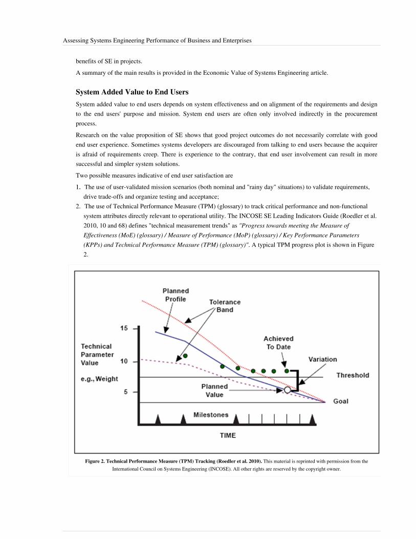
Assessing Systems Engineering Performance of Business and Enterprises 34
benefits of SE in projects.A summary of the main results is provided in the Economic Value of Systems Engineering article.
System Added Value to End UsersSystem added value to end users depends on system effectiveness and on alignment of the requirements and designto the end users' purpose and mission. System end users are often only involved indirectly in the procurementprocess.Research on the value proposition of SE shows that good project outcomes do not necessarily correlate with goodend user experience. Sometimes systems developers are discouraged from talking to end users because the acquireris afraid of requirements creep. There is experience to the contrary, that end user involvement can result in moresuccessful and simpler system solutions.Two possible measures indicative of end user satisfaction are1.1. The use of user-validated mission scenarios (both nominal and "rainy day" situations) to validate requirements,
drive trade-offs and organize testing and acceptance;2. The use of Technical Performance Measure (TPM) (glossary) to track critical performance and non-functional
system attributes directly relevant to operational utility. The INCOSE SE Leading Indicators Guide (Roedler et al.2010, 10 and 68) defines "technical measurement trends" as "Progress towards meeting the Measure ofEffectiveness (MoE) (glossary) / Measure of Performance (MoP) (glossary) / Key Performance Parameters(KPPs) and Technical Performance Measure (TPM) (glossary)". A typical TPM progress plot is shown in Figure2.
Figure 2. Technical Performance Measure (TPM) Tracking (Roedler et al. 2010). This material is reprinted with permission from theInternational Council on Systems Engineering (INCOSE). All other rights are reserved by the copyright owner.

Assessing Systems Engineering Performance of Business and Enterprises 35
SE Added Value to OrganizationSE at the business/enterprise level aims to develop, deploy and enable effective SE to add value to the organization’sbusiness. The SE function in the business/enterprise should understand the part it has to play in the bigger pictureand identify appropriate performance measures - derived from the business or enterprise goals, and coherent withthose of other parts of the organization - so that it can optimize its contribution.
Organization's SE Capability DevelopmentThe CMMI (SEI 2010) provides a means of assessing the process capability and maturity of businesses andenterprises. The higher CMMI levels are concerned with systemic integration of capabilities across the business orenterprise.CMMI measures one important dimension of capability development, but CMMI maturity level is not a directmeasure of business effectiveness unless the SE measures are properly integrated with business performancemeasures. These may include bid success rate, market share, position in value chain, development cycle time andcost, level of innovation and re-use, and the effectiveness with which SE capabilities are applied to the specificproblem and solution space of interest to the business.
Individuals' SE Competence DevelopmentAssessment of Individuals' SE competence development is described in Assessing Individuals.
Resource Utilization, Current and ForecastRoedler et al. (2010, 58) offer various metrics for staff ramp-up and use on a project. Across the business orenterprise, key indicators include the overall manpower trend across the projects, the stability of the forward load,levels of overtime, the resource headroom (if any), staff turnover, level of training, and the period of time for whichkey resources are committed.
Deployment and Consistent Usage of Tools and MethodsIt is common practice to use a range of software tools in an effort to manage the complexity of system developmentand in-service management. These range from simple office suites to complex logical, virtual reality andphysics-based modeling environments.Deployment of SE tools requires careful consideration of purpose, business objectives, business effectiveness,training, aptitude, method, style, business effectiveness, infrastructure, support, integration of the tool with theexisting or revised SE process, and approaches to ensure consistency, longevity and appropriate configurationmanagement of information. Systems may be in service for upwards of 50 years, but storage media and file formatsthat are 10-15 years old are unreadable on most modern computers. It is desirable for many users to be able to workwith a single common model; it can be that two engineers sitting next to each other using the same tool usesufficiently different modeling styles that they cannot work on or re-use each others' models.License usage over time and across sites and projects is a key indicator of extent and efficiency of tool deployment.More difficult to assess is the consistency of usage. Roedler et al. (2010, 73) recommend metrics on "facilities andequipment availability".

Assessing Systems Engineering Performance of Business and Enterprises 36
Practical ConsiderationsAssessment of SE performance at the business/enterprise level is complex and needs to consider soft issues as wellas hard issues. Stakeholder concerns and satisfaction criteria may not be obvious or explicit. Clear and explicitreciprocal expectations and alignment of purpose, values, goals and incentives help to achieve synergy across theorganization and avoid misunderstanding."What gets measured gets done." Because metrics drive behavior, it is important to ensure that metrics used tomanage the organization reflect its purpose and values, and that they do not drive perverse behaviors (Roedler et al.2010).Process and measurement cost money and time, so it is important to get the right amount of process definition andthe right balance of investment between process, measurement, people and skills. Any process flexible enough toallow innovation will also be flexible enough to allow mistakes. If process is seen as excessively restrictive orprescriptive, in an effort to prevent mistakes it may inhibit innovation and demotivate the innovators, leading toexcessive risk avoidance.It is possible for a process improvement effort to become an end in itself rather than a means to improve businessperformance (Sheard 2003). To guard against this, it is advisable to remain clearly focused on purpose (Blockley andGodfrey 2000) and on added value (Oppenheim et al. 2010) as well as to ensure clear and sustained top managementcommitment to driving the process improvement approach to achieve the required business benefits. Good processimprovement is as much about establishing a performance culture as about process.
The Systems Engineering process is an essential complement to, and is not a substitute for, individualskill, creativity, intuition, judgment etc. Innovative people need to understand the process and how tomake it work for them, and neither ignore it nor be slaves to it. Systems Engineering measurementshows where invention and creativity need to be applied. SE process creates a framework to leveragecreativity and innovation to deliver results that surpass the capability of the creative individuals –results that are the emergent properties of process, organisation, and leadership. (Sillitto 2011)
References
Works CitedBasili, V. 1992. "Software Modeling and Measurement: The Goal/Question/Metric Paradigm" Technical ReportCS-TR-2956. University of Maryland: College Park, MD, USA. Accessed on August 28, 2012. Available at http:/ /www. cs. umd. edu/ ~basili/ publications/ technical/ T78. pdf.Blockley, D. and P. Godfrey. 2000. Doing It Differently – Systems For Rethinking Construction. London, UK:Thomas Telford Ltd.Davies, P. and N. Hunter. 2001. "System Test Metrics on a Development-Intensive Project." Paper presented at the11th Annual International Council on System Engineering (INCOSE) International Symposium. 1-5 July 2001.Melbourne, Australia.Oppenheim, B., E. Murman, and D. Sekor. 2010. Lean Enablers for Systems Engineering. Systems Engineering.14(1). New York, NY, USA: Wiley and Sons, Inc.Roedler, G. D. Rhodes, H. Schimmoller, and C. Jones (eds.). 2010. Systems Engineering Leading Indicators Guide,version 2.0. January 29, 2010, Published jointly by LAI, SEARI, INCOSE, and PSM. INCOSE-TP-2005-001-03.Accessed on September 14, 2011. Available at http:/ / seari. mit. edu/ documents/ SELI-Guide-Rev2. pdf.SEI. 2010. CMMI for Development, version 1.3. Pittsburgh, PA, USA: Software Engineering Institute/CarnegieMellon University. CMU/SEI-2010-TR-033. Accessed on September 14, 2011. Available at http:/ / www. sei. cmu.edu/ reports/ 10tr033. pdf.
Assessing Systems Engineering Performance of Business and Enterprises 37
Sheard, S, 2003. "The Lifecycle of a Silver Bullet." Crosstalk: The Journal of Defense Software Engineering. (July2003). Accessed on September 14, 2011. Available at http:/ / www. crosstalkonline. org/ storage/ issue-archives/2003/ 200307/ 200307-Sheard. pdf.Sillitto, H. 2011. Panel on "People or Process, Which is More Important". Presented at the 21st Annual InternationalCouncil on Systems Engineering (INCOSE) International Symposium. 20-23 June 2011. Denver, CO, USA.Woodcock, H. 2009. "Why Invest in Systems Engineering." INCOSE UK Chapter. Z-3 Guide, Issue 3.0. March2009. Accessed on September 14, 2011. Available at http:/ / www. incoseonline. org. uk/ Documents/ zGuides/Z3_Why_invest_in_SE. pdf.
Primary ReferencesBasili, V. 1992. "Software Modeling and Measurement: The Goal/Question/Metric Paradigm". College Park, MD,USA: University of Maryland. Technical Report CS-TR-2956. Accessed on August 28, 2012. Available at http:/ /www. cs. umd. edu/ ~basili/ publications/ technical/ T78. pdf.Frenz, P., et al. 2010. Systems Engineering Measurement Primer: A Basic Introduction to Measurement Conceptsand Use for Systems Engineering, version 2.0. San Diego, CA, USA: International Council on System Engineering(INCOSE). INCOSE‐TP‐2010‐005‐02.Oppenheim, B., E. Murman, and D. Sekor. 2010. Lean Enablers for Systems Engineering. Systems Engineering.14(1). New York, NY, USA: Wiley and Sons, Inc.Roedler, G., D. Rhodes, H. Schimmoller, and C. Jones (eds.). 2010. Systems Engineering Leading Indicators Guide,version 2.0. January 29, 2010, Published jointly by LAI, SEARI, INCOSE, PSM. INCOSE-TP-2005-001-03.Accessed on September 14, 2011. Available at http:/ / seari. mit. edu/ documents/ SELI-Guide-Rev2. pdf.
Additional ReferencesJelinski, Z. and P.B. Moranda. 1972. "Software Reliability Research". In W. Freiberger. (ed.), Statistical ComputerPerformance Evaluation. New York, NY, USA: Academic Press. p. 465-484.Alhazmi O.H. and Y.K. Malaiya. 2005. Modeling the Vulnerability Discovery Process. 16th IEEE InternationalSymposium on Software Reliability Engineering (ISSRE'05). 8-11 November 2005. Chicago, IL, USA.Alhazmi, O.H. and Y.K. Malaiya. 2006. "Prediction Capabilities of Vulnerability Discovery Models." Paperpresented at Annual Reliability and Maintainability Symposium (RAMS). 23-26 January 2006. p 86-91. NewportBeach, CA, USA. Accessed on September 14, 2011. Available at http:/ / ieeexplore. ieee. org/ stamp/ stamp.jsp?tp=& arnumber=1677355& isnumber=34933.
< Previous Article | Parent Article | Next Article >SEBoK v. 1.4 released 29 June 2015
SEBoK DiscussionPlease provide your comments and feedback on the SEBoK below. You will need to log in to DISQUS using anexisting account (e.g. Yahoo, Google, Facebook, Twitter, etc.) or create a DISQUS account. Simply type yourcomment in the text field below and DISQUS will guide you through the login or registration steps. Feedback will bearchived and used for future updates to the SEBoK. If you provided a comment that is no longer listed, that commenthas been adjudicated. You can view adjudication for comments submitted prior to SEBoK v. 1.0 at SEBoK Reviewand Adjudication. Later comments are addressed and changes are summarized in the Letter from the Editor andAcknowledgements and Release History.
If you would like to provide edits on this article, recommend new content, or make comments on the SEBoKas a whole, please see the SEBoK Sandbox [1].

Assessing Systems Engineering Performance of Business and Enterprises 38
ENCODED_CONTENTMTc0NjgPGRpdiBpZD0iZGlzcXVzX3RocmVhZCI+PC9kaXY+CjxzY3JpcHQgdHlwZT0idGV4dC9qYXZhc2NyaXB0Ij4KICAgIC8qICogKiBDT05GSUdVUkFUSU9OIFZBUklBQkxFUzogRURJVCBCRUZPUkUgUEFTVElORyBJTlRPIFlPVVIgV0VCUEFHRSAqICogKi8KICAgIHZhciBkaXNxdXNfc2hvcnRuYW1lID0gJ3NlYm9rd2lraTEwJzsgLy8gcmVxdWlyZWQ6IHJlcGxhY2UgZXhhbXBsZSB3aXRoIHlvdXIgZm9ydW0gc2hvcnRuYW1lCiAgICB2YXIgZGlzcXVzX2lkZW50aWZpZXIgPSAnQXNzZXNzaW5nIFN5c3RlbXMgRW5naW5lZXJpbmcgUGVyZm9ybWFuY2Ugb2YgQnVzaW5lc3MgYW5kIEVudGVycHJpc2VzJzsgICAgdmFyIGRpc3F1c191cmwgPSAnaHR0cDovL3NlYm9rd2lraS5vcmcvZHJhZnQvQXNzZXNzaW5nX1N5c3RlbXNfRW5naW5lZXJpbmdfUGVyZm9ybWFuY2Vfb2ZfQnVzaW5lc3NfYW5kX0VudGVycHJpc2VzJzsKICAgIC8qICogKiBET04nVCBFRElUIEJFTE9XIFRISVMgTElORSAqICogKi8KICAgIChmdW5jdGlvbigpIHsKICAgICAgICB2YXIgZHNxID0gZG9jdW1lbnQuY3JlYXRlRWxlbWVudCgnc2NyaXB0Jyk7IGRzcS50eXBlID0gJ3RleHQvamF2YXNjcmlwdCc7IGRzcS5hc3luYyA9IHRydWU7CiAgICAgICAgZHNxLnNyYyA9ICdodHRwOi8vJyArIGRpc3F1c19zaG9ydG5hbWUgKyAnLmRpc3F1cy5jb20vZW1iZWQuanMnOwogICAgICAgIChkb2N1bWVudC5nZXRFbGVtZW50c0J5VGFnTmFtZSgnaGVhZCcpWzBdIHx8IGRvY3VtZW50LmdldEVsZW1lbnRzQnlUYWdOYW1lKCdib2R5JylbMF0pLmFwcGVuZENoaWxkKGRzcSk7CiAgICB9KSgpOwo8L3NjcmlwdD4KPG5vc2NyaXB0PlBsZWFzZSBlbmFibGUgSmF2YVNjcmlwdCB0byB2aWV3IHRoZSA8YSBocmVmPSJodHRwOi8vZGlzcXVzLmNvbS8/cmVmX25vc2NyaXB0Ij5jb21tZW50cyBwb3dlcmVkIGJ5IERpc3F1cy48L2E+PC9ub3NjcmlwdD4KPGEgaHJlZj0iaHR0cDovL2Rpc3F1cy5jb20iIGNsYXNzPSJkc3EtYnJsaW5rIj5ibG9nIGNvbW1lbnRzIHBvd2VyZWQgYnkgPHNwYW4gY2xhc3M9ImxvZ28tZGlzcXVzIj5EaXNxdXM8L3NwYW4+PC9hPg==END_ENCODED_CONTENT
Developing Systems Engineering Capabilitieswithin Businesses and EnterprisesThe pursuit of continuous improvement is a constant for many organizations. The description of Toyota (Morgan andLiker 2006), the Lean principle of “pursue perfection” (Oppenheim et al. 2010), and the principle of “don’t let up”(Kotter 1995), all drive a need for continuous improvement.The ability to manage teams through their lifecycle - mobilize teams rapidly, establish and tailor an appropriate set ofprocesses, metrics and systems engineering plans, support them to maintain a high level of performance, capitalizeacquired knowledge and redeploy team members expeditiously as the team winds down - is a key organizationalcompetence that has substantial leverage on project and organizational efficiency and effectiveness.The enterprise provides teams with the necessary resources, background information, facilities, cash, supportservices, tooling, etc. It also provides a physical, cultural and governance environment in which the teams can beeffective. The key functions of the enterprise include generating and maintaining relevant resources, allocating themto teams, providing support and governance functions, maintaining expertise and knowledge (on process, applicationdomain and solution technologies), securing the work that teams perform, organizing finance, and maintaining theviability of the enterprise.For improvements to persist, they must reside in the enterprise rather than just the individuals, so the improvementscan endure as personnel leave. This is reflected in the Capability Maturity Model Integrated (CMMI) (SEI 2010)progression from a "hero culture" to a "quantitatively managed and optimizing process".This topic outlines the issues to be considered in capability development and organizational learning.
OverviewFigure 1 shows an "analyze - organize - perform - assess - develop" cycle, which is essentially a reformulation of theDeming (1994) PDCA (Plan Do Check Act) cycle. The analysis step should cover both current and future needs, asfar as these can be determined or predicted. Goals and performance assessment, as discussed in Assessing SystemsEngineering Performance of Business and Enterprises, can be based on a number of evaluation frameworks, such asdirect measures of business performance and effectiveness and the CMMI capability maturity models. There isevidence that many organizations find a positive correlation between business performance and CMMI levels (SEI2010). This is discussed further in the Economic Value of Systems Engineering.

Developing Systems Engineering Capabilities within Businesses and Enterprises 39
Figure 1. Concept Map for Businesses and Enterprises Topics. (SEBoK Original)
Change LeversSE managers have a number of possible change levers they can use to develop SE capabilities. The amount of timedelay between moving a lever and seeing the effect varies with the type of level, size of the enterprise, culture of theenterprise, and other factors.
Adjust Context, Scope, Purpose, Responsibility, Accountability Business EnterpriseIf the other change levers cannot achieve the desired effect, the business or enterprise may have to renegotiate itscontribution to the higher level strategy and mission.
Review and Adjust Required CapabilitiesIn the initial analysis the needed capability may have been over- or under-estimated. The need should bere-evaluated after each rotation of the cycle to make sure the planning assumptions are still valid.
Adjust Organization within Business EnterpriseAdjusting organization and responsibilities so that "the right people are doing the right things", and ensuring that theorganization is making full use of their knowledge and skills, is often the easiest change to make (and the one thatmay have the quickest effect).A potential risk is that too much organizational churn disrupts relationships and can destabilize the organization anddamage performance. Process improvement can be set back by an ill-considered re-organization and can jeopardizeany certifications the organization has earned which demonstrate its process capability or performance.

Developing Systems Engineering Capabilities within Businesses and Enterprises 40
Develop/Train/Redeploy/Get New Resources, Services and IndividualsResources, services and individuals may include any of the components of organizational SE capability listed inOrganizing Business and Enterprises to Perform Systems Engineering.Levers include subcontracting elements of the work, improving information flows, upgrading facilities, andlaunching short-term training and/or long term staff development programs. Many organizations consider how theyapproach these improvements to be proprietary, but organizations such as NASA offer insight on their APPELwebsite (NASA 2012).Development of individuals is discussed in Enabling Individuals.
Improve CultureCulture change is very important, very powerful, but needs to be handled as a long-term game and given long termcommitment.
Adjust and Improve Alignment of Measures and MetricsMeasurement drives behavior. Improving alignment of goals and incentives of different parts of thebusiness/enterprise so that everyone works to a common purpose can be a very effective and powerful way ofimproving business/enterprise performance. This alignment does require some top-down guidance, perhaps atop-down holistic approach, considering the business/enterprise as a system with a clear understanding of how theelements of enterprise capability interact to produce synergistic value (See Assessing Systems EngineeringPerformance of Business and Enterprises). It is commonly reported that as an organization improves its processeswith respect to the CMMI, its approach to metrics and measurement has to evolve.
Change Methods
Doing Everyday Things BetterThere is a wealth of sources and techniques, including Kaizen, Deming PDCA (Deming 1994), Lean (Womack andJones 2003, Oppenheim et al. 2010), Six-Sigma (Harry 1997), and CMMI.Value stream mapping is a powerful Lean technique to find ways to improve flow and handovers at interfaces.
Managing Technology ReadinessIn high-technology industries many problems are caused by attempting to transition new technologies into productsand systems before the technology is mature; to make insufficient allowance for the effort required to make the stepfrom technology demonstration to reproducible and dependable performance in a product; or to overestimate there-usability of an existing product. NASA's TRL (Technology Readiness Level) construct, first proposed by JohnMankins in 1995 (Mankins 1995), is widely and successfully used to understand and mitigate technology transitionrisk. Several organizations beyond NASA, such as the U.S. Department of Defense, even have automation to aidengineers in evaluating technology readiness.Variations on TRL have even emerged, such as System Readiness Levels (SRL) (Sauser et al. 2006), whichrecognize that the ability to successfully deliver systems depends on much more than the maturity of the technologybase used to create those systems; e.g., there could be surprising risks associated with using two technologies that arerelatively mature in isolation, but have never been integrated together before.

Developing Systems Engineering Capabilities within Businesses and Enterprises 41
Planned Change: Standing Up or Formalizing SE in an OrganizationPlanned change may include:•• introducing SE to a business (Farncombe and Woodcock 2009);•• improvement/transformation;•• formalizing the way a business or project does SE;•• dealing with a merger/demerger/major re-organization;•• developing a new generation or disruptive product, system, service or product line (Christensen 1997);•• entering a new market; and•• managing project lifecycle transitions: start-up, changing to the next phase of development, transition to
manufacture/operation/support, wind down and decommissioning.CMMI is widely used to provide a framework for planned change in a systems engineering context. Planned changeneeds to take a holistic approach considering people (knowledge, skills, culture, ability and motivation), process,measurement and tools as a coherent whole. It is now widely believed that tools and process are not a substitute forskills and experience. Instead, they merely provide a framework in which skilled and motivated people can be moreeffective. So change should start with people rather than with tools.Before a change is started, it is advisable to baseline the current business performance and SE capability andestablish metrics that will show early on whether the change is achieving the desired effect.
Responding to Unforeseen DisruptionUnforeseen disruptions may be internally or externally imposed. Externally imposed disruptions may be caused by•• the customer - win/lose contract, mandated teaming or redirection;•• competitors - current offering becomes less/more competitive, a disruptive innovation may be launched in market;
or•• governance and regulatory changes - new processes, certification, safety or environmental standards.Internal or self-induced disruptions may include•• a capability drop-out due to loss of people, facilities, financing;•• product or service failure in operation or disposal; or•• strategy change (e.g. new CEO, response to market dynamics, or a priority override).
Embedding ChangeIn an SE context, sustained effort is required to maintain improvements such as higher CMMI levels, Lean andSafety cultures, etc., once they are achieved. There are several useful change models, including Kotter’s 8 phases ofchange (Kotter 1995):1.1. Establish a sense of urgency;2.2. Create a coalition;3.3. Develop a clear vision;4.4. Share the vision;5.5. Empower people to clear obstacles;6.6. Secure short term wins;7.7. Consolidate and keep moving; and8.8. Anchor the change.The first six steps are the easy ones. The Chaos Model (Zuijderhoudt 1990; 2002) draws on complexity theory toshow that regression is likely if the short term wins are not consolidated, institutionalized and anchored. Thisexplains the oft-seen phenomenon of organizations indulging in numerous change initiatives, none of which sticksbecause attention moves on to the next before the previous one is anchored.

Developing Systems Engineering Capabilities within Businesses and Enterprises 42
Change Management LiteratureSE leaders (directors, functional managers, team leaders and specialists) have responsibilities, and control levers toimplement them, that vary depending on their organization’s business model and structure. A great deal of their timeand energy is spent managing change in pursuit of short, medium and long term organizational goals: “doingeveryday things better”; making change happen, embedding change and delivering the benefit; and coping with theeffects of disruptions. Mergers, acquisitions and project start-ups, phase changes, transitions from “discovery” to“delivery” phase, transition to operation, sudden change in level of funding, can all impose abrupt changes onorganizations that can destabilize teams, processes, culture and performance. Table 1 below provides both thegeneral management literature and specific systems engineering knowledge.
Table 1. Change Management – Business and SE References. (SEBoK Original)
Area Business references SE references
Doing every daythings better
Kaizen; Lean (Womack and Jones 2003); 6-Sigma(Harry 1997) Four competencies of LearningOrganisation – absorb, diffuse, generate, exploit(Sprenger and Ten Have 1996)
Covey’s seven habits of very effective people (Covey1989)
CMMI Forsberg & Mooz, Visualizing project management(Forsberg and Mooz 2005)
INCOSE IEWG "Conops for a Systems EngineeriingEducational Community" (Ring and Wymore 2004)
INCOSE Lean Enablers for SE (Oppenhein et al. 2010)
Dealing withunplanned disruption
Mitroff, managing crises before they happen (Mitroffand Anagnos 2005); Shell, Scenario Planning (Wack1985; Ringland 1988)
Scott Jackson, architecting resilient systems (Jackson 2010)Design principles for ultra-large-scale systems (Sillitto 2010)
Driving disruptiveinnovation
Christensen’s Innovator’s Dilemma (Christensen 1997)Mintzberg “Rise and fall of strategic planning”,(Mintzberg 2000)
BS7000, Standard for innovation management (BSI2008)
Exploitingunexpectedopportunities
Mintzberg, rise and fall of strategic planning (Mintzberg2000) Mission Command (military), Auftragstechnik(Bungay 2002, 32)
Architecting for Flexibility and Resilience (Jackson 2010) Opensystem architectures;
Lean SE; (Oppenheim et al. 2010)
Agile methodologies
Implementing andembedding plannedchange
Kotter’s eight phases of change (Kotter 1995),Berenschot’s seven forces (ten Have et al. 2003)
Levers of control (Simons 1995) – tension betweencontrol, creativity, initiative and risk taking
Chaos model, “complexity theory applied to changeprocesses in organisations”; (Zuiderhoudt and Ten Have1999)
Business Process Re-engineering (Hammer and Champy1993)
Senge’s 5th discipline (Senge 2006)
Change Quadrants (Amsterdam 1999)
"Doing it differently - systems for rethinking construction"(Blockley and Godfrey 2000) INCOSE UK Chapter Z-guides:
•• Z-2, introducing SE to an organisation (Farncombe andWoodcock 2009);
•• Z-7, Systems Thinking (Godfrey and Woodcock 2010)
Understandingpeoples’ motivation,behaviour
Maslow’s hierarchy of needs Myers-Briggs TypeIndicator;
NLP (Neuro-Linguistic Programming) (See for example:Knight 2009)
Socio-technical organisation (Taylor and Felten 1993)
Core quadrants, (Offman 2001)
INCOSE Intelligent Enterprise Working Group – “enthusiasm”,stretch goals (Ring and Wymore 2004) Sommerville, SocioTechnical Systems Engineering, Responsibility Mapping(Sommerville et al. 2009)
Understanding culture Cultural Dimensions, (Hofstede 1994) ComplianceTypology (Etzione 1961)

Developing Systems Engineering Capabilities within Businesses and Enterprises 43
Helping individualscope with change
5 C’s of individual change, and Rational/emotional axes,Kets De Vries, quoted in “key management models” (TenHave et al. 2003)
Relationships made easy (Fraser 2010) – rational/emotional,NLP and other methods
References
Works CitedBlockley, D. and P. Godfrey. 2000. Doing It Differently – Systems For Rethinking Construction. London, UK:Thomas Telford, Ltd.Bungay, S. 2002. Alamein. London, UK: Aurum press. First published 2002, Paperback 2003.BSI. 2008. Design Management Systems. Guide to Managing Innovation. London, UK: British Standards Institution(BSI). BS 7000-1:2008.Christensen, C. 1997. The Innovator's Dilemma: When New Technologies Cause Great Firms to Fail. Cambridge,MA, USA: Harvard Business School Press.Covey, S.R. 1989. The Seven Habits of Highly Effective People. Also released as a 15th Anniversary Edition (2004).New York, NY, USA: Simon & Schuster, 1989.Deming, W.E. 1994. The New Economics. Cambridge, MA, USA: Massachusetts Institute of Technology, Centre forAdvanced Educational Services.Etzione, A. 1961. A Comparative Analysis of Complex Organizations. On Power, Involvement and their Correlates.New York, NY, USA: The Free Press of Glencoe, Inc.Farncombe, A. and H. Woodcock. 2009. "Enabling Systems Engineering." Somerset, UK: INCOSE UK Chapter. Z-2Guide, Issue 2.0 (March 2009). Accessed September 14, 2011. Available at http:/ / www. incoseonline. org. uk/Documents/ zGuides/ Z2_Enabling_SE. pdf.Forsberg, K. and H. Mooz. 2005. Visualizing Program Management, Models and Frameworks for MasteringComplex Systems, 3rd ed. New York, NY, USA: Wiley and Sons, Inc.Fraser, D. 2010. Relationships Made Easy: How To Get on with The People You Need to Get on With...and StayFriends with Everyone Else. Worcestershire, UK: Hothive Publishing.Godfrey, P. and H. Woodcock. 2010. "What is Systems Thinking?" Somerset, UK: INCOSE UK Chapter, Z-7 Guide,Issue 1.0 (March 2010). Accessed on September 7, 2011. Available at http:/ / www. incoseonline. org. uk/Documents/ zGuides/ Z7_Systems_Thinking_WEB. pdf.Hammer, M. and J.A. Champy. 1993. Reengineering the Corporation: A Manifesto for Business Revolution. NewYork, NY, USA Harper Business Books.Harry, M.J. 1997. The Nature of Six Sigma Quality. Schaumburg, IL, USA: Motorola University Press.Hofstede, G. 1984. Culture’s Consequences: International Differences in Work-Related Values. Newbury Park, CA,USA and London, UK: Sage Publications Inc.Jackson, S. 2010. Architecting Resilient Systems: Accident Avoidance and Survival and Recovery from Disruptions.A. P. Sage (ed.). Wiley Series in Systems Engineering and Management. New York, NY, USA: Wiley & Sons, Inc.Knight, S. 2009. NLP at Work - Neuro Linguistic Programming - The Essence of Excellence, 1st edition 1995. 3rdedition 2009. London, UK and Boston, MA, USA: Nicholas Brealey Publishing.Kotter, J. 1995. "Leading Change: Why Transformation Efforts Fail". Harvard Business Review. (March-April1995).Mintzberg, H. 2000. The Rise and Fall of Strategic Planning. Upper Saddle River, NJ, USA: Pearson Education.
Developing Systems Engineering Capabilities within Businesses and Enterprises 44
Mitroff, I. and G. Anagnos. 2005.Managing Crises Before They Happen: What Every Executive and Manager Needsto Know about Crisis Management. New York, NY, USA: AMACOM Press.Morgan, J. and J. Liker. 2006. The Toyota Product Development System: Integrating People, Process andTechnology. New York, NY, USA: Productivity Press.NASA. 2012. "APPEL: Academy of Program/Project & Engineering Leadership." Accessed on September 9, 2012.Available at http:/ / www. nasa. gov/ offices/ oce/ appel/ seldp/ nasa-se/ index. html.Offman, D.D. 2001. Inspiration and Quality in Organizations, (Original title (Dutch): Bezieling en kwaliteit inorganisaties), 12th Edition. Utrecht, The Netherlands: Kosmos-Z&K.Oppenheim, B., E. Murman, and D. Sekor. 2010. Lean Enablers for Systems Engineering. Systems Engineering.14(1). New York, NY, USA: Wiley and Sons, Inc.Ring, J. and A.W. Wymore (eds.) 2004. Concept of Operations (conops) of A Systems Engineering EducationCommunity (SEEC). Seattle, WA, USA: INCOSE Education Measurement Working Group (EMWG),INCOSE-TP-2003-015-01.Ringland, G. 1998. Scenario Planning: Managing for the Future. New York, NY, USA: Wiley and Sons, Inc.Sauser, B., Verma, D., Ramirez-Marquez, J. and Gove, R. 2006. From TRL to SRL: The Concept of SystemReadiness Levels. Proceedings of the Conference on Systems Engineering Research (CSER), Los Angeles, CA.SEI. 2010. Capability Maturity Model Integrated (CMMI) for Development, version 1.3. Pittsburgh, PA, USA:Software Engineering Institute (SEI)/Carnegie Mellon University (CMU).Senge, P.M. 2006. The Fifth Discipline: The Art and Practice of the Learning Organization, 2nd ed. New York, NY,USA: Doubleday/Currency.Simons, R. 1995. Levers of Control, How Managers Use Innovative Control Systems to Drive Strategic Renewal.Boston, MA, USA: Harvard Business School Press.Sillitto, H. 2010. "Design Principles for Ultra-Large Scale Systems." Paper in 20th Annual International Council onSystems Engineering (INCOSE) International Symposium. 12-15 July 2010. Chicago, IL, USA. (Reprinted in TheSingapore Engineer, IES, April 2011).Sommerville, I., R. Lock, T. Storer, and J.E. Dobson. 2009. "Deriving Information Requirements fromResponsibility Models. Paper in the 21st International Conference on Advanced Information Systems Engineering(CAiSE). June 2009. Amsterdam, Netherlands. p. 515-529.
Sprenger, C. and S. Ten Have. 1996. "4 Competencies of a Learning Organisation." (Original title (Dutch):Kennismanagement als moter van delerende organisatie), Holland Management Review, (Sept–Oct): 73–89.Taylor, J.C.and D.F. Felten. 1993. Performance by Design: Sociotechnical Systems in North America. EnglewoodCliffs, NJ, USA: Formerly Prentice Hall, Pearson Education Ltd.ten Have, S., W.T. Have, F. Stevens, and M. van der Elst. 2003. Key Management Models - The Management Toolsand Practices That Will Improve Your Business. Upper Saddle River, NJ, USA: Pearson Education Ltd. (FormerlyPrentice Hall).Wack, P. 1985. "Scenarios: Uncharted Waters Ahead." Harvard Business Review. (September-October 1985).Womack, J. and D. Jones. 2003. Lean Thinking: Banish Waste and Create Wealth in Your Corporation, RevisedEdition. New York, NY, USA: Simon & Schuster.Zuiderhoudt, W. and B. Ten Have. 1999. Complexity Theory Applied to Change Processes in Organisations.

Developing Systems Engineering Capabilities within Businesses and Enterprises 45
Primary ReferencesKotter, J. 1995. Leading Change: Why Transformation Efforts Fail. Harvard Business Review. (March-April 1995).Oppenheim, B., E. Murman, and D. Sekor. 2010. Lean Enablers for Systems Engineering. Systems Engineering.14(1). New York, NY, USA: Wiley and Sons, Inc.SEI. 2010. Capability Maturity Model Integrated (CMMI) for Development, version 1.3. Pittsburgh, PA, USA:Software Engineering Institute (SEI)/Carnegie Mellon University (CMU).Senge, P.M. 2006. The Fifth Discipline: The Art and Practice of the Learning Organization, 2nd ed. New York, NY,USA: Doubleday/Currency.
Additional ReferencesNone.
< Previous Article | Parent Article | Next Article >SEBoK v. 1.4 released 29 June 2015
SEBoK DiscussionPlease provide your comments and feedback on the SEBoK below. You will need to log in to DISQUS using anexisting account (e.g. Yahoo, Google, Facebook, Twitter, etc.) or create a DISQUS account. Simply type yourcomment in the text field below and DISQUS will guide you through the login or registration steps. Feedback will bearchived and used for future updates to the SEBoK. If you provided a comment that is no longer listed, that commenthas been adjudicated. You can view adjudication for comments submitted prior to SEBoK v. 1.0 at SEBoK Reviewand Adjudication. Later comments are addressed and changes are summarized in the Letter from the Editor andAcknowledgements and Release History.
If you would like to provide edits on this article, recommend new content, or make comments on the SEBoKas a whole, please see the SEBoK Sandbox [1].
ENCODED_CONTENTMTg2MTMPGRpdiBpZD0iZGlzcXVzX3RocmVhZCI+PC9kaXY+CjxzY3JpcHQgdHlwZT0idGV4dC9qYXZhc2NyaXB0Ij4KICAgIC8qICogKiBDT05GSUdVUkFUSU9OIFZBUklBQkxFUzogRURJVCBCRUZPUkUgUEFTVElORyBJTlRPIFlPVVIgV0VCUEFHRSAqICogKi8KICAgIHZhciBkaXNxdXNfc2hvcnRuYW1lID0gJ3NlYm9rd2lraTEwJzsgLy8gcmVxdWlyZWQ6IHJlcGxhY2UgZXhhbXBsZSB3aXRoIHlvdXIgZm9ydW0gc2hvcnRuYW1lCiAgICB2YXIgZGlzcXVzX2lkZW50aWZpZXIgPSAnRGV2ZWxvcGluZyBTeXN0ZW1zIEVuZ2luZWVyaW5nIENhcGFiaWxpdGllcyB3aXRoaW4gQnVzaW5lc3NlcyBhbmQgRW50ZXJwcmlzZXMnOyAgICB2YXIgZGlzcXVzX3VybCA9ICdodHRwOi8vc2Vib2t3aWtpLm9yZy9kcmFmdC9EZXZlbG9waW5nX1N5c3RlbXNfRW5naW5lZXJpbmdfQ2FwYWJpbGl0aWVzX3dpdGhpbl9CdXNpbmVzc2VzX2FuZF9FbnRlcnByaXNlcyc7CiAgICAvKiAqICogRE9OJ1QgRURJVCBCRUxPVyBUSElTIExJTkUgKiAqICovCiAgICAoZnVuY3Rpb24oKSB7CiAgICAgICAgdmFyIGRzcSA9IGRvY3VtZW50LmNyZWF0ZUVsZW1lbnQoJ3NjcmlwdCcpOyBkc3EudHlwZSA9ICd0ZXh0L2phdmFzY3JpcHQnOyBkc3EuYXN5bmMgPSB0cnVlOwogICAgICAgIGRzcS5zcmMgPSAnaHR0cDovLycgKyBkaXNxdXNfc2hvcnRuYW1lICsgJy5kaXNxdXMuY29tL2VtYmVkLmpzJzsKICAgICAgICAoZG9jdW1lbnQuZ2V0RWxlbWVudHNCeVRhZ05hbWUoJ2hlYWQnKVswXSB8fCBkb2N1bWVudC5nZXRFbGVtZW50c0J5VGFnTmFtZSgnYm9keScpWzBdKS5hcHBlbmRDaGlsZChkc3EpOwogICAgfSkoKTsKPC9zY3JpcHQ+Cjxub3NjcmlwdD5QbGVhc2UgZW5hYmxlIEphdmFTY3JpcHQgdG8gdmlldyB0aGUgPGEgaHJlZj0iaHR0cDovL2Rpc3F1cy5jb20vP3JlZl9ub3NjcmlwdCI+Y29tbWVudHMgcG93ZXJlZCBieSBEaXNxdXMuPC9hPjwvbm9zY3JpcHQ+CjxhIGhyZWY9Imh0dHA6Ly9kaXNxdXMuY29tIiBjbGFzcz0iZHNxLWJybGluayI+YmxvZyBjb21tZW50cyBwb3dlcmVkIGJ5IDxzcGFuIGNsYXNzPSJsb2dvLWRpc3F1cyI+RGlzcXVzPC9zcGFuPjwvYT4=END_ENCODED_CONTENT
Culture 46
CultureEstablishing and managing cultures, values, and behaviors is a critical aspect of systems engineering, especially inthe context of deploying SE within an organization (Fasser and Brettner 2002). The Columbia Accident InvestigationReport (NASA 2003, 101), defines culture (glossary) as “the basic values, norms, beliefs, and practices thatcharacterize the functioning of a particular institution.”Stable safety and process cultures are key to effective SE, and can be damaged by an overly-rapid pace of change, ahigh degree of churn (see the Nimrod Crash Report, Haddon-Cave 2009), or by change that engineers perceive asarbitrarily imposed by management (see Challenger, discussed below). On the other hand, a highly competitive,adversarial or “blame” culture can impede the free flow of information and disrupt synergies in the workplace.In the multi-national, multi-business, multi-discipline collaborative projects becoming increasingly prevalent in SE,these factors take on greater importance.Effective handling of cultural issues is a major factor in the success or failure of SE endeavors.
Systems Thinking and the Culture of the Learning OrganizationImproving SE efficiency and effectiveness can be the goal of cultural change. This kind of culture changeencourages people to learn to think and act in terms of systems, organizations and their enterprises; and, to take asystems approach as described in Overview of Systems Approaches in Part 2, and by Lawson (2010). See theknowledge area Systems Thinking.Attaining a learning organization culture can be another goal of cultural change. And once the learning organizationexists, cultural change in general becomes easier to accomplish.A learning organization aims to absorb, diffuse, generate, and exploit knowledge (Sprenger and Have 1996).Organizations need to manage formal information and facilitate the growth and exploitation of tacit knowledge.They should learn from experience and create a form of corporate memory – including process, problem domain andsolution space knowledge, and information about existing products and services. Fassner and Brettner (2002,122-124) suggest that shared mental models are a key aspect of corporate knowledge and culture.A learning organization culture is enabled by disciplines such as• personal mastery where a person continually clarifies and deepens personal vision, focuses energy upon it,
develops patience in seeking it so as to view reality in an increasingly objective way;• mental models where people appreciate that mental models do indeed occupy their minds and shape their actions;• shared vision where operating values and sense of purpose are shared to establish a basic level of mutuality; and• team learning where people’s thoughts align, creating a feeling that the team as a whole achieves something
greater than the sum of what is achieved by its individual members.Systems thinking supports these four disciplines, and in so doing becomes the fifth discipline and plays a criticalrole in promoting the learning organization (Senge et al. 1994).

Culture 47
Cultural Shortfalls and How to Change themCultural shortfalls that are injurious to a system are described as negative paradigms (glossary) by Jackson (2010)and others. For example, a cultural reluctance to identify true risks (glossary) is the hallmark of the Risk Denialparadigm as seen in the Challenger and Columbia cases. When individuals believe a system is safe that in fact is not,that is the Titanic Effect paradigm, which is of course named for the ocean liner catastrophe of 1912.
Approaches to ChangeJackson and Erlick (Jackson 2010, 91-119) have found that there is a lack of evidence that a culture can be changedfrom a success point of view. However, they do suggest the Community of Practice (Jackson 2010, 110-112), anapproach founded on the principles of organizational psychology, and discuss the pros and cons of other approachesto culture change, including training, coaching, Socratic teaching, use of teams, independent reviews, standardprocesses, rewards and incentives, use of cost and schedule margins, reliance on a charismatic executive, andmanagement selection. Shields (2006) provides a similarly comprehensive review.The Columbia Accident (NASA 2003) and the Triangle fire (NYFIC 1912) official reports, among many others, callfor cultural issues to be addressed through improved leadership, usually augmented by the more objective approachof auditing. One form of auditing is the Independent Technical Authority, which•• is separate from the program organization;•• addresses only technical issues, not managerial ones; and•• has the right to take action to avoid failure, including by vetoing launch decisions.An Independent Technical Authority cannot report to the program manager of the program in question, and it may beformulated within an entirely separate business or enterprise which can view that program objectively. The point ofthese stipulations is to insure that the Independent Technical Authority is indeed independent.Management and leadership experts have identified ways to lead cultural change in organizations, apart fromspecifically safety-related cultural change. For example, Gordon (1961) in his work on the use of analogicalreasoning called synectics is one of several who emphasize creative thinking. Kotter (1995) advocates a series ofsteps to transform an organization.
How Culture Manifests in Individuals and GroupsAs a community’s physical, social, and religious environment changes over the generations, cultural beliefs, values,and customs evolve in response, albeit at a slower pace.Helmreich and Merritt describe the effects of cultural factors in the context of aviation safety, and suggestimplications for safety cultures in other domains such as medicine. See (Helmreich and Merritt, 2000) and otherwritings by the same authors.We can describe the cultural orientation of an individual in terms of•• national and/or ethnic culture;•• professional culture; and•• organizational culture.Some particulars of these aspects of culture are sketched below.

Culture 48
National and/or Ethnic CultureA product of factors such as heritage, history, religion, language, climate, population density, availability ofresources, and politics, national culture is acquired in one's formative years and is difficult to change. Nationalculture affects attitudes, behavior, and interactions with others.National culture may help determine how a person handles or reacts to•• rules and regulations;•• uncertainty; and• display of emotion, including one’s own.National culture may also play a role in whether a person•• communicates in a direct and specific style, or the opposite;•• provides leadership in a hierarchical manner, or a consultative one; and• accepts decisions handed down in superior–inferior relationships, or question them.
Professional CultureProfessional culture acts as an overlay to ethnic or national culture, and usually manifests in a sense of communityand in bonding based on a common identity (Helmreich and Merritt 2000). Well-known examples of professionalcultures include those of medical doctors, airline pilots, teachers, and the military.Elements of professional culture may include•• a shared professional jargon•• binding norms for behavior•• common ethical values•• self-regulation•• barriers to entry like selectivity, competition and training•• institutional and/or individual resistance to change•• prestige and status, sometimes expressed in badges or uniforms•• stereotyped notions about members of the profession, in general and/or based on genderParticularly important elements of professional culture (for example, those that affect safety or survivability) need tobe inculcated by extensive training and reinforced at appropriate intervals.
Organizational CultureAn organization's culture builds up cumulatively, determined by factors like its leadership, products and services,relationships with competitors, and role in society.Compared with one another, organizational cultures are not standardized because what works in one organizationseldom works in another. Even so, strength in the following elements normally engenders a strong organizationalculture:•• corporate identity;•• leadership;•• morale and trust;•• teamwork and cooperation;•• job security;•• professional development and training;•• empowerment of individuals; and•• confidence, for example in quality and safety practices, or in management communication and feedback.
Culture 49
When the culture of the people in an organization is considered as a whole, organizational culture acts as a commonlayer shared by all. In spite of this, differing national cultures can produce differences in leadership styles,manager-subordinate relationships, and so on, especially in organizations with a high degree of multinationalintegration.Because organizations have formal hierarchies of responsibility and authority, organizational culture is moreamenable to carefully-planned change than are either professional or national cultures. If changes are made in amanner that is sympathetic to local national culture (as opposed to that of a distant group head office, for example),they can bring significant performance benefits. This is because organizational culture channels the effects ofnational and professional cultures into standard working practices.There are many definitions of culture in the literature. The Columbia Accident Investigation Board (NASA 2003)provides a useful one for understanding culture and engineering.
Culture and SafetyReason (1997, 191-220) describes a culture which focuses on safety as having four components:1.1. A reporting culture which encourages individuals to report errors and near misses, including their own.2. A just culture which provides an atmosphere of trust in which people are encouraged, even rewarded, for
providing essential safety-related information.3.3. A flexible culture which abandons the traditional hierarchical reporting structure in favor of more direct
team-to-team communications.4.4. A learning culture which is willing to draw the right conclusions from safety-related information and to
implement reforms when necessary.Weick and Sutcliffe (2001, 3) introduce the term High Reliability Organizations (HROs) (glossary). HROs havefewer than their fair share of accidents despite operating under trying conditions in domains subject to catastrophicevents. Examples include power grid dispatching centers, air traffic control systems, nuclear aircraft carriers,nuclear power generation plants, hospital emergency departments, and hostage negotiation teams. There are fivehallmarks of HROs (Weick and Sutcliffe 2001, 10):1. Preoccupation with Failure—HROs eschew complacency, learn from near misses, and do not ignore errors,
large or small.2. Reluctance to Simplify Interpretations—HROs simplify less and see more. They “encourage skepticism
towards received wisdom.”3. Sensitivity to Operations—HROs strive to detect “latent failures,” defined by James Reason (1997) as systemic
deficiencies that amount to accidents waiting to happen. They have well-developed situational awareness andmake continuous adjustments to keep errors from accumulating and enlarging.
4. Commitment to Resilience—HROs keep errors small and improvise “workarounds that keep the systemfunctioning.” They have a deep understanding of technology and constantly consider worst case scenarios in orderto make corrections.
5. Deference to Expertise—HROs “push decision making down.” Decisions are made “on the front line.” Theyavoid rigid hierarchies and go directly to the person with the expertise.
The US Nuclear Regulatory Agency (2011) focuses mainly on leadership and individual authority in its policystatement on safety culture.

Culture 50
Historical Catastrophes and Safety CultureThe cases described in the table below are some of the many in which official reports or authoritative experts citedculture as a factor in the catastrophic failure of the systems involved.
Example Cultural Discussion
Apollo According to Feynman (1988), Apollo was a successful program because of its culture of “common interest.” The “loss of commoninterest” over the next 20 years then caused “the deterioration in cooperation, which . . . produced a calamity.”
Challenger Vaughn (1997) states that rather than taking risks seriously, NASA simply ignored them by calling them normal—what she terms“normalization of deviance,” whose result was that “flying with acceptable risks was normative in NASA culture.”
Columbia The Columbia Accident Investigation Report (NASA 2003, 102) echoed Feynman’s view and declared that NASA had a “brokensafety culture.” The board concluded that NASA had become a culture in which bureaucratic procedures took precedence overtechnical excellence.
Texas City -2005
On August 3, 2005, a process accident occurred at the BP refinery in a Texas City refinery in the USA resulting in 19 deaths andmore than 170 injuries. The Independent Safety Review Panel (2007) found that a corporate safety culture existed that “has notprovided effective process safety leadership and has not adequately established process safety as a core value across all its five U.S.refineries.” The report recommended “an independent auditing function.”
TheTriangleFire
On August 11, 1911, a fire at the Triangle shirtwaist factory in New York City killed 145 people, mostly women (NYFIC 1912). TheNew York Factory Investigating Commission castigated the property owners for their lack of understanding of the “human factors” inthe case and called for the establishment of standards to address this deficiency.
Nimrod On September 2, 2006, a Nimrod British military aircraft caught fire and crashed, killing its entire crew of 14. The Haddon-Cavereport (Haddon-Cave 2009) found that Royal Air Force culture had come to value staying within budget over airworthiness.Referencing the conclusions of the Columbia Accident Investigation Report, the Haddon-Cave report recommends creation of asystem of detailed audits.
Relationship to EthicsA business's culture has the potential to reinforce or undermine ethical behavior. For example, a culture thatencourages open and transparent decision making and behavior makes it harder for unethical behavior to goundetected. The many differences in culture around the world are reflected in different perspectives on what isethical behavior. This is often reflected in difficulties that international companies face when doing businessglobally, sometimes leading to scandals because behavior that is considered ethical in one country may beconsidered unethical in another. See Ethical Behavior for more information about this.
Implications for Systems EngineeringAs SE increasingly seeks to work across national, ethnic, and organizational boundaries, systems engineers need tobe aware of cultural issues and how they affect expectations and behavior in collaborative working environments.SEs need to present information in an order and a manner suited to the culture and personal style of the audience.This entails choices like whether to start with principles or practical examples, levels of abstraction or use cases, thebig picture or the detailed view.Sensitivity to cultural issues is a success factor in SE endeavors (Siemieniuch and Sinclair 2006).
Culture 51
References
Works CitedFasser, Y. and D. Brettner. 2002. Management for Quality in High-Technology Enterprises. New York, NY, USA:Wiley.Feynman, R. 1988. "An Outsider's Inside View of the Challenger Inquiry." Physics Today. 41(2) (February 1988):26-27.Gordon, W.J.J. 1961. Synectics: The Development of Creative Capacity. New York, NY, USA: Harper and Row.Haddon-Cave, C. 2009. An Independent Review into the Broader Issues Surrounding the Loss of the RAF NimrodMR2 Aircraft XV230 in Afganistan in 2006. London, UK: The House of Commons.Helmreich, R.L., and A.C. Merritt. 2000. "Safety and Error Management: The Role of Crew Resource Management."In Aviation Resource Management, edited by B.J. Hayward and A.R. Lowe. Aldershot, UK: Ashgate. (UTHFRPPub250). p. 107-119.Independent Safety Review Panel. 2007. The Report of the BP U.S. Refineries Independent Safety Panel. Edited byJ.A. Baker. Texas City, TX, USA.Jackson, S. 2010. Architecting Resilient Systems: Accident Avoidance and Survival and Recovery from Disruptions.Hoboken, NJ, USA: John Wiley & Sons.Kotter, J.P. 1995. "Leading Change: Why Transformation Efforts Fail." Harvard Business Review. (March-April):59-67.Lawson, H. 2010. A Journey Through the Systems Landscape. London, UK: College Publications, Kings College.NASA. 2003. Columbia Accident Investigation Report. Washington, DC, USA: National Aeronautics and SpaceAdministration (NASA). August 2003.Nuclear Regulatory Agency. 2011. "NRC Issues Final Safety Culture Policy Statement." NRC News (14 June 2011).Available at: http:/ / pbadupws. nrc. gov/ docs/ ML1116/ ML11166A058. pdf.NYFIC. 1912. Preliminary Report of the New York Factory Investigating Commission. R. F. Wagner (ed). NewYork, NY, USA: New York Factory Investigating Commission (NYFIC).Reason, J. 1997. Managing the Risks of Organisational Accidents. Aldershot, UK: Ashgate Publishing Limited.Senge, P.M., A. Klieiner, C. Roberts, R.B. Ross, and B.J. Smith. 1994. The Fifth Discipline Fieldbook: Strategiesand Tools for Building a Learning Organization. New York, NY, USA: Currency Doubleday.Shields, J.L. 2006. "Organization and Culture Change." In Enterprise Transformation, W.B. Rouse (ed.). Hoboken,NJ, USA: John Wiley & Son.Siemieniuch, C.E. and M.A. Sinclair. 2006. "Impact of Cultural Attributes on Decision Structures and Interfaces."Paper presented at the 11th ICCRTS Coalition Command and Control in the Networked Era. Cambridge, MA, USA.p. 1-20.Sprenger, C. and S.T. Have. 1996. "4 Competencies of a Learning Organization." (Original title:"Kennismanagement als moter van delerende organisatie"). Holland Management Review Sept–Oct, p. 73–89.Vaughn, D. 1997. The Challenger Launch Decision: Risky Technology, Culture, and Deviance at NASA. Chicago,IL, USA: University of Chicago Press.Weick, K.E. and K.M. Sutcliffe. 2001. Managing the Unexpected: Assuring High Performance in an Age ofComplexity. San Francisco, CA, USA: Jossey-Bass (Jossey-Bass acquired by Hoboken, NJ, USA: Wiley Periodicals,Inc.).

Culture 52
Primary ReferencesFasser, Y. and D. Brettner. 2002. Management for Quality in High-Technology Enterprises. New York, NY, USA:Wiley.Helmreich, R.L., and A.C. Merritt. 2000. "Safety and Error Management: The Role of Crew Resource Management."In Aviation Resource Management, edited by B.J. Hayward and A.R. Lowe. Aldershot, UK: Ashgate. (UTHFRPPub250). p. 107-119.Hofstede, G. 1984. Culture’s Consequences: International Differences in Work-Related Values. London, UK: SagePublications.Jackson, S. 2010. Architecting Resilient Systems: Accident Avoidance and Survival and Recovery from Disruptions.Hoboken, NJ, USA: John Wiley & Sons.NASA. 2003. Columbia Accident Investigation Report. Washington, DC, USA: National Aeronautics and SpaceAdministration (NASA). August 2003.Reason, J. 1997. Managing the Risks of Organisational Accidents. Aldershot, UK: Ashgate Publishing Limited.Senge, P.M., A. Klieiner, C. Roberts, R.B. Ross, and B.J. Smith. 1994. The Fifth Discipline Fieldbook: Strategiesand Tools for Building a Learning Organization. New York, NY, USA: Currency Doubleday.
Additional ReferencesHofstede, G. 2001. Culture's Consequences: Comparing Values, Behaviors, Institutions and Organizations AcrossNations, Second Edition. Thousand Oaks, CA, USA: Sage Publications.Hofstede, G. 2010. Cultures and Organizations: Software for the Mind, Third Edition. New York, NY, USA:McGraw Hill.
< Previous Article | Parent Article | Next Article >SEBoK v. 1.4 released 29 June 2015
SEBoK DiscussionPlease provide your comments and feedback on the SEBoK below. You will need to log in to DISQUS using anexisting account (e.g. Yahoo, Google, Facebook, Twitter, etc.) or create a DISQUS account. Simply type yourcomment in the text field below and DISQUS will guide you through the login or registration steps. Feedback will bearchived and used for future updates to the SEBoK. If you provided a comment that is no longer listed, that commenthas been adjudicated. You can view adjudication for comments submitted prior to SEBoK v. 1.0 at SEBoK Reviewand Adjudication. Later comments are addressed and changes are summarized in the Letter from the Editor andAcknowledgements and Release History.
If you would like to provide edits on this article, recommend new content, or make comments on the SEBoKas a whole, please see the SEBoK Sandbox [1].
ENCODED_CONTENTMzgyMjQPGRpdiBpZD0iZGlzcXVzX3RocmVhZCI+PC9kaXY+CjxzY3JpcHQgdHlwZT0idGV4dC9qYXZhc2NyaXB0Ij4KICAgIC8qICogKiBDT05GSUdVUkFUSU9OIFZBUklBQkxFUzogRURJVCBCRUZPUkUgUEFTVElORyBJTlRPIFlPVVIgV0VCUEFHRSAqICogKi8KICAgIHZhciBkaXNxdXNfc2hvcnRuYW1lID0gJ3NlYm9rd2lraTEwJzsgLy8gcmVxdWlyZWQ6IHJlcGxhY2UgZXhhbXBsZSB3aXRoIHlvdXIgZm9ydW0gc2hvcnRuYW1lCiAgICB2YXIgZGlzcXVzX2lkZW50aWZpZXIgPSAnQ3VsdHVyZSc7ICAgIHZhciBkaXNxdXNfdXJsID0gJ2h0dHA6Ly9zZWJva3dpa2kub3JnL2RyYWZ0L0N1bHR1cmUnOwogICAgLyogKiAqIERPTidUIEVESVQgQkVMT1cgVEhJUyBMSU5FICogKiAqLwogICAgKGZ1bmN0aW9uKCkgewogICAgICAgIHZhciBkc3EgPSBkb2N1bWVudC5jcmVhdGVFbGVtZW50KCdzY3JpcHQnKTsgZHNxLnR5cGUgPSAndGV4dC9qYXZhc2NyaXB0JzsgZHNxLmFzeW5jID0gdHJ1ZTsKICAgICAgICBkc3Euc3JjID0gJ2h0dHA6Ly8nICsgZGlzcXVzX3Nob3J0bmFtZSArICcuZGlzcXVzLmNvbS9lbWJlZC5qcyc7CiAgICAgICAgKGRvY3VtZW50LmdldEVsZW1lbnRzQnlUYWdOYW1lKCdoZWFkJylbMF0gfHwgZG9jdW1lbnQuZ2V0RWxlbWVudHNCeVRhZ05hbWUoJ2JvZHknKVswXSkuYXBwZW5kQ2hpbGQoZHNxKTsKICAgIH0pKCk7Cjwvc2NyaXB0Pgo8bm9zY3JpcHQ+UGxlYXNlIGVuYWJsZSBKYXZhU2NyaXB0IHRvIHZpZXcgdGhlIDxhIGhyZWY9Imh0dHA6Ly9kaXNxdXMuY29tLz9yZWZfbm9zY3JpcHQiPmNvbW1lbnRzIHBvd2VyZWQgYnkgRGlzcXVzLjwvYT48L25vc2NyaXB0Pgo8YSBocmVmPSJodHRwOi8vZGlzcXVzLmNvbSIgY2xhc3M9ImRzcS1icmxpbmsiPmJsb2cgY29tbWVudHMgcG93ZXJlZCBieSA8c3BhbiBjbGFzcz0ibG9nby1kaXNxdXMiPkRpc3F1czwvc3Bhbj48L2E+END_ENCODED_CONTENT

Enabling Teams 53
Enabling TeamsThis knowledge area focuses on enabling a team to perform SE. Once that is done using the techniques describedhere, the knowledge found in Part 3, Systems Engineering and Management, about how to perform SE can beapplied. Part 5, Enabling Systems Engineering, to which this knowledge area belongs, explores how systemsengineering (SE) is enabled at three levels of organization: the business or enterprise, the team, and the individual.For the sake of brevity, the term “business” is used to mean “business or enterprise” throughout most of thisknowledge area. For a nuanced explanation of what distinguishes a business from a enterprise, see Enabling SystemsEngineering.
TopicsEach part of the SEBoK is composed of knowledge areas (KAs). Each KA groups topics together around a themerelated to the overall subject of the part. This KA contains the following topics:•• Team Capability•• Team Dynamics•• Technical Leadership in Systems Engineering
OverviewProducts, enterprise systems, and services are developed, delivered, and sustained with the contributions of systemsengineers, who also coordinate the technical aspects of the multiple projects that comprise a program. Theseactivities require certain individuals to work in a cooperative manner to achieve shared objectives based on acommon vision—that is, as teams. Not every group of individuals working together is a team. To perform SEactivities efficiently and effectively, the capabilities of and dynamics within the team must be specifically attuned toSE.Although individuals sometimes perform SE activities, it is more usual to find project teams performing SE activitieswhile providing specialty engineering capabilities (see Systems Engineering and Specialty Engineering). Not all whoperform SE activities are labeled “systems engineers.” Thus, electrical, mechanical, and software engineers, serviceproviders, or enterprise architects in IT organizations may lead or be members of teams that perform SE tasks. Thoseindividuals are referred to as systems engineers in this knowledge area, regardless of their job titles within theirorganizations.This knowledge area is concerned with methods, tools, and techniques for enabling project teams to perform SEactivities. Its first topic, Team Capability, answers the questions•• How do businesses determine value added by SE activities performed by project teams?•• How does an organization determine the efficiency and effectiveness of SE activities performed by project teams?Its other topic, Team Dynamics, answers the question•• How are group dynamics crucial to enabling systems engineers to perform work and achieve goals?Topics from elsewhere in the SEBoK that cover related questions include Relationships between SystemsEngineering and Project Management and The Influence of Project Structure and Governance on SystemsEngineering and Project Management Relationships, which answer the question•• What do managers need to know about managing systems engineers and project teams that perform SE activities?

Enabling Teams 54
References
Works CitedNone.
Primary ReferencesBrooks, F. 1995. The Mythical Man-Month, Anniversary Edition. Reading, MA, USA: Addison Wesley.Curtis, B., W.E. Hefley, and S.A. Miller. 2001. People Capability Maturity Model (P-CMM), Version 2.0. Pittsburg,PA, USA: Software Engineering Institute (SEI). CMU/SEI-2001-MM-01. Accessed on June 8, 2012. Available athttp:/ / www. sei. cmu. edu/ library/ abstracts/ reports/ 01mm001. cfm.DeMarco, T. and T. Lister. 1999. Peopleware: Productive Projects and Teams, 2nd ed. New York, NY, USA: DorsetHouse.Eisner, H. 2008.Essentials of Project and Systems Engineering Management, 3rd ed. Hoboken, NJ, USA: JohnWiley and Sons.Fairley, R.E. 2009. Managing and Leading Software Projects. Hoboken, NJ, USA: John Wiley & Sons.Forsyth, D.R. 2010. Group Dynamics, 5th edition. Belmont, CA, USA: Wadsworth, Cengage Learning.Hase, S. 2000. "Measuring Organisational Capability: Beyond Competence", Paper presented at Future Research,Research Futures: Australian Vocational Education and Training Research Association (AVETRA) Conference(2000). Accessed on June 8, 2012. Available at http:/ / www. avetra. org. au/ abstracts_and_papers_2000/ shase_full.pdf.INCOSE. 2010. Systems Engineering Competencies Framework 2010-0205. San Diego, CA, USA: InternationalCouncil on Systems Engineering (INCOSE). INCOSE-TP-2010-003.NASA. 2011. Academy of Program/Project and Engineering Leadership (APPEL), NASA APPEL PerformanceEnhancement. Accessed on September 15, 2011. Available at http:/ / www. nasa. gov/ offices/ oce/ appel/performance/ index. html.
Additional ReferencesNone.
< Previous Article | Parent Article | Next Article >SEBoK v. 1.4 released 29 June 2015
SEBoK DiscussionPlease provide your comments and feedback on the SEBoK below. You will need to log in to DISQUS using anexisting account (e.g. Yahoo, Google, Facebook, Twitter, etc.) or create a DISQUS account. Simply type yourcomment in the text field below and DISQUS will guide you through the login or registration steps. Feedback will bearchived and used for future updates to the SEBoK. If you provided a comment that is no longer listed, that commenthas been adjudicated. You can view adjudication for comments submitted prior to SEBoK v. 1.0 at SEBoK Reviewand Adjudication. Later comments are addressed and changes are summarized in the Letter from the Editor andAcknowledgements and Release History.
If you would like to provide edits on this article, recommend new content, or make comments on the SEBoKas a whole, please see the SEBoK Sandbox [1].
ENCODED_CONTENTMTM2NjEPGRpdiBpZD0iZGlzcXVzX3RocmVhZCI+PC9kaXY+CjxzY3JpcHQgdHlwZT0idGV4dC9qYXZhc2NyaXB0Ij4KICAgIC8qICogKiBDT05GSUdVUkFUSU9OIFZBUklBQkxFUzogRURJVCBCRUZPUkUgUEFTVElORyBJTlRPIFlPVVIgV0VCUEFHRSAqICogKi8KICAgIHZhciBkaXNxdXNfc2hvcnRuYW1lID0gJ3NlYm9rd2lraTEwJzsgLy8gcmVxdWlyZWQ6IHJlcGxhY2UgZXhhbXBsZSB3aXRoIHlvdXIgZm9ydW0gc2hvcnRuYW1lCiAgICB2YXIgZGlzcXVzX2lkZW50aWZpZXIgPSAnRW5hYmxpbmcgVGVhbXMnOyAgICB2YXIgZGlzcXVzX3VybCA9ICdodHRwOi8vc2Vib2t3aWtpLm9yZy9kcmFmdC9FbmFibGluZ19UZWFtcyc7CiAgICAvKiAqICogRE9OJ1QgRURJVCBCRUxPVyBUSElTIExJTkUgKiAqICovCiAgICAoZnVuY3Rpb24oKSB7CiAgICAgICAgdmFyIGRzcSA9IGRvY3VtZW50LmNyZWF0ZUVsZW1lbnQoJ3NjcmlwdCcpOyBkc3EudHlwZSA9ICd0ZXh0L2phdmFzY3JpcHQnOyBkc3EuYXN5bmMgPSB0cnVlOwogICAgICAgIGRzcS5zcmMgPSAnaHR0cDovLycgKyBkaXNxdXNfc2hvcnRuYW1lICsgJy5kaXNxdXMuY29tL2VtYmVkLmpzJzsKICAgICAgICAoZG9jdW1lbnQuZ2V0RWxlbWVudHNCeVRhZ05hbWUoJ2hlYWQnKVswXSB8fCBkb2N1bWVudC5nZXRFbGVtZW50c0J5VGFnTmFtZSgnYm9keScpWzBdKS5hcHBlbmRDaGlsZChkc3EpOwogICAgfSkoKTsKPC9zY3JpcHQ+Cjxub3NjcmlwdD5QbGVhc2UgZW5hYmxlIEphdmFTY3JpcHQgdG8gdmlldyB0aGUgPGEgaHJlZj0iaHR0cDovL2Rpc3F1cy5jb20vP3JlZl9ub3NjcmlwdCI+Y29tbWVudHMgcG93ZXJlZCBieSBEaXNxdXMuPC9hPjwvbm9zY3JpcHQ+CjxhIGhyZWY9Imh0dHA6Ly9kaXNxdXMuY29tIiBjbGFzcz0iZHNxLWJybGluayI+YmxvZyBjb21tZW50cyBwb3dlcmVkIGJ5IDxzcGFuIGNsYXNzPSJsb2dvLWRpc3F1cyI+RGlzcXVzPC9zcGFuPjwvYT4=

Enabling Teams 55
END_ENCODED_CONTENT
Team CapabilityThe capability of a team to perform systems engineering (SE) depends on having competent personnel, adequatetime, sufficient resources and equipment, and appropriate policies and procedures (Torres and Fairbanks 1996).The team should have a charter. Staff must be proficient in the needed competencies and must work together withthe right attitude, under the right organization, and with appropriate tools, training, and processes such asconfiguration management and peer review.Those responsible for the team attaining the desired capability need to organize, staff, develop, and assess the team.Techniques for pilot projects, post-mortem analysis, and lessons learned can be applied as well.
Organizing the TeamProject teams, and the roles of systems engineers within those teams, depend on factors such as the nature, size, andscope of the project, the organization's preferred way of organizing teams, and external constraints such as a largerprogram in which the project may be embedded. Options range from a dedicated team of systems engineers, toIntegrated Product Teams, to teams that include other kinds of engineers that perform systems engineering.Systems engineers and SE teams may play the roles of technical leads, consultants, or advisers; this also influencesthe ways in which SE teams are organized. In some organizations, systems engineers and SE teams provide technicalleadership; they perform requirements analysis and architectural design, conduct trade studies, and allocaterequirements and interfaces to the various elements of a system. In addition, they work with component specialists,develop integration plans and perform system integration, verification, and validation. Depending on the scope ofeffort, they may also install the system and train the operators and users; provide ongoing services to sustain thesystem; and retire/replace an aged system. Systems engineers may be housed within a functional unit of anorganization and assigned, in matrix fashion, to projects and programs, or they may be permanently attached to aproject or program for the duration of that endeavor. They may be organized based, in part, on their domain ofexpertise, such as finance or telecommunications. For additional information on organizational options seeDetermining Needed Systems Engineering Capabilities in Businesses and Enterprises.In other cases, one or more systems engineers may provide consulting or advisory services, as requested, to projectsand programs. These engineers may be dispatched from a central pool within an organization, or they may be hiredfrom an outside agency.An SE team can be organized by job specialization, where each SE team member (or each SE sub-team) plays adifferent role; for example, requirements engineering, system architecture, integration, verification and validation,field test, and installation and training; in this case the various job specializations are typically coordinated by a leadsystems engineer.Alternatively, an SE team can be organized by subsystem where each SE team member (or SE sub-team) performsthe previously indicated functions for each of the subsystems with a top-level team to coordinate requirementsallocation, interfaces, system integration, and system verification and validation.Ideally, roles, responsibilities, and authority will be established for each project or program and used to determinethe optimal way to organize the team. Sometimes, however, an a priori organizational, project, or program structuremay determine the structure, roles, responsibilities, and authority of the SE team within a project or program; thismay or may not be optimal.Within a project, a systems engineer or SE team may occupy a staff position subordinate to the project manager, as indicated in Figure 1 or conversely, the SE team may provide the authoritative interface to the customer with the

Team Capability 56
project manager or management team, serving in a staff capacity, as indicated in Figure 2. In both cases, SE andproject management must work synergistically to achieve a balance among product attributes, schedule, and budget.Eisner (2008) lays out various approaches to organizing systems engineers. For additional information see SystemsEngineering and Project Management.
Figure 1. SE Team Subordinate to Project Management. (SEBoK Original)
Figure 2. Project Management Subordinate to Systems Engineering. (SEBoK Original)
In scaling up to the program level, the considerations portrayed in Figures 1 and 2 can be generalized so that atop-level SE team provides coordination among the subordinate projects. In this case, each project has an SE team,and within each project the SE team members can be organized in either of the ways indicated in the figures. Whenscaling up to programs, each of the sub-systems in Figures 1 and 2 are separate, coordinated projects.The models presented in Figures 1 and 2 can be scaled down to smaller projects, where an individual systemsengineer performs the SE activities, either in the subordinate position of Figure 1 or the superior position of Figure 2.In this case, there is a single subsystem (i.e., the system) and the supporting functions may be provided by thesystems engineer or by supporting elements of the larger organization.The roles to be played by members of a SE team are influenced by the structures adopted as part of theorganizational strategy of the business in which the team is operating (see Systems Engineering OrganizationalStrategy). In Product Centered Organizations, for example, an Integrated Product Team (IPT) is assigned to eachelement of the system breakdown structure (SBS). Each IPT consists of members of the technical disciplinesnecessary to perform systems engineering functions for that element of the system.
Team Capability 57
At the program level there is a top-level IPT commonly called a SE and integration team (SEIT), whose purpose is tooversee all of the lower level IPTs. Some specialists, such as reliability and safety engineers, may be assigned to ateam to cover all elements within a given level of the SBS. These teams are sometimes called Analysis andIntegration teams (AITs), and are created at various levels of the SBS as needed.Organizing communication and coordination among a group of systems engineers should follow the well known 7 ±2 rule because the number of communication paths among N engineers is N(N-1)/2; i.e., the number of links in afully connected graph (Brooks 1995). There are 10 communication paths among 5 engineers, 21 among 7 engineers,and 36 among 9 engineers. An SE team of more than 10 members (45 paths) should be organized hierarchically witha top-level team leader. Sub-teams can be partitioned by product subsystem or by process work activities (analysis,design, integration).
Staffing the TeamOnce the organizational structure of the SE team is understood, the team can be staffed. As noted in EnablingIndividuals, competency of an individual is manifest in the knowledge, skills, abilities, and attitudes needed for theindividual to perform a specific task efficiently and effectively. Different levels of competency may be needed indifferent situations. Competencies include occupational competence, social competence, and communicationcompetence. Competent systems engineers, for example, have SE knowledge, skills, and ability; engage in systemsthinking; possess emotional intelligence; and have good communication and negotiation skills. In addition,competent systems engineers are typically competent within specific domains (e.g. aerospace, medicine, informationtechnology) and within specific process areas of systems engineering (e.g., requirements, design, verification andvalidation). (See Part 3, Systems Engineering and Management for more information on specific process areas.) Thearticle on Roles and Competencies includes a summary of SE competency models. Based on the context, thesecompetency models are tailored to match the needs of each project. The roles within the team are defined, andcompetencies are linked to the roles. The lists of competencies given in those models are most often distributedamong the members of a SE team. It is not often that a single individual will possess the full list of competenciesgiven in these models.In addition to individual competencies to perform SE roles, the collective SE competencies needed by a team dependon additional factors including the domain, the stakeholders, the scope of the effort, criticality of outcome, newinitiative versus enhancement, and the responsibilities and authority assigned to the team. For example, collective SEcompetencies needed to develop the IT enterprise architecture for a small company are quite different from thoseneeded to develop the architecture of an aircraft which is engineered and manufactured in a distributed fashionaround the world.To determine the collective set of competencies an SE team needs to conduct a project or program, perform thefollowing steps:1.1. Identify the context, to include
1.1. domain2.2. stakeholders3.3. organizational culture4.4. scope of effort5.5. criticality of the product, enterprise endeavor, or service6.6. new initiative or sustainment project
2.2. Clarify the responsibilities, authority, and communication channels of the systems engineering team3.3. Establish the roles to be played by systems engineers, and other project personnel as determined by context,
responsibilities, and authority4.4. Determine the required competencies and competency levels needed to fill each of the systems engineering roles

Team Capability 58
5.5. Determine the number of systems engineers needed to provide the competencies and competency levels for eachrole
6.6. Determine the availability of needed systems engineers7.7. Make adjustments based on unavailability of needed systems engineers8.8. Organize the systems engineering team in a manner that facilitates communication and coordination within the
SE team and throughout the project or program9. Consult stakeholders to ask “What are we missing?”Competency models and skills inventories, such as INCOSE (2010) and Curtis et al. (2001), can be used aschecklists to assist in determining the needed competencies and competency levels for a product, enterprise, orservice. (See Roles and Competencies.)When the needed competencies, competency levels, and capacities have been determined, one of two situations willarise: optimally, the number of systems engineers who have the needed competencies and competency levels to fillthe identified roles will be available; or, they will either be unavailable or cannot be provided because of insufficientfunding. For example, a new initiative may need a lead engineer, a requirements engineer, a systems architect and asystems integrator-tester to accomplish systems engineering tasks. Budgetary constraints may indicate that only twoof the four roles can be supported. Compromises must be made; perhaps the system architect will be the leadengineer and the requirements engineer will also be assigned the tasks of system integration and testing even thoughhe or she does not have the desired skill and experience (i.e., competency level) in integration and testing.
Developing the TeamBefore a team that performs SE can be effective, it needs to establish its own identity, norms, and culture. Thewell-known four stages of “forming, storming, norming, performing” (Tuckman 1965, 384-399) indicate that a SEteam needs time to form, for the members to get to know and understand each other as well as the tasks to beperformed, and to work out how best to work together. It is also important that care is taken to ensure, to the extentpossible, assignment of roles and responsibilities that would allow SE team members to satisfy their individual goals(Fraser 2010).The cost and time to cohesion can be minimized by good selection and management of the SE team, consistenttraining across the business so that team members have a common framework of understanding and language fortheir work, good “infostructure” to allow easy and useful sharing of information, and shared behavioral norms andvalues. Conversely, in cross-site, inter-company and international SE teams, more time must be allowed for teamformation. SE teams are more effective if attention is given to ensuring that each member's work satisfies theirindividual goals as well as the team and organizational objectives (Fraser 2010).According to Stephenson and Weil (1992), capable people are:
those who know how to learn; are creative; have a high degree of self-efficacy, can apply competenciesin novel as well as familiar situations; and work well with others. In comparison to competency, whichinvolves the acquisition of knowledge and skills, capability is a holistic attribute.
The results of a survey by Steward Hase (2000) concluded that the following are significant contributors to thehuman elements of capability:•• Competent People•• Working in Teams•• Visible Vision and Values•• Ensuring Learning Takes Place•• Managing the Complexity of Change•• Demonstrating the Human Aspects of Leadership•• Performing as Change Agents

Team Capability 59
•• Involving People in Change•• Developing Management Talent•• Committing to Organizational DevelopmentThese attributes of human capability apply to all members of an organization, including systems engineers, both asindividuals and as members of project teams.DeMarco and Lister (1999) discuss “teamicide” techniques by which management, perhaps unintentionally, practicessure fire techniques to kill teams. Teamicide techniques include•• physical separation of team members•• fragmentation of time•• unrealistic schedules•• excessive overtimeMethods for developing and improving SE capabilities within teams include building cohesive teams, conductingpilot projects, participating in and studying post-mortem analyses, and preparation and examination of lessonslearned. Members of a cohesive systems engineering team have a strong sense of commitment to the work and to theother team members. Commitment creates synergy, which results in performance greater than the sum of theperformance of the individual team members.Some key indicators of a cohesive systems engineering team (Fairley 2009, 411) are•• clear understanding of systems engineering roles and responsibilities•• shared ownership of systems engineering work products•• willingness of systems engineers to help one another and to help other project members•• good communication channels among systems engineers and with other project elements•• enjoyment of working togetherNegations of these indicators—the hallmarks of a dysfunctional team—are•• confusion of systems engineering roles and responsibilities•• protective ownership of systems engineering work products•• unwillingness to help one another•• absence of good communications among systems engineers and with other project elements•• personal dislike of one or more other systems engineering team membersTechniques for building and maintaining cohesive systems engineering teams include•• an appropriate number of systems engineering team members•• a correct mix of systems engineering competencies•• celebration of project milestones•• team participation in off-site events•• social events that include family members
Assessing the TeamPerformance evaluation is most often conducted for individuals. Robbins (1998, 576) states the historic belief thatindividuals are the core building blocks around which organizations are built. However, it is also important to assessthe team's capability and performance. To design a system that supports and improves the performance of teams,including SE teams, Robbins offers four suggestions:1.1. Tie the SE team's performance and the overall project team's results to the organization's goals2. Begin with the team's customer (glossary) and the work process the team follows to satisfy customer's needs3.3. Measure both team and individual performance and compare them to organizational norms and benchmarks4.4. Train the team to create its own measures.

Team Capability 60
Robbins' approach can be applied in the context of SE:1. Tie the SE and overall project team's results to the project's and the organization's goals. Use measures that apply
to goals the team must achieve. For SE in particular, the team effort should be tied to the product or service whichthe organization seeks to deliver. The end product for the SE team should not be only the SE work products butthe delivered products and services provided by the project. For more information on general SE assessment, seeSystems Engineering Assessment and Control.
2.2. Consider the SE team's customers and more broadly the key stakeholders and the work processes that the SEteam follows to satisfy customer needs. SE customers and stakeholders can be internal or external; the internalcustomers of systems engineering are the other project elements that depend on systems engineering workproducts and services, which can be evaluated for on-time delivery of quantity and quality. The process steps canbe evaluated for waste and cycle time; i.e., efficiency and effectiveness.
3. Assess both individual and team performance. Define the roles of each SE team member in terms of the tasks thatmust be accomplished to produce the team's work products. For more information on individual assessment, seeAssessing Individuals.
4.4. Finally, have the team define its own measures of achievement of goals. This helps all members of the team tounderstand their roles, while also building team cohesion.
As an example, NASA's Academy of Program/Project and Engineering Leadership (APPEL) provides a servicewhere team performance is assessed and interventions are provided to the team for specific gaps in performance(NASA 2011). This performance enhancement service increase a project's probability of success by delivering theright support to a project team at the right time. APPEL offers the following assessments:• Project/Team Effectiveness — Measures effectiveness of a team’s behavioral norms• Individual Effectiveness — Measures effectiveness of an individual’s behavioral norms• Project/Team Process Utilization — Measures the extent of a team’s utilization of key processes• Project/Team Knowledge — Covers topics that NASA project personnel should know in order to perform in their
jobsThe APPEL approach can be applied to assessing the performance of a SE team and individual systems engineers.
Further Techniques for Building Team CapabilityFurther techniques for developing SE capabilities within teams include conducting pilot projects, preparingpost-mortem analyses, and participating in and studying lessons learned.
Pilot ProjectsPilot projects are an effective mechanism by which SE teams can build team cohesion, acquire new skills, andpractice applying newly acquired skills to projects and programs. Pilot projects can be conducted for the solepurpose of skills acquisition, or additionally they can be conducted to determine the feasibility of a proposedapproach to solving a problem. Feasibility studies and acquisition of new team skills can be combined inproof-of-concept studies. Primary inhibitors to conducting SE pilot projects are the time required and diversion ofpersonnel resources.
Team Capability 61
Post-mortem AnalysisA post-mortem analysis identifies areas for improvement of SE performance in future projects and programs. Inputsto a post-mortem analysis include•• personal reflections and recollections of project personnel and other stakeholders;•• email messages, memos, and other forms of communication collected during a project or program;•• successful and unsuccessful risk mitigation actions taken; and•• trends and issues in change requests and defect reports processed by the change control board.Team participation in a post-mortem analysis allows SE team members to reflect on past efforts, which can lead toimproved team capabilities for future projects or, if the present team is being disbanded, improved individual abilityto participate in future systems engineering teams.Inhibitors for effective post-mortem analysis include not allocating time to conduct the analysis, failure to effectivelycapture lessons-learned, failure to adequately document results, reluctance of personnel to be candid about theperformance of other personnel, and negative social and political aspects of a project or program. Mechanisms toconduct effective post-mortem analyses of SE projects include using a third party facilitator, brainstorming,Strength-Weakness-Opportunity-Threat (SWOT) analysis, fishbone (Ishikawa) diagrams, and mind mapping.
Lessons LearnedLessons learned in SE include both positive and negative lessons. Experiences gained and documented from pastprojects and programs can be an effective mechanism for developing and improving the capabilities of a team thatperforms SE tasks. Studying past lessons learned can aid in team formation during the initiation phase of a newproject. Lessons learned during the present project or program can result in improved capabilities for the remainderof the present project and for future projects. Inputs for developing and documenting SE lessons learned includeresults of past post-mortem analyses plus personal recollections of the team members, informal war stories, andanalysis of email messages, status reports, and risk management outcomes. Inhibitors for developing and using SElessons learned include failure to study lessons learned from past projects and programs during the initiation phase ofa project, failure to allocate time and resources to developing and documenting lessons learned from the presentproject or program, and reluctance to discuss problems and issues.
References
Works CitedBrooks, F. 1995. The Mythical Man-Month, anniversary edition. Reading, MA, USA: Addison Wesley.Curtis, B., W.E. Hefley, and S.A. Miller. 2001. People Capability Maturity Model (P-CMM), version 2.0. Pittsburgh,PA, USA: Software Engineering Institute (SEI). CMU/SEI-2001-MM-01. Accessed April 24, 2013. Available: http:// www. sei. cmu. edu/ library/ abstracts/ reports/ 01mm001. cfm.DeMarco, T., and T. Lister. 1999. Peopleware: Productive Projects and Teams, 2nd ed. New York, NY, USA:Dorset House.Eisner, H. 2008. Essentials of Project and Systems Engineering Management, 3rd ed. Hoboken, NJ, USA: JohnWiley & Sons.Fairley, R.E. 2009. Managing and Leading Software Projects. Hoboken, NJ, USA: John Wiley & Sons.Fraser, D. 2010. Relationships Made Easy: How to Get on with The People You Need to Get on with...and StayFriends with Everyone Else. Worchestershire, UK: Hothive Books.Hase, S. 2000. "Measuring Organisational Capability: Beyond Competence." Paper presented at Future Research, Research Futures: Australian Vocational Education and Training Research Association (AVETRA) Conference

Team Capability 62
(2000). Accessed September 14, 2011. Available: http:/ / www. avetra. org. au/ abstracts_and_papers_2000/shase_full. pdf.INCOSE. 2010. Systems Engineering Competencies Framework 2010-0205. San Diego, CA, USA: InternationalCouncil on Systems Engineering (INCOSE). INCOSE-TP-2010-003.NASA. 2011. Academy of Program/Project and Engineering Leadership (APPEL), NASA APPEL PerformanceEnhancement. Accessed September 15, 2011. Available: http:/ / appel. nasa. gov/ team/ request-support/ .Robbins, S.P. 1998. Organizational Behavior: Concepts, Controversies, Applications, 8th ed. Upper Saddle River,NJ, USA: Prentice Hall. p. 576.Stephenson, J. and S. Weil. 1992. Quality in Learning: A Capability Approach in Higher Education. London, UK:Kogan Page.Torres, C., and D. Fairbanks. 1996. Teambuilding: The ASTD Trainer's Sourcebook. New York, NY, USA:McGraw-Hill.Tuckman, B. 1965. "Developmental Sequence in Small Groups." Psychological Bulletin. 63 (6): 384-99.
Primary ReferencesBrooks, F. 1995. The Mythical Man-Month. Anniversary Edition. Reading, MA, USA: Addison Wesley.Curtis, B., W.E. Hefley, and S.A. Miller. 2001. People Capability Maturity Model (P-CMM), Version 2.0. Pittsburg,PA, USA: Software Engineering Institute (SEI). CMU/SEI-2001-MM-01. Accessed on June 8, 2012. Available athttp:/ / www. sei. cmu. edu/ library/ abstracts/ reports/ 01mm001. cfm.DeMarco, T. and T. Lister. 1999. Peopleware: Productive Projects and Teams. 2nd ed. New York, NY, USA: DorsetHouse.Eisner, H. 2008. Essentials of Project and Systems Engineering Management. 3rd ed. Hoboken, NJ, USA: JohnWiley & Sons.Fairley, R.E. 2009. Managing and Leading Software Projects. Hoboken, NJ, USA: John Wiley & Sons.Hase, S. 2000. "Measuring Organisational Capability: Beyond Competence". Paper presented at Future Research,Research Futures: Australian Vocational Education and Training Research Association (AVETRA) Conference(2000). Accessed on June 8, 2012. Available at http:/ / www. avetra. org. au/ abstracts_and_papers_2000/ shase_full.pdf.INCOSE. 2010. Systems Engineering Competencies Framework 2010-0205. San Diego, CA, USA: InternationalCouncil on Systems Engineering (INCOSE). INCOSE-TP-2010-003.NASA. 2011. Academy of Program/Project and Engineering Leadership (APPEL), NASA APPEL PerformanceEnhancement. Accessed on May 2, 2014. Available at http:/ / appel. nasa. gov/ team/ request-support/ .Torres, C. and D. Fairbanks. 1996. Teambuilding: The ASTD Trainer's Sourcebook. New York, NY, USA:McGraw-Hill.
Additional ReferencesFasser, T. and D. Brettner. 2002. Management for Quality in High Technology Enterprises. New York, NY, USA:Wiley.INEEL 2004. A Project Management and Systems Engineering Structure for a Generation IV Very HighTemperature Reactor. Idaho Falls, ID, USA: Idaho National Engineering and Environmental Laboratory,NEEL/CON-04-02175. Accessed on September 14, 2011. Available at http:/ / www. inl. gov/ technicalpublications/Documents/ 2808490. pdf.

Team Capability 63
< Previous Article | Parent Article | Next Article >SEBoK v. 1.4 released 29 June 2015
SEBoK DiscussionPlease provide your comments and feedback on the SEBoK below. You will need to log in to DISQUS using anexisting account (e.g. Yahoo, Google, Facebook, Twitter, etc.) or create a DISQUS account. Simply type yourcomment in the text field below and DISQUS will guide you through the login or registration steps. Feedback will bearchived and used for future updates to the SEBoK. If you provided a comment that is no longer listed, that commenthas been adjudicated. You can view adjudication for comments submitted prior to SEBoK v. 1.0 at SEBoK Reviewand Adjudication. Later comments are addressed and changes are summarized in the Letter from the Editor andAcknowledgements and Release History.
If you would like to provide edits on this article, recommend new content, or make comments on the SEBoKas a whole, please see the SEBoK Sandbox [1].
ENCODED_CONTENTMTA0NTEPGRpdiBpZD0iZGlzcXVzX3RocmVhZCI+PC9kaXY+CjxzY3JpcHQgdHlwZT0idGV4dC9qYXZhc2NyaXB0Ij4KICAgIC8qICogKiBDT05GSUdVUkFUSU9OIFZBUklBQkxFUzogRURJVCBCRUZPUkUgUEFTVElORyBJTlRPIFlPVVIgV0VCUEFHRSAqICogKi8KICAgIHZhciBkaXNxdXNfc2hvcnRuYW1lID0gJ3NlYm9rd2lraTEwJzsgLy8gcmVxdWlyZWQ6IHJlcGxhY2UgZXhhbXBsZSB3aXRoIHlvdXIgZm9ydW0gc2hvcnRuYW1lCiAgICB2YXIgZGlzcXVzX2lkZW50aWZpZXIgPSAnVGVhbSBDYXBhYmlsaXR5JzsgICAgdmFyIGRpc3F1c191cmwgPSAnaHR0cDovL3NlYm9rd2lraS5vcmcvZHJhZnQvVGVhbV9DYXBhYmlsaXR5JzsKICAgIC8qICogKiBET04nVCBFRElUIEJFTE9XIFRISVMgTElORSAqICogKi8KICAgIChmdW5jdGlvbigpIHsKICAgICAgICB2YXIgZHNxID0gZG9jdW1lbnQuY3JlYXRlRWxlbWVudCgnc2NyaXB0Jyk7IGRzcS50eXBlID0gJ3RleHQvamF2YXNjcmlwdCc7IGRzcS5hc3luYyA9IHRydWU7CiAgICAgICAgZHNxLnNyYyA9ICdodHRwOi8vJyArIGRpc3F1c19zaG9ydG5hbWUgKyAnLmRpc3F1cy5jb20vZW1iZWQuanMnOwogICAgICAgIChkb2N1bWVudC5nZXRFbGVtZW50c0J5VGFnTmFtZSgnaGVhZCcpWzBdIHx8IGRvY3VtZW50LmdldEVsZW1lbnRzQnlUYWdOYW1lKCdib2R5JylbMF0pLmFwcGVuZENoaWxkKGRzcSk7CiAgICB9KSgpOwo8L3NjcmlwdD4KPG5vc2NyaXB0PlBsZWFzZSBlbmFibGUgSmF2YVNjcmlwdCB0byB2aWV3IHRoZSA8YSBocmVmPSJodHRwOi8vZGlzcXVzLmNvbS8/cmVmX25vc2NyaXB0Ij5jb21tZW50cyBwb3dlcmVkIGJ5IERpc3F1cy48L2E+PC9ub3NjcmlwdD4KPGEgaHJlZj0iaHR0cDovL2Rpc3F1cy5jb20iIGNsYXNzPSJkc3EtYnJsaW5rIj5ibG9nIGNvbW1lbnRzIHBvd2VyZWQgYnkgPHNwYW4gY2xhc3M9ImxvZ28tZGlzcXVzIj5EaXNxdXM8L3NwYW4+PC9hPg==END_ENCODED_CONTENT
Team DynamicsA systems engineering (SE) team (glossary) is a group of individuals who cooperatively perform a collection of SEtasks based on a shared vision and a common set of engineering objectives. Applying the practical considerations ofgroup dynamics is essential to enabling SE teams to successfully perform SE activities. The interplay of thebehaviors of humans in groups is varied, changing, and inescapable. Nevertheless, study of these behaviors hasyielded valuable insight and knowledge on the dynamics of individuals within groups. The awareness andapplication of group dynamics is crucial to facilitating systems engineers' performance of work and achievement oftheir goals.The study of group dynamics was initially within the province of psychology and later within sociology. Theimportance of group dynamics to successful teams has led other disciplines such as business management to studyand apply team dynamics.
HistoryThe origins of the study of group dynamics began with Gustave Le Bon. Le Bon wrote La psychologie des fouls in1895, which was translated into English as The Crowd: A Study of the Popular Mind a year later. Sigmund Freudwrote Group Psychology and the Analysis of the Ego in 1922 responding to Le Bon's work. Kurt Lewin isacknowledged as the "founder of social psychology", coining the term group dynamics. He founded the ResearchCenter for Group Dynamics at the Massachusetts Institute of Technology in 1945, relocating in 1948 to theUniversity of Michigan. Wilfred Bion studied group dynamics from a psychoanalytical perspective. He help foundthe Tavistock Institute of Human Relations in 1947. In that same year, both the Research Center for GroupDynamics and the Tavistock Institute of Human Relations founded the journal Human Relations. The study of groupdynamics is now worldwide, active, and well established.
Team Dynamics 64
Nature of GroupsGroups are endemic to human existence and experience; humans are by nature social animals. Consequentially, aninformed understanding of the nature of groups is very useful in enabling teams to perform SE. Research into groupbehavior reveals that the nature of a group can be described by interaction, goals, interdependence, structure, unity,and stage. (Forsyth 2010, 5-10)
InteractionCommunication (both verbal and non-verbal) among members within a group produces constantly changing andvaried interactions. Group dynamics are more than the sum of the interactions between individual members; groupinteractions create synergistic behaviors and results. Interactions can be placed into two categories (1)socio-emotional interactions and (2) task interactions (Bales 1950, 1999).
GoalsAll groups exist for the purpose of achieving one or more goals. The goals provide the basis for the group’s tasks.The tasks accomplished by the group can be categorized into activities and characterized by a Circumplex Model(McGrath 1984, 61), which establishes four quadrants, where the X-axis is choose vs. execute and the Y-axis isgenerate vs. negotiate.
InterdependenceInterdependence is the state of being dependent to some degree on other people, as when one’s outcomes, actions,thoughts, feelings, and experiences are determined in whole or in part by others. Interdependence can be categorizedinto five types (1) mutual, reciprocal; (2) unilateral; (3) reciprocal, unequal; (4) serial; and (5) multi-level. (Forsyth2010, 8)
StructureStructure includes the organization and patterned behaviors of a group. Structure can be deliberately devised and/oremergently observed. Most groups have both kinds of structures, which are evinced in the roles and norms of thegroup. The roles of leader and follower are fundamental ones in many groups, but other roles — information seeker,information giver, elaborator, procedural technician, encourager, compromiser, harmonizer — may emerge in anygroup (Benne and Sheats 1948; Forsyth 2010, 9). Norms are the rules that govern the actions of group members;norms can include both formal and informal rules.
CohesionThe interpersonal forces that bind the members together in a single unit with boundaries that mark who is in thegroup and who is outside of it constitute a group’s cohesion (Dion 2000). Cohesion is an essential quality of group; itcan vary from weak to strong. A team cannot perform effectively without strong group cohesion.
StageGroups exhibit stages of development. Being comprised of people, it is not surprising that groups collectivelydemonstrate the dynamics and growth of the individuals that constitute the group members. The most well-knownand wide-spread model of the stages of group development was developed by Bruce Tuckman. The initial modelidentified the sequence of group development as (1) Forming, (2) Storming, (3) Norming, and (4) Performing(Tuckman 1965). He later added a final stage to the model: (5) Adjourning (Tuckman and Jensen 1977). WhileTuckman’s model is sequential, others have observed that groups actually may recursively and iteratively progressthrough the different stages (Forsyth 2010, 20).

Team Dynamics 65
Practical ConsiderationsThe dynamics associated with creating, nurturing, and leading a team that will successfully achieve the team's goalsis important and challenging. Although psychologists and sociologists have conducted and continue to conductresearch to understand team dynamics, the profession of business management has additionally sought to developpractical guidance for utilizing and applying this knowledge to foster high-performance teams. Accordingly,business management has focused its contribution to the field of team dynamics by publishing practical guidebooksto analyze the problems and focus on developing solutions to the problems of team dynamics (see AdditionalReferences). There are many consultancy firms throughout the world that assist organizations with the application ofpractical knowledge on team dynamics. Successful systems engineering teams would do well to not ignore, butrather take advantage of this knowledge.
References
Works CitedBales, R.F. 1950. Interaction Process Analysis: A Method for The Study of Small Groups. Reading, MA, USA:Addison-Wesley.Bales, R.F. 1999. Social Interaction Systems: Theory and Measurement. New Brunswick, NJ, USA: Transaction.Benne, K.D. and P. Sheats. 1948. "Functional Roles of Group Members." Journal of Social Issues. 4 (2): 41-49.Blackwell Publishing Ltd.Dion, K.L. 2000. "Group Cohesion: From 'Field of Forces' to Multidimensional Construct." Group Dynamics:Theory, Research, and Practice. 4 (1): 7-26. Washington DC, USA: American Psychological Association.Forsyth, D.R. 2010. Group Dynamics, 5th edition. Belmont, CA, USA: Wadsworth, Cengage Learning.McGrath, J.E. 1984. Groups: Interaction and Performance. Upper Saddle River, NJ, USA: Prentice Hall.Tuckman, B.W. 1965. "Developmental Sequence in Small Groups." Psychological Bulletin. 63 (6):384-399.Washington DC, USA: American Psychological Association.Tuckman, B.W. and M.C. Jensen. 1977. "Stages of Small Group Development Revisited." Group and OrganizationManagement 2 (4): 419-427. Thousand Oaks, CA, USA: Sage Publications.
Primary ReferencesForsyth, D.R. 2010. Group Dynamics, 5th edition. Belmont, CA, USA: Wadsworth, Cengage Learning.
Additional ReferencesScholtes, P.R., B.L. Joiner, and B.J. Streibel. 2003. The Team Handbook, 3rd edition. Edison, NJ, USA: Oriel Inc.Larson, C.E. and F.M.J. LaFaso. 1989. Teamwork: What Must Go Right, What Can Go Wrong. Newbury Park, CA,USA: Sage Publications, Inc.Lencioni, P. 2002. The Five Dysfunctions of a Team: A Leadership Fable. San Francisco, CA, USA: Jossey-Bass.Lencioni, P. 2005. Overcoming the Five Dysfunctions of a Team. San Francisco, CA, USA: Jossey-Bass.McShane, S.L. and M.A. Von Glinow. 2010. Organizational Behavior: Emerging Knowledge and Practice for theReal World. New York, NY, USA: McGraw-Hill/Irwin.

Team Dynamics 66
< Previous Article | Parent Article | Next Article >SEBoK v. 1.4 released 29 June 2015
SEBoK DiscussionPlease provide your comments and feedback on the SEBoK below. You will need to log in to DISQUS using anexisting account (e.g. Yahoo, Google, Facebook, Twitter, etc.) or create a DISQUS account. Simply type yourcomment in the text field below and DISQUS will guide you through the login or registration steps. Feedback will bearchived and used for future updates to the SEBoK. If you provided a comment that is no longer listed, that commenthas been adjudicated. You can view adjudication for comments submitted prior to SEBoK v. 1.0 at SEBoK Reviewand Adjudication. Later comments are addressed and changes are summarized in the Letter from the Editor andAcknowledgements and Release History.
If you would like to provide edits on this article, recommend new content, or make comments on the SEBoKas a whole, please see the SEBoK Sandbox [1].
ENCODED_CONTENTMTI5NDUPGRpdiBpZD0iZGlzcXVzX3RocmVhZCI+PC9kaXY+CjxzY3JpcHQgdHlwZT0idGV4dC9qYXZhc2NyaXB0Ij4KICAgIC8qICogKiBDT05GSUdVUkFUSU9OIFZBUklBQkxFUzogRURJVCBCRUZPUkUgUEFTVElORyBJTlRPIFlPVVIgV0VCUEFHRSAqICogKi8KICAgIHZhciBkaXNxdXNfc2hvcnRuYW1lID0gJ3NlYm9rd2lraTEwJzsgLy8gcmVxdWlyZWQ6IHJlcGxhY2UgZXhhbXBsZSB3aXRoIHlvdXIgZm9ydW0gc2hvcnRuYW1lCiAgICB2YXIgZGlzcXVzX2lkZW50aWZpZXIgPSAnVGVhbSBEeW5hbWljcyc7ICAgIHZhciBkaXNxdXNfdXJsID0gJ2h0dHA6Ly9zZWJva3dpa2kub3JnL2RyYWZ0L1RlYW1fRHluYW1pY3MnOwogICAgLyogKiAqIERPTidUIEVESVQgQkVMT1cgVEhJUyBMSU5FICogKiAqLwogICAgKGZ1bmN0aW9uKCkgewogICAgICAgIHZhciBkc3EgPSBkb2N1bWVudC5jcmVhdGVFbGVtZW50KCdzY3JpcHQnKTsgZHNxLnR5cGUgPSAndGV4dC9qYXZhc2NyaXB0JzsgZHNxLmFzeW5jID0gdHJ1ZTsKICAgICAgICBkc3Euc3JjID0gJ2h0dHA6Ly8nICsgZGlzcXVzX3Nob3J0bmFtZSArICcuZGlzcXVzLmNvbS9lbWJlZC5qcyc7CiAgICAgICAgKGRvY3VtZW50LmdldEVsZW1lbnRzQnlUYWdOYW1lKCdoZWFkJylbMF0gfHwgZG9jdW1lbnQuZ2V0RWxlbWVudHNCeVRhZ05hbWUoJ2JvZHknKVswXSkuYXBwZW5kQ2hpbGQoZHNxKTsKICAgIH0pKCk7Cjwvc2NyaXB0Pgo8bm9zY3JpcHQ+UGxlYXNlIGVuYWJsZSBKYXZhU2NyaXB0IHRvIHZpZXcgdGhlIDxhIGhyZWY9Imh0dHA6Ly9kaXNxdXMuY29tLz9yZWZfbm9zY3JpcHQiPmNvbW1lbnRzIHBvd2VyZWQgYnkgRGlzcXVzLjwvYT48L25vc2NyaXB0Pgo8YSBocmVmPSJodHRwOi8vZGlzcXVzLmNvbSIgY2xhc3M9ImRzcS1icmxpbmsiPmJsb2cgY29tbWVudHMgcG93ZXJlZCBieSA8c3BhbiBjbGFzcz0ibG9nby1kaXNxdXMiPkRpc3F1czwvc3Bhbj48L2E+END_ENCODED_CONTENT
Technical Leadership in Systems EngineeringTechnical leadership in systems engineering is exhibited by effectively communicating a vision, strategy, method, ortechnique needed to achieve a shared goal, which is accepted and enacted by team members, technical personnel,managers, and other project/program stakeholders. A systems engineering leader may lead a team of systemsengineers for a project or program, or may be the only systems engineer who leads a team of members from thevarious disciplines involved in the project or program (e.g., other engineers, IT personnel, service providers). Thereis a vast amount of literature addressing leadership issues from multiple points of view, including philosophical,psychological, and emotional considerations (Yukl 2013). This article is concerned with the pragmatic aspects of theleading team members involved in a systems engineering project. Related knowledge areas and articles are in Part 5Enabling Systems Engineering and the Part 6 knowledge area Systems Engineering and Project Management.
Attributes of Effective LeadersSome commonly cited attributes of effective leaders are listed in Table 1 below.
Table 1. Attributes of Effective Leaders (Fairley 2009).Reprinted with permission of the IEEE Computer Society. All other rights are reserved by
the copyright owner.
Listening carefully Maintaining enthusiasm
Delegating authority Saying “thank you”
Facilitating teamwork Praising team for achievements
Coordinating work activities Accepting responsibility for shortcomings
Facilitating communication Coaching and training
Making timely decisions Indoctrinating newly assigned personnel
Involving appropriate stakeholders Reconciling differences and resolving conflicts

Technical Leadership in Systems Engineering 67
Speaking with individual team members on a frequent basis Helping team members develop career paths and achieve professionalgoals
Working effectively with the project/program manager and externalstakeholders
Reassigning, transferring, and terminating personnel as necessary
Characteristics that result in effective leadership of systems engineering activities include behavioral attributes,leadership style, and communication style. In addition, a team leader for a systems engineering project or programhas management responsibilities that include, but are not limited to: developing and maintaining the systemsengineering plan, as well as establishing and overseeing the relationships between the project/program manager andproject/program management personnel.
Behavioral AttributesBehavioral attributes are habitual patterns of behavior, thought, and emotion that remain stable over time (Yukl2013). Positive behavioral attributes enable a systems engineering leader to communicate effectively and to makesound decisions, while also taking into consideration the concerns of all stakeholders. Desirable behavioral attributesfor a systems engineering leader include characteristics such as (Fairley 2009):•• Aptitude - This is exhibited by the ability to effectively lead a team. Leadership aptitude is not the same as
knowledge or skill but rather is indicative of the ability (either intuitive or learned) to influence others. Leadershipaptitude is sometimes referred to as charisma or as an engaging style.
•• Initiative - This is exhibited by enthusiastically starting and following through on every leadership activity.•• Enthusiasm - This is exhibited by expressing and communicating a positive, yet realistic attitude concerning the
project, product, and stakeholders.•• Communication Skills - These are exhibited by expressing concepts, thoughts, and ideas in a clear and concise
manner, in oral and written forms, while interacting with colleagues, team members, managers, projectstakeholders, and others.
•• Team Participation - This is exhibited by working enthusiastically with team members and others whencollaborating on shared work activities.
•• Negotiation - This is the ability to reconcile differing points of view and achieve consensus decisions that aresatisfactory to the involved stakeholders.
• Goal Orientation – This involves setting challenging but not impossible goals for oneself, team members, andteams.
•• Trustworthiness - This is demonstrated over time by exhibiting ethical behavior, honesty, integrity, anddependability in taking actions and making decisions that affect others.
Weakness, on the other hand, is one example of a behavioral attribute that may limit the effectiveness of a systemsengineering team leader.
Personality Traits“Personality traits” was initially introduced in the early 1900's by Carl Jung, who published a theory of personality based on three continuums: introversion-extroversion, sensing-intuiting, and thinking-feeling. According to Jung, each individual has a dominant style which includes an element from each of the three continuums. Jung also emphasized that individuals vary their personality traits in the context of different situations; however, an individual’s dominant style is the preferred one, as it is the least stressful for the individual to express and it is also the style that an individual will resort to when under stress (Jung 1971). The Myers-Briggs Type Indicator (MBTI), developed by Katherine Briggs and her daughter Isabel Myers, includes Jung’s three continuums, plus a forth continuum of judging-perceiving. These four dimensions characterize 16 personality styles for individuals designated by letters, such as ISTP (Introverted, Sensing, Thinking, and Perceiving). An individual’s personality type indicator is determined through the answers the person has provided on a questionnaire (Myers 1995). MBTI profiles

Technical Leadership in Systems Engineering 68
are widely used by job counselors to match an individual’s personality type to job categories in which the individualwould be "most comfortable and effective”. Matching is based on the results of having applied the MBTI model toseveral thousands of subjects who have described themselves as comfortable and effective in their jobs. The MBTIhas also been applied to group dynamics and leadership styles. Most studies indicate that groups perform better whena mixture of personality styles work together to provide different perspectives. Some researchers claim that there isevidence suggests that positive leadership styles are most closely related to an individual’s position on thejudging-perceiving scale of the MBTI profile (Hammer 2001). Those on the judging side of the scale are most likelyto be “by the book” managers, while those on the perceiving side of the scale are most likely to be “people-oriented”leaders. “Judging” in the MBTI model does not mean judgmental; rather, a judging trait indicates a quantitativeorientation and a perceiving trait indicates a qualitative orientation. The MBTI has its detractors (http:/ / en.wikipedia. org/ wiki/ Myers-Briggs_Type_Indicator#Criticism), (Nowack 1996); however, MBTI personality stylescan provide insight into effective and ineffective modes of interaction and communication among team members andteam leaders. For example, an individual with a strongly Introverted, Thinking, Sensing, and Judging personalityindex (ITSJ) may have difficulty interacting with an individual who has a strongly Extroverted, Intuiting, Feeling,Perceiving personality index (ENFP).
Leadership Styles and Communication StylesThere is a vast amount of literature pertaining to leadership styles and there are many models of leadership. Most ofthese leadership models are based on some variant of Jung’s psychological types. One of the models, the WilsonSocial Styles, integrates leadership styles and communication styles (Wilson 2004). The Wilson model characterizesfour kinds of leadership styles:•• Driver leadership style - This is exhibited when a leader focuses on the work to be accomplished and on
specifying how others must do their jobs.•• Analytical-style leadership - This emphasizes collecting, analyzing, and sharing data and information. An
analytical leader asks others for their opinions and recommendations to gather information.• Amiable leadership style – This is characterized by emphasis on personal interactions and on asking others for
their opinions and recommendations.• Expressive leadership style – Like the amiable style, this also focuses on personal relationships, but an expressive
leader tells others rather than asking for opinions and recommendations.When taken to extremes, each of these styles can result in weakness of leadership. By focusing too intently on thework, "drivers" can provide too much or too little guidance and direction. Too little guidance occurs when theindividual is preoccupied with her or his personal work, while too much guidance results in micromanagement,which limits the personal discretion for team members. Drivers may also be insensitive to interpersonal relationshipswith team members and others. Analytical leaders may provide too much information or may fail to provideinformation that is obvious to them, but not their team members. They do not like to discuss things they alreadyknow or that are irrelevant to the task at hand. Like driver-style leaders, they may be insensitive to interpersonalrelationships with other individuals. Amiable leaders focus on interpersonal relationships in order to get the jobdone. They may exhibit a dislike of those who fail to interact with them on a personal level and may fail to showlittle concern for those who show little personal interest in them. Expressive leaders also focus on interpersonalrelationships. In the extreme, an expressive leader may be more interested in stating their opinions than in listeningto others. Additionally, they may play favorites and ignore those who are not favorites. While these characterizationsare gross oversimplifications, they serve to illustrate leadership styles that may be exhibited by systems engineeringteam leaders. Effective team leaders are able to vary their leadership style to accommodate the particular context andthe needs of their constituencies without going to extremes; but as emphasized by Jung, each individual has apreferred comfort zone that is least stressful and to which an individual will resort during times of added pressure.

Technical Leadership in Systems Engineering 69
Communication StylesAn additional characterization of the Wilson model is the preferred style of communication for different leadershipstyles, which is illustrated by the dimensions of assertiveness and responsiveness.
Figure 1. Dimensions of Communication Styles (Fairley 2009). Reprinted with permission of the IEEE Computer Society. All other rights arereserved by the copyright owner.
Task-oriented assertiveness is exhibited in a communication style that emphasizes the work to be done rather than onthe people who will do the work, while the people-oriented communication style addresses personnel issues first andtasks secondly. A tell-oriented communication style involves telling rather than asking, while an ask-orientedassertiveness emphasizes asking over telling. Movies, plays, and novels often include caricatures of extremes in theassertiveness and responsiveness dimensions of Wilson communication styles. An individual’s communication stylemay fall anywhere within the continuums of assertiveness and responsiveness, from extremes to more moderatestyles and may vary considering the situation. Examples include:•• Driver communication style exhibits task-oriented responsiveness and tell-oriented assertiveness.•• Expressive communication style shares tell-oriented assertiveness with the driver style, but favors people-oriented
responsiveness.•• Amiable communication style involves asking rather than telling (as does the analytical style) and emphasizes
people relationships over task orientation (as does the expressive style).•• Analytical communication style exhibits task-oriented responsiveness and ask-oriented assertiveness.The most comfortable communication occurs when individuals share the same communication styles or shareadjacent quadrants in Figure 1. Difficult communication may occur when individuals are in diagonal quadrants; forexample, communication between an extreme amiable style and an extreme driver style. Technical leaders and otherscan improve communications by being aware of different communication styles (both their own and others) and bymodifying their communication style to accommodate the communication styles of others.
Technical Leadership in Systems Engineering 70
Management ResponsibilitiesLeading a systems engineering team involves communicating, coordinating, providing guidance, and maintainingprogress and morale. Managing a project, according to the PMBOK® Guide (PMBOK 2013), involves application ofthe five process groups of project management: initiating, planning, executing, monitoring and controlling, andclosing. Colloquially, systems engineering project/program management is concerned with making and updatingplans and estimates, providing resources, collecting and analyzing product and process data, working with thetechnical leader to control work processes and work products, as well as managing the overall schedule and budget.Good engineering managers are not necessarily good technical leaders and good technical leaders are not necessarilygood engineering managers; the expression of different personality traits and skill sets is required. Those who areeffective as both managers and leaders have both analytical and interpersonal skills, although their comfort zone maybe in one of managing or leading. Two management issues that are typically the responsibility of a systemsengineering team leader are:•• Establishing and maintaining the division of responsibility among him or herself, the systems engineering team
leader, and the project/program manager.•• Developing, implementing, and maintaining the systems engineering plan (SEP).Relationships between systems engineering and project management are addressed in the Part 6 Knowledge Area(KA) of the SEBoK, Systems Engineering and Project Management. Also, see the Part 5 KA Enabling Teams for adiscussion of the relationships between a project/program manager and a systems engineering technical leader.The System Engineering Plan (SEP) is, or should be, the highest-level plan for managing the Systems Engineeringeffort and the technical aspects of a project or program. It defines how a project will be organized and conducted interms of both performing and controlling the Systems Engineering activities needed to address a project's systemrequirements and technical content. It can have a number of secondary technical plans that provide details onspecific technical areas and supporting processes, procedures, tools. Also, see the Planning article in Part 3, whichincludes a section on Systems Engineering Planning Process Overview.In United States DoD acquisition programs, the System Engineering Plan (SEP) is a Government produceddocument which assists in the development, communication, and management of the overall systems engineering(SE) approach that guides all technical activities of the program. It provides direction to developers for programexecution. The developer uses the SEP as guidance for producing the System Engineering Management Plan(SEMP), which is a separate document and usually a contract deliverable that aligns with the SEP. As the SEP is aGovernment produced and maintained document and the SEMP is a developer/contractor developed and maintaineddocument, the SEMP is typically a standalone, coordinated document.The following SEP outline from (ODASD 2011) serves as an example (see https:/ / acc. dau. mil/ ILC_SEP for adiscussion of the outline).1. Introduction – Purpose and Update Plan2.2. Program Technical Requirements
1.1. Architectures and Interface Control2.2. Technical Certifications
3.3. Engineering Resources and Management
1.1. Technical Schedule and Schedule Risk Assessment2.2. Engineering Resources and Cost/Schedule Reporting3.3. Engineering and Integration Risk Management4.4. Technical Organization5.5. Relationships with External Technical Organizations6.6. Technical Performance Measures and Metrics
4.4. Technical Activities and Products

Technical Leadership in Systems Engineering 71
1.1. Results of Previous Phase SE Activities2.2. Planned SE Activities for the Next Phase3.3. Requirements Development and Change Process4.4. Technical Reviews5.5. Configuration and Change Management Process6.6. Design Considerations7.7. Engineering Tools
5. Annex A – Acronyms
SEP templates are often tailored to meet the needs of individual projects or programs by adding needed elements andmodifying or deleting other elements. A systems engineering team leader typically works other team members, theproject/program manager (or management team), and other stakeholders to develop the SEP and maintain currencyof the plan as a project evolves. Some organizations provide one or more SEP templates and offer guidance fordeveloping and maintaining an SEP. Some organizations have a functional group that can provide assistance indeveloping the SEP.
References
Works CitedFairley, R.E. Managing and Leading Software Projects. Hoboken, NJ, USA: John Wiley & Sons. ISBN978-0470294550.Hammer, A.L. 2001.Myers-Briggs Type Indicator Work Styles Report. Mountain View, CA: ConsultingPsychologists Press. Available: http:/ / www. cpp. com/ images/ reports/ smp261182. pdf.Jung, Carl Gustav. 1971.Psychological Type. Collected Works of C.G. Jung, Volume 6. Princeton, NJ: PrincetonUniversity Press. ISBN 0-691-09774.Myers, I.B., and P.B. Myers. 1995. Gifts Differing: Understanding Personality Type, 2nd ed. Mountain View, CA:Davies-Black Publishing under special license from CPP, Inc.Nowack, K. 1996.Is the Myers Briggs Type Indicator the Right Tool to Use? Performance in Practice. Alexandria,VA: American Society of Training and Development (ASTD).ODASD. 2011. Systems Engineering Plan Outline, version 1.0. Arlington, VA: Office Deputy Assistant Secretary ofDefense (ODASD) Systems Engineering (SE) Division. Available: https:/ / acc. dau. mil/ ILC_SEP.PMI. 2013. A Guide to the Project Management Body of Knowledge (PMBOK® Guide), 5th ed. Newtown Square,PA, USA: Project Management Institute (PMI).Wilson, L. 2004. The Social Styles Handbook. Belgium: Nova Vista Publishing.Yukl, G. 2013. Leadership in Organizations, 8th ed. Upper Saddle River, NJ, USA: Pearson.

Technical Leadership in Systems Engineering 72
Primary ReferencesFairley, R.E. 2009. Managing and Leading Software Projects. Hoboken, NJ, USA: John Wiley & Sons.Myers, I.B., and P.B. Myers. 1995. Gifts Differing: Understanding Personality Type, 2nd ed. Mountain View, CA:Davies-Black Publishing under special license from CPP, Inc.Wilson, Larry. 2004. The Social Styles Handbook. Belgium: Nova Vista Publishing.
Additional ReferencesNone.
< Previous Article | Parent Article | Next Article >SEBoK v. 1.4 released 29 June 2015
SEBoK DiscussionPlease provide your comments and feedback on the SEBoK below. You will need to log in to DISQUS using anexisting account (e.g. Yahoo, Google, Facebook, Twitter, etc.) or create a DISQUS account. Simply type yourcomment in the text field below and DISQUS will guide you through the login or registration steps. Feedback will bearchived and used for future updates to the SEBoK. If you provided a comment that is no longer listed, that commenthas been adjudicated. You can view adjudication for comments submitted prior to SEBoK v. 1.0 at SEBoK Reviewand Adjudication. Later comments are addressed and changes are summarized in the Letter from the Editor andAcknowledgements and Release History.
If you would like to provide edits on this article, recommend new content, or make comments on the SEBoKas a whole, please see the SEBoK Sandbox [1].
ENCODED_CONTENTMTcxNzgPGRpdiBpZD0iZGlzcXVzX3RocmVhZCI+PC9kaXY+CjxzY3JpcHQgdHlwZT0idGV4dC9qYXZhc2NyaXB0Ij4KICAgIC8qICogKiBDT05GSUdVUkFUSU9OIFZBUklBQkxFUzogRURJVCBCRUZPUkUgUEFTVElORyBJTlRPIFlPVVIgV0VCUEFHRSAqICogKi8KICAgIHZhciBkaXNxdXNfc2hvcnRuYW1lID0gJ3NlYm9rd2lraTEwJzsgLy8gcmVxdWlyZWQ6IHJlcGxhY2UgZXhhbXBsZSB3aXRoIHlvdXIgZm9ydW0gc2hvcnRuYW1lCiAgICB2YXIgZGlzcXVzX2lkZW50aWZpZXIgPSAnVGVjaG5pY2FsIExlYWRlcnNoaXAgaW4gU3lzdGVtcyBFbmdpbmVlcmluZyc7ICAgIHZhciBkaXNxdXNfdXJsID0gJ2h0dHA6Ly9zZWJva3dpa2kub3JnL2RyYWZ0L1RlY2huaWNhbF9MZWFkZXJzaGlwX2luX1N5c3RlbXNfRW5naW5lZXJpbmcnOwogICAgLyogKiAqIERPTidUIEVESVQgQkVMT1cgVEhJUyBMSU5FICogKiAqLwogICAgKGZ1bmN0aW9uKCkgewogICAgICAgIHZhciBkc3EgPSBkb2N1bWVudC5jcmVhdGVFbGVtZW50KCdzY3JpcHQnKTsgZHNxLnR5cGUgPSAndGV4dC9qYXZhc2NyaXB0JzsgZHNxLmFzeW5jID0gdHJ1ZTsKICAgICAgICBkc3Euc3JjID0gJ2h0dHA6Ly8nICsgZGlzcXVzX3Nob3J0bmFtZSArICcuZGlzcXVzLmNvbS9lbWJlZC5qcyc7CiAgICAgICAgKGRvY3VtZW50LmdldEVsZW1lbnRzQnlUYWdOYW1lKCdoZWFkJylbMF0gfHwgZG9jdW1lbnQuZ2V0RWxlbWVudHNCeVRhZ05hbWUoJ2JvZHknKVswXSkuYXBwZW5kQ2hpbGQoZHNxKTsKICAgIH0pKCk7Cjwvc2NyaXB0Pgo8bm9zY3JpcHQ+UGxlYXNlIGVuYWJsZSBKYXZhU2NyaXB0IHRvIHZpZXcgdGhlIDxhIGhyZWY9Imh0dHA6Ly9kaXNxdXMuY29tLz9yZWZfbm9zY3JpcHQiPmNvbW1lbnRzIHBvd2VyZWQgYnkgRGlzcXVzLjwvYT48L25vc2NyaXB0Pgo8YSBocmVmPSJodHRwOi8vZGlzcXVzLmNvbSIgY2xhc3M9ImRzcS1icmxpbmsiPmJsb2cgY29tbWVudHMgcG93ZXJlZCBieSA8c3BhbiBjbGFzcz0ibG9nby1kaXNxdXMiPkRpc3F1czwvc3Bhbj48L2E+END_ENCODED_CONTENT

Enabling Individuals 73
Enabling IndividualsThis knowledge area focuses on enabling an individual to perform SE, and addresses the roles of individuals in theSE profession, how individuals are developed for and assessed in these roles, and what ethical behavior is expectedof them. Once an individual is enabled to perform SE using the techniques described here, the individual can applythe knowledge found in Part 3, Systems Engineering and Management, about how to perform SE.Part 5, Enabling Systems Engineering, to which this knowledge area belongs, explores how systems engineering(SE) is enabled at three levels of organization: the business or enterprise, the team, and the individual. Ultimately,individuals perform SE tasks within a team or business.For the sake of brevity, the term “business” is used to mean “business or enterprise” throughout most of thisknowledge area. For a nuanced explanation of what distinguishes a business from a enterprise, see Enabling SystemsEngineering.
TopicsEach part of the SEBoK is composed of knowledge areas (KAs]. Each KA groups topics together around a themerelated to the overall subject of the part. This KA contains four topics:• Roles and Competencies discusses allocation of SE roles, which sets of competencies (glossary) correspond to
particular roles, and what competency models are current in the SE world.• Assessing Individuals discusses how to determine the level of individual proficiency and quality of performance.• Developing Individuals explains how SE competency is acquired.• Ethical Behavior describes the ethical standards that apply to individuals and organizations.
ContextThe following brief review of terms and concepts provides context for the topics in this knowledge area.
Individuals, Teams, Businesses, and EnterprisesThe ability to perform SE resides in individuals, teams, and businesses. An expert systems engineer possesses manycompetencies at a high level of proficiency, but no one can be highly proficient in all possible competencies.Collectively, a team and a business might possess all needed competencies at a high level of proficiency. A businessperforms the full range of SE roles, may have dedicated functions to perform specific SE roles, and may have astrategy for combining individual, team, and business abilities to execute SE on a complex activity. Individualswithin the business may be responsible for performing one or more roles.For descriptions of SE roles and competencies from the literature, see Roles and Competencies.
Competency, Capability, Capacity, and PerformanceThe final execution and performance of SE is a function of competency, capability, and capacity. There is somecomplexity here. For example:•• There is disagreement in the literature about whether the term competency applies to the individual level only, or
can be correctly used at the team, project, and enterprise levels as well.•• Capability encompasses not just human capital, but processes, machines, tools, and equipment as well. Even if an
individual has an outstanding level of competency, having to perform within a limited timeframe might degradethe results. Capacity accounts for this.

Enabling Individuals 74
Systems Engineering CompetencyCompetency is built from knowledge, skills, abilities, and attitudes (KSAA). What is inherent in an individual maybe subsequently developed through education, training, and experience. Traditionally, SE competencies have beendeveloped primarily through experience, but recently, education and training have taken on a much greater role.SE competency must be viewed through its relationships to the systems life cycle, the SE discipline, and the domainin which the engineer practices SE.
Competency ModelsSE competency models can be used to explicitly state and actively manage the SE competencies within in anorganization.Competency models for SE typically include•• technical KSAAs;• “soft” KSAAs such as leadership and communications;•• KSAAs that focus on the domains within which SE is to be practiced;•• a set of applicable competencies; and•• a scale for assessing the level of individual proficiency in each competency (often subjective, since proficiency is
not easily measured).See Roles and Competencies for descriptions of publicly available SE competency models.
ReferencesNone.
< Previous Article | Parent Article | Next Article >SEBoK v. 1.4 released 29 June 2015
SEBoK DiscussionPlease provide your comments and feedback on the SEBoK below. You will need to log in to DISQUS using anexisting account (e.g. Yahoo, Google, Facebook, Twitter, etc.) or create a DISQUS account. Simply type yourcomment in the text field below and DISQUS will guide you through the login or registration steps. Feedback will bearchived and used for future updates to the SEBoK. If you provided a comment that is no longer listed, that commenthas been adjudicated. You can view adjudication for comments submitted prior to SEBoK v. 1.0 at SEBoK Reviewand Adjudication. Later comments are addressed and changes are summarized in the Letter from the Editor andAcknowledgements and Release History.
If you would like to provide edits on this article, recommend new content, or make comments on the SEBoKas a whole, please see the SEBoK Sandbox [1].
ENCODED_CONTENTMTIyNTQPGRpdiBpZD0iZGlzcXVzX3RocmVhZCI+PC9kaXY+CjxzY3JpcHQgdHlwZT0idGV4dC9qYXZhc2NyaXB0Ij4KICAgIC8qICogKiBDT05GSUdVUkFUSU9OIFZBUklBQkxFUzogRURJVCBCRUZPUkUgUEFTVElORyBJTlRPIFlPVVIgV0VCUEFHRSAqICogKi8KICAgIHZhciBkaXNxdXNfc2hvcnRuYW1lID0gJ3NlYm9rd2lraTEwJzsgLy8gcmVxdWlyZWQ6IHJlcGxhY2UgZXhhbXBsZSB3aXRoIHlvdXIgZm9ydW0gc2hvcnRuYW1lCiAgICB2YXIgZGlzcXVzX2lkZW50aWZpZXIgPSAnRW5hYmxpbmcgSW5kaXZpZHVhbHMnOyAgICB2YXIgZGlzcXVzX3VybCA9ICdodHRwOi8vc2Vib2t3aWtpLm9yZy9kcmFmdC9FbmFibGluZ19JbmRpdmlkdWFscyc7CiAgICAvKiAqICogRE9OJ1QgRURJVCBCRUxPVyBUSElTIExJTkUgKiAqICovCiAgICAoZnVuY3Rpb24oKSB7CiAgICAgICAgdmFyIGRzcSA9IGRvY3VtZW50LmNyZWF0ZUVsZW1lbnQoJ3NjcmlwdCcpOyBkc3EudHlwZSA9ICd0ZXh0L2phdmFzY3JpcHQnOyBkc3EuYXN5bmMgPSB0cnVlOwogICAgICAgIGRzcS5zcmMgPSAnaHR0cDovLycgKyBkaXNxdXNfc2hvcnRuYW1lICsgJy5kaXNxdXMuY29tL2VtYmVkLmpzJzsKICAgICAgICAoZG9jdW1lbnQuZ2V0RWxlbWVudHNCeVRhZ05hbWUoJ2hlYWQnKVswXSB8fCBkb2N1bWVudC5nZXRFbGVtZW50c0J5VGFnTmFtZSgnYm9keScpWzBdKS5hcHBlbmRDaGlsZChkc3EpOwogICAgfSkoKTsKPC9zY3JpcHQ+Cjxub3NjcmlwdD5QbGVhc2UgZW5hYmxlIEphdmFTY3JpcHQgdG8gdmlldyB0aGUgPGEgaHJlZj0iaHR0cDovL2Rpc3F1cy5jb20vP3JlZl9ub3NjcmlwdCI+Y29tbWVudHMgcG93ZXJlZCBieSBEaXNxdXMuPC9hPjwvbm9zY3JpcHQ+CjxhIGhyZWY9Imh0dHA6Ly9kaXNxdXMuY29tIiBjbGFzcz0iZHNxLWJybGluayI+YmxvZyBjb21tZW50cyBwb3dlcmVkIGJ5IDxzcGFuIGNsYXNzPSJsb2dvLWRpc3F1cyI+RGlzcXVzPC9zcGFuPjwvYT4=END_ENCODED_CONTENT

Roles and Competencies 75
Roles and CompetenciesEnabling individuals to perform systems engineering (glossary) (SE) requires an understanding of SE competencies,roles, and tasks; plus knowledge, skills, abilities, and attitudes (KSAA). Within a business (glossary) or enterprise,SE responsibilities are allocated to individuals through the definition of SE roles associated with a set of task. For anindividual, a set of KSAAs enables the fulfillment of the competencies needed to perform the tasks associated withthe assigned SE role. SE competencies reflect the individual’s KSAAs, which are developed through education,training, and on-the-job experience. Traditionally, SE competencies build on innate personal qualities and have beendeveloped primarily through experience. Recently, education and training have taken on a greater role in thedevelopment of SE competencies.
Relationship of SE Competencies and KSAAsThere are many ways to define competency. It can be thought of as a measure of the ability to use the appropriateKSAAs to successfully complete specific job-related tasks (Whitcomb, Khan, White 2014). Competencies align withthe tasks that are expected to be accomplished for the job position (Holt and Perry 2011). KSAAs belong to theindividual. In the process of filling a position, organizations have a specific set of competencies associated with tasksthat are directly related to the job. A person possesses the KSAAs that enable them to perform the desired tasks at anacceptable level of competency.The KSAAs are obtained and developed from a combination of several sources of learning including education,training, and on-the-job experience. By defining the KSAAs in terms of a standard taxonomy, they can be used aslearning objectives for competency development (Whitcomb, Khan, White 2014). Bloom’s Taxonomy for thecognitive and affective domains provides this structure (Bloom 1956, Krathwohl 2002). The cognitive domainincludes knowledge, critical thinking, and the development of intellectual skills, while the affective domain describesgrowth in awareness, attitude, emotion, changes in interest, judgment, and the development of appreciation (Bloom1956). The affective does not refer to additional topics which a person learns about, but rather to a transformation ofthe person in relation to the original set of topics learned. Cognitive and affective processes within Bloom’staxonomic classification schema refer to levels of observable actions, which indicate learning is occurring. Bloom’sTaxonomy for the cognitive and affective domains define terms as categories of levels that can be used forconsistently defining KSAA statements (Krathwohl 2002):Cognitive Domain•• Remember•• Understand•• Apply•• Analyze•• Evaluate•• CreateAffective Domain•• Receive•• Respond•• Value•• Organize•• CharacterizeBoth cognitive and affective domains should be included in the development of systems engineering competencymodels, because the cognitive domain learning concerns the consciously developed knowledge about the varioussubjects and the ability to perform tasks, whilst the affective learning concerns the interest in or willingness to use

Roles and Competencies 76
particular parts of the knowledge learned and the extent to which the systems engineer is characterized by takingapproaches which are inherently systemic. Using the affective domain in the specification of KSAAs, is alsoimportant as every piece of information we process in our brains goes through our affective (emotional) processorsbefore it is integrated by our cognitive processors (Whitcomb and Whitcomb 2013).
SE Competency ModelsContexts in which individual competency models are typically used include• Recruitment and Selection: Competencies define categories for behavioral event interviewing (BEI), increasing
the validity and reliability of selection and promotion decisions.• Human Resources Planning and Placements: Competencies are used to identify individuals to fill specific
positions and/or identify gaps in key competency areas.• Education, Training, and Development: Explicit competency models let employees know which competencies
are valued within their organization. Curriculum and interventions can be designed around desired competencies.
Commonality and Domain ExpertiseNo single individual is expected to be proficient in all the competencies found in any model. The organization,overall, must satisfy the required proficiency in sufficient quantity to support business needs. Organizationalcapability is not a direct summation of the competency of the individuals in the organization, since organizationaldynamics play an important role that can either raise or lower overall proficiency and performance. The articlesEnabling Teams and Enabling Businesses and Enterprises explore this further.SE competency models generally agree that systems thinking, taking a holistic view of the system that includes thefull life cycle, and specific knowledge of both technical and managerial SE methods are required to be a fullycapable systems engineer. It is also generally accepted that an accomplished systems engineer will have expertise inat least one domain of practice. General models, while recognizing the need for domain knowledge, typically do notdefine the competencies or skills related to a specific domain. Most organizations tailor such models to includespecific domain KSAAs and other peculiarities of their organization.
INCOSE CertificationCertification is a formal process whereby a community of knowledgeable, experienced, and skilled representatives ofan organization, such as the International Council on Systems Engineering (INCOSE), provides formal recognitionthat a person has achieved competency in specific areas (demonstrated by education, experience, and knowledge).(INCOSE nd). The most popular credential in SE is offered by INCOSE, which requires an individual to pass a testto confirm knowledge of the field, requires experience in SE, and recommendations from those who have knowledgeabout the individual's capabilities and experience. Like all such credentials, the INCOSE certificate does notguarantee competence or suitability of an individual for a particular role, but is a positive indicator of an individual'sability to perform. Individual workforce needs often require additional KSAAs for any given systems engineer, butcertification provides an acknowledged common baseline.

Roles and Competencies 77
Domain- and Industry-specific ModelsNo community consensus exists on a specific competency model or small set of related competency models. ManySE competency models have been developed for specific contexts or for specific organizations, and these models areuseful within these contexts.Among the domain- and industry-specific models is the Aerospace Industry Competency Model (ETA 2010),developed by the Employment and Training Administration (ETA) in collaboration with the Aerospace IndustriesAssociation (AIA) and the National Defense Industrial Association (NDIA), and available online. This model isdesigned to evolve along with changing skill requirements in the aerospace industry. The ETA makes numerouscompetency models for other industries available online (ETA 2010). The NASA Competency Management System(CMS) Dictionary is predominately a dictionary of domain-specific expertise required by the US NationalAeronautics and Space Administration (NASA) to accomplish their space exploration mission (NASA 2009).Users of models should be aware of the development method and context for the competency model they plan to use,since the primary competencies for one organization might differ from those for another organization. These modelsoften are tailored to the specific business characteristics, including the specific product and service domain in whichthe organization operates. Each model typically includes a set of applicable competencies along with a scale forassessing the level of proficiency.
SE Competency Models — ExamplesThough many organizations have proprietary SE competency models, published SE competency models can be usedfor reference. Table 1 lists information about several published SE competency models, and links to these sourcesare shown below in the references section. Each model was developed for a unique purpose within a specific contextand validated in a particular way. It is important to understand the unique environment surrounding each competencymodel to determine its applicability in any new setting.
Table 1. Summary of Competency Models. (SEBoK Original)
Competency Model Date Author Purpose Development Method Competency Model
INCOSE UK WG 2010 INCOSE Identify the competencies required to conductgood systems engineering
INCOSE Working Group (INCOSE 2010),(INCOSE UK 2010)
ENG CompetencyModel
2013 DAU Identify competencies required for the DoDacquisition engineering professional.
DoD and DAU internaldevelopment
(DAU 2013)
NASA APPELCompetency Model
2009 NASA To improve project management and systemsengineering at NASA
NASA internal development- UPDATE IN WORK
(NASA 2009)
MITRE CompetencyModel
2007 MITRE To define new curricula systems engineeringand to assess personnel and organizationalcapabilities
Focus groups as described in(Trudeau 2005)
(Trudeau 2005),(MITRE 2007)
CMMI forDevelopment
2007 SEI Process improvement maturity model for thedevelopment of products and services
SEI Internal Development (SEI 2007), (SEI 2004)
Other models and lists of traits include: Hall (1962), Frank (2000; 2002; 2006), Kasser et al. (2009), Squires et al. (2011), and Armstrong et al. (2011). Ferris (2010) provides a summary and evaluation of the existing frameworks for personnel evaluation and for defining SE education. Squires et al. (2010) provide a competency-based approach that can be used by universities or companies to compare their current state of SE capability development against a government-industry defined set of needs. SE competencies can also be inferred from standards such as ISO-15288 (ISO/IEC/IEEE 15288 2015) and from sources such as the INCOSE Systems Engineering Handbook (INCOSE 2012), the INCOSE Systems Engineering Certification Program, and CMMI criteria (SEI 2007). Whitcomb, Khan, and White describe the development of a systems engineering competency model for the United States Department
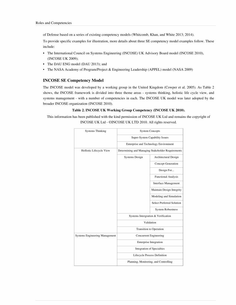
Roles and Competencies 78
of Defense based on a series of existing competency models (Whitcomb, Khan, and White 2013; 2014).To provide specific examples for illustration, more details about three SE competency model examples follow. Theseinclude:•• The International Council on Systems Engineering (INCOSE) UK Advisory Board model (INCOSE 2010),
(INCOSE UK 2009);•• The DAU ENG model (DAU 2013); and• The NASA Academy of Program/Project & Engineering Leadership (APPEL) model (NASA 2009)
INCOSE SE Competency ModelThe INCOSE model was developed by a working group in the United Kingdom (Cowper et al. 2005). As Table 2shows, the INCOSE framework is divided into three theme areas - systems thinking, holistic life cycle view, andsystems management - with a number of competencies in each. The INCOSE UK model was later adopted by thebroader INCOSE organization (INCOSE 2010).
Table 2. INCOSE UK Working Group Competency (INCOSE UK 2010).
This information has been published with the kind permission of INCOSE UK Ltd and remains the copyright ofINCOSE UK Ltd - ©INCOSE UK LTD 2010. All rights reserved.
Systems Thinking System Concepts
Super-System Capability Issues
Enterprise and Technology Environment
Hollistic Lifecycle View Determining and Managing Stakeholder Requirements
Systems Design Architectural Design
Concept Generation
Design For...
Functional Analysis
Interface Management
Maintain Design Integrity
Modeling and Simulation
Select Preferred Solution
System Robustness
Systems Intergration & Verification
Validation
Transition to Operation
Systems Engineering Management Concurrent Engineering
Enterprise Integration
Integration of Specialties
Lifecycle Process Definition
Planning, Monitoring, and Controlling

Roles and Competencies 79
United States DoD Engineering Competency ModelThe model for US Department of Defense (DoD) acquisition engineering professionals (ENG) includes 41competency areas, as shown in Table 3 (DAU 2013). Each is grouped according to a “Unit of Competence” as listedin the left-hand column. For this model, the four top-level groupings are analytical, technical management,professional, and business acumen. The life cycle view used in the INCOSE model is evident in the ENG analyticalgrouping, but is not cited explicitly. Technical management is the equivalent of the INCOSE SE management, butadditional competencies are added, including software engineering competencies and acquisition. Selected generalprofessional skills have been added to meet the needs for strong leadership required of the acquisition engineeringprofessionals. The business acumen competencies were added to meet the needs of these professionals to be able tosupport contract development and oversight activities and to engage with the defense industry.
Table 3. DoD Competency Model (DAU 2013) Defense Acquisition University (DAU)/U.S. Department ofDefense (DoD).
Analytical (11) 1. Mission-Level Assessment
2. Stakeholder Requirements Definition
3. Requirements Analysis
4. Architecture Design
5. Implementation
6. Intergration
7. Verification
8. Validation
9. Transition
10. Design Considerations
11. Tools and Techniques
Technical Management (10) 12. Decision Analysis
13. Technical Planning
14. Technical Assessment
15. Configuration Management
16. Requirements Management
17. Risk Management
18. Data Management
19. Interface Management
20. Software Engineering
21. Acquisition

Roles and Competencies 80
Professional (10) 22. Problem Solving
23. Strategic Thinking
24. Professional Ethics
25. Leading High-Performance Teams
26. Communication
27. Coaching and Mentoring
28. Managing Stakeholders
29. Mission and Results Focus
30. Personal Effectiveness/Peer Interaction
31. Sound Judgment
Business Acumen (10) 32. Industry Landscape
33. Organization
34. Cost, Pricing, and Rates
35. Cost Estimating
36. Financial Reporting and Metrics
37. Business Strategy
38. Capture Planning and Proposal Process
39. Supplier Management
40. Industry Motivation, Incentives, Rewards
41. Negotiations
NASA SE Competency ModelThe US National Aeronautics and Space Administration (NASA) APPEL website provides a competency model thatcovers both project engineering and systems engineering (APPEL 2009). There are three parts to the model, one thatis unique to project engineering, one that is unique to systems engineering, and a third that is common to bothdisciplines. Table 4 below shows the SE aspects of the model. The project management items include projectconceptualization, resource management, project implementation, project closeout, and program control andevaluation. The common competency areas are NASA internal and external environments, human capital andmanagement, security, safety and mission assurance, professional and leadership development, and knowledgemanagement. This 2010 model is adapted from earlier versions. (Squires at al. 2010, 246-260) offer a method thatcan be used to analyze the degree to which an organization’s SE capabilities meet government-industry defined SEneeds.
Table 4. SE Portion of the APPEL Competency Model (APPEL 2009). Released by NASA APPEL.

Roles and Competencies 81
System Design SE 1.1 - Stakeholder Expectation Definition & Management
SE 1.2 - Technical Requirements Definition
SE 1.3 - Logical Decomposition
SE 1.4 - Design Solution Definition
Product Realization SE 2.1 - Product Implementation
SE 2.2 - Product Integration
SE 2.3 - Product Verification
SE 2.4 - Product Validation
SE 2.5 - Product Transition
Technical Management SE 3.1 - Technical Planning
SE 3.2 - Requirements Management
SE 3.3 - Interface Management
SE 3.4 - Technical Risk Management
SE 3.5 - Configuration Management
SE 3.6 - Technical Data Management
SE 3.7 - Technical Assessment
SE 3.8 - Technical Decision Analysis
Relationship of SE Competencies to Other CompetenciesSE is one of many engineering disciplines. A competent SE must possess KSAAs that are unique to SE, as well asmany other KSAAs that are shared with other engineering and non-engineering disciplines.One approach for a complete engineering competency model framework has multiple dimensions where each of thedimensions has unique KSAAs that are independent of the other dimensions (Wells 2008). The number ofdimensions depends on the engineering organization and the range of work performed within the organization. Theconcept of creating independent axes for the competencies was presented in Jansma and Derro (2007), usingtechnical knowledge (domain/discipline specific), personal behaviors, and process as the three axes. An approachthat uses process as a dimension is presented in Widmann et al. (2000), where the competencies are mapped toprocess and process maturity models. For a large engineering organization that creates complex systems solutions,there are typically four dimensions:1. Discipline (e.g., electrical, mechanical, chemical, systems, optical);2. Life Cycle (e.g., requirements, design, testing);3. Domain (e.g., aerospace, ships, health, transportation); and4. Mission (e.g., air defense, naval warfare, rail transportation, border control, environmental protection).These four dimensions are built on the concept defined in Jansma and Derro (2007) and Widmann et al. (2000) byseparating discipline from domain and by adding mission and life cycle dimensions. Within many organizations, themission may be consistent across the organization and this dimension would be unnecessary. A three-dimensionalexample is shown in Figure 1, where the organization works on only one mission area so that dimension has beeneliminated from the framework.

Roles and Competencies 82
Figure 1. Layered and Multi-dimensional in the Engineering Layer (IEEE 2008). Reprinted with permission of © Copyright IEEE– All rights reserved. All other rights are reserved by the copyright owner.
The discipline, domain, and life cycle dimensions are included in this example, and some of the first-level areas ineach of these dimensions are shown. At this level, an organization or an individual can indicate which areas areincluded in their existing or desired competencies. The sub-cubes are filled in by indicating the level of proficiencythat exists or is required. For this example, blank indicates that the area is not applicable, and colors (shades of gray)are used to indicate the levels of expertise. The example shows a radar electrical designer that is an expert athardware verification, is skilled at writing radar electrical requirements, and has some knowledge of electricalhardware concepts and detailed design. The radar electrical designer would also assess his or her proficiency in theother areas, the foundation layer, and the leadership layer to provide a complete assessment.
References
Works CitedArmstrong, J.R., D. Henry, K. Kepcher, and A. Pyster. 2011. "Competencies Required for Successful Acquisition ofLarge, Highly Complex Systems of Systems." Paper presented at 21st Annual International Council on SystemsEngineering (INCOSE) International Symposium (IS), 20-23 June 2011, Denver, CO, USA.Bloom, Benjamin S., Max D. Engelhart, Edward J. Furst, Walker H. Hill, and David R. Krathwohl. 1956. Taxonomyof Educational Objectives. New York: David McKay.Cowper, D., S. Bennison, R. Allen-Shalless, K. Barnwell, S. Brown, A. El Fatatry, J. Hooper, S. Hudson, L. Oliver,and A. Smith. 2005. Systems Engineering Core Competencies Framework. Folkestone, UK: International Council onSystems Engineering (INCOSE) UK Advisory Board (UKAB).

Roles and Competencies 83
DAU. 2013. ENG Competency Model, 12 June 2013 version. in Defense Acquisition University (DAU)/U.S.Department of Defense Database Online. Accessed on June 3, 2015. Available at https:/ / dap. dau. mil/ workforce/Documents/ Comp/ ENG%20Competency%20Model%2020130612_Final. pdf.ETA. 2010. Career One Stop: Competency Model Clearing House: Aerospace Competency Model. in Employmentand Training Administration (ETA)/U.S. Department of Labor. Washington, DC. Accessed on September 15, 2011.Available at http:/ / www. careeronestop. org/ / competencymodel/ pyramid. aspx?AEO=Y.Ferris, T.L.J. 2010. "Comparison of Systems Engineering Competency Frameworks." Paper presented at the 4thAsia-Pacific Conference on Systems Engineering (APCOSE), Systems Engineering: Collaboration for IntelligentSystems, 3-6 October 2010, Keelung, Taiwan.Frank, M. 2000. "Engineering Systems Thinking and Systems Thinking." Systems Engineering. 3(3): 163-168.Frank, M. 2002. "Characteristics of Engineering Systems Thinking – A 3-D Approach for Curriculum Content."IEEE Transaction on System, Man, and Cybernetics. 32(3) Part C: 203-214.Frank, M. 2006. "Knowledge, Abilities, Cognitive Characteristics and Behavioral Competences of Engineers withHigh Capacity for Engineering Systems Thinking (CEST)." Systems Engineering. 9(2): 91-103. (Republished inIEEE Engineering Management Review. 34(3)(2006):48-61).Hall, A.D. 1962. A Methodology for Systems Engineering. Princeton, NJ, USA: D. Van Nostrand Company Inc.Holt, Jon, and Perry, Simon,A Pragmatic Guide to Competency, Tools, Frameworks, and Assessment.BCS, TheChartered Institute for IT, Swindon, UK, 2011.INCOSE. 2011. "History of INCOSE Certification Program." Accessed April 13, 2015 at http:/ / www. incose. org/certification/ CertHistoryINCOSE. 2012. Systems Engineering Handbook: A Guide for System Life Cycle Processes and Activities, version3.2.2. San Diego, CA, USA: International Council on Systems Engineering (INCOSE),INCOSE-TP-2003-002-03.2.2.INCOSE. 2010. Systems Engineering Competencies Framework 2010-0205. San Diego, CA, USA: InternationalCouncil on Systems Engineering (INCOSE), INCOSE-TP-2010-003.INCOSE UK. 2010. "Systems Engineering Competency Framework," Accessed on June 3, 2015. Available at,<http://www.incoseonline.org.uk/Normal_Files/Publications/Framework.aspx?CatID=Publications&SubCat=INCOSEPublications>>.Jansma, P.A. and M.E. Derro. 2007. "If You Want Good Systems Engineers, Sometimes You Have to Grow YourOwn!." Paper presented at IEEE Aerospace Conference. 3-10 March, 2007. Big Sky, MT, USA.Kasser, J.E., D. Hitchins, and T.V. Huynh. 2009. "Reengineering Systems Engineering." Paper presented at the 3rdAnnual Asia-Pacific Conference on Systems Engineering (APCOSE), 2009, Singapore.Krathwohl, David. A Revision of Bloom’s Taxonomy: An Overview. 2002.Menrad, R. and H. Lawson. 2008. "Development of a NASA Integrated Technical Workforce Career DevelopmentModel Entitled: Requisite Occupation Competencies and Knowledge – The ROCK." Paper presented at the 59thInternational Astronautical Congress (IAC), 29 September-3 October, 2008, Glasgow, Scotland.MITRE. 2007. "MITRE Systems Engineering (SE) Competency Model." Version 1.13E. September 2007. Accessedon June 3, 2015. Available at, http:/ / www. mitre. org/ publications/ technical-papers/systems-engineering-competency-model.NASA. 2009. NASA Competency Management Systems (CMS): Workforce Competency Dictionary, revision 7a. U.S.National Aeronautics and Space Administration (NASA). Washington, D.C.NASA. 2009. Project Management and Systems Engineering Competency Model. Academy of Program/Project &Engineering Leadership (APPEL). Washington, DC, USA: US National Aeronautics and Space Administration(NASA). Accessed on June 3, 2015. Available at http:/ / appel. nasa. gov/ competency-model/ .
Roles and Competencies 84
SEI. 2007. Capability Maturity Model Integrated (CMMI) for Development, version 1.2, Measurement and AnalysisProcess Area. Pittsburg, PA, USA: Software Engineering Institute (SEI)/Carnegie Mellon University (CMU).SEI. 2004. CMMI-Based Professional Certifications: The Competency Lifecycle Framework, Software EngineeringInstitute, CMU/SEI-2004-SR-013. Accessed on June 3, 2015. Available at http:/ / resources. sei. cmu. edu/ library/asset-view. cfm?assetid=6833.Squires, A., W. Larson, and B. Sauser. 2010. "Mapping space-based systems engineering curriculum togovernment-industry vetted competencies for improved organizational performance." Systems Engineering. 13 (3):246-260. Available at, http:/ / dx. doi. org/ 10. 1002/ sys. 20146.Squires, A., J. Wade, P. Dominick, and D. Gelosh. 2011. "Building a Competency Taxonomy to Guide ExperienceAcceleration of Lead Program Systems Engineers." Paper presented at the Conference on Systems EngineeringResearch (CSER), 15-16 April 2011, Los Angeles, CA.Wells, B.H. 2008. "A Multi-Dimensional Hierarchical Engineering Competency Model Framework." Paperpresented at IEEE International Systems Conference, March 2008, Montreal, Canada. Whitcomb, Clifford, RabiaKhan, and Corina White. 2014. "Systems Engineering Competency FY14 Technical Report." Naval PostgraduateSchool Technical Report, Monterey, CA. https:/ / calhoun. nps. edu/ handle/ 10945/ 44705Whitcomb, Clifford, Leslie Whitcomb. 2013. Effective Interpersonal and Team Communication Skills for Engineers.IEEE Press, John Wiley and Sons.Whitcomb, Clifford, Rabia Khan, and Corina White. 2013. "Systems Engineering Competency FY13 TechnicalReport." Naval Postgraduate School Technical Report, Monterey, CA. Accessed on June 4, 2015. Available at,https:/ / calhoun. nps. edu/ handle/ 10945/ 43424.Whitcomb, Clifford, Rabia Khan, and Corina White. 2014. "Systems Engineering Competency FY14 TechnicalReport." Naval Postgraduate School Technical Report, Monterey, CA. Accessed on June 4, 2015. Available at,https:/ / calhoun. nps. edu/ handle/ 10945/ 44705.Widmann, E.R., G.E. Anderson, G.J. Hudak, and T.A. Hudak. 2000. "The Taxonomy of Systems EngineeringCompetency for The New Millennium." Presented at 10th Annual INCOSE Internal Symposium, 16-20 July 2000,Minneapolis, MN, USA.
Primary ReferencesDAU. 2013. ENG Competency Model, 12 June 2013 version. in Defense Acquisition University (DAU)/U.S.Department of Defense Database Online. Accessed on June 3, 2015. Available at https:/ / dap. dau. mil/ workforce/Documents/ Comp/ ENG%20Competency%20Model%2020130612_Final. pdf.INCOSE. 2010. Systems Engineering Competencies Framework 2010-0205. San Diego, CA, USA: InternationalCouncil on Systems Engineering (INCOSE), INCOSE-TP-2010-003.
Additional ReferencesWhitcomb, Clifford, Jessica Delgado, Rabia Khan, Juli Alexander, Corina White, Dana Grambow, Paul Walter.2015. "The Department of the Navy Systems Engineering Career Competency Model." Proceedings of the TwelfthAnnual Acquisition Research Symposium. Naval Postgraduate School, Monterey, CA..
< Previous Article | Parent Article | Next Article >SEBoK v. 1.4 released 29 June 2015

Roles and Competencies 85
SEBoK DiscussionPlease provide your comments and feedback on the SEBoK below. You will need to log in to DISQUS using anexisting account (e.g. Yahoo, Google, Facebook, Twitter, etc.) or create a DISQUS account. Simply type yourcomment in the text field below and DISQUS will guide you through the login or registration steps. Feedback will bearchived and used for future updates to the SEBoK. If you provided a comment that is no longer listed, that commenthas been adjudicated. You can view adjudication for comments submitted prior to SEBoK v. 1.0 at SEBoK Reviewand Adjudication. Later comments are addressed and changes are summarized in the Letter from the Editor andAcknowledgements and Release History.
If you would like to provide edits on this article, recommend new content, or make comments on the SEBoKas a whole, please see the SEBoK Sandbox [1].
ENCODED_CONTENTMTk1ODMPGRpdiBpZD0iZGlzcXVzX3RocmVhZCI+PC9kaXY+CjxzY3JpcHQgdHlwZT0idGV4dC9qYXZhc2NyaXB0Ij4KICAgIC8qICogKiBDT05GSUdVUkFUSU9OIFZBUklBQkxFUzogRURJVCBCRUZPUkUgUEFTVElORyBJTlRPIFlPVVIgV0VCUEFHRSAqICogKi8KICAgIHZhciBkaXNxdXNfc2hvcnRuYW1lID0gJ3NlYm9rd2lraTEwJzsgLy8gcmVxdWlyZWQ6IHJlcGxhY2UgZXhhbXBsZSB3aXRoIHlvdXIgZm9ydW0gc2hvcnRuYW1lCiAgICB2YXIgZGlzcXVzX2lkZW50aWZpZXIgPSAnUm9sZXMgYW5kIENvbXBldGVuY2llcyc7ICAgIHZhciBkaXNxdXNfdXJsID0gJ2h0dHA6Ly9zZWJva3dpa2kub3JnL2RyYWZ0L1JvbGVzX2FuZF9Db21wZXRlbmNpZXMnOwogICAgLyogKiAqIERPTidUIEVESVQgQkVMT1cgVEhJUyBMSU5FICogKiAqLwogICAgKGZ1bmN0aW9uKCkgewogICAgICAgIHZhciBkc3EgPSBkb2N1bWVudC5jcmVhdGVFbGVtZW50KCdzY3JpcHQnKTsgZHNxLnR5cGUgPSAndGV4dC9qYXZhc2NyaXB0JzsgZHNxLmFzeW5jID0gdHJ1ZTsKICAgICAgICBkc3Euc3JjID0gJ2h0dHA6Ly8nICsgZGlzcXVzX3Nob3J0bmFtZSArICcuZGlzcXVzLmNvbS9lbWJlZC5qcyc7CiAgICAgICAgKGRvY3VtZW50LmdldEVsZW1lbnRzQnlUYWdOYW1lKCdoZWFkJylbMF0gfHwgZG9jdW1lbnQuZ2V0RWxlbWVudHNCeVRhZ05hbWUoJ2JvZHknKVswXSkuYXBwZW5kQ2hpbGQoZHNxKTsKICAgIH0pKCk7Cjwvc2NyaXB0Pgo8bm9zY3JpcHQ+UGxlYXNlIGVuYWJsZSBKYXZhU2NyaXB0IHRvIHZpZXcgdGhlIDxhIGhyZWY9Imh0dHA6Ly9kaXNxdXMuY29tLz9yZWZfbm9zY3JpcHQiPmNvbW1lbnRzIHBvd2VyZWQgYnkgRGlzcXVzLjwvYT48L25vc2NyaXB0Pgo8YSBocmVmPSJodHRwOi8vZGlzcXVzLmNvbSIgY2xhc3M9ImRzcS1icmxpbmsiPmJsb2cgY29tbWVudHMgcG93ZXJlZCBieSA8c3BhbiBjbGFzcz0ibG9nby1kaXNxdXMiPkRpc3F1czwvc3Bhbj48L2E+END_ENCODED_CONTENT
Assessing IndividualsThe ability to fairly assess individuals is a critical aspect of enabling individuals. This article describes how to assessthe systems engineering (glossary) (SE) competencies needed and possessed by an individual, as well as thatindividual’s SE performance.
Assessing Competency NeedsIf an organization wants to use its own customized competency model, an initial decision is make vs. buy. If there isan existing SE competency model that fits the organization's context and purpose, the organization might want to usethe existing SE competency model directly. If existing models must be tailored or a new SE competency modeldeveloped, the organization should first understand its context.
Determining ContextPrior to understanding what SE competencies are needed, it is important for an organization to examine the situationin which it is embedded, including environment, history, and strategy. As Figure 1 shows, MITRE has developed aframework characterizing different levels of systems complexity. (MITRE 2007, 1-12) This framework may help anorganization identify which competencies are needed. An organization working primarily in the traditional programdomain may need to emphasize a different set of competencies than an organization working primarily in the messyfrontier. If an organization seeks to improve existing capabilities in one area, extensive technical knowledge in thatspecific area might be very important. For example, if stakeholder involvement is characterized by multiple equitiesand distrust, rather than collaboration and concurrence, a higher level of competency in being able to balancestakeholder requirements might be needed. If the organization's desired outcome builds a fundamentally newcapability, technical knowledge in a broader set of areas might be useful.
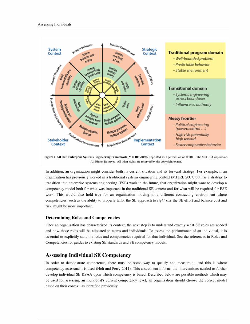
Assessing Individuals 86
Figure 1. MITRE Enterprise Systems Engineering Framework (MITRE 2007). Reprinted with permission of © 2011. The MITRE Corporation.All Rights Reserved. All other rights are reserved by the copyright owner.
In addition, an organization might consider both its current situation and its forward strategy. For example, if anorganization has previously worked in a traditional systems engineering context (MITRE 2007) but has a strategy totransition into enterprise systems engineering (ESE) work in the future, that organization might want to develop acompetency model both for what was important in the traditional SE context and for what will be required for ESEwork. This would also hold true for an organization moving to a different contracting environment wherecompetencies, such as the ability to properly tailor the SE approach to right size the SE effort and balance cost andrisk, might be more important.
Determining Roles and CompetenciesOnce an organization has characterized its context, the next step is to understand exactly what SE roles are neededand how those roles will be allocated to teams and individuals. To assess the performance of an individual, it isessential to explicitly state the roles and competencies required for that individual. See the references in Roles andCompetencies for guides to existing SE standards and SE competency models.
Assessing Individual SE CompetencyIn order to demonstrate competence, there must be some way to qualify and measure it, and this is wherecompetency assessment is used (Holt and Perry 2011). This assessment informs the interventions needed to furtherdevelop individual SE KSAA upon which competency is based. Described below are possible methods which maybe used for assessing an individual's current competency level; an organization should choose the correct modelbased on their context, as identified previously.

Assessing Individuals 87
Proficiency LevelsIn order to provide a context for individuals and organizations to develop competencies, a consistent system ofdefining KSAAs should be created. One popular method is based on Bloom’s taxonomy (Bloom 1984), presentedbelow for the cognitive domain in order from least complex to most complex cognitive ability.• Remember: Recall or recognize terms, definitions, facts, ideas, materials, patterns, sequences, methods,
principles, etc.• Understand: Read and understand descriptions, communications, reports, tables, diagrams, directions,
regulations, etc.• Apply: Know when and how to use ideas, procedures, methods, formulas, principles, theories, etc.• Analyze: Break down information into its constituent parts and recognize their relationship to one another and
how they are organized; identify sublevel factors or salient data from a complex scenario.• Evaluate: Make judgments about the value of proposed ideas, solutions, etc., by comparing the proposal to
specific criteria or standards.• Create: Put parts or elements together in such a way as to reveal a pattern or structure not clearly there before;
identify which data or information from a complex set is appropriate to examine further or from which supportedconclusions can be drawn.
One way to assess competency is to assign KSAAs to proficiency level categories within each competency.Examples of proficiency levels include the INCOSE competency model, with proficiency levels of: awareness,supervised practitioner, practitioner, and expert (INCOSE 2010). The Academy of Program/Project & EngineeringLeadership (APPEL) competency model includes the levels: participate, apply, manage, and guide, respectively(Menrad and Lawson 2008). The U.S. National Aeronautics and Space Administration (NASA), as part of theAPPEL (APPEL 2009), has also defined proficiency levels: technical engineer/project team member, subsystemlead/manager, project manager/project systems engineer, and program manager/program systems engineer. TheDefense Civilian Personnel Advisory Service (DCPAS) defines a 5-tier framework to indicate the degree to whichemployees perform competecnies as awareness, basic, intermediate, advanced, and expert.The KSAAs defined in the lower levels of the cognitive domain (remember, understand) are typically foundational,and involve demonstration of basic knowledge. The higher levels (apply, analyze, evaluate, and create) reflect highercognitive ability. Cognitive and affective processes within Bloom’s taxonomy refer to levels of observable actionsthat indicate learning is occuring (Whitcomb, Delgado, Khan, Alexander, White, Grambow, Walter 2015). TheBloom’s domain levels should not be used exclusively to determine the proficiency levels required for attainment orassessment of a competency. Higher level cognitive capabilites belong across proficiency levels, and should be usedas appropriate to the KSAA involved. These higher level terms infer some observbable action or outcome, so thecontext for assessing the attainment of the KSAA, or a group of KSAAs, related to a competency needs to bedefined. For example, applying SE methods can be accomplished on simple subsystems or systems and so perhapsbelong in a lower proficiency level such as supervised practitioner. Applying SE methods to complex enterprise orsystems of systems, may belong in the practitioner or even the expert level. The determination of what proficiencylevel is desired for each KSAA is determined by the organization, and may vary among different organizations.
Quality of Competency AssessmentWhen using application as a measure of competency, it is important to have a measure of goodness. If someone isapplying a competency in an exceptionally complex situation, they may not necessarily be successful in thisapplication. An individual may be managing and guiding, but this is only helpful to the organization if it is beingdone well. In addition, an individual might be fully proficient in a particular competency, but not be given anopportunity to use that competency; for this reason, it is important to understand the context in which thesecompetencies are being assessed.

Assessing Individuals 88
Individual SE Competency versus PerformanceEven when an individual is highly proficient in an SE competency, context may preclude exemplary performance ofthat competency. For example, an individual with high competency in risk management may be embedded in a teamor an organization which ignores that talent, whether because of flawed procedures or some other reason. Developingindividual competencies is not enough to ensure exemplary SE performance.When SE roles are clearly defined, performance assessment at least has a chance to be objective. However, sinceteams are most often tasked with accomplishing the SE tasks on a project, it is the team's performance which ends upbeing assessed. (See Team Capability). The final execution and performance of SE is a function of competency,capability, and capacity. (See Enabling Teams and Enabling Businesses and Enterprises.)
References
Works CitedAcademy of Program/Project & Engineering Leadership (APPEL). 2009. NASA's Systems EngineeringCompetencies. Washington, DC, USA: U.S. National Aeronautics and Space Administration. Available at: http:/ /www. nasa. gov/ offices/ oce/ appel/ pm-development/ pm_se_competency_framework. html.Bloom, B. S. 1984. Taxonomy of Educational Objectives. New York, NY, USA: Longman.Holt, Jon, and Simon Perry. 2011. A Pragmatic Guide to Competency, Tools, Frameworks, and Assessment. BCS,The Chartered Institute for IT, Swindon, UK.INCOSE. 2010. Systems Engineering Competencies Framework 2010-0205. San Diego, CA, USA: InternationalCouncil on Systems Engineering (INCOSE), INCOSE-TP-2010-003.Menrad, R. and H. Lawson. 2008. "Development of a NASA Integrated Technical Workforce Career DevelopmentModel Entitled: Requisite Occupation Competencies and Knowledge – The ROCK." Paper presented at the 59thInternational Astronautical Congress (IAC). 29 September-3 October 2008. Glasgow, Scotland.MITRE. 2007. Enterprise Architecting for Enterprise Systems Engineering. Warrendale, PA, USA: SEPOCollaborations, SAE International. June 2007.Whitcomb, Clifford, Jessica Delgado, Rabia Khan, Juli Alexander, Corina White, Dana Grambow, Paul Walter.2015. "The Department of the Navy Systems Engineering Career Competency Model." Proceedings of the TwelfthAnnual Acquisition Research Symposium. Naval Postgraduate School, Monterey, CA.
Primary ReferencesAcademy of Program/Project & Engineering Leadership (APPEL). 2009. NASA's Systems EngineeringCompetencies. Washington, DC, USA: U.S. National Aeronautics and Space Administration (NASA). Accessed onMay 2, 2014. Available at http:/ / appel. nasa. gov/ career-resources/project-management-and-systems-engineering-competency-model/ .INCOSE. 2010. Systems Engineering Competencies Framework 2010-0205. San Diego, CA, USA: InternationalCouncil on Systems Engineering (INCOSE), INCOSE-TP-2010-003.

Assessing Individuals 89
Additional ReferencesHolt, J., and S. Perry. 2011. A pragmatic guide to competency: tools, frameworks and assessment. Swindon, UK:British Computer Society.
< Previous Article | Parent Article | Next Article >SEBoK v. 1.4 released 29 June 2015
SEBoK DiscussionPlease provide your comments and feedback on the SEBoK below. You will need to log in to DISQUS using anexisting account (e.g. Yahoo, Google, Facebook, Twitter, etc.) or create a DISQUS account. Simply type yourcomment in the text field below and DISQUS will guide you through the login or registration steps. Feedback will bearchived and used for future updates to the SEBoK. If you provided a comment that is no longer listed, that commenthas been adjudicated. You can view adjudication for comments submitted prior to SEBoK v. 1.0 at SEBoK Reviewand Adjudication. Later comments are addressed and changes are summarized in the Letter from the Editor andAcknowledgements and Release History.
If you would like to provide edits on this article, recommend new content, or make comments on the SEBoKas a whole, please see the SEBoK Sandbox [1].
ENCODED_CONTENTNzk4NDQPGRpdiBpZD0iZGlzcXVzX3RocmVhZCI+PC9kaXY+CjxzY3JpcHQgdHlwZT0idGV4dC9qYXZhc2NyaXB0Ij4KICAgIC8qICogKiBDT05GSUdVUkFUSU9OIFZBUklBQkxFUzogRURJVCBCRUZPUkUgUEFTVElORyBJTlRPIFlPVVIgV0VCUEFHRSAqICogKi8KICAgIHZhciBkaXNxdXNfc2hvcnRuYW1lID0gJ3NlYm9rd2lraTEwJzsgLy8gcmVxdWlyZWQ6IHJlcGxhY2UgZXhhbXBsZSB3aXRoIHlvdXIgZm9ydW0gc2hvcnRuYW1lCiAgICB2YXIgZGlzcXVzX2lkZW50aWZpZXIgPSAnQXNzZXNzaW5nIEluZGl2aWR1YWxzJzsgICAgdmFyIGRpc3F1c191cmwgPSAnaHR0cDovL3NlYm9rd2lraS5vcmcvZHJhZnQvQXNzZXNzaW5nX0luZGl2aWR1YWxzJzsKICAgIC8qICogKiBET04nVCBFRElUIEJFTE9XIFRISVMgTElORSAqICogKi8KICAgIChmdW5jdGlvbigpIHsKICAgICAgICB2YXIgZHNxID0gZG9jdW1lbnQuY3JlYXRlRWxlbWVudCgnc2NyaXB0Jyk7IGRzcS50eXBlID0gJ3RleHQvamF2YXNjcmlwdCc7IGRzcS5hc3luYyA9IHRydWU7CiAgICAgICAgZHNxLnNyYyA9ICdodHRwOi8vJyArIGRpc3F1c19zaG9ydG5hbWUgKyAnLmRpc3F1cy5jb20vZW1iZWQuanMnOwogICAgICAgIChkb2N1bWVudC5nZXRFbGVtZW50c0J5VGFnTmFtZSgnaGVhZCcpWzBdIHx8IGRvY3VtZW50LmdldEVsZW1lbnRzQnlUYWdOYW1lKCdib2R5JylbMF0pLmFwcGVuZENoaWxkKGRzcSk7CiAgICB9KSgpOwo8L3NjcmlwdD4KPG5vc2NyaXB0PlBsZWFzZSBlbmFibGUgSmF2YVNjcmlwdCB0byB2aWV3IHRoZSA8YSBocmVmPSJodHRwOi8vZGlzcXVzLmNvbS8/cmVmX25vc2NyaXB0Ij5jb21tZW50cyBwb3dlcmVkIGJ5IERpc3F1cy48L2E+PC9ub3NjcmlwdD4KPGEgaHJlZj0iaHR0cDovL2Rpc3F1cy5jb20iIGNsYXNzPSJkc3EtYnJsaW5rIj5ibG9nIGNvbW1lbnRzIHBvd2VyZWQgYnkgPHNwYW4gY2xhc3M9ImxvZ28tZGlzcXVzIj5EaXNxdXM8L3NwYW4+PC9hPg==END_ENCODED_CONTENT
Developing IndividualsDeveloping each individual’s systems engineering (SE) competencies(glossary) is a key aspect of enablingindividuals. The goal may be to develop competency in a broad range of SE competencies or a single aspect of SE,and it is important to know exactly which SE competencies are desired. This article describes strategies to developSE competencies in individuals.
Closing Competency GapsDelivering excellent systems that fulfill customer needs is the primary goal of the organization. Developing thecapability to deliver such systems is a secondary goal, and while necessary, is not sufficient. To attain both of thesegoals, the organization must assess itself and effect a strategy to identify and close competency gaps.To identify competency gaps, an organization may take two basic steps:1. Listing desired competencies, as discussed in Roles and Competencies; and2. Assessing the competencies of individual systems engineers, as discussed in Assessing Individuals.Models useful for listing competencies include the International Council on Systems Engineering (INCOSE) UnitedKingdom Advisory Board model (Cowper et al. 2005; INCOSE 2010), the ENG Competency Model (DAU 2013),and the Academy of Program/Project & Engineering Leadership (APPEL 2009) model (Menrad and Lawson 2008).Once the organization knows the SE competencies it needs to develop to close the competency gaps it has identified,it may choose from the several methods (Davidz and Martin 2011) outlined in the table below.
Table 1. SE Competency Development Framework. (SEBoK Original)<html>

Developing Individuals 90
Goal Objective Method
PRIMARY GOAL = Delivery of excellent systemsto fulfill customer needs
Focus on successful performanceoutcome
Corporate intiatives
Focus on performance of project team Team coaching of project team for performanceenhancement
SECONDARY GOAL = Competency to deliverexcellent systems to fulfill customer needs
Develop individual competency Training courses
Job rotation
Mentoring
Hands-on experience
Develop a few hand-picked individuals
University educational degree program
Customized educational program
Combination program - education, training, jobrotation, mentoring, hands-on experience
Course certificate program
Ensure individual competencythrough certification
Certification program
Filter those working in systems roles Use individual characteristics to select employeesfor systems roles
Ensure organizational competencythrough certification
ISO 9000
Develop organizational systemscompetency through processes
Process improvement using an establishedframework
Concept maps to identify the thought processes ofsenior systems engineers
Standarize systems policies and procedures forconsistency
Systems engineering web portal
Systems knowledge management repository
On-call organizational experts
Rotating professor who works at companypart-time and is at university part-time
</html>
System DeliverySome organizations mount initiatives which focus directly on successful system delivery. Others focus on projectteam performance, in some cases by offering coaching, as a means to ensure successful system delivery.One example of the latter approach is the performance enhancement service of the US National Aeronautics andSpace Administration (NASA) Academy of Program/Project & Engineering Leadership (APPEL), which assessesteam performance and then offers developmental interventions with coaching (NASA 2010).Organizations pursue multiple paths towards developing the capability to deliver excellent systems, including•• developing the competency of individuals;•• developing the competency of the organization through processes (Davidz and Maier 2007); and
Developing Individuals 91
•• putting measures should in place to verify the efficacy of the selected methods.
Individual CompetencyAn organization may choose a combination of methods to develop individual systems competency. GeneralElectric’s Edison Engineering Development Program (GE 2010) and Lockheed Martin’s Leadership DevelopmentPrograms (Lockheed Martin 2010) are examples among the many combination programs offered within companies.Whether or not the program is specifically oriented to develop systems skills, the breadth of technical training andexperience, coupled with business training, can produce a rich understanding of systems for the participant.Furthermore, new combination programs can be designed to develop specific systems-oriented skills for anorganization.Methods for developing individual competency include• classroom or online training courses, a traditional choice for knowledge transfer and skill acquisition. Here, an
instructor directs a classroom of participants. The method of instruction may vary from a lecture format to casestudy work to hands-on exercises. The impact and effectiveness of this method varies considerably based on theskill of the instructor, the effort of the participants, the presentation of the material, the course content, the qualityof the course design process, and the matching of the course material to organizational needs. These types ofinterventions may also be given online. Squires (2011) investigates the relationship between online pedagogy andstudent perceived learning of SE competencies.
• job rotation, where a participant rotates through a series of work assignments that cut across different aspects ofthe organization to gain broad experience in a relatively short time.
• mentoring, where a more experienced individual is paired with a protégé in a developmental relationship. Manyorganizations use mentoring, whose impact and effectiveness vary considerably. Success factors are the tenablepairing of individuals, and the provision of adequate time for mentoring.
• hands-on experience, where organizations provide for their engineers to get hands-on experience that they wouldotherwise lack. A research study by Davidz on enablers and barriers to the development of systems thinkingshowed that systems thinking is developed primarily by experiential learning (Davidz 2006; Davidz andNightingale 2008, 1-14). As an example, some individuals found that working in a job that dealt with the fullsystem, such as working in an integration and test environment, enabled development of systems thinking.
• selecting individuals who appear to have high potential and focusing on their development. Hand-selection mayor may not be accompanied by the other identified methods.
• formal education, such as a university degree program. A growing number of SE degree programs are offeredworldwide (Lasfer and Pyster 2011). Companies have also worked with local universities to set up customizededucational programs for their employees. The company benefits because it can tailor the educational program tothe unique needs of its business. In a certificate program, individuals receive a certificate for taking a specific setof courses, either at a university or as provided by the company. There are a growing number of certificateprograms for developing systems competency.
Individual Certification
Organizations may seek to boost individual systems competency through certification programs. These can combinework experience, educational background, and training classes. Certifications are offered by local, national, andinternational professional bodies.SE organizations may encourage employees to seek certification from the International Council on SystemsEngineering (INCOSE 2011) or may use this type of certification as a filter (see Filters, below). In addition, manycompanies have developed their own internal certification measures. For example, the Aerospace Corporation has anAerospace Systems Architecting and Engineering Certificate Program (ASAECP). (Gardner 2007)
Developing Individuals 92
Filters
Another approach to developing individual competency is to select employees for systems roles based on certaincharacteristics, or filters. Before using a list of characteristics for filtering, though, an organization should criticallyexamine1.1. how the list of individual characteristics was determined, and2.2. how the characteristics identified enable the performance of a systems job.Characteristics used as filters should•• enable one to perform a systems job•• be viewed as important to perform a systems job, or•• be necessary to perform a systems job.A necessary characteristic is much stronger than an enabling one, and before filtering for certain traits, it is importantto understand whether the characteristic is an enabler or a necessity.Finally, it is important to understand the extent to which findings are generally applicable, since a list ofcharacteristics that determine success in one organization may not be generalizable to another organization.
Organizational CapabilityOnce an organization has determined which SE capabilities are mission critical (please see Deciding on DesiredSystems Engineering Capabilities within Businesses and Enterprises), there are many different ways in which anorganization can seek to develop or improve these capabilities. Some approaches seen in the literature include thefollowing:•• Organizations may choose to develop organizational systems capability through processes. One method
organizations may choose is to pursue process improvement using an established framework. An example is theCapability Maturity Model® Integration (CMMI) process improvement approach (SEI 2010, 1).
•• Concept maps - graphical representations of engineering thought processes - have been shown to be an effectivemethod of transferring knowledge from senior engineering personnel to junior engineering personnel (Kramer2007, 26-29; Kramer 2005). These maps may provide a mechanism for increasing knowledge of the systemsengineering population of an organization.
• An organization may also choose to develop organizational systems competencies by standardizing systemspolicies and procedures. An example from NASA is their NASA Systems Engineering Processes and Requirement(NASA 2007).
•• Some organizations use a web portal to store and organize applicable systems engineering knowledge andprocesses, which assists in developing organizational systems competency. An example is the Mission AssurancePortal for the Aerospace Corporation (Roberts et al. 2007, 10-13).
•• Another approach being considered in the community is the development of a rotating professor role, where theperson would work at the company and then be at a university to strengthen the link between academia andindustry.
•• Another approach is to alter organizational design to foster and mature a desired competency. For example, anorganization that identifies competency in the area of reliability as critical to its SE success may develop areliability group, which will help foster growth and improvement in reliability competencies.
Developing Individuals 93
Organizational Certification
Certification at the organizational level exists also, and can be a means for ensuring competency. ISO certification isone example (ISO 2010). Before taking this approach, the organization should verify that the capabilities required bythe certification are indeed the systems capabilities it seeks. For more on determining appropriate organizationalcapabilities, see Deciding on Desired Systems Engineering Capabilities within Businesses and Enterprises.
Repositioning the Product Life Cycle
An organization may also choose to reposition its product life cycle philosophy to maintain system competency. Forexample, NASA has done this with its APPEL program (APPEL 2009).Since the systems competencies of individuals are primarily developed through experiential learning, providingexperiential learning opportunities is critical. Shortening the product life cycle is one way to ensure that individualsacquire the full range of desired competency sooner.
Maintaining Competency PlansAn organization that has developed an SE competency plan should consider how to maintain it. How, and how often,will the competency plan be re-examined and updated? The maintenance process should account for the ongoingevolution of global contexts, business strategies, and the SEBoK. The process for assessing competencies and takingaction to improve them must be part of the normal operations of the organization and should occur periodically.
References
Works CitedAcademy of Program/Project & Engineering Leadership (APPEL). 2009. NASA's Systems EngineeringCompetencies. Washington, D.C.: U.S. National Aeronautics and Space Association. Accessed on September 15,2011. Available at http:/ / www. nasa. gov/ offices/ oce/ appel/ pm-development/ pm_se_competency_framework.html.Cowper, D., S. Bennison, R. Allen-Shalless, K. Barnwell, S. Brown, A. El Fatatry, J. Hooper, S. Hudson, L. Oliver,and A. Smith. 2005. Systems Engineering Core Competencies Framework. Folkestone, UK: International Council onSystems Engineering (INCOSE) UK Advisory Board (UKAB).Davidz, H.L. and J. Martin. 2011. "Defining a Strategy for Development of Systems Capability in the Workforce".Systems Engineering. 14(2): 141-143.Davidz, H.L. and M.W. Maier. 2007. "An Integrated Approach to Developing Systems Professionals." Paperpresented at the 17th Annual International Council on Systems Engineering (INCOSE) International Symposium,24-28 June 2007. San Diego, CA, USA.Davidz, H.L., and D. Nightingale. 2008. "Enabling Systems Thinking to Accelerate the Development of SeniorSystems Engineers." Systems Engineering. 11(1): 1-14.Davidz, H.L. 2006. Enabling Systems Thinking to Accelerate the Development of Senior Systems Engineers.Dissertation. Massachusetts Institute of Technology (MIT), Cambridge, MA, USA.Gardner, B. 2007. "A Corporate Approach to National Security Space Education." Crosslink, the AerospaceCorporation Magazine of Advances in Aerospace Technology. 8(1) (Spring 2007):10-5. Accessed April 23, 2013.Available at: http:/ / aerospace. wpengine. netdna-cdn. com/ wp-content/ uploads/ crosslink/ V8N1. pdf.GE. 2010. Edison Engineering Development Program (EEDP) in General Electric. Accessed on September 15,2011. Available at http:/ / www. gecareers. com/ GECAREERS/ jsp/ us/ studentOpportunities/ leadershipPrograms/eng_program_guide. jsp.

Developing Individuals 94
INCOSE. 2010. Systems Engineering Competencies Framework 2010-0205. San Diego, CA, USA: InternationalCouncil on Systems Engineering (INCOSE), INCOSE-TP-2010-003.INCOSE. 2011. "Systems Engineering Professional Certification." In International Council on Systems Engineeringonline. Accessed April 13, 2015. Available at: http:/ / www. incose. org/ certification/ .Kramer, M.J. 2007. "Can Concept Maps Bridge The Engineering Gap?" Crosslink, the Aerospace CorporationMagazine of Advances in Aerospace Technology. 8(1) (Spring 2007): 26-9. Accessed April 23, 2013. Available at:http:/ / aerospace. wpengine. netdna-cdn. com/ wp-content/ uploads/ crosslink/ V8N1. pdf.Kramer, M.J. 2005. Using Concept Maps for Knowledge Acquisition in Satellite Design: Translating 'Statement ofRequirements on Orbit' to 'Design Requirements. Dissertation. Ft. Lauderdale, FL, USA: Graduate School ofComputer and Information Sciences, Nova Southeastern University.Lasfer, K. and A. Pyster. 2011. "The Growth of Systems Engineering Graduate Programs in the United States."Paper presented at Conference on Systems Engineering Research, 15-16 April 2011. Los Angeles, CA, USA.Lockheed Martin. 2010. Training and Leadership Development Programs for College Applicants in LockheedMartin Corporation. Bethesda, MD, USA. Accessed on August 30, 2012. Available at http:/ / www.lockheedmartinjobs. com/ leadership-development-program. asp.NASA. 2010. Academy of Program/Project & engineering leadership (APPEL): Project life cycle support in U.S.National Aeronautics and Space Administration (NASA). Washington, DC, USA: U.S. National Air and SpaceAdministration (NASA). Accessed on September 15, 2011. Available at http:/ / www. nasa. gov/ offices/ oce/ appel/performance/ lifecycle/ 161. html.NASA. 2007. NASA Procedural Requirements: NASA Systems Engineering Processes and Requirements.Washington, DC, USA: U.S. National Aeronautic and Space Administration (NASA). NPR 7123.1A.Roberts, J., B. Simpson, and S. Guarro. 2007. "A Mission Assurance Toolbox." Crosslink, the AerospaceCorporation Magazine of Advances in Aerospace Technology. 8(2) (Fall 2007): 10-13.SEI. 2007. Capability Maturity Model Integrated (CMMI) for Development, version 1.2, Measurement and AnalysisProcess Area. Pittsburgh, PA, USA: Software Engineering Institute (SEI)/Carnegie Mellon University (CMU).Squires, A. 2011. Investigating the Relationship between Online Pedagogy and Student Perceived Learning ofSystems Engineering Competencies. Dissertation. Stevens Institute of Technology, Hoboken, NJ, USA.
Primary ReferencesAcademy of Program/Project & Engineering Leadership (APPEL). 2009. NASA's Systems EngineeringCompetencies. Washington, DC, USA: U.S. National Aeronautics and Space Administration (NASA). Accessed onMay 2, 2014. Available at http:/ / appel. nasa. gov/ career-resources/project-management-and-systems-engineering-competency-model/ .DAU. 2013. ENG Competency Model, 12 June 2013 version. in Defense Acquisition University (DAU)/U.S.Department of Defense Database Online. Accessed on September 23, 2014. Available at https:/ / acc. dau. mil/CommunityBrowser. aspx?id=657526& lang=en-USDavidz, H.L. and J. Martin. 2011. "Defining a Strategy for Development of Systems Capability in the Workforce".Systems Engineering. 14(2): 141-143.INCOSE. 2010. Systems Engineering Competencies Framework 2010-0205. San Diego, CA, USA: InternationalCouncil on Systems Engineering (INCOSE), INCOSE-TP-2010-003.

Developing Individuals 95
Additional ReferencesNone.
< Previous Article | Parent Article | Next Article >SEBoK v. 1.4 released 29 June 2015
SEBoK DiscussionPlease provide your comments and feedback on the SEBoK below. You will need to log in to DISQUS using anexisting account (e.g. Yahoo, Google, Facebook, Twitter, etc.) or create a DISQUS account. Simply type yourcomment in the text field below and DISQUS will guide you through the login or registration steps. Feedback will bearchived and used for future updates to the SEBoK. If you provided a comment that is no longer listed, that commenthas been adjudicated. You can view adjudication for comments submitted prior to SEBoK v. 1.0 at SEBoK Reviewand Adjudication. Later comments are addressed and changes are summarized in the Letter from the Editor andAcknowledgements and Release History.
If you would like to provide edits on this article, recommend new content, or make comments on the SEBoKas a whole, please see the SEBoK Sandbox [1].
ENCODED_CONTENTMTQ4NDIPGRpdiBpZD0iZGlzcXVzX3RocmVhZCI+PC9kaXY+CjxzY3JpcHQgdHlwZT0idGV4dC9qYXZhc2NyaXB0Ij4KICAgIC8qICogKiBDT05GSUdVUkFUSU9OIFZBUklBQkxFUzogRURJVCBCRUZPUkUgUEFTVElORyBJTlRPIFlPVVIgV0VCUEFHRSAqICogKi8KICAgIHZhciBkaXNxdXNfc2hvcnRuYW1lID0gJ3NlYm9rd2lraTEwJzsgLy8gcmVxdWlyZWQ6IHJlcGxhY2UgZXhhbXBsZSB3aXRoIHlvdXIgZm9ydW0gc2hvcnRuYW1lCiAgICB2YXIgZGlzcXVzX2lkZW50aWZpZXIgPSAnRGV2ZWxvcGluZyBJbmRpdmlkdWFscyc7ICAgIHZhciBkaXNxdXNfdXJsID0gJ2h0dHA6Ly9zZWJva3dpa2kub3JnL2RyYWZ0L0RldmVsb3BpbmdfSW5kaXZpZHVhbHMnOwogICAgLyogKiAqIERPTidUIEVESVQgQkVMT1cgVEhJUyBMSU5FICogKiAqLwogICAgKGZ1bmN0aW9uKCkgewogICAgICAgIHZhciBkc3EgPSBkb2N1bWVudC5jcmVhdGVFbGVtZW50KCdzY3JpcHQnKTsgZHNxLnR5cGUgPSAndGV4dC9qYXZhc2NyaXB0JzsgZHNxLmFzeW5jID0gdHJ1ZTsKICAgICAgICBkc3Euc3JjID0gJ2h0dHA6Ly8nICsgZGlzcXVzX3Nob3J0bmFtZSArICcuZGlzcXVzLmNvbS9lbWJlZC5qcyc7CiAgICAgICAgKGRvY3VtZW50LmdldEVsZW1lbnRzQnlUYWdOYW1lKCdoZWFkJylbMF0gfHwgZG9jdW1lbnQuZ2V0RWxlbWVudHNCeVRhZ05hbWUoJ2JvZHknKVswXSkuYXBwZW5kQ2hpbGQoZHNxKTsKICAgIH0pKCk7Cjwvc2NyaXB0Pgo8bm9zY3JpcHQ+UGxlYXNlIGVuYWJsZSBKYXZhU2NyaXB0IHRvIHZpZXcgdGhlIDxhIGhyZWY9Imh0dHA6Ly9kaXNxdXMuY29tLz9yZWZfbm9zY3JpcHQiPmNvbW1lbnRzIHBvd2VyZWQgYnkgRGlzcXVzLjwvYT48L25vc2NyaXB0Pgo8YSBocmVmPSJodHRwOi8vZGlzcXVzLmNvbSIgY2xhc3M9ImRzcS1icmxpbmsiPmJsb2cgY29tbWVudHMgcG93ZXJlZCBieSA8c3BhbiBjbGFzcz0ibG9nby1kaXNxdXMiPkRpc3F1czwvc3Bhbj48L2E+END_ENCODED_CONTENT
Ethical BehaviorIf the competency(glossary) of the systems engineer is a matter of KSAA—knowledge, skills, abilities, andattitudes—then the word “attitudes” must have an ethical dimension. The ethical framework that guides the SE'sactions insures that the SE ultimately does good and not harm. Ethical standards apply both to individuals and toorganizations. This section discusses the moral foundations of ethics, and the elements of ethical conduct that areespecially relevant to systems engineering.
Ethics and Morals in Systems EngineeringLike other people, systems engineers have morals: guiding personal thoughts and feelings about what is right andwrong. All of us also share, with other members of various communities to which we belong, ethics: standards thatsay what conduct is appropriate and what is not (Whitbeck 2007).Morals are part of a person's character, the result of upbringing, culture, and other environmental influences. Ethicsapply morals within the frame of a social system, which could be professional, business, academic, recreational,cultural, political, religious, or even familial. While a person’s moral code is usually considered immutable, one'sethics may need to account for new situations as one's profession or role in life changes. Tensions may exist betweenan engineer's responsibilities to society and those to the customer, the employer, or even the family, resulting inethical dilemmas, and creating situations where morals come into play.There is no shortage of discussion on ethics. Ethical codes are promulgated by professional and other organizations.Professions here refers to occupations that require learning and advanced knowledge and which safeguard orpromote the well-being of others and of society as a whole.Systems engineers have two ethical responsibilities over and above those of most other engineering professions:• While engineers in general use their professional skills to address customer needs and desires, systems
engineering (SE) helps determine those needs and desires in the course of defining and managing requirements.

Ethical Behavior 96
SEs have an obligation to ensure that problem or program definition is influenced solely by the interests of thecustomer or user, not by those of the systems engineer or his firm.
• Systems engineers typically integrate and oversee the work of others whose expertise differs from their own. Thismakes the obligation to widen one’s understanding and to seek competent advice from other professionals moreacute in SE than in other disciplines.
Caroline Whitbeck's Ethics in Engineering Practice and Research explains what ethical behavior means forengineering professionals. Like most books on ethics, this one starts by clarifying the differences between ethics andmorals, which can seem somewhat obscure at times (Whitbeck 2007).A sampling of areas where ethics figure in the engineering of modern systems are described below.
Data Confidentiality and Security, Surveillance, and PrivacyPrivacy, confidentiality, and security in systems which touch Personally Identifiable Information (PII) have anethical dimension for the systems engineers responsible for developing those systems.
Laws and RegulationsSystems are typically developed in societies, sometimes involving international communities, which have lawsconcerning contracts, intellectual property, freedom of information, and employment. The requirements andrestraints of those laws govern the practice of the systems engineer, who must be aware of the laws and mustconsider their implications for the partnerships that system development entails.Whether or not they are stated in the system requirements document or provided by the customer, laws andregulations do in fact impose system requirements. SEs are responsible for knowing and applying relevant laws andregulations. This means recognizing other people’s proprietary interests by safeguarding their intellectual property(trade secrets, copyrights, trademarks, and patents), and giving them credit for performing work and makinginnovations.
Cultural IssuesSince systems engineers develop and maintain products used by humans globally, it is important that they understandthe historical and cultural aspects of their profession and the related context in which their products will be used.System engineers need to be aware of societal diversity and act without prejudice or discrimination.
Ethical Considerations in the Systems Engineering MethodNaturally, SE approaches to meeting customer needs must integrate SE ethics.
Codes of Ethics and Professional ConductCodes of ethics are promulgated by the IEEE (IEEE 2009), the National Society of Professional Engineers (NSPE)(NSPE 2007), the International Council on Systems Engineering (INCOSE 2006) and other engineeringorganizations.The INCOSE Code of Ethics enunciates fundamental ethical principles like honesty, impartiality, integrity, keepingabreast of knowledge, striving to increase competence, and supporting educational and professional organizations.Based on these principles, the code identifies the systems engineer's fundamental duties to society and the public,and the rules of practice that systems engineers should follow to fulfill those duties.According to the INCOSE Code of Ethics, it is the systems engineer's duty to•• guard the public interest and protect the environment, safety, and welfare of those affected by engineering
activities and technological artifacts;

Ethical Behavior 97
•• accept responsibility for one's actions and engineering results, including being open to ethical scrutiny andassessment;
•• proactively mitigate unsafe practice;•• manage risk using knowledge gained by applying a whole-system viewpoint and understanding of systemic
interfaces; and•• promote the understanding, implementation, and acceptance of prudent SE measures.
Enforcing EthicsMany organizations enforce ethics internally by means of ethics policies. These polices typically include rules suchas the following:•• There shall be no exchange of favors between anyone in the organization and entities with which it does business,
such as suppliers, customers, or regulatory agencies.•• Product information, for example, test data, shall be reported accurately and completely to the contracting agency.•• There shall be no conflict of interest between the organization and entities with which it does business.Favors can consist of providing money, reimbursement of travel or entertainment expenses, other items of equivalentvalue, or inappropriate job offers. Conflict of interest can arise when the personal or professional financial interestsor organizational ties of an engineer are potentially at odds with the best interests of the customer or the engineer’semployer. Since conflict of interest and other ethical transgressions can be hard to define, care must be taken todesign ethics policies that are observable and enforceable. Internal audit functions or external regulatory agenciesmay enforce ethical rules at the individual, team, organizational, or enterprise level. Punishment for violating ethicspolicies can include termination and other disciplinary actions.Unlike self-employed physicians who may choose to not do something specific, many systems engineers areindividuals employed by organizations. Depending on the organizational context, an issue in conflict with thecompany might result in giving up the job. This may result in additional ethical considerations.
Responsibility to SocietyEngineers who create products and services for use in society have an obligation to serve the public good.Additionally, the IEEE Code of Ethics states that engineers have an obligation to foster the professional developmentand ethical integrity of colleagues (IEEE 2015). Because of the criticality and scope of many systems, systemsengineers, operating in teams within projects and on behalf of the public in delivery of products, have specialresponsibility. Poorly designed systems or services can have calamitous effects on society. The INCOSE Code ofEthics asserts the responsibility of systems engineers to “guard the public interest and protect the environment,safety, and welfare of those affected by engineering activities and technological artifacts” (INCOSE 2006).
References
Works CitedIEEE. 2009. IEEE Code of Ethics. in IEEE [database online]. Accessed September 7, 2012. Available: http:/ / www.ieee. org/ ethics.IEEE. 2015. IEEE Code of Ethics. Accessed April 6, 2015. Available: http:/ / www. ieee. org/ about/ corporate/governance/ p7-8. html.INCOSE. 2006. INCOSE Code of Ethics. in International Council on Systems Engineering [database online].Accessed April 13, 2015. Available: http:/ / www. incose. org/ about/ leadershiporganization/ codeofethics.NSPE. 2007. NSPE Code of Ethics for Engineers. Alexandria, VA, USA: National Society of Professional Engineers. NSPE publication #1102. Accessed on September 15, 2011. Available: http:/ / www. nspe. org/ resources/

Ethical Behavior 98
ethics.Whitbeck, C. 2007. Ethics in Engineering Practice and Research. New York, NY, USA: Cambridge UniversityPress.
Primary ReferencesWhitbeck, C. 2007. Ethics in Engineering Practice and Research. New York, NY, USA: Cambridge UniversityPress.
Additional ReferencesNational Institute for Ethics in Engineering. "National Institute for Engineering Ethics." In the Murdough Center forfor Engineering Professionalism. Hosted by Texas Technical University. Accessed on September 15, 2011.Available at http:/ / www. murdough. ttu. edu/ pd. cfm?pt=NIEE.OnlineEthics.org. "Online Ethics Center (OEC)." Accessed September 8, 2011. Available at: http:/ / www.onlineethics. org/ .Martin, M. and R. Schinzinger. 2004. Ethics in Engineering, 4th ed. New York, NY, USA: McGraw-Hill.Penn State. "Ethics: Books." In Penn State College of Engineering. Accessed September 8, 2011. Available at: http:// www. engr. psu. edu/ ethics/ books. asp.Smith, J.H. (ed). 2008. Engineering Ethics – Concepts, Viewpoint, Cases and Codes. National Institute forEngineering Ethics, Texas Technical University.
< Previous Article | Parent Article | Next Article (Part 6)>SEBoK v. 1.4 released 29 June 2015
SEBoK DiscussionPlease provide your comments and feedback on the SEBoK below. You will need to log in to DISQUS using anexisting account (e.g. Yahoo, Google, Facebook, Twitter, etc.) or create a DISQUS account. Simply type yourcomment in the text field below and DISQUS will guide you through the login or registration steps. Feedback will bearchived and used for future updates to the SEBoK. If you provided a comment that is no longer listed, that commenthas been adjudicated. You can view adjudication for comments submitted prior to SEBoK v. 1.0 at SEBoK Reviewand Adjudication. Later comments are addressed and changes are summarized in the Letter from the Editor andAcknowledgements and Release History.
If you would like to provide edits on this article, recommend new content, or make comments on the SEBoKas a whole, please see the SEBoK Sandbox [1].
ENCODED_CONTENTMzgyMjQPGRpdiBpZD0iZGlzcXVzX3RocmVhZCI+PC9kaXY+CjxzY3JpcHQgdHlwZT0idGV4dC9qYXZhc2NyaXB0Ij4KICAgIC8qICogKiBDT05GSUdVUkFUSU9OIFZBUklBQkxFUzogRURJVCBCRUZPUkUgUEFTVElORyBJTlRPIFlPVVIgV0VCUEFHRSAqICogKi8KICAgIHZhciBkaXNxdXNfc2hvcnRuYW1lID0gJ3NlYm9rd2lraTEwJzsgLy8gcmVxdWlyZWQ6IHJlcGxhY2UgZXhhbXBsZSB3aXRoIHlvdXIgZm9ydW0gc2hvcnRuYW1lCiAgICB2YXIgZGlzcXVzX2lkZW50aWZpZXIgPSAnRXRoaWNhbCBCZWhhdmlvcic7ICAgIHZhciBkaXNxdXNfdXJsID0gJ2h0dHA6Ly9zZWJva3dpa2kub3JnL2RyYWZ0L0V0aGljYWxfQmVoYXZpb3InOwogICAgLyogKiAqIERPTidUIEVESVQgQkVMT1cgVEhJUyBMSU5FICogKiAqLwogICAgKGZ1bmN0aW9uKCkgewogICAgICAgIHZhciBkc3EgPSBkb2N1bWVudC5jcmVhdGVFbGVtZW50KCdzY3JpcHQnKTsgZHNxLnR5cGUgPSAndGV4dC9qYXZhc2NyaXB0JzsgZHNxLmFzeW5jID0gdHJ1ZTsKICAgICAgICBkc3Euc3JjID0gJ2h0dHA6Ly8nICsgZGlzcXVzX3Nob3J0bmFtZSArICcuZGlzcXVzLmNvbS9lbWJlZC5qcyc7CiAgICAgICAgKGRvY3VtZW50LmdldEVsZW1lbnRzQnlUYWdOYW1lKCdoZWFkJylbMF0gfHwgZG9jdW1lbnQuZ2V0RWxlbWVudHNCeVRhZ05hbWUoJ2JvZHknKVswXSkuYXBwZW5kQ2hpbGQoZHNxKTsKICAgIH0pKCk7Cjwvc2NyaXB0Pgo8bm9zY3JpcHQ+UGxlYXNlIGVuYWJsZSBKYXZhU2NyaXB0IHRvIHZpZXcgdGhlIDxhIGhyZWY9Imh0dHA6Ly9kaXNxdXMuY29tLz9yZWZfbm9zY3JpcHQiPmNvbW1lbnRzIHBvd2VyZWQgYnkgRGlzcXVzLjwvYT48L25vc2NyaXB0Pgo8YSBocmVmPSJodHRwOi8vZGlzcXVzLmNvbSIgY2xhc3M9ImRzcS1icmxpbmsiPmJsb2cgY29tbWVudHMgcG93ZXJlZCBieSA8c3BhbiBjbGFzcz0ibG9nby1kaXNxdXMiPkRpc3F1czwvc3Bhbj48L2E+END_ENCODED_CONTENT

Article Sources and Contributors 99
Article Sources and ContributorsEnabling Systems Engineering Source: http://sebokwiki.org/d/index.php?oldid=50216 Contributors: Apyster, Asquires, Bkcase, Blawson, Dfairley, Dhenry, Dholwell, Gparnell, Hsillitto,Janthony, Jgercken, Kguillemette, Smenck2, Wikiexpert, Zamoses
Enabling Businesses and Enterprises Source: http://sebokwiki.org/d/index.php?oldid=50638 Contributors: Apyster, Asquires, Bkcase, Dhenry, Dholwell, Hdavidz, Hsillitto, Jgercken,Rbeasley, Rturner, Sjackson, Skmackin, Smenck2, Wikiexpert, Ymordecai, Zamoses
Systems Engineering Organizational Strategy Source: http://sebokwiki.org/d/index.php?oldid=49441 Contributors: Afaisandier, Apyster, Asquires, Bkcase, Dfairley, Dhenry, Hsillitto,Jgercken, Kguillemette, Mhenshaw, Skmackin, Smenck2, Wikiexpert, Ymordecai, Zamoses
Determining Needed Systems Engineering Capabilities in Businesses and Enterprises Source: http://sebokwiki.org/d/index.php?oldid=50461 Contributors: Apyster, Asquires, Bkcase,Dhenry, Dholwell, Groedler, Hdavidz, Hsillitto, Jgercken, Kguillemette, Mhenshaw, Rbeasley, Rmadachy, Rturner, Sjackson, Smenck2, Wikiexpert, Ymordecai, Zamoses
Organizing Business and Enterprises to Perform Systems Engineering Source: http://sebokwiki.org/d/index.php?oldid=50408 Contributors: Apyster, Asquires, Bkcase, Dhenry, Dholwell,Hdavidz, Hsillitto, Jgercken, Kguillemette, Mhenshaw, Qwang, Rbeasley, Sjackson, Smenck2, Wikiexpert, Ymordecai, Zamoses
Assessing Systems Engineering Performance of Business and Enterprises Source: http://sebokwiki.org/d/index.php?oldid=50418 Contributors: Apyster, Asquires, Bkcase, Dhenry,Dholwell, Hdavidz, Hsillitto, Jgercken, Mhenshaw, Rbeasley, Smenck2, Wikiexpert, Ymordecai, Zamoses
Developing Systems Engineering Capabilities within Businesses and Enterprises Source: http://sebokwiki.org/d/index.php?oldid=50448 Contributors: Apyster, Asquires, Bkcase, Dhenry,Dholwell, Hdavidz, Hsillitto, Jgercken, Mhenshaw, Rbeasley, Smenck2, Wikiexpert, Ymordecai, Zamoses
Culture Source: http://sebokwiki.org/d/index.php?oldid=50195 Contributors: Apyster, Bkcase, Dhenry, Dholwell, Gparnell, Hsillitto, Jgercken, Jsnoderly, Kguillemette, Mhenshaw, Rbeasley,Rturner, Sjackson, Smenck2, Wikiexpert, Zamoses
Enabling Teams Source: http://sebokwiki.org/d/index.php?oldid=50196 Contributors: Apyster, Asquires, Bkcase, Dfairley, Dhenry, Dholwell, Gparnell, Jgercken, Kguillemette, Smenck2,Wikiexpert, Zamoses
Team Capability Source: http://sebokwiki.org/d/index.php?oldid=50197 Contributors: Apyster, Asquires, Bkcase, Dfairley, Dhenry, Dholwell, Gparnell, Hdavidz, Jgercken, Kguillemette,Skmackin, Smenck2, Wikiexpert, Zamoses
Team Dynamics Source: http://sebokwiki.org/d/index.php?oldid=49115 Contributors: Apyster, Asquires, Bkcase, Dfairley, Dhenry, Dholwell, Janthony, Jgercken, Skmackin, Smenck2,Wikiexpert, Zamoses
Technical Leadership in Systems Engineering Source: http://sebokwiki.org/d/index.php?oldid=51009 Contributors: Bkcase, Cnielsen, Eleach, Hdavidz, Kguillemette, Smenck2
Enabling Individuals Source: http://sebokwiki.org/d/index.php?oldid=51010 Contributors: Apyster, Asquires, Bkcase, Dfairley, Dhenry, Dholwell, Gparnell, Hdavidz, Janthony, Jgercken,Skmackin, Smenck2, Wikiexpert, Zamoses
Roles and Competencies Source: http://sebokwiki.org/d/index.php?oldid=51427 Contributors: Apyster, Asquires, Bkcase, Cnielsen, Dfairley, Dhenry, Dholwell, Gparnell, Hdavidz, Janthony,Jgercken, Kguillemette, Mhenshaw, Radcock, Skmackin, Smenck2, Thilburn, Wikiexpert, Zamoses
Assessing Individuals Source: http://sebokwiki.org/d/index.php?oldid=50827 Contributors: Apyster, Asquires, Bkcase, Cnielsen, Dhenry, Dholwell, Gparnell, Hdavidz, Janthony, Jgercken,Kguillemette, Mhenshaw, Skmackin, Smenck2, Wikiexpert, Zamoses
Developing Individuals Source: http://sebokwiki.org/d/index.php?oldid=50447 Contributors: Apyster, Asquires, Bkcase, Cnielsen, Dhenry, Dholwell, Gparnell, Hdavidz, Janthony, Jgercken,Kguillemette, Mhenshaw, Skmackin, Smenck2, Wikiexpert, Zamoses
Ethical Behavior Source: http://sebokwiki.org/d/index.php?oldid=50840 Contributors: Apyster, Asquires, Bkcase, Ccalvano, Dfairley, Dhenry, Dholwell, Gparnell, Hdavidz, Janthony,Jgercken, Kguillemette, Sjackson, Skmackin, Smenck2, Wikiexpert, Zamoses

Image Sources, Licenses and Contributors 100
Image Sources, Licenses and ContributorsFile:Organizational_coupling_diagram_v2.png Source: http://sebokwiki.org/d/index.php?title=File:Organizational_coupling_diagram_v2.png License: unknown Contributors: Smenck2,SmurawskiFile:System_enterprises_and_organizations_v2.png Source: http://sebokwiki.org/d/index.php?title=File:System_enterprises_and_organizations_v2.png License: unknown Contributors:Smenck2, SmurawskiFile:Culture_competence_team_performance_and_individual_competence.png Source:http://sebokwiki.org/d/index.php?title=File:Culture_competence_team_performance_and_individual_competence.png License: unknown Contributors: Smenck2, SmurawskiFile:Part_5_(Organization)_Concept_maps_additions_hgs_15_Aug.png Source:http://sebokwiki.org/d/index.php?title=File:Part_5_(Organization)_Concept_maps_additions_hgs_15_Aug.png License: unknown Contributors: Smenck2, SmurawskiFile:Picture1_HGS.png Source: http://sebokwiki.org/d/index.php?title=File:Picture1_HGS.png License: unknown Contributors: Smenck2, SmurawskiFile:TPM_Chart_from_INCOSE_SELIG.png Source: http://sebokwiki.org/d/index.php?title=File:TPM_Chart_from_INCOSE_SELIG.png License: unknown Contributors: Smenck2,SmurawskiFile:Concept_map_for_businesses_and_enterprises_topics.png Source: http://sebokwiki.org/d/index.php?title=File:Concept_map_for_businesses_and_enterprises_topics.png License:unknown Contributors: Smenck2, SmurawskiFile:Fairley_Fig_1_(2)_Layer_1.png Source: http://sebokwiki.org/d/index.php?title=File:Fairley_Fig_1_(2)_Layer_1.png License: unknown Contributors: Smenck2, SmurawskiFile:Fairley_Fig_2_Layer_1.png Source: http://sebokwiki.org/d/index.php?title=File:Fairley_Fig_2_Layer_1.png License: unknown Contributors: Smenck2, SmurawskiFile:Dimensions_of_Communication_Styles.png Source: http://sebokwiki.org/d/index.php?title=File:Dimensions_of_Communication_Styles.png License: unknown Contributors: Smenck2File:Layered_and_Multi-dimensional_in_the_Engineering_Layer.PNG Source: http://sebokwiki.org/d/index.php?title=File:Layered_and_Multi-dimensional_in_the_Engineering_Layer.PNG License: unknown Contributors: Janthony, Smenck2, SmurawskiFile:MITRE_Enterprise_Systems_Engineering_Framework.PNG Source: http://sebokwiki.org/d/index.php?title=File:MITRE_Enterprise_Systems_Engineering_Framework.PNG License:unknown Contributors: Janthony, Smenck2, Smurawski


Part 6: Related Disciplines


ContentsArticlesPart 6: Related Disciplines 1
Related Disciplines 1Systems Engineering and Software Engineering 2The Nature of Software 5An Overview of the SWEBOK Guide 8Key Points a Systems Engineer Needs to Know about Software Engineering 12Key Points a Systems Engineer Needs to Know about Managing a Software Team 16Systems Engineering and Project Management 20The Nature of Project Management 21An Overview of the PMBOK® Guide 25Relationships between Systems Engineering and Project Management 27The Influence of Project Structure and Governance on Systems Engineering and ProjectManagement Relationships 30Systems Engineering and Industrial Engineering 35Systems Engineering and Procurement/Acquisition 41Systems Engineering and Specialty Engineering 47Integration of Specialty Engineering 49Reliability, Availability, and Maintainability 51Human Systems Integration 58Safety Engineering 61Security Engineering 64System Assurance 69Electromagnetic Interference/Electromagnetic Compatibility 71Resilience Engineering 77Manufacturability and Producibility 81Affordability 82Environmental Engineering 86
ReferencesArticle Sources and Contributors 92Image Sources, Licenses and Contributors 93

1
Part 6: Related Disciplines
Related DisciplinesSystems engineering (SE), as a discipline, intersects with other disciplines across the practice of engineering andacross the enterprise. Part 6 of the SEBoK presents knowledge that would be useful to systems engineers as theyinteract with these other fields and experts in those fields. The knowledge areas (KAs) contained in this part, and thetopics under them, are not meant to comprise additional bodies of knowledge but, rather, to give an overview withemphasis on what a systems engineer needs to know, accompanied by pointers to that knowledge.
Knowledge Areas in Part 6Each part of the SEBoK is divided into knowledge areas (KAs), which are groupings of information with a relatedtheme. Part 6 contains the following KAs:•• Systems Engineering and Software Engineering•• Systems Engineering and Project Management•• Systems Engineering and Industrial Engineering•• Systems Engineering and Procurement/Acquisition•• Systems Engineering and Specialty Engineering
References
Works CitedNone.
Primary ReferencesAbran, A. and J.W. Moore (exec. eds); P. Borque and R. Dupuis (eds.). 2004. SWEBOK: Guide to the SoftwareEngineering Body of Knowledge. Piscataway, NJ, USA: The Institute of Electrical and Electronic Engineers, Inc.(IEEE). Available: http:/ / swebok. org.DAU. 2010. Defense Acquisition Guidebook (DAG). Ft. Belvoir, VA, USA: Defense Acquisition University(DAU)/US Department of Defense. February 19, 2010.PMI. 2013. A Guide to the Project Management Body of Knowledge (PMBOK® Guide), 5th ed. Newtown Square,PA, USA: Project Management Institute (PMI).

Related Disciplines 2
Additional ReferencesNone.
< Previous Article | Parent Article | Next Article >SEBoK v. 1.4 released 29 June 2015
SEBoK DiscussionPlease provide your comments and feedback on the SEBoK below. You will need to log in to DISQUS using anexisting account (e.g. Yahoo, Google, Facebook, Twitter, etc.) or create a DISQUS account. Simply type yourcomment in the text field below and DISQUS will guide you through the login or registration steps. Feedback will bearchived and used for future updates to the SEBoK. If you provided a comment that is no longer listed, that commenthas been adjudicated. You can view adjudication for comments submitted prior to SEBoK v. 1.0 at SEBoK Reviewand Adjudication. Later comments are addressed and changes are summarized in the Letter from the Editor andAcknowledgements and Release History.
If you would like to provide edits on this article, recommend new content, or make comments on the SEBoKas a whole, please see the SEBoK Sandbox [1].
ENCODED_CONTENTMzY1MzkPGRpdiBpZD0iZGlzcXVzX3RocmVhZCI+PC9kaXY+CjxzY3JpcHQgdHlwZT0idGV4dC9qYXZhc2NyaXB0Ij4KICAgIC8qICogKiBDT05GSUdVUkFUSU9OIFZBUklBQkxFUzogRURJVCBCRUZPUkUgUEFTVElORyBJTlRPIFlPVVIgV0VCUEFHRSAqICogKi8KICAgIHZhciBkaXNxdXNfc2hvcnRuYW1lID0gJ3NlYm9rd2lraTEwJzsgLy8gcmVxdWlyZWQ6IHJlcGxhY2UgZXhhbXBsZSB3aXRoIHlvdXIgZm9ydW0gc2hvcnRuYW1lCiAgICB2YXIgZGlzcXVzX2lkZW50aWZpZXIgPSAnUmVsYXRlZCBEaXNjaXBsaW5lcyc7ICAgIHZhciBkaXNxdXNfdXJsID0gJ2h0dHA6Ly9zZWJva3dpa2kub3JnL2RyYWZ0L1JlbGF0ZWRfRGlzY2lwbGluZXMnOwogICAgLyogKiAqIERPTidUIEVESVQgQkVMT1cgVEhJUyBMSU5FICogKiAqLwogICAgKGZ1bmN0aW9uKCkgewogICAgICAgIHZhciBkc3EgPSBkb2N1bWVudC5jcmVhdGVFbGVtZW50KCdzY3JpcHQnKTsgZHNxLnR5cGUgPSAndGV4dC9qYXZhc2NyaXB0JzsgZHNxLmFzeW5jID0gdHJ1ZTsKICAgICAgICBkc3Euc3JjID0gJ2h0dHA6Ly8nICsgZGlzcXVzX3Nob3J0bmFtZSArICcuZGlzcXVzLmNvbS9lbWJlZC5qcyc7CiAgICAgICAgKGRvY3VtZW50LmdldEVsZW1lbnRzQnlUYWdOYW1lKCdoZWFkJylbMF0gfHwgZG9jdW1lbnQuZ2V0RWxlbWVudHNCeVRhZ05hbWUoJ2JvZHknKVswXSkuYXBwZW5kQ2hpbGQoZHNxKTsKICAgIH0pKCk7Cjwvc2NyaXB0Pgo8bm9zY3JpcHQ+UGxlYXNlIGVuYWJsZSBKYXZhU2NyaXB0IHRvIHZpZXcgdGhlIDxhIGhyZWY9Imh0dHA6Ly9kaXNxdXMuY29tLz9yZWZfbm9zY3JpcHQiPmNvbW1lbnRzIHBvd2VyZWQgYnkgRGlzcXVzLjwvYT48L25vc2NyaXB0Pgo8YSBocmVmPSJodHRwOi8vZGlzcXVzLmNvbSIgY2xhc3M9ImRzcS1icmxpbmsiPmJsb2cgY29tbWVudHMgcG93ZXJlZCBieSA8c3BhbiBjbGFzcz0ibG9nby1kaXNxdXMiPkRpc3F1czwvc3Bhbj48L2E+END_ENCODED_CONTENT
References[1] http:/ / www. sebokwiki. org/ sandbox/
Systems Engineering and Software EngineeringSoftware is prominent in most modern systems architectures and is often the primary means for integrating complexsystem components. Software engineering and systems engineering are not merely related disciplines; they areintimately intertwined. (See Systems Engineering and Other Disciplines.) Good systems engineering is a key factorin enabling good software engineering.The SEBoK explicitly recognizes and embraces the intertwining between systems engineering and softwareengineering, as well as defining the relationship between the SEBoK and the Guide to the Software EngineeringBody of Knowledge (SWEBOK) (Abran et al. 2004).This knowledge area describes the nature of software, provides an overview of the SWEBOK, describes the conceptsthat are shared by systems engineers and software engineers, and indicates the similarities and difference in howsoftware engineers and systems engineers apply these concepts and use common terminology.

Systems Engineering and Software Engineering 3
TopicsEach part of the SEBoK is divided into knowledge areas (KAs), which are groupings of information with a relatedtheme. The KAs in turn are divided into topics. This KA contains the following topics:•• The Nature of Software•• An Overview of the SWEBOK Guide•• Key Points a Systems Engineer Needs to Know about Software Engineering•• Key Points a Systems Engineer Needs to Know about Managing a Software Team
DiscussionSoftware engineers, like systems engineers,•• engage in analysis and design, allocation of requirements, oversight of component development, component
integration, verification and validation, life cycle sustainment, and system retirement.•• work with component specialists (for example, user interface, database, computation, and communication
specialists) who construct or otherwise obtain the needed software components.•• may be component specialists for certain kinds of components; they engage with other kinds of software
component specialists as necessary.•• sometimes adapt existing components and incorporate components supplied by customers and affiliated
organizations.These commonalities would make it appear that software engineering is merely an application of systemsengineering, but this is only a superficial appearance. The differences between the two disciplines arise from twofundamental issues:1.1. Differences in educational backgrounds and work experiences that result in different approaches to problem
solving, and2.2. Different ways of applying shared concepts based on the contrasting natures of the software medium and the
physical media of traditional engineering.Table 1 itemizes some of the shared concepts that are applied in different ways by systems engineers and softwareengineers. Each discipline has made contributions to the other. Table 1 indicates the methods and techniquesdeveloped by systems engineers adapted for use by software engineers and, conversely, those that have been adaptedfor use by systems engineers.
Table 1. Adaptation of Methods Across Systems Engineering and Software Engineering (Fairleyand Willshire 2011). Reprinted with permission of Dick Fairley and Mary Jane Willshire. All other
rights are reserved by the copyright owner.
Systems Engineering MethodsAdapted to Software Engineering
Software Engineering MethodsAdapted to Systems Engineering
•• Stakeholder Analysis •• Model-Driven Development•• Requirements Engineering •• UML-SysML•• Functional Decomposition •• Use Cases•• Design Constraints •• Object-Oriented Design•• Architectural Design •• Iterative Development•• Design Criteria •• Agile Methods•• Design Tradeoffs •• Continuous Integration•• Interface Specification •• Process Modeling•• Traceability •• Process Improvement•• Configuration Management • Incremental V&V•• Systematic Verification And Validation

Systems Engineering and Software Engineering 4
References
Works CitedAbran, A. and J.W. Moore (exec. eds); P. Borque and R. Dupuis (eds.). 2004. Guide to the Software EngineeringBody of Knowledge (SWEBOK). Piscataway, NJ, USA: The Institute of Electrical and Electronic Engineers, Inc.(IEEE). Available at: http:/ / www. computer. org/ portal/ web/ swebok
Primary ReferencesAbran, A. and J.W. Moore (exec. eds); P. Borque and R. Dupuis (eds.). 2004. Guide to the Software EngineeringBody of Knowledge (SWEBOK). Piscataway, NJ, USA: The Institute of Electrical and Electronic Engineers, Inc.(IEEE). Available at: http:/ / www. computer. org/ portal/ web/ swebokBrooks, F. 1995. The Mythical Man-Month, Anniversary Edition. Boston, MA, USA: Addison Wesley Longman Inc.Fairley, R.E. 2009. Managing and Leading Software Projects. Hoboken, NJ, USA: John Wiley and Sons.
Additional ReferencesPressman, R. 2009. Software Engineering: A Practitioner's Approach. 7th Ed. New York, NY, USA: McGraw Hill.Schneidewind, N. 2009. Systems and Software Engineering with Applications. New York, NY: Institute of Electricaland Electronics Engineers.Sommerville, I. 2010. Software Engineering. 9th Ed. Boston, MA, USA: Addison Wesley.
< Previous Article | Parent Article | Next Article >SEBoK v. 1.4 released 29 June 2015
SEBoK DiscussionPlease provide your comments and feedback on the SEBoK below. You will need to log in to DISQUS using anexisting account (e.g. Yahoo, Google, Facebook, Twitter, etc.) or create a DISQUS account. Simply type yourcomment in the text field below and DISQUS will guide you through the login or registration steps. Feedback will bearchived and used for future updates to the SEBoK. If you provided a comment that is no longer listed, that commenthas been adjudicated. You can view adjudication for comments submitted prior to SEBoK v. 1.0 at SEBoK Reviewand Adjudication. Later comments are addressed and changes are summarized in the Letter from the Editor andAcknowledgements and Release History.
If you would like to provide edits on this article, recommend new content, or make comments on the SEBoKas a whole, please see the SEBoK Sandbox [1].
ENCODED_CONTENTMTE2MzYPGRpdiBpZD0iZGlzcXVzX3RocmVhZCI+PC9kaXY+CjxzY3JpcHQgdHlwZT0idGV4dC9qYXZhc2NyaXB0Ij4KICAgIC8qICogKiBDT05GSUdVUkFUSU9OIFZBUklBQkxFUzogRURJVCBCRUZPUkUgUEFTVElORyBJTlRPIFlPVVIgV0VCUEFHRSAqICogKi8KICAgIHZhciBkaXNxdXNfc2hvcnRuYW1lID0gJ3NlYm9rd2lraTEwJzsgLy8gcmVxdWlyZWQ6IHJlcGxhY2UgZXhhbXBsZSB3aXRoIHlvdXIgZm9ydW0gc2hvcnRuYW1lCiAgICB2YXIgZGlzcXVzX2lkZW50aWZpZXIgPSAnU3lzdGVtcyBFbmdpbmVlcmluZyBhbmQgU29mdHdhcmUgRW5naW5lZXJpbmcnOyAgICB2YXIgZGlzcXVzX3VybCA9ICdodHRwOi8vc2Vib2t3aWtpLm9yZy9kcmFmdC9TeXN0ZW1zX0VuZ2luZWVyaW5nX2FuZF9Tb2Z0d2FyZV9FbmdpbmVlcmluZyc7CiAgICAvKiAqICogRE9OJ1QgRURJVCBCRUxPVyBUSElTIExJTkUgKiAqICovCiAgICAoZnVuY3Rpb24oKSB7CiAgICAgICAgdmFyIGRzcSA9IGRvY3VtZW50LmNyZWF0ZUVsZW1lbnQoJ3NjcmlwdCcpOyBkc3EudHlwZSA9ICd0ZXh0L2phdmFzY3JpcHQnOyBkc3EuYXN5bmMgPSB0cnVlOwogICAgICAgIGRzcS5zcmMgPSAnaHR0cDovLycgKyBkaXNxdXNfc2hvcnRuYW1lICsgJy5kaXNxdXMuY29tL2VtYmVkLmpzJzsKICAgICAgICAoZG9jdW1lbnQuZ2V0RWxlbWVudHNCeVRhZ05hbWUoJ2hlYWQnKVswXSB8fCBkb2N1bWVudC5nZXRFbGVtZW50c0J5VGFnTmFtZSgnYm9keScpWzBdKS5hcHBlbmRDaGlsZChkc3EpOwogICAgfSkoKTsKPC9zY3JpcHQ+Cjxub3NjcmlwdD5QbGVhc2UgZW5hYmxlIEphdmFTY3JpcHQgdG8gdmlldyB0aGUgPGEgaHJlZj0iaHR0cDovL2Rpc3F1cy5jb20vP3JlZl9ub3NjcmlwdCI+Y29tbWVudHMgcG93ZXJlZCBieSBEaXNxdXMuPC9hPjwvbm9zY3JpcHQ+CjxhIGhyZWY9Imh0dHA6Ly9kaXNxdXMuY29tIiBjbGFzcz0iZHNxLWJybGluayI+YmxvZyBjb21tZW50cyBwb3dlcmVkIGJ5IDxzcGFuIGNsYXNzPSJsb2dvLWRpc3F1cyI+RGlzcXVzPC9zcGFuPjwvYT4=END_ENCODED_CONTENT

The Nature of Software 5
The Nature of SoftwareThe nature of the software medium has many consequences for systems engineering (SE) of software-intensivesystems. Fred Brooks has famously observed that four properties of software, taken together, differentiate it fromother kinds of engineering artifacts (Brooks 1995). These four properties are1.1. complexity,2.2. conformity,3.3. changeability, and4.4. invisibility.Brooks states:
Software entities are more complex for their size than perhaps any other human construct because notwo parts are alike (at least above the statement level). If they are, we make the two similar parts into asubroutine — open or closed. In this respect, software systems differ profoundly from computers,buildings, or automobiles, where repeated elements abound. (Brooks 1987; Brooks 1995, 182)
ComplexityThe complexity of software arises from the large number of unique interacting parts in a software system. The partsare unique because they are encapsulated as functions, subroutines, or objects, and invoked as needed rather thanbeing replicated. Software parts have several different kinds of interactions, including serial and concurrentinvocations, state transitions, data couplings, and interfaces to databases and external systems.Depiction of a software entity often requires several different design representations to portray the numerous staticstructures, dynamic couplings, and modes of interaction that exist in computer software. Complexity within the parts,and in the connections among parts requires that changes undergo substantial design rigor and regression testing.Software provides functionality for components that are embedded, distributed and data centric. Software canimplement simple control and complex algorithms and heuristics.Complexity can hide defects that may not be discovered easily, thus requiring significant additional and unplannedrework.
ConformitySoftware must conform to exacting specifications in the representation of each part, in the interfaces to other internalparts, and in the connections to the environment in which it operates. A missing semicolon or other syntactic errorcan be detected by a compiler. But, a defect in the program logic or a timing error may be difficult to detect whenencountered during operation.Unlike software, tolerance among the interfaces of physical entities is the foundation of manufacturing andassembly. No two physical parts that are joined together have, or are required to have, exact matches. There are nocorresponding tolerances in the interfaces among software entities or between software entities and theirenvironments. There are no interface specifications for software stating that a parameter can be an integer plus orminus 2%. Interfaces among software parts must agree exactly in numbers, types of parameters and kinds ofcouplings.Lack of conformity can cause problems when an existing software component cannot be reused as planned because itdoes not conform to the needs of the product under development. Lack of conformity might not be discovered untillate in a project, thus necessitating the development and integration of an acceptable component to replace the onethat cannot be reused. This requires an unplanned allocation of resources (usually) and can delay project completion.

The Nature of Software 6
ChangeabilityChangeability is the third of Brooks’ factors that make software development difficult. Software coordinates theoperation of physical components and provides most of the functionality in software-intensive systems. Becausesoftware is the most malleable (easily changed) element in a software-intensive system, it is the most frequentlychanged element. This is particularly true during the late stages of a development project and during systemsustainment.However, this does not mean that software is easy to change. Complexity and the need for conformity can makechanging software an extremely difficult task. Changing one part of a software system often results in undesired sideeffects in other parts of the system, requiring more changes before the software can operate at maximum efficiency.
InvisibilityThe fourth of Brooks’ factors is invisibility. Software is said to be invisible because it has no physical properties.While the effects of executing software on a digital computer are observable, software itself cannot be seen, tasted,smelled, touched, or heard. Software is an intangible entity because our five human senses are incapable of directlysensing it.Work products such as requirements specifications, design documents, source code and object code arerepresentations of software, but they are not the software. At the most elemental level, software resides in themagnetization and current flow in an enormous number of electronic elements within a digital device. Becausesoftware has no physical presence, software engineers use different representations at different levels of abstractionin an attempt to visualize the inherently invisible entity.
TeamsIn addition to the four essential properties of software identified by Brooks, one additional factor distinguishessoftware from other kinds of engineering artifacts. This factor is that software projects are team-oriented,intellect-intensive endeavors (Fairley 2009, 6).Other kinds of engineers (including systems engineers) engage in team-oriented problem solving. Unlike otherengineering artifacts, however, there is no fabrication phase for software. Software is composed from the thoughts ofsoftware engineers that flow through their fingers onto a keyboard and into a computer. Software teams arenecessary because it would take too much time for one person to develop a modern software system. It is alsounlikely that a single individual would possess the full range of skills required for this task.It has also been observed that the issues of team-oriented software development are similar to the issues that wouldbe encountered if a team of authors were to write a novel as a collaborative project (Fairley 2009).
UniquenessSoftware and software projects are unique for the following reasons:•• Software has no physical properties;•• Software is the product of intellect-intensive teamwork;•• Productivity of software developers varies more widely than the productivity of other engineering disciplines;•• Estimation and planning for software projects is characterized by a high degree of uncertainty, which can be at
best partially mitigated by best practices;•• Risk management for software projects is predominantly process-oriented;•• Software alone is useless, as it is always a part of a larger system; and•• Software is the most frequently changed element of software intensive systems.

The Nature of Software 7
References
Works CitedBrooks, F. P. 1987. "No Silver Bullet: Essence and Accidents of Software Engineering," IEEE Computer. 20(4)(April 1987): 10-19.Brooks, F. 1995. The Mythical Man-Month, Anniversary Edition. Boston, MA, USA: Addison Wesley Longman Inc.Fairley, R.E. 2009. Managing and Leading Software Projects. Hoboken, New Jersey: John Wiley and Sons.
Primary ReferencesAbran, A. and J.W. Moore (exec. eds); P. Borque and R. Dupuis (eds.). 2004. Guide to the Software EngineeringBody of Knowledge (SWEBOK). Piscataway, NJ, USA: The Institute of Electrical and Electronic Engineers, Inc.(IEEE). Available at: http:/ / www. computer. org/ portal/ web/ swebokBrooks, F. 1995. The Mythical Man-Month, Anniversary Edition. Boston, MA, USA: Addison Wesley Longman Inc.Fairley, R.E. 2009. Managing and Leading Software Projects. Hoboken, New Jersey: John Wiley and Sons.
Additional ReferencesMITRE. 2011. "Design Patterns." Systems Engineering Guide. Accessed 6 March 2012 at [the MITRE site. [1]]
< Previous Article | Parent Article | Next Article >SEBoK v. 1.4 released 29 June 2015
SEBoK DiscussionPlease provide your comments and feedback on the SEBoK below. You will need to log in to DISQUS using anexisting account (e.g. Yahoo, Google, Facebook, Twitter, etc.) or create a DISQUS account. Simply type yourcomment in the text field below and DISQUS will guide you through the login or registration steps. Feedback will bearchived and used for future updates to the SEBoK. If you provided a comment that is no longer listed, that commenthas been adjudicated. You can view adjudication for comments submitted prior to SEBoK v. 1.0 at SEBoK Reviewand Adjudication. Later comments are addressed and changes are summarized in the Letter from the Editor andAcknowledgements and Release History.
If you would like to provide edits on this article, recommend new content, or make comments on the SEBoKas a whole, please see the SEBoK Sandbox [1].
ENCODED_CONTENTMTg1MzIPGRpdiBpZD0iZGlzcXVzX3RocmVhZCI+PC9kaXY+CjxzY3JpcHQgdHlwZT0idGV4dC9qYXZhc2NyaXB0Ij4KICAgIC8qICogKiBDT05GSUdVUkFUSU9OIFZBUklBQkxFUzogRURJVCBCRUZPUkUgUEFTVElORyBJTlRPIFlPVVIgV0VCUEFHRSAqICogKi8KICAgIHZhciBkaXNxdXNfc2hvcnRuYW1lID0gJ3NlYm9rd2lraTEwJzsgLy8gcmVxdWlyZWQ6IHJlcGxhY2UgZXhhbXBsZSB3aXRoIHlvdXIgZm9ydW0gc2hvcnRuYW1lCiAgICB2YXIgZGlzcXVzX2lkZW50aWZpZXIgPSAnVGhlIE5hdHVyZSBvZiBTb2Z0d2FyZSc7ICAgIHZhciBkaXNxdXNfdXJsID0gJ2h0dHA6Ly9zZWJva3dpa2kub3JnL2RyYWZ0L1RoZV9OYXR1cmVfb2ZfU29mdHdhcmUnOwogICAgLyogKiAqIERPTidUIEVESVQgQkVMT1cgVEhJUyBMSU5FICogKiAqLwogICAgKGZ1bmN0aW9uKCkgewogICAgICAgIHZhciBkc3EgPSBkb2N1bWVudC5jcmVhdGVFbGVtZW50KCdzY3JpcHQnKTsgZHNxLnR5cGUgPSAndGV4dC9qYXZhc2NyaXB0JzsgZHNxLmFzeW5jID0gdHJ1ZTsKICAgICAgICBkc3Euc3JjID0gJ2h0dHA6Ly8nICsgZGlzcXVzX3Nob3J0bmFtZSArICcuZGlzcXVzLmNvbS9lbWJlZC5qcyc7CiAgICAgICAgKGRvY3VtZW50LmdldEVsZW1lbnRzQnlUYWdOYW1lKCdoZWFkJylbMF0gfHwgZG9jdW1lbnQuZ2V0RWxlbWVudHNCeVRhZ05hbWUoJ2JvZHknKVswXSkuYXBwZW5kQ2hpbGQoZHNxKTsKICAgIH0pKCk7Cjwvc2NyaXB0Pgo8bm9zY3JpcHQ+UGxlYXNlIGVuYWJsZSBKYXZhU2NyaXB0IHRvIHZpZXcgdGhlIDxhIGhyZWY9Imh0dHA6Ly9kaXNxdXMuY29tLz9yZWZfbm9zY3JpcHQiPmNvbW1lbnRzIHBvd2VyZWQgYnkgRGlzcXVzLjwvYT48L25vc2NyaXB0Pgo8YSBocmVmPSJodHRwOi8vZGlzcXVzLmNvbSIgY2xhc3M9ImRzcS1icmxpbmsiPmJsb2cgY29tbWVudHMgcG93ZXJlZCBieSA8c3BhbiBjbGFzcz0ibG9nby1kaXNxdXMiPkRpc3F1czwvc3Bhbj48L2E+END_ENCODED_CONTENT
References[1] http:/ / www. mitre. org/ work/ systems_engineering/ guide/ enterprise_engineering/ engineering_info_intensive_enterprises/ design_patterns.
html

An Overview of the SWEBOK Guide 8
An Overview of the SWEBOK GuideSystems engineers are fortunate that the software community has developed its own body of knowledge. Theintroduction to Version 3 of the Guide to the Software Engineering Body of Knowledge states:
The purpose of the Guide is to describe the portion of the Body of Knowledge that is generally accepted,to organize that portion, and to provide topical access to it. (Bourque and Fairley 2014)
SWEBOK Guide Version 3Version 3 of the SWEBOK Guide (SWEBOK V3) was released at the end of 2013. The purposes of SWEBOK V3are• to characterize the contents of the software engineering discipline;•• to promote a consistent view of software engineering worldwide;•• to clarify the place of, and set the boundary of, software engineering with respect to other disciplines;•• to provide a foundation for training materials and curriculum development; and•• to provide a basis for certification and licensing of software engineers.SWEBOK V3 contains 15 knowledge areas (KAs). Each KA includes an introduction, a descriptive breakdown oftopics and sub-topics, recommended references, references for further reading, and a matrix matching referencematerial with each topic. An appendix provides a list of standards most relevant to each KA. An overview of theindividual KAs presented in the guide is provided in the next two sections.
Knowledge Areas Characterizing the Practice of Software Engineering
Software RequirementsThe Software Requirements KA is concerned with the elicitation, negotiation, analysis, specification, and validationof software requirements. It is widely acknowledged within the software industry that software engineering projectsare critically vulnerable when these activities are performed poorly. Software requirements express the needs andconstraints placed on a software product that contribute to the solution of some real-world problems.
Software DesignDesign is defined as both the process of defining the architecture, components, interfaces, and other characteristicsof a system or component and the result of [that] process (IEEE 1991). The Software Design KA covers the designprocess and the resulting product. The software design process is the software engineering life cycle activity inwhich software requirements are analyzed in order to produce a description of the software’s internal structure and itsbehavior that will serve as the basis for its construction. A software design (the result) must describe the softwarearchitecture -- that is, how software is decomposed and organized into components and the interfaces between thosecomponents. It must also describe the components at a level of detail that enables their construction.
Software ConstructionSoftware construction refers to the detailed creation of working software through a combination of detailed design,coding, unit testing, integration testing, debugging, and verification. The Software Construction KA includes topicsrelated to the development of software programs that will satisfy their requirements and design constraints. This KAcovers software construction fundamentals; managing software construction; construction technologies; practicalconsiderations; and software construction tools.

An Overview of the SWEBOK Guide 9
Software TestingTesting is an activity performed to evaluate product quality and to improve it by identifying defects. Software testinginvolves dynamic verification of the behavior of a program against expected behavior on a finite set of test cases.These test cases are selected from the (usually very large) execution domain. The Software Testing KA includes thefundamentals of software testing; testing techniques; human-computer user interface testing and evaluation;test-related measures; and practical considerations.
Software MaintenanceSoftware maintenance involves enhancing existing capabilities, adapting software to operate in new and modifiedoperating environments, and correcting defects. These categories are referred to as perfective, adaptive, andcorrective software maintenance. The Software Maintenance KA includes fundamentals of software maintenance(nature of and need for maintenance, categories of maintenance, maintenance costs); key issues in softwaremaintenance (technical issues, management issues, maintenance cost estimation, measurement of softwaremaintenance); the maintenance process; software maintenance techniques (program comprehension, re-engineering,reverse engineering, refactoring, software retirement); disaster recovery techniques, and software maintenance tools.
Software Configuration ManagementThe configuration of a system is the functional and/or physical characteristics of hardware, firmware, software, or acombination of these. It can also be considered as a collection of specific versions of hardware, firmware, orsoftware items combined according to specific build procedures to serve a particular purpose. Software configurationmanagement (SCM) is thus the discipline of identifying the configuration of a system at distinct points in time forthe purposes of systematically controlling changes to the configuration, as well as maintaining the integrity andtraceability of the configuration throughout the software life cycle. The Software Configuration Management KAcovers management of the SCM process; software configuration identification, control, status accounting, auditing;software release management and delivery; and software configuration management tools.
Software Engineering ManagementSoftware engineering management involves planning, coordinating, measuring, reporting, and controlling a projector program to ensure that development and maintenance of the software is systematic, disciplined, and quantified.The Software Engineering Management KA covers initiation and scope definition (determining and negotiatingrequirements, feasibility analysis, and review and revision of requirements); software project planning (processplanning, estimation of effort, cost, and schedule, resource allocation, risk analysis, planning for quality); softwareproject enactment (measuring, reporting, and controlling; acquisition and supplier contract management); productacceptance; review and analysis of project performance; project closure; and software management tools.
Software Engineering ProcessThe Software Engineering KA is concerned with definition, implementation, assessment, measurement,management, and improvement of software life cycle processes. Topics covered include process implementation andchange (process infrastructure, models for process implementation and change, and software process management);process definition (software life cycle models and processes, notations for process definition, process adaptation, andprocess automation); process assessment models and methods; measurement (process measurement, productsmeasurement, measurement techniques, and quality of measurement results); and software process tools.

An Overview of the SWEBOK Guide 10
Software Engineering Models and MethodsThe Software Engineering Models and Methods KA addresses methods that encompass multiple life cycle stages;methods specific to particular life cycle stages are covered by other KAs. Topics covered include modeling(principles and properties of software engineering models; syntax vs. semantics vs. invariants; preconditions,post-conditions, and invariants); types of models (information, structural, and behavioral models); analysis(analyzing for correctness, completeness, consistency, quality and interactions; traceability; and tradeoff analysis);and software development methods (heuristic methods, formal methods, prototyping methods, and agile methods).
Software QualitySoftware quality is a pervasive software life cycle concern that is addressed in many of the SWEBOK V3 KAs. Inaddition, the Software Quality KA includes fundamentals of software quality (software engineering cultures,software quality characteristics, the value and cost of software quality, and software quality improvement); softwarequality management processes (software quality assurance, verification and validation, reviews and audits); andpractical considerations (defect characterization, software quality measurement, and software quality tools).
Software Engineering Professional PracticeSoftware engineering professional practice is concerned with the knowledge, skills, and attitudes that softwareengineers must possess to practice software engineering in a professional, responsible, and ethical manner. TheSoftware Engineering Professional Practice KA covers professionalism (professional conduct, professional societies,software engineering standards, employment contracts, and legal issues); codes of ethics; group dynamics (workingin teams, cognitive problem complexity, interacting with stakeholders, dealing with uncertainty and ambiguity,dealing with multicultural environments); and communication skills.
Knowledge Areas Characterizing the Educational Requirements of SoftwareEngineering
Software Engineering EconomicsThe Software Engineering Economics KA is concerned with making decisions within the business context to aligntechnical decisions with the business goals of an organization. Topics covered include fundamentals of softwareengineering economics (proposals, cash flow, the time-value of money, planning horizons, inflation, depreciation,replacement and retirement decisions); not for-profit decision-making (cost-benefit analysis, optimization analysis);estimation, economic risk and uncertainty (estimation techniques, decisions under risk and uncertainty); and multipleattribute decision making (value and measurement scales, compensatory and non-compensatory techniques).
Computing FoundationsThe Computing Foundations KA covers fundamental topics that provide the computing background necessary forthe practice of software engineering. Topics covered include problem solving techniques, abstraction, algorithms andcomplexity, programming fundamentals, the basics of parallel and distributed computing, computer organization,operating systems, and network communication.
Mathematical FoundationsThe Mathematical Foundations KA covers fundamental topics that provide the mathematical background necessaryfor the practice of software engineering. Topics covered include sets, relations, and functions; basic propositionaland predicate logic; proof techniques; graphs and trees; discrete probability; grammars and finite state machines; andnumber theory.
An Overview of the SWEBOK Guide 11
Engineering FoundationsThe Engineering Foundations KA covers fundamental topics that provide the engineering background necessary forthe practice of software engineering. Topics covered include empirical methods and experimental techniques;statistical analysis; measurements and metrics; engineering design; simulation and modeling; and root causeanalysis.
Related DisciplinesSWEBOK V3 also discusses related disciplines. The related disciplines are those that share a boundary, and often acommon intersection, with software engineering. SWEBOK V3 does not characterize the knowledge of the relateddisciplines but, rather, indicates how those disciplines interact with the software engineering discipline. The relateddisciplines include•• Computer Engineering•• Computer Science•• General Management•• Mathematics•• Project Management•• Quality Management•• Systems Engineering
References
Works CitedBourque, P. and R.E. Fairley (eds.). 2014. Guide to the Software Engineering Body of Knowledge (SWEBOK). LosAlamitos, CA, USA: IEEE Computer Society. Available at: http:/ / www. swebok. orgIEEE. 1991. IEEE Standard computer dictionary. A Compilation of IEEE Standard computer glossaries. TheInstitute of Electrical and Electronic Engineers (IEEE). IEEE Standard 610.
Primary ReferencesBourque, P. and R.E. Fairley (eds.). 2014. Guide to the Software Engineering Body of Knowledge (SWEBOK). LosAlamitos, CA, USA: IEEE Computer Society. Available at: http:/ / www. swebok. org
Additional ReferencesNone.
< Previous Article | Parent Article | Next Article >SEBoK v. 1.4 released 29 June 2015
SEBoK DiscussionPlease provide your comments and feedback on the SEBoK below. You will need to log in to DISQUS using anexisting account (e.g. Yahoo, Google, Facebook, Twitter, etc.) or create a DISQUS account. Simply type yourcomment in the text field below and DISQUS will guide you through the login or registration steps. Feedback will bearchived and used for future updates to the SEBoK. If you provided a comment that is no longer listed, that commenthas been adjudicated. You can view adjudication for comments submitted prior to SEBoK v. 1.0 at SEBoK Reviewand Adjudication. Later comments are addressed and changes are summarized in the Letter from the Editor andAcknowledgements and Release History.

An Overview of the SWEBOK Guide 12
If you would like to provide edits on this article, recommend new content, or make comments on the SEBoKas a whole, please see the SEBoK Sandbox [1].
ENCODED_CONTENTODEyNDUPGRpdiBpZD0iZGlzcXVzX3RocmVhZCI+PC9kaXY+CjxzY3JpcHQgdHlwZT0idGV4dC9qYXZhc2NyaXB0Ij4KICAgIC8qICogKiBDT05GSUdVUkFUSU9OIFZBUklBQkxFUzogRURJVCBCRUZPUkUgUEFTVElORyBJTlRPIFlPVVIgV0VCUEFHRSAqICogKi8KICAgIHZhciBkaXNxdXNfc2hvcnRuYW1lID0gJ3NlYm9rd2lraTEwJzsgLy8gcmVxdWlyZWQ6IHJlcGxhY2UgZXhhbXBsZSB3aXRoIHlvdXIgZm9ydW0gc2hvcnRuYW1lCiAgICB2YXIgZGlzcXVzX2lkZW50aWZpZXIgPSAnQW4gT3ZlcnZpZXcgb2YgdGhlIFNXRUJPSyBHdWlkZSc7ICAgIHZhciBkaXNxdXNfdXJsID0gJ2h0dHA6Ly9zZWJva3dpa2kub3JnL2RyYWZ0L0FuX092ZXJ2aWV3X29mX3RoZV9TV0VCT0tfR3VpZGUnOwogICAgLyogKiAqIERPTidUIEVESVQgQkVMT1cgVEhJUyBMSU5FICogKiAqLwogICAgKGZ1bmN0aW9uKCkgewogICAgICAgIHZhciBkc3EgPSBkb2N1bWVudC5jcmVhdGVFbGVtZW50KCdzY3JpcHQnKTsgZHNxLnR5cGUgPSAndGV4dC9qYXZhc2NyaXB0JzsgZHNxLmFzeW5jID0gdHJ1ZTsKICAgICAgICBkc3Euc3JjID0gJ2h0dHA6Ly8nICsgZGlzcXVzX3Nob3J0bmFtZSArICcuZGlzcXVzLmNvbS9lbWJlZC5qcyc7CiAgICAgICAgKGRvY3VtZW50LmdldEVsZW1lbnRzQnlUYWdOYW1lKCdoZWFkJylbMF0gfHwgZG9jdW1lbnQuZ2V0RWxlbWVudHNCeVRhZ05hbWUoJ2JvZHknKVswXSkuYXBwZW5kQ2hpbGQoZHNxKTsKICAgIH0pKCk7Cjwvc2NyaXB0Pgo8bm9zY3JpcHQ+UGxlYXNlIGVuYWJsZSBKYXZhU2NyaXB0IHRvIHZpZXcgdGhlIDxhIGhyZWY9Imh0dHA6Ly9kaXNxdXMuY29tLz9yZWZfbm9zY3JpcHQiPmNvbW1lbnRzIHBvd2VyZWQgYnkgRGlzcXVzLjwvYT48L25vc2NyaXB0Pgo8YSBocmVmPSJodHRwOi8vZGlzcXVzLmNvbSIgY2xhc3M9ImRzcS1icmxpbmsiPmJsb2cgY29tbWVudHMgcG93ZXJlZCBieSA8c3BhbiBjbGFzcz0ibG9nby1kaXNxdXMiPkRpc3F1czwvc3Bhbj48L2E+END_ENCODED_CONTENT
Key Points a Systems Engineer Needs to Knowabout Software EngineeringThe field of Software Engineering (glossary) is extensive and specialized. Its importance to modern systems makes itnecessary for systems engineers to be knowledgeable about software engineering and its relationship to systemsengineering.
Key Concepts a Systems Engineer Needs to Know about Software EngineeringThe following items are significant aspects that systems engineers need to know about software and softwareengineering. Most are documented in (Fairley and Willshire 2011):1. For the time, effort, and expense devoted to developing it, software is more complex than most other
system components - Software complexity arises because few elements in a software program (even down to thestatement level) are identical as well as because of the large number of possible decision paths found even insmall programs, with the number of decision paths through a large program often being astronomical. There areseveral detailed references on software complexity. Chapter 4 of the SWEBOK [1] (Abran and Moore 2004)discusses minimizing complexity as part of the software construction fundamentals. Zuse (1991) has a highlycited article on software complexity measures and methods. Chapter 4 of the SWEBOK also has furtherreferences.
2. Software testing and reviews are sampling processes - In all but the simplest cases, exhaustive testing ofsoftware is impossible because of the large number of decision paths through most programs. Also, the combinedvalues of the input variables selected from a wide combinatorial range may reveal defects that other combinationsof the variables would not detect. Software test cases and test scenarios are chosen in an attempt to gainconfidence that the testing samples are representative of the ways the software will be used in practice. Structuredreviews of software are an effective mechanism for finding defects, but the significant effort required limitsexhaustive reviewing. Criteria must be established to determine which components (or sub-components) shouldbe reviewed. Although there are similar concerns about exhaustive testing and reviewing of physical products, thecomplexity of software makes software testing, reviews, and the resulting assurance provided, more challenging.Other points include:1.1. All software testing approaches and techniques are heuristic. Hence, there is no universal "best" approach,
practice, or technique for testing, since these must be selected based on the software context.2.2. Exhaustive testing is not possible.3.3. Errors in software tend to cluster within the software structures; therefore, any one specific approach or a
random approach to testing is not advised.4.4. Pesticide paradox exists. As a result, running the same test over and over on the same software-system
provides no new information.5.5. Testing can reveal the presence of defects but cannot guarantee that there will be no errors, except under the
specific conditions of a given test.

Key Points a Systems Engineer Needs to Know about Software Engineering 13
6. Testing, including verification and validation (V&V), must be performed early and continually throughout thelifecycle (end to end.
7. Even after extensive testing and V&V, errors are likely to remain after long term use of the software.8. Chapter 5 of the SWEBOK [2] discusses software testing and provides a bibliography.
3. Software often provides the interfaces that interconnect other system components - Software is oftenreferred to as the glue that holds a system together because the interfaces among components, as well as theinterfaces to the environment and other systems, are often provided by digital sensors and controllers that operatevia software. Because software interfaces are behavioral rather than physical, the interactions that occur amongsoftware components often exhibit emergent behaviors that cannot always be predicted in advance. In addition tocomponent interfaces, software usually provides the computational and decision algorithms needed to generatecommand and control signals. The SWEBOK has multiple discussions of interfaces: Chapter 3 on SoftwareDesign [3] is a good starting point and includes a bibliography.
4. Every software product is unique - The goal of manufacturing physical products is to produce replicated copiesthat are as nearly identical as much as possible, given the constraints of material sciences and manufacturing toolsand techniques. Because replication of existing software is a trivial process (as compared to manufacturing ofphysical products), the goal of software development is to produce one perfect copy (or as nearly perfect as can beachieved given the constraints on schedule, budget, resources, and technology). Much of software developmentinvolves altering existing software. The resulting product, whether new or modified, is uniquely different from allother software products known to the software developers. IEEE Standard 1517-99 addresses software reuse, andChapter 4 of the SWEBOK provides additional references. [4]
5. In many cases, requirements allocated to software must be renegotiated and reprioritized - Softwareengineers often see more efficient and effective ways to restate and prioritize requirements allocated to software.Sometimes, the renegotiated requirements have system-wide impacts that must be taken into account. One ormore senior software engineers should be, and often are, involved in analysis of system-level requirements. Thistopic is addressed in the SWEBOK under Chapter 2 [5] with topics on the iterative nature of software and changemanagement.
6. Software requirements are prone to frequent change - Software is the most frequently changed component incomplex systems, especially late in the development process and during system sustainment. This is due to thefact that software is perceived to be the most easily changed component of a complex system. This is not to implythat changes to software requirements, and the resulting changes to the impacted software, can be easily donewithout undesired side effects. Careful software configuration management is necessary, as discussed in Chapter7 of the SWEBOK [6] with extensive references.
7. Small changes to software can have large negative effects (A corollary to frequently changing softwarerequirements: There are no small software changes) - In several well-known cases, modifying a few lines of codein very large systems that incorporated software negatively impacted the safety, security, and/or reliability ofthose systems. Applying techniques such as traceability, impact analysis, object-oriented software development,and regression testing reduces undesired side effects of changes to software code. These approaches limit but donot eliminate this problem.
8. Some quality attributes for software are subjectively evaluated - Software typically provides the interfaces tosystems that have human users and operators. The intended users and operators of these systems oftensubjectively evaluate quality attributes, such as ease of use, adaptability, robustness, and integrity. These qualityattributes determine the acceptance of a system by its intended users and operators. In some cases, systems havebeen rejected because they were not judged to be suitable for use by the intended users in the intendedenvironment, even though those systems satisfied their technical requirements. Chapter 11 of the SWEBOK [7]
provides an overview of software quality, with references.9. The term prototyping has different connotations for systems engineers and software engineers - For a
systems engineer, a prototype is typically the first functioning version of a hardware. For software engineers,
Key Points a Systems Engineer Needs to Know about Software Engineering 14
software prototyping is primarily used for two purposes: (1) as a mechanism to elicit user requirements byiteratively evolving mock-ups of user interfaces, and (2) as an experimental implementation of some limitedelement of a proposed system to explore and evaluate alternative algorithms. Chapter 2 of the SWEBOKdiscusses this here [8] and here, [9] with excellent references.
10. Cyber security is a present and growing concern for systems that incorporate software - In addition to thetraditional specialty disciplines of safety, reliability, and maintainability, systems engineering teams increasinglyinclude security specialists at both the software level and the systems level in an attempt to cope with the cyberattacks that may be encountered by systems that incorporate software. Additional information about securityengineering can be found in the Systems Engineering and Specialty Engineering KA.
11. Software growth requires spare capacity - Moore’s Law no longer fully comes to the rescue. As systemsadapt to changing circumstances, the modifications can most easily be performed and upgraded in the software,requiring additional computer execution cycles and memory capacity (Belady and Lehman 1979). For severaldecades, this growth was accommodated by Moore’s Law (Moore, 1965), but recent limits that have occurred as aresult of heat dissipation have influenced manufacturers to promote potential computing power growth by slowingdown the processors and putting more of them on a chip. This requires software developers to revise theirprograms to perform more in parallel, which is often an extremely difficult problem (Patterson 2010). Thisproblem is exacerbated by the growth in mobile computing and limited battery power.
12. Several Pareto 80-20 distributions apply to software - These refers to the 80% of the avoidable rework thatcomes from 20% of the defects, that 80% of the defects come from 20% of the modules, and 90% of thedowntime comes from at most 10% of the defects (Boehm and Basili 2001). These, along with recent dataindicating that 80% of the testing business value comes from 20% of the test cases (Bullock 2000), indicate thatmuch more cost-effective software development and testing can come from determining which 20% need themost attention.
References
Works CitedBelady, L. and M. Lehman. 1979. "Characteristics of Large Systems." In P. Wegner (ed.), Research Directions inSoftware Technology. Cambridge, MA, USA: MIT Press.Boehm, B. and V. Basili. 2001. "Software defect reduction Top 10 List." Computer. 34(1):135-137.Bullock, J. 2000. "Calculating the Value of Testing." Software Testing and Quality Engineering, May-June, 56-62.Fairley, R.E. and M.J. Willshire. 2011. "Teaching software engineering to undergraduate systems engineeringstudents." Proceedings of the 2011 American Society for Engineering Education (ASEE) Annual Conference andExposition. 26-29 June 2011. Vancouver, BC, Canada.Moore, G.E. 1965. "Cramming more components onto integrated circuits," Electronics Magazine, April 19, 4.Patterson, D. 2010. "The Trouble With Multicore." IEEE Spectrum, July, 28-32, 52-53.Zuse, Horst. 1991. Software Complexity: measures and methods. Hawthorne, NJ, USA: Walter de Gruyter and Co.

Key Points a Systems Engineer Needs to Know about Software Engineering 15
Primary ReferencesAbran, A. and J.W. Moore (exec. eds); P. Bourque and R. Dupuis (eds.). 2004. Guide to the Software EngineeringBody of Knowledge (SWEBOK). Piscataway, NJ, USA: The Institute of Electrical and Electronic Engineers, Inc.(IEEE). Available at: http:/ / www. computer. org/ portal/ web/ swebok.Fairley, R.E. 2009. Managing and Leading Software Projects. Hoboken, NJ, USA: John Wiley & Sons.PMI. 2013. A Guide to the Project Management Body of Knowledge (PMBOK® Guide). 5th ed. Newtown Square,PA, USA: Project Management Institute (PMI).
Additional ReferencesPyster, A., M. Ardis, D. Frailey, D. Olwell, A. Squires. 2010. "Global workforce development projects in softwareengineering." Crosstalk - The Journal of Defense Software Engineering, Nov/Dec, 36-41. Available at: http:/ / www.dtic. mil/ cgi-bin/ GetTRDoc?AD=ADA535633.
< Previous Article | Parent Article | Next Article >SEBoK v. 1.4 released 29 June 2015
SEBoK DiscussionPlease provide your comments and feedback on the SEBoK below. You will need to log in to DISQUS using anexisting account (e.g. Yahoo, Google, Facebook, Twitter, etc.) or create a DISQUS account. Simply type yourcomment in the text field below and DISQUS will guide you through the login or registration steps. Feedback will bearchived and used for future updates to the SEBoK. If you provided a comment that is no longer listed, that commenthas been adjudicated. You can view adjudication for comments submitted prior to SEBoK v. 1.0 at SEBoK Reviewand Adjudication. Later comments are addressed and changes are summarized in the Letter from the Editor andAcknowledgements and Release History.
If you would like to provide edits on this article, recommend new content, or make comments on the SEBoKas a whole, please see the SEBoK Sandbox [1].
ENCODED_CONTENTMTU5NzAPGRpdiBpZD0iZGlzcXVzX3RocmVhZCI+PC9kaXY+CjxzY3JpcHQgdHlwZT0idGV4dC9qYXZhc2NyaXB0Ij4KICAgIC8qICogKiBDT05GSUdVUkFUSU9OIFZBUklBQkxFUzogRURJVCBCRUZPUkUgUEFTVElORyBJTlRPIFlPVVIgV0VCUEFHRSAqICogKi8KICAgIHZhciBkaXNxdXNfc2hvcnRuYW1lID0gJ3NlYm9rd2lraTEwJzsgLy8gcmVxdWlyZWQ6IHJlcGxhY2UgZXhhbXBsZSB3aXRoIHlvdXIgZm9ydW0gc2hvcnRuYW1lCiAgICB2YXIgZGlzcXVzX2lkZW50aWZpZXIgPSAnS2V5IFBvaW50cyBhIFN5c3RlbXMgRW5naW5lZXIgTmVlZHMgdG8gS25vdyBhYm91dCBTb2Z0d2FyZSBFbmdpbmVlcmluZyc7ICAgIHZhciBkaXNxdXNfdXJsID0gJ2h0dHA6Ly9zZWJva3dpa2kub3JnL2RyYWZ0L0tleV9Qb2ludHNfYV9TeXN0ZW1zX0VuZ2luZWVyX05lZWRzX3RvX0tub3dfYWJvdXRfU29mdHdhcmVfRW5naW5lZXJpbmcnOwogICAgLyogKiAqIERPTidUIEVESVQgQkVMT1cgVEhJUyBMSU5FICogKiAqLwogICAgKGZ1bmN0aW9uKCkgewogICAgICAgIHZhciBkc3EgPSBkb2N1bWVudC5jcmVhdGVFbGVtZW50KCdzY3JpcHQnKTsgZHNxLnR5cGUgPSAndGV4dC9qYXZhc2NyaXB0JzsgZHNxLmFzeW5jID0gdHJ1ZTsKICAgICAgICBkc3Euc3JjID0gJ2h0dHA6Ly8nICsgZGlzcXVzX3Nob3J0bmFtZSArICcuZGlzcXVzLmNvbS9lbWJlZC5qcyc7CiAgICAgICAgKGRvY3VtZW50LmdldEVsZW1lbnRzQnlUYWdOYW1lKCdoZWFkJylbMF0gfHwgZG9jdW1lbnQuZ2V0RWxlbWVudHNCeVRhZ05hbWUoJ2JvZHknKVswXSkuYXBwZW5kQ2hpbGQoZHNxKTsKICAgIH0pKCk7Cjwvc2NyaXB0Pgo8bm9zY3JpcHQ+UGxlYXNlIGVuYWJsZSBKYXZhU2NyaXB0IHRvIHZpZXcgdGhlIDxhIGhyZWY9Imh0dHA6Ly9kaXNxdXMuY29tLz9yZWZfbm9zY3JpcHQiPmNvbW1lbnRzIHBvd2VyZWQgYnkgRGlzcXVzLjwvYT48L25vc2NyaXB0Pgo8YSBocmVmPSJodHRwOi8vZGlzcXVzLmNvbSIgY2xhc3M9ImRzcS1icmxpbmsiPmJsb2cgY29tbWVudHMgcG93ZXJlZCBieSA8c3BhbiBjbGFzcz0ibG9nby1kaXNxdXMiPkRpc3F1czwvc3Bhbj48L2E+END_ENCODED_CONTENT
References[1] http:/ / www. computer. org/ portal/ web/ swebok/ html/ ch4#Ref22[2] http:/ / www. computer. org/ portal/ web/ swebok/ html/ ch5[3] http:/ / www. computer. org/ portal/ web/ swebok/ html/ ch3[4] http:/ / www. computer. org/ portal/ web/ swebok/ html/ ch4#Ref18[5] http:/ / www. computer. org/ portal/ web/ swebok/ html/ ch2#ch2-7. 1[6] http:/ / www. computer. org/ portal/ web/ swebok/ html/ ch7[7] http:/ / www. computer. org/ portal/ web/ swebok/ html/ ch11[8] http:/ / www. computer. org/ portal/ web/ swebok/ html/ ch2#ch2-3. 2[9] http:/ / www. computer. org/ portal/ web/ swebok/ html/ ch2#ch2-6. 2

Key Points a Systems Engineer Needs to Know about Managing a Software Team 16
Key Points a Systems Engineer Needs to Knowabout Managing a Software TeamSoftware is a major component of many complex (glossary) systems. Because of this, a systems engineer’sinvolvement in the technical management of a project involves leading, coordinating, and directing the workactivities of the software team(s). This article summarizes the key aspects of managing software projects that asystems engineer must take into account and provides references for further reading.
Key Concepts for a Systems Engineer Managing a Software Team1. Software estimates are often inaccurate - There are several reasons software estimates are frequently
inaccurate. Some of these reasons are the same as the reasons systems engineering estimates are often inaccurate:unrealistic assumptions, vague and changing requirements, and failure to update estimates as conditions change.In addition, software estimates are often inaccurate because productivity and quality are highly variable amongseemingly similar software engineers. Knowing the performance characteristics of the individuals who will beinvolved in a software project can greatly increase the accuracy of a software estimate. Another factor is thecohesion of the software development team. Working with a team that has worked together before and knowingtheir collective performance characteristics can also increase the accuracy of a software estimate. Conversely,preparing an estimate for unknown teams and their members can result in a very low degree of accuracy. Chapter8 of the SWEBOK [1] briefly discusses this further. Kitchenam (1997) discusses the organizational context ofuncertainty in estimates. Lederer and Prasad (1995) also identify organizational and management issues thatincrease uncertainty; additionally, a recent dissertation from Sweden by Magazinus (2012) shows that the issuespersist.
2. Most software projects are conducted iteratively - "Iterative development" has a different connotation forsystems engineers and software engineers. A fundamental aspect of iterative software development is that eachiteration of a software development cycle adds features and capabilities to produce a next working version ofpartially completed software. In addition, each iteration cycle for software development may occur on a daily orweekly basis, while (depending on the scale and complexity of the system) the nature of physical systemcomponents typically involves iterative cycles of longer durations. Classic articles on this include (Royce 1970)and (Boehm 1988), among others. Larman and Basili (2003) provide a history of iterative development, and theSWEBOK discusses this in life cycle processes in Chapter 9. [2]
3. Teamwork within software projects is closely coordinate - The nature of software and its developmentrequires close coordination of work activities that are predominately intellectual in nature. Certainly otherengineers engage in intellectual problem solving, but the collective and ongoing daily problem solving required ofa software team requires a level of communication and coordination among software developers that is of adifferent more elevated type. Highsmith (2000) gives a good overview.
4. Communication among team members - Coordination of work activities among software development teammembers requires continuous communication. As famously observed by Brooks (1995), the number ofcommunication paths among a group of individuals who must closely coordinate their work activities growsgeometrically with the number of individuals: (n*(n–1))/2. For this reason, software development teams areusually limited to ten or fewer members. Large software projects are typically decomposed into a set of smallloosely coupled teams, each of which is highly cohesive. A related key observation in (Brooks 1995) is that,contrary to many physical-system construction projects, software project communication and learning-curveeffects relate to Brooks’ Law: Adding manpower to a late software project will only delay the project further.
5. Agile development processes are increasingly used to develop software - Agile development of software is a widely used and growing approach to developing software. Agile teams are typically small and closely

Key Points a Systems Engineer Needs to Know about Managing a Software Team 17
coordinated, for the reasons cited above. Multiple agile teams may be used on large software projects, althoughthis is highly risky without an integrating architecture (Elssamadisy and Schalliol 2002). Agile developmentproceeds iteratively in cycles that produce incremental versions of software, with cycle durations that vary fromone day to one month, although shorter durations are more common. Among the many factors that distinguishagile development is the tendency to evolve the detailed requirements iteratively. Most agile approaches do notproduce an explicit design document. Martin (2003) gives a highly cited overview.
6. Verification and validation (V&V) of software should preferably proceed incrementally and iteratively -Iterative development of working product increments allows incremental verification, which ensures that thepartial software product satisfies the technical requirements for that incremental version; additionally, it allowsfor the incremental validation (glossary) of the partial product to make certain that it satisfies its intended use, byits intended users, in its intended environment. Incremental verification and validation of working software allowsearly detection and correction of encountered problems. Waiting to perform integration, verification, andvalidation of complex system until later life cycle stages, when these activities are on the critical path to productrelease, can result in increased cost and schedule impacts. Typically, schedules have minimal slack time duringlater stages in projects. However, with iterative V&V, software configuration management processes andassociated traceability aspects may become complex and require special care to avoid further problems. Chapter 5of the SWEBOK [3] discusses software testing, and provides numerous references, including standards. Much hasbeen written on the subject; a representative article is (Wallace and Fujii 1989).
7. Performance trade-offs are different for software than systems - Systems engineers use “performance” todenote the entire operational envelope of a system; whereas, software engineers use “performance” to meanresponse time and the throughput of software. Consequentially, systems engineers have a larger design space inwhich to conduct trade studies. In software, performance is typically enhanced by reducing other attributes, suchas security or ease of modification. Conversely, enhancing attributes such as security and ease of modificationtypically impacts performance of software (response time and throughput) in a negative manner.
8. Risk management for software projects differs in kind from risk management for projects that developphysical artifacts - Risk management for development of hardware components is often concerned with issuessuch as supply chain management, material science, and manufacturability. Software and hardware share somesimilar risk factors: uncertainty in requirements, schedule constraints, infrastructure support, and resourceavailability. In addition, risk management in software engineering often focuses on issues that result fromcommunication problems and coordination difficulties within software development teams, across softwaredevelopment teams, and between software developers and other project members (e.g., hardware developers,technical writers, and those who perform independent verification and validation). See (Boehm 1991) for afoundational article on the matter.
9. Software metrics include product measures and process measures - The metrics used to measure and reportprogress of software projects include product (glossary) measures and process (glossary) measures. Productmeasures include the amount of software developed (progress), defects discovered (quality), avoidable rework(defect correction), and budgeted resources used (technical budget, memory and execution cycles consumed, etc.).Process measures include: the amount of effort expended (because of the people-intensive nature of softwaredevelopment), productivity (software produced per unit of effort expended), production rate (software producedper unit time), milestones achieved and missed (schedule progress), and budgeted resources used (financialbudget). Software metrics are often measured on each (or, periodically, some) of the iterations of a developmentproject that produces a next working version of the software. Chapter 9 [4] and Chapter 8 [5] of the SWEBOKaddress this.
10. Progress on software projects is sometimes inadequately tracked - In some cases, progress on software projects is not adequately tracked because relevant metrics are not collected and analyzed. A fundamental problem is that accurate tracking of a software project depends on knowing how much software has been developed that is suitable for delivery into the larger system or into a user environment. Evidence of progress, in

Key Points a Systems Engineer Needs to Know about Managing a Software Team 18
the form of working software, is one of the primary advantages of the iterative development of working softwareincrements.
11. Software team members are not interchangeable parts - As emphasized in (DeMarco and Lister 1987), thecommon practice in physical construction projects of pulling people off one project to work another generally hasdisastrous effects on software projects, as the productivity of software teams depends strongly on the softwareknowledge workers’ shared knowledge and mutual trust.
References
Works CitedBoehm, B. 1988. "A spiral model of software development and enhancement." Computer. 21(5):61-72.Boehm, B. 1991. "Software Risk Management: Principles and Practices." IEEE Software. 8(1):32-41.Brooks, F. 1995. The Mythical Man-Month. Anniversary Edition. Boston, MA, USA: Addison Wesley Longman Inc.DeMarco, T. and T. Lister. 1987. Peopleware: Predictive Projects and Teams. New York, NY, USA: Dorset House.Elssamadisy, A. and G. Schalliol. 2002. "Recognizing and Responding to 'Bad Smells' in Extreme Programming."Proceedings, ICSE 2002, ACM-IEEE, 617-622.Highsmith, J.A. 2000. Adaptive Software Development: A Collaborative Approach to Managing Complex Systems.New York, NY, USA: Dorset.Kitchenham, B. 1997. "Estimates, Uncertainty, and Risk." IEEE Software. 14(3): 69-74.Larman, C. and V.R. Basili. 2003. "Iterative and incremental developments: a brief history." Computer. 36(6): 47-56.Lederer, A.L. and J. Prasad. 1995. "Causes of inaccurate software development cost estimates." Journal of Systemsand Software. 31(2):125-134.Magazinius, A. 2012. "Exploring Software Cost Estimation Inaccuracy." Doctoral Dissertation. Chalmers Universityof Technology. Goteborg, SE.Martin, R.C. 2002. Agile Software Development: Principles, Patterns and Practices. Upper Saddle River, NJ, USA:Prentice Hall.Royce, W.W. 1970. "Managing the development of large software systems." Proceedings of IEEE WESCON.August, 1970. Available at http:/ / leadinganswers. typepad. com/ leading_answers/ files/original_waterfall_paper_winston_royce. pdf [6].Wallace, D.R. and R.U. Fujii. 1989. "Software verification and validation: an overview." IEEE Software. 6(3):10-17.
Primary ReferencesAbran, A. and J.W. Moore (exec. eds); P. Bourque and R. Dupuis (eds.). 2004. Guide to the Software EngineeringBody of Knowledge (SWEBOK Guide). Piscataway, NJ, USA: The Institute of Electrical and Electronic Engineers,Inc. (IEEE). Available at: http:/ / www. computer. org/ portal/ web/ swebok.Fairley, R.E. 2009. Managing and Leading Software Projects. Hoboken, NJ, USA: John Wiley & Sons.PMI. 2013. A Guide to the Project Management Body of Knowledge (PMBOK® Guide). 5th ed. Newtown Square,PA, USA: Project Management Institute (PMI).

Key Points a Systems Engineer Needs to Know about Managing a Software Team 19
Additional ReferencesBrooks, F.P. 1995. The Mythical Man-Month,Anniversary Edition. New York, NY, USA: Addison Wesley.
< Previous Article | Next Article | Next Article >SEBoK v. 1.4 released 29 June 2015
SEBoK DiscussionPlease provide your comments and feedback on the SEBoK below. You will need to log in to DISQUS using anexisting account (e.g. Yahoo, Google, Facebook, Twitter, etc.) or create a DISQUS account. Simply type yourcomment in the text field below and DISQUS will guide you through the login or registration steps. Feedback will bearchived and used for future updates to the SEBoK. If you provided a comment that is no longer listed, that commenthas been adjudicated. You can view adjudication for comments submitted prior to SEBoK v. 1.0 at SEBoK Reviewand Adjudication. Later comments are addressed and changes are summarized in the Letter from the Editor andAcknowledgements and Release History.
If you would like to provide edits on this article, recommend new content, or make comments on the SEBoKas a whole, please see the SEBoK Sandbox [1].
ENCODED_CONTENTNzU4ODAPGRpdiBpZD0iZGlzcXVzX3RocmVhZCI+PC9kaXY+CjxzY3JpcHQgdHlwZT0idGV4dC9qYXZhc2NyaXB0Ij4KICAgIC8qICogKiBDT05GSUdVUkFUSU9OIFZBUklBQkxFUzogRURJVCBCRUZPUkUgUEFTVElORyBJTlRPIFlPVVIgV0VCUEFHRSAqICogKi8KICAgIHZhciBkaXNxdXNfc2hvcnRuYW1lID0gJ3NlYm9rd2lraTEwJzsgLy8gcmVxdWlyZWQ6IHJlcGxhY2UgZXhhbXBsZSB3aXRoIHlvdXIgZm9ydW0gc2hvcnRuYW1lCiAgICB2YXIgZGlzcXVzX2lkZW50aWZpZXIgPSAnS2V5IFBvaW50cyBhIFN5c3RlbXMgRW5naW5lZXIgTmVlZHMgdG8gS25vdyBhYm91dCBNYW5hZ2luZyBhIFNvZnR3YXJlIFRlYW0nOyAgICB2YXIgZGlzcXVzX3VybCA9ICdodHRwOi8vc2Vib2t3aWtpLm9yZy9kcmFmdC9LZXlfUG9pbnRzX2FfU3lzdGVtc19FbmdpbmVlcl9OZWVkc190b19Lbm93X2Fib3V0X01hbmFnaW5nX2FfU29mdHdhcmVfVGVhbSc7CiAgICAvKiAqICogRE9OJ1QgRURJVCBCRUxPVyBUSElTIExJTkUgKiAqICovCiAgICAoZnVuY3Rpb24oKSB7CiAgICAgICAgdmFyIGRzcSA9IGRvY3VtZW50LmNyZWF0ZUVsZW1lbnQoJ3NjcmlwdCcpOyBkc3EudHlwZSA9ICd0ZXh0L2phdmFzY3JpcHQnOyBkc3EuYXN5bmMgPSB0cnVlOwogICAgICAgIGRzcS5zcmMgPSAnaHR0cDovLycgKyBkaXNxdXNfc2hvcnRuYW1lICsgJy5kaXNxdXMuY29tL2VtYmVkLmpzJzsKICAgICAgICAoZG9jdW1lbnQuZ2V0RWxlbWVudHNCeVRhZ05hbWUoJ2hlYWQnKVswXSB8fCBkb2N1bWVudC5nZXRFbGVtZW50c0J5VGFnTmFtZSgnYm9keScpWzBdKS5hcHBlbmRDaGlsZChkc3EpOwogICAgfSkoKTsKPC9zY3JpcHQ+Cjxub3NjcmlwdD5QbGVhc2UgZW5hYmxlIEphdmFTY3JpcHQgdG8gdmlldyB0aGUgPGEgaHJlZj0iaHR0cDovL2Rpc3F1cy5jb20vP3JlZl9ub3NjcmlwdCI+Y29tbWVudHMgcG93ZXJlZCBieSBEaXNxdXMuPC9hPjwvbm9zY3JpcHQ+CjxhIGhyZWY9Imh0dHA6Ly9kaXNxdXMuY29tIiBjbGFzcz0iZHNxLWJybGluayI+YmxvZyBjb21tZW50cyBwb3dlcmVkIGJ5IDxzcGFuIGNsYXNzPSJsb2dvLWRpc3F1cyI+RGlzcXVzPC9zcGFuPjwvYT4=END_ENCODED_CONTENT
References[1] http:/ / www. computer. org/ portal/ web/ swebok/ html/ ch8#Ref2. 3[2] http:/ / www. computer. org/ portal/ web/ swebok/ html/ ch9#Ref2. 1[3] http:/ / www. computer. org/ portal/ web/ swebok/ html/ contentsch5#ch5[4] http:/ / www. computer. org/ portal/ web/ swebok/ html/ contentsch9#ch9[5] http:/ / www. computer. org/ portal/ web/ swebok/ html/ ch8#Ref6[6] http:/ / leadinganswers. typepad. com/ leading_answers/ files/ original_waterfall_paper_winston_royce. pdf

Systems Engineering and Project Management 20
Systems Engineering and Project ManagementThe goal of project management is to plan and coordinate the work activities needed to deliver a satisfactory product,service, or enterprise endeavor within the constraints of schedule, budget, resources, infrastructure, and availablestaffing and technology. The purpose of this knowledge area (KA) is to acquaint systems engineers with theelements of project management and to explain the relationships between systems engineering (SE) and projectmanagement (PM).
TopicsEach part of the SEBoK is divided into knowledge areas (KAs), which are groupings of information with a relatedtheme. The KAs in turn are divided into topics. This KA contains the following topics:•• The Nature of Project Management•• An Overview of the PMBOK® Guide•• Relationships between Systems Engineering and Project Management•• The Influence of Project Structure and Governance on Systems Engineering and Project Management
Relationships
References
Works CitedNone.
Primary ReferencesFairley, R.E. 2009. Managing and Leading Software Projects. Hoboken, NJ, USA: John Wiley & Sons.Forsberg, K., H. Mooz, and H. Cotterman. 2005. Visualizing Project Management, 3rd ed. New York, NY, USA:John Wiley & Sons.PMI. 2013. A Guide to the Project Management Body of Knowledge (PMBOK® Guide), 5th ed. Newtown Square,PA, USA: Project Management Institute (PMI).
Additional ReferencesNone.
< Previous Article | Parent Article | Next Article >SEBoK v. 1.4 released 29 June 2015
SEBoK DiscussionPlease provide your comments and feedback on the SEBoK below. You will need to log in to DISQUS using anexisting account (e.g. Yahoo, Google, Facebook, Twitter, etc.) or create a DISQUS account. Simply type yourcomment in the text field below and DISQUS will guide you through the login or registration steps. Feedback will bearchived and used for future updates to the SEBoK. If you provided a comment that is no longer listed, that commenthas been adjudicated. You can view adjudication for comments submitted prior to SEBoK v. 1.0 at SEBoK Reviewand Adjudication. Later comments are addressed and changes are summarized in the Letter from the Editor andAcknowledgements and Release History.

Systems Engineering and Project Management 21
If you would like to provide edits on this article, recommend new content, or make comments on the SEBoKas a whole, please see the SEBoK Sandbox [1].
ENCODED_CONTENTODEyNDUPGRpdiBpZD0iZGlzcXVzX3RocmVhZCI+PC9kaXY+CjxzY3JpcHQgdHlwZT0idGV4dC9qYXZhc2NyaXB0Ij4KICAgIC8qICogKiBDT05GSUdVUkFUSU9OIFZBUklBQkxFUzogRURJVCBCRUZPUkUgUEFTVElORyBJTlRPIFlPVVIgV0VCUEFHRSAqICogKi8KICAgIHZhciBkaXNxdXNfc2hvcnRuYW1lID0gJ3NlYm9rd2lraTEwJzsgLy8gcmVxdWlyZWQ6IHJlcGxhY2UgZXhhbXBsZSB3aXRoIHlvdXIgZm9ydW0gc2hvcnRuYW1lCiAgICB2YXIgZGlzcXVzX2lkZW50aWZpZXIgPSAnU3lzdGVtcyBFbmdpbmVlcmluZyBhbmQgUHJvamVjdCBNYW5hZ2VtZW50JzsgICAgdmFyIGRpc3F1c191cmwgPSAnaHR0cDovL3NlYm9rd2lraS5vcmcvZHJhZnQvU3lzdGVtc19FbmdpbmVlcmluZ19hbmRfUHJvamVjdF9NYW5hZ2VtZW50JzsKICAgIC8qICogKiBET04nVCBFRElUIEJFTE9XIFRISVMgTElORSAqICogKi8KICAgIChmdW5jdGlvbigpIHsKICAgICAgICB2YXIgZHNxID0gZG9jdW1lbnQuY3JlYXRlRWxlbWVudCgnc2NyaXB0Jyk7IGRzcS50eXBlID0gJ3RleHQvamF2YXNjcmlwdCc7IGRzcS5hc3luYyA9IHRydWU7CiAgICAgICAgZHNxLnNyYyA9ICdodHRwOi8vJyArIGRpc3F1c19zaG9ydG5hbWUgKyAnLmRpc3F1cy5jb20vZW1iZWQuanMnOwogICAgICAgIChkb2N1bWVudC5nZXRFbGVtZW50c0J5VGFnTmFtZSgnaGVhZCcpWzBdIHx8IGRvY3VtZW50LmdldEVsZW1lbnRzQnlUYWdOYW1lKCdib2R5JylbMF0pLmFwcGVuZENoaWxkKGRzcSk7CiAgICB9KSgpOwo8L3NjcmlwdD4KPG5vc2NyaXB0PlBsZWFzZSBlbmFibGUgSmF2YVNjcmlwdCB0byB2aWV3IHRoZSA8YSBocmVmPSJodHRwOi8vZGlzcXVzLmNvbS8/cmVmX25vc2NyaXB0Ij5jb21tZW50cyBwb3dlcmVkIGJ5IERpc3F1cy48L2E+PC9ub3NjcmlwdD4KPGEgaHJlZj0iaHR0cDovL2Rpc3F1cy5jb20iIGNsYXNzPSJkc3EtYnJsaW5rIj5ibG9nIGNvbW1lbnRzIHBvd2VyZWQgYnkgPHNwYW4gY2xhc3M9ImxvZ28tZGlzcXVzIj5EaXNxdXM8L3NwYW4+PC9hPg==END_ENCODED_CONTENT
The Nature of Project ManagementWhile A Guide to the Project Management Body of Knowledge (PMBOK® Guide) provides an overview of projectmanagement for those seeking PMI certification, Fairley (2009) and Forsberg (2005) suggest another way tocharacterize the important aspects of project management:•• Planning and Estimating•• Measuring and Controlling•• Leading and Directing•• Managing Risk
IntroductionProject managers and systems engineers are both concerned with management issues such as planning, measuringand controlling, leading, directing, and managing risk. In the case of project managers, the project attributes to bemanaged include project plans; estimates; schedule; budget; project structure; staffing; resources; infrastructure; andrisk factors. Product attributes managed by systems engineers include items such as requirements allocation andflow-down; system architecture; structure of and interactions among technical teams; specialty engineering;integration; verification; and validation.The exact allocation of the SE and PM duties depend on many factors, such as customer and stakeholderinteractions, organizational structure of the parent organization, and relationships with affiliate contractors andsubcontractors. (See the article on The Influence of Project Structure and Governance on Systems Engineering andProject Management Relationships in this KA.)
Planning and Estimating
PlanningPlanning a project involves providing answers to the who, what, where, when, and why of every project:• Who: Addresses staffing issues (competencies, numbers of staff, communication and coordination)• What: Addresses the scope of activities• Where: Addresses issues of locale (local, geographically distributed)• When: Addresses scheduling issues• Why: Addresses rationale for conducting a projectGuidance for developing project plans can be found in INCOSE (2012), NASA (2007), and ISO/IEC/IEEE Standard16326:2009. It is often observed that communication and coordination among stakeholders during project planningare equally as important as (and sometimes more important than) the documented plan that is produced.In defense work, event-driven integrated master plans and time-driven integrated master schedules are planningproducts. Chapter 11 of the Defense Acquisition Guidebook provides details (DAU 2010).

The Nature of Project Management 22
EstimatingEstimation is an important element of planning. An estimate is a projection from past to future, adjusted to accountfor differences between past and future. Estimation techniques include analogy, rule of thumb, expert judgment, anduse of parametric models such as the PRICE model for hardware, COCOMO for software projects and COSYSMOfor systems projects (Stewart 1990; Boehm et al. 2000; Valerdi 2008).Entities estimated include (but are not limited to) schedule; cost; performance; and risk.Systems engineering contributes to project estimation efforts by ensuring that•• the overall system life cycle is understood;•• dependencies on other systems and organizations are identified;•• the logical dependencies during development are identified; and•• resources and key skills are identified and planned.Additionally, high-level system architecture and risk assessment provide the basis for both the work breakdownstructure and the organizational breakdown structure.
Measuring and ControllingMeasuring and controlling are the key elements of executing a project. Measurement includes collecting measuresfor work products and work processes. For example, determining the level of coverage of requirements in a designspecification can be assessed through review, analysis, prototyping, and traceability. Effort and schedule expendedon the work processes can be measured and compared to estimates; earned value tracking can be used for thispurpose. Controlling is concerned with analyzing measurement data and implementing corrective actions whenactual status does not align with planned status.Systems engineers may be responsible for managing all technical aspects of project execution, or they may serve asstaff support for the project manager or project management office. Organizational relationships between systemsengineers and project managers are presented in Team Capability. Other organizational considerations for therelationships between systems engineering and project management are covered in the Enabling SystemsEngineering knowledge area.Additional information on measurement and control of technical factors can be found in the Measurement andAssessment and Control articles in Part 3: Systems Engineering and Management.
Leading and DirectingLeading and directing requires communication and coordination among all project stakeholders, both internal andexternal. Systems engineers may be responsible for managing all technical aspects of project execution, or they mayserve as staff support for the project manager or project management office. Organizational relationships betweensystems engineers and project managers are presented in the article Team Capability in Part 5. Other organizationalconsiderations for the relationships between systems engineering and project management are discussed in Part 5:Enabling Systems Engineering.

The Nature of Project Management 23
Managing RiskRisk management is concerned with identifying and mitigating potential problems before they become realproblems. Systems engineering projects are, by nature, high-risk endeavors because of the many unknowns anduncertainties that are inherent in projects. Because new risk factors typically emerge during a project, ongoingcontinuous risk management is an important activity for both systems engineers and project managers.Potential and actual problems may exist within every aspect of a project. Systems engineers are typically concernedwith technical risk and project managers with programmatic risk. Sometimes, technical risk factors are identified andconfronted by systems engineers and programmatic risk factors are identified and confronted by project managerswithout adequate communication between them. In these cases, appropriate tradeoffs among requirements, schedule,budget, infrastructure, and technology may not be made, which creates additional risk for the successful outcome ofa project.In the last ten years, there has been an increasing interest in opportunity management as the converse of riskmanagement. Hillson(2003), Olsson (2007), and Chapman and Ward (2003) provide highly cited introductions.Additional information on risk management for systems engineering projects can be found in the Risk Managementarticle in Part 3: Systems Engineering and Management.
References
Works CitedBoehm, B., C. Abts., A.W. Brown, S. Chulani, B.K. Clark, E. Horowitz, R. Madachy, D. Reifer, and B. Steece.2000. Software Cost Estimation with COCOMO II. Upper Saddle River, NJ, USA: Prentice Hall.Chapman, C., and S. Ward. 2003. Project Risk Management: Processes, Techniques and Insights. Chichester, WestSussex, England, UK: John Wiley & Sons.DAU. 2010. Defense Acquisition Guidebook (DAG). Ft. Belvoir, VA, USA: Defense Acquisition University(DAU)/U.S. Department of Defense (DoD). February 19, 2010.Fairley, R.E. 2009. Managing and Leading Software Projects. Hoboken NJ, USA: John Wiley & Sons.Forsberg, K., H. Mooz, and H. Cotterman. 2005. Visualizing Project Management. Hoboken, NJ, USA: John Wiley& Sons.Hillson, David. 2003. Effective Opportunity Management for Projects: Exploiting Positive Risk. Boca Raton, FL,USA: CRC Press.INCOSE. 2012. Systems Engineering Handbook: A Guide for System Life Cycle Processes and Activities, version3.2.2. San Diego, CA, USA: International Council on Systems Engineering (INCOSE),INCOSE-TP-2003-002-03.2.2.ISO/IEC/IEEE. 2009. ISO/IEC/IEEE 16326:2009(E). Systems and Software Engineering - Life Cycle Processes -Project Management. Geneva, Switzerland: International Organization for Standardization (ISO)/InternationalElectrotechnical Commission (IEC)/Institute of Electrical and Electronics Engineers (IEEE).NASA. 2007. Systems Engineering Handbook. Washington, DC, USA: National Aeronautics and SpaceAdministration.Olsson, Rolf. 2007. "In search of opportunity management: Is the risk management process enough?" InternationalJournal of Project Management, 25 (8), 745–752, 2011.Stewart, Rodney. 1990. Cost Estimating. New York, NY, USA: Wiley.Valerdi, R. The Constructive Systems Engineering Cost Model (COSYSMO): Quantifying the Costs of SystemsEngineering Effort. Saarbrucken, Germany: VDM Verlag.
The Nature of Project Management 24
Primary ReferencesFairley, R.E. 2009. Managing and Leading Software Projects. Hoboken, NJ, USA: John Wiley & Sons.PMI. 2013. A Guide to the Project Management Body of Knowledge (PMBOK® Guide). 5th ed. Newtown Square,PA, USA: Project Management Institute (PMI).
Additional ReferencesBlanchard, B. 2008. System Engineering Management. Hoboken, NJ, USA: John Wiley & Sons.Kerzner, Harold. 2003. Project Management: A Systems Approach to Planning, Scheduling, and Controlling, 8th ed.Hoboken, NJ, USA: John Wiley & Sons.Martin, J. 1997. Systems Engineering Guidebook: A Process for Developing Systems and Products. London, UK:Taylor and Francis Group CRC-Press, LLC.
< Previous Article | Parent Article | Next Article >SEBoK v. 1.4 released 29 June 2015
SEBoK DiscussionPlease provide your comments and feedback on the SEBoK below. You will need to log in to DISQUS using anexisting account (e.g. Yahoo, Google, Facebook, Twitter, etc.) or create a DISQUS account. Simply type yourcomment in the text field below and DISQUS will guide you through the login or registration steps. Feedback will bearchived and used for future updates to the SEBoK. If you provided a comment that is no longer listed, that commenthas been adjudicated. You can view adjudication for comments submitted prior to SEBoK v. 1.0 at SEBoK Reviewand Adjudication. Later comments are addressed and changes are summarized in the Letter from the Editor andAcknowledgements and Release History.
If you would like to provide edits on this article, recommend new content, or make comments on the SEBoKas a whole, please see the SEBoK Sandbox [1].
ENCODED_CONTENTNTYxMTAPGRpdiBpZD0iZGlzcXVzX3RocmVhZCI+PC9kaXY+CjxzY3JpcHQgdHlwZT0idGV4dC9qYXZhc2NyaXB0Ij4KICAgIC8qICogKiBDT05GSUdVUkFUSU9OIFZBUklBQkxFUzogRURJVCBCRUZPUkUgUEFTVElORyBJTlRPIFlPVVIgV0VCUEFHRSAqICogKi8KICAgIHZhciBkaXNxdXNfc2hvcnRuYW1lID0gJ3NlYm9rd2lraTEwJzsgLy8gcmVxdWlyZWQ6IHJlcGxhY2UgZXhhbXBsZSB3aXRoIHlvdXIgZm9ydW0gc2hvcnRuYW1lCiAgICB2YXIgZGlzcXVzX2lkZW50aWZpZXIgPSAnVGhlIE5hdHVyZSBvZiBQcm9qZWN0IE1hbmFnZW1lbnQnOyAgICB2YXIgZGlzcXVzX3VybCA9ICdodHRwOi8vc2Vib2t3aWtpLm9yZy9kcmFmdC9UaGVfTmF0dXJlX29mX1Byb2plY3RfTWFuYWdlbWVudCc7CiAgICAvKiAqICogRE9OJ1QgRURJVCBCRUxPVyBUSElTIExJTkUgKiAqICovCiAgICAoZnVuY3Rpb24oKSB7CiAgICAgICAgdmFyIGRzcSA9IGRvY3VtZW50LmNyZWF0ZUVsZW1lbnQoJ3NjcmlwdCcpOyBkc3EudHlwZSA9ICd0ZXh0L2phdmFzY3JpcHQnOyBkc3EuYXN5bmMgPSB0cnVlOwogICAgICAgIGRzcS5zcmMgPSAnaHR0cDovLycgKyBkaXNxdXNfc2hvcnRuYW1lICsgJy5kaXNxdXMuY29tL2VtYmVkLmpzJzsKICAgICAgICAoZG9jdW1lbnQuZ2V0RWxlbWVudHNCeVRhZ05hbWUoJ2hlYWQnKVswXSB8fCBkb2N1bWVudC5nZXRFbGVtZW50c0J5VGFnTmFtZSgnYm9keScpWzBdKS5hcHBlbmRDaGlsZChkc3EpOwogICAgfSkoKTsKPC9zY3JpcHQ+Cjxub3NjcmlwdD5QbGVhc2UgZW5hYmxlIEphdmFTY3JpcHQgdG8gdmlldyB0aGUgPGEgaHJlZj0iaHR0cDovL2Rpc3F1cy5jb20vP3JlZl9ub3NjcmlwdCI+Y29tbWVudHMgcG93ZXJlZCBieSBEaXNxdXMuPC9hPjwvbm9zY3JpcHQ+CjxhIGhyZWY9Imh0dHA6Ly9kaXNxdXMuY29tIiBjbGFzcz0iZHNxLWJybGluayI+YmxvZyBjb21tZW50cyBwb3dlcmVkIGJ5IDxzcGFuIGNsYXNzPSJsb2dvLWRpc3F1cyI+RGlzcXVzPC9zcGFuPjwvYT4=END_ENCODED_CONTENT

An Overview of the PMBOK® Guide 25
An Overview of the PMBOK® GuideThe Guide to the Project Management Book of Knowledge (PMBOK® Guide) is published and maintained by theProject Management Institute (PMI). It is acknowledged as the authoritative documentation of good practices inproject management. It is also the basis for certification exams to qualify Project Management Professionals (PMPs).Many organizations require PMP certification as a basic qualification for the role of project manager.
OverviewAccording to Section 1.3 of the PMBOK® Guide, project management is accomplished through the appropriateapplication and integration of the 47 logically grouped project management processes, which are categorized intofive Process Groups (PMI 2013). The five Process Groups are1.1. Initiating Process Group2.2. Planning Process Group3.3. Executing Process Group4.4. Monitoring and Controlling Process Group5.5. Closing Process GroupEach of the 47 processes is specified by Inputs, Tools & Techniques, and Outputs. Data flow diagrams are used inthe PMBOK to illustrate the relationships between each process and the other processes in which each processinteracts. The processes are also grouped into ten Knowledge Areas. These Knowledge Areas are1.1. Project Integration Management2.2. Project Scope Management3.3. Project Time Management4.4. Project Cost Management5.5. Project Quality Management6.6. Project Human Resources Management7.7. Project Communications Management8.8. Project Risk Management9.9. Project Procurement Management10.10. Project Stakeholder ManagementThe five process groups are discussed in more detail next.
Initiating Process GroupActivities performed in the Initiating process group include obtaining authorization to start a project; defining thehigh-level scope of the project; developing and obtaining approval for the project charter; performing keystakeholder analysis; and identifying and documenting high-level risks, assumptions, and constraints. The Initiatingprocess group contains two processes: develop the project charter and identify stakeholders.
Planning Process GroupThe Planning process group consists of 24 processes, including assessing detailed project requirements, constraints,and assumptions with stakeholders; developing the project management plan; creating the work breakdown structure;developing a project schedule; determining a project budget; and planning for quality management, human resourcemanagement, communication management, change and risk management, procurement management, andstakeholder management. The integrated project management plan is presented to key stakeholders.
An Overview of the PMBOK® Guide 26
Executing Process GroupThe Executing process group includes eight processes that involve performing the work necessary to achieve thestated objectives of the project. Activities include obtaining and managing project resources; executing the tasksdefined in the project plan; implementing approved changes according to the change management plan; performingquality assurance; acquiring, developing, and managing the project team; managing communications; conductingprocurements; and managing stakeholder engagement.
Monitoring and Controlling Process GroupThe Monitoring and Controlling process group is comprised of 11 processes that include validate and controlscope; control schedule; control cost; control quality; control communications, control risks; control procurements;and control stakeholder engagement. Activities include measuring project performance and using appropriate toolsand techniques; managing changes to the project scope, schedule, and costs; ensuring that project deliverablesconform to quality standards; updating the risk register and risk response plan; assessing corrective actions on theissues register; and communicating project status to stakeholders.
Closing Process GroupThe Closing process group involves two processes: closing project or phase and closing procurements. Closing theproject or phase involves finalizing all project activities, archiving documents, obtaining acceptance for deliverables,and communicating project closure. Other activities include transferring ownership of deliverables; obtainingfinancial, legal, and administrative closure; distributing the final project report; collating lessons learned; archivingproject documents and materials; and measuring customer satisfaction.The scope of project management, as specified in the PMBOK Guide, encompasses the total set of managementconcerns that contribute to successful project outcomes.
References
Works CitedPMI. 2013. A Guide to the Project Management Body of Knowledge (PMBOK® Guide), 5th ed. Newtown Square,PA, USA: Project Management Institute (PMI).
Primary ReferencesPMI. 2013. A Guide to the Project Management Body of Knowledge (PMBOK® Guide), 5th ed. Newtown Square,PA, USA: Project Management Institute (PMI).
Additional ReferencesBlanchard, B. 2008. System Engineering Management. Hoboken, NJ, USA: John Wiley & Sons.Fairley, R.E. 2009. Managing and Leading Software Projects. Hoboken, NJ, USA: John Wiley & Sons.Martin, J. 1997. Systems Engineering Guidebook: A Process for Developing Systems and Products. London, UK:Taylor and Francis Group CRC-Press, LLC.
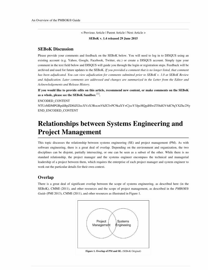
An Overview of the PMBOK® Guide 27
< Previous Article | Parent Article | Next Article >SEBoK v. 1.4 released 29 June 2015
SEBoK DiscussionPlease provide your comments and feedback on the SEBoK below. You will need to log in to DISQUS using anexisting account (e.g. Yahoo, Google, Facebook, Twitter, etc.) or create a DISQUS account. Simply type yourcomment in the text field below and DISQUS will guide you through the login or registration steps. Feedback will bearchived and used for future updates to the SEBoK. If you provided a comment that is no longer listed, that commenthas been adjudicated. You can view adjudication for comments submitted prior to SEBoK v. 1.0 at SEBoK Reviewand Adjudication. Later comments are addressed and changes are summarized in the Letter from the Editor andAcknowledgements and Release History.
If you would like to provide edits on this article, recommend new content, or make comments on the SEBoKas a whole, please see the SEBoK Sandbox [1].
ENCODED_CONTENTNTUzMDMPGRpdiBpZD0iZGlzcXVzX3RocmVhZCI+PC9kaXY+CjxzY3JpcHQgdHlwZT0idGV4dC9qYXZhc2NyaXB0Ij4KICAgIC8qICogKiBDT05GSUdVUkFUSU9OIFZBUklBQkxFUzogRURJVCBCRUZPUkUgUEFTVElORyBJTlRPIFlPVVIgV0VCUEFHRSAqICogKi8KICAgIHZhciBkaXNxdXNfc2hvcnRuYW1lID0gJ3NlYm9rd2lraTEwJzsgLy8gcmVxdWlyZWQ6IHJlcGxhY2UgZXhhbXBsZSB3aXRoIHlvdXIgZm9ydW0gc2hvcnRuYW1lCiAgICB2YXIgZGlzcXVzX2lkZW50aWZpZXIgPSAnQW4gT3ZlcnZpZXcgb2YgdGhlIFBNQk9Lwq4gR3VpZGUnOyAgICB2YXIgZGlzcXVzX3VybCA9ICdodHRwOi8vc2Vib2t3aWtpLm9yZy9kcmFmdC9Bbl9PdmVydmlld19vZl90aGVfUE1CT0slQzIlQUVfR3VpZGUnOwogICAgLyogKiAqIERPTidUIEVESVQgQkVMT1cgVEhJUyBMSU5FICogKiAqLwogICAgKGZ1bmN0aW9uKCkgewogICAgICAgIHZhciBkc3EgPSBkb2N1bWVudC5jcmVhdGVFbGVtZW50KCdzY3JpcHQnKTsgZHNxLnR5cGUgPSAndGV4dC9qYXZhc2NyaXB0JzsgZHNxLmFzeW5jID0gdHJ1ZTsKICAgICAgICBkc3Euc3JjID0gJ2h0dHA6Ly8nICsgZGlzcXVzX3Nob3J0bmFtZSArICcuZGlzcXVzLmNvbS9lbWJlZC5qcyc7CiAgICAgICAgKGRvY3VtZW50LmdldEVsZW1lbnRzQnlUYWdOYW1lKCdoZWFkJylbMF0gfHwgZG9jdW1lbnQuZ2V0RWxlbWVudHNCeVRhZ05hbWUoJ2JvZHknKVswXSkuYXBwZW5kQ2hpbGQoZHNxKTsKICAgIH0pKCk7Cjwvc2NyaXB0Pgo8bm9zY3JpcHQ+UGxlYXNlIGVuYWJsZSBKYXZhU2NyaXB0IHRvIHZpZXcgdGhlIDxhIGhyZWY9Imh0dHA6Ly9kaXNxdXMuY29tLz9yZWZfbm9zY3JpcHQiPmNvbW1lbnRzIHBvd2VyZWQgYnkgRGlzcXVzLjwvYT48L25vc2NyaXB0Pgo8YSBocmVmPSJodHRwOi8vZGlzcXVzLmNvbSIgY2xhc3M9ImRzcS1icmxpbmsiPmJsb2cgY29tbWVudHMgcG93ZXJlZCBieSA8c3BhbiBjbGFzcz0ibG9nby1kaXNxdXMiPkRpc3F1czwvc3Bhbj48L2E+END_ENCODED_CONTENT
Relationships between Systems Engineering andProject ManagementThis topic discusses the relationship between systems engineering (SE) and project management (PM). As withsoftware engineering, there is a great deal of overlap. Depending on the environment and organization, the twodisciplines can be disjoint, partially intersecting, or one can be seen as a subset of the other. While there is nostandard relationship, the project manager and the systems engineer encompass the technical and managerialleadership of a project between them, which requires the enterprise of each project manager and system engineer towork out the particular details for their own context.
OverlapThere is a great deal of significant overlap between the scope of systems engineering, as described here (in theSEBoK), CMMI (2011), and other resources and the scope of project management, as described in the PMBOK®Guide (PMI 2013), CMMI (2011), and other resources as illustrated in Figure 1.
Figure 1. Overlap of PM and SE. (SEBoK Original)

Relationships between Systems Engineering and Project Management 28
These sources describe the importance of understanding the scope of the work at hand, how to plan for criticalactivities, how to manage efforts while reducing risk, and how to successfully deliver value to a customer. Thesystems engineer working on a project will plan, monitor, confront risk, and deliver the technical aspects of theproject, while the project manager is concerned with the same kinds of activities for the overall project. Because ofthese shared concerns, at times there may be confusion and tension between the roles of the project manager and thesystems engineer on a given project. As shown in Figure 2, on some projects, there is no overlap in responsibility.On other projects, there may be shared responsibilities for planning and managing activities. In some cases,particularly for smaller projects, the project manager may also be the lead technical member of the team performingboth roles of project manager and systems engineer.
Figure 2. Overlap of Project Roles. (SEBoK Original)
Defining Roles and ResponsibilitiesRegardless of how the roles are divided up on a given project, the best way to reduce confusion is to explicitlydescribe the roles and responsibilities of the project manager and the systems engineer, as well as other key teammembers. The Project Management Plan (PMP) and the Systems Engineering Management Plan (SEMP) are keydocuments used to define the processes and methodologies the project will employ to build and deliver a product orservice.The PMP is the master planning document for the project. It describes all activities, including technical activities, tobe integrated and controlled during the life of the program. The SEMP is the master planning document for thesystems engineering technical elements. It defines SE processes and methodologies used on the project and therelationship of SE activities to other project activities. The SEMP must be consistent with, and evolve in concert,with the PMP. In addition, some customers have technical management plans and expectations that the project’sSEMP integrate with customer plans and activities. In the U.S. Department of Defense, most government projectteams have a systems engineering plan (SEP) with an expectation that the contractor’s SEMP will integrate andremain consistent with customer technical activities. In cases where the project is developing a component of a largersystem, the component project’s SEMP will need to integrate with the overall project’s SEMP.Given the importance of planning and managing the technical aspects of the project, an effective systems engineerwill need to have a strong foundation in management skills and prior experience, as well as possess strong technicaldepth. From developing and defending basis of estimates, planning and monitoring technical activities, identifyingand mitigating technical risk, and identifying and including relevant stakeholders during the life of the project, thesystems engineer becomes a key member of the project’s management and leadership team. Additional informationon Systems Engineering Management and Stakeholder Needs and Requirements can be found in Part 3: SystemsEngineering and Management.
Relationships between Systems Engineering and Project Management 29
Practical ConsiderationsEffective communication between the project manager and the system engineer is essential for missionaccomplishment. This communication needs to be established early, and occur frequently.Resource reallocation, schedule changes, product/system changes and impacts, risk changes: all these and more needto be quickly and clearly discussed between the PM and SE.
References
Works CitedCMMI. 2011. CMMI for Development: Guidelines for Process Integration and Product Improvement. Old Tappan,NJ, USA: Pearson Education.PMI. 2013. A Guide to the Project Management Body of Knowledge (PMBOK® Guide), 5th ed. Newtown Square,PA, USA: Project Management Institute (PMI).
Primary ReferencesChrissis, M.B, M. Konrad, S. Shrum. 2011. CMMI for Development: Guidelines for Process Integration and ProductImprovement, 3rd ed. Boston, MA, USA: Addison-Wesley Professional.PMI. 2013. A Guide to the Project Management Body of Knowledge (PMBOK® Guide), 5th ed. Newtown Square,PA, USA: Project Management Institute (PMI).
Additional ReferencesNASA. 2007. Systems Engineering Handbook, Revision 1. Washington, DC, USA: National Aeronautics and SpaceAdministration (NASA). NASA/SP-2007-6105.
< Previous Article | Parent Article | Next Article >SEBoK v. 1.4 released 29 June 2015
SEBoK DiscussionPlease provide your comments and feedback on the SEBoK below. You will need to log in to DISQUS using anexisting account (e.g. Yahoo, Google, Facebook, Twitter, etc.) or create a DISQUS account. Simply type yourcomment in the text field below and DISQUS will guide you through the login or registration steps. Feedback will bearchived and used for future updates to the SEBoK. If you provided a comment that is no longer listed, that commenthas been adjudicated. You can view adjudication for comments submitted prior to SEBoK v. 1.0 at SEBoK Reviewand Adjudication. Later comments are addressed and changes are summarized in the Letter from the Editor andAcknowledgements and Release History.
If you would like to provide edits on this article, recommend new content, or make comments on the SEBoKas a whole, please see the SEBoK Sandbox [1].
ENCODED_CONTENTMTc4MjMPGRpdiBpZD0iZGlzcXVzX3RocmVhZCI+PC9kaXY+CjxzY3JpcHQgdHlwZT0idGV4dC9qYXZhc2NyaXB0Ij4KICAgIC8qICogKiBDT05GSUdVUkFUSU9OIFZBUklBQkxFUzogRURJVCBCRUZPUkUgUEFTVElORyBJTlRPIFlPVVIgV0VCUEFHRSAqICogKi8KICAgIHZhciBkaXNxdXNfc2hvcnRuYW1lID0gJ3NlYm9rd2lraTEwJzsgLy8gcmVxdWlyZWQ6IHJlcGxhY2UgZXhhbXBsZSB3aXRoIHlvdXIgZm9ydW0gc2hvcnRuYW1lCiAgICB2YXIgZGlzcXVzX2lkZW50aWZpZXIgPSAnUmVsYXRpb25zaGlwcyBiZXR3ZWVuIFN5c3RlbXMgRW5naW5lZXJpbmcgYW5kIFByb2plY3QgTWFuYWdlbWVudCc7ICAgIHZhciBkaXNxdXNfdXJsID0gJ2h0dHA6Ly9zZWJva3dpa2kub3JnL2RyYWZ0L1JlbGF0aW9uc2hpcHNfYmV0d2Vlbl9TeXN0ZW1zX0VuZ2luZWVyaW5nX2FuZF9Qcm9qZWN0X01hbmFnZW1lbnQnOwogICAgLyogKiAqIERPTidUIEVESVQgQkVMT1cgVEhJUyBMSU5FICogKiAqLwogICAgKGZ1bmN0aW9uKCkgewogICAgICAgIHZhciBkc3EgPSBkb2N1bWVudC5jcmVhdGVFbGVtZW50KCdzY3JpcHQnKTsgZHNxLnR5cGUgPSAndGV4dC9qYXZhc2NyaXB0JzsgZHNxLmFzeW5jID0gdHJ1ZTsKICAgICAgICBkc3Euc3JjID0gJ2h0dHA6Ly8nICsgZGlzcXVzX3Nob3J0bmFtZSArICcuZGlzcXVzLmNvbS9lbWJlZC5qcyc7CiAgICAgICAgKGRvY3VtZW50LmdldEVsZW1lbnRzQnlUYWdOYW1lKCdoZWFkJylbMF0gfHwgZG9jdW1lbnQuZ2V0RWxlbWVudHNCeVRhZ05hbWUoJ2JvZHknKVswXSkuYXBwZW5kQ2hpbGQoZHNxKTsKICAgIH0pKCk7Cjwvc2NyaXB0Pgo8bm9zY3JpcHQ+UGxlYXNlIGVuYWJsZSBKYXZhU2NyaXB0IHRvIHZpZXcgdGhlIDxhIGhyZWY9Imh0dHA6Ly9kaXNxdXMuY29tLz9yZWZfbm9zY3JpcHQiPmNvbW1lbnRzIHBvd2VyZWQgYnkgRGlzcXVzLjwvYT48L25vc2NyaXB0Pgo8YSBocmVmPSJodHRwOi8vZGlzcXVzLmNvbSIgY2xhc3M9ImRzcS1icmxpbmsiPmJsb2cgY29tbWVudHMgcG93ZXJlZCBieSA8c3BhbiBjbGFzcz0ibG9nby1kaXNxdXMiPkRpc3F1czwvc3Bhbj48L2E+END_ENCODED_CONTENT

The Influence of Project Structure and Governance on Systems Engineering and Project Management Relationships 30
The Influence of Project Structure andGovernance on Systems Engineering and ProjectManagement RelationshipsThis article reviews various project structures that impact or provide governance to the project and that require keyinvolvement from the program manager and the systems engineer. These structures include: the structure of theorganization itself (functional, project, matrix, and specialized teams, such as Integrated Product Teams (IPTs),Change Control Boards (CCBs), and Engineering Review Boards (ERBs). This article also addresses the influence ofschedule-driven versus requirements-driven projects on these structures.The Relationships between Systems Engineering and Project Management is covered in a related article.
An Overview of Project StructuresProject management and systems engineering governance are dependent on the organization's structure. For someprojects, systems engineering is subordinated to project management and in other cases, project managementprovides support to systems engineering. These alternatives are illustrated in Figures 1 and 2 of the Organizing theTeam section in Team Capability.A project exists within the structural model of an organization. Projects are one-time, transient events that areinitiated to accomplish a specific purpose and are terminated when the project objectives are achieved. Sometimes,on small projects, the same person accomplishes the work activities of both project management and systemsengineering. Because the nature of the work activities are significantly different, it is sometimes more effective tohave two persons performing project management and systems engineering, each on a part-time basis. On largerprojects there are typically too many tasks to be accomplished for one person to accomplish all of the necessarywork. Very large projects may have project management and systems engineering offices with a designated projectmanager and a designated lead systems engineer.Projects are typically organized in one of three ways: (1) by functional structure, (2) by project structure, and (3) bya matrix structure (see Systems Engineering Organizational Strategy for a fourth structure and related discussion). Ina function-structured organization, workers are grouped by the functions they perform. The systems engineeringfunctions can be: (1) distributed among some of the functional organizations, (2) centralized within one organizationor (3) a hybrid, with some of the functions being distributed to the projects, others centralized and others aredistributed to functional organization. The following figure provides an organizational structure continuum andillustrates levels of governance among the functional organizations and the project.• In a functional-structured organization, the project manager is a coordinator and typically has only limited control
over the systems engineering functions. In this type of organization, the functional manager typically controls theproject budget and has authority over the project resources. However, the organization may or may not have afunctional unit for systems engineering. In the case where there is a functional unit for systems engineering,systems engineers are assigned across existing projects. Trades can be made among their projects to move thepriority of a specific systems engineering project ahead of other projects; thus, reducing the nominal schedule forthat selected project. However, in the case where there is not a functional unit for systems engineering, the projectmanager may have to find alternate sources of staffing for systems engineering – for example, hiring systemsengineering talent or consultants, or may consider promoting or expanding the responsibilities of a current teammember, etc.
•• In a project-structured organization, the project manager has full authority and responsibility for managing thebudget and resources to meet the schedule requirements. The systems engineer is subject to the direction of theproject manager. The project manager may work with human resources or a personnel manager or may go outside

The Influence of Project Structure and Governance on Systems Engineering and Project Management Relationships 31
the organization to staff the project.•• Matrix-structured organization can have the advantages of both the functional and project structures. For a
schedule driven project, function specialists are assigned to projects as needed to work for the project manager toapply their expertise on the project. Once they are no longer needed, they are returned to their functional groups(e.g. home office). In a weak matrix, the functional managers have authority to assign workers to projects andproject managers must accept the workers assigned to them. In a strong matrix, the project manager controls theproject budget and can reject workers from functional groups and hire outside workers if functional groups do nothave sufficient available and trained workers.
Figure 1. The Organizational Continuum (2). (SEBoK Original and Adapted from Fairley 2009). Reprinted with permission of the IEEE ComputerSociety. All other rights are reserved by the copyright owner.
In all cases, it is essential that the organizational and governance relationships be clarified and communicated to allproject stakeholders and that the project manager and systems engineer work together in a collegial manner.The Project Management Office (PMO) provides centralized control for a set of projects. The PMO is focused onmeeting the business objectives leveraging a set of projects, while the project managers are focused on meeting theobjectives of those projects that fall under their purview. PMOs typically manage shared resources and coordinatecommunication across the projects, provide oversight and manage interdependencies, and drive project-relatedpolicies, standards, and processes. The PMO may also provide training and monitor compliance (PMI 2013).

The Influence of Project Structure and Governance on Systems Engineering and Project Management Relationships 32
Schedule-Driven versus Requirements-Driven Influences on Structure andGovernanceThis article addresses the influences on governance relationships between the project manager and the systemsengineer. One factor that establishes this relationship is whether a project is schedule-driven or requirements-driven.In general, a project manager is responsible for delivering an acceptable product/service on the specified deliverydate and within the constraints of the specified schedule, budget, resources, and technology.The systems engineer is responsible for collecting and defining the operational requirements, specifying the systemsrequirements, developing the system design, coordinating component development teams, integrating the systemcomponents as they become available, verifying that the system to be delivered is correct, complete and consistent toits technical specification, and validating the operation of the system in its intended environment.From a governance perspective, the project manager is often thought of as being a movie producer who isresponsible for balancing the schedule, budget, and resource constraints to meet customer satisfaction. The systemsengineer is responsible for product content; ergo, the systems engineer is analogous to a movie director.Organizational structures, discussed previously, provide the project manager and systems engineer with differentlevels of governance authority. In addition, schedule and requirements constraints can influence governancerelationships. A schedule-driven project is one for which meeting the project schedule is more important thansatisfying all of the project requirements; in these cases lower priority requirements may not be implemented in orderto meet the schedule.Classic examples of these types of projects are:•• a project that has an external customer with a contractual delivery date and an escalating late delivery penalty, and• a project for which delivery of the system must meet a major milestone (e.g. a project for an announced product
release of a cell phone that is driven by market considerations).For schedule-driven projects, the project manager is responsible for planning and coordinating the work activitiesand resources for the project so that the team can accomplish the work in a coordinated manner to meet the schedule.The systems engineer works with the project manager to determine the technical approach that will meet theschedule. An Integrated Master Schedule (IMS) is often used to coordinate the project.A requirements-driven project is one for which satisfaction of the requirements is more important than the scheduleconstraint. Classic examples of these types of projects are:1.1. exploratory development of a new system that is needed to mitigate a potential threat (e.g. military research
project) and2.2. projects that must conform to government regulations in order for the delivered system to be safely operated (e.g.,
aviation and medical device regulations).An Integrated Master Plan is often used to coordinate event-driven projects.To satisfy the product requirements, the systems engineer is responsible for the making technical decisions andmaking the appropriate technical trades. When the trade space includes cost, schedule, or resources, the systemsengineer interacts with the project manager who is responsible for providing the resources and facilities needed toimplement a system that satisfies the technical requirements.Schedule-driven projects are more likely to have a management structure in which the project manager plays thecentral role, as depicted in Figure 1 of the Organizing the Team section in Team Capability. Requirement-drivenprojects are more likely to have a management structure in which the systems engineer plays the central role, asdepicted in Figure 2 of the Organizing the Team section in Team Capability.Along with the Project Management Plan and the Systems Engineering Management Plan, IMP/IMS are critical tothis process.
The Influence of Project Structure and Governance on Systems Engineering and Project Management Relationships 33
Related StructuresIntegrated Product Teams (IPTs), Change Control Boards (CCBs), and Engineering Review Boards (ERBs) areprimary examples of project structures that play a significant role in project governance and require coordinationbetween the project manager, systems engineer and other members of the team.
Integrated Product TeamThe Integrated Product Team (IPT) ensures open communication flow between the government and industryrepresentatives as well as between the various product groups (see Good Practices in Planning). There is typically atop level IPT, sometimes referred to as the Systems Engineering and Integration Team (SEIT) (see SystemsEngineering Organizational Strategy), that oversees the lower level IPTs. The SEIT can be led by either the projectmanager for a specific project or by the systems engineering functional manager or functional lead across manyprojects. Each IPT consists of representatives from the appropriate management and technical teams that need tocollaborate on systems engineering, project management, and other activities to create a high quality product. Theserepresentatives meet regularly to ensure that the technical requirements are understood and properly implemented inthe design. Also see Team Capability.
Change Control BoardAn effective systems engineering approach includes a disciplined process for change control as part of the largergoal of configuration management. The primary objective of configuration management is to track changes toproject artifacts that include software, hardware, plans, requirements, designs, tests, and documentation.Alternatively, a Change Control Board (CCB) with representatives from appropriate areas of the project is set up toeffectively analyze, control and manage changes being proposed to the project. The CCB typically receives anEngineering Change Proposal (ECP) from design/development, production, or operations/support and initiallyreviews the change for feasibility. The ECP may also be an output of the Engineering Review Board (ERB) (see nextsection). If determined feasible, the CCB ensures there is an acceptable change implementation plan and propermodification and installation procedures to support production and operations.There may be multiple CCBs in a large project. CCBs may be comprised of members from both the customer and thesupplier. As with the IPTs, there can be multiple levels of CCB starting with a top level CCB with CCBs alsoexisting at the subsystem levels. A technical lead typically chairs the CCB; however, the board includesrepresentation from project management since the CCB decisions will have an impact on schedule, budget, andresources.See Figure 2 under Configuration Management for a flow of the change control process adapted from Blanchard andFabrycky (2011). See also Capability Updates, Upgrades, and Modernization, and topics included under EnablingTeams. See also the UK West Coast Route Modernisation Project Vignette which provides an example where changecontrol was an important success factor.
Engineering Review BoardAnother example of a board that requires collaboration between technical and management is the EngineeringReview Board (ERB). Examples of ERBs include the Management Safety Review Board (MSRB) (see SafetyEngineering. Responsibilities of the ERB may include technical impact analysis of pending change requests (like theCCB), adjudication of results of engineering trade studies, and review of changes to the project baseline. In somecases the ERB may be the management review board and the CCB may be the technical review board. Alternatively,in a requirement driven organization the ERB may have more influence while in a schedule driven organization theCCB may have more impact.

The Influence of Project Structure and Governance on Systems Engineering and Project Management Relationships 34
References
Works CitedBlanchard, B.S., and W. J. Fabrycky. 2011. Systems Engineering and Analysis. 5th ed. Prentice-Hall Internationalseries in Industrial and Systems Engineering. Englewood Cliffs, NJ, USA: Prentice-Hall.Fairley, R.E. 2009. Managing and Leading Software Projects. IEEE Computer Society, John Wiley & Sons, Inc.Publication. ISBN: 978-0-470-29455-0.PMI. 2013. A Guide to the Project Management Body of Knowledge (PMBOK® Guide), 5th ed. Newtown Square,PA, USA: Project Management Institute (PMI).
Primary ReferencesForsberg, K., H. Mooz, and H. Cotterman. 2005. Visualizing Project Management. 3rd ed. New York, NY, USA:John Wiley & Sons.
Additional ReferencesNone.
< Previous Article | Parent Article | Next Article >SEBoK v. 1.4 released 29 June 2015
SEBoK DiscussionPlease provide your comments and feedback on the SEBoK below. You will need to log in to DISQUS using anexisting account (e.g. Yahoo, Google, Facebook, Twitter, etc.) or create a DISQUS account. Simply type yourcomment in the text field below and DISQUS will guide you through the login or registration steps. Feedback will bearchived and used for future updates to the SEBoK. If you provided a comment that is no longer listed, that commenthas been adjudicated. You can view adjudication for comments submitted prior to SEBoK v. 1.0 at SEBoK Reviewand Adjudication. Later comments are addressed and changes are summarized in the Letter from the Editor andAcknowledgements and Release History.
If you would like to provide edits on this article, recommend new content, or make comments on the SEBoKas a whole, please see the SEBoK Sandbox [1].
ENCODED_CONTENTMjA1NjgPGRpdiBpZD0iZGlzcXVzX3RocmVhZCI+PC9kaXY+CjxzY3JpcHQgdHlwZT0idGV4dC9qYXZhc2NyaXB0Ij4KICAgIC8qICogKiBDT05GSUdVUkFUSU9OIFZBUklBQkxFUzogRURJVCBCRUZPUkUgUEFTVElORyBJTlRPIFlPVVIgV0VCUEFHRSAqICogKi8KICAgIHZhciBkaXNxdXNfc2hvcnRuYW1lID0gJ3NlYm9rd2lraTEwJzsgLy8gcmVxdWlyZWQ6IHJlcGxhY2UgZXhhbXBsZSB3aXRoIHlvdXIgZm9ydW0gc2hvcnRuYW1lCiAgICB2YXIgZGlzcXVzX2lkZW50aWZpZXIgPSAnVGhlIEluZmx1ZW5jZSBvZiBQcm9qZWN0IFN0cnVjdHVyZSBhbmQgR292ZXJuYW5jZSBvbiBTeXN0ZW1zIEVuZ2luZWVyaW5nIGFuZCBQcm9qZWN0IE1hbmFnZW1lbnQgUmVsYXRpb25zaGlwcyc7ICAgIHZhciBkaXNxdXNfdXJsID0gJ2h0dHA6Ly9zZWJva3dpa2kub3JnL2RyYWZ0L1RoZV9JbmZsdWVuY2Vfb2ZfUHJvamVjdF9TdHJ1Y3R1cmVfYW5kX0dvdmVybmFuY2Vfb25fU3lzdGVtc19FbmdpbmVlcmluZ19hbmRfUHJvamVjdF9NYW5hZ2VtZW50X1JlbGF0aW9uc2hpcHMnOwogICAgLyogKiAqIERPTidUIEVESVQgQkVMT1cgVEhJUyBMSU5FICogKiAqLwogICAgKGZ1bmN0aW9uKCkgewogICAgICAgIHZhciBkc3EgPSBkb2N1bWVudC5jcmVhdGVFbGVtZW50KCdzY3JpcHQnKTsgZHNxLnR5cGUgPSAndGV4dC9qYXZhc2NyaXB0JzsgZHNxLmFzeW5jID0gdHJ1ZTsKICAgICAgICBkc3Euc3JjID0gJ2h0dHA6Ly8nICsgZGlzcXVzX3Nob3J0bmFtZSArICcuZGlzcXVzLmNvbS9lbWJlZC5qcyc7CiAgICAgICAgKGRvY3VtZW50LmdldEVsZW1lbnRzQnlUYWdOYW1lKCdoZWFkJylbMF0gfHwgZG9jdW1lbnQuZ2V0RWxlbWVudHNCeVRhZ05hbWUoJ2JvZHknKVswXSkuYXBwZW5kQ2hpbGQoZHNxKTsKICAgIH0pKCk7Cjwvc2NyaXB0Pgo8bm9zY3JpcHQ+UGxlYXNlIGVuYWJsZSBKYXZhU2NyaXB0IHRvIHZpZXcgdGhlIDxhIGhyZWY9Imh0dHA6Ly9kaXNxdXMuY29tLz9yZWZfbm9zY3JpcHQiPmNvbW1lbnRzIHBvd2VyZWQgYnkgRGlzcXVzLjwvYT48L25vc2NyaXB0Pgo8YSBocmVmPSJodHRwOi8vZGlzcXVzLmNvbSIgY2xhc3M9ImRzcS1icmxpbmsiPmJsb2cgY29tbWVudHMgcG93ZXJlZCBieSA8c3BhbiBjbGFzcz0ibG9nby1kaXNxdXMiPkRpc3F1czwvc3Bhbj48L2E+END_ENCODED_CONTENT
Systems Engineering and Industrial Engineering 35
Systems Engineering and Industrial EngineeringIndustrial Engineering is concerned with the design, improvement and installation of integrated systemsof people, materials, information, equipment and energy. It draws upon specialized knowledge and skillin the mathematical, physical, and social sciences together with the principles and methods ofengineering analysis and design, to specify, predict, and evaluate the results to be obtained from suchsystems. (IIE 1992)
Industrial engineering (IE) encompasses several aspects of systems engineering (SE) (i.e., production planning andanalysis, continuous process improvement, etc.) and also many elements of the engineered systems domain(production control, supply chain management, operations planning and preparation, operations management, etc.),as depicted in Figure 3 of the article Scope and Context of the SEBoK.This knowledge area covers the overarching aspects of industrial engineering and describes the synergies between IEand SE.
Overview of Industrial EngineeringIndustrial engineers are trained to design and analyze the components of which man-machine systems are composed.They bring together individual elements that are designed via other engineering disciplines and properly synergizethese subsystems together with the people components for a completely integrated man-machine system. Industrialengineers are focused on the improvement of any system that is being designed or evaluated. They make individualhuman tasks more productive and efficient by optimizing flow, eliminating unnecessary motions, utilizing alternatematerials to improve manufacturing, improving the flow of product through processes, and optimizing theconfiguration of work spaces. Fundamentally, the industrial engineer is charged with reducing costs and increasingprofitability through ensuring the efficient use of human, material, physical, and/or financial resources (Salvendy2001).A systems engineer leverages industrial engineering knowledge to provide:•• production planning and analysis•• systems integration•• lifecycle planning and estimating•• change analysis and management•• continuous process improvement•• quality assurance•• business case analysis / return on investment•• engineering management•• systems integrationIndustrial engineers complement systems engineers with knowledge in:•• supply chain management•• budgeting and economic analysis•• production line preparation•• production•• production control•• testing•• staffing, organizing, directing•• cost, schedule, and performance monitoring•• risk monitoring and control•• operations planning and preparation

Systems Engineering and Industrial Engineering 36
•• operations management
Industrial Engineering Body of KnowledgeThe current overview of the industrial engineering body of knowledge is provided in the Handbook of IndustrialEngineering (Salvendy 2001) and Maynard's Industrial Engineering Handbook (Zandin 2001). The Institute ofIndustrial Engineers (IIE 1992) is currently in the process of developing a specific industrial engineering body ofknowledge. Additionally, industrial engineering terminology defines specific terms related to the industrialengineering profession. Definitions used in this section are from this reference. Turner et al. (1992) provide anoverview of industrial and systems engineering.The elements of IE include the following:
Operations EngineeringOperations engineering involves the management and control aspects of IE and works to ensure that all the necessaryrequirements are in place to effectively execute a business. Key areas of knowledge in this field include: product andprocess life cycles, forecasting, project scheduling, production scheduling, inventory management, capacitymanagement, supply chain, distribution, and logistics. Concepts such as materials requirements planning andenterprise resource planning find their roots in this domain.
Operations ResearchOperations research is the organized and systematic analysis of complex situations, such as if there is a spike in theactivities of organizations of people and resources. The analysis makes use of certain specific disciplinary methods,such as probability, statistics, mathematical programming, and queuing theory. The purpose of operations research isto provide a more complete and explicit understanding of complex situations, to promote optimal performanceutilizing the all the resources available. Models are developed that describe deterministic and probabilistic systemsand these models are employed to aid the decision maker. Knowledge areas in operations research include linearprogramming, network optimization, dynamic programming, integer programming, nonlinear programming,metaheuristics, decision analysis and game theory, queuing systems, and simulation. Classic applications include thetransportation problem and the assignment problem.
Production Engineering / Work DesignProduction engineering is the design of a production or manufacturing process for the efficient and effective creationof a product. Included in this knowledge area is classic tool and fixture design, selection of machines to produceproduct, and machine design. Closely related to production engineering, work design involves such activities asprocess, procedural and work area design, which are geared toward supporting the efficient creation of goods andservices. Knowledge in work simplification and work measurement are crucial to work design. These elements forma key foundation, along with other knowledge areas in IE, for lean principles.
Facilities Engineering and Energy ManagementFacilities engineering involves attempting to achieve the optimal organization in factories, buildings, and offices. Inaddition to addressing the aspects of the layout inside a facility, individuals in this field also possess knowledge ofmaterial and equipment handling as well as storage and warehousing. This area also involves the optimal placementand sizing of facilities according to the activities they are required to contain. An understanding of code complianceand use of standards is incorporated. The energy management aspect of this area encompasses atmospheric systemsand lighting and electrical systems. Through the development of responsible management of resources in the energymanagement domain, industrial engineers have established a basis in sustainability.

Systems Engineering and Industrial Engineering 37
ErgonomicsErgonomics is the application of knowledge in the life sciences, physical sciences, social sciences, and engineeringthat studies the interactions between the human and the total working environment, such as atmosphere, heat, lightand sound, as well as the interactions of all tools and equipment in the workplace. Ergonomics is sometimes referredto as human factors. Individuals in this field have a specialized knowledge in areas such as: anthropometricprinciples, standing/sitting, repetitive task analysis, work capacity and fatigue, vision and lighting, hearing, sound,noise, vibration, human information processing, displays and controls, and human-machine interaction. Members inthis field also consider the organizational and social aspects of a project.
Engineering Economic AnalysisEngineering economic analysis concerns techniques and methods that estimate output and evaluate the worth ofcommodities and services relative to their costs. Engineering economic analysis is used to evaluate systemaffordability. Fundamental to this knowledge area are value and utility, classification of cost, time value of moneyand depreciation. These are used to perform cash flow analysis, financial decision making, replacement analysis,break-even and minimum cost analysis, accounting and cost accounting. Additionally, this area involves decisionmaking involving risk and uncertainty and estimating economic elements. Economic analysis also addresses any taximplications.
Quality and ReliabilityQuality is the totality of features and characteristics of a product or service that bear on its ability to satisfy stated orimplied needs. Reliability is the ability of an item to perform a required function under stated conditions for a statedperiod of time. The understanding of probability and statistics form a key foundation to these concepts. Knowledgeareas in quality and reliability include: quality concepts, control charts, lot acceptance sampling, rectifyinginspection and auditing, design of experiments, and maintainability. Six sigma has its roots in the quality domain;however, its applicability has grown to encompass a total business management strategy.
Engineering ManagementEngineering management refers to the systematic organization, allocation, and application of economic and humanresources in conjunction with engineering and business practices. Knowledge areas include: organization, people,teamwork, customer focus, shared knowledge systems, business processes, resource responsibility, and externalinfluences.
Supply Chain ManagementSupply chain management deals with the management of the input of goods and services from outside sources thatare required for a business to produce its own goods and services. Information is also included as a form of input.Knowledge areas include: building competitive operations, planning and logistics, managing customer and supplierrelationships, and leveraging information technology to enable the supply chain.
Systems Engineering and Industrial Engineering 38
References
Works CitedIIE. 1992. Industrial Engineering Terminology, revised ddition. Norwood, GA, USA: Institute of IndustrialEngineers (IIE). Accessed March 7, 2012. Available: http:/ / www. iienet2. org/ Details. aspx?id=645.Salvendy, G. (ed.) 2001. Handbook of Industrial Engineering, Technology and Operations Management, 3rd ed.Hoboken, NJ, USA: John Wiley & Sons, Inc.Turner, W.C., J.H. Mize, K.E. Case, and J.W. Nazemtz. 1992. Introduction To Industrial And Systems Engineering,3rd ed. Upper Saddle River, NJ, USA: Prentice Hall.Zandin, K.B. (ed.) 2001. Maynard's Industrial Engineering Handbook, 5th ed. New York, NY, USA: McGraw-Hill.
Primary ReferencesIIE. 1992. Industrial Engineering Terminology, revised ddition. Norwood, GA, USA: Institute of IndustrialEngineers (IIE). Accessed March 7, 2012. Available: http:/ / www. iienet2. org/ Details. aspx?id=645.Salvendy, G. (ed.) 2001. Handbook of Industrial Engineering, Technology and Operations Management, 3rd ed.Hoboken, NJ, USA: John Wiley & Sons, Inc.Zandin, K.B. (ed.) 2001. Maynard's Industrial Engineering Handbook, 5th ed. New York, NY, USA: McGraw-Hill.
Additional References
Operations Engineering
Hopp, W., and M. Spearman. 2001. Factory Physics, 3rd ed., New York, NY, USA: McGraw-Hill.Heizer, J., and B. Render. 2001. Operations Management, 6th ed. Upper Saddle River, NJ, USA: Prentice Hall.Mantel, S., J. Meredith, S. Shafer, and M. Sutton. 2008. Project Management in Practice. New York, NY, USA:John Wiley & Sons.
Operations Research
Banks, J., J. Carson, B. Nelson, and D. Nicol. 2005. Discrete-Event System Simulation, 4th ed. Upper Saddle River,NJ, USA: Prentice Hall.Hillier, F., and G. Lieberman. 2010. Introduction to Operations Research, 9th ed. New York, NY, USA: McGrawHill.Kelton, W. David, R. Sadowski, and D. Sturrock. 2006. Simulation with Arena, 4th ed. New York, NY, USA:McGraw-Hill.Law, A. 2007. Simulation Modelling and Analysis, 4th ed. New York, NY, USA: McGraw-Hill.Winston, W. and J. Goldberg. 2004. Operations Research Applications & Algorithms, Independence, KY, USA:Thomson Brooks/Cole.
Systems Engineering and Industrial Engineering 39
Production Engineering / Work Design
Freivalds, A. 2009. Niebel's Methods, Standards, and Work Design, 12th ed. New York, NY, USA: McGraw-Hill.Groover, M. 2007 Work Systems: The Methods, Measurement, and Management of Work, Upper Saddle River, NJ,USA: Pearson-Prentice Hall.Grover, M. 2007. Fundamentals of Modern Manufacturing, 3rd ed. New York, NY, USA: John Wiley & Sons.Konz, S., and S. Johnson, 2008. Work Design: Occupational Ergonomics, 7th ed. Scottsdale, AZ, USA: HolcombHathaway.Meyers, F., and J. Stewart, 2001 Motion and Time Study for Lean Manufacturing, 3rd ed. Upper Saddle River, NJ,USA: Prentice Hall.
Facilities Engineering and Energy Management
Garcia-Diaz, A., and J. MacGregor Smith. 2008. Facilities Planning and Design, Upper Saddle River, NJ, USA:Pearson-Prentice Hall.Tompkins, J., J. White, Y. Bozer, and J. Tanchoco. 2003. Facilities Planning, 3rd ed. New York, NY, USA: JohnWiley & Sons.
Ergonomics
Chaffin, D., and G. Andersson. 1991. Occupational Biomechanics. New York, NY, USA: John Wiley & Sons.Wickens, C., S. Gordon, and Y. Liu. 2004. An Introduction to Human factors Engineering. Upper Saddle River, NJ,USA: Pearson-Prentice Hall.
Engineering Economic Analysis
Blank, L.T., and A.J. Tarquin. 2011. Engineering Economy, 7th ed. New York, NY, USA: McGraw-Hill.Newnan, D., T. Eschenbach, and J. Lavelle. 2011. Engineering Economic Analysis, 11th ed. New York, NY, USA:Oxford University Press.Parl, C. 2007. Fundamentals of Engineering Economics. Upper Saddle River, NJ, USA: Prentice Hall.Thuesen, G., and W. Fabrycky. 2001. Engineering Economy, 9th ed. Upper Saddle River, NJ, USA: Prentice Hall.
Quality & Reliability
Ebeling, C.E. 2005. An Introduction to Reliability and Maintainability Engineering. Long Grove, IL, USA:Waveland Press, Inc.Hawkins, D., and D. Olwell. 1998. Cumulative Sum Chars and Charting for Quality Improvement. New York, NY,USA: Springer.Kiemele, M., S. Schmidt, and R. Berdine. 1999. Basic Statistics: Tools for Continuous Improvement, 4th ed.Colorado Springs, CO, USA: Air Academy Press.Montgomery, D., and G. Runger. 2007. Applied Statistics and Probability for Engineers, 4th ed. Hoboken, NJ, USA:John Wiley & Sons.Montgomery, D. 2013. Design & Analysis of Experiments, 8th ed. Hoboken, NJ, USA: John Wiley & Sons.Montgomery, D. 2009. Introduction to Statistical Quality Control, 6th ed. Hoboken, NJ, USA: John Wiley & Sons.Quality Staff. 2006. Data Quality Assessment: Statistical Methods for Practitioners. Washington, DC, USA:Environmental Protection Agency (EPA).
Systems Engineering and Industrial Engineering 40
Engineering Management
Gido, J., and J. Clements. 2009. Successful Project Management. Cincinnati, OH, USA: South Western.Kersner, H. 2009. A Systems Approach to Planning, Scheduling, and Controlling, 10th ed. New York, NY, USA:John Wiley & Sons.
Supply Chain Management
Jacobs, F., and R. Chase. 2010. Operations and Supply Chain Management. New York, NY, USA: McGraw-Hill.Mentzer, J. 2004. Fundamentals of Supply Chain Management: Twelve Drivers of Competitive Advantage. ThousandOaks, CA, USA: Sage.
< Previous Article | Parent Article | Next Article >SEBoK v. 1.4 released 29 June 2015
SEBoK DiscussionPlease provide your comments and feedback on the SEBoK below. You will need to log in to DISQUS using anexisting account (e.g. Yahoo, Google, Facebook, Twitter, etc.) or create a DISQUS account. Simply type yourcomment in the text field below and DISQUS will guide you through the login or registration steps. Feedback will bearchived and used for future updates to the SEBoK. If you provided a comment that is no longer listed, that commenthas been adjudicated. You can view adjudication for comments submitted prior to SEBoK v. 1.0 at SEBoK Reviewand Adjudication. Later comments are addressed and changes are summarized in the Letter from the Editor andAcknowledgements and Release History.
If you would like to provide edits on this article, recommend new content, or make comments on the SEBoKas a whole, please see the SEBoK Sandbox [1].
ENCODED_CONTENTNTE3MDQPGRpdiBpZD0iZGlzcXVzX3RocmVhZCI+PC9kaXY+CjxzY3JpcHQgdHlwZT0idGV4dC9qYXZhc2NyaXB0Ij4KICAgIC8qICogKiBDT05GSUdVUkFUSU9OIFZBUklBQkxFUzogRURJVCBCRUZPUkUgUEFTVElORyBJTlRPIFlPVVIgV0VCUEFHRSAqICogKi8KICAgIHZhciBkaXNxdXNfc2hvcnRuYW1lID0gJ3NlYm9rd2lraTEwJzsgLy8gcmVxdWlyZWQ6IHJlcGxhY2UgZXhhbXBsZSB3aXRoIHlvdXIgZm9ydW0gc2hvcnRuYW1lCiAgICB2YXIgZGlzcXVzX2lkZW50aWZpZXIgPSAnU3lzdGVtcyBFbmdpbmVlcmluZyBhbmQgSW5kdXN0cmlhbCBFbmdpbmVlcmluZyc7ICAgIHZhciBkaXNxdXNfdXJsID0gJ2h0dHA6Ly9zZWJva3dpa2kub3JnL2RyYWZ0L1N5c3RlbXNfRW5naW5lZXJpbmdfYW5kX0luZHVzdHJpYWxfRW5naW5lZXJpbmcnOwogICAgLyogKiAqIERPTidUIEVESVQgQkVMT1cgVEhJUyBMSU5FICogKiAqLwogICAgKGZ1bmN0aW9uKCkgewogICAgICAgIHZhciBkc3EgPSBkb2N1bWVudC5jcmVhdGVFbGVtZW50KCdzY3JpcHQnKTsgZHNxLnR5cGUgPSAndGV4dC9qYXZhc2NyaXB0JzsgZHNxLmFzeW5jID0gdHJ1ZTsKICAgICAgICBkc3Euc3JjID0gJ2h0dHA6Ly8nICsgZGlzcXVzX3Nob3J0bmFtZSArICcuZGlzcXVzLmNvbS9lbWJlZC5qcyc7CiAgICAgICAgKGRvY3VtZW50LmdldEVsZW1lbnRzQnlUYWdOYW1lKCdoZWFkJylbMF0gfHwgZG9jdW1lbnQuZ2V0RWxlbWVudHNCeVRhZ05hbWUoJ2JvZHknKVswXSkuYXBwZW5kQ2hpbGQoZHNxKTsKICAgIH0pKCk7Cjwvc2NyaXB0Pgo8bm9zY3JpcHQ+UGxlYXNlIGVuYWJsZSBKYXZhU2NyaXB0IHRvIHZpZXcgdGhlIDxhIGhyZWY9Imh0dHA6Ly9kaXNxdXMuY29tLz9yZWZfbm9zY3JpcHQiPmNvbW1lbnRzIHBvd2VyZWQgYnkgRGlzcXVzLjwvYT48L25vc2NyaXB0Pgo8YSBocmVmPSJodHRwOi8vZGlzcXVzLmNvbSIgY2xhc3M9ImRzcS1icmxpbmsiPmJsb2cgY29tbWVudHMgcG93ZXJlZCBieSA8c3BhbiBjbGFzcz0ibG9nby1kaXNxdXMiPkRpc3F1czwvc3Bhbj48L2E+END_ENCODED_CONTENT
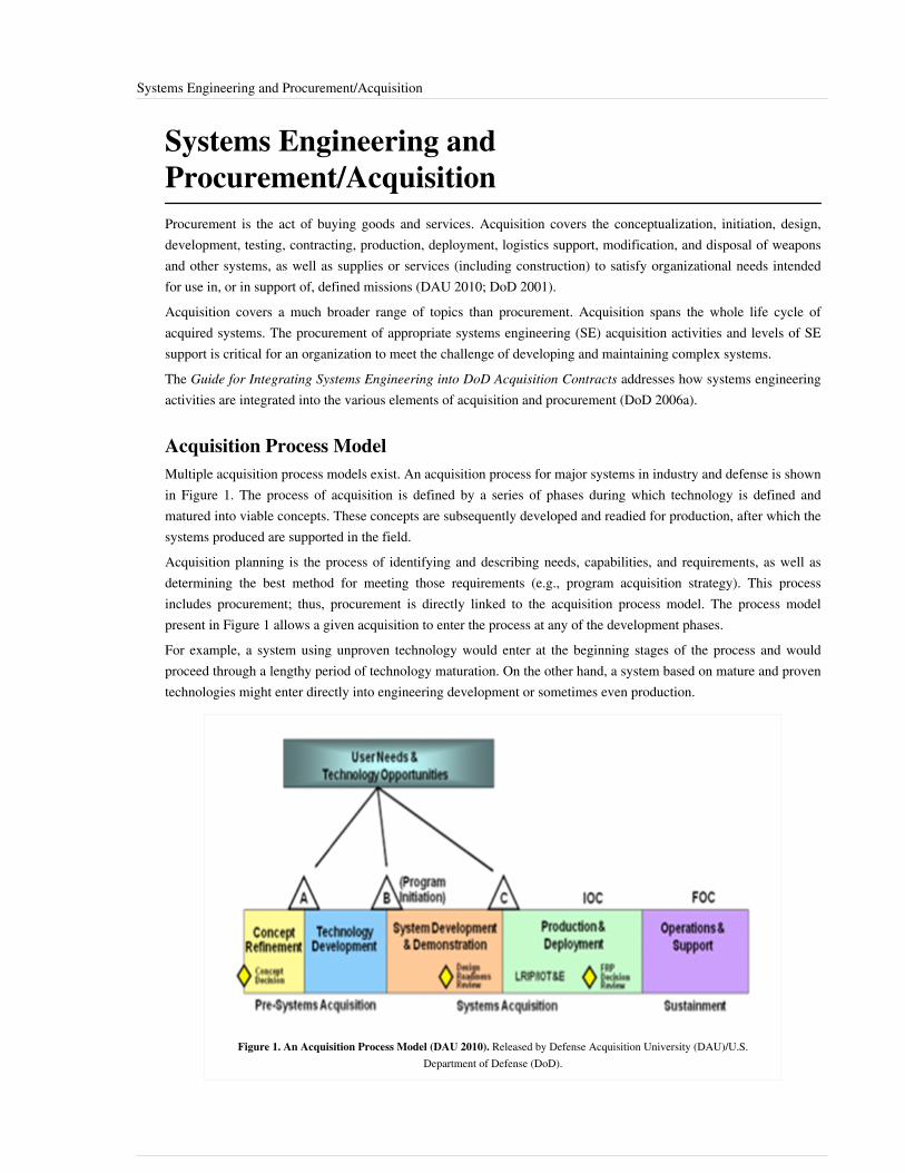
Systems Engineering and Procurement/Acquisition 41
Systems Engineering andProcurement/AcquisitionProcurement is the act of buying goods and services. Acquisition covers the conceptualization, initiation, design,development, testing, contracting, production, deployment, logistics support, modification, and disposal of weaponsand other systems, as well as supplies or services (including construction) to satisfy organizational needs intendedfor use in, or in support of, defined missions (DAU 2010; DoD 2001).Acquisition covers a much broader range of topics than procurement. Acquisition spans the whole life cycle ofacquired systems. The procurement of appropriate systems engineering (SE) acquisition activities and levels of SEsupport is critical for an organization to meet the challenge of developing and maintaining complex systems.The Guide for Integrating Systems Engineering into DoD Acquisition Contracts addresses how systems engineeringactivities are integrated into the various elements of acquisition and procurement (DoD 2006a).
Acquisition Process ModelMultiple acquisition process models exist. An acquisition process for major systems in industry and defense is shownin Figure 1. The process of acquisition is defined by a series of phases during which technology is defined andmatured into viable concepts. These concepts are subsequently developed and readied for production, after which thesystems produced are supported in the field.Acquisition planning is the process of identifying and describing needs, capabilities, and requirements, as well asdetermining the best method for meeting those requirements (e.g., program acquisition strategy). This processincludes procurement; thus, procurement is directly linked to the acquisition process model. The process modelpresent in Figure 1 allows a given acquisition to enter the process at any of the development phases.For example, a system using unproven technology would enter at the beginning stages of the process and wouldproceed through a lengthy period of technology maturation. On the other hand, a system based on mature and proventechnologies might enter directly into engineering development or sometimes even production.
Figure 1. An Acquisition Process Model (DAU 2010). Released by Defense Acquisition University (DAU)/U.S.Department of Defense (DoD).

Systems Engineering and Procurement/Acquisition 42
Systems Engineering Role in the Acquisition ProcessThe procurement of complex systems usually requires a close relationship between the offeror and supplier SE teamsdue to the breadth and depth of SE activities. SE is an overarching process that the program team applies in order totransition from a stated capability need to an affordable, operationally effective, and suitable system.SE is important to every phase of the acquisition process. SE encompasses the application of SE processes across theacquisition life cycle and is intended to be an integrating mechanism for balanced solutions addressing capabilityneeds, design considerations, and constraints. It is also intended to address limitations imposed by technology,budget, and schedule.SE is an interdisciplinary approach; that is, it is a structured, disciplined, and documented technical effort tosimultaneously design and develop system products and processes to satisfy the needs of the customer. Regardless ofthe scope and type of program, or at what point it enters the program acquisition life cycle, the technical approach tothe program needs to be integrated with the acquisition strategy to obtain the best program solution.Acquisition and procurement in the commercial sector have many characteristics in common with their counterpartsin the realm of government contracting, although the processes in the commercial world are usually accomplishedwith fewer rigors than occur between government and contractor interactions. Offshore outsourcing is commonlypracticed in the commercial software arena with the goal of reducing the cost of labor. Commercial organizationssometimes subcontract with other commercial organizations to provide missing expertise and to balance the ebb andflow of staffing needs.In some cases, relations between the contracting organization and the subcontractor are strained because of thecontracting organization’s desire to protect its intellectual property and development practices from potentialexposure to the subcontractor. Commercial organizations often have lists of approved vendors that are used toexpedite the procurement of needed equipment, products, and services. In these situations, commercial organizationshave processes to evaluate and approve vendors in ways that are analogous to the qualification of governmentcontractors. Many commercial organizations apply SE principles and procedures even though they may not identifythe personnel and job functions as “systems engineers” or “systems engineering.”
Importance of the Acquisition Strategy in the Procurement ProcessThe acquisition strategy is usually developed during the front end of the acquisition life cycle. (For an example ofthis, see the Technology Development Phase in Figure 1.) The acquisition strategy provides the integrated strategyfor all aspects of the acquisition program throughout the program life cycle.In essence, the acquisition strategy is a high-level business and technical management approach designed to achieveprogram objectives within specified resource constraints. It acts as the framework for planning, organizing, staffing,controlling, and leading a program, as well as for establishing the appropriate contract mechanisms. It provides amaster schedule for research, development, testing, production, fielding, and other SE related activities essential forprogram success, as well as for formulating functional strategies and plans.The offeror’s program team, including systems engineering, is responsible for developing and documenting theacquisition strategy, which conveys the program objectives, direction, and means of control based on the integrationof strategic, technical, and resource concerns. A primary goal of the acquisition strategy is the development of a planthat will minimize the time and cost of satisfying an identified, validated need while remaining consistent withcommon sense and sound business practices. While the contract officer (CO) is responsible for all contractingaspects, including determining which type of contract is most appropriate, and following the requirements of existingregulations, directives, instructions, and policy memos of an organization, the program manager (PM) works with theCO to develop the best contract/procurement strategy and contract types.

Systems Engineering and Procurement/Acquisition 43
Relating Acquisition to Request for Proposal and Technical AttributesThere are several formats for requesting proposals from offerors for building complex systems. Figure 2 relatesacquisition program elements to a representative request for proposal (RFP) topical outline and key programtechnical attributes that have been used by the Department of Defense. In general, programs have a better chance ofsuccess when both the offeror and supplier understand the technical nature of the program and the need for theassociated SE activities.The offeror and supplier need to clearly communicate the technical aspect of the program throughout theprocurement process. The offeror’s RFP and the associated supplier proposal represent one of the formalcommunications paths. A partial list of key program technical attributes is presented in Figure 2.
Figure 2. Relating Acquisition to Request for Proposal and Technical Attributes. (DoD 2006a). Released by the U.S. Office of theSecretary of Defense.
Contract-Related Activities and the Offeror’s Systems Engineering andProject Management RolesA clear understanding of the technical requirements is enhanced via the development of a Systems Engineering Plan(SEP). The SEP documents the system engineering strategy for a project or program and acts as the blueprint for theconduct, management, and control of the technical aspects of the acquisition program (DoD 2011). The SEPdocuments the SE structure and addresses government and contractor boundaries. It also summarizes the program’sselected acquisition strategy. It identifies and links to program risks. It also describes how the contractor's, andsometimes the subcontractor's and suppliers', technical efforts are to be managed.Once the technical requirements are understood, a contract may be developed and followed by the solicitation of suppliers. The offeror's PM, chief or lead systems engineer, and CO must work together to translate the program’s acquisition strategy and associated technical approach (usually defined in a SEP) into a cohesive, executable

Systems Engineering and Procurement/Acquisition 44
contract(s).Table 1 shows some key contracting-related tasks with indicators of the roles of the PM and LSE.
Table 1. Offeror’s Systems Engineering and Program Management Roles (DoD 2006).Released by the U.S. Office of the Secretary of Defense.
Typical Contract-Related Activities System Engineer and Project Manager Roles
1. Identify overall procurement requirements and associated budget.Describe the offer’s needs and any constraints on the procurement.
Lead system engineer (LSE) provides program technical requirements. PMprovides any programmatic related requirements.
2. Identify technical actions required to successfully completetechnical and procurement milestones. The program’s SEP is the keysource for capturing this technical planning.
LSE defines the technical strategy/approach and required technical efforts.This should be consistent with the program’s Acquisition Strategy.
3. Document market research results and identify potential industrysources.
PM and LSE identify programmatic and technical information needed andassist in evaluating the results.
4. Prepare a Purchase Request, including product descriptions;priorities, allocations and allotments; architecture;government-furnished property or equipment (orGovernment-Off-The-Shelf (GOTS); government-furnishedinformation; information assurance and security considerations; andrequired delivery schedules.
PM and LSE ensure the specific programmatic and technical needs aredefined clearly (e.g., commercial-off-the-shelf (COTS) products).
5. Identify acquisition streamlining approach and requirements,budgeting and funding, management information requirements,environmental considerations, offeror’s expected skill sets, andmilestones. These should be addressed in the Acquisition Strategy.
The procurement team work together, but the CO has the primeresponsibility. The PM is the owner of the program Acquisition Strategy.The LSE develops and reviews (and the PM approves) the technicalstrategy.
6. Plan the requirements for the contract Statement of Objectives(SOO) / Statement of Work (SOW) / specification, project technicalreviews, acceptance requirements, and schedule.
LSE is responsible for the development of the technical aspects of theSOO/SOW.
7. Plan and conduct Industry Days as appropriate. PM and LSE supports the CO in planning the meeting agenda to ensuretechnical needs are discussed.
8. Establish contract cost, schedule, and performance reportingrequirements. Determine an incentive strategy and appropriatemechanism (e.g., Award Fee Plan and criteria).
LSE provides technical resource estimates. LSE supports development ofthe Work Breakdown Structure (WBS) based on preliminary systemspecifications, determines event-driven criteria for key technical reviews,and determines what technical artifacts are baselined. The PM and LSEadvise the CO in developing the metrics/criteria for an incentivemechanism.
9. Identify data requirements. LSE identifies all technical Contractor Data Requirements List (CDRL)and technical performance expectations.
10. Establish warranty requirements, if applicable. LSE works with the CO to determine cost-effective warranty requirements.
11. Prepare a Source Selection Plan (SSP) and RFP (for competitivecontracts).
PM and LSE provide input to the SSP per the SOO/SOW.
12. Conduct source selection and award the contract to the successfulofferor.
PM and LSE participate on evaluation teams.

Systems Engineering and Procurement/Acquisition 45
Offeror and Supplier InteractionsThere should be an environment of open communication prior to the formal source selection process. This ensuresthat the supplier understands the offeror’s requirements and that the offeror understands the supplier's capabilitiesand limitations, as well as enhancing the supplier's involvement in the development of a program acquisitionstrategy. During the pre-solicitation phase, the offeror develops the solicitation and may ask suppliers to provideimportant insights into the technical challenges, program technical approach, and key business motivations.For example, potential bidders could be asked for their assessment of a proposed system's performance based on thematurity level of new and existing technologies.
Contracts and SubcontractsTypical types of contracts include the following:• Fixed Price: In a fixed price contract the offeror proposes a single price for all products and services to
implement the project. This single price is sometimes referred to as low bid or lump sum. A fixed price contracttransfers the project risks to the supplier. When there is a cost overrun, the supplier absorbs it. If the supplierperforms better than planned, their profit is higher. Since all risks are absorbed by the supplier, a fixed price bidmay be higher to reflect this.
• Cost-reimbursement [Cost plus]: In a cost-reimbursement contract the offeror provides a fixed fee, but alsoreimburses the contractor for labor, material, overhead, and administration costs. Cost-reimbursement typecontracts are used when there is a high level of project risk and uncertainty. With this type of contract the risksreside primarily with the offeror. The supplier gets reimbursed for all of its costs. Additional costs that arise dueto changes or rework are covered by the offeror. This type of contract is often recommended for the systemdefinition of hardware and software development when there is a risk of stakeholder changes to the system.
• Subcontracts: A subcontractor performs work for another company as part of a larger project. A subcontractor ishired by a general contractor (also known as a prime or main contractor) to perform a specific set of tasks as partof the overall project. The incentive to hire subcontractors is either to reduce costs or to mitigate project risks. Thesystems engineering team is involved in establishing the technical contract requirements, technical selectioncriteria, acceptance requirements, and the technical monitoring and control processes.
• Outsource contracts: Outsourced contracts are used to obtain goods or services by contracting with an outsidesupplier. Outsourcing usually involves contracting a business function, such as software design and codedevelopment, to an external provider.
• Exclusively Commercial Off-the-Shelf (COTS): Exclusively COTS contracts are completely satisfied withcommercial solutions that require no modification for use. COTS solutions are used in the environment withoutmodifying the COTS system. They are integrated into an existing user's platform or integrated into an existingoperational environment. The systems engineering team is involved in establishing the technical contractrequirements, technical acceptance, and technical selection criteria.
• Integrated COTS: Integrated COTS contracts use commercially available products and integrate them intoexisting user platforms or operational environments. In some cases, integrated COTS solutions modify thesystem's solution. The cost of integrating the commercial COTS product into the operational environment canexceed the cost of the COTS product itself. As a result, the systems engineering team is usually involved inestablishing the technical outsourcing contract requirements, technical selection criteria, technical monitoring andcontrol processes, and technical acceptance and integration processes.
• COTS Modification: COTS modification requires the most time and cost because of the additional work neededto modify the COTS product and integrate it into the system. Depending on how complex and critical the need is,the systems engineering team is usually involved in establishing the technical outsource contract requirements,technical selection criteria, technical monitoring and control processes, and technical acceptance requirements.

Systems Engineering and Procurement/Acquisition 46
• IT services: IT services provide capabilities that can enable an enterprise, application, or Web service solution. ITservices can be provided by an outsourced service provider. In many cases, the user interface for these Webservices is as simple as a Web browser. Depending on how complex and critical the needs are, the systemsengineering team can be involved in establishing the technical outsourcing contract requirements, technicalselection criteria, and technical acceptance process.
References
Works CitedDAU. 2010. Defense Acquisition Guidebook (DAG). Ft. Belvoir, VA, USA: Defense Acquisition University(DAU)/US Department of Defense (DoD).DoD. 2011. Systems Engineering Plan (SEP) Outline. Washington, DC, USA: Office of the Undersecretary ofDefense for Acquisition, Transportation, and Logistics (AT&L), US Department of Defense (DoD).DoD. 2006. Guide for Integrating Systems Engineering into DoD Acquisition Contracts. Washington, DC, USA:Office of the Undersecretary of Defense for Acquisition, Transportation, and Logistics (AT&L), US Department ofDefense (DoD).DoD. 2001. Systems Engineering Fundamentals. Washington, DC, USA: Defense Acquisition University Press/USDepartment of Defense.
Primary ReferencesDAU. 2010. Defense Acquisition Guidebook (DAG). Ft. Belvoir, VA, USA: Defense Acquisition University(DAU)/US Department of Defense (DoD).DoD. 2011. Systems Engineering Plan (SEP) Outline. Washington, DC, USA: Office of the Undersecretary ofDefense for Acquisition, Transportation, and Logistics (AT&L), US Department of Defense (DoD).DoD. 2006. Guide for Integrating Systems Engineering into DoD Acquisition Contracts. Washington, DC, USA:Office of the Undersecretary of Defense for Acquisition, Transportation, and Logistics (AT&L), US Department ofDefense (DoD).
Additional ReferencesMITRE. 2011. "Acquisition Systems Engineering." Systems Engineering Guide. Accessed March 9, 2012. Available:http:/ / www. mitre. org/ work/ systems_engineering/ guide/ acquisition_systems_engineering/ .
< Previous Article | Parent Article | Next Article >SEBoK v. 1.4 released 29 June 2015
SEBoK DiscussionPlease provide your comments and feedback on the SEBoK below. You will need to log in to DISQUS using anexisting account (e.g. Yahoo, Google, Facebook, Twitter, etc.) or create a DISQUS account. Simply type yourcomment in the text field below and DISQUS will guide you through the login or registration steps. Feedback will bearchived and used for future updates to the SEBoK. If you provided a comment that is no longer listed, that commenthas been adjudicated. You can view adjudication for comments submitted prior to SEBoK v. 1.0 at SEBoK Reviewand Adjudication. Later comments are addressed and changes are summarized in the Letter from the Editor andAcknowledgements and Release History.
If you would like to provide edits on this article, recommend new content, or make comments on the SEBoKas a whole, please see the SEBoK Sandbox [1].

Systems Engineering and Procurement/Acquisition 47
ENCODED_CONTENTMjIzMzMPGRpdiBpZD0iZGlzcXVzX3RocmVhZCI+PC9kaXY+CjxzY3JpcHQgdHlwZT0idGV4dC9qYXZhc2NyaXB0Ij4KICAgIC8qICogKiBDT05GSUdVUkFUSU9OIFZBUklBQkxFUzogRURJVCBCRUZPUkUgUEFTVElORyBJTlRPIFlPVVIgV0VCUEFHRSAqICogKi8KICAgIHZhciBkaXNxdXNfc2hvcnRuYW1lID0gJ3NlYm9rd2lraTEwJzsgLy8gcmVxdWlyZWQ6IHJlcGxhY2UgZXhhbXBsZSB3aXRoIHlvdXIgZm9ydW0gc2hvcnRuYW1lCiAgICB2YXIgZGlzcXVzX2lkZW50aWZpZXIgPSAnU3lzdGVtcyBFbmdpbmVlcmluZyBhbmQgUHJvY3VyZW1lbnQvQWNxdWlzaXRpb24nOyAgICB2YXIgZGlzcXVzX3VybCA9ICdodHRwOi8vc2Vib2t3aWtpLm9yZy9kcmFmdC9TeXN0ZW1zX0VuZ2luZWVyaW5nX2FuZF9Qcm9jdXJlbWVudC9BY3F1aXNpdGlvbic7CiAgICAvKiAqICogRE9OJ1QgRURJVCBCRUxPVyBUSElTIExJTkUgKiAqICovCiAgICAoZnVuY3Rpb24oKSB7CiAgICAgICAgdmFyIGRzcSA9IGRvY3VtZW50LmNyZWF0ZUVsZW1lbnQoJ3NjcmlwdCcpOyBkc3EudHlwZSA9ICd0ZXh0L2phdmFzY3JpcHQnOyBkc3EuYXN5bmMgPSB0cnVlOwogICAgICAgIGRzcS5zcmMgPSAnaHR0cDovLycgKyBkaXNxdXNfc2hvcnRuYW1lICsgJy5kaXNxdXMuY29tL2VtYmVkLmpzJzsKICAgICAgICAoZG9jdW1lbnQuZ2V0RWxlbWVudHNCeVRhZ05hbWUoJ2hlYWQnKVswXSB8fCBkb2N1bWVudC5nZXRFbGVtZW50c0J5VGFnTmFtZSgnYm9keScpWzBdKS5hcHBlbmRDaGlsZChkc3EpOwogICAgfSkoKTsKPC9zY3JpcHQ+Cjxub3NjcmlwdD5QbGVhc2UgZW5hYmxlIEphdmFTY3JpcHQgdG8gdmlldyB0aGUgPGEgaHJlZj0iaHR0cDovL2Rpc3F1cy5jb20vP3JlZl9ub3NjcmlwdCI+Y29tbWVudHMgcG93ZXJlZCBieSBEaXNxdXMuPC9hPjwvbm9zY3JpcHQ+CjxhIGhyZWY9Imh0dHA6Ly9kaXNxdXMuY29tIiBjbGFzcz0iZHNxLWJybGluayI+YmxvZyBjb21tZW50cyBwb3dlcmVkIGJ5IDxzcGFuIGNsYXNzPSJsb2dvLWRpc3F1cyI+RGlzcXVzPC9zcGFuPjwvYT4=END_ENCODED_CONTENT
Systems Engineering and Specialty EngineeringSpecialty engineering disciplines support product, service and enterprise development by applying crosscuttingknowledge to system design decisions, balancing total system performance and affordability. This knowledge areapresents several of the supporting engineering disciplines with a focus on the systems engineer.
TopicsEach part of the SEBoK is divided into knowledge areas (KAs), which are groupings of information with a relatedtheme. The KAs in turn are divided into topics. This KA contains the following topics:•• Integration of Specialty Engineering•• Reliability, Availability, and Maintainability•• Human Systems Integration•• Safety Engineering•• Security Engineering•• System Assurance•• Electromagnetic Interference/Electromagnetic Compatibility•• Resilience Engineering•• Manufacturability and Producibility•• Affordability•• Environmental Engineering
Specialty RequirementsThe systems engineering team must ensure that specialty requirements are properly reviewed with regard to theirimpact on life cycle costs, development schedule, technical performance, and operational utility. For example,security requirements can impact operator workstations, electromagnetic interference requirements can impact thesignal in the interfaces between subsystems, and mass-volume requirements may preclude the use of certainmaterials to reduce subsystem weight.Engineering specialists audit the evolving design and resulting configuration items to ensure that the overall systemperformance also satisfies the specialty requirements. Including appropriate specialty engineers within each systemsengineering team assures that all system requirements are identified and balanced throughout the development cycle.

Systems Engineering and Specialty Engineering 48
References
Works CitedNone.
Primary ReferencesNone.
Additional ReferencesNone.
< Previous Article | Parent Article | Next Article >SEBoK v. 1.4 released 29 June 2015
SEBoK DiscussionPlease provide your comments and feedback on the SEBoK below. You will need to log in to DISQUS using anexisting account (e.g. Yahoo, Google, Facebook, Twitter, etc.) or create a DISQUS account. Simply type yourcomment in the text field below and DISQUS will guide you through the login or registration steps. Feedback will bearchived and used for future updates to the SEBoK. If you provided a comment that is no longer listed, that commenthas been adjudicated. You can view adjudication for comments submitted prior to SEBoK v. 1.0 at SEBoK Reviewand Adjudication. Later comments are addressed and changes are summarized in the Letter from the Editor andAcknowledgements and Release History.
If you would like to provide edits on this article, recommend new content, or make comments on the SEBoKas a whole, please see the SEBoK Sandbox [1].
ENCODED_CONTENTMTA4NzAPGRpdiBpZD0iZGlzcXVzX3RocmVhZCI+PC9kaXY+CjxzY3JpcHQgdHlwZT0idGV4dC9qYXZhc2NyaXB0Ij4KICAgIC8qICogKiBDT05GSUdVUkFUSU9OIFZBUklBQkxFUzogRURJVCBCRUZPUkUgUEFTVElORyBJTlRPIFlPVVIgV0VCUEFHRSAqICogKi8KICAgIHZhciBkaXNxdXNfc2hvcnRuYW1lID0gJ3NlYm9rd2lraTEwJzsgLy8gcmVxdWlyZWQ6IHJlcGxhY2UgZXhhbXBsZSB3aXRoIHlvdXIgZm9ydW0gc2hvcnRuYW1lCiAgICB2YXIgZGlzcXVzX2lkZW50aWZpZXIgPSAnU3lzdGVtcyBFbmdpbmVlcmluZyBhbmQgU3BlY2lhbHR5IEVuZ2luZWVyaW5nJzsgICAgdmFyIGRpc3F1c191cmwgPSAnaHR0cDovL3NlYm9rd2lraS5vcmcvZHJhZnQvU3lzdGVtc19FbmdpbmVlcmluZ19hbmRfU3BlY2lhbHR5X0VuZ2luZWVyaW5nJzsKICAgIC8qICogKiBET04nVCBFRElUIEJFTE9XIFRISVMgTElORSAqICogKi8KICAgIChmdW5jdGlvbigpIHsKICAgICAgICB2YXIgZHNxID0gZG9jdW1lbnQuY3JlYXRlRWxlbWVudCgnc2NyaXB0Jyk7IGRzcS50eXBlID0gJ3RleHQvamF2YXNjcmlwdCc7IGRzcS5hc3luYyA9IHRydWU7CiAgICAgICAgZHNxLnNyYyA9ICdodHRwOi8vJyArIGRpc3F1c19zaG9ydG5hbWUgKyAnLmRpc3F1cy5jb20vZW1iZWQuanMnOwogICAgICAgIChkb2N1bWVudC5nZXRFbGVtZW50c0J5VGFnTmFtZSgnaGVhZCcpWzBdIHx8IGRvY3VtZW50LmdldEVsZW1lbnRzQnlUYWdOYW1lKCdib2R5JylbMF0pLmFwcGVuZENoaWxkKGRzcSk7CiAgICB9KSgpOwo8L3NjcmlwdD4KPG5vc2NyaXB0PlBsZWFzZSBlbmFibGUgSmF2YVNjcmlwdCB0byB2aWV3IHRoZSA8YSBocmVmPSJodHRwOi8vZGlzcXVzLmNvbS8/cmVmX25vc2NyaXB0Ij5jb21tZW50cyBwb3dlcmVkIGJ5IERpc3F1cy48L2E+PC9ub3NjcmlwdD4KPGEgaHJlZj0iaHR0cDovL2Rpc3F1cy5jb20iIGNsYXNzPSJkc3EtYnJsaW5rIj5ibG9nIGNvbW1lbnRzIHBvd2VyZWQgYnkgPHNwYW4gY2xhc3M9ImxvZ28tZGlzcXVzIj5EaXNxdXM8L3NwYW4+PC9hPg==END_ENCODED_CONTENT

Integration of Specialty Engineering 49
Integration of Specialty EngineeringIntegration of engineering specialties into a project or program is, or should be, a major objective of systemsengineering management. With properly implemented procedures, the rigor of the systems engineering processensures participation of the specialty disciplines at key points in the technical decision making process. Specialemphasis on integration is mandatory because a given design could in fact be accomplished without consideration ofthese “specialty” disciplines, leading to the possibility of system ineffectiveness or failure when an unexaminedsituation occurs in the operational environment.For example, human factors considerations can contribute to reduced workloads and therefore lower error rates byoperators in aircraft cockpits, at air-traffic consoles, or nuclear reactor stations. Similarly, mean-time-to-repairfeatures can significantly increase overall system availability in challenging physical environments, such asmid-ocean or outer space. Specialty engineering requirements are often manifest as constraints on the overall systemdesign space. The role of system engineering is to balance these constraints with other functionality in order toharmonize total system performance. The end goal is to produce a system that provides utility and effectiveness tothe customer at an affordable price.
Integration Process for Specialty EngineeringAs depicted in Figure 1, systems engineering plays a leadership role in integrating traditional disciplines, specialtydisciplines, and unique system product demands to define the system design. Relationships for this integrationprocess are represented as interactions among three filters.The first filter is a conceptual analysis that leverages traditional design consideration (structural, electronics,aerodynamics, mechanical, thermodynamics, and other). The second filter evaluates the conceptual approach usingspecialty disciplines, such as safety, affordability, quality assurance, human factors, reliability and maintainability,producibility, packaging, test, logistics, and others, to further requirements development. Design alternatives thatpass through these two processes go through a third filter that incorporates facility design, equipment design,procedural data, computer programs, and personnel to develop the final requirements for design selection and furtherdetailed development.

Integration of Specialty Engineering 50
Figure 1. Integration Process for Specialty Engineering (USAF 2000). Released by the U.S. Air Force.
References
Works CitedUSAF. 2000. Guidelines for Successful Acquisition and Management of Software-Intensive Systems: WeaponSystems Command and Control Systems Management Information Systems, version 3.0. Hill AFB: Department of theAir Force Software Technology Support Center. May 2000. Accessed on September 11, 2011. Available at http:/ /www. stsc. hill. af. mil/ resources/ tech%5Fdocs/ .
Primary ReferencesUSAF. 2000. Guidelines for Successful Acquisition and Management of Software-Intensive Systems: WeaponSystems Command and Control Systems Management Information Systems, version 3.0. Hill AFB: Department of theAir Force Software Technology Support Center. May 2000. Accessed on September 11, 2011. Available at http:/ /www. stsc. hill. af. mil/ resources/ tech%5Fdocs/ .
Integration of Specialty Engineering 51
Additional ReferencesNone.
< Previous Article | Parent Article | Next Article >SEBoK v. 1.4 released 29 June 2015
SEBoK DiscussionPlease provide your comments and feedback on the SEBoK below. You will need to log in to DISQUS using anexisting account (e.g. Yahoo, Google, Facebook, Twitter, etc.) or create a DISQUS account. Simply type yourcomment in the text field below and DISQUS will guide you through the login or registration steps. Feedback will bearchived and used for future updates to the SEBoK. If you provided a comment that is no longer listed, that commenthas been adjudicated. You can view adjudication for comments submitted prior to SEBoK v. 1.0 at SEBoK Reviewand Adjudication. Later comments are addressed and changes are summarized in the Letter from the Editor andAcknowledgements and Release History.
If you would like to provide edits on this article, recommend new content, or make comments on the SEBoKas a whole, please see the SEBoK Sandbox [1].
ENCODED_CONTENTMTQyNzQPGRpdiBpZD0iZGlzcXVzX3RocmVhZCI+PC9kaXY+CjxzY3JpcHQgdHlwZT0idGV4dC9qYXZhc2NyaXB0Ij4KICAgIC8qICogKiBDT05GSUdVUkFUSU9OIFZBUklBQkxFUzogRURJVCBCRUZPUkUgUEFTVElORyBJTlRPIFlPVVIgV0VCUEFHRSAqICogKi8KICAgIHZhciBkaXNxdXNfc2hvcnRuYW1lID0gJ3NlYm9rd2lraTEwJzsgLy8gcmVxdWlyZWQ6IHJlcGxhY2UgZXhhbXBsZSB3aXRoIHlvdXIgZm9ydW0gc2hvcnRuYW1lCiAgICB2YXIgZGlzcXVzX2lkZW50aWZpZXIgPSAnSW50ZWdyYXRpb24gb2YgU3BlY2lhbHR5IEVuZ2luZWVyaW5nJzsgICAgdmFyIGRpc3F1c191cmwgPSAnaHR0cDovL3NlYm9rd2lraS5vcmcvZHJhZnQvSW50ZWdyYXRpb25fb2ZfU3BlY2lhbHR5X0VuZ2luZWVyaW5nJzsKICAgIC8qICogKiBET04nVCBFRElUIEJFTE9XIFRISVMgTElORSAqICogKi8KICAgIChmdW5jdGlvbigpIHsKICAgICAgICB2YXIgZHNxID0gZG9jdW1lbnQuY3JlYXRlRWxlbWVudCgnc2NyaXB0Jyk7IGRzcS50eXBlID0gJ3RleHQvamF2YXNjcmlwdCc7IGRzcS5hc3luYyA9IHRydWU7CiAgICAgICAgZHNxLnNyYyA9ICdodHRwOi8vJyArIGRpc3F1c19zaG9ydG5hbWUgKyAnLmRpc3F1cy5jb20vZW1iZWQuanMnOwogICAgICAgIChkb2N1bWVudC5nZXRFbGVtZW50c0J5VGFnTmFtZSgnaGVhZCcpWzBdIHx8IGRvY3VtZW50LmdldEVsZW1lbnRzQnlUYWdOYW1lKCdib2R5JylbMF0pLmFwcGVuZENoaWxkKGRzcSk7CiAgICB9KSgpOwo8L3NjcmlwdD4KPG5vc2NyaXB0PlBsZWFzZSBlbmFibGUgSmF2YVNjcmlwdCB0byB2aWV3IHRoZSA8YSBocmVmPSJodHRwOi8vZGlzcXVzLmNvbS8/cmVmX25vc2NyaXB0Ij5jb21tZW50cyBwb3dlcmVkIGJ5IERpc3F1cy48L2E+PC9ub3NjcmlwdD4KPGEgaHJlZj0iaHR0cDovL2Rpc3F1cy5jb20iIGNsYXNzPSJkc3EtYnJsaW5rIj5ibG9nIGNvbW1lbnRzIHBvd2VyZWQgYnkgPHNwYW4gY2xhc3M9ImxvZ28tZGlzcXVzIj5EaXNxdXM8L3NwYW4+PC9hPg==END_ENCODED_CONTENT
Reliability, Availability, and MaintainabilityReliability, availability, and maintainability (RAM) are three system attributes that are of tremendous interest tosystems engineers, logisticians, and users. Collectively, they affect economic life-cycle costs of a system and itsutility.This article focuses primarily on the reliability of physical system elements. Software reliability is a separatediscipline. Readers interested in software reliability should refer to the IEEE Std 1633 (IEEE 2008).
Probability Models for PopulationsReliability is defined as the probability of a system or system element performing its intended function under statedconditions without failure for a given period of time (ASQ 2011). A precise definition must include a detaileddescription of the function, the environment, the time scale, and what constitutes a failure. Each can be surprisinglydifficult to define as precisely as one might wish. Different failure mechanisms are referred to as failure modes andcan be modeled separately or aggregated into a single failure model.Let T be a random time to failure. Reliability can be thought of as the complement of the cumulative distributionfunction (CDF) for T for a given set of environmental conditions e:
Maintainability is defined as the probability that a system or system element can be repaired in a definedenvironment within a specified period of time. Increased maintainability implies shorter repair times (ASQ 2011).Availability is the probability that a repairable system or system element is operational at a given point in time undera given set of environmental conditions. Availability depends on reliability and maintainability and is discussed indetail later in this topic (ASQ 2011).

Reliability, Availability, and Maintainability 52
Each of these probability models is usually specified by a continuous, non-negative distribution. Typicaldistributions used in practice include exponential (possibly with a threshold parameter), Weibull (possibly with athreshold parameter), log-normal, and generalized gamma.Maintainability models present some interesting challenges. The time to repair an item is the sum of the timerequired for evacuation, diagnosis, assembly of resources (parts, bays, tool, and mechanics), repair, inspection, andreturn. Administrative delay (such as holidays) can also affect repair times. Often these sub-processes have aminimum time to complete that is not zero, resulting in the distribution used to model maintainability having athreshold parameter.A threshold parameter is defined as the minimum probable time to repair. Estimation of maintainability can befurther complicated by queuing effects, resulting in times to repair that are not independent. This dependencyfrequently makes analytical solution of problems involving maintainability intractable and promotes the use ofsimulation to support analysis.
Data IssuesTrue RAM models for a system are generally never known. Data on a given system is assumed or collected, used toselect a distribution for a model, and then used to fit the parameters of the distribution. This process differssignificantly from the one usually taught in an introductory statistics course.First, the normal distribution is seldom used as a life distribution, since it is defined for all negative times. Second,and more importantly, reliability data is different from classic experimental data. Reliability data is often censored,biased, observational, and missing information about covariates such as environmental conditions. Data from testingis often expensive, resulting in small sample sizes. These problems with reliability data require sophisticatedstrategies and processes to mitigate them.One consequence of these issues is that estimates based on limited data can be very imprecise.
Design IssuesSystem requirements should include specifications for reliability, maintainability, and availability, and each shouldbe conditioned on the projected operating environments.A proposed design should be analyzed prior to development to estimate whether or not it will meet thosespecifications. This is usually done by assuming historical data on actual or similar components represents the futureperformance of the components for the proposed system. If no data is available, conservative engineering judgmentis often applied. The system dependency on the reliability of its components can be captured in several ways,including reliability block diagrams, fault trees, and failure mode effects and criticality analyses (FMECA)(Kececioglu 1991).If a proposed design does not meet the preliminary RAM specifications, it can be adjusted. Critical failures aremitigated so that the overall risk is reduced to acceptable levels. This can be done in several ways:1. Fault tolerance is a strategy that seeks to make the system robust against the failure of a component. This can be
done by introducing redundancy. Redundant units can operate in a stand-by mode. A second tolerance strategy isto have the redundant components share the load, so that even if one or more of them fail the system continues tooperate. There are modeling issues associated with redundancy, including switching between components,warm-up, and increased failure rates for surviving units under increased load when another load-sharing unit fails.Redundancy can be an expensive strategy as there are cost, weight, volume, and power penalties associated withstand-by components.
2. Fault avoidance seeks to improve individual components so that they are more reliable. This can also be anexpensive strategy, but it avoids the switching issues, power, weight, and volume penalties associated with usingredundant components.

Reliability, Availability, and Maintainability 53
3. A third strategy is to repair or replace a component following a preventive maintenance schedule. This requiresthe assumption that the repair returns the component to “good as new” status, or possibly to an earlierage-equivalent. These assumptions can cause difficulties; for example, an oil change on a vehicle does not returnthe engine to ‘good as new’ status. Scheduled replacement can return a unit to good as new, but at the cost ofwasting potential life for the replaced unit. As a result, the selection of a replacement period is a non-linearoptimization problem that minimizes total expected life-cycle costs. These costs are the sum of the expected costsof planned and unplanned maintenance actions.
4. A fourth strategy is to control the environment so that a system is not operated under conditions that acceleratethe aging of its components.
Any or all of the above strategies (fault tolerance, fault avoidance, preventive maintenance, and environmentalcontrol) may be applied to improve the designed reliability of a system.
Post-Production Management SystemsOnce a system is fielded, its reliability and availability should be tracked. Doing so allows the producer / owner toverify that the design has met its RAM objectives, to identify unexpected failure modes, to record fixes, to assess theutilization of maintenance resources, and to assess the operating environment.One such tracking system is generically known as a FRACAS system (Failure Reporting and Corrective ActionSystem). Such a system captures data on failures and improvements to correct failures. This database is separatefrom a warranty data base, which is typically run by the financial function of an organization and tracks costs only.A FRACAS for an organization is a system, and itself should be designed following systems engineering principles.In particular, a FRACAS system supports later analyses, and those analyses impose data requirements.Unfortunately, the lack of careful consideration of the backward flow from decision to analysis to model to requireddata too often leads to inadequate data collection systems and missing essential information. Proper prior planningprevents this poor performance.Of particular importance is a plan to track data on units that have not failed. Units whose precise times of failure areunknown are referred to as censored units. Inexperienced analysts frequently do not know how to analyze censoreddata, and they omit the censored units as a result. This can bias an analysis.An organization should have an integrated data system that allows reliability data to be considered with logisticaldata, such as parts, personnel, tools, bays, transportation and evacuation, queues, and costs, allowing a totalawareness of the interplay of logistical and RAM issues. These issues in turn must be integrated with managementand operational systems to allow the organization to reap the benefits that can occur from complete situationalawareness with respect to RAM.
ModelsThere are a wide range of models that estimate and predict reliability (Meeker and Escobar 1998). Simple models,such as exponential distribution, can be useful for ‘back of the envelope’ calculations.There are more sophisticated probability models used for life data analysis. These are best characterized by theirfailure rate behavior, which is defined as the probability that a unit fails in the next small interval of time, given ithas lived until the beginning of the interval, and divided by the length of the interval.Models can be considered for a fixed environmental condition. They can also be extended to include the effect ofenvironmental conditions on system life. Such extended models can in turn be used for accelerated life testing(ALT), where a system is deliberately and carefully overstressed to induce failures more quickly. The data is thenextrapolated to usual use conditions. This is often the only way to obtain estimates of the life of highly reliableproducts in a reasonable amount of time (Nelson 1990).

Reliability, Availability, and Maintainability 54
Also useful are degradation models, where some characteristic of the system is associated with the propensity ofthe unit to fail (Nelson 1990). As that characteristic degrades, we can estimate times of failure before they occur.The initial developmental units of a system often do not meet their RAM specifications. Reliability growth modelsallow estimation of resources (particularly testing time) necessary before a system will mature to meet those goals(Meeker and Escobar 1998).Maintainability models describe the time necessary to return a failed repairable system to service. They are usuallythe sum of a set of models describing different aspects of the maintenance process (e.g., diagnosis, repair, inspection,reporting, and evacuation). These models often have threshold parameters, which are minimum times until an eventcan occur.Logistical support models attempt to describe flows through a logistics system and quantify the interaction betweenmaintenance activities and the resources available to support those activities. Queue delays, in particular, are a majorsource of down time for a repairable system. A logistical support model allows one to explore the trade spacebetween resources and availability.All these models are abstractions of reality, and so at best approximations to reality. To the extent they provideuseful insights, they are still very valuable. The more complicated the model, the more data necessary to estimate itprecisely. The greater the extrapolation required for a prediction, the greater the imprecision.Extrapolation is often unavoidable, because high reliability equipment typically can have long life and the amount oftime required to observe failures may exceed test times. This requires strong assumptions be made about future life(such as the absence of masked failure modes) and that these assumptions increase uncertainty about predictions.The uncertainty introduced by strong model assumptions is often not quantified and presents an unavoidable risk tothe system engineer.
System MetricsProbabilistic metrics describe system performance for RAM. Quantiles, means, and modes of the distributions usedto model RAM are also useful.Availability has some additional definitions, characterizing what downtime is counted against a system. Forinherent availability, only downtime associated with corrective maintenance counts against the system. Forachieved availability, downtime associated with both corrective and preventive maintenance counts against asystem. Finally, operational availability counts all sources of downtime, including logistical and administrative,against a system.Availability can also be calculated instantaneously, averaged over an interval, or reported as an asymptotic value.Asymptotic availability can be calculated easily, but care must be taken to analyze whether or not a systems settlesdown or settles up to the asymptotic value, as well as how long it takes until the system approaches that asymptoticvalue.Reliability importance measures the effect on the system reliability of a small improvement in a component’sreliability. It is defined as the partial derivative of the system reliability with respect to the reliability of a component.Criticality is the product of a component’s reliability, the consequences of a component failure, and the frequencywith which a component failure results in a system failure. Criticality is a guide to prioritizing reliabilityimprovement efforts.Many of these metrics cannot be calculated directly because the integrals involved are intractable. They are usuallyestimated using simulation.

Reliability, Availability, and Maintainability 55
System ModelsThere are many ways to characterize the reliability of a system, including fault trees, reliability block diagrams, andfailure mode effects analysis.A Fault Tree (Kececioglu 1991) is a graphical representation of the failure modes of a system. It is constructedusing logical gates, with AND, OR, NOT, and K of N gates predominating. Fault trees can be complete or partial; apartial fault tree focuses on a failure mode or modes of interest. They allow 'drill down' to see the dependencies ofsystems on nested systems and system elements. Fault trees were pioneered by Bell Labs in the 1960s.
Figure 1. Fault Tree. (SEBoK Original)
A Reliability Block Diagram (RBD) is a graphical representation of the reliability dependence of a system on itscomponents. It is a directed, acyclic graph. Each path through the graph represents a subset of system components.As long as the components in that path are operational, the system is operational. Component lives are usuallyassumed to be independent in a RBD. Simple topologies include a series system, a parallel system, a k of n system,and combinations of these.RBDs are often nested, with one RBD serving as a component in a higher level model. These hierarchical modelsallow the analyst to have the appropriate resolution of detail while still permitting abstraction.RBDs depict paths that lead to success, while fault trees depict paths that lead to failure.

Reliability, Availability, and Maintainability 56
Figure 2. Simple Reliability Block Diagram. (SEBoK Original)
A Failure Mode Effects Analysis is a table that lists the possible failure modes for a system, their likelihood, andthe effects of the failure. A Failure Modes Effects Criticality Analysis scores the effects by the magnitude of theproduct of the consequence and likelihood, allowing ranking of the severity of failure modes (Kececioglu 1991).System models require even more data to fit them well. “Garbage in, garbage out” (GIGO) particularly applies in thecase of system models.
Software ToolsThe specialized analyses required for RAM drive the need for specialized software. While general purpose statisticallanguages or spreadsheets can, with sufficient effort, be used for reliability analysis, almost every serious practitioneruses specialized software.Minitab (versions 13 and later) includes functions for life data analysis. Win Smith is a specialized package that fitsreliability models to life data and can be extended for reliability growth analysis and other analyses. Relex has anextensive historical database of component reliability data and is useful for estimating system reliability in the designphase.There is also a suite of products from ReliaSoft (2007) that is useful in specialized analyses. Weibull++ fits lifemodels to life data. ALTA fits accelerated life models to accelerated life test data. BlockSim models systemreliability, given component data.

Reliability, Availability, and Maintainability 57
References
Works CitedAmerican Society for Quality (ASQ). 2011. Glossary: Reliability. Accessed on September 11, 2011. Available athttp:/ / asq. org/ glossary/ r. html.IEEE. 2008. IEEE Recommended Practice on Software Reliability. New York, NY, USA: Institute of Electrical andElectronic Engineers (IEEE). IEEE Std 1633-2008.Kececioglu, D. 1991. Reliability Engineering Handbook, Volume 2. Upper Saddle River, NJ, USA: Prentice Hall.Meeker, W.Q. and L.A. Escobar. 1998. Statistical Methods for Reliability Data. New York, NY, USA: Wiley andSons.Nelson, Wayne. 1990. Accelerated Testing: Statistical Models, Test Plans, and Data Analysis. New York, NY, USA:Wiley and Sons.ReliaSoft. 2007. Failure Modes and Effects Analysis (FMEA) and Failure Modes, Effects and Criticality Analysis(FMECA). Accessed on September 11, 2011. Available at http:/ / www. weibull. com/ basics/ fmea. htm.
Primary ReferencesBlischke, W.R. and D.N. Prabhakar Murthy. 2000. Reliability Modeling, Prediction, and Optimization. New York,NY, USA: Wiley and Sons.DoD. 2005. DOD Guide for Achieving Reliability, Availability, and Maintainability. Arlington, VA, USA: U.S.Department of Defense (DoD). Accessed on September 11, 2011. Available at: http:/ / www. acq. osd. mil/ se/ docs/RAM_Guide_080305. pdf [1]
Kececioglu, D. 1991. Reliability Engineering Handbook, Volume 2. Upper Saddle River, NJ, USA: Prentice Hall.Lawless, J.F. 1982. Statistical Models and Methods for Lifetime Data. New York, NY, USA: Wiley and Sons.Martz, H.F. and R.A. Waller. 1991. Bayesian Reliability Analysis. Malabar, FL, USA: Kreiger.Meeker, W.Q. and L.A. Escobar. 1998. Statistical Methods for Reliability Data. New York, NY, USA: Wiley andSons.
Additional ReferencesOlwell, D.H. 2011. "Reliability Leadership." Proceedings of the 2001 Reliability and Maintainability M Symposium.Philadelphia, PA, USA: IEEE. Accessed 7 March 2012 at [IEEE web site. [2]]ReliaSoft. 2007. "Availability." Accessed on September 11, 2011. Available at: http:/ / www. weibull. com/SystemRelWeb/ availability. htm.SAE. 2000a. Aerospace Recommended Practice ARP5580: Recommended Failure Modes and Effects Analysis(FMEA) Practices for Non-Automobile Applications. Warrendale, PA, USA: Society of Automotive Engineers(SAE) International.SAE. 2000b. Surface Vehicle Recommended Practice J1739: (R) Potential Failure Mode and Effects Analysis inDesign (Design FMEA), Potential Failure Mode and Effects Analysis in Manufacturing and Assembly Processes(Process FMEA), and Potential Failure Mode and Effects Analysis for Machinery (Machinery FMEA). Warrendale,PA, USA: Society of Automotive Engineers (SAE) International.
Reliability, Availability, and Maintainability 58
< Previous Article | Parent Article | Next Article >SEBoK v. 1.4 released 29 June 2015
SEBoK DiscussionPlease provide your comments and feedback on the SEBoK below. You will need to log in to DISQUS using anexisting account (e.g. Yahoo, Google, Facebook, Twitter, etc.) or create a DISQUS account. Simply type yourcomment in the text field below and DISQUS will guide you through the login or registration steps. Feedback will bearchived and used for future updates to the SEBoK. If you provided a comment that is no longer listed, that commenthas been adjudicated. You can view adjudication for comments submitted prior to SEBoK v. 1.0 at SEBoK Reviewand Adjudication. Later comments are addressed and changes are summarized in the Letter from the Editor andAcknowledgements and Release History.
If you would like to provide edits on this article, recommend new content, or make comments on the SEBoKas a whole, please see the SEBoK Sandbox [1].
ENCODED_CONTENTMTAzMjgPGRpdiBpZD0iZGlzcXVzX3RocmVhZCI+PC9kaXY+CjxzY3JpcHQgdHlwZT0idGV4dC9qYXZhc2NyaXB0Ij4KICAgIC8qICogKiBDT05GSUdVUkFUSU9OIFZBUklBQkxFUzogRURJVCBCRUZPUkUgUEFTVElORyBJTlRPIFlPVVIgV0VCUEFHRSAqICogKi8KICAgIHZhciBkaXNxdXNfc2hvcnRuYW1lID0gJ3NlYm9rd2lraTEwJzsgLy8gcmVxdWlyZWQ6IHJlcGxhY2UgZXhhbXBsZSB3aXRoIHlvdXIgZm9ydW0gc2hvcnRuYW1lCiAgICB2YXIgZGlzcXVzX2lkZW50aWZpZXIgPSAnUmVsaWFiaWxpdHksIEF2YWlsYWJpbGl0eSwgYW5kIE1haW50YWluYWJpbGl0eSc7ICAgIHZhciBkaXNxdXNfdXJsID0gJ2h0dHA6Ly9zZWJva3dpa2kub3JnL2RyYWZ0L1JlbGlhYmlsaXR5LF9BdmFpbGFiaWxpdHksX2FuZF9NYWludGFpbmFiaWxpdHknOwogICAgLyogKiAqIERPTidUIEVESVQgQkVMT1cgVEhJUyBMSU5FICogKiAqLwogICAgKGZ1bmN0aW9uKCkgewogICAgICAgIHZhciBkc3EgPSBkb2N1bWVudC5jcmVhdGVFbGVtZW50KCdzY3JpcHQnKTsgZHNxLnR5cGUgPSAndGV4dC9qYXZhc2NyaXB0JzsgZHNxLmFzeW5jID0gdHJ1ZTsKICAgICAgICBkc3Euc3JjID0gJ2h0dHA6Ly8nICsgZGlzcXVzX3Nob3J0bmFtZSArICcuZGlzcXVzLmNvbS9lbWJlZC5qcyc7CiAgICAgICAgKGRvY3VtZW50LmdldEVsZW1lbnRzQnlUYWdOYW1lKCdoZWFkJylbMF0gfHwgZG9jdW1lbnQuZ2V0RWxlbWVudHNCeVRhZ05hbWUoJ2JvZHknKVswXSkuYXBwZW5kQ2hpbGQoZHNxKTsKICAgIH0pKCk7Cjwvc2NyaXB0Pgo8bm9zY3JpcHQ+UGxlYXNlIGVuYWJsZSBKYXZhU2NyaXB0IHRvIHZpZXcgdGhlIDxhIGhyZWY9Imh0dHA6Ly9kaXNxdXMuY29tLz9yZWZfbm9zY3JpcHQiPmNvbW1lbnRzIHBvd2VyZWQgYnkgRGlzcXVzLjwvYT48L25vc2NyaXB0Pgo8YSBocmVmPSJodHRwOi8vZGlzcXVzLmNvbSIgY2xhc3M9ImRzcS1icmxpbmsiPmJsb2cgY29tbWVudHMgcG93ZXJlZCBieSA8c3BhbiBjbGFzcz0ibG9nby1kaXNxdXMiPkRpc3F1czwvc3Bhbj48L2E+END_ENCODED_CONTENT
References[1] http:/ / www. acq. osd. mil/ se/ docs/ RAM_Guide_080305. pdf[2] http:/ / ieeexplore. ieee. org/ xpls/ abs_all. jsp?arnumber=902456
Human Systems IntegrationHuman systems integration (HSI) is an interdisciplinary technical and management process for integrating humanconsiderations with and across all system elements, an essential enabler to systems engineering practice. Humanactivity considered by HSI includes operating, maintaining, and supporting the system. HSI also considers trainingand training devices, as well as the infrastructure used for operations and support (DAU 2010). HSI incorporates thefollowing domains as integration considerations: manpower, personnel, training, human factors engineering,occupational health, environment, safety, habitability, and human survivability.
HSI DomainsHSI is more than human factors, human-computer interaction, or systems engineering. It is an technical andmanagerial set of processes that involves the consideration and integration of multiple domains. Variousorganizations represent the HSI domains differently as the number and names of the domains are aligned withexisting organizational structures. Booher (2003) presents the seven US Army domains. The Canadian Forces have adifferent number of domains while the UK Ministry of Defense has another. All the technical work of the domains ispresent while the number and names and the domains is the same. According to the Defense Acquisition University,the HSI domains are• Manpower: Manpower describes the number and mix of personnel required to carry out a task, multiple tasks, or
mission in order to operate, maintain, support, and provide training for a system. Manpower factors are thosevariables that define manpower requirements. These variables include job tasks, operation/maintenance rates,associated workload, and operational conditions (e.g., risk of operator injury) (DAU 2010).
• Personnel: Personnel factors are those human aptitudes (i.e., cognitive, physical, and sensory capabilities), knowledge, skills, abilities, and experience levels that are needed to properly perform job tasks. Personnel factors

Human Systems Integration 59
are used to develop occupational specialties for system operators, maintainers, trainers, and support personnel(DAU 2010). The selection and assignment of personnel is critical to the success of a system, as determined bythe needs set up by various work-related requirements.
• Training: Training is the learning process by which personnel individually or collectively acquire or enhancepre-determined job-relevant knowledge, skills, and abilities by developing their cognitive, physical, sensory, andteam dynamic abilities. The "training/instructional system" integrates training concepts and strategies, as well aselements of logistic support to satisfy personnel performance levels required to operate, maintain, and support thesystems. It includes the "tools" used to provide learning experiences, such as computer-based interactivecourseware, simulators, actual equipment (including embedded training capabilities on actual equipment), jobperformance aids, and Interactive Electronic Technical Manuals (DAU 2010).
• Human factors engineering: Human factors engineering is primarily concerned with designing human-machineinterfaces consistent with the physical, cognitive, and sensory abilities of the user population. Human-machineinterfaces include:•• functional interfaces (functions and tasks, and allocation of functions to human performance or automation);•• informational interfaces (information and characteristics of information that provide the human with the
knowledge, understanding, and awareness of what is happening in the tactical environment and in the system);•• environmental interfaces (the natural and artificial environments, environmental controls, and facility design);•• co-operational interfaces (provisions for team performance, cooperation, collaboration, and communication
among team members and with other personnel);•• organizational interfaces (job design, management structure, command authority, and policies and regulations
that impact behavior);•• operational interfaces (aspects of a system that support successful operation of the system such as procedures,
documentation, workloads, and job aids);•• cognitive interfaces (decision rules, decision support systems, provisions for maintaining situational
awareness, mental models of the tactical environment, provisions for knowledge generation, cognitive skillsand attitudes, and memory aids); and
•• physical interfaces (hardware and software elements designed to enable and facilitate effective and safe humanperformance such as controls, displays, workstations, worksites, accesses, labels and markings, structures,steps and ladders, handholds, maintenance provisions, etc.) (DAU 2010).
• Occupational health: Occupational health factors are those system design features that serve to minimize the riskof injury, acute or chronic illness, or disability, and/or reduce job performance of personnel who operate,maintain, or support the system. Prevalent issues include noise, chemical safety, atmospheric hazards (includingthose associated with confined space entry and oxygen deficiency), vibration, ionizing and non-ionizing radiation,and human factors issues that can create chronic disease and discomfort such as repetitive motion diseases. Manyoccupational health problems, particularly noise and chemical management, overlap with environmental impacts.Human factors stresses that creating a risk of chronic disease and discomfort overlaps with occupational healthconsiderations (DAU 2010).
• Habitability: Habitability factors are those living and working conditions that are necessary to sustain the morale,safety, health, and comfort of the user population. They directly contribute to personnel effectiveness and missionaccomplishment and often preclude recruitment and retention problems. Examples include: lighting, space,ventilation, and sanitation; noise and temperature control (i.e., heating and air conditioning); religious, medical,and food services availability; and berthing, bathing, and personal hygiene. Habitability consists of thosecharacteristics of systems, facilities (temporary and permanent), and services necessary to satisfy personnel needs.Habitability factors are those living and working conditions that result in levels of personnel morale, safety,health, and comfort adequate to sustain maximum personnel effectiveness, support mission performance, andavoid personnel retention problems (DAU 2010).

Human Systems Integration 60
• Safety: The design features and operating characteristics of a system that serve to minimize the potential forhuman or machine errors or failure that cause injurious accidents (DAU, 2010). Safety also encompasses theadministrative procedures and controls associated with the operations, maintenance, and storage of a system.
• Environment: Environment includes the physical conditions in and around the system, as well as the operationalcontext within which the system will be operated and supported. Environmental attributes include temperature,humidity, noise, vibration, radiation, shock, air quality, among many others. This "environment" affects thehuman's ability to function as a part of the system (DAU 2010).
• Human survivability: Survivability factors consist of those system design features that reduce the risk offratricide, detection, and the probability of being attacked, and that enable personnel to withstand man-madehostile environments without aborting the mission, objective, or suffering acute chronic illness, disability, ordeath. Survivability attributes are those that contribute to the survivability of manned systems (DAU 2010).
References
Works CitedBooher, H.R. (ed.). 2003. Handbook of Human Systems Integration. Hoboken, NJ, USA: Wiley.DAU. 2010. Defense Acquisition Guidebook (DAG). Ft. Belvoir, VA, USA: Defense Acquisition University(DAU)/U.S. Department of Defense (DoD). February 19, 2010.US Air Force. 2009. Air Force Human Systems Integration Handbook. Brooks City-Base, TX, USA: Directorate ofHuman Performance Integration. Available at http:/ / www. wpafb. af. mil/ shared/ media/ document/AFD-090121-054. pdf. [1]
Primary ReferencesDAU. 2010. Defense Acquisition Guidebook (DAG). Ft. Belvoir, VA, USA: Defense Acquisition University(DAU)/U.S. Department of Defense (DoD). February 19, 2010.
Additional ReferencesBlanchard, B. S., and W. J. Fabrycky. 2011. Systems Engineering and Analysis. 5th ed. Prentice-Hall Internationalseries in Industrial and Systems Engineering. Englewood Cliffs, NJ, USA: Prentice-Hall.Helander, Martin, Landauer, T.K, and Prabhu, P.V. 1997. Handbook of Human-Computer Interaction. Amsterdam,Netherlands: Elsevier.Pew, R.W. and A.S. Mavor. 2007. Human-System Integration in the System Development Process: A New Look.Washington, DC, USA: National Academies Press.Wickens, C.D., Lee, J. D, Liu, Y., and Becker, S.E. Gordon. 2004. An Introduction to Human Factors Engineering.Englewood Cliffs, NJ, USA: Prentice-Hall.Woodson, W.E, Tillman, B. and Tillman, P. 1992. "Human Factors Design Handbook: Information and Guidelinesfor the Design of Systems, Facilities, Equipment, and Products for Human Use." 2nd Ed. New York, NY, USA:McGraw Hill.
Human Systems Integration 61
< Previous Article | Parent Article | Next Article >SEBoK v. 1.4 released 29 June 2015
SEBoK DiscussionPlease provide your comments and feedback on the SEBoK below. You will need to log in to DISQUS using anexisting account (e.g. Yahoo, Google, Facebook, Twitter, etc.) or create a DISQUS account. Simply type yourcomment in the text field below and DISQUS will guide you through the login or registration steps. Feedback will bearchived and used for future updates to the SEBoK. If you provided a comment that is no longer listed, that commenthas been adjudicated. You can view adjudication for comments submitted prior to SEBoK v. 1.0 at SEBoK Reviewand Adjudication. Later comments are addressed and changes are summarized in the Letter from the Editor andAcknowledgements and Release History.
If you would like to provide edits on this article, recommend new content, or make comments on the SEBoKas a whole, please see the SEBoK Sandbox [1].
ENCODED_CONTENTMTQ1OTUPGRpdiBpZD0iZGlzcXVzX3RocmVhZCI+PC9kaXY+CjxzY3JpcHQgdHlwZT0idGV4dC9qYXZhc2NyaXB0Ij4KICAgIC8qICogKiBDT05GSUdVUkFUSU9OIFZBUklBQkxFUzogRURJVCBCRUZPUkUgUEFTVElORyBJTlRPIFlPVVIgV0VCUEFHRSAqICogKi8KICAgIHZhciBkaXNxdXNfc2hvcnRuYW1lID0gJ3NlYm9rd2lraTEwJzsgLy8gcmVxdWlyZWQ6IHJlcGxhY2UgZXhhbXBsZSB3aXRoIHlvdXIgZm9ydW0gc2hvcnRuYW1lCiAgICB2YXIgZGlzcXVzX2lkZW50aWZpZXIgPSAnSHVtYW4gU3lzdGVtcyBJbnRlZ3JhdGlvbic7ICAgIHZhciBkaXNxdXNfdXJsID0gJ2h0dHA6Ly9zZWJva3dpa2kub3JnL2RyYWZ0L0h1bWFuX1N5c3RlbXNfSW50ZWdyYXRpb24nOwogICAgLyogKiAqIERPTidUIEVESVQgQkVMT1cgVEhJUyBMSU5FICogKiAqLwogICAgKGZ1bmN0aW9uKCkgewogICAgICAgIHZhciBkc3EgPSBkb2N1bWVudC5jcmVhdGVFbGVtZW50KCdzY3JpcHQnKTsgZHNxLnR5cGUgPSAndGV4dC9qYXZhc2NyaXB0JzsgZHNxLmFzeW5jID0gdHJ1ZTsKICAgICAgICBkc3Euc3JjID0gJ2h0dHA6Ly8nICsgZGlzcXVzX3Nob3J0bmFtZSArICcuZGlzcXVzLmNvbS9lbWJlZC5qcyc7CiAgICAgICAgKGRvY3VtZW50LmdldEVsZW1lbnRzQnlUYWdOYW1lKCdoZWFkJylbMF0gfHwgZG9jdW1lbnQuZ2V0RWxlbWVudHNCeVRhZ05hbWUoJ2JvZHknKVswXSkuYXBwZW5kQ2hpbGQoZHNxKTsKICAgIH0pKCk7Cjwvc2NyaXB0Pgo8bm9zY3JpcHQ+UGxlYXNlIGVuYWJsZSBKYXZhU2NyaXB0IHRvIHZpZXcgdGhlIDxhIGhyZWY9Imh0dHA6Ly9kaXNxdXMuY29tLz9yZWZfbm9zY3JpcHQiPmNvbW1lbnRzIHBvd2VyZWQgYnkgRGlzcXVzLjwvYT48L25vc2NyaXB0Pgo8YSBocmVmPSJodHRwOi8vZGlzcXVzLmNvbSIgY2xhc3M9ImRzcS1icmxpbmsiPmJsb2cgY29tbWVudHMgcG93ZXJlZCBieSA8c3BhbiBjbGFzcz0ibG9nby1kaXNxdXMiPkRpc3F1czwvc3Bhbj48L2E+END_ENCODED_CONTENT
References[1] http:/ / www. wpafb. af. mil/ shared/ media/ document/ AFD-090121-054. pdf
Safety EngineeringIn the most general sense, safety is freedom from harm. As an engineering discipline, system safety is concernedwith minimizing hazards that can result in a mishap with an expected severity and with a predicted probability.These events can occur in elements of life-critical systems as well as other system elements. MIL-STD-882E definessystem safety as “the application of engineering and management principles, criteria, and techniques to achieveacceptable risk, within the constraints of operational effectiveness and suitability, time, and cost, throughout allphases of the system life cycle" (DoD 2012). MIL-STD-882E defines standard practices and methods to apply asengineering tools in the practice of system safety. These tools are applied to both hardware and software elements ofthe system in question."
HazardsSystem safety engineering focuses on identifying hazards, their causal factors, and predicting the resultant severityand probability. The ultimate goal of the process is to reduce or eliminate the severity and probability of theidentified hazards, and to minimize risk and severity where the hazards cannot be eliminated. MIL STD 882Edefines a hazard as "A real or potential condition that could lead to an unplanned event or series of events (i.e.,mishap) resulting in death, injury, occupational illness, damage to or loss of equipment or property, or damage to theenvironment." (DoD 2012).While Systems safety engineering attempt to minimize safety issues throughout the planning and design of systems, mishaps do occur from combinations of unlikely hazards with minimal probabilities. As a result, safety engineering is often performed in reaction to adverse events after deployment. For example, many improvements in aircraft safety come about as a result of recommendations by the National Air Traffic Safety Board based on accident investigations. Risk is defined as “A combination of the severity of the mishap and the probability that the mishap will occur" (DoD 2012, 7). Failure to identify risks to safety, and the according inability to address or "control" these

Safety Engineering 62
risks, can result in massive costs, both human and economic (Roland and Moriarty 1990)."
System Safety PersonnelSystem Safety specialists are typically responsible for ensuring system safety. Air Force Instruction (AFI) providesthe following guidance:
9.1 System safety disciplines apply engineering and management principles, criteria, and techniquesthroughout the life cycle of a system within the constraints of operational effectiveness, schedule, andcosts.
9.1.1. System safety is an inherent element of system design and is essential to supporting systemrequirements. Successful system safety efforts depend on clearly defined safety objectives and systemrequirements.
9.1.2. System safety must be a planned, integrated, comprehensive effort employing both engineeringand management resources.
(USAF 1998, 91-202)Safety personnel are responsible for the integration of system safety requirements, principles, procedures, andprocesses into the program and into lower system design levels to ensure a safe and effective interface. Two commonmechanisms are the Safety Working Group (SWG) and the Management Safety Review Board (MSRB). The SWGenables safety personnel from all integrated product teams (IPTs) to evaluate, coordinate, and implement a safetyapproach that is integrated at the system level in accordance with MIL-STD-882E (DoD 2012). Increasingly, safetyreviews are being recognized as an important risk management tool. The MSRB provides program level oversightand resolves safety related program issues across all IPTs. Table 1 provides additional information on safety.
Table 1. Safety Ontology. (SEBoK Original)
Ontology Element Name Ontology Element Attributes Relationships to Safety
Failure modes Manner of failure Required attribute
Severity Consequences of failure Required attribute
Criticality Impact of failure Required attribute
Hazard Identification Identification of potential failure modes Required to determine failure modes
Risk Probability of a failure occurring Required attribute
Mitigation Measure to take corrective action Necessary to determine criticality and severity
Table 1. indicates that achieving System safety involves a close tie between Safety Engineering and other specialtySystems Engineering disciplines such as Reliability and Maintainability Engineering.
References
Works CitedDoD. 2012. Standard practice for System Safety. Arlington, VA, USA: Department of Defense (DoD). MIL-STD882E. Accessed 4 November 2014 at http:/ / assistdoc1. dla. mil/ qsDocDetails. aspx?ident_number=36027Roland, H.E. and B. Moriarty. 1990. System Safety Engineering and Management. Hoboken, NJ, USA: Wiley-IEEE.USAF. 1998. The US Air Force Mishap Prevention Program. Washington, DC, USA: US Air Force, Air ForceInstruction (AFI).

Safety Engineering 63
Primary ReferencesNone.
Additional ReferencesBahr, N. J. 2001. "System Safety Engineering and Risk Assessment." In International Encyclopedia of Ergonomicsand Human Factors. Vol. 3. Ed. Karwowski, Waldemar. New York, NY, USA: Taylor and Francis.ISSS. "System Safety Hazard Analysis Report." The International System Safety Society (ISSS). DI-SAFT-80101B.http:/ / www. system-safety. org/ Documents/ DI-SAFT-80101B_SSHAR. DOC.ISSS. "Safety Assessment Report." The International System Safety Society (ISSS). DI-SAFT-80102B. http:/ /www. system-safety. org/ Documents/ DI-SAFT-80102B_SAR. DOC.ISSS. "Engineering Change Proposal System Safety Report." The International System Safety Society (ISSS).DI-SAFT-80103B. http:/ / www. system-safety. org/ Documents/ DI-SAFT-80103B_ECPSSR. DOC.ISSS. "Waiver or Deviation System Safety Report." The International System Safety Society (ISSS).DI-SAFT-80104B. http:/ / www. system-safety. org/ Documents/ DI-SAFT-80104B_WDSSR. DOC.ISSS. "System Safety Program Progress Report." The International System Safety Society (ISSS).DI-SAFT-80105B. http:/ / www. system-safety. org/ Documents/ DI-SAFT-80105B_SSPPR. DOC.ISSS. "Health Hazard Assessment Report." The International System Safety Society (ISSS). DI-SAFT-80106B.http:/ / www. system-safety. org/ Documents/ DI-SAFT-80106B_HHAR. DOC.ISSS. "Explosive Ordnance Disposal Data." The International System Safety Society (ISSS). DI-SAFT-80931B.http:/ / www. system-safety. org/ Documents/ DI-SAFT-80931B_EODD. pdf.ISSS. "Explosive Hazard Classification Data." The International System Safety Society (ISSS). DI-SAFT-81299B.http:/ / www. system-safety. org/ Documents/ DI-SAFT-81299B_EHCD. pdf.ISSS. "System Safety Program Plan (SSPP)." The International System Safety Society (ISSS). DI-SAFT-81626.http:/ / www. system-safety. org/ Documents/ DI-SAFT-81626_SSPP. pdf.ISSS. "Mishap Risk Assessment Report." The International System Safety Society (ISSS). DI-SAFT-81300A. http:/ /www. system-safety. org/ Documents/ DI-SAFT-81300A_MRAR. DOC.Joint Software System Safety Committee. 1999. Software System Safety Handbook. Accessed 7 March 2012 at http:// www. system-safety. org/ Documents/ Software_System_Safety_Handbook. pdf.Leveson, N. 2011. Engineering a safer world: systems thinking applied to safety. Cambridge, Mass: MIT Press.Leveson, N. G. 2012. “Complexity and Safety.” In Complex Systems Design & Management, ed. Omar Hammami,Daniel Krob, and Jean-Luc Voirin, 27–39. Springer Berlin Heidelberg. http:/ / dx. doi. org/ 10. 1007/978-3-642-25203-7_2.NASA. 2004. NASA Software Safety Guidebook. Accessed 7 March 2012 at [[1]].Roland, H. E., and Moriarty, B. 1985. System Safety Engineering and Management. New York, NY, USA: JohnWiley.SAE. 1996. Guidelines and Methods for Conducting the Safety Assessment Process on Civil Airborne Systems andEquipment. ARP 4761. Warrendale, PA, USA: Society of Automotive Engineers. Accessed 28 August 2012 at [http:// standards. sae. org/ arp4761/ [2]].SAE. 1996. Certification Considerations for Highly-Integrated Or Complex Aircraft Systems. ARP 4754.Warrendale, PA, USA: Society of Automotive Engineers. Accessed 28 August 2012 at [http:/ / standards. sae. org/arp4754/ [3]].

Safety Engineering 64
< Previous Article | Parent Article | Next Article >SEBoK v. 1.4 released 29 June 2015
SEBoK DiscussionPlease provide your comments and feedback on the SEBoK below. You will need to log in to DISQUS using anexisting account (e.g. Yahoo, Google, Facebook, Twitter, etc.) or create a DISQUS account. Simply type yourcomment in the text field below and DISQUS will guide you through the login or registration steps. Feedback will bearchived and used for future updates to the SEBoK. If you provided a comment that is no longer listed, that commenthas been adjudicated. You can view adjudication for comments submitted prior to SEBoK v. 1.0 at SEBoK Reviewand Adjudication. Later comments are addressed and changes are summarized in the Letter from the Editor andAcknowledgements and Release History.
If you would like to provide edits on this article, recommend new content, or make comments on the SEBoKas a whole, please see the SEBoK Sandbox [1].
ENCODED_CONTENTMTAyNTIPGRpdiBpZD0iZGlzcXVzX3RocmVhZCI+PC9kaXY+CjxzY3JpcHQgdHlwZT0idGV4dC9qYXZhc2NyaXB0Ij4KICAgIC8qICogKiBDT05GSUdVUkFUSU9OIFZBUklBQkxFUzogRURJVCBCRUZPUkUgUEFTVElORyBJTlRPIFlPVVIgV0VCUEFHRSAqICogKi8KICAgIHZhciBkaXNxdXNfc2hvcnRuYW1lID0gJ3NlYm9rd2lraTEwJzsgLy8gcmVxdWlyZWQ6IHJlcGxhY2UgZXhhbXBsZSB3aXRoIHlvdXIgZm9ydW0gc2hvcnRuYW1lCiAgICB2YXIgZGlzcXVzX2lkZW50aWZpZXIgPSAnU2FmZXR5IEVuZ2luZWVyaW5nJzsgICAgdmFyIGRpc3F1c191cmwgPSAnaHR0cDovL3NlYm9rd2lraS5vcmcvZHJhZnQvU2FmZXR5X0VuZ2luZWVyaW5nJzsKICAgIC8qICogKiBET04nVCBFRElUIEJFTE9XIFRISVMgTElORSAqICogKi8KICAgIChmdW5jdGlvbigpIHsKICAgICAgICB2YXIgZHNxID0gZG9jdW1lbnQuY3JlYXRlRWxlbWVudCgnc2NyaXB0Jyk7IGRzcS50eXBlID0gJ3RleHQvamF2YXNjcmlwdCc7IGRzcS5hc3luYyA9IHRydWU7CiAgICAgICAgZHNxLnNyYyA9ICdodHRwOi8vJyArIGRpc3F1c19zaG9ydG5hbWUgKyAnLmRpc3F1cy5jb20vZW1iZWQuanMnOwogICAgICAgIChkb2N1bWVudC5nZXRFbGVtZW50c0J5VGFnTmFtZSgnaGVhZCcpWzBdIHx8IGRvY3VtZW50LmdldEVsZW1lbnRzQnlUYWdOYW1lKCdib2R5JylbMF0pLmFwcGVuZENoaWxkKGRzcSk7CiAgICB9KSgpOwo8L3NjcmlwdD4KPG5vc2NyaXB0PlBsZWFzZSBlbmFibGUgSmF2YVNjcmlwdCB0byB2aWV3IHRoZSA8YSBocmVmPSJodHRwOi8vZGlzcXVzLmNvbS8/cmVmX25vc2NyaXB0Ij5jb21tZW50cyBwb3dlcmVkIGJ5IERpc3F1cy48L2E+PC9ub3NjcmlwdD4KPGEgaHJlZj0iaHR0cDovL2Rpc3F1cy5jb20iIGNsYXNzPSJkc3EtYnJsaW5rIj5ibG9nIGNvbW1lbnRzIHBvd2VyZWQgYnkgPHNwYW4gY2xhc3M9ImxvZ28tZGlzcXVzIj5EaXNxdXM8L3NwYW4+PC9hPg==END_ENCODED_CONTENT
References[1] http:/ / www. hq. nasa. gov/ office/ codeq/ doctree/ 871913. pdf[2] http:/ / standards. sae. org/ arp4761/[3] http:/ / standards. sae. org/ arp4754/
Security EngineeringSecurity engineering is concerned with building systems that remain secure despite malice or error. It focuses on thetools, processes, and methods needed to design and implement complete systems that proactively and reactivelymitigate vulnerabilities. Security engineering is a primary discipline used to achieve system assurance.The term System Security Engineering (SSE) is used to denote this specialty engineering field and the USDepartment of Defense define it as: "an element of system engineering that applies scientific and engineeringprinciples to identify security vulnerabilities and minimize or contain risks associated with these vulnerabilities"(DODI5200.44, 12).
Multidisciplinary ReachSecurity engineering incorporates a number of cross-disciplinary skills, including cryptography, computer security,tamper-resistant hardware, applied psychology, supply chain management, and law. Security requirements differgreatly from one system to the next. System security often has many layers built on user authentication, transactionaccountability, message secrecy, and fault tolerance. The challenges are protecting the right items rather than thewrong items and protecting the right items but not in the wrong way.

Security Engineering 65
Robust Security DesignRobust security design explicitly rather than implicitly defines the protection goals. The Certified InformationSystems Security Professional (CISSP) Common Body of Knowledge (CBK) partitions robust security into tendomains (Tipton 2006):1. Information security governance and risk management addresses the framework, principles, policies, and
standards that establish the criteria and then assess the effectiveness of information protection. Security riskmanagement contains governance issues, organizational behavior, ethics, and security awareness training.
2. Access control is the procedures and mechanisms that enable system administrators to allow or restrict operationand content of a system. Access control policies determine what processes, resources, and operations users caninvoke.
3. Cryptography can be defined as the principles and methods of disguising information to ensure its integrity,confidentiality, and authenticity during communications and while in storage. Type I devices are certified by theUS National Security Agency (NSA) for classified information processing. Type 2 devices are certified by NSAfor proprietary information processing. Type 3 devices are certified by NSA for general information processing.Type 4 devices are produced by industry or other nations without any formal certification.
4. Physical (environmental) security addresses the actual environment configuration, security procedures,countermeasures, and recovery strategies to protect the equipment and its location. These measures includeseparate processing facilities, restricted access into those facilities, and sweeps to detect eavesdropping devices.
5. Security architecture and design contains the concepts, processes, principles, and standards used to define,design, and implement secure applications, operating systems, networks, and equipment. The security architecturemust integrate various levels of confidentiality, integrity, and availability to ensure effective operations andadherence to governance.
6. Business continuity and disaster recovery planning are the preparations and practices which ensure businesssurvival given events, natural or man-made, which cause a major disruption in normal business operations.Processes and specific action plans must be selected to prudently protect business processes and to ensure timelyrestoration.
7. Telecommunications and network security are the transmission methods and security measures used to provideintegrity, availability, and confidentiality of data during transfer over private and public communication networks.
8. Application development security involves the controls applied to application software in a centralized ordistributed environment. Application software includes tools, operating systems, data warehouses, and knowledgesystems.
9. Operations security is focused on providing system availability for end users while protecting data processingresources both in centralized data processing centers and in distributed client/server environments.
10. Legal, regulations, investigations, and compliance issues include the investigative measures to determine ifan incident has occurred and the processes for responding to such incidents.
One response to the complexity and diversity of security needs and domains that contribute to system security is“defense in depth,” a commonly applied architecture and design approach. Defense in depth implements multiplelayers of defense and countermeasures, making maximum use of certified equipment in each layer to facilitatesystem accreditation.

Security Engineering 66
Defense ApplicationSecurity engineering is an area of increasing emphasis in the defense domain. Baldwin et al. (2012) provide a surveyof the issues and a detailed reference list.The primary objective of System Security Engineering (SSE) is to minimize or contain defense systemvulnerabilities to known or postulated security threats and to ensure that developed systems protect against thesethreats. Engineering principles and practices are applied during all system development phases to identify and reducethese system vulnerabilities to the identified system threats.The basic premise of SSE is recognition that an initial investment in “engineering out” security vulnerabilities and“designing-in” countermeasures is a long-term benefit and cost saving measure. Further, SSE provides a means toensure adequate consideration of security requirements, and, when appropriate, that specific security-related designsare incorporated into the overall system design during the engineering development program. Security requirementsinclude•• physical;•• personnel;•• procedural;•• emission;•• transmission;•• cryptographic;•• communications;•• operations; and•• computer security.There may be some variation in the SSE process from program to program, due mainly to the level of designassurance—that is, ensuring that appropriate security controls have been implemented correctly asplanned—required of the contractor. These assurance requirements are elicited early in the program (where they canbe adequately planned), implemented, and verified in due course of the system development.The System Security Engineering Management Plan (SSEMP) is a key document to develop for SSE. The SSEMPidentifies the planned security tasks for the program and the organizations and individuals responsible for securityaspects of the system. The goals of the SSEMP are to ensure that pertinent security issues are raised at theappropriate points in the program, to ensure adequate precautions are taken during design, implementation, test, andfielding, and to ensure that only an acceptable level of risk is incurred when the system is released for fielding. TheSSEMP forms the basis for an agreement with SSE representing the developer, the government program office, thecertifier, the accreditor, and any additional organizations that have a stake in the security of the system. The SSEMPidentifies the major tasks for certification & accreditation (C&A), document preparation, system evaluation, andengineering; identifies the responsible organizations for each task; and presents a schedule for the completion ofthose tasks.SSE security planning and risk management planning includes task and event planning associated with establishingstatements of work and detailed work plans as well as preparation and negotiation of SSE plans with projectstakeholders. For each program, SSE provides the System Security Plan (SSP) or equivalent. An initial systemsecurity Concept of Operations (CONOPS) may also be developed. The SSP provides•• the initial planning of the proposed SSE work scope;•• detailed descriptions of SSE activities performed throughout the system development life cycle;•• the operating conditions of the system;•• the security requirements;•• the initial SSE risk assessment (includes risks due to known system vulnerabilities and their potential impacts due
to compromise and/or data loss); and

Security Engineering 67
•• the expected verification approach and validation results.These plans are submitted with the proposal and updated as required during engineering development. In the casewhere a formal C&A is contracted and implemented, these plans comply with the government’s C&A process,certification responsibilities, and other agreement details, as appropriate. The C&A process is the documentedagreement between the customer and contractor on the certification boundary. Upon agreement of the stakeholders,these plans guide SSE activities throughout the system development life cycle.
References
Works CitedBaldwin, K., J. Miller, P. Popick, and J. Goodnight. 2012. The United States Department of Defense Revitalization ofSystem Security Engineering Through Program Protection. Proceedings of the 2012 IEEE Systems Conference,19-22 March 2012, Vancouver, BC, Canada. Accessed 28 August 2012 at http:/ / www. acq. osd. mil/ se/ docs/IEEE-SSE-Paper-02152012-Bkmarks. pdf [1].DODI5200.44, United States Department of Defense, Protection of Mission Critical Functions to Achieve TrustedSystems and Networks, Department of Defense Instruction Number 5200.44, November 2012, Accessed 3 November2014 at Defense Technical Information Center http:/ / www. dtic. mil/ whs/ directives/ corres/ pdf/ 520044p. pdf [2].Tipton, H.F. (ed.). 2006. Official (ISC)2 guide to the CISSP CBK, 1st ed. Boston, MA, USA: Auerbach Publications.
Primary ReferencesAnderson, R.J. 2008. Security Engineering: A Guide to Building Dependable Distributed Systems, 2nd Ed. NewYork, NY, USA: John Wiley & Sons. Accessed October 24, 2014 at http:/ / www. cl. cam. ac. uk/ ~rja14/ book. htmlDAU. 2012. "Defense Acquisition Guidebook (DAG): Chapter 13 -- Program Protection." Ft. Belvoir, VA, USA:Defense Acquisition University (DAU)/U.S. Department of Defense (DoD). November 8, 2012. Accessed October24, 2014 at https:/ / dag. dau. mil/ [3]
ISO. 2008. "Information technology -- Security techniques -- Systems Security Engineering -- Capability MaturityModel® (SSE-CMM®)," Second Edition. Geneva, Switzerland: International Organization for Standardization(ISO), ISO/IEC 21827:2008.ISO/IEC. 2013. "Information technology — Security techniques — Information security management systems —Requirements," Second Edition. Geneva, Switzerland: International Organization for Standardization(ISO)/International Electrotechnical Commission (IEC), ISO/IEC 27001:2013.Kissel, R., K. Stine, M. Scholl, H. Rossman, J. Fahlsing, J. Gulick. 2008. "Security Considerations in the SystemDevelopment Life Cycle," Revision 2. Gaithersburg, MD. National Institute of Standard and Technology (NIST),NIST 800-64 Revision 2:2008. Accessed October 24, 2014 at the Computer Security Resource Center [4]Ross, R., J.C. Oren, M. McEvilley. 2014. "System Security Engineering: An Integrated Approach to BuildingTrustworthy Resilient Systems." Gaithersburg, MD. National Institute of Standard and Technology (NIST) SpecialPublication (SP), NIST SP 800-160:2014 (Initial Public Draft). Accessed October 24, 2014 at the Computer SecurityResource Center http:/ / csrc. nist. gov/ publications/ drafts/ 800-160/ sp800_160_draft. pdf [5]

Security Engineering 68
Additional ReferencesAllen, Julia; Barnum, Sean; Ellison, Robert; McGraw, Gary; and Mead, Nancy. 2008. Software security engineering:a guide for project managers. New York, NY, USA: Addison Wesley Professional.ISO. 2005. Information technology -- Security techniques -- Code of practice for information security management.Geneva, Switzerland: International Organization for Standardization (ISO). ISO/IEC 27002:2005.Jurjens, J. 2005. "Sound Methods and effective tools for model-based security engineering with UML." Proceedingsof the 2005 International Conference on Software Engineering. Munich, GE: ICSE, 15-21 May.MITRE. 2012. "Systems Engineering for Mission Assurance." In Systems Engineering Guide. Accessed 19 June2012 at MITRE http:/ / www. mitre. org/ work/ systems_engineering/ guide/ enterprise_engineering/se_for_mission_assurance/ [6].NIST SP 800-160. Systems Security Engineering - An Integrated Approach to Building Trustworthy ResilientSystems. National Institute of Standards and Technology, U.S. Department of Commerce, Special Publication800-160. Accessed October 24, 2014 at the Computer Security Resource Center http:/ / csrc. nist. gov/ publications/drafts/ 800-160/ sp800_160_draft. pdf [5].
< Previous Article | Parent Article | Next Article >SEBoK v. 1.4 released 29 June 2015
SEBoK DiscussionPlease provide your comments and feedback on the SEBoK below. You will need to log in to DISQUS using anexisting account (e.g. Yahoo, Google, Facebook, Twitter, etc.) or create a DISQUS account. Simply type yourcomment in the text field below and DISQUS will guide you through the login or registration steps. Feedback will bearchived and used for future updates to the SEBoK. If you provided a comment that is no longer listed, that commenthas been adjudicated. You can view adjudication for comments submitted prior to SEBoK v. 1.0 at SEBoK Reviewand Adjudication. Later comments are addressed and changes are summarized in the Letter from the Editor andAcknowledgements and Release History.
If you would like to provide edits on this article, recommend new content, or make comments on the SEBoKas a whole, please see the SEBoK Sandbox [1].
ENCODED_CONTENTNjY4NTMPGRpdiBpZD0iZGlzcXVzX3RocmVhZCI+PC9kaXY+CjxzY3JpcHQgdHlwZT0idGV4dC9qYXZhc2NyaXB0Ij4KICAgIC8qICogKiBDT05GSUdVUkFUSU9OIFZBUklBQkxFUzogRURJVCBCRUZPUkUgUEFTVElORyBJTlRPIFlPVVIgV0VCUEFHRSAqICogKi8KICAgIHZhciBkaXNxdXNfc2hvcnRuYW1lID0gJ3NlYm9rd2lraTEwJzsgLy8gcmVxdWlyZWQ6IHJlcGxhY2UgZXhhbXBsZSB3aXRoIHlvdXIgZm9ydW0gc2hvcnRuYW1lCiAgICB2YXIgZGlzcXVzX2lkZW50aWZpZXIgPSAnU2VjdXJpdHkgRW5naW5lZXJpbmcnOyAgICB2YXIgZGlzcXVzX3VybCA9ICdodHRwOi8vc2Vib2t3aWtpLm9yZy9kcmFmdC9TZWN1cml0eV9FbmdpbmVlcmluZyc7CiAgICAvKiAqICogRE9OJ1QgRURJVCBCRUxPVyBUSElTIExJTkUgKiAqICovCiAgICAoZnVuY3Rpb24oKSB7CiAgICAgICAgdmFyIGRzcSA9IGRvY3VtZW50LmNyZWF0ZUVsZW1lbnQoJ3NjcmlwdCcpOyBkc3EudHlwZSA9ICd0ZXh0L2phdmFzY3JpcHQnOyBkc3EuYXN5bmMgPSB0cnVlOwogICAgICAgIGRzcS5zcmMgPSAnaHR0cDovLycgKyBkaXNxdXNfc2hvcnRuYW1lICsgJy5kaXNxdXMuY29tL2VtYmVkLmpzJzsKICAgICAgICAoZG9jdW1lbnQuZ2V0RWxlbWVudHNCeVRhZ05hbWUoJ2hlYWQnKVswXSB8fCBkb2N1bWVudC5nZXRFbGVtZW50c0J5VGFnTmFtZSgnYm9keScpWzBdKS5hcHBlbmRDaGlsZChkc3EpOwogICAgfSkoKTsKPC9zY3JpcHQ+Cjxub3NjcmlwdD5QbGVhc2UgZW5hYmxlIEphdmFTY3JpcHQgdG8gdmlldyB0aGUgPGEgaHJlZj0iaHR0cDovL2Rpc3F1cy5jb20vP3JlZl9ub3NjcmlwdCI+Y29tbWVudHMgcG93ZXJlZCBieSBEaXNxdXMuPC9hPjwvbm9zY3JpcHQ+CjxhIGhyZWY9Imh0dHA6Ly9kaXNxdXMuY29tIiBjbGFzcz0iZHNxLWJybGluayI+YmxvZyBjb21tZW50cyBwb3dlcmVkIGJ5IDxzcGFuIGNsYXNzPSJsb2dvLWRpc3F1cyI+RGlzcXVzPC9zcGFuPjwvYT4=END_ENCODED_CONTENT
References[1] http:/ / www. acq. osd. mil/ se/ docs/ IEEE-SSE-Paper-02152012-Bkmarks. pdf[2] http:/ / www. dtic. mil/ whs/ directives/ corres/ pdf/ 520044p. pdf[3] https:/ / dag. dau. mil/[4] http:/ / csrc. nist. gov/ publications/ nistpubs/ 800-64-Rev2/ SP800-64-Revision2. pdf[5] http:/ / csrc. nist. gov/ publications/ drafts/ 800-160/ sp800_160_draft. pdf[6] http:/ / www. mitre. org/ work/ systems_engineering/ guide/ enterprise_engineering/ se_for_mission_assurance/

System Assurance 69
System AssuranceSystems are subject to attacks for a multitude of reasons. System Assurance is the discipline that identifies andmitigates or removes exploitable vulnerabilities. This is increasingly important for both commercial andgovernmental activities.
System AssuranceNATO AEP-67 (Edition 1), Engineering for System Assurance in NATO Programs, defines system assurance(glossary) as:
…the justified confidence that the system functions as intended and is free of exploitable vulnerabilities,either intentionally or unintentionally designed or inserted as part of the system at any time during thelife cycle... This confidence is achieved by system assurance activities, which include a planned,systematic set of multi-disciplinary activities to achieve the acceptable measures of system assuranceand manage the risk of exploitable vulnerabilities. (NATO 2010, 1)
The NATO document is organized based on the life cycle processes in ISO/IEC 15288:2008 and provides processand technology guidance to improve system assurance.
Software AssuranceSince most modern systems derive a good portion of their functionality from software, software assurance (glossary)becomes a primary consideration in systems assurance. The Committee on National Security Systems (CNSS) (2010,69) defines software assurance as a “level of confidence that software is free from vulnerabilities, either intentionallydesigned into the software or accidentally inserted at anytime during its lifecycle and that the software functions inthe intended manner.”Goertzel, et. al (2008, 8) point out that “the reason software assurance matters is that so many business activities andcritical functions—from national defense to banking to healthcare to telecommunications to aviation to control ofhazardous materials—depend on the on the correct, predictable operation of software.”
Web-based ResourceA good online resource for system and software assurance is the US Department of Homeland Security’s BuildSecurity In [1] web site (DHS 2010), which provides resources for best practices, knowledge, and tools forengineering secure systems.
References
Works CitedCNSS. 2010. National Information Assurance Glossary", Committee on National Security Systems Instruction(CNSSI) no. 4009". Fort Meade, MD, USA: The Committee on National Security Systems.
DHS. 2010. Build Security In. Washington, DC, USA: US Department of Homeland Security (DHS). AccessedSeptember 11, 2011. Available: https:/ / buildsecurityin. us-cert. gov.Goertzel, K., et al. 2008. Enhancing the Development Life Cycle to Produce Secure Software: A ReferenceGuidebook on Software Assurance. Washington, DC, USA: Data and Analysis Center for Software (DACS)/USDepartment of Homeland Security (DHS).

System Assurance 70
NATO. 2010. Engineering for System Assurance in NATO programs. Washington, DC, USA: NATOStandardization Agency. DoD 5220.22M-NISPOM-NATO-AEP-67.
Primary ReferencesAnderson, Ross J. 2008. Security Engineering: A Guide to Building Dependable Distributed Systems, 2nd ed. NewYork, NY, USA: John Wiley & Sons.
Additional ReferencesMITRE. 2011. "Systems Engineering for Mission Assurance." System Engineering Guide. Accessed March 7, 2012.Available: http:/ / www. mitre. org/ work/ systems_engineering/ guide/ enterprise_engineering/se_for_mission_assurance/ .
< Previous Article | Parent Article | Next Article >SEBoK v. 1.4 released 29 June 2015
SEBoK DiscussionPlease provide your comments and feedback on the SEBoK below. You will need to log in to DISQUS using anexisting account (e.g. Yahoo, Google, Facebook, Twitter, etc.) or create a DISQUS account. Simply type yourcomment in the text field below and DISQUS will guide you through the login or registration steps. Feedback will bearchived and used for future updates to the SEBoK. If you provided a comment that is no longer listed, that commenthas been adjudicated. You can view adjudication for comments submitted prior to SEBoK v. 1.0 at SEBoK Reviewand Adjudication. Later comments are addressed and changes are summarized in the Letter from the Editor andAcknowledgements and Release History.
If you would like to provide edits on this article, recommend new content, or make comments on the SEBoKas a whole, please see the SEBoK Sandbox [1].
ENCODED_CONTENTMTE4MTcPGRpdiBpZD0iZGlzcXVzX3RocmVhZCI+PC9kaXY+CjxzY3JpcHQgdHlwZT0idGV4dC9qYXZhc2NyaXB0Ij4KICAgIC8qICogKiBDT05GSUdVUkFUSU9OIFZBUklBQkxFUzogRURJVCBCRUZPUkUgUEFTVElORyBJTlRPIFlPVVIgV0VCUEFHRSAqICogKi8KICAgIHZhciBkaXNxdXNfc2hvcnRuYW1lID0gJ3NlYm9rd2lraTEwJzsgLy8gcmVxdWlyZWQ6IHJlcGxhY2UgZXhhbXBsZSB3aXRoIHlvdXIgZm9ydW0gc2hvcnRuYW1lCiAgICB2YXIgZGlzcXVzX2lkZW50aWZpZXIgPSAnU3lzdGVtIEFzc3VyYW5jZSc7ICAgIHZhciBkaXNxdXNfdXJsID0gJ2h0dHA6Ly9zZWJva3dpa2kub3JnL2RyYWZ0L1N5c3RlbV9Bc3N1cmFuY2UnOwogICAgLyogKiAqIERPTidUIEVESVQgQkVMT1cgVEhJUyBMSU5FICogKiAqLwogICAgKGZ1bmN0aW9uKCkgewogICAgICAgIHZhciBkc3EgPSBkb2N1bWVudC5jcmVhdGVFbGVtZW50KCdzY3JpcHQnKTsgZHNxLnR5cGUgPSAndGV4dC9qYXZhc2NyaXB0JzsgZHNxLmFzeW5jID0gdHJ1ZTsKICAgICAgICBkc3Euc3JjID0gJ2h0dHA6Ly8nICsgZGlzcXVzX3Nob3J0bmFtZSArICcuZGlzcXVzLmNvbS9lbWJlZC5qcyc7CiAgICAgICAgKGRvY3VtZW50LmdldEVsZW1lbnRzQnlUYWdOYW1lKCdoZWFkJylbMF0gfHwgZG9jdW1lbnQuZ2V0RWxlbWVudHNCeVRhZ05hbWUoJ2JvZHknKVswXSkuYXBwZW5kQ2hpbGQoZHNxKTsKICAgIH0pKCk7Cjwvc2NyaXB0Pgo8bm9zY3JpcHQ+UGxlYXNlIGVuYWJsZSBKYXZhU2NyaXB0IHRvIHZpZXcgdGhlIDxhIGhyZWY9Imh0dHA6Ly9kaXNxdXMuY29tLz9yZWZfbm9zY3JpcHQiPmNvbW1lbnRzIHBvd2VyZWQgYnkgRGlzcXVzLjwvYT48L25vc2NyaXB0Pgo8YSBocmVmPSJodHRwOi8vZGlzcXVzLmNvbSIgY2xhc3M9ImRzcS1icmxpbmsiPmJsb2cgY29tbWVudHMgcG93ZXJlZCBieSA8c3BhbiBjbGFzcz0ibG9nby1kaXNxdXMiPkRpc3F1czwvc3Bhbj48L2E+END_ENCODED_CONTENT
References[1] https:/ / buildsecurityin. us-cert. gov/
Electromagnetic Interference/Electromagnetic Compatibility 71
Electromagnetic Interference/ElectromagneticCompatibilityElectromagnetic Interference (EMI) is the disruption of operation of an electronic device when it is in the vicinityof an electromagnetic field in the radio frequency (RF) spectrum. Many electronic devices fail to work properly inthe presence of strong RF fields. The disturbance may interrupt, obstruct, or otherwise degrade or limit the effectiveperformance of the circuit. The source may be any object, artificial or natural, that carries rapidly changing electricalcurrents.Electromagnetic Compatibility (EMC) is the ability of systems, equipment, and devices that utilize theelectromagnetic spectrum to operate in their intended operational environments without suffering unacceptabledegradation or causing unintentional degradation because of electromagnetic radiation or response. It involves theapplication of sound electromagnetic spectrum management; system, equipment, and device design configurationthat ensures interference-free operation; and clear concepts and doctrines that maximize operational effectiveness(DAU 2010, Chapter 7).
Electromagnetic Interference
Narrowband and Broadband EmissionsTo help in analyzing conducted and radiated interference effects, EMI is categorized into two types—narrowbandand broadband—which are defined as follows:•• Narrowband Emissions
A narrowband signal occupies a very small portion of the radio spectrum… Such signals are usuallycontinuous sine waves (CW) and may be continuous or intermittent in occurrence… Spurious emissions,such as harmonic outputs of narrowband communication transmitters, power-line hum, localoscillators, signal generators, test equipment, and many other man made sources are narrowbandemitters. (Bagad 2009, G-1)
•• Broadband Emissions
A broadband signal may spread its energy across hundreds of megahertz or more… This type of signalis composed of narrow pulses having relatively short rise and fall times. Broadband signals are furtherdivided into random and impulse sources. These may be transient, continuous or intermittent inoccurrence. Examples include unintentional emissions from communication and radar transmitters,electric switch contacts, computers, thermostats, ignition systems, voltage regulators, pulse generators,and intermittent ground connections. (Bagad 2009, G-1)
TEMPESTTEMPEST is a codename used to refer to the field of emission security. The National Security Agency (NSA)investigations conducted to study compromising emission (CE) were codenamed TEMPEST. National SecurityTelecommunications Information Systems Security Issuance (NSTISSI)-7000 states:
Electronic and electromechanical information-processing equipment can produce unintentionalintelligence-bearing emanations, commonly known as TEMPEST. If intercepted and analyzed, theseemanations may disclose information transmitted, received, handled, or otherwise processed by theequipment. (NSTISS 1993, 3)
These compromising emanations consist of electrical, mechanical, or acoustical energy intentionally orunintentionally emitted by sources within equipment or systems which process national security information.

Electromagnetic Interference/Electromagnetic Compatibility 72
Electronic communications equipment needs to be secured from potential eavesdroppers while allowing securityagencies to intercept and interpret similar signals from other sources. The ranges at which these signals can beintercepted depends upon the functional design of the information processing equipment, its installation, andprevailing environmental conditions.
Electromagnetic Compatibility
SpectrumEach nation has the right of sovereignty over the use of its spectrum and must recognize that other nations reservethe same right. It is essential that regional and global forums exist for the discussion and resolution of spectrumdevelopment and infringement issues between bordering and proximal countries that might otherwise be difficult toresolve.The oldest, largest, and unquestionably the most important such forum, with 193 member countries, is theInternational Telecommunications Union (ITU) agency of the United Nations, which manages spectrum at a globallevel. As stated in Chapter 3 of the NTIA Manual, “The International Telecommunication Union (ITU)...isresponsible for international frequency allocations, worldwide telecommunications standards and telecommunicationdevelopment activities” (NTIA 2011, 3-2). The broad functions of the ITU are the regulation, coordination anddevelopment of international telecommunications.The spectrum allocation process is conducted by many different international telecommunication geographicalcommittees. Figure 1 shows the various international forums represented worldwide.
Figure 1. International & Regional Spectrum Management Forums. (SEBoK Original)
Assigning frequencies is very complicated, as shown in the radio spectrum allocation chart in Figure 2. Sometimes,commercial entities try to use frequencies that are actually assigned to US government agencies, such as the

Electromagnetic Interference/Electromagnetic Compatibility 73
Department of Defense (DoD). One such incident occurred when an automatic garage door vendor installed doors onhomes situated near a government installation. Random opening and closing of the doors created a problem for thevendor that could have been avoided.Four ITU organizations affect spectrum management (Stine and Portigal 2004):1.1. World Radio-communication Conference (WRC)2.2. Radio Regulations Board (RRB)3.3. Radio-communications Bureau (RB)4.4. Radio-communication Study Groups (RSG)The WRC meets every four years to review and modify current frequency allocations. The RB registers frequencyassignments and maintains the master international register. The RRB approves the Rules of Procedures used by theBR to register frequency assignments and adjudicates interference conflicts among member nations. The SGanalyzes spectrum usage in terrestrial and space applications and makes allocation recommendations to the WRC.Most member nations generally develop national frequency allocation polices that are consistent with the RadioRegulations (RR). These regulations have treaty status.
Dual Management of Spectrum in the US
Whereas most countries have a single government agency to perform the spectrum management function, the US hasa dual management scheme intended to insure that•• decisions concerning commercial interests are made only after considering their impact on government systems;
and•• government usage supports commercial interests.The details of this scheme, established by the Communications Act of 1934, are as follows:•• the Federal Communications Commission (FCC) is responsible for all non-government usage•• the FCC is directly responsible to Congress;•• the president is responsible for federal government usage, and by executive order, delegates the federal
government spectrum management to the National *Telecommunications and Information Administration(NTIA); and
•• the NTIA is under the authority of the Secretary of Commerce.The FCC regulates all non-federal government telecommunications under Title 47 of the Code of FederalRegulations. For example, see FCC (2009, 11299-11318). The FCC is directed by five Commissioners appointed bythe president and confirmed by the Senate for five-year terms. The Commission staff is organized by function. Theresponsibilities of the six operating Bureaus include processing applications for licenses, analyzing complaints,conducting investigations, implementing regulatory programs, and conducting hearings (http:/ / www. fcc. gov).The NTIA performs spectrum management function through the Office of Spectrum Management (OSM), governedby the Manual of Regulations and Procedures for Federal Radio Frequency Management. The IRAC develops andexecutes policies, procedures, and technical criteria pertinent to the allocation, management, and usage of spectrum.The Spectrum Planning and Policy Advisory Committee (SPAC) reviews the reviews IRAC plans, balancingconsiderations of manufacturing, commerce, research, and academic interests.Within the DoD, spectrum planning and routine operation activities are cooperatively managed. Spectrumcertification is a mandated process designed to ensure that1.1. frequency band usage and type of service in a given band are in conformance with the appropriate national and
international tables of frequency allocations;2.2. equipment conforms to all applicable standards, specifications, and regulations; and3.3. approval is provided for expenditures to develop equipment dependent upon wireless communications.

Electromagnetic Interference/Electromagnetic Compatibility 74
Host Nation Coordination and Host Nation ApprovalIn peacetime, international spectrum governance requires military forces to obtain host nation permission — HostNation Coordination (HNC)/Host Nation Approval (HNA) — to operate spectrum-dependent systems and equipmentwithin a sovereign nation. For example, international governance is honored and enforced within the United Statesby the US departments of State, Defense, and the user service.In wartime, international spectrum governance is not honored between warring countries; however, the sovereignspectrum rights of bordering countries must be respected by military forces executing their assigned missions. Forexample, HNA is solicited by US naval forces to use spectrum-dependent systems and equipment in borderingcountries’ airspace and/or on bordering countries’ soil. HNA must be obtained before the operation ofspectrum-dependent systems and equipment within a sovereign nation. The combatant commander is responsible forcoordinating requests with sovereign nations within his or her area of responsibility. Because the combatantcommander has no authority over a sovereign nation, the HNC/HNA process can be lengthy and needs to be startedearly in the development of a system. Figure 2 illustrates a spectrum example.
Figure 2. The Radio Spectrum (Department of Commerce 2003). Released by the U.S. Department of Commerce. Source is available at http:/ /www. ntia. doc. gov/ files/ ntia/ publications/ 2003-allochrt. pdf (Retrieved September 15, 2011)

Electromagnetic Interference/Electromagnetic Compatibility 75
Radiation HardnessElectronic devices and systems can be designed, by means of Radiation Hardening techniques, to resist damage ormalfunction caused by ionizing and other forms of radiation (Van Lint and Holmes Siedle 2000). Electronics insystems can be exposed to ionizing radiation in the Van Allen radiation belts around the Earth’s atmosphere, cosmicradiation in outer space, gamma or neutron radiation near nuclear reactors, and electromagnetic pulses (EMP) duringnuclear events.A single charged particle can affect thousands of electrons, causing electronic noise that subsequently producesinaccurate signals. These errors could affect safe and effective operation of satellites, spacecraft, and nuclear devices.Lattice displacement is permanent damage to the arrangement of atoms in element crystals within electronic devices.Lattice displacement is caused by neutrons, protons, alpha particles, and heavy ions. Ionization effects are temporarydamages that create latch-up glitches in high power transistors and soft errors like bit flips in digital devices.Ionization effects are caused by charged particles.Most radiation-hardened components are based on the functionality of their commercial equivalents. Design featuresand manufacturing variations are incorporated to reduce the components’ susceptibility to interference fromradiation. Physical design techniques include insulating substrates, package shielding, chip shielding with depletedboron, and magneto-resistive RAM. Logical design techniques include error-correcting memory, error detection inprocessing paths, and redundant elements at both circuit and subsystem levels (Dawes 1991). Nuclear hardness isexpressed as susceptibility or vulnerability for given environmental conditions. These environmental conditionsinclude peak radiation levels, overpressure, dose rates, and total dosage.
Practical ConsiderationsEMI/EMC is difficult to achieve for systems that operate world-wide because of the different frequencies in whichproducts are designed to operate in each of the telecommunication areas. Billions of US dollars have been spent inretrofitting US DoD equipment to operate successfully in other countries.It is important to note that the nuclear radiation environment is drastically more stressing than, and very differentfrom, the space radiation environment.
References
Works CitedBagad, V.S. 2009. Electronic Product Design, 4th ed. Pune, India: Technical Publications Pune.DAU. 2010. Defense Acquisition Guidebook (DAG). Ft. Belvoir, VA, USA: Defense Acquisition University(DAU)/U.S. Department of Defense (DoD). February 19, 2010.NSTISS. 1993. Tempest Countermeasures for Facilities. Ft. Meade, MD, USA: National SecurityTelecommunications and Information Systems Security (NSTISSI). 29 November, 1993. NSTISSI No. 7000.NTIA. 2011. Manual of Regulations and Procedures for Federal Radio Frequency Management, May 2011Revision of the 2008 Edition. Washington, DC, USA: National Telecommunications and InformationAdministration, U.S. Department of Commerce.Stine, J. and D. Portigal. 2004. An Introduction to Spectrum Management. Bedford, MA, USA: MITRE TechnicalReport Spectrum. March 2004.Van Lint, V.A.J. and A.G. Holmes Siedle. 2000. Radiation Effects in Electronics: Encyclopedia of Physical Scienceand Technology. New York, NY, USA: Academic Press.

Electromagnetic Interference/Electromagnetic Compatibility 76
Primary ReferencesDAU. 2010. Defense Acquisition Guidebook (DAG). Ft. Belvoir, VA, USA: Defense Acquisition University(DAU)/U.S. Department of Defense (DoD). February 19, 2010.
Additional ReferencesNone.
< Previous Article | Parent Article | Next Article >SEBoK v. 1.4 released 29 June 2015
SEBoK DiscussionPlease provide your comments and feedback on the SEBoK below. You will need to log in to DISQUS using anexisting account (e.g. Yahoo, Google, Facebook, Twitter, etc.) or create a DISQUS account. Simply type yourcomment in the text field below and DISQUS will guide you through the login or registration steps. Feedback will bearchived and used for future updates to the SEBoK. If you provided a comment that is no longer listed, that commenthas been adjudicated. You can view adjudication for comments submitted prior to SEBoK v. 1.0 at SEBoK Reviewand Adjudication. Later comments are addressed and changes are summarized in the Letter from the Editor andAcknowledgements and Release History.
If you would like to provide edits on this article, recommend new content, or make comments on the SEBoKas a whole, please see the SEBoK Sandbox [1].
ENCODED_CONTENTODEyNDUPGRpdiBpZD0iZGlzcXVzX3RocmVhZCI+PC9kaXY+CjxzY3JpcHQgdHlwZT0idGV4dC9qYXZhc2NyaXB0Ij4KICAgIC8qICogKiBDT05GSUdVUkFUSU9OIFZBUklBQkxFUzogRURJVCBCRUZPUkUgUEFTVElORyBJTlRPIFlPVVIgV0VCUEFHRSAqICogKi8KICAgIHZhciBkaXNxdXNfc2hvcnRuYW1lID0gJ3NlYm9rd2lraTEwJzsgLy8gcmVxdWlyZWQ6IHJlcGxhY2UgZXhhbXBsZSB3aXRoIHlvdXIgZm9ydW0gc2hvcnRuYW1lCiAgICB2YXIgZGlzcXVzX2lkZW50aWZpZXIgPSAnRWxlY3Ryb21hZ25ldGljIEludGVyZmVyZW5jZS9FbGVjdHJvbWFnbmV0aWMgQ29tcGF0aWJpbGl0eSc7ICAgIHZhciBkaXNxdXNfdXJsID0gJ2h0dHA6Ly9zZWJva3dpa2kub3JnL2RyYWZ0L0VsZWN0cm9tYWduZXRpY19JbnRlcmZlcmVuY2UvRWxlY3Ryb21hZ25ldGljX0NvbXBhdGliaWxpdHknOwogICAgLyogKiAqIERPTidUIEVESVQgQkVMT1cgVEhJUyBMSU5FICogKiAqLwogICAgKGZ1bmN0aW9uKCkgewogICAgICAgIHZhciBkc3EgPSBkb2N1bWVudC5jcmVhdGVFbGVtZW50KCdzY3JpcHQnKTsgZHNxLnR5cGUgPSAndGV4dC9qYXZhc2NyaXB0JzsgZHNxLmFzeW5jID0gdHJ1ZTsKICAgICAgICBkc3Euc3JjID0gJ2h0dHA6Ly8nICsgZGlzcXVzX3Nob3J0bmFtZSArICcuZGlzcXVzLmNvbS9lbWJlZC5qcyc7CiAgICAgICAgKGRvY3VtZW50LmdldEVsZW1lbnRzQnlUYWdOYW1lKCdoZWFkJylbMF0gfHwgZG9jdW1lbnQuZ2V0RWxlbWVudHNCeVRhZ05hbWUoJ2JvZHknKVswXSkuYXBwZW5kQ2hpbGQoZHNxKTsKICAgIH0pKCk7Cjwvc2NyaXB0Pgo8bm9zY3JpcHQ+UGxlYXNlIGVuYWJsZSBKYXZhU2NyaXB0IHRvIHZpZXcgdGhlIDxhIGhyZWY9Imh0dHA6Ly9kaXNxdXMuY29tLz9yZWZfbm9zY3JpcHQiPmNvbW1lbnRzIHBvd2VyZWQgYnkgRGlzcXVzLjwvYT48L25vc2NyaXB0Pgo8YSBocmVmPSJodHRwOi8vZGlzcXVzLmNvbSIgY2xhc3M9ImRzcS1icmxpbmsiPmJsb2cgY29tbWVudHMgcG93ZXJlZCBieSA8c3BhbiBjbGFzcz0ibG9nby1kaXNxdXMiPkRpc3F1czwvc3Bhbj48L2E+END_ENCODED_CONTENT

Resilience Engineering 77
Resilience EngineeringAccording to the Oxford English Dictionary on Historical Principles (1973), resilience (glossary) is “the act ofrebounding or springing back.” This definition most directly fits the situation of materials which return to theiroriginal shape after deformation. For human-made systems this definition can be extended to say “the ability of asystem to recover from a disruption (glossary).” The US government definition for infrastructure (glossary) systemsis the “ability of systems, infrastructures, government, business, communities, and individuals to resist, tolerate,absorb, recover from, prepare for, or adapt to an adverse occurrence that causes harm, destruction, or loss of nationalsignificance” (DHS 2010). The concept of creating a resilient human-made system or resilience engineering isdiscussed by Hollnagel, Woods, and Leveson (2006). The principles are elaborated by Jackson (2010).
OverviewThe purpose of resilience engineering and architecting is to achieve full or partial recovery of a system following anencounter with a threat (glossary) that disrupts the functionality of that system. Threats can be natural, such asearthquakes, hurricanes, tornadoes, or tsunamis. Threats can be internal and human-made such as reliability flawsand human error. Threats can be external and human-made, such as terrorist attacks. Often, a single incident is theresult of multiple threats, such as a human error committed in the attempt to recover from another threat.Figure 1 depicts the loss and recovery of the functionality of a system. System types include product systems of atechnological nature and enterprise systems such as civil infrastructures. They can be either individual systems orsystems of systems. A resilient system possesses four attributes — capacity (glossary), flexibility (glossary),tolerance (glossary), and cohesion (glossary) — and thirteen top level design principles through which to achievethese attributes. The four attributes are adapted from Hollnagel, Woods, and Leveson (2006), and the designprinciples are extracted from Hollnagel et al. and are elaborated based on Jackson (2010).
Figure 1. Disruption Diagram. (SEBoK Original)
Resilience Engineering 78
The Capacity AttributeCapacity is the attribute of a system that allows it to withstand a threat. Resilience allows that the capacity of asystem may be exceeded, forcing the system to rely on the remaining attributes to achieve recovery. The followingdesign principles apply to the capacity attribute:• The absorption (glossary) design principle calls for the system to be designed including adequate margin to
withstand a design-level threat.• The physical redundancy (glossary) design principle states that the resilience of a system is enhanced when
critical components are physically redundant.• The functional redundancy design principle calls for critical functions to be duplicated using different means.• The layered defense design principle states that single points of failure should be avoided.The absorption design principle requires the implementation of traditional specialties, such as Reliability and Safety.
The Flexibility AttributeFlexibility is the attribute of a system that allows it to restructure itself in the face of a threat. The following designprinciples apply to the capacity attribute:• The reorganization design principle says that the system should be able to change its own architecture (glossary)
before, during, or after the encounter with a threat. This design principle is applicable particularly to humansystems.
• The human backup design principle requires that humans be involved to back up automated systems especiallywhen unprecedented threats are involved.
• The complexity (glossary) avoidance design principle calls for the minimization of complex elements, such assoftware and humans, except where they are essential (see human backup design principle).
• The drift correction (glossary) design principle states that detected threats or conditions should be correctedbefore the encounter with the threat. The condition can either be immediate as for example the approach of athreat, or they can be latent (glossary) within the design or the organization.
The Tolerance AttributeTolerance is the attribute of a system that allows it to degrade gracefully following an encounter with a threat. Thefollowing design principles apply to the tolerance attribute.• The localized capacity (glossary) design principle states that, when possible, the functionality of a system should
be concentrated in individual nodes of the system and stay independent of the other nodes.• The loose coupling (glossary) design principle states that cascading failures in systems should be checked by
inserting pauses between the nodes. According to Perrow (1999) humans at these nodes have been found to be themost effective.
• The neutral state (glossary) design principle states that systems should be brought into a neutral state beforeactions are taken.
• The reparability design principle states that systems should be reparable to bring the system back to full or partialfunctionality.
Most resilience design principles affect system design processes such as architecting. The reparability designprinciple affects the design of the sustainment system.

Resilience Engineering 79
The Cohesion AttributeCohesion is the attribute of a system that allows it to operate before, during, and after an encounter with a threat.According to (Hitchins 2009), cohesion is a basic characteristic of a system. The following global design principleapplies to the cohesion attribute.• The inter-node interaction (glossary) design principle requires that nodes (glossary) (elements) of a system be
capable of communicating, cooperating, and collaborating with each other. This design principle also calls for allnodes to understand the intent of all the other nodes as described by (Billings 1991).
The Resilience ProcessImplementation of resilience in a system requires the execution of both analytic and holistic processes. In particular,the use of architecting with the associated heuristics is required. Inputs are the desired level of resilience and thecharacteristics of a threat or disruption. Outputs are the characteristics of the system, particularly the architecturalcharacteristics and the nature of the elements (e.g., hardware, software, or humans).Artifacts depend on the domain of the system. For technological systems, specification and architectural descriptionswill result. For enterprise systems, enterprise plans will result.Both analytic and holistic methods, including the principles of architecting, are required. Analytic methodsdetermine required capacity. Holistic methods determine required flexibility, tolerance, and cohesion. The onlyaspect of resilience that is easily measurable is that of capacity. For the attributes of flexibility, tolerance, andcohesion, the measures are either Boolean (yes/no) or qualitative. Finally, as an overall measure of resilience, thefour attributes (capacity, flexibility, tolerance, and cohesion) can be weighted to produce an overall resilience score.The greatest pitfall is to ignore resilience and fall back on the assumption of protection. The Critical Thinking project(CIPP 2007) lays out the path from protection to resilience. Since resilience depends in large part on holisticanalysis, it is a pitfall to resort to reductionist thinking and analysis. Another pitfall is failure to consider the systemsof systems philosophy, especially in the analysis of infrastructure systems. Many examples show that systems aremore resilient when they employ the cohesion attribute — the New York Power Restoration case study by Mendocaand Wallace (2006, 209-219) is one. The lesson is that every component system in a system of systems mustrecognize itself as such, and not as an independent system.
Practical ConsiderationsResilience is difficult to achieve for infrastructure systems because the nodes (cities, counties, states, and privateentities) are reluctant to cooperate with each other. Another barrier to resilience is cost. For example, achievingredundancy in dams and levees can be prohibitively expensive. Other aspects, such as communicating on commonfrequencies, can be low or moderate cost; even there, cultural barriers have to be overcome for implementation.
References
Works CitedBillings, C. 1991. Aviation Automation: A Concept and Guidelines. Moffett Field, CA, USA: National Aeronauticsand Space Administration (NASA).CIPP. February 2007. Critical Thinking: Moving from Infrastructure Protection to Infrastructure Resilience, CIPProgram Discussion Paper Series. Fairfax, VA, USA: Critical Infrastructure Protection (CIP) Program/School ofLaw/George Mason University (GMU).DHS. 2010. Department of Homeland Security Risk Lexicon. Washington, DC, USA: US Department of HomelandSecurity, Risk Steering Committee. Available: http:/ / www. dhs. gov/ xlibrary/ assets/ dhs-risk-lexicon-2010. pdf.

Resilience Engineering 80
Hitchins, D. 2009. "What Are The General Principles Applicable to Systems?" INCOSE Insight 12 (4): 59-63.Hollnagel, E., D. Woods, and N. Leveson (eds). 2006. Resilience Engineering: Concepts and Precepts. Aldershot,UK: Ashgate Publishing Limited.Jackson, S. 2010. Architecting Resilient Systems: Accident Avoidance and Survival and Recovery from Disruptions.Hoboken, NJ, USA: John Wiley & Sons.Mendoca, D., and W. Wallace. 2006. "Adaptive Capacity: Electric Power Restoration in New York City Followingthe 11 September 2001 Attacks." Presented at 2nd Resilience Engineering Symposium, November 8-10, 2006,Juan-les-Pins, France.C. T. Onions (ed.). 1973. Oxford English Dictionary on Historical Principles, 3rd ed., s.v. "Resilience". Oxford, UK:Oxford Univeristy Press.Perrow, C. 1999. Normal Accidents. Princeton, NJ, USA: Princeton University Press.
Primary ReferencesDHS. 2010. Department of Homeland Security Risk Lexicon. Washington, DC, USA: US Department of HomelandSecurity, Risk Steering Committee. Available: http:/ / www. dhs. gov/ xlibrary/ assets/ dhs-risk-lexicon-2010. pdf.Jackson, S. 2010. Architecting Resilient Systems: Accident Avoidance and Survival and Recovery from Disruptions.Hoboken, NJ, USA: John Wiley & Sons.
Additional ReferencesJackson, S. 2007. "A Multidisciplinary Framework for Resilience to Disasters and Disruptions." Journal of Designand Process Science. 11: 91-108.Madni, A., and S. Jackson. 2009. "Towards A Conceptual Framework for Resilience Engineering." IEEE SystemsJournal. 3 (2): 181-191.MITRE. 2011. "Systems Engineering for Mission Assurance." System Engineering Guide. Accessed March 7, 2012.Available: http:/ / www. mitre. org/ work/ systems_engineering/ guide/ enterprise_engineering/se_for_mission_assurance/ .
< Previous Article | Parent Article | Next Article >SEBoK v. 1.4 released 29 June 2015
SEBoK DiscussionPlease provide your comments and feedback on the SEBoK below. You will need to log in to DISQUS using anexisting account (e.g. Yahoo, Google, Facebook, Twitter, etc.) or create a DISQUS account. Simply type yourcomment in the text field below and DISQUS will guide you through the login or registration steps. Feedback will bearchived and used for future updates to the SEBoK. If you provided a comment that is no longer listed, that commenthas been adjudicated. You can view adjudication for comments submitted prior to SEBoK v. 1.0 at SEBoK Reviewand Adjudication. Later comments are addressed and changes are summarized in the Letter from the Editor andAcknowledgements and Release History.
If you would like to provide edits on this article, recommend new content, or make comments on the SEBoKas a whole, please see the SEBoK Sandbox [1].
ENCODED_CONTENTMTgwMjUPGRpdiBpZD0iZGlzcXVzX3RocmVhZCI+PC9kaXY+CjxzY3JpcHQgdHlwZT0idGV4dC9qYXZhc2NyaXB0Ij4KICAgIC8qICogKiBDT05GSUdVUkFUSU9OIFZBUklBQkxFUzogRURJVCBCRUZPUkUgUEFTVElORyBJTlRPIFlPVVIgV0VCUEFHRSAqICogKi8KICAgIHZhciBkaXNxdXNfc2hvcnRuYW1lID0gJ3NlYm9rd2lraTEwJzsgLy8gcmVxdWlyZWQ6IHJlcGxhY2UgZXhhbXBsZSB3aXRoIHlvdXIgZm9ydW0gc2hvcnRuYW1lCiAgICB2YXIgZGlzcXVzX2lkZW50aWZpZXIgPSAnUmVzaWxpZW5jZSBFbmdpbmVlcmluZyc7ICAgIHZhciBkaXNxdXNfdXJsID0gJ2h0dHA6Ly9zZWJva3dpa2kub3JnL2RyYWZ0L1Jlc2lsaWVuY2VfRW5naW5lZXJpbmcnOwogICAgLyogKiAqIERPTidUIEVESVQgQkVMT1cgVEhJUyBMSU5FICogKiAqLwogICAgKGZ1bmN0aW9uKCkgewogICAgICAgIHZhciBkc3EgPSBkb2N1bWVudC5jcmVhdGVFbGVtZW50KCdzY3JpcHQnKTsgZHNxLnR5cGUgPSAndGV4dC9qYXZhc2NyaXB0JzsgZHNxLmFzeW5jID0gdHJ1ZTsKICAgICAgICBkc3Euc3JjID0gJ2h0dHA6Ly8nICsgZGlzcXVzX3Nob3J0bmFtZSArICcuZGlzcXVzLmNvbS9lbWJlZC5qcyc7CiAgICAgICAgKGRvY3VtZW50LmdldEVsZW1lbnRzQnlUYWdOYW1lKCdoZWFkJylbMF0gfHwgZG9jdW1lbnQuZ2V0RWxlbWVudHNCeVRhZ05hbWUoJ2JvZHknKVswXSkuYXBwZW5kQ2hpbGQoZHNxKTsKICAgIH0pKCk7Cjwvc2NyaXB0Pgo8bm9zY3JpcHQ+UGxlYXNlIGVuYWJsZSBKYXZhU2NyaXB0IHRvIHZpZXcgdGhlIDxhIGhyZWY9Imh0dHA6Ly9kaXNxdXMuY29tLz9yZWZfbm9zY3JpcHQiPmNvbW1lbnRzIHBvd2VyZWQgYnkgRGlzcXVzLjwvYT48L25vc2NyaXB0Pgo8YSBocmVmPSJodHRwOi8vZGlzcXVzLmNvbSIgY2xhc3M9ImRzcS1icmxpbmsiPmJsb2cgY29tbWVudHMgcG93ZXJlZCBieSA8c3BhbiBjbGFzcz0ibG9nby1kaXNxdXMiPkRpc3F1czwvc3Bhbj48L2E+END_ENCODED_CONTENT

Manufacturability and Producibility 81
Manufacturability and ProducibilityManufacturability and producibility is an engineering specialty. The machines and processes used to build a systemmust be architected and designed. A systems engineering approach to manufacturing and production is necessarybecause manufacturing equipment and processes can sometimes cost more than the system being built (Maier andRechtin 2002). Manufacturability and producibility can be a discriminator between competing system solutionconcepts and therefore must be considered early in the study period, as well as during the maturing of the finaldesign solution.
Multiple SystemsThe system being built might be intended to be one-of-a-kind, or to be reproduced multiple times. Themanufacturing system differs for each of these situations and is tied to the type of system being built. For example,the manufacture of a single-board computer would be vastly different from the manufacture of an automobile.Production involves the repeated building of the designed system. Multiple production cycles require theconsideration of production machine maintenance and downtime.
Manufacturing and Production EngineeringManufacturing and production engineering involve similar systems engineering processes specifically tailored to thebuilding of the system. Manufacturability and producibility are the key attributes of a system that determine the easeof manufacturing and production. While manufacturability is simply the ease of manufacture, producibility alsoencompasses other dimensions of the production task, including packaging and shipping. Both these attributes can beimproved by incorporating proper design decisions that take into account the entire system life cycle (Blanchard andFabrycky 2005).
References
Works CitedMaier, M., and E. Rechtin. 2002. The Art of Systems Architecting, 2nd ed. Boca Raton, FL, USA: CRC Press.Blanchard, B.S., and W.J. Fabrycky. 2005. Systems Engineering and Analysis, 4th ed. Prentice-Hall InternationalSeries in Industrial and Systems Engineering. Englwood Cliffs, NJ, USA: Prentice-Hall.
Primary ReferencesNone.
Additional ReferencesAnderson, D. 2010. Design for Manufacturability & Concurrent Engineering; How to Design for Low Cost, Designin High Quality, Design for Lean Manufacture, and Design Quickly for Fast Production. Cambria, CA, USA: CIMPress.Boothroyd, G., P. Dewhurst, and W. Knight. 2010. Product Design for Manufacture and Assembly. 3rd Ed. BocaRaton, FL, USA: CRC Press.Bralla, J. 1998. Design for Manufacturability Handbook. New York, NY, USA: McGraw Hill Professional.

Manufacturability and Producibility 82
< Previous Article | Parent Article | Next Article >SEBoK v. 1.4 released 29 June 2015
SEBoK DiscussionPlease provide your comments and feedback on the SEBoK below. You will need to log in to DISQUS using anexisting account (e.g. Yahoo, Google, Facebook, Twitter, etc.) or create a DISQUS account. Simply type yourcomment in the text field below and DISQUS will guide you through the login or registration steps. Feedback will bearchived and used for future updates to the SEBoK. If you provided a comment that is no longer listed, that commenthas been adjudicated. You can view adjudication for comments submitted prior to SEBoK v. 1.0 at SEBoK Reviewand Adjudication. Later comments are addressed and changes are summarized in the Letter from the Editor andAcknowledgements and Release History.
If you would like to provide edits on this article, recommend new content, or make comments on the SEBoKas a whole, please see the SEBoK Sandbox [1].
ENCODED_CONTENTMzIyNTAPGRpdiBpZD0iZGlzcXVzX3RocmVhZCI+PC9kaXY+CjxzY3JpcHQgdHlwZT0idGV4dC9qYXZhc2NyaXB0Ij4KICAgIC8qICogKiBDT05GSUdVUkFUSU9OIFZBUklBQkxFUzogRURJVCBCRUZPUkUgUEFTVElORyBJTlRPIFlPVVIgV0VCUEFHRSAqICogKi8KICAgIHZhciBkaXNxdXNfc2hvcnRuYW1lID0gJ3NlYm9rd2lraTEwJzsgLy8gcmVxdWlyZWQ6IHJlcGxhY2UgZXhhbXBsZSB3aXRoIHlvdXIgZm9ydW0gc2hvcnRuYW1lCiAgICB2YXIgZGlzcXVzX2lkZW50aWZpZXIgPSAnTWFudWZhY3R1cmFiaWxpdHkgYW5kIFByb2R1Y2liaWxpdHknOyAgICB2YXIgZGlzcXVzX3VybCA9ICdodHRwOi8vc2Vib2t3aWtpLm9yZy9kcmFmdC9NYW51ZmFjdHVyYWJpbGl0eV9hbmRfUHJvZHVjaWJpbGl0eSc7CiAgICAvKiAqICogRE9OJ1QgRURJVCBCRUxPVyBUSElTIExJTkUgKiAqICovCiAgICAoZnVuY3Rpb24oKSB7CiAgICAgICAgdmFyIGRzcSA9IGRvY3VtZW50LmNyZWF0ZUVsZW1lbnQoJ3NjcmlwdCcpOyBkc3EudHlwZSA9ICd0ZXh0L2phdmFzY3JpcHQnOyBkc3EuYXN5bmMgPSB0cnVlOwogICAgICAgIGRzcS5zcmMgPSAnaHR0cDovLycgKyBkaXNxdXNfc2hvcnRuYW1lICsgJy5kaXNxdXMuY29tL2VtYmVkLmpzJzsKICAgICAgICAoZG9jdW1lbnQuZ2V0RWxlbWVudHNCeVRhZ05hbWUoJ2hlYWQnKVswXSB8fCBkb2N1bWVudC5nZXRFbGVtZW50c0J5VGFnTmFtZSgnYm9keScpWzBdKS5hcHBlbmRDaGlsZChkc3EpOwogICAgfSkoKTsKPC9zY3JpcHQ+Cjxub3NjcmlwdD5QbGVhc2UgZW5hYmxlIEphdmFTY3JpcHQgdG8gdmlldyB0aGUgPGEgaHJlZj0iaHR0cDovL2Rpc3F1cy5jb20vP3JlZl9ub3NjcmlwdCI+Y29tbWVudHMgcG93ZXJlZCBieSBEaXNxdXMuPC9hPjwvbm9zY3JpcHQ+CjxhIGhyZWY9Imh0dHA6Ly9kaXNxdXMuY29tIiBjbGFzcz0iZHNxLWJybGluayI+YmxvZyBjb21tZW50cyBwb3dlcmVkIGJ5IDxzcGFuIGNsYXNzPSJsb2dvLWRpc3F1cyI+RGlzcXVzPC9zcGFuPjwvYT4=END_ENCODED_CONTENT
AffordabilityA system is affordable to the degree that system performance, cost, and schedule constraints are balanced over thesystem life, while mission needs are satisfied in concert with strategic investment and organizational needs (INCOSE2011). Design for affordability is the practice of considering affordability as a design characteristic or constraint.Increasing competitive pressures and the scarcity of resources demand that systems engineering (SE) improveaffordability. Several recent initiatives have made affordability their top technical priority. They also call for a highpriority to be placed on research into techniques — namely, improved systems autonomy and human performanceaugmentation — that promise to reduce labor costs, provide more efficient equipment to reduce supply costs, andcreate adaptable systems whose useful lifetime is extended cost-effectively.Yet methods for cost and schedule estimation have not changed significantly to address these new challenges andopportunities. There is a clear need for•• new methods to analyze tradeoffs between cost, schedule, effectiveness, and resilience;•• new methods to adjust priorities and deliverables to meet budgets and schedules; and•• more affordable systems development processes.All of this must be accomplished the context of the rapid changes underway in technology, competition, operationalconcepts, and workforce characteristics.
BackgroundHistorically, cost and schedule estimation has been decoupled from technical SE tradeoff analyses and decisionreviews. Most models and tools focus on evaluating either cost-schedule performance or technical performance, butnot the tradeoffs between the two. Meanwhile, organizations and their systems engineers often focus on affordabilityto minimize acquisition costs. They are then drawn into the easiest-first approaches that yield early successes, at theprice of being stuck with brittle, expensive-to-change architectures that increase technical debt and life cycle costs.Two indications that the need for change is being recognized in systems engineering are that the INCOSE SE Handbook now includes affordability as one of the criteria for evaluating requirements (INCOSE 2011); and, there is

Affordability 83
a trend in SE towards stronger focus on maintainability, flexibility, and evolution (Blanchard, Verma, and Peterson1995).
ModularizationModularization of the system’s architecture around its most frequent sources of change (Parnas 1979) is a key SEprinciple for affordability. This is because when changes are needed, their side effects are contained in a singlesystems element, rather than rippling across the entire system.This approach creates the need for three further improvements:•• refocusing the system requirements, not only on a snapshot of current needs, but also on the most likely sources
of requirements change, or evolution requirements;•• monitoring and acquiring knowledge about the most frequent sources of change to better identify requirements for
evolution; and• evaluating the system’s proposed architecture to access how well it supports the evolution requirements, as well as
the initial snapshot requirements.This approach can be extended to produce several new practices. Systems engineers can• identify the commonalities and variability across the families of products or product lines, and develop
architectures for creating (and evolving) the common elements once with plug-compatible interfaces for insertingthe variable elements (Boehm, Lane, and Madachy 2010);
•• extrapolate principles for service-oriented system elements that are characterized by their inputs, outputs, andassumptions, and that can easily be composed into systems in which the sources of change were not anticipated;and
•• develop classes of smart or autonomous systems whose many sensors identify needed changes, and whoseautonomous agents determine and effect those changes in microseconds, or much more rapidly than humans can,reducing not only reaction time, but also the amount of human labor needed to operate the systems, thusimproving affordability.
PitfallsThere are pitfalls for the unwary. Autonomous systems experience several hazardous failure modes, including• system instability due to positive feedback — where an agent senses a parameter reaching a control limit and
gives the system a strong push in the other direction, causing the system to rapidly approach the other controllimit, causing the agent (or another) to give it an even stronger push in the original direction, and so on
• self-modifying autonomous agents which fail after several self-modifications — the failures are difficult todebug because the agent’s state has been changing
• autonomous agents performing weakly at commonsense reasoning about system control decisions by humanoperators, and so tend to reach wrong conclusions and make wrong decisions about controlling the system
• multiple agents making contradictory decisions about controlling the system, and lacking the ability tounderstand the contradiction or to negotiate a solution to resolve it

Affordability 84
Practical ConsiderationsAutonomous systems need human supervision, and the humans involved require better methods for trend analysisand visualization of trends (especially, undesired ones).There is also the need, with autonomous systems, to extend the focus from life cycle costs to total ownership costs,which encompass the costs of failures, including losses in sales, profits, mission effectiveness, or human quality oflife. This creates a further need to evaluate affordability in light of the value added by the system underconsideration. In principle, this involves evaluating the system’s total cost of ownership with respect to its missioneffectiveness and resilience across a number of operational scenarios. However, determining the appropriatescenarios and their relative importance is not easy, particularly for multi-mission systems of systems. Often, the bestthat can be done involves a mix of scenario evaluation and evaluation of general system attributes, such as cost,schedule, performance, and so on.As for these system attributes, different success-critical stakeholders will have different preferences, or utilityfunctions, for a given attribute. This makes converging on a mutually satisfactory choice among the candidatesystem solutions a difficult challenge involving the resolution of the multi-criteria decision analysis (MCDA)problem among the stakeholders (Boehm and Jain 2006). This is a well-known problem with several paradoxes, suchas Arrow’s impossibility theorem that describes the inability to guarantee a mutually optimal solution among severalstakeholders, and several paradoxes in stakeholder preference aggregation in which different voting proceduresproduce different winning solutions. Still, groups of stakeholders need to make decisions, and various negotiationsupport systems enable people to better understand each other’s utility functions and to arrive at mutually satisfactorydecisions, in which no one gets everything that they want, but everyone is at least as well off as they are with thecurrent system.Also see System Analysis for considerations of cost and affordability in the technical design space.
Primary References
Works CitedBlanchard, B., D. Verma, and E. Peterson. 1995. Maintainability: A Key to Effective Serviceability and MaintenanceManagement. New York, NY, USA: Wiley and Sons.Boehm, B., J. Lane, and R. Madachy. 2010. "Valuing System Flexibility via Total Ownership Cost Analysis."Proceedings of the NDIA SE Conference, October 2010, San Diego, CA, USA.Boehm, B., and A. Jain. 2006. "A Value-Based Theory of Systems Engineering." Proceedings of the InternationalCouncil on Systems Engineering (INCOSE) International Symposium (IS), July 9-13, 2006, Orlando, FL, USA.INCOSE. 2012. Systems Engineering Handbook: A Guide for System Life Cycle Processes and Activities, version3.2.2. San Diego, CA, USA: International Council on Systems Engineering (INCOSE),INCOSE-TP-2003-002-03.2.2. p. 79.Parnas, D.L. 1979. "Designing Software for Ease of Extension and Contraction." IEEE Transactions on SoftwareEngineering. 5 (2): 128-138.
Affordability 85
Primary ReferencesINCOSE. 2012. Systems Engineering Handbook: A Guide for System Life Cycle Processes and Activities, version3.2.2. San Diego, CA, USA: International Council on Systems Engineering (INCOSE),INCOSE-TP-2003-002-03.2.2. p. 79.Blanchard, B., D. Verma, and E. Peterson. 1995. Maintainability: A Key to Effective Serviceability and MaintenanceManagement. New York, NY, USA: Wiley and Sons.Parnas, D.L. 1979. "Designing Software for Ease of Extension and Contraction." IEEE Transactions on SoftwareEngineering. 5 (2): 128-138.
Additional ReferencesKobren, Bill. 2011. "Supportability as an Affordability Enabler: A Critical Fourth Element of Acquisition SuccessAcross the System Life Cycle." Defense AT&L: Better Buying Power. Accessed August 28, 2012. Available: http:/ /www. dau. mil/ pubscats/ ATL%20Docs/ Sep-Oct11/ Kobren. pdf.Myers, S.E., P.P. Pandolfini, J.F. Keane, O. Younossi, J.K. Roth, M.J. Clark, D.A. Lehman, and J.A. Dechoretz.2000. "Evaluating affordability initiatives." Johns Hopkins APL Tech. Dig. 21 (3): 426–437.
< Previous Article | Parent Article | Next Article >SEBoK v. 1.4 released 29 June 2015
SEBoK DiscussionPlease provide your comments and feedback on the SEBoK below. You will need to log in to DISQUS using anexisting account (e.g. Yahoo, Google, Facebook, Twitter, etc.) or create a DISQUS account. Simply type yourcomment in the text field below and DISQUS will guide you through the login or registration steps. Feedback will bearchived and used for future updates to the SEBoK. If you provided a comment that is no longer listed, that commenthas been adjudicated. You can view adjudication for comments submitted prior to SEBoK v. 1.0 at SEBoK Reviewand Adjudication. Later comments are addressed and changes are summarized in the Letter from the Editor andAcknowledgements and Release History.
If you would like to provide edits on this article, recommend new content, or make comments on the SEBoKas a whole, please see the SEBoK Sandbox [1].
ENCODED_CONTENTODE3MDMPGRpdiBpZD0iZGlzcXVzX3RocmVhZCI+PC9kaXY+CjxzY3JpcHQgdHlwZT0idGV4dC9qYXZhc2NyaXB0Ij4KICAgIC8qICogKiBDT05GSUdVUkFUSU9OIFZBUklBQkxFUzogRURJVCBCRUZPUkUgUEFTVElORyBJTlRPIFlPVVIgV0VCUEFHRSAqICogKi8KICAgIHZhciBkaXNxdXNfc2hvcnRuYW1lID0gJ3NlYm9rd2lraTEwJzsgLy8gcmVxdWlyZWQ6IHJlcGxhY2UgZXhhbXBsZSB3aXRoIHlvdXIgZm9ydW0gc2hvcnRuYW1lCiAgICB2YXIgZGlzcXVzX2lkZW50aWZpZXIgPSAnQWZmb3JkYWJpbGl0eSc7ICAgIHZhciBkaXNxdXNfdXJsID0gJ2h0dHA6Ly9zZWJva3dpa2kub3JnL2RyYWZ0L0FmZm9yZGFiaWxpdHknOwogICAgLyogKiAqIERPTidUIEVESVQgQkVMT1cgVEhJUyBMSU5FICogKiAqLwogICAgKGZ1bmN0aW9uKCkgewogICAgICAgIHZhciBkc3EgPSBkb2N1bWVudC5jcmVhdGVFbGVtZW50KCdzY3JpcHQnKTsgZHNxLnR5cGUgPSAndGV4dC9qYXZhc2NyaXB0JzsgZHNxLmFzeW5jID0gdHJ1ZTsKICAgICAgICBkc3Euc3JjID0gJ2h0dHA6Ly8nICsgZGlzcXVzX3Nob3J0bmFtZSArICcuZGlzcXVzLmNvbS9lbWJlZC5qcyc7CiAgICAgICAgKGRvY3VtZW50LmdldEVsZW1lbnRzQnlUYWdOYW1lKCdoZWFkJylbMF0gfHwgZG9jdW1lbnQuZ2V0RWxlbWVudHNCeVRhZ05hbWUoJ2JvZHknKVswXSkuYXBwZW5kQ2hpbGQoZHNxKTsKICAgIH0pKCk7Cjwvc2NyaXB0Pgo8bm9zY3JpcHQ+UGxlYXNlIGVuYWJsZSBKYXZhU2NyaXB0IHRvIHZpZXcgdGhlIDxhIGhyZWY9Imh0dHA6Ly9kaXNxdXMuY29tLz9yZWZfbm9zY3JpcHQiPmNvbW1lbnRzIHBvd2VyZWQgYnkgRGlzcXVzLjwvYT48L25vc2NyaXB0Pgo8YSBocmVmPSJodHRwOi8vZGlzcXVzLmNvbSIgY2xhc3M9ImRzcS1icmxpbmsiPmJsb2cgY29tbWVudHMgcG93ZXJlZCBieSA8c3BhbiBjbGFzcz0ibG9nby1kaXNxdXMiPkRpc3F1czwvc3Bhbj48L2E+END_ENCODED_CONTENT
Environmental Engineering 86
Environmental EngineeringEnvironmental engineering addresses four issues that arise in system design and operation. They include: (1) designfor a given operating environment, (2) environmental impact, (3) green design, and (4) compliance with environmentregulations.
Operating EnvironmentA system is designed for a particular operating environment. Product systems, in particular, routinely considerconditions of temperature and humidity. Depending on the product, other environmental conditions may need to beconsidered, including UV exposure, radiation, magnetic forces, vibration, and others. The allowable range of theseconditions must be specified in the requirements for the system.
RequirementsThe general principles for writing requirements also apply to specifying the operating environment for a system andits elements. Requirements are often written to require compliance with a set of standards.
StandardsDepending on the product being developed, standards may exist for operating conditions. For example, ISO 9241-6specifies the office environment for a video display terminal. Military equipment may be required to meet MILSTD810G standard (DoD 2014) in the US, or DEF STAN 00-35 in the UK (MoD 2006).
Environmental ImpactMany countries require assessment of environmental impact of large projects before regulatory approval is given.The assessment is documented in an environmental impact statement (EIS). In the United States, a complex projectcan require an EIS that greatly adds to the cost, schedule, and risk of the project.
ScopeIn the U.S., the process in Figure 1 is followed. A proposal is prepared prior to a project being funded. The regulatorexamines the proposal. If it falls into an excluded category, no further action is taken. If not, an environmentalassessment is made. If that assessment determines a finding of no significant impact (FONSI), no further action istaken. In all other cases, an environmental impact statement is required.

Environmental Engineering 87
Figure 1. Flowchart to Decide if an EIS is Necessary. (SEBoK Original)
Preparation of an EIS is a resource significant task. Bregman (2000) and Kreske (1996) provide accessible overviewsof the process. Lee and Lin (2000) provide a handbook of environmental engineering calculations to aid in thetechnical submission. Numerous firms offer consulting services.
Legal ReferencesBasic references in the U.S. include the National Environmental Policy Act of 1969 and its implementing regulations(NEPA 1969) and the European commission directive (EC 1985). State and local regulations can be extensive;Burby and Paterson (1993) discuss improving compliance.
Cost and Schedule ImplicationsDepending on the scale of the project, the preparation of an EIS can take years and cost millions. For example, theEIS for the Honolulu light rail project took four years and cost $156M (Hill 2011). While a project may proceedeven if the EIS finds a negative impact, opponents to a project may use the EIS process to delay a project. Acommon tactic is to claim the EIS was not complete in that it omitted some environmental impacts. Eccleston (2000)provides a guide to planning for EIS.
Best PracticesThe U.S. Federal Aviation Administration publishes a list of EIS best practices (FAA 2002).
Green DesignThe U.S. Environmental Protection Agency (EPA) defines Green Engineering (glossary) as: the design,commercialization, and use of processes and products, which are feasible and economical, while minimizing (1)generation of pollution at the source and (2) risk to human health and the environment (EPA 2011). Greenengineering embraces the concept that decisions to protect human health and the environment can have the greatestimpact and cost effectiveness when applied early to the design and development phase of a process or product.

Environmental Engineering 88
The EPA (2011) offers the following principles of green engineering:•• Engineer processes and products holistically, use systems analysis, and integrate environmental impact
assessment tools.•• Conserve and improve natural ecosystems while protecting human health and well-being.•• Use life-cycle thinking in all engineering activities.•• Ensure that all material and energy inputs and outputs are as inherently safe and benign as possible.•• Minimize depletion of natural resources.•• Strive to prevent waste.•• Develop and apply engineering solutions, while being cognizant of local geography, aspirations, and cultures.•• Create engineering solutions beyond current or dominant technologies; additionally, improve, innovate, and
invent (technologies) to achieve sustainability.•• Actively engage communities and stakeholders in development of engineering solutions.
Energy EfficiencyThere is a large amount of literature that has been published about design for energy efficiency. Lovins (2010) offerten design principles. He also provides case studies (Lovins et al. 2011). Intel (2011) provides guidance forimproving the energy efficiency of its computer chips. A great deal of information is also available in regard to theefficient design of structures; DOE (2011) provides a good overview.Increased energy efficiency can significantly reduce total life cycle cost for a system. For example, the Toyota Priuswas found to have the lowest life cycle cost for 60,000 miles, three years despite having a higher initial purchaseprice (Brown 2011).
Carbon FootprintIncreased attention is being paid to the emission of carbon dioxide. BSI British Standards offers a specification forassessing life cycle greenhouse emissions for goods and services (BSI 2011).
SustainabilityGraedel and Allenby (2009), Maydl (2004), Stasinopoulos (2009), Meryman (2004), and Lockton and Harrison(2008) discuss design for sustainability. Sustainability is often discussed in the context of the UN report on OurCommon Future (WCED 1987) and the Rio Declaration (UN 1992).
Compliance and the EnterpriseAn enterprise must attend to compliance with the various environmental regulations. Dechant et al. (1994) providethe example of a company in which 17% of every sales dollar goes toward compliance activities. They discussgaining a competitive advantage through better compliance. Gupta (1995) studies how compliance can improve theoperations function. Berry (1998) and Nash (2001) discuss methods for environmental management by theenterprise.ISO14001 sets the standards for organization to comply with environmental regulations. Kwon and Seo (2002)discuss this in a Korean context, and Whitelaw (2004) presents a handbook on implementing ISO14001.

Environmental Engineering 89
References
Works CitedBerry, MA. 1998. "Proactive corporate environmental management: a new industrial revolution." The Academy ofManagement Executive, 12 (2): 38-50.Bregman, J.I. 2000. Environmental Impact Statements, 2nd ed. Boca Raton, FL, USA: CRC Press.Brown, C. 2011 "The Green Fleet Price Tag." Business Fleet. Available: http:/ / www. businessfleet. com/ Article/Story/ 2011/ 07/ The-Green-Fleet-Price-Tag. aspx.BSI. 2011. "Specification for the assessment of the life cycle greenhouse gas emissions of goods and service, PAS2050:2011." London, UK: British Standards Institution (BSI). Available: http:/ / shop. bsigroup. com/ en/ forms/PASs/ PAS-2050.Burby, R.J., and R.G. Paterson. 1993. "Improving compliance with state environmental regulations." Journal ofPolicy Analysis and Management, 12(4): 753–772.Dechant, K., B. Altman, R.M. Downing, and T. Keeney. 1994. "Environmental Leadership: From Compliance toCompetitive Advantage." Academy of Management Executive, 8(3): 7.DoD. 2014. Department of Defense Test Method Standard: Environmental Engineering Considerations andLaboratory Tests, MIL-STD-810G Change Notice 1. Washington, DC, USA: US Army Test and EvaluationCommand, US Department of Defense (DoD). Accessed November 4, 2014. Available: http:/ / www. atec. army.mil/ publications/ Mil-Std-810G/ MIL-STD-810G%20CN1. pdf.Eccleston, C. 2000. Environmental Impact Statements: A Comprehensive Guide to Project and Strategic Planning.New York, NY, USA: Wiley.EPA. 2011. "Green Engineering. Environmental Protection Agency (EPA)." Available: http:/ / www. epa. gov/ oppt/greenengineering/ .EC. 1985. "Council Directive of 27 June 1985 on the assessment of the effects of certain public and private projectson the environment (85/337/EEC)." European Commission (EC). Available: http:/ / eur-lex. europa. eu/ LexUriServ/LexUriServ. do?uri=CONSLEG:1985L0337:20090625:EN:PDF.FAA. 2002. "Best Practices for Environmental Impact Statement (EIS) Management." Federal AviationAdministration (FAA). Available: http:/ / www. faa. gov/ airports/ environmental/ eis_best_practices/ ?sect=intro.Graedel, T.E., and B.R. Allenby. 2009. Industrial Ecology and Sustainable Engineering. Upper Saddle River, NJ,USA: Prentice Hall.Gupta, M.C. 1995. "Environmental management and its impact on the operations function." International Journal ofOperations and Production Management, 15 (8): 34-51.Hill, T. 2011. "Honolulu Rail's Next Stop?" Honolulu Magazine. July 2011.Intel. 2011. "Energy Efficiency." Intel Corporation. Accessed: August 29, 2012. Available: http:/ / www. intel. com/intel/ other/ ehs/ product_ecology/ energy. htm.Kreske, D.L. 1996. Environmental impact statements: a practical guide for agencies, citizens, and consultants. NewYork, NY: Wiley.Kwon, D.M., and M.S. Seo. 2002. "A study of compliance with environmental regulations of ISO 14001 certifiedcompanies in Korea." Journal of Environmental Management. 65 (4): 347-353.Lee, C.C., and S.D. Lin. 2000. Handbook of Environmental Engineering Calculations. New York, NY, USA:McGraw Hill Professional.Lockton, D., and D. Harrison. 2008. "Making the user more efficient: Design for sustainable behaviour."International Journal of Sustainable Engineering. 1 (1): 3-8.
Environmental Engineering 90
Lovins, A. 2010. "Factor Ten Engineering Design Principles," version 1.0. Available: http:/ / www. rmi. org/Knowledge-Center/ Library/ 2010-10_10xEPrinciples.Lovins, A., et al. 2011. "Case Studies." Available: http:/ / move. rmi. org/ markets-in-motion/ case-studies/ .Maydl, Peter. 2004. "Sustainable Engineering: State-of-the-Art and Prospects." Structural Engineering International.14 (3): 176-180.Meryman, H. 2004. "Sustainable Engineering Using Specifications to Make it Happen." Structural EngineeringInternational. 14 (3).MoD. 2006. Standard 00-35, Environmental Handbook for Defence Materiel (Part 3) Environmental Test Methods.London, England, UK: UK Ministry of Defence (MoD). Available: http:/ / www. everyspec. com/ DEF-STAN/download. php?spec=DEFSTAN00-35_I4. 029214. pdf.Nash, J. 2001. Regulating from the inside: can environmental management systems achieve policy goals?Washington, DC, USA: Resources for the Future Press.NEPA. 1969. 42 USC 4321-4347. National Environmental Policy Act (NEPA). Accessed January 15, 2012.Available: http:/ / ceq. hss. doe. gov/ nepa/ regs/ nepa/ nepaeqia. htm.Stasinopoulos, P. 2009. Whole system design: an integrated approach to sustainable engineering. London, UK:Routledge.UN. 1992. "Rio Declaration on Environment and Development." United Nations (UN). Available: http:/ / www.unep. org/ Documents. Multilingual/ Default. asp?documentid=78& articleid=1163.Whitelaw, K. 2004. ISO 14001: Environmental Systems Handbook, 2nd ed. Oxford, UK: Elsevier.WCED. 1987. "Our Common Future. World Commission on Economic Development (WCED)." Available: http:/ /www. un-documents. net/ wced-ocf. htm.
Primary ReferencesBregman, J.I. 2000. Environmental Impact Statements, 2nd ed. Boca Raton, FL, USA: CRC Press.Graedel, T.E., and B.R. Allenby. 2009. Industrial Ecology and Sustainable Engineering. Upper Saddle River, NJ,USA: Prentice Hall.Lee, C.C., and S.D. Lin. 2000. Handbook of Environmental Engineering Calculations. New York, NY, USA:McGraw Hill Professional.Whitelaw, K. 2004. ISO 14001: Environmental Systems Handbook, 2nd ed. Oxford, UK: Elsevier.
Additional ReferencesNone.
< Previous Article | Parent Article | Next Article (Part 7) >SEBoK v. 1.4 released 29 June 2015
SEBoK DiscussionPlease provide your comments and feedback on the SEBoK below. You will need to log in to DISQUS using anexisting account (e.g. Yahoo, Google, Facebook, Twitter, etc.) or create a DISQUS account. Simply type yourcomment in the text field below and DISQUS will guide you through the login or registration steps. Feedback will bearchived and used for future updates to the SEBoK. If you provided a comment that is no longer listed, that commenthas been adjudicated. You can view adjudication for comments submitted prior to SEBoK v. 1.0 at SEBoK Reviewand Adjudication. Later comments are addressed and changes are summarized in the Letter from the Editor andAcknowledgements and Release History.

Environmental Engineering 91
If you would like to provide edits on this article, recommend new content, or make comments on the SEBoKas a whole, please see the SEBoK Sandbox [1].
ENCODED_CONTENTMTQyMTIPGRpdiBpZD0iZGlzcXVzX3RocmVhZCI+PC9kaXY+CjxzY3JpcHQgdHlwZT0idGV4dC9qYXZhc2NyaXB0Ij4KICAgIC8qICogKiBDT05GSUdVUkFUSU9OIFZBUklBQkxFUzogRURJVCBCRUZPUkUgUEFTVElORyBJTlRPIFlPVVIgV0VCUEFHRSAqICogKi8KICAgIHZhciBkaXNxdXNfc2hvcnRuYW1lID0gJ3NlYm9rd2lraTEwJzsgLy8gcmVxdWlyZWQ6IHJlcGxhY2UgZXhhbXBsZSB3aXRoIHlvdXIgZm9ydW0gc2hvcnRuYW1lCiAgICB2YXIgZGlzcXVzX2lkZW50aWZpZXIgPSAnRW52aXJvbm1lbnRhbCBFbmdpbmVlcmluZyc7ICAgIHZhciBkaXNxdXNfdXJsID0gJ2h0dHA6Ly9zZWJva3dpa2kub3JnL2RyYWZ0L0Vudmlyb25tZW50YWxfRW5naW5lZXJpbmcnOwogICAgLyogKiAqIERPTidUIEVESVQgQkVMT1cgVEhJUyBMSU5FICogKiAqLwogICAgKGZ1bmN0aW9uKCkgewogICAgICAgIHZhciBkc3EgPSBkb2N1bWVudC5jcmVhdGVFbGVtZW50KCdzY3JpcHQnKTsgZHNxLnR5cGUgPSAndGV4dC9qYXZhc2NyaXB0JzsgZHNxLmFzeW5jID0gdHJ1ZTsKICAgICAgICBkc3Euc3JjID0gJ2h0dHA6Ly8nICsgZGlzcXVzX3Nob3J0bmFtZSArICcuZGlzcXVzLmNvbS9lbWJlZC5qcyc7CiAgICAgICAgKGRvY3VtZW50LmdldEVsZW1lbnRzQnlUYWdOYW1lKCdoZWFkJylbMF0gfHwgZG9jdW1lbnQuZ2V0RWxlbWVudHNCeVRhZ05hbWUoJ2JvZHknKVswXSkuYXBwZW5kQ2hpbGQoZHNxKTsKICAgIH0pKCk7Cjwvc2NyaXB0Pgo8bm9zY3JpcHQ+UGxlYXNlIGVuYWJsZSBKYXZhU2NyaXB0IHRvIHZpZXcgdGhlIDxhIGhyZWY9Imh0dHA6Ly9kaXNxdXMuY29tLz9yZWZfbm9zY3JpcHQiPmNvbW1lbnRzIHBvd2VyZWQgYnkgRGlzcXVzLjwvYT48L25vc2NyaXB0Pgo8YSBocmVmPSJodHRwOi8vZGlzcXVzLmNvbSIgY2xhc3M9ImRzcS1icmxpbmsiPmJsb2cgY29tbWVudHMgcG93ZXJlZCBieSA8c3BhbiBjbGFzcz0ibG9nby1kaXNxdXMiPkRpc3F1czwvc3Bhbj48L2E+END_ENCODED_CONTENT

Article Sources and Contributors 92
Article Sources and ContributorsRelated Disciplines Source: http://sebokwiki.org/d/index.php?oldid=50204 Contributors: Apyster, Asquires, Bkcase, Dfairley, Dhenry, Dholwell, Jgercken, Kguillemette, SYSIND11,Smenck2, Wikiexpert, Ymordecai, Zamoses
Systems Engineering and Software Engineering Source: http://sebokwiki.org/d/index.php?oldid=49748 Contributors: Apyster, Asquires, Bkcase, Dfairley, Dhenry, Dholwell, Jgercken,Mhenshaw, Rmadachy, Skmackin, Wikiexpert, Ymordecai, Zamoses
The Nature of Software Source: http://sebokwiki.org/d/index.php?oldid=49114 Contributors: Apyster, Asquires, Bkcase, Dhenry, Dholwell, Jgercken, Wikiexpert, Ymordecai, Zamoses
An Overview of the SWEBOK Guide Source: http://sebokwiki.org/d/index.php?oldid=49205 Contributors: Apyster, Asquires, Bkcase, Dfairley, Dhenry, Dholwell, Hdavidz, Jgercken,Kguillemette, Smenck2, Wikiexpert, Ymordecai, Zamoses
Key Points a Systems Engineer Needs to Know about Software Engineering Source: http://sebokwiki.org/d/index.php?oldid=49717 Contributors: Apyster, Asquires, Bkcase, Dfairley,Dhenry, Dholwell, Eleach, Jgercken, Kguillemette, Mhenshaw, Smenck2, Wikiexpert, Ymordecai, Zamoses
Key Points a Systems Engineer Needs to Know about Managing a Software Team Source: http://sebokwiki.org/d/index.php?oldid=49715 Contributors: Apyster, Asquires, Bkcase, Dhenry,Dholwell, Eleach, Kguillemette, Smenck2, Wikiexpert, Ymordecai
Systems Engineering and Project Management Source: http://sebokwiki.org/d/index.php?oldid=50201 Contributors: Apyster, Asquires, Bkcase, Dfairley, Dhenry, Dholwell, Jgercken,Kguillemette, Rturner, Skmackin, Smenck2, Wikiexpert, Zamoses
The Nature of Project Management Source: http://sebokwiki.org/d/index.php?oldid=50205 Contributors: Apyster, Asquires, Bkcase, Dhenry, Dholwell, Hdavidz, Jgercken, Kguillemette,Rturner, Smenck2, Wikiexpert, Ymordecai, Zamoses
An Overview of the PMBOK® Guide Source: http://sebokwiki.org/d/index.php?oldid=50206 Contributors: Asquires, Bkcase, Dhenry, Dholwell, Kguillemette, Smenck2, Wikiexpert,Ymordecai
Relationships between Systems Engineering and Project Management Source: http://sebokwiki.org/d/index.php?oldid=49461 Contributors: Apyster, Asquires, Bkcase, Dhenry, Dholwell,Dnewbern, Jgercken, Kguillemette, Mhenshaw, Rturner, Smenck2, Wikiexpert, Zamoses
The Influence of Project Structure and Governance on Systems Engineering and Project Management Relationships Source: http://sebokwiki.org/d/index.php?oldid=49712 Contributors:Asquires, Bkcase, Dhenry, Dholwell, Dnewbern, Kguillemette, Mhenshaw, Smenck2, Wikiexpert
Systems Engineering and Industrial Engineering Source: http://sebokwiki.org/d/index.php?oldid=50208 Contributors: Apyster, Bkcase, Dhenry, Dholwell, Dnewbern, Hsillitto, Kguillemette,SYSIND11, Smenck2, Wikiexpert
Systems Engineering and Procurement/Acquisition Source: http://sebokwiki.org/d/index.php?oldid=50209 Contributors: Apyster, Asquires, Bkcase, Cnielsen, Dfairley, Dhenry, Dholwell,Jgercken, Kguillemette, Mhenshaw, Skmackin, Smenck2, Wikiexpert, Ymordecai, Zamoses
Systems Engineering and Specialty Engineering Source: http://sebokwiki.org/d/index.php?oldid=48451 Contributors: Asquires, Bkcase, Dfairley, Dhenry, Dholwell, Jgercken, Rturner,Skmackin, Smenck2, Wikiexpert, Ymordecai, Zamoses
Integration of Specialty Engineering Source: http://sebokwiki.org/d/index.php?oldid=46168 Contributors: Apyster, Asquires, Bkcase, Dcarey, Dfairley, Dhenry, Jgercken, Kforsberg,Mhenshaw, Skmackin, Smenck2, Wikiexpert, Ymordecai, Zamoses
Reliability, Availability, and Maintainability Source: http://sebokwiki.org/d/index.php?oldid=51011 Contributors: Apyster, Asquires, Bkcase, Dhenry, Dholwell, Jgercken, Mhenshaw,Rturner, Skmackin, Smenck2, Wikiexpert, Ymordecai, Zamoses
Human Systems Integration Source: http://sebokwiki.org/d/index.php?oldid=48802 Contributors: Apyster, Asquires, Bkcase, Dfairley, Dhenry, Dholwell, Jgercken, Mhenshaw, Sbooth,Skmackin, Smenck2, Wikiexpert, Ymordecai, Zamoses
Safety Engineering Source: http://sebokwiki.org/d/index.php?oldid=49997 Contributors: Apyster, Asquires, Bkcase, Cnielsen, Dfairley, Dhenry, Dholwell, Jgercken, Mhenshaw, Skmackin,Smenck2, Wikiexpert, Ymordecai, Zamoses
Security Engineering Source: http://sebokwiki.org/d/index.php?oldid=49987 Contributors: Apyster, Asquires, Bkcase, Cnielsen, Dfairley, Dhenry, Dholwell, Gparnell, Jgercken, Skmackin,Smenck2, Wikiexpert, Zamoses
System Assurance Source: http://sebokwiki.org/d/index.php?oldid=50210 Contributors: Apyster, Asquires, Bkcase, Dhenry, Dholwell, Gparnell, Jgercken, Kguillemette, Wikiexpert, Zamoses
Electromagnetic Interference/Electromagnetic Compatibility Source: http://sebokwiki.org/d/index.php?oldid=46957 Contributors: Apyster, Asquires, Bkcase, Dfairley, Dhenry, Dholwell,Gparnell, Jgercken, Jsnoderly, Mhenshaw, Rturner, Skmackin, Smenck2, Wikiexpert, Zamoses
Resilience Engineering Source: http://sebokwiki.org/d/index.php?oldid=50211 Contributors: Apyster, Asquires, Bkcase, Dhenry, Dholwell, Gparnell, Jgercken, Kguillemette, Mhenshaw,Rturner, Sjackson, Skmackin, Smenck2, Wikiexpert, Zamoses
Manufacturability and Producibility Source: http://sebokwiki.org/d/index.php?oldid=49117 Contributors: Apyster, Asquires, Bkcase, Dfairley, Dhenry, Dholwell, Gparnell, Jgercken,Kforsberg, Rturner, Skmackin, Wikiexpert, Zamoses
Affordability Source: http://sebokwiki.org/d/index.php?oldid=50213 Contributors: Bkcase, Dhenry, Dholwell, Gparnell, Kguillemette, Rmadachy, Smenck2, Wikiexpert
Environmental Engineering Source: http://sebokwiki.org/d/index.php?oldid=50214 Contributors: Bkcase, Cnielsen, Dhenry, Dholwell, Dnewbern, Kguillemette, Mhenshaw, Smenck2,Wikiexpert

Image Sources, Licenses and Contributors 93
Image Sources, Licenses and ContributorsFile:PM-SE1.jpg Source: http://sebokwiki.org/d/index.php?title=File:PM-SE1.jpg License: unknown Contributors: Smenck2, SmurawskiFile:PM-SE2.jpg Source: http://sebokwiki.org/d/index.php?title=File:PM-SE2.jpg License: unknown Contributors: Smenck2, SmurawskiFile:P6_Fig1_The_Organizational_Continuum_KN.jpg Source: http://sebokwiki.org/d/index.php?title=File:P6_Fig1_The_Organizational_Continuum_KN.jpg License: unknown Contributors: Smenck2, SmurawskiFile:ACQProcessModel_NoWhiteS.png Source: http://sebokwiki.org/d/index.php?title=File:ACQProcessModel_NoWhiteS.png License: unknown Contributors: Dhenry, Smenck2,SmurawskiFile:RelatingACQtoRFP_NoWhiteS.png Source: http://sebokwiki.org/d/index.php?title=File:RelatingACQtoRFP_NoWhiteS.png License: unknown Contributors: Smenck2, SmurawskiFile:Fig._1_Integration_Process_for_Specialty_Engineering.png Source: http://sebokwiki.org/d/index.php?title=File:Fig._1_Integration_Process_for_Specialty_Engineering.png License:unknown Contributors: Smenck2, SmurawskiFile:SEBoKv05_KA-SpecialtyEng_RAM_Eqation1.png Source: http://sebokwiki.org/d/index.php?title=File:SEBoKv05_KA-SpecialtyEng_RAM_Eqation1.png License: unknown Contributors: BkcaseFile:Fault_tree.jpg Source: http://sebokwiki.org/d/index.php?title=File:Fault_tree.jpg License: unknown Contributors: Smenck2, SmurawskiFile:Simple_RBD.jpg Source: http://sebokwiki.org/d/index.php?title=File:Simple_RBD.jpg License: unknown Contributors: Smenck2, SmurawskiFile:Figure 1.png Source: http://sebokwiki.org/d/index.php?title=File:Figure_1.png License: unknown Contributors: Smenck2, SmurawskiFile:Figure 2.jpg Source: http://sebokwiki.org/d/index.php?title=File:Figure_2.jpg License: unknown Contributors: Smenck2, SmurawskiFile:Disruption_Diagram.PNG Source: http://sebokwiki.org/d/index.php?title=File:Disruption_Diagram.PNG License: unknown Contributors: Bkcase, SmurawskiFile:Environmental_Engineering_HighRes.jpg Source: http://sebokwiki.org/d/index.php?title=File:Environmental_Engineering_HighRes.jpg License: unknown Contributors: Smenck2,Smurawski
Part 7: SE ImplementationExamples

ContentsArticlesPart 7: SE Implementation Examples 1
Systems Engineering Implementation Examples 1Matrix of Implementation Examples 2Case Studies 6Successful Business Transformation within a Russian Information Technology Company 8Federal Aviation Administration Next Generation Air Transportation System 16How Lack of Information Sharing Jeopardized the NASA/ESA Cassini/Huygens Mission toSaturn 21Hubble Space Telescope Case Study 26Global Positioning System Case Study 30Global Positioning System Case Study II 35Medical Radiation Case Study 42FBI Virtual Case File System Case Study 46MSTI Case Study 50Next Generation Medical Infusion Pump Case Study 52Design for Maintainability 57Complex Adaptive Operating System Case Study 60Vignettes 64Denver Airport Baggage Handling System Vignette 65Virginia Class Submarine Vignette 67UK West Coast Route Modernisation Project Vignette 70Singapore Water Management Vignette 72FAA Advanced Automation System (AAS) Vignette 74Standard Korean Light Transit System Vignette 76
ReferencesArticle Sources and Contributors 81Image Sources, Licenses and Contributors 82

1
Part 7: SE Implementation Examples
Systems Engineering Implementation ExamplesTo illustrate the principles described in the Systems Engineering Body of Knowledge (SEBoK) Parts 1-6, Part 7 is acollection of systems engineering (SE) implementation examples. These examples describe the application of SEpractices, principles, and concepts in real settings. The intent is to provide typical instances of the application of SEso readers can learn from these experiences. This can improve the practice of SE by illustrating to students,educators, and practitioners the benefits of effective practice, as well as the risks and liabilities of poor practice.A matrix of implementation examples is used to map the implementation examples to topics in the SEBoK, primarilyPart 3. To provide a broader set of domains, both formal case studies and shorter vignettes are used. For the casestudies, an introduction and analysis of the case is given with references to the full external case study. For thevignettes, the implementation example is described directly. In the SE literature, a wide variety of examples andformats are considered "case studies." Here, the distinction between a case study and a vignette is that a vignette is ashort wiki article written for the SEBoK and a case study exists externally in the SE literature.An initial set of examples is included with the anticipation that more will be added over time to highlight thedifferent aspects and applications of SE. In addition, new examples can be added to demonstrate the evolving state ofpractice, such as the application of model-based SE and the engineering of complex, adaptive systems.
Knowledge Areas in Part 7Each part of the SEBoK is divided into knowledge areas (KAs), which are groupings of information with a relatedtheme. Part 7 is organized into the following KAs:•• Matrix of Implementation Examples•• Case Studies•• Vignettes
References
Works CitedNone.
Primary ReferencesNone.
Additional ReferencesNone.
< Previous Article | Parent Article | Next Article >SEBoK v. 1.4 released 29 June 2015

Systems Engineering Implementation Examples 2
SEBoK DiscussionPlease provide your comments and feedback on the SEBoK below. You will need to log in to DISQUS using anexisting account (e.g. Yahoo, Google, Facebook, Twitter, etc.) or create a DISQUS account. Simply type yourcomment in the text field below and DISQUS will guide you through the login or registration steps. Feedback will bearchived and used for future updates to the SEBoK. If you provided a comment that is no longer listed, that commenthas been adjudicated. You can view adjudication for comments submitted prior to SEBoK v. 1.0 at SEBoK Reviewand Adjudication. Later comments are addressed and changes are summarized in the Letter from the Editor andAcknowledgements and Release History.
If you would like to provide edits on this article, recommend new content, or make comments on the SEBoKas a whole, please see the SEBoK Sandbox [1].
ENCODED_CONTENTMTM3NDAPGRpdiBpZD0iZGlzcXVzX3RocmVhZCI+PC9kaXY+CjxzY3JpcHQgdHlwZT0idGV4dC9qYXZhc2NyaXB0Ij4KICAgIC8qICogKiBDT05GSUdVUkFUSU9OIFZBUklBQkxFUzogRURJVCBCRUZPUkUgUEFTVElORyBJTlRPIFlPVVIgV0VCUEFHRSAqICogKi8KICAgIHZhciBkaXNxdXNfc2hvcnRuYW1lID0gJ3NlYm9rd2lraTEwJzsgLy8gcmVxdWlyZWQ6IHJlcGxhY2UgZXhhbXBsZSB3aXRoIHlvdXIgZm9ydW0gc2hvcnRuYW1lCiAgICB2YXIgZGlzcXVzX2lkZW50aWZpZXIgPSAnU3lzdGVtcyBFbmdpbmVlcmluZyBJbXBsZW1lbnRhdGlvbiBFeGFtcGxlcyc7ICAgIHZhciBkaXNxdXNfdXJsID0gJ2h0dHA6Ly9zZWJva3dpa2kub3JnL2RyYWZ0L1N5c3RlbXNfRW5naW5lZXJpbmdfSW1wbGVtZW50YXRpb25fRXhhbXBsZXMnOwogICAgLyogKiAqIERPTidUIEVESVQgQkVMT1cgVEhJUyBMSU5FICogKiAqLwogICAgKGZ1bmN0aW9uKCkgewogICAgICAgIHZhciBkc3EgPSBkb2N1bWVudC5jcmVhdGVFbGVtZW50KCdzY3JpcHQnKTsgZHNxLnR5cGUgPSAndGV4dC9qYXZhc2NyaXB0JzsgZHNxLmFzeW5jID0gdHJ1ZTsKICAgICAgICBkc3Euc3JjID0gJ2h0dHA6Ly8nICsgZGlzcXVzX3Nob3J0bmFtZSArICcuZGlzcXVzLmNvbS9lbWJlZC5qcyc7CiAgICAgICAgKGRvY3VtZW50LmdldEVsZW1lbnRzQnlUYWdOYW1lKCdoZWFkJylbMF0gfHwgZG9jdW1lbnQuZ2V0RWxlbWVudHNCeVRhZ05hbWUoJ2JvZHknKVswXSkuYXBwZW5kQ2hpbGQoZHNxKTsKICAgIH0pKCk7Cjwvc2NyaXB0Pgo8bm9zY3JpcHQ+UGxlYXNlIGVuYWJsZSBKYXZhU2NyaXB0IHRvIHZpZXcgdGhlIDxhIGhyZWY9Imh0dHA6Ly9kaXNxdXMuY29tLz9yZWZfbm9zY3JpcHQiPmNvbW1lbnRzIHBvd2VyZWQgYnkgRGlzcXVzLjwvYT48L25vc2NyaXB0Pgo8YSBocmVmPSJodHRwOi8vZGlzcXVzLmNvbSIgY2xhc3M9ImRzcS1icmxpbmsiPmJsb2cgY29tbWVudHMgcG93ZXJlZCBieSA8c3BhbiBjbGFzcz0ibG9nby1kaXNxdXMiPkRpc3F1czwvc3Bhbj48L2E+END_ENCODED_CONTENT
References[1] http:/ / www. sebokwiki. org/ sandbox/
Matrix of Implementation ExamplesThe following matrix maps the SEBoK Systems Engineering Implementation Examples to topics in the SystemsEngineering Body of Knowledge (SEBoK), primarily Part 3. It provides both a list of potential systems engineeringimplementation examples for topics of interest, and a list of relevant topics for each implementation example. Sincethe number of topics in the SEBoK is extensive, only a subset are included here for clarity. For additionalinformation, see the implementation example of interest and the corresponding SEBoK topic.
Organization and Mapping of Case Studies to the SEBoKThe following short titles shown in Table 1 (Developed for BKCASE) are used for the Case Study implementationexamples:
Table 1. Short Titles for the SEBoK Case Studies. (SEBoK Original)
Case Studies
BT Business Transformation
ATC NextGen Air Traffic Control
NASA NASA's Mission to Saturn
HST Hubble Space Telescope
GPS Global Positioning System
GPS II Global Positioning System II
Radiation Medical Radiation
FBI VCF FBI Virtual Case File System
MSTI Miniature Seeker Technology Integration
Infusion Pump Next Generation Medical Infusion Pump
DfM Design for Maintainability

Matrix of Implementation Examples 3
CAS Complex Adaptive Operating System
Table 2 shows how the topics (each row) align with the Case Study implementation examples (each column):
Table 2. Implementation Examples. Coverage of SEBoK Topics for Each Case Study(SEBoK Original)
SEBoK Topic (Part 3) BT ATC NASA HST GPS GPS II Radiation FBI VCF MSTI Infusion Pump DfM CAS
Systems Thinking X X X X X X X
Models and Simulation X X X
Product Systems Engineering X X X X
Service Systems Engineering X X
Enterprise Systems Engineering X X X X
Systems of Systems (SoS) X X X
Life Cycle Models X X X X X X X
Business or Mission Analysis X X X X X
Stakeholder Needs and Requirements X X X X X X
System Requirements X X X X
System Architecture X X X X X X
System Analysis X X X
System Implementation X X
System Integration X X X X X X X
System Verification X X X X X
System Validation X X X X X X
System Deployment X X X
Operation of the System X X X X
System Maintenance
Logistics
Planning X X X X X
Assessment and Control X X X
Risk Management X X X X X X X X
Measurement X
Decision Management X X X
Configuration Management X X X X X
Information Management X X
Quality Management
Enabling Systems Engineering X X X X X X X
Related Disciplines X X X X X
The following short titles shown in Table 3 (Developed for BKCASE) are used for the Vignette implementationexamples:
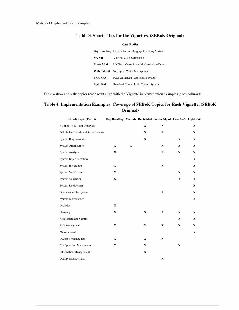
Matrix of Implementation Examples 4
Table 3. Short Titles for the Vignettes. (SEBoK Original)
Case Studies
Bag Handling Denver Airport Baggage Handling System
VA Sub Virginia Class Submarine
Route Mod UK West Coast Route Modernisation Project
Water Mgmt Singapore Water Management
FAA AAS FAA Advanced Automation System
Light Rail Standard Korean Light Transit System
Table 4 shows how the topics (each row) align with the Vignette implementation examples (each column):
Table 4. Implementation Examples. Coverage of SEBoK Topics for Each Vignette. (SEBoKOriginal)
SEBoK Topic (Part 3) Bag Handling VA Sub Route Mod Water Mgmt FAA AAS Light Rail
Business or Mission Analysis X X X
Stakeholder Needs and Requirements X X X
System Requirements X X X
System Architecture X X X X X
System Analysis X X X X
System Implementation X
System Integration X X X
System Verification X X X
System Validation X X X
System Deployment X
Operation of the System X X
System Maintenance X
Logistics X
Planning X X X X X
Assessment and Control X X
Risk Management X X X X X
Measurement X
Decision Management X X X
Configuration Management X X X
Information Management X
Quality Management X
Matrix of Implementation Examples 5
References
Works CitedNone.
Primary ReferencesNone.
Additional ReferencesNone.
< Previous Article | Parent Article | Next Article >SEBoK v. 1.4 released 29 June 2015
SEBoK DiscussionPlease provide your comments and feedback on the SEBoK below. You will need to log in to DISQUS using anexisting account (e.g. Yahoo, Google, Facebook, Twitter, etc.) or create a DISQUS account. Simply type yourcomment in the text field below and DISQUS will guide you through the login or registration steps. Feedback will bearchived and used for future updates to the SEBoK. If you provided a comment that is no longer listed, that commenthas been adjudicated. You can view adjudication for comments submitted prior to SEBoK v. 1.0 at SEBoK Reviewand Adjudication. Later comments are addressed and changes are summarized in the Letter from the Editor andAcknowledgements and Release History.
If you would like to provide edits on this article, recommend new content, or make comments on the SEBoKas a whole, please see the SEBoK Sandbox [1].
ENCODED_CONTENTMTIwODgPGRpdiBpZD0iZGlzcXVzX3RocmVhZCI+PC9kaXY+CjxzY3JpcHQgdHlwZT0idGV4dC9qYXZhc2NyaXB0Ij4KICAgIC8qICogKiBDT05GSUdVUkFUSU9OIFZBUklBQkxFUzogRURJVCBCRUZPUkUgUEFTVElORyBJTlRPIFlPVVIgV0VCUEFHRSAqICogKi8KICAgIHZhciBkaXNxdXNfc2hvcnRuYW1lID0gJ3NlYm9rd2lraTEwJzsgLy8gcmVxdWlyZWQ6IHJlcGxhY2UgZXhhbXBsZSB3aXRoIHlvdXIgZm9ydW0gc2hvcnRuYW1lCiAgICB2YXIgZGlzcXVzX2lkZW50aWZpZXIgPSAnTWF0cml4IG9mIEltcGxlbWVudGF0aW9uIEV4YW1wbGVzJzsgICAgdmFyIGRpc3F1c191cmwgPSAnaHR0cDovL3NlYm9rd2lraS5vcmcvZHJhZnQvTWF0cml4X29mX0ltcGxlbWVudGF0aW9uX0V4YW1wbGVzJzsKICAgIC8qICogKiBET04nVCBFRElUIEJFTE9XIFRISVMgTElORSAqICogKi8KICAgIChmdW5jdGlvbigpIHsKICAgICAgICB2YXIgZHNxID0gZG9jdW1lbnQuY3JlYXRlRWxlbWVudCgnc2NyaXB0Jyk7IGRzcS50eXBlID0gJ3RleHQvamF2YXNjcmlwdCc7IGRzcS5hc3luYyA9IHRydWU7CiAgICAgICAgZHNxLnNyYyA9ICdodHRwOi8vJyArIGRpc3F1c19zaG9ydG5hbWUgKyAnLmRpc3F1cy5jb20vZW1iZWQuanMnOwogICAgICAgIChkb2N1bWVudC5nZXRFbGVtZW50c0J5VGFnTmFtZSgnaGVhZCcpWzBdIHx8IGRvY3VtZW50LmdldEVsZW1lbnRzQnlUYWdOYW1lKCdib2R5JylbMF0pLmFwcGVuZENoaWxkKGRzcSk7CiAgICB9KSgpOwo8L3NjcmlwdD4KPG5vc2NyaXB0PlBsZWFzZSBlbmFibGUgSmF2YVNjcmlwdCB0byB2aWV3IHRoZSA8YSBocmVmPSJodHRwOi8vZGlzcXVzLmNvbS8/cmVmX25vc2NyaXB0Ij5jb21tZW50cyBwb3dlcmVkIGJ5IERpc3F1cy48L2E+PC9ub3NjcmlwdD4KPGEgaHJlZj0iaHR0cDovL2Rpc3F1cy5jb20iIGNsYXNzPSJkc3EtYnJsaW5rIj5ibG9nIGNvbW1lbnRzIHBvd2VyZWQgYnkgPHNwYW4gY2xhc3M9ImxvZ28tZGlzcXVzIj5EaXNxdXM8L3NwYW4+PC9hPg==END_ENCODED_CONTENT

Case Studies 6
Case StudiesSystems engineering principles described in the Systems Engineering Body of Knowledge (SEBoK) Parts 1-6 areillustrated in Part 7, Systems Engineering Implementation Examples. These examples describe the application ofsystems engineering practices, principles, and concepts in real settings. These systems engineering examples can beused to improve the practice of systems engineering by illustrating to students and practitioners the benefits ofeffective practice and the risks of poor practice. The SEBoK systems engineering implementation examples aregrouped in two categories, Case Studies (glossary) and Vignettes (glossary). Case studies reference cases that havealready been published by external sources in the existing literature. Vignettes are short wiki articles writtenspecifically for the SEBoK.
List of Case StudiesThe following case studies are included:•• Successful Business Transformation within a Russian Information Technology Company•• Federal Aviation Administration Next Generation Air Transportation System•• How Lack of Information Sharing Jeopardized the NASA/ESA Cassini/Huygens Mission to Saturn•• Hubble Space Telescope Case Study•• Global Positioning System Case Study•• Medical Radiation Case Study•• FBI Virtual Case File System Case Study•• MSTI Case Study•• Next Generation Medical Infusion Pump Case Study•• Design for Maintainability•• Complex Adaptive Operating System
Value of Case StudiesCase studies have been used for decades in medicine, law, and business to help students learn fundamentals and tohelp practitioners improve their practice. A Matrix of Implementation Examples is used to show the alignment ofsystems engineering case studies to specific areas of the SEBoK. This matrix is intended to provide linkages betweeneach implementation example to the discussion of the systems engineering principles illustrated. The selection ofcase studies cover a variety of sources, domains, and geographic locations. Both effective and ineffective use ofsystems engineering principles are illustrated.The number of publicly available systems engineering case studies is growing. Case studies that highlight theaerospace domain are more prevalent, but there is a growing number of examples beyond this domain.The United States Air Force Center for Systems Engineering (AF CSE) has developed a set of case studies "tofacilitate learning by emphasizing the long-term consequences of the systems engineering/programmatic decisionson cost, schedule, and operational effectiveness." (USAF Center for Systems Engineering 2011) The AF CSE isusing these cases to enhance SE curriculum. The cases are structured using the Friedman-Sage framework (Friedmanand Sage 2003; Friedman and Sage 2004, 84-96), which decomposes a case into contractor, government, and sharedresponsibilities in the following nine concept areas:1.1. Requirements Definition and Management2.2. Systems Architecture Development3.3. System/Subsystem Design4.4. Verification/Validation5.5. Risk Management
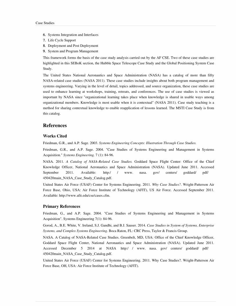
Case Studies 7
6.6. Systems Integration and Interfaces7.7. Life Cycle Support8.8. Deployment and Post Deployment9.9. System and Program ManagementThis framework forms the basis of the case study analysis carried out by the AF CSE. Two of these case studies arehighlighted in this SEBoK section, the Hubble Space Telescope Case Study and the Global Positioning System CaseStudy.The United States National Aeronautics and Space Administration (NASA) has a catalog of more than fiftyNASA-related case studies (NASA 2011). These case studies include insights about both program management andsystems engineering. Varying in the level of detail, topics addressed, and source organization, these case studies areused to enhance learning at workshops, training, retreats, and conferences. The use of case studies is viewed asimportant by NASA since "organizational learning takes place when knowledge is shared in usable ways amongorganizational members. Knowledge is most usable when it is contextual" (NASA 2011). Case study teaching is amethod for sharing contextual knowledge to enable reapplication of lessons learned. The MSTI Case Study is fromthis catalog.
References
Works CitedFriedman, G.R., and A.P. Sage. 2003. Systems Engineering Concepts: Illustration Through Case Studies.
Friedman, G.R., and A.P. Sage. 2004. "Case Studies of Systems Engineering and Management in SystemsAcquisition." Systems Engineering. 7 (1): 84-96.NASA. 2011. A Catalog of NASA-Related Case Studies. Goddard Space Flight Center: Office of the ChiefKnowledge Officer, National Aeronautics and Space Administration (NASA). Updated June 2011. AccessedSeptember 2011. Available: http:/ / www. nasa. gov/ centers/ goddard/ pdf/450420main_NASA_Case_Study_Catalog. pdf.United States Air Force (USAF) Center for Systems Engineering. 2011. Why Case Studies?. Wright-Patterson AirForce Base, Ohio, USA: Air Force Institute of Technology (AFIT), US Air Force. Accessed September 2011.Available: http:/ / www. afit. edu/ cse/ cases. cfm.
Primary ReferencesFriedman, G., and A.P. Sage. 2004. "Case Studies of Systems Engineering and Management in SystemsAcquisition". Systems Engineering 7(1): 84-96.Gorod, A., B.E. White, V. Ireland, S.J. Gandhi, and B.J. Sauser. 2014. Case Studies in System of Systems, EnterpriseSystems, and Complex Systems Engineering. Boca Raton, FL: CRC Press, Taylor & Francis Group.NASA. A Catalog of NASA-Related Case Studies. Greenbelt, MD, USA: Office of the Chief Knowledge Officer,Goddard Space Flight Center, National Aeronautics and Space Administration (NASA). Updated June 2011.Accessed December 5 2014 at NASA http:/ / www. nasa. gov/ centers/ goddard/ pdf/450420main_NASA_Case_Study_Catalog. pdf.United States Air Force (USAF) Center for Systems Engineering. 2011. Why Case Studies?. Wright-Patterson AirForce Base, OH, USA: Air Force Institute of Technology (AFIT).

Case Studies 8
Additional ReferencesNone.
< Previous Article | Parent Article | Next Article >SEBoK v. 1.4 released 29 June 2015
SEBoK DiscussionPlease provide your comments and feedback on the SEBoK below. You will need to log in to DISQUS using anexisting account (e.g. Yahoo, Google, Facebook, Twitter, etc.) or create a DISQUS account. Simply type yourcomment in the text field below and DISQUS will guide you through the login or registration steps. Feedback will bearchived and used for future updates to the SEBoK. If you provided a comment that is no longer listed, that commenthas been adjudicated. You can view adjudication for comments submitted prior to SEBoK v. 1.0 at SEBoK Reviewand Adjudication. Later comments are addressed and changes are summarized in the Letter from the Editor andAcknowledgements and Release History.
If you would like to provide edits on this article, recommend new content, or make comments on the SEBoKas a whole, please see the SEBoK Sandbox [1].
ENCODED_CONTENTMjAwMDIPGRpdiBpZD0iZGlzcXVzX3RocmVhZCI+PC9kaXY+CjxzY3JpcHQgdHlwZT0idGV4dC9qYXZhc2NyaXB0Ij4KICAgIC8qICogKiBDT05GSUdVUkFUSU9OIFZBUklBQkxFUzogRURJVCBCRUZPUkUgUEFTVElORyBJTlRPIFlPVVIgV0VCUEFHRSAqICogKi8KICAgIHZhciBkaXNxdXNfc2hvcnRuYW1lID0gJ3NlYm9rd2lraTEwJzsgLy8gcmVxdWlyZWQ6IHJlcGxhY2UgZXhhbXBsZSB3aXRoIHlvdXIgZm9ydW0gc2hvcnRuYW1lCiAgICB2YXIgZGlzcXVzX2lkZW50aWZpZXIgPSAnQ2FzZSBTdHVkaWVzJzsgICAgdmFyIGRpc3F1c191cmwgPSAnaHR0cDovL3NlYm9rd2lraS5vcmcvZHJhZnQvQ2FzZV9TdHVkaWVzJzsKICAgIC8qICogKiBET04nVCBFRElUIEJFTE9XIFRISVMgTElORSAqICogKi8KICAgIChmdW5jdGlvbigpIHsKICAgICAgICB2YXIgZHNxID0gZG9jdW1lbnQuY3JlYXRlRWxlbWVudCgnc2NyaXB0Jyk7IGRzcS50eXBlID0gJ3RleHQvamF2YXNjcmlwdCc7IGRzcS5hc3luYyA9IHRydWU7CiAgICAgICAgZHNxLnNyYyA9ICdodHRwOi8vJyArIGRpc3F1c19zaG9ydG5hbWUgKyAnLmRpc3F1cy5jb20vZW1iZWQuanMnOwogICAgICAgIChkb2N1bWVudC5nZXRFbGVtZW50c0J5VGFnTmFtZSgnaGVhZCcpWzBdIHx8IGRvY3VtZW50LmdldEVsZW1lbnRzQnlUYWdOYW1lKCdib2R5JylbMF0pLmFwcGVuZENoaWxkKGRzcSk7CiAgICB9KSgpOwo8L3NjcmlwdD4KPG5vc2NyaXB0PlBsZWFzZSBlbmFibGUgSmF2YVNjcmlwdCB0byB2aWV3IHRoZSA8YSBocmVmPSJodHRwOi8vZGlzcXVzLmNvbS8/cmVmX25vc2NyaXB0Ij5jb21tZW50cyBwb3dlcmVkIGJ5IERpc3F1cy48L2E+PC9ub3NjcmlwdD4KPGEgaHJlZj0iaHR0cDovL2Rpc3F1cy5jb20iIGNsYXNzPSJkc3EtYnJsaW5rIj5ibG9nIGNvbW1lbnRzIHBvd2VyZWQgYnkgPHNwYW4gY2xhc3M9ImxvZ28tZGlzcXVzIj5EaXNxdXM8L3NwYW4+PC9hPg==END_ENCODED_CONTENT
Successful Business Transformation within aRussian Information Technology CompanyThis article describes a successful business transformation of an information technology enterprise. The topic may beof particular interest, especially because this transformation was accomplished by a Russian company during therepublic’s fast growing economic recovery.For addition information, refer to the closely related topics of Enabling Businesses and Enterprises and EnterpriseSystems Engineering.
BackgroundIn 2001, the top management of the IBS company [1] in Moscow initiated a fundamental transformation to changethe company’s strategy and business model. The company was one of the biggest Russian information technology(IT) systems integrators at that time, with about 900 employees. Annual revenues of about $80M were mainlygenerated by information technology (IT) infrastructure projects (complex computing systems, multi-servicenetworks, etc.) and hardware and software distribution. The transformation of the company to form new capabilitiesin IT services and the associated consulting area is the main topic in the case study.During the transformation period (from 2001 to the present) IBS was represented as a set of autonomous businessunits (BUs), called constituent systems, which are virtual, independent businesses with the following characteristics.•• Profit and loss reporting was required for each BU according to management accounting procedures•• BU management established and independently conducted human resources, technology, and product policy• A centralized back-office was organized to provide supporting functions for each BU. Thus, BUs do not have
back-offices; they rely on and “pay” a corporate governing center (CGC) for these services.

Successful Business Transformation within a Russian Information Technology Company 9
A thorough Enterprise System (glossary) (ES) transformation was executed as a set of activities: mission analysisand capabilities decomposition, business architecting, planning of the project program, and implementation of thenew business model.Before and after transformation IBS was an exemplar directed System of Systems (SoS) (glossary): the constituentBUs are autonomous but their operations are supervised by CGC. At the same time IBS also has significant featuresof an acknowledged SoS: the constituent BUs retain their independent development and sustainment approaches, andchanges in the company are based on collaboration between the CGC and each constituent; even operations of BUsare not controlled but only supervised/governed by the CGC through “soft” recommendations and coordination.IBS was a quite mature ES before the transformation, and it was thoroughly upgraded to form new capabilities of thewhole system as well as of the constituents.
PurposeIn 2000-2001 IBS management forecasted considerable growth of the Russian IT services and consulting marketbased on the fast growing Russian economy, which was rapidly recovering from the national financial crisis of 1998.The largest corporations started overseas expansion and borrowed from international markets to finance this growth.IBS predicted corresponding growth in the complexity of business processes and their associated software andhardware systems all of which should require more consulting and IT services.Based on this forecast, management established a strategy goal to double the share of IT services and consultingfrom 25% to 50% over one year; further growth in this business was planned as a long term trend.The consulting and IT services business is very complex technologically and organizationally and dramaticallydiffers from IBS’s former infrastructure focus. Thus, a fundamental transformation was required, and it was executedduring 2002.Initially detected problems appeared as expenditures exceeding resources, slow delivery of the projects andreworking. Later, as it was expected, new problems appeared, for example, disinterest of BUs’ managers indeveloping new technologies or raising qualified employees’ motivation. All those problems were solved duringtransformation and during further development.The first step of the transformation included strategic analysis and mission-to-capabilities decomposition. Five majorcapability groups to be focused on were defined. The groups and exemplar capabilities for each group arerepresented at Figure 1.

Successful Business Transformation within a Russian Information Technology Company 10
Figure 1. Mission and capabilities desired. (Belov 2014) Reprinted with permission of Taylor and Francis, New York, NY. All other rights arereserved by the copyright owner.
ChallengesAll main challenges were caused by knowledge/information deficit described by three factors listed as a, b, and cbelow.a. The lack of experience in enterprise transformation (and capability based approaches, even the lack of anytextbooks or guides in those areas) was the major challenge which IBS management faced. The task to be solved didnot devolve to organizational changes (which was a well-developed and described area), but was appropriatelyallocated to Enterprise System (glossary) or system of systems (SoS) engineering. In spite of the lack of experience itwas decided to prepare and execute the transformation based on the company’s employees without involving externalconsultants. The following arguments supported the decision.• The task to be solved was not typical, so there weren’t widely used and well tested algorithms or methods, and
there weren’t a lot of consultants experienced in exactly what was needed. So only consultants with generalexperience (strategy consulting, organizational management) might be hired.
•• The Russian consulting industry in 2001-2002 was not well developed, so only foreign professionals wereavailable. But foreign consultants would have needed to study Russian specifics; such study would have undulylengthened the duration and increased the cost of the transformation.
•• A joint transformation team would have to be formed, and IBS employees would have to be involved:management would have to be interviewed and be involved in decision making. In any case all employees wouldhave to participate in change implementations.
•• External consultants are not stakeholders; so their level of interest in helping to achieve success might not be veryhigh, and their output also might not be outstanding.
•• Unwillingness to open professional secrets and other intellectual property issues to direct competitors were otherfactors that prevented hiring of external consultants.
Thus, the final decision was to execute the transformation without involvement of external consulting resources. Aspecial BoU responsible for business processes development was established and an agile (glossary) programmanagement approach was applied to handle challenges and to pursue opportunities as well as to mitigate risks.

Successful Business Transformation within a Russian Information Technology Company 11
b. A very high complexity IBS as an enterprise system or SoS. Management recognized that the company and itsenvironment was very complex, with a lot different agents, many constituents, and countless relationships; and thatan enterprise system or SoS might become even more complex after transformation. This complexification happenedas the company became an “extended enterprise”, the governing hierarchies weakened, and the demand for moresophisticated relationships increased.c. The risk of mistaken forecast of IT market development. The expected growth of the consulting and servicesmarket might have not happened. In this case the transformation would have been senseless. This challengegenerated additional emotional stress for management.
Systems Engineering PracticesThe SE task of the transformation was established in the form: to develop required capabilities for an enterprisesystem or SoS – IBS company. The SE process might be represented by the following specific IBS interpretation ofthe Vee (V) Model (glossary) (“V model”) with Stages 1 through 7 (Figure 2).Initially (Stage 1) the mission was translated to capabilities (Figure 1); “understanding the constituent systems (BUs)and their relationships” was executed. The transformation team found that capabilities might not be directlytranslated to any business-agent. Neither BUs (they serves as resource pools), nor projects (being temporalelements), nor employees (each of them have a finite set of skills, experience, responsibilities, etc.) might realizenecessary capabilities.Realizing this (Stage 2) transformation team defined several key areas (Figure 2) of company’s operations oractivities which were supposed to be changed to form new capabilities. Appropriate artifacts (procedures, guides,documents, software systems) to support new capabilities were developed and implemented for each of the areas;these new assets formed exactly the corporate infrastructure of new business model.

Successful Business Transformation within a Russian Information Technology Company 12
Figure 2. “V model” of systems engineering process of the transformation. (Belov 2014) Reprinted with permission of Taylor andFrancis, New York, NY. All other rights are reserved by the copyright owner..
For each new and legacy system (Stage 3) a set of conceptual design documents was developed, describingapproaches, polices, processes, and procedures. The entire set of documents formed the business architecturedescription of the company. The description connected all key areas and defined a target operation model of thecompany after transformation. This architecture represented multiple views of the IBS company, and thus aptlyreflected its enterprise system or SoS nature.Somewhat in contrast with the conventional linear systems engineering approach advocated by the V model, Stages4-6 were conducted in parallel to save time and resources. The company’s performance (Stage 7) should bemonitored based on indicators’ measurements, and improvements should be developed and implemented (arrowsfrom Stage 3 to Stage 7). Such iterations have been executed in practice not only during transformation but also later,when procedures, guides and the whole systems were updated.Integration and interoperability of the new systems required a thorough integration of parallel development jobs. Sojoint workgroups were formed of the employees at the level of low officers; and CGC played the role of integratedworkgroup at the management level. Actually, multi-level integrated workgroups were formed.The major complexity and risks derived from the challenges described above.The transformation team developed and used an approach which is very similar to the agile development approach toaddress those risks. The following principles were used to manage the portfolio of projects in case of uncertainty anddeficit of knowledge.•• Form solutions as fast as possible (but not necessarily with pure quality) to test them in practice faster.•• Recognizing failures are unavoidable, perceive them readily and react rationally.•• In case of failure analyze the situation and find a new solution, generate changes, and update the plan.•• Work in parallel, verifying and coordinating intermediate results.

Successful Business Transformation within a Russian Information Technology Company 13
•• The schedule might be corrected and updated but should not be jeopardized by improper execution.•• Formulate and test the most critical and most questionable solutions at first.•• Start from pilot area and then expand to embrace the entire scope.• Use high quality monitoring and a “manual control mode” for piloting and testing developing solutions but not
additional aspects to limit waste of the resources.Following those principles including a very strong discipline of execution, a high level of the sponsorship andall-employee involvement enabled the transformation to be completed on time without hiring consultants whilekeeping and developing on-going business.
Lessons learnedIBS’s accomplishment of the mission was the major result of ES transformation. Shareholders and managementrecognized that new capabilities had been formed, that the company could deliver consulting and services, sell andexecute complex projects, manage consulting resources effectively, measure its performance, and plan and forecastfinancial results. Created capabilities are emergent in some sense because they are not directly related to concreteconstituents (BUs, or employee, or projects) but are realized by means of integrated end-to-end processes andfunctions, which are executed in the projects by employees.The systems organization did not dramatically change during transformation; “visible structure” was not practicallychanged: no new types of business-agents appeared, existing types did not change much. Those factors did not createnew capabilities. Target capabilities were formed as the result of development and implementation of, it would seem,auxiliary and supporting tools – new capabilities support systems. New capabilities were formed mainly by thechanges in the intangible areas of governing media, corporate culture, relations, and personnel competences; as wellas by the creation of new capabilities support systems; without considerable changes in main company’sbusiness-agents. (Refer to Figure 3.)The main challenges which management faced (the lack of experience and the ambiguity of market growth forecast)made the uncertainty factor the critical one in the transformation.
What Worked and Why?An agile program management in general demonstrated its efficiency and applicability to “soft and uncertain” tasks,especially in triggering a pre-established process for dealing with unexpected events; the main aspects of theapproach are:•• Senior and credible sponsors•• Multi-level integrated project team(s)•• Open information exchange•• Partnership and collaboration•• Proactive and motivated parties and constituents•• Creative and innovative way of development

Successful Business Transformation within a Russian Information Technology Company 14
Figure 3. The results of transformation. (Belov 2014) Reprinted with permission of Taylor and Francis, NewYork, NY. All other rights are reserved by the copyright owner.
•• Prioritizing and focusing on the most ambiguous elements of systems design•• Piloting and subsequent roll-out in realistic environments•• Strong project scope control• Strong project execution control – time schedule and resources control.
What Did Not Work and Why?Perhaps corporate knowledge base development was the only more or less serious task which was not solved intransformation. The company’s management understood the usefulness of knowledge accumulation and furtheralienation from the carriers in utilizing their business knowledge, so the goal of developing their own knowledgebase was established. Special database and software system were developed with appropriate guides, reports and datacollection forms; but formal regulation to fill in engineering knowledge accumulation templates did not work.However later this issue progressed quite naturally and simply: common folders were established to store projectdata in free formats. Such folders served to accumulate knowledge but in flat, unstructured form.

Successful Business Transformation within a Russian Information Technology Company 15
Best Practices and Replication ProspectsThe following methods and approaches were proven as efficient and convenient in transformation.1.1. Capability based development approach and capability based architecting might be recommended to be utilized in
creation and transformation of an enterprise system or SoS. These focused all efforts on the required capabilitiesand involved very important relations from mission to capabilities and to functions in systems engineeringprocess.
2. An agile program management might be used to solve a wide range of fuzzy and ambiguous problems ofdifferent scale in the areas of SE, ES engineering, SoS engineering where there is much uncertainty and lacks ofexpertise and proven methods or algorithms to solve them. The combination of “soft” and very creative designswith strong planning and progress control is the crucial foundation of this approach.
3.3. Key area definition and development appropriate to generating new capabilities for support systems (coreconsulting and services technologies, project implementation systems, systems for business unit growth,management accounting systems, motivation systems). Precisely defining these areas and developing integratedsystems in these areas might be considered as quite common for application to a broader group of ESs.
References
Works CitedBelov, M. 2014. "IBS Group, Eastern European ITS Services – Capability-Based Development for BusinessTransformation," in Case Studies in System of Systems, Enterprise Systems, and Complex Systems Engineering,edited by A. Gorod et al. Boca Raton, FL, USA: CRC Press, Taylor & Francis Group.
Primary ReferencesBelov, M. 2014. “IBS Group, Eastern European ITS Services – Capability-Based Development for BusinessTransformation.” Case Studies in System of Systems, Enterprise Systems, and Complex Systems Engineering.Gorod, A., B. E. White, V. Ireland, S. J. Gandhi, and B. J. Sauser. Boca Raton, FL: CRC Press, Taylor & FrancisGroup. Scheduled for publication in July 2014. http:/ / www. taylorandfrancis. com/ books/ details/ 9781466502390/.
Additional ReferencesNone
< Previous Article | Parent Article | Next Article>SEBoK v. 1.4 released 29 June 2015
SEBoK DiscussionPlease provide your comments and feedback on the SEBoK below. You will need to log in to DISQUS using anexisting account (e.g. Yahoo, Google, Facebook, Twitter, etc.) or create a DISQUS account. Simply type yourcomment in the text field below and DISQUS will guide you through the login or registration steps. Feedback will bearchived and used for future updates to the SEBoK. If you provided a comment that is no longer listed, that commenthas been adjudicated. You can view adjudication for comments submitted prior to SEBoK v. 1.0 at SEBoK Reviewand Adjudication. Later comments are addressed and changes are summarized in the Letter from the Editor andAcknowledgements and Release History.
If you would like to provide edits on this article, recommend new content, or make comments on the SEBoKas a whole, please see the SEBoK Sandbox [1].

Successful Business Transformation within a Russian Information Technology Company 16
ENCODED_CONTENTMzg5NzcPGRpdiBpZD0iZGlzcXVzX3RocmVhZCI+PC9kaXY+CjxzY3JpcHQgdHlwZT0idGV4dC9qYXZhc2NyaXB0Ij4KICAgIC8qICogKiBDT05GSUdVUkFUSU9OIFZBUklBQkxFUzogRURJVCBCRUZPUkUgUEFTVElORyBJTlRPIFlPVVIgV0VCUEFHRSAqICogKi8KICAgIHZhciBkaXNxdXNfc2hvcnRuYW1lID0gJ3NlYm9rd2lraTEwJzsgLy8gcmVxdWlyZWQ6IHJlcGxhY2UgZXhhbXBsZSB3aXRoIHlvdXIgZm9ydW0gc2hvcnRuYW1lCiAgICB2YXIgZGlzcXVzX2lkZW50aWZpZXIgPSAnU3VjY2Vzc2Z1bCBCdXNpbmVzcyBUcmFuc2Zvcm1hdGlvbiB3aXRoaW4gYSBSdXNzaWFuIEluZm9ybWF0aW9uIFRlY2hub2xvZ3kgQ29tcGFueSc7ICAgIHZhciBkaXNxdXNfdXJsID0gJ2h0dHA6Ly9zZWJva3dpa2kub3JnL2RyYWZ0L1N1Y2Nlc3NmdWxfQnVzaW5lc3NfVHJhbnNmb3JtYXRpb25fd2l0aGluX2FfUnVzc2lhbl9JbmZvcm1hdGlvbl9UZWNobm9sb2d5X0NvbXBhbnknOwogICAgLyogKiAqIERPTidUIEVESVQgQkVMT1cgVEhJUyBMSU5FICogKiAqLwogICAgKGZ1bmN0aW9uKCkgewogICAgICAgIHZhciBkc3EgPSBkb2N1bWVudC5jcmVhdGVFbGVtZW50KCdzY3JpcHQnKTsgZHNxLnR5cGUgPSAndGV4dC9qYXZhc2NyaXB0JzsgZHNxLmFzeW5jID0gdHJ1ZTsKICAgICAgICBkc3Euc3JjID0gJ2h0dHA6Ly8nICsgZGlzcXVzX3Nob3J0bmFtZSArICcuZGlzcXVzLmNvbS9lbWJlZC5qcyc7CiAgICAgICAgKGRvY3VtZW50LmdldEVsZW1lbnRzQnlUYWdOYW1lKCdoZWFkJylbMF0gfHwgZG9jdW1lbnQuZ2V0RWxlbWVudHNCeVRhZ05hbWUoJ2JvZHknKVswXSkuYXBwZW5kQ2hpbGQoZHNxKTsKICAgIH0pKCk7Cjwvc2NyaXB0Pgo8bm9zY3JpcHQ+UGxlYXNlIGVuYWJsZSBKYXZhU2NyaXB0IHRvIHZpZXcgdGhlIDxhIGhyZWY9Imh0dHA6Ly9kaXNxdXMuY29tLz9yZWZfbm9zY3JpcHQiPmNvbW1lbnRzIHBvd2VyZWQgYnkgRGlzcXVzLjwvYT48L25vc2NyaXB0Pgo8YSBocmVmPSJodHRwOi8vZGlzcXVzLmNvbSIgY2xhc3M9ImRzcS1icmxpbmsiPmJsb2cgY29tbWVudHMgcG93ZXJlZCBieSA8c3BhbiBjbGFzcz0ibG9nby1kaXNxdXMiPkRpc3F1czwvc3Bhbj48L2E+END_ENCODED_CONTENT
References[1] http:/ / www. en. ibs. ru/
Federal Aviation Administration Next GenerationAir Transportation SystemThis article describes a massive undertaking to modernize the air traffic management enterprise (glossary). The topicmay be of particular interest to those involved in air transportation whether in connection with their careers or aspilots or passengers on airplanes. For addition information, refer to the closely related topics of Enabling Businessesand Enterprises and Enterprise Systems Engineering.
BackgroundThis case study presents the Systems Engineering (glossary) and Enterprise Systems Engineering (ESE) (glossary)efforts in the Next Generation (NextGen) Air Transportation Systems by the Federal Aviation Administration (FAA2008). NextGen is an unprecedented effort by multiple U.S. federal organizations to transform the U.S. airtransportation infrastructure (glossary) from a fragmented ground-based navigation system to a net-centricsatellite-based navigation system. This project is unique to the FAA because of its large scale, the huge number ofstakeholder(s) involved, the properties of the system of interest, and the revolutionary changes required in the U.S.Air Transportation Network (U.S. ATN) enterprise.A Sociotechnical System (glossary) like the U.S. ATN is a “large-scale [system] in which humans and technicalconstituents are interacting, adapting, learning, and coevolving. In [such] systems technical constraints and socialand behavioral complexity are of essential essence”. (Darabi and Mansouri 2014). Therefore, in order to understandchanges in the U.S. ATN it was seen as necessary to view it through a lens of evolutionary adaptation rather thanrigid systems design. The U.S. ATN serves both military and commercial aircraft with its 19,782 airports, including547 are commercial airports. Nineteen major airlines, with more than a billion dollars in annual total revenue, alongwith other 57 national and regional airlines, transport 793 million passengers and realize 53 billion revenueton-miles.The Air Traffic Organization (ATO) is responsible for ensuring aircraft navigation in the U.S. National Air Space(NAS) system using a five-layer architecture (glossary). Each aircraft goes through different layers and possiblyvarious zones of this architecture as it takes off from an airport until its lands at another airport (Donohue andZellweger 2001). However, this architecture is fragmented and many issues are raised: an airplane’s path through itsroute is not optimized, and the path may change its direction from one zone to another, the destination airport’scapacity is limited by the current regulations of minimum aircraft separation distance due to navigation limitations,the real-time weather information is not integrated into the system, and communications are mainly voice-based, etc.In NextGen major changes to the U.S. ATN design are planned. As already stated, the navigation system will bechanged from ground-based communication to satellite-based navigation. The current fragmented architecture willbe integrated into a seamless net-centric information system in which the digital communication will replace thecurrent voice communications. Moreover, weather information will be assimilated into decision making andplanning across the system.

Federal Aviation Administration Next Generation Air Transportation System 17
PurposeThe FAA’s purpose is “to provide the safest, most efficient aerospace system in the world”. Toward this end theNextGen project is aimed at enhancing the U.S.’s leadership position in air transportation.During the last three decades the demand for air transportation shows exponential growth. In just one decade from1995 to 2005 this demand showed a 44% percent increase. Therefore, the change in infrastructure was inevitable.Moreover, 9/11 attacks on the U.S. ATN emphasized this need for change. The combination of a requirement for asafer and more secure network and increasing demand was the motivation for President Bush to enact the Vision100-Century of Aviation Reauthorization Act on 2003. A major part of this Act was to revolutionize the U.S. ATNby means of the NextGen project. The first integration plan of the project was released in 2004, and the project isestimated to continue until 2025.The demand behavior of the U.S. ATN shows diverse degrees of congestion among airports. Although there aremultitudes of airports in the system, the top 35 most congested airports carried more than 60% of the total trafficconsistently during the period of 2000 to 2008. Because the growth of the network demand is not proportional, thedemand in congested airports will be even higher.A study by the Joint Planning and Development Office (JPDO) shows that flight delays in the current network willcause $6.5 billion of economic loss until 2015, and $19.6 billion until 2025. By implementing NextGen the delaysare estimated to be reduced by 38% until 2020. Moreover, aircraft CO2 emissions are a major part of environmentalpollution in crowded cities; these will be reduced by 14 million metric tons by 2020. The current level of jet fuelusage is also a known problem because of increasing fuel prices. The NextGen project will improve fuel usage by1.4 billion gallons cumulative through 2020.NextGen is pursuing multiple goals to retain the U.S. leadership in aviation, to expand the U.S. ATN capacity, tocontinue to ensure safety, to increase environment protection, to help ensure national air defense, all generallyhelping to increase the nation’s security (JPDO 2007a).Eight general capabilities are defined in conducting this mission: (1) network-enabled information access, (2)performance-based operations and services, (3) weather assimilated into decision making, (4) layered adaptivesecurity, (5) positioning, navigation, and timing (PNT) services, (6) aircraft trajectory-based operations (TBO), (7)equivalent visual operations (EVO), and (8) super-density arrival/departure operations.To create the desired capabilities, general areas of transformations are defined as air traffic management operations,airport operations and infrastructure services, net-centric infrastructure services, shared situational awarenessservices, layered and adaptive security services, environmental management services, safety management services,and performance management services. The detailed changes in each area are discussed in Concept of Operations forNextGen (JPDO 2007a).
ChallengesAn instructive part of this case study is observing evolution in understanding challenges from initial steps of theproject through current efforts for delivering it. As an overall conclusion, the perspective on challenges shifted fromtechnical problems and intra-organizational issues to more enterprise-wide issues.The NextGen Implementation Plan 2008 discussed the following challenges (FAA 2008):•• performance analysis, to understand and assess operational capabilities•• policy, to balance responsibility between humans and automation, for environmental management processes, and
for global harmonization strategies•• acquisition workforce staffing•• environmental planning, to resolve conflicts with local environmental constraints•• security

Federal Aviation Administration Next Generation Air Transportation System 18
• transition from current ground-based navigation to automatic dependent surveillance – broadcast (ADS-B)technology.
A more recent report on Targeted NextGen Capabilities for 2025 (JPDO 2011) highlights the effect of themulti-stakeholder nature of the project on raising additional challenges. Achieving Interagency Collaboration is thefirst issue, which is important in implementing security, safety, policy making, and technological advancement.Increasing capacity, reducing delay and protecting the environment are the main three promises of the NextGenproject. However, reaching the defined high standards is not an easy task. A major part of this challenge isintegrating new technologies into legacy systems, aircraft, airports, facilities, and organizations. Airlines and generalaviation pilots resist the expense of additional avionics and communications equipment, even though it bolsters thecommon good of air travel.Maintaining airports and airspace security requires coherent and harmonious work of multiple U.S. agencies. Thecore of this challenge is not just changing the technology but also the processes, organizational structures, andenterprises to meet the new requirements of security.Moreover, the need for greater information sharing in this net-centric environment is a challenge. The current cultureof limited information sharing in which inter-organizational and intra-organizational information is strictly dividedcreates tension in a seamless information sharing infrastructure. In addition to that, the responsibility of generating,sharing, and utilizing useful information should be addressed in advance to avoid costly mistakes.Verification and validation of NextGen deliverables is a major issue. The traditional systems engineering methods ofverification and validation are tailored for testing an isolated system, while by definition a project like NextGenrequires new methodologies of verification and validation beyond the scope of one system. The knowledge andexperience of advancement in systems engineering in this area can be of priceless value for future projects.Balance between human decision-making and automation is required to ensure a correct policy for increasing trafficand safety concerns. Changes in both human resource and technological facilities are required to effectively addressthis challenge.The support of local communities is essential to facilitate development of the U.S. ATN and its physicalinfrastructure.Communication, navigation, and surveillance systems in NextGen are going through major changes in terms ofcapacity and technology. However, planning required backups for them in case of any emergency is an area ofchallenge in developing NextGen.The rise of Unmanned Aircraft Systems (UASs) provides significant opportunities for both military and commercialapplications. However, integrating them into the NAS and developing policing and strategies for safe and secure useis a concern for the revolutionized U.S. ATN.And finally realizing the benefits of NextGen is dependent on the critical mass of early adopters, similar to anytechnological advancement. Therefore, the NextGen project authority requires well-defined policies for motivatingstakeholders’ participation.
Systems Engineering PracticesThe FAA NextGen is not just a revolution of the U.S. air transportation infrastructure, but also a shift in itsenterprise. The enterprise architecture document, which is developed by JPDO, provides an overview of the desiredcapabilities (JPDO 2007b).The Enterprise Architecture (glossary) is described using Department of Defense Architecture Framework (DoDAF) and the Federal Enterprise Architecture (FEA). DoDAF is used to describe the operational aspects of the project. The three views of DoDAF, the Operational View (OV), the Systems View (SV), and the Technical Standards View (TV), are presented in the enterprise architecture document. The Overview and Summary Information (AV-1) is the formal statement about how to use the architecture, the Integrated Dictionary (AV-2) defines the terms in the
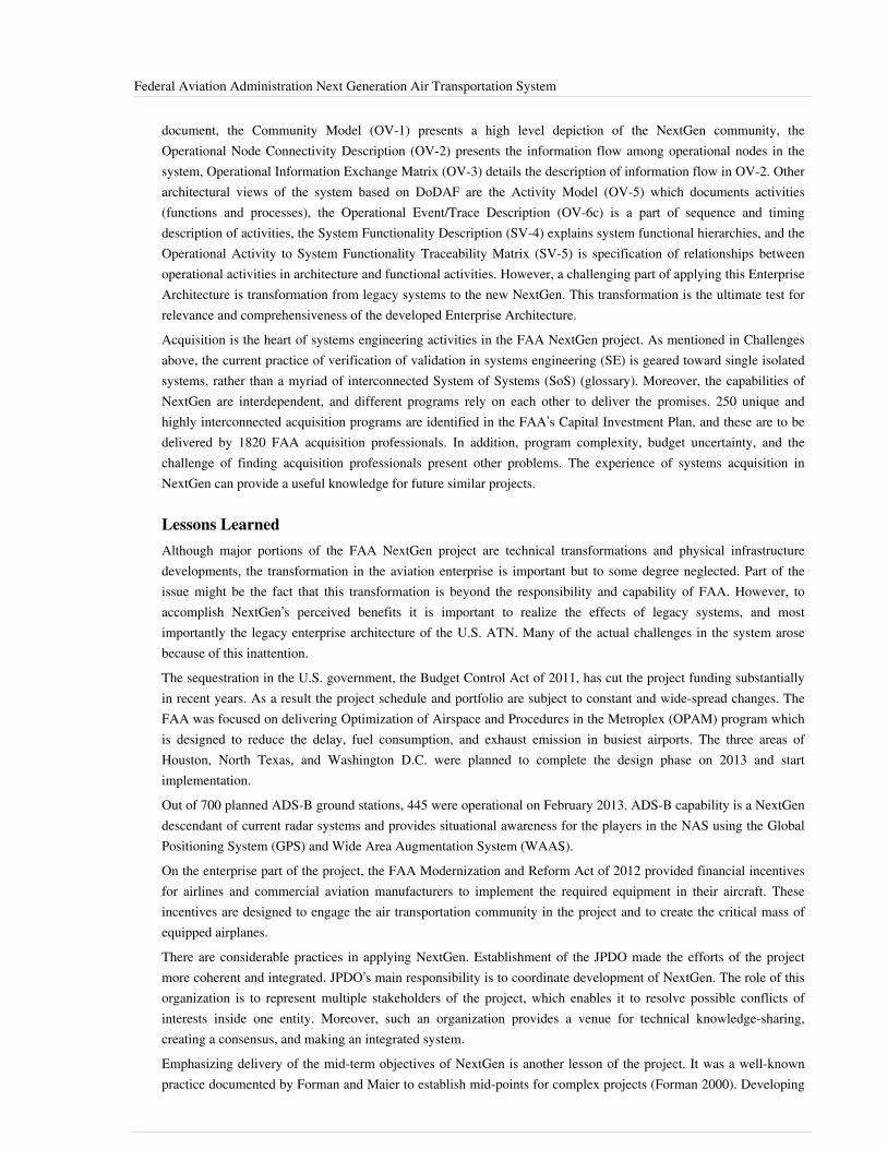
Federal Aviation Administration Next Generation Air Transportation System 19
document, the Community Model (OV-1) presents a high level depiction of the NextGen community, theOperational Node Connectivity Description (OV-2) presents the information flow among operational nodes in thesystem, Operational Information Exchange Matrix (OV-3) details the description of information flow in OV-2. Otherarchitectural views of the system based on DoDAF are the Activity Model (OV-5) which documents activities(functions and processes), the Operational Event/Trace Description (OV-6c) is a part of sequence and timingdescription of activities, the System Functionality Description (SV-4) explains system functional hierarchies, and theOperational Activity to System Functionality Traceability Matrix (SV-5) is specification of relationships betweenoperational activities in architecture and functional activities. However, a challenging part of applying this EnterpriseArchitecture is transformation from legacy systems to the new NextGen. This transformation is the ultimate test forrelevance and comprehensiveness of the developed Enterprise Architecture.Acquisition is the heart of systems engineering activities in the FAA NextGen project. As mentioned in Challengesabove, the current practice of verification of validation in systems engineering (SE) is geared toward single isolatedsystems, rather than a myriad of interconnected System of Systems (SoS) (glossary). Moreover, the capabilities ofNextGen are interdependent, and different programs rely on each other to deliver the promises. 250 unique andhighly interconnected acquisition programs are identified in the FAA’s Capital Investment Plan, and these are to bedelivered by 1820 FAA acquisition professionals. In addition, program complexity, budget uncertainty, and thechallenge of finding acquisition professionals present other problems. The experience of systems acquisition inNextGen can provide a useful knowledge for future similar projects.
Lessons LearnedAlthough major portions of the FAA NextGen project are technical transformations and physical infrastructuredevelopments, the transformation in the aviation enterprise is important but to some degree neglected. Part of theissue might be the fact that this transformation is beyond the responsibility and capability of FAA. However, toaccomplish NextGen’s perceived benefits it is important to realize the effects of legacy systems, and mostimportantly the legacy enterprise architecture of the U.S. ATN. Many of the actual challenges in the system arosebecause of this inattention.The sequestration in the U.S. government, the Budget Control Act of 2011, has cut the project funding substantiallyin recent years. As a result the project schedule and portfolio are subject to constant and wide-spread changes. TheFAA was focused on delivering Optimization of Airspace and Procedures in the Metroplex (OPAM) program whichis designed to reduce the delay, fuel consumption, and exhaust emission in busiest airports. The three areas ofHouston, North Texas, and Washington D.C. were planned to complete the design phase on 2013 and startimplementation.Out of 700 planned ADS-B ground stations, 445 were operational on February 2013. ADS-B capability is a NextGendescendant of current radar systems and provides situational awareness for the players in the NAS using the GlobalPositioning System (GPS) and Wide Area Augmentation System (WAAS).On the enterprise part of the project, the FAA Modernization and Reform Act of 2012 provided financial incentivesfor airlines and commercial aviation manufacturers to implement the required equipment in their aircraft. Theseincentives are designed to engage the air transportation community in the project and to create the critical mass ofequipped airplanes.There are considerable practices in applying NextGen. Establishment of the JPDO made the efforts of the projectmore coherent and integrated. JPDO’s main responsibility is to coordinate development of NextGen. The role of thisorganization is to represent multiple stakeholders of the project, which enables it to resolve possible conflicts ofinterests inside one entity. Moreover, such an organization provides a venue for technical knowledge-sharing,creating a consensus, and making an integrated system.Emphasizing delivery of the mid-term objectives of NextGen is another lesson of the project. It was a well-knownpractice documented by Forman and Maier to establish mid-points for complex projects (Forman 2000). Developing

Federal Aviation Administration Next Generation Air Transportation System 20
a mid-level system provides the system designers an opportunity to examine their underlying assumptions, toidentify best practices and heuristics in the context of the project, and to reapply the acquired knowledge thoroughevolutionary developments. A major shift in the policy of FAA in recent years was to focus on delivering projectmid-term objectives.There are unique characteristics of NextGen which makes it a valuable case for learning and replicating to othercomplex transformation projects of sociotechnical systems. The scale of the project for infrastructure transformationis unprecedented. The system includes legacy systems and cutting edge technology, and its performance is based ontheir coherent work. The project implementation is dependent on involved participation of multiple governmentaland commercial organizations. Moreover, this case-study provides a great investigation in enterprise governance andenterprise transformation beyond a single organization.
References
Works CitedDarabi, H.R., and M. Mansouri. 2014. "NextGen: Enterprise Transformation of the United States Air TransportNetwork," in Case Studies in System of Systems, Enterprise Systems, and Complex Systems Engineering, edited byA. Gorod et al. Boca Raton, FL, USA: CRC Press, Taylor & Francis Group.Donohue, G.L., and A.G. Zellweger. 2001. "Air Transportation Systems Engineering." American Institute ofAeronautics and Astronautics. 193 (1).FAA. 2008. FAA's NextGen Implementation Plan. Federal Aviation Administration. Washington, DC, USA.Accessed March 29, 2014. Available: http:/ / www. faa. gov/ nextgen/ media/ ng2008_implementation_plan. pdf.Forman, B. 2000. "The political process and systems architecting," in The Art of Systems Architecting, 2nd ed.,edited by M.W. Maier and E. Rechtin. Boca Raton, FL, USA: CRC Press LLC.JPDO. 2007a. Concept of operations for the next generation air transportation system. Joint Planning DevelopmentOffice. Accessed March 29, 2014. Available: http:/ / www. jpdo. gov/ library/ nextgen_v2. 0. pdf.JPDO. 2007b. Enterprise Architecture V2.0 for the Next Generation Air Transportation System. Joint Planning andDevelopment Office. Accessed March 29, 2014. Available: http:/ / www. jpdo. gov/ library/EnterpriseArchitectureV2. zip.JPDO. 2011. Targeted NextGen Capabilities for 2025. Joint Planning and Development Office. Accessed March 29,2014. Available: http:/ / www. jpdo. gov/ library/ 2011_Targeted_NextGen-Capabilities_for_2025_v3. 25. pdf.
Primary ReferencesDarabi, H.R. and M. Mansouri. 2014. "NextGen: Enterprise Transformation of the United States Air TransportNetwork." Case Studies in System of Systems, Enterprise Systems, and Complex Systems Engineering. Gorod, A.,B.E. White, V. Ireland, S. J. Gandhi, and B.J. Sauser. Boca Raton, FL: CRC Press, Taylor & Francis Group.Scheduled for publication in July 2014. http:/ / www. taylorandfrancis. com/ books/ details/ 9781466502390/ .Accessed 29 March 2014.

Federal Aviation Administration Next Generation Air Transportation System 21
Additional ReferencesNone.
< Previous Article | Parent Article | Next Article>SEBoK v. 1.4 released 29 June 2015
SEBoK DiscussionPlease provide your comments and feedback on the SEBoK below. You will need to log in to DISQUS using anexisting account (e.g. Yahoo, Google, Facebook, Twitter, etc.) or create a DISQUS account. Simply type yourcomment in the text field below and DISQUS will guide you through the login or registration steps. Feedback will bearchived and used for future updates to the SEBoK. If you provided a comment that is no longer listed, that commenthas been adjudicated. You can view adjudication for comments submitted prior to SEBoK v. 1.0 at SEBoK Reviewand Adjudication. Later comments are addressed and changes are summarized in the Letter from the Editor andAcknowledgements and Release History.
If you would like to provide edits on this article, recommend new content, or make comments on the SEBoKas a whole, please see the SEBoK Sandbox [1].
ENCODED_CONTENTMTgxMDYPGRpdiBpZD0iZGlzcXVzX3RocmVhZCI+PC9kaXY+CjxzY3JpcHQgdHlwZT0idGV4dC9qYXZhc2NyaXB0Ij4KICAgIC8qICogKiBDT05GSUdVUkFUSU9OIFZBUklBQkxFUzogRURJVCBCRUZPUkUgUEFTVElORyBJTlRPIFlPVVIgV0VCUEFHRSAqICogKi8KICAgIHZhciBkaXNxdXNfc2hvcnRuYW1lID0gJ3NlYm9rd2lraTEwJzsgLy8gcmVxdWlyZWQ6IHJlcGxhY2UgZXhhbXBsZSB3aXRoIHlvdXIgZm9ydW0gc2hvcnRuYW1lCiAgICB2YXIgZGlzcXVzX2lkZW50aWZpZXIgPSAnRmVkZXJhbCBBdmlhdGlvbiBBZG1pbmlzdHJhdGlvbiBOZXh0IEdlbmVyYXRpb24gQWlyIFRyYW5zcG9ydGF0aW9uIFN5c3RlbSc7ICAgIHZhciBkaXNxdXNfdXJsID0gJ2h0dHA6Ly9zZWJva3dpa2kub3JnL2RyYWZ0L0ZlZGVyYWxfQXZpYXRpb25fQWRtaW5pc3RyYXRpb25fTmV4dF9HZW5lcmF0aW9uX0Fpcl9UcmFuc3BvcnRhdGlvbl9TeXN0ZW0nOwogICAgLyogKiAqIERPTidUIEVESVQgQkVMT1cgVEhJUyBMSU5FICogKiAqLwogICAgKGZ1bmN0aW9uKCkgewogICAgICAgIHZhciBkc3EgPSBkb2N1bWVudC5jcmVhdGVFbGVtZW50KCdzY3JpcHQnKTsgZHNxLnR5cGUgPSAndGV4dC9qYXZhc2NyaXB0JzsgZHNxLmFzeW5jID0gdHJ1ZTsKICAgICAgICBkc3Euc3JjID0gJ2h0dHA6Ly8nICsgZGlzcXVzX3Nob3J0bmFtZSArICcuZGlzcXVzLmNvbS9lbWJlZC5qcyc7CiAgICAgICAgKGRvY3VtZW50LmdldEVsZW1lbnRzQnlUYWdOYW1lKCdoZWFkJylbMF0gfHwgZG9jdW1lbnQuZ2V0RWxlbWVudHNCeVRhZ05hbWUoJ2JvZHknKVswXSkuYXBwZW5kQ2hpbGQoZHNxKTsKICAgIH0pKCk7Cjwvc2NyaXB0Pgo8bm9zY3JpcHQ+UGxlYXNlIGVuYWJsZSBKYXZhU2NyaXB0IHRvIHZpZXcgdGhlIDxhIGhyZWY9Imh0dHA6Ly9kaXNxdXMuY29tLz9yZWZfbm9zY3JpcHQiPmNvbW1lbnRzIHBvd2VyZWQgYnkgRGlzcXVzLjwvYT48L25vc2NyaXB0Pgo8YSBocmVmPSJodHRwOi8vZGlzcXVzLmNvbSIgY2xhc3M9ImRzcS1icmxpbmsiPmJsb2cgY29tbWVudHMgcG93ZXJlZCBieSA8c3BhbiBjbGFzcz0ibG9nby1kaXNxdXMiPkRpc3F1czwvc3Bhbj48L2E+END_ENCODED_CONTENT
How Lack of Information Sharing Jeopardizedthe NASA/ESA Cassini/Huygens Mission toSaturnThis article describes a deep space mission where more forthright information exchanges between teamed but rivalagencies could have preserved the original plan as well as saved much time and money. The topic may be ofparticular interest to those involved in institutional collaborations where there are vested interests in protecting ratherthan sharing information.For addition information, refer to the closely related topics of Information Management, Organizing Business andEnterprises to Perform Systems Engineering and Fundamentals of Services.
BackgroundBefore the “Faster, Better, Cheaper” philosophy introduced in the 1990s, the United States National Aeronautics andSpace Administration (NASA) focused on three classes of unmanned space missions. In order of increasing cost,these were the Discovery, New Frontiers, and Flagship programs. Flagship programs typically cost more than $1B,and included the Voyager (outer planets), Galileo (Jupiter), Cassini-Huygens (Saturn), Mars Science Laboratory(Mars), and the James Webb Space Telescope. (Wall 2012)The concept of the Cassini-Huygens mission was initiated in 1982 as the result of a working group formed by theNational Academy of Sciences and the European Science Foundation. This group sought opportunities for jointspace missions; several subsequent reports endorsed the working group’s concept of a Saturn orbiter coupled with aTitan (Saturn’s largest moon) lander. (Russell 2003, p. 61)By 1988, NASA was politically motivated to reverse earlier tensions with the European Space Agency (ESA) byengaging in a joint mission. Cassini-Huygens was seen as a mechanism to achieve this goal, and the cooperation
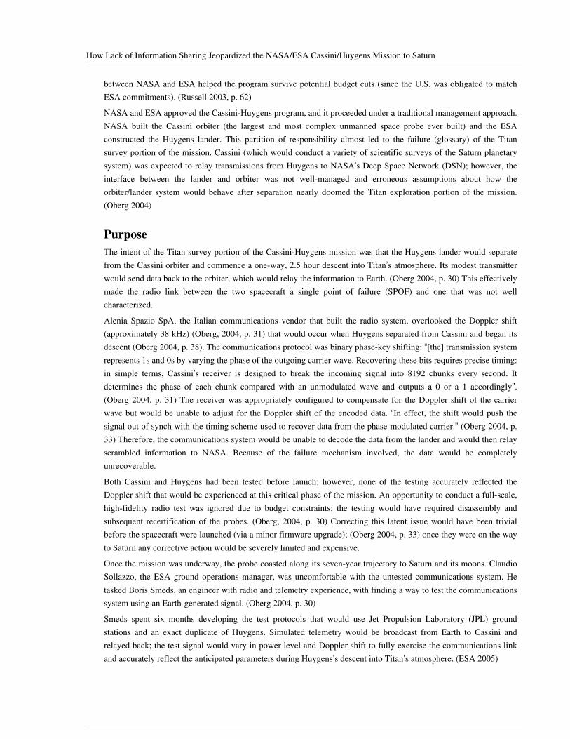
How Lack of Information Sharing Jeopardized the NASA/ESA Cassini/Huygens Mission to Saturn 22
between NASA and ESA helped the program survive potential budget cuts (since the U.S. was obligated to matchESA commitments). (Russell 2003, p. 62)NASA and ESA approved the Cassini-Huygens program, and it proceeded under a traditional management approach.NASA built the Cassini orbiter (the largest and most complex unmanned space probe ever built) and the ESAconstructed the Huygens lander. This partition of responsibility almost led to the failure (glossary) of the Titansurvey portion of the mission. Cassini (which would conduct a variety of scientific surveys of the Saturn planetarysystem) was expected to relay transmissions from Huygens to NASA’s Deep Space Network (DSN); however, theinterface between the lander and orbiter was not well-managed and erroneous assumptions about how theorbiter/lander system would behave after separation nearly doomed the Titan exploration portion of the mission.(Oberg 2004)
PurposeThe intent of the Titan survey portion of the Cassini-Huygens mission was that the Huygens lander would separatefrom the Cassini orbiter and commence a one-way, 2.5 hour descent into Titan’s atmosphere. Its modest transmitterwould send data back to the orbiter, which would relay the information to Earth. (Oberg 2004, p. 30) This effectivelymade the radio link between the two spacecraft a single point of failure (SPOF) and one that was not wellcharacterized.Alenia Spazio SpA, the Italian communications vendor that built the radio system, overlooked the Doppler shift(approximately 38 kHz) (Oberg, 2004, p. 31) that would occur when Huygens separated from Cassini and began itsdescent (Oberg 2004, p. 38). The communications protocol was binary phase-key shifting: “[the] transmission systemrepresents 1s and 0s by varying the phase of the outgoing carrier wave. Recovering these bits requires precise timing:in simple terms, Cassini’s receiver is designed to break the incoming signal into 8192 chunks every second. Itdetermines the phase of each chunk compared with an unmodulated wave and outputs a 0 or a 1 accordingly”.(Oberg 2004, p. 31) The receiver was appropriately configured to compensate for the Doppler shift of the carrierwave but would be unable to adjust for the Doppler shift of the encoded data. “In effect, the shift would push thesignal out of synch with the timing scheme used to recover data from the phase-modulated carrier.” (Oberg 2004, p.33) Therefore, the communications system would be unable to decode the data from the lander and would then relayscrambled information to NASA. Because of the failure mechanism involved, the data would be completelyunrecoverable.Both Cassini and Huygens had been tested before launch; however, none of the testing accurately reflected theDoppler shift that would be experienced at this critical phase of the mission. An opportunity to conduct a full-scale,high-fidelity radio test was ignored due to budget constraints; the testing would have required disassembly andsubsequent recertification of the probes. (Oberg, 2004, p. 30) Correcting this latent issue would have been trivialbefore the spacecraft were launched (via a minor firmware upgrade); (Oberg 2004, p. 33) once they were on the wayto Saturn any corrective action would be severely limited and expensive.Once the mission was underway, the probe coasted along its seven-year trajectory to Saturn and its moons. ClaudioSollazzo, the ESA ground operations manager, was uncomfortable with the untested communications system. Hetasked Boris Smeds, an engineer with radio and telemetry experience, with finding a way to test the communicationssystem using an Earth-generated signal. (Oberg 2004, p. 30)Smeds spent six months developing the test protocols that would use Jet Propulsion Laboratory (JPL) groundstations and an exact duplicate of Huygens. Simulated telemetry would be broadcast from Earth to Cassini andrelayed back; the test signal would vary in power level and Doppler shift to fully exercise the communications linkand accurately reflect the anticipated parameters during Huygens’s descent into Titan’s atmosphere. (ESA 2005)

How Lack of Information Sharing Jeopardized the NASA/ESA Cassini/Huygens Mission to Saturn 23
ChallengesSmeds faced opposition to his test plans from those who felt it was unnecessary, but ultimately prevailed due tosupport from Sollazzo and Jean-Pierre Lebreton, the Huygens project (glossary) scientist. More than two years afterthe mission was launched, Smeds traveled to a DSN site in California to conduct the test. (Oberg 2004, p. 31)A test signal was broadcast, received by Cassini, re-transmitted to the DSN site, and relayed to ESA's EuropeanSpace Operation Centre (ESOC) in Darmstadt, Germany for analysis. Testing had to be conducted when the orbiterwas in the correct relative position in the sky; it was more than a quarter of a million miles away with a signalround-trip time of nearly an hour. The test immediately exposed an issue; the data stream was intermittentlycorrupted, with failures not correlated to the power level of the test signal. The first of two days of testing concludedwith no clear root cause identified. (Oberg 2004, p. 31)Even though the probe was far from its ultimate destination, many science teams were competing for time tocommunicate with it using the limited bandwidth available. The communications team would not be able to conductanother set of trials for several months. Smeds diagnosed the root cause of the problem; he felt it was the Dopplershifts induced in the simulated signal. However, the test plan did not include unshifted telemetry (an ironicoversight). He modified his test plan overnight and shortened the planned tests by 60%; this recovered sufficienttime for him to inject an unshifted signal into the test protocols. (Oberg 2004, p. 32)This unshifted signal did not suffer from the same degradation; however, other engineers resisted the diagnosis of theproblem. Follow-up testing using probe mockups and other equipment ultimately convinced the ESA of the issue;this took an additional seven months. (Oberg 2004, p. 33)By late 2000, ESA informed NASA of the latent failure of the communications link between Cassini and Huygens.Inquiry boards confirmed that Alenia Spazio had reused timing features of a communications system used onEarth-orbiting satellites (which did not have to compensate for Doppler shifts of this magnitude). (Oberg, 2004, p.33) In addition, because NASA was considered a competitor, full specifications for the communications moduleswere not shared with JPL. The implementation of the communications protocols was in the system’s firmware; trivialto correct before launch, impossible to correct after. (ESA 2005)A 40-man Huygens Recovery Task Force (HRTF) was created in early 2001 to investigate potential mitigationactions. Analysis showed that no amount of modification to the signal would prevent degradation; the team(glossary) ultimately proposed changing the trajectory of Cassini to reduce the Doppler shift. (ESA 2005) Multiplestudies were conducted to verify the efficacy of this remedy, and it ultimately allowed the mission to successfullycomplete the Titan survey.
Systems Engineering PracticesSpace missions are particularly challenging; once the spacecraft is en route to its destination, it is completelyisolated. No additional resources can be provided and repair (particularly for unmanned mission) can be impossible.Apollo 13’s crew barely survived the notable mishap on its mission because of the resources of the docked LunarExcursion Module (LEM) and the resourcefulness of the ground control team’s experts. A less well-known failureoccurred during the Galileo mission to Jupiter. After the Challenger disaster, NASA adopted safety standards thatrestricted the size of boosters carried in the Space Shuttle. (Renzetti 1995) Galileo was delayed while the Shuttleswere grounded and Galileo’s trajectory was re-planned to include a Venus fly-by to accelerate and compensate for asmaller booster. Galileo’s main antenna failed to deploy; lubricant had evaporated during the extended unplannedstorage (Evans 2003) and limited computer space led to the deletion of the antenna motor-reversing software to makeroom for thermal protection routines. When the antenna partially deployed, it was stuck in place with no way tore-furl and redeploy it. Engineers ultimately used an onboard tape recorder, revised transmission protocols, theavailable low-gain antenna, and ground-based upgrades to the DSN to save the mission. (Taylor, Cheung, and Seo2002)

How Lack of Information Sharing Jeopardized the NASA/ESA Cassini/Huygens Mission to Saturn 24
The Titan survey was ultimately successful because simulation (glossary) techniques were able to verify the plannedtrajectory modifications and sufficient reaction mass was available to complete the necessary maneuvers. In addition,Smeds’s analysis gave the mission team the time it needed to fully diagnose the problem and develop and implementthe remedy. If this test were conducted the day before the survey it would merely have given NASA and ESAadvance warning of a disaster. The time provided enabled the mission planners to craft a trajectory that resolved thecommunication issue and then blended back into the original mission profile to preserve the balance of the Saturnfly-bys planned for Cassini. (Oberg 2004, p. 33)
Lessons LearnedThe near-failure of the Cassini-Huygens survey of Titan was averted because a handful of dedicated systemsengineers fought for and conducted relevant testing, exposed a latent defect, and did so early enough in the missionto allow for a recovery (glossary) plan to be developed and executed. Root causes of the issue includedpolitically-driven partitioning, poor interface management, overlooked contextual information, and a lack ofappreciation for single-points-of-failure (SPOFs).The desire to use a joint space mission as a mechanism for bringing NASA and ESA closer together (with theassociated positive impact in foreign relations) introduced an unnecessary interface into the system. Interfaces mustalways be managed carefully; interfaces between organizations (particularly those that cross organizational orpolitical borders) require extra effort and attention. Boeing and Airbus experienced similar issues during thedevelopment of the Boeing 787 and A380; international interfaces in the design (glossary) activities and supplychains led to issues:
…every interface in nature has a surface energy. Creating a new surface (e.g., by cutting a block ofsteel into two pieces) consumes energy that is then bound up in that surface (or interface). Interfaces inhuman systems (or organizations), a critical aspect of complex systems such as these, also have costs inthe effort to create and maintain them. Second, friction reduces performance. Carl von Clausewitz, thenoted military strategist, defined friction as the disparity between the ideal performance of units,organizations, or systems, and their actual performance in real-world scenarios. One of the primarycauses of friction is ambiguous or unclear information. Partitioning any system introduces friction atthe interface. (Vinarcik 2014, p. 697)
Alenia Spazio SpA’s unclear understanding of the Doppler shift introduced by the planned relative trajectories ofHuygens and Cassini during the Titan survey led it to reuse a component from Earth-orbiting satellites. Because itconsidered NASA a competitor and cloaked details of the communications system behind a veil of propriety, itprevented detection of this flaw in the design phase. (Oberg 2004, p. 33)Because NASA and ESA did not identify this communication link as a critical SPOF, they both sacrificed pre-launchtesting on the altar of expediency and cost-savings. This prevented detection and correction of the flaw before themission was dispatched to Saturn. The resource cost of the later analysis and remedial action was non-trivial and ifsufficient time and reaction mass had not been available the mission would have been compromised. It should benoted that a number of recent spacecraft failures are directly attributable to SPOFs (notably, the Mars Polar Lander(JPL 2000) and the Genesis sample return mission (GENESIS, 2005)). Effective SPOF detection and remediationmust be a priority for any product development effort. More generally, early in the development process, significantemphasis should be placed on analyses focused on what might go wrong (“rainy day scenarios”) in addition to whatis expected to go right (“sunny day scenarios”).The success of the Huygens survey of Titan was built upon the foundation established by Boris Smeds by identifyingthe root cause of the design flaws in a critical communications link. This case study underscores the need for clearcontextual understanding, robust interface management, representative testing, and proper characterization andmanagement of SPOFs.
How Lack of Information Sharing Jeopardized the NASA/ESA Cassini/Huygens Mission to Saturn 25
References
Works CitedEvans, B. 2003. "The Galileo Trials." Spaceflight Now. Available: http:/ / www. spaceflightnow. com/ galileo/030921galileohistory. html.GENESIS. 2005. "GENESIS Mishap Investigation Board Report Volume I." Washington, DC, USA: NationalAeronautics and Space Administration (NASA).JPL. 2000. "Report on the Loss of the Mars Polar Lander and Deep Space 2 Missions." Special Review Board.Pasadena, CA, USA: NASA Jet Propulsion Laboratory (JPL).ESA. 2005. "Modest Hero Sparks Team Response." European Space Agency. Available: http:/ / www. esa. int/Our_Activities/ Operations/ Modest_hero_sparks_team_response.Oberg, J. 2004. "Titan Calling: How a Swedish engineer saved a once-in-a-lifetime mission to Saturn's mysteriousmoon." IEEE Spectrum. 1 October 2004, pp. 28-33.Renzetti, D.N. 1995. "Advanced Systems Program and the Galileo Mission to Jupiter." The Evolution of Technologyin the Deep Space Network: A History of the Advanced Systems Program. Available: http:/ / deepspace. jpl. nasa.gov/ technology/ 95_20/ gll_case_study. html.Russell, C. 2003. The Cassini-Huygens Mission: Volume 1: Overview, Objectives and Huygens Instrumentarium.Norwell, MA, USA: Kluwer Academic Publishers.Taylor, J., K.-M. Cheung, and D. Seo. 2002. "Galileo Telecommunications. Article 5." DESCANSO Design andPerformance Summary Series. Pasadena, CA, USA: NASA/Jet Propulsion Laboratory.Vinarcik, M.J. 2014. "Airbus A380 and Boeing 787 — Contrast of Competing Architectures for Air Transportation,"in Case Studies in System of Systems, Enterprise Systems, and Complex Systems Engineering, edited by A. Gorod etal. Boca Raton, FL, USA: CRC Press. p. 687-701.Wall, M. 2012. "NASA Shelves Ambitious Flagship Missions to Other Planets." Space News. Available: http:/ /www. space. com/ 14576-nasa-planetary-science-flagship-missions. html.
Primary ReferencesNone.
Additional ReferencesNone.
< Previous Article | Parent Article | Next Article>SEBoK v. 1.4 released 29 June 2015
SEBoK DiscussionPlease provide your comments and feedback on the SEBoK below. You will need to log in to DISQUS using anexisting account (e.g. Yahoo, Google, Facebook, Twitter, etc.) or create a DISQUS account. Simply type yourcomment in the text field below and DISQUS will guide you through the login or registration steps. Feedback will bearchived and used for future updates to the SEBoK. If you provided a comment that is no longer listed, that commenthas been adjudicated. You can view adjudication for comments submitted prior to SEBoK v. 1.0 at SEBoK Reviewand Adjudication. Later comments are addressed and changes are summarized in the Letter from the Editor andAcknowledgements and Release History.

How Lack of Information Sharing Jeopardized the NASA/ESA Cassini/Huygens Mission to Saturn 26
If you would like to provide edits on this article, recommend new content, or make comments on the SEBoKas a whole, please see the SEBoK Sandbox [1].
ENCODED_CONTENTNjYyNTUPGRpdiBpZD0iZGlzcXVzX3RocmVhZCI+PC9kaXY+CjxzY3JpcHQgdHlwZT0idGV4dC9qYXZhc2NyaXB0Ij4KICAgIC8qICogKiBDT05GSUdVUkFUSU9OIFZBUklBQkxFUzogRURJVCBCRUZPUkUgUEFTVElORyBJTlRPIFlPVVIgV0VCUEFHRSAqICogKi8KICAgIHZhciBkaXNxdXNfc2hvcnRuYW1lID0gJ3NlYm9rd2lraTEwJzsgLy8gcmVxdWlyZWQ6IHJlcGxhY2UgZXhhbXBsZSB3aXRoIHlvdXIgZm9ydW0gc2hvcnRuYW1lCiAgICB2YXIgZGlzcXVzX2lkZW50aWZpZXIgPSAnSG93IExhY2sgb2YgSW5mb3JtYXRpb24gU2hhcmluZyBKZW9wYXJkaXplZCB0aGUgTkFTQS9FU0EgQ2Fzc2luaS9IdXlnZW5zIE1pc3Npb24gdG8gU2F0dXJuJzsgICAgdmFyIGRpc3F1c191cmwgPSAnaHR0cDovL3NlYm9rd2lraS5vcmcvZHJhZnQvSG93X0xhY2tfb2ZfSW5mb3JtYXRpb25fU2hhcmluZ19KZW9wYXJkaXplZF90aGVfTkFTQS9FU0FfQ2Fzc2luaS9IdXlnZW5zX01pc3Npb25fdG9fU2F0dXJuJzsKICAgIC8qICogKiBET04nVCBFRElUIEJFTE9XIFRISVMgTElORSAqICogKi8KICAgIChmdW5jdGlvbigpIHsKICAgICAgICB2YXIgZHNxID0gZG9jdW1lbnQuY3JlYXRlRWxlbWVudCgnc2NyaXB0Jyk7IGRzcS50eXBlID0gJ3RleHQvamF2YXNjcmlwdCc7IGRzcS5hc3luYyA9IHRydWU7CiAgICAgICAgZHNxLnNyYyA9ICdodHRwOi8vJyArIGRpc3F1c19zaG9ydG5hbWUgKyAnLmRpc3F1cy5jb20vZW1iZWQuanMnOwogICAgICAgIChkb2N1bWVudC5nZXRFbGVtZW50c0J5VGFnTmFtZSgnaGVhZCcpWzBdIHx8IGRvY3VtZW50LmdldEVsZW1lbnRzQnlUYWdOYW1lKCdib2R5JylbMF0pLmFwcGVuZENoaWxkKGRzcSk7CiAgICB9KSgpOwo8L3NjcmlwdD4KPG5vc2NyaXB0PlBsZWFzZSBlbmFibGUgSmF2YVNjcmlwdCB0byB2aWV3IHRoZSA8YSBocmVmPSJodHRwOi8vZGlzcXVzLmNvbS8/cmVmX25vc2NyaXB0Ij5jb21tZW50cyBwb3dlcmVkIGJ5IERpc3F1cy48L2E+PC9ub3NjcmlwdD4KPGEgaHJlZj0iaHR0cDovL2Rpc3F1cy5jb20iIGNsYXNzPSJkc3EtYnJsaW5rIj5ibG9nIGNvbW1lbnRzIHBvd2VyZWQgYnkgPHNwYW4gY2xhc3M9ImxvZ28tZGlzcXVzIj5EaXNxdXM8L3NwYW4+PC9hPg==END_ENCODED_CONTENT
Hubble Space Telescope Case StudyThis article describes a remarkable engineering feat with vast scientific benefits and implications. The topic may beof particular interest to those facing formidable Systems Engineering (glossary) challenges where one might thriveon a thoughtful blend of humility and optimism. For addition information, refer to the links provided in Section V.Lessons Learned below.
BackgroundThe Hubble Space Telescope (HST) Case Study was developed by the United States Air Force Center for SystemsEngineering (AF CSE) located at the Air Force Institute of Technology (AFIT). The AF CSE was tasked to developcase studies focusing on the application of Systems Engineering (glossary) principle (glossary) s within variousaerospace program (glossary) s. The HST study (Mattice 2005) is one of four initial case studies selected by AFITfor development in support of systems engineering graduate school instruction. The cases are structured using theFriedman-Sage framework (glossary) (Friedman and Sage 2003; Friedman and Sage 2004, 84-96), whichdecomposes a case into contractor, government, and shared responsibilities in the following nine concept areas:1.1. Requirements Definition and Management2.2. Systems Architecture Development3.3. System/Subsystem Design4.4. Verification/Validation5.5. Risk Management6.6. Systems Integration and Interfaces7.7. Life Cycle Support8.8. Deployment and Post Deployment9.9. System and Program ManagementThe case study provides a useful example of the rising cost (glossary) of defect correction through successive lifecycle phases, demonstrating how an error (in test fixture specification) that could have been fixed for $1,000 at thedesign (glossary) stage, or detected and fixed with a $10 million investment in an end-to-end test of the telescope onthe ground, ended up costing $1 billion to fix when the system was in service (glossary).
PurposeThe Hubble Space Telescope (HST) is an orbiting astronomical observatory operating in the spectrum from thenear-infrared into the ultraviolet. Launched in 1990 and still operational, HST carries and has carried a wide varietyof instruments producing imaging, spectrographic, astrometric, and photometric data through both pointed andparallel observing programs. Over 100,000 observations of more than 20,000 targets have been produced forretrieval. The telescope is well known as a marvel of science. This case study hopes to represent the facet of the HSTthat is a marvel of systems engineering, which, in fact, generated the scientific research and observation capabilitiesnow appreciated worldwide.
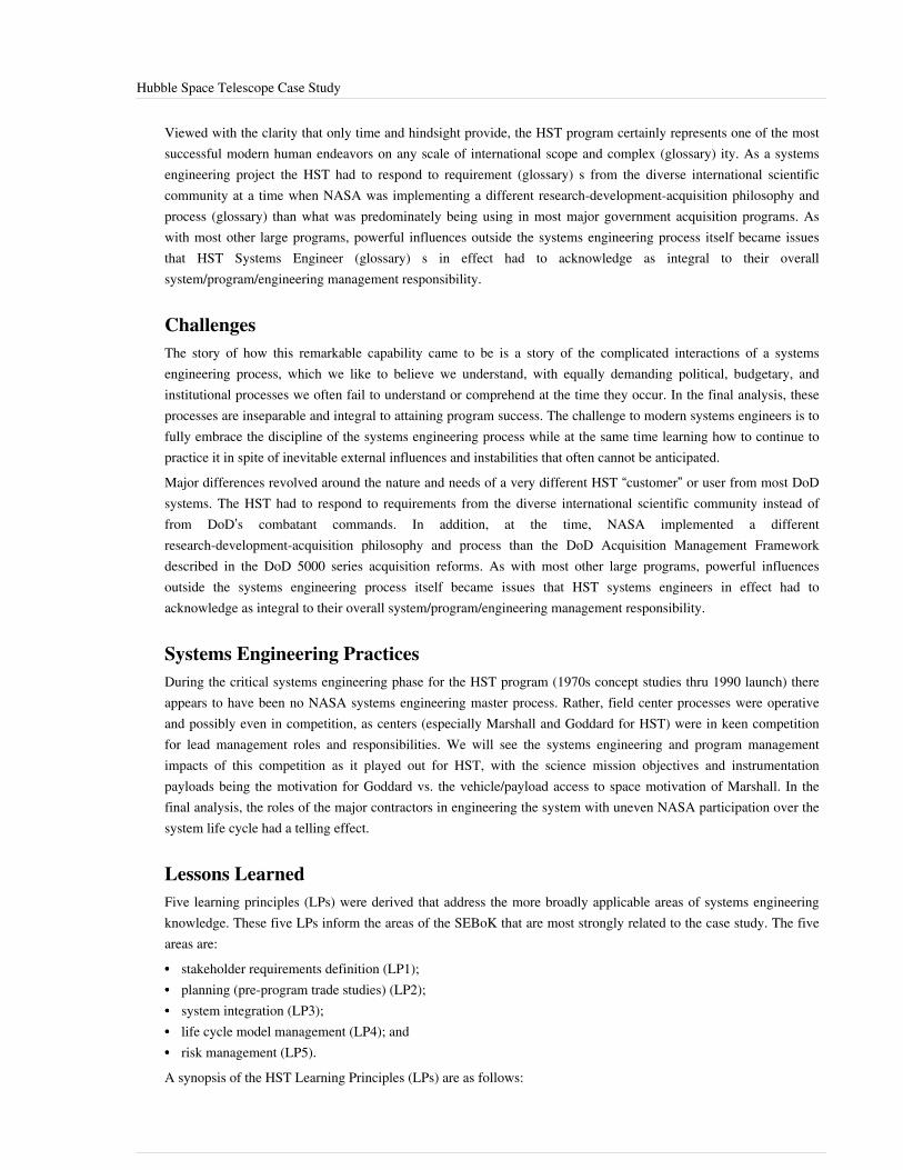
Hubble Space Telescope Case Study 27
Viewed with the clarity that only time and hindsight provide, the HST program certainly represents one of the mostsuccessful modern human endeavors on any scale of international scope and complex (glossary) ity. As a systemsengineering project the HST had to respond to requirement (glossary) s from the diverse international scientificcommunity at a time when NASA was implementing a different research-development-acquisition philosophy andprocess (glossary) than what was predominately being using in most major government acquisition programs. Aswith most other large programs, powerful influences outside the systems engineering process itself became issuesthat HST Systems Engineer (glossary) s in effect had to acknowledge as integral to their overallsystem/program/engineering management responsibility.
ChallengesThe story of how this remarkable capability came to be is a story of the complicated interactions of a systemsengineering process, which we like to believe we understand, with equally demanding political, budgetary, andinstitutional processes we often fail to understand or comprehend at the time they occur. In the final analysis, theseprocesses are inseparable and integral to attaining program success. The challenge to modern systems engineers is tofully embrace the discipline of the systems engineering process while at the same time learning how to continue topractice it in spite of inevitable external influences and instabilities that often cannot be anticipated.Major differences revolved around the nature and needs of a very different HST “customer” or user from most DoDsystems. The HST had to respond to requirements from the diverse international scientific community instead offrom DoD’s combatant commands. In addition, at the time, NASA implemented a differentresearch-development-acquisition philosophy and process than the DoD Acquisition Management Frameworkdescribed in the DoD 5000 series acquisition reforms. As with most other large programs, powerful influencesoutside the systems engineering process itself became issues that HST systems engineers in effect had toacknowledge as integral to their overall system/program/engineering management responsibility.
Systems Engineering PracticesDuring the critical systems engineering phase for the HST program (1970s concept studies thru 1990 launch) thereappears to have been no NASA systems engineering master process. Rather, field center processes were operativeand possibly even in competition, as centers (especially Marshall and Goddard for HST) were in keen competitionfor lead management roles and responsibilities. We will see the systems engineering and program managementimpacts of this competition as it played out for HST, with the science mission objectives and instrumentationpayloads being the motivation for Goddard vs. the vehicle/payload access to space motivation of Marshall. In thefinal analysis, the roles of the major contractors in engineering the system with uneven NASA participation over thesystem life cycle had a telling effect.
Lessons LearnedFive learning principles (LPs) were derived that address the more broadly applicable areas of systems engineeringknowledge. These five LPs inform the areas of the SEBoK that are most strongly related to the case study. The fiveareas are:•• stakeholder requirements definition (LP1);•• planning (pre-program trade studies) (LP2);•• system integration (LP3);•• life cycle model management (LP4); and•• risk management (LP5).A synopsis of the HST Learning Principles (LPs) are as follows:

Hubble Space Telescope Case Study 28
Stakeholder Requirements Definition LP1: Early and full participation by the customer/user throughout theprogram is essential to success. In the early stages of the HST program the mechanism for involving the customerwas not well defined. The user community was initially polarized and not effectively engaged in program definitionand advocacy. This eventually changed for the better, albeit driven heavily by external political and related nationalprogram initiatives. Ultimately, institutionalization of the user’s process for involvement ensured powerfulrepresentation and a fundamental stake and role in both establishing and managing program requirements. Over time,the effectiveness of “The Institute” led to equally effective user involvement in the deployment and on-orbitoperations of the system as well.Planning LP 2: The use of Pre-Program Trade Studies (e.g. “Phased Studies” or “Phased Project Planning”) tobroadly explore technical concepts and alternatives is essential and provides for a healthy variety of inputs from avariety of contractors and government (NASA) centers. These activities cover a range of feasibility, conceptual,alternative and preliminary design trades, with cost initially a minor (later a major) factor. In the case of HST,several NASA Headquarters and Center organizations funded these studies and sponsored technical workshops forHST concepts. This approach can promote healthy or unhealthy competition, especially when roles andresponsibilities within and between the participating management centers have not yet been decided and competingexternal organizations use these studies to further both technical and political agendas. NASA Center roles andmissions can also be at stake depending on political and or budgetary realities. The systems engineering challenge atthis stage is to “keep it technical, stupid!”Systems Integration LP 3: A high degree of systems integration to assemble, test, deploy, and operate the system isessential to success and must be identified as a fundamental program resource need as part of the program baseline.For HST, the early wedding of the program to the Shuttle, prior NASA and NASA contractor experience withsimilarly complex programs, such as Apollo, and the early requirement for manned, on-orbit servicing made it hardnot to recognize this was a big systems engineering integration challenge. Nonetheless, collaboration betweengovernment engineers, contractor engineers, as well as customers, must be well defined and exercised early on toovercome inevitable integration challenges and unforeseen events.Life Cycle Models LP 4: Life Cycle Support planning and execution must be integral from day one, includingconcept and design phases. The results will speak for themselves. Programs structured with real life cycleperformance as a design driver will be capable of performing in-service better, and will be capable of dealing withunforeseen events (even usage in unanticipated missions). HST probably represents a benchmark for building insystem sustainment (reliability, maintainability, provision for technology upgrade, built-in redundancy, etc.), whileproviding for human execution of functions (planned and unplanned) critical to servicing missions. With foursuccessful service missions complete, including one initially not planned (the primary mirror repair), the benefits ofdesign-for-sustainment, or life cycle support, throughout all phases of the program becomes quite evident. Withoutthis design approach, it is unlikely that the unanticipated, unplanned mirror repair could even have been attempted,let alone been totally successful.Risk Management LP 5: For complex programs, the number of stakeholders (government and contractor) demandsthat the program be structured to cope with high risk factors in many management and technical areassimultaneously. The HST program relied heavily on the contractors (especially Lockheed Missiles and SpaceCompany (LMSC) and Perkin-Elmer (P-E)), each of which “owned” very significant and unique program risk areas.In the critical area of optical systems, NASA depended on LMSC as the overall integrator to manage risk in an areawhere P-E was clearly the technical expert. Accordingly, NASA relied on LMSC and LMSC relied on P-E withinsufficient checks, oversight, and independence of the quality assurance function throughout. While most other riskareas were no doubt managed effectively, lapses here led directly to the HST’s going to orbit with the primary mirrordefect undetected, in spite of substantial evidence that could have been used to prevent this.

Hubble Space Telescope Case Study 29
References
Works CitedFriedman, G.R. and A.P. Sage. 2003. Systems Engineering Concepts: Illustration Through Case Studies. January 19,2003. Accessed in September 2011. Available at: http:/ / www. afit. edu/ cse/ docs/ Friedman-Sage%20Framework.pdf.Friedman, G. and A. Sage. 2004. “Case Studies of Systems Engineering and Management in Systems Acquisition.”Systems Engineering. 7(1): 84-96.Mattice, J. “Hubble Space Telescope Case Study." Ft. Belvoir, VA: Defense Acquisition University (DAU). Lastmodified May 2, 2005. Accessed on November 27, 2012. Available at https:/ / acc. dau. mil/ adl/ en-US/ 37600/ file/9105/ Hubble%20Space%20Telescope%20SE%20Case%20Study%20-%20JJ%20Mattice. pdf.
Primary ReferencesNone.
Additional ReferencesNone.
< Previous Article | Parent Article | Next Article >SEBoK v. 1.4 released 29 June 2015
SEBoK DiscussionPlease provide your comments and feedback on the SEBoK below. You will need to log in to DISQUS using anexisting account (e.g. Yahoo, Google, Facebook, Twitter, etc.) or create a DISQUS account. Simply type yourcomment in the text field below and DISQUS will guide you through the login or registration steps. Feedback will bearchived and used for future updates to the SEBoK. If you provided a comment that is no longer listed, that commenthas been adjudicated. You can view adjudication for comments submitted prior to SEBoK v. 1.0 at SEBoK Reviewand Adjudication. Later comments are addressed and changes are summarized in the Letter from the Editor andAcknowledgements and Release History.
If you would like to provide edits on this article, recommend new content, or make comments on the SEBoKas a whole, please see the SEBoK Sandbox [1].
ENCODED_CONTENTODQ1MDAPGRpdiBpZD0iZGlzcXVzX3RocmVhZCI+PC9kaXY+CjxzY3JpcHQgdHlwZT0idGV4dC9qYXZhc2NyaXB0Ij4KICAgIC8qICogKiBDT05GSUdVUkFUSU9OIFZBUklBQkxFUzogRURJVCBCRUZPUkUgUEFTVElORyBJTlRPIFlPVVIgV0VCUEFHRSAqICogKi8KICAgIHZhciBkaXNxdXNfc2hvcnRuYW1lID0gJ3NlYm9rd2lraTEwJzsgLy8gcmVxdWlyZWQ6IHJlcGxhY2UgZXhhbXBsZSB3aXRoIHlvdXIgZm9ydW0gc2hvcnRuYW1lCiAgICB2YXIgZGlzcXVzX2lkZW50aWZpZXIgPSAnSHViYmxlIFNwYWNlIFRlbGVzY29wZSBDYXNlIFN0dWR5JzsgICAgdmFyIGRpc3F1c191cmwgPSAnaHR0cDovL3NlYm9rd2lraS5vcmcvZHJhZnQvSHViYmxlX1NwYWNlX1RlbGVzY29wZV9DYXNlX1N0dWR5JzsKICAgIC8qICogKiBET04nVCBFRElUIEJFTE9XIFRISVMgTElORSAqICogKi8KICAgIChmdW5jdGlvbigpIHsKICAgICAgICB2YXIgZHNxID0gZG9jdW1lbnQuY3JlYXRlRWxlbWVudCgnc2NyaXB0Jyk7IGRzcS50eXBlID0gJ3RleHQvamF2YXNjcmlwdCc7IGRzcS5hc3luYyA9IHRydWU7CiAgICAgICAgZHNxLnNyYyA9ICdodHRwOi8vJyArIGRpc3F1c19zaG9ydG5hbWUgKyAnLmRpc3F1cy5jb20vZW1iZWQuanMnOwogICAgICAgIChkb2N1bWVudC5nZXRFbGVtZW50c0J5VGFnTmFtZSgnaGVhZCcpWzBdIHx8IGRvY3VtZW50LmdldEVsZW1lbnRzQnlUYWdOYW1lKCdib2R5JylbMF0pLmFwcGVuZENoaWxkKGRzcSk7CiAgICB9KSgpOwo8L3NjcmlwdD4KPG5vc2NyaXB0PlBsZWFzZSBlbmFibGUgSmF2YVNjcmlwdCB0byB2aWV3IHRoZSA8YSBocmVmPSJodHRwOi8vZGlzcXVzLmNvbS8/cmVmX25vc2NyaXB0Ij5jb21tZW50cyBwb3dlcmVkIGJ5IERpc3F1cy48L2E+PC9ub3NjcmlwdD4KPGEgaHJlZj0iaHR0cDovL2Rpc3F1cy5jb20iIGNsYXNzPSJkc3EtYnJsaW5rIj5ibG9nIGNvbW1lbnRzIHBvd2VyZWQgYnkgPHNwYW4gY2xhc3M9ImxvZ28tZGlzcXVzIj5EaXNxdXM8L3NwYW4+PC9hPg==END_ENCODED_CONTENT

Global Positioning System Case Study 30
Global Positioning System Case StudyThe Global Positioning System (GPS) case study was developed by the United States Air Force Center for SystemsEngineering (AF CSE) located at the Air Force Institute of Technology (AFIT). The GPS is a space-basedradio-positioning system. A constellation of twenty-four satellites, including three spares, comprise the overallsystem which provides navigation and timing information to military and civilian users worldwide. GPS satellites, inone of six Earth orbits, circle the globe every twelve hours, emitting continuous navigation signals on two differentL-band frequencies. The system consists of two other major segments: a world-wide satellite control network, andthe GPS user equipment that can either be carried by a human user or integrated into host platforms such as ships,vehicles, or aircraft.This case study discussion is based on the original source (O’Brien and Griffin 2007) which provides useful insightsinto what we might consider a "traditional" SE application. A second Global Positioning System Case Study II looksat the same case study from the perspectives of System of Systems (SoS) (glossary) engineering and EnterpriseSystems Engineering (ESE) (glossary).
Domain BackgroundWhen looking at the Global Positioning System (GPS), it would be difficult to imagine another system that relie s soheavily upon such a wide range of domains, with the possible exception of the World Wide Web (WWW).Additionally, the various systems operating within these domains must all function together flawlessly to achievesuccess. It is evident from reading this case study that it directly relates to the following domains:•• aerospace;•• space;•• communications; and•• transportation.This is also an example of systems of systems (SoS) and is considered an innovative technology.The GPS case study includes a detailed discussion of the development of the GPS and its components, as well asother applicable areas. The reader of this study will gain an increased understanding of the effect that GPS has onmilitary and commercial industries in the context of the systems engineering support required to achieve success.
Case Study BackgroundThe United States Air Force Center for Systems Engineering (AF CSE), established in 2002 at the Air Force Instituteof Technology (AFIT), was tasked to develop case studies focusing on the application of systems engineeringprinciples within various aerospace programs. The GPS case study (O'Brien and Griffin 2007) was developed byAFIT in support of systems engineering graduate school instruction. The cases are structured using theFriedman-Sage framework (Friedman and Sage 2003; Friedman and Sage 2004, 84-96), which decomposes a caseinto contractor, government, and shared responsibilities in the following nine concept areas:1.1. Requirements Definition and Management2.2. Systems Architecture Development3.3. System/Subsystem Design4.4. Verification/Validation5.5. Risk Management6.6. Systems Integration and Interfaces7.7. Life Cycle Support8.8. Deployment and Post Deployment9.9. System and Program Management

Global Positioning System Case Study 31
The Friedman-Sage framework (2004) is provided in Appendix A of the case study. This case study is an examplewhere the government - specifically the JPO Systems Engineering Directorate - bore the responsibility for systemsintegration and configuration management. That is, the government played more than an oversight role in thesystems engineering of the GPS system of systems. As mentioned in the case study, JPO developed the CONOPs,mission analysis, requirements and design analysis including security, and developed their own approach to thecryptology methodology. JPO coordinated the Configuration Control Board (CCB) chaired by the Program Director.JPO was also responsible for Level I ICDs and system design configurations; where the contractors were responsiblefor the system architecture and ICDs within their segment.
Case Study DescriptionThe “Global Positioning System - Systems Engineering Case Study” describes the application of systems engineeringduring the concept validation, system design and development, and production phases of the GPS program (O'Brienand Griffin 2007). The case examines the applied systems engineering processes, as well as the interactions of theGPS joint program office (JPO), the prime contractors, and the plethora of government agencies that were associatedwith the program’s development and fielding. The systems engineering process is traced from the initiation of studiesand the development of key technologies, which established the vision of a satellite navigation system in the 1960s,through to the multiphase joint-program that resulted in a fully operational capability release in 1995. This casestudy does not cover system enhancements incorporated through Blocks IIM, IIF, and III.The GPS case study derived four learning principles (LPs) that explain the more broadly applicable areas of systemsengineering knowledge that are addressed by the case study. These four LPs relate strongly to the SEBoK in thefollowing areas:• enabling individuals (LP1);• configuration management (LP2);• enabling the organization (LP3); and• risk management (LP4).Additionally, the GPS case study contains a thorough overview of life cycle management and exemplifies systemsthinking principles.
Enabling IndividualsLearning Principle 1: Programs must strive to staff key positions with domain experts.From the program management team, to the systems engineering, design, manufacturing, and operations teams, theindividuals on the program were well-versed in their disciplines and all possessed a systems view of the program.While communications, working relationships, and organization were important, it was the ability of the whole teamat all levels to understand the implications of their work on the system that was vital. Their knowledge-basedapproach for decision making had the effect of shortening the decision cycle because the information was understoodand the base and alternative solutions were accurately presented.
Configuration ManagementLearning Principle 2: The systems integrator must rigorously maintain program baselines.The joint program office (JPO) retained the role of managing and controlling the system specification and, therefore,the functional baseline. The JPO derived and constructed a mutually agreed to set of system requirements thatbecame the program baseline in 1973. While conducting the development program, the GPS team was able to makeperformance, risk, cost, and trade analyses against the functional baseline to control both risk and cost. The JPO wasfully cognizant of the implications of the functional requirements on the allocated baseline because they managed theinterface control working group process. Managing that process gave them first-hand knowledge and insight into the

Global Positioning System Case Study 32
risks at the lowest level. The individual with the system integrator role must rigorously maintain the systemspecification and functional baseline. There must be appropriate sharing of management and technicalresponsibilities between the prime contractor and their government counterparts to ensure success.
Enabling the OrganizationLearning Principle 3: Achieving consistent and continuous high-level support and advocacy helps funding stability,which impacts systems engineering stability.Consistent, continuous high-level support provides the requirements and assists funding stability. In this role, theOffice of the Secretary of Defense (OSD) provided advocacy and sourced the funding at critical times in theprogram, promoted coordination among the various services, and reviewed and approved the GPS JPO systemrequirements. The OSD played the central role in the establishment and survivability of the program. The GPS JPOhad clear support from the Director of Defense Development, Research, and Engineering, Dr. Malcolm Currie, andprogram support from the Deputy Secretary of Defense, Dr. David Packard. Clearly, the armed services –particularly the Navy and the Air Force early on, and later the Army – were the primary users of GPS and theeventual customers. However, each armed service had initial needs for their individual programs, or for thethen-current operational navigation systems. Additionally, the secretary of the Air Force provided programmaticsupport to supply manpower and facilities.
Risk ManagementLearning Principle 4: Disciplined and appropriate risk management must be applied throughout the life cycle.The GPS program was structured to address risk in several different ways throughout the multiphase program.Where key risks were known up front, the contractor and/or the government utilized a classic risk managementapproach to identify and analyze risk, as well as develop and track mitigation actions. These design (ormanufacturing/launch) risks were managed by the office who owned the risks. Identified technical risks were oftentracked by technical performance measures (such as satellite weight and software lines of codes) and addressed atweekly chief engineer’s meetings.Serving in the clear role of program integrator allowed the JPO to sponsor risk trade studies at the top level. The JPOwould issue study requests for proposals to several bidders for developing concepts and/or preliminary designs.Then, one contractor would be down-selected and the process would continue. This approach provided innovativesolutions through competition, as well as helped in defining a lower risk, more clearly defined development programfor the fixed-price contracts approach that was being used for development and production.As the system integrator, the JPO was also closely involved with technical development. To identify unforeseeableunique technical challenges, the JPO would fund studies to determine the optimal approaches to new issues. Therewere schedule risks associated with the first launch due to unforeseen Block II issues with respect to the spacevehicle and control segments (software development). Although a catastrophic event, the Challenger accidentactually provided much needed schedule relief. Using decision analysis methodology led the JPO to an alternativeapproach to develop the expendable launch vehicle for the Block II satellites.Good communication, facilitated by cooperative working relationships, was a significantly positive (thoughintangible) factor in the success of the GPS program, regardless of whether it was between the contractors and thegovernment (JPO or other agencies), or between contractors and sub-contractors. A true team environment alsoplayed a significant role in reducing risk, especially considering the plethora of government agencies and contractorsthat were involved in the effort.

Global Positioning System Case Study 33
Life Cycle ManagementThe GPS case study takes the reader through the initial concept of GPS (March 1942) all the way to thedevelopment, production, and operational capability of the system. The current GPS program traces its heritage tothe early 1960s when Air Force Systems Command initiated satellite-based navigation systems analyses conductedby The Aerospace Corporation. The case study follows the execution of the GPS program from the inception of theidea to the full operational capability release on April 27th, 1995. The concentration of the case study is not limitedto any particular period, and the learning principles come from various times throughout the program’s life.
Systems ThinkingThe GPS case study highlights the need for systems thinking throughout. GPS satellites, in one of six Earth orbits,circle the globe every twelve hours. These satellites emit continuous navigation signals on two different L-bandfrequencies. The system consists of two other major segments: a world-wide satellite control network and the GPSuser equipment that can either be carried by a human user, or integrated into host platforms such as ships, vehicles,or aircraft. The ability to conceive, develop, produce, field, and sustain the GPS demands the highest levels ofsystems thinking.
SummaryThe GPS case study is useful for global systems engineering learning and provides a comprehensive perspective onthe systems engineering life cycle. The study is applicable for detailed instruction in the following areas:• enabling individuals;• configuration management;• enabling the organization;• risk management;• life cycle management; and• systems thinking.The GPS case study revealed that key Department of Defense personnel maintained a clear and consistent vision forthis unprecedented, space-based navigation capability. The case study also revealed that good fortune was enjoyedby the JPO as somewhat independent, yet critical, space technologies matured in a timely manner.Although the GPS program required a large degree of integration, both within the system and external to the systemamongst a multitude of agencies and contractors, the necessary efforts were taken to achieve success.Lastly, the reader of the GPS case study will gain an increased understanding of the effect that GPS has on themilitary and commercial industries in the context of the systems engineering support required to achieve success.The system was originally designed to help “drop five bombs in one hole” which defines the accuracy requirement incontext-specific terms. The GPS signals needed to be consistent, repeatable, and accurate to a degree that, when usedby munitions guidance systems, would result in the successful delivery of multiple, separately-guided munitions tovirtually the identical location anywhere at any time across the planet. Forty to fifty years ago, very few outside ofthe military recognized the value of the proposed accuracy and most non-military uses of GPS were not recognizedbefore 1990. GPS has increasingly grown in use and is now used every day.
Global Positioning System Case Study 34
References
Works CitedFriedman, G.R. and A.P. Sage. 2003. Systems Engineering Concepts: Illustration Through Case Studies. January 19,2003. Accessed September 2011. Available at: http:/ / www. afit. edu/ cse/ docs/ Friedman-Sage%20Framework.pdf.Friedman, G. and A. Sage. 2004. "Case Studies of Systems Engineering and Management in Systems Acquisition."Systems Engineering. 7(1): p. 84-96.O’Brien, Patrick J., and John M. Griffin. 4 October 2007. Global Positioning System. Systems Engineering CaseStudy. Air Force Center for Systems Engineering (AFIT/SY) Air Force Institute of Technology (AFIT). 2950Hobson Way, Wright-Patterson AFB OH 45433-7765
Primary ReferencesO’Brien, Patrick J., and John M. Griffin. 4 October 2007. Global Positioning System. Systems Engineering CaseStudy. Air Force Center for Systems Engineering (AFIT/SY) Air Force Institute of Technology (AFIT). 2950Hobson Way, Wright-Patterson AFB OH 45433-7765
Additional Referencesnone.
< Previous Article | Parent Article | Next Article >SEBoK v. 1.4 released 29 June 2015
SEBoK DiscussionPlease provide your comments and feedback on the SEBoK below. You will need to log in to DISQUS using anexisting account (e.g. Yahoo, Google, Facebook, Twitter, etc.) or create a DISQUS account. Simply type yourcomment in the text field below and DISQUS will guide you through the login or registration steps. Feedback will bearchived and used for future updates to the SEBoK. If you provided a comment that is no longer listed, that commenthas been adjudicated. You can view adjudication for comments submitted prior to SEBoK v. 1.0 at SEBoK Reviewand Adjudication. Later comments are addressed and changes are summarized in the Letter from the Editor andAcknowledgements and Release History.
If you would like to provide edits on this article, recommend new content, or make comments on the SEBoKas a whole, please see the SEBoK Sandbox [1].
ENCODED_CONTENTNTY5OTcPGRpdiBpZD0iZGlzcXVzX3RocmVhZCI+PC9kaXY+CjxzY3JpcHQgdHlwZT0idGV4dC9qYXZhc2NyaXB0Ij4KICAgIC8qICogKiBDT05GSUdVUkFUSU9OIFZBUklBQkxFUzogRURJVCBCRUZPUkUgUEFTVElORyBJTlRPIFlPVVIgV0VCUEFHRSAqICogKi8KICAgIHZhciBkaXNxdXNfc2hvcnRuYW1lID0gJ3NlYm9rd2lraTEwJzsgLy8gcmVxdWlyZWQ6IHJlcGxhY2UgZXhhbXBsZSB3aXRoIHlvdXIgZm9ydW0gc2hvcnRuYW1lCiAgICB2YXIgZGlzcXVzX2lkZW50aWZpZXIgPSAnR2xvYmFsIFBvc2l0aW9uaW5nIFN5c3RlbSBDYXNlIFN0dWR5JzsgICAgdmFyIGRpc3F1c191cmwgPSAnaHR0cDovL3NlYm9rd2lraS5vcmcvZHJhZnQvR2xvYmFsX1Bvc2l0aW9uaW5nX1N5c3RlbV9DYXNlX1N0dWR5JzsKICAgIC8qICogKiBET04nVCBFRElUIEJFTE9XIFRISVMgTElORSAqICogKi8KICAgIChmdW5jdGlvbigpIHsKICAgICAgICB2YXIgZHNxID0gZG9jdW1lbnQuY3JlYXRlRWxlbWVudCgnc2NyaXB0Jyk7IGRzcS50eXBlID0gJ3RleHQvamF2YXNjcmlwdCc7IGRzcS5hc3luYyA9IHRydWU7CiAgICAgICAgZHNxLnNyYyA9ICdodHRwOi8vJyArIGRpc3F1c19zaG9ydG5hbWUgKyAnLmRpc3F1cy5jb20vZW1iZWQuanMnOwogICAgICAgIChkb2N1bWVudC5nZXRFbGVtZW50c0J5VGFnTmFtZSgnaGVhZCcpWzBdIHx8IGRvY3VtZW50LmdldEVsZW1lbnRzQnlUYWdOYW1lKCdib2R5JylbMF0pLmFwcGVuZENoaWxkKGRzcSk7CiAgICB9KSgpOwo8L3NjcmlwdD4KPG5vc2NyaXB0PlBsZWFzZSBlbmFibGUgSmF2YVNjcmlwdCB0byB2aWV3IHRoZSA8YSBocmVmPSJodHRwOi8vZGlzcXVzLmNvbS8/cmVmX25vc2NyaXB0Ij5jb21tZW50cyBwb3dlcmVkIGJ5IERpc3F1cy48L2E+PC9ub3NjcmlwdD4KPGEgaHJlZj0iaHR0cDovL2Rpc3F1cy5jb20iIGNsYXNzPSJkc3EtYnJsaW5rIj5ibG9nIGNvbW1lbnRzIHBvd2VyZWQgYnkgPHNwYW4gY2xhc3M9ImxvZ28tZGlzcXVzIj5EaXNxdXM8L3NwYW4+PC9hPg==END_ENCODED_CONTENT
Global Positioning System Case Study II 35
Global Positioning System Case Study IIThis article highlights some of the differences between the so-called classical, traditional, or conventional systemsengineering (SE) approaches and the newer, and, as yet, less defined principles of system of systems (SoS)engineering (SoSE). enterprise systems engineering (ESE), and/or complex systems engineering (CSE) or complexadaptive systems engineering (Gorod et al. 2015). The topic is still somewhat controversial, especially consideringthose that are sceptical that broader views of SE might work better when one is immersed in trying to cope with ourmost difficult problems. Indeed, the lack of a unified theory of SE is one of the prime motivations for producing andanalysing case studies to develop more knowledge of what seems to work, what does not seem to work, and reasonswhy, really challenging SE environments.For addition information, refer to Systems Engineering: Historic and Future Challenges, Systems Engineering andOther Disciplines, Enterprise Systems Engineering, and System of Systems Engineering.Rather than modifying the previous discussion of the Global Positioning System Case Study in SEBoK, the focus ison comparing and contrasting the older and newer forms of SE by commenting on quotations from the original casestudy source documents (O’Brien and Griffin 2007).
PrefaceThe original case study begins by describing systems engineering (SE) principles. For example,
System requirements are critical to all facets of successful system program development. First, systemdevelopment must proceed from a well-developed set of requirements. Second, regardless of theevolutionary acquisition approach, the system requirements must flow down to all subsystems andlower-level components. And third, the system requirements must be stable, balanced, and mustproperly reflect all activities in all intended environments. However, system requirements are notunchangeable. As the system design proceeds, if a requirement or set of requirements is provingexcessively expensive to satisfy, the process must rebalance schedule, costs, and performance bychanging or modifying the requirements or set of requirements. (O’Brien and Griffin 2007, p. 9)
The Global Positioning System (GPS), including its multi-various applications, was developed over many years asthe result of the efforts of a host of contributors. It is very difficult to believe that the classical, traditional orconventional systems engineering approach described in the above paragraph (especially those phrases highlighted inbold by the present authors) was truly responsible for this remarkable achievement that so profoundly impacts ourlives. Rather, some more advanced form of systems engineering (SE), that might be called, system of systems (SoS)engineering (SoSE), enterprise systems engineering (ESE), or complex (adaptive) systems engineering (CSE), or ablend and/or combination of these approaches or methodologies, had to be responsible. This premise is supportedexplicitly and repeatedly in the following case study revision using bold font.Continuing, the following quoted paragraphs seem flawed in several places highlighted in bold. The bold phrasesmight be replaced by the phrases in brackets […]. Such brackets might also include other editorial comments of thepresent authors.
Systems engineering includes making key system and design trades early in the process to establish thesystem architecture. These architectural artifacts This architecture can depict any new system, legacysystem, modifications thereto, introduction of new technologies, and overall system-level behavior andperformance. Modeling and simulation are generally employed to organize and assess architecturalsystem alternatives at this stage. System and subsystem design follows the functional [system]architecture [as defined from a functional point of view]. System architectures designs are modified ifelements are too risky, expensive, or time-consuming. (O’Brien and Griffin 2007, p. 9)
Global Positioning System Case Study II 36
A good architecture, once established, should guide systems development, and not change very much, if at all, atleast compared to possible changes in the system design, which, of course, can evolve as one learns more about theproblem and potential solutions that may increase the system’s capability. Thus, it is crucial to not confusearchitecture with designs instantiating the architecture, contrary to what seems to be the case in (Ricci, et al. 2013).
Important to the efficient decomposition and creation of functional and physical architectural designs arethe management of interfaces and the integration of subsystems. interface management and integrationis applied to subsystems within a system or across a large, complex system of systems. Once a solutionis planned, analyzed, designed, and constructed, validation and verification take place to ensuresatisfaction of requirements. Definition of test criteria, measures of effectiveness (MOEs), and measuresof performance (MOPs) are established as part of the requirements process, taking place well before anycomponent/subsystem assembly design and construction occurs. (O’Brien and Griffin 2007, p. 10)
In the quoted paragraph just above bold phrases note the emphasis on a reductionist approach, reductionism, wheregreat attention is paid to the subsystems and managing the interfaces among them. This is the antithesis of a holisticapproach where one concentrates on the whole system, recognizing that it is difficult to identify overall systembehavior as depending on any particular subsystem or set of subsystems. In a truly complex system that iscontinually evolving, the above-mentioned requirements process is flawed because the system is continuallychanging, i.e., the system is evolutionary; the requirements are either ill-defined at the outset, or are modifiedbecause stakeholders change their minds, or become somewhat irrelevant because the system environment changes.
There are several excellent representations of the [usual traditional or conventional] systems engineeringprocess presented in the literature. These depictions present the current state of the art in maturity andevaluation of the systems engineering process. One can find systems engineering process definitions,guides, and handbooks from the International Council on Systems Engineering (INCOSE), EuropeanIndustrial Association (EIA), Institute of Electrical and Electronics Engineers (IEEE), and variousDepartment of Defense (DoD) agencies and organizations. They show the process as it should beapplied [Really? In all situations?] by today’s experienced practitioner. One of these processes, longused by the Defense Acquisition University (DAU), is [a model] not accomplished in a single pass. Thisiterative and nested process gets repeated to the lowest level of definition of the design and itsinterfaces. (O’Brien and Griffin 2007, p. 10)
The above description appears to be written with pride without any acknowledgement that this SE methodologymight fail to work if applied according to these guidelines, or that there might be new SE techniques that could bemore effective in some situations. Again, this reflects a reductionist approach that ignores holism and emergentproperties that might not be explained even when thoroughly understanding the systems components and theirinteractions. On the positive side, the next paragraph suggest how the world is changing and hints that somethingmore is needed. Nevertheless, the advice seems to be oriented toward applying the existing SE discipline morevigorously instead of seeking new methods that might be more effective.
The DAU model, like all others, has been documented in the last two decades, and has expanded and developed to reflect a changing environment. Systems are becoming increasingly complex internally and more interconnected externally. The process used to develop aircraft and systems of the past was effective at the time. It served the needs of the practitioners and resulted in many successful systems in our inventory. Notwithstanding, the cost and schedule performance of the past programs are replete with examples of well-managed programs and ones with less-stellar execution. As the nation entered the 1980s and 1990s, large DoD and commercial acquisitions experienced overrunning costs and slipping schedules. The aerospace industry and its organizations were becoming larger and were more geographically and culturally distributed. Large aerospace companies have worked diligently to establish common systems engineering practices across their enterprises. However, because of the mega-trend of teaming in large (and some small) programs, these common practices must be understood

Global Positioning System Case Study II 37
and used beyond the enterprise and to multiple corporations. It is essential that the systems engineeringprocess govern integration, balance, allocation, and verification, and be useful to the entire programteam down to the design and interface level. (O’Brien and Griffin 2007, p. 11)
Finally, in the next paragraph there is a suggestion that SE could be made more sophisticated but there is no mentionof addressing people problems or advocating a broader transdisciplinary approach.
Today, many factors overshadow new acquisition; including system-of-systems (SoS) con- text, networkcentric warfare and operations, and rapid growth in information technology. These factors are driving amore sophisticated systems engineering process with more complex and capable features, along withnew tools and procedures. One area of increased focus of the systems engineering process is theinformational systems architectural definitions used during system analysis. This process, described inDoD Architectural Framework (DoDAF), emphasizes greater reliance on reusable architectural viewsdescribing the system context and concept of operations, interoperability, information and data flows,and network service-oriented characteristics. (O’Brien and Griffin 2007, p. 11)
The last two sections of the systems engineering principles portion of the original case study address case studiesthemselves, mainly for academic purposes, to help people appreciate systems engineering principles, and theframework used in the case study, namely the rather narrowly defined Friedman-Sage framework that will bediscussed briefly in Section II below.The treatment of the reason for case studies is quite good in that it talks about the benefits of applying systemsengineering principles, as highlighted from real-world examples of what works and what does not. Except near theend, where there is allusion to the possibility of new endeavor systems engineering principles, the principlesespoused tend to be traditional or conventional.On the other hand, based upon the original case study (O’Brien and Griffin 2007), if one views the boundary of theGPS system to include primarily the technology associated with the GPS space segment and its controlling groundnetwork, then it can be assumed that system was likely implemented primarily by following traditional orconventional systems engineering processes. If one takes this viewpoint, then all of the above criticism whichattempts to point out some of the shortcomings of conventional systems engineering, may seem vacuous at best, orpolitically incorrect at worst. It may well be that many would rather not denigrate the original GPS case study byexposing it to the possibilities of a broader system engineering approach.Unless otherwise indicated, as the present authors have already been doing, unchanged quotations from the existingSEBoK are indented below. Modifications to such quotations are shown in brackets [...]; deletions are notnecessarily shown explicitly.
BackgroundThe Global Positioning System (GPS) case study was developed by the United States Air Force Centerfor Systems Engineering (AF CSE) located at the Air Force Institute of Technology (AFIT). The GPS isa space-based radio-positioning system. A constellation of twenty-four satellites, including three spares,comprise the overall system which provides navigation and timing information to military and civilianusers worldwide. GPS satellites, in one of six Earth orbits, circle the globe every twelve hours, emittingcontinuous navigation signals on two different L-band frequencies. The system consists of two othermajor segments: a world-wide satellite control network, and the GPS user equipment that can either becarried by a human user or integrated into host platforms such as ships, vehicles, or aircraft.
A user needs to receive signals from at least four GPS satellites simultaneously (satellite orbital positions andterrestrial terrain blockage can be issues that degrade performance) to determine one’s position in three dimensions;the altitude determination is typically less accurate than the other two dimensions.

Global Positioning System Case Study II 38
When looking at [GPS], it would be difficult to imagine another system that relies so heavily upon sucha wide range of [domains containing systems that must interact effectively to achieve successful GPSoperation]. It is evident that [GPS directly relates to many domains and applications including:
•• position location and tracking•• time synchronization•• navigation•• transportation•• times of arrival•• air traffic management•• situational awareness•• jam-resistant communications•• business and commerce•• farming•• aerospace•• sensing nuclear detonations from space•• military war-fighting•• targeting•• weapons delivery•• etc.].
[GPS is] an example of [a collaborative (Dahmann, et al. 2008) systems of systems (SoS)]. As such, noone is in charge, and the capabilities (not requirements) flow from the bottom-up, as opposed totop-down.
PurposeThe GPS case study includes a detailed discussion of the development of the GPS and its components,as well as other applicable areas. The reader of this study will gain an increased understanding of theeffect that GPS has on military and commercial industries in the context of the systems engineeringsupport required to achieve success.
This may be, but the principal purpose of this revised case study is to suggest a broader view of GPS that discussessignature aspects of SoS, enterprises, and complex systems, and emphasizes SoSE, ESE, and CSE.
[AF CSE] was tasked to develop case studies focusing on the application of [SE] principles withinvarious aerospace programs. The GPS case study [was developed in support of SE] graduate schoolinstruction using the Friedman-Sage framework (Friedman and Sage 2003) (Friedman and Sage 2004).]
However, the Friedman-Sage framework involves only two contractual stakeholders, the Government and thecontractor; further, the framework is limited to the traditional or conventional SE life cycle which mainly treatsactivities in a linear instead of nonlinear fashion; still further, only risks are considered, not a balance of risk andopportunity. Thus, the present authors believe a broader framework embracing SoSE, ESE, and CSE is moreappropriate.
ChallengesIn the original case study the first highly technical section (Section 2) was the system description. The original ideaderived from trying to determine the precise orbital parameters of the first artificial satellites such as Sputniklaunched by the Soviets in 1957. Researchers at Johns Hopkins realized the inverse, that if one knew precisely theorbital parameters, the locations of ground stations receiving satellite signals could be determined quite accurately.(O’Brien and Griffin 2007, p. 20)

Global Positioning System Case Study II 39
GPS got its start in the early 70s (O’Brien and Griffin 2007, p. 19) building upon several previous satellite navigationsystems. The primary motive was very accurate position information for the purposes of military applications. Forexample, the U.S. Air Force wanted to deliver nuclear weapons from bombers with unprecedented accuracy andprecision. (O’Brien and Griffin 2007, p. 29)With such an intense interest from the military, the first real challenge, other than the many technical challenges ofmaking GPS work as well as envisioned, might have been the question of how to make GPS available to the civiliancommunity so they could share the benefits. The study claimed that the system was always offered for civilian use,albeit with some charge. After the Korean airliner went astray and got shot down by a Soviet interceptor aircraft,President Reagan made GPS officially available for civilian use free of charge. (O’Brien and Griffin 2007, p. 14)The second challenge could be associated with preserving precision capabilities for the military only, and relegatingcourse acquisition (C/A) accuracy to the civilian community. (O’Brien and Griffin 2007, p. 15) Later this dichotomywas essentially eliminated with the realization that a differential GPS configuration involving a fixed ground stationwith a precisely known location will yield great accuracy. (Kee, et al. 1991)The GPS satellites used space-borne atomic clocks. To alleviate the need for updating these clocks too often asuccessful effort was initiated to revise the international time standard which ended up using relatively infrequent“leap seconds”. (O’Brien and Griffin 2007, p. 23) Even these are still annoying for many other applications, such asthe continual need to achieve precise synchronization of frequency hopping radios.An organizational challenge of inter-service rivalries was overcome with the formation of the Joint Program Office(JPO). (O’Brien and Griffin 2007, p. 25)In the early days of satellite communication systems, for example, the satellites were quite small and low poweredwhile the terminals were large and high-powered. By the time GPS came along, the satellites are getting bigger andmore sophisticated. Then the challenge to develop relatively low-cost terminals, particularly for mobile users, greatlyincreased. (O’Brien and Griffin 2007, p. 29)A small but interesting challenge was the definition of system of systems (SoS). It was decided that GPS was an SoSbecause it involved three independent systems, namely, the space vehicle (SV), the control segment (CS), and theuser equipment (UE), that “merely” had to interface with each other. (O’Brien and Griffin 2007, p. 30)Continually changing requirements is usually a problem, although in this case the requirements did not change asoften as they could have. (O’Brien and Griffin 2007, p. 31)Difficulties of defining and updating the many GPS interfaces was largely overcome by the GPS program director,Col. Brad Parkinson, when he convinced his own management, Gen. Schultz at Space and Missile Systems Office(SAMSO) (which eventually became the Space Division) that GPS ought to be defined solely by thesignal-structure-in-space and not the physical interfaces. (O’Brien and Griffin 2007, p. 31)
Systems Engineering PracticesAlthough the systems engineering process in Phase I has been discussed previously, this section willexpand on the concepts. For example, one of the user equipment contractors was technically competent,but lacked effective management. The JPO strongly suggested that a systems engineering firm be hiredto assist the contractor in managing program and they agreed. (O’Brien and Griffin 2007, p. 42)
There did not seem to be any mention of what SE firm was hired, if any. The Aerospace Corporation, a non-profitFederally Funded Research and Development Center (FFRDC), which had such a key role in the run-up to GPS wasalso prominently and centrally involved in development phase of this humungous project. (O’Brien and Griffin 2007,pp. 20, 22, 25, 33, 34, 40, 41, 44, 48, 50-52, 56, 57, 62, 63, 64, 66, 67, 71)

Global Positioning System Case Study II 40
Lessons LearnedCommunications was a key ingredient that was fostered throughout GPS development. (O’Brien andGriffin 2007, p. 71)
Yes, from reading the original case study there seems to have been a lot of cooperation among the variousorganizations, more so than might have been expected in a less compelling case.
Several precepts or foundations of the Global Positioning Satellite program are the reasons for itssuccess. These foundations are instructional for today’s programs because they are thought-provoking tothose who always seek insight into the program’s progress under scrutiny. These foundations of pastprograms are, of course, not a complete set of necessary and sufficient conditions. For the practitioner,the successful application of different systems engineering processes is required throughout thecontinuum of a program, from the concept idea to the usage and eventual disposal of the system.Experienced people applying sound systems engineering principles, practices, processes, and tools arenecessary every step of the way. Mr. Conley, formerly of the GPS JPO, provided these words: “Systemsengineering is hard work. It requires knowledgeable people who have a vision of the program combinedwith an eye for detail.” (O’Brien and Griffin 2007, p. 72)
In very complex systems engineering efforts of this type, it is also important to explore new techniques that attemptto deal with “soft” issues involving people. Those that seem to work can be added to the systems engineering processcollection.
Systems engineering played a major role in the success of this program. The challenges of integratingnew technologies, identifying system requirements, incorporating a system of systems approach,interfacing with a plethora of government and industry agencies, and dealing with the lack of anoperational user early in the program formation required a strong, efficient systems engineering process.The GPS program embedded systems engineering in their knowledge-base, vision, and day-to-daypractice to ensure proper identification of system requirements. It also ensured the allocation of thoserequirements to the almost-autonomous segment developments and beyond to the subcontractor/vendorlevel, the assessments of new requirements, innovative test methods to verify design performance to therequirements, a solid concept of operations/mission analysis, a cost-benefit analysis to defend the needfor the program, and a strong system integration process to identify and control the “hydra” of interfacesthat the program encountered. The program was able to avoid major risks by their acquisition strategy,the use of trade studies, early testing of concept designs, a detailed knowledge of the subject matter, andthe vision of the program on both the government and contractor side. (O’Brien and Griffin 2007, p. 72)
This well summarizes the successful systems engineering approach utilized in GPS. Another element of achievingoverall balance is the pursuit of opportunities as the “flipside” of risk mitigation.Finally, here is the list of academic questions offered in original case study.
QUESTIONS FOR THE STUDENT (O’Brien and Griffin 2007, p. 73) The following questions are meant tochallenge the reader and prepare for a case discussion.
•• Is this program start typical of an ARPA/ DARPA funded effort? Why or why not?•• Have you experiences similar or wildly different aspects of a Joint Program?•• What were some characteristics that should be modeled from the JPO?• Think about the staffing for the GPS JPO. How can this be described? Should it be duplicated in today’s
programs? Can it?•• Was there anything extraordinary about the support for this program?•• What risks were present throughout the GPS program. How were these handled?•• Requirement management and stability is often cited as a central problem in DoD acquisition. How was this
program like, or [un]like, most others?

Global Positioning System Case Study II 41
•• Could the commercial aspects of the User Equipment be predicted or planned? Should the COTS aspect be astrategy in other DoD programs, where appropriate? Why or why not?Other questions might be: What possible influences did the demand for or offering to the public of this GPScapability entail?What differences in the development of GPS might have emerged if the public was moreaware of the potential applications for their benefit at the outset?
References
Works CitedDahmann, J. S., George Rebovich, Jr., and Jo Ann Lane. November 2008. “Systems Engineering for Capabilities.”CrossTalk, The Journal of Defense Software Engineering. http:/ / www. stsc. hill. af. mil/ crosstalk/ 2008/ 11/ index.html. Accessed 12 May 2015).Friedman, G.R., and A.P. Sage. 19 January 2003. Systems Engineering Concepts: Illustration Through Case Studies.Accessed September 2011. http:/ / www. afit. edu/ cse/ docs/ Friedman-Sage%20Framework. pdf.Gorod, A., B. E. White, V. Ireland, S. J. Gandhi, and B. J. Sauser. 2015. Case Studies in System of Systems,Enterprise Systems, and Complex Systems Engineering. Boca Raton, FL: CRC Press, Taylor & Francis Group. 2015.http:/ / www. taylorandfrancis. com/ books/ details/ 9781466502390/ . Accessed 8 May 2015Friedman, G.R., and A.P. Sage. 2004. “Case Studies of Systems Engineering and Management in SystemsAcquisition.” Systems Engineering 7(1): 84-96.Kee, Changdon, Bradford W. Parkinson, Penina Axelrad. Summer 1991. “Wide Area Differential GPS.” Journal ofThe Institute of Navigation 38(2): 123-46.O’Brien, Patrick J., and John M. Griffin. 4 October 2007. Global Positioning System. Systems Engineering CaseStudy. Air Force Center for Systems Engineering (AFIT/SY) Air Force Institute of Technology (AFIT). 2950Hobson Way, Wright-Patterson AFB OH 45433-7765.Ricci, Nicola, Adam M. Ross, Donna H. Rhodes, and Matthew E. Fitzgerald. 2013. “Considering AlternativeStrategies for Value Sustainment in Systems-of-Systems.” 6th IEEE International Systems Conference (SysCon).15-18 April. Orlando, FL.
Primary ReferencesGorod, A., B. E. White, V. Ireland, S. J. Gandhi, and B. J. Sauser. 2015. Case Studies in System of Systems,Enterprise Systems, and Complex Systems Engineering. Boca Raton, FL: CRC Press, Taylor & Francis Group. 2015.http:/ / www. taylorandfrancis. com/ books/ details/ 9781466502390/ . Accessed 12 May 2015
Additional ReferencesNone
< Previous Article | Parent Article | Next Article>SEBoK v. 1.4 released 29 June 2015
Global Positioning System Case Study II 42
SEBoK DiscussionPlease provide your comments and feedback on the SEBoK below. You will need to log in to DISQUS using anexisting account (e.g. Yahoo, Google, Facebook, Twitter, etc.) or create a DISQUS account. Simply type yourcomment in the text field below and DISQUS will guide you through the login or registration steps. Feedback will bearchived and used for future updates to the SEBoK. If you provided a comment that is no longer listed, that commenthas been adjudicated. You can view adjudication for comments submitted prior to SEBoK v. 1.0 at SEBoK Reviewand Adjudication. Later comments are addressed and changes are summarized in the Letter from the Editor andAcknowledgements and Release History.
If you would like to provide edits on this article, recommend new content, or make comments on the SEBoKas a whole, please see the SEBoK Sandbox [1].
ENCODED_CONTENTMTQwMDgPGRpdiBpZD0iZGlzcXVzX3RocmVhZCI+PC9kaXY+CjxzY3JpcHQgdHlwZT0idGV4dC9qYXZhc2NyaXB0Ij4KICAgIC8qICogKiBDT05GSUdVUkFUSU9OIFZBUklBQkxFUzogRURJVCBCRUZPUkUgUEFTVElORyBJTlRPIFlPVVIgV0VCUEFHRSAqICogKi8KICAgIHZhciBkaXNxdXNfc2hvcnRuYW1lID0gJ3NlYm9rd2lraTEwJzsgLy8gcmVxdWlyZWQ6IHJlcGxhY2UgZXhhbXBsZSB3aXRoIHlvdXIgZm9ydW0gc2hvcnRuYW1lCiAgICB2YXIgZGlzcXVzX2lkZW50aWZpZXIgPSAnR2xvYmFsIFBvc2l0aW9uaW5nIFN5c3RlbSBDYXNlIFN0dWR5IElJJzsgICAgdmFyIGRpc3F1c191cmwgPSAnaHR0cDovL3NlYm9rd2lraS5vcmcvZHJhZnQvR2xvYmFsX1Bvc2l0aW9uaW5nX1N5c3RlbV9DYXNlX1N0dWR5X0lJJzsKICAgIC8qICogKiBET04nVCBFRElUIEJFTE9XIFRISVMgTElORSAqICogKi8KICAgIChmdW5jdGlvbigpIHsKICAgICAgICB2YXIgZHNxID0gZG9jdW1lbnQuY3JlYXRlRWxlbWVudCgnc2NyaXB0Jyk7IGRzcS50eXBlID0gJ3RleHQvamF2YXNjcmlwdCc7IGRzcS5hc3luYyA9IHRydWU7CiAgICAgICAgZHNxLnNyYyA9ICdodHRwOi8vJyArIGRpc3F1c19zaG9ydG5hbWUgKyAnLmRpc3F1cy5jb20vZW1iZWQuanMnOwogICAgICAgIChkb2N1bWVudC5nZXRFbGVtZW50c0J5VGFnTmFtZSgnaGVhZCcpWzBdIHx8IGRvY3VtZW50LmdldEVsZW1lbnRzQnlUYWdOYW1lKCdib2R5JylbMF0pLmFwcGVuZENoaWxkKGRzcSk7CiAgICB9KSgpOwo8L3NjcmlwdD4KPG5vc2NyaXB0PlBsZWFzZSBlbmFibGUgSmF2YVNjcmlwdCB0byB2aWV3IHRoZSA8YSBocmVmPSJodHRwOi8vZGlzcXVzLmNvbS8/cmVmX25vc2NyaXB0Ij5jb21tZW50cyBwb3dlcmVkIGJ5IERpc3F1cy48L2E+PC9ub3NjcmlwdD4KPGEgaHJlZj0iaHR0cDovL2Rpc3F1cy5jb20iIGNsYXNzPSJkc3EtYnJsaW5rIj5ibG9nIGNvbW1lbnRzIHBvd2VyZWQgYnkgPHNwYW4gY2xhc3M9ImxvZ28tZGlzcXVzIj5EaXNxdXM8L3NwYW4+PC9hPg==END_ENCODED_CONTENT
Medical Radiation Case StudyThis case study presents system and software engineering issues relevant to the accidents associated with theTherac-25 medical linear accelerator that occurred between 1985 and 1988. The six accidents caused five deaths andserious injury to several patients. The accidents were system accidents that resulted from complex interactionsbetween hardware components, controlling software, and operator functions.
Domain BackgroundMedical linear accelerators, devices used to treat cancer, accelerate electrons to create high energy beams that candestroy tumors. Shallow tissue is treated with the accelerated electrons. The electron beam is converted to X-rayphotons to reach deeper tissues. Accidents occur when a patient is delivered an unsafe amount of radiation.A radiation therapy machine is controlled by software that monitors the machine's status, accepts operator inputabout the radiation treatment to be performed, and initializes the machine to perform the treatment. The softwareturns the electron beam on in response to an operator command. The software turns the beam off whenever thetreatment is complete, the operator requests the beam to shutdown, or when the hardware detects a machinemalfunction. A radiation therapy machine is a reactive system in which the system's behavior is state dependent andthe system's safety depends upon preventing entry into unsafe states. For example, the software controls theequipment that positions the patient and the beam. The positioning operations can take a minute or more to execute,thus it is unsafe to activate the electron beam while a positioning operation is in process.In the early 1980s, Atomic Energy of Canada (AECL) developed the Therac-25, a dual-mode (X-rays or electrons)linear accelerator that can deliver photons at 25 megaelectron volts (MeV) or electrons at various energy levels. TheTherac-25 superseded the Therac-20, the previous 20-MeV dual mode accelerator with a history of successfulclinical use. The Therac-20 used a DEC PDP-11 (Digital Equipment Corporation Programmed Data Processor)minicomputer for computer control and featured protective circuits for monitoring the electron beam, as well asmechanical interlocks for policing the machine to ensure safe operation. AECL decided to increase theresponsibilities of the Therac-25 software for maintaining safety and eliminated most of the hardware safetymechanisms and interlocks. The software, written in PDP-11 assembly language, was partially reused from earlierproducts in the Therac product line. Eleven Therac-25s were installed at the time of the first radiation accident inJune 1985.
Medical Radiation Case Study 43
The use of radiation therapy machines has increased rapidly in the last 25 years. The number of medical radiationmachines in the United States in 1985 was approximately 1000. By 2009 the number had increased to approximately4450. Some of the types of system problems found in the Therac-25 may be present in the medical radiation devicescurrently in use. References to more recent accidents are included below.
Case Study BackgroundThe Therac-25 accidents and their causes are well documented in materials from the U.S. and Canadian regulatoryagencies (e.g., the U.S. Food and Drug Administration (FDA) and the Canadian Bureau of Radiation and MedicalDevices) and in depositions associated with lawsuits brought against AECL. An article by Leveson and Turner(1993) provides the most comprehensive, publicly available description of the accident investigations, the causes ofthe accidents, and the lessons learned relevant to developing systems where computers control dangerous devices.
Case Study DescriptionThe Therac-25 accidents are associated with the non-use or misuse of numerous system engineering practices,especially system verification and validation, risk management, and assessment and control. In addition, numeroussoftware engineering good practices were not followed, including design reviews, adequate documentation, andcomprehensive software unit and integration tests.The possibility of radiation accidents increased when AECL made the systems engineering decision to increase theresponsibilities of the Therac-25 software for maintaining safety and eliminated most of the hardware safetymechanisms and interlocks. In retrospect, the software was not worthy of such trust. In 1983 AECL performed asafety assessment on the Therac-25. The resulting fault tree did include computer failures, but only those associatedwith hardware; software failures were not considered in the analysis.The software was developed by a single individual using PDP-11 assembly language. Little software documentationwas produced during development. An AECL response to the FDA indicated the lack of software specifications andof a software test plan. Integrated system testing was employed almost exclusively. Leveson and Turner (1993)described the functions and design of the software and concluded that there were design errors in how concurrentprocessing was handled. Race conditions resulting from the implementation of multitasking also contributed to theaccidents.AECL technical management did not believe that there were any conditions under which the Therac-25 could causeradiation overdoses, and this belief was evident in the company’s initial responses to accident reports. The firstradiation overdose accident occurred in June 1985 at the Kennestone Regional Oncology Center in Marietta,Georgia, where the Therac-25 had been operating for about 6 months. The patient who suffered the radiationoverdose filed suit against the hospital and AECL in October 1985. No AECL investigation of the incident occurredand FDA investigators later found that AECL had no mechanism in place to follow up potential reports of suspectedaccidents. Additionally, other Therac-25 users received no information that an accident had occurred.Two more accidents occurred in 1985, including a radiation overdose at Yakima Valley Memorial Hospital inYakima, Washington that resulted in an accident report to AECL. The AECL technical support supervisor respondedto the hospital in early 1986: “After careful consideration, we are of the opinion that this damage could not have beenproduced by any malfunction of the Therac-25 or by any operator error… there have apparently been no otherinstances of similar damage to this or other patients.”In early 1986 there were two accidents at the East Texas Cancer Center in Tyler, Texas, both of which resulted in thedeath of the patient within a few months. On March 21, 1986 the first massive radiation overdose occurred, thoughthe extent of the overdose was not realized at the time. The Therac-25 was shut down for testing the day after theaccident. Two AECL engineers, one from the plant in Canada, spent a day running machine tests but could notreproduce the malfunction code observed by the operator at the time of the accident. The home office engineer

Medical Radiation Case Study 44
explained that it was not possible for the Therac-25 to overdose a patient. The hospital physicist, who supervised theuse of the machine, asked AECL if there were any other reports of radiation overexposure. The AECL qualityassurance manager told him that AECL knew of no accidents involving the Therac-25.On April 11, 1986 the same technician received the same malfunction code when an overdose occurred. Three weekslater the patient died; an autopsy showed acute high-dose radiation injury to the right temporal lobe of the brain andto the brain stem. The hospital physicist was able to reproduce the steps the operator had performed and measuredthe high radiation dosage delivered. He determined that data-entry speed during editing of the treatment script wasthe key factor in producing the malfunction code and the overdose. Examination of the portion of the coderesponsible for the Tyler accidents showed major software design flaws. Levinson and Turner (1993) describe indetail how the race condition occurred in the absence of the hardware interlocks and caused the overdose. The firstreport of the Tyler accidents came to the FDA from the Texas Health Department. Shortly thereafter, AECLprovided a medical device accident report to the FDA discussing the radiation overdoses in Tyler.On May 2, 1986 the FDA declared the Therac-25 defective and required the notification of all customers. AECL wasrequired to submit to the FDA a corrective action plan for correcting the causes of the radiation overdoses. Aftermultiple iterations of a plan to satisfy the FDA, the final corrective action plan was accepted by the FDA in thesummer of 1987. The action plan resulted in the distribution of software updates and hardware upgrades thatreinstated most of the hardware interlocks that were part of the Therac-20 design.AECL settled the Therac-25 lawsuits filed by patients that were injured and by the families of patients who diedfrom the radiation overdoses. The total compensation has been estimated to be over $150 million.
SummaryLeveson and Turner (1993) describe the contributing factors to Therac-25 accidents: “We must approach theproblems of accidents in complex systems from a systems-engineering point of view and consider all contributingfactors." For the Therac-25 accidents, the contributing factors included•• management inadequacies and a lack of procedures for following through on all reported incidents;•• overconfidence in the software and the resulting removal of hardware interlocks (causing the software to be a
single point of failure that could lead to an accident);•• less than acceptable software engineering practices; and•• unrealistic risk assessments along with over confidence in the results of those assessments.
Recent Medical Radiation ExperienceBetween 2009 and 2011, The New York Times published a series of articles by Walter Bogdanich on the use ofmedial radiation, entitled “Radiation Boom" (2011).The following quotations are excerpts from that series:
Increasingly complex, computer-controlled devices are fundamentally changing medical radiation,delivering higher doses in less time with greater precision than ever before.” But patients often knowlittle about the harm that can result when safety rules are violated and ever more powerful andtechnologically complex machines go awry. To better understand those risks, The New York Timesexamined thousands of pages of public and private records and interviewed physicians, medicalphysicists, researchers and government regulators. The Times found that while this new technologyallows doctors to more accurately attack tumors and reduce certain mistakes, its complexity has creatednew avenues for error — through software flaws, faulty programming, poor safety procedures orinadequate staffing and training. . . .
Linear accelerators and treatment planning are enormously more complex than 20 years ago,’ said Dr. Howard I. Amols, chief of clinical physics at Memorial Sloan-Kettering Cancer Center in New York. But

Medical Radiation Case Study 45
hospitals, he said, are often too trusting of the new computer systems and software, relying on them as ifthey had been tested over time, when in fact they have not. . . .
Hospitals complain that manufacturers sometimes release new equipment with software that is poorlydesigned, contains glitches or lacks fail-safe features, records show. Northwest Medical PhysicsEquipment in Everett, Wash., had to release seven software patches to fix its image-guided radiationtreatments, according to a December 2007 warning letter from the F.D.A. Hospitals reported that thecompany’s flawed software caused several cancer patients to receive incorrect treatment, governmentrecords show.
References
Works CitedBogdanich, W. 2011. Articles in the "Radiation Boom" series. New York Times. June 2009-February 2011. AccessedNovember 28, 2012. Available: http:/ / topics. nytimes. com/ top/ news/ us/ series/ radiation_boom.Leveson, N.G., and C.S. Turner. 1993. "An Investigation of the Therac-25 Accidents." Computer. 26 (7): 18-41.
Primary ReferencesNone.
Additional ReferencesNone.
< Previous Article | Parent Article | Next Article >SEBoK v. 1.4 released 29 June 2015
SEBoK DiscussionPlease provide your comments and feedback on the SEBoK below. You will need to log in to DISQUS using anexisting account (e.g. Yahoo, Google, Facebook, Twitter, etc.) or create a DISQUS account. Simply type yourcomment in the text field below and DISQUS will guide you through the login or registration steps. Feedback will bearchived and used for future updates to the SEBoK. If you provided a comment that is no longer listed, that commenthas been adjudicated. You can view adjudication for comments submitted prior to SEBoK v. 1.0 at SEBoK Reviewand Adjudication. Later comments are addressed and changes are summarized in the Letter from the Editor andAcknowledgements and Release History.
If you would like to provide edits on this article, recommend new content, or make comments on the SEBoKas a whole, please see the SEBoK Sandbox [1].
ENCODED_CONTENTMTU2NjQPGRpdiBpZD0iZGlzcXVzX3RocmVhZCI+PC9kaXY+CjxzY3JpcHQgdHlwZT0idGV4dC9qYXZhc2NyaXB0Ij4KICAgIC8qICogKiBDT05GSUdVUkFUSU9OIFZBUklBQkxFUzogRURJVCBCRUZPUkUgUEFTVElORyBJTlRPIFlPVVIgV0VCUEFHRSAqICogKi8KICAgIHZhciBkaXNxdXNfc2hvcnRuYW1lID0gJ3NlYm9rd2lraTEwJzsgLy8gcmVxdWlyZWQ6IHJlcGxhY2UgZXhhbXBsZSB3aXRoIHlvdXIgZm9ydW0gc2hvcnRuYW1lCiAgICB2YXIgZGlzcXVzX2lkZW50aWZpZXIgPSAnTWVkaWNhbCBSYWRpYXRpb24gQ2FzZSBTdHVkeSc7ICAgIHZhciBkaXNxdXNfdXJsID0gJ2h0dHA6Ly9zZWJva3dpa2kub3JnL2RyYWZ0L01lZGljYWxfUmFkaWF0aW9uX0Nhc2VfU3R1ZHknOwogICAgLyogKiAqIERPTidUIEVESVQgQkVMT1cgVEhJUyBMSU5FICogKiAqLwogICAgKGZ1bmN0aW9uKCkgewogICAgICAgIHZhciBkc3EgPSBkb2N1bWVudC5jcmVhdGVFbGVtZW50KCdzY3JpcHQnKTsgZHNxLnR5cGUgPSAndGV4dC9qYXZhc2NyaXB0JzsgZHNxLmFzeW5jID0gdHJ1ZTsKICAgICAgICBkc3Euc3JjID0gJ2h0dHA6Ly8nICsgZGlzcXVzX3Nob3J0bmFtZSArICcuZGlzcXVzLmNvbS9lbWJlZC5qcyc7CiAgICAgICAgKGRvY3VtZW50LmdldEVsZW1lbnRzQnlUYWdOYW1lKCdoZWFkJylbMF0gfHwgZG9jdW1lbnQuZ2V0RWxlbWVudHNCeVRhZ05hbWUoJ2JvZHknKVswXSkuYXBwZW5kQ2hpbGQoZHNxKTsKICAgIH0pKCk7Cjwvc2NyaXB0Pgo8bm9zY3JpcHQ+UGxlYXNlIGVuYWJsZSBKYXZhU2NyaXB0IHRvIHZpZXcgdGhlIDxhIGhyZWY9Imh0dHA6Ly9kaXNxdXMuY29tLz9yZWZfbm9zY3JpcHQiPmNvbW1lbnRzIHBvd2VyZWQgYnkgRGlzcXVzLjwvYT48L25vc2NyaXB0Pgo8YSBocmVmPSJodHRwOi8vZGlzcXVzLmNvbSIgY2xhc3M9ImRzcS1icmxpbmsiPmJsb2cgY29tbWVudHMgcG93ZXJlZCBieSA8c3BhbiBjbGFzcz0ibG9nby1kaXNxdXMiPkRpc3F1czwvc3Bhbj48L2E+END_ENCODED_CONTENT

FBI Virtual Case File System Case Study 46
FBI Virtual Case File System Case StudyThis case study presents systems and software engineering issues encountered in the Federal Bureau of Investigation(FBI) Virtual Case File (VCF) project in the period between 2000-2005. VCF development was abandoned in 2005after over $170 million had been spent.
Domain BackgroundThe FBI is an organization within the United States Department of Justice (DoJ) consisting of 23 divisions, includingcounterintelligence, criminal investigation, and cyber crime. The Bureau's 12,400 agents investigate everything fromcounter-terrorism leads to kidnappings. They interview witnesses, develop informants, conduct surveillance, hunt forclues, and collaborate with local law enforcement to find and arrest criminals. Agents document every step andmethodically build case files. They spend a tremendous amount of time processing paperwork. This system of formsand approvals stretches back to the 1920s when forms for all of the bureau's investigative reports were standardized.In 2000, the Bureau had hundreds of standardized paper forms and obsolete information technology (IT) systems.The FBI’s 13,000 computers could not run modern software. Most of the agency offices were connected to the FBIIntranet with links operating at about the speed of a 56 kilobits-per-second modem. Agents could not e-mail U.S.Attorneys, federal agencies, local law enforcement, or each other; instead, they typically sent case-relatedinformation by fax. The agency’s problems in 2000 were summarized in the 9/11 Commission Report: "the FBI'sinformation systems were woefully inadequate. The FBI lacked the ability to know what it knew; there was noeffective mechanism for capturing or sharing its institutional knowledge" (National Commission on Terrorist Actsupon the United States 2004).In September 2000, Congress approved $380 million over three years for what was then called the FBI InformationTechnology Upgrade Program. Eventually divided into three parts, the program became known as the TrilogyInformation Technology Modernization Program. The first part would provide all 56 FBI field offices with updatedcomputer terminals, as well as new hardware such as scanners, printers, and servers. The second part wouldre-implement the FBI Intranet to provide secure local area and wide area networks, allowing agents to shareinformation with their supervisors and each other. The third part was intended to replace the FBI's investigativesoftware applications, including the obsolete Automated Case Support (ACS) system.In June 2001, the FBI awarded a contract to develop the investigative software applications of Trilogy to ScienceApplications International Corporation (SAIC) over a three year period. The purpose of the software to be developedwas to•• provide the capability to find information in FBI databases without having prior knowledge of its location, and to
search all FBI databases with a single query through the use of search engines;•• Web-enable the existing investigative applications;•• improve capabilities to share information inside and outside the FBI;•• provide access to authorized information from both internal and external databases; and•• allow the evaluation of cases and crime patterns through the use of commercial and FBI-enhanced analytical and
case management tools.After the September 11 terrorist attacks, the inability of FBI agents to share the most basic information about alQaeda's U.S. activities was front-page news. Within days, the FBI's obsolete technology infrastructure was beingdiscussed in Congress and the FBI was under intense pressure to improve its information sharing capabilities. OnSeptember 4, 2001, Robert S. Mueller III became FBI director, and, in the face of intense public and congressionalpressure, Mueller accelerated the Trilogy program. The planned three year period to develop the investigativesoftware was considered politically unacceptable. In January 2002, the FBI requested an additional $70 million toaccelerate Trilogy; Congress went further, approving $78 million.

FBI Virtual Case File System Case Study 47
Providing web-enablement of the existing but antiquated and limited ACS system would not provide theinvestigative case management capabilities required to meet the FBI’s post-September 11 mission. In December2001, the FBI asked SAIC to stop building a Web-based front end for the old programs. Instead, SAIC was asked todevise a new case management system, the Virtual Case File (VCF), to replace ACS. The VCF would contain amajor new application, database, and graphical user interface. In order to make both criminal and terroristinvestigation information readily accessible throughout the FBI, major changes to the standardized FBI processeswould be required. This case study focuses on the VCF component of the Trilogy program.
Case Study BackgroundThe most complete description of the development of the VCF is the report by the DoJ Office of the InspectorGeneral (OIG). The OIG reports to the Attorney General and is independent of the FBI organizations responsible forthe Trilogy program. The introduction to the report states, “We conducted this audit to assess the FBI’s progress inmeeting cost, schedule, technical, and performance targets for the three components of Trilogy. We also examinedthe extent to which Trilogy will meet the FBI’s current and longer-term IT needs” (OIG 2004).An IEEE Spectrum article complements the OIG audit report by providing detailing the development of the VCFrequirements, the contractor’s activities, and the project management failures by both the FBI and the contractor. Thecontractor’s viewpoint is presented in testimony given before a subcommittee of the U.S. Senate AppropriationsCommittee.These materials, in total, provide a comprehensive view of the VCF program and the reasons for its failure.
Case Study DescriptionIn the political environment following the 9/11 attacks, funding for the VCF project was never a problem. By early2002, SAIC and the FBI committed to creating an entirely new case management system in 22 months. High-levelfunding enabled the project to continue gaining momentum in spite of the problems it encountered. The schedulingfor the VCF project focused on what was desired, not what was possible. Trilogy’s scope grew by approximately80% from the initial project baseline (Moore 2010).The reasons for the failure of the VCF project are associated with the non-use or misuse of numerous systemengineering practices, especially within stakeholder requirements, system requirements, planning, assessment andcontrol, and risk management. Given the political pressures following the 9/11 attacks, the schedule was acceleratedto the point that it was nearly impossible for the developers to follow an appropriate systems engineering process.The FBI cycled through five people in the role of Chief Information Officer in four years and most decisions weremade by committees. In order to compress the schedule, the FBI even proposed replacing the ACS with the VCFover a weekend using an IT procedure called a “flash cut-over.” In this proposed implementation, the ACS systemwould be taken offline and entirely replaced by VCF. Once the cut-over happened, there would be no mechanism toreturn to ACS, even if the VCF did not work properly.SAIC worked under a cost-plus-award-fee contract for the VCF as the scope of the project was undefined in early2002 when work began. Given the schedule pressures, the FBI believed that there was no time to develop formalrequirements (glossary), validate them with the various FBI user communities, and then estimate the cost and timerequired to develop the VCF. The SAIC contract did not require specific completion milestones and the cost-pluscontract allowed the scope to increase. VCF was a case of not getting the requirements sufficiently defined in termsof completeness and correctness. The continuous redefinition of requirements had a cascading effect on what hadalready been designed and produced. Once there was demonstrable software, change requests startedarriving—roughly 400 from December 2002 to December 2003.The new FBI Intranet was specified during 2001, before the start of the VCF project and with little understanding ofthe network traffic that would result from information sharing. By early 2003, the FBI began to realize how taxing

FBI Virtual Case File System Case Study 48
the network traffic would be once all 22,000 users came online. The requirements for the FBI Intranet were modifiedbased on the best guesses for the bandwidth that would be required when the VCF was fully operational. By early2004, the new FBI Intranet was in operation, although the VCF software was far from complete.In reaction to the time pressure, SAIC broke its VCF development group into eight teams working in parallel ondifferent functional elements of the program. However, this posed many integration challenges and the eight threadswould later prove too difficult for SAIC to combine into a single system. By the time VCF was canceled, SAIC haddeveloped over 700,000 lines of software based upon an incomplete set of requirements that were documented in an800-page volume.
SummaryThe OIG summarizes its conclusions as
Various reasons account for the delays and associated cost increases in the Trilogy project, including:
•• poorly defined and slowly evolving design requirements,•• contracting weaknesses,•• IT investment management weaknesses,•• lack of an Enterprise Architecture,•• lack of management continuity and oversight,•• unrealistic scheduling of tasks,•• lack of adequate project integration, and•• inadequate resolution of issues raised in our previous reports on Trilogy. . . .
According to the Government Accountability Office (GAO), an Enterprise Architecture is a set ofdescriptive models such as diagrams and tables that define, in business and technology terms, how anorganization operates today, how it intends to operate in the future, and how it intends to invest intechnology to transition from today's operational environment to tomorrow's. . . .
As of early 2005 the FBI’s operations remain significantly hampered due to the poor functionality andlack of information-sharing capabilities of its current IT systems. . . . (OIG 2005)In May 2005, FBI director Mueller announced Sentinel, a four-phase, four-year project intended to fulfill thepurpose of VCF and provide the Bureau with a web-based case and records management system. During theprevious five years, commercial case management software had become available; as a result, Sentinel isintended to utilize commercial off-the-shelf (COTS) software. A report by the OIG in late 2009 describesSentinel and its status at that time. Sentinel was put on line for all employees on July 1, 2012, and it ended upat $451 million and 2 1/2 years overdue (Yost 2012).
References
Works CitedMoore, S. 2010. "The Failure of the FBI's Virtual Case File Project." Strategic PPM: Project and PortfolioManagement, last modified April 5, accessed on September 11, 2011. Available at http:/ / strategicppm. wordpress.com/ 2010/ 04/ 05/ the-fbis-virtual-case-file-project-and-project-failure.National Commission on Terrorist Attacks upon the United States. 2004. The 9/11 Commission Report: Final Reportof the National Commission on Terrorist Attacks Upon the United States. New York, NY, USA: W. W. Norton &Company.Office of the Inspector General. 2005. The Federal Bureau of Investigation’s Management of the Trilogy InformationTechnology Project. Washington, DC, USA: United States Department of Justice. Audit Report 05-07. February2005. Accessed on September 11, 2011. Available at http:/ / www. justice. gov/ oig/ reports/ FBI/ a0507.

FBI Virtual Case File System Case Study 49
Office of the Inspector General. 2009. Sentinel Audit V: Status of the Federal Bureau of Investigation’s CaseManagement System. Washington, DC, USA: U.S. Department of Justice. Audit Report 10-03. November 2009.Accessed on September 11, 2011. Available at http:/ / www. justice. gov/ oig/ reports/ FBI/ a1003_redacted. pdf.Yost, P. 2012. "'Sentinel', New FBI Computer System, Finally Tracking Cases -- Years Late and Millions OverBudget." Washington, DC, USA. Accessed on August 6, 2012. Available at http:/ / www. huffingtonpost. com/2012/ 07/ 31/ sentinel-fbi_n_1725958. html.
Primary ReferencesNone.
Additional ReferencesGoldstein, H. 2005. "Who Killed the Virtual Case File?" IEEE Spectrum. September. Accessed at September 11,2011. Available at http:/ / spectrum. ieee. org/ computing/ software/ who-killed-the-virtual-case-file.Testimony before the Subcommittee on Commerce, Justice, State and the Judiciary, U.S. Senate Committee onAppropriations, February 3, 2005 (statement of Arnold Punaro, Executive Vice President, Science ApplicationsInternational Corporation).
< Previous Article | Parent Article | Next Article >SEBoK v. 1.4 released 29 June 2015
SEBoK DiscussionPlease provide your comments and feedback on the SEBoK below. You will need to log in to DISQUS using anexisting account (e.g. Yahoo, Google, Facebook, Twitter, etc.) or create a DISQUS account. Simply type yourcomment in the text field below and DISQUS will guide you through the login or registration steps. Feedback will bearchived and used for future updates to the SEBoK. If you provided a comment that is no longer listed, that commenthas been adjudicated. You can view adjudication for comments submitted prior to SEBoK v. 1.0 at SEBoK Reviewand Adjudication. Later comments are addressed and changes are summarized in the Letter from the Editor andAcknowledgements and Release History.
If you would like to provide edits on this article, recommend new content, or make comments on the SEBoKas a whole, please see the SEBoK Sandbox [1].
ENCODED_CONTENTMTg3NTgPGRpdiBpZD0iZGlzcXVzX3RocmVhZCI+PC9kaXY+CjxzY3JpcHQgdHlwZT0idGV4dC9qYXZhc2NyaXB0Ij4KICAgIC8qICogKiBDT05GSUdVUkFUSU9OIFZBUklBQkxFUzogRURJVCBCRUZPUkUgUEFTVElORyBJTlRPIFlPVVIgV0VCUEFHRSAqICogKi8KICAgIHZhciBkaXNxdXNfc2hvcnRuYW1lID0gJ3NlYm9rd2lraTEwJzsgLy8gcmVxdWlyZWQ6IHJlcGxhY2UgZXhhbXBsZSB3aXRoIHlvdXIgZm9ydW0gc2hvcnRuYW1lCiAgICB2YXIgZGlzcXVzX2lkZW50aWZpZXIgPSAnRkJJIFZpcnR1YWwgQ2FzZSBGaWxlIFN5c3RlbSBDYXNlIFN0dWR5JzsgICAgdmFyIGRpc3F1c191cmwgPSAnaHR0cDovL3NlYm9rd2lraS5vcmcvZHJhZnQvRkJJX1ZpcnR1YWxfQ2FzZV9GaWxlX1N5c3RlbV9DYXNlX1N0dWR5JzsKICAgIC8qICogKiBET04nVCBFRElUIEJFTE9XIFRISVMgTElORSAqICogKi8KICAgIChmdW5jdGlvbigpIHsKICAgICAgICB2YXIgZHNxID0gZG9jdW1lbnQuY3JlYXRlRWxlbWVudCgnc2NyaXB0Jyk7IGRzcS50eXBlID0gJ3RleHQvamF2YXNjcmlwdCc7IGRzcS5hc3luYyA9IHRydWU7CiAgICAgICAgZHNxLnNyYyA9ICdodHRwOi8vJyArIGRpc3F1c19zaG9ydG5hbWUgKyAnLmRpc3F1cy5jb20vZW1iZWQuanMnOwogICAgICAgIChkb2N1bWVudC5nZXRFbGVtZW50c0J5VGFnTmFtZSgnaGVhZCcpWzBdIHx8IGRvY3VtZW50LmdldEVsZW1lbnRzQnlUYWdOYW1lKCdib2R5JylbMF0pLmFwcGVuZENoaWxkKGRzcSk7CiAgICB9KSgpOwo8L3NjcmlwdD4KPG5vc2NyaXB0PlBsZWFzZSBlbmFibGUgSmF2YVNjcmlwdCB0byB2aWV3IHRoZSA8YSBocmVmPSJodHRwOi8vZGlzcXVzLmNvbS8/cmVmX25vc2NyaXB0Ij5jb21tZW50cyBwb3dlcmVkIGJ5IERpc3F1cy48L2E+PC9ub3NjcmlwdD4KPGEgaHJlZj0iaHR0cDovL2Rpc3F1cy5jb20iIGNsYXNzPSJkc3EtYnJsaW5rIj5ibG9nIGNvbW1lbnRzIHBvd2VyZWQgYnkgPHNwYW4gY2xhc3M9ImxvZ28tZGlzcXVzIj5EaXNxdXM8L3NwYW4+PC9hPg==END_ENCODED_CONTENT

MSTI Case Study 50
MSTI Case StudyThe Miniature Seeker Technology Integration (MSTI) spacecraft was the first of its kind: a rapid developmentspacecraft, designed and launched in one year. As an aerospace example for a satellite application, the case study,"M.S.T.I.: Optimizing the Whole System" (Grenville, Kleiner, and Newcomb 2004), describes the project's systemsengineering approach. Driven by an aggressive schedule, MSTI optimized over the whole project, rather thanallowing sub-optimizations at the component level. As a partnership with Phillips Laboratories, the Jet PropulsionLaboratory (JPL), and Spectrum Astro, MSTI went into orbit on November 21, 1992. The MSTI-1 succeeded inmeeting all primary mission objectives, surpassing the 6-day data collection mission requirement.
Domain BackgroundThere are many case study examples for aerospace systems. This case is of particular interest because it highlightsmechanisms which enabled successful performance following an aggressive schedule. Since this rapid developmentspacecraft was designed and launched in one year, new ways of structuring the project were necessary. Within thisdomain, the MSTI project used an innovative approach. Practices from this project led to the Mission Design Centerand the System Test Bed at JPL.
Case Study BackgroundThis case study was developed in support of the National Aeronautics and Space Administration (NASA) Programand Project Management Initiative by authors at the Virginia Polytechnic Institute and State University andScientific Management, Inc. The case study was developed in the interest of continuously improving program andproject management at NASA (NASA 2010). Research for this case included comprehensive literature review anddetailed interviews. The project was selected based on the potential for providing lessons learned.
Case Study DescriptionThe MSTI case study illustrates many principles described in the Systems Engineering Body of Knowledge(SEBoK). The MSTI team had to make adjustments to the traditional approach to spacecraft development in order tostay within budget and to meet the aggressive timeline of bringing a spacecraft from conception to launch within oneyear. The team realized that they were "building Porsches not Formula 1s"(Grenville, Kleiner, Newcomb 2004).Meeting the schedule was a crucial factor that affected all decisions. The SEBoK knowledge area on life cyclemodels describes life cycle design in more detail.The team took advantage of existing hardware architectures for their architectural design to expedite the project. Inaddition, at each design phase, the whole system was optimized instead of optimizing subsystems, and the level ofoptimization at the subsystem level was reduced. A hardware-in-the-loop test bed was used throughout the project,which expedited system integration.The schedule was maintained only at a high level in the project management office, and the costs were managedusing a cost reporting technique for "cost to completion." Rather than report on past spending, the ResponsibleEngineering Authorities (REAs) were expected to continually evaluate their ability to complete their tasks withinprojected costs. Faster procurement was achieved using the Hardware Acquisition Team, where a technical teammember was matched with a procurement representative for each design function. This pair wrote the specificationstogether and initiated the purchase requisitions.From the organizational perspective, increased responsibility and accountability were given to each team member. Individuals took ownership of their work and the decision process was streamlined. The team made more "good decisions," rather than optimal decisions. The team was collocated, and daily meetings were used to assign daily

MSTI Case Study 51
tasks and keep the team focused on the launch. The standard Problem Failure Report (PFR) was streamlined andelectronic reports provided snapshots of the resolved and outstanding PFRs. The report helped REAs stay on top ofpotential problem areas. REAs were responsible for looking forward on the project horizon and notifying the team ofany potential problem areas.The first satellite in the MSTI series, MSTI-1, was launched on November 21, 1992. The spacecraft weighed 150 kgand was built for $19M in less than 12 months. Over 200,000 photographs were returned from the spacecraft. From aproject management standpoint, all mission objectives were completed.In addition, MSTI had a lasting legacy. Faster procurement developed into an approach JPL now calls "Fast TrackProcurement." Hardware acquisition teams are used often in JPL projects. The hardware-in-the-loop test bed was theprecursor to the Flight System Test Bed at JPL. Team members moved up quickly in JPL due to the increasedresponsibility and authority they were given on the MSTI project.
SummaryMSTI demonstrated that an aggressive schedule can be used to design low earth-orbiting spacecraft to optimize thefull system. The MSTI experience changed JPL's culture and their approach to spacecraft development and missionmanagement. The insights from this case study example can help both students and practitioners better understandprinciples described in the SEBoK.
References
Works CitedGrenville, D., B.M. Kleiner, and J.F. Newcomb. 2004. M.S.T.I., Optimizing the Whole System. Blacksburg, VA:Virginia Polytechnic Institute, case study developed in support of the NASA Program and Project ManagementInitiative. 1-27. Accessed June 3, 2011. Available at http:/ / www. nasa. gov/ pdf/293212main_58529main_msti_casestudy_042604. pdf.NASA. 2010. A Catalog of NASA-Related Case Studies, version 1.6. Compiled by the Office of the ChiefKnowledge Officer, Goddard Space Flight Center, MD, USA: National Aeronautics and Space Administration(NASA). Accessed June 3, 2011. Available at http:/ / www. nasa. gov/ centers/ goddard/ pdf/450420main_NASA_Case_Study_Catalog. pdf.
Primary ReferencesNone.
Additional ReferencesNone.
< Previous Article | Parent Article | Next Article >SEBoK v. 1.4 released 29 June 2015
SEBoK DiscussionPlease provide your comments and feedback on the SEBoK below. You will need to log in to DISQUS using an existing account (e.g. Yahoo, Google, Facebook, Twitter, etc.) or create a DISQUS account. Simply type your comment in the text field below and DISQUS will guide you through the login or registration steps. Feedback will be archived and used for future updates to the SEBoK. If you provided a comment that is no longer listed, that comment has been adjudicated. You can view adjudication for comments submitted prior to SEBoK v. 1.0 at SEBoK Review
MSTI Case Study 52
and Adjudication. Later comments are addressed and changes are summarized in the Letter from the Editor andAcknowledgements and Release History.
If you would like to provide edits on this article, recommend new content, or make comments on the SEBoKas a whole, please see the SEBoK Sandbox [1].
ENCODED_CONTENTMjAwNTYPGRpdiBpZD0iZGlzcXVzX3RocmVhZCI+PC9kaXY+CjxzY3JpcHQgdHlwZT0idGV4dC9qYXZhc2NyaXB0Ij4KICAgIC8qICogKiBDT05GSUdVUkFUSU9OIFZBUklBQkxFUzogRURJVCBCRUZPUkUgUEFTVElORyBJTlRPIFlPVVIgV0VCUEFHRSAqICogKi8KICAgIHZhciBkaXNxdXNfc2hvcnRuYW1lID0gJ3NlYm9rd2lraTEwJzsgLy8gcmVxdWlyZWQ6IHJlcGxhY2UgZXhhbXBsZSB3aXRoIHlvdXIgZm9ydW0gc2hvcnRuYW1lCiAgICB2YXIgZGlzcXVzX2lkZW50aWZpZXIgPSAnTVNUSSBDYXNlIFN0dWR5JzsgICAgdmFyIGRpc3F1c191cmwgPSAnaHR0cDovL3NlYm9rd2lraS5vcmcvZHJhZnQvTVNUSV9DYXNlX1N0dWR5JzsKICAgIC8qICogKiBET04nVCBFRElUIEJFTE9XIFRISVMgTElORSAqICogKi8KICAgIChmdW5jdGlvbigpIHsKICAgICAgICB2YXIgZHNxID0gZG9jdW1lbnQuY3JlYXRlRWxlbWVudCgnc2NyaXB0Jyk7IGRzcS50eXBlID0gJ3RleHQvamF2YXNjcmlwdCc7IGRzcS5hc3luYyA9IHRydWU7CiAgICAgICAgZHNxLnNyYyA9ICdodHRwOi8vJyArIGRpc3F1c19zaG9ydG5hbWUgKyAnLmRpc3F1cy5jb20vZW1iZWQuanMnOwogICAgICAgIChkb2N1bWVudC5nZXRFbGVtZW50c0J5VGFnTmFtZSgnaGVhZCcpWzBdIHx8IGRvY3VtZW50LmdldEVsZW1lbnRzQnlUYWdOYW1lKCdib2R5JylbMF0pLmFwcGVuZENoaWxkKGRzcSk7CiAgICB9KSgpOwo8L3NjcmlwdD4KPG5vc2NyaXB0PlBsZWFzZSBlbmFibGUgSmF2YVNjcmlwdCB0byB2aWV3IHRoZSA8YSBocmVmPSJodHRwOi8vZGlzcXVzLmNvbS8/cmVmX25vc2NyaXB0Ij5jb21tZW50cyBwb3dlcmVkIGJ5IERpc3F1cy48L2E+PC9ub3NjcmlwdD4KPGEgaHJlZj0iaHR0cDovL2Rpc3F1cy5jb20iIGNsYXNzPSJkc3EtYnJsaW5rIj5ibG9nIGNvbW1lbnRzIHBvd2VyZWQgYnkgPHNwYW4gY2xhc3M9ImxvZ28tZGlzcXVzIj5EaXNxdXM8L3NwYW4+PC9hPg==END_ENCODED_CONTENT
Next Generation Medical Infusion Pump CaseStudyThis case study summarizes the systems engineering aspects of the next-generation Symbiq™ IV (intravenous)medical pump development. Symbiq™ was developed by Hospira Inc. and documented in detail in Chapter 5 of theNational Research Council book, Human-System Integration in the System Development Process. As described inthe book, Symbiq™'s purpose was “to deliver liquid medications, nutrients, blood and other solutions at programmedflow rates, volumes and time intervals via intravenous and other routes to a patient, primarily for hospital use withsecondary limited feature use by patients at home" (Pew 2007).
Domain BackgroundThis case study provides insight into the use of systems engineering practices in a medical application.
Case Study BackgroundThe project that is the subject of this report was approved by the Governing Board of the National Research Council,whose members are drawn from the councils of the National Academy of Sciences, the National Academy ofEngineering, and the Institute of Medicine.The study was supported by Award Nos. W911NF-05-0150 and FA5650-06-1-6610 between the National Academyof Sciences, the U.S. Department of the Army, and the U.S. Department of the Air Force.
Case Study DescriptionIn creating a next-generation product, Hospira proposed to introduce new IV pump features, such as:•• multi-channel vs. single-channel liquid delivery;•• the ability to group multi-channeled devices together;•• associated user-programming capabilities and programmable drug libraries for specifying parallel delivery of
liquids;•• use of color touchscreen devices;•• integration with numerous types of hospital information systems;•• ease of use for both medical personnel and patients at home;•• handling of potential hardware, software, and human-user faults;•• compliance with U.S. and international safety standards;•• use of alternating-current or battery power; and•• the ability to be cost-competitive and attractive to traditional medical and hospital administration personnel.Many of these features are highly coupled, such as the multi-channel hardware controls, concurrent softwaresynchronization, distinctive displays and alarms for multi-channel devices, and rigorous medical safety standards.

Next Generation Medical Infusion Pump Case Study 53
Views of the resulting medical infusion pump can be found as Figures 5-5 and 5-6 in Chapter 5, page 107 of the Pewand Mavor (2007) book. Systems engineering for the device involved a great deal of concurrent analysis andengineering of its hardware, software, human factors, operational, business, and safety aspects. It has been acommercial success and won the 2006 Human Factors and Ergonomics Society’s User-Centered Product DesignAward and the 2007 Medical Design Excellence Award.Not only were there numerous technical challenges in the development of Symbiq™, but there were also challengesin the systems engineering of a product with a life-cycle operational concept that would produce satisfactoryoutcomes for a wide variety of product and operational stakeholders whose value propositions were often in someconflict. Some stakeholders wanted numerous features that would require a complex user interface, while otherswanted a simple and easy to learn interface. Some users wanted the most advanced color touchscreen displaysavailable, while others wanted a simpler, less-expensive product that was harder to misuse due to inadvertent screencommands. Some organizations felt that a minimal interpretation of the required safety features would be acceptable,while others advocated ultrahigh assurance levels. Some marketing personnel wanted a quick development andfielding of the basic product to capture market share, while maintainers wanted initial built-in life cycle support,maintenance, and diagnostic capabilities.In such situations, many organizations focus on making quick requirement decisions and rapidly proceed intodevelopment. However, Hospira’s understanding of the uncertainties and risks caused them to pursue a risk-driven,incremental commitment course of buying information to reduce risk, as emphasized in the SEBoK Part 3knowledge area on Risk Management. As described in Pew and Mavor (2007), Hospira used a version of theIncremental Commitment Spiral Model (ICSM) summarized in the SEBoK Part 3 Knowledge Area on representativesystems engineering process models. The following sections describe the project’s incremental system definitionprogress through the ICSM exploration, valuation, foundations, and Development phases. Some evolution ofterminology has occurred, the Pew and Mavor (2007) version uses ICM instead of ICSM and "architecting phase"instead of "foundations phase".
Symbiq™ Exploration Phase SummaryIn the exploration phase, the project carried out numerous analyses on stakeholder needs, technical opportunities,and business competition. Using these analyses, the project team determined ranges of preferred options. Stakeholderneeds analyses included contextual inquiry via shadowing of nurses using IV pumps and followup interviews, aswell as creating task flow diagrams, use environment analyses, and user profiles analyses. Technical opportunityanalyses included initial conceptual designs of multi-channel pump configurations, evaluation of commerciallyavailable single-color and multicolor display devices with touchscreen capabilities, and software approaches forspecifying multi-channel delivery options and synchronizing concurrent processes.Business competition analyses included hiring a management and marketing planning firm to examinnext-generation pump competitor strengths and weaknesses with respect to such capabilities as the number of pumpchannels, therapies, programming options, air-in-line management, battery and alternating current capabilities,biomedical domain expertise, and alarms. Several key competitive advantages of a next-generation pump wereidentified, such as the ability to read bar-codes, small size, light weight, stand-alone functional channels, anextensive drug library, a high level of reliability, and clear mapping of screen displays and pumping channels.Market research and market segment analyses also identified market windows, pricing alternatives, hospitalpurchasing decision-making trends, and safety aspects. These were iterated by focus groups of key thought leaders incritical care. The results were factored into a product concept plan, cost analysis, and business case analysis. Thesewere independently reviewed by experts as part of the ICSM Valuation Phase Commitment Review process, whichresulted in a go-ahead decision with an identification of several risks to be managed.

Next Generation Medical Infusion Pump Case Study 54
Symbiq™ Valuation Phase SummaryThe valuation phase focused on the major risks highlighted in the Valuation Commitment Review, such as themulti-channel pump options, the types of programmable therapies, the need for tailorable medication libraries, thedisplay screen and user interface options, and the safety considerations. The valuation phase also elaborated theproduct concept plan for the most attractive general set of options, including a development plan and operations plan,along with an associated cost analysis, risk analysis, and business case for review at the Foundations CommitmentReview.The multi-channel pump options were explored via several hardware industrial design mockups and early usabilitytests of the mockups. These included evaluation of such desired capabilities as semi-automatic cassette loading,special pole-mounting hardware, stacking of and total number of channels, and tubing management features. Theevaluations led to the overall all choice to use a semi-automatic cassette loading capability with a red-yellow-greenLED display to indicate concerns with the loading mechanism and with the pump in general.Field exercises with prototypes of the pole mountings indicated the need for quick release and activationmechanisms, which were subsequently implemented. Risk analyses of alternative stacking mechanisms and thepotential number of channels available established a preference for side-by-side stacking, a decision to develop oneand two channel units, and to support a maximum of four channels in a stacked configuration.The types of programmable therapies considered included continuous delivery for a specified time period, patientweight-based dosing, piggyback or alternating delivery between the two channels, tapered or ramped-rate delivery,intermittent-interval delivery, variable-time delivery, and multistep delivery. These were evaluated via prototypingof the software on a simulated version of the pump complexes and were iterated until satisfactory versions werefound.Evaluation of the tailorable medication libraries addressed the issue that different hard and soft safety limits wereneeded for dosages in different care settings (e.g., emergency room, intensive care, oncology, pediatric care, etc.)which creates a need for hospitals to program their own soft limits (overridable by nurses with permission codes) andhard limits (no overrides permitted). Stakeholder satisfaction with the tailoring features was achieved via prototypeexercises and iteration with representative hospital personnel.A literature review was conducted to determine the relative advantages and disadvantages of leading input anddisplay technologies, including cost and reliability data. After down-selecting to three leading vendors of touchscreen color LCD displays and further investigating their costs and capabilities, a business risk analysis focused onthe trade offs between larger displays and customer interest in small-footprint IV pumps. The larger display wasselected based on better readability features and the reduced risk of accidental user entries since the larger screenbuttons would help to avoid these occurrences. Extensive usability prototyping was done with hardware mockupsand embedded software that delivered simulated animated graphic user interface (GUI) displays to a touchscreeninterface that was integrated into the hardware case.The safety risk analysis in the valuation phase followed ISO 14971:2000 standards for medical device design,focusing on Failure Modes and Effects Analyses (FMEAs). This analysis was based on the early high-level design,such as entry of excessive drug doses or misuse of soft safety limit overrides. Subsequent-phase FMEAs wouldelaborate this analysis, based on the more detailed designs and implementations.As in the exploration phase, the results of the valuation phase analyses, plans, budgets for the succeeding phases, theresulting revised business case, evidence of solution feasibility, and remaining risks with their risk managementplans were reviewed by independent experts and the ICSM Foundations Commitment Review was passed, subject toa few risk level and risk management adjustments.

Next Generation Medical Infusion Pump Case Study 55
Symbiq™ Foundations Phase SummaryDuring the foundations phase, considerable effort was focused on addressing the identified risks such as the need forprototyping the full range of GUI usage by the full range of targeted users, including doctors, home patients, theneed for interoperability of the Symbiq™ software with the wide variety of available hospital information systems,and the need for fully detailed FMEAs and other safety analyses. Comparable added effort went into detailedplanning for development, production, operations, and support, providing more accurate inputs for business caseanalyses.GUI prototyping was done with a set of usability objectives, such as•• 90% of experienced nurses will be able to insert the cassette the first time while receiving minimal training;•• 99% will be able to correct any insertion errors;•• 90% of first time users with no training will be able to power the pump off when directed; and•• 80% of patient users would rate the overall ease of use of the IV pump three or higher on a five-point scale (with
five being the easiest to use).Similar extensive evaluations were done on the efficacy and acceptability of the audio alarms, including the use of apatient and intensive care unit simulator that included other medical devices that produced noises, as well as otherdistractions such as ringing telephones. These evaluations were used to enable adjustment of the alarms and to makethe visual displays easier to understand.Software interoperability risk management involved extensive testing of representative interaction scenarios betweenthe Symbiq™ software and a representative set of hospital information systems. These resulted in severaladjustments to the software interoperability architecture. Also, as the product was being developed as a platform forthe next generation of infusion pump products, the software design was analyzed for overspecialization to the initialproduct, resulting in several revisions. Similar analyses and revisions were performed for the hardware design.As the design was refined into complete build-to specifications for the hardware and the operational software, thesafety analyses were elaborated into complete FMEAs of the detailed designs. These picked up several potentialsafety issues, particularly involving the off-nominal usage scenarios, but overall confirmed a high assurance level forthe safety of the product design. However, the safety risk assessment recommended a risk management plan for thedevelopment phase to include continued FMEAs, thorough off-nominal testing of the developing product’s hardwareand software, and extensive beta-testing of the product at representative hospitals prior to a full release.This plan and the other development and operations phase plans, product feasibility evidence, and business caseanalysis updates were reviewed at a Development Commitment Review, which resulted in a commitment to proceedinto the development phase.
Symbiq™ Development Phase Systems Engineering SummaryThe development phase was primarily concerned with building and testing the hardware and software to the build-tospecifications, but continued to have an active systems engineering function to support change management;operations, production, and support planning and preparation; and further safety assurance activities asrecommended in the risk management plan for the phase.For hospital beta-testing, thoroughly bench-tested and working beta versions of the IV pump were deployed in twohospital settings. The hospitals programmed drug libraries for at least two clinical care areas. The devices were usedfor about four weeks. Surveys and interviews were conducted with the users to capture their “real world” experienceswith the pump. Data from the pump usage and interaction memory was also analyzed and compared to the originaldoctors’ orders. The beta tests revealed a number of opportunities to make improvements, including revision of themore annoying alarm melodies and the data entry methods for entering units of medication delivery time in hours orminutes.

Next Generation Medical Infusion Pump Case Study 56
Usability testing was also conducted on one of the sets of abbreviated instructions called TIPS cards. These cardsserve as reminders for how to complete the most critical tasks. Numerous suggestions for improvement in the TIPScards themselves, as well as the user interface, came from this work, including how to reset the “Air-in-Line” alarmand how to check all on-screen help text for accuracy.The above mentioned usability objectives were used as Acceptance Criteria (glossary) for the validation usabilitytests. These objectives were met. For example, the calculated task completion accuracy was 99.66% for all tasks forfirst time nurse users with minimal training. There were a few minor usability problems uncovered that weresubsequently fixed without major changes to the GUI or effects on critical safety related tasks.The risk analysis was iterated and revised as the product development matured. FMEAs were updated for safetycritical risks associated with three product areas: the user interface, the mechanical and electrical subsystems, and theproduct manufacturing process. Some detailed implementation problems were found and fixed, but overall the risk ofcontinuing into full-scale production, operations, and support was minimal. Systems engineering continued into theoperations phase, primarily to address customer change requests and problem reports, and to participate in planningfor a broader product line of IV pumps.Overall, customer satisfaction, sales, and profits from the Symbiq™ IV pump have been strong and satisfactionlevels from the management, financial, customer, end user, developer, maintainer, regulatory, andmedical-community stakeholders have been quite high (Pew 2007).
SummaryIn summary, the Symbiq™ Medical Infusion Pump Case Study provides an example of the use of the systemsengineering practices discussed in the SEBoK. As appropriate for a next-generation, advanced technology product, ithas a strong focus on risk management, but also illustrates the principles of synthesis, holism, dynamic behavior,adaptiveness, systems approach, progressive entropy reduction, and progressive stakeholder satisfying discussed inPart 2 of the SEBoK. It provides an example of an evolutionary and concurrent systems engineering process, such asthe incremental commitment spiral process, and of other knowledge areas discussed in SEBoK Parts 3 and 4, such assystem definition, system realization, system engineering management, and specialty engineering.
References
Works CitedPew, R. and A. Mavor. 2007. Human-System Integration in the System Development Process: A New Look.Washington, DC, USA: The National Academies Press.
Primary ReferencesNone.
Additional ReferencesNone.
< Previous Article | Parent Article | Next Article >SEBoK v. 1.4 released 29 June 2015

Next Generation Medical Infusion Pump Case Study 57
SEBoK DiscussionPlease provide your comments and feedback on the SEBoK below. You will need to log in to DISQUS using anexisting account (e.g. Yahoo, Google, Facebook, Twitter, etc.) or create a DISQUS account. Simply type yourcomment in the text field below and DISQUS will guide you through the login or registration steps. Feedback will bearchived and used for future updates to the SEBoK. If you provided a comment that is no longer listed, that commenthas been adjudicated. You can view adjudication for comments submitted prior to SEBoK v. 1.0 at SEBoK Reviewand Adjudication. Later comments are addressed and changes are summarized in the Letter from the Editor andAcknowledgements and Release History.
If you would like to provide edits on this article, recommend new content, or make comments on the SEBoKas a whole, please see the SEBoK Sandbox [1].
ENCODED_CONTENTMTgyMTQPGRpdiBpZD0iZGlzcXVzX3RocmVhZCI+PC9kaXY+CjxzY3JpcHQgdHlwZT0idGV4dC9qYXZhc2NyaXB0Ij4KICAgIC8qICogKiBDT05GSUdVUkFUSU9OIFZBUklBQkxFUzogRURJVCBCRUZPUkUgUEFTVElORyBJTlRPIFlPVVIgV0VCUEFHRSAqICogKi8KICAgIHZhciBkaXNxdXNfc2hvcnRuYW1lID0gJ3NlYm9rd2lraTEwJzsgLy8gcmVxdWlyZWQ6IHJlcGxhY2UgZXhhbXBsZSB3aXRoIHlvdXIgZm9ydW0gc2hvcnRuYW1lCiAgICB2YXIgZGlzcXVzX2lkZW50aWZpZXIgPSAnTmV4dCBHZW5lcmF0aW9uIE1lZGljYWwgSW5mdXNpb24gUHVtcCBDYXNlIFN0dWR5JzsgICAgdmFyIGRpc3F1c191cmwgPSAnaHR0cDovL3NlYm9rd2lraS5vcmcvZHJhZnQvTmV4dF9HZW5lcmF0aW9uX01lZGljYWxfSW5mdXNpb25fUHVtcF9DYXNlX1N0dWR5JzsKICAgIC8qICogKiBET04nVCBFRElUIEJFTE9XIFRISVMgTElORSAqICogKi8KICAgIChmdW5jdGlvbigpIHsKICAgICAgICB2YXIgZHNxID0gZG9jdW1lbnQuY3JlYXRlRWxlbWVudCgnc2NyaXB0Jyk7IGRzcS50eXBlID0gJ3RleHQvamF2YXNjcmlwdCc7IGRzcS5hc3luYyA9IHRydWU7CiAgICAgICAgZHNxLnNyYyA9ICdodHRwOi8vJyArIGRpc3F1c19zaG9ydG5hbWUgKyAnLmRpc3F1cy5jb20vZW1iZWQuanMnOwogICAgICAgIChkb2N1bWVudC5nZXRFbGVtZW50c0J5VGFnTmFtZSgnaGVhZCcpWzBdIHx8IGRvY3VtZW50LmdldEVsZW1lbnRzQnlUYWdOYW1lKCdib2R5JylbMF0pLmFwcGVuZENoaWxkKGRzcSk7CiAgICB9KSgpOwo8L3NjcmlwdD4KPG5vc2NyaXB0PlBsZWFzZSBlbmFibGUgSmF2YVNjcmlwdCB0byB2aWV3IHRoZSA8YSBocmVmPSJodHRwOi8vZGlzcXVzLmNvbS8/cmVmX25vc2NyaXB0Ij5jb21tZW50cyBwb3dlcmVkIGJ5IERpc3F1cy48L2E+PC9ub3NjcmlwdD4KPGEgaHJlZj0iaHR0cDovL2Rpc3F1cy5jb20iIGNsYXNzPSJkc3EtYnJsaW5rIj5ibG9nIGNvbW1lbnRzIHBvd2VyZWQgYnkgPHNwYW4gY2xhc3M9ImxvZ28tZGlzcXVzIj5EaXNxdXM8L3NwYW4+PC9hPg==END_ENCODED_CONTENT
Design for MaintainabilityThis article describes an example of where systems thinking led to a much more practical solution to a commonproblem. For addition information, refer to Systems Thinking.This article is excerpted and condensed from Johnson, Steven. 2010. Where Good Ideas Come From: The NaturalHistory of Innovation. New York: Riverhead Books. pp. 25-28.
BackgroundIn the late 1870s a Parisian obstetrician named Stephane Tarnier was visiting the Paris Zoo where they had farmanimals. While there he conceived the idea of adapting a chicken incubator to use for human newborns, and he hired“the zoo’s poultry raiser to construct a device that would perform a similar function for human newborns.” At thetime infant mortality was staggeringly high “even in a city as sophisticated as Paris. One in five babies died beforelearning to crawl, and the odds were far worse for premature babies born with low birth weights.” Tarnier installedhis incubator for newborns at Maternité de Paris, and embarked on a quick study of five hundred babies. “The resultsshocked the Parisian medical establishment: while 66 percent of low-weight babies died within weeks of birth, only38 percent died if they were housed in Tarnier’s incubating box. … Tarnier’s statistical analysis gave newbornincubation the push that it needed: within a few years the Paris municipal board required that incubators be installedin all the city’s maternity hospitals.” …
Purpose“Modern incubators, supplemented with high-oxygen therapy and other advances, became standard equipment in allAmerican hospitals after the end on World War II, triggering a spectacular 75 percent decline in infant mortalityrates between 1950 and 1998.”… “In the developing world, however, the infant mortality story remains bleak.Whereas infant deaths are below ten per thousand births throughout Europe and the United States, over a hundredinfants die per thousand (births) in countries like Liberia and Ethiopia, many of them premature babies that wouldhave survived with access to incubators.

Design for Maintainability 58
ChallengesBut modern incubators are complex, expensive things. A standard incubator in an American hospital might costmore than $40,000 [about €30,000]. But the expense is arguably the smaller hurdle to overcome. Complexequipment breaks and when it breaks you need the technical expertise to fix it, and you need replacement parts. Inthe year that followed the 2004 Indian Ocean tsunami, the Indonesian city of Meulaboh received eight incubatorsfrom a range on international relief organizations. By late 2008, when an MIT professor named Timothy Presterovisited the hospital, all eight were out of order, the victims of power surges and tropical humidity, along with thehospital staff’s inability to read the English repair manual. The Meulaboh incubators were a representative sample:some studies suggest that as much as 95 percent of medical technology donated to developing countries breakswithin the first five years of use.
Systems Engineering Practices“Prestero had a vested interest in those broken incubators, because the organization he founded, Design that Matters,had been working for several years on a scheme for a more reliable, and less expensive, incubator, one thatrecognized complex medical technology was likely to have a very different tenure in a developing world contextthan it would in an American or European hospital. Designing an incubator for a developing country wasn’t just amatter of creating something that worked; it was also a matter of designing something that would break in anon-catastrophic way. You couldn’t guarantee a steady supply of spare parts, or trained repair technicians. Soinstead, Prestero and his team decided to build an incubator out of parts that were already abundant in the developingworld. The idea had originated with a Boston doctor named Jonathan Rosen, who had observed that even the smallertowns of the developing world seemed to be able to keep automobiles in working order. The towns might lack airconditioning and laptops and cable television, but they managed to keep their Toyota 4Runners on the road. SoRosen approached Prestero with an idea: What if you made an incubator out of automobile parts?
Lessons Learned“Three years after Rosen suggested the idea, the Design that Matters team introduced a prototype device calledNeoNurture. From the outside, it looked like a streamlined modern incubator, but its guts were automotive.Sealed-beam headlights supplied the crucial warmth; dashboard fans provided filtered air circulation; door chimessounded alarms. You could power the device via an adapted cigarette lighter, or a standard-issue motorcycle battery.Building the NeoNurture out of car parts was doubly efficient, because it tapped both the local supply of partsthemselves and the local knowledge of automobile repair. These were both abundant resources in the developingworld context, as Rosen liked to say. You didn’t have to be a trained medical technician to fix the NeoNurture; youdidn’t even have to read the manual. You just needed to know how to replace a broken headlight.”
Design for Maintainability 59
References
Works CitedJohnson, Steven. 2010. Where Good Ideas Come From: The Natural History of Innovation. New York: RiverheadBooks. pp. 25-28.
Primary ReferencesJohnson, Steven. 2010. Where Good Ideas Come From: The Natural History of Innovation. New York: RiverheadBooks. pp. 25-28.
Additional ReferencesNone.
< Previous Article | Parent Article | Next Article >SEBoK v. 1.4 released 29 June 2015
SEBoK DiscussionPlease provide your comments and feedback on the SEBoK below. You will need to log in to DISQUS using anexisting account (e.g. Yahoo, Google, Facebook, Twitter, etc.) or create a DISQUS account. Simply type yourcomment in the text field below and DISQUS will guide you through the login or registration steps. Feedback will bearchived and used for future updates to the SEBoK. If you provided a comment that is no longer listed, that commenthas been adjudicated. You can view adjudication for comments submitted prior to SEBoK v. 1.0 at SEBoK Reviewand Adjudication. Later comments are addressed and changes are summarized in the Letter from the Editor andAcknowledgements and Release History.
If you would like to provide edits on this article, recommend new content, or make comments on the SEBoKas a whole, please see the SEBoK Sandbox [1].
ENCODED_CONTENTNTc4NTEPGRpdiBpZD0iZGlzcXVzX3RocmVhZCI+PC9kaXY+CjxzY3JpcHQgdHlwZT0idGV4dC9qYXZhc2NyaXB0Ij4KICAgIC8qICogKiBDT05GSUdVUkFUSU9OIFZBUklBQkxFUzogRURJVCBCRUZPUkUgUEFTVElORyBJTlRPIFlPVVIgV0VCUEFHRSAqICogKi8KICAgIHZhciBkaXNxdXNfc2hvcnRuYW1lID0gJ3NlYm9rd2lraTEwJzsgLy8gcmVxdWlyZWQ6IHJlcGxhY2UgZXhhbXBsZSB3aXRoIHlvdXIgZm9ydW0gc2hvcnRuYW1lCiAgICB2YXIgZGlzcXVzX2lkZW50aWZpZXIgPSAnRGVzaWduIGZvciBNYWludGFpbmFiaWxpdHknOyAgICB2YXIgZGlzcXVzX3VybCA9ICdodHRwOi8vc2Vib2t3aWtpLm9yZy9kcmFmdC9EZXNpZ25fZm9yX01haW50YWluYWJpbGl0eSc7CiAgICAvKiAqICogRE9OJ1QgRURJVCBCRUxPVyBUSElTIExJTkUgKiAqICovCiAgICAoZnVuY3Rpb24oKSB7CiAgICAgICAgdmFyIGRzcSA9IGRvY3VtZW50LmNyZWF0ZUVsZW1lbnQoJ3NjcmlwdCcpOyBkc3EudHlwZSA9ICd0ZXh0L2phdmFzY3JpcHQnOyBkc3EuYXN5bmMgPSB0cnVlOwogICAgICAgIGRzcS5zcmMgPSAnaHR0cDovLycgKyBkaXNxdXNfc2hvcnRuYW1lICsgJy5kaXNxdXMuY29tL2VtYmVkLmpzJzsKICAgICAgICAoZG9jdW1lbnQuZ2V0RWxlbWVudHNCeVRhZ05hbWUoJ2hlYWQnKVswXSB8fCBkb2N1bWVudC5nZXRFbGVtZW50c0J5VGFnTmFtZSgnYm9keScpWzBdKS5hcHBlbmRDaGlsZChkc3EpOwogICAgfSkoKTsKPC9zY3JpcHQ+Cjxub3NjcmlwdD5QbGVhc2UgZW5hYmxlIEphdmFTY3JpcHQgdG8gdmlldyB0aGUgPGEgaHJlZj0iaHR0cDovL2Rpc3F1cy5jb20vP3JlZl9ub3NjcmlwdCI+Y29tbWVudHMgcG93ZXJlZCBieSBEaXNxdXMuPC9hPjwvbm9zY3JpcHQ+CjxhIGhyZWY9Imh0dHA6Ly9kaXNxdXMuY29tIiBjbGFzcz0iZHNxLWJybGluayI+YmxvZyBjb21tZW50cyBwb3dlcmVkIGJ5IDxzcGFuIGNsYXNzPSJsb2dvLWRpc3F1cyI+RGlzcXVzPC9zcGFuPjwvYT4=END_ENCODED_CONTENT

Complex Adaptive Operating System Case Study 60
Complex Adaptive Operating System Case StudyThis article revolves around project management in complex adaptive systems and focuses on creating tool andmethods that project managers can use in managing complex projects.
BackgroundThe International Centre for Complex Project Management (ICCPM) is a non-profit organization that was created toaddress “the international community’s ability to successfully deliver very complex projects and manage complexityacross all industry and government sectors” (ICCPM, 2012).In an ongoing effort to help member organizations successfully undertake major complex projects, ICCPMconducted a bi-annual series of international roundtables. The purpose of the roundtables was to better understandwhat contributes to the success of complex projects and to identify and develop new and improved tools andapproaches. The roundtables were facilitated using a computer-assisted collaborated meeting process that leveragesthe features of complex adaptive systems—described below—to help people with diverse viewpoints and experiencecreate new collective understanding and plans for action.Complex major projects are known for being unsuccessful in on-time and on-budget completion. An (IBM, 2008)survey of 1,500 change managers found that only 40% of projects finished on time and on budget. Barriers tosuccess were the inability to change attitudes or mindsets (58%), dysfunctional culture (40%) lack of seniormanagement support (32%) and underestimating the complexity of a project (35%).However, several new systemic approaches show considerable promise as a way to think about and manage projects.Six frameworks help inform these approaches: systems thinking, the features of complex adaptive systems (CASs),complexity theory, the Complexity Model of Change (Findlay and Straus, 20011); polarity thinking as a way ofthinking about and leveraging wicked problems, cognitive complexity and adult development theory.Systems thinking recognizes whole systems and the interdependencies of their parts. A system may be defined as “aset of things, organisms, and people that, as a result of their interconnection, produce their own patterns of behaviorover time” (Meadows, 2008, p.2). A system cannot be understood by focusing on its parts alone (Wheatley, 1999).To successfully address and influence a system, such as a complex project, one must understand the whole and howits parts interact.Some project managers continue to think of a project as a “machine” that operates according to linear or algorithmrules. This persistent and largely unhelpful meme is now being displaced by a new and more robust model, whichregards projects as complex adaptive systems (CASs). Unlike strictly mechanical systems, CASs are self-organizing,learn from experience, are emergent, and from time to time undergo large scale phase transitions to new and higherstates of the system. This view of large-scale projects—which are heavily influenced by human interaction—isproving to be much more accurate and allows project managers to leverage techniques for exerting influence inenvironments that have previously presented intractable problems .Leaders of complex projects would also be wise to consider three fundamental theorems of complexity theory, whichapply to CASs and which are critical to project success. These are a robust model of the system, requisite variety andadopting solutions which act at an appropriate scale.• The robust model axiom considers that “no one can effectively influence a system until they have a thorough
understanding of its scope and the connections and interdependencies” (Conant and Ashby, 1970).• The law of requisite variety contents that “complexity can only be dealt with by equal or greater complexity”
(Ashby, 1956, p. 2). In other words, in order to deal effectively with the diversity of problems presented by acomplex project, one must have a repertoire of responses which is (at least) as nuanced as the problemsthemselves (Requisite Variety, 2015).

Complex Adaptive Operating System Case Study 61
• The scale condition requires that those who wish to exercise leverage over a system must recognize that “highlycomplex situations can best be addressed by greater degrees of freedom at the local scale so that innovation andadaptability are maximized” (Bar-Yam, 2004).
A third framework, the Complexity Model of Change, is a model of socio-technological change, comprising a seriesof growth and decay curves or waves, which helps project managers better understand how to influence systems anddesign new ones, so the roles, methods, rules of interaction or engagement, technologies and relationships betweenpeople are better aligned with each other and the desired outcome. The overlapping waves represent large-scale eras,for example, the Industrial Age and the Information Age, which have at their core a metaphor, for example themachine and the computer. The current wave, the Knowledge Age, is based on a network metaphor. The wave weare now entering is the Wisdom Age, which began in 2010. Its core metaphor is the complex adaptive system and themain thrust of this period is the wise application of knowledge.Another area that project managers may now address differently is that of wicked problems or paradoxes: problemsthat are ill-defined and recurrent, and which, when attempts are made to solve them with single optimal solutions,create another problem. Polarity thinking regards wicked problems as sets of interdependent values or ideas—likecentralizing for efficiency and decentralizing for adaptability—that persist together over time and need each other forthe success of the system. If we pay attention to one pole at the expense of the other we achieve sub-optimal results.When we manage polarities as a system, we realize the benefits of both poles and achieve high performance overtime with a minimum of vacillation and the need for correction.Other disciplines that are critical to project success are understanding and making best use of new ways of thinkingabout issues and relating to others in more flexible and adaptive ways. Theories of cognitive complexity and adultdevelopment theory can contribute to how we think about this problem. For example, “triple-loop learning” (Gragert,2013), helps us think about issues from a higher level of cognitive complexity. Instead of asking are we doing thingsright (single loop), we might ask are we doing the right things (double loop) or how do we decide what is the mosteffective paradigm to use to influence and create benefit for the system (triple)?
PurposeThe purpose of the ICCPM roundtables was to help project managers develop new and better ways to lead complexmajor projects, by bringing together people from both the buy-side and the supply-side to share their knowledge andexperience and to grow a network of practitioners, professionals, researchers, and educators able to deliver leadingedge complex project management solutions to client organizations and partners around the world (Findlay andStraus, 2015, p. 489).
ChallengesThere are many challenges to be addressed in the complex project management environments. The three topcontenders are 1) developing new ways of thinking, acting, and interacting; 2) developing more robust models of thesystem by getting everyone in the room—the project management team and their stakeholders; and 3) steeringprojects through multiple disruptive socio-technological shifts using the feature of complex adaptive systems.
“People, their organizations, and their projects need to be capable of reorganizing into new forms, which are a better fit with the new
context” (Findlay and Straus, 2015, p. 494).
Complex Adaptive Operating System Case Study 62
Systems Engineering PracticesOne of the tools Findlay and Straus use to deal with all three challenges in the context of group interaction, such asthe ICCPM roundtables, is the Zing complex adaptive meeting process. The process is used to guide conversation inthe room, to capture, simultaneously display ideas and to help participants integrate and make meaning from theideas. The tool was used for the roundtables to help people work together in new ways, develop new and bettermodels of the system together and to design and pilot new and better decision and learning methods.The technology “provide[s] a container for a suitably representative sample of the people in the system to meet andconceptualize a robust model of the system and develop strategies for how to leverage the system” (Findlay andStraus, 2015, p. 492).A “talk-type-read-review” (Findlay and Straus, 2015, p. 492) etiquette was employed to organize the session, which,in complexity theory terms, is a simple rule of interaction. Rich, open-ended questions guide the conversations, theideas are read out aloud and the common themes or stand out ideas are recorded by the facilitators.The open-ended questions are asked one at a time to explore all possibilities and reduce complexity. Although,roundtable participants often held opposing views at the beginning, of the session, through a processes of continual,iterative feedback, they ultimately arrived at similar or complementary conclusions by the end of the roundtable.The process “automates”—or helps participants engage in—ways of interacting that incorporate a higher level ofcognitive complexity than the participants might engage in individually, thus facilitating a shift in the group to ahigher level of system performance.
Lessons LearnedThe role of leaders of complex projects is to help their organization systems successfully deliver on time and onbudget amidst constant change. Their mandate is to deliver amazing new solutions while making few or nomistakes—a challenging goal even in far less complex environments. In order to be successful, project leaders (andtheir teams) need new systems structures—new tools and methods—that reliably get better results. They need tohave a robust and fresh understanding of the systems over which they preside and how they might influence them togreatest effect.No longer can the complex project leader go off into a corner and design a project and then try to sell it to thecommunity and political leaders, for example. Leaders now need to involve the whole system in the design of aproject from its inception through to completion. They need to deal with wicked problems not by looking for the onebest solution, but by integrating and leveraging competing ideas. This requires a shift in perspective: from attemptingto “control” a complex project system as one might control a mechanical device, to understanding projects as highlycomplex and interconnected “living” systems that evolve over time. While we do not have “control” over our systemsin the classical sense, we can exert influence very effectively, provided that we constantly update our understandingof what is going on and learn new ways to act and interact that are more likely to achieve our desired outcomes.To achieve this, leaders need to develop the capacity to “anticipate the skills, leadership and coordination roles,technologies, methods, and processes that will be required to successfully surf the waves of change…” (Findlay andStraus, 2015, p. 501).The 2012 ICCPM roundtable series discussion paper (ICCPM, 2012) uses the example of a system undergoingtransformation of many levels to illustrate the difficulty that complex project leaders face:
“The issue has been characterized as learning to fly a plane, while the plane is already in the air, and being re-assembled into another kind
of transportation technology altogether. And, at the same time, the
current passengers are disembarking and another group is boarding that
demands a better quality of service or experience at lower cost than

Complex Adaptive Operating System Case Study 63
ever before. (ICCPM 2015 p. 21)”
This case study illustrates the need, in times of accelerating change, of “a real-time, systems-wide approach to thedevelopment of the methods and tools for managing complex projects” (Findlay and Straus, 2015, p. 500) so leaderscan deal successfully and creatively with uncertainty and ambiguity.
References
Works CitedAshby, R. 1956. An introduction to cybernetics. London: Chapman and Hall.Bar Yam, Y. 2004. Making things work: Solving complex problems in a complex world. Cambridge, MA:Knowledge Press.Conant, R., and Ashby, R. 1970. Every good regulator of a system must be a model of that system. InternationalJournal of System Sciences. 1(2): 89-97.Findlay, J., and Straus, A. 2011. A shift from systems to complex adaptive systems thinking. In O. Bodrova and N.Mallory (Eds.), Complex Project Management Task Force Report: Compendium of Working Papers. Canberra:International Centre for Complex Project Management: 24-26.Findlay, J., and Straus, A. 2015. Complex Adaptive Operating System: Creating Methods for Complex ProjectManagement. In Case Studies in System of Systems, Enterprise Systems, and Complex Systems Engineering. Gorod,A., White, B.E., Ireland, V., Gandhi, S.J., and Sauser, B. (Eds.). Boca Raton: CRC Press: 471-505.Gragert, T. 2013. Triple loop learning. Thorston’s site. Retrieved 12 June, 2015 from http:/ / www. thorsten. org/wiki/ index. php?title=Triple_Loop_Learning.IBM. 2008 Making Change Work. New York: IBM.ICCPM. 2012. Roundtable discussion paper: Complexity in a time of global financial change: Program delivery forthe new economy. Findlay, J., Straus, A., and Hatcher, C. (Eds). Canberra: International Centre for Complex ProjectManagement.Meadows, D. 2008. Thinking in Systems: A primer. White River Junction, Vermont: Chelsea Green Publishing.Requisite Variety. 2015. What is requisite variety?. Retrieved 1 June, 2015 from http:/ / requisitevariety. co. uk/what-is-requisite-variety.Wheatley, M. 1999. Leadership and the new science: Discovering order in a chaotic world. San Francisco:Berrett-Koehler.
Primary ReferencesFindlay, J., and Straus, A. 2015. Complex Adaptive Operating System: Creating Methods for Complex ProjectManagement. In Case Studies in System of Systems, Enterprise Systems, and Complex Systems Engineering. Gorod,A., White, B.E., Ireland, V., Gandhi, S.J., and Sauser, B. (Eds.). Boca Raton: CRC Press: 471-505.
Additional ReferencesNone.
< Previous Article | Parent Article | Next Article>SEBoK v. 1.4 released 29 June 2015

Complex Adaptive Operating System Case Study 64
SEBoK DiscussionPlease provide your comments and feedback on the SEBoK below. You will need to log in to DISQUS using anexisting account (e.g. Yahoo, Google, Facebook, Twitter, etc.) or create a DISQUS account. Simply type yourcomment in the text field below and DISQUS will guide you through the login or registration steps. Feedback will bearchived and used for future updates to the SEBoK. If you provided a comment that is no longer listed, that commenthas been adjudicated. You can view adjudication for comments submitted prior to SEBoK v. 1.0 at SEBoK Reviewand Adjudication. Later comments are addressed and changes are summarized in the Letter from the Editor andAcknowledgements and Release History.
If you would like to provide edits on this article, recommend new content, or make comments on the SEBoKas a whole, please see the SEBoK Sandbox [1].
ENCODED_CONTENTMTg1MDgPGRpdiBpZD0iZGlzcXVzX3RocmVhZCI+PC9kaXY+CjxzY3JpcHQgdHlwZT0idGV4dC9qYXZhc2NyaXB0Ij4KICAgIC8qICogKiBDT05GSUdVUkFUSU9OIFZBUklBQkxFUzogRURJVCBCRUZPUkUgUEFTVElORyBJTlRPIFlPVVIgV0VCUEFHRSAqICogKi8KICAgIHZhciBkaXNxdXNfc2hvcnRuYW1lID0gJ3NlYm9rd2lraTEwJzsgLy8gcmVxdWlyZWQ6IHJlcGxhY2UgZXhhbXBsZSB3aXRoIHlvdXIgZm9ydW0gc2hvcnRuYW1lCiAgICB2YXIgZGlzcXVzX2lkZW50aWZpZXIgPSAnQ29tcGxleCBBZGFwdGl2ZSBPcGVyYXRpbmcgU3lzdGVtIENhc2UgU3R1ZHknOyAgICB2YXIgZGlzcXVzX3VybCA9ICdodHRwOi8vc2Vib2t3aWtpLm9yZy9kcmFmdC9Db21wbGV4X0FkYXB0aXZlX09wZXJhdGluZ19TeXN0ZW1fQ2FzZV9TdHVkeSc7CiAgICAvKiAqICogRE9OJ1QgRURJVCBCRUxPVyBUSElTIExJTkUgKiAqICovCiAgICAoZnVuY3Rpb24oKSB7CiAgICAgICAgdmFyIGRzcSA9IGRvY3VtZW50LmNyZWF0ZUVsZW1lbnQoJ3NjcmlwdCcpOyBkc3EudHlwZSA9ICd0ZXh0L2phdmFzY3JpcHQnOyBkc3EuYXN5bmMgPSB0cnVlOwogICAgICAgIGRzcS5zcmMgPSAnaHR0cDovLycgKyBkaXNxdXNfc2hvcnRuYW1lICsgJy5kaXNxdXMuY29tL2VtYmVkLmpzJzsKICAgICAgICAoZG9jdW1lbnQuZ2V0RWxlbWVudHNCeVRhZ05hbWUoJ2hlYWQnKVswXSB8fCBkb2N1bWVudC5nZXRFbGVtZW50c0J5VGFnTmFtZSgnYm9keScpWzBdKS5hcHBlbmRDaGlsZChkc3EpOwogICAgfSkoKTsKPC9zY3JpcHQ+Cjxub3NjcmlwdD5QbGVhc2UgZW5hYmxlIEphdmFTY3JpcHQgdG8gdmlldyB0aGUgPGEgaHJlZj0iaHR0cDovL2Rpc3F1cy5jb20vP3JlZl9ub3NjcmlwdCI+Y29tbWVudHMgcG93ZXJlZCBieSBEaXNxdXMuPC9hPjwvbm9zY3JpcHQ+CjxhIGhyZWY9Imh0dHA6Ly9kaXNxdXMuY29tIiBjbGFzcz0iZHNxLWJybGluayI+YmxvZyBjb21tZW50cyBwb3dlcmVkIGJ5IDxzcGFuIGNsYXNzPSJsb2dvLWRpc3F1cyI+RGlzcXVzPC9zcGFuPjwvYT4=END_ENCODED_CONTENT
VignettesSystems engineering (SE) principles described in the SEBoK Parts 1-6 are illustrated in Part 7, Systems EngineeringImplementation Examples. These examples describe the application of systems engineering practices, principles, andconcepts in real settings. These examples can be used to improve the practice of systems engineering by illustratingto students and practitioners the benefits of effective practice and the risks of poor practice.The SEBoK systems engineering implementation examples are grouped in two categories: case studies and vignettes.The SEBoK examines case studies previously published by external sources and demonstrates the real worldexamples of systems engineering principles that are present in these studies. The vignettes are short wiki articleswritten specifically for the SEBoK. These vignettes were developed to illustrate the applicability of systemsengineering principles in a broader range of domains and geographic locations.A matrix is used to map the implementation examples to topics in the SEBoK. This matrix maps eachimplementation example to the discussion of the specific systems engineering principles illustrated.
List of VignettesThe following vignettes are included:•• Denver Airport Baggage Handling System Vignette•• Virginia Class Submarine Vignette•• UK West Coast Route Modernisation Project Vignette•• Singapore Water Management Vignette•• FAA Advanced Automation System (AAS) Vignette•• Standard Korean Light Transit System Vignette

Vignettes 65
ReferencesNone.
< Previous Article | Parent Article | Next Article >SEBoK v. 1.4 released 29 June 2015
SEBoK DiscussionPlease provide your comments and feedback on the SEBoK below. You will need to log in to DISQUS using anexisting account (e.g. Yahoo, Google, Facebook, Twitter, etc.) or create a DISQUS account. Simply type yourcomment in the text field below and DISQUS will guide you through the login or registration steps. Feedback will bearchived and used for future updates to the SEBoK. If you provided a comment that is no longer listed, that commenthas been adjudicated. You can view adjudication for comments submitted prior to SEBoK v. 1.0 at SEBoK Reviewand Adjudication. Later comments are addressed and changes are summarized in the Letter from the Editor andAcknowledgements and Release History.
If you would like to provide edits on this article, recommend new content, or make comments on the SEBoKas a whole, please see the SEBoK Sandbox [1].
ENCODED_CONTENTMTgyMTQPGRpdiBpZD0iZGlzcXVzX3RocmVhZCI+PC9kaXY+CjxzY3JpcHQgdHlwZT0idGV4dC9qYXZhc2NyaXB0Ij4KICAgIC8qICogKiBDT05GSUdVUkFUSU9OIFZBUklBQkxFUzogRURJVCBCRUZPUkUgUEFTVElORyBJTlRPIFlPVVIgV0VCUEFHRSAqICogKi8KICAgIHZhciBkaXNxdXNfc2hvcnRuYW1lID0gJ3NlYm9rd2lraTEwJzsgLy8gcmVxdWlyZWQ6IHJlcGxhY2UgZXhhbXBsZSB3aXRoIHlvdXIgZm9ydW0gc2hvcnRuYW1lCiAgICB2YXIgZGlzcXVzX2lkZW50aWZpZXIgPSAnVmlnbmV0dGVzJzsgICAgdmFyIGRpc3F1c191cmwgPSAnaHR0cDovL3NlYm9rd2lraS5vcmcvZHJhZnQvVmlnbmV0dGVzJzsKICAgIC8qICogKiBET04nVCBFRElUIEJFTE9XIFRISVMgTElORSAqICogKi8KICAgIChmdW5jdGlvbigpIHsKICAgICAgICB2YXIgZHNxID0gZG9jdW1lbnQuY3JlYXRlRWxlbWVudCgnc2NyaXB0Jyk7IGRzcS50eXBlID0gJ3RleHQvamF2YXNjcmlwdCc7IGRzcS5hc3luYyA9IHRydWU7CiAgICAgICAgZHNxLnNyYyA9ICdodHRwOi8vJyArIGRpc3F1c19zaG9ydG5hbWUgKyAnLmRpc3F1cy5jb20vZW1iZWQuanMnOwogICAgICAgIChkb2N1bWVudC5nZXRFbGVtZW50c0J5VGFnTmFtZSgnaGVhZCcpWzBdIHx8IGRvY3VtZW50LmdldEVsZW1lbnRzQnlUYWdOYW1lKCdib2R5JylbMF0pLmFwcGVuZENoaWxkKGRzcSk7CiAgICB9KSgpOwo8L3NjcmlwdD4KPG5vc2NyaXB0PlBsZWFzZSBlbmFibGUgSmF2YVNjcmlwdCB0byB2aWV3IHRoZSA8YSBocmVmPSJodHRwOi8vZGlzcXVzLmNvbS8/cmVmX25vc2NyaXB0Ij5jb21tZW50cyBwb3dlcmVkIGJ5IERpc3F1cy48L2E+PC9ub3NjcmlwdD4KPGEgaHJlZj0iaHR0cDovL2Rpc3F1cy5jb20iIGNsYXNzPSJkc3EtYnJsaW5rIj5ibG9nIGNvbW1lbnRzIHBvd2VyZWQgYnkgPHNwYW4gY2xhc3M9ImxvZ28tZGlzcXVzIj5EaXNxdXM8L3NwYW4+PC9hPg==END_ENCODED_CONTENT
Denver Airport Baggage Handling SystemVignetteThis vignette describes systems engineering (SE) issues related to the development of the automated baggagehandling system for the Denver International Airport (DIA) from 1990 to 1995. The computer controlled,electrical-mechanical system was part of a larger airport system.
Vignette DescriptionIn February 1995, DIA was opened 16 months later than originally anticipated with a delay cost of $500 million(Calleam Consulting Ltd. 2008). A key schedule and cost problem—the integrated automated baggage handlingsystem—was a unique feature of the airport. The baggage system was designed to distribute all baggageautomatically between check-in and pick-up on arrival. The delivery mechanism consisted of 17 miles of track onwhich 4,000 individual, radio-controlled carts would circulate. The $238 million system consisted of over 100computers networked together, 5,000 electric eyes, 400 radio receivers, and 56 bar-code scanners. The purpose of thesystem was to ensure the safe and timely arrival of every piece of baggage. Significant management, mechanical,and software problems plagued the automated baggage handling system. In August 2005, the automated system wasabandoned and replaced with a manual one.The automated baggage system was far more complex than previous systems. As planned, it would have been ten times larger than any other automated system, developed on an ambitious schedule, utilized novel technology, and required shorter-than-average baggage delivery times. As such, the system involved a very high level of SE risk. A fixed scope, schedule, and budget arrangement precluded extensive simulation or physical testing of the full design. System design began late as it did not begin until well after construction of the airport was underway. The change management system allowed acceptance of change requests that required significant redesigns to portions of work already completed. The design did not include a meaningful backup system; for a system that required very high

Denver Airport Baggage Handling System Vignette 66
mechanical and computer reliability, this increased failure risks. The system had an insufficient number of tugs andcarts to cope with the volume of baggage expected and this, along with severely limited timing requirements, causedbaggage carts to jam in the tracks and for them to misalign with the conveyor belts feeding the bags. This resulted inmutilated and lost bags (Neufville 1994; Gibbs 1994).The baggage system problems could be associated with the non-use or misuse of a number of systems engineering(SE) concepts and practices: system architecture complexity, project scheduling, risk management, changemanagement, system analysis and design, system reliability, systems integration, system verification andvalidation/testing, and insufficient management oversight.
SummaryThe initial planning decisions, such as the decision to implement one airport-wide integrated system, the contractualcommitments to scope, schedule, and cost, as well as the lack of adequate project management (PM) procedures andprocesses, led to a failed system. Attention to SE principles and practices might have avoided the system’s failure.
References
Works CitedCalleam Consulting Ltd. 2008. Case Study – Denver International Airport Baggage Handling System – Anillustration of ineffectual decision making. Accessed on September 11, 2011. Available at http:/ / calleam. com/WTPF/ ?page_id=2086.Neufville, R. de. 1994. "The Baggage System at Denver: Prospects and Lessons." Journal of Air TransportManagement. 1(4): 229-236.Gibbs, W.W. 1994. "Software’s Chronic Crisis." Scientific American. September 1994: p. 72-81.
Primary ReferencesNone.
Additional ReferencesDOT. 1994. "New Denver Airport: Impact of the Delayed Baggage System." US Department of Transportation(DOT), Research Innovation Technology Administration. GAO/RCED-95-35BR. Available at http:/ / ntl. bts. gov/DOCS/ rc9535br. htmlDonaldson, A.J.M. 2002. "A Case Narrative of the Project Problems with the Denver Airport Baggage HandlingSystems (DABHS)," Software Forensics Center technical Report TR 2002-01. Middlesex University, School ofComputer Sciences. Available at http:/ / www. eis. mdx. ac. uk/ research/ SFC/ Reports/ TR2002-01. pdf
< Previous Article | Parent Article | Next Article >SEBoK v. 1.4 released 29 June 2015
SEBoK DiscussionPlease provide your comments and feedback on the SEBoK below. You will need to log in to DISQUS using an existing account (e.g. Yahoo, Google, Facebook, Twitter, etc.) or create a DISQUS account. Simply type your comment in the text field below and DISQUS will guide you through the login or registration steps. Feedback will be archived and used for future updates to the SEBoK. If you provided a comment that is no longer listed, that comment has been adjudicated. You can view adjudication for comments submitted prior to SEBoK v. 1.0 at SEBoK Review and Adjudication. Later comments are addressed and changes are summarized in the Letter from the Editor and
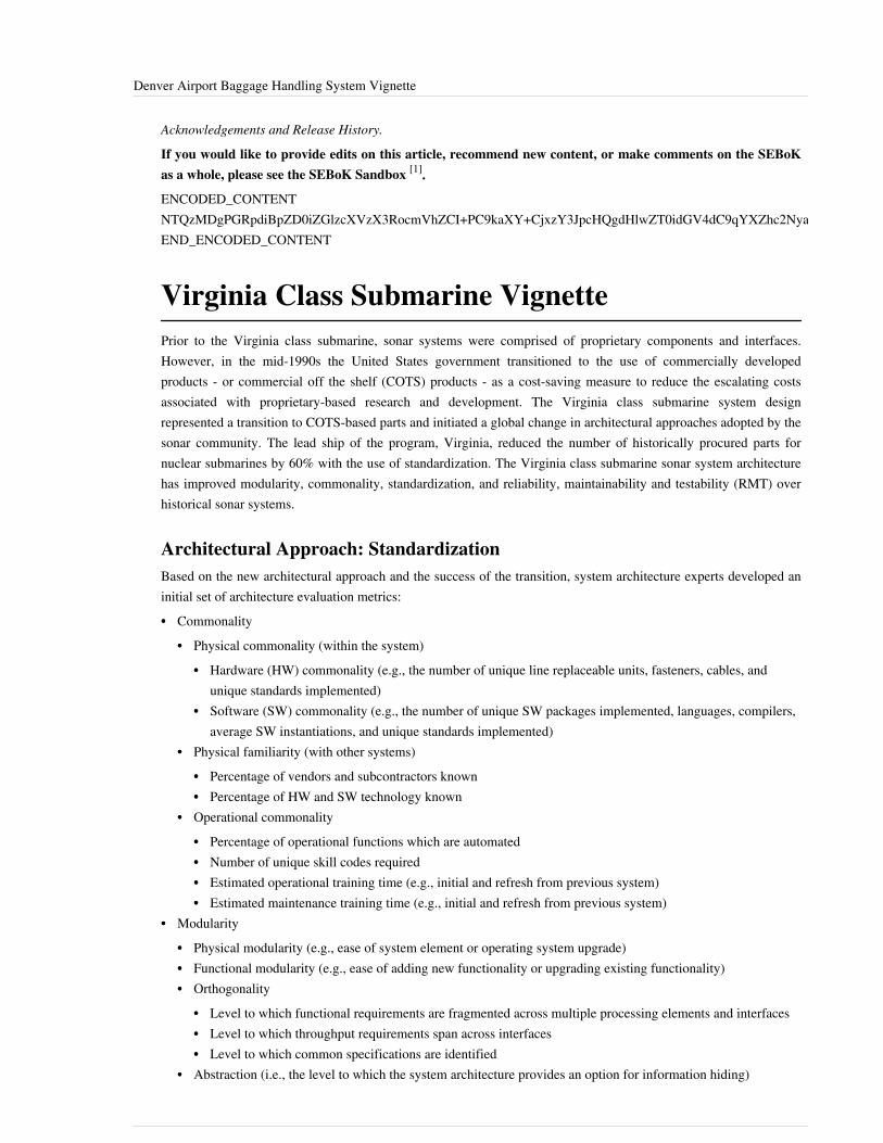
Denver Airport Baggage Handling System Vignette 67
Acknowledgements and Release History.
If you would like to provide edits on this article, recommend new content, or make comments on the SEBoKas a whole, please see the SEBoK Sandbox [1].
ENCODED_CONTENTNTQzMDgPGRpdiBpZD0iZGlzcXVzX3RocmVhZCI+PC9kaXY+CjxzY3JpcHQgdHlwZT0idGV4dC9qYXZhc2NyaXB0Ij4KICAgIC8qICogKiBDT05GSUdVUkFUSU9OIFZBUklBQkxFUzogRURJVCBCRUZPUkUgUEFTVElORyBJTlRPIFlPVVIgV0VCUEFHRSAqICogKi8KICAgIHZhciBkaXNxdXNfc2hvcnRuYW1lID0gJ3NlYm9rd2lraTEwJzsgLy8gcmVxdWlyZWQ6IHJlcGxhY2UgZXhhbXBsZSB3aXRoIHlvdXIgZm9ydW0gc2hvcnRuYW1lCiAgICB2YXIgZGlzcXVzX2lkZW50aWZpZXIgPSAnRGVudmVyIEFpcnBvcnQgQmFnZ2FnZSBIYW5kbGluZyBTeXN0ZW0gVmlnbmV0dGUnOyAgICB2YXIgZGlzcXVzX3VybCA9ICdodHRwOi8vc2Vib2t3aWtpLm9yZy9kcmFmdC9EZW52ZXJfQWlycG9ydF9CYWdnYWdlX0hhbmRsaW5nX1N5c3RlbV9WaWduZXR0ZSc7CiAgICAvKiAqICogRE9OJ1QgRURJVCBCRUxPVyBUSElTIExJTkUgKiAqICovCiAgICAoZnVuY3Rpb24oKSB7CiAgICAgICAgdmFyIGRzcSA9IGRvY3VtZW50LmNyZWF0ZUVsZW1lbnQoJ3NjcmlwdCcpOyBkc3EudHlwZSA9ICd0ZXh0L2phdmFzY3JpcHQnOyBkc3EuYXN5bmMgPSB0cnVlOwogICAgICAgIGRzcS5zcmMgPSAnaHR0cDovLycgKyBkaXNxdXNfc2hvcnRuYW1lICsgJy5kaXNxdXMuY29tL2VtYmVkLmpzJzsKICAgICAgICAoZG9jdW1lbnQuZ2V0RWxlbWVudHNCeVRhZ05hbWUoJ2hlYWQnKVswXSB8fCBkb2N1bWVudC5nZXRFbGVtZW50c0J5VGFnTmFtZSgnYm9keScpWzBdKS5hcHBlbmRDaGlsZChkc3EpOwogICAgfSkoKTsKPC9zY3JpcHQ+Cjxub3NjcmlwdD5QbGVhc2UgZW5hYmxlIEphdmFTY3JpcHQgdG8gdmlldyB0aGUgPGEgaHJlZj0iaHR0cDovL2Rpc3F1cy5jb20vP3JlZl9ub3NjcmlwdCI+Y29tbWVudHMgcG93ZXJlZCBieSBEaXNxdXMuPC9hPjwvbm9zY3JpcHQ+CjxhIGhyZWY9Imh0dHA6Ly9kaXNxdXMuY29tIiBjbGFzcz0iZHNxLWJybGluayI+YmxvZyBjb21tZW50cyBwb3dlcmVkIGJ5IDxzcGFuIGNsYXNzPSJsb2dvLWRpc3F1cyI+RGlzcXVzPC9zcGFuPjwvYT4=END_ENCODED_CONTENT
Virginia Class Submarine VignettePrior to the Virginia class submarine, sonar systems were comprised of proprietary components and interfaces.However, in the mid-1990s the United States government transitioned to the use of commercially developedproducts - or commercial off the shelf (COTS) products - as a cost-saving measure to reduce the escalating costsassociated with proprietary-based research and development. The Virginia class submarine system designrepresented a transition to COTS-based parts and initiated a global change in architectural approaches adopted by thesonar community. The lead ship of the program, Virginia, reduced the number of historically procured parts fornuclear submarines by 60% with the use of standardization. The Virginia class submarine sonar system architecturehas improved modularity, commonality, standardization, and reliability, maintainability and testability (RMT) overhistorical sonar systems.
Architectural Approach: StandardizationBased on the new architectural approach and the success of the transition, system architecture experts developed aninitial set of architecture evaluation metrics:•• Commonality
•• Physical commonality (within the system)•• Hardware (HW) commonality (e.g., the number of unique line replaceable units, fasteners, cables, and
unique standards implemented)•• Software (SW) commonality (e.g., the number of unique SW packages implemented, languages, compilers,
average SW instantiations, and unique standards implemented)•• Physical familiarity (with other systems)
•• Percentage of vendors and subcontractors known•• Percentage of HW and SW technology known
•• Operational commonality•• Percentage of operational functions which are automated•• Number of unique skill codes required•• Estimated operational training time (e.g., initial and refresh from previous system)•• Estimated maintenance training time (e.g., initial and refresh from previous system)
•• Modularity•• Physical modularity (e.g., ease of system element or operating system upgrade)•• Functional modularity (e.g., ease of adding new functionality or upgrading existing functionality)•• Orthogonality
•• Level to which functional requirements are fragmented across multiple processing elements and interfaces•• Level to which throughput requirements span across interfaces•• Level to which common specifications are identified
•• Abstraction (i.e., the level to which the system architecture provides an option for information hiding)

Virginia Class Submarine Vignette 68
•• Interfaces•• Number of unique interfaces per system element•• Number of different networking protocols•• Explicit versus implicit interfaces•• Level to which the architecture includes implicit interfaces•• Number of cables in the system
•• Standards-based openness•• Interface standards
•• Ratio of the number of interface standards to the number of interfaces•• Number of vendors for products based on standards•• Number of business domains that apply/use the standard (e.g., aerospace, medical, and telecommunications)•• Standard maturity
•• Hardware standards•• Ratio of the number of form factors to the number of line replaceable units (LRUs)•• Number of vendors for products based on standards•• Standard maturity
•• Software standards•• Number of proprietary and unique operating systems•• Number of non-standard databases•• Number of proprietary middle-ware•• Number of non-standard languages
•• Consistency orientation•• Common guidelines for implementing diagnostics and performance monitor/fault location (PM/FL)•• Common guidelines for implementing human-machine interface (HMI)
•• Reliability, maintainability, and testability•• Reliability (fault tolerance)•• Critical points of fragility (e.g., system loading comprised of percent of processor, memory, and network
loading)•• Maintainability (e.g., expected mean time to repair (MTTR), maximum fault group size, whether the system
can be operational during maintenance)•• Accessibility (e.g., space restrictions, special tool requirements, special skill requirements)•• Testability
•• Number of LRUs covered by built-in tests (BIT) (BIT coverage)•• Reproducibility of errors•• Logging/recording capability•• Whether the system state at time of system failure can be recreated•• Online testing (e.g., whether the system is operational during external testing and the ease of access to
external test points)•• Automated input/stimulation insertion

Virginia Class Submarine Vignette 69
Other PointsThe Virginia class submarine acquisition exhibited other best practices. These are discussed by Schank (2011), GAO(2008), and General Dynamics (2002).These best practices included stringent design trades to keep costs under control, careful consideration of technicalmaturity of components, and the importance of program stability.
SummaryIn summary, the work on the Virginia class submarine prompted a change in the traditional architectural approachused in the sonar community to design submarine sonar and validated the cost savings in both research anddevelopment (R&D) and in component costs when transitioning from proprietary interfaces to industry standardinterfaces. The identification of a list of feasible architecture evaluation metrics was an added benefit of the effort.
References
Works CitedGAO. 2008. Defense Acquisitions: Assessment of Selected Weapon Programs Report. Washington, DC, USA: US.Government Accountability Office (GAO). March 2009. GAO-09-326SP.GD Electric Boat Division. 2002. The Virginia Class Submarine Program: A Case Study. Groton, CT: GeneralDynamics. February, 2002.Schank, J.F. et al. 2011. Learning from Experience, Volume 2: Lessons from the U.S. Navy's Ohio, Seawolf, andVirginia Submarine Programs. Santa Monica, CA, USA: Rand. Available at http:/ / www. rand. org/ content/ dam/rand/ pubs/ monographs/ 2011/ RAND_MG1128. 2. pdf [1]
Primary ReferencesNone.
Additional ReferencesNone.
< Previous Article | Parent Article | Next Article >SEBoK v. 1.4 released 29 June 2015
SEBoK DiscussionPlease provide your comments and feedback on the SEBoK below. You will need to log in to DISQUS using anexisting account (e.g. Yahoo, Google, Facebook, Twitter, etc.) or create a DISQUS account. Simply type yourcomment in the text field below and DISQUS will guide you through the login or registration steps. Feedback will bearchived and used for future updates to the SEBoK. If you provided a comment that is no longer listed, that commenthas been adjudicated. You can view adjudication for comments submitted prior to SEBoK v. 1.0 at SEBoK Reviewand Adjudication. Later comments are addressed and changes are summarized in the Letter from the Editor andAcknowledgements and Release History.
If you would like to provide edits on this article, recommend new content, or make comments on the SEBoKas a whole, please see the SEBoK Sandbox [1].
ENCODED_CONTENTMjU5ODUPGRpdiBpZD0iZGlzcXVzX3RocmVhZCI+PC9kaXY+CjxzY3JpcHQgdHlwZT0idGV4dC9qYXZhc2NyaXB0Ij4KICAgIC8qICogKiBDT05GSUdVUkFUSU9OIFZBUklBQkxFUzogRURJVCBCRUZPUkUgUEFTVElORyBJTlRPIFlPVVIgV0VCUEFHRSAqICogKi8KICAgIHZhciBkaXNxdXNfc2hvcnRuYW1lID0gJ3NlYm9rd2lraTEwJzsgLy8gcmVxdWlyZWQ6IHJlcGxhY2UgZXhhbXBsZSB3aXRoIHlvdXIgZm9ydW0gc2hvcnRuYW1lCiAgICB2YXIgZGlzcXVzX2lkZW50aWZpZXIgPSAnVmlyZ2luaWEgQ2xhc3MgU3VibWFyaW5lIFZpZ25ldHRlJzsgICAgdmFyIGRpc3F1c191cmwgPSAnaHR0cDovL3NlYm9rd2lraS5vcmcvZHJhZnQvVmlyZ2luaWFfQ2xhc3NfU3VibWFyaW5lX1ZpZ25ldHRlJzsKICAgIC8qICogKiBET04nVCBFRElUIEJFTE9XIFRISVMgTElORSAqICogKi8KICAgIChmdW5jdGlvbigpIHsKICAgICAgICB2YXIgZHNxID0gZG9jdW1lbnQuY3JlYXRlRWxlbWVudCgnc2NyaXB0Jyk7IGRzcS50eXBlID0gJ3RleHQvamF2YXNjcmlwdCc7IGRzcS5hc3luYyA9IHRydWU7CiAgICAgICAgZHNxLnNyYyA9ICdodHRwOi8vJyArIGRpc3F1c19zaG9ydG5hbWUgKyAnLmRpc3F1cy5jb20vZW1iZWQuanMnOwogICAgICAgIChkb2N1bWVudC5nZXRFbGVtZW50c0J5VGFnTmFtZSgnaGVhZCcpWzBdIHx8IGRvY3VtZW50LmdldEVsZW1lbnRzQnlUYWdOYW1lKCdib2R5JylbMF0pLmFwcGVuZENoaWxkKGRzcSk7CiAgICB9KSgpOwo8L3NjcmlwdD4KPG5vc2NyaXB0PlBsZWFzZSBlbmFibGUgSmF2YVNjcmlwdCB0byB2aWV3IHRoZSA8YSBocmVmPSJodHRwOi8vZGlzcXVzLmNvbS8/cmVmX25vc2NyaXB0Ij5jb21tZW50cyBwb3dlcmVkIGJ5IERpc3F1cy48L2E+PC9ub3NjcmlwdD4KPGEgaHJlZj0iaHR0cDovL2Rpc3F1cy5jb20iIGNsYXNzPSJkc3EtYnJsaW5rIj5ibG9nIGNvbW1lbnRzIHBvd2VyZWQgYnkgPHNwYW4gY2xhc3M9ImxvZ28tZGlzcXVzIj5EaXNxdXM8L3NwYW4+PC9hPg==

Virginia Class Submarine Vignette 70
END_ENCODED_CONTENT
References[1] http:/ / www. rand. org/ content/ dam/ rand/ pubs/ monographs/ 2011/ RAND_MG1128. 2. pdf
UK West Coast Route Modernisation ProjectVignetteThe West Coast Main Line (WCML) is a principal United Kingdom (UK) railway artery serving London, theMidlands, the North West and Scotland. The Line is responsible for over 2,000 train movements each day, with morethan 75 million rail journeys made each year on the route. It accounts for 43% of Britain’s UK freight market(Railway People 2011). In 1998, the British government embarked on a modernization program called the WestCoast Route Modernisation (WCRM) project, to carry out a significant volume of modernization work between 1998and 2008, delivering increased capacity and reduced journey times as well as replacing worn-out parts of the railway.It was challenging a job involving 640 kilometers of track—much of which was incapable of carrying high-speed railcars. Some sections were seriously dilapidated, and new trains would require a complete overhaul of signaling,power supply, and switching systems.This vignette is based on information from an INCOSE publication on systems engineering case studies (INCOSE2011) and a report of the UK National Audit Office (NAO 2006).
Vignette DescriptionEarly on, the WCRM upgrade had serious problems. A major complicating factor was the introduction of a newsignaling technology that was designed to allow improved services for new trains running at 140 miles per hour. By2001, neither the rail infrastructure upgrade nor the new trains were on course for delivery as expected in the 1998agreement. By May 2002 the projection of the program’s final cost had risen from £2.5 billion (in 1998) to £14.5billion, but had delivered only a sixth of the original scope.In January 2002, the UK Secretary of State instructed the Strategic Rail Authority (SRA) to intervene and find a wayto renew and upgrade the WCML. An SRA analysis identified the following issues:•• The program lacked direction and leadership before 2002.•• The project did not have a delivery strategy and there was no central point for responsibility and communication.• There was a lack of openness and communication regarding the program with interested parties before 2002 and a
lack of stakeholder management.• Scope changes arose because WCRM did not have an agreed-upon specification that matched required outputs
with inputs.•• There was inadequate knowledge about the West Coast asset condition.• Technology issues related to the decision to replace conventional signaling with unproven moving block signaling
introduced major risk into deliverability and cost before 2002. These technology issues caused scope changes andprogram delay.
•• Project management (PM) was weak, with a lack of senior management skills, too many changes in personnel,and ill-defined and fragmented roles and responsibilities. There was no integrated delivery plan and there waslimited oversight of contractors. Poor management of contracts added to costs.
In order to remedy the situation the SRA initiated the following actions, which align with generally accepted systemsengineering (SE) practice:

UK West Coast Route Modernisation Project Vignette 71
•• A clear direction for the project was developed and documented in the June 2003 West Coast Main Line Strategy,specifying desired goals and outcomes.
•• A clear, measurable set of program outputs was established, along with more detailed infrastructure requirements,which were then subject to systematic change control and monitoring procedures fixing scope. Contractors wereinvited to tender complete detailed designs and deliver the work to a fixed price.
•• Clear program governance structures were instituted.•• The SRA consulted widely with stakeholders and, in turn, kept stakeholders informed.A National Audit Office (NAO) report concluded that the new arrangements worked well and that there werebenefits to this approach. (NAO 2006) Until this time, one of the program's key constraints and cost drivers had beenthe ability to access certain areas of the track. The new approach facilitated the ability to obtain possession of thetrack for engineering work, which was crucial to delivery. The new approach also enabled the program to identifyopportunities to reduce the total cost by over £4 billion.The NAO report also discussed a business case analysis by the SRA that identified the following benefits (NAO2006):•• benefit:cost ratio for the enhancements element was 2.5:1;•• journey times and train frequencies exceeded the targets set out in the 2003 West Coast Strategy;•• growth in passenger numbers exceeded expectations (e.g., by 2005-06, following Phase 1 of the West Coast
program, annual passenger journeys on Virgin West Coast grew by more than 20%); and•• punctuality improved (e.g., by September 2006, average time delays on Virgin West Coast trains have been
approximately 9.5 minutes, a 43% improvement on the average delay of 17 minutes in September 2004).The WCRM problems could be associated with a number of systems engineering concepts and practices:stakeholders requirements, planning, analysis of risks and challenges of new technology and associated riskmanagement, decision management, configuration or change management, information management, andmanagement oversight.
SummaryThe WCRM project illustrates that when SE concepts and practices are not used or applied properly, systemdevelopment can experience debilitating problems. This project also demonstrates how such problems can be abatedand reversed when SE principles and methods are applied.
References
Works CitedINCOSE Transportation Working Group. 2011. Systems Engineering in Transportation Projects: A Library of CaseStudies, version 1.0. Seattle, WA, USA: International Council on Systems Engineering. March 9th, 2011.NAO. 2006. The Modernisation of the West Coast Main Line, Report by the Comptroller and Auditor General.London, UK: National Audit Office. November 22, 2006. HC 22 Session 2006-2007.Railway People. 2011. '"West Coast Route Modernisation." RailwayPeople.com website. Accessed July 25, 2011.Available at: http:/ / www. railwaypeople. com/ rail-projects/ west-coast-route-modernisation-3. html.

UK West Coast Route Modernisation Project Vignette 72
Primary ReferencesNone.
Additional ReferencesNone.
< Previous Article | Parent Article | Next Article >SEBoK v. 1.4 released 29 June 2015
SEBoK DiscussionPlease provide your comments and feedback on the SEBoK below. You will need to log in to DISQUS using anexisting account (e.g. Yahoo, Google, Facebook, Twitter, etc.) or create a DISQUS account. Simply type yourcomment in the text field below and DISQUS will guide you through the login or registration steps. Feedback will bearchived and used for future updates to the SEBoK. If you provided a comment that is no longer listed, that commenthas been adjudicated. You can view adjudication for comments submitted prior to SEBoK v. 1.0 at SEBoK Reviewand Adjudication. Later comments are addressed and changes are summarized in the Letter from the Editor andAcknowledgements and Release History.
If you would like to provide edits on this article, recommend new content, or make comments on the SEBoKas a whole, please see the SEBoK Sandbox [1].
ENCODED_CONTENTMTMwMTAPGRpdiBpZD0iZGlzcXVzX3RocmVhZCI+PC9kaXY+CjxzY3JpcHQgdHlwZT0idGV4dC9qYXZhc2NyaXB0Ij4KICAgIC8qICogKiBDT05GSUdVUkFUSU9OIFZBUklBQkxFUzogRURJVCBCRUZPUkUgUEFTVElORyBJTlRPIFlPVVIgV0VCUEFHRSAqICogKi8KICAgIHZhciBkaXNxdXNfc2hvcnRuYW1lID0gJ3NlYm9rd2lraTEwJzsgLy8gcmVxdWlyZWQ6IHJlcGxhY2UgZXhhbXBsZSB3aXRoIHlvdXIgZm9ydW0gc2hvcnRuYW1lCiAgICB2YXIgZGlzcXVzX2lkZW50aWZpZXIgPSAnVUsgV2VzdCBDb2FzdCBSb3V0ZSBNb2Rlcm5pc2F0aW9uIFByb2plY3QgVmlnbmV0dGUnOyAgICB2YXIgZGlzcXVzX3VybCA9ICdodHRwOi8vc2Vib2t3aWtpLm9yZy9kcmFmdC9VS19XZXN0X0NvYXN0X1JvdXRlX01vZGVybmlzYXRpb25fUHJvamVjdF9WaWduZXR0ZSc7CiAgICAvKiAqICogRE9OJ1QgRURJVCBCRUxPVyBUSElTIExJTkUgKiAqICovCiAgICAoZnVuY3Rpb24oKSB7CiAgICAgICAgdmFyIGRzcSA9IGRvY3VtZW50LmNyZWF0ZUVsZW1lbnQoJ3NjcmlwdCcpOyBkc3EudHlwZSA9ICd0ZXh0L2phdmFzY3JpcHQnOyBkc3EuYXN5bmMgPSB0cnVlOwogICAgICAgIGRzcS5zcmMgPSAnaHR0cDovLycgKyBkaXNxdXNfc2hvcnRuYW1lICsgJy5kaXNxdXMuY29tL2VtYmVkLmpzJzsKICAgICAgICAoZG9jdW1lbnQuZ2V0RWxlbWVudHNCeVRhZ05hbWUoJ2hlYWQnKVswXSB8fCBkb2N1bWVudC5nZXRFbGVtZW50c0J5VGFnTmFtZSgnYm9keScpWzBdKS5hcHBlbmRDaGlsZChkc3EpOwogICAgfSkoKTsKPC9zY3JpcHQ+Cjxub3NjcmlwdD5QbGVhc2UgZW5hYmxlIEphdmFTY3JpcHQgdG8gdmlldyB0aGUgPGEgaHJlZj0iaHR0cDovL2Rpc3F1cy5jb20vP3JlZl9ub3NjcmlwdCI+Y29tbWVudHMgcG93ZXJlZCBieSBEaXNxdXMuPC9hPjwvbm9zY3JpcHQ+CjxhIGhyZWY9Imh0dHA6Ly9kaXNxdXMuY29tIiBjbGFzcz0iZHNxLWJybGluayI+YmxvZyBjb21tZW50cyBwb3dlcmVkIGJ5IDxzcGFuIGNsYXNzPSJsb2dvLWRpc3F1cyI+RGlzcXVzPC9zcGFuPjwvYT4=END_ENCODED_CONTENT
Singapore Water Management VignetteThis vignette describes a systems engineering approach in the development of a sustainable National WaterManagement System for the Republic of Singapore. It demonstrates the successful outcome of long term planningand a systems approach to preempt a critical water shortage. The vignette is primarily based on information takenfrom a paper presented at the INCOSE International Symposium in 2008. (Chia 2008)
Vignette DescriptionWhen Singapore achieved independence in 1965, water supply depended on water catchment in local reservoirs andtwo bilateral water agreements with its closest neighbor, Malaysia. These water agreements are registered with theUnited Nations. The first agreement expired in August 2011, and the second agreement will expire in 2061(Singapore 2012). After several failed attempts to renegotiate the extension of the first water agreement, Singaporedetermined that it was necessary to achieve full water self sufficiency by 2060 in case the second water agreementalso could not be extended. An intermediate goal was to match the supply of the first water agreement before itexpired. This was achieved in several ways. In 2001, the Public Utilities Board (PUB), the national water agencyresponsible for treating raw water in Singapore, was charged to also begin managing wastewater and stormwater,allowing for an integrated and holistic approach to water management.This vignette examines Singapore’s water management system from a large-scale systems engineering perspective, particularly focusing on the goals, boundaries (see Concepts of Systems Thinking), stakeholders (see Stakeholder Needs and Requirements), and complexities involved in this type of a national system. This approach illustrates how Systems Thinking (illustrated through causal loop diagrams) and other systems engineering tools may be used to
Singapore Water Management Vignette 73
understand systems complexities. Concepts and methodologies of learning organizations were applied to enableunderstanding of behavioral complexities. Lean thinking facilitated a long term strategic philosophy, built on thepremise of continuous improvements.Perhaps more importantly, it shows that while systems engineering, especially the Systems Approach, is necessaryfor the conceptualization and planning of such a complex system, it is not sufficient for success. It is the systemicstructures that have been put in place over decades, political will, leadership, people, and culture that make suchtasks realizable.The supply of water in Singapore is managed in totality. Collecting rainwater, purchasing water, purifying waterutilizing reverse osmosis and desalination were all considered. Approaches included even incentivising consumers tochange their habits by making drains and canals recreational areas to encourage the public not to dispose of waste intheir drains. By managing sewage and drainage together with water, environmental considerations are taken intoaccount as well. By carefully adjusting organizational boundaries, Singapore has managed to reduce silo thinkingand parochial interests. The relationships between the industry innovators, government, suppliers and users, andtechnology innovators create opportunities for Singapore’s water management. This demonstrates how multiplestakeholder interests can be combined to create a viable water management solution. Continuous improvementsthrough the use of technology and elimination of waste, such as reducing water that is not accounted for in thesystem, help to assure the sustainability of an adequate supply of water for a growing Singapore population. TheSingapore Water Management system is already in successful operation and is being studied by the Organisation forEconomic Co-operation and Development (OECD) and by other nations.
SummaryThe supply of water in Singapore is managed in totality through a systems approach, i.e., water catchment, supply,sewage and drainage. The importance of relationships between the stakeholders is also recognized. Industryinnovators, political leadership, suppliers, and consumers are all involved; the project has been able to incentivizethis diverse group to work together for a common goal, i.e., assuring the sustainability of an adequate supply ofwater for Singapore into the future.Utilizing systems engineering and taking into consideration the systemic structures and culture required has helpedSingapore achieve its first milestone of supplying its own water resources by 2010. Singapore has been able toovercome the shortfall that would have come about with the expiry of the first water agreement with Malaysia in2011.
References
Works CitedChia, A. 2008. "A Large-Scale Systems Engineering Perspective of Water Management in Singapore." Proceedingsof the 18th Annual INCOSE International Symposium, 15-19 June 2008, Utrech, The Netherlands.Singapore Government. 2012. "The Singapore Water Story." Accessed August 2012. Available at http:/ / www. pub.gov. sg/ water/ Pages/ singaporewaterstory. aspx.
Primary ReferencesNone.

Singapore Water Management Vignette 74
Additional ReferencesPublic Utilities Board. 2007. "PUB Main Website". Accessed August 2011. Available at http:/ / www. pub. gov. sg.Tortajada, C. 2006. "Water Management in Singapore." International Journal of Water Resources Development.22(2): 227-240.
< Previous Article | Parent Article | Next Article >SEBoK v. 1.4 released 29 June 2015
SEBoK DiscussionPlease provide your comments and feedback on the SEBoK below. You will need to log in to DISQUS using anexisting account (e.g. Yahoo, Google, Facebook, Twitter, etc.) or create a DISQUS account. Simply type yourcomment in the text field below and DISQUS will guide you through the login or registration steps. Feedback will bearchived and used for future updates to the SEBoK. If you provided a comment that is no longer listed, that commenthas been adjudicated. You can view adjudication for comments submitted prior to SEBoK v. 1.0 at SEBoK Reviewand Adjudication. Later comments are addressed and changes are summarized in the Letter from the Editor andAcknowledgements and Release History.
If you would like to provide edits on this article, recommend new content, or make comments on the SEBoKas a whole, please see the SEBoK Sandbox [1].
ENCODED_CONTENTMTEwNzEPGRpdiBpZD0iZGlzcXVzX3RocmVhZCI+PC9kaXY+CjxzY3JpcHQgdHlwZT0idGV4dC9qYXZhc2NyaXB0Ij4KICAgIC8qICogKiBDT05GSUdVUkFUSU9OIFZBUklBQkxFUzogRURJVCBCRUZPUkUgUEFTVElORyBJTlRPIFlPVVIgV0VCUEFHRSAqICogKi8KICAgIHZhciBkaXNxdXNfc2hvcnRuYW1lID0gJ3NlYm9rd2lraTEwJzsgLy8gcmVxdWlyZWQ6IHJlcGxhY2UgZXhhbXBsZSB3aXRoIHlvdXIgZm9ydW0gc2hvcnRuYW1lCiAgICB2YXIgZGlzcXVzX2lkZW50aWZpZXIgPSAnU2luZ2Fwb3JlIFdhdGVyIE1hbmFnZW1lbnQgVmlnbmV0dGUnOyAgICB2YXIgZGlzcXVzX3VybCA9ICdodHRwOi8vc2Vib2t3aWtpLm9yZy9kcmFmdC9TaW5nYXBvcmVfV2F0ZXJfTWFuYWdlbWVudF9WaWduZXR0ZSc7CiAgICAvKiAqICogRE9OJ1QgRURJVCBCRUxPVyBUSElTIExJTkUgKiAqICovCiAgICAoZnVuY3Rpb24oKSB7CiAgICAgICAgdmFyIGRzcSA9IGRvY3VtZW50LmNyZWF0ZUVsZW1lbnQoJ3NjcmlwdCcpOyBkc3EudHlwZSA9ICd0ZXh0L2phdmFzY3JpcHQnOyBkc3EuYXN5bmMgPSB0cnVlOwogICAgICAgIGRzcS5zcmMgPSAnaHR0cDovLycgKyBkaXNxdXNfc2hvcnRuYW1lICsgJy5kaXNxdXMuY29tL2VtYmVkLmpzJzsKICAgICAgICAoZG9jdW1lbnQuZ2V0RWxlbWVudHNCeVRhZ05hbWUoJ2hlYWQnKVswXSB8fCBkb2N1bWVudC5nZXRFbGVtZW50c0J5VGFnTmFtZSgnYm9keScpWzBdKS5hcHBlbmRDaGlsZChkc3EpOwogICAgfSkoKTsKPC9zY3JpcHQ+Cjxub3NjcmlwdD5QbGVhc2UgZW5hYmxlIEphdmFTY3JpcHQgdG8gdmlldyB0aGUgPGEgaHJlZj0iaHR0cDovL2Rpc3F1cy5jb20vP3JlZl9ub3NjcmlwdCI+Y29tbWVudHMgcG93ZXJlZCBieSBEaXNxdXMuPC9hPjwvbm9zY3JpcHQ+CjxhIGhyZWY9Imh0dHA6Ly9kaXNxdXMuY29tIiBjbGFzcz0iZHNxLWJybGluayI+YmxvZyBjb21tZW50cyBwb3dlcmVkIGJ5IDxzcGFuIGNsYXNzPSJsb2dvLWRpc3F1cyI+RGlzcXVzPC9zcGFuPjwvYT4=END_ENCODED_CONTENT
FAA Advanced Automation System (AAS)VignetteIn 1981 the Federal Aviation Administration (FAA) announced the Advanced Automation Program, which wasestablished to modernize air traffic control (ATC) computer systems. A centerpiece of the project was the AdvancedAutomation System (AAS). AAS was the largest project in FAA’s history to modernize the nation’s ATC system.AAS would replace computer hardware and software as well as controller work stations at tower, terminal, anden-route facilities and allow the ATC system to accommodate forecasted large increases in traffic through the use ofmodern equipment and advanced software functions. (GAO 1992)
Vignette DescriptionThe FAA originally proposed AAS in 1982 as a project that would cost $2.5 billion and be completed in 1996.However, substantial cost increases and schedule delays beset the AAS project over it history, caused by numerousproblems in AAS development:• The project began with a design competition between Hughes and IBM. The competition involved numerous
extensions and took four years to complete. Analysis by the FAA and others pointed to inadequate considerationof user expectations and improper assessment of the technology risks. (Barlas 1996)
• The FAA pushed for 99.99999% reliability, which was considered by some “more stringent than on any systemthat has ever been implemented” and extremely costly. (DOT 1998)
• The program created unworkable software testing schedules - “Testing milestones were skipped or shortcutted andnew software was developed assuming that the previously developed software had been tested and performed.”(Barlas 1996)

FAA Advanced Automation System (AAS) Vignette 75
• There were an extraordinary number of requirements changes. For example, for the Initial Sector Suite System(ISSS), a key component of AAS, there were over 500 requirements changes in 1990. Because of these changes,150,000 lines of software code had to be rewritten at a cost of $242 million. (Boppana et al. 2006)
• IBM’s cost estimation and development process tracking used inappropriate data, were performed inconsistently,and were routinely ignored by project managers. The FAA conservatively expected to pay about $500 per line ofcomputer code - five times the industry average. The FAA ended up paying $700 to $900 per line for the AASsoftware. (Gibbs 1994)
• In 1988, FAA estimated that the AAS program - both contract and supporting efforts - would cost $4.8 billion. Bylate 1993, the FAA estimated that it would cost $5.9 billion. Before the program was dramatically restructured in1994, estimates had risen to as much as $7 billion, with key segments expected to be behind schedule by as much8 years. In 1994, with significant cost and schedule overruns, as well as concerns about adequate quality,usability, and reliability, the AAS program ceased to exist as originally conceived, leaving its various elementsterminated, restructured, or as parts of smaller programs. (DOT 1998)
The AAS problems could be associated with the non-use or misuse of a number of systems engineering (SE)concepts and practices: system requirements, system architecture complexity, project planning, risk management,change management, system analysis and design, system reliability, system integration, system verification andsystem validation/testing, and management oversight.
SummaryThe AAS program was the centerpiece of an ambitious effort begun in the 1980s to replace the computer hardwareand software throughout the ATC system - including controller workstations, and en-route, terminal, and tower airtraffic control facilities. AAS was intended to provide new automated capabilities to accommodate increases in airtraffic. After sustaining serious cost and schedule problems, FAA dramatically restructured the program into moremanageable pieces. This action included terminating major segments of the contract. (DOT 1998)
References
Works CitedBarlas, S. “Anatomy of a Runaway: What Grounded the AAS.” IEEE Software. 13(1): 104-106.Boppana, K., S. Chow, O.L. de Weck, C. LaFon, S.D. Lekkakos, J. Lyneis, M. Rinaldi, Z. Wang, P. Wheeler, M.Zborovskiy. 2006. "Can Models Capture the Complexity of the Systems Engineering Process?" Proceedings of theInternational Conference on Complex Systems (ICC2006), 11-15 June 2006, Istanbul, Turkey.DOT. 1998. Audit Report: Advance Automation System, Federal Aviation Administration. Washington, DC, USA:Office of Inspector General, U.S. Department of Transportation.GAO. 1992. Advanced Automation System Still Vulnerable to Cost and Schedule Problems. Washington, DC, USA:United States General Accounting Office (GAO). GAO/RCED-92-264.Gibbs, W.W. “Software’s Chronic Crisis.” Scientific American. September 1994.
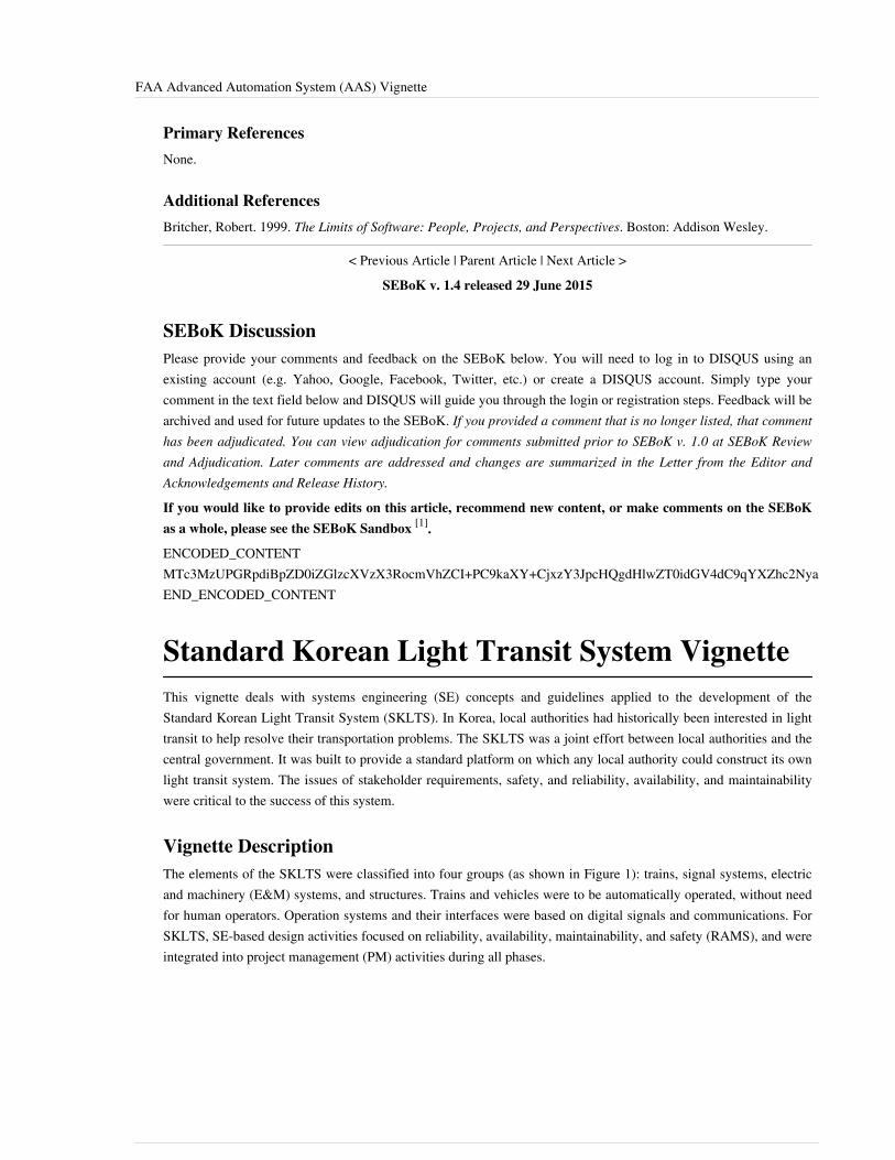
FAA Advanced Automation System (AAS) Vignette 76
Primary ReferencesNone.
Additional ReferencesBritcher, Robert. 1999. The Limits of Software: People, Projects, and Perspectives. Boston: Addison Wesley.
< Previous Article | Parent Article | Next Article >SEBoK v. 1.4 released 29 June 2015
SEBoK DiscussionPlease provide your comments and feedback on the SEBoK below. You will need to log in to DISQUS using anexisting account (e.g. Yahoo, Google, Facebook, Twitter, etc.) or create a DISQUS account. Simply type yourcomment in the text field below and DISQUS will guide you through the login or registration steps. Feedback will bearchived and used for future updates to the SEBoK. If you provided a comment that is no longer listed, that commenthas been adjudicated. You can view adjudication for comments submitted prior to SEBoK v. 1.0 at SEBoK Reviewand Adjudication. Later comments are addressed and changes are summarized in the Letter from the Editor andAcknowledgements and Release History.
If you would like to provide edits on this article, recommend new content, or make comments on the SEBoKas a whole, please see the SEBoK Sandbox [1].
ENCODED_CONTENTMTc3MzUPGRpdiBpZD0iZGlzcXVzX3RocmVhZCI+PC9kaXY+CjxzY3JpcHQgdHlwZT0idGV4dC9qYXZhc2NyaXB0Ij4KICAgIC8qICogKiBDT05GSUdVUkFUSU9OIFZBUklBQkxFUzogRURJVCBCRUZPUkUgUEFTVElORyBJTlRPIFlPVVIgV0VCUEFHRSAqICogKi8KICAgIHZhciBkaXNxdXNfc2hvcnRuYW1lID0gJ3NlYm9rd2lraTEwJzsgLy8gcmVxdWlyZWQ6IHJlcGxhY2UgZXhhbXBsZSB3aXRoIHlvdXIgZm9ydW0gc2hvcnRuYW1lCiAgICB2YXIgZGlzcXVzX2lkZW50aWZpZXIgPSAnRkFBIEFkdmFuY2VkIEF1dG9tYXRpb24gU3lzdGVtIChBQVMpIFZpZ25ldHRlJzsgICAgdmFyIGRpc3F1c191cmwgPSAnaHR0cDovL3NlYm9rd2lraS5vcmcvZHJhZnQvRkFBX0FkdmFuY2VkX0F1dG9tYXRpb25fU3lzdGVtXyhBQVMpX1ZpZ25ldHRlJzsKICAgIC8qICogKiBET04nVCBFRElUIEJFTE9XIFRISVMgTElORSAqICogKi8KICAgIChmdW5jdGlvbigpIHsKICAgICAgICB2YXIgZHNxID0gZG9jdW1lbnQuY3JlYXRlRWxlbWVudCgnc2NyaXB0Jyk7IGRzcS50eXBlID0gJ3RleHQvamF2YXNjcmlwdCc7IGRzcS5hc3luYyA9IHRydWU7CiAgICAgICAgZHNxLnNyYyA9ICdodHRwOi8vJyArIGRpc3F1c19zaG9ydG5hbWUgKyAnLmRpc3F1cy5jb20vZW1iZWQuanMnOwogICAgICAgIChkb2N1bWVudC5nZXRFbGVtZW50c0J5VGFnTmFtZSgnaGVhZCcpWzBdIHx8IGRvY3VtZW50LmdldEVsZW1lbnRzQnlUYWdOYW1lKCdib2R5JylbMF0pLmFwcGVuZENoaWxkKGRzcSk7CiAgICB9KSgpOwo8L3NjcmlwdD4KPG5vc2NyaXB0PlBsZWFzZSBlbmFibGUgSmF2YVNjcmlwdCB0byB2aWV3IHRoZSA8YSBocmVmPSJodHRwOi8vZGlzcXVzLmNvbS8/cmVmX25vc2NyaXB0Ij5jb21tZW50cyBwb3dlcmVkIGJ5IERpc3F1cy48L2E+PC9ub3NjcmlwdD4KPGEgaHJlZj0iaHR0cDovL2Rpc3F1cy5jb20iIGNsYXNzPSJkc3EtYnJsaW5rIj5ibG9nIGNvbW1lbnRzIHBvd2VyZWQgYnkgPHNwYW4gY2xhc3M9ImxvZ28tZGlzcXVzIj5EaXNxdXM8L3NwYW4+PC9hPg==END_ENCODED_CONTENT
Standard Korean Light Transit System VignetteThis vignette deals with systems engineering (SE) concepts and guidelines applied to the development of theStandard Korean Light Transit System (SKLTS). In Korea, local authorities had historically been interested in lighttransit to help resolve their transportation problems. The SKLTS was a joint effort between local authorities and thecentral government. It was built to provide a standard platform on which any local authority could construct its ownlight transit system. The issues of stakeholder requirements, safety, and reliability, availability, and maintainabilitywere critical to the success of this system.
Vignette DescriptionThe elements of the SKLTS were classified into four groups (as shown in Figure 1): trains, signal systems, electricand machinery (E&M) systems, and structures. Trains and vehicles were to be automatically operated, without needfor human operators. Operation systems and their interfaces were based on digital signals and communications. ForSKLTS, SE-based design activities focused on reliability, availability, maintainability, and safety (RAMS), and wereintegrated into project management (PM) activities during all phases.

Standard Korean Light Transit System Vignette 77
Figure 1. Subsystems of the SKLTS (Ahn, 2005). (Notes: CCU: Central Control Unit; TTC: Total Traffic Control; ATP: Automatic TrainProtection; ATO: Automatic Train Operation; PSD: Platform Screen Door) Reprinted with permission of Journal of the Korean Society for Railway.
All other rights are reserved by the copyright owner.
The project life cycle for the SKLTS is summarized in Figure 2. It consisted of 7 phases: concept studies, conceptdevelopment, preliminary design, design, system production and testing, performance evaluation, andoperation/maintenance/close-out (OMC) - please see (Choi 2007) and (Chung et al. 2010) for further details. Thesephases, with the exception of the production and test phases, are completed through an evaluation and decision point(EDP) (milestone), depicted as a colored circle in Figure 2. These EDPs correspond to common life cycle artifactssuch as requests for proposal (RFPs), proposals, preliminary design reviews (PDRs), and critical design reviews(CDRs).
Figure 2. 7 phases of the SKLTS development (Ahn 2005). Reprinted with permission of the Journal of the Korean Society for Railway. All otherrights are reserved by the copyright owner.
During the SKLTS development, SE activities were focused on RAMS as summarized in Table 1.
Table 1. The SE Framework of the SKLTS (Ahn 2005). Reprinted with permission of theJournal of the Korean Society for Railway. All other rights are reserved by the copyright
owner.
Phases Safety Reliability Function Performance
Concept studies •• Requirements analysis •• Identifying RAMconditions
•• RAM allocation
•• System configuration•• Interface management
•• Performancesimulation
Concept development& pre-design
•• Safety planning• Defining safety
procedures & levels
•• RAM planning•• Initial availability analysis
•• Defining scenarios andalarm procedure
•• Pre-designing commandrooms
•• Interface analysis
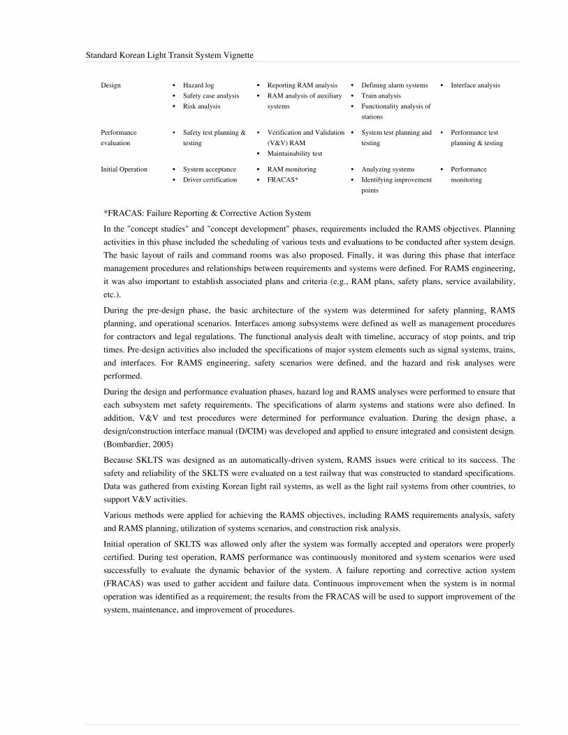
Standard Korean Light Transit System Vignette 78
Design •• Hazard log•• Safety case analysis•• Risk analysis
•• Reporting RAM analysis•• RAM analysis of auxiliary
systems
•• Defining alarm systems•• Train analysis•• Functionality analysis of
stations
•• Interface analysis
Performanceevaluation
• Safety test planning &testing
• Verification and Validation(V&V) RAM
•• Maintainability test
•• System test planning andtesting
• Performance testplanning & testing
Initial Operation •• System acceptance•• Driver certification
•• RAM monitoring•• FRACAS*
•• Analyzing systems•• Identifying improvement
points
•• Performancemonitoring
*FRACAS: Failure Reporting & Corrective Action SystemIn the "concept studies" and "concept development" phases, requirements included the RAMS objectives. Planningactivities in this phase included the scheduling of various tests and evaluations to be conducted after system design.The basic layout of rails and command rooms was also proposed. Finally, it was during this phase that interfacemanagement procedures and relationships between requirements and systems were defined. For RAMS engineering,it was also important to establish associated plans and criteria (e.g., RAM plans, safety plans, service availability,etc.).During the pre-design phase, the basic architecture of the system was determined for safety planning, RAMSplanning, and operational scenarios. Interfaces among subsystems were defined as well as management proceduresfor contractors and legal regulations. The functional analysis dealt with timeline, accuracy of stop points, and triptimes. Pre-design activities also included the specifications of major system elements such as signal systems, trains,and interfaces. For RAMS engineering, safety scenarios were defined, and the hazard and risk analyses wereperformed.During the design and performance evaluation phases, hazard log and RAMS analyses were performed to ensure thateach subsystem met safety requirements. The specifications of alarm systems and stations were also defined. Inaddition, V&V and test procedures were determined for performance evaluation. During the design phase, adesign/construction interface manual (D/CIM) was developed and applied to ensure integrated and consistent design.(Bombardier, 2005)Because SKLTS was designed as an automatically-driven system, RAMS issues were critical to its success. Thesafety and reliability of the SKLTS were evaluated on a test railway that was constructed to standard specifications.Data was gathered from existing Korean light rail systems, as well as the light rail systems from other countries, tosupport V&V activities.Various methods were applied for achieving the RAMS objectives, including RAMS requirements analysis, safetyand RAMS planning, utilization of systems scenarios, and construction risk analysis.Initial operation of SKLTS was allowed only after the system was formally accepted and operators were properlycertified. During test operation, RAMS performance was continuously monitored and system scenarios were usedsuccessfully to evaluate the dynamic behavior of the system. A failure reporting and corrective action system(FRACAS) was used to gather accident and failure data. Continuous improvement when the system is in normaloperation was identified as a requirement; the results from the FRACAS will be used to support improvement of thesystem, maintenance, and improvement of procedures.

Standard Korean Light Transit System Vignette 79
SummaryKorean local authorities have successfully introduced the SKLTS to their precincts with some modifications.Successful examples include the Inchun Airport Line and the Seoul 9th Subway Line. One lesson learned identifiedwas that requirement analysis, especially in the first few phases, should have been more complete.
References
Works CitedAhn, S.H. 2005. “Systems Engineering Applied to the Construction of Unmanned Light Rail Transit Systems.”Journal of the Korean Society for Railway. 8(2): 41-49.Bombardier. 2005. Design/Construction Interface Manual. Montréal, Québec, Canada: Bombardier.Choi, Y.C. 2007. "Systems Engineering Application Model for the National R&D Project: Focusing on the RailwaySystems." Ph.D. dissertation, Ajou University, 2007.Chung, S. Y., S.G. Lee, D.W. Lee, and S.T. Jeon. 2010. “A Study on The Application Model of Systems Engineeringto Advance the Business of the Light Rail Transit (LRT).” Proceedings on the Autumn Conference of the KoreanSociety for Railway, p. 24-30.
Primary ReferencesNone.
Additional ReferencesHan, S.Y. and A.H. Lee. 2005. System Engineering for The Technology Development Program of Light TransitSystems: Internal Research Report. Gyeongi-do, Korea: Korea Railroad Research Institute.Korean Agency for Technology and Standards. 2009. KSX ISO/IEC 15288: Life Cycle Processes of IT SystemsBased on Systems and Software Engineering, Research Report. Gyeonggi-do, Korea: Korean Agency forTechnology and Standards.Lee, W.D. 2002. “A Study on the Top-Level Functional Analysis for the Automated Guideway Transit by SystemEngineering Tools.” Proceedings of the Autumn Conference of the Korean Society for Railway, p. 202-207.
< Previous Article | Parent Article | Last Article (Return to TOC)SEBoK v. 1.4 released 29 June 2015
SEBoK DiscussionPlease provide your comments and feedback on the SEBoK below. You will need to log in to DISQUS using anexisting account (e.g. Yahoo, Google, Facebook, Twitter, etc.) or create a DISQUS account. Simply type yourcomment in the text field below and DISQUS will guide you through the login or registration steps. Feedback will bearchived and used for future updates to the SEBoK. If you provided a comment that is no longer listed, that commenthas been adjudicated. You can view adjudication for comments submitted prior to SEBoK v. 1.0 at SEBoK Reviewand Adjudication. Later comments are addressed and changes are summarized in the Letter from the Editor andAcknowledgements and Release History.
If you would like to provide edits on this article, recommend new content, or make comments on the SEBoKas a whole, please see the SEBoK Sandbox [1].
ENCODED_CONTENTMTgyMTQPGRpdiBpZD0iZGlzcXVzX3RocmVhZCI+PC9kaXY+CjxzY3JpcHQgdHlwZT0idGV4dC9qYXZhc2NyaXB0Ij4KICAgIC8qICogKiBDT05GSUdVUkFUSU9OIFZBUklBQkxFUzogRURJVCBCRUZPUkUgUEFTVElORyBJTlRPIFlPVVIgV0VCUEFHRSAqICogKi8KICAgIHZhciBkaXNxdXNfc2hvcnRuYW1lID0gJ3NlYm9rd2lraTEwJzsgLy8gcmVxdWlyZWQ6IHJlcGxhY2UgZXhhbXBsZSB3aXRoIHlvdXIgZm9ydW0gc2hvcnRuYW1lCiAgICB2YXIgZGlzcXVzX2lkZW50aWZpZXIgPSAnU3RhbmRhcmQgS29yZWFuIExpZ2h0IFRyYW5zaXQgU3lzdGVtIFZpZ25ldHRlJzsgICAgdmFyIGRpc3F1c191cmwgPSAnaHR0cDovL3NlYm9rd2lraS5vcmcvZHJhZnQvU3RhbmRhcmRfS29yZWFuX0xpZ2h0X1RyYW5zaXRfU3lzdGVtX1ZpZ25ldHRlJzsKICAgIC8qICogKiBET04nVCBFRElUIEJFTE9XIFRISVMgTElORSAqICogKi8KICAgIChmdW5jdGlvbigpIHsKICAgICAgICB2YXIgZHNxID0gZG9jdW1lbnQuY3JlYXRlRWxlbWVudCgnc2NyaXB0Jyk7IGRzcS50eXBlID0gJ3RleHQvamF2YXNjcmlwdCc7IGRzcS5hc3luYyA9IHRydWU7CiAgICAgICAgZHNxLnNyYyA9ICdodHRwOi8vJyArIGRpc3F1c19zaG9ydG5hbWUgKyAnLmRpc3F1cy5jb20vZW1iZWQuanMnOwogICAgICAgIChkb2N1bWVudC5nZXRFbGVtZW50c0J5VGFnTmFtZSgnaGVhZCcpWzBdIHx8IGRvY3VtZW50LmdldEVsZW1lbnRzQnlUYWdOYW1lKCdib2R5JylbMF0pLmFwcGVuZENoaWxkKGRzcSk7CiAgICB9KSgpOwo8L3NjcmlwdD4KPG5vc2NyaXB0PlBsZWFzZSBlbmFibGUgSmF2YVNjcmlwdCB0byB2aWV3IHRoZSA8YSBocmVmPSJodHRwOi8vZGlzcXVzLmNvbS8/cmVmX25vc2NyaXB0Ij5jb21tZW50cyBwb3dlcmVkIGJ5IERpc3F1cy48L2E+PC9ub3NjcmlwdD4KPGEgaHJlZj0iaHR0cDovL2Rpc3F1cy5jb20iIGNsYXNzPSJkc3EtYnJsaW5rIj5ibG9nIGNvbW1lbnRzIHBvd2VyZWQgYnkgPHNwYW4gY2xhc3M9ImxvZ28tZGlzcXVzIj5EaXNxdXM8L3NwYW4+PC9hPg==

Standard Korean Light Transit System Vignette 80
END_ENCODED_CONTENT

Article Sources and Contributors 81
Article Sources and ContributorsSystems Engineering Implementation Examples Source: http://sebokwiki.org/d/index.php?oldid=50215 Contributors: Bkcase, Dhenry, Dholwell, Hdavidz, Jgercken, Kguillemette, Rturner,Skmackin, Smenck2, Wikiexpert, Zamoses
Matrix of Implementation Examples Source: http://sebokwiki.org/d/index.php?oldid=51387 Contributors: Alee, Apyster, Asquires, Bkcase, Dhenry, Dholwell, Hdavidz, Jbrackett, Jgercken,Kguillemette, Mhenshaw, Radcock, Rturner, Skmackin, Smenck2, Thilburn, Wikiexpert, Zamoses
Case Studies Source: http://sebokwiki.org/d/index.php?oldid=51383 Contributors: Alee, Apyster, Bkcase, Bwhite, Cnielsen, Dcarey, Dhenry, Dholwell, Hdavidz, Jgercken, Kguillemette,Radcock, Skmackin, Smenck2, Wikiexpert, Zamoses
Successful Business Transformation within a Russian Information Technology Company Source: http://sebokwiki.org/d/index.php?oldid=50318 Contributors: Bkcase, Bwhite, Cnielsen,Kguillemette, Radcock
Federal Aviation Administration Next Generation Air Transportation System Source: http://sebokwiki.org/d/index.php?oldid=50315 Contributors: Bkcase, Bwhite, Cnielsen, Kguillemette,Radcock
How Lack of Information Sharing Jeopardized the NASA/ESA Cassini/Huygens Mission to Saturn Source: http://sebokwiki.org/d/index.php?oldid=50227 Contributors: Bkcase, Bwhite,Kguillemette, Radcock
Hubble Space Telescope Case Study Source: http://sebokwiki.org/d/index.php?oldid=51075 Contributors: Apyster, Asquires, Bkcase, Bwhite, Dhenry, Dholwell, Hdavidz, Jgercken, Radcock,Rfreeman, Smenck2, Wikiexpert, Zamoses
Global Positioning System Case Study Source: http://sebokwiki.org/d/index.php?oldid=51120 Contributors: Apyster, Asquires, Bkcase, Bwhite, Dhenry, Dholwell, Hdavidz, Jgercken,Radcock, Rfreeman, Smenck2, Thilburn, Wikiexpert, Zamoses
Global Positioning System Case Study II Source: http://sebokwiki.org/d/index.php?oldid=51119 Contributors: Bkcase, Bwhite, Radcock
Medical Radiation Case Study Source: http://sebokwiki.org/d/index.php?oldid=50969 Contributors: Apyster, Bkcase, Dhenry, Dholwell, Hdavidz, Jbrackett, Jgercken, Kguillemette, Smenck2,Wikiexpert, Zamoses
FBI Virtual Case File System Case Study Source: http://sebokwiki.org/d/index.php?oldid=46934 Contributors: Apyster, Bkcase, Dhenry, Dholwell, Hdavidz, Jbrackett, Jgercken, Skmackin,Smenck2, Wikiexpert, Zamoses
MSTI Case Study Source: http://sebokwiki.org/d/index.php?oldid=51393 Contributors: Apyster, Bkcase, Dhenry, Dholwell, Hdavidz, Jgercken, Skmackin, Smenck2, Wikiexpert, Zamoses
Next Generation Medical Infusion Pump Case Study Source: http://sebokwiki.org/d/index.php?oldid=50573 Contributors: Apyster, Bkcase, Dhenry, Dholwell, Hdavidz, Jgercken, Smenck2,Wikiexpert
Design for Maintainability Source: http://sebokwiki.org/d/index.php?oldid=51378 Contributors: Bkcase, Radcock
Complex Adaptive Operating System Case Study Source: http://sebokwiki.org/d/index.php?oldid=51379 Contributors: Bkcase, Radcock
Vignettes Source: http://sebokwiki.org/d/index.php?oldid=50963 Contributors: Bkcase, Dhenry, Dholwell, Hdavidz, Jgercken, Skmackin, Smenck2, Thilburn, Wikiexpert, Zamoses
Denver Airport Baggage Handling System Vignette Source: http://sebokwiki.org/d/index.php?oldid=51389 Contributors: Apyster, Asquires, Bkcase, Dhenry, Dholwell, Hdavidz, Jgercken,Kguillemette, Qwang, Skmackin, Smenck2, Thilburn, Wikiexpert, Zamoses
Virginia Class Submarine Vignette Source: http://sebokwiki.org/d/index.php?oldid=46755 Contributors: Apyster, Asquires, Bkcase, Dhenry, Dholwell, Hdavidz, Jgercken, Skmackin,Smenck2, Wikiexpert, Zamoses
UK West Coast Route Modernisation Project Vignette Source: http://sebokwiki.org/d/index.php?oldid=46740 Contributors: Alee, Apyster, Asquires, Bkcase, Dhenry, Dholwell, Hdavidz,Jgercken, Rturner, Skmackin, Smenck2, Thilburn, Wikiexpert, Zamoses
Singapore Water Management Vignette Source: http://sebokwiki.org/d/index.php?oldid=46710 Contributors: Alee, Apyster, Asquires, Bkcase, Dhenry, Dholwell, Hdavidz, Jgercken, Rturner,Skmackin, Wikiexpert, Zamoses
FAA Advanced Automation System (AAS) Vignette Source: http://sebokwiki.org/d/index.php?oldid=51390 Contributors: Apyster, Asquires, Bkcase, Dhenry, Dholwell, Hdavidz, Jgercken,Rturner, Thilburn, Wikiexpert
Standard Korean Light Transit System Vignette Source: http://sebokwiki.org/d/index.php?oldid=47985 Contributors: Apyster, Asquires, Bkcase, Ccalvano, Dhenry, Dholwell, Hdavidz,Jgercken, Mhenshaw, Rturner, Skmackin, Smenck2, Wikiexpert, Zamoses

Image Sources, Licenses and Contributors 82
Image Sources, Licenses and ContributorsFile:MissionAndCapabilities.png Source: http://sebokwiki.org/d/index.php?title=File:MissionAndCapabilities.png License: unknown Contributors: BkcaseFile:V Model Process of Transformation.png Source: http://sebokwiki.org/d/index.php?title=File:V_Model_Process_of_Transformation.png License: unknown Contributors: BkcaseFile:Results of Tranformation.png Source: http://sebokwiki.org/d/index.php?title=File:Results_of_Tranformation.png License: unknown Contributors: BkcaseFile:ChoeKimFigure1.png Source: http://sebokwiki.org/d/index.php?title=File:ChoeKimFigure1.png License: unknown Contributors: Smenck2, SmurawskiFile:ChoeKimFigure2.png Source: http://sebokwiki.org/d/index.php?title=File:ChoeKimFigure2.png License: unknown Contributors: Smenck2, Smurawski