Design Considerations for HVAC Systems in Wide-Body ...
26
Washington University in St. Louis Washington University in St. Louis Washington University Open Scholarship Washington University Open Scholarship Mechanical Engineering and Materials Science Independent Study Mechanical Engineering & Materials Science 12-31-2021 Design Considerations for HVAC Systems in Wide-Body Design Considerations for HVAC Systems in Wide-Body Commercial Aircraft Commercial Aircraft Reuben Smith Washington University in St. Louis Follow this and additional works at: https://openscholarship.wustl.edu/mems500 Recommended Citation Recommended Citation Smith, Reuben, "Design Considerations for HVAC Systems in Wide-Body Commercial Aircraft" (2021). Mechanical Engineering and Materials Science Independent Study. 162. https://openscholarship.wustl.edu/mems500/162 This Final Report is brought to you for free and open access by the Mechanical Engineering & Materials Science at Washington University Open Scholarship. It has been accepted for inclusion in Mechanical Engineering and Materials Science Independent Study by an authorized administrator of Washington University Open Scholarship. For more information, please contact [email protected].
-
Upload
khangminh22 -
Category
Documents
-
view
1 -
download
0
Transcript of Design Considerations for HVAC Systems in Wide-Body ...
Washington University in St. Louis Washington University in St. Louis
Washington University Open Scholarship Washington University Open Scholarship
Mechanical Engineering and Materials Science Independent Study Mechanical Engineering & Materials Science
12-31-2021
Design Considerations for HVAC Systems in Wide-Body Design Considerations for HVAC Systems in Wide-Body
Commercial Aircraft Commercial Aircraft
Reuben Smith Washington University in St. Louis
Follow this and additional works at: https://openscholarship.wustl.edu/mems500
Recommended Citation Recommended Citation Smith, Reuben, "Design Considerations for HVAC Systems in Wide-Body Commercial Aircraft" (2021). Mechanical Engineering and Materials Science Independent Study. 162. https://openscholarship.wustl.edu/mems500/162
This Final Report is brought to you for free and open access by the Mechanical Engineering & Materials Science at Washington University Open Scholarship. It has been accepted for inclusion in Mechanical Engineering and Materials Science Independent Study by an authorized administrator of Washington University Open Scholarship. For more information, please contact [email protected].
MEMS 500
Design Considerations for HVAC Systems in
Wide-Body Commercial Aircraft
Name: Reuben Smith
Email: [email protected]
Academic Supervisor: Dr. Harold Brandon
This report is submitted in partial fulfillment of MEMS 500 (MEMS 5420), an independent study course in
Heating, Ventilation and Air-Conditioning I
MEMS 500 i Final Report
ABSTRACT
MEMS 500 (MEMS 5420) was an independent study course using the text “Heating, Ventilating, and Air-
Conditioning” authored by McQusiton, Parker and Spitler (6th Edition). The course included the material
up to and including the space heating load. The cooling load material was covered during the use of the
TRACE 700 software developed by the Trane Company. The report presented herein was an additional
requirement of the course.
This report provides an introductory overview to the technical considerations required when establishing
the design conditions for heating, ventilation, and air-conditioning system selection in a wide-body
commercial aircraft. Rather than focusing on specific computations applicable to a sole aircraft model, a
generalized approach to understanding the environmental parameters affecting design conditions across
any passenger airplane has been adopted.
MEMS 500 ii Final Report
TABLE OF CONTENTS
ABSTRACT ....................................................................................................................................................... i
LIST OF FIGURES ............................................................................................................................................ 1
LIST OF TABLES .............................................................................................................................................. 1
1.0 INTRODUCTION ................................................................................................................................. 2
2.0 AIRCRAFT HVAC SYSTEM FUNCTIONALITY ........................................................................................ 4
3.0 AIRCRAFT SPECIFICATIONS................................................................................................................ 7
4.0 DESIGN CONDITIONS ........................................................................................................................ 9
4.1 Temperature, Humidity and Heat Transfer Modes ...................................................................... 9
4.2 Calculation of Ambient Air Temperature .................................................................................... 11
4.3 Calculation of Air Speed .............................................................................................................. 13
4.4 Calculation of External Heat Transfer Coefficient ....................................................................... 14
4.5 Calculation of External Radiation ................................................................................................ 16
4.6 Conduction .................................................................................................................................. 17
4.7 Analysis of Aircraft Cabin Air Velocity ......................................................................................... 18
5.0 CONCLUSION ................................................................................................................................... 20
6.0 REFERENCES .................................................................................................................................... 21
MEMS 500 1 Final Report
LIST OF FIGURES
Figure 1 – typical arrangement of an airflow path in an aircraft [3] ............................................................ 2
Figure 2 – an A380-800 aircraft model operated by Emirates [1] ................................................................ 3
Figure 3 – diagram of a typical airliner turbofan [6] ..................................................................................... 4
Figure 4 – air conditioning unit of a Comac C919 aircraft [6] ....................................................................... 5
Figure 5 – schematic of a typical engine/auxiliary power unit bleed system [3] ......................................... 6
Figure 6 – typical internal arrangement of an A380-800 [9] ........................................................................ 8
Figure 7 – averaged ambient temperature profiles [3] ................................................................................ 9
Figure 8 – ambient moisture content as a result of altitude variation [3] ................................................. 10
Figure 9 – sectional view of internal-to-external aircraft insulation layout [3].......................................... 17
Figure 10 – prefabricated insulation blankets on a Boeing 777 [6] ............................................................ 18
Figure 11 – CFD model of aircraft cabin air velocities [3] ........................................................................... 19
LIST OF TABLES
Table 1 – general, dimensional and performance specifications for an A380-800 [9] ................................ 7
MEMS 500 2 Final Report
1.0 INTRODUCTION
As opposed to being viewed as a luxury, heating, ventilation and cooling (HVAC) systems which provide a
safe and healthy environment have become accepted as a requirement for the majority of indoor spaces
that humans occupy in the developed world. Rather than being confined to ground-based structures such
as personal dwellings, schools, offices and retail facilities, considerable time, effort and money has also
been invested in developing HVAC systems suitable for use in mass transportation. In particular, a
pertinent application of HVAC technology can be seen in commercial aircraft to ensure that human health
and comfort is maintained from ground-level all the way into the troposphere.
One of the primary differences in HVAC systems developed for commercial aircraft applications is the
need to make extreme and unusual external environmental habitable for (temporary) human occupation.
Whilst the most common conditions that are factored into the design of ground-based HVAC systems
generally include hot and humid air contaminated with pollutants such as industrial exhaust gases, fumes
and biological particulate matter, during any given flight the ambient air outside of the aircraft is typically
cold, dry, and laced with potentially dangerous levels of trioxygen (ozone) [3]. Depending on the
geographical location and elevation of the flight, these conditions may change substantially. Additional
challenges to the design of HVAC systems in aircraft involve the need to ensure that the final working unit
is lightweight, accessible for maintenance and repair, unaffected by vibrations induced by the aircraft’s
motion, and highly reliable in a manner that does not impact the integrity or efficiency of surrounding
flight equipment. Indeed, this combination of factors makes the selection of a HVAC system in a modern-
day jet airliner complicated, to say the least.
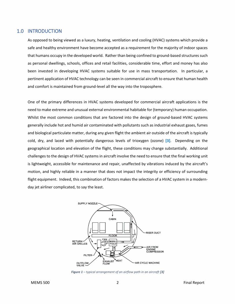
Figure 1 – typical arrangement of an airflow path in an aircraft [3]
MEMS 500 3 Final Report
As with any occupied space, before the design of an aircraft HVAC system can be undertaken a robust
estimate must be made regarding the maximum probable heat loss/gain occurring within the cabin
section of the aircraft’s fuselage, as well understanding other quantifiable parameters such as cabin air
velocity and the effects of condition through the cabin walls [3]. Within the cabin of any given commercial
airliner the primary mode of heat loss is that transmitted through the walls of the fuselage, whilst the
primary gain is that of the occupants (passengers) and electrical equipment located within the space [6].
Of course, the actual concept of heat loss/gain is completely transient because of the constant variation
in the large number of parameters that impact the thermodynamic state and contaminant quality of the
air within the cabin at any given time. Such parameters, such as external (ambient temperature), air
velocity, passenger density and in-flight human activity/metabolic rate [5].
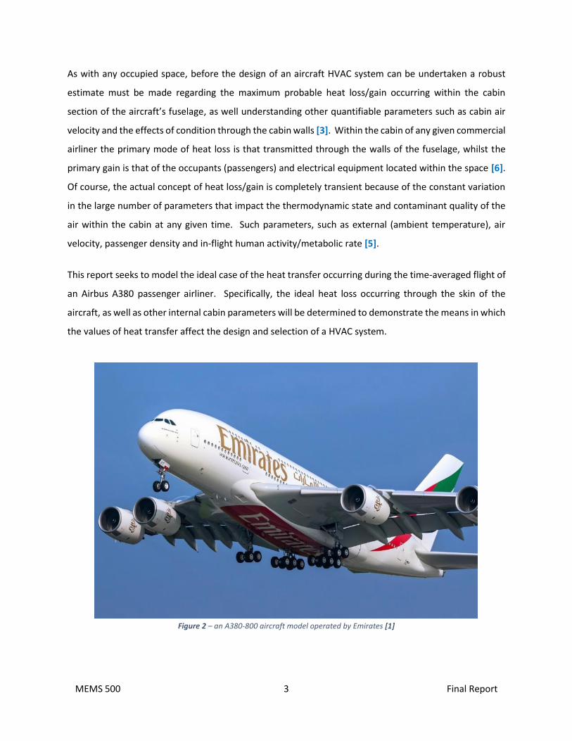
This report seeks to model the ideal case of the heat transfer occurring during the time-averaged flight of
an Airbus A380 passenger airliner. Specifically, the ideal heat loss occurring through the skin of the
aircraft, as well as other internal cabin parameters will be determined to demonstrate the means in which
the values of heat transfer affect the design and selection of a HVAC system.
Figure 2 – an A380-800 aircraft model operated by Emirates [1]
MEMS 500 4 Final Report
2.0 AIRCRAFT HVAC SYSTEM FUNCTIONALITY
Although not paramount to the primary aim of this report, a breakdown of the working principles of the
air conditioning system of a commercial airliners is key to understanding the foundational principles of
the design conditions upon which a HVAC system is based. Such background information will
subsequently be presented herein.
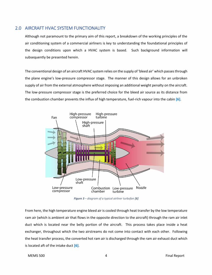
The conventional design of an aircraft HVAC system relies on the supply of ‘bleed air’ which passes through
the plane engine’s low-pressure compressor stage. The manner of this design allows for an unbroken
supply of air from the external atmosphere without imposing an additional weight penalty on the aircraft.
The low-pressure compressor stage is the preferred choice for the bleed air source as its distance from
the combustion chamber prevents the influx of high temperature, fuel-rich vapour into the cabin [6].
Figure 3 – diagram of a typical airliner turbofan [6]
From here, the high temperature engine bleed air is cooled through heat transfer by the low temperature
ram air (which is ambient air that flows in the opposite direction to the aircraft) through the ram air inlet
duct which is located near the belly portion of the aircraft. This process takes place inside a heat
exchanger, throughout which the two airstreams do not come into contact with each other. Following
the heat transfer process, the converted hot ram air is discharged through the ram air exhaust duct which
is located aft of the intake duct [6].
MEMS 500 5 Final Report
Meanwhile, the colder engine bleed air passes through a compressor which in turn cools the air further
by reducing the pressure. Afterwards, the now significantly colder air passes through the condenser to
remove any excess water vapour in the air prior to being routed to the mixing chamber [5]. Delivery of
the air into the cabin occurs via two different routes. The first, referred to as centralized air conditioning,
is the often incorrectly perceived ‘white smoke’ that flows from the side wall panel directly above the
cabin. This is the primary condition air that is supplied to the entire cabin. The second supply air category
is the ‘personal’ air conditioning which is delivered through the individual vents located above every
passenger seat [3].
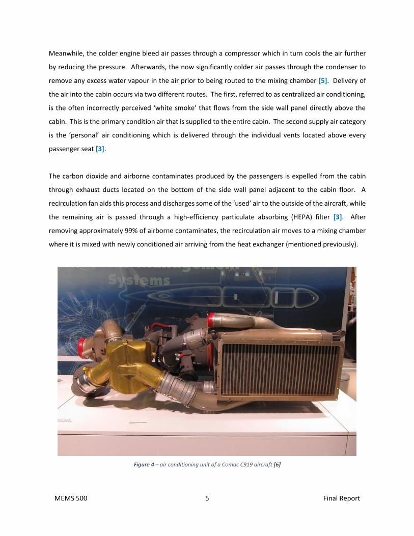
The carbon dioxide and airborne contaminates produced by the passengers is expelled from the cabin
through exhaust ducts located on the bottom of the side wall panel adjacent to the cabin floor. A
recirculation fan aids this process and discharges some of the ‘used’ air to the outside of the aircraft, while
the remaining air is passed through a high-efficiency particulate absorbing (HEPA) filter [3]. After
removing approximately 99% of airborne contaminates, the recirculation air moves to a mixing chamber
where it is mixed with newly conditioned air arriving from the heat exchanger (mentioned previously).
Figure 4 – air conditioning unit of a Comac C919 aircraft [6]
MEMS 500 6 Final Report
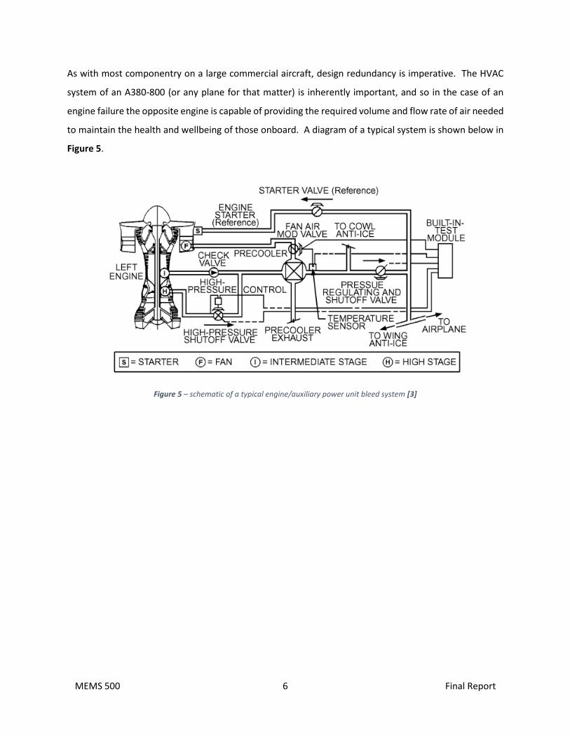
As with most componentry on a large commercial aircraft, design redundancy is imperative. The HVAC
system of an A380-800 (or any plane for that matter) is inherently important, and so in the case of an
engine failure the opposite engine is capable of providing the required volume and flow rate of air needed
to maintain the health and wellbeing of those onboard. A diagram of a typical system is shown below in
Figure 5.
Figure 5 – schematic of a typical engine/auxiliary power unit bleed system [3]
MEMS 500 7 Final Report
3.0 AIRCRAFT SPECIFICATIONS
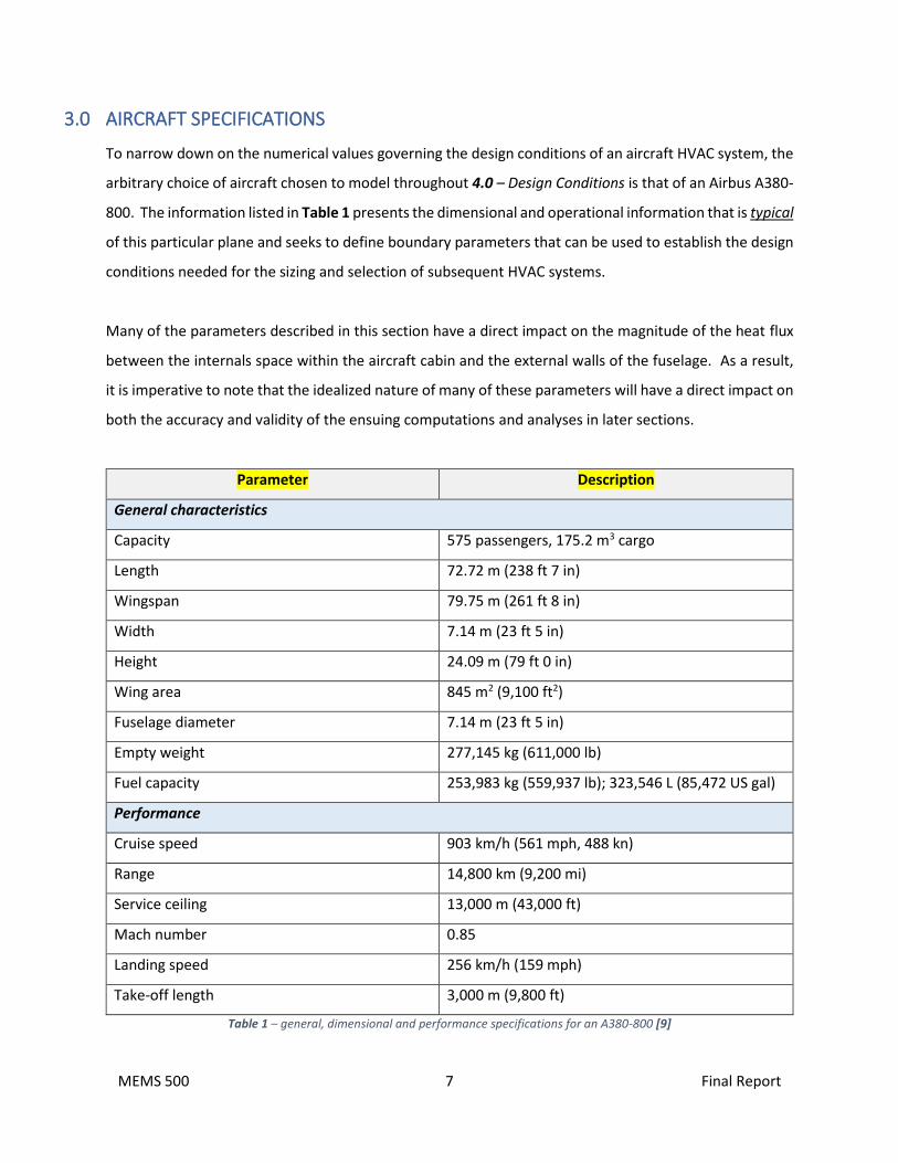
To narrow down on the numerical values governing the design conditions of an aircraft HVAC system, the
arbitrary choice of aircraft chosen to model throughout 4.0 – Design Conditions is that of an Airbus A380-
800. The information listed in Table 1 presents the dimensional and operational information that is typical
of this particular plane and seeks to define boundary parameters that can be used to establish the design
conditions needed for the sizing and selection of subsequent HVAC systems.
Many of the parameters described in this section have a direct impact on the magnitude of the heat flux
between the internals space within the aircraft cabin and the external walls of the fuselage. As a result,
it is imperative to note that the idealized nature of many of these parameters will have a direct impact on
both the accuracy and validity of the ensuing computations and analyses in later sections.
Parameter Description
General characteristics
Capacity 575 passengers, 175.2 m3 cargo
Length 72.72 m (238 ft 7 in)
Wingspan 79.75 m (261 ft 8 in)
Width 7.14 m (23 ft 5 in)
Height 24.09 m (79 ft 0 in)
Wing area 845 m2 (9,100 ft2)
Fuselage diameter 7.14 m (23 ft 5 in)
Empty weight 277,145 kg (611,000 lb)
Fuel capacity 253,983 kg (559,937 lb); 323,546 L (85,472 US gal)
Performance
Cruise speed 903 km/h (561 mph, 488 kn)
Range 14,800 km (9,200 mi)
Service ceiling 13,000 m (43,000 ft)
Mach number 0.85
Landing speed 256 km/h (159 mph)
Take-off length 3,000 m (9,800 ft)
Table 1 – general, dimensional and performance specifications for an A380-800 [9]

MEMS 500 8 Final Report
Figure 6 – typical internal arrangement of an A380-800 [9]

MEMS 500 9 Final Report
4.0 DESIGN CONDITIONS
As discussed previously, design conditions for aircraft vary significantly when compared to what can be
seen as more ‘conventional’ ground-based HVAC applications. Due to the fact that commercial air
transportation is undertaken in a physical environment that is not inherently meant for human habitation,
the differences in the quality and state of the air supplied to aircraft passengers and crew are accounted
for by taking into account the design conditions described in this section. Using the information pertaining
to an Airbus A380-800 as presented in Table 1, the ensuing calculations aim to provide a generalized
approach to calculating various parameters associated with the heat transfer between the fuselage and
the external atmosphere, and the heat generated from within the cabin itself.
4.1 Temperature, Humidity and Heat Transfer Modes
The plot shown in Figure 7 depicts the average design ambient temperature profiles for days classed as
either ‘standard’, ‘hot’ or ‘cold’ at increasing elevation above sea-level. Understandably, ambient
temperature varies significantly with geographical location, and so the temperatures used for the design
of a particular aircraft HVAC system may differ from the values shown in Figure 1.
Figure 7 – averaged ambient temperature profiles [3]
MEMS 500 10 Final Report
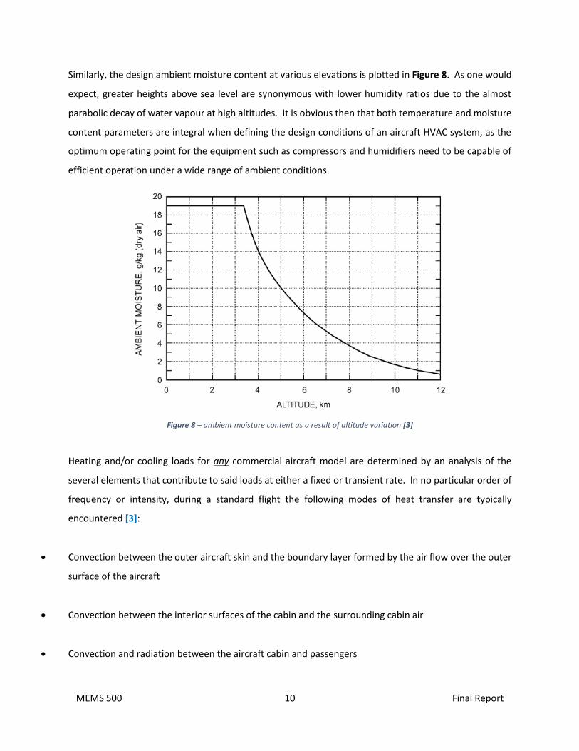
Similarly, the design ambient moisture content at various elevations is plotted in Figure 8. As one would
expect, greater heights above sea level are synonymous with lower humidity ratios due to the almost
parabolic decay of water vapour at high altitudes. It is obvious then that both temperature and moisture
content parameters are integral when defining the design conditions of an aircraft HVAC system, as the
optimum operating point for the equipment such as compressors and humidifiers need to be capable of
efficient operation under a wide range of ambient conditions.
Figure 8 – ambient moisture content as a result of altitude variation [3]
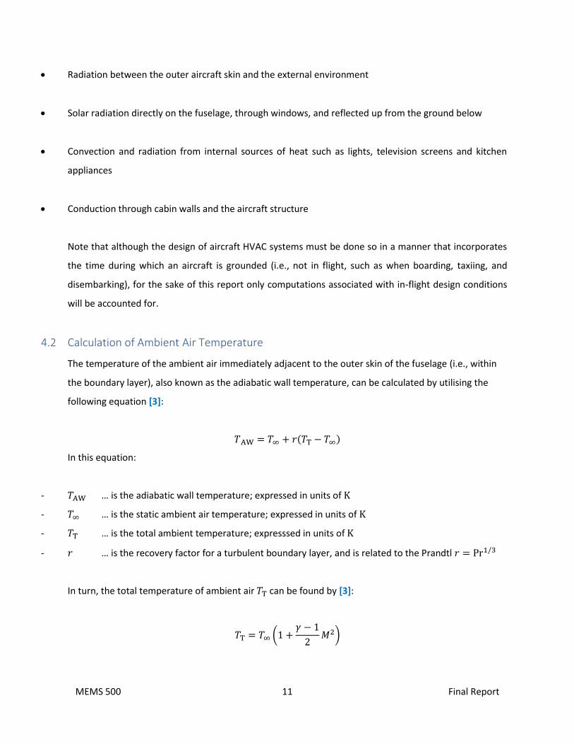
Heating and/or cooling loads for any commercial aircraft model are determined by an analysis of the
several elements that contribute to said loads at either a fixed or transient rate. In no particular order of
frequency or intensity, during a standard flight the following modes of heat transfer are typically
encountered [3]:
• Convection between the outer aircraft skin and the boundary layer formed by the air flow over the outer
surface of the aircraft
• Convection between the interior surfaces of the cabin and the surrounding cabin air
• Convection and radiation between the aircraft cabin and passengers
MEMS 500 11 Final Report
• Radiation between the outer aircraft skin and the external environment
• Solar radiation directly on the fuselage, through windows, and reflected up from the ground below
• Convection and radiation from internal sources of heat such as lights, television screens and kitchen
appliances
• Conduction through cabin walls and the aircraft structure
Note that although the design of aircraft HVAC systems must be done so in a manner that incorporates
the time during which an aircraft is grounded (i.e., not in flight, such as when boarding, taxiing, and
disembarking), for the sake of this report only computations associated with in-flight design conditions
will be accounted for.
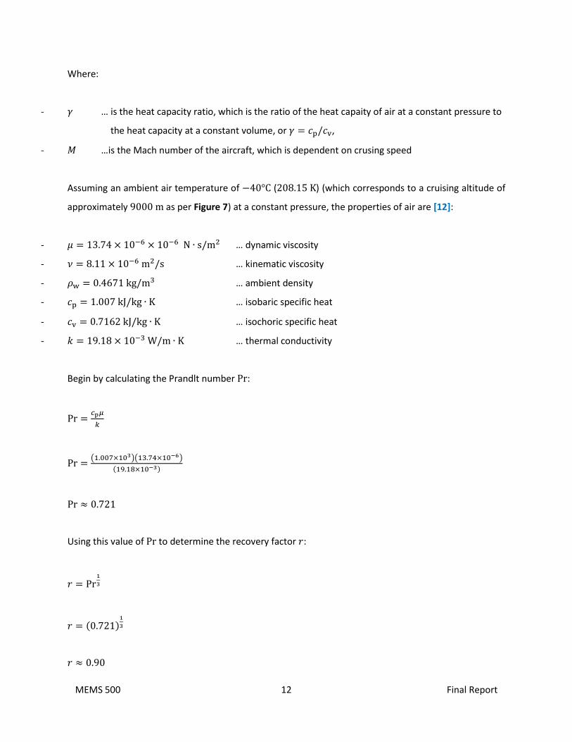
4.2 Calculation of Ambient Air Temperature
The temperature of the ambient air immediately adjacent to the outer skin of the fuselage (i.e., within
the boundary layer), also known as the adiabatic wall temperature, can be calculated by utilising the
following equation [3]:
𝑇AW = 𝑇∞ + 𝑟(𝑇T − 𝑇∞)
In this equation:
- 𝑇AW … is the adiabatic wall temperature; expressed in units of K
- 𝑇∞ … is the static ambient air temperature; expressed in units of K
- 𝑇T … is the total ambient temperature; expresssed in units of K
- 𝑟 … is the recovery factor for a turbulent boundary layer, and is related to the Prandtl 𝑟 = Pr1/3
In turn, the total temperature of ambient air 𝑇T can be found by [3]:
𝑇T = 𝑇∞ (1 +𝛾 − 1
2𝑀2)
MEMS 500 12 Final Report
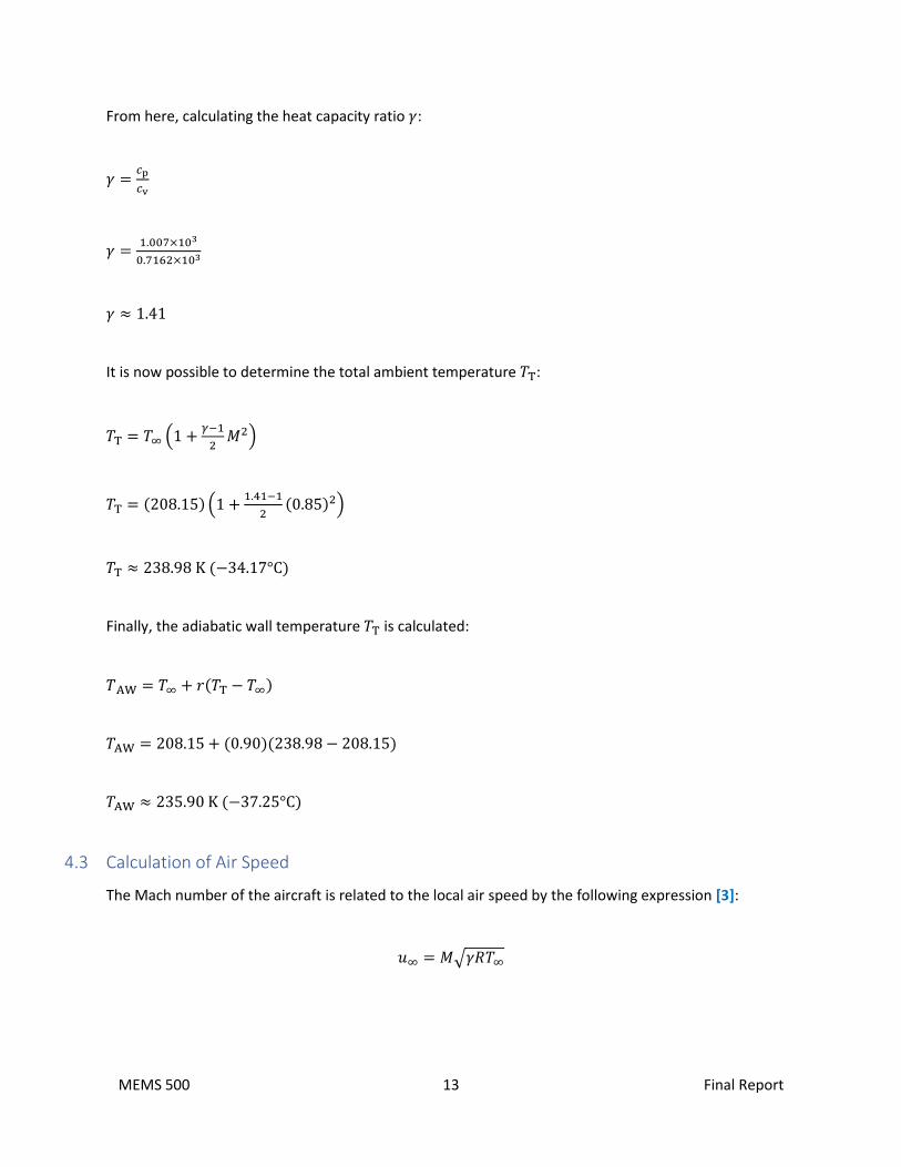
Where:
- 𝛾 … is the heat capacity ratio, which is the ratio of the heat capaity of air at a constant pressure to
the heat capacity at a constant volume, or 𝛾 = 𝑐p/𝑐v,
- 𝑀 …is the Mach number of the aircraft, which is dependent on crusing speed
Assuming an ambient air temperature of −40°C (208.15 K) (which corresponds to a cruising altitude of
approximately 9000 m as per Figure 7) at a constant pressure, the properties of air are [12]:
- 𝜇 = 13.74 × 10−6 × 10−6 N ∙ s/m2 … dynamic viscosity
- 𝜈 = 8.11 × 10⁻⁶ m2/s … kinematic viscosity
- 𝜌w = 0.4671 kg/m3 … ambient density
- 𝑐p = 1.007 kJ/kg ∙ K … isobaric specific heat
- 𝑐v = 0.7162 kJ/kg ∙ K … isochoric specific heat
- 𝑘 = 19.18 × 10⁻³ W/m ∙ K … thermal conductivity
Begin by calculating the Prandlt number Pr:
Pr =𝑐p𝜇
𝑘
Pr =(1.007×10³)(13.74×10⁻⁶)
(19.18×10⁻³)
Pr ≈ 0.721
Using this value of Pr to determine the recovery factor 𝑟:
𝑟 = Pr1
3
𝑟 = (0.721)1
3
𝑟 ≈ 0.90
MEMS 500 13 Final Report
From here, calculating the heat capacity ratio 𝛾:
𝛾 =𝑐p
𝑐v
𝛾 =1.007×10³
0.7162×10³
𝛾 ≈ 1.41
It is now possible to determine the total ambient temperature 𝑇T:
𝑇T = 𝑇∞ (1 +𝛾−1
2𝑀2)
𝑇T = (208.15) (1 +1.41−1
2(0.85)2)
𝑇T ≈ 238.98 K (−34.17°C)
Finally, the adiabatic wall temperature 𝑇T is calculated:
𝑇AW = 𝑇∞ + 𝑟(𝑇T − 𝑇∞)
𝑇AW = 208.15 + (0.90)(238.98 − 208.15)
𝑇AW ≈ 235.90 K (−37.25°C)
4.3 Calculation of Air Speed
The Mach number of the aircraft is related to the local air speed by the following expression [3]:
𝑢∞ = 𝑀√𝛾𝑅𝑇∞
MEMS 500 14 Final Report
Here:
- 𝑢∞ … is the aircraft air speed; expressed in units of m/s
- 𝑅 … is the universal gas contant; 287 m2/s2 ∙ K
Substituting in the known values and solving for the air speed 𝑢∞:
𝑢∞ = 𝑀√𝛾𝑅𝑇∞
𝑢∞ = (0.85)√(1.405)(287)(208.15)
𝑢∞ ≈ 246.26 m/s
4.4 Calculation of External Heat Transfer Coefficient
The fact that the fuselage of the aircraft is essentially at free-stream static pressure permits the use of a
flat-plate analogy to determine the external heat transfer coefficient ℎ at any point 𝑥 along the length of
the fuselage. It therefore follows that [3]:
ℎ = 𝜌w𝑐p𝑢∞0.185(log Re𝑥)−2.584Pr−23
For the sake of calculation, an arbitrary length of 𝑥 = 40 m (corresponding to the assumed length of the
economy-class cabin within an A380-800) will be used. Finding the Reynolds number Re𝑥:
Re𝑥 =𝜌w𝑢∞𝑥
𝜇 … Where 107 < Re𝑥 < 109
Re𝑥 =(0.4671)(246.26)(40)
(13.74×10⁻⁶)
Re𝑥 ≈ 3.35 × 10⁸
This value of Re𝑥 is within the acceptable range of 107 < Re𝑥 < 109.
MEMS 500 15 Final Report
Solving for the heat transfer coefficient ℎ by substituting in the known values:
ℎ = 𝜌w𝑐p𝑢∞0.185(log Re𝑥)−2.584Pr−2
3
ℎ = (0.4671)(1.007 × 10³)(246.26)(0.185)(log(3.35 × 10⁸))−2.584(0.721)−2
3
ℎ ≈ 104.91 W/m2 ∙ K
Now that a suitable value of ℎ has been arrived at, the convective heat loss from the outer skin 𝑞 can be
determined using the following expression [3]:
𝑞 = ℎ𝐴(𝑇 − 𝑇AW)
In this equation:
- 𝑞 … is the convective heat loss from the outer skin of the fuselage; expressed in units of W
- 𝐴 … outside surface area of the passenger cabin; expressed in units of m2
- 𝑇 … is the outer skin temperature (assumed equal to 𝑇T); expressed in units of K
Idealising the shape of an economy-class section of the fuselage as a cylinder with a length of 40 m and
a diameter of 7.14 m, the surface area 𝐴 can be determined:
𝐴 = 2𝜋𝑟𝐿
𝐴 = (2)(𝜋) (7.14
2) (40)
𝐴 ≈ 897.24 m2
From here, it is possible to solve for the convective heat loss 𝑞.
MEMS 500 16 Final Report
𝑞 = ℎ𝐴(𝑇 − 𝑇AW)
𝑞 = (104.91)(897.24)(238.98 − 235.90)
𝑞 ≈ 2.9 × 10⁵ W
𝒒 ≈ 𝟎. 𝟐𝟗 𝐌𝐖
This result indicates heat loss from the aircraft skin to the ambient air on the external side of the fuselage.
4.5 Calculation of External Radiation
Ignoring the influence of the aircraft’s wings, nose, and aft portion of the fuselage, the section of the
planes fuselage that surrounds the economy cabin radiates heat primarily to the sky [3]. Starting from
ground level, as the plane increases in elevation there is a corresponding decrease in the amount of air to
radiate to, meaning that the difference between air temperature and sky temperature increases. Recall
that sky temperature is defined as the temperature one would meausre if pointing an infra-red
‘thermometer’ at the sky [3]. Conversely, air temperature describes the kinetic eneergy of motion of the
gases that comprise the air itself. For the fuselage, the heat loss to the sky through means of radiation is
quantifed by the below expression [3]:
𝑞R = 𝐴𝜎𝜖(𝑇4 − 𝑇sky4 )
In this equation:
- 𝑞R … radiation heat loss from the outer skin; expressed in units of W
- 𝜎 … Stefan-Boltzmann constant; 5.67 × 10⁻⁸ W/m2 ∙ K4
- 𝜖 … Emissivity of the fuselage skin surface/paint
Most commonly, the skin of an aircract is manufactured from aluminium and aluminium alloys comprised
of other metals such as zinc, copper and magnesium. In the case of an A380-800, we ignore the effect of
paint coatings on the skin of the plane and instead take the emissivity of highly polished aluminium as 0.1
[10].

MEMS 500 17 Final Report
Solving for the radiation heat loss 𝑞R:
𝑞R = 𝐴𝜎𝜖(𝑇4 − 𝑇sky4 )
𝑞R = (897.24)(5.67 × 10⁻⁸)(0.1)(235.904 − 208.154)
𝑞R ≈ 6204.6 W
𝒒𝐑 ≈ 𝟔. 𝟐 𝐤𝐖
Evidently, in-flight radiative losses are minimal compared to conductive effects through the skin of the
aircraft, which will be discussed to a greater extent in the next section.
4.6 Conduction
The transient path of conduction from the internal cabin air to the external environment is a combination
of multiple heat transfer elements in both series and parallel with each other [3]. Although the external
skin of the aircraft (which is typically manufactured from aluminium and composite alloys) has a low
emissivity, the material is quite conductive in nature and hence must be insulated to avoid an increased
ability of heat to escape to the outside of the plane. As shown in Figure 9, the outer skin of the aircraft is
supported by circumferential and longitudinal ribs [3].
Figure 9 – sectional view of internal-to-external aircraft insulation layout [3]

MEMS 500 18 Final Report
To maintain optimum passenger comfort, the internal cabin wall temperature should not be too different
from the air temperature within the cabin due to the fact that passengers are frequently mobile
throughout the cabin and in contact with various internal surfaces [3]. Figure 10 shows an example of
thermal insulation padded around the circumference of the internal cabin skin.
Figure 10 – prefabricated insulation blankets on a Boeing 777 [6]
4.7 Analysis of Aircraft Cabin Air Velocity
When it comes to the passenger cabin of a commercial aircraft, particularly a wide-body plane such as an
A380-800, the internal space can be modelled closely to that of high-density buildings such as lecture
halls, cinemas and theatres. In such settings, the air-conditioning system is set to a cooling mode in which
the supply diffuser temperature is cooler than that of the room temperature. However, unlike buildings
situated at or just above sea level, in aircraft cabins the ducting networks generally have higher air
velocities and smaller fractions of recirculated air (approximately 50%) [3].
Because the velocity characteristics of an airplane are uniquely affected by transitional flow behaviour,
turbulence induced by the air diffuser can affect the perceived ‘draftiness’ within a cabin and lead to
passengers feeling uncomfortable or even cold [3]. Figure 11 shows a computational fluid dynamics (CFD)
model of cabin air velocities within a wide-body aircraft provided by ASHRAE. Due to the transient nature
of the velocity field, variations in such a setting will always exist and give rise to different sensations of
‘coldness’ at various areas in a given row of occupied passenger seats.
MEMS 500 19 Final Report
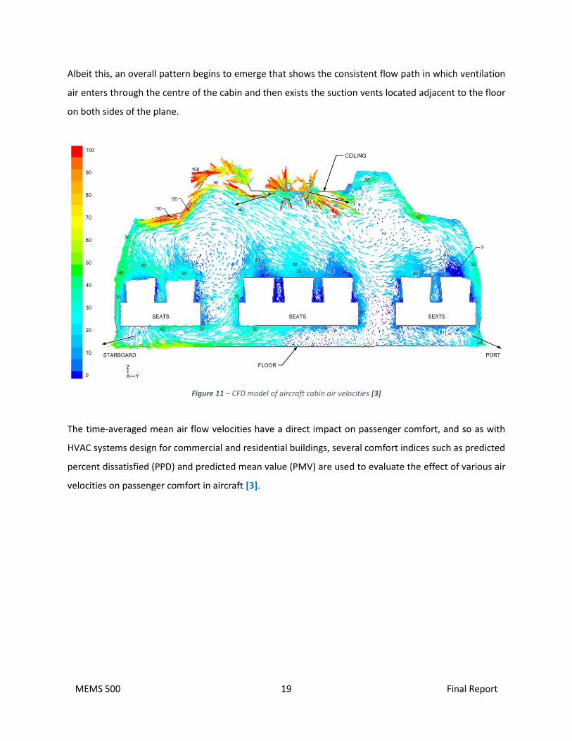
Albeit this, an overall pattern begins to emerge that shows the consistent flow path in which ventilation
air enters through the centre of the cabin and then exists the suction vents located adjacent to the floor
on both sides of the plane.
Figure 11 – CFD model of aircraft cabin air velocities [3]
The time-averaged mean air flow velocities have a direct impact on passenger comfort, and so as with
HVAC systems design for commercial and residential buildings, several comfort indices such as predicted
percent dissatisfied (PPD) and predicted mean value (PMV) are used to evaluate the effect of various air
velocities on passenger comfort in aircraft [3].
MEMS 500 20 Final Report
5.0 CONCLUSION
Well before the outbreak of the COVID-19 pandemic in December of 2019, properly designed HVAC
systems in commerical aircraft were critical in ensuring that passenger comfort and thermoregulation
were maintained during both ground (hot) and in-flight (cold) operations. Often overlooked by the
everyday frequent flyer, commercial airline HVAC systems are now presented with the challenge of
reducing the transmission of COVID-19 through smart design which incorporates the underlying
thermodynamic principles that have been utilised in space heating/cooling for decades.
For this to be possible, it is imperative that the HVAC teams behind the design, selection, installation and
maintenace of HVAC systems in modern aircraft take into account the large array of design conditions
which will ultimately impact the sizing and performance requirements of the final system. Although by
no means an exahustive list of factors that need to be accounted for during system design, it has been
insinuated throughout this report that the most important design condition which directly impacts these
requirements is the thermal loads attributed to heat entering and leaving the plane through conductive
and radiative effects. Although transient by definition, a decent numerical approximation of the heat flux
and internal cabin velocity for a given aircraft designation is crucial in the selection of a HVAC system
which is capable of maintaining high quality space conditions for aircraft passengers and crew alike.
MEMS 500 21 Final Report
6.0 REFERENCES
• [1] Airlines Inform, 2021. Airbus A380. [Online]
Available at: https://www.airlines-inform.com/commercial-aircraft/airbus-a380.html
[Accessed 1 December 2021].
• [2] Andrews, J. & Jelley, N., 2017. Energy Science. 3rd ed. Oxford: Oxford University Press.
• [3] ASHRAE, 2019. Aircraft. In: 2. SI, ed. Heating, Ventilating, and Air-Conditioning Applications. Atlanta:
ASHRAE, pp. 13.1-13.14.
• [4] Cremers, D. J., 2013. Basics of the Aircraft Cabin Environment. [Online] Available at:
https://www.icao.int/EURNAT/Other%20Meetings%20Seminars%20and%20Workshops/CAPSCA%20EU
R/CAPSCA-EUR03/2-5-Basics%20of%20the%20aircraft%20cabin%20environment_v4.pdf
[Accessed 8 December 2021].
• [5] CXAssociates, 2014. HVAC and the Aircraft Cabin Environment at 30,000 Feet. [Online]
Available at: https://buildingenergy.cx-associates.com/2014/12/hvac-and-the-cabin-environment-at-
30000-feet/
[Accessed 2 December 2021].
• [6] Engineering360, 2020. A Look at Aircraft HVAC Systems. [Online]
Available at: https://insights.globalspec.com/article/14376/a-look-at-aircraft-hvac-systems
[Accessed 9 December 2021].
• [7] Flaig, A., 2008. Airbus A380 - Solutions to the Aerodynamic Challenges of Designing the World's Largest
Passenger Aircraft. [Online]
Available at: https://www.fzt.haw-hamburg.de/pers/Scholz/dglr/hh/text_2008_01_30_A380.pdf
[Accessed 1 December 2021].
• [8] McQuiston, F. C., Parker, J. D. & Spitler, J. D., 2006. Heating, Ventilation, and Air Conditioning. 6th ed.
Hoboken: John Wiley & Sons, Inc.
MEMS 500 22 Final Report
• [9] Modern Airlines, 2021. Airbus A380 Specifications. [Online]
Available at: https://modernairliners.com/airbus-a380/airbus-a380-specs/
[Accessed 2 December 2021].
• [10] The Engineering Toolbox, 2003. Aluminium - Radiation Heat Emissivity. [Online]
Available at: https://www.engineeringtoolbox.com/radiation-heat-emissivity-aluminum-d_433.html
[Accessed 10 December 2021].
• [11] The Engineering Toolbox, 2018. Air - Prandtl Number. [Online]
Available at: https://www.engineeringtoolbox.com/air-prandtl-number-viscosity-heat-capacity-thermal-
conductivity-d_2009.html
[Accessed 10 December 2021].
• [12] White, F. M. & Majdalani, J., 2021. Viscous Fluid Flow. 4th ed. New York: McGraw-Hill Education.
Wikipedia, 2021. Adiabatic Wall. [Online] Available at: https://en.wikipedia.org/wiki/Adiabatic_wall
[Accessed 11 December 2021].
• [13] Wikipedia, 2021. Skin (Aeronautics). [Online]
Available at: https://en.wikipedia.org/wiki/Skin_(aeronautics)
[Accessed 13 December 2021].
End of Report