Model-based navigation of left and right ventricular leads to optimal targets for cardiac...
28
Islam, R. Terry Thompson, Maria Drangova and James A. White Jamie Manlucu, David McCarty, Yosra Turkistani, David Scholl, Martin Rajchl, Aashish Goela, Ali Zachary Laksman, Raymond Yee, John Stirrat, Lorne J. Gula, Allan C. Skanes, Peter Leong-Sit, Resynchronization Therapy: A Single Centre Feasibility Study Model-based Navigation of Left and Right Ventricular Leads to Optimal Targets for Cardiac Print ISSN: 1941-3149. Online ISSN: 1941-3084 Copyright © 2014 American Heart Association, Inc. All rights reserved. Dallas, TX 75231 is published by the American Heart Association, 7272 Greenville Avenue, Circulation: Arrhythmia and Electrophysiology published online September 14, 2014; Circ Arrhythm Electrophysiol. http://circep.ahajournals.org/content/early/2014/09/14/CIRCEP.114.001729 World Wide Web at: The online version of this article, along with updated information and services, is located on the http://circep.ahajournals.org//subscriptions/ is online at: Circulation: Arrhythmia and Electrophysiology Information about subscribing to Subscriptions: http://www.lww.com/reprints Information about reprints can be found online at: Reprints: document. Permissions and Rights Question and Answer information about this process is available in the requested is located, click Request Permissions in the middle column of the Web page under Services. Further Center, not the Editorial Office. Once the online version of the published article for which permission is being can be obtained via RightsLink, a service of the Copyright Clearance Circulation: Arrhythmia and Electrophysiology Requests for permissions to reproduce figures, tables, or portions of articles originally published in Permissions: at Imperial College London Library on October 2, 2014 http://circep.ahajournals.org/ Downloaded from at Imperial College London Library on October 2, 2014 http://circep.ahajournals.org/ Downloaded from
Transcript of Model-based navigation of left and right ventricular leads to optimal targets for cardiac...

Islam, R. Terry Thompson, Maria Drangova and James A. WhiteJamie Manlucu, David McCarty, Yosra Turkistani, David Scholl, Martin Rajchl, Aashish Goela, Ali
Zachary Laksman, Raymond Yee, John Stirrat, Lorne J. Gula, Allan C. Skanes, Peter Leong-Sit,Resynchronization Therapy: A Single Centre Feasibility Study
Model-based Navigation of Left and Right Ventricular Leads to Optimal Targets for Cardiac
Print ISSN: 1941-3149. Online ISSN: 1941-3084 Copyright © 2014 American Heart Association, Inc. All rights reserved.
Dallas, TX 75231is published by the American Heart Association, 7272 Greenville Avenue,Circulation: Arrhythmia and Electrophysiology
published online September 14, 2014;Circ Arrhythm Electrophysiol.
http://circep.ahajournals.org/content/early/2014/09/14/CIRCEP.114.001729World Wide Web at:
The online version of this article, along with updated information and services, is located on the
http://circep.ahajournals.org//subscriptions/
is online at: Circulation: Arrhythmia and Electrophysiology Information about subscribing to Subscriptions:
http://www.lww.com/reprints Information about reprints can be found online at: Reprints:
document. Permissions and Rights Question and Answerinformation about this process is available in the
requested is located, click Request Permissions in the middle column of the Web page under Services. FurtherCenter, not the Editorial Office. Once the online version of the published article for which permission is being
can be obtained via RightsLink, a service of the Copyright ClearanceCirculation: Arrhythmia and Electrophysiology Requests for permissions to reproduce figures, tables, or portions of articles originally published inPermissions:
at Imperial College London Library on October 2, 2014http://circep.ahajournals.org/Downloaded from at Imperial College London Library on October 2, 2014http://circep.ahajournals.org/Downloaded from

DOI: 10.1161/CIRCEP.114.001729
1
Model-based Navigation of Left and Right Ventricular Leads to Optimal Targets
for Cardiac Resynchronization Therapy: A Single Centre Feasibility Study
Running title: Laksman et al.; Model based navigation for resynchronization
Zachary Laksman, MD1; Raymond Yee, MD1; John Stirrat, BMSc2; Lorne J. Gula, MD, MSc1;
Allan C. Skanes, MD1; Peter Leong-Sit, MD1; Jamie Manlucu, MD1; David McCarty, MB BCh1;
Yosra Turkistani, MD1; David Scholl, BSc2; Martin Rajchl, BSc2; Aashish Goela, MD4;
Ali Islam, MD4; R. Terry Thompson, PhD3,4; Maria Drangova, PhD2,4; James A. White, MD1,5
1Division of Cardiology, Department of Medicine, 2Imaging Laboratories - Robarts Research Institute,3Lawson Health Research Institute, University of Western Ontario; 4Department of Medical Imaging,
Schulich School of Medicine and Dentistry, London, Ontario; 5Stephenson Cardiac Imaging Centre, LibinCardiovascular Institute University of Calgary, Calgary, Alberta, Canada
Correspondence:
Dr. James A. White
Stephenson Cardiovascular MR Centre
Suite 0700 – Special Services Building
Foothills Medical Centre, 1403 – 29th Street NW
Calgary, Alberta, T2N 2T9
Canada
Tel: 403-944-8806
Fax: 403-944-8510
E-mail: [email protected]
Journal Subject Codes: [120] Pacemaker, [30] CT and MRI, [110] Congestive
; AaAashshshshisisisishhhh GoGoGoGoelelelela,a,a,a MDMDMDMD
4, MD ; R Terry Thompson PhDy ; Maria Drangova PhD ; James A White M
tg
c e
, MD ; ;; R. Terrrrrryyyy Thompson, PhDy ; Mariaa Drangova, PhD ; James A. White, M
offf CaCaCaC rdrdrdioooolololoogygygygy,,, DDepapapaartttmentntnt oooff MeMMM dididicicicinenenee, 222ImImImagaggginngggg LLLabababborororatttororororieieies - RoRoRoobabababartrr s ReReReR seeearrch InnnstHeallththh Reseeeearaa ch Innnstss itute, UnUUU iversity of ff y WeWeeestststereee n Ontario; 444Depappp rtmenntt t of MeMMM dical Imag
chooll l ofofofo MeMeMedididicicicic nenenen aandndndn DeDeDeDentntn isisisstrtrtrt y, LoLoLoLondndndndononono , OnOnnntaaaririririoooo; ; ; ; 5555StStStS epeppephehehehensnsnssononon CaCaCaCardrdrdrdiaiaiai ccc ImImImImagagaggininininggg CeCeCeenntnn reCardiovascscscular Institute Universityyy of y Calgggaryyy,,, Calgggary,y,y,y Albebeberta,,, Canada
at Imperial College London Library on October 2, 2014http://circep.ahajournals.org/Downloaded from

DOI: 10.1161/CIRCEP.114.001729
2
Abstract:
Background - Left ventricular (LV) and right ventricular (RV) pacing site characteristics have
been shown to influence response to cardiac resynchronization therapy (CRT). This study aimed
to determine the clinical feasibility of image-guided lead delivery using a 3D navigational model
displaying both LV and RV pacing targets. Serial echocardiographic measures of clinical
response and procedural metrics were evaluated.
Methods and Results - Thirty-one consecutive patients underwent pre-implant cardiac MRI with
generation of a 3D navigational model depicting optimal segmental targets for LV and RV leads.
Lead delivery was guided by the model in matched views to intra-procedural fluoroscopy.
Blinded assessment of final lead tip location was performed from post-procedural cardiac CT.
Clinical and LV remodeling response criteria were assessed at baseline, 3 and 6-months using a
6-minute hall walk, quality of life questionnaire and echocardiography. Mean age and LV
ejection fraction was 66±8 years and 26±8 %, respectively. LV leads were successfully
delivered to a target or adjacent segment in 30 of 31 patients (97%), 68% being non-
posterolateral. RV leads were delivered to a target or adjacent segment in 30 of 31 patients
(97%), 26% being non-apical. Twenty-three patients (74%) met standard criteria for response
(LVESV reduction 15%), 18 patients (58%) for super-response (LVESV reduction 30%). LV
ejection fraction improved at 6 months (31±8 vs. 26±8 %, p=0.04).
Conclusions - This study demonstrates clinical feasibility of dual CRT lead delivery to optimal
targets using a 3D navigational model. High procedural success, acceptable procedural times,
and a low rate of early-procedural complications were observed.
Key words: cardiac resynchronization therapy, image-guided intervention, cardiac magneticresonance imaging, viability imaging, dyssynchrony, Navigation, Guidance, Scar, lategadolinium enhancement, 3D
ppyyyy
--prprprprococococededededururururalalalal cacacacardrdrdrdiaiaaacccc CCCC
e, 3 anannndddd 6666-m-mmmononononthththths s s s usu iddd
h
a
o
e
% n
e ), p ( ) p p ( 30%)
hallll wawawaw lklklkl , qqquualililitytytyt of life questionnaire andndndnd eeechocardiogrrraphyhyhy. Mean age and LV
acccctiiiion was 66±6±6±6 88 yeyeyeearararrsss anananandddd 2226±6±6±6±888dddd %%, rressspeccttiveeeelylylyly. LVLVL leeeadadaddsss wwwerererere succcccccesesesssfs ulululullylylyy
o aaa tatatarget oooor rrr addjjaj ceeennt seeegmgmgmennntttt innn 3330 ofofof 31 pppatiiitieeentssss (9(9(9( 7%7%7%%),,, 6868% bebebeeingggg nnnonn--
ral. RVRRR leadadada s wewewererere delivevevevered to a targrgrgr ett oooor r rr adaadjajj cececentn segmgg enenene t in 3000 of fff 3133 papp tients
% beinggg non-apapapapicalll. TTwT entytyty-thhhhree papp tients (7(7(774%4%4%%))) met ssttatt ndndndarararard ddd critteriiia fofofoforrr rrreeese popp nrrr
eeduductctioionn 15151515%)%)%)%),, 1118888 pappatititit enentsttst (5(5(5(58%8%8%%)))) fofofof rr ssupuperer-rr rerespppspoonsnse e (L(L(L(LVEVEVEVESVSVSVSV rr dededducuctititiionon 3030%)%)
at Imperial College London Library on October 2, 2014http://circep.ahajournals.org/Downloaded from

DOI: 10.1161/CIRCEP.114.001729
3
Introduction
An important clinical role of bi-ventricular pacing or cardiac resynchronization therapy (CRT) in
the treatment of systolic heart failure has emerged over the past decade. Clinical trials have
consistently demonstrated improvements in quality of life, functional status, and exercise
capacity among symptomatic patients with reduced left ventricular (LV) systolic function and
significant intra-ventricular conduction delay; benefits that have translated into reduced heart
failure hospitalizations, cardiac morbidity and mortality (MUSTIC SR, MIRACLE, CONTAK-
CD, MIRACLE ICD CARE-HF) 1-5.
One dominant mechanism of benefit from CRT is reverse remodelling of the left
ventricle, a manifestation that appears to evolve over the first 6-months of therapy and can have
sustained effect6. Unfortunately, not all patients experience this, with as much as 30-40% of
patients being classified as non-responders by remodelling criteria7-9. Reasons for this failure to
respond are multifactorial, but include a lack of baseline mechanical dyssynchrony10, suboptimal
geographic placement of the left ventricular (LV) lead11-14, and the presence of transmural scar
within the LV pacing region15-17.
Detailed studies evaluating characteristics of the LV pacing region, inclusive of
mechanical delay and myocardial scar, have shown significant associations with CRT response
rates16-19. In particular, an inverse relationship has been noted between LV lead placement to
regions of transmural scar and the occurrence of LV remodeling16. Mounting evidence now
supports that a similar influence of transmural scar exists for the right ventricular (RV) pacing
site, its presence also being associated with reduced rates of CRT response20, 21. The latter is of
potential importance as its prevalence is significantly higher for RV lead targets than for LV
targets and is associated with lower CRT response at 6-months22.
odellllliniini gg oof fff ththththee leleftftftft
a
e o
i u
e p
c placement of thef left entric lar (LV) lead11 14 and thed presence of transm ral s
a mamamamanininiifefefef stststtatatationnnn thttt at appears to evolve ovvvveree the r first 6-mmmonthththhsss of therapy and can
efffffeeeect6. Unfortununatelelelyy, nnnototot alllll pppatttieentss eeexperriennnceceee thttht is, wwith as mumumum ch aasaa 30-0-40%%% o
ing clclclclasasassisisisifffiedddd as non-respopooonddndnders bybybyby reeemodddellllll ininngggg crrrititititeriaiaiaia7-7-7-7-9999. RReRR asononononssss ffffor thththiiis fafff illililu
e multifififactoriririalalalal, bbbbut iiincllul deddd a llllackkk offf fkkk baselililine me hhchaniciccc lall dydydyysssss ynyy hchhhronyyy1010100, sususuuboppp
c lpl tt fof tthheff lleftft ttriic llar (L(LV)V) lle dd111111-141414 dd tthhedd ff ttr lal
at Imperial College London Library on October 2, 2014http://circep.ahajournals.org/Downloaded from

DOI: 10.1161/CIRCEP.114.001729
4
In recognition of these findings a new paradigm of image-guided CRT has recently been
proposed where-by imaging markers of myocardial health are used to recommend lead
placement to preferred targets. To date this concept has been evaluated for the delivery of LV
leads to dyssynchronous but viable (non-scarred) segments using the echocardiographic
surrogate marker of radial strain23. In the current study we explored the clinical feasibility of
performing dual (LV and RV) CRT lead navigation to optimal targets using an interactive 3-
dimensional (3-D) surface-rendered model, derived from routine cardiac magnetic resonance
(CMR) imaging. Procedural success was determined by a blinded segmental scoring of LV and
RV lead tip location from a post-procedural 3D cardiac-gated computed tomography (CT) with
measures of LV remodelling assessed by serial trans-thoracic echocardiography.
Methods
Study Population
Thirty-two consecutive patients referred for CRT between May 2011 and February 2013 at the
London Health Sciences Centre met study eligibility and consented to study participation.
Inclusion criteria were: age years, LV ejection fraction (EF) QRS duration
msec, New York Heart Association (NYHA) class and on maximal tolerated medical therapy
for weeks. Exclusion criteria were: myocardial infarction or revascularization procedure
months, standard contraindications to magnetic resonance imaging (MRI), a glomerular filtration
rate (GFR) 30ml/min/1.73m2 or a pre-existing pacemaker or implantable cardiac defibrillator
(ICD) system. Patients were classified according to cardiomyopathy etiology. Ischemic
cardiomyopathy (ICM) was defined as those with prior myocardial infarction (admission for
chest pain with cardiac marker elevation and/or development of new Q waves on ECG) or an
invasive coronary angiogram with obstructive coronary artery disease (CAD) coronary artery
mental scoringg of f ff LVLVLL
ed toomomogrgrapaphyhyhyhy (C(CC(CT)T)T)T) w
o
p
p y y t
of LVLVLVV rereremomomom dedd lllllliiini g assessed by serial transnsns-ttthoracic echohoocardrdrdiography.
pulatatata ioioioi n nn
ccono sesecucutititit veve papatitititiene tstsst reefeffef rrededdd fofor CRCRCRCRTTTT bebbeb twtwtt eeeen MaMaMaMayy 22220101010 1111yy ana dddd FeFFeF brbrbb uauaryy 2010 33yy atat
at Imperial College London Library on October 2, 2014http://circep.ahajournals.org/Downloaded from

DOI: 10.1161/CIRCEP.114.001729
5
with stenosis). Patients not meeting these criteria were classified as having a dilated
cardiomyopathy (DCM).
Study protocol
All patients underwent a standardized study protocol inclusive of baseline clinical evaluation,
Late Gadolinium Enhancement (LGE) CMR with 3D model generation, pre-procedural and
serial post-procedural echocardiography, and a post-procedural cardiac-gated cardiac CT, the
latter used to accurately establish final LV and RV lead tip location relative to respective target
segments.
All clinical evaluations were performed by an experienced research nurse and included a
12-lead ECG, NYHA class determination, 6-minute walk test (6-MWT)24 and a quality of life
(QOL) assessment using the Minnesota Living With Heart Failure (MLWH) questionnaire25.
LGE-CMR and Cardiac CT studies were blindly analyzed using a16-segment cardiac
model26 with standardized anatomic markers (RV insertion site) used to provide a consistent
segmental assignment. Model-prescribed target segments (based upon CMR data), and final
targeted segments (based upon Cardiac CT data) were recorded using the same AHA 16-segment
bulls-eye map. Detailed components of imaging procedures are provided below.
The study protocol was approved by Western University's ethics review board, and all
patients provided informed consent.
LGE-CMR Protocol and Image Analysis
LGE-CMR was performed using a 3.0 Tesla scanner (Trio or Verio, Siemens Medical Solutions,
Germany) equipped with a 32-channel cardiac coil. Retrospectively gated, breath-held cine
imaging was performed in serial short axis planes from the atrio-ventricular annulus to apex in
addition to 2, 3 and 4-chamber views. Typical pulse sequence parameters were: slice thickness 6
earchhhh nnurursese anandddd iincncncnclulululudd
C 24 l
e 2
E a
i n
assignment Model prescribed target segments (based pond CMR data) and fina
CG,G,,G, NYNYNYN HAHAHAHA clasasasass determination, 6-minutetete wwalk test (6-MWMWMWMWTTT)24 and a quality of d l
esssss mmmem nt using thhe MMMinnenenessotaa LLLiL vivving WWWithh HHHeaaartrrtr FaFFaF iluuureee (MMLWLWWWHH)H quueuu stss ioionnaaairrre2
E-CMCMCMMRRR and CCCCd ardidididiac CT sssstutututuddddies weweweree bbbblililil nddddlylll ananana lalallyzyy edddd uusiiing a16666-ddd sesesesegmgmenttt ca dddrdiaii
ith standdad drddizizizedededed anatomicii markkkkers (R(R(RRV iiinserttiiion iisite)e)e)) ususus dedd tototoo pppro iiviiddedd a ccononononsisisiisten
isi tnt MModdell ibib ded tta tet tts (b(b ded CMCMRR ddatta)) dd fifi
at Imperial College London Library on October 2, 2014http://circep.ahajournals.org/Downloaded from

DOI: 10.1161/CIRCEP.114.001729
6
mm, gap 2 mm, TE 1.8 ms, flip angle 50, matrix 256 x 213, temporal resolution 30-35 ms, iPAT
= 2. Ten to fifteen minutes following intravenous administration of 0.2 mmol/kg gadolinium
chelate (Gadovist®, Bayer Inc. Canada) LGE imaging was performed using a standard
inversion-recovery gradient pulse sequence in matched slice orientations. The inversion time
(TI) time was manually adjusted to provide optimal nulling of the normal myocardium, as
previously described27. Typical pulse sequence parameters were: slice thickness = 6 mm, gap = 2
mm, TR = 800 ms, TE = 3.9 ms, flip angle = 20 degrees, matrix 256 x 205, iPAT = 2.
All CMR images were analyzed using commercially available visualization and analysis
software (CVI42, Circle Cardiovascular Imaging, Calgary, Canada). Short axis cine images were
analyzed to obtain segmental measures of time to maximal wall thickening using semi-automated
enodcardial and epicardial contour tracing throughout the cardiac cycle (all phases). The time to
maximal radial wall thickness (TmWT) was determined for each myocardial segment, as
previously described16.
A blinded investigator visually scored all myocardial segments for “any myocardial
scar”, defined as unequivocal signal enhancement within the myocardium not due to image
artifact. Quantitative assessment of myocardial scar was performed by trained core-lab personnel
using a signal-threshold based analysis, and reported in volume percentage for each myocardial
segment (segmental percent scar) as well as for the whole LV (total percent scar). A Signal
Threshold versus Reference Myocardium (STRM) approach was employed, as previously
described28, 29, where a signal threshold of above the mean signal of normal myocardium
was used to define scar. Careful attention was paid to avoid tissue-blood and tissue-fat
interfaces, and to select only homogeneous regions of signal-nulled tissue within the reference
tissue region.
visualization andd anananana
hortt axaxiiisis ciiciinene imimii agagagagese
o o
a m
a
blinded in estigator is allr scored all m ocardial segments for “an m ocardial
o obtbttbtaiaiainnn seseses gmgmgmenenenental measures of time to mmam xix mal wall thih ckkkenenene ing using semi-auto
al annnd epicardiall conoontttourrr ttttracininini g thhrouuggghouutt thhhhee e cacacacarddiaaac cyclee (aaaallll phaasaa eese )). Theee tim
adialll wawawwallllllll thiickkkness (T((T(TmWWWWT)T)T)T) wass dedededetetetermiiined fofofofor eaeaeaea hhchh mymymyocardialalalal seseses gmgmenttt,t as
descriiibebb ddd16166.
bblili dnd ded iin tstiig tat iis llll ded lalll didi lal tt ffo ““a didi lal
at Imperial College London Library on October 2, 2014http://circep.ahajournals.org/Downloaded from
DOI: 10.1161/CIRCEP.114.001729
7
3-D Navigation Model Generation
Segmental values of percent myocardial scar and TmWT were transferred to locally developed
software designed to generate a colour-coded, surface rendered 3-D cardiac model, as shown in
Figure 1. A patient-averaged cardiac model (ie: atlas) was generated with segmentation of both
the LV and RV chambers, this model then divided into the 16 American Heart Association
(AHA) segments. Each candidate LV pacing target (4 basal and 4 mid) was presented using a
red colour scale, RV sites in a blue colour scale. A range from white (not recommended) to
100% opacity (recommended) was employed to represent rank. Pre-defined ranking was
established based upon prior published data22. This algorithm ensured that; A) The LV lead was
directed to the segment with: i) lowest scar burden, ii) greatest mechanical delay, and iii) greatest
geographic distance from the prescribed RV lead tip location, and; B) The RV lead tip was
directed to the segment with lowest scar burden. The algorithm used an iterative mathematical
formula starting with the RV lead assignment, and then sequentially removing the LV lead
targets with lowest rank. Each 3-D model was displayed to the implanting Electrophysiologist
throughout device implantation with projections matched to procedural fluoroscopic views, as
shown in Figures 1 and 2.
Echocardiography Imaging Protocol and Image Analysis
Standard 2D echocardiography was performed at baseline, 3 and 6 months using a 3.5 MHz
transducer (S5-1, Philips, Bothell, WA, USA) on commercially available equipment (iE33,
Philips, Eindhoven, Netherlands). Digitally captured images were stored for offline analysis
using the Xcelera software suite version 3.1 (Philips, Eindhoven, Netherlands). All imaging was
performed at end-expiration. The LV end-diastolic volume (EDV) and LV end-systolic volume
(ESV) were determined using the biplane method of discs method (modified Simpson’s
efined rankingg d waaaassss
that;; A)A)A)A) ThThThThee LVLVLVLV leleleleaaadad
r
c
t
a
h lo est rank Each 3 D model as displa ed to the implanting Electroph siolo
theee sesesesegmgmgmmenenent wiwiwiwith: i) lowest scar burden,n r iiiiiiii)) greatest meeechananananicii al delay, and iii) gr
c dists ance fromm tthe pprescrcrcribedddd RVVV leadadd tipp llocatatatioioionnn,n andndnd; B)) ThThTheee RRV lelell adada ttitip wawawas
the sesessegmmgmgmenttt wiiiithththth lllowest scscs aar burrdedededen.nnr ThThThT e algggororororitititthmhmhmhm usususs ddedd an iterratatatativivivive maththththemat
artinggg withhh thehehe RVRVRVRV llel ddad as iisigngg ment, andddd hhthen sequqq en ititiialallllylylyl remememmovinii g gg thhhe yyy LVLVLVLV llelel ad
hh llo tst kk EEa hch 33 DD ddell ddiis lpl ded tto tthhe iim lpl titi ElEl ttr hh isi lol
at Imperial College London Library on October 2, 2014http://circep.ahajournals.org/Downloaded from

DOI: 10.1161/CIRCEP.114.001729
8
technique)30 by an experienced, blinded echocardiographer.
CRT device implantation
CRT device systems were installed according to standard clinical practice with exception of the
described lead implantation strategy. All patients received a left-sided device system with a
subcutaneous generator pocket in the prepectoral fascia. After securing axillary or subclavian
vein access, the right heart leads were implanted first. The active fixation right atrial (RA) lead
was placed in a stable appendage or high lateral wall site that yielded adequate sensing and
pacing capture. Both RV and LV leads were implanted with focussed effort to match the final
lead tip locations to prescribed geographic targets, as shown by the navigational model. This
was accomplished by simultaneous visualization of fluoroscopic balloon-occlusive coronary
venography and 3D models in matched spatial orientation. The Electrophysiologist was
instructed to first place the RV lead in the target septal segment, if necessary using a separate
active fixation lead (if stability or defibrillation efficacy was felt to be of concern). Of note, the
study protocol provided choice to the implanting physician to deliver a pace-defibrillation lead to
non-apical targets, or to deliver a separate pacing lead to the target. It was felt by the implanting
physicians at the enrolling site that routine defibrillation testing would be required using the
latter approach, which was not desired, and therefore a separate RV pace lead was delivered for
all non-apical RV targets. For apical RV targets the lead was fluoroscopically guided to the apex
in the PA projection and confirmed by right anterior oblique 15 and left anterior oblique 30-40
degree views. For cardiac resynchronization therapy defibrillator (CRT-D) systems where the
RV target site was non-apical, a separate RV ICD lead was typically placed at the RV apex with
a bipolar pace-sense lead introduced to the target location.
Following cannulation of the coronary sinus and performance of occlusive venograms a
effort to match thehehehe ffi
vigatatttioioii nnalllal mm doddodelell. TTThTh
m r
y
t a
t
ocol pro ided choice to the implanting ph sician to deli er a pace defibrillation l
mpliiishshhshedededed bybybyby simmmuluu taneousy visualization of fff flflflfluoroscopic bbballooooonoo -occlusive coronar
yyyy annndn 3D y moddells inn matctctchhedddd sspaaatiial oorrrienntaationonon.. TTheee EElecttropopphyhyhyh siollllogggisstt waaas
to fiiirsrsrsrsttt plpplplace ththhthe RVRVRVR lelll adddd inininin tttthhe taaargrgrgrgettt septtpt llall seeeegmgmgmgmenenenent, ifififf necessaryyy uuuusing a yyy separa
tion le dadd (i(i(ifff stststabababa ililililiiityyy or y dedd fififif bbrb ililillllla itiion effififif cacyyy was fffelltlt tototo bbbe ofofofo concern)n)n)). OfOfOfOf nnnnoteffff
lol iiddedd hch ioi tto tthhe iim lpl titi hph iiciia tto dd lelii ddefifibbrililllatiti ll
at Imperial College London Library on October 2, 2014http://circep.ahajournals.org/Downloaded from
DOI: 10.1161/CIRCEP.114.001729
9
coronary vein branch that best approximated the target LV cardiac segment was identified.
Venograms were obtained in PA, RAO 15 degree and LAO 30-40 with approximately 10-
degrees of caudal angulation. A bipolar LV lead was advanced to the most stable location within
this segment where LV stimulation parameters were considered clinically acceptable. If this was
not achieved the implanter was directed to the next ranked LV segment. Following this, the
implanter was allowed to proceed to a non-navigated approach. The choice of LV lead and
accessories used to deliver the lead was at the discretion of the implanter. Once all leads were
anchored, the generator was connected and inserted in the pocket and the wound closed. Total
procedural time (skin to skin) and fluoroscopy times were recorded.
Post-implant chest x-rays were obtained to confirm lead stability and exclude
complications. Pre-discharge device programming was at the discretion of the responsible
physician but, in general, sensed and paced AV delay were set to 110 and 150 msec, respectively
and RV-LV timing was left at nominal values (-4 msec).
Cardiac CT Imaging Protocol and Image Analysis
Cardiac CT imaging was performed at the 1-month follow-up device interrogation visit using a
64-slice CT scanner (Lightspeed VCT, GE Medical Systems, USA) using standard acquisition
protocols31. As part of an expanded study protocol (although not required for lead localization)
contrast enhancement was employed with 80-100 cc of iodinated contrast agent (VisipaqueTM
(iodixanol), Amersham Health, Princeton, NJ) administered. Typical imaging parameters were:
slice thickness 0.625 mm, tube voltage 120 kV, and tube current 550 mA, followed by a 40 cc
saline flush. Image reconstruction was performed using retrospective ECG-gating to obtain the
optimal phase for lead visualization with overlapping 0.75 mm cross-sectional images
reconstructed at 0.5mm and image matrix of 512 x 512 pixels.
the wound closedd.... TTTT
o
b c
V
CT I i P t l d I A l i
immmplpllplananana tt chchchcheesttt xxx-rays were obtained to conononfifff rm lead stabbbilitttyyyy and exclude
ooono ssss. Pre-dischahargeee dddeviiiccce prorogrrrammmminnng waw s atatata tttthehheh diiiscccretiionn ooof f f the rererer sppoonsiiiblblble
but, inininin geegegeneral,ll sens ddded andddd ppapaceddd AVAVAVAV ddded lalll yy weeereere seeetttt to 11111010100 and 11150505050 d msec, respec
V timiiinggg was leleleeftfftf at nomiini lall valllues ((((-4 msec).).).
CTCT II ii PP tt ll dd II AA ll ii
at Imperial College London Library on October 2, 2014http://circep.ahajournals.org/Downloaded from

DOI: 10.1161/CIRCEP.114.001729
10
Segmental assignment of LV and RV lead tip location was performed by a blinded
interpreter using 3D multi-planar reconstruction (OsiriX, Version 3.7.1), as previously
described22. To minimize artifact related to the CRT lead system we reconstructed images using
a 2.5 mm slice thickness and displayed this dataset using 3D multi-planar reconstruction (MPR),
averaging signal of 4 consecutive slices (MIP thickness 10mm). The tips of the LV and RV lead
were separately localized on axial images and orthogonal short and long-axis projections
generated. A radial grid was manually over-laid on the short axis view to mark standard
segmental assignments according to the AHA 16-segment model (6 basal, 6 mid and 4 apical)26
and the segmental position of both the LV and RV leads recorded. The corresponding long axis
view was used to determine its basal, mid or apical position (equal division of the LV into 3
zones). For the LV lead, pacing lead polarity (i.e. ring to tip versus tip to ring) was
incrementally considered to ensure that the pacing portion of the lead was scored.
Procedural Success
The primary endpoint of the study was rate of concordant lead delivery to prescribed LV and RV
segmental targets. The secondary procedural endpoints included; i) total procedural time, ii)
fluoroscopy dose and exposure time, iii) procedural complications (pericardial effusion requiring
pericardiocentesis and major bleeding requiring transfusion units), iv) device complications
(lead failure or fracture, diaphragmatic stimulation requiring lead re-positioning, and lead
dislodgement).
Secondary clinical endpoints, while under-powered and therefore exploratory, included
objective response by echocardiographic LV remodelling criteria and clinical markers of
improvement. The former response criterion was defined as a reduction in the LVESV at
6-months post implantation, as previously described22, 32. Super responders were defined by a
asal,, 6 mid and 4 d apapapapiici
e cororrerespsponondidididingngg llllonononongg
u 3
o
a
a
r endpoint of the st d as rate of concordantf lead deli er to prescribed LV an
usededd totototo dedededetetetermrmmininine its basal, mid or d apicallll pppoosition (equalaa divvviiision of the LV into 3
orrrr thhheh r LV lead,, pppaciiinng leeeadaaa pololollarrritty d (ii.eee. riingg toooo tititipppp vverrrsuuus tip tooo riririring) wwaw ss
ally cononoonsisiisiddded red ddy ttto ensure ththththattatat the papapapacicicingng pportittt onononon of fff ththththe lelelee ddadd was scccorororored.
al Success
dnd iintt fof tthhe tt dd tte fof drd ttff lle dad ddelili r tto ibib ded LVLV
at Imperial College London Library on October 2, 2014http://circep.ahajournals.org/Downloaded from

DOI: 10.1161/CIRCEP.114.001729
11
reduction in the LVESV % at 6-months post implantation. Pre-defined thresholds for the
following clinical variables were used to define secondary clinical endpoints: NYHA functional
class improvement by class, 6-MWT increase by m or 10%, and QOL score
improvement (reduction) by points.
Inter-observer and Intra-observer Reproducibility
Inter-observer and intra-observer reproducibility measures for both time to maximal wall
thickness and for signal-threshold-based scar signal analysis have been previously reported by
our laboratory22, 29.
Statistical Methods
Baseline clinical and cardiovascular MRI variables are expressed as mean±SD and percentages
for continuous and categorical variables respectively. Baseline echocardiography variables such
as LVEDV indexed to BSA, LVESV indexed to BSA and LV EF were compared to 6 months
post commencement of CRT using the paired t-test. Similarly, QOL and 6-minute walk test were
also compared using the paired t-test. All statistical tests were two-tailed and p value of <0.05
was regarded as significant. S-Plus (version 8.0, Insightful Software, Seattle, WA) was used to
perform the statistical analyses.
Results
Baseline Patient Characteristics
Thirty-one patients (23 male with a mean age 66±8 years) received CRT implantation and
completed the study protocol, one patient not receiving a device. The latter patient demonstrated
extensive sub-epicardial scar throughout the LV on LGE-CMR and was scored by the
navigational model to have no reasonable targets. This was confirmed intra-procedurally with no
c t
u
V n
m t
ared sing thed paired td test All statistical tests ere t o tailed and p al e of <0d
clinnnicicicalalal anananndddd caardrdrddiovascular MRI variableseses arre expresseddd as mmemm an±SD and percent
uooouo ssss and categgorricaaal variririaabaa less respsspecttivvvelyy. Baaaaseseeelililiinee eeechhhocaarrdiooooggrg aphyhyhyh vvarriabbbleees
V indededeexexexedddd to BSBSBSB AA,AA LVLVLVVESVVVV ininindexeeedddd tooo BSBSBSBSAAA andddd LVLVLVLV EFEFEFEF wwwere compmpmpmpararara ed ttto 6666 mon
mencement of ff CRCRCRCRTTTT usiiinggg thehhh papp iiireddd tt-d test. SiSS milllarlylylyl , QOQOQOQ LLLL annnndddd 6666-d miiiinutte wawawawalklklkk test
ded isi tthhedd iir ded ttdd tte tst AlAlll tst tatiistiti ll tte tst tt ttailil ded dnd lal ff <0<0dd
at Imperial College London Library on October 2, 2014http://circep.ahajournals.org/Downloaded from

DOI: 10.1161/CIRCEP.114.001729
12
pacing capture at any LV epicardial pacing location. Accordingly, this patient was excluded
from statistical analysis.
Baseline clinical characteristics are shown in Table 1. A total of 14 patients had an
ischemic cardiomyopathy (44%) with the majority of patients being NYHA class II or III (41%
and 56% respectively). The mean QRS duration was 161±16 msec.
Baseline imaging findings from CMR and Echocardiography are shown in Table 2. The
mean LVEF by CMR was 26±8 with an RVEF of 47±14. Total LV scar burden by signal-
threshold based quantification was 26±25 g, representing 14±15 % of the LV mass.
Primary Outcome: Procedural Success
Based upon Cardiac CT analysis the RV lead was delivered to the target or immediately adjacent
segment in 30 of 31 patients (97%). A non-apical RV pacing target was prescribed by the
navigational model in 8 patients (26%), 7 having their RV lead delivered to a target or adjacent
segment. LV leads were prescribed to "typical" locations (basal or mid posterolateral wall
segment – AHA segments 5 and 11) in 10 patients (32%), an anterolateral wall segment
(segments 6 and 12) in 12 patients (39%), and an anterior or inferior wall segment (segments 1,
4, 7 and 10) in 9 patients (29%). Model-prescribed LV lead targets were found to differ between
those with typical LBBB versus those without. Among those with LBBB the optimal LV pacing
site was typically prescribed as a posterolateral (43%) or anterolateral (39%) wall segment. In
contrast, those without LBBB pattern had atypical locations prescribed, as follows; anterior wall
(46%), anterolateral wall (27%), inferior wall (18%) and posterolateral wall (9%). Irrespective
of prescription location the LV lead was successfully navigated to the prescribed segment or its
immediately adjacent segment in 30 of 31 patients (97%).
In the one patient where the RV lead was scored as “remote” to the target the lead had
the LV mass.
n dj
a a
L
AHA segments 5 and 11)d in 10 patients (32%) an anterolateral all segment
n CCCCarararardidididiacaccc CTCC ananananalysis the RV lead was dedededelilill vered to theee targrgrggeete or immediately adj
33330000 of 31 patienents (((9997%)%)%).. A nnonnn-aapiccaaal RVRV paaacicicinnngn targrgrget wawawas prprprprescribibibi eddd bbby tttthhhe y
al mododododelellel iiiin 8888 patititit enttts (26%6%6%6%)))), 7 hhhhavavavviniininggg ththhheiiir RVRVRVV lllleaaadddd dedededelililil veredddd to aaa ttatat rgrgettt or addddjjjja
LV lelll addds wereee prprprp escribibib dded to "typypypicii llal"""" loca iitions ((((bbbasalll or rrr iimiddd popopop tster lollateralalala wawww ll
AHAHAA tts 55 dd 111)1)dd iin 1100 titi tts (3(32%2%)) tte llatte ll llll tt
at Imperial College London Library on October 2, 2014http://circep.ahajournals.org/Downloaded from

DOI: 10.1161/CIRCEP.114.001729
13
been placed directly adjacent to the prescribed segment (apical), however was on the free wall.
As this did not comply with our pre-specified 16-segmental model it was categorized as
“remote”.
Secondary Outcomes: Procedural endpoints
Patients received a mean of 3±1 leads during device implantation. In total, there were 8 non-
apical RV lead positions prescribed. In six of these cases an RV pace sense lead was used in
addition to the high voltage lead as it was considered sufficiently basal as to potentially
compromise defibrillation. Two patients did not receive atrial leads because of chronic persistent
atrial fibrillation.
Total mean procedural and fluoroscopy time was 154±43 and 27±15 minutes,
respectively. One patient required a second procedure because of a drop in sensing on the RV
lead, which was identified at the first follow-up device interrogation. This lead had been
prescribed to a typical apical position, and was successfully moved to an adjacent apical position.
No other procedural complications were encountered throughout the study.
Secondary Outcomes: Clinical endpoints
At 6 months follow-up, patients appreciated an overall improvement in LV volumes compared to
baseline, both with respect to LV EDV indexed for body surface area (100±30 vs. 141±36 ml/m2,
p=0.002) and LV ESV indexed for body surface area (71±27 vs. 105±33 ml/m2, p=0.013) (Table
3). Twenty-three patients (74%) met pre-defined echocardiographic remodelling criteria for
standard response (LV ESV reduction %), while 18 patients (58%) met pre-defined criteria
for super-response (LV ESV reduction 30%). Patients also showed a significant improvement
in LV EF at 6 months versus baseline (31±8 vs. 26±8 %, p=0.04).
Significant benefit was found in secondary clinical endpoints at 6-months with both an
cause of chronic pepepepersr
t
y R
h
o
roced ral complications ere enco ntered thro gho t the st d
tal mememeanaanan pppprorroceeeedddud ral and fluoroscopy timememe wwwas 154±43 andddd 27±15 dd minutes,
yyyy. OOOnO e patientt rrrequuuiriired aaa d secoonddd pprocceeedurrree beeeecacaaauuusu ee oof a drropp ininini senssiss nngn oon thhheee R
h wasss iddidideeenentififififieddd ttat ttthhhhe firstttt ffffollow-upupupu ddddeviiice innnnteteteterrrogogogogatttioioioon. ThThThhis lelelleadadadad hadddd bbbbeen
to a tytytypipipicalll apapappicicici llal ppposiiitioii n, anddd was successfff llullylylyl movededdd y to anananan daddjajajace tnt apapappicicicicalaaa pppo
dd ll lpliic tatiio tnt ded tthhr hgh tt thth tst dd
at Imperial College London Library on October 2, 2014http://circep.ahajournals.org/Downloaded from

DOI: 10.1161/CIRCEP.114.001729
14
improvement in mean 6-minute hall walk (358±114 vs. 381±129 m, p=0.002) and the Minnesota
Living with Heart Failure Quality of Life Score (49±23 vs. 34±26, p=0.029) (Table 3). Eighteen
patients (58%) met the pre-specified criteria for significant improvement in quality of life score,
15 patients (48%) meeting criteria for the 6-minute hall walk.
Comparison to Historical Controls
While exploratory, we performed a post-hoc evaluation of CRT response rates in the current
cohort versus those in our previously published observational cohort study. The latter enrolled
an identical referral population and evaluated outcomes following standard CRT (non-guided)
implantation22. This cohort was similar in age, LVEF and all other relevant baseline
characteristics. The current cohort showed higher 6-month response rates versus the historic
cohort for both standard LV ESV reduction) and super-response LV ESV
reduction) criteria with a relative increase of 6% (74 vs 70%) and 53% (58 vs 38%), respectively.
Procedural times and device-related complications were similar; the historic cohort having a
mean total procedure time of 139±36 mins (p value= 0.99) and mean total fluoroscopy time of
25±14 mins (p value= 0.78) compared to the current cohort. Early device-related complications
were similar at 8% (2 lead dislodgements, 2 infections, 1 perforation leading to tamponade)
compared to 3% in the current cohort.
Discussion
This study is the first to explore the clinical feasibility of dual CRT lead navigation to optimal
myocardial targets in patients with heart failure. We employed a 3D navigational model,
matched to intra-procedural fluoroscopic views as a practical and intuitive approach to
procedural guidance, one that resulted in high procedural success, acceptable procedural times,
and low procedural complications.
ndard CRT ((non-guguguuididii
evantnttt babbbaseselilililinene
t r
b
c
proced re time of 139±36 mins (p al e 0 99) and mean total fl oroscop time
ticcs.s.ss ThThThTheeee cuccurrrrenenenent cohort showed higher 6-6-6-mmonth responnnse rarararates versus the histor
bbbbotototothhh standard LVVVV ESVVVV redeeducttiooon) anand ssupupupupereere -reesesponnseed LVLVLVL EEESVVV
critererrriaiaia wiwiwiw th a relalll tititive incrcrcrreaeaease ofofof 6666%%%% (7(7(7(7444 vs 77770%0%0%0%)))) ffff aandddd 55553%3%3%3 ddd (5(5(( 8 vvsss 33383 %)%)%)% , respec
times anddd dededeevivvv ce-relllateddd comppplililicatiitiions were siii iimillal r; tthehehh hihihiststststoriici c hohhort hahahahavivvv nggg
dd titi ff 13139±9±3636 imi ((p ll 00 999)9) dnd ttottall ffll p titi
at Imperial College London Library on October 2, 2014http://circep.ahajournals.org/Downloaded from

DOI: 10.1161/CIRCEP.114.001729
15
A paradigm of “image-guided” CRT appears justified on the basis of a strong inverse
association between pacing site scar burden and response to CRT16. This association has been
identified for both LV15, 33, 34 and RV lead pacing regions21,22 and, while mechanisms of response
interference may be distinct, a compelling argument for scar avoidance at both sites exists.
Elevated interest in LV lead navigation suggests broader recognition of scar as an important
determinant of CRT response; however, studies to date remain focussed on the isolated
modification of the LV lead position. While important sentinel studies, the incremental
consideration of RV pacing site characteristics and optimal LV lead placement relative to this
RV pacing site may provide the most ideal solution to image-guided CRT.
Recently published studies support that a greater response to CRT may be achieved
through the targeted delivery of LV leads to dyssynchronous segments free of transmural scar35.
In the TARGET trial, echocardiographic speckle tracking with radial strain estimation (employed
as a surrogate marker for regional scar) was used to guide LV lead placement and yield a 15%
improvement in CRT response by standard LV remodeling criteria23. Similarly, a feasibility
study Bakos, et al. recently employed a combination of echocardiographic speckle tracking and
CMR to guide placement of the LV lead to prescribed targets36. Similar to the current study,
procedural success was defined as lead delivery to the prescribed or immediately adjacent
segment, and was achieved in 95% of patients. Neither of these studies evaluated or prescribed
targets for the RV lead. The concept of using an intra-procedural model to guide lead delivery
was recently described by Shetty, et al.37 CMR was similarly exploited to identify optimal
segmental targets for the LV lead based on both scar and mechanical dyssynchrony measures.
Their approach was to incorporate this model into a vendor-based architecture to provide image
fusion with live fluoroscopy. Using this sophisticated approach they identified procedural
lacement relative totototo tht
CRT.
c d
e c
R p
ent in CRT response b standard LV remodeling criteria23 Similarl a feasibilit
centntntntlylyly pppubububublilililishhhedededd studies support yyyy that a grreaeae ter responser to CRCRCRC T may be y achieved
e taaargr eted delivevery ooff y LVVVV leadadadds ttto dysssssyncchhronnnouououussss ssegmgmgmentts freeeee of trtrtrt aana smsmuralalal sc
RGETETETT trtrtriaiaaialll, echhhocardidididiographphphphiiiic spececececklkklklee trackikikikinggg iwiwiithhthth raadididid llal ttstrain esesesestitititimatitition (e((( mp
ate markkker fofoforrrr regggiiionalll scar))) was used to ggg iuiiiddde LVLVLVL lell adadadd plplplaccceeeme entt andddd yiyiyiyieleleleldddd a 1dddd
tt iin CRCRTT bb tst dda drd LVLV dod leliin itit iia232323 SiSi imilla lrl ffe ibibililitit
at Imperial College London Library on October 2, 2014http://circep.ahajournals.org/Downloaded from

DOI: 10.1161/CIRCEP.114.001729
16
success of 75% with respect to LV lead delivery to the prescribed segment, noting a higher rate
of echocardiographic response among such patients.
Compared to prior studies, our approach employed a spatially matched 3D navigational
model presented adjacent to intra-procedural fluoroscopy, and provided for navigation of both
LV and RV pacing leads. The use of adjacent visualization rather than image fusion provides
both advantages and potential disadvantages. Two clear advantages are the elimination of
dependence on vendor-based software integration, and the removal of inherent technical
challenges associated with image-fusion and motion correction. While removal of the latter may
be perceived as a disadvantage, image fusion of organs with both intrinsic (cardiac) and extrinsic
(respiratory) motion poses substantial generic and patient-specific challenges. The introduction
of a complex architecture to manage these substantive barriers may not be necessary in the
context of a desired clinical endpoint; in this case, the delivery of a lead to a segmentally defined
region. In this study the adjacent visualization approach appeared to provide sufficient spatial
information to achieve this goal while maintaining an easily translatable architecture.
The concept of navigating both the RV lead and LV lead to non-scarred myocardial
segments is novel, and is based upon the consistent recognition that RV pacing site scar is
similarly associated with a reduced response to CRT20, 22, 38.The most recently published study by
Wong, et al. showed that transmural scar was 3-times more prevalent in the RV versus LV
pacing region, being seen in one-third of CRT patients22. This study found that the delivery of
both pacing leads to non-scarred regions resulted in an 82% response rate versus 55% if the RV
pacing site was scarred, 25% if the LV site was scarred, and 0% if both were scarred. While
focussed on basal RV septal lead placement, a small cohort study by Duckett, et al. suggested
that targeted placement of the RV lead to non-scarred basal septal segments was associated with
e removal of the lalaaattttttttee
nsic ((c(c(carardidididiacac)))) anandddd eeexextt
y c
e
a e
a
n to achie e this goal hile maintaining an easil translatable architect re
y) momomomotititiiononnn ppposeseseses substantial generic and papapatit ent-specificcc chalalallell nges. The introduc
eeeex ara chitecturee to mamm naaagegege theheese suubsttaaantiveve baaaarrrrrrieieieerss mamamay notot beee y nnneceeessssssarryy in thhhe
a desisisisirereredddd clinicii llall e dddndpoint;t;t;t iiiin thisisisis cacases , ttthehh dedd lilililivvveryryryry offff aaa ay lelll ddadd to aaa sesesesegmgmenttttallllllly deddd
this studydydy thehehe adadadadjajajaj cent iivisualizatiioi n apppprpp oachhh appppepp aredededed to ppprorororoviiiidedd sufffffffiicii ieieieientntntnt spppa
tto hihi e ththiis lal hhilil iinttaiiniin isill ttr lsl tat bablle hchitit tt
at Imperial College London Library on October 2, 2014http://circep.ahajournals.org/Downloaded from
DOI: 10.1161/CIRCEP.114.001729
17
greater response to CRT. This finding was in contrast to patients paced from a transmurally
scarred RV apical segment who experienced a 36% absolute reduction in clinical response38.
These findings support that the prescribed placement of RV leads away from transmural scar
may be of clinical benefit. While contrasting results from post-hoc analysis of the REVERSE
study suggested no benefit from non-apical RV lead placement39, this study was not designed to
assess targeted RV lead delivery to non-scarred myocardium among those with apical scar.
Finally, one important consideration for the navigation of CRT leads to prescribed
geographic sites is its potential impact on procedural times, fluoroscopy usage, and early device
related complications. In this study we observed a mean use of 3±1 leads, mean total procedural
time of 154±43 mins, mean total fluoroscopy time of 27±15 mins, and identified 1 patient (3%)
to have an early device-related complication (drop in R wave sensing requiring revision).
Study limitations
As a single centre feasibility study the current analysis cannot evaluate the clinical impact of
dual-lead navigation on response to CRT. Such outcomes are more appropriately evaluated
within a randomized control trial study, which has now been initiated (Clinical trial number
NCT01640769). While our study design provided choice to the implanting physician to deliver
either a single pace-defibrillation lead to non-apical RV targets or to add a separate RV pace lead
to the target, our implanting physicians reliably chose the latter. As stated previously, the reason
was to avoid the need for routine defibrillation testing, which was not routine practice at the
enrolling site. Accordingly, future studies must address the efficacy of the former approach,
which would eliminate requirement for additional lead delivery.
Conclusions
This study demonstrates clinical feasibility of performing dual (LV and RV) CRT lead
pypy usagge,, and earllyyyy ddedd
ads, memeanan totott tattat llll ppprorooocccecedd
4 (
i
e o
na igation on response to CRT S ch o tcomes are more appropriatel e al ated
4±43434343 mimimim nsnsnsn , meeeeaana total fluoroscopy time oooff ff 27±15 mins,, anndddd identified 1 d patient (
eeeae rrrlr y device-y rrrellateeeddd compmm licaatttionoon (droroop inn R wawawaaveveveve sensnsnsing reequququiiri ingg reveve issionnn)...
itatiiionnnsss
e centre feff asibibibililililittyyy studydydy thehhh yyy current anallllysyy iisi cannot evalallluatetete ththththe cliniii icii allll imimimimpapapapact o
iig tatiio tto CRCRTT SS hch tt iri tat lel lal ttedd
at Imperial College London Library on October 2, 2014http://circep.ahajournals.org/Downloaded from

DOI: 10.1161/CIRCEP.114.001729
18
navigation to optimal myocardial targets using a 3D navigational model. The described
approach is practical, easily translated into clinical practice, and was associated with high
procedural success, acceptable procedural times, and a low rate of early-procedural
complications. A higher than historical rate of super-response to CRT was also observed. The
clinical impact of this novel “image-guided” paradigm for CRT lead delivery is currently being
explored within a multi centre randomized clinical trial (Clinical trial number NCT01640769).
Acknowledgments: The authors would like to thank Linda Marziali, Kris Carter (RN), Kim
Krueger (RMT) and John Butler (RMT) for their important contributions to this work.
Funding Sources: During this study Dr White was supported by a Clinician Scientist award with
the Heart and Stroke Foundation of Ontario, Canada. Dr Drangova is supported by a Career
Scientist award from the Heart and Stroke Foundation of Ontario. Dr Krahn is a Career
Investigator of the Heart and Stroke Foundation of Ontario. This research was supported in part
by Heart and Stroke Foundation grant # NA6488 (PI: J.A.W.), the Canada Foundation of
Innovation Leaders Opportunity Fund and the Ontario Research Fund, Imaging in
Cardiovascular Therapeutics grant.
Conflict of Interest Disclosures: Dr White receives in-kind research support from Bayer, Inc.
Canada, and has received consultative fees from Medtronic, Inc. There are no other conflicts of
interest or financial relationships to disclose.
References:
1. Higgins SL, Hummel JD, Niazi IK, Giudici MC, Worley SJ, Saxon LA, Boehmer JP,Higginbotham MB, De Marco T, Foster E, Yong PG. Cardiac resynchronization therapy for the treatment of heart failure in patients with intraventricular conduction delay and malignantventricular tachyarrhythmias. J Am Coll Cardiol. 2003;42:1454-1459.
2. Cazeau S, Leclercq C, Lavergne T, Walker S, Varma C, Linde C, Garrigue S, Kappenberger L, Haywood GA, Santini M, Bailleul C, Daubert JC, Multisite Stimulation in Cardiomyopathies Study I. Effects of multisite biventricular pacing in patients with heart failure and
( ),
oooonsnsnsns totototo ththththisisisis wwwworororork.k.k.k.
S r
a e
w
o n
n
pp y , g g
Soururururcecececesss:::: DuDuDuD ringngngng this study Dr White wassss suupported by a y Cllllinininician Scientist awar
annnnd Stroke Foooununu daaatttit onononon oooof ff f OnOnOnOntatatatariirio,oo, d CaCaCaannnadaa. Drrrr DDDrarrar nngn ovovova r isisisi ssupppppopopop trttedededed bybybyb aaaa y CaCaCaC rrerr e
waara dddd from thththt e HHeaaartt anddd StSSS rokekkk Foouo ndndndatioonn ofofoff OOOnnntn aariooo. Dr KKrahahahhnnnn is aaaa CaCaCaC reeer
or of f ththththe Heeeearaa t annnddd Strokeeee Foundationnnn of f ff OnOnOnO tario.. ddd This reseseses arch wawww s ssssupupuppop rted in
nd StSSS rokkke FFFouuundndndnd tatiiion grgg ant # NNNNA6A6A6484848488 (P(P(P( III: JJJJ AA.A WW.WW.).).), ,, thhthheeee CCCanananaadadd FFFoundddatioioioionnn n ooofo a
LLeaeadedersrs OOOOpppporortututt niniiitytyt FFFFunund dd d annanddd ttthehehhddd OnOnOnO tatatt riiriioo ReReRR sesearaaarchhchh FFFFunund,d,dd ImImII agagininii gg iniini
at Imperial College London Library on October 2, 2014http://circep.ahajournals.org/Downloaded from
DOI: 10.1161/CIRCEP.114.001729
19
intraventricular conduction delay. N Engl J Med. 2001;344:873-880.
3. Abraham WT, Fisher WG, Smith AL, Delurgio DB, Leon AR, Loh E, Kocovic DZ, Packer M,Clavell AL, Hayes DL, Ellestad M, Trupp RJ, Underwood J, Pickering F, Truex C, McAtee P,Messenger J, Evaluation MSGMIRC. Cardiac resynchronization in chronic heart failure. N Engl J Med. 2002;346:1845-1853.
4. Abraham WT, Young JB, Leon AR, Adler S, Bank AJ, Hall SA, Lieberman R, Liem LB,O'Connell JB, Schroeder JS, Wheelan KR, Multicenter InSync ICDIISG. Effects of cardiacresynchronization on disease progression in patients with left ventricular systolic dysfunction, anindication for an implantable cardioverter-defibrillator, and mildly symptomatic chronic heartfailure. Circulation. 2004;110:2864-2868.
5. Cleland JG, Daubert JC, Erdmann E, Freemantle N, Gras D, Kappenberger L, Tavazzi L. Longer-term effects of cardiac resynchronization therapy on mortality in heart failure [the CArdiac REsynchronization-Heart Failure (CARE-HF) trial extension phase]. Eur Heart J.2006;27:1928-1932.
6. Ghio S, Freemantle N, Scelsi L, Serio A, Magrini G, Pasotti M, Shankar A, Cleland JG,Tavazzi L. Long-term left ventricular reverse remodelling with cardiac resynchronizationtherapy: Results from the care-hf trial. Eur J Heart Fail. 2009;11:480-488.
7. Linde C, Ellenbogen K, McAlister FA. Cardiac resynchronization therapy (crt): Clinical trials,guidelines, and target populations. Heart Rhythm. 2012;9:S3-S13.
8. Birnie DH, Tang AS. The problem of non-response to cardiac resynchronization therapy. Curr Opin Cardiol. 2006;21:20-26.
9. McAlister FA, Ezekowitz J, Hooton N, Vandermeer B, Spooner C, Dryden DM, Page RL,Hlatky MA, Rowe BH. Cardiac resynchronization therapy for patients with left ventricularsystolic dysfunction: A systematic review. JAMA. 2007;297:2502-2514.
10. Penicka M, Bartunek J, De Bruyne B, Vanderheyden M, Goethals M, De Zutter M, BrugadaP, Geelen P. Improvement of left ventricular function after cardiac resynchronization therapy ispredicted by tissue doppler imaging echocardiography. Circulation. 2004;109:978-983.
11. Ansalone G, Giannantoni P, Ricci R, Trambaiolo P, Fedele F, Santini M. Doppler myocardialimaging to evaluate the effectiveness of pacing sites in patients receiving biventricular pacing. J Am Coll Cardiol. 2002;39:489-499.
12. Singh JP, Klein HU, Huang DT, Reek S, Kuniss M, Quesada A, Barsheshet A, Cannom D,Goldenberg I, McNitt S, Daubert JP, Zareba W, Moss AJ. Left ventricular lead position andclinical outcome in the multicenter automatic defibrillator implantation trial-cardiacresynchronization therapy (madit-crt) trial. Circulation. 2011;123:1159-1166.
13. Ypenburg C, van Bommel RJ, Delgado V, Mollema SA, Bleeker GB, Boersma E, Schalij
in heart failure [[ththhhe e eephphphphasasasase]e]e]e].. EuEuEuEurrrr HeHeHeHeararrrtttt J.J.J.J.
F
e
,
D yi l 2006;21:20 26
Freeeeeeeemamamam ntntnttlelelee N,N,N,, ScSS elsi L, Serio A, Magrinnnniiii G,GG Pasotti M,M,M Shahahanknn ar A, Cleland JG,LoLoLoLonnng-termmmm leeeftftftft veeentntntririricucucuc laarrrr rererereveeversrsrse rrremememoddelllingnggng wiwiwwitht cacacacardrdrdiaaiacccc resysysysyncncncnchrhrhrh onnnizizizzatatatioioioonn
esusususults from thee ccar -ee-hf trtrtrtriiaii l. EuEuEuE rrr JJ r Heeeaaart FaFail. 2020202 090090 ;11:::4800-4488.88.8
, Ellelel nbnbnbnbooogogen K,KKK McMMM AAAAlisterrrr FAFAFAFA. CaCaCaCardrdrdrdiaiaiac resynynchchchchrrroninininizatitititiononono thththerapyyy (c(c(c(crt): ClClClliniii iiicalanddd tatatatargrgrgetetet pppopopopopululullatatatatioioioionsnsnsns.. HeHeHeHearaa tttt RRRRhyhyhyhythththhmm.tttt 2222010012;2;2;2;9:9:9:9 S3S3S3S -SS-SS1313133.
DH, Tang ASASASAS.... ThThThTheeee pppprororoblbblblemememe ooof fff nonononon-n-n-rerereespspspspononononseseses totototo cacacardrdrddiaiiaiaccc rereresysysysyncncncnchrhrhrhrononononizizizizatatattioioioionnnn therapydidi ll 22000066;2121 2:200 2626
at Imperial College London Library on October 2, 2014http://circep.ahajournals.org/Downloaded from

DOI: 10.1161/CIRCEP.114.001729
20
MJ, Bax JJ. Optimal left ventricular lead position predicts reverse remodeling and survival aftercardiac resynchronization therapy. J Am Coll Cardiol. 2008;52:1402-1409.
14. Becker M, Kramann R, Franke A, Breithardt OA, Heussen N, Knackstedt C, Stellbrink C,Schauerte P, Kelm M, Hoffmann R. Impact of left ventricular lead position in cardiacresynchronization therapy on left ventricular remodelling. A circumferential strain analysis basedon 2d echocardiography. Eur Heart J. 2007;28:1211-1220.
15. Bleeker GB, Kaandorp TA, Lamb HJ, Boersma E, Steendijk P, de Roos A, van der Wall EE,Schalij MJ, Bax JJ. Effect of posterolateral scar tissue on clinical and echocardiographic improvement after cardiac resynchronization therapy. Circulation. 2006;113:969-976.
16. Marsan NA, Westenberg JJ, Ypenburg C, van Bommel RJ, Roes S, Delgado V, Tops LF, vander Geest RJ, Boersma E, de Roos A, Schalij MJ, Bax JJ. Magnetic resonance imaging andresponse to cardiac resynchronization therapy: Relative merits of left ventricular dyssynchrony and scar tissue. Eur Heart J. 2009;30:2360-2367.
17. Ypenburg C, Roes SD, Bleeker GB, Kaandorp TA, de Roos A, Schalij MJ, van der Wall EE,Bax JJ. Effect of total scar burden on contrast-enhanced magnetic resonance imaging on response to cardiac resynchronization therapy. Am J Cardiol. 2007;99:657-660.
18. Taylor AJ, Elsik M, Broughton A, Cherayath J, Leet A, Wong C, Iles L, Butler M, Pfluger H.Combined dyssynchrony and scar imaging with cardiac magnetic resonance imaging predictsclinical response and long-term prognosis following cardiac resynchronization therapy.Europace. 2010;12:708-713.
19. Delgado V, van Bommel RJ, Bertini M, Borleffs CJ, Marsan NA, Arnold CT, Nucifora G,van de Veire NR, Ypenburg C, Boersma E, Holman ER, Schalij MJ, Bax JJ. Relative merits of left ventricular dyssynchrony, left ventricular lead position, and myocardial scar to predict long-term survival of ischemic heart failure patients undergoing cardiac resynchronization therapy.Circulation. 2011;123:70-78.
20. White JA, Yee R, Yuan X, Krahn A, Skanes A, Parker M, Klein G, Drangova M. Delayedenhancement magnetic resonance imaging predicts response to cardiac resynchronization therapyin patients with intraventricular dyssynchrony. J Am Coll Cardiol. 2006;48:1953-1960.
21. Duckett SG, Chiribiri A, Ginks MR, Sinclair S, Knowles BR, Botnar R, Carr-White GS,Rinaldi CA, Nagel E, Razavi R, Schaeffter T. Cardiac mri to investigate myocardial scar andcoronary venous anatomy using a slow infusion of dimeglumine gadobenate in patientsundergoing assessment for cardiac resynchronization therapy. J Magn Reson Imaging. 2011;33:87-95.
22. Wong JA, Yee R, Stirrat J, Scholl D, Krahn AD, Gula LJ, Skanes AC, Leong-Sit P, Klein GJ,McCarty D, Fine N, Goela A, Islam A, Thompson T, Drangova M, White JA. Influence of pacing site characteristics on response to cardiac resynchronization therapy. Circ Cardiovasc Imaging. 2013;6:542-550.
ventricular dysy syyncncncnchrhhhr
halij MJMJMJMJ vavavavannnn dededederrrr WWWaWfo
uc
p
do V an Bommel RJ Bertini M Borleffs CJ Marsan NA Arnold CT N cifora
fectttt oooof fff tottotatatat llll sccccararar burden on r contrast-enhaaaancncn ed magneticcc resososonnan nce imaging on o cacacardiac reseseesynynynchccc rooronininizazazaationononn ththththerrerapapapy. AmAmAm JJ CCarrrdidididiolololol.. 2000000007;7;7;999999:6:6:6: 57-666-660606060...
AJAJAJA , Elsik M,MMM BBrrouguughhtonnn A,AAA ChChhCheerraayayattthhh J, LeLeetttt AAA,A WWWWonnnggg g C, Illes L,L,L,L Buuutlllerr MM, PfPfPfludyssysysyyncncnchrhrhrh ony andddd scar immmmagagaging wiwiwiwithhthth cardddiiiac mamamamagnnnneeeeticcc rrresonance imimiimaginiii g pr dddediciiponsnsnsseeee anananddd lllononono g-gg-gddd tetetermrmrmr pppprororor gngngngnosoo isisiss ffffolololollooolowwingngngn cacacaardrdrddiaiaaiaccc rresesesesynynynynchchchc rororoonininiizazazazatitititionononn thththhererere apapapa y.y.y.20111100;0 121212:777080808-7-7-7713333.
dd VV BBo lel RJRJ BBe trtiinii MM BBo lrl fefffs CJCJ MMa NANA AAr ldld CTCT NN iciffo
at Imperial College London Library on October 2, 2014http://circep.ahajournals.org/Downloaded from

DOI: 10.1161/CIRCEP.114.001729
21
23. Khan FZ, Virdee MS, Palmer CR, Pugh PJ, O'Halloran D, Elsik M, Read PA, Begley D,Fynn SP, Dutka DP. Targeted left ventricular lead placement to guide cardiac resynchronization therapy: The target study: A randomized, controlled trial. J Am Coll Cardiol. 2012;59:1509-1518.
24. Demers C, McKelvie RS, Negassa A, Yusuf S, Investigators RPS. Reliability, validity, andresponsiveness of the six-minute walk test in patients with heart failure. Am Heart J.2001;142:698-703.
25. Rector TS, Kubo SH, Cohn JN. Validity of the minnesota living with heart failurequestionnaire as a measure of therapeutic response to enalapril or placebo. Am J Cardiol.1993;71:1106-1107.
26. Cerqueira MD, Weissman NJ, Dilsizian V, Jacobs AK, Kaul S, Laskey WK, Pennell DJ,Rumberger JA, Ryan T, Verani MS, American Heart Association Writing Group on MyocardialS, Registration for Cardiac I. Standardized myocardial segmentation and nomenclature fortomographic imaging of the heart. A statement for healthcare professionals from the cardiacimaging committee of the council on clinical cardiology of the american heart association.Circulation. 2002;105:539-542.
27. Kim RJ, Fieno DS, Parrish TB, Harris K, Chen EL, Simonetti O, Bundy J, Finn JP, Klocke FJ, Judd RM. Relationship of mri delayed contrast enhancement to irreversible injury, infarctage, and contractile function. Circulation. 1999;100:1992-2002.
28. Amado LC, Gerber BL, Gupta SN, Rettmann DW, Szarf G, Schock R, Nasir K, KraitchmanDL, Lima JA. Accurate and objective infarct sizing by contrast-enhanced magnetic resonanceimaging in a canine myocardial infarction model. J Am Coll Cardiol. 2004;44:2383-2389.
29. Gao P, Yee R, Gula L, Krahn AD, Skanes A, Leong-Sit P, Klein GJ, Stirrat J, Fine N,Pallaveshi L, Wisenberg G, Thompson TR, Prato F, Drangova M, White JA. Prediction of arrhythmic events in ischemic and dilated cardiomyopathy patients referred for implantablecardiac defibrillator: Evaluation of multiple scar quantification measures for late gadolinium enhancement magnetic resonance imaging. Circ Cardiovasc Imaging. 2012;5:448-456.
30. Lang RM, Bierig M, Devereux RB, Flachskampf FA, Foster E, Pellikka PA, Picard MH,Roman MJ, Seward J, Shanewise JS, Solomon SD, Spencer KT, Sutton MS, Stewart WJ,Chamber Quantification Writing G, American Society of Echocardiography's G, Standards C,European Association of E. Recommendations for chamber quantification: A report from the american society of echocardiography's guidelines and standards committee and the chamberquantification writing group, developed in conjunction with the european association of echocardiography, a branch of the european society of cardiology. J Am Soc Echocardiogr.2005;18:1440-1463.
31. Cademartiri F, Schuijf JD, Mollet NR, Malagutti P, Runza G, Bax JJ, de Feyter PJ. Multislicect coronary angiography: How to do it and what is the current clinical performance? Eur J NuclMed Mol Imaging. 2005;32:1337-1347.
tingg Groupp on MyMyyyococococannnndddd nonononomemememencncncnclalalalatutututurrerere fofofoforronalss frfrff omom tttthheheh cacardrdrdrdiiaiaiaan heeearararartttt asasasassosososocicicic atatatatioioioionnn
n
J oM ro
o hJ na canine m ocardial infarction model J A C ll C di l 2004;44:2383 2389
n. 202020200202020 ;1;110505050 :539393939-542.
J,,,, FFFiF eno DS, PPParrrisssh TBBBB, HHarrriiisi K,KK Cheheen ELEL, SiSiSiS momomomonnetttti O, BBununndydydyd J, FiFiFiF nnnnn JJJP, KKKloMMMM.. RRRelatiooonsnnn hhipp offf mmmri dededelal yeyeeyedddd cococontrararast enenenhahaancncnncemmmmeenttt ttot irrereveveersrsrsr ibiii le innjn urury, innfffarontractcctctiliilileeee fffun ttctiiion. CiCiCiircullllatatata iiiion. 1919191999999999;1;11;10000000 1:11999999992222-2020202002020202.
o LCCCC, GGGeG rbbber BLBLBLBL, GGGupppta SNSNSN, ReRRR ttmann DWDWDWD , SSzSS arffff GGG, ScScSchhoh ckckckk R,RRR NaNN isiir K,KKK KrKrKrKraaaia tchJA. Accuuuurarararatetetete aaandndndnd oooobjbjbjecececectiititiveveve ininininfafff rcrcrcr tttt sisisisizizizizingngngng bybybyby coontntnntrarararastsstst--enenennhahahahancncncncedededed mamamaagngngngneteteteticiicic resonan
iin didi lal iinffa titi dod lel JJ AA CC llll CC ddii ll 22000044;4444 2:2383833 23238989
at Imperial College London Library on October 2, 2014http://circep.ahajournals.org/Downloaded from

DOI: 10.1161/CIRCEP.114.001729
22
32. Chung ES, Leon AR, Tavazzi L, Sun JP, Nihoyannopoulos P, Merlino J, Abraham WT, GhioS, Leclercq C, Bax JJ, Yu CM, Gorcsan J, 3rd, St John Sutton M, De Sutter J, Murillo J. Resultsof the predictors of response to crt (prospect) trial. Circulation. 2008;117:2608-2616.
33. Adelstein EC, Saba S. Scar burden by myocardial perfusion imaging predictsechocardiographic response to cardiac resynchronization therapy in ischemic cardiomyopathy. Am Heart J. 2007;153:105-112.
34. Ypenburg C, Schalij MJ, Bleeker GB, Steendijk P, Boersma E, Dibbets-Schneider P, Stokkel MP, van der Wall EE, Bax JJ. Impact of viability and scar tissue on response to cardiacresynchronization therapy in ischaemic heart failure patients. Eur Heart J. 2007;28:33-41.
35. Cleland JG, Coletta AP, Cullington D, Castiello T, de Boer RA, Clark AL. Clinical trialsupdate from the european society of cardiology meeting 2011: Aristotle, smart-av: Qlv substudy, shift: Echocardiography and quality of life substudies, european crt survey, and basic scienceupdate. Eur J Heart Fail. 2011;13:1376-1380.
36. Bakos Z, Markstad H, Ostenfeld E, Carlsson M, Roijer A, Borgquist R. Combined preoperative information using a bullseye plot from speckle tracking echocardiography, cardiacct scan, and mri scan: Targeted left ventricular lead implantation in patients receiving cardiacresynchronization therapy. Eur Heart J Cardiovasc Imaging. 2014;15:523-531.
37. Shetty AK, Duckett SG, Ginks MR, Ma Y, Sohal M, Bostock J, Kapetanakis S, Singh JP,Rhode K, Wright M, O'Neill MD, Gill JS, Carr-White G, Razavi R, Rinaldi CA. Cardiacmagnetic resonance-derived anatomy, scar, and dyssynchrony fused with fluoroscopy to guide lvlead placement in cardiac resynchronization therapy: A comparison with acute haemodynamicmeasures and echocardiographic reverse remodelling. Eur Heart J Cardiovasc Imaging.2013;14:692-699.
38. Duckett SG, Ginks M, Shetty A, Kirubakaran S, Bostock J, Kapetanakis S, Gill J, Carr-WhiteG, Razavi R, Rinaldi CA. Adverse response to cardiac resynchronisation therapy in patients withseptal scar on cardiac mri preventing a septal right ventricular lead position. J Interv Card Electrophysiol. 2012;33:151-160.
39. Thebault C, Donal E, Meunier C, Gervais R, Gerritse B, Gold MR, Abraham WT, Linde C, Daubert JC, group Rs. Sites of left and right ventricular lead implantation and response tocardiac resynchronization therapy observations from the reverse trial. Eur Heart J.2012;33:2662-2671.
rveyy, and basic sccccieieieienn
ist R CCCComomomombibibibinenenen ddddv rd in
A JWe um mand echocardiographic re erse remodelling E H t J C di I it
ve inininfofofof rmrmrmmatatatioii nnnn uuuusing a bullseye plot frommm sppeckle trackini g ececece hocardiography, card mmmmri scan: TaTaargrgrgrgettededed lelelleftf veveveventnntn rir cucuculall rrr lelelead immplllanannantatataatit onnnon ininini papaapatititit entssts rererrecececeivvvinninngggg cacaccardr iniiizi aaata ion therappy. Euuurr Heeeeaaart JJJJ CCCCaaarddiovvaaasc ImImaggginininnggg.gt 201444;155:5523333--531..
AK, DuDuDuDuckckckckettttt SGSGSGG, GGGGiiiinks MRMRMRMR, Ma YYY,Y SSSS hhohhalll MM,MM BBBBossstoototockkkk JJ,JJ KaKKK petananananakikikikis S,SSS SiSiSiS nghhhh JWrigggghthhth M,M,M, O'O'O'NeNeNeNeililili ll MDMDMDMD,,, GiGiGiGilllllll JSSS,,, CaCaCaCarrrrrrrr---WhWhWhhitititee G,G,G,G, RaRaRaR zazazaavivivivi R,R,R,R RRRRininininalallaldidididi CACACACA... CaCaCaCardrdrdrdiaiaiaaccccesonance-dedd riririvvvev dddd anatomy,y,y scar, andddd dydydyssynyy hhchronyyy fufff seseeeddd wiwiwiwithththt fffflull oroscopypypypy totototo gggument in caaaardrdrdrdiaiaiaiaccc rrresesesesynynynynchhchchrororoonininizazazatittit ononono ththththererererapapapapy:y:y:y: AAAA cococompmpmpmpararararisisisonononon wiwiwiwiththhth acacacacututuuteee hahahahaemeee odynam
dd hho drdiio hihic dod lellili EE HH t JJ CC didi II iit
at Imperial College London Library on October 2, 2014http://circep.ahajournals.org/Downloaded from
DOI: 10.1161/CIRCEP.114.001729
23
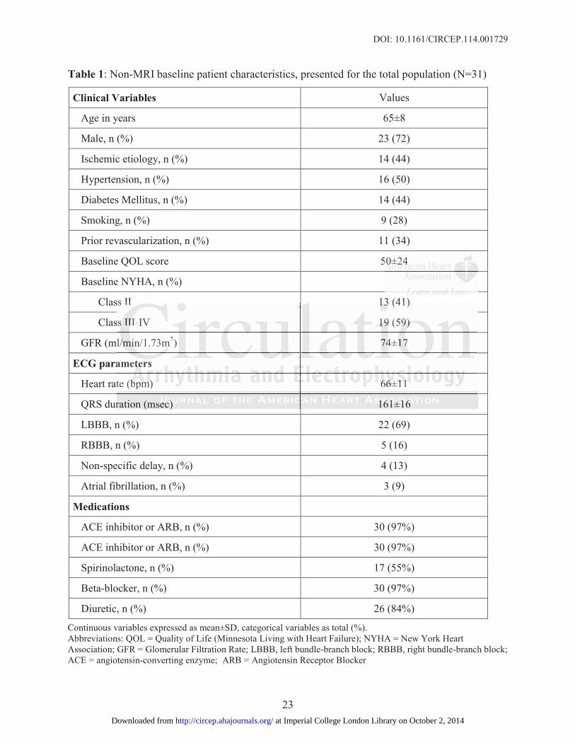
Table 1: Non-MRI baseline patient characteristics, presented for the total population (N=31)
Clinical Variables Values
Age in years 65±8
Male, n (%) 23 (72)
Ischemic etiology, n (%) 14 (44)
Hypertension, n (%) 16 (50)
Diabetes Mellitus, n (%) 14 (44)
Smoking, n (%) 9 (28)
Prior revascularization, n (%) 11 (34)
Baseline QOL score 50±24
Baseline NYHA, n (%)
Class II 13 (41)
Class III-IV 19 (59)
GFR (ml/min/1.73m2) 74±17
ECG parameters
Heart rate (bpm) 66±11
QRS duration (msec) 161±16
LBBB, n (%) 22 (69)
RBBB, n (%) 5 (16)
Non-specific delay, n (%) 4 (13)
Atrial fibrillation, n (%) 3 (9)
Medications
ACE inhibitor or ARB, n (%) 30 (97%)
ACE inhibitor or ARB, n (%) 30 (97%)
Spirinolactone, n (%) 17 (55%)
Beta-blocker, n (%) 30 (97%)
Diuretic, n (%) 26 (84%)
Continuous variables expressed as mean±SD, categorical variables as total (%).Abbreviations: QOL = Quality of Life (Minnesota Living with Heart Failure); NYHA = New York HeartAssociation; GFR = Glomerular Filtration Rate; LBBB, left bundle-branch block; RBBB, right bundle-branch block;ACE = angiotensin-converting enzyme; ARB = Angiotensin Receptor Blocker
505000±2±22444
ss II 13 (41)
s
l
a
t
r
ss II 13131313 (41)
ssss IIIII-IV 1919199 (59)9)9)9)
l////mimimimin/1.73m2) 7474±111777
ameteteteers
te (bbbbpmpmpm))) 6666666±1±1±1±111
ration (m( seseses c)c)c)c) 161616161±1±1±1±16161616
at Imperial College London Library on October 2, 2014http://circep.ahajournals.org/Downloaded from

DOI: 10.1161/CIRCEP.114.001729
24
Table 2: Baseline Cardiac MRI and Echocardiographic Imaging
Cardiovascular MRI variables, Values
LV EDV indexed to BSA (ml/m2) 141 ± 36
LV ESV indexed to BSA (ml/m2) 105± 33
LV EF 26 ± 8
LV mass indexed to BSA (g/m2) 105± 26
RV EDV indexed to BSA (ml/m2) 66± 18
RV ESV indexed to BSA (ml/m2) 35± 17
RV EF 47± 14
Total scar volume (g) 26± 25
Total percent scar (% LV mass) 13.7 ± 14.7
Echocardiography variables
LVESV indexed to BSA (ml/m2) 90.6 ± 31
V-V delay (msec) 10 ± 20
SPWD (msec) 70 ± 28
Values expressed as mean±SD.Abbreviations: LV = left ventricular; EDV = end-diastolic volume; ESV = end-systolic volume; EF=ejection fraction; SD = Standard Deviation; V-V delay = Interventricular delay, SPWD = Septal to PosteriorWall Delay.
Table 3: Comparison of baseline and 6 months echocardiographic and clinical response criteriafor study population (N=31).
Echocardiography Baseline 6-months P value*
LV EDV indexed to BSA 140.8 ± 36.3 100± 30 0.002
LV ESV indexed to BSA 105.2 ± 32.8 71± 27 0.013
LV EF (%) 25.9 ± 7.8 31± 8 0.040
Clinical variables Baseline 6-months P value
6-min hall walk (m) 358± 114 381± 129 0.002
QOL score 49± 23 34± 26 0.029
Values expressed as mean±SD. *P value calculated using the paired t-test. Abbreviations: LV = left ventricular; EDV = end-diastolic volume; ESV = end-systolic volume; EF= ejection fraction; QOL = Quality of Life (Minnesota Living with Heart Failure)
g p y
n
s
nt
g p y
deeeexexexx d to BSBSSSA (ml/m2) 90.6666 ±±± 31
(m(m(m(msec) 10 ± 20
sec)c)c)) 7070707 ±±±± 28282828
sseddd asasasa mememeananan±S±S±SSD.D.D.D.ns: LVLV = llel ftff ventntntrrrir culall r; EDEDVV = enddd-dididiastolililil c volllume; ESESESSVVVV = endd---systolololiicicic volllume; EFEFEF===tion; SD = StStStananandadadardrdrd DeDeDeviv attatioioi n;nn VVV-VVV deeelalalayyy = yyy InInnteteervrvvenenentrt iciciculululararr deddelalaay,y,, SPSPPWDWDWD = SeSeSeptpptalalal tototo Posterior
at Imperial College London Library on October 2, 2014http://circep.ahajournals.org/Downloaded from

DOI: 10.1161/CIRCEP.114.001729
25
Figure Legends:
Figure 1: Example of 3D Navigation Model (upper left) generated for a patient with isolated
transmural infarction of the inferior and inferolateral wall and basal septal fibrosis. Modeling
algorithm selected typical apical location for the RV lead (blue arrow) and basal anterolateral
segment for the LV lead (red arrow). Intra-procedural fluoroscopy images shown in matched
imaging planes during balloon contrast injection (upper) and at end of procedure (lower). A
mid-ventricular LGE image of myocardial scar is shown in the top right with 3D LGE
reconstruction shown immediately below. Post-procedural 3D CT reconstruction of final lead
placement is shown at bottom right in a matched view.
Figure 2: Example of 3D Navigation Model (upper left) generated for a patient with transmural
infarction of both the septum / apex, and the inferolateral wall (ie: two most conventional lead
positions). Modeling algorithm selected atypical locations for both leads; a basal anteroseptal
location for the RV lead (blue arrow), and a mid inferior segment for the LV lead (red arrow).
Intra-procedural fluoroscopy images shown in matched imaging planes during balloon contrast
injection (upper) and at end of procedure (lower). Note the use of an additional pacing wire to
the basal RV septum. A mid-ventricular LGE image of myocardial scar is shown in the top right
with 3D LGE reconstruction shown immediately below. Post-procedural 3D CT reconstruction
of final lead placement is shown at bottom right in a matched view.
ht with 3D LGE
onsttruructtctioiiion n ofofff ffif nananaallll lele
E m
o e
Modeling algorithm selected at pical locations for bothr leads; a basal anterosep
is sssshohohoh wnwnwnn atatata bototototttot m right in a matched viiiiewewe .
Exammmmplplpleeee of 3D3D3D3 NNNaN iiivigationonnn MMMModelelelel (((upupppeer llleftfff )))) gegegeg nenenenerrrrateeedddd fofff r a r patitititienenenentt wiiiiththth trtt ansm
of bobbb thhh thehh seeptptptptum /// apppex, and tthhhe dd iini ffef rolllateral wallllll (i(i(i( e:: two mmmmost convennnntitititiononononal le
MM dod leliin lal irithth lle tct ded tat iic lal llocatiti ffo bb tothh lle dad bba ll tte p
at Imperial College London Library on October 2, 2014http://circep.ahajournals.org/Downloaded from

at Imperial College London Library on October 2, 2014http://circep.ahajournals.org/Downloaded from
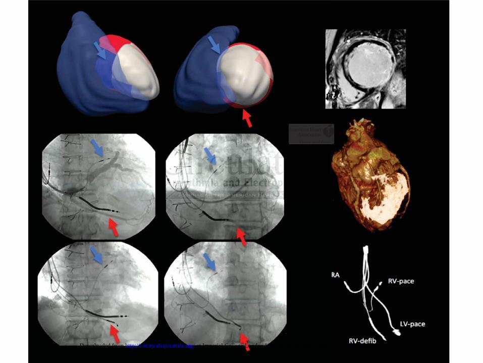
at Imperial College London Library on October 2, 2014http://circep.ahajournals.org/Downloaded from