MINIATURIZATION OF GROUND STATION FOR UNMANNED AIR VEHICLES
42
MINIATURIZATION OF GROUND STATION FOR UNMANNED AIR VEHICLES By URIEL RODRIGUEZ A THESIS PRESENTED TO THE GRADUATE SCHOOL OF THE UNIVERSITY OF FLORIDA IN PARTIAL FULFILLMENT OF THE REQUIREMENTS FOR THE DEGREE OF MASTER OF SCIENCE UNIVERSITY OF FLORIDA 2004
-
Upload
independent -
Category
Documents
-
view
2 -
download
0
Transcript of MINIATURIZATION OF GROUND STATION FOR UNMANNED AIR VEHICLES

MINIATURIZATION OF GROUND STATION FOR UNMANNED AIRVEHICLES
By
URIEL RODRIGUEZ
A THESIS PRESENTED TO THE GRADUATE SCHOOLOF THE UNIVERSITY OF FLORIDA IN PARTIAL FULFILLMENT
OF THE REQUIREMENTS FOR THE DEGREE OFMASTER OF SCIENCE
UNIVERSITY OF FLORIDA
2004

TABLE OF CONTENTS
page
LIST OF FIGURES . . . . . . . . . . . . . . . . . . . . . . . . . . . . . . . . iv
ABSTRACT . . . . . . . . . . . . . . . . . . . . . . . . . . . . . . . . . . . . vi
1 INTRODUCTION . . . . . . . . . . . . . . . . . . . . . . . . . . . . . . 1
1.1 Motivation . . . . . . . . . . . . . . . . . . . . . . . . . . . . . . . 11.2 Previous Work . . . . . . . . . . . . . . . . . . . . . . . . . . . . . 21.3 Challenges . . . . . . . . . . . . . . . . . . . . . . . . . . . . . . . 31.4 Overview . . . . . . . . . . . . . . . . . . . . . . . . . . . . . . . . 4
2 GROUND STATION . . . . . . . . . . . . . . . . . . . . . . . . . . . . . 5
2.1 Previous Work . . . . . . . . . . . . . . . . . . . . . . . . . . . . . 52.2 Handheld Ground Station . . . . . . . . . . . . . . . . . . . . . . 7
2.2.1 Motivation for Miniaturization . . . . . . . . . . . . . . . . 72.2.2 Selection and Specifications of the Handheld Ground Station 72.2.3 Limitations . . . . . . . . . . . . . . . . . . . . . . . . . . . 8
3 HORIZON ESTIMATION . . . . . . . . . . . . . . . . . . . . . . . . . . 10
3.1 Previous Work . . . . . . . . . . . . . . . . . . . . . . . . . . . . . 103.2 Our Approach . . . . . . . . . . . . . . . . . . . . . . . . . . . . . 11
3.2.1 Overview . . . . . . . . . . . . . . . . . . . . . . . . . . . . 113.2.2 Algorithm Details . . . . . . . . . . . . . . . . . . . . . . . 123.2.3 Algorithm Performance . . . . . . . . . . . . . . . . . . . . 16
4 TESTBED AND EXPERIMENTAL RESULTS . . . . . . . . . . . . . . 20
4.1 Testbed . . . . . . . . . . . . . . . . . . . . . . . . . . . . . . . . 204.1.1 Testbed Setup . . . . . . . . . . . . . . . . . . . . . . . . . 204.1.2 Controller . . . . . . . . . . . . . . . . . . . . . . . . . . . 22
4.2 Results . . . . . . . . . . . . . . . . . . . . . . . . . . . . . . . . . 234.2.1 Virtual Testbed . . . . . . . . . . . . . . . . . . . . . . . . 234.2.2 Flight Testing . . . . . . . . . . . . . . . . . . . . . . . . . 27
ii

5 FUTURE WORK . . . . . . . . . . . . . . . . . . . . . . . . . . . . . . . 29
5.1 Ground Station . . . . . . . . . . . . . . . . . . . . . . . . . . . . 295.2 Vision Algorithm . . . . . . . . . . . . . . . . . . . . . . . . . . . 30
REFERENCES . . . . . . . . . . . . . . . . . . . . . . . . . . . . . . . . . . . 32
BIOGRAPHICAL SKETCH . . . . . . . . . . . . . . . . . . . . . . . . . . . . 35
iii

LIST OF FIGURES
Figure page
2.1 The folding-wing ”Pocket MAV” can be stored in the container shown. 6
2.2 Size comparison of 12” Powerbook to Zaurus. . . . . . . . . . . . . . 8
3.1 Visual representation of algorithm. . . . . . . . . . . . . . . . . . . . 11
3.2 Example of Ettinger’s initial attempt failing. . . . . . . . . . . . . . . 12
3.3 The result of our algorithm on a sample image is shown above. (a)The estimated horizon is shown in red. (b) Blue pixels were classi-fied as sky while green pixels were classified as ground. . . . . . . . 13
3.4 The output of the bootstrap process is shown above. (a) Bootstrapimage from a real flight test. (b) Distribution of ground and skypixels for the given bootstrap image. . . . . . . . . . . . . . . . . . 13
3.5 Output of our algorithm for a bank angle greater than 45 degrees.(a) Estimated horizon shown in red. (b) Classified pixels and es-timated horizon. . . . . . . . . . . . . . . . . . . . . . . . . . . . . 15
3.6 Correct estimation of horizon. . . . . . . . . . . . . . . . . . . . . . . 17
3.7 The horizon was properly estimated in both images even though bothimages were noisy. . . . . . . . . . . . . . . . . . . . . . . . . . . . 18
3.8 The results of skipping pixels are shown above. (a) Classifying everyother 5 lines. (b) Classifying every other 20 lines. . . . . . . . . . . 19
4.1 Testbed setup. . . . . . . . . . . . . . . . . . . . . . . . . . . . . . . . 21
4.2 Linear estimator. 3 degrees of error at worst between -45 and 45 de-grees. . . . . . . . . . . . . . . . . . . . . . . . . . . . . . . . . . . 22
4.3 Various images from the flight simulator software. . . . . . . . . . . . 24
4.4 Controller output. . . . . . . . . . . . . . . . . . . . . . . . . . . . . . 25
iv

4.5 Image sequence from a virtual environment test flight. . . . . . . . . . 25
4.6 MAV flown in tests. . . . . . . . . . . . . . . . . . . . . . . . . . . . . 26
4.7 Sample images taken from the flight test. . . . . . . . . . . . . . . . . 27
5.1 The disparity between CCD and CMOS image quality is shown above.(a) Image taken with CMOS camera. (b) Image taken with CCDcamera. . . . . . . . . . . . . . . . . . . . . . . . . . . . . . . . . . 31
v

Abstract of Thesis Presented to the Graduate Schoolof the University of Florida in Partial Fulfillment of the
Requirements for the Degree of Master of Science
MINIATURIZATION OF GROUND STATION FOR UNMANNED AIRVEHICLES
By
Uriel Rodriguez
December 2004
Chair: Amauri A. ArroyoMajor Department: Electrical and Computer Engineering
In this thesis, we seek to miniaturize the ground station responsible for the
image processing that is used to autonomously stabilize unmanned air vehicles
(UAVs). The image processing performed on the ground station consists of finding
the horizon in the images transmitted from the UAV’s forward-facing camera. In
conjunction with a proportional derivative controller, the estimated horizon is then
used to stabilize the UAV. Thus, the focus of our research is to derive a horizon
estimating algorithm that can be executed in real-time on a smaller ground station.
To achieve our goals, we propose to use a ground station based on a handheld
computer, also known as personal digital assistant (PDA). The PDA-based ground
station is considerably smaller than the previous ground station which consisted of
a notebook computer. However, the lack of a floating-point unit (FPU) hinders the
development of a real-time horizon estimation algorithm.
vi

To address the lack of an FPU, we propose the use of a non-floating point
intensive horizon estimation algorithm. The overall approach of the algorithm is to
find the transition between sky and ground in each vertical line of the image. The
classification of sky and ground is achieved by comparing the pixel in question to
the color models for both the sky and the ground. The pixel is then classified as
sky or ground depending on its nearest color model. Once the positions of all the
transitions are known, linear regression is performed on the transition points to
estimate the horizon in the image.
Our initial results support the outlined approach. The proposed algorithm
successfully estimates the horizon in real-time environments.
vii

CHAPTER 1INTRODUCTION
1.1 Motivation
A major focus of the United States Air Force is the development of unmanned
air vehicles (UAVs) that can be deployed in strategic operations as well as tactical
scenarios including the ability for soldiers in the field to deploy micro air vehicles
(MAVs). A MAV is an UAV with a small wing span that flies at low altitudes and
slow airspeeds. A MAV consists of a wingspan and fuselage that ranges from 30
inches down to six inches and operates at speeds less than 25 miles per hour [1].
The MAVs offer great potential in both the military and civilian sectors.
Equipped with small cameras and transmitters, MAVs can be used to survey and
monitor areas that are too far or too dangerous to send human scouts. Possible
civilian applications include monitoring radiation spills, forest fires, and volcanic
activity. In the military, MAVs are intended to reduce the risk of personnel by
assisting ground troops in search and rescue missions, tracking remote moving-
targets, and assessing immediate bomb damage.
However, there are certain limitations that have restricted the wide deployment
of MAVs. A MAV requires highly skilled pilots to fly such small planes. The small
size of the aircrafts tends to make the MAVs more susceptible to wind gusts,
and thus, harder to stabilize and control. This problem can be remedied by the
development of an autonomous MAV that is self-stabalizable [2]. However, the
1

2
ground station required to deploy an autonomous MAV is bulky and would disallow
the use of a self-stabilizing MAV in certain situations. The development of a
smaller ground station would allow for the deployment of autonomous MAVs in
wider variety of scenarios.
1.2 Previous Work
There have been numerous successful UAVs implemented by various companies
including Lockheed Martin, Northrop Grumman, and AeroVironment. A notable
UAV is the Pointer and is developed by AeroVironment [3]. The Pointer was
designed as a tactical reconnaissance vehicle for military and law enforcement
applications. An onboard camera relays live video images to a ground station that
the pilot can use to control the UAV remotely. Although the Pointer is currently
being used by the military, its large size keeps it from being deployed in certain
situations. For situations requiring a smaller UAV, AeroVironment developed an
autonomous MAV named the Black Widow [4]. Like the Pointer, the Black Widow
is capable of autonomous flight and is equipped with a camera whose video is
transmitted to the ground.
At the University of Florida, the MAV Lab has become very proficient in the
research and development of such small aircrafts [5-7]. The MAV Lab continues to
develop planes with improved flight characteristics, payload capacity, and structural
integrity. The Lab has developed planes that have won the International MAV
Competition for the past six consecutive years. The competition judges entries
based on the size and the operational range of the aircrafts. The planes of the MAV
Lab were originally controlled by off the shelf remote control airplane equipment,
and therefore, controlled completely by a human pilot. Since the operational range

3
of the plane was limited by the ability of the pilot to effectively follow the small
plane in the air, the planes were fitted with forward-looking cameras and video
transmitters that would allow the pilot to fly the planes well beyond visual range.
The computer vision research at the University of Florida took advantage
of the fact that the MAVs were sending a video signal to the ground. The initial
vision system developed analyzed the images obtained from the forward-looking
camera in order to find the horizon [8, 9, 10]. In conjunction with a proportional
integral derivative (PID) controller, the horizon was used to determine the neces-
sary adjustments needed to keep the plane level with respect to the ground. Once
implemented in real-time, the vision-based flight stability system could keep a MAV
in the air without any input from a human pilot. The advantage of an autonomous
MAV is that it allows unexperienced pilots to fly them since the MAVs are capable
of self-stabilization.
1.3 Challenges
Initially, the image processing, required to estimate the horizon, was performed
on the ground using a desktop computer. As technology improved, the vision
algorithm was ported to a ground-based notebook computer. However, if ground
troops are to deploy MAVs on the battlefield, then it is essential that the ground
station be as compact as possible.
A number of formidable challenges have been encountered when miniaturizing
the ground station. These challenges result from features that are unavailable
on current handheld computers. These missing features include the lack a fast
input/output (I/O) port and the lack of a floating-point unit (FPU).

4
In previous ground stations, the FireWire port (IEEE 1394) was used in
conjunction with a frame grabber to import the incoming video stream to the
ground station. However, handheld computers are currently lacking a FireWire port
or an equivalently fast I/O port like the second generation Universal Serial Bus
(USB2). The proposed approach is to use the compact flash card slot to import the
video stream via a wireless Internet connection.
Since floating-point instructions take about an order of magnitude longer to
execute on a processor without an FPU [11], the lack of an FPU will limit the
ability of the vision system. A non-floating point intensive horizon estimation
algorithm is proposed.
1.4 Overview
In this thesis, we first introduce the motivation and challenges for miniaturiz-
ing the ground station. Chapter 2 discusses the need for a smaller ground station
and implications of migrating the ground station to a handheld computer. Chapter
3 describes the horizon detection algorithm designed to overcome the shortcomings
of the handheld computer. Chapter 4 describes the testbed setup and illustrates the
experimental results of autonomous flights in a simulator as well as in real flights.
Finally, Chapter 5 offers some ideas for future work.

CHAPTER 2GROUND STATION
In this Chapter, we first describe the evolution of the ground station and the
motivation to shrink the ground station even further. We then propose the use of a
handheld computer as the next ground station. Finally, we examine the limitations
encountered when using a handheld computer as the ground station.
2.1 Previous Work
Our ultimate goal is to perform the horizon estimation, used to stabilize the
aircraft, on-board the MAV [12, 13]. On-board image processing would eliminate
the transmission noise problems and frame dropouts caused by transmitting
the video to the ground for processing. However, because of the computational
demands of the horizon estimation and the payload limitations of the MAV, the
calculations presently need to be performed on the ground.
Both the Pointer and the Black Widow use a ground station that pilots use to
control the UAVs. The Pointer ground station is the size of a briefcase – 7” x 11”
x 16” [3]. The Black Widow went through several iterations of its ground station
[4]. It started as a collection of off-the-shelf components that had to be assembled
on the field and evolved into the size of a 15-lb briefcase. Eventually, the Black
Widow’s ground station shrunk to the size a compact Pelican case.
5

6
Figure 2.1: The folding-wing ”Pocket MAV” can be stored in the container shown.
At the University of Florida, the first ground station consisted of a 900MHz
desktop computer with a frame grabber card running the Mandrake Linux operat-
ing system [8]. As computer technology improved over the years, the ground station
was further reduced from a desktop computer to a 12” Apple Powerbook notebook
computer running at 1GHz [14]. Switching to an Apple Powerbook removed the
need for a frame grabber card since the notebook is equipped with a FireWire
400 (IEEE1394a) port and a QuickTime API that provides an easy interface to
capture images from the FireWire port. Another advantage of this Apple computer
is its operating system – OS X. OS X is UNIX-based operating system, and thus,
allows for easy migration of existing code from a Linux environment to the OS X
platform.

7
2.2 Handheld Ground Station
2.2.1 Motivation for Miniaturization
In 2003, the Mechanical and Aerospace Engineering Department at the
University of Florida received a grant from the U.S. Army that would require the
development of a plane with a small storage footprint. This grant was for the
development of a plane and the ground station that could fit in the pocket of a
soldier’s battle dress uniform (BDU). The BDU’s pocket dimensions are 8” x 8” x
2”. The MAV Lab produced a folding-wing airplane that when folded, can fit in
a container that is 8” x 4” x 2”. The remaining 8” x 4” x 2” of unoccupied space
in the BDU is too small to accommodate the 12” Powerbook. Therefore, a smaller
ground station needs to be developed. Both the MAV and the container are shown
in Figure 2.1.
2.2.2 Selection and Specifications of the Handheld Ground Station
The Sharp Zaurus SL-5600 is the handheld computer, also known as a personal
digital assistant (PDA), selected to become the next ground station. The Zaurus
specifications are shown in Table 2.1. The main advantage of the Zaurus is its
Embedded Linux Operating System. A Linux-based operating system is an
advantage because once again, any previously designed code can be cross-compiled
for this device. It also provides a familiar set of development tools, including, the
GNU Development Tools.
A more obvious advantage of the handheld is its size. Measuring 0.9” x
5.4” x 2.9”, the Zaurus is more than 12 times smaller in volume than the 12”
Powerbook (1.35” x 12.7” x 10.2”). At 7.1 oz, the Zaurus weighs 13 times less than

8
Figure 2.2: Size comparison of 12” Powerbook to Zaurus.
the Powerbook (5.9 lbs). Figure 2.2 illustrates the physical difference between the
Zaurus and the Powerbook.
2.2.3 Limitations
The Zaurus adds two major limitations. Even though the Zaurus utilizes
Intel’s XScale processor running at 400MHz, it is lacking a Floating-Point Unit
(FPU). Since floating-point operations must be performed in software on the
Table 2.1: Specifications of the Sharp Zaurus SL-5600.
CPU Intel XScale (PXA255, 400MHz)Platform Linux 2.4 (Embedix)Display 3.5” Reflective TFT Color Display with 240x320 ResolutionMemory 32MB SDRAM / 64MB Flash ROMI/O Compact Flash Slot, SD Card Slot, Serial Port
9
Zaurus, floating-point operations place a huge burden on the processor, taking up
to an order of magnitude longer to execute than integer operations [11]. Therefore,
the algorithm performed on the Zaurus should be designed to avoid using floating-
point calculations.
Another limitation of the Zaurus SL-5600 is the lack of FireWire or USB ports.
This eliminates the possibility of using a FireWire or USB frame grabber to import
the video feed from the plane. An 802.11b Wireless Compact Flash Card on the
Zaurus and a host computer with a FireWire port and network access are used to
import the images in to the Zaurus.
Brigham Young University (BYU) has successfully used PDAs as an interface
to UAVs [15]. BYU employs a similar method of using a host computer to commu-
nicate to the PDA via an 802.11b link. It is important to note that BYU has only
used the PDA as an interface to the MAV while still using the host computer to
handle the data processing and communication to the UAV.
In the next Chapter, we will discuss the previous attempts to detect the
horizon and describe an algorithm that will successfully estimate the horizon on a
PDA in real-time.

CHAPTER 3HORIZON ESTIMATION
In this Chapter, we discuss the previous work done to estimate the horizon.
We also propose a new approach that will allow us to estimate the horizon on a
handheld computer. Finally, the performance of the new approach is discussed.
3.1 Previous Work
In the initial attempt to estimate the horizon, the main assumption was that
the sky would be represented by high-intensity (light) image region while the
ground would be represented by the low-intensity (dark) image region [8]. Locating
the boundary between the sky and the ground would result in the horizon. The
basic idea behind the algorithm was to fit a step function to the intensity values
of each vertical line in the image as shown in Figure 3.1. Once the position of the
best-fit transitions for each vertical line in the image are known, a linear regression
was performed on the set of (x,y) positions. The resulting line would estimate
the horizon. Although this approach worked when flying over a uniform forest on
a sunny day, it resulted in large errors in the horizon estimates when flying over
ground objects of high intensity. An example of this error is shown in Figure 3.2.
Since only marginal results were obtained from the first algorithm, a different
approach was taken to correctly estimate the horizon. Instead of combining the
color information into intensity, and thus, losing two-thirds of the information avail-
able in the process, both sky and ground were modeled as a statistical distribution
10

11
Figure 3.1: Visual representation of algorithm.
in color space [16]. The task was then to find the set of points within the image
that would have the highest likelihood of fitting the given distributions. This is
accomplished by performing a search through the potential set of all lines in the
image space and finding the line that best fit the distributions.
Although the color model-based horizon detection algorithm was demonstrated
to work at 30Hz in real-time with over 99.9% correct horizon identification, it will
not run anywhere close to 30Hz in real-time on the Zaurus because of its reliance
on floating-point calculations [16].
3.2 Our Approach
3.2.1 Overview
In order to stabilize the MAV with the Zaurus, a robust, yet non-floating-point
intensive horizon detection algorithm must be developed. The new algorithm

12
Figure 3.2: Example of Ettinger’s initial attempt failing.
borrows from both of the algorithms discussed above to create a lightweight, yet
effective horizon detection system.
The overall approach of the algorithm is to find the transition between sky
and ground in each vertical line. Pixels are classified according to its nearest sky
or ground color model. Once all the (x,y) positions of the transitions for each
vertical line are known, a linear regression is performed to estimate the horizon as
illustrated in Figure 3.3.
3.2.2 Algorithm Details
The first step in the estimation of the horizon is to be able to classify each
pixel in the image as either sky or ground. A color-based model is built of both
the sky and the ground. Not surprisingly, it turns out that the blue and green
channels of an image containing a horizon produce a distinct distribution of the
sky and the ground pixels. A bootstrap procedure is performed before each aircraft

13
(a) (b)
Figure 3.3: The result of our algorithm on a sample image is shown above. (a) Theestimated horizon is shown in red. (b) Blue pixels were classified as sky while greenpixels were classified as ground.
(a)
(b)
Figure 3.4: The output of the bootstrap process is shown above. (a) Bootstrap im-age from a real flight test. (b) Distribution of ground and sky pixels for the givenbootstrap image.

14
launch to build the color model. This is accomplished by pointing the plane’s
camera towards the horizon and assuming that the top one-third of the image is
sky and the bottom third of the image is ground. Figure 3.4 shows the color model
distribution results of the bootstrap sequence.
Once the color models are acquired, the image is traversed in the vertical
direction. As each column is traversed, each pixel is classified as sky or ground
depending on its nearest color model. The starting and ending locations of the
largest consecutive set of sky and ground pixels in each column are also recorded.
Next, the transition between sky and ground is determined by the sky pixel from
the largest consecutive set of sky pixels that is closest to the largest consecutive
set of ground pixels. This is based on the assumption that ground pixels are more
likely to be classified as sky pixels than sky pixels being classified as ground pixels.
This algorithm does not assume that every vertical line will include a transi-
tion from sky to ground, as would be the case in an image with a roll angle greater
than 45 degrees. Therefore, the algorithm must determine when a transition has
not occurred and discard the transition point generated by that line. A good tran-
sition must meet the following two requirements: (1) The end of the largest set of
sky pixels that is closest to the edge of the image must be close enough to the edge
of the image, and (2) the other edge which is nearest to the middle of the image
must be far enough from the edge.
It should be evident that there will be cases in which only a few good transi-
tions will be found by the algorithm. This again is the case in an image with a roll
angle greater than 45 degrees. One way to approach this problem is to calculate an
initial horizon estimate, then if the roll angle is greater than 45 degrees, repeat the

15
(a) (b)
Figure 3.5: Output of our algorithm for a bank angle greater than 45 degrees. (a)Estimated horizon shown in red. (b) Classified pixels and estimated horizon.
process using the horizontal lines in order to increase the accuracy of the horizon.
However, this approach would require the linear regression to be performed twice,
once for the vertical lines and once for the horizon lines. The linear regression
calculation are floating-point intensive, and therefore, would hurt the overall per-
formance. Moreover, it might be possible not to be able to estimate a horizon from
the vertical lines if the roll angle is close to 90 degrees. The alternate approach
used to eliminate the extra floating-point calculations is to keep track of the num-
ber of good transitions. Based on the number of good transitions found and the
size of the image, it is possible to determine if the process needs to be performed on
the horizon lines. The result of a horizontal sweep is shown in Figure 3.5.
Once the pixels have been classified and the minimum number of good
transition points have been identified, linear regression is performed on the good
transitions to estimate the horizon. Linear regression outputs the slope, m, and
the y-intercept, b, of the line that corresponds to the estimated horizon and is

16
calculated by using the following formulas:
m =n
∑(xy) −
∑x
∑y
n∑
(x2) − (∑
x)2, (3.1)
b =
∑y
∑(x2) −
∑x
∑xy
n∑
(x2) − (∑
x)2, (3.2)
where x and y represent the (x,y) coordinates of good transitions identified in the
image. The roll angle (in degrees), φ, can be calculated by the inverse tangent of
the slope of the horizon line:
φ = atan(m) × 180/π. (3.3)
This algorithm also allows a way to easily determine the orientation of
the aircraft at all times. While performing vertical scans, if the largest set of
consecutive sky pixels is above the largest set of consecutive ground pixels, then
the plane is flying normal. If the largest set of consecutive sky pixels is below
the largest set of consecutive ground pixels, then the plane is flying upside down.
Similarly, it is possible to determine the location of the sky relative to the ground
while performing horizontal scans when the plane is in a steep roll angle.
3.2.3 Algorithm Performance
The performance of our algorithm is more robust than the first algorithm
discussed in the beginning of this Chapter. As previously shown in Figure 3.2,
the intensity-based algorithm failed to correctly estimate the horizon where high-
intensity objects were present on the ground. Figure 3.6 shows the correctly
estimated horizon achieved by using our algorithm on the same image. Our

17
Figure 3.6: Correct estimation of horizon.
algorithm can also correctly estimate the horizon in noisy images as shown in
Figure 3.7.
Our algorithm also executes much faster in a CPU without an FPU than the
previous algorithms since the new approach uses significantly less floating-point
operations. Performance can be further enhanced by skipping lines. If every other
line is skipped, the vertical scan time would be decreased by one-half. If every third
vertical line is analyzed, then the vertical scan time would be decreased by a third,
and so forth. The difference between the output produced by analyzing each line
and the output produced by skipping lines is negligible. The algorithm results of
skipping pixels is shown in Figure 3.8. The amount of pixels that are skippable
depends on the size of the image. For a larger image, more lines can be skipped.
In the next Chapter, we will discuss the testbed setup used to test the al-
gorithm in a real-time environment. This setup will include flights in a virtual

18
Figure 3.7: The horizon was properly estimated in both images even though bothimages were noisy.
environment as well as real test flights. Finally, the results of both the virtual and
real test flights will be shown.

19
(a) (b)
Figure 3.8: The results of skipping pixels are shown above. (a) Classifying everyother 5 lines. (b) Classifying every other 20 lines.

CHAPTER 4TESTBED AND EXPERIMENTAL RESULTS
In this Chapter, we discuss the testbed setup used to test the vision algorithm
in a real-time environment. We show how a virtual environment is used to verify
the algorithm before a real test flight takes place. Finally, the results of the flight
tests are discussed.
4.1 Testbed
4.1.1 Testbed Setup
A pictorial diagram of the testbed setup is shown in Figure 4.1. The video
signal is transmitted from the airborne MAV to the ground via a 2.4GHz RF
transmitter. The signal is then fed into a laptop via a FireWire frame buffer that
down-samples the image to 80x60 resolution. The laptop then transmits the down-
sampled image to the Zaurus via an 802.11b link for image processing. After the
horizon is estimated on the Zaurus, the desired servo positions are transmitted
via an RS-232 link to an 8-bit micro-controller that converts them to a servo
train-pulse that is then fed to the RC controller. When the trainer switch on the
controller is engaged, the controller transmits the train-pulse generated from the
desired servo positions. When the trainer switch is not engaged, then a human pilot
has control of the plane. This is beneficial for flight testing in case something goes
wrong, and the human has to retake control of the plane to avoid a potential crash.
20

21
Figure 4.1: Testbed setup.
The image needs to be down-sampled to 80x60 resolution or smaller, not
because of the performance of the algorithm, but because of the bottleneck caused
by the bandwidth of the 802.11b connection. An 8-bit depth, uncompressed
RGB image arriving at 30Hz would need a bandwidth of 3.4Mbps (8 bits × 3
color channels × 80 width × 60 height × 30 times per second). Although the
802.11b protocol has a raw rate of to up 11Mbps, its actual throughput is about
half of that [17]. Also, as signal strength and quality decreases, the throughput
diminishes. If the image size is increased to 120x80, then the required bandwidth
would be 6.7Mbps which is more than the 5.5Mbps actual throughput bandwidth
of 802.11b. However, there is a positive side-effect to down-sampling the image.
The down-sampling acts as a mean filter [18], so there are less outliers in the color
distribution.

22
Figure 4.2: Linear estimator. 3 degrees of error at worst between -45 and 45 de-grees.
4.1.2 Controller
In the past, complicated controllers have been used to stabilize the plane
[19, 20]; however, a simpler approach is taken in the experiments performed. A
simple proportional derivative (PD) controller is used to correct the roll of the
plane [21]. Equation 4.1 is used to calculate the desired servo position, δd, where
Kp and Kd are the proportional and derivative gains, respectively, and δn is the
neutral servo position. The roll angle, φ, calculation can be simplified from a
floating-point inverse tangent (4.2) to an integer multiplication (4.3) via a linear

23
estimator.
δd = δn − Kpφ − Kdφ̇, (4.1)
φ = arctan(m) × 180/π, (4.2)
φ′
≈ m × 48. (4.3)
The linear estimator for the roll angle works best for angles between -45 and
45 degrees where the error is less 4 degrees as shown in Figure 4.2. A non-linear
estimator can easily be built to produce small errors for all possible roll angles.
The fact that the linear estimator causes a large error at angles greater than ±45
degrees is not a problem since the effect that the error causes is a larger correction
rate.
4.2 Results
4.2.1 Virtual Testbed
A virtual environment is used to test the hardware, software, and algorithm
before an actual test flight [22]. The virtual testbed is based on an off-the-shelf
remote control airplane simulation package. This setup uses the same interface to
the ground station that the MAV uses, and thus, allows for seamless interchanging
between the two. Instead of transmitting the plane’s video to the ground station,
the simulator’s video output is fed into the ground station. Similarly, the RC
controller’s output becomes the input to the airplane simulator. The simulation
package offers a diverse set of scenery that allows for to the testing of hardware,
horizon estimation, and the controller without the need to fly a MAV. Figure 4.3

24
Figure 4.3: Various images from the flight simulator software.

25
Figure 4.4: Controller output.
Figure 4.5: Image sequence from a virtual environment test flight.

26
Figure 4.6: MAV flown in tests.
illustrates some of the environments available in the simulation package as well as
the results from the horizon estimator.
Although the initial results as shown in Figure 4.3 are good, a lag has been
encountered that rendered the system unusable in a real-time environment. The lag
is introduced by the time required to send the image from the host computer to the
Zaurus via 802.11b. By the time that the first image is transfered to the Zaurus,
the next image is ready to be transfered, and thus, leaving virtually no time for the
image processing. This problem is remedied by only transferring every other frame
to the Zaurus. This technique diminishes the effect of the lag and allows the entire
process to execute in real-time at 15Hz.
The controller performs well while running in real-time at 15Hz. The servo
command sent to the simulation as produced by the controller to stabilize the plane

27
Figure 4.7: Sample images taken from the flight test.
is show in Figure 4.4. Figure 4.5 shows a sequence of images where the plane is
stabilizing the horizon.
4.2.2 Flight Testing
After finalizing the system parameters in the virtual environment, the ground
station is ready for a real test flight. The UAV flown for this experiment is shown
in Figure 4.6. On its maiden flight, the ground station produced excellent results.
The PDA-based ground station correctly estimated the horizon and successfully
stabilized the plane in real-time. The controller gains used in the virtual testbed
worked on the real plane without requiring any additional adjustments. The images
shown in Figure 4.7 are the result of the horizon estimator on images taken from
the test flight.
An unforeseen advantage was encountered while flight testing. In the past, the
pilot has been constrained to flying the plane just a few feet away from the ground

28
station because the pilot’s RC controller was used to send commands to the plane.
Now, the pilot is free to roam as he is flying the plane because only the PDA is
attached to his RC controller. The other parts of the ground station which include
the antenna, receiver, frame grabber, and laptop can be located away from the pilot
since the data is transmitted to the PDA wirelessly.

CHAPTER 5FUTURE WORK
The systems developed in this work have only taken initial steps toward a
small, stand-alone ground station. This Chapter will discuss improvements to both
the ground station and the vision algorithm that will allow us to meet those goals.
5.1 Ground Station
As technology improves, the potential and importance of the PDA as a stand-
alone ground station for a UAV will increase. There are already better PDAs in
the market sporting a 624MHz CPU and 64MB of SDRAM. That is already a 64%
increase in processing power and double the amount of RAM. A new transflective
TFT VGA display with 640x480 resolution is a huge improvement over the old
320x240 resolution reflective TFT display which had poor visibility in direct
sunlight. The new PDAs also carry a 2D and 3D video accelerator with 16MB of
video memory. The video accelerator will greatly decrease the amount of CPU
processing power required to repaint the screen when displaying the incoming
images to the PDA display.
Although some PDAs have the capability to act as a USB host, and thus, allow
the possible use of a USB frame grabber that would eliminate the need for laptop
computer, the limitation lies in the inability to easily customize the operating
system. Complete embedded Linux distributions, such as OpenZaurus, are not
yet easy to configure and customize, but will be available in the near future. This
29
30
ability would not only be beneficial to the overall performance of the system by
trimming needless features from the kernel and other unnecessary applications, but
it would also be needed to compile Video4Linux and other features into the kernel
which are required by most frame grabber modules.
Ideally, FireWire support would be added to PDAs. Unfortunately, there is not
much demand for such a feature. The CPUs would probably need to reach speeds
of at least 1GHz before such a fast data bus can be fully utilized. After all, there’s
no need to transfer information so quickly into a system, if the processor cannot
keep up with it. A Floating-Point Unit would also be a welcomed edition to the
PDA, but again, there is not much demand for it in the current market. Hopefully,
as PDAs become more and more powerful, they will start replacing laptops, and
thus, in the process be retrofitted with some of the features that they currently
lack.
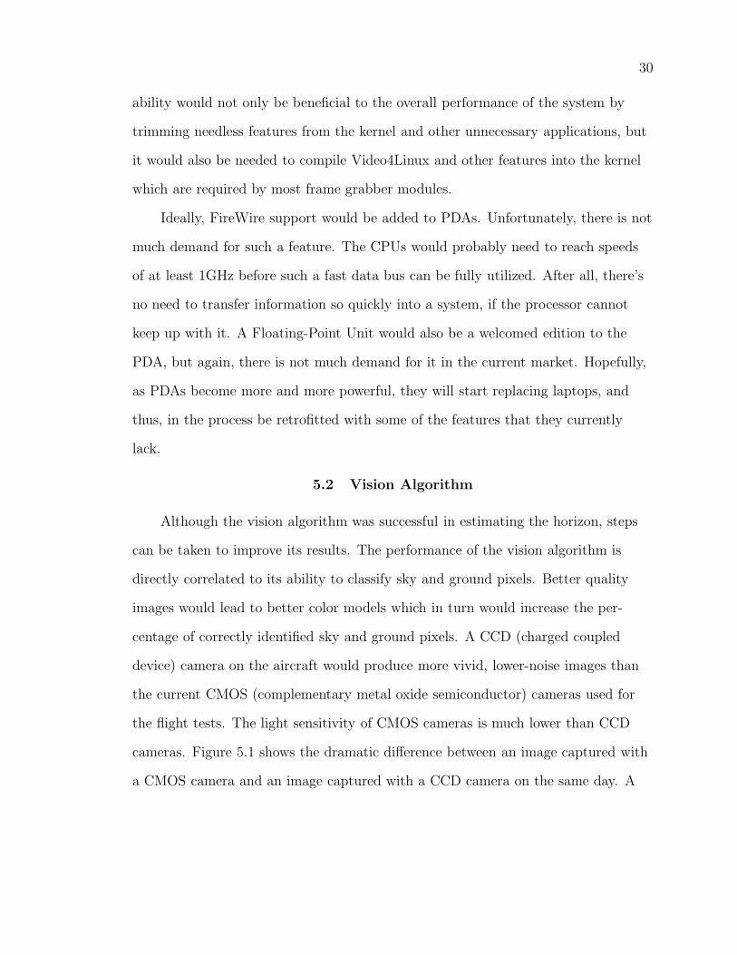
5.2 Vision Algorithm
Although the vision algorithm was successful in estimating the horizon, steps
can be taken to improve its results. The performance of the vision algorithm is
directly correlated to its ability to classify sky and ground pixels. Better quality
images would lead to better color models which in turn would increase the per-
centage of correctly identified sky and ground pixels. A CCD (charged coupled
device) camera on the aircraft would produce more vivid, lower-noise images than
the current CMOS (complementary metal oxide semiconductor) cameras used for
the flight tests. The light sensitivity of CMOS cameras is much lower than CCD
cameras. Figure 5.1 shows the dramatic difference between an image captured with
a CMOS camera and an image captured with a CCD camera on the same day. A

31
(a) (b)
Figure 5.1: The disparity between CCD and CMOS image quality is shown above.(a) Image taken with CMOS camera. (b) Image taken with CCD camera.
dynamic color model could also boost classification results as lighting conditions
change throughout the day.
More traditional image processing technics like erosion and dilation can reduce
unwanted noise or misclassifications in an image. Also, a blob-finding technic to
find and eliminate small sets of connected pixels can be used similarly to erosion
and dilation to improve the overall quality of the image after classification.
The controller could also be greatly improved. A model-based controller using
state feedback from the vision system would be a tremendous improvement over
the current proportional-derivative controller approach. The controller could also
implement joystick control from the PDA to use to directly manipulate the plane.
Along with a compact flash modem, this would eliminate the need for the 8-bit
micro-controller and the RC controller.

REFERENCES
[1] J. M. McM. and Col. M. S. Francis, “Micro Air Vehicles - Toward a NewDimension in Flight,” World Wide Web, http://www.darpa.mil/tto/mav/mav_auvsi.html, last accessed on November 15, 2004.
[2] J. W. Grzywna, J. Plew, M. C. Nechyba, and P. G. Ifju, “Enabling Au-tonomous Flight,” in Proc. Florida Conference on the Recent Advances in
Robotics, Dania Beach, August 2003, vol. 16, sec. TA3, pp. 1–3.
[3] AeroVironment, “AUV: Pointer,” World Wide Web, http://www.aerovironment.com/area-aircraft/prod-serv/pointer.html, last ac-cessed on November 15, 2004.
[4] J. M. Grasmeyer and M. T. Keennon, “Development of the Black WidowMicro Air Vehicle,” in AIAA-2001-127, January 2001.
[5] P. G. Ifju, S. Ettinger, D. A. Jenkins, Y. Lian, W. Shyy, and M. R. Waszak,“Flexible-wing-based Micro Air Vehicles,” in 40th AIAA Aerospace Sciences
Meeting, Reno, Nevada, January 2002.
[6] P. G. Ifju, S. Ettinger, D. A. Jenkins, and L. M.ez, “Composite Materials forMicro Air Vehicles,” in SAMPE Journal, July/August 2001, vol. 46/2, pp.1926–1937.
[7] D. A. Jenkins, P. G. Ifju, M. Abdulrahim, and S. Olipra, “Assessment ofControllability of Micro Air Vehicles,” in Proc. 16th Intl Conf. Unmanned Air
Vehicle Systems, April 2001, vol. 17, pp. 617–640.
[8] S. M. Ettinger, “Design and Implementation of Autonomous Vision-guidedMicro Air Vehicles,” M.S. thesis, University of Florida, May 2001.
[9] S. Todorovic, “Statistical Modeling and Segmentation of Sky/Ground Images,”M.S. thesis, University of Florida, December 2002.
[10] S. Todorovic, M. C. Nechyba, and P. G. Ifju, “Sky/Ground Modeling forAutonomous MAVs,” in Proc. IEEE Int. Conference on Robotics and
Automation, New Orleans, September 2003, vol. 1, pp. 1422–1427.
32

33
[11] T. D. Morton, Embedded Microcontrollers, Prentice-Hall, Columbus, 2001.
[12] J. Plew, J. W. Grzywna, M. C. Nechyba, and P. G. Ifju, “Recent Progress inthe Development of On-Board Electronics for Micro Air Vehicles,” in Proc.
Florida Conference on the Recent Advances in Robotics, Orlando, August2004, vol. 17, sec. FP3, pp. 1–6.
[13] J. Plew, “Development of Flight Avionics System for Autonomous MAVControl,” M.S. thesis, University of Florida, December 2004.
[14] J. W. Grzywna, A. Jain, J. Plew, and M. C. Nechyba, “Rapid Development ofVision-Based Control for MAVs through a Virtual Flight Testbed,” submittedto IEEE Int. Conf. on Robotics and Automation, April 2005.
[15] M. Quigley, M. A. Goodrich, and R. W. Beard, “Semi-Autonomous Human-UAV Interfaces for Fixed-Winged Mini-UAVs,” to be presented at IEEE Int.Conf. on Intelligent Robots and Systems, August 2005.
[16] S. M. Ettinger, M. C. Nechyba, P. G. Ifju, and M. Waszak, “Vision-guidedFlight Stability and Control for Micro Air Vehicles,” in Proceedings IEEE Int.
Conference on Intelligent Robots and Systems, Lausane, October 2002, vol. 3,pp. 2134–2140.
[17] B. Nadel, “Wireless Networking 101,” World Wide Web, http://reviews.cnet.com/4520-3243_7-5021297.html, last accessed on November 15, 2004.
[18] D. A. Forsyth and J. Ponce, Computer Vision: A Modern Approach, Prentice-Hall, Upper Saddle River, 2003.
[19] A. Kurdila, M. C. Nechyba, R. Lind, P. G. Ifju, W. Dahmen, R. DeVore,and R. Sharpley, “Vision-based Control of Micro Air Vehicles: Progress andProblems in Estimation,” in Presented at IEEE Int. Conference on Decision
and Control, Atlantis, 2004.
[20] L. Armesto, S. Chroust, M. Vincze, and J. Tornero, “Multi-rate Fusion withVision and Inertial Sensors,” in Proc. IEEE Int. Conference on Robotics and
Automation, April 2004, vol. 1, pp. 193–199.
[21] R. C. Dorf and R. H. Bishop, Modern Control Systems, Addison-Wesley,Menlo Park, 1998.

34
[22] J. W. Grzywna, “A Flight Testbed with Virtual Environment Capabilitiesfor Developing Autonomous Micro Air Vehicles,” M.S. thesis, University ofFlorida, December 2004.

BIOGRAPHICAL SKETCH
Uriel Rodriguez was born in Ponce, Puerto Rico, on June 6, 1979. His family
moved to Coral Springs, FL, in 1988. He received his high school diploma from
Marjory Stoneman Douglas High School in Parkland, FL. He then attended the
University of Florida and received his bachelor’s degree in computer engineering
in December 2001. While working on his undergraduate work, Uriel was active in
the Student IEEE Branch and was a member of the IEEE SoutheastCon Student
Hardware Team which won 1st Place with its Pong robot. Since then Uriel has
worked in the Machine Intelligence Lab under Dr. Antonio Arroyo, Dr. Michael
Nechyba, and Dr. Eric Schwartz.
35