AISI 304 stainless steel marking by a Q-switched diode pumped Nd:YAG laser
Upload
inti-plasticosCategory
view
0download
0
www.elsevier.com/locate/surfcoat
Surface & Coatings Technology 187 (2004) 63–69
Microstructure and corrosion behaviour of DC-pulsed plasma nitrided
AISI 410 martensitic stainless steel
P. Corengiaa,*, G. Ybarraa, C. Moinaa, A. Cabob, E. Broitmanc
a Instituto Nacional de Tecnologıa Industrial, Av. Gral. Paz 5445, C.C. 157, (B1650 WAB) San Martın, Argentinab Ionar S.A., Arias 3422, C1430CRB Ciudad de Buenos Aires, Argentina
cDepartment of Chemical Engineering, Carnegie Mellon University, Pittsburg, PA 15213, USA
Received 5 August 2003; accepted in revised form 20 January 2004
Available online 27 March 2004
Abstract
AISI 410 martensitic stainless steel samples with different metallurgical structures were DC-pulsed plasma nitrided at 623, 723 and
773 K. The samples were ion nitrided in an industrial equipment using a gas mixture consisting of 25% N2+75% H2 under a pulsed
DC glow discharge. Optical and scanning electron microscopy, as well as glancing angle X-ray diffraction and microhardness
measurements have been used to study the ion nitrided surfaces. All plasma nitrided samples showed surface hardness values higher
than 1000 HV; the highest value was obtained at 673 K. The case depth was approximately 30 Am for samples nitrided at 673 and
773 K, while the sample nitrided at 623 K showed an ‘expanded ferrite’ phase (aN) and an incipient precipitation of Fe4N. Depending
on the treatment temperature and time, two fronts were formed, termed diffusion front and transformation front; the latter produces a
softening of the nitrided case. Electrochemical measurements showed a decrease of corrosion resistance in the samples nitrided during
20 h at 673 and 773 K. Conversely, the sample nitrided at 623 K presented a low corrosion current and more noble corrosion
potential.
D 2004 Elsevier B.V. All rights reserved.
Keywords: Pulsed plasma nitriding; Martensitic stainless steel; Corrosion
1. Introduction
Stainless steels are usually employed as engineering
materials due to high corrosion resistance. However, low
wear resistance and poor tribological behaviour limit their
use in some applications. Therefore, there is an increasing
interest in improving surface properties through plasma
assisted thermochemical treatments, notably ion nitriding
[1–3].
Although stainless steels can be nitrided with the
consequential increase in surface hardness, which improves
their tribological performance, this is accompanied by a
loss of corrosion resistance of the nitrided case [1,4]. In
the last years, several investigations have been carried out
to solve this problem. Plasma nitriding has been success-
0257-8972/$ - see front matter D 2004 Elsevier B.V. All rights reserved.
doi:10.1016/j.surfcoat.2004.01.031
* Corresponding author. Tel.: +54-11-4724-6297; fax: +54-11-4752-
0818.
E-mail address: [email protected] (P. Corengia).
fully employed at relatively low temperature (below 723 K)
[5,6], rather than at conventional nitriding temperatures of
approximately 873 K [7]. Further, it has been observed that
plasma nitriding at low temperature in austenitic stainless
steels can produce an extremely hard layer with good
corrosion resistance [8,9]. This layer contains a supersatu-
rated interstitial solid solution of N in austenite; this phase is
also termed expanded austenite (gN).
Although several studies were carried out on plasma
nitriding of austenitic stainless steels, few have been done
on martensitic stainless steels [10–12]. Nitrided martensitic
stainless steels remain a good choice for mildly corrosive
environments and low temperature applications [13,14].
However, the studies of Refs. [10–12] did not include any
corrosion study. In the present work, an AISI 410 martens-
itic stainless steel with different metallurgical structures
(annealed and quenched-tempered) was DC-pulsed plasma
nitrided at different treatment temperatures. The obtained
metallurgical structures as well as microhardness profiles
and corrosion behaviour were analysed and discussed.
P. Corengia et al. / Surface & Coatings Technology 187 (2004) 63–6964
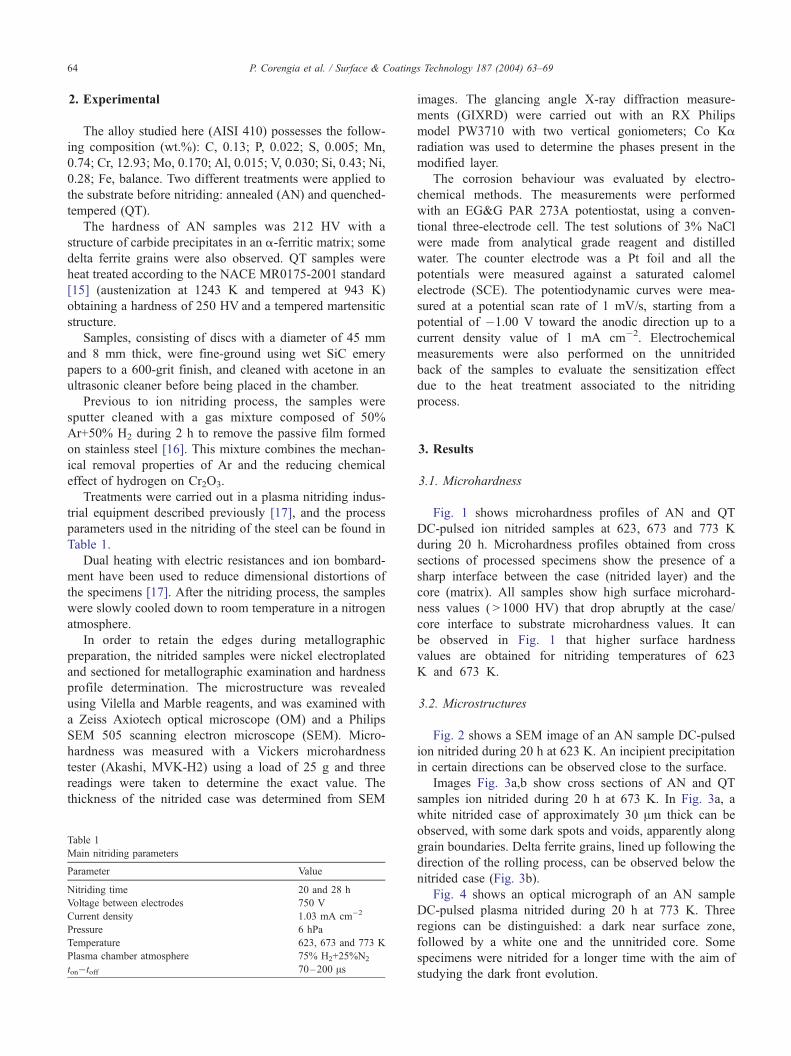
2. Experimental
The alloy studied here (AISI 410) possesses the follow-
ing composition (wt.%): C, 0.13; P, 0.022; S, 0.005; Mn,
0.74; Cr, 12.93; Mo, 0.170; Al, 0.015; V, 0.030; Si, 0.43; Ni,
0.28; Fe, balance. Two different treatments were applied to
the substrate before nitriding: annealed (AN) and quenched-
tempered (QT).
The hardness of AN samples was 212 HV with a
structure of carbide precipitates in an a-ferritic matrix; some
delta ferrite grains were also observed. QT samples were
heat treated according to the NACE MR0175-2001 standard
[15] (austenization at 1243 K and tempered at 943 K)
obtaining a hardness of 250 HV and a tempered martensitic
structure.
Samples, consisting of discs with a diameter of 45 mm
and 8 mm thick, were fine-ground using wet SiC emery
papers to a 600-grit finish, and cleaned with acetone in an
ultrasonic cleaner before being placed in the chamber.
Previous to ion nitriding process, the samples were
sputter cleaned with a gas mixture composed of 50%
Ar+50% H2 during 2 h to remove the passive film formed
on stainless steel [16]. This mixture combines the mechan-
ical removal properties of Ar and the reducing chemical
effect of hydrogen on Cr2O3.
Treatments were carried out in a plasma nitriding indus-
trial equipment described previously [17], and the process
parameters used in the nitriding of the steel can be found in
Table 1.
Dual heating with electric resistances and ion bombard-
ment have been used to reduce dimensional distortions of
the specimens [17]. After the nitriding process, the samples
were slowly cooled down to room temperature in a nitrogen
atmosphere.
In order to retain the edges during metallographic
preparation, the nitrided samples were nickel electroplated
and sectioned for metallographic examination and hardness
profile determination. The microstructure was revealed
using Vilella and Marble reagents, and was examined with
a Zeiss Axiotech optical microscope (OM) and a Philips
SEM 505 scanning electron microscope (SEM). Micro-
hardness was measured with a Vickers microhardness
tester (Akashi, MVK-H2) using a load of 25 g and three
readings were taken to determine the exact value. The
thickness of the nitrided case was determined from SEM
Table 1
Main nitriding parameters
Parameter Value
Nitriding time 20 and 28 h
Voltage between electrodes 750 V
Current density 1.03 mA cm�2
Pressure 6 hPa
Temperature 623, 673 and 773 K
Plasma chamber atmosphere 75% H2+25%N2
ton�toff 70–200 As
images. The glancing angle X-ray diffraction measure-
ments (GIXRD) were carried out with an RX Philips
model PW3710 with two vertical goniometers; Co Ka
radiation was used to determine the phases present in the
modified layer.
The corrosion behaviour was evaluated by electro-
chemical methods. The measurements were performed
with an EG&G PAR 273A potentiostat, using a conven-
tional three-electrode cell. The test solutions of 3% NaCl
were made from analytical grade reagent and distilled
water. The counter electrode was a Pt foil and all the
potentials were measured against a saturated calomel
electrode (SCE). The potentiodynamic curves were mea-
sured at a potential scan rate of 1 mV/s, starting from a
potential of �1.00 V toward the anodic direction up to a
current density value of 1 mA cm�2. Electrochemical
measurements were also performed on the unnitrided
back of the samples to evaluate the sensitization effect
due to the heat treatment associated to the nitriding
process.
3. Results
3.1. Microhardness
Fig. 1 shows microhardness profiles of AN and QT
DC-pulsed ion nitrided samples at 623, 673 and 773 K
during 20 h. Microhardness profiles obtained from cross
sections of processed specimens show the presence of a
sharp interface between the case (nitrided layer) and the
core (matrix). All samples show high surface microhard-
ness values ( > 1000 HV) that drop abruptly at the case/
core interface to substrate microhardness values. It can
be observed in Fig. 1 that higher surface hardness
values are obtained for nitriding temperatures of 623
K and 673 K.
3.2. Microstructures
Fig. 2 shows a SEM image of an AN sample DC-pulsed
ion nitrided during 20 h at 623 K. An incipient precipitation
in certain directions can be observed close to the surface.
Images Fig. 3a,b show cross sections of AN and QT
samples ion nitrided during 20 h at 673 K. In Fig. 3a, a
white nitrided case of approximately 30 Am thick can be
observed, with some dark spots and voids, apparently along
grain boundaries. Delta ferrite grains, lined up following the
direction of the rolling process, can be observed below the
nitrided case (Fig. 3b).
Fig. 4 shows an optical micrograph of an AN sample
DC-pulsed plasma nitrided during 20 h at 773 K. Three
regions can be distinguished: a dark near surface zone,
followed by a white one and the unnitrided core. Some
specimens were nitrided for a longer time with the aim of
studying the dark front evolution.

Fig. 2. SEM image of an AN sample AISI 410 steel DC-pulsed ion nitrided
at 623 K for 20 h.
Fig. 1. Microhardness profiles of the samples DC-pulsed plasma nitrided for 20 h at: 623 K (a), 673 K (b) and 773 K (c). QT: () and AN:(o).
P. Corengia et al. / Surface & Coatings Technology 187 (2004) 63–69 65
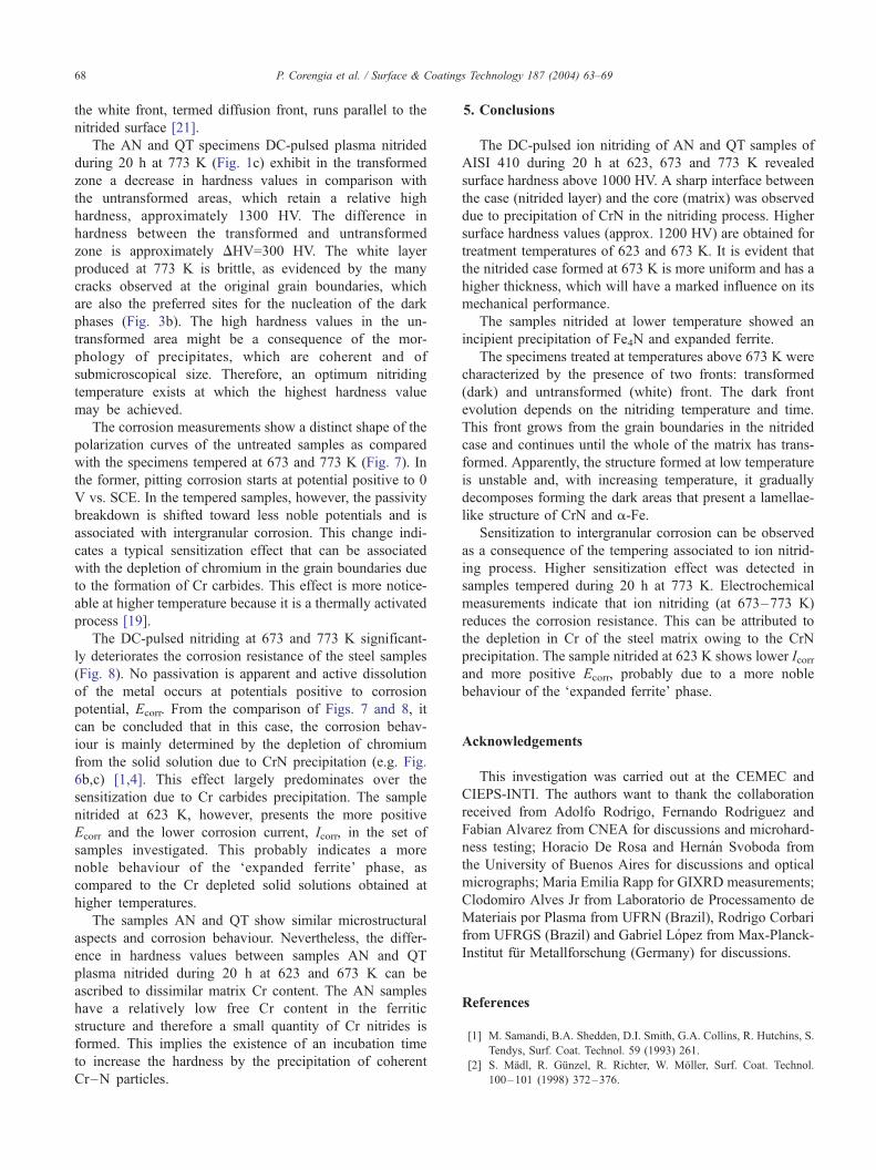
Fig. 5 shows a SEM image of an AN sample ion nitrided
at 773 K during 28 h, where the dark zone occupies the
complete nitrided case. It is possible to observe a lamellae-
like structure inside the dark zone.
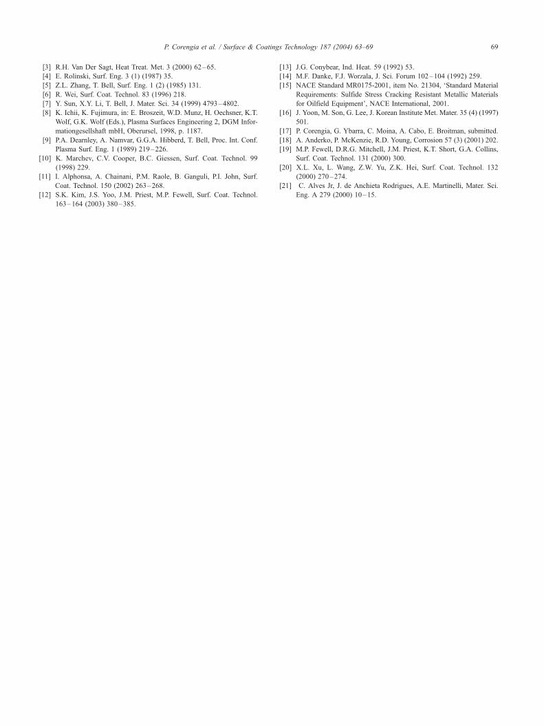
Fig. 6a shows the GIXRD pattern obtained from an AN
unnitrided sample and a DC-pulsed ion nitrided during 20
h at 623 K specimen of AISI 410 martensitic stainless steel
with AN structure. The figure evidences the presence of an
a-Fe peak for the unnitrided sample. For the nitrided
sample, in addition to the a-Fe peak, the presence of a
minor phase of gV-Fe4N was detected; it is worth noting that
no evidence of CrN was found. It can also be observed that
the a-Fe peak is shifted towards lower diffraction angles and
broadened considerably.
Fig. 6b,c show the diffractograms of samples ion nitrided
during 20 h at 673 K and 773 K, respectively. The images
show that in both cases, the main components of the nitrided
layer are gV-Fe4N, q-Fe2–3 N, CrN and a-Fe. It is also
observed that the a-Fe peak sharpens and returns to the
unnitrided higher diffraction angle (Fig. 6c).
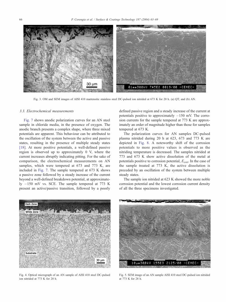
Fig. 3. OM and SEM images of AISI 410 martensitic stainless steel DC-pulsed ion nitrided at 673 K for 20 h. (a) QT; and (b) AN.
P. Corengia et al. / Surface & Coatings Technology 187 (2004) 63–6966
3.3. Electrochemical measurements
Fig. 7 shows anodic polarization curves for an AN steel
sample in chloride media, in the presence of oxygen. The
anodic branch presents a complex shape, where three mixed
potentials are apparent. This behaviour can be attributed to
the oscillation of the system between the active and passive
states, resulting in the presence of multiple steady states
[18]. At more positive potentials, a well-defined passive
region is observed up to approximately 0 V, where the
current increases abruptly indicating pitting. For the sake of
comparison, the electrochemical measurements on AN
samples, which were tempered at 673 and 773 K, are
included in Fig. 7. The sample tempered at 673 K shows
a passive zone followed by a steady increase of the current
beyond a well-defined breakdown potential, at approximate-
ly �150 mV vs. SCE. The sample tempered at 773 K
present an active/passive transition, followed by a poorly
Fig. 4. Optical micrograph of an AN sample of AISI 410 steel DC-pulsed
ion nitrided at 773 K for 20 h.
defined passive region and a steady increase of the current at
potentials positive to approximately �150 mV. The corro-
sion currents for the sample tempered at 773 K are approx-
imately an order of magnitude higher than those for samples
tempered at 673 K.
The polarization curves for AN samples DC-pulsed
plasma nitrided during 20 h at 623, 673 and 773 K are
depicted in Fig. 8. A noteworthy shift of the corrosion
potentials to more positive values is observed as the
nitriding temperature is decreased. The samples nitrided at
773 and 673 K show active dissolution of the metal at
potentials positive to corrosion potential, Ecorr. In the case of
the sample treated at 773 K, the active dissolution is
preceded by an oscillation of the system between multiple
steady states.
The sample ion nitrided at 623 K showed the more noble
corrosion potential and the lowest corrosion current density
of all the three specimens investigated.
Fig. 5. SEM image of an AN sample AISI 410 steel DC-pulsed ion nitrided
at 773 K for 28 h.
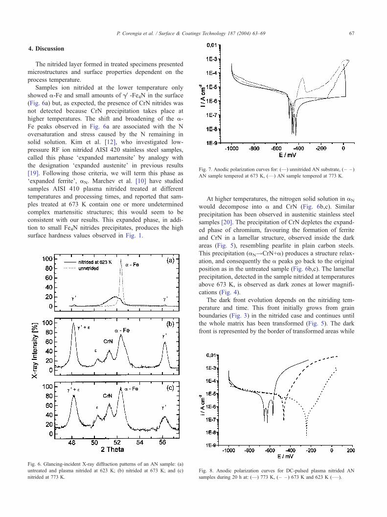
Fig. 7. Anodic polarization curves for: (—) unnitrided AN substrate, ( – – )
AN sample tempered at 673 K, (����) AN sample tempered at 773 K.
P. Corengia et al. / Surface & Coatings Technology 187 (2004) 63–69 67
4. Discussion
The nitrided layer formed in treated specimens presented
microstructures and surface properties dependent on the
process temperature.
Samples ion nitrided at the lower temperature only
showed a-Fe and small amounts of gV-Fe4N in the surface
(Fig. 6a) but, as expected, the presence of CrN nitrides was
not detected because CrN precipitation takes place at
higher temperatures. The shift and broadening of the a-
Fe peaks observed in Fig. 6a are associated with the N
oversaturation and stress caused by the N remaining in
solid solution. Kim et al. [12], who investigated low-
pressure RF ion nitrided AISI 420 stainless steel samples,
called this phase ‘expanded martensite’ by analogy with
the designation ‘expanded austenite’ in previous results
[19]. Following those criteria, we will term this phase as
‘expanded ferrite’, aN. Marchev et al. [10] have studied
samples AISI 410 plasma nitrided treated at different
temperatures and processing times, and reported that sam-
ples treated at 673 K contain one or more undetermined
complex martensitic structures; this would seem to be
consistent with our results. This expanded phase, in addi-
tion to small Fe4N nitrides precipitates, produces the high
surface hardness values observed in Fig. 1.
Fig. 6. Glancing-incident X-ray diffraction patterns of an AN sample: (a)
untreated and plasma nitrided at 623 K; (b) nitrided at 673 K; and (c)
nitrided at 773 K.
At higher temperatures, the nitrogen solid solution in aN
would decompose into a and CrN (Fig. 6b,c). Similar
precipitation has been observed in austenitic stainless steel
samples [20]. The precipitation of CrN depletes the expand-
ed phase of chromium, favouring the formation of ferrite
and CrN in a lamellar structure, observed inside the dark
areas (Fig. 5), resembling pearlite in plain carbon steels.
This precipitation (aN!CrN+a) produces a structure relax-
ation, and consequently the a peaks go back to the original
position as in the untreated sample (Fig. 6b,c). The lamellar
precipitation, detected in the sample nitrided at temperatures
above 673 K, is observed as dark zones at lower magnifi-
cations (Fig. 4).
The dark front evolution depends on the nitriding tem-
perature and time. This front initially grows from grain
boundaries (Fig. 3) in the nitrided case and continues until
the whole matrix has been transformed (Fig. 5). The dark
front is represented by the border of transformed areas while
Fig. 8. Anodic polarization curves for DC-pulsed plasma nitrided AN
samples during 20 h at: (—) 773 K, (– – ) 673 K and 623 K (�����).
P. Corengia et al. / Surface & Coatings Technology 187 (2004) 63–6968
the white front, termed diffusion front, runs parallel to the
nitrided surface [21].
The AN and QT specimens DC-pulsed plasma nitrided
during 20 h at 773 K (Fig. 1c) exhibit in the transformed
zone a decrease in hardness values in comparison with
the untransformed areas, which retain a relative high
hardness, approximately 1300 HV. The difference in
hardness between the transformed and untransformed
zone is approximately DHV=300 HV. The white layer
produced at 773 K is brittle, as evidenced by the many
cracks observed at the original grain boundaries, which
are also the preferred sites for the nucleation of the dark
phases (Fig. 3b). The high hardness values in the un-
transformed area might be a consequence of the mor-
phology of precipitates, which are coherent and of
submicroscopical size. Therefore, an optimum nitriding
temperature exists at which the highest hardness value
may be achieved.
The corrosion measurements show a distinct shape of the
polarization curves of the untreated samples as compared
with the specimens tempered at 673 and 773 K (Fig. 7). In
the former, pitting corrosion starts at potential positive to 0
V vs. SCE. In the tempered samples, however, the passivity
breakdown is shifted toward less noble potentials and is
associated with intergranular corrosion. This change indi-
cates a typical sensitization effect that can be associated
with the depletion of chromium in the grain boundaries due
to the formation of Cr carbides. This effect is more notice-
able at higher temperature because it is a thermally activated
process [19].
The DC-pulsed nitriding at 673 and 773 K significant-
ly deteriorates the corrosion resistance of the steel samples
(Fig. 8). No passivation is apparent and active dissolution
of the metal occurs at potentials positive to corrosion
potential, Ecorr. From the comparison of Figs. 7 and 8, it
can be concluded that in this case, the corrosion behav-
iour is mainly determined by the depletion of chromium
from the solid solution due to CrN precipitation (e.g. Fig.
6b,c) [1,4]. This effect largely predominates over the
sensitization due to Cr carbides precipitation. The sample
nitrided at 623 K, however, presents the more positive
Ecorr and the lower corrosion current, Icorr, in the set of
samples investigated. This probably indicates a more
noble behaviour of the ‘expanded ferrite’ phase, as
compared to the Cr depleted solid solutions obtained at
higher temperatures.
The samples AN and QT show similar microstructural
aspects and corrosion behaviour. Nevertheless, the differ-
ence in hardness values between samples AN and QT
plasma nitrided during 20 h at 623 and 673 K can be
ascribed to dissimilar matrix Cr content. The AN samples
have a relatively low free Cr content in the ferritic
structure and therefore a small quantity of Cr nitrides is
formed. This implies the existence of an incubation time
to increase the hardness by the precipitation of coherent
Cr–N particles.
5. Conclusions
The DC-pulsed ion nitriding of AN and QT samples of
AISI 410 during 20 h at 623, 673 and 773 K revealed
surface hardness above 1000 HV. A sharp interface between
the case (nitrided layer) and the core (matrix) was observed
due to precipitation of CrN in the nitriding process. Higher
surface hardness values (approx. 1200 HV) are obtained for
treatment temperatures of 623 and 673 K. It is evident that
the nitrided case formed at 673 K is more uniform and has a
higher thickness, which will have a marked influence on its
mechanical performance.
The samples nitrided at lower temperature showed an
incipient precipitation of Fe4N and expanded ferrite.
The specimens treated at temperatures above 673 K were
characterized by the presence of two fronts: transformed
(dark) and untransformed (white) front. The dark front
evolution depends on the nitriding temperature and time.
This front grows from the grain boundaries in the nitrided
case and continues until the whole of the matrix has trans-
formed. Apparently, the structure formed at low temperature
is unstable and, with increasing temperature, it gradually
decomposes forming the dark areas that present a lamellae-
like structure of CrN and a-Fe.
Sensitization to intergranular corrosion can be observed
as a consequence of the tempering associated to ion nitrid-
ing process. Higher sensitization effect was detected in
samples tempered during 20 h at 773 K. Electrochemical
measurements indicate that ion nitriding (at 673–773 K)
reduces the corrosion resistance. This can be attributed to
the depletion in Cr of the steel matrix owing to the CrN
precipitation. The sample nitrided at 623 K shows lower Icorrand more positive Ecorr, probably due to a more noble
behaviour of the ‘expanded ferrite’ phase.
Acknowledgements
This investigation was carried out at the CEMEC and
CIEPS-INTI. The authors want to thank the collaboration
received from Adolfo Rodrigo, Fernando Rodriguez and
Fabian Alvarez from CNEA for discussions and microhard-
ness testing; Horacio De Rosa and Hernan Svoboda from
the University of Buenos Aires for discussions and optical
micrographs; Maria Emilia Rapp for GIXRD measurements;
Clodomiro Alves Jr from Laboratorio de Processamento de
Materiais por Plasma from UFRN (Brazil), Rodrigo Corbari
from UFRGS (Brazil) and Gabriel Lopez from Max-Planck-
Institut fur Metallforschung (Germany) for discussions.
References
[1] M. Samandi, B.A. Shedden, D.I. Smith, G.A. Collins, R. Hutchins, S.
Tendys, Surf. Coat. Technol. 59 (1993) 261.
[2] S. Madl, R. Gunzel, R. Richter, W. Moller, Surf. Coat. Technol.
100–101 (1998) 372–376.
P. Corengia et al. / Surface & Coatings Technology 187 (2004) 63–69 69
[3] R.H. Van Der Sagt, Heat Treat. Met. 3 (2000) 62–65.
[4] E. Rolinski, Surf. Eng. 3 (1) (1987) 35.
[5] Z.L. Zhang, T. Bell, Surf. Eng. 1 (2) (1985) 131.
[6] R. Wei, Surf. Coat. Technol. 83 (1996) 218.
[7] Y. Sun, X.Y. Li, T. Bell, J. Mater. Sci. 34 (1999) 4793–4802.
[8] K. Ichii, K. Fujimura, in: E. Broszeit, W.D. Munz, H. Oechsner, K.T.
Wolf, G.K. Wolf (Eds.), Plasma Surfaces Engineering 2, DGM Infor-
mationgesellshaft mbH, Oberursel, 1998, p. 1187.
[9] P.A. Dearnley, A. Namvar, G.G.A. Hibberd, T. Bell, Proc. Int. Conf.
Plasma Surf. Eng. 1 (1989) 219–226.
[10] K. Marchev, C.V. Cooper, B.C. Giessen, Surf. Coat. Technol. 99
(1998) 229.
[11] I. Alphonsa, A. Chainani, P.M. Raole, B. Ganguli, P.I. John, Surf.
Coat. Technol. 150 (2002) 263–268.
[12] S.K. Kim, J.S. Yoo, J.M. Priest, M.P. Fewell, Surf. Coat. Technol.
163–164 (2003) 380–385.
[13] J.G. Conybear, Ind. Heat. 59 (1992) 53.
[14] M.F. Danke, F.J. Worzala, J. Sci. Forum 102–104 (1992) 259.
[15] NACE Standard MR0175-2001, item No. 21304, ‘Standard Material
Requirements: Sulfide Stress Cracking Resistant Metallic Materials
for Oilfield Equipment’, NACE International, 2001.
[16] J. Yoon, M. Son, G. Lee, J. Korean Institute Met. Mater. 35 (4) (1997)
501.
[17] P. Corengia, G. Ybarra, C. Moina, A. Cabo, E. Broitman, submitted.
[18] A. Anderko, P. McKenzie, R.D. Young, Corrosion 57 (3) (2001) 202.
[19] M.P. Fewell, D.R.G. Mitchell, J.M. Priest, K.T. Short, G.A. Collins,
Surf. Coat. Technol. 131 (2000) 300.
[20] X.L. Xu, L. Wang, Z.W. Yu, Z.K. Hei, Surf. Coat. Technol. 132
(2000) 270–274.
[21] C. Alves Jr, J. de Anchieta Rodrigues, A.E. Martinelli, Mater. Sci.
Eng. A 279 (2000) 10–15.
Copyright © 2022 FDOKUMEN