![(Microsoft PowerPoint - MI2oct 09.ppt [tryb zgodno\234ci])](https://static.fdokumen.com/doc/165x107/6334652f4e43a4bcd80d3474/microsoft-powerpoint-mi2oct-09ppt-tryb-zgodno234ci.jpg)
(Microsoft PowerPoint - CAD_Dynamics_Chapter 7_20210205.ppt ...
162
TU Darmstadt, Institut für Elektrische Energiewandlung | Energy Converters – CAD & System Dynamics, 7. / 1 Prof. Dr.-Ing. habil. Dr. h.c. Andreas Binder Energy Converters – CAD and System Dynamics 1. Basic design rules for electrical machines 2. Design of Induction Machines 3. Heat transfer and cooling of electrical machines 4. Dynamics of electrical machines 5. Dynamics of DC machines 6. Space vector theory 7. Dynamics of induction machines 8. Dynamics of synchronous machines Source: SPEED program
-
Upload
khangminh22 -
Category
Documents
-
view
0 -
download
0
Transcript of (Microsoft PowerPoint - CAD_Dynamics_Chapter 7_20210205.ppt ...

TU Darmstadt, Institut für Elektrische Energiewandlung | Energy Converters – CAD & System Dynamics, 7. / 1
Prof. Dr.-Ing. habil. Dr. h.c. Andreas Binder
Energy Converters – CAD and System Dynamics
1. Basic design rules for electrical machines
2. Design of Induction Machines
3. Heat transfer and cooling of electrical machines
4. Dynamics of electrical machines
5. Dynamics of DC machines
6. Space vector theory
7. Dynamics of induction machines
8. Dynamics of synchronous machines
Source:
SPEED program

TU Darmstadt, Institut für Elektrische Energiewandlung | Energy Converters – CAD & System Dynamics, 7. / 2
Prof. Dr.-Ing. habil. Dr. h.c. Andreas Binder
7. Dynamics of induction machines
Energy Converters - CAD and System Dynamics
TU Darmstadt, Institut für Elektrische Energiewandlung | Energy Converters – CAD & System Dynamics, 7. / 3
Prof. Dr.-Ing. habil. Dr. h.c. Andreas Binder
Energy Converters – CAD and System Dynamics
7. Dynamics of induction machines
7.1 Per unit calculation
7.2 Dynamic voltage equations and reference frames of induction machine
7.3 Dynamic flux linkage equations
7.4 Torque equation
7.5 Dynamic equations of induction machines in stator reference frame
7.6 Solutions of dynamic equations for constant speed
7.7 Solutions of dynamic equations for induction machines with varying
speed
7.8 Linearized transfer function of induction machines in synchronous
reference frame
7.9 Inverter-fed induction machines with field-oriented control
TU Darmstadt, Institut für Elektrische Energiewandlung | Energy Converters – CAD & System Dynamics, 7. / 4
Prof. Dr.-Ing. habil. Dr. h.c. Andreas Binder
7. Dynamics of induction machines
Per unit calculation (p.u.)
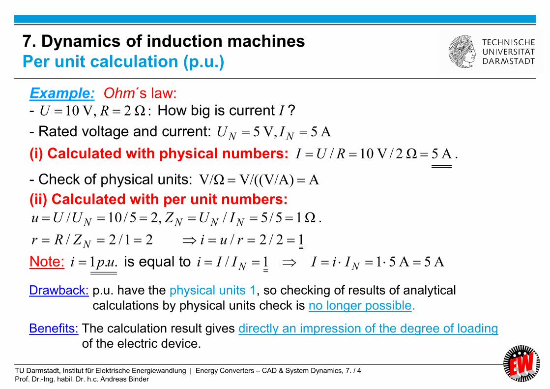
Example: Ohm´s law: - :Ω2,V10 RU How big is current I ?
- Rated voltage and current: A5,V5 NN IU
(i) Calculated with physical numbers: A5Ω2/V10/ RUI .
- Check of physical units: AV/((V/A)V/Ω
(ii) Calculated with per unit numbers:
Ω15/5/,25/10/ NNNN IUZUUu .
12/2/21/2/ ruiZRr N
Note: ..1 upi is equal to A5A511/ NN IiIIIi
Drawback: p.u. have the physical units 1, so checking of results of analytical
calculations by physical units check is no longer possible.
Benefits: The calculation result gives directly an impression of the degree of loading
of the electric device.

TU Darmstadt, Institut für Elektrische Energiewandlung | Energy Converters – CAD & System Dynamics, 7. / 5
Prof. Dr.-Ing. habil. Dr. h.c. Andreas Binder
• Values for per unit calculation are taken from machine data plate
• In three phase systems the rated impedance ZN has to be calculated with
phase values = ratio of rated phase voltage versus rated phase current.
• Data plate voltage & current values are ALWAYS line values !
• Electric machine models are based on phase values in order to be
independent from the kind of winding connection (Y or D). For per unit
voltage, current and impedance calculation: rated phase values are taken.
• Symbols for per unit values are small letters (u(t), i(t), ...).
• For time varying voltage, current etc. in physical units capital letters are used here
(U(t), I(t), ...).
7. Dynamics of induction machines
Basic rules for per unit calculation

TU Darmstadt, Institut für Elektrische Energiewandlung | Energy Converters – CAD & System Dynamics, 7. / 6
Prof. Dr.-Ing. habil. Dr. h.c. Andreas Binder
• Example: Six-pole cage AC induction machine:
NphNNphN IIUU ,, ,V230V2313/4003/
74.284/230/ ,, phNphNN IUZ
Type MKG-222 M06 F3B-9 ...... Motor Company/2003
AC-Motor Nr. 691 502
400 V Y 84 A
45 kW 1490/3000 /min S1
75 Hz cos = 0.88
Th.Cl. F IP 44
• We calculate from the data plate the rated u & i phase values and the rated impedance:
7. Dynamics of induction machines
Typical data plate of electric machine

TU Darmstadt, Institut für Elektrische Energiewandlung | Energy Converters – CAD & System Dynamics, 7. / 7
Prof. Dr.-Ing. habil. Dr. h.c. Andreas Binder
- Per unit time: tN
- Per unit electric angular frequency: NrrNss //
- Per unit mechanical angular frequency: Nmm p /
- Per unit electric resistance: phNphNNNrrNss IUZZRrZRr ,, ///
16.3141)502(:s1,Hz50:e.g. N ttf N
0.316.314/5.942/s/16.314502
942.5/ss/15022:Hz150,Hz50:e.g.
NsN
N
s
sss fff
33.116.314/47.104/
33.154.78/7.104/s)/54.784/502/2(
s/7.104)60/1000(22
:82min,/1000s,/16.314,Hz50:e.g.
N
synNsyn
NN
p
pf
n
pnf
mm
mm
m
50 cycles: 16.31428.650250
7. Dynamics of induction machines
Summary of per unit values (1)
TU Darmstadt, Institut für Elektrische Energiewandlung | Energy Converters – CAD & System Dynamics, 7. / 8
Prof. Dr.-Ing. habil. Dr. h.c. Andreas Binder
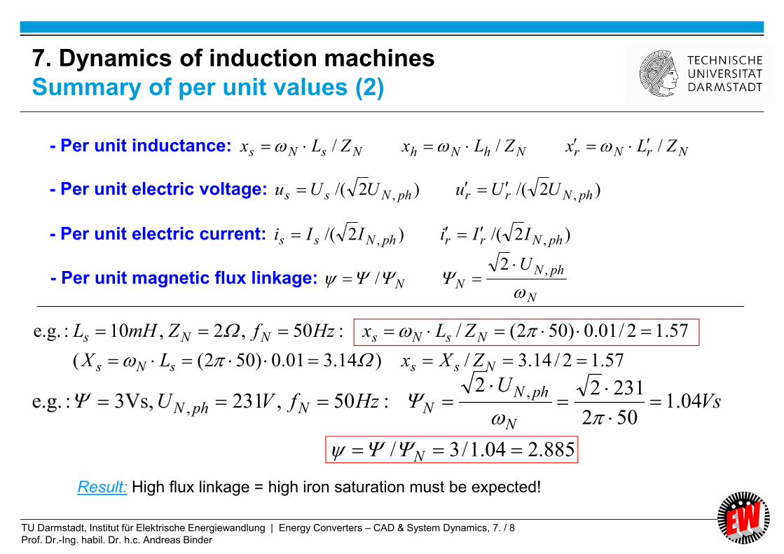
- Per unit inductance: NrNrNhNhNsNs ZLxZLxZLx ///
- Per unit electric voltage: )2/()2/( ,, phNrrphNss UUuUUu
- Per unit electric current: )2/()2/( ,, phNrrphNss IIiIIi
- Per unit magnetic flux linkage: N
phNNN
U
,2
/
57.12/14.3/)14.301.0)502((
57.12/01.0)502(/:50,2,10:e.g.
NsssNs
NsNsNNs
ZXxLX
ZLxHzfZmHL
885.204.1/3/
04.1502
23122:50,2313Vs,:e.g.
,,
N
N
phNNNphN Vs
UHzfVU
Result: High flux linkage = high iron saturation must be expected!
7. Dynamics of induction machines
Summary of per unit values (2)

TU Darmstadt, Institut für Elektrische Energiewandlung | Energy Converters – CAD & System Dynamics, 7. / 9
Prof. Dr.-Ing. habil. Dr. h.c. Andreas Binder
)2/()()()2/()()( ,, phNssphNss ItIiUtUu
In dynamic calculations instantaneous values U(t), I(t) are derived as results.
Therefore in AC machinery the per unit calculation is done with the momentary
peak values (amplitudes) of the stationary sinusoidal rated operational values.
Example: Sinusoidal rated operation:
1
)sin(1)2/()()(
)2sin(2)(
,
,
phNUU
NphNU
ItIi
tfItI
One RATED “per-unit” period is ALWAYS 2,
independent from rated frequency fN
22:1
:e.g. N
NN
N f
ft
ft
7. Dynamics of induction machines
Per unit electric phase voltage and current

TU Darmstadt, Institut für Elektrische Energiewandlung | Energy Converters – CAD & System Dynamics, 7. / 10
Prof. Dr.-Ing. habil. Dr. h.c. Andreas Binder
7. Dynamics of induction machines
Summary of per unit values (3)
a) Per unit torque: - Reference: Rated apparent torque MB = rated APPARENT power SN vs. synchronous speed !
- This MB includes power factor cosN and machine efficiency N !
p
SMMMm
N
NBB
//
Note: Induction motor operation: Rated apparent torque MB is bigger than rated torque MN :
NN
NN
NN
N
mN
N
N
mN
NNN
N
NB
sM
sP
s
P
p
SM
cos
1
cos
1
1
)/(cos
/
NN
NNB
sMM
cos
1
b) Per unit moment of inertia:
- Rotor inertia J is calculated from TJ as per unit starting time constant J.
B
NJJNJ
M
pJTT
/
TU Darmstadt, Institut für Elektrische Energiewandlung | Energy Converters – CAD & System Dynamics, 7. / 11
Prof. Dr.-Ing. habil. Dr. h.c. Andreas Binder
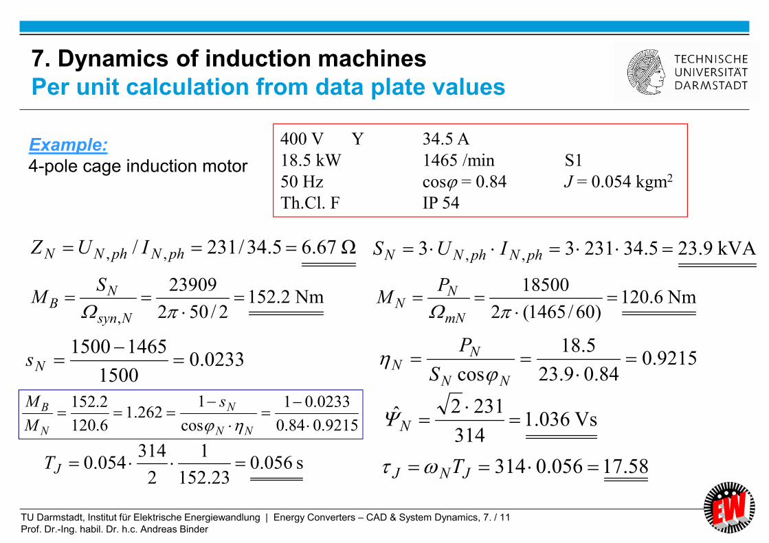
Ω67.65.34/231/ ,, phNphNN IUZ
Nm2.1522/502
23909
,
Nsyn
NB
SM Nm6.120
)60/1465(2
18500
mN
NN
PM
Vs036.1314
2312ˆ
N
s056.023.152
1
2
314054.0 JT 58.17056.0314 JNJ T
400 V Y 34.5 A
18.5 kW 1465 /min S1
50 Hz cos = 0.84 J = 0.054 kgm2
Th.Cl. F IP 54
Example:
4-pole cage induction motor
kVA9.235.3423133 ,, phNphNN IUS
9215.084.09.23
5.18
cos
NN
NN
S
P
0233.0
1500
14651500
Ns
9215.084.0
0233.01
cos
1262.1
6.120
2.152
NN
N
N
B s
M
M
7. Dynamics of induction machines
Per unit calculation from data plate values
TU Darmstadt, Institut für Elektrische Energiewandlung | Energy Converters – CAD & System Dynamics, 7. / 12
Prof. Dr.-Ing. habil. Dr. h.c. Andreas Binder
dt
tdtIRtU
)()()(
d
diru
tdU
td
I
I
U
tIR
U
tUtu
NN
phNphN
phN
phNphNN
)()()(
2
)(
2
2
2
)(
2
)()(
,,
,
,,
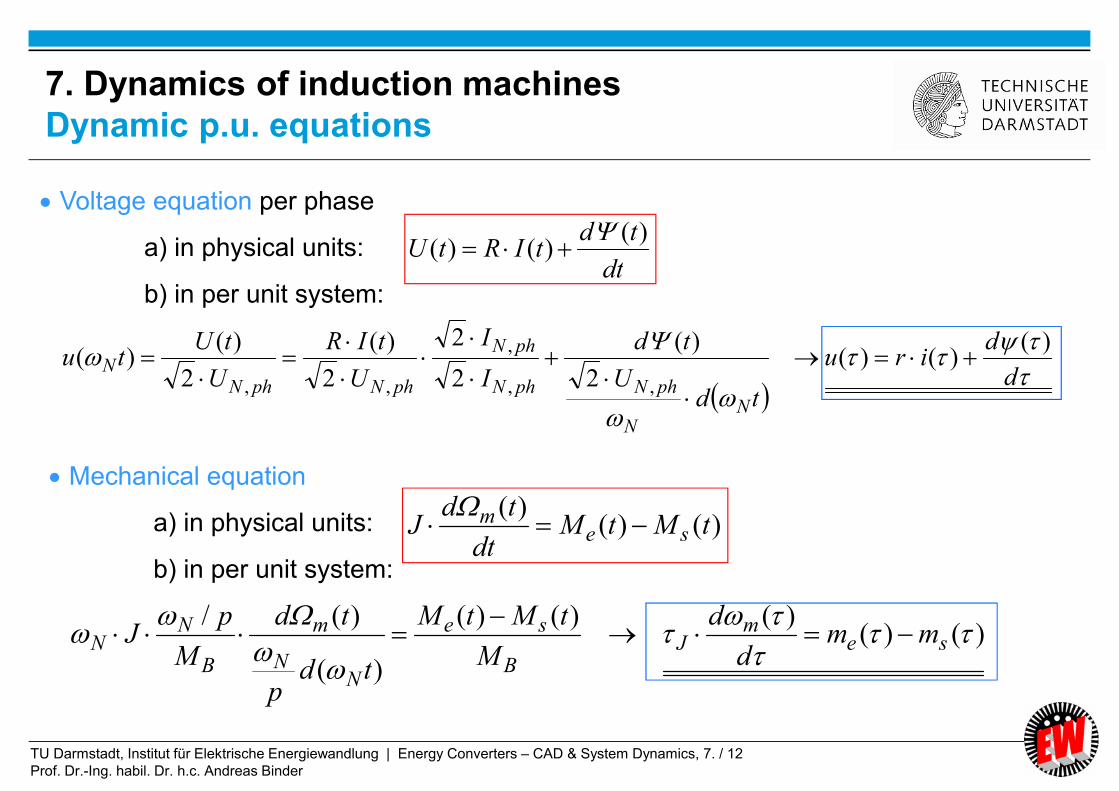
Voltage equation per phase
a) in physical units:
b) in per unit system:
)()()(
tMtMdt
tdJ se
m
)()()()()(
)(
)(/
sem
JB
se
NN
m
B
NN mm
d
d
M
tMtM
tdp
td
M
pJ
Mechanical equation
a) in physical units:
b) in per unit system:
7. Dynamics of induction machines
Dynamic p.u. equations

TU Darmstadt, Institut für Elektrische Energiewandlung | Energy Converters – CAD & System Dynamics, 7. / 13
Prof. Dr.-Ing. habil. Dr. h.c. Andreas Binder
Summary:
Per unit calculation
- Name-plate data used for per-unit calculation
- Usually phase quantities used for p.u.
- Not the rated real torque MN, but the rated apparent torque MB used for p.u.
- Fast estimate of percentage of loading of a device possible by p.u. values
Energy Converters – CAD and System Dynamics

TU Darmstadt, Institut für Elektrische Energiewandlung | Energy Converters – CAD & System Dynamics, 7. / 14
Prof. Dr.-Ing. habil. Dr. h.c. Andreas Binder
7. Dynamics of induction machines
7.1 Per unit calculation
7.2 Dynamic voltage equations and reference frames of induction machine
7.3 Dynamic flux linkage equations
7.4 Torque equation
7.5 Dynamic equations of induction machines in stator reference frame
7.6 Solutions of dynamic equations for constant speed
7.7 Solutions of dynamic equations for induction machines with varying
speed
7.8 Linearized transfer function of induction machines in synchronous
reference frame
7.9 Inverter-fed induction machines with field-oriented control
Energy Converters – CAD and System Dynamics
TU Darmstadt, Institut für Elektrische Energiewandlung | Energy Converters – CAD & System Dynamics, 7. / 15
Prof. Dr.-Ing. habil. Dr. h.c. Andreas Binder
d
diru
d
diru
a
a
d
diru
d
diru
d
diru
ssss
ssss
WsWssWs
VsVssVs
UsUssUs
)()()(
)()()(
3
13
13
1
3
23
23
2
)()()(
)()()(
)()()(
000
2,,,
,,,
,,,
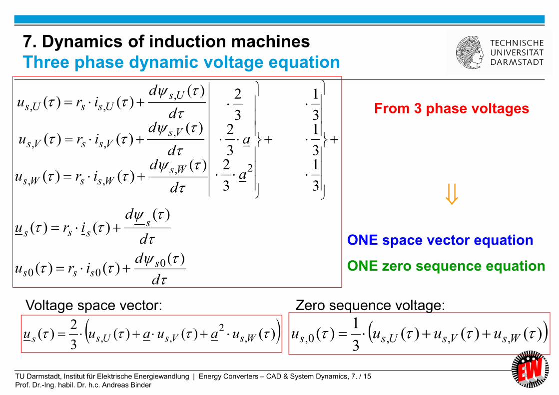
)()()(3
2)( ,
2,, WsVsUss uauauu )()()(
3
1)( ,,,0, WsVsUss uuuu
From 3 phase voltages
ONE space vector equation
ONE zero sequence equation
Voltage space vector: Zero sequence voltage:
7. Dynamics of induction machines
Three phase dynamic voltage equation
TU Darmstadt, Institut für Elektrische Energiewandlung | Energy Converters – CAD & System Dynamics, 7. / 16
Prof. Dr.-Ing. habil. Dr. h.c. Andreas Binder
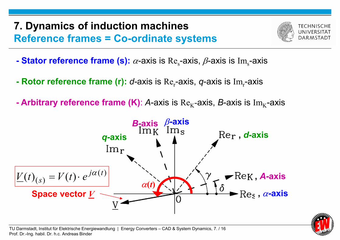
- Stator reference frame (s): -axis is Res-axis, -axis is Ims-axis
- Rotor reference frame (r): d-axis is Rer-axis, q-axis is Imr-axis
- Arbitrary reference frame (K): A-axis is ReK-axis, B-axis is ImK-axis
Space vector V
)()( )()( tj
s etVtV (t)
, -axis
-axis
, A-axis
, d-axis
B-axis
q-axis
7. Dynamics of induction machines
Reference frames = Co-ordinate systems
TU Darmstadt, Institut für Elektrische Energiewandlung | Energy Converters – CAD & System Dynamics, 7. / 17
Prof. Dr.-Ing. habil. Dr. h.c. Andreas Binder
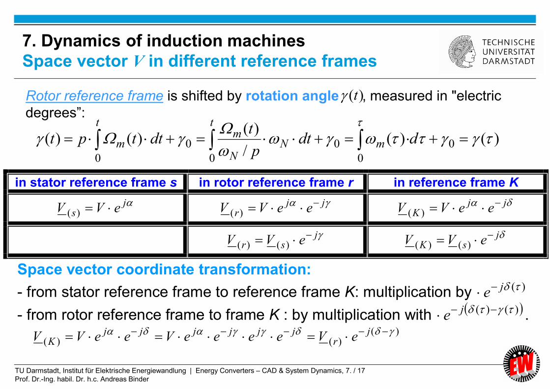
in stator reference frame s in rotor reference frame r in reference frame K
js eVV )(
jjr eeVV )(
jjK eeVV )(
jsr eVV )()(
jsK eVV )()(
Space vector coordinate transformation:
- from stator reference frame to reference frame K: multiplication by )(je
- from rotor reference frame to frame K : by multiplication with )()( je .
)()(/
)()()( 0
0
0
0
0
0
ddtp
tdttpt m
t
NN
mt
m
)(tRotor reference frame is shifted by rotation angle , measured in "electric
degrees”:
)()()(
jr
jjjjjjK eVeeeeVeeVV
7. Dynamics of induction machines
Space vector V in different reference frames

TU Darmstadt, Institut für Elektrische Energiewandlung | Energy Converters – CAD & System Dynamics, 7. / 18
Prof. Dr.-Ing. habil. Dr. h.c. Andreas Binder
• Space vector rotor voltage equation:
in rotor reference frame
)(
000
)(
)()()(
)()()(
r
rrrr
r
rrrr
d
diru
d
diru
Subscript (r) means:
“in rotor reference frame”
• Note: Cage induction machine:
Qr phases: May be treated as a 3-phase machine,
transformed into space vector formulation !
7. Dynamics of induction machines
Three phase rotor dynamic voltage equation

TU Darmstadt, Institut für Elektrische Energiewandlung | Energy Converters – CAD & System Dynamics, 7. / 19
Prof. Dr.-Ing. habil. Dr. h.c. Andreas Binder
)(
)()()( Ks
KsKss
jsjss
jsKs
d
dj
d
dire
d
deireuu
)(
)()(
)()()()(
)(Kr
KrKrr
jrjrr
jrKr
d
dj
d
dire
d
deireuu
d
dej
d
de
d
ed
d
de
d
edj
s
sjj
s
sj
j
s )()(
)()(
)()()()(
)()(
)(
Rule for differentiation of product of two functions:
Transformation of voltage equations into arbitrary co-ordinate system K:
)(
)()()(
)(
)()()(
)(Kr
KrKrrKr
Ks
KsKssKs
d
dj
d
diru
d
dj
d
diru
7. Dynamics of induction machinesTransformation of voltage equation between reference frames

TU Darmstadt, Institut für Elektrische Energiewandlung | Energy Converters – CAD & System Dynamics, 7. / 20
Prof. Dr.-Ing. habil. Dr. h.c. Andreas Binder
)(
)()()(
)(
)()()(
)(Kr
KrKrrKr
Ks
KsKssKs
d
dj
d
diru
d
dj
d
diru
Transformer
inductionRotary induction
7. Dynamics of induction machines
Transformer and rotary induction

TU Darmstadt, Institut für Elektrische Energiewandlung | Energy Converters – CAD & System Dynamics, 7. / 21
Prof. Dr.-Ing. habil. Dr. h.c. Andreas Binder
Reference frame Angular rotation of reference frame
stator reference frame
(, ) 0:0)(
d
dK
rotor reference frame (d, q) mK
d
d
)(:
synchronous reference frame (a, b) s
N
s
N
synK
pd
d
)(
/
)()(
)(
Stator and rotor equation in stator reference frame (--system):
rmr
rr
ssss
jd
dir
d
diru
0Induction machine:
00 ju r
7. Dynamics of induction machines
Mainly used reference frames (1)

TU Darmstadt, Institut für Elektrische Energiewandlung | Energy Converters – CAD & System Dynamics, 7. / 22
Prof. Dr.-Ing. habil. Dr. h.c. Andreas Binder
)(
)()(
)()()( 0
srmsr
srrss
sssss jd
dir
d
diru
0:0)(
d
dK
mKd
d
)(:
Stator reference frame (, )
Rotor reference frame (d, q)
Synchronous reference frame (a, b)
)(
)()()(
)(
)()()(
synrmssynr
synrrsynr
synsssyns
synsssyns
jd
diru
jd
diru
d
dirj
d
diru
rrrrrrrm
rsrssrs
)()()(
)()()( 0
sN
s
N
synK
p
)(
/
)()(
7. Dynamics of induction machines
Mainly used reference frames (2)

TU Darmstadt, Institut für Elektrische Energiewandlung | Energy Converters – CAD & System Dynamics, 7. / 23
Prof. Dr.-Ing. habil. Dr. h.c. Andreas Binder
rmrrr
rmrrr
ssss
ssss
ddir
ddir
ddiru
ddiru
/0
/0
/
/
In stator reference frame: - -system: components:
rmr
rr
ssss
jd
dir
d
diru
0
rrrj sss
j rrr ijii sss ijii
“Transformer” part “Rotary” part
of voltage induction
sss ujuu , Re
, Im us
us
us
0
Induction machine:
0ru
7. Dynamics of induction machinesExample: Voltage equations in stator reference frame

TU Darmstadt, Institut für Elektrische Energiewandlung | Energy Converters – CAD & System Dynamics, 7. / 24
Prof. Dr.-Ing. habil. Dr. h.c. Andreas Binder
ßmrotitrii dtdUUtUp /)()(:1 ,,,,,
lBNvtBNlrtU ßcci 2/)2()(,
ßmßcmßcmßcmßc NBlrNlBNrlBNv 2)(22
Blr2
Blr2 cN
cN
Example: Rotating rotor coil (Nc turns) in stator B-field
“Transformer” “Rotary”
Flux linkages
RtItUtURtItUtU ii )()()()()()((t)
(t)
v = m.r
v = m.r
m
2r
l
Nc
B(t)
B(t)
l
ci sdBvNttU���
)(/)(
mdtdtIRtU /)()(
7. Dynamics of induction machines
Transformer and rotary part of induction
TU Darmstadt, Institut für Elektrische Energiewandlung | Energy Converters – CAD & System Dynamics, 7. / 25
Prof. Dr.-Ing. habil. Dr. h.c. Andreas Binder
Summary:
Dynamic voltage equations and reference frames of induction machine
- Space vector formulation allows one voltage equation instead of three U, V, W
- One stator and one rotor voltage equation
- Different reference frames may be used: stator, rotor, arbitrary
- Voltage induction separated into „transformer“ and „rotary“ part
Energy Converters – CAD and System Dynamics
TU Darmstadt, Institut für Elektrische Energiewandlung | Energy Converters – CAD & System Dynamics, 7. / 26
Prof. Dr.-Ing. habil. Dr. h.c. Andreas Binder
7. Dynamics of induction machines
7.1 Per unit calculation
7.2 Dynamic voltage equations and reference frames of induction machine
7.3 Dynamic flux linkage equations
7.4 Torque equation
7.5 Dynamic equations of induction machines in stator reference frame
7.6 Solutions of dynamic equations for constant speed
7.7 Solutions of dynamic equations for induction machines with varying
speed
7.8 Linearized transfer function of induction machines in synchronous
reference frame
7.9 Inverter-fed induction machines with field-oriented control
Energy Converters – CAD and System Dynamics

TU Darmstadt, Institut für Elektrische Energiewandlung | Energy Converters – CAD & System Dynamics, 7. / 27
Prof. Dr.-Ing. habil. Dr. h.c. Andreas Binder
)()( mhhix
Magnetizing
space
current
vector im()
Main flux linkage (fundamental wave, excited by sinusoidal distributed
current layer of stator and rotor = magnetizing current layer):
Sinusoidal
distributed current
layer
Resulting
main magnetic
flux lines
7. Dynamics of induction machines
Main flux linkage

TU Darmstadt, Institut für Elektrische Energiewandlung | Energy Converters – CAD & System Dynamics, 7. / 28
Prof. Dr.-Ing. habil. Dr. h.c. Andreas Binder
rhrrmhrrshrrhshr
hsmhssrhssrhsshs
ixixixixixxix
ixixixixixixx
)(
)(
- Stator and rotor space current vector excite ALSO leakage flux linkage:
)()( sssix )()( rrr
ix
N
rNr
N
sNs
Z
Lx
Z
Lx
,- Per unit stray inductance:
- Resulting flux linkage in stator and rotor:
- Total leakage flux space vector is described by Blondel´s total leakage coefficient:
rs
h
xx
x
2
1
7. Dynamics of induction machines
Dynamic stator and rotor flux linkages
TU Darmstadt, Institut für Elektrische Energiewandlung | Energy Converters – CAD & System Dynamics, 7. / 29
Prof. Dr.-Ing. habil. Dr. h.c. Andreas Binder
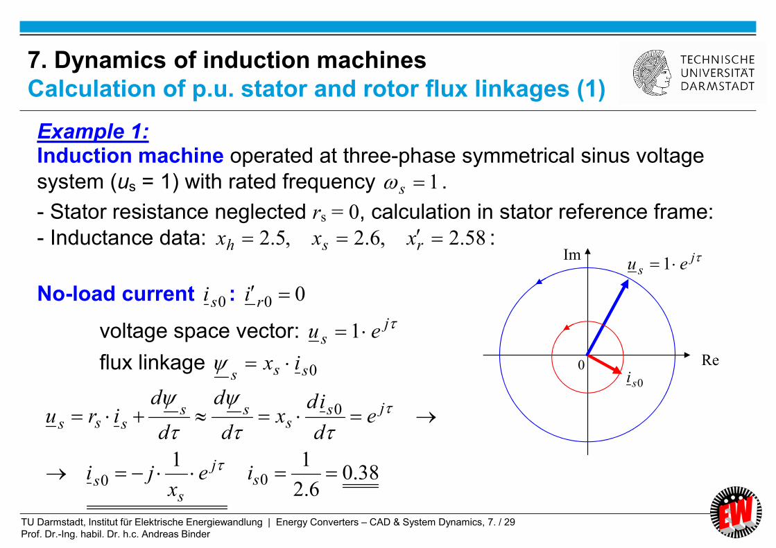
Example 1: Induction machine operated at three-phase symmetrical sinus voltage
system (us = 1) with rated frequency 1s .
- Stator resistance neglected rs = 0, calculation in stator reference frame:
- Inductance data: 58.2,6.2,5.2 rsh xxx :
No-load current 0si : 00 ri
voltage space vector: js eu 1
flux linkage 0sssix
38.06.2
1100
0
sj
ss
jss
sssss
iex
ji
ed
idx
d
d
d
diru
Re
Im js eu 1
0si0
7. Dynamics of induction machines
Calculation of p.u. stator and rotor flux linkages (1)
TU Darmstadt, Institut für Elektrische Energiewandlung | Energy Converters – CAD & System Dynamics, 7. / 30
Prof. Dr.-Ing. habil. Dr. h.c. Andreas Binder
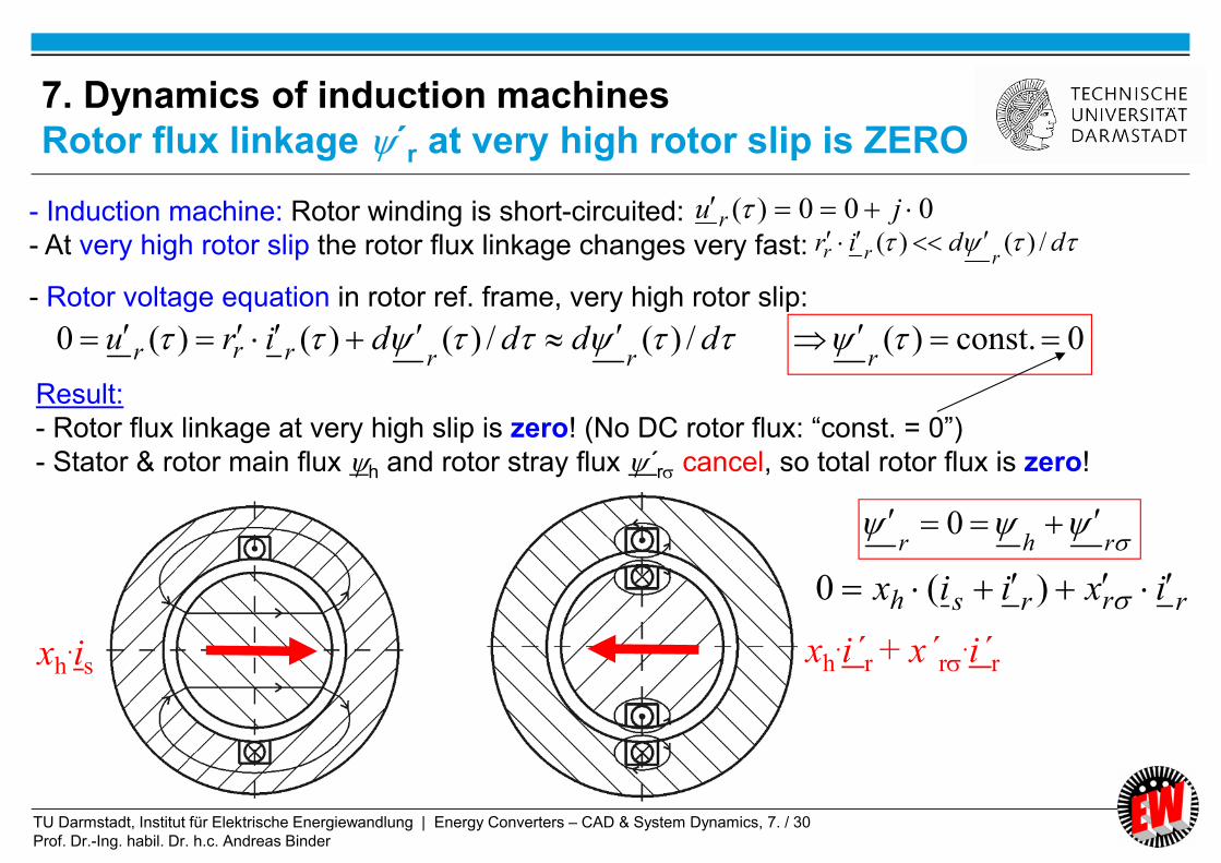
- Induction machine: Rotor winding is short-circuited:
- At very high rotor slip the rotor flux linkage changes very fast:
- Rotor voltage equation in rotor ref. frame, very high rotor slip:
0const.)( r
000)( ju r ddir
rrr /)()(
ddddirurrrrr /)(/)()()(0
rhr 0
xh.is
xh.i´r + x´r
.i´r
Result:
- Rotor flux linkage at very high slip is zero! (No DC rotor flux: “const. = 0”)
- Stator & rotor main flux h and rotor stray flux ´r cancel, so total rotor flux is zero!
rrrsh ixiix )(0
7. Dynamics of induction machines
Rotor flux linkage ´r at very high rotor slip is ZERO

TU Darmstadt, Institut für Elektrische Energiewandlung | Energy Converters – CAD & System Dynamics, 7. / 31
Prof. Dr.-Ing. habil. Dr. h.c. Andreas Binder
rrss
rhrhrhssrhshsss
ixix
ixixxxixixixix
)/(
sssrhsssrhsssixxxxixixxix )))/((1()/( 22
rrsssssixixix
srhr ixxi )/(
rrshr
rhsss
ixix
ixix
0
Stator flux linkage:
or:
ssrhr iixxi )/(With : srsrrsssssixxixixix )(
rss xxx
Stator flux linkage is
at high slip nearly
equal to the total
leakage flux!
Rotor flux linkage is
zero!
Example: Slip = 1
Very big slip |Slip| >> 1:
7. Dynamics of induction machinesStator flux linkage s at high rotor slip is total leakage

TU Darmstadt, Institut für Elektrische Energiewandlung | Energy Converters – CAD & System Dynamics, 7. / 32
Prof. Dr.-Ing. habil. Dr. h.c. Andreas Binder
At no-load (Slip = 0, rotor current zero) At stand still (locked rotor) Slip = 1
Numerically calculated two-dimensional magnetic flux density B of a three-phase,
4-pole high voltage cage induction machine with wedge rotor slots (Qs / Qr = 60/44) at rated voltage
At big slip (already Slip = 1!) the rotor inner part is nearly free
of flux (“rotor shielding effect”)
0r
sssix
sssix
shrix
2. Design of Induction Machines
Rotor shielding effect at big slip

TU Darmstadt, Institut für Elektrische Energiewandlung | Energy Converters – CAD & System Dynamics, 7. / 33
Prof. Dr.-Ing. habil. Dr. h.c. Andreas Binder
Example 2: Induction machine operated at three-phase symmetrical sinus voltage system
(us = 1) with rated frequency 1s at high slip (e.g.: Slip 1):
- Calculation in stator reference frame:
- Inductance data: 58.2,6.2,5.2 rsh xxx :
- Current data at big slip:
rssssrhsrhr iiiiixxixxis 97.0)58.2/5.2()/()/(:1 .
Leakage inductances:
08.05.258.2,1.05.26.2 hrrhss xxxxxx
- Total leakage coefficient: 068.058.26.2
5.211
22
rs
h
xx
x
- Stator flux linkage at s 1: sssssiiix 177.06.2068.0 with total
leakage flux linkage ssrrsssiiixix 177.0)97.0(08.01.0
7. Dynamics of induction machinesCalculation of per unit stator and rotor flux linkages (2)

TU Darmstadt, Institut für Elektrische Energiewandlung | Energy Converters – CAD & System Dynamics, 7. / 34
Prof. Dr.-Ing. habil. Dr. h.c. Andreas Binder
srhr ixxi )/(
rrshrrhsssixixixix 0Very big slip |Slip| >> 1:
srrsh iixxx 969.0:08.0,1.0,5.2 rrrhsh ixixix 0
sss iii 077.0423.25.20Also the rotor leakage flux linkage is due to the
rotor shielding effect linked with the stator winding!
si sixh
.is = 2.5.is
xh.i´r + x´r
.i´r =
= (2.423 + 0.077).is = 2.5.is
xs.is = 0.1.is
ssrs
ssss
iixx
iix
18.0)(
177.0
stator
field
rotor
field
resulting
field
7. Dynamics of induction machinesExample: Rotor flux linkage is ZERO at very big rotor slip

TU Darmstadt, Institut für Elektrische Energiewandlung | Energy Converters – CAD & System Dynamics, 7. / 35
Prof. Dr.-Ing. habil. Dr. h.c. Andreas Binder
Summary:
Dynamic flux linkage equations
- Stator and rotor current space vectors is, i´r excite
resulting air gap flux linkage vector h
- Separation of main and stray flux h, possible
- Physical separation of stator and rotor stray flux linkage s, ´r
by measurement not possible
- Rotor total flux linkage ´r decreases with increasing slip
due to rotor short-circuit
- Saturation may be introduced by current-depending inductances xh(im)
Energy Converters – CAD and System Dynamics

TU Darmstadt, Institut für Elektrische Energiewandlung | Energy Converters – CAD & System Dynamics, 7. / 36
Prof. Dr.-Ing. habil. Dr. h.c. Andreas Binder
7. Dynamics of induction machines
7.1 Per unit calculation
7.2 Dynamic voltage equations and reference frames of induction machine
7.3 Dynamic flux linkage equations
7.4 Torque equation
7.5 Dynamic equations of induction machines in stator reference frame
7.6 Solutions of dynamic equations for constant speed
7.7 Solutions of dynamic equations for induction machines with varying
speed
7.8 Linearized transfer function of induction machines in synchronous
reference frame
7.9 Inverter-fed induction machines with field-oriented control
Energy Converters – CAD and System Dynamics

TU Darmstadt, Institut für Elektrische Energiewandlung | Energy Converters – CAD & System Dynamics, 7. / 37
Prof. Dr.-Ing. habil. Dr. h.c. Andreas Binder
cosˆ
)( 2
BAlp
M sp
e
BlkN pwsh 2ˆ
1
p
sssssws
p
INmAAkA
2
22ˆ
1
cosˆˆ2
3 hse IpM
)(cos)()()(cos)(ˆ)(ˆ22
3
3
/)()(
,,
hshsphNphN
N
B
ee itttIp
IU
p
M
tMm
)()(cos)(
)( hshsB
ee ii
M
tMm
- Introduction of flux linkage and current:
Amplitude of flux linkage Amplitude of current loading:
- Per unit torque equation:
Torque is product of main flux
linkage vector and orthogonal
component of current space vector !
3sm
7. Dynamics of induction machines
Torque equation

TU Darmstadt, Institut für Elektrische Energiewandlung | Energy Converters – CAD & System Dynamics, 7. / 38
Prof. Dr.-Ing. habil. Dr. h.c. Andreas Binder
Positive torque on rotor =
ACTIO EST REACTIO
h
s
s
cos ss ii
0
ss
hshsB
ee ii
M
Mm cos
Positive torque
on stator
Example:
Stator current loading
and resulting stator &
rotor field
lBIF ss
7. Dynamics of induction machines
Per unit torque equation

TU Darmstadt, Institut für Elektrische Energiewandlung | Energy Converters – CAD & System Dynamics, 7. / 39
Prof. Dr.-Ing. habil. Dr. h.c. Andreas Binder
- Positive counting of rotor torque in counter-clockwise sense!
(Mathematical positive counting sense!)
- Flux (linkage) space vector turns into direction of current space vector
hse im h
si
0
me > 0 on rotor
7. Dynamics of induction machines
Per Rotor torque direction with stator current

TU Darmstadt, Institut für Elektrische Energiewandlung | Energy Converters – CAD & System Dynamics, 7. / 40
Prof. Dr.-Ing. habil. Dr. h.c. Andreas Binder
*Im
hshshshse iiiim - Introduction of vector product:
- If stator current space vector component is 90° leading
to flux linkage space vector torque on rotor is positive.
hshshshshshs
hßhsßshßhsßshse
iiiijiji
jijijijiim
Im
)()(Im*)()(ImIm*
h
is
00
s
s
s
s
Positive
direction of
torque on
ROTOR hh
h h
7. Dynamics of induction machines
Orthogonal vector components define torque

TU Darmstadt, Institut für Elektrische Energiewandlung | Energy Converters – CAD & System Dynamics, 7. / 41
Prof. Dr.-Ing. habil. Dr. h.c. Andreas Binder
*Im
hshshshse iiiim
**ImIm
sshse iim
- Stator stray flux does not generate torque !
**
******
ImIm
ImImIm
sshss
rhshsssrhshshse
ii
ixixixiixixiim
Proof:
rshrshe iixiixm **ImIm
- Stator flux does not generate torque with stator current !
****ImImIm rhsrhshshse ixiixixiim
- Note: *ImIm* zbzbjazbjaz
7. Dynamics of induction machines
Different formulations for the torque (1)

TU Darmstadt, Institut für Elektrische Energiewandlung | Energy Converters – CAD & System Dynamics, 7. / 42
Prof. Dr.-Ing. habil. Dr. h.c. Andreas Binder
*Im
hshshshse iiiim
**ImIm
rrhre iim
rrrrshrrshrshe iixiixiiixiixm ******)(Im)(ImIm
- Other formulation for torque with rotor flux linkage !
rrrre iim
*Im
sssssse iiim
h, r
ir
me > 0 on rotor- If rotor current space vector component is 90° lagging
to flux linkage space vector torque on rotor is positive.
7. Dynamics of induction machines
Different formulations for the torque (2)

TU Darmstadt, Institut für Elektrische Energiewandlung | Energy Converters – CAD & System Dynamics, 7. / 43
Prof. Dr.-Ing. habil. Dr. h.c. Andreas Binder
Summary:
Torque equation
- Orthogonal components of flux and current space vector yield torque
- Different formulations of torque with stator or rotor quantities
- Stray flux does not generate torque
Energy Converters – CAD and System Dynamics

TU Darmstadt, Institut für Elektrische Energiewandlung | Energy Converters – CAD & System Dynamics, 7. / 44
Prof. Dr.-Ing. habil. Dr. h.c. Andreas Binder
7. Dynamics of induction machines
7.1 Per unit calculation
7.2 Dynamic voltage equations and reference frames of induction machine
7.3 Dynamic flux linkage equations
7.4 Torque equation
7.5 Dynamic equations of induction machines in stator reference frame
7.6 Solutions of dynamic equations for constant speed
7.7 Solutions of dynamic equations for induction machines with varying
speed
7.8 Linearized transfer function of induction machines in synchronous
reference frame
7.9 Inverter-fed induction machines with field-oriented control
Energy Converters – CAD and System Dynamics
TU Darmstadt, Institut für Elektrische Energiewandlung | Energy Converters – CAD & System Dynamics, 7. / 45
Prof. Dr.-Ing. habil. Dr. h.c. Andreas Binder
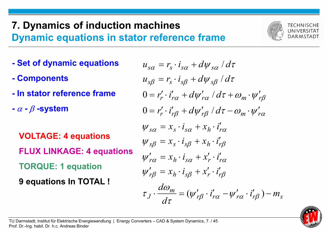
srrrrm
J
rrshr
rrshr
rhsss
rhsss
rmrrr
rmrrr
ssss
ssss
miid
d
ixix
ixix
ixix
ixix
ddir
ddir
ddiru
ddiru
)(
/0
/0
/
/
- Set of dynamic equations
- Components
- In stator reference frame
- - -system
VOLTAGE: 4 equations
FLUX LINKAGE: 4 equations
TORQUE: 1 equation
9 equations In TOTAL !
7. Dynamics of induction machines
Dynamic equations in stator reference frame

TU Darmstadt, Institut für Elektrische Energiewandlung | Energy Converters – CAD & System Dynamics, 7. / 46
Prof. Dr.-Ing. habil. Dr. h.c. Andreas Binder
rr
hssr
r
h
rs
hsss
r
shrhssrhsss
x
xix
x
x
xx
xix
x
ixxixixix
2
1
rrshrixix
In the same way:
ss
hrrr x
xix
rr
hsss x
xix
7. Dynamics of induction machines
A different flux linkage formulation
TU Darmstadt, Institut für Elektrische Energiewandlung | Energy Converters – CAD & System Dynamics, 7. / 47
Prof. Dr.-Ing. habil. Dr. h.c. Andreas Binder
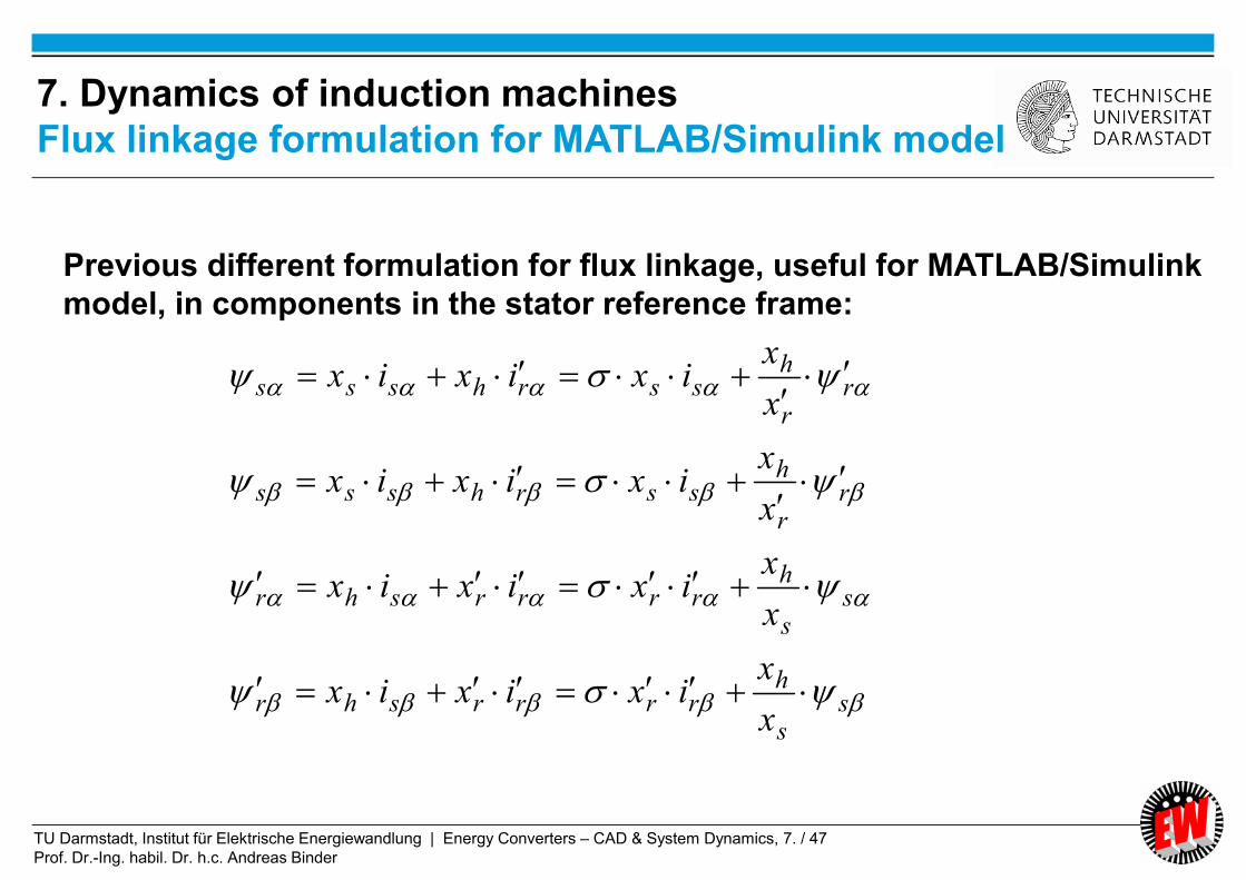
ss
hrrrrshr
ss
hrrrrshr
rr
hssrhsss
rr
hssrhsss
x
xixixix
x
xixixix
x
xixixix
x
xixixix
Previous different formulation for flux linkage, useful for MATLAB/Simulink
model, in components in the stator reference frame:
7. Dynamics of induction machines
Flux linkage formulation for MATLAB/Simulink model

TU Darmstadt, Institut für Elektrische Energiewandlung | Energy Converters – CAD & System Dynamics, 7. / 48
Prof. Dr.-Ing. habil. Dr. h.c. Andreas Binder
rrrre
ss
hrrr
ss
hrrr
rr
hsss
rr
hsss
rmrrr
rmrrr
ssss
ssss
iim
x
xix
x
xix
x
xix
x
xix
ddir
ddir
ddiru
ddiru
/0
/0
/
/
7. Dynamics of induction machinesDynamic equations in stator reference frame for MATLAB/Simulink
model WITHOUT mechanical equation

TU Darmstadt, Institut für Elektrische Energiewandlung | Energy Converters – CAD & System Dynamics, 7. / 49
Prof. Dr.-Ing. habil. Dr. h.c. Andreas Binder
7. Dynamics of induction machinesPer unit formulation of equations in stator reference frame

TU Darmstadt, Institut für Elektrische Energiewandlung | Energy Converters – CAD & System Dynamics, 7. / 50
Prof. Dr.-Ing. habil. Dr. h.c. Andreas Binder
7. Dynamics of induction machines
Formulation of equations in physical units
TU Darmstadt, Institut für Elektrische Energiewandlung | Energy Converters – CAD & System Dynamics, 7. / 51
Prof. Dr.-Ing. habil. Dr. h.c. Andreas Binder
Summary:
Dynamic equations of induction machines in stator reference frame
- In the --frame:
4 voltage equations, four flux linkage equations, one mechanical equation
- Mechanical equation may be replaced by more detailed description:
e.g. torsion oscillations (resonance frequencies)
- Time-step solution via RUNGE-KUTTA
Energy Converters – CAD and System Dynamics
TU Darmstadt, Institut für Elektrische Energiewandlung | Energy Converters – CAD & System Dynamics, 7. / 52
Prof. Dr.-Ing. habil. Dr. h.c. Andreas Binder
7. Dynamics of induction machines
7.1 Per unit calculation
7.2 Dynamic voltage equations and reference frames of induction machine
7.3 Dynamic flux linkage equations
7.4 Torque equation
7.5 Dynamic equations of induction machines in stator reference frame
7.6 Solutions of dynamic equations for constant speed
7.7 Solutions of dynamic equations for induction machines with varying
speed
7.8 Linearized transfer function of induction machines in synchronous
reference frame
7.9 Inverter-fed induction machines with field-oriented control
Energy Converters – CAD and System Dynamics
TU Darmstadt, Institut für Elektrische Energiewandlung | Energy Converters – CAD & System Dynamics, 7. / 53
Prof. Dr.-Ing. habil. Dr. h.c. Andreas Binder
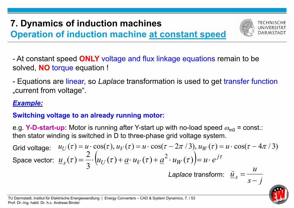
- At constant speed ONLY voltage and flux linkage equations remain to be
solved, NO torque equation !
- Equations are linear, so Laplace transformation is used to get transfer function
„current from voltage“.
Example:
Switching voltage to an already running motor:
e.g. Y-D-start-up: Motor is running after Y-start up with no-load speed m0 = const.:
then stator winding is switched in D to three-phase grid voltage system.
Grid voltage:
Space vector:
)3/4cos()(),3/2cos()(),cos()( uuuuuu WVU
jWVUs euuauauu )()()(
3
2)(
2
js
uu s
⌣
Laplace transform:
7. Dynamics of induction machines
Operation of induction machine at constant speed

TU Darmstadt, Institut für Elektrische Energiewandlung | Energy Converters – CAD & System Dynamics, 7. / 54
Prof. Dr.-Ing. habil. Dr. h.c. Andreas Binder
rrshr
rhsss
rrmrr
sssss
ixix
ixix
jsir
usir
⌣⌣⌣
⌣⌣⌣
⌣⌣
⌣⌣⌣
0
0
Initial conditions: Example: Flux, current, voltage is zero ! 0,000
rs
)(0
)(
0
0
rrrmrshm
ssrhsss
ixjsrixjs
uixsixsr
⌣⌣
⌣⌣⌣
Unknowns: Stator and rotor current space vectors
0)()(
)()(
rmr
rr
ss
ss
jd
dir
ud
dir
)()()(
)()()(
rrshr
rhsss
ixix
ixix
)(),( sisi rs
⌣⌣
7. Dynamics of induction machinesLaplace-transform of voltage & flux linkage equations(in stator reference frame)

TU Darmstadt, Institut für Elektrische Energiewandlung | Energy Converters – CAD & System Dynamics, 7. / 55
Prof. Dr.-Ing. habil. Dr. h.c. Andreas Binder
0
rrmrshm
srhsss
ixjsrixjs
uixsixsr⌣⌣
⌣⌣⌣
bars
rmr
rs
rmrsm
rs
rsrsrs
rmr
mhrmrss
rmrs
ssssxx
xjsr
js
u
xx
xjrrj
xx
rxxrssxx
xjsr
js
u
jsxsxjsrxsr
xjsr
js
ui
)(
)(
)(
)())(()(
)(
2
2
⌣
bars
rmrs
ssssxx
xjsr
js
ui
)(⌣
Solutions for stator &
rotor current vectors:
7. Dynamics of induction machinesSolution of 2nd order linear algebraic equation system
bars
mhr
ssssxx
jsx
js
ui
)(⌣

TU Darmstadt, Institut für Elektrische Energiewandlung | Energy Converters – CAD & System Dynamics, 7. / 56
Prof. Dr.-Ing. habil. Dr. h.c. Andreas Binder
mrsmrs
rs
rmrsm
rs
rsrs
jjsssP
xx
xjrrj
xx
rxxrsssP
22
22
)(
)()(
r
r
rr
s
s
ss
r
x
r
x
1
,1
r
rr
s
ss
r
x
r
x
,
We define:
- Stator and rotor short-circuit time constant:
- Stator and rotor open-circuit time constant:
The polynomial describes the transient electrical behaviour
of the induction machine ! ba sssssP )(2
7. Dynamics of induction machines
Second order characteristic polynomial

TU Darmstadt, Institut für Elektrische Energiewandlung | Energy Converters – CAD & System Dynamics, 7. / 57
Prof. Dr.-Ing. habil. Dr. h.c. Andreas Binder
- Stator short-circuit time constant
xh
s
ss
r
x
rs xs
xs
rs xs x´r
xh . xss
ss
r
x
- Stator open-circuit time constant
m = 1 (Slip: zero)
No rotor current = OPEN circuit
Change of total flux,
including main flux 05.0...01.01/0/ rrr rrSlipr
- Rotor circuit interrupted - Rotor circuit has no resistance
m = (Slip: infinite)
m = , current similar to:
m = 0 (Slip: Unity)
“SHORT circuit” = STAND STILL
Change of stray flux
7. Dynamics of induction machines
Stator open-circuit & short-circuit time constant

TU Darmstadt, Institut für Elektrische Energiewandlung | Energy Converters – CAD & System Dynamics, 7. / 58
Prof. Dr.-Ing. habil. Dr. h.c. Andreas Binder
506.0
31.01,5
06.0
31.01
r
r
rr
s
s
ss
r
x
r
x
- Stator and rotor short-circuit time constant = SHORT time constant
- Stator and rotor open-circuit time constant = LONG time constant
2.02.05
1,2.0
5
1 rsrs
5006.0
31,50
06.0
31
r
r
rr
s
s
ss
r
x
r
x
06.0,3,1.0 rsrs rrxx
(Note: = 50 means 50/(2) 8 periods at rated frequency!)
7. Dynamics of induction machinesTypical values for open-circuit & short-circuit time constant
TU Darmstadt, Institut für Elektrische Energiewandlung | Energy Converters – CAD & System Dynamics, 7. / 59
Prof. Dr.-Ing. habil. Dr. h.c. Andreas Binder
0)( 22
mrsmrsrs
rmrsm
rs
rsrs jjssxx
xjrrj
xx
rxxrss
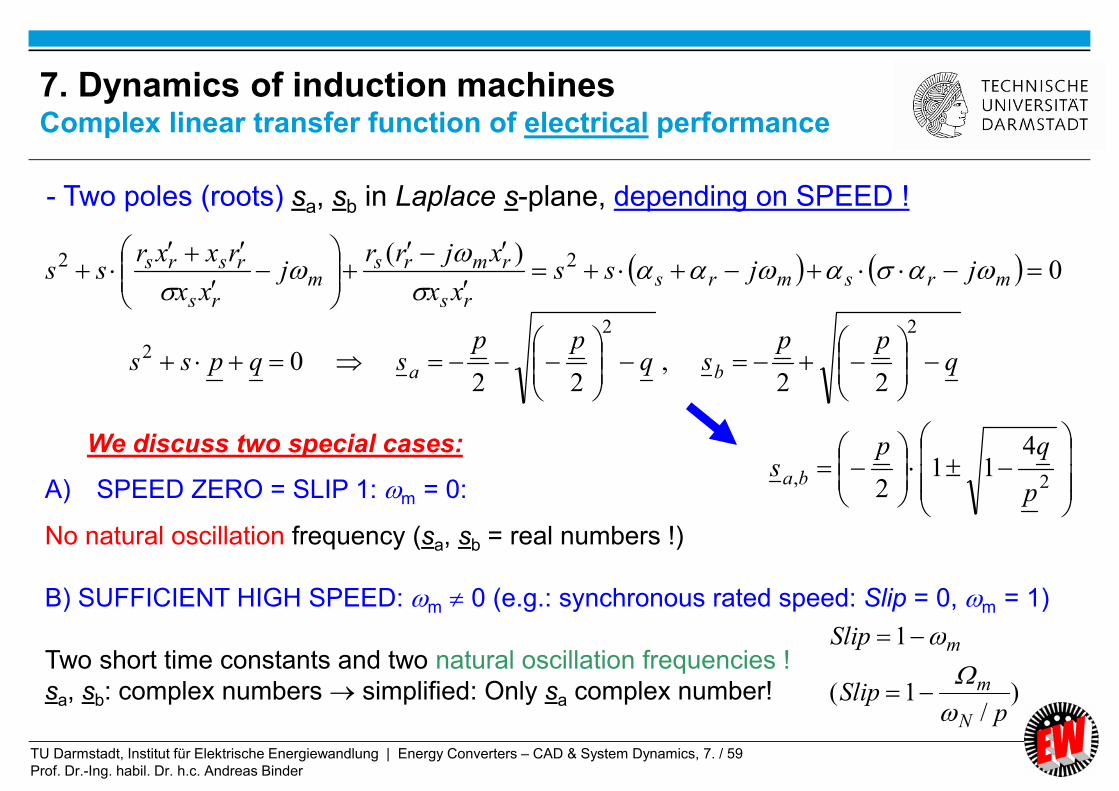
- Two poles (roots) sa, sb in Laplace s-plane, depending on SPEED !
A) SPEED ZERO = SLIP 1: m = 0:
No natural oscillation frequency (sa, sb = real numbers !)
B) SUFFICIENT HIGH SPEED: m 0 (e.g.: synchronous rated speed: Slip = 0, m = 1)
Two short time constants and two natural oscillation frequencies !
sa, sb: complex numbers simplified: Only sa complex number!
We discuss two special cases:
qpp
sqpp
sqpss ba
22
2
22,
220
2,
411
2 p
qps ba
)/
1(
1
pSlip
Slip
N
m
m
7. Dynamics of induction machinesComplex linear transfer function of electrical performance

TU Darmstadt, Institut für Elektrische Energiewandlung | Energy Converters – CAD & System Dynamics, 7. / 60
Prof. Dr.-Ing. habil. Dr. h.c. Andreas Binder
Zero speed operation (stand still): 0m
022 rsrsmrsmrs ssjjss
rsrsrs
bas
2
,22
∓
022
:1
22
rs
rsrs
0 1: > 0
Worst case: No main flux linkage = 1
The two roots sa, sb are in any case at m = 0 real numbers!
Example:
Starting the induction machine at zero speed and blocked rotor (= switching
three-phase grid voltage system to stator winding at m = 0)
7. Dynamics of induction machinesTwo real roots sa, sb of the characteristic polynomial at m = 0

TU Darmstadt, Institut für Elektrische Energiewandlung | Energy Converters – CAD & System Dynamics, 7. / 61
Prof. Dr.-Ing. habil. Dr. h.c. Andreas Binder
02 rsrsss
22,)(
211
2)(
411
2rs
rsrs
rs
rsrsbas
As 0.1 is small: 1,2/11 xxx
)()( rsrs
rsrsas
sr
rs
rsbs
11
1
r
r
s
srsa
x
r
x
rs
1
/1/1
111
r
r
s
srs
b r
x
r
x
s
1
2
short time constant
(change of stray flux)
long time constant
(change of main flux)
11.0
4
4
)(
42
2
2
rs
rs
7. Dynamics of induction machinesTwo real roots sa, sb of the characteristic polynomial at m = 0

TU Darmstadt, Institut für Elektrische Energiewandlung | Energy Converters – CAD & System Dynamics, 7. / 62
Prof. Dr.-Ing. habil. Dr. h.c. Andreas Binder
At bigger speed: 2.0, rsm
If 0.1 s, r 0.2 are smaller than m: 1,2/11 xxx
Two short time constants
(only stray flux changes)
m
smrs
mrs
mrsmrsba
jj
j
jjs
411
2)(
)(411
2 2,
)
21(1
2,
m
smrsba
jjs
mrm
rssmra jjs
)(s
m
srssb js
)(
ss
rr
1
,1
21
02 mrsmrs jjss e.g.: synchronous speed m = 1
0, 2,1, dmd Two natural frequencies
7. Dynamics of induction machinesTwo complex roots sa, sb of the characteristic polynomial at m 0

TU Darmstadt, Institut für Elektrische Energiewandlung | Energy Converters – CAD & System Dynamics, 7. / 63
Prof. Dr.-Ing. habil. Dr. h.c. Andreas Binder
A) At zero speed and low speed: No natural oscillation frequency (= “real numbers” !)
B) High speed operation:
Two short time constants:
Natural oscillation frequencies: 02,1, dmd 21
2/2
1
r
x
222 r
x
Short time constant:
Long time constant:
x
r
x
r
x
r
r
r
s
s
2
111
r
x
r
x
r
x
r
r
s
s
22
0 1 5 … 10 = x/r 50 … 100 2 100 … 200
rs 21 ,
0 1 = = 2 = 5 ... 10
7. Dynamics of induction machinesSimplified electric time constants for rs = r´r = r, xs = x´r = x

TU Darmstadt, Institut für Elektrische Energiewandlung | Energy Converters – CAD & System Dynamics, 7. / 64
Prof. Dr.-Ing. habil. Dr. h.c. Andreas Binder
0667.0
2.0
15.0
r
s
67.603.0/30667.0//1lim
0.504.0/30667.0//1lim
2
1
ssss
rrrr
rx
rx
m
m
0.5lim
67.6lim
1
2
r
s
m
m
7. Dynamics of induction machinesTwo IM electric time constants 1, 2 depend on speed m

TU Darmstadt, Institut für Elektrische Energiewandlung | Energy Converters – CAD & System Dynamics, 7. / 65
Prof. Dr.-Ing. habil. Dr. h.c. Andreas Binder
0667.0
2.0
15.0
r
s
0lim
lim
2
1
d
md
m
m
7. Dynamics of induction machinesImaginary parts d1, d2 of roots of electric transfer function
TU Darmstadt, Institut für Elektrische Energiewandlung | Energy Converters – CAD & System Dynamics, 7. / 66
Prof. Dr.-Ing. habil. Dr. h.c. Andreas Binder
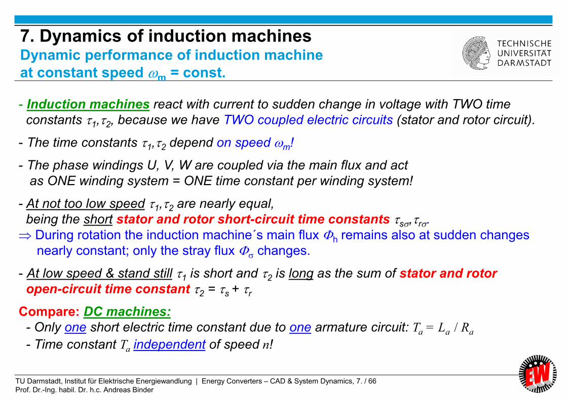
- Induction machines react with current to sudden change in voltage with TWO time
constants 1,2, because we have TWO coupled electric circuits (stator and rotor circuit).
- The time constants 1,2 depend on speed m!
- The phase windings U, V, W are coupled via the main flux and act
as ONE winding system = ONE time constant per winding system!
- At not too low speed 1,2 are nearly equal,
being the short stator and rotor short-circuit time constants s,r.
During rotation the induction machine´s main flux h remains also at sudden changes
nearly constant; only the stray flux changes.
- At low speed & stand still 1 is short and 2 is long as the sum of stator and rotor
open-circuit time constant 2 = s + r
Compare: DC machines:
- Only one short electric time constant due to one armature circuit: Ta = La / Ra
- Time constant Ta independent of speed n!
7. Dynamics of induction machinesDynamic performance of induction machine
at constant speed m = const.

TU Darmstadt, Institut für Elektrische Energiewandlung | Energy Converters – CAD & System Dynamics, 7. / 67
Prof. Dr.-Ing. habil. Dr. h.c. Andreas Binder
- Short stator and rotor short-circuit time constant:
Change of stator and rotor stray flux
- Long stator and rotor open-circuit time constant: Change of main flux
xh
s
ss
r
x
rs xs
xs
rs xs x´r
xh . xss
ss
r
x
7. Dynamics of induction machinesDynamic Time-constants for change of main and stray flux

TU Darmstadt, Institut für Elektrische Energiewandlung | Energy Converters – CAD & System Dynamics, 7. / 68
Prof. Dr.-Ing. habil. Dr. h.c. Andreas Binder
bas
ss
C
ss
B
js
Ai
⌣
ba ssjs eCeBeAi )(
Laplace transform current space vector :
Inverse transform current space vector :
bars
rmrs
ssssxx
xjsr
js
ui
)(⌣
Solution for stator
current vector:
Grid voltage:
Space vector:
)3/4cos()(),3/2cos()(),cos()( uuuuuu WVU
js
uueuuauauu s
jWVUs
⌣ )()()(
3
2)(
2
js
uu s
⌣
Laplace transform:
7. Dynamics of induction machinesExample: Switching stator winding to grid at m = const.
TU Darmstadt, Institut für Elektrische Energiewandlung | Energy Converters – CAD & System Dynamics, 7. / 69
Prof. Dr.-Ing. habil. Dr. h.c. Andreas Binder
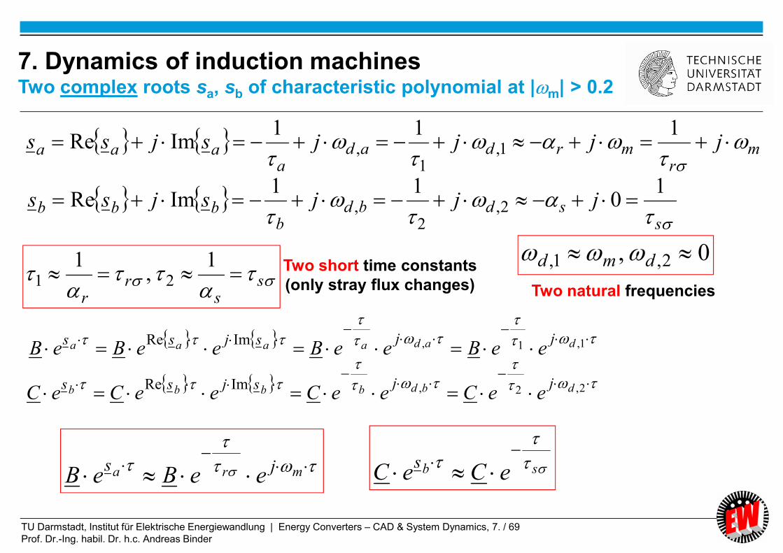
Two short time constants
(only stray flux changes)
mr
mrdada
aaa jjjjsjss
111
ImRe 1,1
,
ss
rr
1
,1
21
0, 2,1, dmd Two natural frequencies
7. Dynamics of induction machinesTwo complex roots sa, sb of characteristic polynomial at |m| > 0.2
s
sdbdb
bbb jjjsjss1
011
ImRe 2,2
,
1,1,ImRe dadaaaajjsjss
eeBeeBeeBeB
2,2,ImRe dbdbbbbjjsjss
eeCeeCeeCeC
mra jseeBeB
sb eCeC
s

TU Darmstadt, Institut für Elektrische Energiewandlung | Energy Converters – CAD & System Dynamics, 7. / 70
Prof. Dr.-Ing. habil. Dr. h.c. Andreas Binder
Stator and rotor current change with two time constants
21)Re(
1,
)Re(
1
bb
aa
ss
having two natural oscillation frequencies
2,,1,, )Im(,)Im( dbbddaad ss
2,1,21 ,,, dd depend on resistances rs rr , , inductances hrs xxx ,,
AND on rotor speed m
ba ssjs eCeBeAi )(
a) Homogeneous part of solution: ba ss
hs eCeBi )(,
b) Particular solution: j
ps eAi )(,
Inverse transform current space vector :
2,2
1,1
/
/, )(
d
d
j
jhs
eeC
eeBi
7. Dynamics of induction machines
Inverse Laplace transformation
TU Darmstadt, Institut für Elektrische Energiewandlung | Energy Converters – CAD & System Dynamics, 7. / 71
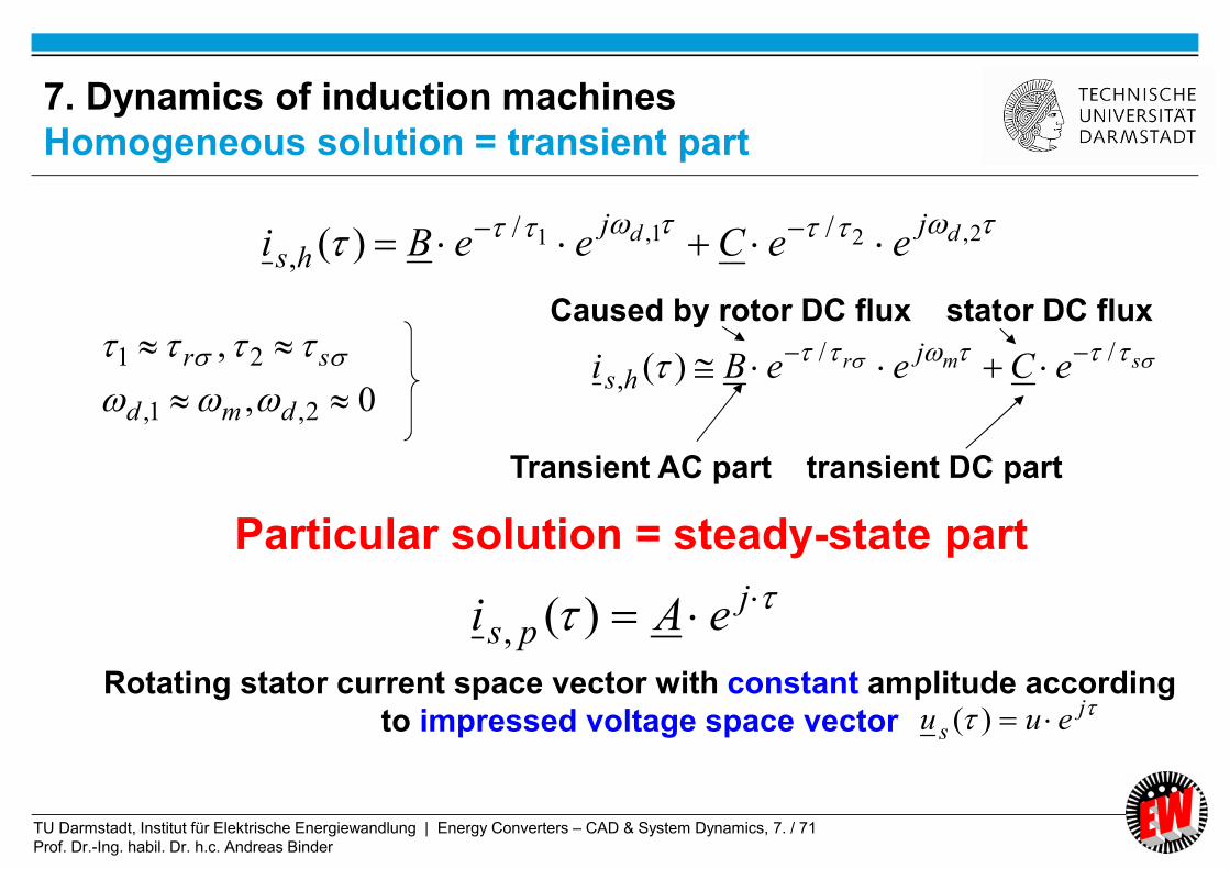
Prof. Dr.-Ing. habil. Dr. h.c. Andreas Binder
2,21,1 //, )( dd jjhs eeCeeBi
0,
,
2,1,
21
dmd
sr
jps eAi )(,
Particular solution = steady-state part
Rotating stator current space vector with constant amplitude according
to impressed voltage space vector j
s euu )(
smr eCeeBij
hs//
, )(
Transient AC part transient DC part
Caused by rotor DC flux stator DC flux
7. Dynamics of induction machines
Homogeneous solution = transient part

TU Darmstadt, Institut für Elektrische Energiewandlung | Energy Converters – CAD & System Dynamics, 7. / 72
Prof. Dr.-Ing. habil. Dr. h.c. Andreas Binder
7. Dynamics of induction machinesDetermination of constants A, B, C by Heaviside´s rule
::1 1 jsi bars
rmr
sjsjxx
xjjruA
))((
::2 2 assi baars
rmar
ssjsxx
xjsruB
))((
::3 3 bssi abbrs
rmbr
ssjsxx
xjsruC
))((
bars
rmrs
ssssxx
xjsr
js
ui
)(⌣
tsn
iiknk
ki
i
n
iess
sZ
ssssss
sZL
sN
sZL
1
...121
11
)(
)(
)(...)()(
)(
)(
)(
bas
ss
C
ss
B
js
Ai
⌣
Heaviside´s rule:
So we get:
If condition: Order of numerator polynomial Z(s) less than of denominator polynomial N(s)

TU Darmstadt, Institut für Elektrische Energiewandlung | Energy Converters – CAD & System Dynamics, 7. / 73
Prof. Dr.-Ing. habil. Dr. h.c. Andreas Binder
7. Dynamics of induction machines
Determination of non-damped solution: rs = r´r = 0
rs
rmrsm
rs
rsrsrs
rmrs
xx
xjrrj
xx
rxxrssxx
xjsr
js
ui
)(
)(
2
⌣
)()(
12
bas
m
sms
ms
ssssx
js
js
u
sxjs
u
jssx
js
js
ui
⌣
011
2)(
)(411
2 2,b
mam
mrs
mrsmrsba
s
jsj
j
jjs
rs = r´r = 0
rs = r´r = 0

TU Darmstadt, Institut für Elektrische Energiewandlung | Energy Converters – CAD & System Dynamics, 7. / 74
Prof. Dr.-Ing. habil. Dr. h.c. Andreas Binder
7. Dynamics of induction machinesNon-damped transient solution is independent of speed m
sin)sin(cosRe1Re)(Re)(
ss
j
ssU
x
ujjj
x
ue
x
ujii
Time function of U phase current:
Simplification: Damping is neglected: 0,0 rs rr : Determination of roots ba ss , :
0),/(0,02 BxjuCAsjsjss sbmam
sjsx
uj
s
C
js
A
jssx
u
sjsxx
xjs
js
ui
ssmrs
rms
11
0
)(
⌣
Inverse transformation:
j
ss e
x
uji 1)(
transient stationary
solution
Re
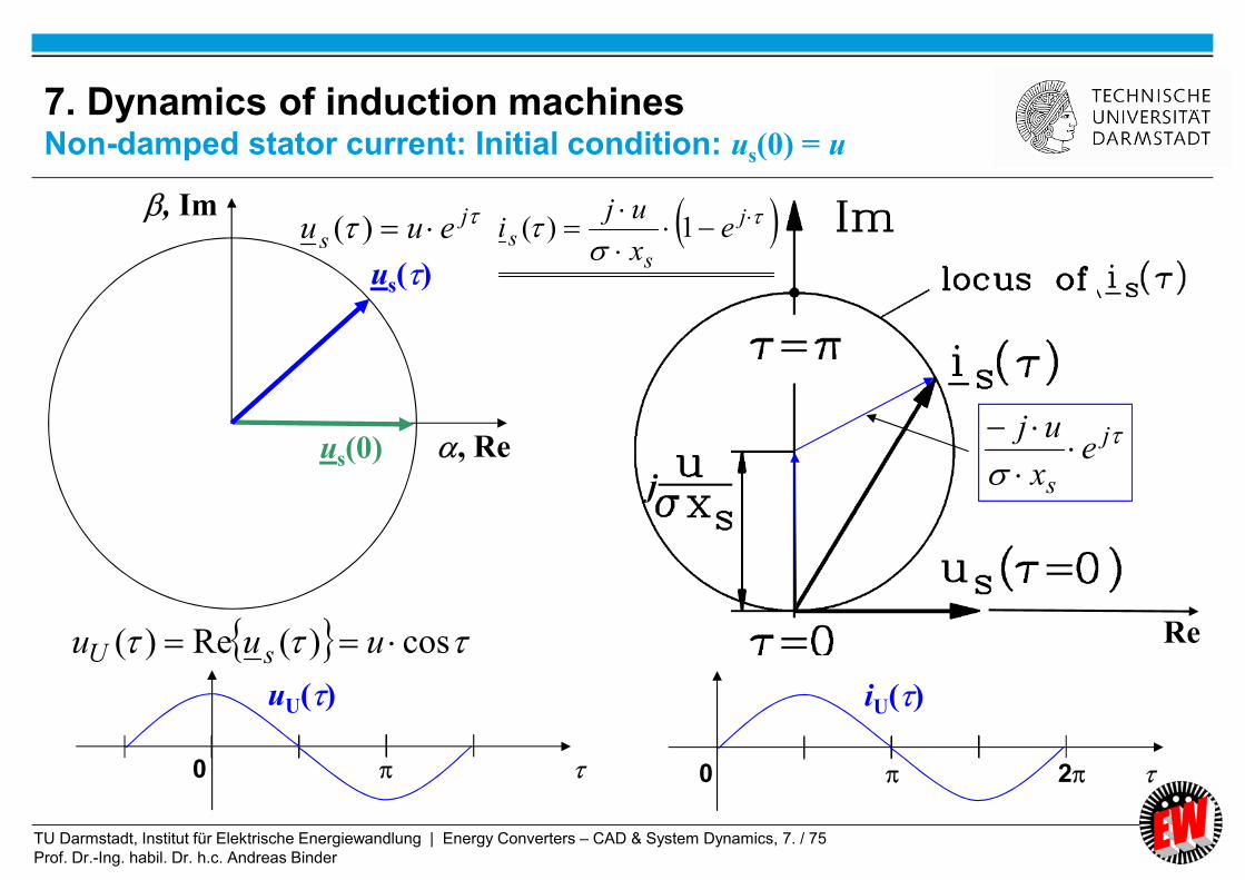
TU Darmstadt, Institut für Elektrische Energiewandlung | Energy Converters – CAD & System Dynamics, 7. / 75
Prof. Dr.-Ing. habil. Dr. h.c. Andreas Binder
js euu )(
, Re
, Im
us()
us(0)
Re
j
s
ex
uj
j
cos)(Re)( uuu sU
uU()
0
iU()
0 2
j
ss e
x
uji 1)(
7. Dynamics of induction machinesNon-damped stator current: Initial condition: us(0) = u
TU Darmstadt, Institut für Elektrische Energiewandlung | Energy Converters – CAD & System Dynamics, 7. / 76
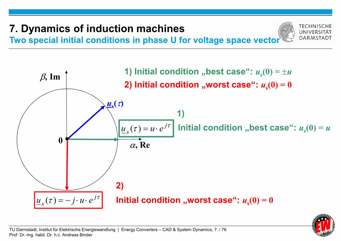
Prof. Dr.-Ing. habil. Dr. h.c. Andreas Binder
Initial condition „best case“: us(0) = u
Initial condition „worst case“: us(0) = 0
1) Initial condition „best case“: us(0) = u
2) Initial condition „worst case“: us(0) = 0
js euu )(
js euju )(
, Re
, Im
us()
0
1)
2)
7. Dynamics of induction machinesTwo special initial conditions in phase U for voltage space vector

TU Darmstadt, Institut für Elektrische Energiewandlung | Energy Converters – CAD & System Dynamics, 7. / 77
Prof. Dr.-Ing. habil. Dr. h.c. Andreas Binder
sin)(Re)( uuu sU
0 2
uU()
0 2
iU()
s
j
sU
x
ue
x
ui
)cos1(
1Re)(
js euju )(
, Re
, Im
us()
us(0)
0Re
j
s
ex
u
Im
sx
u
j
ss e
x
ui 1)(
0
7. Dynamics of induction machinesNon-damped stator current: Initial condition: us(0) = 0

TU Darmstadt, Institut für Elektrische Energiewandlung | Energy Converters – CAD & System Dynamics, 7. / 78
Prof. Dr.-Ing. habil. Dr. h.c. Andreas Binder
Switching on at zero voltage Switching on at maximum voltage
Current: DC component AND AC component Current: no DC component
Peak current 200% Peak current 100%
Peak occurs at half period after switching on Peak occurs at quarter period after switching on
10)30667.0/(12)/(2, sspeaks xui 5)30667.0/(1)/(, sspeaks xui
worst case best case
uu
uu
U
U
)0(
)cos()(
0)0(
sin)2/cos()(
U
U
u
uuu
non-damped DC
component
7. Dynamics of induction machinesDynamic turn-on current - depends on switching-on instant

TU Darmstadt, Institut für Elektrische Energiewandlung | Energy Converters – CAD & System Dynamics, 7. / 79
Prof. Dr.-Ing. habil. Dr. h.c. Andreas Binder
j
rsrsrsrs
rrps e
rxxrSlipjxxSliprr
xSlipjrui
)()(,
jps eAi )(,
Steady state solution ( = particular solution of differential equation):
bars
rmr
sjsjxx
xjjruA
))((
rsrsrsrs
rsrshrsrs
hrrss
mhrmrss
mrsmrsrsbars
rxxrSlipjxxSliprr
rxxrSlipjSlipxxSlipxrr
SlipxxSlipjrxjr
jjxjxjjrxjr
jjjjxxsjsjxx
2
2
2
2
)()(
)())(()(
)(
Slipm 1
7. Dynamics of induction machines
Complete stationary solution (1)

TU Darmstadt, Institut für Elektrische Energiewandlung | Energy Converters – CAD & System Dynamics, 7. / 80
Prof. Dr.-Ing. habil. Dr. h.c. Andreas Binder
Slip
Rotor and stator current:
rr
hsr
Xjs
R
jXII
)( rsrsrsrs
rrss
RXXRsjXXsRR
XsjRUI
j
rsrsrsrs
rrps e
rxxrSlipjxxSliprr
xSlipjrui )(,
Compare:
)( Slips
7. Dynamics of induction machines
Stationary solution equivalent circuit
Solution of the two linear equations of
T-equivalent circuit:
Two unknowns rs II ´,
rhsssss IjXIjXIRU
shrrrr IjXIXjI
s
R0

TU Darmstadt, Institut für Elektrische Energiewandlung | Energy Converters – CAD & System Dynamics, 7. / 81
Prof. Dr.-Ing. habil. Dr. h.c. Andreas Binder
7. Dynamics of induction machines
Complete stationary solution (2)
js
j
rsrsrsrs
rrpss euue
rxxrSlipjxxSliprr
xSlipjruii )(,
)()()( ,
Stationary solution gives for stator current space vector the well-known OSSANNA “circle diagram”
as locus of all solutions is,p for varying speed (= varying Slip s)
0
us(0)
is(0)
Re
ImMachine cross-
section plane Complex Gauss´ian plane0:e.g.
sN
ss
sN
ss
I
Ii
U
Uuu
ˆ
2
ˆ
2

TU Darmstadt, Institut für Elektrische Energiewandlung | Energy Converters – CAD & System Dynamics, 7. / 82
Prof. Dr.-Ing. habil. Dr. h.c. Andreas Binder
02 mrsmrs jjss
0.504.0/30667.0//1
,67.603.0/30667.0//1
rrrr
ssss
rx
rx
1m :
0288.073.6
11,971.0
96.4
11
149.0
2,2
202.0
1,1
jjsjjs dbda������
Roots for transient solution
(i) (ii)
0,1 Slipm 04.0,96.0 Slipm
029.0149.0,971.0202.0 jsjs ba 03.0149.0,93.0202.0 jsjs ba
Steady state current = no-load current = 0.33 steady state current = rated current = 1
7. Dynamics of induction machinesExample: Complete transient solution with damping
Solution for "inrush" current of induction machine, being switched to grid, when already running
(i) at synchronous speed: (ii) at rated speed:33.0si 0.1si

TU Darmstadt, Institut für Elektrische Energiewandlung | Energy Converters – CAD & System Dynamics, 7. / 83
Prof. Dr.-Ing. habil. Dr. h.c. Andreas Binder
7. Dynamics of induction machinesStator current space vector solution with damping, Slip = 0
Source:
H. Kleinrath, Springer-Verlag
ba ssjs eCeBeAi )(
js eju )(
0
Steady state solution = no-load current is = is0 = 0.33 p.u.
04.0,03.0,3,3,0667.0 rsrs rrxx
Solution for "inrush" current space vector is
of induction machine
Switched to sinusoidal grid, when running
at synchronous speed m = 1
Worst-case for phase U, where switching occurs
at zero voltage,
yielding maximum current peak

TU Darmstadt, Institut für Elektrische Energiewandlung | Energy Converters – CAD & System Dynamics, 7. / 84
Prof. Dr.-Ing. habil. Dr. h.c. Andreas Binder
Steady state solution = no-load current is = is0 = 0.33 p.u.
Induction machine switched to sinusoidal grid, when running at synchronous speed m = 1
Worst-case for phase U:
Switching occurs at zero voltageBest-case for phase U:
Switching occurs at maximum voltage
4-times rated peak current at /2
6.3-times rated peak current at
04.0,03.0,3,3,0667.0 rsrs rrxx 1)( su
7. Dynamics of induction machinesStator „inrush“ current iU() at m = 1, (Slip = 0)

TU Darmstadt, Institut für Elektrische Energiewandlung | Energy Converters – CAD & System Dynamics, 7. / 85
Prof. Dr.-Ing. habil. Dr. h.c. Andreas Binder
7. Dynamics of induction machinesStator current space vector solution with damping,
at rated Slip = 0.04
Source:
H. Kleinrath, Springer-Verlag
js eju )(
ba ssjs eCeBeAi )(
0
Steady state solution = rated current, is = isN = 1.0 p.u.
Solution for "inrush" current space vector is
of induction machine
Switched to sinusoidal grid, when running
at rated speed m = 0.96
Worst-case for phase U, where switching occurs
at zero voltage,
yielding maximum current peak
04.0,03.0,3,3,0667.0 rsrs rrxx
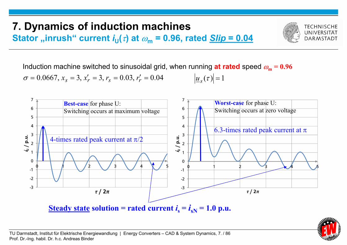
TU Darmstadt, Institut für Elektrische Energiewandlung | Energy Converters – CAD & System Dynamics, 7. / 86
Prof. Dr.-Ing. habil. Dr. h.c. Andreas Binder
Steady state solution = rated current is = isN = 1.0 p.u.
Induction machine switched to sinusoidal grid, when running at rated speed m = 0.96
Worst-case for phase U:
Switching occurs at zero voltageBest-case for phase U:
Switching occurs at maximum voltage
4-times rated peak current at /2
6.3-times rated peak current at
04.0,03.0,3,3,0667.0 rsrs rrxx 1)( su
7. Dynamics of induction machinesStator „inrush“ current iU() at m = 0.96, rated Slip = 0.04
TU Darmstadt, Institut für Elektrische Energiewandlung | Energy Converters – CAD & System Dynamics, 7. / 87
Prof. Dr.-Ing. habil. Dr. h.c. Andreas Binder
Voltage switching such as
a) switching on motor ( = in-rush current),
b) sudden short-circuit,
...
leads to a DC current component, which is largest,
when switching occurs at zero voltage in the considered phase.
DC current component limited by rotor and stator stray inductances and resistances
DC current component vanishes with two short time constants 1 r, 2 s ,
determined by the rotor and stator stray inductances and resistances
7. Dynamics of induction machinesTransient response of induction machine
at elevated speed at |m| > 0.2

TU Darmstadt, Institut für Elektrische Energiewandlung | Energy Converters – CAD & System Dynamics, 7. / 88
Prof. Dr.-Ing. habil. Dr. h.c. Andreas Binder
Maximum short circuit phase current amplitude:
87.612ˆ
,
s
Usx
ui (at = , undamped)
Maximum short circuit current,
when short circuit occurs at voltage zero crossing
Stator current space vector at (nearly) constant speed
m = 1 contains transient DC and AC component:
mr
sj
ss eee
ii/
/
0
11
33.0/)0( 0 ssss xuii No-load current
110 kW, 380 V, 212 A, 720 Nm,
4 pole motor, 50 Hz, = 0.097
No-load
is0 = 0.33
1500/min 1450/min
Numerical solution for speed and torque
Zero current
is = 0
Dynamic short circuit torque:
)sin(Im)(
11
20
2*
msr
hsrhe
sreix
xiixm
3.333.0097.0
3 220
2
max,
sr
he i
x
xm
04.0,03.0,3,3,0667.0 rsrs rrxx
7. Dynamics of induction machinesSudden short-circuit of a 4-pole no-load induction motor
TU Darmstadt, Institut für Elektrische Energiewandlung | Energy Converters – CAD & System Dynamics, 7. / 89
Prof. Dr.-Ing. habil. Dr. h.c. Andreas Binder
7. Dynamics of induction machinesSuperconducting rotor in induction machines: rr = 0
bars
rm
bars
rmrs
ssssxx
xjs
js
u
ssssxx
xjsr
js
ui
)()(⌣
0
)(
rrshrsr
h
bars
mhr ixixi
x
x
ssssxx
jsx
js
ui
⌣⌣⌣⌣⌣
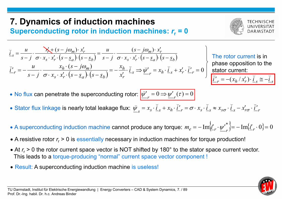
No flux can penetrate the superconducting rotor:
rrssssrhsssixixixixix ⌣⌣⌣⌣⌣⌣
0)(0 rr
⌣
The rotor current is in
phase opposition to the
stator current:
ssrhr iixxi⌣⌣⌣
)/(
Stator flux linkage is nearly total leakage flux:
00ImIm* rrre iim A superconducting induction machine cannot produce any torque:
A resistive rotor rr > 0 is essentially necessary in induction machines for torque production!
At rr > 0 the rotor current space vector is NOT shifted by 180° to the stator space current vector.
This leads to a torque-producing “normal” current space vector component !
Result: A superconducting induction machine is useless!
TU Darmstadt, Institut für Elektrische Energiewandlung | Energy Converters – CAD & System Dynamics, 7. / 90
Prof. Dr.-Ing. habil. Dr. h.c. Andreas Binder
Summary:
Solutions of dynamic equations for constant speed
- Linear voltage & flux linkage equations at constant speed
- LAPLACE domain solution with transfer function is = F(us)
- Time-constants 1, 2 and natural frequencies d,1, d,2 depend on speed m
- Homogeneous solution = transient part = DC current component
in inductive circuit
- Particular solution for steady-state solution is,p = rotary current space vector
- Examples:
Switching of voltage on stator winding of running machine
Sudden short circuit at stator terminals
Energy Converters – CAD and System Dynamics

TU Darmstadt, Institut für Elektrische Energiewandlung | Energy Converters – CAD & System Dynamics, 7. / 91
Prof. Dr.-Ing. habil. Dr. h.c. Andreas Binder
7. Dynamics of induction machines
7.1 Per unit calculation
7.2 Dynamic voltage equations and reference frames of induction machine
7.3 Dynamic flux linkage equations
7.4 Torque equation
7.5 Dynamic equations of induction machines in stator reference frame
7.6 Solutions of dynamic equations for constant speed
7.7 Solutions of dynamic equations for induction machines with varying
speed
7.8 Linearized transfer function of induction machines in synchronous
reference frame
7.9 Inverter-fed induction machines with field-oriented control
Energy Converters – CAD and System Dynamics

TU Darmstadt, Institut für Elektrische Energiewandlung | Energy Converters – CAD & System Dynamics, 7. / 92
Prof. Dr.-Ing. habil. Dr. h.c. Andreas Binder
Solution of all 9 equations simultaneously (e.g. in --frame)
Equations are non-linear, so numerical solution is necessary:
VOLTAGE: 4 equations
FLUX LINKAGE: 4 equations
TORQUE: 1 equation
9 equations in TOTAL !
Example:
a) No-load start-up of induction motors
and afterwards
b) loading with rated torque
is investigated.
7. Dynamics of induction machinesSolutions of dynamic equations for varying speed

TU Darmstadt, Institut für Elektrische Energiewandlung | Energy Converters – CAD & System Dynamics, 7. / 93
Prof. Dr.-Ing. habil. Dr. h.c. Andreas Binder
Induction machine 1 (big) Induction machine 2 (small)
Rated power 110.8 kW 1.18 kW
Rated voltage 380 V 380 V
Rated current 212 A 2.6 A
Efficiency 93.4 % 85.5 %
Power factor 0.85 0.81
Rated slip 2 % 8 %
Rated speed 1470/min 1380/min
Rated torque 720 Nm 8.2 Nm
sR 25 m 0.024 p.u. 9.5 0.113 p.u.
rR 20 m 0.019 p.u. 6.2 0.073 p.u.
sL 9.71 mH 2.95 p.u. 668 mH 2.49 p.u.
L´r 9.55 mH 2.90 p.u. 662 mH 2.46 p.u.
hL 9.17 mH 2.78 p.u. 633 mH 2.36 p.u.
0.094 0.094
J 2.8 kgm2 J = 155.5 0.00349 kgm
2 J = 15.8
TJ with MN 611 ms 67 ms
7. Dynamics of induction machines
Data of two example machines
TU Darmstadt, Institut für Elektrische Energiewandlung | Energy Converters – CAD & System Dynamics, 7. / 94
Prof. Dr.-Ing. habil. Dr. h.c. Andreas Binder
7. Dynamics of induction machines
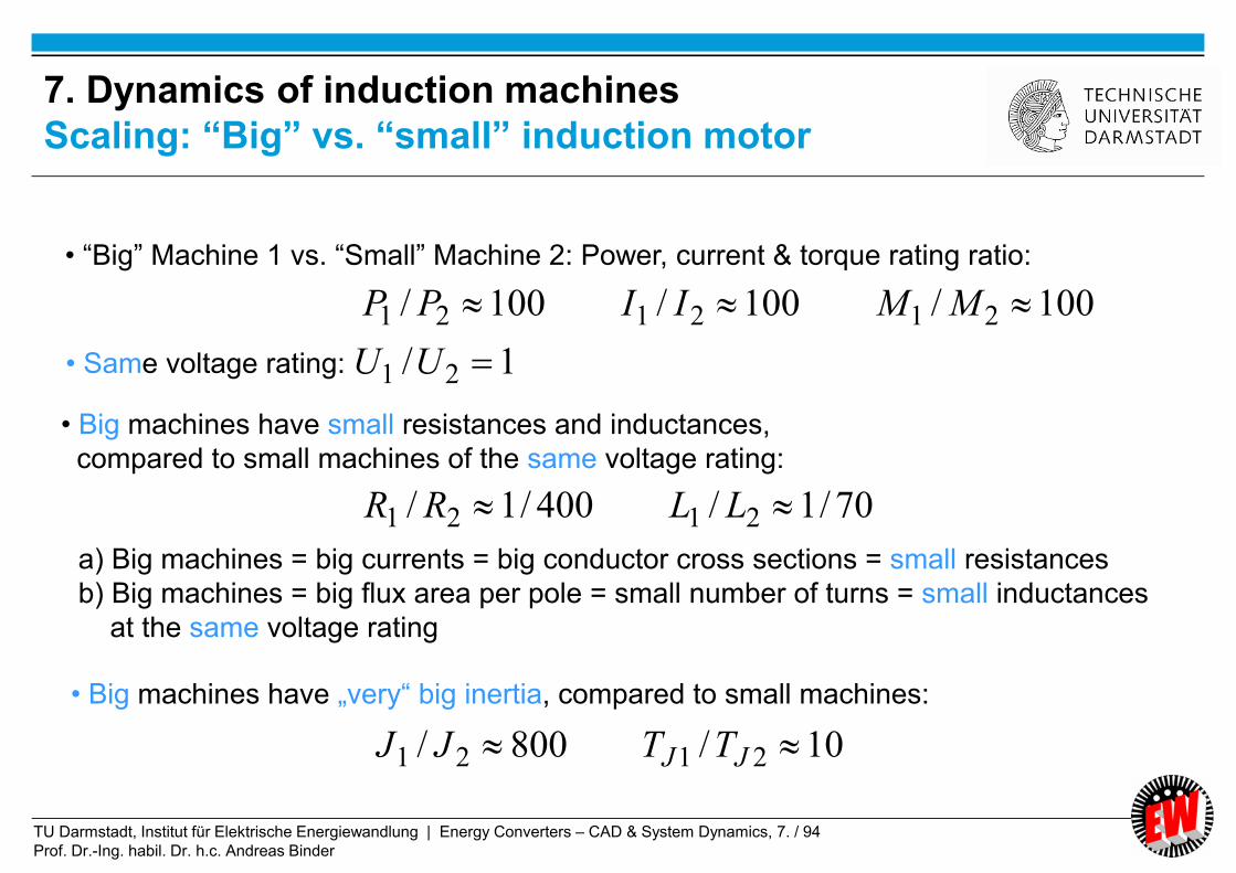
Scaling: “Big” vs. “small” induction motor
100/100/100/ 212121 MMIIPP
70/1/400/1/ 2121 LLRR
10/800/ 2121 JJ TTJJ
• Big machines have „very“ big inertia, compared to small machines:
1/ 21 UU
• “Big” Machine 1 vs. “Small” Machine 2: Power, current & torque rating ratio:
• Same voltage rating:
• Big machines have small resistances and inductances,
compared to small machines of the same voltage rating:
a) Big machines = big currents = big conductor cross sections = small resistances
b) Big machines = big flux area per pole = small number of turns = small inductances
at the same voltage rating
TU Darmstadt, Institut für Elektrische Energiewandlung | Energy Converters – CAD & System Dynamics, 7. / 95
Prof. Dr.-Ing. habil. Dr. h.c. Andreas Binder
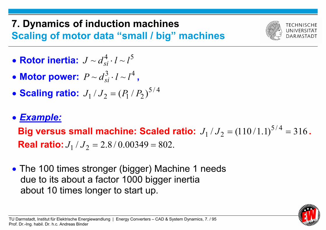
Rotor inertia: 54 ~~ lldJ si
Motor power: 43 ~~ lldP si ,
Scaling ratio: 4/52121 )/(/ PPJJ
Example:
Big versus small machine: Scaled ratio: 316)1.1/110(/ 4/521 JJ .
Real ratio: .80200349.0/8.2/ 21 JJ
The 100 times stronger (bigger) Machine 1 needs due to its about a factor 1000 bigger inertia about 10 times longer to start up.
7. Dynamics of induction machines
Scaling of motor data “small / big” machines

TU Darmstadt, Institut für Elektrische Energiewandlung | Energy Converters – CAD & System Dynamics, 7. / 96
Prof. Dr.-Ing. habil. Dr. h.c. Andreas Binder
No-load starting at 50 Hz grid voltage; motor loaded at 1.8 s with rated torque
1.8 s
MN = 720 Nm
50 Hz torque pulsation
Low frequent torque pulsation
J = JN
7. Dynamics of induction machinesCalculated electromagnetic torque of “big” induction machine

TU Darmstadt, Institut für Elektrische Energiewandlung | Energy Converters – CAD & System Dynamics, 7. / 97
Prof. Dr.-Ing. habil. Dr. h.c. Andreas Binder
7. Dynamics of induction machines
Calculated rotational speed of induction machine
Line frequent
speed ripple
Varying inertia
Decay time of speed ripple increases
with decreasing speed, because time
constant T2 increases
Starting time at JN
longer as TJ,
because M(t) MN
No-load starting with 0.5JN, JN, 2JN

TU Darmstadt, Institut für Elektrische Energiewandlung | Energy Converters – CAD & System Dynamics, 7. / 98
Prof. Dr.-Ing. habil. Dr. h.c. Andreas Binder
7. Dynamics of induction machinesCalculated electromagnetic torque of induction machine
No-load starting at 50 Hz grid voltage with ten times increased inertiaSpeed n up to 2.5s below ca. 10% rated speed:
Line-frequent torque
pulsation
Ca. three time-constants 3T2 for
DC current component to decay:
2.3 s
s866.0s478.0s388.0//2 rrss RLRLT

TU Darmstadt, Institut für Elektrische Energiewandlung | Energy Converters – CAD & System Dynamics, 7. / 99
Prof. Dr.-Ing. habil. Dr. h.c. Andreas Binder
7. Dynamics of induction machinesInfluence of mechanical speed n on time constant
for decay of oscillating starting torque
a) NJJ b) NJJ 10
Time of decay of 50 Hz oscillating torque
0.5 s 2.3 s
s866.0s478.0s388.0//2 rrss RLRLT
Case b): Big inertia 10JN (= slow acceleration) Decay of transient DC current component occurs
at still low speed n 0, so “zero speed” formula for time constant T2(n = 0) applies.
Case a): Small inertia JN (= fast acceleration) Decay of transient DC current component occurs
at already elevated speed |m| > 0.2, so time constant T2(n > 0) < T2(n = 0) is shorter!
T2(n > 0) tends TOWARDS “Short circuit time constant !”: T2(n > 0) Ts . T2(n = 0)/2
0.1 3T2(n > 0) 0.05 . 3T2(n = 0) 0.05 . 2.5 = 0.13 s
s5.2s866.033 2 T
After 3T2(n = 0) both DC current & torque oscillation have vanished!
r
x
r
x
r
x
r
r
s
s
m2
02
022.022 mm
s
s
r
x
� �
NN JJJ
100
s2.3s5.0s13.0���

TU Darmstadt, Institut für Elektrische Energiewandlung | Energy Converters – CAD & System Dynamics, 7. / 100
Prof. Dr.-Ing. habil. Dr. h.c. Andreas Binder
Transient solution: At speed n = 0:
DC current space vector is,DC does not rotate
Stationary solution: AC current space vector rotates with
line frequency s = 1 and its flux induces the rotor cage
Rotating AC rotor current space vector
DCsj
ACss ieii ,,)( Simplified: Undamped: is,DC = const.:
Result:
Constant starting torque me,1, but torque me,2 pulsates with line frequency s = 1
jACr ei
,
jACrDCs
jACshrshe eiieixiixm *
,,,*
)(ImIm
const.ImIm*
,,*
,,1, ACrACsh
jACr
jACshe iixeieixm
)cos(ˆ)sin(cosImIm 2,*
,,*
,,2, eACrDCsh
jACrDCshe mjiixeiixm
jACsACs eii ,, )(
, Re
, Im
is,AC()
is,DC
0
7. Dynamics of induction machines
Line-frequent starting torque oscillation

TU Darmstadt, Institut für Elektrische Energiewandlung | Energy Converters – CAD & System Dynamics, 7. / 101
Prof. Dr.-Ing. habil. Dr. h.c. Andreas Binder
a) Oscillating starting torque:
Switching on of stator voltage:
DC current component iDC occurs in stator and rotor winding.
(i)
The 50 Hz AC stator current is,AC reacts with the DC flux of rotor DC current i´r,DC,
yielding a first pulsating 50 Hz-torque component
(ii)
The 50 Hz AC rotor current i´r,AC reacts with the DC flux of stator DC current is,DC,
yielding a second pulsating 50 Hz-torque component
(i) + (ii) constitute the oscillating starting torque!
7. Dynamics of induction machines
Phenomena of “dynamic” starting performance (1)

TU Darmstadt, Institut für Elektrische Energiewandlung | Energy Converters – CAD & System Dynamics, 7. / 102
Prof. Dr.-Ing. habil. Dr. h.c. Andreas Binder
7. Dynamics of induction machinesCalculated dynamic torque-speed characteristic
of induction machine
No-load starting at 50 Hz grid voltage; motor loaded at 1.8 s with rated torque.
-------- Dashed line: Static torque-speed characteristic from equivalent circuit diagram
Dynamic break-down
torque Mb,dyn, lower than
stationary break-down
torque Mb,stat
J = JN
Slip

TU Darmstadt, Institut für Elektrische Energiewandlung | Energy Converters – CAD & System Dynamics, 7. / 103
Prof. Dr.-Ing. habil. Dr. h.c. Andreas Binder
b) Dynamic break-down torque:
Main flux is changing with
big electric time constant T2 (at n = 0: Ls/Rs + Lr/Rr = 0.866 s)
Full flux at ca. 3T2 = 2.5 s.
Therefore at reaching at 1.2 s break-down slip sb,
still full flux is missing,
reducing the dynamic break-down torque Mb,dyn < Mb,stat
Example:
Reduction by 25% with respect to static break-down torque!
c) Eigen-frequency of induction machine at synchronous and rated speed
("synchronous machine effect in asynchronous machines"):
Low oscillation frequency fd,m at each load step.
Explanation:
Rotor (main) flux changes with big rotor time constant r = xr/rr,
may be regarded as "frozen" for a “short” time << r It acts like the constant rotor flux in synchronous machines rotor oscillation possible
7. Dynamics of induction machinesPhenomena of “dynamic” starting performance (2)

TU Darmstadt, Institut für Elektrische Energiewandlung | Energy Converters – CAD & System Dynamics, 7. / 104
Prof. Dr.-Ing. habil. Dr. h.c. Andreas Binder
7. Dynamics of induction machines
Calculated rotational speed of induction machine
Jf md
1~,Line
frequency Natural
motor
frequency
decreases
by
increasing
inertia Decay time
increases with
decreasing speed
No-load starting at grid voltage with 0.5JN, JN, 2JN
Varying inertia
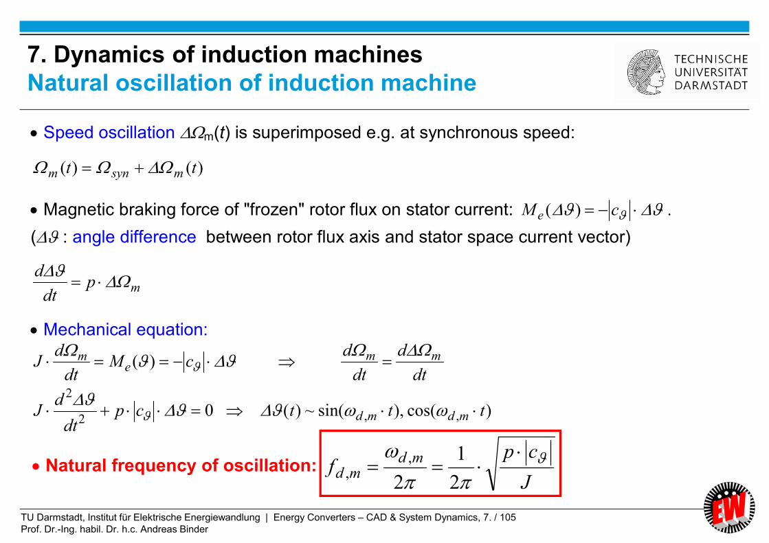
TU Darmstadt, Institut für Elektrische Energiewandlung | Energy Converters – CAD & System Dynamics, 7. / 105
Prof. Dr.-Ing. habil. Dr. h.c. Andreas Binder
Speed oscillation m(t) is superimposed e.g. at synchronous speed:
)()( tt msynm
Magnetic braking force of "frozen" rotor flux on stator current: cM e )( .
( : angle difference between rotor flux axis and stator space current vector)
mpdt
d
Mechanical equation:
cMdt
dJ e
m )( dt
d
dt
d mm
02
2
cpdt
dJ )cos(),sin(~)( ,, ttt mdmd
J
cpf
mdmd
2
1
2
,, Natural frequency of oscillation:
7. Dynamics of induction machines
Natural oscillation of induction machine

TU Darmstadt, Institut für Elektrische Energiewandlung | Energy Converters – CAD & System Dynamics, 7. / 106
Prof. Dr.-Ing. habil. Dr. h.c. Andreas Binder
No-load starting with rated inertia JN
a) without additional rotor resistance, b) with Rv = 10-times rotor resistance
Varying total rotor
resistance Rr + Rv
Natural
motor
frequency
influenced
by rotor
resistance
Line
frequency
a)
b)
Decay time decreases
with increasing
resistance
rr
vr
rr
r
rr
rr
x
r
x
11
*
Reduced rotor time constant allows
fast change of rotor flux =
= no “frozen” rotor flux phenomenon
*r
7. Dynamics of induction machines
Calculated rotational speed of induction machine

TU Darmstadt, Institut für Elektrische Energiewandlung | Energy Converters – CAD & System Dynamics, 7. / 107
Prof. Dr.-Ing. habil. Dr. h.c. Andreas Binder
Inertia J = JN
Additional rotor resistance:
Break-down torque is shifted
from slip sb = 0.08 to 0.88:
Motor now starts nearly
with break-down torque,
hence with reduced start-up time
88.008.01111
10
*
*
bb
b
rr
b
r
ss
s
RR
s
R
7. Dynamics of induction machines
Dynamic starting of slip ring induction machine

TU Darmstadt, Institut für Elektrische Energiewandlung | Energy Converters – CAD & System Dynamics, 7. / 108
Prof. Dr.-Ing. habil. Dr. h.c. Andreas Binder
7. Dynamics of induction machinesCalculated electromagnetic torque of “small” induction machine
Very quick start-up, so no clear distinction
between line frequency oscillation and natural oscillation
0.35 s: Loading with MN
No-load start-up
TJ = 67 ms
No-load starting at 50 Hz grid voltage; motor loaded at 0.35 s with rated torque
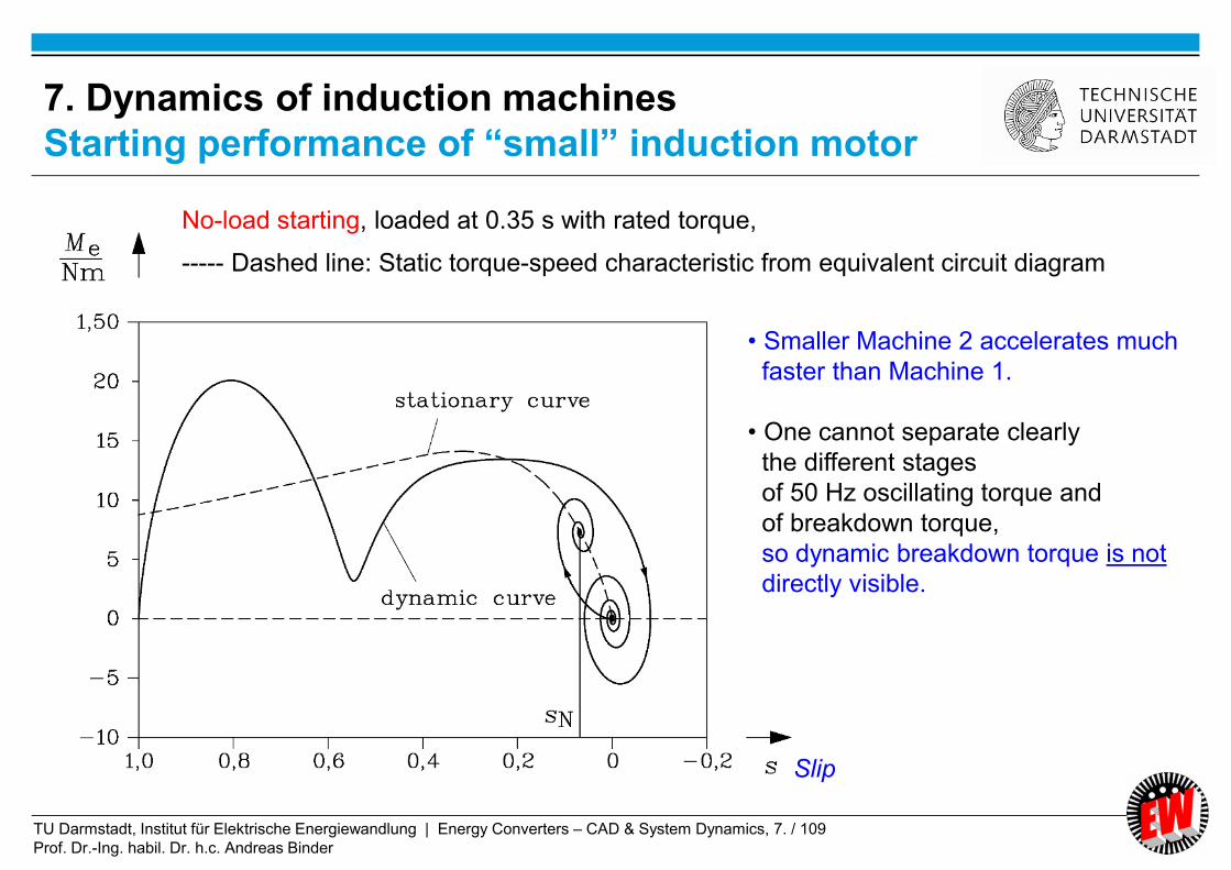
TU Darmstadt, Institut für Elektrische Energiewandlung | Energy Converters – CAD & System Dynamics, 7. / 109
Prof. Dr.-Ing. habil. Dr. h.c. Andreas Binder
7. Dynamics of induction machines
Starting performance of “small” induction motor
No-load starting, loaded at 0.35 s with rated torque,
----- Dashed line: Static torque-speed characteristic from equivalent circuit diagram
• Smaller Machine 2 accelerates much
faster than Machine 1.
• One cannot separate clearly
the different stages
of 50 Hz oscillating torque and
of breakdown torque,
so dynamic breakdown torque is not
directly visible.
Slip
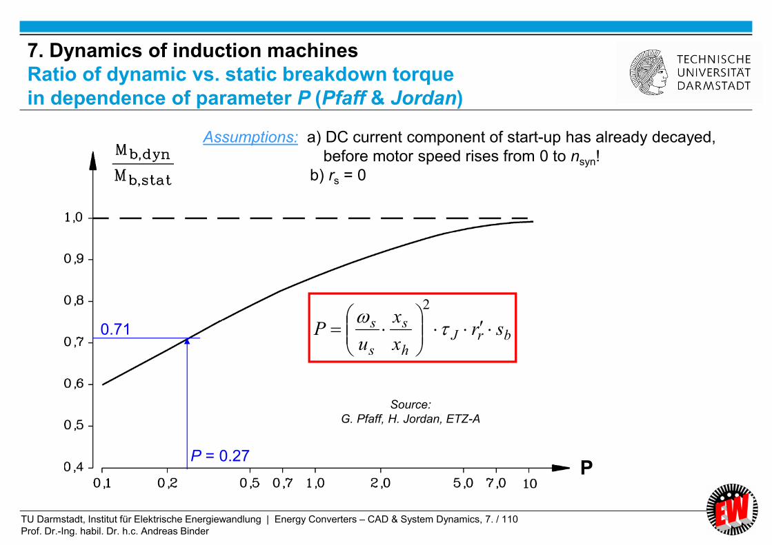
TU Darmstadt, Institut für Elektrische Energiewandlung | Energy Converters – CAD & System Dynamics, 7. / 110
Prof. Dr.-Ing. habil. Dr. h.c. Andreas Binder
brJh
s
s
s srx
x
uP
2
Source:
G. Pfaff, H. Jordan, ETZ-A
P = 0.27
0.71
Assumptions: a) DC current component of start-up has already decayed,
before motor speed rises from 0 to nsyn!
b) rs = 0
P
7. Dynamics of induction machines
Ratio of dynamic vs. static breakdown torque
in dependence of parameter P (Pfaff & Jordan)

TU Darmstadt, Institut für Elektrische Energiewandlung | Energy Converters – CAD & System Dynamics, 7. / 111
Prof. Dr.-Ing. habil. Dr. h.c. Andreas Binder
Example: Data of induction machine 1: Break down slip sb = 8%. Line start at 50 Hz, rated voltage: Us = 231 V
2696.023
50208.002.08.2
00917.0
00971.0
3/380
502
3
22
2
2
2
2
p
fsRJ
L
L
U
fP Nbr
h
s
s
s
Curve with P: 71.0/ ,, statbdynb MM
Compare: Numerical solution yields 0.74 ! = sufficient coincidence !
2
22
3
22
p
fsRJ
L
L
U
fsr
x
x
uP Nbr
h
s
s
sbrJ
h
s
s
s
7. Dynamics of induction machinesDynamic break down torque: Pfaff-Jordan parameter P

TU Darmstadt, Institut für Elektrische Energiewandlung | Energy Converters – CAD & System Dynamics, 7. / 112
Prof. Dr.-Ing. habil. Dr. h.c. Andreas Binder
JP ~
22
1~
h
s
h
s
x
x
x
xP
Bigger inertia = slower motor acceleration = less dynamic starting
Bigger parameter P = less dynamic starting
Bigger stator leakage flux = lower motor torque =
less motor acceleration = less dynamic starting
2
21
~ss
s
uP
Bigger stator flux linkage s = bigger motor torque = faster
motor acceleration = more dynamic starting
7. Dynamics of induction machines
Explanation of Pfaff-Jordan parameter P
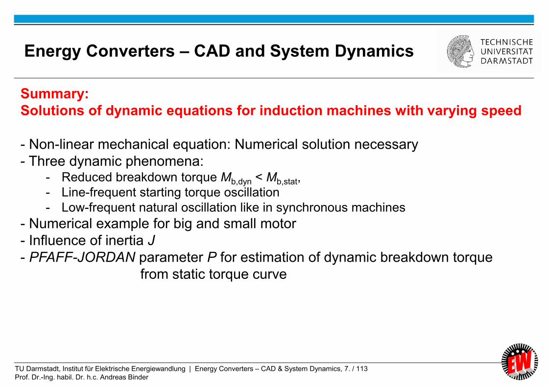
TU Darmstadt, Institut für Elektrische Energiewandlung | Energy Converters – CAD & System Dynamics, 7. / 113
Prof. Dr.-Ing. habil. Dr. h.c. Andreas Binder
Summary:
Solutions of dynamic equations for induction machines with varying speed
- Non-linear mechanical equation: Numerical solution necessary
- Three dynamic phenomena:- Reduced breakdown torque Mb,dyn < Mb,stat,
- Line-frequent starting torque oscillation
- Low-frequent natural oscillation like in synchronous machines
- Numerical example for big and small motor
- Influence of inertia J
- PFAFF-JORDAN parameter P for estimation of dynamic breakdown torque
from static torque curve
Energy Converters – CAD and System Dynamics
TU Darmstadt, Institut für Elektrische Energiewandlung | Energy Converters – CAD & System Dynamics, 7. / 114
Prof. Dr.-Ing. habil. Dr. h.c. Andreas Binder
7. Dynamics of induction machines
7.1 Per unit calculation
7.2 Dynamic voltage equations and reference frames of induction machine
7.3 Dynamic flux linkage equations
7.4 Torque equation
7.5 Dynamic equations of induction machines in stator reference frame
7.6 Solutions of dynamic equations for constant speed
7.7 Solutions of dynamic equations for induction machines with varying
speed
7.8 Linearized transfer function of induction machines in synchronous
reference frame
7.9 Inverter-fed induction machines with field-oriented control
Energy Converters – CAD and System Dynamics
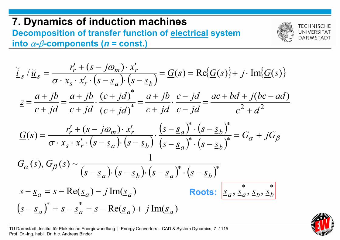
TU Darmstadt, Institut für Elektrische Energiewandlung | Energy Converters – CAD & System Dynamics, 7. / 115
Prof. Dr.-Ing. habil. Dr. h.c. Andreas Binder
)(Im)(Re)(
)(/ sGjsGsG
ssssxx
xjsrui
bars
rmrss
⌣⌣
jGG
ssss
ssss
ssssxx
xjsrsG
ba
ba
bars
rmr
**
**)(
)(
22*
* )(
)(
)(
dc
adbcjbdac
jdc
jdc
jdc
jba
jdc
jdc
jdc
jba
jdc
jbaz
**
1~)(),(
baba sssssssssGsG
)Im()Re(**
aaaa sjssssss
)Im()Re( aaa sjssss Roots:**
,,, bbaa ssss
7. Dynamics of induction machinesDecomposition of transfer function of electrical system
into --components (n = const.)

TU Darmstadt, Institut für Elektrische Energiewandlung | Energy Converters – CAD & System Dynamics, 7. / 116
Prof. Dr.-Ing. habil. Dr. h.c. Andreas Binder
Complex space vector .... Complex transfer function of space vectors G(s)
Two-axis components .... Real transfer function of components G(s), G(s),
Two roots of complex transfer function sa, sb =
= two pairs of conjugate complex roots of real transfer function s1, s4 & s2, s5
ada
a js ,
1
, bd
bb js ,
1
ada
js ,1
1
, ad
a
js ,4
1
bd
b
js ,2
1
, bd
b
js ,5
1
- NOTE: With variable speed dynamic equations are non-linear,
so no linear transfer function exists.
- BUT: Small signal linearized equations allow transfer function formulation.
7. Dynamics of induction machines
Transfer function of electrical system at n = const.

TU Darmstadt, Institut für Elektrische Energiewandlung | Energy Converters – CAD & System Dynamics, 7. / 117
Prof. Dr.-Ing. habil. Dr. h.c. Andreas Binder
Transfer function of linearized performance (small signal theory)
of induction machine for electromechanical performance (variable speed):
2,252,22
33
1,141,11
dd
dd
jsjs
s
jsjs
The five roots of induction machine electro-mechanical transfer function comprise two
pairs of conjugate complex poles and one real pole (= mechanical influence!)
Compare: DC machines: Two poles for electromechanical performance.
7. Dynamics of induction machines
Roots of linearized electromechanical transfer function in s-plane

TU Darmstadt, Institut für Elektrische Energiewandlung | Energy Converters – CAD & System Dynamics, 7. / 118
Prof. Dr.-Ing. habil. Dr. h.c. Andreas Binder
Stator reference frame Rotor reference frame Synchronous reference frame
Does not rotate Rotates with ddm / Rotates with ddsyn /
Use in induction machines Use in synchronous machines
Use in induction machines for small signal theory
)()()()( juuu s )()()()( qdr juuu )()()()( basyn juuu
)(3
2 2)( WVUs uauauu
)()()( )()( j
sr euu )(
)()( )()( jssyn euu
7. Dynamics of induction machines
Use of different co-ordinate systems
Stator reference frame Synchronous reference frame
Space vector rotates Space vector does not move at line operation
K = syn
s
s Three phase sinus voltage system
N
ss
1
:e.g.
sNs
sN
s
N
synsyn
p
p
p
/
/
/
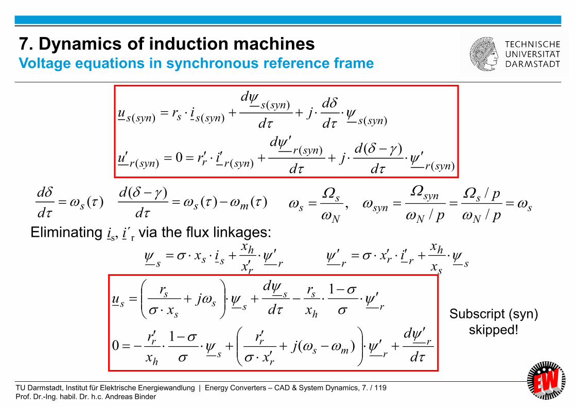
TU Darmstadt, Institut für Elektrische Energiewandlung | Energy Converters – CAD & System Dynamics, 7. / 119
Prof. Dr.-Ing. habil. Dr. h.c. Andreas Binder
)(
)(
)()(
)(
)(
)()(
)(0
synr
synr
synrrsynr
syns
syns
synsssyns
d
dj
d
diru
d
dj
d
diru
)()()(
)(
mssd
d
d
d
Eliminating is, i´r via the flux linkages:
ss
hrrrr
r
hsss x
xix
x
xix
d
dj
x
r
x
r
x
r
d
dj
x
ru
r
rmsr
r
sh
r
rh
ss
sss
ss
)(1
0
1
Subscript (syn)
skipped!
sN
s
N
synsyn
N
ss
p
p
p
/
/
/,
7. Dynamics of induction machinesVoltage equations in synchronous reference frame

TU Darmstadt, Institut für Elektrische Energiewandlung | Energy Converters – CAD & System Dynamics, 7. / 120
Prof. Dr.-Ing. habil. Dr. h.c. Andreas Binder
ss
hrrrr
r
hsss x
xix
x
xix
**2
*Im
1Im
)/(Im
rsh
rsh
rsh
rrexx
xxxim
Eliminating is, i´r via the flux linkages:
*Im
1rs
he
xm
7. Dynamics of induction machines
Torque equation with flux linkages
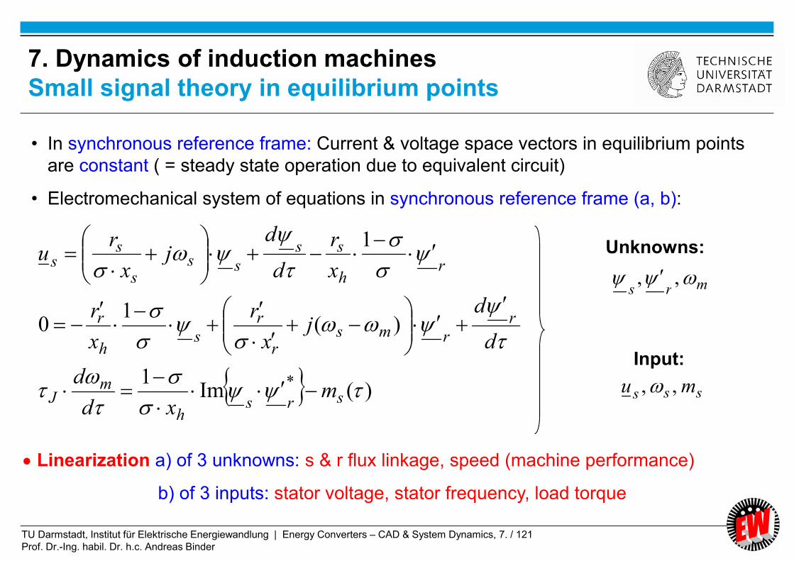
TU Darmstadt, Institut für Elektrische Energiewandlung | Energy Converters – CAD & System Dynamics, 7. / 121
Prof. Dr.-Ing. habil. Dr. h.c. Andreas Binder
• In synchronous reference frame: Current & voltage space vectors in equilibrium points
are constant ( = steady state operation due to equivalent circuit)
• Electromechanical system of equations in synchronous reference frame (a, b):
)(Im1
)(1
0
1
*
srsh
mJ
r
rmsr
r
sh
r
rh
ss
sss
ss
mxd
d
d
dj
x
r
x
r
x
r
d
dj
x
ru
Linearization a) of 3 unknowns: s & r flux linkage, speed (machine performance)
b) of 3 inputs: stator voltage, stator frequency, load torque
Unknowns:
Input:
mrs ,,
sss mu ,,
7. Dynamics of induction machines
Small signal theory in equilibrium points
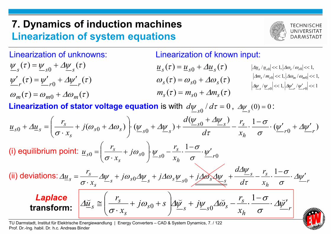
TU Darmstadt, Institut für Elektrische Energiewandlung | Energy Converters – CAD & System Dynamics, 7. / 122
Prof. Dr.-Ing. habil. Dr. h.c. Andreas Binder
Linearization of unknowns: Linearization of known input:
)()(
)()(
)()(
0
0
0
mmm
rrr
sss
)()(
)()(
)()(
0
0
0
sss
sss
sss
mmm
uuu
Linearization of stator voltage equation is with 0/0
dds
, 0)0( s
:
)(1)(
)()(0
0
000 rrh
sss
sssss
sss
x
r
d
dj
x
ruu
(i) equilibrium point: 0000
1r
h
s
sss
ss
x
rj
x
ru
(ii) deviations:r
h
ss
ssssssss
ss
x
r
d
djjj
x
ru
100
rh
sssss
s
ss
x
rjsj
x
ru
⌣⌣⌣⌣
100
Laplace
transform:
1/,1/
,1/,1/
,1/,1/
00
00
00
rrss
mmss
ssss
mm
uu
7. Dynamics of induction machines
Linearization of system equations
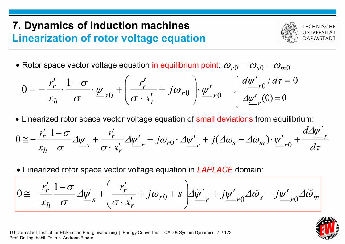
TU Darmstadt, Institut für Elektrische Energiewandlung | Energy Converters – CAD & System Dynamics, 7. / 123
Prof. Dr.-Ing. habil. Dr. h.c. Andreas Binder
7. Dynamics of induction machines
Linearization of rotor voltage equation
000
10
rrr
r
sh
r jx
r
x
r
d
djj
x
r
x
r r
rmsrrrr
r
sh
r
00 )(1
0
mrsrrrr
r
sh
r jjsjx
r
x
r
⌣⌣⌣⌣
000
10
Rotor space vector voltage equation in equilibrium point:
Linearized rotor space vector voltage equation of small deviations from equilibrium:
Linearized rotor space vector voltage equation in LAPLACE domain:
000 msr
0/0
ddr
0)0( r

TU Darmstadt, Institut für Elektrische Energiewandlung | Energy Converters – CAD & System Dynamics, 7. / 124
Prof. Dr.-Ing. habil. Dr. h.c. Andreas Binder
Decomposition of complex space vectors in a-b-components:
)()()(
)()()(
rbrar
sbsas
j
j
brarr
bsass
j
j
000
000
)()()( sbsas ujuu
srbsarasbh
mJ m
xd
d
1
00000
10 sbrasarbs
h
mx
Cancelling of equilibrium condition and linearization, e.g.: 0 sarb
sbrsarbasarsbrabsh
mJ m
xd
d
0000
1
Laplace-transformation ( 0)0( m ):
ssabrrbassbarrabsh
mJ mx
s⌣⌣⌣⌣⌣⌣
0000
1
7. Dynamics of induction machines
Linearization of torque equation

TU Darmstadt, Institut für Elektrische Energiewandlung | Energy Converters – CAD & System Dynamics, 7. / 125
Prof. Dr.-Ing. habil. Dr. h.c. Andreas Binder
mrsrrrr
r
sh
r jjsjx
r
x
r
⌣⌣⌣⌣
000
10
rh
sssss
s
ss
x
rjsj
x
ru
⌣⌣⌣⌣
100
rah
ssbssbssa
s
ssa
x
rs
x
ru
⌣⌣⌣⌣⌣
100
rbh
ssassassb
s
ssb
x
rs
x
ru
⌣⌣⌣⌣⌣
100
mbrsbrrbrrar
rsa
h
r sx
r
x
r
⌣⌣⌣⌣⌣
000
10
marsarrarrbr
rsb
h
r sx
r
x
r
⌣⌣⌣⌣⌣
000
10
7. Dynamics of induction machines
Linearized voltage equations in a-b-components
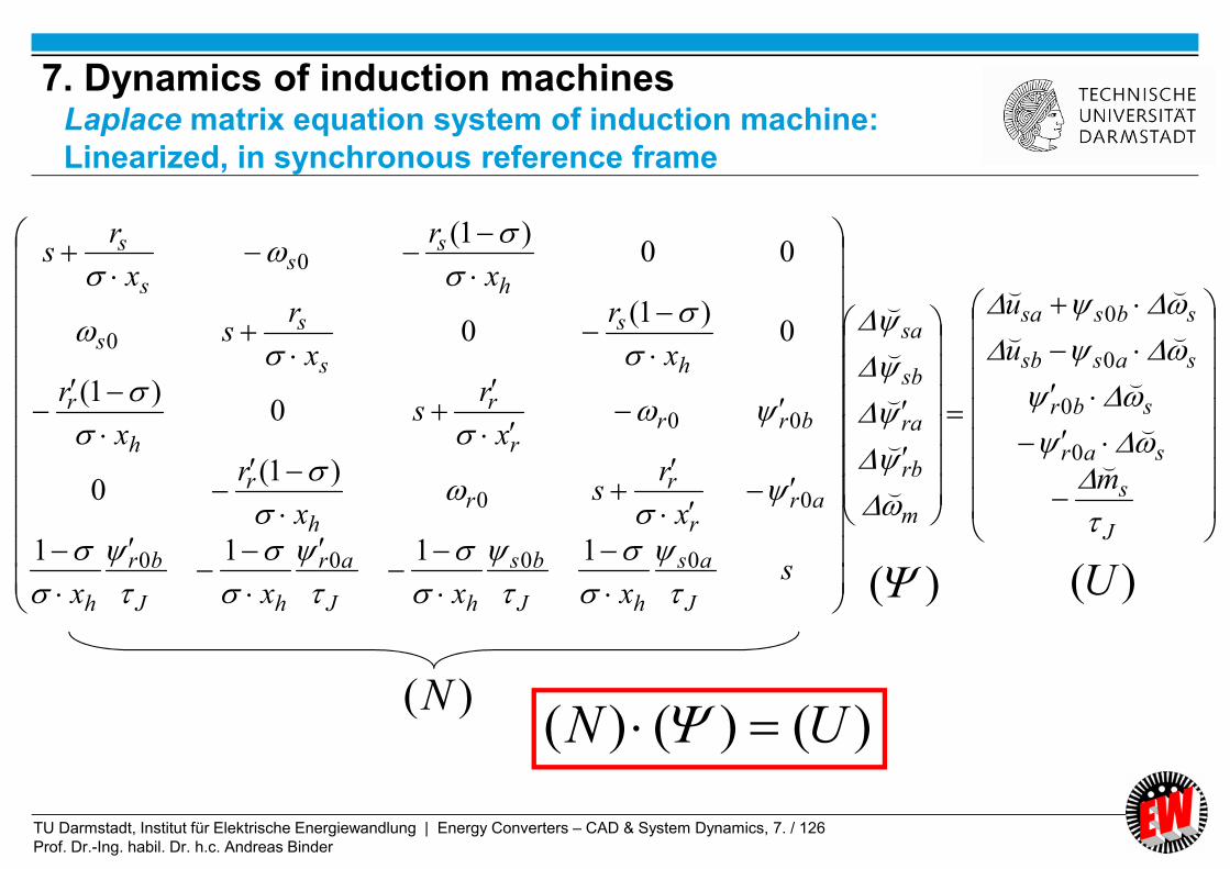
TU Darmstadt, Institut für Elektrische Energiewandlung | Energy Converters – CAD & System Dynamics, 7. / 126
Prof. Dr.-Ing. habil. Dr. h.c. Andreas Binder
J
s
sar
sbr
sassb
sbssa
m
rb
ra
sb
sa
J
as
hJ
bs
hJ
ar
hJ
br
h
arr
rr
h
r
brrr
r
h
r
h
s
s
ss
h
ss
s
s
m
u
u
sxxxx
x
rs
x
r
x
rs
x
r
x
r
x
rs
x
r
x
rs
⌣
⌣
⌣
⌣⌣
⌣⌣
⌣
⌣
⌣
⌣
⌣
0
0
0
0
0000
00
00
0
0
1111
)1(0
0)1(
0)1(
0
00)1(
)()()( UN )(N
)( )(U
7. Dynamics of induction machinesLaplace matrix equation system of induction machine:
Linearized, in synchronous reference frame
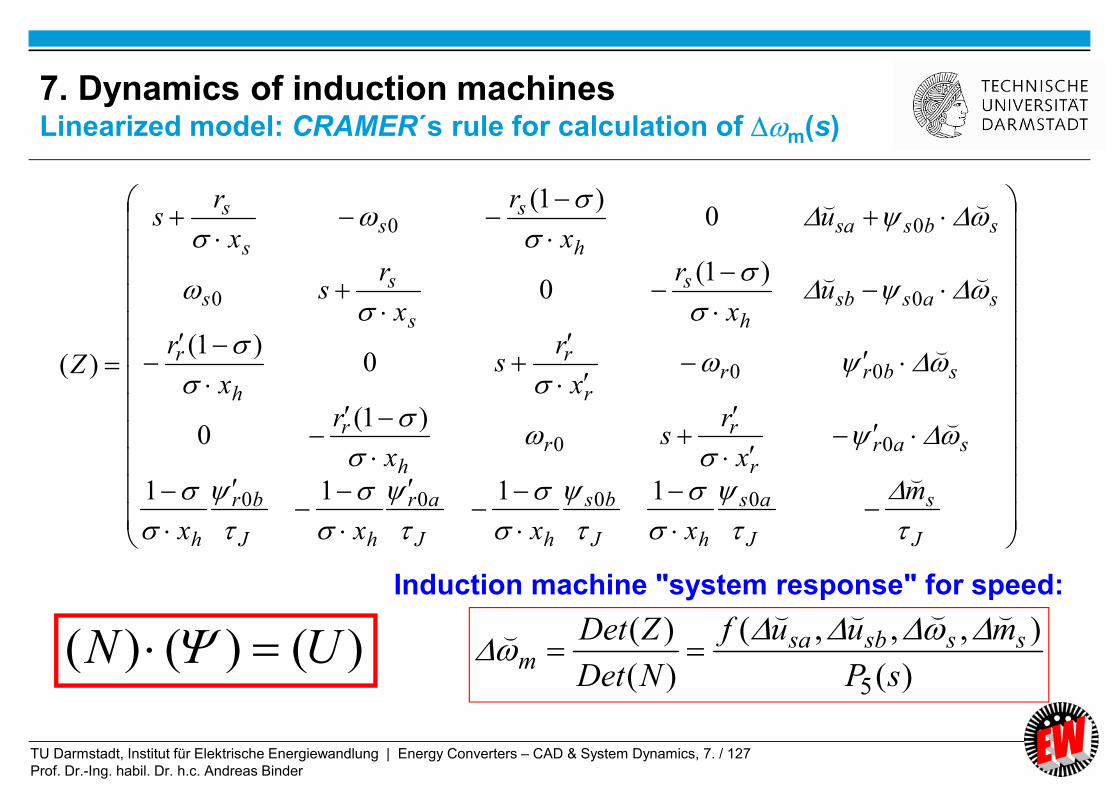
TU Darmstadt, Institut für Elektrische Energiewandlung | Energy Converters – CAD & System Dynamics, 7. / 127
Prof. Dr.-Ing. habil. Dr. h.c. Andreas Binder
J
s
J
as
hJ
bs
hJ
ar
hJ
br
h
sarr
rr
h
r
sbrrr
r
h
r
sassbh
s
s
ss
sbssah
ss
s
s
m
xxxx
x
rs
x
r
x
rs
x
r
ux
r
x
rs
ux
r
x
rs
Z
⌣
⌣
⌣
⌣⌣
⌣⌣
0000
00
00
00
00
1111
)1(0
0)1(
)1(0
0)1(
)(
)()()( UN Induction machine "system response" for speed:
)(
),,,(
)(
)(
5 sP
muuf
NDet
ZDet sssbsam
⌣⌣⌣⌣⌣
7. Dynamics of induction machinesLinearized model: CRAMER´s rule for calculation of m(s)
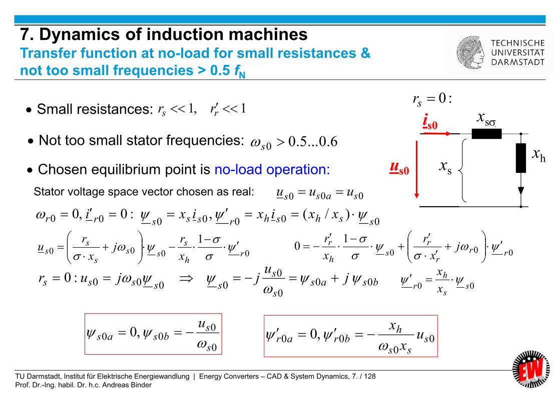
TU Darmstadt, Institut für Elektrische Energiewandlung | Energy Converters – CAD & System Dynamics, 7. / 128
Prof. Dr.-Ing. habil. Dr. h.c. Andreas Binder
Small resistances: 1,1 rs rr
Not too small stator frequencies: 6.0...5.00 s
bsass
s
sssss ju
jjur 000
0
0000:0
Chosen equilibrium point is no-load operation:
Stator voltage space vector chosen as real:
0000000 )/(,:0,0sshshrsssrr xxixixi
000 sass uuu
0
000 ,0
s
sbsas
u
00
00 ,0 sss
hbrar u
x
x
xh
xs
xs
is0
us0
:0sr
0000
1r
h
s
sss
ss
x
rj
x
ru
000
10
rrr
r
sh
r jx
r
x
r
00 ss
h
r x
x
7. Dynamics of induction machinesTransfer function at no-load for small resistances &
not too small frequencies > 0.5 fN

TU Darmstadt, Institut für Elektrische Energiewandlung | Energy Converters – CAD & System Dynamics, 7. / 129
Prof. Dr.-Ing. habil. Dr. h.c. Andreas Binder
(1) rs rr
(2) rs xx : short-circuit time constants: 111
r
r
rs
s
s x
r
x
r
(3) not too small stator frequencies sss xr 0
(4) usually small resistance rrss xrxr ,
2
,
2
20
2
52
11)
1()()( mds ssssPNDet
Characteristic polynomial:
)()()()()()( 543215 sssssssssssP
00
20
2111
sss jsjss
NOTE:04
01
1
1
s
s
js
js
)1.031.0
03.01:(e.g.
7. Dynamics of induction machinesCharacteristic polynomial of linearized transfer function

TU Darmstadt, Institut für Elektrische Energiewandlung | Energy Converters – CAD & System Dynamics, 7. / 130
Prof. Dr.-Ing. habil. Dr. h.c. Andreas Binder
Mechanical system natural frequency:
2
2
0
02,
)2(
111
s
s
sJd
u
x
2,252,22
33
1,141,11
dd
dd
jsjs
s
jsjs
mddsd ,2,01,
Five roots of P5(s) = five poles in s-plane:
Poles s1, s3, s4: DC components in current and flux torque and speed oscillation
with stator frequency.
Poles s2, s5: “frozen" rotor flux = "synchronous" machine phenomenon!
2
12
131
7. Dynamics of induction machines
Roots of linearized electromechanical transfer function in s-plane

TU Darmstadt, Institut für Elektrische Energiewandlung | Energy Converters – CAD & System Dynamics, 7. / 131
Prof. Dr.-Ing. habil. Dr. h.c. Andreas Binder
2
2
0
0,
)2(
111
s
s
sJmd
u
x
“Frozen" rotor flux = "synchronous" machine phenomenon!
Per unit values:
2
2
0
02
,)2(
113
T
U
LJ
p
s
s
smd
ss
s
sb
LU
pmM
1
2
2
2
Physical units:
Breakdown torque at Rs = 0:
(of KLOSS-function)
2,)2(
12
TJ
pMbmd
ms = 3
Valid for small signal
at no-load operation!
(No-load, )rsrs xxrr
7. Dynamics of induction machines
Mechanical system natural frequency

TU Darmstadt, Institut für Elektrische Energiewandlung | Energy Converters – CAD & System Dynamics, 7. / 132
Prof. Dr.-Ing. habil. Dr. h.c. Andreas Binder
“Frozen" rotor flux = "synchronous" machine phenomenon!
Induction machine:
J
cpmd
, COMPARE: Synchronous machine (without damping):
At no-load equilibrium:
2,
0
J
Mp
mdp
Synchronous machine (with damping):
00/ pe MMc
2,)2(
12
TJ
pMbmd
2
0,
1
TJ
Mp pmd
(No-load, )rsrs xxrr
T/1
(No-load)
1sr
b
b
s
e
s
M
ds
dM 2
0
7. Dynamics of induction machinesMechanical system natural frequency for small signals
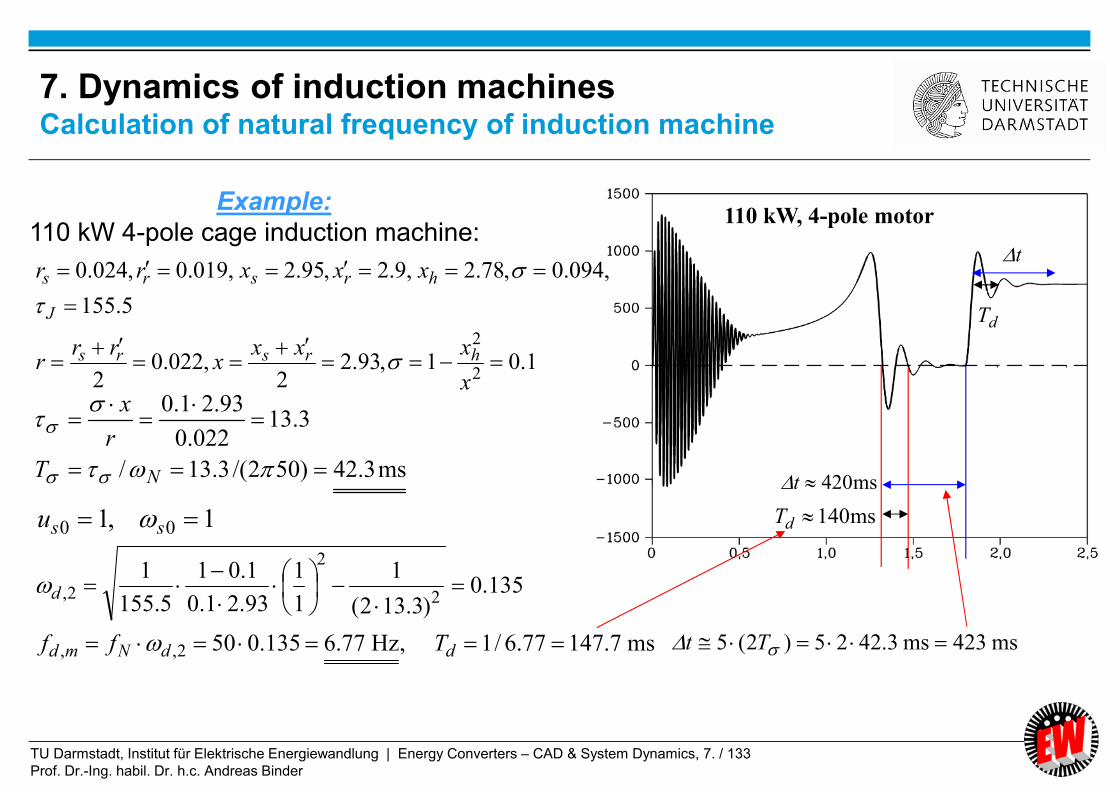
TU Darmstadt, Institut für Elektrische Energiewandlung | Energy Converters – CAD & System Dynamics, 7. / 133
Prof. Dr.-Ing. habil. Dr. h.c. Andreas Binder
1,1 00 ssu
110 kW, 4-pole motor
ms140dT
ms420t
dT
t
ms423ms3.4225)2(5 Tt
Example:
110 kW 4-pole cage induction machine:
1.01,93.22
,022.02
5.155
,094.0,78.2,9.2,95.2,019.0,024.0
2
2
x
xxxx
rrr
xxxrr
hrsrs
J
hrsrs
ms3.42)502/(3.13/
3.13022.0
93.21.0
NT
r
x
ms7.14777.6/1,Hz77.6135.050
135.0)3.132(
1
1
1
93.21.0
1.01
5.155
1
2,,
2
2
2,
ddNmd
d
Tff
7. Dynamics of induction machinesCalculation of natural frequency of induction machine

TU Darmstadt, Institut für Elektrische Energiewandlung | Energy Converters – CAD & System Dynamics, 7. / 134
Prof. Dr.-Ing. habil. Dr. h.c. Andreas Binder
0000
0000
)(1
0
1
rmsr
r
sh
r
rh
s
sss
ss
jx
r
x
r
x
rj
x
ru
Rated operation:
10 sNs uu 10 sNs
NmNms Slip 100
rNNr
r
sNh
r
rNh
s
sNs
ssN
Slipjx
r
x
r
x
rj
x
ru
10
1
jx
rSlipj
x
r
x
r
x
r
ux
r
s
sN
r
r
h
r
h
s
sNh
r
rN
2
1
1Rated rotor flux linkage:
Selected equilibrium points at:
00000,,, sssmrNru
Example: No-load as equilibrium point with rated rotor flux linkage:
rNh
s
sss
ss
rNmsr
h
r
h
s
x
rj
x
ru
r
xj
x
x
1
)(1
1
000
000
000, smrNr
000
10000
~1
1
1sss
rs
s
ss
s
ssrN
h
s
rNr
h
sj
x
rj
x
ru
x
x
x
x
s
7. Dynamics of induction machines
Equilibrium point: d./d = 0

TU Darmstadt, Institut für Elektrische Energiewandlung | Energy Converters – CAD & System Dynamics, 7. / 135
Prof. Dr.-Ing. habil. Dr. h.c. Andreas Binder
:1,1 00 ssu
Example:
30 kW 4-pole cage induction machine:
75,0667.0,0.3,03.0 Jrsrs xxrr
ms2.21)502/(67.6/67.603.0
30667.0
Nsrss
srs TT
r
x
ms849.11/1,Hz9.11238.050
238.0)67.62(
1
1
1
30667.0
0667.01
75
1
2,,
2
2
2,
ddNmd
d
Tff
075.067.62
12
Operation point (= equilibrium point):
7. Dynamics of induction machinesCalculation of natural frequency of induction machine

TU Darmstadt, Institut für Elektrische Energiewandlung | Energy Converters – CAD & System Dynamics, 7. / 136
Prof. Dr.-Ing. habil. Dr. h.c. Andreas Binder
Variation of damping 2 and natural angular frequency d,2 with varying feeding stator
frequency s0 and constant rated rotor flux linkage
No-load machine operation ms0 = 0, m0 = s0 , Slip = 0.
WEAK DAMPING AT LOW FREQUENCY, if machine is not controlled !
75,0667.0,0.3,04.0,03.0 Jrsrs xxrr
Weak damping
Source:
H. Kleinrath,
Archiv f. Elektrotechnik
U-f-ramp of inverter0su
0s
(~ 0.075)
(~ 0.238)
(analytical)
rNr
0000 sss ju
7. Dynamics of induction machinesSmall-signal transfer function for varying stator frequency

TU Darmstadt, Institut für Elektrische Energiewandlung | Energy Converters – CAD & System Dynamics, 7. / 137
Prof. Dr.-Ing. habil. Dr. h.c. Andreas Binder
Variation of damping 2 and natural angular frequency d,2 with varying stator resistance rs
at rated stator frequency s0 = 1 and constant rated rotor flux linkage
No-load machine operation ms0 = 0, m0 = s0 = 1, Slip = 0.
UNSTABLE OPERATION AT BIG STATOR RESISTANCE !
Unstable operation =
increasing amplitude
Source:
H. Kleinrath,
Archiv f. Elektrotechnik
rNr
0
7. Dynamics of induction machinesSmall-signal transfer function for increasing stator resistance rs

TU Darmstadt, Institut für Elektrische Energiewandlung | Energy Converters – CAD & System Dynamics, 7. / 138
Prof. Dr.-Ing. habil. Dr. h.c. Andreas Binder
Negative
damping!
1.6
0.56
75,0667.0
,0.3,04.0,03.0
J
rsrs xxrr
39.003.013 sr
and by 1/3 reduced
rotor inertia: 253/75 J .
Speed oscillation
amplitude increases =
UNSTABLE operation
a) directly
b) with 13-fold increased stator
resistance
56.06.1)39.01( 2 Reduced breakdown torque:
7. Dynamics of induction machines
Starting machine at no load, constant stator voltage & frequency

TU Darmstadt, Institut für Elektrische Energiewandlung | Energy Converters – CAD & System Dynamics, 7. / 139
Prof. Dr.-Ing. habil. Dr. h.c. Andreas Binder
Cage induction motor
with deep bar rotor
6 kV Y, 3500 kW, 415 A, 50 Hz
ZN = 8.35 , 2p = 4
Rs = 0.0426 (20°C), rs = 0.0426/8.35 = 0.5%
No-load current: Is0 = 74.2 A
- Direct no-load start up of the induction motor at the 20 kV-grid with a 20kV/6 kV-
transformer at closed switch S. Transformer impedance XT Xs helps to stabilize!
- Opening of the switch S after completed start-up at no-load speed
- Measurement of the 50 Hz-no-load current is0(t)
3 x 6 kV, 50 Hz
Variable
resistance RV
Induction motor
at no-load
Switch S
is0(t)
First reported measurement in history of induction machine instability
(BBC, Mannheim, Germany, 1969):
7. Dynamics of induction machinesMeasurement of instability at big stator resistance rs

TU Darmstadt, Institut für Elektrische Energiewandlung | Energy Converters – CAD & System Dynamics, 7. / 140
Prof. Dr.-Ing. habil. Dr. h.c. Andreas Binder
RV /Rs = 75.8
RV /Rs = 93.2
rs + rV = 0.39
rs + rV = 0.48
Stable
operation
Zero damping
= Limit of
stability:
Source: BBC, Mannheim,
Germany
fd2 = 3.26 Hz
fd2 = 2.91 Hz
RV = 3.23
RV = 3.97
Envelope of 50 Hz current plus low-frequent
switching transient
Envelope of 50
Hz current
switch S
opened
20 ms
7. Dynamics of induction machinesMeasured stator current with a big stator resistance rs
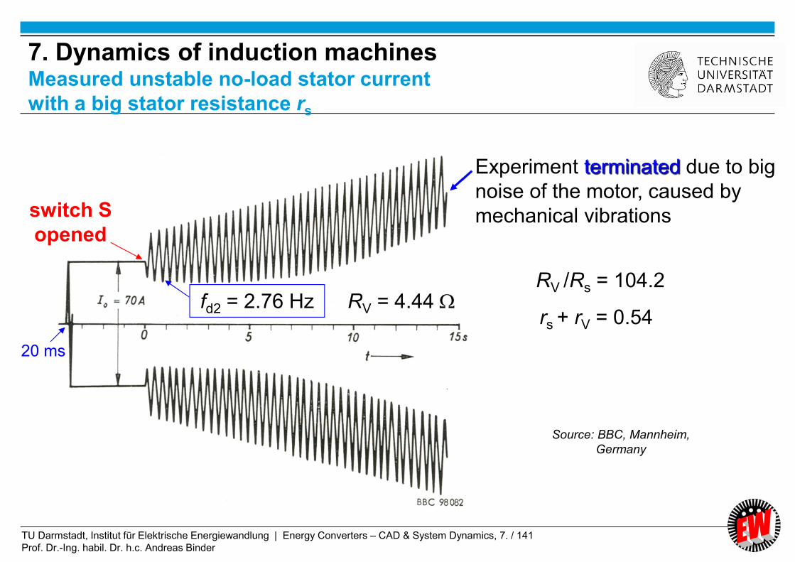
TU Darmstadt, Institut für Elektrische Energiewandlung | Energy Converters – CAD & System Dynamics, 7. / 141
Prof. Dr.-Ing. habil. Dr. h.c. Andreas Binder
fd2 = 2.76 Hz RV = 4.44
switch S
opened
20 ms
RV /Rs = 104.2
rs + rV = 0.54
Experiment terminated due to big
noise of the motor, caused by
mechanical vibrations
Source: BBC, Mannheim,
Germany
7. Dynamics of induction machinesMeasured unstable no-load stator current
with a big stator resistance rs
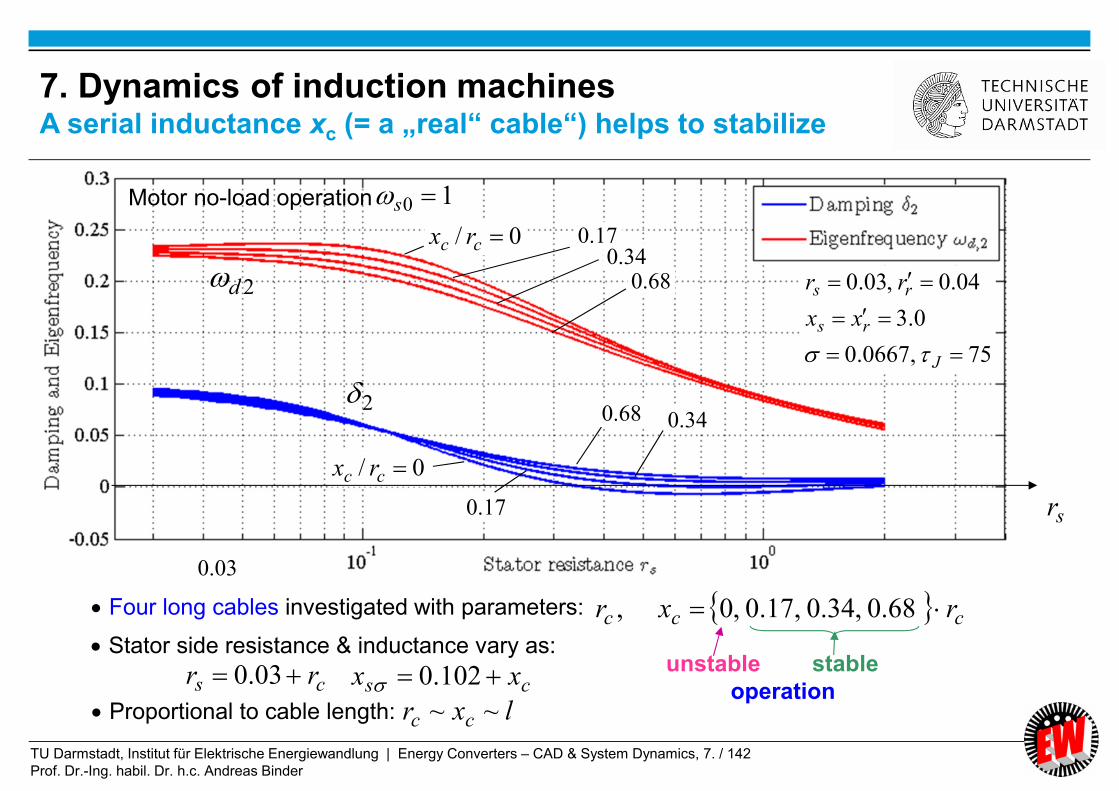
TU Darmstadt, Institut für Elektrische Energiewandlung | Energy Converters – CAD & System Dynamics, 7. / 142
Prof. Dr.-Ing. habil. Dr. h.c. Andreas Binder
75,0667.0
0.3
04.0,03.0
J
rs
rs
xx
rr
0/ cc rx
0/ cc rx
17.034.0
68.0
68.0 34.0
17.0
Motor no-load operation 10 s
Four long cables investigated with parameters: ccc rxr 68.0,34.0,17.0,0,
Stator side resistance & inductance vary as:
cs rr 03.0
Proportional to cable length: lxr cc ~~
03.0
unstable stable
operationcs xx 102.0
sr
2
2d
7. Dynamics of induction machinesA serial inductance xc (= a „real“ cable“) helps to stabilize

TU Darmstadt, Institut für Elektrische Energiewandlung | Energy Converters – CAD & System Dynamics, 7. / 143
Prof. Dr.-Ing. habil. Dr. h.c. Andreas Binder
Summary:
Linearized transfer function of induction machines in
synchronous reference frame
- Small signal theory for transfer function m = F(us, s, ms)
in LAPLACE domain
- Short-circuit rotor cage and related flux time constant explain
“synchronous machine” effect
- Weakly damped oscillation at U/f-control us ~ fs and low speed fs << fsN
- Unstable operation at strongly increased stator resistance rs
- Speed control stabilizes the unstable or weakly damped oscillations
of the induction machine
Energy Converters – CAD and System Dynamics
TU Darmstadt, Institut für Elektrische Energiewandlung | Energy Converters – CAD & System Dynamics, 7. / 144
Prof. Dr.-Ing. habil. Dr. h.c. Andreas Binder
7. Dynamics of induction machines
7.1 Per unit calculation
7.2 Dynamic voltage equations and reference frames of induction machine
7.3 Dynamic flux linkage equations
7.4 Torque equation
7.5 Dynamic equations of induction machines in stator reference frame
7.6 Solutions of dynamic equations for constant speed
7.7 Solutions of dynamic equations for induction machines with varying
speed
7.8 Linearized transfer function of induction machines in synchronous
reference frame
7.9 Inverter-fed induction machines with field-oriented control
Energy Converters – CAD and System Dynamics
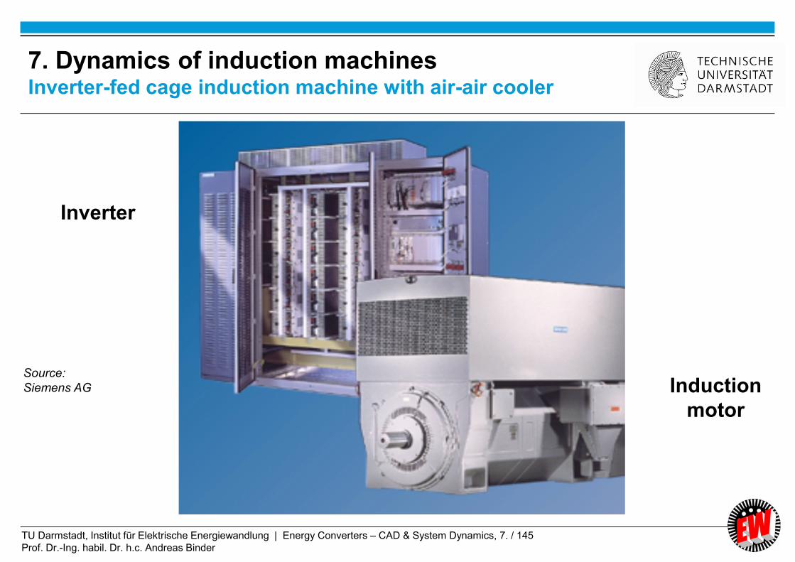
TU Darmstadt, Institut für Elektrische Energiewandlung | Energy Converters – CAD & System Dynamics, 7. / 145
Prof. Dr.-Ing. habil. Dr. h.c. Andreas Binder
Inverter
Induction
motor
Source:
Siemens AG
7. Dynamics of induction machinesInverter-fed cage induction machine with air-air cooler
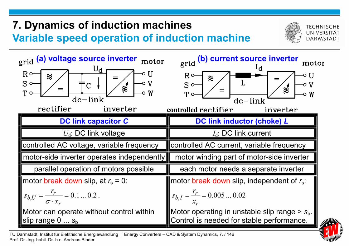
TU Darmstadt, Institut für Elektrische Energiewandlung | Energy Converters – CAD & System Dynamics, 7. / 146
Prof. Dr.-Ing. habil. Dr. h.c. Andreas Binder
7. Dynamics of induction machines
Variable speed operation of induction machine
DC link capacitor C DC link inductor (choke) L
Ud: DC link voltage Id: DC link current
controlled AC voltage, variable frequency controlled AC current, variable frequency
motor-side inverter operates independently motor winding part of motor-side inverter
parallel operation of motors possible each motor needs a separate inverter
motor break down slip, at rs = 0:
2.0...1.0,
r
rUb
x
rs
.
Motor can operate without control within slip range 0 ... sb
motor break down slip, independent of rs:
02.0...005.0, r
rIb
x
rs
Motor operating in unstable slip range > sb. Control is needed for stable performance.
controlled
(a) voltage source inverter (b) current source inverter

TU Darmstadt, Institut für Elektrische Energiewandlung | Energy Converters – CAD & System Dynamics, 7. / 147
Prof. Dr.-Ing. habil. Dr. h.c. Andreas Binder
1)/11(
jRjXs
R
X
UI
rr
r
s
ss
r
rUb
X
Rs
,
r
ropt
X
Rs
Maximum cos at:
is in the stable area of
rising torque with slip
Break-down slip:
Rs = 0
Heyland circle
Re
φ
Us
sb,U
-sb,U
sopt
Is
s = 0 s = ∞
Stable
Im0
s = -∞
Motor
Generator
M
22
2
)(
1
rr
rr
ss
syn
se
XsR
XRs
XU
mM
Current phasor locus at Us = const.
7. Dynamics of induction machinesVoltage-fed induction machine at Rs = 0 (HEYLAND circle)

TU Darmstadt, Institut für Elektrische Energiewandlung | Energy Converters – CAD & System Dynamics, 7. / 148
Prof. Dr.-Ing. habil. Dr. h.c. Andreas Binder
Impressed current Is, so change of voltage drop
of no influence on current locus !
sss IjXR )(
*Re shssyne IUmMP
rr
rrhs
rr
h
rr
h
sh XsjR
XsjRjXI
Xjs
RjX
Xjs
RjX
IU
Uh
rr
rrhssh XsjR
XsRjXIIU
2*
22
22*
)(Re
rr
rhssh
XsR
RsXIIU
2
22
2
)(s
rr
rh
syn
se I
XsR
RsXmM
Ubr
rIb
e sX
Rs
ds
dM,,0
02.0...005.01.0 ,, UbIb ss
.constsI
Ibs ,
bM
)(nM
7. Dynamics of induction machinesTorque-speed-curve of current-fed induction machine

TU Darmstadt, Institut für Elektrische Energiewandlung | Energy Converters – CAD & System Dynamics, 7. / 149
Prof. Dr.-Ing. habil. Dr. h.c. Andreas Binder
j
RjXs
RIXU
rr
rsss
)1(
r
r
r
rIb
X
R
X
Rs
,
r
ropt
X
Rs
Maximum cos at:
is in the unstable area of
falling torque with slip
sb,I much smaller than
at voltage-fed machine
Re
Im
φUs
sb,I
-sb,I
sopt
Is
s = 0 s = ∞
s = -∞
Stable
0ss IjX ss IXj
Motor
Generator
M
Voltage phasor locus at Is = const.
7. Dynamics of induction machines
Current-fed induction machine (Rs = 0)

TU Darmstadt, Institut für Elektrische Energiewandlung | Energy Converters – CAD & System Dynamics, 7. / 150
Prof. Dr.-Ing. habil. Dr. h.c. Andreas Binder
7. Dynamics of induction machines
Voltage vs. current feeding of induction machine
controlled
2.0...1.0
r
rb
x
rs
Impressed
voltage
.constsI
bs
bM
)(nM
02.0...005.0r
rb
x
rs
Impressed
current
Operation
point
cos high low
No influence on motor
power conversion
(a) voltage source inverter (b) current source inverter
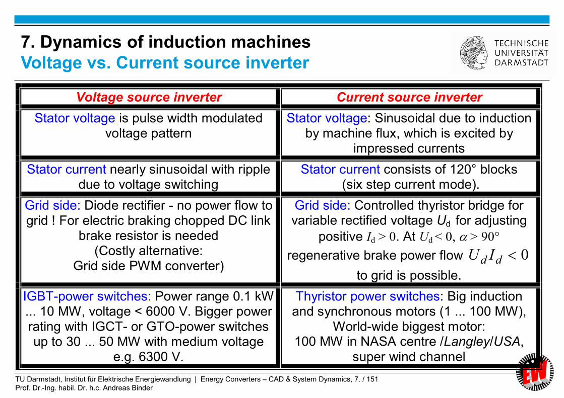
TU Darmstadt, Institut für Elektrische Energiewandlung | Energy Converters – CAD & System Dynamics, 7. / 151
Prof. Dr.-Ing. habil. Dr. h.c. Andreas Binder
Voltage source inverter Current source inverter
Stator voltage is pulse width modulated voltage pattern
Stator voltage: Sinusoidal due to induction by machine flux, which is excited by
impressed currents
Stator current nearly sinusoidal with ripple due to voltage switching
Stator current consists of 120° blocks (six step current mode).
Grid side: Diode rectifier - no power flow to grid ! For electric braking chopped DC link
brake resistor is needed (Costly alternative:
Grid side PWM converter)
Grid side: Controlled thyristor bridge for variable rectified voltage Ud for adjusting
positive Id > 0. At Ud < 0, > 90°
regenerative brake power flow 0dd IU
to grid is possible.
IGBT-power switches: Power range 0.1 kW ... 10 MW, voltage < 6000 V. Bigger power rating with IGCT- or GTO-power switches up to 30 ... 50 MW with medium voltage
e.g. 6300 V.
Thyristor power switches: Big induction and synchronous motors (1 ... 100 MW),
World-wide biggest motor: 100 MW in NASA centre /Langley/USA,
super wind channel
7. Dynamics of induction machines
Voltage vs. Current source inverter

TU Darmstadt, Institut für Elektrische Energiewandlung | Energy Converters – CAD & System Dynamics, 7. / 152
Prof. Dr.-Ing. habil. Dr. h.c. Andreas Binder
Current source inverter operation
NASA Langley
Research Center,
Hampton, Virginia, USA
Synchronous 12-pole
motor as wind tunnel
drive
100 MW, two thyristor
current source inverters
in parallel: 2 x 12.5 kV
36 … 60 Hz
360 … 600/min
Source: ABB, Switzerland
7. Dynamics of induction machinesVariable speed operation of synchronous motor (1)
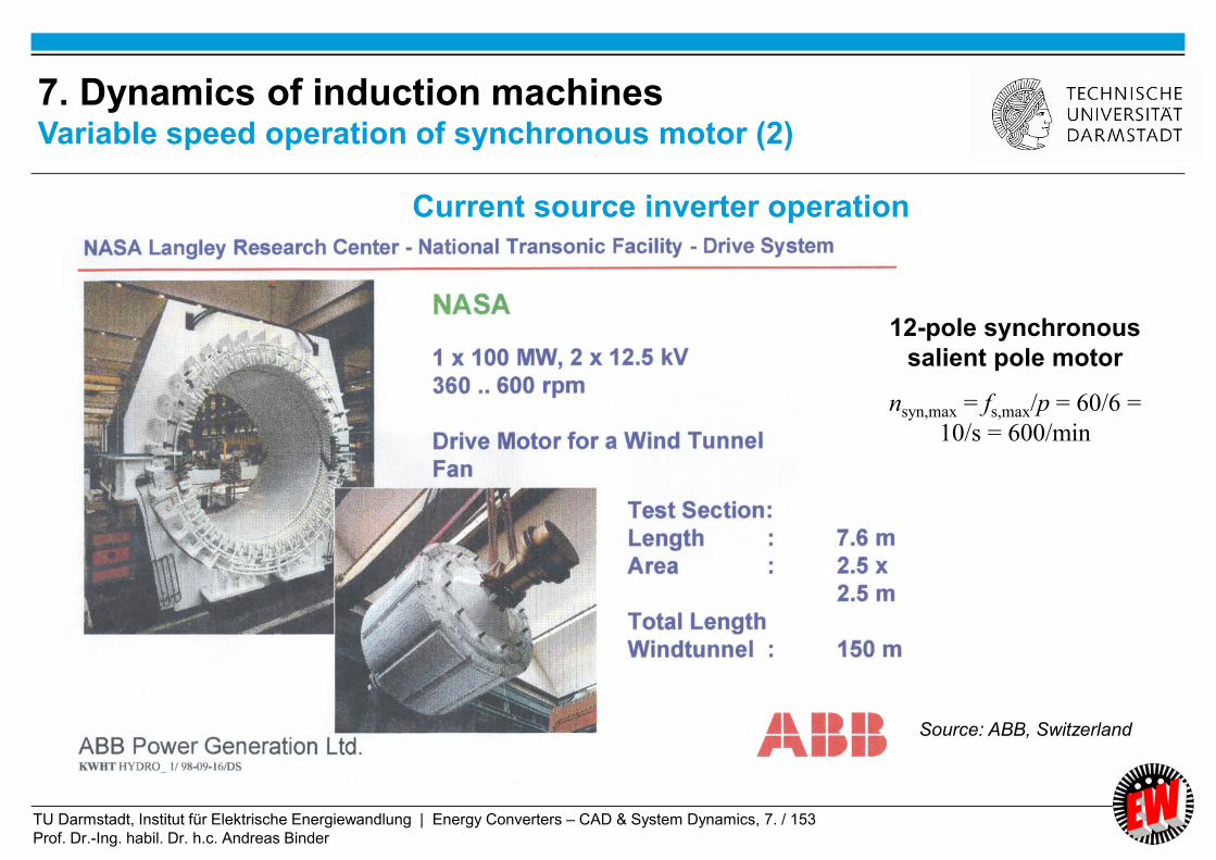
TU Darmstadt, Institut für Elektrische Energiewandlung | Energy Converters – CAD & System Dynamics, 7. / 153
Prof. Dr.-Ing. habil. Dr. h.c. Andreas Binder
12-pole synchronous
salient pole motor
nsyn,max = fs,max/p = 60/6 =
10/s = 600/min
Source: ABB, Switzerland
7. Dynamics of induction machinesVariable speed operation of synchronous motor (2)
Current source inverter operation

TU Darmstadt, Institut für Elektrische Energiewandlung | Energy Converters – CAD & System Dynamics, 7. / 154
Prof. Dr.-Ing. habil. Dr. h.c. Andreas Binder
-
Decomposition of stator space current vector is in torque- and flux-generating
component (F. BLASCHKE, Erlangen & K. HASSE, Darmstadt, 1969)
Main flux excitation h by stator and Torque generation in induction
rotor current space vector machine by main flux and per-
( = magnetizing current im) pendicular current component is
7. Dynamics of induction machines
Principle of field-oriented control (1)

TU Darmstadt, Institut für Elektrische Energiewandlung | Energy Converters – CAD & System Dynamics, 7. / 155
Prof. Dr.-Ing. habil. Dr. h.c. Andreas Binder
Main flux excitation h by magnetizing Torque generation me by perpendicular
current via main inductance current component is via total leakage
inductance
xh .xs
xh
xs x´r
. xs
hh
me
xs
7. Dynamics of induction machines
Principle of field-oriented control (2)

TU Darmstadt, Institut für Elektrische Energiewandlung | Energy Converters – CAD & System Dynamics, 7. / 156
Prof. Dr.-Ing. habil. Dr. h.c. Andreas Binder
Torque generation me :
****ImImIm hshshsshse iiiiim
Long time constant for changing h:
Short time constant for changing : si sss rx /
shsss rxxrx /)(/
By decomposition of the stator current in a flux exciting and a torque generating
component, the control via an appropriate stator voltage space vector us
a) can keep the flux exciting component is= constant ( = constant main flux h)
b) can vary the torque generating component is = variable torque.
As b) changes very fast with short circuit time constant s, we get a dynamic torque
variation = Field-oriented control principle of Blaschke and Hasse (Germany, 1969)
7. Dynamics of induction machines
Principle of field-oriented control (3)

TU Darmstadt, Institut für Elektrische Energiewandlung | Energy Converters – CAD & System Dynamics, 7. / 157
Prof. Dr.-Ing. habil. Dr. h.c. Andreas Binder
Type of machine DC machine Cage induction machine
Control Armature voltage control Field oriented control
Guiding variable Armature voltage Stator voltage
Fixed main flux Separately excited main flux Main flux linkage h
Magnetization Field current if Magnetizing current im
Long flux time constant
Field time constant Lf /Rf Open-circuit time constant
ss rx /
Torque changed by Armature current ia Flux-perpendicular current space vector component
si
Short time constant for torque change
Armature time constant La/Ra Short-circuit time constant
ss rx /
7. Dynamics of induction machinesComparison of speed control of DC and AC induction machine

TU Darmstadt, Institut für Elektrische Energiewandlung | Energy Converters – CAD & System Dynamics, 7. / 158
Prof. Dr.-Ing. habil. Dr. h.c. Andreas Binder
VWUWWVWUs
WWW
WVUs
uauuuauuu
uauau
uauauu
3
2)(
3
2
3
20
3
2
2
2
)()1(3
2
3
2 222aaiaiiaiaii VUWVUs
From stator voltage and flux linkage equations in stator reference frame we get:
h
rsssss
rssr
r
h
s
rrshr
rhsss
ssss
x
x
d
idxiru
d
dix
x
x
ixix
ixix
ddiru
/
0 WVU iii
7. Dynamics of induction machinesRotor flux linkage space-vector from stator quantities
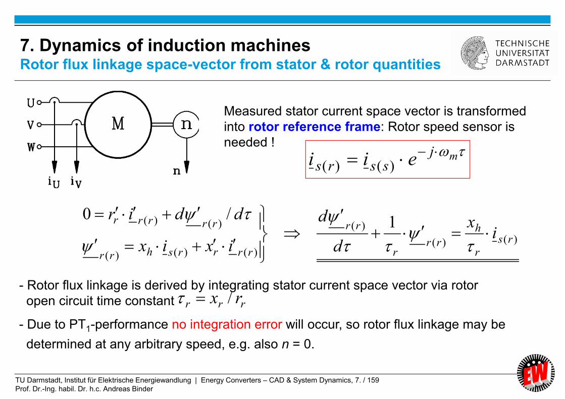
TU Darmstadt, Institut für Elektrische Energiewandlung | Energy Converters – CAD & System Dynamics, 7. / 159
Prof. Dr.-Ing. habil. Dr. h.c. Andreas Binder
)()(
)(
)()()(
)()( 1/0
rs
r
h
rrr
rr
rrrrshrr
rrrrr
ix
d
d
ixix
ddir
mjssrs eii
)()(
- Rotor flux linkage is derived by integrating stator current space vector via rotor
open circuit time constant
- Due to PT1-performance no integration error will occur, so rotor flux linkage may be
determined at any arbitrary speed, e.g. also n = 0.
Measured stator current space vector is transformed
into rotor reference frame: Rotor speed sensor is
needed !
rrr rx /
7. Dynamics of induction machinesRotor flux linkage space-vector from stator & rotor quantities
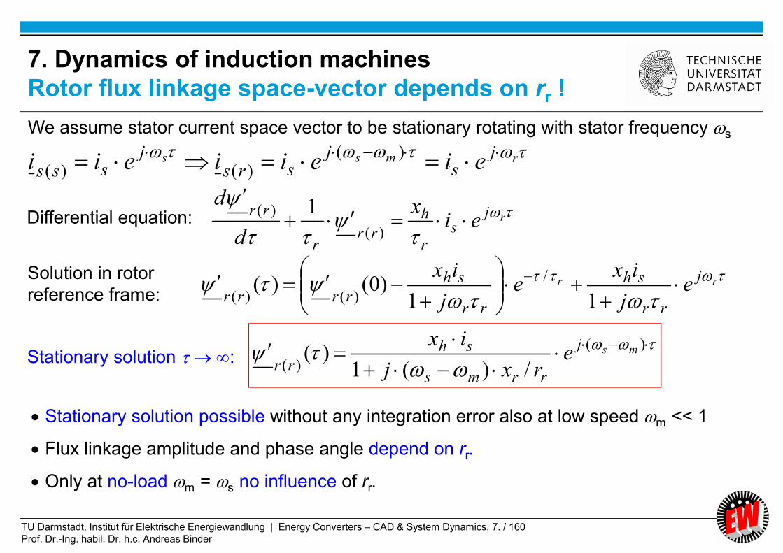
TU Darmstadt, Institut für Elektrische Energiewandlung | Energy Converters – CAD & System Dynamics, 7. / 160
Prof. Dr.-Ing. habil. Dr. h.c. Andreas Binder
rj
sr
h
rrr
rrei
x
d
d
)(
)( 1
We assume stator current space vector to be stationary rotating with stator frequency s
rmss js
jsrs
jsss eieiieii
)()()(
rr j
rr
sh
rr
sh
rrrre
j
ixe
j
ix
11)0()(
/
)()(
Differential equation:
Solution in rotor
reference frame:
)(
)( /)(1)( msj
rrms
sh
rre
rxj
ixStationary solution :
Stationary solution possible without any integration error also at low speed m << 1
Flux linkage amplitude and phase angle depend on rr.
Only at no-load m = s no influence of rr.
7. Dynamics of induction machines
Rotor flux linkage space-vector depends on rr !
TU Darmstadt, Institut für Elektrische Energiewandlung | Energy Converters – CAD & System Dynamics, 7. / 161
Prof. Dr.-Ing. habil. Dr. h.c. Andreas Binder
a) from stator current and voltage:
- At high speed voltage is big and can be measured with high accuracy.
- At very low speed voltage is very low. Measurement errors such e.g. offset
will be integrated to big values, so at low speed this method is NOT useful.
b) from stator current and rotor speed:
- Flux linkage may be determined at any speed, e.g. also n = 0.
- In cage induction machines it is difficult to determine on-line rotor resistance,
which may change between 20°C and e.g. 150°C by 50%:
Thermal model of the machine is needed.
7. Dynamics of induction machinesDetermination of rotor flux linkage
for field oriented control

TU Darmstadt, Institut für Elektrische Energiewandlung | Energy Converters – CAD & System Dynamics, 7. / 162
Prof. Dr.-Ing. habil. Dr. h.c. Andreas Binder
Summary:
Inverter-fed induction machines with field-oriented control
- Voltage source inverter much wider used than current source inverter
- Field-oriented control utilizes separation of current space vector into
flux-parallel and flux-orthogonal component
- Flux-parallel component magnetizes main flux = long time constant
- Flux-orthogonal component magnetizes stray flux = short time constant
- Fast change of torque via fast change of flux-orthogonal current
- Dynamic change of torque via field-oriented current space vector separation
Energy Converters – CAD and System Dynamics