Microphone Handbook - PCB Piezotronics
24
pcb.com | 1 800 828 8840 OVER 30 YEARS OF EXPERIENCE MANUFACTURING ACOUSTIC PRODUCTS Microphone Handbook
-
Upload
khangminh22 -
Category
Documents
-
view
3 -
download
0
Transcript of Microphone Handbook - PCB Piezotronics

pcb.com | 1 800 828 8840
MICROPHONE HANDBOOK
OVER 30 YEARS OF EXPERIENCE MANUFACTURING ACOUSTIC PRODUCTS
Microphone Handbook


3
INTRODUCTION
FUNDAMENTAL CONCEPTS OF SOUNDSound is an audible, mechanical vibration that travels as pressure oscillates through any physical medium; solid, liquid, or gas. In psychology and physiology, sound is the reception of such pressure oscillations and the perception of such by the brain.
Acoustics is the science of sound. This discipline includes sounds and vibrations in the infrasonic, ultrasonic, and audible frequency range. Subcategories of acoustics include: aeroacoustics, bioacoustics, psychoacoustics, music theory, noise control, speech, speech pathology, underwater acoustics, and vibration. Within each of these subcategories, a multitude of experiments and analyses are performed.
Sound pressure is the local pressure deviation from the ambient atmospheric pressure caused by a sound wave. The SI (metric) unit for sound pressure is the Pascal (Pa). In air, sound pressure is measured using a microphone. In water, it is measured with a hydrophone. For humans and other creatures, sound is typically perceived by the ear.
Particle velocity is the physical speed of a parcel of fluid as it moves back and forth about its original position in the direction of travel when a sound wave travels through a medium. Particle velocity is a vector quantity where the direction of the vector is parallel to the motion of the transmitted wave. The SI unit for particle velocity is meters per second (m/s). Particle velocity should not be confused with either the velocity of individual molecules or the speed of sound.
Speed of sound is the speed with which the compressions or rarefactions of a sound wave move in the direction of sound propagation. The speed of sound should not be confused with particle velocity. The sound wave moves relatively fast, while the particles oscillate around their original position with a relatively small particle velocity. The speed of sound in air at standard atmospheric conditions (20 °C and 101.325kPa) is 343 m/s.
The purpose of this handbook is to assist in the basic understanding of the operation of various types of measurement microphones. Topics include: microphone selection, calibration, handling, and an explanation of product specifications. For more information on specific PCB Piezotronics Inc. microphones, please refer to our Acoustic Measurement Sensors and Instrumentation brochure.

4
A Sound Wave, as shown in Figure 1, illustrates how the distribution of particles may appear. The sinusoid plotted above the particle diagram shows how the sound pressure (p on the vertical axis) of the wave varies spatially at a moment in time as it propagates from left to right. The horizontal axis (x) is position, which means the distance between similar parts of the wave is the wavelength (λ). The sound pressure at the positive peak (Apk) in the sinusoid corresponds to the maximum compression of the wave, and the negative peak corresponds to a rarefaction. Typically when measuring sound pressure, the root-mean-square (RMS) sound pressure average is used, which is 1.414 times Apk for a sinusoid. In some instances, the peak-to-peak amplitude is also used (Apk-pk).
Peak Amplitude Peak to Peak Amplitude
Period
p
x
Propagation Direction
Distribution of air particles
PHENOMENON THRESHOLD OF HEARING
BEDROOMAT NIGHT RAINFALL BUSINESS
OFFICE
LIGHT SHOP NOISE
TABLE SAW MOTORCYCLE ROCK
CONCERTTHRESHOLD
OF PAIN
12 GAUGE
SHOTGUN
1 PSI
Sound Pressure (Pa) 0.00002 0.0002 0.002 0.02 0.2 1 2 20 200 2000 6900
Sound Pressure Level
(dB re 20 µPa)0 20 40 60 80 94 100 120 140 160 171
Figure 1: Propagation of sound through space
Table 1: Sound Pressure Levels
Table 1 compares the sound pressure to the sound pressure levels of everyday sound phenomena. The second row shows the magnitude of sound pressure of various phenomena. For humans, sound is not perceived in this way. Rainfall is not perceived as ten times louder than a bedroom at night. The way sound is perceived has a logarithmic relationship compared to the way it is measured. Sound Pressure Level measurements are widely used as a method of displaying acoustic data in a way that is comparable to the way it is sensed. In Table 1, sound pressure level is given and shown in the second row. Sound pressure level dB is 20 times the log of the ratio of the RMS sound pressure over the reference sound pressure of 20 µPa.
Sound intensity is defined as the power flowing through a unit area by means of a sound wave. Sound intensity is a vector quantity where the direction of the vector is parallel to the motion of the transmitting wave. Sound intensity is a sound energy quantity with units of watts per square meter (w/m2).

5
ACOUSTIC ENVIRONMENTS The environment where a sound is propagating, or sound field, has an effect on how sound travels through the medium. Hard or rigid surfaces cause sound reflections and soft or compliant surfaces absorb sound. Reflection and absorption have an effect on the measured or perceived sound. Large cathedrals and gymnasiums have many hard reflective and irregular surfaces that increase the perceived sound pressure level in the room and make it less coherent. Small theatres or recording rooms are designed to absorb sound, restrict reverberations, and restrict echoes to create sound that is more coherent. Sound fields are scientifically categorized in several ways:
Free-fields are those that are free of reflections. Acousticians simulate a free sound field by using an anechoic chamber. Anechoic chambers, such as the one shown in Figure 3, are lined with absorbing wedges that prevent sound waves from being reflected back out into the main area of the room. A free sound field exists if the direct sound from a single source is at least 6 dB greater than the sound reflected off any surface. Anechoic chambers are also isolated from their surroundings in order to be sure that the only source being measured is within the chamber. If a source is located in a free-field, the direct sound of the source dominates the sound field, because there are no reflections.
Sound Intensity Measurements
Measured Average Sound Intensity
Figure 2: Sound Intensity Measurements using two microphones
The sound intensity of a particular sound source in the far field is always normal to the center point of the sound source.Typically, sound intensity measurements require at least two microphones or one microphone and a particle velocity sensor. Devices designed for measurement of sound intensity consist of multiple microphones with the diaphragms oriented at a known fixed distance apart. A sound intensity probe is typically two microphones and uses multiple sound pressure measurements to calculate the particle velocity. Particle velocity is then used to determine the direction of the sound wave, as well as the final sound intensity. Figure 2 shows a diagram of the intensity measurement utilizing two microphones. The measurement, outlined in Figure 2, measures only the sound intensity in the axis of the microphones. Intensity measurements may also be performed by acquiring data from several microphones positioned in an array configuration.
Sound power is a measure of sound energy transmitted per unit time, and is measured in watts (W). It is computed as the product of sound intensity and area. There are many standardized ways of measuring sound power with several microphones. It is an intrinsic and constant property of a source in a specified state, unlike sound pressure that will change depending on the location of the measurement and the environment into which the source is placed.

6
Measurement microphones are the tools used to measure sound pressure in air. Sound pressure is used to determine many characteristics of a sound field. Basic sound pressure measurements are used to learn about sound sources and the effects of the sound on structures in the sound field. Microphones for test and measurement applications are designed to have a flat frequency response, consistent sensitivity, environmental robustness, and high stability. Measurement microphones also have a well-defined calibration method, which has traceability to the fundamental quantities of physics. Microphones for recording audio (studio microphones) do not have the tight specifications or traceability of measurement microphones. This means that a studio microphone, which measures sound pressure, lacks the stability and calibration to perform precision acoustic measurements.
Precision condenser microphones consist of a thin metal membrane in close proximity to a solid metal plate. This forms a variable capacitor that converts the motion of the diaphragm to voltage. When the microphone is exposed to a change in pressure, the resulting motion of the diaphragm causes a change in the capacitance of the microphone. The diaphragm displacement is directly proportional to the exposed sound pressure. Precision condenser microphones are the best designs for accurate acoustic testing. They are very stable over time and temperature or humidity fluctuations. The cartridges are standardized to fit onto a wide range of preamplifiers and handheld calibrators. They are the most widely used microphone type for precision sound level meters.
Figure 3: Anehoic Chamber
Recording studios take advantage of free sound fields to get the best possible recordings of the pure sound of individual vocalists or instruments.
Diffuse fields are sound fields with a uniform sound pressure level. Diffuse sound fields are dominated by sound reflecting off various surfaces. Reverberant rooms, for example, are constructed to simulate a diffuse environment. Cathedrals and gymnasiums take advantage of the effect of diffuse sound fields to increase the perceived loudness of the crowds. In a diffuse field, the sound perceived or measured appears to have no single source.
ACOUSTIC SENSING METHODS

7
To measure the varying capacitance of the microphone due to the changing sound pressure, a constant charge is applied to the backplate. In some condenser microphones, a voltage is used to create a charge differential between the backplate and the diaphragm. These are externally polarized microphones. The motion of the diaphragm (specifically the minute change in the gap due to sound pressure) is proportional to the change in voltage across the microphone terminals. The output voltage of the microphone is directly proportional to the sound pressure on the diaphragm.
The design, manufacture, assembly, and calibration process for condenser microphones is vital to the quality of the final product, and ultimately the quality of the measurements produced. Figure 4 shows a cross-sectional view of a working measurement microphone. It is not a complicated device; however, careful consideration must be given to each of the components to produce a stable, accurate, and durable microphone that will last many years. The most important components of the microphone are the backplate and the diaphragm. They form the capacitor that reacts to sound pressure. More precisely, the change in the gap is proportional to the sound pressure on the diaphragm.
The rest of the microphone components are to support and transmit the signal from the backplate and diaphragm. The body acts as the ground terminal and the backplate nut acts as the signal terminal. The grid cap, or protection grid, prevents damage to the diaphragm. The insulator electrically isolates the backplate from the body and holds the electronic terminals of the microphone in place.
Design
Measurement microphones must be mechanically stable over time, resistant to corrosion, and have limited susceptibility to environmental input. Diaphragm materials must be strong due to the high tension required for operation. Diaphragms must also be lightweight, as added mass lowers the resonant frequency of the microphone. The body and backplate materials are selected for their matching thermal expansion. This minimizes the effect of temperature on sensitivity. The body and grid cap materials must resist corrosion because microphones are sometimes used in extreme environments. All threads for measurement microphones are standardized to be compatible with many measurement devices and adapters.
The dimensions of a microphone are tightly controlled. The gap formed between the diaphram and backplate is on the order of 1 mil (25.4 µm). The surface finish of the front body edge where the diaphragm is tensioned should be pristine. The backplate surface finish should be mirror quality. The diaphragm is about 1/8th the thickness of a sheet of standard cooking aluminum foil. In addition to very delicate parts, any imperfections may cause problems, especially in externally polarized microphones.
Grid Cap / Protection Grid
Insulator
Retaining Nut
Body
Diaphragm
Backplate
Center Electrode / Backplate Nut
Figure 4: Cross-Sectional View of a Working Standard Condenser Microphone

8
Figure 5: Microphone Manufacturing
Manufacturing
Measurement microphone parts must be very clean at the time of assembly. This is of particular concern for externally polarized microphones. In externally polarized microphones, any dust particle or burr on a backplate may cause an arc, which prevents an accurate measurement and may permanently damage the microphone. In prepolarized microphones, oils and contamination of the backplate will cause problems with electret adhesion. To avoid low frequency problems, the vent of the microphone needs to be clear and free of dust and contaminants. During manufacturing, all microphone cartridges are environmentally aged and are exposed to high temperatures to ensure many years of stable operation. In addition, as Figure 5 illustrates, microphones must be handled gently to avoid tears in the delicate diaphragm.
Microphone preamplifiers are required to connect a measurement microphone to a voltmeter, sound meter, or data acquisition system. The primary purpose of a preamplifier (preamp) is to provide an impedance conversion so that the combined system can drive a signal down a long cable. It is important to understand that the specifications of a microphone/preamplifier combination are the result of the most limiting specifications of each component.
The output of a condenser microphone is characterized in two main ways: the sensitivity and the frequency response. Microphone sensitivity depends on diaphragm tension, backplate charge/voltage, and the initial gap. Frequency response is goverened by the same properties as sensitivity, but also by damping (holes in the backplate), and back cavity volume. The scope of manipulating each of these design variables to give the proper specifications is beyond the scope of this handbook and only the very basics of microphone tuning will be discussed.

9
Microphone Cartridge
Preamplifier
Figure 6: Microphone System
Microphone systems and components - Figure 6 - are the combination of measurement microphones permanently coupled with preamplifiers. Microphone systems are provided by many manufacturers as a convenience. Microphones are never used without a preamplifier, so it is important to provide one as part of the system. Often a preamplifier will slightly attenuate the output of a microphone cartridge. This means that if a microphone cartridge and preamplifier are built as a system, they should be calibrated together rather than individually calibrated. A calibration as a whole system removes the need to resolve the individual calibrations at the beginning of a measurement. Measurement microphone systems have a concise list of specifications that are designed for their exact configuration. This means that no computations are required to determine the combined specifications of the system from the constituent parts.
Array microphones - Figure 7 - use either an electret style cartridge or a MEMS microphone cartridge, similar to those used in small electronics. The advantage of array style microphones is that they are easily mass-produced at lower costs. Although, the dynamic range and frequency response of an array microphone is not as flat as a condenser microphone, the low cost makes it an ideal choice for large channel count tests. For ease of use, array microphones are permanently mated to preamplifiers.
Piezoelectric microphones - Figure 8 - or dynamic pressure transducers use a quartz or ceramic crystal as the sensory element. The charge output of the crystal is proportional to the stress place on the crystal. These dynamic pressure transducers may have an integrated amplifier with an ICP® design, allowing the sensor to output a voltage proportional to the input pressure. Although these acoustic sensors have very low sensitivity levels, they are very durable and measure very high amplitude pressure (170 dB or higher). As a result, the noise floor level on piezoelectric microphones is very high (greater than 70 dB) versus condenser and array microphones. This design is suitable for shock, blast, and very high acoustic pressure measurement applications.
Surface microphones - Figure 9 - are used to measure surface pressure and noise in confined areas. A surface microphone should have a faring designed and optimized to reduce wind-induced noise. The flexible design of the faring allows flush mounting or adhesive mounting on flat or curved surfaces. The low profile of a surface microphone allows noise measurements to be taken that minimize interference with the sound field.
Probe microphones are designed for acoustic measurements in: small, hard-to-reach locations, near field acoustic tests, confined areas, and extremely high temperature environments (up to 800 °C). Measurements are taken by isolating the sensor from the source with a thin tube. Probe microphones are tuned to have a flat frequency response in most field types. The small size of the probe makes it less obstructive, no matter which sound field it is placed.
Figure 7: Array Microphones
Figure 8: PCB 106B52 Pressure Sensor
Figure 9: PCB 130B40 Surface Microphone
10
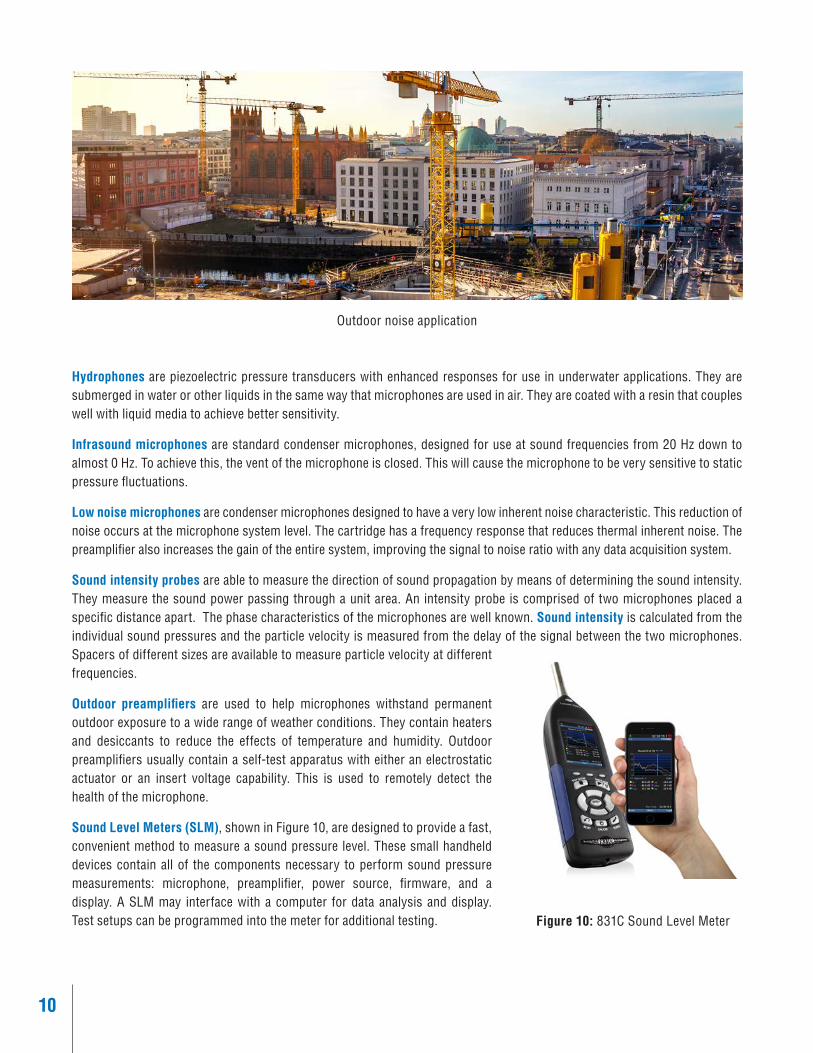
Outdoor noise application
Hydrophones are piezoelectric pressure transducers with enhanced responses for use in underwater applications. They are submerged in water or other liquids in the same way that microphones are used in air. They are coated with a resin that couples well with liquid media to achieve better sensitivity.
Infrasound microphones are standard condenser microphones, designed for use at sound frequencies from 20 Hz down to almost 0 Hz. To achieve this, the vent of the microphone is closed. This will cause the microphone to be very sensitive to static pressure fluctuations.
Low noise microphones are condenser microphones designed to have a very low inherent noise characteristic. This reduction of noise occurs at the microphone system level. The cartridge has a frequency response that reduces thermal inherent noise. The preamplifier also increases the gain of the entire system, improving the signal to noise ratio with any data acquisition system.
Sound intensity probes are able to measure the direction of sound propagation by means of determining the sound intensity. They measure the sound power passing through a unit area. An intensity probe is comprised of two microphones placed a specific distance apart. The phase characteristics of the microphones are well known. Sound intensity is calculated from the individual sound pressures and the particle velocity is measured from the delay of the signal between the two microphones. Spacers of different sizes are available to measure particle velocity at different frequencies.
Outdoor preamplifiers are used to help microphones withstand permanent outdoor exposure to a wide range of weather conditions. They contain heaters and desiccants to reduce the effects of temperature and humidity. Outdoor preamplifiers usually contain a self-test apparatus with either an electrostatic actuator or an insert voltage capability. This is used to remotely detect the health of the microphone.
Sound Level Meters (SLM), shown in Figure 10, are designed to provide a fast, convenient method to measure a sound pressure level. These small handheld devices contain all of the components necessary to perform sound pressure measurements: microphone, preamplifier, power source, firmware, and a display. A SLM may interface with a computer for data analysis and display. Test setups can be programmed into the meter for additional testing. Figure 10: 831C Sound Level Meter

11
MICROPHONE SPECIFICATIONSThere are many specifications that describe the performance of a microphone. This section outlines the most common criteria used to determine if a microphone is appropriate for use in a particular application.
The sensitivity of a microphone is the ratio of the output voltage with respect to the input sound pressure. In precision measurement microphones, this is typically stated at the specific reference frequency of 250 Hz. Sensitivity is expressed in volts per Pascal (mV/Pa), while a sensitivity level is stated in decibels, referring to one volt per Pascal (dB re 1V/Pa).
A reference frequency of 250 Hz is the convention used for sensitivity because the difference in sensitivity in each sound field (free-field, diffuse field, and pressure) at this frequency is minimal. The sensitivity reported for a cartridge alone is an open circuit sensitivity. This is the sensitivity if the microphone was connected to an infinitely high impedance. In practice this isn’t the case. The system sensitivity depends on the microphone capacitance and the input impedance of the preamplifier. The influence of this combination is several tenths of a dB.
When a microphone cartridge is coupled with a preamplifier, the output sensitivity of the microphone/preamplifier system is attenuated by a small fraction of a dB with respect to only the cartridge. Since a microphone can be connected to several preamplifier models, each with its own gain characteristics, the published sensitivity of a microphone cartridge is the open circuit sensitivity. Using the open circuit sensitivity and the known gain of a particular preamp, the system sensitivity can be calculated. The dynamic range of a microphone is defined by the maximum and minimum useable sound pressure levels. A microphone may be exposed to sound pressure levels beyond the limits of its dynamic range, but at these amplitudes, the output of the microphone is not proportional to the input pressure.
Self-noise or inherent noise is measureable by a microphone or microphone system when no external stimuli are present. The output is due to the thermal motion of the diaphragm in a microphone cartridge and the preamplifier noise in a microphone system. A major limiting factor of microphone noise is related to the combined system specifications.
Total Harmonic Distortion (THD) of a microphone system is the ratio of the Root Mean Square (RMS) level of a pure sinusoid at a fundamental frequency with additional harmonics (sinusoids at whole number multiples of the fundamental frequency) to the level of only the pure sinusoid. For microphones, the 3% THD sound pressure level is stated in the specification as an indication of the upper usable sound pressure. A microphone can be used above this sound pressure level, but the output will be affected by distortion, contaminating the measurement.
The frequency response of a microphone refers to its ability to have constant sensitivity over the entire frequency range. The high frequency response of a microphone is governed by the external geometry of the microphone, the design of the backplate, and the tension in the diaphragm. The low frequency response is controlled by the vent.

12
The high frequency response of a microphone is tuned for a specific type of acoustic field. Larger microphones (up to 1”) tend to have a lower high frequency cutoff due to the geometry interfering with the sound field. Smaller microphones (standardized down to 1/8”) tend to have higher cutoff frequencies. Microphones are tuned for three basic acoustic field types; free-field, random incidence, and pressure. The acoustic field response that is optimal for a microphone dictates the microphone designation. Figure 11 illustrates details of the relationships between the three microphone responses.
Figure 12: Diagram of Free-field Microphone Showing Single Source and No Reflections
A free-field microphone is designed for use in an environment without reflections. Anechoic rooms and outdoor spaces without structures are good examples of a free-field. The free-field response is the voltage response with respect to the pressure when exposed to a plane progressive sound wave. A free-field microphone has a flat frequency response with respect to any source whose primary direction is collinear (0° angle of incidence) with the acoustic axis of the microphone. Figure 12 shows a simulation of a free-field response.
Random incidence microphones are designed for use in areas where the sound field comes from any direction and have very uniform directivity characteristics. The random incidence response is the output voltage of the cartridge with respect to an input in a diffuse sound field. Random incidence microphones are best for use in reverberant rooms and manufacturing floors where many sound sources are present. Figure 13 shows a sound field with multiple sources.
Figure 13: Diagram of Random Incidence Microphone with Sources
at Various Angles & Amplitudes
Typical Response of a 1/2” Free Field Microphone
Sens
itivi
ty R
espo
nse
(dB)
Frequency (Hz)Figure 11: Free Field, Random Incidence and Pressure Responses
- Free Field- Random Incidence- Pressure

13
A pressure microphone is designed to be installed in a similar manner as a pressure transducer, which is flush mounted in a wall or coupler. It is unique in that the microphone is not designed to be in the sound field. The strict definition of pressure sensitivity is the output voltage of the microphone when the diaphragm is exposed to a uniform sound pressure. This is shown in Figure 14. Pressure microphones are not tuned to compensate for the microphone being part of the field. Pressure microphones are commonly used as calibration transfer standards.
The electrostatic actuator response is a special response in precision microphones. This response is exhibited when a microphone is excited by an electrostatic actuator. It is typically used to simulate a pressure response. For a specific microphone model, the response of the microphone with respect to each sound field type is proportional to the response of the other sound fields. This includes the electrostatic actuator response. The actuator response is convenient to measure because it is a bench top test that can be performed with very little fixturing. This makes an electrostatic actuator ideal for manufacturers to use to provide a frequency response calibration for a specific microphone.
With any of the typical responses and the proper correction factor, any of the acoustic responses of the microphone can be determined. It is most commonly used by manufacturers as the final frequency response calibration step for a working standard microphone. A microphone is designed to have flat frequency response when used in the field type for which it is named. In most cases it is best to use a microphone for its specific field type.
Figure 14: Typical Installation of a Pressure Microphone
Figure 15: Electrostatic Actuator
There are three exceptions where any microphone can be used in ANY field type: 1. The measurements of interest are at frequencies well below the resonant frequency. Most microphones have a very
flat frequency response in this region.
2. The response is known and can be backed out of the measurements in post processing to simulate a flat frequency response.
3. The microphone is oriented to be most uniformly sensitive to the incident sound over the frequency range
of interest. This means that if the sound field is a free-field with a single source, a free-field microphone should be pointing right at the source. A random incidence microphone should be pointed 30 degrees off axis from the noise source in a free-field because that angle of incidence has the flattest frequency response in a free-field.
Pressure equalization allows the microphones to operate well in varying ambient pressures. The low frequency response of a microphone depends on its equalization vent and how it is exposed to the sound field. As the frequency of the sound being measured drops, the pressure equalization of the vent begins to overtake the measurement capability of the microphone and the output drops off.

14
When microphone vents are blocked or a vent is not present, the response of the microphone has a slight rise as the frequency approaches 0 Hz. A problem in this case is that the microphone is very sensitive to atmospheric fluctuations. An action as simple as a door slamming will cause the microphone system to saturate. The return of the microphone output is completely dependent upon the inherent leaks within a microphone system.
To avoid this, a good practice is to always keep the equalization vent exposed to the sound field. The placement of the vent in the sound field should be carefully considered in highly contaminated environments, high moisture, and almost all environmental applications. In these applications, the vent should only be obscured from the sound field by a properly tested environmental shroud or outdoor preamplifier. These shrouds allow the air that passes into the vent to be treated. Air treatments in an environmental shroud include heaters, filters, and desiccants.
The operation of a condenser microphone is based in the motion of the diaphragm due to changing air pressure altering the capacitance of the sensor. To determine the varying capacitance caused by the diaphragm motion, the capacitor formed by the diaphragm and backplate needs to be polarized. A polarization voltage can be applied in two ways.
Grid Cap
Body
Insulator
Figure 16: Front (or side) Vent (left) and Back Vent (right), Equalization Vent is Denoted by Yellow Arrows
There are two methods for venting a microphone. 1) A front (also referred to as side) vent is a hole specifically drilled into the side of the body. In this case, the equalization vent also consists of the threads in the protection grid. 2) A back vent uses a series of spacers with gaps to allow air to flow around the insulator. A diagram of both of these vent methods is shown in Figure 16.

15
Externally polarized microphones - Figure 17 - have positive 200 volts applied directly to the backplate. This requires additional isolation in the preamplifier to prevent system overload. External polarization makes modular systems, such as sound level meters, difficult to power. They require specialized signal conditioning and cabling to power the preamplifier and the separate polarization voltage required to operate the microphone.
Prepolarized microphones - Figure 18 - use a permanent charge equivalent to 200 volts embedded into an electret material on the backplate of the microphone. By removing the polarization voltage wiring, this simplifies the design of the preamplifier and makes ICP® two wire microphone systems possible. This allows for lower complexity in sound level meter circuitry. Prepolarized ICP® systems are easily interchanged with other test and measurement sensors and may be used with data acquisition systems that also support externally polarized microphones. Prepolarized microphones are becoming increasingly more popular due to their low cost per channel and interchangeability with other test and measurement sensors cables and power supplies.
A major difference between externally and prepolarized microphones occurs when exposed to the same acoustic stimuli, they will have opposite phases. The equivalent voltage of a prepolarized microphone is -200 volts, and external polarization supplies +200 volts. In practice, when making a measurement with an externally polarized microphone, the phase of the output voltage is opposite to that of the sound pressure. Positive pressure on the diaphragm creates a negative output voltage for externally polarized microphones and a positive output voltage for prepolarized microphones.
Figure 17: Externally Polarized Microphone
Figure 18: Prepolarized MicrophoneENVIRONMENTAL EFFECTS
Wind, temperature, relative humidity, and ambient pressure all affect the performance of a microphone. Microphones operate under a variety of environmental conditions, and manufacturers are required to maintain tight tolerances on the environment that affects a microphone. Many acoustic measurements are taken in factories where there are wide variations in temperature, humidity, and barometric pressure. Outdoor measurements are also very common Wind, rain, heat, and ambient (barometric) pressure all affect the performance of a microphone. A prepolarized microphone, with an environmental shroud, as seen in Figure 19, may be required. Understanding each of these phenomena and minimizing their effect is part of the design of a microphone.
Figure 19: Environmental Shroud Microphone

16
Temperature Coefficient
Temperature coefficients are used to characterize the reversible shift in sensitivity resulting from temperature exposure. Standards require this effect to be very small, between ±0.03 dB/°C over a range between -10°C and +50°C. The changes due to minor temperature fluctuations are temporary.
Sensitivity shifts resulting from the temperature coefficient can be exhibited during microphone calibration. When a microphone is handled with warm hands while performing a measurement, the output of the microphone is affected. Gloves should be worn during microphone calibration. After handling a microphone, a minimum of 30-40 seconds should pass before taking a measurement. This allows the microphone to acclimate to ambient temperature.
Ambient Pressure Coefficient
The output of a condenser microphone is affected by the ambient pressure of its surroundings. Ambient pressure is directly affected by elevation and the local weather. A microphone calibrated at sea level will have a different sensitivity when compared to that same microphone calibrated in the mountains. The higher the ambient pressure, the less compliant the back cavity, resulting in a lower sensitivity of the microphone. This is the reason why microphone sensitivity needs to include the laboratory conditions during calibration. Several labs state the sensitivity level of the microphone at reference conditions. The ambient pressure coefficient is standardized to be ±0.03 dB/kPa between 65 kPa and 115 kPa.
Humidity Coefficient
Microphones are resistant to changes in relative humidity. Standards allow a coefficient of ±0.001 dB/%RH from 10% to 90% relative humidity. Humidity is more likely to cause issues when combined with extreme temperature, resulting in condensation forming. When condensation forms on a diaphragm, it causes a change in the mass, which directly changes sensitivity. Malfunctions due to electrical leakage are caused by condensation on the electrical terminals, causing short circuits. For the most part, effects of humidity are reversible. Total failures of externally polarized microphones can happen when humidity causes a short circuit between the diaphragm and backplate.
Mechanical Stability
Precision microphones are mechanically stable. They are designed to maintain their measurement specifications for many years and be resistant to permanent changes. Still, microphones are susceptible to shock and any physical contact with the diaphragm. Dropping or mishandling a microphone may cause a shift in performance. Grid caps protect the microphone diaphragm from both contact and contamination. The grid cap should not be removed unless another protection, a nose cone for example, is installed. Contaminating a diaphragm by touching it with bare hands or fingers will alter the mechanical stability and operating parameters. Dust on the diaphragm is usually insignificant. The mass added by dust is negligible and should not alter the microphone performance.
Temperature Stability
When a microphone is exposed to extreme temperatures (in excess of 120°C), permanent mechanical shifts may occur. Threads may creep and press fits may slip. High temperatures loosen the diaphragm and/or backplate. In prepolarized microphones, the electret applied to the backplate can lose charge. Microphones have stated working and storage temperature ranges. Using or storing a microphone outside of these ranges may cause a permanent shift in sensitivity.

17
MICROPHONE HANDLINGWhen microphones are handled and stored properly, they are stable for many years. With that being said, microphones are fragile and may become damaged with misuse. The diaphragm is made of a very thin metal foil and should be kept clean of dust, dirt, moisture, and any type of imperfection. A grid cap is installed on a microphone to protect the diaphragm. In most cases, the response of the microphone is stated with the grid cap in place and it should not be removed when making measurements. Figure 20 illustrates proper handling of the microphone during calibration.
It is highly recommended that the grid cap is never removed in an attempt to clean a microphone. If precautionary measures are taken to keep the microphone clean, any minor dry dust on the diaphragm should not affect performance. If the microphone becomes highly contaminated with dust or infiltrated with liquid, contact the manufacturer for the best way to proceed.
Any physical contact with a microphone diaphragm can negatively impact its sensitivity and long term stability. The diaphragm of a microphone is resistant to oxidation. Do not touch the microphone diaphragm or let it come in contact with any sharp or pointed object. Never remove the grid cap in the field.
Accessories, such as windscreens and desiccants, will help keep moisture off a microphone. Nose cones help prevent turbulence from influencing the displacement of the microphone diaphragm and allow accurate sound pressure level measurements.
Figure 20: Proper Handling during Calibration of a Precision Condenser Microphone
When preparing for testing, keep the microphone and preamplifier assembled. No tools are needed to fasten or remove the microphone from the preamplifier. When threading the microphone onto the preamplifier, it should only be hand tightened. Always assemble microphones and preamplifiers while seated at a table. Keep the maintenance caps on the preamplifier’s electrical connector when storing them separate from the microphone. When not being used, store microphones and preamplifiers in their protective cases. Never place the preamplifier maintenance cap onto the microphone. This will damage the microphone. With proper handling, a microphone and preamplifier will provide stable and accurate results for many years.

18
FIELD CALIBRATIONPrecision microphones measure sound with a high level of accuracy. These microphones are shipped from the manufacturer with a factory provided calibration certificate, stating sensitivity under laboratory temperature, pressure, and humidity conditions. Changes in atmospheric conditions affect microphone sensitivity. It is recommended that an acoustic calibrator be used to obtain an accurate single point calibration verification of the sensitivity. This should be performed in the actual test environment before and after experimentation.
Calibrators come in two varieties; pistonphones and speakerphones. A pistonphone, Figure 21, is a device used to calibrate microphones with a well-defined change in air volume, which creates sound. As the name suggests, pistonphones typically use one or more pistons driven by a cam at a reference frequency (usually 250 Hz). The piston displacement causes a pressure oscillation within the volume of the pistonphone. The sound pressure level of the pistonphone is calculated from the change in volume due to the pistons, the volume of the pistonphone chamber, and the ambient atmospheric conditions. Errors in pistonphone measurements are primarily due to environmental variables and the front volume of a microphone. Therefore, a pistonphone is better used in tightly controlled environments by well trained personnel.
A speakerphone acoustic calibrator, Figure 22, uses a feedback loop to maintain accurate sound pressure. Speakerphone style calibrators are driven by a small speaker to provide the sound pressure output. Sound pressure in speakerphones is monitored with a reference pressure sensor or the speaker current. These measurements are used as feedback into a controller that adjusts the output for small volume or environmental changes. A speakerphone controls the dynamic pressure specifically, and the resulting calibration math is simple. In most field calibrations, a speakerphone is a simpler and more accurate method of calibration.
Figure 22: Speakerphone Calibrator
Figure 21: Pistonphone Calibrator
Regular field calibration checks establish a history of the operation of the instrumentation. This covers the entire measurement chain from sensor, through cabling and signal conditioning, to data acquisition. This is important because cabling and other parts of the measurement chain can wear out. By referring to a recent calibration check for comparison, a fault in the measurement chain can be identified. Legal metrology measurements require a microphone calibration before and after measurements. This is to discover any large discrepancies in the measurement due to environmental conditions or damage during experimentation. Field calibration helps establish the level of uncertainty associated with the measurements. It gives a historical account of a sensor’s performance and level of accuracy.
Initial equipment calibration should be done when it is first put into service. Subsequent calibrations should be performed prior to each use. This establishes confidence in the measurements when data is questioned. Post test calibration should be performed after taking measurements for long periods of time. This helps determine equipment drift over time and variations due to temperature, humidity, and ambient pressure. All microphones have coefficients related to environmental parameters and any major changes can cause small temporary deviations in sensitivity. Understanding these changes and recording them are important for measurement accuracy.
19
When to perform calibration verification
A microphone calibration should be verified once the measurement chain (sensor, cable, signal conditioner, and data acquisition system) has been completely assembled and after the sensor has acclimated to the measurement environment. If a microphone is checked before it is acclimated, the operational sensitivity will not be the same as the pretest calibration sensitivity. The drift of a microphone due to a difference of 5°C can be up to 0.15 dB. Be sure to read the manual of the particular calibrator used and follow all directions. Allow the calibrator to run for a minimum of 30-40 seconds to assure a stable signal is being applied to the microphone. Do not touch the microphone/preamplifier system during calibration. Body heat is often sufficient enough to produce a significant change in sensitivity when performing field calibration.
How often should accredited calibration be performed?
The duration between calibrations of instrumentation is a balance between risk and cost. A shorter time period between calibrations by an accredited laboratory will lower the risk of questionable measurements. Annual calibration is highly recommended for all sensors. Equipment used on a daily basis should have a shorter calibration cycle than equipment used once a month.
Several other factors should be considered when determining the calibration interval. Consider the cost of necessary corrective measures required if an instrument is not reliable over a long period. As components age and equipment undergoes changes in temperature or mechanical stress, performance gradually degrades. This is called ‘drift’. A condenser microphone’s design, minimizes the probability of drift but cannot eliminate it completely. Regularly performed accredited calibrations provide trend data and will document and highlight changes attributable to wear and drift. Microphones can be damaged when mishandled or inadvertently exposed to inclement conditions. When this happens, measurement results become unreliable. Drift cannot be eliminated but it can be detected and mitigated through the laboratory calibration process.
Exposure to hazardous conditions is another important factor to consider during calibration. Extreme climatic conditions such as vibration, ionizing radiation, electrial shock, and mechanical shock, adversely affect microphone performance. Microphones must be stored and transported with extreme care. Do not allow microphones to roll around unprotected in a toolbox.Lack of proper training will also affect microphone performance. An improperly trained technician may mishandle a microphone during calibration checks, drop the sensor, or unknowingly damage the microphone diaphragm. If legal requirements exist, or if changes in an instrument over time needs to be documented, then data from the initial calibration is required. The initial calibration verification data should be kept along with annual re-calibration data. A comparison of the results over the years can be tracked. Missing an annual calibration can put an entire two years’ worth of measurements in jeopardy if an undetected drift occurred.

20
ACOUSTIC MEASUREMENT STANDARDS
Microphone Standards
The IEC 61094 Series defines condenser microphone standards and details important features such as thread size, grid cap dimensions, and minimum specification requirements. The series contains two distinct types of microphones.
Laboratory standard (LS) microphones are designed to provide an extremely high level of stability. They are typically used in a very stable environment, and thus may be used to transfer a calibration. The laboratory standard microphone basic specifications are called out in IEC 61094-1, and are usually calibrated via pressure reciprocity or free-field reciprocity (IEC 61094-2 and 3 respectively). These methods are forms of primary calibration. This means that they generate the open circuit sensitivity of a microphone from its raw electroacoustic parameters and the acoustic parameters used in the method of calibration.
Working standard (WS) microphones, like the one in Figure 23, are those with a more robust design for use in field testing. These microphones are used in most test and measurement applications. They are very stable over a wide range of environmental conditions. Basic specifications for WS microphones are found in IEC 61094-4. WS microphones are usually calibrated by secondary methods using a calibrated standard to transfer calibration. IEC 61094-5 (Secondary Pressure Calibration), 61094-6 (Electrostatic Actuator Calibration), and 61094-8 (Secondary Free-Field Calibration) are used individually or in concert with one another to provide the sensitivity and frequency response of working standard microphones. IEC 61094-4 specifies dimensional tolerances for precision condenser microphones to ensure interchangeability between different manufacturers.
For both LS and WS microphones, an acoustic field designation further identifies the microphone along with a dimension designation. One inch, ½ inch, and ¼ inch microphones are noted as 1, 2, or 3. F, D, and P denote free-field, random incidence (or diffuse field), and pressure respectively. This means that a ½” working standard free-field microphone is denoted as a WS2F microphone. When this type of modifier is stated in the microphone specification it must, at a minimum, meet the requirements called out in the IEC 61094 standards. To be competitive, manufacturers may choose to further tighten the specifications of a microphone, but the minimum requirements of the standard must still be met.
Calibrator Standards
Handheld sound calibrators (speakerphones and pistonphones) are very important tools to help end users keep track of the sensitivity of a microphone in various conditions. Calibrators emit a pure tone of a constant frequency and sound pressure. This is used to calculate the sensitivity of the test microphone. IEC 60942 describes the performance requirements of the various classes of sound calibrators. Laboratory standard (Class LS) calibrators are based on using laboratory standard microphones for pattern testing, and have the most stringent specifications. Class 1 and 2 sound calibrators, by comparison, have slightly relaxed tolerances and are used in field calibrations.
Sound Level Meter Standards
There is no such thing as a Class 1 microphone according to the IEC 61672 standards. The IEC 61672 (ANSI/ASA S1.4) Sound Level Meters Series describes the minimum measurement capability, calibration, and pattern testing for Class 1 or 2 sound level meters. Sound level meters conforming to the requirements of these standards must meet specific frequency response
Figure 23: Working Standard Microphone
(PCB Model 377B02)

21
characteristics when placed in various sound fields. This is regardless of microphone type, free-field or diffuse field. These standards control equipment that is typically used in the human hearing range (20 Hz to 20 kHz). The difference in Class 1 vs Class 2 sound level meters lies in the tolerance limits. Class 2 meters have equal or less stringent tolerances when compared to Class 1 meters.
Acoustic Standards
Ultimately, the standards of interest are not the equipment standards, but the standards used to take measurements. The table below lists some of the common acoustic measurement standards. This is by no means a comprehensive list. There are many standards surrounding the noise testing of specific devices, as well as subjective tests for sound equipment. Be aware that various companies may have their own, more stringent, versions of these standards, as they may be looking for something specific in their measurement application.
TERMINOLOGY THESE STANDARDS DEFINE THE TERMINOLOGY, MEASUREMENT POINTS (FREQUENCIES), AND REPORTING VALUES (DECIBELS) USED IN ACOUSTIC MEASUREMENTS
ANSI s1.1-1994 Acoustical terminology
ANSI/ASA s1.6-1984 Preferred frequencies, frequency levels, and band numbers for acoustical measurements
ANSI/ASA s1.8-1989 Reference quantities for acoustical levels
BUILDING ACOUSTICS THESE STANDARDS DESCRIBE THE TESTING METHODS USED FOR BUILDINGS AND ROOMS
ASTM e 90-09 Standard test method for laboratory measurement of airborne sound transmission loss of building partitions and elements
ISO 10848-2006/Parts 1 to 4 Laboratory measurement of the flanking transmission of airborne and impact sound between adjoining rooms
ISO 15712-2005/Parts 1 to 4 Estimation of acoustic performance of buildings from the performance of elements
ACOUSTIC MATERIAL TESTING THESE STANDARDS DESCRIBE THE TESTING OF MATERIALS USED TO CREATE ACOUSTIC OR SOUND DEADENING STRUCTURES
ASTM C 423-09a Standard Test Method for Sound Absorption and Sound Absorption Coefficients by the Reverberation Room Method
ASTM e 1050-08 Standard test method for impedance and absorption of acoustical materials using a tube, two microphones and a digital frequency analysis system
ENVIRONMENTAL NOISE THESE STANDARDS OUTLINE EXPERIMENTATION IN OUTDOOR OR ENVIRONMENTAL NOISE
ISO 9613-1:1993 Acoustics — attenuation of sound during propagation outdoors — part 1: calculation of the absorption of sound by the atmosphere
ISO 1996-1: 05 Acoustics — description, measurement and assessment of environmental noise — part 1: basic quantities and assessment procedures
ISO 1996-2: 07 Acoustics — description and measurement of environmental noise — part 2: determination of environmental noise levels
SOUND POWER MEASUREMENTS THESE STANDARDS DESCRIBE METHODS OF DETERMINING THE SOUND POWER RADIATED BY A STRUCTURE
ISO 3741:2010 Acoustics -- determination of sound power levels and sound energy levels of noise sources using sound pressure -- precision methods for reverberation test rooms
ISO 3743-2:1994 Acoustics -- determination of sound power levels of noise sources using sound pressure -- engineering methods for small, movable sources in reverberant fields -- part 2: methods for special reverberation test rooms
ISO 3745:2012 Acoustics -- determination of sound power levels and sound energy levels of noise sources using sound pressure -- precision methods for anechoic rooms and hemi-anechoic rooms

22
What is the frequency range of interest?
Frequencies above 20 Hz and up to 5 kHz can be measured by all ½” and ¼” condenser microphones, regardless of field type, with a reasonably flat frequency response. Measurements above 5 kHz to 20 kHz for ½” microphones require knowledge of the acoustic environment. Single sources or measurements in anechoic rooms should use a free-field microphone, while multiple sources or diffuse sound fields would benefit from the use of a random incidence microphone. Higher frequencies, up to 100 kHz, require the use of specialized ½” microphones or ¼” microphones. If the response of the microphone is intended to be corrected in the measurements in post processing, then the field type of microphone is less important. It is always preferred to use a microphone in the sound field in which it was designed.
What are the sound pressure levels of interest? Determine the Sound Pressure Level (SPL) range of the intended experiment and compare them with the dynamic range of various microphones. Very low SPL (less than 15 dBA) may require a specialty low noise microphone system and either an anechoic chamber or low background noise environment. Very high SPL (greater than 130 dB) may require a ¼” microphone. When trying to measure very high SPLs, be aware that the preamplifier may cause the system to clip before the distortion point of the microphone cartridge. If a microphone system specification is available, use that to verify the dynamic range.
MICROPHONE SELECTIONThere are some general guidelines that should be used to determine which microphone would give the best results for the intended measurements. The following questions should be posed before setting up an experiment.
If this measurement has been performed before, what microphone was used for those measurements?
This can greatly simplify the sensor selection process. If this measurement has been performed before, regardless if the correct microphone was used, the microphone used prior should be used again. Maintaining repeatability with existing measurements is more important, in most cases, than selecting precisely the correct microphone.
Therefore, if a better suited microphone is available, additional measurements should be taken to determine the capability of the new microphone in comparison to the original. Various advantages may exist, in using a new microphone, that cannot be known until its performance is assessed and compared to existing data.
Is the measurement being performed based on existing standards that might call out specific equipment?
ISO and ANSI standards sometimes call out specific microphone types (free-field, random incidence, ½”, ¼”, Working Standard vs Laboratory Standard). If the measurements in question are being reported to a governing body, the equipment used must be what is dictated by the standards.
23
How many data channels are required for the measurement?
If one or two microphones are being used, a precision condenser microphone or microphone system will provide the best overall measurements. Array microphones can be used in cases where high channel counts would increase the cost of the system beyond what is feasible.
Using many sensors in an array, whether array microphones or precision condenser microphone systems, is made easier through the use of Transducer Electronic Data Sheets (TEDS). TEDS stores the sensor calibration information right on a chip in the preamplifier. This data can then be polled by a TEDS capable DAQ, and read directly into the software. It is important to note that TEDS is not built into the microphone element itself but into the preamplifier. If a mated microphone system is separated into its constituent preamplifier/microphone pair, the TEDS stays with the preamplifier and will not be correct for another microphone cartridge.
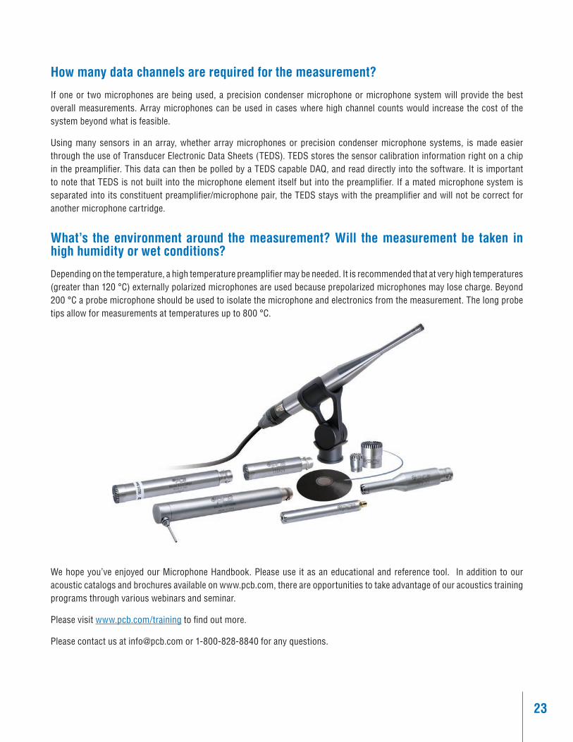
What’s the environment around the measurement? Will the measurement be taken in high humidity or wet conditions?
Depending on the temperature, a high temperature preamplifier may be needed. It is recommended that at very high temperatures (greater than 120 °C) externally polarized microphones are used because prepolarized microphones may lose charge. Beyond 200 °C a probe microphone should be used to isolate the microphone and electronics from the measurement. The long probe tips allow for measurements at temperatures up to 800 °C.
We hope you’ve enjoyed our Microphone Handbook. Please use it as an educational and reference tool. In addition to our acoustic catalogs and brochures available on www.pcb.com, there are opportunities to take advantage of our acoustics training programs through various webinars and seminar.
Please visit www.pcb.com/training to find out more.
Please contact us at [email protected] or 1-800-828-8840 for any questions.

3425 Walden Avenue, Depew, NY 14043 USA pcb.com | [email protected] | 800 828 8840 | +1 716 684 0001
© 2021 PCB Piezotronics - all rights reserved. PCB Piezotronics is a wholly-owned subsidiary of Amphenol Corporation. Endevco is an assumed name of PCB Piezotronics of North Carolina, Inc., which is a wholly-owned subsidiary of PCB Piezotronics, Inc. Accumetrics, Inc. and The Modal Shop, Inc. are wholly-owned subsidiaries of PCB Piezotronics, Inc. IMI Sensors and Larson Davis are Divisions of PCB Piezotronics, Inc. Except for any third party marks for which attribution is provided herein, the company names and product names used in this document may be the registered trademarks or unregistered trademarks of PCB Piezotronics, Inc., PCB Piezotronics of North Carolina, Inc. (d/b/a Endevco), The Modal Shop, Inc. or Accumetrics, Inc. Detailed trademark ownership information is available at www.pcb.com/trademarkownership.
TM-AC-MicHandbook-1021