
Industrial Vibration Sensors, Switches & Instrumentation - PCB ...
202
Industrial Vibration Sensors, Switches & Instrumentation Accelerometers, Vibration Transmitters & Switches, Pressure Sensors and Accessories visit us at www.imi-sensors.com Toll-free in USA 800-959-4464 716-684-0003 IMI Sensors - A PCB Piezotronics Division
-
Upload
khangminh22 -
Category
Documents
-
view
5 -
download
0
Transcript of Industrial Vibration Sensors, Switches & Instrumentation - PCB ...

Industrial Vibration Sensors,Switches & InstrumentationAccelerometers, Vibration Transmitters & Switches, Pressure Sensors and Accessories
visit us at www.imi-sensors.com Toll-free in USA 800-959-4464 716-684-0003
IMI Sensors - A PCB Piezotronics Division

Energy & Power GenerationIMI® Sensors specializes in the design and manufacture of innovativesensors and associated signal conditioning instrumentation to meet thedemanding requirements of the energy, power generation, reciprocatingequipment, oil & gas and petrochemical industries.
In particular, IMI's instrumentation is ideally suited to detect andmeasure dynamic pressure and vibration of gas turbines in extreme heatenvironments. Our high temperature pressure sensors andaccelerometers are intrinsically safe formeasuring combustion dynamicsand vibration levels in gas turbines.
Process Monitoring & ProtectionIMI's line of 4-20 mA vibration transmitters will interface directly withyour PLC, DCS or SCADA system so data can be easily monitored andanalyzed. Our electronic vibration switches and smart switches eliminatefalse trips, making it a technically superior option to traditionalmechanical switches.
IMI's impact detection products offer the ultimate machine protection,including the Bearing Fault Detector, which provides early warning ofimpending bearing failure. In addition, IMI's DIN rail devices aredesigned to facilitate vibrationmonitoringwith equipment that is familiarto the process control technician. Signals representing overall vibrationlevels are monitored with threshold points providing the judgment foralarm, control, or shutdown.
Predictive MaintenanceIMI® Sensors is a global leader in the manufacture of low cost industrialaccelerometers for machinery condition monitoring and predictivemaintenance requirements. General purpose, precision, low frequency,high frequency, seismic and multi-axis applications are supported withan extensive product offering including piezoelectric accelerometers,cables and accessories.
IMI's industrial accelerometers are relied on throughout theworld to helpoptimize machinery performance and to keep maintenance expense anddowntime to a minimum. IMI® serves a wide range of industries,including those with intrinsically safe requirements; virtually all of ourproducts are available with certifications for us in hazardous areasthrough ATEX and CSA.

visit us online at www.imi-sensors.comToll-free in USA 800-959-4464 716-684-0003
i
Table of Contents
Motor Vibration. . . . . . . . . . . . . . . . . . . . . . . . . . . . . . 3Pumps & Submersible Pumps . . . . . . . . . . . . . . . . . . . 9Paper Machines & Conveyors. . . . . . . . . . . . . . . . . . 15Combustion Dynamics Instrumentation . . . . . . . . . . 21Protecting Cooling Towers & HVAC Systems . . . . . . 29Gearboxes . . . . . . . . . . . . . . . . . . . . . . . . . . . . . . . . . 33Wind Turbine Condition Monitoring & Assessment . . 37Oil & Gas Wells and Pipelines . . . . . . . . . . . . . . . . . 47Vibratory Screens & Feeders . . . . . . . . . . . . . . . . . . 51Reciprocating Machinery . . . . . . . . . . . . . . . . . . . . . 55Machine Tool Spindles . . . . . . . . . . . . . . . . . . . . . . . 59Steel Rolling & Annealing. . . . . . . . . . . . . . . . . . . . . 63Rotary Screw Compressors. . . . . . . . . . . . . . . . . . . . 67Nuclear Power Instrumentation . . . . . . . . . . . . . . . . 71Shock Monitoring . . . . . . . . . . . . . . . . . . . . . . . . . . . 77
Low Cost ICP® Accelerometers. . . . . . . . . . . . . . . . . 82Multi-Axis ICP® Accelerometers. . . . . . . . . . . . . . . . 90Precision ICP® Accelerometers. . . . . . . . . . . . . . . . . 92Quartz ICP® Accelerometers . . . . . . . . . . . . . . . . . . . 98High Temperature Accelerometers . . . . . . . . . . . . . 100Embeddable Accelerometers . . . . . . . . . . . . . . . . . 110Vibration Transmitters. . . . . . . . . . . . . . . . . . . . . . . 112Programmable Vibration Transmitters . . . . . . . . . . 122Bearing Fault Detector . . . . . . . . . . . . . . . . . . . . . . 124Reciprocating Machinery Protector . . . . . . . . . . . . 126Vibration Switches . . . . . . . . . . . . . . . . . . . . . . . . . 128USB Programmer Kits . . . . . . . . . . . . . . . . . . . . . . . 136Pressure Sensors. . . . . . . . . . . . . . . . . . . . . . . . . . . 138Echo® Wireless Vibration System . . . . . . . . . . . . . 142Enclosures . . . . . . . . . . . . . . . . . . . . . . . . . . . . . . . . 150Signal Conditioners. . . . . . . . . . . . . . . . . . . . . . . . . 154In-line Charge Converters . . . . . . . . . . . . . . . . . . . . 158Portable Calibration Units. . . . . . . . . . . . . . . . . . . . 160Mounting Hardware . . . . . . . . . . . . . . . . . . . . . . . . 162Cables & Connectors. . . . . . . . . . . . . . . . . . . . . . . . 165Breakaway Safety Connector . . . . . . . . . . . . . . . . . 176
Accelerometer Selection Worksheet . . . . . . . . . . . 178Accelerometer Selection Guidelines . . . . . . . . . . . 179Technical Information - Accelerometers. . . . . . . . . 182Technical Information - Pressure Sensors . . . . . . . 185
Products By Application.................1
Products By Technology...............81
Technical Information................177
IMI Sensors: A Division of PCB Piezotronics, Inc.IMI® industrial sensors are used to spot imbalance, bearing faults andmisalignment by measuring machine vibration, providing early faultdiagnosis thus reducing downtime. Our vast product line interfacesdirectly with data acquisition equipment including online systems andhandheld data collectors.
IMI® offers a full line of piezoelectric accelerometers, pressure sensors,velocity sensors, 4-20 mA vibration transmitters, switches, relays,cables, displays and accessories. Virtually all of our products areavailable with hazardous area certifications through CSA and ATEX. Weare proud to state that all of our sensors are made in the USA and backedby our Total Customer Satisfaction policy.
At IMI Sensors we have experienced, dedicated staff members ready andwaiting to exceed your expectations. This customer orientedorganization makes it easier for you to find the best product and gettechnical support as fast as possible. Please call our dedicated hotline atany time at 800-959-4464; we look forward to helping you be successful.
New Product Releases..................viTable ofContents

visit us online at www.imi-sensors.comToll-free in USA 800-959-4464 716-684-0003
ii
IMI Sensors: Product Catalog
Using this CatalogWelcome to the newest edition of the IMI Sensors Product Catalog. We have made a number of improvementsand additions to this catalog that we hope will enhance the usability, as well as provide a valuable resourcebeyond the purchasing of our products.
This catalog has two main sections (Application and technology) to give you insight beyond the products andinto the applications for which they are designed. You will also find helpful “Tips from Techs” throughout thecatalog to offer deeper insight into common issues with various applications and product categories.
The third section provides valuable technical information on sensor selection, hazardous area approvals,mounting techniques and sensor construction.
Products By TechnologyThe Products By Technology Section of this catalog focuses on the different sensing technologies that IMI Sensors offers,grouped by product type (ie: Precision ICP®, Low Frequency ICP®, Pressure Sensors, Cables & Connectors, Enclosures). Youwill find complete information on each product including: complete specifications, technical drawings and in some cases“actual size” product photographs.
Technical InformationThe Technical Section features useful reference materials to assist you in selecting sensors, as well as installation andmounting techniques. The Accelerometer Selection Worksheet will help you choose the right sensor for your needs. You willalso find illustrations of typical Industrial Vibration Measurement Systems to provide an overview of the components neededfor specific systems.
Sensor Placement IllustrationsAt the beginning of each application section you will find a SensorPlacement Illustration. These illustrations are designed to give you someinsight into some typical measurement points for that specific application.
Suggested sensor placement is indicated using the red dot shown: ( )
Please note that illustrations represent only suggested sensor placements.
Please contact an IMI® application engineerfor complete information.
Products By ApplicationThe Application Section of this catalog provides overviews of the most typical applications of IMI Sensors. Each applicationfeatures products that are proven for the specific needs of the given application. You will also find useful information on themethods for taking measurements, as well as a Sensor Placement Illustration to give you an overview of suggestedmeasurement points for that application. You can also request individual applications in brochure form by contacting an IMI®representative, or by visiting www.imi-sensors.com.
Model Number Index
visit us online at www.imi-sensors.comToll-free in USA 800-959-4464 716-684-0003
iii
Model Number IndexThis index provides page references for accelerometers, signal conditioners and test equipment. For cables, mounting hardware andaccessory items, please check the appropriate sections listed in the table of contents.
PCB® Platinum Products are available with our Lifetime Warranty and fast delivery. If anyPCB® Platinum Product ever fails, PCB® will repair, replace or exchange the product at nocharge. For U.S. customers orders up to 10 units will ship in three days or less and ordersover ten units will ship in thirty days or less. IF NOT, YOUR SHIPPING IS FREE!Visit www.imi-sensors.com for complete details.
Our Platinum products represent some of our most popular models and can be used in a wide range of applications.As you browse this catalog, you will find Platinum products indicated with the “Platinum Shield” icon (right).
Red Part Numbers Indicate Platinum Stock Products
086D29.....................................................44102M205 .................................23, 138, 139121A44..............................23, 49, 138, 1391400 Series..............................................421500 Series..............................................451503 Series........................................49, 57171M01..................................................141171 Series ................................................24176M03 .........................................140, 141176M07 .........................................140, 141176M09 .........................................140, 141176M12 .........................................140, 141176M0X Series........................................25176MXX Series........................................252100E11 ...................................................443711 Series ............................................453713 Series ............................................453741 Series..............................................45357B53.............................................73, 102357B54.............................................73, 102357B61.............................................74, 105357B69.............................................74, 105357B81 ...................................................103357B82 ...................................................103357B83 ...................................................103357B8X Series .......................................103357C71.............................................75, 104357C72.............................................75, 104357C73.............................................75, 104357C7X Series .......................................104357D90 ....................................76, 108, 109357D91 ....................................76, 108, 109357D9X Series ........................................26422E35 .............................................76, 159422E36 .............................................76, 159422E55/D.........................................24, 159422E65/A...................................73, 74, 159422E66/A...................................73, 74, 159422M182 ...................................25, 75, 158422M183..................................................755300 Series..............................................42
600A02.....................................................65600A12...............................................36, 69600A15 Kit.......................................54, 136600A16 Kit .............................................136600A20...................................................146600A21 Kit .............................................137600B1X.....................................................26601A01 ..............................................82, 83601A02 ..................................18, 39, 88, 89601 Series ................................................39602D01........................5, 19, 39, 61, 82, 83603C00...............................................88, 89603C01.....5, 11, 19, 32, 39, 61, 66, 82, 83603C02...............................................88, 89604B31...........................................5, 90, 91605B01...............................................90, 91607A01.....................................................83607A11 .................. 11, 20, 35, 62, 66, 84, 85607A61 ..................................19, 61, 62, 85607A Series...........................11, 13, 19, 39608A11 .....................11, 13, 32, 64, 84, 85612A01.....................................................26621B40.........................................69, 96, 97622B01........................5, 35, 66, 69, 92, 93623C00...............................................96. 97623C01.........................................61, 96, 97624B01...............................................92, 93625B01............................18, 35, 61, 92, 93625B02.........................................18, 94, 95625B61 .....................................................61626B01......................18, 35, 39, 64, 94, 95626B02.........................................18, 94, 95627A01 ..............................................98, 99628F01 ...............................................98, 99629A31...........................................5, 90, 91640B01..........................6, 32, 64, 112, 113640B02...........................................112, 113640 Series ................................................13641B01 ..........................................112, 113641B02...........................................112, 113642A01...........................................118, 119
642A11...........................................118, 119642A61...........................................118, 119642 Series ................................................53645B00...........................................112, 113646B02............................................112,113649A01 ....................................57, 126, 127649A03..............................................vi, 122649A04..............................................vi, 123653A01............................................114,115660 Series ...............................39, 110, 11166103LPZ1 .............................................11066292CNZ1 ............................................11066332APZ1.............................................110670A01......................................ix, 142, 147672A01......................................ix, 143, 147673A01......................................ix, 143, 147682A00...........................................6, 13, 20682A01...............................................6, 154682A02...................................................155682A06...........................................156, 157682A09...................................................120682A16.............................................66, 157682B03 ............................6, 13, 32, 53, 121682B05 ..........................7, 20, 64, 124, 125683A.......................................................114684A Series ...........................................114685A07 ....................................31, 134, 135685A08.............................................31, 135685A Series ...........................................128685B Series ........30, 31, 53, 128, 132, 133686B01 ..............................31, 53, 130, 131686B11...........................................130, 131686B Series ...................................128, 129691A50/06 ............................................151691A50/12 ................................14, 70, 151691A50 Series .......................................151691A51/01 .............................................150691A51/02 ............................................150691A51/03 .............................................150691A51/04.................................14, 70, 150691A51 Series .......................................150
691B41.....................................70, 153, 154691B42 ..............................14, 70, 153, 154699A02...................................................161699A06...................................................1608180-CUTO...............................................438180-RE110A ...........................................438180-SH2 .................................................438180-SH4 .................................................43831............................................................41962............................................................40HT602D01 ...................vii, 17, 65, 100, 101HT602D11 ...................vii, 17, 20, 100, 101HT602D61 ...................vii, 17, 20, 100, 101HT622A01..........................................17, 26HT628F01...................................17, 65, 101HT7000 Series .........................................40EX600B13.................................vii, 106, 107EX600B14 ......................................106, 107EX600B1X Series...............................26, 65EX602D01.................................................86EX603C01.................................................86EX607A11.................................................86EX607A61.................................................86EX608A11.................................................86EX607 Series............................................49EX640 Series............................................49EX640B71 ................................53, 116, 117EX640B72 ......................................116, 117EX641B71 ......................................116, 117EX641B72 ......................................116, 117EX649A71 ..............................................127EX686B71...............................................131PC9000 Series..........................................40RHM240A02 ............................................42TO-5 (Low Profile) ...................79, 110, 111TO-5 (Standard).......................79, 110, 111TO-8 .........................................79, 110, 111TO603C01.................................................87TO607A11 ................................................87TO607A61 ................................................87

0 = Accessory1 = Pressure - Test2 = Strain / Force - Test3 = Vibration - Test
4 = Signal Conditioner - Test5 = (Unassigned)6 = Vibration - Industrial
IntrinsicallySafe Option
IMI SensorsModel Number GuideDecoding IMI Sensors’ Model Numbers:
100 mV/g
Revision C
Integral 2-pin MIL Cable
Category
Product Technology
0 = Low cost ICP® sensor1 = High temperature
charge output2 = Precision ICP® sensor3 = Precision ICP® sensor4 = 4-20 mA sensor5 = (Unassigned)
6 = Embeddable sensor7 = Wireless8 = Signal conditioner/
Transmitter9 = Enclosure/shaker
0 = 2-pin MIL1 = Integral polyurethane
jacketed cable2 = Integral FEP
jacketed cable3 = Bayonet MIL
4 = 10-32 top exit5 = 10-32 side exit6 = Integral armored polyurethane
jacketed cable7 = Terminal block8 = Mini MIL
Electrical Connector /Integral Cable Type (Sensors Only)
Series Number601, 623, etc.
Revision Number
A, B, C, etc.
Sensitivity(ICP® Accelerometers Only)
0 = 10 mV/g1 = 100 mV/g2 = 500 mV/g
3 = 1 V/g4 = 10 V/g5 = 50 mV/g
Indicates specific divisionof PCB Piezotronics.
Series 603Low Cost IndustrialICP® Accelerometer
Example Model Number
X X 6 N N X C S
E X 6 0 3 C 0 1
Optional Version PrefixIntrinsically Safe (EX) & Metric (M)Options are available on most products
visit us online at www.imi-sensors.comToll-Free in USA 800-959-4464 716-684-0003
iv

Option “M”
Model 601A01, Model 601A02, Model 608A11,Model 627A01, Model 628F01, Series 640B
Model M081A61 Mounting Stud1/4-28 to M6 X 1 (1) replacesModel 081A40
Model 607A11, Model 626B01, Model 626B02
Model M080A159 Mounting stud,1/2-20 to M6 x 1 (1) replaces Model080A156
Model 649A01, Model EX649A71
Model M081A61 Mounting Stud1/4-28 to M6 X 1 (1) replacesModel 081A41
Model 603C01, Model 622B01, Model 686B01
Model M081A61 Mounting Stud1/4-28 to M6 X 1 (1)
Model 604B31, Model 605B01, Model 606B01
Model M081A68 Captive mounting boltM6 x 1 (1) replaces Model 081A68
Model 607A01, Model 625B02
Model M080A163 (1)replaces Model 080A162
Model 625B01
Model M081A73 Mounting BoltM6 x 1.00 replaces 081A73
Model 602D01
Model M081A97 Captive mounting bolt,M6 x 1 x 25.4 mm long, hex head (1 )replaces 081A97
Model 624B01
Model M081A67 Captive mounting boltM6 x 1 (1) replaces Model 081A67
Model 102
Model 065A40 Seal ring0.435" OD x 0.397"ID x 0.030"thk brass (3) replaces Model 118B11
This option permits installation of the vibration sensor into a tapped hole having a metric thread. It simply designatesa change in the supplied mounting stud, screw, or bolt. Metric mounting studs are adaptor studs that have an Englishthread on the end that screws into the sensor base and a metric thread on the other end that screws into the testspecimen. Metric screws or bolts are used for through-hole mounted sensors.
IMI Sensors Model Number Guide
Sensor OptionsOption “EX”
For use in hazardous areas, the CS optiondesignates a vibration sensor certified by theCanadian Standards Association asintrinsically safe, when used with a properlyinstalled, intrinsic safety barrier inenvironments shown on the table to the right.
Model 602D01, Model 603C01, Model 607A01,Model 607A11, Model 608A11, Model 607A61
Class I, Div 1, Groups A, B, C, DClass II, Div 1, Groups E, F, GClass III, Div 1Exia IIC T4AExia IIC T4Class I, Div 2, Groups A, B, C, DExnL IIC T4AExnA IIC T4Ex ia IIC T4, -40ºC ≤ Ta ≤ 121ºC, II 1 GEx nL IIC T4, -40ºC ≤ Ta ≤ 121ºC, II 3 GGOST-R: 0ExiaIICT4 X
Model 628F01
EEx ia IIC T4, -54 °C≤Ta≤121 °C, II 1 G
Model 640B01, Model 640B02, Model 641B01, Model 641B02,Model EX640B71, Model EX640B72
DIV II, CL I, GRPS A-D, ExnL, AExnA, IIC T4EEx ia IIC T4, -40 °C≤Ta≤80 °C, II 1 GEEx nL IIC T4, -40 °C≤Ta≤80 °C, II 3 GDIV I, CL I, II, III, GRPS A-G, Exia, AExia, IIC T4
Model 686B01, Model 686B02, Model 686B11
Current Rating (Relay Closed) 100 mAHazardous Area Approval Cl I, Div 2, Groups A, B, C, DEx nL IICT3, AEx nA IICT3 Power Required 10 to 30 VDCRelay 10 to 30 VDC, 100 mA
ATEX Approved Intrinsically Safe (e.g., EX622A01)
Metric Installation (e.g., M603C01)
Supplied Accessories for Option “M”
Group A Acetylene
Group B Hydrogen
Group C Ethylene
Group D Methane
CSA Approved Hazardous EnvironmentsDivision 1 Continuous or Intermittent HazardsClass 1 Gases and Vapors
Temperature Code T4 +135 ºC Maximum Surface Temperature
visit us online at www.imi-sensors.comToll-Free in USA 800-959-4464 716-684-0003
v

Programmable 4-20 mABearing Condition TransmitterModel 649A03
Programmable 4-20 mAUniversal TransmitterModel 649A04
USB ProgrammableSmart Vibration SensorsIMI Sensors advances the industry exclusive USB Programmable Vibration Sensors with 2 additional products. The649A03 4-20 mA output Bearing Condition Monitor offers a high level of bearing fault monitoring in the smallpackage of a typical sensor housing. Five selectable measurement methods and selectable sensing range increasereliability and accuracy in every application. The 649A04 4-20 mA Output Universal Transmitter brings USBprogrammability to IMI’s tried and true current output vibration sensor line. Selectable displacement, velocity, oracceleration measurement coupled with selectable range scaling brings flexibility and “in field” programming.
See page 122 for more information
See page 123 for more information
Scan with smart phone for more informationon new product releases from IMI Sensors
visit us online at www.imi-sensors.comToll-Free in USA 800-959-4464 716-684-0003
vi
New Product Releases
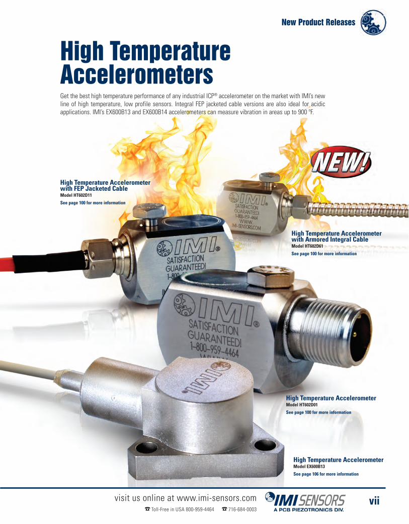
High Temperature AccelerometerModel HT602D01
See page 100 for more information
High Temperature AccelerometerModel EX600B13
See page 106 for more information
High Temperature Accelerometerwith FEP Jacketed CableModel HT602D11
See page 100 for more information
High Temperature Accelerometerwith Armored Integral CableModel HT602D61
See page 100 for more information
High TemperatureAccelerometersGet the best high temperature performance of any industrial ICP® accelerometer on the market with IMI’s newline of high temperature, low profile sensors. Integral FEP jacketed cable versions are also ideal for acidicapplications. IMI’s EX600B13 and EX600B14 accelerometers can measure vibration in areas up to 900 ºF.
visit us online at www.imi-sensors.comToll-Free in USA 800-959-4464 716-684-0003
vii

visit us online at www.imi-sensors.comToll-Free in USA 800-959-4464 716-684-0003
viii

visit us online at www.imi-sensors.comToll-Free in USA 800-959-4464 716-684-0003
ix
Forget Cables,Go Wireless!
Wireless Vibration SensorModel 670A01
� Batteries last over 5 years� Transmits long distances� Eliminates expensive cable runs
See page 142 for more information
ReceiverModel 673A01
� Requires no repeaters,gateways, or mesh
� Outputs to ethernet� Receives Echo® andEchoPlus® Signals
See page 143 for more information
Instantly ConvertsInstalled Sensorsto Wireless!Wireless Junction BoxModel 672A01
� Converts existing sensors to wireless� Runs independently or with existing junction box� Uses 24 VDC or battery power
See page 143 for more information
New Product Releases

� Motor Vibration . . . . . . . . . . . . . . . . . . . . . . . . . . 3� Pumps & Submersible Pumps . . . . . . . . . . . . . 9� Paper Machines & Conveyors . . . . . . . . . . . . . 15� Combustion Dynamics Instrumentation . . . . 21� Cooling Towers & HVAC. . . . . . . . . . . . . . . . . . 29� Gearboxes . . . . . . . . . . . . . . . . . . . . . . . . . . . . . 33� WindTurbine Condition Monitoring . . . . . . . . 37� Oil & GasWells and Pipelines . . . . . . . . . . . . . 47� Vibration Screens & Feeders. . . . . . . . . . . . . . 51� Reciprocating Machinery. . . . . . . . . . . . . . . . . 55� Machine Tool Spindles . . . . . . . . . . . . . . . . . . . 59� Steel Rolling & Annealing . . . . . . . . . . . . . . . . 63� Rotary Screw Compressors . . . . . . . . . . . . . . 67� Nuclear Power Instrumentation. . . . . . . . . . . . 71� Shock Monitoring . . . . . . . . . . . . . . . . . . . . . . . 77
Products By
Application

Industrial VibrationMeasurements?
We Do!TM We do it all - sensors to measure
vibration, acoustics, force, pressure, load,strain, shock and torque - Sure we do!
www.imi-sensors.com/sure

IMI Sensors - A PCB Piezotronics Division
visit us at www.imi-sensors.com Toll-free in USA 800-959-4464 716-684-0003
Motor VibrationDetect Mechanical & Electrical Motor Faults withVibration Monitoring Instrumentation
Sensor
MountingStud
Motor FinMount
visit us online at www.imi-sensors.comToll-free in USA 800-959-4464 716-684-0003
4
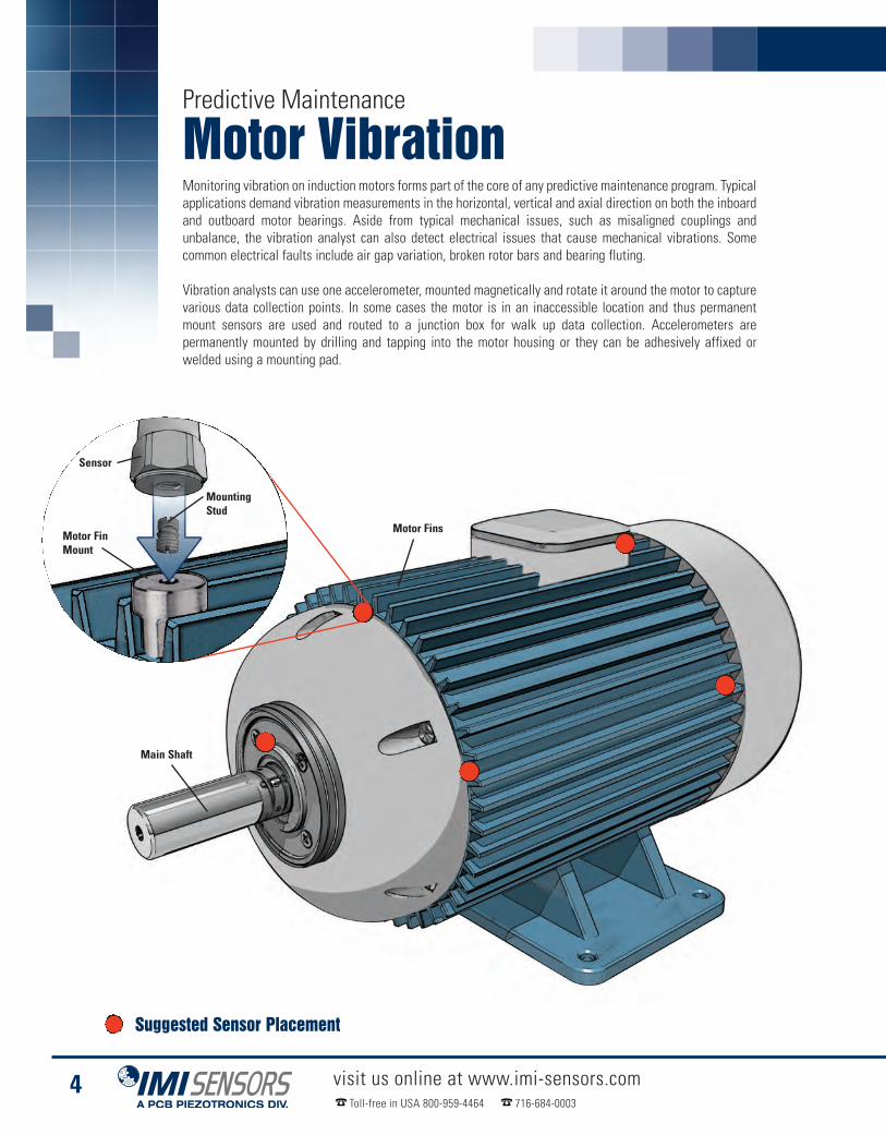
Predictive Maintenance
Motor VibrationMonitoring vibration on induction motors forms part of the core of any predictive maintenance program. Typicalapplications demand vibration measurements in the horizontal, vertical and axial direction on both the inboardand outboard motor bearings. Aside from typical mechanical issues, such as misaligned couplings andunbalance, the vibration analyst can also detect electrical issues that cause mechanical vibrations. Somecommon electrical faults include air gap variation, broken rotor bars and bearing fluting.
Vibration analysts can use one accelerometer, mounted magnetically and rotate it around the motor to capturevarious data collection points. In some cases the motor is in an inaccessible location and thus permanentmount sensors are used and routed to a junction box for walk up data collection. Accelerometers arepermanently mounted by drilling and tapping into the motor housing or they can be adhesively affixed orwelded using a mounting pad.
Main Shaft
Motor Fins
Suggested Sensor Placement

ICP® Accelerometers - Predictive Maintenance
Precision AccelerometerModel 622B01
� Full frequency sweep calibration:5% sensitivity deviation tolerance
� 15 kHz high frequency responseideal for early detection ofbearing fluting conditions
� Ideal for route-based data collection
See page 92 for more information
Low Cost ICP® AccelerometerModel 602D01
� Easy installation in tight spaces
� Through-bolt aides in cable orientation
� Low profile, less than 1 in. height
See page 82 for more information
IECEx
Motor Vibration
visit us online at www.imi-sensors.comToll-free in USA 800-959-4464 716-684-0003
5
Low Cost ICP® AccelerometerModel 603C01
� General purpose, hermetically sealed
� IMI’s most popular accelerometer
� Small footprint
See page 82 for more information
Triaxial AccelerometersMonitor motor bearing vibration in all three axes with a single accelerometer
Low Cost TriaxialAccelerometerModel 604B31
� General purpose, hermeticallysealed accelerometer
� Perfect for permanentmount applications
See page 90 for more information
Precision TriaxialAccelerometerModel 629A31
� Ideal for route-based datacollection, magnet mount
� Full frequency sweep calibration,superior frequency response
Page 90 for more information
IECEx
4-20 mA Transmitters - Process Monitoring & Protection
visit us online at www.imi-sensors.comToll-free in USA 800-959-4464 716-684-0003
6
Process Monitoring & Protection
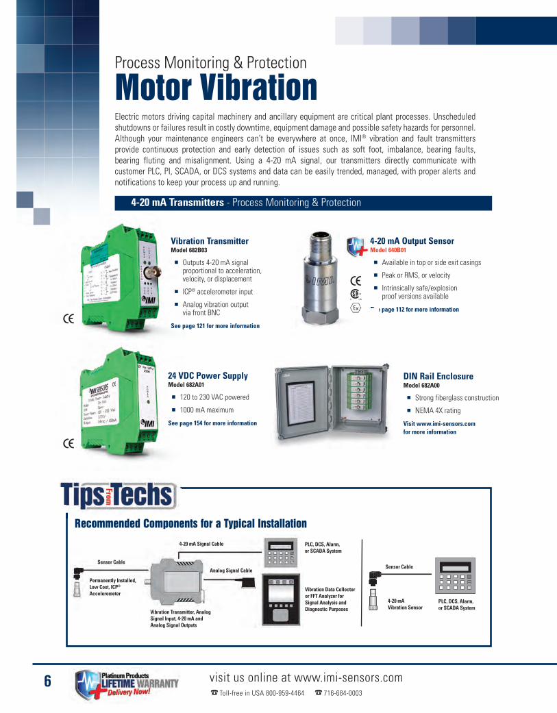
Motor VibrationElectric motors driving capital machinery and ancillary equipment are critical plant processes. Unscheduledshutdowns or failures result in costly downtime, equipment damage and possible safety hazards for personnel.Although your maintenance engineers can’t be everywhere at once, IMI® vibration and fault transmittersprovide continuous protection and early detection of issues such as soft foot, imbalance, bearing faults,bearing fluting and misalignment. Using a 4-20 mA signal, our transmitters directly communicate withcustomer PLC, PI, SCADA, or DCS systems and data can be easily trended, managed, with proper alerts andnotifications to keep your process up and running.
24 VDC Power SupplyModel 682A01
� 120 to 230 VAC powered
� 1000 mA maximum
See page 154 for more information
Vibration TransmitterModel 682B03
� Outputs 4-20 mA signalproportional to acceleration,velocity, or displacement
� ICP® accelerometer input
� Analog vibration outputvia front BNC
See page 121 for more information
4-20 mA Output SensorModel 640B01
� Available in top or side exit casings
� Peak or RMS, or velocity
� Intrinsically safe/explosionproof versions available
See page 112 for more information
DIN Rail EnclosureModel 682A00
� Strong fiberglass construction
� NEMA 4X rating
Visit www.imi-sensors.comfor more information
Sensor Cable
PLC, DCS, Alarm,or SCADA System
Sensor Cable
4-20 mA Signal Cable
Analog Signal Cable
PLC, DCS, Alarm,or SCADA System
Permanently Installed,Low Cost, ICP®
Accelerometer
Vibration Transmitter, AnalogSignal Input, 4-20 mA andAnalog Signal Outputs
Vibration Data Collectoror FFT Analyzer forSignal Analysis andDiagnostic Purposes
Recommended Components for a Typical Installation
4-20 mAVibration Sensor

Bearing Fault Detector - Process Monitoring & Protection
Motor Vibration
visit us online at www.imi-sensors.comToll-free in USA 800-959-4464 716-684-0003
7
Bearing fluting occurs when current ispassed through the motor bearing insteadof a grounded source. PWM (Pulse WidthModulated) drive switching frequenciesresult in undesirable motor shaft currents,a side effect that causes bearing damageincluding pitting and fluting. The pittingand fluting will result in undesirablebearing vibration. Because the BearingFault Detector’s additional fault output isextremely sensitive to high frequencyimpacting, it provides an early indicationthat pitting or fluting has occurred. Thiswill allow your motor to be servicedbefore catastrophic damage occurs.
Bearing Fluting in Electric Motors
Bearing Fault DetectorModel 682B05
� Provides early warning of bearing and gear faults
� Operates with PLC, DCS, SCADA, alarm and control systems
� Outputs 4-20 mA signals for peak acceleration and overall vibration
See page 124 for more information

XXX = Denote cable length, 010 = 10 feet (Metric lengths available)
visit us online at www.imi-sensors.comToll-free in USA 800-959-4464 716-684-0003
8
Motor Vibration
Accessories
BNC Switch Boxes & Termination EnclosuresSafe, Convenient, Centralized Access for Efficient Data Collection� Consolidate up to 48 channels of outputs
into one enclosure� Switch boxes save time and extend cable life;
connect once, change the channel� Factory installed cord grips provide simple,
quick and convenient installation
Small Adhesive KitModel 075A05
Curved Surface MagnetModel 080A131: Ø1.0”Model 080A132: Ø1.5”
Sensor Mounting PadModel 080A93: Ø0.75”Model 080A118: Ø1.0”
Cables & Connectors
Mounting Hardware
Polyurethane Cablingwith Right AngleMIL-Style Connector052BQXXXBZ
Polyurethane Cablingwith MIL-Style Connector052BRXXXBZ
FEP Cabling with RightAngle MIL-Style Connector053BQXXXBZ
FEP Cabling withMIL-Style Connector053BRXXXBZ
Typical InaccessibleMotor Monitoring System
Sensor to DataCollector Cable
Sensor Cables
Switch Box
Permanently Installed, Low costICP® Accelerometers for Axialand Radial Vibration Monitoring
Vibration Data Collector
IMI Sensors - A PCB Piezotronics Division
visit us at www.imi-sensors.com Toll-free in USA 800-959-4464 716-684-0003
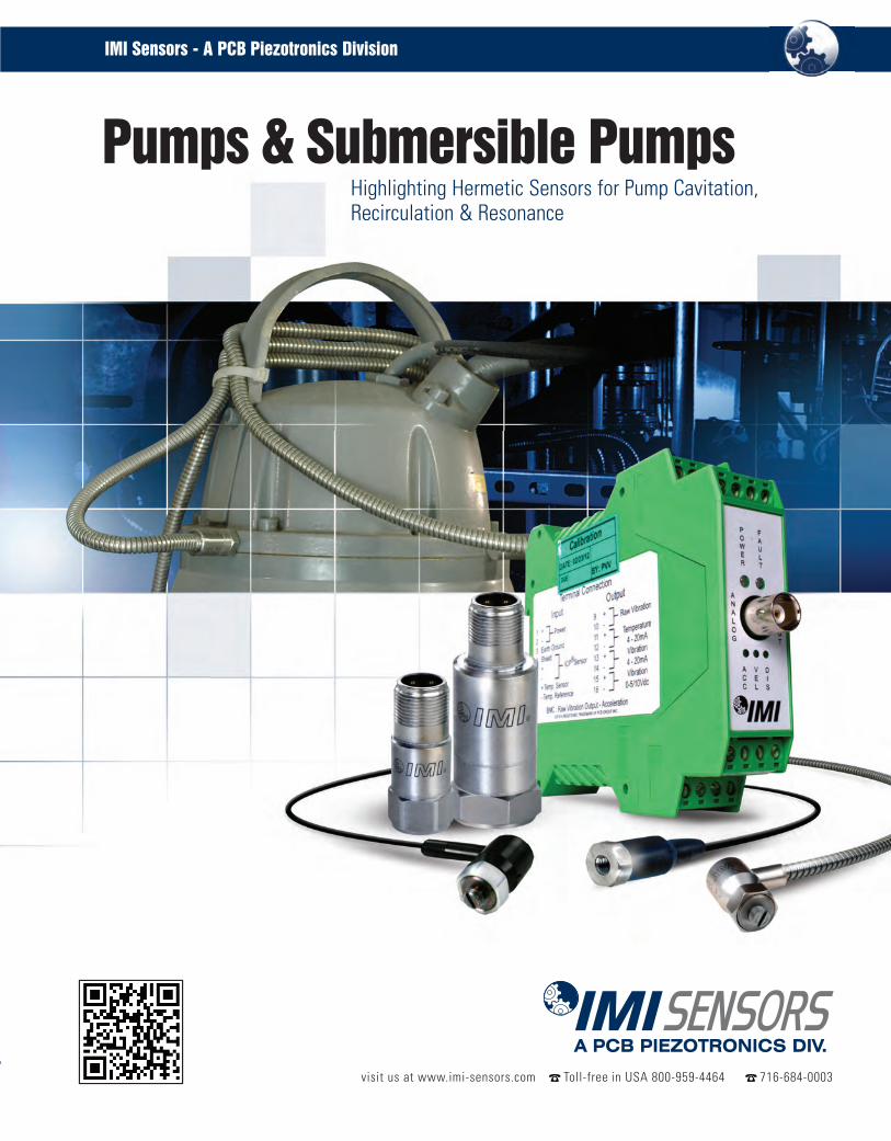
Pumps & Submersible PumpsHighlighting Hermetic Sensors for Pump Cavitation,Recirculation & Resonance

visit us online at www.imi-sensors.comToll-free in USA 800-959-4464 716-684-0003
10
Predictive Maintenance
Pumps &Submersible PumpsThere are dozens of different types of pumps and a seemingly endless list of applications but industrialaccelerometers can often help the maintenance professional diagnose sometimes tricky issues with pumpoperation. Using vibration monitoring in your predictive maintenance program can help identify pump problemssuch as cavitation, recirculation and resonance.
A good rule of thumb is to select an accelerometer that has alinear high frequency response capability to three times thepump’s vane pass frequency (vane pass frequency = # of vanesx RPM). Most general purpose accelerometers will have morethan adequate high frequency response and thus the next keyis selecting a transducer that will survive the application. Forthis purpose IMI® has a wide range of submersibleaccelerometers as well as sensors and cabling that will survivein corrosive environments.
Output Flange
Input Flange
Motor
Suggested Sensor Placement

ICP® Accelerometers - Predictive Maintenance
Sensors for Corrosive Environments - PdM
Pumps & Submersible Pumps
visit us online at www.imi-sensors.comToll-free in USA 800-959-4464 716-684-0003
11
Low Cost ICP® AccelerometerModel 608A11
� Ideal for submersible applications
� Small installation footprint
� Stock integral cable lengths of10 ft, 20 ft, 30 ft and 50 ft
See page 84 for more information
Low Cost ICP® AccelerometerSeries 607A
� Ideal for submersible applications
� Smallest true industrialaccelerometer on the market
� Armored integral cableoptions available
See page 84 for more information
Low Cost ICP® AccelerometerModel 603C01
� General purpose, hermetically sealed
� IMI’s most popular accelerometer
� Small installation footprint
See page 82 for more information
FEP Jacketed Cable with Right AnglePPS 2-pin MIL-style Connector055PBXXXBZ
In some cases accelerometers installed onpumps must survive in acidic applications. Inthese situations its best to use FEP jacketedcables. Special attention should be given tomaterials used to make the cable connector.For example, polyurethane cable and aconnector that uses a silicone boot willdegrade rapidly in most corrosiveapplications. Connectors made out of ryton orFKM are generally recommended for corrosiveapplications. Please contact an IMI®
Applications Engineer for a proper chemicalcompatibility study.
Corrosive Applications
Accessories for Corrosive Environments
XXX = Denote cable length, 010 = 10 feet (Metric lengths available)

visit us online at www.imi-sensors.comToll-free in USA 800-959-4464 716-684-0003
12
Process Monitoring & Protection
Pumps &Submersible PumpsPump failure can lead to costly unexpected shutdowns and expensive damage to plant processes andequipment. IMI’s low cost current output (mA) transmitters offer continuous protection to critical equipmentand provide maintenance professionals information between scheduled walk-around data collection.IMI’s 4-20 mA loop powered transmitters provide an easy and low cost continuous monitoring solution and aredirectly compatible with PLC, DCS, SCADA and PI systems. External DIN rail transmitters are an excellentsolution for customers interested in both PredictiveMaintenance and Continuous Monitoring. Using an externalICP® accelerometer, the DIN rail transmitters power thesensor and convert the raw vibration data to a 4-20 mAsignal proportional to RMS or Peak. Raw vibration data isavailable from the BNC connector during schedule route datacollection. Additionally, the transmitter provides a 4-20 mAsignal proportional to temperature for sensors with the TO(Temperature Output) option. Both of these solutions willprovide you 24/7 protection from critical failures preventingdowntime and expensive repairs.
Intake
Impellor
Motor
Main Shaft
Fluid
Suggested Sensor Placement

4-20 mA Sensors - Process Monitoring & Protection
ICP® DIN Rail Transmitters - Process Monitoring & Protection
DIN Rail EnclosureModel 682A00
Visit www.imi-sensors.comfor more information
Vibration TransmitterModel 682B03
� Outputs 4-20 mA signal proportionalacceleration, velocity, or displacement
� ICP® accelerometer input
� Analog vibration output via front BNC
See page 121 for more informationLow Cost ICP®
AccelerometerSeries 607A
See page 84 for more information
Low Cost ICP®
AccelerometerModel 608A11
See page 84 for more information
Pumps & Submersible Pumps
visit us online at www.imi-sensors.comToll-free in USA 800-959-4464 716-684-0003
13
4-20 mA Output TransmitterSeries 640
� Multiple ranges available
� Peak or RMS, acceleration or velocity
� Intrinsically safe / explosion proofversions available
� Temperature output and raw vibrationoutput options available
� 24 volt Loop Powered
See page 112-119 for more information

visit us online at www.imi-sensors.comToll-free in USA 800-959-4464 716-684-0003
14
Pump & Submersible Pumps
Accessories
Floating Hex NutModel 080A165
BNC TerminationEnclosureModel 691A50/12
BNC TerminationEnclosureModel 691A51/04
1.25” Spot Face ToolModel 080A128
BNC Switch BoxModel 691B42
Polyurethane Cablingwith Right AngleMIL-Style Connector052BQXXXBZ
Polyurethane Cablingwith MIL-Style Connector052BRXXXBZ
XXX = Denote cable length, 010 = 10 feet (Metric lengths available)
Model 608A11 Easy-mount MethodEasy installation of sensors with a long integral cable
� Permits mounting and dismounting withouttwisting sensor and integral cable
� Speeds sensor dismount for routine sensitivityverification or system troubleshooting
Mounting stud is tightenedto recommended torquewith appropriately sizedhex Allen key.
Mounting hole is preparedinto machine surface toaccept sensor’s mountingstud. Sensor integral cableis threaded through thefloating hex nut.
Mounting StudModel 080A162
Mounting Hardware
Cables & Connectors
Enclosures
Sensor Mounting PadModel 080A93: Ø0.75”Model 080A118: Ø1.0”

IMI Sensors - A PCB Piezotronics Division
visit us at www.imi-sensors.com Toll-free in USA 800-959-4464 716-684-0003
Paper Machines & ConveyorsSensors Built to Survive Hot, Wet andDebris Filled Environments

Small Roller
Small Roller
Large Roller
Drive Motor
visit us online at www.imi-sensors.comToll-free in USA 800-959-4464 716-684-0003
16
Predictive Maintenance
Paper Machines& ConveyorsRolling-element bearings are the life blood of many industrial processes including the manufacturing of paperand plastics as well as mining. Often these bearings are located in hot, wet or dangerous areas that areinaccessible to the predictive maintenance professional. Using permanent mount accelerometers will allowthe vibration analyst an opportunity to detect critical bearing faults such as pitting or spalling as well aslubrication issues before they cause a critical shutdown.
High temperature ICP® accelerometers outlined on page 17 allow for affordable protection. These designsoffer the best high temp capability of any industrial sensor in the industry without an external charge amplifier.Integrated circuit high temp accelerometers can be routed straight to portable data collectors, saving thecompany money and providing a simple, clean installation.
Suggested Sensor Placement

High Temp ICP® AccelerometerModel HT602D01
� Ceramic sensing element
� Low profile design
� Through-bolt mount
See page 100 for more information
High Temp ICP® AccelerometerModel HT628F01
� Quartz sensing element
� Excellent thermal stability
� Welded hermetic
See page 101 for more information
High Temp ICP® AccelerometerModel HT622A01
� Ceramic sensing element
� Short settling time
� Welded hermetic
Visit www.imi-sensors.com for more information
� Ideal for high temp applicationsto 325 ºF (163 ºC)
� Hermetically sealed with integral FEPjacketed cable (optional armor jacket)
� Low profile design eliminatesconcerns about cable bend radius
Paper Machines & Conveyors
visit us online at www.imi-sensors.comToll-free in USA 800-959-4464 716-684-0003
17
Accelerometers for Dryer Section - Predictive Maintenance
See page 100 for more information
Model HT602D11 & Model HT602D61High Temperature ICP® Accelerometers

visit us online at www.imi-sensors.comToll-free in USA 800-959-4464 716-684-0003
18
Predictive Maintenance
Paper Machines& ConveyorsOften in paper and plastics manufacturing locations rolling-element bearings are difficult to monitor becauseof their slow speeds. The 1x running speed of the bearing may be lower in frequency than the low frequencyrange of a typical piezoelectric accelerometer.
For these applications IMI Sensors offers low frequency accelerometers. In these models the discharge timeconstant has been extended, thus allowing the sensor to monitor slower speeds down to 12 CPM (0.2 Hz).These sensors are ideal for both permanent mount applications and route-based applications. They are allwelded hermetic, case isolated construction and built to survive harsh environments.
Accelerometers for Slow Speed - Predictive Maintenance
Slow speed applications such as slow moving roller element bearings in a paper mill produce lower vibration levels.Consider increasing the sensor’s sensitivity to 500 mV/g, thus increasing signal resolution in these applications.
Precision ICP® AccelerometerModel 626B01
� Low noise floor
� Low frequency responseto 12 cpm (0.2 Hz)
� Full sweep calibration
See page 94 for more information
Low Frequency, 500 mV/g Accelerometers
Precision ICP® AccelerometerModel 625B01
� Side exit, ring-style
� Low frequency responseto 12 cpm (0.2 Hz)
� Ceramic sensing element
See page 92 for more information
Low Cost IndustrialICP® AccelerometerModel 601A02
� Low Noise
See page 88 for more information
Low Frequency IndustrialICP® AccelerometerModel 625B02
� Full sweep calibrationcertificate provided
See page 94 for more information
Low Frequency IndustrialICP® AccelerometerModel 626B02
� Full sweep calibrationcertificate provided
See page 94 for more information

Paper Machines & Conveyors
visit us online at www.imi-sensors.comToll-free in USA 800-959-4464 716-684-0003
19
General Purpose Accelerometers - Predictive Maintenance
Low Cost ICP® AccelerometerModel 602D01
� Easy installation in tight spaces
� Through-bolt aides inconnector orientation
� Less than 1 in. height
See page 82 for more information
Low Cost ICP® AccelerometerModel 603C01
� Cost-effective sensor option
� IMI’s most popular accelerometer
� Small footprint
See page 82 for more information
Low Cost ICP® AccelerometerSeries 607A
� Unique 360º swivel design
� Allows for easy cable orientation
� Integral or armored integralcable options available
See page 84 for more information
Mining Industry, Conveyors - Predictive Maintenance
Low Cost ICP® AccelerometerModel 607A61
� Unique 360º swivel design
� Allows for easy cable orientation
� Armored integral cable
See page 85 for more information

visit us online at www.imi-sensors.comToll-free in USA 800-959-4464 716-684-0003
20
Process Monitoring & Protection
Paper Machines& ConveyorsThe continuous monitoring of bearing health is critical to the uptime and safety of paper machines andconveyor systems. IMI’s Bearing Fault Detector directly interfaces with PLC, DCS, PI and other control systemsproviding an easy continuous monitoring solution. Not only does the Bearing Fault Detector provide overallRMS and Peak vibration, but also provides a 4-20 mA signal proportional to True Peak acceleration that issensitive to early bearing faults. Paper machines and other conveyor processes often expose accelerometersand transmitters to extreme environments including high temperature, debris and caustic chemicals.IMI® offers ICP® accelerometers able to handle the harshest of environments with temperatures up to 325 ºFand integral armor jacketed cable.
Recommended Componentsfor a Typical Installation
Sensor Cable
4-20 mA Signal Cable
Analog Signal Cable
PLC, DCS, Alarm, orSCADA System
PermanentlyInstalled,Low Cost, ICP®
Accelerometer
Vibration Transmitter, AnalogSignal Input, 4-20 mA andAnalog Signal Outputs
Complete Bearing Detection - Process Monitoring & Protection
Vibration Data Collector or FFTAnalyzer for Signal Analysis andDiagnostic Purposes
High Temperature ICP®
AccelerometerModel HT602D11
Low Cost ICP®
AccelerometerModel 607A11
High TemperatureICP®AccelerometerModel HT602D61
See page 84 for moreinformation
See page 100 for more information
Bearing Fault DetectorModel 682B05
� Provides early warning of bearingand gear faults
� Operates with PLC, DCS, SCADA,alarm and control systems
� Outputs 4-20 mA signals for peakacceleration and overall vibration
See page 124 for more information
See page 100 for moreinformation
DIN Rail EnclosureModel 682A00
� Strong fiberglass construction
� NEMA 4X rating
Visit www.imi-sensors.com for more information

IMI Sensors - A PCB Piezotronics Division
visit us at www.imi-sensors.com Toll-free in USA 800-959-4464 716-684-0003
Combustion DynamicsInstrumentation For the Most Demanding Gas Turbine
Measurement & Monitoring Requirements

The diagram above shows a typical setting for a gas turbine in apower generation plant. Shown within the illustration are the threestandard methods of measuring pressure; Remote, Close Coupledand On-Turbine Instability Sensor (OTIS). The red bullets indicate thelocation of the actual sensor for each different method.
On-TurbineInstability Sensor
Gas TurbineCombustor
“Infinite” Coil
Remote Sensor(located outside of turbine room)
Close CoupledSensor
visit us online at www.imi-sensors.comToll-free in USA 800-959-4464 716-684-0003
22
Energy & Power Generation
Combustion DynamicsInstrumentationFor more than 40 years, PCB®. has specialized in the design and manufacture of innovative sensors andmeasurement systems for the gas turbine market. In those four decades, our expertise in combustion dynamicsinstrumentation has met the industry’s most demanding requirements for dynamic combustion measurementand turbine engine monitoring.
With the move toward increased fuel efficiency and lower exhaust emissions, today’s gas turbine engines arebased on technological innovation yet also bring potential problems. Burning a leaner flame keeps NOxemissions low but at the same time increases instability (combustion dynamics) in the gas turbine engine. Thisinstability can damage components in the combustion chamber such as nozzles, baskets and transition pieces,as well as downstream components such as blades, resulting in downtime and loss of revenue.
IMI’s instrumentation is designed to detect and measure dynamic pressure spikes, pulsations and surges ingas turbine engines. Our pressure sensors have three basic applications for detecting and measuring dynamicpressure phenomena and combustion instability in gas turbine engines: remote sensors, close coupled sensorsand On-turbine Instability Sensors.
Suggested Sensor Placement
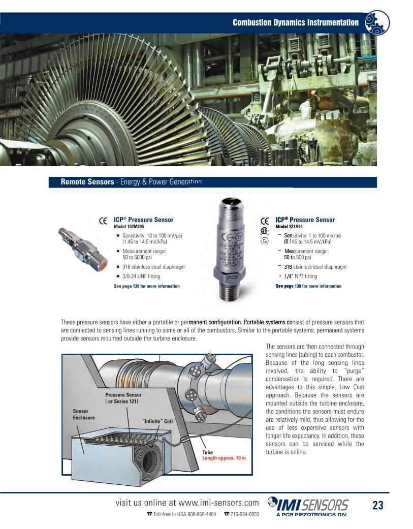
These pressure sensors have either a portable or permanent configuration. Portable systems consist of pressure sensors thatare connected to sensing lines running to some or all of the combustors. Similar to the portable systems, permanent systemsprovide sensors mounted outside the turbine enclosure.
The sensors are then connected throughsensing lines (tubing) to each combustor.Because of the long sensing linesinvolved, the ability to “purge”condensation is required. There areadvantages to this simple, Low Costapproach. Because the sensors aremounted outside the turbine enclosure,the conditions the sensors must endureare relatively mild, thus allowing for theuse of less expensive sensors withlonger life expectancy. In addition, thesesensors can be serviced while theturbine is online.
Remote Sensors - Energy & Power Generation
Combustion Dynamics Instrumentation
visit us online at www.imi-sensors.comToll-free in USA 800-959-4464 716-684-0003
23
ICP® Pressure SensorModel 121A44
� Sensitivity: 1 to 100 mV/psi(0.145 to 14.5 mV/kPa)
� Measurement range:50 to 500 psi
� 316 stainless steel diaphragm
� 1/4” NPT fitting
See page 138 for more information
ICP® Pressure SensorModel 102M205
� Sensitivity: 10 to 100 mV/psi(1.45 to 14.5 mV/kPa)
� Measurement range:50 to 5000 psi
� 316 stainless steel diaphragm
� 3/8-24 UNF fitting
See page 138 for more information
SensorEnclosure
Pressure Sensor( or Series 121)
“Infinite” Coil
TubeLength approx. 10 m

In-Line Charge ConverterModel 422E55/D
� Output voltage:(at specified measurement range) ±5 Vpk
� Sensitivity: (charge conversion) 0.5 mV/pC
� Frequency range (±5%) 0.5 Hz to 100 kHz
� Housing material: stainless steel
See page 159 for more information
visit us online at www.imi-sensors.comToll-free in USA 800-959-4464 716-684-0003
24
Energy & Power Generation
Combustion DynamicsInstrumentation
Close coupled sensors permanently mounted to a gas turbine are ideal for monitoring combustiondynamics (instability). Operating at a wider frequency range than remote sensors, the high sensitivity andhigher-temperature capability of these sensors allow for precision measurement in turbine locationswhere the application of other instrumentation is not possible.
Close coupling of the sensors to the combustor enables the measurement and detection of dynamicpressure phenomena such as high frequency events that can cause damage to downstream componentssuch as blades. Like the portable and permanent remote sensors, close coupled sensors also require apurging system to eliminate condensation.
High Sensitivity Pressure SensorSeries 171
� Measurement range:10 psi (68.9 kPa)
� Sensitivity: 1100 pC/psi(160 pC/kPa)
� 2-pin connector,1-1/8”-12 UNF-2A port
� Weight: 6.5 oz (185 gm)
See page 141 for more information
Gas Turbine
TubeLength approx. 5 m
“Infinite”Coil
Pressure Sensor(Series 171)
Combustor
Close Coupled Sensors - Energy & Power Generation

Combustion Dynamics Instrumentation
visit us online at www.imi-sensors.comToll-free in USA 800-959-4464 716-684-0003
25
Length approx. 10 mSeries 176High TempPressure Sensor
Inner Wallof Can
045M19 Cable toCharge Amplifier Enclosure
Combustor
Charge Amplifier(Series 422M182)(located outside turbine room)
High Temperature Pressure SensorSeries 176M0X
� Sensitivities to 17 pC/psi
� Measurements to 20 psi
See page 140 for more information
High Temperature Pressure SensorSeries 176MXX
� Sensitivities to 17 pC/psi
� Measurements to 20 psi
See page 140 for more information
On-Turbine Instability Sensors - Energy & Power Generation
Differential Charge AmplifierModel 422M182
� Sensitivity 4 mV/pC
� Frequency Range from2 Hz to 30 kHz
See page 158 for more information
High temperature sensors directly mounted to the combustor basket provide 24/7, consistent, reliable combustion dynamicsdata monitoring so that tuning changes can be made at anytime. On-Turbine Instability Sensors allow for diagnostics, partfatigue analysis and the ability to continuously monitor and control emissions. The higher frequency capability of the OTISsensors enable the use of auto-tuning and online diagnostic monitoring systems. In addition, these sensors provide an outputthat can easily connect to legacy combustion dynamics monitoring systems. By having sensors directly mounted to thecombustor, operators save time during combustion analysis.

visit us online at www.imi-sensors.comToll-free in USA 800-959-4464 716-684-0003
26
Energy & Power Generation
Combustion DynamicsInstrumentation
Vibration monitoring of gas turbines can provide crucial information to diagnose potential problems, leadingto an increase in uptime and a decrease in unplanned maintenance, catastrophic failures and accidents.
Very High TemperatureAccelerometerSeries EX600B1X
� Sensitivity: 10 to 100 mV/g(1.02 mV/(m/s2) to 10.2 mV/(m/s2))
� Frequency Range: (±5%) 282 to 240000 cpm(4.7 to 4 kHz)
� Measurement Range: ±50 to 500 g peak(±490 to 4900 m/s2)
� Mounting: Through Holes (3)
See page 106 for more information
Extreme TemperatureCharge Accelerometerwith Integral Hardline CableSeries 357D9X
� Sensitivity: (±10%) 5 pC/g (.51 pC/(m/s²))
� Measurement Range: ±1000 g pk(±9800 m/s² pk)
� Frequency Range: (±5%) 2.5 kHz
� Electrical Connector: Integral Hardline Cable
See page 108 for more information
High Temperature Accelerometers - Energy & Power Generation
Innovations in high temperature accelerometer technology for gas turbine monitoring now enable vibration measurement inextreme heat environments up to +1200 °F (+649 °C). IMI’s high-temp accelerometers come in a variety of frequencies,temperature ranges and configurations. Integral charge amplifiers allow for use with standard data acquisition equipment.
ICP® Accelerometer withHigh Temperature Range OptionModel HT622A01
� Sensitivity: (±5%) 100 mV/g (10.2 mV/(m/s²))
� Frequency Range: (±3dB) 12 to 480k cpm(0.2 to 8 kHz)
� Measurement Range: ±50 g (±490 m/s²)
� Electrical Connector: 2-Pin MIL-C-5015
Visit www.imi-sensors.com for more information
High Temperature IndustrialCharge AccelerometerModel 612A01
� Sensitivity: (±10%) 26 pC/g (2.6 pC/(m/s²))
� Temperature Range: (Operating)-65 to +500 °F (-54 to +260 °C)
� Electrical Connector: 2-Pin MIL-C-5015
� Electrical Connection Position: Top
Visit www.imi-sensors.com for more information

Combustion Dynamics Instrumentation
visit us online at www.imi-sensors.comToll-free in USA 800-959-4464 716-684-0003
27
Low Noise, TFE, CoaxialCable 10-32 Coaxial Plugto BNC Plug003CXX Cabling
Polyurethane, Twisted PairCable with Composite 2-SocketMIL-style Connector to BNC Plug052FVXXXAC Cabling
Combustion Dynamics Instrumentation
Accessories
Low Noise, PFA Cable, 2-socket 7/16MIL to 2-Socket MIL-C-5015045M19 Cabling
Polyurethane Cable, Composite2-Socket MIL-style Connectorto BNC Plug052BRXXXAC Cabling
Polyurethane Cable,BNC Plug to Pig Tails052ACXXXAD Cabling
Low noise, PFA, Twisted Pair Cable2-Socket MIL to BNC Plug045ERXXXAC Cabling
Accessories - For On-Turbine Instability Sensors
Accessories - For Remote Sensors For Close Coupled Sensors
XXX = Denote cable length, 010 = 10 feet (Metric lengths available)

Cooling TowerMeasurements?
We Do!TM We do it all - sensors to measure
vibration, acoustics, force, pressure, load,strain, shock and torque - Sure we do!
www.imi-sensors.com/sure

IMI Sensors - A PCB Piezotronics Division
visit us at www.imi-sensors.com Toll-free in USA 800-959-4464 716-684-0003
Protecting Cooling Towers& HVAC Systems Reliable and Cost-Effective Vibration
Monitoring Solutions for Cooling Fansand Other Low Frequency Equipment

visit us online at www.imi-sensors.comToll-free in USA 800-959-4464 716-684-0003
30
Process Monitoring & Protection
ProtectingCooling TowersCooling Towers are a critical component of production in many industries today. Most towers use the samedesign, which is a horizontal electric motor driving a jack shaft into a right angle gearbox with vertical outputto a large fan. Vibration monitoring of this drive train is essential to provide signals for early warning or provideshutdown when vibration levels exceed a predetermined threshold. The classic legacy solution involved theuse of “earthquake” mechanical switches. These devices utilize a spring and magnet concept and are designedto mechanically trip during high vibration. Reliability becomes an issue with mechanical switches due to harshcooling tower environments, especially in critical applications.
The next generation 686B Smart Vibration Switches are USB programmable and employ piezoelectric sensingelements coupled with field adjustable threshold settings. Also integrated programmable time delays virtuallyeliminate false trips. When streaming vibration data is required, the 685B Series electronic vibration switchprovides 4-20 mA output as well as analog vibration data output for data analysis. Two separate relay outputs,for alert and alarm, are field adjustable with separate time delays for each relay. Other IMI® solutions include4-20 mA output sensors for continuous monitoring in conjunction with existing PLCs, DCS and SCADA systems.All products are available with hazardous area approvals.
Cooling Tower Fan
Torque TubeGearbox
Motor
Suggested Sensor Placement

Protecting Cooling Towers & HVAC Systems
visit us online at www.imi-sensors.comToll-free in USA 800-959-4464 716-684-0003
31
Electronic Vibration SwitchSeries 685B
� Lower cost than competitive models
� Dual set points (relays)
� Explosion proof options available
� On-board or remote piezoelectricaccelerometer
See page 132 for more information
Mechanical Vibration SwitchModel 685A08
� Weatherproof & CSA/ULapproved, explosions proof
� Cost-effective protection forless-critical applications
� Requires no power
See page 135 for more information
USB Programmable Smart SwitchModel 686B01
� Programmable delays eliminatefalse trips
� Competitive price comparedto mechanical switches
� Hazardous area approvals available
See page 130 for more information
Mechanical Vibration SwitchModel 685A07
� Cost-effective protectionfor less critical applications
� Utilizes spring-loaded,magnetically coupledmechanism
� External reset button
See page 134 for more information
Mechanical Vibration Switches - Process Monitoring & Protection
Electronic Vibration Switches - Process Monitoring & Protection
PhotoCourtesyofMidwestTower,Inc

visit us online at www.imi-sensors.comToll-free in USA 800-959-4464 716-684-0003
32
Process Monitoring & Protection
Heating, Ventilation &Air Conditioning (HVAC)In other cooling applications there may be a need for vibration trending or route based inspection of criticalbearing and critical gearbox conditions. It this case vibration switches may not be the correct solution. IMISensors supplies industry leading general purpose vibration sensors to interface with any data collector usedfor classic condition monitoring applications. For 24/7 vibration trending the 640 Series 4-20 mA outputsensors provide current signals to interface with any PLC, SCADA, or DCS panel. These sensors are availablein several measurement ranges RMS or Peak and various measurement methods (displacement, velocity,acceleration). For the best of both worlds, IMI’s din-rail transmitters output 4-20 mA signals for trending plusvoltage signals for time waveform and spectral analysis.
Low Cost ICP® AccelerometerModel 608A11
� Excellent sensor for submersible applications
� Small size (9/16” footprint)
� Integral cable easily connects to boxes
See page 84 for more information
Low Cost ICP® AccelerometerModel 603C01
� Cost-effective sensor option
� IMI’s most popular accelerometer
� Small footprint
See page 82 for more information
Low Cost 4-20 mA Output SensorModel 640B01
� Continuous monitoring
� Outputs acceleration or velocity
� Designed to work with any PLC,DCS, or SCADA system
See page 112 for more informationFEP Jacketed Cablewith MIL-Style Connector053BRXXXBZ Cable
Vibration TransmitterModel 682B03
� Outputs 4-20 mA signal proportionalto acceleration, velocity, or displacement
� ICP® accelerometer input
� Analog vibration output via front BNC
See page 121 for more information
Sensors for Cooling Towers - Process Monitoring & Protection
XXX = Denote cable length, 010 = 10 feet (Metric lengths available)

IMI Sensors - A PCB Piezotronics Division
visit us at www.imi-sensors.com Toll-free in USA 800-959-4464 716-684-0003
GearboxesInstrumentation Built to Survive in Grease & Grimeand Pickup Gear Mesh Faults

visit us online at www.imi-sensors.comToll-free in USA 800-959-4464 716-684-0003
34
Predictive Maintenance
GearboxesThe sensor has to be chosen based on calculated gear mesh frequency and bearing defect frequencies. Thegear mesh frequency is easily determined by multiplying the number of teeth on a gear by the rotationalfrequency. For example, a motor with 1800 rpm (30 Hz) and a gear with 50 teeth results in a gear meshfrequency of 1500 Hz. This result multiplied by a factor of 3.25 will provide the maximum frequency the sensorshould be able to measure for best results. If the number of teeth on a gear is unknown, as a rule of thumb,the maximum sensor frequency should be assumed to be 200 times rpm (in Hz). Typically high speed input andlow speed output frequencies need to be measured near shaft bearings. Sensors should not be mounted onresonance frequency prone housing locations to improve accuracy of the readings. Sensors can be placed inradial, ideally two sensors with a 90 degree angle and axial locations. Radial sensors can be used to spotimbalance and axial sensors will best analyze gear mesh and bearing faults. Most IMI® sensors can be offeredwith an option to safely affix them inside of the gear housing for best measurement results. Sensors can bepressure tested, can withstand oils and chemicals inside of the case and are available in high temperatureversions. Advanced vibration monitoring systems in combination with experienced analysis can deliver a broadrange of results. Tooth wear, gear eccentricity & misalignment, damaged teeth and other potential problemscan be spotted instantly while the transmission is in service.
Main Drive Shaft
Bearing Housing
High Speed / Gear Mesh - Predictive Maintenance
Reducer / Slow Speed - Predictive Maintenance
Gearboxes
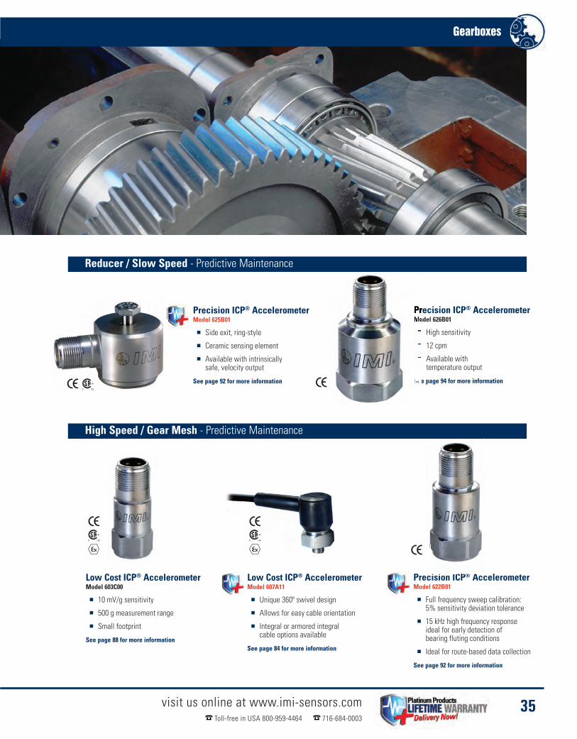
Precision ICP® AccelerometerModel 622B01
� Full frequency sweep calibration:5% sensitivity deviation tolerance
� 15 kHz high frequency responseideal for early detection ofbearing fluting conditions
� Ideal for route-based data collection
See page 92 for more information
visit us online at www.imi-sensors.comToll-free in USA 800-959-4464 716-684-0003
35
Precision ICP® AccelerometerModel 625B01
� Side exit, ring-style
� Ceramic sensing element
� Available with intrinsicallysafe, velocity output
See page 92 for more information
Precision ICP® AccelerometerModel 626B01
� High sensitivity
� 12 cpm
� Available withtemperature output
See page 94 for more information
Low Cost ICP® AccelerometerModel 603C00
� 10 mV/g sensitivity
� 500 g measurement range
� Small footprint
See page 88 for more information
Low Cost ICP® AccelerometerModel 607A11
� Unique 360º swivel design
� Allows for easy cable orientation
� Integral or armored integralcable options available
See page 84 for more information

visit us online at www.imi-sensors.comToll-free in USA 800-959-4464 716-684-0003
36
Gearboxes
Accessories
Sensor Mounting PadModel 080A93: Ø0.75”Model 080A118: Ø1.0”
Model 600A12
Small Adhesive KitModel 075A05
Polyurethane Cabling with RightAngle MIL-Style Connector052BQXXXBZ
Polyurethane Cablingwith MIL-Style Connector052BRXXXBZ
Flat Surface MagnetModel 080A157
Very High Frequency Accelerometer Kit
This high frequency 10 mV/g accelerometer kit features a verysmall accelerometer with a magnet and cable assembly
� High frequency response to 30 kHz, even when mounted magnetically� Supplied with 5 ft. cable with BNC plug termination� Kit features Model 621B40 accelerometer, with titanium housing
Cables & Connectors
Mounting Hardware
XXX = Denote cable length, 010 = 10 feet(Metric lengths available)

visit us at www.imi-sensors.com Toll-free in USA 800-959-4464 716-684-0003
Wind Turbine Condition Monitoring& Assessment Sensors and Instrumentation for Permanent
Installation and Testing of Wind Turbinesand Turbine Components
IMI Sensors - A PCB Piezotronics Division

Continuous Monitoring:Measurements on gearboxes
Load & Torque:Measurements on couplings & bolt tightness
Modal Analysis:Measurements on turbine blades
Sensor Placement Reference Key:
Main Bearing
Gearbox
Generator
Blades
Coupling
visit us online at www.imi-sensors.comToll-free in USA 800-959-4464 716-684-0003
38
Energy & Power Generation
Wind TurbineCondition MonitoringSome of the world’s largest wind farms rely on IMI Sensors to keep their wind turbine operations at optimalperformance by increasing reliability and reducing downtime. A broad range of industrial grade sensors fromPCB® measure vibration, strain, torque and noise in new and existing wind turbines, providing measurementsthat are crucial to keep the operating health of these systems in tip-top shape.

Condition Monitoring Accelerometers - Energy & Power Generation
Low Cost ICP® AccelerometerSeries 607A
n Unique 360º swivel design
n Allows for easy cable orientation
n Integral or armored integralcable options available
See page 84 for more information
Low Cost ICP® AccelerometerModel 602D01
� Easy installation in tight spaces
� 360º connector orientation
� Integral or armored integralcable options available
See page 82 for more information
Low Cost ICP® AccelerometerModel 603C01
� General purpose, hermetically sealed
� IMI’s most popular accelerometer
� Small footprint
See page 82 for more information
Low Cost ICP® AccelerometerSeries 601
� Low noise
� Ceramic shear
� 100 mV/g or 500 mV/g
See page 82 and 88 for more information
Low Frequency ICP® AccelerometerModel 626B01
� Ideal for slow rotating equipment
� Low noise floor
� High output sensitivity
See page 94 for more information
Embeddable AccelerometerSeries 660
� ICP®, charge and low powerversions available
� Easily designed into PC boards
� Variety of sensitivities
See page 110 for more information
Wind Turbine Condition Monitoring
visit us online at www.imi-sensors.comToll-free in USA 800-959-4464 716-684-0003
39

Portable Transducer, Model 962 - Energy & Power Generation
RS Technologies, a division of PCB Load & Torque, Inc., serves the product assembly and fastenermanufacturing communities with a complete line of rotary and stationary torque sensors, hand torquewrenches, measuring instruments and threaded fastener torque-tension testing systems. For moreinformation on any of these products, please visit www.pcbloadtorque.com
Model 962 Portable Data Recorder Instrument can be used withother RS Technologies' products such as the Stationary TorqueTransducer, Rotary Torque Transducers, Hand Torque Wrenchesand more. The instrument is powerful and accurate enough tobe used as a primary standard for auditing most torqueapplications in manufacturing and quality departments. Whenconnected to a Rotary Torque Transducer, the unit can be usedto test the capability of power tools, verify the accuracy of handtools, monitor the capability of a fastening process, or audit thequality of an assembled joint.
Portable Data RecorderModel 962
� Battery operated
� Cost-effective option
� Easy to operate
� Print both numeric andgraphic data
Visit www.pcbloadtorque.comfor more information
Series PC9000 Rotary Torque Sensors are widely used in thefastener assembly market to verify the performance of handand power torque tools. These strain gage-basedtransducers are fitted on the output drive of a power tool andmeasure the torque applied by the tool to the fastener on anactual assembly. When equipped with a Model 920 PortableDigital Transducer Instrument this measurement providesimportant information about tool shut off and can assist inestablishing specifications for proper assembly.
Rotary Torque TransducerSeries PC9000
� Industrial-rated for powerand pulse tools
� Measure torque onlyor torque and angle
� 2 mV/V output with matchedshunt calibration
Visit www.pcbloadtorque.comfor more information
RS Technologies, a division of PCB Load & Torque, Inc,manufactures a complete line of lightweight, precisionhand torque wrenches that are among the lightest inthe industry and durable enough to be used in thetoughest industrial environments.Auditing the torque applied to tightened fasteners is animportant part of assembly and maintenance of windturbines. Monitoring the residual torque in assembledfasteners can be accomplished by using Series HT7000Hand Torque Wrenches along with Model 920 PortableDigital Transducer Instrument.
Torque WrenchSeries HT7000
� Durable ergonomic construction
� Lightweight and high strength
� Excellent accuracy of measurements
� Compatible with most data collectors
Visit www.pcbloadtorque.comfor more information
visit us online at www.imi-sensors.comToll-free in USA 800-959-4464 716-684-0003
40
Wind TurbineAssessmentWind turbines and towers utilize literally thousands of fasteners. Selecting the proper tools and applying thecorrect amount of torque to each fastener is imperative for optimizing the costs of operation.
Rotary Torque Transducers - Energy & Power Generation
Hand Torque Wrenches - Energy & Power Generation

Microphones & Preamplifiers - Energy & Power Generation
Sound Level Meters - Energy & Power Generation
Microphones are used to measure the noise from the wind turbine both internally and externally. The gearbox and the mainbearing are typical noise sources which should be measured internally, while the overall turbine noise is monitored externally.Larson Davis, a division of PCB Piezotronics, manufacturers various Sound Level Meters and Microphones which can be usedto make these different types of acoustic measurements.
By utilizing the built-in narrow band FFT analysis option on Model 831, higherfrequency components can be analyzed to predict possible machine faults. Ananalysis of the source of the audible noise can result in gearbox modificationsso that the equipment runs quietly and efficiently. In addition, the low frequencycontent of blade generated noise can be quantified using octave analysis.
� High-temperature (120 °C) 248 °F preamplifier for prepolarized microphones
� Type 1 compliant, modern prepolarized (0 V) and externally polarized (200 V) microphones
� Value oriented array microphones
� TEDS compliant with IEEE standards
Visit www.pcb.com/acoustics for more information
The rugged, ergonomic design of the Larson Davis Sound LevelMeter, Model 831, is ideal for one handed operation and itslarge display can be read in any lighting conditions. The 831can also be used with a complete range of microphones andpreamplifiers including weather-resistant units for unattendedand semi-permanent wind turbine monitoring applications.Advances in technology provide 2GB of internal memory, withsuperior performance and a reliable design. The inclusion ofWeather Parameters allows all environmental noise data to beintegrated in one common report.
For environmental noisemonitoring and buildingacoustics, Larson Davis
offers a full line of instruments, accessories and software. For personal noiseand vibration exposure monitoring, Larson Davis complements this with soundlevel meters, personal noise dosimeters, human vibration meters, audiometriccalibration systems and hearing conservation programs.
Sound Level MeterModel 831
� Over 16 hours of runtime on 4 AA batteries
� USB 2.0 peripheral connectors
� 120dB dynamic range
� 2 GB memory standard
� RMS & peak A, C & Z frequency weighting
� RMS slow, fast & impulse detectioncharacteristics
� Real time 1/1 & 1/3 octave frequency analysis
� 6400 line FFT analysis
� .WAV sound recording for source identification
� Automatic data logging (20ms to 24 hours)
� Complete environmental packages available
Visit www.larsondavis.com for more information
Wind Turbine Assessment
visit us online at www.imi-sensors.comToll-free in USA 800-959-4464 716-684-0003
41

Load, Strain & Torque - Energy & Power Generation
PCB Piezotronics, Inc. Model RHM240A02 single axisICP® Strain Sensor is structured with a quartz sensingelement and microelectronic circuitry in a low profiletitanium housing, making this sensor ideal for highresolution measurements of dynamic strain on windturbine blades. This unit is compatible with PCB’s ICP®
Sensor signal conditioners and is capable of drivinglong cables.
PCB Load & Torque, Inc. Series 5300 TORKDISC®
in-line rotary torque sensor systems are designed fortest applications requiring a robust rotary torquetransducer where axial space is at a premium.
PCB Load & Torque, Inc. manufactures a wide range ofhigh accuracy, strain gage load cells. The 1200 and1400 series load cells are compact and are availablevarious capacities from 250 lbf and up. While the 1200series is a general purpose load cell with a cycle life of10 million plus reversing cycles, the 1400 series is afatigue rated load cells with a life cycle of 100 millionplus reversing cycles. The 1400 series load cell isavailable in both single and dual bridge configurations.
Load CellsSeries 1200 & Series 1400
� Low deflection, high accuracy
� Low profile for easy installation
� NIST traceable, A2LA accreditedcalibration to ISO 17025
� Temperature & pressure compensated
Visit www.pcbloadtorque.com for more information
TORKDISC® Rotary TorqueSensor SystemSeries 5300
� Digital system alleviatesnoise & data corruption
� Immune to RF & EMI
� Maintenance free
Visit www.pcbloadtorque.com for more information
ICP® Strain SensorModel RHM240A02
� Measure Longitudinal Strain onMachinery Structures
� Monitor Quality, Safety and Reliability
� Robust Construction Endures Harsh,Industrial Environments
� Simple Installation isNon-Invasive to Process
Visit www.pcb.com for more information
visit us online at www.imi-sensors.comToll-free in USA 800-959-4464 716-684-0003
42
Wind TurbineAssessmentInstrumentation that can provide voltage excitation and bridge completion is ideal for this measurement.Strain gages can be placed anywhere on the blade, but the distribution varies with the amount of sensors.These sensors should be in a configuration to optimally model the stress on the blade, taking measurementsfrom both the flap-wise and edge-wise directions.
PCB Load & Torque, Inc., designs and manufactures a full line of load cell and torque sensorsfor numerous industries including: aerospace & defense, automotive, medical rehabilitation,material testing, textile, process control, robotics & automation and more. PCB Load &Torque offers exceptional customer service, 24-hour technical assistanceand a Total Customer Satisfaction guarantee.

Single Channel Telemetry Systems - Energy & Power Generation
PCB Load & Torque, Inc., designs and manufactures afull line of load cells, torque sensors and telemetrysystems for numerous industries including: aerospace& defense, automotive, energy & power generation,material testing, textile, process control, robotics &automation and more.
PCB Load & Torque, Inc. single channel telemetrysystems provide a simple, accurate method ofconditioning and transmitting strain signals onrotating or moving machinery while operating ina completely contactless mode. Power istransferred inductively and the signal is RF-transferred between the moving and staticcomponent - no brushes or wires required. Thismethod guarantees an absolute maintenancefree continuous operation and accuratetransmission of measured data. Series 8180performs a remote shunt calibration when theunit is powered up.
� Factory configurable for strain, thermocouple,voltage, or ICP®
� Easy to use, wear & maintenance free
� Extremely robust, dust & waterproof,yet compact and lightweight
� Contact-free signal transmission andpower supply for continuous operation
� Remote shunt calibration
� Adjustable output
Stator HeadModel 8180-SH2
� Compact size, light weight
� Inductive power
� Distance to shaft 10 mm
Visit www.pcbloadtorque.comfor more information
Stator HeadModel 8180-SH4
� Compact size, light weight
� Inductive power
� Distance to shaft 200 mm
Visit www.pcbloadtorque.comfor more information
Wind Turbine Assessment
visit us online at www.imi-sensors.comToll-free in USA 800-959-4464 716-684-0003
43
Receiving UnitModel 8180-CUTO
� Extremely robust, dustand waterproof
� Remote shunt calibration
� Factory configurable for strain,thermocouple, voltage,or ICP®
Visit www.pcbloadtorque.comfor more information
Rotor ElectronicsModel 8180-RE110A
� Compact size, light weight
� Easy to use, wear andmaintenance free
� Contact free signal transmissionand power supply
Visit www.pcbloadtorque.comfor more information

visit us online at www.imi-sensors.comToll-free in USA 800-959-4464 716-684-0003
44
Wind TurbineAssessmentTest engineers have used the principles of modal analysis, using PCB Piezotronics, Inc. ICP® accelerometers,Modally Tuned® Impulse Hammers and ICP® quartz force sensors to determine the strength and structuralintegrity. Single axis and triaxial MEMS DC accelerometers are placed on the tip of each blade. The photo onpage 45 shows a wind turbine blade mounting in a dynamically controlled, hydraulic structural loadingmachine, along with the various sensors and cables mounted on the blade.
For structural excitation, Modally Tuned® ICP® impulsehammers and shakers are also available, allowing PCB®
to be a complete, front-end instrumentation provider. Ifthe excitation is coming from a shaker, The Modal Shop,a PCB Group Company, offers a full line of modal andvibration shakers. The Model 2100E11, a lightweightelectrodynamic modal exciter, is capable of providing upto 100 lbf (440 N) of peak force excitation in a smallfootprint weighing just 33 pounds (15 kg)..
Modal ShakerModel 2100E11
� Through-hole armature providessimple setup with modal stingers
� Lightweight and portable –weighing just 33 lbs (15 kg)
� Trunnion base provides flexibility whenchoosing best exciter location(s)
� 1” stroke supplies adequate input energyfor most modal test applications
Visit www.modalshop.com for more information
The Modal Shop, a PCB Group Company based in Cincinnati, Ohio, USA, offers a complete line of electrodynamic modaland vibration shakers ideal for applications ranging from experimental modal analysis and general vibration testing toaccelerometer calibration. Shakers are also available through the TMS Rental Program in addition to accelerometers,force sensors, hammers, microphones and sound level meters. As a global leader in sound and vibration, The ModalShop is PCB Group’s focal point for a comprehensive product range of dynamic calibration systems.
ICP® Impact HammerModel 086D20
� Sensitivity: (±15%) 1 mV/lbf(0.23 mV/N)
� Measurement Range:±5000 lbf pk (±22,240 N pk)
� Hammer Mass: 2.4 lb (1.1 kg)Visit www.pcb.com for more information
Modal Shakers & Hammers - Energy & Power Generation

MEMS DC Response - Energy & Power Generation
Pressure Transducers - Energy & Power Generation
Wind Turbine Assessment
visit us online at www.imi-sensors.comToll-free in USA 800-959-4464 716-684-0003
45
Blade Pitch ControlBlade mounted pressure sensors can provide a signal to a blade pitch controller, which uses the signal to adjust the blade pitch to anacceptable level. PCB Piezotronics, Inc. pressure transducers, Series 1500, achieve the accuracy, repeatability and stabilityrequirements of wind turbine measurement and control.
PCB® pressure sensors have been specifically designed toprovide high accuracy, excellent repeatability and unmatchedlong term stability. This is achieved by a unique thin-film process,which “atomically fuses” sensitive resistive material directly tothe pressure sensing element. This process eliminates thetraditional use of adhesives, as well as the need for a “fluid fill.”The pressure sensing element is mated to an integrated circuit,programmed to provide the required span, zero and outputconfiguration. Then, to ensure reliability, the sensing cores areencapsulated by an all-welded, corrosion resistant, stainlesssteel diaphragm and housing.
Series 3711 (singe-axis), 3713 (triaxial) and3741(single-axis) MEMS DC responseaccelerometers are designed to measure lowfrequency vibration and motion and are offeredin full-scale ranges from ± 2 to ± 200 g toaccommodate a variety of testing requirements.The units feature gas-damped, silicon MEMSsensing elements for uniform, repeatableperformance and offer high frequency overloadprotection. Electrically, the units offer a singleended or differential output signal with power,signal and ground leads for each channel. Supplyvoltage regulation permits operation from + 6 to+ 30 VDC and the low-noise, low-impedanceoutput signal may be transmitted over long cablelengths without degradation.
Pressure Transducers &TransmittersSeries 1500
� Available in guage, absolute,and sealed guage
� High precision final assembly� Configure with a variety of electricalconnectors and integral cables
Visit www.pcb.com for more information
Single-axis MEMS DC AccelerometerSeries 3711
� Hermetically sealed� Robust titanium housing� Single ended output
Visit www.pcb.com for more information
Triaxial MEMS DC AccelerometerSeries 3713
� Hermetically sealed� Robust titanium housing� Single ended output
Visit www.pcb.com for more information
Single-axis MEMS DC AccelerometerSeries 3741
� Low profile and low mass� Anodized aluminum housing� Differential output
Visit www.pcb.com for more information

Oil & Gas PipelineMeasurements?
We Do!TM We do it all - sensors to measure
vibration, acoustics, force, pressure, load,strain, shock and torque - Sure we do!
www.imi-sensors.com/sure

IMI Sensors - A PCB Piezotronics Division
visit us at www.imi-sensors.com Toll-free in USA 800-959-4464 716-684-0003
Oil & Gas Wells and PipelinesSensors for Natural Gas Supply & Petrochemical Industry

Master Valve
Well Head
Motor Valve
Lubricator
Controller
visit us online at www.imi-sensors.comToll-free in USA 800-959-4464 716-684-0003
48
Energy & Power Generation
Oil & GasWells and PipelinesSensors that offer hazardous area approvals are widely used on gas and oil well heads, supply lines, natural gaspower engines, multi-stage gas compressors and other machinery operating in hazardous environments.Piezoelectric pressure sensors offer the capability to detect and monitor dynamic pressure spikes, pulsations andsurges in gaseous or liquid media. Engine pressure sensors offer walk-around or permanent monitoring capability,allowing engine balancing and emissions control. Vibration monitoring has proven effective for determiningmachinery health, planning maintenance intervals, reducing downtime and avoiding catastrophic loss.
Fluid
Plunger
Gas
Bottom hole bumperspring standing valve
Casing
Tubing
Suggested Sensor Placement

Sensors for Motors & Pumps - Energy & Power Generation
Sensors for Compressors - Energy Sensors for Well Heads - Energy
Oil & Gas Wells and Pipelines
visit us online at www.imi-sensors.comToll-free in USA 800-959-4464 716-684-0003
49
4-20 mA Pressure TransmitterSeries 1503
� Ranges from 300 to 10,000 psi
� Withstands sour gas environments
� 1/2” NPT fitting
Visit www.pcb.com for more information
Low Cost ICP® AccelerometerSeries 607
� Unique 360º Swivel Design
� Allows for easy cable orientation
� Integral or Armored IntegralCable options available
See page 84 for more information
4-20 mA Vibration TransmitterSeries EX640
� Available in velocity oracceleration output
� ATEX / CSA approved withexplosion proof conduit
� Top exit, 2-pole terminal block
See page 116 for more information
ICP® Pressure SensorModel 121A44
� Sensitivity: 10 to 100 mV/psi(1.45 to 14.5 mV/kPa)
� Measurement range: 50 to 500 psi
� 316 stainless steel diaphragm
� 1/4” NPT fitting
See page 138 for more information
Typical Intrinsically Safe Installation
Approved, IntrinsicallySafe ICP® Accelerometer
Hazardous Area Safe Area
Vibration Data Collectoror Analyzer with ICP®
Sensor Power
Sensor Cable
IntrinsicSafety Barrier
Output Cable

Conveyor VibrationMeasurements?
We Do!TM We do it all - sensors to measure
vibration, acoustics, force, pressure, load,strain, shock and torque - Sure we do!
www.imi-sensors.com/sure

IMI Sensors - A PCB piezotronics Division
visit us at www.imi-sensors.com Toll-free in USA 800-959-4464 716-684-0003
Vibratory Screens & FeedersMeeting the Demands of Environmental VibrationMeasurement & Trending Applications

visit us online at www.imi-sensors.comToll-free in USA 800-959-4464 716-684-0003
52
Process Monitoring & Protection
Vibratory Screens& FeedersVibration monitoring of vibrating screens and feeders is critical to determining machinery health andpreventing overloading or catastrophic damage to equipment. Because this type of equipment is intended tooperate with high levels of vibration, low sensitivity high range sensors are optimal. Because these types ofprocesses are often dirty, wet and debris may damage cables, armor jacketed cables are recommended.
Sorting Screen
Journal Bearing
Suggested Sensor Placement

4-20 mA Transmitters - Process Monitoring & Protection
Vibration Switches - Process Monitoring & Protection
Vibratory Screens & Feeders
Intrinsically Safe4-20 mA Output TransmitterModel EX640B71
� Available in velocity oracceleration output
� ATEX / CSA approved withexplosion proof conduit
� Top exit, 2-pole terminal block
See page 116 for more information
visit us online at www.imi-sensors.comToll-free in USA 800-959-4464 716-684-0003
53
Electronic Vibration SwitchSeries 685B
� Lower cost than competitive models
� Dual set points (relays)
� Explosion proof options available
See page 132 for more information
4-20 mA Output TransmitterSeries 642
� Cost-effective 4-20 mA output sensor
� Available in top or side exit casings
� Ruggedized industrial design
See page 118 for more information
4-20 mA Sensor Retransmit ModuleModel 682B03
� Accepts ICP® sensor input, outputs4-20 mA proportional to vibration
� Selectable displacement, velocity,or acceleration output
� Analog vibration output via front BNCfor fault diagnostics
See page 121 for more information
USB Programmable Smart SwitchModel 686B01
� Programmable delays eliminate false trips
� Competitive price comparedto mechanical switches
� Explosion proof options available
See page 130 for more information

visit us online at www.imi-sensors.comToll-free in USA 800-959-4464 716-684-0003
54
Vibratory Screens & Feeders
Accessories
Armor Jacketed, FEP Cable with MILConnector to Blunt Cut048BPXXXBZ
Adapter Plate for Model 685BModel 080A209
Accessories for 4-20 mA Transmitters
Accessories for Vibration Switches
Mounting Stud forSide Exit TransmittersModel 080A162
XXX = Denote cable length, 010 = 10 feet (Metric lengths available)
Sensor Mounting PadModel 080A91: Ø1.375”
Polyurethane Cabling withRight Angle MIL-Style Connector052BQXXXBZ
USB Programming Kit for Model 686B600A15 Kit

IMI Sensors - A PCB Piezotronics Division
visit us at www.imi-sensors.com Toll-free in USA 800-959-4464 716-684-0003
Reciprocating MachinerySensors Optimized for the Unique Challenges of Protecting& Monitoring Reciprocating Machinery
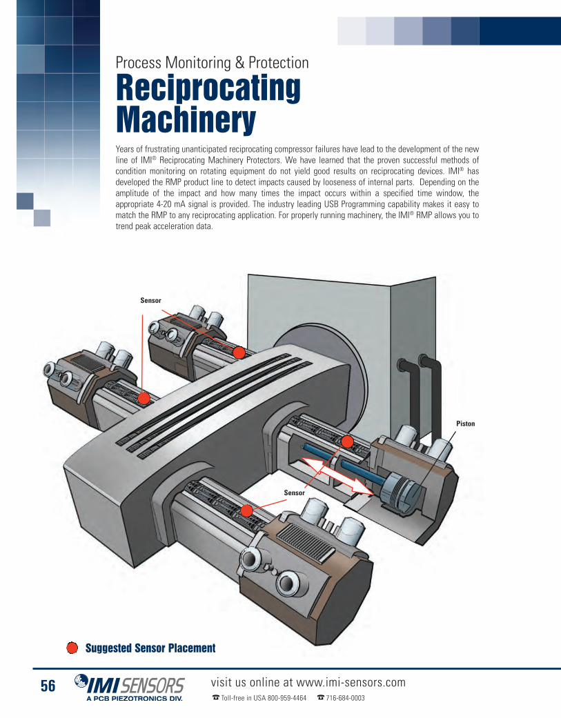
visit us online at www.imi-sensors.comToll-free in USA 800-959-4464 716-684-0003
56
Process Monitoring & Protection
ReciprocatingMachineryYears of frustrating unanticipated reciprocating compressor failures have lead to the development of the newline of IMI® Reciprocating Machinery Protectors. We have learned that the proven successful methods ofcondition monitoring on rotating equipment do not yield good results on reciprocating devices. IMI® hasdeveloped the RMP product line to detect impacts caused by looseness of internal parts. Depending on theamplitude of the impact and how many times the impact occurs within a specified time window, theappropriate 4-20 mA signal is provided. The industry leading USB Programming capability makes it easy tomatch the RMP to any reciprocating application. For properly running machinery, the IMI® RMP allows you totrend peak acceleration data.
Sensor
Piston
Sensor
Suggested Sensor Placement

Sensors for Compressors - Process Monitoring & Protection
Reciprocating Machinery
visit us online at www.imi-sensors.comToll-free in USA 800-959-4464 716-684-0003
57
4-20 mA Pressure SensorSeries 1503
� Mounts on the compressor
� Withstands sour gas environments
� 1/2” NPT fitting
Visit www.pcb.com for more information
Reciprocating Machinery ProtectorModel 649A01
� Detects faults / mechanical loosenessin reciprocating compressors
� Outperforms impact transmitters
� Continuous trending, with alarm& alert levels for early warning
See page 126 for more information
USB Programming Kits� Customize settings on your USB programmable sensor� Power-on, startup, & operating delays� Kit includes CD-ROM software & cable adapters
See page 136 for more information

Machine ToolMeasurements?
We Do!TM We do it all - sensors to measure
vibration, acoustics, force, pressure, load,strain, shock and torque - Sure we do!
www.imi-sensors.com/sure

visit us at www.imi-sensors.com Toll-free in USA 800-959-4464 716-684-0003
Machine Tool SpindlesEliminate the Guesswork, Use Vibration Trendsto Change Tooling Efficiently
IMI Sensors - A PCB Piezotronics Division

visit us online at www.imi-sensors.comToll-free in USA 800-959-4464 716-684-0003
60
Predictive Maintenance
Machine Tool SpindlesVibration monitoring of machine tools is useful for the analysis of tool life, tool integrity, part quality andpreventing unexpected tool failure causing unscheduled downtime. Machining processes, like cutting,generate very high levels of vibration, therefore a 100 mV/g accelerometer or less is always recommended.Furthermore, cutting operations often leave the accelerometer exposed to large amounts of cutting fluids andrazor sharp chips and metal scrap. To prevent damage, it is always recommended to utilize a sensor withintegral armor jacketed cable in this environment.
Bearings
Main Shaft
Debris
Suggested Sensor Placement

Machine Tool Spindles
visit us online at www.imi-sensors.comToll-free in USA 800-959-4464 716-684-0003
61
ICP® Accelerometers - Predictive Maintenance
Low Cost ICP® AccelerometerModel 607A61
� Unique 360º swivel design
� Allows for easy cable orientation
� Integral or armored integralcable options available
See page 85 for more information
Low Cost ICP® AccelerometerModel 603C01
� General purpose, hermetically sealed
� IMI’s most popular accelerometer
� Small footprint
See page 82 for more information
Low Cost ICP® AccelerometerModel 602D01
� Easy installation in tight spaces
� No cable/connector clearance required
� Less than 1 in height
See page 82 for more information
Precision ICP® AccelerometerModel 625B61
� 5% sensitivity tolerance
� Through-hole mounting
� Intrinsically safe,velocity output versions
Visit www.imi-sensors.com for more information
Precision ICP® AccelerometerModel 625B01
� Side exit, ring-style
� Low frequency responseto 12 cpm (0.2 Hz)
� Ceramic sensing element
See page 92 for more information
High FrequencyICP® AccelerometerModel 623C01
� 15 kHz high frequency response
� 10 mV/g or 100 mV/g options
� Intrinsically safe models available
See page 96 for more information

visit us online at www.imi-sensors.comToll-free in USA 800-959-4464 716-684-0003
62
Machine Tool Spindles
Accessories
Armor Jacketed, FEP Cable withMIL Connector to Blunt Cut048BPXXXBZ
Flat Surface MagnetModel 080A120: Ø0.75”Model 080A121 Ø1.0”
1/2-20 to 1/4-28Mounting StudModel 080A156
Mounting hole is prepared intomachine surface to accept sensor’smounting stud (A). Stud is thentightened to recommended torque withhex Allen key. Sensor (B) hex nut (C) isthreaded onto mounting stud.
B
Using the 360º capabilities of theSwiveler®, the cable is positioned intodesired orientation & temporarily handtightened. Using a wrench, the hex nutis tightened to the recommended torquewhile holding the cable or connector inthe desired location.
C
A
Swiveler® & Spindler® Accelerometers
This industry exclusive product is innovative in both itssmall size and its convenient swiveling mounting method
Model 607A11 Model 607A61
� Patented 360º swivel mount allows for convenientcable orientation (US Patent #6,435,902)
� Lower cost alternative to through-bolt sensors� Small footprint & very low profile for installation in tight spaces
Spot Face ToolsModel 080A128Model 080A129
See page 84 & 85 for more information
Cables & Connectors
Mounting Hardware
XXX = Denote cable length, 010 = 10 feet (Metric lengths available)
Sensor Mounting PadModel 080A93: Ø0.75”Model 080A118: Ø1.0”

IMI Sensors - A PCB Piezotronics Division
visit us at www.imi-sensors.com Toll-free in USA 800-959-4464 716-684-0003
Steel Rolling & AnnealingSensors that stand up to the harsh, high temperatureand extreme environments of steel mills

visit us online at www.imi-sensors.comToll-free in USA 800-959-4464 716-684-0003
64
Predictive Maintenance
Steel Rolling& AnnealingSteel Mills not only have typical fans, pumps, compressors, gearboxes and cooling towers but also havemachines and processes unique to the steel industry. The machine sizes, machine designs, operating speeds,cycle times, batch operations and harsh mill environments often command the use of carefully selectedsensors and methods for effective equipment monitoring. Iron making and steel making areas often have anabundance of large belt conveyors, critical ultra-low speed machines with limited rotation, critical large EOTcranes and large volume turbo blowers coupled with >2300 ºF hot blast air, molten liquid iron, red hot slabs,often carbon monoxide risks and of course, rolling mills.
Sensor Selection - IMI® recognizes the varied needs and challenges of the steel industry and has successfullydesigned a wide variety of transducers and accessories to help meet the needs of their customers. While mostsensors can be used in a wide range of applications, some sensors are better suited for the harsh conditionsencountered in steel mill applications and have been pointed out in this section.
Cold Rolling Mills have similar operating and cyclic challenges as hot rolling, but add in large numbers of roll "chock" bearingsthat are inherently difficult to instrument, run at varying speeds/loads in batch cycles. These “chocks” are removed andreinstalled into the mill with new rolls many times a day, after only minutes of operation at times. Couple this with stringentproduct quality critical requirements and again, many more extreme monitoring challenges are raised.
Precision ICP® AccelerometerModel 626B01
� Low noise floor
� Low frequency responseto 12 cpm (0.2 Hz)
� Full sweep calibration
See page 94 for more information
Low Cost ICP® AccelerometerModel 608A11
� Ideal for submersible applications
� Small installation footprint
� Stock integral cable lengths of10 ft, 20 ft, 30 ft and 50 ft
See page 84 for more information
4-20 mA Output SensorModel 640B01
� Available in top or side exit casings
� Peak or RMS, acceleration or velocity
� Intrinsically safe / explosionproof versions available
See page 112 for more information
Bearing Fault DetectorModel 682B05
� Provides early warning of bearing and gear faults
� Operates with PLC, DCS, SCADA,alarm and control systems
� Outputs 4-20 mA signals for peakacceleration and overall vibration
See page 124 for more information
Cold Rolling Areas - Process Monitoring & Protection

Hot Rolling Machines - Predictive Maintenance
Steel Rolling & Annealing
visit us online at www.imi-sensors.comToll-free in USA 800-959-4464 716-684-0003
65
Hot Rolling Mills have large low speed gearboxes, pinion stands, drive shafts and large diameter rolls in bearings to reducethe thickness of red hot steel slabs. Running these at variable loads/speeds and cycle times which may last only 30 secondsduring speed variations of >500% presents challenges. Environmental factors here include reheat furnace temperatures,steam and scale from cooling water sprays and of course coiling red hot steel traveling at thousands of feet per minute.
Model 600A02High TemperatureAccelerometer Kit
� Includes accelerometer, cableand charge amplifier
� Sensor temperature rangeup to 500 ºF (260 ºC)
� Compatible with ICP® signal conditioners
Visit www.imi-sensors.com for more information
High TemperatureICP® AccelerometerModel HT602D01
� Ceramic sensing element
� Low profile design
� Through-bolt mount
See page 100 for more information
High TemperaturePrecision ICP® AccelerometerModel HT628F01
� Quartz sensing element
� Excellent thermal stability
� Welded hermetic
See page 101 for more information
Very High TemperatureAccelerometerSeries EX600B1X
� Sensitivity: 10 to 100 mV/g(1.02 mV/(m/s2) to 10.2 mV/(m/s2))
� Frequency Range: (±5%)282 to 240,000 cpm (4.7 to 4 kHz)
� Measurement Range: ±50 to 500 g peak(±490 to 4900 m/s2)
� Mounting: Through Holes (3)
See page 106 for more information
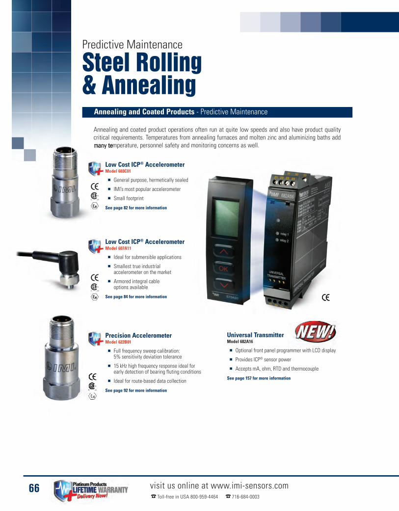
visit us online at www.imi-sensors.comToll-free in USA 800-959-4464 716-684-0003
66
Predictive Maintenance
Steel Rolling& Annealing
Annealing and coated product operations often run at quite low speeds and also have product qualitycritical requirements. Temperatures from annealing furnaces and molten zinc and aluminizing baths addmany temperature, personnel safety and monitoring concerns as well.
Annealing and Coated Products - Predictive Maintenance
Precision AccelerometerModel 622B01
� Full frequency sweep calibration:5% sensitivity deviation tolerance
� 15 kHz high frequency response ideal forearly detection of bearing fluting conditions
� Ideal for route-based data collection
See page 92 for more information
Universal TransmitterModel 682A16
� Optional front panel programmer with LCD display
� Provides ICP® sensor power
� Accepts mA, ohm, RTD and thermocouple
See page 157 for more information
Low Cost ICP® AccelerometerModel 607A11
� Ideal for submersible applications
� Smallest true industrialaccelerometer on the market
� Armored integral cableoptions available
See page 84 for more information
Low Cost ICP® AccelerometerModel 603C01
� General purpose, hermetically sealed
� IMI’s most popular accelerometer
� Small footprint
See page 82 for more information

IMI Sensors - A PCB Piezotronics Division
visit us at www.imi-sensors.com Toll-free in USA 800-959-4464 716-684-0003
Rotary Screw CompressorsHigh Frequency Accelerometers Capable ofCapturing Rotor Mesh and Bearing Faults
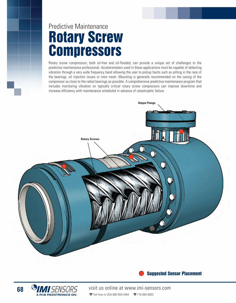
visit us online at www.imi-sensors.comToll-free in USA 800-959-4464 716-684-0003
68
Predictive Maintenance
Rotary ScrewCompressorsRotary screw compressors, both oil-free and oil-flooded, can provide a unique set of challenges to thepredictive maintenance professional. Accelerometers used in these applications must be capable of detectingvibration through a very wide frequency band allowing the user to pickup faults such as pitting in the race ofthe bearings, oil injection issues or rotor mesh. Mounting is generally recommended on the casing of thecompressor as close to the radial bearings as possible. A comprehensive predictive maintenance program thatincludes monitoring vibration on typically critical rotary screw compressors can improve downtime andincrease efficiency with maintenance scheduled in advance of catastrophic failure.
Rotary Screws
Output Flange
Suggested Sensor Placement

ICP® Accelerometers - Predictive Maintenance
Rotary Screw Compressors
visit us online at www.imi-sensors.comToll-free in USA 800-959-4464 716-684-0003
69
Very High Frequency AccelerometerModel 621B40
� 30 kHz frequency, even with magnet
� Titanium housing
� Smallest available footprint
See page 96 for more information
Precision AccelerometerModel 622B01
� Full frequency sweep calibration:5% sensitivity deviation tolerance
� 15 kHz high frequency response ideal forearly detection of bearing fluting conditions
� Ideal for route-based data collection
See page 92 for more information
Photo Courtesy of Abby Services, Inc.
Model 600A12Very High Frequency Accelerometer Kit
This high frequency 10 mV/g accelerometer kit features a verysmall accelerometer with a magnet and cable assembly
� High frequency response to 30 kHz, even when mounted magnetically� Supplied with 5 ft. cable with BNC plug termination� Kit features Model 621B40 accelerometer, with titanium housing

visit us online at www.imi-sensors.comToll-Free in USA 800-959-4464 716-684-0003
70
Rotary Screw Compressors
Accessories
Lightweight Coaxial Cable withBNC Plug to 5-44 Microdot Plug018C05 Cabling
Cables & Connectors
Mounting Hardware
Coiled TPE Cable withBNC Plug to 2-Pin MIL Connector050LQ006AC Cabling
Polyurethane Cable with BNC Plugto 2-Pin MIL-style Connector052BR010AC Cabling
BNC TerminationEnclosureModel 691A50/12
BNC TerminationEnclosureModel 691A51/04
BNC Switch BoxModel 691B41
BNC Switch BoxModel 691B42
Enclosures
Flat Surface MagnetModel 080A121
High Frequency MagnetModel 080A157
Curved Surface MagnetModel 080A131: Ø1.0”Model 080A132: Ø1.5”
Sensor Mounting PadModel 080A93: Ø0.75”Model 080A118: Ø1.0”

IMI Sensors - A PCB Piezotronics Division
visit us at www.imi-sensors.com Toll-free in USA 800-959-4464 716-684-0003
Nuclear Power InstrumentationSensors featuring the radiation hardened approvalsnecessary for nuclear power environments

visit us online at www.imi-sensors.comToll-free in USA 800-959-4464 716-684-0003
72
Energy & Power Generation
Nuclear PowerInstrumentation
� High temperature vibration measurements� Steam turbine testing� Monitoring of boiling water reactors
PCB®’s Charge Output accelerometers utilize piezo ceramic sensing elements to directly output an electrostaticcharge signal that is proportional to applied acceleration. Charge output accelerometers do not contain built-in signal conditioning electronics. As a result, external signal conditioning is required to interface theirgenerated measurement signals to readout or recording instruments. The sensor’s charge output signals canbe conditioned with an in-line, fixed charge converter.
Since there are no electronics built into Charge Output accelerometers, they can operate and survive exposureto very high temperatures (up to +1200 °F/+649 °C for some models). In addition, Charge Outputaccelerometers are used for thermal cycling requirements or to take advantage of existing charge amplifiersignal conditioning equipment. It is important to note that measurement resolution and low frequencyresponse for charge output, acceleration sensing systems are dependent upon the noise floor and dischargetime constant characteristics of the signal conditioning and readout devices used.

Nuclear Power Instrumentation
visit us online at www.imi-sensors.comToll-free in USA 800-959-4464 716-684-0003
73
Charge Output AccelerometerModel 357B53
� Sensitivity: (±15%) 100 pC/g(10.2 pC/(m/s2))
� Measurement Range:±150 g pk (±1470 m/s2 pk)
� Frequency Range: (+5%) 3 kHz
� Electrical Connector: 10-32 Coaxial Jack
See page 102 for more information
Charge Output AccelerometerModel 357B54
� Sensitivity: (±15%) 100 pC/g(10.2 pC/(m/s2))
� Measurement Range: ±150 g pk(±1470 m/s2 pk)
� Frequency Range: (+5%) 3 kHz
� Electrical Connector: 10-32 Coaxial Jack
See page 102 for more information
Shielded Hardline CableModel 023
Hardline Cable, Radiation Hardened
Recommended Components for a Typical InstallationA Charge output, radiation hardened accelerometerB Model 023FZXXXFZ cable assembly, 10-32 plug to 10-32 plugC In-line charge converter, Model 422E65/A or 422E66/AD Model 023FZXXXGA cable assembly, 10-32 plug to 10-32 jackE Model 003C03 cable, 10-32 plug to BNC plugF ICP® sensor signal conditionerG Model 012A03 output cable, BNC plug each endH Readout, recording, or data acquisition device
In-line Charge ConverterModel 422E65/A
� Sensitivity: (Charge Conversion)1 mV/pC
� Output Voltage: ±5 V
� Temperature Range: (Operating)-65 to +250 °F (-54 to +121 °C)
See page 159 for more information
In-line Charge ConverterModel 422E66/A
� Sensitivity: (Charge Conversion)10 mV/pC
� Output Voltage: ±5 V
� Temperature Range: (Operating)-65 to +250 °F (-54 to +121 °C)
See page 159 for more information
10-32 Coaxial JackModel GA
10-32 Coaxial PlugModel FZ
Charge Output Radiation Hardened Accelerometers - Energy & Power Generation
In-line Charge Converters, Radiation Hardened
XXX = Denote cable length, 010 = 10 feet (Metric lengths available)
� Survives integrated gamma flux to 108 rads� Survives integrated neutron flux to 1010 N/cm2
≤ 550 ºF (288 ºC)
Radiation Area
≤ 550 ºF (288 ºC)
Safe Zone

visit us online at www.imi-sensors.comToll-free in USA 800-959-4464 716-684-0003
74
Energy & Power Generation
Nuclear PowerInstrumentation
Hardline Cable with10-32 Plug to 10-32 JackModel 023A10
Charge Output AccelerometerModel 357B61
� Sensitivity: (±10%) 10 pC/g(1.02 pC/(m/s2))
� Measurement Range: ±1000 g pk(±9810 m/s2 pk)
� Frequency Range: (±5%) 5 kHz
� Electrical Connector: 10-32 Coaxial Jack
See page 105 for more information
Charge Output AccelerometerModel 357B69
� Sensitivity: (±10%) 3.5 pC/g(.357 pC/(m/s2))
� Measurement Range: ±500 g pk(±4950 m/s2 pk)
� Frequency Range: (±5%) 6 kHz
� Electrical Connector: 10-32 Coaxial Jack
See page 105 for more information
In-line Charge ConverterModel 422E65/A
� Sensitivity: (Charge Conversion)1 mV/pC
� Output Voltage: ±5 V
� Temperature Range: (Operating)-65 to +250 °F (-54 to +121 °C)
In-line Charge ConverterModel 422E66/A
� Sensitivity: (Charge Conversion)10 mV/pC
� Output Voltage: ±5 V
� Temperature Range: (Operating)-65 to +250 °F (-54 to +121 °C)
A B C D E F G
Supplied Accessory for 357B61 & 357B69
See page 159 for more information See page 159 for more information
High Temperature Charge Output Accelerometers, Radiation Hardened
H
A High temperature, radiation hardened accelerometer, Model 357B61 or 357B69B Model 023A10 cable assembly, 10-32 plug to 10-32 jackC Model 003EBXXXAL cable, 10-32 plug to 10-32 jackD In-line charge converter, Model 422E65/A or 422E66/AE Model 003D03, BNC plug to BNC plugF ICP® sensor signal conditionerG Model 012A03 output cable, BNC plug each endH Readout, recording, or data acquisition device
XXX = Denote cable length, 010 = 10 feet (Metric lengths available)
Hardline Cable, Radiation Hardened
In-line Charge Converter, Radiation Hardened
Recommended Components for a Typical Installation
≤ 550 ºF (288 ºC) ≤ 250 ºF (121 ºC)
Radiation Area Safe Zone

Nuclear Power Instrumentation
visit us online at www.imi-sensors.comToll-free in USA 800-959-4464 716-684-0003
75
Charge Output AccelerometerModel 357C71
� Sensitivity: (±5%) 10 pC/g(1.02 pC/(m/s2))
� Measurement Range: ±1000 g pk(±9810 m/s2 pk)
� Frequency Range: (±5%) 4 kHz
� Electrical Connector: 7/16-27 2-Pin
See page 104 for more information
Charge Output AccelerometerModel 357C72
� Sensitivity: (±5%) 50 pC/g(5.1 pC/(m/s2))
� Measurement Range: ±500 g pk(±4905 m/s2 pk)
� Frequency Range: (±5%) 2.5 kHz
� Electrical Connector: 7/16-27 2-Pin
See page 104 for more information
Charge Output AccelerometerModel 357C73
� Sensitivity: (±5%) 100 pC/g(10.2 pC/(m/s2))
� Measurement Range: ±300 g pk(±2943 m/s2 pk)
� Frequency Range: (±5%) 2 kHz
� Electrical Connector: 7/16-27 2-Pin
See page 104 for more information
PFA Cable with ET Connectorto EP Connector (25 ft cable)045M19 Cabling
Recommended Components for a Typical Installation
Differential Charge ConverterModel 422M182
� Sensitivity: 4 mV/pC
� Output Voltage: ±5 VpK
� Temperature Range: -60 to 185 ºF
See page 158 for more information
Differential Charge ConverterModel 422M183
� Sensitivity: 6 mV/pC
� Output Voltage: ±5 VpK
� Temperature Range: -60 to 185 ºF
Visit www.pcb.com for more information
2-pin Jack, 7/16-27 thdModel GP
2-socket Plug, 7/16-27 thdModel GN
2-conductor Hardline CableModel 013
High Temperature Radiation Hardened Accelerometers - Energy & Power Generation
Differential Charge Converters
A High temperature, radiation hardened accelerometer, Model 357C71, Model 357C72, Model 357C73B Model 013GNXXXGP cable assembly, 2 socket plug, 7/16 to 2 pin jackC Model 045M19, FEP cable with ET connector to EP connectorD Model 422M182, or Model 422M183E Model 003D03, BNC plug to BNC plugF ICP® sensor signal conditionerG Model 012A03 output cable, BNC plug each endH Readout, recording, or data acquisition device
PFA Jacketed Cable
Hardline Cable, Radiation Hardened
A B C D E F HG
≤ 900 ºF (482 ºC) ≤ 250 ºF (121 ºC)
Radiation Area Safe Zone
XXX = Denote cable length, 010 = 10 feet (Metric lengths available)

visit us online at www.imi-sensors.comToll-free in USA 800-959-4464 716-684-0003
76
Energy & Power Generation
Nuclear PowerInstrumentation
Charge Output AccelerometerModel 357D90
� Resonant frequency over 14 kHz
� 10 ft integral, hardline cable to 10-32 jack
� Measurement range: ± 1000 g pk
� Sensitivity: (±10%) 5 pC/g (.51 pC/(m/s²))
� Output into sensor base
See page 108 for more information
Charge Output AccelerometerModel 357D91
� Sensitivity in the transverse direction
� Resonant frequency over 14 kHz
� 10 ft integral, hardline cable to 10-32 jack
� Sensitivity: (±10%) 5 pC/g (.51 pC/(m/s²))
� Output perpendicular to sensor base
See page 108 for more information
Recommended Components for a Typical InstallationA High temperature, radiation hardened accelerometerB Model 003AXX cable assembly, 10-32 plug to 10-32 jackC In-line charge converter, Model 422E35/A or 422E36/AD 003DXX BNC plug to BNC plugE ICP® sensor signal conditioner.F Model 012A03 output cable, BNC plug each endG Readout, recording, or data acquisition device A B C D E F G
Safe Zone
In-line Charge ConverterModel 422E36
� Sensitivity: (Charge Conversion) 10 mV/pC
� Output Voltage: ±2.5 V
� Temperature Range: (Operating)-65 to +250 °F (-54 to +121 °C)
See page 159 for more information
In-line Charge ConverterModel 422E35
� Sensitivity: (Charge Conversion) 1 mV/pC
� Output Voltage: ±2.5 V
� Temperature Range: (Operating)-65 to +250 °F (-54 to +121 °C)
See page 159 for more information
TFE Cable with10-32 Plug to 10-32 PlugModel 003AXX
Very High Temp Charge Output Accelerometers, Radiation Hardened
Radiation Area
≤ 250 ºF (121 ºC)≤ 1200 ºF (649 ºC)
TFE Jacketed Cable
In-Line Charge Converter, Radiation Hardened
Axis of MeasurementModel 357D90
Axis of MeasurementModel 357D91
XXX = Denote cable length, 010 = 10 feet (Metric lengths available)
XXX = Denote cable length, 010 = 10 feet(Metric lengths available)

IMI Sensors - A PCB Piezotronics Division
visit us at www.imi-sensors.com Toll-free in USA 800-959-4464 716-684-0003
Shock MonitoringMiniature Embeddable Accelerometers for MonitoringShock in Critical Shipping Containers

visit us online at www.imi-sensors.comToll-free in USA 800-959-4464 716-684-0003
78
Process Monitoring & Protection
Shock MonitoringReusable ocean going shipping containers sometimes carry critical cargo that can be exposed to high shocklevels during loading and unloading. It has become necessary to monitor shock and vibration loading to preventdamage and provide a record of these events.
IMI’s line of embeddable miniature accelerometers in conjunction with other geographical logging devicesprovides vibration and shock signals to logging devices creating a dock to dock record of events occurringduring the shipment cycle.
Series 660 low cost embeddable accelerometers offer an affordable solution for vibration and shockmeasurements in high volume and commercial OEM applications. The units are particularly well suited forshock and impact detection of packages or components, as well as bearing and gear mesh vibrationmeasurements in predictive maintenance and condition monitoring requirements. The compact designs maybe embedded into machinery at the OEM level to provide value added monitoring protection.
The units employ field proven, solid state, piezoelectric sensing elementsfor durability and broadband performance. Choose from chargeoutput types, which survive high operating temperatures, orvoltage output ICP® types, with built-in signal conditioningmicroelectronics, for simplified operation and connectivity todata acquisition and vibration monitoring instrumentation.
Crate Floor
Shipping Crate
Suggested Sensor Placement

Low-power Pellet Accelerometers - Process Monitoring & Protection
� Choice of standard TO-5 or TO-8 transistor style packages� Variety of sensitivities to accommodate a wide range of applications� Charge output piezoelectric, voltage output ICP® and 3-wire low power options� Mountable via adhesive or soldering and choice of either integral cable
or solder pin electrical connections� Broadband width, high shock survivability, wide operating temperature range,
high resolution and large dynamic range
Embeddable AccelerometerLow Profile TO-5
Embeddable AccelerometerTO-5
Embeddable AccelerometerTO-8
Shock Monitoring
visit us online at www.imi-sensors.comToll-free in USA 800-959-4464 716-684-0003
79
See page 110 for more information See page 110 for more information See page 110 for more information
Embeddable Accelerometer Mounting Examples
Encapsulated SensorInstallation
IMI’s embeddable accelerometers are an excellent choice formonitoring shock and vibration in a very small package. Examples tothe right show different options for potting or completeencapsulation into mounting hardware, creating the optimal solution.
Potted SensorInstallation

Products By
Technology� Low Cost ICP®Accelerometers . . . . . . . . . . . . . . . . 82� Multi-axis ICP® Accelerometers . . . . . . . . . . . . . . . 90� Precision ICP® Accelerometers . . . . . . . . . . . . . . . 92� Quartz ICP® Accelerometers . . . . . . . . . . . . . . . . . . 98� HighTemperature Accelerometers . . . . . . . . . . . . 100� Embeddable Accelerometers . . . . . . . . . . . . . . . . 110� Vibration Transmitters . . . . . . . . . . . . . . . . . . . . . . 112� Programmable Vibration Transmitters . . . . . . . . . 122� Bearing Fault Detector . . . . . . . . . . . . . . . . . . . . . . 124� Reciprocating Machinery Protector . . . . . . . . . . . 126� Vibration Switches . . . . . . . . . . . . . . . . . . . . . . . . . 128� USB Programmer Kits . . . . . . . . . . . . . . . . . . . . . 136� Pressure Sensors . . . . . . . . . . . . . . . . . . . . . . . . . . 138� Echo®Wireless Vibration System . . . . . . . . . . . . . 142� Enclosures . . . . . . . . . . . . . . . . . . . . . . . . . . . . . . . 150� Signal Conditioners . . . . . . . . . . . . . . . . . . . . . . . . 154� In-line Charge Converters . . . . . . . . . . . . . . . . . . . 158� Portable Calibration Units . . . . . . . . . . . . . . . . . . . 160� Mounting Hardware . . . . . . . . . . . . . . . . . . . . . . . . 162� Cables & Connectors . . . . . . . . . . . . . . . . . . . . . . . 165� Breakaway Safety Connector . . . . . . . . . . . . . . . . 176

Ø0.87 in(Ø22.1 mm)
Low Cost ICP® Accelerometers� Economical designs ideal for permanent mounting� Rugged stainless steel housings with hermetic sealing� Case isolated electronics eliminate noise issues
visit us online at www.imi-sensors.comToll-Free in USA 800-959-4464 716-684-0003
82
Low Cost IndustrialICP® AccelerometerModel 602D01
� 100 mV/g (50 g measurement range)
� Frequency Range: (±3dB)30 to 480,000 cpm (0.5 to 8 kHz)
� Side exit, through-bolt design
� Available in high temperature (+325 ºF)& dual temperature/vibration output
Product shown at actual size
General Purpose
Low Cost IndustrialICP® AccelerometerModel 601A01
� 100 mV/g (50 g measurement range)
� Frequency range:16 to 600,000 cpm (0.27 to 10 kHz)
� Very good signal to noise ratio
� Integral cable option available
Product shown at actual size
Low Cost IndustrialICP® AccelerometerModel 603C01
� 100 mV/g (50 g measurement range)
� Frequency Range: (±3dB)30 to 600,000 cpm (0.5 to 10 kHz)
� Also available in 10, 50 and 500 mV/g
Product shown at actual size
1.65 in(42.2 mm)
1.0 in(25.4 mm)
0.85 in(21.5 mm)
1/4-28 Mtg. Bolt
1.65 in(41.9 mm)
2-Pin ThreadedMIL-C-5015Connector
2-Pin ThreadedMIL-C-5015Connector
2-Pin ThreadedMIL-C-5015Connector
11/16 hex
1/4-28 Mtg. Hole
Sig/Pwr Ground
Sig/Pwr Ground Sig/Pwr Ground
7/8 Hex
1/4-28 Mtg. Bolt
1.94 in(49.3 mm)
Ø0.68 in(Ø17.3 mm)

Low Cost ICP® Accelerometers
visit us online at www.imi-sensors.comToll-Free in USA 800-959-4464 716-684-0003
83
Low Cost IndustrialICP® AccelerometerModel 606B01
� 100 mV/g (50 g measurement range)
� Frequency Range: (±3dB)30 to 300,000 cpm (0.5 to 5 kHz)
� Side exit, through-bolt design
Product shown at actual size
Technical SpecificationsModel Number 601A01 602D01 603C01 606B01 607A01
Sensitivity100 mV/g
10.2 mV/(m/s²) [2]Sensitivity Tolerance ±20 % ±10 % ±20 % ±15 %
Measurement Range±50 g
±490 m/s²
Frequency Range(±3 dB)
16 to 600,000 cpm 30 to 480,000 cpm 30 to 600,000 cpm0.27 to 10 kHz [4] 0.5 to 8 kHz [4] 0.5 to 10 kHz [4]
Resonant Frequency960 kcpm 1,500 kcpm 1,080 kcpm16 kHz [5] 25 kHz [5] 18 kHz [5]
Broadband Resolution(1 to 10 kHz)
50 µg 350 µg491 µm/sec² [5] 3,434 µm/sec2 [5]
Non-linearity ±1 % [6]Transverse Sensitivity ≤ 7 %
EnvironmentalOverload Limit(Shock)
5,000 g pk49,050 m/s² pk
Temperature Range-65 to 250 °F-54 to 121 °C
Enclosure Rating IP68
ElectricalSettling Time(within 1% of bias) ≤ 4.0 sec ≤ 2.0 sec
Discharge TimeConstant ≥ 0.6 sec ≥ 0.3 sec
Excitation Voltage 18 to 28 VDCConstant CurrentExcitation 2 to 20 mA
Output Impedance <150 ohmOutput Bias Voltage 8 to 12 VDC
Spectral Noise(10 Hz)
3.2 µg/√Hz 8.0 µg/√Hz31.0 (µm/sec²)/√Hz [5] 78.5 (µm/sec²)/√Hz [5]
Spectral Noise(100 Hz)
1.0 µg/√Hz 5 µg/√Hz9.81 (µm/sec²)/√Hz [5] 49.1 (µm/sec²)/√Hz [5]
Spectral Noise(1 kHz)
0.7 µg/√Hz 4 µg/√Hz6.94 (µm/sec²)/√Hz [5] 39.2 (µm/sec²)/√Hz [5]
Electrical Isolation(Case) >108 ohm
Physical
Size - Hex7/8 in
N/A11/16 in
N/A7/8 in
22 mm 18 mm 22 mm
Size - Diameter N/A1.38 in
N/A35.1 mm
Size - Height1.94 in 0.845 in 1.65 in 1.00 in 1.23 in49.3 mm 21.5 mm 42.2 mm 25.4 mm 31.2 mm
Size - Length N/A1.65 in
N/A1.93 in 1.52 in
41.9 mm 49 mm 38.6 mm
Size - Width N/A0.74 in
N/A18.8 mm
Weight2.8 oz 2.61 oz 1.8 oz 4.4 oz 3.7 oz80 gm 74.0 gm 51 gm 124 gm 105 gm
Mounting Thread 1/4-28 Female
Mounting Torque2 to 5 ft-lb
2.7 to 6.8 N-mSensing Element Ceramic ShearHousing Material Stainless SteelSealing Welded HermeticElectrical Connector 2-pin MIL-C-5015
Supplied Accessories
Model 081A40MountingStud (1)
Model 081A97Through-bolt1/4-28 (1)
Model 081A40Mounting Stud
Model 081A68CaptiveMounting Bolt1/4-28 x .90" (1)
Model080A162MountingStud (1)
Model ICS-2 NIST-traceable single-axis single-point amplituderesponse calibration at 6000 cpm (100 Hz) [1]
NotesAll specifications are at room temperature unless otherwise specified
[1] 1/4-28 has no equivalent in S.I. units.[2] Conversion Factor 1g = 9.81 m/s².[3] For CE reference PCB® Declaration of ConformancePS023 for details.
[4] The high frequency tolerance is accurate within ±10%of the specified frequency.
[5] Typical.[6] Zero-based, least-squares,straight line method.
[7] Twisted shielded pair.[8] Stainless steel armor jacketover twisted shielded pair.
Swiveler® IndustrialICP® AccelerometerModel 607A01
� 100 mV/g (50 g measurement range)
� Frequency Range: (±3dB)30 to 600,000 cpm (0.5 to 10 kHz)
� Electrical Connector: 2-pin MIL-C-5015
� Patented swivel mounting base for easeof cable orientation (US patent #6,435,902)
Product shown at actual size
2-Pin ThreadedMIL-C-5015Connector
1/4-28 Mtg. BoltØ1.38 in(Ø35.1 mm)
1.00 in(25.4 mm)
1.93 in(49 mm)
1.52 in(38.6 mm)
1.23 in(31.20 mm)
1.00 in(25.40 mm)
Sig/Pwr Ground
7/8 Floating Hex 3/4-16 UNF-2B
2-Pin ThreadedMIL-C-5015Connector
3/4-16 UNF-2A
1/4-28 UNF-2A
Model 080A162Mounting Stud(Supplied)
Sig/Pwr Ground
Optional Versions
EX - Hazardous Area ApprovalFor Models: 602D01, 603C01, 607A01
M - Metric MountFor Models: 601A01, 602D01, 603C01, 606B01, 607A01
TO - Temperature OutputFor Models: 602D01, 603C01, 607A01
Technical Specifications
Model Number 601A01 602D01 603C01 606B01 607A01 Model Number 601A01 602D01 603C01 606B01 607A01
Performance Physical
Accessories & Cables: Pages 162-176

Low Cost ICP® Accelerometers� Integral cable designs meet IP68 qualification� Save conduit and tray space with smaller diameter polyurethane cable� Smallest footprints of any true industrial accelerometer
visit us online at www.imi-sensors.comToll-Free in USA 800-959-4464 716-684-0003
84
Low Cost IndustrialICP® AccelerometerModel 608A11
� 100 mV/g (50 g measurement range)
� Frequency Range: (±3dB)30 to 600,000 cpm (0.5 to 10 kHz)
� Versions with 10 ft, 20 ft, 30 ft and 50 ftintegral cable are available in stock
Product shown at actual size
2.50 (63.5) to bending radius
9/16 HEX
Black: Ground
White: Sig/Power
Integral, 10 ft (3 m), 2 conductor cable terminating in blunt cut
28 Mtg Hole
Patented Mounting of Swiveler®
and Spindler® AccelerometersModels 607A11 and 607A61 feature a unique mountingsystem patented to IMI Sensors (US Patent #6,435,902).First, screw down the supplied mounting stud. Then simplyget the sensor started on the thread. At this point one canorient the integral cable in any direction. Finally, lock thesensor down with 2 to 5 ft-lbs of torque. This locks thecable in place and provides a secure mount that will notcome loose.
Submersible
Swiveler® IndustrialICP® AccelerometerModel 607A11
� 100 mV/g (50 g measurement range)
� Frequency Range: (±3dB)30 to 600,000 cpm (0.5 to 10 kHz)
� Versions with 10 ft and 30 ft integralcable are available in stock
� Patented swivel mounting base forease of cable orientation(US Patent #6,435,902)
Product shown at actual size
Alternate Mounting Method for 608A11When stud mounting the model 608A11 we suggest takinga look at a couple accessories that might make the jobeasier: model 080A162 floating hex nut and model080A165 mounting stud. Simply drill and tap into themachine and then screw down the 080A162 mountingstud, then slide the floating hex nut over the end of theintegral cable. The hex nut mates with the stud and allowsthe installer to lock the sensor in place, turning the nutfrom the side. It is sometimes preferred in lieu of turningdown the entire sensor and it’s integral cable.
Mounting hole is prepared intomachine surface to acceptsensor’s mounting stud (A). Studis then tightened to recommendedtorque with hex Allen key. Sensor(B) hex nut (C) is threaded ontomounting stud.
B
Using the 360º capabilities of theSwiveler®, the cable is positioned intodesired orientation & temporarily handtightened. Using a wrench, the hex nutis tightened to the recommendedtorque while holding the cable orconnector in the desired location.
C
A
Mounting stud is tightened torecommended torque withappropriately sized hex Allen key.
Mounting hole is prepared into machinesurface to accept sensor’s mountingstud. Sensor integral cable is threadedthrough the floating hex nut.
Model 080A156Mounting Stud(Supplied)
10 ft (3 m)Integral Cable
Integral 10ft (3 m)2 Conductor CableTerminating inBlunt Cut
9/16 Floating Hex
0.625 in(15.9 mm)
1.58 in(40.1 mm)
0.97 in(24.6 mm)
2.50 in (63.5 mm)to Bending Radius
White: Sig/Pwr
Black: Ground
White: Sig/PwrBlack: Ground
1/2-20 UNF-2A
1/4-28 UNF-2A
9/16 Hex
1/4-28Mounting Hole

Low Cost ICP® Accelerometers
visit us online at www.imi-sensors.comToll-Free in USA 800-959-4464 716-684-0003
85
Low Cost Spindler® IndustrialICP® AccelerometerModel 607A61
� 100 mV/g (50 g measurement range)
� Frequency Range: (±3dB)30 to 600,000 cpm (0.5 to 10 kHz)
� Selectable armor length and overall cable length
Product shown at actual size
Low Cost Accelerometers� Rugged design ideal for machine tool
monitoring or mining applications� Smallest footprint and profile of any
industrial accelerometer� Thin armor jacket for easy handling
and installation
Armored Integral Cable
Physical
Size (Hex)9/16 in 9/16 in 9/16 in14 mm 14 mm 14 mm
Size (Height)0.97 in 1.0 in 2.5 in24.6 mm 25.4 mm 64 mm
Weight1.1 oz 3.5 oz
31 gm [4] 99.3 gmMounting StudMounting Thread 1/4-28 [1]
Mounting Torque (stud)7 to 8 ft-lb 2 to 5 ft-lb
9.5 to 10.8 N-m [2][6] 2.7 to 6.8 N-m
Mounting Torque (hex nut)2 to 5 ft-lb
N/A2.7 to 6.8 N-m
Sensing Element Ceramic ShearHousing Material Stainless SteelSealing Welded Hermetic MoldedElectrical Connector Molded Integral Cable Integral Armored Cable Molded Integral CableElectrical Connector Position Side Top
Cable Length10 ft3.0 m
Cable Type Polyurethane [7] Polyurethane [10] Polyurethane [7]
Supplied Accessories
Model 080A156 Mounting Base (1) Model 081A40Mounting Stud (1)
Model ICS-2 NIST-traceable single-axis single-point amplituderesponse calibration at 6000 cpm (100 Hz) (1)
NotesAll specifications are at room temperature unless otherwise specified
Technical SpecificationsModel Number 607A11 607A61 608A11
Sensitivity (± 15 %)100 mV/g
(10.2 mV/(m/s2)) [3]
Measurement Range± 50 g
± 490 m/s²
Frequency Range (± 3 dB)30 to 600,000 cpm0.5 to 10 kHz
Resonant Frequency1,500 kcpm 1,320 kcpm25 kHz [8] 22 kHz [8]
Broadband Resolution(1 to 10 kHz)
350 µg3,434 µm/sec² [8]
Non-linearity ±1 % [9]Transverse Sensitivity ≤ 7 %
Environmental
Overload Limit (Shock)5,000 g pk
49,050 m/s² pk
Temperature Range-65 to +250 °F-54 to +121 °C
Enclosure Rating IP68
ElectricalSettling Time(within 1% of bias) ≤ 2.0 sec
Discharge Time Constant ≥ 0.3 secExcitation Voltage 18 to 28 VDCConstant Current Excitation 2 to 20 mAOutput Impedance <150 ohmOutput Bias Voltage 8 to 12 VDC
Spectral Noise (10 Hz)8 µg/√Hz
78.5 (µm/sec²)/√Hz [8]
Spectral Noise (100 Hz)5 µg/√Hz
49.1 (µm/sec²)/√Hz [8]
Spectral Noise (1 kHz)4 µg/√Hz
39.2 (µm/sec²)/√Hz [8]Electrical Isolation (Case) >108 ohm
[1] 1/4-28 has no equivalent in S.I. units.[2] 1/8" hex Allen key required for English version,4 mm hex Allen key required for Metric version.
[3] Conversion Factor 1g = 9.81 m/s².[4] Measured with mounting stud.[5] For CE reference PCB® Declaration of ConformancePS023 or PS060 for details.
[6] Stud torque must exceed sensor hex nut torque toensure proper dismantling.
[7] Twisted shielded pair.[8] Typical.[9] Zero-based, least-squares, straight line method.[10] Stainless steel armor jacket over
twisted shielded pair Ø0.625 in(Ø15.9 mm)
1.10 in(27.9 mm)
1.0 in(25.4 mm)
1/2-20 UNF-2B
Model 080A156Mounting Stud(supplied)
9/16 Floating Hex
10 ft (3 m) Armored CableBlack: Ground
1/4-28 UNF-2A
1/2-20 UNF-2A
Optional Versions
EX - Hazardous Area ApprovalFor Models: 607A11, 607A61, 608A11
M - Metric MountFor Models: 607A11, 607A61, 608A11
TO - Temperature OutputFor Models: 607A11, 607A61, 608A11
White: Sig/Pwr
Technical Specifications
Model Number 607A11 607A61 608A11
Performance
Environmental
Electrical
Physical
Supplied Accessories
Notes
Accessories & Cables: Pages 162-176

Low Cost ICP® Accelerometers� CSA & ATEX approvals for use in hazardous areas� Use with or without energy limiting barriers
depending upon area classification� Trend critical vibration data from a safe location
visit us online at www.imi-sensors.comToll-Free in USA 800-959-4464 716-684-0003
86
Hazardous Area Approved
Low Cost IndustrialICP® AccelerometerModel EX602D01
� 100 mV/g (50 g measurement range)
� Frequency Range: (±3dB)30 to 480,000 cpm (0.5 to 8 kHz)
� Side exit, through-bolt design
Product shown at actual sizeSee page 83 for complete specifications
Low Cost IndustrialICP® AccelerometerModel EX603C01
� 100 mV/g (50 g measurement range)
� Frequency Range: (±3dB)30 to 600,000 cpm (0.5 to 10 kHz)
� Also available in 10, 50 and 500 mV/g
Product shown at actual sizeSee page 83 for complete specifications
Low Cost IndustrialICP® AccelerometerModel EX608A11
� 100 mV/g (50 g measurement range)
� Frequency Range: (±3dB)30 to 600,000 cpm (0.5 to 10 kHz)
� Selectable cable length in meters or feet
Product shown at actual sizeSee page 85 for complete specifications
Model EX607A11Swiveler® IndustrialICP® Accelerometer
� 100 mV/g (50 g measurement range)
� Frequency Range: (±3dB)30 to 600,000 cpm (0.5 to 10 kHz)
� Supplied with 10 ft. integral cable
� Selectable cable length in meters or feet
Product shown at actual sizeSee page 85 for complete specifications
Model EX607A61Low Cost Spindler®
Industrial ICP® Accelerometer� 100 mV/g (50 g measurement range)
� Frequency Range: (±3dB)30 to 600,000 cpm (0.5 to 10 kHz)
� Selectable armor length andoverall cable length
Product shown at actual sizeSee page 85 for complete specifications
Technical Specifications for Hazardous Area Approved and Dual Temperature& Vibration Output sensors are equal to thier standard model equivalent.See page 83 and 85 for complete specifications
Hazardous Area ApprovalsIMI Sensors’ low cost accelerometerscarry CSA & ATEX approvals as follows.Div 1 or Zone 0 or 1 installations requirean energy limiting barrier. Div 2 or Zone 2installations do not require an energylimiting barrier if an approved sensorpower supply is used.Class I, Div 1, Groups A, B, C, DClass II, Div 1, Groups E, F, GClass III, Div 1Exia IIC T4AExia IIC T4Class I, Div 2, Groups A, B, C, DExnL IIC T4AExnA IIC T4Ex ia IIC T4, -40ºC ≤ Ta ≤ 121ºC, II 1 GEx nL IIC T4, -40ºC ≤ Ta ≤ 121ºC, II 3 GGOST-R: 0ExiaIICT4 X

Low Cost ICP® Accelerometers
visit us online at www.imi-sensors.comToll-Free in USA 800-959-4464 716-684-0003
87
Low Cost ICP® Accelerometers� Simultaneously measure vibration and temperature levels� For use with multi-channel data acquisition systems� Simple to read DC voltage temperature output
Dual Temperature & Vibration Output
Low Cost IndustrialICP® AccelerometerModel TO603C01
� 100 mV/g (50 g measurement range)
� Frequency Range: (±3dB)30 to 600,000 cpm (0.5 to 10 kHz)
� 3-pin MIL connector
Product shown at actual sizeSee page 83 for complete specifications
Swiveler® IndustrialICP® AccelerometerModel TO607A11
� 100 mV/g (50 g measurement range)
� Frequency Range: (±3dB)30 to 600,000 cpm (0.5 to 10 kHz)
� Supplied with 10 ft. integral cable
� Selectable cable length in meters or feet
Product shown at actual sizeSee page 85 for complete specifications
Low Cost Spindler®
Industrial ICP® AccelerometerModel TO607A61
� 100 mV/g (50 g measurement range)
� Frequency Range: (±3dB)30 to 600,000 cpm (0.5 to 10 kHz)
� Selectable armor length andoverall cable length
Product shown at actual sizeSee page 85 for complete specifications
Dual Output Sensor Switch Box with2 BNC Output(Temperature& Vibration)
2 ChannelData Collector
Dual Temperature & Vibration Output SensorsIMI’s dual temperature and vibration output sensors are anexcellent asset for technicians using a 2 channel datacollector or online monitoring system. The temperatureoutput is a simple DC voltage scaled from 0 to 120 ºC with10 mV/ºC sensitivity thus a 0 to 1.2 VDC output. One cansend the temperature output to a 0-5 VDC input channel andscale it properly by making the full scale range 500 ºC. Thetemperature sensor draws its power from the vibrationelectronics and can only be read when ICP® power is beingapplied to the vibration leads. All IMI® switch boxes comestandard with two BNC’s for each channel: one fortemperature and one for vibration.

Low Cost ICP® Accelerometers� Increase sensitivity for greater resolution on slow speed applications� Decrease sensitivity for increased range on impacting applications� Low frequency response down to 12 cycles per minute
visit us online at www.imi-sensors.comToll-Free in USA 800-959-4464 716-684-0003
88
Alternate Sensitivity
Low Cost IndustrialICP® AccelerometerModel 603C00
� 10 mV/g (500 g measurement range)
� Frequency Range: (±3dB)30 to 600,000 cpm (0.5 to 10 kHz)
� Monitor high speed, high vibrationapplications without worryingabout saturation
Product shown at actual size
Low Cost, Same High QualityThere is no “entry level” spending point withIMI Sensors industrial accelerometers. Infact, most of our Application Engineers –certified vibration analysts – recommend“low cost” sensors to customers as theirfirst sensor option. Despite their economicalmoniker, low-cost accelerometers are idealfor applications where sensors will bepermanently mounted to trend vibration24/7, monthly or even quarterly. No matterhow often data is taken one can count onlow cost accelerometers to hold theirsensitivity year after year, giving the analystquality data from which to compare valuesfrom last collection. Low costaccelerometers are all hermetically sealedin stainless steel housings and most arecovered by IMI Sensors’ Lifetime WarrantyPlus program.
1.65 in(42.2 mm)
2-Pin ThreadedMIL-C-5015Connector
11/16 hex
1/4-28Mtg. Hole
Ø0.68 in (Ø17.3 mm)
Sig/Pwr Ground
2-Pin ThreadedMIL-C-5015Connector
1.90 in(48.2 mm)
1.25 in(31.75 mm)
1/4-28 Mtg. Bolt Ø0.87 in(Ø22.1 mm)
0.050 in(1.27 mm)
0.875 in(22.23 mm)Hex
Low Cost IndustrialICP® AccelerometerModel 601A02
� 500 mV/g (10 g measurement range)
� Low frequency responsedown to 12 CPM
� Best value of any slow speedindustrial accelerometer
Product shown at actual size
Low Cost IndustrialICP® AccelerometerModel 603C02
� 500 mV/g (10 g measurement range)
� Frequency Range: (±3dB)30 to 600,000 cpm (0.5 to 10 kHz)
� Increased resolution for slowspeed applications
Product shown at actual sizeTechnical Drawing
Model 603C00 & Model 603C02
Model 603C00 & Model 603C02
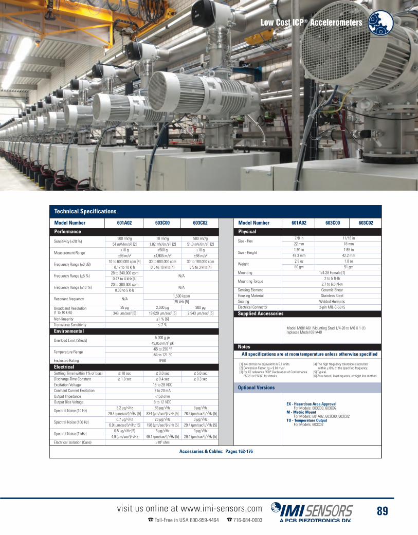
Low Cost ICP® Accelerometers
visit us online at www.imi-sensors.comToll-Free in USA 800-959-4464 716-684-0003
89
Low Cost Ac-Model Number 601A02 603C00 603C02
Performance
Sensitivity (±20 %)500 mV/g 10 mV/g 500 mV/g
51 mV/(m/s²) [2] 1.02 mV/(m/s2) [2] 51.0 mV/(m/s2) [2]
Measurement Range±10 g ±500 g ±10 g
±98 m/s² ±4,905 m/s² ±98 m/s²
Frequency Range (±3 dB)10 to 600,000 cpm [4] 30 to 600,000 cpm 30 to 180,000 cpm
0.17 to 10 kHz 0.5 to 10 kHz [4] 0.5 to 3 kHz [4]
Frequency Range (±5 %)28 to 240,000 cpm
N/A0.47 to 4 kHz [4]
Frequency Range (±10 %)20 to 300,000 cpm
N/A0.33 to 5 kHz
Resonant Frequency N/A1,500 kcpm25 kHz [5]
Broadband Resolution(1 to 10 kHz)
35 µg 2,000 µg 300 µg343 µm/sec² [5] 19,620 µm/sec2 [5] 2,943 µm/sec2 [5]
Non-linearity ±1 % [6]Transverse Sensitivity ≤ 7 %
Environmental
Overload Limit (Shock)5,000 g pk
49,050 m/s2 pk
Temperature Range-65 to 250 °F-54 to 121 °C
Enclosure Rating IP68
ElectricalSettling Time (within 1% of bias) ≤ 10 sec ≤ 3.0 sec ≤ 5.0 secDischarge Time Constant ≥ 1.0 sec ≥ 0.4 sec ≥ 0.3 secExcitation Voltage 18 to 28 VDCConstant Current Excitation 2 to 20 mAOutput Impedance <150 ohmOutput Bias Voltage 8 to 12 VDC
Spectral Noise (10 Hz)3.2 µg/√Hz 85 µg/√Hz 8 µg/√Hz
29.4 (µm/sec²)/√Hz [5] 834 (µm/sec²)/√Hz [5] 78.5 (µm/sec²)/√Hz [5]
Spectral Noise (100 Hz)0.7 µg/√Hz 20 µg/√Hz 3 µg/√Hz
6.9 (µm/sec²)/√Hz [5] 196 (µm/sec²)/√Hz [5] 29.4 (µm/sec²)/√Hz [5]
Spectral Noise (1 kHz)0.5 µg/√Hz [5] 5 µg/√Hz 3 µg/√Hz
4.9 (µm/sec²)/√Hz 49.1 (µm/sec²)/√Hz [5] 29.4 (µm/sec²)/√Hz [5]Electrical Isolation (Case) >108 ohm
Physical
Size - Hex7/8 in 11/16 in22 mm 18 mm
Size - Height1.94 in 1.65 in49.3 mm 42.2 mm
Weight2.8 oz 1.8 oz80 gm 51 gm
Mounting 1/4-28 Female [1]
Mounting Torque2 to 5 ft-lb
2.7 to 6.8 N-mSensing Element Ceramic ShearHousing Material Stainless SteelSealing Welded HermeticElectrical Connector 2-pin MIL-C-5015
Supplied Accessories
Model M081A61 Mounting Stud 1/4-28 to M6 X 1 (1)replaces Model 081A40
NotesAll specifications are at room temperature unless otherwise specified
Optional Versions
EX - Hazardous Area ApprovalFor Models: 603C00, 603C02
M - Metric MountFor Models: 601A02, 603C00, 603C02
TO - Temperature OutputFor Models: 603C02
[1] 1/4-28 has no equivalent in S.I. units.[2] Conversion Factor 1g = 9.81 m/s².[3] For CE reference PCB® Declaration of ConformancePS023 or PS060 for details.
[4] The high frequency tolerance is accuratewithin ±10% of the specified frequency.
[5] Typical.[6] Zero-based, least-squares, straight line method.
Technical Specifications
Model Number 601A02 603C00 603C02 Model Number 601A02 603C00 603C02
Performance Physical
Accessories & Cables: Pages 162-176

Multi-axis ICP® Accelerometers� Triaxial designs measure vibration in horizontal, vertical and axial directions� Side exit, through-bolt mount designs ideal for spaces with
limited clearance and cable orientation� Ideal for route-based PdM with 2 or 3 channel data collector
Multi-axis accelerometers contain two or three independent acceleration sensing elements within one housing. Thesensing elements are oriented in mutually perpendicular geometries in order to respond to vibration in independent,orthogonal directions. Biaxial accelerometers contain two sensing elements, whereas triaxial versions containthree. Each sensing axis contains a dedicated, Built in , low noise, microelectronic signal amplifier whose outputsignal is delivered to an independent cable lead or connector pin.
Multi-axis measurements are useful for radial vs. axial bearing vibration monitoring, machinery foundationtroubleshooting, and structural impulse and response studies. Styles for low cost and precision requirements aredifferentiated by their sensitivity tolerances and extent of supplied NIST-traceable calibration.
visit us online at www.imi-sensors.comToll-Free in USA 800-959-4464 716-684-0003
90
Low Cost Biaxial IndustrialICP® AccelerometerModel 605B01
� 100 mV/g (50 g measurement range)
� Frequency Range: (±3dB)30 to 300,000 cpm (0.5 to 5 kHz)
� Side exit, through-bolt design
Product shown at actual size
Precision TriaxialIndustrial ICP® AccelerometerModel 629A31
� 100 mV/g (50 g measurement range)
� Frequency Range: (+/- 3dB)48 to 480,000 cpm (0.8 to 8 kHz)
� Full frequency sweep calibrationon all three axes
Product shown at actual size
Low Cost Triaxial IndustrialICP® AccelerometerModel 604B31
� 100 mV/g (50 g measurement range)
� Frequency Range: (±3dB)30 to 300,000 cpm (0.5 to 5 kHz)
� Side exit, through-bolt design
Product shown at actual size
4-pin BayonetMIL-C-26482Connector
4-pin BayonetMIL-C-26482Connector
3-pin ThreadedMIL-C-5015Connector
4-pin BayonetMIL-C-26482Connector
Y
Z
ZZY
X X
Z
X
Y
“X”
“Z”
“X”
X
1.5 in(38.1 mm)
0.835 in(21.2 mm)
1/4-28 Mounting Bolt
1/4-28Mounting Bolt
1/4-28Mounting Bolt
Ø1.38 in(Ø35.1 mm)
“Y” “Z”
“Ground”
1.49 in(37.8 mm)
1.49 in(37.8 mm)
1/4-28 Mounting Bolt
1.93 in(49 mm)
1.0 in(25.4 mm)
Ø1.38 in(Ø35.1 mm)
“Ground”
2.11 in(53.6 mm)
1.0 in(25.4 mm)
Ø1.38 in(Ø35.1 mm)
“Ground”“X”
“Y” “Z”
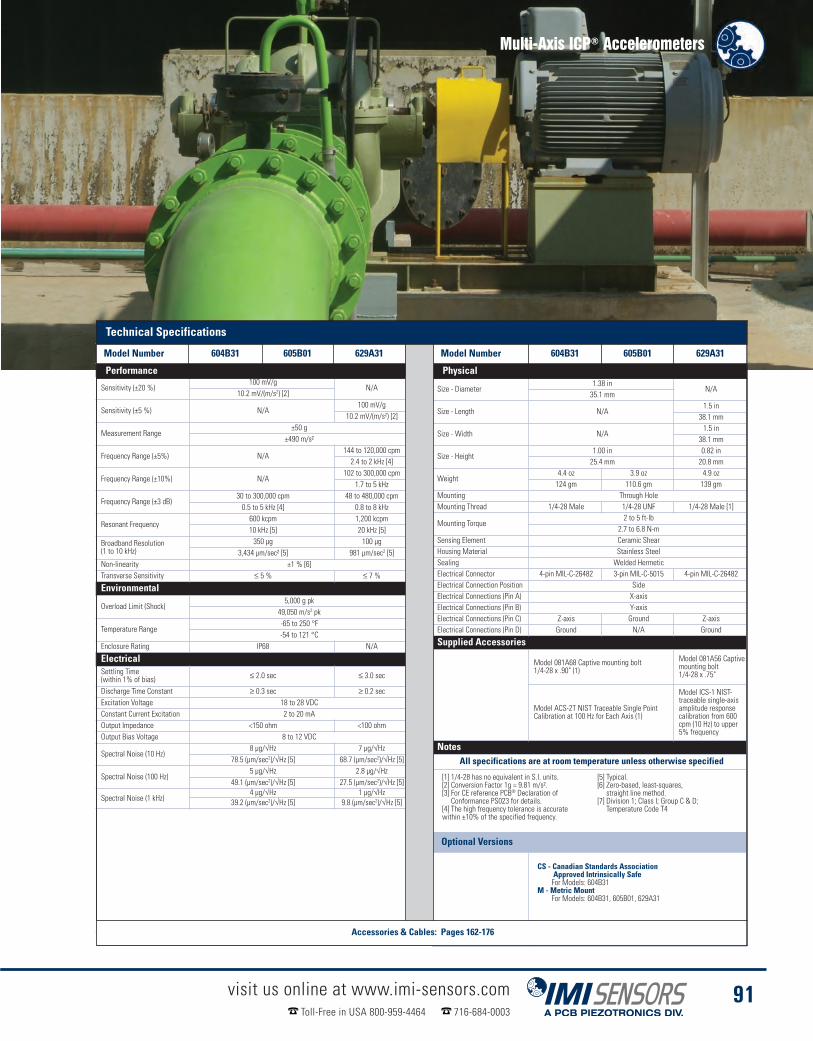
Multi-Axis ICP® Accelerometers
visit us online at www.imi-sensors.comToll-Free in USA 800-959-4464 716-684-0003
91
Low Cost AccelerometersModel Number 604B31 605B01 629A31
Sensitivity (±20 %)100 mV/g
N/A10.2 mV/(m/s2) [2]
Sensitivity (±5 %) N/A100 mV/g
10.2 mV/(m/s2) [2]
Measurement Range±50 g
±490 m/s²
Frequency Range (±5%) N/A144 to 120,000 cpm2.4 to 2 kHz [4]
Frequency Range (±10%) N/A102 to 300,000 cpm
1.7 to 5 kHz
Frequency Range (±3 dB)30 to 300,000 cpm 48 to 480,000 cpm0.5 to 5 kHz [4] 0.8 to 8 kHz
Resonant Frequency600 kcpm 1,200 kcpm10 kHz [5] 20 kHz [5]
Broadband Resolution(1 to 10 kHz)
350 µg 100 µg3,434 µm/sec² [5] 981 µm/sec2 [5]
Non-linearity ±1 % [6]Transverse Sensitivity ≤ 5 % ≤ 7 %
Environmental
Overload Limit (Shock)5,000 g pk
49,050 m/s2 pk
Temperature Range-65 to 250 °F-54 to 121 °C
Enclosure Rating IP68 N/A
ElectricalSettling Time(within 1% of bias) ≤ 2.0 sec ≤ 3.0 sec
Discharge Time Constant ≥ 0.3 sec ≥ 0.2 secExcitation Voltage 18 to 28 VDCConstant Current Excitation 2 to 20 mAOutput Impedance <150 ohm <100 ohmOutput Bias Voltage 8 to 12 VDC
Spectral Noise (10 Hz)8 µg/√Hz 7 µg/√Hz
78.5 (µm/sec2)/√Hz [5] 68.7 (µm/sec2)/√Hz [5]
Spectral Noise (100 Hz)5 µg/√Hz 2.8 µg/√Hz
49.1 (µm/sec2)/√Hz [5] 27.5 (µm/sec2)/√Hz [5]
Spectral Noise (1 kHz)4 µg/√Hz 1 µg/√Hz
39.2 (µm/sec2)/√Hz [5] 9.8 (µm/sec2)/√Hz [5]
Physical
Size - Diameter1.38 in
N/A35.1 mm
Size - Length N/A1.5 in38.1 mm
Size - Width N/A1.5 in38.1 mm
Size - Height1.00 in 0.82 in25.4 mm 20.8 mm
Weight4.4 oz 3.9 oz 4.9 oz124 gm 110.6 gm 139 gm
Mounting Through HoleMounting Thread 1/4-28 Male 1/4-28 UNF 1/4-28 Male [1]
Mounting Torque2 to 5 ft-lb
2.7 to 6.8 N-mSensing Element Ceramic ShearHousing Material Stainless SteelSealing Welded HermeticElectrical Connector 4-pin MIL-C-26482 3-pin MIL-C-5015 4-pin MIL-C-26482Electrical Connection Position SideElectrical Connections (Pin A) X-axisElectrical Connections (Pin B) Y-axisElectrical Connections (Pin C) Z-axis Ground Z-axisElectrical Connections (Pin D) Ground N/A Ground
Supplied Accessories
Model 081A68 Captive mounting bolt1/4-28 x .90" (1)
Model 081A56 Captivemounting bolt1/4-28 x .75"
Model ACS-2T NIST Traceable Single PointCalibration at 100 Hz for Each Axis (1)
Model ICS-1 NIST-traceable single-axisamplitude responsecalibration from 600cpm (10 Hz) to upper5% frequency
NotesAll specifications are at room temperature unless otherwise specified
[1] 1/4-28 has no equivalent in S.I. units.[2] Conversion Factor 1g = 9.81 m/s².[3] For CE reference PCB® Declaration ofConformance PS023 for details.
[4] The high frequency tolerance is accuratewithin ±10% of the specified frequency.
[5] Typical.[6] Zero-based, least-squares,straight line method.
[7] Division 1; Class I; Group C & D;Temperature Code T4
Optional Versions
CS - Canadian Standards AssociationApproved Intrinsically SafeFor Models: 604B31
M - Metric MountFor Models: 604B31, 605B01, 629A31
Supplied Accessory : Model M081A68Captive mounting bolt M6 x 1 (1)
Technical Specifications
Model Number 604B31 605B01 629A31 Model Number 604B31 605B01 629A31
Performance Physical
Accessories & Cables: Pages 162-176

Precision ICP® Accelerometers� Full frequency sweep calibration data provided� Additional Built in RF & EMI protection� Tighter sensitivity tolerances� Quartz elements available with superior thermal stability� Velocity output options with integral integration
Precision industrial ICP® accelerometers are recommended for route-based vibration data collection andquantitative diagnostic measurements on industrial machinery. These sensors are directly compatible with mostcommercially available vibration data collectors and FFT analyzers that supply excitation power for ICP® sensors.These precision, shear structured sensors offer tighter sensitivity tolerances than low cost series units and aresupported with full NIST-traceable calibration data that encompasses an extensive frequency range. All units arelaser welded and leak tested to ensure a truly hermetic seal. Shock protection to 5,000 g (49 k m/s2) guardsagainst damage due to accidental overloads. A host of available options, including velocity and temperatureoutputs and hazardous area approvals adapt units for virtually any machinery vibration monitoring requirement.
visit us online at www.imi-sensors.comToll-Free in USA 800-959-4464 716-684-0003
92
Precision IndustrialICP® AccelerometerModel 622B01
� Sensitivity (±5%) 100 mV/g(50 g measurement range)
� Frequency Range: (±3dB)12 to 900,000 cpm (0.2 to 15 kHz)
� Optional hazardous area approvedmodel available ( Model EX622A01)
Product shown at actual size
Precision Quartz IndustrialICP® AccelerometerModel 624B01
� Sensitivity (±5%) 100 mV/g(50 g measurement range)
� Frequency Range: (±3dB)48 to 600,000 cpm (0.8 to 10 kHz)
� Electrical Connector: 2-pin MIL-C-5015
� Side exit, through-bolt design
Product shown at actual size
Precision IndustrialICP® AccelerometerModel 625B01
� Sensitivity (±5%) 100 mV/g(50 g measurement range)
� Frequency Range: (±3dB)12 to 630,000 cpm (0.2 to 10.5 kHz)
� Electrical Connector: 2-pin MIL-C-5015
� Side exit, through-bolt design
Product shown at actual size
Ø0.87 in(Ø22.1 mm)
2-Pin ThreadedMIL-C-5015Connector
Sig/Pwr Ground
7/8 Hex
1/4-28Mounting Bolt
2.06 in(52.3 mm)
1.11 in(28.2 mm)
.955 in(24.3 mm)
Ø1.11 in(Ø28.2 mm)
Sig/Pwr Ground
1/4-28 UNF-2A
1.29 in(32.7 mm)
1.13 in(28.7 mm)
Ø1.38(Ø35.1 mm)
Sig/Pwr Ground
1/4-28Mounting Bolt
2-pin ThreadedMIL-C-5015Connector
2.08 in(52.8 mm)
Ø1.37 in(Ø34.8 mm)

Precision ICP® Accelerometers
visit us online at www.imi-sensors.comToll-Free in USA 800-959-4464 716-684-0003
93
Physical
Size - Hex7/8 in
N/A22 mm
Size - Diameter N/A1.37 in 1.36 in34.8 mm 35.1 mm
Size - Height2.06 in .955 in 1.13 in52.3 mm 24.3 mm 28.7 mm
Weight3.3 oz 4.2 oz 5.1 oz94 gm 120 gm 145 gm
Mounting Through HoleMounting Thread 1/4-28 Female [1] 1/4-28 Male [1]
Mounting Torque2 to 5 ft-lb
2.7 to 6.8 N-mSensing Element Ceramic Shear Quartz Shear Ceramic ShearHousing Material Stainless SteelSealing Welded HermeticElectrical Connector 2-pin MIL-C-5015Electrical ConnectionPosition Top Side
Supplied Accessories
Model 081A40Mounting Stud
Model ICS-1 NIST-traceablesingle-axis amplitude responsecalibration from 600 cpm (10Hz) to upper 5% frequency (1)
Model 081A67 Captivemounting bolt 1/4-28 x 1.12"(1)
Model ICS-1 NIST-traceablesingle-axis amplitude responsecalibration from 600 cpm (10Hz) to upper 5% frequency
Model 080B45 Thermal Boot(1)
Model 081A73 Captivemounting bolt 1/4-28 x 1.34"(1)
Model ICS-1 NIST-traceablesingle-axis amplitude responsecalibration from 600 cpm(10 Hz) to upper 5% frequency
NotesAll specifications are at room temperature unless otherwise specified
Technical SpecificationsModel Number 622B01 624B01 625B01
Sensitivity (±5 %)100 mV/g
10.2 mV/(m/s2) [2]
Measurement Range±50 g
±490 m/s²
Frequency Range (±5 %)35 to 360,000 cpm 144 to 300,000 cpm 30 to 390,000 cpm0.58 to 6 kHz [4] 2.4 to 5 kHz [4] 0.5 to 6.5 kHz [4]
Frequency Range (±10 %)25 to 600,000 cpm 102 to 420,000 cpm 22 to 450,000 cpm0.42 to 10 kHz 1.7 to 7 kHz 0.37 to 7.5 kHz
Frequency Range (±3 dB)12 to 900,000 cpm 48 to 600,000 cpm 12 to 630,000 cpm0.2 to 15 kHz 0.8 to 10 kHz 0.2 to 10.5 kHz
Resonant Frequency1,800 kcpm 1,080 kcpm 1,500 kcpm30 kHz [5] 18 kHz [5] 25 kHz [5]
Broadband Resolution(1 to 10 kHz)
50 µg 1,000 µg 50 µg490 µm/sec2 [5] 9,810 µm/sec2 [5] 491 µm/sec2 [5]
Non-linearity ±1 % [6]Transverse Sensitivity ≤ 5 %
Environmental
Overload Limit (Shock)5,000 g pk
49,050 m/s2 pk
Temperature Range-65 to 250 °F-54 to 121 °C
Enclosure Rating IP68
ElectricalSettling Time(within 1% of bias) ≤ 5.0 sec ≤ 10 sec ≤ 8.0 sec
Discharge Time Constant ≥ 0.8 sec ≥ 0.2 sec ≥ 1.0 secExcitation Voltage 18 to 28 VDCConstant Current Excitation 2 to 20 mAOutput Impedance <100 ohmOutput Bias Voltage 8 to 12 VDC
Spectral Noise (10 Hz)4.0 µg/√Hz 50 µg/√Hz 2.5 µg/√Hz
39.2 (µm/sec2)/√Hz [5] 491 (µm/sec2)/√Hz [5] 24.5 (µm/sec2)/√Hz [5]
Spectral Noise (100 Hz)0.8 µg/√Hz 20 µg/√Hz 0.8 µg/√Hz
7.85 (µm/sec2)/√Hz [5] 196 (µm/sec2)/√Hz [5] 7.8 (µm/sec2)/√Hz [5]
Spectral Noise (1 kHz)0.4 µg/√Hz 6 µg/√Hz 0.5 µg/√Hz
3.92 (µm/sec2)/√Hz [5] 59 (µm/sec2)/√Hz [5] 4.9 (µm/sec2)/√Hz [5]Electrical Protection RFI/ESDElectrical Isolation >108 ohm
[1] 1/4-28 has no equivalent in S.I. units.[2] Conversion Factor 1 g = 9.81 m/s².[3] For CE reference PCB® Declaration of ConformancePS023 for details.
[4] The high frequency tolerance is accuratewithin ±10% of the specified frequency.
[5] Typical.[6] Zero-based, least-squares, straight line method.
Optional Versions
CS - Canadian Standards Association Approved Intrinsically SafeFor Models: 625B01
M - Metric MountFor Models: 622B01, 624B01, 625B01
TO - Temperature OutputFor Models: 624B01, 625B01
Technical Specifications
Model Number 622B01 624B01 625B01 Model Number 622B01 624B01 625B01
Performance Physical
Accessories & Cables: Pages 162-176

Precision ICP® AccelerometersLow amplitude vibration levels go hand-in-hand with low frequency vibration measurements. For thisreason, IMI Sensors offers accelerometers combining extended low frequency response with high outputsensitivity. This is in order to obtain desired resolution characteristics and strong output signal levels,necessary for conducting low frequency vibration measurements and analysis.
The most sensitive IMI Sensors low frequency accelerometers are known as seismic accelerometers.These models are larger in size to accommodate their larger seismic, internal masses necessary togenerate a stronger output signal. These sensors have limited amplitude range, which renders themunsuitable for many general purpose industrial vibration measurement applications. However, whenmeasuring vibration of slow, rotating machinery, buildings, bridges and large structures, these lowfrequency, low noise accelerometers will provide characteristics required for successful results.
Low frequency industrial ICP® accelerometers benefit from the same advantages offered by IMI Sensorsgeneral purpose industrial accelerometers: rugged, laser welded, stainless steel housing with ability toendure dirty, wet, or harsh environments; hermetically sealed military connector or sealed integral cable;and a low noise, low-impedance, voltage output signal with long distance, signal transmission capability.
visit us online at www.imi-sensors.comToll-Free in USA 800-959-4464 716-684-0003
94
Precision IndustrialICP® AccelerometerModel 626B02
� Sensitivity: 500 mV/g(10 g measurement range, ±5%)
� Frequency Range: (±3dB)12 to 360,000 cpm (0.2 to 6 kHz)
� Electrical Connector: 2-pin MIL-C-5015
Product shown at actual size
Precision IndustrialICP® AccelerometerModel 625B02
n Sensitivity: 500 mV/g(10 g measurement range, ±5%)
n Frequency Range: (±3dB)12 to 360,000 cpm (0.2 to 6 kHz)
n Electrical Connector: 2-pin MIL-C-5015
Product shown at actual size
Low Frequency
Precision IndustrialICP® AccelerometerModel 626B01
� Sensitivity: 100 mV/g(50 g measurement range, ±5%)
� Frequency Range: (±3dB)12 to 600,000 cpm (0.2 to 10 kHz)
� Electrical Connector: 2-pin MIL-C-5015
Product shown at actual size
1.29 in(32.7 mm)
1.13 in(28.7 mm)
Ø1.38 (Ø35.1 mm)
Sig/Pwr Ground
1/4-28Mounting Bolt
2-pin ThreadedMIL-C-5015Connector
2-pin ThreadedMIL-C-5015Connector
2.08 in(52.8 mm)
2.30 in(58.4 mm)
Ø1.0 in(Ø25.4 mm)
Sig/Pwr Ground
Protective/ThermalJacket
1-3/16 Hex
1/4-28Mounting Hole
2-pin ThreadedMIL-C-5015Connector
2.30 in(58.4 mm)
Ø1.0 in(Ø25.4 mm)
Sig/Pwr Ground
Protective/ThermalJacket
1-3/16 Hex
1/4-28Mounting Hole

Precision ICP® Accelerometers
visit us online at www.imi-sensors.comToll-Free in USA 800-959-4464 716-684-0003
95
Technical Speci-Model Number 625B02 626B01 626B02
Sensitivity (±5 %)500 mV/g 100 mV/g 500 mV/g
51 mV/(m/s2) [2] 10.2 mV/(m/s2) [2] 51 mV/(m/s2) [2]
Measurement Range±10 g ±50 g ±10 g
±98 m/s² ±490 m/s² ±98 m/s²
Frequency Range (±5 %)30 to 120,000 cpm 30 to 300,000 cpm 30 to 120,000 cpm0.5 to 2 kHz [4] 0.5 to 5 kHz [4] 0.5 to 2 kHz [4]
Frequency Range (±10 %)22 to 240,000 cpm 22 to 420,000 cpm 22 to 240,000 cpm0.37 to 4 kHz 0.37 to 7 kHz 0.37 to 4 kHz
Frequency Range (±3 dB)12 to 360,000 cpm 12 to 600,000 cpm 12 to 360,000 cpm
0.2 to 6 kHz 0.2 to 10 kHz 0.2 to 6 kHz
Resonant Frequency720 kcpm 1,380 kcpm 720 kcpm12 kHz [5] 23 kHz [5] 12 kHz [5]
Broadband Resolution(1 to 10 kHz)
15 µg 100 µg 20 µg147 µm/sec2 [5] 981 µm/sec2 [5] 196 µm/sec2 [5]
Non-linearity ±1 % [6] ±1 % ±1 % [6]Transverse Sensitivity ≤ 7 % ≤ 5 % ≤ 7 %
Environmental
Overload Limit (Shock)2,500 g pk 5,000 g pk 2,500 g pk
24,525 m/s2 pk 49,050 m/s2 pk 24,525 m/s2 pk
Temperature Range-65 to 250 °F -65 to 250 °F -65 to 250 °F-54 to 121 °C -54 to 121 °C -54 to 121 °C
Enclosure Rating IP68 IP68 IP68
ElectricalSettling Time(within 1% of bias) ≤ 4.5 sec ≤ 5.0 sec ≤ 3.0 sec
Discharge Time Constant ≥ 1.0 secExcitation Voltage 18 to 28 VDCConstant Current Excitation 2 to 20 mAOutput Impedance <100 ohmOutput Bias Voltage 8 to 12 VDC
Spectral Noise (1 Hz) N/A15 µg/√Hz
N/A147.2 (µm/sec2)/√Hz [5]
Spectral Noise (10 Hz)0.9 µg/√Hz 4.0 µg/√Hz 0.9 µg/√Hz
8.8 (µm/sec2)/√Hz [5] 39.2 (µm/sec2)/√Hz [5] 8.8 (µm/sec2)/√Hz [5]
Spectral Noise (100 Hz)0.7 µg/√Hz 1.5 µg/√Hz 0.7 µg/√Hz
7.0 (µm/sec2)/√Hz [5] 14.7 (µm/sec2)/√Hz [5] 7.0 (µm/sec2)/√Hz [5]
Spectral Noise (1 kHz)0.3 µg/√Hz 0.7 µg/√Hz 0.3 µg/√Hz
3.1 (µm/sec2)/√Hz [5] 6.9 (µm/sec2)/√Hz [5] 3.1 (µm/sec2)/√Hz [5]Electrical Protection RFI/ESDElectrical Isolation (Case) >108 ohm
625B02 626B01 626B02
Size - Diameter1.3 in
N/A35.1 mm
Size - Hex N/A1 3/16 in30.2 mm
Size - Height1 1/8 in 2 3/16 in28.7 mm 55.6 mm
Weight6.1 oz 5.3 oz 7.0 oz173 gm 150 gm 199 gm [1]
Mounting Through Hole N/AMounting Thread 1/4-28 Male [1] 1/4-28 UNF
Mounting Torque2 to 5 ft-lb 2 to 5 ft-lb
2.7 to 6.8 N-m 2.7 to 6.8 N-mSensing Element Ceramic ShearHousing Material Stainless SteelSealing Welded HermeticElectrical Connector 2-pin MIL-C-5015Electrical ConnectorPosition Side Top
Supplied Accessories
Model 080B45Thermal Boot (1)
Model 081A73 Captivemounting bolt1/4-28 x 1.34" (1)
Model ICS-1 NIST-traceable single-axisamplitude responsecalibration from 600cpm (10 Hz) to upper5% frequency
Model 081A40Mounting Stud (1)
Model 085A31 Protective Thermal Jacket (1)
Model ICS-1 NIST-traceable single-axis amplituderesponse calibration from 600 cpm (10 Hz) toupper 5% frequency
NotesAll specifications are at room temperature unless otherwise specified
Notes
[1] 1/4-28 has no equivalent in S.I. units.[2] Conversion Factor 1 g = 9.81 m/s².[3] For CE reference PCB® Declaration ofConformance PS023 for details
[4] The high frequency tolerance is accuratewithin ±10% of the specified frequency.
[5] Typical.[6] Zero-based, least-squares,straight line method.
Optional Versions
M - Metric MountFor Models: 625B02, 626B01, 626B02
TO - Temperature OutputFor Models: 625B02, 626B01
Notes
Electrical
Supplied Accessories
Environmental
Technical Specifications
Model Number 625B02 626B01 626B02 Model Number 625B02 626B01 626B02
Performance Physical
Accessories & Cables: Pages 162-176
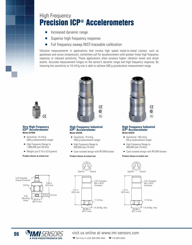
Precision ICP® Accelerometers� Increased dynamic range� Superior high frequency response� Full frequency sweep NIST-traceable calibration
Vibration measurements in applications that involve high speed metal-to-metal contact, such asgearboxes and screw compressors, sometimes call for accelerometers with greater linear high frequencyresponse or reduced sensitivity. These applications often produce higher vibration levels and shockevents. Accurate measurement hinges on the sensor’s dynamic range and high frequency response. Bylowering the sensitivity to 10 mV/g one is able to achieve 500 g acceleration measurement range.
visit us online at www.imi-sensors.comToll-Free in USA 800-959-4464 716-684-0003
96
High Frequency
High Frequency IndustrialICP® AccelerometerModel 623C01
� Sensitivity: 100 mV/g(50 g measurement range)
� High Frequency Range to900,000 cpm (15 kHz)
� Case-isolated design with RF/EMI blocker
Product shown at actual size
Very High FrequencyICP® AccelerometerModel 621B40
� Sensitivity: 10 mV/g(500 g measurement range)
� High Frequency Range to1,800,000 cpm (30 kHz)
� Weighs just 0.10 oz (2.8 grams)
Product shown at actual size
High Frequency IndustrialICP® AccelerometerModel 623C00
� Sensitivity: 10 mV/g(500 g measurement range)
� High Frequency Range to900,000 cpm (15 kHz)
� Case-isolated design with RF/EMI blocker
Product shown at actual size
1.97 in(50.0 mm)
2-Pin ThreadedMIL-C-5015Connector
11/16 Hex
3/8 Hex
1/4-28 Mtg. Hole
0.10 in (2.54 mm)
Ø0.685 in(Ø17.3 mm)
Ø0.36 in(Ø9.14 mm)
0.66 in(16.8 mm)
5-40MountingScrew
5-44 ThreadedCoaxial Connector
Sig/Pwr Ground
1.97 in(50.0 mm)
2-Pin ThreadedMIL-C-5015Connector
11/16 Hex
1/4-28 Mtg. HoleØ0.685 in(Ø17.3 mm)
Sig/Pwr Ground

Precision ICP® Accelerometers
visit us online at www.imi-sensors.comToll-Free in USA 800-959-4464 716-684-0003
97
Technical SpecificationsModel Number 621B40 623C00 623C01
Sensitivity (±5 %) N/A10 mV/g 100 mV/g
1.0 mV/(m/s2) [2] 10.2 mV/(m/s2)
Sensitivity (±10 %)10 mV/g
N/A N/A1.02 mV/(m/s2) [2]
Measurement Range±500 g ±500 g ±50 g
±4,905 m/s² ±4,905 m/s² ±490 m/s²
Frequency Range (±5 %) N/A144 to 480,000 cpm2.4 to 8 kHz [4]
Frequency Range (±10 %)204 to 1,080,000 cpm 102 to 600,000 cpm3.4 to 18 kHz [4][7] 1.7 to 10 kHz
Frequency Range (±3 dB)96 to 1,800,000 cpm 48 to 900,000 cpm1.6 to 30 kHz [4][7] 0.8 to 15 kHz
Resonant Frequency5,100 kcpm 2,400 kcpm85 kHz [5][8] 40 kHz [5]
Broadband Resolution(1 to 10 kHz)
1.2 mg 300 µg 100 µg1,176 µm/sec2 [5] 2,943 µm/sec2 [5] 981 µm/sec2 [5]
Non-linearity ±1 % [6]Transverse Sensitivity ≤ 5 %
Environmental
Overload Limit (Shock)10,000 g pk 5,000 g pk
98,100 m/s2 pk 49,050 m/s2 pk
Temperature Range-65 to 250 °F-54 to 121 °C
Enclosure Rating N/A IP68
ElectricalSettling Time(within 1% of bias) ≤ 3.0 sec ≤ 2.0 sec
Discharge Time Constant ≥ 0.1 sec ≥ 0.2 secExcitation Voltage 18 to 28 VDCConstant Current Excitation 2 to 20 mAOutput Impedance <100 ohmOutput Bias Voltage 8 to 12 VDC
Spectral Noise (10 Hz)100 µg/√Hz 12 µg/√Hz 7.0 µg/√Hz
980 (µm/sec2)/√Hz [5] 117 (µm/sec2)/√Hz [5] 68.7 (µm/sec2)/√Hz [5]
Spectral Noise (100 Hz)30 µg/√Hz 4.5 µg/√Hz 2.8 µg/√Hz
294 (µm/sec2)/√Hz [5] 44 (µm/sec2)/√Hz [5] 27.5 (µm/sec2)/√Hz
Spectral Noise (1 kHz)10 µg/√Hz 2.7 µg/√Hz 0.5 µg/√Hz
98.1 (µm/sec2)/√Hz [5] 26.5 (µm/sec2)/√Hz [5] 4.9 (µm/sec2)/√Hz [5]Electrical Protection RFI/ESDElectrical Isolation N/A >108 ohm
Physical
Size - Hex3/8 in 11/16 in9.6 mm 17.5 mm
Size - Height0.66 in 1.97 in16.8 mm 50 mm
Weight0.10 oz 1.80 oz2.8 gm 51 gm
Mounting Thread5-40 Male
1/4-28 Female [1]M3 x 0.50 Male
Mounting Torque18 to 20 in-lb 2 to 5 ft-lb
203 to 226 N-cm 2.7 to 6.8 N-mSensing Element Ceramic ShearHousing Material Titanium Stainless SteelSealing Welded HermeticElectrical Connector 5-44 Coaxial Jack 2-pin MIL-C-5015Electrical ConnectionPosition Top
Supplied AccessoriesModel ICS-1 NIST-traceable single-axisamplitude responsecalibration from 600cpm (10 Hz) to upper5% frequency
Model 081A40Mounting Stud (1)Model ICS-1 NIST-traceable single-axis amplituderesponse calibration from 600 cpm (10 Hz) to upper5% frequency (1)
NotesAll specifications are at room temperature unless otherwise specified
[1] 1/4-28 has no equivalent in S.I. units.[2] Conversion Factor 1g = 9.81 m/s².[3] For CE reference PCB® Declaration ofConformance PS023 or PS061 for details.
[4] The high frequency tolerance is accuratewithin ±10% of the specified frequency.
[5] Typical.[6] Zero-based, least-squares, straight line method.[7] Frequency response with adhesive base.[8] Mounted resonance (nominal) without magnet.
Optional Versions
EX - ATEX Approved Intrinsically SafeHazardous Area ApprovalFor Models: 623C00. 623C01
CS - Canadian Standards AssociationApproved Intrinsically SafeFor Models: 623C00. 623C01
M - Metric MountFor Models: 621B40, 623C00. 623C01
Technical Specifications
Model Number 621B40 623C00 623C01 Model Number 621B40 623C00 623C01
Performance Physical
Accessories & Cables: Pages 162-176

Quartz ICP® Accelerometers� Ideal for permanent installations & online monitoring systems� Promote safety when installed in hazardous or inaccessible locations� Connect through switch or junction box for route-based data collection
visit us online at www.imi-sensors.comToll-Free in USA 800-959-4464 716-684-0003
98
Low Cost Quartz IndustrialICP® AccelerometerModel 627A01
� 100 mV/g (50 g measurement range, +/-15%)
� Frequency Range: (±3dB)20 to 600,000 cpm (0.33 to 10 kHz)
� Electrical Connector: 2-pin MIL-C-5015
Product shown at actual size
Precision Quartz IndustrialICP® AccelerometerModel 628F01
� 100 mV/g (50 g measurement range)
� Frequency Range: (±3dB)20 to 720,000 cpm (0.33 to 12 kHz)
� Available in high temperature version (325 ºF)
Product shown at actual size
0.87 in(22.1 mm) dia
2-Pin ThreadedMIL-C-5015Connector
Sig/Pwr Ground
7/8 Hex
1/4-28 Mtg. Bolt
2.06 in(52.3 mm)
+20%
-5%
+15%
-10%
+10%
-15%
+5%
0 ºF
Quartz
Ceramic
250 ºF
-20%
0
Piezoelectric Accelerometers: Benefits of Quartz vs. CeramicPiezoelectric materials emit a unit of electrical charge when compressed, stressed or sheared and form the core of mostindustrial accelerometers. Many sensors utilize artificially piezoelectric ceramics as their sensing element. An alternate optionis to use quartz which is naturally piezoelectric and thus exhibits some technical advantages. Quartz sensors remain more linearin environments where temperature fluctuates. They also exhibit superior stability over time. In fact, quartz sensors that arerecalibrated as much as a decade later sometimes show no sensitivity deviation from when they were originally made.
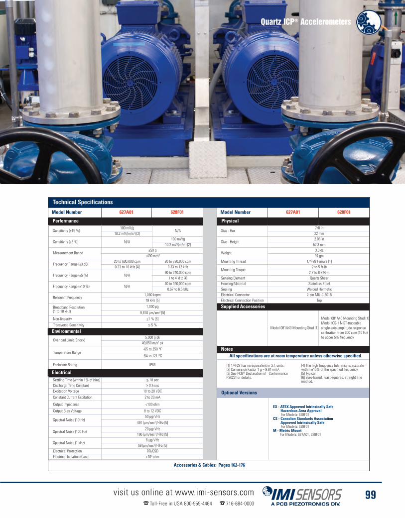
Quartz ICP® Accelerometers
visit us online at www.imi-sensors.comToll-Free in USA 800-959-4464 716-684-0003
99
Technical SpecificationsModel Number 627A01 628F01 627A01 628F01
Sensitivity (±15 %)100 mV/g
N/A Size - Hex7/8 in
10.2 mV/(m/s2) [2] 22 mm
Sensitivity (±5 %) N/A100 mV/g
Size - Height2.06 in
10.2 mV/(m/s2) [2] 52.3 mm
Measurement Range±50 g
Weight3.3 oz
±490 m/s² 94 gm
Frequency Range (±3 dB)20 to 600,000 cpm 20 to 720,000 cpm Mounting Thread 1/4-28 Female [1]0.33 to 10 kHz [4] 0.33 to 12 kHz
Mounting Torque2 to 5 ft-lb
Frequency Range (±5 %) N/A60 to 240,000 cpm 2.7 to 6.8 N-m1 to 4 kHz [4] Sensing Element Quartz Shear
Frequency Range (±10 %) N/A40 to 390,000 cpm Housing Material Stainless Steel0.67 to 6.5 kHz Sealing Welded Hermetic
Resonant Frequency1,080 kcpm Electrical Connector 2-pin MIL-C-501518 kHz [5] Electrical Connection Position Top
Broadband Resolution(1 to 10 kHz)
1,000 µg Supplied Accessories9,810 µm/sec2 [5]
Model 081A40 Mounting Stud (1)
Model 081A40 Mounting Stud (1)Model ICS-1 NIST-traceablesingle-axis amplitude responsecalibration from 600 cpm (10 Hz)to upper 5% frequency
Non-linearity ±1 % [6]
Transverse Sensitivity ≤ 5 %
Environmental
Overload Limit (Shock)5,000 g pk
49,050 m/s2 pk
Temperature Range-65 to 250 °F Optional Versions-54 to 121 °C All specifications are at room temperature unless otherwise specified
Enclosure Rating IP68
ElectricalSettling Time (within 1% of bias) ≤ 10 secDischarge Time Constant ≥ 0.5 secExcitation Voltage 18 to 28 VDC
Constant Current Excitation 2 to 20 mA
Output Impedance <100 ohm
Output Bias Voltage 8 to 12 VDC
Spectral Noise (10 Hz)50 µg/√Hz
491 (µm/sec2)/√Hz [5]
Spectral Noise (100 Hz)20 µg/√Hz
196 (µm/sec2)/√Hz [5]
Spectral Noise (1 kHz)6 µg/√Hz
59 (µm/sec2)/√Hz [5]Electrical Protection RFI/ESDElectrical Isolation (Case) >108 ohm
[1] 1/4-28 has no equivalent in S.I. units.[2] Conversion Factor 1 g = 9.81 m/s².[3] See PCB® Declaration of ConformancePS023 for details.
[4] The high frequency tolerance is accuratewithin ±10% of the specified frequency.[5] Typical.[6] Zero-based, least-squares, straight linemethod.
Optional Versions
EX - ATEX Approved Intrinsically SafeHazardous Area ApprovalFor Models: 628F01
CS - Canadian Standards AssociationApproved Intrinsically SafeFor Models: 628F01
M - Metric MountFor Models: 627A01, 628F01
Notes
Supplied Accessories
Environmental
Electrical
Technical Specifications
Model Number 627A01 628F01 Model Number 627A01 628F01
Performance Physical
Accessories & Cables: Pages 162-176
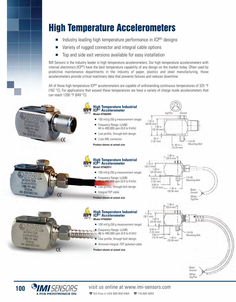
High Temperature Accelerometers� Industry leading high temperature performance in ICP® designs� Variety of rugged connector and integral cable options� Top and side exit versions available for easy installation
IMI Sensors is the industry leader in high temperature accelerometers. Our high temperature accelerometers withinternal electronics (ICP®) have the best temperature capability of any design on the market today. Often used bypredictive maintenance departments in the industry of paper, plastics and steel manufacturing, theseaccelerometers provide critical machinery data that prevents failures and reduces downtime.
All of these high temperature ICP® accelerometers are capable of withstanding continuous temperatures of 325 °F(162 °C). For applications that exceed these temperatures we have a variety of charge mode accelerometers thatcan reach 1200 °F (649 °C).
visit us online at www.imi-sensors.comToll-Free in USA 800-959-4464 716-684-0003
100
High Temperature IndustrialICP® AccelerometerModel HT602D01
� 100 mV/g (50 g measurement range)
� Frequency Range: (±3dB)48 to 480,000 cpm (0.8 to 8 kHz)
� Low profile, through-bolt design
� 2-pin MIL connector
Product shown at actual size
Sig/Pwr Ground
1/4-28Mounting Bolt
1/4-28Mounting Bolt
1/4-28Mounting Bolt
1.06 in(26.9 mm)
1.06 in(26.9 mm)
1.19 in(30.2 mm)
1.00 in(25.40 mm)
1.19 in(30.2 mm)
1.40 in(35.56 mm)
1.40 in(35.56 mm)
.04 in(1.02 mm)
1.00 in(25.40 mm)
1.20 in(30.48 mm)
.60 in(15.24 mm)
White:Sig/Pwr
Black:Ground
White:Sig/Pwr
Black:Ground
High Temperature IndustrialICP® AccelerometerModel HT602D11
� 100 mV/g (50 g measurement range)
� Frequency Range: (±3dB)48 to 480,000 cpm (0.8 to 8 kHz)
� Low profile, through-bolt design
� Integral FEP cable
Product shown at actual size
1.00 in(25.40 mm)
0.60 in(15.24 mm)
0.04 in(1.02 mm)
0.60 in(15.24 mm)
0.04 in(1.02 mm)
High Temperature IndustrialICP® AccelerometerModel HT602D61
� 100 mV/g (50 g measurement range)
� Frequency Range: (±3dB)48 to 480,000 cpm (0.8 to 8 kHz)
� Low profile, through-bolt design
� Armored integral, FEP jacketed cable
Product shown at actual size

High Temperature Accelerometers
visit us online at www.imi-sensors.comToll-Free in USA 800-959-4464 716-684-0003
101
High Temperature IndustrialICP® AccelerometerModel HT628F01
� Sensitivity: (±10%) 100 mV/g
� Measurement Range: ±50 g pk
� Frequency Range: (±3dB) 12 kHz
� Electrical Connector: 2-pin MIL-C-5015
Product shown at actual size
Low Cost AccelerometersModel Number HT602D01 HT602D11 HT602D61 HT628F01
Sensitivity (±10 %)100 mV/g
10.2 mV/(m/s2) [2]
Measurement Range±50 g
±490 m/s²
Frequency Range(±5%) N/A
144 to 180,000 cpm2.4 to 3 kHz [4]
Frequency Range(±10%)
102 to 180,000 cpmN/A
102 to 300,000 cpm1.7 to 3 kHz [4][7] 1.7 to 5 kHz
Frequency Range(±3 dB)
48 to 480,000 cpm0.8 to 8 kHz [4][7]
Resonant Frequency1,500 kcpm 1,080 kcpm25 kHz [5] 18 kHz [5]
Broadband Resolution(1 to 10 kHz)
150 µg 1 mg1,472 µm/sec2 [5] 3,434 µm/sec2 [5]
Non-linearity ±1 % [6] ±1 % [5] ±1 % [6] ±1 % [4]Transverse Sensitivity ≤ 5 %
EnvironmentalOverload Limit(Shock)
5,000 g pk 1,000 g pk49,050 m/s2 pk 981 m/s2 pk [9]
Temperature Range-65 to 325 °F-54 to 162 °C
Temperature Range(survivable limit) N/A
350 ºF176 ºC
Enclosure Rating IP68 IP67 IP68
ElectricalSettling Time(within 1% of bias) ≤ 2.0 sec ≤ 3 sec
Discharge TimeConstant ≥ 0.2 sec
Excitation Voltage 18 to 28 VDCConstant CurrentExcitation 2 to 20 mA 2 to 10 mA [8]
Output Impedance <150 ohm <500 OhmOutput Bias Voltage 8 to 12 VDC
Spectral Noise(10 Hz)
9.0 µg/√Hz 50 µg/√Hz88.3 (µm/sec2)/√Hz [5] 491 (µm/sec2)/√Hz [3]
Spectral Noise(100 Hz)
4.0 µg/√Hz 20 µg/√Hz39.2 (µm/sec2)/√Hz [5] 196 (µm/sec2)/√Hz [3]
Spectral Noise (1 kHz)2.0 µg/√Hz 6 µg/√Hz
19.6 (µm/sec2)/√Hz [5] 59 (µm/sec2)/√Hz [3]Electrical Isolation(Case) >108 ohm
Physical
Size - Hex N/A7/8 in22.2 mm
Size - Length2.1 in
N/A53.3 mm
Size - Width1.0 in
N/A25.4 mm
Size - Height1.0 in 2.06 in25.4 mm 52.3 mm
Weight(without cable)
5.4 oz 3.2 oz153 gm 91 gm
Mounting 1/4-28 UNF [1]
Mounting Torque2 to 5 ft-lb
2.7 to 6.8 N-mSensing Element Ceramic Shear Quartz ShearHousing Material Stainless SteelSealing Welded Hermetic
ElectricalConnector
2-pin MIL-C-5015(side)
Integral Cable(side)
Armored IntegralCable (side) MIL-C-5015 (top)
Cable Termination N/A Blunt Cut N/A
ElectricalConnections
Signal/Power (Pin A) Signal/Power (White) Signal/Power (Pin A)Ground (Pin B) Ground (Black) Ground (Pin B)
Cable Length N/A10 ft
N/A3 m
Cable Type N/A FEP Jacketed N/A
Supplied Accessories
Model 081A73 Captive mounting bolt 1/4-28 x 1.34" (1)
Model 081A40Mounting Stud (1)
Model ICS-1 NIST-traceable single-axisamplitude responsecalibration from 600cpm (10 Hz) to upper5% frequency
NotesAll specifications are at room temperature unless otherwise specified
Environmental
Supplied AccessoriesElectrical
Notes
[1] 1/4-28 has no equivalent in S.I. units.[2] Conversion Factor 1g = 9.81 m/s².[3] For CE reference PCB® Declaration ofConformance PS023 for details.
[4] The high frequency tolerance is accuratewithin ±10% of the specified frequency.
[5] Typical.
[6] Zero-based, least-squares,straight line method.[7] 1Hz = 60 cpm (cycles per minute).[8] Constant current should be reduced to≤6mA when operating sensor above 250°F.
[9] Not recommended for use with magneticmounting base.
Optional Versions
M - Metric MountFor Models: HT602D01, HT602D11, HT602D61, HT628F01
Technical Specifications
Model Number HT602D01 HT602D11 HT602D61 HT628F01 Model No. HT602D01 HT602D11 HT602D61 HT628F01
Performance Physical
Accessories & Cables: Pages 162-176

High Temperature Accelerometers� 550 ºF (288 ºC) accelerometer� Electrically ground isolated� 10/32 connector (side or top exit)
These units are structured with a piezoelectric ceramic sensing element, operating in a shear mode geometry,for stable operation in the presence of thermal transients and base bending. Welded, hermetically sealed,titanium construction prevents any influx of dirt or moisture. Electrical ground isolation prevents ground loopproblems and noise pick-up from the surface of the monitored device.
Since the output of these accelerometers is at a very highimpedance, a high degree of insulation resistance is requiredof the signal transmission path. Low noise cables arerecommended for routine, high temperature applications andhardline cables are advised for radiation environments. Theuse of an in-line charge converter is recommended to convertthe measurement signal to a low-impedance voltage for longdistance transmission.
visit us online at www.imi-sensors.comToll-Free in USA 800-959-4464 716-684-0003
102
1.44(36.6)
10-32 Mtg Hole
10-32Connector
13/16 Hex
Lock Wire Hole(2 places)
1.13(28.6)
10-32 Mtg Hole
10-32Connector
13/16 HexLock Wire Hole
(2 places)
High Temperature ChargeOutput AccelerometerModel 357B53
� Sensitivity: (±15%) 100 pC/g
� Measurement Range: ±150 g pk
� Frequency Range: (±5%) 3 kHz
� Electrical Connector: 10-32 coaxial jack
Product shown at actual size
High Temperature ChargeOutput AccelerometerModel 357B54
� Sensitivity: (±15%) 100 pC/g
� Measurement Range: ±150 g pk
� Frequency Range: (±5%) 3 kHz
� Electrical Connector: 10-32 coaxial jack
Product shown at actual size
Model Number 357B53 357B54
Sensitivity (± 15 %)100 pC/g
10.2 pC/(m/s²)
Measurement Range± 150 g pk
± 1,470 m/s² pkFrequency Range (+5 %) 3 kHz [2]Frequency Range (+10 %) 3.5 kHz [2]Frequency Range (+3 dB) 5.5 kHz [2]Resonant Frequency ≥ 12 kHzNon-linearity ≤ 1 % [3]Transverse Sensitivity ≤ 5 %
Environmental
Overload Limit (Shock)± 2,000 g pk
± 19,600 m/s² pk
Temperature Range-100 ºF to 550 ºF-73 ºC to 288 ºC
Base Strain Sensitivity0.0002 g/µ
0.002 (m/s²)/µ [1]Radiation Exposure Limit(Integrated Gamma Flux) ≤ 108 rad
Radiation Exposure Limit(Integrated Neutron Flux) ≤ 1010 N/cm²
ElectricalCapacitance 930 pF [1]Insulation Resistance(at 550°F) ≥ 108 ohm [1]
Insulation Resistance(at 70° F [21°C]) ≥ 1012 ohm
Output Polarity NegativeElectrical Isolation (Base) ≥ 108 ohm
PhysicalSensing Element CeramicSensing Geometry ShearHousing Material TitaniumSealing Hermetic
Size (Hex x Height)3/4 in x 1.13 in 3/4 in x 1.43 in3/4 in x 28.7 mm 3/4 in x 36.3 mm
Weight1.80 oz51 gm [1]
Electrical Connector 10-32 Coaxial Jack (side)Mounting Thread 10-32 Female
Supplied AccessoriesModel 081B05 Mounting Stud(10-32 to 10-32) (1)Model ACS-1 NIST traceable frequencyresponse (10 Hz to upper 5% point). (1)Model M081B05 Mounting Stud10-32 to M6 X 0.75 (1)
NotesAll specifications are at room temperature
unless otherwise specified
[1] Typical.[2] Low frequency response is determined byexternal signal conditioning electronics.
[3] Zero-based, least-squares, straight line method.13/16 Hex
13/16 Hex
10-32 Mounting Hole
10-32 Mounting Hole
10-32Connector
10-32Connector
Lock Wire Hole(2 Places)
Lock Wire Hole(2 Places)
1.13 in(28.6 mm)
1.44 in(36.6 mm)
Technical Specifications
Model Number 357B53 357B54
Performance
Environmental
Electrical
Physical
Supplied Accessories
Notes
Accessories & Cables: Pages 162-176
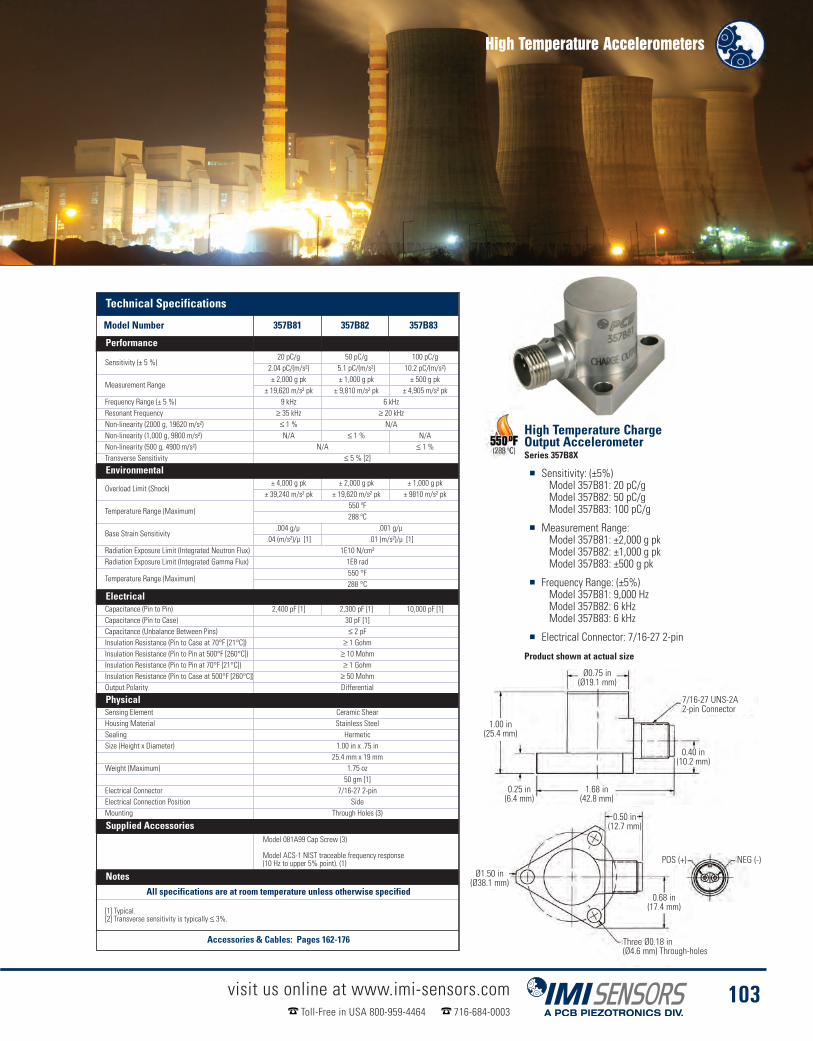
High Temperature Accelerometers
visit us online at www.imi-sensors.comToll-Free in USA 800-959-4464 716-684-0003
103
Model Number 357B81 357B82 357B83
Sensitivity (± 5 %)20 pC/g 50 pC/g 100 pC/g
2.04 pC/(m/s²) 5.1 pC/(m/s²) 10.2 pC/(m/s²)
Measurement Range± 2,000 g pk ± 1,000 g pk ± 500 g pk
± 19,620 m/s² pk ± 9,810 m/s² pk ± 4,905 m/s² pkFrequency Range (± 5 %) 9 kHz 6 kHzResonant Frequency ≥ 35 kHz ≥ 20 kHzNon-linearity (2000 g, 19620 m/s²) ≤ 1 % N/ANon-linearity (1,000 g, 9800 m/s²) N/A ≤ 1 % N/ANon-linearity (500 g, 4900 m/s²) N/A ≤ 1 %Transverse Sensitivity ≤ 5 % [2]
Environmental
Overload Limit (Shock)± 4,000 g pk ± 2,000 g pk ± 1,000 g pk
± 39,240 m/s² pk ± 19,620 m/s² pk ± 9810 m/s² pk
Temperature Range (Maximum)550 ºF288 ºC
Base Strain Sensitivity.004 g/µ .001 g/µ
.04 (m/s²)/µ [1] .01 (m/s²)/µ [1]Radiation Exposure Limit (Integrated Neutron Flux) 1E10 N/cm²Radiation Exposure Limit (Integrated Gamma Flux) 1E8 rad
Temperature Range (Maximum)550 °F288 °C
ElectricalCapacitance (Pin to Pin) 2,400 pF [1] 2,300 pF [1] 10,000 pF [1]Capacitance (Pin to Case) 30 pF [1]Capacitance (Unbalance Between Pins) ≤ 2 pFInsulation Resistance (Pin to Case at 70°F [21°C]) ≥ 1 GohmInsulation Resistance (Pin to Pin at 500°F [260°C]) ≥ 10 MohmInsulation Resistance (Pin to Pin at 70°F [21°C]) ≥ 1 GohmInsulation Resistance (Pin to Case at 500°F [260°C]) ≥ 50 MohmOutput Polarity Differential
PhysicalSensing Element Ceramic ShearHousing Material Stainless SteelSealing HermeticSize (Height x Diameter) 1.00 in x .75 in
25.4 mm x 19 mmWeight (Maximum) 1.75 oz
50 gm [1]Electrical Connector 7/16-27 2-pinElectrical Connection Position SideMounting Through Holes (3)
Supplied AccessoriesModel 081A99 Cap Screw (3)
Model ACS-1 NIST traceable frequency response(10 Hz to upper 5% point). (1)
NotesAll specifications are at room temperature unless otherwise specified
[1] Typical.[2] Transverse sensitivity is typically ≤ 3%.
High Temperature ChargeOutput AccelerometerSeries 357B8X
� Sensitivity: (±5%)Model 357B81: 20 pC/gModel 357B82: 50 pC/gModel 357B83: 100 pC/g
� Measurement Range:Model 357B81: ±2,000 g pkModel 357B82: ±1,000 g pkModel 357B83: ±500 g pk
� Frequency Range: (±5%)Model 357B81: 9,000 HzModel 357B82: 6 kHzModel 357B83: 6 kHz
� Electrical Connector: 7/16-27 2-pin
Product shown at actual size
Ø0.75 in(Ø19.1 mm)
Ø1.50 in(Ø38.1 mm)
1.00 in(25.4 mm)
0.25 in(6.4 mm)
1.68 in(42.8 mm)
0.68 in(17.4 mm)
POS (+)
0.50 in(12.7 mm)
0.40 in(10.2 mm)
7/16-27 UNS-2A2-pin Connector
Three Ø0.18 in(Ø4.6 mm) Through-holes
NEG (-)
Technical Specifications
Model Number 357B81 357B82 357B83
Performance
Environmental
Electrical
Physical
Supplied Accessories
Notes
Accessories & Cables: Pages 162-176

High Temperature Accelerometers� Case isolated charge output accelerometers� Available with hazardous area approvals� Differential output for long term monitoring
visit us online at www.imi-sensors.comToll-Free in USA 800-959-4464 716-684-0003
104
Technical SpecificationsModel Number 357C71 357C72 357C73
Sensitivity (± 5 %)10 pC/g 50 pC/g 100 pC/g
1.02 pC/(m/s²) 5.1 pC/(m/s²) 10.2 pC/(m/s²)
Measurement Range± 1,000 g pk ± 500 g pk ± 300 g pk
± 9,810 m/s² pk ± 4,905 m/s² pk ± 2,943 m/s² pkFrequency Range (± 5 %) 4 kHz [2] 2.5 kHz [2] 2 kHz [2]Resonant Frequency ≥ 25 kHz ≥ 13 kHz ≥ 11 kHzNon-linearity ≤ 1 % [3]Transverse Sensitivity ≤ 5 % [4]
Environmental
Overload Limit(Shock)± 2,000 g pk ± 1,000 g pk
± 19,620 m/s² pk ± 9810 m/s² pk
Base Strain Sensitivity0.033 g/µ
0.32 (m/s²)/µ [1]Radiation Exposure Limit(Integrated Neutron Flux) 1 E10 N/cm²
Radiation Exposure Limit(Integrated Gamma Flux) 1 E8 rad
Temperature Range-65 to +900 °F-54 to +482 °C
ElectricalCapacitance (Pin to Pin) 525 pF [1] 945 pF [1] 1575 pF [1]Capacitance (Pin to Case) 26 pF [1]Capacitance (Unbalance Between Pins) ≤ 2 pFInsulation Resistance (Pin to Case 70°F) >108 ohm [1]Insulation Resistance (Pin to Pin 70°F) >109 ohmInsulation Resistance (Pin to Pin 900°F) >100 kohmOutput Polarity Differential
PhysicalSensing Element CeramicSealing Hermetic
Size (Height x Diameter)1.0 in x 0.75 in 1.25 in x 0.75 in 1.48 in x 0.75 in
25.4 mm x 19 mm 31.8 mm x 19 mm 37.6 mm x 19 mm
Weight2.6 oz 3.15 oz 3.8 oz
75 gm [1] 90 gm [1] 110 gm [1]Electrical Connector 7/16-27 2-pinElectrical Connection Position SideMounting Through Holes (3)
Supplied AccessoriesModel 081A99 Cap Screw (3)Model ACS-1 NIST traceable frequency response(10 Hz to upper 5% point).
NotesAll specifications are at room temperature unless otherwise specified
[1] Typical.[2] Low frequency response is determined by external signal conditioning electronics.[3] Zero-based, least-squares, straight line method.[4] Transverse sensitivity is typically ≤ 3%.[5] For CE reference PCB® Declaration of Conformance PS081 for details.
High Temperature ChargeOutput AccelerometerSeries 357C7X
� Sensitivity: (±5%)Model 357C71: 10 pC/gModel 357C72: 50 pC/gModel 357C73: 100 pC/g
� Measurement Range:Model 357C71: ±1,000 g pkModel 357C72: ±500 g pkModel 357C73: ±300 g pk
� Frequency Range: (±5%)Model 357C71: 4 kHzModel 357C72: 2,500 HzModel 357C73: 2 kHz
� Electrical Connector: 7/16-27 2-pin
Product shown at actual size
Case Height (Value A)Model 357C73 = 1.48 in (37.6 mm)Model 357C72 = 1.25 in (31.8 mm)Model 357C71 = 1.00 in (25.4 mm)
Keyway
“A”
Signal (+)
Ø0.75 in(Ø19.1 mm)
Ø1.50 in(Ø38.1 mm)
Three Ø0.18(Ø4.6 mm)Through-holes
0.40 in(10.2 mm)
0.25 in (6.4 mm)
1.69 in(42.8 mm)
0.50 in(12.7 mm)
0.68 in(17.4 mm)
7/16-27 UNS-2A2-Pin Connector
Signal (-)
Optional Versions
EX - ATEX Approved Intrinsically SafeHazardous Area ApprovalFor Models: 357C71, 357C72
Technical Specifications
Model Number 357C71 357C72 357C73 Model Number 357C71 357C72 357C73
Performance Physical
Accessories & Cables: Pages 162-176

High Temperature Accelerometers
visit us online at www.imi-sensors.comToll-Free in USA 800-959-4464 716-684-0003
105
1.0(25.4)
5/8 Hex
10–32Connector
10–32 Mtg Hole
Lock Wire Hole(2 places)
High Temperature ChargeOutput AccelerometerModel 357B61
� Sensitivity: (±10%) 10 pC/g
� Measurement Range: ±1,000 g pk
� Frequency Range: (±5%) 5 kHz
� Electrical Connector: 10-32 coaxial jack
Product shown at actual size
Charge Output AccelerometerModel 357B69
� Sensitivity: (±10%) 3.5 pC/g (.357 pC/(m/s2))
� Measurement Range: ±500 g pk (±2450 m/s2 pk)
� Frequency Range: (±5%) 6 kHz
� Electrical Connector: 10-32 Coaxial Jack
Product shown at actual size
PhysicalSensing Element Ceramic N/ASensing Geometry CompressionHousing Material InconelSealing Hermetic
Size (Hex x Height)5/8 in x 1.0 in .875 in x .45 in5/8 in x 25.4 mm 22.2 mm x 11.4 mm
Weight1.1 oz 0.56 oz
30 gm [1] 16 gm [1]Electrical Connector 10-32 Coaxial JackElectrical Connection Position SideMounting Thread 10-32 Female
Mounting torque N/A18 in-lb2 N-m
Supplied AccessoriesModel 023A10 Hardline cable, 10-ft,10-32 plug to 10-32 jack (1)Model 081A107 Mounting stud(10-32 to 10-32) (1)Model ACS-1 NIST traceable frequency response(10 Hz to upper 5% point). (1)Model M081A107Metric mounting stud(10-32 toM6 x 0.75) (1)
NotesAll specifications are at room temperature unless otherwise specified
[1] Typical.[2] Low frequency response is determined by external signal conditioning electronics.[3] Zero-based, least-squares, straight line method.
Technical SpecificationsModel Number 357B61 357B69
Sensitivity (± 10 %)10 pC/g 3.5 pC/g
1.02 pC/(m/s²) .357 pC/(m/s²)
Measurement Range± 1,000 g pk ± 500 g pk
± 9,810 m/s² pk ± 2,450 m/s² pkFrequency Range (+5 %) 5 kHz [2] 6 kHzResonant Frequency ≥ 24 kHz ≥ 35 kHzNon-linearity ≤ 1 % [3] ≤ 1 %Transverse Sensitivity ≤ 3 % ≤ 5 %
Environmental
Overload Limit (Shock)± 5,000 g pk ± 3,000 g pk
± 49,050 m/s² pk ± 29,420 m/s² pk
Temperature Range-65 to +900 °F-54 to +482 °C
Base Strain Sensitivity0.001 g/µ 0.0008 g/µε
0.01 (m/s²)/µ [1] 0.008 (m/s²)/µε [1]Radiation Exposure Limit(Integrated Gamma Flux) 1 E10 N/cm²
Radiation Exposure Limit(Integrated Neutron Flux) 1 E8 rad
ElectricalCapacitance 630 pF [1] 196 pF [1]Insulation Resistance (900° F [482° C]) >100 kohmInsulation Resistance (at 70° F [21°C]) >108 ohm >1 GohmOutput Polarity Negative
.88 in(22.2 mm)
.43 in(10.8 mm)
.25 in(6.4 mm)
1.0 in(25.4 mm)
5/8 Hex
10-32Connector
Lock Wire Hole(2 places)
10-32Mounting Hole
10-32 UNF-2BMounting Hole
Optional Versions
P - Positive Output PolarityFor Model 357B69
Technical Specifications
Model Number 357B61 357B69 Model Number 357B61 357B69
Performance Physical
Accessories & Cables: Pages 162-176
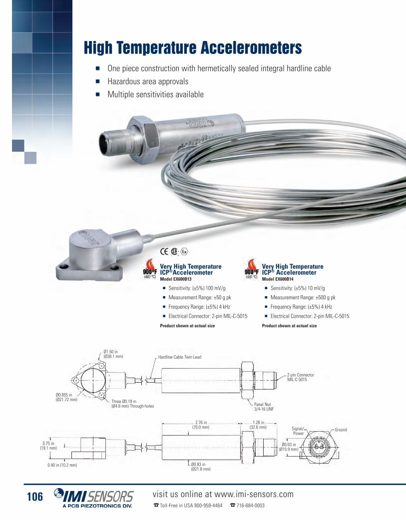
High Temperature Accelerometers� One piece construction with hermetically sealed integral hardline cable� Hazardous area approvals� Multiple sensitivities available
visit us online at www.imi-sensors.comToll-Free in USA 800-959-4464 716-684-0003
106
Very High TemperatureICP® AccelerometerModel EX600B14
� Sensitivity: (±5%) 10 mV/g
� Measurement Range: ±500 g pk
� Frequency Range: (±5%) 4 kHz
� Electrical Connector: 2-pin MIL-C-5015
Product shown at actual size
Very High TemperatureICP®AccelerometerModel EX600B13
� Sensitivity: (±5%) 100 mV/g
� Measurement Range: ±50 g pk
� Frequency Range: (±5%) 4 kHz
� Electrical Connector: 2-pin MIL-C-5015
Product shown at actual size
Signal/Power
Ø1.50 in(Ø38.1 mm)
Ø0.855 in(Ø21.72 mm) Three Ø0.19 in
(Ø4.8 mm) Through-holes
Hardline Cable Twin Lead
2-pin ConnectorMIL-C-5015
Panel Nut3/4-16 UNF
0.40 in (10.2 mm)
2.76 in(70.0 mm)
1.28 in(32.6 mm)
Ø0.63 in(Ø15.9 mm)
Ø0.83 in(Ø21.8 mm)
Ground
0.75 in(19.1 mm)

High Temperature Accelerometers
visit us online at www.imi-sensors.comToll-Free in USA 800-959-4464 716-684-0003
107
Technical Specifications - Confirm PDF SpecsPart Number 600B13 600B14
Sensitivity (± 5 %)100 mV/g 10 mV/g
10.2 mV/(m/s²) [2] 1.0 mV/(m/s2) [2]
Measurement Range± 50 g pk ± 500 g pk
± 490 m/s² pk ± 4,900 m/s² pk
Frequency Range (± 5 %)282 to 210,000 cpm4.7 to 3.5 kHz [3] [4]
Frequency Range (± 10 %)204 to 300,000 cpm
3.4 to 5 kHz
Resonant Frequency1,200 kcpm20 kHz [1]
Broadband Resolution (1 to 10 kHz) 450 µg 4,415 µm/sec2 [2]Non-linearity (per full scale range) ≤ 1 % [5]Transverse Sensitivity ≤ 5 %
Environmental
Overload Limit (Shock)± 1,000 g pk
± 9,810 m/s² pk [2]
Temperature Range(Accelerometer)
-65 to 900 °F-54 to 482 °C
Temperature Range(Charge Amplifier)
-60 to 250 °F-51 to 121 °C
Base Strain Sensitivity ≤ 0.006 g/µε ≤ 0.06 (m/s²)/µε [2]
ElectricalSettling Time(@ 70 ºF within 1% bias) ≤ 1.0 sec
Discharge Time Constant ≥ .10 sec
Excitation Voltage 22 to 28 VDCConstant Current Excitation 2.2 to 20 mAOutput Impedance <1,000 ohm [1]Output Bias Voltage 12 to 16 VDC
Spectral Noise (10 Hz)30 µg/√Hz
294 (µm/sec2)/√Hz [1][2]
Spectral Noise (100 Hz)8 µg/√Hz
78 (µm/sec2)/√Hz [1][2]
Spectral Noise (1 kHz)4 µg/√Hz
39 (µm/sec2)/√Hz [1][2]Electrical Isolation (Case) >108 ohm
Physical
Size (Diameter x Height)1.5 in x 0.75 in
38.1 mm x19.1 mm
Weight (without cable)9.5 oz270 gm
Electrical Connector 2-pin MIL-C-5015
Cable Length10 ft3 m
Cable Type Integral HardlineMounting Through Holes (3)
Supplied AccessoriesModel 081A99 Cap Screw (3)Model ICS-1 NIST-traceable single-axis amplitude responsecalibration from 600 cpm (10 Hz) to upper 5% frequency (1)
NotesAll specifications are at room temperature unless otherwise specified
Single Ended vs. Differential OutputMany operating engine environments generate temperaturesin excess of 550 ºF (288 ºC). Above this temperature, many ofthe design features and materials used in high temperatureaccelerometers change considerably. For 550 ºF to 1,200 ºF(288 ºC to 650 ºC) operating environments, PCB® offers arange of both single ended output (measurement output as asignal and ground) and differential output (measurementoutput as a plus and minus signal) sensors. The former tendto be smaller and more suitable for short term testing needs,while the latter are more appropriate for long term monitoringapplications. Obviously, the environments in which thesesensors operate are challenging. In fact, in some of thehighest temperature operating environments, the operatingsensor measures vibration signatures while glowing red hot.These sensors are complemented by both lab grade and in-line charge amplifier systems. This differential chargeamplifier is suitable for interfacing to any of PCB’s differentialcharge output accelerometers.
[1] Typical[2] Conversion Factor 1g = 9.81 m/s²[3] 1Hz = 60 cpm (cycles per minute)[4] The high frequency tolerance is accuratewithin ±10% of the specified frequency.
[5] Zero-based, least-squares,straight line method[6] For CE reference PCB® Declaration ofConformance PS023 for details
[7] Class I, Div. 1, Groups A, B, C and D; Class II,Div. 1, Groups E, F and G; Class III, Div. 1
[8] Class I, Div. 1, Groups A, B, C, D[9] Ex ia IIC T4[10] Ex nL IIC T1, II 3 G
Technical Specifications
Model Number EX600B13 [7][8][9][10] EX600B14 [7][8][9][10]
Performance
Environmental
Electrical
Physical
Supplied Accessories
Optional Versions
Accessories & Cables: Pages 162-176

High Temperature Accelerometers� Sensors operating to 1,200 ºF (649 ºC)� Ideal for monitoring gas turbines� Integral hardline cable� Welded, hermetically sealed
visit us online at www.imi-sensors.comToll-Free in USA 800-959-4464 716-684-0003
108
High Temperature ChargeOutput AccelerometerModel 357D90
� Sensitivity: (±10%) 5 pC/g
� Measurement Range: ±1,000 g pk
� Frequency Range: (±5%) 2.5 kHz
� Electrical Connector:Integral hardline cable
Product shown at actual size
High Temperature ChargeOutput AccelerometerModel 357D91
� Sensitivity: (±10%) 5 pC/g
� Measurement Range: ±1,000 g pk
� Frequency Range: (±5%) 2.5 kHz
� Sensitivity in the transverse direction
Product shown at actual size
Ø0.286 in± .005 in(Ø7.26 mm± 0.013 mm)Through-holes
Mineral Oxide InsulatedTriaxial Hardline Cable
Ø0.095 in(2.41 mm)
0.290 in(7.37 mm)
1.16 in(29.5 mm)
0.72 in(18.2 mm)
120 in ± 4 in(3048 mm + 102 mm)
1.30 in(32.9 mm)
0.265 in (6.73 mm)
Marking Location
Ø0.47 in(11.8 mm)10-32 CoaxialConnector
Axis of MeasurementModel 357D90
Axis of MeasurementModel 357D91
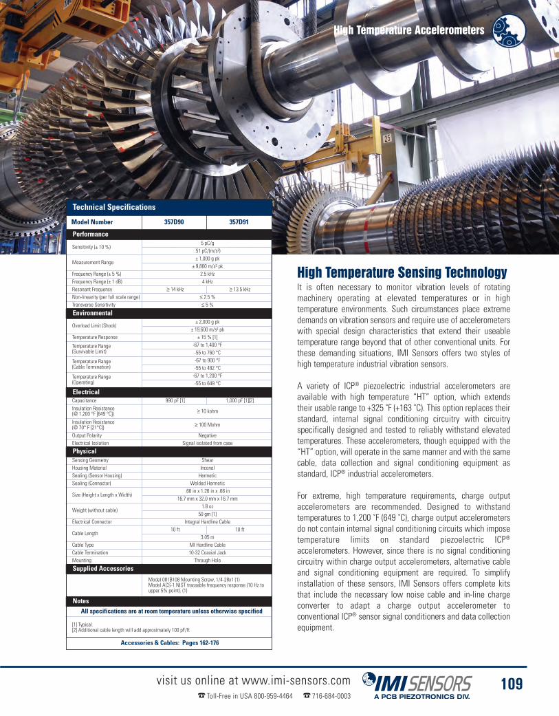
High Temperature Accelerometers
visit us online at www.imi-sensors.comToll-Free in USA 800-959-4464 716-684-0003
109
High Temperature Sensing TechnologyIt is often necessary to monitor vibration levels of rotatingmachinery operating at elevated temperatures or in hightemperature environments. Such circumstances place extremedemands on vibration sensors and require use of accelerometerswith special design characteristics that extend their useabletemperature range beyond that of other conventional units. Forthese demanding situations, IMI Sensors offers two styles ofhigh temperature industrial vibration sensors.
A variety of ICP® piezoelectric industrial accelerometers areavailable with high temperature “HT” option, which extendstheir usable range to +325 ˚F (+163 ˚C). This option replaces theirstandard, internal signal conditioning circuitry with circuitryspecifically designed and tested to reliably withstand elevatedtemperatures. These accelerometers, though equipped with the“HT” option, will operate in the same manner and with the samecable, data collection and signal conditioning equipment asstandard, ICP® industrial accelerometers.
For extreme, high temperature requirements, charge outputaccelerometers are recommended. Designed to withstandtemperatures to 1,200 ˚F (649 ˚C), charge output accelerometersdo not contain internal signal conditioning circuits which imposetemperature limits on standard piezoelectric ICP®
accelerometers. However, since there is no signal conditioningcircuitry within charge output accelerometers, alternative cableand signal conditioning equipment are required. To simplifyinstallation of these sensors, IMI Sensors offers complete kitsthat include the necessary low noise cable and in-line chargeconverter to adapt a charge output accelerometer toconventional ICP® sensor signal conditioners and data collectionequipment.
Technical SpecificationsPart Number 357D90 357D91
Sensitivity (± 10 %)5 pC/g
.51 pC/(m/s²)
Measurement Range± 1,000 g pk
± 9,800 m/s² pkFrequency Range (± 5 %) 2.5 kHzFrequency Range (± 1 dB) 4 kHzResonant Frequency ≥ 14 kHz ≥ 13.5 kHzNon-linearity (per full scale range) ≤ 2.5 %Transverse Sensitivity ≤ 5 %
Environmental
Overload Limit (Shock)± 2,000 g pk
± 19,600 m/s² pkTemperature Response ± 15 % [1]
Temperature Range(Survivable Limit)
-67 to 1,400 °F-55 to 760 °C
Temperature Range(Cable Termination)
-67 to 900 °F-55 to 482 °C
Temperature Range(Operating)
-67 to 1,200 °F-55 to 649 °C
ElectricalCapacitance 990 pF [1] 1,000 pF [1][2]Insulation Resistance(@ 1,200 °F [649 °C]) ≥ 10 kohm
Insulation Resistance(@ 70° F [21°C]) ≥ 100 Mohm
Output Polarity NegativeElectrical Isolation Signal isolated from case
PhysicalSensing Geometry ShearHousing Material InconelSealing (Sensor Housing) HermeticSealing (Connector) Welded Hermetic
Size (Height x Length x Width).66 in x 1.26 in x .66 in
16.7 mm x 32.0 mm x 16.7 mm
Weight (without cable)1.8 oz
50 gm [1]Electrical Connector Integral Hardline Cable
Cable Length10 ft 10 ft
3.05 mCable Type MI Hardline CableCable Termination 10-32 Coaxial JackMounting Through Hole
Supplied AccessoriesModel 081B108 Mounting Screw, 1/4-28x1 (1)Model ACS-1 NIST traceable frequency response (10 Hz toupper 5% point). (1)
NotesAll specifications are at room temperature unless otherwise specified
[1] Typical.[2] Additional cable length will add approximately 100 pF/ft
Technical Specifications
Model Number 357D90 357D91
Performance
Environmental
Electrical
Physical
Supplied Accessories
Notes
Accessories & Cables: Pages 162-176

Embeddable Accelerometers� Choice of standard TO-5 or TO-8� Choice of charge mode piezoelectric, voltage mode ICP®,
and 3-wire low power varieties� Range of sensitivities to accommodate a variety of applications
The Series 660 low cost accelerometers offer an affordable solution for vibration and shock measurements inhigh volume and commercial OEM applications. The units are particularly well suited for shock and impactdetection of packages or components, as well as bearing and gear mesh vibration measurements in predictivemaintenance and condition monitoring requirements. The compact designs may be imbedded into machineryat the OEM level to provide value added monitoring protection.
The units employ field proven, solid state, piezoelectric sensing elements for durability and broadbandperformance. Choose from either charge mode types, which achieve high operating temperatures or voltagemode ICP® types, with Built in signal conditioning microelectronics, for simplified operation and connectivityto data acquisition and vibration monitoring instrumentation.
visit us online at www.imi-sensors.comToll-Free in USA 800-959-4464 716-684-0003
110
Pellet Type AccelerometerLow Profile T-05, Model 66103LPZ1
� 3-wire voltage output(power, signal, ground)
� Sensitivity: (±20%) 10 mV/g
� Low power consumption
Product shown at actual size
Pellet Type AccelerometerStandard T-05, Model 66292CNZ1
� 2-wire charge output (signal, ground)
� Sensitivity: (±20%) 11 pC/g
� Power supply not required
Product shown at actual size
Pellet Type AccelerometerStandard T-08, Model 66332APZ1
� 2-wire ICP® power(power/signal, ground)current regulated power
� Sensitivity: (±20%) 1,000 mV/g
� High resolution
Product shown at actual size
0.33 in(8.4 mm)
0.03 in(0.8 mm)
0.26 in(6.6 mm)
0.33 in(8.4 mm)
0.38 in(9.7 mm)
0.03 in(0.8 mm)
0.15 in(3.8 mm)
0.05 in(1.3 mm)
0.58 in(14.7 mm)
0.57 in(14.5 mm)
0.15 in(3.8 mm)
0.64 in (16.3 mm)
0.15 in(3.8 mm)
0.36 in(9.1 mm)
0.36 in(9.1 mm)
0.2 in (5.1 mm) 0.2 in (5.1 mm)
0.38 in (9.7 mm)
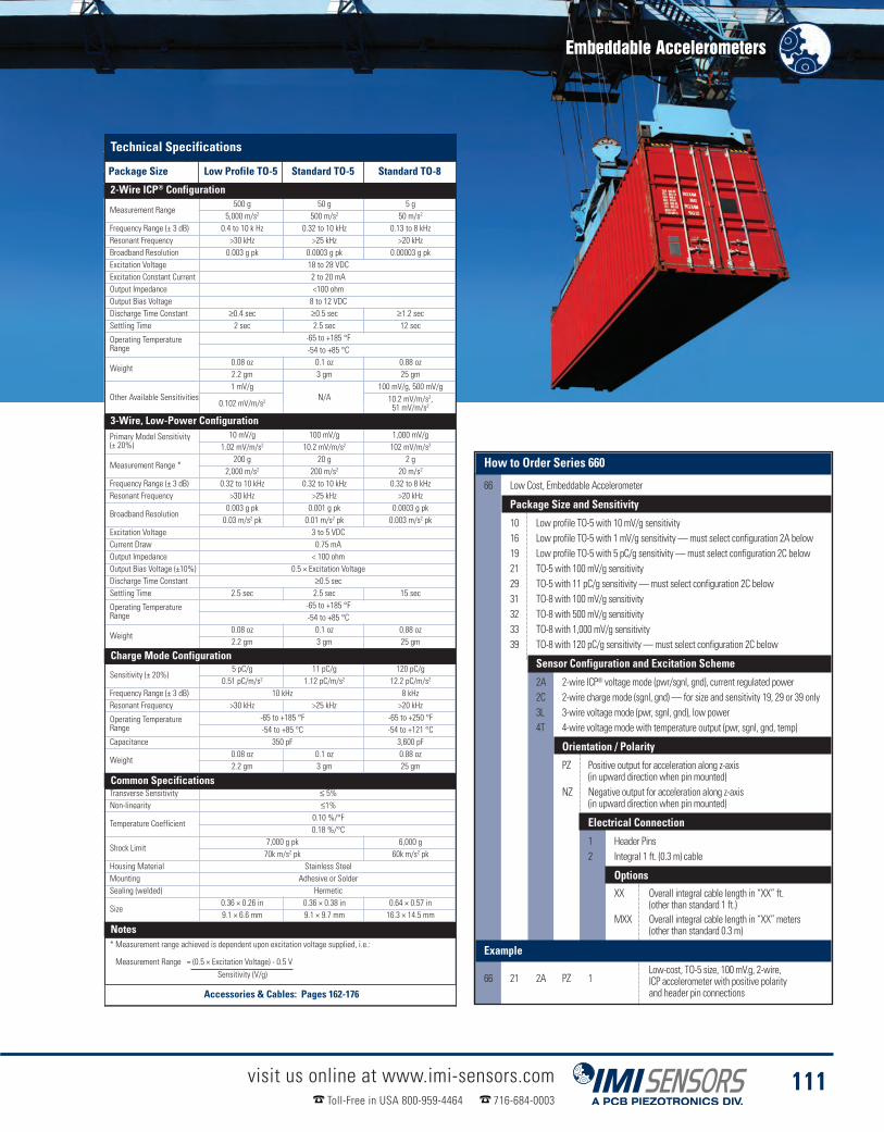
Embeddable Accelerometers
visit us online at www.imi-sensors.comToll-Free in USA 800-959-4464 716-684-0003
111
Technical SpecificationsPackage Size Low Profile TO-5 TO-5 TO-82-Wire ICP® Configuration
Measurement Range500 g 50 g 5 g
5,000 m/s2 500 m/s2 50 m/s2
Frequency Range (± 3 dB) 0.4 to 10 k Hz 0.32 to 10 kHz 0.13 to 8 kHzResonant Frequency >30 kHz >25 kHz >20 kHzBroadband Resolution 0.003 g pk 0.0003 g pk 0.00003 g pkExcitation Voltage 18 to 28 VDCExcitation Constant Current 2 to 20 mAOutput Impedance <100 ohmOutput Bias Voltage 8 to 12 VDCDischarge Time Constant ≥0.4 sec ≥0.5 sec ≥1.2 secSettling Time 2 sec 2.5 sec 12 sec
Operating TemperatureRange
-65 to +185 °F-54 to +85 °C
Weight0.08 oz 0.1 oz 0.88 oz2.2 gm 3 gm 25 gm
Other Available Sensitivities1 mV/g
N/A100 mV/g, 500 mV/g
0.102 mV/m/s2 10.2 mV/m/s2,51 mV/m/s2
3-Wire, Low-Power ConfigurationPrimary Model Sensitivity(± 20%)
10 mV/g 100 mV/g 1,000 mV/g1.02 mV/m/s2 10.2 mV/m/s2 102 mV/m/s2
Measurement Range *200 g 20 g 2 g
2,000 m/s2 200 m/s2 20 m/s2
Frequency Range (± 3 dB) 0.32 to 10 kHz 0.32 to 10 kHz 0.32 to 8 kHzResonant Frequency >30 kHz >25 kHz >20 kHz
Broadband Resolution0.003 g pk 0.001 g pk 0.0003 g pk0.03 m/s2 pk 0.01 m/s2 pk 0.003 m/s2 pk
Excitation Voltage 3 to 5 VDCCurrent Draw 0.75 mAOutput Impedance < 100 ohmOutput Bias Voltage (±10%) 0.5 × Excitation VoltageDischarge Time Constant ≥0.5 secSettling Time 2.5 sec 2.5 sec 15 sec
Operating TemperatureRange
-65 to +185 °F-54 to +85 °C
Weight0.08 oz 0.1 oz 0.88 oz2.2 gm 3 gm 25 gm
Charge Mode Configuration
Sensitivity (± 20%)5 pC/g 11 pC/g 120 pC/g
0.51 pC/m/s2 1.12 pC/m/s2 12.2 pC/m/s2
Frequency Range (± 3 dB) 10 kHz 8 kHzResonant Frequency >30 kHz >25 kHz >20 kHz
Operating TemperatureRange
-65 to +185 °F -65 to +250 °F-54 to +85 °C -54 to +121 °C
Capacitance 350 pF 3,600 pF
Weight0.08 oz 0.1 oz 0.88 oz2.2 gm 3 gm 25 gm
Common SpecificationsTransverse Sensitivity ≤ 5%Non-linearity ≤1%
Temperature Coefficient0.10 %/°F0.18 %/°C
Shock Limit7,000 g pk 6,000 g70k m/s2 pk 60k m/s2 pk
Housing Material Stainless SteelMounting Adhesive or SolderSealing (welded) Hermetic
Size0.36 × 0.26 in 0.36 × 0.38 in 0.64 × 0.57 in9.1 × 6.6 mm 9.1 × 9.7 mm 16.3 × 14.5 mm
Note:* Measurement range achieved is dependent upon excitation voltage supplied, i.e.:
Measurement Range = (0.5 × Excitation Voltage) - 0.5 VSensitivity (V/g)
How to Order Series 660
66 Low Cost, Embeddable Accelerometer
Package Size and Sensitivity
10 Low profile TO-5 with 10 mV/g sensitivity16 Low profile TO-5 with 1 mV/g sensitivity—must select configuration 2A below19 Low profile TO-5 with 5 pC/g sensitivity—must select configuration 2C below21 TO-5 with 100 mV/g sensitivity29 TO-5 with 11 pC/g sensitivity—must select configuration 2C below31 TO-8 with 100 mV/g sensitivity32 TO-8 with 500 mV/g sensitivity33 TO-8 with 1,000 mV/g sensitivity39 TO-8 with 120 pC/g sensitivity—must select configuration 2C below
Sensor Configuration and Excitation Scheme
2A 2-wire ICP® voltage mode (pwr/sgnl, gnd), current regulated power2C 2-wire charge mode (sgnl, gnd)— for size and sensitivity 19, 29 or 39 only3L 3-wire voltage mode (pwr, sgnl, gnd), low power4T 4-wire voltage mode with temperature output (pwr, sgnl, gnd, temp)
Orientation / Polarity
PZ Positive output for acceleration along z-axis(in upward direction when pin mounted)
NZ Negative output for acceleration along z-axis(in upward direction when pin mounted)
Electrical Connection
1 Header Pins2 Integral 1 ft. (0.3 m) cable
OptionsXX Overall integral cable length in “XX” ft.
(other than standard 1 ft.)MXX Overall integral cable length in “XX” meters
(other than standard 0.3 m)
Example
66 21 2A PZ 1Low-cost, TO-5 size, 100 mV.g, 2-wire,ICP accelerometer with positive polarityand header pin connections
Technical Specifications
Package Size Low Profile TO-5 Standard TO-5 Standard TO-8
2-Wire ICP® Configuration
3-Wire, Low-Power Configuration
Charge Mode Configuration
Common Specifications
Notes
Accessories & Cables: Pages 162-176

Vibration Transmitters� 4-20 mA sensors for permanent installation that
interface directly to a PLC, DCS and SCADA systems� Provides continuous, 24/7 monitoring of critical machinery� Cost-effective monitoring solution
visit us online at www.imi-sensors.comToll-Free in USA 800-959-4464 716-684-0003
112
4-20 mA Output TransmitterModel 640B01
� Measurement range: 0 to 1 in/sec pk(0 to 25.4 mm/s pk)
� Frequency range: (±10%)180 to 60,000 cpm (3 to 1 kHz)
� Raw vibration or temperature outputsignal options, intrinsically safeoptions available
Product shown at actual size
4-20 mA Output TransmitterModel 640B02
� Measurement range: 0 to 2 in/sec pk(0 to 50.8 mm/s pk)
� Frequency range: (±10%)180 to 60,000 cpm (3 to 1 kHz)
� Raw vibration or temperature outputsignal options, intrinsically safeoptions available
Product shown at actual size
4-20 mA Output TransmitterModel 641B01
� Measurement range: 0 to 1 in/sec rms(0 to 25.4 mm/s rms)
� Frequency range: (±10%)600 to 60,000 cpm (10 to 1 kHz)
� Raw vibration or temperature outputsignal options, intrinsically safeoptions available
Product shown at actual size
4-20 mA Output TransmitterModel 641B02
� Measurement range: 0 to 2 in/sec rms(0 to 25.4 mm/s rms)
� Frequency range: (±10%)600 to 60,000 cpm (10 to 1 kHz)
� Raw vibration or temperature outputsignal options, intrinsically safeoptions available
Product shown at actual size
Ø0.87 in(Ø22.1 mm)
2.48 in(63.0 mm)
1/4-28 Mounting Hole
7/8 Hex
Return
2-pin ThreadedMIL-C-5015Connector
Power
4-20 mA Output TransmitterModel 645B00
� Measurement range: 0 to 5 g rms(0 to 49 m/s2 rms)
� Frequency range: (±10%)180 to 60,000 cpm (3 to 1 kHz)
� Raw vibration or temperature outputsignal options, intrinsically safeoptions available
Product shown at actual size
4-20 mA Output TransmitterModel 646B02
� Measurement range: 0 to 10 g rms(0 to 98.1 m/s2 rms)
� Frequency range: (±10%)180 to 600,000 cpm (3 to 10 kHz)
� Raw vibration or temperature outputsignal options, intrinsically safeoptions available
Product shown at actual size
Getting Started withLoop Powered Vibration SensorsStarting a vibration monitoring program is notalways easy. It requires investing human resourcesfor training and capital dollars to obtain dataacquisition equipment. But most plants alreadyhave PLC, DCS or SCADA systems in placemonitoring pressure, flow and temperature. IMI’sloop-powered 4-20 mA vibration transmitters are“plug and play” with today’s plant control systems.Thus 4-20 mA vibration transmitters are anexcellent way to monitor vibration and protectcritical equipment without the expense ofadditional costly data acquisition systems. While4-20 mA sensors cannot perform diagnostic tasksthey provide early warnings that help maintenancetechnicians avoid catastrophic failure.

Vibration Transmitters
visit us online at www.imi-sensors.comToll-Free in USA 800-959-4464 716-684-0003
113
Technical SpecificationsModel Number 640B01 640B02 641B01 641B02 645B00 646B02
Measurement Range0.0 to 1 in/sec pk 0.0 to 2 in/sec pk 0.0 to 1 in/sec rms 0.0 to 2 in/sec rms 0.0 to 5 g rms 0.0 to 10 g rms
0.0 to 25.4 mm/s pk [2] 0.0 to 50.8 mm/s pk [2] 0.0 to 25.4 mm/s rms [2] 0.0 to 50.8 mm/s rms [2] 0.0 to 49 m/s2 rms [2] 0.0 to 98.1 m/s2 rms [2]Output 4-20 mA
Frequency Range (±10 %)180 to 60,000 cpm 600 to 60,000 cpm 180 to 60,000 cpm 180 to 600,000 cpm3 to 1 kHz [1][3] 10 to 1 kHz [1][3] 3 to 1 kHz [1][3] 3 to 10 kHz [1][3]
Broadband Resolution0.005 in/sec pk 0.01 in/sec pk 0.005 in/sec rms 0.01 in/sec rms 0.025 g rms 0.05 g rms0.13 mm/s pk [5] 0.26 mm/s pk [5] 0.13 mm/s rms [5] 0.26 mm/s rms [5] 0.24 m/s2 rms [5] 0.49 m/s2 rms
Non-linearity ±1 %
Environmental
Temperature Range-40 to 185 °F-40 to 85 °C
ElectricalExcitation Voltage 12 to 30 VDCLoad Resistance 50 (Vs-12) ohms
Settling Time(within 2% of value) <15 sec
Electrical Isolation (Case) >108 ohm
Physical
Size - Hex1.0 in
25.4 mm
Size - Height2.6 in66 mm
Weight4.7 oz131 gm
Mounting Thread 1/4-28 UNF
Mounting Torque3 to 5 ft-lb4 to 7 N-m
Sensing Element Ceramic ShearHousing Material Stainless SteelSealing Welded HermeticElectrical Connector 2-pin MIL-C-5015 (Top)Electrical Connections (Pin A) 4-20 mA Pos (+)Electrical Connections (Pin B) 4-20 mA Neg (-)
Supplied AccessoriesModel 081A40 Mounting Stud (1)Model ICS-4 NIST-traceable single-axis amplitude response calibration from 0 cpm (0 Hz)to upper 10% frequency for 4 - 20 mA output vibration sensor (1)
NotesAll specifications are at room temperature unless otherwise specified
[1] 1Hz = 60 cpm (cycles per minute).[2] Conversion Factor 1 in/sec = 0.0254 m/sec.[3] Current will fluctuate at frequencies below 5 Hz.[4] For CE reference PCB® Declaration of Conformance PS039 or PS053 for details.[5] Typical.
Optional Versions
EX - Hazardous Area ApprovalFor Models: 640B01, 640B02, 641B01, 641B02
M - Metric MountFor Models: 640B01, 640B02, 641B01, 641B02
RV - Buffered Analog Signal Output 100 mV/g (±20%)For Models: 640B01, 640B02, 641B01, 641B02
RVVO - Buffered Analog Signal Output 100 mV/in/sec (±20%)For Models: 640B01
Technical Specifications
Model Number 640B01 640B02 641B01 641B02 645B00 646B02
Performance
Environmental
Electrical
Physical
Supplied Accessories
Notes
Accessories & Cables: Pages 162-176

Vibration Transmitters� Industry leading low frequency response� Interface directly to PLC, DCS and SCADA systems� Superior signal resolution on slow speed machinery
visit us online at www.imi-sensors.comToll-Free in USA 800-959-4464 716-684-0003
114
2.6 in(66 mm)
1.87 in(47.5 mm)
0.80 in(20.3 mm)
Ø1.24 in(Ø31.50 mm)
20 in(5.1 mm)
1/4-28 UNF-2B
2-pin ThreadedMIL-C-5015Connector
1.25 in(31.8 mm) Hex
Pins are Bi-polar
Ø0.920(Ø23.37 mm)
4-20 mA Indicator / Alarm
The model 683A panel meter can be used with eitherICP® sensors or 4-20 mA vibration transmittersdepending on the options selected. Each display alsofeatures two programmable relays with time delaysand optional 4-20 mA re-transmit.
Model 683A
� Provides 24 VDC excitation for loop powered4-20 mA sensors, or ICP® power
� Up to four programmable set-point relays� Highly visible, fully scalable LED display and
user friendly, menu-driven setup
4-20 mA Alarm EnclosureSeries 684A
� Houses 1 to 8 panel meters
� Fiberglass NEMA 4X enclosure
� BNC’s for walk up analysis whenICP® option is selected
Displacement
4-20 mA Output TransmitterModel 653A01
� Effective on slow speed machinery
� Measures absolute p-p displacement
� Accurate down to 90 cpm
Product shown at actual size
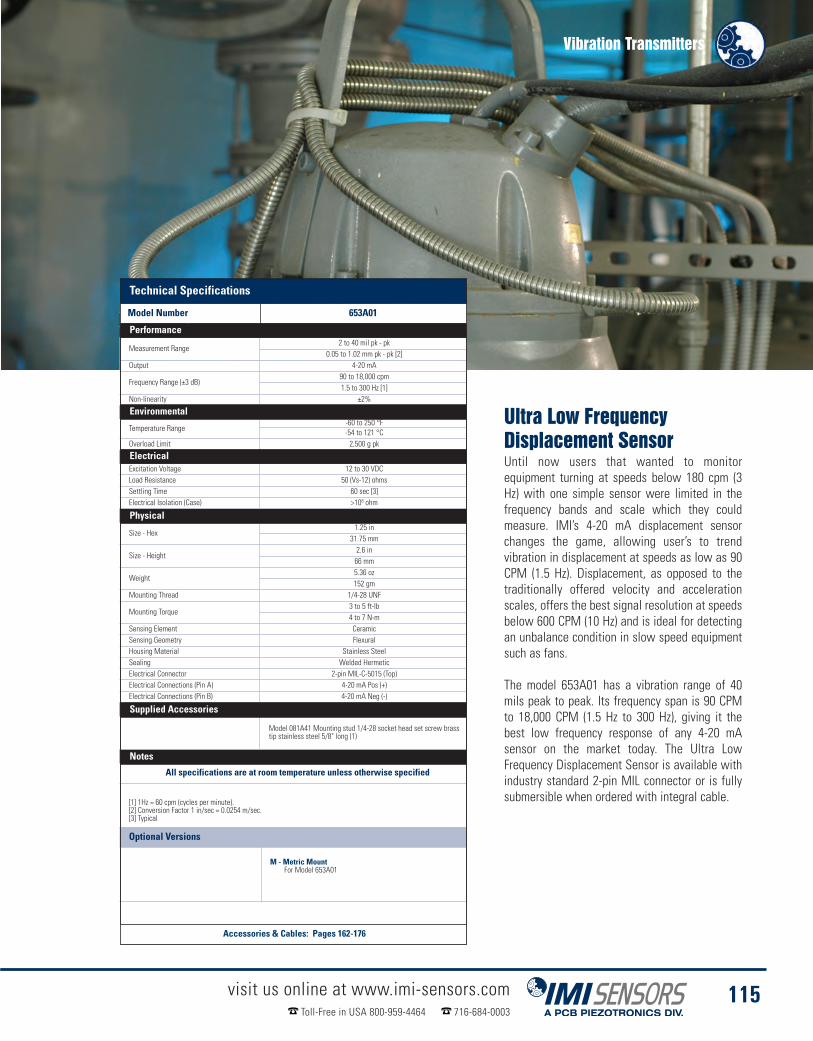
Vibration Transmitters
visit us online at www.imi-sensors.comToll-Free in USA 800-959-4464 716-684-0003
115
Technical SpecificationsModel Number 653A01
Measurement Range2 to 40 mil pk - pk
0.05 to 1.02 mm pk - pk [2]Output 4-20 mA
Frequency Range (±3 dB)90 to 18,000 cpm1.5 to 300 Hz [1]
Non-linearity ±2%
Environmental
Temperature Range-60 to 250 °F-54 to 121 °C
Overload Limit 2,500 g pk
ElectricalExcitation Voltage 12 to 30 VDCLoad Resistance 50 (Vs-12) ohmsSettling Time 60 sec [3]Electrical Isolation (Case) >108 ohm
Physical
Size - Hex1.25 in
31.75 mm
Size - Height2.6 in66 mm
Weight5.36 oz152 gm
Mounting Thread 1/4-28 UNF
Mounting Torque3 to 5 ft-lb4 to 7 N-m
Sensing Element CeramicSensing Geometry FlexuralHousing Material Stainless SteelSealing Welded HermeticElectrical Connector 2-pin MIL-C-5015 (Top)Electrical Connections (Pin A) 4-20 mA Pos (+)Electrical Connections (Pin B) 4-20 mA Neg (-)
Supplied Accessories
Model 081A41 Mounting stud 1/4-28 socket head set screw brasstip stainless steel 5/8" long (1)
Notes
All specifications are at room temperature unless otherwise specified
[1] 1Hz = 60 cpm (cycles per minute).[2] Conversion Factor 1 in/sec = 0.0254 m/sec.[3] Typical
Optional Versions
M - Metric MountFor Model 653A01
Ultra Low FrequencyDisplacement SensorUntil now users that wanted to monitorequipment turning at speeds below 180 cpm (3Hz) with one simple sensor were limited in thefrequency bands and scale which they couldmeasure. IMI’s 4-20 mA displacement sensorchanges the game, allowing user’s to trendvibration in displacement at speeds as low as 90CPM (1.5 Hz). Displacement, as opposed to thetraditionally offered velocity and accelerationscales, offers the best signal resolution at speedsbelow 600 CPM (10 Hz) and is ideal for detectingan unbalance condition in slow speed equipmentsuch as fans.
The model 653A01 has a vibration range of 40mils peak to peak. Its frequency span is 90 CPMto 18,000 CPM (1.5 Hz to 300 Hz), giving it thebest low frequency response of any 4-20 mAsensor on the market today. The Ultra LowFrequency Displacement Sensor is available withindustry standard 2-pin MIL connector or is fullysubmersible when ordered with integral cable.
Technical Specifications
Model Number 653A01
Performance
Environmental
Electrical
Physical
Supplied Accessories
Notes
Accessories & Cables: Pages 162-176
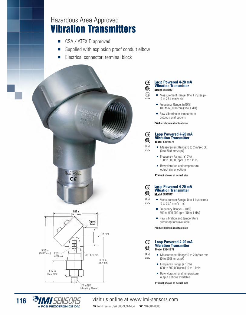
Vibration Transmitters� CSA / ATEX D approved� Supplied with explosion proof conduit elbow� Electrical connector: terminal block
visit us online at www.imi-sensors.comToll-Free in USA 800-959-4464 716-684-0003
116
Loop Powered 4-20 mAVibration TransmitterModel EX640B71
� Measurement Range: 0 to 1 in/sec pk(0 to 25.4 mm/s pk)
� Frequency Range: (±10%)180 to 60,000 cpm (3 to 1 kHz)
� Raw vibration or temperatureoutput signal options
Product shown at actual size
Loop Powered 4-20 mAVibration TransmitterModel EX640B72
� Measurement Range: 0 to 2 in/sec pk(0 to 50.8 mm/s pk)
� Frequency Range: (±10%)180 to 60,000 cpm (3 to 1 kHz)
� Raw vibration and temperatureoutput signal options
Product shown at actual size
IECEx IECEx
I
IECEx IECEx
I
Hazardous Area Approved
Loop Powered 4-20 mAVibration TransmitterModel EX641B71
� Measurement Range: 0 to 1 in/sec rms(0 to 25.4 mm/s rms)
� Frequency Range (± 10%)600 to 600,000 cpm (10 to 1 kHz)
� Raw vibration and temperatureoutput options available
Product shown at actual size
Loop Powered 4-20 mAVibration TransmitterModel EX641B72
� Measurement Range: 0 to 2 in/sec rms(0 to 50.8 mm/s pk)
� Frequency Range (± 10%)600 to 600,000 cpm (10 to 1 kHz)
� Raw vibration and temperatureoutput options available
Product shown at actual size
IECEx IECEx
I
IECEx IECEx
I
3.85 in(97.8 mm)
3.73 in(94.7 mm)
5.52 in(140.2 mm)
1.67 in(42.2 mm)
1/4 in NPTMounting Thread
NEG 4-20 mAPOS4-20 mA
CappedElbow
1 in NPT

Vibration Transmitters
visit us online at www.imi-sensors.comToll-Free in USA 800-959-4464 716-684-0003
117
Technical Specifi-Model Number EX640B71 EX640B72
Measurement Range0.0 to 1 in/sec pk 0.0 to 2.0 in/sec pk 0.0 to 1 in/sec rms 0.0 to 2.0 in/sec rms
0.0 to 25.4 mm/s pk [1] 0.0 to 50.8 mm/s pk [1] 0.0 to 25.4 mm/s rms [1] 0.0 to 50.8 mm/s rms [1]Output 4-20 mA 4-20 mA 4-20 mA 4-20 mA
Frequency Range(± 3 dB)180 to 60,000 cpm 600 to 60,000 cpm3 to 1 kHz [2][3] 10 to 1 kHz [2][3]
Broadband Resolution0.005 in/sec pk 0.01 in/sec pk 0.005 in/sec rms 0.01 in/sec rms0.13 mm/s pk [4] 0.26 mm/s pk [4] 0.13 mm/s rms [4] 0.26 mm/s rms [4]
Non-linearity ± 1 %
Environmental
Temperature Range-40 to 176 °F-40 to 80 °C
ElectricalExcitation Voltage 12 to 30 VDCSettling Time (within 2% of value) <15 secElectrical Isolation(Case) >108 ohm
Physical
Size (Hex x Height)3.85 in x 5.52 in98 mm x 140 mm
Weight1.2 lb544 gm
Mounting Thread 1/4 NPTSensing Element Ceramic ShearHousing Material Stainless SteelElectrical Connector Removable Screw TerminalsElectrical Connection Position TopElectrical Connections(Tab 1) 4-20 mA Pos (+)Electrical Connections(Tab 2) 4-20 mA Neg (-)
Screw Terminal Wire Size12-24 AWG3.0 - .2mm²
Supplied Accessories
Model ICS-4 NIST-traceable single-axis amplitude response calibration from 0 cpm (0 Hz)to upper 10% frequency for 4-20 mA output vibration sensor (1)
NotesAll specifications are at room temperature unless otherwise specified
[1] Conversion Factor 1 in/sec = 0.0254 m/sec.[2] Current will fluctuate at frequencies below 5 Hz.[3] 1Hz = 60 cpm (cycles per minute).[4] Typical.[5] For CE reference PCB® Declaration of Conformance PS039 or PS053 for details
Optional Versions
Optional versions have identical specifications and accessories as listed for the standard modelexcept where noted below. More than one option may be used.
EX - Hazardous Area ApprovalFor Models: EX640B71, EX640B72, EX641B71, EX641B72
RV - Buffered Analog Signal Output 100 mV/g (±20%)For Models: EX640B71, EX640B72, EX641B71, EX641B72
Easy ImplementationIMI® 4-20mA Vibration Transmitters areparticularly well suited for 24/7 vibrationmonitoring of critical rotating equipment.Simply install the transmitter on the bearinghousing and run a cable to the nearest PLC,DCS, SCADA, or any plant information system.That is all it takes to begin continuous vibrationmonitoring and avoid costly unexpected downtime. Using the reliable 4-20mA trending signalenables the user to schedule diagnostic testingbased on real data rather than using timescheduled route based testing. This practicesaves time and reduces overall costs ofpredictive maintenance.
These transmitters employ field proven solidstate piezoelectric sensing technologies and areavailable in many measurement ranges ofacceleration, velocity or displacement. Optionalhazardous area approved models also available.
Technical Specifications
Model Number EX640B71 EX640B72 EX641B71 EX641B72
Performance
Environmental
Electrical
Physical
Supplied Accessories
Notes
Accessories & Cables: Pages 162-176

Vibration Transmitters� 4-20 mA sensors for permanent mount installation that interface directly to
a PLC, DCS, SCADA, or any PI systems� Side exit versions allows for simple mounting in tight spaces� Swivel mounting mechanism eliminates spinning sensors during installation
visit us online at www.imi-sensors.comToll-Free in USA 800-959-4464 716-684-0003
118
Loop Powered 4-20 mAVibration TransmitterModel 642A01
� Low profile, side exit
� Measurement range 0-1.0 ips velocity pk(0-25.4 mm/sec peak)
� 2-pin MIL-C-5015 connector
Product shown at actual size
Loop Powered 4-20 mAVibration TransmitterModel 642A11
� Measurement range 0-1.0 ips velocity pk(0-25.4 mm/sec peak)
� 10 ft (3 m) of Integral Cable
� Submersible
Product shown at actual size
Loop Powered 4-20 mAVibration TransmitterModel 642A61
� Measurement range 0-1.0 ips velocity pk(0-25.4 mm/sec peak)
� 10 ft (3 m) of Integral Armored Cable
� Useful in exceedingly rough environments
Product shown at actual size
1.24 (31.5) Dia.
7/8 Hex
1.41 (35.8)
3/4 - 16 Thd
1/4 - 28 Mtg Thd(Metric version M6 x 1.0 - 6g)
Mounting studModel 080A162
1.24 (31.5) Dia.
1.41 (35.8)
1/4 - 28 Mtg Thd
7/8 Hex
3/4 - 16 Thd
Mounting studModel 080A162
7/8 Hex 7/8 Hex 7/8 Hex
3/4-16Thread
3/4-16Thread 3/4-16 Thread
1/4-28MountingThread
1/4-28MountingThread
1/4-28MountingThread
MountingStud Model080162
MountingStud Model080162
MountingStud Model080162
1/8 in HEX
Ø1.24 in(Ø31.5 mm)
Ø1.24 in(Ø31.5 mm)
1.41 in(35.8 mm)
1.41 in(35.8 mm)1.41 in
(35.8 mm)
1.99 in (50.5 mm)

Vibration Transmitters
visit us online at www.imi-sensors.comToll-Free in USA 800-959-4464 716-684-0003
119
Technical SpecificationsModel Number 642A01 642A11 642A61
Measurement Range0.0 to 1 in/sec pk
0.0 to 25.4 mm/s pk [1]Output 4-20 mA
Frequency Range (± 3 dB)180 to 60,000 cpm3 to 1 kHz [1][3]
Broadband Resolution0.005 in/sec pk0.13 mm/s pk [4]
Non-linearity ± 1 %
Environmental
Temperature Range-40 to 185 °F-40 to 85 °C
ElectricalExcitation Voltage 12 to 30 VDCSettling Time (within 2% of value) <15 secLoad Resistance 50 (Vs-12) ohmsElectrical Isolation (Case) >108 ohm
Physical
Size (Hex x Height)0.875 in x 1.41 in22.2 mm x 35.8 mm
Weight3.8 oz (without cable)108 gm (without cable)
Mounting Thread 1/4-28 UNF
Mounting Torque3 to 5 ft-lb4 to 7 N-m
Sensing Element Ceramic ShearHousing Material Stainless SteelElectrical Connector 2-pin MIL-C-5015 Integral CableElectrical Connection Position Side SideCable Termination N/A Pigtail Ends
Cable Length N/A10 ft3.0 m
Cable Type N/A Polyurethane
Electrical ConnectionsPin A - 4-20 mA Pos (+) Red - 4-20 mA Pos (+)Pin B - 4-20 mA Neg (-) Blue - 4-20 mA Neg (-)
Supplied AccessoriesModel 080A162 Mounting Stud (1)
Model ICS-4 NIST-traceable single-axis amplitude response calibration from 0 cpm (0 Hz) to upper 10% frequency for 4-20 mA output vibration sensor (1)
NotesAll specifications are at room temperature unless otherwise specified
[1] 1Hz = 60 cpm (cycles per minute).[2] Conversion Factor 1 in/sec = 0.0254 m/sec.[3] Current will fluctuate at frequencies below 5 Hz.[4] For CE reference PCB® Declaration of Conformance PS039 or PS053 for details.[5] Typical
Optional Versions
EX - Hazardous Area ApprovalFor Models: 642A01, 642A11, 642A61
M - Metric MountFor Models: 642A01, 642A11, 642A61
RV - Buffered Analog Signal OutputFor Models: 642A01, 642A11, 642A61
Technical Specifications
Model Number 642A01 642A11 642A61
Performance
Environmental
Electrical
Physical
Supplied Accessories
Notes
Accessories & Cables: Pages 162-176
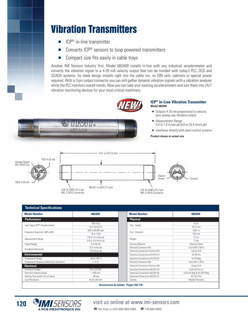
Vibration Transmitters� ICP® in-line transmitter� Converts ICP® sensors to loop powered transmitters� Compact size fits easily in cable trays
Another IMI Sensors industry first, Model 682A09 installs in-line with any industrial accelerometer andconverts the vibration signal to a 4-20 mA velocity output that can be trended with today’s PLC, DCS andSCADA systems. Its sleek design installs right into the cable run, no DIN rails, cabinets or special powerrequired. With a 3-pin output connector you can still gather dynamic vibration signals with a vibration analyzerwhile the PLC monitors overall trends. Now you can take your existing accelerometers and turn them into 24/7vibration monitoring devices for your most critical machinery.
visit us online at www.imi-sensors.comToll-Free in USA 800-959-4464 716-684-0003
120
Model Number 682A09 682A09
Input Signal (ICP® Accelerometer)100 mV/g
Size - Height4.0 in
10.2 mV/(m/s2) 101.6 mm
Frequency Response (-3dB ±2dB)600 to 60,000 cpm
Size - Diameter0.621 in
10 to 1 kHz 15.8 mm
Measurement Range0.0 to 1.0 in/sec pk
Weight2.5 oz
0.0 to 25.4 mm/s pk 71 gmOutput Range 4 to 20 mA Housing Material Stainless Steel
Broadband Resolution0.01 in/sec pk Electrical Connector (#1) 2-pin MIL-C-50150.26 mm/s pk Electrical Connection Position (#1) Sensor End
Environmental Electrical Connections (#1) (Pin A) AC IN Pos
Temperature Range -40 to 185 °F Electrical Connections (#1) (Pin B) AC IN NegTemperature Response (Sensitivity Deviation) ≤ 15 % Electrical Connector (#2) 3-pin MIL-C-5015
Electrical Electrical Connection Position (#2) Output End
Excitation Voltage 20 to 30 VDC Electrical Connections (#2) (Pin A) 4-20 mA Pos (+)Electrical Isolation (Case) >108 ohm Electrical Connections (#2) (Pin B) 4-20 mA Neg & AC OUT NegSettling Time (within 2% of value) <60 sec Electrical Connections (#2) (Pin C) AC OUT PosLoad Resistance 50 (Vs-20) ohm Sealing Welded Hermetic
ICP® In-Line Vibration TransmitterModel 682A09
� Outputs 4-20 mA proportional to velocityplus analog raw vibration output
� Measurement Range:0.0 to 1.0 in/sec pk (0.0 to 25.4 mm/s pk)
� Interfaces directly with plant control systems
Product shown at actual size
Analog Signal(RV, RVVO Out
GroundNEG 4-20 mA
POS 4-20 mA
4.01 in (101.9 mm)
Ø0.621 in (Ø15.77 mm)5/8-24 UNEF-2A 3-pinMIL-C-5015 Connector
5/8-24 UNEF-2A 2-pinMIL-C-5015 Connector
Signal /Power
Environmental
Electrical
Technical Specifications
Model Number 682A09 Model Number 682A09
Performance Physical
Accessories & Cables: Pages 162-176

Vibration Transmitters
visit us online at www.imi-sensors.comToll-Free in USA 800-959-4464 716-684-0003
121
Technical SpecificationsModel Number 682B03 682B03Channels 1 Power Required DC power
Input Signal (Vibration) ±100 mV/g [10] DC Power 23 to 25 VDC±10.2 mV/(m/s2) DC Power (maximum) 100 mA
Input Signal (Temperature) 0 to 1.2 VDC [11] Settling Time <2 minOutput Signal (DC Vibration) 4 to 20 mA [9] Excitation Voltage (delivered to sensor) 17 to 19 VDCOutput Signal (DC Vibration) 0 to 5 VDC [4][6] Constant Current Excitation (delivered to sensor) 3 to 5 mA [1][7]Output Signal (DC Vibration) 0 to 10 VDC [4][6] Output Span (±5.0 %) (DC Vibration Current Output) 16 mAOutput Signal (Temperature) 4 to 20 mA [11] Output Span (±5.0 %) (Temperature Output) 16 mA
Output Signal (±0.01 %)(AC Vibration)
100 mV/g [2] Output Span (±5.0 %) (DC Vibration Voltage Output) 5 or 10 VDC [6]10.2 mV/(m/s2) Physical
Frequency Range (-3 dB)(Acceleration)
180 to 600,000 cpm [3][13][14] Electrical Connector (input/output) Removable Screw Terminals3 to 10 kHz Electrical Connector (raw vibration output) BNC Jack
Frequency Range (-3 dB) (Velocity) 210 to 600,000 cpm [3][13][14] Housing Material Polyamide3.5 to 10 kHz Size - Height 3.9 in
Frequency Range (-3 dB)(Displacement)
210 to 60,000 cpm [3][8][14] 99 mm3.5 to 1 kHz Size - Width 0.9 in
Output Range (DC Acceleration) 0 to 5.00 g pk or rms [5][6][10] 22.5 mm0 to 49.03 m/s2 pk or rms Size - Depth 4.5 in
Output Range (DC Acceleration) 0 to 10.00 g pk or rms [5][6][10] 114.5 mm0 to 98.06 m/s2 pk or rms Weight (Maximum) 6.4 oz
Output Range (DC Acceleration) 0 to 20.00 g pk or rms [5][6][10] 1270 to 196.12 m/s2 pk or rms Screw Terminal Wire Size 24-14 AWG
Output Range (DC Velocity) 0 to 0.5 in/sec pk or rms [5][6][10] Din Rail Mount 1.38 in0 to 12.7 mm/s pk or rms 35 mm
Output Range (DC Velocity) 0 to 1.00 in/sec pk or rms [5][6][10] Status Indicator (Power "on") Green LED0 to 25.4 mm/s pk or rms Status Indicator (Input Fault) Red LED
Output Range (DC Velocity) 0 to 2.00 in/sec pk or rms [5][6][10] Status Indicator (Measurement Mode - Acceleration) Green LED0 to 50.8 mm/s pk or rms Status Indicator (Measurement Mode - Velocity) Green LED
Output Range (DC Displacement)0 to 10.0 mil pk - pk [5][6][10] Status Indicator (Measurement Mode - Displacement) Green LED
0 to 0.254 mm pk - pk Notes
Output Range (DC Displacement) 0 to 20.0 mil pk - pk [5][6][10]0 to 0.508 mm pk - pk
Output Range (DC Displacement) 0 to 40.0 mil pk - pk [5][6][10]0 to 1.02 mm pk - pk
Environmental
Temperature Range (Operating) 32 to 158 °F0 to 70 °C
Temperature Range (Storage) -40 to 257 °F-40 to 125 °C
Humidity Range(Non-Condensing) 0 to 95 %
ICP® Sensor to 4-20 mA TransmitterModel 682B03
� Provides constant current ICP® sensor excitation� 24 VDC powered, DIN rail mount� Analog vibration output for fault diagnostics(through BNC or terminals)
� Adjustable low pass and high pass filtering, selectableacceleration, velocity, or displacement output signal
POWER LED
ANALOG OUTPUT 3
0.9 (22.5) 4 4.5 (114.5)
0.5 (12.7)
Product shown at actual size
[1] 4 mA constant current diode is internal to 9330VT[2] Achieved with 100 mV/g ICP® accelerometer input.[3] Attenuation is -40 dB/decade.[4] Factory set, 0-5 VDC.[5] Factory set, 1 in/sec peak.[6] Internal Dip switch selectable[7] Jumper selectable for 18 VDC regulated, 24 VDC power
supply voltage or ICP® sensor excitation disabled[8] Maximum 1 kHz for displacement.[9] Output current voltage will fluctuate atfrequencies below 5 Hz.
[10] Output measurement range is based upon input from100 mV/g ICP® accelerometer and will be scaledinversely proportional to any percentage deviation ofthis input.
[11] Requires use of accelerometer with "TO"temperature output option.
[12] For CE reference PCB® Declaration of ConformancePS051 for details.
[13] The high frequency tolerance is accurate within ± 0.5kHz of the specified frequency.
[14] The low frequency tolerance is accurate within± 0.5 Hz of the specified frequency.
Power LED
AnalogOutput
0.9 in(22.5 mm)
3.9 in(99 mm)
0.5 in (12.7 mm)
4.5 in(114.5 mm)
Notes
Physical
Environmental
Technical Specifications
Model Number 682B03 Model Number 682B03
Performance Electrical
Accessories & Cables: Pages 162-176
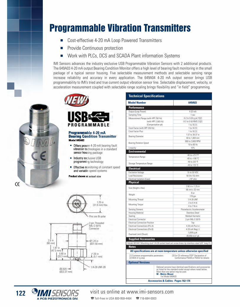
Programmable Vibration Transmitters� Cost-effective 4-20 mA Loop Powered Transmitters� Provide Continuous protection� Work with PLCs, DCS and SCADA Plant information Systems
IMI Sensors advances the industry exclusive USB Programmable Vibration Sensors with 2 additional products.The 649A03 4-20 mA output Bearing Condition Monitor offers a high level of bearing fault monitoring in the smallpackage of a typical sensor housing. Five selectable measurement methods and selectable sensing rangeincrease reliability and accuracy in every application. The 649A04 4-20 mA output sensor brings USBprogrammability to IMI’s tried and true current output vibration sensor line. Selectable displacement, velocity, oracceleration measurement coupled with selectable range scaling brings flexibility and “in field” programming.
visit us online at www.imi-sensors.comToll-Free in USA 800-959-4464 716-684-0003
122
Programmable 4-20 mABearing Condition TransmitterModel 649A03
� Offers proven 4-20 mA bearing faultvibration technologies in a standardsensor housing package
� Industry exclusive USBprogramming technology
� Effective monitoring of constant speedand variable speed systems
Product shown at actual size
Technical SpecificationsModel Number Model 649A03Output (Loop Power) 4-20 mASampling Time 1 secMeasurement Range (with HPF 250 Hz)
(with HPF 2,500 Hz)(Compensation pk)
0-2 to 0-50 g pk [1][2]0-2 to 0-50 RMS [1][2]
1 to 16 [1]Crest Factor (with HPF 250 Hz) 1 to 16 [1]Crest Factor Plus 1 to 16 [1]
Bearing Diameter1.57 to 39.37 in40 to 1,000 mm
Bearing Rotation Speed600 to 3,600 RPM
10 to 60 HzLinearity 10%
Environmental
Temperature Range-40 to +212 ºF-40 to +100 ºC
Storage Temperature Range-40 to 257 ºF-40 to 125 ºC
ElectricalExcitation Voltage 15 to 30 VDCLoad Resistance 50 (Vs-15) ohmElectrical Isolation (Case) >108 ohm
Physical
Size (Height x Hex)2.60 in x 1.25 in66 mm x 32 mm
Weight6 oz
170 gmMounting Thread 1/4-28 UNF
Mounting Torque3 to 5 ft-lb4 to 7 N-m
Sensing Element Piezoelectric AccelerometerHousing Material Stainless SteelSealing Welded HermeticElectrical Connector 2-pin MIL-C-5015Electrical Connection Position TopElectrical Connections (Pin A) 4-20 mA Pos (+)Electrical Connections (Pin B) 4-20 mA Neg (-)
Overload Limit (Shock)5,000 g pk
49,050 m/s2 pk
Supplied AccessoriesModel 081A41 Mounting stud 1/4-28 socket head set screw brass tip stainless steel 5/8” long (1)
NotesAll specifications are at room temperature unless otherwise specified
[1] Customer programmable parameters[2] With 0.1g step
[3] For CE reference PCB® Declaration ofConformance PS039 or PS053 for details
2.6 in(66 mm)
1.87 in(47.5 mm)
0.80 in(20.3 mm)
Ø1.24 in(Ø31.50 mm)
20 in(5.1 mm)
1/4-28 UNF-2B
2-pin ThreadedMIL-C-5015Connector
1.25 in(31.8 mm) Hex
Pins are Bi-polar
Ø0.920(Ø23.37 mm)
Optional VersionsOptional versions have identical specifications and accessoriesas listed for the standard model except where noted below.More than one option may be used.M - Metric Mount
For Model 649A03
Technical Specifications
Model Number 649A03
Performance
Environmental
Electrical
Physical
Supplied Accessories
Notes
Accessories & Cables: Pages 162-176

2.6 in(66 mm)
1.87 in(47.5 mm)
0.80 in(20.3 mm)
Ø1.24 in(Ø31.50 mm)
20 in(5.1 mm)
1/4-28 UNF-2B
2-pin ThreadedMIL-C-5015Connector
1.25 in(31.8 mm) Hex
Pins are Bi-polar
Ø0.920(Ø23.37 mm)
visit us online at www.imi-sensors.comToll-Free in USA 800-959-4464 716-684-0003
123
Technical SpecificationsModel Number Model 649A04Measurement Range(Velocity)
0.5 to 3 in/sec pk [1][2][3][4]12.7 to 76.2 mm/s pk [1][2][3][4]
Measurement Range(Acceleration)
1 to 10 g pk0.0 to 98.1 m/s2
Measurement Range(Displacement)
4 to 20 mil pk - pk [6][2][4]0.1 to 0.5 mm pk - pk [6][2][4]
Output (± 5 %) 4-20 mA
Frequency Range (-6 dB)180 to 60,000 cpm3 to 1 kHz [7][8][4][9]
USB Programmable Optionsfor Frequency Range
180 to 300,000 cpm3 to 5 kHz [7][8][4]180 to 600,000 cpm3 to 10 kHz [7][8][4]600 to 60,000 cpm10 to 1 kHz [7][8][4]600 to 300,000 cpm10 to 5 kHz [7][8][4]600 to 600,000 cpm10 to 10 kHz [7][8][4]
Environmental
Temperature Range-40 to +185 °F-40 to +85 °C
ElectricalExcitation Voltage 12 to 30 VDCSettling Time(within 2% of value) <30 secElectrical Isolation (Case) >108 ohm
Physical
Size (Height x Length x Width)1.0 in x 2.6 in
25.4 mm x 66 mm
Weight3.7 oz
3.7 oz [10]
Mounting Thread1/4-28 UNF
N/A
Mounting Torque3 to 5 ft-lb4 to 7 N-m
Sensing Element CeramicSensing Geometry ShearHousing Material Stainless SteelSealing Welded HermeticElectrical Connector 2-pin MIL-C-5015Electrical Connection Position TopElectrical Connections (Pin A) 4-20 mA Pos (+)Electrical Connections (Pin B) 4-20 mA Neg (-)
Supplied AccessoriesModel 081A40 Mounting Stud (1)
NotesAll specifications are at room temperature unless otherwise specified
[1] Conversion Factor 1 in/sec = 25.4 mm/sec.[2] FS - Full Scale.[3] Factory set, 1 in/sec peak.[4] USB Programmable with 600A21 kit.[5] Conversion Factor 1g = 9.81 m/s².[6] Conversion Factor 1 mil = 0.0254 mm
[7] Current will fluctuate atfrequencies below 5 Hz.
[8] 1Hz = 60 cpm (cycles per minute).[9] Factory Set[10] Typical.
Programmable 4-20 mAVibration TransmitterModel 649A04
� Output signal proportional todisplacement, velocity or acceleration
� Selectable high pass and low passfilters, selectable full scale range
� Compatible with plant information systems
Product shown at actual size
Programmable 4-20 mAVibration Transmitters
Optional Versions
Optional versions have identical specifications andaccessories as listed for the standard model exceptwhere noted below. More than one option may be used.
M - Metric MountFor Model 649A04
RV - Buffered Analog Signal OutputFor Model 649A04
Programmable Vibration Transmitters
Technical Specifications
Model Number 649A04
Performance
Environmental
Electrical
Physical
Supplied Accessories
Notes
Accessories & Cables: Pages 162-176

Bearing Fault Detector� Bearing condition transmitter� Provides early warning of bearing and gear faults� Detects impacting associated with spalling cracking
and lubrication problemsModel 682A05 Bearing Fault Detector (BFD) is an advanced vibration signal conditioner designed to provide theearliest warning of imminent machinery failure. The unit works with a 100 mV/g ICP® accelerometer and servesto deliver two, 4-20 mA output signals that are proportional to the measured vibration levels of operating rotatingmachinery. In order to enable detection of a wide variety of machinery faults, the 4-20 mA signals are conditionedto characterize two unique vibration measurements; one containing high frequency peak data and the othercontaining low frequency rms data. These 4-20 mA signals may be monitored, alongside other plant processvariables, using familiar PLC, DCS, SCADA, alarm and control systems. An additional analog voltage outputsignal is provided for spectral analysis of the monitored vibration for fault diagnostic purposes.
The unit employs a patented signal conditioning technique (US Patent #6,889,553) that provides the uniqueability to detect bearing and gear problems at their earliest stages, thus permitting ample maintenance planningto avert a catastrophic failure. The simplified 4-20 mA signal monitoring approach represents a cost-effectivealternative to complex vibration monitoring instrumentation and associated training.
visit us online at www.imi-sensors.comToll-Free in USA 800-959-4464 716-684-0003
124
Bearing Fault DetectorModel 682B05
� Provides early warning of bearing and gear faults
� Operates with PLC, DCS, SCADA, alarm,and control systems
� Outputs 2 discreet 4-20 mA signals;one proportional to peak acceleration,the other proportional to overall vibration
Product shown at actual size
POWER LED
ANALOG OUTPUT 3
0.9 (22.5) 4.5 (114.5)
0.5 (12.7)
Power LED
AnalogOutput
0.9 in(22.5 mm)
3.9 in(99 mm)
0.5 in (12.7 mm)
4.5 in(114.5 mm)

visit us online at www.imi-sensors.comToll-Free in USA 800-959-4464 716-684-0003
125
Early Impact DetectionIMI Sensors Model 682B05 Bearing Fault Detector (US Patent6,889,553) senses impacts within rolling element bearings causedby bearing faults. Typical bearing faults, such as cracked races,spalling, brinelling, fatigue failure, looseness and loss oflubrication result in impacts and high frequency vibrations insidethe bearing. The impacts are represented as high amplitude,narrow peaks on the acceleration time waveform and add verylittle energy to the overall vibration level. As a result, they areoften missed in normal trending analysis. The Bearing FaultDetector accurately measures these impacts and other highfrequency vibrations, providing early warning of potentialproblems. This unit is also effective for monitoring other problemsthat produce similar impacts and vibrations data, such as achipped tooth on a gear.
The Bearing Fault Detector is a DIN rail mount vibrationtransmitter that works in conjunction with a typical ICP®
accelerometer. It supplies the constant current power required bythe accelerometer, processes data and has the following threeoutputs: 4-20 mA proportional to peak amplitude, 4-20 mAproportional to overall vibration level and raw vibration signal viaBNC connector for diagnostic analysis. To obtain peak amplitude(measured in a 7 second window) the signal is passed through ahigh pass filter, rectified and run through a high speed peakdetection circuit. To obtain overall vibration level, the signal ispassed through a low pass filter, integrated when velocity isrequired, processed through a true rms circuit and scaled,depending on the desired output type (rms or calculated peak).Bearing Fault Detector output is compatible with any vibrationmonitoring device or plant equipment that accepts a 4-20 mAsignal. It can provide 24/7 protection when used with a PLC, DCS,or SCADA system. It can also be used with numerous off-the-shelfmeters, alarms and recorders.
Model Number 682A05
Input Signal100 mV/g
10.2 mV/(m/s2)Frequency Response (±3 dB) (Overall Vibration) 10 to 1k HzFrequency Response (±3 dB) (Fault) 1 or 5 to 100 kHz [1]Measurement Range (Fault Detector) 50 gOutput Range (Linear Scale) 4 to 20 mA [1][2]Output Range (Linear Scale) 4 to 20 mASampling Time 7 secSpan (±5 %) 16 mA
Control InterfacePower LED Green
EnvironmentalWarm Up <2 minutes
Temperature Range (Operating)32 to 158 °F0 to 70 °C
Temperature Range (Storage)-40 to 257 °F-40 to 125 °C
Humidity Range (Non-Condensing) <95 %
ElectricalSupply Voltage 24 VDCCurrent Consumption ≤ 150 mAExcitation Voltage (±1 V) 24 VDCConstant Current Excitation (±1 mA) 4 mARaw Vibration Output +/- 0.01% of Input VibrationLoad Resistance 500 ohm
Physical
Load Resistance500 ohm22.5 mm
Size - Height3.9 in99 mm
Size - Depth4.5 in
114.5 mm
Weight5.2 oz
145.2 gmHousing Material Polyamide
Screw Terminal Wire Size24-14 AWG0.2 - 2.5 mm2
Electrical Connector (input/output) Removable Screw TerminalsElectrical Connector (Output, Vibration) BNC JackDin Rail Mount 1.38 in
35 mm
NotesAll specifications are at room temperature unless otherwise specified
[1] Internal dip switch selectable[2] Output current voltage will fluctuate at frequencies below 5 Hz.[3] For CE reference PCB® Declaration of Conformance PS051 for details
Bearing Fault Detector
Technical Specifications
Model Number 682B05
Performance
Control Interface
Environmental
Electrical
Physical
Notes
Accessories & Cables: Pages 162-176

Reciprocating Machinery Protector� Loop Powered 4-20 mA output reciprocating machinery protector (RMP)� Outperforms impact transmitters� Provides early warning of faults and mechanical looseness
visit us online at www.imi-sensors.comToll-Free in USA 800-959-4464 716-684-0003
126
ReciprocatingMachinery ProtectorModel 649A01
� Output Range: 4-20 mA
� Machinery RPM Range:150 to 4,800 cpm (2.5 to 80 Hz)
� Sampling Time: 0.2 to 6.4 sec
Product show at actual size
ReciprocatingMachinery ProtectorModel EX649A71
� CSA/ATEX Approved
� Supplied with explosion proofconduit elbow
� Electrical Connector: Terminal block
Product shown at actual size
2.6 in(66 mm)
1.87 in(47.5 mm)
0.80 in(20.3 mm)
Ø1.24 in(Ø31.50 mm)
20 in(5.1 mm)
1/4-28 UNF-2B
2-pin ThreadedMIL-C-5015Connector
1.25 in(31.8 mm) Hex
Pins are Bi-polar
Ø0.920(Ø23.37 mm)
1/4” NPT
3.73(94.7)
NEG 4-20 mA
1” NPT
CappedElbow
3
5.52(140.2)
1.67(42.4)
POS4-20 mA
3.85 in(97.8 mm)
4.06 in(103.2 mm)
5.8 in(147 mm)
2.0 in(50.8 mm)
1/4 in NPT Mounting Thread
NEG 4-20 mAPOS4-20 mA
CappedElbow
1 in NPT

visit us online at www.imi-sensors.comToll-Free in USA 800-959-4464 716-684-0003
127
Technical SpecificationsModel Number 649A01 EX649A71Output 4-20 mA
Machinery RPM Range150 to 4,800 cpm
2.5 to 80 Hz 2.5 to 80 Hz [10]Sampling Time 0.2 to 6.4 secWeighting Factor 0.1 to 20 mAPeak Coupling Current Range 4 to 20 mAShock Threshold Limit 2 to 50 g
Environmental
Temperature Range-40 to 212 °F-40 to 100 °C
Storage Temperature Range-40 to 257 °F-40 to 125 °C
ElectricalExcitation Voltage 15 to 30 VDCLoad Resistance 50(Vs-15) ohmElectrical Isolation >108 ohm
Physical
Size - Hex1.25 in 1.375 in32 mm 35 mm
Size - Height2.60 in 5.8 in66 mm 147 mm
Size - Width N/A3.85 in98 mm
Weight7 oz 1.1 lb
198 gm 500 gmMounting Thread 1/4-28 UNF 1/4 NPT
Mounting Torque3 to 5 ft-lb
N/A4 to 7 N-m
Sensing Element Piezoelectric AccelerometerHousing Material Stainless SteelSealing Welded Hermetic N/AElectrical Connector MIL-C-5015 (Top)Electrical Connections (Pin A) 4-20 mA Pos (+)Electrical Connections (Pin B) 4-20 mA Neg (-)
Overload Limit (Shock)5,000 g pk
49,050 m/s2 pk
Screw Terminal Wire Size N/A12-24 AWG3.0 - .2mm²
Conduit Housing Thread N/A 1" NPT Female
Supplied AccessoriesModel 081A41 Mounting stud 1/4-28 socket head set screw brasstip stainless steel 5/8" long (1)
NotesAll specifications are at room temperature unless otherwise specified
[1] For CE reference PCB® Declaration of Conformance PS039 or PS053 for details.[2] AEx ia IIC T4[3] AEx nA IIC T4[4] Class I, Div. 1, Groups A, B, C and D; Class II, Div. 1, Groups E, F and G; Class III, Div. 1[5] Class I, Div. 2, Groups A, B, C, D[6] Ex ia IIC T4, II IG[7] Ex ia IIC T4.[8] Ex nL IIC T4, II 3 G[9] Ex nL IIC T4.[10] 1Hz = 60 cpm (cycles per minute)
Impact Detection: Preventing FailureAlthough overall vibration trending is an excellent tool formonitoring the health of rotating machinery, it is not generallyeffective for monitoring reciprocating machinery. Sinceimpacts generally have little effect on overall vibration level,common faults are not detected at an early stage. As a result,abnormalities are not diagnosed until damage has occurredand it is too late to take simple corrective measures. There areseveral reciprocating machinery faults which do notsignificantly increase a machine’s overall vibration level untildamage has reached a severe level, including: loose or brokenbolts, excessive clearance in connecting pins, loose or crackedrod nuts, liquid or debris in the cylinder, cracked connecting orpiston rod, scoring in the cylinder, excessive crosshead/slipperclearance and other broken parts.
The patented IMI Sensors Reciprocating Machinery Protector(RMP) Model 649A01 (US Patent #7,171,313) is very sensitiveto these faults in their early stages of development. For thisreason, the RMP is particularly effective in monitoringreciprocating compressors. Model 649A01 is a loop powereddevice which detects mechanical shock events occurring in ornear the machine’s cylinder assembly. The ReciprocatingMachinery Protector continuously outputs the peakacceleration value, as long as there is no fault conditiondetected. When a threshold is exceeded, the RMP recognizesa potential fault condition and accurately outputs a computedReciprocating Fault Index (RFI) proportional to the severity ofthe fault. With configurable speed parameters, adjustablesampling time and ability to customize alarm levels, the RMPis a powerful tool for reciprocating machinery protection.
PhotoCourtesy
ofLone
StarCompressor
Optional Versions
EX - Hazardous Area ApprovalContact factory for specific approvalsFor Models: 649A01, EX649A71
M - Metric MountFor Models: 649A01, EX649A71
Reciprocating Machinery Protector
Technical Specifications
Model Number 649A01 EX649A71
Performance
Environmental
Electrical
Physical
Supplied Accessories
Notes
Accessories & Cables: Pages 162-176

Vibration Switches� Provides continuous machinery protection� Electronic & mechanical switches available� Single or dual relay versions� Responds to acceleration, velocity, or displacement� Adjustable time delays to prevent false trips� Works with PLC, DCS and SCADA systems for data trending
A vibration switch is a simple protection device that senses vibration and triggers an alarm or shuts down amachine if the vibration exceeds a preset threshold level. The vibration switch can sense vibration due to faultssuch as imbalance, misalignment, looseness, worn bearings, cracked gears or lack of lubrication. IMI Sensorsoffers a complete selection of electronic and mechanical vibration switches to suit many applications andinstallations. Mechanical switches provide basic protection at a low cost for less critical machinery. Theseswitches are easy to install, do not require power to operate and are the most basic type of vibration switchprotection available.
For more critical machinery, electronic vibration switches use a Built in precision accelerometer to accuratelymonitor vibration levels. An electronic switch consists of an accelerometer, circuit board and one or moreelectromechanical or solid state relays for alarm and shutdown protection. The internal circuitry monitors thesensor’s vibration level and compares it to a preset threshold or alarm value. When the vibration level exceedsthis threshold, the relay is then activated. A typical electronic vibration switch has several advantages over amechanical unit. It has no moving parts, is more reliable and has a much higher degree of accuracy andrepeatability. Time delays can be used to avoid false trips during switch power up, equipment startup,operational changes and the chance occurrences of short term vibration increases.
visit us online at www.imi-sensors.comToll-Free in USA 800-959-4464 716-684-0003
128
Smart Vibration Switchwith MAVTTM OptionSeries 686B
Electronic VibrationSwitchSeries 685B
Mechanical Vibration SwitchSeries 685A
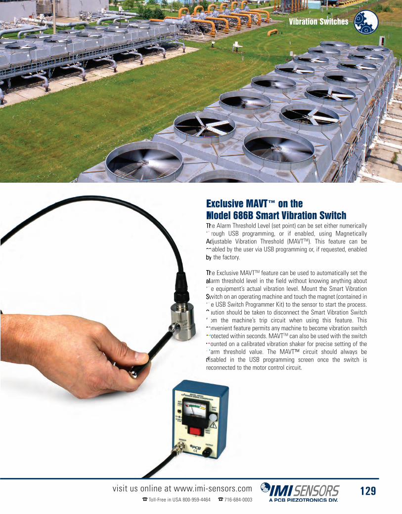
Vibration Switches
visit us online at www.imi-sensors.comToll-Free in USA 800-959-4464 716-684-0003
129
Exclusive MAVT™ on theModel 686B Smart Vibration SwitchThe Alarm Threshold Level (set point) can be set either numericallythrough USB programming, or if enabled, using MagneticallyAdjustable Vibration Threshold (MAVTTM). This feature can beenabled by the user via USB programming or, if requested, enabledby the factory.
The Exclusive MAVTTM feature can be used to automatically set thealarm threshold level in the field without knowing anything aboutthe equipment’s actual vibration level. Mount the Smart VibrationSwitch on an operating machine and touch the magnet (contained inthe USB Switch Programmer Kit) to the sensor to start the process.Caution should be taken to disconnect the Smart Vibration Switchfrom the machine’s trip circuit when using this feature. Thisconvenient feature permits any machine to become vibration switchprotected within seconds. MAVTTM can also be used with the switchmounted on a calibrated vibration shaker for precise setting of thealarm threshold value. The MAVT™ circuit should always bedisabled in the USB programming screen once the switch isreconnected to the motor control circuit.

Smart Vibration Switches� Low cost fully USB Programmable vibration switch that replaces
unreliable mechanical vibration switches� 2-wire operation uses existing mechanical switch wires� Features the accuracy and small footprint of a piezoelectric accelerometer
The all new electronic Smart Vibration Switch from IMI Sensors is highly versatile, fully user programmable viaUSB, low cost and a drop-in replacement for most popular mechanical vibration switches. The Smart VibrationSwitch includes an embedded piezoelectric accelerometer for accurate measurement, monitors vibration velocityfor more consistent results and provides the reliability not found in mechanical switches. It is a lower costalternative when single relay action is required vs. higher cost dual relay models.
In addition to being a more reliable device than mechanical vibration switches, the unique Series 686B SmartVibration Switch is a much lower cost solution for many conventional electronic vibration switch applications aswell. The Smart Vibration Switch is a great choice in applications where a single relay provides sufficient protectionand/or an overall vibration output (typically 4-20 mA) is not required. Multiple Smart Vibration Switches can be usedin series or parallel to monitor several points or machines as necessary. They can also be used in conjunction withexternal SPST and DPDT relays to increase current capacity or when such relays are required.
visit us online at www.imi-sensors.comToll-Free in USA 800-959-4464 716-684-0003
130
USB ProgrammableElectronic Vibration SwitchModel 686B01
� 2-pin MIL-C-5015 connector
� Programmable alarm threshold, relayaction (NO, NC) and 3 time delays
� Monitors in velocity
Product shown at actual size
USB ProgrammableElectronic Vibration SwitchModel 686B11
� Integral cable version forharsh environments
� Ideal for submersible applications
� Remote reset standard
Product shown at actual size
2.6 in(66 mm)
1.87 in(47.5 mm)
1.87 in(47.5 mm)
0.80 in(20.3 mm)
0.20 in(5.1 mm)
0.80 in(20.3 mm)
Ø1.24 in(Ø31.50 mm)
20 in(5.1 mm)
1/4-28 UNF-2B
5.0 in (127 mm)to Typical Bend Radius
Conductors are Bi-polar
Molded Integral2-conductor cable
2-pin ThreadedMIL-C-5015Connector
1.25 in(31.8 mm) Hex
Pins are Bi-polar
Ø0.920(Ø23.37 mm)
Ø1.24(Ø31.5 mm)
1.25 (31.8 mm) Hex
1/4-28 UNF-2BØ0.92 in(Ø23.4 mm)
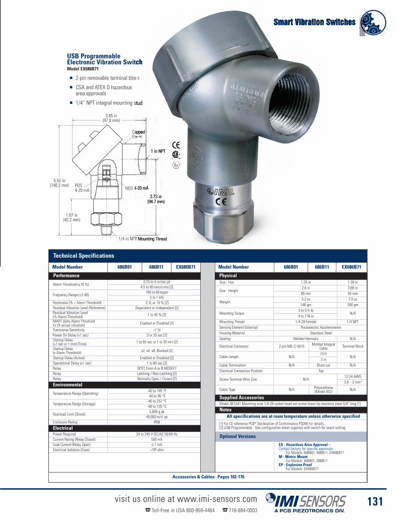
Smart Vibration Switches
visit us online at www.imi-sensors.comToll-Free in USA 800-959-4464 716-684-0003
131
Model Number 686B01 686B11 EX686B71Alarm Threshold (±10 %)
0.25 to 5 in/sec pk4.5 to 90 mm/s rms [2]
Frequency Range (±3 dB)180 to 60 kcpm3 to 1 kHz
Hysteresis (% < Alarm Threshold) 3; 6; or 10 % [2]Residual Vibration Level (Reference) Dependent or Independent [2]Residual Vibration Level(% Alarm Threshold) 1 to 40 % [2]
MAVT (Sets Alarm Thresholdto 2X actual vibration) Enabled or Disabled [2]
Transverse Sensitivity <7 %Power On Delay (±1 sec) 3 or 20 sec [2]Startup Delay(±1 sec or 1 min) (Time) 1 to 60 sec or 1 to 30 min [2]
Startup Delay(x Alarm Threshold) x2; x4; x8; Blocked [2]
Startup Delay (Active) Enabled or Disabled [2]Operational Delay (±1 sec) 1 to 60 sec [2]Relay SPST, Form A or B MOSFETRelay Latching / Non-Latching [2]Relay Normally Open / Closed [2]
Environmental
Temperature Range (Operating)-40 to 185 °F-40 to 85 °C
Temperature Range (Storage)-40 to 257 °F-40 to 125 °C
Overload Limit (Shock)5,000 g pk
49,050 m/s2 pkEnclosure Rating IP68
ElectricalPower Required 24 to 240 V DC/AC 50/60 HzCurrent Rating (Relay Closed) 500 mALeak Current (Relay Open) ≤ 1 mAElectrical Isolation (Case) >108 ohm
PhysicalSize - Hex 1.25 in 1.38 in
Size - Height2.6 in 3.68 in66 mm 94 mm
Weight5.2 oz 7.0 oz148 gm 200 gm
Mounting Torque3 to 5 ft-lb
N/A4 to 7 N-m
Mounting Thread 1/4-28 Female 1/4 NPTSensing Element (Internal) Piezoelectric AccelerometerHousing Material Stainless SteelSealing Welded Hermetic N/A
Electrical Connector 2-pin MIL-C-5015 Molded IntegralCable Terminal Block
Cable Length N/A10 ft
N/A3 m
Cable Termination N/A Blunt cut N/AElectrical Connection Position Top
Screw Terminal Wire Size N/A12-24 AWG3.0 - .2 mm2
Cable Type N/A Polyurethane(Model 052) N/A
Supplied AccessoriesModel 081A41 Mounting stud 1/4-28 socket head set screw brass tip stainless steel 5/8" long (1)
NotesAll specifications are at room temperature unless otherwise specified
[1] For CE reference PCB® Declaration of Conformance PS096 for details.[2] USB Programmable - See configuration sheet supplied with switch for exact setting.
USB ProgrammableElectronic Vibration SwitchModel EX686B71
� 2-pin removable terminal block
� CSA and ATEX D hazardousarea approvals
� 1/4” NPT integral mounting stud
1/4” NPTM
3.73(94.7)
NEG 4-20 mA
1” NPT
CappedElbow
5.52(140.2)
1.67(42.4)
POS4-20 mA
3.85 in(97.8 mm)
3.73 in(94.7 mm)
5.52 in(140.2 mm)
1.67 in(42.2 mm)
1/4 in NPT Mounting Thread
NEG 4-20 mAPOS4-20 mA
CappedElbow
1 in NPT
Optional Versions
EX - Hazardous Area Approval -Contact factory for specific approvals
For Models: 686B01, 686B11, EX686B71M - Metric Mount
For Models: 686B01, 686B11EP - Explosion Proof
For Models: EX686B71
Technical Specifications
Model Number 686B01 686B11 EX686B71 Model Number 686B01 686B11 EX686B71
Performance Physical
Accessories & Cables: Pages 162-176
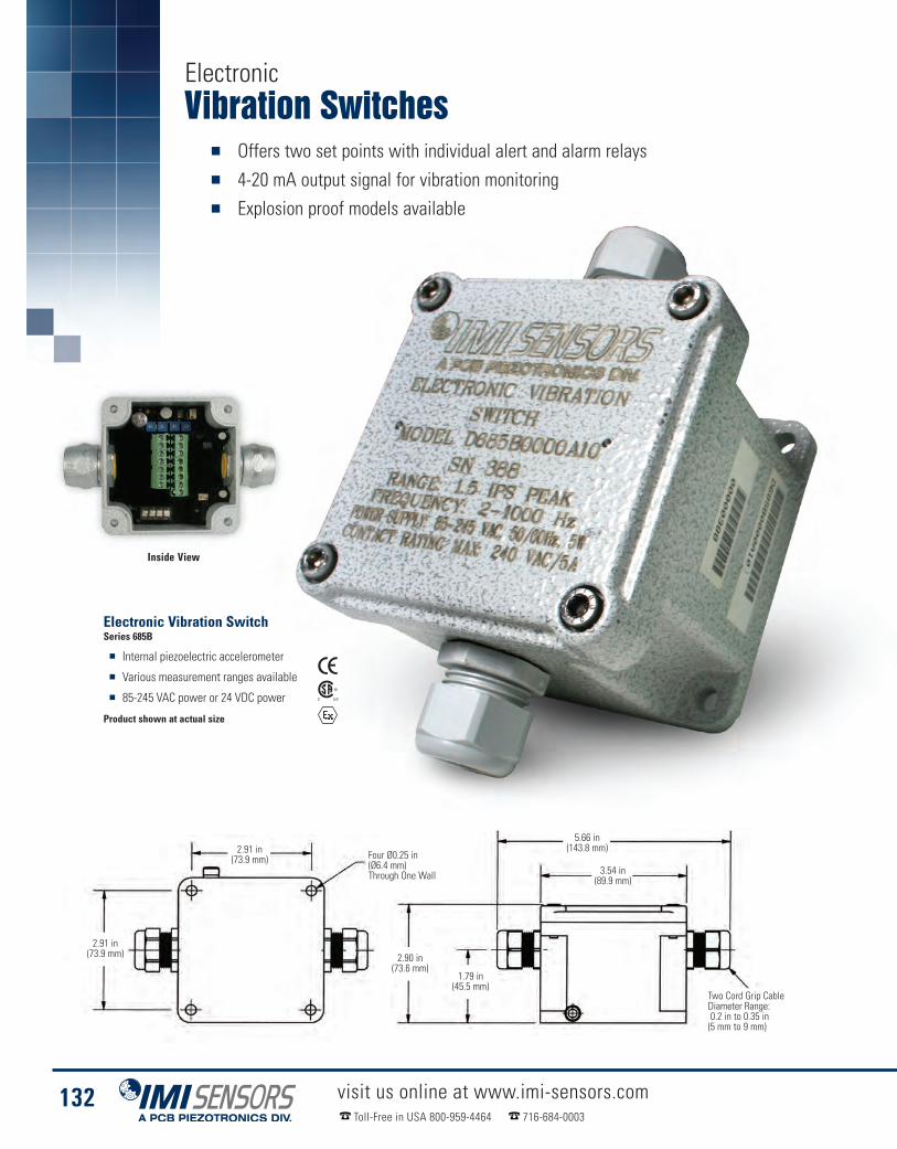
Vibration Switches� Offers two set points with individual alert and alarm relays� 4-20 mA output signal for vibration monitoring� Explosion proof models available
visit us online at www.imi-sensors.comToll-Free in USA 800-959-4464 716-684-0003
132
Electronic Vibration SwitchSeries 685B
� Internal piezoelectric accelerometer
� Various measurement ranges available
� 85-245 VAC power or 24 VDC power
Product shown at actual size
Inside View
Electronic
Four Ø0.25 in(Ø6.4 mm)Through One Wall
2.91 in(73.9 mm)
2.91 in(73.9 mm) 2.90 in
(73.6 mm)1.79 in(45.5 mm)
5.66 in(143.8 mm)
3.54 in(89.9 mm)
Two Cord Grip CableDiameter Range:0.2 in to 0.35 in(5 mm to 9 mm)
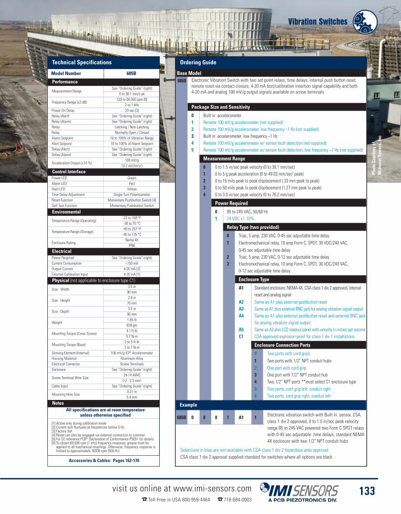
Vibration Switches
visit us online at www.imi-sensors.comToll-Free in USA 800-959-4464 716-684-0003
133
How to Order
Base Model685B Electronic Vibration Switch with two set point relays, time delays, internal push button reset,
remote reset via contact closure, 4-20 mA test/calibration insertion signal capability and both4-20 mA and analog 100 mV/g output signals available on screw terminals
Package Size and Sensitivity
0 Built in accelerometer1 Remote 100 mV/g accelerometer (not supplied)2 Remote 100 mV/g accelerometer, low frequency ~1 Hz (not supplied)3 Built in accelerometer, low frequency ~1 Hz4 Remote 100 mV/g accelerometer w/ sensor fault detection (not supplied)5 Remote 100 mV/g accelerometer w/ sensor fault detection, low frequency ~1 Hz (not supplied)
Measurement Range
0 0 to 1.5 in/sec peak velocity (0 to 38.1 mm/sec)1 0 to 5 g peak acceleration (0 to 49.03 mm/sec2 peak)2 0 to 15 mils peak to peak displacement (.33 mm peak to peak)3 0 to 50 mils peak to peak displacement (1.27 mm peak to peak)4 0 to 3.0 in/sec peak velocity (0 to 76.2 mm/sec)
Power Required
0 85 to 245 VAC, 50/60 Hz1 24 VDC +/- 10%
Relay Type (two provided)
0 Triac, 5 amp, 230 VAC, 0-45 sec adjustable time delay1 Electromechanical relay, 10 amp Form C, SPDT, 30 VDC/240 VAC,
0-45 sec adjustable time delay2 Triac, 5 amp, 230 VAC, 0-12 sec adjustable time delay3 Electromechanical relay, 10 amp Form C, SPDT, 30 VDC/240 VAC,
0-12 sec adjustable time delay
Enclosure Type
A1 Standard enclosure, NEMA 4X, CSA class 1 div 2 approved, internalreset and analog signal
A2 Same as A1 plus external pushbutton resetA3 Same as A1 plus external BNC jack for analog vibration signal outputA4 Same as A1 plus external pushbutton reset and external BNC jack
for analog vibration signal outputA5 Same as A3 plus LCD readout panel with velocity in inches per secondC1 CSA approved explosion proof for class 1 div 1 installations
Enclosure Connection Ports
0 Two ports with cord grips1 Two ports with 1/2” NPT conduit hubs2 One port with cord grip3 One port with 1/2” NPT conduit hub4 Two 1/2” NPT ports **must select C1 enclosure type5 Two ports, cord grip left, conduit right6 Two ports, cord grip right, conduit left
Example
685B 0 0 0 1 A1 1 Electronic vibration switch with Built in sensor, CSAclass 1 div 2 approved, 0 to 1.5 in/sec peak velocityrange 85 to 245 VAC powered two Form C SPDT relayswith 0-45 sec adjustable time delays, standard NEMA4X enclosure with two 1/2" NPT conduit hubs
Selections in blue are not available with CSA class 1 div 2 hazardous area approvalCSA class 1 div 2 approval supplied standard for switches where all options are black
Technical Specifica-Model Number 685B0001A10
Measurement RangeSee “Ordering Guide” (right)
0 to 38.1 mm/s pk
Frequency Range (±3 dB)120 to 60,000 cpm [6]
2 to 1 kHzPower On Delay 20 sec [3]Relay (Alert) See “Ordering Guide” (right)Relay (Alarm) See “Ordering Guide” (right)Relay Latching / Non-LatchingRelay Normally Open / ClosedAlarm Setpoint 10 to 100% of Vibration RangeAlert Setpoint 10 to 100% of Alarm SetpointDelay (Alert) See “Ordering Guide” (right)Delay (Alarm) See “Ordering Guide” (right)
Acceleration Output (±10 %)100 mV/g
10.2 mV/(m/s2)
Control InterfacePower LED GreenAlarm LED RedAlert LED YellowTime Delay Adjustment Single Turn PotentiometerReset Function Momentary Pushbutton Switch [4]Self Test Function Momentary Pushbutton Switch
Environmental
Temperature Range (Operating)-22 to 158 °F-30 to 70 °C
Temperature Range (Storage)-40 to 257 °F-40 to 125 °C
Enclosure RatingNema 4XIP66
ElectricalPower Required See “Ordering Guide” (right)Current Consumption <150 mAOutput Current 4-20 mA [2]External Calibration Input 4-20 mA [1]
Physical
Size - Width3.5 in90 mm
Size - Height2.8 in70 mm
Size - Depth3.5 in90 mm
Weight1.85 lb839 gm
Mounting Torque (Cover Screw)4.1 ft-lb5.7 N-m
Mounting Torque (Base)2 to 5 ft-lb3 to 7 N-m
Sensing Element (Internal) 100 mV/g ICP" AccelerometerHousing Material Aluminum AlloyElectrical Connector Screw TerminalsEnclosure See “Ordering Guide” (right)
Screw Terminal Wire Size24-14 AWG0.2 - 2.5 mm2
Cable Input See “Ordering Guide” (right)
Mounting Hole Size0.21 in5.4 mm
NotesAll specifications are at room temperature
unless otherwise specified
[1] Active only during calibration mode[2] Current will fluctuate at frequencies below 5 Hz.[3] Factory Set[4] Reset can also be engaged via external connection to common[5] For CE reference PCB® Declaration of Conformance PS051 for details.[6] To obtain 60,000 cpm (1 kHz) frequency response, grease must beapplied to all mechanical couplings. Otherwise, frequency response islimited to approximately 30000 cpm (500 Hz)
Phot
oCo
urte
syof
Mid
wes
tTow
ers,
Inc
Technical Specifications
Model Number 685B
Performance
Control Interface
Environmental
Electrical
Physical (not applicable to enclosure type C1)
Notes
Accessories & Cables: Pages 162-176
Ordering Guide
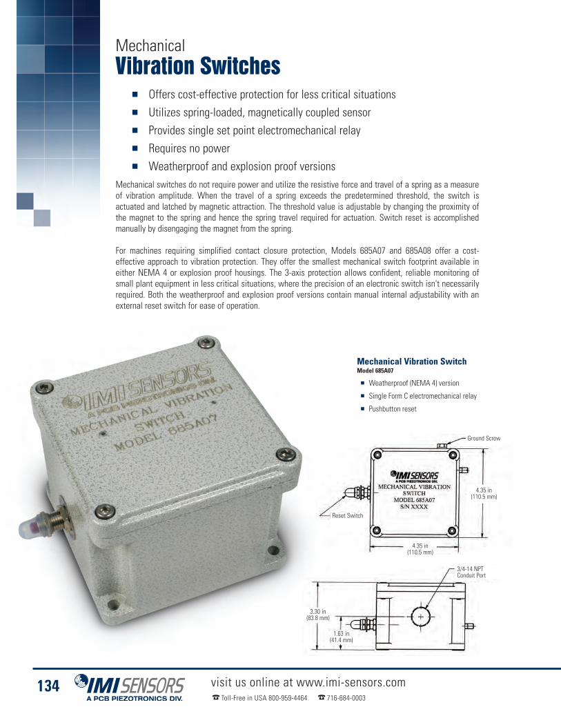
visit us online at www.imi-sensors.comToll-Free in USA 800-959-4464 716-684-0003
134
Vibration Switches� Offers cost-effective protection for less critical situations� Utilizes spring-loaded, magnetically coupled sensor� Provides single set point electromechanical relay� Requires no power� Weatherproof and explosion proof versions
Mechanical switches do not require power and utilize the resistive force and travel of a spring as a measureof vibration amplitude. When the travel of a spring exceeds the predetermined threshold, the switch isactuated and latched by magnetic attraction. The threshold value is adjustable by changing the proximity ofthe magnet to the spring and hence the spring travel required for actuation. Switch reset is accomplishedmanually by disengaging the magnet from the spring.
For machines requiring simplified contact closure protection, Models 685A07 and 685A08 offer a cost-effective approach to vibration protection. They offer the smallest mechanical switch footprint available ineither NEMA 4 or explosion proof housings. The 3-axis protection allows confident, reliable monitoring ofsmall plant equipment in less critical situations, where the precision of an electronic switch isn't necessarilyrequired. Both the weatherproof and explosion proof versions contain manual internal adjustability with anexternal reset switch for ease of operation.
Mechanical Vibration SwitchModel 685A07
� Weatherproof (NEMA 4) version
� Single Form C electromechanical relay
� Pushbutton reset
Mechanical
Ground Screw
4.35 in(110.5 mm)
4.35 in(110.5 mm)
Reset Switch
3.30 in(83.8 mm)
1.63 in(41.4 mm)
3/4-14 NPTConduit Port

3.00 in(76.2 mm)
Four Ø0.375 in(Ø9.525 mm)Through
5.25 in(133.4 mm)
6.38 in(162.0 mm)
5.12 in(130.0 mm)
0.45 in (11.4 mm)
Vibration Switches
visit us online at www.imi-sensors.comToll-Free in USA 800-959-4464 716-684-0003
135
Mechanical Vibration SwitchModel 685A08
� Weatherproof & CSA / UL approved, explosion proof
� Cost-effective protection for less critical applications
� Requires no power
Technical SpecificationsModel Number 685A07 685A08
Measurement Range0 to 7 g pk
0 to 68.7 m/s2 pk
Frequency Range0 to 6,000 cpm0 to 100 Hz
Relay 5A FormC 480 VAC
5A Form C 480 VAC/2AResistive,1A Inductive
@ 30 VDC
Relay LatchingRelay Normally Open / Closed
Control InterfaceReset Function Momentary Pushbutton Switch
Environmental
Temperature Range (Operating)-40 to 140 °F-40 to 60 °C
Enclosure Rating IP50
Hazardous Area Approval N/A
CSA Class I Div 1,Groups C & D
UL 516U Explosion Proof,Flame Proof
Physical
Size - Width4.35 in 6.38 in
110.5 mm 162 mm
Size - Height3.30 in 4.88 in83.8 mm 124 mm
Size - Depth4.35 in 5.63 in
110.5 mm 143 mm
Weight2.1 lb 4.5 lb953 gm 2.04 kg
Sensing Element MagnetHousing Material Aluminum AlloyElectrical Connector Screw Terminals
Screw Terminal Wire Size24-14 AWG 14 AWG0.2 - 2.5 mm2 2.5 mm2
Cable Input 3/4-14 NPT 1/2-14 NPT
Mounting Hole Size0.25 in 0.38 in
6.4 mmSensing Geometry Inertial Element
NotesAll specifications are at room temperature unless otherwise specified
Technical SpecificationsModel Number 685A07 685A08 Model Number 685A07 685A08
Performance Physical

USB Programming Kits� Customize settings on your USB programmable sensor� Kits include CD-ROM software & cable adapters� Free software updates available at www.imi-sensors.com
USB Programming Kits for IMI’s exclusive line of USB programmable sensors include all the hardware and softwareneeded. Use the programming cable to connect the sensors to any PC with the software installed and follow thesimple programming steps to complete the process. Each software package allows the user to enter the variablesavailable to customize the sensor to the specific application resulting in the most accurate output results.
visit us online at www.imi-sensors.comToll-Free in USA 800-959-4464 716-684-0003
136
686B01 Smart Switch Programming Kit� Program the alarm threshold, normally open,normally closed, latching or non-latching relay action
� Time delays for power up, start upand operation create high reliability
� Kit includes 2-pin MIL to USB cable,terminal block adapter and CD-ROM software
� Programming screen creates a unique configurationpart number for use when programming multiple sensors
� Kit 600A15 includes an additional adapter for use withintegral cable and terminal block sensor connections
� Kit 600A16 is used on 2-pin MIL connections
USB Programming KitKit 600A16
USB Programming KitKit 600A15
� Includes additional adaptor for use withintegral cable and terminal block sensors

USB Programming Kits
visit us online at www.imi-sensors.comToll-Free in USA 800-959-4464 716-684-0003
137
649A01 Reciprocating MachineryProtector Programming Kit
� Use programming Kit 600A21 for 2-pin MIL sensorconnection. Use programming kit 600A24 forintegral cable and terminal block sensor connection
� Simply enter the compressor RPM and letthe software recommend all settings orindependently setting each parameter
� Program 2 alarm levels with the relatedweighting values
� Kit can be used to program multiple RMP units
649A03 Bearing Condition MonitorProgramming Kit
� Use programming Kit 600A21 for 2-pin MIL sensorconnection. Use programming kit 600A24 forintegral cable and terminal block sensor connection
� Choose from Acceleration Peak, Acceleration RMS,Acceleration with compensation, Crest Factor orCrest Factor Plus based on your unique application
� Choose whatever full scale range suits the specificapplication providing the most resolution
� Kit can be used to program multipleBearing Condition Monitors
649A04 Programmable 4-20 mA TransmitterProgramming Kit
� Use programming Kit 600A21 for 2-pin MIL sensorconnection. Use programming kit 600A24 forintegral cable and terminal block sensor connection
� Choose Displacement, Velocity or Accelerationmeasurement method
� Set full scale range
� Choose high pass and low pass filter options
� Kit can be used to program multipleProgrammable 4-20 mA output transmitters

Pressure Sensors� Detect and monitor pulsations, instability, surges, turbulence and acoustics� Hazardous location troubleshooting, predictive maintenance
and process improvement� For gas compressors, chemical plants, power generation
and other hazardous processesPiezoelectric pressure sensors offer the unique ability to respond to very rapid pressure spikes, pulsations andsurges. They can also sense minute pressure fluctuations, while subjected to very high static pressures. Series121A44 case isolated and 102M205 ground isolated Hazardous Area Approved, dynamic ICP® pressure sensorssatisfy such measurement requirements in monitoring, diagnostic, troubleshooting and control applications typicalof hazardous factory environments.
Applications include monitoring dynamic pressure events such as surges, pulsations, spikes, leakdetection,combustion instability; and acoustics found in operation of compressors, pumps, pipelines and gasturbines. Sensors may be used with ICP® signal conditioning and permit use of a variety of inexpensive 2-wire cablesystems. The low-impedance signal may be transmitted over long cable distances and sensors may be used in dirtyenvironments without signal degradation. PCB® Model 121A44 case isolation eliminates all electrical noise fromboth environment and structure. Model 102M205 ground isolation eliminates electrical noise from the structureunder test.
visit us online at www.imi-sensors.comToll-Free in USA 800-959-4464 716-684-0003
138
ICP® Pressure SensorModel 121A44
� Sensitivity: 0 to 110 mV/psi(1.45 to 14.5 mV/kPa)
� Measurement range: 50 to 500 psi
� 316 stainless steel diaphragm
� 1/4” NPT fitting
Product shown at actual size
ICP® Pressure SensorModel 102M205
� Sensitivity: 50 mV/psi(7.25 mV/kPa)
� Measurement range: 100 psi
� 316 stainless steel diaphragm
� 3/8-24 UNF fitting
Product shown at actual size
3/8-24Thd
Clamp Nut
7/16 HEX
0.31 (7.9)
10-32Connector
1.48 (37.6)
Seal ring
1.48 in(37.6 mm)
3/8-24Thread
2.70 in(68.6 mm)
0.90 in(22.86 mm)
1/4-18 NPT
0.34 in(8.6 mm)
0.31 in(7.9 mm)
2-pin ThreadedMIL-C-5015 Connector
A = Power / InputB = Ground
3/4 Hex
Seal Ring
7/16 Hex
Clamp Nut
10-32 Connector

Pressure Sensors
visit us online at www.imi-sensors.comToll-Free in USA 800-959-4464 716-684-0003
139
Technical SpecificationsModel Number Series 102
Measurement Range (for ±5V output)100 psi689.5 kPa
Useful Overrange (for ± 10V output)200 psi [1]1,379 kPa [1]
Sensitivity(± 10 mV/psi)50 mV/psi7.25 mV/kPa
Maximum Pressure500 psi3,448 kPa
Resolution2 mpsi
0 0138 kPaResonant Frequency ≥ 250 kHzRise Time ≤ 2 µ secLow Frequency Response (-5 %) 0.50 HzNon-linearity ≤ 1 % FS [2]
Environmental
Acceleration Sensitivity≤ 0.002 psi/g
≤ 0 0014 kPa/(m/s²)
Temperature Range (Operating)-100 to +275 °F-73 to +135 °C
Temperature Coefficient of Sensitivity≤ 0.1 %/°F≤ 0.18 %/°C
Maximum Flash Temperature3,000 °F1 649 °C
Maximum Vibration2,000 g pk
19,614 m/s² pk
Maximum Shock20,000 g pk
196,140 m/s² pk
ElectricalOutput Polarity (Positive Pressure) PositiveDischarge Time Constant (at room temp) ≥ 1 secExcitation Voltage 20 to 30 VDCConstant Current Excitation 2 to 20 mAOutput Bias Voltage 8 to 14 VDC
PhysicalSensing Element QuartzHousing Material 17-4 Stainless SteelDiaphragm 316L Stainless Steel [3]Sealing Welded HermeticElectrical Connector 10-32 Coaxial Jack
Weight0.4 oz11 gm
Supplied AccessoriesModel 065A44 Seal ring 0.435" OD x 0.377" ID x 0.030" thk Cu (3)
NotesAll specifications are at room temperature unless otherwise specified
Model Number Series 121Measurement Range(for ±5V output)
50 psi344.8 kPa
Sensitivity (± 10 mV/psi)100 mV/psi
14.5037 mV/kPa
Maximum Pressure8 kpsi [8]
55.16 MPa [8]
Resolution0.5 mpsi0.003 kPa
Resonant Frequency ≥ 60 kHzRise Time (Reflected) ≤ 4 µ secLow Frequency Response (-5 %) 0.5 HzNon-linearity ≤ 2.0 % FS [9]
Environmental
Acceleration Sensitivity≤ 0.05 psi/g
≤ 0.035 kPa/(m/s²)
Temperature Range (Operating)-65 to +250 °F-54 to +121 °C
Hazardous Area ApprovalCSA (C-US) NRTL - Canadian Standards Association
[1][2][3][4]
ATEX [5][6][7]
ElectricalOutput Polarity (Positive Pressure) PositiveDischarge Time Constant (at room temp) ≥ 1 secExcitation Voltage 22 to 28 VDCConstant Current Excitation 2 to 20 mAOutput Bias Voltage 10 to 15 VDCElectrical Isolation ≥ 108 ohm
PhysicalSensing Geometry CompressionSensing Element QuartzHousing Material 316L Stainless SteelDiaphragm 316L Stainless SteelSealing Welded HermeticElectrical Connector 2-pin MIL-C-5015
Weight2.7 oz75.6 gm
NotesAll specifications are at room temperature unless otherwise specified
[1] For +10 volt output, minimum 24 VDC supplyvoltage required. Negative 10 volt output maybe limited by output bias.
[2] Zero-based, least-squares,straight line method.
[3] Diaphragm with ablative coating.[4] For CE reference PCB® Declaration ofConformance PS023 for details.
[1] AEx ia IIC T4, DIV1 CL1 GR A-D[2] Ex ia IIC T4, DIV1 CL1 GR A-D[3] AEx nA IIC T4, DIV2 CL1 GR A-D[4] Ex nL IIC T4, DIV2 CL1 GR A-D[5] Ex ia IIC T4.[6] Ex nL IIC T4.[7] Ex nA IIC T4.
[8] Due to high sensitivity, the static pressure should beapplied and removed very slowly. Rate should preventmore than 10 Volt change in output until Output BiasVoltage returns to normal(approximately 15 times discharge time constant).
[9] Zero-based, least-squares, straight line method.[10] For CE reference PCB® Declaration of Conformance
PS059 for details.
Optional Versions
M - Metric MountSupplied Accessory : Model 065A40 Seal ring0.435" OD x 0.397" ID x 0.030" thk brass (3)
For Model 121M205W- Water Resistant Cable
For Model 121M205
Technical Specifications
Model Number 121A44
Performance
Environmental
Electrical
Physical
Notes
Accessories & Cables: Pages 162-176
Technical Specifications
Model Number 102M205
Performance
Environmental
Electrical
Physical
Supplied Accessories
Notes
Accessories & Cables: Pages 162-176

Pressure Sensors� On-Turbine Instability Sensor (OTIS)� Detects and measures dynamic pressure phenomena� Various configurations available
When directly mounted to a gas turbine’s combustor, IMI’s Series 176 high temperature dynamic pressuresensors provide 24/7, consistent, reliable combustion dynamics data monitoring to help control instabilitywhich can damage components in the combustion chamber as well as downstream equipment.
By mounting the Series 176 high temperature dynamic pressure sensors to the combustor, gas turbineoperators can rely on critical diagnostics, part fatigue analysis and the ability to continuously monitor andcontrol emissions.
High Temperature DynamicPressure SensorSeries 176M0X
� Sensitivities to 17 pC/psi
� Dynamic measurement range 20 psi
� Removable clamp nut
Product shown at actual size
High Temperature DynamicPressure SensorSeries 176MXX
� Sensitivities to 17 pC/psi
� Dynamic measurement range 20 psi
� Various tip diameters available
Product shown at actual size
visit us online at www.imi-sensors.comToll-Free in USA 800-959-4464 716-684-0003
140
Model 176M03 & Model 176M09 Technical Drawing
Seal (Supplied)
POS
0.030 in(0.762 mm)
18.0 in ± 0.50 in(457.2 mm ± 12.7 mm)
1.500 in(38.1 mm)
1.500 in ± 0.001 in(38.1mm±0.254mm)
Ø0.750 in ± 0.002 in(19.05mm±0.050mm)
Ø0.484 in(Ø12.29mm)Through
7/16-27UNS-2A2-Pin Connector
Ø0.484 in ± 0.001 in(12.29mm±0.02mm)
M22X 2.5-6g
Ø0.565 in(Ø14.351mm)
1.250 in(31.75mm)
22mmHEX
Ø0.56 in (14.22mm)
Ø0.475 in(Ø12.06mm)
+ 0.00- 0.003
1.80 in (45.72)
2.00 in (50.80 mm)NEG
Model 176M07 Technical Drawing
Model 176M12 Technical Drawing
Ø0.375 in(Ø9.53 mm)
Ø0.250 in(Ø6.35 mm)
12.0 in ± 0.5 in(304.8 mm ± 12.7 in)
12.0 in ± 0.5 in(304.7 mm ± 12.7 in)
Ø0.750 in (19.05 mm) 7/16-27 UNS-2A2-Pin Connector
7/16-27 UNS-2A2-Pin Connector
1.18 in(29.8 mm)
1.18 in(29.8 mm)
6.3 in(160 mm)
6.3 in(160 mm)
POS (+) NEG (-)
POS (+) NEG (-)
Ø0.750 in (19.05 mm)
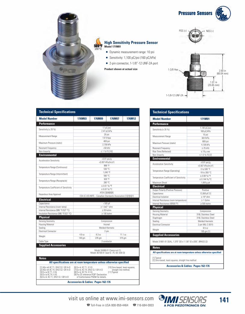
Technical Specifications
Model Number 171M01
Performance
Sensitivity (± 20 %)1,100 pC/psi160 pC/kPa
Measurement Range10 psi68.9 kPa
Maximum Pressure (static)600 psi4,136 kPa
Resonant Frequency ≥ 25 kHzRise Time (Reflected) ≤ 10 µ secNon-linearity ≤ 1.0 % FS [2]
Environmental
Acceleration Sensitivity<0.01 psi/g
<0.007 kPa/(m/s²)
Temperature Range (Operating)0 to 500 °F-18 to 260 °C
Temperature Coefficient of Sensitivity≤ 0.08 %/°F
≤ 0.144 %/°CMaximum Shock 1,000 g pk
ElectricalOutput Polarity (Positive Pressure) PositiveCapacitance 12,000 pF [1]Electrical Isolation ≥ 108 ohmInternal Resistance (room temperature) ≥ 1 GohmInternal Resistance (@500 ºF) ≥ 500 kohm
PhysicalSensing Geometry CompressionHousing Material 316L Stainless SteelDiaphragm 316L Stainless SteelSealing Welded HermeticElectrical Connector 2-pin MIL-C-5015
Weight6.5 oz
185 gm [1]
Supplied Accessories
Model 31061-01 SEAL, 1.370" OD x 1.130" ID x.030", BRASS (2)
NotesAll specifications are at room temperature unless otherwise specified
[1] Typical[2] Zero-based, least-squares, straight line method
High Sensitivity Pressure SensorModel 171M01
� Dynamic measurement range: 10 psi
� Sensitivity: 1,100 pC/psi (160 pC/kPa)
� 2-pin connector, 1-1/8”-12 UNF-2A port
Product shown at actual size
Technical InformationModel Number 176M03 176M09 176M07 176M12
Sensitivity (± 20 %)17 pC/psi2.47 pC/kPa
Measurement Range20 psi
137.9 kpa
Maximum Pressure (static)400 psi2,758 kPa
Resonant Frequency >50 kHzNon-linearity ≤ 1 % FS [10]
Environmental
Acceleration Sensitivity<0.01 psi/g
<0.007 kPa/(m/s²)
Temperature Range (Continuous)986 °F530 °C
Temperature Range (Intermittent)1,040 °F560 °C
Temperature Range (Receptacle)500 °F260 °C
Temperature Coefficient of Sensitivity≤ 0.01 %/°F≤ 0.02 %/°C
Hazardous Area ApprovalATEX [3][4][6][8]
CSA (C-US) NRTL - Canadian Standards Association [1][2][5][7]
ElectricalCapacitance <165 pFInternal Resistance (room temp) ≥ 1.0xE12 ohmInternal Resistance (986 °F/527 °C) ≥ 50 kohmInsulation Resistance (986 °F/527 °C) ≥ 100 kohm
PhysicalSensing Geometry CompressionHousing Material InconelSealing Welded HermeticElectrical Connector 2-pin
Weight4.9 oz 8.3 oz 11.1 oz140 gm 235 gm 315 gm
Cable Type 2-conductor
Supplied Accessories
Model 30498-01 Clamp nut (1)Model 30736-01 Seal-G-.75-.50-.030 (3)
NotesAll specifications are at room temperature unless otherwise specified
[1] AEx nA IIC T1, DIV2 CL1 GR A-D[2] AEx nA IIC T4, DIV2 CL1 GR A-D[3] Ex ia IIC T1, II IG[4] Ex ia IIC T4, II IG[5] Ex nL IIC T1, DIV2 CL1 GR A-D
[6] Ex nL IIC T1, II 3 G[7] Ex nL IIC T4, DIV2 CL1 GR A-D[8] Ex nL IIC T4, II 3 G[9] For CE reference PCB® Declarationof Conformance PS058 for details.
[10] Zero-based, least-squares,straight line method.
[11] Typical
Pressure Sensors
visit us online at www.imi-sensors.comToll-Free in USA 800-959-4464 716-684-0003
141
2.60 in(66.04 mm)
POS (+) NEG (-)
1-3/8 Hex
1-1/8-12 UNF-2A
1.01 in(25.65 mm)
Technical Specifications
Model Number 176M03 176M09 176M07 176M12
Performance
Environmental
Electrical
Physical
Supplied Accessories
Notes
Accessories & Cables: Pages 162-176
Technical Specifications
Model Number 171M01
Performance
Environmental
Electrical
Physical
Supplied Accessories
Notes
Accessories & Cables: Pages 162-176

Echo® Wireless Vibration System
visit us online at www.imi-sensors.comToll-Free in USA 800-959-4464 716-684-0003
142
The Echo® Wireless Vibration Sensor is a stand alone, battery powered, industrialvibration sensor. At the default setting of three measurements per day (userprogrammable) battery life is greater than 5 years. A Raw Vibration (RV) outputversion includes an integral connector that can be used with an optional cable anda standard vibration data collector for fault analysis. The sensor can beprogrammed via RS-232 to set the transmission (collection) interval and a ResidualVibration Level (RVL) if desired. Echo® has an LED that provides visual feedback onthe status of the sensor, including: on, off, measuring, transmitting, or changingstates. The sensor has an embedded magnetic switch and can be activated ordeactivated by holding a strong magnet next to the sensor. Upon activation, thesensor makes and transmits a set of measurements.
Wireless Vibration SensorModel 670A01
� Batteries last over 5 years
� Transmits long distances
� Eliminates expensive cable runs
Product shown at actual size
The Echo® Wireless Vibration System has been tested and found to perform very well, in a number of differenttypes of plants including: power, steel, food processing, paper, chemical and automotive. The system hasperformed reliably and provided accurate and useful data regarding machinery health.
Performance
The Echo® Wireless Vibration Sensor and the EchoPlus® Wireless Junction Box make the set of overallvibration measurements, listed below, that are sure to provide early warning of most common machine faults.In addition to these measurements, Echo® provides accurate battery status. Using a user programmablevibration threshold, Echo® can detect if the machine is not running and if not, skip a measurement to conservebattery power. It also has an optional Raw Vibration Output (requires optional Model 070A86 cable) for usewith a portable data collector.
Fault Detection
� RMS Velocity - for “Balance-of-plant” faults such as imbalance, misalignment and flow problems� RMS Acceleration - for higher frequency faults and high frequency energy (HFE)detection such as high speed gear mesh, broken rotor bars and loss of bearing lubrication
� True Peak Acceleration - for bearing, gear and impulsive faults, including looseness� Crest Factor - for fault severity indication

visit us online at www.imi-sensors.comToll-Free in USA 800-959-4464 716-684-0003
143
The EchoPlus® Wireless Junction Box is an 8 channel junction box that instantlyconverts installed industrial sensors to wireless operation. This incrediblyeconomical device periodically powers each sensor, makes the same set of overallmeasurements as Echo® and transmits them wirelessly. The default transmissioninterval is 8 hours but is user programmable. Additionally, it operates as a standardjunction box allowing full data collection with a portable data collector at the box. Itcan be powered using either standard 24 VDC or any battery between 6 and 13 VDC.The unit can be used by itself or in conjunction with an existing junction box by simplyjumping wires between them.
Wireless Junction BoxModel 672A01
� Converts existing sensors to wireless
� Runs independently orwith existing junction box
� Uses 24 VDC or battery power
The Echo® Receiver is a stand alone unit that communicates point-to-point withEcho® Wireless Vibration Sensors and EchoPlus® Wireless Junction Boxes. Operatingin the 916 MHz range, using an ultra-narrow bandwidth filter with Extended Range RF(ERRF) technology, it has unprecedented -145 dBm sensitivity and can detect anddecode RF signals as low as about a millionth of a billionth of a milliwatt. This resultsin very long distance point-to-point communications in plants, eliminating the needfor repeaters or complicated mesh networks. Actual tests in a typical power plantachieved successful signal transmission distances of over 1/3 mile and even throughbuildings. Outdoor tests have achieved transmission distances measured in miles andtransmissions are at only 0.75 mW ERP using very little battery power.
ReceiverModel 673A01
� Requires no repeaters,gateways, or mesh
� Outputs to ethernet
� Installs easily
Echo® Wireless Vibration Sensors

Echo® Wireless Vibration SystemThe Echo® Wireless Vibration System is simple in design, easy to install, cost-effective and flexible inconfiguration. With 12 independent RF bands and over 400 points per receiver, the system can monitor over5,000 points even within the same RF coverage area. Outside the same coverage area, the number is evenhigher. Stand alone Echo® Sensors and EchoPlus® Junction Boxes can be mixed and matched as desired.EchoPlus® and optional RV Echo® provide a raw vibration output via cable to a data collector for detailed faultanalysis. Echo® Monitoring Software provides standard monitoring features such as: machine status, reports,trend plots and email alerts. It can be run single or multi-user at no additional charge per user.
visit us online at www.imi-sensors.comToll-Free in USA 800-959-4464 716-684-0003
144
Direct point to point transmission typical distance = 1/3 to 1/2 mile radiusActual distances can vary widely based on conditions
EchoPlus® Wireless Junction BoxSee page 143 for more information
Echo® Wireless Vibration SensorsSee page 142 for more information
100-240 VAC to12 VDC UniversalPower Supply
TCP/IP
Echo® ReceiverSee page 143 for more information
Typical Configuration 1
Monitored Machinery
Traditional,Wired Sensor
Includedantenna
EchoPlus® Wireless Junction Box & Echo® Wireless Vibration Sensor
Receiver has DHCP or static IP addressing
Optional high gainantenna
Typical Configuration 2
Echo® ReceiverSee page 143 for more information
Vibration Analysis Using Data Collector
Wireless transmission stops while analog accelerationoutput is acquired via BNC. After handheld data collection,device returns to regular transmission schedule
Data collector connects directly to:
Transmissions temporarilypaused during handhelddata collection
Process 24 VDC power or 6-13 VDC battery power
Traditional, Wired SensorConnected to EchoPlus®
Wireless Junction Box
� EchoPlus® Wireless Junction Boxvia standard BNC connector
� Echo® Wireless Vibration Sensorwith optional RV output and 070A86 cable
See page 142 for more information

visit us online at www.imi-sensors.comToll-Free in USA 800-959-4464 716-684-0003
145
Echo® Monitoring SoftwareSee page 146 for more information
Ethernet
Echo® DataClient Service
Echo® DataPresentation SW
Access to SQL Databasethrough internet with LAN
Echo® DataPresentation SW
Access to SQL Databasethrough internet with VPN
Echo® DataPresentation SW
All monitor stations,either through LAN orremote access, have allthe same functionality asserver system, but do notstore data
TCP/IP
Echo®
SensorData MS SQL
Server 2005
� Collects transmission� Formats data� Stores in database� Generates alarm email� Integrated or standalone ModbusTCP/ICP Server interface
� Trend plots� Status� Alarms� Reports� Echo® sensorconfiguration utilities
� Trend plots� Status� Alarms
� Reports� Sensorconfiguration
� Trend plots� Status� Alarms
� Reports� Sensorconfiguration
Echo® Wireless Vibration Sensors

Echo® Monitoring SoftwareEcho® sensor data is stored by the Echo® Data Client Service software in a Microsoft SQL 2005 database. Thedatabase structure is available from IMI® so it can be accessed by users directly using any ODBC compliantapplication. The Echo® Data Client Service can also be configured as a Modbus TCP/IP Server to serviceModbus requests from an existing Modbus Client application. The Modbus capability can coexist with the SQLdatabase capability or function as a standalone application without the SQL database. However, the SQLinterface is required if the Echo® Data Presentation Software is to be used.
Echo® data can also be exported from the Echo® DataPresentation Software to a tab delimited spreadsheetfile that is suitable for use with Excel or other dataviewing applications for post processing. Contact IMI® todiscuss other interfaces to legacy condition monitoringprograms and plant monitoring systems.
visit us online at www.imi-sensors.comToll-Free in USA 800-959-4464 716-684-0003
146
� Configuration utilities to setup a machinerydatabase and set alarms levels
� Tabular displays to view live and historical data.
� System level sensor status display to warn of low batteries,low RF signal, or missed measurements
� Alarm reporting - graphically via system statusscreens and electronically via email
The Echo® Monitoring Software provides two major functions
Echo® Data Client Service� Installs locally or on a server
It is highly recommended that the service is installedon a dedicated PC or Server running 24/7
� Runs continuously whether a user is logged on or not
� SQL Database interface and/or Modbus TCP/IP
� Provides email alerts if SQL interface is enabled
� Service Status application runs from notification trayto view service / receiver status
� Collect transmission data reported by the receiver and store in the SQL database and/or Modbus response file� Present Echo® sensor data to the user through an intuitive and concise interface that includes:
Sensor Vibration Trend Plot
Model 600A20Echo® Monitoring Software
Echo® Data Presentation Software� Runs in single or multi-user environments, and does notaffect the Data Client Service that collectsIdeally a dedicated PC would also be used to run thePresentation Software continuously for constantmonitoring of the alarm display
� Provides data alarms, trend plots and history
� Provides sensor status and configuration utility
� Live data window to view receiver activity
� Single and multi-sensor plot displays with alarmlevels to show trends
� Hardcopy report generation for last transmissionand alarm events
� Additional utilities to query and program Echo® Sensors,EchoPlus® Junction Boxes and Echo® Receivers.
Sensor Alarm Panel
Sensor Status Window

visit us online at www.imi-sensors.comToll-Free in USA 800-959-4464 716-684-0003
147
Receiver Identification Specification
Receiver ID Factory set unique, readableusing supplied utility software
MAC Address Factory set unique,supplied by factory
IP Address Dynamic (default), static capableusing supplied utility software
Radio & StandardRadio Standard Proprietary Extended Range RFModulation Narrowband FSKMinimum Noise Floor -155 dBmRadio Sensitivity -145 dBmFrequency ISM Band 902 - 928 MHz ISM BandNumber of RF Bands 12 (Default RF Band 1)Number of RF Bands 12 (User selectable)RF Data Receive Rate 20 bps
Number of receivers handledby a single computer
Limited Only by End UserNetwork and Computer
HardwareSensors per receiver @ 3meas/day, 1% miss rate,measurements spaced
~400
Sensors per receiver @ 3meas/day, 5% miss rate,measurements spaced
~2,000
ElectricalPower/RS232 Connectors(interchangeable)
12 VDC, 15 W max, Usingsupplied AC power adapter
Power PN CBL-0043(supplied with receiver)
RS-232 Model number 009M201(Optional)
LED Power indicator
PhysicalEnclosure Material Die Cast Aluminum
Size Overall(Length x Width x Height)
8.4 x 7.2 x 2.1 in(213 x 182 x 53 mm)
(without mounting bracket)Weight(without mounting bracket) 2.84 lb (1.23 kg)
Weight(with mounting bracket) 3.76 lb (1.71 kg)
Antennal Connector N-female
Ethernet Connector RJ-45 Waterproof(with mating connector cover)
Interface Ethernet TCP/IP packetcontaining XML text
Antenna supplied 916 MHz, Whip SMA w/Nconnector adapter
Enclosure Rating
MIL-STD-810 Method 506.4Procedure 1 Blowing Rain MIL-STD-810F, Method 510.4,
Procedures I and II, Sand & Dust
Performance SpecificationEcho® AccelerationLinearity (0 to 20 g pk) <1%
EchoPlus® AccelerationLinearity (0 to 20 grms) <1%
Derived Peak Acceleration 1.414 x RMS AccelerationMinimum True PeakAcceleration Pulse Width ~50 s
Modified Crest Factor(~2 kHz HPF)
True Peak / RMS Acceleration, MaximumValue = 16
ADC/dynamic range 16 bit / >90 dBResidual Vibration Level (RVL)If RVL = 0 Collect on normal transmission period
If RVL > 0 Check at normal transmission period andcollect data only if RMS velocity ≥ RVL
Operation Status Indicator LEDEcho® SensorActivation/Deactivation Magnetic Switch
EnvironmentalEcho® MechanicalShock Limit 1,000 g through mounting base
Temperature Range -20° to 70° C (-4 to 158° F)Humidity 5% - 100%Echo® Enclosure Rating IP 66
Echo® Electrical
Echo® Power 7.2V Lithium Battery(073A20 battery replacement kit)
Replaceable YesBattery OperatingTemperature -60° to 85° C (-76 to 185° F)
Battery Life >5 years @ 3-measurementsper day, room temperature
Electrical Isolation (Case) >108 ohm
Echo® PhysicalDimensionsBase Assembly 1-3/8" HexHousing 1.66" DiaHeight (overall) 4.40"Weight(including battery pack) 450 g (15.9 Oz)
Mounting Thread 1/4-28 FemaleMounting Torque 2 to 5 ft-lbSensing Element Piezo Ceramic ShearMaterialBase 304L Stainless SteelHousing Material 304L Stainless SteelHousing Cap PolycarbonateMechanical Isolator UrethaneMounting 1/4-28 StudSealing O-ring
EchoPlus® ParameterChannels per Box 8Channels Active User selectable in any combinationChannel ID Individual factory set unique ID per channel
Sensors Supported ICP® (≤2 sec settling time,10, 50, 100, 500 mV/g)
Sensor Power Supplied 24 VDC @ 2.2 mA constant current
Channel Gain Set per channel for sensor normalization(Default set for 100 mV/g accelerometer)
Buffered Sensor AnalogOutput BNC, push SELECT SENSOR
Sensor Select timeout 15 min of non-useExternal DC Power 24 VDC ±1 VExternal Battery Power(battery not supplied) 6 to 13 VDC
Over Voltage Protection onBattery Terminals
14 to 30 VDC (Fuse auto resetsafter voltage removed)
Reverse Polarity Protection Yes
Transmission IntervalProgrammable in 4 sec increments up to 24
hours, default = 8 hours, minimumdependent on the number of active channels
EchoPlus® PhysicalEnclosure Rating NEMA 4X, IP 66Input Connector Terminal stripEnclosure Material FiberglasSize(Height x Width x Depth) 8 x 6 x 4 in (203 x 152 x 102 mm)
Weight 2.88 lb (1.3 kg)Cord Grips 10 Individual, PGME07
Measurements DetailsEcho® RMS Velocity (±3 dB) 4 Hz to 2.3 kHzEcho® RMS Acceleration(±3 dB) 2.2 kHz to 15 kHz
EchoPlus® RMS Velocity(±3 dB)
4 Hz to 2.3 kHz, may belimited by sensor FR
EchoPlus® RMS Acceleration(±3 dB)
2.2 kHz to 15 kHz, may belimited by sensor FR
True Peak Acceleration of 2 kHz HP filtered accelerationBattery voltage at maximumload For battery status report
System Information ProvidedDateTimeSensor ID Factory set unique IDRMS VelocityDerived Peak Velocity 1.414 x RMS Velocity
RMS Acceleration 2 kHz high pass filtered for improvedHFE detection
Derived Peak Acceleration 1.414 x RMS Acceleration
True Peak Acceleration 3.7 sec time sample @ 61.4 kHzsample rate, 2 kHz HPF
Filtered Crest Factor True Peak / RMS AccelerationMaximum Value = 16
Battery Status 4-levels, status based on previoustransmission @ max load
RF Status 4 levelsNoise Power Background noise level (dBm)Average Power Average transmission power (dBm)
Average SNR Difference between Noiseand Average Power (dB)
Radio & Standard SpecificationRadio Standard ProprietaryModulation Narrowband FSK
Transmission Range ~250' to >1 mile radius,installation dependent
Transmission Interval Programmable from 12 sec to 24 hoursin 4 sec increments (default = 8 hours)
Certifications FCC, ICMinimum Noise Floor -155 dBmRadio Sensitivity -145 dBmFrequency Band 900 MHz ISM BandNumber of RF Bands 12 (User selectable)Maximum Power (ERP) 0.75 mW
Signal Attenuation -45 dBm, user selectable forsensors close to receiver
RF Data Rate 20 bps
ProgrammingRS-232 (Echo® sensor requires
optional 070A87 adapter. EchoPlus®uses standard 9-pin serial cable.)
Number of receivers handledby a single computer
Limited Only by End User Networkand Computer Hardware
Sensors per receiver @ 3meas/day, 1% miss rate,measurement spaced
~400
Sensors per receiver @ 3meas/day, 5% miss rate,measurements
~2,000
Antenna Integral 1/2" Ceramic
PerformanceRMS Velocity Analog Integration, FFT SumVelocity HP Filter 2 Hz, 1-pole RCVelocity LP Filter 2400 Hz, 3-pole ChebyshevVelocity Resolution 0.001 ips rmsVelocity Range 4.0 ips rmsEcho® Velocity Linearity(0 to 1 ips rms) <1%
Echo® Velocity Linearity(0 to 4 ips rms) <8.5%
EchoPlus®Velocity Linearity(0 to 1 ips rms) <1%
EchoPlus® Velocity Linearity(1 to 4 ips rms) <7%
Derived peak velocity 1.414 x RMS VelocityRMS Acceleration(HP filtered) Time Sample Average @ 61.4 kHz
Acceleration HP Filter 2 kHz, 4-pole ChebyshevAcceleration LP Filter 15k Hz, 3-pole Chebyshev + 1-pole RC
Acceleration Resolution 0.005 gEcho® Acceleration Range 20 g pk
EchoPlus® AccelerationRange 40 g pk (for 100 mV/g accelerometer)
Echo® Wireless Vibration Sensors
Echo® Receiver Measurements
Receiver Identification Specification
Electrical
Physical
System Information Provided
Environmental
Radio & Standard Specifications
Performance
Echo® Electrical
Echo® Physical
EchoPlus® Parameter
EchoPlus® Physical
Technical SpecificationsMeasurements Details Performance Specification
All specifications are at room temperature unless otherwise specified

Echo® Wireless Accessories� Programming and antenna cables� Multiple antenna options� Replacement batteries
visit us online at www.imi-sensors.comToll-Free in USA 800-959-4464 716-684-0003
148
Echo® RV Output CableModel 070A86
Model 070A86 is a 4-pin mini connector toBNC power adapter and cable. When usedin conjunction with a portable data
collector, this cable converts standard sensor power to low voltagepower required by Echo® Wireless Vibration Sensors. It alsoallows normal cabled broadband data collection when used withthe RV Echo® Sensor, Model RV670A01.
Echo® Programming CableModel 070A87
Model 070A87 is a special RS-232 adaptercable with a DB9 connector to a MicroUSB connector that allows serialcommunication with Echo® Wireless
Vibration Sensors. The cable’s Micro USB connector mates with a Micro USBconnector in the in the sensor and is used to read and program the units.
Echo® Receiver Serial CableModel 009M201
Model 009M201 is a special RS-232 serialcable with a DB9 connector to a MIL-stylebayonet connector that allows serial
communication with Echo® Receivers. The cable’s MIL-style connector mates witha MIL-style connector on the receiver and is used to read and program the units.
Echo® RV Shorting CapModel 070A88
Model 070A88 is a shorting cap that isused with the RV670A01 Echo® WirelessVibration Sensor for normal wireless use.
When removed, a Model 070A86, Echo® RV Output Cable can be used to obtainRaw Vibration output from the sensor for input to a portable data collector fordiagnostic analysis.
Echo® Replacement Battery KitModel 073A20
Model 073A20 is a battery replacement kitthat includes a battery pack, 0-ring, silicongrease, foam compressor and instructions.
Low Loss Antenna CableModel 009M205
Model 009M205/xxx is a high performance,low loss antenna cable with N-Male to N-Male connectors. xxx is the length in feet.Valid Models are as follows:
009M205/002 (2’)009M205/004 (4’)009M205/010 (10’)009M205/020 (20’)
009M205/025 (25’)009M205/030 (30’)009M205/040 (40’)009M205/050 (50’)
009M205/075 (75’)009M205/100 (100’)
900 MHz Antenna, 6 dBiModel 070A90
Model 070A90 is an 800/900 MHz, 6 dBi omnidirectional antenna &bracket for use with the Echo® Wireless Vibration System
900 MHz Antenna, 8 dBiModel 070A91
Model 070A91 is an 800/900 MHz, 8 dBi omnidirectional antenna &bracket for use with the Echo®Wireless Vibration System
900 MHz Antenna, 13 dBiModel 070A92
Model 070A92 is a 900 MHz, 13 dBi directional Yagi antenna withN female connector

Wireless VibrationMeasurements?
We Do!TM We do it all - sensors to measure
vibration, acoustics, force, pressure, load,strain, shock and torque - Sure we do!
www.imi-sensors.com/Echo_Wireless
Scan with smart phone formore information on theEcho® Wireless Vibration System
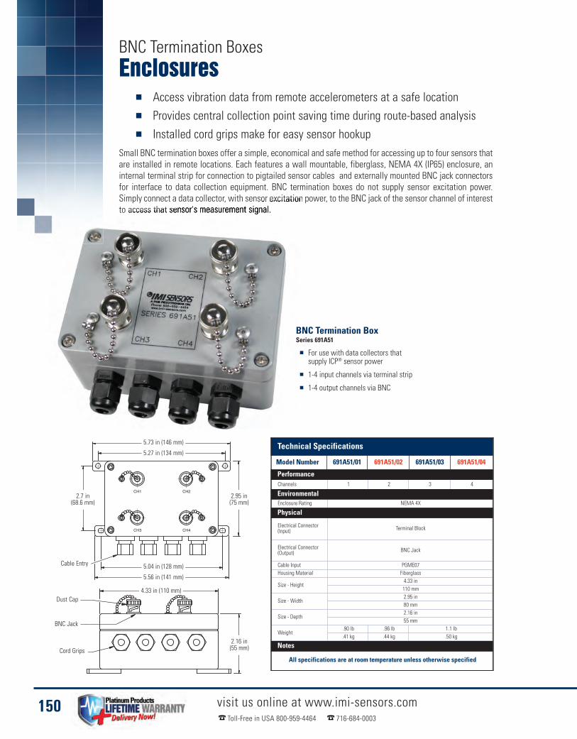
Enclosures� Access vibration data from remote accelerometers at a safe location� Provides central collection point saving time during route-based analysis� Installed cord grips make for easy sensor hookup
Small BNC termination boxes offer a simple, economical and safe method for accessing up to four sensors thatare installed in remote locations. Each features a wall mountable, fiberglass, NEMA 4X (IP65) enclosure, aninternal terminal strip for connection to pigtailed sensor cables and externally mounted BNC jack connectorsfor interface to data collection equipment. BNC termination boxes do not supply sensor excitation power.Simply connect a data collector, with sensor excitation power, to the BNC jack of the sensor channel of interestto access that sensor's measurement signal.
visit us online at www.imi-sensors.comToll-Free in USA 800-959-4464 716-684-0003
150
BNC Termination BoxSeries 691A51
� For use with data collectors thatsupply ICP® sensor power
� 1-4 input channels via terminal strip
� 1-4 output channels via BNC
Model Number 691A51/02 691A51/03 691A51/04Channels 1 2 3 4
EnvironmentalEnclosure Rating NEMA 4X
Physical
Electrical Connector(Input) Terminal Block
Electrical Connector(Output) BNC Jack
Cable Input PGME07Housing Material Fiberglass
Size - Height4.33 in110 mm
Size - Width2.95 in80 mm
Size - Depth2.16 in55 mm
Weight.90 lb .96 lb 1.1 lb.41 kg .44 kg .50 kg
Notes
All specifications are at room temperature unless otherwise specified
BNC Termination Boxes
2.7 in(68.6 mm)
5.73 in (146 mm)
4.33 in (110 mm)
2.16 in(55 mm)
5.27 in (134 mm)
Dust Cap
BNC Jack
Cable Entry
Cord Grips
2.95 in(75 mm)
5.04 in (128 mm)
5.56 in (141 mm)
Technical Specifications
Model Number 691A51/01 691A51/02 691A51/03 691A51/04
Performance
Environmental
Physical
Notes

Enclosures
visit us online at www.imi-sensors.comToll-Free in USA 800-959-4464 716-684-0003
151
BNC termination enclosures offer a simple, economical and safemethod for accessing up to 12 sensors that are installed in remotelocations. Each features a wall mountable, fiberglass NEMA 4X(IP66) enclosure, an internal terminal strip for connection to pigtailedsensor cables and internally mounted BNC jack connectors forinterface to data collection equipment. BNC termination enclosuresdo not supply sensor excitation power turn on.Simply open theenclosure door and connect a data collector, with sensor excitationpower turned on, to the BNC jack of the sensor channel of interestto access that sensor's measurement signal.
BNC Termination BoxSeries 691A50
� Consolidate up to 12 channels in a centralized location
� Connections protected by NEMA 4X enclosure
� Includes installed cord grips
Technical SpecificationsModel Number 691A50/06Channels 6 12
Environmental
Enclosure RatingNEMA 4XIP66
PhysicalElectrical Connector (Input) Terminal BlockElectrical Connector (Output) BNC JackCable Input PGME07Housing Material Fiberglass
Size - Height8 in
203 mm
Size - Width6 in
152 mm
Size - Depth4 in
102 mm
Weight2.5 lb1.14 kg
NotesFiberglass EnclosureCord Grip
3.25 in(82.5 mm)
8.50 in(215.9 mm)
BNC Jack
6.91 in (175.5 mm)
TerminalStrip
Technical Specifications
Model Number 691A50/06 691A50/12
Performance
Environmental
Physical
NotesAll specifications are at room temperature unless otherwise specified

Enclosures� Enclosures provide a convenient, centralized data collection point� Improve efficiency with temperature & vibration outputs in one enclosure� Help extend cable life by reducing the number of connections needed
Switch boxes assist with route-based data collection by terminating the cables of permanently installedsensors at convenient, safe, data collection locations.
The unit does not contain a power supply rather it relies on transferring excitation power provided by thevibration data collector or signal conditioner to connected sensors. Since excitation power is presented to eachsensor when its measurement channel is selected, the sensor’s settling time must be considered prior to takingmeasurements. Models 691B41 and 691B42 are available with a variety of cord grip options. When cord gripsare ordered, the enclosure will be provided with holes drilled for the appropriate cord grips.
visit us online at www.imi-sensors.comToll-Free in USA 800-959-4464 716-684-0003
152
Rotary Switch BoxModel 691B41
� Dual BNC connector for vibrationand temperature output
� Variety of cord grip options available
� Fiberglass or painted steel enclosure
Model 691B41 Technical Drawing Model 691B42 Technical Drawing
Rotary Switch BoxModel 691B42
� 12 input channels
� Fiberglass enclosure
� For use with data collectorsthat supply ICP® power
Switch Boxes
6 Channel Switch
Fiberglass EnclosureFiberglass Enclosure
1.0 in (25.4 mm) 6.93 in(176 mm)
6.93 in(176 mm)
8.5 in(216 mm)
8.5 in(216 mm)
3.46 in(87.9 mm)3.46 in
(87.9 mm)
BNC JacksBNC Jacks
TerminalStrip Inputs
TerminalStrip Inputs
12 Channel Switch
1.0 in (25.4 mm)
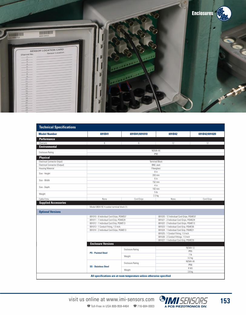
Enclosures
visit us online at www.imi-sensors.comToll-Free in USA 800-959-4464 716-684-0003
153
Technical SpecificationsModel Number 691B41 691B41/691010 691B42 691B42/691020Channels 6 6 12 12
Environmental
Enclosure RatingNEMA 4XIP66
PhysicalElectrical Connector (Input) Terminal BlockElectrical Connector (Output) BNC JackHousing Material Fiberglass
Size - Height8 in
203 mm
Size - Width6 in
152 mm
Size - Depth4 in
102 mm
Weight5 lb2.3 kg
Cable Entry None Cord Grips None Cord Grips
Supplied AccessoriesModel 080A192 4-socket terminal block (1)
Optional Versions691010 - 6 Individual Cord Grips, PGME07 691020 - 12 Individual Cord Grips, PGME07691011 - 1 Individual Cord Grip, PGME29 691021 - 2 Individual Cord Grips, PGME29691012 - 1 Individual Cord Grip, PGME13 691022 - 2 Individual Cord Grips, PGME13691013 - 1 Conduit Fitting, 1.5 Inch. 691023 - 1 Individual Cord Grip, PGME36691014 - 2 Individual Cord Grips, PGME13 691024 - 1 Individual Cord Grip, PGME21
691025 - 1 Conduit Fitting, 1.5 Inch.691026 - 2 Conduit Fittings, 1.5 Inch691027 - 1 Individual Cord Grip, PGME29
Enclosure Versions
PS - Painted SteelEnclosure Rating
NEMA 12IP65
Weight7 lb3.2 kg
SS - Stainless SteelEnclosure Rating
NEMA 4XIP66
Weight8 lb53.6 kg
All specifications are at room temperature unless otherwise specified
Technical Specifications
Model Number 691B41 691B41/691010 691B42 691B42/691020
Performance
Environmental
Physical
Supplied Accessories
Enclosure Versions
All specifications are at room temperature unless otherwise specified

Signal Conditioners� Conveniently mounts to any standard DIN rail� Capable of powering transmitters & ICP® sensors� Easy to use terminal strip connection
visit us online at www.imi-sensors.comToll-Free in USA 800-959-4464 716-684-0003
154
DIN Rail Mounting Power SupplyModel 682A01
� Provides 24 VDC, 1.0 amps power
� Operates from 120 to 230 VAC line power
� Powers transmitters, signal conditioners,and alarm modules
Product shown at actual size
Technical SpecificationsModel Number 682A01MTBF >500,000hEfficiency >80%
Control InterfaceDisplay LED
Environment
Temperature Range (Operating)-13 to 158 °F-25 to 70 °C
Temperature Range (Storage)-40 to 185 °F-40 to 85 °C
Humidity Range (Non-Condensing) <95 %
ElectricalPower Required 85-264 VAC / 95-350 VDCOutput Voltage 24 VDCOutput Current 1.0 ampsInput Frequency 45 to 63 HzInrush Current (@ 25 deg C) <15ACurrent Consumption (230/120 VAC) 0.3/0.5AFuse 1.25A / 250VMains Buffering >20/110ms (120/230 VAC)Surge Voltage Protection Varistor10-90% Load Tolerance +/- 3%Turn On Delay <0.5/1s (230/120 VAC)Turn Off Delay <150msInternal Surge Voltage Protection 35 VDC +/- 5%Parallel Switching Redundant Systems OnlyRipple Voltage <100 mV ppMaximum Power Loss 0.9/4.5W (No Load/Load)DC OK (Active) 24V / 20mAFuse 1.25A/250VInsulation Voltage 3kV
Physical
Size - Height3.90 in99 mm
Size - Width0.89 in22.5 mm
Size - Depth4.51 in
114.5 mm
Weight7.4 oz0.21 kg
Conductor Cross SectionAWG 14-240.2-2.5mm^2
Vibration (10Hz-150Hz)2g
0.15mmShock (3 directions for 18 ms) 30g
NotesAll specifications are at room temperature
unless otherwise specified.
[1] In the case of DC applications it is necessary to connect an adequate fuse in series[2] For CE reference PCB® Declaration of Conformance for details[3] This device is in compliance with the EMC guideline 89/336/EECand the low voltage guideline 73/23/EEC
[4] This device must be installed in accordance with the specifications of EN60950.It must be possible to switch off the device using a suitable disconnecting deviceoutside the power supply. For example, primary side line protection could be used.
0.886 in(2.5 mm)
3.90 in(99 mm)
4.48 in(114 mm)
Technical Specifications
Model Number 682A01
Performance
Control Interface
Environment
Electrical
Physical
Notes

Signal Conditioners
visit us online at www.imi-sensors.comToll-Free in USA 800-959-4464 716-684-0003
155
ICP® Signal ConditionerModel 682A02
n Frequency range: 1 Hz to 100 kHz
n Single channel
n 24 VDC input
Product shown at actual size
Technical SpecificationsModel Number 682A02Channels 1Voltage Gain 1/10/100 [5]
Frequency Range (±1 dB)60 to 6 cpm1 to 100 Hz
Non-linearity ≤ 2 %
Environmental
Temperature Range32 °F0 °C
ElectricalPower Required (Standard) DC powerExcitation Voltage (±1 VDC) (To Sensor) 18 VDC [4]
DC Power24 VDC60 mA
Constant Current Excitation (To Sensor) 4/10 mA [5]Spectral Noise (10 Hz) 0.8 µV/√Hz [1]Spectral Noise (100 Hz) 0.5 µV/√Hz [1]Spectral Noise (1 kHz) 0.5 µV/√Hz [1]Spectral Noise (10 kHz) 0.6 µV/√Hz [1]Broadband Electrical Noise (1 to 10 kHz) (Gain x1) 50 µVSpectral Noise (10 Hz) 7.5 µV/√Hz [2]Spectral Noise (100 Hz) 3.6 µV/√Hz [2]Spectral Noise (1 kHz) 3.2 µV/√Hz [2]Spectral Noise (10 kHz) 6.0 µV/√Hz [2]Broadband Electrical Noise (1 to 10 kHz) (Gain x10) 400 µVSpectral Noise (10 Hz) 80 µV/√Hz [3]Spectral Noise (100 Hz) 40 µV/√Hz [3]Spectral Noise (1 kHz) 32 µV/√Hz [3]Spectral Noise (10 kHz) 50 µV/√Hz [3]Broadband Electrical Noise (1 to 10 kHz) (Gain x100) 3.5 mVFuse 1 APhysical
Size - Height3.1 in78.7 mm
Size - Width0.97 in24.6 mm
Size - Depth3.3 in83.8 mm
Weight0.194 lb0.088 kg
Electrical Connector (ICP® Sensor Input) Screw TerminalsElectrical Connector (Output) Screw TerminalsElectrical Connector (DC Power Input) Screw TerminalsMounting DIN Rail
NotesAll specifications are at room temperature unless otherwise specified
[1] Gain x1[2] Gain x10[3] Gain x100
[4] If unit is used in conjunction with a sensor having a bias over 13VDC, full scale output may be affected or sensor may not power up.
[5] Jumper selectable on internal circuit board.3.30 in(83.8 mm)
2.89 in(73.4 mm)
3.10 in(78.7 mm)
.970 in(24.6 mm)
Technical Specifications
Model Number 682A02
Performance
Environmental
Electrical
Physical
Notes
Accessories & Cables: Pages 162-176

Signal Conditioners� Accepts mA, VDC, RTD, TC, Linear Resistance and Potentiometer input signals� Delivers either current or voltage output signals� Offers two set points with Form A relay outputs (2 Amp AC, 1 Amp DC)
Model 682A06 is a DIN rail mounted, general purpose, universal transmitter for industrial monitoring, control andalarm requirements. It accepts a variety of sensor input signals and provides excitation voltage for 2-wire looppowered sensors and transmitters. This unit is especially well-suited for industrial machinery protection andvibration monitoring applications with IMI Sensors’ Series 640 loop powered 4-20 mA output vibration sensors.
Model 682A06 operated as a blind transmitter and delivers VDC, isolated mA and relay outputs; however, it maybe fitted with an optional display module (Model 070A80) to view measurement data. The display module alsooffers pushbutton programmability of many setup parameters, including: zero, span, set point threshold, set pointhysteresis and relay action time delay, as well as TC and RTD linearization. The unit also supports passwordprotection for security purposes and memory retention of all set up parameters, to permit common setup ofadditional transmitters for quick deployment.
Model 682A16 (see page 157) provides ICP® power for voltage output sensors and provides all the same outputtechnology found in the 682A06
visit us online at www.imi-sensors.comToll-Free in USA 800-959-4464 716-684-0003
156
Universal TransmitterModel 682A06
� 24 VDC loop power for 4-20 mA sensors
� Offers two set points with Form A relay outputs(2 amp AC, 1 amp DC)
� Optional, removable programming /display module 070A80
Product shown at actual size
Programming / Display ModuleModel 070A80
Model 682A06 & Model 682A16 Technical Drawing
4.29 in(109 mm)
4.56 in (116 mm)
3.54 in(90 mm)
4.09 in (104 mm).92 in (23.5 mm)

Signal Conditioners
visit us online at www.imi-sensors.comToll-Free in USA 800-959-4464 716-684-0003
157
Model Number 682A06 682A16 682A06 682A16
Environmental Physical
Temperature Range(Operating)
-04 to 140 °FSize - Height
4.29 in
-20 to 60 °C 109 mm
ElectricalSize - Width
0.93 in
Supply Voltage 19.2 to 300 VDC 23.5 mm
Current Consumption ≤ 2.5 WSize - Depth
4.09 in
Excitation Voltage(delivered to sensor) 24 V Loop Power 23 to 25 VDC
104 mm
Weight6.00 oz
Constant Current Excitation(delivered to sensor) N/A 3 to 5 mA
170 gm
Notes
Universal TransmitterModel 682A16
� Provides ICP® power for sensors
� Offers two set points with Form A relay outputs(2 amp AC, 1 amp DC)
� Optional, removable programming /display module 070A80
Product shown at actual size
Programming / Display ModuleModel 070A80
Technical Specifications
Model Number 682A06 682A16 Model Number 682A06 682A16
Environmental Physical
Notes
All specifications are at room temperature unless otherwise specified
[1] For CE reference appropriate Declaration of Conformance for details

In-line Charge Converters� All charge converters shown are ICP® powered� Industry standard input and output connectors� Specifically designed for use with charge mode sensors
visit us online at www.imi-sensors.comToll-Free in USA 800-959-4464 716-684-0003
158
Technical SpecificationsModel Number 422M182Sensitivity (± 5 %) (Charge Conversion) 4 mV/pCLow Frequency Response (-5 %) 2 HzHigh Frequency Response (2.2 mA) 30 kHz [2]High Frequency Response (4 mA) 45 kHz [2]High Frequency Response (20 mA) 30 kHz [2]Non-linearity ≤ 1.0 % FS
Environmental
Temperature Range (Operating)-60 to +185 °F-51 to +85 °C
Temperature Response (Sensitivity Deviation) <1 %
ElectricalExcitation Voltage 22 to 28 VDCConstant Current Excitation 2.2 to 20 mAOutput Voltage (at specified measurement range) ± 5 VpkOutput Impedance <250 ohmOutput Bias Voltage 12 to 16 VDC
Broadband Electrical Noise (1 to 10 kHz)28 µV [1]-91 dB
Model Number 422M182Electrical (continued)
Spectral Noise (1 Hz)10.0 µV/√Hz [1]
-100 dB
Spectral Noise (10 Hz)3.2 µV/√Hz [1]
-110 dB
Spectral Noise (100 Hz)1.0 µV/√Hz [1]
-120 dB
Spectral Noise (1 kHz)0.56 µV/√Hz [1]
-125 dB
Spectral Noise (1 kHz)0.56 µV/√Hz [1]
-125 dBDischarge Time Constant 0.25 secResistance (Minimum required at input) 50,000 ohmSource Capacitance Loading 0.0009 %/pF
PhysicalHousing Material AluminumElectrical Connector (Input) 2-pinElectrical Connector (Output) BNC Jack
Weight3.5 oz109 gm
NotesAll specifications are at room temperature unless otherwise specified
[1] Tested using voltage source and input capacitor equal to the feedback capacitor,to simulate a charge output sensor.
[2] Above stated frequency, the amplifier becomes slew rate limited.
Differential Charge ConverterModel 422M182
� Sensitivity: 4 mV/pC
� Output Voltage: ±5 Vpk
� Temperature Range: -60 to 185 ºF
Product shown at actual size
4.545 in (115.44 mm)
3.375 in (85.73 mm)
4.575 in (116.21 mm) 0.10 in(2.54 mm)
1.250 in(31.75 mm)
1.250 in(31.75 mm)
0.575 in (14.61 mm)
Two Ø0.206 Through
Two Ø0.175(4.45 mm) Two Ø0.175
(4.45 mm)
0.625 in (15.88 mm)
BNC Connector5/8-24 UNF 2A 2-Pin Connector
In (+) In (-)
Technical Specifications
Model Number 422M182 Model Number 422M182
Performance Electrical
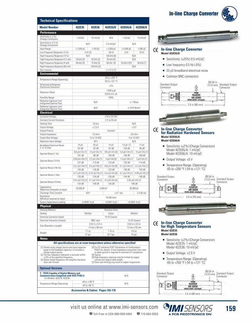
In-line Charge Converter
visit us online at www.imi-sensors.comToll-Free in USA 800-959-4464 716-684-0003
159
Model Number 422E35 422E36 422E55/D 422E65/A 422E66/ASensitivity (± 2 %)(Charge Conversion) 1 mV/pC 10 mV/pC N/A 1 mV/pC 10 mV/pC
Sensitivity (± 2.5 %)(Charge Conversion) N/A 0.5 mV/pC N/A
Input Range ± 2,500 pC ± 250 pC ± 2,500 pC ± 5,000 pC ± 500 pCLow Frequency Response (-5 %) 5 Hz [2] .05 Hz 5 Hz 10 HzHigh Frequency Response (-5 %) N/A 100 kHz [6] N/AHigh Frequency Response (2.2 mA) 30 kHz [3] 50 kHz [3] 30 kHz [4] N/AHigh Frequency Response (4 mA) 60 kHz [3] 75 kHz [3] 60 kHz [4] 35 kHz [1][7] 90 kHz [1]High Frequency Response (20 mA) 100 kHz [3] N/ANon-linearity ≤ 1.0 % FS
Environmental
Temperature Range (Operating)-65 to +250 °F-54 to +121 °C
Temperature Response(Sensitivity Deviation) <2%
Maximum Shock1,000 g pk
9,810 m/s2 pkHumidity Range 100%Radiation Exposure Limit(Integrated Gamma Flux) N/A ≤ 1 Mrad
Radiation Exposure Limit(Integrated Neutron Flux) N/A ≤ 1010 N/cm²
ElectricalExcitation Voltage +18 to 28 VDCConstant Current Excitation 2.2 to 20 mASettling Time <6 min N/AOutput Voltage ± 2.5 V ± 5 VOutput Polarity InvertedOutput Impedance <10 ohm <20 ohmOutput Bias Voltage 12 to 15 VDC 9 to 13 VDCMaximum Input Voltage 30 V N/A
Broadband Electrical Noise(1 to 10 kHz)
14 µV 26 µV 14 µV 7.0 µV [1] 17 µV-97 dB -92 dB -97 dB -103 dB -95 dB
Spectral Noise (1 Hz)8.9 µV/√Hz [1] 13 µV/√Hz [1] 9.8 µV/√Hz [5] 5.0 µV/√Hz [1] 10 µV/√Hz [1]
-101 dB -98 dB -100 dB -106 dB -100 dB
Spectral Noise (10 Hz)0.85 µV/√Hz [1] 2.2 µV/√Hz [1] 3 µV/√Hz [5] 1.0 µV/√Hz [1] 2 µV/√Hz [1]
-121 dB -113 dB -110 dB -120 dB -114 dB
Spectral Noise (100 Hz)0.31 µV/√Hz [1] 0.5 µV/√Hz [1] 0.8 µV/√Hz [5] 0.1 µV/√Hz [1] 0.3 µV/√Hz [1]
-130 dB -126 dB -122 dB -140 dB -130 dB
Spectral Noise (1 kHz)0.17 µV/√Hz [1] 0.19 µV/√Hz [1] 0.4 µV/√Hz [5] 0.1 µV/√Hz [1] 0.05 µV/√Hz [1]
-135 dB -134 dB -128 dB -140 dB -146 dB
Spectral Noise (10 kHz)0.07 µV/√Hz [1] 0.1 µV/√Hz [1] 0.2 µV/√Hz [5] 0.05 µV/√Hz [1]
-143 dB -140 dB -134 dB -146 dBCapacitance(Maximum allowable at input) 20,000 pF 2,000 pF 20,000 pF
Discharge Time Constant N/A ≥ 0.1 sec ≥ 0.05 secResistance(Minimum required at input) 10,000 ohm
Source Capacitance Loading <0.0005 %/pF -0.0005 %/pF <0.0005 %/pF
PhysicalHousing Material Stainless SteelSealing Welded Epoxy WeldedElectrical Connector (Input) 10-32 CoaxialElectrical Connector (Output) BNC Jack 10-32 Coaxial
Size (Diameter x Length)0.52 in x 3.4 in 0.50 in x 3.0 in13 mm x 86 mm 13 mm x 76 mm
Weight1.1 oz 1.15 oz 0.8 oz31 gm 32.7 gm 23 gm
NotesAll specifications are at room temperature unless otherwise specified
In-line Charge ConverterModel 422E55/D
� Sensitivity: (±25%) 0.5 mV/pC
� Low frequency 0.5 Hz (-5%)
� 33 µV broadband electrical noise
� Common BNC connectors
In-line Charge Converterfor Radiation Hardened SensorsModel 422E65/AModel 422E66/A
� Sensitivity: (±2%) (Charge Conversion)Model 422E65/A: 1 mV/pCModel 422E66/A: 10 mV/pC
� Output Voltage: ±5 V
� Temperature Range: (Operating)-65 to +250 °F (-54 to +121 °C)
In-line Charge Converterfor High Temperature SensorsModel 422E35Model 422E36
� Sensitivity: (±2%) (Charge Conversion)Model 422E35: 1 mV/pCModel 422E36: 10 mV/pC
� Output Voltage: ±2.5 V
� Temperature Range: (Operating)-65 to +250 °F (-54 to +121 °C)
[1] Tested using voltage source and input capacitorequal to the feedback capacitor, to simulate acharge output sensor.
[2] The low frequency tolerance is accurate within±10% of the specified frequency.
[3] Above stated frequency, the amplifier becomesslew rate limited.
[4] For CE reference PCB® Declaration of ConformancePS024 for details. A low-impedance connection from caseto earth ground is required to maintain CE compliance.
[5] Typical[6] High frequency response may be limited by supplycurrent and output cable length.
[7] Slow rate limiting may result at higher frequencies
Optional Versions
T - TEDS Capable of Digital Memory andCommunication Compliant with IEEE P1451.4
For Models: 422E35, 422E36N/A
Temperature Range (Operating)-40 to +185 ºF
N/A-40 to +85 ºC
Standard OutputConnector
Ø0.50 in(12.6 mm)2
1
21
21
Standard OutputConnector
Ø0.50 in(12.6 mm)Standard Output
Connector
3.4 in (86 mm)
Standard OutputConnector
Standard OutputConnector
Ø0.50 in(12.6 mm)
3.0 in (76 mm)
Standard OutputConnector
3.4 in (86 mm)
Technical Specifications
Model Number 422E35 422E36 422E55/D 422E65/A 422E66/A
Performance
Environmental
Electrical
Physical
Notes
Accessories & Cables: Pages 162-176

Portable Calibration Units� Quickly verify sensor sensitivity while working in the field� Lightweight designs transport easily� Long battery life, rechargeable options
visit us online at www.imi-sensors.comToll-Free in USA 800-959-4464 716-684-0003
160
Temperature Model 9100D
Operating32 to 122 °F0 to 50 °C
Physical
Dimensions (H x W x D)8.5” x 12” x 10”
22 cm x 30.5 cm x 28 cm
Weight18 lbs8.2 kg
Sensor Mounting Platform Thread Size 1/4-28
Notes[1] Operating range reduced at higher payloads. Reference manual for full details[2] As shipped from factory in new condition
Accessory Products for 699A06
600A22Proximity probe adaptor kit, supports probes with common case threads rangingfrom M6 to 3/8”. Includes Mitutoyo micrometer (metric) and nickel plated 4140steel target.
600A23Proximity probe adaptor kit, supports probes with common case threads rangingfrom M6 to 3/8”. Includes Mitutoyo micrometer (metric) and nickel plated 4140steel target.
600A24Mounting accessory kit for 699A06 Portable Vibration Calibrators to adapt to1/4-28 threaded mounting platforms. Includes studs/inserts (1/4-28, 10-32, 6-32and 5-40) and bases (for adhesive, magnetic and custom thread patterns)
600A25 18 Volt, 1 amp power supply/charger for 9100D Portable Vibration Calibrator,universal 100-240 V, 50/60 Hz
9100-BAT01 Replacement battery for 699A06 Portable Vibration Calibrators
Model Number Model 9100DFrequency Range(operating, 100 gram payload)
7 Hz to 10 kHz420 to 600,000 cpm
Maximum Amplitude(100 Hz with no payload)
20 g pk (196 m/s2 pk)15 in/s pk (380 mm/s pk)
50 mils pk-pk (1.27 mm pk-pk)Maximum Payload [1] Maximum Payload[1] 800 gram
Accuracy of Readout(measured with 10 gram quartz reference accelerometer)
Acceleration (30 Hz to 2 kHz) ±3%Acceleration (7 Hz to 2 kHz) ±1 dBVelocity (30 Hz to 500 Hz) ±3%Displacement (30 Hz to 150 Hz) ±3%Amplitude Linearity(100 gram payload, 100 Hz) <1% up to 10 g pk
Waveform Distortion(100 gram payload, 30 Hz to 2 kHz) 5% THD up to 5 g pk
Units of ReadoutAcceleration g pk, g rms, m/s2 pk, m/s2 rmsVelocity in/s pk, mm/s pkDisplacement mils pk-pk, mm pk-pkFrequency Hz, CPM
Power RequirementsInternal Battery(sealed solid gel lead acid) 12 VDC, 4 amp hours
AC Power (for recharging battery) 110-240 Volts, 50-60 HzOperating Battery Life [2]100 gram payload, 100 Hz 1 g pk100 gram payload, 100 Hz 10 g pk
18 hours1 hour
The 699A06 Industrial Portable Vibration Calibrator is the ideal tool tofield check accelerometers, velocity transducers and proximity probesover a wide operating frequency and amplitude range. The unit is asmall, handy, completely self-contained vibration reference sourcewhich can be conveniently used to validate the entire channel oftransducers through measurement, monitoring or recording systems.Packaged in a ruggedized, weatherproof enclosure with two press andpull latches and padlockable clasps, the 699A06 is always ready fortravel to test sites. With an integral, precision quartz referenceaccelerometer, the shaker table is built with robust carbon fibercomposite armature flexure supports. Closed loop level control gives the699A06 superior quality vibration calibration from 7 Hz to 10 kHzcompared with other portable field calibrators.
Industrial Portable Vibration CalibratorModel 699A06
� Perform variable frequency & amplitude calibration
� Calibrate proximity probes with optional adaptor kit
� Portable, plug in or use battery power
Technical Specifications
Model Number 699A06 Model Number 699A06
Performance Temperature

Portable Calibration Units
visit us online at www.imi-sensors.comToll-Free in USA 800-959-4464 716-684-0003
161
This handheld, portable shaker delivers a controlled, 1.0 g rms or 1 g pk vibration, at 159.2 Hz, forverifying vibration sensor operation and sensitivity. The unit accommodates sensors weighing up to250 grams and is powered by four standard “AA” type batteries. An automatic shut off featurepreserves battery life, however, continuous operation is switch selectable and an external DC powersupply (Model 073A16) is available. Included is a nylon carry pouch with carry strap/belt loop.
Portable Reference ShakerModel 699A02
� Calibrates permanently mounted accelerometers at the machine
� Verifies system performance
� Confirms operation of cables, switching devices and monitoring systems
� Can perform up to 1,600 operating cycles without loss of battery power
Model Number 699A02 699A02Operating Frequency (± 1 %) 159.2 Hz
Size (Diameter x Height)2.2 in x 7.8 in
Acceleration Output (± 3 %)1 g rms 56 mm x 200 mm
9.81 m/s² rms [4]Weight (with batteries)
31 oz
Velocity Output0.39 in/sec rms 900 gm [1]9.81 mm/s rms [5] Mounting Thread 1/4-28 Female [9][10]
Displacement Output0.39 mil rms Mounting Torque (Maximum) to 10 in-lb [9]
9.81 mil rms [5] Supplied AccessoriesTransverse Output ≤ 3 %
Model 073A15 Battery Pack (1)Model 081A40 Mounting Stud (1)Model M081A19 Mounting stud, 1/4-28 to M6 x 1,SS with shoulder (1)
Distortion (0 to 250 grams load) ≤ 7 % [6]
Maximum Load8.8 oz
250 gm [7]
Automatic Switch Off Time 1.0 to 2.5 minutes [8] NotesCalibration Cycles (250 gram load) 90 cycles [3] All specifications are at room temperature unless otherwise specified
Environmental
Temperature Range (Operating)15 to 130 °F
-10 to 55 °C
ElectricalRamp-Up time ≤ 3 sec [1]Power Required (Standard) Internal BatteryPower Required (Alternate) DC powerInternal Battery (Quantity) 4Internal Battery (Type) AA [2]DC Power (± 5 %) to 10 VDCDC Power to 2.4 ampsBattery Life (250 gram load) 2.3 hours [3]
[1] Typical[2] Alkaline type recommended for longest service life[3] Approximate values, based on automatic switchoff time and dependent on type of batteries
[4] Unit supplied set to rms; see manualfor peak selection
[5] Calculated values for reference only[6] Typical max for range
[7] For sensors weighing <75 grams addModel 080A136 mass
[8] Unit supplied set to auto shut off; see manualfor continuous use selection
[9] Transducer to shaker table[10] Test sensor should be hand tightened
(without tools)[11] For CE reference PCB® Declaration of
Conformance PS022 for details
Environmental
Supplied Accessories
Electrical
Notes
Technical Specifications
Model Number 699A02 Model Number 699A02
Performance Physical

visit us online at www.imi-sensors.comToll-Free in USA 800-959-4464 716-684-0003
162
Mounting HardwareMagnetic mounting offers the most convenient method of temporary sensor installation for route-basedmeasurements and data collection. IMI Sensors magnetic mounting bases feature rare-earth magnet elementsto achieve high attraction forces to the test structure. This aids in high frequency transmissibility and assuresattraction for weighty sensors and conditions of high vibration. Rail mount styles are utilized for curved surfaces,such as motor housings and pipes. Knurled housings aid in gripping for removal.
Note: Exercise caution when installing magnetically mounted sensors by engaging the edge of the magnet withthe structure and carefully rolling the sensor/magnet assembly to an upright position. Never allow the magnetto impact against the structure as this may create shock acceleration levels that saturate the sensor. When thesensor is saturated users should wait a few seconds for the accelerometer to settle prior to taking data.
Curved Surface MagnetModel 080A130
Curved Surface MagnetModel 080A132
Curved Surface MagnetModel 080A133
Curved Surface MagnetModel 080A131
Flat Surface MagnetModel 080A120
Flat Surface MagnetModel 080A121
Flat Surface MagnetModel 080A122
Magnetic Mounting Base ModelsFor Flat Surfaces Diameter Thread Pull StrengthModel 080A120* 0.75 in (19 mm) 1/4-28 (M6 x 1.0) stud 15 lb (67 N)Model 080A121* 1 in (25 mm) 1/4-28 (M6 x 1.0) stud 35 lb (156 N)Model 080A122* 1.5 in (38 mm) 1/4-28 (M6 x 1.0) stud 50 lb (222 N)
For Curved SurfacesModel 080A130* 0.75 in (19 mm) 1/4-28 (M6 x 1.0) stud 15 lb (67 N)Model 080A131* 1 in (25 mm) 1/4-28 (M6 x 1.0) stud 35 lb (156 N)Model 080A132* 1.5 in (38 mm) 1/4-28 (M6 x 1.0) stud 55 lb (245 N)Model 080A133* 2 in (51 mm) 1/4-28 (M6 x 1.0) stud 85 lb (378 N)
Notes:
* For models with metric dimensions, please use “M” prefix with model number listed above.
Magnetic Mounting Bases
Model Number Diameter Thread Pull Strength
For Flat Surface
For Curved Surface
Notes

Mounting Hardware
visit us online at www.imi-sensors.comToll-Free in USA 800-959-4464 716-684-0003
163
Sensor Mounting PadModel M080A118
Sensor Mounting PadModel 080A91
Sensor Mounting PadModel 080A93
1/4-28Through-boltModel 081A97
1/4-28Mounting StudModel 081A40
1/4-28 to M6x1Mounting StudModel M081A61
Vibration Sensor Mounting Pad ModelsModel Number Diameter Tapped HoleModel 080A91 1.375 in (35 mm)
1/4-28 Stud(M6 x 1.0)Model 080A118* 1 in (25 mm)
Model 080A93 0.75 in (19 mm)Model 080A92 1.375 in (35 mm
N/AModel 080A94 0.75 in (19 mm)
Notes:* For models with metric dimensions, please use “M” prefixwith model number listed above.
Vibration Sensor Mounting ScrewsSet Screws Thread Comment
Model 081A40 1/4-28 SS with brass tip,socket head, .375 in
Model 080A156 1/2-20 to 1/4-28 For use with 607A11and 607A61
Model M080A159 1/2-20 to M6x1 For use with M607A11and M607A61
Model M081A61 1/4-28 to M6x1 BeCu, no shoulder
Model 081A73 1/4-28 to 1.34 in For use with Series 625B
Model M081A73 M6x1 to 34 mm For use with Series 625B
Model 081A97 1/4-28 x 1.0 in For use with Series 602and Model 635A01
Model M081A97 M6x1 x 25.4 mm For use with Series M602and Model M635A01
Mounting PadModel 080A92
Mounting PadModel 080A94
M6x1Through-boltModel M081A97
1/2-20 to M6x1Mounting StudModel M080A159
1/2-20 to 1/4-28Mounting StudModel 080A156
M6x1Through-boltModel M081A73
1/4-28Through-boltModel 081A73
These mounting pads may be adhesively bonded or welded to machinery surfaces at specific vibration sensor installation points.The pads ensure that periodic measurements are always taken from the exact same location, lending to more accurate andrepeatable measurement data. Pads with tapped holes are for use with stud mounted sensors whereas the untapped pads areintended for use with magnetically mounted sensors. For permanent installations, the pads facilitate mounting of sensors withoutactually machining the surface onto which they are to be installed. Untapped pads may be utilized to achieve magnetic attractionon non-ferrous surfaces. All mounting pads are manufactured from resilient, stainless steel.
Quick-connectMounting BaseModel 080A69
The quick disconnect adhesive pad and mating connector system allows for 1/4-turn mounting of sensors during route-basedmeasurements. Simply install the adhesive pad at your monitoring locations and screw the mate onto the bottom of theaccelerometer. The system shortens data collection time while providing a target for consistent sensor placement.
Quick-connectMounting StudModel 081A69
Sensor Mounting Pads
Model Number Diameter Tapped Hole
Notes
Sensor Mounting Studs
Model Number Thread Comments

IMI Sensors offers Data Collection Extension Poles which allow vibration technicians the ability to stay on the ground, away fromheat sources, while collecting the data required to maintain the reliability of your machinery. The extension pole also offers quickaccess to measurement points, contributing to the overall efficiency of your routes.
The data collection poles are designed to be flexible toyour specific applications and equipment. IMI®supplies cables & connectors to perfectly fit anymodern data collector/analyzer manufacturer. Hightemperature bushings are included to adapt to yourpreferred sensor.
Mounting Hardware
visit us online at www.imi-sensors.comToll-Free in USA 800-959-4464 716-684-0003
164
Small Adhesive KitModel 075A05
Large Adhesive KitModel 075A06
These epoxy kits provide a secure means for mounting accelerometers and adhesive mounting bases tomachine structures. The small kit is intended for mounting approximately 10 sensors; and the large kit isintended for approximately 100 senors.
1.25” Spot Face ToolModel 080A128
1.5” Spot Face ToolModel 080A129
1” Spot Face ToolModel 080A137
Spot face tools install into a drill and prepare the machine surface for accelerometer mounting, creating asmooth surface and pilot hole. The pilot hole is then tapped to fit the sensor’s mounting thread.
Data Collection Extension PoleModel 080A225: 4-7 ftModel 080A226: 6-11 ft
� Keeps technicians on the ground and away from heatsources, reducing the need for safety harnesses andother equipment
� Non-conductive properties reduce therisk of electric shock
� Includes multiple high temperature bushingsto fit your preferred vibration sensor
� Spring loaded head tilts 180º for proper sensorplacement (US Patent #27,076,138)
Exclusive 180ºtilting head
Model080A225shown
1/2” Outer Diameter5/8” Outer Diameter7/8” Outer Diameter
1” Outer Diameter1 1/4” Outer Diameter
Sensor Bushings400 ºF (204 ºC) High Temp Bushings, 70 Durometer
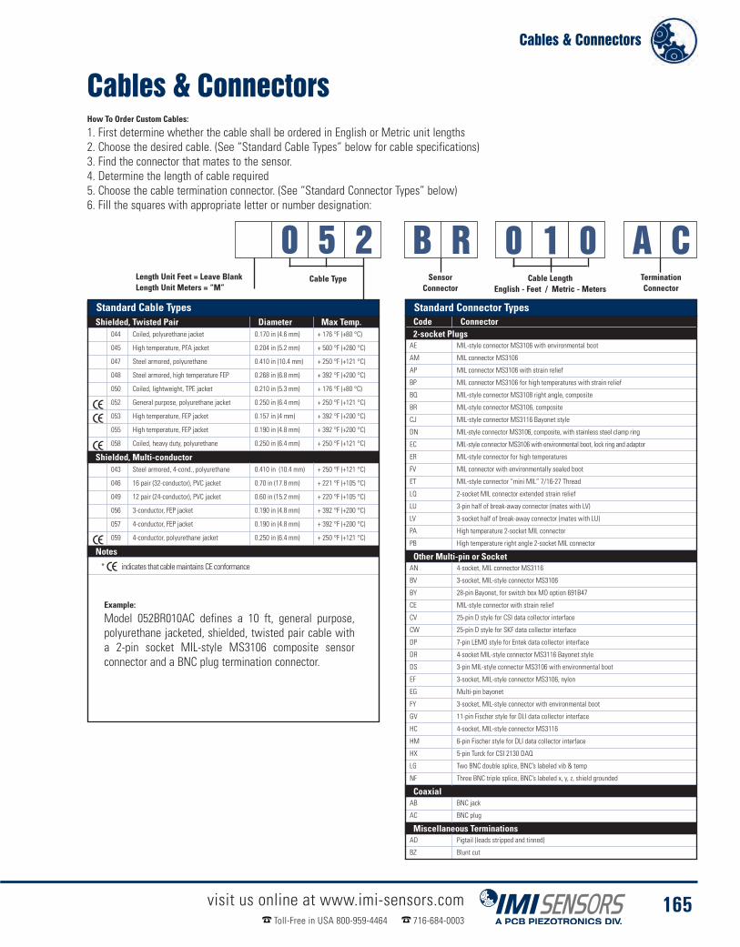
Cables & Connectors
visit us online at www.imi-sensors.comToll-Free in USA 800-959-4464 716-684-0003
165
Cables & ConnectorsHow To Order Custom Cables:
1. First determine whether the cable shall be ordered in English or Metric unit lengths2. Choose the desired cable. (See “Standard Cable Types” below for cable specifications)3. Find the connector that mates to the sensor.4. Determine the length of cable required5. Choose the cable termination connector. (See “Standard Connector Types” below)6. Fill the squares with appropriate letter or number designation:
0 5 2 B R
Example:
Model 052BR010AC defines a 10 ft, general purpose,polyurethane jacketed, shielded, twisted pair cable witha 2-pin socket MIL-style MS3106 composite sensorconnector and a BNC plug termination connector.
Standard Cable TypesShielded, Twisted Pair Diameter Max Temp.
044 Coiled, polyurethane jacket 0.170 in (4.6 mm) + 176 °F (+80 °C)
045 High temperature, PFA jacket 0.204 in (5.2 mm) + 500 °F (+260 °C)
047 Steel armored, polyurethane 0.410 in (10.4 mm) + 250 °F (+121 °C)
048 Steel armored, high temperature FEP 0.268 in (6.8 mm) + 392 °F (+200 °C)
050 Coiled, lightweight, TPE jacket 0.210 in (5.3 mm) + 176 °F (+80 °C)
052 General purpose, polyurethane jacket 0.250 in (6.4 mm) + 250 °F (+121 °C)
053 High temperature, FEP jacket 0.157 in (4 mm) + 392 °F (+200 °C)
055 High temperature, FEP jacket 0.190 in (4.8 mm) + 392 °F (+200 °C)
058 Coiled, heavy duty, polyurethane 0.250 in (6.4 mm) + 250 °F (+121 °C)
Shielded, Multi-conductor043 Steel armored, 4-cond., polyurethane 0.410 in (10.4 mm) + 250 °F (+121 °C)
046 16 pair (32-conductor), PVC jacket 0.70 in (17.8 mm) + 221 °F (+105 °C)
049 12 pair (24-conductor), PVC jacket 0.60 in (15.2 mm) + 220 °F (+105 °C)
056 3-conductor, FEP jacket 0.190 in (4.8 mm) + 392 °F (+200 °C)
057 4-conductor, FEP jacket 0.190 in (4.8 mm) + 392 °F (+200 °C)
059 4-conductor, polyurethane jacket 0.250 in (6.4 mm) + 250 °F (+121 °C)
Notes
* indicates that cablemaintains CE conformance
Standard Connector TypesCode Connector2-socket PlugsAE MIL-style connector MS3106 with environmental boot
AM MIL connector MS3106
AP MIL connector MS3106 with strain relief
BP MIL connector MS3106 for high temperatures with strain relief
BQ MIL-style connector MS3108 right angle, composite
BR MIL-style connector MS3106, composite
CJ MIL-style connector MS3116 Bayonet style
DN MIL-style connector MS3106, composite, with stainless steel clamp ring
EC MIL-style connector MS3106 with environmental boot, lock ring and adaptor
ER MIL-style connector for high temperatures
FV MIL connector with environmentally sealed boot
ET MIL-style connector “mini MIL” 7/16-27 Thread
LQ 2-socket MIL connector extended strain relief
LU 3-pin half of break-away connector (mates with LV)
LV 3-socket half of break-away connector (mates with LU)
PA High temperature 2-socket MIL connector
PB High temperature right angle 2-socket MIL connector
Other Multi-pin or SocketAN 4-socket, MIL connector MS3116
BV 3-socket, MIL-style connector MS3106
BY 28-pin Bayonet, for switch box MO option 691B47
CE MIL-style connector with strain relief
CV 25-pin D style for CSI data collector interface
CW 25-pin D style for SKF data collector interface
DP 7-pin LEMO style for Entek data collector interface
DR 4-socket MIL-style connector MS3116 Bayonet style
DS 3-pin MIL-style connector MS3106 with environmental boot
EF 3-socket, MIL-style connector MS3106, nylon
EG Multi-pin bayonet
FY 3-socket, MIL-style connector with environmental boot
GV 11-pin Fischer style for DLI data collector interface
HC 4-socket, MIL-style connector MS3116
HM 6-pin Fischer style for DLI data collector interface
HX 5-pin Turck for CSI 2130 DAQ
LG Two BNC double splice, BNC’s labeled vib & temp
NF Three BNC triple splice, BNC’s labeled x, y, z, shield grounded
CoaxialAB BNC jack
AC BNC plug
Miscellaneous TerminationsAD Pigtail (leads stripped and tinned)
BZ Blunt cut
A C0 1 0Length Unit Feet = Leave BlankLength Unit Meters = “M”
Cable LengthEnglish - Feet / Metric - Meters
SensorConnector
Cable Type TerminationConnector
Standard Cable Types Standard Connector Types

Cables & Connectors
visit us online at www.imi-sensors.comToll-Free in USA 800-959-4464 716-684-0003
166
Polyurethane Cable, 2-conductorTwisted Pair, ShieldedModel 052 Cable
� Flexible cable, durable and easy to work with.� Braided shield twists into drain wire� Seals out moisture
052BRXXXBZ Indoor/outdoor permanent mount sensor applications 10 ft, 20 ft, 30 ft, 40 ft, 50 ft, 100 ft
052BQXXXBZ Indoor/outdoor permanent mount sensor applications where low profile is required 10 ft, 30 ft, 50 ft
052AEXXXBZ Indoor/outdoor applications where sensor will need to endure extreme wet conditions 30 ft, 50 ft
052BRXXXAC Straight cable with BNC for route-based data collection or permanent mount installations 10 ft
052BQXXXAC Straight cable with BNC and right angle 2-socket MIL for route-based data collection Built to order
Cable Jacket Material Polyurethane
Temperature Range-58 to 250 ºF-50 to 121 ºC
Capacitance36 pF/ft118 pF/m
Cable Jacket Diameter.250 in6.35 mm
Number of Conductors 2Shield Type Braid (90% minimum coverage)AWG (Gauge) 20
Braid Shield
Black Polyurethane Jacket
Conductor #1 Red (signal)
Conductor #2 Blue (ground)
Molded Composite2-socket MIL to Blunt CutModel 052BRXXXBZ
Molded Composite Right Angle2-socket MIL to Blunt CutModel 052BQXXXBZ
Silicone Environmental Push-OnBoot 2-socket MIL to Blunt CutModel 052AEXXXBZ
Molded Composite2-socket MIL To BNC PlugModel 052BRXXXAC
Molded Composite Right Angle2-socket MIL To BNC PlugModel 052BQXXXAC
22 AWG Drain Wire
Cable Information & Cordset Options
Model 052 Cable
Cable Construction Technical Specifications
Popular Cable Assemblies
Performance Typical Usage Stock Cable Lengths

Cables & Connectors
visit us online at www.imi-sensors.comToll-Free in USA 800-959-4464 716-684-0003
167
053BRXXXBZ Indoor/Outdoor permanent mount sensor applications 10 ft, 20 ft, 30 ft, 50 ft
053BQXXXBZ Indoor/Outdoor permanent mount sensor applications where low profile is required Built to order
053AEXXXBZ High temperature installations (over 250 ºF) and extreme wet conditions Built to order
053BPXXXBZ High temperature installations (over 250 ºF) where metal sensor connector is preferred Built to order
Molded Composite2-socket MIL to Blunt CutModel 053BRXXXBZ
Molded Composite Right Angle2-socket MIL-style to Blunt CutModel 053BQXXXBZ
Silicone Environmental Push-On Boot2-socket MIL-style to Blunt CutModel 053AEXXXBZ
Aluminum 2-socket MIL withCollar Strain Relief to Blunt CutModel 053BPXXXBZ
Conductor #1Red (signal)
Conductor #2Black (ground)
Foil Shield
Red FEP JacketCable Jacket Material FEP
Temperature Range-90 to 392 ºF-70 to 200 ºC
Capacitance51 pF/ft
167.3 pF/m
Cable Jacket Diameter.154 in3.91 mm
Number of Conductors 2Shield Type Aluminum / MylarAWG (Gauge) 18
High Temperature FEP Cable2-conductor Twisted Pair withDrain, ShieldedModel 053 Cable
� Thin, slides easily, ideal for pullingthrough conduit & cable trays
� Drain wire attached to foil shield� High temperature capability when paired
with proper connector
Drain Wire
Cable Information & Cordset Options
Model 053 Cable
Cable Construction Technical Specifications
Popular Cable Assemblies
Performance Typical Usage Stock Cable Lengths
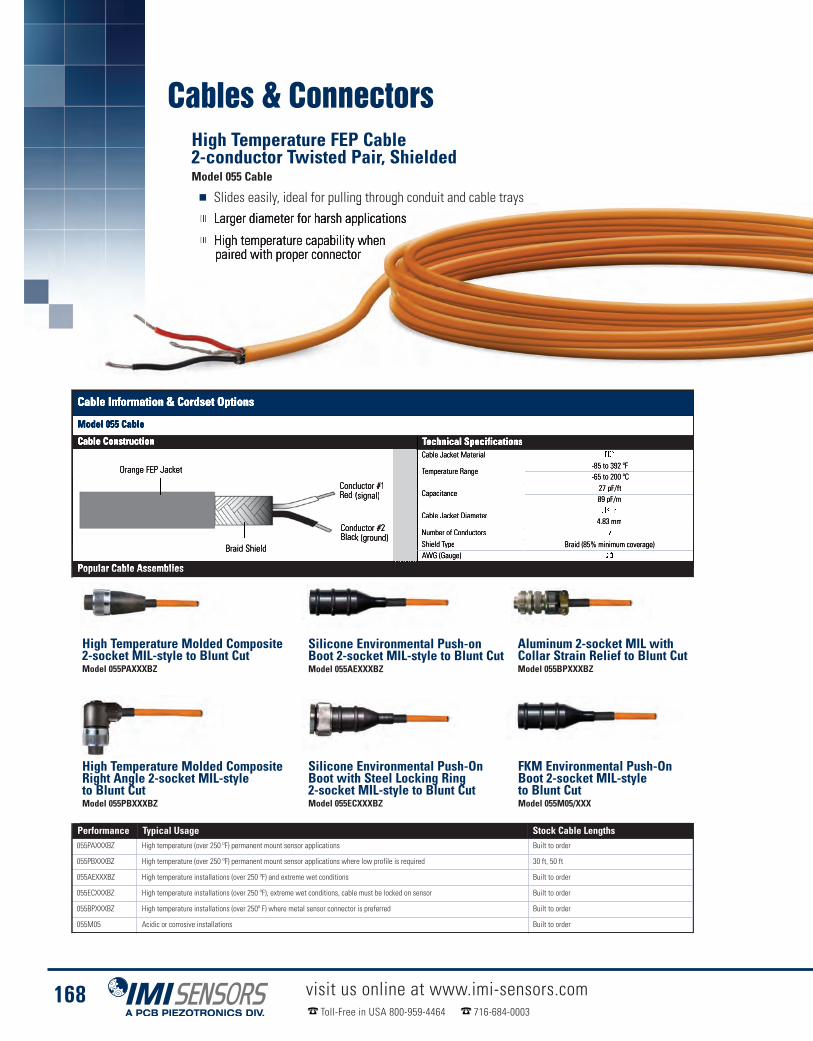
Cables & Connectors
visit us online at www.imi-sensors.comToll-Free in USA 800-959-4464 716-684-0003
168
055PAXXXBZ High temperature (over 250 ºF) permanent mount sensor applications Built to order
055PBXXXBZ High temperature (over 250 ºF) permanent mount sensor applications where low profile is required 30 ft, 50 ft
055AEXXXBZ High temperature installations (over 250 ºF) and extreme wet conditions Built to order
055ECXXXBZ High temperature installations (over 250 ºF), extreme wet conditions, cable must be locked on sensor Built to order
055BPXXXBZ High temperature installations (over 250º F) where metal sensor connector is preferred Built to order
055M05 Acidic or corrosive installations Built to order
Cable Jacket Material FEP
Temperature Range-85 to 392 ºF-65 to 200 ºC
Capacitance27 pF/ft89 pF/m
Cable Jacket Diameter.19 in
4.83 mmNumber of Conductors 2Shield Type Braid (85% minimum coverage)AWG (Gauge) 20
High Temperature Molded Composite2-socket MIL-style to Blunt CutModel 055PAXXXBZ
High Temperature Molded CompositeRight Angle 2-socket MIL-styleto Blunt CutModel 055PBXXXBZ
Silicone Environmental Push-onBoot 2-socket MIL-style to Blunt CutModel 055AEXXXBZ
Silicone Environmental Push-OnBoot with Steel Locking Ring2-socket MIL-style to Blunt CutModel 055ECXXXBZ
FKM Environmental Push-OnBoot 2-socket MIL-styleto Blunt CutModel 055M05/XXX
High Temperature FEP Cable2-conductor Twisted Pair, ShieldedModel 055 Cable
� Slides easily, ideal for pulling through conduit and cable trays� Larger diameter for harsh applications� High temperature capability when
paired with proper connector
Aluminum 2-socket MIL withCollar Strain Relief to Blunt CutModel 055BPXXXBZ
Conductor #1Red (signal)
Conductor #2Black (ground)
Braid Shield
Orange FEP Jacket
Cable Information & Cordset Options
Model 055 Cable
Cable Construction Technical Specifications
Popular Cable Assemblies
Performance Typical Usage Stock Cable Lengths

Cables & Connectors
visit us online at www.imi-sensors.comToll-Free in USA 800-959-4464 716-684-0003
169
045ERXXXBZ Extreme high temperature installations up to 500 ºF Built to order
045ETXXXBZ Connects to on-turbine combustion dynamics pressure sensors Built to order
Extreme High Temperature2-socket MIL to Blunt CutModel 045ERXXXBZ
Extreme High Temperature2-socket Mini-MIL to Blunt CutModel 045ETXXXBZ
Very High Temperature LowNoise PFA Cable 2-conductorTwisted Pair, ShieldedModel 045 Cable
� Designed for extreme high temperatureapplications
� Slides easily, ideal for pulling throughconduit & cable trays
� Larger diameter for harsh applications
Cable Jacket Material PFA
Temperature Range-130 to 500 ºF-90 to 260 ºC
Capacitance35 pF/ft
114.83 pF/m
Cable Jacket Diameter.204 in5.18 mm
Number of Conductors 2Shield Type Braid (85% minimum coverage)AWG (Gauge) 22
Conductor #1(with low noise TFE wrap)
Conductor #2(with low noise TFE wrap)
Red PFA Jacket
Graphite Impregnated Tape
Braid Shield
Cable Information & Cordset Options
Model 045 Cable
Cable Construction Technical Specifications
Popular Cable Assemblies
Performance Typical Usage Stock Cable Lengths

Cables & Connectors
visit us online at www.imi-sensors.comToll-Free in USA 800-959-4464 716-684-0003
170
High Temperature Armor Jacketed FEP Cable2-conductor, Twisted Pair with Drain, ShieldedModel 048 Cable
� Armor jacket protects cable from abuse� Small diameter armor jacket makes for easy handling and installation� High temperature capability when paired with proper connector
048APXXXBZ Rugged installations where metal sensor connector is preferred Built to order
048BPXXXBZ Rugged high temperature installations (over 250 ºF) where metal sensor connector is preferred Built to order
048AEXXXBZ Rugged high temperature installations (over 250 ºF) and extreme wet conditions Built to order
048ECXXXBZ Rugged high temperature installations (over 250 ºF), extreme wet conditions, cable must be locked on sensor Built to order
Cable Jacket Material FEP
Temperature Range-90 to 392 ºF-70 to 200 ºC
Capacitance51 pF/ft
167.3 pF/m
Cable Jacket Diameter.154 in3.91 mm
Number of Conductors 2Shield Type Aluminum / MylarAWG (Gauge) 18
Aluminum 2-socket MIL withCollar Strain Relief to Blunt CutModel 048APXXXBZ
High Temperature Aluminum 2-socketMIL with Collar Strain Relief to Blunt CutModel 048BPXXXBZ
Silicone Environmental Push-OnBoot 2-socket MIL-style to Blunt CutModel 048AEXXXBZ
Silicone Environmental Push-On Boot withSteel Locking Ring 2-socket MIL-style to Blunt CutModel 048ECXXXBZ
Foil Shield
FEP Jacket
Conductor #1Red (signal)
Conductor #2Blue (ground)
Stainless Steel Armor Jacket
20 AWG Drain Wire
Cable Information & Cordset Options
Model 048 Cable
Cable Construction Technical Specifications
Popular Cable Assemblies
Performance Typical Usage Stock Cable Lengths
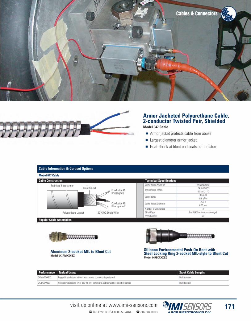
Cables & Connectors
visit us online at www.imi-sensors.comToll-Free in USA 800-959-4464 716-684-0003
171
047AMXXXBZ Rugged installations where metal sensor connector is preferred Built to order
047ECXXXBZ Rugged installations (over 250 ºF), wet conditions, cable must be locked on sensor Built to order
Cable Jacket Material Polyurethane
Temperature Range-58 to 250 ºF-50 to 121 ºC
Capacitance36 pF/ft118 pF/m
Cable Jacket Diameter.250 in6.35 mm
Number of Conductors 2Shield Type Braid (90% minimum coverage)AWG (Gauge) 20
22 AWG Drain Wire
Stainless Steel ArmorBraid Shield
Polyurethane Jacket
Conductor #1Red (signal)
Conductor #2Blue (ground)
Armor Jacketed Polyurethane Cable,2-conductor Twisted Pair, ShieldedModel 047 Cable
� Armor jacket protects cable from abuse� Largest diameter armor jacket� Heat-shrink at blunt end seals out moisture
Cable Information & Cordset Options
Model 047 Cable
Cable Construction Technical Specifications
Popular Cable Assemblies
Performance Typical Usage Stock Cable Lengths
Aluminum 2-socket MIL to Blunt CutModel 047AMXXXBZ
Silicone Environmental Push-On Boot withSteel Locking Ring 2-socket MIL-style to Blunt CutModel 047ECXXXBZ

Cables & Connectors
visit us online at www.imi-sensors.comToll-Free in USA 800-959-4464 716-684-0003
172
050LQXXXAC Commtest & Datastick analyzers 6 ft & 10 ft050LQXXXHX Emerson/CSI 2130 analyzer 6 ft & 10 ft050LQXXXDP Rockwell/Entek Datapak/Enpac analyzers 6 ft050FVXXXCV Emerson/CSI 2110, 2115 & 2120 analyzers Built to order050FVXXXCW SKF Microlog® analyzers Built to order050FVXXXHM SKF GX® series & Azima-DLI DCA-31 analyzers Built to order050ACXXXAC Connect accelerometer switch box outputs to Commtest & Datastick analyzers Built to order050DPXXXAC Connect accelerometer switch box outputs to Rockwell/Entek Datapak/Enpac analyzers Built to order050HXXXXAC Connect accelerometer switch box outputs to Emerson/CSI 2130 analyzer Built to order050ACXXXCV Connect accelerometer switch box outputs to Emerson/CSI 2110, 2115 & 2120 analyzers Built to order
Cable Jacket Material Thermoplastic Elastomer
Temperature Range-22 to 176 ºF-30 to 80 ºC
Capacitance31 pF/ft102 pF/m
Cable Jacket Diameter.21 in
5.33 mmNumber of Conductors 2Shield Type Braid (90% minimum coverage)AWG (Gauge) 23
2-socket MIL with Extended StrainRelief Ergonomic Design to BNC PlugModel 050LQXXXAC
2-socket MIL with Extended Strain ReliefErgonomic Design to 5-pin ConnectorModel 050LQXXXHX
2-socket MIL with Extended StrainRelief to 25-pin D-SubModel 050FVXXXCV
2-socket MIL with ExtendedStrain Relief to 25-pin D-SubModel 050FVXXXCW
BNC Plug to BNC PlugModel 050ACXXXAC
General Purpose, Coiled PolyurethaneJacket Twisted Pair, ShieldedModel 050 Cable
� Ideal for route-based predictivemaintenance with portable analyzer
� Many major data collector terminationsavailable for immediate delivery
� Stays coiled despite heavy usage
7-pin Connector to BNC PlugModel 050DPXXXAC
Conductor #1Red (signal)
Conductor #2Blue (ground)
Black Polyurethane Jacket
Braid shieldover each conductor
2-socket MIL with Extended Strain ReliefErgonomic Design to 7-pin ConnectorModel 050LQXXXDP
2-socket MIL with ExtendedStrain Relief to 6-pin ConnectorModel 050FVXXXHM
BNC Plug to 25-pin D-subModel 050ACXXXCV
See Page 176 for Information on OptionalBreakaway Safety Connector
Cable Information & Cordset Options
Model 050 Cable
Cable Construction Technical Specifications
Popular Cable Assemblies
Performance Typical Usage Stock Cable Lengths
Five-pin Connector to BNC PlugModel 050HXXXXAC
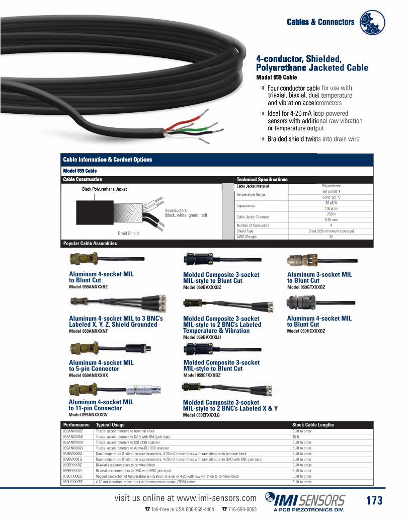
Cables & Connectors
visit us online at www.imi-sensors.comToll-Free in USA 800-959-4464 716-684-0003
173
059ANXXXBZ Triaxial accelerometers to terminal block Built to order059ANXXXNF Triaxial accelerometers to DAQ with BNC jack input 10 ft059ANXXXHX Triaxial accelerometers to CSI 2130 analyzer Built to order059ANXXXGV Triaxial accelerometers to Azima-DLI DCX analyzer Built to order059BVXXXBZ Dual temperature & vibration accelerometers, 4-20 mA transmitters with raw vibration to terminal block Built to order059BVXXXLG Dual temperature & vibration accelerometers, 4-20 mA transmitters with raw vibration to DAQ with BNC jack input Built to order059EFXXXBZ Bi-axial accelerometers to terminal block Built to order059EFXXXLG Bi-axial accelerometers to DAQ with BNC jack input Built to order059GTXXXBZ Rugged connection of temperature & vibration, bi-axial or 4-20 with raw vibration to terminal block Built to order059HCXXXBZ 4-20 mA vibration transmitters with temperature output (TO64 series) Built to order
Cable Jacket Material Polyurethane
Temperature Range-58 to 250 ºF-50 to 121 ºC
Capacitance36 pF/ft118 pF/m
Cable Jacket Diameter.250 in6.35 mm
Number of Conductors 4Shield Type Braid (90% minimum coverage)AWG (Gauge) 20
Aluminum 4-socket MILto Blunt CutModel 059ANXXXBZ
Aluminum 4-socket MIL to 3 BNC’sLabeled X, Y, Z, Shield GroundedModel 059ANXXXNF
Aluminum 4-socket MILto 11-pin ConnectorModel 059ANXXXGV
Molded Composite 3-socketMIL-style to Blunt CutModel 059BVXXXBZ
Molded Composite 3-socketMIL-style to Blunt CutModel 059EFXXXBZ
4-conductor, Shielded,Polyurethane Jacketed CableModel 059 Cable
� Four conductor cable for use withtriaxial, biaxial, dual temperatureand vibration accelerometers
� Ideal for 4-20 mA loop-poweredsensors with additional raw vibrationor temperature output
� Braided shield twists into drain wire
Molded Composite 3-socketMIL-style to 2 BNC’s Labeled X & YModel 059EFXXXLG
Aluminum 4-socket MILto 5-pin ConnectorModel 059ANXXXHX
Molded Composite 3-socketMIL-style to 2 BNC’s LabeledTemperature & VibrationModel 059BVXXXLH
Aluminum 3-socket MILto Blunt CutModel 059GTXXXBZ
Aluminum 4-socket MILto Blunt CutModel 059HCXXXBZ
4-conductors(black, white, green, red)
Braid Shield
Black Polyurethane Jacket
Cable Information & Cordset Options
Model 059 Cable
Cable Construction Technical Specifications
Popular Cable Assemblies
Performance Typical Usage Stock Cable Lengths
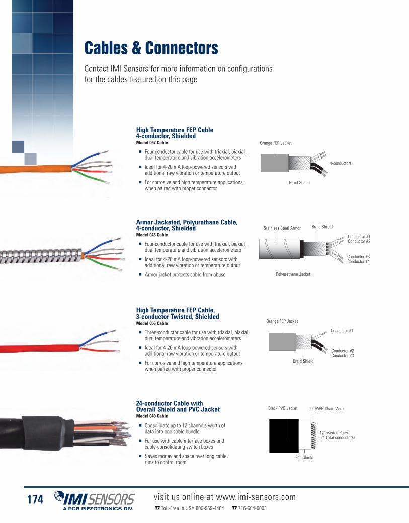
Cables & ConnectorsContact IMI Sensors for more information on configurationsfor the cables featured on this page
visit us online at www.imi-sensors.comToll-Free in USA 800-959-4464 716-684-0003
174
High Temperature FEP Cable4-conductor, ShieldedModel 057 Cable
� Four-conductor cable for use with triaxial, biaxial,dual temperature and vibration accelerometers
� Ideal for 4-20 mA loop-powered sensors withadditional raw vibration or temperature output
� For corrosive and high temperature applicationswhen paired with proper connector
Armor Jacketed, Polyurethane Cable,4-conductor, ShieldedModel 043 Cable
� Four-conductor cable for use with triaxial, biaxial,dual temperature and vibration accelerometers
� Ideal for 4-20 mA loop-powered sensors withadditional raw vibration or temperature output
� Armor jacket protects cable from abuse
High Temperature FEP Cable,3-conductor Twisted, ShieldedModel 056 Cable
� Three-conductor cable for use with triaxial, biaxial,dual temperature and vibration accelerometers
� Ideal for 4-20 mA loop-powered sensors withadditional raw vibration or temperature output
� For corrosive and high temperature applicationswhen paired with proper connector
24-conductor Cable withOverall Shield and PVC JacketModel 049 Cable
� Consolidate up to 12 channels worth ofdata into one cable bundle
� For use with cable interface boxes andcable-consolidating switch boxes
� Saves money and space over long cableruns to control room
4-conductors
Orange FEP Jacket
Braid Shield
Conductor #1Conductor #2
Conductor #3Conductor #4
Braid ShieldStainless Steel Armor
Polyurethane Jacket
Conductor #2Conductor #3
Conductor #1
Braid Shield
Orange FEP Jacket
12 Twisted Pairs(24 total conductors)
Foil Shield
Black PVC Jacket 22 AWG Drain Wire

Cables & Connectors
visit us online at www.imi-sensors.comToll-Free in USA 800-959-4464 716-684-0003
175
Cable Jacket Material FEP Polyurethane FEP Polyvinyl Chloride Polyvinyl Chloride Polyurethane Polyurethane
Temperature Range-85 to 392 ºF -58 to 250 ºF -85 to 392 ºF -40 to 221 ºF -40 to 221 ºF -76 to 176 ºF -58 to 250 ºF
-65 to 200 ºC -50 to 121 ºC -65 to 200 ºC -40 to 105 ºC -40 to 105 ºC -60 to 80 ºC -50 to 121 ºC
Capacitance24 pF/ft 36 pF/ft 27 pF/ft 23 pF/ft 23 pF/ft 20 pF/ft 36 pF/ft
79 pF/m 118 pF/m 89 pF/m 76 pF/m 76 pF/m 66 pF/m 118 pF/m
Cable Jacket Diameter.19 in .250 in .19 in .61 in .70 in .17 in .250 in
4.83 mm 6.35 mm 4.83 mm 15.5 mm 17.8 mm 4.32 mm 6.35 mm
Number of Conductors 4 4 3 24 32 2 2
Shield Type Braid(85% minimum coverage)
Braid(90% minimum coverage)
Braid(85% minimum coverage) Aluminum / Mylar Aluminum / Mylar Spiral
(90% minimum coverage)Braid
(97% minimum coverage)
AWG (Gauge) 22 20 20 20 20 20 20
PVC Cable, 32-conductor,Twisted Pairs, Overall ShieldedModel 046 Cable
� Consolidate up to 16 channels worth ofdata into one cable bundle
� For use with model 691B47 16 channelcable-consolidating switch box
� Saves money and space over long cableruns to control room
Coiled, Lightweight,Shielded, 2-conductorModel 044 Cable
� Ideal for route-based predictivemaintenance with portable analyzer
� Lightweight, easy to carry and handle
� Stays coiled despite heavy usage
Coiled, Heavy Duty,Shielded, TwistedModel 058 Cable
� Ideal for route-based predictivemaintenance with portable analyzer
� Heavy duty, thick cable designed forvery rugged situations
� Stays coiled despite heavy usage
16 Twisted Pairs(32 total conductors)
Foil Shield
Black PVC Jacket22 AWG Drain Wire
Conductor #1Red (signal)
Conductor #2Blue (ground)
Black Polyurethane Jacket
Braid shieldover each conductor
Conductor #1Red (signal)
Conductor #2Blue (ground)
Black Polyurethane Jacket
Braid shieldover each conductor
Technical Specifications
Model Number 057 Cable 043 Cable 056 Cable 049 Cable 046 Cable 044 Cable 058 Cable

Breakaway Safety Connector
visit us online at www.imi-sensors.comToll-Free in USA 800-959-4464 716-684-0003
176
Connector Style Circular BreakawayConnector Type 3 Socket (female) / 3 Pin (male)Coupling Method Snap-OnStrain Relief Potted
Temperature Range-40 to +176 °F-40 to +80 °C
Shell Protection IP67Housing Material Plastic
Size (OD x Length)0.75 in x 2.2 in19 mm x 57 mm
Weight0.39 oz11.1 gm
6 ft. Coiled Cable, 2-socket MIL withExtended Strain Relief to 3-pin HalfBreakaway ConnectorModel 050LQ006LU Cable*
3-socket Half BreakawayConnector to 5-pin ConnectorModel 052LVXXXHX
3-socket Half BreakawayConnector to 7-pin ConnectorModel 052LVXXXDP
3-socket Half BreakawayConnector to BNC PlugModel 052LVXXXAC
3-socket Half BreakawayConnector to 6-pin ConnectorModel 052LVXXXHM
3-socket Half BreakawayConnector to 25-pin D-SubModel 052LVXXXCV
3-socket Half BreakawayConnector to 25-pin D-SubModel 052LVXXXCW
Breakaway Safety Connector� Prevents technicians from being pulled
into rotating machinery� Flexible ordering options allows for
quick, in-field adaptations� Many popular data collector
terminations in stockProduct shown at actual size
*Model 050LQ006LU required. Choose option below that corresponds with your data acquisition equipment.
2.09 in(53 mm)
3.87 in (98 mm)Connected Lengths
Ø0.63 in(16 mm)
2.19 in(56 mm)
Cable Information & Cordset Options
Breakaway Safety Connector
Cable Construction Technical Specifications

TechnicalInformation� Accelerometer SelectionWorksheet . . . . . . 178� Accelerometer Selection Guidelines . . . . . . 179� Technical Information - Accelerometers . . . 182� Technical Information - Pressure Sensors . 185

AccelerometerSelection WorksheetAnswering the following questions will help define the sensor best suited for a particular application. Refer tothe following pages on “Accelerometer Selection Guidelines”, for detailed information regarding each of thequestions below.
1. Measurement Range / SensitivityEnter the highest overall acceleration level to bemeasured. __________ g (m/sec2)
If < 10 g (98 m/sec2), choose 100 mV/g(most commonly used).If > 10 g (98 m/sec2), choose 10 mV/g.If < 0.001g (0.0098 m/sec2), choose 500 m V/g.If monitoring slow speed machinery, <500 cpm (8 Hz )or seismic (e.g., building or bridge vibrations),choose 500 mV/g or higher sensitivity.
2. Frequency RangeLowest frequency to be analyzed _______cpm (Hz)Highest frequency to be analyzed _______ cpm (Hz)
3. Broadband Resolution(select the smallest of the two)Lowest vibration amplitude of interest_________ g (m/sec2)Smallest change in vibration level to be resolved__________ g ( m/sec2)
4. Temperature Range (select one)Normal Temperature ___ <250 °F (121 °C)High Temperature ___ <325 °F (162 °C)Very High Temperature ___ <500 °F (260 °C)Cryogenic (contact IMI) ___ <-65 °F (-54 °C)
5. SizeMax footprint allowable ________ in (mm)Max height allowable (clearance) ________ in (mm)
6. Duty___ Permanent mount___ Walk-a-round
7. CableIntegral cable required ____ Yes ____ NoIf Yes, enter length __________ ft (m)Temperature Range:For -58 to 250 ºF (-50 to 121 ºC), use polyurethanejacketed cable, (Models 042 or 052) or equivalent.For -90 to 392 ºF (-70 to 200 ºC), use (FEP)jacketed cable, Model 053.For -130 to 500 ºF (-90 to 260 ºC), use (PFA)jacketed cable, Model 045.Armored Cable Required ____ Yes ____ No
8. SubmersionIf used in a submersed application up to 750 psi (51.7bar), select an integral polyurethane cable (Models 042,052, or 059). Note: Any accelerometer, whose modelnumber includes a one (1) in the second to last character,is supplied with an integral polyurethane cable, (e.g.Model 623C10).
9. Intrinsically Safe / Explosion ProofIntrinsically safe required ____ Yes ____ No____ “EP”—Explosion Proof Condulet Enclosure____ “EX”— Intrinsically Safe Approved____ “MS”— Mine Safety Administration Approved
Intrinsically Safe____ “MX”— CENELEC Approved
Intrinsically Safe for Mining
(accuracy/sensitivity tolerance required)
visit us online at www.imi-sensors.comToll-Free in USA 800-959-4464 716-684-0003
178

There will usually be several accelerometer models that will meetthe required measurement parameters, so the question naturallyarises, which should be used? This section provides detailedexplanations for the questions on the “Accelerometer SelectionWorksheet” on page 178. Use the information provided here tohelp answer the questions on the Worksheet as accurately aspossible. This will result in a set of key specifications required forthe accelerometer. For detailed specifications on these sensors,refer to the “Products by Technology Section” (pages 81-176).
1. Measurement Range / Sensitivity—Determine themaximum peak vibration amplitude that will be measured andselect a sensor with an appropriate measurement range. For atypical accelerometer, the maximum measurement range is equalto ±5 volts divided by the sensitivity. For example, if the sensitivityis 100 mV/g then the measurement range is (5 V / 0.1 V/g) = ±50g. Allow some overhead in case the vibration is a little higher thanexpected.
2. Frequency Range — Determine the lowest and highestfrequencies to be analyzed. If you are not sure what the upperfrequency range should be, use the following table showing“Recommended Frequency Spans” as a guideline.
Recommended Frequency Spans (Upper Frequency)Shaft Vibration. . . . . . . . . . . . . . 10 x RPMGearbox . . . . . . . . . . . . . . . . . . . 3 x GMFRolling Element Bearings . . . . . 10 x BPFIPumps . . . . . . . . . . . . . . . . . . . . 3 x VPMotors / Generators . . . . . . . . . 3 x (2 x LF)Fans . . . . . . . . . . . . . . . . . . . . . . 3 x BPSleeve Bearings. . . . . . . . . . . . . 10 x RPMRPM— Revolutions Per MinuteGMF — Gear Mesh FrequencyBPFI — Ball Pass Frequency Inner raceVP — Vane Pass frequencyLF — Line Frequency (60 Hz in USA)BP — Blade Pass frequency
The above table was taken from Eshleman, Ronald L., BasicMachinery Vibrations: An Introduction to Machine Testing,Analysis, and Monitoring, VIPress, Incorporated, 1999 p. 2.4.
Select an accelerometer that has a frequency range thatencompasses both the low and high frequencies of interest. Insome cases, it may not be possible to measure the entire range ofinterest with a single accelerometer. In such a case, select thesensor that comes the closest to what is needed.
High Frequency Caution — Many machines, such as pumps,compressors, and some spindles, generate high frequenciesbeyond the measurement range of interest. Even though thesevibrations are out of the range of interest, the accelerometer isstill excited by them. Since high frequencies are usuallyaccompanied by high accelerations, they will often drive highersensitivity accelerometers (100 and 500 mV/g models) intosaturation causing erroneous readings. If a significant highfrequency vibration is suspected or if saturation occurs, a lowersensitivity (typically 10 or 50 mV/g) accelerometer should beused. For some applications, IMI offers higher sensitivityaccelerometers with built in low pass filters. These sensors filterout the unwanted high frequency signals and thus provide betteramplitude resolution at the frequencies of interest. Contact anIMI® Application Specialist for assistance if you experience thisproblem.
To determine if you have a condition that will overdrive (saturate)the accelerometer, look at the raw vibration signal in the timedomain on a data collector, spectrum analyzer, oroscilloscope. Set the analyzer for a range greater than themaximum rated output of the accelerometer. If the amplitudeexceeds the maximum rated measurement range of theaccelerometer (typically 5 volts or 50 g for a 100 mV/g unit), thena lower sensitivity sensor should be selected. If the highersensitivity sensor is used, clipping of the signal and saturation ofthe electronics is likely to occur. This will result in falseharmonics, “ski slope” as well as many other seriousmeasurement errors.
3. Broadband Resolution (Noise) — Determine theamplitude resolution that is required. This will be the smaller ofeither the lowest vibration level or the smallest change inamplitude that must be measured. Select a sensor that has abroadband resolution value equal to or less than this value. Forexample, if measuring a precision spindle with 0.0001 g minimumamplitude, choose an accelerometer with 100 g or betterresolution. If the known vibration levels are in velocity (in/s) ordisplacement (mils), convert the amplitudes to acceleration (g) atthe primary frequencies.Note: The lower there solution value, the better the resolution is.Generally, ceramic sensing elements have better resolutions (lessnoise) than do quartz.
AccelerometerSelection Guidelines
Typical Accelerometer Frequency Response Plot for a Filtered Sensor
Technical Information
visit us online at www.imi-sensors.comToll-Free in USA 800-959-4464 716-684-0003
179
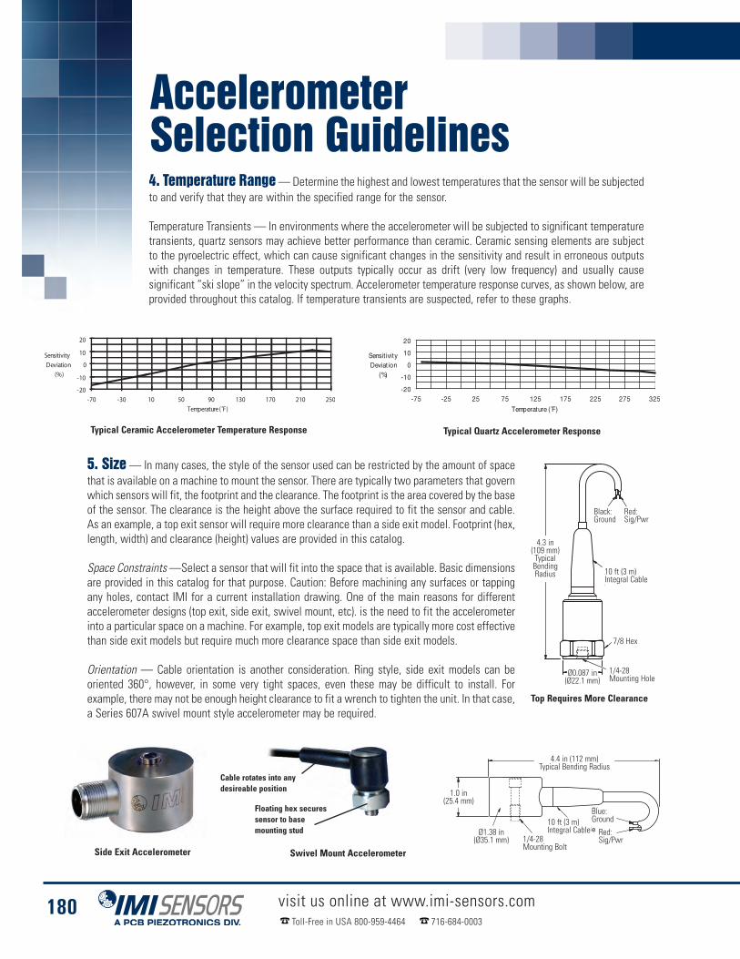
AccelerometerSelection Guidelines
Typical Ceramic Accelerometer Temperature Response
Side Exit Accelerometer
Typical Quartz Accelerometer Response
Top Requires More Clearance
5. Size — In many cases, the style of the sensor used can be restricted by the amount of spacethat is available on a machine to mount the sensor. There are typically two parameters that governwhich sensors will fit, the footprint and the clearance. The footprint is the area covered by the baseof the sensor. The clearance is the height above the surface required to fit the sensor and cable.As an example, a top exit sensor will require more clearance than a side exit model. Footprint (hex,length, width) and clearance (height) values are provided in this catalog.
Space Constraints —Select a sensor that will fit into the space that is available. Basic dimensionsare provided in this catalog for that purpose. Caution: Before machining any surfaces or tappingany holes, contact IMI for a current installation drawing. One of the main reasons for differentaccelerometer designs (top exit, side exit, swivel mount, etc). is the need to fit the accelerometerinto a particular space on a machine. For example, top exit models are typically more cost effectivethan side exit models but require much more clearance space than side exit models.
Orientation — Cable orientation is another consideration. Ring style, side exit models can beoriented 360°, however, in some very tight spaces, even these may be difficult to install. Forexample, there may not be enough height clearance to fit a wrench to tighten the unit. In that case,a Series 607A swivel mount style accelerometer may be required.
4. Temperature Range—Determine the highest and lowest temperatures that the sensor will be subjectedto and verify that they are within the specified range for the sensor.
Temperature Transients — In environments where the accelerometer will be subjected to significant temperaturetransients, quartz sensors may achieve better performance than ceramic. Ceramic sensing elements are subjectto the pyroelectric effect, which can cause significant changes in the sensitivity and result in erroneous outputswith changes in temperature. These outputs typically occur as drift (very low frequency) and usually causesignificant “ski slope” in the velocity spectrum. Accelerometer temperature response curves, as shown below, areprovided throughout this catalog. If temperature transients are suspected, refer to these graphs.
Swivel Mount Accelerometer
Cable rotates into anydesireable position
Floating hex securessensor to basemounting stud
Black:Ground
Red:Sig/Pwr
4.3 in(109 mm)TypicalBendingRadius 10 ft (3 m)
Integral Cable
7/8 Hex
1/4-28Mounting Hole
Ø0.087 in(Ø22.1 mm)
4.4 in (112 mm)Typical Bending Radius
1.0 in(25.4 mm)
Ø1.38 in(Ø35.1 mm) 1/4-28
Mounting Bolt
10 ft (3 m)Integral Cable
Blue:Ground
Red:Sig/Pwr
visit us online at www.imi-sensors.comToll-Free in USA 800-959-4464 716-684-0003
180

6. Duty (Accuracy, Sensitivity Tolerance, and Safety)—Theduty refers to the type of use that a sensor will see. The mosttypical uses for predictive maintenance applications are either ina walk around application, as with a portable data collector, orpermanently mounted to a particular machine. In permanentmount applications, the sensor may terminate at a junction boxwhere measurements are taken with a portable data collector ortied to an on-line monitoring system. 4-20 mA output sensorswould usually be tied to existing plant systems such as a PLC.
Sensitivity Tolerance (Absolute Accuracy) —Sensitivity toleranceis the maximum deviation that the actual sensitivity of anaccelerometer can vary from its published nominal sensitivity andstill be within specification. IMI offers accelerometers with ±5%,±10%, ±15%, and ±20% tolerances on sensitivity. Thus, a nominal100 mV/g sensor with a ±5% tolerance could have an actualsensitivity between 95 and 105 mV/g. A ±20% tolerance unitcould vary between 80 and 120 mV/g. If the nominal sensitivity isused to convert to engineering units (e.g., the calibration usedwith a data collection device), then a looser tolerance sensor willbe less accurate, in general, than a tighter tolerance model.However, if the actual calibration value that is supplied with thesensor is used, then both readings will be equally accurate. Inapplications were absolute accuracy is important (e.g., inacceptance testing) then either higher tolerance sensors or actualcalibration factors should be used. Lower tolerance sensors aretypically provided with a single point calibration rather than fullcalibration. This, coupled with the looser tolerance, helps keepcosts down and allows them to be offered at a much moreeconomical price. Normally, these sensors are selected forpermanent mount applications where larger numbers ofaccelerometers are needed.
Repeatability—All IMI® sensors, regardless of their sensitivitytolerance, are very repeatable. That means, a given measurementwill repeat time and again, thus giving very accurate trends. Iftrend data is of primary importance, any IMI sensor will work fineeven when using the nominal sensitivity.
Calibration Interval — Due to the inherent stability of quartz,accelerometers with quartz sensing elements have a longerrecommended calibration interval than do ceramic sensors. Therecommended time between calibrations is 1 year for ceramicsensors and 5 years for quartz. As a practical matter, however, itmay not be possible to send ceramic sensors in for yearlyrecalibration. As long as the sensor is permanently mounted andnot going through severe thermal transients on a regular basis, itssensitivity should remain fairly stable. However, if it is seeingrepeated shocks (as with magnetic mounting in a walk aroundsystem) or severe thermal transients, it is highly recommendedthat the sensor be recalibrated yearly. One advantage of quartzsensors is its long-term stability even in high shock and thermallytransient environments. It may also beadvantageous to purchase a portable shaker for in-place
sensitivity verification. See the Model 699A02 Portable Shaker onpage 161.
Accessibility, Safety, and Production Considerations—Monitoringlocations on machines are often inaccessible due to shrouds,space constraints, or other physical obstacles. Additionally, theymay be in hazardous areas or have limited access due to pressingproduction schedules. In cases like these, low-cost, permanentmount accelerometers should be selected. This provides a fast,easy, and safe way to collect vibration data. When selectingthese sensors, remember to also select the appropriate cabling,connectors, and switch or termination boxes.
7. Cable — It is recommended, in most cases, that connectorstyle accelerometers be used rather than ones with integral cable.Cables are very susceptible to damage and are usually the sourceof most sensor problems, therefore, it is much easier and morecost effective to replace a cable rather then the entireaccelerometer/cable assembly. Integral cable models arerecommended in submersible applications where sealing is ofprime importance. Armored cable is recommended in applicationswhere sharp objects could cut the cable, such as metal chips inmachining operations.
8. Submersion — If the accelerometer is used in asubmersed application, it is generally recommended to use anintegral cable. For submersed applications up to 750 psi (51.7 bar),select an integral polyurethane cable (IMI cable model numbers042, 052, 059, or 062). Note: Any accelerometer, whose modelnumber includes a one (1) in the second to last character, issupplied with an integral polyurethane cable (e.g., Model623C10).
9. Intrinsically Safe/Explosion Proof—Many sensormodels are approved for use in hazardous areas when used witha properly installed intrinsic safety (I.S.) barrier. Approvalauthorities include Canadian Standards Association, CENELEC,Factory Mutual, and Mine Safety Administration. Check thespecification table of the sensor of interest to see which I.S.approvals are available for that model. IMI 4-20 mA models arealso available with an explosion proof condulet enclosure.
10. Factory Assistance—When questions arise, do nothesitate to contact the factory to speak with an ApplicationSpecialist about your requirements.
Integral Cable Armor JacketedIntegral Cable
visit us online at www.imi-sensors.comToll-Free in USA 800-959-4464 716-684-0003
181
Technical Information

Technical Information
AccelerometersPiezoelectric Sensing MaterialsTwo categories of piezoelectric materials predominantly used in accelerometer designs are quartz andpolycrystalline ceramics. Quartz is a naturally occurring crystal. However, the quartz used in sensors today isproduced by a process that creates material free from impurities. Ceramic materials, on the other hand, areman-made. Different specific ingredients yield ceramic materials that possess certain desired sensorproperties. Each material offers distinct benefits, and material choice depends on the particular performancefeatures desired of the accelerometer.
QuartzQuartz is widely known for it ability to perform accurate measurements tasks and contributes heavily in everyday applicationsfor time and frequency measurements, such as wrist watches, radios, computers, and home appliances. Accelerometers alsobenefit from several unique characteristics of quartz. Since quartz is naturally piezoelectric, it has not tendency to relax toan alternative state and is considered the most stable of all piezoelectric materials. Quartz-based sensors, therefore, makeconsistent, repeatable measurements and continue to do so over long periods of time. Also, quartz has not output occurringfrom temperature fluctuations, a formidable advantage when placing sensors in thermally active environments. Becausequarts has a low capacitance value, the voltage sensitivity is relatively high compared to most ceramic materials, making itideal for ruse in voltage-amplified systems. Conversely, the charge sensitivity of quartz is low, limiting its usefulness incharge-amplified systems, where low noise is an inherent feature.
CeramicsA wide variety of ceramic materials are used foraccelerometers, and which material to use depends on therequirements of the particular application. All ceramicmaterials are man made and are forced to becomepiezoelectric by a polarization process. This process, knownas “poling,” exposes the material to a high-intensityelectrical field, which aligns the electric dipoles, causing thematerial to become piezoelectric. Ceramics offer a higheroutput than quartz when using similar size crystals. They arean ideal for use with a large output is required from a verysmall sensor. Different ceramic packages may be used todetermine such factors as charge sensitivity, voltagesensitivity, and temperature range. Charge output ceramicsmay be mated with built-in charge amplifier circuits toachieve high output signals, high resolution, and an excellentsignal to noise ratio. High temperature ceramics are nowbeing incorporated into charge mode accelerometers tooperate to temperatures exceeding 900 °F (482 °C).
Structures for Piezoelectric AccelerometersA variety of mechanical structures are available to perform the transduction principles required of a piezoelectricaccelerometer. These configurations are defined by the nature in which the inertial force of an accelerated mass acts uponthe piezoelectric material. Such terms as compression mode, flexural mode and shear mode describe the nature of the stressacting upon the piezoelectric material. Current designs of IMI® accelerometers utilize, almost exclusively, the shear mode ofoperation for their sensing elements. Therefore, the information provided herein is limited to that pertaining to shear modeaccelerometers.
Shear Mode Accelerometer
ICP® Sensor Circuit
Cover
Piezoelectric Material
Seismic Mass
Preload Ring
Base with ThreadedMounting Hole
Lead Wire
ElectricalConnector
visit us online at www.imi-sensors.comToll-Free in USA 800-959-4464 716-684-0003
182

Stud Mounted Accelerometer
Screw Mounted Accelerometer
Shear ModeShear mode accelerometer designs feature sensing crystals attachedbetween a center post and a seismic mass. A compression ring or stud appliesa pre-load force to the element assembly to insure a rigid structure and linearbehavior. Under acceleration, the mass causes a shear stress to be applied tothe sensing crystals. This stress results in a proportional electrical output bythe piezoelectric material. The output is collected by electrodes andtransmitted by lightweight lead wires to either the built-in signal conditioningcircuitry of ICP® sensors, or directly to the electrical connector for chargemode types. By having the sensing crystals isolated from the base andhousing, shear mode accelerometers excel in rejecting thermal transient andbase-bending effects. Also, the shear geometry lends itself to small size,which promotes high frequency response while minimizing mass loadingeffects on the test structure. With this combination of ideal characteristics,shear mode accelerometers offer optimum performance.
MEMS DC Accelerometer
Sensor Mounting and Frequency ResponseOne of the most important considerations in dealing with accelerometer mounting is the effect the mounting technique has on theaccuracy of the usable frequency response. The accelerometer's operating frequency range is determined, in most cases, by securelystud mounting the test sensor directly to the reference standard accelerometer. The direct, stud mounted coupling to a very smoothsurface generally yields the highest mounted resonant frequency and therefore, the broadest usable frequency range. The addition ofany mass to the accelerometer, such as an adhesive or magnetic mounting base, lowers the resonant frequency of the sensing systemand may affect the accuracy and limits of the accelerometer's usable frequency range. Also, compliant materials, such as a rubberinterface pad, can create a mechanical filtering effect by isolating and damping high-frequency transmissibility.
Surface PreparationFor best measurement results, especially at high frequencies, it is importantto prepare a smooth and flat machined surface where the accelerometer is tobe attached. Inspect the area to ensure that no metal burrs or other foreignparticles interfere with the contacting surfaces. The application of a thin layerof silicone grease between the accelerometer base and the mounting surfacealso assists in achieving a high degree of intimate surface contact required forbest high-frequency transmissibility.
Stud MountingFor permanent installations, where a very secure attachment of theaccelerometer to the test structure is preferred, stud mounting isrecommended. First, grind or machine on the test object a smooth, flat area atleast the size of the sensor base, per the manufacturer's specifications. Then,prepare a tapped hole in accordance with the supplied installation drawing,ensuring that the hole is perpendicular to the mounting surface. Installaccelerometers with the mounting stud and make certain that the stud doesnot bottom in either the mounting surface or accelerometer base. Most IMI®
mounting studs have depth-limiting shoulders that ensure that the stud cannotbottom-out into the accelerometer's base. Each base incorporates acounterbore so that the accelerometer does not rest on the shoulder.Acceleration is transmitted from the structure's surface into theaccelerometer's base. Any stud bottoming or interfering between theaccelerometer base and the structure inhibits acceleration transmission andaffects measurement accuracy. When tightening, apply only therecommended torque to the accelerometer. A thread-locking compound maybe applied to the threads of the mounting stud to safeguard against loosening.
MEMS VC Sensing Element
Housing
Electrical Connector
Accelerometer
Printed Circuit Board(For Voltage Regulation, Protectionand Temperature Compensation)
MaintainClearance
MaintainClearance
SiliconeGrease
SiliconeGrease
visit us online at www.imi-sensors.comToll-Free in USA 800-959-4464 716-684-0003
183
Technical Information

Technical Information
Accelerometers
Adhesive MountingMounting by stud or screw may not always be practical., Adhesive mounting offers an alternative mounting method. The useof separate adhesive mounting bases is recommended to prevent the adhesive from damaging the accelerometer base orclogging the mounting threads. Miniature accelerometers that normally contain integral mounting studs may have the studmachined off to form a flat base. Most adhesive mounting bases available from PCB® also provide electrical isolation. Thiseliminates potential noise pick-up and ground loop problems.
The type of adhesive recommended depends on the particular application. Petro Wax (available from PCB®) offers a veryconvenient, easily removable approach for room temperature use. Two-part epoxies offer stiffness, which maintains high-frequency response and as the installation becomes a permanent mount. Other adhesives, such as dental cement, hot glues,instant glues, and duct putty are also viable options with a history of success. There is no one "best" adhesive for allapplications because of the many different structural and environmental considerations, such as temporary or permanentmount, temperature, type of surface finish, and so forth.
To avoid damaging the accelerometers mounted with permanent adhesives, a debonding agent must be applied to theadhesive prior to sensor removal. With so many adhesives in use (everything from super glues, dental cement, epoxies, etc),there is no universal debonding agent available. The debonder for the Loctite 454 adhesive that PCB® Suggests is Acetone.If you are using anything other than Loctite 454, you will have to check with the individual manufactures for their debondingrecommendations. The debonding agent must be allowed to penetrate the surface in order to properly react with theadhesive, so, after the application of the agent, it is advisable to wait a few minutes before removing the sensor. Once thedebonding agent has set, you can use an ordinary open-end wrench applied to the hex or square base and, with a gentleshear (or twisting) motion (by hand only) the sensor can be removed from the test structure. Base or square base, or miniatureteardrop accelerometers are supplied with a removal tool for use in the shearing motion.
Magnetic MountingMagnetic mounting bases offer a very convenient, temporary attachment tomagnetic surfaces. Magnets offering high pull strengths provide best high-frequencyresponse. Wedged dual-rail magnetic bases are generally used for installations oncurved surfaces, such as motor and compressor housings and pipes. However, dual-rail magnets usually significantly decrease the operational frequency range of anaccelerometer. For best results, the magnetic base should be attached to a smooth,flat surface. A thin layer of silicone grease should be applied between the sensorand magnetic base, as well as between the magnetic base and the structure toimprove surface contact continuity. When surfaces are uneven or non-magnetic,steel pads can be welded or epoxied in place to accept the magnetic base.
Caution: Magnetically mounting an accelerometer has the potential to generate veryhigh and very damaging acceleration levels. To prevent such damage, exercisecaution when attaching the magnet to your test structure and gently “rock” or“slide” the assembly in place. Do not allow the magnet to “snap” on to the teststructure as excessive “shocks” are generated. These “shocks” could damage thesensor. Another more ideal mounting method is to attach the magnetic base to yourtest structure first, and then screw the accelerometer on to the magnetic base.
Magnet Mounted to Steel Pad
Screw MountingWhen installing accelerometers onto thin-walled structures, a cap screw passing through a hole of sufficientdiameter is an acceptable means for securing the accelerometer to the structure. The screw engagementlength should always be checked to ensure that the screw does not bottom into the accelerometer base. A thinlayer of silicone grease at the mounting interface ensures high-frequency transmissibility.
Magnet Mounted Directly to Test Structure
SiliconeGrease
Weld orEpoxy
Magnetic Base
Steel Pad
Magnetic Base
SiliconeGrease
SiliconeGrease
visit us online at www.imi-sensors.comToll-Free in USA 800-959-4464 716-684-0003
184

Technical Information
Pressure SensorsTypical Piezoelectric System OutputPiezoelectric pressure sensors measure fast responding, microsecond dynamic pressure events. They are not suited for longer, staticevents. Dynamic pressure measurements including turbulence, blast, ballistics and engine combustion may require sensors with specialcapabilities. Fast response, ruggedness, high stiffness, extended ranges, and the ability to also measure “quasi-static” pressures arestandard features associated with PCB® quartz pressure sensors. The following information presents some of the design and operatingcharacteristics of PCB® pressure sensors to help you better understand how they function, which, in turn, helps you make betterdynamic measurements.
Types of Pressure SensorsPiezoelectric pressure sensors are available in various shapes and thread configurations to allow suitable mounting for variousapplications. IMI® manufactures two types of piezoelectric sensors. Charge mode pressure sensors generate a high-impedance chargeoutput. ICP® (Integrated Circuit Piezoelectic) voltage mode-type sensors feature built-in microelectronic amplifiers, which convert thehigh-impedance charge into a low-impedance voltage output. (ICP® is a registered trademark of PCB Group, Inc.)
Why Can Dynamic Pressure Only Be Measure with Piezoelectric Pressure Sensors?The quartz crystals of a piezoelectric pressure sensor generate a charge when pressure is applied. However, even though the electricalinsulation resistance is quite large, the charge eventually leaks to zero. The leakage rate is dependent on the electrical insulationresistance. In a pressure sensor with built-in ICP® electronics, the resistance and capacitance of the crystal and the built-in ICP®
electronics normally determine the leakage rate. In a charge mode pressure sensor used with a voltage amplifier, the leakage rate isfixed by values of capacitance and resistance in the sensor, by low-noise cable, and by the external source follower voltage amplifierused. In the case of a charge mode pressure sensor used with a charge amplifier, the leakage rate is fixed by the electrical feedbackresistor and capacitor in the charge amplifier.
The output characteristic of piezoelectric pressure sensor systems isthat of an AC-coupled system, where repetitive signals decay untilthere is an equal area above and below the original base line. Asmagnitude levels of the monitored event fluctuate, the output remainsstabilized around the base line with the positive and negative areas ofthe curve remaining equal. The graph (right) represents an AC signalfollowing this curve. (Output from sensors operating in DC mode followthis same pattern but over an extended time frame associated withsystem discharge time constant values.)
Assume that a 0 to 3 volt output signal is generated from an AC-coupledpressure application with a one-second steady-state pulse rate and onesecond between pulses. The frequency remains constant, but thenatural decay associated with a piezoelectric sensors will cause thesignal to quickly decay negatively until the signal centers around theoriginal base line. Eventually the signal reaches an equilibrium point,where the area above the baseline equals the area below the (area A =area B. The original output signal remains the same, though one is nowreading a peak to peak output , from -1 Volt to +1 Volt, instead of anoutput from 0 to 3 Volts.
3
1
-1
-3 Repetitive Pulse AC Signal
Incorrect
Correct
Flush MountPressure Alignment
Pressure Sensor
Clamp Nut
Off-centerSide WallStrain
Off-centerSide WallStrain
Pressure Sensor
Apply RecommendedTorque to Clamp Nut
visit us online at www.imi-sensors.comToll-Free in USA 800-959-4464 716-684-0003
185
Technical Information

High Frequency ResponseMost PCB® piezoelectric pressure sensors are constructed with either compression mode quartz crystals preloadedin a rigid housing, or unconstrained tourmaline crystals. These designs give the sensors microsecond response timesand resonant frequencies in the hundreds of kHz, with minimal overshoot or ringing. Small diaphragm diametersensure spatial resolution of narrow shockwaves. High-frequency response and rise time can be affected by mountingport geometry and associated electronics. Check all system component specifications before making measurements,or contact PCB® for application assistance.
Technical Information
Pressure Sensors
InstallationPrecision mounting of pressure sensors is essential for good pressure measurements. Although some mounting information isshown in this catalog, always check the installation drawings supplied in the product manual, or contact PCB® to request detailedmounting instructions. Good machining practices will improve the drilling and threading of mounting ports. Use the propermounting torque, as noted on the specification sheet and/or installation drawing, during sensor installation.. Mounting hardwareis supplied with PCB® sensors, as noted on a product specification sheet. Various standard thread adaptors are available tosimplify sensor installations. For free field blast applications, try to use “aerodynamically clean” mounts, minimizing unwantedreflections from mounting brackets or tripods.
The sensing crystals of many pressure sensors described in this catalog are located in the diaphragm end of the sensor. Sideloading of this part of the sensor during a pressure measurement creates distortions in the signal output.
Also important is the avoidance of unusual side loading stresses and strains on the upper body of the sensor. Proper installationminimizes distortions in the output signal. A taut cable pulling at right angles to the electrical connector or a heavy electricaladaptor added to a smaller sensor connector are two examples of putting a side strain into the body. In the later case, the addedconnector mass, when used in a high vibration environment may cause the connector to break away from the sensor housing. Insome applications, such as free-field blast measurements, a pressure sensor mounted in a thin plate can be subjected to sideloading stresses caused when the plate flexes, under pressure. Use of an O-ring mounts suited to withstand the pressure levelsunder test minimizes this effect.
Flush vs. Recess MountingFlush mounting of pressure sensors in a plate or wall is desirable for maximizing thesensors frequency response, minimizing turbulence, avoiding a cavity effect, oravoiding an increase in a chamber volume. Recess mounting is more desirable inapplications where the diaphragm end of the pressure sensor is likely to be subjectedto potential damage, possibly from heat, excessive flash temperatures or particleimpingement. Most PCB® pressure sensors are supplied with seal rings for flushmounting. Certain models can be provided with seal sleeves for recess mountingports, as shown in the illustration (right). Consider ordering enough spare seal ringsor sleeves, particularly in applications that require frequent removal and reinstallationof the pressure sensor. Before reinstalling a pressure sensor, be sure to check themounting port to be sure that an old, distorted seal ring is not still in the mountinghole. If you are using PCB® pressure sensors and find that you have lost or misplacedthe seals, call PCB® and request that the needed items be sent out as no-chargesamples. Various mounting adaptors facilitate mounting of the pressure sensors. Notethat pressure sensors and adaptors with straight machined threads use a seal ring asa pressure seal. Pipe thread adaptors have a tapered thread, which results in thethreads themselves creating the pressure seal.
Typical Recess Mount
Pressure Sensor
Clamp Nut
Recess Port
SpacerSleeve
visit us online at www.imi-sensors.comToll-Free in USA 800-959-4464 716-684-0003
186

Thermal ShockThermal shock can be in the form of a radiant heat, such as the flash from an explosion, heat from convection of hot gasses passingover a pressure sensor’s diaphragm, or conductive heat from a hot liquid.Virtually all piezoelectric pressure sensors are sensitive tothermal shock. As mentioned, most PCB® pressure sensors use quartz as the sensing crystal. Quartz, itself, is thermally insensitive tothermal transients. However, the crystals are preloaded between parts within the sensor itself, the sensors element package. Whenheat strikes the diaphragm of a piezoelectric pressure sensor, the heat can cause an expansion of the material surrounding the internalcrystals. Although quartz crystals are not significantly sensitive to thermal shock, the case expansion causes a lessening of the preloadforce on the crystals, which will cause the signal to drift as a result of this change in preload. Usually, as heat goes up, sensorsensitivity will decrease causing a negative-going signal output drift. Precautions can be made to the test setup in an effort to minimizeor delay thermal shock from distorting the intended output signal.
Certain PCB quartz pressure sensors feature thermal isolation designs to minimize the effects of thermal shock. Some feature baffleddiaphragms. Other models designed for maximizing the frequency response may require thermal protection coating, recess mounting,or a combination to lessen the effects of thermal shock. Examples of coatings include silicone grease, which may also be used to filla recess mounting hole, RTV silicone rubber, vinyl electrical tape, and ceramic coatings. The RTV and tape are used as ablatives, whilethe ceramic coating is also used to protect some diaphragms from corrosive gasses and particle impingements.
Crystals other than quartz are used in some PCB® sensors. Tourmaline is used for shock tube and underwater blast sensors becauseof its superior frequency characteristics. In shock tube measurements, the duration of the pressure measurement is usually so shortthat a layer of vinyl tape is sufficient to delay the thermal event from affecting the desired pulse for the duration of the desiredmeasurement. In underwater blast applications, heat transfer through the water is not significant.
Note that thermal shock effects do not relate to the “temperature coefficient” pressure sensor specification. The temperaturecoefficient specification refers to the change in sensitivity of the sensor relative to the static, ambient temperature of the sensor.Unfortunately, since the thermal shock effects cannot be easily quantified, they must be anticipated and minimized by one of the abovementioned techniques in order to ensure better measurement data.
PolarityWhen a positive pressure is applied to the diaphragm of an ICP® pressure sensor, the sensor yields a positive voltage. The polarity ofPCB® charge mode pressure sensors is just the opposite: when a positive pressure is applied, the sensor yields a negative output.Charge output sensors are usually used with external charge amplifiers that invert the signal. Therefore, the resulting system outputpolarity of a charge output sensor used with a charge amplifier will produce a positive going output for a positive event. (Reversepolarity sensors are also available.)
Flush vs. Recess Mounting (continued)Control of the location of the pressure sensor diaphragm is achieved with a straight thread/seal ring mount. Reference the sensorsinstallation instructions for proper mounting hole preparation instructions to achieve a flush mount. Pipe thread mounts do not allowa precision positioning of the depth of the sensor since the seal is provided by progressive tightening of threads in the tapered holeuntil the required thread engagement is reached. However, pipe threads do offer a convenience of an easier machined port than straightthreads. Pipe thread mounts are well suited for some general applications.
visit us online at www.imi-sensors.comToll-Free in USA 800-959-4464 716-684-0003
187
Technical Information
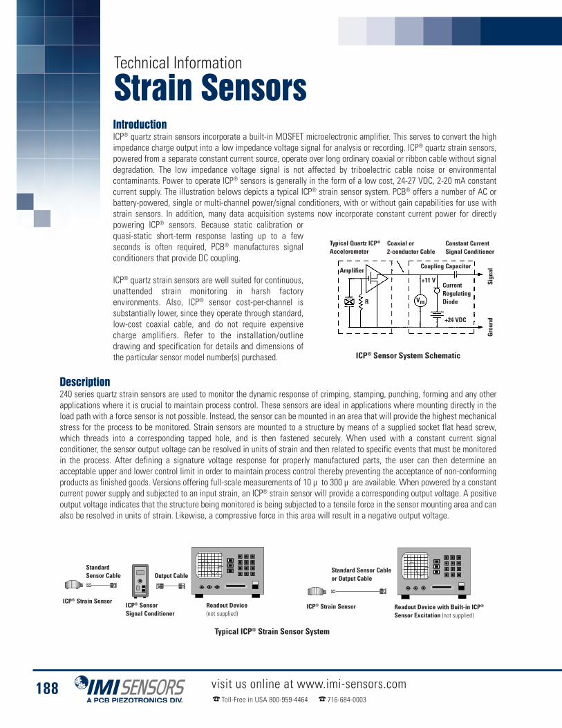
Technical Information
Strain Sensors
OutputCable
I
Standard Sensor Cable
I
Standard Sensor Cable or Output Cable
I
IntroductionICP® quartz strain sensors incorporate a built-in MOSFET microelectronic amplifier. This serves to convert the highimpedance charge output into a low impedance voltage signal for analysis or recording. ICP® quartz strain sensors,powered from a separate constant current source, operate over long ordinary coaxial or ribbon cable without signaldegradation. The low impedance voltage signal is not affected by triboelectric cable noise or environmentalcontaminants. Power to operate ICP® sensors is generally in the form of a low cost, 24-27 VDC, 2-20 mA constantcurrent supply. The illustration belows depicts a typical ICP® strain sensor system. PCB® offers a number of AC orbattery-powered, single or multi-channel power/signal conditioners, with or without gain capabilities for use withstrain sensors. In addition, many data acquisition systems now incorporate constant current power for directlypowering ICP® sensors. Because static calibration orquasi-static short-term response lasting up to a fewseconds is often required, PCB® manufactures signalconditioners that provide DC coupling.
ICP® quartz strain sensors are well suited for continuous,unattended strain monitoring in harsh factoryenvironments. Also, ICP® sensor cost-per-channel issubstantially lower, since they operate through standard,low-cost coaxial cable, and do not require expensivecharge amplifiers. Refer to the installation/outlinedrawing and specification for details and dimensions ofthe particular sensor model number(s) purchased.
Description240 series quartz strain sensors are used to monitor the dynamic response of crimping, stamping, punching, forming and any otherapplications where it is crucial to maintain process control. These sensors are ideal in applications where mounting directly in theload path with a force sensor is not possible. Instead, the sensor can be mounted in an area that will provide the highest mechanicalstress for the process to be monitored. Strain sensors are mounted to a structure by means of a supplied socket flat head screw,which threads into a corresponding tapped hole, and is then fastened securely. When used with a constant current signalconditioner, the sensor output voltage can be resolved in units of strain and then related to specific events that must be monitoredin the process. After defining a signature voltage response for properly manufactured parts, the user can then determine anacceptable upper and lower control limit in order to maintain process control thereby preventing the acceptance of non-conformingproducts as finished goods. Versions offering full-scale measurements of 10 µ to 300 µ are available. When powered by a constantcurrent power supply and subjected to an input strain, an ICP® strain sensor will provide a corresponding output voltage. A positiveoutput voltage indicates that the structure being monitored is being subjected to a tensile force in the sensor mounting area and canalso be resolved in units of strain. Likewise, a compressive force in this area will result in a negative output voltage.
ICP® Sensor System Schematic
Standard Sensor Cableor Output Cable
ICP® Strain SensorICP® SensorSignal Conditioner
ICP® Strain Sensor
StandardSensor Cable
Readout Device with Built-in ICP®
Sensor Excitation (not supplied)
Readout Device(not supplied)
Output Cable
Typical ICP® Strain Sensor System
Typical Quartz ICP®
Accelerometer
Amplifier
R Vm
Coaxial or2-conductor Cable
Constant CurrentSignal Conditioner
Coupling Capacitor
+11 VCurrentRegulatingDiode
+24 VDC
Signal
Ground
188 visit us online at www.imi-sensors.comToll-Free in USA 800-959-4464 716-684-0003

General InstallationRefer to the Installation Drawing for specific outline dimensions and installationdetails for your particular model.
It is important that the mounting surface is clean and free of paint, oil, or othercoatings that could prevent the proper transfer of strain into the mounting padsof the sensor. Poor surface contact may affect sensor sensitivity and result inerroneous data. Prior to mounting, it is recommended that the machine surfaceand the mounting pads of the sensor be cleaned with acetone. This will maintainproper coupling with these mating surfaces and prevent slippage at peak strain.Connect one end of the coaxial cable to the sensor connector and the other endto the XDCR jack on the signal conditioner. Make sure to tighten the cableconnector to the sensor. DO NOT spin the sensor onto the cable, as this fatiguesthe cable’s center pin, resulting in a shorted signal and a damaged cable. If thecable cannot be attached prior to sensor installation, the protective cap shouldremain on the connector to prevent contamination or damage.
For installation in dirty, humid, or rugged environments, it is suggested that theconnection be shielded against dust or moisture with shrink tubing or otherprotective material. Strain relieving the cable/sensor connection can also prolongcable life. Mounting cables to a test structure with tape, clamps, or adhesivesminimizes the chance of damage.
Strain Sensor InstallationThe illustration (left) displays the sensor mounted using the supplied mountingscrew to a minimum torque of 10 N-m. Allow for the static component of the signalto discharge prior to calibration. Installations not preloaded to the recommendedvalue, or that utilizes a screw of different material and/or dimensions than thesupplied screw, may yield inaccurate output readings. The supplied screw allowsproper strain transmission to the sensor while holding the sensor in place. Properlymachined holes for the mounting screw will ensure proper vertical orientation ofthe sensor. Refer to the installation drawing for additional mounting details.Consult a PCB® applications engineer for calibration and output recommendations.
1.14(29.0)
0.60(15.2)
1.58(40.1)
0.23(5.8)
0.18(4.6)
0.67(17.0)
10-32Connector
M6 MountingScrew (supplied)
0.67 in(17.0 mm)
1.58 in(40.1 mm)
0.60 in(15.2 mm)
1.14 in(29.0 mm)
0.18 in (4.6 mm)
0.23 in(5.8 mm)
10-32 Connector
M6 MountingScrew (supplied)
Industrial ICP® Strain SensorsSeries M240
PolarityExtension of the mounting area of an ICP® strain sensor produces a positive-going voltage output. The retraction of the mounting areaproduces a negative-going voltage output.
Low Frequency MonitoringStrain sensors used for applications in short term, steady-state monitoring, such as sensor calibration, or short term, quasistatic testingshould be powered by signal conditioners that operate in DC-coupled mode. PCB® Series 484 Signal Conditioner operates in either ACor DC-coupled mode and may be supplied with gain features or a zero “clamped” output often necessary in repetitive, positive polaritypulse train applications.
If you wish to learn more about ICP® sensors, consult PCB’s General Signal Conditioning Guide, a brochure outlining the technicalspecifics associated with piezoelectric sensors. This brochure is available from PCB® by request, free of charge.
Low Frequency MonitoringStrain sensors are calibrated relative to a strain gage reference sensor. A calibration certificate is supplied with each strain sensorproviding its relative voltage sensitivity (mV/µ ). A calibration must be performed once strain sensors are installed in the specificequipment being measured. This is necessary so that a direct comparison of relative data can be made thereby allowing the user toset control limits and properly monitor a specific event as well as the entire process.
Strain Sensor Installation
189visit us online at www.imi-sensors.comToll-Free in USA 800-959-4464 716-684-0003
Technical Information

LifetimeWarranty Plus / Total Customer Satisfaction – IMI Sensors guarantees Total Customer Satisfaction through its “LifetimeWarrantyPlus”, Toll-free Customer Service, and 24-hour SensorLineSM. Contact IMI® for a complete statement of our warranty or view our warranty online athttp://www.imi-sensors.com/NoRiskPolicy.aspx
Toll-free Customer Service – IMI® offers direct, Toll-free telephone numbers for customer use. Specific numbers are available for the areain which your product interest lies.When uncertain, call our general number at 800-959-4464. Customer Service Representatives and Application Engineersare available to assist with requests for product literature, price quotations, discuss application requirements, orders, order status, expedited delivery,troubleshooting equipment, or arranging for returns. Our general fax number is: 716-684-3823. We look forward to hearing from you.
24-hour SensorLineSM – IMI® offers to all customers, at no charge, 24-hour emergency product or application support, day or night, seven daysper week, anywhere in the world. To reach a IMI® SensorLineSM Customer Service Representative, call 716-684-0003.
Web site - www.imi-sensors.com – Visit us online at www.imi-sensors.com to view a broader selection of products, newly released products, complete productspecifications, product drawings, technical information, and literature. Additional Test & Measurement equipment can also be found on the PCB® web site at www.pcb.com. Sound levelmeters, noise dosimeters and acoustic measurement systems are featured on Larson Davis’ web site at www.larsondavis.com.
AS9100 and ISO 9001 Certifications – IMI® is registered by the Underwriters Laboratory, Inc. as an AS9100 and ISO 9001 facility and maintains a quality assurance systemdedicated to resolving any concern to ensure Total Customer Satisfaction. IMI® also conforms to the former MIL-STD-45662 and MIL-Q-9858.
A2LA Accredited Calibration Facility – PCB Piezotronics microphones, accelerometers, pressure and force transducers are calibrated with full traceability to NIST (NationalInstitute of Standards & Technology) to ensure conformance to published specifications. Certificates of calibration are furnished which include actual measured data. Calibration systemsutilized are kept in full compliancewith ISO 9001:2000 standards. Calibrationmethods are accredited in accordancewith the recognized International Standard ISO/IEC 17025:2005 GeneralRequirements for the Competence of Testing and Calibration Laboratories, as well as AS9100 and ISO 10012-1 standards. PCB® also meets requirements of ANSI/NCSL Z540-1-1994 andany additional program requirements in the field of calibration.
Delivery Policy – IMI® is committed to making every effort possible to accommodate all delivery requests. Our extensive in-house production capabilities permit us to manufacturemost products to order in a timely fashion. In the event that a specific model is unavailable in the time frame that you need, we can usually offer a comparable unit, for sale or loan, tosatisfy your urgent requirements. Many products are available from stock for immediate shipment. Standard cable assemblies and accessory hardware items are always stocked forimmediate shipment and IMI® never requires a minimum order amount. If you have urgent requirements, call a factory representative and every effort will be made to fulfill your needs.
Custom Products – IMI® prides itself on being able to respond to customers’ needs. Heavy investment in machinery, capabilities, and personnel allow us to design, test, andmanufacture products for specialized applications. Please contact us to discuss your special needs.
CE Marking – Many IMI® products are designed, tested, and qualified to bear CE marking in accordance with European Union EMC Directive. Products that have earned thisqualification are so indicated by the logo.
Hazardous Area Use – Certain equipment is available with CSA and/or ATEX certifications to enable use in hazardous environments. Contact IMI® for detailedspecifications, which will identify the specific approved environments for any particular model.
Accuracy of Information – IMI® has made a reasonable effort to ensure that the specifications contained in this catalog were correct at the time of printing. In the interest ofcontinuous product improvement, IMI® reserves the right to change product specifications without notice at any time. Dimensions and specifications in this catalog may be approximateand for reference purposes only. Before installing sensors, machining any surfaces, or tapping any holes, contact a IMI® application specialist to obtain a current installation drawing andthe latest product specifications.
Routine Modification of Standard Models – In addition to the product options noted in our catalogues,customers from all business sectors regularly request adjustments for their specific implementation and measurementneeds. IMI® has accommodated customers bymaking numerous standard adjustments to thousands of sensors, aswellas to associated electronics. These adjustments to sensitivity, range, frequency response, resolution, grounding issues,mounting, cabling, and electrical requirements can often be made for a certain premium over the base model.
Stock Products – For the added convenience of our customers, IMI® offers a wide selection of sensors andinstrumentation as stock products, available in-house and off the shelf, competitively priced with expedited delivery.These products have been identified and stocked based upon customer demand, with models that offer reliability andversatility across multiple application environments.We alsomanufacture custom products made to your requirements.We invite our customers to work with our Applications Engineers in evaluating your application first, to see if we mighthave a stock product alternative that fits your requirements with a short delivery time.
USA Toll-free Customer Service:800-959-4464
International Customers:716-684-0003
Fax:716-684-3823
E-mail:[email protected]® Web Site:
www.imi-sensors.comIMI® 24-Hour SensorLineSM:
716-684-0003
IMI® Contact Guide
PCB, ECHO, ICP, IMI with associated logo, SPINDLER, SWIVELER, TORKDISC, and Modally Tuned are registeredtrademarks of PCB Group, Inc. Sensorline is a service mark of PCB Group, Inc.
Services& Qualifications

PCB Load & Torque,Inc., a wholly-owned subsidiary
of PCB Piezotronics, is a manufacturer of high quality, precision load cells,torque transducers, telemetry units, fastener technology test systems, andthreaded fastener torque / angle /tension systems. In addition to the qualityproducts produced, the PCB Load & Torque facility offers many services.
With more than 40 years of products, innovation and customer service, PCBPiezotronics is a global leader in the design and manufacture of force, torque,load, strain, pressure, acoustic, shock and vibration sensors, as well as thepioneer of ICP® technology. Core competencies include ICP® and charge
output piezoelectric, piezoresistive, strain gage, MEMS and capacitive sensors and instrumentation. To address the growing need for sensors and related instrumentationin the target market areas of test & measurement, industrial vibration, automotive, aerospace & defense, environmental noise monitoring and industrial hygiene, PCB®
has established a series of focused divisions, with dedicated sales, marketing, engineering, and customer service resource support tailored to the needs of customersin these very specific areas. PCB® divisions and their core competencies include:
IMI Sensors designs and manufactures a full line of accelerometers, sensors, vibrationswitches, vibration transmitters, cables and accessories for predictive maintenance,continuous vibration monitoring, and machinery and equipment protection. Productsinclude rugged industrial ICP® accelerometers; 4-20 mA industrial vibration sensors
and transmitters for 24/7 monitoring; electronic and mechanical vibration switches; the patented Bearing Fault Detector, for earlywarning of rolling element bearing faults; high temperature accelerometers to +900 °F (+482 °C); 2-wire Smart Vibration Switch, withMAVTTM technology, which automatically sets trip level; and the patented Reciprocating Machinery Protector, which outperformsconventional impact transmitters. CE approved and intrinsically safe versions are available for most products. Toll-free 1-800-959-4464;email: [email protected]; www.imi-sensors.com
PCB® Aerospace & Defense specializes in products and programs developedexclusively for the global aerospace, civil and military aviation, defense,homeland security, nuclear, power generation, and test and measurementmarkets. Products include space-rated high temperature and high-g shock
accelerometers; space-qualified hardware; sensors and instrumentation for Health and Usage Monitoring Systems (HUMS), for UAV's,helicopters, fixed wing aircraft and ground vehicles; system electronics; combustion monitoring pressure sensors; high temperatureengine vibration monitoring sensors; launch and separation shock sensors; Active Noise Cancellation products; and aircraft hydraulicpressure sensors, among others. Typical applications include vibration and fatigue testing; qualification testing; aircraft and engineground, flutter and flight testing; blast pressure and hydraulic system pressure measurements; structural dynamics; engine vibrationmonitoring; launch and separation shock studies; pressure, wind tunnel and aerodynamic studies; aircraft and ground vehicle prognostics;and noise cancellation applications. Toll-free in the USA 1-866-816-8892; email: [email protected].
PCB® Automotive Sensors is a dedicated sales and technical supportfacility, located in Novi, Michigan, devoted to the testing andinstrumentation needs of the global automotive test market. This newteam is focused on development and application of sensors and related
instrumentation technologies for specific vehicle development test programs, in the areas of modal and structural analysis, vehicle andcomponent NVH characterization, powertrain testing, vehicle and component durability, vehicle dynamics, safety and regulatory testing,component and system level performance, driveability, road load, and crash, among others. PCB® designs and manufactures sensors forautomotive testing, including vibration, acoustic, pressure, force, load, dynamic strain and torque sensing technologies. These robustsensors are designed to excel in a variety of automotive applications. Toll-free in the USA 1-888-684-0014; email: [email protected]
Larson Davis Environmental Noise Monitoring and Industrial Hygiene offers a fullline of Noise and Vibration measurement instrumentation, including Type 1 soundlevel meters, personal noise dosimeters, octave band, audiometric calibrationsystems, microphones and preamplifiers, hearing conservation software, and
Human Vibration Exposure Monitor for Hand-Arm/Whole Body Vibration for evaluating human exposures to ISO 2631 and 5349, as wellas to help ensure compliancy with a number of ANSI and OSHA and other related industrial hygiene standards, as well as formeasurement of building acoustics, community and environmental noise monitoring, as well as supporting various automotive,aerospace and industrial applications. Toll-free 1-888-258-3222; email: [email protected]; www.larsondavis.com
PCB Piezotronics Test & Measurement Products supports theapplication of traditional sensor technologies of acoustics, pressure,force, load, strain, torque, acceleration, shock, vibration, electronicsand signal conditioning within product design and development,
consumer product testing, quality assurance, civil structure monitoring, research and development, education and engineeringapplication areas. Visit www.pcb.com for more details
The Modal Shop, Inc. (www.modalshop.com)specializes in multi-channel sound and vibration sensingsystems for lab measurements and industrial processmonitoring, including calibration systems and test and
measurement equipment rental. Also, smart sensing systems applied to parts qualityNDT analysis, process monitoring and machinery gauging.
Toll-free in USA 866-684-7107 E-mail [email protected] in USA 800-860-4867 Phone 513-351-9919
Company Information

Corporate Headquarters - Depew, NY
IMI Sensors - A PCB Piezotronics Division
Corporate Headquarters3425 Walden Avenue, Depew, NY 14043-2495 USA
Toll-free in USA 800-959-446424-hour SensorLineSM 716-684-0003
Fax 716-684-3823 � E-mail [email protected] Site www.imi-sensors.com
AS9100 CERTIFIED � ISO 9001 CERTIFIED � A2LA ACCREDITED to ISO 17025
Toll-free in USA 800-828-8840E-mail [email protected]
The Global Leader in Sensors and Instrumentation For All Your Applications
Toll-free in USA 866-816-8892E-mail [email protected]
Toll-free in USA 888-258-3222E-mail [email protected]
Toll-free in USA 800-860-4867E-mail [email protected]
Toll-free in USA 888-684-0014E-mail [email protected]
Toll-free in USA 866-684-7107E-mail [email protected]
Test & Measurement Products
© 2012 PCB Group, Inc. In the interest of constant product improvement, specifications are subject to change withoutnotice. PCB, ECHO, ICP, IMI, Modally Tuned, Spindler, Swiveler and TORKDISC are registered trademarks of PCB Group.SoundTrack LXT, Spark and Blaze are registered trademarks of PCB Piezotronics. SensorLine is a service mark of PCBGroup. All other trademarks are properties of their respective owners. PCB is an EOE/AAP Employer
IMI-Catalog-0612 Printed in U.S.A.