CMOS microelectrode array for bidirectional interaction with neuronal networks
Upload
independentCategory
view
0download
0
726 IEEE TRANSACTIONS ON BIOMEDICAL ENGINEERING, VOL. 53, NO. 4, APRIL 2006
Microelectrode Array for Chronic Deep-BrainMicrostimulation and RecordingDouglas McCreery, Albert Lossinsky, Victor Pikov, and Xindong Liu
Abstract—We have developed an array of microelectrodes thatis suitable for long-term implantation into the subthalamic nucleus(STN) or the globus pallidus and is able to record from single neu-rons, as well as deliver localized microstimulation. This device canbe used to investigate the mechanisms by which deep brain stimula-tion can ameliorate the symptoms of Parkinson’s disease and othermovement disorders, and also may be the basis for a new clinicaltool for the treatment of Parkinson’s disease, by capitalizing on thehigh spatial specificity of intranuclear microstimulation. The arrayincludes 16 activated iridium microelectrodes, 5–6 mm in length,within a cluster approximately 1.8 mm in diameter. We have fab-ricated the array using materials carrying the USP Category VIclassification, and we have developed an apparatus and a proce-dure for implanting the microelectrode arrays into the deep brain.
Ten arrays have been implanted into the STN of domesticcats, and one into the internal segment of the globus pallidus, for140–415 days. During that time, we were able to record actionpotentials from individual neurons, on 4 to 8 of the 16 channels.The microelectrode’ active surface areas ranged from 500 to 2 000
m2. Controlled-current pulses, 26.5 A in amplitude and 150s/phase in duration (4 nC/phase) were used to excite neurons
in the cat’s STN. In addition to direct activation, the stimulusmodulated the neuronal activity over a distance of at least 1.2mm from the site of stimulation. These parameters did not inducehistologically detectable changes around the tip sites after 35hours of stimulation at 100 Hz (7 hours of stimulation per day, on5 successive days), if the electrode’ active surface area was 1 000
m2 or greater.
Index Terms—Cats, chronic implant, deep brain stimulation,microstimulation, safety of electrical stimulation, subthalamicnucleus.
I. INTRODUCTION
E LECTRICAL stimulation in deep brain structures [deepbrain stimulation (DBS)] has developed into an effective
treatment modality for advanced Parkinson’s disease and es-sential tremor. DBS also is being evaluated as a treatment forother neurological conditions and appears to be helpful in thetreatment of several types of dystonia and hyperkinetic disor-ders. (For recent reviews of these topics, see [1]–[5]. While therange of clinical applications for DBS has expanded in recentyears, its mechanism of action remains unclear (e.g., [4] and[6]). Studies directed toward an elucidation of the physiologic
Manuscript received February 1, 2005; revised July 17, 2005. This work wassupported in part by the National Institutes of Health (NIH) under ResearchGrant NS40860-02. Asterisk indicates corresponding author.
*D. McCreery is with Huntington Medical Research Institutes, Neural En-gineering Program, 734 Fairmount Ave., Pasadena, CA 91105 USA (e-mail:[email protected]).
A. Lossinsky, V. Pikov, and X. Liu are with Huntington Medical ResearchInstitutes, Neural Engineering Program, Pasadena, CA 91105 USA.
Digital Object Identifier 10.1109/TBME.2006.870215
underpinnings of DBS certainly would be aided by a microelec-trode array that could be implanted chronically into animals,including subhuman primates, which would deliver highly lo-calized electrical stimulation into the target nucleus, and whichwould include the capability of monitoring the response to theelectrical stimulation by individual neurons in the target nu-cleus. These capabilities may prove useful in a clinical device,with the additional requirement that the microelectrodes mustdeliver the stimulation for an extended interval, without injuryto the tissue. An array of independently controllable stimulatingmicroelectrodes distributed throughout the target nucleus wouldpermit precise control of the spatial distribution of the stimula-tion, by stimulating either with single microelectrodes or with asubgroup of microelectrodes that could be pulsed either simul-taneously or sequentially.
II. METHODS
Fig. 1(A) shows an example of our deep brain microelec-trode array. The entire array assembly is 16 mm in length and 2mm in diameter. It includes a 6-mm stainless-steel (type 316L)alignment cylinder and 16 iridium microelectrodes, each 5 to 6mm in length, comprising a fascicle that is 1.8 mm in diameter.While the length of the microelectrodes is greater than what isrequired for the animal model in which it was developed (STNof the adult domestic cat), we have developed the device withan eye toward its eventual clinical use in the human STN andthe internal segment of the globus pallidus, which are muchlarger than their counterparts in the domestic cat. The fascicleof iridium microelectrodes extends from a cap of EpoTek 301epoxy, a material that carries a USP Category VI certificationfor chronic implantation.
The shafts of the discrete iridium microelectrodes are formedfrom iridium wire, 75 m in diameter. In a 3-step process, oneend of each shaft is etched electrolytically to a cone having anincluded angle of approximately 8 . The cone terminates in ablunt tip with a radius of curvature of 5–6 m. The blunt tip al-lows a more uniform distribution of the stimulus current over theexposed surface [7] and induces minimal tissue damage duringchronic implantation into the feline cochlear nucleus [8]–[10]. Awire lead (platinum-10% iridium, 25 m in diameter) is micro-welded near the upper end of the shaft. The microelectrodeshafts and wire are insulated with 3 m of Parylene-C and theinsulation is ablated from the tips of the shafts, using an ex-cimer laser operating at 248 nm. The surface areas thus exposedranged from approximately 500 m to 2 000 m [Fig. 1(B)].
The individual microelectrodes are assembled into a fascicleof 16 with a center-to-center spacing of 350 m. A custom fix-ture holds the microelectrode shafts in alignment and also serves
0018-9294/$20.00 © 2006 IEEE

McCREERY et al.: MICROELECTRODE ARRAY FOR CHRONIC DEEP-BRAIN MICROSTIMULATION AND RECORDING 727
Fig. 1. (A) The deep brain microelectrode array. (B) A scanning electron micrograph of the tip of one of the iridium microelectrodes. The exposed iridium metalappears light, the Parylene insulation dark. (C) The array and cable with the stiffening pin inserted into the cable lumen. The percutaneous connector also is shown.(D) A Photograph of the apparatus for implanting the array into the deep brain. The inserter is mounted on a standard stereotaxic electrode carrier.
as a mold for casting the epoxy cap. The fascicle is composedof two concentric rings of microelectrodes, those in the innerring being approximate 1 mm longer than in the outer ring. Twomicroelectrodes are omitted from the outer ring. This gap, andthe differences in the lengths of the microelectrodes, allows foreach of the tip sites to be identified in the histologic sections, asdescribed below.
The 16 lead wires are spiraled around a section of silicontubing 0.5 mm in diameter and the windings are overlaid witha layer of Med A silicone elastomer, to form a cable that termi-nates in a percutaneous connector. During implantation, a steelstylet is inserted into the lumen of the silicon tubing. When thestylet is withdrawn, the cable is sufficiently flexible to allowthe implanted array to move with the brain. Fig. 1(C) shows anarray, the cable with the stylet inserted, and the percutaneousconnector.
The microelectrodes are “activated” (a film of polyvalentiridium oxide is formed) by potentiodynamic cycling between
and V with respect to an Ag/AgCl electrode, with
the microelectrodes immersed in saturated sodium phosphatesolution. The activation continues until the electrodes have atotal charge capacity of approximately 25 mC/cm . The chargecapacity of iridium oxide (“activated iridium”) is very high,[11], [12] allowing the microelectrode’s surface area to besufficiently small such that action potentials can be recordedfrom single neurons, yet have adequate charge capacity forprolonged microstimulation. The arrays are then cleaned usingthe “modified Clemson protocol” [13] and sterilized in ethyleneoxide, in preparation for implantation.
Aseptic technique and general anesthesia were used duringimplantation of the arrays into deep brain structures of 11 youngadultcatsofeithersex(age10mo-2years).Theanimal’sheadwasfixed in a stereotaxic apparatus, the scalp and temporalis musclewere reflected and a small craniectomy (approximately 6 6mm) was made over the right cerebral cortex. The apparatus forimplanting the array into the deep brain is shown in Fig. 1(D). It ismounted on a standard microelectrode carrier, on the stereotaxichead frame. Fig. 2(A)–(E) depicts the sequence for implanting

728 IEEE TRANSACTIONS ON BIOMEDICAL ENGINEERING, VOL. 53, NO. 4, APRIL 2006
Fig. 2. (A)–(F) Sequence of steps for implanting the array using the apparatusshown in Fig. 1(D) (see text for details). (G) The tissue dilator cone protrudingfrom the orifice of the slotted introducer tube. (H) The dilator cone has beenretracted and replaced by the microelectrode array.
the array into the cat’s deep brain. The procedure is designedto prevent the brain tissue from being raked by the fascicle of
microelectrodes, and also to protect the microelectrodes untilthey are close to the target. The introducer apparatus is advancedby the stereotaxic drive [Fig. 2(A)], and the slotted introducertube, with a tissue dilator cone protruding from the orifice[Fig. 2(G)], is passed through a slit in the dura and a small nickin the pia, and advanced into the brain in steps of 1 mm, at 2steps per minute, to within a few millimeters of the target. Thedilator cone is then withdrawn and the microelectrode array,supported by the steel stylet within the cable, is guided into theintroducer tube by a rack-and-pinion drive until the electrodeshafts protrude fully from the end of the tube [Fig. 2(B), (H)].Next, the entire assembly is advanced a few millimeters sothat the electrode tips enter their target [Fig. 2(C)]. The array’selongated alignment tube ensures that the microelectrodes arekept aligned with the long axis of the introducer, and thisreduces the risk of slashing the tissue. The introducer tubeis then retracted out of the brain. The stylet within the cableprevents the array from retracting as the introducer is withdrawn[Fig. 2(D)]. The burr-hole is filled with a thin layer of gelfoamand then with bone cement [Fig. 2(E)] and when the cement iscured, the stylet is withdrawn. [Fig. 2(F)]. The cable terminatesin a 25-pin percutaneous connector, which is attached to theskull with stainless-steel screws and bone cement.
Most of the arrays were implanted into the STN, at stereotaxiccoordinatesA7.5,R6.4,andwith theelectrode tipsapproximately3 mm below the interaural line. The array is introduced vertically(in the parasagittal and frontal planes). Final adjustment ofthe vertical coordinate is aided by intraoperative monitoringof neuronal activity. In normal adult cats, the STN can berecognized by well-resolved neuronal units with discharge ratesof 15–25 pulses per second, and relatively high background“noise” due to unresolved neuronal activity.
For microstimulation in the STN, the waveform was charge-balanced, cathodic-first pulse pairs, 150 s/phase in duration.The controlled-current stimulator is isolated from the recordingamplifier by a radio frequency link, to eliminate ground loopsand reduce stimulus artifacts. This allows us to stimulate throughone microelectrode and to record neuronal action potentialsvia an adjacent microelectrode.
Recordings of neuronal activity and short-term stimulationswere performed with the cat unanesthetized. In most cases,the cats were lying on the technician’s lap, to avoid becomingentangled in the tethering cable. Extracellularly recorded actionpotentials (spikes) were amplified 2500 times and bandpassfiltered at 100 Hz to 8 KHz using a custom-build 16-channelamplifier and digitized into a computer at 25 000 samples persecond using a 16-channel data acquisition board (NationalInstruments PCI-6070E). The recordings were processed offlinethrough a software digital filter with a band pass of 500 Hz–5KHz. An amplitude distribution histogram of all positive andnegative peaks were generated and from this, a histogram of thenoise component was generated, assuming a Gaussian amplitudedistribution of the noise peaks. Spikes were detected as eventswhose amplitude was at least 3 times the standard deviation ofthe noise distribution. From these events, and the responses to1500 successive stimulus pulses, poststimulus time histogramswith a bin width of 1 ms were constructed.
The prolonged stimulations were conducted using a16-channel controlled- current simulator housed in a back-

McCREERY et al.: MICROELECTRODE ARRAY FOR CHRONIC DEEP-BRAIN MICROSTIMULATION AND RECORDING 729
Fig. 3. The tip sites of 4 microelectrodes implanted in cat DB2 for 294 days. The neurons and neuropil adjacent to the tip sites (T) appear normal (Luxol fastblue and Cresyl violet).
pack and controlled from a computer via an RF telemetry link.During the stimulation, the cats could move about freely ina large acrylic cage. The backpack module also contained adownlink transmitter that permitted continuous monitoring ofthe voltage transients induced across the microelectrodes bythe controlled current stimulus pulses.
For histologic evaluations of the implant sites, the cats weredeeply anesthetized with pentobarbital and perfused through theascending aorta with 1 liter of phosphate-buffered saline pre-wash followed by 3 liters of phosphate-buffered 4% formalinsolution. Twenty-four hours later, the array was withdrawn and ablock of brain containing the lower part of the array’s alignmentcylinder and the electrode shafts was resected and embeddedinto paraffin. The tissue was sectioned at a thickness of 8 m,approximately in the frontal plane and approximately parallel tothe electrode shafts. The boundaries of the STN are most easilyvisualized when the tissue is sectioned in the frontal plane. Thetissue sections were stained with Luxol Fast Blue to highlightaxons and neuropil and counterstained with Cresyl Violet (Nisslstain) to visualize cell bodies. The site of each of the 16 micro-electrode tips was photographed with a digital camera and theseimages were used to reconstruct a face-on view of the array’sfootprint using a MatLab script. The gap in the outer ring of mi-croelectrodes can be identified in this face-on view so that theidentity of each of the microelectrode tip sites is established.
III. RESULTS
Eleven arrays have been implanted into 11 adult cats. The firstarray was implanted into the internal segment of a cat’s the leftglobus pallidus and the next 10 were targeted to the right STN. Inall cases, the animal’s postsurgical recovery was uneventful. Allcats were sacrificed for histologic evaluation of the implant sitesat 140–415 days after the implant surgery. Some experience wasrequired in order to strike the small feline STN and in 2 of thefirst 3 animals, the array was implanted slightly rostral of itstarget. In 8 of the 10 cats in which the array was targeted to theSTN, and for which histologic data are available, some of themicroelectrode tips were in the STN.
The feline STN is bounded ventrally and laterally by the cere-bral peduncle and dorsally by the zona inserta. Fig. 3 shows thetip sites of the 4 microelectrodes in cat DB2 that were locatedwithin the STN. The plane of the histologic sections is slightlyoblique to the axis of the microelectrodes, causing the terminusof each microelectrode track to appear as an ellipsoid. This catwas sacrificed 294 days after the implant surgery, but the gli-otic sheaths around the microelectrodes were only a few micronsin thickness, and the surrounding neurons and neuropil appearnormal.
Fig. 4(A) shows a section through the center of the epoxybutton, at the transition from the array’s superstructure to the

730 IEEE TRANSACTIONS ON BIOMEDICAL ENGINEERING, VOL. 53, NO. 4, APRIL 2006
Fig. 4. Micrographs of the tissue adjacent to the array’s supporting structures,from cat DB2. (A) A section through the center of the site of the epoxy button,showing the upper end of 3 of the microelectrode shafts (S). (B) A view at highermagnification of the tissue subjacent to the epoxy button. (C) The tissue adjacentto the stainless-steel alignment cylinder (cyl).
fascicle of microelectrodes [see also Fig. 1(A)]. Fig. 4(B) showsthe tissue subjacent to the underside of the button, at higher mag-nification. Here, the gliosis is more extensive than around the in-dividual microelectrode shafts and tip sites (Fig. 3), but neuronsand neuropil 1 mm beneath the epoxy button appear normal.This demonstrates good preservation of tissue in the midst ofthe fascicle of microelectrode shafts. Fig. 4(C) shows the tissue
adjacent to the side of the stainless-steel alignment tube. Theglial sheath is quite thin (approximately 25 m). However, manyof the neurons within approximately 300 m of the tube, whilerecognizable, are somewhat shrunken. Neurons 300 m or morefrom the alignment tube appear normal. The results from 8 othercats were similar. In one animal (DB7), inflammatory cells wereseen around some of the microelectrode shafts, apparently dueto an undetermined contamination of the Parylene insulation.
In all 11 cats, we were able to record the action potentials ofsingle neurons in and around the STN, and in cat DB1, from theglobus pallidus. Fig. 5(A)–(E) shows neural activity recordedfrom 5 cats at 220–340 days after array implantation. Theresponses shown in Fig. 5(A) were from the microelectrodeswhose tip sites are shown in Fig. 3. The surface areas of theelectrodes were m in cat DB9, m incats DB2, DB10, and DB11, and m in cat DB8.Rather unexpectedly, the quality of the unit recordings wasnot significantly poorer when the electrode surface areas werelarger, although the microelectrodes with the large exposed tipstended to record multiple, rather than single, neuronal units.Fig. 5(F) is a plot of the number of channels in each of the 11cats from which we were able to record action potentials withsignal-to-noise ratios (SNRs) of 3 or greater (S/N Mean peakspike amplitude/RMS noise amplitude). We could record froman average of 4 to 5 microelectrodes in each cat, throughout theperiod of implantation. In three cats (DB5, 6, 7), we were notable to record action potentials with good S/N from any of themicroelectrodes. The temporal grouping of these 3 implantsis suspicious, but we have been unable to identify a particularreason for the failure. In the other cats, the number of channelsfrom which we could record action potentials varied over time,but showed no clear trend.
An important feature of our array is its ability to stimulate inthe STN and record neuronal activity via the same set of mi-croelectrodes. Fig. 6(A) is a diagram of the face-on view of thearray implanted in the cat DB2, showing the relative position ofthe 4 microelectrodes in the STN [the tip sites of these micro-electrodes are depicted in Figs. 3(A)–4(D)]. Fig. 6(B) shows thelocation of the tips of the 4 microelectrodes, all projected ontoa histologic section near the caudal end of the electrode fascicle(the terminus of the track of microelectrode #16 is seen in thissection). The tip sites are clustered in the lateral and dorsolat-eral part of the nucleus, the portion that is associated with motorcircuits, so this animal best illustrates the interaction of stimu-lation and recording sites along the rostral-caudal dimension ofthe nucleus. In all cases, the stimulus was biphasic pulse pairs,26.5 A in amplitude and 150 s/phase in duation.
Our recording system does not permit simultaneous recordingand stimulation through the same microelectrode. However, wewere able to record via the adjacent microelectrodes, 350 mdistant, and in a few instances, we were able to record the directresponse of the neurons to the stimulus pulse [Fig. 6(C)]. In mostcases we were able to record delayed responses while stimulatingwith one microelectrode and recording with another. These re-sponses are illustrated by the poststimulus time (pst) histogramsof the single-unit neuronal activity [Fig. 6(D)–H]. We comparedthe pst histograms shown in Fig. 6 (and, also, in Fig. 7) with thosegenerated without the stimulation, using a chi-squared test for

McCREERY et al.: MICROELECTRODE ARRAY FOR CHRONIC DEEP-BRAIN MICROSTIMULATION AND RECORDING 731
Fig. 5. (A)–(E) Extracellular action potentials (�) recorded in 5 cats at 228 to 343 days after array implantation. The 4 channels of data from cat DB2 are from theelectrodes whose tip sites are shown in Fig. 4. The electrode surface areas were approximately as follows:A;D;E = 1 000�m ;C = 500�m ;B = 2000�m .(F) The number of microelectrodes in each of the 11 cats from which we were able to record action potentials with SNRs of 3 or greater (S/N= Mean peak spikeamplitude/RMS noise amplitude). The plots end at the time the cats were sacrificed, except for DB11, which remains alive.
goodness of fit. In all cases, the histograms generated with thestimulation were significantly different from those without stim-ulation ,showingthat thestimulusproducedsignificant
modulation of the temporal distribution of action potentials. Themost common response to the stimulus was a burst of 2 or moreaction potentials peaking 8–12 ms after the stimulus pulse. These

732 IEEE TRANSACTIONS ON BIOMEDICAL ENGINEERING, VOL. 53, NO. 4, APRIL 2006
Fig. 6. (A) A diagram of the microelectrode fascicle from the array implanted into cat DB2, seen in a face-on view. (B) The location in the subthalamic nucleusof the tip sites of the 4 microelectrodes depicted in (A). Note that the views in (A) and (B) are at right angles to one another. The tip sites are projected onto onehistologic section in the frontal plane and through the subthalamic nucleus (Cresyl violet stain). (C) Samples of the actions potentials recorded at microelectrodesite 4 while stimulating at adjacent site 3. The neural unit (�) responded to the stimulus at short and constant latency. (D–H) Poststimulus time histograms of theactivity of single neural units recorded at the sites depicted in (A) and (B) while stimulating at other sites. The action potentials shown in (C) and the histogramshown in (D) were from different neural units, and the data were recorded on different days. In all cases, the stimulus was 26.5 �A current pulses, at 50 Hz. Thehistograms were generated from the responses to 1500 successive stimulus pulses. In each frame, the broken horizontal line indicates the average firing rate of theunit without stimulation. (See text for details)
were temporally dispersed after the stimulus, indicating that theywere induced transynaptically. In most cases, the units’ averagefiring rate was little changed, and the effect of the stimulationwas to partially entrain the action potentials. The entrainment ef-fect was strongest when the stimulating and recording microelec-trodes were close together. Thus, Fig. 6(D), (E) shows the strongmutual excitation when stimulating and recording at a pair of ad-jacent sites (sites 3 and 4, separated by 350 m). Fig. 6(F), (G),(H) show the somewhat weaker entrainment of the action poten-tials between sites 8 and 4, that were separated by approximately700 m [Fig. 6(F)] between sites 16 and 3, separated by about
1500 m [Fig. 7(G)], and between sites 16 and 4 [Fig. 6(H)], sep-arated by about 1400 m.
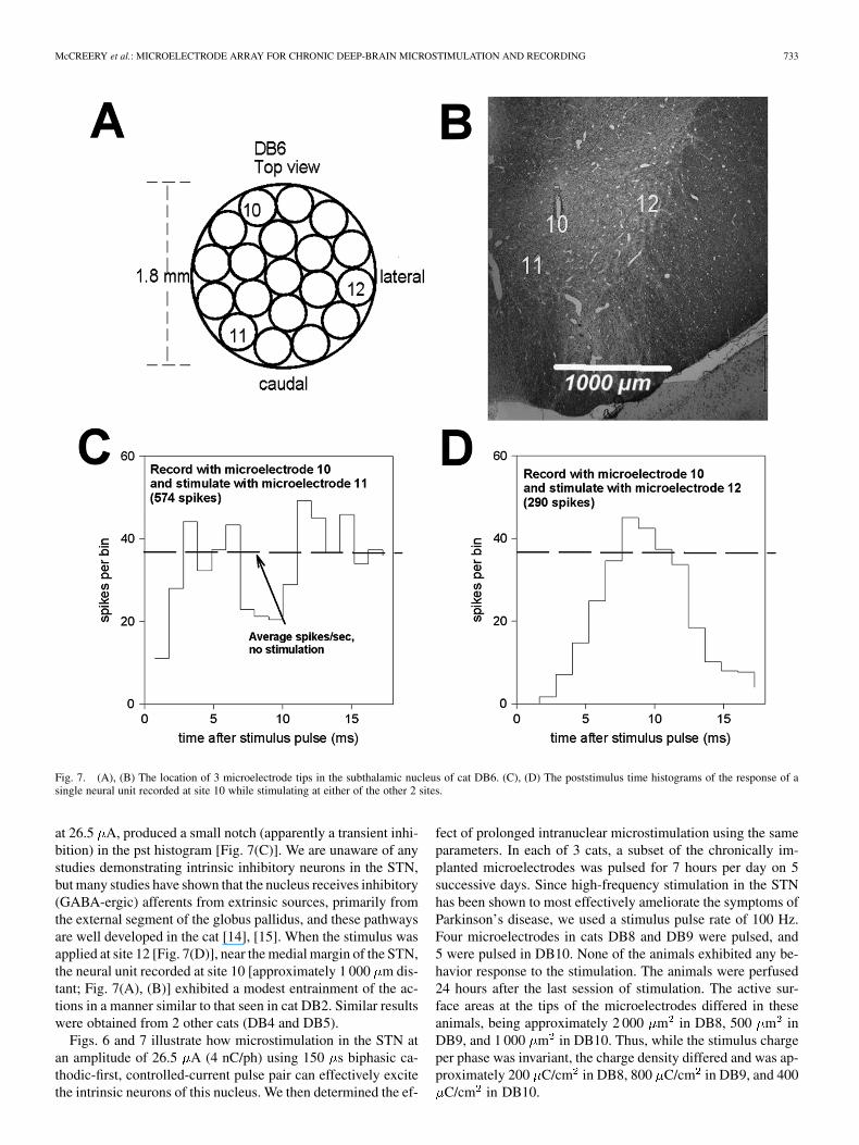
Fig. 7(A) shows the relative positions of 3 microelectrodeswhose tips were in the STN of cat DB6. Fig. 7(B) shows thelocations of the tips in the STN, projected onto a histologic sec-tion through the most rostral of the microelectrode tracks (mi-croelectrode 10). These microelectrode sites are more widelydispersed in the medio-lateral dimension than those in cat DB2.Thus, microelectrode 10 was on the dorsal margin of the STN,microelectrode 12 in the extreme lateral part of the nucleus, andmicroelectrode 11 near its medial margin. Stimulating at site 11,
McCREERY et al.: MICROELECTRODE ARRAY FOR CHRONIC DEEP-BRAIN MICROSTIMULATION AND RECORDING 733
Fig. 7. (A), (B) The location of 3 microelectrode tips in the subthalamic nucleus of cat DB6. (C), (D) The poststimulus time histograms of the response of asingle neural unit recorded at site 10 while stimulating at either of the other 2 sites.
at 26.5 A, produced a small notch (apparently a transient inhi-bition) in the pst histogram [Fig. 7(C)]. We are unaware of anystudies demonstrating intrinsic inhibitory neurons in the STN,but many studies have shown that the nucleus receives inhibitory(GABA-ergic) afferents from extrinsic sources, primarily fromthe external segment of the globus pallidus, and these pathwaysare well developed in the cat [14], [15]. When the stimulus wasapplied at site 12 [Fig. 7(D)], near the medial margin of the STN,the neural unit recorded at site 10 [approximately 1 000 m dis-tant; Fig. 7(A), (B)] exhibited a modest entrainment of the ac-tions in a manner similar to that seen in cat DB2. Similar resultswere obtained from 2 other cats (DB4 and DB5).
Figs. 6 and 7 illustrate how microstimulation in the STN atan amplitude of 26.5 A (4 nC/ph) using 150 s biphasic ca-thodic-first, controlled-current pulse pair can effectively excitethe intrinsic neurons of this nucleus. We then determined the ef-
fect of prolonged intranuclear microstimulation using the sameparameters. In each of 3 cats, a subset of the chronically im-planted microelectrodes was pulsed for 7 hours per day on 5successive days. Since high-frequency stimulation in the STNhas been shown to most effectively ameliorate the symptoms ofParkinson’s disease, we used a stimulus pulse rate of 100 Hz.Four microelectrodes in cats DB8 and DB9 were pulsed, and5 were pulsed in DB10. None of the animals exhibited any be-havior response to the stimulation. The animals were perfused24 hours after the last session of stimulation. The active sur-face areas at the tips of the microelectrodes differed in theseanimals, being approximately 2 000 m in DB8, 500 m inDB9, and 1 000 m in DB10. Thus, while the stimulus chargeper phase was invariant, the charge density differed and was ap-proximately 200 C/cm in DB8, 800 C/cm in DB9, and 400
C/cm in DB10.

734 IEEE TRANSACTIONS ON BIOMEDICAL ENGINEERING, VOL. 53, NO. 4, APRIL 2006
Fig. 8. Histologic sections through the tip sites of microelectrodes in the subthalamic nucleus of 3 cats. The sites labeled as pulsea (A), (B), (D), and (E)had received 7 hours of stimulation at 100 Hz and 4 nC/phase, on 5 successive days. The charge density varied across animals due to the differences in themicroelectrodes’ surface areas, and were approximately as follows: A;B = 200 �C/cm ; D = 400 �C/cm ; E = 800 �C/cm . See text for details. (Luxol fastblue with Cresyl violet.)
Fig. 8(A), (B) shows the tip sites of 2 of the 4 pulsed micro-electrodes from cat DB8. Fig. 8(C) shows an unpulsed tip sitefrom the same animal. The neurons and neuropil at the 4 stimu-lated sites appeared normal, and are indistinguishable from theunstimulated sites. The 5 stimulated sites from cat DB10 alsoappear normal; one site is shown in Fig. 8(D).
Fig. 8(E) shows the tip site of 1 of the 4 pulsed microelec-trodes from cat DB9. All 4 of the pulse sites from this cat weresurrounded by aggregates of inflammatory cells (from their
morphology, probably macrophages). The charge density in catDB9 was higher than in the other animals (approximately 800
C/cm ).
IV. DISCUSSION
The objective of this study has been to develop a chronicallyimplantable microelectrode array in which the spatial density

McCREERY et al.: MICROELECTRODE ARRAY FOR CHRONIC DEEP-BRAIN MICROSTIMULATION AND RECORDING 735
of the microelectrodes is sufficient to allow close control of thespatial distribution of the stimulus.
Numerous studies have demonstrated a topographic organi-zation of the afferent and efferent projections to and from theSTN of many species [16]–[23]. On the basis of the reciprocalconnections between the STN and the cerebrum, the broadest to-pographic subdivision appears to be between motor, associationand limbic functions. However, there is ample evidence for finersubdivisions of the topology, including a somatotopic mappingof motor functions in humans. It is quite possible that a clin-ical device that can access this topology will allow for greaterflexibility in the treatment of motor disorders than is possiblewith the deep brain arrays now in clinical use. These use macro-electrodes, and the electrical stimulation tends to spread quitebroadly. McIntyre et al. [24] modeled the current field that isinduced by the stimulus parameters typically used to amelio-rate the symptoms of Parkinson’s disease, and found that theeffective stimulus may extend well beyond the boundaries ofthe STN. They suggested that this may account for some of theside effects that often accompany deep brain stimulation in theSTN, including tetanic muscle contraction, speech disturbanceand ocular deviations [25].
We have developed a microstimulating device that can be im-planted chronically into the deep brain. There was remarkablylittle tissue injury in the vicinity of the fascicle of 16 microelec-trodes. The tissue responses shown in Fig. 3 are typical of all tipsites of the unpulsed microelectrodes. All of the microelectrodetips were surrounded by thin gliotic sheaths 5–15 m in thick-ness. The density of the neurons in the vicinity of the tip sitesvaried according to the tip’s location in the STN. We did notperform a quantitative analysis of neuronal density around thetip sites, but there was no suggestion that the neuronal densitysurrounding the electrode tips was reduced. Small gliotic scars,40 to 60 m in diameter, sometimes were seen adjacent to oneside of the tips of the microelectrodes [e.g, Fig. 9(D)]. In the 9cats for which histology is available, we found no areas of in-farction or evidence of hemorrhages or hematomas.
In most cases, we were able to record single neuronal actionpotentials from at least some of the microelectrodes, for the du-ration of the implant (up to 435 days), using microelectrodeswith tip areas of 500 to 2 000 m (Fig. 6). Thus a tip area of1 000 to 2 000 m appears to be appropriate for microelec-trodes that are to be used for both prolonged stimulation andrecording of neuronal activity. This will allow prolonged, non-damaging stimulation at an amplitude of at least 4 nC/ph, whichis adequate to excite the neurons in the STN. Within the rangeof tip sizes between 1 000 to 2 000 m , there will be a tradeoffbetween the maximum safe amplitude of prolonged microstim-ulation and the ability to resolve the action potential of singleneurons.
We have identified stimulus parameters that can safely ex-cite the neurons of the feline STN during a regimen of pro-longed stimulation. We found that a stimulus of 4 nC/ph (26.4
A biphasic current pulses, 150 s/ph in duration) was suffi-cient to directly excite the neurons of the feline STN, and thisstimulus also could modulate the activity of these neurons over aconsiderable distance within the STN, possibly by excitation ofafferent axons that make synapses upon the neurons of the STN.
It remains to be determined if this somewhat widely distributedtranssynaptic effect of the intra-nuclear microstimulation, illus-trated in Figs. 6 and 7, would be useful in the clinical treat-ment of movement disorders or more generally, what the clin-ical role of highly localized microstimulation in the treatmentof movement disorders might be. However, we have demon-strated that prolonged, high-rate microstimulation can be ap-plied in the STN without histologically detectable injury to theadjacent neurons and neuropil.
In the feline cochlear nucleus, stimulation-induced neuraldamage is manifested as vacuolations of the large myelinatedaxons that characterize the neuropil of this nucleus [9]. Thethreshold for this type of injury is approximately 3 nC/phaseand is relatively independent of charge density for iridiummicroelectrodes of the same range of surface areas as thoseused in the present study (500–2 000 m ). The charge perphase used in the present study (4 nC/ph) was slightly abovethe level at which the vacuolations were observed in the felinecochlear nucleus. These vacuoles were not seen in the felineSTN or in the feline cerebral cortex stimulated with similarparameters, and their presence in the feline cochlear nucleusmay simply be a consequence of the predominance of largemyelinated axons in that structure. However, in the STN, wenoted a different phenomenon; namely, a dense aggregate ofinflammatory cells (from their morphology, apparently mostlymacrophages) around the tips of some of the pulsed microelec-trodes. We previously have observed these aggregates aroundpulsed microelectrodes implanted in the feline spinal cord[26] and in the cerebral cortex. In the STN, the aggregates ofinflammatory cells were seen around microelectrodes pulsed at800 C/cm and 4 nC/ph, but not at 500 C/cm . While thesignificance of these aggregates to the viability and function-ality of the neural substrate is unclear, we prefer a conservativecriterion for safety of electrical stimulation; namely, that thestimulus should induce no histologically detectable changes inthe tissue. On this basis, we tentatively define the upper limitsfor safe microstimulation in the feline STN to lie between500 and 800 C/cm at 4 nC/ph. This criterion can be metby using microelectrodes having surface areas of 1 000 mor greater. We were able to record the action potentials fromsingle neurons in the STN with microelectrodes having surfaceareas of at 500 to 2 000 m . Thus, by judicious selection ofthe microelectrode’ active area, the microelectrodes can beused both for microstimulation and for recording of neuronalactivity, with the caveat that the larger electrodes are morelikely to record multi-unit activity. Microelectrodes with largersurface areas would permit safe stimulation at a greater chargeper phase and thus through a larger volume of tissue, whilestill allowing much greater localization of the stimulus than ispossible with the arrays now in clinical use. The function ofrecording single-unit action potentials would then have to berelegated to other microelectrodes with smaller surface areas,if such a capability capacity is deemed to be of value in aclinical device, either as an aid in the positioning of the array,or subsequently, as an aid to individualizing the treatment.
Some modifications will be necessary in order to adapt thearray to clinical use. The human STN is substantially larger thanits counterpart in the domestic cat, being approximately 10 mm

736 IEEE TRANSACTIONS ON BIOMEDICAL ENGINEERING, VOL. 53, NO. 4, APRIL 2006
in length along a dorsolateral axis and 4 mm in width [27]. Ap-proximately the dorsolateral half of the nucleus is dedicated tomotor functions [28] and presumably it is this subdivision thatthe arrays should access in order to ameliorate the symptoms ofmovement disorders. Thus, the microelectrodes of a clinical de-vice should range in length from approximately 1 to about 6 mm,the longest of these being identical to the longest shafts in thepresent array. If the array were to be introduced into the humanSTN approximately along the long axis of the nucleus, via an ap-proach lateral to the caudate nucleus and the 4th ventricle [29]then the array should be at least 4 mm in diameter (or perhapsslightly larger), to allow for a tolerance of at least 1 mm, whichappears to be consistent with the best techniques for targetingthe existing clinical arrays into the human STN [30]. With thesame spacing between electrode shafts as in the present array(350 m), this array would include about 90 electrodes. Whilesuch a device could be fabricated by essentially the same pro-cedure as the present array, it is not certain that the array wouldneed to span the entire width and breadth of the subthalamicnucleus in order to be clinically effective. In the feline nucleus,stimulation at a safe level can modulate the responses of neuronsover a distance of approximately 1 mm (Figs. 6, 7). There maybe some increased risk of vascular injury during implantation ofan array with a footprint that is sufficiently large so as to encom-pass the entire subthalamic nucleus. Perhaps a prudent strategyfor introducing this technology into clinical use would be to pro-ceed in a staged manner using an array of approximately thesame diameter as the device described here (or perhaps an arraywith one extra ring of electrodes, for a total of 32) and modifiedto ensure that it can provide all of the capabilities of the devicesnow in clinical use, while also introducing the capabilities for lo-calized microstimulation and for recording of neuronal activityat multiple sites within the nucleus. If these capabilities can beshown to provide increased clinical benefit over the extant de-vices, then arrays of greater diameter and with additional micro-electrodes could be introduced, while carefully monitoring foran increased incidence of vascular damage during implantation.
The array’s utility as a clinical and experimental device mightbe enhanced by replacing some or most of the discrete iridiumelectrodes with multisite silicon-substrate probes. This woulddistribute more electrode sites along the array’s long axis whilealso reducing the number of electrode shafts, which may reducethe risk of tissue damage and facilitate fabrication. Especially ina device intended for clinical use, the risks that may arise fromthe fragility of the silicon-substrate probes must be evaluatedcarefully.
Any novel array for clinical deep brain stimulation must retainall of the functionality of the devices now in clinical use as well asproviding new capabilities. Kuncel and Grill [31] estimated thatthe extant clinical devices (e.g, Medtronics Soletra) must inject135–400 nC/ph into the STN in order to elicit the desired clin-ical effect.These devices have 4 independentmacroelectrodes. Inorder to deliver 400 nC/ph, 4 of our microelectrodes must be con-figured to have exposed surface areas of approximately 100 000
m , if the charge density is not to exceed 400 C/cm . Thiswould require removing the insulation from approximately 1 mmof the electrode’s tip region. It then will be necessary to investi-gate the safety issues that are attendant to prolonged stimulating
with this combination of chargedensity and chargeper phase, andat the rather high pulse rates (135–185 Hz) that are used for ther-apeutic deep brain stimulation in the STN.
ACKNOWLEDGMENT
The authors thank C. Graham and J. Chavez for prepara-tion of the histologic material, and assistance with the three-di-mensional reconstruction of the electrode sites, D. Minick andA. Tirado for fabrication of the microelectrode arrays, and L.Bullara for assistance with the design of the electrode array. E.Smith provided invaluable assistance with the animal surgeries.They also thank E. Smith and the animal care staff for excellentcare of the animals. N. Kuleviciute provide assistance with thelong-terms stimulations and C. Long provided secretarial assis-tance.
The animal studies were approved by the Animal Care & UseCommittee of HMRI, and were performed under the guidelinesset forth in the Guide to Care and Use of Laboratory Animals(1996 edition)
REFERENCES
[1] K. Ashkan, B. Wallace, B. A. Bell, and A. L. Benabid, “Deep brain stim-ulation of the subthalamic nucleus in Parkinson’s disease 1993–2003:Where are we 10 years on?,” Br. J. Neurosurg., vol. 18, pp. 19–34, 2004.
[2] K. E. Lyons and R. Pahwa, “Deep brain stimulation in Parkinson’s dis-ease,” Curr. Neurol. Neurosci. Rep., vol. 4, pp. 290–295, 2004.
[3] , “Deep brain stimulation and essential tremor,” J. Clin. Neuro-physiol., vol. 21, pp. 2–5, 2004.
[4] E. B. Montgomery Jr., “Deep brain stimulation for hyperkinetic disor-ders,” Neurosurg. Focus., vol. 17, p. E1, 2004.
[5] J. K. Krauss, J. Yianni, T. J. Loher, and T. Z. Aziz, “Deep brain stimu-lation for dystonia,” J. Clin. Neurophysiol., vol. 21, pp. 18–30, 2004.
[6] C. C. McIntyre, M. Savasta, B. L. Walter, and J. L. Vitek, “How doesdeep brain stimulation work? Present understanding and future ques-tions,” J. Clin. Neurophysiol., vol. 21, pp. 40–50, 2004.
[7] C. C. McIntyre and W. M. Grill, “Finite element analysis of the cur-rent-density and electric field generated by metal microelectrodes,” Ann.Biomed. Eng., vol. 29, pp. 227–235, 2001.
[8] D. B. McCreery, T. G. Yuen, W. F. Agnew, and L. A. Bullara, “Stimula-tion with chronically implanted microelectrodes in the cochlear nucleusof the cat: Histologic and physiologic effects,” Hear. Res., vol. 62, pp.42–56, 1992.
[9] , “Stimulus parameters affecting tissue injury during microstimula-tion in the cochlear nucleus of the cat,” Hear. Res., vol. 77, pp. 105–115,1994.
[10] D. B. McCreery, T. G. Yuen, and L. A. Bullara, “Chronic microstimu-lation in the feline ventral cochlear nucleus: Physiologic and histologiceffects,” Hear. Res., vol. 149, pp. 223–238, 2000.
[11] X. Beebe and T. L. Rose, “Charge injection limits of activated iridiumoxide electrodes with 0.2 ms pulses in bicarbonate buffered saline,”IEEE Trans. Biomed. Eng., vol. BME-35, no. 6, pp. 494–495, Jun 1988.
[12] L. S. Robblee, J. Lefko, and S. B. Brummer, “Activated Ir: An elec-trode suitable for reversible charge injection in saline solution,” J. Elec-trochem. Soc., vol. 130, pp. 731–733, 1983.
[13] S. A. Rowland, S. W. Shalaby, R. A. Latour Jr., and A. F. von Recum,“Effectiveness of cleaning surgical implants: Quantitative analysis ofcontaminant removal,” J. Appl. Biomater., vol. 6, pp. 1–7, 1995.
[14] K. V. Romansky, K. G. Usunoff, D. P. Ivanov, and R. Hassler, “Palli-dosubthalamic projection in the cat. Electron microscopic study,” Anat.Embryol. (Berl.), vol. 159, pp. 163–180, 1980.
[15] I. L’Vovich A, “[Connections between the globus pallidus and putamenand the hypothalamus and subthalamus],” Arkh. Anat. Gistol. Embriol.,vol. 74, pp. 35–41, 1978.
[16] S. Afsharpour, “Topographical projections of the cerebral cortex to thesubthalamic nucleus,” J. Comp. Neurol., vol. 236, pp. 14–28, 1985.
[17] R. M. Beckstead, “A reciprocal axonal connection between the subtha-lamic nucleus and the neostriatum in the cat,” Brain. Res., vol. 275, pp.137–142, 1983.
[18] A. Abosch, W. D. Hutchison, J. A. Saint-Cyr, J. O. Dostrovsky, and A.M. Lozano, “Movement-related neurons of the subthalamic nucleus inpatients with Parkinson disease,” J. Neurosurg., vol. 97, pp. 1167–1172,2002.

McCREERY et al.: MICROELECTRODE ARRAY FOR CHRONIC DEEP-BRAIN MICROSTIMULATION AND RECORDING 737
[19] S. N. Haber, E. Lynd-Balta, and S. J. Mitchell, “The organization ofthe descending ventral pallidal projections in the monkey,” J. Comp.Neurol., vol. 329, pp. 111–128, 1993.
[20] F. A. Mettler and G. M. Stern, “Somatotopic localization in rhesus sub-thalamic nucleus,” Arch. Neurol., vol. 7, pp. 328–329, 1962.
[21] M. Miyata, “Interconnections between the subthalamic nucleus and thecerebral cortex of the cat,” Neurosci. Res., vol. 4, pp. 1–11, 1986.
[22] P. V. Theodosopoulos, W. J. Marks Jr., C. Christine, and P. A. Starr,“Locations of movement-related cells in the human subthalamic nucleusin Parkinson’s disease,” Mov. Disord., vol. 18, pp. 791–798, 2003.
[23] P. Romanelli, G. Heit, B. C. Hill, A. Kraus, T. Hastie, and H. M. Bronte-Stewart, “Microelectrode recording revealing a somatotopic body mapin the subthalamic nucleus in humans with Parkinson disease,” J. Neu-rosurg., vol. 100, pp. 611–618, 2004.
[24] C. C. McIntyre, S. Mori, D. L. Sherman, N. V. Thakor, and J. L. Vitek,“Electric field and stimulating influence generated by deep brain stim-ulation of the subthalamic nucleus,” Clin. Neurophysiol., vol. 115, pp.589–595, 2004.
[25] P. Pollak, P. Krack, V. Fraix, A. Mendes, E. Moro, S. Chabardes, andA. L. Benabid, “Intraoperative micro- and macrostimulation of thesubthalamic nucleus in Parkinson’s disease,” Mov. Disord., vol. 17, pp.S155–S161, 2002.
[26] D. McCreery, V. Pikov, A. Lossinsky, L. Bullara, and W. Agnew, “Arraysfor chronic functional microstimulation of the lumbosacral spinal cord,”IEEE Trans. Neural. Syst. Rehabil. Eng., vol. 12, no. 2, pp. 195–207,Jun. 2004.
[27] C. D. Hardman, J. M. Henderson, D. I. Finkelstein, M. K. Horne, G. Pax-inos, and G. M. Halliday, “Comparison of the basal ganglia in rats, mar-mosets, macaques, baboons, and humans: Volume and neuronal numberfor the output, internal relay, and striatal modulating nuclei,” J. Comp.Neurol., vol. 445, pp. 238–255, 2002.
[28] C. Hamani, J. A. Saint-Cyr, J. Fraser, M. Kaplitt, and A. M. Lozano,“The subthalamic nucleus in the context of movement disorders,” Brain,vol. 127, pp. 4–20, 2004.
[29] A. L. Benabid, A. Koudsie, A. Benazzouz, J. F. Le Bas, and P. Pollak,“Imaging of subthalamic nucleus and ventralis intermedius of the thal-amus,” Mov. Disord., vol. 17, pp. S123–S129, 2002.
[30] Y. M. Andrade-Souza, J. M. Schwalb, C. Hamani, H. Eltahawy,T. Hoque, J. Saint-Cyr, and A. M. Lozano, “Comparison of threemethods of targeting the subthalamic nucleus for chronic stimulationin Parkinson’s disease,” Neurosurgery, vol. 56, pp. 360–368, 2005.discussion 360-8.
[31] A. M. Kuncel and W. M. Grill, “Selection of stimulus parameters fordeep brain stimulation,” Clin. Neurophysiol., vol. 115, pp. 2431–2441,2004.
Douglas B. McCreery received the B.Sc. and M.Sc.degrees in electrical engineering and the Ph.D. de-gree in biomedical engineering from the Universityof Connecticut, Storrs, in 1966, 1970, and 1975, re-spectively.
He is currently Director of the Neural Engineeringprogram at Huntington Medical Research Institutes.His research interests include the development ofneuroprostheses for the central nervous system, andthe physiologic and histologic effects of electricalstimulation of the central and peripheral nervous
system.Dr. McCreery is a member of the Society for Neuroscience.
Albert Lossinsky received the B.A. degree inbiology and chemistry from Kansas WesleyanUniversity, Salina, in 1969, the M.S. degree in mi-crobiology and electron microscopy from EmporiaState University, Emporia, KS in 1974, and the Ph.D.degree in neurobiology from the Medical ResearchCenter of the Polish Academy of Sciences, Warsaw,Poland, in 1994.
He is currently the head of the Immunohistochem-istry and Scanning Electron Microscopy laboratorieswithin the Neural Engineering Program at Hunt-
ington Medical Research Institutes, Pasadena, CA. His research interestsinclude ultrastructural pathology, neurodegenerative changes after electricalstimulation of the brain and spinal cord, and transport across the blood-brainbarrier.
Victor Pikov received the B.A. degree in biopsy-chology from Vassar College, Pougkeepsie, NY,in 1995. In 2000, he received the Ph.D. degree incell biology at Georgetown University, Washington,DC. He then completed a Boswell postdoctoralfellowship at the California Institute of Technologyin 2002.
He is a Research Scientist in the Neural Engi-neering Program at the Huntington Medical ResearchInstitutes, Pasadena, CA. His research interest is indevelopment of prostheses for the central nervous
system.
Xindong Liu received the Ph.D. degree in biomed-ical engineering in 1995 from Xi’an Jiaotong Univer-sity, Xi’an, China.
In 1996, he was awarded the James BoswellPostdoctoral Fellowship, cosponsored by the Cali-fornia Institute of Technology, Pasadena, CA and theHuntington Medical Research Institutes (HMRI),Pasadena, CA. He now is a Researcher in theNeural Engineering Program at HMRI. His researchinterests include biomedical instrumentation, signalprocessing, computation and modeling, and neuro-
prostheses.
Copyright © 2022 FDOKUMEN