
Magnetic recording media and its requirements - NPTEL
50
NPTEL – Physics – Physics of Magnetic recording Joint initiative of IITs and IISc – Funded by MHRD Page 1 of 50 Module 05: Advances in Recording Technology and Materials Lecture 31: Magnetic recording media and its requirements Objectives: In the earlier lectures, we have covered the discussion on recording and readback theories, aspects of various types of magnetic recording head. Another important part of the magnetic recording is the media, as it contains all the recorded information. Although there are lot of components in the disk to function properly, it is no wonder that many refer to a magnetic disk drive simply as a magnetic disk. Note that a magnetic media is composed of either closelypacked magnetic particles, continuous magnetic thin films depositedon a substrate, or artificially designed nanostructure for recording the information. Hence, they are called as particulate, thin-film disks, and patterning media, respectively. As the magnetic recording media is one of the core parts of the magnetic disk, it is important to understand various requirements for a material to act as a medium, availability of different types of media and their functionality for recording and storing the digital information. Hence in this module, our primary motivation is to provide detailed information on 1. Magnetic recording media and its requirement, 2. Various types of media (Particulate, thin films and pattern media), 3. Properties of the medium, 4. Perpendicular recording, 5. High density recording, and 6. Future projections on ultrahigh density magnetic recording. Magnetic recording media: Magnetic disks are generally classified as flexible disks or floppy disk and hard disk based on the types of substrates used. The first types commonly use the polyester substrates suitable for removable disk storage. For example, 1.4 MB floppy disk and zip disk. Hard disks usually use Al-Mg based light weight substrates, glass, and ceramic substrates. Since they are rigid, it allows higher rotation speed, reduced magnetic spacing, and accommodates high linear data and track densities.
-
Upload
khangminh22 -
Category
Documents
-
view
0 -
download
0
Transcript of Magnetic recording media and its requirements - NPTEL
NPTEL – Physics – Physics of Magnetic recording
Joint initiative of IITs and IISc – Funded by MHRD Page 1 of 50
Module 05: Advances in Recording Technology and Materials
Lecture 31: Magnetic recording media and its requirements
Objectives:
In the earlier lectures, we have covered the discussion on recording and readback
theories, aspects of various types of magnetic recording head. Another important part of
the magnetic recording is the media, as it contains all the recorded information. Although
there are lot of components in the disk to function properly, it is no wonder that many
refer to a magnetic disk drive simply as a magnetic disk. Note that a magnetic media is
composed of either closelypacked magnetic particles, continuous magnetic thin films
depositedon a substrate, or artificially designed nanostructure for recording the
information. Hence, they are called as particulate, thin-film disks, and patterning media,
respectively. As the magnetic recording media is one of the core parts of the magnetic
disk, it is important to understand various requirements for a material to act as a medium,
availability of different types of media and their functionality for recording and storing
the digital information. Hence in this module, our primary motivation is to provide
detailed information on
1. Magnetic recording media and its requirement,
2. Various types of media (Particulate, thin films and pattern media),
3. Properties of the medium,
4. Perpendicular recording,
5. High density recording, and
6. Future projections on ultrahigh density magnetic recording.
Magnetic recording media:
Magnetic disks are generally classified as flexible disks or floppy disk and hard disk
based on the types of substrates used. The first types commonly use the polyester
substrates suitable for removable disk storage. For example, 1.4 MB floppy disk and zip
disk. Hard disks usually use Al-Mg based light weight substrates, glass, and ceramic
substrates. Since they are rigid, it allows higher rotation speed, reduced magnetic spacing,
and accommodates high linear data and track densities.

NPTEL – Physics – Physics of Magnetic recording
Joint initiative of IITs and IISc – Funded by MHRD Page 2 of 50
Rigid disk drives and disks have shrunk in size over the years. The first rigid disks,
manufactured in 1957, were 24 inch in diameter. Later up to 1970, 14 inch diameter disks
with a thickness of 0.075 inch dominated the industry. The sizes were rapidly decreased
during the 1980s. The late 1980s saw the 95 mm diameter (3.5 inch) disks with 0.8 mm
thickness, which dominates the disk volumes of this day.48 mm disks were emerged out
in late 1990s. Different sizes of the disks were produced over a last decade suitable for
various consumer electronics.The magnetic disks were classified according to their form
factor as listed in Table 31.1 [1].
Table 31.1: Form factor of the magnetic disks.
Form Factor (in.) 24 14 8 5.25 3.5 2.5 1.8 1.3
Diameter (mm) 606 355 210 130 95 65 48 33
-20 -10 0 10 20
-160
-80
0
80
160H
NM
R
Ke
rr s
ign
al (a
rb.
un
its)
H (kOe)
HC
(a)
(b)
Figure 31.1: (a) Typical magnetic hysteresis (M-H) loop and (b) nanogranular microstructure of a material suitable for
magnetic recording application [2].

NPTEL – Physics – Physics of Magnetic recording
Joint initiative of IITs and IISc – Funded by MHRD Page 3 of 50
Requirements of magnetic medium:
In order to use the magnetic materials in a recording medium, these materials should have
the following basic requirements (see Figure 31.1) for high density recording:
1. Coercivity (HC): A high coercivity in the materials is necessary to accommodate
very sharptransitions. Coercivities of the hard magnetic materials are often
determined by magnetocrystalline anisotropy, meaning that high
anisotropymaterials,such as CoCrPt, FePt based alloys, are required. However, the
coercivity of the materials should not exceed the writing capability of the
currently available write heads, which does not allow efficient writing in the
medium.
2. Magnetization at remnant state (MR): High values of remnant magnetization (>95
% of Saturation magnetization) in small thickness () films are preferred to obtain
adequate readback signals with the minimumthickness spacing loss. For MR
heads, the product 𝑀𝑟𝛿 should match that of the MR element (or spin valve free
layer).
3. Negative nucleation field: This is defined as the reversing field (preferably in the
second quadrant of a hysteresis loop) at which the magnetization starts to drop
from its value at saturation. The more negative the nucleation field, the more
stable the remnant magnetic state should be, since a larger reversing field is
required to alter the magnetization. The value of the nucleation field should also
scale with the component of anisotropy in the direction of the applied magnetic
field.
4. Nearly squared M-H loop is very much important (see eqn.(14.15))to achieve a
sharp transitions and satisfactory overwrite ratio.
5. As shown in Figure 31.1b, fine and well isolated single domain particles with
uniform size distributionsand large anisotropy are required to obtain sufficient
coercivity and to reduce the switching field distribution. This is needed to reduce
the noises in the media.
6. Very smooth surface on top of the disk and reliable mechanical stability are
needed to attaining small magnetic spacing with the acceptable tribological
performance.

NPTEL – Physics – Physics of Magnetic recording
Joint initiative of IITs and IISc – Funded by MHRD Page 4 of 50
References:
[1]. K.G. Ashar, Magnetic Disk Drive Technology, Heads, Media, Channel, Interfaces
and Integration, IEEE Press, New York, 1997.
[2]. A. Perumal et al., FePtAg-C nanogranular films fabricated on a heat resistant glass
substrate for perpendicular magnetic recording, Journal of Applied Physics 108 (2010)
083907.
NPTEL – Physics – Physics of Magnetic recording
Joint initiative of IITs and IISc – Funded by MHRD Page 5 of 50
Module 05: Advances in Recording Technology and Materials
Lecture 32: Particulate and Thin Film Media
Particulate media:
The first rigid disk drives employed the particulate magnetic recording layers made of
acicular magnetic particles in organic polymer matrix with avolume fraction of 20-45%.
These magnetic particles are first preparedthrough complex chemical reaction process
and then they are dispersed inpolymer binder, solvents, dispersants, lubricants, etc.
Subsequently, the mixture iscoated on rotating disk substrates at very high speed [1]. The
film, while still in fluid, is passed under a magnetic field to circumferentially align the
acicular particles, and thereby improving the magnetic properties. The wet film is then
backed in an oven that locks the particles into a thin film on the substrate. A post bake
process thins hard coating to the required thickness, also leaving a smooth finish. Finally,
the lubrication layer is made with a perfluoropolyether lubricant and the disk is ready for
testing.
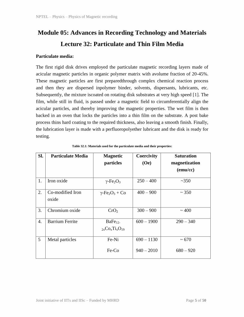
Table 32.1: Materials used for the particulate media and their properties:
Sl. Particulate Media Magnetic
particles
Coercivity
(Oe)
Saturation
magnetization
(emu/cc)
1. Iron oxide -Fe2O3 250 – 400 ~350
2. Co-modified Iron
oxide
-Fe2O3 + Co 400 – 900 ~ 350
3. Chromium oxide CrO2 300 – 900 ~ 400
4. Barrium Ferrite BaFe12-
2xCoxTixO19
600 – 1900 290 – 340
5 Metal particles Fe-Ni
Fe-Co
690 – 1130
940 – 2010
~ 670
680 – 920
NPTEL – Physics – Physics of Magnetic recording
Joint initiative of IITs and IISc – Funded by MHRD Page 6 of 50
Table 32.1 lists the most commonly used particulate magnetic media.The coercivity of
particulate media is mainly due to magnetocrystallineanisotropy and shape anisotropy of
the magnetic particles. The magnetic particles were made of -iron oxide developed for
tape recording at the end of the World War II. To increase the coercivity of the -iron
oxide particles, a surface layer of Co was added. This increases the magnetocrystallaine
contribution to the total coercivity.As the required recording densitiesrise, the coercivities
of the particles are also increased. Therefore, the metalparticles and barium ferrite were
proposed as alternative choices for high-densityapplications. However, the fabrication of
particulate media with higher coercivity was not so easy. In later 1980s, the development
of thin-film media helped to attain high coercivity and low noise, in comparison with the
particular disks. Therefore, the particulate media in rigid disks were quickly replaced by
the more superior thin film media.
Thin film media:
The particulate media technology is limited in its areal density and is no longer used in
rigid-disk drives, as the rigid disks made using thin film technology showed enhanced
properties. The magnetic thin film fabricated using the thin film deposition techniques
exhibits higher magnetization than the particulate thin films, which allows the use of very
thinner films on the rigid substrate. Also, the thin films are endowed with much higher
coercivity values than the particulate films.
Thin film disk structure and properties:
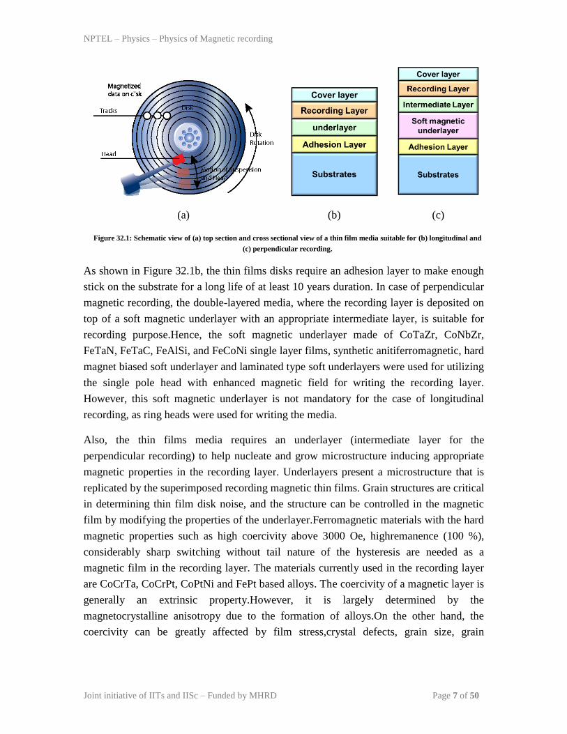
Figure 32.1 shows the schematic view of (a) top section and (b) cross sectional structures
of the thin film media suitable for longitudinal and (c) perpendicular magnetic recording.
The selection of substrate for the application mainly comes from its light weight, high
strength and low cost. A fine and very smooth surface is required for a rigid disk to
provide uniform readback signal from low-flying heads. On top of a disk, Ni-P surface is
abrasively polished to a 1 nm root-mean-square finish followed by a texturing process
resulting in circumferential grooves (see Figure 32.1a), which serves two purposes: the
added roughness minimizes the head stiction on the disk surface and it induce a
circumferential magnetic anisotropy on the disk, resulting in uniform magnetic readback
signals during the course of disk rotation.
NPTEL – Physics – Physics of Magnetic recording
Joint initiative of IITs and IISc – Funded by MHRD Page 7 of 50
(a)
(b)
(c)
Figure 32.1: Schematic view of (a) top section and cross sectional view of a thin film media suitable for (b) longitudinal and
(c) perpendicular recording.
As shown in Figure 32.1b, the thin films disks require an adhesion layer to make enough
stick on the substrate for a long life of at least 10 years duration. In case of perpendicular
magnetic recording, the double-layered media, where the recording layer is deposited on
top of a soft magnetic underlayer with an appropriate intermediate layer, is suitable for
recording purpose.Hence, the soft magnetic underlayer made of CoTaZr, CoNbZr,
FeTaN, FeTaC, FeAlSi, and FeCoNi single layer films, synthetic anitiferromagnetic, hard
magnet biased soft underlayer and laminated type soft underlayers were used for utilizing
the single pole head with enhanced magnetic field for writing the recording layer.
However, this soft magnetic underlayer is not mandatory for the case of longitudinal
recording, as ring heads were used for writing the media.
Also, the thin films media requires an underlayer (intermediate layer for the
perpendicular recording) to help nucleate and grow microstructure inducing appropriate
magnetic properties in the recording layer. Underlayers present a microstructure that is
replicated by the superimposed recording magnetic thin films. Grain structures are critical
in determining thin film disk noise, and the structure can be controlled in the magnetic
film by modifying the properties of the underlayer.Ferromagnetic materials with the hard
magnetic properties such as high coercivity above 3000 Oe, highremanence (100 %),
considerably sharp switching without tail nature of the hysteresis are needed as a
magnetic film in the recording layer. The materials currently used in the recording layer
are CoCrTa, CoCrPt, CoPtNi and FePt based alloys. The coercivity of a magnetic layer is
generally an extrinsic property.However, it is largely determined by the
magnetocrystalline anisotropy due to the formation of alloys.On the other hand, the
coercivity can be greatly affected by film stress,crystal defects, grain size, grain

NPTEL – Physics – Physics of Magnetic recording
Joint initiative of IITs and IISc – Funded by MHRD Page 8 of 50
orientation, grain boundaries, etc. The coercivity is also a strong function of
switchingtime and temperature due to the superparamagnetic effect.
Figure 32.2: (a) Variation of coercivity with the particle size and (b) the corresponding variation of magnetic hysteresis loop
shape.
The correlationbetween microstructures and coercivity tends to be complicated and
qualitative.For example, let us examine how coercivity varies with grain sizeor medium
thickness. As shown in Figure 32.2, it is common that the coercivityof magnetic thin
films increases with decreasing the average particle size until it reaches a peak at a
critical size in the range of 10 – 30nm. The decrease in coercivity with increasing film
thickness above the critical thickness is attributed to a combination of magnetostatic
interaction and an increasedout-of-plane c-axis orientation of the grains. For independent
magneticparticles, the coercivity peaks at a critical grain size that separatessingle domain
and multidomain regimes. In the single domain particle regime, the shape of the magnetic
hysteresis loop tuns out to be almost square shaped suitable for recoding purpose. For
magnetic thin films, thecritical thickness is also dependent on the material and process.
Below the critical thickness, the coercivity drops rapidlywith decreasing thickness
because of the superparamagnetic effect whichcauses thermally assisted switching of
magnetic grains. Also, the shape of the hysteresis changes from square shape to flat loop
shape (see Figure 32.2b).
NPTEL – Physics – Physics of Magnetic recording
Joint initiative of IITs and IISc – Funded by MHRD Page 9 of 50
As linear recording density is scaled up, the remnance-thicknessproduct Mrof the thin-
film disk needs to be scaled down. For example,at an areal recording density of above
100Gbits/in2, the product of Mris expected to be ~0.2memu/cm
2, and medium thickness
to be 10 nm. This isat the regime where film coercivity may drop quickly with
thickness.Therefore, attaining high coercivity in real thin films is an
increasinglychallenging task.Thin film disks need a protection of the magnetic layer from
therecording head, which makes surface contact during turn-on and shutdown of thedisk
drive. Amorphouscarbon of about 10 – 15 nm is used as protection layer in thin film disk
industry, as the materials’ properties can be tailored by incorporation of dopants such as
hydrogen or nitrogen. The overcoat not only servesto protect the magnetic layer, but also
acts as a support structure for the lubricant. The final layer in the thin film disk structure
is the lubricant. The lubricant is typically a perfluoropolyether organic polymer with a
thickness between 1 and 3 nm. Lubricants serve to reduce friction and wearbetween the
carbon overcoat and the recording head. Important lubricant propertiesembodied in the
perfluoropolyethers are chemical inertness, low vapor pressure toprevent evaporative
loss, a low contact angle allowing uniform wetting of the carbonovercoat surface, and a
chemical affinity for the overcoat, preventing spin-off anddesorption.
References:
[1].E. Koster, Particulate Media in Magnetic recording technology, edited by C.D. Mee
and E.D. Daniel, McGraw Hill, New York, 1996.
NPTEL – Physics – Physics of Magnetic recording
Joint initiative of IITs and IISc – Funded by MHRD Page 10 of 50
Module 05: Advances in Recording Technology and Materials
Lecture 33: Media Substrates
Introduction:
Since the thin film based recording materials have to be deposited on a typical rigid
substrates for sustaining the films over a period of time and to avoid any damages during
the read and writing process, several methods have been employed to support the
recording films.As we knew well that the tapes and flexible disks use plastic films in the
early days, today’s tapes and diskettes use a polyethylene terephthalate (PET, also called
as Mylar) films. Rigid disks use an aluminium, glass, and ceramic based substrates. The
selection and the usage of different types of substrates are mainly determined by the type
of recording conditions. Hence, in this lecture, we will briefly cover the different types of
substrates such as flexible media substrates and rigid media substrates.
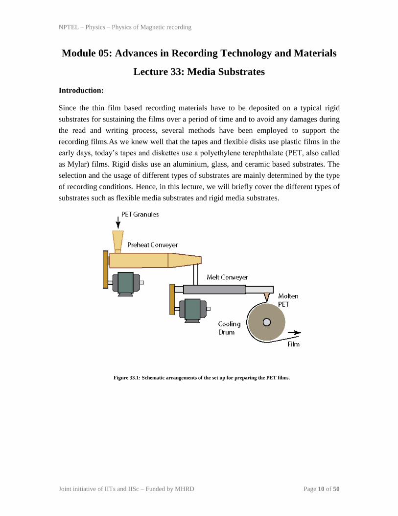
Figure 33.1: Schematic arrangements of the set up for preparing the PET films.
NPTEL – Physics – Physics of Magnetic recording
Joint initiative of IITs and IISc – Funded by MHRD Page 11 of 50
Flexible Media Substrates:
PET is one of the many long molecule materials where the cross linking between the
molecules causes uneven surfaces due to lumping effects. However, the efforts are made
to develop new base films by combining the PET with other polymers. Figure 33.1 shows
the typical schematic arrangement of the system for preparing the PET films (see also
Fig. 1.2). PET, a group of complicated polymer esters made from terephthalicacide and
ethylene glycol, has molecular weight between 15,000 and 30,000. The creation of
continuous films is started by thoroughly drying the granules so that the water content is
as low as possible. These granules are fed into one end of the conveyor, where they are
melted at a temperature around 300 oC and form a liquid syrup-like substance. This is
forced through an extrusion head under uniform pressure to form the liquid sheet that
immediately cooled by contact with a cooling drum to avoid the formation of any
spherulites. The non-uniform pressure can result in the pulsations where the thickness of
the film is not very uniform.Subsequent to the preparation, the strength of the films is
increased by stretching the films both in lengthwise and sideways and finally fixed and
cooled. The finalized PET film varies in width from 0.6 to 4 meters and is trimmed from
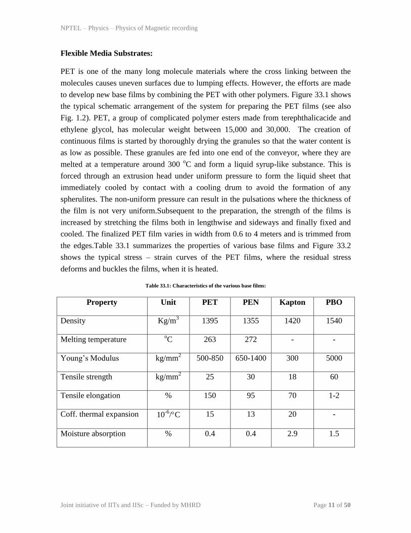
the edges.Table 33.1 summarizes the properties of various base films and Figure 33.2
shows the typical stress – strain curves of the PET films, where the residual stress
deforms and buckles the films, when it is heated.
Table 33.1: Characteristics of the various base films:
Property Unit PET PEN Kapton PBO
Density Kg/m3 1395 1355 1420 1540
Melting temperature oC 263 272 - -
Young’s Modulus kg/mm2 500-850 650-1400 300 5000
Tensile strength kg/mm2 25 30 18 60
Tensile elongation % 150 95 70 1-2
Coff. thermal expansion 10-6
/C 15 13 20 -
Moisture absorption % 0.4 0.4 2.9 1.5

NPTEL – Physics – Physics of Magnetic recording
Joint initiative of IITs and IISc – Funded by MHRD Page 12 of 50
Figure 33.2: Stress – Strain curves of the PET films.
High temperature application requires special films, such as polyimide film named
Kapton, which maintain their properties up to 400 oC. These films are often used in the
flight data recorders on board commercial airlines. Also, the polyimide based substrates
are good candidates for the flexible disks for perpendicular recording of CoCr based
films.Kapton is very expensive and hence limited in only on selected applications.
Alternative base films such as PEN, which has 20 % higher mechanical strength and
thermal stability, and polybenzoxazole (PBO), a rigid-rod polymer were developed.
However, all these base films were not considered for the recent devices due to the
limited data storage density per unit area.Tapes are often back coated with the carbon
black to provide rougher surface for better tracking. The back coating also lowers the
tape’s resistivity and thereby prevents electrostatic build-up.
Rigid Disk Substrates:
Rigid disk based substrates are mandatory for preparing the thin based media for
increasing the areal density. The final disk surface should be ideally be free of any voids
and has a clear mirror finish, with the surface roughness in nm scale. This is essentially
needed to fly the head at a closest possible distance with respect to the disk surface.
Aluminium based alloys ranging the thickness of mm to sub mm scale is used at the
initial stages. However, they were very soft and to increase the strength and reduce the
weight, magnesium was added. Furthermore, the addition of Mn and Cr helps to improve
the corrosion resistance [1].Later, a Ni alloy of micrometer thickness is electroplated onto
NPTEL – Physics – Physics of Magnetic recording
Joint initiative of IITs and IISc – Funded by MHRD Page 13 of 50
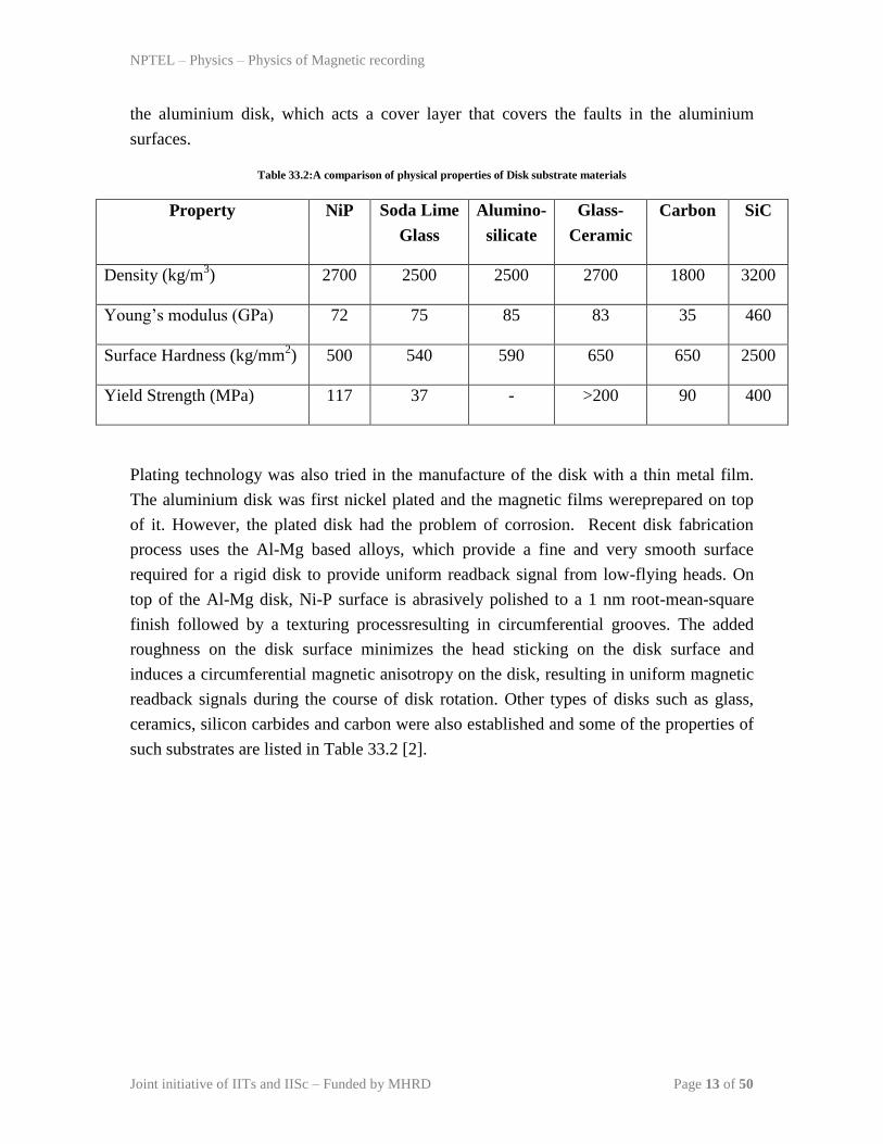
the aluminium disk, which acts a cover layer that covers the faults in the aluminium
surfaces.
Table 33.2:A comparison of physical properties of Disk substrate materials
Property NiP Soda Lime
Glass
Alumino-
silicate
Glass-
Ceramic
Carbon SiC
Density (kg/m3) 2700 2500 2500 2700 1800 3200
Young’s modulus (GPa) 72 75 85 83 35 460
Surface Hardness (kg/mm2) 500 540 590 650 650 2500
Yield Strength (MPa) 117 37 - >200 90 400
Plating technology was also tried in the manufacture of the disk with a thin metal film.
The aluminium disk was first nickel plated and the magnetic films wereprepared on top
of it. However, the plated disk had the problem of corrosion. Recent disk fabrication
process uses the Al-Mg based alloys, which provide a fine and very smooth surface
required for a rigid disk to provide uniform readback signal from low-flying heads. On
top of the Al-Mg disk, Ni-P surface is abrasively polished to a 1 nm root-mean-square
finish followed by a texturing processresulting in circumferential grooves. The added
roughness on the disk surface minimizes the head sticking on the disk surface and
induces a circumferential magnetic anisotropy on the disk, resulting in uniform magnetic
readback signals during the course of disk rotation. Other types of disks such as glass,
ceramics, silicon carbides and carbon were also established and some of the properties of
such substrates are listed in Table 33.2 [2].

NPTEL – Physics – Physics of Magnetic recording
Joint initiative of IITs and IISc – Funded by MHRD Page 14 of 50
The following key points were considered while choosing the substrate for rigid disk
application:
1. Young’s modulus should be high to produce a thin disk, and to reduce the flutter
at high rotational speed. The typical value of the Young’s modulus is around 80
GPa for Al alloy with the Ni-P overcoat.
2. The substrate should have sufficient hardness to prevent damage and head slap
against the disk.
3. Other specifications such as materials properties, coefficient of thermal
expansion, physical requirements, and surface properties under static and dynamic
conditions, regarding the substrates for the disk applications are discussed
IDEMA standards [3].
References:
[1]. E.J. Westerman, SMART symposium WS 1-A-1 (1986).
[2]. K.E. Johnson, Thin Film Media in K. Ashar, Magnetic Disk Drive Technology,
IEEE, New York, 1997.
[3]. International Disk Drive Equipment and Materials Associate (IDEMA), Doc. No.
D2-91.

NPTEL – Physics – Physics of Magnetic recording
Joint initiative of IITs and IISc – Funded by MHRD Page 15 of 50
Module 05: Advances in Recording Technology and Materials
Lecture 34: Patterned Media
In the last few lectures, we have discussed the particulate and thin films based media for
the recording applications. Although the thin films based media had advantages over the
particulate media for high density recording, one of the major problems with the thin film
media is the non-linear transition shift and track edge noise at very high areal density
recording. Hence, the search for an alternate media for the future recording resulted to be
patterned media. Figure 34.1 shows the typical road map of the hard disk recording
density since 1991. After the utilization of the perpendicular magnetic recording in thin
film based media, the next focus is project on Heat assisted magnetic recording and
patterned media.
Figure 34.1: Roadmap of Hard disk recording density [1].

NPTEL – Physics – Physics of Magnetic recording
Joint initiative of IITs and IISc – Funded by MHRD Page 16 of 50
Figure 34.2: Schematic representation of a patterned media for longitudinal and perpendicular magnetic recording.
The idea of the patterned media started in 1963 itself, when the physically etched discrete
tracks were proposed to improve the capability of head positioning [2]. However, the
next step towards the patterned media was only developed in late 80s by IBM group after
the induction of efficient lithography techniques. Subsequently, there were many
discussions on patterned media recording technology [3-5] both on longitudinal and
perpendicular recording as shown in Figure 1. The potential advantages of the patterned
media cover elimination of nonlinear transition shift and track edge noise, reduction of
medium noise, and the extension of superparamagnetic effect. Out of these, the last
attribute is the most attractive one for patterned media.
Superparamagnetic limit in a single domain particle:
We have already discussed the occurrence of the superparamagnetic effect in the
thin film media. According to the limit, when the average size of the particles decreases
in its single domain state, then the ability of the particle to store the magnetization in one
direction is not guaranteed due to the thermal energy, as shown in Figure 34.3.The loss of
magnetic properties in such small particles may arise due to the reduction in the average
magnetocrystalline anisotropy energy with decreasing particle size.
Figure 34.3: Schematic representation of bits under stable and unstable conditions.

NPTEL – Physics – Physics of Magnetic recording
Joint initiative of IITs and IISc – Funded by MHRD Page 17 of 50
Therefore, the thermal stability was defined as the ratio between the anisotropy energy
and the thermal energy, as given in eqn.(34.1).
𝑇𝑒𝑟𝑚𝑎𝑙 𝑠𝑡𝑎𝑏𝑖𝑙𝑖𝑡𝑦 =𝐾𝑢𝑉
𝑘𝐵𝑇≥ 40 (34.1)
According to the eqn.(34.1), the thermal stability of the particles decreases largely with
decreasing the size the particles and hence one needs a material with high anisotropy such
that the product of the anisotropy energy and the volume of the particles does not reduces
a lot. The concept of patterned media offers to push out the superparamagneticlimit
several orders of magnitude. In conventional recording a bitmust contain ~100 exchange-
decoupled magnetic grains as required bysignal-to-noise ratio (SNR), each of these
magnetic grains must be thermallystable (see Figure 34.3). In contrast, a patterned bit can
contain one or any numberof exchange-coupled magnetic grains because there is no
longer transitionnoise due to exchange coupling. If only the superparamagnetic limit
isconcerned, patterned magnetic densities can be ~100 times that of
conventionalrecording if the same medium material is used. In practice, thelimit of
patterned media will be constrained by patterning defects, signal to noise ratio, head
design, and servo requirements.
Figure 34.4: Readback waveforms of longitudinal patterned media.

NPTEL – Physics – Physics of Magnetic recording
Joint initiative of IITs and IISc – Funded by MHRD Page 18 of 50
Read/write processes and noises in patterned media:
The read/write experiments on patterned nickel (Ni) islands have been performedby
magnetic force microscope (MFM) tips and by quasi-static MRheads. For longitudinal
patterned islands, the edge of the island is ideallya sharp step transition (from 0 to Mr),
which generates a voltagepulse similar to that from a step transition (from –Mr to +Mr)
but withhalf of the amplitude. If the read head is Karlqvist-head-like, as demonstrated
earlier, and theislands are very thin, then the isolated pulse is given as
𝑉𝑆𝑃 𝑥 ∝ tan−1 𝑥 + 𝑔/2
𝑦 − tan−1
𝑥 − 𝑔/2
𝑦 (34.2)
Where g is the gap length and y is the magnetic spacing. This equation is similar to the
one we obtained earlier in the read back signal in lecture 29. The efficiency of the read-
back signal from the recorded pattern (longitudinal recording) in the patterned media can
be simulated for different gap length as shown in Figure 34.4. Assume that the island
length is l, and magnetic spacing, y=g/4 and the recorded pattern is given as shown in
Figure 34.4.It is clear from the figure 34.4 that the linear bit shifts still exist in
patternedmedia. However, if we take gas 2l, which is equal to bit length, then the
recorded bits can berecovered like conventional longitudinal recording with peak
detection. With even more advanced detection schemes, even higher recording densities
at g ~ 5l= 2.5 bit length may be realized.
Challenges in patterned media:
Although conventional nonlinear transition shift no longer exists inpatterned media
because the location of transition is now defined bylithography, several issues related to
the bit writing have to be resolved. Furthermore, the patterning defects such as island
irregularities, missing islands, merging islands, etc become the major source of noise in
the patterned media. Though the lithographic techniques are used to produce the
patterned media, the major challenge is to find a suitable low cost patterning technology.
Although the critical dimension required is smaller than that in the VLSI technology, but
the patterns in magnetic media are periodic and much simpler than semiconductor
memory cells. Therefore, the other lithography processes using nano-imprinting, laser
interference lithography, self-assembly patterning, etc would be suitable for making
patterning media. However, this subject is really challenging and expected to advance in
the years to come.

NPTEL – Physics – Physics of Magnetic recording
Joint initiative of IITs and IISc – Funded by MHRD Page 19 of 50
References:
[1]. Mark Kryder, Fifty Years of Disk Drives and the exciting road ahead, Seagate
Technology, Sep 2006.
[2]. L.F. Shew, IEEE Trans Broadcast & TV Rec. 9 (1963) 56.
[3]. S.E. Lambert et al, IEEE Trans. Magn. 25 (1989) 3381; J. Appl. Phys. 69 (1991)
4724.
[4]. S.Y. Chou et al, J. Appl. Phys. 76 (1994) 6673.
[5]. R.L. White et al, IEEE Trans. Magn. 33 (1997) 990.
Quiz:
(1) What are the requirements of the magnetic medium to use as a magnetic recording?
(2) What are the different materials used in particulate media?
(3) What are the limitations in the particular media technology towards high density
recording?
(4) What are the advantages of the thin film media for high density recording?
(5) What is superparamagnetic effect?
(6) What are the key points considered while choosing the substrate for rigid disk
applications?
(7) What are the advantages and challenges in pattern media as compared to thin film
media?

NPTEL – Physics – Physics of Magnetic recording
Joint initiative of IITs and IISc – Funded by MHRD Page 20 of 50
Module 05: Advances in Recording Technology and Materials
Lecture 35: Properties of magnetic thin films: Part 1
Introduction:
The choice of materials for the magnetic recording comes mainly from the control of the
magnetic properties suitable for the recording purpose. The magnetic properties of the
materials are learned from the magnetic hysteresis (M-H), i.e., the response of the sample
magnetization with respect to the change in the applied field. The control of the shape
and size of the hysteresis is the heart of designing the materials for magnetic related
applications. Numerous magnetic parameters can be extracted from the M-H loop, which
are mainly optimized with respect to the fabrication conditions for a particular
application. As the study of M-H loops and associate phenomena is very much important,
in the next four lectures, we shall cover
1. Magnetic hysteresis loops for recording,
2. Coercivity and remnant flux, slope at coercivity,
3. Effects of switching field distribution on the magnetic properties, and
4. Effects of time and temperature on the stability of the magnetic properties.
-20 -10 0 10 20
-1.0
-0.5
0.0
0.5
1.0 HN
MR
[M / M
Sa
t]
H (kOe)
HC
MSat
HSat

NPTEL – Physics – Physics of Magnetic recording
Joint initiative of IITs and IISc – Funded by MHRD Page 21 of 50
-60 -40 -20 0 20 40 60
-1.0
-0.5
0.0
0.5
1.0
M (
em
u/c
c)
H (kOe)
(a) (b)
Figure 35.1: Typical M-H loops of a hard magnetic material with (a) perfect orientation of easy axis perpendicular to the
film plane, and (b) considerable random distribution of easy axis.

NPTEL – Physics – Physics of Magnetic recording
Joint initiative of IITs and IISc – Funded by MHRD Page 22 of 50
Magnetic hysteresis loops for recording:
Figure 35.1shows the M-H loops measured along the two directions of the thin film
samples: perpendicular to the film plane (blue curve) and parallel to the film plane (red).
It is clear from the figure 35.1a that the magnetic loop measured under perpendicular
direction exhibited a clear almost square shaped loop, while the loop measured in the film
direction showed almost a linear variation with the field up to 15 kOe field and then
saturates at higher fields. These results reveal that the film has magnetization easy-axis
perpendicular to the film plane and hard axis exists along the film plane. If the easy-axis
orientation is not perfect along the perpendicular direction, then the magnetization
measured along the hard axis direction depictsa definite hysteresis as shown in Figure
35.1b. Such behaviours arecorrelated to the crystal structure and microstructural
properties of the films. Therefore, the optimization of the magnetic properties of the films
with respect to the fabrication conditions is very much essential.
Figure 35.2: Typical M-H loops of a hard and soft magnetic material.
NPTEL – Physics – Physics of Magnetic recording
Joint initiative of IITs and IISc – Funded by MHRD Page 23 of 50
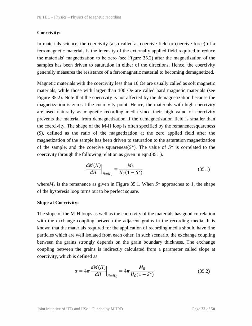
Coercivity:
In materials science, the coercivity (also called as coercive field or coercive force) of a
ferromagnetic materials is the intensity of the externally applied field required to reduce
the materials’ magnetization to be zero (see Figure 35.2) after the magnetization of the
samples has been driven to saturation in either of the directions. Hence, the coercivity
generally measures the resistance of a ferromagnetic material to becoming demagnetized.
Magnetic materials with the coercivity less than 10 Oe are usually called as soft magnetic
materials, while those with larger than 100 Oe are called hard magnetic materials (see
Figure 35.2). Note that the coercivity is not affected by the demagnetization because the
magnetization is zero at the coercivity point. Hence, the materials with high coercivity
are used naturally as magnetic recording media since their high value of coercivity
prevents the material from demagnetization if the demagnetization field is smaller than
the coercivity. The shape of the M-H loop is often specified by the remanencesquareness
(S), defined as the ratio of the magnetization at the zero applied field after the
magnetization of the sample has been driven to saturation to the saturation magnetization
of the sample, and the coercive squareness(S*). The value of S* is correlated to the
coercivity through the following relation as given in eqn.(35.1).
𝑑𝑀(𝐻)
𝑑𝐻 𝐻=𝐻𝐶
=𝑀𝑅
𝐻𝐶(1 − 𝑆∗) (35.1)
whereMR is the remanence as given in Figure 35.1. When S* approaches to 1, the shape
of the hysteresis loop turns out to be perfect square.
Slope at Coercivity:
The slope of the M-H loops as well as the coercivity of the materials has good correlation
with the exchange coupling between the adjacent grains in the recording media. It is
known that the materials required for the application of recording media should have fine
particles which are well isolated from each other. In such scenario, the exchange coupling
between the grains strongly depends on the grain boundary thickness. The exchange
coupling between the grains is indirectly calculated from a parameter called slope at
coercivity, which is defined as.
𝛼 = 4𝜋 𝑑𝑀(𝐻)
𝑑𝐻 𝐻=𝐻𝐶
= 4𝜋𝑀𝑅
𝐻𝐶(1 − 𝑆∗) (35.2)

NPTEL – Physics – Physics of Magnetic recording
Joint initiative of IITs and IISc – Funded by MHRD Page 24 of 50
The values of required for recording are reported to be between 1.5 and 3. Honda et al
[1] showed a good correlation between the slope at coercivity, exchange constant and the
coercivity of the medium. It was reported that with increasing the exchange constant, the
values of loop slope increases significantly and at the same time, the coercivity of the
media decreased largely due a strong exchange coupling between the grains. With
increasing the loop slope, the noise in the recording media increases due to the exchange
coupling. Hence, the study of control of the loop slope at coercivity in relation with the
exchange coupling between the grains provides a good understanding between the
microstructure and magnetic properties of the nanogranular thin films.
References:
[1]. N. Honda, IEEE trans. Magn. 38 (2002) 1615.

NPTEL – Physics – Physics of Magnetic recording
Joint initiative of IITs and IISc – Funded by MHRD Page 25 of 50
Module 05: Advances in Recording Technology and Materials
Lecture 36: Properties of magnetic thin films: Part 2
Product of MR:
As the demand for high areal density increases, the thickness of the films () utilized for
the magnetic recording medium decreases. However, there is a superparamagnetic limit,
where the average grain size of the magnetic layer becomes less thermally stable with a
reduction in the grain size. Therefore, a small thermal agitation will deteriorate the stored
magnetic information. Moreover, even before the superparamagnetic limit is reached, as
the film thickness is reduced, additional factors negatively impact magnetic coupling,
such as the smaller grain size and the non-uniformity of the films. Scaling the media
parameters involve both a reduction in grain diameter and the media’s effective magnetic
thickness, MR, where MR is the remanent magnetization of the media. Scaling of MR is
needed in order to scale the transition parameter, which is the effective width of the
boundary between the bits and limits how close the bits can be recorded.The typical value
of MR for the recording purpose varies between 0.4 memu/cm2to 4 memu/cm
2.
The transition parameter for magnetic films with S* = 1 and for which the contribution to
the transition parameter from the details of the recording head are negligible is
approximately (following eqn.(14.15)) given as,
𝑎 ≈ 4𝑀𝑅𝛿 𝑑 +
𝛿2
𝐻𝐶
12
(36.1)
Since the output signal depends on the magnetic flux MR, the best way to reduce the
transition parameter is to increase the coercivity to the highest level that can be written
with the recording head field.
NPTEL – Physics – Physics of Magnetic recording
Joint initiative of IITs and IISc – Funded by MHRD Page 26 of 50
Switching field distribution:
In the magnetic recording media, the switching field distribution (SFD) is an important
micromagnetic characteristic curve, which measures the ability to record short transitions,
i.e., a small SFD results in higher resolution. Also, it is defined as the dispersion of the
fields required to reverse the magnetization direction of the individual grains. The SFD
can be a serious limitation factor on the areal recording density. When a group of
particles is placed in a magnetic field, they will not rotate in unison, because they exhibit
various degrees of resistance to domain rotation and they also influenced by the magnetic
field from the neighbours due to the interaction fields. If we assume that these particles
do not interact and respond to the field independently, then all the particles rotate
together and the whole medium becomes fully magnetized without any intermediate
dynamic range. In reality, the fabrication of magnetic granular films with uniform grain
distribution is one of the challenges from the application point of view.
(a)
(b)
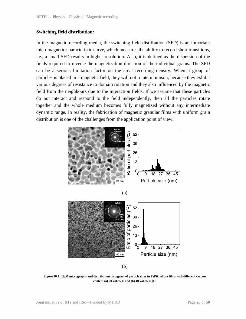
Figure 36.1: TEM micrographs and distribution histogram of particle sizes in FePtC alloys films with different carbon
content (a) 20 vol.% C and (b) 40 vol.% C [1].

NPTEL – Physics – Physics of Magnetic recording
Joint initiative of IITs and IISc – Funded by MHRD Page 27 of 50
Figure 36.1depicts the typical TEM image of FePtCgranular thin films and their size
distributions. It could be clearly observed that in FePtC (C=20 vol.%) the particle size
distribution is not uniform and exhibits two peaks in the particle size distribution. With
increasing the C to 40 vol.%, the particle morphology changed largely and showed
almost narrow size distribution. Even in the narrow size distribution, we could see that
the particle size ranges between 5 to 10 nm. This suggests that the different sized
particles would have different coercivities and when we measure the magnetic properties
as a whole, the loop slope around the coercivity is not expected to be sharp (see Figure
36.2). The loop slope at coercivity is mainly determined by the size distribution in
particles. Recalling our discussion in lecture 32, the coercivity of the particles in the
single domain state changes largely with decreasing particle sizeand the coercivity
distribution around the maximum value of coercivity can be correlated to the distribution
of the particle size in the granular medium. The distribution in coercivity can be taken as
the values up to 50 % of its maximum value (see Figure 36.2).
H-HR
HR
M
Figure 36.2: M-H loop and derivative of the M-H loop for a hard magnetic material.
NPTEL – Physics – Physics of Magnetic recording
Joint initiative of IITs and IISc – Funded by MHRD Page 28 of 50
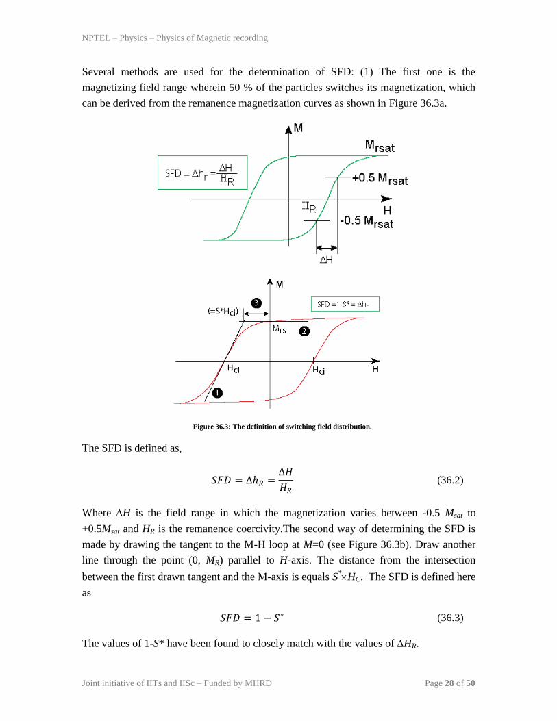
Several methods are used for the determination of SFD: (1) The first one is the
magnetizing field range wherein 50 % of the particles switches its magnetization, which
can be derived from the remanence magnetization curves as shown in Figure 36.3a.
Figure 36.3: The definition of switching field distribution.
The SFD is defined as,
𝑆𝐹𝐷 = ∆𝑅 =∆𝐻
𝐻𝑅 (36.2)
Where H is the field range in which the magnetization varies between -0.5 Msat to
+0.5Msat and HR is the remanence coercivity.The second way of determining the SFD is
made by drawing the tangent to the M-H loop at M=0 (see Figure 36.3b). Draw another
line through the point (0, MR) parallel to H-axis. The distance from the intersection
between the first drawn tangent and the M-axis is equals S*HC. The SFD is defined here
as
𝑆𝐹𝐷 = 1 − 𝑆∗ (36.3)
The values of 1-S* have been found to closely match with the values of HR.

NPTEL – Physics – Physics of Magnetic recording
Joint initiative of IITs and IISc – Funded by MHRD Page 29 of 50
References:
[1].A. Perumal et al, Appl. Phys. Exp. 1 (2008) 101301.
NPTEL – Physics – Physics of Magnetic recording
Joint initiative of IITs and IISc – Funded by MHRD Page 30 of 50
Module 05: Advances in Recording Technology and Materials
Lecture 37: Properties of magnetic thin films: Part 3
Effects of time and temperature on the magnetic properties:
Since the magnetic properties of the materials are affected by the environment such as
temperature, external field, and stability time, the discussion of effects of various
parameters on the stability of the magnetic properties is essential to extend the materials
for particular applications.
When the mean time of spontaneous reversal of a collection of independent particles due
to thermal fluctuations is comparable to observation time, the measured magnetization is
a function of measurement time. This is generally called magnetic viscosity or magnetic
after effect. Here, the magnetization is expect to vary exponentially,
𝑀 𝑡 = 𝑀0𝑒−𝑡/𝜏 + 𝑀𝑡 1 − 𝑒−𝑡/𝜏 (37.1)
where, M0 and Mt are the initial magnetization at time t=0 and final magnetization after a
considerable time t, respectively. In the presence of constant opposing field, Mt = - M0,
then the above equation can be rewritten as
𝑀 𝑡 = 𝑀0𝑒−𝑡/𝜏 − 𝑀0 1 − 𝑒−𝑡/𝜏
𝑀 𝑡 = 𝑀0 2𝑒−𝑡/𝜏 − 1 = 𝑀0 2𝑒 −𝑓0𝑡 𝑒𝑥𝑝 −
𝐾𝑢𝑉𝐾𝐵𝑇
− 1
(37.2)
where, 𝜏 = 𝜏0𝑒𝐾𝑢𝑉
𝐾𝐵𝑇 , is known as relaxation time or time constant required for a magnetic
particle to switch its magnetization. Interestingly, the above equation reveals that the
magnetization decay is extremely sensitive to the thermal effect. A simple calculation
using the room temperature data (T = 300 K, kB = 1.38110-23
m2kgS
-2 and Ku = 210
6
ergs/cc) for a particle of below 10 nm shows a sharp falling in magnetization within the
10 days from the initial recording. It is important to note that for the ultrahigh density
recording, the scaling on the bit size and average particle size is needed and hence one to
get suitable materials with high anisotropy for compensating the loss due to the decrease
in particle size.
NPTEL – Physics – Physics of Magnetic recording
Joint initiative of IITs and IISc – Funded by MHRD Page 31 of 50
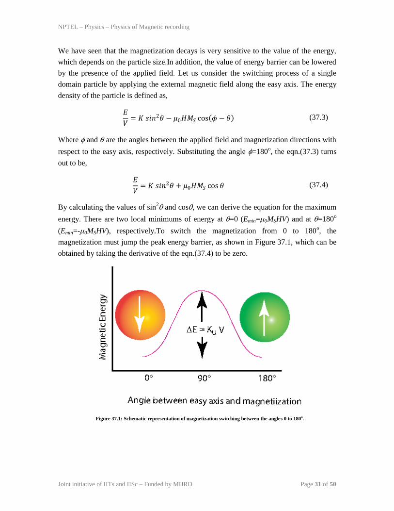
We have seen that the magnetization decays is very sensitive to the value of the energy,
which depends on the particle size.In addition, the value of energy barrier can be lowered
by the presence of the applied field. Let us consider the switching process of a single
domain particle by applying the external magnetic field along the easy axis. The energy
density of the particle is defined as,
𝐸
𝑉= 𝐾 𝑠𝑖𝑛2𝜃 − 𝜇0𝐻𝑀𝑆 cos 𝜙 − 𝜃 (37.3)
Where and are the angles between the applied field and magnetization directions with
respect to the easy axis, respectively. Substituting the angle =180o, the eqn.(37.3) turns
out to be,
𝐸
𝑉= 𝐾 𝑠𝑖𝑛2𝜃 + 𝜇0𝐻𝑀𝑆 cos 𝜃 (37.4)
By calculating the values of sin2 and cos, we can derive the equation for the maximum
energy. There are two local minimums of energy at =0 (Emin=0MSHV) and at =180o
(Emin=-0MSHV), respectively.To switch the magnetization from 0 to 180o, the
magnetization must jump the peak energy barrier, as shown in Figure 37.1, which can be
obtained by taking the derivative of the eqn.(37.4) to be zero.
Figure 37.1: Schematic representation of magnetization switching between the angles 0 to 180o.

NPTEL – Physics – Physics of Magnetic recording
Joint initiative of IITs and IISc – Funded by MHRD Page 32 of 50
1
𝑉
𝑑𝐸
𝑑𝜃= 2𝐾 cos 𝜃 sin 𝜃 − 𝜇0𝐻𝑀𝑆 sin 𝜃 = 0
(2𝐾 cos 𝜃 − 𝜇0𝐻𝑀𝑆) sin 𝜃 = 0
This gives,
cos 𝜃 =𝜇0𝐻𝑀𝑆
2𝐾; sin 𝜃 = 1 −
𝜇0𝐻𝑀𝑆
2𝐾
2
(37.5)
Substituting the values of cos and sin in eqn.(37.4), gives
𝐸𝑚𝑎𝑥
𝑉= 𝐾 1 −
𝜇0𝐻𝑀𝑆
2𝐾
2
+ 𝜇0𝐻𝑀𝑆
𝜇0𝐻𝑀𝑆
2𝐾
𝐸𝑚𝑎𝑥
𝑉= 𝐾 − 𝐾
𝜇0𝐻𝑀𝑆
2𝐾
2
+ 2𝐾 𝜇0𝐻𝑀𝑆
2𝐾
2
𝐸𝑚𝑎𝑥
𝑉= 𝐾 1 +
𝜇0𝐻𝑀𝑆
2𝐾
2
(37.6)

NPTEL – Physics – Physics of Magnetic recording
Joint initiative of IITs and IISc – Funded by MHRD Page 33 of 50
Module 05: Advances in Recording Technology and Materials
Lecture 38: Properties of magnetic thin films: Part 4
Therefore, the difference in the energy barrier can be calculated by subtracting the
eqn.(37.6) to minimum energy condition,
Δ𝐸 = 𝐸𝑚𝑎𝑥 − 𝐸𝑚𝑖𝑛 = 𝐾𝑉 1 + 𝜇0𝐻𝑀𝑆
2𝐾
2
− 𝜇0𝐻𝑀𝑆𝑉
= 𝐾𝑉 1 + 𝜇0𝐻𝑀𝑆
2𝐾
2
−𝜇0𝐻𝑀𝑆
𝐾
Δ𝐸 = 𝐾𝑉 1 −𝜇0𝐻𝑀𝑆
2𝐾
2
= 𝐾𝑉 1 −𝐻
𝐻0
2
(38.1)
where, the ratio H0=2K/0MS is referred as intrinsic coercivity and when we apply the
field H is equal to H0, then the energy barrier turns out to be zero, indicating that the
magnetization reversal takes place when the externally applied field exceeds H0. This is
true even without considering the effect of thermal energy. Although the eqn.(38.1) is
true for the perfect alignment between easy axis and applied field direction, in real media,
the alignment of easy axis is not perfect and hence the eqn.(38.1) can be written in
general form
Δ𝐸 = 𝐾𝑉 1 −𝐻
𝐻0 𝑛
(38.2)
where the value of n varies between 1.5 and 2.Now, substituting the eqn.(38.1) in
eqn.(37.2) in place of energy (KuV), we get the general equation for magnetization as
𝑀 𝑡 = 𝑀0
2𝑒
−𝑓0𝑡 𝑒𝑥𝑝 −𝐾𝑉 1−
𝐻𝐻0
𝑛
𝐾𝐵𝑇
− 1
(38.3)

NPTEL – Physics – Physics of Magnetic recording
Joint initiative of IITs and IISc – Funded by MHRD Page 34 of 50
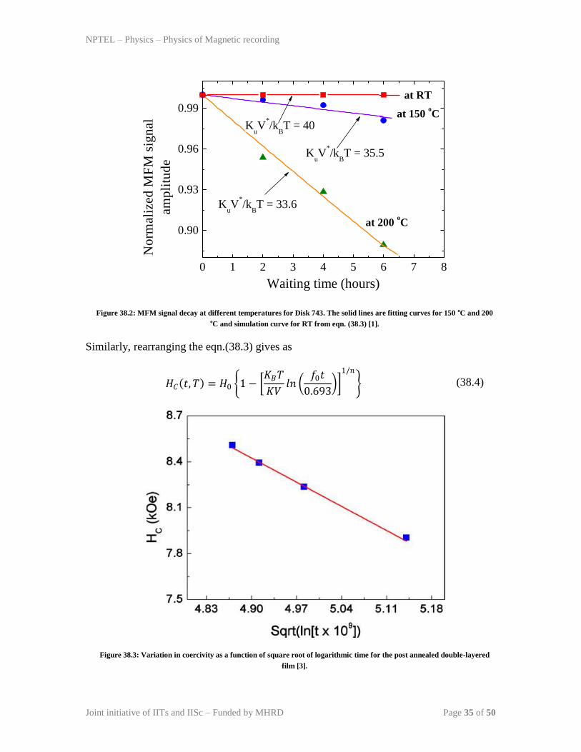
In order to study the effects of temperature and time on the stability of the magnetic bits
recorded in the magnetic medium, MFM signal amplitude was extracted from MFM
images by averaging the output signal across 1.5 m track width. Figure 38.1shows the
10 kfci written bits observed at different temperature [1]. The bits were observed right
away after raising the temperature. At room temperature and 150 oC, well-defined bits are
observed. There is no reversed domain inside bits as a result of high thermal stability
factor, large negative nucleation field, unity squarenessvalue and strong exchange
coupling. At 200 oC, more reversed domains are observed both in the center and
transition area of the bits. The amount of reversed domains increases with waiting time
particularly at higher temperature. The normalized MFM signal amplitude of 10 kfci
written bits is given in Figure 38.2as a function of waiting time at different temperatures.
With this time scale, no detectable signal decay was observed at a temperature below 100 oC. At 150
oC, about 3 % signal decay was observed after 6-hour waiting. At 200
oC,
significant signal decay up to 12 % was observed after 6-hour waiting. For Stoner-
Wohlfarth (SW) grain assembly, the magnetization thermal decay can be simply
described by eqn.(38.3), if no thermal barrier distribution and no external magnetic field
are taken into consideration. The value of fo is taken as 109 Hz in the present analysis.
The observed thermal decay at 150 and 200 oC can be accounted for eqn.(38.3) if the
thermal stability factor is taken to be 35.5 and 33.6, respectively. With a factor of 40, no
observable signal decay within this time scale can be expected from eqn.(38.3). To
evaluate the temperature dependence of FePt grain Ku in double-layered disks, out-of-
plane hysteresis loops were taken at different temperatures by Polar Kerr effect.
Figure 38.1: MFM images of written bits of 10 kfci observed at RT, 150 oC, and 200 oC for [MgO 4-nm/FePt 3-nm]3 /MgO 4-
nm /SiO2 4-nm /Fe-Ta-C 200-nm /Glass disc. The size of the image is 20 m in length and 1.5 m in width [1].
RT
150 oC
200 oC
NPTEL – Physics – Physics of Magnetic recording
Joint initiative of IITs and IISc – Funded by MHRD Page 35 of 50
KuV
*/k
BT = 40
KuV
*/k
BT = 35.5
KuV
*/k
BT = 33.6
at RT
at 150 oC
at 200 oC
0 1 2 3 4 5 6 7 8
0.90
0.93
0.96
0.99
Waiting time (hours)
No
rmali
zed
MF
M s
ign
al
am
pli
tud
e
Figure 38.2: MFM signal decay at different temperatures for Disk 743. The solid lines are fitting curves for 150 oC and 200 oC and simulation curve for RT from eqn. (38.3) [1].
Similarly, rearranging the eqn.(38.3) gives as
𝐻𝐶 𝑡, 𝑇 = 𝐻0 1 − 𝐾𝐵𝑇
𝐾𝑉𝑙𝑛
𝑓0𝑡
0.693
1/𝑛
(38.4)
Figure 38.3: Variation in coercivity as a function of square root of logarithmic time for the post annealed double-layered
film [3].
NPTEL – Physics – Physics of Magnetic recording
Joint initiative of IITs and IISc – Funded by MHRD Page 36 of 50
The eqn.(38.4) is called as Sharrock’s law [2].The Sharrock’s equation takes care both
the time dependent (when the temperature is fixed constant) and temperature dependent
coercivity when the time for measurement is kept constant. Figure 38.3 shows the
utilization of the model to study the time dependent coercivity in the FePt based alloys
for magnetic recording applications [3].
References:
[1].Z. Zhang et al, J. Magn. Magn.Mater.287 (2005) 224.
[2]. M.P. Sharrock, J.T. Mckinney, IEEE Trans. Magn. 17 (1981) 3020.
[3]. A. Perumal, L. Zhang, Y.K. Takahashi, and K. Hono, J. Appl. Phys. 108 (2010)
083907.
Quiz:
(1) What magnetic parameters are important while choosing materials for magnetic
recording?
(2) What is the role of switching field distribution on the magnetic recording?
(3) What is thermal stability?
(4) What are the parameters affect the thermal stability of the media?

NPTEL – Physics – Physics of Magnetic recording
Joint initiative of IITs and IISc – Funded by MHRD Page 37 of 50
Module 05: Advances in Recording Technology and Materials
Lecture 39: Future projection on magnetic recording
We have already discussed the various aspects associated with the magnetic recording.
Also, we have briefly seen through the write process, read process using various types of
magnetic heads and the improvement in the areal densities of existing recording
technology (longitudinal magnetic recording). One of the series problems faced in the
current longitudinal magnetic technology is that with increasing the areal density, the
scaling on the bit size and average particles have come down, which is limited by the
superparamagnetic effects. Hence, it is believed that the present technology will not
survive for long time and new technology have to be adopted for further improvement in
the recording process. Hence, in this lecture, we shall cover
1. Improvement in the perpendicular recording for high areal density,
2. Heat assisted magnetic recording,
3. Patterned media
4. Bit patterned media.

NPTEL – Physics – Physics of Magnetic recording
Joint initiative of IITs and IISc – Funded by MHRD Page 38 of 50
Improvement in the perpendicular magnetic recording
We have already discussed the requirement of alternative recording technology
(perpendicular recording), as compared to the exiting recording technology (longitudinal
recording) and the possible head for writing the perpendicular recording media. However,
we have not discussed the types of media required for the perpendicular recording. As we
understand that for perpendicular recording, there must be a magnetic anisotropy
perpendicular to the surface of the film of sufficient magnitude that the demagnetization
does not force the magnetization to lie in the film plane. Figure 39.1 shows the typical
geometry used in perpendicular recording, where the magnetic anisotropy (K) and the
external magnetic field (Happ.) directions are shown perpendicular direction to the film
plane, while the magnetization makes an angle with respect to the normal to the film
plane.
Figure 39.1: Geometry for perpendicular recording.
In this scenario, the total energy density is given by
𝐸 = 𝐾 𝑠𝑖𝑛2𝜃 −1
2𝐻𝑑𝑀𝑆 cos 𝜃 − 𝑀𝑆𝐻𝑎𝑝𝑝 . cos 𝜃 (39.1)
and the demagnetization field, 𝐻𝑑 = −4𝜋𝑀𝑆 cos 𝜃. Hence, the eqn.(39.1) turns out to be
𝐸 = 𝐾 𝑠𝑖𝑛2𝜃 + 2𝜋𝑀𝑆2𝑐𝑜𝑠2𝜃 − 𝑀𝑆𝐻𝑎𝑝𝑝 . cos 𝜃 (39.2)
The equilibrium angle for the magnetization is obtained by taking the derivative of the
energy density with respect to the angle,:Hence, eqn.(39.2) differentiated with respect to
the angle,
𝑑𝐸
𝑑𝜃= 2𝐾 sin 𝜃 cos 𝜃 − 4𝜋𝑀𝑆
2 sin 𝜃 cos 𝜃 + 𝑀𝑆𝐻𝑎𝑝𝑝 . sin 𝜃 = 0 (39.3)
K
Happ.
M

NPTEL – Physics – Physics of Magnetic recording
Joint initiative of IITs and IISc – Funded by MHRD Page 39 of 50
𝑑𝐸
𝑑𝜃= 𝑠𝑖𝑛 𝜃 2𝐾 − 4𝜋𝑀𝑆
2 𝑐𝑜𝑠 𝜃 + 𝑀𝑆𝐻𝑎𝑝𝑝 . 𝑠𝑖𝑛 𝜃 = 0 (39.4)
The solution for the energy minimum is sin=0, but the stability of the solution
requires𝑑2𝐸
𝑑𝜃2 > 0,
𝑑2𝐸
𝑑𝜃2= 2𝐾 − 4𝜋𝑀𝑆
2 𝑐𝑜𝑠2𝜃 − 𝑠𝑖𝑛2𝜃 + 𝑀𝑆𝐻𝑎𝑝𝑝 . 𝑐𝑜𝑠 𝜃 > 0 (39.5)
The above eqn.(39.5) requires 2𝐾 − 4𝜋𝑀𝑆2 > 0for stability in any value of external
magnetic field, including 𝐻𝑎𝑝𝑝 . = 0. The satisfaction of the above condition for various
materials is summarized in Table 39.1 for comparison.
Table 39.1: Anisotropy energy and saturation magnetization for the magnetic materials proposed for perpendicular magnetic
recording.
Sl. Materials Ku
(erg/cc)
MS
(emu/cc)
𝟐𝝅𝑴𝑺𝟐 𝑲
− 𝟐𝝅𝑴𝑺𝟐
Remarks
1 Cobalt 4.5106 1422 1.2710
7 < 0 Not stable
2 CoCr based
alloys
2106 450 1.2710
6 > 0 Stable
3 FePt 4107 1100 7.6110
6 > 0 Stable
It could be clearly seen from the table that the condition for the stability is not satisfied
for pure Cobalt, but the CoCr based alloys and FePt based alloys satisfy the stability
condition.A careful observation of the values reveals that the CoCr based alloys exhibit
the difference K– 2MS2 0, indicating that the CoCr based alloys with smaller particles
size would not be suitable for the perpendicular recording, as the magnetocrystalline
anisotropy energy in the smaller particles decreases with decreasing the particle size.
NPTEL – Physics – Physics of Magnetic recording
Joint initiative of IITs and IISc – Funded by MHRD Page 40 of 50
Module 05: Advances in Recording Technology and Materials
Lecture 40: Trilemma in magnetic recording
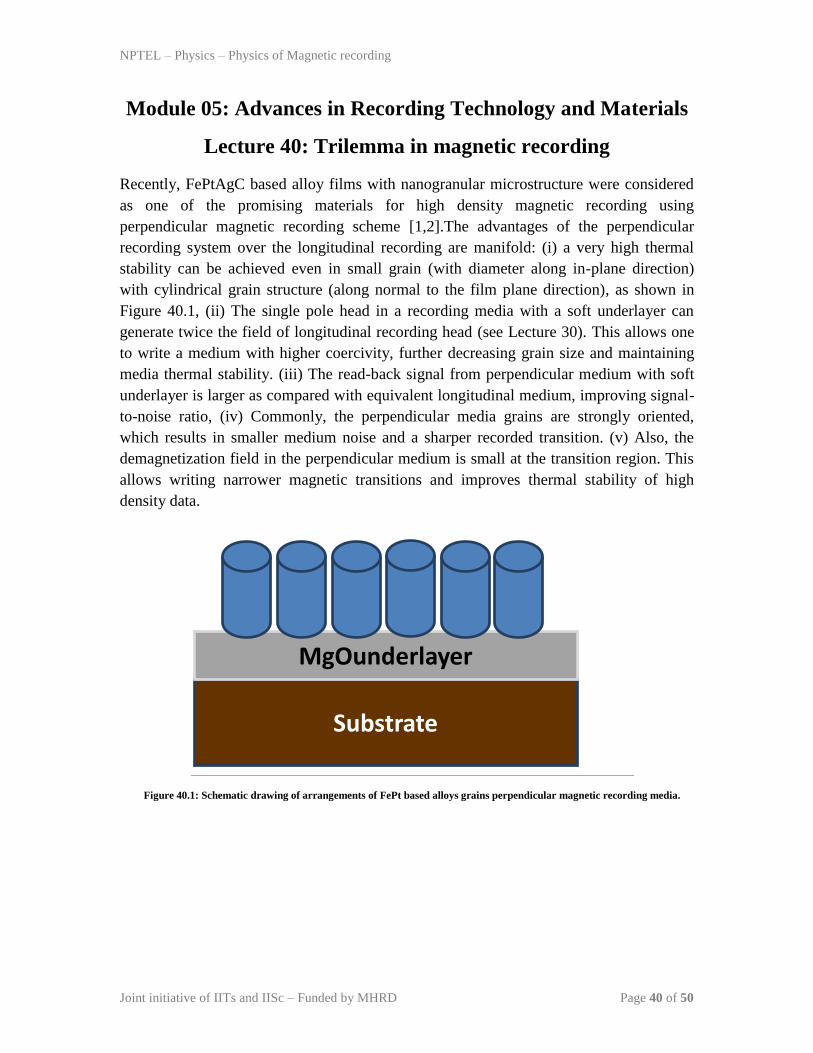
Recently, FePtAgC based alloy films with nanogranular microstructure were considered
as one of the promising materials for high density magnetic recording using
perpendicular magnetic recording scheme [1,2].The advantages of the perpendicular
recording system over the longitudinal recording are manifold: (i) a very high thermal
stability can be achieved even in small grain (with diameter along in-plane direction)
with cylindrical grain structure (along normal to the film plane direction), as shown in
Figure 40.1, (ii) The single pole head in a recording media with a soft underlayer can
generate twice the field of longitudinal recording head (see Lecture 30). This allows one
to write a medium with higher coercivity, further decreasing grain size and maintaining
media thermal stability. (iii) The read-back signal from perpendicular medium with soft
underlayer is larger as compared with equivalent longitudinal medium, improving signal-
to-noise ratio, (iv) Commonly, the perpendicular media grains are strongly oriented,
which results in smaller medium noise and a sharper recorded transition. (v) Also, the
demagnetization field in the perpendicular medium is small at the transition region. This
allows writing narrower magnetic transitions and improves thermal stability of high
density data.
Figure 40.1: Schematic drawing of arrangements of FePt based alloys grains perpendicular magnetic recording media.
Substrate
MgOunderlayer

NPTEL – Physics – Physics of Magnetic recording
Joint initiative of IITs and IISc – Funded by MHRD Page 41 of 50
It is important to highlight that the introduction of perpendicular recording technology
postpones the superparamagnetic problem. However, this solution can only delay the
problem for short duration. On the other hand, clearly, a reduction in the grain size can be
compensated for by an increase in the magnetocrystalline anisotropy constant. This
results in an increase in the anisotropy field of the medium, as given by,𝐻𝐾 = 2𝐾/𝑀𝑆
and increasesthe medium coercivity. Therefore, one needs a larger write fields.
Unfortunately, the maximum field of the writing heads is limited in the current
technology and this poses a huge difficulty to the use of magnetic materials with high
anisotropy fields. This establishes a well-known magnetic recording trilemma (see Figure
40.2).
Figure 40.2: Schematic drawing of the magnetic recording trilemma.
Figure 40.3: Temperature dependent perpendicular coercivity for a ferromagnetic material.

NPTEL – Physics – Physics of Magnetic recording
Joint initiative of IITs and IISc – Funded by MHRD Page 42 of 50
Currently, various research teams in industry and academia are actively involved in
searching new solutions for the future. Two types of approaches have been proposed to
push the areal densities above Terabits/inch2. In the first type, an additional source of
energy is needed to assist the applied magnetic field in reversing the bit magnetization,
thus allowing higher anisotropy media to be used. These additional energies can either be
provided by both heat-based processes, where locally heating the bit [3] and lower the
anisotropy during writing or by adding a radio-frequency magnetic field [4]. The second
type of approaches involves the use of lithographically patterned media, which has the
advantage that the head designs similar to those in production todaycan still be used, but
with radically different media. In the following, we shall discuss both of these suggested
methods.
NPTEL – Physics – Physics of Magnetic recording
Joint initiative of IITs and IISc – Funded by MHRD Page 43 of 50
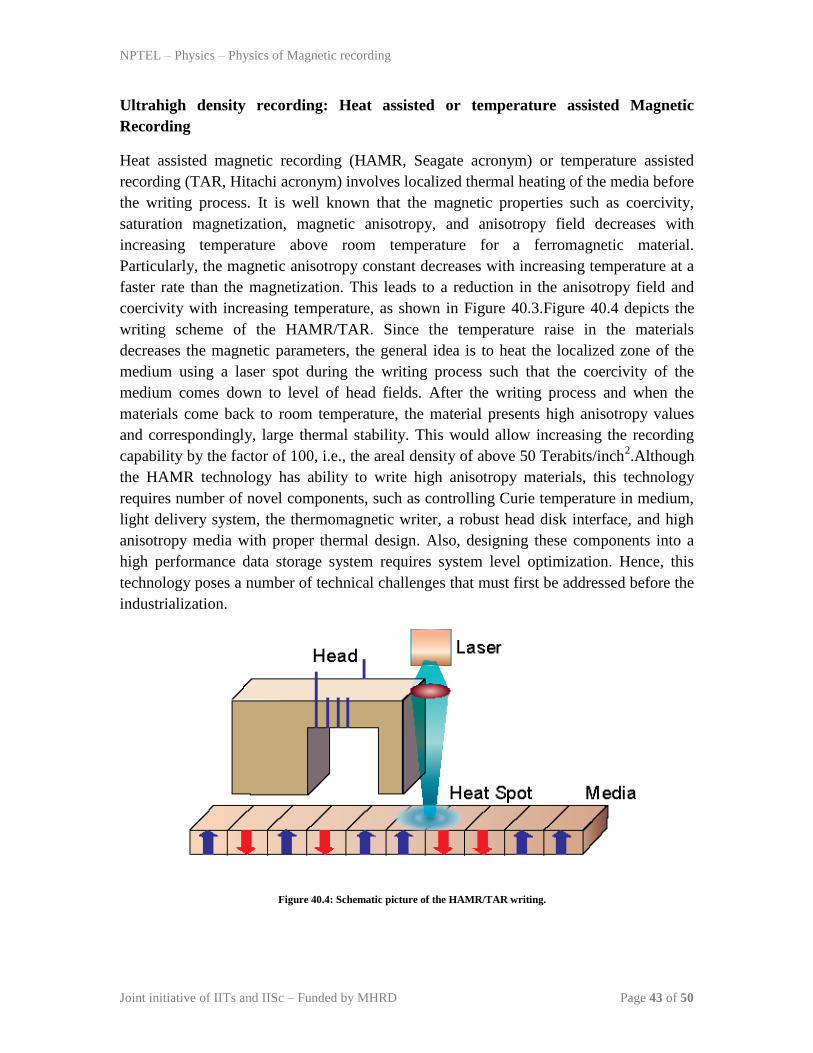
Ultrahigh density recording: Heat assisted or temperature assisted Magnetic
Recording
Heat assisted magnetic recording (HAMR, Seagate acronym) or temperature assisted
recording (TAR, Hitachi acronym) involves localized thermal heating of the media before
the writing process. It is well known that the magnetic properties such as coercivity,
saturation magnetization, magnetic anisotropy, and anisotropy field decreases with
increasing temperature above room temperature for a ferromagnetic material.
Particularly, the magnetic anisotropy constant decreases with increasing temperature at a
faster rate than the magnetization. This leads to a reduction in the anisotropy field and
coercivity with increasing temperature, as shown in Figure 40.3.Figure 40.4 depicts the
writing scheme of the HAMR/TAR. Since the temperature raise in the materials
decreases the magnetic parameters, the general idea is to heat the localized zone of the
medium using a laser spot during the writing process such that the coercivity of the
medium comes down to level of head fields. After the writing process and when the
materials come back to room temperature, the material presents high anisotropy values
and correspondingly, large thermal stability. This would allow increasing the recording
capability by the factor of 100, i.e., the areal density of above 50 Terabits/inch2.Although
the HAMR technology has ability to write high anisotropy materials, this technology
requires number of novel components, such as controlling Curie temperature in medium,
light delivery system, the thermomagnetic writer, a robust head disk interface, and high
anisotropy media with proper thermal design. Also, designing these components into a
high performance data storage system requires system level optimization. Hence, this
technology poses a number of technical challenges that must first be addressed before the
industrialization.
Figure 40.4: Schematic picture of the HAMR/TAR writing.
NPTEL – Physics – Physics of Magnetic recording
Joint initiative of IITs and IISc – Funded by MHRD Page 44 of 50
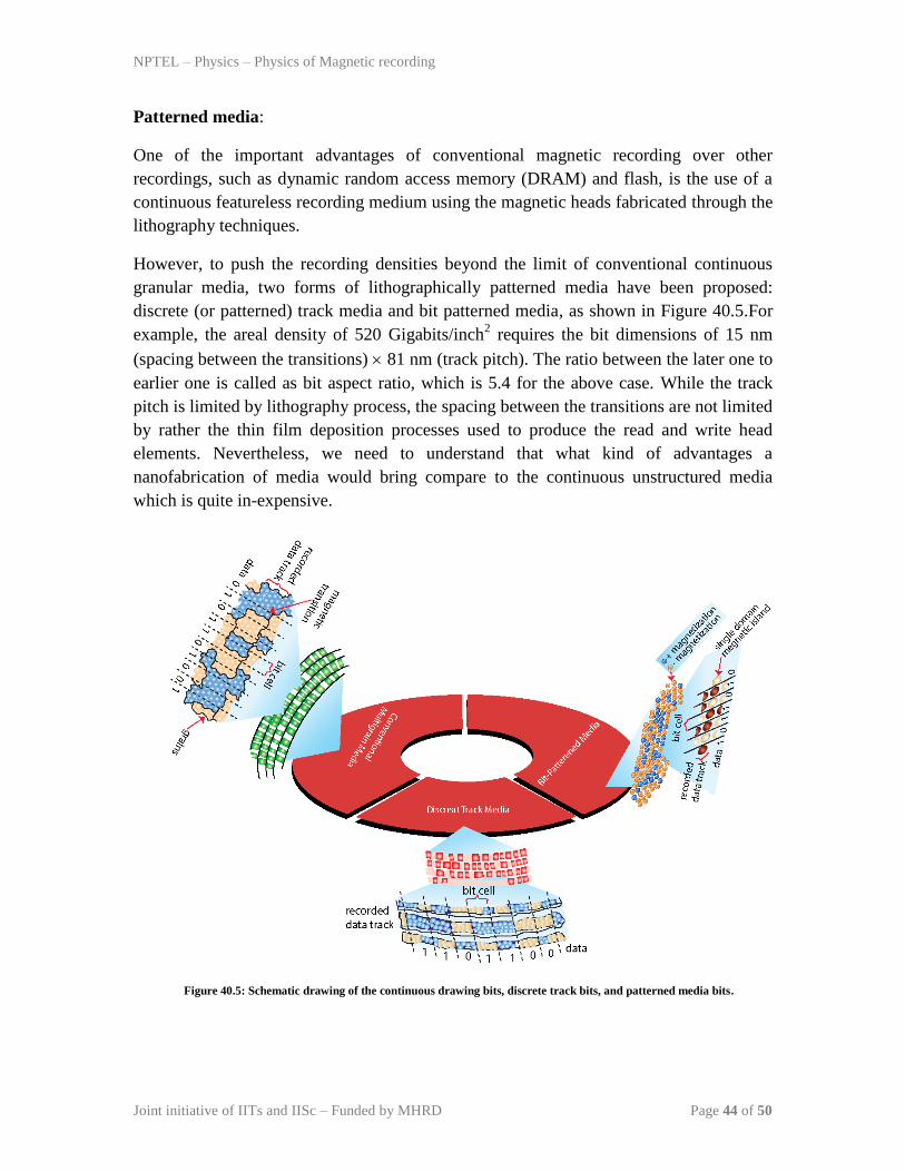
Patterned media:
One of the important advantages of conventional magnetic recording over other
recordings, such as dynamic random access memory (DRAM) and flash, is the use of a
continuous featureless recording medium using the magnetic heads fabricated through the
lithography techniques.
However, to push the recording densities beyond the limit of conventional continuous
granular media, two forms of lithographically patterned media have been proposed:
discrete (or patterned) track media and bit patterned media, as shown in Figure 40.5.For
example, the areal density of 520 Gigabits/inch2 requires the bit dimensions of 15 nm
(spacing between the transitions) 81 nm (track pitch). The ratio between the later one to
earlier one is called as bit aspect ratio, which is 5.4 for the above case. While the track
pitch is limited by lithography process, the spacing between the transitions are not limited
by rather the thin film deposition processes used to produce the read and write head
elements. Nevertheless, we need to understand that what kind of advantages a
nanofabrication of media would bring compare to the continuous unstructured media
which is quite in-expensive.
Figure 40.5: Schematic drawing of the continuous drawing bits, discrete track bits, and patterned media bits.

NPTEL – Physics – Physics of Magnetic recording
Joint initiative of IITs and IISc – Funded by MHRD Page 45 of 50
References:
[1]. A. Perumal, L. Zhang, Y.K. Takahashi, and K. Hono, J. Appl. Phys. 108 (2010)
083907.
[2]. L. Zhang, A. Perumal, Y.K. Takahashi, and K. Hono, J. Magn. Magn.Mater.322
(2010) 2658.
[3]. S. Batra et al, IEEE Trans Magn 42 (2006) 2417.
[4]. J. G. Zhu, X. C. Zhu, and Y. H. Tang, IEEE Trans. Magn. 44 (2008) 125.

NPTEL – Physics – Physics of Magnetic recording
Joint initiative of IITs and IISc – Funded by MHRD Page 46 of 50
Module 05: Advances in Recording Technology and Materials
Lecture 41: Patterning Media
In this lecture, we shall discuss on the discrete and patterned tracks, patterned bits, and
magnetic property requirements for patterned media.
Problems encountered in the conventional media:
The bit length and the width in the conventional magnetic recording are defined by the
field gradient from the write head with the assumption that the grains in the bits are small
and are well separated to avoid any exchange coupling. On the other hand, the track
locations in the media are defined by the servo marks and hence there is a mis-
registration of the head to the track locations from the revolution to revolution due to the
mechanical vibrations and non-perfect following of the track by the write head. This
problem increases with decreasing the bit width for the increase in the areal densities.
Also, there should not be any signal from the space between the different tracks to avoid
any noise, which is possible only if the medium is either non-magnetic or recessed from
the head. Such arrangements reduces the problem of noise signal coming out of poorly
written bits and partially erased information at the edges of the track. This additional
noise can be avoided, if one incorporates the discrete tracks. In the discrete track media,
the tracks (track width) are well defined by lithography process, while the spacing
between the transitions is still limited by the write head field gradient. This suggests that
the materials requirement for the discrete track media is similar to the conventional
recording media.
Figure 41.1: Schematic drawing of Bit patterned media.
NPTEL – Physics – Physics of Magnetic recording
Joint initiative of IITs and IISc – Funded by MHRD Page 47 of 50
Advantages of patterned media:
On the other hand, bit patterned media is a technology that allows to record data in a
uniform array of magnetic grains, storing one bit per grain, as opposed to regular hard-
drive technology, where each bit is stored in a few hundred of magnetic grains to get
adequate signal to noise ratio. As shown in Figure 41.1, this media consists of a periodic
array of discrete magnetic elements either prepared artificially by different lithography
techniques or self-organized spontaneously. Each element is a bit that is well isolated
from other elements but the magnetization inside the bit is strongly exchange coupled,
compared to the conventional recording media. Therefore, the energy barrier of the bit is
larger than that of the corresponding bit in conventional media and hence the thermal
stability is improved. Another advantage of the patterned media is the elimination of the
transition noise between bits as they are completely separated. However, the relative
orientation of the magnetic easy axis of the islands and head field must be the same for
every bit on the disk. This requirement automatically favours the use of materials with
strong perpendicular anisotropy. The transition from the conventional magnetic recording
to perpendicular recoding has occurred around 2006 with the advantage of larger write
fields and higher areal densities in the perpendicular magnetic recording. However, the
fabrication of the low cost and large area patterned structures without any damages and
faults is still a challenge and various lithography processes are attempted to enhance the
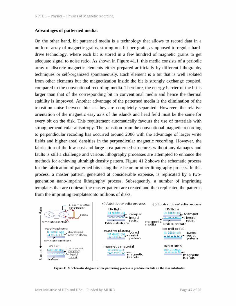
methods for achieving ultrahigh density pattern. Figure 41.2 shows the schematic process
for the fabrication of patterned bits using the e-beam or other lithography process. In this
process, a master pattern, generated at considerable expense, is replicated by a two-
generation nano-imprint lithography process. Subsequently, a number of imprinting
templates that are copiesof the master pattern are created and then replicated the patterns
from the imprinting templatesonto millions of disks.
Figure 41.2: Schematic diagram of the patterning process to produce the bits on the disk substrates.

NPTEL – Physics – Physics of Magnetic recording
Joint initiative of IITs and IISc – Funded by MHRD Page 48 of 50
Magnetic properties of the patterned media:
The magnetic property requirement for the bit patterned media is different from the
conventional media. In the case of bit patterned media the entire bit to the information
write must switch as a single unit which requires a highly exchange coupled behaviour
within a single bit. Similarly, the bit switching between the grains should be identical to
avoid the requirement of different field to switch different bits. This is typically defined
as switching field distribution, which should be narrower. However, in the real scenario,
there are several factors contributing to switching field distributions: (i) the magnetic
property variation within the bit considered for writing, and (ii) magnetic exchange
interaction between the bits. Hence, the applied field necessary to switch a particular bit
depends on the sum of the magnetostatic fields produced by the other bits in the bit
patterned media. This can be controlled by manipulating the magnetization of the media
and hence the switching field distribution. However, one should also keep a note that this
is limited by the fact that the same magnetostatic stray fields are responsible for the
signal detected by the read element.
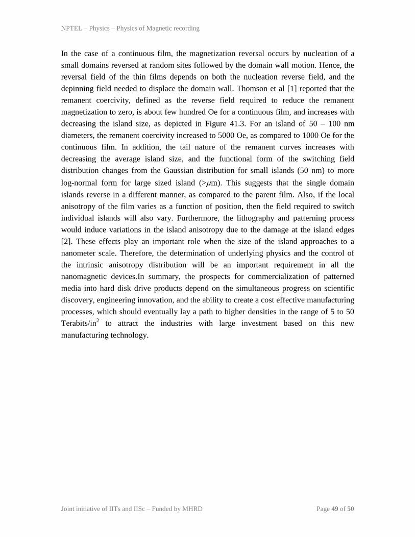
Figure 41.3: (a) Variations of remnant coercivity and SFD for thin films and different islands, and (b) simulated switching
field distributions as a function of various island sizes [1].
NPTEL – Physics – Physics of Magnetic recording
Joint initiative of IITs and IISc – Funded by MHRD Page 49 of 50
In the case of a continuous film, the magnetization reversal occurs by nucleation of a
small domains reversed at random sites followed by the domain wall motion. Hence, the
reversal field of the thin films depends on both the nucleation reverse field, and the
depinning field needed to displace the domain wall. Thomson et al [1] reported that the
remanent coercivity, defined as the reverse field required to reduce the remanent
magnetization to zero, is about few hundred Oe for a continuous film, and increases with
decreasing the island size, as depicted in Figure 41.3. For an island of 50 – 100 nm
diameters, the remanent coercivity increased to 5000 Oe, as compared to 1000 Oe for the
continuous film. In addition, the tail nature of the remanent curves increases with
decreasing the average island size, and the functional form of the switching field
distribution changes from the Gaussian distribution for small islands (50 nm) to more
log-normal form for large sized island (>m). This suggests that the single domain
islands reverse in a different manner, as compared to the parent film. Also, if the local
anisotropy of the film varies as a function of position, then the field required to switch
individual islands will also vary. Furthermore, the lithography and patterning process
would induce variations in the island anisotropy due to the damage at the island edges
[2]. These effects play an important role when the size of the island approaches to a
nanometer scale. Therefore, the determination of underlying physics and the control of
the intrinsic anisotropy distribution will be an important requirement in all the
nanomagnetic devices.In summary, the prospects for commercialization of patterned
media into hard disk drive products depend on the simultaneous progress on scientific
discovery, engineering innovation, and the ability to create a cost effective manufacturing
processes, which should eventually lay a path to higher densities in the range of 5 to 50
Terabits/in2 to attract the industries with large investment based on this new
manufacturing technology.
NPTEL – Physics – Physics of Magnetic recording
Joint initiative of IITs and IISc – Funded by MHRD Page 50 of 50
References:
[1]. T. Thomson et al, Phys. Rev. Lett. 96 (2006) 257204.
[2]. J.M. Shaw et al, Phys. Rev. B 78 (2008) 024414.
Quiz:
(1) What are the improvements possible in the perpendicular magnetic recording to
enhance the areal density?
(2) What are the materials satisfy the stability condition for perpendicular magnetic
rercording?
(3) Describe the magnetic recording trilemma?
(4) How the heat assisted magnetic recording or patterned media helps to improve the
area density of recording in the future?