Permeability and Seepage -2 - Nptel
38
Prof. B V S Viswanadham, Department of Civil Engineering, IIT Bombay 13
-
Upload
khangminh22 -
Category
Documents
-
view
0 -
download
0
Transcript of Permeability and Seepage -2 - Nptel

Prof. B V S Viswanadham, Department of Civil Engineering, IIT Bombay
13

Prof. B V S Viswanadham, Department of Civil Engineering, IIT Bombay
Permeability and Seepage -2

Prof. B V S Viswanadham, Department of Civil Engineering, IIT Bombay
Conditions favourable for the formation quick sandQuick sand is not a type of sand but a flow conditionoccurring within a cohesion-less soil when its effective stressis reduced to zero due to upward flow of water.
Quick sand occurs in nature when water is being forcedupward under pressurized conditions.
In this case, the pressure of the escaping water exceedsthe weight of the soil and the sand grains are forced apart.The result is that the soil has no capability to support a load.
Why does quick condition or boiling occurs mostly in fine sands or silts?

Prof. B V S Viswanadham, Department of Civil Engineering, IIT Bombay
Some practical examples of quick conditionsExcavations in granular materials behindcofferdams alongside rivers
Any place where artesian pressures exist (i.e. wherehead of water is greater than the usual static waterpressure).
-- When a pervious underground structure iscontinuous and connected to a place where head ishigher.
Behind river embankments to protect floods

Prof. B V S Viswanadham, Department of Civil Engineering, IIT Bombay
Contrary to popular belief, it is not possible to drownin quick sand, because the density of quick sand ismuch greater than that of water.
waterquicksand ρρ >>
Consequently, it is literally impossible for a person tobe sucked into quicksand and disappear. So, aperson walking into quicksand would sink to aboutwaist depth and then float.
Some practical examples of quick conditions

Prof. B V S Viswanadham, Department of Civil Engineering, IIT Bombay
• Example• The sand layer of the
soil profile shown in figure is under artesian pressure. A trench is to be excavated in the clay up to a depth of 4m. Determine the depth of water h to avoid boiling.
PSand
Rock
3m
4m5m
Water level
h
stiff clay γ = 18kN/m3
6m
Boiling condition

Prof. B V S Viswanadham, Department of Civil Engineering, IIT Bombay
• Solution:• At P: σ = hγw + (6-4)γclay• = hγw + 2γclay
• At P: u = 5γw
• At P: σ’ = hγw + 2γclay - 5γw
• σ’ = 0 (boiling condition)• hγw + 2γclay - 5γw = 0• h = (5γw - 2γclay )/γw
• = (5 x 9.81 – 2x18)/9.81• h = 1.33m
PSand
Rock
3m
4m5m
Water level
h = 1.33 m
stiff clay γ = 18kN/m3
6m
Boiling condition

Prof. B V S Viswanadham, Department of Civil Engineering, IIT Bombay
Seepage forcesWater flowing past asoil particle exerts a dragforce on the particle inthe direction of flow.
The drag force iscaused by pressuregradient and by viscousdrag.
h
L
B
Wd
(Fs)c

Prof. B V S Viswanadham, Department of Civil Engineering, IIT Bombay
B
Wd
(Fs)cW
FBD of soil
Direction of flow
FBD of grain
At critical condition; h = hc
( ) wcws ALhAL
eeG γγ +=
++
1
+−
==e
GLhi sc
c 11
Seepage forces

Prof. B V S Viswanadham, Department of Civil Engineering, IIT Bombay
Considering FBD of grain in the direction of flow at i = ic( )
( )
( )
( ) ( )
( ) wws
cs
wVws
cs
wsws
cs
dcs
csd
ALnALe
GF
VV
VVALe
GF
VALe
GF
BWFBFW
γγ
γγ
γγ
)1(1
1
1
−−
+=
−−
+=
−
+=
−=
+=
ViF
Ve
GF
wccs
ws
cs
γ
γ
=
+−
=
)(1
1)(
Seepage pressure
ps = icγw
If h < hc then seepage force Js is iγwV

Prof. B V S Viswanadham, Department of Civil Engineering, IIT Bombay
∆l
∆lDirection of flow
∆h
Seepage forceArea per unit width of section = ∆l x 1
Volume affected by seepage force = ∆l2 x 1
Force applied to sand particles = γwh1 -γwh2 (∆l x 1)
h1 h2
h1 > h2

Prof. B V S Viswanadham, Department of Civil Engineering, IIT Bombay
Seepage force
Force applied to sand particles = γw (∆h) (∆l x 1)
= γw (∆h/∆l) (∆l2 x 1)
J = i γw V
Seepage pressure ps = Seepage force per
unit volume
= i γw

Prof. B V S Viswanadham, Department of Civil Engineering, IIT Bombay
Critical hydraulic gradient – Quick conditionThe quick condition occurs at a critical upwardhydraulic gradient ic, when the seepage force justbalances the buoyant weight of an element of soil.(Shear stresses on the sides of the element are
neglected.)
−
=υ
1sc
Gi
The critical hydraulic gradient is typically around 1.0 for manysoils. Fluidized beds in chemical engineering systems rely ondeliberate generation of quick conditions to ensure that thechemical process can occur most efficiently.
Prof. B V S Viswanadham, Department of Civil Engineering, IIT Bombay
Example problem
Determine and plot totalstress, PWP and effectivestress diagrams if: (i) h = 1 m;(ii) h = 4 m; and (iii) h = 2 m.
a
b
c
d
2 m
h
1 m
1 m
Datum
γsat =20 kN/m32hi =
Case – I; i = 0.5;
Case – II; i = 2;
Case – III; i = 1

Prof. B V S Viswanadham, Department of Civil Engineering, IIT Bombay
Case - I i = 0.5
Point PH [m] EH [m] TH [m]
a 0 4 4
b 2 2 4
d 5 0 5
c 3.5 1 4.5

Prof. B V S Viswanadham, Department of Civil Engineering, IIT Bombay
a
b
c
d
2 m
h = 1 m
1 m
1 m
Datum
γsat =20 kN/m320
40
60
20
35
50 10
5
σ σ´u
Stress units are in kN/m2
Case - I i = 0.5

Prof. B V S Viswanadham, Department of Civil Engineering, IIT Bombay
Case - II i = 2
Point PH [m] EH [m] TH [m]
a 0 4 4
b 2 2 4
d 8 0 8
c 5 1 6

Prof. B V S Viswanadham, Department of Civil Engineering, IIT Bombay
a
b
c
d
2 m
h = 4 m
1 m
1 m
Datum
γsat =20 kN/m320
40
60
20
50
80
σ
-10
σ´u
-20
Quick sand condition wouldhave already occurred…
Stress units are in kN/m2Case - II
Prof. B V S Viswanadham, Department of Civil Engineering, IIT Bombay
Case - III i = 1
Point PH [m] EH [m] TH [m]
a 0 4 4
b 2 2 4
d 6 0 6
c 4 1 5

Prof. B V S Viswanadham, Department of Civil Engineering, IIT Bombay
Just subjected to Quick sand condition…
a
b
c
d
2 m
h = 2 m
1 m
1 m
Datum
γsat =20 kN/m320
40
60
20
40
60
σ
0
σ´u
0
0
Stress units are in kN/m2
0
Case - III
Prof. B V S Viswanadham, Department of Civil Engineering, IIT Bombay
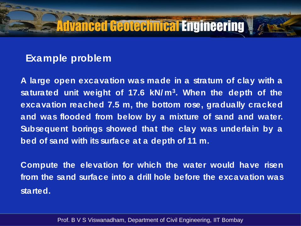
A large open excavation was made in a stratum of clay with asaturated unit weight of 17.6 kN/m3. When the depth of theexcavation reached 7.5 m, the bottom rose, gradually crackedand was flooded from below by a mixture of sand and water.Subsequent borings showed that the clay was underlain by abed of sand with its surface at a depth of 11 m.
Compute the elevation for which the water would have risenfrom the sand surface into a drill hole before the excavation wasstarted.
Example problem

Prof. B V S Viswanadham, Department of Civil Engineering, IIT Bombay
γsat = 17.6 kN/m3
11m
Solution

Prof. B V S Viswanadham, Department of Civil Engineering, IIT Bombay
h
For σ´= 0 at A: σ´= 17.6 x (11 – 7.5) - 10 x h = 0
h = 6.16 m
Solution
Elevation for which thewater would have risenfrom the sand surfaceinto a drill hole beforethe excavation wasstarted.
A
7.5 m

Prof. B V S Viswanadham, Department of Civil Engineering, IIT Bombay
3 m
6 m
4 m
Coarse sand; Gs = 2.65; e = 0.833
Silty clay; Gs = 2.70; w = 45.2 %
3 mB
A
C
Determine and plot the total vertical stress, pore waterand effective vertical stress distribution at levels A, Band C.
Example problem

Prof. B V S Viswanadham, Department of Civil Engineering, IIT Bombay
Example problemAn artesian pressureexists in the lowersand layer.
Determine σ, u, andσ ′ at A, B, and C.
(TH)A = 2 + 3 = 5m
(TH)B = 7 + 0 = 7m
1 m
2 m
γclay = 17 kN/m3
A
C
B
2 m
1 m
γd = 18.5 kN/m3
γsat = 19 kN/m3
DATUM
1 m
2 m
1.33 m

Prof. B V S Viswanadham, Department of Civil Engineering, IIT Bombay
At point A:σ = 18.5 x 1 + 19 x 2 = 56.5 kN/m2
u = 10 x 2 = 20 kN/m2
σ′ = 56.5 – 20 = 36.5 kN/m2
At point B:
σ = 18.5 x 1 + 19 x 2 + 17 x 3 = 107.5 kN/m2
u = 10 x 7 = 70 kN/m2
σ′ = 107.5 – 70 = 37.5 kN/m2
Solution
Prof. B V S Viswanadham, Department of Civil Engineering, IIT Bombay
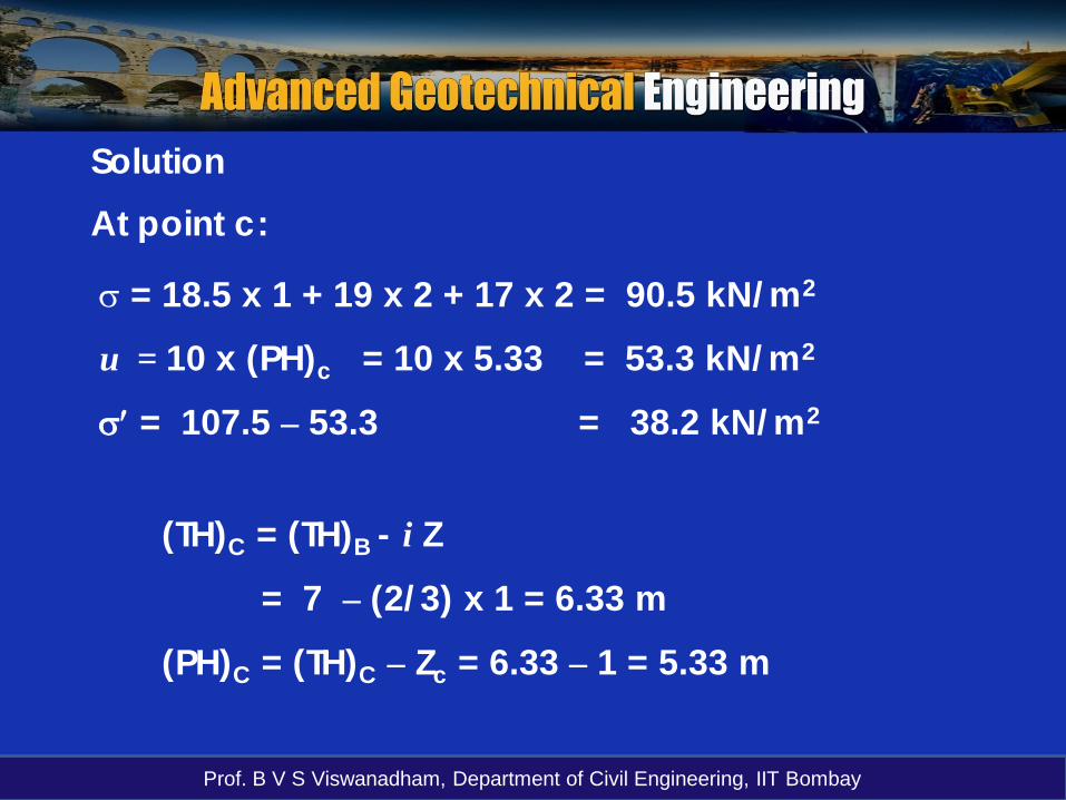
At point c:
σ = 18.5 x 1 + 19 x 2 + 17 x 2 = 90.5 kN/m2
u = 10 x (PH)c = 10 x 5.33 = 53.3 kN/m2
σ′ = 107.5 – 53.3 = 38.2 kN/m2
Solution
(TH)C = (TH)B - i Z
= 7 – (2/3) x 1 = 6.33 m
(PH)C = (TH)C – Zc = 6.33 – 1 = 5.33 m

Prof. B V S Viswanadham, Department of Civil Engineering, IIT Bombay
1 m
2 mA
C
B
2 m
1 mDATUM
1 m
90.5
56.5
53.3
20 36.5
107.5 70
38.2
37.5

Prof. B V S Viswanadham, Department of Civil Engineering, IIT Bombay
Measurement of soil permeabilitiesThe rate of flow of water q (volume/time) throughcross-sectional area A is found to be proportional tohydraulic gradient i according to Darcy’s law:
kiAqv ==
Lhi =
where v is flow velocity and k is coefficient of permeability with dimensions of velocity (length/time).
The coefficient of permeability of a soil is a measure of theconductance (i.e. the reciprocal of the resistance) that itprovides to the flow of water through its pores.

Prof. B V S Viswanadham, Department of Civil Engineering, IIT Bombay
The value of the coefficient of permeability k dependson:
(i) Average size of the pores and is related to theparticle sizes and their packing,
(ii) Particle shape, and(iii) Soil structure.
Measurement of soil permeabilities
The ratio of permeabilities of typical sands/gravels to those oftypical clays is of the order of 106. A small proportion of finematerial in a coarse-grained soil can lead to a significantreduction in permeability.
510
10
dd
edd
=
=

Prof. B V S Viswanadham, Department of Civil Engineering, IIT Bombay
Measurement of soil permeabilities
Laboratory methods:
The constant head test (used for highly permeable soils)The falling head test
(used for relatively impermeable soils)Indirect methods: computation from grain size distribution and During Oedometer test
A number of tests can be used to measure or estimate the permeability of soils
Field methods:1. Pumping tests and 2. Borehole tests

Prof. B V S Viswanadham, Department of Civil Engineering, IIT Bombay
Laboratory measurement of permeabilityIn determining permeability of coarse grainedmaterial, large quantities of flow occur in short periodsof time and small quantities of flow occur over longperiods of time for fine grained soils.
Two aspects that need careful attention for all types of soils are:(i) To ensure that flow occurs only through the soil and not at theinterface between soil and the mould in which the soil iscontained.
(ii) The soil sample is fully saturated before recordingobservations

Prof. B V S Viswanadham, Department of Civil Engineering, IIT Bombay
hL
Constant water level
Water supply
Determination of coefficient of permeability in the laboratory
Constant Head test
AhtQLk
tLhAkQ
Lhi
AvtQ
=
=
=
=A = area of C/S of the specimen

Prof. B V S Viswanadham, Department of Civil Engineering, IIT Bombay
Main features of constant head test
It is suitable for soils having a coefficient ofpermeability in the range of 10-2 m/s to 10-5 m/s,which applies to clean sand and sand-gravelmixtures with less than 10 % fines.
It can be suitable for soils when used in theircompletely disturbed or remolded states such as fordrainage materials and filters to confirm that theirperformance will be adequate.
Prof. B V S Viswanadham, Department of Civil Engineering, IIT Bombay
dh
L
h1h2h
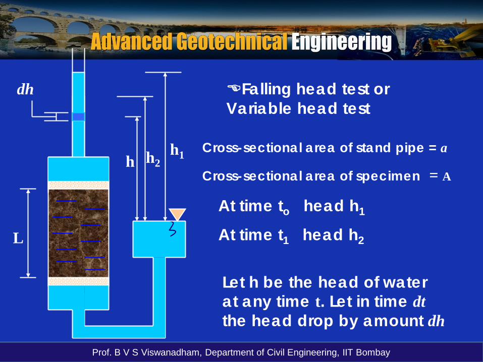
Falling head test or Variable head test
Cross-sectional area of stand pipe = a
Cross-sectional area of specimen = A
At time to head h1
At time t1 head h2
Let h be the head of water at any time t. Let in time dtthe head drop by amount dh
Prof. B V S Viswanadham, Department of Civil Engineering, IIT Bombay
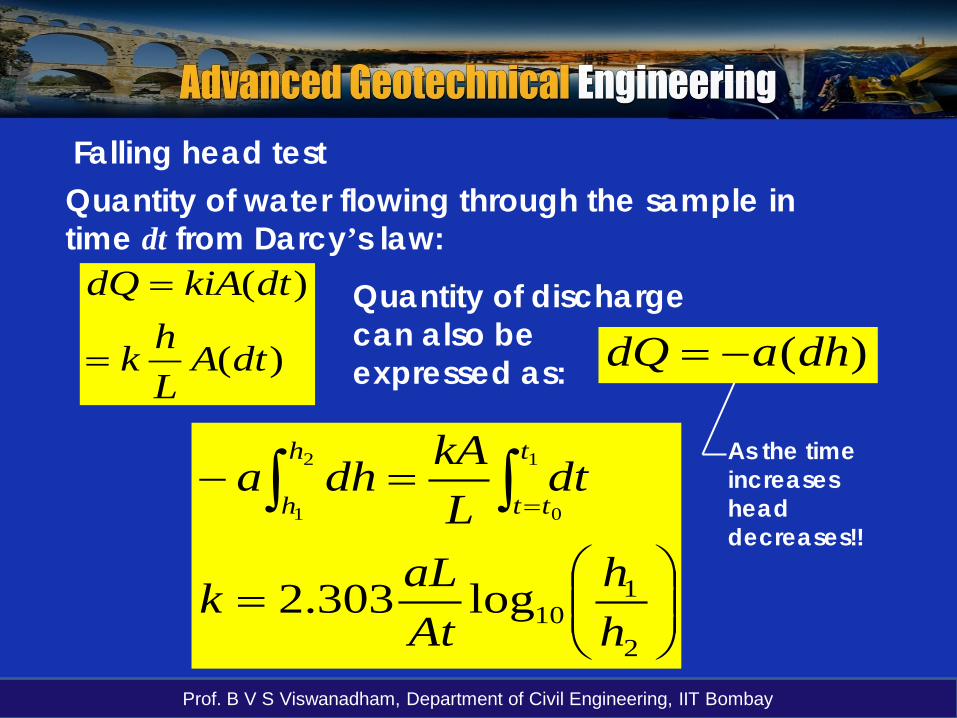
Quantity of water flowing through the sample in time dt from Darcy’s law:
)(
)(
dtALhk
dtkiAdQ
=
= Quantity of discharge can also be expressed as: )(dhadQ −=
=
=− ∫∫ =
2
110log303.2
1
0
2
1
hh
AtaLk
dtLkAdha
t
tt
h
h
Falling head test
As the time increases head decreases!!

Prof. B V S Viswanadham, Department of Civil Engineering, IIT Bombay
Main features of constant head and falling head testsIn the constant head test, permeability is computed on thebasis of fluid that passes through the soil sample.
While in the falling head test, k is computed on the basis offluid flowing into the sample.With the constant head test, time is required to accumulatethe fluid volume necessary to perform computation. Extremecare would be required to prevent leaks in the apparatus andevaporation of discharge water.
With the falling head test, the duration of the test is shortenedand care is required to prevent evaporation of water in the inlettube.

Prof. B V S Viswanadham, Department of Civil Engineering, IIT Bombay
3 m
6 m
4 m
Coarse sand; Gs = 2.65; e = 0.833
Silty clay; Gs = 2.70; w = 45.2 %
3 mB
A
C
Determine and plot the total vertical stress, pore waterand effective vertical stress distribution at levels A, Band C.
Problem