
METTLER TOLEDO JagX Installation Guide
46
Industrial Terminal Installation Guide A15888800A (7/03).01
-
Upload
khangminh22 -
Category
Documents
-
view
0 -
download
0
Transcript of METTLER TOLEDO JagX Installation Guide

Industrial Terminal Installation Guide
®
A15888800A(7/03).01

Copyright 2003, 2002, 2001 Mettler-Toledo, Inc. This documentation contains proprietary information of Mettler-Toledo, Inc. It may not be copied in whole or in part without the express written consent of Mettler-Toledo, Inc. METTLER TOLEDO reserves the right to make refinements or changes to the product or manual without notice.
U.S. Government Restricted Rights Legend: This software is furnished with Restricted Rights. Use, duplication, or disclosure of the Software by the U.S. Government is subject to the restrictions as set forth in subparagraph (C) (1) (ii) of the Rights in Technical Data and Computer Software clause at 40 C.F.R. Sec. 252.227-7013 or in subparagraphs (c) (1) and (2) of the Commercial Computer Software-Restricted Rights clause at 40 C.F.R. Sec. 52-227-19, as applicable.

CUSTOMER FEEDBACK
Your feedback is important to us! If you have a problem with this product or its documentation, or a suggestion on how we can serve you better, please fill out and send this form to us. Or, send your feedback via email to: [email protected]. If you are in the United States, you can mail this postpaid form to the address on the reverse side or fax it to (614) 438-4355. If you are outside the United States, please apply the appropriate amount of postage before mailing.
Your Name: Date: Organization Name: METTLER TOLEDO Order Number: Address: Part / Product Name: Part / Model Number: Serial Number: Company Name for Installation: Phone Number: ( ) Fax Number: ( ) Contact Name: E-mail Address: Phone Number:
Please check the appropriate box to indicate how well this product met your expectations in its intended use? Met and exceeded my needs Met all needs Met most needs Met some needs Did not meet my needs Comments/Questions:
DO NOT WRITE IN SPACE BELOW; FOR METTLER TOLEDO USE ONLY
Retail Light Industrial Heavy Industrial Custom RESPONSE: Include Root Cause Analysis and Corrective Action Taken.

FOLD THIS FLAP FIRST
BUSINESS REPLY MAILFIRST CLASS PERMIT NO. 414 COLUMBUS, OH
POSTAGE WILL BE PAID BY ADDRESSEE
Mettler-Toledo, Inc. Quality Manager - MTWT P.O. Box 1705 Columbus, OH 43216 USA
NO POSTAGE NECESSARY IF MAILED IN THE UNITED STATES
Please seal with tape.

DECLARATION OF CONFORMITY Konformitätserklärung Déclaration de conformité Declaración de Conformidad Conformiteitsverklaring Dichiarazione di conformità
We/Wir/Nous/Wij/Noi: Mettler-Toledo, Inc. 1150 Dearborn Drive Worthington, Ohio 43085 USA declare under our sole responsibility that the product, erklären, in alleiniger Verantwortung, daß dieses Produkt, déclarons sous notre seule responsabilité que le produit, declaramos, bajo nuestra sola responsabilidad, que el producto, verklaren onder onze verantwoordelijkheid, dat het product, dichiariamo sotto nostra unica responsabilitá, che il prodotto, Model/Type: Jaguar and JagXtreme to which this declaration relates is in conformity with the following standard(s) or other normative document(s). auf das sich diese Erklärung bezieht, mitder/den folgenden Norm(en) oder Richtlinie(n) übereinstimmt. Auquel se réfère cette déclaration est conforme à la (aux) norme(s) ou au(x) document(s) normatif(s). Al que se refiere esta declaración es conforme a la(s) norma(s) u otro(s) documento(s) normativo(s). Waarnaar deze verklaring verwijst, aan de volende norm(en) of richtlijn(en) beantwoordt. A cui si riferisce questa dichiarazione è conforme alla/e sequente/i norma/e o documento/i normativo/i. in combination with a weighing platform produced by Mettler-Toledo is in conformity with the following directives and standards.
Council directive on the harmonization of the laws of the Member states: standards:
relating to non-automatic weighing instruments (90/384/EEC) amended by directive (93/68/EEC)
EN 45501
relating to electromagnetic compatibility (89/336/EEC) amended by directive (93/68/EEC; 92/31/EEC)
EN 55022-1
relating to electrical equipment designed for use within certain voltage limits (73/23/EEC amended by directive (93/68/EEC)
EN 60950
Worthington, Ohio USA, May, 2000 Mettler-Toledo, Inc.
Darrell Flocken, Manager - Weights & Measures Office of Weights and Measures Original issue: July, 1995 Revised: October, 1996 added compliance to Low Voltage Directive May, 2000 added JagXtreme

Mettler-Toledo Inc. Columbus, Ohio
Declaration of Conformance to SMA Standard Production Meets Type
(Year of Declaration 2002)
We the manufacturer of
Model Certificate and Number Issued by
JagXtreme CoC 94-096 NCWM
declare in our responsibility the conformance of the above listed models and types to the mentioned certificates and the requirements of the SMA standard. This declaration becomes valid when the SMA Compliance Logo, having our name or trademark is applied to the device or its accompanying documentation.

FCC Notice
This device complies with Part 15 of the FCC Rules and the Radio Interference Requirements of the Canadian Department of Communications. Operation is subject to the following conditions: (1) this device may not cause harmful interference, and (2) this device must accept any interference received, including interference that may cause undesired operation.
This equipment has been tested and found to comply with the limits for a Class A digital device, pursuant to Part 15 of FCC Rules. These limits are designed to provide reasonable protection against harmful interference when the equipment is operated in a commercial environment. This equipment generates, uses, and can radiate radio frequency energy and, if not installed and used in accordance with the instruction manual, may cause harmful interference to radio communications. Operation of this equipment in a residential area is likely to cause harmful interference in which case the user will be required to correct the interference at his or her own expense.
ORDERING INFORMATION It is most important that the correct part number is used when ordering parts. Parts orders are machine processed, using only the part number and quantity as shown on the order. Orders are not edited to determine if the part number and description agree.
COPYRIGHT METTLER TOLEDO® and JAGXTREME® are registered trademarks of Mettler-Toledo, Inc. All other brand or product names are trademarks or registered trademarks of their respective companies.

PRECAUTIONS
WARNING DISCONNECT ALL POWER TO THIS UNIT BEFORE INSTALLING, SERVICING, CLEANING, OR REMOVING THE FUSE. FAILURE TO DO SO COULD RESULT IN BODILY HARM AND/OR PROPERTY DAMAGE.
CAUTION OBSERVE PRECAUTIONS FOR HANDLING ELECTROSTATIC SENSITIVE DEVICES.
WARNING ONLY PERMIT QUALIFIED PERSONNEL TO SERVICE THIS EQUIPMENT. EXERCISE CARE WHEN MAKING CHECKS, TESTS AND ADJUSTMENTS THAT MUST BE MADE WITH POWER ON. FAILING TO OBSERVE THESE PRECAUTIONS CAN RESULT IN BODILY HARM.
WARNING FOR CONTINUED PROTECTION AGAINST SHOCK HAZARD, CONNECT TO PROPERLY GROUNDED OUTLET ONLY. DO NOT REMOVE THE GROUND PRONG.
WARNING! THE JAGXTREME TERMINAL IS NOT INTRINSICALLY SAFE! DO NOT USE IN AREAS CLASSIFIED AS HAZARDOUS BY THE NATIONAL ELECTRIC CODE (NEC) BECAUSE OF COMBUSTI-BLE OR EXPLOSIVE ATMOSPHERES.
WARNING! USE ONLY THE POWER CORD SUPPLIED OR AN EQUIVALENT TYPE. U.S. MODELS USE UL APPROVED TYPE SJT CORD; EC MODELS USE HARMONIZED APPROVED TYPE H05VV-F CORDS.
READ this manual BEFORE operating or servicing this equipment. FOLLOW these instructions carefully. SAVE this manual for future reference. DO NOT allow untrained personnel to operate, clean, inspect, maintain, service, or tamper with this equipment. ALWAYS DISCONNECT this equipment from the power source before cleaning or performing maintenance. CALL METTLER TOLEDO for parts, information, and service.

WARNING! IMPROPER INSTALLATION OF THE POWER CABLE WILL RESULT IN PERSONAL INJURY AND/OR DAMAGE TO THE EQUIPMENT. THE HOT WIRE MUST BE APPLIED TO "L", NEUTRAL TO "N" AND GROUND TO
CAUTION FOR PANEL MOUNT INSTALLATIONS: • INCLUDE A POWER DISCONNECT SWITCH IN AC POWER WIRING. • SWITCH MUST BE WITHIN 10 FEET (3 METERS) AND EASILY ACCESSIBLE TO
OPERATOR. • SWITCH MUST BE CLEARLY IDENTIFIED AS DISCONNECT FOR TERMINAL
POWER. • SWITCH AND/OR CIRCUIT BREAKER MUST COMPLY WITH APPROPRIATE
ELECTRICAL CODES (FOR EC—IEC947).
FOR DESK/WALL INSTALLATIONS: • POWER CORD PLUG MUST BE CLEARLY IDENTIFIED AS DISCONNECT FOR
TERMINAL POWER. • POWER CORD MUST BE PLUGGED INTO OUTLET WITHIN 10 FEET (3
METERS) AND EASILY ACCESSIBLE TO OPERATOR.
WARNING! IF AN ANALOG SCALE IS TO BE USED AND IT WILL BE LOCATED IN A HAZARDOUS (EXPLOSIVE) AREA, SPECIAL PRECAUTIONS MUST BE TAKEN. LOAD CELLS APPROVED FOR USE IN HAZARDOUS LOCATIONS MUST BE USED AND A LOAD CELL BARRIER AND/OR A LOW VOLTAGE ANALOG PCB MAY BE REQUIRED. CONTACT YOUR AUTHORIZED METTLER TOLEDO REPRESENTATIVE FOR DETAILS ON EACH SPECIFIC APPLICATION.
CAUTION TO AVOID DAMAGE TO THE PCB OR LOAD CELL, REMOVE POWER FROM THE JAGXTREME TERMINAL AND WAIT AT LEAST 30 SECONDS BEFORE CONNECTING OR DISCONNECTING ANY HARNESS.
CAUTION DO NOT ATTACH AN ANALOG LOAD CELL TO THE DIGITOL SCALE INPUT ON THE CONTROLLER PCB COM2. DO NOT ATTACH A DIGITOL SCALE TO THE ANALOG LOAD CELL INPUT ON THE OPTIONAL ANALOG A/D PCB. DOING SO MAY RESULT IN DAMAGE TO THE LOAD CELL OR PCB.
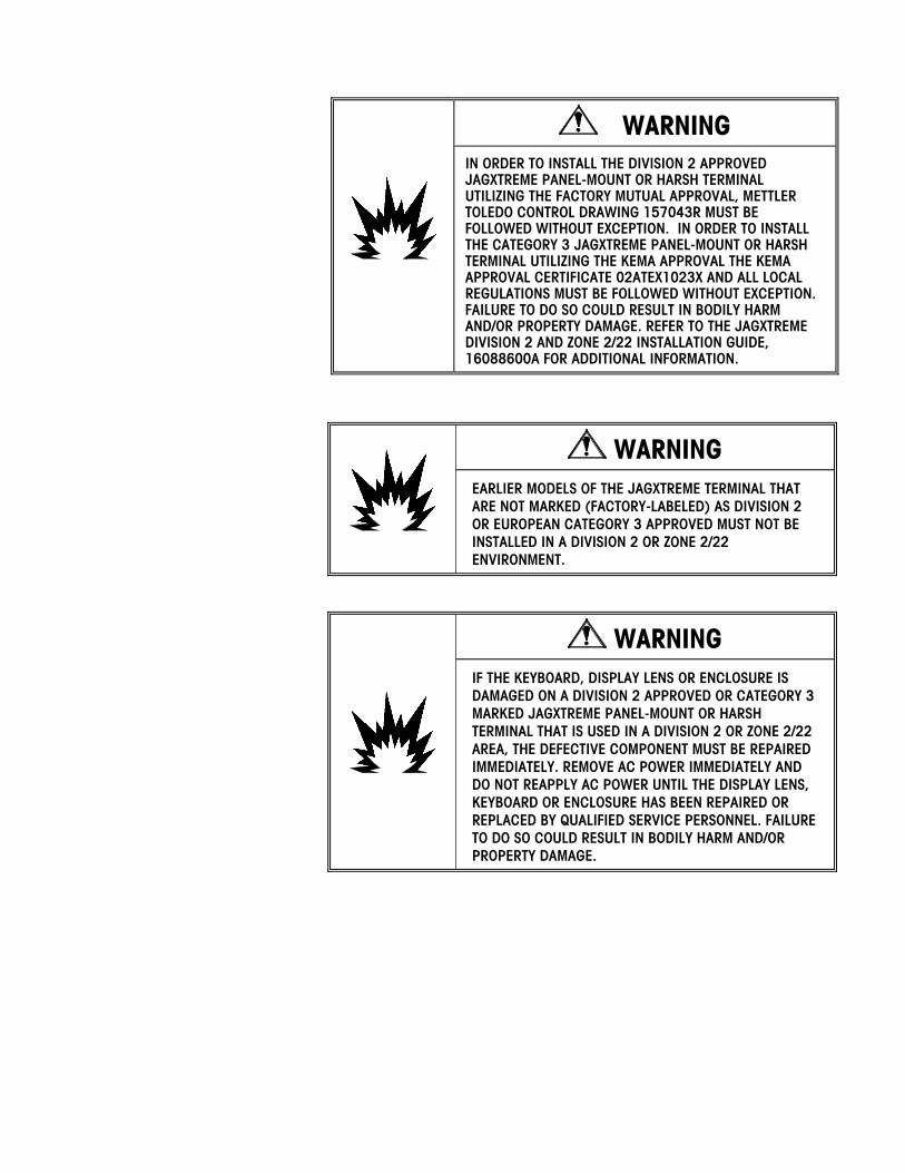
WARNING IN ORDER TO INSTALL THE DIVISION 2 APPROVED JAGXTREME PANEL-MOUNT OR HARSH TERMINAL UTILIZING THE FACTORY MUTUAL APPROVAL, METTLER TOLEDO CONTROL DRAWING 157043R MUST BE FOLLOWED WITHOUT EXCEPTION. IN ORDER TO INSTALL THE CATEGORY 3 JAGXTREME PANEL-MOUNT OR HARSH TERMINAL UTILIZING THE KEMA APPROVAL THE KEMA APPROVAL CERTIFICATE 02ATEX1023X AND ALL LOCAL REGULATIONS MUST BE FOLLOWED WITHOUT EXCEPTION. FAILURE TO DO SO COULD RESULT IN BODILY HARM AND/OR PROPERTY DAMAGE. REFER TO THE JAGXTREME DIVISION 2 AND ZONE 2/22 INSTALLATION GUIDE, 16088600A FOR ADDITIONAL INFORMATION.
WARNING EARLIER MODELS OF THE JAGXTREME TERMINAL THAT ARE NOT MARKED (FACTORY-LABELED) AS DIVISION 2 OR EUROPEAN CATEGORY 3 APPROVED MUST NOT BE INSTALLED IN A DIVISION 2 OR ZONE 2/22 ENVIRONMENT.
WARNING IF THE KEYBOARD, DISPLAY LENS OR ENCLOSURE IS DAMAGED ON A DIVISION 2 APPROVED OR CATEGORY 3 MARKED JAGXTREME PANEL-MOUNT OR HARSH TERMINAL THAT IS USED IN A DIVISION 2 OR ZONE 2/22 AREA, THE DEFECTIVE COMPONENT MUST BE REPAIRED IMMEDIATELY. REMOVE AC POWER IMMEDIATELY AND DO NOT REAPPLY AC POWER UNTIL THE DISPLAY LENS, KEYBOARD OR ENCLOSURE HAS BEEN REPAIRED OR REPLACED BY QUALIFIED SERVICE PERSONNEL. FAILURE TO DO SO COULD RESULT IN BODILY HARM AND/OR PROPERTY DAMAGE.

CONTENTS
1 Introduction.................................................................................................... 1-1
Introduction ........................................................................................................................1-1 Unpacking and Inspection ....................................................................................................1-1
2 Specifications................................................................................................. 2-1
Standards Compliance.........................................................................................................2-1 UL and cUL Listing ................................................................................................................. 2-1 Weights and Measures Approval .............................................................................................. 2-1 CE Conformity........................................................................................................................ 2-2 Conducted and Radiated Emissions (RFI) ................................................................................. 2-2 Radio Frequency Interference Susceptibility ................................................................................ 2-2 AC Power Line Voltage Variation............................................................................................... 2-2
Environmental Considerations..............................................................................................2-3 Temperature and Humidity ...................................................................................................... 2-3 Environmental Protection......................................................................................................... 2-3
Power Considerations..........................................................................................................2-3
3 Wiring ........................................................................................................... 3-5
Connecting to the JAGXTREME Terminal ...............................................................................3-5 Connecting the Load Cell......................................................................................................... 3-5 Serial Port Connections Controller PCB.................................................................................... 3-12 Discrete Wiring .................................................................................................................... 3-16 Optional Multifunction I/O PCB Serial and Discrete Connections ................................................. 3-19 Connecting the Power Cable .................................................................................................. 3-21
4 Hardware Installation.................................................................................... 4-23
Installing the General Purpose Model .................................................................................4-23 Installing the Panel-Mount Model.......................................................................................4-25 Installing the Blind Panel-Mount Unit .................................................................................4-26 Installing the Harsh Environment Enclosure ........................................................................4-27
Mounting the Harsh Environment Terminal .............................................................................. 4-27 Opening the Harsh Environment Terminal................................................................................ 4-28
Ethernet Connection ..........................................................................................................4-29 Additional Information .......................................................................................................4-29

For your notes
Chapter 1: Introduction Introduction
(7/03) 1-1
1 Introduction
Introduction The following information is intended ONLY to help you install the JAGXTREME terminal and connect the external wiring. Please read the information thoroughly before beginning installation as separate instructions are provided for the various enclosure types: general purpose, panel-mount/panel-mount blind chassis, and harsh environment wall mount.
Any internal wiring, installation of options or programming should be performed only by qualified technicians. This information is found in the JAGXTREME Terminal Technical Manual provided on the Documentation CD-ROM included with the terminal.
Unpacking and Inspection
1. If upon delivery the shipping container for the terminal appears damaged, check for internal damage and file a freight claim with the carrier if required.
2. If the container is undamaged, unpack the terminal from its protective package and inspect each component for damage.
3. Verify that you have the correct package contents. To install the terminal, you need the terminal, the screwdriver provided, and these instructions. You may also need common hand tools, such as flat and Phillips head screwdrivers for the general purpose unit and a drill and wrenches for use with the harsh environment unit. All other package contents should remain in the box.
Package contents for all JAGXTREME terminals include:
• JAGXTREME terminal • Screwdriver • Installation Guide • Set of capacity labels • Weights and Measures sealing
screws• JAGXTREME CD-ROM with documentation
and utilities • Mating connectors for the I/O port
Package contents for the panel-mount and blind chassis JAGXTREME terminal also include:
• Hardware kit (*)15411600A
Package contents for the harsh environment JAGXTREME terminal include:
• 2 stainless steel wall mount brackets
• 4 stainless steel bolts for attaching the wall mount brackets
• Hardware kit (*)15411500A
Package contents for the general purpose JAGXTREME terminal includes:
• Hardware kit (*)15411400A
Note: The documentation CD-ROM contains a copy of this installation guide, as well as other documentation needed for installing, configuring, operating, and servicing the terminal. The CD-ROM also includes software utilities that can be used with the terminal. Refer to the technical manual for more information.

METTLER TOLEDO JAGXTREME Terminal Installation Guide
(7/03) 1-2
For your notes
Chapter 2: Specifications Standards Compliance
(7/03) 2-1
2 Specifications
Standards Compliance
UL and cUL Listing The JAGXTREME terminal has been tested and complies with UL 1950 and CSA 22.2 No. 950-M89. The JAGXTREME terminal carries the UL and cUL labels.
Weights and Measures Approval
United States The JAGXTREME terminal meets or exceeds requirements for Class III or IIIL devices. Certificate of Conformance No. 94-096A4 was issued under the National Type Evaluation Program of the National Conference on Weights and Measures.
Canada The JAGXTREME terminal meets or exceeds requirements for a 10,000 division rating and approval AM-5041 has been issued by statutory authority of the Minister of Industry, Science and Technology of Canada.
Australia The JAGXTREME terminal meets or exceeds the requirements for Class III and IIIL non-automatic weighing instruments as defined in the National Standards Commission, Document 100. The National Standards Commission has approved the JAGXTREME terminal for use with approved and compatible platforms.
Europe The JAGXTREME terminal was submitted for approval to The Nederlands Meetindtituut (NMi) in the Netherlands. After evaluation, the JAGXTREME terminal was found to meet and/or exceed the requirements for a Class III weighing instrument. EC type approval certificate TC2618 (Revision 5) was issued by the NMi in accordance to Council Directive 90/384/EEC.

METTLER TOLEDO JAGXTREME Terminal Installation Guide
(7/03) 2-2
CE Conformity The JAGXTREME terminal conforms to the following European Union regulations:
90/384/EU—Non-automatic Balances and Scales
EN45501:1992—Adopted European Standard
89/336/EU—EMC Directive
EN55022, A 01.04.87
Conducted and Radiated Emissions (RFI)
The JAGXTREME terminal meets or exceeds FCC Part 15 for conducted and radiated emissions requirements as a Class A digital device.
Radio Frequency Interference Susceptibility
The JAGXTREME terminal meets US, Canadian, and European requirements for RFI susceptibility as listed in the following table with a maximum of one display increment of change when calibrated for recommended builds.
Radio Interference Frequency Field Strength 26-1000 MHz 3 volts/meter
AC Power Line Voltage Variation
The JAGXTREME terminal meets NIST H-44, Canadian Gazette Part 1, and OIML-SP7/SP2 line voltage variation specifications as listed in the following table.
AC Power Line Voltages
Specification AC Line Voltage Line Frequency in Hz Line Voltage Variation Minimum Nominal Maximum Minimum Nominal Maximum NIST H-44 100 120 130 59.5 60 60.5 Canadian 108 120 132 58.8 60 61.2 OIML-SP7/SP2
102 187 204
120 220 264
132 242 264
58.8 49.0 49.0
60 50 50
61.2 51 51

Chapter 2: Specifications Environmental Considerations
(7/03) 2-3
Environmental Considerations
Temperature and Humidity • Operating temperature: 14 to 113ºF (-10 to 45ºC) at 10% to 95% humidity, non-
condensing.
• Storage temperature: -40 to 140ºF (-40 to 60ºC) at 10% to 95% humidity, non-condensing.
Environmental Protection The JAGXTREME terminal is not intrinsically safe and must not be installed in areas classified as hazardous by the National Electric Code (NEC) unless appropriate hazardous area options provided by METTLER TOLEDO are used and the installation is performed by a qualified service technician.
WARNING! THE JAGXTREME TERMINAL IS NOT INTRINSICALLY SAFE! DO NOT USE IN AREAS CLASSIFIED AS HAZARDOUS BY THE NATIONAL ELECTRIC CODE (NEC) BECAUSE OF COMBUSTI-BLE OR EXPLOSIVE ATMOSPHERES.
Power Considerations 85 to 264 VAC with a line frequency of 47 to 63 Hz.
Power consumption -- 20 Watts maximum.
Power termination -- single three-position removable terminal strip (panel-mount)
-- integral power cord (general purpose, harsh)
The wire size range -- 12 to 16 AWG.
The integrity of the power ground for equipment is important for safety and for the dependable operation of the terminal and its associated scale bases. A poor ground can result in an unsafe condition if an electrical short develops in the equipment. A good ground connection is needed to assure extraneous electrical noise pulses are minimized. The power line for the terminal must not be shared with equipment such as motors, relays, or heaters that generate line noise. If adverse power conditions exist, a dedicated power circuit or power line conditioner may be required.
To confirm ground integrity, a commercial branch circuit analyzer is recommended. This instrument uses a high amperage pulse to check ground resistance. It measures the voltage from the neutral wire to the ground connection and will provide an assessment of the line loading. Instructions with the instrument give guidelines about limits that assure good connections.

METTLER TOLEDO JAGXTREME Terminal Installation Guide
(7/03) 2-4
WARNING! USE ONLY THE POWER CORD SUPPLIED OR AN EQUIVALENT TYPE. U.S. MODELS USE UL APPROVED TYPE SJT CORD; EC MODELS USE HARMONIZED APPROVED TYPE H05VV-F CORDS.
WARNING! IMPROPER INSTALLATION OF THE POWER CABLE WILL RESULT IN PERSONAL INJURY AND/OR DAMAGE TO THE EQUIPMENT. THE HOT WIRE MUST BE APPLIED TO "L", NEUTRAL TO "N" AND GROUND TO
CAUTION FOR PANEL MOUNT INSTALLATIONS: • INCLUDE A POWER DISCONNECT SWITCH IN AC POWER WIRING. • SWITCH MUST BE WITHIN 10 FEET (3 METERS) AND EASILY ACCESSIBLE TO
OPERATOR. • SWITCH MUST BE CLEARLY IDENTIFIED AS DISCONNECT FOR TERMINAL
POWER. • SWITCH AND/OR CIRCUIT BREAKER MUST COMPLY WITH APPROPRIATE
ELECTRICAL CODES (FOR EC—IEC947).
FOR DESK/WALL INSTALLATIONS: • POWER CORD PLUG MUST BE CLEARLY IDENTIFIED AS DISCONNECT FOR
TERMINAL POWER. • POWER CORD MUST BE PLUGGED INTO OUTLET WITHIN 10 FEET (3
METERS) AND EASILY ACCESSIBLE TO OPERATOR.
CAUTION DO NOT APPLY AC POWER TO THE JAGXTREME TERMINAL. POWER SHOULD NOT BE APPLIED UNTIL ALL INTERNAL WIRING HAS BEEN COMPLETED BY A QUALIFIED SERVICE TECHNICIAN.

Chapter 3: Wiring Connecting to the JAGXTREME Terminal
(7/03) 3-5
3 Wiring
Connecting to the JAGXTREME Terminal
Connecting the Load Cell Make the load cell connection to the Controller PCB (DigiTOL scales), the optional Analog A/D PCB (analog load cells), or the POWERCELL I/O PCB, following the instructions provided here.
WARNING! IF AN ANALOG SCALE IS TO BE USED AND IT WILL BE LOCATED IN A HAZARDOUS (EXPLOSIVE) AREA, SPECIAL PRECAUTIONS MUST BE TAKEN. LOAD CELLS APPROVED FOR USE IN HAZARDOUS LOCATIONS MUST BE USED AND A LOAD CELL BARRIER AND/OR A LOW VOLTAGE ANALOG PCB MAY BE REQUIRED. CONTACT YOUR AUTHORIZED METTLER TOLEDO REPRESENTATIVE FOR DETAILS ON EACH SPECIFIC APPLICATION.
CAUTION TO AVOID DAMAGE TO THE PCB OR LOAD CELL, REMOVE POWER FROM THE JAGXTREME TERMINAL AND WAIT AT LEAST 30 SECONDS BEFORE CONNECTING OR DISCONNECTING ANY HARNESS.
CAUTION DO NOT ATTACH AN ANALOG LOAD CELL TO THE DIGITOL SCALE INPUT ON THE CONTROLLER PCB COM2. DO NOT ATTACH A DIGITOL SCALE TO THE ANALOG LOAD CELL INPUT ON THE OPTIONAL ANALOG A/D PCB. DOING SO MAY RESULT IN DAMAGE TO THE LOAD CELL OR PCB.

METTLER TOLEDO JAGXTREME Terminal Installation Guide
(7/03) 3-6
Analog Load Cell Connections The maximum cable length for analog load cell connections to the terminal depends on the total scale resistance (TSR) of the scale base. To calculate TSR:
Load Cell Input Resistance (Ohms)
TSR = —————————————————
#Load Cells
The chart below gives recommended cable lengths based on TSR and cable gauge.
Recommended Maximum Cable Length TSR (Ohms) 24 Gauge*
(feet/meters) 20 Gauge
(feet/meters) 16 Gauge
(feet/meters)
350 87 58 35
800/243.84 200/60.96 100/30.48 70/21.336
2000/609.6 600/182.88 300/91.44 190/57.91
4000/1219.2 1000/304.8 500/152.4
350/106.68
The following diagrams describe analog load cell terminal strip wiring for standard 6-wire cable and standard 4-wire cable.
Standard 6-wire Cable
-EXC
-SEN
-SIG
Shield
+SIG
+SEN
+EXC
4-wire Cable
-EXC
-SEN
-SIG
Shield
+SIG
+SEN
+EXC
* If an increase in load results in a decrease in weight display, reverse the signal wires (+SIG and −SIG).

Chapter 3: Wiring Connecting to the JAGXTREME Terminal
(7/03) 3-7
UltraRes and DigiTOL Load Cell Connections The maximum recommended cable length for all DigiTOL bases is 50 feet (15 meters). The following diagram describes DigiTOL load cell terminal strip wiring.
JAGXTREME Terminal COM2 or COM4*
DigiTOL B/P Base
TXDB
RXDB
Gnd Blue 7
TXD+ Red 1
TXD- White 4
RXD+ Black 8
RXD- Yellow 6
+2-V Green 5
*When interfacing a DigiTOL or UltraRes base to COM4 (available on the optional Multifunction PCB), W2 must be set for 20V.
Enhanced DigiTOL J-Box Connections Use the following table to determine the cable gauge and recommended distance between the JAGXTREME terminal and the Enhanced DigiTOL J-Box.
Cable Gauge Cable Distance Part Number
6 cond. 24 AWG Up to 150 feet (45.72 meters)
510624370 or
14264100A
*6 cond. 20 AWG Up to 300 feet (91.44 meters)
510620370
*6 conductor 16 AWG cable can also be used. The maximum cable distance remains 300 feet (91.4 meters).
Shield
Chassis Ground

METTLER TOLEDO JAGXTREME Terminal Installation Guide
(7/03) 3-8
The following diagrams describe DigiTOL terminal strip wiring.
JAGXTREME Terminal COM2 or COM4*
Enhanced DigiTOL J-Box
NC TXDB
NC RXDB
Gnd Blue TB2-12
TXD+ Red TB1-2
TXD- White TB1-3
RXD+ Black TB1-5
RXD- Yellow TB1-4
+2-V Green TB2-10
POWERCELL Connections (Non-Hazardous Area POWERCELL Applications) Recommended maximum cable distance is 900 feet (274.32 meters) for all non-hazardous applications regardless of the number of cells (16 or 20 gauge wire). The following shows the connection to a RAAD box, MTX, or CMOS J-Box.
JAGXTREME Terminal RAAD Box, MTX, or
CMOS J-Box
COM A A
COM B B
GND GND
GND GND
GND GND
+20V* +VA
+20V +VB
+20V +VC
External power connector Pin 1 is +V and Pin 2 is ground.
Chassis Ground
Chapter 3: Wiring Connecting to the JAGXTREME Terminal
(7/03) 3-9
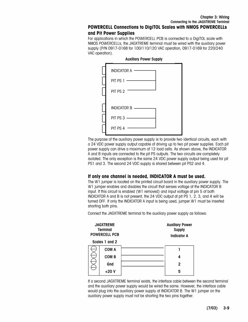
POWERCELL Connections to DigiTOL Scales with NMOS POWERCELLs and Pit Power Supplies For applications in which the POWERCELL PCB is connected to a DigiTOL scale with NMOS POWERCELLs, the JAGXTREME terminal must be wired with the auxiliary power supply (P/N 0917-0168 for 100/110/120 VAC operation, 0917-0169 for 220/240 VAC operation).
The purpose of the auxiliary power supply is to provide two identical circuits, each with a 24 VDC power supply output capable of driving up to two pit power supplies. Each pit power supply can drive a maximum of 12 load cells. As shown above, the INDICATOR A and B inputs are connected to the pit PS outputs. The two circuits are completely isolated. The only exception is the same 24 VDC power supply output being used for pit PS1 and 3. The second 24 VDC supply is shared between pit PS2 and 4.
If only one channel is needed, INDICATOR A must be used. The W1 jumper is located on the printed circuit board in the auxiliary power supply. The W1 jumper enables and disables the circuit that senses voltage at the INDICATOR B input. If this circuit is enabled (W1 removed) and input voltage at pin 5 of both INDICATOR A and B is not present, the 24 VDC output at pit PS 1, 2, 3, and 4 will be turned OFF. If only the INDICATOR A input is being used, jumper W1 must be inserted shorting both pins.
Connect the JAGXTREME terminal to the auxiliary power supply as follows:
Auxiliary Power Supply
JAGXTREME Terminal
POWERCELL PCB
Scales 1 and 2 Indicator A
COM A 1
COM B 4
Gnd 2
+20 V 5
If a second JAGXTREME terminal exists, the interface cable between the second terminal and the auxiliary power supply would be wired the same. However, the interface cable would plug into the auxiliary power supply at INDICATOR B. The W1 jumper on the auxiliary power supply must not be shorting the two pins together.
Auxiliary Power Supply
INDICATOR A
PIT PS 1
PIT PS 2
INDICATOR B
PIT PS 3
PIT PS 4

METTLER TOLEDO JAGXTREME Terminal Installation Guide
(7/03) 3-10
Replacing an Existing 8146 or 8530 on a DigiTOL Scale having an Auxiliary Power Supply and Pit Power Supply(s)
Wire the JAGXTREME terminal POWERCELL PCB to the auxiliary power supply as shown previously. The home-run cables plugged into pit PS 1, 2, 3, or 4 can be left as is.
Replacing an Existing 8530 on a DigiTOL Scale with a Pit Power Supply and not having an Auxiliary Power Supply
An auxiliary power supply must be supplied. Wire the JAGXTREME terminal POWERCELL PCB to the auxiliary power supply as shown previously. Plug the home-run cable from the 8530 into pit PS 1.
Replacing an Existing 8146 or 8530 on a DigiTOL Scale if a Second Scale Is Present
The POWERCELL PCB should be programmed for two scales (Scale 1 + Scale 2 = 24 load cells maximum). The home-run cable(s) should be plugged into pit PS 1 (and PIT PS 2 if a second home-run cable exists).
Replacing an Existing 8146 or 8530 on a DigiTOL Scale if a Third Scale Is Present
The first JAGXTREME terminal with a POWERCELL PCB should be wired as indicated previously. The second terminal with a POWERCELL PCB should be wired into INDICATOR B of the auxiliary power supply and the home-run cable going to the third scale should be plugged into pit PS 3 or 4.
Shield wire must be connected to chassis ground or "GND" terminal at the JAGXTREME terminal end for reliable operation. You can purchase this adapter harness (0900-0284) or cut the base cables and wire directly to the terminals.
Chapter 3: Wiring Connecting to the JAGXTREME Terminal
(7/03) 3-11
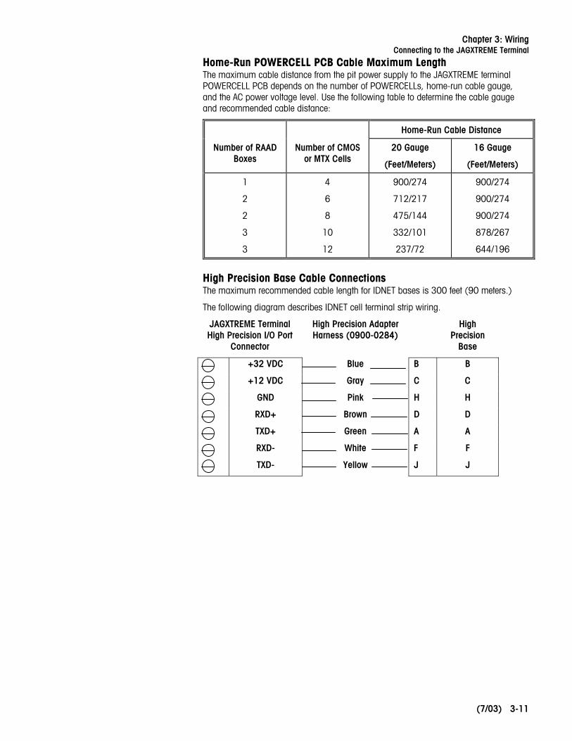
Home-Run POWERCELL PCB Cable Maximum Length The maximum cable distance from the pit power supply to the JAGXTREME terminal POWERCELL PCB depends on the number of POWERCELLs, home-run cable gauge, and the AC power voltage level. Use the following table to determine the cable gauge and recommended cable distance:
Home-Run Cable Distance
Number of RAAD Boxes
Number of CMOS or MTX Cells
20 Gauge
(Feet/Meters)
16 Gauge
(Feet/Meters)
1
2
2
3
3
4
6
8
10
12
900/274
712/217
475/144
332/101
237/72
900/274
900/274
900/274
878/267
644/196
High Precision Base Cable Connections The maximum recommended cable length for IDNET bases is 300 feet (90 meters.)
The following diagram describes IDNET cell terminal strip wiring.
JAGXTREME Terminal High Precision I/O Port
Connector
High Precision Adapter Harness (0900-0284)
High Precision
Base
+32 VDC Blue B B
+12 VDC Gray C C
GND Pink H H
RXD+ Brown D D
TXD+ Green A A
RXD- White F F
TXD- Yellow J J

METTLER TOLEDO JAGXTREME Terminal Installation Guide
(7/03) 3-12
Serial Port Connections Controller PCB
Refer to the following diagrams for proper cable connections to the JAGXTREME terminal’s serial ports COM1 and COM2. COM1 and COM2 are located on the Controller board, which is positioned in the top slot.
The COM1 and COM2 terminal strips will accommodate wire sizes from 16 to 22 AWG. The terminal strips may be removed to facilitate wiring. Removal of the terminal strips permits easier viewing of the terminal designations printed on the board back plate.
LNK
T/R
METTLER TOLEDO
A
KEYBOARD PAR 2 PAR 1 COM 1 COM 2
CONTROLLER
422/485232CL232
+5V
OUT
1O
UT2
OUT
3O
UT4
IN1
IN2
IN3
IN4
GN
D
T R T+ R+ R- T R T+ T- R+ R-GN
D
+20
V
GN
D/C
LT-
Note: Keyboard wedges and other non-keyboard devices are not supported.
Chapter 3: Wiring Connecting to the JAGXTREME Terminal
(7/03) 3-13
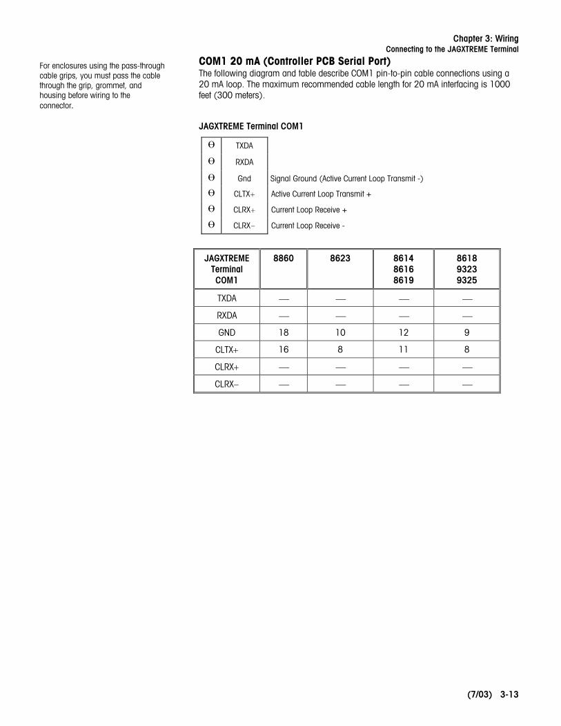
COM1 20 mA (Controller PCB Serial Port) The following diagram and table describe COM1 pin-to-pin cable connections using a 20 mA loop. The maximum recommended cable length for 20 mA interfacing is 1000 feet (300 meters).
JAGXTREME Terminal COM1
TXDA
RXDA
Gnd Signal Ground (Active Current Loop Transmit -)
CLTX+ Active Current Loop Transmit +
CLRX+ Current Loop Receive +
CLRX- Current Loop Receive -
JAGXTREME Terminal COM1
8860 8623 8614 8616 8619
8618 9323 9325
TXDA ⎯ ⎯ ⎯ ⎯
RXDA ⎯ ⎯ ⎯ ⎯
GND 18 10 12 9
CLTX+ 16 8 11 8
CLRX+ ⎯ ⎯ ⎯ ⎯
CLRX− ⎯ ⎯ ⎯ ⎯
For enclosures using the pass-through cable grips, you must pass the cable through the grip, grommet, and housing before wiring to the connector.

METTLER TOLEDO JAGXTREME Terminal Installation Guide
(7/03) 3-14
COM1 RS-232 (Controller PCB Serial Port) The following diagram and table describe COM1 pin-to-pin cable connections using an RS-232 cable. Maximum recommended cable length is 50 feet (15 meters).
JAGXTREME Terminal COM 1
TXD RS-232 Transmit
RXD RS-232 Receive
GND Signal Ground
CLTX+
CLRX+
CLRX-
Pin Connection for METTLER TOLEDO Devices Using COM1 RS-232
JAGXTREME Terminal COM1
8863 8846
8867
8806
8807
8808
8845
8856
8857
8860
8861
8865
9323-TB2
9325-TB2
8624
8618
TXDA 3 2 3 2 InputCom
RXDA 2 3 2 ⎯ ⎯
GND 5 7 7 3 RS232 Input
CLTX+ ⎯ ⎯ ⎯
CLRX+ ⎯ ⎯ ⎯
CLRX− ⎯ ⎯ ⎯

Chapter 3: Wiring Connecting to the JAGXTREME Terminal
(7/03) 3-15
COM2/COM4 RS-232 (Controller PCB Serial Port) The following describes COM2 pin-to-pin cable connections using an RS-232 cable and the connections to COM4 when an optional Multifunction I/O PCB is installed. The maximum recommended cable length for RS-232 is 50 feet (15 meters). Maximum recommended total distance for RS-422 and RS-485 is 2000 feet (600 meters).
JAGXTREME Terminal COM2/COM4
TXD RS-232 Transmit
RXD RS-232 Receive
GND Signal Ground
TXD+ RS-422/485 Transmit +
TXD- RS-422/485 Transmit -
RXD+ RS-422/485 Receive +
RXD- RS-422/485 Receive -
+20 V +20 VDC Supply
Pin Connection for METTLER TOLEDO Devices Using
COM2 RS-232/RS-485
JAGXTREME Terminal COM2
8806 8807 8808
8844 8845 8857
8861 8865
8846
8867
8863 8617-TB2 9323-TB2 9325-TB2
8618
TXDB 3 2 3 2 ⎯
RXDB ⎯ 3 2 ⎯ ⎯
GND 7 7 5 3 ⎯
TXD+ ⎯ ⎯ RS-485B
TXD− ⎯ ⎯ RS-485A
RXD+ ⎯ ⎯ ⎯
RXD− ⎯ ⎯ ⎯
+20 V ⎯ ⎯ ⎯
The COM4+20 V terminal voltage output is determined by the W2 jumper on the Multifunction I/O PCB.

METTLER TOLEDO JAGXTREME Terminal Installation Guide
(7/03) 3-16
Discrete Wiring The Controller PCB contains four discrete input and four discrete output connections.
PAR 1 Input Connections The input connections must be referenced to ground. A switch or relay contact may be used to make this connection. The remote device should hold the input at logic ground for at least 100 ms. Scale functions are performed when the input is held to ground (leading edge triggered). The maximum recommended cable length between the remote device and the JAGXTREME terminal is 10 feet (3 meters).
Each of the four PAR 1 inputs can be configured for different remote inputs including input from the keypad for remote print, unit switching, alternate scale selection, or template selection. Polarity (switch to ground or open a ground connection to initiate remote input) can also be selected.
Figure 2-g: Input Wiring Example
When the JagMAX software is used, the terminal reserves inputs one and two for use with the optional traffic light controller. The terminal reserves input three for an optional pushbutton to return the terminal to local control. (Used only remotely operated installations.)
IN 1 Remote Weigh Mode Pushbutton*
IN 2 Remote Re-Weigh Mode Pushbutton*
IN 3 ESC from Remote Controller
(Reserved but used only for remotely operated installations)
*See optional traffic light controller wiring diagram.
For more information see the section entitled Inputs in Appendix 2 at the back of this manual.
PAR 1 Terminal
For more information see the section entitled Outputs in Appendix 2 at the back of this manual.
Figure 1-r: Input Wiring Example

Chapter 3: Wiring Connecting to the JAGXTREME Terminal
(7/03) 3-17
PAR 2 Output Connections Each of the four PAR 2 outputs can be configured to announce Setpoints 1 through 12 coincidence. The 12 setpoint outputs can be configured to request either Feed or Fast Feed, or announce setpoint tolerance status. The standard number of outputs is 4. Eight additional outputs are available if a multifunction PCB is installed.
PAR 2 outputs can be configured to announce “current scale status” conditions such as:
• Net or Gross Mode • Gross Zero • Motion • Over Capacity • Under Zero
Outputs are negative-true, open collector type.
PAR 2 outputs can be referenced to the 5 volt supply available on the PAR2 connector or can sink up to 35 mA of current and have a maximum voltage of 30 volts DC from an external source. The maximum cable length between the remote device and JAGXTREME terminal is 10 feet (3 meters).
PAR 2 Terminal
Output Wiring Example
JAGXTREME PAR 2
PLC Sourcing Input Card
+5V - NC
OUT1 IN1
OUT2 IN2
OUT3 IN3
OUT4 IN4
GND GND
PLC Input Wiring Example
GND NC

METTLER TOLEDO JAGXTREME Terminal Installation Guide
(7/03) 3-18
Optional JagMAX Software When using the optional JagMAX software, the terminal reserves the first three outputs for use with the optional traffic light controller, and the fourth is reserved to indicate the center of zero for the summation scale for Canadian applications.
OUT 1 Entrance Traffic Light*
OUT 2 Exit Traffic Light*
OUT 3 Truck On Alarm Output*
OUT 4 Sum scale center-of-zero light
*See optional traffic light controller wiring diagram.
IN1 YEL
IN2 GRN
IN3 BLU
IN4 VIO Optional
OUT1 BLK Traffic Light
OUT2 BRN Controller
OUT3 RED (90382800A)
OUT4 ORG
GND WHT/BLK
WHT/ORG
WHT/RED
+5V WHT/BRN
Figure 1-s
Traffic Light Controller Wiring Diagram
Chapter 3: Wiring Connecting to the JAGXTREME Terminal
(7/03) 3-19
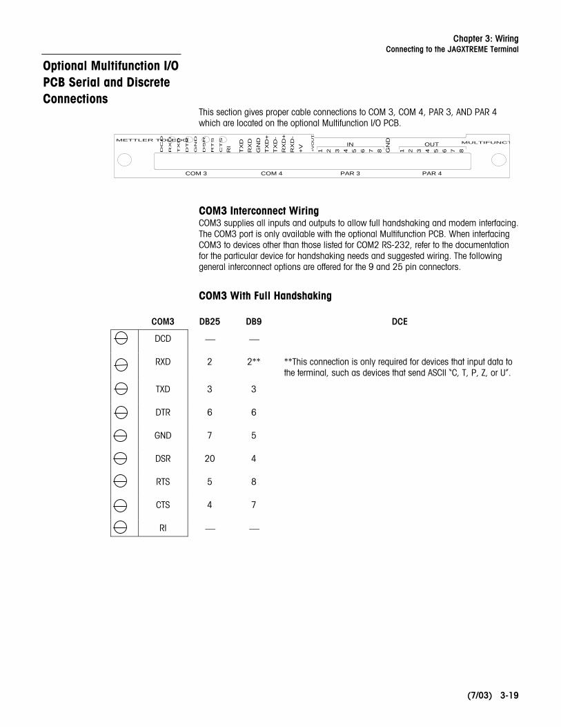
Optional Multifunction I/O PCB Serial and Discrete Connections
This section gives proper cable connections to COM 3, COM 4, PAR 3, AND PAR 4 which are located on the optional Multifunction I/O PCB.
RX
D
DC
D
TX
D
DT
R
GN
D
CT
S
RT
S
DS
R
COM 3 COM 4
RI
TX
DR
XD
GN
D
RX
D+
TX
D-
TX
D+
RX
D-
+V
87654321GN
D
1 2 3 4 5 6 7 8+V
OU
T
IN OUT MULTIFUNCT
PAR 3 PAR 4
METTLER TOLEDO
COM3 Interconnect Wiring COM3 supplies all inputs and outputs to allow full handshaking and modem interfacing. The COM3 port is only available with the optional Multifunction PCB. When interfacing COM3 to devices other than those listed for COM2 RS-232, refer to the documentation for the particular device for handshaking needs and suggested wiring. The following general interconnect options are offered for the 9 and 25 pin connectors.
COM3 With Full Handshaking
COM3 DB25 DB9 DCE
DCD
⎯ ⎯
RXD 2 2** **This connection is only required for devices that input data to the terminal, such as devices that send ASCII “C, T, P, Z, or U”.
TXD
3 3
DTR
6 6
GND
7 5
DSR
20 4
RTS
5 8
CTS
4 7
RI ⎯ ⎯

METTLER TOLEDO JAGXTREME Terminal Installation Guide
(7/03) 3-20
COM4 Interconnect Wiring The wiring instructions for the COM2 serial port apply to COM4 on the Multifunction PCB. Refer to the section presented earlier entitled COM2/COM4 RS-232 (Controller PCB Serial Port) to interface COM4 to DigiTOL scales and printers.
PAR 3 Discrete Input Port Each of the eight PAR 3 inputs can be configured for different remote inputs including input from the JAGXTREME keypad (Tare, Clear, Zero, Select, Escape, and Enter). PAR 3 inputs can also be configured for remote print, unit switching, alternate scale selection, or template selection. Polarity (switch to ground or open a ground connection to initiate remote input) can also be selected.
The wiring instructions for the PAR 1 discrete inputs apply to PAR 3 on the Multifunction PCB. Refer to the section entitled PAR 1 Input Connections for wiring details.
PAR 4 Discrete Output Port Each of the eight PAR 4 outputs can be configured to announce Setpoints 1 through 12 coincidence. The 12 setpoint outputs can be configured to request either Feed or Fast Feed, or to announce setpoint tolerance status. PAR 4 outputs can also be configured to announce “current scale status” conditions such as:
• Net or Gross Mode • Gross Zero • Motion • Over Capacity • Under Zero The +VOUT terminal supplies a jumper selectable voltage of +5, +12, or +20 VDC.
The wiring instructions for the PAR 2 discrete outputs apply to PAR 4 on the Multifunction PCB. Please refer to the section entitled PAR 2 Output Connections for wiring details.

Chapter 3: Wiring Connecting to the JAGXTREME Terminal
(7/03) 3-21
Connecting the Power Cable
A power cord is provided with the general purpose and harsh environment JAGXTREME terminals. Connection to the panel-mount JAGXTREME terminal must be made at installation. The AC power connection must be wired as follows for harsh and general-purpose models:
The terminal strip will accommodate wire sizes from 12 to 16 AWG. The wire size used must meet all local and national electrical codes. On panel-mount models, you must secure the wiring with a cable tie as a strain relief. Cable ties are supplied loose. If the power terminal strip is removed from the terminal, reinsert it until it is completely seated in the jack at the rear of the enclosure.
An auxiliary chassis ground screw is located at the lower right corner of the power supply cabinet. This ground connection is provided for surge voltage protection applications and for chassis ground. On panel-mount models (JXPx) you must connect a safety ground to this screw.
Note: Some regions and/or power cords may use different color codes than shown.
Power Connection for Harsh and General Purpose Terminal
Power Connections for Panel-Mount Terminal and Blind Panel-Mount Terminal
Shown with option kit, 0917-0333.

METTLER TOLEDO JAGXTREME Terminal Installation Guide
(7/03) 3-22
For your notes

Chapter 4: Hardware Installation Installing the General Purpose Model
(7/03) 4-23
4 Hardware Installation
Installing the General Purpose Model
Dimensions:
• 12.45 in. (250 mm) wide x 7.86 in. (200 mm) high
• 10.6 in (270 mm) deep
1. Place the terminal at the operating site. Refer to the illustrations on this page and the next when following the directions provided here.
2. Remove the four screws securing the rear access cover to the main housing using a Phillips head screwdriver.
3. With the rear access cover removed, you can now make connections to the unit. (Refer to the illustration and table that follow for suggested wire connections.)
4. Pass the cables that enter the enclosure through an appropriately sized cable grip before connecting the wires.
7 8
10 5
12 312 4
10 0
3 °
2 °
11 °
12.45
10.05
12.31
29°
115°
39°
7.85
10.59

METTLER TOLEDO JAGXTREME Terminal Installation Guide
(7/03) 4-24
5. Tighten the cable grip to provide a water-tight seal around the cable after re-securing the back cover. This allows any internal cable slack to be received through the cable grip.
6. Connect a PS/2 type keyboard, if desired, using an optional external keyboard connector kit.
7. You can now make the electrical connections.
Reference Letter Suggested Cable
A Serial I/O Cables (Except DigiTOL) PLC I/F Cabling
B Analog Load Cell Cabling DigiTOL Load Cell Cabling
C Ethernet RJ-45 Category 5
D QWERTY PS/2
General Purpose Model Wiring Connections and Cable
To make keyboard and/or Ethernet connections to the general-purpose model, follow these steps:
1. Remove the plugs from the back of the JAGXTREME terminal.
2. Remove the cap from the grip bushing assembly (supplied in the shipping kit that accompanies the harsh environment and general purpose JAGXTREME terminals).
3. Route the cable end through the cap of the grip bushing.
4. Route the cable end through the grip bushing.
5. Assemble the bushing to the appropriate hole in the access cover.
6. Plug in the cable to the appropriate port (Ethernet or keyboard) on the JAGXTREME terminal.
7. Reassemble the access cover to the JAGXTREME terminal.
8. Tighten the grip bushing cap to the grip bushing.
C or D C or D
A
A
B
B

Chapter 4: Hardware Installation Installing the Panel-Mount Model
(7/03) 4-25
Installing the Panel-Mount Model
Dimensions (Panel Mount):
• 10.05 in. (255 mm) x 5.6 in. (140 mm) at the front of the terminal
• 9.5 in. (240 mm) x 4.91 in. (125 mm) at the rear
• 8.03 in. (210 mm) deep
Open 5.12±.06
9.58±.06
4XR 0.25±.01
1. Refer to the illustrations provided.
2. Cut an opening 9.58 in. (243.3 mm) × 5.12 in. (130 mm) to accommodate the terminal. The tolerance for the panel cutout is ±0.06 in. (01.5 mm).
3. Using the Allen wrench included, remove the four retaining set screws (A) located at the rear of the enclosure in the top and bottom mounting plate grooves.
4. Remove both mounting plates (B).
5. Insert the terminal through the panel opening from the front until it is flush against the panel. Confirm that the terminal is installed right side up.
6. Slide the top and bottom mounting plates back in the grooves. Push them flush against the panel from the back. The flared end of the plate should contact the back of the panel.
7. Holding the unit in place, replace the four set screws and tighten until the unit is secured and the front panel gasket is compressed.
8. Inspect the front of the terminal for a good seal to the front of the enclosure.
9. You can now make the electrical connections. (Ethernet and keyboard connections can be made directly to the Controller PCB.)

METTLER TOLEDO JAGXTREME Terminal Installation Guide
(7/03) 4-26
Installing the Blind Panel-Mount Unit
Panel-Mount Enclosure—Blind Chassis (PB) The front of the panel-mount enclosure has a blank plate to cover the electronics and to provide a method of mounting. There is no keyboard or display on the front of the unit. This allows the terminal’s use as a “blind” terminal (installed behind a panel,) sharing another JAGXTREME terminal’s keyboard and display via the Ethernet connection. The terminal enclosure has a NEMA 1 or IP30 rating with a “blind” front panel.
The blind chassis mount model measures:
10.75 in. (270 mm) × 4.31 in. (109 mm) at the base
10.25 in. (260 mm) × 3.91 in. (100 mm) c-c mounting
9.5 in. (241 mm) × 5.00 in. (130 mm) chassis

Chapter 4: Hardware Installation Installing the Harsh Environment Enclosure
(7/03) 4-27
Installing the Harsh Environment Enclosure
Dimensions: 9.42 x 11.12 x 9.56" (239.3 x 282.4 x 242.8 mm)
*Refers only to JAGXTREME harsh environment enclosures manufactured after July 15, 2001.
Mounting the Harsh Environment Terminal
1. Locate the two mounting brackets that came in the JAGXTREME terminal package.
2. Mount the brackets using the four stainless steel screws supplied with the unit. Refer to figure below and note the correct positioning of the brackets. The slotted holes must protrude beyond the enclosure and the bracket tabs must point toward the front as shown.
* Shown with wall mount brackets (included with enclosure) installed.

METTLER TOLEDO JAGXTREME Terminal Installation Guide
(7/03) 4-28
3. Tighten the brackets to the back of the enclosure (torque 25 inch pounds or 2.83 N•m).
4. Using the dimensions on the previous page, prepare the mounting surface to accept the enclosure. The mounting surface and brackets must be able to support 45 lb (20 kg).
5. Place the enclosure on the mounting surface and secure with appropriate fasteners. You can now make the electrical connections.
Opening the Harsh Environment Terminal
1. Disconnect power.
2. Locate the two slots on the bottom lip of the front of the harsh environment enclosure.
3. Gently insert the blade of a slotted screwdriver into one of the slots and press inward (toward the enclosure). This releases a pressure tab that allows the access panel of the enclosure to open slightly.
4. Repeat steps 2 and 3 for the other slot.
5. Remove the access panel away from the enclosure. The access panel is connected to the Controller PCB by a cable and cannot be removed without disconnecting the cable. You should be able to access the unit with the front panel connected.
6. With the access cover removed, you are now ready to make connections to the unit. The illustration and table that follow describe the recommended wiring connections.
Reference Letter Suggested Cable
A Serial I/O Cables (Except DigiTOL) PLC I/F Cabling
B Analog Load Cell Cabling DigiTOL Load Cell Cabling
C Ethernet Cabling RJ-45 Category 5
D QWERTY Keyboard PS/2
C or D C or D
A
A
B (load cells) B (load cells)
Power cord

Chapter 4: Hardware Installation Ethernet Connection
(7/03) 4-29
Ethernet Connection The JAGXTREME terminal can be connected to LAN, WAN, automation or enterprise systems using ETHERNET, a standard network hardware platform.
The ETHERNET connection on the rear of the JAGXTREME terminal Controller PCB is designed for an RJ45 connector. METTLER TOLEDO recommends using Category 5 cable, which provides unshielded, four twisted pair cable.
Depending upon the equipment to which the JAGXTREME terminal will be connected, either a “crossover” or standard cable is required.
• When connecting directly between a PC and a JAGXTREME terminal (point to point connection), a crossover cable is used.
• To connect the JAGXTREME terminal to other equipment through a hub, a standard cable is normally used as the hub provides the crossover connections. Refer to the specifications of the hub used to determine if a crossover cable is required.
Additional Information The JAGXTREME terminal can now be configured via the front panel or web server interface. This procedure should be performed only by qualified technicians following the instructions provided in the JAGXTREME Terminal Technical Manual. Once setup is complete, the unit can be sealed if required.

METTLER TOLEDO JAGXTREME Terminal Installation Guide
(7/03) 4-30
For your notes


METTLER TOLEDO 1900 Polaris Parkway Columbus, Ohio 43240 Phone: (US and Canada) (800) 786-0038 (614) 438-4511 Phone: (International) (614) 438-4888 www.mt.com P/N: A15888800A (7/03).01 METTLER TOLEDO® is a registered trademark of Mettler-Toledo, Inc. ©2003 Mettler-Toledo, Inc. Printed in USA
A15888800A