pH 2700i(X) module - Mettler Toledo
120
pH 2700i(X) module Instruction manual Order number: 52 121 276
-
Upload
khangminh22 -
Category
Documents
-
view
4 -
download
0
Transcript of pH 2700i(X) module - Mettler Toledo

pH 2700i(X) moduleInstruction manual
Order number: 52 121 276
69904_E_2700i.QXD 28.09.2005 15:01 Uhr Seite 1 gro DAISY.DATA01:NETDATA:MAC2ALL:BA:M700X_Version_6:pH2

TA-201.035-MTE01 011005 Software version 1.x
Registered trademarksThe following registered trademarks are used in this instruction manualwithout further marking
CalimaticSensocheckSensofaceServiceScopeVariPower
SMARTMEDIA®
is a registered trademark of Toshiba Corp., Japan
InPro®
is a registered trademark of Mettler-Toledo GmbH, Switzerland
WarrantyDefects occurring within 1 year from delivery date shall be remedied free of charge at our plant(carriage and insurance paid by sender). ©2005 Subject to change without notice
Mettler-Toledo GmbH, Process Analytics, Industrie Nord,CH-8902 Urdorf, Tel. +41 (44) 736 22 11 Fax +41 (44) 736 26 36 Subject to technical changes. Mettler-Toledo GmbH, 09/05. Printed in Germany.
Return of products under warrantyPlease contact your local Mettler-Toledo representative before returning a defective device. Ship thecleaned device to the address you have been given. If the device has been in contact with process fluids,it must be decontaminated/disinfected before shipment. In that case, please attach a correspondingcertificate, for the health and safety of our service personnel.
DisposalPlease observe the applicable local or national regulations concerning the disposal of “waste electricaland electronic equipment”.
69904_E_2700i.QXD 28.09.2005 15:01 Uhr Seite 2 gro DAISY.DATA01:NETDATA:MAC2ALL:BA:M700X_Version_6:pH2

69904_E_2700i.QXD 28.09.2005 15:01 Uhr Seite 3 gro DAISY.DATA01:NETDATA:MAC2ALL:BA:M700X_Version_6:pH2

Warranty ......................................................................................................2Registered trademarks ..................................................................................2EC Declaration of Conformity ......................................................................3Intended use ................................................................................................8Safety information........................................................................................9Software version .......................................................................................10
Modular concept and instruction manuals ...........................................11Short description: M 700 FRONT ................................................................12Short description: Menu structure ..............................................................13Short description: M 700 BASE...................................................................15Parameter tables (Excel) at www.mtpro.com...............................................17
ISM - Intelligent Sensor Management...................................................18ISM - Plug and Measure...........................................................................19ISM - First Calibration ..............................................................................20ISM - Parameter setting ...........................................................................21ISM - Predictive maintenance...................................................................22ISM - Diagnostics.....................................................................................23Setting ISM diagnostics messages as favorite ...........................................24
Terminal plate ..........................................................................................27Inserting the module ..................................................................................28
Wiring examplesISM pH/ORP measurement with glass electrode .......................................29ISM pH measurement with ISFET sensor ..................................................30pH measurement with Sensocheck of glass electrode ..............................31Simultaneous pH and ORP measurement .................................................31ORP measurement with Sensocheck for reference electrode ....................32
Quick start:Menu selection, menu structure .................................................................34Passcode entry............................................................................................35Configuring the measurement display ........................................................36
Contents
4 pH 2700i(X)
69904_E_2700i.QXD 28.09.2005 15:01 Uhr Seite 4 gro DAISY.DATA01:NETDATA:MAC2ALL:BA:M700X_Version_6:pH2

5
Calibration / adjustment ........................................................................38Adjustment ................................................................................................39
Calibration methods ................................................................................40Temperature compensation......................................................................41Select calibration method ........................................................................42Calimatic automatic buffer recognition....................................................44Calibration with manual entry of buffer values .......................................46Product calibration (calibration with sampling) ........................................48Data entry of premeasured electrodes .....................................................50Monitoring functions for calibration ........................................................51ORP adjustment ......................................................................................52Temperature dependence of commonly used reference systems ..............53ISFET zero adjustment .............................................................................54
Maintenance ............................................................................................56
Setting the module parametersOperating levels.......................................................................................57Enable / lock functions.............................................................................58Setting the module parameters................................................................59Setting the sensor data parameters .........................................................60Sensoface ................................................................................................61Settings of sensor data ............................................................................62Tolerance adjustment: Program flow .......................................................65Activating the tolerance adjustment (SW 700-005)..................................66TC process medium .................................................................................68ORP/rH value ...........................................................................................71Delta function..........................................................................................71Messages.................................................................................................73
Setting the logbook parameters (System control)Logbook ..................................................................................................74Factory setting .........................................................................................74
Contents
69904_E_2700i.QXD 28.09.2005 15:01 Uhr Seite 5 gro DAISY.DATA01:NETDATA:MAC2ALL:BA:M700X_Version_6:pH2

6 pH 2700i(X)
Contents
Setting the system control and the outputs (BASE)Setting the current output .......................................................................75Output filter (time constant) ....................................................................78NAMUR signals (current outputs) - Behavior during messages - ...............79NAMUR signals (relay contacts):failure, maintenance request, function check...........................................80Relay contacts: protective wiring..............................................................81Setting the relay contacts ........................................................................82Limit value, hysteresis, contact type .........................................................83
Setting the OK1, OK2 inputs (BASE)Optocoupler inputs (BASE): Usage and switching level.............................84Switching parameter sets via OK2 (system control) ..................................85
Calculation Blocks (System control)Calculation of new variables from measured variables .............................86
Diagnostics functions ..............................................................................89Device description....................................................................................90FRONT module ........................................................................................90BASE module...........................................................................................90Module diagnostics..................................................................................91Sensor monitor ........................................................................................91ServiceScope (SW 700-004) .....................................................................91Cal timer .................................................................................................92Adaptive cal timer ...................................................................................92Tolerance band recorder (SW 700-005)....................................................92Cal record................................................................................................93Sensor network diagram..........................................................................93Statistics ..................................................................................................93
Specifications ...........................................................................................94
69904_E_2700i.QXD 28.09.2005 15:01 Uhr Seite 6 gro DAISY.DATA01:NETDATA:MAC2ALL:BA:M700X_Version_6:pH2

7
Contents
Appendix:Minimum measuring spans for current outputs ..........................................98Buffer tables...............................................................................................99Buffer set to be entered (SW 700-002).....................................................105
Overview of parameter setting............................................................106
Index.......................................................................................................111
Overview of icons .................................................................................115
Overview of menu selection ................................................................116
69904_E_2700i.QXD 28.09.2005 15:01 Uhr Seite 7 gro DAISY.DATA01:NETDATA:MAC2ALL:BA:M700X_Version_6:pH2

8 pH 2700i(X)
Intended use
The module is used for simultaneous pH, ORP, and temperature measurementwith glass electrodes, ISFET sensors, or sensors with ISM technology (IntelligentSensor Management). The use of ISFET sensors is an additional function whichcan be enabled by a separately orderable TAN.
The pH 2700iX module is intended for operation in locations subject toexplosion hazards which require equipment of Group II, device category 2(1),gas/dust.
Conformity with FDA 21 CFR Part 11In their directive “Title 21 Code of Federal Regulations, 21 CFR Part 11,Electronic Records; Electronic Signatures” the US American health agencyFDA (Food and Drug Administration) regulates the production and processingof electronic documents for pharmaceutical development and production.This results in requirements for measuring devices used for correspondingapplications. The following features ensure that the M 700(X) modularprocess analysis system meets the demands of FDA 21 CFR Part 11:
Electronic SignatureAccess to the device functions is regulated and limited by individuallyadjustable codes – “Passcodes”. This prevents unauthorized modification ofdevice settings or manipulation of the measurement results. Appropriate useof these passcodes makes them suitable as electronic signature.
Audit Trail LogEvery change of device settings can be automatically recorded and docu-mented in the Audit Trail Log on the SmartMedia card. The recording can beencoded.
69904_E_2700i.QXD 28.09.2005 15:01 Uhr Seite 8 gro DAISY.DATA01:NETDATA:MAC2ALL:BA:M700X_Version_6:pH2

9
Safety information
Caution!Never try to open the module! If a repair should be required, return themodule to our factory.
If the specifications in the instruction manual are not sufficient for assessingthe safety of operation, please contact the manufacturer to make sure thatyour intended application is possible and safe.
Be sure to observe during installation:• Switch off power supply before replacing or inserting a module.• Protect the signal inputs of the modules against electrostatic discharge.• Before commissioning it must be proved that the device may be connected
with other equipment.• Observe correct shielding: To avoid interferences, the cable shielding must
be completely covered by the ESD shielding cap.
Application in hazardous locations: pH 2700iX moduleWhen using the M 700 module pH 2700iX, the stipulations for electricalinstallations in hazardous areas (EN 60079-14) must be observed. Wheninstalling the device outside the range of applicability of the 94/9/EC direc-tive, the appropriate standards and regulations in the country of use must beobserved. The module has been developed and manufactured in compliancewith the applicable European guidelines and standards.
Compliance with the European Harmonized Standards for use in hazardouslocations is confirmed by the EC-Type-Examination Certificate. Compliancewith the European guidelines and standards is confirmed by the ECDeclaration of Conformity.
There is no particular direct hazard caused by the operation of the device inthe specified environment.
69904_E_2700i.QXD 28.09.2005 15:01 Uhr Seite 9 gro DAISY.DATA01:NETDATA:MAC2ALL:BA:M700X_Version_6:pH2

10 pH 2700i(X)
Menu Display Device description
Provides information about all mod-ules installed: Module type and func-tion, serial number, hardware andsoftware version and device options. Select the different modules (FRONT,BASE, slots 1 - 3) using the arrowkeys.
Device description
Return
22.7 °C7.00 pH
M 700 operating panelModule FRONT 700X-015
Hardware: 2, Software: 6.2Serial number: 0000815
BASEModule FRONT
Software versionpH 2700i(X) module
Device software M 700(X)The pH 2700i module is supported by software version 6.2 or higher.The pH 2700iX module is supported by software version 6.2 or higher.
Module software pH 2700i(X)Software version 1.0 xx.xx.2005 pH module with ISM functionality.
Query actual device/module softwareWhen the analyzer is in measuring mode:Press menu key, open Diagnostics menu.
Options
69904_E_2700i.QXD 28.09.2005 15:01 Uhr Seite 10 gro DAISY.DATA01:NETDATA:MAC2ALL:BA:M700X_Version_6:pH

11
Modular concept and instruction manualsInstruction manuals for basic unit, measuring module, additional functions.
• The instruction manual for the M 700(X) describes how to install, commission and operate the basic unit.
• The instruction manual for the measuring or communication moduledescribes all functions required for commissioning and working withthe respective measuring or communication module.
• Additional functions are supplied with a function description.
The M 700(X) is an expandable modular process analysis system.The basic unit (M 700 FRONT and BASE) provides three slots which can beequipped by the user with any combination of measuring or communicationmodules. The software capabilities can be expanded by additional functions(options). Additional functions must be ordered separately. They are suppliedwith a device-specific TAN for function release.
3 module slotsfor free combination ofmeasuring and communica-tion modules
Measuring modules• pH / ORP / Temp (also ISM)• 02/Temp (also ISM)• Noncontacting conductivity / Temp• Contacting conductivity / Temp
Additional functionsActivation via device-specific TANFor an overview, seewww.mtpro.com
SmartMedia cardData recordingFor an overview, seewww.mtpro.com.
M 700(X) modular process analysis system
Communication modules• Out (additional switching and
current outputs)• PID (analog and digital controller)• Profibus PA
retrofita
ble
Option
69904_E_2700i.QXD 28.09.2005 15:01 Uhr Seite 11 gro DAISY.DATA01:NETDATA:MAC2ALL:BA:M700X_Version_6:pH

pH 2700i(X)12
Short description: M 700 FRONTM 700Modular hardware and software system for liquid analysis.
Transflective LC graphic display(240 x 160 pixels)white backlighting, high resolution and high contrast.
Red LEDsignals failure (On) ormaintenance request/function check(flashing) according to NE 44.
4 captive scewsfor opening the analyzer(Caution! Make sure that the gasket between FRONT and BASE is properly seated and clean!)
Green LEDVoltage supply okay
5 self-sealing cable glandsM20 x 1.5for entry of voltage supply and signal lines
2 softkeyswith context-sensitive functions.
User interfacewith plaintext menus as recom-mended by NAMUR. Menu texts can be switched to:German, English, French, Italian,Swedish, and Spanish.Intuitively acquirable menu logic,based on Windows standards.
Control panel3 function keys(menu, meas, enter)and 4 arrow keys for menu selectionand data entries
Measurement displayFor parameter setting, see Pg 36
Secondary displayssee Pg 24
69904_E_2700i.QXD 28.09.2005 15:01 Uhr Seite 12 gro DAISY.DATA01:NETDATA:MAC2ALL:BA:M700X_Version_6:pH

13
Measuring
Short description: Menu structureBasic functions: Calibration, maintenance, parameter setting, diagnostics
Calibration Maintenance Parameter setting Diagnostics
Menu groups
1
2
3
1147 2958 1246Operator level
1989Administrator level
Passcode:
Selection offurthermenu items:
Module 1Module 2Module 3
BASEModule 1Module 2Module 3
SYSTEMFRONTBASEModule 1Module 2Module 3
4
5
Legend:(1) Pressing the menu key accesses menu selection(2) Pressing the meas key returns to measurement(3) Menu groups are selected using the arrow keys(4) Press enter to confirm, enter passcode(5) Further menu items are displayed(6) Selected functions of the Diagnostics menu can be recalled via
softkey even when in measuring mode (“Favorites”, Pg 24)
Message listPoint of measdescriptionLogbookDevice description
FRONTBASEModule 1Module 2Module 3
69904_E_2700i.QXD 28.09.2005 15:01 Uhr Seite 13 gro DAISY.DATA01:NETDATA:MAC2ALL:BA:M700X_Version_6:pH

04
pH 2700i(X)14
Short description: M 700 FRONTM 700View into the open device (M 700 FRONT)
Terminal platesof “hidden” modulesEach module comes with an adhesivelabel containing the contact assignments.This label should be sticked to the innerside of the front (as shown).Then, the terminal assignments remainvisible even if further modules are insert-ed.
Slot for SmartMedia card• Data recording
The SmartMedia card expands the measurement recorder capacity to > 50000 records.
• Exchange of parameter sets5 parameter sets can be stored on the SmartMedia card, 2 of them can be loaded to the M 700 and switched by remote control. Configurations can be transferred from one transmitter to the other.
• Function expansionsare possible with additional softwaremodules which are released using transaction numbers (TAN).
• Software updates
The circumferential sealingguarantees IP 65 protection and allows spraycleaning / disinfection.Caution! Keep clean!
Replacing the front modulePull off power cord and ground wire. To separate the M 700 FRONT from theM 700 BASE, turn the retaining screws ofthe pivot hinge by 90°.
69904_E_2700i.QXD 28.09.2005 15:01 Uhr Seite 14 gro DAISY.DATA01:NETDATA:MAC2ALL:BA:M700X_Version_6:pH

15
Short description: M 700 BASEM 700View into the open device (M 700 BASE, 3 function modules installed)
M 700 BASE2 current outputs (free assignment ofprocess variable) and 4 relay contacts, 2 digital inputs. VariPower broad-range power supply,20 ... 265 V AC/DC, suitable for all publicmains supplies in the world.
Power supply units, IS version:100 ... 230 V AC or24 V AC/DC
Important note concerning SmartMedia cardThe SmartMedia card may be inserted or replaced with the power supplyswitched on. Before a memory card is removed, it must be “closed” in themaintenance menu. When closing the device, make sure that the sealing isproperly seated and clean.
Module equipmentModule identification: Plug & PlayUp to 3 modules can be combined asdesired. Several input and communicationmodules are available.
Warning! Do not touch the terminal compartment, there may bedangerous contact voltages!
69904_E_2700i.QXD 28.09.2005 15:01 Uhr Seite 15 gro DAISY.DATA01:NETDATA:MAC2ALL:BA:M700X_Version_6:pH

16 pH 2700i(X)
69904_E_2700i.QXD 28.09.2005 15:01 Uhr Seite 16 gro DAISY.DATA01:NETDATA:MAC2ALL:BA:M700X_Version_6:pH

17
Parameter tables (Excel):www.mtpro.com
Parameter tables (Excel)2 complete parameter sets can be stored in the basic device M 700(X). Youcan document the parameter settings of your complete measuring point inan Excel table that can be downloaded from our website.
The complete documentation is available in the download area of ourwebsite www.mtpro.com.
69904_E_2700i.QXD 28.09.2005 15:01 Uhr Seite 17 gro DAISY.DATA01:NETDATA:MAC2ALL:BA:M700X_Version_6:pH

18 pH 2700i(X)
ISM – Intelligent Sensor Management
The pH 2700i(X) module allows the connection of sensorswith ISM technology.ISM is an open system that is compatible to existingVarioPin (VP) connection systems and permits the use of
conventional sensors. ISM is not restricted to pH measurement. Sensors fromdifferent manufacturers can be connected. During pH measurement it is stillpossible to continuously monitor the glass and reference electrode.
ISM sensors have an “electronic datasheet” which allows the storage of addi-tional operating parameters such as calibration date and settings directly in thesensor.
An ISM sensor is immediately identified due to the “Plug & Measure” con-cept. This ensures the clear assignment of a sensor to a measuring point. Therisk of confusing the sensors is eliminated. The sensors can be precalibratedin the lab. On-site calibration/adjustment is no more required.
Information available in the ISM sensorEach sensor is clearly identified by the unalterable factory data. They consistof information concerning manufacturer, production date, sensor descrip-tion, application data, and original calibration data, as well as information onpredictive maintenance, such as the maximum load index and maximallypermitted number of CIP/SIP cycles.Statistical data inform on the product life cycle of the sensor: data of the last3 calibrations, adjustment record, buffer values, voltages, temperature,response time, glass and reference impedance.This allows a comprehensive diagnostic:- Calculation of the individual load index- Wear indication- Adaptive calibration timer
69904_E_2700i.QXD 28.09.2005 15:01 Uhr Seite 18 gro DAISY.DATA01:NETDATA:MAC2ALL:BA:M700X_Version_6:pH

19
ISM – Plug and Measure
Thanks to the “Plug & Measure” method, an ISM sensor is immediately iden-tified after being connected:
ISM sensor connected25.6 °C
Proceed
Manufacturer:
Article No.:
6.53 pH
Adjustment:Serial number:
Sensor:
Mettler-Toledo
52002559
09.05.05 08:150000313
InPro 3250SG
All sensor-typical parameters are automaticallysent to the analyzer.These are, for example, the measurement range,zero and slope of the sensor, but also the type of temperature probe. Without any furtherparameter setting, measurement starts at once,the measuring temperature is simultaneouslydetected.With “Plug & Measure”, premeasured ISMsensors can immediately be used formeasurement without previous calibration. 6.53
25.6pH
°CDate 09/06/05 Parameter set
The ISM logo is displayed as long as an ISMsensor is connected.When the ISM sensor has not been adjusted,the “maintenance request” icon is displayed.
Failure message (incorrect meas. values) Measured value, alarm icon, and module slotidentifier are flashing.The flashing means:Caution! The displayed value is no “valid”measured value!
A new entry is added to the message list ofthe Diagnostics menu:Warn New sensor, adjustment required
Message list 1 messg.
Return
Warn New sensor, adjustment required
25.6 °C6.53 pH
16.53125.6
pH
°CDate 09/06/05 Parameter set
69904_E_2700i.QXD 28.09.2005 15:01 Uhr Seite 19 gro DAISY.DATA01:NETDATA:MAC2ALL:BA:M700X_Version_6:pH

20 pH 2700i(X)
ISMFirst Calibration
It is possible to use a new sensor without previous calibration. However, aFIrst Calibration is recommended to achieve optimum measurement results.
Call up calibrationPress menu key to select menu.The “maintenance request” and “calibration”icons are flashing to indicate that calibration isrecommended. An entry is made in the mes-sage list.
Menu selection
Return to meas
6.53 pH25.6 °C
Select: [enter]
Lingua
Select calibration using arrow keys, confirmwith enter. Passcode: 1147.(To change passcode: Parameter setting/Systemcontrol/Passcode entry) After passcode entry,the system is in function check mode: Currentoutputs and relay contacts behave as config-ured* and supply either the last measuredvalue or a fixed value until the Calibrationmenu is exited.
* The current outputs / relay contacts are configuredin the M 700 BASE or the communication modules (Out, PID).
Calibration
Return Info
Module pH 2700i
6.53 pH25.6 °C
The“function check” mode is indicated by the“Hold” icon (upper left of display).
Select module using arrow keys, confirm withenter.Calibration: See Pg 42.
69904_E_2700i.QXD 28.09.2005 15:01 Uhr Seite 20 gro DAISY.DATA01:NETDATA:MAC2ALL:BA:M700X_Version_6:pH

21
ISMParameter setting
Menu selection
Return to meas
20.1 °C
Select: [enter]
Lingua
7.00 pH
Parameter setting (Administrator)20.2°C
ReturnModule Cond Ind 7700
Module FRONT M 700-011Module BASE M 700-021
7.00 pH
System control
Module PID 700Module pH 2700i
Module pH 2700i (Administrator)20.1 °C
Return
TC process medium
Sensor dataCal preset values
7.00 pH
ORP/rH valueDelta function
Input filter
Block
Sensor monitoring details (administrator)20.1 °C
Sensocheck glass el
ZeroSensocheck ref el
7.00 pH
Response timeSensor wear
Slope
Return
(Auto)(Auto)
(Auto)(Auto)
(Auto)(Auto)
Sensor monitoring details (Pg 60)When an ISM sensor is connected, the valuesfor slope, zero, reference impedance, glassimpedance (pH electrodes), and response timeare automatically read by the module*.Additional specifications are required for sensorwear, CIP/SIP counter, autoclaving counter, andsensor operating time. The tolerance limits aredisplayed in gray.
* Individual specifications are not overwritten by ISM electrode data.
Configuring an ISM sensor is considerably saferand easier than configuring a conventionalsensor. Since ISM sensors have an “electronicdatasheet”, many parameters are alreadyprovided by the sensor and automaticallytaken over by the analyzer.
To enter the process-related parameters, select:
• Parameter setting• Module selection• Sensor data• Sensor monitoring details
Sensor data (Administrator)20.1 °C
Abort
Sensoface
7.00 pH
Temperature detectionSensor type
Sensor monitoring details
OK
StandardStandard(Pt100)
On
69904_E_2700i.QXD 28.09.2005 15:02 Uhr Seite 21 gro DAISY.DATA01:NETDATA:MAC2ALL:BA:M700X_Version_6:pH

22 pH 2700i(X)
ISMPredictive maintenance
Module pH 2700i
Return
22.3 °C
Adjust temp probe
Membrane body changesInner body changes
Autoclaving counter
7.00 pH
Sensor monitor
Autoclaving counter
Max. cyclesCount cycles
22.3 °C7.00 pH
Return Cycles+1
050007
Autoclaving counter (ISM only)When setting the sensor data, the maximumnumber of autoclaving procedures permittedmust be specified. Then, each cycle can berecorded in the Maintenance menu. This showshow many autoclaving cycles are still permit-ted.
ISM sensors provide important tools forpredictive maintenance. The settings are made in the• Maintenance menu /
Module selection
Temp probe adjustmentThis function is used for compensating forthe individual tolerance of the temperatureprobe and the influence of the lead resis-tances. Adjustment may only be carried outafter the process temperature is preciselymeasured using a calibrated reference ther-mometer. The measurement error of thereference thermometer should be less than0.1 °C. Adjustment without precise measure-ment might result in considerable deviationsof the measured value display!
Sensor monitorfor validation of sensor and completemeasured-value processing.
Sensor monitor
Return
pH input
22.3 °C
ORP input
Adjust temp probe
Return
Probe tolerance and lead adjustment
22.3 °C
Enter measured process temp
22.3 °C
Installation adjustment
7.00 pH
7.00 pH
RTDTemperature
Impedance ref (25 °C)
-56 mV200 mV1100 Ω25 °C
086.5 kΩ
Process temp:
On Off
Impedance glass (25 °C) 880.5 MΩ
69904_E_2700i.QXD 28.09.2005 15:02 Uhr Seite 22 gro DAISY.DATA01:NETDATA:MAC2ALL:BA:M700X_Version_6:pH

23
ISMDiagnostics
Sensor wear monitor22.3 °C
Return
Sensor operating timeAutoclaving cycles
7.00 pH
SIP cyclesCIP cycles
Sensor wear335 d1 of 2
0 of 31 of 5
Sensor wear monitor (ISM only)The Diagnostics menu provides single-glanceinformation on the current sensor wear.In addition, the sensor operating time, thenumber of executed autoclaving, CIP, or SIPcycles, as well as the max. process temperatureare indicated.
Sensor network diagram
Return
22.3 °C7.00 pH
2 - Zero1 - Slope
4 - Glass impedance3 - Ref impedance
5 - Response time
7 - Sensor wear6 - Cal timer
Sensor network diagram• Slope• Zero• Reference impedance• Glass impedance• Response time• Calibration timer• Sensor wear
The measured values are continuously moni-tored during the measurement process. Thesensor network diagram provides at-a-glanceinformation about critical parameters. If a toler-ance limit has been exceeded, the respectiveparameter is flashing.Values in gray: Monitoring switched off.
Critical range – “inner circle”Value out of toleranceThe tolerance can bemodified as required!
“Outer circle”Value within tolerance
StatisticsIndication of sensor data for the FirstCalibration (adjustment) and the last 3 calibra-tions compared to the First Calibration (dateand time of First Calibration, zero and slope,impedance of glass and reference electrode,response time). For ISM, the data are stored in thesensor.
Statistics
Return
Zero
22.3 °C7.00 pH
Diff +00.03 pH 01/08/0517:241st Cal +07.00 pH 01/07/05 10:03
Diff +00.02 pH 12/08/05 09:14Diff +00.03 pH 28/08/05 11:47
Slope
Max. temperature 120 °C 09/01/05
69904_E_2700i.QXD 28.09.2005 15:02 Uhr Seite 23 gro DAISY.DATA01:NETDATA:MAC2ALL:BA:M700X_Version_6:pH

24 pH 2700i(X)
Setting diagnostics messages as favoriteSelect menu: Parameter setting/System control/Function control matrix
Example:“Favorites” to be selected with“Right softkey”
To select a softkey function:Select desired function usingarrow keys,press “Connect” softkeyand confirm with enter.
Deselect function:Press “Disconnect” softkey,confirm with enter.
25.6 °C
Input OK2
98.1 %Air
Return Connect
Function control matrix (Administrator)
Left softkey
Right softkeyProfibus DO 2
ParSet KI rec. Fav EC 400– –
–
–
––
FavoritesSelected Diagnostics functions can be calledup directly from the measuring mode using asoftkey. The following table (Pg 25) explains how toselect favorites.
Secondary displays (1)Here, additional values are displayed in themeasuring mode according to the factorysetting. When the respective softkey (2) ispressed, the process variables measured bythe modules plus date or time are displayed.
In addition, you can use the softkeys (2)to control functions. To assign a function to asoftkey, select
• Parameter setting/System control/• Function control matrix (Fig.):
Function which can be controlled by soft-keys:• Parameter set selection• KI recorder Start/Stop• Favorites• EC 400 (fully automated probe controller)
2
1
69904_E_2700i.QXD 28.09.2005 15:02 Uhr Seite 24 gro DAISY.DATA01:NETDATA:MAC2ALL:BA:M700X_Version_6:pH

25
Set/delete favorite:“Set favorite” allows activation ofthe selected diagnostic functiondirectly from the measuring mode viasoftkey. The respective function ismarked with a heart icon (seeSoftkey usage, Pg 24).
Pressing the meas key returns tomeasurement. When the softkey hasbeen assigned to “Favorites”,“Favorites menu” is read in the sec-ondary display (see “Function controlmatrix”, Pg 24).
Note:When one of the softkeys has been assigned to the “Favorites menu” func-tion, diagnostic functions which have been set as “Favorite” can be directlycalled up from the measuring mode.
Menu Display Select favorites
Favorites menuDiagnostics functions can be calledup directly from the measuring modeusing a softkey. The “Favorites” are selected in theDiagnostics menu.
Select favoritesPress menu key to select menu.Select diagnostics using arrow keys,confirm with enter. Then selectmodule and confirm with enter.
7.0224.0
pH
°C09.06.05 Favorites menu
7.0224.0
pH
°C09/06/05 Favorites menu
Menu selection
Return to meas
7.00 pH25.6 °C
Select: [enter]
Lingua
Return
25.6 °C
Set favorite
7.02 pH
Sensor monitor
Sensor wear monitor
Cal recordSensor network diagram pH
Statistics
Module diagnostics
Module pH 2700i
69904_E_2700i.QXD 28.09.2005 15:02 Uhr Seite 25 gro DAISY.DATA01:NETDATA:MAC2ALL:BA:M700X_Version_6:pH

26 pH 2700i(X)
CIP (Cleaning in Place) / SIP (Sterilize in Place)
CIP/SIP cycles are used for cleaning or sterilizing the process-wetted parts inthe process. They are performed for biotech applications, for example.Depending on the application, one (hot acid, water) or more media (hot acid,water, hot alkaline solution, water) are used. The temperatures for CIP arearound 80 °C, for SIP around 110 °C.This procedure extremely stresses the sensors. ISM sensors can release a message when a preset number of permitted CIP/SIPcycles is exceeded. This allows replacing the sensor in time.
Practical advantages of ISM sensors(e.g. in biotech applications)
Example of CIP cycle:The device automatically recognizes the CIP and SIP cycles and correspond-ingly increments the counter. The user can specify the max. number of cyclesand decide whether a message is to be generated when this number isexceeded. These data are not overwritten even after sensor replacement.The number of CIP cycles is shown in the sensor wear monitor of theDiagnostics menu when an individual max value has been specified.
Sensor wear monitor22.3 °C
Return
Sensor operating timeAutoclaving cycles
7.00 pH
SIP cyclesCIP cycles
Sensor wear335 d1 of 2
0 of 31 of 5
Max. temperature 120 °C 09/01/05
69904_E_2700i.QXD 28.09.2005 15:02 Uhr Seite 26 gro DAISY.DATA01:NETDATA:MAC2ALL:BA:M700X_Version_6:pH

27
Terminal plate pH 2700i(X) module
Attaching the terminal platesThe terminal plates of the lower modules can besticked to the inner side of the door. This facilitates maintenance and service.
Terminal plate pH 2700i module:
Terminal plate pH 2700iX module:
69904_E_2700i.QXD 28.09.2005 15:02 Uhr Seite 27 gro DAISY.DATA01:NETDATA:MAC2ALL:BA:M700X_Version_6:pH

28 pH 2700i(X)
Inserting the moduleNote: Be sure to connect the shielding properly!
Switch off power supplyOpen the device (loosen the 4 screws at the front)Place module in slot (D-SUB connector)Tighten fastening screws of the moduleOpen ESD shielding cap (covering terminals 2 and 8)Connect sensor cable. To avoid interferences, the cable shielding must be completelycovered by the ESD shielding cap.Close ESD shielding cap (covering terminals 2 and 8)Close device, tighten screws at the frontSwitch on power supplySet parameters (Pg 59)
Make sure that the cableglands are tightly closed toprotect against humidity.
Terminals 2 and 8 are coveredby an ESD shield. To connect the sensor cable, just pull it back.
1.2.3.4.5.6.
7.8.9.
10.
69904_E_2700i.QXD 28.09.2005 15:02 Uhr Seite 28 gro DAISY.DATA01:NETDATA:MAC2ALL:BA:M700X_Version_6:pH

29
Whi
te
Pink
Wiring example 1pH/ORP measurement with glass electrode and ISM; VP8 connection, Sensocheck of glass and reference electrode
Tran
spar
ent
Gre
en/
Yello
w
Gra
y
Brow
n
Gre
en
Red
Blue
pH 2700i(X)
EEPROM
Note:Compatible to connection with VP6 (without ISM functionality).
69904_E_2700i.QXD 28.09.2005 15:02 Uhr Seite 29 gro DAISY.DATA01:NETDATA:MAC2ALL:BA:M700X_Version_6:pH

30 pH 2700i(X)
Whi
te
Wiring example 2pH measurement with InPro 3300 ISFET sensor
Tran
spar
ent
Gre
en/
Yello
w
Gra
y
Gre
en
Jumper
Red
Note:Each time a new sensor is connected, an ISFET zero point adjustment mustbe performed.After that, you should perform one of the following calibration methods:• Calimatic: automatic calibration• Manual: entry of buffer values• Data entry: premeasured electrodes
Blue
pH 2700i(X)
69904_E_2700i.QXD 28.09.2005 15:02 Uhr Seite 30 gro DAISY.DATA01:NETDATA:MAC2ALL:BA:M700X_Version_6:pH

31
Wiring example 3pH measurement with Sensocheck of glass electrode
Wiring example 4Simultaneous pH and ORP measurement with Sensocheck of glass and reference electrode
pH 2700i(X)
pH 2700i(X)
69904_E_2700i.QXD 28.09.2005 15:02 Uhr Seite 31 gro DAISY.DATA01:NETDATA:MAC2ALL:BA:M700X_Version_6:pH

32 pH 2700i(X)
Wiring example 5Wiring example ORP measurementwith Sensocheck of reference electrode
Jumper
Cor
e
Shie
ldpH 2700i(X)
69904_E_2700i.QXD 28.09.2005 15:02 Uhr Seite 32 gro DAISY.DATA01:NETDATA:MAC2ALL:BA:M700X_Version_6:pH

33
69904_E_2700i.QXD 28.09.2005 15:02 Uhr Seite 33 gro DAISY.DATA01:NETDATA:MAC2ALL:BA:M700X_Version_6:pH

34 pH 2700i(X)
Menu selection
Return to meas
6.93 pH
Select: [enter]
Lingua
Menu selection
1 Pressing the menu key accesses menu selection.2 Pressing the meas key returns to measurement.
After switching on, the analyzer performs an internal test routine and auto-matically detects the number and type of modules installed.Then, the analyzer goes to measuring mode.
Measuring
Menu structure
Calibration Maintenance Parameter setting Diagnostics
Menu groups (Select using arrow keys)
1
2
3
1147 2958 1246Operator level
1989Administrator level
Passcode(as delivered)
Selection of furthermenu items:
3 Arrow keys for selecting a menu group4 enter key for confirming a selection
1
2
12
7.00pHman
25.6 °C09.06.02
3
4Meas Menu Enter
MET
TLER
TOL
EDO
AlarmPower
25.6 °C
69904_E_2700i.QXD 28.09.2005 15:02 Uhr Seite 34 gro DAISY.DATA01:NETDATA:MAC2ALL:BA:M700X_Version_6:pH

35
Changing a passcode:“Passcode entry” menuWhen this menu is opened, the ana-lyzer displays a warning (Fig.).Passcodes (factory settings): Calibration (cal) 1147Maintenance (maint) 2958Operator level (opl) 1246Administrator level (adm) 1989CautionIf you lose the Administrator pass-code, system access is locked! Please consult our technical support!
To change a passcode, select “On”using the arrow keys. Confirm withenter.Select the position using theleft/right keys, then edit thenumber using the up/down keys. When all numbers have beenentered, confirm with enter.
Enter passcode:Select the position using the left/right keys,then edit the number using the up/down keys. When all numbers have been entered, confirm with enter.
To change a passcode• Open the menu selection (menu key)• Select parameter setting• Administrator level, enter passcode• Select System control: Passcode entry
Passcode entry
Menu Display System control:Passcode entry
Passcode entry (Administrator)
OK
25.6 °C6.53 pH
Passcode entry (Administrator)25.6 °C6.53 pH
cal Calibration On Off
maint Maintenance On Off
Change passcode
opl Operator level
1147
On Off
Close
cal Calibration On
maint
opl
Off
If you lose youradm passcode, systemaccess will be locked!
Return Info
69904_E_2700i.QXD 28.09.2005 15:02 Uhr Seite 35 gro DAISY.DATA01:NETDATA:MAC2ALL:BA:M700X_Version_6:pH

36 pH 2700i(X)
Configuring the measurement displaySelect menu: Parameter setting/Module FRONT/Measurement display
Pressing meas (1) returns the analyzer to the measuring mode from anyfunction. All process variables coming from the modules can be displayed. The tableon the next page describes how to configure the measurement display.
Secondary displaysAdditional values, also tagdescription, date, and time, canbe displayed depending on themodules installed. They areselected using the softkeys.
Measurement displayTypical display for2 pH measuring points
SoftkeysIn measuring mode, the softkeysallow selection of values for thesecondary displays or control offunctions (user defined).
7.008.06
pH
pH24.0°C 25.8°C
1
69904_E_2700i.QXD 28.09.2005 15:02 Uhr Seite 36 gro DAISY.DATA01:NETDATA:MAC2ALL:BA:M700X_Version_6:pH

37
Menu Display Configure measurement display
Configure measurement displayPress menu key to select menu.Select parameter setting using arrowkeys, confirm with enter. Select:“Administrator level”: Passcode 1989(For passcodes, see Pg 35)
Parameter setting:Select “Module FRONT”
Module FRONT:Select “Measurement display”
Measurement display:Set the number of primary values(large display)to be displayed
Select process variable(s) to bedisplayedand confirm with enter.
Pressing the meas key returns tomeasurement.
Menu selection
Return to meas
7.00 pH25.6 °C
Select: [enter]
Lingua
Parameter setting (Administrator)System control
Return
25.6 °C
Module BASE M 700-021Module O2 4700i
7.00 pH
Module pH 2700iModule Cond Ind 7700
Module FRONT M 700-011 (Administrator)Languages
Return
25.6 °C
Measurement recorder
7.00 pH
EnglishMeasurement display
Module FRONT M 700-011
25.6 °C7.00 pH
1 primary value1st primary value
Viewing angle
2 primary values
Abort OK
Measurement display (Administrator)25.6 °C7.00 pH
1st primary value
Viewing angle
Main display
Abort OK
Main display
values
2nd primary value°C
Measurement display (Administrator)
2nd primary value
rHS/cm°Cg/kg
pH
69904_E_2700i.QXD 28.09.2005 15:02 Uhr Seite 37 gro DAISY.DATA01:NETDATA:MAC2ALL:BA:M700X_Version_6:pH

38 pH 2700i(X)
Calibration / adjustmentNote: Function check activeCurrent outputs and relay contacts behave as configured
• Calibration: Detecting deviations without readjustment• Adjustment: Detecting deviations with readjustment
Caution:Without adjustment every pH meter delivers an imprecise or wrong outputvalue! Every pH electrode has its individual zero point and its individualslope. Both values are altered by aging and wear. To determine the correct pH value, the pH meter must be adjusted to theelectrode. The M 700 corrects the voltage delivered by the electrode withregard to electrode zero and slope and displays it as the pH value.Be sure to perform an adjustment after having replaced theelectrode!
ProcedureFirst, a calibration is performed to detect the deviations of the electrode(zero, slope). To do so, the electrode is immersed in buffer solutions whosepH value is exactly known. The measuring module measures the electrodevoltages and the buffer solution temperature and automatically calculatesthe electrode zero and slope. These data are stored in a calibration record. By “Adjustment” the determined calibration data can be used for correction(see following page).
Parameters determined by calibration
• Zero is the pH value at which the pH electrode outputs the voltage 0 mV. It is different for each electrode and changes with age and wear.
• Temperature of the process solution must be detected since pH measure-ment is temperature-dependent. Many electrodes have anintegrated temperature probe.
• Slope of an electrode is the voltage change per pH unit. For an ideal pH electrode, it lies at -59.2 mV/pH.
69904_E_2700i.QXD 28.09.2005 15:02 Uhr Seite 38 gro DAISY.DATA01:NETDATA:MAC2ALL:BA:M700X_Version_6:pH

39
Adjustmentmeans that the values determined by a calibration are taken over.The values determined for zero and slope are entered in the calibrationrecord. (Cal record can be called up in the Diagnostics menu for thepH 2700i(X) module, see Pg 93). These values are only effective for calculating the measured variables whenthe calibration has been terminated with an adjustment.A passcode ensures that an adjustment can only be performed by an autho-rized person (Administrator).The Operator can check the current sensor data by a calibration and informthe Administrator when there are deviations.You can use the additional function SW 700-107 for granting access rights(passcodes) and for AuditTrail (continuous data recording and backup accord-ing to FDA 21 CFR Part 11).
AdjustmentSee also additional function “Tolerance adjustment” SW700-005, Pg 64.
Operator (without administrator rights)
After calibration, change to measur-ing mode. Inform Administrator.When opening the menu(Calibration, respective module), theAdministrator sees all data of the lastcalibration and can take over the val-ues or perform a new calibration.
Calibration data record
Cal mode
25.6 °C8.30 pH
Slope
Product calibration
058.0 mV/pH
End Adjust
Calibration
Zero
09/12/05 12:34
+07.00 pH
Menu Display Adjustment after calibration
AdministratorWith the corresponding access rights,the device can immediately be adjust-ed after calibration. The calibrationvalues are taken over for calculatingthe measured variables.
Module pH 2700i
Return
25.6°C
View/adjust calibration data record
8.30 pH
Start new calibration
Stored calibration data recordCalibration 09/12/05 12:44
69904_E_2700i.QXD 28.09.2005 15:02 Uhr Seite 39 gro DAISY.DATA01:NETDATA:MAC2ALL:BA:M700X_Version_6:pH

40 pH 2700i(X)
Calibration / adjustmentCalibration methods
One-point calibrationThe electrode is calibrated with one buffer solution only.Here, only the electrode zero point is detected and taken into account by theM 700. One-point calibration is appropriate and permissible whenever themeasured values lie near the electrode zero point so that slope changes donot have much of an impact.
Two-point calibrationThe electrode is calibrated with two buffer solutions.In that case, zero point and slope of the electrode can be detected and takeninto account by the M 700. Two-point calibration is required if• the electrode has been replaced• the measured pH values cover a wide range,• there is great difference between the measured pH value and
the electrode zero,• the pH measurement must be very accurate,• the electrode is exposed to extreme wear.
Three-point calibrationThe electrode is calibrated with three buffer solutions.Zero and slope are calculated using a line of best fit according to DIN 19268.
Sensor replacement – First CalibrationA First Calibration must be performed each time the electrode is replaced.During First Calibration, the electrode data together with the electrode typeand serial number are stored as reference values for electrode statistics. The”Statistics” menu of Diagnostics (Pg 93) shows the deviations of zero, slope,glass and reference impedance, and response time of the last three calibra-tions with respect to the reference values of the First Calibration. This allowsevaluation of the drift behavior and aging of the electrode.
Product calibration (calibration with sampling) See Pg 48
69904_E_2700i.QXD 28.09.2005 15:02 Uhr Seite 40 gro DAISY.DATA01:NETDATA:MAC2ALL:BA:M700X_Version_6:pH

For automatic cal temp detection, the M 700measures the temperature of the buffer solu-tion with a temperature probe (Pt 100 /Pt 1000 / NTC 30 kΩ / NTC 8.55 kΩ). If youwork with automatic temperature compensa-tion during calibration, a temperature probeconnected to the temperature input of theM 700 must be in the buffer solution!
Otherwise, you must select manual entry of calibration temperature. When”Cal temp automatic” is set, ”Measured cal temp” appears in the menu.
41
Temperature compensation during calibration
Calibration / adjustmentTemperature compensation
Calimatic
Return
Cal medium: Buffer solutionMettler-Toledo 2.00 4.01 7.00 9.21When changing sensors performFirst cal for statistics!
Measured cal temp
25.6 °C7.00 pH
+025.6 °C
Proceed
Sensor replacement
Manual temperature compensation
Automatic temperature compensation
The temperature of the buffer solution must beentered manually in the Calibration menu.Temperature measurement is performed usinga glass thermometer, for example. When ”Caltemp manual” is set, ”Enter cal temp” appearsin the menu.
Calimatic
Return
Cal medium: Buffer solutionMettler-Toledo 2.00 4.01 7.00 9.21When changing sensors performFirst cal for statistics!
Enter cal temp
25.6 °C7.00 pH
+025.6 °C
Proceed
Sensor replacement
There are two important reasons for determining the temperature of thebuffer solution:The slope of the pH electrode is temperature-dependent. Therefore the mea-sured voltage must be corrected by the temperature influence. The pH value of the buffer solution is temperature-dependent. For calibra-tion, the buffer solution temperature must therefore be known in order tochoose the actual pH value from the buffer table.During parameter setting you define whether cal temperature is measuredautomatically or must be entered manually:
69904_E_2700i.QXD 28.09.2005 15:02 Uhr Seite 41 gro DAISY.DATA01:NETDATA:MAC2ALL:BA:M700X_Version_6:pH

42 pH 2700i(X)
Calibration / adjustmentSelect calibration method
Measuring
Calibration Maintenance Parameter setting Diagnostics
Menu groups
1
2
3
1147Passcode:
Selection ofpH module:
Module 1Module 2Module 3
4
5
Calibration pH module: Select calibration method(1) Pressing the menu key accesses menu selection(2) Pressing the meas key returns to measurement(3) Select Calibration menu group using the arrow keys(4) Press enter to confirm, enter passcode(5) Select “Module pH”, confirm with enter(6) Select calibration method
6Module pH 2700i
25.6 °C
Return
Calimatic: automatic calibration
Manual: entry of buffer valuesProduct calibration
7.00 pH
ORP calibrationData entry: premeasured electrodes
69904_E_2700i.QXD 28.09.2005 15:02 Uhr Seite 42 gro DAISY.DATA01:NETDATA:MAC2ALL:BA:M700X_Version_6:pH

43
Menu Display Select calibration method (pH)
Call up calibrationPress menu key to select menu. Select calibration using arrow keys,confirm with enter, passcode 1147(To change passcode: Parameter set-ting/System control/Passcode entry)After passcode entry, the system is infunction check mode: Current out-puts and relay contacts behave asconfigured (BASE, Out, PID) until theCalibration menu is exited.
Calibration:Select “Module pH”
Select calibration method:• Automatic buffer recognition (Pg 44)
Menu selection
Return to meas
7.00 pH25.6 °C
Select: [enter]
Lingua
Calibration25.6 °C
Return Info
7.00 pH
Module pH 2700i
Module pH 2700i25.6 °C
Return
Data entry: premeasured electrodes
Manual: entry of buffer valuesProduct calibration
7.00 pH
Calimatic: automatic calibration
ORP calibration
When you open the Calibrationmenu, the M 700 automaticallyproposes the previous calibrationmethod. If you do not want to cali-brate, press the “Return” softkey orthe meas key.
• Manual entry of buffer values (Pg 46)• Product calibration (Pg 48)
(calibration with sampling)• Data entry of premeasured (Pg 50)
electrodes• ORP calibration (Pg 52)• ORP calibration (Pg 52)• ISFET zero adjustment (Pg 54)
69904_E_2700i.QXD 28.09.2005 15:02 Uhr Seite 43 gro DAISY.DATA01:NETDATA:MAC2ALL:BA:M700X_Version_6:pH

44 pH 2700i(X)
Calibration / adjustmentCalimatic automatic buffer recognition
Automatic buffer recognition (Calimatic)Automatic calibration using Calimatic is performed with one, two, or threebuffer solutions. The M 700 automatically detects the nominal buffer valueon the basis of the electrode potential and the measured temperature. Anysequence of buffer solutions is possible, but they must belong to the bufferset defined during parameter setting (Pg 64). The Calimatic takes the temperature dependence of the buffer value intoaccount. All calibration data is converted using a reference temperature of25 °C.During calibration the M 700 is in function check mode. Currentoutputs and relay contacts behave as configured (BASE, Out, PID modules).
Caution!Only ever use fresh, undiluted buffer solutions which belong to the selectedbuffer set (Pg 64)!
Menu Display Automatic buffer recognition
Remove and rinse the electrode(Caution: Do not rub! Electrostatic hazard!),then immerse it in the first buffersolution. Start with softkey or enter
Calimatic
Return
Kalibriermedium: Buffer solutionMettler-Toledo 2.00 4.01 7.00 9.21When changing sensors performFirst cal for statistics!
Enter cal temp
25.6 °C7.00 pH
+025.6 °C
Proceed
Calimatic
Return
Dip electrode in 1st buffer solution!then ‘’Start’’ calibration.
25.6 °C7.00 pH
Start
Display of selected buffer set (Pg 64)Select: Sensor replacement (see Pg. 40)Enter calibration temp (Pg 41)Proceed with softkey or enter
Select: Calimatic (Pg 43)
Sensor replacement
69904_E_2700i.QXD 28.09.2005 15:02 Uhr Seite 44 gro DAISY.DATA01:NETDATA:MAC2ALL:BA:M700X_Version_6:pH

45
Menu Display Automatic buffer recognition
Display of nominal buffer value.You can press “End” to reduce thewaiting time before stabilization ofthe electrode potential (reducedaccuracy of calibration values).From the response time, you see howmuch time the electrode needs forthe potential to stabilize. If the elec-trode potential or the measured tem-perature fluctuate greatly, the calibra-tion procedure is aborted after 2 min.
For a one-point calibration, press”End” softkey.For two-point calibration:Rinse electrode thoroughly!Immerse it in the second buffer solu-tion. Start with softkey or enter
Calibration is performed with thesecond buffer.
Three-point calibration is performedcorrespondingly with the thirdbuffer.
AdjustmentPress “Adjust” to take over the valuesdetermined during calibration forcalculating the measured variables.See Pg 39.
Calimatic
0001s
Drift check with 1st buffer runningZero correction
Electrode potential -0000 mVCalibration temp +25.5°C
25.6 °C7.00 pH
Nominal buffer valueResponse time
Calimatic
Dip electrode in 2nd buffer solution!then ‘’Start’’ calibration.For one-point calibration‘End’ procedure
25.6 °C7.00 pH
End Start
Calimatic
Drift check with 2nd buffer runningZero and slope correction
Electrode potential -0000 mVCalibration temp +25.5°C
25.6 °C4.00 pH
0000sNominal buffer valueResponse time
25.6 °C7.00 pH
End
7.00 pH
4.00 pH
Calibration data record
Cal mode
Response timeSlope
Calimatic
058.0 mV/pH
End Adjust
0070 s
Calibration
Zero
09/15/05 09:20
+07.00 pH
69904_E_2700i.QXD 28.09.2005 15:02 Uhr Seite 45 gro DAISY.DATA01:NETDATA:MAC2ALL:BA:M700X_Version_6:pH
46 pH 2700i(X)
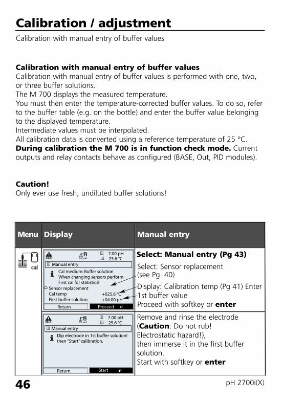
Calibration / adjustmentCalibration with manual entry of buffer values
Calibration with manual entry of buffer valuesCalibration with manual entry of buffer values is performed with one, two,or three buffer solutions. The M 700 displays the measured temperature.You must then enter the temperature-corrected buffer values. To do so, referto the buffer table (e.g. on the bottle) and enter the buffer value belongingto the displayed temperature. Intermediate values must be interpolated.All calibration data is converted using a reference temperature of 25 °C.During calibration the M 700 is in function check mode. Currentoutputs and relay contacts behave as configured (BASE, Out, PID modules).
Caution!Only ever use fresh, undiluted buffer solutions!
Menu Display Manual entry
Manual entry
Return
Cal medium: Buffer solutionWhen changing sensors performFirst cal for statistics!
Cal temp
25.6 °C7.00 pH
+025.6 °C
Proceed
First buffer solution +04.00 pH
Manual entry
Return
Dip electrode in 1st buffer solution!then ‘’Start’’ calibration.
25.6 °C7.00 pH
Start
Remove and rinse the electrode(Caution: Do not rub! Electrostatic hazard!),then immerse it in the first buffersolution. Start with softkey or enter
Select: Manual entry (Pg 43)
Select: Sensor replacement (see Pg. 40)
Display: Calibration temp (Pg 41) Enter1st buffer valueProceed with softkey or enter
Sensor replacement
69904_E_2700i.QXD 28.09.2005 15:02 Uhr Seite 46 gro DAISY.DATA01:NETDATA:MAC2ALL:BA:M700X_Version_6:pH

47
Menu Display Manual entry
Calibration with first buffer solution.You can press “End” to reduce thewaiting time before stabilization ofthe electrode potential (reducedaccuracy of calibration values).From the response time, you see howmuch time the electrode needs forthe potential to stabilize. If the elec-trode potential or the measured tem-perature fluctuate greatly, the calibra-tion procedure is aborted after 2 min.
One-point calibration: “End”. Two-point calibration:Rinse electrode thoroughly! Enter 2nd buffer value for correcttemperature. Immerse it in the secondbuffer solution. Start with softkey or enter
Calibration is performed with thesecond buffer.
Three-point calibration is performedcorrespondingly with the thirdbuffer.
Manual entry
Drift check with 1st buffer runningZero correction
Electrode potential -0224 mVCalibration temp +25.6°C
25.6 °C4.00 pH
0018sNominal buffer valueResponse time
+04.00 pH
End
Manual entry
Dip electrode in 2nd buffer solution!then ‘’Start’’ calibration.For one-point calibration‘End’ procedure
25.6 °C7.00 pH
End Start
Second buffer solution +07.00 pH
Manual entry
Drift check with 2nd buffer runningZero and slope correction
Electrode potential -0000 mVCalibration temp +25.6°C
25.6 °C7.00 pH
0007sNominal buffer valueResponse time
+07.00 pH
End
AdjustmentPress “Adjust” to take over the val-ues determined during calibration forcalculating the measured variables.See Pg 39.
25.6 °C7.00 pH
Calibration data record
Cal mode
Response timeSlope
Manual input
058.0 mV/pH
End Adjust
0070 s
Calibration
Zero
06/21/05 09:20
+07.00 pH
69904_E_2700i.QXD 28.09.2005 15:02 Uhr Seite 47 gro DAISY.DATA01:NETDATA:MAC2ALL:BA:M700X_Version_6:pH

48 pH 2700i(X)
Calibration / adjustmentProduct calibration
Product calibration (calibration with sampling)When the electrode cannot be removed – e.g. for sterility reasons – its zeropoint can be determined with “sampling”. To do so, the currently measuredprocess value is stored by the analyzer. Immediately afterwards, you take asample from the process. The pH value of the sample is measured in the labor directly on the site using a portable pH meter. The reference value isentered into the measuring system. From the difference between measuredvalue and reference value, the electrode zero point is calculated (this methodonly allows one-point calibration).During calibration the M 700 is in function check mode. Currentoutputs and relay contacts behave as configured (BASE, Out, PID).Caution!The pH value of the sample is temperature-dependent. Therefore, the refer-ence measurement should be performed at the sample temperature shownin the display. Transport the sample in an insulated container. The pH valuemay also be altered due to escaping of volatile substances.
Menu Display Product calibration
Select module: pH 2700iThe M 700 is in function checkmode. Current outputs and relaycontacts behave as configured (BASE,Out, PID). Confirm with enter.
Select calibration mode“Product calibration”
Confirm with enter.
Calibration25.6 °C
Return Info
7.00 pH
Module pH 2700i
Module pH 2700i25.6 °C
Return
Manual: entry of buffer values
7.00 pH
Calimatic: automatic calibration
Product calibration
ORP calibrationData entry: premeasured electrodes
69904_E_2700i.QXD 28.09.2005 15:02 Uhr Seite 48 gro DAISY.DATA01:NETDATA:MAC2ALL:BA:M700X_Version_6:pH

49
Menu Display Product calibration
Product calibrationProduct calibration is performedin 2 steps.Prepare sampling,start with softkey or enter.
Step 1Take sample.Store measured value and tempera-ture at the moment of sampling(“Save” softkey or enter)Press meas to return to measure-ment.Exception:Sample value can be measured onthe site and be entered immediately.To do so, press “Input” softkey.
Step 2Lab value has been measured.When you open the Product calibra-tion menu again, the display shownon the left appears:Enter reference value (“Lab value”).Confirm with OK or repeat calibra-tion.
Product calibration
Return
Cal medium: ProductCal by taking sampleand input of pH value
25.6 °C7.00 pH
Start
Product calibration
Step 1: Sampling‘Save’ the sample value‘Input’ lab valueMeasured value
25.0°C7.00 pH
+25.0°CTemperature7.00 pH
Input Save
Product calibration
Abort
Step 2: Lab valueInput sample lab value
25.6 °C7.00 pH
OK
+7.15 pHLab value
AdjustmentPress “Adjust” to take over the val-ues determined during calibration forcalculating the measured variables.See Pg 39.
25.6 °C7.00 pH
Calibration data record
Cal mode
Response timeSlope
Product calibration
058.0 mV/pH
End Adjust
0000 s
Calibration
Zero
06/21/05 09:20
+07.00 pH
69904_E_2700i.QXD 28.09.2005 15:02 Uhr Seite 49 gro DAISY.DATA01:NETDATA:MAC2ALL:BA:M700X_Version_6:pH

50 pH 2700i(X)
Calibration / adjustmentCalibration by entering data from premeasured electrodes
Data entry of premeasured electrodesEntry of values for zero point, slope, and isothermal potential of a pH elec-trode. The values must be known, e.g. determined beforehand in the labora-tory.
Caution! Input of an isothermal potential Viso also applies to the calibrationmethods
• Calimatic• Manual entry• Product calibration
For an explanation of the isothermal potential, refer to Pg 51.
During calibration the M 700 is in function check mode. Currentoutputs and relay contacts behave as configured (BASE, Out, PID modules).
Menu Display Manual entry
Select: Data entry ofpremeasured electrodes(Pg 40)Remove electrode and connect pre-measured electrode.Call up “Sensor replacement”.Enter the values for• Zero• Slope• Isothermal potential
Return with softkey. Return to mea-surement with meas
Data entry
Return
When changing sensors performFirst cal for statistics!
25.6 °C7.00 pH
+07.00pHZeroSlopeIsothermal potential +0000 mV
058.0 mV/pH
Sensor replacement
69904_E_2700i.QXD 28.09.2005 15:02 Uhr Seite 50 gro DAISY.DATA01:NETDATA:MAC2ALL:BA:M700X_Version_6:pH

51
Isothermal potentialThe isothermal intersection point is the point of intersection between twocalibration lines at two different temperatures. The potential differencebetween the electrode zero point and this intersection point is the isothermalpotential “Viso”.
It may cause measurement errors depending on the temperature. These errors can be compensated for by defining the “Viso” value.
Measurement errors are avoided by calibrating at measuring temperature orat a controlled and stable temperature.
Monitoring functions for calibrationThe M 700 provides comprehensive functions for monitoring proper calibra-tion performance and the electrode condition. This allows documentation forquality management to ISO 9000 and GLP/GMP.• Sensocheck monitors the electrode condition by measuring the glass and
reference electrode impedances.• Regular calibration can be monitored by the cal timer (see Pg 67).• Adaptive cal timer - automatically reduces the calibration interval when
the electrode is subjected to high stress• The calibration record (GLP/GMP) provides all relevant data of the last
calibration and adjustment.• The statistics show the behavior of the electrode parameters during
the last three calibrations compared to the First Calibration.• The logbook shows the time and date of a performed calibration
Zero
mV
Viso
25 °C
80 °C
pH
69904_E_2700i.QXD 28.09.2005 15:02 Uhr Seite 51 gro DAISY.DATA01:NETDATA:MAC2ALL:BA:M700X_Version_6:pH

52 pH 2700i(X)
Calibration / adjustmentORP adjustment
ORP adjustmentThe potential of a redox electrode is calibrated using a redox (ORP) buffersolution. In the course of that, the difference between the measured poten-tial and the potential of the calibration solution is determined. This potentialdifference is printed on the calibration solution bottle and is defined as thevoltage across the redox electrode and a reference electrode.
Examples: 220 mV Pt against Ag/AgCl, KCl 3 mol/l427 mV Pt against SHE
During measurement this difference is added to the measured potential.
mVORP = mVmeas + ∆mV
mVORP = displayed oxidation-reduction potential (measured ORP)mVmeas = direct electrode potential (ORP input, see Sensor monitor)∆mV = delta value, determined during calibration
ORP related to the standard hydrogen electrode (SHE)The oxidation-reduction potential can also be calibrated automatically withrespect to the standard hydrogen electrode (SHE). To do so, you must firstselect the reference electrode used (see parameter setting Pg 68).The temperature behavior of the reference electrode is automatically takeninto account.
You can choose from the following types of reference electrodes:
Ag/AgCl, KCl 1 mol/l (Silver/silver chloride)Ag/AgCl, KCl 3 mol/l (Silver/silver chloride)Hg, Tl/TlCl, KCl 3.3 mol/l (Thalamid)Hg/Hg2SO4, K2SO4 saturated (Mercury sulfate)
69904_E_2700i.QXD 28.09.2005 15:02 Uhr Seite 52 gro DAISY.DATA01:NETDATA:MAC2ALL:BA:M700X_Version_6:pH

53
Menu Display ORP adjustment
The type of reference electrode isselected during parameter setting (Pg 68).Immerse electrode in calibrationmedium and wait until the ORP valuehas stabilized. Enter the nominal ORP value (bottle).Be sure to observe the correctreference! (as configured)
Confirm with “OK”.
End adjustmentwith softkey or enter
ORP adjustment
Return
Reference electrode
25.6 °C200 mV
Ag/AgCl,KCl 1m
+25.5°CTemperature
ORP input
+200 mV
+200 mV
ORP setpoint
ORP adjustment
Abort
Reference electrode
25.6 °C200 mV
Ag/AgCl,KCl 1m
+25.5°CTemperature
ORP input +200 mV
ORP setpoint +0220 mV
OK
ORP adjustment
Reference electrode
25.6 °C220 mV
Ag/AgCl,KCl 1m
+25.5°CTemperature
ORP input
+220 mV
+200 mV
ORP setpoint
Return End
0102025304050607080
Temperature[°C]
Ag/AgCl/KCl1 mol/l[∆mV]
Ag/AgCl/KCl3 mol/l[∆mV]
Thalamid[∆mV]
Mercurysulfate[∆mV]
249244240236233227221214207200
224217211207203196188180172163
-559-564-569-571-574-580-585-592-598-605
672664655651647639631623613603
Temp dependence of commonly used reference systems measured against SHE
69904_E_2700i.QXD 28.09.2005 15:02 Uhr Seite 53 gro DAISY.DATA01:NETDATA:MAC2ALL:BA:M700X_Version_6:pH

54 pH 2700i(X)
Calibration / adjustmentISFET zero adjustment
ISFET zero adjustmentWhen measuring with an ISFET sensor (e.g. InPro 3300), the nominal zeropoint must be adjusted each time a new sensor is connected (to adjust theoperating point). The adjustment for that sensor remains stored in the ana-lyzer.Afterwards, you should perform a two-point calibration using one of thefollowing methods:• Calimatic: automatic calibration• Manual: entry of buffer values• Data entry: premeasured electrodes
During calibration the M 700 is in function check mode. Currentoutputs and relay contacts behave as configured (BASE, Out, PID modules).
69904_E_2700i.QXD 28.09.2005 15:02 Uhr Seite 54 gro DAISY.DATA01:NETDATA:MAC2ALL:BA:M700X_Version_6:pH

55
Menu Display ISFET zero adjustment
Immerse sensor in a zero point buffer (6.5 ... 7.5).Enter temperature-corrected pH value(see buffer table).Start zero adjustment.
Return
Dip sensor in buffer solution!Enter temperature-corrected pHin the range pH 6.5...7.5then ‘Start’ calibration
25.6°C7.00 pH
Enter cal temp
Buffer
End
Drift check runningZero correction
25.6°C7.00 pH
Nominal buffer value
+025.6°C
+07.00 pH
ISFET zero adjustment
Start
Response time
Electrode potentialCalibration tempCalibration temp
s
mV°CpH
10
122
7.0025.6
ISFET zero adjustment
At the end of the adjustment proce-dure the ISFET zero (based on 25 °C)is displayed. However, this is not thereal sensor value!The actual values must be deter-mined afterwards by a completetwo-point calibration.
To abort, you can press the “End”softkey. However, this reducesadjustment accuracy.(Zero error of sensor up to max.±200 mV possible)
25.6 °C7.00 pH
Calibration data record
Cal mode
Response time
ISFET zero
End
0070 s
Active adjustment
ISFET zero
24.11.03 09:20
+0122 mV
69904_E_2700i.QXD 28.09.2005 15:02 Uhr Seite 55 gro DAISY.DATA01:NETDATA:MAC2ALL:BA:M700X_Version_6:pH

56 pH 2700i(X)
MaintenanceSensor monitor, temperature probe adjustmentNote: Function check active
Menu Display Maintenance
Call up MaintenanceFrom the measuring mode:Press menu key to select menu.Select maintenance using arrow keys, confirm with enter.Passcode 2958(For passcodes, see Pg 35)Then select “Module pH”.
Temp probe adjustmentThis function allows you to compen-sate for the individual temperatureprobe tolerance and the influence ofthe lead resistances to increase accu-racy of temperature measurement.Adjustment may only be carried outwhen the process temperature isprecisely measured using a calibratedreference thermometer! The mea-surement error of the reference ther-mometer should be less than 0.1 °C.Adjustment without precise mea-surement might result in consider-able deviations of the measuredvalue display!
Sensor monitorfor validation of sensor and com-plete measured-value processing.
Menu selection
Return to meas
22.3 °C
Select: [enter]
Lingua
7.00 pH
Sensor monitor
Return
pH input
22.3 °C
ORP input
Adjust temp probe
Return
Probe tolerance and lead adjustment
22.3 °C
Enter measured process temp
22.3 °C
Installation adjustment
7.00 pH
7.00 pH
RTDTemperatureImpedance ref (25 °C)
-56 mV200 mV1100 Ω25 °C086.5 kΩ
Process temp:
On Off
69904_E_2700i.QXD 28.09.2005 15:02 Uhr Seite 56 gro DAISY.DATA01:NETDATA:MAC2ALL:BA:M700X_Version_6:pH

57
Menu Display Viewing level, Operator level,Administrator level
Call up parameter settingFrom the measuring mode:Press menu key to select menu.Select parameter setting using arrowkeys, confirm with enter.
Administrator levelAccess to all functions, also passcodesetting.Releasing or blocking function foraccess from the Operator level.
Parameter setting: Operating levels Viewing level, Operator level, Administrator levelNote: Function check active (Parameter setting: BASE, Out, PID modules)
Functions which can be blocked forthe Operator level are marked withthe “lock” symbol.The functions are released orblocked using the softkey.
Operator levelAccess to all functions which havebeen released at the Administratorlevel. Blocked functions are displayedin gray and cannot be edited (Fig.).
Viewing levelDisplay of all settings.No editing possible!
Menu selection
Return to meas
22.3 °C7.00 pH
Select: [enter]
Lingua
Parameter setting
Return
22.3 °C7.00 pH
Viewing level
Administrator level (All Data) adm(Operation Data) opl(All Data) view
Operator level
Module FRONT (Administrator)
Return
22.3 °C7.00 pH
LanguagesMeasurement display
KI recorder
English
Measurement recorder
Release
Module FRONT
Return
22.3 °C7.00 pH
Measurement display
KI recorder
English
Measurement recorder
Languages
69904_E_2700i.QXD 28.09.2005 15:02 Uhr Seite 57 gro DAISY.DATA01:NETDATA:MAC2ALL:BA:M700X_Version_6:pH

58 pH 2700i(X)
Menu Display Administrator level:Enable / lock functions
Example: Blocking access to the calibrationadjustments from the Operator level
Call up parameter settingSelect Administrator level.Enter passcode (1989).Select “Module pH” using arrowkeys,confirm with enter.
Parameter setting: Lock functionsAdministrator level: Enable / lock functions for Operator levelNote: Function check active (Parameter setting: BASE, Out, PID modules)
Select “Cal preset values” using arrowkeys.“Block” with softkey.
Now, the “Cal preset values” line ismarked with the “lock” icon. Thisfunction cannot be accessed from theOperator level any more. The softkeyfunction changes to “Release”.
Activating parameter settingSelect Operator level, passcode(1246).Select “Module pH”. Now, the lockedfunction is displayed in gray andmarked with the “lock” icon.
Module pH 2700i (Administrator)25.0°C
Return
Sensor dataCal preset values
11.03 pH
ORP/rH valueDelta function
TC process medium
Input filter
Block
Parameter setting (Administrator)25.0°C
Return
Module FRONT M 700-011Module BASE M 700-021
11.03 pH
System control
Module pH 2700iModule Cond Ind 7700
Module pH 2700i
Module pH 2700i (Administrator)25.0°C
Return
Sensor dataCal preset values
11.03 pH
ORP/rH valueDelta function
TC process medium
Input filter
Release
Module pH 2700i25.0°C
Return
Sensor dataCal preset values
11.03 pH
ORP/rH valueDelta function
TC process medium
Input filter
69904_E_2700i.QXD 28.09.2005 15:02 Uhr Seite 58 gro DAISY.DATA01:NETDATA:MAC2ALL:BA:M700X_Version_6:pH

59
Setting the module parametersActivating parameter settingNote: Function check active (Parameter setting: BASE, Out, PID modules)
Menu Display Parameter setting
Call up parameter settingFrom the measuring mode:Press menu key to select menu.Select parameter setting using arrowkeys, confirm with enter.Passcode 1989(For passcodes, see Pg 35)
Select “Module pH”,confirm with enter.
Select parameter using arrow keys,confirm with enter.
Menu selection
Return to meas
20.1 °C
Select: [enter]
Lingua
7.0 0pH
Parameter setting (Administrator)20.2°C
Return
Module Cond Ind 7700
Module FRONT M 700-011Module BASE M 700-021
7.00 pH
System control
Module PID 700Module pH 2700i
Module pH 2700i (Administrator)20.1 °C
Return
TC process medium
Sensor dataCal preset values
7.00 pH
ORP/rH valueDelta function
Input filter
Block
Function checkDuring parameter setting the M 700 is in “function check” mode: Current outputs and relay contacts behave as configured. See instruction manuals of BASE, Out, PID communication modules.(Free download at www.mtpro.com).
69904_E_2700i.QXD 28.09.2005 15:02 Uhr Seite 59 gro DAISY.DATA01:NETDATA:MAC2ALL:BA:M700X_Version_6:pH
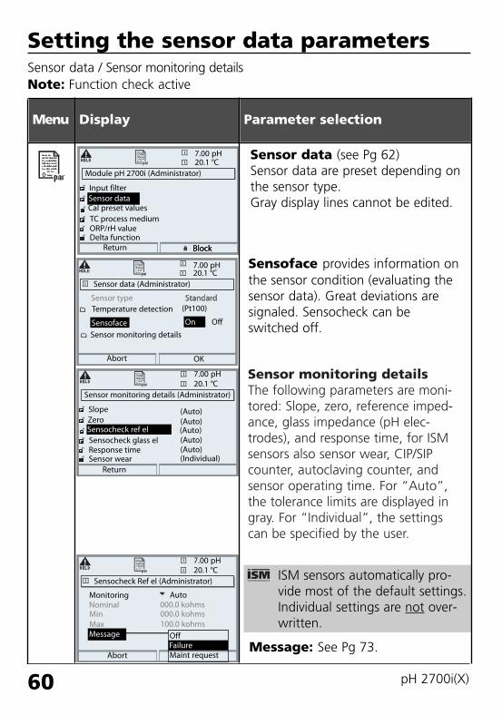
Sensor monitoring detailsThe following parameters are moni-tored: Slope, zero, reference imped-ance, glass impedance (pH elec-trodes), and response time, for ISMsensors also sensor wear, CIP/SIPcounter, autoclaving counter, andsensor operating time. For “Auto”,the tolerance limits are displayed ingray. For “Individual”, the settingscan be specified by the user.
Message: See Pg 73.
60 pH 2700i(X)
Setting the sensor data parametersSensor data / Sensor monitoring detailsNote: Function check active
Menu Display
Module pH 2700i (Administrator)20.1 °C
Return
TC process medium
Sensor dataCal preset values
7.00 pH
ORP/rH valueDelta function
Input filter
Block
Sensor data (Administrator)20.1 °C
Abort
Sensoface
7.00 pH
Temperature detection
Display Parameter selection
Sensor type
Sensor monitoring details
Block
OK
Sensocheck Ref el (Administrator)20.1 °C
Abort
7.00 pH
Nominal
StandardStandard(Pt100)
OffOn
Sensor data (see Pg 62)Sensor data are preset depending onthe sensor type.Gray display lines cannot be edited.
OffFailureMaint request
Message
Sensor monitoring details (Administrator)20.1 °C
Sensocheck glass el
ZeroSensocheck ref el
7.00 pH
Response timeSensor wear
Slope
Return
(Auto)(Auto)
(Auto)(Individual)
(Auto)(Auto)
MinMax
Monitoring000.0 kohms000.0 kohms100.0 kohms
Auto
Sensoface provides information onthe sensor condition (evaluating thesensor data). Great deviations aresignaled. Sensocheck can beswitched off.
ISM sensors automatically pro-vide most of the default settings.Individual settings are not over-written.
69904_E_2700i.QXD 28.09.2005 15:02 Uhr Seite 60 gro DAISY.DATA01:NETDATA:MAC2ALL:BA:M700X_Version_6:pH

Parameter
Slope
Zero
Reference impedance
Glass impedance
Response timeFineMediumCoarse
Cal timer
Sensor wear
61
SensofaceSensoface is a graphic indication of the sensor condition.Prerequisite: Sensocheck must have been activated during parameter setting.
7.0011.00
pH
pH24.3°C
Sensocheck:Automatic monitoring of glass and reference electrode
The “smileys” provide information on wear and required maintenance of thesensor (“friendly” - “neutral” - “sad”).
Sensoface criteria
Auto*
59.2
7.00
Rcal **
Rcal **
Standard electrodes
< 53.3 or > 61
< 6.00 or > 8.00
< 0.3 Rcal or > 3.5 Rcal
< 0.6 Rcal or > 100 KΩ + 0.5 Rcal
120 sec80 sec60 sec
when 80 % expired
as specified (ISM sensors only)
* Valid for standard electrodes with pH = 7.00.** Rcal is determined during calibration
69904_E_2700i.QXD 28.09.2005 15:02 Uhr Seite 61 gro DAISY.DATA01:NETDATA:MAC2ALL:BA:M700X_Version_6:pH

62 pH 2700i(X)
Parameter Default Selection / Range / Notes
Off, On (suppression of fast transients at the input)Input filter• Pulse suppression Off
Standard, Other, ISFET (SW 700-012), ISM (automatically identified)
Pt100, Pt1000, NTC30 kΩ, NTC 8.55 kΩ
Auto, Individual
Off, failure, maintenance request
Auto, Individual
Off, failure, maintenance request
Auto, Individual
Off, failure, maintenance request(not for sensor type ISFET)Auto, Individual
Off, failure, maintenance request
Auto, Individual
Off, failure, maintenance request
Sensor data• Sensor type
• Temperature detectionTemperature probe
Sensor monitoring details• Slope
MonitoringNominal MinMaxMessage
• ZeroMonitoringNominal MinMaxMessage
• Sensocheck Ref elMonitoringNominal MinMaxMessage
• Sensocheck Glass elMonitoringNominal MinMaxMessage
• Response timeMonitoringResponse time MaxMessage
Standard
Pt 1000
Auto59.2 mV/pH53.3 mV/pH61.0 mV/pHMaint. request
Auto06.95 pH05.95 pH07.95 pHMaint. request
Auto025.5 kΩ015.9 kΩ112.8 kΩOff
Auto305.0 MΩ087.1 MΩ999.9 MΩOff
Auto0080 sOff
Settings of sensor data
With “Auto”, the tolerance limits for the monitoring criteria are determinedby the analyzer. They are then displayed in gray. With “Individual”, these tolerances can be adjusted. Note: Function check active. Gray values (display) cannot be edited.
69904_E_2700i.QXD 28.09.2005 15:02 Uhr Seite 62 gro DAISY.DATA01:NETDATA:MAC2ALL:BA:M700X_Version_6:pH

63
Parameter Default Selection / Range / Notes
Off, Auto, IndividualHigh, Normal, LowOff, failure, maintenance request
Off, Individual
Off, failure, maintenance request
Off, Individual
Off, failure, maintenance request
Off, Individual
Off, failure, maintenance request
Off, Individual
Off, failure, maintenance request
Auto, Individual(For ISM: default value from electrode)Off, failure, maintenance request
• Sensor wear*MonitoringMeasurement quality** Message
• CIP counter* Monitoring Max. cyclesMessage
• SIP counter* Monitoring Max. cyclesMessage
• Autoclaving counter* Monitoring Max. cyclesMessage
• Sensor operating time*MonitoringMax. operating timeMessage
• ISFET leakage current***MonitoringMax. Message
AutoNormalMaint. request
Off000Maint. request
Off000Maint. request
Off000Maint. request
Off0000 dMaint. request
Auto1000 nAMaint. request
* Only for ISM ** Measurement quality allows the user to take account of the influence of the individual process
conditions on the sensor wear.*** Only available with ISFET additional function (SW 700-012)
ISM sensors automatically provide most of the default settings.Individual entries are not overwritten by the ISM sensor.
69904_E_2700i.QXD 28.09.2005 15:02 Uhr Seite 63 gro DAISY.DATA01:NETDATA:MAC2ALL:BA:M700X_Version_6:pH

64 pH 2700i(X)
Parameter Default Selection / Range
Cal preset values• Calimatic buffer
• Drift check
• Cal timerMonitoringCal timerAdaptive cal timer
• Tolerance band check(SW 700-005)
Mettler-Toledo: 2.00 4.01 7.00 9.21Merck/Riedel: 2.00 4.00 7.00 9.00 12.00DIN 19267: 1.09 4.65 6.79 9.23 12.75NIST standard: 4.006 6.865 9.180NIST technical: 1.68 4.00 7.00 10.01 12.46
Fine: 1.2 mV/min (Abort after 180 s)Standard: 2.4 mV/min (Abort after 120 s)Coarse: 3.75 mV/min (Abort after 90 s)
Auto, Off, IndividualOff, entryOff, On
Tolerance adjustment: Off, OnTolerance band zero +00.20 pH (entry)Tolerance band slope +002.0 mV/pH (entry)
Mettler-Toledo
Standard
Auto168 h0000h (Off)
Off
Setting the cal preset valuesCal preset valuesNote: Function check active
Tolerance adjustment(Additional function SW 700-005)During calibration the tolerance band checks zero and slope and automati-cally performs an adjustment when the tolerance band is exceeded. Theparameters are stored in the tolerance band recorder (Diagnostics menu). The additional function SW 700-005 is device-specific. When ordering anadditional function, you therefore have to specify the serial number of yourM 700 FRONT in addition to the respective order number.(The M 700 FRONT contains the M 700 system control).The manufacturer then supplies a TAN (transaction number) to release theadditional function in the system control menu (see Pg 66).
69904_E_2700i.QXD 28.09.2005 15:02 Uhr Seite 64 gro DAISY.DATA01:NETDATA:MAC2ALL:BA:M700X_Version_6:pH

65
SW 700-005: Tolerance adjustmentProgram flow
Calibration /Adjustment ?
YesNo
First Calibration? Yes
Erase tolerance band
New entryZero + Slope
T-band check? NoYes
Zero > Tolerance ? Yes
Slope > Tolerance ? Yes
CalibrationOld tolerance band
AdjustmentNew tolerance band
Manual check
No
No
No
Start tolerance band
End of tolerance band
69904_E_2700i.QXD 28.09.2005 15:02 Uhr Seite 65 gro DAISY.DATA01:NETDATA:MAC2ALL:BA:M700X_Version_6:pH

66 pH 2700i(X)
Menu Display Activate additional function
Activating the tolerance adjustmentSelect menu: Parameter setting/System control/Release of optionsNote: The TAN for releasing an additional function is only valid for the
device with the corresponding serial number!
Release of optionsSelect the additional function to bereleased (“Cal tolerance band”). Setoption to “active”. Enter the TAN atthe prompt. (Note: The TAN is onlyvalid for the device with the corre-sponding serial number, see previouspage.) The option is available afterthe TAN has been entered.
Release of options (Administrator)
Return
25.6 °C7.00 pH
Menu selectionCall up parameter setting.From the measuring mode:Press menu key to select menu.Select parameter setting using arrowkeys, confirm with enter.
Menu selection
Return to meas
7.00 pH25.6 °C
Select: [enter]
Lingua
Parameter setting (Administrator)
System control
Return
25.6 °C
Module BASE
Module O2 4700i
7.00 pH
Module pH 2700i
Module Cond Ind 7700
Module FRONT
Parameter setting
Return
Viewing level
Administrator level (All Data) adm(Operation Data) opl(All Data) view
Operator level
Parameter settingSelect Administrator level usingarrow keys, confirm with enter.Enter passcode and confirm(Passcode as delivered: 1989).
Select System control using arrow keys,confirm with enter.Then select Release of optionsusing arrow keys, confirm withenter.
25.6 °C7.00 pH
002 Buffer sets001 KI recorder
004 ServiceScope003 Adaptive timer
006 Current characteristic005 Cal tolerance band
InactiveInactiveInactiveActiveInactive
Inactive
69904_E_2700i.QXD 28.09.2005 15:02 Uhr Seite 66 gro DAISY.DATA01:NETDATA:MAC2ALL:BA:M700X_Version_6:pH

67
Setting the cal preset valuesCal preset values: Calimatic buffer, cal timer, cal tolerance bandNote: Function check active
Menu Display Cal preset values
Calimatic bufferFor automatic calibration, you mustdefine the buffer set you want touse. For calibration, you must thenuse buffer solutions from this bufferset in any order. The selected buffer set with thenominal values of the individualbuffer solutions is displayed in gray.The “Calimatic buffer” menu showsall buffer sets available.Select buffer set with enter.
Cal timerEntry of the time interval until thenext due calibration.
Adaptive cal timerWhen the electrode is exposed tohigh stress (temperature, extreme pHvalues), the time until the next duecalibration is reduced.
Module pH 2700i (Administrator)20.1 °C
Return
TC process medium
Sensor dataCal preset values
7.00 pH
ORP/rH valueDelta function
Input filter
Block
Cal preset values (Administrator)20.1 °C
Abort
Cal timer
Mettler-Toledo 2.00
Calimatic buffer
7.00 pH
Cal tolerance band
Drift check
Mettler-Toledo
DIN 19267NIST standardNIST technical
Merck/Riedel
Table
Cal timer (Administrator)20.1 °C
Adaptive cal timer
7.00 pH
Monitoring
Return
168 hOffOn
Cal tolerance bandIf the measured value leaves thetolerance band specified here forzero and slope, an adjustment isautomatically performed duringcalibration.
Cal tolerance band (Administrator)20.1 °C
Tolerance band check
7.00 pH
Return
Calibration data taken over when
OffOn
tolerance band exceeded
Tolerance ZeroTolerance Slope
+00.20 pH002.0 mV/pH
Cal timerAuto
ORP checkOK
69904_E_2700i.QXD 28.09.2005 15:02 Uhr Seite 67 gro DAISY.DATA01:NETDATA:MAC2ALL:BA:M700X_Version_6:pH

68 pH 2700i(X)
Parameter settingDefault settings and selection rangeNote: Function check active
Parameter Default Selection / Range
Ag/AgCl,KCI 3mol/lHg, Tl/TlCl, KCl 3.3 mol/lHg/Hg2SO4, K2SO4 satNo, YesNo, Yes, entry of factor
ORP/rH value• Reference electrode
• ORP conversion to SHE• Calculate rH with factor
Ag/AgCl,KCI3mol/l
NoNo
Delta function• Delta function Off, pH, mV+ORP or rH: entry of delta valueOff
Off, linear, ultrapure water, table,Linear: enter temperature factor +XX.XX %/K
TC process medium• TC correction Off
69904_E_2700i.QXD 28.09.2005 15:02 Uhr Seite 68 gro DAISY.DATA01:NETDATA:MAC2ALL:BA:M700X_Version_6:pH

69
Parameter settingTC process mediumNote: Function check active
Menu Display TC process medium(Parameter selection Pg 68)
TC process mediumYou can choose from:• Linear (input of TC coefficient)• Ultrapure water• ChartWhen measuring media with aknown temperature behavior, theoutput pH value can be correctedusing a chart. TC can be entered in5 °C steps for temperaturesbetween 0 and +95 °C. Then, theoutput pH value is corrected by thecorresponding TC value dependingon the measuring temperature.Intermediate values are linearly inter-polated. In the case of lower orhigher temperatures (< 0 °C or> +95 °C), the last chart value isused for calculation. If the deltafunction has been activated (seePg 68) simultaneously withtemperature compensation, the tem-perature is compensated first andthen the delta value is subtracted.
When the TC correction for processmedium is switched on, ”TC”appears in the display in measuringmode.
Module pH 2700i (Administrator)20.1 °C
Return
TC process medium
Sensor dataCal preset values
7.00 pH
ORP/rH valueDelta function
Input filter
Block
TC process medium (Administrator)20.1 °C
Abort
TC OffLinear
7.00 pH
TableUltrapure water
OK
TC process medium (Administrator)20.1 °C
Abort
TC
7.00 pH
Table
Info
TC at 00°C:TC at 05°C:TC at 10°C:TC at 15°C:TC at 20°C:
+00.00%+00.00%+00.00%+00.00%+00.00%
7.0020.1
pH
°COutp I1 5.70 mA Favorites menu
TC
69904_E_2700i.QXD 28.09.2005 15:02 Uhr Seite 69 gro DAISY.DATA01:NETDATA:MAC2ALL:BA:M700X_Version_6:pH
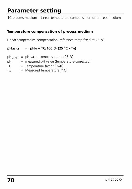
70 pH 2700i(X)
Parameter settingTC process medium – Linear temperature compensation of process medium
Temperature compensation of process medium
LInear temperature compensation, reference temp fixed at 25 °C
pH(25 °C) = pHM + TC/100 % (25 °C - TM)
pH(25 °C) = pH value compensated to 25 °CpHM = measured pH value (temperature-corrected)TC = Temperature factor [%/K]TM = Measured temperature [° C]
69904_E_2700i.QXD 28.09.2005 15:02 Uhr Seite 70 gro DAISY.DATA01:NETDATA:MAC2ALL:BA:M700X_Version_6:pH

71
Parameter settingORP/rH value, delta function, messagesNote: Function check active
Menu Display ORP/rH value, delta function,messages (Selection Pg 64)
ORP/rH value• Select type of reference electrode:Ag/AgCl, KCl 1 mol/l (Silver/silver chloride)Ag/AgCl, KCl 3 mol/l (Silver/silver chloride)Hg, Tl/TlCl, KCl 3.3 mol/l (Thalamid)Hg/Hg2SO4, K2SO4 saturated (mercury sulfate)
• ORP conversion to SHE• Calculate rH with factor
Delta functionWhen a delta value is entered, theanalyzer calculates the difference
Output value = measured value – delta value
The output value controls all outputsand is shown on the display. If thedelta function has been activatedsimultaneously with temperaturecompensation, the temperature iscompensated first and then thedelta value is subtracted.When delta function is switched on,“∆” appears in the display inmeasuring mode.
ORP/rH value (Administrator)20.1 °C
Abort
Ref el
7.00 pH
Ag/AgCl, KCl 1m
OK
ORP conversionrH with factor
Ag/AgCl, KCl 3mHg,Ti/TiCl,KCl 3.5mHg/Hg2SO4,K2SO4 sat
7.0020.1
pH
°COutp I1 5.70 mA Favorites menu
∆
Delta function (Administrator)20.1 °C
Abort
Delta function
7.00 pH
pH
OK
Delta valuemVORPrH
Off
69904_E_2700i.QXD 28.09.2005 15:02 Uhr Seite 71 gro DAISY.DATA01:NETDATA:MAC2ALL:BA:M700X_Version_6:pH

72 pH 2700i(X)
Device limits• Device limits max. Maximum measurement range of device• Variable limits: Range limits specified
Variable limits
Device limits max.
Setting the message parametersMessages: Default settings and selection rangeNote: Function check active
Off, device limits max., variable limits*Off, device limits max., variable limits*Off, device limits max., variable limits*Off, device limits max., variable limits*Off, device limits max., variable limits*
*) With “Variable limits” selected,the following parameters can be edited:
• Failure Limit Lo• Warning Limit Lo• Warning Limit Hi• Failure Limit Hi
Messages• pH value• ORP value• rH value• Temperature• mV value
Parameter Default Selection / Range
Limits maxOffOffLimits maxOff
–02.00 pH
+16.00 pH
69904_E_2700i.QXD 28.09.2005 15:02 Uhr Seite 72 gro DAISY.DATA01:NETDATA:MAC2ALL:BA:M700X_Version_6:pH

Messages
73
Setting the message parametersMessagesNote: Function check active
Menu Display
MessagesAll parameters determined by themeasuring module can generatemessages.• Device limits max.:Messages are generated when theprocess variable (e.g. pH) is outsidethe measurement range. The“Failure” icon is displayed, theNAMUR failure contact is activated(M 700 BASE, factory setting:contact K4, N/C contact). The current outputs can signal a22 mA message (user defined).• Variable limits:For the “failure” and “warning”messages you can define upper andlower limits for message generation.• Message icons:
Messages (Administrator)20.1 °C
Return
7.00 pH
Messages pH value (Administrator)20.1 °C
Abort
Monitoring
7.00 pH
Variable limits
OK
Device limits max.Off
Messages Temperature
Messages ORP value
Messages pH value
Messages mV value
Messages rH value
Messages (Administrator)20.1 °C7.00 pH
Warning Limit Hi
MonitoringFailure Limit Lo
Failure Limit Hi
Warning Limit Lo+16.00 pH
Variable limits
+16.00 pH
–02.00 pH–02.00 pH
Abort OK
Message list22.3 °C
Fail pH rangeFail Meas. processing
7.00 pH
Fail Temperature range
Abort
Diagnostics menuIf the “Maintenance” or “Failure”icons are flashing in the display, youshould call up the Diagnostics menu.The messages are displayed in the“Message list”.
Failure (Failure limit HiHi/LoLo)
Maintenance (Warning limit Hi/Lo)
69904_E_2700i.QXD 28.09.2005 15:02 Uhr Seite 73 gro DAISY.DATA01:NETDATA:MAC2ALL:BA:M700X_Version_6:pH

74 pH 2700i(X)
Menu Display Logbook, factory setting
Logbook, factory settingParameter setting/System control/LogbookNote: Function check active
LogbookSelect which messages are to belogged in the logbook. The last 50events are recorded with date andtime. This permits quality managementdocumentation to ISO 9000.
The logbook can be called up fromthe diagnostics menu (Fig.).
Additional function SW 700-104:Extended logbook for recording dataon SmartMedia card (TAN).
Logbook (Administrator)
24.8 °C7.00 pH
Return
Erase logbook
NoLog failure
Log warning
Yes
NoYes
Logbook
Return
24.8 °C7.00 pH
09/13/05 09:50 Measurement active
09/12/05 17:52 Measurement active09/12/05 17:44 Parameter setting active
09/13/05 09:36 Parameter setting active
09/12/05 17:04 Measurement active09/12/05 17:40 Wrong passcode
09/12/05 16:53 Diagnostics active
Factory settingAllows resetting the parameters totheir factory setting. When thismenu is opened, the analyzer dis-plays a warning (Fig.).
Factory setting (Administrator)
24.8 °C7.00 pH
Return
The factory setting erasesall your set parameters!
Set factory setting NoYes
69904_E_2700i.QXD 28.09.2005 15:02 Uhr Seite 74 gro DAISY.DATA01:NETDATA:MAC2ALL:BA:M700X_Version_6:pH

Current outputs, contacts, OK inputsSelect menu: Parameter setting/Module BASENote: Function check active
Menu Display Parameter setting M 700 BASE
Configure current output• Call up parameter setting• Enter passcode• Select “Module BASE”• Select “Output current I1”
• Select measured variable
• Select Curve, e.g. “Linear”: The measured variable is representedby a linear output current curve. The desired range of the measuredvariable is specified by the values for“Start” and “End”.
Output current
Assignment of measured values: Beginning (4 mA) and end (20 mA)Example 1: Range pH 0 - 14 Example 2: Range pH 5 - 7
Advantage: Higher resolution in range of interest[mA]
Configure current output• Call up parameter setting• Enter passcode• Select “Module BASE”• Select “Output current ...”
Module BASE (Administrator)19.2°C
Return
Contact K2 (NAMUR function check)
Contact K4 (NAMUR Failure)Contact K3 (NAMUR maintenance)
7.00 pH
Output current I2
Contact K1 (Limit)Inputs OK1, OK2
Block
Output current I1 (Administrator)
OK
19.0 °C7.00 pH
Measured variable
Output
Abort
Curve Linear°C
TrilinearFunctionTable
Output current I1 (Administrator)
OK
19.0 °C7.00 pH
CurveOutput
Behavior during messages
Start
Abort
Measured variable
°CrHS/cm°Cg/kg
OffpH
EndStart
End
Output filter
75[pH]
20
4140 [pH]
20
475
[mA]
5 7
69904_E_2700i.QXD 28.09.2005 15:02 Uhr Seite 75 gro DAISY.DATA01:NETDATA:MAC2ALL:BA:M700X_Version_6:pH

76 pH 2700i(X)
[%]
100
Start End
0
Output currentY
XMeasured variable
[%]
100
Start End
0
Output currentY
XMeasured variable
2nd corner Y
1st. corner Y
2nd corner X
1st corner X
• Linear characteristicThe measured variable is represented by a linear output current curve.
• Note: Bilinear characteristicFor a bilinear characteristic, identical parameters are entered for the two corner points (1st corner, 2nd corner).
• Trilinear characteristicTwo additional corner points must be entered:
Current outputs: Current output curvesSelect menu: Parameter setting/Module BASE
69904_E_2700i.QXD 28.09.2005 15:02 Uhr Seite 76 gro DAISY.DATA01:NETDATA:MAC2ALL:BA:M700X_Version_6:pH

77
[%]
Entry for “50 % point”:e.g.: 10 % of measured value
End
0
Output currentY
XMeasured variable
• Function characteristicNonlinear output current characteristic: allows measurements over several decades, e.g. measuring very low values with a high resolution andhigh values with a low resolution.Required: Entering a value for 50 % output current.
100
50
Equation
Output current (4 to 20 mA) = 16 mA + 4 mA(1+K)x
1+KxE + I - 2 * X50%
X50% - IK =
M - I
E - Ix =
I: Initial value at 4 mAX50%: 50% value at 12 mA (output current range 4 to 20 mA)E: End value at 20 mAM: Measured value
Logarithmic output curve over one decade: I: 10 % of maximum valueX50%: 31.6 % of maximum valueE: Maximum value
Logarithmic output curve over two decades I: 1 % of maximum valueX50%: 10 % of maximum valueE: Maximum value
69904_E_2700i.QXD 28.09.2005 15:02 Uhr Seite 77 gro DAISY.DATA01:NETDATA:MAC2ALL:BA:M700X_Version_6:pH

78 pH 2700i(X)
Output filterTime constant
Time constant of output filterTo smoothen the current output, a low-pass filter with adjustable timeconstant can be switched on. When there is a jump at the input (100 %),the output level is at 63 % after the time constant has been reached.The time constant can be set from 0 to 120 sec. If the time constant is setto 0 s, the current output follows the input.
Note:The filter only acts on the current output and the current value of the sec-ondary display, not on the measurement display, the limit values, or thecontroller!
Time constant 0 to 120 sec
Measured variable 0 (4) - 20 mA
69904_E_2700i.QXD 28.09.2005 15:02 Uhr Seite 78 gro DAISY.DATA01:NETDATA:MAC2ALL:BA:M700X_Version_6:pH

79
NAMUR signals: Current outputsBehavior during messages: Function check, 22 mA signal
Behavior during messages
Output current[mA] “Fixed 22 mA”
Function check
22
4
“Last usable value”
Function check
Depending on the parameter setting(“Messages”), the current outputs switch to:
• Currently measured value• Last measured value (HOLD function)• Fixed value (22 mA)In the case of a fault a 22 mA signal can begenerated for the selected process variable (1st primary value).
Function check
“Current meas.”
Behavior during messages
OK
19.0 °C7.00 pH
22mA message
Abort
Function check
Fixed 22 mA
Curr. meas. valueLast meas. value
Message when the current range is exceededAs delivered, the “Maintenance request” (Warn) message is generated whenthe current range is exceeded (< 3.8 mA or > 20.5 mA).This setting can be changed in the Parameter setting menu of the respectivemeasuring module at “Messages”.
To generate a “Failure” message, the limit value monitoring must be set to“Variable limits”:Parameter setting - <measuring module> - Messages - Variable limits -Failure limit ...
Enter the same values for the failure limits as for the current output:Parameter setting - Module BASE - Output current - Variable Start / End.
69904_E_2700i.QXD 28.09.2005 15:02 Uhr Seite 79 gro DAISY.DATA01:NETDATA:MAC2ALL:BA:M700X_Version_6:pH

80 pH 2700i(X)
NAMUR signals: Relay contactsFailure, maintenance request, function check
Failure is activewhen a value has exceeded (or fallen below, resp.) a preset ”Failure Limit Hi”or ”Failure Limit Lo”, when the measured value is out of range or in theevent of other failure messages. That means that the equipment no longeroperates properly or that process parameters have reached a critical value.Failure is disabled during function check.
Maintenance request is activewhen a value has exceeded (or fallen below, resp.) a preset “Warning LimitHi” or “Warning Limit Lo”, or when other warning messages have beenactivated. That means that the equipment is still operating properly butshould be serviced, or that process parameters have reached a value requir-ing intervention.Warning is disabled during “Function check”.
Function check is active: • during calibration• during maintenance (current source, meas. point maintenance)• during parameter setting at the Operator level and the Administrator level• during an automatic rinsing cycle.
As delivered, the floating relay outputs of the M 700 BASE are assigned tothe NAMUR signals:• Failure Contact K4, Normally closed contact (signaling current failure)• Maint. request Contact K3, normally open contact• Function check Contact K2, normally open contact
NAMUR signals: Factory setting of contacts• Select parameter setting• Administrator level• Select “Module BASE” (Fig.)You can define a delay time for “Maintenance request”and “Failure”, resp. If an alarm message is released, thecontact will only be activated after expiry of this delaytime.
Module BASE (Administrator)Output current I1
Return Block
7.00 pH
Contact K4Output current I2
Contact K3
19.0 °C
(NAMUR Failure)
Contact K2Contact K1
(NAMUR maintenance)(NAMUR function check)(Limit)
69904_E_2700i.QXD 28.09.2005 15:02 Uhr Seite 80 gro DAISY.DATA01:NETDATA:MAC2ALL:BA:M700X_Version_6:pH

81
Relay contacts: protective wiring
1
23
1 2
3
Typical AC applicationswith inductive load
1 Load2 RC combination, e.g. RIFA PMR 209
Typical RC combinationse.g.:Capacitor 0.1 µF, Resistor 100 ohms / 1 W
3 Contact
Warning!Make sure that the maximum ratings of the relay contacts arenot exceeded even during switching!
Protective wiring of relay contacts
Relay contacts are subjected to electrical erosion. Especially with inductiveand capacitive loads, the service life of the contacts will be reduced. For suppression of sparks and arcing, components such as RC combinations,nonlinear resistors, series resistors and diodes should be used.
Information concerning relay contactsAs delivered, the relay contacts are suitable for low signal currents (down toapprox. 1 mA). If currents above approx. 100 mA are switched, the goldplating is destroyed during the switching process. After that, the contactswill not reliably switch low currents.
69904_E_2700i.QXD 28.09.2005 15:02 Uhr Seite 81 gro DAISY.DATA01:NETDATA:MAC2ALL:BA:M700X_Version_6:pH

82 pH 2700i(X)
Relay contactsParameter setting/Module BASE/Relay contacts
The M 700 BASE provides 4 relay contacts(max. AC/DC rating 30 V / 3 A each).Contact K4 is provided for failure message.The switching behavior (normally open ornormally closed), as well as a switch-on orswitch-off delay can be defined.
Default settings of the user-definable relaycontacts of the M 700 BASE:K3: NAMUR maintenance requestK2: NAMUR function checkK1: Limit value
The contact assignment K1 - K3 is user defined(“Usage”):• NAMUR maintenance request• NAMUR function check• Limit value• Rinse contact• Parameter set 2 active• USP output (COND module only)
Menu Display Setting the relay contacts
Configure current output• Call up parameter setting• Enter passcode• Select “Module BASE”• Select “Output current I1”
Relay contacts, usage• Call up parameter setting• Enter passcode• Select “Module BASE”• Select “Contact ...”• “Usage” (Fig.)
M 700 BASE
Alarm (K4)
K1
K2
K3
Contact K1 (Administrator)19.2°C
Return
Hysteresis
Measured variablLimit value
7.00 pH
Usage
Effective directionContact type
Limit value
NAMUR maintenanceNAMUR function check
Rinse contactParameter set 2 activeUSP output
Contact assignment: See terminal plate of M 700 BASE
69904_E_2700i.QXD 28.09.2005 15:02 Uhr Seite 82 gro DAISY.DATA01:NETDATA:MAC2ALL:BA:M700X_Version_6:pH

83
Limit value, hysteresis, contact typeParameter setting/Module BASE/Relay contacts/Usage
Menu Display Usage as limit value
Configure current output• Call up parameter setting• Enter passcode• Select “Module BASE”• Select “Output current I1”
Relay output: Limit value• Call up parameter setting• Enter passcode• Select “Module BASE”• Select “Contact ...”• “Usage: Limit” (Fig.)
Limit valueEffective direction min
Hysteresis +
Limit value
Contact
0
1
Signal
Limit valueEffective direction max
Hysteresis -
Signal
Limit value
Contact
0
1
HysteresisTolerance band around the limit value, within which the contact is not actu-ated. Serves to obtain appropriate switching behavior at the output and suppress slight fluctuations of the measured variable (Fig.)
Contact typeSpecifies whether the active contact is closed (N/O) or open (N/C).
Contact K1 (Administrator)19.2°C
Return
Hysteresis
Measured variablLimit value
7.00 pH
Usage
Effective directionContact type
Limit value
NAMUR maintenanceNAMUR function check
Rinse contactParameter set 2 activeUSP output
Icons in the measurement display:Measured value falls below limit:Measured value exceeds limit:
69904_E_2700i.QXD 28.09.2005 15:02 Uhr Seite 83 gro DAISY.DATA01:NETDATA:MAC2ALL:BA:M700X_Version_6:pH

84 pH 2700i(X)
OK1, OK2 inputs: Specify levelParameter setting/Module BASE/Inputs OK1, OK2Note: Function check active
Menu Display Setting the OK inputs
Configure current output• Call up parameter setting• Enter passcode• Select “Module BASE”• Select “Output current I1”
OK1 usage• Call up parameter setting• Enter passcode• Select “Module BASE”• Select “Inputs OK1/OK2”• Select “OK1 usage”
Configure current output• Call up parameter setting• Enter passcode• Select “Module BASE”• Select “Output current I1”
OK1/OK2 switching level• Call up parameter setting• Enter passcode• Select “Module BASE”• Select “Inputs OK1/OK2”• Specify active switching level
The M 700 BASE provides 2 digital inputs(OK1, OK2). The following functions (depend-ing on the parameter setting) can be startedvia a control signal:
• OK1: “Off” or “Function check”• OK2: Select: System control /
Function control matrix. (“Off”, “Parameter set A/B”,“Start KI recorder”)
The switching level for the control signal must be specified:(active 10...30 V or active > 2 V).
M 700 BASE
OK1
OK2
OK1
OK2
OK
Inputs OK1, OK2 (Administrator)19.2°C
Return
OK2 usage
7.00 pH
OK1 usage Off
Function check
For OK2 usage see“Function control matrix”
Inputs OK1, OK2 (Administrator)19.2°C
Return
OK1 usage
7.00 pH
Input OK1 active 10 ... 30 V
active < 2 V
For OK2 usage see“Function control matrix”
Function check
Contact assign-ment: See terminalplate of M 700 BASE
Input OK2
OK
69904_E_2700i.QXD 28.09.2005 15:02 Uhr Seite 84 gro DAISY.DATA01:NETDATA:MAC2ALL:BA:M700X_Version_6:pH

85
Switching parameter sets via OK2Parameter setting / System control / Function control matrixNote: Function check active
Parameter sets2 complete parameter sets (A, B) can be stored in the M 700. You can switch between the parameter sets using the OK2 input. The currently activated set can be signaled by a relay contact. An icon in the measurement display shows which parameter set is active:
or
Menu Display Parameter sets
Signaling active parameterset via relay contact• Call up parameter setting• Select “Module BASE”• Select contact• Usage: “Parameter set ...”.
Select parameter set (A, B) viainput OK2• Call up parameter setting• System control• Function control matrix• Select “OK2”• Connect “Parameter set A/B”
Contact K3 (Administrator)
Abort
24.8 °C
Contact type
OK
NAMUR maintenanceUsage
ON delayNAMUR function checkLimit valueRinse contactParameter set B activeUSP output
7.00pH
OFF delay
NoteThe selection has no effect when working on SmartMedia card with SW 700-102.
24.8 °C
Left softkey
7.00pH
Return Connect
Function control matrix (Administrator)
Input OK2
Right softkeyProfibus DO 2
ParSet KI rec. Fav EC 400– –
–
–
––
69904_E_2700i.QXD 28.09.2005 15:03 Uhr Seite 85 gro DAISY.DATA01:NETDATA:MAC2ALL:BA:M700X_Version_6:pH

86 pH 2700i(X)
Calculation BlocksSelect menu: Parameter setting/System control/Calculation BlocksCalculation of new variables from measured variables
Calculation BlocksTwo measuring modules with all their measured values serve as input for thecalculation block. In addition, the general device status (NAMUR signals) istaken into account. The analyzer calculates the differences between theexisting values.
Current outputsAll current outputs can be set to output the new process variables formed bythe Calculation Blocks.Measurement displayAll new process variables can be displayed as primary or as secondary value.ControllerController functions are not supported.
Module I
e.g.:pH module
Inputs:Sensors, terminals
OutputsMeasured values / Status
pH
Temp
pHmVORP°CrHMΩkΩ
Meas. module
Module I + II
pH / pH
Inputs:Outputs of 2 measuring modules
Outputs:Measured values / Status
Module
I
pH-DiffORP-Diff°C-Diff....
Calculation Block
Module
II
Functionality of measuring module
Functionality of Calculation Block
69904_E_2700i.QXD 28.09.2005 15:03 Uhr Seite 86 gro DAISY.DATA01:NETDATA:MAC2ALL:BA:M700X_Version_6:pH

87
Parameter setting (Administrator)
Return
25.6 °C7.20 pH
Module FRONT M 700-011
Module pH 2700iModule pH 2700i
Module BASE M 700-021
System control
Calc pH/pH
Combining measuring modulesWith three measuring modules the following Calculation Block combinationsare possible:
Two Calculation Blocks can be activated.
I + II , I + III , II + III
Activating Calculation BlocksSelect menu: Parameter setting/System control/Calculation BlocksCombining measuring modules to Calculation Blocks
Menu Display Activating Calculation Blocks
Calculation Blocks• Call up parameter setting• System control• Select “Calculation Blocks”
• Depending on modules installed, the possible combinationsfor Calculation Blocks are offered
Return
25.6 °C7.20 pH
Point of measurement
Logbook
Concentration chart
Release of options
Calculation Blocks
Buffer table
System control (Administrator)
Return
25.6 °C7.10 pH
Block 2Block 1
Calculation Blocks (Administrator)
OffCalc pH/pH
During parameter setting theCalculation Blocks are displayed likemodules.
69904_E_2700i.QXD 28.09.2005 15:03 Uhr Seite 87 gro DAISY.DATA01:NETDATA:MAC2ALL:BA:M700X_Version_6:pH

88 pH 2700i(X)
Configuring a Calculation BlockSelect menu: Parameter setting/System control/Select Calculation BlockSetting the process variable to be calculated
Parameter setting (Administrator)
Return
25.6 °C7.20 pH
Module FRONT M 700-011
Module pH 2700iModule pH 2700i
Module BASE M 700-021
System control
Calc pH/pH
Menu Display Configuring a Calculation Block
Select Calculation Block• Call up parameter setting• System control• Select module
• Depending on modules installed, the possible combinationsfor Calculation Blocks are offered
MessagesYou can activate messages for theselected variables.
Variables which have been set as“Off” cannot be processed further.
The measured values which shallrelease a message are set using thearrow keys(left/right: select position, up/down:edit number). Confirm with enter.
Calc pH/pH (Administrator)
Return
25.6 °C7.20 pH
Difference ORP
MessagesDifference °C
Difference pH –
Messages (Administrator)
Return
25.6 °C7.20 pH
Messages ORP diffMessages Temp diff
Messages pH diff
Messages pH diff (Administrator)
Return
25.6 °C7.20 pH
Failure Limit Lo
Warning Limit HiWarning Limit Lo
Monitoring Variable limits
Failure Limit Hi
-01.00 pH-00.50 pH+00.50 pH+01.00 pH
–
–Off
69904_E_2700i.QXD 28.09.2005 15:03 Uhr Seite 88 gro DAISY.DATA01:NETDATA:MAC2ALL:BA:M700X_Version_6:pH

89
Menu Display Diagnostics functions
Call up diagnosticsFrom the measuring mode:Press menu key to select menu.Select diagnostics using arrow keys,confirm with enter.
The “Diagnostics” menu gives anoverview of all functions available.Functions which have been set as“Favorite” can be directly accessedfrom the measuring mode (see Pg 24).
Diagnostics functionsGeneral status information of the measuring systemSelect menu: Diagnostics
Message listShows the currently activated warn-ing or failure messages in plain text.
LogbookShows the last 50 events with dateand time, e.g. calibrations, warningand failure messages, power failureetc. This permits quality managementdocumentation to ISO 9000.Extended logbook:SmartMedia card (SW 700-104)
Menu selection
Return to meas
7.20 pH23.7 °C
Select: [enter]
Lingua
Diagnostics
Return
23.7 °C
Set favorite
7.20 pH
LogbookMessage list
Device descriptionModule FRONTModule BASE
Message list
Return
23.7 °C7.20 pH
Warn Current IV1 load
Meas. point description
1 messg.
Logbook
Return
23.7 °C7.20 pH
06/13/0515:00 Diagnostics active
06/13/05 09:50: Parameter setting active06/13/05 10:05 Measurement active
06/10/05 14:33 Measurement active06/13/05 09:42 Wrong passcode
06/10/05 14:11 Parameter setting active
06/13/05 15:17 Measurement active
69904_E_2700i.QXD 28.09.2005 15:03 Uhr Seite 89 gro DAISY.DATA01:NETDATA:MAC2ALL:BA:M700X_Version_6:pH

90 pH 2700i(X)
Menu Display Diagnostics functions
Device descriptionSelect module using arrow keys:Provides information about allmodules installed: Function, serialnumber, hardware and softwareversion and device options.
Module FRONTThe module the display and keypadcontrol. Test possibilities:• Module diagnostics• Display test• Keypad test
Module BASEThe module generates the standardoutput signals. Test possibilities:• Module diagnostics• Input/output status
Example:Module BASE, input/output status.
Device description
Return
22.7 °C7.20 pH
Input for pH, ORP and °CModule pH 2700i
Hardware: 1, Software: 1Serial number: 0002283
BASEModule FRONT
Module FRONT
Return
22.7 °C7.20 pH
Display testKeypad test
Module diagnostics
Module BASE
Return
22.7 °C7.20 pH
Input/output status
Set favorite
Module diagnostics
Input/output status
Return
22.7 °C7.20 pH
Current load I1
K1Current load I2 okContact
Input OK1
ok
Input OK2
K3InactiveInactive
K2K4
ISM sensor
ISM sensor connected25.6 °C
Return
Manufacturer:
Article No.:
7.20 pH
Adjustment:Serial number:
Sensor:
Mettler-Toledo
52002559
09.05.05 08:150000313
InPro 3250SG
ISM sensor descriptionInformation on sensor type, manu-facturer, article no., serial number,date of last adjustment
69904_E_2700i.QXD 28.09.2005 15:03 Uhr Seite 90 gro DAISY.DATA01:NETDATA:MAC2ALL:BA:M700X_Version_6:pH

91
Menu Display Module diagnostics, sensormonitor, ServiceScope
Call up diagnosticsFrom the measuring mode:Press menu key to select menu.Select diagnostics using arrow keys,confirm with enter.Then select “Module pH”.
The Diagnostics menu gives anoverview of all diagnostics functionsavailable. Messages set as “Favorite”can be called up directly from themeasuring mode using a softkey. To configure: Parameter setting / System control /Function control matrix.
Module diagnosticsModule diagnostics, sensor monitor, ServiceScope
Sensor monitor (Fig.)Shows the values currently measuredby the sensor. Important function fordiagnostics and validation! (cf Maintenance)
ServiceScope (SW 700-004)Monitors the pH input signal.Displays the noise levels over thetime. An error message is generated if thenoise level exceeds the failure limit.
Menu selection
Return to meas
22.3 °C
Select: [enter]
Lingua
Module pH 2700i22.3 °C
Return
Cal record
ServiceScopeSensor monitor
7.00 pH
7.00 pH
Sensor network diagramStatistics
Set favorite
Module diagnostics
ServiceScope0.2 °C
Return
Fail
Noise level
7.00 pH
t
Sensor monitor
Return
pH input
22.3 °C
ORP input
7.00 pH
TemperatureImpedance glass (25°C)Impedance ref (25°C)
43 mV-109 mV
25.6 °C322.8 MΩ80.0 kΩ
RTD 1.100 kΩ
69904_E_2700i.QXD 28.09.2005 15:03 Uhr Seite 91 gro DAISY.DATA01:NETDATA:MAC2ALL:BA:M700X_Version_6:pH

92 pH 2700i(X)
Menu DisplayCalibration timer, toleranceadjustment
Cal timerAfter expiration of a presettableinterval (Parameter setting, ModulepH, Cal preset values), the calibrationtimer generates a warning messageas a reminder that calibration isrequired. The remaining time can beindicated in the measuring mode bypressing a softkey (secondary display:“CTime”).
Module diagnosticsCalibration timer, Tolerance adjustment, Cal record, Sensor network diagram, Statistics
Tolerance adjustment(Additional function SW 700-005)Records the tolerance ranges for zeroand slope over the time. If the values determined by a calibra-tion exceed the tolerance limits, thecalibration is taken over as adjust-ment. Display can be graphical or as a list-ing. The tolerance band (zero, slope) isconfigured during parameter setting(Module pH, Cal preset values).
Adaptive cal timer22.3 °C7.00 pH
T-band recorder
Return
ZERO
22.3 °C7.00 pH
Slope
Return
Next calibration in approx. 102 h(02.08.02 14:08)
DefaultAdaptiveCurrentEl stress
168 h160 h58 h
5 %
61.750.78.006.00
7.0022.3
pH
°CCTime 160h Favorites menu
Adaptive calibration timerThe time until the next due calibra-tion is automatically reduceddepending on the electrode stress(temperature, pH value), i.e. oldelectrode = timer expires sooner.
69904_E_2700i.QXD 28.09.2005 15:03 Uhr Seite 92 gro DAISY.DATA01:NETDATA:MAC2ALL:BA:M700X_Version_6:pH

93
Menu Display Cal record, sensor network dia-gram, statistics
Cal recordData of last adjustment/calibration,suitable for documentation to ISO9000 and GLP/GMP(Date, time, calibration method, zero and slope,isothermal potential, information concerning cali-bration buffers and response times)
Sensor network diagramGraphical representation of thesensor parameters. Tolerance limitviolations can be seen at a glance.Critical parameters are flashing.Parameters displayed in gray havebeen disabled during parametersetting or do not apply to the cur-rently selected sensor.The tolerance limits (radius of“inner circle”) can be modified asdesired. See Parameter setting/Module pH/Sensor data/Sensor monitoring details,Pg 62
StatisticsIndication of sensor data for the FirstCalibration (adjustment) and the last 3 calibrations compared to the FirstCalibration.(Date and time of First Calibration, zero and slope,impedance of glass and reference electrode, responsetime. For ISM, the data are stored in the sensor)
Cal record
Return
Active adjustment
24.2°C7.00pH
25.05.05 15:35
00150313Serial numberSensor type
CalimaticCal mode
058.7 mV/pH6.95 pHZero
Slope
Sensor network diagram pH
Return
24.1°C7.00pH
2 - Zero1 - Slope
4 - Glass impedance3 - Ref impedance
5 - Response time
7 - Sensor wear6 - Cal timer
Statistics
Return
Zero
20.2°C7.00pH
Diff +00.03 pH 01/08/0517:241st Cal +07.00 pH 01/07/05 10:03
Diff +00.02 pH 12/08/05 09:14Diff +00.03 pH 28/08/05 11:47
Slope
Critical range – “inner circle”Value out of toleranceThe tolerance can bemodified as required!
“Outer circle”Value within tolerance
InPro3200SG
Calibration data
69904_E_2700i.QXD 28.09.2005 15:03 Uhr Seite 93 gro DAISY.DATA01:NETDATA:MAC2ALL:BA:M700X_Version_6:pH

94 pH 2700i(X)
Specifications
Specifications M 700 pH 2700i(X)l–––––––––––––––––––––– l–––––––––––––––––––––––––––––––––––––––––––––––––
pH/ORP input Simultaneous measurement of pH and ORP (EEx ia IIC) with glass electrodes or ISFET (InPro 3300),
control of ISM sensorsInput for glass electrodeInput for reference electrodeInput for redox (ORP) electrode or solution GND (SG)Input for ISFET
Measurement range (MR) pH value -2.00 ... +16.00ORP value -2000 ... +2000 mVrH value 0.0 ... 42.5
Adm. voltage ORP + pH [mV] 2000 mVAdm. cable capacitance < 2 nF (cable length max. 20 m)Glass electrode input ** Input resistance > 1 x 10¹² Ω
Input current < 1 x 10-12 A ****
Impedance range 0,5 ... 1000 MΩReference electrode input ** Input resistance > 1 x 10¹⁰ Ω
Input current < 1 x 10⁻¹⁰ A ****
Impedance range 0,5 ... 200 kΩMeasurement error *** pH value < 0.02 TC < 0.001 pH/K(Display) ORP value < 1 mV TC < 0.05 mV/Kl–––––––––––––––––––––– l–––––––––––––––––––––––––––––––––––––––––––––––––
Temperature input 2-wire connection, adjustable(EEx ia IIC) Pt 100 -50 ... +150 °C / -58 ... 302 °FMeasurement range (MR) Pt 1000 -50 ... +150 °C / -58 ... 302 °F
NTC 30 kohms -20 ... +150 °C / -4 ... 302 °FNTC 8.55 kohms -10 ... +130 °C / 14 ... 266 °F
Resolution 0.1 °C / 1 °FMeasurement error*** 0.2 % meas.val. + 0.5 K (< 1 K with NTC > 100 °C)l–––––––––––––––––––––– l–––––––––––––––––––––––––––––––––––––––––––––––––
Temp compensation Reference temp 25 °Cmedia-dependent – Linear temperature coefficient,
user-defined from 00.00 ... 19.99%/K– Ultrapure water 0 ... 150 °C– Table 0 to 95 °C, user-defined in 5 K steps
69904_E_2700i.QXD 28.09.2005 15:03 Uhr Seite 94 gro DAISY.DATA01:NETDATA:MAC2ALL:BA:M700X_Version_6:pH

95
l–––––––––––––––––––––– l–––––––––––––––––––––––––––––––––––––––––––––––––
ORP * Automatic conversion to standard hydrogenelectrode SHE when type of reference electrode is entered
ORP calibration * Zero adjustment -200 ... +200 mVl–––––––––––––––––––––– l–––––––––––––––––––––––––––––––––––––––––––––––––
ISFET ISFET sensor standardization(Additional function SW 700-012) Automatic determination of zero offset
adm. range -1800 mV to 0l–––––––––––––––––––––– l–––––––––––––––––––––––––––––––––––––––––––––––––
pH sensor standardization * 1-/2-/3-point calibration (best fit lines)Operating modes:– Calimatic automatic buffer recognition– Input of individual buffer values– Product calibration– Data entry of premeasured electrodes
Drift check*: fine / standard / coarseCalimatic buffer sets: * – Fixed buffer sets:
1 Mettler-Toledo 2.00 / 4.01 / 7.00 / 9.212 Merck/Riedel 2.00 / 4.00 / 7.00 / 9.00 / 12.003 DIN 19267 1.09 / 4.65 / 6.79 / 9.23 / 12.754 NIST standard 4.006 / 6.865 / 9.1805 Techn. buffers to NIST 1.68 / 4.00 / 7.00 / 10.01 / 12.46
– Manually enterable buffer set with max. three buffer tables(Additional function SW 700-002)
Nom. zero * pH 0 ... 14; calibration range ∆pH = ± 1Nom. slope (25 °C) * 25 ... 61 mV/pH; calibration range 80 ... 103 %Viso
* -1000 to +1000 mVl–––––––––––––––––––––– l–––––––––––––––––––––––––––––––––––––––––––––––––
Calibration record Recording of: zero, slope, Viso, response time,calibration method with date and time
l–––––––––––––––––––––– l–––––––––––––––––––––––––––––––––––––––––––––––––
Statistics Recording of:zero, slope, Viso, response time, glass and referenceimpedance with date and time of the lastthree calibrations and the First Calibration
l–––––––––––––––––––––– l–––––––––––––––––––––––––––––––––––––––––––––––––
Sensocheck Glass electrode:Automatic monitoring of glass and referenceelectrode, message can be switched offISFET electrode:Monitoring of ISFET parameters and reference electrode
l–––––––––––––––––––––– l–––––––––––––––––––––––––––––––––––––––––––––––––
Sensoface Provides information on the sensor condition:Zero/slope, response time, calibration interval, Sensocheck, sensor wear (ISM only)
69904_E_2700i.QXD 28.09.2005 15:03 Uhr Seite 95 gro DAISY.DATA01:NETDATA:MAC2ALL:BA:M700X_Version_6:pH

96 pH 2700i(X)
l–––––––––––––––––––––– l–––––––––––––––––––––––––––––––––––––––––––––––––
Sensor network diagram Graphical representation of sensor parameters ina network diagram: slope, zero, reference impedance,glass impedance, response time, cal timer, sensor wear (ISM only)
l–––––––––––––––––––––– l–––––––––––––––––––––––––––––––––––––––––––––––––
Sensor monitor Direct display of measured values from sensor for validationpH input / ORP input / glass el. impedance / ref. el. impedance / RTD / temperature
l–––––––––––––––––––––– l–––––––––––––––––––––––––––––––––––––––––––––––––
Wear monitor Display of wear parametersSensor load / sensor operating time / autoclaving cycles / CIP cycles / SIP cycles / maximum process temperature
l–––––––––––––––––––––– l–––––––––––––––––––––––––––––––––––––––––––––––––
ISM Intelligent Sensor ManagementPlug & Measure Display of sensor data: manufacturer, production date, calibration date, wear dataEnhanced diagnostic capabilities
l–––––––––––––––––––––– l–––––––––––––––––––––––––––––––––––––––––––––––––
KI recorder Adaptive representation of a process sequence with monitoring(Additional function SW 700-001) and signaling of critical parameters l–––––––––––––––––––––– l–––––––––––––––––––––––––––––––––––––––––––––––––
Adaptive calibration timer * Automatic adjustment of calibration interval(Sensoface signal), depending on measured values
l–––––––––––––––––––––– l–––––––––––––––––––––––––––––––––––––––––––––––––
ServiceScope * Monitoring of glass / reference electrode inputs(Additional function SW 700-004) for overdrive, graphical representationl–––––––––––––––––––––– l–––––––––––––––––––––––––––––––––––––––––––––––––
Tolerance adjustment Tolerant calibration/adjustment, tolerance limits adjustable(Additional function SW 700-005) graphical representation of zero and slope
for the last 40 calibrations/adjustments
*) User-defined**) To IEC 746 Part 1, at nominal operating conditions***) ± 1 count, plus sensor error****) at 20 °C, doubles every 10 K
Specifications
69904_E_2700i.QXD 28.09.2005 15:03 Uhr Seite 96 gro DAISY.DATA01:NETDATA:MAC2ALL:BA:M700X_Version_6:pH

97
General data l–––––––––––––––––––––– l–––––––––––––––––––––––––––––––––––––––––––––––––
Explosion protection See rating plate: KEMA 04 ATEX 2056(Module pH 2700iX only) ATEX: II 2 (1) GD EEx ib [ia] IIC T4 T 70 °
FM: IS, Class I, Div 1, Group A, B, C, D T4NI, Class I, Div 2, Group A, B, C, D T4
l–––––––––––––––––––––– l–––––––––––––––––––––––––––––––––––––––––––––––––
EMC NAMUR NE 21 andEN 61326 VDE 0843 Part 20 /01.98EN 61326/A1 VDE 0843 Part 20/A1 /05.99
Emitted interference Class BImmunity to interference Industry–––––––––––––––––––––––––––– l––––––––––––––––––––––––––––––––––––––––––––––
Lightning protection EN 61000-4-5, Installation Class 2l–––––––––––––––––––––– l–––––––––––––––––––––––––––––––––––––––––––––––––
Nominal operating Ambient temperature -20 ... +55 °C (Ex: max. +50 °C)conditions Relative humidity 10 ... 95 % not condensing
l–––––––––––––––––––––– l–––––––––––––––––––––––––––––––––––––––––––––––––
Transport/ -20 ... +70 °CStorage temperature
l–––––––––––––––––––––– l–––––––––––––––––––––––––––––––––––––––––––––––––
Terminals Single wires and flexible leads up to 2.5 mm2 (AWG 14)
Specifications
69904_E_2700i.QXD 28.09.2005 15:03 Uhr Seite 97 gro DAISY.DATA01:NETDATA:MAC2ALL:BA:M700X_Version_6:pH

98 pH 2700i(X)
Annex:Minimum measuring spans for current outputs
The pH 2700i(X) module is a measuring module. It does not provide currentoutputs. Current outputs are provided by the M 700 BASE (basic device) orby communication modules (e.g. Out, PID). The corresponding parametersmust be set there.
The minimum current span shall prevent that the resolution limit of themeasurement technology (± 1 count) is seen in the current.
pH 2700i(X) modulepH 1.00ORP 100.0°C 10.0mV 100.0rH 1.00°F 10.0
Calculation Block pH/pHDiff pH 1.00Diff ORP 100.0Diff °C 10.0
69904_E_2700i.QXD 28.09.2005 15:03 Uhr Seite 98 gro DAISY.DATA01:NETDATA:MAC2ALL:BA:M700X_Version_6:pH

99
Puffertabellen / Buffer tables / Tables des tamponsMettler-Toledo
69904_E_2700i.QXD 28.09.2005 15:03 Uhr Seite 99 gro DAISY.DATA01:NETDATA:MAC2ALL:BA:M700X_Version_6:pH
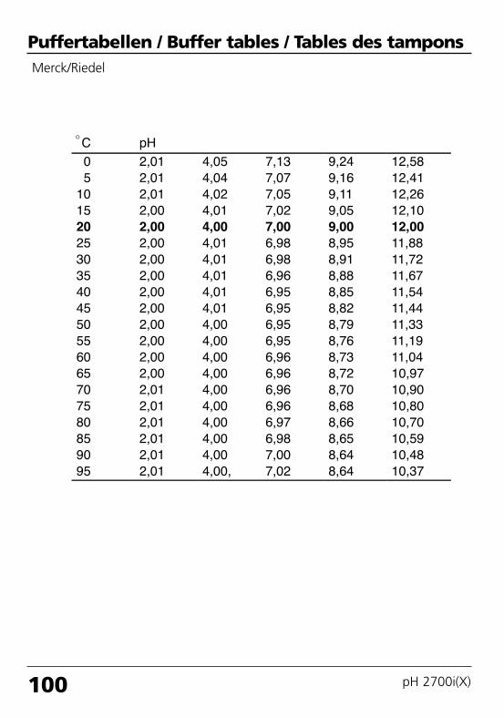
100 pH 2700i(X)
Puffertabellen / Buffer tables / Tables des tamponsMerck/Riedel
69904_E_2700i.QXD 28.09.2005 15:03 Uhr Seite 100 gro DAISY.DATA01:NETDATA:MAC2ALL:BA:M700X_Version_6:p

101
Puffertabellen / Buffer tables / Tables des tamponsDIN 19267
69904_E_2700i.QXD 28.09.2005 15:03 Uhr Seite 101 gro DAISY.DATA01:NETDATA:MAC2ALL:BA:M700X_Version_6:p

102 pH 2700i(X)
Puffertabellen / Buffer tables / Tables des tamponsNIST Standard (DIN 19266 : 2000-01)
Note:The table above only serves for orientation purposes.The actual pH values of the individual batches of the reference materials aredocumented in a certificate of an accredited laboratory. This certificate issupplied with the respective buffers.
69904_E_2700i.QXD 28.09.2005 15:03 Uhr Seite 102 gro DAISY.DATA01:NETDATA:MAC2ALL:BA:M700X_Version_6:p

103
Puffertabellen / Buffer tables / Tables des tamponsTechn. Puffer nach NIST / According to NIST / Suivant NIST
69904_E_2700i.QXD 28.09.2005 15:03 Uhr Seite 103 gro DAISY.DATA01:NETDATA:MAC2ALL:BA:M700X_Version_6:p

104 pH 2700i(X)
69904_E_2700i.QXD 28.09.2005 15:03 Uhr Seite 104 gro DAISY.DATA01:NETDATA:MAC2ALL:BA:M700X_Version_6:p

105
Buffer sets to be entered: SW 700-002Select menu: Parameter setting/System control/Buffer tableIndividual buffer set (with 3 buffer solutions) for pH measurement
Buffer tableYou can enter an individual buffer set. To do so, you enter 3 complete buffersolutions in ascending order (e.g. pH 4, 7, 10) for the correct temperature(range 0 ... 95 °C, 5 °C steps). Distance between buffers in the whole temperature range: min. 2 pH units.Then this buffer set is available as “Table” in addition to the permanently setstandard buffer solutions.
Menu Display Buffer table: Entering values
Enter buffer set• Call up parameter setting• System control• Select “Buffer table”
• Select buffer to be entered3 complete buffer solutionsmust be entered in ascending order (e.g. pH 4, 7, 10).Mininum distance: 2 pH units
Return
25.6 °C7.20 pH
Point of measurement
Logbook
Concentration chart
Release of options
Calculation Blocks
Buffer table
System control (Administrator)
Return
25.6 °C7.10 pH
Buffer 2Buffer 3
Buffer 1
Buffer table (Administrator)
Return
25.6 °C7.10 pH
Nominal buffer value
pH value at 10 °CpH value at 15 °C
pH value at 05 °C
pH value at 20 °C
pH value at 00 °C
Buffer 1 (Administrator)
+04.00 pH+04.00 pH
+04.00 pH
+04.00 pH+04.00 pH
• Enter nominal buffer value and all other values for the correct temperature (right/left arrow keys to select position, up/down arrow keys to edit number, confirm with enter.)
The special buffer set is selected as follows:Parameter setting/Module pH/Cal preset values/Calimatic buffer/Table.
+04.00 pH
69904_E_2700i.QXD 28.09.2005 15:03 Uhr Seite 105 gro DAISY.DATA01:NETDATA:MAC2ALL:BA:M700X_Version_6:p

106 pH 2700i(X)
Parameter settingActivated from measuring mode: Press menu key to selectmenu.Select parameter setting using arrow keys, confirm with enter.Administrator levelAccess to all functions, also passcode setting. Releasing or block-ing function for access from the Operator level.Operator levelAccess to all functions which have been released at theAdministrator level. Blocked functions are displayed in gray and cannot be edited.Viewing levelOnly display, no editing possible!
Select menu
Return to meas
7.00 pH25.6 °C
Select: [enter]
Lingua
Parameter setting
Return
7.00 pH25.6 °C
Viewing level
Administrator level (All Data) adm(Operation Data) opl(All Data) view
Operator level
System control
Parameter sets• Load• Save
Parameter setting menu
2 parameter sets (A,B) are available in the analyzer. The currently active parameter set is read on the display.Parameter sets contain all settings except:Sensor type, Options, System control settingsUp to 5 parameter sets (1, 2, 3, 4, 5) are available when a SmartMedia card (Option) is used.
Memory card (Option)• Register Logbook• Register recorder• Decimal separator• Card full• Formatting
Menu only appears with SmartMedia Card inserted. Make sure that it is a memory card,not an update card.Commercially available SmartMedia cards must be formattedbefore they can be used as memory card.
Copy configuration The complete configuration of an analyzer can be written on aSmartMedia card. This allows transferring all device settings - exceptoptions and passcodes - to other devices with identical equipment.
Function control matrix• Input OK2• Left softkey• Right softkey
Selecting the control element for the following functions:- Parameter set selection- KI recorder (Start/Stop)- Favorites menu (selected diagnostics functions)- EC 400 (fully automated probe controller)
Time/dateMeas. point descriptionRelease of optionsSoftware updateLogbookBuffer tableFactory settingPasscode entry
Selecting the display format, entryCan be called up in the diagnostics menu.A TAN is required to release an Option.Software update from SmartMedia card (update card)Selecting events to be recordedEntering own buffer set for automatic calibrationResetting all parameters to factory settingEditing the passcodes
69904_E_2700i.QXD 28.09.2005 15:03 Uhr Seite 106 gro DAISY.DATA01:NETDATA:MAC2ALL:BA:M700X_Version_6:p

107
Display settings: FRONT module
Measurement recorder• Time base• Zoom function• Min/Max display
Parameter setting menu
Option. 2-channel, selection of process variable, start and end
Languages
Measurement display• Main display• Display format• Viewing angle
Representation of measured values on the display:- Selecting the number of primary values displayed (one or two)- Decimal places
Output current I1, I2• Process variable• Characteristic• Output (0/4 - 20 mA)• Output filter• Behavior during messages
- Function check--- Currently meas. value--- Last meas. value--- Fixed 22 mA
- 22 mA message
2 current outputs, separately adjustable
KI recorder Option. See more detailed “Options” manual
Signal outputs and inputs, contacts: BASE module
Contact K4• Contact type• ON delay• OFF delay
NAMUR Failure
Contacts K3, K2, K1• Usage
- Maintenance request- Function check
- Limit value (adjustable) - Rinse contact (adjustable)- Parameter set B active- USP output- KI recorder active
• Contact type• ON delay• OFF delay
Factory setting:K3: Maintenance request, K2: Function check, K1: Limit value
- Variable, limit value, hysteresis, effective direction, ...- Rinsing interval, lead times, rinse duration, logbook entry, ...
Inputs OK1, OK2• OK1 usage
- Signal level
Optocoupler - signal inputs Off, function checkactive level switchable from 10 to 30 V or < 2 V, resp.For OK2 see System control/Function control matrix
Output current[mA]
“Fixed22 mA”
Function check
22
4
“Last usablevalue”
Function check
Function check
“Currentmeas.”
Behavior during messages
69904_E_2700i.QXD 28.09.2005 15:03 Uhr Seite 107 gro DAISY.DATA01:NETDATA:MAC2ALL:BA:M700X_Version_6:p

108 pH 2700i(X)
pH 2700i(X) module
Parameter setting menu
Input filter
Sensor data• Sensor type• Temperature detection• Sensoface• Sensor monitoringDetails- Slope- Zero- Sensocheck ref. el.- Sensocheck glass el.- Response time- Sensor wear- CIP counter- SIP counter- Autoclaving counter- Sensor operating time
Representation of measured values on the display:- Selection (automatic for ISM)- Selection (automatic for ISM) for meas / cal
Cal preset values• Calimatic buffer
- Mettler-Toledo- Merck/Riedel- DIN 19267- NIST standard- NIST technical- Table
• Drift check• Calibration timer• Cal tolerance band• ORP check
TC process medium Selection: Off, linear, ultrapure water, table
ORP/rH value• Reference electrode• ORP conversion to SHE• Calculate rH with factor
Delta function
Messages• pH value• ORP value• rH value• Temperature• mV value
Devaluate ISM sensor
69904_E_2700i.QXD 28.09.2005 15:03 Uhr Seite 108 gro DAISY.DATA01:NETDATA:MAC2ALL:BA:M700X_Version_6:p

109
pH 2700i(X) module
Calibration menu
CalimaticEntry of buffer valuesProduct calibrationData entryORP calibration
Current source Output current definable 0 ... 22 mA
Message listMeas. point descriptionLogbookDevice description
List of all warning and failure messages
Hardware version, Serial no., (Module) Firmware, ISM, Options
Maintenance menu
BASE module
pH 2700i(X) module
Sensor monitorTemp probe adjustment
pH / ORP input, RTD, Temp, Impedance glass + ref. el.Compesating for lead length
Diagnostics menu
FRONT module
Module diagnosticsDisplay testKeypad test
BASE module
Module diagnosticsInput/output status
pH 2700i(X) module
Module diagnosticsServicescopeSensor monitorCal recordCal record ORPSensor network diagram pHSensor wear monitorStatistics
Internal function testpH input signal: Displays the noise levels over the timeShows the values currently measured by the sensorData of last adjustment / calibrationData of last ORP adjustment / calibrationGraphical representation of the sensor parametersCurrent sensor wear, No. of CIP/SIP/autoclaving cyclesDisplays first calibration and deviations of last 3 calibrations
69904_E_2700i.QXD 28.09.2005 15:03 Uhr Seite 109 gro DAISY.DATA01:NETDATA:MAC2ALL:BA:M700X_Version_6:p

110 pH 2700i(X)
69904_E_2700i.QXD 28.09.2005 15:03 Uhr Seite 110 gro DAISY.DATA01:NETDATA:MAC2ALL:BA:M700X_Version_6:p

111
Index
AAdaptive cal timer 67, 92Adjustment 39Administrator level 57Audit Trail log 8Autoclaving counter (ISM only) 22
BBuffer sets to be entered 105Buffer tables 99
CCal record 93Cal tolerance band 67Cal tolerance band, Program flow 65Calculation Blocks 86Calibration 38Calibration by entering data from premeasured electrodes 50Calibration methods 42Calibration timer 67, 92Calibration with manual entry of buffer values 46Calimatic automatic buffer recognition 44Calimatic buffer 67Characteristics 76CIP (Cleaning in Place) 26Configuring the module 59Contact type 83Control signal 84Current output: Settings 75Current outputs 98Current outputs: Characteristics 76Current range is exceeded 79Current span 98
69904_E_2700i.QXD 28.09.2005 15:03 Uhr Seite 111 gro DAISY.DATA01:NETDATA:MAC2ALL:BA:M700X_Version_6:p

112 M 700(X)
Index
DData recording 14Declaration of Conformity 3Delta function 68, 71Device description 10, 90Device limits 72Diagnostics 91-92Diagnostics functions 89Digital inputs 84Display icons 115Disposal 2
EEC Declaration of Conformity 3Electronic Signature 8EMC 97Enable / lock functions 58Explosion protection 97
FFactory settings 74Failure 73, 80Failure message 79Favorites 24FDA 21 CFR Part 11 8First Calibration 40First Calibration ISM 20Function check 59, 80Function control matrix 24Functions 13
HHazardous-area application 9Hysteresis 83
69904_E_2700i.QXD 28.09.2005 15:03 Uhr Seite 112 gro DAISY.DATA01:NETDATA:MAC2ALL:BA:M700X_Version_6:p

113
IIcons 115Input filter 62Input/output status 90Inserting the module 28Intended use 8ISFET sensor 30ISFET zero adjustment 54ISM - Intelligent Sensor Management 18ISM diagnostics 23ISM Plug and Measure 19ISM sensor description 90Isothermal potential 51
LLightning protection 97Limit value 83Locking a function 58Logarithmic output curve 77Logbook 74, 89
MM 700 BASE 15M 700 FRONT 12, 14Maintenance 56, 73Maintenance request 80Maintenance request message 79Max. device limits 72Measured values 75Measurement display settings 36Menu groups 13Menu items 13Menu selection 34Menu structure 34
Index
69904_E_2700i.QXD 28.09.2005 15:03 Uhr Seite 113 gro DAISY.DATA01:NETDATA:MAC2ALL:BA:M700X_Version_6:p

114 M 700(X)
Message icons 73Message list 73, 89Message when the current range is exceeded 79Messages 72-73Minimum measuring spans for current outputs 98Modular concept 11Module diagnostics 90-91Module equipment 15Monitoring functions for calibration 51
NNAMUR signals 79-80
OOK inputs 84OK1,OK2 inputs 84One-point calibration 40Operator level 57ORP adjustment 52ORP measurement 32ORP related to the standard hydrogen electrode (SHE) 52ORP/rH value 68, 71Output current 75Output filter 78Overview of menu selection 116
PParameter sets 14, 85Parameter sets: Signal via relay contact 85Parameter sets: Switching via OK2 85Parameter setting: Cal preset values 64Parameter setting: Default settings and selection range 68Parameter setting: ISM 21Parameter setting: Limit value 83
Index
69904_E_2700i.QXD 28.09.2005 15:03 Uhr Seite 114 gro DAISY.DATA01:NETDATA:MAC2ALL:BA:M700X_Version_6:p

115
Parameter setting: Locking a function 58Parameter setting: Messages 72Parameter setting: Operating levels 57Parameter setting: ORP/rH value 71Parameter setting: Relay contacts 82Parameter setting: Sensor data 60Parameter setting: TC process medium 69Parameter tables (Excel) 17Passcode entry 35pH sensor monitoring adjustable 60Predictive maintenance 22Product calibration 48
RReference electrode types 52Relay contacts 80Relay contacts: Protective wiring 81Release of options 66Resolution limit 98Return of products 2
SSafety information 9Secondary displays 24, 36Select favorites 25Sensocheck - Sensor monitoring 61Sensocheck, Sensoface 61Sensoface 60Sensoface criteria 61Sensor connection 29Sensor data 62Sensor monitor 56, 91Sensor monitoring details 21, 60Sensor network diagram 93
Index
69904_E_2700i.QXD 28.09.2005 15:03 Uhr Seite 115 gro DAISY.DATA01:NETDATA:MAC2ALL:BA:M700X_Version_6:p
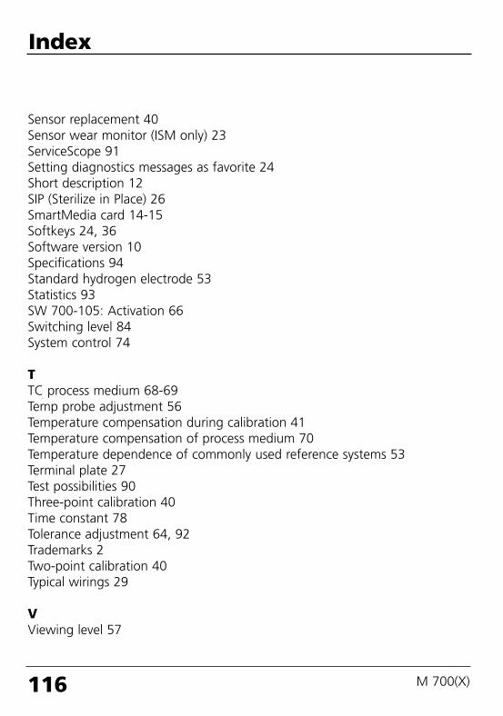
116 M 700(X)
Sensor replacement 40Sensor wear monitor (ISM only) 23ServiceScope 91Setting diagnostics messages as favorite 24Short description 12SIP (Sterilize in Place) 26SmartMedia card 14-15Softkeys 24, 36Software version 10Specifications 94Standard hydrogen electrode 53Statistics 93SW 700-105: Activation 66Switching level 84System control 74
TTC process medium 68-69Temp probe adjustment 56Temperature compensation during calibration 41Temperature compensation of process medium 70Temperature dependence of commonly used reference systems 53Terminal plate 27Test possibilities 90Three-point calibration 40Time constant 78Tolerance adjustment 64, 92Trademarks 2Two-point calibration 40Typical wirings 29
VViewing level 57
Index
69904_E_2700i.QXD 28.09.2005 15:03 Uhr Seite 116 gro DAISY.DATA01:NETDATA:MAC2ALL:BA:M700X_Version_6:p

117
WWarranty 2Wiring examples 29
ZZero point 51
Index
69904_E_2700i.QXD 28.09.2005 15:03 Uhr Seite 117 gro DAISY.DATA01:NETDATA:MAC2ALL:BA:M700X_Version_6:p

118 M 700(X)
69904_E_2700i.QXD 28.09.2005 15:03 Uhr Seite 118 gro DAISY.DATA01:NETDATA:MAC2ALL:BA:M700X_Version_6:p

119
Icon Explanation of icons important for this module
The analyzer is in measuring mode, an ISM sensor is connected.
The analyzer is in calibration mode. Function check is active.
The analyzer is in maintenance mode. Function check is active.
The analyzer is in parameter setting mode. Function check is active.
The analyzer is in diagnostics mode.
Function check. The NAMUR “function check” contact is active (factory setting: BASEmodule, contact K2, N/O contact). Current outputs as configured: • Currently meas. value: The currently measured value appears at the current output• Last measured value: The last measured value is held at the current output• Fix 22 mA: The output current is at 22 mA
Calibration is performed
Calibration - Step 1 of product calibration has been executed. The analyzer is waiting for the sample value.
Temperature detection by manual input
In the plaintext display in front of a menu line:Access to next menu level with enter
In the plaintext display in front of a menu line when it has been blocked by theAdministrator against access from the Operator level.
Designates the module slot (1, 2 or 3), allowing the clear assignment of measured-value/parameter displays in the case of identical module types.
Indicates the active parameter set (The analyzer provides two parameter sets A and B. Up to 5 sets can be added using additional functions and SmartMedia card.)
Failure: The NAMUR “failure” contact is active (factory setting: BASE module, contactK4, N/C contact). To view error message, call up: Diagnostics menu/Message listMaintenance: The NAMUR “maintenance request” contact is active (factory setting:BASE module, contact K2, N/O contact). To view error message, call up: Diagnosticsmenu/Message list
NA
MU
R s
ign
als
Calibration:Temperature compensation for process medium is active (Linear/Ultrapure water/Chart)
TC
Delta function is active (Output value = measured value – delta value)∆
man
69904_E_2700i.QXD 28.09.2005 15:03 Uhr Seite 119 gro DAISY.DATA01:NETDATA:MAC2ALL:BA:M700X_Version_6:p

Menu selection
Calibration and adjustment.........................................38Calimatic: automatic calibration............................................44Manual entry of buffer values...............................................46Product calibration................................................................48Data entry: premeasured electrodes......................................50ORP calibration .....................................................................52
Maintenance ....................................................................56
Parameter setting...........................................................59Input filter ............................................................................62Sensor data ..........................................................................62Cal preset values ..................................................................64TC process medium ..............................................................69ORP/rH value ........................................................................71Delta function.......................................................................71Messages..............................................................................72
Diagnostics .......................................................................91Module diagnostics...............................................................91ServiceScope.........................................................................91Sensor monitor .....................................................................91Adaptive calibration timer.....................................................92Cal record.............................................................................93Sensor network diagram.......................................................93Statistics ...............................................................................93Tolerance adjustment............................................................92
ISFET zero adjustment...........................................................54
Autoclaving counter (ISM) ....................................................22
Current outputs, contacts, OK inputs (BASE) ........................75
Set favorite ...........................................................................24
Order number: 52 121 276
69904_E_2700i.QXD 28.09.2005 15:03 Uhr Seite 120 gro DAISY.DATA01:NETDATA:MAC2ALL:BA:M700X_Version_6:p