methods for global and local fem analysis of riveted joint on ...
14
Fatigue of Aircraft Structures Vol. 1 (2009) 212-225 10.2478/v10164-010-0019-5 METHODS FOR GLOBAL AND LOCAL FEM ANALYSIS OF RIVETED JOINT ON THE EXAMPLE OF THE PZL M28 SKYTRUCK AIRCRAFT. Wojciech Wronicz, Jerzy Kaniowski Institute of Aviation Warsaw, Poland Jerzy Jachimowicz Military University of Technology Warsaw, Poland Abstract The paper considers some aspects of FEM modeling of riveted joints with application of shell elements and submodeling technique. Presented works were carried out within Eureka project No. E!3496 called IMPERJA. The goal of the IMPERJA project is to increase the fatigue life of riveted joints. The project assumed FEM modeling of the operating aircraft’s structure at three different complexity levels, namely considering the complete structure, a structural detail and a single riveted joint. The paper presents analyses of various rivet models and calculations of a structure and a riveted joint. In the first part examples of various rivet models were presented and usefulness of them was discussed. Influence of the following simplification was analyzed; • neglecting of rivets in a model (elements are jointed continuously) • rivet as a rigid element (MPC) • neglecting of contact phenomenon • neglecting of secondary bending. The basis of the analysis was the asymmetric butt joint model with 14 rivets. The model which took into account secondary bending and contact phenomenon was analyzed as well. In the second part, the example of analysis of riveted joint on a lower skin of the PZL M28 Skytruck aircraft wing was presented. A submodeling technique was used there. At first, part of the wing model, was built. It includes 7 ribs and 6 bulkheads between them. Boundary conditions were taken on a basis of operation data. Presence of rivets was neglected. The Linear material model was used. The purpose of this calculation was to gain accurate boundary conditions for the model of riveted joint on the middle rib. Next a shell model of chosen area was build. Boundary conditions were set on a basis of result from previous analysis. Because of large stiffness difference between part models (part of wing and riveted joint) forces, instead of displacements, were used, as boundary conditions. The nonlinear model of material was used. A contact effect, secondary bending and residual stresses were taken into account. Results from this analysis are planned to be used as boundary conditions in a calculation of single rivet with solid detailed model. The presented method allows analyzing phenomena that appear around a rivet in a real structure, during operation. Analyses were performed with MSC PATRAN and NASTRAN software. 1. INTRODUCTION Riveting still remains the most popular method of joining metal parts of the aircraft structure. During the riveting process and the operation severe stress concentrations and effects such as fretting and secondary bending occur, which leads to reduction of fatigue life. Although the literature on the fatigue behaviour of riveted joints is quite abundant, many aspects are still not sufficiently understood and investigated and, therefore, they require a further study. Moreover most of them do not concern types of rivets and sheets used in Poland.
-
Upload
khangminh22 -
Category
Documents
-
view
2 -
download
0
Transcript of methods for global and local fem analysis of riveted joint on ...
Fatigue of Aircraft Structures Vol. 1 (2009) 212-225 10.2478/v10164-010-0019-5
METHODS FOR GLOBAL AND LOCAL FEM ANALYSIS OF RIVETED JOINT ON THE EXAMPLE OF THE PZL M28 SKYTRUCK
AIRCRAFT.
Wojciech Wronicz, Jerzy Kaniowski
Institute of Aviation Warsaw, Poland
Jerzy Jachimowicz
Military University of Technology
Warsaw, Poland
Abstract The paper considers some aspects of FEM modeling of riveted joints with application of shell elements
and submodeling technique. Presented works were carried out within Eureka project No. E!3496 called IMPERJA. The goal of the IMPERJA project is to increase the fatigue life of riveted joints. The project assumed FEM modeling of the operating aircraft’s structure at three different complexity levels, namely considering the complete structure, a structural detail and a single riveted joint. The paper presents analyses of various rivet models and calculations of a structure and a riveted joint.
In the first part examples of various rivet models were presented and usefulness of them was discussed. Influence of the following simplification was analyzed; • neglecting of rivets in a model (elements are jointed continuously) • rivet as a rigid element (MPC) • neglecting of contact phenomenon • neglecting of secondary bending. The basis of the analysis was the asymmetric butt joint model with 14 rivets. The model which took into account secondary bending and contact phenomenon was analyzed as well.
In the second part, the example of analysis of riveted joint on a lower skin of the PZL M28 Skytruck aircraft wing was presented. A submodeling technique was used there. At first, part of the wing model, was built. It includes 7 ribs and 6 bulkheads between them. Boundary conditions were taken on a basis of operation data. Presence of rivets was neglected. The Linear material model was used. The purpose of this calculation was to gain accurate boundary conditions for the model of riveted joint on the middle rib. Next a shell model of chosen area was build. Boundary conditions were set on a basis of result from previous analysis. Because of large stiffness difference between part models (part of wing and riveted joint) forces, instead of displacements, were used, as boundary conditions. The nonlinear model of material was used. A contact effect, secondary bending and residual stresses were taken into account. Results from this analysis are planned to be used as boundary conditions in a calculation of single rivet with solid detailed model. The presented method allows analyzing phenomena that appear around a rivet in a real structure, during operation. Analyses were performed with MSC PATRAN and NASTRAN software. 1. INTRODUCTION
Riveting still remains the most popular method of joining metal parts of the aircraft structure. During the riveting process and the operation severe stress concentrations and effects such as fretting and secondary bending occur, which leads to reduction of fatigue life. Although the literature on the fatigue behaviour of riveted joints is quite abundant, many aspects are still not sufficiently understood and investigated and, therefore, they require a further study. Moreover most of them do not concern types of rivets and sheets used in Poland.
Methods for global and local FEM analysis of riveted joint on the example of the PZL M28 Skytruck aircraft
213
The Paper presents some consideration about riveted joint FEM modelling with shell elements on different levels based on analyses performed within the IMPERJA project. The goal of this project is to increase fatigue life. This objective is met by investigating and improving the riveting process as well as improving prediction methods for fatigue life. The project refers to real structures. One of the IMPERJA consortium partners, the PZL Mielec, recommended its product, the airplane M28 Skytruck, as the object of investigations and analyses. In the IMPERJA programme, the study of FEM methodology modelling of the structure at different complexity levels was planned:
• complete structure, • structural detail , • single riveted joint.
A key issue of the proposed approach will be defining rules of transferring the excitation (loading and boundary conditions) for the above modelling path.
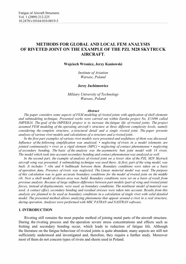
Analyses were performed with MSC PATRAN and NASTRAN software. During calculations several material models were used. Fig. 1 presents stress-strain curves for these models. D16AT_lin-wing model is a linear model, used in the test of rivet models and in the analysis of part of the wing model. D16AT-joint and D16AT-smoothed joint model are models used in the riveted joint analysis. D16AT properties were assumed according to USSR aerospace industrial branch standard OST 1 90070-92.
D16AT material models
0
50
100
150
200
250
300
350
400
450
0 0,05 0,1 0,15 0,2 0,25 0,3Strain [/]
Stre
ss [M
Pa] D16AT_lin-wing model
D16AT-smoothed joint model
D16AT-joint model
Fig. 1. Material models
Modelling method depends on aim of an analysis as well as computing and financial
capabilities. The simplest way of rivet modelling is merging nodes on rivet axis. Sometimes rivets are modelled as a single MPC (Multi Point Constrains) or bar elements. Better models take into account rivet hole and contact phenomenon. It makes number of elements considerably increase and calculation become nonlinear (which noticeably extends its time). Solid element models are the most precise. Because of their size and complexity they cover only one or few rivets. 2. RIVET MODELS
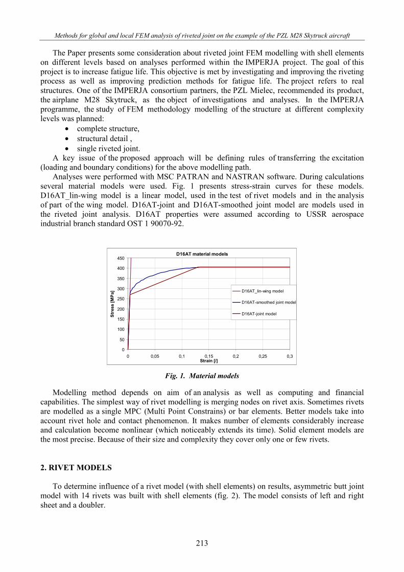
To determine influence of a rivet model (with shell elements) on results, asymmetric butt joint model with 14 rivets was built with shell elements (fig. 2). The model consists of left and right sheet and a doubler.
Wojciech Wronicz, Jerzy Kaniowski, Jerzy Jachimowicz
214
Fig. 2 Asymmetric butt joint model
Thickness of the doubler is 1,2 mm. Thickness of sheets is 1,2 mm in central area and 0,9 mm
outside. Dimension of the model is 200x64mm. Linear material model of D16AT aluminium alloy was used. The model was constrained and tensed. Residual stresses were not modelled.
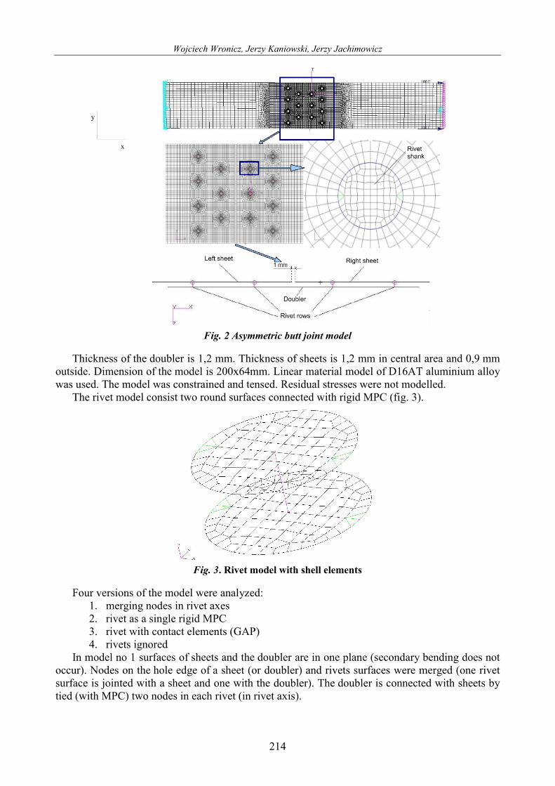
The rivet model consist two round surfaces connected with rigid MPC (fig. 3).
Fig. 3. Rivet model with shell elements
Four versions of the model were analyzed:
1. merging nodes in rivet axes 2. rivet as a single rigid MPC 3. rivet with contact elements (GAP) 4. rivets ignored
In model no 1 surfaces of sheets and the doubler are in one plane (secondary bending does not occur). Nodes on the hole edge of a sheet (or doubler) and rivets surfaces were merged (one rivet surface is jointed with a sheet and one with the doubler). The doubler is connected with sheets by tied (with MPC) two nodes in each rivet (in rivet axis).
Methods for global and local FEM analysis of riveted joint on the example of the PZL M28 Skytruck aircraft
215
Model no 2 is similar to model no 1 but elements of sheets ant the doubler are in two planes 1,2 mm distant from each other, so secondary bending was taken into account.
Model no 3 is also similar to model no 1 but nodes were not merged. GAP elements were introduced between nodes of rivets and sheet(doubler). All elements are in one plane so secondary bending don’t occurs.
In model no 4 all elements are in one plane. All nodes of sheets and the doubler were merged on the area were these parts interacts with each other.
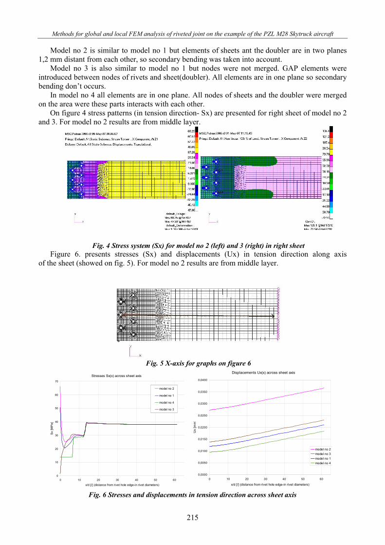
On figure 4 stress patterns (in tension direction- Sx) are presented for right sheet of model no 2 and 3. For model no 2 results are from middle layer.
Fig. 4 Stress system (Sx) for model no 2 (left) and 3 (right) in right sheet Figure 6. presents stresses (Sx) and displacements (Ux) in tension direction along axis
of the sheet (showed on fig. 5). For model no 2 results are from middle layer.
Fig. 5 X-axis for graphs on figure 6
Stresses Sx(x) across sheet axis
0
10
20
30
40
50
60
70
0 10 20 30 40 50 60
x/d [/] (distance from rivet hole edge-in rivet diameters)
Sx [M
Pa]
model no 2
model no 1
model no 4
model no 3
Displacements Ux(x) across sheet axis
0,0000
0,0050
0,0100
0,0150
0,0200
0,0250
0,0300
0,0350
0,0400
0 10 20 30 40 50 60
x/d [/] (distance from rivet hole edge-in rivet diameters)
Ux
[mm
]
model no 2model no 3model no 1model no 4
Fig. 6 Stresses and displacements in tension direction across sheet axis
Wojciech Wronicz, Jerzy Kaniowski, Jerzy Jachimowicz
216
There are two stress jumps in model no 4. The phenomenon is connected with thickness changes. Near rivets stress differences between models are very high, but 15-20 rivet diameter from
rivet hole edge are unnoticeably. Displacement differences between models do not disappear but are quite constant across the axis. Displacements in model no 2 are considerably higher than in others. It is connected with higher flexibility of the model due to secondary bending taken into account in this model. In other model all elements are in one plane and bending does not occur. Results indicate that rivet model has no influence on stresses far away from rivets, but can seriously affects whole model flexibility.
In analysis of big part of a construction with few hundred rivets is practically impossible to model rivets . Submodelling technique is very often used in such cases. More precise (local) model, which covers smaller area is built and boundary conditions are set based on analysis of a big (global) model. Results, presented on graphs above, indicate that if models (global and local) differ considerably in flexibility, it is better to use stresses instead of displacements as a boundary conditions.
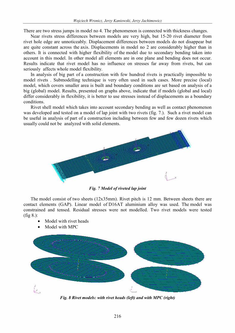
Rivet shell model which takes into account secondary bending as well as contact phenomenon was developed and tested on a model of lap joint with two rivets (fig. 7.). Such a rivet model can be useful in analysis of part of a construction including between few and few dozen rivets which usually could not be analyzed with solid elements.
Fig. 7 Model of riveted lap joint
The model consist of two sheets (12x35mm). Rivet pitch is 12 mm. Between sheets there are
contact elements (GAP). Linear model of D16AT aluminium alloy was used. The model was constrained and tensed. Residual stresses were not modelled. Two rivet models were tested (fig 8.):
• Model with rivet heads • Model with MPC
Fig. 8 Rivet models: with rivet heads (left) and with MPC (right)
Methods for global and local FEM analysis of riveted joint on the example of the PZL M28 Skytruck aircraft
217
Models were developed based on model shown on fig. 3. The model with heads consists of two
circular surfaces (diameter equal to rivet shank diameter) connected with bar element. There are contact elements (GAP), in sheet plane, between each of round surface and corresponded rivet hole edge in sheet. Two ring surfaces act as heads of a rivet. Outer diameter of surfaces is equal to rivet driven head diameter. One ring surface is 0.01 mm above upper sheet, second ring surface is 0.01 mm below bottom sheet. There are GAP elements between ring surfaces and sheets. Ring surfaces are connected with round surfaces with rigid MPC elements.
The model with MPC is similar to model with heads but there are no ring surfaces in it. Instead of them there are MPC elements in edge of round surfaces. They tie, in direction perpendicular to sheet plane, nodes on round surface edge with nodes on hole edge in sheet. Every one MPC connects one rivet node with one sheet node.
Model with heads is more precise but it turned out to be too complicated to use in analysis of construction with many rivets. Simpler model with smaller number of contact elements was needed. For this purpose model with MPC was developed.
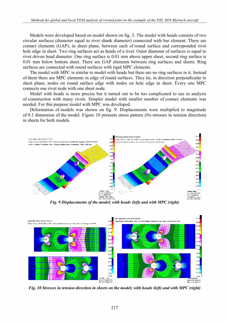
Deformation of models was shown on fig. 9. Displacements were multiplied to magnitude of 0.1 dimension of the model. Figure 10 presents stress pattern (Sx-stresses in tension direction) in sheets for both models
Fig. 9 Displacements of the model; with heads (left) and with MPC (right)
Fig. 10 Stresses in tension direction in sheets on the model; with heads (left) and with MPC (right)
Wojciech Wronicz, Jerzy Kaniowski, Jerzy Jachimowicz
218
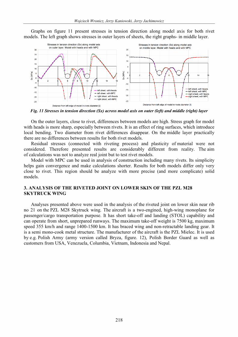
Graphs on figure 11 present stresses in tension direction along model axis for both rivet models. The left graph shows stresses in outer layers of sheets, the right graphs- in middle layer.
Fig. 11 Stresses in tension direction (Sx) across model axis on outer (left) and middle (right) layer
On the outer layers, close to rivet, differences between models are high. Stress graph for model
with heads is more sharp, especially between rivets. It is an effect of ring surfaces, which introduce local bending. Two diameter from rivet differences disappear. On the middle layer practically there are no differences between results for both rivet models.
Residual stresses (connected with riveting process) and plasticity of material were not considered. Therefore presented results are considerably different from reality. The aim of calculations was not to analyze real joint but to test rivet models.
Model with MPC can be used in analysis of construction including many rivets. Its simplicity helps gain convergence and make calculations shorter. Results for both models differ only very close to rivet. This region should be analyze with more precise (and more complicate) solid models. 3. ANALYSIS OF THE RIVETED JOINT ON LOWER SKIN OF THE PZL M28 SKYTRUCK WING
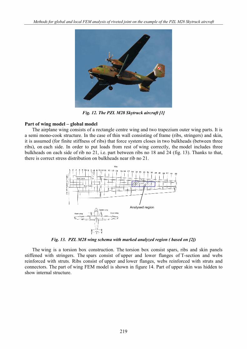
Analyses presented above were used in the analysis of the riveted joint on lower skin near rib no 21 on the PZL M28 Skytruck wing. The aircraft is a two-engined, high-wing monoplane for passenger/cargo transportation purpose. It has short take-off and landing (STOL) capability and can operate from short, unprepared runways. The maximum take-off weight is 7500 kg, maximum speed 355 km/h and range 1400-1500 km. It has braced wing and non-retractable landing gear. It is a semi mono-cook metal structure. The manufacturer of the aircraft is the PZL Mielec. It is used by e.g. Polish Army (army version called Bryza, figure. 12), Polish Border Guard as well as customers from USA, Venezuela, Columbia, Vietnam, Indonesia and Nepal.
Methods for global and local FEM analysis of riveted joint on the example of the PZL M28 Skytruck aircraft
219
Fig. 12. The PZL M28 Skytruck aircraft [1]
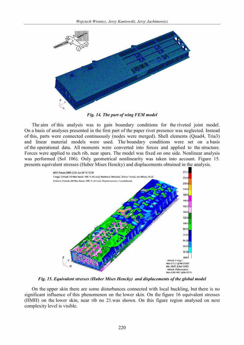
Part of wing model – global model
The airplane wing consists of a rectangle centre wing and two trapezium outer wing parts. It is a semi mono-cook structure. In the case of thin wall consisting of frame (ribs, stringers) and skin, it is assumed (for finite stiffness of ribs) that force system closes in two bulkheads (between three ribs), on each side. In order to put loads from rest of wing correctly, the model includes three bulkheads on each side of rib no 21, i.e. part between ribs no 18 and 24 (fig. 13). Thanks to that, there is correct stress distribution on bulkheads near rib no 21.
Fig. 13. PZL M28 wing schema with marked analyzed region ( based on [2])
The wing is a torsion box construction. The torsion box consist spars, ribs and skin panels
stiffened with stringers. The spars consist of upper and lower flanges of T-section and webs reinforced with struts. Ribs consist of upper and lower flanges, webs reinforced with struts and connectors. The part of wing FEM model is shown in figure 14. Part of upper skin was hidden to show internal structure.
Wojciech Wronicz, Jerzy Kaniowski, Jerzy Jachimowicz
220
Fig. 14. The part of wing FEM model
The aim of this analysis was to gain boundary conditions for the riveted joint model.
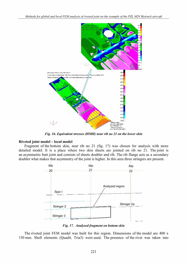
On a basis of analyses presented in the first part of the paper rivet presence was neglected. Instead of this, parts were connected continuously (nodes were merged). Shell elements (Quad4, Tria3) and linear material models were used. The boundary conditions were set on a basis of the operational data. All moments were converted into forces and applied to the structure. Forces were applied to each rib, near spars. The model was fixed on one side. Nonlinear analysis was performed (Sol 106). Only geometrical nonlinearity was taken into account. Figure 15. presents equivalent stresses (Huber Mises Hencky) and displacements obtained in the analysis.
Fig. 15. Equivalent stresses (Huber Mises Hencky) and displacements of the global model
On the upper skin there are some disturbances connected with local buckling, but there is no
significant influence of this phenomenon on the lower skin. On the figure 16 equivalent stresses (HMH) on the lower skin, near rib no 21.was shown. On this figure region analysed on next complexity level is visible.
Methods for global and local FEM analysis of riveted joint on the example of the PZL M28 Skytruck aircraft
221
Fig. 16. Equivalent stresses (HMH) near rib no 21 on the lower skin
Riveted joint model – local model
Fragment of the bottom skin, near rib no 21 (fig. 17) was chosen for analysis with more detailed model. It is a place where two skin sheets are jointed on rib no 21. The joint is an asymmetric butt joint and consists of sheets doubler and rib. The rib flange acts as a secondary doubler what makes that asymmetry of the joint is higher. In this area three stringers are present.
Fig. 17. Analysed fragment on bottom skin
The riveted joint FEM model was built for this region. Dimensions of the model are 400 x
150 mm. Shell elements (Quad4, Tria3) were used. The presence of the rivet was taken into
Wojciech Wronicz, Jerzy Kaniowski, Jerzy Jachimowicz
222
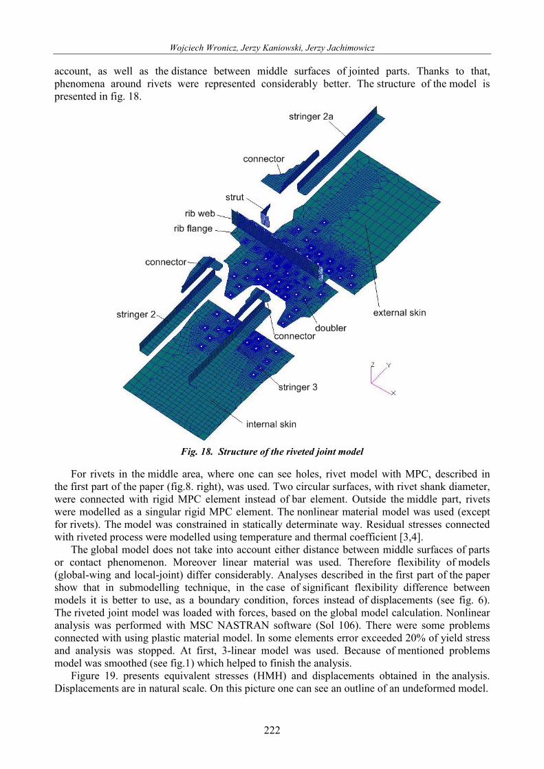
account, as well as the distance between middle surfaces of jointed parts. Thanks to that, phenomena around rivets were represented considerably better. The structure of the model is presented in fig. 18.
Fig. 18. Structure of the riveted joint model
For rivets in the middle area, where one can see holes, rivet model with MPC, described in
the first part of the paper (fig.8. right), was used. Two circular surfaces, with rivet shank diameter, were connected with rigid MPC element instead of bar element. Outside the middle part, rivets were modelled as a singular rigid MPC element. The nonlinear material model was used (except for rivets). The model was constrained in statically determinate way. Residual stresses connected with riveted process were modelled using temperature and thermal coefficient [3,4].
The global model does not take into account either distance between middle surfaces of parts or contact phenomenon. Moreover linear material was used. Therefore flexibility of models (global-wing and local-joint) differ considerably. Analyses described in the first part of the paper show that in submodelling technique, in the case of significant flexibility difference between models it is better to use, as a boundary condition, forces instead of displacements (see fig. 6). The riveted joint model was loaded with forces, based on the global model calculation. Nonlinear analysis was performed with MSC NASTRAN software (Sol 106). There were some problems connected with using plastic material model. In some elements error exceeded 20% of yield stress and analysis was stopped. At first, 3-linear model was used. Because of mentioned problems model was smoothed (see fig.1) which helped to finish the analysis.
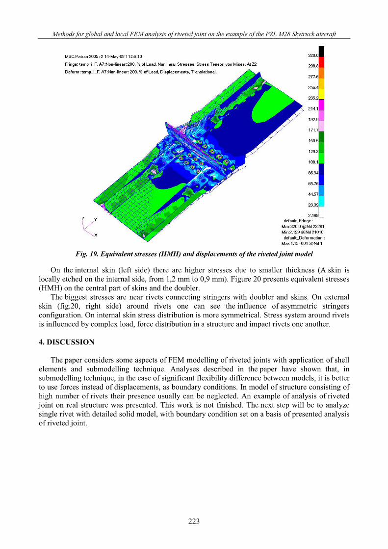
Figure 19. presents equivalent stresses (HMH) and displacements obtained in the analysis. Displacements are in natural scale. On this picture one can see an outline of an undeformed model.
Methods for global and local FEM analysis of riveted joint on the example of the PZL M28 Skytruck aircraft
223
Fig. 19. Equivalent stresses (HMH) and displacements of the riveted joint model
On the internal skin (left side) there are higher stresses due to smaller thickness (A skin is
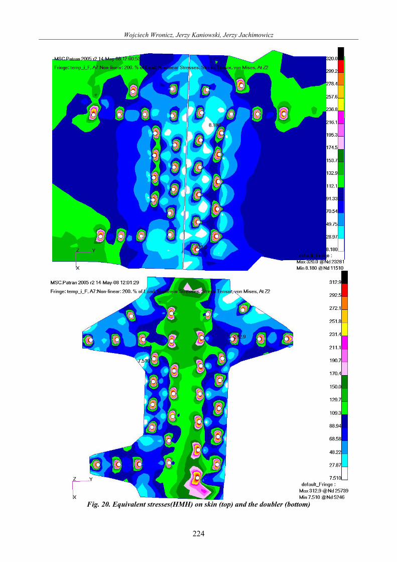
locally etched on the internal side, from 1,2 mm to 0,9 mm). Figure 20 presents equivalent stresses (HMH) on the central part of skins and the doubler.
The biggest stresses are near rivets connecting stringers with doubler and skins. On external skin (fig.20, right side) around rivets one can see the influence of asymmetric stringers configuration. On internal skin stress distribution is more symmetrical. Stress system around rivets is influenced by complex load, force distribution in a structure and impact rivets one another. 4. DISCUSSION
The paper considers some aspects of FEM modelling of riveted joints with application of shell elements and submodelling technique. Analyses described in the paper have shown that, in submodelling technique, in the case of significant flexibility difference between models, it is better to use forces instead of displacements, as boundary conditions. In model of structure consisting of high number of rivets their presence usually can be neglected. An example of analysis of riveted joint on real structure was presented. This work is not finished. The next step will be to analyze single rivet with detailed solid model, with boundary condition set on a basis of presented analysis of riveted joint.
Wojciech Wronicz, Jerzy Kaniowski, Jerzy Jachimowicz
224
Fig. 20. Equivalent stresses(HMH) on skin (top) and the doubler (bottom)
Methods for global and local FEM analysis of riveted joint on the example of the PZL M28 Skytruck aircraft
225
5. REFERENCES [1] Marcin Jagodziński / airnews.pl [2] PZL M28 Maintenance manual. [3] Fawaz, S., Schijve, J., & de Koning, U. A. (1997). Fatigue Crack Growth in Riveted Joints,
Fatigue in New and Ageing Aircraft. In: Proceeding of the 19th Symposium of the International Committee on Aeronautical Fatigue. Edinburgh, Scotland: EMAS PUBLISHING.
[4] Jachimowicz, J., & Kajka, R. (2003). Problems of FEM modelling of riveted joints [in Polish], VIII Konferencja Naukowo-Techniczna; Programy MES w komputerowym wspomaganiu analizy, projektowania i wytwarzania, Rynia.
[5] Wronicz, W. (2008). Methods for global and local FEM analysis of riveted joints on the example of the PZL M28 Skytruck aircraft [in Polish], Master’s Dissertation, Warsaw University of Technology.
[6] Jachimowicz J., & Wronicz W. (2008). Some problems of FEM modelling of riveted thin-walled aircraft structures [in Polish]. Przegląd Mechaniczny, 5(2008).
[7] Wronicz, W., Kaniowski, J., Jachimowicz, J., & Szymczyk, E. (2009). Methods for FEM analysis of riveted joints of thin-walled aircraft structures within the IMPERJA project. Bridging the Gap between Theory and Operational Practice. In: Proceeding of the 25th Symposium of the International Committee on Aeronautical Fatigue, 27-29 May 2009. Rotterdam, Netherlands.