FEM modeling and analysis of a novel rotary-linear isotropic brushless machine
6
Φ Abstract -- In several applications, ranging from industrial robotics to advanced automotive, a combination of rotary and linear motions along the same axis is ultimately required. Rotary-linear motors, providing both torque and force, may permit to fulfill the related requirements more effectively than conventional solutions using 2 distinct normal actuators. This paper presents the FEM modeling and analysis of a novel rotary-linear permanent magnets synchronous machine, whose structure, analytical modeling and control are presented in companion papers. Such machine was purposely conceived to be manufactured using common affordable technologies or even by assembling standard parts. A 3-D parametric model purposely developed to permit a detailed analysis of the machine operation is described. Several simulation results concerning various operative conditions are reported and commented, confirming the substantial validity of the basic idea and highlighting the secondary effects due to non-ideal aspects of machine behavior. Index Terms -- Actuators, brushless machines, permanent magnet machines, rotary-linear motors. I. INTRODUCTION IHE combination of rotary and linear motions along the same axis is used in several applications, including tooling machines (e.g. for drilling, threading, machining etc.), robotics (both for arms and end-effectors) and various industrial apparatuses for pick&place assembly, packaging, mixing, shaking etc. Therefore, rotary-linear motors, able to effectively generate torque and axial force in a suitably controllable way, constitute one of the most interesting typologies of multi-degree-of-freedom machines (e.g. [1]). A further potential application field emerging for such machines is the vehicular ambit, for example as servo- actuators for gearboxes (e.g. [2]) or for the integrated actuation of pairs of basic motions in active wheels on board of electric and hybrid vehicles (e.g. [3]) in the context of x- by-wire technology. Several rotary-linear machine typologies were proposed in the literature or patented (e.g. [4]). The simplest solutions consist in mechanically coupling a rotary and a linear motor not sharing any active part (e.g. [2]). More integrated machine configurations were also proposed. Anyway, some types exhibit a rather complicated behavior making difficult achieving an effective decoupled control of force and torque (e.g. [5,6]). Due to the unconventional layout of magnetic core and/or windings, other types (e.g. [7,8]) require peculiar and potentially costly manufacturing processes. In fact, for example magnetic core parts facing variable flux conditions with non-planar field maps cannot be properly realized using laminations, thus requiring different solutions such as iron Φ This work was partly supported by PRIN National Project concerning "Distributed-architecture propulsion and steering system for light electric vehicles employing rotary-linear drives", which was co-funded in 2008 by the Italian Ministry of University and Research. P. Bolognesi and F. Papini are with the University of Pisa, Department of Electric Systems and Automation, 56122 Pisa, Italy (e-mail: [email protected], [email protected]). powder materials. Anyway, such technology has not yet gained a sufficient industrial diffusion and maturity, making presently not much attractive even potentially interesting machines such as [9], featuring a simple modular structure and a linear decoupled control of force and torque. Recently, aiming to overcome the above issues a novel typology of rotary-linear permanent magnets brushless synchronous machine was proposed, inspired to [9] yet permitting to be manufactured using common affordable technologies or even assembling standard parts available on the market while still featuring a good ideal controllability. The theoretical analysis and the intermediate-level modeling of the basic variant of the machine, which was first proposed in [10], are described in more detail in companion papers. After a brief recall of the most relevant aspects, hereafter the FEM modeling of such machine variant will be presented, reporting several simulation results referring to a case study. II. PROPOSED MACHINE A. Basic Variant Structure As sketched in the qualitative axial section depicted in fig. 1, the basic variant of the proposed machine consists in a couple of identical stator modules, featuring an almost hollow-cylindrical shape and aligned side-by-side along their shared axis, inside which a mover having almost cylindrical shape is located and aligned to the same axis. The stator modules are hosted inside an appropriate mechanical frame also supporting the mover by means of suitable rotary-linear bearings, permitting it to rotate and translate along the machine axis yet bounding its active part to stay inside the frame delimited from stator cores. The 2 stator modules feature identical characteristics, including each one a separated winding and a ferromagnetic core. Such core is macroscopically isotropic and may feature semi- closed slots whose openings are located on the inner side, as usual; the core may be manufactured by stacking standard silicon iron laminations. Each winding section, eventually hosted inside its core slots, features a standard symmetrical poly-phase structure, typically 3-phase, featuring any number p of pole pairs. The distance l D between stator cores is kept as short as possible, compatibly with the room required by the end parts of windings. Fig. 1. Qualitative axial section of the basic variant of proposed machine Mover core Magnet Stator core A Winding sec. A Stator core B Winding sec. B lA y lD lM lB lE FEM Modeling and Analysis of a Novel Rotary-Linear Isotropic Brushless Machine P. Bolognesi, F. Papini T
Transcript of FEM modeling and analysis of a novel rotary-linear isotropic brushless machine

ΦAbstract -- In several applications, ranging from industrial robotics to advanced automotive, a combination of rotary and linear motions along the same axis is ultimately required. Rotary-linear motors, providing both torque and force, may permit to fulfill the related requirements more effectively than conventional solutions using 2 distinct normal actuators. This paper presents the FEM modeling and analysis of a novel rotary-linear permanent magnets synchronous machine, whose structure, analytical modeling and control are presented in companion papers. Such machine was purposely conceived to be manufactured using common affordable technologies or even by assembling standard parts. A 3-D parametric model purposely developed to permit a detailed analysis of the machine operation is described. Several simulation results concerning various operative conditions are reported and commented, confirming the substantial validity of the basic idea and highlighting the secondary effects due to non-ideal aspects of machine behavior.
Index Terms -- Actuators, brushless machines, permanent magnet machines, rotary-linear motors.
I. INTRODUCTION IHE combination of rotary and linear motions along the same axis is used in several applications, including tooling machines (e.g. for drilling, threading, machining
etc.), robotics (both for arms and end-effectors) and various industrial apparatuses for pick&place assembly, packaging, mixing, shaking etc. Therefore, rotary-linear motors, able to effectively generate torque and axial force in a suitably controllable way, constitute one of the most interesting typologies of multi-degree-of-freedom machines (e.g. [1]). A further potential application field emerging for such machines is the vehicular ambit, for example as servo-actuators for gearboxes (e.g. [2]) or for the integrated actuation of pairs of basic motions in active wheels on board of electric and hybrid vehicles (e.g. [3]) in the context of x-by-wire technology.
Several rotary-linear machine typologies were proposed in the literature or patented (e.g. [4]). The simplest solutions consist in mechanically coupling a rotary and a linear motor not sharing any active part (e.g. [2]). More integrated machine configurations were also proposed. Anyway, some types exhibit a rather complicated behavior making difficult achieving an effective decoupled control of force and torque (e.g. [5,6]). Due to the unconventional layout of magnetic core and/or windings, other types (e.g. [7,8]) require peculiar and potentially costly manufacturing processes. In fact, for example magnetic core parts facing variable flux conditions with non-planar field maps cannot be properly realized using laminations, thus requiring different solutions such as iron
Φ This work was partly supported by PRIN National Project concerning
"Distributed-architecture propulsion and steering system for light electric vehicles employing rotary-linear drives", which was co-funded in 2008 by the Italian Ministry of University and Research.
P. Bolognesi and F. Papini are with the University of Pisa, Department of Electric Systems and Automation, 56122 Pisa, Italy (e-mail: [email protected], [email protected]).
powder materials. Anyway, such technology has not yet gained a sufficient industrial diffusion and maturity, making presently not much attractive even potentially interesting machines such as [9], featuring a simple modular structure and a linear decoupled control of force and torque.
Recently, aiming to overcome the above issues a novel typology of rotary-linear permanent magnets brushless synchronous machine was proposed, inspired to [9] yet permitting to be manufactured using common affordable technologies or even assembling standard parts available on the market while still featuring a good ideal controllability. The theoretical analysis and the intermediate-level modeling of the basic variant of the machine, which was first proposed in [10], are described in more detail in companion papers. After a brief recall of the most relevant aspects, hereafter the FEM modeling of such machine variant will be presented, reporting several simulation results referring to a case study.
II. PROPOSED MACHINE
A. Basic Variant Structure As sketched in the qualitative axial section depicted in
fig. 1, the basic variant of the proposed machine consists in a couple of identical stator modules, featuring an almost hollow-cylindrical shape and aligned side-by-side along their shared axis, inside which a mover having almost cylindrical shape is located and aligned to the same axis.
The stator modules are hosted inside an appropriate mechanical frame also supporting the mover by means of suitable rotary-linear bearings, permitting it to rotate and translate along the machine axis yet bounding its active part to stay inside the frame delimited from stator cores. The 2 stator modules feature identical characteristics, including each one a separated winding and a ferromagnetic core. Such core is macroscopically isotropic and may feature semi-closed slots whose openings are located on the inner side, as usual; the core may be manufactured by stacking standard silicon iron laminations. Each winding section, eventually hosted inside its core slots, features a standard symmetrical poly-phase structure, typically 3-phase, featuring any number p of pole pairs. The distance lD between stator cores is kept as short as possible, compatibly with the room required by the end parts of windings.
Fig. 1. Qualitative axial section of the basic variant of proposed machine
Mover core Magnet
Stator core A
Winding sec. AStator core B
Winding sec. B
lA
y
lD
lM
lB
lE
FEM Modeling and Analysis of a Novel Rotary-Linear Isotropic Brushless Machine
P. Bolognesi, F. Papini
T

The active parts of the mover include a basically cylindrical ferromagnetic core and a number of identical permanent magnets equal to the number of stator poles 2⋅p . The magnets, featuring a basically radial uniform magnetization and a sector-hollow-cylindrical shape, are attached (e.g. by gluing) around the mover core in aligned centered position giving rise to an alternated belt-like sequence of magnetic poles. Alternatively, a unique ring of permanent magnet material featuring an equivalent magnetization pattern may be also used. The useful stroke of the machine is intended to be bounded by the conditions of alignment of the magnets borders with the external orders of stator cores; i.e. ( )0,∈y l . The length of magnets is not smaller and ideally equal to the sum of the axial length of stator cores A Bl l l= = plus the distance between stator cores, i.e. M Dl l l≥ + . In fact, this way each stator core faces a portion of the permanent magnets at any position along the useful stroke, to ensure the proper operation of the machine. Actually, the length of the magnets may be slightly increased with respect to its minimal value to ensure a finite residual overlap length even at stroke ends, aiming to cope with the inherent reduction of performances that would otherwise take place due to fringing effects.
The mover core protrudes beyond the borders of the magnets at both sides in such a way that inside such stroke the stator cores always face an active portion of the mover, i.e. 2E D Ml l l l≥ ⋅ + − .
B. Sinusoidal Theoretical Modeling As described in [10] and in the related companion paper,
the proposed machine may be analyzed in a way fairly similar to common isotropic brushless motors when a set of simplifying hypotheses is assumed, including neglecting parasitic currents as well as m.m.f. drops inside cores and magnetic coupling between the 2 winding sections, also assuming that magnets feature the same differential permeability as air. Under such assumptions, considering the machine as a 6-phase 2-degrees-of-freedom device a global variables transformation may be conveniently introduced, actually consisting in 2 separate Park transformations applied to the 2 machine modules. This permits to derive an effective theoretical model of the machine, resulting somewhat similar to a common rotary brushless machine. In particular, the ideal theoretical value of the total wrench acting on the mover, composed of the resulting force and torque, may be expressed as a function of transformed currents:
( )( )
( )( )( )
'
0'
'
,/
Ad B d
Aq B q
i
y i
i iFl
C p y i l y iψ
⎡ ⎤−⎡ ⎤ ⎢ ⎥= ⋅⎢ ⎥ ⎢ ⎥⋅ ⋅ + − ⋅⎣ ⎦ ⎣ ⎦ . (1)
The electromagnetic force F results then proportional to the difference between the d components of the 2 windings currents sets ,Ad B di i independently on the mover position. The torque C results indeed ideally proportional to a linear combination of the q components ,Aq B qi i of the 2 currents sets, with complementary coefficients linearly varying with the mover axial position y shown in fig. 1 .
C. Regulation Criteria As better illustrated in the companion papers, different
regulation criteria may be considered for the proposed
machine, inherently leading to different wrench capabilities. The simplest criterion is promptly deduced by noting
from (1) that the stator section facing the largest portion of magnets is more and more favored in producing torque as the mover position approaches the stroke end, while the force depends in symmetric way from the supply currents amplitudes of the 2 sections. Therefore, the wrench generation task may be split between the 2 mover sections, using the most favored one to produce torque while the other one is charged to generate force. Accordingly, in the region where section A is favored for torque production one has
( )( ) ( )0
',
//
−⎡ ⎤ ⎡ ⎤=⎢ ⎥ ⎢ ⎥⋅⎣ ⎦⎣ ⎦
B d
Aq
F
y C
i Fl
i C p yψ ( )/ 2,∈y l l . (2)
The standstill wrench capability of the machine under such simple regulation criterion may be derived referring to the maximum resistive losses constraint, cautiously considering each stator modules as thermally independent. When the related rated current is indicated as IR , the amplitude of each wrench component results limited by
0' / RF l Iψ≤ ⋅ ,
( ) 0' /y RC l p y Iψ≤ ⋅ ⋅ ⋅ for ( )/ 2,∈y l l . (3)
i.e. no cross interference exists and the force limit results even independent on mover position.
More articulated regulation criteria, for example aimed to minimize the total resistive losses while ensuring that they do not exceeded the rated limit in each machine section, are discussed in the companion papers.
D. Preliminary Design and Case Study Basing on the theoretical model above recalled, suitable
criteria may be deduced for the preliminary design of the machine, also referring to the opportunity to assemble commercially available standard parts originally intended to be used for standard brushless motors. For the sake of brevity, such criteria are not illustrated here and will be described in future papers.
As application example, in the next section the FEM modeling and simulation analysis of a case study will be presented referring to a machine featuring the basic structure above described and designed using the criteria above mentioned. The main constructive characteristics of such machine are summarized in tab. I. As shown in fig. 2, where a part of the frontal stator section is hidden for clarity, the machine features a simple and inexpensive tooth-wound layout minimizing the length of end-turns, although the actual operation may be then expected resulting somewhat different from the ideal sinusoidal model above recalled.
Fig. 2. Cut-out view of analyzed case study (hiding half of front module)
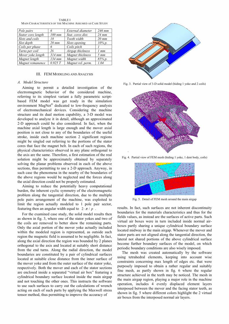
TABLE I MAIN CHARACTERISTICS OF THE MACHINE ASSUMED AS CASE STUDY
Pole pairs 6 External diameter 246 mmStator core length 100 mm Stat. cores dist. 24 mmSlots and coils 18 Tooth width 20 mmSlot depth 20 mm Slots opening 10% p.Coils per phase 6 Coils pitch 1Turns per coil 20 Airgap thickness 1 mmMover yoke length 314 mm Magnet thickness 5 mmMagnet length 134 mm Magnet width 85% p.Magnet remanence 0.925 T Magnet rel. perm. 1.04
III. FEM MODELING AND ANALYSIS
A. Model Structure Aiming to permit a detailed investigation of the
electromagnetic behavior of the considered machine, referring to its simplest variant a fully parametric script-based FEM model was get ready in the simulation environment MagNet® dedicated to low-frequency analysis of electromechanical devices. Considering the machine structure and its dual motion capability, a 3-D model was developed to analyze it in detail, although an approximated 2-D approach could be also considered. In fact, when the machine axial length is large enough and the mover axial position is not close to any of the boundaries of the useful stroke, inside each machine section 2 significant regions might be singled out referring to the portions of the stator cores that face the magnet belt. In each of such regions, the physical characteristics observed in any plane orthogonal to the axis are the same. Therefore, a first estimation of the real solution might be approximately obtained by separately solving the planar problems observed in each of the above sections, thus permitting to use a 2-D approach. Anyway, in such case the phenomena in the nearby of the boundaries of the above regions would be neglected and the forces along the axial direction could not be properly estimated.
Aiming to reduce the potentially heavy computational burden, the inherent cyclic symmetry of the electromagnetic problem along the tangential direction, due to the multiple pole pairs arrangement of the machine, was exploited to limit the region actually modeled to 1 pole pair sector, featuring then an angular width equal to 2 / pπ⋅ .
For the examined case study, the solid model results then as shown in fig. 3, where one of the stator yokes and two of the coils are removed to better show the remaining parts. Only the axial portion of the mover yoke actually included within the modeled region is represented, as outside such region the magnetic field is assumed to be negligible. In fact, along the axial direction the region was bounded by 2 planes orthogonal to the axis and located at suitably short distance from the end turns. Along the radial direction, the model boundaries are constituted by a pair of cylindrical surfaces located at suitable close distance from the inner surface of the mover yoke and from the outer surface of the stator yoke, respectively. Both the mover and each of the stator sections are enclosed inside a separated “virtual air box” featuring a cylindrical boundary surface located inside the main airgap and not touching the other ones. This instructs the software to use such surfaces to carry out the calculations of wrench acting on each of such parts by applying the Maxwell stress tensor method, thus permitting to improve the accuracy of
Fig. 3. Partial view of 3-D solid model (hiding 1 yoke and 2 coils)
Fig. 4. Partial view of FEM mesh (hiding 1 yoke, 1 dent body, coils)
Fig. 5. Detail of FEM mesh around the main airgap
results. In fact, such surfaces are not inherent discontinuity boundaries for the materials characteristics and thus for the fields values, as instead are the surfaces of active parts. Such virtual air boxes were in turn included inside normal air-boxes partly sharing a unique cylindrical boundary surface located midway in the main airgap. Whenever the mover and stator parts are not aligned along the tangential direction, the lateral not shared portions of the above cylindrical surface become further boundary surfaces of the model, on which periodic boundary conditions are also wisely imposed.
The mesh was created automatically by the software using tetrahedral elements, keeping into account wise constraints concerning max length of edges etc. that were purposely imposed to obtain a rather regular and suitably fine mesh, as partly shown in fig. 6 where the regular structure achieved in the teeth may be noticed. The mesh in the main airgap region, playing a major role in the machine operation, includes 4 evenly displaced element layers interposed between the mover and the facing stator teeth, as shown in fig. 5 where different colors highlight the 2 virtual air boxes from the interposed normal air layers.
B. Simulation Results As a first approximation - also motivated by the heavy
computational burden - the problem was modeled as linear magnetostatic, meaning that saturation, eddy currents and hysteresis that are usually observed in the ferromagnetic cores were neglected. Aiming to highlight the basic ideal behavior of the machine, the relative permeability of the material composing the stator and mover cores was assumed equal to a large value μFr= 10.000 .
As example of the results provided from the FEM model developed, hereafter some simulation data are reported referring to the split tasks regulation criterion previously recalled. Accordingly, hereafter module A is assumed to be the one facing the largest portion of the magnets and is then used to ideally generate only torque by adjusting its supply currents to obtain the required iAq Park component. Conversely, module B, facing the smaller portion of magnets, is ideally used to produce only the required force by achieving the required iBd supply current component.
Assuming that the central tooth of the modeled region is aligned with one of the magnets and considering a reference force pulling the mover towards module B, for the start condition of mover located in the middle of the useful axial stroke a partial view of the surface map of flux density in the active parts is reported in fig. 6, where a tooth of stator section A is hidden to better show the underlying parts.
For the same condition, in fig. 7 the flux density and arrow map is plotted onto a cross section cutting the model orthogonally to its axis midway inside the facing region of magnets within module A, assuming that the sign of iAq is chosen to generate a clockwise torque as seen in the figure.
In fig. 8 the analogous map is provided referring to a cross section located midway inside the facing region within module B, whereas in fig. 9 the flux density map is plotted on an a axial section of the machine corresponding to the symmetry plane of the central tooth (module A on the left). As expected due to the additive effect of armature reaction, it may be noticed that the highest flux density is obtained just in the central tooth of module B, where a 3D axial expansion of flux lines coming from the facing area also takes place as well as in the inter-magnets portions of the mover yoke. The different values of flux density in the various areas of the magnets may be also noticed, including the secondary lateral flux tubes originating in the gap between stator sections.
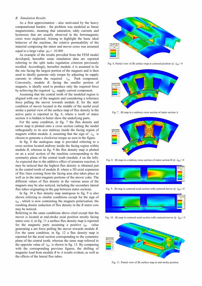
In fig. 10 a flux density map analogous to fig. 9 is also shown referring to similar conditions except for the sign of iBd , which is now contrasting the magnets polarization: the resulting drastic reduction of flux density in the B stator core may be noticed. Referring to the same conditions above cited except that the mover is located at end-stroke axial position mostly facing stator core A, in fig. 11 a surface flux density map is reported for the magnetic parts assuming a positive iBd value generating a net force pulling the mover towards module B. For the same condition, in fig. 12 a flux density map is reported for the axial section corresponding to the symmetry plane of the central tooth, whereas the same map referred to the opposite value of iBd is shown in fig. 13. By comparing with the corresponding previous figures, the shifting of magnetic load from module B to A results evident, as well as the effects of the lateral flux tubes.
Fig. 6. Partial view of |B| surface map at centered position @ iBd >0
Fig. 7. |B| map in a midway cross section of stator section A
Fig. 8. |B| map in a midway cross section of stator section B @ iBd >0
Fig. 9. |B| map in centered axial section with centered mover @ iBd >0
Fig. 10. |B| map in centered axial section with centered mover @ iBd <0
Fig. 11. Partial view of |B| surface map at end-stroke position

Fig. 12. |B| map in centered axial section at end-stroke position, iBd >0
Fig. 13. |B| map in centered axial section at end-stroke position, iBd <0
The effects on the developed force and torque due to secondary phenomena neglected by the ideal model were also investigated. First of all, the wrench acting on the mover and on each stator section at null currents was determined for various mover positions. As theoretically expected and shown in fig. 14, due to the machine structure in most of the stroke length such torques results rather small. In fact, the stator cores result basically isotropic except for the slots openings, meaning that only small variations of internal energy take place at null currents due to rotation of any stator core with respect to the mover. This leads then to a small torque on each stator core, which tends to vanish as the magnets move towards the other core.
On the opposite, rather large axial forces, amounting to about 335 N almost independently on the angular position, were highlighted attracting each stator core towards the mover. As long as the mover is not close to the extremes of the stroke, such forces have almost perfectly opposite values thus determining a negligible net force acting on the mover. Obviously, the machine frame must be able to keep in place the stator cores contrasting such forces. Such result confirms the theoretical expectations, since the presence of the magnets in the gap between stator cores determines a clear dependence on axial position of the internal magnetic energy in each machine section, thus giving rise to the above forces. Nevertheless, as the total value of energy is instead almost constant vs. position, such forces have to compensate each other, yet determining a tensile stress inside the mover.
The torque and force profiles vs. angular position were then investigated within 1 slot pitch, considering the 4 combinations of reference force and torque determined by 2 reference current values ±iAq , ±iBd . Referring to the centered axial position of the mover, in fig. 15 the trend of the torque Ca provided by module A for the positive reference iAq is reported as well as the net torque Cm acting on the mover in the 2 opposite force conditions. The corresponding curves referred to a negative reference iAq are reported in fig. 16. The fairly good correspondence between the 2 sets of curves may be noticed, as in the considered machine one should theoretically have
( ) ( ), ,= − − −m mAd Ad sC i C iδ τ δ (4)
where τs is the slot pitch and δ is the mover angular displacement from the alignment condition between the axes of a magnet and a stator tooth, as assumed in the previous figures. The entity of the ripple due to the non-sinusoidal operation of the machine may be realized, as well as the spurious torque produced by module B whose entity is larger when a force is exerted tending to pull the mover towards it.
0 2 4 6 8 10 12 14 16 18 20-6
-4
-2
0
2
4
6
Mover Angular Posi tion [°]
Nul
l-C
urre
nts
Torq
ue [
Nm
]
Ca @ center Cb @ center Ca @ end Cb @ end
Fig. 14. Torque at null currents on modules A, B vs. angular position at centered and end-stroke axial positions
0 2 4 6 8 10 12 14 16 18 2042
48
54
60
66
72
Mover Angular Position [°]
Mov
er a
nd S
tat.
A T
orqu
e [N
m]
Cm
@ Fm
>0 Cm
@ Fm
<0 - Ca
Fig. 15. Torque on mover and module A vs. angular position at centered axial position for positive reference torque and opposite reference forces
0 2 4 6 8 10 12 14 16 18 20-72
-66
-60
-54
-48
-42
Mover Angular Position [°]
Mov
er a
nd S
tat.
A T
orqu
e [N
m]
Cm
@ Fm
>0 Cm
@ Fm
<0 - Ca
Fig. 16. Torque on mover and module A vs. angular position at centered axial position for positive reference torque and opposite reference forces
0 2 4 6 8 10 12 14 16 18 2042
48
54
60
66
Mover Angular Position [°]
Mov
er a
nd S
tat.
A T
orqu
e [N
m]
Cm
@ Fm
>0 Cm
@ Fm
<0 - Ca
Fig. 17. Torque on mover and module A vs. angular position at extreme axial position for positive reference torque and opposite reference forces
0 2 4 6 8 10 12 14 16 18 20-66
-60
-54
-48
-42
Mover Angular Position [°]
Mov
er a
nd S
tat.
A T
orqu
e [N
m]
Cm
@ Fm
>0 Cm
@ Fm
<0 - Ca
Fig. 18. Torque on mover and module A vs. angular position at extreme axial position for negative reference torque and opposite reference forces
Such difference may be explained by the fact that in such condition the flux density within region B is higher, thus enhancing the torque ripple due to stator slotting; in fact, a quasi periodic trend may be noticed in half slot pitch.
A corresponding set of torque vs. position curves referred to axial position corresponding to a stroke end is reported in fig. 17 and fig. 18 respectively concerning positive and negative reference torque values. Besides the same above considerations that basically still stand, it is worth noting the much smaller contribution generated by module B, due to the much lower amount of magnets now facing it. Referring again to the axially centred position, in fig. 19 the

0 2 4 6 8 10 12 14 16 18 20150
160
170
180
190
200
Mover Angular Position [°]
Mov
er a
nd S
tat.
B F
orce
[N]
Fm
@ Cm
>0 Fm
@ Cm
<0 Fb
Fig. 19. Force on mover and module B vs. angular position at centered axial position for positive reference force and opposite reference torques
0 2 4 6 8 10 12 14 16 18 20150
160
170
180
190
200
Mover Angular Position [°]
Mov
er a
nd S
tat.
B F
orce
[N]
Fm
@ Cm
>0 Fm
@ Cm
<0 Fb
Fig. 20. Force on mover and stator sec. B vs. angular position at extreme axial position for positive reference force and opposite reference torques
trend vs. angular position of the axial force provided by module B is reported for the positive reference force value above considered; the trends of the net force acting on the mover referring to both the positive and negative torque conditions are also shown. The corresponding curves concerning the extreme axial position of the mover are reported in fig. 20. In both cases, the small influence of the torque sign may be noticed, as well as the difference with the force developed by module B: in fact, as a net force pushing the mover towards module A is required, by means of currents control the force exerted by section B is actually reduced with respect to the large balanced attractive value previously highlighted.
IV. CONCLUSIONS Rotary-linear drives, able to simultaneously produce force
and torque, might result useful is several practical applications. Nevertheless, rotary-linear motors are still scarcely used mainly due to manufacturing cost and control complexity. A novel machine structure was recently proposed aiming to overcome such problems by using standard common processes and active parts while featuring a good decoupled controllability. The theoretical model of such machine and a first investigation of the related control opportunities are presented in companion papers.
This paper focused on the FEM electromagnetic modeling and analysis of the basic variant of the proposed machine. A fully parametric script-based 3-D model purposely developed was described and commented, referring as example to a case study concerning a tooth-wound machine layout particularly suited to achieve easy manufacturing and low costs. Several simulation results concerning such case study, including field maps and force and torque trends vs. position under different operative conditions, were finally reported and commented in the perspective of the theoretical expectations. Such results basically confirm the validity of the proposed machine concept, also permitting to yet highlight and estimate several secondary aspects that were neglected in the theoretical analytical model.
Further results concerning the preliminary design criteria and the modeling of different machine configurations will be reported in future papers.
V. REFERENCES [1] P. Bolognesi, O. Bruno, A. Landi, L. Sani, and L. Taponecco,
“Electric Motors Featuring Multiple Degrees-of-Freedom,” in Proc. ICEM 2004 Conf., paper 518
[2] A. Turner, K. Ramsay, R. Clark and D. Howe, “Direct-drive rotary-linear electromechanical actuation system for control of gearshift in automated transmissions,” in Proc. IEEE VPPC 2007 Conf., pp. 267-272
[3] P. Bolognesi, O. Bruno and L. Taponecco, “Dual-Function Wheel Drives Using Rotary-Linear Actuators in Electric and Hybrid Vehicles,” in Proc. IECON 2009 Conf., pp. 3916-3921
[4] G. Krebs, A. Tounzi, B. Pauwels and D. Willemot, “General overview of integrated linear rotary actuators,” in Proc. ICEM 2008 Conf.
[5] W.J. Jeon, M. Tanabiki, and T. Onuki, “Rotary-Linear Induction Motor Composed of Four Primaries with Independently Energized Ring-Windings,” in Proc. IEEE IAS 1997 Annual Meeting, pp. 365-372
[6] L. Gobel, and W. Hofmann, “Control of a Rotation-Thrust Drive with Helical Motor,” in Proc. IEEE IECON 1997 Conf., pp. 1343-1348
[7] E.A. Mendrela, “Double-winding rotary-linear induction motor,” IEEE Trans. Energy Conversion, vol. EC-2, pp. 47–54, 1987
[8] L. Chen and W. Hofmann, “Design of one rotary-linear permanent magnet motor with two independently energized three-phase windings,” in Proc. IEEE PEDS 2007 Conf., pp. 1372–1376
[9] P. Bolognesi, “A 2-Degrees-of-Freedom Drive Employing a Novel Rotary-Linear Motor,” in Proc. EPE 2003 Conf., paper 527
[10] P. Bolognesi, “A Novel Rotary-Linear Permanent Magnets Synchronous Machine Using Common Active Parts,” in Proc. of MELECON 2010 Conf,, p. 1179-1183b
VI. BIOGRAPHIES Paolo Bolognesi graduated with honors in Electrical Engineering in 1995 at University of Pisa, Italy, where in 1999 he also earned his Ph.D. degree working in the fields of power electronics and electric machines. After a 2-years post-doc research fellowship position, in 2001 he finally joined the Department of Electric Systems and Automation of University of Pisa as a Researcher and Assistant Professor. His main research interests are in the fields of innovative electric machines and unconventional converter control techniques, using both theoretical and simulation modeling approaches.
Francesco Papini received his Electrical Engineering graduate degree with honors in 2006 from University of Pisa, Italy. He joined then the Electric Machines, Power Electronics and Drives group of the Department of Electric Systems and Automation of the same University as a Ph.D. student. Since 2010 he got a post-doc fellowship position at the same Department. His main research interests concern the analysis and design of innovative electric machines using both analytical methods and FEM models.