Meta-modelling and graph grammars for multi-paradigm modelling in AToM3
16
Softw Syst Model (2004) / Digital Object Identifier (DOI) 10.1007/s10270-003-0047-5 Meta-modelling and graph grammars for multi-paradigm modelling in AToM 3 Juan de Lara 1 , Hans Vangheluwe 2 , Manuel Alfonseca 1 1 Escuela Polit´ ecnica Superior, Ingenier´ ıa Inform´ atica, Universidad Aut´ onoma de Madrid, 28049 Madrid, Spain 2 School of Computer Science, McGill University, 3480 University Street, H2A 2A7 Montr´ eal, Qu´ ebec, Canada Received: 30 January 2003/Accepted: 13 October 2003 Published online: 1 April 2004 – Springer-Verlag 2004 Abstract. This paper presents the combined use of meta-modelling and graph grammars for the generation of visual modelling tools for simulation formalisms. In meta-modelling, formalisms are described at a meta- level. This information is used by a meta-model processor to generate modelling tools for the described formalisms. We combine meta-modelling with graph grammars to extend the model manipulation capabilities of the gen- erated modelling tools: edit, simulate, transform into another formalism, optimize and generate code. We store all (meta-)models as graphs, and thus, express model ma- nipulations as graph grammars. We present the design and implementation of these concepts in AToM 3 (A To ol for M ulti-formalism, M eta- M odelling). AToM 3 supports modelling of complex sys- tems using different formalisms, all meta-modelled in their own right. Models in different formalisms may be transformed into a single common formalism for fur- ther processing. These transformations are specified by graph grammars. Mosterman and Vangheluwe [18] in- troduced the term multi-paradigm modelling to denote the combination of multiple formalisms, multiple ab- straction levels, and meta-modelling. As an example of multi-paradigm modelling we present a meta-model for the Object-Oriented Continuous Simulation Language OOCSMP, in which we combine ideas from UML class diagrams (to express the OOCSMP model structure), Causal Block Diagrams (CBDs), and Statecharts (to specify the methods of the OOCSMP classes). A graph grammar is able to generate OOCSMP code, and then a compiler for this language (C-OOL) generates Java ap- plets for the simulation execution. Keywords: Meta-modelling – Multi-formalism – Multi- paradigm modelling – Graph grammars – Model trans- This is a revised and extended version of a paper presented at the GT-VMT’02 workshop, see [10] formation – Code generation – Causal block diagrams – Statecharts – AToM 3 – OOCSMP 1 Introduction Complex systems are characterized by components and aspects whose structure as well as behaviour cannot be described in a single formalism (due to their different na- ture). For example, if we wish to model a temperature and level controlled vessel, the controller can be described with a discrete formalism (such as Petri-Nets or State- charts [15]) whereas the behaviour of the liquid (which de- scribes the variation in volume and temperature) should be described using a continuous formalism (such as Ordi- nary Differential Equations or CBDs). One of the approaches to tackle complex systems is multi-formalism modelling. In this approach the differ- ent parts of the system are modelled using different for- malisms. In order to analyze a multi-formalism system, it is not enough to look at each component in isolation. One must consider the whole system. For this reason, multi- formalism modelling attempts to convert all components into a common formalism which is closed under composi- tion, so that the whole system can be properly analyzed or simulated. In order to make the multi-formalism approach pos- sible, we still have to solve the problem of dealing with a plethora of different formalisms. One would like to ded- icated tools to model in each one of these formalisms, but the cost of building such tools from scratch is pro- hibitive. Meta-Modelling is useful to deal with this prob- lem, as it allows the (possibly graphical) modelling of the formalisms themselves. A model of a formalism should contain enough information to permit the automatic gen- eration of a tool to check and build models subject to
-
Upload
independent -
Category
Documents
-
view
0 -
download
0
Transcript of Meta-modelling and graph grammars for multi-paradigm modelling in AToM3
Softw Syst Model (2004) / Digital Object Identifier (DOI) 10.1007/s10270-003-0047-5
Meta-modelling and graph grammarsformulti-paradigmmodelling inAToM3
Juan de Lara1, Hans Vangheluwe2, Manuel Alfonseca1
1Escuela Politecnica Superior, Ingenierıa Informatica, Universidad Autonoma de Madrid, 28049 Madrid, Spain2School of Computer Science, McGill University, 3480 University Street, H2A 2A7 Montreal, Quebec, Canada
Received: 30 January 2003/Accepted: 13 October 2003
Published online: 1 April 2004 – Springer-Verlag 2004
Abstract. This paper presents the combined use ofmeta-modelling and graph grammars for the generationof visual modelling tools for simulation formalisms. Inmeta-modelling, formalisms are described at a meta-level. This information is used by a meta-model processorto generate modelling tools for the described formalisms.We combine meta-modelling with graph grammars toextend the model manipulation capabilities of the gen-erated modelling tools: edit, simulate, transform intoanother formalism, optimize and generate code. We storeall (meta-)models as graphs, and thus, express model ma-nipulations as graph grammars.We present the design and implementation of these
concepts in AToM3 (A Tool for Multi-formalism, Meta-Modelling). AToM3 supports modelling of complex sys-tems using different formalisms, all meta-modelled intheir own right. Models in different formalisms may betransformed into a single common formalism for fur-ther processing. These transformations are specified bygraph grammars. Mosterman and Vangheluwe [18] in-troduced the term multi-paradigm modelling to denotethe combination of multiple formalisms, multiple ab-straction levels, and meta-modelling. As an example ofmulti-paradigm modelling we present a meta-model forthe Object-Oriented Continuous Simulation LanguageOOCSMP, in which we combine ideas from UML classdiagrams (to express the OOCSMP model structure),Causal Block Diagrams (CBDs), and Statecharts (tospecify the methods of the OOCSMP classes). A graphgrammar is able to generate OOCSMP code, and thena compiler for this language (C-OOL) generates Java ap-plets for the simulation execution.
Keywords: Meta-modelling – Multi-formalism – Multi-paradigm modelling – Graph grammars – Model trans-
This is a revised and extended version of a paper presented atthe GT-VMT’02 workshop, see [10]
formation – Code generation – Causal block diagrams –Statecharts – AToM3 – OOCSMP
1 Introduction
Complex systems are characterized by components andaspects whose structure as well as behaviour cannot bedescribed in a single formalism (due to their different na-ture). For example, if we wish to model a temperatureand level controlled vessel, the controller can be describedwith a discrete formalism (such as Petri-Nets or State-charts [15]) whereas the behaviour of the liquid (which de-scribes the variation in volume and temperature) shouldbe described using a continuous formalism (such as Ordi-nary Differential Equations or CBDs).One of the approaches to tackle complex systems is
multi-formalism modelling. In this approach the differ-ent parts of the system are modelled using different for-malisms. In order to analyze a multi-formalism system, itis not enough to look at each component in isolation. Onemust consider the whole system. For this reason, multi-formalism modelling attempts to convert all componentsinto a common formalism which is closed under composi-tion, so that the whole system can be properly analyzedor simulated.In order to make the multi-formalism approach pos-
sible, we still have to solve the problem of dealing witha plethora of different formalisms. One would like to ded-icated tools to model in each one of these formalisms,but the cost of building such tools from scratch is pro-hibitive. Meta-Modelling is useful to deal with this prob-lem, as it allows the (possibly graphical) modelling of theformalisms themselves. A model of a formalism shouldcontain enough information to permit the automatic gen-eration of a tool to check and build models subject to

J. de Lara et al.: Meta-modelling and graph grammars for multi-paradigm modelling in AToM3
the described formalism’s syntax. The advantage of thismeta-modelling approach is clear: rather than buildinga whole application from scratch, it is only necessary tospecify the kind of models we will deal with. If this specifi-cation is done graphically, the time to develop amodellingtool can be drastically reduced to a few hours. Otherbenefits, such as reduction of testing, ease of change andmaintainability are obvious.At the very least, the generated tool should be able
to allow the construction of valid models and discover er-rors in their construction. If (meta-)models are stored asgraphs, further manipulations of the models can be de-scribed as graph grammars [22]. In Multi-ParadigmMod-elling and Simulation we are interested in model manipu-lations such as:
– Model simulation or animation.– Model optimization, for example, to reduce its com-plexity.– Model transformation into another model (equivalentin behaviour), expressed in a different formalism.– Generation of (textual) model representations for useby existing simulators or tools. In this paper we willfocus on this kind of model transformation.
In this article, we present AToM3 [3, 8], a tool whichimplements the ideas presented above. AToM3 has ameta-modelling layer in which formalisms are modelled graph-ically. From the meta-specification (a model in the En-tity Relationship formalism extended with constraints),AToM3 generates a tool to process models described inthe specified formalism. Models are represented inter-nally using Abstract Syntax Graphs (ASGs), a general-ization of the concept of Abstract Syntax Trees used bycompilers. The ASG represents – in the form of a graph –the syntactic information of the model built by the user.As a consequence, model manipulation can be expressedas graph grammars.As an example, we show the generation of a tool
to graphically build OOCSMP [2] models. OOCSMP isa (textual) object-oriented continuous simulation lan-guage whose development started in Madrid in 1997. Inthis paper we define a meta-model similar to UML class
Table 1. Meta-modelling levels
Level Description Example
Meta-Meta-Model Model describes a formalism thatwill be used to describe other for-malisms. Specified with a meta-formalism
Description of Entity-Relation-ship Diagrams, UML ClassDiagrams
Meta-Model Model describes a simulationformalism. Specified with a meta-formalism
Description of DeterministicFinite Automata, OrdinaryDifferential Equations (ODE)
Model Description of an object. Specifiedwith a formalism
f ′(x) = − sin x, f(0) = 0 (in theODE formalism)
diagrams [6]. In contrast to UML class diagrams,methodscan be described using graphical formalisms used com-monly for simulation, such as Statecharts and CausalBlock Diagrams. A model described using the previousmeta-model is translated into (textual) OOCSMP usinga graph grammar. Once the visual model has been trans-lated into OOCSMP, anOOCSMP compiler can translateit into Java or C++ for simulation.The article is organized as follows: Sect. 2 presents the
main ideas behind Multi-Paradigm Modelling. Section 3gives an overview of the AToM3 tool. Section 4 presentsthe meta-model for OOCSMP and for Causal Block Dia-grams in detail. Section 5 gives an overview of the graphgrammar for code generation. Section 6 presents an ex-ample, in which a model of a hybrid system (a tempera-ture and level controlled vessel) is built and OOCSMPcode is generated for subsequent simulation. Section 7presents some related work and finally Sect. 8 states theconclusions and future work.
2 Computer AidedMulti-ParadigmModelling
Computer Aided Multi-ParadigmModelling (CAMPaM)[18, 25] is a research area which has the objective to sim-plify the modelling of complex systems by combiningthree different directions of research:
– Meta-Modelling, which is the process of modellingformalisms. Formalisms are described as models de-scribed in meta-formalisms. The latter are nothingbut expressive enough formalisms, such as Entity Re-lationship diagrams (ER) or UML class diagrams.A model of a meta-formalism is called a meta-meta-model; a model of a formalism is called a meta-model.Table 1 depicts the levels considered in our meta-modelling approach. Note that we only consider threelevels, although a meta-formalism mf1 can be pow-erful enough to describe the meta-meta-model of an-other meta-formalism mf2. We consider both mf1 andmf2 as meta-formalisms and place them in the samemeta-level. As we will see later, in AToM3 it is usu-

J. de Lara et al.: Meta-modelling and graph grammars for multi-paradigm modelling in AToM3
ally the case that meta-formalisms can describe meta-formalisms as well as formalisms.To be able to fully specify modelling formalisms, themeta-formalism may have to be extended with theability to express constraints (limiting the numberof meaningful models). For example, when modellingDeterministic Finite Automata, different transitionsleaving a given state must have distinct labels. Thiscannot be expressed within ER diagrams alone. Ex-pressing constraints is usually done by adding a con-straint language to the meta-formalism. Whereas themeta-formalism frequently uses a graphical notation,constraints are usually given in textual form. For thispurpose, some systems [14] (including ours) take ad-vantage of the Object Constraint Language OCL [19]used in the UML. As AToM3 [3] is implemented in thescripting language Python [21], arbitrary Python codecan also be used.Another alternative to using constraints is to expressas graph grammar rules, the kind of editing actionsthe user can perform at each moment in the modellingphase. This approach is called syntax-directed [4].Other kinds of visual editors are called free-hand [17]and allow the user more flexibility in the model edit-ing phase, but they have to check that the modelthe user is building is correct. In AToM3, free-handediting is the default approach, and model correct-ness is guaranteed by evaluating the constraints de-fined at the meta-level (and associated with events)when the user is building the model. In AToM3,free-hand editing can be combined with the syntax-directed approach by building graph grammar rulesfor editing tasks. See Sect. 7 for some comments aboutthis.– Model Abstraction, concerned with the relationshipbetween models at different levels of abstraction.
Fig. 1. Formalism Transformation Graph (FTG)
– Multi-Formalism modelling, concerned with the coup-ling of and transformation between models describedin different formalisms. In Fig. 1, a part of the “for-malism space” is depicted in the form of a Formal-ism Transformation Graph [24]. The different for-malisms are shown as nodes in the graph. The solidarrows between them denote a homomorphic relation-ship “can be mapped onto”. The mapping consistsof transforming a model in the source formalism intoa behaviourally equivalent one in the target formal-ism. The dotted, vertical thick arrows denote the ex-istence of a simulator for the formalism, which pro-duces simulation traces. This iterative simulation canbe seen as a special case of formalism transformation(into the “traces” formalism). The vertical dashed lineseparates continuous (left) and discrete (right) for-malisms, whereas the horizontal dashed line below for-malism “DAE non-causal set” separates causal (up-per) and non-causal formalisms. It can be observedhow DEVS [26] (Discrete EVent system Specification)can be a suitable target formalism when the purposeof the transformation is simulation, as DEVS can besimulated by parallel, highly efficient simulators basedon the HLA arquitecture.In our approach, we allow the specification of com-posite systems by coupling heterogeneous componentsexpressed in different formalisms. For the analysis ofits properties, the composite system must be assessedby looking at the whole multi-formalism system. Thatis, its components may have to be transformed toa common formalism, which can be found in the FTG.In our approach formalisms are meta-modelled andstored as graphs. Thus, the transformations denotedby the arrows (both for simulation and for formalismtransformation) of the FTG can be modelled as graphgrammars. In Sect. 6, we present a simple hybrid sys-
J. de Lara et al.: Meta-modelling and graph grammars for multi-paradigm modelling in AToM3
tem specified with Statecharts and Causal Block Dia-grams. Both components are transformed into OOC-SMP (a causal simulation language whose runtimesystem can solve Algebraic, Ordinary and Partial Dif-ferential Equations) for simulation.
3 AToM3: An overview
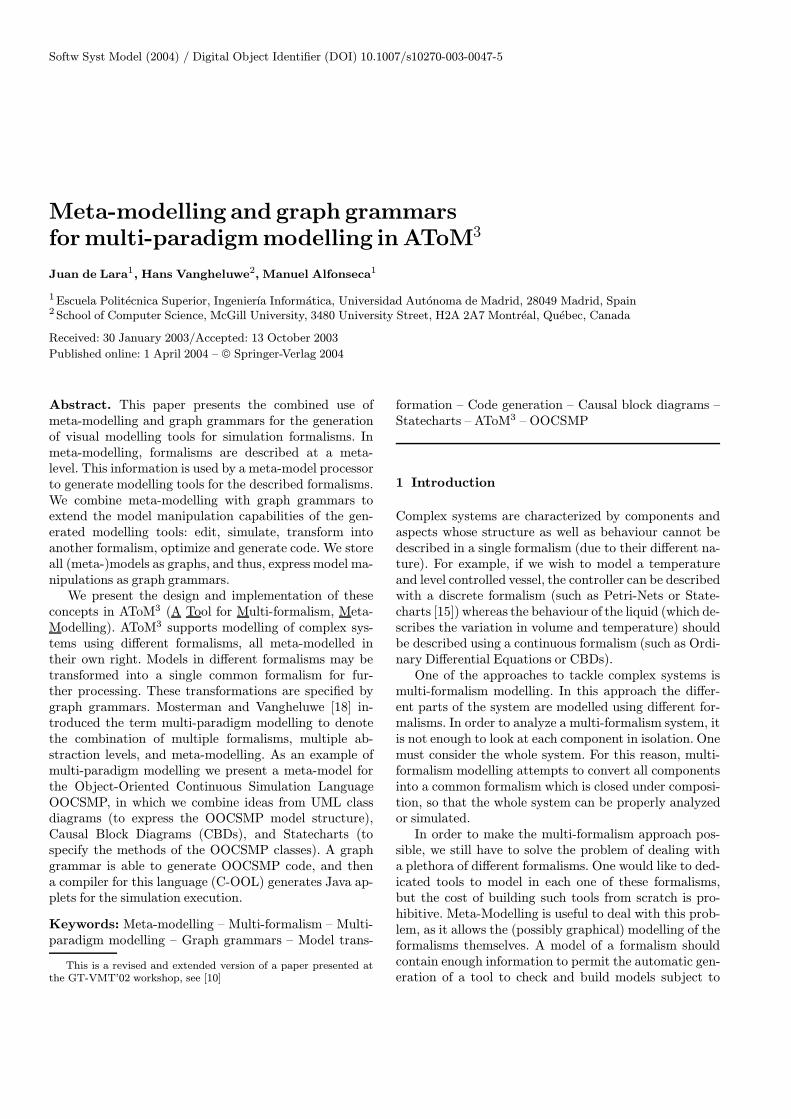
AToM3 [3, 8] is a tool which uses and implements the con-cepts presented above. As it has been implemented inPython, it is able to run (without any change) on all plat-forms for which an interpreter for Python is available:Linux,Windows andMacOS. The main idea of the tool is:“everything is a model”. During its implementation, theAToM3 kernel has been bootstrapped from a small ini-tial kernel. Models were defined for bootstrapped partsof it, code was generated and then later incorporatedinto it. Also, for AToM3 users, it is possible to mod-ify some of these model-defined components, such as the(meta-)formalisms and the user interface.AToM3’s architecture is shown in Fig. 2, where models
are represented as white boxes, having on their upper-right corner an indication of the formalism they werespecified with. In the figure, and for the example in thispaper – a graphical representation of OOCSMP models –the meta-meta-model is ER (theMMF is also ER, as thismeta-formalismwas bootstrapped). This meta-formalismis used to describe which are the valid OOCSMP models.The meta-model obtained is thus OOCSMP, the meta-formalismMF is ER. Finally, using this OOCSMP meta-model, it is possible to build OOCSMPmodels such as theone shown in Fig. 8.The main component of AToM3 is the Kernel, re-
sponsible for loading, saving, creating and manipulat-ing models (at any meta-level, with the Graph Rewrit-ing Processor and graph grammar models), as well as
Fig. 2. The architecture of AToM3
for generating code from the (meta-)+models. This code(meta-models and meta-meta-models) can be loaded intoAToM3 as shown in Fig. 2 (load Formalism arrows). Thefirst kind of models allows constructing valid models ina certain formalism, the second is used to describe the for-malisms themselves.The ER formalism extended with constraints is avail-
able at the meta-meta-level. As stated before, it is per-fectly possible to define other meta-formalisms using ER.Constraints can be specified as OCL or Python expres-sions, and are associated with events (similar to event-programming systems such as Visual Basic). The designermust specify when (pre- or post- and on which event) thecondition must be evaluated. Events can be related ei-ther to the abstract syntax (such as editing an attribute,connecting two entities, etc.) or purely graphical (such asdragging, dropping, etc.) If the constraint associated withan event is evaluated to false, the event is cancelled, or un-done if the constraint was a post-condition. Constraintscan be either associated with entities (local constraints)or with the whole model (global constraints). In AToM3,we can also define Actions, similar to Constraints butwith side-effects.Whenmodelling at the (meta-)+level, the entities that
may appear in a model must be specified together withtheir attributes (and constraints and actions as statedbefore). For example, to define the Petri Net Formal-ism, it is necessary to define both Places and Transitions.Furthermore, for Places we need to add the attributesname and number of tokens. For Transitions, we needto add the name attribute. The (meta-)+information isused by the AToM3 Kernel to generate some Python files,which, when loaded by the Kernel, allow the processing ofmodels in the defined formalism (see upper-right corner inFig. 2, labelled as “AToM3 (meta-)+models’ structure”.)One of the components of the generated files is
a model of a part of the AToM3 user interface (see arrow-
J. de Lara et al.: Meta-modelling and graph grammars for multi-paradigm modelling in AToM3
like box labelled as “User Interface Model” in the upper-right corner of Fig. 2) . This user interface model followsthe “Buttons” formalism, and has its own meta-model.Initially, this model represents the necessary buttons tocreate the entities defined in the formalism’s meta-model.It can be modified by the user to include, for example,buttons to execute graph grammars on the currentmodel.In the example of this paper, we define a graph grammarto generate OOCSMP (textual) code from the OOCSMPmeta-model. We have added a button to the user inter-face to execute this graph grammar, invoke the OOCSMPcompiler with the generated code, and execute the re-sulting simulation applets. AToM3 generates this userinterface model by executing a graph grammar on themeta-model (in the ER formalism) whose interface is tobe generated. The graph grammar traverses the modeland converts each Entity and each Relationship intoa Button (the basic entity of the Buttons formalism).When a formalism is loaded, this user interface model isinterpreted by AToM3 to create the real buttons in theuser interface. It is envisioned that, in the future, a morecomplete user interface model will be generated, possiblycombining the current “Buttons” formalism with a State-chart model of user interaction dynamics.In AToM3, entities may have two kinds of attributes:
regular and generative. Regular attributes are used toidentify characteristics of the current entity. Generativeattributes are used to generate new attributes at a lowermeta-level. The generated attributes may be generativein their own right. Both types of attributes may containdata or code for pre- and post-conditions.Entities are connected by means of ports, which can
be named or unnamed. An entity may have both types ofports. Unnamed ports are used when all the connectionsare semantically equal and there is no need to distin-guish them. A typical example is Statecharts, in whichstates have unnamed ports to connect to other states.Named ports are used when we have different meaningsfor the same types of connections. A typical example ofthis are the entities in the CBD formalism, where someentities represent functions to which other entities may beconnected, representing the function’s parameters. Oneneeds to know exactly which parameter corresponds toeach connection. For example, an INTEGRAL block hastwo parameters: the initial condition and the signal to beintegrated. If we connect a block to an INTEGRAL, weneed to know if this connection is to be interpreted asthe initial condition or as the value to be integrated. Thisway, two named ports are needed for the INTEGRALblock to store the connections to each parameter.In the meta-model, it is also possible to specify the
graphical appearance of each entity of the defined for-malism. This appearance is, in fact, a special kind ofgenerative attribute. Objects’ graphical appearance canbe icon-like or arrow-like with optional icon decorationsin the centre, segments and extremes. For example, forStatecharts, we can choose to represent States as ovals
with the name inside the oval. Transitions are arrow-like drawings with the events, conditions and actions be-sides them. That is, we can specify how some semanticattributes are displayed graphically. Constraints and ac-tions can also be associated with the graphical entities.Each graphical form, part of the graphical entity, canbe referenced by an automatically generated name thathas methods to change its graphical properties (colour,visibility, etc.) That is, in AToM3, graphical manipula-tions must be explicitly specified by the user by meansof constraints expressed in Python. This is in contrastwith other approaches [4] in which constraint languagesfor graphical layout are used. Python constraints have thedrawback of being at a lower abstraction level than a con-straint language, but they are usually more efficient.
3.1 Graph transformation in AToM3
Graph grammars [22] are a generalization of Chomskygrammars, for graphs. They are composed of rules; eachhaving graphs on their left and right hand sides (LHS andRHS). Rules are evaluated against an input graph (calledhost graph). If a matching is found between the LHS ofa rule and a zone in the graph, then the rule can be ap-plied. When a rule is applied, the matching subgraph ofthe host graph is replaced by the RHS of the rule. Rulescan have applicability conditions, as well as actions to beperformed when the rule is applied. Some graph rewrit-ing systems have control mechanisms to decide which ruleshould be checked next. In AToM3, rules are ordered ac-cording to a priority, and are checked from higher to lowerpriority. After the application of a matching rule, the sys-tem again tries to match, starting from the higher priorityrule in the list. The graph grammar execution ends whenno more applicable rules are found.Model manipulations can be expressed in AToM3, ei-
ther as Python programs or as graph grammar models.The latter has the advantage of being a higher-level, nat-ural, visual, declarative and formal notation. This makescomputations become models, easier to specify, under-stand, and maintain and frees the user of knowing AToM3
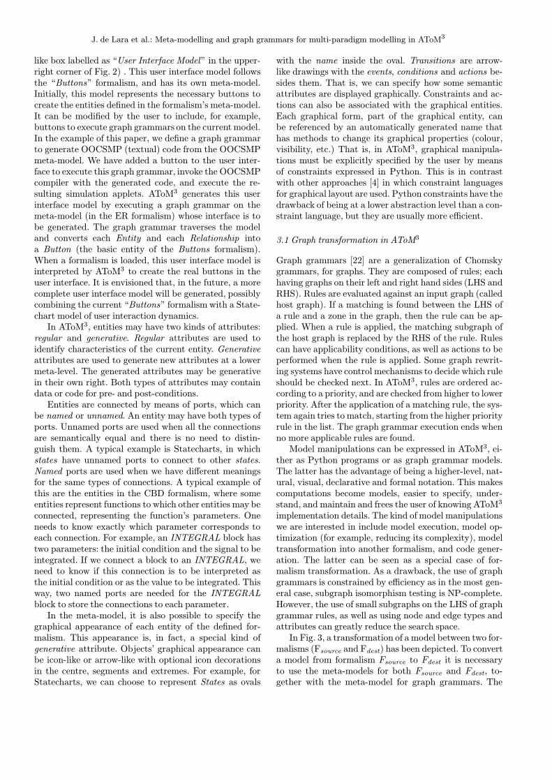
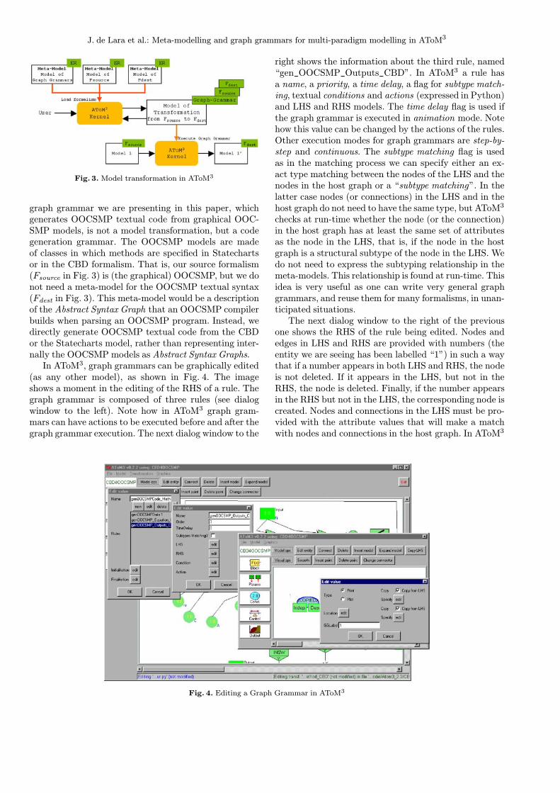
implementation details. The kind of model manipulationswe are interested in include model execution, model op-timization (for example, reducing its complexity), modeltransformation into another formalism, and code gener-ation. The latter can be seen as a special case of for-malism transformation. As a drawback, the use of graphgrammars is constrained by efficiency as in the most gen-eral case, subgraph isomorphism testing is NP-complete.However, the use of small subgraphs on the LHS of graphgrammar rules, as well as using node and edge types andattributes can greatly reduce the search space.In Fig. 3, a transformation of a model between two for-
malisms (Fsource and Fdest) has been depicted. To converta model from formalism Fsource to Fdest it is necessaryto use the meta-models for both Fsource and Fdest, to-gether with the meta-model for graph grammars. The
J. de Lara et al.: Meta-modelling and graph grammars for multi-paradigm modelling in AToM3
Fig. 3. Model transformation in AToM3
graph grammar we are presenting in this paper, whichgenerates OOCSMP textual code from graphical OOC-SMP models, is not a model transformation, but a codegeneration grammar. The OOCSMP models are madeof classes in which methods are specified in Statechartsor in the CBD formalism. That is, our source formalism(Fsource in Fig. 3) is (the graphical) OOCSMP, but we donot need a meta-model for the OOCSMP textual syntax(Fdest in Fig. 3). This meta-model would be a descriptionof the Abstract Syntax Graph that an OOCSMP compilerbuilds when parsing an OOCSMP program. Instead, wedirectly generate OOCSMP textual code from the CBDor the Statecharts model, rather than representing inter-nally the OOCSMP models as Abstract Syntax Graphs.In AToM3, graph grammars can be graphically edited
(as any other model), as shown in Fig. 4. The imageshows a moment in the editing of the RHS of a rule. Thegraph grammar is composed of three rules (see dialogwindow to the left). Note how in AToM3 graph gram-mars can have actions to be executed before and after thegraph grammar execution. The next dialog window to the
Fig. 4. Editing a Graph Grammar in AToM3
right shows the information about the third rule, named“gen_OOCSMP_Outputs_CBD”. In AToM3 a rule hasa name, a priority, a time delay, a flag for subtype match-ing, textual conditions and actions (expressed in Python)and LHS and RHS models. The time delay flag is used ifthe graph grammar is executed in animation mode. Notehow this value can be changed by the actions of the rules.Other execution modes for graph grammars are step-by-step and continuous. The subtype matching flag is usedas in the matching process we can specify either an ex-act type matching between the nodes of the LHS and thenodes in the host graph or a “subtype matching”. In thelatter case nodes (or connections) in the LHS and in thehost graph do not need to have the same type, but AToM3
checks at run-time whether the node (or the connection)in the host graph has at least the same set of attributesas the node in the LHS, that is, if the node in the hostgraph is a structural subtype of the node in the LHS. Wedo not need to express the subtyping relationship in themeta-models. This relationship is found at run-time. Thisidea is very useful as one can write very general graphgrammars, and reuse them for many formalisms, in unan-ticipated situations.The next dialog window to the right of the previous
one shows the RHS of the rule being edited. Nodes andedges in LHS and RHS are provided with numbers (theentity we are seeing has been labelled “1”) in such a waythat if a number appears in both LHS and RHS, the nodeis not deleted. If it appears in the LHS, but not in theRHS, the node is deleted. Finally, if the number appearsin the RHS but not in the LHS, the corresponding node iscreated. Nodes and connections in the LHS must be pro-vided with the attribute values that will make a matchwith nodes and connections in the host graph. In AToM3
J. de Lara et al.: Meta-modelling and graph grammars for multi-paradigm modelling in AToM3
we can specify that any value of these attributes will makea match, or we can set a specific value. Attributes of nodesand connections in the RHS of a rule, can either main-tain the value (checkbox labelled as “Copy from LHS” inthe right-most dialog window in the figure), receive a spe-cific value (specified in the different widgets in the dialogwindow, depending on the attribute’s type), or calculatea new one by means of Python code (button labelled as“Specified”). This code can use other node and connec-tion attributes.
4 A graphical representationof OOCSMPmodels
Our approach formodelling complex systemswithAToM3
is to use the most appropriate formalism for each com-ponent in the system, and translate them into a commonformalism for simulation. In our case, the common formal-ism is OOCSMP [2]. This is an Object Oriented extensionof the CSMP Continuous Simulation Language [16], de-veloped at the Universidad Autonoma in Madrid. OOC-SMP has been extended to handle discrete events, solvePartial Differential Equations, and produce distributedsimulations. A compiler (called C-OOL) is able to pro-duce Java applets from the OOCSMP models to performthe simulation. The C-OOL compiler generates a graphi-cal user interface for the simulation that allows the usersto experiment, change parameters and answer “what if..?”questions. One of the main drawbacks of OOCSMP is thelack of a graphicalmodelling environment:models are textfiles whichmust be coded by hand.OOCSMP models are made of objects that interact
via method invocations. Instructions inside methods areindeed equations, which the compiler sorts appropriatelyin order to be able to solve them (the language is causal).The main simulation loop is called DYNAMIC, and is
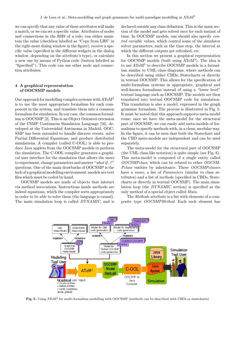
Fig. 5. Using AToM3 for multi-formalism modelling with OOCSMP (methods can be described with CBDs or statecharts)
declared outside any class definition. This is the main sec-tion of the model and gets solved once for each instant oftime. In OOCSMP models, one should also specify con-trol variable values, which control some of the simulatorsolver parameters, such as the time step, the interval atwhich the different outputs get refreshed, etc.In this section we present a graphical representation
for OOCSMP models (built using AToM3). The idea isto use AToM3 to describe OOCSMP models in a formal-ism similar to UML class diagrams, where methods canbe described using either CBDs, Statecharts or directlyin textual OOCSMP. This allows for the specification ofmulti-formalism systems in appropriate, graphical andwell-known formalisms instead of using a “lower level”textual language such as OOCSMP. The models are thentranslated into textual OOCSMP code for simulation.This translation is also a model, expressed in the graphgrammar formalism. The process is illustrated in Fig. 5.It must be noted that this approach supports meta-modelreuse: once we have the meta-model for the structuralpart of OOCSMP, we can easily add meta-models of for-malisms to specify methods with, in a clean, modular way.In the figure, it can be seen that both the Statechart andthe CBD meta-models are independent and can be usedseparately.The meta-model for the structural part of OOCSMP
(the UML class-like notation) is quite simple (see Fig. 6).This meta-model is composed of a single entity calledOOCSMPclass, which can be related to other OOCSM-Pclass entities by inheritance. These OOCSMPclasseshave a name, a list of Parameters (similar to class at-tributes) and a list of methods (specified in CBDs, State-charts or directly in textual OOCSMP). The main simu-lation loop (the DYNAMIC section) is specified as theonly method of a special object calledMain.TheMethods attribute is a list with elements of a com-
posite type OOCSMPMethod. Each such element has
J. de Lara et al.: Meta-modelling and graph grammars for multi-paradigm modelling in AToM3
OOCSMPInheritance
OOCSMPClass
Name, type=StringParameters, type=ListMethods, type=List
Fig. 6. A meta-model for OOCSMP(structural part)
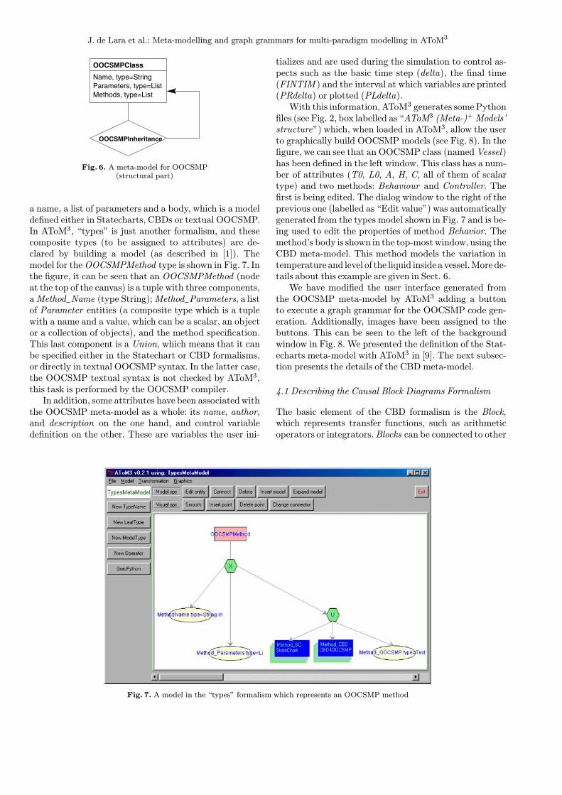
a name, a list of parameters and a body, which is a modeldefined either in Statecharts, CBDs or textual OOCSMP.In AToM3, “types” is just another formalism, and thesecomposite types (to be assigned to attributes) are de-clared by building a model (as described in [1]). Themodel for theOOCSMPMethod type is shown in Fig. 7. Inthe figure, it can be seen that an OOCSMPMethod (nodeat the top of the canvas) is a tuple with three components,aMethod_Name (type String);Method_Parameters, a listof Parameter entities (a composite type which is a tuplewith a name and a value, which can be a scalar, an objector a collection of objects), and the method specification.This last component is a Union, which means that it canbe specified either in the Statechart or CBD formalisms,or directly in textual OOCSMP syntax. In the latter case,the OOCSMP textual syntax is not checked by AToM3,this task is performed by the OOCSMP compiler.In addition, some attributes have been associatedwith
the OOCSMP meta-model as a whole: its name, author,and description on the one hand, and control variabledefinition on the other. These are variables the user ini-
Fig. 7. A model in the “types” formalism which represents an OOCSMP method
tializes and are used during the simulation to control as-pects such as the basic time step (delta), the final time(FINTIM ) and the interval at which variables are printed(PRdelta) or plotted (PLdelta).With this information, AToM3 generates some Python
files (see Fig. 2, box labelled as “AToM3 (Meta-)+Models’structure”) which, when loaded in AToM3, allow the userto graphically build OOCSMP models (see Fig. 8). In thefigure, we can see that an OOCSMP class (namedVessel)has been defined in the left window. This class has a num-ber of attributes (T0, L0, A, H, C, all of them of scalartype) and two methods: Behaviour and Controller. Thefirst is being edited. The dialog window to the right of theprevious one (labelled as “Edit value”) was automaticallygenerated from the types model shown in Fig. 7 and is be-ing used to edit the properties of method Behavior. Themethod’s body is shown in the top-mostwindow, using theCBD meta-model. This method models the variation intemperature and level of the liquid inside a vessel.More de-tails about this example are given in Sect. 6.We have modified the user interface generated from
the OOCSMP meta-model by AToM3 adding a buttonto execute a graph grammar for the OOCSMP code gen-eration. Additionally, images have been assigned to thebuttons. This can be seen to the left of the backgroundwindow in Fig. 8. We presented the definition of the Stat-echarts meta-model with AToM3 in [9]. The next subsec-tion presents the details of the CBD meta-model.
4.1 Describing the Causal Block Diagrams Formalism
The basic element of the CBD formalism is the Block,which represents transfer functions, such as arithmeticoperators or integrators.Blocks can be connected to other

J. de Lara et al.: Meta-modelling and graph grammars for multi-paradigm modelling in AToM3
Fig. 8. The generated tool for OOCSMP modelling (defining an OOCSMP method with the CBD formalism)
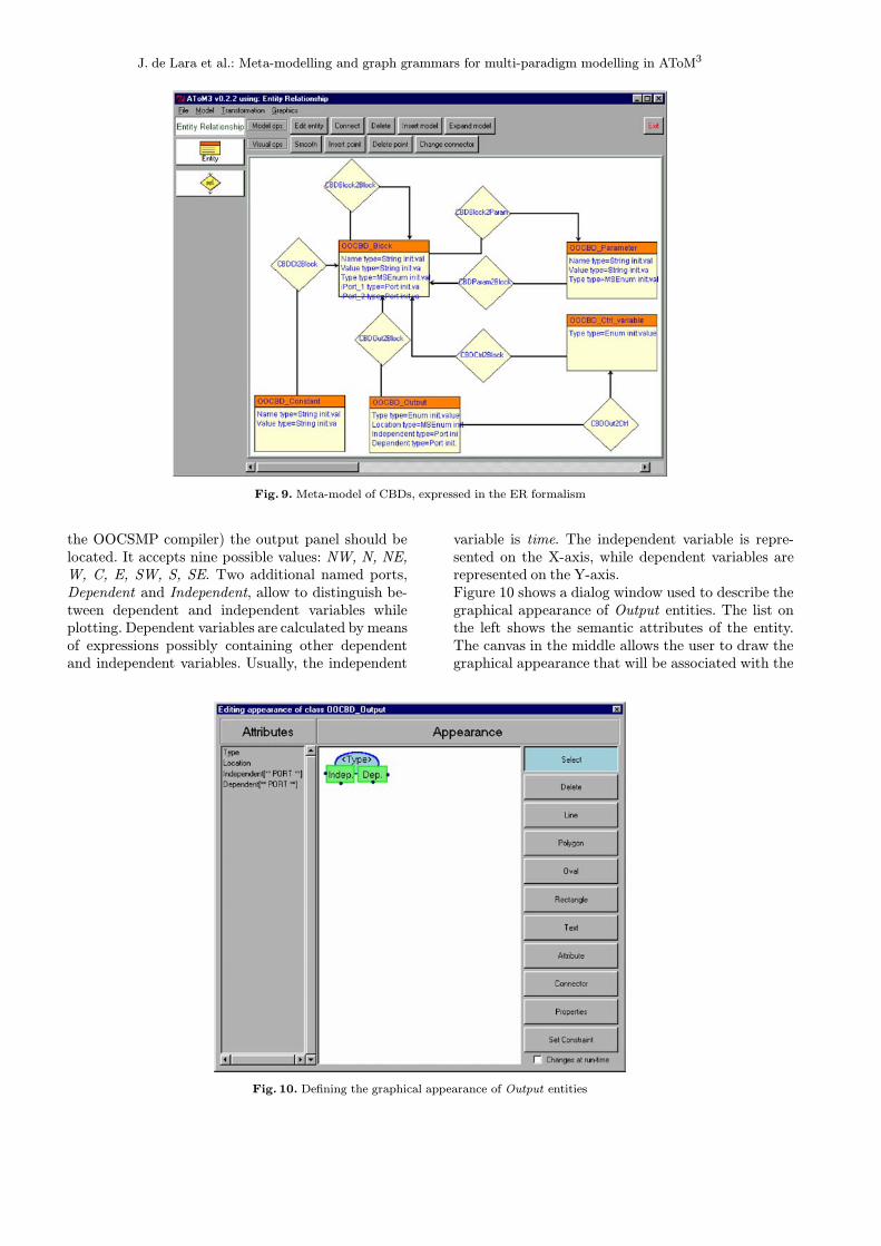
blocks, these connections transmit signals between them.Signals are functions of time. In the meta-model in Fig. 9we have also included entities to represent constants, con-trol variables (such as TIME, the basic time interval,etc.), parameters and outputs. These last elements areconnected to the blocks whose values we want to visual-ize (print or plot) in the simulation execution. Thus, themeta-model is made of the following entities:
– Block entities, composed of aName (which is filled au-tomatically with a unique name by AToM3, but theuser canmodify it) and a field namedType, which is anenumerate type that indicates the kind of function thisblock performs. These functions include infix n-aryoperators, such as “+” and “*”, prefix unary opera-tors, such as “−”, and functions such as INTEGRALand DERIVATIVE. There are 60 blocks in OOCSMP,all of them included in this meta-model. Block entities
also have aValue, which is the result of the applicationof the block’s function to its parameters, six namedports for connecting input blocks, and one named portfor output. The input ports are used in some types ofBlocks (such as INTEGRAL and DERIVATIVE) todistinguish the inputs. Other blocks (such as the adderor the multiplier) do not need to distinguish betweenindividual ports.– Constant entities, which represent values that do notchange during the simulation. They are composed ofa Value (a float) and a Name (a string).– Output entities are used to indicate which Blockvalues should be displayed in the simulation (once themodel is compiled into OOCSMP). This entity is com-posed of an attribute named Type (to select whetherthe value should be plotted or printed) and another at-tribute called Location to select in which part of theuser interface (automatically generated by C-OOL,
J. de Lara et al.: Meta-modelling and graph grammars for multi-paradigm modelling in AToM3
Fig. 9. Meta-model of CBDs, expressed in the ER formalism
the OOCSMP compiler) the output panel should belocated. It accepts nine possible values: NW, N, NE,W, C, E, SW, S, SE. Two additional named ports,Dependent and Independent, allow to distinguish be-tween dependent and independent variables whileplotting. Dependent variables are calculated by meansof expressions possibly containing other dependentand independent variables. Usually, the independent
Fig. 10. Defining the graphical appearance of Output entities
variable is time. The independent variable is repre-sented on the X-axis, while dependent variables arerepresented on the Y-axis.Figure 10 shows a dialog window used to describe thegraphical appearance of Output entities. The list onthe left shows the semantic attributes of the entity.The canvas in the middle allows the user to draw thegraphical appearance that will be associated with the
J. de Lara et al.: Meta-modelling and graph grammars for multi-paradigm modelling in AToM3
entity. In this canvas, it is possible to show semanticattributes. In this case the canvas shows the Type at-tribute. Notice that it is also possible to put in thecanvas as many instances of the named ports (the twolast attributes in theAttributes list) as desired, but allconnections to any of the instances of the same namedport are stored in the same attribute. In this example,we have added two instances of ports Dependent andIndependent (shown as little circles in the border ofthe rectangles). The button labelledConnector is usedto add unnamed ports to the canvas. Notice also thatit is possible to specify graphical constraints by meansof the “Set Constraint” button.– Control_Variable entities are used to include in themodel those variables used by the simulator to controlthe simulator execution. These entities have only oneattribute, which is an enumerate type with the controlvariable to be selected: TIME (the simulation time),delta, (the time step size for the numerical integration)PRdelta and PLdelta (communication intervals, thatis, time elapsed between output refreshes, for printingpanels and for plot panels). For example, TIME is of-ten used as the independent variable for plotting, andwe frequently place this control variable connected toan Output entity of type plot.– Parameter entities, which are used to input or outputvalues to the outside of this component. These entitieshave a Name, a Value and a Type that can be eitherInput, Output or both.
In order to keep the model correct, some constraintshave to be added:
– The number of connections to the Independent port ofOutput entities is one. This constraint is local to Out-put entities and must be verified before saving and be-fore applying a graph grammar, as we want the modelto be always correct in this respect. In this way, weensure that all saved models are correct and that allmodels to which a graph grammar is applied (such asthe one for code generation explained in Sect. 5) arealso correct.– The number of connections that Block entities can re-ceive depends on its type. For example, integratorsreceive two, whereas adders can receive any numberof connections greater than one. This means that wecannot set the exact number as the arity of the rela-tionship Connected_to_Block in the meta-model. Wehave to set a local constraint on Block entities, thatmakes sure that, depending on the Type attribute, thenumber of connections is the correct one.
The tool generated from this meta-model descriptioncan be seen in the top-most window in Fig. 8. We havemodified the default user interface model generated byAToM3, in such a way that we have only left the buttonsto create Blocks, Outputs, Parameters, Control Variablesand Constants. The buttons to create relationships have
been eliminated, as relationships are created when con-necting entities.
5 Generating OOCSMP code
As was mentioned before, one of the main drawbacks ofOOCSMP is the lack of a graphical modelling environ-ment. Models are textual files which must be coded byhand. The work in this paper provides such an environ-ment, replacing the OOCSMP syntax by graphical, well-known simulation formalisms. This has the advantagethat one does not have to remember the exact OOCSMPsyntax, but only use graphical simulation formalisms.That is, the user can use graphical modelling formalisms,as opposed to coding directly in the “low-level” OOC-SMP (low-level, from the point of view of these high-level,graphical formalisms).In this section, we show how to produce OOCSMP
code for the modelling environment generated in the pre-vious section. This task can be performed with a graphgrammar. The initial action of the graph grammar opensa file to store the OOCSMP code and adds an extra at-tribute (visited) to all the nodes of the graph (that is,to all the classes in the model). This attribute controlswhether code for that node has been already generated,and is initialized to 0. The initial action also writes inthe file the name of the simulation model and of theauthor.The only rule of the graph grammar traverses each
of the classes declared in the model, generating code forthe attributes. Then, for each method, the rule calls an-other graph grammar, specifically built for the formalismin which this method is expressed. The next subsectionexplains the graph grammar for code generation fromCBD. The called graph grammar generates code for themethod, specified either in Statecharts, in CBD or in tex-tual OOCSMP. The advantage of this approach is thatgraph grammars that generate OOCSMP code from dif-ferent formalisms are independent and modular.The final action in the grammar generates code to give
values to the control variables, including the final time,the communication intervals (PLdelta and PRdelta) andthe time advance (delta). These were indicated as globalattributes of the model (see Sect. 4).Of course, there are more efficient ways to generate
code from visual models than by using a graph grammar.For example, coding the algorithm in Python and access-ing the AToM3 API for retrieving the model elements.But graph grammars provide high level control mechan-isms which allow the user to perform complex manip-ulations and graph matching, and the user can specifymodel manipulations without too much knowledge of theAToM3 internals.The next subsection presents the graph grammar to
generate OOCSMP code from methods described in theCBD formalism.
J. de Lara et al.: Meta-modelling and graph grammars for multi-paradigm modelling in AToM3
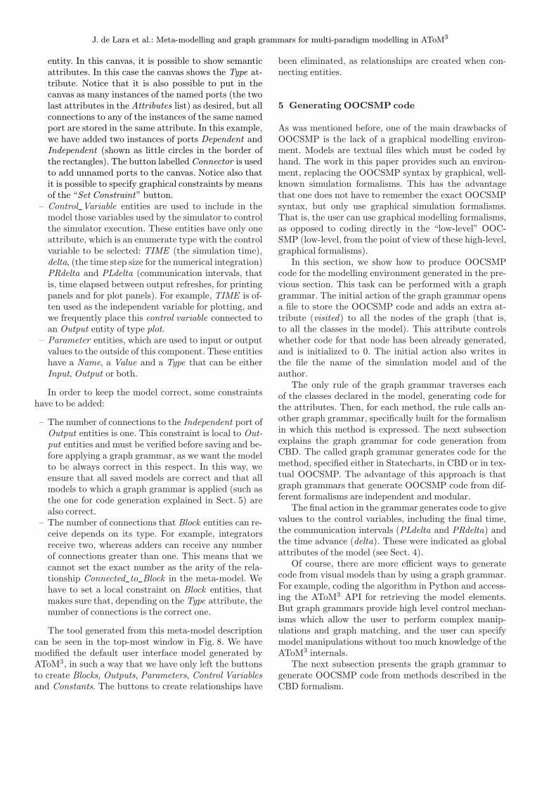
Fig. 11. Graph Grammar for OOCSMP code generationfrom methods specified as block diagrams
5.1 Generating OOCSMP code from the methods specifiedin the CBD formalism
The initial action of this graph grammar adds an extraattribute (visited) to all the nodes of the graph exceptControl Variables (that is, to all Constant, Block andOutput nodes). This attribute controls whether code forthat node has already been generated, and is initialized to0. The graph grammar is composed of three rules, noneof which changes the matching subgraph. It is shown inFig. 11. We use the notation “n(x)” in the “action” sec-tion to refer to the node in the host graph which matchesthe LHS node whose label is “x”.Rule number one is applied when a Constant node is
found that has not been previously processed. The rulegenerates a DATA statement for the constant node andmarks it as visited. Rule number two is applied whena Block node is found that has not been previously pro-cessed. It generates the appropriate OOCSMP syntax,depending on the type of the block, and marks it as vis-ited. Rule number three is applied when an Output nodeis found that has not been previously processed. It gener-ates the necessary OOCSMP code to output the variablesconnected to it (plotted or printed). Note how, in the “ac-tion” sections, we are accessing the connected elementsof the nodes (through ports), as these may have an arbi-trary number of connections. Another approach is to usesimilar ideas with amalgamated and parallel graph trans-formation [23], which allow dealing with variable contextby combining and syncronizing productions.
6 Example: A temperatureand level controlled vessel
As an example of how to apply the concepts and tools pre-sented above, we introduce a toy model to illustrate the
usefulness of the approach. In the example, we considera temperature and level controlled liquid in a vessel. Thisis a modification of the system described in [5], wherestructural change is the main issue. On the one hand,the liquid can be heated or cooled; on the other hand, li-quid can be added or removed (we do not consider phasechanges for this simple example). The liquid’s tempera-ture T and level L are governed by the following OrdinaryDifferential Equation model:
dT
dt=1
L
[W
cρA−φT
](1)
dL
dt= φ if 0< L<H else 0 (2)
is_low = (L< Llow) (3)
is_full= (L> Lhigh) (4)
is_cold= (T < Tcold) (5)
is_hot= (T > Thot) (6)
The inputs to the model are φ, the flow rate, and W ,the rate at which heat is added or removed. The model’sparameters are A, the cross-section surface of the vessel,H, its height, c, the specific heat of the liquid and ρ, the li-quid density. Equations (3)–(6) set threshold output sen-sors, which are the outputs of this model and are sent tothe discrete-event controller. Equations (1)–(6) have beenincluded in method Behaviour in class Vessel (see Fig. 8)using CBDs. Note how, in the model, the is_low, is_full,is_cold and is_hot flags appear as green boxes (parame-ters), labelled as “Output” at the bottom of the model.Their value is calculated with the OOCSMP block INSW,which returns the second argument if the first argument isless than zero, else it returns the third argument. The in-puts of the model appear labelled as Fi andW, to the topof the window. Note also how we are plotting the value ofL and T with respect to time.The other part of the system is a controller for the
temperature and the level, which tries to maintain bothquantities between certain limits. This is implementedas a Statechart (shown in Fig. 12) and is embedded inmethod Controller in the Vessel class. The idea is to havean orthogonal component for the temperature and an-other one for the level. Each component has three states,corresponding to the situation in which the quantity tocontrol (level or temperature) is high, medium or low.The possible events (that is, the model’s inputs) whichmake the system change its state are is_low, is_high,is_cold and is_hot. As associated actions to these events,φ and W are modified. For example, if the system is instate cold in orthogonal component temperature and re-ceives the event IS_COLD, it increases W by some fixedamount DW and remains in the same state (respondingto subsequent IS_COLD events in the same way) untilthe event IS_COLD is no longer sent by the Behaviourmodel. φ andW are the outputs of this model, which arefed to method Behaviour. Finally, the main simulationloop is modelled as textual OOCSMP code and contains

J. de Lara et al.: Meta-modelling and graph grammars for multi-paradigm modelling in AToM3
Fig. 12. Defining the controller for the Vessel in the Statecharts formalism
Fig. 13. A moment in the simulation of the vessel model
the appropriate invocation of methods Behaviour andController.This model is transformed into OOCSMP for simu-
lation using the graph grammar defined in Sect. 5. Oncethe model has been compiled into Java with C-OOL, wecan execute the simulation. A moment in the simula-tion is shown in Fig. 13. In the upper plot, the variationof temperature and level is shown. After some tran-sitory effects at the beginning of the simulation (notshown), the temperature reaches an oscillatory equi-librium. In the middle plot the values of IS_COLD,IS_HOT, IS_LOW and IS_HIGH are shown. It canbe observed how IS_COLD is switching from 0 to1 periodically to maintain the temperature between
the limits. The listing at the bottom shows some ofthe variable values. This simulation applet is availableat http://www.ii.uam.es/∼jlara/investigacion/ecomm/hybrid.html for the reader interested in experi-menting with it.
7 Related work
There are some similar tools in the graph grammars com-munity, such as GenGed [4], which builds syntax directedor free-hand visual modelling environments. Their ideasare similar to ours, butwedonotpose thediagram’s graph-ical appearance as Constraint Satisfaction Problems. It is

J. de Lara et al.: Meta-modelling and graph grammars for multi-paradigm modelling in AToM3
the meta-model designer who, by means of pre- and post-conditions and actions, expressed as Python code, musttake care of the graphical layout. Sometimes, this can bemore difficult than using constraints, but our approach of-fers more efficiency as constraint solvers tend to be slow.Other systems also make a clear distinction between ab-stract and concrete (graphical information) syntax, witha flexible mapping between both models. The current ver-sion of AToM3 only supports a one-to-one mapping fromentities into icons and relationships into arrows.DiaGen [17] is a tool based on hypergraph grammars
thatmay combine characteristics of free-hand and syntax-directed editors. The user inputs a textual specificationof the visual language and obtains a set of Java classeswhich are complemented by a Java library to obtain thevisual environment. In AToM3, the specification of the vi-sual language (the meta-model) is done graphically, andthe generated files are loaded again into AToM3. Thereis no structural difference between the generated editors(which could be used to generate other ones!), and the edi-tor which generated them. In fact, one of the main differ-ences of the approach taken in AToM3 with other similartools, is the concept that (almost) everything in AToM3
has been defined by a model (under the rules of some for-malism) and thus the user canmodify it.In the simulation community, with respect to com-
plex systems modelling, the approach of [20] is similar toours. They have implemented several editors for continu-ous (sequential function charts) and discrete formalisms(Statecharts) using the meta-modelling tool DoME [11].The user builds composite models with these editors.Models are subsequently translated into the object ori-ented simulation language MODELICA [12]. In DoME,model manipulations must be expressed either in theLisp-like language Alter or in Smalltalk; in our approachthey can be visually specified by means of graph gram-mars (combined with Python if desired).A different approach to the modelling of complex sys-
tems is Paul Fishwick’s Multi-Modelling [13]. His ap-proach deals with multi-formalism (a multi-model canbe composed of components described in different for-malisms) and multiple abstraction levels. To synchronizethe system at its highest level, a coordinator is used to dir-ect the events to the appropriate models (co-simulation).The approach of the Ptolomey [7] environment is anotherexample of the power of this approach. It is noted that itspower is partly due to the fact that it is an integrated en-vironment, which does not need to interface with externalsimulations.Our approach (Multi-Paradigm Modelling) proposes
Meta-Modelling as a method to obtain a tool to modelin each formalism, and translates models between for-malisms for the purpose of simulation and analysis. Thisprevious step (translation) to simulation makes the simu-lation process cleaner and permits analysis of propertiesof the multi-formalism model with tools available in thebase formalism. In addition, when a model is translated
into a formalism, there are possibilities to apply opti-mizing transformations. If the translation process goesthroughmultiple formalisms, then one can apply optimiz-ing transformation in each formalism. For example, if allthe components of a multi-formalism system are trans-lated, say, to Petri-Nets, then one can use complexityreduction transformations and later reachability analy-sis to verify that certain system states are reachable. Incontrast, in the Multi-Modelling approach, one cannotapply these analysis tools, as each component has beendescribed in a different formalism and no transformationto a common formalism is performed. As stated in the in-troduction, it is not sufficient to look at properties of thesubcomponents in isolation, one should look at the prop-erties of the system as a whole.
8 Conclusions and future work
In this paper we have presented an overview of AToM3,a tool which makes the generation of modelling toolspossible by combining meta-modelling and graph gram-mars. By means of meta-modelling, it is easy to de-fine the syntax of the kind of models we are interestedin. By means of graph grammars we can express modelmanipulation, such as simulation, optimization, trans-formation and code generation. As an example, we havepresented the generation of a visual modelling environ-ment for OOCSMP. For that purpose, we have designeda meta-model similar to UML class diagrams, in whichmethods can be described using Statecharts, CBDs orOOCSMP textual code. Thus, the user does not haveto know the OOCSMP syntax, but may use some well-known simulation formalisms. These are then translatedinto OOCSMP syntax using a graph grammar for subse-quent simulation.The advantages of using an automated tool for gen-
erating customized model-processing tools are clear: in-stead of building the whole application from scratch, it isonly necessary to specify – in a graphical manner – thekind of models we will deal with. The processing of suchmodels can be expressed by means of graph grammars, atthe meta-level. Our approach is also highly applicable ifwe want to work with a slight variation of some formal-ism, where we only have to specify the meta-model forthe new formalism and a transformation into a “known”formalism (for example, one that already has a simulatoravailable). We then obtain a tool to model in the new for-malism, and are able to convert models in this formalisminto the other for further processing.In the future, we plan to extend the tool in several
ways:
– Exploring the automatic proof of behavioural equiv-alence between two models in different formalismsby bi-simulation. This may help in validating thata graph grammar for formalism transformation iscorrect.

J. de Lara et al.: Meta-modelling and graph grammars for multi-paradigm modelling in AToM3
– Integrating a module to help the user decide whichalternatives are available at a certain moment of themodelling of a multi-formalism system. This modulemay assist in deciding which formalism to use to trans-form each component (using the Formalism Trans-formation Graph, see [24]).– Extending the tool to allow collaborative modelling.This possibility, as well as the need to exchange andre-use (meta-. . . ) models, raises the issue of formatsfor model exchange. A viable candidate format isXML.– Extend the user interface model (which is generatedby AToM3 for meta-models) with Statecharts. Thiswill allow the user to control more complex behavioursof the generated tool.– Provide the tool with automatic layout algorithms forthe graphical representation of the models. These canbe specially useful after applying a graph grammarwhich modifies the model’s structure.
TheMeta Object Facility (MOF) [19] is an OMG stan-dard for a meta-metamodel. Using this MOF Model, onecould define different metamodels (for example for UML).Using XMI it is possible to automatically obtain DTDsand XML documents for the models. It is worth exploringeither the possibility of meta-modelling the MOF Modelor to change the current AToM3 “hard-wired” primitivesfor meta-generation to make it “MOF compatible”. Thiswould require a completely separate model for the graphi-cal representation of models as well, together with a muchmore flexible mapping from abstract to concrete syntax(such as in GenGed).With respect to AToM3 as a front end for OOCSMP,
we would like to improve the graph grammar for codegeneration from CBD models, to distinguish expressionswhose value is not going to change during the simulation.These values may be calculated at the beginning of thesimulation (in a section called INITIAL) rather than ateach time step. We are also working to extend the num-ber of formalisms available to specify OOCSMP models,in particular we are working on meta-modelling ForresterSystem Dynamics and their translation into OOCSMP.
Acknowledgements. The authors would like to thank three anony-mous referees for their useful comments. Juan de Lara and ManuelAlfonseca gratefully acknowledge partial sponsorship for this workby the Spanish Ministry of Science and Technology (MCYT),project number TIC2002-01948. Hans Vangheluwe gratefully ac-knowledges partial support for this work by a National Sciencesand Engineering Research Council of Canada (NSERC) IndividualResearch Grant.
References
1. Aho AV, Sethi R, Ullman JD (1986) Compilers, principles,techniques and tools. Chapter 6, Type Checking. Addison-Wesley
2. Alfonseca M, Pulido E, Orosco R, de Lara J (1997) OOCSMP:An Object-Oriented Simulation Language. In: Proceedings ofthe 9th European Simulation Symposium ESS97, SCS Int.,
Erlangen, Germany, pp. 44–48. See the OOCSMP home pageat: http://www.ii.uam.es/∼jlara/investigacion/download/OOCSMP.html
3. AToM3 home page: http://atom3.cs.mcgill.ca4. Bardohl R, Ermel C, Weinhold I (2002) AGG and GenGED:Graph Transformation-Based Specification and AnalysisTechniques for Visual Languages. In: Proc. GraBaTs 2002.Electronic Notes in Theoretical Computer Science,vol 72(2)
5. Barros FJ, Zeigler BP, Fishwick PA (1998) Multimodels anddynamic structure models: an integration of DSDE/DEVSand OOPM. In: Proceedings of the 1998 Winter SimulationConference, pp 413–419
6. Booch G, Rumbaugh J, Jacobson I (1999) The Unified Model-ing Language User Guide. Addison Wesley
7. Davis II J, Hylands C, Kienhuis B, Lee EA, Liu J, Liu X, Mu-liadi L, Neuendorffer S, Tsay J, Vogel B, Xiong Y (2001) Het-erogeneous Concurrent Modeling and Design in Java. Tech-nical Memorandum UCB/ERL M01/12, EECS, University ofCalifornia, Berkeley. See also:http://ptolomey.eecs.berkeley.edu/publications
8. de Lara J, Vangheluwe H (2002) AToM3: A Tool for Multi-Formalism Modelling and Meta-Modelling. In: European Con-ferences on Theory And Practice of Software EngineeringETAPS’02, Fundamental Approaches to Software Engineer-ing (FASE). Lecture Notes in Computer Science, vol 2306.Springer-Verlag, pp 174–188
9. de Lara J, Vangheluwe H (2002) Computer Aided Multi-Paradigm Modelling to process Petri-Nets and Statecharts.In: 1st International Conference on Graph Transformations,ICGT’2002 (Barcelona). Lecture Notes in Computer Science,vol 2505, pp 239–253
10. de Lara J, Vangheluwe H, Alfonseca M (2002) Using Meta-Modelling and Graph Grammars to create Modelling Environ-ments. In: Graph Transformations and Visual Modelling Tech-niques (GT-VMT) Workshop, Barcelona. Electronic Notes inTheoretical Computer Science, vol 72(3)
11. DOME guide (2000) http://www.htc.honeywell.com/dome/,Honeywell Technology Center. Honeywell, version 5.3
12. Elmqvist H, Mattson SE (1997) An Introduction to the Phys-ical Modeling Language Modelica. In: Proceedings 9th Euro-pean Simulation Sympossium ESS97, SCS Int., Erlangen, pp110–114. See also http://www.modelica.org
13. Fishwick P, Zeigler BP (1992) A Multimodel Methodology forQualitative Model Engineering. ACM Transactions on Mod-elling and Computer Simulation 1(2):52–81
14. Gray J, Bapty T, Neema S (2000) Aspectifying Constraints inModel-Integrated Computing. In: OOPSLA 2000: Workshopon Advanced Separation of Concerns, Minneapolis, MN, Oc-tober, 2000
15. Harel D (1987) Statecharts: A Visual Formalism for ComplexSystems. Science of Computer Programming 8:231–274
16. IBM Corp. (1972) Continuous System Modelling Program III(CSMP III) and Graphic Feature (CSMP III Graphic Feature)General Information Manual. IBM Canada, Ontario, GH19-7000
17. Minas M (2002) Specifying Graph-like diagrams with DIA-GEN. Science of Computer Programming 44:157–180
18. Mosterman P, Vangheluwe H (2002) Computer AutomatedMulti-Paradigm Modeling. ACM Transactions on Modelingand Computer Simulation 12(4):1–7. Special Issue Guest Ed-itorial
19. OMG Home Page: http://www.omg.org20. Pereira Remelhe M, Engel S, Otter M, Derarade A, Moster-man P (2002) An Environment for Integrated Modelling ofSystems with Complex Continuous and Discrete Dynamics.In: Lecture Notes in Control and Information Systems, vol279, pp: 83–105
21. Python home page: http://www.python.org22. Rozenberg G (ed) (1999) Handbook of Graph Grammarsand Computing by Graph Transformation. Vol. 1. WorldScientific
23. Taentzer G (1996) Parallel and Distributed Graph Transform-ation. Formal Description and Application to Communication-Based Systems. PhD Dissertation, Shaker Verlag
J. de Lara et al.: Meta-modelling and graph grammars for multi-paradigm modelling in AToM3
24. Vangheluwe H (2000) DEVS as a common denominator formulti-formalism hybrid systems modelling. In: Varga A (ed)IEEE International Symposium on Computer-Aided ControlSystem Design. IEEE Computer Society Press, Anchorage,Alaska, pp 129–134
25. Vangheluwe H, de Lara J, Mosterman P (2002) An Introduc-tion to Multi-Paradigm Modelling and Simulation. In: Pro-ceedings of AI, Simulation and Planning – AIS’2002. Lisbon.SCS International, pp: 9–20
26. Zeigler BP, Praehofer H, Kim TG (2000) Theory of mod-elling and simulation: Integrating discrete event and continu-ous complex dynamic systems, second ed. Academic Press
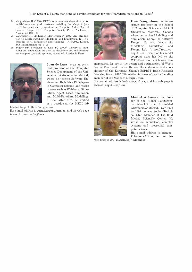
Juan de Lara is an an assis-tant professor at the ComputerScience Department of the Uni-versidad Autonoma in Madrid,where he teaches Software En-gineering. He holds a PhD degreein Computer Science, and worksin areas such as Web based Simu-lation, Agent based Simulationand Multi-Paradigm Modelling.In the latter area he workedas a postdoc at the MSDL lab
headed by prof. Hans Vangheluwe.His e-mail address is [email protected], and his web pageis www.ii.uam.es/∼jlara.
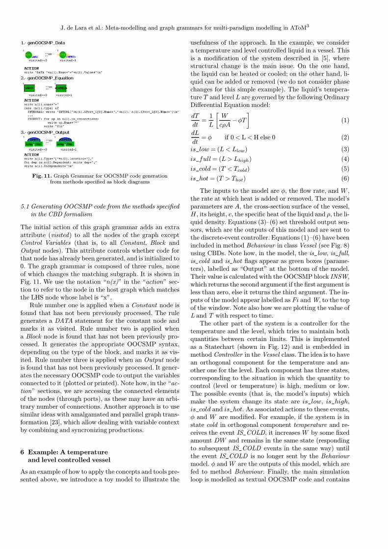
Hans Vangheluwe is an as-sistant professor in the Schoolof Computer Science at McGillUniversity, Montreal, Canadawhere he teaches Modelling andSimulation, as well as SoftwareDesign. He also heads theModelling, Simulation andDesign Lab (http://msdl.cs.mcgill.ca). Some of his modelcompiler work has led to theWEST++ tool, which was com-
mercialised for use in the design and optimization of WasteWater Treatment Plants. He was the co-founder and coor-dinator of the European Union’s ESPRIT Basic ResearchWorking Group 8467 “Simulation in Europe”, and a foundingmember of the Modelica Design Team.His e-mail address is [email protected], and his web page iswww.cs.mcgill.ca/∼hv.
Manuel Alfonseca is direc-tor of the Higher Polytechni-cal School in the UniversidadAutonoma of Madrid. From 1972to 1994 he was Senior Techni-cal Staff Member at the IBMMadrid Scientific Center. Heworks on simulation, complexsystems and theoretical com-puter science.His e-mail address is [email protected], and his
web page is www.ii.uam.es/∼alfonsec.