The Other September 11th: El Mercurio Media Coverage After the Chilean Coup
Upload
khangminh22Category
view
0download
0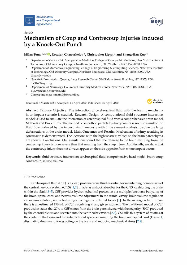
Mathematical
and Computational
Applications
Article
Mechanism of Coup and Contrecoup Injuries Inducedby a Knock-Out Punch
Milan Toma 1,2,* , Rosalyn Chan-Akeley 3, Christopher Lipari 2 and Sheng-Han Kuo 4
1 Department of Osteopathic Manipulative Medicine, College of Osteopathic Medicine, New York Institute ofTechnology, Old Westbury Campus, Northern Boulevard, Old Westbury, NY 11568-8000, USA
2 Department of Mechanical Engineering, College of Engineering & Computing Sciences, New York Instituteof Technology, Old Westbury Campus, Northern Boulevard, Old Westbury, NY 11568-8000, USA;[email protected]
3 NewYork-Presbyterian Queens, Lang Research Center, 56-45 Main Street, Flushing, NY 11355, USA;[email protected]
4 Department of Neurology, Columbia University Medical Center, New York, NY 10032-3784, USA;[email protected]
* Correspondence: [email protected]
Received: 3 March 2020; Accepted: 14 April 2020; Published: 15 April 2020�����������������
Abstract: Primary Objective: The interaction of cerebrospinal fluid with the brain parenchymain an impact scenario is studied. Research Design: A computational fluid-structure interactionmodel is used to simulate the interaction of cerebrospinal fluid with a comprehensive brain model.Methods and Procedures: The method of smoothed particle hydrodynamics is used to simulate thefluid flow, induced by the impact, simultaneously with finite element analysis to solve the largedeformations in the brain model. Main Outcomes and Results: Mechanism of injury resulting inconcussion is demonstrated. The locations with the highest stress values on the brain parenchymaare shown. Conclusions: Our simulations found that the damage to the brain resulting from thecontrecoup injury is more severe than that resulting from the coup injury. Additionally, we show thatthe contrecoup injury does not always appear on the side opposite from where impact occurs.
Keywords: fluid-structure interaction; cerebrospinal fluid; comprehensive head model; brain; coup;contrecoup; injury; trauma
1. Introduction
Cerebrospinal fluid (CSF) is a clear, proteinaceous fluid essential for maintaining homeostasis ofthe central nervous system (CNS) [1,2]. It acts as a shock absorber for the CNS, cushioning the brainwithin the skull [3–5]. CSF provides hydromechanical protection via multiple functions: buoyancy ofthe brain, spinal cord, and nerves; volume adjustment in the cranial cavity; brain volume regulationvia osmoregulation, and a buffering effect against external forces [1]. In the average adult human,there is an estimated 150 mL of CSF circulating at any given moment. The traditional model of CSFproduction states that 20% of CSF comes from the brain parenchyma with the majority (80%) producedby the choroid plexus and secreted into the ventricular cavities [2,6]. CSF fills this system of cavities atthe center of the brain and the subarachnoid space surrounding the brain and spinal cord (Figure 1)dissipating downward forces acting on the brain and reducing mechanical stress [7,8].
Math. Comput. Appl. 2020, 25, 22; doi:10.3390/mca25020022 www.mdpi.com/journal/mca
Math. Comput. Appl. 2020, 25, 22 2 of 14
Arachnoid Granulation Dural Sinus (Venous Blood)
Sub Arachnoid Space
Choroid Plexus(CSF Production)
Lateral Ventricle
Fourth Ventricle
Spinal ChordSub Arachnoid Space(Spinal Canal)
Pituitary Gland
Figure 1. The schematic of the cerebrospinal fluid in which the brain is submerged. The 3D computationalmodel used is designed based on this schematic.
There are three published constitutive models representing CSF behavior: solid-like, viscoelastic,and fluid-like. However, all represent solid material models with varying material properties.The solid-like constitutive model represents CSF as a linear and nearly incompressible elastic solidwith a bulk modulus much larger than the shear modulus [9,10]. The viscoelastic CSF constitutivemodel is a linear viscoelastic model with shear relaxation behavior [11,12]. The fluid-like CSF utilizesan elastic solid material with fluid-like constitutive behavior and an equation of state constitutivemodel [13]. In recent years, many groups have shifted to the use of fluid-structure interaction (FSI)models [14–18]. Since the start of this project, recent work has shown that others are also attempting touse similar numerical methods to simulate FSI of CSF with brain, but with geometrically simplified 2Dmodels [19]. The Arbitrary Lagrangian–Eulerian (ALE) formulation has also been used to model theCSF interaction with brain structures [14]. The accuracy of ALE methods depends on the use of mesheswith high density, which can be a problem in modelling the small gap between the skull and highlydetailed brain geometry. The use of ALE brings additional complications to models which containdetailed anatomy such as gyri and sulci. For example, ALE methods are either strongly coupled, orweakly coupled. Weakly coupled ALE methods are known for accuracy issues and their inability toperform well when attempting to parallelize the algorithms. Strongly coupled ALE methods yieldlarge ill-conditioned system matrices, i.e., system matrices that are prone to large numerical errorswith each system-solving iteration within each non-linear iteration within each time-step [20].
While the importance of including CSF in the numerical simulations is now well-documented [21],the current finite element studies reported in the literature often lack more detailed anatomicalstructures [12,14,15,22–25]. The brain is more complex in structure than what has been describedin prior models. For example, CSF is commonly presented as existing only outside of the brain,i.e., between the skull and a single solid mass representing the brain. The model presented in thisstudy is an FSI model which uses fluid material properties to represent the CSF, replicating fluid foundin the brain parenchyma, skull, and ventricular system, as well as including all major anatomicalfeatures of the brain [16–18,26]. A detailed analysis of the CSF cushioning mechanism and its impactin mitigating stress and pressure inflicted on brain tissue is useful for the treatment and prevention ofbrain injuries. The importance of studying CSF interaction with brain parenchyma, and its implicationon human diseases such as traumatic brain injury and hydrocephalus [27], is axiomatic.
In this study we look at the mechanics of interaction between CSF and brain parenchyma in thecontext of coup-contrecoup injuries obtained during a direct impact to the head. Most boxing-relatedbrain injuries result from a coup-contrecoup type of injury. Coup injury occurs at the point of impactand, as the brain rebounds, contrecoup injury typically occurs on the opposite side of impact. In this

Math. Comput. Appl. 2020, 25, 22 3 of 14
model one particular punch is studied. It is known that this punch has resulted in knockout. It occurredduring a match between G. Lorenzo and D. Jacobs on August 19, 2013. The resulting dual impacting ofthe brain into the skull, i.e., coup-contrecoup injury, is demonstrated.
2. Methods
2.1. Smoothed-Particle Hydrodynamics
Smoothed-particle hydrodynamics (SPH) is a mesh-free, particle-based method for computationalfluid dynamics. In each time step, the velocity governs the movement of the particles. Acceleration iscomputed with a momentum equation. Density and pressure are calculated with a continuity equationand an equation of state. Variables needed, namely density, pressure and velocity, are interpolatedusing shape functions called kernels. For each particle, the interpolation is performed across a certainrange of neighboring particles yielding a weighted sum. Numerically, the SPH method is advantageousin comparison to mesh-based methods. There are no convergence problems associated with largedeformations. Biomedical applications are typically exposed to large deformation.
As stated above, the fluid in the SPH method is modeled using discrete particles that are movingwith its flow. Each particle is defined by its position and carries a set of physical properties. At eachtime step, these properties are interpolated between particles found in the vicinity of the investigatedlocation. Let A be a property evaluated at point r, the interpolation can then be derived from anintegral interpolation
AI(r) =∫
AI(r′)W(r− r′, h)dr′, (1)
where W denotes a weighting function also called the smoothing kernel. The property A is weightedwith W and integrated over r′. The smoothing kernel W is a function of the vector from the integrationvariable r′ to the investigated point r as well as a smoothing length h. While the smoothing lengthcan be considered as a variable it is further assumed to be constant. Moreover, assuming that Wis rotationally symmetrical and introducing the normalized variable q = |r − r′|/h, W(q) becomesdependent upon q only. The W(q) has to fulfill the following properties:
W(q) > 0 ∀q,∂W∂q≤ 0 ∀q,
∫W(q)dq = 1. (2)
The first condition states that the weighting has to be positive. The second condition states thatthe weighting has to decrease with increasing distance of the investigated point. The third conditionrepresents a normalization ensuring the integral conservation of A over the interpolation process.
2.2. Head Model
The five distinct anatomical structures used in this model are shown in Figure 2. The skull,cerebrum, cerebellum, pituitary gland, and brainstem each have unique material properties.The patient-specific model is based on the Digital Imaging and Communications in Medicine (DICOM)images acquired from an online database. Anatomical features missing in this model include the skin,spinal cord, meninges, and the arachnoid granulation, Figure 1. When compared to the very shortimpact impulse time history used in these simulations, the CSF flow in the head can be neglected, too.The CSF flow is relatively slow, 0.05–0.08 m·s−1, i.e., during the impact impulse time history the CSFflows by 0.2–0.3 mm. These assumptions also make the presence of the granulations negligible.

Math. Comput. Appl. 2020, 25, 22 4 of 14
Figure 2. The depiction of the entire head model with skull, cerebrum, cerebellum, pituitary glandand brain stem, respectively. The subarachnoid space and other cavities are filled with fluid particles(blue dots surrounding the brain model, in the lower right corner). The entire model with half the skullis also shown (lower left).
2.3. Loading Conditions
The power of a punch can be calculated in terms of explosive power, i.e., kgs of TNT(trinitrotoluene). It takes 1 g of TNT to produce an energy of 4184 joules or 429 watts, equal tothe power necessary to move 429 kg of mass with the speed of 1 m·s−1. The speed, force and weight ofthe boxer are the three main factors that determine the force of a blow to the head. Other factors includehow heavy the boxer’s hands and gloves are, and how rigidly the boxer holds their wrist. The blowsin a professional boxing match are powerful and can introduce peak translational acceleration of 58 gto the head [28]. The maximum power that is generated in a boxer blow is around 750 kg of force at theheavyweight category and achieved by some of the hardest hitting boxers in history. Average boxers,depending on their height and weight, could deliver punches with up to 600 kgs of force (5884 N),equivalent to 1.4 g of TNT [29].
A model of an actual boxing glove is used to deliver the blow to the head model containing theCSF. A speed of 10 m·s−1 is prescribed to the rigid-solid part that fills the inside of the glove [30].A slow-motion video of a knockout punch between D. Jacobs and G. Lorenzo (19 August 2013) is usedto extract the direction and location of the punch (Figure 3a). The blow is delivered at a 40◦ angle tothe head, an angle found in the majority of punches resulting in a knockout (≈45◦). Foam material

Math. Comput. Appl. 2020, 25, 22 5 of 14
properties are prescribed to the glove elements. The simulations become more complex that way but itguarantees more realistic outcome (Figure 3b). The subsequent rotation of the head after the blow isdetermined by the shape and material of the glove as well, not just by the direction and speed of theforce.
≈ 40◦
(a) an actual knockout punch
x
yz
(b) a simulated punch
Figure 3. The actual (a) and simulated (b) punches. The actual punch led to a knockout of G. Lorenzoby D. Jacobs (August 19, 2013).
2.4. Computer Simulations
The model is comprised of 5 parts. The skull is assigned rigid material properties with density1900 kg·m−3 [31]. Data from studies characterizing the macroscopic physical characteristics of thebrain show that it is a viscoelastic material [32]. The cerebrum, cerebellum, pituitary gland, andbrainstem are simulated using a non-linear elastic constitutive material model with varying materialproperties based from the literature [33–37]. The cerebrum, cerebellum, brainstem, and pituitarygland are each composed of a different number of tetrahedral elements; 96,385, 40,808, 18,634, 310,respectively. The CSF was modeled using the SPH method with the bulk modulus of 21.9 GPa [12] anddensity 1000 kg·m−3 [38]. The number of fluid particles filling the subarachnoid space between theskull and brain, and other cavities, is 94,690.
The IMPETUS Afea Finite Element and γSPH solvers R© (IMPETUS Afea AS, Norway) were usedto model the impact scenario. Fluid motion and boundary interaction calculations were solved withthe IMPETUS Afea γSPH Solver, while large deformations in the solid parts were simultaneouslysolved with the IMPETUS Afea Solver. Both the solvers use a commodity GPU for parallel processing.All solid elements were fully integrated, removing the possibility of hourglass modes and elementinversion that plagues the classic under-integrated elements. Both fluid and solid domains and theirinteraction were solved with an explicit integration scheme. All simulations were solved on a standardworkstation. Parallel acceleration was achieved with a Tesla K40 GPU with 12 GB of Graphic DDRmemory and 2880 CUDA Cores.
The contact, i.e., particle to structure contact, is very simple which is why γSPH is ideal for thesecomplex applications because it can easily account for movement in any direction, as opposed to finiteelement fluid solvers which involve more complicated contact and usually require remeshing of thefluid domain during the simulation. The fact that IMPETUS can allow for a very high resolution interms of particle density provides for a very accurate particle to structure contact, especially with sucha detailed and complex structure as the brain. The other critical part of the simulation is the structuralmodel. The IMPETUS Aset R© Element Technology provides high order tetrahedron elements that areaccurate for nonlinear dynamic response. This allows for automeshing complicated structures such

Math. Comput. Appl. 2020, 25, 22 6 of 14
as those found in biomedical applications. The accuracy of these elements has been demonstrated inmany commercial applications when compared with hexahedron elements and is very accurate inbending and plasticity.
To confirm that convergence was reached, h-refinement of the finite element mesh was performed,and the solution was found to yield same results. Similarly, smaller number of fluid particles was usedto obtain results within 5% of the values obtained with the higher number of particles. The abovestated number of particles, 94,690, is high considering that the volume of the cavities and subarachnoidspace is much smaller than rest of the model. This confirmed that the results are converged. Our priorpublication describes the SPH equations in greater detail [39]. The SPH method is chosen for this studybecause traditional FSI techniques can be computationally expensive and challenging regarding theirparallelization [20]. In order to use traditional FSI techniques, geometrical simplifications would needto occur, and the anatomical accuracy would have to be sacrificed. Moreover, in recent years the SPHhas been increasingly used in biomedical applications [40].
3. Results
While the pressure response in the CSF in a head exposed to trauma has been previously validatedagainst cadaveric experiments [17,18], for the given scenario the dynamic response of the head tothe punch had to be validated as well. The response of the head model to the simulated punch iscompared with the head movement resulting from the actual punch in Figure 4. As the resulting headmovement of the actual boxer taking the punch matches the resulting head model movement from thesimulated punch, the subsequent results from the CSF interacting with the brain structures can now beanalyzed. The coup-contrecoup injuries after the simulated knock-out punch are depicted in Figure 5.The contrecoup injury, located in the right parietal and occipital lobes, appear to be more severe thanthe coup injury.
Figure 6 shows six time instances of stress values seen from the superior view. It can be observedthat while the punch was introduced to the left zygomatic bone (cheekbone) of the skull, the mainprimary (coup) injury can be found in the left posterior temporal lobe. The maximum stress valuesin the left temporal lobe keep increasing until about 2.5 ms after the first contact of the glove withthe skull and spread forward towards the anterior temporal lobe, until they dissipate at around3 ms. The time point of 3 ms is when the secondary (contrecoup) injury reaches its maximum values.The contrecoup injury can be located primarily in the right occipital lobe. After the last time pointshown the contrecoup injury also begins to dissipate, see Figure 7.
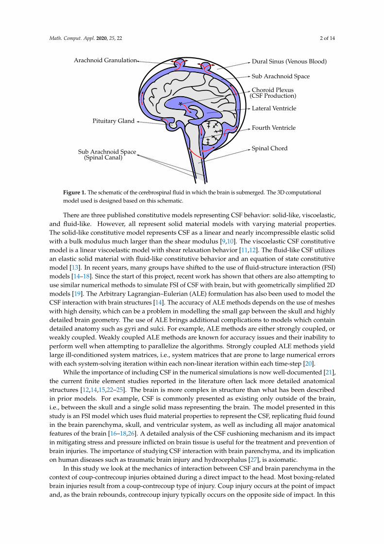
The majority of CSF is produced by the choroid plexus in the lateral, third, and fourth ventricles [2].The ventricular system transports CSF around the cranial cavity with the assistance of ciliatedependyma that beat in synchrony [2]. A disease called post-traumatic hydrocephalus is when CSFbuilds up in the ventricles after a traumatic brain injury, resulting in increased intracranial pressure [41].The excessive accumulation of CSF surrounding the brain can be due to a multitude of factors:overproduction of CSF, blockage of normal CSF flow, or insufficient absorption resulting in fluidaccumulation [2,42]. The response of lateral ventricles to the knockout punch is shown in Figure 8.As seen in Figure 5, the response to the contrecoup injury is more severe than the response to thecoup injury, Figure 8 additionally shows the first deviatoric principal stress in the ventricles at themoment when the brain rebounds within the skull. High levels of stress can be found in the anteriorand posterior horns of the left and right ventricles, respectively. Similarly, the coup-contrecoup injuriesin the brain stem, after the simulated knock-out punch, are depicted in Figure 9. Again, the contrecoupinjury appear to be more severe than the coup injury. The coup injury is located in the left thalamuswhereas the contrecoup injury is located in the right midbrain, pons, medulla and spinal cord.

Math. Comput. Appl. 2020, 25, 22 7 of 14
Actual response Simulated responseFigure 4. Validation of the dynamic response of the head model to the simulated punch.

Math. Comput. Appl. 2020, 25, 22 8 of 14
(a) The moment glove lands on the chin (b) The moment brain rebounds inside the skull
Figure 5. First deviatoric principal stress at the moment when the glove lands on the head, i.e., coupinjury (a); and, at the point when the brain rebounds, i.e., contrecoup injury (b). By comparison, thecontrecoup injury can be seen more severe.
0.5 ms 1.0 ms 1.5 ms
2.0 ms 2.5 ms 3.0 msFigure 6. Time evolution of the first deviatoric principal stress from the moment the glove and skullcome into contact (0 ms). Maximum value (red) is ≥ 1 MPa.
Math. Comput. Appl. 2020, 25, 22 9 of 14
Time [ms]
Firs
tdev
iato
ric
prin
cipa
lstr
ess
[MPa
]
1.0
0.8
0.6
0.4
0.2
0.0
0.0 2.0 4.0 6.0 8.0
Left
Right
Figure 7. Averaged first deviatoric principal stress values compared between left and right hemispheres.
Ant
erio
r
Ant
erio
rho
rn Anterior
horn
Post
erio
r
Posterior horn
Inferior horn
Post
erio
r hor
n
Inferior horn
Left Ventricle Right VentricleFigure 8. First deviatoric principal stress values in ventricles during the contrecoup injury.

Math. Comput. Appl. 2020, 25, 22 10 of 14
Thalamus
Midbrain
Pons
Medulla
Spinal cord
(a) Coup Response (b) Contrecoup ResponseFigure 9. High values of first deviatoric principal stress are observed on both sides of the brain stembut predominantly in the contrecoup response (right midbrain, pons and medulla/spinal chord).
4. Conclusions
The mechanism of the coup and contrecoup injuries sustained in a knock-out punch is shown.The brain regions most affected are the parietal and occipital lobes after the brain rebounded inside theskull, i.e., contrecoup injury. The damage associated with the regions most affected in the given trauma(Figure 5) can yield difficulties with co-ordinating sensory information, perception, spatial relationships,recognizing faces and objects, responding to internal sensations (i.e., damage to parietal lobe) and/orsight (i.e., damage to occipital lobe).
Trauma to the ventricles is also analyzed (Figure 8) and shows that the highest stress valuesoccur in the anterior and posterior horns of the left and right ventricles, respectively. This canresult in CSF build up leading to increased intracranial pressure, a condition called post-traumatichydrocephalus [41]. More important is the impact of this damage to the corpus callosum and theability to predict diffuse axonal injury. Trauma to the ventricles and the white matter alongside theventricular areas is likely to cause axonal injuries, which can then lead to a wide variety of neurologicalsequelae such as mood disorders and cognitive impairment [43]. Damage to the brain stem can also beseen (Figure 9). The coup injury is located in the left thalamus but it is not as severe as the contrecoupinjury which is located in the right brain stem, more precisely the right midbrain, pons, medulla andspinal cord (Figure 9b). The reticular activating system (RAS) is a network of neurons located in thebrain stem. The mechanism of concussion is often defined as dysfunction of the RAS as it is believedto control consciousness.
5. Discussion
Athletes tend to neglect reporting symptoms for various reasons, e.g., not thinking the injury isserious enough to need medical attention (66.4%), a desire to remain in competition (41.0%), and/orlack of awareness of what to consider as a symptom (36.1%) [44]. Depending on the circumstancesleading to a traumatic brain injury, different regions of the brain are affected, thus yielding different setsof possible symptoms. The regions affected cannot be predicted by simply locating the point of impactfor the coup injury and the side opposite the area that was hit for the contrecoup injury. The resultingsymptoms will also depend on subsequent head rotation, acceleration and deceleration, and whetherany protective gear was utilized. Different designs of head protective gears will also yield differentresults. The latest research shows that the newest helmet designs do not necessarily improve theuser’s protection against concussion even when compared with helmets used during the First WorldWar [45]. One of the ways to use this model is to perform a comparative study between two designs of
Math. Comput. Appl. 2020, 25, 22 11 of 14
protective equipments and assess their efficacy. In other words, this model could help in the creationof specialized equipment with a known efficacy in comparison to existing protective equipment.
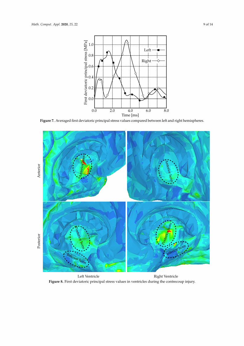
While the relationship between brain structure and function is still debated, the Brodmann’s mapof cytoarchitectonics is widely used for that purpose. In Figure 10 the first deviatoric principal stress atthe point when the brain rebounds, i.e., contrecoup injury, is superimposed with the Brodmann’s map.It can be seen that region 18 has the highest area covered by the stress maximum. That region is partof the occipital cortex and is known as the ‘visual association area’ responsible for the interpretationof images. Similarly, region 17 is another area of the brain with high stress levels and is called the‘primary visual cortex’. It is the part of the visual cortex that receives the visual information comingfrom the eye. The third area largely affected by the stress exerted on the brain is region 39. Damage toregion 39 is associated with semantic aphasia, i.e., inability to comprehend or formulate language.
The ventricles are where CSF is produced and can serve as an important cushion for brainparenchyma when encountering impacts. In Figure 8, it is shown that certain areas of the ventriclesare affected, particularly the anterior horn of the left ventricle and the posterior horn of the rightventricle. These impacts are likely to cause injury to the corpus callosum which contains large numbersof neuronal axons running along these ventricular structures. Damage to the corpus callosum and theunderlying white matter can result in diffuse axonal injury, a common consequence of traumatic braininjury. This particular type of trauma has been linked to a variety of neurological symptoms such asmood disorders, inattention, and impulsivity [43]. Our FSI model could begin to predict and to studythese impacts numerically and will have broader implications in studying traumatic brain injury.
11
10
4645
44
8
964
31
2
5
7
434039
41 52
42
2238
21
20
37
1918
17
Figure 10. First deviatoric principal stress during the contrecoup injury (right hemisphere)superimposed with the Brodmann’s map of cytoarchitectonics.
Several limitations can be considered. The results presented here are from a single casestudy. However, in professional boxing, this is a very typical punch that often leads to a knockout.Hence, the same study (roughly) applies to many other reported cases. Moreover, the boxer sufferedseveral other punches before the final knockout punch; these prior punches are not considered inthis study. A major limitation of this model is the omission of the cerebral vasculature. The networkof arteries and veins significantly alters brain stiffness since it functions as a spring-like suspensionsystem that limits the brain’s motion [46,47]. Design of a model that includes the cerebral vasculatureis currently under way.
Additionally, we do not wish to claim that this SPH approach is better suited for modeling the CSFthan commonly used solid elements in other models. There may be cases where it might be necessaryto study the behavior of the fluid in a model using an actual fluid domain. For example, when studying
Math. Comput. Appl. 2020, 25, 22 12 of 14
the effect of CSF drainage via ventriculoperitoneal shunt as a form of treatment for hyrocephalus [27].Models that utilize solid elements to study the CSF behavior in such conditions could not be used.However, in other more straightforward scenarios, such as traumatic brain injury where a single blowto the head is studied, the use of solid elements is justified when properly validated. It is certainly lesscomputationally expensive than using traditional FSI techniques in order to represent the CSF usingfluid domain. Though, compared to the methods used in this study, the use of solid elements to modelthe CSF does not provide significant advantage in terms of computational cost.
Author Contributions: M.T. designed the model and the computational framework and carried out theimplementation. M.T., R.C.-A., C.L., and S.-H.K. analyzed the data and wrote the manuscript. All authorshave read and agreed to the published version of the manuscript.
Funding: This study was funded by a grant provided by the New York Institute of Technology and a donationfrom New York Thoroughbred Horsemen’s Association. No benefits in any form have been or will be receivedfrom a commercial party related directly or indirectly to the subject of this manuscript.
Conflicts of Interest: The authors declare no conflict of interest.
Data Availability: Data are available upon reasonable request.
Ethical Approval: This article does not contain any studies with human participants or animals performed byany of the authors.
References
1. Matsumae, M.; Sato, O.; Hirayama, A.; Hayashi, N.; Takizawa, K.; Atsumi, H.; Sorimachi, T. Research intothe physiology of cerebrospinal fluid reaches a new horizon: Intimate exchange between cerebrospinalfluid and interstitial fluid may contribute to maintenance of homeostasis in the central nervous system.Neurol. Med. Chir. 2016, 56, 416–441. [CrossRef] [PubMed]
2. Khasawneh, A.H.; Garling, R.J.; Harris, C.A. Cerebrospinal fluid circulation: What do we know and how dowe know it? Brain Circ. 2018, 4, 14–28. [PubMed]
3. Bothwell, S.W.; Janigro, D.; Patabendige, A. Cerebrospinal fluid dynamics and intracranial pressure elevationin neurological diseases. Fluids Barriers CNS 2019, 16, 9. [CrossRef] [PubMed]
4. Rengachary, S.S.; Ellenbogen, R.G. Principles of Neurosurgery; Elsevier Mosby: Edinburgh, UK, 2008.5. Linninger, A.A.; Tangen, K.; Hsu, C.Y.; Frim, D. Cerebrospinal fluid mechanics and its coupling to
cerebrovascular dynamics. Annu. Rev. Fluid Mech. 2016, 48, 219–257. [CrossRef]6. Brinker, T.; Stope, E.; Morrison, J.; Klinge, P. A new look at cerebrospinal fluid circulation. Fluids Barriers
CNS 2014, 11, 10. [CrossRef] [PubMed]7. Tangen, K.M.; Hsu, C.Y.; Zhu, D.C.; Linninger, A.A. CNS wide simulation of flow resistance and drug
transport due to spinal microanatomy. J. Biomech. 2015, 48, 2144–2154. [CrossRef]8. Huff, T.; Tadi, P.; Varacallo, M. Neuroanatomy, cerebrospinal fluid. Available online: https://www.ncbi.nlm.
nih.gov/pubmed/29262203 (accessed on 10 April 2020).9. Ho, J.; Kleiven, S. Dynamic response of the brain with vasculature: A three-dimensional computational
study. J. Biomech. 2007, 40, 3006–3012. [CrossRef]10. Chen, Y.; Ostoja-Starzewski, M. MRI-based finite element modeling of head trauma: spherically focusing
shear waves. Acta Mechanica 2010, 213, 155–167. [CrossRef]11. Watanabe, D.; Yuge, K.; Nishimoto, T.; Murakami, S.; Takao, H. Impact injury analysis of the human head.
AutoTechnology 2007, 7, 34–37.12. Chafi, M.S.; Dirisala, V.; Karami, G.; Ziejewski, M. A finite element method parametric study of the dynamic
response of the human brain with different cerebrospinal fluid constitutive properties. Proc. Inst. Mech. Eng.H J. Eng. Med. 2009, 223, 1003–1019. [CrossRef]
13. Madhukar, A.; Chen, Y.; Ostoja-Starzewski, M. Effect of cerebrospinal fluid modelling on sphericallyconvergent shear waves during blunt head trauma. Int. J. Numer. Methods Biomed. Eng. 2017, 33, e2881.[CrossRef] [PubMed]
14. Zhou, Z.; Li, X.; Kleiven, S. Fluid–structure interaction simulation of the brain–skull interface for acutesubdural haematoma prediction. Biomech. Model. Mechanobiol. 2019, 18, 155–173. [CrossRef] [PubMed]
Math. Comput. Appl. 2020, 25, 22 13 of 14
15. Zhou, Z.; Li, X.; Kleiven, S. Biomechanics of acute subdural hematoma in the elderly: A fluid-structureinteraction study. Adv. Intell. Syst. Comput. 2019, 36, 2099–2108. [CrossRef] [PubMed]
16. Toma, M.; Nguyen, P.D.H. Fluid–structure interaction analysis of cerebrospinal fluid with a comprehensivehead model subject to a rapic acceleration and deceleration. Brain Injury 2018, 32, 1576–1584. [CrossRef][PubMed]
17. Toma, M.; Nguyen, P.D.H. Coup-contrecoup brain injury: Fluid-structure interaction simulations. Int. J.Crashworthiness 2019, 15, 1–8. [CrossRef]
18. Toma, M. Predicting concussion symptoms using computer simulations. In Proceedings of the FutureTechnologies Conference (FTC) 2018; Springer: Cham, Switzerland, 2018; pp. 557–569.
19. Duckworth, H.; Ghajari, M. Modelling brain biomechanics using a hybrid smoothed particle hydrodynamicsand finite element model. Available online: http://ibrc.osu.edu/wp-content/uploads/2019/05/2019-IBS-Manuscript_Duckworth.pdf (accessed on 14 April 2020).
20. Toma, M.; Oshima, M.; Takagi, S. Decomposition and parallelization of strongly coupled fluid–structureinteraction linear subsystems based on the Q1/P0 discretization. Comput. Struct. 2016, 173, 84–94. [CrossRef]
21. Vorwerk, J.; Clerc, M.; Burger, M.; Wolters, C.H. Comparison of boundary element and finite elementapproaches to the eeg forward problem. Biomedizinische Technik 2012, 57, 795–798. [CrossRef]
22. Luo, Y.; Li, Z.; Chen, H. Finite-element study of cerebrospinal fluid in mitigating closed head injuries. J. Eng.Med. 2012, 226, 499–509. [CrossRef]
23. Liang, Z.; Luo, Y. A QCT-based nonsegmentation finite element head model for studying traumatic braininjury. Appl. Bionics Biomech. 2015, 2015, 1–8. [CrossRef]
24. Li, B.; Ruan, S.; Li, H.; Cui, S.; He, L. The effects of different mesh density of the cerebrospinal fluid onthe dynamic responses of a 6 years old child finite element head model. In Proceedings of the EighthInternational Conference on Measuring Technology and Mechatronics Automation (ICMTMA), Macau,China, 11–12 March 2016; pp. 756–767.
25. Gilchrist, M.D.; O’Donoghue, D. Simulation of the development of the frontal head impact injury. Comput.Mech. 2000, 26, 229–235. [CrossRef]
26. Toma, M.; Dehesa-Baeza, A.; Chan-Akaley, R.; Nguyen, P.D.H.; Zwibel, H. Cerebrospinal fluid interactionwith cerebral cortex during pediatric abusive head trauma. J. Pediatr. Neurol. 2020. [CrossRef]
27. Toma, M.; Kuo, S.-H. Computational assessment of risk of subdural hematoma associated withventriculoperitoneal shunt placement. In Computer Methods, Imaging and Visualization in Biomechanics andBiomedical Engineering; Ateshian, G.A., Myers, K.M., Tavares, J.M.S., Eds.; Springer International Publishing:Cham, Switzerland, 2020; pp. 36–47.
28. Walilko, T.J.; Vian, D.C.; Bir, C.A. Biomechanics of the head for olympic boxer punches to the face. Br. J.Sports Med. 2005, 39, 710–719. [CrossRef]
29. Atha, J.; Yeadon, M.R.; Sandover, J.; Parsons, K.C. The damaging punch. Br. Med. J. 1985, 291, 21–28.[CrossRef] [PubMed]
30. Kimm, D.; Thiel, D.V. Hand speed measurements in boxing. Procedia Eng. 2015, 112, 502–506. [CrossRef]31. Fry, F.J.; Barger, J.E. Acoustical properties of the human skull. J. Acoust. Soc. Am. 1978, 63, 1576–1590.
[CrossRef] [PubMed]32. Tyler, W.J. The mechanobiology of brain function. Nat. Rev. Neurosci. 2012, 13, 867–878. [CrossRef]33. Barser, T.W.; Brockway, J.A.; Higgins, L.S. The density of tissues in and about the head. Acta Neurol.
Scandinav. 1970, 46, 85–92.34. Elkin, B.S.; Azeloglu, E.U.; Costa, K.D.; Morrison, B. Mechanical heterogeneity of the rat hippicampus
measured by atomic force microscope indentation. J. Neurotrauma 2007, 24, 812–822. [CrossRef]35. A. Gefen, N. Gefen, Q. Zhu, R. Raghupathi, and S.S. Margulies. Age-dependent changes in material
properties of the brain and braincase of the rat. J. Neurotrauma 2003, 20, 1163–1177. [CrossRef]36. Kruse, S.A.; Rose, G.H.; Glaser, K.J.; Manduca, A.; Felmlee, J.P.; Jack Jr., C.R.; Ehman, R.L. Magnetic resonance
elastography of the brain. Neuroimage 2008, 39, 231–237. [CrossRef]37. Moore, S.W.; Sheetz, M.P. Biophysics of substrate interaction: Influence on neutral motility, differentiation,
and repair. Dev. Neurobiol. 2011, 71, 1090–1101. [CrossRef] [PubMed]38. Lui, A.C.; Polis, T.Z.; Cicutti, N.J. Densities of cerebrospinal fluid and spinal anaesthetic solutions in surgical
patients at body temperature. Can. J. Anaesth. 1998, 45, 297–303. [CrossRef] [PubMed]
Math. Comput. Appl. 2020, 25, 22 14 of 14
39. Toma, M.; Einstein, D.R.; Bloodworth, C.H.; Cochran, R.P.; Yoganathan, A.P.; Kunzelman, K.S.Fluid–structure interaction and structural analyses using a comprehensive mitral valve model with 3Dchordal structure. Int. J. Numer. Methods Biomed. Eng. 2017, 33, e2815. [CrossRef] [PubMed]
40. Toma, M. The emerging use of SPH in biomedical applications. Significances Bioeng. Biosci. 2017, 1. [CrossRef]41. Beyerl, B.; Black, M.L.P. Post-traumatic hydrocephalus. Neurosurgery 1984, 15, 257–261. [CrossRef] [PubMed]42. Ochieng, D.; Figaji, A.; Fieggen, G. Post-Traumatic Hydrocephalus. In Pediatric Hydrocephalus; Springer:
Cham, Switzerland, 2018.43. Blennow, K.; Brody, D.L.; Kochanek, P.M.; Levin, H.; McKee, A.; Ribbers, G.M.; Yaffe, K.; Zetterberg, H.
Traumatic brain injuries. Nat. Rev. Dis. Primers 2016, 2, 1–9. [CrossRef] [PubMed]44. McCrea, M.; Hammeke, T.; Olsen, G.; Leo, P.; Guskiewicz, K. Unreported concussion in high school footbal
playes: Implications for prevention. Clin. J. Sport Med. 2004, 14, 13–17. [CrossRef]45. Eynde, J.O.; Yu, A.W.; Eckersley, C.P.; Bass, C.R. Primary blast wave protection in combat helmet design:
A historical comparison between present day and World War I. PLoS ONE 2020, 15, e0228802.46. Hsu, C.Y.; Schneller, B.; Alaraj, A.; Flannery, M.; Zhou, X.J.; Linninger, A.A. Automatic recognition of
subject-specific cerebrovascular trees. Magn. Reson. Med. 2016, 77, 398–410. [CrossRef]47. Ghaffari, M.; Tangen, K.M.; Alaraj, A.; Du, X.; Charbel, F.T.; Linninger, A.A. Large-scale subject-specific
cerebral arterial tree modeling simulation. Comput. Biol. Med. 2017, 91, 353–365. [CrossRef]
c© 2020 by the authors. Licensee MDPI, Basel, Switzerland. This article is an open accessarticle distributed under the terms and conditions of the Creative Commons Attribution(CC BY) license (http://creativecommons.org/licenses/by/4.0/).
Copyright © 2022 FDOKUMEN


![[Treating frostbite injuries]](https://static.fdokumen.com/doc/165x107/633ff39332b09e4bae09a1b5/treating-frostbite-injuries.jpg)