Validation of Time Domain Flutter Prediction Tool with ... - DiVA
Upload
independentCategory
view
0download
0
Mechanism and Location of Atrial Flutter in Transplanted Hearts:Observations During Transient Entrainment From Distant Sites
ANGEL ARENAL, MD, JESUS ALMENDRAL, MD, FESC, ROBERTO MUNOZ, MD,JULIAN VILLACASTIN, MD, JOSE LUIS MERINO, MD, JESUS PALOMO, MD,JOSE ANTONIO GARCIA ROBLES, RAFAEL PEINADO, MD, JUAN LUIS DELCAN, MD
Madrid, Spain
Objectives. This study was designed to elucidate the locationand mechanism of typical atrial flutter in the transplanted heart.
Background. Although the F wave morphology in atrial flutteris similar in nontransplanted and transplanted hearts, the surgi-cal incision needed for the atrial anastomosis may create adistinct electrophysiologic substrate of atrial flutter.
Methods. Entrainment from the lateral wall of the right atriumand interatrial septum was used to determine the location of atrialflutter in five patients with a transplanted heart and six patientswith a nontransplanted heart. The difference between the firstpostpacing interval (FPPI) and the flutter cycle length (FCL) wasused as an index of proximity to the circuit.
Results. In the transplant group, the FPPI was equal to the FCLat sites located close to the tricuspid annulus (TA); the meandifferences (6SD) were 1 6 5 and 21 6 2 ms at the lateral walland interatrial septum, respectively. However, from sites close to
the surgical incision at the lateral wall and at the interatrialseptum, these differences were significantly longer (29 6 12 and27 6 9 ms, respectively, p < 0.05). In the nontransplant group, theFPPI was similar to the FCL at points in the lateral wall andinteratrial septum close to the TA (mean difference 7 6 6 and 6 611 ms, respectively) and at sites close to the crista terminalis (CT)in the lateral wall (mean difference 4 6 4 ms). However, in sitesseparated from the TA at the interatrial septum the difference wasmarkedly longer (35 6 11 ms, p < 0.05).
Conclusions. Atrial flutter in transplanted hearts may best beexplained by macroreentry around the tricuspid ring. In non-transplanted hearts a different structure (perhaps the CT?) maybe the basis for atrial flutter at the lateral wall.
(J Am Coll Cardiol 1997;30:539–46)©1997 by the American College of Cardiology
Activation mapping studies in animal models of atrial flutterand in patients with common or typical flutter suggest thatatrial flutter is a macroreentrant rhythm propagating in acounterclockwise direction around or near the venae cavae(1–8). For such a circuit to exist, posterior and anteriorelectrical barriers have to be present. Two lines of conductionblock have been identified as part of the posterior barrier. Thefirst is localized in the lateral wall (9,10) and is related to thecrista terminalis (CT) (11); the second line of block is theeustachian valve/ridge extending from the inferior vena cava tothe coronary sinus ostium (12). Recent data obtained duringactivation and entrainment mapping identified the tricuspidannulus (TA) as the anterior barrier of the common atrialflutter (13).
Although the surface electrocardiographic (ECG) appear-ance of atrial flutter in transplanted hearts is similar to the Fwaves observed in common flutter, it is unknown whether theanatomic characteristics of the donor atrium modify the ana-
tomic barrier observed in nontransplanted hearts. The surgicalincision in the lateral free wall opens the right atrium of thedonor heart from the inferior vena cava toward the right atrialappendage. This incision, connected to the inferior vena cava,forms an orifice that permits the anastomosis to the recipientright atrium (Fig. 1A). This orifice might create a sufficientlylarge anatomic obstacle around which macroreentrant excita-tion could be established, even if no area of slow conductionwere present. Another possibility is that this incision, inter-rupting the continuity of the CT in the lateral wall, may modifythe posterior anatomic barrier of the reentry. Even the locationof the circuit may change, as demonstrated by Frame et al.(14,15). In their Y-like lesion model of atrial flutter, the lesionin the right lateral free wall moved the reentrant circuit to thetissue surrounding the TA. In that model, no area of slowconduction was found.
The aim of the present study was to compare the anatomicbarriers of atrial flutter in transplanted and nontransplantedhearts. More specifically, we tried to determine whether atrialflutter in transplanted hearts was a broad counterclockwisereentrant excitation constrained between the TA and theconnecting orifice with the recipient atrium, or whether it wasjust a reentry around one of these two anatomic obstacles withsecondary activation of the rest of the atrium. We compared
From the Department of Cardiology, Hospital General Universitario Gre-gorio Maranon, Madrid, Spain.
Manuscript received August 5, 1996; revised manuscript received March 25,1997, accepted April 16, 1997.
Address for correspondence: Dr. Angel Arenal, Laboratorio de Electrofi-siologıa, Departamento de Cardiologıa, Hospital General Universitario Grego-rio Maranon, C/ Dr. Esquerdo 46, 28007 Madrid, Spain.
JACC Vol. 30, No. 2August 1997:539–46
539
©1997 by the American College of Cardiology 0735-1097/97/$17.00Published by Elsevier Science Inc. PII S0735-1097(97)00186-0

results of entrainment mapping from sites around the TA andthe connecting orifice to analyze these hypotheses.
MethodsPatients. Transplant group. From January 1988 to Novem-
ber 1995, 165 patients underwent heart transplantation at ourinstitution. During the hospital stay 15 of these patients had atleast one episode of typical or common atrial flutter, defined bya regular atrial rate .240 beats/min in the transplanted atriumand inverted sawtooth pattern in the inferior ECG leads. Thetransplant study group consisted of four men and one woman(mean age 6 SD 59 6 6 years) in whom atrial stimulation wasperformed to terminate the atrial flutter. All five patients werein hemodynamically stable condition and had no evidence ofcardiac rejection or ventricular dysfunction by endocardialbiopsy or echocardiography.
Nontransplant group. This group consisted of six patients(six men, mean age 64 6 12 years) with a nontransplantedheart and typical atrial flutter who underwent electrophysi-ologic study to terminate the flutter or to ablate the cavotri-cuspid isthmus.
Electrophysiologic testing, electrical stimulation and re-cordings. The studies were performed with patients in anonsedated and postabsorptive state after they had givenwritten informed consent. Intracardiac recordings were filteredat 30 to 500 Hz and displayed simultaneously with at least threeECG leads (I, aVF, V1) on a 12-channel photographic recorder(VR-12, Honeywell), at a paper speed of 100 mm/s. In somepatients digitized recordings (Bard Electrophysiology) werestored in a computer system for further analysis. Atrial stim-ulation was performed with a programmable stimulator(UHS-20 Biotronik, Berlin, Germany) set to deliver rectangu-lar pulses of 1-ms duration at twice the diastolic threshold.Multiple 10-s duration synchronized trains of rapid atrialpacing at a constant rate were delivered, beginning at a cyclelength 10 ms shorter than the flutter cycle length (FCL). Whenthere was some variability in the FCL (always ,20 ms), pacingstarted at a cycle length 10 ms less than the shortest FCL. Thepacing cycle length was decreased by 10-ms decrements untiltermination of flutter or the production of a sustained changein the atrial rate. Stimulation at the same cycle length wasperformed at all sites before proceeding to a faster stimulationrate.
Five patients with and six patients without a transplantedheart were studied. The fluoroscopic appearance of catheterpositioning is shown in Figure 2. A “deflectable halo” catheter(2-mm interelectrode distance, 10-mm interbipole distance;Webster Laboratories) was placed in the right atrium to obtaina complete activation sequence during flutter. A quadripolardeflectable tip catheter, spacing 2-5-2 mm, was used forentrainment mapping from four sites close to the TA at the 1,5, 7 and 11 o’clock positions in the left anterior obliqueprojection (C sites in Fig. 1) and four sites distant from the TA(D sites in Fig. 1). C sites were identified by recording of alarge ventricular electrogram or ventricular capture duringatrial stimulation. At each C site, the catheter was movedposteriorly to obtain its homologous D site. In the transplantgroup, D sites were intended to be close to the recipient atriumbut not in the scar tissue resulting from the surgical incision.These positions were identified by: 1) presence of normal-looking electrograms, 2) low stimulation threshold of donoratrial tissue, 3) absence of significant latency between thestimulus artifact and the atrial electrogram, and 4) recording ofa small recipient atrial electrogram. In the nontransplantgroup, D sites were intended to be at the junction of the septaland posterior walls (1 and 5 o’clock positions) and slightlyanterior to the CT (7 and 11 o’clock positions). D positionswere recognized by 1) loss or marked decrease of ventricularelectrogram, and 2) proximity to the CT, identified by therecording of a double electrogram. Right and left anterioroblique fluoroscopic projections were used to confirm thecatheter location. The distal pair of the quadripolar catheterswas used for stimulation and the proximal pair for recording;because the distance between both pairs of electrodes was only5 mm, stimulation and recording were considered to beperformed at the same site. We assumed that the differencebetween the first postpacing interval (FPPI) and the FCL was
Abbreviations and Acronyms
CT 5 crista terminalisECG 5 electrocardiogram, electrocardiographicFCL 5 flutter cycle lengthFPPI 5 first postpacing intervalLPCL 5 longest pacing cycle lengthTA 5 tricuspid annulus
Figure 1. A, Transplanted atrium. This view of the right atrium fromthe tricuspid ring shows the locations of pacing sites C (close to theTA) and D (distant from the TA). The shaded area represents theorifice created by the inferior vena cava (IVC) and the surgicalincision. B, Nontransplanted atrium. The pacing sites separated fromthe TA were close to the CT in the lateral wall and in the interatrialseptum close junction with the posterior wall. SVC 5 superior venacava. Dashed lines 5 fossa ovalis.
540 ARENAL ET AL. JACC Vol. 30, No. 2MECHANISM OF ATRIAL FLUTTER IN TRANSPLANTED HEARTS August 1997:539–46

Figure 2. Right (left panel) and left (right panel)anterior oblique fluoroscopic projections showingcatheter positioning. The halo catheter (HALO) spansthe area from the 4 o’clock (distal pair) to the 8 o’clockposition (proximal pair) on the TA. The roving cath-eter (ROVE) is situated at the 5 o’clock position nearthe TA. 1*, 5*, 7* and 11* 5 1, 5, 7 and 11 o’clockpositions along the tricuspid ring (see text for details).
Table 1. Differences Between the First Postpacing Interval and the Flutter Cycle Length (FPPI 2FCL) From Sites Close to (C) and Distant From (D) the Tricuspid Annulus
PtNo. Position*
FPPI—FCL (ms)
LRA IS
Site C Site D Site C Site D
A. Transplant Group†
1 Upper 0 25 0 30Lower 10 15 0 20
2 Upper 10 25 0 35Lower 0 20 0 45
3 Upper 0 — 25 15Lower 210 15 0 15
4 Upper 0 35 25 20Lower 0 35 0 25
5 Upper 0 45 0 30Lower 0 50 0 35
Mean 6 SD 1 6 5 29 6 12 21 6 2 27 6 9
B. Nontransplant Group‡
6 Upper 0 0 10 50Lower 0 — 0 —
7 Upper 10 5 0 30Lower 10 10 210 30
8 Upper 5 0 0 35Lower 10 10 10 50
9 Upper 20 0 30 40Lower — — 5 15
10 Upper — 5 0 —Lower 0 0 0 25
11 Upper 5 0 — 30Lower 10 10 20 50
Mean 6 SD 7 6 6 4 6 4 6 6 11 35 6 11
*Upper position 5 11 o’clock for LRA (lateral right atrium) and 1 o’clock for IS (interatrial septum); lowerposition 5 7 o’clock for LRA and 5 o’clock for IS in the left anterior oblique projection. †p , 0.01 in transplant group;LRA, site C versus LRA, site D and IS, site D; IS, site C versus IS site D and LRA, site D. ‡p , 0.01 in nontransplantgroup: IS, site D versus LRA, site C, LRA, site D and IS, site C. Values presented are mean value (6SD). Pt 5 patient.
541JACC Vol. 30, No. 2 ARENAL ET AL.August 1997:539–46 MECHANISM OF ATRIAL FLUTTER IN TRANSPLANTED HEARTS
an index of distance in terms of the conduction time to theflutter circuit.
Definitions and measurements. Entrainment. Transiententrainment was considered to occur when constant fusion wasobserved during rapid pacing at a constant rate (16,17). Iffusion was not evident in the surface ECG, it could berecognized when all atrial electrograms were accelerated to thestimulation rate and each stimulus was delivered during anobvious ongoing distant atrial deflection that started before thestimulus artifact. Such atrial deflections depend on the preced-ing beat as recognized on intracavitary recordings. Therefore,we can assume that the right atrium was being activated by twodifferent activation wave fronts at the pacing rate; that is,fusion was present (18,19). If constant fusion was not evidentduring stimulation at one site, but the entire right atrium wasaccelerated at the stimulation rate and entrainment had pre-viously been observed from a different site at the samestimulation rate, concealed entrainment was considered tohave taken place (7).
FPPI at the pacing site. FPPI was defined as the intervalfrom the last pacing stimulus artifact to the next atrial electro-gram recorded at the proximal pair of the pacing electrode. Itwas considered an estimation of the distance from the circuit(11,12,17,20).
Activation sequence. The activation sequence was definedas similar during pacing and during flutter if the intervals betweenthe stimulus artifact and the rest of the local electrograms differedby #10 ms from the intervals between the local electrogramrecorded at the pacing site and the other local electrograms. Theactivation sequence was determined during the last stimulusbecause all electrograms are captured orthodromically.
All measurements were performed from the stimulus arti-fact to the beginning of the first rapid deflection of local
electrograms and during the longest pacing cycle length toavoid decremental conduction.
Statistical analysis. Values are expressed as mean value 6SD. Multiple statistical comparisons were performed by usinganalysis of variance and the Tukey test when appropriate. A pvalue ,0.05 was considered significant.
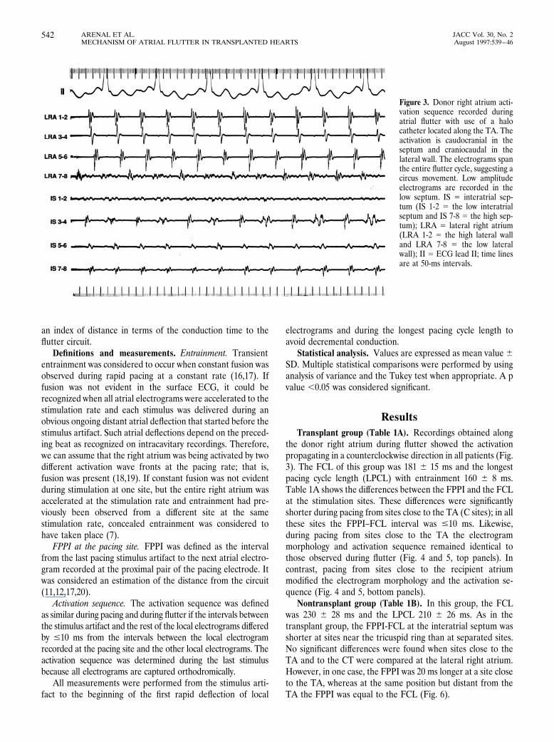
ResultsTransplant group (Table 1A). Recordings obtained along
the donor right atrium during flutter showed the activationpropagating in a counterclockwise direction in all patients (Fig.3). The FCL of this group was 181 6 15 ms and the longestpacing cycle length (LPCL) with entrainment 160 6 8 ms.Table 1A shows the differences between the FPPI and the FCLat the stimulation sites. These differences were significantlyshorter during pacing from sites close to the TA (C sites); in allthese sites the FPPI–FCL interval was #10 ms. Likewise,during pacing from sites close to the TA the electrogrammorphology and activation sequence remained identical tothose observed during flutter (Fig. 4 and 5, top panels). Incontrast, pacing from sites close to the recipient atriummodified the electrogram morphology and the activation se-quence (Fig. 4 and 5, bottom panels).
Nontransplant group (Table 1B). In this group, the FCLwas 230 6 28 ms and the LPCL 210 6 26 ms. As in thetransplant group, the FPPI-FCL at the interatrial septum wasshorter at sites near the tricuspid ring than at separated sites.No significant differences were found when sites close to theTA and to the CT were compared at the lateral right atrium.However, in one case, the FPPI was 20 ms longer at a site closeto the TA, whereas at the same position but distant from theTA the FPPI was equal to the FCL (Fig. 6).
Figure 3. Donor right atrium acti-vation sequence recorded duringatrial flutter with use of a halocatheter located along the TA. Theactivation is caudocranial in theseptum and craniocaudal in thelateral wall. The electrograms spanthe entire flutter cycle, suggesting acircus movement. Low amplitudeelectrograms are recorded in thelow septum. IS 5 interatrial sep-tum (IS 1-2 5 the low interatrialseptum and IS 7-8 5 the high sep-tum); LRA 5 lateral right atrium(LRA 1-2 5 the high lateral walland LRA 7-8 5 the low lateralwall); II 5 ECG lead II; time linesare at 50-ms intervals.
542 ARENAL ET AL. JACC Vol. 30, No. 2MECHANISM OF ATRIAL FLUTTER IN TRANSPLANTED HEARTS August 1997:539–46

Figure 4. ECG surface leads II and V1 and nine intracardiac electro-grams (IS 1-2 5 the low interatrial septum and IS 5-6 5 the high septum;HRA 5 the high right atrium; LRA 1-2 5 the high lateral right atrial walland LRA 7-8 5 the low lateral wall; MAP 5 the pacing and mappingcatheter) recorded during pacing with entrainment from the low LRA.Top panel, The pacing site is close to the TA. The FPPI at the stimulationsite is equal to the FCL, suggesting that this site belongs to the fluttercircuit. The stimuli are delivered when LRA 1-2, 3-4 and 5-6 are beingactivated orthodromically by the preceding stimulus. Therefore, the rightatrium is simultaneously activated by two activation wave fronts. Theelectrogram morphology and activation sequence are identical duringpacing and flutter. Only the morphology of LRA 7-8, which is activatedantidromically, changes during pacing; this site is also captured ortho-dromically by the last stimulus. The dashed lines and the numbers
bracketed between < and > signs help to compare the activationsequences showing the time intervals in reference to the last stimulusartifact and to the local electrogram at the pacing site. Unbracketednumbers indicate time intervals between local electrograms. Bot-tom panel, The pacing site is close to the receptor atrium (RA),which is recorded along with the donor atrium. The FPPI is 50 mslonger than the FCL, suggesting that this point is out of the fluttercircuit. The electrogram morphology and activation sequence areclearly different during pacing. The conduction time from thepacing catheter to LRA from 1-2 to LRA 7-8 is short. Additionally,the activation of these sites is simultaneous. These observationsrefute the possibility that the CT acts as a line of block between thepacing site and the TA. A and V 5 atrial and ventricular electro-grams, respectively.

DiscussionAtrial flutter in transplanted hearts. The endocardial re-
cordings along the right donor atrium showed atrial activationpropagating in a counterclockwise direction. Because a circusmovement around the connection between both atria oraround the TA may produce an activation sequence similar tothat we observed, we sought to determine whether the TA orthe connecting orifice was the substrate of atrial flutter. Wetherefore compared the activation sequence and the difference
between the FPPI at the stimulation site and the FCL duringentrainment from sites close to the TA and distant from it butcloser to the receptor atrium. Entrainment from sites close tothe TA showed that: 1) the flutter activation sequence wasreproduced during stimulation from all sites, and 2) the returncycle or post-stimulation interval was similar or equal to theFCL. However, the activation sequence and electrogram mor-phology changed when the pacing site was separated from theTA and close to the receptor atrium; moreover, at these points
Figure 5. Same heart as in Figure 4during entrainment from the lowseptum. Top panel, As in Figure 4,pacing near the TA reproduces theflutter activation sequence, and theFPPI is equal to the FCL. Bottompanel, The mapping catheter hasbeen pulled back from the TA untilthe ventricular electrogram almostdisappeared (a small ventricularelectrogram compared with alarger atrial electrogram). At thissite the FPPI and FCL differ by35 ms, suggesting that this point isout of the circuit. The activationsequence is clearly different fromthat during atrial flutter. Formatand abbreviations as in Figure 4.
544 ARENAL ET AL. JACC Vol. 30, No. 2MECHANISM OF ATRIAL FLUTTER IN TRANSPLANTED HEARTS August 1997:539–46

the difference between the FPPI and the FCL was .20 ms.These data weaken the possibility of a broad reentrant excita-tion constrained between the TA and the connecting orifice,and they strengthen the hypothesis of reentry around the TAwith secondary activation of the rest of the atrium.
Differences from atrial flutter in nontransplanted hearts.According to our data and those of others (6,7), common atrialflutter in nontransplanted hearts is a counterclockwise reen-trant excitation in the right atrium. In the lateral wall, entrain-ment mapping suggests that atrial flutter is a broad activationfront constrained between the CT and the TA, whereas at theinteratrial septum only the sites close to the TA belong to thecircuit; these observations are in accordance with data recentlyreported by Olguin et al. (11) and Kalman et al. (13). There-fore, we can assume that both transplanted and nontrans-planted hearts have the same anterior anatomic barrier, that is,
the TA. However, the path of the flutter circuit in the lateralwall is probably different in the two groups.
Although the distance between the surgical incision and theTA in transplanted hearts is shorter than the distance betweenthe CT and the TA in nontransplanted hearts, the FPPI fromsites close to the connecting orifice is longer than the FCL.This finding implies that the surgical incision does not have allthe functions that the CT has in nontransplanted hearts. Theanisotropic characteristics of the CT may play a major role inthese differences. Although this structure may create a line ofblock in the transverse direction, such as with the surgicalincision, it is also the fastest pathway in the lateral free wall inthe craniocaudal direction. The longitudinal conduction veloc-ity (1.5 m/s) is double that in other atrial fibers (21), and it hasbeen reported (22) that the intraatrial conduction time fromthe high to the low right atrium is significantly prolonged after
Figure 6. Twelve right atrial bipolar electrograms(IS 1-2 5 the low interatrial septum and IS 7-8 thehigh septum; LRA 1-2 5 the high lateral rightatrial wall and LRA 9-10 5 the low lateral wall,MAP 5 the pacing and mapping catheter) aredepicted along with ECG surface leads II and V1in a nontransplanted heart. Top panel, Entrain-ment from a site of the LRA close to the TA (alarge ventricular electrogram is recorded) atwhich the FPPI is longer than the FCL. Note thatthe LRA 7-8 and 9-10 are captured antidromi-cally, whereas the interatrial septum is capturedorthodromically. In this case, it was possible torecord the local electrograms with the distal (pac-ing) pair, which permits us to observe that the firstrapid deflections are simultaneously recordedwith both the proximal and the distal pairs ofelectrodes. Bottom panel, Same heart during en-trainment from a site separated from the TA. TheFPPI is equal to the FCL. Format and abbrevia-tions as in Figure 4.
545JACC Vol. 30, No. 2 ARENAL ET AL.August 1997:539–46 MECHANISM OF ATRIAL FLUTTER IN TRANSPLANTED HEARTS

CT ligation. It is conceivable that during flutter the activation,arriving from the fibers around the TA of the septum, spreadsover the lateral wall in a nearly simultaneous fashion around theTA and along the CT. In such a situation, stimuli delivered at anyarea of the lateral wall between the TA and the CT would have asimilar FPPI; occasionally, conduction along the CT may be fasterthan around the TA (Fig. 6). In the transplanted heart, thesurgical incision in the lateral wall interrupts the continuitybetween the CT and the cavotricuspid isthmus; therefore, the onlybasis for propagation is constituted by the longitudinal fiberssurrounding the TA (23) and the transverse fibers of the pectinatemuscle. As the conduction velocity in the longitudinal fibers isfaster (14), the FCL will be determined by the conductionthrough these fibers; consequently, the FPPI will be similar to theFCL only during pacing from sites close to the TA.
CT in the transplanted heart. Although in the low lateralwall, part of the CT may be interposed between the site distantfrom the TA and the TA, we never observed double electro-grams in the lateral wall; moreover, during pacing from thissite close to the recipient atrium all the electrograms recordedin the lateral wall near the TA were activated simultaneouslywith a short conduction time (Fig. 4). These observationssuggest that the existence of an area of block between thepacing and recording sites, similar to that created by the CT innontransplanted hearts (9), is unlikely.
Clinical basis. In our series, as in a previous report (24),atrial flutter was not related to severe allograft rejection. In onepatient in our study, atrial flutter was associated with acuterespiratory failure and with tricuspid regurgitation due to rightventricular dysfunction, suggesting that in some cases an increasein pressure in the right heart chambers may cause distension ofthe tricuspid ring and change the electrophysiologic properties ofthe atrium provoking the flutter. In the remaining patients noclinical explanation for the appearance of arrhythmia was found.
Study limitations. Recording and stimulation were notperformed with the same pair of electrodes, and we used astimulus intensity of double the threshold. Both factors couldpotentially underestimate the conduction times and FPPIs.However, in normal tissue, these factors are unlikely to resultin any significant change because the intervals analyzed repre-sent conduction over distances much longer than those be-tween electrodes or those recruited directly by stimulation.
Conclusions. The observations obtained during entrain-ment from distant sites suggest that a circus movement aroundthe TA may be the most likely electrophysiologic mechanismof atrial flutter in transplanted hearts. Nevertheless, in non-transplanted hearts, alternative pathways to the TA are possi-ble in the lateral wall.
References1. Lewis T, Feil HS, Stroud WD. Observations upon flutter and fibrilation: Part
II: The nature of auricular flutter. Heart 1920;7:191–246.2. Rosenblueth A, Garcia-Ramos J. Studies on flutter and fibrilation–II: the
influence of artificial obstacles on experimental auricular flutter. Am Heart J1947;33:677–84.
3. Kimura E, Kato S, Murao S, Ajisaka H, Koyama S, Omiya Z. Experimentalstudies on the mechanism of the auricular flutter. Tohoku J Exp Med1954;60:197–207.
4. Hayden WG, Hurley EJ, Rytand DAS. The mechanism of canine atrialflutter. Circ Res 1967;20:496–505.
5. Inoue H, Matsuo H, Takayanagi K, Murao S. Clinical and experimentalstudies of the effects of atrial extrastimulation and rapid pacing on atrialflutter cycle: evidence of macro-reentry with an excitable gap. Am J Cardiol1981;48:623–31.
6. Cosio FG, Arribas F, Palacios J, Tascon J, Lopez-Gil M. Fragmentedelectrograms and continuous electrical activity in atrial flutter. Am J Cardiol1986;57:1309–14.
7. Olshanky B, Okumura K, Hess PG, Waldo AL. Demonstration of an area ofslow conduction in human atrial flutter. J Am Coll Cardiol 1990;16:1639–48.
8. Almendral JM, Arenal A. Electrophysiology of human atrial flutter. In:Josephson MB, Welfens H JJ, editors. Tachycardias: Mechanism andManagement. Mount Kisco (NY): Futura, 1993:107–19.
9. Cosio FG, Arribas F, Barbero JM. Validation of double spike electrogramsas markers of conduction delay or block in atrial flutter. Am J Cardiol1988;61:775–80.
10. Olshansky B, Okumura K, Henthorn RW, Waldo AL. Characterization ofdouble potential in human atrial flutter: studies during transient entrain-ment. J Am Coll Cardiol 1990;15:833–41.
11. Olgin JE, Kalman JM, Fitzpatrick AP, Lesh MD. Role of right atrialendocardial structures as barriers to conduction during human type I atrialflutter: activation and entrainment mapping guided by intracardiac echocar-diography. Circulation 1995;92:1839–48.
12. Nakagawa H, Lazzara R, Khastgir T, et al. Role of the tricuspid annulus andthe eustachian valve/ridge on atrial flutter: relevance to catheter ablation ofthe septal isthmus and a new technique for rapid identification of ablationsuccess. Circulation 1996;94:407–24.
13. Kalman JM, Olgin JE, Saxon LA, Fisher WG, Lee RJ, Lesh MD. Activationand entrainment mapping defines the tricuspid annulus as the anteriorbarrier in typical atrial flutter. Circulation 1996;94:398–406.
14. Frame LH, Page RL, Hoffman BF. Atrial reentry around an anatomicbarrier with a partially refractory excitable gap: a canine model of atrialflutter. Circ Res 1986;58:495–511.
15. Frame LH, Page RL, Boyden PA, Fenoglio JJ, Hoffman BF. Circusmovement in the canine atrium around the tricuspid ring during experimen-tal atrial flutter and during reentry in motion. Circulation 1987;76:1165–75.
16. Waldo AL, Olshanky B, Okumura K, Henthorn RW. Current perspectiveson entrainment of tachyarrhythmias. In: Brugada P, Wellens HJ, editors.Cardiac Arrhythmias: Where to Go From Here? Mount Kisco (NY): Futura,1987:171–89.
17. Waldo AL, Maclean VAH, Karp RB, Kouchoukos MT, James TN. Entrain-ment and interruption of atrial flutter with atrial pacing. Circulation1977;56:737–45.
18. Arenal A, Almendral J, San Roman D, Delcan JL, Josephson ME. Fre-quency and implications of resetting and entrainment with right atrialstimulation in atrial flutter. Am J Cardiol 1992;70:1292–8.
19. Almendral JM, Gottlieb CD, Rosenthal ME, et al. Entrainment of ventric-ular tachycardia: explanation for surface electrocardiographic phenomena byanalysis of electrogram recorded within the tachycardia circuit. Circulation1988;77:569–80.
20. Stevenson WG, Nademanee K, Weiss JN, et al. Programmed electricalstimulation at potential ventricular reentry circuit sites: a comparison ofobservation in humans with predictions from computer simulations. Circu-lation 1989;80:793–806.
21. Pressler ML, Munster PN, Huang X. Gap junction distribution in the heart:functional relevance. In: Zipes DP, Jalife J, editors. Cardiac Electrophysiol-ogy: From Cell to Bedside. Philadelphia: WB Saunders, 1995:144–51.
22. Yamasita T, Inoue H, Nozaki A, Sugimoto T. Role of anatomic architecturein sustained atrial reentry and double potentials. Am Heart J 1992;124:938–46.
23. Racker DK, Ursell PC, Hoffman BF. Anatomy of the tricuspid annulus:circumferential myofibers as structural basis for atrial flutter in a caninemodel. Circulation 1991;84:841–51.
24. Pavri BB, O’Nunain SS, Newell JB, Ruskin JN, Dec GW. Prevalence andprognostic significance of atrial arrhythmias after orthotopic cardiac trans-plantation. J Am Coll Cardiol 1995;25:1673–80.
546 ARENAL ET AL. JACC Vol. 30, No. 2MECHANISM OF ATRIAL FLUTTER IN TRANSPLANTED HEARTS August 1997:539–46
Copyright © 2022 FDOKUMEN