
Mechanics' geometry, plainly teaching the carpenter, joiner ...
164
^^
-
Upload
khangminh22 -
Category
Documents
-
view
1 -
download
0
Transcript of Mechanics' geometry, plainly teaching the carpenter, joiner ...

^^

.-./"^ ^^^ ^\\.,.-^/^ v,_; ^\=,?.^^/%. \^; #\i„
.x^^'
v\''
*-, =S ,-0' ^"^'• *
i*o'"-'
.^^^
'/-
r ,.>^
-7 £ #v1n^5^ -
:^-
.
-sj-i^ civ /.^^^>^' o p,0 o V
'<* ^ ^' ',S
S^ '^^..
•J
.(
v^"^ -''ct
:, %/ -'i^.^' r>^^V\ %/'^^
^.. S^'
^' ;,^^^°: ^.# :^' \^ %/ r^^^^i. ^,^' :^
'o'.N*^ .. %- »..>° _^o :... °/, *'. N"' v# .._ %. ^7^,»^.iO•
''b. .-0^
vO-
^0 0"^<i
'/
"^^ ^^'
.s^^
'^/Z*. NO ^^V «.

-^^ v^
x'*^ %
,00,
^ . s » "
.^^.
V>>\'"',.'^
"o o"^
O - , V ^ ^U^
.0, . '^/. * > s ^ ,^^
rl. I.^^J.
%4'
.^^ '^^
y f?telfl ; c X - '^
V ?.''"/ ^
3
•^
c,^ '<%,. A^^ -^.^ r ~
^. .^^
-1^ -^
--0^"^ a'*
^Si S *^ ' 7 *^
A z
,.v .^ W'nJ'' S. <, - -." ^ > ..^ .\^^^CSr..\f--;?•
,0-^.^":
^-c 0^
"c*-.,i
s"^-^
.*\.o^ -- ''' « o -
0' ^. *«


(Si^ainrfrg;

MECHANICS' GE03IETRTT
///y £ ^PLAINLY TEACHDs'G THE
OAEPENTEE, JOIXEE, ]\IASOis', METAL-PLATEArOEE:EE,
Df FACT THE
IN AXY AXD EVERY BRAXCH OF IXDUSTRY WHATSOEVER,
THE COXSTEUCTIYE PEIXCIPLES OF HIS CALLING.
Illustrated bg
ACCURATE EXPL.A:sATORY CAED-E0_\ED MODELS XXD DIAGEAMS,
BY
ROBERT RIDDELL,Author of " Hand-Eailing Simplified," " Practical Geometry," "The Carpenter and Joiner," Etc

Entered, according to Act of Congress, in tlie year 1874, by
ROBERT RIDDELL,in the Office of the Librarian of Congress, at Washington.
.'* J. FAGAN 4 SON,''^l
I). ELECTROTTPEBS, PHUAD'A. »^'
wli^ '^ r- a*-^
TMPg6-024392

PKEFACE.
TTTR book here presented to the public is intended to serve the double purpose of aiding the student— whether
he be man or boy — in understanding the theory of geometry, and of giving the boy who is about to choose a
trade a clear idea of the geometric principles upon which much of his future work will be based. To secure these
ends, the illustrations that have been used are not mere surface pictures, requiring the use of the imagination to
present them to the mind, but they are, at the same time, surface pictures and plane models.
Illustrations can only be read and comprehended by minds that have been educated in the language they use
to convey thought to the mind. To a geometrician, a few lines drawn on a flat surface will express that which
can be shown to the novice only by means of blocks and of careful drawings. In this book the language of
illustration is one that can be comprehended by all minds : it is the language of form, of visible presences. The
student can see the lines brought together in actual projection, and can then more readily understand the geometric
plan the parts will cover when laid back upon the level surface of the illustration.
An elementary work that impresses so forcibly the practical value of the rules it is designed to teach, will
interest the student and afford him excellent mental training, without overtasking the mind by mere memorizing.
To the boy about to learn a trade of which geometry is an underlying principle, that which is otherwise dry,
and, to the boy-mind, barren of fruit, becomes in this book an attractive study. He can see for himself its advan-
tages, his ambition will be aroused, and he will labor with that feeling without which good results are seldom
obtained— the feeling of personal pleasure.
It will also be found useful, though possibly in a less degree, to those who have already become mechanics, but
who have not learned the science involved in their trade.
So much of the prosperity of any community depends upon the skill of its workmen, whatever may be its
natural wealth of resources, that the education of mechanics in the science of their trade becomes a matter of
national importance. It is believed that this treatise will do something towards increasing the skill of American
mechanics, besides stimulating the minds of boys who desire to excel in some of the more intricate branches of humanlabor. If it should make but a few of our working-people master mechanics, in the true sense of that term, it will
have incidentally solved some of the social problems of the day with regard to labor, and will have met, in some
degree, the wishes of the author.
ROBERT RIDDELL,1214 Haxcock Steeet,
Philadelphia, 1874.

^^^ettiimlar. %rfexittful ati^ ©Mii|ue.
lip
n
/ riX^v
1l*arre;S.


Plate 1
MffS
^ -^:b
JFl^.S.

Plate 1.
MECHANICS, GEOMETRY.
The illustrations on this and the following plates
will show that the whole principle of practical geome-
try consists of but three representations—namely, the
Circle, Square, and Triangle. These combine with
other geometrical figures in endless variety, and are
all constantly employed in almost every mechanical
art.
Fig. 1 shows a circle, said to be a plain figure
bounded by a curved line, all parts of which are
equally distant from one point, called the centre.
The diameter is a line passing through the centre,
and cutting the circumference, as A B. The radius
of a circle is a line drawn from the centre to cir-
cumference, as 2 C. The tangent means a line touch-
ing the circle, as at C, square with it and 2. The
chord is a line which cuts off a portion of a circle,
and terminates in the circumference both ways, as
DE.The above definitions should be remembered, in
order that the explanations of other figures may be
understood by the learner.
Fig. 2. Here is a circle, the radius of which divides
its circumference into six equal parts, and lines being
drawn to each part it forms a hexagon, or figure of
six sides, and on one of which, as A B, may be con-
structed the equilateral triangle. This means a figure
ofthree equal sides; it is drawn by takingAB as radius, i
also centres; describe the arcs, cutting each other
at C ;join it with A B, and we have an equilateral
triangle ; observe that its sides are parallel with those
of the hexagon.
Fig. 3. To trisect a right angle or quadrant into
three equal, parts, take A as centre, and B radius;
intersect the quadrant at E ; take C as centre, and
with same radius intersect at D ; thus the quadrant
is divided into three equal parts.
Fig. 4 shows a semicircle; all the angles in-
scribed in it are right angles. For example, draw
from A, cutting any point, say C, join it and B;
thus a right angle is formed.
Again, draw from A, say to D; join it and B; the
result is the same. Or take A E B ; the angle is
still the same.
This valuable problem will be often brought into
requisition in the illustration of practical works which
are yet to come.
Fig. 5. Any three points not in a straight line
must be in a circle ; or, to put the question in another
form, any three fingers of the hand are in a circle
;
you cannot make them touch a straight line without
bending. This ]3roblem is of value and imjjortance,
as will be shown a little farther on ; but, to solve it,
place the thumb on A, and next finger say on B, and
third finger on C; join these letters, and bisect ABat J ; • draw from it square with A B ; now bisect B Cat H ; draw from it square with B C, cutting at D,
which is a centre for describing a circle that will pass
through ABC.Fig. 6. To inscribe an oval in a circle; draw
from centre B, the right angle ABC; divide A C
at F, draw from it parallel with A B, and B C,
cutting at E and D, which are centres, to draw
quadrants A H and C L ; then F is also a centre to
draw quadrant H L, and the figure is complete.

Plate 2.
THE MEASUREMENT OP SURFACES BY GEOMETRICAL CONSTRUCTION.
Figure 1 shows a rectangle, as A B C D. Ex-
tend A D and C B ; divide A B at H, and D C at F
;
draw from D through H, cutting at J ; draw from Bthrough F, cutting at. E ; this gives a figure as J B
E D, and its surface is just equal to that of the
rectangle A B C D. This fact is self-evident, be-
cause, if we cut ofP angle J B H, it will fit that of
B C F ; and in like manner the angle E D F being
cut off, it must fit that of D A H ; thus proving the
surfaces of both figures to be equal.
Fig. 2. To construct two unequal squares so that
the surface of the larger shall measure double that
of the smaller. For example, let A B C D be any-
square. Draw from B through D, and from C
through A ; make L H and L K equal B D ; com-
plete the other two sides of the square ; then the
surface of L H N K is double that of A B C D.
The solution of this problem is the answer to a
question that is often put.
Thus : Here is a rod one inch square (its length
immaterial). Now we wish you to produce another
rod exactly on^-half, or double the square of the
first ; or Ave may take a pocket-handkerchief twenty-
four inches square, and wish it reduced to one-half its
original size, or another just double its size. Figure
2 shows the rule to do this.
Fig. 3. The circle T> and semicircle ABC have
equal surfaces.
The construction is as follows : Draw line B C
;
divide it at 2 ; make C D equal C 2 ; then D is a
centre from which describe a circle ; its surface will
be found equal to that of the semicircle ABC.Fig. 4. To describe two circles of unequal diamr
eters, the surface of the smaller to measure half that
of the larger. Take any point, as A, on diameter,
and with any radius, as D, draw a circle cutting
diameter at L, square up from it, and make L Nequal L A
;join N A. This line having cut at D
gives a point from which draw parallel with N L,
cutting at C as centre and D radius for small cir-
cle ; its surface will be found one-half that of large
circle.
This problem is sometimes used for proportions
of columns or cylinders ; this means that it will give
the proportion of half or double in diameters.
Fig. 5. To find a straight line that shall equal
the circumference of a circle or quadrant. For ex-
ample, take the semicircle ABC; draw the chord
B C ; divide it at P;join it and A ; then four times
P A are equal to the circumference of a circle whose
diameter is A C, or equal to curve C B.
To divide the quadrant A B into any number of
equal parts, say thirteen. To do this, lay the rule
on, and make A E, measure 3^ inches, which are
thirteen quarters or parts on the rule; make B 2
equal one-quarter inch; join E, P; draw from 2
parallel with K P, cutting at V ; now take P V in
the dividers, and set off from A on the circle thirteen
parts, which end at B ; each part being equal to P V,
and we have the solution.
Fig. 6. To construct two equal angles on any
two given lines, as A B and D B. Draw from Aany angle, as A C ; take A as centre, and with any
radius draw the arc, say B C ; come to D, take it
as centre, and with same radius draw the arc B E
;
make it measure equal to that of B C; then draw
from D through E, and we have two equal angles.
This is a simple problem, yet it will be often
brought into requisition as an assistant for many
of our most important constructions.

Plate 2.


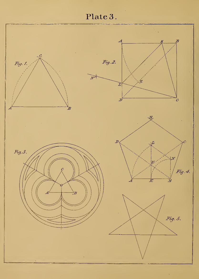
Plate 3
.

Plate 3.
MECHANICS' GEOMETEY.
FiGUEE 1. To construct the equilateral triangle
on a given line, as A B, which take for radius, also
centres. Describe circles cutting each other at C;
join C with A and B, thus producing a figure of
three equal sides.
Fig. 2. To construct the largest equilateral tri-
angle that a given square will contain. Draw the
diagonal B D ; take D as centre, and A radius ; draw
the circle cutting at E; take it as centre, and Aradius ; describe an arc at N, with same radius, and
A centre ; intersect the arc at N, from which point
draw to C ; make B H equal D L;join H C L, and
the problem is solved.
Fig. 3. Here is shown one of the uses to which
the equilateral triangle may be put in describing a
figure called the trefoil, which is often introduced
in the construction of windows and other ornamental
work. Each corner of the triangle, as A B C, is a
centre from which are struck all the inner curves,
and the outer circles being struck from centre, O.
The construction is so simple and self-evident as not
to require further explanation.
Fig, 4. To construct a pentagon on a given line,
as A B, which divide at K, square up from it and
B ; take B as centre, and A radius ; draw the circle
cutting at L, with same centre, and K radius; draw
circle cutting at N ;join it and L ; draw from B
parallel with N L; this having cut at F gives a
point through which draw from A ; make F C Dequal A B
;join C B and D A ; draw from C parallel-
with B D ; draw from D parallel Avith A C, cutting
at H, which completes the pentagon by parallels.
Fig. 5 shows a pentagon. Its sides, being extended,
produce a figure that may be used in ornamental
works.
11
1
Plate 4.
MECHANICS' GEOMETRY.
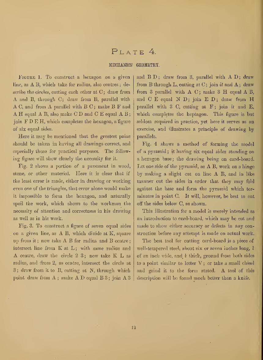
Figure 1. To construct a hexagon on a given
line, as A B, which take for radius, also centres ; de-
scribe the circles, cutting each other at C ; draw from
A and B, through C; draw from B, parallel with
A C, and from A parallel with B C ; make B F and
A H equal A B, also make C D and C E equal A B
;
join F D E H, which completes the hexagon, a figure
of six equal sides.
Here it may be mentioned that the greatest pains
should be taken in having all drawings correct, and
especially those for practical, purposes. The follow-
ing figure will show clearly the necessity for it.
Fig. 2 shows a portion of a pavement in wood,
stone, or other material. Here it is clear that if
the least error is made, either in drawing or working
even one of the triangles, that error alone would make
it impossible to form the hexagon, and naturally
spoil the work, which shows to the workman the
necessity of attention and correctness in his drawing
as well as in his work.
Fig. 3. To construct a figure of seven equal sides
on a given line, as A B, which divide at K, square
up from it ; now take A B for radius and B centre;
intersect line from K at L ; with same radius and
A centre, draw the circle 2 3; now take K L as
radius, and from 2, as centre, intersect the circle at
3 ; draw from it to B, cutting at N, through which
point draw from A ; make A D equal B 3;join A 3
and B D ; draw from 3, parallel with A D ; draw
from B through L, cutting at C;join it and A ; draw
from 3 parallel with A C ; make 3 H equal A B,
and C E equal N D;join E D ; draw from H
parallel with 3 C, cutting at F;join it and E,
which completes the heptagon. This figure is but
seldom required in practice, yet here it serves as an
exercise, and illustrates a principle of drawing by
parallels.
Fig. 4 shows a method of forming the model
of a pyramid ; it having six equal sides standing on
a hexagon base ; the drawing being on card-board.
Let one side of the pyramid, as A B, work on a hinge
by making a slight cut on line A B, and in like \
manner cut the sides in order that they may fold
against the base and form the pyramid which ter-
minates in point C. It will, however, be best to cut
off the sides below C, as shown.
This illustration for a model is merely intended as
an introduction to card-board, which may be cut and
made to show either accuracy or defects in any con-
struction before any attempt is made on actual work.
The best tool for cutting card-board is a piece of
well-tempered steelj about six or seven inches long, I
of an inch wide, and_^ i thick, ground from both sides
to a point similar to letter V ; or take a small chisel
and grind it to the form stated. A tool of this
description will bo found much better than a knife.
12

Plate 4. .


Plate 5.

Plate 5.
THE OCTAGON.
FiGUKE 1. To construct an octagon, one of its
sides being given as A B, from which square up two
lines. Take A B as radius, also centres; draw the
circles cutting at C and J ; draw from A B through
C J ; again from A draw parallel with B J ; draw
from B parallel with A C ; make B V and C Eequal A B; join E V ; make C F equal C A ; square
over F N;join F E ; draw N P parallel with A C
;
join P B.
This completes a figure of eight equal sides, or
octagon. The same may be quickly done by using
both a J and set-square, the latter having an angle
of 45° as shown.
Fig. 2. To work the octagon in a practical way.
This means that if a piece of square timber is given,
and it is required to work it to eight equal sides,
proceed by drawing a line from corner to corner, as
A B ; make A C equal one side of the square, as
A D ; square over C K ; set a gauge to B K ; run
this on sides of stuff; work off the .corners, and we
have eight equal sides.
Fig. 3. To construct a scale by which the side of
any octagon is known at once. .
Commence and make any right angle, as that from
A; take it as centre, and with any radius draw the
quadrant E H ; divide it at C ; take C as centre, and
with any radius make an arc at L ; with same radius
and centre H intersect the arc, through which draw
from A, and the scale is complete. To prove it, make
A N equal A N, Fig. 1 ; square up from N, cutting
at D ; then N D is found equal to A B, Fig. 1. As
a further proof, make A B equal A D, Fig. 2
;
square up from B,- catting at L ; then B L equals 2
L, Fig. 2.
This simple method gives the side of any octagon
without drawing the whole figure^
17

Plate 6.
TO FIND THE CIRCUMFERENCE OF A CIRCLE.
Figure 1. To find a straight line that shall equal
a quadrant or semicircle. Take A B radius, and Acentre ; intersect the circle at C
;join it and B
;
draw from D, parallel with C B, cutting at H ; then
A H will be found equal to curve A D.
This method is somewhat different to that already
given ; both, however, are practical.
Fig. 2. To find a straight line which is equal to
the circumference of a circle. ' Draw from centre, O,
any right angle, cutting at J and V ;join J V
;
draw from O parallel with J V; square.down from
J, cutting at N ;join it and V ; then four times N V
will be found to equal the circumference.
I am not aware that this and the previous simple
methods have ever before been given in any publi-
cation.
18

Plate 6.


Plate 7.

Plate 7.
TO DRAW PARALLEL LINES; AND BISECT IRREGULAR ANGLES!
Figure 1. To draw a line parallel with a given
line, as A B. Take A for centre and C radius ; draw
an arc through point C, then, with same radius, take
any point on given line as B ; draw the arc D ; now
draw through C D, and the line is parallel with that
of AB.Fig. 2. SECOND METHOD.— Assume A B as
the given line, and C a point through which a paral-
lel is to pass ; draw through C, at any angle, cutting
A ; take it as centre, and, with any radius, draw arc
V V ; with same radius, and C centre, draw arc JV
;
make it measure equal to that of V V ; then a line
drawn through C V is parallel to that of A B.
Fig. 3. To bisect acute or obtuse angles, extend
line C A ; take A as centre, and with any radius
draw an arc, cutting at N L, which join ; draw from
A, parallel with N L ; draw from C ; square with line
from A, cutting at H, and angles A C are bisected.
Fig. 4. To bisect acute or obtuse angles when two
of the sides are not parallel, as is the case here. For
example, the lines D E and E. X are sides ; then
extend the end E. D, and side X B ; take D as cen-
tre, and with any radius draw the circle, cutting at
E F, which join; draw from D, parallel with FE;this done, come to B, take it as centre, and with any
radius draw the circle, cutting at K J, which join;
draw from B, parallel with K J, intersecting line
from D at P : thus the angles are bisected.
This will be found a valuable and useful problem
in laying out framing, mitring mouldings, finding
the seats of hip-rafters, and it may also be applied
to many other practical purposes.
23

Plate 8.
TO HOT) CURVES OP ANY SPAN AND RISE WITHOUT USING A CENTRE.
Figure 1. To construct an arch of any span and
of any rise without using a centre. For example,
assume A B as the span and O O as rise. Now take
a piece of board, as that of Fig. 2 ; draw on it a semi-
circle ; make its radius O O equal rise of arch ; set
off from each side of O on circle any number of equal
parts, say four ; and in like manner set off four parts
on each side of O, at base;join the parts on base and
circle by lines, as 1 1, 2 2, 3 3 ; these lines are drawn
to cut upper edge of board, as shown.
Now come to span or chord A B, and set off on
right and left of O four parts ; bring upper edge of
board, Fig, 2, against the chord A B ; make line 1, 1
through semicircle come opposite point 1 on chord
A B ; extend the line by a straight edge, and make
distance 1, 1 equal to 1, 1 on- semicircle; move the
board until line 2 2 comes 6pj)0site point 2 on chord
;
draw line 2 2 in the same direction as that of 2 2
through semicircle ; make the distance of both equal
;
slide the board along the chord in this manner, and
mark lines from the chord in the same direction as
those through semicircle ; then corresponding letters
and distances of both being the same gives points into
which drive nails as a guide to bend a strip ; mark
the curve by it, and the work is complete.
This method will be found more simple and more
reliable for large or small curves than any other that
has yet been devised.
Fig. 3. To construct a flat curve or arch, its span,
say sixteen feet and its rise only two inches. Take, for
example, the camber on a joist or beam. To do this
by a practical and ready method, have a board of
sufficient length and parallel width, joint one edge
;
divide the length into two parts, as line L ; divide
the joist in like manner, and from' the top edge of
it, at the extreme ends, set off two inches, as A B
;
drive a nail into each ; lay the . board on, and
bring its jointed edge against the nails ; then force
lower edge until its upper edge L reaches point
N. Now mark the curve A N B, which is- the
camber required.
Here it is understood that the method just given is
for a pattern by which a flat curve may be marked
on joist or anything else ; the span, of course, being
limited to length of board, which bends and forms
the curve.
24

Plate 8.


Plate 9
.

Plate 9.
THE CONE.
FiGUEE 1. Shows the base of half a cone, its sides
terminating in point K. Perhaps there is nothing
that a workman should be more thoroughly conver-
sant with than that of cov^eriug a cone. It is of the
greatest service to joiners, masons, metal plate-work-
ers, and, in fact, every one connected with building
trades. But, to give some idea of. its value, suppose
we are required to bend a j)iece -of metal, board, or
any other material to a curve, and it to stand on a
given slant. For example, take the back of a pew,
or even a tin dish with slanting sides, and scores of
other things ; all have a simple construction, that
must be understood before any attempt can be madeto give the material the desired shape. But, to ex-
plain this ix)int, let us show the method by which
the covering of a cone is obtained.
Take K as centre, and A radius ; draw the circle
AY L ;• divide the quadrant A B into say nine, or any
number of equal parts ; set off the same from A to.V ;
make V L equal V A ; take any width for covering,
say A 2 ; draw the curve 2 T. This completes the
work ; and it is certainly simple, considering what
has been said of its importance. But let us examine
the matter a little further by cutting a piece of card-
board in the shape given for covering, then bend its
edge AVL around the base ABC. Here notice
that the lower edge, although curved, yet comes to a
perfect level, and the face of the card-board stands onslant A K. This could not be ' done without somerule, and that just given is the one usually adopted,
and a correct one.
But it sometimes happens that the work having a
conical form and of large dimensions where it wouldbe not only inconvenient but almost impracticable to
find a centre for striking curves on lower and upperedges of the work ; in such cases other means thanthose given must be used. The following new andsimple problem obviates all difficulties.
Fig, 2. Let A B be the radius for base of work ; or
have it equal A D on the left, draw slant A D, ex-
tended, the slant having cut the circle at D, from
which draw square with A B ; draw from B square
with slant cutting line from D at V; draw from Athrough V, cutting circle at C ; square down from it,
cutting line from B at L ; make D N equal C L.
This gives A N for half the chord, and is proved to
be correct because it equals that of A N on the left
;
again D V is the rise ; this is also proved correct by
it being equal to N V on the left.
Here it is noticed that radius and slant at both
places are alike, and purposely made so in order that
this new problem may be tested.
The distance A P is radius; but it is not required,
as we are assuming the work to be. on an extensive
scale where no centre can be used.
Fig. 3 shows the practical application of this new
method. Let H H be the edge of a board which is
to be curved in order to fit a circular base of a dome,
cone, or slanting back for a circular pew. In either
case, when the board is bent, its edges are to be level.
To find the curve. Have a piece of board' as shown,
and draw on it a semicircle, with radius A V, which
corresponds with D V, Fig. 2 ; divide the circle on
each side of V into any number of parts, say four,
and in like manner set off on each side of A four
equal parts; join the parts on circle and base by
drawing lines, as 1 1, 2 2, 3 3. Now set off rise Y Aon the board which is to be bent ; draw through Aparallel with H H ; make A N on right and left
equal A IST, Fig. 2 ; divide AN on right and left into
four equal parts, as 1 1, 2 2, 3 3 ; now slide the board
with semicircle along the edge H H, and at the same
time make line 1 1 ; cut point 1 on chord N N ; con-
tinue in this manner until the lines on face of board
are drawn, and in the same direction as those on
semicircle; make distance 1 1, 2 2, 3 3, on right and
left equal corresponding distances and figures of
semicircle ; thus points are given to drive nails,
against which bend a stiip and mark the curve ; the
edge being worked, draw the width parallel with
worked edge ; both edges fall to a level when the
board is bent, and stand on slant A D, Fig. 2,
29

Plate 10.
THE SEMI-ELLIPSE.
Figure 1. To construct a semi-ellipse by means
of a string and two pins..
Nearly every one knows this problem. It is indis-
pensable to the joiner, stair-builder, mason, metal-
worker, and even the gardener. The operation is
simple. All that is requisite being at hand, namely,
two pins, a linen thread or fine cord. The method
is as follows : Assume A B as long diameter ; divide
it at 2 ; from which point square up a line, as 2 E
;
call this short diameter ; take A 2 as radius ; with
same radius and E centre intersect long diameter at
C and D ; these are points into which fix two pins
;
tie a string to pin D ; bring it around pin C ;place
the finger on string ; stretch it with a pencil, making
its point touch E ; now sweep the curve to B ; re-
turn to E, and complete the curve to A. This
operation is done best by having a notch in the
pencil near its point in order to keep the string
from slipping.
Fig. 2 shows a method for describing a semi-ellipse
by means of a rod. The two diameters, as A B and
2 L, being given, take a rod and mark on it the dis-
tance V N, which is equal to half of long diameter
A 2 ; make V T equal short diameter 2 L ; lay the
rod on ; keep mark T on line A B,. and mark N on
sliort diameter ; move the rod a short distance, keep-
ing T and N on diameters ; mark a point at the end
of rod V; continue in this manner marking any
number of points, through which trace a curve by
ben'ding a strip, and we have a semi-ellipse. This
method answers to check any defect in the elliptic
curve when drawn by a string, which might happen
if the operation is done in a careless manner. Some
adopt the method of having two brad-awls through
the rod at marks T and N ; the awls work against a
fence which is fastened on the two diameters. Both
these methods are tedious and not equal to the string,
which is quick, practical, and off-hand.
Fig. 3. To find tangents on any part of an elliptic
curve. Let A B be the long diameter and 2 N the
short ; take A 2 as radius ; with same radius and Ncentre intersect long diameter at C and D. Now find
a tangent at any point, say L; join it and C; draw
from D parallel with L C ; take D as centre and Las radius ; draw the circle cutting at P ; draw from
it through L, and we have a tangent. Assume any
other point, say J;join it and D ; draw from C
parallel with J D ; take C as centre and J as radius
;
draw the circle cutting at T ; draw from it through
J, and a tangent is the result. It is understood that
long and short diameters must be at right angles for
every ellipse; therefore a tangent, as that through
N, it, and the short diameter, must always be at right
angles, as shown.
30

Plate 10
B
F^'.2. 2<
Tcutffervt p /T


Plate 11
.

Plate 11.
TO CONSTRUCT SLANTING WORK STANDING ON A CIRCULAR BASE.
This plate shows a practical construction by which
the joiner is directed in finding the form of boards
or framing that stand on a slant around a circular
base.
Fig. 1 shows the problem by which the metal-plate
worker cuts and shapes his material in forming a
can, a- circular flange, a tapering pipe, or anything
having the form of a cone,— even the sailor uses it,
or something similar, in finding the shape of a piece
of canvas that will slant from the deck and inclose
the mast as- a protection against leakage. Many
other purposes might be named to which this valu-
able problem applies. To illustrate it, let us con-
sider the large circle as the base of a cone, its upper
part cut off, making the small circle C D. We now
want to find a covering that will go around the large
circle and stand on a given slant. To do this, draw
diameter A B, Square up from E D B. Take any
point, as K, square over from it to J. Beturn to K,
and draw from it the slant which the work is to
have, say that of K L. This line, having cut the
perpendiculars from the base at L F, gives L K as
width of covering and J L as perpendicular height
of work, and F as centre to strike the curves through
L K, which being done, divide the quadrant A H at
Fig. 1 into any number of parts, as seven ; set ofi" the
same from V to P on left of Fig. 2 ; make P B equal
P V ; set off V P B on the right to equal corre-
sponding letters and distances on the left; draw
through B R on right and left, and the covering is
complete. If the work is to be in metal, then allow
for a lap, as indicated by dotted lines.
To have a practical illustration of this problem,
take a piece of stiff paper and cut it to the shape of
covering ; this being done, bring the joints E B to-
gether, which contracts the circles and makes their
diameters just equal to those of A B and C D at the
base of Fig. 1. We also see that the side stands
exactly on the given slant K L.
This practical method shows how easy and simple
the means are by which we can accomplish some of
the most difficult kinds of work in either wood,
metal, or stone. Understand that this problem is
not limited to the few useful purposes just named,
but it is equally applicable to many other branches
of art.
35

Plate 12.
THE PYRAMID IN CARD-BOARD.
To construct a pyramid, which means a figure with
a square base and slanting sides.
This and similar forms frequently occur in the
practice of joiners, masons, and metal plate-workers.
Fig. 1 shows the base ; erect on one of its sides the
triangle A B V ; draw from A and B through V
;
draw from it parallel with A B ; make V F and VS, also V H, equal A B
;join A F S H ; the four
sides of pyramid are now spread out ; these, when
in position, inclose and terminate in j)oint V, as may
be clearly shown by having the drawing on card-
board and cut; but before this is done, one or two
other important points should be known, nainely, the
slant and perpendicular height of sides ; these are
found by squaring up from B and drawing V Lsquare with A B ; take L as centre and V radius
;
draw the circle cutting, at E; draw from it through
L ; then E L is slant of sides, and B E their perpen-
dicular height. Now suppose the sides are to be
mitred at each angle; this would require a bevel,
which is found by making B C equal B L ; take B as
centre, and for radius a circle touching L E, cutting
at D;join it and C, and you have the bevel, as shown.
It may, however, be that the sides are not to
mitre. In that' case the sides make butt-joints, and
for which a bevel has to be found to apply on edges
of work ; L K, being square with slant.
It is obtained by taking any point, say R; square
down from it, cutting at P ;. take K as centre, and for
radius a circle touching L K, cutting at J; 'join it
and P, thus giving the bevel shown to be ajoplied on
edges of sides.
This completes a very iinportant construction,
which may be more fully understood by cutting clear
through three sides of a square base, and a slight cut
on line A B, so as to form a hinge ; this done, cut
clear through B .V H and all outer lines from Hdown to A ; now make a slight cut on line V S and
V F, also V A. These cuts form hinges ; lift the
piece and fold the sides on base, and the result is a
model of a pyramid having its base square, its sides
slanting, and terminate in a j)oint. This and similar
illustrations, by means of card-board, is of more jorac-
tical value to workmen than a hundred drawings on
a flat surface, which may not be understood by more
than one out of ten.
36

Plate 12.

1


Plate 13.

Plate 13.
CONSTRUCTION OF A TRIANGULAR PYRAMID.
Iif order that the actual construction of any piece
of work may be fairly and clearly understood by
young beginners or learners, we have cut a few
models for this publication, which will show how
simple the means are of forming them out of card-
board, and the great advantages to be derived from
such practical illustrations.
The construction on this plate is simply a pyramid
in the shaj^e of an equilateral triangle. It will be
observed that any of the triangles forms a base, as
may be seen by lifting the piece and folding it from
you. This to some might appear trifling, and of
little moment ; such, however, is not the case, as will
be seen by laying the piece in its original position,
that we may exj)lain its construction.
Let A B C be the base. Draw through C parallel
with A B ; make C H and C L equal A B ; draw
from H L through A B, intersecting at F. Here
we have four equal triangles, three of which form the
sides of pyramid.
It is now requii-ed to show slant of sides and per-
pendicular height of work. To do this, draw from
B, square with A C, cutting at D ; draw from C,
square with A B, cutting at 2 ; draw from it square
with D B ; take B as centre, and C as radius ; draw
the circle, cutting at 3; join it and D ; this gives
3 D as slant of sides, and 2'3 for perpendicular height
of pyramid.
Now su|)j)ose the sides are sejDarate pieces of wood,
stone, or metal, and these are to be mitred. To do
this. Work the lower edge of base by bevelW ; this
being done, apply bevel N, and mark the mitre on
edge which has been worked. Thus a direction is
given to mitre the sides with the least possible trouble.
41

Plate 14.
TO CONSTRUCT SLANTING SIDES TO STAND ON AN OCTAGON BASE.
The material may be either wood or sheet-metal
;
if the latter, the sides and base may be in one piece.
The intention here is to have the drawing on card-
board, and cut in such a manner as to form a perfect
model of the work, by which means the learner sees
the necessity of being correct in drawing every line
;
for, if the work is done properly on card-board, it is
evident that the same practice applies to any other
material, be it wood, stone, or metal.
The octagon base being given, we must now have
a bevel for cut on face of slanting sides. It is found
by drawing a line through any two angles of the
base. For instance, draw . from 2 through F ; take
any point on the line, say P ; draw through it parallel
with F L ; now determine on slant of sides, say P K
;
take any point as C, square down from it, cutting at
D ; take it as centre, and C radius ; draw the arc of
circle, with same radius and P centre ; draw arc A K
;
make it and arc C K equal ; draw from K square
with C D, cutting at S ; square up from it, cutting at
V ;join it and D. This gives bevel W, to apply for
cut on face of sides. Let us now find a bevel for
mitre on edge of stuff. To do this, draw P T square
with P K ; take C as centre, and for radius a circle
touching P T, cutting at J ; draw from D through
J; this gives bevel X for mitre on edge of stuff.
The drawing being on card-board, and intended for
a model, two of its sides, as H H, on right and left,
are hinged to the base by making a slight cut on
line H H. The bevel W being applied as shown,
gives the cut on face of sides. Their position as spread
out is found by drawing equal circles on each side as
shown. The same, however, may be done by having
a pattern, which is obtained by bevel W.
All that now remains is to cut clear through the
outer and inner lines ; this done, make a slight cut
through each joint, in order to form a hinge. The
cutting being done, lift the piece, fold the sides from
you on the octagon base, and we have a correct model
, of the work.
i
12

Plate 14


Plate 15

Plate IB.
TO CONSTRUCT SLANTING SIDES TO A BASE HAVING RIGHT ANGLES.
Figure 1. The practical solution of this problem
is before us. The card-board having been already
cut to represent the actual work, lift the piece and
fold the sides from you. Here we have a perfect
model. Examine it thoroughly, and think for a
moment if this practical illustration could be given
by mere cutting and guessing, and without rule or
guidance. Certainly not
!
Then the next question is : Is there any advantage
in knowing how to solve this or- any other problem
correctly ? Yes, many !
In the first place, it requires judgment and
consideration to do anything which has a cout
structive principle ; and those who are most ex-
pert and conversant with it are entitled to more
respect and better wages than others who never
think at all.
But, to say nothing of either respect or reward,
there is a positive satisfaction in knowing that we
have the ability and power to do and act when called
upon.
Now, my young friends, if you wish to be skilful
and expert workmen, look to this matter, and by all
means endeavor to make yourselves thoroughly con-
versant with the teachings already given, and those
that are to follow.
The model having been examined, lay it in its
original position, in order that we may explain its
construction, which is shown at
Fig. 2. Here draw any line for a base, as that of
A B; now determine on slant of sides which the
work is to have, say B C ; take any point on A B,
as D ; draw through it square with A B, cutting at
C; square down from B; take C as centre and Bradius ; draw the circle cutting at E ; draw from it
parallel with D B, cutting at F; join it and C; this
gives bevel W to apply on face of sides, as shown on
model. We now want a bevel to apply across the
edges of stuff for mitres. It is found by making DA equal D B; take D as centre, and for radius a
circle touching B C, cutting at L; join it and A, and
we have bevel X for mitres. It is understood that
edges of stuff are to be square.
Here it may be mentioned that this same construc-
tion gives the cuts for sides and edges of hoppers or
boxes. It also gives the side and down cut for jjur-
lins, or any kind of framing which stands on a slant,
the base of work being square.
47

Plate 16.
ROOFING.
To find the covering of an irregular roof; also
lengths and cuts of liips and rafters.
This problem is of equal importance to the carpen-
ter as well as the metal jDlate-worker. Let us sup-
pose that the covering is to be sheet copper, which is
not unusual for roofing. Then it is evident that
some 230sitive rule must be known before any attempt
is made at cutting the material, otherwise the waste
would be enormous ; besides, the work could not be
satisfactory and might be justly condemned.
Here, however, is given a construction which is
plain and simple that obviates all difiiculties. It is a
rule that any one can understand. It not only gives
the covering, but the lengths and cuts of every rafter.
The irregular ground plan of this building is shown
by the letters A B C D. The covering of roof is now
spread out, the drawing being on card-board and
already cut, so that you may lift the piece and fold
the covering from you. Bring cuts E E and A Wtogether ; let the piece in the form of a wedge fall
level. Here we have an exact model of the roof;
its sides are out of wind; its, heights are equal; its
hips are regular. Nothing can be more satisfactory
than this ; it is a self-evident and practical fact before
us. Such being the case, then, it is clear that the
same rules which j^i'oduced this model will also give
lengths of hip, jack, and common rafters, and all the
bevels for cuts.
Keplace the model in its original position, and let
us explain the construction, as follows
:
In the first place bisect angles A B, and through
intersections thus made draw seat of hip-rafters meet-
ing at L ; draw from it parallel with A D and B C
;
take any j^oint on line DC, as Y ; draw from it
square with D C ; make Y K equal Y L on the left
;
draw through K, parallel with D C, cutting lines
from L at K H;join D K and C H. These are
seats of hip-rafters.
. Now determine on rise of roof, say N T ; this gives
T P for lengtli of rafters between hips L H and L Kon both sides of roof. The same length answers be-
tween H K, because Y K is equal to N P or Y L on
the left ; make the rise of hips at L K H equal rise
of roof, as N T.
Now find the covering for side B C, and end C Dby drawing from L H K square with B C ; makeP V equal P T ; draw through V parallel with B C,
cutting lines from L H at F and J; join FB and
J C. This completes covering for side B CTo find the covering for end D C, take C as cen-
tre, and with any radius draw the circle shown ; makeit measure equal on each side of C J ; this gives a
point, as X, through which draw from C ; make C Requal C D ; draw from J parallel with C E, ; makeJ E equal K H
;join E R ; make 2 3 equal K T
;
join 2 J and 2 F. This completes covering for one
side and end.
To find the covering for side A D, and end A B
;
draw from L K, square with A D ; make L S equal
L F ; draw from S j)arallel with A D, cutting at O;
join it and D, also S A.
Now find the covering for end A B by taking B Fas radius ; with same radius, take S for centre, draw
the arc of a circle at W ; take A as centre, and Bradius ; intersect the arc at W, thus giving a point
;
which join with A S. This completes the covering;
its accuracy having already been tested by the model,
which would not have come together had there been
any error in the construction.
The covering, of course, gives bevels for side cuts
of jack-rafters. For examj)le, bevel 4 is side cut for
rafters on each side of hip C J, its seat being H.
Again bevel 5 is the side cut for. rafters which come
against each side of hip that stand over seat D K
;
and bevel 6 gives side cut of rafters on both sides of
hip that stand over seat A L ; then bevel 7 gives
side cut for rafters which come against both sides of
hip that stand over seat B L ; lastly, the bevels for
down and foot cut of all the rafters are the same as
that for common rafter P T ; hip-rafters not included.
The angles which they make contain these bevels.
It hns, we think, been shown that the carpenter and
metal plate-worker are equally interested in the solu-
tion of this and similar problems, which clearly teach
and explain every difiicult point by means of card-
board models ; it is the only way that will satisfy
any inquiring mind who wishes to know the reason
why.
48
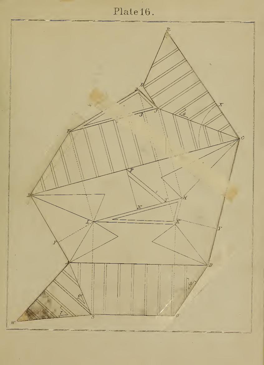
Plate 16.
rv


Plate 17.

Plate 17.
CONSTRUCTION OF AN OBLONG WTTH SLANTING SIDES.
FiGUKE 1. The letters' A B C D show an oblong
base which is to have slanting sides; these, when
itogether at the top, form a square of any given size,
as that shown on base.
Now, it is very evident by this arrangement that
sides and ends must stand on different slants; in
other words, let us suppose a metal or wooden box,
with oblong bottom, slanting sides and ends, and the
top square. If the material is to be metal, then the
whole work may be cut out of one sheet, which
means bottom, sides, and top all connected. This
understood, the construction is as follows
:
Extend upper side of square, cutting at E on the
right; make E F equal E B. Now determine on
perpendicular height of sides and ends, say E K
;
join K F ; make O N equal K F, square over N J,
join J A and X B : this gives one side of the work.
Next find slant of ends by making B V equal B N,
square down from V to L, join L B : this gives bevel
W as the cut for ends. The bevel being reversed
and applied as shown, gives a direction to draw B P,
which make equal B C; draw from N parallel with
B P, make N S equal one side of top as N T,
' join S P; draw from S parallel with N J; make
S T on the left equal S T on the right; join S J;
draw from A parallel with J S ; make A Y equal
AD; join Y S. This completes one side and both
ends.
To find the side which stands on the base D C.
' Take bevel X, already given, and apply it as shown
at P ; or take B for centre, and with any radius
draw the circle 2.3 ; with same radius and P centre,
draw 2.3 ; make both circles equal ; draw from Pthrough 3 ; make P E. equal A B ; draw from S
;
parallel with P B ; make S 4 equal S N;join 4 B.
I
This completes sides, ends, and top.
To have a correct idea of this construction, let the
drawing be made on card-board ; tben cut it clear
through all the outer lines. This done, make side
and base work on a hinge by a slight cut on line
A B ; make a similar cut on A J and B N ; also on
P S and N J.
Now lift the piece and fold its sides and ends from
Iyou ; bring the joints R 4 and S Y together ; make
the top fall level, and we have a perfect model of the
work.
53

Plate 18.
CONSTRUCTION IN SHEET-METAL OP A HOLLOW PIPE AT RIGHT ANGLES.
Figure 1 shows the elbow of a hollow pipe stand-
ing at a right angle. The object here is to give the
form of sheet-metal for mitre-joints of pipes.
This problem being nothing more than that of
finding the covering of a cylinder which has been
cut obliquely.
To understand this is just as much the business of
a carpenter as a metal-plate worker— both are
equally interested.
The construction is quite simple, and is as follows
:
Fig. 2 shows the base of a hollow pipe, its diame-
ter being A B. It is now required to find the shape
of two pieces of sheet -metal which, being rolled
and connected, will form a mitre -joint, as that of
Fig. 1. .
To do this, square up from B ; make B C equal BA
;join C A ; divide the semicircle into any number
of equal parts, as six ; draw through each part square
with diameter, cutting it and line A C. This done,
come to Fig. 3. Here draw any line, as L K ; take
any point on it, say B ; set ofi* on each side of it six
equal parts, each to equal one of those on semicircle,
Fig. 2 ; square up all the divisions on line L K ; make
B C equal B C, Fig. 2 ; make all the heights on each
side of B C equal corresponding heights and letters
at Fig. 2. This done, trace through the points a
curved line, as shown, and we have an exact pattern
by which the metal is cut, making two pieces, as that
of Fig. 3 and Fig. 4 ; these being rolled into j)ipes,
the edges form mitre-joints, and these being brought
together and fastened, form the elbow standing at a
right angle.
It is easy to have a practical illustration of this by
having the drawing.on card-board, which cut and roll
in the manner stated, and the result is a model of the
pipe or two sections of a cylinder cut obliquely.
It will be noticed that parts of the curve may be
struck from centres, as shown.
54

Plate 18.
Fig.-^.
m


Plate 19.
^
\
\
\
\
\
\
\ ^ ~-HV
I
1
1
1
t
1
I
1
1
\ ^r^ \"~^^-^^
1
1
1
\
\ ^/1
/ -^ t
1
1
\ ^'^\ ' i^v.~^^-# 1
1
\l_Jj^-^ V
; |\^^^__z\J' S F A7 J)
\
\
\
1
1
DBF ^ J
\
\
1
1
1
1
1
F^.,2.,
A J R F E n :b

Plate 19.
SECTIONS OF HOLLOW PIPES.
Figure 1. To find the form of sheet-metal for
mitre-joint of a hollow pipe standing at any angle.
Here it will be noticed that this construction is al-
most similar to that given on preceding plate. The
same rule applies to all angles, on condition that the
pipe is i^arallel, and of equal diameter at each end, as
in this case.
The assumed aus:le here is B L X, and the mitre-
joint L K. The diameter of pipe being A B ; draw
A C parallel with K L ; divide the semicircle into any
number of equal parts, say six ; draw through each
part square with diameter cutting it and line A C.
This done, come to Fig. 2. Here draw any line, as
L L ; take any point on it, as B ; set off on each side
of it six parts, each to equal one of those on semi-
circle, Fig. 1. Square up lines from each division on
L L ; now make B C equal B C, Fig. 1 ; also make all
heights on each side of B C equal corresponding
heights and letters of Fig. 1. Thus points are given
throuofh which trace the curved line.
Here it will be observed that parts of this curve
may be struck from centres, as shown.
We have now a pattern by which the metal is
marked and cut, thus giving two pieces having
curved edges, which form mitres when the metal is
rolled into pipes; these being connected, form the
angle B L X, Fig. 1.
The practical solution of this problem may be had
by cutting a piece of paper to curved line, as drawn.
The cut making two pieces, roll these into the form
of pipes ; bring the mitres together, and we have the
model of an elbow, making the required angle B L iN".
The dotted lines from L L on right and left, are
overlaps for sheet-metal.
59

Plate 20.
HOLLOW PIPE IN THREE SECTIONS.
Figure 1. To construct a pattern by which sheet-
metal may be cut to form the elbow of a pipe in
three or more sections. The solution of this prob-
lem differs but little, if any, from those already given.
The three pieces of pipe may be considered as three
sections of a cylinder which have been cut obliquely,
each piece in the form of a blunt wedge ; these, on
being brought together, form a solid elbow, which
shows the problem to be nothing more than that of
finding the covering of sections cut in the manner
just stated. This is done by the following rule
:
Draw any line as 2 P parallel with diameter A B
of pipe ; take any point as P, and draw the quadrant
2 N, which divide into four equal j)arts ; draw from
P through each part, square up from 2, cutting K
;
then square over from N, cutting L; join it and K;
draw A C. parallel with P K, divide semicircle A B
into six parts ; draw through each part square with
diameter A B, cutting it and line A C
Now come to Fig. 2. Here draw any line as that
of L L ; take any point on it as B ; draw through it
square with L L ; set off on each side of B six j^arts,
each to equal one of those on semicircle, Fig. 1 ; make
L K on. right and left equal K L, Fig. 1 ;join K K
:
this done, square up divisions as shown from line
L L, cutting line K K ; make B C equal B C, Fig.
1 ; also make all heights on each side of B C, above
line L L, equal corresponding heights and letters at
Fig. 1.
Points are now given, indicated by letters, through
which trace the curve for pattern; this being cut,
turn it over ; keep line L L on that of K K, Now
mark curve K V K, thus giving Figs. 2, 3, 4 as the
shape of three pieces of sheet-metal; these, rolled
into pipes, are three sections which form the elbow.
Here notice that the distance C V, at Fig. 3, is equal
to P V, at Fig. 1, and, further, observe that parts of
curve may be struck from centres.
60

Plate 2 .
\
/ \
1t
1
\Fz^.^.
1«-
4
I1 "^
/ ^\ 7—-^
\ 1
/ [
I f 1
1 / ,
1 ' 1
,/ *
J/ '
"J^^^"^ 1 1 ^ ' '
/ 1 ^~^^--~_[_______^>^-—-^ 'I t * /
1 • \ \ A
1 A
/ j
i2? £^~~A''^^^-"^ ~\-~-
/ 1
/ !
/ 1
\ 1 J^1 \ 1
^K^i
/'i \
k1JJ^^^ \ , /'
i 1 ^"^"--*i__\^\/ ^ s F £ \D
1
' B F S J
'\
//
/
/
/
//
//
F^.2.
• \
I
/
/
/ < •
2
Iiff.7.


Plate 21.

Plate 21.
THE PRISM AND ITS SECTION.
To find tlie section of a hexagon prism which, has
been cut obliquely to any angle not parallel with its
base. The meaning and use of this problem will be
best understood by having the drawing on card-
board, which, being cut as directed, will form an
exact model of a prism and its section. The con-
struction is as follows
:
Fig. 1 is the base, and Fig. 2 shows six sides of
the base unfolded or spread out. Take one of the
sides as T E, and draw on the upper part of it any
given slant, say L B ; extend this line ; then draw a
line from A, Fig. 1, cutting the slant at J ; square
over from it cutting at K ; draw from B and L par-
allel with J K, cutting at D and P on the right
;
join B K and K D P ; this done, make L H on the
left equal C K above ; draw through H, cutting at
N and B.;join B P on the right and N L on the
left ; now draw from L B J square with slant ; this
done, make J A equal O A at the base ; draw A Yparallel with slant; make W Y equal V A and
make V S equal V B ; draw S X ; now join X Y Land SAB. This completes the section, and shows
its exact form as made by the cut through L B,
which is on one side of the prism.
Let us now produce the model by cutting clear
through all the outer lines ; make the section work
on a hinge by a slight cut on line L B, and in like
manner cut the base on line E F. Also a slight cut
on each line representing the sides, in order that
they may work on a hinge. This being done, lift
the piece and fold its sides against the base, and
make the section rest on the sides ; thus a model is
formed by means of a simple construction which
should be known by metal-plate workers and others.
65

Plate 22.
THE ELLIPSE AND SECTIONS OF SOLIDS.
Figure 1 shows a method to describe the semi-
ellipse from three centres. Here it may be observed
that this or a similar figure cannot be drawn cor-
rectly by means of compasses ; and yet it is near
enough for many practical purposes, and in some
cases it is even preferable to the exact figure, as will
be shown presently.
Here the long diameter is given as A B, which
divide at C; draw through it square with A B;
assume C D as the rise ; square up from A ; make it
and E equal C D ; divide A E at N;join it and D
;
divide A C at H ;join it and E, cutting line N D at
V. Now bisect V D, and draw through intersec-
tions thus made, cutting at O;join it and E. This
line, having cut long diameter at L, gives it for a
centre. Make B P on the right equal A L, and we
have O L P as three points or centres from which
the curves are struck, as shown.
The figure just drawn is a near approximate to
being correct, and we shall use it, as above stated,
for several constructions yet to follow.
Fig. 2 is the base of a cylinder inclosed by a
square. The object here is to show that if a cylinder
is cut obliquely, its section must be elliiotical ; and,
on the other hand, if the oblique cut B C is through
a square prism, its section must be a rectangle or
obloug. But to have a clear perception of this, the
learner is advised to use card-board : it being cut and
folded as directed, gives a model by which every-
thing is understood at a glance. To do this, set off
from R two sides of the square and one from P on
the left ; this done, square up sides of prism, as
shown ; take any point on line from P, say A ; draw
from it parallel with P B, cutting at A on the right.
Now assume the slant or oblique cut as B C ; make
A B on the right equal A B on the left;join B F
;
draw from B and C square with slant ; make C Eequal C A ; draw from E parallel with slant, cutting
at S ; this gives B C E S as the section of a square
prism made by slant cut B C. It is also clear that
if a cylinder is cut in like manner, its section must
be the elliptical figure shown. This will be quite
evident by cutting the card clear through all the
outer lines of the drawing, and making a slight cut
on lines B C and P E.. In order to form a hinge for
each piece, make a slight cut on line P A B, and in
like manner on R C, also K F. Now lift the piece
and fold its sides on square base, turn the section on
its hinge B C until line E S rests on cut F B, and
we have the model of a square prism, also its section
and that of a cylinder made by cut B C.
This illustration, being on card-board, conveys
more instruction to the mind of the learner, as to
what is meant by the sections of solids, than any
other means. In our own experience, we have found
the card-board to possess every advantage over the
old " wooden block " system. The material is inex-
pensive and readily obtained ; it is quite manageable,
requiring simply a knife to cut, and in cutting it
forms its own hinges. In fact, its entire superiority
occasions surprise that so simple and clean a substi-
tute has not been generally adopted long since.
66
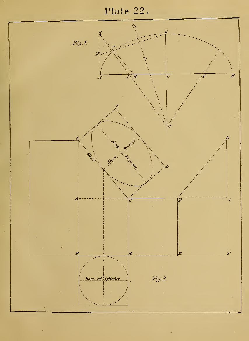
Plate 22.
Fi^J.
J)
o
o
R r


Plate 23

Plate 23.
SECTIONS OF HOLLOW CONES.
To find the mitre-joint for a tapering pipe similar
to figure shoAvn on upper part of plate to the right.
The only difference in this construction fi'om pre-
vious plates is, that here the pipe may be considered
a hollow cone, for which we are to find a covering;
and also show the form of a curve that will make a
mitre-joint for an elbow. This we can readily do by
the followincr method
:
Fig. 1. The semicircle on the risrht shows half
the base of pipe, its diameter being B B. Assume
the taper as meeting in point A. Xow determine on
angle of mitre, say forty-five degrees, which is that
of B P on semicircle. The next question is the
portion of pipe where the elbow mitres, say line C D,
which is parallel with that of B P ; divide the semi-
circle into any number of parts, as six ; draw from
each part square with diameter B B, cutting it at
points 0, and from each of these draw in
the direction of point A, cutting line C D, and from
which intersections draw parallel with B B, cutting
slant A B at X L K J, etc.
Now come to Fig. 2. Here draw any line, as A P
;
make it equal A B, Fig. 1 ; take A as centre and Pas radius ; draw the curve through P ; set off on
each side of P six parts ; make each part equal one
of those on semicircle, Fig. 1 ; this done, draw from
A, cutting at each point on curve through P, ending
at B on right and left, which is equal to the circum-
ference of pipe at its base ; make A C on right and
left equal A C at Fig. 1 ; again make A F E equal
A F E, Fig. 1. Continue in this manner until points
are found, through which trace the curve as shown,
and we have a pattern to cut the sheet-metal by ; it
making two pieces, which, being rolled, form two
pieces of tapering pipe with mitres : these being con-
nected form the elbow, as stated.
71

Plate 24.
TO FIND THE CURVES OF BOARDS OR METAL FOR COVERING A DOME,
To make a pattern by which metal or boards may
be cut for covering a spherical " dome." Each piece
of covering having its edges curved, and terminate
in a point. To do this, divide the base of dome, or
one-quarter of it, into any number of courses that
will suit the metal or boards. The method is as
follows
:
Fig. 1 shows the elevation of dome, as A B C. Wenow want a straight line which shall equal the curve
C B. Take C as centre and L as radius ; intersect
the curve at E; join it and L; draw from B parallel
with E L, cutting at D; then D C is equal to curve
CB.
Fig. 2. Here have a board of sufficient length for
a pattern, and at any convenient place draw a quar-
ter circle as shown ; let its radius N P equal half the
width of board for pattern ; this means, at the base
;
here divide the curve N P into any number of equal
parts, say four ; and in like manner divide N N into
four parts ; draw from these through divisions on
quarter circle, giving 2.2 3.3 4.4 ; this done, run a
line through the board as C B ; make it equal C Din Fig. 1 ; divide C B into four equal parts, through
which draw 2.2 3.3 4.4 parallel and equal with cor-
responding distances and figures at quarter circle;
thus giving points for nails as a guide to bend a strip,
by which the curve is marked. The same a23plica-
tion to opposite side gives a similar curve : then the
board being worked to both curves completes the
pattern.
72
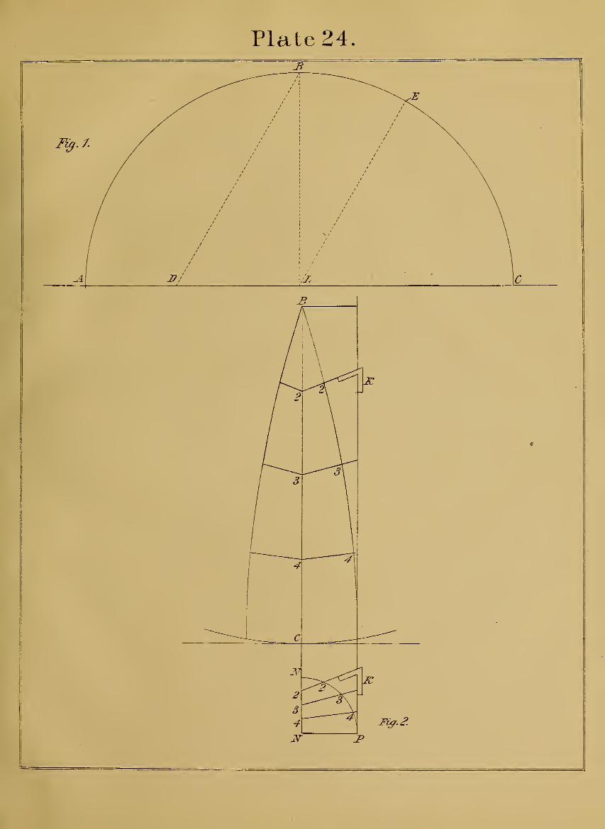
Plate 24.


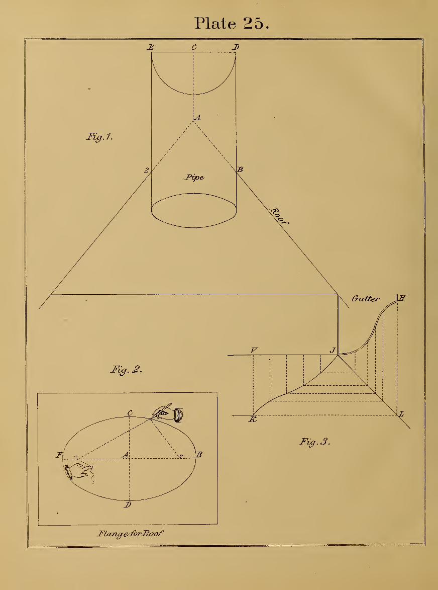
Plate 25.

Plate 25.
A HOLLOW PIPE PASSING THROUGH A ROOF.
Figure 1. To find the aperture or opening of a
flange in sheet-metal, which shall fit both pitches of
a roof, and receive a circular pipe passing through
the roof, and stand perpendicular. Its diameter being
E D and its radius C D. Draw from D parallel with
C A, cutting the roof at B ; then A B is half the
long diameter of an ellipse.
We now want a piece of flat sheet-metal ; this is
shown at Fig. 2. Here draw any two lines at right
angles; make A B and A F each equal A B
on roof, Fig. 1 ; also make D A C equal E C D,
Fig. 1.
We are now ready to strike the curves with a
string. This method has been already explained,
but here it may be repeated, and in this way : take
A B as radius; with same radius take C for centre,
and intersect long diameter to left of B and right of
F. These are points that may be punched to re-
ceive pins. Tie a string to that on the right, bring
it around the pin on the left ; now sweep the curve,
as shown. This being done, cut out the ellipse ; then
bend the flange on its short diameter, D C, until it
forms an angle to equal that of 2 A B on the roof;
this done, the pipe will be found to fit the opening
which has been cut through the flange.
Fig. 3. To find on the flat surface of sheet-metal
the form of a mitre-joint for a curved gutter, as that
of H J, which is to return on the corner of a build-
ing at right angles. To do this, set off from H to
J any number of equal parts on curve, say five;
set off the same number from J, ending at V ; now
draw from each part square with J V, and in like
manner draw from each part on curve, cutting mitre-
line J L ; thus points are given on J L, from which
draw, cutting the lines from J V, and through inter-
sections thus made draw the curved line from K to
J ; then a pattern being made to this line gives the
mitre-joint for gutter.
1
1

Plate 26.
PENETRATION OF PIPES AT ANY ANGLE.
Figure 1 shows a small pipe on a slant entering
a main one standing upright. The diameter A Xenters side of main pipe at points A and X. Now
proceed and find a straight line that will equal one-
quarter circumference of main pipe. To do this,
take P as centre and H radius ; intersect the
circle at V ;join it and H ; draw from N parallel
with V H, cutting at K ; then K P equals one-
quarter of the circumference ; this done, make H 2
equal half diameter of small pipe; draw from 2
square with P H, cutting at 3 ; this gives L 3 as
half the opening on surface of main pipe for small
one.
Fig. 2. Here is shown a surface of sheet-metal
for main pipe. Draw any two lines at right
angles, cutting at point O ; make O Y and O W on
right and left equal double the distance P E, on
diameter of main pipe ; make O L on right and left
equal 3 L, the curve on main pipe ; this done, make
O A and X equal D X on side of main pipe, Fig.
1. The drawing being completed, we place the main
pipe in position,—standing upright,—and it becomes
clear that the line A X is the long diameter of an
ellipse, and L O L, the short diameter, stands level.
Now the ellipse being cut through, the metal is
rolled, and forms the main pipe, and the elliptic
opening on its surface is ready to receive the small
slanting pipe, as shown at Fig. 1. The dotted lines
on right of Y and left of W indicate a lap for
riveting.
To find on a flat surface the shape of metal for
small pipe, we now return to Fig. 1. Here divide
the semicircle from A to X into any number of equal
parts, say six ; draw through each part parallel with
X X, cutting diameter and side of main pipe.
Now come to Fig. 3. Here draw the right angles
as A A and XX; set off on each side ofX six parts,
each to equal one of those on semicircle at Fig. 1
;
square up the parts from line A A, and make X Xequal X X, Fig. 1. Now on each side of X, on line
A A, make heights equal to corresponding heights
and letters at Fig. 1 ; points are thus given, through
which trace the curve, as shown. The metal being
rolled, forms the small pipe; its end, which has been
cut to the curve, will be found to enter or fit opening
in main pipe.
73

Plate 2 6
.


Plate 27.
/K
/
/ \\
/ CD\^—— '''""
^"''"'^'' \ ^""^^.^^
^\. /v/""^ / X V 11
y^"^^ /
-
/ \ /^ / \
1 ' ^ \ "/ \
T \ \/ -iv- \c-
I''^^
\ 1 ^ ' \
\ / ^ ' ^^ L
\'' \ 1
V' \ 1
\ / \ ' ^ /
>x/ \^ \^ ^/ \^
^^~>,^^^ \ ^' ^^^^
Fixf. /- ^"^^^^ —^{---'^''^-t f^
\ T ' '
\
\ fi//
\ /\ /VB
2 «
/ / / / X' ' 1 1 ' \\ I
I 1 / \/ \
i
/ / / / /' .'XD
/ '^^^"'"'^^^ ^^~"~~"~~'\
/ / / \y^\ ^^=X/
"~^^ /^ ^»/ ^X''''"""- / '
"". / \ / \ ''''
N
\ ^^^^- ^
\ \
\ " \\ V
\ ^\ *\ V
X "
'
\ \
/
I
/
/
/
/
I
I
t
I
J1
1
1
1
1
1
/
/
B \r7 \27 .
1
1
I
1
1
1
"""""" \""""" \ 1
\ ^
\
^ S 2

Plate 27.
TO CONSTRUCT SLANTING SIDES FOR AN ELLIPTICAL BASE.
Figure 1 represents an elliptical figure, which may
be considered either a base or a bottom, around which
is to stand a side of any width, and incline to any
angle.
This problem and its solution is of equal value to
the joiner, mason, and metal-plate worker.
Let us give some idea of its use and practical ap-
plication. For example, it is required to construct a
splayed arch, its form to be elliptical, and its edges
come flush with straight walls. This statement
shows that the arch must have two unequal curves,
because its face is on the same splay at the crown
and at the springing. To accomplish this might
seem a very difficult task. Such, however, is not the
case. We have only to look around and see a
tinsmith cutting his metal for a boiler, or anything
having an oval bottom and slanting sides. The rule
that he applies to his work alsa applies, without the
slightest deviation, to the perfect construction of a
splayed arch, or any work which bends and stands
on a slant.
Let us now explain the simple method by which
is found a slanting side for semi-ellipse as T D C,
which is one-half the figure shown. Come to Fig. 2.
Here form a right angle ; take A 2 for a base. Nowdetermine the perpendicular height of side above the
base, say A B ; draw from B parallel with A 2
;
make B C equal B C, Fig. 1 ; again, make B Dequal B D, Fig. 1 ; this done, draw through D any
slant desired for side of work, say line Is" 2 ; now
draw through C parallel with X 2, cutting at Hand J.
We are now ready to give the curves on edges of
side, as shown at Fig. 3. Here draw any perpendic-
ular line as that of 2 D N, which make equal with
2 D I^, Fig. 2. Take N as centre, and draw the
curves through D and C ; this done, come to Fig. 1,
and divide L K into any number of equal parts, say
five; with one of these return to Fig. 3, and set
off from D five parts, ending in C ; draw from Nthrough C ; now make C H equal C J, Fig. 2 ; take
H as centre, and draw the curves from C and J.
Come again to Fig. 1, and divide K C into any num-
ber of equal parts, say three; return with one of
these, and set off from C three parts, ending in K
;
draw from H through K ; make curves on left of D 2
equal those on the right. This completes one slant-
ing side; and if it were cut through the paper as
now drawn, and its curved edge, TDK, made to
stand on T D C, Fig. 1, then both its edges will be
found perfectly level, and the face or surface of side
stands on the given slant.
Here we see in this simple construction a complete
illustration of the splayed semi-elliptical arch.
83

Plate 28.
STRAIGHT AND CffiCULAR WORK ON THE SLANT.
FiGTJKE 1. To construct slanting sides to a base or
bottom, parts of which are straight and circular, as
that shown.
This problem, like the preceding, applies and gives
the cuts and curves for anything standing on a slant.
It applies to either wood or metal. It is practical
and simple. The plan of work may be either
straight or circular. Take, for example, something
which is familiar, and similar to the drawing before
us, say a seat having a slanting back and circular
ends, or such as may be seen in carriages and other
vehicles. The edges of a board for this back must
be curved, and in a manner that when its ends are
bent for quarter circles, that operation at once throws
the board on a slant, and its edges, which have been
curved, are now level. This might seem simple,
which it really is; and yet it has a constructive
principle that must be known, in order to find the
proper curves for edges of work, which bend and
stand on a slant, as is the case here, where we have
four quarter circles. Around these and straight
parts of the plan are to stand sides on an equal slant,
which means that circular corners and straight sides
incline alike.
To do this, come to Fig. 2. Here form a right
angle ; take L N as a base ; now determine the per-
pendicular height of sides, say L A ; draw from Aparallel with L N ; make A B equal A B, Fig. 1
;
draw through B any slant desired, say line P N;
this gives N B for slant width of sides ; make B P,
Fig. 1, equal B P, Fig. 2 ; take P as centre and Bradius; draw the curve towards C; divide quarter
circle B E into any number of equal parts, say five
;
set off the same from B on the curve, ending at C
;
draw from P through C ; draw from C square with
it and P, and make C K equal E H. This com-
pletes the inner curve. Now make B N equal the
slant width of sides ; take P again as centre and Nas radius, and draw the outer curve.
This simple construction is now complete. Its
accuracy may be tested by having the drawing on
card-board, and cut clear through all the outer and
inner lines, making the sides on right and left work
on a hinge by a slight cut along each line; this
being done, lift the piece, fold the straight and circu-
lar parts from you; bring the square joints together,
and you have an exact model of the work,— its sides
and circular corners standing on the given slant.
Here it is understood that the construction just
explained applies to either wood or metal.
8i

Plate 28.


Plate 2 9.
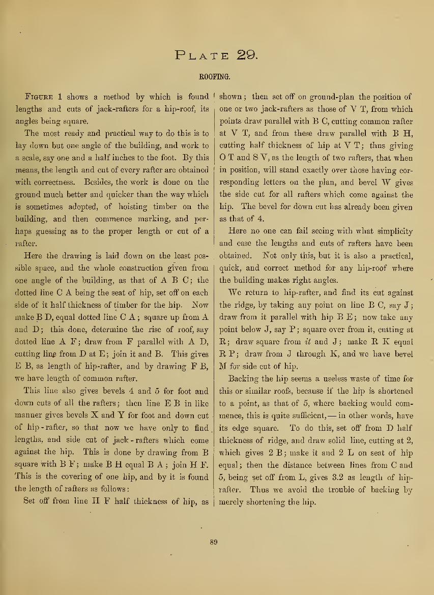
Plate 29.
ROOFING.
FiGUEE 1 shows a method by which is found
lengths and cuts of jack-rafters for a hip-roof, its
angles being square.
The most ready and practical way to do this is to
lay down but one angle of the building, and work to
a scale, say one and a half inches to the foot. By this
means, the length and cut of every rafter are obtained
with correctness. Besides, the work is done on the
ground much better and quicker than the way which
is sometimes adopted, of hoisting timber on the
building, and then commence marking, and per-
haps guessing as to the proper length or cut of a
rafter.
Here the drawing is laid down on the least pos-
sible space, and the whole construction given from
one angle of the building, as that of A B C; the
dotted line C A being the seat of hip, set off on each
side of it half thickness of timber for the hip. Nowmake B D, equal dotted line C A ; square up from Aand D ; this done, determine the rise of roof, say
dotted line A F ; draw from F parallel with A D,
cutting lin^ from D at E; join it and B. This gives
E B, as length of hip-rafter, and by drawing F B,
we have length of common rafter.
This line also gives bevels 4 and 5 for foot and
down cuts of all the rafters ; then line E B in like
manner gives bevels X and Y for foot and down cut
of hip - rafter, so that now we have only to find
lengths, and side cut of jack -rafters which come
against the hip. This is done by drawing from Bsquare with B F ; make B H equal B A
;join H F.
This is the covering of one hip, and by it is found
the length of rafters as follows
:
Set off from line H F half thickness of hip, as
shown ; then set off on ground-plan the position of
one or two jack-rafters as those of V T, from which
points dra,w parallel with B C, cutting common rafter
at V T, and from these draw parallel with B H,
cutting half thickness of hip at V T ; thus giving
O T and S V, as the length of two rafters, that when
in position, will stand exactly over those having cor-
responding letters on the plan, and bevel W gives
the side cut for all rafters which come against the
hip. The bevel for down cut has already been given
as that of 4.
Here no one can fail seeing with what simplicity
and ease the lengths and cuts of rafters have been
obtained. Not only this, but it is also a practical,
quick, and correct method for any hip-roof where
the building makes right angles.
We return to hip-rafter, and find its cut against
the ridge, by taking any point on line B C, say J
;
draw from it parallel with hip B E; now take any
jDoint below J, say P ; square over from it, cutting at
E. ; draw square from it and J ; make E K equal
R P; draw from J through K, and we have bevel
M for side cut of hip.
Backing the hip seems a useless waste of time for
this or similar roofs, because if the hip is shortened
to a point, as that of 5, where backing would com-
mence, this is quite sufficient,— in other words, have
its edge square. To do this, set off from D half
thickness of ridge, and draw solid line, cutting at 2,
which gives 2 B ; make it and 2 L on seat of hip
equal ; then the distance between lines from C and
5, being set off from L, gives 3,2 as length of hip-
rafter. Thus we avoid the trouble of backing by
merely shortening the hip.
89

Plate 30.
ROOFING.
To find lengths and cuts of rafters for a hexagon
roof.
Fig. 1 is the ground-plan of the building, it having
six sides; one of which being projected, by means
of it we find, in the most simple manner, the exact
length and cut of every rafter in the roof.
Commence by dividing any two sides of plan into
equal parts, as that of C D and F E ; draw from
divisions thus made, square with sides C D and F E,
meeting in O as centre; around it form the small
hexagon. Draw from L through O ; now determine
rise of roof, say O B ; draw from B through A, and
we have the given rafter. Its foot and down cuts
are shown by bevels X and Y.
To find the hip-rafter, make O N equal O B;join
N L, which gives the hij). Here notice centre of
seat, cutting the angle of small hexagon : this would
cause a double cut on upper end of hip ; but to
avoid that, take off the corner, as shown.
The bevels V and P give foot and down cut for
all the hips. These perhaps would be better to have
a backing, which is found by drawing a line through
any part of the seat, and square with L N ; draw from
the two points of intersection at seat, and square with
it, cutting L N from that point, as shown ; draw
square with O N, cutting line from half thickness of
hip. Thus a point is given to draw dotted line,
which is the backing required.
To find lengths and side cut of jack-rafters. Draw
a line from O square with C D ; make 2 B equal
A B;join B D C ; set off on each side of B C and
B D half thickness of hips. Now lay off position of
rafters on line C D, draw them parallel with 2 B,
cutting the hips, and we have the lengths ; also
bevel W for side cuts. The down and foot cuts are
the same as given rafter.
Here is seen that every rafter, hip, and cut for
this roof, is obtained by the most simple means. It
is also clear that by working to a scale, say one
and a half inches to a foot, then every piece of
timber may be cut on the ground and ready for
fixing.
To have a correct mod^l of this roof let the drawing
be on card-board, and cut in the follov/ing manner
:
Take C D as radius, also centres ; draw arcs of
circles at H and N ; now take B as centre, and
C as radius ; intersect the ares;join B* H C and
B N D; make a similar construction to this on line
L E. The whole covering of roof being spread out,
cut clear through all the outer lines ; this done,
•make a slight cut on line L E and that of C D;
also cut in a similar manner dotted lines B C
and B D, and in like manner cut the covering which
hinges on line L E. Now lift the piece and fold
covering from you, bring the half hips together, and
a perfect model of the roof is sliown.
90

Plate 30


Plate 31.

Plate 31.
TO FIND THE RIBS ^NB COVERING OF A GROIN.
Let S 2 L Y be the ground-plan. Draw diagonals
from corner to corner, intersecting in O ; this done,
draw on line S Y a semicircle, its radius being A B,
which determines height of groin ; draw through O,
to the right and left, square with S 2 ; again draw
through O parallel with S 2 ; take O as centre and
A as radius ; draw quarter circle A J ; make A B i
equal A O ; draw semi-ellijDse L B Y ; now draw
from O square with diagonal 2 Y ; make O B equal
O A ; this done, draw semi-ellipse 2 B Y. The ribs
of groin are now in position. To find the covering,
divide quadrant A J into any number of equal parts,
say four ; draw from each point parallel with Y L,
cutting diagonal S L at E. N C, from which draw
square with Y L, cutting ellipse at K P E-. These
are measurements on the curve; set off the same
above line 2 L L. In this way L K equals L K on
curve, and K P equals K P on curve ; again PUBequals corresponding letters on curve, thus giving
points, through which di-aw parallel with 2 L, cut-
ting lines from quadrant A J, and through intersec-
tions thus made draw the curve from B to L ; set off
distances on the left to equal those on right, and
draw the curve froui B to 2, which completes the
end covering.
To find the covering of side S 2, take any ])oint,
say J ; set off from it four parts, each to equal one
of those on quadrant A J ; draw through each point
parallel with S 2 ; make C C equal C C on the right
;
again make N N equal N N on the right ; once more
make Y ,V equal V R on the right ; now draw
the curve from H throuo;h V Is C W; set off
distances on the other side, and draw a similar
curve to that just made, which completes the side
covering.
To have a correct idea of this, suppose the curved
lines cut through the paper, and a cut made in like
manner on line passing through J. Now the piece
is loose, lift it, and bring edge through J on line S 2
;
bend the paper until point H stands over centre of
groin O. Here the bending, has caused curved edges
of covering to range with the straight lines O 2 and
O S. Then if the end covering is cut in a similar
manner, and bends from line 2 L L until point Bstands over centre O, then its curved edges will be
found to range with lines O 2 on the left and O Lon the right, so that when the curved edges on both
pieces of covering come together, they close directly
over line O 2.
This problem and its solution should be well un-
derstood by metal-plate workers and masons.
We now come to the ribs. These are formed by a
carpenter.
The view which this groin presents on looking
through its narrow ends, is that of a semicircle, as
shown on line S Y. Then it follows that all ribs
which come in angle O L Y, must be parts of quad-
rant A J.
Again, the view presented on looking through the
main arch is a semi-ellipse, as that of L B Y, parts
of which are to be cut for angle O L 2. Then all
the short ribs being cut to their proper lengths, and
nailed to diagonal ribs, the groin is formed and ready
for lathing.
95

Plate 32.
CONSTRUCTION OF A ROOF HAVING HIPS AND VALLEYS.
The ground-plan of this roof shows an extension
on one front of the building, which occasions the
necessity of having valleys.
Here it may be stated, that the usual rule of laying
down a roof of this construction, is not only compli-
cated, but obscure, owing to the multiplicity of lines
and other details, making it almost impossible to
understand their intention or meaning. But to ob-
viate every difficulty in any construction, and to
make all its parts perfectly clear, have the drawing
on card-board, and cut in such manner as to fold, and
show a correct model of the work, as is the object here.
We now commence by spreading out the covering
of this roof, and show exactly " lengths and cuts
"
of every rafter. To obtain this, draw from angle Ethrough T, cutting at E, and join T B; now deter-
mine on rise of roof, say T S;join S E, E ; draw
from C parallel with B T, cutting at 5. This done,
draw from angle A parallel with B T, cutting at K
;
draw from it parallel with A H ; make K 4 equal
T S ;join A 4.
Now find the foot and down cut of all the rafters,
except those of extension from line C D. This is
done by drawing from S parallel with T E, ; make
R L equal E K ; square up from L, cutting through
P, and draw from E through P. This gives bevel
7 for down cut, and bevel 8 for foot cut of all the
rafters.
To find the covering for end of building A H and
its side H G. Make E V equal E P;join V H
;
now take A 4 as radius, and with same radius take
A and H for centres ; make intersections at Y; join
it with A H. These lines, to be correct, must equal
line H V.
We now want a covering spread out, so that when
in its position it will cover A B T K. To do this,
take H for centre, and with any radius draw the
arc 2.2; with same radius and A centre, draw arc
2.2' ; make both arcs measure equal ; draw from Athrough 2' ; then draw from Y parallel with A 2'
;
make the distance on line A 2' measure equal to that
of A B. This done, draw parallel with Y A, and
we have the covering.
Adopt the same process to cover the end F G, as
shown.
The bevel 6 is the side cut for jack-rafters, the
down cut having already been obtained by bevel 7.
We now want to spread out the covering for the
extension B C D E.
Commence at 5, and draw from it parallel with
C D ; take E S on valley-rafter for radius ; with
same radius, and C centre intersect line from 5 at J,
and from same centre intersect dotted line at W;join it with C D ; also join C J. Again, take C as
centre and B as radius ; draw the arcs B 3 and 3 3'
;
make both arcs measure equal; this done, join C3';
draw from W parallel with C 3'; then draw from
3' parallel with C W. This completes the covering,
with the exception of j)iece from line W D, which is
equal to that just done.
Set off the actual position of rafters ; this being
done, shows that bevel X, gives side cuts for rafters
which stand on line C B, and bevel 5 gives side cuts
for rafters in angle C W D.
Here it will be noticed, that the exact lengths of
rafters, are obtained by setting off half thickness of
hips, on each side of hip lines spread out.
Let the drawing be made to a scale, say one and a
half inches to a foot. By this means everything is
done on the ground.
Work according to the drawing, and every piece
of timber cut, will answer the purpose intended.
This drawing is presumed to be on card-board. It
will show the necessity of being correct by cutting
clear through all the outer lines. This done, make
a slight cut on line H G to form a hinge, and for the
same purpose, make a slight cut through lines F 2,
A Y, W D, and W C. Now lift the piece and fold
the covering from you, bring the hips together, and
form the valleys, and we have a perfect model of the
roof, showing the most simple and practical method
that can be devised, for the length and cut of every
piece of timber in it. This I have practically tested,
and I hope it will be the means of assisting others,
in more thoroughly mastering their trades, and ulti-
mately open to them the way to success.
96

Plate 3 2
.


Plate 33
.

Plate 33.
THE INTERSECTIONS OF STRAIGHT AND CIRCULAR MOULDINGS.
Figure 1 shows the form of an irregular piece
of framing or other work, which requires to have
mouldings mitre and properly intersect.
The usual way of doing this is to bisect each
angle, or to lay two pieces of moulding against the
sides of framing, and mark along the edge of each
piece, thus making an intersection or point, so that
by drawing through it to the next point, which is
the angle of framing, the direction of mitre is ob-
tained. This process, however, is not the quickest
and best by any means. The most simple and
correct method is to extend the sides A L and
PH.Now sujDpose we wish to find a mitre from L;
take it as centre, and with any radius, as K, draw
the circle, cutting at J;join it and K ; draw from L
parallel with J K, and we have the mitre at once.
Now come to angle on the right ; here take H as
centre, and with any radius, as E, draw the circle,
cutting at F; join it and E; draw from H parallel
with E F, and you will find a correct mitre.
The next question is the intersection of straight
and circular mouldings.
In the present case an extreme curve is given, in
order to show the direction of mitre here, which is
simply on the principle of finding a centre, for three
points not on a straight line. For example, ABCare points ; bisect A B and B C ; draw through in-
tersections thus made, and lines meeting in point D
give a centre, from which strike the circular mitre
as shown.
Here it may be stated that in some cases a straight
line for mitres will answer; this means when the
curve is a quadrant or less.
Fig. 2 shows the intersections of rake and level
mouldings for pediments.
The moulding on the rake, increases in width, and
is entirely different from that on the level, yet both
mitre, and intersect, the rake moulding being worked
to suit the level. If the curves of Fig. 2, are struck
from centres as shown, then by the same rule, the
rake moulding is also struck from centres.
Take any point in the curve, as C; square up from
it, cutting at B ; draw from C parallel with S L
;
join L K, which bisect at N ; make E D equal A Bon the right; join L D and D N ; bisect L D, also
D N ; draw through intersections thus made, and
the lines meeting in F, give a point, from which
draw through N ; make N J equal N F ; then Fand J are centres, from which strike the curve, and
it will be found to exactly intersect with that of
Fig. 2.
Both mouldings here are shown as solid, and of
the same thickness. This is done for the purpose
of making the drawing more plain and easily under-
stood; but bear in mind that all crown mouldings
are generally sprung. This and mitreing will be
fully explained in the next plate.
.101

Plate 34.
TO FIND THE FORM OF A SPRUNG OR SOLE) MOULDING ON ANY RAKE WrTHOUT THE USE OF EITHER
ORDMATES OR CENTRES.
It may not be generally known, that if a level
moulding is cut to a mitre, that the extreme parts
of mitre, when in a certain position, will instantly
give the exact form of a rake moulding, and it will
intersect, and mitre correctly with that of level
moulding. To do this, take the level piece which
has been mitred ; lay its flat surface on the drawing
;
make its point P at Fig. 1, stand opposite point P at
Fig. 2; keep the outer edge fair with line N L.
The piece being in this position, take a marker, hold,
it plumb against the mitre, and in this way, prick
off any number of points, as shown, through which
trace the curve-line, and the result is a correct pat-
tern by which the rake moulding is worked.
A moment's consideration, will convince us that
this simple method, must give the exact form of
any rake moulding, to intersect with one on the
level.
To cut the mitres and dispense with the use of a
box, this method will be found quick and off-hand.
Take, for example, the back of level moulding, and
square over on its top edge any line, as that of F N
;
continue it across the back to H ; make H V equal
T L above, and from V, square over lower edge H K.
Now take bevel 2 from above, and apply it on top
edge, as shown ; mark F L ; then join L V ; cut
through these lines from the back, and the mitre is
complete.
To cut the mitre on the rake moulding, square
over any line on its back, as that of H J ; continue
it across the top and lower edge; take bevel X,
shown above Fig. 1, apply it here on top edge, and
mark D A ; take the same bevel, and apply it on
small square at E, and mark E 2,
We now want the plumb cut on lower edge J K,
and the same cut on front edge N P, shown at Fig.
2. Take bevel W above Fig. 1, apply it here and
mark 2 B;join B A ; this done, apply the same
bevel on front edge N P, and mark the plumb cut,
it being parallel with that of 2 B here, or K J, Fig,
2 ; now cut through lines on the back, and the mitre
is complete.
102

Plate 34.
liCrwer^cl^e.^JC
^a4ik, o^J^eyeiMouZclvn^
Top i:ci^e. ZJsr
Ti^.2.
IiowerlEoUie'J
R
3cuck o-f^Roihe^MmiJdin^f
Topi:d^&^N


Plate 3 5

Plate 35.
TO MITRE SPRUNG MOULDINGS ON A GABLE.
It has already been shown, that we dispense with
making or using a box for mitreing sprung mould-
ings.
In this case, the front edge or upper member, stands
parallel with face of wall, so that bevel X being ap-
plied, gives the plumb cut ; tlien the cut on top edge
is square with face of wall. This shows, that we have
odIv to fiud the direction of a cut on the back of
moulding to make the mitre.
To do this, take any point as H ; draw from it
square with rake of gable. Xbw mark sections of
moulding, as shown, its back parallel with E, F
;
draw from D square with E N ; extend the rake to
cut line from D at K ; this done, take any point on
the rake, say L ; draw from it parallel with R F,
cutting at K ; take it as centre and L as .radius, and
draw the arc of a circle ; with same radius return to
K' on the right ; take it as centre, and draw the arc
L' H' ; make the first arc equal it : then draw fi'om
I
H parallel with L C, cutting at J; draw fi-om it
square with rake, cutting at G, and join C K. This
gives bevel 'SV for cut on back of moulding.
A most perfect illustration of this may be had by
having the drawing on card-board, and cutting it
I
clear through all the outer lines, including that of
the moulding on lines F D N E, making a hinge by
a slight cut on line K F ; also make a hinge of line
I
E, A, by a' slight cut on tlie back, and in like manner
make front edge work on a hin^e bv a slio-ht cut on
line F V. This cut is made on toj) sui'face. Per-
form the same operation on the left. All the cuts
being made, raise both sides on hinges A K and A 2;
push the sections of mouldings on right and left from
1 you; make front edge rest on F D. ZSTow bring
mitres together, and we have a practical illustration
of mitreing sprung mouldings on the rake.
i07

Plate 36.
TO CONSTRUCT SPLAYED WORK, THE GROUND-PLAN FORMING EITHER RIGHT, ACUTE, OR OBTUSE ANGLES.
The problem which is here presented, is one of
more than ordinary importance, for by it is found,
every conceivable cut that is requisite for framing,
panelling, and boxes with slanting sides, or anything
where angles are thrown out of square. In a word,
it is immaterial how the angles of base are situ-
ated.
Our meaning of this will be, perhaps better under-
stood by referring to Fig. 1. Here is given a "base"
line as A D, on which is to stand slanting sides at
any angle, say C B; the perpendicular height of
work is D E. This shows that edges of sides are to
be worked to bevel Z.
We will now assume a ground -plan, on which
stand the slanting sides just given.
For this, come to Fig. 2. Here let T 2.3 S be the
plan ; set off width of sides to equal C B, Fig. 1
.
These are shown to intersect at P L above; then
draw from P L through 2.3 ; these lines have inter-
sected at C ; take it as centre and A as radius ; draw
the semicircle A A, and with same radius come to
Fig. 1. Take C as centre and draw the arc A B;
take it in the dividers and return to Fig. 2. Here
set off arcs A B on right and left, to equal A B, Fig.
1 ; draw through B on the right parallel with S 3,
cutting at J and F ; .square over F H and J K, and
join H C; this gives bevel X, as the cut for face of
sides which come together at angle 3. The mitres
on edges of stuff are parallel with line L 3. The
reason why this mitre is correct, is because the edges
are worked to bevel Z, Fig. 1.
Now come to square corner at S. Here join K V;
this gives bevel Y, for cut on face of sides which come
together at square corners.
To find a bevel to cut the sides for angle 2. Draw
from B on the left, square with A A, cutting at E
;
square over from it, cutting at N; join N C; this
gives bevel W for cut on face of sides. The mitres
on edges are found by drawing parallel with P 2.
All the cuts and everything requisite for the work are
now complete. It is understood that in actual prac-
tice, there is no necessity for spreading out the sides
as here shown. The base of work and slant of sides
being given, that alone is sufficient ; but as we are
particularly anxious that this construction should be
clear and intelligible, let the drawing be on card-
board ; then, by cutting through all the outer lines,
including mitres, the piece becomes loose.
Now make a slight cut on the back opposite lines
T 2.3 S. These form hinges for sides to work on.
Again, make a slight cut on top surface along lines,
which represent thickness of bevelled edges. Now
raise the sides, bring the cuts together, and let the
edges fall level ; bring their mitres together, and we
have a model of the work, its accuracy proved by its
sides standing on given slant C B, Fig. 1.
108
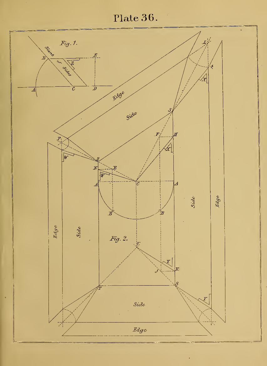
Plate 36.
Side
Beige


Plate 37.

Plate 37.
TO PDTO BEVELS FOR CUTS ON SHOULDEES, AND FACE OF ffiREGULAR FRAMING, OR ANY WORK WHICH INCLINES.
In the preceding plate "was shown that by first
working the edges of inclined sides to a bevel, then
the intersection of angle on the base, gives the mitre si
on edge of sides. But in this case the edges are to
be square, which will make it necessary to find by
construction a bevel for the mitre.
The following method, will be found quite simple
for making either mitres or butt-joints, for any work
which stands on a slant, the angles of ground-plan^
being square.
Fig. 1 is the ground-plan, or base of work, whichj
is to have sides, each to stand on a given slant, and
on the right the edges are to make butt-joints, and
on the left to mitre. We leave this and come to
Fig. 2. Here draw a line, as A B, for a base;
take any point on it, say V ; draw through it a line
on any slant desu'ed, as V K,. Again take any point
on line A B, say 3 ; draw through it square with AB, cutting at E ; make E, H equal E. V; square down
from Y; draw from H parallel with 3 V, cutting at
L; join it and E. This gives bevel W, for cuts on
face of sides and ends as shown on plan.
We now want a bevel for mitres on edge of sides
and end, on left of plan. This is found by making
3 A equal 3 V. Take 3 as centre, and for radius a
circle touching E V, cutting at 2; join it and A.
This gives bevel N for the mitre.
The next question is a bevel for butt-joints. This is
easOy found by drawing V K square with V E ; take
any point as D ; square down from it, cutting at C.
Kow take D as centre, and for radius a circle
touching V K, cutting at B;join it and C. This
gives bevel T, to apply on edges of sides and end for
butt-joints, as shown on plan, Fig. 1.
113

Plate 38.
TO CONSTRUCT CYLINDERS, FORM RAMPS, AND CUT MITRE-CAPS.
WoRKMEK differ in different cities as to the best
and quickest methods of constructing cylinders.
Some prefer bending a veneer over a form, which
undoubtedly is a neat and clean method, the grain
of wood running in the same direction as rake of
stairs, thus giving to the work a perfect finish.
This method should always be adopted when the
strings are hard wood ; but if they are pine, or other
wood which is to be painted, then we might dispense
with making forms, bending veneers and backing the
same, and instead have cylinders in staves. These
should be well seasoned, the joints properly glued,
and screwed from the back. It is known that cylin-
ders done in this way have stood for more than a
century, without showing a single joint. Then the
only question to decide is, which of the two methods
is the quickest and best. The workman may exer-
cise his own judgment on this point— we leave it to
him.
Fig. 1 shows a cylinder in three staves ; each
should be worked sufficiently long to make two or
more cylinders ; work the joints by bevel K ; the
piece being cut to proper lengths, let the square ends
stand on the plan ; see that joints are correct by the
three staves forming the semicircle ; bore for screws
;
put the cylinder together; prove its diameter, as
being equal to that of plan.
Now take the pieces apart, glue the joints, and
screw from the back.
Nails should never be used for fastening, and for
this reason : the nail makes a bruise or burr on the
surface of edge, and breaks the joint, or prevents it
from coming together.
Fig. 2 shows the elevation of stairs at the starting.
The centre of newel and position of mitre-cap are
also shown.
The form of mitre which appears best, is to make
L P equal half width of rail.
The mitre on the cap is made by means of having
two saw-cuts in a block.
To find the distance that these cuts should be
apart, draw from N centre of cap parallel with P A
;
this gives a distance as 2 A.
Now have a piece of plank, shown at Fig. 3 ; run
a gauge-line on both sides, as that of A B ; make A 2
and A C equal 2 A, Fig. 2, and square over the lines
on end. Now take a panel saw, and make a cut
through 2 and C, keeping thickness of saw towards
A ; this done, bring centre of cap on line A B; fasten
with a screw ; enter the saw at 2, cut one side of mitre
down to 3 ; set the compasses to width of rail, and
mark point C; this done, revolve the cap, until point
C stands opposite cut C in the block; enter the saw
and finish the. mitre. If this is done properly, all
fitting is avoided. In case a hole is made entirely
through the cap for pin of newel, then bore for a pin
in the block, and let the cap revolve on it instead of
a screw.
114

Plate 38.
^^-z-
2^0
Jn^.3.
5i>
I
<J
Jz^.^.
^fZoorXine/
Scv^I^


Plate 3 9
.

Plate 39.
THE SECTIONS OF CYLINDERS.
Figure 1 shows a hollow semi-cylinder. If this
is cut on any inclination as A B, the section of such
cut must be a semi-ellipse. The feature which this
section presents on its upper and lower ends, is that
the width increases or diminishes according to in-
clination of cut ; but on the short diameter the width
never changes : it is always the same as thickness of
cylinder.
These points should be understood by those who
desire to acquire a knowledge of " hand-rail " con-
struction.
To have a further illustration of this, come to Fig.
2. Here let A C be the diameter, and E D the thick-
ness of a cylinder at its base. We will now draw a
line, say N J, as the direction of a cut through the
cylinder. This line is long diameter ; square up the
thickness, cutting at N above and J K below; square
over B' E' jy. This line is the short diameter, and
it is just equal to B E D at the base.
Here we see that the thickness of cylinder on short
diameter is exactly equal to that on the base. It
never changes : no matter how or on what the in-
clination of cut through the cylinder may be, the
width remains the same.
I
. The elevation conveys a coi'rect idea of the semi-
cylinder and its section ; but for practical purposes
it may be dispensed with. The short and long diam-
Ieters being given are sufficient.
{
This will appear clear by referring to Fig. 3. Here
the long diameter is given as N J, and the short as
BED.I
To find the width of wide end at J, draw from B
at any angle ; make B C 2 equal BED; join 2 J;
draw from C parallel with 2 J, cutting at K ; now
find points for pins, and strike the curves with a
string.
It is here evident that this semi-ellipse is just
equal to the section of cylinder at Fig. 2.
119

Plate 40.
LESSONS ON HAND-RAIL CONSTRUCTION.
Many years ago I recommended the cutting of blocks
aa a means of instruction in this branch of joinery. Atthe same time "I discovered tlie important system of
bevels for butt-joints. This remains unchanged, unalter-
able, and ever must, because it is perfect. But nearly
everything else has been thrown aside for newer andbetter ideas, and perfection at last attained. IS'o morechanges or alterations in this branch will be entertained
or thought of. It is now, for the first and last time, presented
in a new light, clear, simple, and intelligible. All ordiuates
are dispensed with — the angle of tangents found at onceb}' drawing a single line. This alone has been the cause
of our changing all previous thoughts and views on a
matter which has been worn threadbare in more than a
hundred publications on the subject.
The first problem being on card-board, and cut in sucha manner as to convey the whole principle on whichhand-railing depends. Examine it; the lines are fewand simple, and yet it is the key by which any wreathcan be produced.
Fig. 1 shows a square and quarter circle. Let us sup-
pose this to be a ground-plan, over which is to stand a
piece of plank or board, inclined to any angle, and weare required to cut it so that two of its sides shall standexactly over two sides of the square, each edge of theplank making two unequal pitches, and in addition to
this we must draw on its surface a curved line whichshall range with every part of the quarter circle. Hereit is evident that these conditions include everything that
can be known about hand-railing, and to comply withthem the two unequal pitches of the plank must be given.
Then the first step is, extend K !N^ on the right and left,
likewise the sides 3 IST and P K. Now assume K J as
height for one pitch, to stand on P K ; make K C equal
K J ; draw from J through C, cutting at D ; make K Aequal K N; join C A; the two pitches are now given, as
D C and C A; these, when drawn on surface of plank,
form a certain angle, the sides of which make tangents to
an elliptic curve.
This angle is found by drawing from K square with JC ; take C as centre and A radius ; draw the circle, cut-
ting line from K at E;join it and C ; this gives D C E
as the angle, which, being cut and placed in position overthe square, shows the surface of plank making two un-
equal pitches, and angle D C E stands directly over twosides of the square, as K N and K P.To find a curve on surface of plank that will range
with quarter circle of plan. To do this, find the longand short diameters of a semi-ellipse by drawing from Jthrough P; draw from 3 and N parallel with P J; againdraw through 3, square with P J, cutting at 2 F ; nowsquare up from L, cutting at S; draw from D parallel
with CE; make DP equal CE; join R S— this is
short diameter : draw through R, square with R S, andwe have long diameter. To find half its length, makejST B on the right equal 2 F (through corner of square)
;
join BD; make N H equal 'E Y.; square up from H,cutting at R; this gives R D as half the long diameter,
which transfer to Fig. 2, where corresponding letters are
seen ; make R V equal K IvT. N^ow find points for"pins,
and sweep the curve with a string ; observe this curvejust touches at E and D, thus making sides of angle1) C E tangents to a portion of the semi-ellipse. Thecard being already cut, lift the piece and fold the pitches
from you ; bring the edges J K and C K together; let CE rest on pitch J P. Here is a practical solution of asimple yet important problem. Examine carefully themeans which produce this result; endeavor to under-stand it thoroughlj'-. This being done, lay the card in
its original position, in order that we go a step further,
by drawing a mould to suit the two pitches, and at thesame time give bevels for butt-joints.
To do this, set a bevel or rule exact to angle E C D
;
now lift the rule and lay it on a piece of board, shown at
Fig. 3; mark the angle E C D; draw from E parallel
with C D ; make E L equal C D ; this done, come to Fig.
1 and take P 2 as radius ; return with it to E as centre,
and draw the arc; now draw through L, touching theare, and we have the long diameter of a semi-ellipse.
The short diameter is given by squaring up from L;make L equal P 3, Fig. 1 ; set off on each side of Ohalf width of rail ; draw the joint at E ; square with E C.
The width of mould at both joints is obtained by havingthe bevels. To find these, take any convenient place, as
Fig. 4 ; here draw two lines, any distance apart, but par-
allel with long diameter; take any point on lower line,
say V; square up from it, cutting at R; this done, cometo elevation above Fig. 1 on the right; here take D as
centre, and with any radius draw the arc 0'; returnwith it to Fig. 4, and withV as centre draw the arc 0';
make both arcs measure equal, then draw through Y and0, cutting at L ; draw L N parallel with E C on mould;again draw L H parallel with E L, also on mould ; takeR as centre, and for radius a circle touching L N, cutting
at T; draw from it through V— this gives bevel W for
joint E ; again take R as centre, and lor radius a circle
touching L H, cutting at K ; draw through it and V
—
this gives bevel X for joint on the right. Both bevels
being obtained, set ofiF half width of rail below V, anddraw parallel with V O'— this gives P V as half widthof mould on each side of E the joint, and S V to set ofl'
on each side of E" on the right. This done, come to Fig.
3, and make L R on long diameter equal R D at eleva-
tion above on the right ; take F V at Fig. 4 and set it
ofiF on each side of R, and we have width of curves on longdiameter, from which, and width of rail on short diameter,
points are found for pins; by means of these we sweepthe curves with a string, which completes the mould.
This -is the first problem on hand-railing, and a mostimportant one, for if it is clearly understood, there will
not be the least difficulty in having a clear perception of
all that follows.
120

Plate 40.


Plate 41.
Tlouhforrrv-
^RiserX<xn,ddivq
Jiiser
Step fOJruJt.es
G
Scale, BZrvches

Plate 41.
LESSONS ON HAND-RAIL CONSTRUCTION.
The svstem of lines, as given and explained on preceding
plate, will be adopted and applied throughout. Its teachings
are simple, perfect, and reliable for the construction of every
form of wreath, regardless of plan or situation of stairs. Its
first practical application is to a simple wreath for quarter-land-
ing stairs.
Fig. 1 shows the ground-plan. Two sides of the square are
tangents to a quarter circle, which is the centre line of raiL
Let us now place the risers on the plan, in such a position as
will throw straight wood of wreath on the same pitch as the
stairs. To do this, set off from A, half a step on each side of the
square ; now draw riser landing, and riser starting ; set off fromthese the square steps, as shown. Any alteration of risers, fromthe position given, would cause the wreath to be ia two pieces,
which in some cases is not objectionable; but here we have fixed
the risers for a plain and simple wreath to be ia one piece. In
view of this, we wQl now make all clear and distinct in the fol-
lowing maimer : At Fig. 2 (which is a square just equal to Fig.
1), extend the side from D ; now place the pitch board on upperside of square, and draw from C through A ; make A F equal
A D ; square over from F, cutting the pitch at E ; draw through
F ; square with A E ; take A as centre and E radius ; draw the
circle, cutting line through F at B;join it and A. This gives
B A C as angle of tangents for the mould. Set a bevel or rule
to it ; this being done, lift the rule and lay it on a piece of
board, shown at Fig. -3 ; now mark BAG; extend the lines to
right and left ; draw through B parallel with A C ; make B Xequal A C ; draw from A through X— this line is the short
diameter of a semi-ellipse, and to be correct, A X must equal OD ; shown on square above ; draw through X, square with X A,and we have long diameter; make X O equal O C on square
above ; set off on each side of O half width of rail.
The width of mould on straight parts is obtained by having a
bevel for joints. To find this bevel, also half the long diameter
of a semi-ellipse. Take any point, below X, say V: draw fromit to the right ; square with V X ; come to Fig. 2 ; here divide
O D in J ; make D R equal D J ; draw from A through R, cut-
ting at P— this gives A P as half the semi-ellipse on long diam-eter (this line is also pitch of plank) ; take A as centre, andwith any radius draw the arc L D ; return with it to Fig. 3
;
here take V as centre, and draw arc L D ; make both arcs meas-ure equal ; draw through V and L, cutting at J : draw J K par-
allel with C A on mould ; take X as centre, and for radius acircle touching J K, cutting at T ; draw from it through V—this gives bevel W to apply on both joints ; make X P equal AP, Fig. 2 ; set off half width of rail below V, and draw it parallel
with V D— this gives 2 V, as half width of mould on .each side
of S S at the joints ; then 3 V being set off on each side of P,
gives width of curves. The width of curves being thus given onlong diameter, and width of rail on short diameter, directs the
way by which we find points for pins, in order to strike the mouldwith a string, as shown. Make the joints square with S B and S C.
[Here it may be mentioned that plank for wreaths is required
to be as thick as the rail is wide] : in other words, if a rail is fotir
inches wide, have plank for wreaths four inches thick. Xow let
us cut the stuff square through; then face one surface of the
piece out of wind ; this being done, lay the mould on ; mark thejoints by it, and at the same time mark on surface of plank, the
direction of tangents, which are on the surface of mould ; bymeans of this, joints may be proved as to their being correct or
otherwise ; have a nine or twelve inch square, which is perfectly
true, and apply it, by bringing the stock against the joint ; see
that edge of blade, and surface of plank agree ; and for the other
application, keep the stock against the joint ; see that blade of
square, and line on surface of plank agree. Here remember, that
joints are the most important matter in hand-railing, for if theyare not correct, it will be impossible to make the rail stand overits plan ; no attempt at forcing the rail to its position will answer,
because there is a liability of breaking the joints, and rendering
the work useless. [Keep these facts in mind.]Xow proceed, and give the wreath piece its cylinder form, by
drawing the tangents across the joints, and square with surface
of plank ; also square over both edges opposite line through O
;
this done, mark half thickness of stuff on each joint, and on edges
opposite 0. Xow take bevel W, and apply it to the joints; marksquare sections of rail as shown ; then cut off slab X on the left
from top side, and slab X on the right from imder side ; workby the bevel, and at the same time have the edges square with
joints ; this being done, square over half thickness of rail, con-
tinue it along bevelled edges, and square with joints ; set off onthis line the distance S B, and through the extreme point draw-
the spring line by the pitch board ; the line made by bevel Won square section being continued on surface of plank, and the
mould having tangents, as S B and S C, on both sides, lay it onthe piece, keep its outer edge flush with bevelled edge, and inner
edge fair with dotted line on the right. Xow tangents on the
mould are directlv opposite lines on surface of plank— one endof mould projects past the joint, as is always the case in every
application. Mark along the edges ; this done, apply the mouldin like manner to the under side. Xow take off the slabs, andin doing so, hold the plane in the same direction as spring lines
on bevelled edges ; this being done, we are ready to bring the
piece to a thickness, which is quite simple, because the square
section of rail is marked on each joint, and the thickness on both
edges opposite short diameter through O; here the slabs are
equal, and when taken off, the wreath piece is found to be of a
parallel width throughout. This could not be the case had the
mould been prepared in a careless and slovenly manner, as is too
often done, followed by cutting, filing, and tinkering to get the
thing look like a wreath. Avoid this by starting aright, andworking true to every line. Remember that "' Jack of all trades
and master of none '•' is a homely maxim, but true. Learn to do
one thing well ; it matters little what it is, only do it well, andyou need never have fears as to success.
In regard to the application of moidds for giving wreath pieces
their cylinder form, there is only one correct way, and that is,
keep tangents on the surface of mould opposite tangents on the
surface of plank. This is the whole secret in a few words. Hereunderstand that it is the bevels for joints, which direct the tan-
gents on surface of plank.
125

Plate 42.
LESSONS ON HAND-RAIL CONSTRUCTION.
Figure 1 shows the ground-plan for a side wreath,
starting from a newel ; the wreath to form its own eas-
ing from the mitre- cap ; its straight wood thrown on the
same pitch as that made by a square step and riser; the
newel to project from straight string any distance de-
sired ; two or more ends of steps at the starting are
curved. To do this, proceed as follows
:
Fig. 2 is the elevation of a square step and riser; the
centre of short balusters indicated by 2 E, on which rests
the under side of rail. Here the height of newel is de-
termined as being equal to the length of a short baluster
and one riser added : this means from top of first step to
under side of mitre-cap. ISTow assume 2.3 as length of
tangents for ground-plan; make B 3 on the left equal
2.3, (here observe thatB is the centre of a baluster stand-
ing in the same position as that of 2 on the right ;) draw
from B any angle to suit projection of newel, say B N;make B l!T equal B 3 ; draw from 'N square with N" B
;
now draw from 3 square with 3 B, cutting line from Nat P, thus making P a centre, from which is drawn the
curve on ground-plan. Set off from N sufficient woodfor mitre; this done, lay the pitch-board on B 3, and
draw pitch B C.
To find angle of tangents for the mould, draw from I^
square with B 3, cutting at T ; draw from it square with
B C; take B as centre and IST radius; draw the circle,
cutting line from T at A; join it and B; this gives
A B C as the angle. Before leaving here, find half the
long diameter of a semi-ellipse, in order that curves on
mould may be drawn by means of a string. To do this,
draw from B square with B N; draw from 3 parallel
with B N, cutting at J; make 3 K equal B J; draw
from C through K; make 3 H equal 3 P radius ; square
down from H, cutting at V. This gives V C as half the
long diameter ; the same line is also pitch of plank on
its surface along the square edge. Now set a rule to
angle ABC; this done, lift the rule and lay it on a
piece of board, shown at Fig. 3 ; mark ABC; extend
B C, say to J ; draw through it square with J C ; set off
from A sufficient wood for mitre, or to equal that shown
on ground-plan ; work the joint square with A B ; this
being done, lay the piece down, bring a straight edge
against the joint, fasten both, lay down a strip of same
thickness, and draw on it the line through A square with
A B ; this done, make A V equal V C, Fig. 1 ; square
up from V; make V 3 equal radius P 3; set off half
width of rail on each side of 3. The width of mouldis obtained by having the bevels for joints. To find
these bevels, draw a line at any distance below the long
diameter, biit parallel with it; say the line is that
of S L on the right, take any point on this as L;
square up from it, cutting at jST; now come to upper
part of plate at C ; take it as centre, and with any radius
draw arc D S ; return with same radius to L as centre
;
draw the arc D S ; make both arcs measure equal ; drawthrough L D, cutting at E ; draw E F parallel with B Con mould ; take N as centre and for radius a circle touch-
ing E F, cutting at H; draw from it through L. This
gives bevel Y for joint on straight part of wreath : its
application is shown on square section above. The line
L E having already given bevel W, its application is
shown on square section to the left.
To find width of mould at both joints, set off below
L half width of rail, which draw parallel with S L ; this
gives K L to set off on each side of J, at joint on mould,
and F L to set off on each side of A to the left. Nowfind points for pins, and sweep the curves with a string,
which completes the mould.
The plank having been cut square through, and joints
made, apply bevels W and Y; mark square sections of
rail, as shown; this done, take off the slab on outer edge
of straight part, and from top surface, work it by bevel
Y, and at the same time have bevelled edge square with
joint; this done, apply a square, and mark half thick-
ness of rail; continue this along bevelled edge and
square with joint ; then set off on line just made the dis-
tance C J, and at its extreme end mark the plumb-line
by the pitch-board. Now lay the mould on, keep its
outer edge flush with bevelled edge of stuff, and its joint
at wide end even with joint of stuff, makiug line A B on
mould stand opposite line on joint made by bevel W;mark surface of plank as edges of mould direct ; apply
the mould in like manner to the under side. Now take
off" the slabs, and in doing this, hold the plane in the
same direction as plumb-line on bevelled edge. Thewreath piece having its cylinder form, cut off under slab
of straight part and under slab at joint A ; here mark
the mitre, and cut it, but not entirely through until the
moulding is done. Now work off the remainder of slab
as concave corner directs, forming the best possible eas-
ing ;gauge to a thickness, and we have a perfect side
wreath.
126
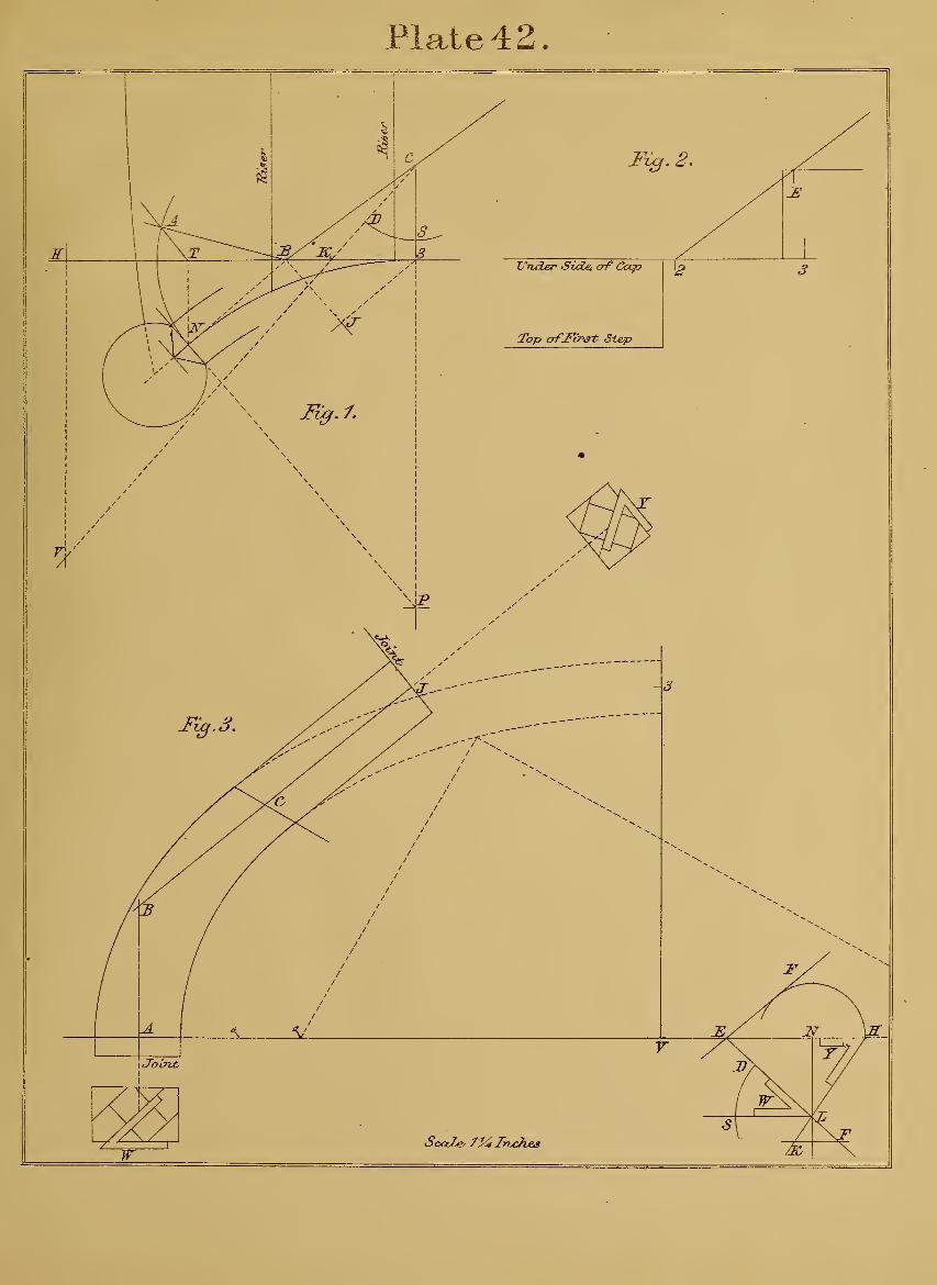
Plate 4 2
Jl
n'/
Fig. 2
L'Tider Sidei of Cocp
Top o-fMrst Step
-3
ScaZe' /^Jhjches


Plate 43.

Plate 43.
lesso:ns on hand-rail construction.
Figure 1 shows a ground-plan for the starting of stairs.
The curve given for centre line of rail is greater than a
quarter circle. Here understand that the radius is not
limited ; it may be less or more, to suit the passage or
situation of stairs, and still have any number of winders-
required. But remeinber, that to have the curve for cen-
tre line of rail just a quarter circle, and no more, that
alone would make it impossible, to give a proper easing
to lower part of wreath, starting from the mitre -cap,
which is the very place most conspicuous in the stairs, and
where no defects of any kind should be seen, nor need
there be, if a little judgment is exercised in laying downa plan similar to that which is here given. The point E,
being the centre from which the curve is drawn for centre
line of rail, take any point on it, as C ; draw from Cthrough E ; again draw C B square vnth C E. This makes
tangents ABC, which are of equal length. Ilfow set off
the number of winders required, say five, as shown ; the
ends on centre line of rail being equal to half a square
step, have the first winder at the newel wider. !N"ow de-
termine height of newel fi'om top of first winder to under
side of mitre-cap, say it shall equal a short baluster, and
one riser added. This understood, make an elevation by
setting ofiT from X five risers ; this done, draw the square
step, and let under side of rail rest on centres of short
balusters ; square over from 3, cutting line through
E A at E ; draw from B through E. This line is the pitch
of one tangent on surface of plank. Now form a ramp
;
let half its thickness be on each side of line E B. This
completes the elevation. To find angle of tangents for
the mould, draw from C square with A B, cutting at D
;
draw from it square with B E; take B as centre and Cradius; intersect line from D at F; join it and B. This
gives F B E as the angle of tangents.
Let us now find half the long diameter of a semi-el-
lipse, in order to strike curves on mould by means of a
string. To do this, draw from A, parallel with B C, cut-
ting atH; make A L equal H C; join L E. This line
is pitch of plank, as its square edge stands over C H on
plan. Now make A N equal radius E C ; square up from
IST, cutting at P. This gives P E for half the long di-
ameter. We are now ready to set a rule to angle F B E.
This done, lift the rule and lay it on a piece of board,
shown at Fig. 2; mark F B E; set off from F the wood
for mitre to equal that on plan; draw the joint square
with F B ; set off from E a distance to equal that shown
on elevation from joint of ramp to E; then make the
joint square with E B. If the board is not sufficiently
wide to draw long diameter on the surface, lay it down
;
bring a straight edge against the joint at F ; fasten both
;
lay down a strip, and draw on it the long diameter square
with F B ; make F 2 equal P E at elevation above ; square
up from 2 ; make 2 H equal radius E C on plan ; set off
half width of rail on each side of H. To determine
width of mould at both ends, we have to find bevels for
joints. To do this, take any convenient place on the
right ; here draw two lines any distance apart, but par-
allel wuth long diameter; take any point on lower line as
D ; draw through it square with D S, cutting at E. This
done, come to elevation above. Here take E as centre,
and with any radius draw the arc S Y ; return with it to
J) as centre ; draw the are S V ; make both arcs meas-
ure equal ; draw through D and "V, cutting K ; draw KC parallel with E B on mould; take E as centre, and for
radius a circle, touching C K, cutting at L ; draw from it
through D. This gives bevel P for joint at E, its appli-
cation, shown oh the joint by square section. The line
D K, having given bevel W, and its application to the
joint, is shown on the left. Now set off half width of
rail below D ; draw it parallel with D S. This gives J J)
to set off on each side of F at wide end of mould, and
N D to set off on each side of tangent at E on mould.
Now find points for pins, and sweep the curves with a
string, which completes the mould. Let us examine it
and see that everything is understood. First prove that
F B E is the actual angle of tangents, this being a most
important point. And to test it, draw any line for a base,
as that of F 2 ; square up from F ; make F B equal C Bon plan. Now take the distance H A on plan, and set
off the same distance above the base, indicated by dotted
line through E. This done, come to elevation above
;
here take E B as radius ; return with it to the mould
;
take B as centre, and intersect dotted line. Now observe
that the intersection thus made has just cut point E,
which shows in the clearest manner the accuracy of this
new discovery in hand-railing.
131

Plate 44.
LESSONS ON HAND-RAIL CONSTRUCTION—PLATFORM STAIRS.
Figure 1 is the ground-plan. The semicircle shows
centre line of rail, its radius being six inches, the steps
ten inches wide. To have the risers on plan in a position,
that will cause both rail and string to present the best
possible effect. This is done by placing one baluster on
the platform opposite A, the position of baluster fixed,
set off from it; the others on centre line of rail. Thedistance apart is five inches, or equal to half a step. This
arrangement gives clear directions to draw riser E on the
right, and riser I) on left, set off from these the width of
two steps, as shown, and draw riser landing and riser
starting. The face of latter should be curved in order to
bring nosing of step into the cylinder. This curve maybe worked in the solid. We have now a plain statement
of the manner in which the ground-plan for platform
stairs should be laid down. And here let it be remem-bered that the same rule applies to stairs having cylinders,
of six or fourteen inches in diameter; but beyond that,
it is best to arrange the risers so as to have three balusters on
platform. Let us now go to work and find a correct
mould for this wreath, which is done by imfolding or
spreading out four times the radius A B on a board, as
shown at Fig. 2. Here lower margin of plate may be
considered the edge of a board, from which are drawndotted lines; these show four divisions, each being equal
to radius A B of plan. Here it may be mentioned that
all principal lines in hand-railing are right angles and
pai-allels. The best and quickest way to draw them is by
a framing square, it having a fence or stop, which is done
by taking a strip, say two inches wide; make a cut
through its edges at each end. This done, slip the piece
on blades of square ; fasten the ends with a screw. Hereyou have a tool with a fence to slide along the edge of
drawing-board; and by means of it right angles or par-
allels are quickly made on any surface, as in the present
case, where are shown steps and risers spread out and
standing exactly in the same position as those on plan.
This being understood, draw the pitches through corners
of square steps on right and left, cutting through D and
B. Join D B ; square over E H and P W, which gives
K as a point. IS'ovv find angle of tangents for the mould,
by drawing from K square with B C; take B as centre
and F radius; draw the circle, cutting line from K at A;join it and B. This gives A B C as the angle. Before
leaving here let us find half the long diameter of a semi-
ellipse, for the purpose of drawing curves on mould bymeans of a string. To do this, make K N equal K W;square over N R; extend pitch C B, cutting at L; draw
from it through IST; draw from W parallel with L N;again draw through E ; square with N L, cutting at Pand T ; make H J on the left equal P T
;join J F. Then
2 F is half the long diameter of semi-ellipse. It is also
pitch of plank. Now set a rule to angle ABC; this
done, lift the rule and lay it on a piece of board, shownat Fig. 3 ; mark ABC; extend B C for straight wood
;
draw from C parallel with B A ; make C 3 equal B A.ISTow come to Fig. 2; here take P IST as radius; return
with it to mould ; take A as centre, and draw the arc of
a circle at 2; then draw through 3, touching the arc at 2;
and we have position of long diameter. This, observe,
may be given independent of point 3 ; and in this way,take T "W" at Fig. 2 as radius ; bring it to the mould
;
take C as centre, and draw the arc as shown ; then a line
touching both arcs produces long diameter. This under-
stood, make 3.2 equal F 2 at Fig. 2; square up from 3;
make 3 O equal A B on plan ; set off half width of rail
on each side of 0. The width of mould at each end is
obtained by having bevels for joints.. To find these bev-
els, take any convenient place on the board as Fig. 4;
here draw two lines any distance apart, but parallel with
long diameter on mould ; take any point on lower line,
say 3 ; draw through it square with 3 Y, cutting through
L. This done, come to Fig. 2; here take F as centre,
and with any radius draw the arc S V; return with it, andtake 3 as centre; draw the arc S Y; make both arcs
equal; draw through 3 and S, cutting at A; draw A Bparallel with A B on mould; again draw A C parallel
with B C on mould. This done, take L as centre, andfor radius a circle touching A B, cutting at R; draw from
3 thi'ough R. This gives bevel H for joint A. Its ap-
plication to joint is shown by square section; then half
width of rail being set off above L, and drawn to cut at
P, which gives P R as half width of mould on each side
of A at the joint. The bevel for joint on straight part
of wreath is found by taking L as centre, and for radius
a circle, touching A C, cutting at IT ; draw from it through
3. This gives bevel W for joint D. Its application to
joint is shown by square section on the right; set off
half width of^rail below 3 ; draw it parallel with 3 Y.
This gives J 3 as half width of mould on each side of
D at the joint; then K 3, being set off on each side of 2
on long diameter, gives width of curves. Now find points
for pins, and sweep the curves with ia string, which com-
pletes the mould. Remember, that when bolting the two
pieces of wreath together, to keep the lines made by bevel
H on each joint opposite.
132

Plate 44
.
Thvtfoi
jRise-T JjozholxTog
Jiiser Sixurting
Fig. 7.
SiserU
JUserJ)
ScoZb' 2Jnches


Plate 45.

Plate 45.
LESSONS ON HAND-RAIL CONSTRUCTION.
Figure 1. Here we change the ground-plan, whicli is
less than a quarter circle, in order to show how easy this
system adapts itself with equal certainty to every con-
ceivable form of wreath, regardless of plan or situation
of stairs. The present case fully illustrates this. Here
we have to find a mould that will produce a wreath
which has two unequal pitches, and is to stand correctly
over its plan.
To solve this problem is not difficult. Let us com-
mence by extending tangent L H to right and left, and
in like manner extend line N H; this done, square up a
line from L ; assume the upper pitch as C A ; extend it,
cutting at R; now make L J equal L H; join A J.
This is lower pitch : both pitches form a certain angle
on surface of plank, that when in position, stands di-
rectly over tangents H L and L T.
To find this angle, draw from T square with L H,
cutting at P ; draw from it square with A C ; take A as
centre and J radius; draw the circle, cutting line from
P at B ; draw from A through B, and we have B A C as
the angle for the mould.
We must now find half the long diameter of a semi-
ellipse, in order to strike curves on mould by means
of a string. To do this, draw from R through T
;
draw from H parallel with R T; now draw through
1^ square with T E, cutting 2.3; make H S equal 2.3;
join S C; make HK equal HN; square up from K,
cutting at E; then E C is half long diameter of semi-
ellipse.
To find position of short diameter on mould, make
H V equal N 3 ; square up from V, cutting at D ; this
gives D C. Here understand that line S C is pitch of
plank : this means on its surface and square edge when
standing inposition over line 2.3 on plan.
"We are now ready to draw the mould. Set a bevel or
rule to angle BAG; this done, lift the rule and lay it
on a piece of board, shown at Fig. 2 ; mark BAG;extend these lines for straight wood, and make joints
square with them ; lay the piece down, and if not sufli-
ciently wide to show long diameter, lay, another piece
alongside ; fasten both ; this done, come to Fig. 1 ; take
3 H as radius ; return with same radius, and from G as
centre draw the arc at D; come again to Fig. 1, and
take 2 T as radius ; return with it, and from B as centre
make the arc as shown. Now draw a line touching both
arcs, and we have long diameter; then, draw from G
square with diameter, cutting at D; make D N E equal
E D G on the right of Fig. 1 ; this done, square up from
IST ; make N equal radius N H, Fig. 1 ; set ofl:" on each
side of half width of rail. The width of mould at each
end is determined as usual by having bevels for joints.
To obtain these bevels, take any convenient place on the
board as Fig. 3. Here draw two lines any distance
apart, but parallel with long diameter at Fig. 2 ; take
any point on lower line, say D ; square up from it, cut-
ting at K ; this done, come to upper corner of plate on
right ; here take G as centre, and with any radius draw
the arc 0' ; return with same radius to D, and with it
as centre draw arc 0'; make both arcs equal; draw
through D and 0, cutting P ; draw P F parallel with B Aon mould; again draw P N parallel with A G on mould;
take K as centre and for radius a circle touching P F,
cutting at J ; draw from it through D ; this gives bevel
"W for joint at wide end of mould, as square section
shows. Again take K as centre and for radius a circle
touching P IT, cutting at L ; draw through it and D
;
this gives bevel X for joint at narrow end of mould, as
shown by square section on the right.
To obtain half width of mould at each joint, and vsddth
of semi-ellipse on long diameter, set ofi" below D half
width of rail ; draw it parallel with T> O' ; this gives
2 D to set off on each side of E, and R D as half width
of mould on wide end ; then 3D is half width of mould
at narrow end on the right. Now find points for pins,
and sweep the curves with a string, which completes the
mould.
137

Plate 46.
LESSONS ON HAND-RAIL CONSTRUCTION.
Figure 1 shows a ground-plan where curve for centre
line of wreath is greater than a quarter circle; this is
just the reverse of that given on preceding plate. This
wreath, like the last, is to have two unequal pitches.
The rule already given holds good in this case as it will
in every other, no matter what the character of wreath
may be. The constructive principle is simply a repetition
of practical truths ; still, we may derive some advantage
by looking over this plate, as it shows how the lines maybe contracted into the least possible space, by means of
which we dispense with great unwieldj'^ drawing-boards,
— a consideration of no small importance where room is
limited.
Let us now proceed with the explanations. The curve
for centre line of rail is struck from point IT, and is in-
closed by tangents meeting in L. Here it may be well
to remember that any two tangents from a circle, as
those of H L and T L, are always equal or the same
length. But tangents to an elliptic curve may be un-
equal, and yet made to stand exactly over equal tangents
to a circle, as will be the case here. To understand this
point, extend L H to right and left, and in like manner
extend line IsT H ; square up a line from L. Now assume
C A as upper pitch for wreath ; square over A J; join
J L. This is lower pitch ; or we may make it the upper,
and C A the lower. Proceed to find angle of tangents
for an elliptic curve. To do this, draw from T square
with L H, cutting at P ; draw from it square with A C
;
take L J as radius ; with same radius and A centre in-
tersect line from P at B ;join it and A; then we have
B A C as the angle, which, being in position, will stand
directly over T L and L H. And if an elliptic curve was
drawn, it would range with circle of plan. But to makeeverything clear, find half the long diameter of a semi-
ellipse and pitch of plank, in order that curves on mould
may be drawn by mieans of a string. To do this, extend
upper pitch C A, cutting at R; draw from it through T;
draw from H parallel with T R; now draw through
centre N square with T R, cutting 2.3 ; this done, makeH S equal 2.3
;join S C. This is pitch of plank. Make
H K equal radius N H ; square up from K, cutting at E.
This gives E C as half long diameter of semi-ellipse. To
find position of short diameter, make H V equal 8 liT;
square up from V, cutting at D. This gives D C.
We are now ready to di-aw the mould in the usual
way, by setting a rule to angle B A C ; this done, lift the
rule and lay it on a piece of board, shown at Fig. 2
;
mark BAG; extend the lines for straight wood, and
make joints square with them; come to Fig. 1; here
take 3 H as radius ; return with it to C as centre ; draw
the arc atD; come again to Fig. 1 ; take 2 T as radius;
return with it, and take B as centre ; draw the arc as
shown. ITow draw a line touching both arcs, and Wehave position of long diameter ; draw from C square
with diameter, which gives point D ; make D IS equal
D E on pitch (above Fig. 1 to the right) ; make D Eequal D C (also on pitch) ; square up from E ; make E Oequal radius IST H, Fig. 1 ; set off on each side of half
width of rail. The width of mould at each end is ob-
tained by having bevels for joints.
To find the bevels. These may be given on a separate
piece of board, or at any convenient place, as Fig. 3.
Here draw two lines any distance apart, but parallel with
long diameter. Take any point on lower line, say A
;
square up from it, cutting at K; this done, come to
upper part of plate at C ; take it as centre, and with any
radius draw the arc 0'; return with same radius to
point A, and with it as centre draw arc 0' ; make^
both arcs measure equal; draw through A and 0', cut-
ting at P ; draw P F parallel with A B on mould ; take
K as centre and for radius a circle touching P F, cutting
at J ; draw from it through A, and we have bevel "W for
joint at wide end of mould; square down from P, cut-
ting at H; draw H L parallel with A C on mould; take
P as centre and for radius a circle touching H L, cutting
at Y ; draw from it through H. This gives bevel X for
joint at narrow end of mould on the right. ]N"ow set off
half width of rail below line A H; draw it, cutting
through bevel lines, which gives 2 A to set off on each
side of N at Fig. 2 ; then 3 A is half width of mould at
wide end, and R H is half width of mould on narrow end
to the right; draw the straight wood parallel with tan-
gents A B and A C. Now find points for pins, and sweep
the curves with a string, and the mould is complete.
138

Plate 46.


Plate 4 7
.
ScaZec /^JnrAes

Plate 47.
LESSONS ON HAND-RAIL CONSTRUCTION.
This drawing gives a practical illustration of preceding
plate. The explanations here, and in fact throughout,
are necessarily repetitions, because the constructive prin-
ciple is the same in every particular, and applies to all
forms of wreath.
Fig. 1 shows the ground -plan of stairs having four
winders in the circle, with square steps above and below;
the tangents for centre line of rail form an acute angle
and meet in point P. This wreath is to be in one piece
;
its upper end to form a ramp, and connect with straight
rail over the square steps.
To do this, extend the tangent P H to right and left
;
draw from centre N through H ; then square up a line
from P. We now want the exact pitches for this wreath,
which is soon given by spreading out the tangents P Tand P H ; also the winders and two square steps. This
is shown at Fig. 2. Here they stand in precisely the
same position as those of Fig. 1. The square steps on
right and left show centres of short balusters, as 0.
Let under side of rail rest on these ; set off half its thick-
ness, and draw the pitch, cutting through B A; then Ais a fixed point, from which draw through C, or in such
manner as to form an easy ramp ; this done, draw from
A square with risers, cutting at P, which gives P B as
one height; now draw from C square with risers, cutting
at S; this gives S A for lower height; transfer height
P B to Fig. 1, and make P A equal it ; square over A S
;
make S C equal S A, Fig. 2 ; draw from C through A,
cutting at R; join A H; this being done, proceed and
find angle of tangents for the mould, by drawing from Tsquare with P H, cutting at L ; draw from it square with
A E, ; now take A as centre and H radius ; intersect line
from L at B; join it and A. This gives B A C as the
angle: its sides are just equal to pitches BAG, Fig. 2.
Before leaving here, find pitch of plank, and half the
long diameter of a semi-ellipse, and position of short
diameter. To do this, draw from R through T; drawfrom H parallel with T R ; again draw through Iv square
with T R, cutting at 2 J; make H 3 on right equal 2 J;
join 3 C ; now make H K equal radius BE jST; square up
from K, cutting at E. This gives E C as half the long
diameter of semi-ellipse.
To find position of short diameter, make H V equal
K" J ; square up from V, cutting at D. This gives D C.
We are now ready for the mould. First set a bevel or
rule to angle BAG; this done, lift the rule and lay it
on a piece of board, shown at Fig. 3 ; here mark BAG;extend these lines for straight wood ; make G H on right
equal G H on the left at ramp below ; draw through Hsquare with G A ; make straight wood B K on the left
any length desired ; draw through K square with B A
;
this done, come to Fig. 1, and take H J as radius; return
with it to G as centre, and draw the arc as shown at D
;
come again to Fig. 1, and take 2 T as radius; return,
with it to B as centre ; draw the arc shown at E ; nowdraw a line touching both arcs, and we have position of
long diameter. This done, draw from G square with
diameter, cutting at D ; make D IST equal D C above Fig.
1 on the right ; then make jST E equal E G at same place
above ; now square up from N, and make IN" equal
radius jST H, Fig. 1 ; set oft" on each side of half width
of rail.
The width of mould at each end is obtained by having
the bevels for joints. To find these bevels, come to any
convenient place on the board as Fig. 4 ; here draw two
lines any distance apart,, but parallel with long diameter
at the mould; take any point on lower line, say L;square up from it, cutting at K; this done, come to upper
part of the plate at G; take it as centre, and with any
radius draw the arc 0' ; return with it to L as centre
;
draw the arc O O' ; make both arcs measure equal; then
draw through L and 0, cutting at P ; draw P A parallel
with A B on the mould ; take K as centre, and for radius
a circle touching P A, cutting at J ; draw from it through
L. This gives bevel X for joint at K on the mould. Thesquare section shows the application of bevel X. Pro-
ceed and find a bevel for joint at H on the mould. Todo this, draw K T parallel with G A on mould ; square
down from P, cutting at Y ; take P as centre, and for
radius a circle touching T K, cutting at R ; draw from
it through Y. This gives bevel W, its application to the
joint shown by square section on the right. ISTow set
off half width of rail below Y L, indicated by dotted line.
This gives S Yto set off on each side ofH on the mould,
and 3 L to set oft" on each side of K, also on the mould
;
then 2 L being set ofi" on each side E on long diameter,
gives width of curves. By means of these and Avidth of
rail on short diameter, points are found for pins, which,
being fixed, take a string, sweep the curves, and the
mould is complete.
143
Plate 48.
LESSONS ON HAND-RAIL CONSTRUCTION.
Figure 1. We uow come to the last plate, where is shown aground-plan, differing from any that has yet been given. Still,
the same rules and system of lines are here applied as in everyother case, so that this plate may be considered to exhaust thesubject entirely. To add anything further would not only be
- useless, but encumber the work to no purpose. Nor is it neces-sary, as we are confident that the instructions already given, if
followed, are quite sufficient for any intelligent workman to be-come a master of this branch of joinery.
Let us now proceed with the explanations. In the first place,enclose centre line of rail by tangents ; this being done, drawriser landing ; set off from it on tangent half a square step asA B ; now set off from B on centre line of rail the number ofwinders required ; let the spaces apart be equal to A B. Thenext question is to find the exact pitches for the wreath. To dothis, unfold or spread out three times the radius N P ou a narrowboard, as shown at Fig. 2, aud indicated by dotted lines fromlower margin of plate, which may be considered the edge of aboard ; uow set ofl" the winders, aud oue square step to stand herein the same position as those on plan. The measurements aretaken from points where risers cut tangents. This being done,we have the elevation of tangents, winders, aud oue square stepas a guide' to draw the pitches ; then let under side of rake-railrest on centre of short balusters O O, as shown ou square step
;
set off half its thickness ; now come to floor line on the left ; heredraw under side of rail to stand half a riser above the floor ; setoff half its thickness, cutting at D, it being a fixed point, fromwhich draw, say through B, aud from B draw through A, or insuch manner as to give the ramp an easy curve at the junctionof winders and square steps. Here it is seen that lower wreathpiece is to have two unequal pitches. This is done for the pur-pose of making the rail more uniform in height over the winders,which would not be the case if a straight line had been drawnfrom D through A. The upper wreath piece forms its own rampon the landing.
To find the heights of both pieces, draw from point A parallelwith the steps, cutting at P. This gives P C as the lower height.Now draw from C square with C P, cutting at E. This givesE D for upper heiglit. Let us now prepare for drawing themould, by forming a square as that at Fig. 3, which is equal toone of those on plan. This done, extend P N to the riglit andleft ; also extend sides K P and T N ; make P C and N B equalheights P C and N B at Fig. 2 ; draw from C through B, cuttingat V
I
make N L equal N P;join L B. This gives L B C for
the pitches of tangents on lower wreath piece. To find the anglewhich these tangents make on the surface of mould. This is
done by drawing from N square with B C ; take B as centre andL radius
; draw the circle, cutting line from N at A;join it and
B. This gives A B C as the angle.
We must now find pitch of plank, and half the long diameterof a semi-ellipse, in order to strike curves ou mould with a string.To do this, draw from V through T ; draw from P parallel withT V
;again draw through K square with T V, cutting at 2 J
;
make P 3 equal 2 J;join 3 C. This is pitch of plank. Now
make P R equal P N ; square up from R, cutting at D. Thisgives D C as half long diameter of semi-ellipse. The positionof short diameter ou the long, is found by making P E equalK J; square up from E, cutting at F, which gives F C; thisdone, set a rule to angle ABC. Be correct in this ; now lift
the rule and lay it on a piece of board, shown at Fig. 4 ; markABC; extend B A ; make A 3 equal A 8 at the ramp below
;
draw joints through 3 and C square with tangents. This done.
come to Fig. 3, and take P J as radius ; return with it to jomtC as centre ; draw the arc at F ; come again to same place, andtake 2 T as radius ; return with it to A as centre ; draw the arc.Now draw a line touching both arcs, and we have the positionof long diameter ; draw from C square with long diameter, cut-tmg at F ; make F L equal F C above Fig. 3 on the right ; nowmake L J equal D C at the place just mentioned ; square up aline from L
; make L O equal one side of square, Fig. 3 ; set offon each side of O half width of rail.
The width of mould at each end is obtained as usual by find-ing bevels for joints. This is done at any convenient place, sayFig. 5. Here draw two lines any distance apart, but parallelwith long diameter at the mould ; take any point on lower lineas V ; square up from it, cutting at N. This done, come to C atupper part of plate ; take it as centre, and with any radius drawthe arc O O' ; return with it to V as centre, and draw arc O O'
;
make both arcs measure equal ; draw through V and O, cuttingat P
; draw P R parallel with A B ou mould ; take N as centre,and for radius a circle touching P R, cutting at C ; draw fromit through V. This gives bevel W for joint at 3 on the mould.Draw from P a line parallel with A L on mould ; take N againas centre, and for radius a circle touching line just drawn fromP, the circle cutting at S ; draw through" it and V. This givesbevel X for joint at C on mould. The application of both bevelsto joints, is shown by the square sections on right and left.
To find width of mould at each joint, set off" half width ofrail below V ; draw it parallel with V O', cutting bevel lines,
which gives K V to set ofl" on each side of 3 at the joint, andE V to set off on each side of C at joint on the right. Then2 V, being set off on each side of J on long diameter, gives widthof elliptic curves, by means of which, and width of rail on shortdiameter, we find points for pins, in order to sweep the curveswith a string. This being done, the mould for lower wreathpiece is complete.
Fig. 6. To draw a mould for upper wreath piece. This is asimple affair, and quickly done by laying the framing square ona piece of board, and drawing the right angle C ,D 2 ; makeC D equal the pitch C D, Fig. 2 ; square down from C, and makeC E equal N P on plan ; draw through E parallel with C D; setoff half width of rail on each side of C. To find width of mouldon wide end aud a bevel for joint. This is done by making E Nequal ED at Fig. 2 ; draw from N through C, which gives bevelL for joint. Now draw the line, cutting at K, and we have C Kto set off on each side of 2 at the joint. The width being ob-tained, draw straight wood parallel with 2 D, the length of this
four or five inches. Now find points for pins, and sweep thecurves with a string, which completes the mould.
_Here, remember, it has already been stated, that the applica-
tion of all moulds is simple, yet positive. The rule perhaps hadbetter be repeated, which is as follows : The wreath piece havingbeen cut square through the plank, and joints made, then thebevel is applied. Its stock rests ou the surface, and its bladepassing through a point which is in half the width and halfthickness of stuff, the line made by bevel is to be continued onboth surfaces and square with joint. Then, similar lines beingon both surfaces of mould, these lines, and those on the piece,are made to fall directly over each other, so that the exact cyl-inder form of a wreath is given by a mould being applied in themanner just stated. The same rule holds good for the thick-ness, half of which always passes througli half the thickness ofplank. Adhere to these plain and simple directions, and noerrors or mistakes can possibly occur in forming a wreath.
144

Plate 48
.

r--^


Ci. '
..V^^' .>>\' '.
c.
^
A^'
^OCS^
c.0^
V'
^ .0-'
V^ V
X*
a\' .^
.^^^^v
,-'^aP ^
^0
x"^-, \..^
\'
^0 O > ^-'l- ,
0'^ >̂
'V^</.
,^V>"
\' v.-**".
V» ,
> - -0-
^^ V^'
> .0' o
«>!r
.x\^
*^^^.
v>''^
0" .<
-bo^
.0 o. .'-. i:>^-
^rS>^'
O^ ^"' " '/, ''r^
\'.^•^ "% .V
Oo.
-:>,
^\> -".f
S>
\^^
<r "^
,0 0^
'7-> *
.*^
V\^^
'<^
.#\"^'.
x^" ''^..^°^..
"oo^ ^^- v^^
\,0- " 'ia
,0'
>>• \'\'
<~ >
"> N
'"-P.
^ .^"^ =
^ o^ "^^
*::(. «
<^^ ^
» « ^
=^/- v^'
nOo.^^^ "'^^

^ N^
V',V '<^^ .^'
A.^ "k..
.-^^
-\^^^
.&^- -^
^
^
,-v ^*,
.v^
"O^ ."
>>.. .-.N
'^, v?^"
..yv^^ %
A'''
.^-^ '"'^^ ^^^ ^^o5--
J 1 ^'
.X' '^r^^'
> -^*^^^"
x^""-^.V'' >^3^>\
^^.V «-
\'S>c.
"5^ -\X
.-^-^
,<;
.\
> -^^
.0-^'
s,^-
vX^^^.r
=i/. * » N ' X^
"CO'
.\
% ...^\^'= -^^
,0
'/. - .X
A A.
^ ^c,-^"^' *'^
.•-^-'
•f-
-S-. .sV'
t. C-
^>'i , ,
^ ,X" '>. -^
O
'^4'
-s^^^.^'^^
•xv"
. ' Kp a'!
oV'
^•^ 6^
vOC-
^^.
-?>
'^^
J- .\\
%*««c;^'v'
;^^^0
^ "v.
A'
..^^ .^
A'
1 "Ox^ ^Vy?:%z.% '

bmm.mfU'l P'' CONGRESS
019 971 097 7i
•'.it^A\.>Jt .
i•'
-I
V 'v V ^ - - ••'''.
-".'
.•.
,1. I . .
•'.'" >',"
' ^?> .;;, -!
1 \, V, •.(,'>.,-l'' >' '.


![John Alden Carpenter Collection [finding aid]. Music Division ...](https://static.fdokumen.com/doc/165x107/63283a2be491bcb36c0baaac/john-alden-carpenter-collection-finding-aid-music-division-.jpg)


