MECHANICAL WORM SCREW JACKS - CP Automation
100
MECHANICAL WORM SCREW JACKS Made in Italy
-
Upload
khangminh22 -
Category
Documents
-
view
1 -
download
0
Transcript of MECHANICAL WORM SCREW JACKS - CP Automation

MECHANICAL WORM SCREW JACKS
Made in Italy

CHIARAVALLI GROUP world: much more than a collection of perfects mechanical components

32000m2 production plants in Italy
26000m2 logistics sites in Italy
10production and commercial sites in Europe
Over240employees in Italy
ONE capillary network of distributors in the European Community
The Manufacturer DISTRIBUTOR

2
The Chiaravalli group is the technological partner that you should turn to knowing that reliability and respect are valuescommonly shared.

The Chiaravalli group is a dynamic, modern company oriented infulfilling customersneeds and desires.
Human progress has always been based on mechanical application and discovery that stem from human intutition and genius.
Mechanics: the genetic heritage ofChiaravalli Group
The Chiaravalli Group, always aware of the needs of the market has found it necessary to provide its long-standing customers with complete, steady up-dated information about its products 24 hours a day 365 days in a year.
This attention comes from B2B, which is the direct consequence of our interest and dedication to our customers. It is an advanced system of research,purchasing and delivery of all Chiaravalli products.B2B Chiaravalli Group becomes a virtual extension of the customer’s warehouse.
3
THE CUSTOMER: ALWAYS AT THE CENTRE OF OUR ATTENTION.

RESEARCHour Group has always been engaged in constant research of brand new products, to be entered into our sales program, together with awareness of the potential benefitsof manufacturinglong-standingproducts using newmodern materials.
DESIGNour technical officedesigns with a CADSystem the new products that will contribute to the expansion of the product range offered by Chiaravalli Group SpA, being able to rely onthe expertise of highlyexperienced co-workers.
PROTOTYPINGwe have at our disposala wide range of CNC Machines, and make use of the most advanced CAM techniques, which enable us to producePrototypes both for our range of products, and also for a large customer base, who rely on our Group with confidence.
4

LOGISTICSour logistics, with its excellent organization and interactive database,allows us to make daily shipments in over52 countries.
QUALITYCERTIFICATION
all our production iscontrolled step by stepduring its production cycle.Various measuring rooms, equipped with modern three-dimensionalmeasuring machines,allow a full certificationof our products.
PRODUCTIONtaking advantage of ourmodern and large CNC tools fleet, we produce by means of CAD-CAM technology, high precision mechanical components.
SHIPPINGSERVICES
we operate in over 52 countrieswith a large number of national and international forwarders.Our constantly updated information service allows us to track thetransport of products to ensure a timely and accurate delivery.
5

JACKSWORM SCREW
JACKSWORM SCREW
The new line of Worm Screw Jacks named CHT (Chiaravalli High Tech) integrates and completes our range of Mechanical Transmission products.
This new line of products is manufactured using high quality materials, manufactured with absolute preci-sion, making use of the modern machinery fleet of the companies belonging to Chiaravalli Group SpA.
The basic elements that make up the final product “Screw Jack” are made in large series, rigorously checked and put in stock.Special virtual software developed by Chiaravalli Group SpA enables our customers to first view the various elements of the required screw jack and then, in the second phase, to order it with absolute preci-sion and confidence.
Chiaravalli Group SpA is engaged to ensure the de-livery of this product in very short time, with quality and precision.
6

NEW SERIES HEAVY LINE
CHS 9 · CHS 10 · CHS 12 · CHS 14 · CHS 16
With our experience, we have designed and realized the New Worm Screw Jack Series Heavy Line.
Only two points to remark the mechanical and dynamic performances of this new range:
1 · monolitic structure, totally obtained by mechanical machining operations
2 · mechanical assembly realised with taper roller bearings
Technical data from pages 52 to pages 71
7
HEAVY LINECHS 9 · CHS 10 · CHS 12 · CHS 14 · CHS 16

INDEX
Introduction Page 10
Screw jack designation Page 11
General features Page 12
Dynamic loads Page 12
Static loads Page 13
Radial load Page 14
Manuak handling / Drive by electric motor Page 15
Lubrication Page 17
Compression load Page 18
Screw jack model TS Page 20
Screw jack model RS 21
Screw jack performance 22
Screw jack model TS Page 24
Screw jack model RS 25
Screw jack performance 26
Screw jack model TS Page 28
Screw jack model RS 29
Screw jack performance 30
Screw jack model TS Page 32
Screw jack model RS 33
Screw jack performance 34
Screw jack model TS Page 36
Screw jack model RS 37
Screw jack performance 38
Screw jack model TS Page 40
Screw jack model RS 41
Screw jack performance 42
Screw jack model TS Page 44
Screw jack model RS 45
Screw jack performance 46
Screw jack model TS Page 48
Screw jack model RS 49
Screw jack performance 50
CHS1
CHS2
CHS3
CHS4
CHS5
CHS6
CHS7
CHS8
8

INDEX
Screw jack model TS Page 52
Screw jack model RS 53
Screw jack performance 54
Screw jack model TS Page 56
Screw jack model RS 57
Screw jack performance 58
Screw jack model TS Page 60
Screw jack model RS 61
Screw jack performance 62
Screw jack model TS Page 64
Screw jack model RS 65
Screw jack performance 66
Screw jack model TS Page 68
Screw jack model RS 69
Screw jack performance 70
Screw jack with ball screw Page 72
Flanged single nut Page 73
CHS 2 VRS - CHS 3 VRS Page 74
CHS 3 VRS - CHS 4 VRS 75
CHS 4 VRS - CHS 5 VRS 76
Special mechanical worm screw jacks Page 77
Configurations Page 78
Options Page 79-82
Protection tube Page 83
Spare parts Page 84
Safety nut Page 86
Pivoting rigid protection - PO Page 87
Mounting examples Page 88
General sales conditions Page 97
CHS9
CHS10
CHS12
CHS14
CHS16
9
HEAVY LINE
HEAVY LINE
HEAVY LINE
HEAVY LINE
HEAVY LINE

INTRODUCTION
The new series of mechanical screw jack CHIARAVALLI, named CHS, is a product, the innovation of it is due to modularity whitch allowins to supply a customized product in reasonable times.The coupling with electric motors (either on normal, motor brake or explosion-proof motors) is guaranteed thanks to the predisposition to IEC B5 and B14 flanges.This type of worm gear screw jack is used in many fields where it is necessary to lift considerable weights, such as automated produc-tion lines for sheet metal machinery, packaging, printing, textiles, plastics, food, renewable energy and more.
PRODUCT FEATURES
- modularity - customization - high strength cast iron case - hardened and ground worm gear - long life lubrication
CHS Series screw jacks are manufactured in 13 sizes, customizable with all the accessories included in the catalogue, according tocustomers’ requirements.
10

SCREW JACK DESIGNATION
SCR
EW
JA
CK
DE
SIG
NA
TIO
NCHS-_-__-C____-R__-__-__-___-PAM___B__--_,__Kw-_P-_-SP___________
SIZE 1·2·3·4·5·6·7·8·9·10·12·14·16
TRANSLATING SCREW TSROTATING SCREW RS
STROKE mm
RATIOCHS 1 RATIO 5 - 20CHS 2 - 3 - 4 - 5 - 6 - 7 - 8 RATIO 5 - 10 - 30CHS 9 - 10 - 12 - 14 - 16 RATIO 10 - 30
SCREW ENDS TS - TF - TL - TP
INPUT SHAFT CONFIGURATION
DX - Right SX - Left DE - Double input
INPUT MOTOR SHAFT
M3 - Right - M4 - LeftM1 - Right shaft DE M2 - Left shaft DE
OPTIONALS
PR - PE - AR - AS - FC - PO - AM - CU - RG - CS - FCO - VRS - LO - CF - OX
MOTOR FLANGE SIZE
56 - 63 - 71 - 80 - 90 - 100 - 112 - 132
MOTOR FLANGE TYPE (B5 O B14)
MOTOR POWER Kw (IF REQUIRED WITH MOUNTED MOTOR)
POLES MOTOR NUMBER: 2 - 4 - 6 (IF REQUIRED WITH MOUNTED MOTOR)
MOTOR TYPE: T-3PHASES, F-SELF BRAKING MOTOR (IF REQUIRED WITH MOUNTED MOTOR)
SP SPECIAL FEATURES - DESCRIPTION
11

TRACTIONThe maximum traction load which can be applied to the screw jack, is determined by several factors: heat capacity, temperature, service, im-pact or radial loads. Make use of tables on pages 20 - 71 and page 18-19
COMPRESSIONThe maximum load used in compression is influenced by several factors: length of the threaded shaft, thermal capacity, shock and radial loads, temperature and type of service. Make use of tables on pages 20 - 71In addition, the load causes a deflection of the same, thus requiring a further examination to be carried out using the table on page 18-19, according to the Eulero’s formula, linked to the type of external guides, so as to determine the maximum load.
RADIALIn dynamic applications radial loads ARE NOT ALLOWED.
OVERTURNING MOMENTAs well as for radial loads, overturning moment are not allowed: over-come the problem by using appropriate sized external guides, that will avoid to subject the screw jack to such loads.
DYNAMIC LOADS
GENERAL FEATURES
The worm gear based mechanical screw jack is one of the most econo-mical and efficient mechanism for lifting and lowering loads, for push-pull applications. It can be used as a single unit or in multiple combinations, with manual or motorized drive. It is possible to link two or more screw jacks by shafts, couplings and right angle gear boxes, so that all the ope-rations are perfectly syncronized. CHIARAVALLI worm screw jacks are built for nominal loads from 0,5 to 100 tons.
ANALYSIS AND COMPOSITION OF LOAD
For the correct selection of the screw jack and, consequently, for its pro-per functioning, it is necessary to identify the actual load and the nature of the load, as better specified here below:
- STATIC loads- DYNAMIC loads
These in turn can be:
- TRACTION loads- COMPRESSION loads- RADIAL loads- COMPOUND loads
RADIAL
TRACTION
CH
T
TRACTION
CH
T
COMPRESSION
RADIAL
CH
T
COMPRESSION
RADIAL
CH
T
12

GENERAL FEATURES
STATIC LOADS
TRACTION
The maximum load in tension applied to the Screw Jack is the max one foreseen by the tables of use on pages 20 - 71
COMPRESSION
The maximum load used in compression is influenced by the length of the threaded shaft, and can be checked in the chart on page 18-19, according to Eulero’s formula, linked in to the type of external guides.
RADIAL
These special loads cause a lateral shift of the shaft, provoking a dan-gerous deflection which would reduce the capacity of the screw jack. These therefore must be avoided.
OVERTURNINGS LOADS
As well as for radial loads, overturning moment are not allowed: over-come the problem by using appropriate sized external guides, that will avoid to subject the screw jack to such loads.
CH
T
CH
T
CH
T
CH
T
CH
T
CH
TC
HT
CH
T
13

WORM SCREW LOAD (INPUT SHAFT)
MAXIMUM RADIAL LOAD (Fr)
The maximum load on the input shaft of the jack (worm screw) must not exceed the values specified in the table below, measured at half shaft.
TORQUE (daNm) (INPUT SHAFT)
For applications with multiple screw jack mounted in series, it is necessa-ry not to exceed the values specified in the table below:
VIBRATIONS
CHIARAVALLI jacks, with threaded shafts, are absolutely IRREVERSIBLE, special braking systems to maintain the set positionso are not required.If they should be subjected to high vibrations, we do suggest to brake the input shaft (for example by using a self-braking electric motor).
GENERAL FEATURES
CHT
Fr
==
Fr
==
CHT CHT CHT CHT CHT
SIZE CHS 1 CHS 2 CHS 3 CHS 4 CHS 5 CHS 6 CHS 7 CHS 8 CHS 9 CHS 10 CHS 12 CHS 14 CHS 16
Fr (daN) 10 22 45 60 60 60 90 90 100 250 250 300 300
SIZE CHS 1 CHS 2 CHS 3 CHS 4 CHS 5 CHS 6 CHS 7 CHS 8 CHS 9 CHS 10 CHS12 CHS 14 CHS 16 MT MT MT MT MT MT MT MT MT MT MT MT MT (daNm) (daNm) (daNm) (daNm) (daNm) (daNm) (daNm) (daNm) (daNm) (daNm) (daNm) (daNm) (daNm)
Fast speed 2,30 5,40 7,00 49,00 49,00 49,00 80,5 80,5 - - - - - (1/5)
Normal speed 2,30 5,40 18,50 15,50 13,00 15,30 60,3 60,2 200 520 520 820 820 (1/10-1/20)
Slow speed - 4,20 15,50 13,00 15,50 13,00 48,2 48,2 200 440 440 980 980 (1/30)
14

GENERAL FEATURES
MANUAL HANDLING
All CHIARAVALLI screw jacks can be operated manually. The following table shows the maximum load, assuming that a 250 mm diameter wheel is put at input jack to and 5 Kg force is applied to that wheel. Higher loads can be obtained by inserting a CHIARAVALLI gear box between the wheel and the jack or by increasing the wheel diameter.
DRIVE BY ELECTRIC MOTOR
CHIARAVALLI series of screw jacks is provided for the connection with electric motors. The tables from pages 20 to 71 define the engine power and the torque at the start-up of dynamic load, the reduction ratio and the linear speed, related to a use of 30% out of 10 minutes of operation. MECHANICAL EFFICIENCY
The mechanical efficiency is shown in the table on pages 20 - 71. In the assembly of several jacks, to calculate the total efficiency of the transmis-sion, it should be considered a decrease of 5% performance by each screw jack, for example: - 2 jacks 95%- 3 jacks 90% etc.. etc..
HEATING
CHIARAVALLI screw jack, being an IRREVERSIBLE machine, has a relati-vely low mechanical efficiency, so a certain amount of installed power will turn into heat, bringing the jack, if used correctly, to a maximum tempe-rature of 80 ° C.
LOAD
From the tables on pages 20 - 71 you can detect the maximum loads for each screw jack not to be exceeded. To select the jack, it is necessary to apply also the coefficients stated below, relating to temperature and duty cycle. If different from the calculation conditions, they can change the actual load. Also check the maximum buckling load from the table on page 18, which changes according to the length of the lifting screw.
Lifting weights with manual operations
SIZE CHS 1 CHS 2 CHS 3 CHS 4 CHS 5 CHS 6 CHS 7 CHS 8 CHS 9 CHS 10 CHS 12 CHS 14 CHS 16 daN daN daN daN daN daN daN daN daN daN daN daN daN
Fast speed 500 1000 2000 1500 1000 950 900 860 - - - - - (1/5)
Normal speed 500 1000 2500 2900 2000 1800 1600 1500 - - - - - (1/10-1/20)
Slow speed - 1000 2500 5000 4300 3800 3200 3200 - - - - - (1/30)
15

OPERATING TEMPERATURE
All data mentioned in this catalogue refer to a room temperature of 20° C. For different room temperatures it is necessary to derive the correction “x” factor from the table here below. For the JACK CORRECT CAPACITY, multiply the jack load capacity by then “x” factor.
OPERATION - SERVICE FACTOR
The tables on pages 22 - 36 refer to a service of 30% in 10 minutes and at a room temperature of 20° C. For different services, it is necessary to find the “SF” Service Factor relating to the service required by consulting the chart here below and multiplying the dynamic load factor such factor.
POWER AND INPUT TORQUE
See the tables from page 20 to page 71: for the boxes with a light blue background consult our technical department.
GENERAL FEATURES
% OUT OF 10 MINUTES 30% 40% 50% 60% 70% 80% 90% 100%
“SF” Factor 1 1,1 1,3 1,6 2 2,5 3 5
ROOM TEMPERATURE 10° 20° 30° 40° 50° 60° 70° 80°
“X” Factor 1,25 1 0,8 0,7 0,5 0,3 0,2 0,1
16

CHIARAVALLI screw jacks are lubricated with a long life lithium soap gre-ase AGIP GR MU EP2 and fitted with grease lubricator, for subsequent operations.
LUBRICATION INTERVALS:
normal working conditions: once a month heavy work conditions: once a weekcontinuous working conditions: foresee lubrication system.
LUBRICATION OIL (OPTIONAL)
On request, it is possible to have oil lubrication.Here below the recommended types of oil:MOBIL GEAR 630SHELL OMALA 220IP MELLANA 220
LUBRIFICATION LIFTING SCREW
A correct life of CHIARAVALLI screw jack also depends on the lifting screw good lubrication, which must be carried out not later than approxi-mately 500 hours of normal working. Heavy duty or special environmen-tal conditions reduce this lubrication interval.
The recommended lubricants for this operation are:
ROTHEN 2000/P SPECIAL - KLUBER STRUCTOVIS CHD
TOTAL CERAN WR2 - BECHEM-RHUS BERUTOX M 21 KN
USE ISTRUCTION
STROKE - 2000 mm maximum standard strokeLonger strokes are made on request.
SPEED - the linear speed that can be used byscrew jacks depends on several factors:TYPE OF SCREW JACK and transmission ratio
THERMAL CAPACITYDYNAMIC LOADROOM TEMPERATURESERVICE
The tables on pages 20 - 71 define, according to the load, the power required torque and the speed limit.
GENERAL FEATURES
LUBRICATION
17

GENERAL FEATURES
CRITICAL COMPRESSION LOAD
SIZE
Deflection lengh (mm)
Eulero 1 Eulero 2 Eulero 3 Eulero 4
100 200 285 400
125 250 355 500
150 300 425 600
175 350 495 700
200 400 565 800
225 450 635 900
250 500 710 1000
275 550 780 1100
300 600 850 1200
325 650 920 1300
350 700 990 1400
375 750 1060 1500
400 800 1130 1600
425 850 1200 1700
450 900 1275 1800
475 950 1345 1900
500 1000 1415 2000
525 1050 1485 2100
550 1100 1555 2200
575 1150 1625 2300
600 1200 1700 2400
625 1250 1770 2500
650 1300 1840 2600
675 1350 1910 2700
700 1400 1980 2800
725 1450 2050 2900
750 1500 2120 3000
775 1550 2200 3100
800 1600 2270 3200
825 1650 2340 3300
850 1700 2400 3400
875 1750 2475 3500
900 1800 2546 3600
925 1850 2620 3700
950 1900 2690 3800
975 1950 2760 3900
1000 2000 2830 4000
1050 2100 2970 4200
1100 2200 3110 4400
1150 2300 3110 4600
1200 2400 3400 4800
1250 2500 3540 5000
1300 2600 3680 5200
EULERO 1
EULERO 2
EULERO 3
EULERO 4
EULERO 4
18

CHS 1 CHS 2 CHS 3 CHS 4 CHS 5 CHS 6 CHS 7 CHS 8 CHS 9 CHS 10 CHS 12 CHS 14 CHS 16
kN kN kN kN kN kN kN kN kN kN kN kN kN
5,00 10,00 25,00 50,00 100,00 150,00 200,00 250,00 300,00 400,00 600,00 800,00 1.000,00
5,00 10,00 25,00 50,00 100,00 150,00 200,00 250,00 300,00 400,00 600,00 800,00 1.000,00
5,00 10,00 25,00 50,00 100,00 150,00 200,00 250,00 300,00 400,00 600,00 800,00 1.000,00
5,00 10,00 25,00 50,00 100,00 150,00 200,00 250,00 300,00 400,00 600,00 800,00 1.000,00
5,00 10,00 25,00 50,00 100,00 150,00 200,00 250,00 300,00 400,00 600,00 800,00 1.000,00
4,00 7,10 25,00 50,00 100,00 150,00 200,00 250,00 300,00 400,00 600,00 800,00 1.000,00
3,30 5,80 25,00 50,00 100,00 150,00 200,00 250,00 300,00 400,00 600,00 800,00 1.000,00
2,75 4,80 22,80 50,00 100,00 150,00 200,00 250,00 300,00 400,00 600,00 800,00 1.000,00
2,30 4,00 19,40 50,00 100,00 150,00 200,00 250,00 300,00 400,00 600,00 800,00 1.000,00
2,00 3,40 16,50 50,00 100,00 150,00 200,00 250,00 300,00 400,00 600,00 800,00 1.000,00
1,70 3,00 14,20 50,00 100,00 150,00 200,00 250,00 300,00 400,00 600,00 800,00 1.000,00
1,50 2,60 12,40 45,60 100,00 150,00 200,00 250,00 300,00 400,00 600,00 800,00 1.000,00
1,30 2,20 10,90 40,90 100,00 150,00 200,00 250,00 300,00 400,00 600,00 800,00 1.000,00
2,00 9,60 36,20 100,00 150,00 200,00 250,00 300,00 400,00 600,00 800,00 1.000,00
1,80 8,60 32,30 100,00 150,00 200,00 250,00 300,00 400,00 600,00 800,00 1.000,00
1,60 7,80 29,00 100,00 150,00 200,00 250,00 300,00 400,00 600,00 800,00 1.000,00
1,40 7,00 26,10 97,40 150,00 200,00 250,00 300,00 400,00 600,00 800,00 1.000,00
6,30 23,80 90,80 150,00 200,00 250,00 300,00 400,00 600,00 800,00 1.000,00
5,80 21,60 84,10 150,00 200,00 250,00 300,00 400,00 600,00 800,00 1.000,00
5,30 19,80 77,40 85,20 200,00 250,00 300,00 400,00 600,00 800,00 1.000,00
4,80 18,10 71,00 78,10 200,00 250,00 300,00 400,00 600,00 800,00 1.000,00
4,50 16,80 65,50 72,00 200,00 250,00 300,00 400,00 600,00 800,00 1.000,00
4,10 15,50 60,50 66,60 200,00 250,00 300,00 400,00 600,00 800,00 1.000,00
3,80 14,40 56,10 61,70 200,00 250,00 300,00 400,00 600,00 800,00 1.000,00
3,60 13,30 52,20 57,40 200,00 250,00 300,00 400,00 600,00 800,00 1.000,00
12,50 48,60 53,50 200,00 250,00 300,00 400,00 600,00 800,00 1.000,00
11,60 45,50 50,00 200,00 250,00 300,00 400,00 600,00 800,00 1.000,00
10,90 42,60 46,85 200,00 250,00 300,00 400,00 600,00 800,00 1.000,00
10,20 40,00 44,00 200,00 250,00 300,00 400,00 600,00 800,00 1.000,00
9,60 37,60 41,40 200,00 250,00 300,00 400,00 600,00 800,00 1.000,00
9,00 35,40 39,00 200,00 250,00 300,00 400,00 600,00 800,00 1.000,00
8,50 33,40 36,80 200,00 250,00 300,00 400,00 600,00 800,00 1.000,00
8,00 31,60 34,80 200,00 250,00 300,00 400,00 600,00 800,00 1.000,00
7,60 29,90 32,90 200,00 250,00 300,00 400,00 600,00 800,00 1.000,00
7,20 28,30 31,10 200,00 250,00 300,00 400,00 600,00 800,00 1.000,00
6,90 26,90 29,60 177,51 250,00 277,50 400,00 600,00 800,00 1.000,00
6,60 25,60 28,20 151,71 250,00 250,70 398,70 600,00 800,00 1.000,00
23,20 25,50 129,35 244,59 230,00 394,00 600,00 800,00 1.000,00
21,10 23,20 109,84 234,32 210,00 387,50 581,20 800,00 1.000,00
19,30 21,30 92,72 199,62 190,00 359,70 539,50 800,00 1.000,00
17,80 19,60 77,61 162,93 177,60 330,00 495,50 800,00 1.000,00
16,40 18,00 64,21 130,56 164,20 304,00 457,00 776,50 1.000,00
15,10 16,60 52,27 101,85 152,00 281,50 422,50 752,70 1.000,00
GENERAL FEATURES
19
GE
NE
RA
L FE
ATU
RE
S -
CR
ITIC
AL
CO
MP
RE
SSIO
N L
OA
D

SERIES CHS 1 TSSE
RIE
S C
HS
1 T
S -
50
0 d
aN ·
TP
N 1
8x4
CHT CHT CHT
DX SX DE
CHT
F E FC C
A
G
IH
Ø f
BB2
B1
CHT
V
Ø d
P
N
P
A B B1 B2 C E F G H CHS1 56 80 28 52 36 78 20 30 96
I N P P1 V Ø d Ø f Ø s TPN
CHS1 30 50 10 15 * 9 8,4 30 18x4
* tapped holes on request
T
T
Ø S
TPN
CH
T
Ø S
SCREW JACK MODEL CHS 1
LOAD daN (Kg) 500
TPN SCREW DIAMETER mm 18 PITCH mm 4
GEAR RATIOS FAST SPEED 5:1 NORMAL SPEED 20:1
STROKE FOR FAST SPEED 0,80INPUT REV. NORMAL SPEED 0,20
EFFICIENCY FAST SPEED 25,5%
NORMAL SPEED 23,8%
JACK WEIGHT (Kg) 2,4
SCREW WEIGHT TPN X 100 mm (Kg) 0,16
CASE MATERIAL G25
GREASE QTY (Kg) 0,06
GREASE TYPE AGIP GR MU EP2
OPERATING TEMPERATURE -5° C +80° C
20
TRANSLATING SCREW

Ø S
TPN
CH
T
Ø S
CHT
V
Ø d
P
N
P1L
P
L = CORSA
CHT
F E FC C
A
G
IH
Ø f
BB2
B1
BRONZE NUT
CONFIGURATION
Ø K
Ø K1
Ø W
Y
X Ø J (4x90)
X Y Ø Ø Ø Ø W K K1 J
CHS1 45 12 26 54 40 7
R
CH
T
R
CH
T
CH
T CM
BM
AM
MOTOR FLANGE TYPE CM AM BM
GR. 56 B5 120
B14 80 94 49
GR. 63 B5 140
B14 90
M1 M2 M3 M4
SERIES CHS 1 RS
SER
IES
CH
S 1
RS
- 5
00
daN
· T
PN
18
x4
PAM DIMENSIONS FOR BELL AND COUPLING
21
ROTATING SCREW

SCREW JACK PERFORMANCE CHS 1
load daN 500 300 100 50
ratio lifting speed input speed Pn Mt Pn Mt Pn Mt Pn Mt
mm
Kw daNm Kw daNm Kw daNm Kw daNm
1200 1500 0,39 0,25 0,24 0,15 0,08 0,05 0,07 0,04
800 1000 0,26 0,25 0,16 0,15 0,07 0,05 0,07 0,04
5
600 750 0,20 0,25 0,12 0,15 0,07 0,05 0,07 0,04
40 50 0,07 0,25 0,07 0,15 0,07 0,05 0,07 0,04
load daN 500 300 100 50
ratio lifting speed input speed Pn Mt Pn Mt Pn Mt Pn Mt
mm
Kw daNm Kw daNm Kw daNm Kw daNm
300 1500 0,11 0,07 0,07 0,04 0,07 0,04 0,07 0,04
200 1000 0,07 0,07 0,07 0,04 0,07 0,04 0,07 0,04
20
150 750 0,07 0,07 0,07 0,04 0,07 0,04 0,07 0,04
10 50 0,07 0,07 0,07 0,04 0,07 0,04 0,07 0,04
SCREW-JACKS WITH BALL SCREWS
FOR TRANSLATING SCREW
BY INTEGRATED NUT
22
SCR
EW
JA
CK
PE
RFO
RM
AN
CE
SE
RIE
S C
HS
1

CHS 1
X
Y
Z 50 mm
96 m
m
72 mm
TS
TS RS
23
X
mm
96
TS

A B B1 B2 C E F G H CHS2 80 85 30 55 49 - 23,5 33,5 102
I N P P1 V Ø d Ø f Ø s TPN
CHS2 30 70 20 15 * 12 8,4 44 20x4
* tapped holes on request
SCREW JACK MODEL CHS 2
LOAD daN (Kg) 1000
TPN SCREW DIAMETER mm 20 PITCH mm 4
GEAR RATIOS FAST SPEED 5:1 NORMAL SPEED 10:1 SLOW SPEED 30:1
STROKE FOR FAST SPEED 0,80INPUT REV. NORMAL SPEED 0,40 SLOW SPEED 0,13
EFFICIENCY FAST SPEED 24,8% NORMAL SPEED 23,1% SLOW SPEED 21,5% JACK WEIGHT (Kg) 4,0
SCREW WEIGHT TPN X 100 mm (Kg) 0,20
CASE MATERIAL G25
GREASE QTY (Kg) 0,1
GREASE TYPE AGIP GR MU EP2
OPERATING TEMPERATURE -5° C
+80° C
SERIES CHS 2 TSSE
RIE
S C
HS
2 T
S -
10
00
daN
· T
PN
20
x4
CHT CHT CHT
DX SX DE
CHT
F E FC C
A
G
IH
Ø f
BB2
B1
CHT
V
Ø d
P
N
P
T
T
Ø S
TPN
CH
T
Ø S
24
TRANSLATING SCREW

L = CORSA
CHT
F E FC C
A
G
IH
Ø f
BB2
B1
CHT
V
Ø d
P
N
P1L
PM5
X Y Ø Ø Ø Ø W K K1 J
CHS2 45 12 32 60 45 7
MOTOR FLANGE TYPE CM AM BM
GR. 63 B5 140
B14 90 84 64
GR. 71 B5 160
B14 105
CH
T CM
BM
AM
Ø S
TPN
CH
T
Ø S
BRONZE NUT
CONFIGURATION
Ø K
Ø K1
Ø W
Y
X Ø J (4x90)
R
CH
T
R
CH
T
M1 M2 M3 M4
SERIES CHS 2 RS
SER
IES
CH
S 2
TS
- 1
00
0 d
aN ·
TP
N 2
0x4
MOTORS ADAPTORS FLANGES
ROTATING SCREW
25

SCREW JACK PERFORMANCE CHS 2
load daN 1000 600 100 50
ratio lifting speed input speed Pn Mt Pn Mt Pn Mt Pn Mt
mm
Kw daNm Kw daNm Kw daNm Kw daNm
1200 1500 0,81 0,51 0,49 0,31 0,24 0,15 0,08 0,05
800 1000 0,54 0,51 0,32 0,31 0,16 0,15 0,07 0,05
5
600 750 0,40 0,51 0,24 0,31 0,12 0,15 0,07 0,05
40 50 0,07 0,51 0,07 0,31 0,07 0,15 0,07 0,05
load daN 1000 600 100 50
ratio lifting speed input speed Pn Mt Pn Mt Pn Mt Pn Mt
mm
Kw daNm Kw daNm Kw daNm Kw daNm
600 1500 0,43 0,28 0,26 0,17 0,13 0,08 0,07 0,03
400 1000 0,29 0,28 0,17 0,17 0,09 0,08 0,07 0,03
10
300 750 0,22 0,28 0,13 0,17 0,07 0,08 0,07 0,03
20 50 0,07 0,28 0,07 0,17 0,07 0,08 0,07 0,03
load daN 1000 600 100 50
ratio lifting speed input speed Pn Mt Pn Mt Pn Mt Pn Mt
mm
Kw daNm Kw daNm Kw daNm Kw daNm
200 1500 0,16 0,10 0,09 0,06 0,07 0,03 0,07 0,01
133 1000 0,10 0,10 0,07 0,06 0,07 0,03 0,07 0,01
30
100 750 0,08 0,10 0,07 0,06 0,07 0,03 0,07 0,01
6,7 50 0,07 0,10 0,07 0,06 0,07 0,03 0,07 0,01
SCREW-JACKS WITH BALL SCREWS
FOR TRANSLATING SCREW
BY INTEGRATED NUT
26
SCR
EW
JA
CK
PE
RFO
RM
AN
CE
SE
RIE
S C
HS
2

CHS 2
X
Y
Z
TS
TS RS
27
TS
102
mm
98 mm
X
102
mm
98 mm 70 mm

A B B1 B2 C E F G H CHS3 102 131 48 83 64 - 39 42,5 150
I N P P1 V Ø d Ø f Ø s TPN
CHS3 50 90 25 20 * 20 10,4 60 30x6
* tapped holes on request
SCREW JACK MODEL CHS 3
LOAD daN (Kg) 2500
TPN SCREW DIAMETER mm 30 PITCH mm 6
GEAR RATIOS FAST SPEED 5:1 NORMAL SPEED 10:1 SLOW SPEED 30:1
STROKE FOR FAST SPEED 1,20INPUT REV. NORMAL SPEED 0,60 SLOW SPEED 0,20
EFFICIENCY FAST SPEED 22,5% NORMAL SPEED 21,0% SLOW SPEED 19,5% JACK WEIGHT (Kg) 9,0
SCREW WEIGHT TPN X 100 mm (Kg) 0,48
CASE MATERIAL G25
GREASE QTY (Kg) 0,3
GREASE TYPE AGIP GR MU EP2
OPERATING TEMPERATURE -5° C
+80° C
SERIES CHS 3 TSSE
RIE
S C
HS
3 T
S -
25
00
daN
· T
PN
30
x6
CHT CHT CHT
DX SX DE
CHT
F E FC C
A
G
IH
Ø f
BB2
B1
CHT
V
Ø d
P
N
P
T
T
Ø S
TPN
CH
T
Ø S
28
TRANSLATING SCREW

X Y Ø Ø Ø Ø W K K1 J
CHS3 48 14 46 80 64 7
MOTOR FLANGE TYPE CM AM BM
GR. 63 B5 140
GR. 71 B5 160
112,5 84
GR. 80 B5 200 B14 120
L = CORSA
CHT
F E FC C
A
G
IH
Ø f
BB2
B1
CHT
V
Ø d
P
N
P1L
PM6
CH
T CM
BM
AM
Ø S
TPN
CH
T
Ø S
BRONZE NUT
CONFIGURATION
Ø K
Ø K1
Ø W
Y
X Ø J (4x90)
R
CH
T
R
CH
T
M1 M2 M3 M4
SERIES CHS 3 RS
SER
IES
CH
S 3
TS
- 2
50
0 d
aN ·
TP
N 3
0x6
MOTORS ADAPTORS FLANGES
ROTATING SCREW
29

SCREW-JACKS WITH BALL SCREWS
FOR TRANSLATING SCREW
BY INTEGRATED NUT
Consult our technical DPT
SCREW JACK PERFORMANCE CHS 3
load daN 2500 1500 750 250
ratio lifting speed input speed Pn Mt Pn Mt Pn Mt Pn Mt
mm
Kw daNm Kw daNm Kw daNm Kw daNm
1800 1500 3,33 2,12 2,00 1,27 1,00 0,64 0,33 0,21
1200 1000 2,22 2,12 1,33 1,27 0,67 0,64 0,22 0,21
5
900 750 1,67 2,12 1,00 1,27 0,50 0,64 0,17 0,21
60 50 0,11 2,12 0,07 1,27 0,07 0,64 0,07 0,21
load daN 2500 1500 750 250
ratio lifting speed input speed Pn Mt Pn Mt Pn Mt Pn Mt
mm
Kw daNm Kw daNm Kw daNm Kw daNm
900 1500 1,79 1,14 1,07 0,68 0,54 0,34 0,18 0,11
600 1000 1,19 1,14 0,71 0,68 0,36 0,34 0,12 0,11
10
450 750 0,89 1,14 0,54 0,68 0,27 0,34 0,09 0,11
30 50 0,07 1,14 0,07 0,68 0,07 0,34 0,07 0,11
load daN 2500 1500 750 250
ratio lifting speed input speed Pn Mt Pn Mt Pn Mt Pn Mt
mm
Kw daNm Kw daNm Kw daNm Kw daNm
300 1500 0,64 0,41 0,38 0,24 0,19 0,12 0,07 0,04
200 1000 0,43 0,41 0,26 0,24 0,13 0,12 0,07 0,04
30
150 750 0,32 0,41 0,19 0,24 0,10 0,12 0,07 0,04
10,0 50 0,07 0,41 0,07 0,24 0,07 0,12 0,07 0,04
30
SCR
EW
JA
CK
PE
RFO
RM
AN
CE
SE
RIE
S C
HS
3

CHS 3
X
Y
Z
TS
TS RS
31
TS
150
mm
128 mm
X
128 90 mm

A B B1 B2 C E F G H CHS4 130 165 60 105 82,5 - 52,5 55 200
I N P P1 V Ø d Ø f Ø s TPN
CHS4 70 120 35 25 * 25 12,5 69 40x7
* tapped holes on request
SCREW JACK MODEL CHS 4
LOAD daN (Kg) 5000
TPN SCREW DIAMETER mm 40 PITCH mm 7
GEAR RATIOS FAST SPEED 5:1 NORMAL SPEED 10:1 SLOW SPEED 30:1
STROKE FOR FAST SPEED 1,40INPUT REV. NORMAL SPEED 0,70 SLOW SPEED 0,23
EFFICIENCY FAST SPEED 21,0% NORMAL SPEED 19,6% SLOW SPEED 18,2% JACK WEIGHT (Kg) 20
SCREW WEIGHT TPN X 100 mm (Kg) 0,9
CASE MATERIAL G25
GREASE QTY (Kg) 0,65
GREASE TYPE AGIP GR MU EP2
OPERATING TEMPERATURE -5° C
+80° C
SERIES CHS 4 TSSE
RIE
S C
HS
4 T
S -
50
00
daN
· T
PN
40
x7
CHT CHT CHT
DX SX DE
CHT
F E FC C
A
G
IH
Ø f
BB2
B1
CHT
V
Ø d
P
N
P
T
T
Ø S
TPN
CH
T
Ø S
32
TRANSLATING SCREW

X Y Ø Ø Ø Ø W K K1 J
CHS4 75 15 60 96 78 9
MOTOR FLANGE TYPE CM AM BM
GR. 80 B5 200 B14 120
GR. 90 B5 200 B14 140
140 108
GR. 100/112 B5 250 B14 160
L = CORSA
CHT
F E FC C
A
G
IH
Ø f
BB2
B1
CHT
V
Ø d
P
N
P1L
PM8
CH
T CM
BM
AM
Ø S
TPN
CH
T
Ø S
BRONZE NUT
CONFIGURATION
Ø K
Ø K1
Ø W
Y
X Ø J (4x90)
R
CH
T
R
CH
T
M1 M2 M3 M4
SERIES CHS 4 RS
SER
IES
CH
S 4
TS
- 5
00
0 d
aN ·
TP
N 4
0x7
MOTORS ADAPTORS FLANGES
ROTATING SCREW
33

SCREW-JACKS WITH BALL SCREWS
FOR TRANSLATING SCREW
BY INTEGRATED NUT
Consult our technical DPT
SCREW JACK PERFORMANCE CHS 4
load daN 5000 3000 1500 500
ratio lifting speed input speed Pn Mt Pn Mt Pn Mt Pn Mt
mm
Kw daNm Kw daNm Kw daNm Kw daNm
2100 1500 8,34 5,31 5,00 3,18 2,50 1,59 0,83 0,53
1400 1000 5,56 5,31 3,33 3,18 1,67 1,59 0,56 0,53
5
1050 750 4,17 5,31 2,50 3,18 1,25 1,59 0,42 0,53
70 50 0,28 5,31 0,17 3,18 0,08 1,59 0,07 0,53
load daN 5000 3000 1500 500
ratio lifting speed input speed Pn Mt Pn Mt Pn Mt Pn Mt
mm
Kw daNm Kw daNm Kw daNm Kw daNm
1050 1500 4,47 2,84 2,68 1,71 1,34 0,85 0,45 0,28
700 1000 2,98 2,84 1,79 1,71 0,89 0,85 0,30 0,28
10
525 750 2,23 2,84 1,34 1,71 0,67 0,85 0,22 0,28
35 50 0,15 2,84 0,09 1,71 0,07 0,85 0,07 0,28
load daN 5000 3000 1500 500
ratio lifting speed input speed Pn Mt Pn Mt Pn Mt Pn Mt
mm
Kw daNm Kw daNm Kw daNm Kw daNm
350 1500 1,60 1,02 0,96 0,61 0,48 0,31 0,16 0,10
233,3 1000 1,07 1,02 0,64 0,61 0,32 0,31 0,11 0,10
30
175,0 750 0,80 1,02 0,48 0,61 0,24 0,31 0,08 0,10
11,7 50 0,07 1,02 0,07 0,61 0,07 0,31 0,07 0,10
34
SCR
EW
JA
CK
PE
RFO
RM
AN
CE
SE
RIE
S C
HS
4

CHS 4
X
Y
Z
TS
TS RS
35
TS
200
mm
165 mm
X
165120 mm

A B B1 B2 C E F G H
CHS5 134 175 60 115 87,5 - 47,5 68 216
I N P P1 V Ø d Ø f Ø s TPN
CHS5 70 150 40 25 40 25 M20 90 55x9
* tapped holes on request
SCREW JACK MODEL CHS 5
LOAD daN (Kg) 10000
TPN SCREW DIAMETER mm 55 PITCH mm 9
GEAR RATIOS FAST SPEED 5:1 NORMAL SPEED 10:1 SLOW SPEED 30:1
STROKE FOR FAST SPEED 1,80INPUT REV. NORMAL SPEED 0,90 SLOW SPEED 0,30
EFFICIENCY FAST SPEED 19,5% NORMAL SPEED 18,2% SLOW SPEED 16,9% JACK WEIGHT (Kg) 27
SCREW WEIGHT TPN X 100 mm (Kg) 1,7
CASE MATERIAL G25
GREASE QTY (Kg) 1,0
GREASE TYPE AGIP GR MU EP2
OPERATING TEMPERATURE -5° C
+80° C
SERIES CHS 5 TSSE
RIE
S C
HS
5 T
S -
10
00
0 d
aN ·
TP
N 5
5x9
CHT CHT CHT
DX SX DE
CHT
F E FC C
A
G
IH
Ø f
BB2
B1
CHT
V
Ø d
P
N
P
T
T
Ø S
TPN
CH
T
Ø S
36
TRANSLATING SCREW

X Y Ø Ø Ø Ø W K K1 J
CHS5 100 20 76 130 100 13
MOTOR FLANGE TYPE CM AM BM
GR. 80 B5 200 B14 120
GR. 90 B5 200 B14 140
145 108
GR. 100/112 B5 250 B14 160
L = CORSA
CHT
F E FC C
A
G
IH
Ø f
BB2
B1
CHT
V
Ø d
P
N
P1L
PM8
CH
T CM
BM
AM
Ø S
TPN
CH
T
Ø S
BRONZE NUT
CONFIGURATION
Ø K
Ø K1
Ø W
Y
X Ø J (4x90)
R
CH
T
R
CH
T
M1 M2 M3 M4
SERIES CHS 5 RS
SER
IES
CH
S 5
TS
- 1
00
00
daN
· T
PN
55
x9
MOTORS ADAPTORS FLANGES
ROTATING SCREW
37

SCREW-JACKS WITH BALL SCREWS
FOR TRANSLATING SCREW
BY INTEGRATED NUT
Consult our technical DPT
SCREW JACK PERFORMANCE CHS 5
load daN 10000 5000 3000 1000
ratio lifting speed input speed Pn Mt Pn Mt Pn Mt Pn Mt
mm
Kw daNm Kw daNm Kw daNm Kw daNm
2700 1500 23,09 14,70 11,54 7,35 6,93 4,41 2,31 1,47
1800 1000 15,39 14,70 7,70 7,35 4,62 4,41 1,54 1,47
5
1350 750 11,54 14,70 5,77 7,35 3,46 4,41 1,15 1,47
90 50 0,77 14,70 0,38 7,35 0,23 4,41 0,08 1,47
load daN 10000 5000 3000 1000
ratio lifting speed input speed Pn Mt Pn Mt Pn Mt Pn Mt
mm
Kw daNm Kw daNm Kw daNm Kw daNm
1350 1500 12,37 7,87 6,18 3,94 3,71 2,36 1,24 0,79
900 1000 8,25 7,87 4,12 3,94 2,47 2,36 0,82 0,79
10
675 750 6,18 7,87 3,09 3,94 1,86 2,36 0,62 0,79
45 50 0,41 7,87 0,21 3,94 0,12 2,36 0,07 0,79
load daN 10000 5000 3000 1000
ratio lifting speed input speed Pn Mt Pn Mt Pn Mt Pn Mt
mm
Kw daNm Kw daNm Kw daNm Kw daNm
450 1500 4,44 2,83 2,22 1,41 1,33 0,85 0,44 0,28
300 1000 2,96 2,83 1,48 1,41 0,89 0,85 0,30 0,28
30
225 750 2,22 2,83 1,11 1,41 0,67 0,85 0,22 0,28
15 50 0,15 2,83 0,07 1,41 0,07 0,85 0,07 0,28
38
SCR
EW
JA
CK
PE
RFO
RM
AN
CE
SE
RIE
S C
HS
5

CHS 5
X
Y
Z
TS
TS RS
39
TS
216
mm
175 mm
X
175 150 mm

A B B1 B2 C E F G H CHS6 134 175 60 115 87,5 - 47,5 68 216
I N P P1 V Ø d Ø f Ø s TPN
CHS6 70 150 40 25 40 25 M20 90 60x9
SCREW JACK MODEL CHS 6
LOAD daN (Kg) 15000
TPN SCREW DIAMETER mm 60 PITCH mm 9
GEAR RATIOS FAST SPEED 5:1 NORMAL SPEED 10:1 SLOW SPEED 30:1
STROKE FOR FAST SPEED 1,80INPUT REV. NORMAL SPEED 0,90 SLOW SPEED 0,30
EFFICIENCY FAST SPEED 19,3% NORMAL SPEED 18,0% SLOW SPEED 16,5% JACK WEIGHT (Kg) 29
SCREW WEIGHT TPN X 100 mm (Kg) 2
CASE MATERIAL G25
GREASE QTY (Kg) 1
GREASE TYPE AGIP GR MU EP2
OPERATING TEMPERATURE -5° C
+80° C
SERIES CHS 6 TSSE
RIE
S C
HS
6 T
S -
15
00
0 d
aN ·
TP
N 6
0x9
CHT CHT CHT
DX SX DE
CHT
F E FC C
A
G
IH
Ø f
BB2
B1
CHT
V
Ø d
P
N
P
T
T
Ø S
TPN
CH
T
Ø S
40
TRANSLATING SCREW

X Y Ø Ø Ø Ø W K K1 J
CHS6 120 25 80 110 92 10,5
MOTOR FLANGE TYPE CM AM BM
GR. 80 B5 200 B14 120
GR. 90 B5 200 B14 140
140 108
GR. 100/112 B5 250 B14 160
L = CORSA
CHT
F E FC C
A
G
IH
Ø f
BB2
B1
CHT
V
Ø d
P
N
P1L
PM8
CH
T CM
BM
AM
Ø S
TPN
CH
T
Ø S
BRONZE NUT
CONFIGURATION
Ø K
Ø K1
Ø W
Y
X Ø J (4x90)
R
CH
T
R
CH
T
M1 M2 M3 M4
SERIES CHS 6 RS
SER
IES
CH
S 6
TS
- 1
50
00
daN
· T
PN
60
x9
MOTORS ADAPTORS FLANGES
41
VITE ROTANTE

SCREW-JACKS WITH BALL SCREWS
FOR TRANSLATING SCREW
BY INTEGRATED NUT
Consult our technical DPT
SCREW JACK PERFORMANCE CHS 6
load daN 15000 7500 5000 2000
ratio lifting speed input speed Pn Mt Pn Mt Pn Mt Pn Mt
mm
Kw daNm Kw daNm Kw daNm Kw daNm
2700 1500 35,17 22,39 17,59 11,20 11,72 7,46 4,69 2,99
1800 1000 23,45 22,39 11,72 11,20 7,82 7,46 3,13 2,99
5
1350 750 17,59 22,39 8,79 11,20 5,86 7,46 2,34 2,99
90 50 1,17 22,39 0,59 11,20 0,39 7,46 0,16 2,99
load daN 15000 7500 5000 2000
ratio lifting speed input speed Pn Mt Pn Mt Pn Mt Pn Mt
mm
Kw daNm Kw daNm Kw daNm Kw daNm
1350 1500 18,76 11,94 9,38 5,97 6,25 3,98 2,50 1,59
900 1000 12,51 11,94 6,25 5,97 4,17 3,98 1,67 1,59
10
675 750 9,38 11,94 4,69 5,97 3,13 3,98 1,25 1,59
45 50 0,63 11,94 0,31 5,97 0,21 3,98 0,07 1,59
load daN 15000 7500 5000 2000
ratio lifting speed input speed Pn Mt Pn Mt Pn Mt Pn Mt
mm
Kw daNm Kw daNm Kw daNm Kw daNm
450 1500 6,70 4,27 3,35 2,13 2,23 1,42 0,89 0,57
300 1000 4,47 4,27 2,23 2,13 1,49 1,42 0,60 0,57
30
225 750 3,35 4,27 1,67 2,13 1,12 1,42 0,45 0,57
15 50 0,22 4,27 0,11 2,13 0,07 1,42 0,07 0,57
42
SCR
EW
JA
CK
PE
RFO
RM
AN
CE
SE
RIE
S C
HS
6

CHS 6
X
Y
Z
TS
TS RS
43
TS
216
mm
175 mm
X
150 mm

A B B1 B2 C E F G H
CHS7 180 230 90 140 116 - 60 76 282
I N P P1 V Ø d Ø f Ø s TPN
CHS7 90 176 40 30 45 30 M30 120 70x10
SCREW JACK MODEL CHS 7
LOAD daN (Kg) 20000
TPN SCREW DIAMETER mm 70 PITCH mm 10
GEAR RATIOS FAST SPEED 5:1 NORMAL SPEED 10:1 SLOW SPEED 30:1
STROKE FOR FAST SPEED 2INPUT REV. NORMAL SPEED 1 SLOW SPEED 0,33
EFFICIENCY FAST SPEED 18,5% NORMAL SPEED 17,5% SLOW SPEED 16% JACK WEIGHT (Kg) 54
SCREW WEIGHT TPN X 100 mm (Kg) 2,8
CASE MATERIAL G25
GREASE QTY (Kg) 1,5
GREASE TYPE AGIP GR MU EP2
OPERATING TEMPERATURE -5° C
+80° C
SERIES CHS 7 TSSE
RIE
S C
HS
7 T
S -
20
00
0 d
aN ·
TP
N 7
0x1
0
CHT CHT CHT
DX SX DE
CHT
F E FC C
A
G
IH
Ø f
BB2
B1
CHT
V
Ø d
P
N
P
T
T
Ø S
TPN
CH
T
Ø S
44
TRANSLATING SCREW
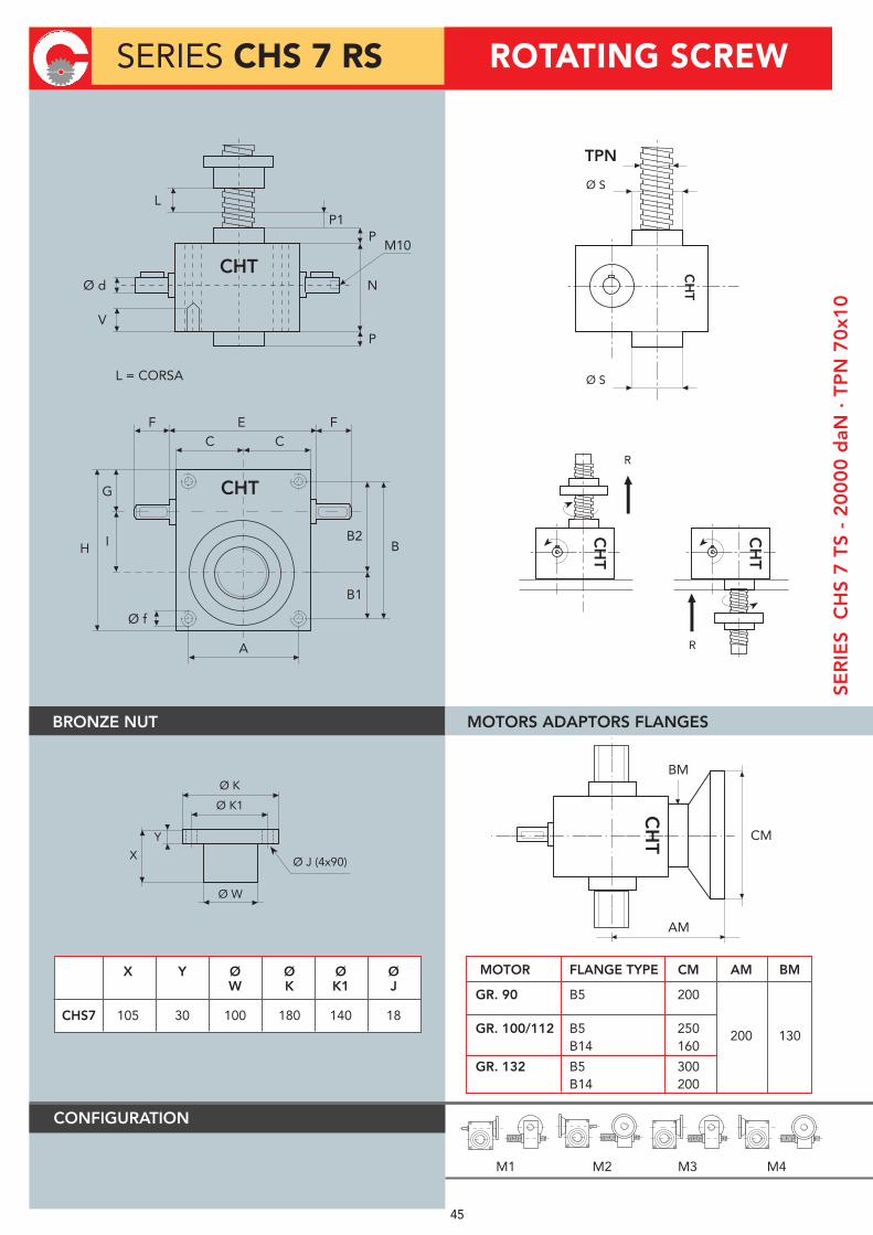
X Y Ø Ø Ø Ø W K K1 J
CHS7 105 30 100 180 140 18
MOTOR FLANGE TYPE CM AM BM
GR. 90 B5 200
200 130 GR. 100/112 B5 250 B14 160
GR. 132 B5 300 B14 200
L = CORSA
CHT
F E FC C
A
G
IH
Ø f
BB2
B1
CHT
V
Ø d
P
N
P1L
PM10
CH
T CM
BM
AM
Ø S
TPN
CH
T
Ø S
BRONZE NUT
CONFIGURATION
Ø K
Ø K1
Ø W
Y
X Ø J (4x90)
R
CH
T
R
CH
T
M1 M2 M3 M4
SERIES CHS 7 RS
SER
IES
CH
S 7
TS
- 2
00
00
daN
· T
PN
70
x10
MOTORS ADAPTORS FLANGES
45
ROTATING SCREW

SCREW-JACKS WITH BALL SCREWS
FOR TRANSLATING SCREW
BY INTEGRATED NUT
Consult our technical DPT
SCREW JACK PERFORMANCE CHS 7
load daN 20000 15000 7500 2500
ratio lifting speed input speed Pn Mt Pn Mt Pn Mt Pn Mt
mm
Kw daNm Kw daNm Kw daNm Kw daNm
3000 1500 52,65 33,52 39,49 25,14 19,75 12,57 6,58 4,19
2000 1000 35,10 33,52 26,33 25,14 13,16 12,57 4,39 4,19
5
1500 750 26,33 33,52 19,75 25,14 9,87 12,57 3,29 4,19
100 50 1,76 33,52 1,32 25,14 0,66 12,57 0,22 4,19
load daN 20000 15000 7500 2500
ratio lifting speed input speed Pn Mt Pn Mt Pn Mt Pn Mt
mm
Kw daNm Kw daNm Kw daNm Kw daNm
1500 1500 27,95 17,79 20,96 13,34 10,48 6,67 3,49 2,22
1000 1000 18,63 17,79 13,97 13,34 6,99 6,67 2,33 2,22
10
750 750 13,97 17,79 10,48 13,34 5,24 6,67 1,75 2,22
50 50 0,93 17,79 0,70 13,34 0,35 6,67 0,07 2,22
load daN 20000 15000 7500 2500
ratio lifting speed input speed Pn Mt Pn Mt Pn Mt Pn Mt
mm
Kw daNm Kw daNm Kw daNm Kw daNm
500 1500 9,98 6,36 7,49 4,77 3,74 2,38 1,25 0,79
333 1000 6,66 6,36 4,99 4,77 2,50 2,38 0,83 0,79
30
250 750 4,99 6,36 3,74 4,77 1,87 2,38 0,62 0,79
17 50 0,33 6,36 0,25 4,77 0,07 2,38 0,07 0,79
46
SCR
EW
JA
CK
PE
RFO
RM
AN
CE
SE
RIE
S C
HS
7

CHS 7
Y
Z
TS
TS RS
47
TS
X
282
mm
232 mm
X
176 mm

A B B1 B2 C E F G H
CHS8 180 230 90 140 116 - 60 76 282
I N P P1 V Ø d Ø f Ø s TPN
CHS8 90 176 40 30 45 30 M30 120 80x10
SCREW JACK MODEL CHS 8
LOAD daN (Kg) 25000
TPN SCREW DIAMETER mm 80 PITCH mm 10
GEAR RATIOS FAST SPEED 5:1 NORMAL SPEED 10:1 SLOW SPEED 30:1
STROKE FOR FAST SPEED 2INPUT REV. NORMAL SPEED 1 SLOW SPEED 0,33
EFFICIENCY FAST SPEED 18,5% NORMAL SPEED 17,5% SLOW SPEED 16% JACK WEIGHT (Kg) 54
SCREW WEIGHT TPN X 100 mm (Kg) 3,2
CASE MATERIAL G25
GREASE QTY (Kg) 1,5
GREASE TYPE AGIP GR MU EP2
OPERATING TEMPERATURE -5° C
+80° C
SERIES CHS 8 TSSE
RIE
S C
HS
8 T
S -
25
00
0 d
aN ·
TP
N 8
0x1
0
CHT CHT CHT
DX SX DE
CHT
F E FC C
A
G
IH
Ø f
BB2
B1
CHT
V
Ø d
P
N
P
T
T
Ø S
TPN
CH
T
Ø S
48
TRANSLATING SCREW

X Y Ø Ø Ø Ø W K K1 J
CHS8 110 30 110 190 150 18
MOTOR FLANGE TYPE CM AM BM
GR. 90 B5 200
200 130 GR. 100/112 B5 250 B14 160 GR. 132 B5 300 B14 200
L = CORSA
CHT
F E FC C
A
G
IH
Ø f
BB2
B1
CHT
V
Ø d
P
N
P1L
PM10
CH
T CM
BM
AM
Ø S
TPN
CH
T
Ø S
BRONZE NUT
CONFIGURATION
Ø K
Ø K1
Ø W
Y
X Ø J (4x90)
R
CH
T
R
CH
T
M1 M2 M3 M4
SERIES CHS 8 RS
SER
IES
CH
S 8
TS
- 2
50
00
daN
· T
PN
80
x10
MOTORS ADAPTORS FLANGES
49
ROTATING SCREW

SCREW-JACKS WITH BALL SCREWS
FOR TRANSLATING SCREW
BY INTEGRATED NUT
Consult our technical DPT
SCREW JACK PERFORMANCE CHS 8
load daN 25000 20000 10000 3000
ratio lifting speed input speed Pn Mt Pn Mt Pn Mt Pn Mt
mm
Kw daNm Kw daNm Kw daNm Kw daNm
3000 1500 67,60 43,04 54,08 34,43 27,04 17,21 8,11 5,16
2000 1000 45,06 43,04 36,05 34,43 18,03 17,21 5,41 5,16
5
1500 750 33,80 43,04 27,04 34,43 13,52 17,21 4,06 5,16
100 50 2,25 43,04 1,80 34,43 0,90 17,21 0,27 5,16
load daN 25000 20000 10000 3000
ratio lifting speed input speed Pn Mt Pn Mt Pn Mt Pn Mt
mm
Kw daNm Kw daNm Kw daNm Kw daNm
1500 1500 35,73 22,75 28,58 18,20 14,29 9,10 4,29 2,73
1000 1000 23,82 22,75 19,06 18,20 9,53 9,10 2,86 2,73
10
750 750 17,86 22,75 14,29 18,20 7,15 9,10 2,14 2,73
50 50 1,19 22,75 0,95 18,20 0,48 9,10 0,07 2,73
load daN 25000 20000 10000 3000
ratio lifting speed input speed Pn Mt Pn Mt Pn Mt Pn Mt
mm
Kw daNm Kw daNm Kw daNm Kw daNm
500 1500 12,63 8,04 10,11 6,43 5,05 3,22 1,52 0,97
333 1000 8,42 8,04 6,74 6,43 3,37 3,22 1,01 0,97
30
250 750 6,32 8,04 5,05 6,43 2,53 3,22 0,76 0,97
17 50 0,42 8,04 0,34 6,43 0,07 3,22 0,07 0,97
50
SCR
EW
JA
CK
PE
RFO
RM
AN
CE
SE
RIE
S C
HS
8

CHS 8
X
Y
Z
TS
TS RS
51
TS
282
mm
232 mm
X
232 176 mm

A B B1 B2 C E F G H
CHS9 200 270 100 170 125 - 70 85 320
I N P P1 V Ø d Ø f Ø s TPN
CHS9 110 230 50 40 40 40 M30 150 90x10
SCREW JACK MODEL CHS 9
LOAD daN (Kg) 30000
TPN SCREW DIAMETER mm 90 PITCH mm 10
GEAR RATIOS NORMAL SPEED 10:1 SLOW SPEED 30:1
STROKE FOR INPUT REV. NORMAL SPEED 1 SLOW SPEED 0,33
EFFICIENCY NORMAL SPEED 18,0% SLOW SPEED 12,5% JACK WEIGHT (Kg) 110
SCREW WEIGHT TPN X 100 mm (Kg) 4,6
CASE MATERIAL Fe 510
GREASE QTY (Kg) 2,3
GREASE TYPE AGIP GR MU EP2
OPERATING TEMPERATURE -5° C
+80° C
SERIES CHS 9 TSSE
RIE
S C
HS
9 T
S -
30
00
0 d
aN ·
TP
N 9
0x1
0
CHT CHT CHT
DX SX DE
CHT
F E FC C
A
G
IH
Ø f
BB2
B1
CHT
V
Ø d
P
N
P
T
T
Ø S
TPN
CH
T
Ø S
52
TRANSLATING SCREW
HEAVY LINE

X Y Ø Ø Ø Ø W K K1 J
CHS9 135 45 150 230 190 20
FOR SPECIAL EXECUTIONplease consult our technical DPT
L = CORSA
CHT
F E FC C
A
G
IH
Ø f
BB2
B1
CHT
V
Ø d
P
N
P1L
PC
HT CM
BM
AM
Ø S
TPN
CH
T
Ø S
BRONZE NUT
CONFIGURATION
Ø K
Ø K1
Ø W
Y
X Ø J (4x90)
R
CH
T
R
CH
T
M1 M2 M3 M4
SERIES CHS 9 RS
SER
IES
CH
S 9
TS
- 3
00
00
daN
· T
PN
90
x10
MOTORS ADAPTORS FLANGES
53
ROTATING SCREW
M10
HEAVY LINE

SCREW-JACKS WITH BALL SCREWS
FOR TRANSLATING SCREW
BY INTEGRATED NUT
Consult our technical DPT
SCREW JACK PERFORMANCE CHS 9
54
SCR
EW
JA
CK
PE
RFO
RM
AN
CE
SE
RIE
S C
HS
9 load daN 30000 20000 10000 5000
ratio lifting speed input speed Pn Mt Pn Mt Pn Mt Pn Mt
mm
Kw daNm Kw daNm Kw daNm Kw daNm
1500 1500 41,68 26,54 27,79 17,69 13,89 8,85 6,95 4,42
1000 1000 27,79 26,54 18,53 17,69 9,26 8,85 4,63 4,42
10
750 750 20,84 26,54 13,89 17,69 6,95 8,85 3,47 4,42
50 50 1,39 26,54 0,93 17,69 0,46 8,85 0,07 4,42
load daN 30000 20000 10000 3000
ratio lifting speed input speed Pn Mt Pn Mt Pn Mt Pn Mt
mm
Kw daNm Kw daNm Kw daNm Kw daNm
500 1500 20,01 12,74 13,34 8,49 6,67 4,25 3,33 2,12
333 1000 13,34 12,74 8,89 8,49 4,45 4,25 2,22 2,12
30
250 750 10,00 12,74 6,67 8,49 3,33 4,25 1,67 2,12
17 50 0,67 12,74 0,44 8,49 0,07 4,25 0,07 2,12
HEAVY LINE

CHS 9
X
Y
Z
TS
TS RS
55
TS
320
mm
250 mm
X
320
250 mm
HEAVY LINE

A B B1 B2 C E F G H
CHS10 230 355 135 220 160 - 85 105 405
I N P P1 V Ø d Ø f Ø s TPN
CHS10 140 270 50 40 45 55 M30 210 100x12
SCREW JACK MODEL CHS 10
LOAD daN (Kg) 40000
TPN SCREW DIAMETER mm 100 PITCH mm 12
GEAR RATIOS NORMAL SPEED 10:1 SLOW SPEED 30:1
STROKE FOR INPUT REV. NORMAL SPEED 1,2 SLOW SPEED 0,4
EFFICIENCY NORMAL SPEED 18,0% SLOW SPEED 12,5% JACK WEIGHT (Kg) 250
SCREW WEIGHT TPN X 100 mm (Kg) 5,6
CASE MATERIAL Fe 510
GREASE QTY (Kg) 4
GREASE TYPE AGIP GR MU EP2
OPERATING TEMPERATURE -5° C
+80° C
SERIES CHS 10 TSSE
RIE
S C
HS
10
TS
- 4
00
00
daN
· T
PN
10
0x1
2
CHT CHT CHT
DX SX DE
CHT
F E FC C
A
G
IH
Ø f
BB2
B1
CHT
V
Ø d
P
N
P
T
T
Ø S
TPN
CH
T
Ø S
56
TRANSLATING SCREW
HEAVY LINE

X Y Ø Ø Ø Ø W K K1 J
CHS10 135 45 150 230 190 20
FOR SPECIAL EXECUTIONplease consult our technical DPT
L = CORSA
CHT
F E FC C
A
G
IH
Ø f
BB2
B1
CHT
V
Ø d
P
N
P1L
PC
HT CM
BM
AM
Ø S
TPN
CH
T
Ø S
BRONZE NUT
CONFIGURATION
Ø K
Ø K1
Ø W
Y
X Ø J (4x90)
R
CH
T
R
CH
T
M1 M2 M3 M4
SERIES CHS 10 RS
SER
IES
CH
S 1
0 T
S -
40
00
0 d
aN ·
TP
N 1
00
x12
MOTORS ADAPTORS FLANGES
57
ROTATING SCREW
M12
HEAVY LINE

SCREW-JACKS WITH BALL SCREWS
FOR TRANSLATING SCREW
BY INTEGRATED NUT
Consult our technical DPT
SCREW JACK PERFORMANCE CHS 10
load daN 40000 30000 15000 5000
ratio lifting speed input speed Pn Mt Pn Mt Pn Mt Pn Mt
mm
Kw daNm Kw daNm Kw daNm Kw daNm
1800 1500 66,70 42,46 50,02 31,85 25,01 15,92 8,34 5,31
1200 1000 44,46 42,46 33,35 31,85 16,67 15,92 5,56 5,31
10
900 750 33,35 42,46 25,01 31,85 12,51 15,92 4,17 5,31
60 50 2,22 42,46 1,67 31,85 0,83 15,92 1,07 5,31
load daN 40000 30000 15000 5000
ratio lifting speed input speed Pn Mt Pn Mt Pn Mt Pn Mt
mm
Kw daNm Kw daNm Kw daNm Kw daNm
600 1500 32,01 20,38 24,01 15,29 12,01 7,64 4,00 2,55
400 1000 21,34 20,38 16,01 15,29 8,00 7,64 2,67 2,55
30
300 750 16,01 20,38 12,01 15,29 6,00 7,64 2,00 2,55
20 50 1,07 20,38 0,80 15,29 1,07 7,64 1,07 2,55
58
SCR
EW
JA
CK
PE
RFO
RM
AN
CE
SE
RIE
S C
HS
10
HEAVY LINE

CHS 10
X
Y
Z
TS
TS RS
59
TS
405
mm
320 mm
X
320 270 mm
HEAVY LINE

A B B1 B2 C E F G H
CHS12 230 355 135 220 160 - 85 105 405
I N P P1 V Ø d Ø f Ø s TPN
CHS12 140 270 50 40 45 55 M30 210 120x14
SCREW JACK MODEL CHS 12
LOAD daN (Kg) 60000
TPN SCREW DIAMETER mm 120 PITCH mm 14
GEAR RATIOS NORMAL SPEED 10:1 SLOW SPEED 30:1
STROKE FOR INPUT REV. NORMAL SPEED 1,4 SLOW SPEED 0,47
EFFICIENCY NORMAL SPEED 17,0% SLOW SPEED 11,5% JACK WEIGHT (Kg) 250
SCREW WEIGHT TPN X 100 mm (Kg) 8,1
CASE MATERIAL Fe 510
GREASE QTY (Kg) 4
GREASE TYPE AGIP GR MU EP2
OPERATING TEMPERATURE -5° C
+80° C
SERIES CHS 12 TSSE
RIE
S C
HS
12
TS
- 6
00
00
daN
· T
PN
12
0x1
4
CHT CHT CHT
DX SX DE
CHT
F E FC C
A
G
IH
Ø f
BB2
B1
CHT
V
Ø d
P
N
P
T
T
Ø S
TPN
CH
T
Ø S
60
TRANSLATING SCREW
HEAVY LINE

X Y Ø Ø Ø Ø W K K1 J
CHS12 160 55 180 280 235 25
L = CORSA
CHT
F E FC C
A
G
IH
Ø f
BB2
B1
CHT
V
Ø d
P
N
P1L
PC
HT CM
BM
AM
Ø S
TPN
CH
T
Ø S
BRONZE NUT
CONFIGURATION
Ø K
Ø K1
Ø W
Y
X Ø J (4x90)
R
CH
T
R
CH
T
M1 M2 M3 M4
SERIES CHS 12 RS
SER
IES
CH
S 1
2 T
S -
60
00
0 d
aN ·
TP
N 1
20
x14
MOTORS ADAPTORS FLANGES
61
ROTATING SCREW
M12
HEAVY LINE
FOR SPECIAL EXECUTIONplease consult our technical DPT

SCREW-JACKS WITH BALL SCREWS
FOR TRANSLATING SCREW
BY INTEGRATED NUT
Consult our technical DPT
SCREW JACK PERFORMANCE CHS 12
load daN 60000 40000 20000 10000
ratio lifting speed input speed Pn Mt Pn Mt Pn Mt Pn Mt
mm
Kw daNm Kw daNm Kw daNm Kw daNm
2100 1500 123,58 76,68 82,39 52,45 41,19 26,23 20,60 13,11
1400 1000 82,39 76,68 54,93 52,45 27,46 26,23 13,73 13,11
10
1050 750 61,79 76,68 41,19 52,45 20,60 26,23 10,30 13,11
70 50 4,12 76,68 2,75 52,45 1,37 26,23 1,07 13,11
load daN 60000 40000 20000 10000
ratio lifting speed input speed Pn Mt Pn Mt Pn Mt Pn Mt
mm
Kw daNm Kw daNm Kw daNm Kw daNm
700 1500 60,90 38,77 40,60 25,85 20,30 12,92 10,15 6,46
467 1000 40,60 38,77 27,06 25,85 13,53 12,92 6,77 6,46
30
350 750 30,45 38,77 20,30 25,85 10,15 12,92 5,07 6,46
23 50 2,03 38,77 1,35 25,85 1,07 12,92 1,07 6,46
62
SCR
EW
JA
CK
PE
RFO
RM
AN
CE
SE
RIE
S C
HS
12
HEAVY LINE

CHS 12
X
Y
Z
TS
TS RS
63
TS
405
mm
320 mm
X
320 270 mm
HEAVY LINE

A B B1 B2 C E F G H
CHS14 360 510 190 320 250 - 140 160 590
I N P P1 V Ø d Ø f Ø s TPN
CHS14 200 370 60 50 110 70 M56 300 140x14
SCREW JACK MODEL CHS 14
LOAD daN (Kg) 80000
TPN SCREW DIAMETRO mm 140 PASSO mm 14
GEAR RATIOS NORMAL SPEED 12:1 SLOW SPEED 36:1
STROKE FOR INPUT REV. NORMAL SPEED 1,16 SLOW SPEED 0,38
EFFICIENCY NORMAL SPEED 16,0% SLOW SPEED 10,0% JACK WEIGHT (Kg) 550
PESO VITE TPNSCREW WEIGHT TPN
CASE MATERIAL Fe 510
GREASE QTY (Kg) 14
GREASE TYPE AGIP GR MU EP2
OPERATING TEMPERATURE -5° C
+80° C
SERIES CHS 14 TSSE
RIE
S C
HS
14
TS
- 8
00
00
daN
· T
PN
14
0x1
4
CHT CHT CHT
DX SX DE
CHT
F E FC C
A
G
IH
Ø f
BB2
B1
CHT
V
Ø d
P
N
P
T
T
Ø S
TPN
CH
T
Ø S
64
TRANSLATING SCREW
HEAVY LINE

X Y Ø Ø Ø Ø W K K1 J
CHS14 250 80 210 320 270 25
L = CORSA
CHT
F E FC C
A
G
IH
Ø f
BB2
B1
CHT
V
Ø d
P
N
P1L
PC
HT CM
BM
AM
Ø S
TPN
CH
T
Ø S
BRONZE NUT
CONFIGURATION
Ø K
Ø K1
Ø W
Y
X Ø J (6x60)
R
CH
T
R
CH
T
M1 M2 M3 M4
SERIES CHS 14 RS
SER
IES
CH
S 1
4 T
S -
80
00
0 d
aN ·
TP
N 1
40
x14
MOTORS ADAPTORS FLANGES
65
ROTATING SCREW
M14
HEAVY LINE
FOR SPECIAL EXECUTIONplease consult our technical DPT

SCREW-JACKS WITH BALL SCREWS
FOR TRANSLATING SCREW
BY INTEGRATED NUT
Consult our technical DPT
SCREW JACK PERFORMANCE CHS 14
load daN 80000 60000 30000 10000
ratio lifting speed input speed Pn Mt Pn Mt Pn Mt Pn Mt
mm
Kw daNm Kw daNm Kw daNm Kw daNm
2100 1500 145,90 92,89 109,42 69,67 54,71 34,83 18,24 11,61
1400 1000 97,26 92,89 72,95 69,67 36,47 34,83 12,16 11,61
12
1050 750 72,95 92,89 54,71 69,67 27,36 34,83 9,12 11,61
70 50 4,86 92,89 13,65 69,67 1,82 34,83 1,07 11,61
load daN 80000 60000 30000 10000
ratio lifting speed input speed Pn Mt Pn Mt Pn Mt Pn Mt
mm
Kw daNm Kw daNm Kw daNm Kw daNm
1500 1500 77,81 49,54 58,36 37,15 29,18 18,58 9,73 6,19
1000 1000 51,87 49,54 38,91 37,15 19,45 18,58 6,48 6,19
36
750 750 38,91 49,54 29,18 37,15 14,59 18,58 4,86 6,19
50 50 2,59 49,54 1,95 37,15 1,07 18,58 1,07 6,19
66
SCR
EW
JA
CK
PE
RFO
RM
AN
CE
SE
RIE
S C
HS
14
HEAVY LINE

CHS 14
X
Y
Z
TS
TS RS
67
TS
590
mm
500 mm
X
500 370 mm
HEAVY LINE

A B B1 B2 C E F G H
CHS16 360 510 190 320 250 - 140 160 590
I N P P1 V Ø d Ø f Ø s TPN
CHS16 200 370 60 50 110 70 M56 300 160x16
SCREW JACK MODEL CHS 16
LOAD daN (Kg) 100000
TPN SCREW DIAMETER mm 160 DIAMETER mm 16
GEAR RATIOS NORMAL SPEED 12:1 SLOW SPEED 36:1
STROKE FOR INPUT REV. NORMAL SPEED 1,33 SLOW SPEED 0,44
EFFICIENCY NORMAL SPEED 15,0% SLOW SPEED 9,0% JACK WEIGHT (Kg) 550
SCREW WEIGHT TPN X 100 mm (Kg) 14
CASE MATERIAL Fe 510
GREASE QTY (Kg) 14
GREASE TYPE AGIP GR MU EP2
OPERATING TEMPERATURE -5° C
+80° C
SERIES CHS 16 TSSE
RIE
S C
HS
16
TS
- 1
00
.00
0 d
aN ·
TP
N 1
60
x16
CHT CHT CHT
DX SX DE
CHT
F E FC C
A
G
IH
Ø f
BB2
B1
CHT
V
Ø d
P
N
P
T
T
Ø S
TPN
CH
T
Ø S
68
TRANSLATING SCREW
HEAVY LINE

X Y Ø Ø Ø Ø W K K1 J
CHS16 250 80 210 320 270 25
L = CORSA
CHT
F E FC C
A
G
IH
Ø f
BB2
B1
CHT
V
Ø d
P
N
P1L
PC
HT CM
BM
AM
Ø S
TPN
CH
T
Ø S
BRONZE NUT
CONFIGURATION
Ø K
Ø K1
Ø W
Y
X Ø J (6x60)
R
CH
T
R
CH
T
M1 M2 M3 M4
SERIES CHS 16 RS
SER
IES
CH
S 1
6 T
S -
10
0.0
00
daN
· T
PN
16
0x1
6
MOTORS ADAPTORS FLANGES
69
ROTATING SCREW
M14
HEAVY LINE
FOR SPECIAL EXECUTIONplease consult our technical DPT

SCREW JACK PERFORMANCE CHS 16
load daN 100000 80000 40000 10000
ratio lifting speed input speed Pn Mt Pn Mt Pn Mt Pn Mt
mm
Kw daNm Kw daNm Kw daNm Kw daNm
2400 1500 222,32 141,54 177,85 113,23 88,93 56,62 22,23 14,15
1600 1000 148,21 141,54 118,57 113,23 59,28 56,62 14,82 14,15
12
1200 750 111,16 141,54 88,93 113,23 44,46 56,62 11,12 14,15
80 50 7,41 141,54 5,93 113,23 2,96 56,62 1,07 14,15
load daN 100000 80000 40000 10000
ratio lifting speed input speed Pn Mt Pn Mt Pn Mt Pn Mt
mm
Kw daNm Kw daNm Kw daNm Kw daNm
800 1500 123,51 78,63 98,81 62,91 49,40 31,45 12,35 7,86
533 1000 82,34 78,63 65,87 62,91 32,94 31,45 8,23 7,86
36
400 750 61,76 78,63 49,40 62,91 24,70 31,45 6,18 7,86
27 50 4,12 78,63 3,29 62,91 1,07 31,45 1,07 7,86
70
SCR
EW
JA
CK
PE
RFO
RM
AN
CE
SE
RIE
S C
HS
16
SCREW-JACKS WITH BALL SCREWS
FOR TRANSLATING SCREW
BY INTEGRATED NUT
Consult our technical DPT
HEAVY LINE

CHS 16
X
Y
Z
TS
TS RS
71
TS
590
mm
500 mm
X
500 370 mm
HEAVY LINE

WORM SCREW JACK WITH BALL SCREW
7272
FOR TRASLATING SCREW WITH INTEGRATED NUT

FLANGED SINGLE NUT TYPE DIN 69051/5 FOR ROLLED SCREWS
73
TYPE do Ph Dw N D D1 D2 D3 L L1 L2 L3 L4 L5 H Co Ca Rs
CHN1405 14 5 3,175 2 24 36 46 5,5 44 5 10 10 40 5 1 846 730 14
CHN1605 5 3,175 3 28 38 48 5,5 50 5 10 10 40 5 1 1191 1160 21
CHN1610 16 10 3,175 3 28 38 48 5,5 55 5 10 10 40 5 1 1191 1160 21
CHN1616 16 3 2 28 38 48 5,5 49 4 12 15 40 6 1 887 783 16
CHN2005 20 5 3,175 4 36 47 58 6,6 54 5 10 10 44 5 1 1985 1525 33
CHN2505 5 3,175 4 40 51 62 6,6 54 5 10 10 48 5 1 2691 1626 40
CHN2506 6 3,969 4 40 51 62 6,6 65 6 10 10 48 5 1 3105 2439 41
CHN2510 25 10 4,762 4 40 51 62 6,6 85 6 10 10 48 5 1 3346 3242 40
CHN2525 25 3,969 2 45 60 73 6,6 72 6 12 15 62 6 1 2383 1872 25
CHN2525-B 25 3,969 3 40 51 62 6,6 95 / 12 30 48 6 1 2940 2458 33
CHN3205 5 3,175 4 50 65 80 9 54 6 12 10 62 6 1 3692 1747 50
CHN3206 32
6 3,969 4 50 65 80 9 65 6 12 10 62 6 1 4221 2618 51
CHN3210 10 6,35 4 50 65 80 9 93 6 12 16 62 6 1 5876 5254 51
CHN3232 32 3,969 3 50 65 80 9 120 / 13 40 62 6,5 1 4270 2642 41
CHN4005 5 3,175 5 63 78 93 9 62 6 14 10 70 7 2 5722 2204 71
CHN4010 40 10 6,35 5 63 78 93 9 106 7 14 16 70 7 2 9377 6611 75
CHN4040 40 6,35 2 70 85 100 9 100 7 14 16 80 7 2 4875 3437 39
CHN5010 50 10 6,35 5 75 93 110 11 108 7 16 16 85 8 2 12714 7050 92
N Round of ballH Flange typedo Nominal diameter (mm)Ph Pitch (mm)
Dw Balls diameter (mm)Co Static load capacity (daN)Ca Dynamic load capacity (daN)Rs Ball stiffness (daN/µm)
Flange type 1 Flange type 2

74
CHS 2 VRS Ø 16 BALL SCREW
CHS 3 VRS Ø 32 BALL SCREW
pitch 5 pitch 5 pitch 5 pitch 16 pitch 16 pitch 16
load daN 500 250 300 150
ratio input RPM lifting speed Pn Mt Pn Mt lifting speed Pn Mt Pn Mt
mm Kw daNm Kw daNm mm Kw daNm Kw daNm
1500 1500 0,20 0,12 0,10 0,06 4800 0,38 0,24 0,19 0,12
1000 1000 0,13 0,12 0,07 0,06 3200 0,25 0,24 0,13 0,12
5
750 750 0,10 0,12 0,05 0,06 2400 0,19 0,24 0,09 0,12
50 50 0,01 0,12 0,00 0,06 160 0,01 0,24 0,01 0,12
pitch 5 pitch 5 pitch 5 pitch 16 pitch 16 pitch 16
load daN 500 250 300 150
ratio input RPM lifting speed Pn Mt Pn Mt lifting speed Pn Mt Pn Mt
mm Kw daNm Kw daNm mm Kw daNm Kw daNm
1500 750 0,11 0,07 0,05 0,03 2400 0,20 0,13 0,10 0,06
1000 500 0,07 0,07 0,04 0,03 1600 0,13 0,13 0,07 0,06
10
750 375 0,05 0,07 0,03 0,03 1200 0,10 0,13 0,05 0,06
50 25 0,00 0,07 0,00 0,03 80 0,01 0,13 0,07 0,06
pitch 5 pitch 5 pitch 5 pitch 16 pitch 16 pitch 16 load daN 500 250 300 150
ratio input RPM lifting speed Pn Mt Pn Mt lifting speed Pn Mt Pn Mt
mm Kw daNm Kw daNm mm Kw daNm Kw daNm
1500 250 0,04 0,02 0,02 0,01 0,07 0,05 0,04 0,02
1000 167 0,03 0,02 0,01 0,01 533 0,05 0,05 0,02 0,02
30
750 125 0,02 0,02 0,01 0,01 400 0,04 0,05 0,02 0,02
50 8 0,00 0,02 0,00 0,01 27 0,00 0,05 0,00 0,02
pitch 5 pitch 5 pitch 5 pitch 10 pitch 10 pitch 10
load daN 1000 500 1500 750
ratio input RPM lifting speed Pn Mt Pn Mt lifting speed Pn Mt Pn Mt
mm Kw daNm Kw daNm mm Kw daNm Kw daNm
1500 1500 0,39 0,25 0,20 0,12 3000 1,18 0,75 0,59 0,37
1000 1000 0,26 0,25 0,13 0,12 2000 0,78 0,75 0,39 0,37
5
750 750 0,20 0,25 0,10 0,12 1500 0,59 0,75 0,29 0,37
50 50 0,01 0,25 0,01 0,12 100 0,04 0,75 0,02 0,37
CH
S 2
VR
SC
HS
3 V
RS

CHS 4 VRS Ø 40 BALL SCREW
CH
S 3
VR
SC
HS
4 V
RS
75
CHS 3 VRS Ø 32 BALL SCREW
pitch 5 pitch 5 pitch 5 pitch 10 pitch 10 pitch 10
load daN 1000 500 1500 750
ratio input RPM lifting speed Pn Mt Pn Mt lifting speed Pn Mt Pn Mt
mm Kw daNm Kw daNm mm Kw daNm Kw daNm
1500 750 0,11 0,07 0,05 0,03 1500 0,20 0,13 0,10 0,06
1000 500 0,07 0,07 0,04 0,03 1000 0,13 0,13 0,07 0,06
10
750 375 0,05 0,07 0,03 0,03 750 0,10 0,13 0,05 0,06
50 25 0,00 0,07 0,00 0,03 50 0,01 0,13 0,00 0,06
pitch 5 pitch 5 pitch 5 pitch 10 pitch 10 pitch 10
load daN 1000 500 1500 750
ratio input RPM lifting speed Pn Mt Pn Mt lifting speed Pn Mt Pn Mt
mm Kw daNm Kw daNm mm Kw daNm Kw daNm
1500 250 0,08 0,05 0,04 0,02 500 0,23 0,14 0,11 0,07
1000 167 0,05 0,05 0,03 0,02 333 0,15 0,14 0,08 0,07
30
750 125 0,04 0,05 0,02 0,02 250 0,11 0,14 0,06 0,07
50 8 0,00 0,05 0,00 0,02 17 0,01 0,14 0,00 0,07
pitch 5 pitch 5 pitch 5 pitch 10 pitch 10 pitch 10 load daN 1000 500 2500 1500
ratio input RPM lifting speed Pn Mt Pn Mt lifting speed Pn Mt Pn Mt
mm Kw daNm Kw daNm mm Kw daNm Kw daNm
1500 1500 0,39 0,25 0,20 0,12 3000 1,96 1,25 1,18 0,75
1000 1000 0,26 0,25 0,13 0,12 2000 1,31 1,25 0,78 0,75
5
750 750 0,20 0,25 0,10 0,12 1500 0,98 1,25 0,59 0,75
50 50 0,01 0,25 0,01 0,12 100 0,07 1,25 0,04 0,75
pitch 5 pitch 5 pitch 5 pitch 10 pitch 10 pitch 10 load daN 1000 500 2500 1500
ratio input RPM lifting speed Pn Mt Pn Mt lifting speed Pn Mt Pn Mt
mm Kw daNm Kw daNm mm Kw daNm Kw daNm
1500 750 0,21 0,13 0,11 0,07 1500 1,05 0,67 0,63 0,40
1000 500 0,14 0,13 0,07 0,07 1000 0,70 0,67 0,42 0,40
10
750 375 0,11 0,13 0,05 0,07 750 0,53 0,67 0,32 0,40
50 25 0,01 0,13 0,00 0,07 50 0,04 0,67 0,02 0,40

CHS 5 VRS Ø 50 BALL SCREW
CHS 4 VRS Ø 40 BALL SCREWC
HS
4 V
RS
CH
S 5
VR
S
76
pitch 10 pitch 10 pitch 10 pitch 10
load daN 3000 2000 1000 500
ratio input RPM lifting speed Pn Mt Pn Mt Pn Mt Pn Mt
mm Kw daNm Kw daNm Kw daNm Kw daNm
1500 3000 2,35 1,50 1,57 1,00 0,78 0,50 0,39 0,25
1000 2000 1,57 1,50 1,05 1,00 0,52 0,50 0,26 0,25
5
750 1500 1,18 1,50 0,78 1,00 0,39 0,50 0,20 0,25
50 100 0,08 1,50 0,05 1,00 0,03 0,50 0,01 0,25
pitch 10 pitch 10 pitch 10 pitch 10
load daN 3000 2000 1000 500
ratio input RPM lifting speed Pn Mt Pn Mt Pn Mt Pn Mt
mm Kw daNm Kw daNm Kw daNm Kw daNm
1500 1500 1,26 0,80 0,84 0,54 0,42 0,27 0,21 0,13
1000 1000 0,84 0,80 0,56 0,54 0,28 0,27 0,14 0,13
10
750 750 0,63 0,80 0,42 0,54 0,21 0,27 0,11 0,13
50 50 0,04 0,80 0,03 0,54 0,01 0,27 0,01 0,13
pitch 10 pitch 10 pitch 10 pitch 10
load daN 3000 2000 1000 500
ratio input RPM lifting speed Pn Mt Pn Mt Pn Mt Pn Mt
mm Kw daNm Kw daNm Kw daNm Kw daNm
1500 500 0,45 0,29 0,30 0,19 0,15 0,10 0,08 0,05
1000 333 0,30 0,29 0,20 0,19 0,10 0,10 0,05 0,05
30
750 250 0,23 0,29 0,15 0,19 0,08 0,10 0,04 0,05
50 17 0,02 0,29 0,01 0,19 0,01 0,10 0,00 0,05
pitch 5 pitch 5 pitch 5 pitch 10 pitch 10
load daN 1000 500 2500 1500
ratio input RPM lifting speed Pn Mt Pn Mt lifting speed Pn Mt Pn Mt
mm Kw daNm Kw daNm mm Kw daNm Kw daNm
1500 250 0,08 0,05 0,04 0,02 500 0,38 0,24 0,23 0,14
1000 167 0,05 0,05 0,03 0,02 333 0,25 0,24 0,15 0,14
30
750 125 0,04 0,05 0,02 0,02 250 0,19 0,24 0,11 0,14
50 8 0,00 0,05 0,00 0,02 17 0,01 0,24 0,01 0,14

77

CONFIGURATIONS
M4
M1 DE
M2 SX
M3 DX
78

79
OPTIONS
SCREW ENDS
For rotating screw RSonly screw ends type TL
* N° 4 holes at 90° ** N° 6 holes at 60° Ø c = + 0 - 0,10
TYPE H R b L E P G T Z Øc Ød Øf Øi Øm Øs Øt
CHS 1 15 20 12 x 1.5 14 8 20 40 70 20 12 54 40 7* 26 16 30
CHS 2 15 20 14 x 1.5 21 8 20 40 75 25 15 79 60 11* 39 20 38
CHS 3 20 30 20 x 2.5 23 10 25 50 95 30 20 89 67 11* 46 25 48
CHS 4 25 30 30 x 3.5 30 15 35 70 125 40 30 109 85 13* 60 35 68
CHS 5 25 50 36 x 4 50 20 50 100 180 60 40 149 117 17* 85 50 88
CHS 6 25 50 36 x 4 50 20 50 100 180 60 40 149 117 17* 85 50 88
CHS 7 25 60 56 x 5.5 60 30 60 120 210 75 55 198 155 25* 105 60 108
CHS 8 25 60 64 x 6 60 30 65 130 225 80 65 218 170 25* 120 65 118
CHS 9 40 70 70 x 6 70 40 80 160 280 100 85 278 220 29** 150 80 138
CHS 10 40 70 70 x 6 70 40 80 160 280 100 85 278 220 29** 150 80 138
CHS 12 40 90 90 x 6 80 50 100 200 350 120 100 298 240 32** 170 100 138
CHS 14 50 110 110 x 6 100 60 140 280 450 155 120 378 300 52** 210 140 168
CHS 16 50 125 125 x 6 100 60 140 280 460 155 140 378 300 52** 210 140 216
TP
Ø dØ f
EL
H
Ø i
Ø m
Ø c
R
H
b
R
H
TLTF
Ø t
Ø sP
Z
GT
H
TS
OPTIONALS PE BELLOWS
PR RIGID COVER PIPE
AR ANTI-ROTATION
AS STOP PLATE
FC LIMIT SWITCH
PO PIVOTING RIGID COVER
AM OVERSIZE SCREW
CU WEAR CONTROL
RG RECOVER BACKLASH
CS SAFETY NUTS
FCO FLANGE FOR PIVOTING FRAME
VRS BALLSCREW
LO OIL LUBRICATION
CF CASE WITH THREAD FIXED HOLE
OX INOX LIFTING SCREW

80
OPTIONS
FLANGE FOR PIVOT WORM SCREW JACK (FCO)
For traslatingscrew TSFC type
A B Ø C Ø E F G CHS 1 40 50 40 22 20 16
CHS 2 40 50 48 36 20 18
CHS 3 50 60 65 52 20 20
CHS 4 60 70 76 61 20 20
CHS 5 60 70 102 82 20 20
CHS 6 60 70 102 82 20 20
CHS 7 60 70 128 110 30 30
CHS 8 60 70 128 110 30 30
CHS 9 60 80 Consult our technical DPT 30 30
CHS 10 60 90 229 119 30 30
CHS 12 60 90 229 119 30 30
CHS 14 Consult our technical DPT
CHS 16 Consult our technical DPT
CH
T
CH
T
C
G F
Ø E
A
STROKE
B1 3
2
4
LIMIT SWITCH
CHS SERIES
Dim. 1 2 3 4 5 6 7 8 9 10 12 14 16
B 20 25 30 40 50 50 Ø dh7 15 20 25 35 45 45 D 34 48 64 75 100 100 H 28 30 48 60 60 60 E 80 85 131 165 175 175 F 56 80 102 130 134 134 A 72 98 128 165 175 175 G 36 38,5 57,5 75 78 78 K 60 63,5 92,5 125 138 138 L 15 20 20 30 35 35
D
dh7
H
E
FA
L G K L
B
NO
T A
VAIL
AB
LE
NO
T A
VAIL
AB
LE
NO
T A
VAIL
AB
LE
NO
T A
VAIL
AB
LE
NO
T A
VAIL
AB
LE
NO
T A
VAIL
AB
LE
NO
T A
VAIL
AB
LE

81
OPTIONS
STOP PLATE
For TS translating screw AS type
GR A B CHS 1 22 16
CHS 2 36 18
CHS 3 52 20
CHS 4 61 20
CHS 5 82 20
CHS 6 82 20
CHS 7 110 30
CHS 8 110 30
CHS 9 Consult our technical DPT
CHS 10 Consult our technical DPT
CHS 12 Consult our technical DPT
CHS 14 Consult our technical DPT
CHS 16 Consult our technical DPT
OVERSIZE SCREW - AM
RS execution only - Rotating screw
For all sizes it is possible to fix screws with oversize diameter and pitch.For TS execution translating screw, please consult our Technical office.
RG - BACK-LASH RECOVERY
CU - WEAR AND TEAR CONTROL
B
A
B
The functioning is based on the role of nuts against nuts. In the TS case, the regulation al-lows to reduce the back lash in the screw jacks.In the RS case, it occurs by means of the counter-nut tightening to the nut.
RS
RS
TS
TS
The application of an additional nut, justconstrained to the helical wheel rotation (in the TS case) and to the female screw (in the RS case), without being subject to the load, allow to visually check the screw-jack wear.

OPTIONS
OUTPUTS ORIENTATION
ANTI-ROTATION
For traslating screw TSAR type
Double guide anti-rotation realized into the protection tube “PR”
TP 2 TS 3 TS 4TP 1
A B Ø C Ø E F G
CHS 1 40 25 40 22 20 16
CHS 2 40 35 48 36 20 18
CHS 3 50 35 65 52 20 20
CHS 4 60 40 76 61 20 20
CHS 5 60 45 102 82 20 20
CHS 6 60 45 102 82 20 20
CHS 7 60 60 128 110 30 30
CHS 8 60 60 128 110 30 30
CHS 9 Consult our technical DPT
CHS 10 Consult our technical DPT
CHS 12 Consult our technical DPT
CHS 14 Consult our technical DPT
CHS 16 Consult our technical DPT
OUTPUTS ORIENTATION
82
CH
T
C
G F
Ø E
A
STROKE
B

83
PR - PROTECTION TUBE
SIZE CHS 1 CHS 2 CHS 3 CHS 4 CHS 5 CHS 6 CHS 7 CHS 8 CHS 9 CHS 10 CHS 12 CHS 14 CHS 16
T 40 48 65 76 102 102 128 128 - - - - -
A 45 55 65 80 85 85 90 90 - - - - -
PE - ELASTIC BELLOWS
OPTIONS
SCREW JACK WITH
TRANSLATING SCREW.
RIGID COVER.
SENSOR CONTROL
FOR STROKE.
FLEXIBLE COVER.
Ø T
STROKE + A
PROTEZIONE ELASTICA - PE
SIZE CHS 1 CHS 2 CHS 3 CHS 4 CHS 5 CHS 6 CHS 7 CHS 8 CHS 9 CHS 10 CHS 12 CHS 14 CHS 16
L 1/10 of the stroke (completely closed)
L1 stroke
B 30 44 60 69 90 90 120 120 150 210 210 300 300
C 26 32 46 60 85 85 120 120 150 150 180 210 210
D 15 15 15 20 30 30 30 30 50 50 50 60 60
E 70 70 78 120 120 120 145 145 145 225 225 265 265
NOTE Round up the stroke to 100 mm over
ROTATING VERSION
OPEN CLOSED
BC
DD
E
L1
L1L
L1L
L
CLOSED
OPEN
TRASLATING VERSION

SPARE PARTS
84
1
21
20
6.1
18.4
18.2
18.4
14
18.3
18.4
18.1
15.1
15
15
3.2
7.1
9
17
7.2
11
11.13.3
1610
3
3.1
8
2.1
13
910
7.1
2
7
6
194
5.3
8 12
4.1
5
5.1
5.2
7

SPARE PARTS
85
1 HOUSING
2
2.1 ROTATING WORM WHEEL
3
3.1 WORM SCREW DX
3.2
3.3 WORM SCREW PAM
4
4.1 WORM WHEEL BEARING RS
5
5.1 TERMINAL SWINGING JOINT TS
5.2
5.3 THREADED TERMINAL TF
6
6.1 BOTTON COVER
7
7.1 VSF BEARING
7.2
8 V RING SEAL
9
10 SEEGER
11
11.1 PAM FLANGE LOCKING SCREW
12
13 LOCKING BLOCK ROTATING SCREW
14
15 FC PREDISPOSITION
15.1
16 KEY
17
18.1 PO END SWINGING RIGID COVER
18.2
18.3 PO CLAMPING BOLT FLANGE
18.4
19 PE ELASTIC COVER
20
21 FAT PLUG
WORM WHELL
WORM SCREW DE
WORM SCREW SX
WORM SCREW BEARING TS
TL CYLINDRICAL END SHAFT
FLAT PLATE TERMINAL TP
TOP COVER
BEARING WORM WHEEL
VSF PAM BEARING
SEALING RING
BEARING PILLOW
BRONZE NUT
PR RIGID COVER
PROXIMITY SENSOR
PAM FLANGE
PO CLAMPING FLANGE
PO SWINGING RIGID COVER
CLAMPING GRUB SCREW

Many applications need the certainty that the screw-jack can bear the loading also when the nut (meant as worm wheel or nut) is worn out.The safety nut couples of the main nut with a frontal key.In case of wear the main nut, the distance betwe-en the two nuts decreases.This wear causes the reduction of the L or L1 di-mension (it depends on the model type, i.e. TS or RS type).When such a decreasing reaches a ∂ value, sta-ted in the table, it is strictly necessary to replace the main and the safety nuts: therefore, this va-lue is to be periodically checked.Please also take into account that the safety nut works only in one direction (so either by traction or by compression).
SAFETY NUT - CS - FOR RS MODELS
SAFETY NUT - CS - FOR TS MODELS
CS - SAFETY NUT
SIZE CHS 1 CHS 2 CHS 3 CHS 4 CHS 5 CHS 6 CHS 7 CHS 8 CHS 9 CHS 10 CHS 12 CHS 14 CHS16
Wearing limit Consult our 1 1,5 1,75 2,25 2,25 2,5 2,5 Consult our technical DPT value ∂ technical DPT
D3 ø Consult our 32 46 60 76 80 100 110 Consult our technical DPT technical DPT
D5 ø Consult our 60 80 96 130 110 180 190 Consult our technical DPT technical DPT
L1~ Consult our 2 3 3,5 4,5 4,5 5 5 Consult our technical DPT technical DPT
S9 Consult our 35 38 64 89 89 90 95 Consult our technical DPT technical DPT
S10 Consult our 82 89 142,5 193,5 193,5 200 210 Consult our technical DPT technical DPT
SIZE CHS 1 CHS 2 CHS 3 CHS 4 CHS 5 CHS 6 CHS 7 CHS 8 CHS 9 CHS 10 CHS 12 CHS 14 CHS 16
Wearing limit Consult our 1 1,5 1,75 2,25 2,25 2,5 2,5 Consult our technical DPT value ∂ technical DPT
D ø Consult our 40 52 65 82 82 100 110 Consult our technical DPT technical DPT
L~ Consult our 17 20 32 42 42 58 63 Consult our technical DPT technical DPT
RS
TS
86
1
D
L S10
S9L1
2 3
D3
D3
D5
4
CH
T
CH
T

SIZE CHS 1 CHS 2 CHS 3 CHS 4 CHS 5 CHS 6 CHS 7 CHS 8 CHS 9 CHS 10 CHS 12 CHS 14 CHS 16
D1 ø Consult our 38 48 68 88 88 118 118 Consult our technical DPT technical DPT
D2 ø Consult our 48 65 76 102 102 128 128 Consult our technical DPT technical DPT D3 ø Consult our 88 110 150 150 150 200 200 Consult our technical DPT technical DPT F ø H9 Consult our 20 25 35 50 50 60 60 Consult our technical DPT technical DPT L Consult our 90 115 145 180 180 215 215 Consult our technical DPT technical DPT
L1 Consult our 55 70 95 140 140 175 175 Consult our technical DPT technical DPT
L2 Consult our 15 20 25 40 40 45 45 Consult our technical DPT technical DPT
L3 Consult our 40 50 70 100 100 130 130 Consult our technical DPT technical DPT
L4 Consult our 20 25 35 50 50 65 65 Consult our technical DPT technical DPT
L5 Consult our 15 20 20 20 20 25 25 Consult our technical DPT technical DPT
S Consult our 25 30 40 60 60 80 80 Consult our technical DPT technical DPT
87
F L3L2 L
+ s
tro
keL
4
L1
D3
D2
D1 S
CH
T
PIVOTING RIGID PROTECTION - PO
For TP models, we offer a rigid cover with rod end.Since this cover bears the loading, it is advisable not to exceed with the length, to avoid any ano-malous flexion.
PIVOTING RIGID PROTECTION - PO

88
MOUNTING EXAMPLES
2.0
2.1
2.2
2.3
2.4
3.1
4.1
4.2
4.3

89
MOUNTING EXAMPLES
4.4 6.2
4.5 6.3
6.1 6.4

60 YEARSOF HISTORYThe goal pursued by Chiaravalli during more than 60 years ofhistory is to become the Italian and European technologicalcenter of excellence in the field of mechanical transmission.
90

Our Logistic Center in Cantalupa is a coordinated set of informatic functions intended for storage, picking, packaging and delivery of products.
All the functions have been automatized at the highest levels available today.
The Chiaravalli logistic group has established itself over the years becoming an example of excellence forall the Europeancompanies workingin the same sector.
STANDARDTRANSMISSIONStandard productsas per catalogue
GEAR BOXES& ELECTRICMOTORSStandard productsas per catalogue
MECHANICALWORM SCREWJACKSCustomized andStandard productsas percatalogue
SPECIALCOMPONENTSProduction ofspecialcomponentswith highcomplexityand extremelyhigh precision
MOTORCYCLEDIVISIONMotorcycle equipmentdistribution
91
www.chiaravalli.com

92
B2B is Chiaravalli Group SpA E-commerce service of Chiaravalli Group SpAand their partners are connected continually 24 hours a day, 365 days a year.
A great, modern and efficient logistics, always.... AT OUR CUSTOMER’S SERVICE.
SHIPPINGSERVICES

93
YOUR SINGLE NEED IS OUR PRIORITY
B2BB2B
Chiaravalli Group SpAChiaravalli Group SpAChiaravalli Group SpAChiaravalli Group SpAE-commerce serviceE-commerce serviceE-commerce serviceE-commerce service
FAST TRACKFAST TRACKFAST TRACK
Daily ShipmentsDaily ShipmentsDaily Shipmentsby airby air
ADVANCED SHIPPINGADVANCED SHIPPINGADVANCED SHIPPING
Thirty hours ShipmentsThirty hours ShipmentsThirty hours Shipmentsby air or truckby air or truckby air or truck
PRIORITYPRIORITYPRIORITY TRUCK SERVICE TRUCK SERVICEPRIORITY TRUCK SERVICEPRIORITY
Truck priority ShipmentsTruck priority ShipmentsTruck priority ShipmentsTruck priority Shipments
The Manufacturer DISTRIBUTOR

GEARBOXESGEARBOXES
94
MOTORS AND
A large range of motors and gearboxes developed by Chiaravalli Group SpA and managed by our Logisticsin Cavaria con Premezzo (Cantalupa). We are able to supply and send any item to catalogue, in over 52 countries, with a minimum lead-time from order receipt.
GEARBOXESMOTORS AND
in Cavaria con Premezzo (Cantalupa). We are able to supply and send any item to catalogue, in over 52 countries, with a minimum lead-time from order receipt.

SPECIALCOMPONENTS MANUFACTURING
SPECIALCOMPONENTS MANUFACTURING
95
We produce high precision Gears and Special Mechanical Components.
A large and varied range of modern CNC machine tools assures large capacity production at high quality level. Chiaravalli Group SpA co-workers, highly skilful and motivated by a great spirit of belonging to the company, operate using the most modern CAE and CAD-CAM technologies.The production is certified and assured using three-dimensional high precision measuring machines.
Chiaravalli Group SpA your technological partner for high quality production.
SPECIALSPECIAL

LOGISTICLOGISTICCENTERCENTER
CANTALUPACANTALUPAThe Chiaravalli Group, always aware of the needs of the market has found it necessary to provide its long-standing customers with complete, steady up-dated information about its products 24 hours a day - 365 days in a year.
The Chiaravalli logistic group has established itself over the years becoming an example of excellence for all the European companies working in the same sector.
96
1) ORDERS - Orders for special and standard material must always refer to offers made by CHIARAVALLI GROUP SpA.The orders are binding for the client. Once work has commenced no cancellations or order reductions will be accepted unless the client reimburses the costs of the material and the work carried out up to the moment in which the order was suspended.The quantity despatched can vary by ± 5% compared to the quantity ordered.
2) PRICES - The prices are those in force at the date of order.All prices are for goods delivered ex-works Premezzo, packing excluded. If there should be any increase in production and material costs over the duration of the sup-ply, CHIARAVALLI GROUP SpA reserves the right to adapt the prices accordingly, even for orders in course.
3) TERMS OF DELIVERY - Only the terms of delivery indicated by CHIARAVALLIGROUP SpA are to be considered valid. However, they must only be consideredas indicative. In the event of difficulty in the procurement of materials, strikes or in any event in all cases of force majeure, the terms of delivery will be automatically extended without CHIARAVALLI GROUP SpA having to pay any reimbursement for damages. The client is obligated to collect special material ordered when ready.
4) DELIVERIES - Deliveries are the responsibility of the purchaser and are carried out at his own risk and peril. Any claims for shortages must be presented within 8 days of receipt of the goods. If it is agreed that the cost of transport is to be paid, even if only in part, by CHIARAVALLI GROUP SpA, the latter reserves the right to choose the most economical means of transport.
5) PACKING - Packing will be invoiced at cost.
6) RETURNS - No returns for any reason will be accepted unless previously authorised and with packing, any customs clearance and the return paid for by the purchaser.To cover warehouse and administrative expenses a debit note will be issued forapprox. 15% of the value of the goods returned.
7) WARRANTY - CHIARAVALLI GROUP SpA promises to repair or substitute free of charge any parts that they recognise as being defective. The questioned goods must be returned to the factory of CHIARAVALLI GROUP SpA, free of all expenses.The warranty will be considered cancelled in the event that the parts returned as de-fective have been repaired or tampered with. The repair of defective parts carried out by the purchaser will only be accepted after authorisation from CHIARAVALLI GROUP SpA and after their approval of the cost estimate. CHIARAVALLI GROUP SpA does not accept responsibility or pay any reimbursement for damages that occur during the use of their products, even if defective. Warranty is excluded for leakage of lubricant caused by wear of the oil seals.
8) RESPONSIBILITY - CHIARAVALLI GROUP SpA does not accept responsibility or pay any reimbursement for damages that occur during the use of their products, even if de-fective. CHIARAVALLI GROUP SpA declines all responsibility in the execution of parts to a client’s design under any patents.
9) PAYMENTS - Only payments carried out in the manner and terms agreed will be considered valid. Once the due date of payment has passed, CHIARAVALLI GROUP SpA will calculate the interest on delayed payment at a rate that is 3% higher than the legal one, retaining the right to demand payment. In the event of delayed or missing payment by the purchaser, the company CHIARAVALLI GROUP SpA reserves the right to suspend deliveries of the orders in course or to demand advance payment without having to pay any reimbursement or compensation to the purchaser. Any dispute re-garding materials in manufacture or already possessed by the purchaser does not free the latter from the commitment of making the payment by the agreed date and for the whole amount of the invoice without making any deductions.
10) OWNERSHIP - All of the goods despatched remain the property ofCHIARAVALLI GROUP SpA until the invoice is fully paid.
11) COMPETENT COURT - Any controversy concerning business relations withCHIARAVALLI GROUP SpA will be dealt with under the jurisdiction of the Court of Busto Arsizio. Chiaravalli Group SpA accepts no responsibility for any errors in the pro-duction of this catalogue and reserves the right to add to the designs or dimensionsof the listed products any modification called for by manufacturing requirements or due to evolution of the product.
GENERAL SALES CONDITIONS

dia
log
acre
a.co
m04
_201
7
Via per Cedrate, 476 21044 Cavaria con Premezzo (VA) · Italy Tel. +39 0331 214 511
SATELLITE POSITION:coordinates N 45° 41.394 - E8° 48.726