Mechanical Treatments for Bowed Marble Panels
117
University of Pennsylvania University of Pennsylvania ScholarlyCommons ScholarlyCommons Theses (Historic Preservation) Graduate Program in Historic Preservation 1-1-2005 Behind the Curtain: Mechanical Treatments for Bowed Marble Behind the Curtain: Mechanical Treatments for Bowed Marble Panels Panels Sandy L. Cross University of Pennsylvania Follow this and additional works at: https://repository.upenn.edu/hp_theses Part of the Historic Preservation and Conservation Commons Cross, Sandy L., "Behind the Curtain: Mechanical Treatments for Bowed Marble Panels" (2005). Theses (Historic Preservation). 24. https://repository.upenn.edu/hp_theses/24 Presented to the Faculties of the University of Pennsylvania in Partial Fulfillment of the Requirements for the Degree of Master of Science in Historic Preservation 2005. Advisor: Frank G. Matero This paper is posted at ScholarlyCommons. https://repository.upenn.edu/hp_theses/24 For more information, please contact [email protected].
-
Upload
khangminh22 -
Category
Documents
-
view
1 -
download
0
Transcript of Mechanical Treatments for Bowed Marble Panels

University of Pennsylvania University of Pennsylvania
ScholarlyCommons ScholarlyCommons
Theses (Historic Preservation) Graduate Program in Historic Preservation
1-1-2005
Behind the Curtain: Mechanical Treatments for Bowed Marble Behind the Curtain: Mechanical Treatments for Bowed Marble
Panels Panels
Sandy L. Cross University of Pennsylvania
Follow this and additional works at: https://repository.upenn.edu/hp_theses
Part of the Historic Preservation and Conservation Commons
Cross, Sandy L., "Behind the Curtain: Mechanical Treatments for Bowed Marble Panels" (2005). Theses (Historic Preservation). 24. https://repository.upenn.edu/hp_theses/24
Presented to the Faculties of the University of Pennsylvania in Partial Fulfillment of the Requirements for the Degree of Master of Science in Historic Preservation 2005. Advisor: Frank G. Matero
This paper is posted at ScholarlyCommons. https://repository.upenn.edu/hp_theses/24 For more information, please contact [email protected].

Behind the Curtain: Mechanical Treatments for Bowed Marble Panels Behind the Curtain: Mechanical Treatments for Bowed Marble Panels
Disciplines Disciplines Historic Preservation and Conservation
Comments Comments Presented to the Faculties of the University of Pennsylvania in Partial Fulfillment of the Requirements for the Degree of Master of Science in Historic Preservation 2005. Advisor: Frank G. Matero
This thesis or dissertation is available at ScholarlyCommons: https://repository.upenn.edu/hp_theses/24

BEHIND THE CURTAIN: MECHANICAL TREATMENTS FOR BOWED MARBLE PANELS
Sandy Lee Cross
A THESIS
in
Historic Preservation
Presented to the Faculties of the University of Pennsylvania in Partial Fulfillment of the Requirements for the Degree of
MASTER OF SCIENCE IN HISTORIC PRESERVATION
2005
_________________________ _________________________ Advisor Reader Frank G. Matero John Hinchman Professor of Architecture Lecturer in Historic Preservation
__________________________Program Chair Frank G. Matero Professor of Architecture

ii
TABLE OF CONTENTS
LIST OF ILLUSTRATIONS iv
ACKNOWLEDGEMENTS vii
CHAPTERI. INTRODUCTION
1. Purpose of Study 1 2. Changing Technologies 3 3. Basics of the Curtain Wall System 6
a. Marble Veneer 8 b. Anchors 9 c. Joints 11
4. Deterioration Mechanisms 12 a. Environment 12 b. Anchoring Systems 14 c. Joints 16 d. Hysteresis 17
5. Case Studies 19 6. Contemporary Preservation and Testing Methods 21 7. Proposed Treatments and Testing 23
II. METHODOLOGY1. Rationale 27
a. Why Stone Veneer 27 b. Why Carrara Marble in Particular 28
2. Proposed Treatments 33 a. Carbon Fiber Straps 33 b. Polypropylene Honeycomb 36
3. Testing Program 40 a. Bowing Potential 40 b. Flexural Strength 43 c. General Marble Characterization 46
4. Limitations 47
III. ANALYSIS AND OBSERVATIONS 1. General Marble Examination 49
a. Color 49 b. Texture 50 c. Hardness 50 d. Dimensions 50

iii
2. Microscopic Examination 51 a. Porosity 51 b. Grain Size 51 c. Grain Shape 51
3. Treatments 53 a. Method of Treatment 53 b. Problems Encountered 58 c. Results 59
4. Bowing Potential Test 59 a. Construction of Assemblies 59 b. Gauge Set-Up 60 c. Method of Testing 62 d. Limitations and Uncertainty 63 e. Results 64
5. Flexural Strength 68 a. Method of Testing 68 b. Limitations/Uncertainty 69 c. Results 70
IV. CONCLUSIONS1. Microscopic Examination 78 2. Treatments 78
a. Cost 78 b. Retreatability 79 c. Ease of Application 80 d. Damage to Marble 80
3. Bowing Potential 81 4. Flexural Strength 81 5. Alternative Approaches 82 6. Further Research 83
BIBLIOGRAPHY 84
APPENDICES1. Materials and Suppliers 91 2. Test Standards 923. Bowing Potential Test Charts and Graphs 994. Flexural Strength Test Graphs 101
INDEX 106

iv
LIST OF ILLUSTRATIONS
CHAPTER I
Figure
1.1 Multi-bladed gang saw. (Photo from Lewis, 19.)
1.2 Quirk miter cutting. (Photo from Lewis, 20.)
1.3 Curtain-wall components. (Diagram from Wang, et al., 18.)
1.4 Anchor types: 1a-c) kerf anchors; 2a-c) rod anchors; 3a-b) rod-and-plug anchors. (Diagrams from Lewis, 89-93.)
1.5 Building envelope environmental exposure. (Diagram from SEI and ASCE, 17.)
1.6 Bending anchor caused by lateral loading. (Photo from Bortz, et al., 27.)
1.7 Effects of restrained building movement. (Photo from Bortz, et al., 17.)
1.8 Marble bowing. (Photo from Wang, et al., 91.)
1.9 Indiana National Bank (1960). (Photo from McDonald and Lewis, 61.)
1.10 Cintec Anchoring System. (Diagram from Adams, "Cutting Edge Masonry," 118.)
CHAPTER II
Figure
2.1 Anisotropic thermal behavior of a single calcite crystal. (Diagram from Grelk et al., 5.)

v
2.2 AnchorFix 3 epoxy gel used to adhere mechanical treatments to the marble panels.
2.3 Carbon fiber straps.
2.4 Composite panel. (Diagram from Nashed, 149.)
2.5 Polypropylene honeycomb.
2.6 Schematic of bowing potential test assembly.
2.7 Flexural strength test drawing. (Diagram from Lewis, 68.)
2.8 Calcitic marbles. Left: Granoblastic; Right: Xenoblastic. (Photos from L. Alnaes, et al., 3.)
CHAPTER III
Figure
3.1 Carrara marble sample.
3.2 Fresh Carrara marble thin section, 100 magnification with analyzer and accessory plate.
3.3 Fresh Carrara marble thin section, stained with alizarin red, 100 magnification.
3.4 Step one: Apply epoxy to the marble panel.
3.5 Step two: Spread the epoxy over the marble panel.
3.6 Step three: Apply treatments to the marble on top of the epoxy.
3.7 Step four: Roll the carbon fiber strap or the polypropylene honeycomb over the epoxy to ensure even contact.
3.8 Constructed bowing potential assemblies.

vi
3.9 Bowing potential thickness gauge set-up.
3.10 Calculated data from the bowing potential test of treated and untreated Carrara marble.
3.11 Bowing potential of treated and untreated Carrara marble.
3.12 Flexural strength, quarter-point loading test assembly.
3.13 Flexural strength test data for treated and untreated samples.
3.14 Failure mode of Sample U2 during the flexural strength test.
3.15 Failure mode of Sample CFV4 during the flexural strength test.
3.16 Failure mode of Sample C2 during the flexural strength test.
3.17 Failure mode of Sample PH2 during the flexural strength test.

vii
ACKNOWLEDGEMENTS
A number of people have contributed their advice, assistance, and
comments to this thesis. Firstly, I would like to thank Frank G. Matero, my
thesis advisor, for agreeing to advise me on a topic largely unexplored. At
times the process was complicated and frustrating, but he was always
there to provide invaluable support and guidance. Also, I am thankful to
John Hinchman, my reader, who not only edited my thesis, but also
provided assistance in the formatting of the text and images.
Regarding the materials and testing procedures, several people
were involved. Bjorn Schouenborg, a member of TEAM, provided a
wealth of information relating to testing the bowing potential of marble,
and especially indispensable was the Nordtest BUILD 499 Bowing Potential
testing standard that he provided. The actual mechanical treatment
materials were supplied by a few key individuals. Kevin Collins at Sika
provided the carbon fiber straps and Tony Poole at Composites One and
Jack Lugus at Nida-Core provided the polypropylene honeycomb; to
these people I am grateful for their advice on which products to choose
and how much to use for ultimate effectiveness. The construction of the
testing assemblies would not have been possible without the expertise of
Dennis Pierattini from the University of Pennsylvania Fabrication
Laboratory. He spent so much time and effort to assist me in the design

viii
and construction of the central items that were needed for the successful
completion of this thesis. Dr. Alex Radin at the University of Pennsylvania
LRSM also gave his time, energy, and resources to provide accurate
flexural strength testing of the marble samples, and to him I am also quite
appreciative.
Finally, I would like to thank all of those individuals who provided the
ever necessary moral support. My fellow conservation classmates always
provided help, even when they had work to complete of their own.
Above all I would like to thank my family, especially my parents, for
constantly believing that I could achieve any goal to which I set my mind,
even when I doubted myself. I am eternally grateful to Dante, to whom
this thesis is dedicated, for his constant and never-ending support
throughout my graduate school adventure.

1
CHAPTER I: INTRODUCTION
Purpose of Study
Architecture of the recent past, particularly marble-clad buildings,
demands the attention of preservationists immediately. Deterioration
mechanisms, especially bowing of panels that lead to a decrease in
flexural strength, are apparent in several post-WWII structures in America
and, therefore, require intervention. In recent years, concerned
architects, engineers, and conservators have examined such buildings,
and have held conferences, published articles and books (see
Bibliography), and some have tested the possible causes of this
deterioration (TEAM present testing program). Nonetheless, further
research is essential to understand problems associated with marble-clad
buildings in conjunction with the steel frame and anchoring systems, in
addition to proper conservation techniques in mediating deterioration.
Often, the solution to failing marble cladding or metallic anchors is not
only complete replacement of the anchoring system, but also of the
marble panels, either in kind or with a substitute material. However, this
severely alters the integrity of the structure by removal of original fabric.
Do established conservation principles, such as minimum intervention, not

Chapter I: Introduction 2
apply to curtain-wall buildings?1 Additionally, what happens when the
material cannot be replaced, such as the presence of original carving,
lack of available stone, or inability to match a substitute material with the
original? Are through-face anchors and netting the only solutions?
Ideally, regular maintenance and preventive methods of stone selection
and fabrication would address these problems before they occur.
Unfortunately, the problems of marble panel deformation and
failure are becoming quite evident and pose a serious public safety issue.
This thesis reviews the existing literature on the use of marble in mid-late
twentieth-century American architecture, as well as examining current
theories and opinions concerning the causes of deterioration of marble
panels and cladding, and contemporary testing and repair methods. The
research will aid in the proposal and testing of possible mechanical
treatments that can mitigate the bowing potential and increase the
flexural strength of thin marble veneers. This thesis will by no means
suggest that it is logically or economically feasible to treat, rather than
replace, all severely deteriorated marble cladding, but that if there is a
need for preservation, at least options for non-replacement intervention
exist.
1 This issue has been discussed in Susan D. Bronson, “Authenticity Considerations for Curtain-Wall Buildings: Seminar Summary,” APT Bulletin 32, no. 1 (2001): 5-8.
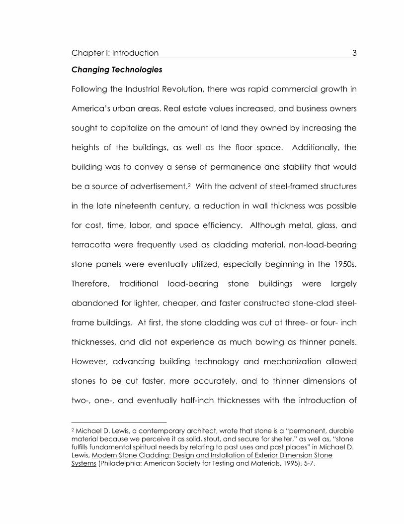
Chapter I: Introduction 3
Changing Technologies
Following the Industrial Revolution, there was rapid commercial growth in
America’s urban areas. Real estate values increased, and business owners
sought to capitalize on the amount of land they owned by increasing the
heights of the buildings, as well as the floor space. Additionally, the
building was to convey a sense of permanence and stability that would
be a source of advertisement.2 With the advent of steel-framed structures
in the late nineteenth century, a reduction in wall thickness was possible
for cost, time, labor, and space efficiency. Although metal, glass, and
terracotta were frequently used as cladding material, non-load-bearing
stone panels were eventually utilized, especially beginning in the 1950s.
Therefore, traditional load-bearing stone buildings were largely
abandoned for lighter, cheaper, and faster constructed stone-clad steel-
frame buildings. At first, the stone cladding was cut at three- or four- inch
thicknesses, and did not experience as much bowing as thinner panels.
However, advancing building technology and mechanization allowed
stones to be cut faster, more accurately, and to thinner dimensions of
two-, one-, and eventually half-inch thicknesses with the introduction of
2 Michael D. Lewis, a contemporary architect, wrote that stone is a “permanent, durable material because we perceive it as solid, stout, and secure for shelter,” as well as, “stone fulfills fundamental spiritual needs by relating to past uses and past places” in Michael D. Lewis, Modern Stone Cladding: Design and Installation of Exterior Dimension Stone Systems (Philadelphia: American Society for Testing and Materials, 1995), 5-7.

Chapter I: Introduction 4
diamond-bladed tools and multi-bladed gang saws, thereby saving time
and money.3
Figure 1.1 Multi-bladed gang saw. (Photo from Lewis, 19.)
Similar technological advances occurred regarding the
accommodation of anchors. Saws suspended on beams above, cut
edge kerfs, quirk miters, or anchor holes into the thin panels on the
conveyor beds below, providing a quicker, easier, and thus less costly
method of production.4 Also, with the introduction of thin stone panels to
the market, new anchors were adapted. In the 1930s interior cladding
techniques, such as bronze, brass, or copper wires, were used for exterior
3 Lewis, 18. 4 Lewis, 20.

Chapter I: Introduction 5
marble cladding. By the 1970s, anchors were usually stainless steel and
attached in a way that visually guaranteed that the anchor had been
properly attached, instead of the blind procedure used for interior
cladding before. However, anchorage standards did not adapt as
rapidly as stone veneer production.5
Figure 1.2 Quirk miter cutting. (Photo from Lewis, 20.)
Thus, the reason for this focus on the construction methods of post-
WWII structures in America derives from the fact that much of the
mechanization of quarrying, cutting, and finishing marble occurred in the
5 S.A. Bortz, B. Erlin, and C.B. Monk, Jr., “Some Field Problems with Thin Veneer Building Stones,” in New Stone Technology, Design, and Construction for Exterior Wall Systems, ed. Barry Donaldson (Philadelphia: American Society for Testing and Materials, 1988), 14.

Chapter I: Introduction 6
1950s and into the present, therefore more buildings were constructed
with this new technology.6 However, the closing and depletion of
quarries, as well as the increasing labor costs associated with quarry
workers, masons, shipping, and construction labor caused the cost of
marble panels to increase since it was no longer as readily available.
Panels were cut increasingly thinner for affordability, and therein lies one
of the main concerns relating to the deterioration of these marble panels.
It was difficult to predict how the interrelated materials, anchors, and
structures would deteriorate.7 Evidence of deterioration emerged after
construction, and was generally caused by insufficient accountability of
stresses, interaction of connections with panels, insufficient size of joints to
allow for movement, and problems relating to the properties of the
marble itself.8
Basics of the Curtain Wall System
Generally, the components of a marble-clad structure include thin stone
panels, anchorage system, steel framework, vapor retardant, and interior
6 Lewis, 18. 7 Although several Roman buildings did face brick buildings with thin stone (as cited in M. Wilson and P. Harrison, Appraisal and Repair of Claddings and Fixings (London: Thomas Telford, 1993), 1.), the anchoring and structural framework is completely different in post-WWII buildings (steel structures and anchors), therefore indicating that some of the decay mechanisms may also be dissimilar. 8 Marcy Li Wang, Isao Sakamoto, Bruce L. Bassler, Cladding: Council on Tall Buildings and Urban Habitat, Committee 12A (New York: McGraw-Hill, Inc., 1992), 8.

Chapter I: Introduction 7
finish.9 Wind, seismic, and gravity forces must be taken into account
when designing curtain-wall structures, as well as the location and
climate. Therefore, certain aspects of the curtain wall system will be
discussed briefly:
Figure 1.3 Curtain-wall components. (Diagram from Wang, et al., 18.)
9 Guideline for Condition Assessment of the Building Envelope (Reston, VA: American Society of Civil Engineers, 2000), 10.

Chapter I: Introduction 8
Marble Veneer
The cladding—marble, in this case—is the initial, and nearly always, the
only barrier to the environment from the interior. The chosen panels must
be lightweight, not only to alleviate loads on the frame, but also for
relative ease of installation, and hence cost of construction and labor.
Color is not usually a factor because various types of marble can exhibit
signs of deformation. Preferably, the marble grain structure would be
xenoblastic (amoeboid) as opposed to granoblastic (equigranular-
polygonal), since the granoblastic marbles tend to bow more, as will be
discussed later.10 Despite the protective assets of a polished finish for the
porosity and durability of the marble, atmospheric agents and acid rain
may eventually destroy this finish on most calcitic and dolomitic marbles.11
Additionally, since the marble panels are quite thin initially by design (¾” -
2”), the unequal movement of the grains causes the marble to bow when
exposed to heat and moisture, more so than with thicker load-bearing
masonry. The marble can also become thinner or possibly contracted
due to disaggregation, differential erosion, or delamination, thereby
indicating that minimum thickness standards should be abided for
10 L. Alnaes, et al., “Influence of Rock and Mineral Properties on the Durability of Marble Panels” (TEAM Conference Proceedings, 2004), 4. 11 Alex S. Gere, “Stone Cladding Systems,” in Exterior Claddings on High Rise Buildings, ed. Chicago Committee on High Rise Buildings (Chicago: The Fall 1989 Symposium Report, No. 12, 1990), 229.

Chapter I: Introduction 9
maximum physical life. The marble should be relatively resistant to
weathering, such as moisture penetration (rain and condensation), UV
light, thermal fluctuations, freeze/thaw cycling, pollution, and acid rain.
As will be discussed, the result of such exposure may be in the form of
cracks, spalls, deformation, or detachment, all of which contribute to a
more rapid rate of decay, and, eventually mechanical failure. Therefore,
minimum standards regarding type, finish, dimensions, and thickness of
stone panels should be examined in order to determine the safety of
maintaining a potentially incipient loss.
Anchors
Anchoring systems are responsible for transferring gravity, as well as lateral
or other vertical loads, to the support system, since marble cladding is
non-load bearing. They are generally attached directly to the back or
sides of the stone, and are available in many different formats, such as
kerf anchors (Figure 1.4 1a-c) (those that fit into a groove cut into the
stone), rod anchors (Figure 1.4 2a-c) (those that fit into drilled holes),
tooled-rod anchors (the head of the bolt fits into the marble, and the
threaded end is fastened to a clip angle on the frame), and rod-and-plug
anchors (Figure 1.4 3a-b) (those that include a threaded rod inside a

Chapter I: Introduction 10
Figure 1.4 Anchor types: 1a-c) kerf anchors; 2a-c) rod anchors; 3a-b) rod-and-plug anchors. (Diagrams from Lewis, 89-93.)
smooth rod, then placed in a drilled hole).12 Attachment systems are
chosen according to the type and thickness of stone panels, since thinner
stones are usually attached by continuous or individual clips, to
accommodate inherent loading and anchoring stresses, as well as
potential for differential movement.13 The anchors should be metal that
will not stain or corrode, such as stainless steel. Any anchoring system
should be easy to install, cost effective, and compatible with the marble
in terms of limiting potential deformation. For example, the Zibell
anchoring system is specifically designed for 7/8 inch or 1¼ inch marble,
and it is lightweight and relatively easy to install, thereby cost, time, and
labor efficient.14 Some guidelines do exist, such as those from ASTM and
The Marble Institute of America, which recommend that there should be
“…a minimum of four anchors per piece of stone up to 12 square feet of
12 Lewis, 90-94. 13 Wang, et al., 8. 14 Fred Nashed, Time-Saver Details for Exterior Wall Design (New York: McGraw-Hill, 1996), 155 and 156.

Chapter I: Introduction 11
surface area, and two for each additional eight square feet. Weight, size,
shape, and type of stone may dictate deviations from the foregoing.”15
Therefore, the type of marble, thickness, weight, finish, design, and
structure should all be taken into account when deciding which
anchoring systems to use.
Joints
When designing joints between the panels, one must account for not only
structural movement, but also the expansion and contraction of the
panels. Any movement that is not accounted for has usually caused
bowing. The type of sealant used for the joints should be resistant to
moisture penetration and thermal breakdown, but also flexible, so that the
marble panels will be able to move accordingly. Also, it is inevitable that
water will penetrate the building at some point, whether through joints or
from interior condensation. Thus, collection and diversion of water
through flashings and weepholes need to be included in the design.
Limiting the opportunities of deterioration within the marble panels during
construction or intervention, in conjunction with routine maintenance, can
greatly increase the chances of a longer lifespan for the material.
15 Dimension Stone Design Manual IV (Farmington, MI: Marble Institute of America, 1991), 1.

Chapter I: Introduction 12
Deterioration Mechanisms
The timeless and durable characteristics of marble were conferred upon
these curtain-wall buildings, but one must remember that all materials
deteriorate; it merely depends on the environment, and the specific
material itself. Many factors affect the deterioration and deformation of
marble cladding, including marble type, finish, thickness, joints, anchors,
and, of course, the surrounding environment. For example, a number of
deterioration mechanisms affect marble in general, such as salt
crystallization in pores, gypsum crusts forming due to the presence of sulfur
in the air from industrial and vehicular pollution, and natural and unnatural
acidity levels in rainwater that can cause erosion, but there are a few
conditions specifically related to marble cladding. Marble deformation
can be caused by moisture infiltration, freeze/thaw cycling, metallic
attachment corrosion, unplanned stresses, and hysteresis (see below).
Environment
The surrounding environment can cause the marble panels to weather.
For example, marble panels are affected by thermal changes and
freeze/thaw cycling, usually not only at the surface, but throughout the
stone because they are so thin. Such exposure can cause hysteresis,
which occurs when the marble panel is so thin that it cannot resist the

Chapter I: Introduction 13
Figure 1.5 Building envelope environmental exposure. (Diagram from SEI and ASCE, 17.)
stresses caused by the anisotropic thermal expansion and contraction of
its fine grains when exposed to heat and moisture. This causes
microfractures within the grain boundaries, thereby increasing porosity
and decreasing strength. Any time the porosity increases, more moisture
can be absorbed and retained within the material, potentially resulting in
salt crystallization, freeze-thaw cycling, and disaggregation caused by
pollutants and acid rain within the marble itself, not just on the surface.

Chapter I: Introduction 14
Marble panels can also heave caused by ice formation behind, if the
weep hole drainage is not functioning properly, or if there is a break in the
sealants or flashing, resulting in water flow into the interior. A way to
prevent this is to accommodate the intrusion of water through a series of
properly functioning interior gutters, downspouts, or weep holes. Usually,
the marble panel is in direct contact with the metallic attachments, and if
metallic corrosion occurs due to exposure to moisture, the metal will
expand within the stone and result in cracks and spalls. Wind, seismic,
and gravity forces can cause undue stresses on the marble panels, which
can result in strength loss, movement, and possibly mechanical failure
(since the marble veneer is supposed to be non-load-bearing). Over
time, the microfractures can turn into larger cracks, the porosity can
increase, thereby allowing more water, pollutants, and chemicals into the
stone that can result in disaggregation, eventually minor losses (spalls),
and bowing and deformation can occur, sometimes leading to complete
failure.
Anchoring Systems
Additionally, the cladding and the anchoring systems affect each other.
Moisture can come into contact with the steel-frame structure from the
outside environment through rain via sealant failures or from the inside

Chapter I: Introduction 15
Figure 1.6 Bending anchor caused by lateral loading. (Photo from Bortz, et al., 27.)
environment through condensation if the vapor retardant is not properly
functioning. In the case of improper diversion of water and/or moisture
infiltration, if the moisture cannot escape, it will remain behind the curtain
wall and can corrode the metallic elements, therefore resulting in material
expansion that leads to cracking, spalling, and deformation of the
marble, not to mention staining. Also, if anchors are missing, unintended
loads can be exerted on the marble slabs, again resulting in
deformation.16 Anchors need to engage in resistance to lateral loads
immediately, or else the stone will warp due to the unintended flexural
16 Michael J. Scheffler, “Thin-Stone Veneer Building Facades: Evolution and Preservation,” APT Bulletin 32, no. 1 (2001): 30.

Chapter I: Introduction 16
stresses.17 Anchors can fail due to lateral wind load, thereby imparting
undue force on the marble cladding, which can result in bowing.
Joints
As discussed above, if joints are not designed large enough and if the
appropriate sealant is not used, the result can be cracking, deformation
and moisture infiltration. Thus, when repairing joints, often they are
widened by abrading down the edges of the surrounding stones or a
replacement sealant allowing for more movement is utilized.
Figure 1.7 Deformational effects of restrained building movement. (Photo from Bortz, et al., 17.)
17 Bortz, et al., 28.

Chapter I: Introduction 17
Hysteresis
Although this topic will be covered in more detail in Chapter 2, it should
be mentioned here as the most notable cause of marble deformation.
Hysteresis occurs when the panel lacks the ability to resist stresses, since it
is so thin, caused by the anisotropic thermal expansion of fine-grained
marbles (exterior and interior faces expand at different rates), resulting in
a permanent, generally convex, bowing. This becomes weaker over time
because the water absorption capacity increases with subsequent
heating cycles.18 This loosens grain boundaries in marble, since calcite
does not expand uniformly in all directions when heated, and the
permeability/water absorption of marble slabs may be a contributing
variable in this thermal deformation.19 The strength of the microstructure
depends on “the rift and cleavage of the crystals, the degree of
cohesion, the interlocking of the crystals, and the nature of any
cementing material present.”20 The deterioration of the marble begins
with “thermal cracking…Weathering increases the pore spaces due to
18 William H. McDonald and Michael D. Lewis, “The Importance of Studying Exemplars when Designing Stone Facades,” in Performance of Exterior Building Walls, ed. Paul G. Johnson (West Conshohocken, PA: ASTM International, 2003), 63. 19 Clemens Widhalm, Elmar Tschegg, and Walter Eppensteiner, “Anisotropic Thermal Expansion Causes Deformation of Marble Claddings,” Journal of Performance of Constructed Facilities, February 1996, 5. 20James E. Amrhein and Michael W. Merrigan, Marble and Stone Slab Veneer (Los Angeles: Masonry Institute of America, 1986),89.

Chapter I: Introduction 18
Figure 1.8 Marble bowing. (Photo from Wang, et al., 91.)
microcrack generation and subsequent solution/precipitation activities.
The result is sugar-like disintegration…”21 This bowing and subsequent
weathering can be costly to repair, as in the case of the Amoco Building
in Chicago, which was clad with 1¼ -inch Carrara marble panels in 1973,
21 Thomas Weiss, Siegfried Siegesmund, and Patrick N.J. Rasolofosaon, “The Relationship between Deterioration, Fabric, Velocity and Porosity Constraint,” in Proceedings of the 9th International Congress on Deterioration and Conservation of Stone, Venice, June 19-24, 2000, ed. Vasco Fassina (Amsterdam: Elsevier Science Publishing Company, 2000), 222.

Chapter I: Introduction 19
and was later replaced in 1994 with 2-inch granite for $60-80 million.22 This
stone deformation could have been prevented if temperatures of the
back side of the panel and the front side of the panel were stabilized.
Case Studies
Some sites have required complete replacement of both the anchoring
systems and the cladding to ensure safety and to decrease the chances
of similar deterioration reoccurrence. For example, at the Indiana
National Bank in Indianapolis, completed in 1969, the Carrara marble
column covers were bowing and warping already by the early 1970’s.
The decision was to face-drill the stones to re-anchor them, but the panels
continued to deform. Thus, later in that same decade, the marble was
replaced with metal panels.23 This is quite similar to the second case
study, the Amoco Building in Chicago, which has already been
mentioned, although the replacement material was a thicker granite.
The third case study does not relate to marble cladding, but rather
basalt, at the Whitney Museum of American Art in New York City. In 1996,
it was discovered that the original steel anchors had corroded due to
galvanic action between the steel bolts and the zinc-coated stainless
22 Nashed, 160-161. 23 McDonald and Lewis, 64.
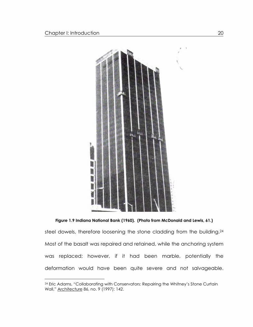
Chapter I: Introduction 20
Figure 1.9 Indiana National Bank (1960). (Photo from McDonald and Lewis, 61.)
steel dowels, therefore loosening the stone cladding from the building.24
Most of the basalt was repaired and retained, while the anchoring system
was replaced; however, if it had been marble, potentially the
deformation would have been quite severe and not salvageable.
24 Eric Adams, “Collaborating with Conservators: Repairing the Whitney’s Stone Curtain Wall,” Architecture 86, no. 9 (1997): 142.

Chapter I: Introduction 21
Although these techniques may be appropriate for some buildings, as
with any treatment, they are not appropriate for all.
Contemporary Preservation and Testing Methods
In confronting the deterioration of marble-clad buildings, some architects,
engineers, and conservators have developed new anchoring systems to
reattach either the original marble or a replacement stone, so as to
reinstate structural safety. Developed in the United Kingdom, the Cintec
Designed Anchor System consists of inserting a steel rod wrapped in a
fabric sock into a predrilled hole, and then pumping ultra-fine grout into
the sock until the grout is forced through the sock to form a chemical
bond between the anchor and the substrate, a technique that was used
at the Essex County New Courts Building and Jail in Newark.25 An
additional treatment method to be considered is the option to increase
the thickness of the marble slab, when feasible, with epoxy adhesive and
aluminum honeycomb core, although this may cause difficulties for water
vapor transmission.
In order to determine appropriate and compatible anchoring
systems for future designs and treatments, testing of various anchoring
systems should be conducted. Hence, TEAM (Testing and Assessment of
25 Eric Adams, “Cutting-Edge Masonry Repair,” Architecture 87, no. 4 (1998): 119.

Chapter I: Introduction 22
Marble and Limestone), a group of engineers, architects, and
conservators in the Netherlands, has identified their purpose as to study
why marble cladding bows and how the bowing affects the decrease in
strength.26 They have been conducting tests on various anchoring
Figure 1.10 Cintec Anchoring System. (Diagram from Adams, "Cutting Edge Masonry," 118.)
26 T. J. S. Yates, et al., “Observations from the Inspection of Marble Cladding in Europe,” in prep. Dimension Stone 2004, 1.

Chapter I: Introduction 23
systems (“kerf, mortised, back face fixings FZP, dowels at vertical edges,
and dowels at horizontal edges”27) on the same Carrara marble since
2003 in Fisherwerke, Waldachtal, Germany. The chief purpose of these
tests is to analyze if there are any differences among the anchoring
systems and how they affect bowing of the marble.28 Also, TEAM is testing
marbles to determine if impregnation with GypStop, an inorganic water-
based product, and Anti Graffiti System, a water-based agent, aids in the
decrease of bowing in thin marble panels.29 The results will not be
conclusive until the end of this year. While these tests, as well as the tests
of treatments conducted in this thesis, may confirm alternative minimal
intervention options, they are only available for those marbles that,
although in danger of becoming so, are not already excessively
deformed. When repairing thin-stone veneer systems safety, aesthetics,
feasibility, cost, and serviceability should be considered.30
Proposed Treatments and Testing
In giving consideration to treatments or repairs of marble panels, one must
implement tests on both the treated and untreated samples for
27 K. Malaga, et al., “Field Exposure Sites and Accelerated Laboratory Test of Marble Panels,” in prep. Dimension Stone 2004, 3. 28 K. Malaga, et al., 3. 29 K. Malaga, et al., 2-3. 30 Scheffler, 33.

Chapter I: Introduction 24
comparative purposes. Tests should be predicated upon what is known
concerning deterioration mechanisms related to marble panels, as has
been discussed. In order to determine the rates and how much water
was absorbed or evaporated, as well as how it affected the sample,
water absorption and evaporation should be tested. Since hysteresis
caused by thermal changes is the chief reason for marble deformation,
tests regarding thermal expansion and bowing potential should definitely
be conducted. Likewise, any treatments should be tested for flexural and
tensile strengths since thin panels are weak in this area, in addition to
movement caused by the wind or material, anchoring, or structural
movement. Those tests developed to determine compatibility of anchors
with marble panel pre-construction could potentially be revised for
material analysis regarding deteriorated samples. Tests would, ideally, be
conducted regarding bowing potential, flexural strength, tensile strength,
attachment strength, effects of thermal changes, and material
compatibility. Few standards, however, exist specifically for this purpose
regarding curtain-wall buildings, so some will need to be adapted.
For this thesis, however, due to time constraints, only the major
properties were tested. Bowing potential and flexural strength tests were
performed, as well as general characterization of the marble. The bowing

Chapter I: Introduction 25
potential and flexural strength tests are especially important, since
according to one expert:
A 1/8 inch (3 mm) reduction of a 1¼ inch (32 mm) veneer reduces bending strength by roughly 20 percent and may increase elastic deflection under wind loads by as much as 37 percent. This problem can be further affected by job-site weathering.31
Hysteresis is one of the major reasons for the bowing of marble panels, so
any method of mitigating this type of deterioration before or after it
occurs should be examined. That is why various mechanical treatments
will be applied to the marble and tested, including carbon fiber straps
and polypropylene honeycomb, both of which will be discussed more in
depth in Chapter 2.
Marble cladding could potentially have an indefinite lifespan if
designed with appropriate anchors, frame, and joints, taking into account
rain, freeze/thaw cycling, wind, sun, temperature changes, pollution, and
acid rain. All materials deteriorate, but the rate of decay can be
controlled and extended through intervention. Technologies, codes,
regulations, and standards need to be developed in accordance with
the positive aspect of hindsight concerning the failures of past exemplars.
Conservators need to learn from design mistakes, and determine how to
31 Forrest Wilson, “The Perils of Using Thin Stone,” Architecture, February 1989, 96, quoted in Fred Nashed, Time-Saver Details for Exterior Wall Design (New York: McGraw-Hill, 1996), 162.

Chapter I: Introduction 26
prolong the lives of curtain-wall buildings, without compromising material
and structural integrity where possible. Non-destructive or minimal
intervention methods need to be examined as a viable option, rather
than immediately choosing to replace anchors and panels. The
deformation of marble panels via hysteresis is a concern, and ways to
maintain temperatures on both sides of the panels should be determined
as an afterthought to the design in order to preserve those marble panels
that have not yet deformed. Treatments need to be proposed and
tested prior to any conclusions concerning possible solutions to this
problem.

27
CHAPTER II: METHODOLOGY
Rationale
Why stone veneer?
Thin marble panels on certain post-WWII American buildings have been
bowing, deforming and failing, as discussed in Chapter 1. Stone tends to
lose strength (flexural, tensile, shear, compressive, etc.) when it is exposed
to thermal and moisture cycles, especially fine-grained white marbles.32 In
the past 10-15 years, more case studies of failing marble cladding have
become apparent, and the body of literature regarding the reasons for
this has slowly developed. However, short of total replacement, there is a
lack of proposed treatments for this obvious problem, and little literature
pertaining to the effectiveness of any potential treatments for retaining
stone slabs and veneers. Although it is not economically feasible or even
logical to consider treating all permanently bowed marble panels, it may
be possible to increase the flexural strength and decrease the bowing
potential by applying certain mechanical reinforcement treatments.
Therefore, in an effort to address the absence of literature available
regarding such treatments, this thesis will be a contributing factor to
further research. Experimental treatments were designed and applied to
32 John P. Stecich, Ian R. Chin, and F. Dirk Heidbrink, “Testing for Thin Stone Veneers on Buildings,” in Exterior Claddings On High Rise Buildings, eds. Chicago Committee on High Rise Buildings (Chicago: The Fall 1989 Symposium, Report No. 12, 1990), 125.

Chapter II: Methodology 28
fresh Carrara marble samples. The samples underwent two chosen
mechanical tests (bowing potential and flexural strength) and the results
will be evaluated. Evaluations will be based according to criteria
established for the treatments’ ability to inhibit bowing potential and/or
improve (flexural) strength with minimal intervention and maximum
retreatability.
Why Carrara marble in particular?
Carrara marble, in particular, was chosen to test because 1) many
monuments and several buildings, such as the Amoco Building, 1974 in
Chicago, were clad with thin Carrara marble panels that failed and were
later replaced with granite, 2) granoblastic Carrara marble, as opposed
to other common veneer stone, such as granite, has a tendency to bow
and deform much more readily than other types of stone and even other
types of marble, and 3) due to time constraints, it is necessary to choose
a marble that will bow and deform easily when exposed to moisture and
thermal cycles. Although under extreme conditions, it will hopefully yield
what would be realistic long-term results.
There are several causes for the deformation of thin marble panels,
such as corroding metallic anchors, joints disallowing movement,
exposure to moisture, and thermal changes, but, as stated above and in

Chapter II: Methodology 29
Chapter 1, bowing of marble is often attributed to hysteresis. Hysteresis
can be defined as “a permanent growth in the stone due to a differential
temperature or moisture change through its thickness.”33 Hysteresis occurs
when the panel lacks the ability to resist stresses, since it is so thin, caused
by the anisotropic thermal expansion and contraction of fine-grained
marbles (exterior and interior faces expand at different rates, since each is
exposed to different levels of moisture and temperature changes). This
results in a permanent, generally convex, bowing, becoming weaker over
time because the water absorption capacity increases with subsequent
Figure 2.1 Anisotropic thermal behavior of a single calcite crystal. (Diagram from Grelk et al., 5.)
33 Bortz et al., 16.

Chapter II: Methodology 30
heating cycles and micro-cracking.34 This loosens grain boundaries in
marble, since calcite does not expand uniformly in all directions when
heated and the permeability/water absorption of marble slabs may be a
contributing variable in this thermal deformation.35 This is because “when
the calcite crystals relax to their original locations during temperature
drop, dislocations along crystal edges keep crystals from returning to their
original positions, resulting in a slight volume increase and slight increase in
porosity due to dislocations along crystal boundaries.”36
Although hysteresis was discussed briefly in Chapter 1, it is important
to mention it again here since this was one contributing factor in the type
of marble chosen for testing. The causes of bowing in Carrara marble
(and other types of marble) have been tested by several scientists,
including TEAM, and many agree that what affects the potential for
bowing is grain boundaries and micro-structure. This means that marbles
with grains that do not interlock well and have straight boundaries will
bow more, such as with granoblastic marbles (i.e. fine-grained Carrara
marble).37 Attention will be given to examine the granoblastic (“a
34 McDonald and Lewis, 63. 35 Widhalm et al., 5. 36 Bernard Erlin, “Contribution to a Better Understanding of the Mechanism Causing Dishing Failures of the Carrara Marble When Used for Outside Building Facades,” in Dimension Stone Cladding: Design, Construction, Evaluation, and Repair, ed. Kurt R. Hoigard (West Conshohocken, PA: ASTM, 2000), 78. 37 Alnaes, et al., 6.

Chapter II: Methodology 31
granular mosaic texture in which the grains are tightly compacted, the
minerals are dominantly of equidimensional kinds and present irregular
mutual boundaries”38) nature of the marble. “Granoblastic marble has
both a higher initial grain boundary porosity and gets a more pronounced
intergranular decohesion during exposure.”39 Since the more marble
panels bow, the greater the decrease in strength, especially flexural
strength, it is essential to examine the effects of exposing marble that is
prone to bowing when exposed to temperature and moisture cycles
(hysteresis) when considering treatments. “The marble becomes
permanently elongated, its porosity increased and its ultimate strength is
diminished.”40
Although it may be impossible to halt the effects of hysteresis,
without stabilizing the environment, at the very least it may be possible to
increase the flexural strength and slow bowing potential with mechanical
treatments such as those proposed in this thesis. In combination with
chemical treatments it may be possible to equalize the different moisture
and thermal exposures to the two sides of the marble panel to decrease
hysteresis, but this thesis only addressed the potential of increasing flexural
strength and decreasing bowing potential via mechanical treatments.
38 Amrhein and Merrigan, 2. 39 Alnaes, et al., 2. 40 Gere, 230.

Chapter II: Methodology 32
Additionally, general characteristics of the marble, such as grain size,
grain size distribution, porosity and texture, were examined. The marble
samples tested were white Carrara marble 15” x 4” x ¾”, (described in
more detail in Chapter 3). The panels were obtained from Cava
International, located at 2001 Washington Avenue in Philadelphia,
Pennsylvania (see Appendix 1).
Figure 2.2 AnchorFix 3 epoxy gel used to adhere mechanical treatments to the marble panels.

Chapter II: Methodology 33
Proposed Treatments
All of the treatments were applied to the marble samples with an epoxy
gel adhesive, Sikadur AnchorFix 3. AnchorFix 3 is a “2-component, 100%
solids, moisture-tolerant, high-modulus, high-strength, structural epoxy.”41
Component A contains epoxy resins and talc, while Component B
contains amines, nonyl phenol, and talc.42 One of its uses is re-anchoring
of veneer masonry, so it is particularly important and relevant to these
experiments. Additionally, the 24-hour cure time is practical and efficient
and it is easy to apply with a caulking gun.
Carbon Fiber Straps
Although limited literature exists regarding the use of carbon fiber straps in
treating stone in general, carbon fiber straps have been used frequently in
the surface repair of concrete beams. For example, the Center for
Transportation Research at the University of Texas in Austin tested carbon
fiber composites to determine if they would increase the flexural strength
of concrete bridges.43 The team tested two configurations, one with
straps applied longitudinally (one direction), and those applied both
41 Product information obtained from the Sika website, www.sika.com.42 Ibid.43 Sergio F. Brena, Sharon L. Wood, and Michael E. Kreger, “Using Carbon Fiber Composites to Increase the Flexural Capacity of Reinforced Concrete Bridges,” in Project Summary Report 1776-S: Development of Methods to Strengthen Existing Structures with Composites (online article, 2001), 1.

Chapter II: Methodology 34
longitudinally and transversally (two directions). They found that the
treatment failed for all configurations due to debonding of the carbon
fiber composite that started at the location of flexural cracks within the
shear span (although those with transverse straps did, in fact, delay
debonding of the carbon fiber straps from the concrete), and also that
flexural capacity did, in fact, increase.44 Other researchers discovered
similar results, stating that “the CFRP system can significantly increase the
serviceability, ductility, and ultimate shear strength of a concrete
beam.”45 Marble, of course, has quite different properties than concrete,
but since the flexural, tensile and shear strengths were increased with
concrete, possibly similar results will occur with the marble.
For the purposes of this thesis the carbon fiber straps will only be
applied in one direction in the middle of the sample on one side of the
marble panel, due to the small size of the samples.46 Since AnchorFix 3
was used to attach the straps, resultant damage at the adhesive-stone
interface could be examined. The type of carbon fiber straps used were
Sika CarboDur CFRP Plates (15” x 2” x 1/32”), produced by the pultrusion
44 Brena, Wood, and Kreger, 3. 45 Zhichao Zhang, Cheng-Tzu Thomas Hsu, and Jon Moren, “Shear Strengthening of Reinforced Concrete Deep Beams using Carbon Fiber-Reinforced Polymer Laminates,” Journal of Composites for Construction 8, no. 5 (2004), 414. 46 Kevin Collins at Sika also recommended to only use one carbon-fiber strap in one direction, as opposed to criss-crossing them, since he believed that would be sufficient reinforcement for the size of the samples.

Chapter II: Methodology 35
process and manufactured to increase flexural strength.47 The intent for
applying carbon fiber straps was to determine if this particular treatment
does in fact increase the flexural strength of the marble and also to
determine if it deters bowing. Straps are flexible longitudinally along their
axis. One must always keep in mind that the sample must be retreatable
(the reason for failure within the bond). Failure mode must also be
predictable and acceptable.
Figure 2.3 Carbon fiber straps.
47 Product information from the Sika website, www.sika.com.

Chapter II: Methodology 36
Polypropylene Honeycomb Backing
Similar to the carbon fiber straps, there is little evidence of using
polypropylene honeycomb to repair marble, or even stone, cladding. In
the latter years of the 1980s, 1/16-inch stone veneer was sometimes
applied to an aluminum honeycomb core, but not much has been written
about its condition, maintenance or treatments.48 However, honeycomb
panels (aluminum, paper, plastic) are frequently used in the conservation
of mosaics and wall paintings and, more relevantly, in the construction of
composite panels49. Starting in the 1950s, honeycomb cores were used in
constructing laminated composite panels. In general, the honeycomb
cores are lightweight, but strong, resistant to moisture and temperature
changes, and offer stability and flexibility.50 All of these properties are
important for treating a thin marble panel, especially the latter
characteristic, since the honeycomb core can move with and adjust to
the changes of the stone facing, and therefore not fail as easily. The
honeycomb core does not have insulating properties, which could aid in
equalizing the temperature and moisture changes between the interior
and exterior faces of the stone, thereby resulting in less bowing
48 Ian R. Chin, “Common Causes of Failure of Stone Claddings on Buildings,” in Dimension Stone Cladding: Design, Construction, Evaluation, and Repair, ed. Kurt R. Hoigard (West Conshohocken, PA: ASTM, 2000), 152. 49 Nashed, 149. 50 William Dudley Hunt, Jr., The Contemporary Curtain Wall: Its Design, Fabrication, and Erection (New York: F.W. Dodge Corporation, 1958), 322.

Chapter II: Methodology 37
deformation, but could have negative impacts on the overall building
system.
Figure 2.4 Composite panel. (Diagram from Nashed, 149.)
This type of treatment can potentially fail within itself or in the bond,
both options being favorable since it is sacrificial to the marble panel,
although that is one reason why these composite panels have failed
frequently in the past.51 In the case of applying honeycomb backing to
thin stone veneers, they are more cost-effective than other techniques
because they are lightweight and easy to manufacture, but the “long-
term durability” is unknown since they have only been used for the last 15
51 Hunt, 325.

Chapter II: Methodology 38
or so years.52 Although often epoxy adhesives are used in application,
some scientists do not recommend this adhesive because some marbles
and epoxies are thermally incompatible, expanding and contracting at
different rates, resulting in “debonding of connections, cracking of stone
panels at connections, debonding of joints between sections of stone,
and cracking of stone panel away from connections.”53 However, if a
suitable attachment method is chosen, it can be an appropriate and
desirable method of attachment. Adhesives must be durable, strong,
withstand creep, and be flexible, resistant to moisture, resistant to high
temperatures, have good bond strength, and be easily applied.54
The polypropylene honeycomb used for treatment in this thesis is
from Nida-Core (15” x 4” x ¾”). This material is noted for its “inherent
toughness, extreme chemical resistance, and elongation.”55 The idea is
that the greater the thickness of the core, the more resistance shall exist to
bending. However, although not known at the time of the treatment, one
should note that this particular product has a flexural modulus rating of 4
out of 10, so that maybe a honeycomb material with a higher flexural
52 Nashed, 151. 53 Chin, 155-156. 54 Hunt, 334-335. 55 “Nida-Core Structural Honeycomb Materials: Rigid-Elastic Technology Handbook” (Port St. Lucie, Florida: Nida-Core Corporation, 2005), 45.
Chapter II: Methodology 39
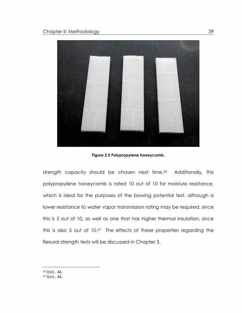
Figure 2.5 Polypropylene honeycomb.
strength capacity should be chosen next time.56 Additionally, this
polypropylene honeycomb is rated 10 out of 10 for moisture resistance,
which is ideal for the purposes of the bowing potential test, although a
lower resistance to water vapor transmission rating may be required, since
this is 5 out of 10, as well as one that has higher thermal insulation, since
this is also 5 out of 10.57 The effects of these properties regarding the
flexural strength tests will be discussed in Chapter 3.
56 Ibid., 46. 57 Ibid., 46.

Chapter II: Methodology 40
Testing Program
Bowing Potential58
One purpose of this thesis was to examine how and why marble bows
above and in combination with remedial treatments. Therefore, the main
focus was to determine the amount of bowing for the white Carrara
marble samples with two different treatments and one control, and to
compare which treatments inhibit the bowing potential of the thin marble
panel. Although this experiment directly measures the amount of
moisture- and thermal-induced bowing, the inherent tendency of
granoblastic marble to bow must be considered an additional factor.
Two treatments were applied: 1) carbon fiber straps applied in one
direction with continuous adhesion and 2) polypropylene honeycomb
backing attached to one side also with continuous adhesion. Each
treatment was applied with an epoxy gel adhesive. Also to allow
retreatability, Acryloid B-72 dissolved in toluene (1:1 w/w) was applied to
the side of the marble that was treated to allow the bond to break at the
stone-epoxy interface, to avoid permanently damaging the marble.59
Each treatment was applied to four samples in order to average the final
58 Modified from test standard Nordtest Method NT Build 499, Cladding Panels: Test for Bowing, 2002. 59 Jerry Podany, et al., “Paraloid B-72 as a Structural Adhesive and as a Barrier Within Structural Adhesive Bonds: Evaluations of Strength and Reversibility,” in Journal of the American Institute for Conservation, 40, no. 1 (2001): 21.

Chapter II: Methodology 41
results of those samples that had been cycled for forty days for higher
accuracy (the fourth sample of each was only cycled for twenty days,
treated, and then tested for flexural strength with no further cycling). The
six treated samples that were cycled for forty days were first cycled
untreated for twenty days, treated with either the carbon fiber straps or
the polypropylene honeycomb, and then cycled for another twenty days
prior to the flexural strength tests.
All of the treated and untreated samples were placed in steel pans
(17” x 16” x 2 ½”) on glass marbles with water up to ½” below the surface
of the samples (moisture exposure component) to ensure even exposure
to moisture and ease in movement during expansion/contraction.
According to TEAM tests “it is assumed that temperature variations in
combination with humidity are the external factors required for bowing to
occur…exposed solely to heat resulted in no bowing.”60 The samples
were exposed to 40 heating cycles, the infrared lamps heating the
sample from 68’F – 180’F, one cycle per 24 hours (thermal exposure
component). Since bowing is largely attributable to hysteresis, as
discussed above, the thermal and moisture cycling will address this fact
since both sides are exposed to different thermal and moisture
conditioning. The bowing was measured with a thickness gauge to the
60 Malaga, et al., 4.

Chapter II: Methodology 42
nearest thousandth of an inch at the sample space on the marble each
time, and subsequent measurements were subtracted from the original
thickness measurement as the reference point. After the test was
completed, the change in height due to bowing was calculated and
each treatment and control was compared to determine the effect, if
any, of the repair system on the bowing potential of the marble.
Figure 2.6 Schematic of bowing potential test assembly. (Design based on TEAM’s Nordtest BUILD 499 Bowing Potential test standard.)

Chapter II: Methodology 43
Flexural Strength61
As a direct result of bowing and deformation, the flexural strength of
thin marble panels decreases over time. The problem is compounded
when the marble is restricted by design or subjected to the forces of
gravity, wind and, sometimes, earthquakes. If the marble cladding is
subjected to too many of these forces, along with hysteresis caused by
differential exposure to thermal and moisture changes, failure will occur
and the stone will detach from the structure or the building. Therefore, the
main purpose of this test was to determine the flexural strength of variously
treated thin marble panels, and to determine if and how the treatments
increase the flexural strength for the given Carrara marble samples. If the
flexural strength is increased by the treatments, this will provide viable
options for times when a panel has or will have the potential to bow,
thereby causing a decrease in flexural strength, and will effectively inhibit
failure by increasing its flexural strength.
All of the samples that were used in the bowing potential test
discussed above, after cycling were tested for flexural strength. This
includes: three fresh samples (U1-U3); one untreated sample cycled for
twenty days (C4); three untreated samples cycled for forty days (C1-C3);
61 Modified from ASTM Designation: C 880-98, “Standard Test Method for Flexural Strength of Dimension Stone,” 2004.

Chapter II: Methodology 44
one sample cycled for twenty days and then treated with carbon fiber
(CFV4); three samples cycled for twenty days, treated with carbon fiber
straps, and cycled for another twenty days (CFV1-CFV3); one cycled for
twenty days and then treated with polypropylene honeycomb (PH4); and
three cycled for twenty days, treated with polypropylene honeycomb,
and then cycled for another forty days (PH1-PH3). The final results for
each sample group were averaged for higher accuracy. Each of the
samples was placed on the testing apparatus consisting of a lower knife
upon which each sample sits, an upper knife that is in contact with the
top of each sample, a steel ball that applies load evenly between the
upper knife and the load cell, and a load cell that will consistently add
weight onto each sample. The type of loading is quarter-point loading,
whereby there are four contact points on the top of each sample. The
span of the lower knife was 8 inches (the standard recommends the span
to be between 7.5 and 11 inches for the sample size tested) and the
upper knife span was 3 inches, which was decided in conjunction with Dr.
Alex Radin. The sample was placed on the lower knife, the upper knife
was lowered onto the top of the sample, the sample was centered, and
the load was applied until the sample failed, either in the bond or within
the sample itself. Once the sample failed, the results were compared to
determine strength increase and failure mode. Here, again, the

Chapter II: Methodology 45
treatment provides options for minimum intervention and retreatability
when needed.
Figure 2.7 Flexural strength test drawing. (Diagram from Lewis, 68.)

Chapter II: Methodology 46
General Marble Characterization
The microstructure of the marble samples was examined in order to
determine general characteristics of the stone. Although marble usually is
thought to have high density, high strength, and low porosity, a
microscopic examination of the material can show why it has such
properties. Therefore, thin sections of the marble were examined with
Polarized Light Microscopy (PLM) at 10x magnification. The texture, grain
size, grain size distribution, grain boundaries, grain shape, and porosity
were examined. All of this information can contribute to a better
understanding of why and how the marble displays an inherent tendency
to bow. According to some research, the “interlocking of the grains and
the lattice preferred orientation”62 are the important factors in
determining if and how marble will deform, so particular attention was
given to these properties. Also, particular attention was given to
determine the grain size and boundary type, since “marbles with larger
grain sizes show thermal cracking at significantly lower temperatures [and]
marbles with straight or only slightly curved grain boundaries are much less
resistant against thermal treatment…”63 Since the grain structure can
62 Alnaes et al., 6. 63 S. Siegesmund, T. Weiss, and E. K. Tschegg, “Control of Marble Weathering by Thermal Expansion and Rock Fabrics,” in Proceedings of the 9th International Congress on

Chapter II: Methodology 47
change when marble is exposed to heat and moisture, it is important to
examine thin sections of the marble samples both before and after testing
for comparison purposes.
Figure 2.8 Calcitic marbles. Left: Granoblastic; Right: Xenoblastic. (Photos from Alnaes, et al., 3.)
Limitations
As the bowing potential test requires nearly two months of daily cycling, it
was important to keep the tests simple, straightforward, and limited,
confined to only the essential tests in order to draw relevant conclusions
and results. Additionally, funding was not unlimited, so several types of
marble and stone could not be tested. Also, tests were modified (i.e.
number of samples, design and construction of assemblies, materials used
for measurement, etc.) in accordance with budgetary constraints. Study
Deterioration and Conservation of Stone, Venice, June 19-24, 2000, ed. Vasco Fassina (Amsterdam: Elsevier Science Publishing Company, 2000), 211-212.

Chapter II: Methodology 48
of other properties of the marble should be conducted (i.e. water vapor
transmission, water absorption, linear strain) to understand all of the
physical properties.

49
CHAPTER III: ANALYSIS AND OBSERVATIONS
General Marble Examination
Initial examination of the general characteristics of the marble was
conducted prior to treatments and testing.
Figure 3.1 Carrara marble sample.
Color
The Carrara marble tested is white (Munsell color 5PB-9/1) with charcoal
gray veining (Munsell color 10PB-6/1). Each piece of marble displays
different veining, but the colors remain consistent.

Chapter III: Analysis and Observations 50
Texture
The marble is polished on one side, while the reverse is unpolished. Since
the bowing potential test will be conducted with the heat lamps facing
the polished side, this may have some effect on how much the marble will
bow.
Hardness
Because this white Carrara marble is largely composed of calcite, the
hardness on the Moh's scale is 3 out of 10. This means it is relatively soft.
Dimensions
The marble tested was cut to 15” x 4” x ¾”. These dimensions are
appropriate for both the Bowing Potential and Flexural Strength tests,
according to, respectively, the Nordtest Method NT Build 499 Bowing
Potential and ASTM Designation: C 880-98 Flexural Strength test standards.
Also, this is a much smaller scale than marble panels that would be used
on buildings, due to space and logistic constraints, as well as the above-
mentioned needed dimensions for the tests. Larger pieces may take
longer to bow and may have greater flexural strength.

Chapter III: Analysis and Observations 51
Microscopic Examination
Porosity
The Carrara marble is not very porous or permeable. The pores range
between 0.0125 and 0.025 mm in width.
Grain Size
The grain sizes of the Carrara marble are approximately 0.2 mm in
diameter. All of the grains are of similar size/homogenous with straight
grain boundaries.
Grain Shape
All of the grains are subrounded and are all in different orientations. It is
quite evident when looking at the thin section with the analyzer and
accessory plate that there is high birefringence. Additionally, the thin
section was stained with Alizarin red for calcite, and the marble is
definitely calcitic (98%) homogeneous and isotropic, the only portions of
the thin section not stained being the pores.

Chapter III: Analysis and Observations 52
Figure 3.2 Fresh Carrara marble thin section, 10x with analyzer and accessory plate.
Figure 3.3 Fresh Carrara marble thin section, stained with alizarin red, 10x.

Chapter III: Analysis and Observations 53
Treatments
Method of Treatment
The first step in the treatment process was to clean the surfaces of the
carbon fiber straps, the polypropylene honeycomb, and the marble
samples with acetone and cotton. This ensures that both surfaces are
clean and free of dirt, oils, and other contaminants, so that the epoxy will
adhere.
Next, Acryloid B-72 dissolved in toluene was applied to the side of
the marble to be treated. The solution was a one to one, weight to
weight ratio.64 (Seventy grams of toluene was measured in a beaker and
placed in a small glass container. Then seventy grams of B-72 were
weighed and placed in cheesecloth that was tied with string, and
immersed in the toluene, suspended above the bottom of the container,
so that the B-72 would dissolve in the covered container over a 24-hour
period). Next, the B-72 solution was applied with a brush to one side of
the marble sample, and allowed to dry for one week.
Once the treatment materials and the marble were cleaned, the
next step was to apply the Sikadur AnchorFix 3 epoxy gel. This is easily
accomplished by inserting the cartridge into a caulking gun, and then
squeezing the trigger. For the marble treated with carbon fiber straps, five
64 Podany, et al., 21.

Chapter III: Analysis and Observations 54
Figure 3.4 Step one: Apply epoxy to the marble panel.

Chapter III: Analysis and Observations 55
Figure 3.5 Step two: Spread the epoxy over the marble panel.
Chapter III: Analysis and Observations 56
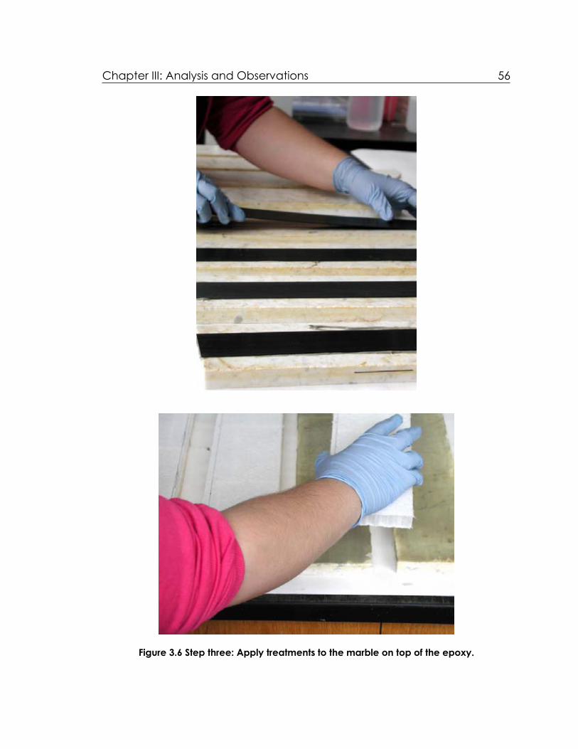
Figure 3.6 Step three: Apply treatments to the marble on top of the epoxy.

Chapter III: Analysis and Observations 57
Figure 3.7 Step four: Roll the carbon fiber strap or the polypropylene honeycomb over the epoxy to ensure even contact.

Chapter III: Analysis and Observations 58
thick lines of epoxy were squeezed onto the marble, and for those treated
with the polypropylene honeycomb ten thick lines of epoxy were required
for even coating. A putty knife was used to the spread the epoxy evenly
and smoothly over the surface of the marble to a depth of approximately
1/16”.
Finally, the treatment material was carefully placed on the marble
and pushed firmly so as to ensure even contact with the epoxy. Then a
sheet of Mylar and a large block of limestone were placed on top of the
treated samples as weights for the 24-hour drying period at room
temperature.
Problems Encountered
The first problem encountered in the treatment process was that the B-72
in toluene is quite sticky, and much care should be taken when applying
this to the marble for a thin, even coating. Also, it took longer than
expected to dry.
Secondly, since the epoxy consists of two-components, the instant
they are in contact they start to react. This can be a problem when
applying the epoxy because it can start to dry within the application
mixing tube if the epoxy is not applied quickly. That is why it is
recommended to have several applicator tubes at hand when

Chapter III: Analysis and Observations 59
conducting these treatment procedures. This also includes spreading the
epoxy evenly and quickly on the marble, since as the more time goes by,
the harder it is to spread.
Finally, the carbon fiber straps were not perfectly straight, so a large
weight is required to ensure even adherence with the epoxy.
Results
By conducting practice treatment sessions, the problems and limitations
could be accounted for and the procedure modified. Thus, the
mechanical treatment of the samples was successful.
Bowing Potential Test
Construction of Assemblies
Based on the recommendations in the Nordtest BUILD 499 standard for the
Bowing Potential test, a modified schematic was drawn for the number
and size of the samples required for this thesis, as discussed in Chapter 2.
In collaboration with Dennis Pierattini, Fabrication Laboratory Supervisor at
the University of Pennsylvania, four test assemblies were designed and
built for the purposes of this test. Each test assembly consisted of a
plywood base, two plywood t-frame pieces, and one plywood support
that is adjustable, all of which were cut, sanded, and varnished. Also,

Chapter III: Analysis and Observations 60
there are two wired light sockets for the infrared heating lamps. Three
pieces of marble were placed on top of ½” depth of glass marbles and
sand in one steel pan (17” x 16” x 2 ½”). One of these set-ups was needed
for the three samples that were cycled for twenty days, and three
assemblies were needed for the nine samples that were cycled for forty
days.
Figure 3.8 Constructed bowing potential assemblies.
Gauge Set-Up
The Nordtest BUILD 499 test standard for bowing potential indicated that
an invar steel gauge set-up was used to measure the dimensional change

Chapter III: Analysis and Observations 61
after each cycling. To construct a gauge set up with invar steel would
have been costly and time-consuming, so in the interest of saving time
and money a modified gauge set-up was designed in collaboration with
Dennis Pierattini. A large granite base insured stability, so that consistent
readings could be obtained each day. Additionally, two one-inch steel
bars served as the supports, and were checked each day confirming that
Figure 3.9 Bowing potential thickness gauge set-up.
they were within the boundaries marked on the granite so that the marble
would be placed in the same spot for each measurement. A thickness
gauge, with an accuracy to the nearest thousandth of an inch, measured
the dimensional change in the marble, by placing the tip of the gauge on

Chapter III: Analysis and Observations 62
a marked spot in the middle of the marble for each measurement.
Although this gauge set up may not have been as precise as the one
recommended in the test standard, consistent and accurate readings
were obtained after each cycle.
Method of Testing
As discussed in Chapter 2, the marble was placed on a ½” bed of glass
marbles, filled with de-ionized water up to ½” below the top of the
marble, and then the infrared heat lamps were turned on for four hours.
The surface temperature of the marble started at 68 degrees Fahrenheit
and ended at around 200 degrees Fahrenheit, which is slightly higher than
the recommendation of the test standard. The lights would then be shut
off, and the whole process would begin again twenty hours later, so that
there would be one cycle each day for forty days. Prior to each cycle,
the marble was measured with the thickness gauge to the nearest
thousandth of an inch to determine the amount the marble bowed. For
the first twenty cycles, all of the marble was left untreated, so as to
determine if the marble would bow, by how much, and to account for
any differences there may be inherently in the marble itself. After twenty
cycles, three untreated samples continued to cycle, three samples were
treated with carbon fiber straps, and three samples were treated with

Chapter III: Analysis and Observations 63
polypropylene honeycomb, and cycled for another twenty days.
Additionally, two samples that had been cycled for twenty days were
treated, one with carbon fiber and one with the polypropylene
honeycomb, so that they could be tested for flexural strength with the
others, and used for comparison purposes.
Limitations and Uncertainty
There were a few problems with the modified test assembly and gauge
set up. Firstly, since there were only two heat lamps for three samples,
some of the samples were more exposed than others. However, this
problem was accounted for by rotating the placement of the samples in
the tray for each cycle, so that each was exposed to the heat for the
same amount of time and intensity. Secondly, the room in which the test
was conducted was not climate-controlled, so that some days the marble
would start at higher or lower temperatures than other days. Thirdly, once
the treatments were applied to the marble, this increased the thickness,
and therefore the distance between the heat lamps and the surface of
the marble. This was corrected by adjusting the plywood support on the
plywood t-frame, so that the lamps were 5 ½” higher than the surface of
each piece of marble. Fourthly, the steel supports could move on the
granite, but this was corrected by placing guides on the granite base.

Chapter III: Analysis and Observations 64
Finally, in order to measure the marble, the thickness gauge was placed
on top of the marble, and the exact spot could change slightly day to
day. That is why the marble was measured several times with the gauge,
to ensure consistent and accurate readings.
Results
After forty days of cycling, all of the marble panels displayed bowing. The
direction of bowing was concave on the side that was in contact with the
water and convex on the side that was facing the heat, as predicted.65
The temperature difference between the heated surface and the surface
in contact with moisture was approximately 130 degrees Fahrenheit,
which is similar to in situ conditions because when accounting for air-
conditioned interior spaces in the summer and heated interior spaces in
the winter there can be a temperature difference of at least 100 degrees
Fahrenheit.66 In general, the dimensional change of all of the marble
panels was quite similar. Most of the bowing occurred within the first
twenty days,67 and continued to bow for the last twenty days, albeit at a
65 Gere, 230. 66 Ian R. Chin and C. B. Monk, Jr., “Design of Stone Curtain Walls to Resist Weathering,” in Proceedings of the Fourth International Congress on the Deterioration and Preservation of Stone Objects, July 7-9, 1982, ed. K. L. Gauri and J. A. Gwinn (Louisville: The University of Louisville, 1982), 91.67 Albert Jornet, Tiziano Teruzzi, and Philipp Ruck, “Bowing of Carrara Marble Slabs: Comparison between Natural and Artificial Weathering,” in Understanding and

Chapter III: Analysis and Observations 65
much slower pace.68 An average of the dimensional change of the
three marble samples within the three groups (C: untreated, CFV: treated
with carbon fiber straps, and PH: treated with polypropylene honeycomb)
was calculated after twenty days, after forty days, and within the last
twenty days of cycling. The reason for the averages is to account for the
differences inherent in each piece of marble. After twenty days of
cycling, when all of the marble was untreated, the marble later used for
the control (C) bowed 0.024 inches, the marble later used for the carbon
fiber treatment (CFV) bowed 0.018 inches, and the marble later used for
the polypropylene honeycomb (PH) bowed 0.027 inches, all of which are
quite similar changes. At this point, one sample untreated (C4), one
sample treated with carbon fiber (CFV4), and one sample treated with
polypropylene honeycomb (PH4) were set aside, after these twenty
Figure 3.10 Calculated data from the bowing potential test of treated and untreated Carrara marble.
Managing of Stone Decay, eds. Richard Prikryl and Heather A. Viles (Prague: The Karolinum Press, 2002), 161. The authors stated that, “the more significant changes occur already after the first 50 cycles.” 68 Malaga, et al., 6. TEAM also found this to be the case, writing that “…(bowing) is not a continuously increasing movement (on fresh marble)…this means that fluctuation of bowing decreases with the time of exposure of a panel.”
20 Cycles 40 Cycles Difference Between 40 and 20 Cycles
% Increase
C 0.024” 0.029” 0.005” 3.8% CFV 0.018” 0.023” 0.005” 3.1% PH 0.027” 0.034” 0.007” 4.5%

Chapter III: Analysis and Observations 66
cycles with no further cycling, for the flexural strength test. After forty
cycles the untreated marble (C1-C3) bowed 0.029 inches (a difference of
0.005 inches and a 3.8% dimensional increase), the marble treated with
carbon fiber straps (CFV1-CFV3) bowed 0.023 inches (a difference of
0.005 inches and a 3.1% dimensional increase), and the marble treated
with the polypropylene honeycomb (PH1-PH3) bowed 0.034 inches (a
difference of 0.007 inches and a 4.5% dimensional increase). The
mechanical treatments appear to have had little effect on decreasing
the bowing potential of the marble, since all of the marble panels, treated
and untreated, continued to bow at similar rates. The differences in
dimensional change, in this case, could simply be attributed to slight
differences within the marble itself, such as veining, porosity, and grain
shape and size. However, what is proven is that when exposed to heat
and moisture, the marble will bow quite significantly, enough that it is
even visible to the naked eye. Also, since the mechanical treatments did
not have much effect on decreasing the bowing potential, this also
indicates that the marble will bow because of hysteresis. The carbon fiber
straps lowered or reduced the bowing potential by decreasing the
amount of deformation. However, it did not change the shape of the
curve on the graph. The polypropylene honeycomb increased the
bowing potential. One possibility is that the water may have been

Chapter III: Analysis and Observations 67
trapped in the pores of the marble for longer than with the other marble
samples. However, this is a topic that ought to be investigated further.
After treatment, with all samples and both treatments, bowing continued
with no bond failure. This indicates that the epoxy is a strong adherent
and that the treatment materials were flexible enough to move with the
marble as it changed.
Bowing Potential Test of Carrara Marble, NT BUILD 499(Untreated 0-20, Treated 21A-40A)
0
5
10
15
20
25
30
35
40
0 3 6 9 12 15 18 21A
24A
27A
30A
33A
36A
39A
Cycles (days)
Con
vex
Cha
nge
(1/1
000"
)
CCFVPH
Figure 3.11 Bowing potential of treated and untreated Carrara marble.
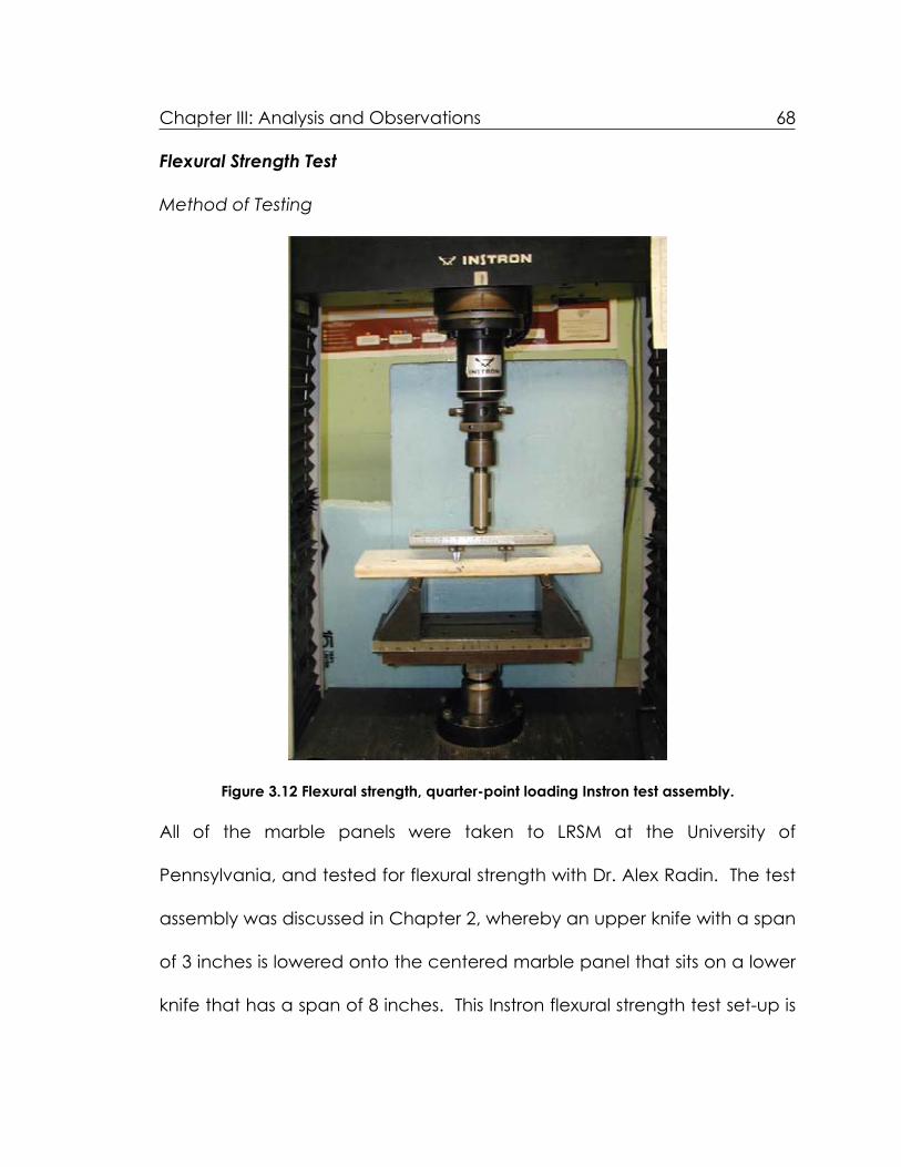
Chapter III: Analysis and Observations 68
Flexural Strength Test
Method of Testing
Figure 3.12 Flexural strength, quarter-point loading Instron test assembly.
All of the marble panels were taken to LRSM at the University of
Pennsylvania, and tested for flexural strength with Dr. Alex Radin. The test
assembly was discussed in Chapter 2, whereby an upper knife with a span
of 3 inches is lowered onto the centered marble panel that sits on a lower
knife that has a span of 8 inches. This Instron flexural strength test set-up is

Chapter III: Analysis and Observations 69
quarter-point loading because the two knives are in contact with the
marble in four places on both sides, and a load limit of 500 pounds (limit
was increased to 2000 pounds for sample CFV4: treated with carbon fiber
strap after 20 cycles) was added on top of the marble at a rate of 0.02
inches per minute until the marble fractures. The load and displacement
data is recorded by the computer, entered into a Microsoft Excel
database sheet, and graphed to determine at what load the marble
fractured.
Limitations and Uncertainty
Since this test assembly did not really have to be modified from the ASTM
C 880-98 standard for flexural strength testing, there were few problems
with accuracy and precision. Once appropriate span lengths for the
upper and lower knives were determined in collaboration with Dr. Alex
Radin, of the University of Pennsylvania’s LRSM, the chance of the marble
failing at a load that was not at the full capacity strength of the stone
could be eliminated. Additionally, to ensure that all four points of the
upper knife would be in even contact with the marble, a steel ball was
placed beneath the knife as it was lowered onto the marble, so that the
upper knife could move slightly to adjust to the surface of the marble. The
weight of the upper knife (two pounds) had to be taken into account

Chapter III: Analysis and Observations 70
when determining the amount of load the marble could withstand
without fracturing. The 500-pound load limit was enough for the majority
of the samples, although the fresh marble samples (U1-U3) required a load
limit of 1,000 pounds and the sample treated with carbon fiber after 20
cycles (CFV4) needed a 2,000-pound load limit, therefore requiring that
the test needed to be started again to account for the increase in load
capacity. However, the one large problem encountered was that the
marble panels treated with polypropylene honeycomb needed two steel
supports (two inches wide) between itself and the lower knife. This is
because once the load was applied, the lower knife would cut into or
crush the polypropylene honeycomb, thereby interfering with an
accurate load capacity reading. Yet, when looking at the results, this
may have negatively affected the amount of weight the marble treated
with polypropylene honeycomb could withstand without failing, as will be
discussed below.
Results (for graphs see Appendix 4)
The flexural strength, , of each marble panel, both treated untreated
was calculated by the equation:
= (3WL)/ (4bd2)
where:

Chapter III: Analysis and Observations 71
= flexural strength (psi) W = maximum load (pounds) L = span (inches) b = width of specimen (inches) d = depth of specimen (inches).
Figure 3.13 Flexural strength test data for treated and untreated samples. (*Samples cycled for twenty days, treated, and no longer cycled prior to flexural strength tests).
The flexural strength tests showed that the bowing significantly reduced
the flexural strength of the marble panels by an average of 45% for the
untreated cycled for forty days, 36% for those samples treated with the
carbon fiber and cycled for forty days, and 63% for the marble samples
treated with the polypropylene honeycomb and cycled for forty days.
Samples Maximum Load (pounds) (psi)
Average(psi)
Average Change from Fresh Samples U1-U3 (%)
C1 281 748 C2 310 827 808 -45% C3 318 848 C4* 251 670 -55%
CFV1 266 708 CFV2 429 975 942 -36% CFV3 366 942 CFV4* 1,631 4,350 +194%
PH1 197 524 PH2 214 571 541 -63% PH3 198 528 PH4* 335 893 -40%
U1 500 1,333 U2 670 1,787 1,482 U3 498 1,327

Chapter III: Analysis and Observations 72
However, the marble sample that was cycled untreated for twenty days,
then treated with the carbon fiber with no further cycling, actually
increased the flexural strength by 194%. The carbon fiber straps and the
polypropylene honeycomb did, in fact, increase the flexural strength of
the marble that was cycled for twenty cycles and then treated when
compared to untreated marble that was cycled for twenty and forty
days. Although the marble samples treated with carbon fiber straps and
cycled for an additional twenty days (CFV1-CFV3) also increased the
flexural strength of the marble when compared to weathered marble
samples with no treatment (C1-C3); for some reason those treated with
Figure 3.14 Failure mode of Sample U2 during the flexural strength test.

Chapter III: Analysis and Observations 73
the polypropylene honeycomb and then cycled for another twenty days
(PH1-PH3) actually decreased the flexural strength capacity of the
marble. As stated above, this could be due to the steel supports beneath
the polypropylene honeycomb or because the honeycomb had doubled
the thickness of the samples. It is obvious from the flexural strength test
results that the fresh Carrara marble samples (U1-U3, i.e. those that have
not undergone any heat and moisture cycling) are the strongest in flexural
strength, with a flexural strength of 1,482 psi, with the exception of the one
sample that underwent 20 cycles, treated with a carbon fiber strap, and
Figure 3.15 Failure mode of Sample CFV4 during the flexural strength test.

Chapter III: Analysis and Observations 74
was tested with quarter-point loading without any further cycling (CFV4)
that had a flexural strength of 4,350 psi. Thus, the carbon fiber straps do, in
fact, provide the marble with increased flexural strength, even when
weathered. The carbon fiber straps that were placed on the marble after
20 cycles and then cycled for an additional 20 days (CFV1-CFV3) on
average were stronger than the 20-cycle untreated sample (C4), the 40-
cycle untreated samples (C1-C3), the 20-cycle polypropylene
honeycomb treated sample (PH4), and the 40-cycle polypropylene
honeycomb treated samples (PH1-PH3), with a flexural strength of 942 psi.
This means that no matter if the sample is treated with the carbon fiber
strap after the marble is weathered with no further cycling or if the marble
is cycled with the carbon fiber afterwards, it will increase the flexural
strength of the marble. Since the marble panel that was treated with the
carbon fiber strap after twenty cycles with no further cycling increased
the flexural strength by a drastic amount, it might be prudent to
determine a way to inhibit a weathered piece of marble to deteriorate
any further once treated.
One unexpected result was the case where the marble panel that
was untreated and cycled for only twenty days (C4) had a lower flexural
strength of 670 psi than those that were untreated and cycled for forty

Chapter III: Analysis and Observations 75
days (C1-C3) with an average of 808 psi. This is probably due to
anomalous microstructure of that marble panel.
Figure 3.16 Failure mode of Sample C2 during the flexural strength test.
The biggest surprise with the flexural strength testing occurred with
those marble panels treated with polypropylene honeycomb. Those
marble panels that were treated with the polypropylene honeycomb and
then cycled for an additional twenty cycles (PH1-PH3). These samples
had lower flexural strengths than even the untreated twenty- and forty-

Chapter III: Analysis and Observations 76
Figure 3.17 Failure mode of Sample PH2 during the flexural strength test.
cycled marbles (C4 and C1-C3) with an average flexural strength of 541
psi. The marble sample that was treated with the polypropylene
honeycomb with no further cycling (PH4) performed slightly better with a
flexural strength of 893 psi. One explanation stated above was that
maybe the two-inch supports added while testing may have had a
negative effect, in addition to the double thickness of these samples due
to the thickness of the honeycomb. A modified method of testing should
be considered for more accurate and reliable flexural strength testing
results regarding the polypropylene honeycomb treatment.

Chapter III: Analysis and Observations 77
In general, with weathered and deteriorated marble, carbon fiber
straps seem to be a good option when considering mechanical
treatments that can enhance the flexural strength capacity of the
marble.

78
CHAPTER IV: CONCLUSIONS
Microscopic Examination
Based on the thin section analysis, it is not surprising that the Carrara
marble easily bowed when subjected to heat and moisture cycling, even
despite one side being polished. This is because, as was discussed in
Chapter 2, marbles with larger grains, slightly curved grain boundaries,
homogeneous grain size and shape, and consisting mainly of calcite, are
prone to hysteresis that other marbles, and stones in general, are not. A
way to mitigate hysteresis is currently unknown, and the mechanical
treatments applied and tested in this thesis seemed to have little effect on
lessening the impact of hysteresis, since this is inherent within the marble.
One suggestion would be to examine various chemical treatments that
could be used to impregnate the marble, or, if in situ, a way to maintain
exterior and interior temperatures so that the thermal gradient is not so
great between the two sides of the marble could be tested.
Treatments
Cost
Based on cost, the polypropylene honeycomb is much cheaper than the
carbon fiber straps. The Sika CarboDur Carbon Fiber Reinforced Plates,

Chapter IV: Conclusions 79
Type S, that are two inches wide, are $25 per foot. This means that for the
four samples that were treated it would have cost $125 just for the carbon
fiber. The Polypropylene Structural Honeycomb from Nida-Core costs
$1.79 per square foot. This translates to $35.80 for the four samples that
were tested in this thesis. Also, when the samples are larger, more carbon
fiber straps are required, not only in one direction, but additionally criss-
crossing is required for optimum reinforcement. Therefore, the carbon
fiber straps are expensive.
Retreatability
As stated in Chapter 2, each of the marble samples that were treated
with carbon fiber straps and polypropylene honeycomb first had a layer
of B-72 dissolved in toluene applied to the side of the marble to be
treated. This aided in the possibility of retreatability. However, when
conducting the flexural strength tests, all of the marble samples failed
within the marble, not within the adhesive or the treatment. This may be a
huge drawback for retreatablity and practicality. Therefore, it is
recommended that a weaker epoxy be applied, one that is sacrificial to
the marble, so that retreatability could be an option. However, if one is
more concerned about public safety on buildings, this strong epoxy may
be more desirable, since the marble will not debond from the treatment.

Chapter IV: Conclusions 80
Ease of Application
Both of the treatments were relatively easy to apply to the marble panels.
The only problem is that with the AnchorFix 3, it is a two-part epoxy and
once the two components come in contact with each other, they
immediately start to set, even within the application tube, therefore
requiring several application tubes in order to apply treatments to more
than one sample. This is also a problem when applying the epoxy to the
marble because one must be quite quick when spreading the epoxy so
that it does not start to set prior to placing the treatment on the marble
considering that complete contact is required for effectiveness. Placing
the treatments on the marble is straightforward, but one must be sure to
place a heavy weight on top, so that the entire treatment material comes
in even contact with the epoxy. Also, one or two days must be allowed
for the epoxy to completely set before any further cycling or testing can
continue.
Damage to Marble
As discussed above, the epoxy may affect retreatability of the marble;
also of consideration is the potential of the failure mode being within the
marble itself, as opposed to within the epoxy or treatment material.
Additionally, though, the epoxy and polypropylene significantly affect

Chapter IV: Conclusions 81
certain critical properties of the marble, such as water absorption and
water vapor transmission. This could easily be remedied by restricting the
surface area of the adhesive to attachment points or spot welds. A
honeycomb that did not have the scrim flap on either side could offer a
better treatment option, since it would not restrict water vapor
transmission of the marble.
Bowing Potential
Based on the results of the bowing potential test in Chapter 3, neither of
the mechanical treatments had a significant impact on decreasing the
bowing potential of the marble panels. This may be because the effects
of hysteresis are inherent within the marble, due its grain size, shape,
distribution, boundaries, porosity, and mineralogical construction.
Therefore, one suggestion for mitigating the problems of hysteresis is to
consider chemical treatments that could alter the physical properties of
the marble, impregnate the marble, and perform the bowing potential
test again, with or without the mechanical treatments.
Flexural Strength
As discussed in Chapter 3, the best option for mechanical treatments with
this type of Carrara marble appears to be the carbon fiber strap. This

Chapter IV: Conclusions 82
seemed to be the most effective regarding flexural strength because it
actually did increase the flexural strength of the weathered marble. In the
case of the marble that was cycled for twenty days and had the carbon
fiber strap applied with no further cycling, the increase in flexural strength
was so great that it would be extremely useful to find a way to inhibit the
weathering of the marble once the carbon fiber strap is applied. Equally
important was the fact that the carbon fiber straps did not induce greater
marble panel damage by restricting the bowing potential.
Alternative Approaches
In hindsight, there are a few things that could have been done differently.
First of all, various types, sizes, and thicknesses of both the carbon fiber
strap and the polypropylene honeycomb should have been examined
prior to application and testing. This is because there may be some
mechanical treatments that would have been more effective, such as a
polypropylene honeycomb that did not have scrim flaps. Secondly,
several other adhesives should have been tested to determine which
would be sacrificial to the marble. Finally, chemical impregnation could
have been examined so as to mitigate thermal gradients between the
two sides of the marble, so that it would not have bowed so dramatically.

Chapter IV: Conclusions 83
Further Research
Information is still needed to form any solid recommendations regarding
treatment of bowed marble. For example, it would be interesting to test
several different types of marble, and even other dimensional stone, for
bowing potential and flexural strength. This would not only aid in
determining what types of stone to use as cladding in new construction,
but could also provide conservators with a prediction of how cladding
already on buildings might weather now and in the future. Similarly,
testing various mechanical treatments, chemical treatments, and both
together, could provide information regarding the most effective ways to
mitigate bowing due to hysteresis, while also increasing flexural strength.
Additionally, it would be useful to conduct other tests, such as water
vapor transmission, water absorption, bond strength, and linear strain tests
on the marbles in order to determine if certain treatments negatively or
positively affect or alter these physical properties of the marble. Finally,
testing of proposed treatments should be on naturally bowed and
deteriorated marble samples to ascertain the same treatment trends.

84
BIBLIOGRAPHY
Adams, Eric. “Collaborating with Conservators: Repairing the Whitney’s Stone Curtain Wall.” Architecture 86, no. 9 (1997): 138-144.
---“Cutting-Edge Masonry Repair.” Architecture 87, no. 4 (1998): 118-122.
Alnaes, L., et al. “Influence of Rock and Mineral Properties on the Durability of Marble Panels.” In prep. Dimension Stone 2004.
Amrhein, James E. and Michael W. Merrigan. “Designing Successful Stone- Slab Veneer.” In Stone World. Troy, N.Y.: Business News Publishing, 1993.
--- Marble and Stone Slab Veneer. Los Angeles: Masonry Institute of America, 1986.
ASTM Designation: C 880-98, Standard Test Method for Flexural Strength of Dimension Stone, 2004.
Bordenaro, Michael. “Weighing Options for Stone Cladding Systems.” Building Design and Construction, July 1992, 82.
Borgal, Christopher. “Thin-Stone Systems: Conflicts between Reality and Expectations.” APT Bulletin 32, no.1 (2001): 19-25.
Bortz, S.A., B. Erlin and C.B. Monk, Jr. “Some Field Problems with Thin Veneer Building Stones.” New Stone Technology, Design, and Construction for Exterior Wall Systems, ASTM STP 996, edited by B. Donaldson. Philadelphia: ASTM, 1988.
Brena, Sergio F., Sharon L. Wood, and Michael E. Kreger. “Using Carbon Fiber Composites to Increase the Flexural Capacity of Reinforced Concrete Bridges.” Project Summary Report 1776-S. Austin: Center for Transportation Research, University of Texas at Austin, 2001.
Bronson, Susan D. “Authenticity Considerations for Curtain-Wall Buildings: Seminar Summary.” APT Bulletin 32, no.1 (2001): 5-8.
Brookes, Alan. The Building Envelope: Applications of New Technology Cladding. London: Butterworths Architecture, 1990.

Bibliography 85
Chin, Ian R. “Common Causes of Failure of Stone Claddings on Buildings.” In Dimension Stone Cladding: Design, Construction, Evaluation, and Repair, edited by Kurt R. Hoigard. West Conshohocken, PA: ASTM, 2000.
Chin, Ian R. and C. B. Monk, Jr. “Design of Stone Curtain Walls to Resist Weathering.” In Proceedings of the Fourth International Congress on the Deterioration and Preservation of Stone Objects, July 7-9, 1982. Edited by K. L. Gauri and J. A. Gwinn. Louisville: The University of Louisville, 1982.
Cohen, Julie Mark and Paulo J.M. Monteiro. “Durability and Integrity of Marble Cladding: A State-of-the-Art Review.” Journal of Performance of Constructed Facilities 5, no.2 (1991): 113-124.
Corbella, Enrico and Lucio Calenzani. The Architect’s Handbook ofMarble, Granite and Stone. New York: Van Nostrand Reinhold, 1990.
Dimension Stone Cladding: Design, Construction, Evaluation, and Repair, edited by Kurt R. Hoigard. West Conshohocken, PA: ASTM, 2000.
Dimension Stone Design Manual IV, “Installation—General Information.” Farmington, MI: Marble Institute of America, 1991.
Dorris, Virginia K. “Anchoring Thin-Stone Veneers.” Architecture(December 1993): 105-107.
Erlin, Bernard. “Contribution to a Better Understanding of the Mechanism Causing Dishing Failures of the Carrara Marble When Used for Outside Building Facades.” Dimension Stone Cladding: Design, Construction, Evaluation, and Repair, edited by Kurt R. Hoigard. West Conshohocken, PA: ASTM, 2000.
Garzonio, Carlo A. et al. “Analyses of the Physical Parameters Correlated to Bending Phenomena in Marble Slabs.” Proceedings of the 9th
International Congress on Deterioration and Conservation of Stone, Venice, June 19-24, 2000. Edited by Vasco Fassina. Amsterdam: Elsevier Science Publishing Company, Inc., 2000.

Bibliography 86
Gere, Alex S. “Stone Cladding Systems.” Exterior Claddings on High Rise Buildings, edited by Chicago Committee on High Rise Buildings. Chicago: The Fall 1989 Symposium Report, No. 12, 1990.
Gibbs, Peter. “Corrosion in Masonry Clad Early 20th-Century Steel-FramedBuildings.” In Historic Scotland Technical Advice Notes, 2000.
Grelk, B., et al. “The Laboratory Testing of Potential Bowing and Expansion in Marble.” In prep. Dimension Stone 2004.
Guideline for Condition Assessment of the Building Envelope. Reston, VA: American Society of Civil Engineers, 2000.
Harriman, Marc S. “Set in Stone.” Architecture (February 1991): 79-83.
Hoigard, Kurt R. and George R. Mulholland. “Repair Methods for Stone Facades.” Dimension Stone Cladding: Design, Construction, Evaluation, and Repair, edited by Kurt R. Hoigard. West Conshohocken, PA: ASTM, 2000.
Hook, Gail. “Look Out Below! The Amoco Building’s Cladding Failure.” Architecture, 1994.
Hunt, William D. The Contemporary Curtainwall: Its Design, Fabrication, and Erection. New York: F.W. Dodge Corporation, 1958.
Jornet, Albert, Tiziano Teruzzi, and Philipp Ruck. “Bowing of Carrara Marble Slabs: Comparison Between Natural and Artificial Weathering.” In Understanding and Managing of Stone Decay. Edited by Richard Prikryl and Heather A. Viles. Prague: The Karolinum Press, 2002.
Kelly, Stephen J. “Conflicts and Challenges in Preserving Curtain Walls.” APT Bulletin 32, no.1 (2001): 9-11.
Lewis, Michael D. Modern Stone Cladding: Design and Installation of Exterior Dimension Stone Systems. Philadelphia: ASTM, 1995.
--- “Anchorage Design: An Installer’s Perspective.” Dimensional Stone. Woodland Hills, CA: Dimensional Stone Institute, Inc., April and June 1992.

Bibliography 87
Lindborg, Ulf, Robert C. Dunakin, and David J. Rowcliffe. “Thermal Stress and Weathering of Carrara, Pentelic and Ekeberg Marble.” Proceedings of the 9th International Congress on Deterioration and Conservation of Stone, Venice, June 19-24, 2000, edited by Vasco Fassina. Amsterdam: Elsevier Science Publishing Company, Inc., 2000.
Malaga, K., et al. “Field Exposure Sites and Accelerated Laboratory Test of Marble Panels.” In prep. Dimension Stone 2004.
McDonald, William H. and Michael D. Lewis. “The Importance of Studying Exemplars when Designing Stone Facades.” In Performance of Exterior Building Walls, edited by Paul G. Johnson. West Conshohocken, PA: ASTM International, 2003.
Nakayama, M. and Y. Takei. “Stains Caused by Sealing Compound on Stone Cladding.” In Proceedings of the Sixth International Congress on Deterioration and Conservation of Stone: Toru´n, September 12-14, 1988. Toru´n: Nicolas Copernicus University, 1988.
Nashed, Fred. Time-Saver Details for Exterior Wall Design. New York: McGraw-Hill, 1996.
Nobel, Philip. “Revamping the Whitney.” Metropolis 17, no. 6 (1998): 50.
Nordtest Method NT BUILD 499. Cladding Panels: Test for Bowing, 2002.
Podany, Jerry, et al. “Paraloid B-72 as a Structural Adhesive and as a Barrier within Structural Adhesive Bonds: Evaluations of Strength and Reversibility.” Journal of the American Institute for Conservation 40, no.1 (2001): 15-33.
Post, Nadine M. “Big Curtain Wall Woes.” Engineering News Record(November 15, 1993): 26-32.
Recheis, Arno, Thomas Bidner, and Peter W. Mirwald. “The Differences of the Ultrasonic Velocity of the Two Marble Portals of Schloss Tirol/South Tyrol-A Case of Weathering or of Material?” In Understanding and Managing of Stone Decay. Edited by Richard Prikryl and Heather A. Viles. Prague: The Karolinum Press, 2002.

Bibliography 88
RILEM/ASTM/CIB Symposium on the Evaluation of Performance of External Vertical Surfaces of Buildings, 1977.
Rohatsch, A. et al. “Physical Properties of Fine-grained Marble before and after Treatment.” Proceedings of the 9th International Congress on Deterioration and Conservation of Stone, Venice, June 19-24,2000, edited by Vasco Fassina. Amsterdam: Elsevier Science Publishing Company, Inc., 2000.
Schaal, Rolf. Curtainwalls, Design Manual. New York: Reinhold Publishing, 1962.
Scheffler, Michael J. “Thin-Stone Veneer Building Facades: Evolution and Preservation.” APT Bulletin 32, no.1 (2001): 27-34.
Siegesmund, S., T. Weiss, and E. K. Tschegg. “Control of Marble Weathering by Thermal Expansion and Rock Fabrics.” Proceedings of the 9th
International Congress on Deterioration and Conservation of Stone, Venice, June 19-24, 2000, edited by Vasco Fassina. Amsterdam: Elsevier Science Publishing Company, Inc., 2000.
Siegesmund, Siegfried, et al. “Physical Weathering of Marbles Caused by Anisotropic Thermal Expansion.” International Journal of EarthSciences 89 (2000): 170-182.
Sripadanna, Nar. “Parking Garage Column Repair with Carbon Fiber Reinforcement.” Online source.
Stecich, John P., Ian R. Chin, and F. Dirk Heidbrink. “Testing for Thin Stone Veneers on Buildings.” Exterior Claddings on High Rise Buildings.Chicago: The Fall 1989 Symposium Report, No. 12, 1990.
Tawresay, John G. and Grant L. Davis. “Structural Design of Thin Stone Curtain Walls.” Building Stone Magazine no. 9-10 (1987): 47-59.
Thomasen, Sven E. and Carolyn Searle Ewart. “Durability of Thin-Set Marble.” Proceedings of the Third International Conference on the Durability of Building Materials and Components, Volume 1. Edited by Tenho Sneck and Anneli Kaarresalo. Finland: Technical Research Centre of Finland, 1984.

Bibliography 89
Tuchman, Janice L. “Curtain Walls in the Spotlight.” In Engineering News Record. New York: McGraw-Hill, Inc., 1993.
Wang, Marcy Li, Isao Sakamoto and Bruce L. Bassler, eds. Cladding: Council on Tall Buildings and Urban Habitat, Committee 12A. NewYork: McGraw-Hill, Inc., 1992.
Ware, Robert Lamb. “A Comparison of Fresh and Weathered Marble from the Tweed Courthouse.” Master’s thesis, University of Pennsylvania, 2001.
Weiss, Thomas, Siegfried Siegesmund, and Patrick N. J. Rasolofosaon. “The Relationship Between Deterioration, Fabric, Velocity and Porosity Constraint.” Proceedings of the 9th International Congress on Deterioration and Conservation of Stone, Venice, June 19-24, 2000,edited by Vasco Fassina. Amsterdam: Elsevier Science Publishing Company, Inc., 2000.
Widhalm, Clemens, Elmar Tschegg and Walter Eppensteiner. “Anisotropic Thermal Expansion Causes Deformation of Marble Claddings.” Journal of Performance of Constructed Facilities February 1996, 5-10.
Wilson, Forrest. “The Perils of Using Thin Stone and Safeguards Against Them.” Architecture, February 1989, 96-97.
Wilson, M. and P. Harrison. Appraisal and Repair of Claddings and Fixings.London: Thomas Telford, 1993.
Winkler, Erhard M. Stone: Properties, Durability In Man’s Environment. 2d ed. Munich: Springer-Verlaq, 1975.
--- “Technical Note: Properties of Marble as Building Veneer.” International Journal of Rock and Mechanical Mineralogical Science and Geomechanical Abstracts 33, no. 2 (1996): 215-218.
www.sika.com
www.sp.se/building/team

Bibliography 90
Yates, T. J. S., et al. “Observations from the Inspection of Marble Cladding in Europe.” In prep. Dimension Stone 2004.
Yee, Roger. “Stonewalling It.” Progressive Architecture, March 1976, 80.
Zhang, Zhichao, Cheng-Tzu Thomas Hsu, and Jon Moren. “Shear Strengthening of Reinforced Concrete Deep Beams Using Carbon Fiber-Reinforced Polymer Laminates.” Journal of Composites for Construction 8, no. 5 (2004): 403-414.

Appendix 1: Materials and Suppliers 91
MATERIALS AND SUPPLIERS
Carrara Marble Cava International
2007 Washington Avenue Philadelphia, PA 19146 215.732.0907
www.cavaintl.com
Construction Materials and Miscellaneous Supplies McMaster-Carr Supply
473 Ridge Road Dayton, NJ 08810 1.732.329.3200
www.mcmaster.com
Polypropylene Structural Honeycomb (Rigid-Elastic Technology) Nida-Core Structural Honeycomb Materials
541 NW Interpark Place Port S. Lucie, FL 34986 1.772.343.7300
www.nida-core.com
Sika CarboDur Carbon Fiber Reinforced Plates, Type S Sikadur AnchorFix-3, Sikadur Injection Gel FS
The Sika Corporation 201 Polito Avenue Lyndhurst, NJ 07071 1.800.933.SIKA
www.sika-construction.com
Thin Sections Spectrum Petrographics, Inc.
3315 NE 112th Ave Ste B98-99 Vancouver, WA 98682 1.877.838.2950
www.petrography.com

Appendix 2: Test Standards 92

Appendix 2: Test Standards 93

Appendix 2: Test Standards 94

Appendix 2: Test Standards 95

Appendix 2: Test Standards 96

Appendix 2: Test Standards 97
Appendix 2: Test Standards 98


Appendix 3: Bowing Potential Test Charts and Graphs 100
Bow
ing
Pote
ntia
l Tes
t of C
arra
ra M
arbl
e, N
T BUI
LD 4
99(U
ntre
ated
0-2
0, T
reat
ed 2
1A-4
0A)
0.0
5.0
10.0
15.0
20.0
25.0
30.0
35.0
40.0
0
2
4
6
8
10
12
14
16
18
20
22A
24A
26A
28A
30A
32A
34A
36A
38A
40A
Cyc
les
(day
s)
Convex Change (1/1000")
C CFV
PH

Appendix 4: Flexural Strength Test Graphs 101
Flex
ural
Stre
ngth
Test
s of
Sam
ples
U1-
U3
0
100
200
300
400
500
600
700
800
00.
002
0.00
40.
006
0.00
80.
010.
012
0.01
40.
016
0.01
80.
02Di
spla
cem
ent (
inch
es)
Load (pounds)
U1 U2 U3

Appendix 4: Flexural Strength Test Graphs 102
Flex
ural
Stre
ngth
Test
s of
Sam
ples
C1-
C4
050100
150
200
250
300
350
00.
005
0.01
0.01
50.
020.
025
0.03
0.03
50.
04Di
spla
cem
ent (
inch
es)
Load (pounds)
C1
C2
C3
C4
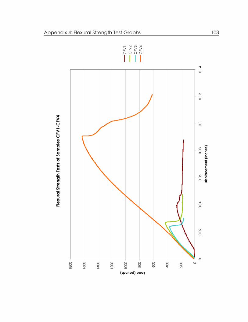
Appendix 4: Flexural Strength Test Graphs 103
Flex
ural
Stre
ngth
Test
s of
Sam
ples
CFV
1-C
FV4
0
200
400
600
800
1000
1200
1400
1600
1800
00.
020.
040.
060.
080.
10.
120.
14Di
spla
cem
ent (
inch
es)
Load (pounds)
CFV
1C
FV2
CFV
3C
FV4

Appendix 4: Flexural Strength Test Graphs 104
Flex
ural
Stre
ngth
Test
s of
Sam
ples
CFV
1-C
FV3
050100
150
200
250
300
350
400
450
00.
010.
020.
030.
040.
050.
060.
070.
080.
090.
1Di
spla
cem
ent (
inch
es)
Load (pounds)
CFV
1C
FV2
CFV
3

Appendix 4: Flexural Strength Test Graphs 105
Flex
ural
Stre
ngth
Test
s of
Sam
ples
PH1
-PH4
050100
150
200
250
300
350
400
00.
010.
020.
030.
040.
050.
060.
070.
08Di
spla
cem
ent (
inch
es)
Load (pounds)
PH1
PH2
PH3
PH4

106
INDEX
Aadhesive, 21, 32, 34, 36, 39, 42, 75 Amoco Building, 18, 19, 27, 97 anchors, 1, 4, 6, 9, 10, 11, 14, 20, 23, 24, 27 application, 36, 56, 76, 78 ASTM, 10, 17, 29, 35, 41, 66, 95, 96, 97, 98, 99
BB-72, 39, 51, 56, 75, 98 bow, 8, 27, 29, 39, 42, 45, 48, 60, 62, 64 bowing, 1, 2, 3, 11, 14, 15, 17, 18, 19, 22, 23,
24, 26, 27, 29, 30, 34, 36, 38, 40, 41, 42, 46, 48, 58, 62, 63, 77, 79
bowing potential, 24, 26, 30, 39, 41, 42, 64, 77 bowing potential test assembly, 40
Ccalcite, 17, 28, 29, 48, 49, 74 carbon fiber, 24, 32, 34, 39, 51, 55, 57, 60, 63,
66, 67, 68, 69, 70, 73, 74, 75, 78 Carrara marble, 18, 22, 26, 27, 29, 31, 38, 42 Cintec Designed Anchor System, 20 cladding, 1, 2, 3, 4, 7, 9, 11, 14, 18, 19, 22, 24,
26, 34, 42, 79 color, 8, 47 concrete, 32 cost, 74 curtain-wall, 1, 6, 11, 24, 25
Ddeformation, 2, 8, 10, 11, 14, 15, 16, 18, 20, 23,
25, 27, 29, 36, 41 deterioration, 1, 2, 6, 11, 18, 19, 20, 23, 24 deterioration mechanisms, 1
Eenvironment, 7, 11, 12, 14, 30 epoxy, 21, 31, 32, 36, 39, 51, 52, 53, 54, 55, 56,
57, 75, 76 Essex County New Courts Building and Jail, 20
Fflexural strength, 1, 2, 24, 26, 30, 32, 34, 38, 39,
41, 48, 61, 65, 66, 67, 68, 69, 70, 71, 72, 73, 75, 78, 79
flexural strength test, 43, 68
Ggauge, 41, 58, 59, 60, 61 grain, 8, 12, 17, 28, 29, 30, 44, 45, 49, 64, 74, 77 granoblastic, 8, 29, 39
Hhardness, 48 honeycomb, 21, 34, 36, 37, 38, 61, 63, 67, 68,
70, 72, 73, 77, 78 hysteresis, 16, 24, 27, 28
IIndiana National Bank, 19 Industrial Revolution, 2
Llimitations, 46, 61, 66
Mmarble, 1, 2, 4, 5, 6, 7, 9, 10, 11, 12, 13, 14, 16,
18, 19, 20, 22, 23, 24, 25, 26, 27, 29, 30, 31, 33, 34, 36, 38, 39, 41, 42, 44, 45, 46, 47, 48, 49, 50, 51, 52, 53, 54, 56, 57, 58, 59, 60, 61, 62, 63, 64, 65, 66, 67, 68, 69, 70, 72, 73, 74, 75, 76, 77, 78, 79
marble-clad buildings, 1, 20 mechanical treatments, 2, 24, 26, 30, 31, 63,
73, 74, 77, 78, 79 minimal intervention, 22, 25, 27 Moh's, 48
NNida-Core, 37, 38, 75, 80 Nordtest, 38, 57, 58, 98

Index 107
Ppanels, 1, 2, 3, 4, 6, 7, 10, 11, 12, 14, 18, 19, 22,
23, 24, 25, 26, 27, 30, 31, 35, 36, 41, 48, 62, 64, 65, 67, 72, 76, 77, 79
polypropylene honeycomb, 24, 34, 37, 39, 51, 55, 56, 60, 63, 67, 68, 69, 70, 72, 73, 74, 75, 77, 78
porosity, 8, 12, 14, 18, 29, 30, 44, 49, 64, 77, 100
post-WWII, 1, 5, 6, 26
Qquarter-point loading, 44, 65, 69
Rresults, 57, 62, 67 retreatability, 27, 39, 42, 44, 75, 76
Ssealant, 11, 14, 15 Sika, 32, 34, 74, 80 Sika CarboDur CFRP Plates, 34 Sikadur AnchorFix 3, 32, 51 steel, 1, 3, 4, 6, 10, 14, 20, 40, 42, 58, 61, 66, 69
TTEAM, 1, 8, 22, 29, 40, 63
testing, 1, 2, 21, 29, 42, 46, 47, 66, 72, 73, 76, 78, 79
tests, 23
toluene, 39, 51, 56, 75 treated, 23, 39, 40, 42, 51, 56, 60, 63, 64, 66,
67, 68, 69, 70, 72, 73, 75, 77 treatments, 21, 23, 26, 30, 31, 35, 38, 39, 42,
47, 51, 54, 61, 64, 74, 76, 77, 79
Uuntreated, 23, 40, 60, 63, 64, 67, 68, 70, 72, 73
Vveneers, 2, 26, 36
Wwater vapor, 21, 38, 46, 77, 79 Whitney Museum of American Art, 19
Xxenoblastic, 8
ZZibell anchoring system, 10