Mechanical behaviour of full unit masonry panels under fire action
11
Mechanical behaviour of full unit masonry panels under fire action Marco Andreini n , Mauro Sassu 1 Department of Civil Engineering – Structural Division, University of Pisa Largo Lucio Lazzarino, 1 – 56126 Pisa, Italy article info Article history: Received 3 May 2010 Received in revised form 14 July 2011 Accepted 18 July 2011 Available online 6 August 2011 Keywords: Masonry structures Fire resistance M–N domains Strength fire models abstract An analytical model is presented to predict the mechanical resistance of full unit masonry panels under combined compressive and bending stress, in the presence of a nominal fire acting on one side. Transitory thermal analysis of the panels is conducted, while accounting for the convection and radiation effects produced by the fire, to determine the collapse conditions for combined compression and bending; five strain field collapse configurations are considered. The numerical analyses, based on data drawn from European regulations EN 1996-1-2, permit the determination of the M–N crushing domains for brick and lightweight aggregate concrete masonry walls, with various thicknesses and exposure times to nominal fire. A numerical example demonstrates the applicability of the model, and a comparison with a set of experimental data on masonry panels demonstrates the efficiency of the model. & 2011 Elsevier Ltd. All rights reserved. Introduction The fire behaviour of masonry elements has prompted a great deal of interest in building construction because of the masonry’s considerable capacity to isolate parts of a building’s interior from both the fire itself and the effects of smoke (so-called compart- ment walls). In addition, masonry is quite resistant to weakening with increasing temperatures. In fact, the structural blocks, generally made up of clay or lightweight aggregate concrete (pumice), maintain their bearing and deformational capacities for a wide range of temperatures, and even when they do degrade, they do so gradually. In addition, the joint mortar generally exhibits favourable properties in terms of resistance and response to fire. Although the response of masonry walls to fire has been the subject of a good deal of study in the past, only recently have experimental results been compared with those from numerical models. Nadjai et al. [1,2] report on numerical studies of the behaviour of walls conducted in the presence of fire on one side. They assumed two preset curves of the compression strength– temperature relation proposed by Abrams [3] and Thelandersson [4] and two possible curves for the crushing strain–temperature relation proposed by Terro [5] and Anderberg and Thelanders- son [6]. The stress–strain curve shown in Fig. 1 depicts a classical relation, with two descending segments whose shapes differ in the two regions of different strain signs, while the isothermal lines have been calculated under the hypothesis of a linear distribution of temperatures throughout the thickness. Al Nahhas et al. [7] address the case of walls made of double- cavity cored bricks, which were subjected to experimental tests and subsequent analytical modelling. The distribution of the isotherms was determined through an energy-balance approach by measuring the proportions of convection, conduction and radiation: the temperature–time curves were determined at various points throughout the wall thickness. The influence of changes in the material mechanical strength with varying temperature was, how- ever, not modelled. In order to check the experimental results reported by Shields et al. [9], Dhanasekar et al. carried out numerical analysis in a thermal field to determine the bowing of panels exposed to fire [8]. With regard to regulations, the recent adoption of the Euro- codes on structures, in particular the adjustments to EN 1996-1-2 [24], has led to the application of new methods for experimental or analytical tabular design of bearing masonry walls, in part based on the results of a series of experimental trials conducted by Hahn et al. [10]. The analytical methods prescribed in the Eurocodes depend on knowing the ultimate strain and compres- sion resistance as functions of temperature, as well as the main thermal parameters (conductivity, specific heat and density). It should, however, be noted that such parameters are significantly influenced by brick humidity, so caution should be exercised when applying standard diagrams in the design process. As is already the case for reinforced concrete, steel and wood constructions, in planning masonry structures, it would be useful for designers to know the fracture domains, N–e (axial force– eccentricity) or M–N (bending moment–axial force), which enable rapid calculation of the bearing capacity of a wall with preset Contents lists available at ScienceDirect journal homepage: www.elsevier.com/locate/firesaf Fire Safety Journal 0379-7112/$ - see front matter & 2011 Elsevier Ltd. All rights reserved. doi:10.1016/j.firesaf.2011.07.004 n Corresponding author. Tel.: þ39 050 2218204; fax: þ39 050 2218201. E-mail addresses: [email protected] (M. Andreini), [email protected] (M. Sassu). 1 Tel.: þ39 050 2218215; fax: þ39 050 2218201. Fire Safety Journal 46 (2011) 440–450
Transcript of Mechanical behaviour of full unit masonry panels under fire action

Fire Safety Journal 46 (2011) 440–450
Contents lists available at ScienceDirect
Fire Safety Journal
0379-71
doi:10.1
n Corr
E-m
m.sassu1 Te
journal homepage: www.elsevier.com/locate/firesaf
Mechanical behaviour of full unit masonry panels under fire action
Marco Andreini n, Mauro Sassu 1
Department of Civil Engineering – Structural Division, University of Pisa Largo Lucio Lazzarino, 1 – 56126 Pisa, Italy
a r t i c l e i n f o
Article history:
Received 3 May 2010
Received in revised form
14 July 2011
Accepted 18 July 2011Available online 6 August 2011
Keywords:
Masonry structures
Fire resistance
M–N domains
Strength fire models
12/$ - see front matter & 2011 Elsevier Ltd. A
016/j.firesaf.2011.07.004
esponding author. Tel.: þ39 050 2218204; fa
ail addresses: [email protected] (M.
@ing.unipi.it (M. Sassu).
l.: þ39 050 2218215; fax: þ39 050 2218201
a b s t r a c t
An analytical model is presented to predict the mechanical resistance of full unit masonry panels under
combined compressive and bending stress, in the presence of a nominal fire acting on one side.
Transitory thermal analysis of the panels is conducted, while accounting for the convection and
radiation effects produced by the fire, to determine the collapse conditions for combined compression
and bending; five strain field collapse configurations are considered. The numerical analyses, based on
data drawn from European regulations EN 1996-1-2, permit the determination of the M–N crushing
domains for brick and lightweight aggregate concrete masonry walls, with various thicknesses and
exposure times to nominal fire. A numerical example demonstrates the applicability of the model, and a
comparison with a set of experimental data on masonry panels demonstrates the efficiency of
the model.
& 2011 Elsevier Ltd. All rights reserved.
Introduction
The fire behaviour of masonry elements has prompted a greatdeal of interest in building construction because of the masonry’sconsiderable capacity to isolate parts of a building’s interior fromboth the fire itself and the effects of smoke (so-called compart-ment walls). In addition, masonry is quite resistant to weakeningwith increasing temperatures. In fact, the structural blocks,generally made up of clay or lightweight aggregate concrete(pumice), maintain their bearing and deformational capacitiesfor a wide range of temperatures, and even when they do degrade,they do so gradually. In addition, the joint mortar generallyexhibits favourable properties in terms of resistance and responseto fire.
Although the response of masonry walls to fire has been thesubject of a good deal of study in the past, only recently haveexperimental results been compared with those from numericalmodels. Nadjai et al. [1,2] report on numerical studies of thebehaviour of walls conducted in the presence of fire on one side.They assumed two preset curves of the compression strength–temperature relation proposed by Abrams [3] and Thelandersson[4] and two possible curves for the crushing strain–temperaturerelation proposed by Terro [5] and Anderberg and Thelanders-son [6]. The stress–strain curve shown in Fig. 1 depicts a classicalrelation, with two descending segments whose shapes differ inthe two regions of different strain signs, while the isothermal
ll rights reserved.
x: þ39 050 2218201.
Andreini),
.
lines have been calculated under the hypothesis of a lineardistribution of temperatures throughout the thickness.
Al Nahhas et al. [7] address the case of walls made of double-cavity cored bricks, which were subjected to experimental tests andsubsequent analytical modelling. The distribution of the isothermswas determined through an energy-balance approach by measuringthe proportions of convection, conduction and radiation: thetemperature–time curves were determined at various pointsthroughout the wall thickness. The influence of changes in thematerial mechanical strength with varying temperature was, how-ever, not modelled. In order to check the experimental resultsreported by Shields et al. [9], Dhanasekar et al. carried out numericalanalysis in a thermal field to determine the bowing of panelsexposed to fire [8].
With regard to regulations, the recent adoption of the Euro-codes on structures, in particular the adjustments to EN 1996-1-2[24], has led to the application of new methods for experimentalor analytical tabular design of bearing masonry walls, in partbased on the results of a series of experimental trials conductedby Hahn et al. [10]. The analytical methods prescribed in theEurocodes depend on knowing the ultimate strain and compres-sion resistance as functions of temperature, as well as the mainthermal parameters (conductivity, specific heat and density). Itshould, however, be noted that such parameters are significantlyinfluenced by brick humidity, so caution should be exercisedwhen applying standard diagrams in the design process.
As is already the case for reinforced concrete, steel and woodconstructions, in planning masonry structures, it would be usefulfor designers to know the fracture domains, N–e (axial force–eccentricity) or M–N (bending moment–axial force), which enablerapid calculation of the bearing capacity of a wall with preset

M. Andreini, M. Sassu / Fire Safety Journal 46 (2011) 440–450 441
exposure times to fire. The method proposed herein aims todefine such M–N diagrams for walls subjected to the eccentricnormal force acting on various types of blocks exposed to fire onone side. To this end, the temperature distributions across thewall thickness are first determined. Then, as the laws governingthe decay of the material resistance and axial stiffness as afunction of the temperature are known, the wall crushing strainfields are calculated as a function of the curvature. Lastly, basedon the isotherms already calculated and the stress–strain–tem-perature constitutive relation, we determine the crushing sur-faces on the plane M–N (in which M is the out-of-plane bendingmoment and N is the axial force) for increasing exposure time tonominal fire. Application of the procedure is illustrated through asimple example.
1. Thermal analysis
We shall refer to a wall of height h, thickness t and unit depth,subjected to a thermal transient due to a heat source acting onone side.
The convective thermal action in terms of net unitary heatflow is
_hnet,c ¼ acðYg�YmÞ ðW=m2Þ, ð1Þ
where Ym is the element’s surface temperature (1C), while thetemperature Yg of the gases produced by fire is determined viathe expression for the nominal temperature–time curve
Yg ¼ 20þ345log10ð8tþ1Þð1CÞ, ð2Þ
The heat transmission coefficient for convection ac has beentaken as 25 W/m2 K, as indicated in [10] EN 1991-1-2.
Fig. 1. Stress–strain relation of masonry materials under compression and tension,
drawn from [1,2].
0.00E+00
2.00E+04
4.00E+04
6.00E+04
8.00E+04
1.00E+05
1.20E+05
0
λ a [d
aN/(m
in°C
)]
T [200 400 600
Fig. 2. Thermal conductivity la(T) [da N/min 1C] and specific heat c
The net unitary heat flow due to irradiation is
_hnet,r ¼Femefs½ðYrþ273Þ4�ðYmþ273Þ4� ðW=m2Þ, ð3Þ
with the emissivity ef¼1.0 and temperature Yr tied to thenormalised curve (2). The Stephan–Boltzmann constant s is5.67�10–8 W/m2 K4, while the emissivity value for the receivingsurface, em, has been set to 0.8, as recommended in [22] EN 1991-1-2. The configuration coefficient F has been assumed equal to 1.
The nonlinear thermal transitory was analysed via the codeANSYS Multiphysics rel. 11.0 using triangular (or quadrangular)shaped plane elements (PLANE55 ‘‘2-D Thermal Solid’’) of dimen-sions varying from 1 to 2 cm.
The initial temperature was 20 1C, while a unit convectivethermal flow was applied to the surface not exposed to the fire,using a transmission coefficient ac of 4 W/m2 K. The functions forspecific heat ca(T) and transmissibility la(T) have been drawnfrom Appendix D of EN 1996-1-2 [24], as shown in Fig. 2 (brickwith density r¼1000 kg/m3) and Fig. 3 (lightweight aggregateconcrete with density r¼800 kg/m3).
The results of such analyses of the nonlinear thermal transitoryare presented in the plots of temperature T versus the thickness x forvarious exposure times to nominal fire (Figs. 4 and 5).
The same procedure has also been performed on a panel ofaerated autoclaved concrete (AAC) blocks to obtain numericalresults for a comparison with a set of experimental data.
2. Mechanical analysis
2.1. Description of the mathematical model and basic hypotheses
In the model, failure of the masonry is associated with theattainment of crushing strain conditions in some point of ageneric cross section. The basic underlying hypotheses are thefollowing:
–
°C]
a(T)
cross sections remain planar (Bernoulli–Navier hypothesis);
– the material does not react to tension; – the material is elastic–perfectly plastic (i.e., Prandtl constitu-tive relation);
– the material responds to the ‘‘Maximum strain’’ yield criterion.0.00
1.50
3.00
4.50
6.00
7.50
9.00
c a(T
) [da
N·c
m/(k
g°C
)]
ca(T)λa(T)
800 1000 1200 1400
[da N cm/kg 1C] functions adopted for the brick masonry.

Fig. 3. Thermal conductivity la(T) [da N/min 1C] and specific heat ca(T) [da N cm/kg 1C] functions adopted for the lightweight concrete blocks.
0
200
400
600
800
1000
1200
0
T [°
C]
x [cm]
30 min
60 min
90 min
120 min
150 min
180 min
Limit Temperature θ2
5 10 15 20 25 30 35
Fig. 4. Brick wall: temperature profile for various exposure times. The value of y2 (the temperature beyond which the material is to be considered ineffective) is indicated
at 600 1C, as per Appendix C of EN 1996-1-2 [24].
M. Andreini, M. Sassu / Fire Safety Journal 46 (2011) 440–450442
In order to simplify the analysis, it has also been consideredthat thermal strain eth, transient strain etr and slenderness effectsare formally computed increasing the applied stress.
Referring to the quantities indicated in Fig. 6, with a fixedexposure time to the nominal fire, the results of the thermalanalyses lead to the following function for the temperatureprofile:
T ¼ TðXÞ: ð4Þ
The term X is the abscissa with its origin on the face exposed tofire, x is the abscissa whose origin lies on the border of theeffectively resistant section, tineff is the depth of the portion ofwall deemed ineffective, tFr is the thickness of the still reactingpart, and t is the total thickness of the wall itself. By placing
X ¼ xþtineff
x¼ X�tineff,
(ð5Þ
the value of the temperature T as a function of x can be obtained
T ¼ TðxÞ: ð6Þ
By observing the behaviour of the resistance fcu(T), the elasti-city modulus E(T) and the crushing strain eu(T), from Fig. 6, itfollows immediately that:
fcu ¼ fcuðxÞ, ð7Þ
E¼ EðxÞ, ð8Þ
eu ¼ euðxÞ, ð9Þ
For this last equation, we assume, where definable, thecondition
@2eu
@x2Z0: ð10Þ
The distributions e(x) vary within five limit fields, as illustratedin Fig. 7, where ty1 indicates the thickness of the part between theunexposed face and isotherm y1 (limit temperature for materialintegrity) and ty2 the portion whose temperature varies betweeny1 itself and y2 (limit temperature for material ineffectiveness),both furnished by EN 1996-1-2 [24].

tt
x X
ε (x)
t
Fig. 6. Horizontal cross section of the wall; the geometric parameters are indicated, together with a diagram of the crushing strain diagram eu(x).
0
200
400
600
800
1000
1200
0
T [°
C]
x [cm]
30 min
60 min
90 min
120 min
150 min
180 min
Limit Temperature θ2
5 10 15 20 25 30 35
Fig. 5. Lightweight aggregate concrete masonry wall: temperature profile for various exposure times. The value of y2 (the temperature beyond which the material is to be
considered ineffective) is indicated at 400 1C, as per Appendix C of EN 1996-1-2 [24].
tt
xX
ε (x)
A
C
D
B
5
4
3
21
t
t
t
x
ε [−]
Fig. 7. Limit e fields.
M. Andreini, M. Sassu / Fire Safety Journal 46 (2011) 440–450 443

M. Andreini, M. Sassu / Fire Safety Journal 46 (2011) 440–450444
2.1.1. Field 1
Field 1 (Fig. 8) represents the subset of the sheaf of straightlines at point
A� ð0; euð0ÞÞ, ð11Þ
whose directive coefficient w, or section curvature, belongs to thefollowing domain:
wA ��1; @euðxÞ
@x
����x ¼ 0
�, ð12Þ
and which is defined by
eðxÞ ¼ wxþeuð0Þ: ð13Þ
By means of the constitutive relation, the function of thenormal stress s(x) through the thickness, which in the compressed
zone, equals
sðxÞ ¼EðxÞeðxÞ if EðxÞeðxÞo fuðxÞ
fuðxÞ if EðxÞeðxÞZ fuðxÞ, 8xA ½0; x1ðwÞ�,
(ð14Þ
while in the tensile zone,
sðxÞ ¼ 0, 8xA �x1ðwÞ; tFr �: ð15Þ
In previous expressions, x1 denotes the following function:
x1ðwÞ ¼�
euð0Þw if wo� euð0Þ
tFr) large eccentricity
tFr if wZ� euð0ÞtFr) small eccentricity
:
8<: ð16Þ
t
xX
t
t
t
Fig. 8. Fie
t
xX
t
t
t
Fig. 9. Fie
2.1.2. Field 2
Field 2 represents the subset of the straight lines tangential tothe curve in Fig. 9, in which w varies within the followingexistence field:
wA �@euðxÞ
@x
����x ¼ 0
; limZ-0�
euðty2þZÞ�euðty2Þ
Z
�, ð17Þ
where x is the generic abscissa of wall thickness belonging to thedomain
xA ½0; ty2�: ð18Þ
The equation of the straight lines in this field is
eðxÞ ¼ @euðxÞ
@x
����x ¼ x
ðx�xÞþeuðxÞ: ð19Þ
From the constitutive relation, the normal stresses s(x) in thecompressed zone are
sðxÞ ¼EðxÞeðxÞ if EðxÞeðxÞo fuðxÞ
fuðxÞ if EðxÞeðxÞZ fuðxÞ, 8xA ½0; x2ðxÞ�,
(ð20Þ
while in the tensile zone,
sðxÞ ¼ 0, 8xA �x2ðxÞ; tFr �: ð21Þ
t
ε (x)
A
C
D
B
x
x
x 1
x
ε [−]
ld 1.
t
ε (x)
A
C
D
B
2
x
x
xx
x
xx
x
ε [−]
ld 2.
M. Andreini, M. Sassu / Fire Safety Journal 46 (2011) 440–450 445
In the previous expressions, x2 denotes
x2ðxÞ ¼
�euðxÞð@euðxÞ=@xÞ9x ¼ x
þx if euðxÞo@euðxÞ@x 9x ¼ xðx�tFrÞ ) large eccentricity
tFr if euðxÞZ@euðxÞ@x 9x ¼ xðx�tFrÞ ) small eccentricity
:
8<:
ð22Þ
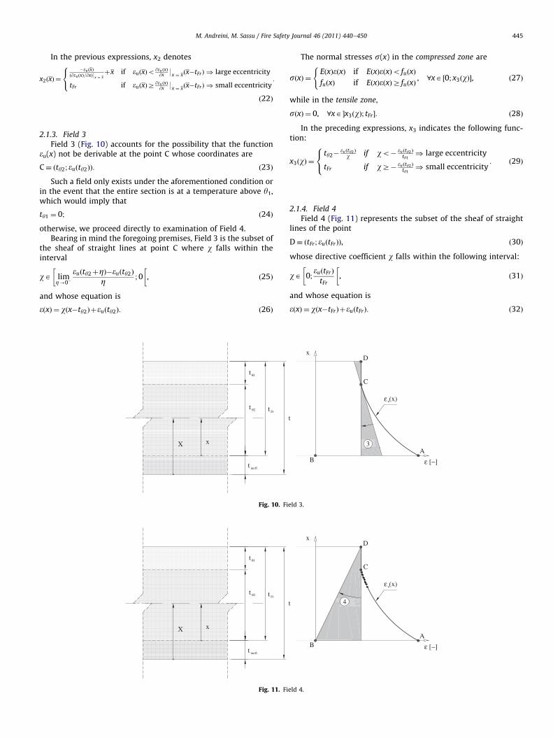
2.1.3. Field 3
Field 3 (Fig. 10) accounts for the possibility that the functioneu(x) not be derivable at the point C whose coordinates are
C� ðty2; euðty2ÞÞ: ð23Þ
Such a field only exists under the aforementioned condition orin the event that the entire section is at a temperature above y1,which would imply that
ty1 ¼ 0; ð24Þ
otherwise, we proceed directly to examination of Field 4.Bearing in mind the foregoing premises, Field 3 is the subset of
the sheaf of straight lines at point C where w falls within theinterval
wA limZ-0�
euðty2þZÞ�euðty2Þ
Z ;0
�,
�ð25Þ
and whose equation is
eðxÞ ¼ wðx�ty2Þþeuðty2Þ: ð26Þ
t
xX
t
t
t
Fig. 10. Fi
t
xX
t
t
t
Fig. 11. Fi
The normal stresses s(x) in the compressed zone are
sðxÞ ¼EðxÞeðxÞ if EðxÞeðxÞo fuðxÞ
fuðxÞ if EðxÞeðxÞZ fuðxÞ, 8xA ½0; x3ðwÞ�,
(ð27Þ
while in the tensile zone,
sðxÞ ¼ 0, 8xA �x3ðwÞ; tFr�: ð28Þ
In the preceding expressions, x3 indicates the following func-tion:
x3ðwÞ ¼ty2�
euðty2Þ
w if wo� euðty2Þ
ty1) large eccentricity
tFr if wZ� euðty2Þ
ty1) small eccentricity
:
8<: ð29Þ
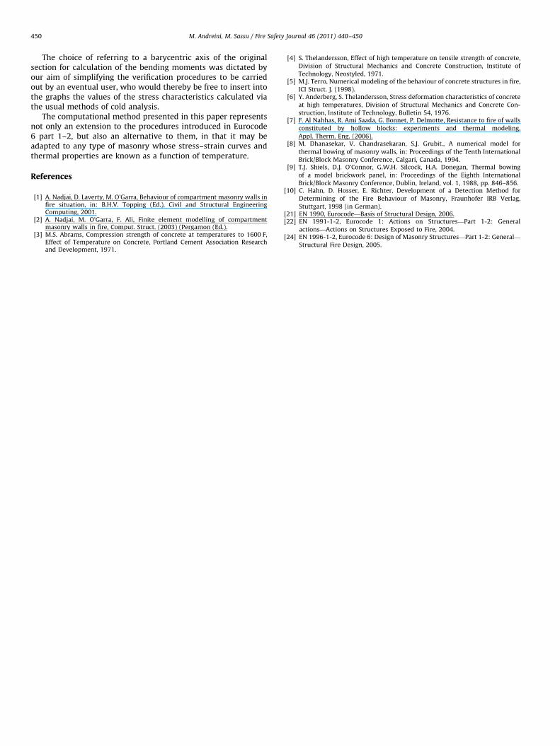
2.1.4. Field 4
Field 4 (Fig. 11) represents the subset of the sheaf of straightlines of the point
D� ðtFr; euðtFrÞÞ, ð30Þ
whose directive coefficient w falls within the following interval:
wA 0;euðtFrÞ
tFr
�,
�ð31Þ
and whose equation is
eðxÞ ¼ wðx�tFrÞþeuðtFrÞ: ð32Þ
t
ε (x)
A
C
D
B
3
x
ε [−]
eld 3.
t
ε (x)
A
C
D
B
4
x
ε [−]
eld 4.

Table 1Integration extremes in relations (38)–(41).
Field a b
1 0 x1(w)
2 0 x2(x)
3 0 x3(w)
4 0 tFr
5 x5(w) tFr
Fig. 13. Constitutive relation of lightweight aggregate concrete (pumice) as a
function of temperature, as per Appendix D of EN 1996-1-2 [24]; (1) denotes the
ratio between the normal stress value at any given temperature T and the
compression strength at 20 1C.
M. Andreini, M. Sassu / Fire Safety Journal 46 (2011) 440–450446
The normal stresses s(x) within the thickness are
sðxÞ ¼EðxÞeðxÞ if EðxÞeðxÞo fuðxÞ
fuðxÞ if EðxÞeðxÞZ fuðxÞ, 8xA ½0; tFr�:
(ð33Þ
2.1.5. Field 5
Field 5 (Fig. 12) represents the subset of the sheaf of straightlines of point D whose coordinates are given by Eq. (30), whosedirective coefficient w falls within the following interval:
wA euðtFrÞ
tFr; þ1
�,
�ð34Þ
and whose equation is still Eq. (32).The normal stresses s(x) in the compressed zone are
sðxÞ ¼EðxÞeðxÞ if EðxÞeðxÞo fuðxÞ
fuðxÞ if EðxÞeðxÞZ fuðxÞ, 8xA ½x5ðwÞ; tFr �,
(ð35Þ
while in the tensile zone,
sðxÞ ¼ 0, 8xA ½0; x5ðwÞ½: ð36Þ
In the preceding expressions, x5 indicates the followingfunction:
x5ðwÞ ¼ tFr�euðtFrÞ
w : ð37Þ
2.1.6. Definition of the M–N crushing domain
By integration, we obtain the curvature functions Nu(w) andMu(w) for fields 1, 3, 4 and 5 via Eqs. (38) and (39), and thefunctions for the generic abscissa through the thickness, Nu(x) andMu(x)x) for field 2 via Eqs. (40) and (41). Therefore, the boundarypoints of the resistance domain M–N can be determined for anygiven value of w or x
NuðwÞ ¼Z b
a wð ÞsðxÞdx, ð38Þ
MuðwÞ ¼Z b
a wð ÞsðxÞ tFr�x�
t
2
� �dx, ð39Þ
NuðxÞ ¼
Z b
aðxÞsðxÞdx, ð40Þ
MuðxÞ ¼
Z b
aðxÞsðxÞ tFr�x�
t
2
� �dx, ð41Þ
t
xX
t
t
t
Fig.12. Fie
The integration extremes a and b in the preceding expressionsare indicated in Table 1.
2.2. Application of the model and presentation of results
The mathematical model already presented has been appliedto materials subjected to preliminary thermal analyses, and theresults obtained are described here.
2.2.1. Lightweight aggregate concrete (pumice)
With reference to the stress–strain curves reported in Appen-dix D of EN 1996-1-2 [24] (Fig. 13), a substantial simplification isapplied to determine a Prandtl-type constitutive relation that
t
ε (x)
A
C
D
B
5
x
x
x
x
x
ε [−]
ld 5.

M. Andreini, M. Sassu / Fire Safety Journal 46 (2011) 440–450 447
similarly accounts for temperature dependence. Hence, thetwo-sided curves presented in Fig. 14 have been considered.
Such a constitutive relation has been used to derive thebehaviour of the resistance, ultimate strain and elastic modulusas a function of temperature; the values are reported in thegraphs shown in the Figs. 15 and 16.
The temperature profiles across the thickness were determinedby preliminary thermal analyses (Fig. 5). Therefore, by then chan-ging the reference system, through Eqs. (5) and (6), we were able todefine relations (7)–(9). Lastly, considering a masonry materialexhibiting, at 20 1C, a resistance of fcu¼5 N/mm2, a crushing straineu of 2.5%, and an elasticity modulus equal to 2800 N/mm2, andapplying the procedure formulated above, we have determinedthe M–N crushing domains (per unit length) for different valuesof total wall thickness and exposure time to the nominal fire(see Figs. 17–19).
Fig. 16. Crushing strain values, adimensionalized to ambient temperature values,
as a function of temperature.
2.2.2. Brick
By referring to the stress–strain curves reported in Appendix Dof EN 1996-1-2 [24] (Fig. 20), it can be seen that the constitutiverelation prescribed for brick is of the limited linear-elastic type.
0
0.1
0.2
0.3
0.4
0.5
0.6
0.7
0.8
0.9
1
1.1
0
[-]
T [°C]
fcu/fcu(20°C)
E/E(20°C)
100 200 300 400 500 600 700 800
Fig. 15. Compression strength and elasticity modulus values, adimensionalized to
ambient temperature values, as a function of temperature.
0
0.2
0.4
0.6
0.8
1
0
(1)
εεT [‰]
20°C
150°C
250°C
350°C
450°C
550°C
650°C
750°C
10 20 30 40 50 60
Fig. 14. Approximate constitutive relation for lightweight aggregate concrete
(pumice) as a function of temperature; (1) denotes the ratio between the normal
stress value at any given temperature T and the compression strength at 20 1C.
Fig. 17. Crushing domains of a 20 cm thick wall for various exposure times to
nominal fire.
-50.00
-40.00
-30.00
-20.00
-10.00
0.00
10.00
20.00
30.00
40.00
0.00
Mu
[kN
·cm
/cm
]
Nu [kN/cm]
180 min150 min120 min90 min60 min30 min20°C
2.00 4.00 6.00 8.00 10.00 12.00 14.00
Fig. 18. Crushing domains of a 25 cm thick wall for various exposure times to
nominal fire.
This constitutive law is used to deduce the resistance, ultimatestrain and elastic modulus as a function of temperature; thevalues are reported in the graphs shown in Fig. 21.

Fig. 20. Constitutive relation of brick as a function of temperature, as per
Appendix D of EN 1996-1-2 [24]; (1) denotes the ratio between the normal stress
value at any given temperature T and the compression strength at 20 1C.
0
0.25
0.5
0.75
1
1.25
1.5
1.75
2
2.25
0
[-]
T [°C]
fcu/fcu(20°C)
εu/εu(20°C)
E/E(20°C)
100 200 300 400 500 600 700 800
Fig. 21. Elasticity modulus, compression strength and crushing strain values,
adimensionalized to the ambient temperature values, as a function of temperature.
Fig. 22. Crushing domains of a 20 cm thick wall for various exposure times to
nominal fire.
Fig. 23. Crushing domains of a 30 cm thick wall for various exposure times to
nominal fire.
Fig. 24. Crushing domains of a 35 cm thick wall for various exposure times to
nominal fire.
Fig. 19. Crushing domains of a 35 cm thick wall for various exposure times to
nominal fire.
M. Andreini, M. Sassu / Fire Safety Journal 46 (2011) 440–450448
Considering a masonry material having, at 20 1C, a resistanceof fcu¼20 N/mm2, a crushing strain eu of 1.49%, and an elasticitymodulus equal to 13,423 N/mm2, and applying the procedure
presented above, we determine the M–N crushing domains(per unit length) for different values of total wall thickness andexposure time to the nominal fire (Figs. 22–24).
2.2.3. Aerated autoclaved concrete (AAC)
A tested masonry panel of dimensions 11.5�100�300 cm3
has been examined. A comparison of the previous calculus

Table 2Comparison of the proposed calculus procedure against experimental results by Hahn et al. [10].
Test Utilisation factor a Exposure time (min) Axial force by Hahn et al. [10](kN/m) Axial force calculated (kN/m) Estimated error (%)
(1) fu(20 1C)¼4.01 MPa 1.0 57 230 265 �15.2
(2) fu(20 1C)¼4.01 MPa 0.6 64 138 160 �15.9
(3) fu(20 1C)¼4.61 MPa 1.0 48 414 317 23.4
(4) fu(20 1C)¼4.61 MPa 0.6 57 253 183 27.7
25y
200
x
Fig. 25. Cross section of the considered building wall (heights in cm).
Table 3Cold mechanical and thermal properties.
Mechanical and thermal properties Value
Density r (kg/m3) 800
Conductivity la (W/m 1C) 0.21
Specific heat ca (J/kg 1C) 1170
Ultimate stress fu (da N/cm2) 50
Ultimate deformation eu (%) 2.5
Elasticity modulus E (da N/cm2) 28,000
Table 4Characteristic values of axial force and out-of-plane bending moment.
Description Characteristicaxial force Nk
(kN/cm)
Characteristicbending momentMxk (kN cm/cm)
Structural element
self-weight G1
3.00 4.00
Non-structural element
self-weight G2
1.00 2.00
Variable overload
(Cat. C) Qk
2.00 4.00
0.00
10.00
20.00cm
]1.29 kN cm/cm
6.00 kN
M. Andreini, M. Sassu / Fire Safety Journal 46 (2011) 440–450 449
procedure against simple compression tests by Hahn et al. [10]are shown in Table 2.
-40.00
-30.00
-20.00
-10.00
0.00Nu [kN/cm]
Mu
[kN
cm
/ 120 min
ActingForces
2.00 4.00 6.00 8.00 10.00 12.00
Fig. 26. Assessment of fire resistance by means of domain M–N.
3. Example application of the model to a load-bearing wall ofa hospital
Hospitals are subject to special regulations, amongst which isthe Italian Ministerial Decree of September 18, 2002, whichprescribes an R120 resistance class for such structures.
Let us consider a masonry wall made of lightweight aggregateconcrete blocks (Fig. 25), with the cold mechanical and thermalproperties reported in Table 3.
The per-unit-length values considered for axial force and out-of-plane bending moment acting on any given transverse sectionhave been drawn from the analysis results and are reported inTable 4.
From the combination for exceptional actions, according to EN1990 [21], we obtain
NEd ¼ 3þ1þð0:6� 2Þ ¼ 5:20kN=cm ð42Þ
Mx,Ed ¼ 4þ2þð0:6� 4Þ ¼ 8:40kN ð43Þ
At this point, referring to Fig. 18 (crushing domains of a 25 cmthick wall for various exposure times to nominal fire), we selectthe curve for 120 min and check that it contains the point withcoordinates (5.20 kN/cm; 8.40 kN), as shown in Fig. 26.
It can be seen that the assessment is satisfied and that theresidual available moment, Mx,Res, equals 6.00 kN cm/cm. Hence,under the hypothesis of a 400 cm high wall, free to rotate at itsextremities, the maximum horizontal pressure qx that may beexerted by the gases produced by the fire is given by
qx ¼8Mx,Resl
lh2¼
8� 600� 200
200� 4002¼ 0:03daN=cm2: ð44Þ
4. Conclusions
Observing the different domains for the lightweight aggregateconcrete units and the brick masonry walls, it can be seen thatincreasing the exposure time causes the curves delimiting theborders to intersect each other, signifying that the walls inquestion do indeed improve their performance at higher tem-peratures. However, such improvement is in part fictitious, in thatthe resisting moment associated to each limit field has beencalculated via the rotational equilibrium of the original sectionaround the barycentric axis, and the stress characteristics atambient temperature are also determined with respect to thissame original section. In fact, given equal axial force, asthe exposure time progressively increases, the resistant part ofthe section becomes ever smaller, with a consequent increase inthe eccentricity.
Moreover, as we have taken the ‘‘maximum strain’’ as the yieldcriterion, any increase in material deformability with increasingtemperature produces a real performance improvement of thegeneric section in terms of resistant axial force and bendingmoment.
M. Andreini, M. Sassu / Fire Safety Journal 46 (2011) 440–450450
The choice of referring to a barycentric axis of the originalsection for calculation of the bending moments was dictated byour aim of simplifying the verification procedures to be carriedout by an eventual user, who would thereby be free to insert intothe graphs the values of the stress characteristics calculated viathe usual methods of cold analysis.
The computational method presented in this paper representsnot only an extension to the procedures introduced in Eurocode6 part 1–2, but also an alternative to them, in that it may beadapted to any type of masonry whose stress–strain curves andthermal properties are known as a function of temperature.
References
[1] A. Nadjai, D. Laverty, M. O’Garra, Behaviour of compartment masonry walls infire situation, in: B.H.V. Topping (Ed.), Civil and Structural EngineeringComputing, 2001.
[2] A. Nadjai, M. O’Garra, F. Ali, Finite element modelling of compartmentmasonry walls in fire, Comput. Struct. (2003) (Pergamon (Ed.).
[3] M.S. Abrams, Compression strength of concrete at temperatures to 1600 F,Effect of Temperature on Concrete, Portland Cement Association Researchand Development, 1971.
[4] S. Thelandersson, Effect of high temperature on tensile strength of concrete,Division of Structural Mechanics and Concrete Construction, Institute ofTechnology, Neostyled, 1971.
[5] M.J. Terro, Numerical modeling of the behaviour of concrete structures in fire,ICI Struct. J. (1998).
[6] Y. Anderberg, S. Thelandersson, Stress deformation characteristics of concreteat high temperatures, Division of Structural Mechanics and Concrete Con-
struction, Institute of Technology, Bulletin 54, 1976.[7] F. Al Nahhas, R. Ami Saada, G. Bonnet, P. Delmotte, Resistance to fire of walls
constituted by hollow blocks: experiments and thermal modeling,
Appl. Therm. Eng. (2006).[8] M. Dhanasekar, V. Chandrasekaran, S.J. Grubit., A numerical model for
thermal bowing of masonry walls, in: Proceedings of the Tenth InternationalBrick/Block Masonry Conference, Calgari, Canada, 1994.
[9] T.J. Shiels, D.J. O’Connor, G.W.H. Silcock, H.A. Donegan, Thermal bowingof a model brickwork panel, in: Proceedings of the Eighth International
Brick/Block Masonry Conference, Dublin, Ireland, vol. 1, 1988, pp. 846–856.[10] C. Hahn, D. Hosser, E. Richter, Development of a Detection Method for
Determining of the Fire Behaviour of Masonry, Fraunhofer IRB Verlag,
Stuttgart, 1998 (in German).[21] EN 1990, Eurocode—Basis of Structural Design, 2006.[22] EN 1991-1-2, Eurocode 1: Actions on Structures—Part 1-2: General
actions—Actions on Structures Exposed to Fire, 2004.[24] EN 1996-1-2, Eurocode 6: Design of Masonry Structures—Part 1-2: General—
Structural Fire Design, 2005.